m return - mbm-Service GmbH
m return - mbm-Service GmbH
m return - mbm-Service GmbH

You also want an ePaper? Increase the reach of your titles
YUMPU automatically turns print PDFs into web optimized ePapers that Google loves.
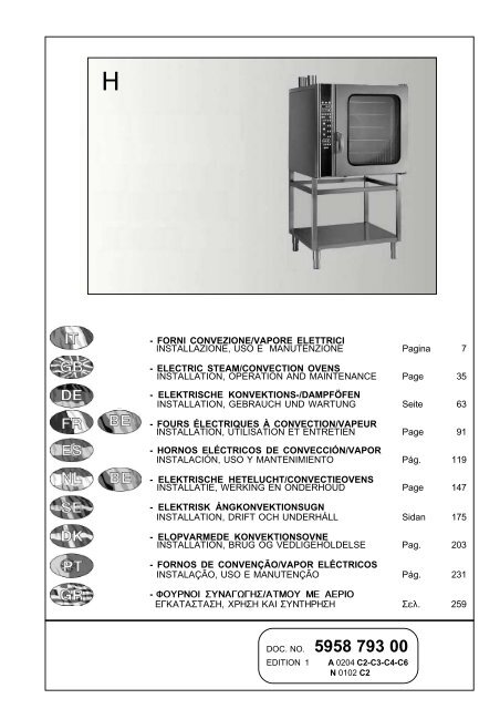
H<br />
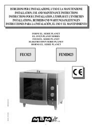
- FORNI CONVEZIONE/VAPORE ELETTRICI<br />
INSTALLAZIONE, USO E MANUTENZIONE Pagina 7<br />
- ELECTRIC STEAM/CONVECTION OVENS<br />
INSTALLATION, OPERATION AND MAINTENANCE Page 35<br />
- ELEKTRISCHE KONVEKTIONS-/DAMPFÖFEN<br />
INSTALLATION, GEBRAUCH UND WARTUNG Seite 63<br />
- FOURS ÉLECTRIQUES À CONVECTION/VAPEUR<br />
INSTALLATION, UTILISATION ET ENTRETIEN Page 91<br />
- HORNOS ELÉCTRICOS DE CONVECCIÓN/VAPOR<br />
INSTALACIÓN, USO Y MANTENIMIENTO Pág. 119<br />
- ELEKTRISCHE HETELUCHT/CONVECTIEOVENS<br />
INSTALLATIE, WERKING EN ONDERHOUD Page 147<br />
- ELEKTRISK ÅNGKONVEKTIONSUGN<br />
INSTALLATION, DRIFT OCH UNDERHÅLL Sidan 175<br />
- ELOPVARMEDE KONVEKTIONSOVNE<br />
INSTALLATION, BRUG OG VEDLIGEHOLDELSE Pag. 203<br />
- FORNOS DE CONVENÇÃO/VAPOR ELÉCTRICOS<br />
INSTALAÇÃO, USO E MANUTENÇÃO Pág. 231<br />
- ÖÏÕÑÍÏÉ ÓÕÍÁÃÙÃÇÓ/ÁÔÌÏÕ ÌÅ ÁÅÑÉÏ<br />
ÅÃÊÁÔÁÓÔÁÓÇ, ×ÑÇÓÇ ÊÁÉ ÓÕÍÔÇÑÇÓÇ Óåë. 259<br />
DOC. NO. 5958 793 00<br />
EDITION 1 A 0204 C2-C3-C4-C6<br />
N 0102 C2
DICHIARAZIONE DI CONFORMITA'<br />
ELECTROLUX PROFESSIONAL SPA<br />
Viale Treviso 15<br />
33170PORDENONE<br />
Dichiara sotto la propria autorità che le macchine appartenenti a questa documentazione,<br />
descritte nella targhetta di identificazione, sono conformi alle seguenti disposizioni legislative:<br />
- Direttiva Europea 73/23/CEE (L.V.D. apparecchiature elettriche bassa tensione)<br />
- Direttiva Europea 89/336/CEE (E.M.C. compatibilità elettromagnetica)<br />
- Direttiva Europea 93/68/CEE (Aggiornamento alle direttive)<br />
- Direttiva Europea 90/396/CEE (Apparecchiature gas)<br />
Data: Pordenone 1.01.2000<br />
Nome: Beniamino Zambon<br />
(Responsabile Stabilimento)<br />
DECLARATION OF CONFORMITY<br />
ELECTROLUX PROFESSIONAL SPA<br />
Viale Treviso 15<br />
33170PORDENONE<br />
Hereby declares under its own authority that the machine described in this document<br />
and specified on the identification plate, conforms to the following provisions laid down<br />
by law:<br />
- European Directive 73/23/CEE (L.V.D. Low Voltage Directive)<br />
- European Directive 89/336/CEE (E.M.C. Electro Magnetic Compatibility)<br />
- European Directive 93/68/CEE (Amendment to the Directive)<br />
- European Directive 90/396/CEE (Gas appliances)<br />
Date: Pordenone 1.01.2000<br />
Name: Beniamino Zambon<br />
(Plant Manager)<br />
2
IT<br />
GB<br />
DE<br />
FR BE<br />
ES<br />
NL<br />
SE<br />
DK<br />
PT<br />
GR<br />
BE<br />
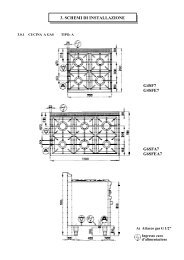
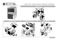
SCHEMI DI INSTALLAZIONE<br />
INSTALLATION DIAGRAM<br />
INSTALLATIONSPLAN<br />
SCHEMAS D'INSTALLATION<br />
ESQUEMA PARA LA INSTALACIÓN<br />
INSTALLATIESCHEMA<br />
INSTALLATIONSRITNING<br />
INSTALLATIONSDIAGRAM<br />
ESQUEMAS DE INSTALAÇAO<br />
���������������������������<br />
3
Mod.: 6 GN 1/1 Mod.: 10 GN 1/1 isg<br />
Mod.: 10 GN 1/1<br />
4<br />
Mod.: 10 GN 2/1
Mod.: 20 GN 1/1<br />
IT<br />
I - Entrata cavo elettrico<br />
B - Attacco alim. acqua (0,5 - 5 °F) ø3/4"M ISO 7/1<br />
C - Collettore scarico acqua ø1"1/4M ISO 7/1<br />
N - Attacco acqua Conden. fumane ø3/4" M ISO 7/1<br />
GB - IE<br />
I - Power supply cable inlet<br />
B - Water supply connection (0.5- 5 °F) ø3/4"M ISO 7/1<br />
C - Water drain connection ø1"1/4M ISO 7/1<br />
N - Steam condens. water connection ø3/4"M ISO 7/1<br />
DE - AT - CH<br />
I - Netzkabeleingang<br />
B - Wasseranschluß(0,5 - 5 °fH) ø3/4"M ISO 7/1<br />
C - Wasserablauf-Sammelrohr ø1"1/4M ISO 7/1<br />
N - Wasseranschluß<br />
Schwadenkondensator ø3/4"M ISO 7/1<br />
FR - BE<br />
I - Entrée câble électrique<br />
B - Entrée eau (0,5 - 5 °F) ø3/4"M ISO 7/1<br />
C - Collecteur évacuation eau ø1"1/4M ISO 7/1<br />
N - Entrée eau Conden.vapeurs ø3/4"M ISO 7/1<br />
ES<br />
I - Ingreso cable eléctrico<br />
B - Conexión de agua (0,5 - 5 °F) ø3/4"M ISO 7/1<br />
C - Colector del desagüe ø1"1/4M ISO 7/1<br />
N - Entrada del agua de condensación ø3/4" M ISO 7/1<br />
5<br />
Mod.: 20 GN 2/1<br />
NL - BE<br />
I - Voedingskabel<br />
B - Aansluiting watertoevoer (0,5 - 5°F) ø3/4"M ISO 7/1<br />
C - Aansluiting waterafvoer ø1"1/4M ISO 7/1<br />
N - Wateraansluiting stoomcondensatie ø3/4"M ISO 7/1<br />
SE<br />
I - Nätkabelintag<br />
B - Vattenanslutning (0,5 – 5° F) ø3/4"M ISO 7/1<br />
C - Vattendräneringsrör ø1"1/4M ISO 7/1<br />
N - Vattenanslutning ångkondensering ø3/4"M ISO 7/1<br />
DK<br />
I - Strømforsyningstilslutning<br />
B - Tilslutning til vandforsyning (0,5 - 5 °F) ø3/4"M ISO 7/1<br />
C - Opsamler til udtømningsvand ø1"1/4M ISO 7/1<br />
N - Tilslutning til kondensvand, dampe ø3/4"M ISO 7/1<br />
PT<br />
I - Entrada do cabo de alimentação eléctrica<br />
B - Ligação de abastecimento<br />
da água (0,5 – 5º F) ø3/4"M ISO 7/1<br />
C - Colector de descarga da água ø1"1/4M ISO 7/1<br />
N - Ligação da água<br />
“condensação de vapor” ø3/4" M ISO 7/1<br />
GR<br />
� �����������������������������<br />
� ������������������������������������� ������ �������<br />
� ��������������������������� ������� �������<br />
� ��������������������������������� ������ �������
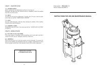
ELECTRIC STEAM/CONVECTION OVENS<br />
INSTRUCTIONS FOR INSTALLATION AND USE (for the United Kingdom)<br />
CONTENTS Page<br />
- Declaration of conformity .................................................................................................... 2<br />
- Installation diagrams.......................................................................................................... 3<br />
- Appliance identification .................................................................................................... 35<br />
I. MAIN FEATURES .............................................................................................. 36<br />
1. Description of appliance ................................................................................................... 36<br />
2. Main components (exploded diagrams) .......................................................................... 36<br />
- Table 1: Technical data .................................................................................................... 38<br />
3 Precautions ....................................................................................................................... 39<br />
4 Safeguarding the environment ......................................................................................... 39<br />
II. INSTRUCTIONS FOR INSTALLATION .............................................................. 40<br />
1. Installation place ............................................................................................................... 40<br />
2. Positioning ........................................................................................................................ 40<br />
3. Electrical connection ........................................................................................................ 41<br />
4. Water mains connection ................................................................................................... 41<br />
5. Safety device .................................................................................................................... 43<br />
6. Operation check ................................................................................................................ 43<br />
7. Servicing ........................................................................................................................... 43<br />
8. Troubleshooting ................................................................................................................ 43<br />
9. Layout of main components ............................................................................................. 44<br />
III. INSTRUCTIONS FOR USE ................................................................................ 45<br />
1. Opening the oven door ..................................................................................................... 45<br />
2. Closing the oven door ...................................................................................................... 45<br />
3. Description of control panel .............................................................................................. 46<br />
- Using the oven .................................................................................................................. 49<br />
4. Functional levels 2-3 ........................................................................................................ 49<br />
5. Functional level 4.............................................................................................................. 52<br />
6. Functional level 6.............................................................................................................. 55<br />
7. All models ......................................................................................................................... 60<br />
- CONTROL PANEL FIGURES (C2-C3-C4-C6) .................................................... 287<br />
Appliance identification<br />
35<br />
GB
GB<br />
I. MAIN FEATURES<br />
1. DESCRIPTION OF APPLIANCE<br />
This booklet describes a number of appliance models.<br />
For more detailed information about the model in your possession,<br />
refer to "Technical Data" table 1.<br />
The appliance has the following features:<br />
• Digital temperature indicator.<br />
• Thermostatic probe for measuring the core temperature of<br />
products (core temperature probe) (only available on certain<br />
models).<br />
• Continuous monitoring of cooking parameters throughout the<br />
entire cooking cycle.<br />
• Periodic draining and automatic washing of the boiler to prevent<br />
the build-up of lime-scale (only available on certain models).<br />
• Boiler lime-scale level indicator (see corresponding paragraph).<br />
• Dehumidification device (with automatic or manual operation<br />
depending on the model) to reduce excess humidity in the oven<br />
for gratinating.<br />
• Oven chamber lighting.<br />
• Double-action door opening mechanism designed to protect<br />
the user from scalding steam.<br />
• Double-glazed oven door for reduced heat dispersion into the<br />
kitchen and low external oven temperatures.<br />
• Daily oven chamber cleaning cycle (clean).<br />
• Self-diagnostics system indicating oven malfunctions by way<br />
of error codes (see "Alarm and diagnostics messages").<br />
6 GN 1/1<br />
10<br />
1<br />
8<br />
2<br />
3<br />
9<br />
36<br />
2. MAIN COMPONENTS<br />
The components marked by a hatched line are not installed on<br />
the following models:<br />
6 GN 1/1 C2-C3, 10 GN 1/1 C2.<br />
KEY:<br />
1.............................................................resistances (steam generator)<br />
2...........................................................electronic card support<br />
3......................................................................electronic card<br />
4...............................................................................control panel<br />
5..........................................................resistances(convector)<br />
6................................door with double-glazing opening system<br />
7������������������������������������������������������������������oven chamber fan<br />
8.........................................................................steam boiler<br />
9............................................................................water injector<br />
10...............................................................water pressure gauge<br />
5<br />
4<br />
7<br />
6<br />
com_e6gn1<br />
1
10 GN 2/1<br />
1<br />
10<br />
20 GN 2/1<br />
1<br />
2<br />
8<br />
8<br />
2<br />
3<br />
5 9<br />
37<br />
5<br />
7<br />
7<br />
com_e10gn1<br />
com_e20gn1<br />
10 GN 1/1<br />
6<br />
6<br />
4<br />
3<br />
20 GN 1/1<br />
4<br />
2<br />
3<br />
GB
GB<br />
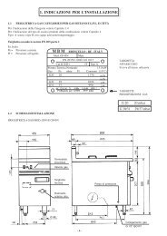
TABLE 1: TECHNICAL DATA<br />
FIGURES<br />
SHELVES<br />
PNC 9731 *<br />
FUNCTIONAL LEVEL<br />
CONVECTOR °<br />
STEAM GENERAT.**<br />
POWER SUPPLY<br />
VOLTAGE (VOLT)<br />
FREQUENCY (Hz)<br />
Max. electrical power<br />
absorption<br />
Mains fuses<br />
(3x500V)<br />
Power supply cable<br />
cross-section (m m 2 )<br />
Electrical output<br />
fan motor (Kw)<br />
Electrical output<br />
steam unit (Kw)<br />
Electrical output<br />
convection unit(Kw)<br />
1 2 3<br />
6 GN 1/1 10 GN 1/1 10 GN 2/1 20 GN 1/1 20 GN 2/1<br />
724251 697821<br />
697807<br />
724253<br />
697843 697883 697845 697885 697847 697887 697849 697889<br />
C2 (ISG) C3 C2 (ISG) C4 C6 C4 C6 C4 C6 C4 C6<br />
°<br />
380...400<br />
3N~<br />
°<br />
**<br />
380...400<br />
3N~<br />
Noise emission data: Noise emissions generated by the appliances<br />
described in this booklet do not exceed 70 dB (A).<br />
* Your appliance model is indicated in the box marked PNC on<br />
the "Technical Data" label affixed to the bottom left hand side of<br />
your oven.<br />
°<br />
380...400<br />
3N~<br />
°<br />
**<br />
380...400<br />
3N~<br />
°<br />
**<br />
380...400<br />
3N~<br />
38<br />
°<br />
**<br />
380...400<br />
3N~<br />
°<br />
**<br />
380...400<br />
3N~<br />
°<br />
**<br />
380...400<br />
3N~<br />
°<br />
**<br />
380...400<br />
3N~<br />
°<br />
**<br />
380...400<br />
3N~<br />
°<br />
**<br />
380...400<br />
3N~<br />
50 50 50 50 50 50 50 50 50 50 50<br />
9,3 9,5 17,3 17,3 17,3 24,5 24,5 34,5 34,5 48,9 48,9<br />
16 25 32 32 32 40 40 50 50 80 80<br />
5x1,5 5x2,5 5x4 5x5 4 5x6 5x6 5x10 5x10<br />
0,19 0,19 0,19 0,19 0,19 0,35 0,35 0,19x2 0,19x2 0,35x2 0,35x2<br />
- 9 - 17 17 24 24 24 24 48 48<br />
9 9 17 17 17 24 24 17x2 17x2 24x2 24x2<br />
5x6<br />
5x6<br />
5x6<br />
5x6
3. PRECAUTIONS<br />
• Before installing or using the appliance, carefully read this<br />
instructions booklet, in as much as it contains important information<br />
concerning the safety, operation and maintenance of the<br />
appliance.<br />
• Keep this instructions booklet in a safe place for future consultation<br />
by other users or purchasers in the event that the appliance<br />
is resold.<br />
Important: Installation and maintenance of the appliance<br />
and its conversion to a different gas supply, must only be<br />
performed by a qualified installer authorised by the<br />
manufacturer.<br />
• This appliance is intended for industrial use only and is<br />
specifically designed to cook food. Any other use of the appliance<br />
is deemed improper.<br />
The appliance must only be used by trained staff and must be<br />
supervised at all times when in use.<br />
• Switch off the appliance if it breaks down or malfunctions.<br />
• Only contact the technical service centre authorised by the<br />
manufacturer for repairs and only use original spare parts.<br />
Failure to comply with the above requirement may jeopardise<br />
the safety of the appliance and render the guarantee null and<br />
void.<br />
• Do not wash the appliance with water jets.<br />
• Do not use products containing chlorine (bleach, hydrochloric<br />
acid etc.) even diluted, to clean steel surfaces.<br />
• Do not use corrosive substances (i.e. muriatic acid) to clean the<br />
floor under the appliance.<br />
• For more information, refer to the chapter on "Care and maintenance".<br />
39<br />
4. SAFEGUARDING THE ENVIRONMENT<br />
4.1. Packaging<br />
• All the packaging materials used are environmentally friendly.<br />
They may be stored at no risk or burnt at an authorised incineration<br />
plant. Plastic materials suitable for recycling are marked with<br />
the following symbols:<br />
polyethylene : external wrapping film, instructions<br />
PE booklet bag and gas injectors bag<br />
pp<br />
PS<br />
polypropylene: top packaging panels and straps<br />
expanded polystyrene: protective surround elements<br />
4.2. Use<br />
• The appliance has been designed and perfected under laboratory<br />
testing conditions to offer exceptional levels of performance.<br />
However, to minimise energy consumption (electricity, gas and<br />
water) , we recommend turning the appliance off when not in use<br />
for long periods and not using it, for example, with the door open<br />
as this may impair the oven's performance. We also recommend<br />
preheating the appliance immediately prior to use.<br />
4.3. Cleaning<br />
• To minimise the emission of pollutants into the environment,<br />
we recommend cleaning the appliance (externally and, where<br />
necessary, internally) with products which are at least 90%<br />
biodegradable.<br />
4.4 Disposal<br />
• The appliance must be disposed of properly at the end of its<br />
service life.<br />
• The appliance is made from 90% recyclable materials (stainless<br />
steel, iron, aluminium, galvanised sheet steel, etc.). These<br />
materials may therefore be scrapped in accordance with local<br />
waste disposal regulations at a conventional recycling plant.<br />
• Make the appliance unusable by cutting off the power cord. Also<br />
remove any compartment or interior closure device fitted on the<br />
appliance to prevent persons from becoming trapped inside.<br />
GB
GB<br />
II. INSTRUCTIONS FOR INSTALLATION<br />
Important: The external oven panels must be removed to perform the operations described in this chapter. Since the appliance<br />
must be switched on to make certain adjustments, exercise the utmost care when working in the vicinity of the appliance’s “live”<br />
parts.<br />
1. INSTALLATION PLACE<br />
• The appliance must only be installed in adequately ventilated premises.<br />
2. POSITIONING<br />
• Unpack the appliance and carefully remove the protective film from the external panels to avoid leaving any trace of glue.<br />
Use a suitable diluent to remove any glue residue.<br />
• Dispose of the packaging as instructed in the chapter on "Safeguarding the environment"<br />
• Refer to the installation diagrams at the beginning of this booklet for the space requirements and connection dimensions of the<br />
appliance.<br />
• The LH side of the appliance must be installed at least 50 cm from adjacent units to provide easy access for maintenance, while<br />
the RH side must be installed 10 cm from adjacent units made from flammable materials.<br />
• Place the appliance in the required position and adjust the height of the work surface using the adjustable feet.<br />
• The appliance is not suitable for built-in installation.<br />
Important:<br />
Make sure vapours from the oven’s drain or adjacent appliances do not enter the aeration vents under the appliance,<br />
which cool the oven’s internal components.<br />
40
3. ELECTRICAL CONNECTION<br />
• The appliance must be connected to the mains power supply<br />
in compliance with current regulations.<br />
• Before connecting the appliance to the mains supply, make<br />
sure that the voltage and frequency shown on the appliance<br />
rating plate correspond with that of the power supply.<br />
• The appliance must be permanently connected to the mains<br />
power supply with an H05 RN-F type cable. The power supply<br />
cable must be protected by a metal or rigid plastic tube. If the<br />
appliance is connected by way of an existing lead, do not insert<br />
the installation tube in the appliance and make sure the tube<br />
has no sharp edges.<br />
• A safety cutout switch of suitable capacity with a contact<br />
breaking distance of at least 3 mm must be fitted upstream of<br />
the appliance.<br />
This cutout switch must be installed near the appliance in the<br />
permanent electrical system of the premises.<br />
• The appliance must be suitably earthed. The earthing conductor<br />
must therefore be connected to the terminal marked G on<br />
the connection terminal board. The appliance must also be<br />
connected to an equipotential system.<br />
This connection is made using the stop screw marked E<br />
located on the outside of the appliance near the power cable<br />
inlet.<br />
The equipotential wire must have a minimum cross-section of<br />
10 mm 2 .<br />
4.1 INSTALLING THE POWER SUPPLY CABLE<br />
(Fig. "10")<br />
To access the power supply cable connection terminal board,<br />
proceed as follows:<br />
Mod. 6 GN1/1 - 10 GN1/1 - 10 GN2/1<br />
• Undo screws "V" fixing the terminal board support panel located<br />
underneath the appliance on the front LH side.<br />
• Feed the power supply cable through cable clamp inlet "B".<br />
• Connect the cable to terminal board “A” as shown in the<br />
enclosed wiring diagram and fasten with the corresponding<br />
cable clamp.<br />
• Remount the panel and secure with the fixing screws.<br />
10<br />
Mod. 20 GN1/1 - 20 GN2/1<br />
• Open the control panel.<br />
• Connect the cable to terminal board as shown in the enclosed<br />
wiring diagram and fasten with the corresponding cable clamp.<br />
The manufacturer declines any responsibility for failure to<br />
comply with existing accident prevention standards.<br />
41<br />
4. WATER MAINS CONNECTION<br />
(Refer to the installation diagrams at the beginning of this booklet).<br />
The appliance is fitted with two separate water inlets ("B" and "N").<br />
The water lines supplying both inlets must be fitted with a<br />
mechanical filter and shut-off cock.<br />
Before fitting the filters, pump water through the system to expel<br />
any solid particles from the piping.<br />
4.1. WATER SUPPLY CHARACTERISTICS<br />
4.1.1 Water inlet "N".<br />
The steam condensation system must be connected to a cold<br />
drinking water supply with the following characteristics:<br />
- total hardness: up to 40°F;<br />
- pressure: 150 to 250 kPa (1.5-2.5 bar); higher pressure<br />
values result in increased water consumption.<br />
4.1.2 Water inlet "B".<br />
The steam production system must be connected to a drinking<br />
water supply with the following characteristics:<br />
- total hardness: 0.5 to 5 °F to prevent the build-up of limescale<br />
inside the boiler (or oven chamber on models with automatic<br />
generation).<br />
On request the oven is supplied with an optional water softener<br />
device with automatic regeneration which must be installed on<br />
inlet line "B". This device is also supplied with a resin sterilisation<br />
kit (available on request).<br />
- pressure: 150 to 250 kPa (1.5-2.5 bar); higher pressure<br />
values result in increased water consumption.<br />
- chlorine ion concentration (Cl -): not more than ~10 ppm<br />
(acceptable value) to avoid damaging the oven's internal steel<br />
elements.<br />
- pH: over 7.<br />
On request the oven is supplied with an optional special filtration<br />
unit which is installed on inlet line "B". This unit also acts as a water<br />
softener by reducing water hardness to less than 5°F.<br />
- electrical conductivity: 50 to 2000 µS/cm (20°C).<br />
Important: Only install the water treatment systems supplied by<br />
the manufacturer. Failure to do so automatically invalidates the<br />
guarantee.<br />
The use of dosing systems designed to prevent the buildup<br />
of lime-scale in pipes (i.e. polyphosphate dosing<br />
systems) is also prohibited since it may impair the<br />
performance of the appliance.<br />
GB
GB<br />
4.2 WATER PRESSURE ADJUSTMENT (ONLY FOR<br />
MODELS 6 GN 1/1 C2-C3 AND 10 GN 1/1 C2)<br />
For correct operation of these appliances, in addition to the<br />
requirements stipulated in point 4.1 above, the water pressure<br />
must also be adjusted using the relative internal pressure<br />
regulator. To adjust the water pressure, proceed as follows (Fig.<br />
"11"):<br />
1) Remove the LH side panel from the oven;<br />
2) Start a steam cooking cycle (see "Instructions for use");<br />
3) Undo knurled cap "A";<br />
4) Using a flat-blade screwdriver, turn the screw underneath until<br />
the read-out on pressure gauge "B" is 120 kPa (1.2 bar);<br />
5) Refit cap "A" and remount the side panel.<br />
11<br />
4.3 WATER DRAIN SYSTEM (Fig. 12a-12b)<br />
Connect drain fitting “C” to a drain pipe of the same<br />
diameter which is between 0.5 and 3 metres in length and<br />
is resistant to temperatures of at least 100°C. The drain pipe<br />
must be siphoned (height 80 mm) to an open drain “O” (“Air-<br />
Break”) or floor grating (see Fig. 12b) in order to prevent any<br />
back-flow from the sewage system from reaching the piping<br />
inside the oven or oven chamber.<br />
Check the hoses and elbows on metal pipes for kinks or pinching<br />
along the entire drain line and make sure the drain line has a<br />
minimum gradient of 5° to prevent water from collecting inside<br />
the system.<br />
Important: The drain system must be installed so that any<br />
vapours from the open drain do not enter the aeration vents<br />
under the appliance.<br />
Note for model 6 GN 1/1 C4:<br />
This model is fitted with two separate drain fittings (see installation<br />
diagram). These fittings must be connected to each other externally<br />
on the appliance before flowing into a single drain.<br />
42<br />
12a<br />
12b
5. SAFETY DEVICES<br />
The appliance is fitted with the following safety devices:<br />
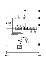
6.1 Safety fuses (see electrical circuit diagram) positioned<br />
behind the control panel.<br />
To replace, loosen the retainer cap, and replace the damaged<br />
component with one of the same capacity; this value is specified<br />
on the relative data plate.<br />
6.5 Chamber safety thermostat, with manual reset located<br />
behind control panel; when this device trips, convection heating<br />
power is shut off.<br />
Reset operations must be performed by specialised technical<br />
personnel after eliminating the cause of the fault.<br />
6.6 Thermal cutout inside fan motor, which trips in the event of<br />
overheating on fuse F1 (see electrical circuit diagram) and shuts<br />
down appliance operation.<br />
Reset operations must be performed by specialised technical<br />
personnel after eliminating the cause of the fault and fuse F1 must<br />
be replaced with a version of the same capacity.<br />
To replace, open the control panel, loosen the retainer cap, and<br />
replace the damaged component with one of the same capacity;<br />
this value is specified on the relative data plate.<br />
6. OPERATION CHECK<br />
- Switch on the appliance in accordance with the instructions for<br />
use.<br />
- Using the instructions manual, explain the operation and<br />
maintenance instructions to the user.<br />
Important:<br />
- Exercise due care since certain areas of the oven exterior get<br />
hot during use.<br />
- Do not cover the exhausts on top of the appliance.<br />
43<br />
7. SERVICING<br />
All components requiring routine maintenance may be easily<br />
reached by opening the control panel or removing the LH side<br />
panel and rear panel.<br />
8. TROUBLESHOOTING<br />
Even during the regular running of the appliance anomalies<br />
or failures can occur.<br />
The oven chamber heating does not activate or is<br />
inefficient.<br />
Possible cause:<br />
- The oven chamber temperature limit switch has intervened<br />
- The heating elements are damaged<br />
- Check the contactor coil relative to the damaged component<br />
- Damaged thermostat probe showing error “EPt1”.<br />
- The controller is damaged<br />
- Fuse “F2” has intervened, see wiring diagram.<br />
Steam production does not start up or is inefficient.<br />
Possible cause:<br />
- The heating elements are damaged<br />
- Check the contactor coil relative to the damaged component<br />
- The controller is damaged<br />
- Fuse “F2” has intervened.<br />
- No water supply from the mains.<br />
- Boiler drainage outlet closing device damaged<br />
- Water inlet solenoid valves are damaged (do not open)<br />
The oven chamber temperature reading is erratic<br />
Possible cause:<br />
- The electronic controller is damaged<br />
- The thermostat probe is damaged, dirty or interrupted see<br />
error “EPt1”.<br />
The oven switches off<br />
Possible cause:<br />
- The fuse “F1” has intervened due to motor overheating and<br />
the oven chamber lighting switches off<br />
- The fuse “F2” has intervened due to damage to the auxiliary<br />
components.<br />
GB
GB<br />
9. LAYOUT OF MAIN COMPONENTS<br />
(All work inside the appliance must only be carried out by a<br />
trained installer authorised by the manufacturer)<br />
(These interventions must be carried out by an authorised<br />
installer)<br />
Removing the left-hand side and rear panels from the<br />
appliance will allow access to the following components:<br />
- Vapour damping system solenoid valve with flow regulator<br />
- Access to the steam generator heating elements<br />
- Probe PT1000 (oven chamber temperature)<br />
- Control circuit ventilator fan<br />
- Oven chamber ventilator fan<br />
- Probe PT1000 (by-pass) activating the vapour damping<br />
system and water injection for the production of steam.<br />
- Motorised boiler drainage valve<br />
- Water loading solenoid valve.<br />
Removing the control panel will allow access to the following<br />
components:<br />
- Electronic PCB card<br />
- Main terminal board (can also be accessed externally from<br />
the bottom of the appliance)<br />
- Oven chamber temperature limit thermostat<br />
- Fuses<br />
- RIF filters<br />
- Heating element contactors<br />
- Door microswitches<br />
- Oven chamber lamp holder<br />
- Oven chamber ventilator fan condenser<br />
- Oven chamber lamp transformer<br />
- Geared motor for the oven chamber butterfly relief valve.<br />
- Control shutter relay controlling the speed of the oven chamber<br />
ventilator fan.<br />
44
III. INSTRUCTIONS FOR USE<br />
Before switching on the appliance, carefully read this instructions<br />
booklet, in as much as it contains important information concerning<br />
correct and optimum use of the appliance. If you require<br />
further information about the oven's features and cooking performance,<br />
consult your local dealer.<br />
• Do not place pans or utensils on top of the oven to avoid<br />
obstructing the fume and steam exhaust ducts.<br />
• Once every six months the burners, the uniformity of their flame<br />
and related components must be inspected by a qualified technician.<br />
• Periodically (at least once a year) the appliance should undergo<br />
a general inspection. For this purpose we recommend<br />
taking out a service contract.<br />
• Some models are equipped with a temperature probe which<br />
measures the core temperature of products. This is a precision<br />
instrument and must therefore be handled with the utmost care<br />
to avoid knocks or damage caused by abrupt insertion or removal<br />
of the lead (particularly when using trolley-mounted units). The<br />
guarantee does not cover damage to the temperature probe<br />
caused by improper usage.<br />
• When using the mixed cooking cycle, do not exceed cooking<br />
temperatures of 200-210°C which might otherwise impair the<br />
performance of the oven chamber seals.<br />
• When using the oven, leave a gap of at least 40 mm between<br />
each container to facilitate the correct circulation of hot air inside<br />
the oven.<br />
• Do not salt foods inside the oven chamber, particularly<br />
during cooking cycles with humidification.<br />
• Do not cook with flammable liquids such as high-alcohol<br />
spirits.<br />
1. OPENING THE OVEN DOOR<br />
1.1. 6 AND 10 SHELF MODELS<br />
a) Pull and lift the bottom of the handle. The door will open<br />
just enough to allow the steam inside the oven to escape.<br />
Any cooking program already in progress stops.<br />
b) Release the handle.<br />
c) Pull and lift the bottom of the handle again to fully open the<br />
oven door.<br />
45<br />
Important! Risk of burning.<br />
Open the door with due care when the appliance is hot.<br />
1.2. 20 SHELF MODELS<br />
a) Turn the door handle anticlockwise until it is horizontal.<br />
The door will open just enough to allow the steam inside the oven<br />
to escape.<br />
Any cooking program already in progress stops.<br />
b) Pull the handle; the door offers a little resistance before<br />
opening completely.<br />
Important! Risk of burning.<br />
Open the door with due care when the appliance is hot.<br />
2. CLOSING THE OVEN DOOR<br />
2.1. 6 AND 10 SHELF MODELS<br />
Simply push the oven door to so that it locks.<br />
2.2. 20 SHELF MODELS<br />
a) Holding the door handle in the horizontal position, push<br />
the door to.<br />
b) Then, holding the door against the oven, turn the handle<br />
clockwise until it is vertical again.<br />
GB
GB<br />
3. DESCRIPTION OF CONTROL PANEL<br />
3.1. INTRODUCTION<br />
To facilitate familiarisation with the oven's functions, refer to the<br />
fold-out page at the end of this booklet illustrating the control<br />
panel of your oven model.<br />
The different functions available on the various models are<br />
described below.<br />
Some functions are common to all models while others are<br />
only available on certain models.<br />
3.2. STANDARD CONTROLS<br />
S1 Main switch.<br />
L1 "Oven on" indicator led.<br />
TS Digital Thermometer/Thermostat: controls the oven<br />
temperature.<br />
TM Timer: sets the cooking time.<br />
PRB Digital Thermometer/Thermostat: controls the core temperature<br />
of products (not available on Functional level C2).<br />
startno2_alp.eps<br />
Cooking cycle/program Start/Stop button.<br />
(Functional levels C4 and C6 only)<br />
3.3. MAIN COOKING CYCLES<br />
c1alp.eps<br />
C1 Convection cycle: ideal for roasting and gratinating at<br />
temperatures of up to 300°C.<br />
c2_2alp.eps<br />
C2 Mixed cycle: combined convection and steam cycle<br />
which simultaneously uses both the convectors and boiler to<br />
keep dishes perfectly tender (maximum temperature 250°C).<br />
c3alp.eps<br />
C3 Steam cycle: ideal for boiling (steam operating temperature:<br />
100°C).<br />
30÷99<br />
c4alp.eps<br />
C4 Low-temperature steam cycle: ideal for delicate and<br />
vacuum-packed cooking and for defrosting at temperatures<br />
between 30°C and 99°C.<br />
Note: On functional level 6 ovens, this option is selected in the<br />
normal steam cycle (C3) by setting a cooking temperature of less<br />
than 100°C.<br />
c5alp.eps<br />
C5 Convection cycle with automatic dehumidification: reduces<br />
excess humidity in the oven when required, thereby<br />
making it ideal for dry cooking (maximum temperature 300°C).<br />
Note: On functional level ovens C2, C3 and C4, this option is<br />
selected in the normal convection cycle (C1) by manually<br />
opening the oven chamber vent using the RH lever above the<br />
door.<br />
46<br />
3.4. SPECIAL COOKING CYCLES<br />
R<br />
cr_alp.eps<br />
CR Regeneration cycle: produces the ideal temperature<br />
and humidity required to quickly reheat previously cooked dishes<br />
(maximum temperature 250°C).<br />
Note: On functional level 6 ovens, this cycle is preprogrammed<br />
and selected in AUTO mode. Refer to the chapter on<br />
INSTRUCTIONS FOR USE - Functional Level 6<br />
COOK<br />
&<br />
HOLD<br />
cokhold2_alp.eps<br />
Cook and hold cycle: this slow, low-heat cooking cycle is ideal<br />
for cooking large joints.<br />
Used in conjunction with convection (C1) and steam (C3)<br />
cooking cycles.<br />
spillone_alp.eps<br />
Cooking with temperature probe: this cooking method precision<br />
controls the core temperature of products between 0 and<br />
99°C.<br />
Used in conjunction with all cooking cycles.<br />
The cooking cycle automatically stops when the set core temperature<br />
is reached.<br />
1<br />
2 potrid2_alp.eps<br />
Low speed and power cycle: ideal for delicate cooking as<br />
required by light pastries.<br />
Used in conjunction with all cooking cycles.<br />
PAUSE<br />
pausa_alp.eps<br />
Pause: by setting a pause using this function you can delay the<br />
start of cooking programs or set a pause between two cooking<br />
cycles (i.e. for proving).
3.5. ADDITIONAL FUNCTIONS<br />
ventola_alp.eps<br />
Rapid oven cooling: this function is used to switch from one<br />
cooking cycle to another operating at a lower temperature. It<br />
controls fan activation and automatic water injection (Levels 4<br />
and 6 only), even when the oven door is open.<br />
Important! Risk of burning.<br />
Open the door with due care when the appliance is hot.<br />
iniezion_alp.eps<br />
Manual water injection: this function immediately increases the<br />
humidity level inside the oven during a cooking cycle.<br />
CLEAN<br />
clean_alp.eps<br />
Clean cycle: this function activates a semi-automatic oven<br />
cleaning cycle (see paragraph 7.3 on "Cleaning").<br />
?SET<br />
occhio_n_alp.eps<br />
Programmed cooking settings display: this display allows you<br />
to check cooking cycle settings at a glance.<br />
1 2<br />
CYCLE<br />
fase12_2alp.eps<br />
1 2 3 4 5 6<br />
PHASE<br />
fase_alp.eps<br />
C4 C6<br />
- Sequential phase controls and leds: used to set automatic<br />
multi-phase cooking programs comprising two sequential<br />
phases on functional level 4 ovens and 6 sequential phases on<br />
functional level 6 ovens.<br />
umidità_alp.eps<br />
- Electronic humidity control (only on functional level 6<br />
ovens): this control allows you to obtain the required degree of<br />
humidity in the oven during convection, mixed and regeneration<br />
cooking cycles.<br />
A<br />
U<br />
T<br />
O<br />
automan_alp.eps<br />
Manual or automatic program (only on functional level 6 ovens):<br />
this function allows you to work in either manual or AUTO mode.<br />
In auto mode you can select one of the programs stored in the<br />
program archive.<br />
PROGRAM<br />
prog_88_alp.eps<br />
- Program display (only on functional level 6 ovens): this<br />
display panel allows you to find and select the required program<br />
using the relative display buttons.<br />
47<br />
M<br />
RETURN CANCEL<br />
biblio_alp.eps<br />
- Program archive control buttons (only on functional<br />
level 6 ovens): these buttons allow you to save, edit and delete<br />
cooking programs.<br />
portaper_alp.eps<br />
Door "open" indicator led.<br />
HACCP haccp.eps<br />
HACCP button (only available on request): this button enables<br />
you to record cooking programs in conformity with Standard<br />
H.A.C.C.P. (Hazard Analysis and Critical Control Points).<br />
Depending on the system installed, you can print cooking parameters<br />
on a dedicated printer or save them directly onto a Personal<br />
Computer.<br />
GB
GB<br />
3.6. STEAM BOILER CONTROLS<br />
Note: the steam boiler is not installed on models 10 GN<br />
1/1 C2 and 6 GN 1/1 C2-C3<br />
scarico_alp.eps<br />
Manual boiler water drain: pressing button "A" this function<br />
allows you to empty the boiler<br />
In the case of all other models, the boiler is emptied using the lever<br />
located under the control panel.<br />
Important! Risk of scalding.<br />
Exercise due care when manually emptying the boiler.<br />
Important! To prevent the build-up of lime-scale inside the<br />
boiler:<br />
� Make sure the water supply corresponds with the required<br />
characteristics - see Installation.<br />
� Always empty the boiler at the end of each day.<br />
genvapor_alp.eps<br />
A<br />
Functional level C6<br />
Boiler status indicator led:<br />
- off: boiler ready;<br />
- on: boiler preheating. Wait until the led switches off.<br />
- flashing: boiler filling or empty. Check the water supply to the<br />
oven!<br />
calcare_alp.eps<br />
Lime-scale indicator led: this indicator led starts flashing when<br />
the boiler needs descaling. To do this, follow the instructions<br />
given in paragraph 7.<br />
Before using the oven make sure:<br />
- the external electrical safety switch is connected;<br />
- the gas shut-off valve is open;<br />
- the water shut-off valves are open;<br />
- the boiler drain lever is in the closed position (only on<br />
those models fitted with a drain lever).<br />
48
USING THE OVEN<br />
4. FUNCTIONAL LEVELS C2 AND<br />
C3<br />
4.1 TURNING ON THE OVEN<br />
To turn on the oven, simply rotate main switch/selector knob S1<br />
from "0" to the required cooking cycle. The following sequence<br />
then occurs:<br />
L1<br />
S1<br />
0<br />
accforno alp eps<br />
4.1.1. ON ALL MODELS<br />
- Green indicator led L1 illuminates;<br />
- Thermometer/Thermostat display TS indicates the oven temperature;<br />
- The oven light switches on.<br />
4.1.2. MODELS WITH STEAM BOILER<br />
- The boiler starts filling.<br />
genva_l_alp2.eps<br />
(flashing led);<br />
- The boiler starts heating up.<br />
genvapor_alp.eps<br />
(fixed illuminated led);<br />
- The boiler is ready (led off)<br />
4.1.3 TURNING OFF THE OVEN<br />
To turn off the oven, simply <strong>return</strong> selector knob S1 back to "0".<br />
C1<br />
C2<br />
C3<br />
49<br />
4.2. SELECTING THE COOKING CYCLE<br />
Set selector S1 to the required cooking cycle, for example, the<br />
"mixed cooking cycle" (the cooking cycle may also be selected<br />
even after cooking has started).<br />
L1 S1<br />
0<br />
CR<br />
C4<br />
modocott alp eps<br />
4.3. SETTING THE COOKING TEMPERATURE<br />
- Turn thermostat knob TS clockwise.<br />
- The temperature setting immediately starts flashing on the<br />
display.<br />
TS<br />
200<br />
t tt l<br />
60<br />
100<br />
150<br />
C1<br />
C2<br />
C3<br />
- Stop the knob at the temperature setting required, for example,<br />
200°C.<br />
200<br />
t 200 l<br />
After about 5 seconds, the display stops flashing and restores the<br />
current oven temperature.<br />
Note: Each cooking cycle (C1, C2, etc. - see paragraph above)<br />
has its own maximum temperature limit beyond which temperature<br />
control knob TS cannot be turned.<br />
In the case of steam cycle C3, no temperature setting is<br />
required since the cycle is automatically set at 100°C.<br />
60<br />
100<br />
150<br />
TS<br />
GB
GB<br />
4.4. START OF COOKING CYCLE<br />
- Make sure the oven door is closed.<br />
- Set timer knob TM to the required cooking time, for example, 20<br />
minutes.<br />
10<br />
90<br />
80 70<br />
20<br />
30<br />
40<br />
50<br />
60<br />
timer20_alp.eps<br />
The cooking cycle now starts. The yellow indicator leds above<br />
knobs TS and TM illuminate to indicate activation of heating and<br />
cooking.<br />
- The pointer on timer knob TM indicates at a glance the time<br />
remaining until the end of the cooking cycle. The time setting may<br />
also be changed even in the middle of a cooking cycle, simply by<br />
turning the knob.<br />
4.4.1. MODELS WITH STEAM BOILER<br />
- The steam, mixed and regeneration cycles cannot start until the<br />
boiler is ready as indicated by extinction of the corresponding led.<br />
During this phase, timer TM remains stationary and green indicator<br />
led L1 flashes.<br />
The same also occurs if the oven door is opened once the cooking<br />
cycle has started.<br />
- The oven does not stop however if the oven door is opened<br />
during a regeneration cooking cycle (CR).<br />
Important! Risk of burning.<br />
Open the door with due care when the appliance is hot.<br />
4.5. END OF COOKING CYCLE<br />
When the set cooking time has elapsed (pointer on timer TM at<br />
zero), the cooking cycle stops automatically and the yellow<br />
indicator leds above knobs TS and TM switch off. The oven then<br />
beeps for about one minute to let you know that the cooking cycle<br />
has finished.<br />
Note:<br />
- To silence the acoustic signal before the full minute has elapsed,<br />
simply press any button on the control panel or open the oven<br />
door.<br />
- The cooking cycle may also be interrupted manually by <strong>return</strong>ing<br />
timer knob TM back to zero.<br />
Open the oven door and remove the cooked food.<br />
Important! Risk of burning.<br />
Open the door with due care when the appliance is hot.<br />
4.6. MANUAL CYCLE �<br />
You can also set manual cooking cycles simply by deactivating<br />
the timer.<br />
To do this, just turn timer knob TM clockwise to "Continuous<br />
cooking" ��<br />
In this case, the cooking cycle can only be stopped by <strong>return</strong>ing<br />
timer knob TM back to zero or by switching off the oven.<br />
50<br />
10<br />
120<br />
110<br />
100<br />
20<br />
30<br />
40<br />
TM<br />
90<br />
80 70<br />
50<br />
60<br />
4.7. PREHEATING<br />
timer_co_alp.eps<br />
To preheat the oven prior to cooking, proceed as follows:<br />
- First switch on the empty oven by setting selector S1 to the<br />
required cooking cycle and then set thermostat TS to the preheating<br />
temperature and timer TM to "Continuous cooking" �.<br />
- Wait until the preheating temperature is indicated on the oven<br />
temperature display.<br />
- Open the oven door and place the food inside.<br />
Important! Risk of burning.<br />
Open the door with due care when the appliance is hot.<br />
Close the oven door, set the required cooking time on timer TM<br />
and, if necessary, readjust the cooking temperature using thermostat<br />
knob TS.<br />
4.8. COOKING WITH TEMPERATURE PROBE (Core<br />
temperature probe)<br />
ONLY AVAILABLE ON FUNCTIONAL LEVEL 3 OVENS<br />
This cooking method offers precise control over the core<br />
temperature of products. Simply set the required core temperature<br />
and the cycle will stop as soon as this temperature is<br />
reached.<br />
Important: The temperature probe is a precision instrument. It<br />
must therefore be handled with the utmost care to avoid knocks<br />
or damage caused by abrupt insertion or removal of the lead<br />
(particularly when using trolley-mounted units). The guarantee<br />
does not cover damage to the core temperature probe caused<br />
by improper usage.<br />
Switch on the oven and, if necessary, preheat as described in the<br />
paragraph above.<br />
Remove the temperature probe from its holder and insert in the<br />
product, taking care not to force it. Make sure the sensor head is<br />
positioned at the heart of the product and close the oven door.<br />
2) Make sure timer knob TM is set to zero.<br />
120<br />
110<br />
100<br />
90<br />
80<br />
70<br />
10<br />
20<br />
30<br />
50<br />
60<br />
40<br />
timer_00_alp.eps<br />
TM
3) Set the required cooking cycle and temperature setting using<br />
knobs S1 and TS.<br />
4) Start of cooking cycle with temperature probe. Turn temperature<br />
probe control knob PRB clockwise.<br />
prb_50_alp.eps<br />
PRB<br />
- The cooking cycle now starts.<br />
- The temperature setting immediately starts flashing on display<br />
PRB. The preset start setting is 50°C.<br />
- Turn the knob clockwise or counter-clockwise to increase or<br />
reduce the setting accordingly until the required temperature is<br />
obtained (i.e. 57°C).<br />
prb_57_alp.eps<br />
PRB<br />
- Release the knob. After 5 seconds the display restores the<br />
current core temperature of the product.<br />
Note: The target core temperature may be changed whenever<br />
required, simply by adjusting probe knob PRB.<br />
The target core temperature may also be checked without actually<br />
changing the setting, simply by turning knob PRB either<br />
clockwise or counter-clockwise by just one notch.<br />
5) End of cooking cycle with temperature probe. When the<br />
target core temperature is reached, the oven switches off automatically<br />
as described in paragraph 4.5 above.<br />
Note: The oven overrides the setting on probe knob PRB during<br />
cooking cycles set by timer TM. Likewise, the oven overrides the<br />
setting on timer TM during temperature probe cooking cycles.<br />
6) Deactivation of temperature probe. Turn knob PRB counterclockwise<br />
until the display switches off (below 0°C).<br />
PRB<br />
prb_57_2_alp.eps<br />
56-55-54.........2-1-0<br />
51<br />
GB
GB<br />
5. FUNCTIONAL LEVEL C4<br />
5.1. TURNING ON THE OVEN<br />
To turn on the oven, simply press the button on main switch S1.<br />
L1<br />
S1<br />
s1_alp.eps<br />
- Green indicator led L1 illuminates;<br />
- The control panel illuminates;<br />
-Thermometer/Thermostat display TS indicates the oven temperature;<br />
- The oven light switches on;<br />
- The boiler starts filling;<br />
genva_l_alp2.eps<br />
(flashing led);<br />
- The boiler starts heating up;<br />
genvapor_alp.eps<br />
(fixed illuminated led);<br />
- The boiler is ready (led off).<br />
5.1.1 TURNING OFF THE OVEN<br />
To turn off the oven, simply press the button on main switch S1<br />
for two seconds.<br />
The oven will not switch off if the button is pressed for less than<br />
two seconds.<br />
5.2. SELECTING THE COOKING CYCLE<br />
When the oven is switched on, the relative cooking cycle leds start<br />
flashing. Select the required cooking cycle simply by pressing the<br />
corresponding button (for example, Mixed cycle C2).<br />
c2alp.eps<br />
The corresponding button led illuminates while the others switch<br />
off.<br />
Note: During this phase you can:<br />
- change the cooking cycle by pressing another cycle button;<br />
-select the low fan speed and power option;<br />
1<br />
2<br />
potrid_alp.eps<br />
- select the cook and hold option.<br />
COOK<br />
&<br />
HOLD<br />
cookhold_alp.eps<br />
(Cook & Hold: only available during Convection and<br />
Steam cooking cycles, and only at low speed and power).<br />
After selecting the required cooking cycle, the displays of Thermostat<br />
TS, Timer TM and temperature probe PRB start flashing<br />
ready to be programmed (a dashed line indicates that the<br />
displays are blank).<br />
5.3. SETTING THE COOKING TEMPERATURE<br />
- Turn thermostat knob TS clockwise.<br />
- The temperature setting immediately starts flashing on the<br />
display.<br />
52<br />
timer_190_alp.eps<br />
- Stop the knob at the temperature setting required (for example,<br />
200°C).<br />
timer200_alp.eps<br />
After about 5 seconds, the display stops flashing and restores the<br />
current oven temperature.<br />
Note: Each cooking cycle (C1, C2, etc. - see paragraph above)<br />
has its own maximum temperature limit beyond which temperature<br />
control knob TS cannot be turned.<br />
In the case of steam cycle C3, no temperature setting is<br />
required since the cycle is automatically set at 100°C.<br />
5.4. SETTING THE COOKING TIME<br />
- Turn timer knob TM clockwise.<br />
timer_alp.eps<br />
- The time setting immediately starts flashing in hours and<br />
minutes on the display.<br />
- Stop the knob at the time setting required (for example, 20<br />
minutes).<br />
timer_20_alp.eps<br />
After about 5 seconds, the display stops flashing.
5.5. START OF COOKING CYCLE<br />
- Make sure the oven door is closed.<br />
start_alp.eps<br />
- Press the cooking start button<br />
The yellow indicator led above the start button illuminates and the<br />
cooking cycle starts. The yellow indicator leds above knobs TS<br />
and TM also illuminate to indicate activation of heating and<br />
cooking.<br />
The displays for Thermostat/Thermometer TS and Timer TM<br />
indicate the following:<br />
- TS - oven temperature;<br />
- TM - time remaining until the end of the cycle.<br />
Note:<br />
- The steam, mixed and regeneration cycles cannot start until the<br />
boiler is ready as indicated by extinction of the corresponding led<br />
(see paragraph 5.1).<br />
During this phase, the timer remains stationary and the yellow<br />
indicator led above the Cooking start button flashes. The same<br />
also occurs if the oven door is opened once the cooking cycle has<br />
started.<br />
The oven does not stop however if the oven door is opened during<br />
a regeneration cooking cycle (CR).<br />
Important! Risk of burning.<br />
Open the door with due care when the appliance is hot.<br />
5.6. END OF COOKING CYCLE<br />
When the set cooking time has elapsed the cooking cycle stops<br />
automatically and the yellow indicator leds above the cooking<br />
start button and knobs TS and TM switch off. The oven then beeps<br />
for about one minute to let you know that the cooking cycle has<br />
finished.<br />
Open the oven door and remove the cooked food.<br />
Important! Risk of burning.<br />
Open the door with due care when the appliance is hot.<br />
Note:<br />
- To silence the acoustic signal before the full minute has elapsed,<br />
simply press any button on the control panel or open the oven<br />
door.<br />
- The cooking cycle may also be interrupted manually by holding<br />
the cycle Start/Stop button pressed in for two seconds.<br />
startnol_alp.eps<br />
To repeat the same cycle, simply press the Start/Stop button<br />
again.<br />
53<br />
5.7. MANUAL CYCLE<br />
You can also set manual cooking cycles simply by deactivating<br />
the timer.<br />
To do this, turn timer knob TM clockwise until the word "Cont" is<br />
displayed. This indicates a continuous cooking cycle which<br />
effectively overrides the timer's maximum setting of 8 hours.<br />
timercon_alp.eps<br />
Press the Start/Stop button to start the cooking cycle.<br />
In this case, the cooking cycle can only be stopped manually by<br />
pressing the Start/Stop button for two seconds or by switching off<br />
the oven.<br />
5.8. PREHEATING<br />
To preheat the oven prior to cooking, proceed as follows:<br />
- Switch on the empty oven:<br />
- set the required cooking cycle;<br />
- set the preheating temperature on thermostat TS;<br />
- set timer TM to "Cont";<br />
- wait until the preheating temperature is indicated on the oven<br />
temperature display, open the oven door and place the food<br />
inside.<br />
Important! Risk of burning.<br />
Open the door with due care when the appliance is hot.<br />
Close the oven door, set the required cooking time on timer TM<br />
and, if necessary, readjust the cooking temperature using thermostat<br />
knob TS.<br />
5.9. COOKING WITH TEMPERATURE PROBE<br />
(Core temperature probe)<br />
This cooking method offers precise control over the core temperature<br />
of products. Simply set the required core temperature<br />
and the cycle will stop as soon as this temperature is reached.<br />
Important: The temperature probe is a precision instrument. It<br />
must therefore be handled with the utmost care to avoid knocks<br />
or damage caused by abrupt insertion or removal of the lead<br />
(particularly when using trolley-mounted units). The guarantee<br />
does not cover damage to the core temperature probe caused<br />
by improper usage.<br />
Switch on the oven and, if necessary, preheat.<br />
2) Stop the cooking cycle.<br />
Remove the temperature probe from its holder and insert in the<br />
product, taking care not to force it. Make sure the sensor head is<br />
positioned at the heart of the product and close the oven door.<br />
3) Select the required cooking cycle and set the cooking temperature<br />
using thermostat knob TS.<br />
Important: do not set timer TM.<br />
GB
GB<br />
4) Turn temperature probe control knob PRB clockwise.<br />
prb_50_alp.eps<br />
PRB<br />
- The temperature setting immediately starts flashing on display<br />
PRB. The preset start setting is 50°C.<br />
- Turn the knob clockwise or counter-clockwise to increase or<br />
reduce the setting accordingly until the required temperature is<br />
obtained (i.e. 57°C).<br />
prb_57_alp.eps<br />
PRB<br />
- Release the knob. After 5 seconds the display restores the<br />
current core temperature of the product.<br />
5) Start of cooking cycle with temperature probe. Press the<br />
Cooking start button.<br />
startnol_alp.eps<br />
6) End of cooking cycle with temperature probe. When the<br />
target core temperature is reached, the oven switches off automatically<br />
as described above (see paragraph 5.6).<br />
7) Deactivation of temperature probe. (Only possible when the<br />
cooking cycle has stopped). Set any cooking time on timer TM to<br />
automatically zero any previous temperature probe setting. Likewise,<br />
set any temperature setting on probe control knob PRB to<br />
automatically zero any previous timer setting. The temperature<br />
probe cooking cycle may also be deactivated by switching off the<br />
oven.<br />
5.10. AUTOMATIC TWO-PHASE COOKING CYCLE<br />
Functional level 4 ovens enable you to program cooking cycles<br />
comprising two sequential phases. For example:<br />
- Phase 1: - Convection, 200°C<br />
- Temperature probe, 70°C<br />
- Phase 2: - Mixed, 220°C<br />
- Length, 40 minutes<br />
The cycle automatically passes from phase 1 to phase 2.<br />
The two-phase cooking cycle is controlled by the button illustrated<br />
below.<br />
1 2<br />
CYCLE<br />
fase12_alp.eps<br />
This button is equipped with two indicator leds (one for each<br />
phase) which illuminate red or green depending on whether the<br />
relative phase is activated or deactivated.<br />
To program a two-phase cooking cycle, proceed as follows:<br />
1) switch on and preheat the oven;<br />
2) stop the cycle when the oven is preheated;<br />
3) set the required cooking cycle, oven temperature and time<br />
setting (or probe temperature setting) as described above.<br />
4) Press the "PHASE" button:<br />
54<br />
1 2<br />
CYCLE<br />
fase1_2_alp.eps<br />
The led for phase 2 turns red while the led for phase 1 turns green.<br />
At the same time, the cooking cycle button leds start flashing<br />
again ready to program phase 2.<br />
5) Select:<br />
- the required cooking cycle for phase 2;<br />
- the required oven temperature for phase 2;<br />
- the required time setting (or probe temperature setting) for<br />
phase 2.<br />
6) The two-phase cooking cycle is now set. Place the product in<br />
the oven and press the Cooking start button.<br />
start_alp.eps<br />
The cooking cycle starts at phase 1 (phase led 1 red) and then<br />
automatically proceeds to phase 2 (phase led 2 red).<br />
The start of phase 2 is also signalled by a brief acoustic signal.<br />
On completion of phase 2, the cooking cycle stops automatically<br />
as previously described.<br />
5.11. EDITING/DISPLAYING COOKING SETTINGS<br />
- Before starting the cooking cycle, you can modify the following<br />
cooking parameters:<br />
1) cooking cycle;<br />
2) cooking temperature TS;<br />
3) cooking time TM;<br />
4) probe temperature PRB (instead of cooking time).<br />
- Once the cooking cycle has started, you can only modify the<br />
cooking parameters by pressing the Parameters view button.<br />
?SET<br />
occhio_alp.eps<br />
In this mode, you can view and change the settings for the active<br />
phase (as indicated by the corresponding red phase led). To view<br />
or edit the parameters of the next phase (if set), you must instead<br />
first press the view button and then the phase button.<br />
?SET<br />
occhio_alp.eps<br />
1 2<br />
CYCLE<br />
fase1_2_alp.eps<br />
To exit viewing mode, simply press the view button again so that<br />
the led switches off. After 5 seconds the display in any case<br />
automatically <strong>return</strong>s to the current parameter settings.
6. FUNCTIONAL LEVEL C6<br />
6.1. TURNING ON THE OVEN<br />
To turn on the oven, simply press the button on main switch S1.<br />
The following sequence then occurs:<br />
- Green indicator led L1 illuminates;<br />
L1<br />
S1<br />
s1_alp.eps<br />
- The control panel illuminates;<br />
- Thermometer/Thermostat display TS indicates the oven<br />
temperature;<br />
- The oven light switches on;<br />
- The boiler starts filling;<br />
genva_l_alp2.eps<br />
(flashing led);<br />
- The boiler starts heating up;<br />
genvapor_alp.eps<br />
(fixed illuminated led);<br />
- The boiler is ready (led off).<br />
6.1.1 TURNING OFF THE OVEN<br />
To turn off the oven, simply press the button on main switch S1<br />
for two seconds.<br />
The oven will not switch off if the button is pressed for less than<br />
two seconds.<br />
6.2. SELECTING MANUAL/AUTO MODE<br />
When the oven is switched on the two leds above the "manual/<br />
AUTO" mode selector button start flashing.<br />
A<br />
U<br />
T<br />
O<br />
automanl_alp.eps<br />
Press the button until the led for the required operating mode<br />
illuminates.<br />
- Manual: In this mode, you must set the required cooking program<br />
each time you turn the oven on. When the oven is turned off the<br />
selected program is thus deleted.<br />
- AUTO: in this mode, you can select one of the cooking programs<br />
stored in the program archive. These programs can be set and<br />
saved as required and are not deleted when the oven is turned<br />
off. This type of oven can memorise up to 50 different cooking<br />
programs.<br />
Each time you press the manual/AUTO button the corresponding<br />
operating mode is selected.<br />
A description follows first of the Manual operating mode and then<br />
of the AUTO operating mode.<br />
6.3. MANUAL MODE<br />
When the oven is switched on press the corresponding button<br />
until the manual operating mode led illuminates.<br />
A<br />
U<br />
T<br />
O<br />
manuale_alp.eps<br />
55<br />
6.4. SELECTING THE COOKING CYCLE<br />
The relative cooking cycle leds start flashing. Select the required<br />
cooking cycle by pressing the corresponding button (for<br />
example, Mixed cycle C2).<br />
C2<br />
PAUSE<br />
c2liv6_alp.eps<br />
The corresponding button led illuminates while the others switch<br />
off.<br />
Note: During this phase you can:<br />
- change the cooking cycle by pressing another cycle button;<br />
- select the low fan speed and power option;<br />
- select the Cook and Hold option (this option is only available<br />
during Convection and Steam cycles and only at low speed and<br />
power).<br />
After selecting the required cooking cycle, the displays for Thermostat<br />
TS, Timer TM and temperature probe PRB start flashing<br />
ready to be programmed (a dashed line indicates that the<br />
displays are blank).<br />
6.5. SETTING THE COOKING TEMPERATURE<br />
Press the up and down buttons on thermostat TS to increase<br />
or reduce the flashing temperature setting shown on the<br />
display.<br />
Release the button when the required temperature setting is<br />
obtained (e.g. 200°C).<br />
ts_200_alp.eps<br />
After about 5 seconds, the display stops flashing and restores the<br />
current oven temperature.<br />
Note: Each cooking cycle (C1, C2, etc. - see paragraph above)<br />
has its own maximum temperature limit beyond which thermostat<br />
buttons TS cannot be set.<br />
In the case of steam cycle C3, no temperature setting is required<br />
since the cycle is automatically set at 100°C. Lower temperatures<br />
may instead be set to select the low-temperature steam<br />
cycle (C4).<br />
6.6. SETTING THE COOKING TIME<br />
Press the up and down buttons on timer TM to increase or<br />
reduce the flashing time setting shown in hours and minutes<br />
on the display.<br />
Release the button when the required time setting is obtained<br />
(i.e. 20 minutes).<br />
After about 5 seconds, the display stops flashing.<br />
tm_20_alp.eps<br />
GB
GB<br />
6.7. START OF COOKING CYCLE<br />
- Make sure the oven door is closed.<br />
- Press the cooking start button.<br />
start_alp.eps<br />
The yellow indicator led above the start button illuminates.<br />
The displays for Thermostat/Thermometer TS and Timer TM<br />
indicate the following:<br />
- TS - oven temperature;<br />
- TM - time remaining until the end of the cycle.<br />
Note:<br />
- The steam, mixed and regeneration cycles cannot start until the<br />
boiler is ready as indicated by extinction of the corresponding led<br />
(see paragraph 5.1).<br />
During this phase, the timer remains stationary and the yellow<br />
indicator led above the Cooking start button flashes. The same<br />
also occurs if the oven door is opened once the cooking cycle has<br />
started.<br />
The oven does not stop however if the oven door is opened during<br />
a regeneration cooking cycle (CR).<br />
Important! Risk of burning.<br />
Open the door with due care when the appliance is hot.<br />
6.8 END OF COOKING CYCLE<br />
When the set cooking time has elapsed the cooking cycle stops<br />
automatically and the oven beeps for about one minute to let you<br />
know that the cooking cycle has finished.<br />
Open the oven door and remove the cooked food.<br />
Important! Risk of burning.<br />
Open the door with due care when the appliance is hot.<br />
Note:<br />
- To silence the acoustic signal before the full minute has elapsed,<br />
simply press any button on the control panel or open the oven door.<br />
- The cooking cycle may also be interrupted manually by holding<br />
the cycle Start/Stop button pressed in for two seconds.<br />
startnol_alp.eps<br />
The oven will not switch off if the button is pressed for less than<br />
two seconds.<br />
To repeat the same cycle, simply press the Start/Stop button<br />
again.<br />
6.9. MANUAL CYCLE<br />
You can also set manual cooking cycles, simply by deactivating<br />
the timer.<br />
To do this, press the down button on timer TM until the word<br />
"Cont" is shown on the display indicating the Continuous<br />
cooking cycle.<br />
cont_liv_alp.eps<br />
In this case, the cooking cycle can only be stopped manually by<br />
pressing the Start/Stop button for two seconds or by switching off<br />
the oven.<br />
6.10. PREHEATING<br />
To preheat the oven prior to cooking, proceed as follows:<br />
Switch on the empty oven:<br />
- set the required cooking cycle;<br />
- set the preheating temperature on thermostat TS;<br />
- set timer TM to "Cont";<br />
- wait until the preheating temperature is indicated on the oven<br />
temperature display, open the oven door and place the food<br />
inside.<br />
56<br />
Important! Risk of burning.<br />
Open the door with due care when the appliance is hot.<br />
Close the oven door, set the required cooking time on timer TM<br />
and, if necessary, readjust the cooking temperature on thermostat<br />
TS.<br />
6.11. COOKING WITH TEMPERATURE PROBE (Core<br />
temperature probe)<br />
This cooking method offers precise control over the core<br />
temperature of products. Simply set the required core temperature<br />
and the cycle will stop as soon as this temperature is<br />
reached.<br />
Important: The temperature probe is a precision instrument. It<br />
must therefore be handled with the utmost care to avoid knocks<br />
or damage caused by abrupt insertion or removal of the lead<br />
(particularly when using trolley-mounted units). The guarantee<br />
does not cover damage to the core temperature probe caused<br />
by improper usage.<br />
1) Switch on the oven and, if necessary, preheat.<br />
2) Stop the cooking cycle.<br />
Remove the temperature probe from its holder and insert in the<br />
product, taking care not to force it. Make sure the sensor head is<br />
positioned at the heart of the product and close the oven door.<br />
3) Select the required cooking cycle and set the cooking temperature<br />
on thermostat TS.<br />
Important: do not set timer TM.<br />
- The temperature setting immediately starts flashing on display<br />
PRB. The preset start setting is 50°C.<br />
4) Press the up and down buttons on probe control PRB to<br />
increase or reduce the temperature setting shown on the<br />
display.<br />
prb2_alp.eps<br />
- Release the button at the required temperature setting.<br />
After 5 seconds the display restores the current core temperature<br />
of the product.<br />
5) Start of cooking cycle with temperature probe. Press the<br />
Cooking Start/Stop button.<br />
start_alp.eps
6) End of cooking cycle with temperature probe. When the<br />
target core temperature is reached, the oven switches off automatically<br />
as described in paragraph 6.8 above.<br />
7) Deactivation of temperature probe. (Only possible when the<br />
cooking cycle has stopped). Set any cooking time on timer TM to<br />
automatically zero any previous temperature probe setting. Likewise,<br />
set any temperature setting on probe control knob PRB to<br />
automatically zero any previous timer setting. The temperature<br />
probe cooking cycle may also be deactivated by switching off the<br />
oven.<br />
6.12. AUTOMATIC MULTI-PHASE COOKING CYCLE<br />
Functional level 6 ovens enable you to program cooking cycles<br />
comprising up to 6 sequential phases. For example:<br />
- Phase 1: - Convection, 200°C<br />
- Temperature probe, 70°C<br />
- Phase 2: - Mixed, 220°C<br />
- Length, 40 minutes<br />
- Phase 3: - Convection, 250°C<br />
- Length, 15 minutes<br />
and so forth up to a maximum of 6 phases.<br />
The cycle automatically passes from one phase to the next until<br />
the program stops on completion of the last phase.<br />
The multi-phase cooking program is controlled by the button<br />
illustrated below.<br />
1 2 3 4 5 6<br />
PHASE<br />
fase_alp.eps<br />
This button is equipped with six indicator leds (one for each<br />
phase) which illuminate red or green depending on whether the<br />
relative phase is activated or deactivated. Those leds which<br />
remain extinguished instead indicate phases which have not yet<br />
been selected.<br />
To program a multi-phase cooking cycle, proceed as follows:<br />
1) Switch on and preheat the oven in manual mode.<br />
A<br />
U<br />
T<br />
O<br />
manuale_alp.eps<br />
2) Stop the cycle when the oven is preheated. The led corresponding<br />
to phase 1 is now red while the leds for the other phases<br />
are extinguished.<br />
3) Enter the required cooking cycle, oven temperature and time<br />
setting (or probe temperature setting) for phase 1 as described<br />
above.<br />
4) Press the "PHASE" button: the led for phase 2 now turns red<br />
while the led for phase 1 turns green.<br />
1 2 3 4 5 6<br />
PHASE<br />
6fasi2r_alp.eps<br />
At the same time, the cooking cycle button leds start flashing.<br />
57<br />
5) Select:<br />
- the required cooking cycle for phase 2;<br />
- the required cooking temperature for phase 2;<br />
- the required time setting (or probe temperature setting) for<br />
phase 2.<br />
6) To set additional phases, simply repeat the steps outlined in<br />
points 4 and 5 above to program up to 6 phases.<br />
7) The multi-phase cooking cycle is now set. Place the product<br />
in the oven and press the Cooking start button.<br />
startnol_alp.eps<br />
The cooking cycle starts at phase 1 (phase led 1 red) and then<br />
automatically proceeds to phase 2 (phase led 2 red), and so<br />
forth until completion of all the programmed phases.<br />
The start of a new phase is also signalled by a brief acoustic<br />
signal.<br />
On completion of the last phase, the cooking cycle stops automatically<br />
as previously described.<br />
6.13. EDITING/DISPLAYING COOKING SETTINGS<br />
- Before starting the cooking cycle, you can modify the following<br />
cooking parameters:<br />
1) cooking cycle;<br />
2) cooking temperature TS;<br />
3) cooking time TM;<br />
4) probe temperature PRB (instead of cooking time).<br />
- Once the cooking cycle has started, you can only modify the<br />
cooking parameters by pressing the Parameters view button.<br />
?SET<br />
occhio_alp.eps<br />
In this mode, you can view and change the settings for the active<br />
phase (as indicated by the corresponding red phase led). To view<br />
or edit the parameters of other phases (if set), you must instead<br />
press first the view button and then the phase button.<br />
?SET<br />
occhio_alp.eps<br />
1 2 3 4 5 6<br />
PHASE<br />
GB<br />
6fasi2r_alp.eps<br />
To exit viewing mode, simply press the view button again so that<br />
the led switches off. After 5 seconds the display in any case<br />
automatically <strong>return</strong>s to the current parameter settings.
GB<br />
6.14. AUTOMATIC MODE<br />
A<br />
U<br />
T<br />
O<br />
auto.eps<br />
Introduction: This operating mode allows you to save manually<br />
set programs.<br />
For more information about the manual operating mode, refer to<br />
paragraph 6.3 ("Manual mode").<br />
Note:<br />
If, after setting a cooking program in manual mode, the oven is<br />
then switched off, the cooking parameters are deleted. This is<br />
because the electronic programmer does not save cooking<br />
programs in manual mode.<br />
If you therefore wish to memorise a cooking program, proceed as<br />
follows:<br />
6.14.1 SAVING A COOKING PROGRAM<br />
Set a cooking program in MANUAL MODE:<br />
1) Simultaneously press memory button M and the ESC button<br />
for two seconds.<br />
M ESC AC biblio2.ep<br />
The led above button M first flashes and then becomes fixed. You<br />
are now in the program memory archive.<br />
2) The program display is initially set to program 1.<br />
PROG. N.<br />
progr_1.eps<br />
Using the up and down arrow buttons, enter the number to be<br />
assigned to the program (for example, program 5).<br />
PROG. N.<br />
progr_5.eps<br />
Note: The programs do not have to be programmed in numerical<br />
order (i.e. 01-02-03 etc.) since they may be assigned any number<br />
between 1 and 50. Program numbers not used flash on the<br />
display while those already assigned to a program are fixed.<br />
3) Save the program.<br />
Note : In order to save a program with a number already assigned<br />
to another program (i.e. fixed illuminated number), you must first<br />
delete the original program (see Deleting a saved program).<br />
This done, simply press button M for two seconds to assign the<br />
new program number.<br />
58<br />
M ESC AC biblio_m.eps<br />
The selected number stops flashing and the oven emits an<br />
acoustic signal to confirm that the program has been memorised.<br />
4) Close the program memory.<br />
To exit the program memory, simultaneously press buttons M and<br />
ESCAPE/RETURN (ESC) so that the yellow led above button M<br />
switches off (2 seconds).<br />
6.14.2 CLOSING THE PROGRAM MEMORY WITHOUT<br />
MAKING ANY CHANGES<br />
Note: Once inside the program memory (button led M illuminated),<br />
you can exit without making any changes simply by<br />
pressing the ESCAPE//RETURN (ESC) button for two seconds.<br />
6.14.3 COOKING IN AUTOMATIC MODE<br />
(using previously saved programs)<br />
1) Make sure the oven door is closed.<br />
2) Switch on the oven.<br />
L1<br />
S1<br />
3) Select AUTO.<br />
A<br />
U<br />
T<br />
O<br />
auto.eps<br />
s1.eps<br />
4) The program archive display illuminates and displays regeneration<br />
program Cr (see paragraph below).<br />
PROG. N.<br />
progr_cr.eps<br />
5) Using the corresponding up and down arrow buttons, enter the<br />
required cooking program number, i.e. Program 5.<br />
PROG. N.<br />
progr_5.eps<br />
6) Press the cooking start button to start the cooking cycle.<br />
startnol.eps
6.14.4 REGENERATION PROGRAM Cr<br />
On functional level ovens C6, regeneration cycle Cr is preprogrammed<br />
and hence cannot be deleted. To set the regeneration<br />
cycle, select automatic mode and, using the up and down arrow<br />
buttons, set Cr on the program display.<br />
The regeneration cycle comprises one single phase featuring:<br />
- a special humidity-controlled cooking cycle;<br />
- a preset temperature of 140°C (modifiable);<br />
- the use of full power;<br />
- continuous cooking (Cont). Once started, the regeneration<br />
cycle also continues even if the oven door is opened.<br />
Important! Risk of burning.<br />
Open the door with due care when the appliance is hot.<br />
The generation cycle may also be programmed for a set time or<br />
used in conjunction with the core temperature probe.<br />
6.14.5 DELETING A SAVED PROGRAM<br />
1) In AUTO mode, simultaneously press buttons M and ESC for<br />
two seconds as described above.<br />
M<br />
RETURN CANCEL<br />
biblio2_alp.eps<br />
2) The program display is initially set to program 1.<br />
PROGRAM<br />
progr_1_alp.eps<br />
3) Using the up and down arrow buttons, enter the number of the<br />
program to be deleted, i.e. Program 5.<br />
PROGRAM<br />
progr_5_alp.eps<br />
Program 5 is now displayed (fixed illuminated led).<br />
4) Press button AC for two seconds.<br />
M<br />
RETURN CANCEL<br />
biblioac_alp.eps<br />
59<br />
Program 5 now flashes on the display indicating that it has been<br />
deleted.<br />
PROGRAM<br />
progr_5_2alp.eps<br />
Note: If necessary, you can then delete other programs by<br />
repeating the steps described in points 3 and 4 above. Regeneration<br />
program Cr is instead protected and cannot therefore be<br />
deleted.<br />
When you have finished, simultaneously press buttons M and<br />
ESC for 2 seconds to close the program memory and save the<br />
changes made.<br />
M<br />
RETURN CANCEL<br />
biblio2_alp.eps<br />
Note: If you inadvertently delete the wrong program, simply press<br />
the ESC button as previously described in paragraph 6.14.2 to<br />
close the program memory without saving any changes.<br />
GB
GB<br />
7. ALL MODELS<br />
7.1. ALARM AND DIAGNOSTICS MESSAGES<br />
Any malfunctions or faults detected by the oven are displayed as<br />
error codes on the various displays.<br />
• The different error codes and their corresponding faults are<br />
listed below.<br />
EPt1 - Oven chamber sensor disconnected or shorted.<br />
EPt2 - Steam boiler sensor disconnected or shorted.<br />
EPt3 - Temperature probe sensor disconnected or shorted.<br />
EPt4 - Bypass sensor disconnected or shorted.<br />
EPt8 - Electronic programmer temperature sensor damaged.<br />
ESCH - Control circuit cooling devices faulty.<br />
Etub - Steam boiler temperature thermostat tripped (150°C).<br />
Etuc - Oven chamber temperature thermostat tripped (320°C).<br />
EFLP - Motorised oven steam vent valve faulty. (Functional level<br />
C6 only)<br />
IMPORTANT!<br />
If an error code is displayed during a cooking cycle, the oven<br />
emits a continuous acoustic warning signal and the cooking<br />
cycle is interrupted.<br />
Thereafter, the oven may only be used if the cooking cycle<br />
selected does not use the damaged component which caused<br />
the alarm to trip in the first place.<br />
Notify your Technical <strong>Service</strong> Centre of the alarm code displayed.<br />
7.2. TURNING OFF IN THE EVENT OF A FAULT<br />
If the appliance malfunctions, switch off the appliance as follows:<br />
• Disconnect the mains cutout switch upstream of the appliance<br />
and close the water and gas cocks.<br />
• Contact a technical service centre with personnel trained and<br />
authorised by the manufacturer.<br />
7.3. CARE AND MAINTENANCE<br />
• At the end of each day clean the oven interior with an oven<br />
cleaner, following the product supplier's directions.<br />
• Do not wash the appliance with water jets.<br />
• Do not use products containing chlorine (bleach, hydrochloric<br />
acid etc.) even diluted, to clean steel surfaces.<br />
• Do not use corrosive substances (i.e. muriatic acid) to clean the<br />
floor under the appliance.<br />
The control panel features a CLEAN<br />
clean_alp.eps<br />
button which serves to clean the oven chamber.<br />
This button is used as follows:<br />
Note: The cleaning cycle can only start when the temperature<br />
inside the oven is below 90 °C. Therefore, if necessary, first run<br />
a rapid cooling cycle to cool down the oven chamber.<br />
ventola_alp.eps<br />
1) - Make sure the oven door is closed and press the "CLEAN"<br />
button for two seconds. The corresponding led illuminates to<br />
indicate the start of the cleaning cycle (phase 1).<br />
60<br />
CLEAN<br />
clean_ac_alp.eps<br />
After about 5 minutes, the oven starts to beep.<br />
2) - Open the oven door and spray the oven surfaces with a<br />
suitable oven cleaner.<br />
3) - Close the oven door again and wait until the automatic twominute<br />
countdown has elapsed on the oven temperature display.<br />
When the display <strong>return</strong>s to zero, the oven automatically starts<br />
a ten-minute steam cycle (phase 2), after which the oven<br />
beeps again and the "CLEAN" button led switches off. The<br />
cleaning cycle is now over.<br />
4) - Open the door and thoroughly rinse inside the oven.<br />
For best cleaning results, remove the trolley-mounted unit runners<br />
(if fitted) in the oven base and also the lateral air diffusors<br />
supporting the oven trays and the fan panel.<br />
• To remove the air diffusors from inside the oven, proceed as<br />
follows:<br />
- Lift the diffusor and rotate to release the two front pins. This done,<br />
remove the diffusor by detaching the hooks from the slots in the<br />
fan panel.<br />
To remount the diffusor, simply repeat the above procedure in<br />
reverse order.<br />
• To remove fan panel "A" (Fig. "18") from inside the oven,<br />
proceed as follows:<br />
- Switch off the oven and disconnect from the power supply.<br />
- Remove the lateral air diffusors and, using a hex wrench, tighten<br />
nuts "D" on the upper threaded bolts until they are flush with the<br />
oven ceiling.<br />
- Lift the panel and detach from the two lower bolts.<br />
- Finally, push the panel down and detach from the two upper<br />
threaded bolts.<br />
18
���������������������������������������������������������������<br />
��������������������������������������������������������������<br />
�����������������������������������������������������������<br />
��������������������������������������������������<br />
• Clean grease filter “B” (if fitted) at least once every three<br />
cooking cycles.<br />
Failure to clean the filter may affect its performance and impair<br />
cooking.<br />
For best cleaning results, remove the filter grille by detaching<br />
flexible steel rod "P" from the filter frame. To do this, first push the<br />
two ends inwards as shown in the figure and then remove from<br />
the frame.<br />
Exercise due care when cleaning the filter mesh since it has sharp<br />
edges. Gloves are recommended.<br />
• Each day wash the stainless steel surfaces with lukewarm<br />
soapy water, rinse and dry thoroughly.<br />
• When cleaning stainless steel, never under any circumstances<br />
use abrasive materials such as steel wool, iron brushes or<br />
scrapers, since they may leave ferrous particles on the steel<br />
surface, thereby causing it to rust.<br />
• If the appliance is not used for long periods, proceed as follows:<br />
- Disconnect the electrical power supply and close the water<br />
cocks;<br />
- Using a cloth soaked in vaseline oil, vigorously rub the<br />
stainless steel surfaces until they are well greased;<br />
- Periodically air the premises.<br />
7.4. PERIODICAL STEAM BOILER MAINTENANCE<br />
(IF FITTED)<br />
• The build-up of lime-scale inside the boiler is signalled by<br />
illumination of the led shown below.<br />
When this led illuminates the boiler must be descaled.<br />
The manufacturer declines all liability for failure to clean the<br />
boiler when specified. Moreover, the repair or replacement of<br />
scale-damaged parts is not covered by the guarantee if the<br />
characteristics of the water supply do not comply with those<br />
stipulated (see corresponding paragraph).<br />
The boiler may be descaled using either:<br />
- pure vinegar (100%);<br />
or<br />
- a chemical descaler (as instructed below).<br />
19<br />
61<br />
The oven must be switched on prior to descaling the boiler.<br />
7.4.1 VINEGAR CLEANING METHOD<br />
1) Close the water delivery cock.<br />
2) Empty the boiler by pressing the drain button "A"<br />
Functional level C6<br />
scarico_alp.eps<br />
A<br />
or operating the manual water drain lever under the control panel<br />
on all other models.<br />
3) Close the boiler drain after one minute using the relative button<br />
or lever.<br />
4) Remove the plastic plug from the boiler inlet tube and pour in<br />
9 litres of pure vinegar.<br />
5) Open the water cock.<br />
6) Run a “steam” cycle for 20 minutes.<br />
7) Switch off the oven and wait 60 minutes.<br />
8) Restart the oven for a further 10 minutes.<br />
9) Switch off the oven again and wait 60 minutes.<br />
10) With the water cock still open, use the corresponding button<br />
or lever to open the boiler drain outlet and drain off the vinegar.<br />
11) Switch off the oven.<br />
12) Insert a rubber hose inside the boiler inlet tube and rinse<br />
thoroughly until the water flowing out of the drain is clear.<br />
13) Refit the plug in the tube and close the boiler drain (again<br />
using the relative button or lever).<br />
7.4.2 DESCALER CLEANING METHOD<br />
If you decide to descale the boiler using a chemical product,<br />
follow the directions provided by the product supplier.<br />
For example, when using ECOLAB's “STRIP-A-WAY” descaler,<br />
proceed as follows:<br />
• Following the instructions described above, fill the boiler with 2.5<br />
litres of descaling liquid and 6.5 litres of water using the boiler inlet<br />
tube.<br />
• Run a “steam” cycle for 12 minutes.<br />
• Switch off the oven and wait 40 minutes.<br />
• Reopen the boiler drain outlet and proceed as described in the<br />
paragraph above.<br />
IMPORTANT<br />
Insert a rubber hose inside the boiler inlet tube and rinse<br />
thoroughly with water to remove all trace of descaling agent.<br />
• Refit the plug in the tube and close the boiler drain (using the<br />
relative button or lever).<br />
After descaling the boiler, it is a good idea to run a 30-minute<br />
steam cycle (C3) with the oven empty.<br />
GB
GB<br />
Changing the oven bulb (Fig. "20")<br />
If the oven bulb burns out, replace as follows:<br />
• Disconnect the appliance from the power supply.<br />
• Unscrew the four screws fixing ring nut "A" to the light fixture and<br />
remove glass shield "V" together with seal "G".<br />
• Wrap a clean piece of paper/cloth around halogen bulb "L" to<br />
prevent burning your fingers when removing it and replace with<br />
one with the same characteristics (12V - 20W - 300°C).<br />
• Make sure the safety glass is correctly fitted inside the seal and<br />
remount in the fixture. This done, fix the ring nut using the four<br />
screws, after first lubricating the seal with non-toxic silicon grease.<br />
Replacing the oven door seal (Fig. "21")<br />
N.B.: The oven door seal is prone to normal wear and should be<br />
replaced whenever it starts to harden or crack.<br />
To change the oven door seal proceed as follows:<br />
• Prise the seal off its seat and remove any trace of old silicon.<br />
• Apply silicon sealant to points "1" and "2" along the seal support<br />
frame.<br />
• Fit the new seal by first pushing inside edge "1" over the<br />
corresponding seat edge, taking care to press it round the corners<br />
first.<br />
• Then, using a hook, stretch outside edge "2" of the seal over the<br />
other seat edge.<br />
Condensation collection tray (Fig. "22")<br />
20<br />
21<br />
If condensation collection tray “R” fills with water, check the<br />
condition of rubber hose "T" or the fitting connecting it to the drain<br />
pipe. To do this, detach hose "T" from the hose connector and<br />
clean thoroughly.<br />
Condensation collection tray “R” may be extracted from the front<br />
of the appliance simply by detaching drain hose "T" and undoing<br />
stop screw "F" underneath the oven.<br />
Cleaning and checking the drain system<br />
Periodically clean the drain pipe and check for obstructions<br />
which may prevent the water from draining.<br />
Cleaning the inner glass panes of the oven door (Fig. "23")<br />
Only clean the inner glass panes when the glass is cold and never<br />
use abrasive cloths or detergents.<br />
To access the internal door cavity, open the internal glass pane<br />
hinged to the door.<br />
• To do this, open the oven door and rotate upper and lower stops<br />
"F" through 180°. For this purpose, insert the rounded end of a<br />
table knife in the stop slots. This done, open the internal glass<br />
pane.<br />
A special latch is mounted on the bottom hinge to limit the<br />
opening radius of the internal glass pane.<br />
After cleaning, close the internal glass pane so that it is flush<br />
against the rubber buffers and rotate the stops back through 180°.<br />
62<br />
22<br />
23
Livello 2<br />
Level 2<br />
Ebene 2<br />
Niveau 2<br />
Nivel 2<br />
Niveau 2<br />
Nivå 2<br />
Niveau 2<br />
Nivel 2<br />
���������<br />
L1<br />
S1<br />
TS<br />
TM<br />
RC<br />
300<br />
120<br />
110<br />
100<br />
90<br />
250<br />
0<br />
287<br />
200<br />
10<br />
60<br />
60<br />
20<br />
50<br />
CLEAN<br />
100<br />
150<br />
30<br />
40<br />
C1<br />
C2<br />
C3
Livello 3<br />
Level 3<br />
Ebene 3<br />
Niveau 3<br />
Nivel 3<br />
Niveau 3<br />
Nivå 3<br />
Niveau 3<br />
Nivel 3<br />
���������<br />
L1<br />
S1<br />
CR<br />
C4<br />
TS<br />
TM<br />
PRB<br />
RC<br />
R<br />
30Ö99<br />
300<br />
120<br />
110<br />
100<br />
90<br />
288<br />
250<br />
80<br />
0<br />
70<br />
200<br />
10<br />
60<br />
60<br />
20<br />
50<br />
CLEAN<br />
100<br />
150<br />
30<br />
40<br />
RB<br />
C1<br />
C2<br />
C3
Livello 4<br />
Level 4<br />
Ebene 4<br />
Niveau 4<br />
Nivel 4<br />
Niveau 4<br />
Nivå 4<br />
Niveau 4<br />
Nivel 4<br />
���������<br />
L1<br />
S1<br />
C1<br />
C2<br />
CR<br />
TS<br />
TM<br />
PRB<br />
1<br />
2<br />
R<br />
289<br />
1 2<br />
CYCLE<br />
30÷99<br />
COOK<br />
&<br />
HOLD ? SET<br />
CLEAN<br />
C3<br />
C4<br />
RC RB<br />
C
Livello 6<br />
Level 6<br />
Ebene 6<br />
Niveau 6<br />
Nivel 6<br />
Niveau 6<br />
Nivå 6<br />
Niveau 6<br />
Nivel 6<br />
���������<br />
TS<br />
TM<br />
L1<br />
S1<br />
C1<br />
C5<br />
PRB<br />
RC<br />
290<br />
PROGRAM<br />
A<br />
U<br />
T<br />
O<br />
1 2 3 4 5 6<br />
COOK<br />
&<br />
HOLD<br />
M<br />
PHASE<br />
RETURN CANCEL<br />
CLEAN<br />
PAUSE<br />
?SET<br />
C2<br />
C3<br />
RB
Il costruttore si riserva il diritto di modificare senza preavviso, le caratteristiche delle apparecchiature presentate in questa pubblicazione.<br />
The Manufacturer reserves the right to modify the appliances presented in this publication without notice.<br />
Le Fabricant se réserve le droit de modifier sans préavis les caractéristiques des appareils présentés dans cette publication.<br />
Der Hersteller behält sich das Recht vor, die in dieser Broschüre vorgelegten Geräte ohne Voranzeige zuändern.<br />
El Constructor se reserva el derecho de modificar sin previo aviso, las características de los aparatos presentados en esta publicación.<br />
De fabrikant behoudt zich het recht voor de kenmerken van het in deze publikatie beschreven apparaat zonder voorafgaande kennisgeving te wijzigen.<br />
Producenten forbeholder sig ret til uden forudgående varsel at foretage ændringer af apparaterne, der er beskrevet i denne brugervejledning.<br />
Tillverkaren förbehåller sig rätten att utan föregående meddelande utföra ändringar på de utrustningar som presenterats i denna broschyr.<br />
������������������������������������������������������������������������������������������������������������������������������������<br />
�����������������������������������������������������������������������������������������������������������������������<br />
�����������������������������������