solenoid valve systems
solenoid valve systems
solenoid valve systems

You also want an ePaper? Increase the reach of your titles
YUMPU automatically turns print PDFs into web optimized ePapers that Google loves.
communication to a PLC. The Easy NET technologymakes it possible to transmit external set points,process values, diagnosis signals and controlcommands.Control Systems are basically differentiatedinto ON/OFF, Continuous Solenoid and ContinuousPneumatic Control Systems. For all these <strong>systems</strong>Burkert has the appropriate sensor, <strong>valve</strong> andcontroller technologies, perfectly suited for allliquids or gases to be controlled - whether pure,viscous, lubricated or particle loaded fluids. Thechoice of control method is determined by theprocess accuracy demanded.Usually the Total Cost of Ownership isdominated by hidden but very timeconsumingwork such as installation,programming, testing and maintenance. Theinnovative Easy System of Burkert reducesthis additional work to a minimum, resultingin a fraction of the previous cost andgenerating an unbeatable low Total Cost ofOwnership for the customer.Burkert´s Customized Fluid Control Solutions:- to order- to install- to commission- to operate- to maintain- to service
Analytical Valve SystemsBurkert offers a wide range of Analytical Valve Systems in severalindustrial fields that have been specially developed for high demandsand are produced under clean-room conditions. The materials utilizedguarantee first class quality and reliability. The dead volume free designensures a process without any entrainment. A diaphragm providesperfect separation of fluid and <strong>valve</strong> mechanics.A new and revolutionary MICRO System for nano-liter dispensing hasbeen introduced in the market. This Customized Fluid Control Systemis based on a unique combination of micro system technology flowsensor and micro flipper <strong>solenoid</strong> <strong>valve</strong> with isolating diaphragm.Local service teams consult and support customers during engineeringof Customized Analytical Valve Systems mounted on a customizedmanifold with integrated piping. That results in an optimized TotalCost of Ownership. Pre-assembly and testing is another good reasonfor confiding in the skillful experts of Burkert.Solenoid Valve SystemsSolenoid Valve Systems from Burkert are suited to operate withneutral, aggressive and contaminated fluids, steam and other hightemperature media. For contaminated media Burkert offers<strong>solenoid</strong> <strong>valve</strong>s with isolating diaphragms. The spectrum ofproducts ranges up to Solenoid Valve Systems with integratedflow sensors.Universal <strong>solenoid</strong> <strong>valve</strong>s are available as top quality single devicesmade of stainless steel, brass or plastic that can be utilized forvarious purposes. A wide range of seal materials has been provento use with acids, lyes, corrosive and toxic fluids. Water <strong>valve</strong>sare developed in a compact and water hammer free design. Toprotect against explosion Burkert has introduced several SolenoidValve Systems with special approvals in the market. The sophisticatedEasy LINK technology connects the <strong>solenoid</strong> <strong>valve</strong> to anintelligent sensor and allows the direct control of the <strong>valve</strong>. BurkertśCustomized Solenoid Valve Systems are pre-assembled andtested.Sensor/Instrumentation andController SystemsBurkert´s easy to handle Sensor and Controller Systemshave proven their outstanding performance all over theworld. The Burkert product program contains sensor/switches and transmitters for flow, level, analysis,pressure and temperature. Controller <strong>systems</strong> areavailable for batch, pH control and chlorine control.Easy LINK technology makes it possible to connect thesensor/switches and transmitters to <strong>valve</strong>s or controllersforming high-performance <strong>systems</strong> with DecentralizedIntelligence. The Sensor and Controller Systems fromBurkert optionally include a fieldbus interface and allowcompatibility to a higher automation level via Easy NET.
Process Actuation SystemsThe broad product range of Burkert Process Actuation Systems variesfrom pneumatic single pilot <strong>valve</strong>s through <strong>valve</strong> islands up to theRemote Process Actuation Control System AirLINE suitable to controleven complex applications.Banjo <strong>valve</strong>s are designed for direct and quick mounting ontopneumatic actuators for the process industry. Special types ofProcess Actuation Systems have NAMUR connections ensuring easyassembly on different pneumatic actuators. The unique RemoteProcess Actuation Control System AirLINE offers any combinationof <strong>valve</strong> island functionality, electronic I/O modules and fieldbusconnectivity in a very compact and revolutionary design even withintegrated Mini PLC.The field of explosion protection is another important application areaof Process Actuation Systems. Various types of protection areavailable.The unique Easy LINK and Easy NET technology permits connectionto an intelligent sensor and a higher automation level, respectively.Process Valve SystemsThe spectrum of Process Valve Systems is capacious: itcontains angle seat <strong>valve</strong>s, globe <strong>valve</strong>s, diaphragm andquarter-turn <strong>valve</strong>s which are actuated in pneumatic, electricalor manual manner. Burkert Process Valve Systems areobtainable for ON/OFF and Continuous Control.TOP and SIDE Control units with Decentralized Intelligenceare designed to be combined with almost every process <strong>valve</strong>.They have an integrated positioner and a PID controller whichcan be connected via Easy LINK to a sensor. The advantagesare obvious: programmable flow characteristics, low wiringcosts and improved communication methods resulting in anoptimized Total Cost of Ownership.Easy NET integrates the system to the next higher automationlevel.The Intelligent Sensors ALL IN ONE set new standards in Indication,Monitoring, Transmitting and ON/OFF Control - and can be obtained forflow, analytical, pressure and temperature control. The user-friendly largedisplay indicates the process value in digits and as a scalable bar graph.The process value is measured and transmitted to a controller via EasyLINK. Freely programmable switching points can be defined both inhysteresis and window mode over the entire measuring range formonitoring. ON/OFF Control enables the entry of internal and externalset point values and in addition permits communication with analogoutput signals to an external PLC. Remote operation allows separatingdisplay and sensor unit.
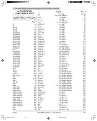
SELECTION CHARTto selectGasesLiquidsPort connection [inch]Orifice [inch]Pressure [psiG]Compressed airDry airNeutral gasesWaterHotwater up to 120 o CDemineralized waterSlightly dirty fluidsSlightly aggressiveAggressive fluidsSteamSensor Systems2/2-Way3/2-Way 2/2-WayMiniature,direct actingCompact,direct actingZerodifferentialpressureServo-AssistedAngle-SeatIsolatingDiaphragmMiniature,direct actingCompact,direct actingIsolatingDiaphragmBall ValvesElectricallyPneumaticallyAngle-SeatGlobe ValveControlValveDiaphragmManuallyPneumaticallyPilotsSOLENOID VALVE SYSTEMS1/8 1/16-3/32 0-1701/8-3/8 5/64-1/4 0-3551/4 5/64-1/8 0-2301/4-3/8 1/8-1/4 0-1401/4-1 3/8-3/4 0-1403/8-2 3/8-11/2 0-1401/2-1 1/2-1 0-1403/8-1 3/8-3/4 2.8-1401/2-2 1/2-2 2.8-2301/2-2 1/2-2 2.8-1401/2-1 7/16-1 14-7003/8-1 7/16-9/16 0-1501/4 1/8-5/32 0-1701/2-2 1/2-2 2.8-1401/8 3/64-1/16 0-1401/8-1/4 5/64-7/64 0-1401/4 5/64-1/8 0-170PROCESS VALVES1/4-1 1/2 3/8-11/2 0-2301/4-1 1/2 3/8-11/2 0-2303/8-3/4 1/2-3/4 0-2301/2-2 1/2 1/2-21/2 0-230Flange 1/2-2 0-2301/2-2 1/2-2 0-2301/4-2 1/4-2 0-1451/4-2 1/4-2 0-1451/4, NAMUR 3/64-1/4 0-230Page Page Page8 889 92130 3031 31 3132 3233 3334 343842 42 4244 44 4448 48 4850 50 509 111214 141816 172026 27 27 2721-2229 28 29 293031 31 3113 13 13 1329 28 29 2932 3233 3635 35 35 3538 38 38 38 3840 40 40 40 4042 42 42 42 42 42 4244 44 46 44 44 44 4648 48 48 4850 50 50 5053,54 53,54 53,54 53,54 53,54 53,5455,56 55,56 55,56 55,56 55,5657-59 57-59 57-59SENSORS/TRANSMITTERS/BATCH CONTROLFlow ControlFlow Sensor/Switch for Easy ON/OFF ControlFlow Sensor/Transmitter for Continuous ControlMagmeterAnalytical ControlInductive Conductivity TransmitterTemperature ControlTemperature Sensor/Switch for Easy ON/OFF ControlPressure ControlPressure Sensor/Switch for Easy ON/OFF ControlLevel ControlUltrasonic Level Transmitter60 62 6264,66 65,68 65,6870 70 7072 72 72 72 7274 74 74 74 7476 76 76 7679 79 79 79 79
SECTION 1GENERATOR GROUPREF PART NO DESCRIPTION QTY REMARKS FROM - TO FIG210 33K-22351-08 STATOR 1 100220 33K-20902-08 ROTOR 1 100222 32B-21001-08 BALL BEARING 1 100224 33K-20906-08 BOLT 1 100252 33K-20907-03 RING 1 100254 33K-20905-08 FLANGE BOLT 2 100260 33K-20903-08 REAR COVER 1 100264 33K-20904-08 FLANGE BOLT 3 100282 32B-23101-01 BRUSH CP 1 100285 32D-21055-08 SCREW 3 100303 32B-23001-00 AVR 1 100360 32B-23121-01 DIODE CP 1 100362 32D-21056-08 SCREW 4 100795 32D-21060-08 CLAMP 3 100680 32B-21053-08 SCREW 1 100R1100 - 7 - 05-04
Miniature Solenoid Valvewith threaded port connection2/2-Way, MiniatureNormally closed60112/2-Way, NPT 1 /8, 0-170 psiGCoil can be changed easilywith <strong>valve</strong> in placeCoil can be locked in 4x90 opositions or move freelybetween positions, as required6011High-quality FPM seal materialstandardDirect acting. Brass body <strong>valve</strong> for neutral gases and liquidssuch as compressed air, water, hydraulic oil. Stainless steel<strong>valve</strong> for more difficult and slightly aggressive media.Suitable for technical vacuum.Technical DataPressure range0-170 psiG, max.Temperature media-10 o C ... +100 o CAmbient temperature+55 o C, max.Body materialBrass, stainless steelSeal materialFPMCoil materialPolyamidePower consumptionDC: 4 WAC: 9 VA (inrush), 6 VA (hold)Protection class withIP 65 (standard delivery:cable plug cable plug DIN 43 650 C,0-250 V)Options- Wide range of cable plugoptions Type 2506 with LEDand varistor (see page 81)Dimensions [inch]2.991.951.174 x M36 depth0.790.77 1.14 0.131.27.79.32.32.99.16.58NPT/8A/F .49.62.55.34.41 1.19.55with standard-cable plug 0-250 V AC/DCSpecificationsPort Orifice Cv Pressure Range Weightconnection (AC) (DC)[inch] [inch] [PSI] [PSI] [oz.]Brass <strong>valve</strong> bodyNPT 1/8 1/16 0.07 0-170 0-85 4.62NPT 1/8 5/64 0.13 0-115 0-65 4.62NPT 1/8 3/32 0.15 0- 85 0-42 4.62Stainless steel <strong>valve</strong> bodyNPT 1/8 1/16 0.07 0-170 0-85 4.62NPT 1/8 5/64 0.13 0-115 0-65 4.62NPT 1/8 3/32 0.15 0- 85 0-42 4.62Ordering ChartItem No.24 V DC 24 V/60 Hz 120 V/60 Hz 240 V/60 HzBrass <strong>valve</strong> body456 780 D 456 781 S 456 782 T 456 783 U456 784 V 456 785 W 456 786 X 456 787 Y456 788 H 456 789 A 456 790 F 456 791 UStainless steel <strong>valve</strong> body457 151 T 457 152 U 457 153 V 457 154 W457 155 X 457 156 Y 457 157 Z 457 158 A457 159 B 457 160 G 457 161 V 457 162 W8
Compact Solenoid Valvefor neutral gases and liquidsNormally closed60132/2-Way, NPT 1 /8 to NPT 3 /8, 0-355 psiGCoil can be changed easilywith <strong>valve</strong> in placeCoil can be locked in 4x90 opositions or move freelybetween positions, as required2/2-Way, CompactModular direct acting <strong>solenoid</strong> <strong>valve</strong> system with brass body.Ideal for neutral gases and liquids such as compressed air,natural gas, water, hydraulic oil. Suitable for technical vacuum.High-quality FKM seal materialstandard6013Technical DataPressure range0 to 355 psiG, max.Temperature media+14 o F ... +212 o FAmbient temperature+131 o F, max.Body materialBrassSeal materialFKMCoil materialPolyamidePower consumptionDC: 8 W 10W (34VA, 14VA)AC: 24 VA(inrush),17 VA(hold)Protection class withNEMA 4 (standard delivery:cable plug cable plug DIN 43650A)Dimensions [inch]Options- Seal materials- Explosion ProofCSA Class 1 Div1Class H CoilVariable dimensions [inch]A B C D E FThreaded port NPT 1/8 1.26 0.82 1.28 1.10 1.62Threaded port NPT 1/4 1.81 1.06 1.93 1.26 1.77with standard cable plug 0-250 V AC/DCSpecificationsPort Orifice Cv Pressure Range Weightconnection (AC) (DC)[Inch] [inch] [PSI] [PSI] [oz.]NPT 1/8 5/64 0.14 0-355 0-170 12.69NPT 1/8 7/64 0.19 0-230 0-140 12.69NPT 1/8 1/8 0.27 0-140 0- 85 12.69NPT 1/4 1/8 0.27 0-140 0- 85 16.39NPT 1/4 5/32 0.35 0- 55 0- 20 16.39NPT 3/8 1/8 0.27 0-200 0-115 16.39Ordering ChartItem No.24 V DC 24 V/60 Hz 120 V/60 Hz 240 V/60 Hz457 294 T 457 295 U 457 296 V 457 297 W457 298 F 457 299 G 457 300 M 457 301 A456 315 W 456 316 X 456 317 Y 456 318 H456 319 A 456 320 F 456 321 U 456 322 V456 323 W 456 324 X 456 325 Y 456 326 Z456 840 H 456 841 W 456 842 Y 456 843 Y9
Customized Solenoid Valve SystemsFluid ControlSolutionsWide product range forneutral and difficult mediaCustomized, pre-assembledand tested <strong>systems</strong>High reliability andsafety in operationMonitoring and ON/OFFControl with LINKIntelligent Sensor/Switch ALL IN ONEwith outstanding Human-Machine Interfacesets new standards inEasy LINK allows the direct control of a<strong>solenoid</strong> <strong>valve</strong>, a process <strong>valve</strong> or otherdevices.Easy LINK connection leads to unmatchedeconomical solutions for any measuringparameter.Easy NET integrates the intelligent sensor infieldbus configurations (e.g. AS-Interface).IndicationMonitoringTransmittingON/OFF Control10
Compact Solenoid Valvefor more difficult and slightly aggressive mediaNormally closed60132/2-Way, NPT 1 /8 - NPT 1 /4, 0-355 psiGMedium is only in contact withthe <strong>valve</strong> internals and bodyHigh-quality FKM seal materialas standard2/2-Way, CompactModular, direct acting <strong>solenoid</strong> <strong>valve</strong> system. Stainless steelbody for more aggressive media. Suitable for technicalvacuum.Technical DataPressure range0-355 psiG, max.Temperature media+14 o F ... +212 o FAmbient temperature+131 o F, max.Body materialStainless steelSeal materialFKMCoil materialPolyamidePower consumptionDC: 8 WAC: 24 VA(inrush),17 VA(hold)Protection class withNEMA 4 (standard delivery:cable plug cable plug DIN 43650A)Options- LED cable plug- Haz-EX CSA Class 1 Div1H rated coilCoil can be changed easilywith <strong>valve</strong> in placeDimensions [inch]6013Variable dimensions [inch]A B C D E FThreaded port NPT 1/8 1.26 0.82 1.28 1.10 1.62Threaded port NPT 1/4 1.26 1.06 1.28 1.26 1.77Threaded port NPT 1) 1/4 1.81 1.06 1.93 1.26 1.771)Only for version NPT 1/4, orifice 5/32SpecificationsOrdering Chartwith H conduit plug 0-250 V AC/DCPort Orifice Cv Pressure Range Weightconnection (AC) (DC)[Inch] [inch] [PSI] [PSI] [oz.]NPT 1/8 5/64 0.14 0-355 0-170 12.16NPT 1/4 5/64 0.27 0-140 0- 85 12.16NPT 1/4 1/8 0.27 0-140 0- 85 15.68NPT 1/4 1) 5/32 0.35 0- 55 0- 20 15.681)Only for version NPT 1/4, orifice 5/3211Item No.24 V DC 24 V/60 Hz 120 V/60 Hz 240 V/60 Hz457 302 B 457 303 C 457 304 D 457 305 E457 306 F 457 307 G 457 308 R 457 309 J456 335 S 456 336 T 456 337 U 456 338 D456 494 K 1) 456 495 L 1) 456 496 M 1) 456 497 N 1)
Solenoid Valve for steam and media at hightemperatures up to 356 o F2/2-Way, Compact6013Normally closed6013Modular direct acting <strong>solenoid</strong> <strong>valve</strong> system with brass bodyand stainless steel seat. For neutral gases and liquids, hightemperatures such us hot water, steam, hot air, thermal oils.Applications: heating, sterilizing, impregnating.Technical DataPressure range0-230 psiG, max.(max. steam pressure is140 PSI @ 356 o F)Temperature media14 o F ... +356 o FAmbient temperature+130 o F, max.Body materialBrassSeat materialStainless steelSeal materialPTFE/GraphiteCoil materialEpoxyPower consumption32 mm coil:DC: 8 WAC: 24 VA(inrush),17 VA(hold)40 mm coil:DC: 10 WAC: 30 VA(inrush),22 VA(hold)Protection class withIP 65 (standard delivery:cable plug cable plug DIN 43 650 A)Options- Version up to 250 o F withEpoxy coil and EPDM seal- LED cable plug- Haz-Ex CSA Class 1 Div.12/2-Way, NPT 1 /4, 0-230 psiGFluid temperature up to 356 o FErosion resistant, st.steel seatHigh-quality seal materialPTFE standardMedia is only in contact withthe <strong>valve</strong> internals and bodyDimensions [inch]Variable dimensions [inch]Coil A B C D E F1.26" mm NPT 1/4 1.81 1.06 1.93 1.26 1.771.58" mm NPT 1/4 1.81 1.06 1.93 1.58 2.01SpecificationsPort Orifice Cv Pressure Range Weightconnection (AC) (DC)[inch] [inch] [PSI] [PSI] [oz.]NPT 1/4 5/64 0.14 0-230 0-170 12.70NPT 1/4 1/8 0.27 0-200 0-115 12.70with standard-cable plug 0-250 V AC/DCOrdering ChartItem No.24/DC 24/60 120/60 240/60457 376 C 1) 457 377 D 1) 457 378 N 1) 457 379 P 1)457 380 D 2) 457 381 S 2) 457 382 T 2) 457 383 U 2)1)1.26" coil, 8W; 2) 1.58" coil, 10W12
Solenoid Valve with Isolating Diaphragm;for neutral, aggressive, slightly contaminated fluidsNormally closedNormally open3302/2-Way, NPT 1 /4, 0-140 psiGSeparating diaphragm isolates<strong>solenoid</strong> system fromoperating fluidLong service life, even in nonlubeconditionsInsensitive to slightlycontaminated fluids2/2-Way, Isolating diaphragm330Direct acting <strong>valve</strong> with pivoted armature. The unique <strong>valve</strong>design hermetically isolates the actuator from the fluid.Making it less sensitive to contaminated fluids than a plungertypesystem and provides a long service life, even inunlubricated applications.Dimensions [inch]Technical DataPressure range0-140 psiG, max.Temperature media+14 o F ... +194 o FAmbient temperature+131 o F, max.Body materialBrass, stainless steelSeal materialFPMCoil materialEpoxyPower consumptionDC: 8 WAC: 30 VA(inrush), 15 VA(hold)Protection class withIP 65 (standard delivery:cable plug cable plug DIN 43 650 A,0-250 V)Options- EPDM seal- Vacuum- Electrical feedback signaller 1060- Impulse coil (zero watt coil)3.942.800.35NPT 1/41.340.940.350.351.501.81SpecificationsOrdering Chartwith standard-cable plug 0-250 V AC/DCPort Orifice Cv 1) Pressure Range Weightconnection (AC) (DC)[inch] [inch] [PSI] [PSI] [oz.]Brass <strong>valve</strong> body (normally closed)NPT 1/4 1/8 0.27 0-140 0-140 14.1NPT 1/4 5/32 0.33 0- 70 0- 70 14.1Stainless steel <strong>valve</strong> body (normally closed)NPT 1/4 1/8 0.27 0-140 0-140 14.1NPT 1/4 5/32 0.33 0- 70 0- 70 14.1Brass <strong>valve</strong> body (normally open)NPT 1/4 1/8 0.27 0-140 0-140 14.1NPT 1/4 5/32 0.33 0- 70 0- 70 14.1Stainless steel <strong>valve</strong> body (normally open)NPT 1/4 1/8 0.27 0-140 0-140 14.1NPT 1/4 5/32 0.33 0- 70 0- 70 14.11) Flow rate reduced 20% with DC-current operationVoltage / Frequency [V/Hz]24/DC 24/60 120/60 240/60Brass <strong>valve</strong> body (normally closed)US 08 967 US 08 966 US 08 965 US 08 964US 08 963 US 08 962 US 08 961 US 08 960Stainless steel <strong>valve</strong> body (normally closed)457 687 V US 08 959 457 688 E 457 689 F457 693 T US 08 958 457 694 U 457 695 VBrass <strong>valve</strong> body (normally open)458 947 A 458 948 K 458 949 L 458 950 R458 951 E 458 952 F 458 953 G 458 954 HStainless steel <strong>valve</strong> body (normally open)458 959 N 458 960 K 458 961 G 458 962 H458 963 A 458 964 B 458 965 C 458 966 D13
Solenoid Valve for 150# Steamand 356°F Neutral Fluids2/2-Way, Compact255Normally closedDirect acting <strong>solenoid</strong> <strong>valve</strong> system. For neutral gases andliquids, high temperature fluids such as hot water, steam,hot air and thermal oils. Applications: heating, sterilizing.2552/2-Way, NPT 1 /4 - NPT 3 /8, 0-230 psiGFluid temperature up to 356 o FMetal seal between coil and<strong>valve</strong> bodyStainless steel seat eliminatesdanger of erosion and dezincificationTechnical DataPressure rangeTemperature mediaAmbient temperatureBody materialSeal materialCoil materialPower consumptionProtection class withcable plugOptions- High temperature versionup to 480 °F- 1/32“ orifice for highpressure to 1400 psiG0-230 psiG, max.-40 o F ... max. steam +356 o F+131 o F, max.Brass, stainless steelPTFEEpoxyDC: 12 WAC: 35 to 40 VA (inrush)IP65 (standard delivery:H conduit plug)Dimensions [inch]Dimensions: Brass versionwith standard cable plug 0-250 V AC/DCSpecificationsPort Orifice Cv Pressure R. Material Weightconnect. (AC) (DC) 1) Body Seal[Inch] [inch] [PSI] [PSI] [lb.]NPT 1/4 1/8 0.29 230 140 Brass PTFE 1.5NPT 1/4 1/8 0.29 230 140 St.Steel PTFE 1.5NPT 1/4 5/32 0.58 140 55 Brass PTFE 1.5NPT 1/4 5/32 0.58 140 55 St.Steel PTFE 1.5NPT 1/4 1/4 0.93 55 14 Brass PTFE 1.5NPT 1/4 1/4 0.93 55 14 St.Steel PTFE 1.5NPT 3/8 1/8 0.29 230 140 Brass PTFE 1.5NPT 3/8 5/32 0.58 140 55 Brass PTFE 1.5NPT 3/8 1/4 0.93 55 14 Brass PTFE 1.51) Dependent from media temperature14Ordering ChartItem No.24 V DC 24 V/60 Hz 120 V/60 Hz 240 V/60 Hz452 431 P 452 432 Q 452 433 R 452 434 J452 435 K 452 436 L 452 437 M 452 438 W452 439 X 450 503 A 452 440 C 452 441 Z452 442 S 452 443 T 452 444 U 452 445 V452 454 W 452 455 X 452 456 Y 452 457 Z452 458 A 452 459 B 452 460 G 452 461 Von request CD 0058 K 454 096 M CD 00582on request CD 0140 V 454 121 J 456 014 LCD 0014 P 456 736 U 453 733 W CD 00584
Water Valve Systems forON/OFF ControlComplete program ofhigh reliability water <strong>valve</strong>s with options forDiagnostic andInsensitive to slightly contaminated and aggressivefluids due to separating diaphragmWaterhammer-freeOperating as from zero pressureMonitoring due to integrated flow / no flow sensorON/OFF Control withLINKNET with AS-Interface connectivity15
Zero-differential Pressure6213Solenoid Valve for clean neutral liquids up to 194 o FNormally closed62132/2-Way, NPT 1 /4 - NPT2, 0-140 psiGZero differential pressureHigh reliabilityWaterhammer-freeCompact design with highflow ratesModular, servo-assisted <strong>solenoid</strong> <strong>valve</strong> system. Operates withzero pressure differential. For clean neutral liquids such aswater and oils.Dimensions [inch]Technical DataPressure rangeTemperature mediaAmbient temperatureBody materialSeal materialCoil material0-140 psiG, max.+14 o F ... +194 o F+131 o F, max.BrassNBRPolyamidePower consumption DC: 10 W (Orifice 1/4,3/8,1/2,3/4)AC:Orifice [inch]3/8 1/2 3/4 1 11/2Inrush [VA] 34 36 38 160 202Hold [VA] 14 14 14 38 38Hold [W] 8 8 8 18 18Protection class withIP65 (standard delivery:cable plug cable plug DIN 43650A)Variable dimensions [inch] - AC-VersionPort Conn. Orifice[Inch] [inch] C D E F L A/F A B H I K1/4, 3/8 3/8 1.48 1.50 0.79 0.41 1.97 1.06 2.68 3.23 1.26 0.81 1.771/2 1/2 1.77 1.99 0.95 0.54 2.29 1.26 3.13 3.76 1.26 0.81 1.773/4 3/4 2.60 2.60 1.38 0.55 3.15 1.62 3.74 4.55 1.26 0.81 1.771 1 4.12 4.12 2.72 0.66 3.74 1.62 5.44 6.24 1.93 0.97 2.321 1/4 1 4.12 4.12 2.72 0.68 3.74 1.97 5.44 6.42 1.93 0.97 2.321 1/2 1 1/2 4.12 4.12 2.72 0.68 5.20 2.36 5.89 7.07 1.93 0.97 2.322 1 1/2 4.12 4.12 2.72 0.69 5.20 2.76 5.89 7.27 1.93 0.97 2.32Variable dimensions [inch] - DC-VersionPort Conn. Orifice[Inch] [inch] C D E F L A/F A B H I K1/4, 3/8 3/8 1.48 1.50 0.79 0.41 1.97 1.06 2.70 3.25 1.58 0.93 2.011/2 1/2 1.77 1.99 0.95 0.54 2.29 1.26 3.15 3.78 1.58 0.93 2.013/4 3/4 2.60 2.60 1.38 0.55 3.15 1.62 3.76 4.57 1.58 0.93 2.01SpecificationsOrdering Chartwith standard cable plug 0-250 V AC/DCPort Orifice Cv Pressure Range Weightconnection (AC) (DC)[Inch] [inch] [PSI] [PSI] [lb.]NPT 1/4 1/4 2.33 0-140 0-140 0.88NPT 3/8 3/8 2.33 0-140 0-140 0.88NPT 1/2 1/2 4.19 0-140 0-140 1.21NPT 3/4 3/4 10.49 0-140 0-140 2.21NPT 1 1 12.82 0-140 ----- 3.75NPT 1 1/4 1 12.82 0-140 ----- 3.75NPT 1 1/2 1 1/2 34.95 0-140 ----- 7.94NPT 2 1 1/2 34.95 0-140 ----- 7.9416Item No.24 V DC 24 V/60 Hz 120 V/60 Hz 240 V/60 Hz458 078 N 458 079 P 458 080 D 458 081 S456 439 T 456 440 G 456 441 V 456 442 W456 443 X 456 444 Y 456 300 L 456 445 Z456 446 S 456 447 T 456 301 H 456 448 C--- --- 457 163 X 457 164 Y 457 165 Z--- --- 457 166 S 457 167 T 457 168 C--- --- 457 169 D 457 170 A 457 171 X--- --- 457 172 Y 457 173 Z 457 174 S1) NPT 1/4 UL Recognized Only
Solenoid Valve for hotwater,low pressure steam up to 248 o FNormally closed62132/2-Way, NPT 1 /4 - NPT2, 0-140 psiGZero differential pressureHigh reliabilityWaterhammer-freeCompact design with highflow ratesZero-differential Pressure6213Servo-assisted <strong>solenoid</strong> <strong>valve</strong> system. All <strong>valve</strong>s operate withzero pressure differential. Ideal for hot water, oil, washing andbleaching lyes and low pressure steam applications.Dimensions [inch]Technical DataPressure range0-140 psiG, max.Temperature media-22 o F ... +248 o FAmbient temperature+131 o F, max.Body materialBrassSeal materialEPDMCoil materialEpoxyPower consumption DC: 10 W (Orifice 1/4,3/8,1/2,3/4)AC:Orifice [inch]3/8 1/2 3/4 1 11/2Inrush [VA] 34 36 38 160 202Hold [VA] 14 14 14 38 38Hold [W] 8 8 8 18 18Protection class withNEMA 4 (standard delivery:cable plug cable plug DIN 43650A)Variable dimensions [inch] - AC-VersionPort Conn. Orifice[Inch] [inch] C D E F L A/F A B H I K1/4, 3/8 3/8 1.48 1.50 0.79 0.41 1.97 1.06 2.68 3.23 1.26 0.81 1.771/2 1/2 1.77 1.99 0.95 0.54 2.29 1.26 3.13 3.76 1.26 0.81 1.773/4 3/4 2.60 2.60 1.38 0.55 3.15 1.62 3.74 4.55 1.26 0.81 1.771 1 4.12 4.12 2.72 0.66 3.74 1.62 5.44 6.24 1.93 0.97 2.321 1/4 1 4.12 4.12 2.72 0.68 3.74 1.97 5.44 6.42 1.93 0.97 2.321 1/2 1 1/2 4.12 4.12 2.72 0.68 5.20 2.36 5.89 7.07 1.93 0.97 2.322 1 1/2 4.12 4.12 2.72 0.69 5.20 2.76 5.89 7.27 1.93 0.97 2.32Variable dimensions [inch] - DC-VersionPort Conn. Orifice[Inch] [inch] C D E F L A/F A B H I K1/4, 3/8 3/8 1.48 1.50 0.79 0.41 1.97 1.06 2.70 3.25 1.58 0.93 2.011/2 1/2 1.77 1.99 0.95 0.54 2.29 1.26 3.15 3.78 1.58 0.93 2.013/4 3/4 2.60 2.60 1.38 0.55 3.15 1.62 3.76 4.57 1.58 0.93 2.01SpecificationsOrdering Chartwith standard cable plug 0-250 V AC/DCPort Orifice Cv Pressure Range Weightconnection (AC) (DC)[Inch] [inch] [PSI] [PSI] [lb.]NPT 1/4 3/8 2.33 0-140 0-140 0.88NPT 3/8 3/8 2.33 0-140 0-140 0.88NPT 1/2 1/2 4.19 0-140 0-140 1.21NPT 3/4 3/4 10.49 0-140 0-140 2.21NPT 1 1 12.82 0-140 ----- 3.75NPT 1 1/4 1 12.82 0-140 ----- 3.75NPT 1 1/2 1 1/2 34.95 0-140 ----- 7.94NPT 2 1 1/2 34.95 0-140 ----- 7.94Item No.24 V DC 24 V/60 Hz 120 V/60 Hz 240 V/60 Hz458 086 X 458 087 Y 458 088 H 458 089 A457 175 T 457 176 U 457 177 V 457 178 E457 179 F 457 180 V 457 181 J 457 182 K457 183 L 457 184 M 457 185 N 457 186 P--- --- 457 234 W 457 235 X 457 236 Y--- --- 457 237 Z 457 238 A 457 239 B--- --- 457 240 Q 457 241 D 457 242 E--- --- 457 243 F 457 244 G 457 245 H17
Zero-differential Pressure6213Stainless Steel Solenoid Valve for moreaggressive media up to 195 o FNormally closed62132/2-Way, NPT 1 /4 - NPT1, 0-140 psiGZero differential pressureHigh reliabilityWaterhammer-freeCompact design with highflow ratesServo-assisted <strong>solenoid</strong> <strong>valve</strong> system. All <strong>valve</strong>s operate fromzero pressure. For more difficult and slightly aggressive fluids.Technical DataPressure range0-140 psiGTemperature media14 o F ... +195 o FAmbient temperature+130 o F, max.Body material Stainless steel 316L 1.4404Seal materialFKMCoil material Polyamide (DN 10-20)Power consumption DC: 10 W (DN 10/13/20)AC:DN [mm]10 13 20Inrush [VA] 34 36 38Hold [VA] 14 14 14Hold [W] 8 8 8Protection class withNEMA 4 (standard delivery:cable plug cable plug DIN 43650A)Variable dimensions [Inch] - AC-VersionPort C. DN[Inch] [inch] C D E F L A/F A B H I K1/4 3/8 1.48 1.50 .79 .471.97 1.1 2.68 3.23 1.3 .81 1.773/8 3/8 1.48 1.50 .79 .471.97 1.1 2.68 3.23 1.3 .81 1.771/2 1/2 1.77 1.99 .95 .552.29 1.3 3.13 3.76 1.3 .81 1.773/4 3/4 2.69 2.60 1.4 .633.15 1.6 3.74 4.55 1.3 .81 1.771 3/4 2.60 2.60 1.4 .633.15 1.6 3.74 4.55 1.3 .81 1.77Variable dimensions [Inch] - DC-VersionPort C. DN[Inch] [inch] C D E F L A/F A B H I K1/4 3/8 1.48 1.50 .79 .47 1.97 1.06 2.70 3.25 1.6 .93 23/8 3/8 1.48 1.50 .79 .47 1.97 1.06 2.70 3.25 1.6 .93 21/2 1/2 1.77 1.99 .95 .55 2.3 1.26 3.15 3.78 1.6 .93 23/4 3/4 2.60 2.60 1.4 .63 3.2 1.62 3.76 4.57 1.6 .93 21 3/4 2.60 2.60 1.4 .63 3.2 1.62 3.76 4.57 1.6 .93 2with standard cable plug 0-250 V AC/DCSpecificationsPort Orifice Cv Pressure Range Weightconnection (AC) (DC)[Inch] [inch] [PSI] [PSI] [oz.]NPT 1/4 3/8 2.33 0-140 0-140 14.10NPT 3/8 3/8 2.33 0-140 0-140 14.10NPT 1/2 1/2 4.19 0-140 0-140 19.38NPT 3/4 3/4 10.49 0-140 0-140 38.76NPT 1 3/4 10.49 0-140 0-140 38.76Ordering ChartVoltage / Frequency [V/Hz]24/DC 24/60 120/60 240/60458 732 A 458 733 B 458 734 C 458 735 D458 736 E 458 737 F 458 738 Q 458 739 R458 740 W 458 741 K 458 742 L 458 743 M458 744 N 458 745 P 458 746 Q 458 747 R458 748 S 458 749 T 458 750 Y 458 751 M18
Intelligent Sensor ALL IN ONEIntelligent Sensor/Switch with outstandingHuman-Machine Interface sets new standards inIndication, Transmitting, Monitoringand ON/OFF Control.IndicationTransmittingMonitoringON/OFF ControlThese intelligent multifunctional sensor/switches are availablefor flow, analytical, temperature and pressure control.The user-friendly display indicates the process value both inlarge digits and as a scalable bargraph.The process value is measured and transmitted to acontroller via Easy LINK connection.Freely programmable switching points can be defined both inhysteresis and window mode over the entire measuring range formonitoring. Easy LINK allows the direct control of a <strong>solenoid</strong><strong>valve</strong>, a process <strong>valve</strong> or other devices.ON/OFF Control enables the entry of internal and externalsetpoint values and in addition permits communicationwith an analog output signal to an external PLC or industry PC.The control precision lies around 5%. The Easy LINK connectionleads to unmatched economical solutions for any measuringparameter.Remote operation allows separating display and sensor.Easy NET integrates the intelligent sensor in fieldbus configurations (e.g. AS-Interface).Improve your Total Cost of Ownership with this attractive, innovative solution.19
Zero-differential Pressure407Solenoid Valve for 150# steam and mediaat high temperatures up to 356 o FNormally closed4072/2-Way, NPT 1 /2 - NPT1, 0-140 psiGZero differential pressureFluid temperature up to 356 o FHigh reliabilityStainless steel seat eliminatesdanger of erosion and dezincificationExtremely reliable servo-assisted (zero differential pressure)<strong>valve</strong> for steam and other hot neutral fluids.hot air etc., for use on the vacuum side of autoclaves, in thetextile, plastic and woodworking industries.Technical DataPressure range0-140 psiG, max.Temperature media+32 o F ... +356 o FAmbient temperature+131 o F, max.Body materialBrass (<strong>valve</strong> seat 305 S.St.)Seal materialPTFECoil materialEpoxyPower consumptionAC: 24-240 VA (inrush),35 VA (hold)Protection class withNEMA 4 (standard delivery:cable plug cable plug DIN 43650A)Dimensions [inch]H1J1A1B1.15Variable dimensions [inch]Port Conn. Orifice A1 B1 F1 E1 L1 J1 H1 A/F[inch]NPT 1/2 1/2 4.45 5.00 0.54 1.58 2.56 3.06 1.26 1.06NPT 3/4 3/4 5.16 5.79 0.55 2.36 3.94 3.35 1.26 1.26NPT 1 1 5.38 6.19 0.66 2.76 4.53 3.35 1.26 1.62L1F1CA/FE1with standard cable plug 0-250 V AC/DCSpecificationsPort Orifice Cv Pressure Range Weightconnection (AC) (DC)[Inch] [inch] [PSI] [PSI] [lb.]NPT 1/2 1/2 4.31 0-140 --- --- 2.21NPT 3/4 3/4 5.83 0-140 --- --- 3.09NPT 1 1 11.65 0-140 --- --- 4.19Ordering ChartItem No.24 V DC 24 V/60 Hz 120 V/60 Hz 240 V/60 Hzon request 456 140 B 453 770 P on requeston request 454 437 P 453 771 C 454 436 Non request 453 874 U 453 772 D on request20
Solenoid Valve, Waterhammer-freefor neutral fluidsNormally closed52812/2-Way, NPT 1 /2 - NPT2, 2.8-230 psiGHigh reliabilityModular <strong>solenoid</strong> coil-systemWaterhammer-free, low noiseCompact design with highflow rates2/2-Way, Servo-Assisted5281Modular, servo-assisted <strong>solenoid</strong> <strong>valve</strong> system, for city water,neutral gases and clean liquids. Require 2.8 psiG acoss the<strong>valve</strong> open.Applications: process <strong>systems</strong>, chemical processing.water/sewage treatment and sterilizers.Technical DataPressure range2.8-230 psiG, max.Temperature media+14 o F ... +194 o FAmbient temperature+131 o F, max.Body materialBrassSeal materialNBRCoil materialPolyamidePower consumptionDC: 8 WAC: 21 VA(inrush),12 VA(hold)Protection class withNEMA 4 (standard delivery:cable plug cable plug DIN 43650A)Options- Manual override- 5 W power consumption- 2 W power consumption- LED cable plug- Valve mounted timer <strong>systems</strong>Dimensions [inch].21AB1.14 1.77A/F 0.55G1/8.151.61Variable dimensions [inch]DN XXPort Conn. Orifice A B F E L A/F[inch][inch]NPT 1/2 1/2 3.39 3.94 0.54 1.58 2.56 1.06NPT 3/4 3/4 3.61 4.24 0.55 2.36 3.94 1.26NPT 1 1 3.76 4.57 0.66 2.76 4.53 1.62NPT 1 1/4 1 1/4 4.00 4.98 0.68 3.35 4.96 1.97NPT 1 1/2 1 1/2 4.16 5.34 0.68 3.35 4.96 2.36NPT 2 2 4.81 6.19 0.69 4.53 6.46 2.76FLDA/FEwith standard cable plug 0-250 V AC/DCSpecificationsPort Orifice Cv Pressure Range Weightconnection[Inch] [inch] [PSI] [lb.]NPT 1/2 1/2 4.66 2.8-230 1.32NPT 3/4 3/4 5.83 2.8-230 2.43NPT 1 1 11.65 2.8-230 3.31NPT 1 1/4 1 1/4 23.30 2.8-230 4.96NPT 1 1/2 1 1/2 23.30 2.8-230 5.84NPT 2 2 46.60 2.8-230 10.91Ordering ChartItem No.24 V DC 24 V/60 Hz 120 V/60 Hz 240 V/60 Hz456 864 V 456 865 W 456 866 X 456 867 Y456 868 H 456 869 A 456 870 F 456 871 U456 872 V 456 873 W 456 874 X 456 875 Y456 876 Z 456 877 S 456 878 B 456 879 C456 880 S 456 881 P 456 882 Q 456 883 R456 884 J 456 885 K 456 886 L 456 888 W21
2/2-Way, Servo-AssistedSolenoid Valve, Waterhammer-freefor neutral fluids, normally openNormally open02812/2-Way, NPT 1 /2 - NPT2, 2.8-230 psiGHigh reliabilityWaterhammer-freeCompact design with highflow rates0281Shown UR-versionModular, normally open, servo-assisted <strong>solenoid</strong> <strong>valve</strong> system,for city water, neutral gases and clean liquids.Requires 2.8 psiG across the <strong>valve</strong> to open.Applications: process <strong>systems</strong>, chemical processing,water/sewage treatment.Technical DataPressure range2.8-230 psiGTemperature media14 o F ... +195 o FAmbient temperature+130 o F, max.Body materialBrassSeal materialNBRCoil materialEpoxy, coil cover brassPower consumptionDC: 8 WAC: 21 VA(inrush),12 VA(hold)Protection class withIP 65 (standard delivery:cable plug cable plug DIN 43 650 A)Dimensions [inch]1.261.14 1.42Options- LED cable plug- Valve mounted timer <strong>systems</strong>Shown UR-versionB1A1Variable dimensions [inch]Port Connection Orifice [inch] A1 B1 F E1 L1 A/FNPT 1/2 1/2 3.78 4.33 .55 1.58 2.56 1.06NPT 3/4 3/4 4.00 4.63 .63 2.36 3.94 1.26NPT 1 1 4.16 4.96 .71 2.76 4.53 1.62NPT 1 1/4 1 1/4 4.39 5.38 .79 3.35 4.96 1.97NPT 1 1/2 1 1/2 4.55 5.73 .87 3.35 4.96 2.36NPT 2 2 5.21 6.59 .95 4.53 6.46 2.76L1FDE1with H conduit plug 0-250 V AC/DCSpecificationsOrdering ChartPort Orifice Cv Pressure Range Weightconnection[Inch] [inch] [PSI] [lb]NPT 1/2 1/2 4.0 2.8- 230 1.32NPT 3/4 3/4 5.0 2.8- 230 2.43NPT 1 1 10.0 2.8- 230 3.31NPT 1 1/4 1 1/4 20.0 2.8- 230 4.96NPT 1 1/2 1 1/2 20.0 2.8- 230 5.84NPT 2 2 40.0 2.8- 230 10.9Item No.24/DC 24/50-60 120/50-60 240/50-60458 891 T 458 892 U 458 893 V 458 894 W458 895 X 458 896 Y 458 897 Z 458 898 A458 899 B 458 900 Q 458 901 D 458 902 E458 903 F 458 904 G 458 905 H 458 906 A458 907 B 458 908 L 458 909 M 458 910 H458 911 W 458 912 X 458 913 Y 458 914 Z22
Time for a New Technologyin Flow IndicationPiping upon customer needs -position independent flow indicationLess piping, maintenance-free technologyconsiderably reduces Total Cost of OwnershipALL IN ONE :Indication, Monitoring, Transmitting andON/OFF Control in one deviceRemote operation allows separatingdisplay and sensorComplete communication due toexternal setpoint, Easy LINK or AS-Interface
AS-Interface Overview2510/11 ASiCable plug according toDIN 43650, Form C and A2510/11 2510/11Compatible <strong>valve</strong>s:- With separating diaphragm- Rocker <strong>solenoid</strong> <strong>valve</strong>s foranalytical applications- Banjo and NAMUR <strong>valve</strong>s330 6605 5281 6012 65191066 / 8631 / 8633 ASiControl HEADS for variousprocess <strong>valve</strong>s1066 8631 8633Compatible <strong>valve</strong>s:- Angle seat- Globe- Diaphragm- Quarter-Turn2000 2012 2030 2031 26555470 / 8640 ASiCentralized process actuationsolution for the processingindustries54708640Sensors ASiSensors for flow, temperature,level and pressure control8032 8400 81818311
2/2-Way, Servo-Assisted6212Brass Solenoid Valve for slightly contaminated fluidsNormally closed62122/2-Way, NPT 3 /8 - NPT1, 2.8-140 psiGSeparating diaphragm isolates<strong>solenoid</strong> from operating fluidLow power consumption(no relay necessary whenused with a PLC)Easy DiagnosticsModular, low-power, servo-assisted <strong>valve</strong> system withBurkert‘s revolutionary Rocker system completely isolatingthe pilot from the fluid. The <strong>valve</strong> is therefore less sensitive toslightly contaminated.Technical DataPressure range 1)2.8-140 psiGTemperature media32 o F ... +160 o FAmbient temperature+130 o F, max.Body materialBrassSeal materialNBRCoil materialPolyamidePower consumptionDC: 3.4 WUC (universal voltage): 4 WProtection class withIP 65 (standard delivery:cable plug cable plug DIN 43 650 A)Spade location sidewardsB11.06 1.171.95B2 1.17Spade location on top1.95.63Options- Diagnostics:- Flow or no flow switch- Normally open (N.O.)- FPM or EPDM sealLFLFGCVariable dimensions [inch]Port Connection Orifice [inch] B1 B2 C F LNPT 3/8 3/8 3.72 3.98 1.26 .47 2.17NPT 1/2 3/8 3.72 3.98 1.26 .55 2.17NPT 1/2 1/2 3.98 4.20 1.58 .55 2.56NPT 3/4 1/2 3.98 4.20 1.58 .63 2.56NPT 3/4 3/4 4.51 4.77 2.36 .63 3.94NPT 1 3/4 4.51 4.77 2.36 .71 3.94with standard-cable plug 0-250 V AC/DCSpecificationsPort Orifice Cv Pressure Range Weightconnection[Inch] [inch] [PSI] [oz.]NPT 3/8 3/8 2.2 2.8- 140 7.05NPT 1/2 3/8 2.2 2.8- 140 7.05NPT 1/2 1/2 4.2 2.8- 140 12.33NPT 3/4 1/2 4.2 2.8- 140 12.33NPT 3/4 3/4 9.7 2.8- 140 28.19NPT 1 3/4 9.7 2.8- 140 28.191)Requires 2.8 psi minimum differential pressureOrdering ChartItem No.A B C24/DC 1) 120/ UC 2) 240/ UC 2)458 003 C 458 004 D 458 005 E458 015 X 458 016 Y 458 017 Z458 027 T 458 028 C 458 029 D458 039 F 458 040 L 458 041 H458 051 B 458 052 C 458 053 D458 063 F 458 064 G 458 065 H1) coil with spade location sidewards2) coil with rectifier, varistor and spade location on top26
Stainless Steel Solenoid Valvefor slightly contaminated and aggressive fluidsNormally closed62122/2-Way, NPT 3 /8 - NPT1, 2.8-140 psiGSeparating diaphragm isolates<strong>solenoid</strong> from operating fluidLow power consumption(no relay necessary whenused with a PLC)Easy Diagnostics2/2-Way, Servo-Assisted6212Modular, low-power, servo-assisted <strong>valve</strong> system withBurkert‘s revolutionary Rocker system completely isolatingthe pilot from the fluid. The <strong>valve</strong> is therefore less sensitive toslightly contaminated.Dimensions [inch]Technical DataPressure range 1)2.8-140 psiGTemperature media32 o F ... +160 o FAmbient temperature+2660 o F, max.Body materialStainless steel 316LSeal materialFPMCoil materialPolyamidePower consumptionDC: 3.4 WUC: 4 WProtection class withNEMA4 (standard delivery:cable plug cable plug DIN 43 650 A)B1Spade location sidewards1.06 1.171.95B2 1.17Spade location on top1.95.63Options- Normally open (N.O.)- EPDM sealFFGLLCVariable dimensions [inch]Port Connection Orifice [inch] B1 B2 C F LNPT 3/8 3/8 3.72 3.98 1.26 .47 2.17NPT 1/2 3/8 3.72 3.98 1.26 .55 2.17NPT 1/2 1/2 3.98 4.20 1.58 .55 2.56NPT 3/4 1/2 3.98 4.20 1.58 .63 2.56NPT 3/4 3/4 4.51 4.77 2.36 .63 3.94NPT 1 3/4 4.51 4.77 2.36 .71 3.94with standard-cable plug 0-250 V AC/DCSpecificationsPort Orifice Cv Pressure Range Weightconnection[Inch] [inch] [PSI] [oz.]NPT 3/8 3/8 2.2 2.8- 140 7.05NPT 1/2 3/8 2.2 2.8- 140 7.05NPT 1/2 1/2 4.2 2.8- 140 12.33NPT 3/4 1/2 4.2 2.8- 140 12.33NPT 3/4 3/4 9.7 2.8- 140 28.19NPT 1 3/4 9.7 2.8- 140 28.191)Requires 2.8 psi minimum differential pressureOrdering ChartItem No.A B C24/DC 1) 120/ UC 2) 240/ UC 2)458 133 S 458 134 T 458 135 U458 137 W 458 138 F 458 139 G458 141 A 458 142 B 458 143 C458 145 E 458 146 F 458 147 G458 149 J 458 150 P 458 151 C458 153 E 458 154 F 458 155 G1) coil with spade location sidewards2) coil with rectifier, varistor and spade location on top27
2/2-Way, Servo-Assisted5282Brass Solenoid Valve with Rocker Systemfor slightly contaminated fluidsNormally closed52822/2-Way, NPT 1 /2 - NPT2, 2.8-140 psiGExtremely long service lifeSeparating diaphragm isolates<strong>solenoid</strong> from operating fluidLockable manualoverride as standardAdjustable open-close rateModular, servo-assisted <strong>valve</strong> system with Burkert‘srevolutionary rocker system completely isolating the pilot fromthe fluid. The <strong>valve</strong> is therefore less sensitive tocontaminated fluids.Technical DataPressure range 1)Temperature mediaAmbient temperatureBody materialSeal materialCoil materialPower consumptionProtection class withcable plug2.8-140 psiG, max.+32 o F ... +194 o F+131 o F, max.BrassNBREpoxyDC: 8 WAC: 21 VA(inrush),12 VA(hold)IP 65 (standard delivery:cable plug DIN 43 650 A))Dimensions [inch]Options- Normally open (N.O.)- Electrical feedback- Impulse coil (zero watt)BA 1.14Variable dimensions [inch]Port Conn. Orifice A B F E L1 A/F[inch][inch]NPT 1/2 1/2 4.29 4.85 0.54 1.58 2.56 1.06NPT 3/4 3/4 4.53 5.16 0.55 2.36 3.94 1.26NPT 1 1 4.75 5.56 0.66 2.76 4.53 1.62NPT 1 1/4 1 1/4 4.81 5.79 0.68 3.35 4.96 1.97NPT 1 1/2 1 1/2 4.96 6.15 0.68 3.35 4.96 2.36NPT 2 2 5.61 6.99 0.69 4.53 6.46 2.76FL1DSW (A/F)Ewith standard cable plug 0-250 V AC/DCSpecificationsPort Orifice Cv Pressure Range Weightconnection[Inch] [inch] [PSI] [lb.]NPT 1/2 1/2 4.66 2.8-140 2.09NPT 3/4 3/4 5.83 2.8-140 3.09NPT 1 1 11.65 2.8-140 4.08NPT 1 1/4 1 1/4 23.30 2.8-140 5.73NPT 1 1/2 1 1/2 23.30 2.8-140 6.73NPT 2 2 46.60 2.8-140 11.361)Requires 2.8 psi minimum differential pressure28Ordering ChartItem No.24 V DC 24 V/50-60 Hz 120 V/60 Hz 240 V/60 Hz456 890 U 456 891 R 456 892 J 456 893 K456 894 L 456 895 M 456 896 N 456 897 P456 898 Y 456 899 Z 456 900 E 456 901 T456 902 U 456 903 V 456 904 W 456 905 X456 906 Y 456 907 Z 456 908 A 456 909 B456 910 X 456 911 L 456 912 M 456 913 N
Stainless Steel Solenoid Valve with Rocker Systemfor slightly contaminated fluidsNormally closed52822/2-Way, NPT 1 /2 - NPT2, 2.8-140 psiGHigh reliabilitySeparating diaphragm isolates<strong>solenoid</strong> from operating fluidLockable manual overrideas standardAdjustable open-close rate2/2-Way, Servo-Assisted5282Modular, servo-assisted <strong>valve</strong> system with Burkert‘srevolutionary rocker system completely isolating the pilot fromthe fluid. The <strong>valve</strong> is therefore less sensitive tocontaminated fluids.Technical DataPressure range 1)2.8-140 psiG, max.Temperature media+32 o F ... +194 o FAmbient temperature+131 o F, max.Body material316 SST, 1.4581 SSTSeal materialFPMCoil materialEpoxyPower consumptionDC: 8 WAC: 21 VA(inrush),12 VA(hold)Protection class withIP 65 (standard delivery:cable plug cable plug DIN 43 650 A)Dimensions [inch]Options- Normally open (N.O.)- CSA electrical feedback- LED Cable plug- Impulse coil (zero watt)A 1.14Variable dimensions [inch]Port Conn. Orifice A B F E L1 A/F[inch][inch]NPT 1/2 1/2 4.53 5.16 0.54 2.36 3.94 1.26NPT 3/4 3/4 3.61 4.24 0.55 2.36 3.94 1.26NPT 1 1 3.76 4.57 0.66 2.76 4.53 1.62NPT 1 1/4 1 1/4 4.00 4.98 0.68 3.35 4.96 1.97NPT 1 1/2 1 1/2 4.16 5.34 0.68 3.35 4.96 2.36NPT 2 2 4.81 6.19 0.69 4.53 6.46 2.76BFL1DSW (A/F)Ewith standard-cable plug 0-250 V AC/DCSpecificationsPort Orifice Cv Pressure Range Weightconnection[Inch] [inch] [PSI] [lb.]NPT 1/2 3/4 5.83 2.8-140 2.09NPT 3/4 3/4 5.83 2.8-140 3.09NPT 1 1 11.65 2.8-140 3.97NPT 1 1/4 1 1/4 23.30 2.8-140 4.96NPT 1 1/2 1 1/2 23.30 2.8-140 5.95NPT 2 2 46.60 2.8-140 10.581)Requires 2.8 psi minimum differential pressure29Ordering ChartItem No.24 V DC 24 V/50-60 Hz 120 V/60 Hz 240 V/60 Hz456 914 P 456 915 Q 456 916 R 456 917 J456 918 T 456 919 U 456 920 Z 456 921 N456 922 P 456 923 Q 456 924 R 456 925 J456 926 K 456 927 L 456 928 V 456 929 W456 930 T 456 931 Q 456 932 R 456 933 J456 934 K 456 935 L 456 936 M 456 937 N
2/2-Way, Servo-Assisted5404Solenoid Valve for High Pressure to 355 psiGNormally closed54042/2-Way, NPT 1 /2 - NPT1, 14-355 psiGHigh reliabilityUneffected by pressure surgesEasy coil changeCoil can be locked in 4x90 opositions, or move freelybetween positions as requiredModular, servo-assisted <strong>solenoid</strong> <strong>valve</strong> system. Designedspecially for high pressure neutral gases and liquis such ascompressed air, natural gas, water.Applications: Compressed air pressure <strong>systems</strong> and gasturbines.Technical DataPressure range 1)14-355 psiG, max.Temperature media+14 o F ... +194 o FAmbient temperature+131 o F, max.Body materialBrassSeal materialPTFE (O-rings NBR)Coil materialPolyamidePower consumptionDC: 8 WAC: 21 VA(inrush),12 VA(hold)Protection class withIP 65 (standard delivery:cable plug cable plug DIN 43 650 A)Dimensions [inch]D.231.81FL.59ABA/FEBAVariable dimensions [inch]Port Conn. Orifice A B F E L A/F[inch][inch]NPT 1/2 1/2 3.27 3.76 0.54 1.26 2.56 1.06NPT 3/4 3/4 3.66 4.29 0.55 2.36 3.94 1.26NPT 1 1 3.92 4.69 0.66 2.76 4.53 1.62DFLA/FEwith standard-cable plug 0-250 V AC/DCSpecificationsPort Orifice Cv Pressure Range Weightconnection (air) (liquids)[Inch] [inch] [PSI] [PSI] [lb.]NPT 1/2 7/16 2.33 14-355 14-355 1.32NPT 3/4 3/4 5.83 14-355 14-355 2.58NPT 1 1 11.65 14-355 14-355 3.701)Requires 2.8 psi minimum differential pressure30Ordering ChartItem No.24 V DC 24 V/50-60 Hz 120 V/60 Hz 240 V/60 Hz456 938 X 456 939 Y 456 940 D 456 941 S456 942 T 456 943 U 456 944 V 456 945 W456 946 X 456 947 Y 456 948 H 456 949 A
I150# Angle-Seat Steam ValveNormally closed60382-way angle seat <strong>solenoid</strong> <strong>valve</strong> for critical steam applications.The powerful coil attracts the plunger opening a bore in thepre-stroke relieving pressure allowing the <strong>valve</strong> to be opened fullyby the magnetic power.When de-energized, the <strong>valve</strong> is pushed closed by a springforce aided by the upstream pressure.The coil is situated away from the fluid stream for longer life.2/2-Way, NPT 3 /8 - NPT1, 0-150 psiGZero differential pressureLong service lifeCompact designExcellent temperaturecontrol system moduleDimensions [inch]2/2-Way, Angle-Seat6038Technical DataPressure range0-150 psiGPort connection NPT 3/8” - NPT 1”Temperature media+32 o F ... +356 o FAmbient temperature+131 o F, max.Body materialGunmetalSeat material Stainless steel 316Seal materialPTFEPlunger sealFPMO-ringsFPMCoil materialEpoxyFluidsSteamPower consumptionAC: 106 VA (inrush)AC: 38 VA / 18 W (hold)Protection class withIP 65 (standard delivery:cable plug cable plug 2508, DIN 43 650 A,0-250 V)BSW45°øDACEHGFCable plug type 2508DIN 43 650, form A,(0-250 V AC/DC),standard deliveryOptions- Wide range of cable plugs(see page 81)Variable dimensions [inch]Port C. DN Thread Depth A B E F G H Iø D [inch] C [inch] [inch] [inch] [inch] [inch] [inch] [inch] [inch]NPT 3/8 7/16 0.40 2.55 4.90 0.94 4.01 4.56 0.53 5.98NPT 1/2 7/16 0.53 2.55 4.90 0.94 4.01 4.56 0.53 5.98NPT 1/2 9/16 0.53 2.95 5.21 1.06 4.21 4.78 0.63 6.41NPT 3/4 9/16 0.55 2.95 5.21 1.06 4.21 4.78 0.63 6.41NPT 1 9/16 0.86 3.74 5.76 1.22 4.80 5.15 0.80 7.20SpecificationsOrdering Chartwith standard-cable plug 0-250 V ACPortconnection[inch]OrificeDN[inch]CvResponse times(opening) (closing)[ms] [ms]Weight[Ib.]24/DCVoltage / Frequency [V/Hz]24/50-60 110/50-60 230/50-60NPT 3/8NPT 1/2NPT 1/2NPT 3/4NPT 17/167/169/169/169/162.62.63.33.33.320.020.030.030.030.060.060.050.050.050.01.981.982.422.422.06--- ------ ------ ------ ------ ---459 059 L459 062 F459 071 G459 077 E459 083 V459 060 R458 083 G459 072 H459 078 P459 084 W459 061 E459 064 M459 073 A459 079 Q459 085 X31
Miniature Brass Solenoid Valvewith threaded port connection3/2-Way, Miniature6012When de-energized,outlet port A exhausted60123/2-Way, NPT 1 /8, 0-140 psiGCoil can be changed easilywith <strong>valve</strong> in placeCoil can be locked in 4x90 opositions or move freelybetween positions as requiredHigh-quality FPM seal materialstandardModular, direct acting, brass body <strong>valve</strong> for neutral gases andliquids such as compressed air, water, hydraulic oil. Stainlesssteel <strong>valve</strong> version is available for more aggressive media.Suitable for technical vacuum.Technical DataPressure range0-140 psiG, max.Temperature media+14 o F ... +212 o FAmbient temperature+131 o F, max.Body materialBrassSeal materialFPMCoil materialPolyamidePower consumptionDC: 4 WAC: 9 VA (inrush), 6 VA (hold)Protection class withIP 65 (standard delivery:cable plug cable plug DIN 43 650 C,0-250 V)Dimensions [inch]1.951.14.191.27.79.32.16.58Options- Normally open version- Wide range of cable plugoptions Type 2506 with LEDand varistor (see page 81)- Stainless steel body1.17.79.77.99.28.62A.55.34.41A/F .431.19.55with standard-cable plug 0-250 V AC/DCSpecificationsPort Orifice Cv Pressure Range Weightconnection (AC) (DC)[Inch] [inch] [PSI] [PSI] [oz.]Brass version (without manual override)NPT 1/8 3/64 0.052 0-140 0-140 4.62NPT 1/8 1/16 0.07 0- 85 0- 85 4.62Ordering ChartItem No.24 V DC 24 V/60 Hz 120 V/60 Hz 240 V/60 HzBrass version (without manual override)456 808 E 456 809 F 456 810 T 456 811 Q456 812 R 456 813 J 456 814 K 456 815 L32
Compact Solenoid Valvewith threaded port connectionWhen de-energized,outlet port Aexhausted60143/2-Way; NPT 1 /8 - NPT 1 /4; 0-140 psiGCoil can be changed easilywith <strong>valve</strong> in placeCoil can be locked in 4x90 opositions or move freelybetween positions as required3/2-Way, CompactModular, direct acting <strong>solenoid</strong> <strong>valve</strong> system with brass body.Suitable for neutral gases and liquids such as compressed air,natural gas, water, hydraulic oil. Also for technical vacuum.Ideal for reliable actuation of spring return process <strong>valve</strong>s.Technical DataPressure range0-140 psiG, max.Temperature media+14 o F ... +212 o FAmbient temperature+131 o F, max.Body materialBrassSeal materialFKMCoil materialPolyamidePower consumptionDC: 8 WAC: 24 VA(inrush),17 VA(hold)Protection class withNEMA 4 (standard delivery:cable plug cable plug DIN 43650A)High-quality FKM seal materialstandardDimensions [inch]6014Variable dimensions [inch]Without manual override A B C D E FThreaded port NPT-inch 1/8 1.26 0.82 1.28 1.26 1.77Threaded port NPT-inch 1/4 1.81 1.06 1.93 1.26 1.77With manual override A B C D E FThreaded port NPT-inch 1/8 1.26 0.82 1.28 1.26 1.77Threaded port NPT-inch 1/4 1.81 1.06 1.93 1.26 1.77SpecificationsPort Orifice Cv Pressure Range Weightconnection (AC) (DC)[Inch] [inch] [PSI] [PSI] [oz.]without manual overrideNPT 1/8 5/64 0.13 0-140 0-140 12.86NPT 1/8 7/64 0.19 0- 85 0- 85 12.86with manual overrideNPT 1/4 5/64 0.13 0-140 0-140 16.39with standard cable plug 0-250 V AC/DCOrdering ChartItem No.24 V DC 24 V/60 Hz 120 V/60 Hz 240 V/60 Hzwithout manual override456 343 A 456 344 B 456 345 C 456 346 D456 351 A 456 352 B 456 353 C 456 354 Dwith manual overrideCD 00587 CD 00588 CD 00589 CD 0059033
3/2-Way, Isolating diaphragm330Rocker Solenoid Valve with Isolating Diaphragmfor neutral fluidsWhen de-energized,outlet port A exhaustedWhen de-energized,outlet port B pressurized3303/2-Way, NPT 1 /4, 0-170 psiGSeparating diaphragm isolates<strong>solenoid</strong> system from theoperating fluidExtremely long service life, evenin non-lubricated fluidsInsensitive to slightlycontaminated fluidsDirect acting <strong>valve</strong> featuring Burkert‘s unique pivotedarmature. The unique <strong>valve</strong> design hermetically isolates theactuator from the fluid. This makes it less sensitive to slightlycontaminated fluids than a plunger-type system and provides along service life, even in non-lubricated applications.Technical DataPressure range0-170 psiG, max.Temperature media+32 o F ... +194 o FAmbient temperature+131 o F, max.Body materialBrassSeal materialFKMCoil materialEpoxyPower consumptionDC: 8 WAC: 30 VA(inrush), 15 VA(hold)Protection class withNEMA 4 (standard delivery:cable plug cable plug DIN 43650A)Dimensions [inch]Options- Vacuum service- EPDM seal- Diagnosis: Electrical feedbacksignaller 1060- Impulse coil- Universal functionsee page 35with standard cable plug 0-250 V AC/DCSpecificationsPort Orifice Cv Pressure Range Weightconnection (AC) (DC)[Inch] [inch] [PSI] [PSI] [oz.]Normally closed configurationNPT 1/4 5/64 0.13 0-170 0-170 14.10NPT 1/4 1/8 0.27 0-140 0-140 14.10Normally open configurationNPT 1/4 5/64 0.13 0-170 0-170 14.10NPT 1/4 1/8 0.27 0-140 0-140 14.10Ordering ChartItem No.24 V DC 24 V/60 Hz 120 V/60 Hz 240 V/60 HzNormally closed configuration451 704 G 451 706 A 450 294 G 451 708 L451 710 H 451 712 X 450 297 B 451 714 ZNormally open configurationUS 00154 CD 0473 U 451 848 G CD 00591450 557 F 451 731 S 450 299 M CD 0059334
Solenoid Valve with Isolating Diaphragm; Universal21 3Universal function,any flow directionCSA-Version3303/2-Way, NPT 1 /4, 0-170 psiGUniversal functionSeparating diaphragm isolates<strong>solenoid</strong> system from theoperating fluidInsensitive to aggressive,slightly contaminated fluids,de-ionized water3/2-Way, Isolating diaphragm330Direct acting <strong>valve</strong> featuring Burkert‘s unique pivotedarmature. The unique <strong>valve</strong> design hermetically isolates theactuator from the fluid. This makes it less sensitive to slightlycontaminated fluids than a plunger-type system and provides along service life, even in non-lubricated applications.Dimensions [inch]Technical DataPressure range0-170 psiG, max.Temperature media+32 o F ... +194 o FAmbient temperature+131 o F, max.Body materialBrass, stainless steelSeal materialFKMCoil materialEpoxyPower consumptionDC: 8 WAC: 30 VA(inrush), 15 VA(hold)Protection class withNEMA 4 (standard delivery:cable plug cable plug DIN 43650A)Options- Vacuum- Impulse coil- Electrical feedback- EPDM seal- Kalrez seal- Buna sealSpecificationsOrdering Chartwith standard cable plug 0-250 V AC/DCPort Orifice Cv 1) Pressure Range Weightconnection (AC) (DC)[Inch] [inch] [PSI] [PSI] [oz.]NPT 1/4 5/64 0.13 0-170 0-170 14.10NPT 1/4 1/8 0.27 0- 85 0- 85 14.10NPT 1/4 5/32 0.33 0- 42 0- 42 14.10Port Orifice Cv 1) Pressure Range Weightconnection (AC) (DC)[Inch] [inch] [PSI] [PSI] [oz.]NPT 1/4 5/64 0.13 0-170 0-170 14.10NPT 1/4 1/8 0.27 0- 85 0- 85 14.10NPT 1/4 5/32 0.33 0- 42 0- 42 14.101) Flow rate reduced 20% with DC-current operationItem No.Brass Body24 V DC 24 V/60 Hz 120 V/60 Hz 240 V/60 Hz457 218 E CD 00651 450 301 P CD 00652US 00151 455 435 N 450 303 R CD 00595454 413 P 454 457 T 450 795 E 454 151 YItem No.Stainless Steel Body24 V DC 24 V/60 Hz 120 V/60 Hz 240 V/60 Hz455 574 Z CD 00653 453 776 H CD 00654453 831 R 455 533 Q 453 777A CD 00655452 808 A US 02322 CD 00656 CD 0065735
Solenoid Valve for neutral mediaand steam up to 356 o F3/2-Way, CompactNormally closed3553/2-Way, NPT 1 /4 , 0-140 psiGFluid temperature up to 356 o FHigh reliabilityNo danger of erosion orde-zincification, due tostainless steel seat355Direct acting <strong>solenoid</strong> <strong>valve</strong> for neutral gases and liquids athigh temperatures.The brass body with stainless seat allowsreliable control of 150# steam, hot water, hot air andthermal oils. Exhaust is though top port.Technical DataPressure rangeTemperature mediaAmbient temperatureBody materialSeal materialCoil materialPower consumption0-140 psiG, max.+14 o F ... +194 o F (seal NBR)-40 o F ... +356 o F (seal PTFE)+131 o F, max.Brass, stainless steelNBR, PTFEEpoxyDC: 12 WAC: 40 VADimensions [inch]4.554.07M14x1.50.71A/F 220.351.06Protection class withNEMA 4 (standard delivery:cable plug cable plug DIN 43 650 A)0.26A/F 32Options- DN 5/64 inch (224 psiG)- High temperatureup to +482 o F1.462.200.470.55NPT 1/40.160.390.472.871.57with standard-cable plug 0-250 V AC/DCSpecificationsPort Orifice Cv Pressure Range Weightconnection (AC) (DC)[inch] [inch] [PSI] [PSI] [oz.]NBR-sealNPT 1/4 1/8 0.2 0-140 0-140 21.2NPT 1/4 5/32 0.5 0- 84 0- 84 21.2PTFE-sealNPT 1/4 1/8 0.2 0-112 0-112 21.2NPT 1/4 5/32 0.5 0- 70 0- 70 21.2Ordering ChartVoltage / Frequency [V/Hz]24/DC 24/60 120/60 240/60Brass <strong>valve</strong> bodyUS 08 935 US 08 934 US 08 933 US 08 932US 08 931 US 08 930 US 08 929 US 08 928Stainless steel <strong>valve</strong> bodyUS 08 927 US 08 926 US 08 925 US 08 924US 08 923 US 08 922 US 08 921 US 08 92036
Mini TOP Control HEADON/OFF Control for Pneumatically Actuated Process ValvesCustomized System Solutions withdifferent process <strong>valve</strong> types, materialsand process connectionsEasy to install with integrated pilot <strong>valve</strong>sand self-adjusting limit switchesEasy LINK with intelligent sensor <strong>systems</strong>Compact designEasy to commissionEasy NET AS-Interface connectionAccording to Burkert‘s strategy to offerCustomized System Solutions at any levelof process automation, we have introducedthe Mini TOP, a new compact generation ofON/OFF control heads for our process <strong>valve</strong><strong>systems</strong> family – bringing all the features ofBurkert‘s Easy concept to smaller sizedpneumatic <strong>valve</strong>s.The Mini TOP integrates pilot <strong>valve</strong>s andposition feedback in a unique compactdesign. Thanks to the modularity of Burkert‘sprocess <strong>valve</strong> range, the Mini TOP can beeasily plugged onto a wide variety of <strong>valve</strong>s.Both single or double acting actuators arepossible. Position feedback can be eitherachieved by using mechanical or inductivelimit switches.Its unique design makes installation andcommissioning very simple and results ina lower Total Cost of Ownership.www.buerkert-contromatic.com37
Electrically Actuated Ball Valve2656NPT 1 /4 - NPT 1 1 /2, Stainless SteelHigh reliabilityInsensitive to slightlyaggressive and slightlycontaminated liquidsCompact designFull port, three piece bodyModular, three piece, full port stainless steel ball <strong>valve</strong> withcompact, powerful electric rotary actuator for on-off control ofslightly aggressive fluids.Ball Valve2656Internally the floating ball design reduces torque requirementswhile stem has been designed to be “blow-out proof“Technical data (<strong>valve</strong> body)Body materialStainless SteelPressure range0 up to 565 psiGPort connections NPT 1/4 - NPT 2SeatsPTFEFluidsNeutral gases and fluids,Ultrapure water,Slightly aggressive fluids,Contaminated liquidsMedium temperature +14 °F up to +248 °F(> +248 °F on request)Max. ambient temperature +14 °F up to +140 °FOptions4...20 mA position controlTechnical data (actuator - electric operation)Body materialPolycarbonateRotation 90° ± 3°Ambient temperature +14 °F up to +122 °FLimit switchChangeover switch, single-poleElectrical connectionCable plug for cableø 6 - 7 mm acc. to DIN 43650 ARatingIP65SignalsImpedance signal input R input: < 50 ΩAccuracy Linearity: < ±1,5 %Hysteresis: < ±1,5 %Flange interface F05 acc. to ISO 5211Installationas required, preferably with<strong>solenoid</strong> system uprightActuator Operating voltage Power Torque Duty Fullwith tolerance ± 10% requiredcycles rotation time[V] [W] [Nm] [%] [s/90°]3011 24 DC 7 12 100 103001 24 DC 20 25 100 73002 24 DC 20 100 100 14Options (actuator - electric operation)Control signal 4...20 mAElectronic control signal of drive torqueSpecificationsOrdering ChartOrifice DN Port conn. Voltage Actuator type Cv Weight[inch] [inch] [oz.]3/8 NPT 1/4 24 V DC 3011 8.2 95.247/16 NPT 3/8 24 V DC 3011 8.2 95.249/16 NPT 1/2 24 V DC 3011 11.8 102.293/4 NPT 3/4 24 V DC 3011 32.9 123.461 NPT 1 24 V DC 3001 47.0 211.641 1/4 NPT 1 1/4 24 V DC 3001 83.5 236.331 1/2 NPT 1 1/2 24 V DC 3002 121.1 299.83Item No.431 297 L431 301 Y431 305 U431 309 G431 313 K431 318 Y431 323 M38
Electrically Actuated Ball ValveDimensions [inch] (<strong>valve</strong> body)Dimensions [inch] (actuator - electric operation)1.52 GFøCBEType 1050DIN 43650APort connection Flange Dimensions [inch]full reduced ISO 5211bore bore[inch] [inch] A B ø CNPT 1/4 – F03 2.62 1.09 0.39NPT 3/8 NPT 1/2 F03 2.62 1.09 0.50NPT 1/2 NPT 3/4 F04 2.82 1.50 0.59NPT 3/4 NPT 1 F04 3.80 1.64 0.79NPT 1 NPT 1 1/4 F05 4.29 2.03 0.98NPT 1 1/4 NPT 1 1/2 F05 4.61 2.17 1.25NPT 1 1/2 NPT 2 F07 5.08 2.60 1.50Materials (<strong>valve</strong> body)Orifice Port connection Actuator Dimensions [inch]DN Full Reducedbore bore[inch] [inch] [inch] E E* F F* G3/8 NPT 1/4 – 3011 4.92 4.92 6.57 6.57 4.807/16 NPT 3/8 NPT 1/2 3011 4.92 4.92 6.57 6.57 4.809/16 NPT 1/2 NPT 3/4 3011 4.92 4.92 7.01 7.01 4.803/4 NPT 3/4 NPT 1 3011 4.92 4.92 7.13 7.13 4.801 NPT 1 NPT 1 1/4 3001 5.31 7.28 7.91 9.88 4.801 1/4 NPT 1 1/4 NPT 1 1/2 3001 5.31 7.28 8.03 10.00 4.801 1/2 NPT 1 1/2 NPT 2 3002 6.69 8.66 8.46 10.43 4.80E* and F* 4-20mA versionBall Valve265612111096543214138715DIN specification1. Body SS 1.44012. End cap SS 1.44013. Seat RPTFE4. Body gasket PTFE / RPTFE5. Nut SS 1.43016. Washer SS 1.43017. Bolt SS 1.43018. Packing Set PTFE9. Bushing PTFE + graphite10. Gland SS 1.430111. Belleville washer SS 1.431012. Lock saddle SS 1.430113. Stem nut SS 1.430114. Stem SS 1.440115. Ball SS 1.4401139
Three Piece Full Port Stainless Actuated Ball Valve2655NPT 1 /4 - NPT 1 1 /2, Stainless SteelHigh reliabilityInsensitive toslightly aggressive andslightly contaminated liquidsSelf-adjusting floating ballDirect ISO mountModular. three piece, full port stainless steel ball <strong>valve</strong> withcompact, powerful pneumatic helical actuator for on-offcontrol of slightly aggressive fluids.Internally the floating ball design reduces torque requirementswhile the stem has been designed to be „blow-out proof“Ball Valve2655Technical data (<strong>valve</strong> body)Body material 316 Stainless Steel 1.4401Pressure range0 up to 565 psiGPort connections NPT 1/4 - NPT 1 1/2Orifice DN 3/8 - DN 1 1/2SealingPTFEFluidsNeutral gases and fluids,Ultrapure water,Slightly aggressive fluids,Contaminated liquidsMedium temperature +14 °F up to +248 °F(> +248 °F on request)Max. ambient temperature +14 °F up to +140 °FOptionsOn-Off Top Control head withintegral pilot <strong>valve</strong> and limit switchesContinuous Top Control for positioncontrolTechnical data (actuator)Body materialPolyamideControl function of actuatorA: single acting with spring force closedI: double acting no springSizeø 63 mm - control function Iø 100 mm (G) - control function A and IControl mediumNeutral gases and airControl pressure (actuator alone)size ø 63 mm28 up to 140 psiGsize ø 100 mm28 up to 85 psiGRotation 90° ± 3°Ambient temperature +14 °F up to +140 °FResponse time1 up to 3.5 sSpecificationsOrdering ChartControl funct. Orifice DN Size. Actuator size Press. range Control press. Cv Weight[mm] [inch] [ø mm] [PSI] [PSI] [oz.]A 3/8 NPT 1/4 63.0 0 - 565 56 / 84 8.2 141.09A 7/16 NPT 3/8 63.0 0 - 565 56 / 84 8.2 141.09A 9/16 NPT 1/2 100.0 0 - 565 56 / 84 11.8 148.15A 3/4 NPT 3/4 100.0 0 - 565 56 / 84 32.9 169.31A 1 NPT 1 100.0 0 - 565 56 / 84 47.0 188.71I 3/8 NPT 1/4 63.0 0 - 565 56 / 140 8.2 56.44I 7/16 NPT 3/8 63.0 0 - 565 56 / 140 8.2 56.44I 9/16 NPT 1/2 63.0 0 - 565 56 / 140 11.8 56.44I 3/4 NPT 3/4 63.0 0 - 565 56 / 140 32.9 77.60I 1 NPT 1 63.0 0 - 565 56 / 140 47.0 98.77I 1 1/4 NPT 1 1/4 100.0 0 - 565 56 / 140 83.5 179.90I 1 1/2 NPT 1 1/2 100.0 0 - 565 56 / 140 121.1 236.33Item No.431 224 J431 225 K431 226 L431 227 M431 228 W431 217 K431 218 U431 219 V431 220 S431 221 P431 222 Q431 223 R40
Three Piece Full Port Stainless Actuated Ball ValveDimensions [inch] (<strong>valve</strong> body)Dimensions [inch] (actuator - pneumatic operation)øG2.87øG2.66øCF0.98F1.81BEAPort connection Flange Dimensions [inch]full reduced ISO 5211bore bore[inch] [inch] A B ø CNPT 1/4 – F03 2.6 1.1 0.4NPT 3/8 NPT 1/2 F03 2.6 1.1 0.5NPT 1/2 NPT 3/4 F04 2.8 1.5 0.6NPT 3/4 NPT 1 F04 3.8 1.6 0.8NPT 1 NPT 1 1/4 F05 4.3 2.0 1.0NPT 1 1/4 NPT 1 1/2 F05 4.6 2.2 1.3NPT 1 1/2 NPT 2 F07 5.1 2.6 1.5Orifice Port connection Actuator Dimensions [inch]DN Full Reducedbore bore[inch] [inch] [inch] E F G1/32 NPT 1/4 – E (63) 5.8 7.5 3.17/16 NPT 3/8 NPT 1/2 E (63) 5.8 7.5 3.19/16 NPT 1/2 NPT 3/4 E (63) 5.8 7.9 3.13/4 NPT 3/4 NPT 1 E (63) 5.8 8.0 3.11 NPT 1 NPT 1 1/4 E (63) 5.8 8.4 3.11 1/4 NPT 1 1/4 NPT 1 1/2 G (100) 8.8 11.5 5.01 1/2 NPT 1 1/2 NPT 2 G (100) 8.8 12.0 5.0Ball ValveMaterials (<strong>valve</strong> body)121110965432114 DIN specification1. Body SS 1.4401132. End cap SS 1.44013. Seat RPTFE4. Body gasket PTFE / RPTFE85. Nut SS 1.430176. Washer SS 1.43017. Bolt SS 1.43018. Packing Set PTFE9. Bushing PTFE + graphite10. Gland SS 1.430111. Belleville washer SS 1.431012. Lock saddle SS 1.430113. Stem nut SS 1.43011514. Stem SS 1.440115. Ball SS 1.44012655Accessories - Adapter plate for NAMUR pilot <strong>valve</strong>SpecificationsOrdering ChartPilot <strong>solenoid</strong> <strong>valve</strong> 6519 NAMUR see page 57DescriptionMaterialItem No.for actuator ø 63 mm Polyamidefor actuator ø 100 mm Brassfor actuator ø 100 mm Stainless St.427 405 M637 114 J634 275 G41
Ultra-Compact Angle-Seat Valve for neutral, aggressivefluids and steam up to 356 o F2/2-Way, NPT 3 /8 - NPT 3 /4, 0-230 psiGNormally closedNormally open2000Ultra-CompactUltra compact:small size, low weightHigh reliabilityWaterhammer-freeOptical position indicationstandard2/2-Way, Angle-SeatThe externally piloted angle-seat <strong>valve</strong> is operated by an ultracompactpiston actuator. The angle-seat construction of thebody makes possible extremely high flow rates, particularly incomparison to conventional globe <strong>valve</strong>s.Technical DataPressure rangeTemperature mediaAmbient temperatureBody materialSeal materialActuator housingControl mediumMax. permissibile controlpressure0-230 psiG (0-140 psiG for steam)+14 o F ... +356 o F+14 o F ... +140 o FBronze, 316SSTPTFEPolyamideNeutral gases, air140 psiGOptionsPilot Valves- Double-acting actuator with- Direct and quick mounting,out spring return (control please order separatelyfunction I) (see page 58-59).Dimensions [inch]H0.65G 1/81.302.09Variable dimensions [inch]2000Port Conn. Orifice Body A B C G H A/F[inch] [inch] materialNPT 3/8 1/2 Bronze 2.56 5.36 0.41 0.75 4.61 1.06NPT 3/8 1/2 St.Steel 2.56 5.56 0.41 0.75 4.45 1.06NPT 1/2 1/2 Bronze 3.35 5.79 0.55 1.30 4.49 1.06NPT 1/2 1/2 St.Steel 3.35 5.79 0.55 1.30 4.49 1.06NPT 3/4 3/4 Bronze 3.74 6.11 0.55 1.42 4.69 1.26NPT 3/4 3/4 St.Steel 3.74 6.11 0.55 1.42 4.69 1.26A/FGACø D45 oBSpecificationsPort C. Orifice Cv Max. operating Minimum required Actuator Flow Controlpressure control pressure Size direction function[inch] [inch] [PSI] [PSI] [øinch]NPT 3/8 1/2 4.3 0-230 1) 55 1.58 above seatNPT 1/2 1/2 4.3 0-230 1) 55 1.58 above seat normallyNPT 3/4 3/4 9.2 0-230 1) 85 1.58 above seat closedNPT 3/8 1/2 4.3 0-215 1) 55 1.58 below seat 2)NPT 1/2 1/2 4.3 0-215 1) 55 1.58 below seat 2) normallyNPT 3/4 3/4 9.2 0- 92.5 55 1.58 below seat 2) closedNPT 3/8 1/2 4.3 0-230 1) 30 1.58 below seat 2)NPT 1/2 1/2 4.3 0-230 1) 30 1.58 below seat 2) normallyNPT 3/4 3/4 9.2 0-230 1) 30 1.58 below seat 2) open1)Max. operating pressure with steam 140 PSI @ 356 o F2)Waterhammer-freeOrdering ChartItem-No.Valve body materialBronze St.Steel459 049 J 459 052 D456 041 X 456 042 Y456 043 Z 456 044 S459 050 P 459 053 E456 024 N 456 025 P456 026 Q 456 027 R459 051 C 459 054 F456 034 Q 456 035 R456 023 M 456 036 J42
“Intelligent Valve”Systems forProcess Control“Decentralized Intelligence”:Integrated PID-Controller withinternal + external setpointCommissioning:Programmable flow curveslinear,equal percentage, freely.3 different input signals:frequency, PT100, 4-20 mANetworking:with multipin and fieldbusconnections (ASi, Profibus,DeviceNet)43
Angle-Seat Valve - Waterhammer-freefor liquid applications2/2-Way, NPT 1 /2 - NPT2 1 /2, 0-230 psiG50% more economical thanball <strong>valve</strong>sFit & Forget Service LifeNormally closed2000Waterhammer-freeCompact design with highflow rates2/2-Way, Angle-Seat2000Angle seat <strong>valve</strong> with “life-loaded“ self-adjusting packing,N-seal and intermediate relief and wiper system.Burkert‘s angle-seat construction of the body exhibitsextremely high flow rates and unmatched cycle life.Technical DataPressure rangeTemperature mediaAmbient temperatureBody materialThreaded connectionSeal materialActuator housingControl mediumOptions- Normally open- Double-acting- Weld-end connection(SST version only)- TriClamp ® connection(SST version only)- Electrical position feedback- Independently adjustablestroke limitor:for high and low flow- Manual override- NAMUR-adapter forpilot <strong>valve</strong> mounting- Continuous control see page 50- High ambient temp. actuatorPilot ValvesDirect and quick mountingwith Banjo and NAMUR <strong>valve</strong>s,please order separately(see page 57-59).Specifications0-230 psiG+14 o F ... +356 o F+14 o F ... +140 o FBronze, 316SSTNPTPTFEPolyamideNeutral gases, airDimensions [inch]0.85G1/4Hø DA/FCABVariable dimensions [inch]45°FlowdirectionFø EPort Conn. DN Actuator A B C E F H A/F[inch] [inch] size [øinch]NPT 1/2 1/2 1.97 3.35 6.82 0.47 2.52 1.73 5.40 1.06NPT 3/4 3/4 1.97 3.74 7.01 0.47 2.52 1.73 5.71 1.26NPT 1 1 2.48 4.14 8.35 0.55 3.15 2.05 6.82 1.62NPT 1 1/4 1 1/4 3.15 4.73 10.05 0.63 3.98 2.36 8.27 1.97NPT 1 1/2 1 1/2 3.94 5.12 11.86 0.71 5.00 2.88 10.24 2.17NPT 2 2 4.93 5.91 13.63 0.79 6.03 3.39 11.86 2.76NPT 2 1/2 2 1/2 4.93 5.91 13.63 0.79 6.03 3.39 11.86 2.76Ordering ChartPort Orifice Cv Max. operating Minimum required Actuator Flow ControlConnection pressure control pressure Size direction function[Inch] [inch] [PSI] [PSI] [øinch]NPT 1/2 1/2 4.9 0-230 55 1.97 below seatNPT 3/4 3/4 9.3 0-155 55 1.97 below seatNPT 1 1 22.1 0-155 60 2.48 below seat normallyNPT 1 1/4 1 1/4 32.0 0-215 71 3.15 below seat closedNPT 1 1/2 1 1/2 48.9 0-177.5 62 4.93 below seatNPT 2 2 64.0 0-230 45 4.93 below seatNPT 2 1/2 2 1/2 104.9 0-140 45 4.93 below seatItem-No.Valve body materialBronze St.Steel454 604 F 454 619 D454 605 G 454 620 A454 606 H 454 621 X454 607 A 454 622 Y456 067 Z 456 068 A454 785 U 454 789 G454 611 V 454 625 T44
AirLINERemote Process Actuation Control SystemThe Way to Combine Process Actuation, Electronic I/O and FieldbusPNEUMATIC OUTPUTSDIGITALINPUTS/OUTPUTSANALOGINPUTS/OUTPUTSFIELDBUSThe unique Remote Process Actuation Control SystemAirLINE offers virtually any combination of <strong>valve</strong>island functionality, electronic inputs and outputs andfieldbus connectivity in an extremely compact andrevolutionary design. The new generation of pneumaticpilot <strong>valve</strong>s allows very high flow ratesAirLINE leaves the freedom to choose betweenPHOENIX CONTACT INLINE and WAGO 750electronic modules. It creates a fully integratedfieldbus communication, process <strong>valve</strong> actuation andcontrol platform.AirLINE integrates established remote I/O technologiesinto Burkert`s Process Control Strategy based on theinnovative technologies of LINK and NET.This means high application flexibility and solutions withup to 80% lower Total Cost of Ownership.
Angle-Seat Valvefor steam 150# and gases up to 356 o F2/2-Way, NPT 1 /2 - NPT 2 1 /2, 0-230 psiG50% more economical thanball <strong>valve</strong>sNormally closed2000Self-adjusting doublepackingMaintenance-free actuatorwith long-life piston ring andhigh reliability2/2-Way, Angle-Seat2000Stainless steel angle seat <strong>valve</strong> with “life-loaded“ self-adjustingpacking, N-seal and intermediate relief and wiper system.Burkert‘s angle-seat construction of the body exhibitsextremely high flow rates and unmatched cycle life.Technical DataPressure rangeTemperature mediaAmbient temperatureBody materialThreaded connectionSeal materialActuator housingControl mediumOptions- Normally open- Double-acting- Weld-end connection(SST version only)- Electrical position feedback- Independently adjustablestroke limitor:for high and low flow- Manual override- NAMUR-adapter forpilot <strong>valve</strong> mounting- Continuous control (see page 50)- High ambient temp. actuator- oz cleared0-230 psiG, max.(140 PSI max. steampressure @ 356 o F)+14 o F ... +356 o F+14 o F ... +140 o FBronze, 316SSTNPTPTFEPolyamideNeutral gases, airDimensions [inch]0.85G1/4Hø DA/FCABVariable dimensions [inch]45°FlowdirectionFø EPort Conn. DN Actuator A B C E F H A/F[inch] [inch] size [øinch]NPT 1/2 1/2 1.97 3.35 6.82 0.47 2.52 1.73 5.40 1.06NPT 3/4 3/4 1.97 3.74 7.01 0.47 2.52 1.73 5.71 1.26NPT 1 1 2.48 4.14 8.35 0.55 3.15 2.05 6.82 1.62NPT 1 1/4 1 1/4 3.15 4.73 10.05 0.63 3.98 2.36 8.27 1.97NPT 1 1/2 1 1/2 3.94 5.12 11.86 0.71 5.00 2.88 10.24 2.17NPT 2 2 4.93 5.91 13.63 0.79 6.03 3.39 11.86 2.76NPT 2 1/2 2 1/2 4.93 5.91 13.63 0.79 6.03 3.39 11.86 2.76SpecificationsOrdering ChartPort Orifice Cv Max. operating Minimum required Actuator Flow ControlConnection pressure control pressure Size direction function[inch] [inch] [PSI] [PSI] [øinch]NPT 1/2 1/2 4.9 0-230 38.3 1.97 above seatNPT 3/4 3/4 9.3 0-230 38.3 1.97 above seatNPT 1 1 22.1 0-230 28.4 2.48 above seat normallyNPT 1 1/4 1 1/4 32.0 0-230 28.4 2.48 above seat closedNPT 1 1/2 1 1/2 48.9 0-230 28.4 2.48 above seatNPT 2 2 64.0 0-230 28.4 2.48 above seatNPT 2 1/2 2 1/2 104.9 0-230 22.7 3.15 above seat1)Max. operating pressure with steam 140 PSI @ 356 o FItem-No.Valve body materialBronze St.Steel454 626 U 454 635 V454 627 V 454 636 W454 628 E 454 637 X454 629 F 454 638 G454 630 C 454 639 H454 632 S 454 641 B454 634 U 454 643 D46
”Solid StateTechnology”Insertion MagmeterFlow SensorsCustomer Value:Flow measurement principle applicableto most demanding mediaBroader dynamic range(1:100 vs 1:20)Easy LINK, Easy NETWORKING
Pneumatic ON/OFF Globe Valve2/2-Way, 1 /2” - 2”, 0-230 psiGNormally closed2012Picture showing a complete Burkert System using Type 2012 with 6012 BanjoHigh operating safetyMaintenance-free actuatorwith long-life piston ringEasy to installExact end to end domensionsComprehensive range of modularswitches & accessoriesMultiple air piloting methodsON/OFF Globe Valve2012The externally piloted globe <strong>valve</strong> consists of a pneumaticallyoperated piston actuator and a globe <strong>valve</strong> body.The actuator is made of PA or for special operating conditionsPPS. The proven self-adjusting packing gland assures highleak-tightness. The <strong>valve</strong> body, with its favorable flowcharacteristics, enables high flow rates to be obtained.Technical DataNominal pressure 230 psiG of 100 °FMax. pilot pressure≤ Actuator size 100140 psiGActuator size 125 100 psiGPort connectionsFlange ANSI • ASME B16.5 Class 150 RF 2)JIS and DIN (on request)Fluid temperature +14 o F …+356 °F (PTFE seal 1) )Ambient temperature+14 o F …+140 °F 1) (PA)Body material316LActuator materialPolyamideSeat materialPTFE (NBR, FPM and EPDMon request)Packing stemPTFE V-rings (silicone grease)spring loadesProcess medium• For neutral gases, water,alcohols, oils, fuels, hydraulicliquids, salt solutions, lyes,organic solvents, steamSeat leakageANSI B16.10 Class VI• Above seat gases & steam onlyControl mediumNeutral gases, airViscosity Max. 600 mm 2 /sInstallationAs required, but preferablywith actuator uprightOptions- ASI control- Normally open- Actuator PPS for highambient temperature oraggressive wash down- Flow above seat- Thread end connections- Weld end connections- Silicone free cleaned foroxygen service- 2 1/2, 3 and 4 inchFlow direction below seat1) In combination with max. ambient temperature of +130 °F,the max. fluid temperature is +230 °F for PA actuators sizes 40, 50 and 63.2) Raised face (RF)48
øDPneumatic ON/OFF Globe ValveDimensions [inch] ASME B16.5 & ISA S75.03øECøDFBFAxaFHJKSize[inch]1/21/23/43/43/41111/211/222AFActuator size[ømm]C-40D-50C-40D-50E-63E-63F-80F-80H-125G-100H-125LFC1.31.71.31.72.02.02.42.43.42.93.4øE2.12.52.12.53.13.14.04.06.05.06.0F4.65.24.65.36.16.36.57.48.78.68.9H6.68.36.78.49.79.910.711.815.614.615.8K1/81/41/81/41/41/41/41/41/41/41/4J0.60.90.60.90.90.90.90.91.21.21.2A x a4 x 90 degreesøDF3.503.503.883.883.884.254.255.005.006.006.00LF7.257.257.257.257.257.257.258.758.7510.0010.00BF2.382.382.752.752.753.123.123.883.884.754.75AF2.382.382.752.752.753.123.123.883.884.754.75øD0.620.620.620.620.620.620.620.620.620.750.75ON/OFF Globe Valve2012SpecificationsOrdering ChartControlfunctionAAAAAAAAAAAOrifice DN[inch]1/21/23/43/43/4111 1/211/222Actuator size[ømm]C-40D-50C-40D-50E-63E-63F-80F-80H-125G-100H-125Cv5.55.59.59.59.515.215.236.236.252.652.6Min. pilotpressure [PSI]58.058.058.058.061.061.073.073.047.064.047.0Max. operatingpressure 3) [PSI]215.0230.095.0160.0230.0160.0230.0145.0230.0130.0160.0Weight (DIN)[Ib.]6.06.07.07.09.011.013.019.032.030.035.0Item-No.PA-Actuator146 246 A146 258 N146 270 N146 282 X146 394 T146 571 Y146 572 Z146 336 S146 338 E146 344 C146 356 G3)Steam up to 180 °C / 10 bar49
Process Control Valve2632NPT 1 /2” - 2”, STAINLESS STEELContinuous Control Valve2632Process control <strong>valve</strong> with a digital positioner and fail safebinary input.Excellent steam, air or water control <strong>valve</strong> with integral PIDloop controller. X-Tune function allows set up in just minutes.No I/P, no 3-15 psiG to worry about it. This system is ready tocontrol your process.Programmable flow curves:• linear, equal percentage• freely programmable at operating pointsTechnical Data (Positioner Type 1067)Voltage supply24 V DCPower consumption< 10 WSignal input for positioner Unit signal:4 ... 20 mA0 ... 20 mA0 ... 10 VBinary inputConfigurable as normallyopen or closed contactConnectionClamping screw 1,5 mmCable gland 2 x PG 9Instrument airAir, filtered compressed airPressure range70-85 psiGInternal air consumptionin leveled status0 cc/minBody materialAluminium, laqueredFluid plate materialAluminium, anodizedRating IP 65Operating temperature +32 °F ... +140 °FIntegrated, cascaded processcontroller with parameterdefinable PID-algorithmUser-friendly operation- LCD and key pad- Clear menu-guided program- Code-protection againstunauthorized access- Local or remote setpointadjustmentLarge CvClass VI shutoffTechnical Data (Control Valve Type 2632)Process connectionAPT Threaded port (otherconnections availableBody material Stainless steel 316Plug and stemStainless steel 316 orStainless steel 316 and PTFEActuator materialPolyamidePacking glandPTFERangeability Control range ≥30:1Flow featuresModified equal percentageMedium temperature +14 °F ... +356 °FMax. operating pressure 232 PSI (at ambient temperature)Actuator size (ø mm) See table page 51SignalAir min. 5.5 bar, air max. 7 barFunctionNormally closedTightness According to ANSI B 16-104Class IV (stainless steel seatand stainless steel seal)Class VI (stainless steel seatand PTFE seal)1)In case of pressure drop from 6 to 5 bar (figures in brackets as option)50
Process Control ValveDimensions [inch]Port C.B [inch]Act. S.[øinch]A[inch]C[inch]D[inch]E[inch]a[inch]Pg 9 (2X)1 1.70.950.67Cø 2.8NPT 1/2NPT 3/4NPT 1NPT 1 1/4NPT 1 1/2NPT 23.153.153.153.153.943.943.113.434.104.734.735.875.485.485.795.796.306.3010.6010.6811.6612.4115.0616.049.579.6910.5210.7612.8113.350.750.750.871.271.391.47EG1/8 (2X)aBFlow directionADSpecifications - Flow CapacityPlugC-value [water m 3 /h]travel [%] 1/2” 3/4” 1” 1 1/4” 1 1/2”0 0.00 0.00 0.00 0.00 0.0010 0.07 0.15 0.47 1.17 2.2120 0.17 0.37 1.28 3.03 6.5230 0.33 0.83 2.45 5.94 11.7740 0.51 1.86 4.19 10.02 20.0450 0.77 3.03 7.12 16.08 28.0860 1.10 4.31 10.83 22.14 34.0270 1.78 5.59 13.86 24.47 39.0380 2.53 6.76 15.73 25.63 41.3690 3.51 8.16 16.54 26.80 42.87100 4.43 8.50 16.89 27.38 43.122”0.003.5010.4918.6430.2940.7848.9357.0964.0867.5769.90Continuous Control Valve2632SpecificationsOrdering ChartPortconnection[inch] NPT1/21/23/43/41111/411/411/211/222Actuatorsize[inch]3.153.153.153.153.153.153.153.153.943.943.943.94Max. operatingpressure[PSI]232232232232232232232232177177150150SealmaterialSt. Steel/St. SteelSt. Steel/PTFESt. Steel/St. SteelSt. Steel/PTFESt. Steel/St. SteelSt. Steel/PTFESt. Steel/St. SteelSt. Steel/PTFESt. Steel/St. SteelSt. Steel/PTFESt. Steel/St. SteelSt. Steel/PTFEWeight[Ib.]6.06.06.46.48.88.811.911.915.015.018.018.0Item-No.430 686 V430 696 X430 687 W430 697 Y420 666 E416 169 V420 667 F416 170 Z420 668 ?416 171 N420 669 R416 172 P51
ProcessControlBurkert Sensor Systemsfor Flow, Analytical,Temperature, Leveland PressureModular system architecture:controllers, transmitters,sensors, indicators, switchesModular measuring principles:flow, analytical, temperature,level and pressureLINKNETWORKING52
Diaphragm Valve - Stainless Steelmanually operatedANPT 1 /2 - NPT 2, DN 9 /16 - 2, 0-140 psiGP3233Hermetic separation of fluidsfrom operating mechanismby diaphragmZero dead volumeCorrosion resistantDiaphragm <strong>valve</strong> for neutral gases and fluids, ultra-pure, sterile,aggressive or abrasive media and technical vacuum.Hydroformed Stainless Steel with threaded port.Surface finish glass beaded. Compact design, installation asrequired and self-draining when installed appropriately are itsfeatures.Technical DataBody material Stainless Steel 1.4404Hand wheel materialPPSBonnet materialStainless SteelSeal materialEPDM and PTFEViscosityup to high viscose fluidsSurface finishInside / outside glass beadedPressure range0 ... 140 psiGRoughness average Ra 40 to Ra 88Temperature media +14 °F ... +266 °FAmbient temperature up to +266 °FInstallationas requiredself-draining when installedappropriatelyOptions- Loxkable Handwheel- SS Bonnet- SS Handwheel- Electropolishing- Other diaphragms:hypalonvitonbunaDimensions [inch]H1H2ø D2AA/FLVariable dimensions [inch]Port C. H1 H2 L A D2 A/FNPT 1/2 3.3 0.3 4.0 0.6 3.1 1.2NPT 3/4 3.7 0.4 4.6 0.5 3.1 1.6NPT 1 3.7 0.5 5.0 0.6 3.1 1.8NPT 1 1/4 4.6 0.7 6.3 0.6 4.5 2.4NPT 1 1/2 4.6 0.7 6.3 0.7 4.5 2.4NPT 2 5.2 1.0 7.5 0.8 4.5 2.8G2/2-Way, Isolating diaphragm3233SpecificationsPort connection DN[inch][inch]NPT 1/2 9/16NPT 3/4 3/4NPT 1 1NPT 1 1/4 1 1/4NPT 1 1/2 1 1/2NPT 2 2Ordering ChartItem-No. Item-No.EPDM PTFEUS 08 906 CD 03361US 08 905 CD 03362US 08 904 CD 03363US 08 903 CD 03364US 08 902 CD 03365US 08 901 CD 0336653
Manual Diaphragm ValveCast Stainless Steel Body32331/4” - 2”, 0-145 psiGHermetic separation of fluidsfrom operating mechanismby diaphragmZero dead volumeVisual position indicationMaterial certifications2/2-Way, Isolating diaphragm3233Modular manual diaphragm <strong>valve</strong> with caststainless steel body, chemical neutral diaphragm.A zero dead volume body, combined with various surfacefinishes provides positive control of ultra-pure, abrasive andaggressive fluids.Technical DataBody material316L Investment castDIN 17440 1.4404 / 316LManual actuatorPPSBonnet materialPPSDiaphragm materialEPDMProcess connectionASME BPESurface finishSatin finishedRoughness average Internal Ra < 30 RaExternal Ra < 250 RaPressure range0 … 145 psiGTemperature media+14 °F ... +226 °F (short +300 °F)Ambient temperature +40 °F … +284 °FFlow directionBi-directOptions- Optionally with lockingfunction (1/2” and above)- Various surface finishes- Various other weld end,Tri-Clamp ® and threaded endconnections- Bonnet- / hand-wheel materialStainless Steel 316L- Diaphragm material PTFE/EPDMothers on requestDimensions [inch]ø D2LVariable dimensions [inch]DN L øD1 sH1H21/43/81/23/43.573.574.374.720.2500.3750.5000.7500.0350.0350.0650.065111/225.126.397.621.0001.5002.0000.0650.0650.065øD21.41.43.13.13.14.54.5sH12.22.23.33.73.74.65.2D1H2------0.30.40.50.71.0SpecificationsOrdering ChartOrifice DN[inch]1/43/81/23/4111/22Connection D1 x s[inch]0.250 x 0.0350.375 x 0.0350.500 x 0.0650.750 x 0.0651.000 x 0.0651.500 x 0.0652.000 x 0.065Cv1.171.177.0012.9018.9034.0058.50Weight[Ib.]0.70.81.42.04.07.08.0Item-No.TubeUS 06 947US 06 948US 06 949US 06 950US 06 951US 06 952US 06 953Item-No.Tri-Clamp ®US 06 954US 06 955US 06 956US 06 957US 06 958US 06 959US 06 96054
Diaphragm Valve for contaminated, dirty, abrasiveor high viscosity fluids2/2-Way, NPT 1 /4 - NPT 2, 0-140 psiGNormally closed2031Hermetic isolation of fluidfrom the actuatorHigher flow than conventionaldiaphragm <strong>valve</strong>sZero dead volumeCorrosion resistantBi-directional flowPneumatic diaphragm <strong>valve</strong> for use with aggressive and solidloaded chemical <strong>systems</strong>. The diaphragm hermetically isolatesthe fluid from the piston actuator. High flow rates are attainedwith the unique hydroformed stainless steel body. This <strong>valve</strong> isan excellent, light weight, alternative to teflon lined cast steeldiaphragm <strong>valve</strong>s.Technical DataPressure rangeTemperature mediaAmbient temperatureBody materialThreaded connectionSeal materialFlow directionActuator housingControl pressure:MaximumMinimumControl mediumOptions- Double-acting actuatorwithout spring return- Flanged connection- TriClamp ® connection- Digital electropneumaticallyoperated positioner/PID controller- Cast stainless food and beverage body- Forged pharmaceutica body- Electrical position feedback- Magnetic-inductive proximitysensors for position indication- Independently adjustablestroke limitor:for high and low flow- Manual override- NAMUR-adapter forpilot <strong>valve</strong> mounting0-140 psiG, max.+14 o F ... +284 o F+14 o F ... +140 o F316SSTNPTEPDMBi-directionalPolyamide140 psiG55 ... 66.7 psiGNeutral gases, airDimensions [inch]ø DHBA/FLVariable dimensions [inch]Port Conn. Orifice Actuator L B øD H A/F[inch] [inch] size [øinch]NPT 1/4 5/16 1.58 3.55 NPT 1/4 2.09 3.35 0.67NPT 1/2 9/16 2.48 4.02 NPT 1/2 3.15 5.48 1.06NPT 3/4 3/4 3.15 4.65 NPT 3/4 3.98 6.86 1.26NPT 1 1 3.15 5.00 NPT 1 3.98 6.97 1.62NPT 1 1/4 1 1/4 3.94 5.75 NPT 1 1/4 5.00 9.06 1.97NPT 1 1/2 1 1/2 4.93 6.26 NPT 1 1/2 6.03 10.80 2.36NPT 2 2 4.93 7.53 NPT 2 6.03 10.95 2.762/2-Way, Isolating diaphragm2031SpecificationsOrdering ChartSize Cv Max. operating pressure [PSI] Minimum required Actuator size[inch] EPDM PTFE control pressure [PSI] [øinch]NPT 1/4 2.0 0-140 0-140 70.0 1.58NPT 1/2 6.3 0-140 0-140 70.0 2.48NPT 3/4 15.7 0-140 0-140 78.0 3.15NPT 1 25.6 0-140 0-107 78.0 3.15NPT 1 1/4 38.4 0-140 0-115 78.0 3.94NPT 1 1/2 50.1 0-140 0-140 78.0 4.93NPT 2 86.2 0-115 0-100 78.0 4.93Item-No. Item-No.EPDMPTFE135 444 N 135 448 S459 024 Z 459 027 U459 026 T 459 028 D458 588 B 458 595 S458 029 E 459 031 Y458 603 J 458 607 N458 609 Y 458 613 B55
Diaphragm Valve for ultra-pure, abrasiveor aggressive fluids2/2-Way, 1 /4” - 2”Normally closed2031Fully integrated in Burkert’sEasy Process Control SystemsHermetic separation of fluidsfrom operating mechanismby diaphragmZero dead volumeMaterial certifications2/2-Way, Isolating diaphragm2031Forged (BPE) stainless steel diaphragm <strong>valve</strong> for positive controlof critical or ultra-pure fluids. Zero dead volume body, combinedwith various surface finishes and end connections allows awide range of applications. The <strong>valve</strong> can be actuated by pneumaticpilot <strong>valve</strong>s (single pilot <strong>valve</strong>s, <strong>valve</strong> islands and control heads).Technical DataPilot pressure5.5 … 7 barBody materialForged 316 L Stainless SteelThreads for pilot <strong>valve</strong>s Stainless SteelActuatorPPSDiaphragm materialEPDMProcess connectionASME BPESurface finishSatin finishedRoughness average Internal Ra < 25 RaExternal Ra < 63 RaTemperature media+18 °F ... +228 °F (short +300 °F)Ambient temperatureActuator < ø100 mm +40 °F … +284 °FActuator ≥ ø100 mm+40 °F … +183 °F (short +284 °F)Flow directionBi-directOptionsPilot Valves- Various other weld end, Direct and quick mountingTri-Clamp ® and threaded end with Banjo and NAMUR <strong>valve</strong>sconnectionsplease order separately (see- Double-acting actuator page 57-59).- Digital positioner- Electrical position feedback- Magnetic-inductive proximitysensors for position- 3” and 4” sizes- Tank bottom <strong>valve</strong>- Point of use <strong>valve</strong>s- Indepentently adjustablestroke limitation:for high and low flow- NAMUR-adapter for pilot <strong>valve</strong>Dimensions [inch]H3Variable dimensions [inch]DN1/43/81/23/4111/22L3.573.574.374.725.326.397.62øD10.2500.3750.5000.7501.0001.5002.000ø D3Ls0.0350.0350.0650.0650.0650.0650.065øD32.12.12.53.13.15.05.0sø D1H33.33.34.85.86.29.29.6SpecificationsOrdering ChartSize[inch]1/43/81/23/4111/22Connection D1 x s[inch]0.250 x 0.0350.375 x 0.0350.500 x 0.0650.750 x 0.0651.000 x 0.0651.500 x 0.0652.000 x 0.065Cv1.171.174.708.2014.0035.0060.20Max. operatingpressure [PSI]14514513011514595123Actuator size[ømm]C-40C-40D-50E-63F-80G-100H-125Weight[Ib.]0.90.91.62.95.010.017.0Item-No.TubeUS 06 961US 06 962US 06 963US 06 964US 06 965US 06 966US 06 967Item-No.Tri-Clamp ®US 06 968US 06 969US 06 970US 06 971US 06 972US 06 973US 06 97456
Solenoid Valve with NAMUR adapter platefor direct field mounting onto actuators144 25135/2-3/2-Way, NPT 1 /4-NAMUR, 28-115 psiG5/2-way <strong>valve</strong> inde-energized position,pressure port 1 connected toport 2, output 4 exhausted12423153/2-way <strong>valve</strong> withexhaust recycling, inde-energized position,port 2 fed back internally6519One <strong>valve</strong> for all applications,5/2 and 3/2-way functions in oneCorrosion resistantSafety position by mechanicalreturn springHigh switch reliabilityThe NAMUR flange layout enables a simple field mounting ofthe <strong>valve</strong> directly onto actuator drives.The <strong>valve</strong> is an extremely reliable, diaphragm seat designwhich is manufactured from high quality plastic. It can beoperated as either a 5/2 or 3/2 way function by the simplerepositioning of the mounting plate.Suitable for lubricated and non-lubricated air.Technical DataPressure rangeTemperature mediaAmbient temperatureBody materialSeal materialCoil materialPower consumptionProtection class with cable plug28 -115 psiG-13 o F ... +140 o F+140 o F, max.PolyamidePB (NBR and PUR)PolyamideDC: 2WAC: 35VA (inrush), 2VA (hold)IP 65 (standard delivery:cable plug 2508, DIN 43 650 A).Dimensions [inch]ManualoverridePilot Valve NAMURInstallationThe <strong>valve</strong> is delivered ex-worksin the 5/2-way function.By rotating the adapter plateby 180 o , the 3/2-way functionis realized.All <strong>valve</strong>s are supplied withadapter plates, manual override,NPT1/4 connection sockets andNAMUR flange connection formounting on the actuator drive.NAMUR connectionVDI/VDE 38456519OptionsHazardous area:acc. to FM/CSA-Ex Div.1 T6Picture showing type 6519 NAMURdirect mounted onto actuatorSpecificationsOrdering Chartwith standard-cable plug 0-250 V AC/DCPort Orifice Cv 1) Pressure Materialconnection Range connection[inch] [mm] [PSI]NPT1/4, Namur 1/4 1.3 28-115 Brass (nickel-plated)NPT1/4, Namur 1/4 1.3 28-115 Brass (nickel-plated)1) Flow equals 31.8 SCFM with pressure of 85 PSI and ∆p of 14.5 PSI @ 60 o FHaz-Ex57Item-No.24/DC 24/60 120/60 240/60US 04 178 420 843 Y 420 844 Z 420 845 S132 727 N 433 789 T 433 790 Y 433 791 M
Direct Mounting Pneumatic Pilot Valvesfor process industry3/2-Way, NPT 1 /8, NPT 1 /4, 0-230 psiGWhen de-energized,outlet port A exhaustedEasy to install60126014Direct and quick mounting onprocess <strong>valve</strong>sAny desired mounting positionLow power consumption, directconnection to PLC possibleThe banjo <strong>valve</strong> types are pneumatic single pilot <strong>valve</strong>sdesigned for a quick mounting onto process <strong>valve</strong>s pneumaticactuators. For neutral gases and compressed air.Banjo Pilot Valves60126014Technical Data type 6012Pressure rangeTemperature mediaAmbient temperatureValve body materialBanjo boltSeal materialCoil materialPower consumptionProtection class withcable plugTechnical Data type 6014Pressure rangeTemperature mediaAmbient temperatureValve body materialBanjo couplerBanjo boltSeal materialCoil materialPower consumptionProtection class withcable plug0-140 psiG14 o F ... +210 o F+130 o F, max.Polyamide (PA)Brass, nickel platedNBRPolyamideDC: 4 WAC: 9 VA(inrush), 6 VA/4W (hold)IP 65 (standard delivery:cable plug DIN 43650 B0-250 V for type 300;cable plug DIN 43650 C0-250 V for type 6012).0-230 psiG, max.14 o F ... +210 o F+130 o F, max.Polyamide (PA) or brassAluminium, anodizedBrass, nickel platedFPMPolyamideDC: 2 W; 8W (see specifications).AC: 11VA(inrush), 6VA/2W (hold),AC: 24VA(inrush), 17VA/8W (hold),see specificationsIP 65 (standard delivery:cable plug DIN 43650 A).GDimensions [inch].14 .79 2.821.26" (2W-coil)1.58" (8W-coil)MLNPT1/4A/F .753.51.45.79 2.27.39NPTG1.85L1.77" (2W-coil)2.01 (8W-coil) 1.14G1/81.221.776012,NPT-Port connectionG LG1/8 .30G1/4 .516014,NPT-Port connectionG M LG1/8 10 2.01G1/4 12 2.1358
Direct Mounting Pneumatic Pilot Valvesfor process industryInstallationPilot Valvefreely rotablePicture showing type 2000 withdirect mounted pilot <strong>valve</strong>APPressure inletfreely rotable○ ○ ○ ○ ○ ○ ○to connectto the actuatorInputcontrol pressureSpecificationsOrdering ChartType 6012, Seal material NBR, cable plug DIN 43 650 form C, manual override standardPort Orifice Cv SCFM 1) Pressure Body PowerItem-No.connection (air) Range Material cons.Voltage / Frequency [V/Hz]P A [inch] [PSI] [W]24/DC 24/50-60 120/60 240/60NPT1/4 G 1/8 3/64 .05 1.69 0-140 PA 4427 923 B 427 924 C 428 551 X 428 552 YNPT1/4 G 1/4 3/64 .05 1.69 0-140 PA 4428 565 V 428 566 W 428 567 X 428 568 G1)Measured at 85 PSI, pressure drop of 15 PSI @ 68 o FBanjo Pilot ValvesType 6014, Seal material FKM, cable plug DIN 43 650 form A, manual override standardPort Orifice Cv SCFM Pressure Body PowerItem-No.connection (air) Range Material cons.Voltage / Frequency [V/Hz]P A [inch] [PSI] [W]24/DC 24/50-60 120/60 240/60NPT1/4 G 1/8 1/16 .08 2.65 0- 85 PA 2429 150 A 429 151 X 429 152 Y 429 153 ZNPT1/4 G 1/8 1/16 .08 2.65 0- 230 Brass 8429 142 W 429 143 X 429 144 Y 429 145 ZNPT1/4 G 1/4 1/16 .09 2.65 0- 85 PA 2429 138 S 429 139 T 429 140 G 429 141 VNPT1/4 G 1/4 1/16 .08 2.65 0- 230 Brass 8429 130 W 429 131 K 429 132 L 429 133 MNPT1/4 G 1/8 5/64 .13 4.24 0- 140 Brass 8429 146 S 429 147 T 429 148 C 429 149 DNPT1/4 G 1/4 5/64 .13 4.24 0- 140 Brass 8429 134 N 429 135 P 429 136 Q 429 137 R1)Measured at 85 PSI, pressure drop of 15 PSI @ 68 o F60126014Hazex 6014 CSA Class 1 Div 159
Paddle-Wheel Flow Sensor/Switch forEasy On/Off Control8032BRASS, INLINE Quarter-TurnON/OFF Control System forSwitching ApplicationsTeach-In: ProgrammableON/ OFF Control System foreasy Fluid Control SystemsSimulation duringcommissioningComplete Communicationthanks to external SetpointLink or AS-InterfaceALL IN ONE Flow Sensor/Switch designed to switch a <strong>valve</strong>and establish an on/off control loop. The switching point canbe programmed with the 3 key pads on the display or canoptionally be programmed externally from a PLC.Easy connection to the process is made through Burkert’sunique Quarter-Turn bayonet.Process SpecificationPipe diameter DN 9/16…DN 2Measuring range0.7 ft/s…32.8 ft/sSwitching accuracy±1% o.F.S. with Teach In.±(1% o.F.S. +3% o.R.) withstandard mean K-factorRepeatability0.4% o.R.Fitting S030Burkert INLINE, brassHousing materialFibre reinforced polycarbonateFront panelPolyesterWetted partsPVDF, ceramic, FPM (Viton)LINKFlow - ON/OFF ControlElectrical SpecificationVoltage supplyReversed polarity of DCTransistor outputon requestRelay output12…30 VDCpolarity protectedNPN and PNP open collector5…30 VDC, 700 mA3 A/250 VAC, or 3 A/30 VDC;programmable4...20 mA (optional)max. 80 mA (no Load)yesInput external SetpointCurrent consumptionShort circuit protectionRecomended max. cable length 328.1 ft shielded,For voltage supply section 0.14...0.5 mm 2Electrical ConnectionsMultipinEaseOnCable plugASI connection5 pin, M12cable plug 2511 (on request)2508, DIN 43650A (on request)(on request)Environment SpecificationsFluid temperature max. 212°FAmbient temperature range 0…+140°FFluid pressure max.230 psiGType of protectionNEMA 4 (IP 65) with connectorplugged inStandards: EMI EN 50081-1, 50082-2, 61010-1PLCON/OFF Controlkeeps the flow rateconstant in watertreatment withON/OFF Control andEasy LINKMonitoring -Alarm if cooling systemdrops under a certainflow rateOptions: EPDMSeal803260
Paddle-Wheel Flow Sensor/Switch forEasy On/Off ControlDimensions [inch]1.97Variable dimensions [inch]DNC9/163.33/43.714.11 1/44.71 1/25.125.9G1NPT 1/2NPT 3/4NPT 1NPT 1 1/4NPT 1 1/2NPT 2L10.60.70.90.90.91.1G1L1CElectrical connection - Transistor version (NPN/PNP)Electrical connection - Relay version (Optional)PNP4 31 2øVSensor1 V+2 OutputNPN0 V3Sensor1 V+ReceiverV+LoadIN0 VReceiverV+Relay outputCommon31not connected2normallyclosedPower supplynot connected4 31 2øVV+NPNPNP34 Output0 VINLoad0 VnormallyopenV+not connectedSpecificationsVoltage Outputsupply12-30 VDC NPN / PNPConnectorM12 plug, 5 pinPort connectionNPT - internal threadedOrdering ChartDN1/23/411 1/41 1/22Item-No.US 08 868US 08 867US 08 866US 08 865US 08 864US 08 863Flow - ON/OFF ControlAccessoryOrdering ChartDescription5 pin M12 Female connector w/no cableItem-No.917 116 D803261
Paddle-Wheel Flow Sensor/Switch forEasy On/Off Control8032 STAINLESS STEEL, INLINE Quarter-TurnON/OFF Control System forSwitching ApplicationsProgrammable ON/OFF ControlSystem for easy Fluid ControlSystemsComplete Communicationthanks to external SetpointLink or AS-InterfaceALL IN ONE Flow Sensor/Switch designed to switch a <strong>valve</strong>and establish an on/off control loop. The switching point canbe programmed with the 3 key pads on the display or canoptionally be programmed externally from a PLC.Easy connection to the process is made through Burkert’sunique Quarter-Turn bayonet.Process SpecificationPipe diameter DN 9/16…DN 2Measuring range0.7 ft/s…32.8 ft/sSwitching accuracy±1% o.F.S. with Teach In.±(1% o.F.S. +3% o.R.) withstandard mean K-factorRepeatability0.4% o.R.Fitting S030Bürkert INLINE, stainless steelHousing materialPC+20% glass fibreFront panel foilPolyesterSensor elementpaddle wheelWetted partsPVDF, ceramic, EPM standard(EPDM option), stainless steelLINKFlow - ON/OFF ControlElectrical SpecificationVoltage supply12…30 VDCReversed polarity of DC protectedTransistor outputNPN and PNP, open collector5…30 VDC, 700 mARelay output3 A/250 VAC, or 3 A/30 VDC;programmableInput external Setpoint 4...20 mAAS-InterfaceFieldbus optionalCurrent consumptionmax. 80 mA (no Load)Short circuit protection yesRecomended max. cable length 328.1 ft shielded,For voltage supply section 0.14...0.5 mm 2EM protection Per EN 50081-1, 50082-2,61010-1Electrical ConnectionsMultipinEaseOnCable plugASI connection5 pin, M12cable plug 2511 (on request)2508, DIN 43650A (on request)(on request)Environment SpecificationsFluid temperature max. 212°FAmbient temperature range 0…+140°FFluid pressure max. 230 psiG (PN 16)Type of protectionNEMA 4 with connector plugged inPLCApplication -ON/OFF Controlkeeps the flow rateconstant in watertreatment withON/OFF control andEasyLINKMonitoring -Min./Max. valuesAlarm if cooling systemdrops under a certainflow rate8032Standards: EMI EN 50081-1, 50082-2, 61010-162
Paddle-Wheel Flow Sensor/Switch forEasy On/Off ControlDimensions [inch]1.97Variable dimensions [inch]DNC1/23.353/43.7414.131 1/44.721 1/25.1225.91G1NPT 1/2NPT 3/4NPT 1NPT 11/4NPT 11/2NPT 2L10.630.670.930.930.931.08G1CExternal threaded, flange, weld ends and TriClamp © port connections on requestElectrical connection - Transistor version (NPN/PNP)Electrical connection - Relay version (Optional)PNP4 31 2øVSensor1 V+2 OutputNPN0 V3Sensor1 V+ReceiverV+LoadIN0 VReceiverV+Relay outputCommon31not connected2normallyclosedPower supplynot connected4 31 2øVV+NPNPNP34 Output0 VINLoad0 VnormallyopenV+not connectedSpecificationsVoltage Outputsupply12-30 VDC NPN / PNPConnectorM12 plug, 5 pinPort connectionNPT - internal threadedOrdering ChartDN1/23/411 1/41 1/22Item-No.US 08 862US 08 861US 08 860US 08 859US 08 858US 08 857Flow - ON/OFF ControlAccessoryDescription5 pin M12 Female connector w/no cableOrdering Chart63Item-No.917 116 D8032
INLINE Pulse Output Flow SensorBrass body8030 1/2" - 2", 230 psiGOnly quarterturn required toconnect or disconnect sensorhead from fitting without depressurizingsystem3-wire hall-effect version tointerface directly with PLC´s(both NPN and PNP)Cost-effective measurementsolution for 1/2"-2"Paddle-wheel flow sensor designed for use in neutral, solidfreeliquids. The hall-effect sensor produces a square wavefrequency signal proportional to the flow. Easy connection tothe process is made through Burkert’s unique Quarter-Turnbayonet.Dimensions [inch]Flow Sensor8030Technical DataPipe diameter 1/2” to 2”Measuring range1.0 to 33 fps1.0 gpm for 1/2“ pipeMeasuring errorwith standard mean K-factor:≤ ± (0.5% o.F.S. +2.5% o.R.)*Linearity≤ ± 0.5% o.F.S (at 33 fps)*Repeatability0.4 % o.R.*Output signalTransistor PNP and NPNopen collector max. 100 mAfrequency 0...200 HzSupply voltage12 ... 30 VDCElectrical connectionCable plug DIN 43650 AEnclosureIP 65 (with cable plug)Temperature media+32 o F ... +212 o FAmbient temperature+32 o F ... +140 o F, max.Pressure rating230 psiGFittingBrassHousingPCPaddle-wheelPVDFAxis and bearingCeramicO-ringsFPM (Viton) standardCurrent draw12 mA minimum* Under reference conditions, i.e. measuring fluid is water at 68 o F, installed with therecommended inlet and outlet straight pipe length dimensions and matched inside pipediameters (o.R. = of reading; o.F.S. = 33 fps) of full scaleOptions- 4...20 mA output (8023)- Calibrated frequencyoutput (8021)- External threaded portSpecificationsPort conn. Orifice Weight[Inch] [inch] [lb.]NPT 1/2 1/2 1.40NPT 3/4 3/4 1.50NPT 1 1 1.90NPT 1 1/4 1 1/4 2.70NPT 1 1/2 1 1/2 3.10NPT 2 2 3.90Ordering ChartItem-No.Brass424 468 Y424 469 Z424 470 W424 471 K424 472 L424 473 MVariable dimensions [inch]Port Conn. [inch] Orifice C L2 HNPT 1/2 1/2 3.35 0.63 3.62NPT 3/4 3/4 3.74 0.67 3.51NPT 1 1 4.14 0.93 3.53NPT 1 1/4 1 1/4 4.73 0.93 3.66NPT 1 1/2 1 1/2 5.12 0.93 3.82NPT 2 2 5.91 1.08 4.10Fitting selection and recommendation of installation see page 82to connect,to disconnectby quarter-turn64
INLINE Pulse Output Flow SensorStainless steel body8030 1/2" - 2", 230 psiGOnly quarterturn required toconnect or disconnect sensorhead from fitting without depressurizingsystem3-wire hall-effect version tointerface directly with PLC´s(both NPN and PNP)Cost-effective measurementsolution for DN 1/2"-2"Paddle-wheel flow sensor designed for use in slightly aggressive,solid-free liquids. The hall-effect sensor produces a square wavefrequency signal proportional to the flow. Easy connection tothe process is made through Burkert’s unique Quarter-Turnbayonet.Dimensions [inch]Technical DataPipe diameter 1/2” to 2”Measuring range1.0 to 33 fps1.0 gpm for 1/2“ pipeMeasuring errorwith standard mean K-factor:≤ ± (0.5% o.F.S. +2.5% o.R.)*Linearity≤ ± 0.5% o.F.S (at 33 fps)*Repeatability0.4 % o.R.*Output signalTransistor PNP and NPNopen collector max. 100 mAfrequency 0...200 HzSupply voltage12 ... 30 VDCElectrical connectionCable plug DIN 43650 AEnclosureIP 65 (with cable plug)Temperature media+32 o F ... +212 o FAmbient temperature+32 o F ... +140 o F, max.Pressure rating230 psiGFittingStainless steelHousingPCPaddle-wheelPVDFAxis and bearingCeramicO-ringsFPM (Viton) standardCurrent draw12 mA minimum* Under reference conditions, i.e. measuring fluid is water at 68 o F, installed with therecommended inlet and outlet straight pipe length dimensions and matched inside pipediameters (o.R. = of reading; o.F.S. = 33 fps) of full scaleOptions- 4...20 mA output (8023)- Calibrated frequencyoutput (8021)- External threaded port;weld-end; TriClamp ® ; flangeSpecificationsPort Conn. Orifice Weight[Inch] [inch] [lb.]NPT 1/2 1/2 1.30NPT 3/4 3/4 1.50NPT 1 1 1.90NPT 1 1/4 1 1/4 2.60NPT 1 1/2 1 1/2 3.00NPT 2 2 3.60Ordering ChartItem-No.424 522 E424 523 F424 524 G424 525 H424 526 A424 527 BVariable dimensions [inch]Port Conn. [inch] Orifice C L2 HNPT 1/2 1/2 3.35 0.63 3.62NPT 3/4 3/4 3.74 0.67 3.51NPT 1 1 4.14 0.93 3.53NPT 1 1/4 1 1/4 4.73 0.93 3.66NPT 1 1/2 1 1/2 5.12 0.93 3.82NPT 2 2 5.91 1.08 4.10Fitting selection and recommendation of installation see page 82to connect,to disconnectby quarter-turnFlow Sensor803065
INLINE Digital Two-Wire Flow TransmitterBrass or Stainless Steel Body80351/2" - 2", 230 psiGDisplays both flow rateand total flowTeach-In: automaticcalibration for non-standardinstallationsSimulation of processvariableFlow transmitter for use in neutral, solid-free liquids. The twowire transmitter displays the flow rate, current output and twoindependent totals. Multiple language, menu-guided operationallows for extreme ease of commissioning with simulation andteach-in features. Easy connection to the process is madethrough Burkert’s unique Quarter-Turn bayonet.Flow Transmitter8035General Technical DataPipe diameter DN 15 ... 50 (1/2“... 2“)Measuring range1.0 to 33 fps1.0 gpm for 1/2“ pipeMeasuring error1.) with In-line calibration(Teach In):≤ ±0.5% o.F.S. (at 33 fps)*2.) with standard mean K-factor:≤ ± (0.5% o.F.S. +2.5% o.R.)*Linearity≤ ± 0.5% o.F.S (at 33 fps)*Repeatability0.4 % o.R.*Electrical connection2x PG 13.5, F-Plug or conduitEnclosure IP 65Temperature media+32 o F ... +212 o FAmbient temperature+32 o F ... +140 o F, max.Pressure rating230 psiGFittingBrass or stainless steelHousingPCFront plate foilPolyesterPaddle-wheelPVDFAxis and bearingCeramicO-ringsFPM standardDisplay8 digit alpha numeric* Under reference conditions, i.e. measuring fluid is water at 68 o F, installed with therecommended inlet and outlet straight pipe length dimensions and matched inside pipediameters (o.R. = of reading; o.F.S. = 33 fps) of full scaleSpecific Data Flow TransmitterVoltage supply12 ... 30 VDC or 115/230 VACsee ordering on page 67Output signal4 ... 20 mALoadmax. 900 Ω at 30 Vmax. 500 Ω at 24 Vmax. 100 Ω at 15 VPulse outputOpen collector NPN and PNP,0 ... 30 V, 100 mA, protectedOption: relay Reed closing0.1 sec., opening dependingon flow rate 0.1 sec. min.max. 34 V, 0.2 AOptional relay output2 relays, freelyprogrammable, 3 A, 230 VOptions- 4...20 mA, pulse output, 2 totalizers,12...30 VDC, 1x PG 13.5- 4...20 mA, pulse output, 2 totalizers,115...230 VAC, 2x PG 13.5- 2 relays, 115...230 VAC, 2x PG 13.5- 4...20 mA, pulse output reed relay, 2 totalizers,115...230 VAC, 2x PG 13.5- CSA Certification- Fittings in PVC, PVDF, PP- Wall mount, panel mount- PROFIBUS connection- External threaded port;weld-end; TriClamp ® ; flangeto connect,to disconnectby quarter-turn66
1"INLINE Digital Two-Wire Flow TransmitterBrass or Stainless Steel BodySelection of Fitting/Pipe-SizeDimensions [inch]gpm3002001005020102"1 1/2"1 1/4"5.03/4"1/2"2.01.00.50.20.3 0.5 1.0 2.0 3.0 5.0 10 20 30fpsExamples of fitting selection and installation see also page 82Operation and display Flow TransmitterVariable dimensions [inch]Port Conn. [inch] DN C L2 HNPT 1/2 1/2 3.35 0.63 4.81NPT 3/4 3/4 3.74 0.67 4.69NPT 1 1 4.14 0.93 4.73NPT 1 1/4 1 1/4 4.73 0.93 4.85NPT 1 1/2 1 1/2 5.12 0.93 5.00NPT 2 2 5.91 1.08 5.28Indication in operating mode-flow- output current- main totalizer- daily totalizer and reset functionParameter definition- language- engineering units- K-factor / Teach-In function- measuring range 4...20 mA- pulse output- relay (option)- filter- reset of main totalizerTest- alteration of basic adjustment (offset, span)- frequency test of sensor- flow simulation (dry-run test operation)SE35 TransmittersS030 Flow FittingsPipe sizeNPT 1/2NPT 3/4NPT 1NPT 1 1/4NPT 1 1/2NPT 2Description Voltage supply Cable entry4…20 mA, pulse output, 2 totalizers 12-30 VDC two-wire F-Plug4…20 mA, pulse output, 2 totalizers 12-30 VDC two-wire PG13 Gland4…20 mA, pulse output, 2 totalizers, 2 relays 12-30 VDC PG13 Gland4…20 mA, pulse output on relay reed, 2 totalizers 12-30 VDC PG13 GlandStand alone with 2 totalizers and flow rate 9 VDC batteries None4…20 mA, pulse output, 2 totalizers 115-230 VAC PG13 Gland4…20 mA, pulse output, 2 totalizers, 2 relays 115-230 VAC PG13 Gland4…20 mA, pulse output on relay reed, 2 totalizers 115-230 VAC PG13 GlandFlow switch with 2 relays 115-230 VAC PG13 GlandOrdering ChartItem-No. Item-No.BrassSt. Steel423 986 F 424 010 L423 987 G 424 011 H423 988 R 424 012 A423 989 J 424 013 B423 990 P 424 014 C423 991 C 424 015 DOrdering ChartItem-No.423 915 F423 916 G423 918 J423 919 K423 921 D423 922 E423 924 G423 925 H423 923 FFlow Transmitter803567
INLINE Digital Batch ControllerBrass or Stainless Steel Body8035 1/2" - 2", 230 psiGTeach-In: automaticcalibration for non-standardinstallationsConfiguration for 7 batch sizesRemote start, freelyprogrammableBatch controller for neutral solid-free liquids. Displays flow rateand total. Can be locally configured for 7 independent batchsizes to be initiated locally, by remote start button or via a PLCpulse. An infinite variety of batch sizes can be initiated via atimed pulse from a PLC. Excellent batch accuracy can berealized with the addition of either a Burkert <strong>solenoid</strong> <strong>valve</strong> orpneumatically actuated <strong>valve</strong>.General Technical DataPipe diameter DN 15 ... 50 (1/2“... 2“)Measuring range1.0 to 33 fps1.0 gpm for 1/2“ pipeBatch error Less than 2%Linearity≤ ± 0.5% o.F.S (at 33 fps)*Repeatability0.4 % o.R.*Electrical connection 2x PG 13.5Enclosure IP 65Temperature media+32 o F ... +212 o FAmbient temperature+32 o F ... +140 o F, max.Pressure rating230 psiGFittingBrass or stainless steelHousingPCFront plate foilPolyesterPaddle-wheelPVDFAxis and bearingCeramicO-ringsFPM standardDisplay8 digit alpha numeric* Under reference conditions, i.e. measuring fluid is water at 68 o F, installed with therecommended inlet and outlet straight pipe length dimensions and matched inside pipediameters (o.R. = of reading; o.F.S. = 33 fps) of full scaleBatch ControllerSpecific Data Batch ControllerVoltage supply115/230 VAC or 12 … 30 VDCsee ordering on page 69Digital inputs4 inputs, 5 ... 30 VDCDigital output1 output, open collector NPNand PNP, 0 ... 30 V, 100 mAprotectedRelay output2 relays, freelyprogrammable, 3 A, 230 VOptions- CSA Certification- External threaded port;weld-end; TriClamp ® ; flangeto connect,to disconnectby quarter-turn803568
1"INLINE Digital Batch ControllerBrass or Stainless Steel BodySelection of Fitting/Pipe-SizeDimensions [inch]gpm3002001005020102"1 1/2"1 1/4"5.03/4"1/2"2.01.00.50.20.3 0.5 1.0 2.0 3.0 5.0 10 20 30fpsExamples of fitting selection and installation see also page 82Operation and display Batch ControllerVariable dimensions [inch]Port Conn. [inch] DN C L2 HNPT 1/2 1/2 3.35 0.63 4.81NPT 3/4 3/4 3.74 0.67 4.69NPT 1 1 4.14 0.93 4.73NPT 1 1/4 1 1/4 4.73 0.93 4.85NPT 1 1/2 1 1/2 5.12 0.93 5.00NPT 2 2 5.91 1.08 5.28Indication in operating mode- main and daily totalizers and- dosing amount- dosing mode-flowParameter definition- language- engineering units- K-factor / Teach-In function- selection of batching mode- over-run correction-alarm- function mode of relays- reset of main totalizerTest- display of state of binary inputs- relay test- frequency test of sensorSE35 ControllersS030 Flow FittingsPipe sizeNPT 1/2NPT 3/4NPT 1NPT 1 1/4NPT 1 1/2NPT 2Ordering ChartItem-No. Item-No.BrassSt. Steel423 986 F 424 010 L423 987 G 424 011 H423 988 R 424 012 A423 989 J 424 013 B423 990 P 424 014 C423 991 C 424 015 DOrdering ChartBatch ControllerDescription Voltage supply Cable entryBatch controller with 2 totalizers, 1 flow, 2 relays 12-30 VDC PG13 GlandBatch controller with 2 totalizers, 1 flow, 2 relays 115-230 VAC PG13 GlandBatch controller with 2 totalizers, 1 flow, 2 relays 12-30 VDC 1/2” conduit entry, (2 ea)Batch controller with 2 totalizers, 1 flow, 2 relays 115-230 VAC 1/2” conduit entry, (2 ea)69Item-No.423 920 Q423 926 A423 932 G423 937 D8035
Insertion Magmeterin solid state technology8045Flow control of liquidswith or without solid particlesEasy commissioning due tomulti-language and menu-quidedoperationSimulation:All output signals providedwithout the need of real flowTeach-In:Automatic calibration inparticular applicationsThe 8045 Magmeter is an insertion flow transmitter for pipe sizes1/2" - 16“ and for liquids having a conductivity > 20 µS.The 8045 has no moving parts and therefore can be employedwhere the paddle-wheel can not be specified. Multilanguage,menu guided operation includes teach-in and simulationfunctions.For commissioning a simulation-mode is available providing asimulation of all output signals as if there was real flow. So, theuser can first simulate all flow conditions safely including alarmconditions before any liquid is present. Calibration is done byeither using the standard calibration factors or the uniqueTeach-In function. In the latter case the unit will do an autocalibrationonce installed in the particular application.For waste water treatment, surface treatment, laundriesand food industryProcess SpecificationsMagmeter8045Measuring rangeMeasuring error0.16 - 32.81 ft/s1. With individual works calibration(on request) or Teach-In:≤ ±2% o.R. (3.28-32.81 ft/s) *2. With standard mean K-factor:≤ ±4% o.R. (3.28-32.81 ft/s) *Linearity ≤ ±(1% o.R. + 0.1% o.F.S.) *Repeatability ±0.25% o.R. *Temp. coefficient DN9/16 = +0.2 % /K 1)DN3/4, DN1 = +0.1 % /K 1)>DN1 = +0.05 % /K 1)Display1)Reference temperatureFluid conductivity > 20 µSFluid temperature max. 0 to 176°FAmbient temperature 0 to 140°FStorage temperature 0 to 140°FPressure classEnclosure0.59x2.360 inch, 8-digit LC-display,alphanumeric, 15 segments,0.35 inch large87 psiGIP65 (NEMA4)Sensor materialO-ringsHousingFront plate foilFittingsPipe diameters 1/2” to 2”Power supplyCable connectorOutput signalLoadPulse outputBody in PVDF,electrodes 316L SSFPM standardPolycarbonatePolyesterStainless Steel and Brass18...32 VDC, 3 wire1 x 1/2” conduit entry4...20 mAmax. 900 Ω at 30 Vmax. 500 Ω at 24 Vmax. 100 Ω at 15 VOpen collector NPN and PNP,0...30 V, 100 mA, protectedOption Reed relay closing 0.1 s,opening depending fromflow rate 0.1 s min. Switchesmax. 34 V, 0.2 ARelay output (Option)2 relays, freely programmable,3 A, 230 V* Under reference conditions, i.e. measuring fluid = water, ambient and water temperature = 20 o C,applying the minimum inlet and outlet pipe straights, matched inside pipe dimensionso.R. = of readingo.F.S. = of full scale (10 m/s)70
Insertion Magmeterin solid state technologyDimensions [inch]4.51PG 13.56.503.98AC3.46BD3.46Variable dimensions [inch]DN A B C D1/2 6.8 3.3 NPT 1/2 0.63/4 6.7 3.7 NPT 3/4 0.71 6.7 4.1 NPT 1 0.91 1/4 7.0 4.7 NPT 11/4 0.91 1/2 7.0 5.1 NPT 11/2 0.92 7.2 5.9 NPT 2 1.1Operation and DisplayIndication in operating mode-flow- output current- main totalizer- daily totalizer and reset functionParameter definition- language- engineering units- K-factor / Teach-In function- measuring range 4...20 mA- pulse output- relay (option)- filter- reset of main totalizerTest- alteration of basic adjustment (offset, span)- zero adjust- flow simulation (dry-run test operation)Specifications - Ordering Chart(Other Versions on Request)Insertion Magmeter TransmitterSpecificationsOrdering ChartDescription4-20 mA, Pulse, 2 x TotalizersFittings Type S020 (to be ordered separately)SpecificationsOrdering ChartFittingMaterialSt. SteelSt. SteelSt. SteelSt. SteelSt. SteelSt. SteelBrassBrassBrassBrassBrassBrassDN Seal[mm] Material9/16 FPM3/4 FPM1 FPM1 1/4 FPM1 1/2 FPM2 FPM9/16 FPM3/4 FPM1 FPM1 1/4 FPM1 1/2 FPM2 FPMItem-No.426 514 GItem-No.428 742 E428 743 F428 744 G428 745 H428 746 A428 747 B428 718 E428 719 F428 720 C428 721 Z428 722 S428 723 TMagmeter804571
Digital Inductive "Toroidal" Conductivity Transmitter8226 Conductivity MeasurementsEasy to commissionwith TEACH-IN functionEasy installationwith SIMULATION functionCompatible with dirty &aggressive fluidsConductivity Transmitter without wetted metal or graphitecomponents. The sensor element consists of a pair of magneticcoils in a solid PVDF enclosure whos output is proportional to theconductivity of the surrounding liquid.An integral temperature sensor allows for automatic compensationand for temperature alarm condition.A 4-20mA standard signal is available as output signal,proportional to the conductivity or the temperature of the fluid.For waste engineering, contaminated liquids, liquids withparticles, liquids with coating and sealing build up.Process SpecificationsMeasuring range100 µS/cm ... 2 S/cmProcess SpecificationsEnclosure NEMA 4 (IP 65)Relative humidity max. 80%Measuring error± 2% of measured valueElectronic housingPCTemperature compensationautomatic with standardizedintegrated temperaturesensor with referencetemperature 77°FSensor housingVoltage supplyConsumptionPVDF; O-rings FPM / EPDM(PEEK on request)12...30 VDCmax. 250 mAAnalytical ControlFluid temperature 0 up to 248°F(depending on fitting,see Pressure-Temperature-Diagram)Ambient temperature 0 up to 140°FStorage temperature 0 up to 140°FFluid pressure(depending on temperature,see Pressure-Temperature-Diagram)Pressure max.87 psiGDisplayAnalog output signal0.59 x 2.36 inch LCD 8 digits,alphanumeric15 segments, 9 mm high4…20 mA programable,proportional to theconductivity or temperatureLoad < 1000 Ω at 30 V< 800 Ω at 24 V< 450 Ω at 15 V< 330 Ω at 12 VRelay output (optional) 2 relays, 3 A / 230 V;freely adjustableElectrical connection1/2” conduit822672
Digital Inductive "Toroidal" Conductivity TransmitterDimensions [inch]4.967.344.17ACBD0 93.46REL 1 REL 2ENTER8226Variable dimensions [inch]DN A B C D3.461 1/4 6.97 4.72 NPT 11/4 23.51 1/2 7.01 5.12 NPT 11/2 23.52 7.24 5.91 NPT 2 27.5Pressure-Temperature-Diagram (metal fittings)Specifications - Ordering Chart(Other Versions on Request)Fluid pressure (psi)14012611298847056422814Application range for complete device(fitting + transmitter)0-58 -22 +14 +50 +86 +122 +158 +194 +230 +266Fluid temperature (°F)stainless steel / brassDigital Inductive Conductivity TransmitterSpecificationsOrdering ChartDescription4-20 mAItem-No.431 683 PFittings Type S020 (to be ordered separately)SpecificationsOrdering ChartFitting DN Seal Item-No.Material [mm] MaterialSt. Steel 1 1/4 FPM 428 745 HSt. Steel 1 1/2 FPM 428 746 ASt. Steel 2 FPM 428 747 BBrass 1 1/4 FPM 428 721 ZBrass 1 1/2 FPM 428 722 SBrass 2 FPM428 723 TAnalytical Control822673
ALL IN ONE Temperature Controller8400 Intelligent Sensor/SwitchON/OFF Control System forSwitching ApplicationsLarge Digital DisplayHigh/Low Temperature AlarmThis 8400 is designed to switch a <strong>valve</strong> as part of an ON/OFFcontrol loop. The switching point can be programmed with the3 key pads on the display or can be programmed externallyfrom a PLC over a 4-20 mA loop. The connection to theprocess in the piping is done with standard fittings.Process SpecificationMeasuring rangeSwitching accuracy-40°F...+257°F (with ambienttemperature 0...104°F)104°F...+194°C (with ambienttemperature above 40°C)±0.9°F (0...176°F)±34.7°C (outside of 0...176°C)Repeatability 0.4%Housing materialPC+20% grass fibreFront panel foilPolyesterSensor elementPt100Wetted partsSS (NPT), FPM standard(EPDM option)LINKTemperature ControlElectrical SpecificationVoltage Supply12…30 VDCReversed polarity of DC protectedTransistor outputNPN and PNP, open collector5…30 VDC, 700 mAor Relay output3 A/250 VAC or 3 A/30 VDC;programmableInput of external Setpoint 4...20 mACurrent consumptionmax. 80 mA (no Load)Short circuit protection yesRecommendedmax. cable length328.1 ft shielded,For voltage supply section 0.14...0.5 mm 2Electrical ConnectionsEaseOn on request cable plug 2511Cable plugDIN 43650AMultipin5 pin, M12 (PNP/NPN version)8 pin, M12 (4-20 mA version)ASI connectionon requestEnvironment SpecificationsFluid temperature max. +257°FAmbient temperature range 0…+140°FFluid pressure max. 230 psiG (PN 16)Type of protectionNEMA 4 (IP 65) with connectorplugged inHotwaterAlarm Pump ValveON/OFF Controlof temperatureControls thetemperature of wineprocessing in aprogrammable narrowband. (remote control)MonitoringMin./Max. Valuesof temperatureMonitoring of min/maxlevels of temperature ina running process.(compact inline control)Standards (EMI) EN 50081-1, 50082-2, 61010-28400Options4-20 mA outputAsibus communication74
ALL IN ONE Temperature Controller8400 Sensor/Switch for sensor connection NPT1/2 Ordering ChartVoltage supply Input Output Connector Item-No.12-30 VDC --- NPN F-Plug 434 877 L12-30 VDC --- PNP F-Plug 434 878 V12-30 VDC --- NPN and PNP M12 plug 5 pin 436 507 L12-30 VDC --- Relay M12 plug, 5 pin and DIN plug 436 509 N12-30 VDC 4-20 mA output Relay Multipin plug and cable plug 2508 (DIN 43 650) 444 698 PAccessory for ON/OFF Temperature Control System 8400Ordering ChartM12 female cable connector with plastic threaded locking ring917 116 D5 pin M12 female connector moulded on cable (2 m., shielded) 438 680 F7 pin M12 female connector moulded on cable (2 m., shielded) (for 444 698 P only) 444 800 EHas to be ordered separatlyFittingsS005 INLINE fittings with adapter plate for 8400S001 fitting brass, stainless steel for 8400Has to be ordered separatlyDimensions [mm] / [inch] NPN/PNP w/ Relay Version Shown107.51047350OUT(4.23)(4)(1.97)(2.87)A40(1.6) 54.2 (2.13)THERMO SWITCH 8400ENTER0......9M12AG 1/2NPT 1/2RC 1/2Electrical connection - Transistor version (NPN/PNP)SensorReceiver1 V+V+LoadPNPøVNPN2 OutputIN4 30 V0 V31 2SensorReceiverV+NPN1 V+V+PNP4 OutputINLoad0 V0 V3Electrical connection - Relay versionRelay outputCommon31normallyopennot connected2normallyclosedPower supplynot connectedV+4 31 2øVnot connectedTemperature - ON/OFF Control840075
ALL IN ONE Pressure Controller8311Intelligent Sensor / SwitchALL IN ONE:Indication, Monitoring, Transmittingand ON/OFF Control in One DeviceProgrammable Monitoring andON/OFF Control System forEasy Fluid Control SystemsComplete Communicationdue to External Setpoint,Easy LINK or AS-InterfaceThis intelligent sensor/switch with an extra-large display isspecifically designed to switch a <strong>valve</strong> and to establish amonitoring system or an ON/OFF control loop.The switching points can be programmed with the 3 key pads oroptionally from an external PLC over a 4...20 mA loop. Additionallythe process value can be transmitted to the PLC (4...20 mA).The connection to the process in the piping is done withstandard fittings.Pressure - ON/OFF Control8311Process SpecificationPipe diameterMeasuring rangeSwitching accuracyRepeatabilityFittingAny pipe with 1/2” FNPTconnection, see ordering chartfitting type S001 or S0050 up to 30, 73, 145, 290, 725 psiG± 1.5% full scaleMax. 0.25...1% full scaleSee ordering chart fittingType S001 or S005PC + 20% glass fibreHousing materialFront panel foilPolyesterSensor element Ceramic cell (Al 2 O 3 )Wetted partsStainless steel, FPM seal(EPDM option)Min. service life of pressure cell 100 million cyclesElectrical SpecificationVoltage Supply12…30 VDCReversed polarity of DC ProtectedTransistor output (programmable) NPN/PNP, open collector5…30 VDC, 700 mAorOptional relay output (progr.) 3 A/230 VAC or 3 A/30 VDCInput external setpoint4...20 mAOutput process value4...20 mAAS-InterfaceFieldbusCurrent consumptionMax. 80 mA (no load)Short circuit protection YesRecommendedmax. cable length328 ft shieldedfor power supply26 to 22 AWGElectrical ConnectionsEase On On request cable plug 2511Cable plugDIN 43650AMultipin5 pin, Multipin plug M12Environment SpecificationsMax. fluid temperature +212 °FAmbient temperature range -4 °F up to +140 °FProtection classNEMA 4 (IP 65) with connectorplugged inChemical restrictions(see manual)StandardsVibration EN 68-2-6Shock EN 68-2-27Application: ON/OFF Control• Stabilized pressure of N 2in liquid tanks• Control of pressure tanks for air• Control of fluid pressure in tanksApplication: Monitoring• Monitoring of fluid flow pressurein Reverse Osmosis <strong>systems</strong>(water treatment)• Monitoring of pressure in autoclavesAlarmValvePLCN 2FluidExternal SetpointProcess Value(PLC)76
ALL IN ONE Pressure ControllerDimensions [inch]9413.59261A/F 2718NPT 1/2PRESSURE SWITCH 8311M 1254.2Electrical connection - Transistor version (NPN/PNP)SensorReceiverPNP4 3øV1 V+2 OutputNPN0 V3V+LoadIN0 V1 21SensorV+ReceiverV+V+NPNPNP34 Output0 VINLoad0 VSpecificationsPressurerange[PSI]0- 300- 730-145Max.pressure[PSI]58145290Burstingpressure[PSI]102174363Powersupply12-30 VDC12-30 VDC12-30 VDCOutputsignalNPN/PNPNPN/PNPNPN/PNPInputsignal(ext. set point)---------ElectricalconnectionM12 plugM12 plugM12 plugAccessories and Fittings for Type 8311 (has to be ordered separately)DescriptionM12 female cable connector with plastic threaded locking ring5 pin M12 female connector moulded on cable (2 m, shielded)S001 fitting (brass or stainless steel)S005 INLINE fitting with adapter plate (brass or stainless steel)Pressure - ON/OFF ControlOrdering ChartItem-No.for correspondingsensor connection NPT 1/2US 08 565US 08 558US 08 551Ordering ChartItem-No.917 116 D438 680 Fsee data sheet type S001see data sheet type S005831177
TheEconomicalAlternativeLevel Sensor SystemCustomer Value:Lower installation costFaster commissioningHigher reliability78
Ultrasonic Level Transmitter8175Non-contact level transmitterTeach-In function for easycommissioning provides lowTotal Cost of OwnershipSimulation function for systemtests under dry run conditionsEasy Link with 4...20 mA currentoutput for continuous controlUltrasonic Level Transmitter with a large 8-digit, multilanguagedisplay in a splash-proof plastic NEMA4X enclosure.The transmitter is powered with 18-32 VDC and features athree-wire 4-20 mA output for direct controlling a continuouscontrol <strong>valve</strong>, a PLC or for monitoring.Easy and fast commissioning is guaranteed with the "OnePoint Teach-In" and "Simulation" functions. Different tankshapes (cylindric, cubic, spheric) can be easily programmedvia fixed default shapes or complex tank shapes can bemanaged via 12 configuration.Parameter transmitted can be level, distance (in cm, m, inch orfeet) or volume (liter, m 3 , imp. gal, us gal).Non-contact continuous level or volume measurement with allliquids in open or closed vessels.Process SpecificationRangeAccuracyResolutionFrequencyPulse rateFull beam widthBlocking distanceDisplay typeSupply voltageCurrentCurrent flowSignal output0.98 up to 32.81 ft*± 0.25% of full scale± 0.15% of full scalewith calibration inTeach-In mode± 0.12 inch50 kHz8 pulses per second8 degrees conical12" from transducer base15 x 60 mm LCD 8 digits,alphanumeric 15 segments,0.35 inch high18-32 VDC200 mA maximumSinking or sourcing4-20 mA alarm 22 mA18-32 VDCLoadat 32 Vmax. 1300 Ωat 24 Vmax. 1000 Ωat 18 Vmax. 550 ΩMedium temperature40 up to +176°FAmbient temperature-4 up to +140°F (-40°Cavailable with remote version)Temperature adjustment Programmable accordingto gas mediumPressure rating max. 28 psiG at 77°FTransducer materialPVDFEnclosure materialPC, reinforced with20% glass fiberEnclosure ratingIP65Mounting threads NPT 2"Signal invert4-20 mA or 20-4 mA*)in reference conditions (77°C, 19 psiG in air, on liquid without foam)Dimensions [inch]Spicifications for TransmitterPowersupply[V]45°18-32 DC18-32 DC4.9Mountingthreads[inch]NPT 2“NPT 2“RelaisNoNo3 5.40.272.761.22Connector1/2“ conduit plug1/2“ conduit entry3.46 1.14ø 1.93NPT 2"3.15Ordering ChartItem-No.430 827 S430 828 T0.67 1.1NPT 1/2Level Control817579
Timer Unit for <strong>valve</strong> control0.5 s... 10 s up to 0.5 h...10 hEasy programming viaDIP-switches and potentiometersEasy to install, direct andquick mounting on<strong>solenoid</strong> <strong>valve</strong>s1078-1Shows <strong>valve</strong> 6213, timer unit 1078-2with operating unit 1077-2The timer unit can be fitted to all <strong>valve</strong>s with the cable plugstandard to DIN 43 650. The timer is internally programmablevia DIP-switches and potentiometers. Unit can be programmedwith one of four different functions.Technical DataTime rangeDisplayAdjustmentBody materialOperating voltagePower consumptionSwitching load I maxIsolation between timer and coil0.5 s...10 s up to 0.5 h...10 h(delivery status 0.5 s...10 s)LED-connected power supplyLED-energized load.4 Function and time range viaDIP-switches, precisionadjustment of response timesvia potentiometersPolyamide12-24 DC;24-48 V DC/AC 50-60Hz110-230 V DC/AC 50-60Hzmax. 1.5 W2 A at supply voltage 12-24 DC.1.5 A at supply voltage24-48 V/50-60 Hz and DC.0.5 A at supply voltage120-240 V/50-60 Hz and DC.Gasket (NBR)0.06 inch mmProtection class IP 65Cable outlet4x 90 o positioningPoles2-Pole + protective earthConnection3-pole terminal strip in the unit,wire diameter max. AWG15OutletConnector pin standard toDIN 43 650Working temperature range 14 o F ... +140 o FDimensions [inch]Functions1.26FunctionsCyclerCycler inverted.71.1.063.54Power ONOFFAB2.76t on1.63.83t offgasket0.06 thickInfluence of temperatureon delay timesInfluence of voltageon delay times±5 % of full scale time range±1 % of full scale time rangeSwitch-on impulseCt offt ont ont off- ∞Switch-on delayDOptions- Extended time range- Top version 1078-2without operating unit(fixed programming with unit1077-2 or factory calibration).- Timer unit 1078-2with operating unit 1077-2(serial programming possible).- CSA approved versionOrdering ChartItem-No.12-24V/DC 24-48V/50-60 /DC 120-240V/50-60 /DC456 180 U456 179 E 456 178 Dt offt on- ∞80
A wide range of Cable Plugsfor electrical devices and components2506 Cable Plug acc. to DIN 43650, Form CPlug-in connection for electrical devices and components, e.g.single and multiple miniature <strong>valve</strong>s.Optional equipment with LED, rectifier, suppressor diode,pole protection or varistor.Modular design allows flexibility in restricted space.2508 Cable Plug acc. to DIN 43650, Form A (F-Plug)Plug-in connection for electrical devices and components,especially <strong>solenoid</strong> <strong>valve</strong>s with lateral tag connectors.Optional equipment with LED, rectifier, suppressor diode,pole protection or varistor.Modular design allows flexibility in restricted space.2509 Cable Plug - 1 /2” Conduit Connection (H-Plug)UR and CSA ApprovedType 2509 has UR approval as a component. Combination ofBurkert <strong>solenoid</strong> <strong>valve</strong>s and the 2509 has UL approval.The combination of FM approved Burkert <strong>solenoid</strong> <strong>valve</strong>s andthe cable plug 2509 is suitable for FM Harzardous Locations,Division 2.Optional versions with LED, rectifier, recovery diode,pole protection or varistor.2510/2512 Cable Plug - Ease ON Technology2510: according to DIN 43650, Form C2512: according to DIN 43650, Form AEase ON Technology “push & turn“Optional versions with LED, rectifier and varistor.Easy, fast electrical installation2510/2511 Cable Plug - ASi versionsacc. to DIN 43650, Form C and ACable plugs for connection of <strong>valve</strong>s to an ASi Bus.Quick installation to an ON/OFF control circuit with <strong>valve</strong>s,sensors and PLC‘s.81
Technical InformationFitting Selection for Flow Sensors and TransmittersThe suitable pipe size is selected using the diagram belowgpm30020010050Example:Specification of nominal flow:Ideal flow velocity:For these specifications,the diagram indicatesa pipe size of 1 1 /2“50 gpm8 fps20105.02.02"1 1/2"1 1/4"1"3/4"1/2"Installation of Sensors and TransmittersThe recommended In- and Outflow straight pipe length shouldrespect 10 x D in and 3 x D out.According to the pipe´s design, necessary distances can bebigger or use a flow tranquilizer to obtain the best accuracy.For more informations, refer to EN ISO 5167-1 or touser manual.1.00.50.20.3 0.5 1.0 2.0 3.0 5.0 10 20 30fpsCircuit Functions of Flow Valves2/2-Way, <strong>solenoid</strong> <strong>valve</strong>, direct acting,normally closed (N.C.).2/2-Way, <strong>solenoid</strong> <strong>valve</strong>, servoassisted,normally closed (N.C.).3/2-Way, <strong>solenoid</strong> <strong>valve</strong>, direct acting,when de-energized,port A exhaust.Pressure RangesAll pressure figures quoted in this catalog represent gaugepressures. Pressure ratings are quoted in psiG.Flow-rate ValuesThe size of <strong>valve</strong> required for a particular application isgenerally established by the Cv-value. This figure is evolved forstandarized units and conditions, i.e. flowrate in GPM andusing water at a temperature of between 40 F and 86 F at apressure drop of 1 psiG.Flow = Cv ------Seal Materials21 33/2-Way, <strong>solenoid</strong> <strong>valve</strong>, when deenergized,port B pressurized.3/2-Way, <strong>solenoid</strong> <strong>valve</strong>,universal function.2/2-Way, externally piloted <strong>valve</strong>,normally closed spring returnNBR: resistant against mechanical wear as well as againstoils and fats.EPDM: resistant against bases and acids up to a mediumconcentration.FPM: high quality seal, for fluids where NBR and EPDMare not resistant.PTFE: practically resistant against all fluids.ApplicationsPlease call to use our expertise in special applications.2/2-Way, externally piloted <strong>valve</strong>,normally open spring return82ModificationsWe reserve the right to make technical changes without notice.
Type specification in numeric orderTypePageSpecification25528133014 2/2-Way, Solenoid <strong>valve</strong>, direct acting22 2/2-Way, Solenoid <strong>valve</strong>, servo-assisted13 2/2-Way, Solenoid <strong>valve</strong>, direct acting34, 35 3/2-Way, Solenoid <strong>valve</strong>, direct acting3554071078200036 3/2-Way, Solenoid <strong>valve</strong>, direct acting20 2/2-Way, Solenoid <strong>valve</strong>, zero-differential pressure80, 81 Timer unit for <strong>valve</strong> control and cable plugs42 2/2-Way, Angle-Seat <strong>valve</strong>, ultra-compact44, 46 2/2-Way, Angle-Seat <strong>valve</strong>2012203126322655265632335281528254046011601248, 49 2/2-Way, Globe <strong>valve</strong>, pneumatically operated55, 56 2/2-Way, Diaphragm <strong>valve</strong>, stainless steel50, 51 Continuous control <strong>valve</strong>, stainless steel40, 41 Quarter-Turn ball <strong>valve</strong> with pneumatic actuator38, 39 Quarter-Turn ball <strong>valve</strong> with electric actuator53, 54 Diaphragm <strong>valve</strong>, stainless steel, manually operated21 2/2-Way, Solenoid <strong>valve</strong>, servo-assisted28, 29 2/2-Way, Solenoid <strong>valve</strong>, servo-assisted30 2/2-Way, Solenoid <strong>valve</strong>, servo-assisted8 2/2-Way, Solenoid <strong>valve</strong>, direct acting32 3/2-Way, Solenoid <strong>valve</strong>, direct acting58, 59 3/2-Way, Solenoid pilot <strong>valve</strong>601360149, 11, 12 2/2-Way, Solenoid <strong>valve</strong>, direct acting33 3/2-Way, Solenoid <strong>valve</strong>, direct acting58, 59 3/2-Way, Solenoid pilot <strong>valve</strong>60386212621365198030803280358045817582268311840031 2/2-Way, Angle-Seat Solenoid <strong>valve</strong>, direct acting26, 27 2/2-Way, Solenoid <strong>valve</strong>, servo-assisted16, 17, 18 2/2-Way, Solenoid <strong>valve</strong>, zero-differential pressure57 5/2-3/2-Way, Solenoid pilot <strong>valve</strong>, NAMUR64, 65 INLINE Flow Sensor60, 61, 62, 63 ALL IN ONE Paddle-Wheel Flow Sensor/Switch66, 67, 68, 69 INLINE Digital Flow Transmitter, Batch Controller70, 71 Insertion Magmeter79 Ultrasonic Level Transmitter72, 73 Digital Inductive Conductivity Transmitter76, 77 ALL IN ONE Pressure Sensor/Switch74, 75 ALL IN ONE Temperature Sensor/Switch83
The Global ServiceYou may orderaround the clock;by telephoneor fax.24-hour OrderingServiceSupport duringCommissioningThe Burkert Team ison stand-by between7 am and 7 pm for anyadditional technicalor application-orientatedinformation.Hotline forTechnical InformationIndividualStaff TrainingBurkert offers youindividual applicationcounselling andengineering support.Technical SupportCustomizedEasy Systems84
Standards of BurkertWe support youduring installationand commissioningwhen requested.Replacements forstandard units returnedunder warranty areshipped within 12 hoursfrom receivingyour notice.Fast RepairServiceBurkert will supportyou in the training ofyour staff whenrequested.Burkert is presentaround the world.You can benefit fromthese services in one ofour 31 subsidiaries and20 representationsin 43 countries.Burkert worldwideCustomized solutions,ranging from simpleto complex <strong>systems</strong>,perfectly adapted toyour applicationare our strength.International certificationauthorities such asDVGW, UL, CSA, VDE,GL, JIS, Factory MutualResearch, etc. confirmthe high Burkertquality.Guarantee throughQuality Certficates85
Customized Fluid Control Systemswith “Decentralized Intelligence”Continuous Pneumatic ControlSystems with “TOP Control”Integrated PID-Controller + Fieldbus ConnectionThe “Easy Continuous Pneumatic Control” is an attractive solutionfor demanding process applications with high control accuracy.It enables the entryof internal and externalset point values,and in additionpermits communicationwith an analogoutput signal toan external PLC orindustry PC.The control precisionlies around 1%.Again, the “EasyLINK” connectionleads to unrivalledeconomical solutionsfor any measuringparameter.Enhanced Networking capabilities allow for integrationin fieldbus configurations (PROFIBUS, DeviceNet).86
Burkert Service and Distribution NetworkAustriaBürkert-ContromaticGes.m.b.H.Diefenbachgasse 1-31150 WienTel. (01) 894 13 33Fax (01) 894 13 00United KingdomBurkert Contromatic Ltd.Brimscombe Port Business ParkBrimscombe, Stroud,Glos., GL5 2QFTel. (01453) 73 13 53Fax (01453) 73 13 43PortugalBurkert ContromaticRua Ferreira Chaves, 81070-127 LisboaTel. 21 382 8000Fax 21 387 3679AustraliaBurkert Fluid ControlSystemsNo. 2 Welder Road,Seven Hills, NSW 2147Tel. (061) 1300 888 868Fax (061) 1300 888 076HongkongBurkert-Contromatic(China/HK) Ltd.Unit 708, Prosperity Centre77-81, Container Port RoadKwai Chung N.T., Hong KongTel. (852) 2480 1202Fax (852) 2418 1945SingaporeBurkert ContromaticSingapore Pte. Ltd.51 Ubi Avenue 1, #03-14Paya Ubi Industrial ParkSingapore 408933Tel. (65) 6844 2233Fax (65) 6844 3532BelgiumBrazilCanadaBürkert-Contromatic SABijkhoevelaan 3B - 2110 WijnegemTél. 03 / 325 89 00Fax 03 / 325 61 61Bürkert-ContromaticBrasil Ltda.Rua Américo Brasiliensenr. 2171 cj 100704715-005 São Paulo - SPTel. (011) 5181 0612Fax (011) 5182 8899Burkert Contromatic Inc.760 Pacific Road, Unit 3Oakville (Ontario) L6L 6M5Tel. (905) 847-5566Fax (905) 847-9006IrelandItalyJapanBurkert Contromatic(Ireland) Ltd.Penrose Wharf CentrePenrose WharfCorkTel. (21) 486 1335(6)Fax (21) 733 2365Burkert ContromaticItaliana S.p.A.Centro Direzionale “Colombirolo“Via Roma 7420060 Cassina De´Pecchi (Mi)Tel. (02) 959071Fax (02) 95.90.7251Buerkert-Contromatic Ltd.1-8-5 Asagaya MinamiSuginami-kuTokyo 166-0004Tel. (03) 5305 3610Fax (03) 5305 3611South AfricaSpainSwedenBurkert Contromatic (Pty) Ltd.94 Griffiths RoadJetparkTel. (011) 397 2900Fax (011) 397 4428Bürkert Contromatic S.A.Avda. Barcelona, 4008970 Sant Joan Despi (Barcelona)Tel. 93 / 477 79 80Fax 93 / 477 79 81Bürkert-Contromatic ABSkeppsbron 13 B211 20 MalmöTel. 040 - 664 51 00Fax 040 - 664 51 01ChinaBurkert Contromatic(Suzhou) Co., Ltd.9-2 Zhu Yuan Road,Suzhou New DistrictJiangsu, China. 215011Tel. 512 68081916Fax 512 68245106KoreaBurkert ContromaticKorea Co., Ltd.287-2, Doksan 4 Dong,Kumcheon-kuSeoul 153-811Tel. (02) 3462 5592Fax (02) 3462 5594SwitzerlandBürkert-Contromatic AGSchweizBösch 716331 HünenbergTel. (041) 785 66 66Fax (041) 785 66 33Czech Rep.DenmarkFinlandFranceGermanyBürkert-Contromaticspol. s.r.o.Krenova 35602 00 BrnoTel. (0543) 25 25 05Fax (0543) 25 25 06Bürkert-Contromatic A/SHørkær 242730 HerlevTlf. 44 50 75 00Fax 44 50 75 75Bürkert OyAtomitie 500370 HelsinkiPuh. (09) 549 70 600Fax (09) 503 12 75Bürkert Contromatic France13/15 rue Eugène HénaffZ.I. Les Vignes93012 Bobigny CedexTél. 01 48 10 31 10Fax 01 48 43 61 04BürkertFluid Control SystemsChristian-Bürkert-Strasse 13-17D-74653 IngelfingenTel. (07940) 10-0Fax (07940) 10-361NetherlandsNew ZealandNorwayPhilippinesPolandBürkert-Contromatic BVPostbus 1248NL - 3600 BE MaarssenTel. 0346 / 58 10 10Fax 0346 / 56 37 17Burkert Contromatic Ltd.2A, Unit L, Edinburgh StPenroseAucklandTel. (09) 622 2840Fax (09) 622 2847Bürkert Contromatic A/SHvamstubben 172026 SkjettenTel. (63) 84 62 10Fax (63) 84 44 55Burkert ContromaticPhilippines, Inc.8467 West Service RoadSouth Superhighway, SunvalleyParanaque City, Metro ManillaTel. (2) 776 43 84Fax (2) 776 43 82Bürkert-Contromatic Sp.z.o.o.Bernardynska street 14 aPL-02-904 WarszawaTel. 22 840 60 10Fax 22 840 60 1187TaiwanTurkeyUSABurkert ContromaticTaiwan Ltd.3F, No. 475,Kuang-Fu South RoadTaipei, TaiwanTel: (02) 2758 3199Fax: (02) 2758 2499Burkert Contromatic AkiskanKontrol Sistemleri Ticaret A.S.1203/8 Sok. No 2-EYenisehir, IzmirTel. (0232) 459 53 95Fax (0232) 459 76 94Burkert Contromatic USA2602 McGaw AvenueIrvine, CA 92614U.S.A.Tel. (949) 223-3100Fax (949) 223-3198
Improve your profitability with ourcustomized system solutions.Our advice oncustomizedsolutions optimizesyour applicationand increases yourprofitability.Our pre-assembledand tested<strong>systems</strong>, as wellas our supportduring commissioning,minimiseyour installationcosts.SF-CDN/2002-1We develop foryou customizedtechnical solutions,which considerablyreduce yourengineering time.We train yourpersonnel– a cost andtime saving.Our tested productsguaranteethe highest level offunctional securityand service life.Our repair servicereduces downtimeand increasesthe safety of yoursystem.Bürkert Contromatic Inc.760 Pacific Road, Unit 3Oakville (Ontario) L6L 6M5Ordering Hotline 905-847-5566Ordering Fax 905-847-9006Web http://www.burkert.comE-mail: info@burkert.com88