SECTION 03300 CAST-IN-PLACE CONCRETE PART 1 - GENERAL ...
SECTION 03300 CAST-IN-PLACE CONCRETE PART 1 - GENERAL ...
SECTION 03300 CAST-IN-PLACE CONCRETE PART 1 - GENERAL ...

You also want an ePaper? Increase the reach of your titles
YUMPU automatically turns print PDFs into web optimized ePapers that Google loves.
<strong>SECTION</strong> <strong>03300</strong><strong>CAST</strong>-<strong>IN</strong>-<strong>PLACE</strong> <strong>CONCRETE</strong><strong>PART</strong> 1 - <strong>GENERAL</strong>1.01 SUMMARYA. Provisions of the General and Supplementary Conditions and Division 01apply to this section.B. Section Includes:C. Related Sections:1.02 SUBMITTALS1. Cast-in-place concrete placement and finishing.1. Section 01300: Submittals2. Section 01420: Testing and Inspection.3. Section 03100: Concrete Forms and Accessories.4. Section 03200: Concrete Reinforcement.5. Section 03331: Lightweight Concrete Floor Topping.6. Section 03360: Integral Color Concrete7. Section 07900: Caulking and Sealants8. Section 07920: Joint SealantsA. Shop Drawings: Submit Shop Drawings indicating locations of cast-inplaceconcrete Work and accessory items such as vapor barriers. Include detailsand locations of reinforcing, embedded items, and interfacing with other Work.B. Product Data:1. Mix Design: Submit a concrete mix design for each mix that will be providedfor the Work. Include water/ cement ratio, size of coarse aggregate andamount of any admixture. Predict minimum compressive strength,maximum slump and air content percentage.2. Manufacturer of ready-mixed concrete shall deliver to the CM acertificate with each mixer truck. Certificate shall bear the signature of representative of the1
testing laboratory, and shall state quantity of cement, water, fine and coarse aggregate andadmixtures.C. Material Samples: Submit Samples illustrating concrete finishes,reveals, and tie-holes, minimum 12 inches x 12 inches in size.D. Certificates: Submit a notarized certificate that each of following conformsto standards indicated:1.03 QUALITY ASSURANCE1. Aggregates – ASTM Standards2. Admixtures - ASTM Standards.3. Curing materials - ASTM Standards.A. Comply with the following as a minimum requirement.B. American Concrete Institute (ACI) Publication:1. ACI 211 - Recommended Practice for Selecting Proportions of Concrete.2. ACI 304 - Recommended Practice for Measuring, Mixing, Transporting andPlacing Concrete.3. ACI 305 - Recommended Practice for Hot Weather Concreting.4. ACI 306 - Recommended Practice for Cold Weather Concreting.5. ACI 308 - Recommended Practice for Curing Concrete.6. ACI 309 - Recommended Practice for Consolidation of Concrete.C. American Society for Testing and Materials (ASTM) Standards:1. ASTM A 185 - Welded Steel Wire Fabric For Concrete Reinforcement.2. ASTM C 31 - Making and Curing Concrete Test Specimens in the Field.3. ASTM C 33 - Concrete Aggregates.4. ASTM C 39 - Compressive Strength of Cylindrical Concrete Specimens.5. ASTM C 88 - Soundness of Aggregates by use of Sulphate or MagnesiumSulphate.6. ASTM C 94 - Ready-Mixed Concrete.2
7. ASTM C 143 - Slump of Hydraulic Cement Concrete.8. ASTM C 150 - Portland Cement.9. ASTM C 171 - Sheet Materials for Curing Concrete.10. ASTM C 172 - Sampling Freshly Mixed Concrete.11. ASTM C 173 - Air Content of Freshly Mixed Concrete by the VolumetricMethod.12. ASTM C 227 - Potential Alkali Reactivity of Cement-AggregateCombinations (Mortar-Bar Method).13. ASTM C 231 - Air Content of Freshly Mixed Concrete by the PressureMethod.14. ASTM C 260 - Air-Entraining Admixtures for Concrete.15. ASTM C 289 - Potential Reactivity of Aggregates (Chemical Method).16. ASTM D 1751 - Preformed Expansion Joint Fillers for Concrete Paving andStructural Construction (Non-extruding and Resilient Bituminous Types).D. Continuous inspection shall be provided at the batch plant and for transit-mixedconcrete to run check sieve analysis of aggregate, check moisture content of fineaggregate, check design of mix, check cement being used with test reports, checkloading of mixer trucks, and certify to quantities of materials placed in each mixertruck.E. Inspection shall be performed by a representative of a testing laboratory selected bythe Owner. Owner will pay for inspection costs. Notify the laboratory 24 hours inadvance of time concrete is to be mixed. Notify the laboratory of postponement orcancellation of mixing within at least 24 hours of scheduling time.F. Continuous batch plant inspection requirement may be waived. Waiver shall be inwriting, including Owner approval.G. Strength Test of Concrete: Refer to Section 01420: Testing and Inspection.1.04 DELIVERY, STORAGE AND HANDL<strong>IN</strong>GA. Mixing and Placing Concrete: Refer to Section 01420: Testing and Inspection.B. Ready-mix concrete shall be mixed and delivered in accordance with ASTM C 94and CBC Standard 19-3 and 19-4. Each batch of concrete delivered to the Projectsite shall be accompanied by a time slip bearing departure time and signature ofbatch plant supervisor. Concrete shall be placed within 90 minutes after start ofmixing.3
C. Store cement and aggregate materials so as to prevent their deterioration or intrusionby foreign matter. Deteriorated or contaminated materials shall not be furnished.1.05 JOB CONDITIONSA. Cold Weather Requirements:1. Adequate equipment shall be provided for heating concrete materials andprotecting concrete during freezing or near-freezing weather. Surfaces, inwhich concrete is to come in contact with, shall be free from frost or ice. Nofrozen materials or materials containing ice shall be furnished.2. When placing concrete during freezing or near-freezing weather the mixshall have a temperature of at least 50 degrees F., but not more than 90degrees F. when cement is added. Concrete shall be maintained at atemperature of at least 50 degrees F. for at least 72 hours after placing oruntil it has thoroughly hydrated. When necessary, concrete materials shallbe heated before mixing. Special precautions shall be provided forprotection of transit-mixed concrete.B. Hot Weather Requirements: During hot weather, proper attention shall be providedfor ingredients, production methods, handling, placing, protection and curing, toprevent excessive concrete temperatures or water evaporation which could impairrequired strength or durability.<strong>PART</strong> 2 - PRODUCTS2.01 <strong>GENERAL</strong>A. Ready-Mixed Concrete: Mix and deliver in accordance with requirements of CBCChapter 1905.B. Strength of Concrete: Concrete, unless otherwise indicated or specified, shall beprovided with a minimum ultimate 28-day strength of 2500 psi (f'c). For high-earlystrengthconcrete, age for reaching the f'c shall be as indicated on Drawings.2.02 MATERIALSA. Cement: ASTM C 150. Furnished cement shall be as selected and reviewed forconcrete proportioning.B. Aggregates: Aggregates shall conform to ASTM C 33 and C 227 except asmodified herein. Any suitable individual grading of coarse aggregate may befurnished, provided Grading of Combined Aggregate indicated in following table isobtained. Refer to Section 01420: Testing and Inspection.GRAD<strong>IN</strong>G OF COMB<strong>IN</strong>ED AGGREGATESieve Number or 1-1/2" 1" 3/4"Size in Inches Maximum Maximum MaximumPassing a 2" ------ ------ ------4
Reglet shall be full thickness of the slab and shall be 3/4 inch wide, unlessotherwise indicated. Requirement does not apply to exterior walks, unlessspecifically indicated.D. Anchor Slots: Dove-tail anchor slots at concrete walls to receive masonry veneershall be set vertically in forms, 24 inches maximum on centers measuredhorizontally. Anchor slots shall be No. 24 gage galvanized sheet steel withremovable fiber filler to prevent seepage of cement in slot.E. Screeds: Install screeds accurately and maintain at required grade or slabelevations after steel reinforcement has been placed, but before starting to placeconcrete. Install screeds adjacent to walls and in parallel rows not to exceed 8 feeton centers.3.03 <strong>IN</strong>STALLATIONA. Conveying and Placing:1. Concrete shall be placed only under direct observation of the IOR. Do notplace concrete outside of regular working hours, unless the IOR has beennotified at least 48 hours in advance.2. Concrete shall be conveyed from mixer to place of final deposit bymethods, which will prevent separation or loss of materials.3. Concrete shall be deposited as nearly as practicable to its final position toavoid segregation due to re-handling or flowing. No concrete that haspartially hydrated or has been contaminated by foreign materials shall bedeposited, nor shall re-tempered concrete or concrete which has beenremixed after initial set be installed.4. In depositing concrete in columns, walls or thin sections, provide openingsin forms, elephant trunks, tremies or other recognized devices, to preventsegregation and accumulation of partially hydrated concrete on forms ormetal reinforcement above level of concrete being placed. Such devicesshall be installed so that concrete will be dropped vertically. Unconfinedvertical drop of concrete from end of such devices to placement surfaceshall not exceed 6 feet.5. Concrete shall be placed as a continuous operation until placing of panel orsection is completed. Top surfaces of vertically formed lifts shall be level.6. Concrete shall be thoroughly consolidated during placement, and shall beworked around reinforcement and embedded fixtures with mechanicalvibrators.7. Where conditions make consolidation difficult, or where reinforcement iscongested, batches of mortar containing same proportions of cement, sand,and water as provided in the concrete, shall first be deposited in the formsto a depth of at least one inch.7
B. Compaction and Screeding:1. Tamp freshly placed concrete with a heavy tamper until at least 3/8 inch ofmortar is brought to surface. Concrete shall then be tamped with a lighttamper and screeded with a heavy straightedge until depressions andirregularities are eliminated, and surface is true to finish grades orelevations. Remove excess water and debris.2. Where slabs are to receive separate cement finish or mortar setting bed,continued tamping to raise mortar to surface is not performed. Laitanceshall be removed by brushing with a stiff brush or by light sandblasting toexpose clean top surface of coarse aggregate.C. Floating and Troweling:D. Curing:1. When concrete has hydrated sufficiently, it shall be floated to a compactand smooth surface. After floating, wait until concrete has reached properconsistency before troweling. Top surfaces shall receive at least 2troweling operations with steel hand trowel. Prior to and during finaltroweling, apply a fine mist of water frequently with an atomizing type fogsprayer. Omit troweling for slabs to receive a separate cement finish.2. For interior finish slabs, final troweling shall provide a hard, impervious, andnon-slip surfaces, free from defects and blemishes. Finished surface shallbe within a tolerance of 1/8 inch in 10 feet. Avoid burnishing. Do not addcement or sand to absorb excess moisture.a. At gymnasium locker room floors finish as specified above, exceptsurface shall be given a non-slip rotary finish.3. Exterior Paving and Cement Walks: Finish as specified above, exceptsurface shall be given a non-slip broom finish to match Sample reviewed bythe Architect.4. Vertical concrete surfaces shall be finished smooth and free from marks.1. Concrete shall be maintained above 50 degrees F., and in a moist conditionfor 7 days after placing, except that high early strength concrete shall bemaintained in a moist condition for 3 days.2. Before applying curing paper, interior floor treated with colored hardenershall be given a heavy protective coat of colored wax left unpolished, andthen immediately covered with paper. If wax is not applied within two hoursafter final troweling, concrete shall be sprayed with a fine water mist andmaintained continuously moist until wax is applied, unless spraying is notrecommended by hardener manufacturer. After other Work such asplastering and painting has been completed, curing paper shall be removedand waxed floors cleaned of protective wax coating.8
3. Forms containing concrete, top of concrete between forms, and exposedconcrete surfaces after removal of forms shall be maintained in athoroughly wet condition for at least 7 consecutive days after placing.4. If weather is hot or surface has dried out, spray surface of concrete slabsand paving with fine mist of water, starting not later than 2 hours after finaltroweling and continuing until sunset. Surface of finish shall be keptcontinuously wet until curing medium has been installed.5. Immediately after finishing, roof slabs and monolithic floor finish to receiveresilient floor covering shall be uniformly and completely coated with liquidcuring compound.a. Install compound in a manner and quantity sufficient to produce auniform continuous thin film of water-impervious membrane.Compound shall be installed in accordance with manufacturer'sdirections.b. Protect adjoining surfaces from damage during installation. Ifcuring compound is not applied immediately, cover finishedconcrete with wet burlap or curing paper and keep concretesurface wet for a period not to exceed thirty hours followingfinishing of concrete. At end of that time, burlap or paper shall beremoved and curing compound installed as specified above.6. Immediately after finishing, monolithic floor slabs not scheduled to receiveresilient floor covering shall be covered with curing paper. Paper shall belapped 3 inches at joints and sealed with waterproof sealer. Edges shall becemented to finish. Repair or replace paper damaged during constructionoperations.7. Within 24 hours after finishing, exterior slabs and paving, and interior slabsto receive cement topping or mortar setting beds, shall be covered withsand to a depth of 2 inches and kept thoroughly wet for 7 days.a. Instead of sand covering, exterior walks and paving where no othersurface treatment is specified, may be cured with clear liquid curingcompound immediately installed in accordance with manufacturer'sdirections.E. Filling, Leveling and Patching:1. Concrete slabs exhibiting high or low spots and indicated to receive resilientfloor covering or soft floor covering, shall have surfaces repaired. Highspots shall be honed, or ground with power-driven machines to requiredtolerances. Low spots shall be filled with latex underlayment, installed instrict accordance with manufacturer's written recommendations.2. Holes resulting from form ties or sleeve nuts shall be solidly packed,through exterior walls, by pressure grouting with cement grout, as specified.9
Grouted holes on exposed surfaces shall be screeded flush and finished tomatch adjoining surfaces.F. Cement Base: Cement base shall be of the height, thickness, and shape detailed.Base shall be reinforced with one inch mesh, 18 gage, zinc-coated wire fabric. Basefinish mixture shall be one part Portland cement, 2 parts of fine aggregate and onepart pea gravel. Colored cement base shall include a chemically inert mineral oxidepigment in the mix.3.04 F<strong>IN</strong>ISH<strong>IN</strong>GA. Soda and Acid Wash: Concrete surfaces to receive plaster, paint or other finish,and which have been formed by oil coated forms, shall be scrubbed with a solutionof 1-1/2 pounds of caustic soda to one gallon of water. Surfaces where smoothwood or waste molds have been furnished shall be scrubbed with a solution of 20percent muriatic acid. Wash with clean water after scrubbing.B. Formed Surface Finishes: Exposed concrete curbs, walls, and other surfaces;remove fins, patch tie holes, unless shown expressed in the drawings, stone jointmarks and out-of –plane surfaces to within 1/16 inch of flush, to produce uniformity.Provide light sandblast finish throughout per Architect approved sample. Suchsurfaces shall be thoroughly washed with clean water after sandblasting.C. Abrasive: Concrete stair treads, landings, ramps and steps on interior and exteriorof buildings, and interior exposed concrete floors in shop buildings shall receive anabrasive finish. Abrasive grains in amount of 30 pounds per 100 square feet shall beevenly installed by dust-on method and embedded into surface during first trowelingoperation. Additional abrasive grains, in amount of 30 pounds per 100 square feet,shall then be evenly installed and embedded into surface during final trowelingoperation.D. Floor Hardener: Exposed interior concrete floors throughout shall be treated withfloor hardener, as specified. Install hardener after surface of concrete has reachedthe point where no excess moisture is present, but while it is still plastic. Hardenershall be installed as follows:1. Colored Hardener: Install at rate of 40 pounds per 100 square feet ofsurface for initial application.2. Gray (natural) Hardener: Install at rate of 20 pounds per 100 square feet ofsurface for initial application.3. Hardener shall be evenly distributed and thoroughly floated into surfacemortar with a wood float. An additional 20 pounds of hardener, colored orgray, specified as above, shall be installed over each 100 square feet, andtroweled to an even surface having uniform color and texture.E. Cement Grout and Dry-Pack Concrete: Cement grout shall be mixed at the Projectsite and shall be composed of one volume of portland cement and 2-1/2 volumes offine aggregate. Materials shall be mixed dry with sufficient water added to make10
mixture flow under its own weight. When grout is used as a dry pack concrete, addsufficient water to provide a stiff mixture, which can be molded into a sphere.F. Broom Finish: Exterior stair treads and landings shall be provided with a non-slipbroom finish in addition to abrasive finish specified.G. Abrasive Stair Nosing: Nosing shall be installed according to manufacturers writtenrecommendations.3.05 EXPANSION AND CONSTRUCTION JO<strong>IN</strong>TSA. Construction Joints: Details and proposed location of construction joints shall be asindicated on the Drawings, located to least impair strength of structure, inaccordance with the following:3.06 TEST<strong>IN</strong>G1. Thoroughly clean contact surface by sand blasting entire surface not earlierthan 5 days after initial placement.2. A mix containing same proportion of sand and cement provided in concreteplus a maximum of 50 percent of coarse aggregate shall be placed to adepth of at least one inch on horizontal joints. Vertical joints shall be wettedand coated with a neat cement grout immediately before placing of newconcrete.3. Should contact surface become coated with earth,sawdust, or deleterious material of any kind after being cleaned, entiresurface shall be re-cleaned before applying mix.B. Expansion Joints: Provide expansion joints where indicated in walks andexterior slabs. Space approximately 20 feet apart, unless otherwise indicated.Joints shall extend entirely through slab with joint filler in one piece for width of walkor slab. Joint filler shall be 3/8 inch thick, unless otherwise indicated.C. Tooled Joints: Slabs, walks and paving shall be marked into areas asindicated with markings made with a V-grooving tool. Marks shall be round-edged,free from burrs or obstructions, with clean cut angles and shall be straight and true.Walks, if not indicated, shall be marked off into rectangles of not more than 12square feet and shall have a center marking where more than 5 feet wide.A. Molded Cylinder Tests:1. Owner Consultant will prepare cylinders. Each cylindershall be dated, given a number, point in structure from which sample wasobtained, mix design number, mix design strength and result ofaccompanying slump test noted.2. Separate tests of molded concrete cylinders obtained atsame place and time shall be made at age of 3 days, 7 days, and 28 days.A strength test shall be the average of the compressive strength of 211
cylinders, obtained from the same sample of concrete and tested at 28days or at test age designated for determination of f'c.3. Test cylinders shall be prepared at the Project site andstored in testing laboratory in accordance with ASTM C 31, and tested inaccordance with ASTM C 39.B. Core Test: At request of the Architect, cores of hardened concrete shall becut from portions of hydrated structures for testing, in accordance with CBC andASTM C 42.1. Provide 4 inch diameter cores at representative placesthroughout the structure as designated by the Architect.2. In general, provide sufficient cores to represent concreteplaced with at least one core for each 4,000 square feet of building area,and at least 3 cores total for each Project.3. Where cores have been removed, fill voids with drypack,and patch the finish to match the adjacent existing surfaces.C. Concrete Consistency: Measure consistency according to ASTM C 143.Test twice each day or partial day's run of the mixer.D. Adjustment of Mix: If the strength of any grade of concrete for any portion ofWork, as indicated by molded test cylinders, fall below minimum 28 dayscompressive strength specified or indicated, adjust mix design for remaining portionof construction so that resulting concrete meets minimum strength requirements.E. Defective Concrete:1. Should strength of any grade of concrete, for any portionof Work indicated by tests of molded cylinders and core tests, fall belowminimum 28 days strength specified or indicated, concrete will be deemeddefective Work and shall be replaced or adequately strengthened in amanner acceptable to the Architect.2. Concrete Work that is not formed as indicated, is not truewithin 1/250 of span, not true to intended alignment, not plumb or levelwhere so intended, not true to intended grades and levels, containssawdust shavings, wood or embedded debris, or does not fully conform toContract provisions, shall be deemed to be defective Work and shall beremoved and replaced.F. Concrete For Equipment Pads, Mechanical and Electrical Work: Unlessotherwise indicated, strength shall be 3,000 psi concrete. Exposed concrete shall beprovided with a hand trowel finish with radius corners and edges. Form and placeconcrete where necessary as described in Section 03100: Concrete Forms andAccessories, and reinforced as described in Section 03200: ConcreteReinforcement. Calcium chloride shall not be furnished in any concrete mix providedfor the installation of underground electrical conduits. For concrete encasement of12
3.07 CLEAN UPmore than one conduit, furnish 3/4 inch to 1 inch aggregate as specified for concretemix.site.A. Remove rubbish, debris and waste materials and legally dispose of off the Project3.08 PROTECTIONA. Protect the Work of this section until Substantial Completion.END OF <strong>SECTION</strong>13
<strong>SECTION</strong> 00001TECHNICAL SPECIFICATIONSROXBURY MEMORIAL PARK IMPROVEMENTSCity of Beverly HillsCommunity Services DepartmentRecreation and Parks Division455 N. Rexford Drive, Room 100Beverly Hills, CA 90210PREPARED BY:HAI, Hirsch & Associates, Inc.2221 E. Winston Road, Suite AAnaheim, CA 92806END OF <strong>SECTION</strong>
<strong>SECTION</strong> 00002PROJECT DIRECTORYOWNER:CITY OF BEVERLY HILLSALAN SCHNEIDER455 N. Rexford DriveBeverly Hills, California 90210TEL: (310) 285-2823FAX: (310) 273-0972PRIME CONSULTANTPATRICK L. HIRSCH, ASLAHIRSCH & ASSOCIATES, <strong>IN</strong>CLANDSCAPE ARCHITECTURE AND PLANN<strong>IN</strong>G2221 East Winston Road, Suite AAnaheim, CA 92806TEL. (714) 776-4340FAX: (714) 776-4395COMMUNITY BUILD<strong>IN</strong>G ARCHITECTSTEPHEN ALBERT AIATHE ALBERT GROUP ARCHITECTS12210 Nebraska AvenueLos Angeles, California 90025TEL: (310) 820-8863FAX: (310) 820-8776STRUCTURAL ENG<strong>IN</strong>EER FOR SITE & COMMUNITY BUILD<strong>IN</strong>GJACK NIELSENJOHNSON & NIELSEN ASSOCIATES18009 Sky Park Circle, Suite LIrvine, CA 92614TEL. (949) 261-1495FAX: (949) 261-2307
MECHANICAL & PLUMB<strong>IN</strong>G ENG<strong>IN</strong>EER FOR COMMUNITY BUILD<strong>IN</strong>GMAJID KIMIAGARHI-TECH ENG<strong>IN</strong>EER<strong>IN</strong>G1431 Ocean AvenueSanta Monica, CA 90401TEL. (310) 576-1553FAX: (310) 576-1596ELECTRICAL ENG<strong>IN</strong>EER FOR SITE AND COMMUNITY BUILD<strong>IN</strong>GRONALD REEDREEDCORP ENG<strong>IN</strong>EER<strong>IN</strong>G2061 Business Center Drive, Suie 110Irvine, CA 92612Tel: (949) 752-1278Fax: (949) 752-1287CIVIL ENG<strong>IN</strong>EERROBERT DEPRATBLUE PEAK ENG<strong>IN</strong>EER<strong>IN</strong>G646 North Sepulveda PlacePlacentia, CA 92870Tel: (714) 749-3077Fax: (714) 996-4154
PROJECT SPECIFICATIONSTABLE OF CONTENTSDOCUMENT 00 - <strong>IN</strong>TRODUCTORY REQUIREMENTSNumber of Pages00001 Title Page................................................................................................................................................ 0100002 Project Directory ..................................................................................................................................... 0200010 Table of Contents. .................................................................................................................................. 04DIVISION 01 - <strong>GENERAL</strong> REQUIREMENTS01005 Summary of the Work............................................................................................................................. 0301025 Allowances.............................................................................................................................................. 0201030 Alternates................................................................................................................................................ 0201100 Coordination ........................................................................................................................................... 0201120 Cutting and Patching .............................................................................................................................. 0301130 Field Engineering.................................................................................................................................... 0201150 Resource Conservation.......................................................................................................................... 0401160 Request for Clarification ......................................................................................................................... 0101200 Project Meetings..................................................................................................................................... 0401300 Submittals ............................................................................................................................................... 0501360 Construction Schedule ........................................................................................................................... 1201420 Testing and Inspection ........................................................................................................................... 0401450 Test and Balance.................................................................................................................................... 1301500 Construction Facilities and Temporary Controls .................................................................................... 1001600 Materials and Equipment ....................................................................................................................... 0401640 Substitutions .......................................................................................................................................... 0201700 Contract Closeout................................................................................................................................... 0401740 Warranties .............................................................................................................................................. 02DIVISION 2 - SITE WORK02110 Clearing and Grubbing ........................................................................................................................... 0302200 Demolition............................................................................................................................................... 0502280 Soil Treatment ........................................................................................................................................ 0302310 Grading ................................................................................................................................................... 0402315 Excavating, Backfilling and Compacting ................................................................................................ 0802319 Base Course........................................................................................................................................... 0202400 Shoring and Bracing ............................................................................................................................... 0202500 Site Drainage System............................................................................................................................. 0202530 Sewer Lateral Line Construction ............................................................................................................ 0302535 Washed Plaster Sand............................................................................................................................. 0202551 Site Domestic Water System.................................................................................................................. 0202610 Asphalt Concrete Paving........................................................................................................................ 0402612 Stabilized Decomposed Granite............................................................................................................. 0302711 Windscreen............................................................................................................................................. 0202750 Irrigation System..................................................................................................................................... 1702760 Site Furnishings...................................................................................................................................... 0302780 Unit Pavers ............................................................................................................................................. 0502800 Landscaping ........................................................................................................................................... 1002830 Chain Link Fences and Gates................................................................................................................ 04DIVISION 3 - <strong>CONCRETE</strong>03100 Concrete Forms and Accessories .........................................................................................................0403200 Concrete Reinforcement .......................................................................................................................04<strong>03300</strong> Cast-In-Place Concrete .........................................................................................................................1203331 Lightweight Concrete Floor Fill..............................................................................................................041
03346 Geocomposite Subdrainage..................................................................................................................0503360 Integral Colored Concrete .....................................................................................................................06DIVISION 4 - MASONRY04220 Concrete Masonry Unit.........................................................................................................................0604700 Manufactured Masonry Veneer.............................................................................................................04DIVISION 5 - METALS05120 Structural Steel ....................................................................................................................................... 0805210 Steel Joists ............................................................................................................................................. 0305300 Metal Decking......................................................................................................................................... 0405500 Metal Fabrications .................................................................................................................................. 04DIVISION 6 - WOOD AND PLASTICS06164 Gypsum Sheathing................................................................................................................................. 0206200 Finish Carpentry ..................................................................................................................................... 0306400 Architectural Woodwork ......................................................................................................................... 07DIVISION 7 - THERMAL AND MOISTURE PROTECTION07131 Sheet Waterproofing at Planters ............................................................................................................ 0407132 Sheet Waterproofing............................................................................................................................... 0407160 Concrete Waterproofing ......................................................................................................................... 0707210 Building Insulation .................................................................................................................................. 0307250 Weather Barriers .................................................................................................................................... 0507410 Metal Wall Panels................................................................................................................................... 0807430 Exterior Composite Wall Panels............................................................................................................. 0607451 Thermoplastic PVC Roofing................................................................................................................... 1407600 Flashing and Sheet Metal ...................................................................................................................... 0607700 Roof Specialties and Accessories.......................................................................................................... 0207840 Fire Stops and Smoke Seals............................................................................................................. 0507900 Caulking and Sealants....................................................................................................................... 0807920 Joint Sealants ......................................................................................................................................... 06DIVISION 8 - DOORS AND W<strong>IN</strong>DOWS08110 Steel Doors and Frames ........................................................................................................................ 1008210 Wood Doors ........................................................................................................................................... 0408210-01 Sound Control Wood Doors ................................................................................................................... 0408310 Access Panels ....................................................................................................................................... 0408330 Coiling Counter Doors ............................................................................................................................ 0208332 Overhead Coiling Doors ......................................................................................................................... 0308411 Aluminum Framed Entrances and Storefronts....................................................................................... 04084113 Aluminum Framed Entrances and Storefronts....................................................................................... o4084413 Glazed Aluminum Curtain Wall .............................................................................................................. 05084523 Translucent Fiberglass Panels............................................................................................................... 05085113 Aluminum Windows................................................................................................................................ 0408520 Aluminum Windows................................................................................................................................ 0208710 Door Hardware ....................................................................................................................................... 32087500 Power Window Equipment ..................................................................................................................... 0408800 Glazing.................................................................................................................................................... 07DIVISION 9 - F<strong>IN</strong>ISHES09100 Metal Support Assemblies...................................................................................................................... 0709220 Portland Cement Plaster and Metal Lath ............................................................................................... 102
09250 Gypsum Board ....................................................................................................................................... 0809310 Ceramic Tile ........................................................................................................................................... 0609430 Interior Composite Wall Panel ............................................................................................................... 0509500 Acoustical Ceiling Systems .................................................................................................................... 0709510 Acoustical Fiber Units ............................................................................................................................ 0509621 Synthetic Athletic Flooring – Exercise Room ......................................................................................... 0409645 Resilient Wood Flooring Assemblies - Gymnasiums ............................................................................. 0409647 Wood Platform Flooring.......................................................................................................................... 0409651 Rubber Flooring and Stair Covering....................................................................................................... 0609652 Resilient Tile Flooring ............................................................................................................................. 0509653 Linoleum Tile .......................................................................................................................................... 0509658 Resilient Base......................................................................................................................................... 0309681 Carpet ..................................................................................................................................................... 0509900 Painting................................................................................................................................................... 0709960 Anti-Graffiti Coatings .............................................................................................................................. 0409980 Concrete Floor Sealers........................................................................................................................... 04DIVISION 10 - SPECIALTIES10170 Solid Plastic Toilet Compartments ......................................................................................................... 0410185 Shower and Dressing Compartments .................................................................................................... 0310190 Fire Extinguishers and Cabinets ............................................................................................................ 0310400 Identification Devices.............................................................................................................................. 1010501 Metal Lockers ......................................................................................................................................... 0310650 Operable Partitions................................................................................................................................. 0410810 Toilet Accessories .................................................................................................................................. 04DIVISION 11 - EQUIPMENT11131 Projection Screens ................................................................................................................................. 03116600 Athletic Equipment.................................................................................................................................. 14116833 Climbing Wall Flooring............................................................................................................................ 02DIVISION 12 - FURNISH<strong>IN</strong>GS12494 Roller Shades ......................................................................................................................................... 0912497 Curtains and Drapes............................................................................................................................... 05DIVISION 13 - SPECIAL CONSTRUCTION13120 Real Rock Climbing Wall ................................................................................................................... 07DIVISION 14 - CONVEY<strong>IN</strong>G SYSTEMS14240 Hydraulic Elevators................................................................................................................................. 0814422 Wheelchair Lifts ...................................................................................................................................... 04DIVISION 15 - MECHANICAL15000 General Requirements ........................................................................................................................... 2015010 Mechanical General Provisions.............................................................................................................. 0315020 Testing, Adjusting, and Balancing ......................................................................................................... 0915030 Identification ........................................................................................................................................... 0415050 Basic Mechanical Materials and Methods.............................................................................................. 2215060 Pipe and Pipe Fittings............................................................................................................................. 0515100 Valves ..................................................................................................................................................... 0315120 Piping Specialties ................................................................................................................................... 0215190 Mechanical Identification ....................................................................................................................... 023
15195 Pipe Identification ................................................................................................................................... 0215200 Sound and Vibration Control .................................................................................................................. 1115240 Vibration and Seismic Control................................................................................................................ 0515250 Mechanical Insulation............................................................................................................................. 0615300 Pipe Cleaning and Sterilization .............................................................................................................. 0315410 Potable Water Heaters ........................................................................................................................... 0315420 Drains and Cleanouts............................................................................................................................. 0415430 Plumbing Specialties .............................................................................................................................. 0315450 Plumbing Fixtures................................................................................................................................... 0415500 Fire Sprinkler System ............................................................................................................................. 1515510 Hydronic Piping ...................................................................................................................................... 0515540 HVAC Pumps ......................................................................................................................................... 1715680 Water Chillers ......................................................................................................................................... 0515772 Air Cooled Packaged Air Conditioning Units.......................................................................................... 0515840 Ductwork and Air Distribution ................................................................................................................. 0215850 Air Handling ............................................................................................................................................ 1015885 Air Cleaning ............................................................................................................................................ 0115890 Ductwork................................................................................................................................................. 0815910 Ductwork Accessories ............................................................................................................................ 0615950 Controls and Instrumentation ................................................................................................................. 09DIVISION 16 - ELECTRICAL16000 Electrical Specifications.......................................................................................................................... 53DIVISION 26 – PV SOLAR SYSTEM263110 Roof Integrated Crystalline Solar System (RICSS) ............................................................................... 08EXHIBIT A SCOPE OF WORK................................................................................................................................. 06EXHIBIT B PRELIM<strong>IN</strong>ARY GEOTECHNICAL REPORT......................................................................................... 35EXHIBIT CEXHIBIT DEXHIBIT ESTORM WATER POLUTION PREVENTION PLANSTANDARD URBAN STORM WATER MITIGATION PLANHAZARDOUS BUILD<strong>IN</strong>G MATERIAL SURVEYEXHIBIT F FIRE ALARM SYSTEM.......................................................................................................................... 16END OF TABLE OF CONTENTS4
<strong>SECTION</strong> 01005SUMMARY OF THE WORK<strong>PART</strong> 1 - <strong>GENERAL</strong>1.01 <strong>SECTION</strong> <strong>IN</strong>CLUDESA. The furnishing of all labor, materials, equipment, services and incidentals necessary for Work ofthe Roxbury Memorial Park Community Center, located at 471 S. Roxbury Drive, Beverly Hills,California.1.02 RELATED <strong>SECTION</strong>SA. Section 01010: Phasing of the WorkB. Section 01020: Project FormsC. Section 01005: AlternatesD. Section 01100: CoordinationE. Section 01130: Field EngineeringF. Section 01360: Construction ScheduleG. Section 01450: Test and BalanceH. Section 01500: Construction Facilities and Temporary Controls<strong>PART</strong> 2<strong>PART</strong> 3- PRODUCTS (Not applicable)- EXECUTION3.01 USE OF PREMISESA. CONTRACTOR shall coordinate the Work of all trades, with OWNER and/or Separate WorkContract. CONTRACTOR shall sequence, coordinate and perform the Work to imposeminimum hardship on the operation and use of the facilities and/or Project site.CONTRACTOR shall install all necessary protection for existing improvements, Project site,property, and new Work against dust, dirt, weather, damage, vandalism, and maintain andrelocate all protection to accommodate progression of the Work.B. CONTRACTOR shall confine entrance and exiting to the Project site and/or facilities to routesdesignated by OWNER.C. Within existing facilities OWNER will remove portable equipment, furniture, and supplies fromWork areas prior to start of Work. CONTRACTOR shall cover and protect remaining items inareas of the WorkD. CONTRACTOR shall utilize all available means to prevent generation of unnecessary noiseand keep noise levels to a minimum. When directed by OWNER, CONTRACTOR shallimmediately discontinue noise-generating activities and/or use alternative methods tominimize noise generation. CONTRACTOR shall install and maintain air compressors,tractors, cranes, hoists, vehicles, and other internal combustion engine equipment withmufflers, including unloading cycle of compressors. CONTRACTOR shall discontinue use ofequipment producing objectionable noise as determined by OWNER.1
E. CONTRACTOR shall furnish, install and maintain adequate supports, shoring, andbracing to preserve structural integrity and prevent collapse of existing Work modifiedand or altered as a part of the Work.F. CONTRACTOR shall secure building entrances and exits and Work areas with lockingdevices in accordance with OWNER instructions.G. CONTRACTOR shall protect areas adjacent to the Work in a similar manner. Prior toOWNER occupancy CONTRACTOR shall clean all surfaces including OWNER property.H. CONTRACTOR shall protect all surfaces, coverings, materials and finished Work fromdamage. Equip mobile equipment with pneumatic tires.I. CONTRACTOR is advised OWNER will award Separate Work Contracts at this Projectsite.3.02 FURNITURE, FIXTURES AND EQUIPMENTA. Certain furniture, fixtures and equipment identified in the Contract Documents may befurnished and delivered to the Project site by OWNER.B. CONTRACTOR shall unload, store, uncrate, assemble, install and connect OWNERsupplied furniture, fixtures and equipment.C. Within ninety (90) days prior to Substantial Completion, CONTRACTOR shall notifyOWNER of the scheduled date for installation of furniture, fixtures and equipment. Upondelivery to the Project site, CONTRACTOR shall store furniture, fixtures and equipmentinside rooms and or protected spaces. OWNER will sign receipt or bill of lading asapplicable.D. CONTRACTOR shall, within ten (10) days after delivery, uncrate and or unpack furniture,fixtures and equipment in presence of Owner’s Representative who shall inspect thedelivered items. Owner’s Representative shall prepare an inspection report listingdamaged or missing parts and accessories. Owner’s Representative shall transmit onecopy of the report to OWNER and CONTRACTOR. OWNER will procure and or replacemissing and or damaged furniture, fixtures and equipment.E. CONTRACTOR shall install furniture, fixtures and equipment in the locations andorientation as indicated in the Contract Documents. CONTRACTOR shall verify exactlocations with OWNER prior to final installation of furniture, fixtures and equipment.F. If required, OWNER will furnish setting and or placement drawings for furniture, fixturesand equipment.G. CONTRACTOR shall install furniture, fixtures and equipment by proper means andmethods to ensure an installation as recommended by the manufacturer. CONTRACTORshall furnish and install all necessary fasteners and required blocking to properly installfurniture, fixtures and equipment.H. CONTRACTOR shall install furniture, fixtures and equipment with manufacturer recommendedfasteners for the type of construction the furniture, fixtures and equipment is being fastenedand or anchored to.2
END OF <strong>SECTION</strong>3
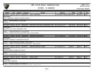
<strong>SECTION</strong> 01025ALLOWANCES<strong>PART</strong> 1 - <strong>GENERAL</strong>1.01 <strong>SECTION</strong> <strong>IN</strong>CLUDESA. This Section specifies administrative and procedural requirements governing Contractallowances.1.) Allowances as set forth in the Specifications are to be used as compensation for items asset forth in this Section. The amounts listed in the schedule and/or Specifications are tobe included in the base bid and shall be listed separately in the Schedule of Values andApplication for Payment.B. Type of allowances include the following:1.) Hazardous material abatement, removal and disposal allowance.2.) {________} allowance1.02 RELATED <strong>SECTION</strong>SA. Section 01050: Schedule of ValuesB. Section 01080: Application for PaymentC. Divisions 2-16: Technical Specifications1.03 ALLOWANCESA. Use the allowances only as authorized for OWNER purposes and only by an approvedallowance disbursement form that indicate the amounts to be charged to the respectiveallowance amount.B. At Substantial Completion of the Work, credit unused amounts remaining in the allowances tothe OWNER by Change Order.1.04 ALLOWANCE DISBURSEMENTA. CONTRACTOR shall submit a request for allowance disbursement on an allowancedisbursement form. Include all substantiating and/or required data along with the request.B. The request shall have the requested amount listed as an allowance disbursement withoutCONTRACTOR overhead and markup.C. Once the OWNER has accepted the disbursement, ARCHITECT and OWNER will sign theallowance disbursement form.<strong>PART</strong> 2 - PRODUCTS (Not Applicable)<strong>PART</strong> 3 - EXECUTION3.01 SCHEDULE OF ALLOWANCESA. Include in the base bid the following allowances in the amounts stated in the Specifications:Specification Section Description Amount1
Hazardous Material Report Hazardous material abatement $50,000.00END OF <strong>SECTION</strong>2
<strong>SECTION</strong> 01030ALTERNATES<strong>PART</strong> 1 - <strong>GENERAL</strong>1.01 <strong>SECTION</strong> <strong>IN</strong>CLUDES:A. This Section specifies administrative and procedural requirements governing bid alternates.1.02 RELATED <strong>SECTION</strong>S:A. Section 01005: Summary of the Work<strong>PART</strong> 2 -<strong>PART</strong> 3 -PRODUCTS (Not applicable)EXECUTION3.01 SPECIFIC:A. An alternate is an amount proposed by bidder and stated on the bid form for certain Workdefined in the Bidding Documents that may be added to or deducted from the base bidamount if OWNER decides to accept a corresponding change in either the amount of Work tobe completed, the Contract Documents, or in the products, materials, equipment, systems, orinstallation methods described in the Contract Documents.1. The amount added or deducted from the base bid is the net addition to or deducted fromthe base bid to incorporate alternate Work into the Work. No other adjustments aremade to the Contract Amount, Milestones and/or the Contract Time.3.02 PROCEDURES:A. CONTRACTOR shall modify or adjust affected adjacent Work as necessary to completelyand fully integrate OWNER accepted alternate Work.1. Include as part of each alternate, miscellaneous devices, accessory objects, and similaritems incidental to or required for a complete installation whether or not mentioned aspart of the alternate.B. Accepted alternates are subject to the same terms and conditions as other Work of theContract Documents.C. OWNER reserves the right to accept alternates for a period of ninety (90) days after bidopening date.D. Schedule: A schedule of alternates is included at the end of this Section. The ContractDocuments referenced in the schedule identify necessary requirements to complete the Workdescribed as specified for each alternate.3.03 SCHEDULE OF ALTERNATES: (See the Bidding Documents for Additional Information)A. Alternate 1: { describe each alternate in these sections and make reference to all appropriatesections, drawings, model numbers. Etc. }1
B. Alternate 2:C. Alternate 3:D. Alternate 4:E. Alternate 5:END OF <strong>SECTION</strong>2
<strong>SECTION</strong> 01050SCHEDULE OF VALUES<strong>PART</strong> 1 - <strong>GENERAL</strong>1.01 <strong>SECTION</strong> <strong>IN</strong>CLUDESA. Procedure for submission of the certified Schedule of Values for review and approval byOWNER.1.02 RELATED <strong>SECTION</strong>SA. Section 01025: AllowancesB. Section 01080: Application for PaymentC. Section 01300: SubmittalsD. Section 01360: Construction Schedule<strong>PART</strong> 2 -<strong>PART</strong> 3 -PRODUCTS (Not applicable)EXECUTION3.01 PREPARATIONA. Upon receipt of the Notice of Intent to Award, CONTRACTOR shall commence preparation ofthe certified Schedule of Values.B. CONTRACTOR shall coordinate the preparation of the certified Schedule of Values withpreparation of the Construction Schedule as set forth in Section 01360.C. CONTRACTOR shall use the table of contents as a Project specific guide to establish theformat for the certified Schedule of Values. Provide at least one (1) line item for each Divisionand/or Specification Section item. Provide separate line items for labor and material whererequired.D. Include the following Project identification on the certified Schedule of Values:1. Project name and location2. Project Number3. ARCHITECT name4. CONTRACTOR name5. Date of SubmittalE. Round amounts to the nearest whole dollar; the total shall equal the Contract Amount.F. The approved certified Schedule of Values shall serve as the basis for the monthly certifiedApplication for Payment.1
3.02 SUBMITTALA. Within five (5) days after the Effective Date of the Contract, CONTRACTOR shall submit five(5) certified copies of the Schedule of Values for review and approval of OWNER.B. OWNER will review and if necessary, return the submitted certified Schedule of Values withsummary comments noting items not in compliance with the requirements of this Section.CONTRACTOR shall revise the certified Schedule of Values and submit five (5) certifiedcopies within three (3) days of receipt of summary comments.C. Signature by OWNER shall constitute acceptance of the certified Schedule of Values.D. A copy of the approved certified Schedule of Values will be transmitted to CONTRACTOR,and ARCHITECT.E. Secure OWNER approval of the certified Schedule of Values prior to submittal of the firstcertified Application for Payment.END OF <strong>SECTION</strong>2
<strong>SECTION</strong> 01080APPLICATION FOR PAYMENT<strong>PART</strong> 1 - <strong>GENERAL</strong>1.01 <strong>SECTION</strong> <strong>IN</strong>CLUDES:A. This Section specifies administrative and procedural requirements relative to a certifiedApplication for Payment.1. Coordinate the certified Schedule of Values and certified Application for Payment with,but not limited to, the Construction Schedule, submittal log, and list of Subcontractors.1.02 RELATED <strong>SECTION</strong>S:1. Section 01025: Allowances2. Section 01050: Schedule of Values3. Section 01360: Construction Schedule4. Section 01700: Contract Closeout<strong>PART</strong> 2 -<strong>PART</strong> 3 -PRODUCTS (Not applicable)EXECUTION3.01 APPLICATION FOR PAYMENTA. Each certified Application for Payment shall be consistent with previous applications andpayments as reviewed by ARCHITECT, paid for by OWNER, and:1. The initial Application for Payment, the Application for Payment at time of SubstantialCompletion, and the final Application for Payment involve additional requirements.B. Payment Application Times: The period of Work covered by each Application for Payment isand the payment date for each progress payment is as specified in the General Conditions.The period covered by each Application for Payment is the previous month.C. Payment Application Forms: Use OWNER provided forms for the Application for Payment.D. Application Preparation: Complete every entry on the form. Include notarization andexecution by a person authorized to sign legal documents on behalf of CONTRACTOR.ARCHITECT will return incomplete applications without action.E. Transmittal: Submit a minimum of three (3) signed and original copies of each certifiedApplication for Payment to the ARCHITECT. All copies shall be complete, including releasesand similar attachments.1. Transmit each copy with a transmittal form listing attachments and recording appropriateinformation related to the application, in a manner acceptable to ARCHITECT.F. Initial Application for Payment: Administrative actions and submittals, that must precede orcoincide with submittal for the first certified Application for Payment include, but are notlimited to, the following:1. Certified Schedule of Values2. Performance and payment bonds. List of principal suppliers and fabricators.3. Worker Compensation certificates, if applicable.4. Auto Insurance, if applicable.5. Hazardous Material Insurance Certificates, if applicable.6. Construction Schedule1
7. Submittal Schedule8. Emergency Contact List9. Copies of authorizations and licenses from governing authorities for performance of theWorkG. Application for Payment at Substantial Completion: Following ARCHITECT issuance of thecertificate of Substantial Completion, submit an Application for Payment:1. Administrative actions, submittals and/or Work that shall precede or coincide with thisapplication include:a. Occupancy permits and similar approvals by authorities having legal jurisdiction overthe Work.b. Removal of temporary facilities and services.c. Testing, adjusting and balance records.d. Removal of surplus materials, rubbish, and similar elements.e. Meter readings.f. Start-up performance reports.g. Owner training and orientations.h. Change over information related to OWNER occupancy, use, operation andmaintenance.i. Final cleaning.j. Ensure that incomplete Work is not accepted and will be completed without unduedelay.k. Advice on shifting insurance coverage.l. List of incomplete Work, recognized as exceptions to ARCHITECT certificate ofSubstantial Completion.m. Change of door locks to OWNER system.H. Final Payment Application: Administrative actions and submittals that must precede orcoincide with submittal of the final Application for Payment include, but are not limited to, thefollowing:1. Completion of Contract Closeout requirements.2. Project record documents.3. Completion of final punch list items.4. Delivery of extra materials, products and or stock.5. Identification of unsettled claims.6. Proof that taxes, fees, and similar obligations are paid.7. Operating and maintenance instruction manuals.8. Consent of surety to final payment.9. Waivers and releases.10. Warranties, guarantees and maintenance agreements.END OF <strong>SECTION</strong>2
<strong>SECTION</strong> 01100COORD<strong>IN</strong>ATION<strong>PART</strong> 1 - <strong>GENERAL</strong>1.1 <strong>SECTION</strong> <strong>IN</strong>CLUDESA. This Section specifies administrative and procedural requirements necessary for coordinatingWork operations including, but not necessarily limited to, the following:1. General coordination procedures.2. Coordination drawings.1.2 RELATED <strong>SECTION</strong>SA. Section 01300: SubmittalsB. Section 01360: Construction ScheduleC. Section 01420: Testing and InspectionD. Section 01450: Test and BalanceE. Section 01700: Contract Closeout<strong>PART</strong> 2 -<strong>PART</strong> 3 -PRODUCTS (Not applicable)EXECUTION3.01 COORD<strong>IN</strong>ATIONA. CONTRACTOR shall coordinate operations included in various sections of the ContractDocuments to assure efficient and orderly installation of each part of the Work. CoordinateWork operations included under related sections of the Contract Documents that depend oneach other for proper installation, connection, and operation of the Work including but limitedto:1. Schedule construction operations in the sequence required where installation of one partof the Work depends on installation of other components, before or after its owninstallation.2. Coordinate installation of different components to assure maximum accessibility forrequired maintenance, service, and repair.3. Make provisions to accommodate items scheduled for later installation.4. Prepare and administer provisions for coordination drawings.B. Where necessary, prepare memoranda for distribution to each party involved, outliningspecial procedures required for coordination. Include such items as required in notices,reports, attendance at meetings and:1. Prepare similar memoranda for OWNER and Separate Work Contract where coordinationof their Work is required.C. Administrative Procedures: Coordinate scheduling and timing of required administrativeprocedures with other construction activities to avoid conflicts and assure orderly progress ofthe Work. Such administrative activities include, but are not limited to, the following:1. Preparation of schedules.2. Installation, relocation and removal of temporary facilities.3. Delivery and processing of submittals.4. Progress meetings.1
5. Project closeout activities.D. Conservation: Coordinate Work operations to assure operations are carried out withconsideration given to conservation of energy, water, materials and:3.02 SUBMITTALS1. Salvage materials and equipment involved in performance of, but not actuallyincorporated into the Work.A. Coordination Drawings: CONTRACTOR shall prepare coordination drawings for coordinationof installation of products and materials fabricated by separate entities. Prepare coordinationdrawings for those areas where limited space availability necessitates maximum utilization ofspace for efficient installation of different components.B. Prepare coordination drawings in the following manner:1. Mechanical, electrical and plumbing Subcontractors are to first submit their respectiveshop drawings for review in order to make any necessary changes prior to going throughthe coordination process.2. The routing process will begin with the HVAC Subcontractor who will provide a black linemylar denoting all of the approved ductwork. HVAC Subcontractor is to locate on mylarall piping in orange pencil lines. In areas without HVAC Work, plumbing Subcontractorwill provide the mylar with blue pencil line. Forward drawings to plumbing Subcontractor.3. Plumbing Subcontractor is to locate the plumbing lines on mylar in blue pencil lines. Firesprinkler Subcontractor is to locate all piping on mylar in red pencil lines and forwarddrawing to electrical Subcontractor.4. Electrical Subcontractor to indicate service and feeder conduit runs in green pencil linesand forward to CONTRACTOR..5. CONTRACTOR will perform the last coordination review. As each coordination drawing iscompleted, CONTRACTOR will meet with ARCHITECT and OWNER to review andresolve all conflicts on the coordination drawings.6. All coordination meetings will be held in the Project field office of CONTRACTOR.CONTRACTOR is required to distribute shop drawings, cut sheets and submittals toSubcontractors where appropriate. Reviewed coordination drawings will be maintained inthe Project field office of CONTRACTOR.END OF <strong>SECTION</strong>2
<strong>SECTION</strong> 01120CUTT<strong>IN</strong>G AND PATCH<strong>IN</strong>G<strong>PART</strong> 1 - <strong>GENERAL</strong>1.1 <strong>SECTION</strong> <strong>IN</strong>CLUDESA. This Section specifies administrative and procedural requirements for cutting and patching.1.2 RELATED <strong>SECTION</strong>SA. Section 01050: Field EngineeringB. Section 01100: CoordinationC. Section 01200: Project MeetingsD. Section 01300: SubmittalsE. Section 01360: Construction ScheduleF. Section 01450: Testing and InspectionG. Section 01740: Warranties<strong>PART</strong> 2 - PRODUCTS (Not applicable)<strong>PART</strong> 3 -EXECUTION3.01 SUBMITTALSA. The word “cutting” as used in the Contract Documents includes but is not limited to cutting,drilling, chopping, and other similar operations and the word “patching” includes but is notlimited to patching, rebuilding, reinforcing, repairing, refurbishing, restoring, replacing, another similar operations.B. Cutting and Patching Proposal: CONTRACTOR shall submit a proposal describingprocedures well in advance of the time cutting and patching will be performed if the ContractDocuments requires approval of these procedures before proceeding. Include the followinginformation, as applicable, in the proposal:1. Describe the extent of cutting and patching required. Denote how it will be performedand indicate why it cannot be avoided.2. Describe anticipated results in terms of changes to existing construction.3. List products to be used and firms or entities that will perform this Work.4. Indicate dates when cutting and patching will be performed.5. Utilities: List utilities that cutting and patching procedures will disturb or affect. Listutilities that will be relocated and those that will be temporarily out-of-service. Indicatehow long service will be disrupted.6. Review by ARCHITECT prior to proceeding with cutting and patching does not waiveARCHITECT right to later require complete removal and replacement of defective Work.3.02 QUALITY ASSURANCEA. Operational Limitations: Do not cut and patch operating elements or related components in amanner that would result in reducing their capacity to perform as intended. Do not cut andpatch operating elements or related components in a manner that would result in increasedmaintenance or decreased operational life or safety.1
3.03 WARRANTY1. Obtain review of the cutting and patching proposal before cutting and patching thefollowing operating elements or safety related systems:a. Primary operational systems and equipmentb. Fire protection systemsc. Noise and vibration control elements and systemsd. Control systemse. Communication systemsf. Electrical wiring systemsg. Operating systems of special construction in Division 13 SectionsA. Existing Warranties: Replace, patch, and repair material and surfaces cut or damaged bymethods and with materials in such a manner as not to void any warranties required orexisting.3.04 <strong>IN</strong>SPECTIONA. Examine surfaces to be cut and patched and conditions under which cutting and patching isto be performed before cutting. If unsafe or unsatisfactory conditions are encountered, takecorrective action before proceeding.3.05 PREPARATION1. Before proceeding, meet at the Project site with parties involved in cutting and patching,including mechanical and electrical trades. Review areas of potential interference andconflict. Coordinate procedures and resolve potential conflicts before proceeding.A. Temporary support: Provide adequate temporary support of Work to be cut.B. Protection: Protect existing improvements and Work during cutting and patching to preventdamage. Provide protection from adverse weather conditions for portions of existingimprovements or Work that might be exposed during cutting and patching operations.C. Avoid interference with use of adjoining areas or interruption of free passage to adjoiningareas.3.06 PERFORMANCEA. General: Employ skilled workmen to perform cutting and patching. Proceed with cutting andpatching at the earliest feasible time and complete without delay. Carefully remove existingWork to be salvaged and or reinstalled. Protect and store for reuse into the Work. Verifycompatibility and suitability of existing substrates before starting the Work.B. Cutting: Cut existing construction using methods least likely to damage elements retained oradjoining Work. Where possible, review proposed procedures with the original installer;comply with the original installer’s recommendations.1. In general, where cutting, use hand or small power tools designed for sawing or grinding,not hammering and chopping. Cut holes and slots as small as possible, neatly to sizerequired, and with minimum disturbance of adjacent surfaces. Temporarily coveropenings when not in use.2. To avoid marring existing finished surfaces, cut or drill from the exposed or finished sideinto concealed surfaces.3. Cut through concrete and masonry using a cutting machine, such as a carborundum sawor a diamond-core drill. Saw cut reinforcing bars and paint ends with bituminous paintexcept where bonded into new concrete or masonry.2
4. Comply with requirements of applicable Division 2 Sections where cutting and patchingrequires excavating, backfill and re-compaction.C. Patching: Patch with durable seams that are as invisible as possible. Comply with specifiedtolerances.3.07 CLEAN<strong>IN</strong>G1. Where feasible, inspect and test patched areas to demonstrate integrity of theinstallation. Verify conditions of existing substrates prior to executing new Work.2. Restore exposed finishes of patched areas and extend finish restoration into retainingadjoining construction in a manner that will eliminate all evidence of patching andrefinishing.3. Concrete: Maintain the cut edges in a moist condition for twenty four (24) hours prior tothe placement of new concrete. In lieu of this an epoxy adhesive may be provided. Finishplaced concrete to match existing unless noted otherwise. Concrete shall have acompressive strength 3,000 psi where used to repair and or match existing Work, unlessnoted otherwise.A. Clean areas and spaces where cutting and patching are performed. Completely removepaint, mortar, oils, putty, and similar items. Thoroughly clean piping, conduit, and similarfeatures before applying paint or other finishing materials. Restore damaged pipe covering toits original condition.END OF <strong>SECTION</strong>3
<strong>SECTION</strong> 01130FIELD ENG<strong>IN</strong>EER<strong>IN</strong>G<strong>PART</strong> 1 - <strong>GENERAL</strong>1.01 <strong>SECTION</strong> <strong>IN</strong>CLUDESSurveying requirements for the Work.1.02 RELATED <strong>SECTION</strong>SA. Section 01005: Summary of the WorkB. Section 01100: CoordinationC. Section 01300: SubmittalsD. Section 01360: Construction ScheduleE. Section 01700: Contract Closeout<strong>PART</strong> 2 - PRODUCTS (Not applicable)<strong>PART</strong> 3 - EXECUTION3.01 SUBMITTALSA. CONTRACTOR shall submit the name and address of the State of California licensedsurveyor to ARCHITECT and OWNER including any changes as they may occur.B. At request of ARCHITECT or OWNER, CONTRACTOR shall submit copies of cut sheets,coordinate plots, data collector printouts, and other documentation as available to verifyaccuracy of field surveying work3.02 LAYOUT OF THE WORKA. CONTRACTOR shall employ a State of California licensed surveyor to lay out the entire Work,set grades, lines, levels, control points, vertical and horizontal control, elevations, grids andpositions. Before the commencement of Work, surveyor shall, in conjunction with OWNERprovided engineering survey of the Project site, locate all reference points and benchmarks,then lay out all lines, elevations, and measurements for the entire Work including but notlimited to, buildings, grading, paving and utilities.3.03 SURVEY REQUIREMENTSA. Establish a minimum of two permanent horizontal and vertical control points on the Projectsite, remote from the building area, referenced to data established by the survey controlpoints.B. Indicate the reference points on the project record drawings with the basis of elevationbeing the established benchmarks.C. Establish lines, grades, locations and dimensions by instrumentation. From time to time,verify the layout of all Work by the same methods.1
D. Provide grade stakes and elevations to construct over excavation and re-compaction,rough and final grades, paved areas, curbs, gutters, sidewalks, building pads,landscaped areas, and other areas as required.E. Calculate and layout proposed finished elevations and intermediate control as required toprovide smooth transitions between the spot elevations indicated in the ContractDocuments.F. Provide stakes and elevations for grading, fill and topsoil placement.G. Provide adequate horizontal and vertical control to locate utility lines, including but notlimited to, storm, sewers, water mains, gas, electric and signal and provide verticalcontrol in proportion to the slope of the line as required for accurate construction. Dryutilities will be based upon adequate horizontal and vertical control layout. Prior to trenchclosure, survey and record invert and flow line elevations. Survey and record top of curband flow line elevations on finished concrete or AC surfaces at key locations such asBC’s, EC’s, grade breaks, corners or angle points in sufficient number to demonstrate theWork complies with the intent of the Contract Documents.H. Provide horizontal and vertical control for batter boards for drainage, utility, and other onsitestructures as required.I. Furnish building corner offsets as required to adequately locate building pads. Providecut and fill stakes within the building pad perimeter adequate to control both overexcavation and re-compaction and the final sub-grade elevation of the building pad.J. Submit a certification signed by the surveyor confirming the elevations and locations ofimprovements are in conformance with the Contract Documents. The statement shallinclude survey notes for the finish floor and building pad, showing the actual measuredelevations on the completed sub-grade, recorded to the nearest 0.01’. Building padtolerance will be 0.10’.3.04 RECORD DRAW<strong>IN</strong>GSA. Upon Substantial Completion, CONTRACTOR shall obtain and pay for reproducibletransparencies of the as built survey drawings. Deliver to ARCHITECT, final “record” drawings ofthe original drawings and completed Work within specified tolerances.B. Record drawings shall indicate locations by coordinate of all utilities onsite with top of pipeelevations at major grade and alignment changes, rim grate or top-of-curb and flow lineelevations of all drainage structures and manholes.C. Completed record drawing transparencies shall be signed and certified as correct and withinspecified tolerances by the licensed surveyor.D. Attention is called to other sections of the Contract Documents requiring verification ormeasurements of installed Work by survey. Surveyor shall perform and certify all such surveysor verification are completed in accordance with the Contract Documents.END OF <strong>SECTION</strong>2
<strong>SECTION</strong> 01150RESOURCE CONSERVATION<strong>PART</strong> 1 - <strong>GENERAL</strong>1.01 <strong>SECTION</strong> <strong>IN</strong>CLUDESA. Procedures for an environmental program at the Project site including but not limited to:1.02 RELATED <strong>SECTION</strong>S1. Use of recycled, toxic-free, and environmentally sensitive materials, equipment,products, and procedures.2. Recycling program for waste materials generated by demolition and construction.A. Section 01100: Summary of the WorkB. Section 01330: Storm Water Pollution PreventionC. Section 01500: Construction Facilities and Temporary ControlsD. Section 01600: Materials and EquipmentE. Section 01700: Contract Closeout<strong>PART</strong> 2 – PRODUCTS (Not applicable)<strong>PART</strong> 3 – EXECUTION3.01 SPECIFIC DEF<strong>IN</strong>ITIONS RELATIVE TO THIS <strong>SECTION</strong>A. Environmental pollution: The presence of chemical, physical, or biological elements whichadversely impact human health or welfare, alter ecological balances of significance to humanlife or impact or alter the future viability of any species deemed to be of importance to humanlife or health.B. Inert fill: Non-liquid solid waste such as soil and concrete, free of hazardous wastes or solublepollutants.C. Class III landfill: A landfill that accepts non-hazardous wastes such as household waste,industrial waste, construction waste and demolition waste.D. Inorganic landfill: Non-reusable items such as solid wastes, such as building materials,packaging, rubbish, debris, and rubble resulting from construction, remodeling, repair, anddemolition operations.E. Rubbish: Combustible and non-combustible wastes, such as paper, boxes, glass, crockery,metal and lumber scrap, tin cans, and bones.F. Debris: Combustible and non-combustible wastes, such as leaves and tree trimmingsthat result from construction or maintenance and repair Work.G. Chemical waste: Substances such as petroleum products, bituminous materials, salts,acids, alkalis, herbicides, pesticides, organic chemicals and inorganic wastes.1
H. Garbage: Refuse and scraps resulting from preparation, cooking, distribution, orconsumption of food.I. Sewage: Domestic sanitary sewage.J. VOC: Volatile organic compounds.G. MSDS: Material Safety Data Sheets.3.02 SUBMITTALSA. Site Management Plan: CONTRACTOR shall submit a plan for proposed solid wastemanagement and environmental protection, including items such as the following:1. List of federal, state and local laws, regulations and permits concerning environmentalprotection, pollution control and abatement that are applicable to CONTRACTORproposed operations.2. Procedures to be implemented to provide the required environmental protection.3. The location of the solid waste disposal areas.4. Procedures for recycling and re-use program.5. Procedures for rebate programs.B. Documentation: CONTRACTOR shall submit documentation in the form of a summary ofsolid wastes generated by construction and demolition operations of the Work. Includemanifests, weight tickets, receipts, and invoices from recycling centers and landfills.C. Closeout Submittals: If required for OWNER rebates, CONTRACTOR shall prepare athree-ring binder with rebate information and product documentation as required toqualify for rebate programs. Submit binder with final closeout submittals.3.03 QUALITY ASSURANCEA. CONTRACTOR shall comply with the following as a minimum requirement:1. Recycling Requirements:a. Implement a recycling program that includes separate collection of wastematerials such as concrete, porcelain fixtures, ferrous and non-ferrous metals,wood, debris, glass and paper.b. Handling: Clean materials contaminated with dirt, adhesives, solvents and othersubstances deleterious to the recycling processes. Arrange for delivery to recyclingcenters or salvage yards.c. Re-use programs: Coordinate with re-use programs, such as Habitat for Humanities.Deliver items salvaged from construction that can be utilized for re-use.2. Environmental Controls:2
a. Comply with federal, state and local regulations for water, air, solid waste, chemicalwaste, sanitary waste and sediment pollution.b. Protection of Natural Resources: Preserve the natural resources within the projectsite. Prevent oily or other hazardous substances from entering the ground, drainageareas, or local bodies of water in such quantities as to affect normal use, aesthetics,or produce a measurable ecological impact on the area.3. Project site Administration:a. Provide training programs to increase awareness of the environmental goals on theProject site.b. Post MSDS sheets on the Project site. Discuss alternatives to minimize exposure topotentially harmful substances.c. Schedule Work so that potentially harmful substances or VOC-releasing Work iscompleted at least seventy-two (72) hours prior to installation of materials or systemsthat may absorb these substances.d. Schedule Work involving VOC-releasing substances or potentially harmful substancesat night or on weekends when the least number of workers are present. Separatethese Work areas with a non-permeable membrane and provide separate ventilationand exhaust during installation and for a minimum of seventy-two (72) hours afterinstallation is complete. Exhaust directly to the exterior; locate exhaust outlets at leastone hundred (100) feet from air intakes, inhabitants or workers.3.04 DELIVERY, STORAGE AND HANDL<strong>IN</strong>GA. CONTRACTOR shall recycle containers and packaging after delivery and uncrating.3.05 EXCESS MATERIALSA. Extra Materials: Where excess materials, in excess of the minimum quantities specified formaintenance materials, remain unused after completion of the Work, CONTRACTOR shallmake such materials available to OWNER, unless such materials can and will be returned tosuppliers for their subsequent reuse. In no event shall such materials be discarded.3.06 PACKAG<strong>IN</strong>GA. Provide reusable or recyclable packaging for Project site delivered items such asoperations and maintenance materials, furniture, equipment, large objects. Generallyapplies to items over 75 pounds or larger than 120 cubic feet:1. Polystyrene "peanuts" will be allowed, provided they are collected andrecycled.2. Plastic sheets or films will be allowed only if labeled with recycling symbolindicating type of plastic.3. Reusable packaging: Items such as blankets, skids and crates that will bereturned to the manufacturer or transportation company for future reuse aspackaging materials.3
4. Recyclable packaging: Items such as boxes, cardboard and paper that will bedelivered to a recycling center.B. After packaging has been removed and prior to application for payment, providedocumentation to substantiate that packaging materials have been reused orrecycled, and that other requirements have been met.END OF <strong>SECTION</strong>4
<strong>SECTION</strong> 01160REQUEST FOR CLARIFICATION<strong>PART</strong> 1 - <strong>GENERAL</strong>1.01 <strong>SECTION</strong> <strong>IN</strong>CLUDESA. Procedure for requesting clarification of the intent of the Contract Documents.1.02 RELATED <strong>SECTION</strong>SA. Section 01005: Summary of the WorkB. Section 01100: CoordinationC. Section 01360: Construction ScheduleD. Section 01700: Contract Closeout<strong>PART</strong> 2 - PRODUCTS (Not applicable)<strong>PART</strong> 3 - EXECUTION3.01 PROCEDUREA. CONTRACTOR shall prepare a Request for Clarification on the form provided.CONTRACTOR shall transmit the Request for Clarification to ARCHITECT with copy toOWNER.B. ARCHITECT response is a clarification of the intent of the Contract Documents and does notauthorize changes in the Contract Amount, Milestones and/or Contract Time.C. A Request for Clarification may be returned with a stamp or notation "Not Reviewed", if, in theopinion of ARCHITECT:1. The requested clarification is ambiguous or unclear to ARCHITECT2. The requested clarification is equally available to the requesting party by researchingand/or examining the Contract Documents3. CONTRACTOR has not reviewed the Request for Clarification prior to submittal toARCHITECTD. Allow a minimum of seven (7) days for review and response time, after receipt by ARCHITECT.CONTRACTOR shall verify and is responsible in verifying ARCHITECT receipt of a Request forClarification.END OF <strong>SECTION</strong>1
<strong>SECTION</strong> 01200PROJECT MEET<strong>IN</strong>GS<strong>PART</strong> 1 - <strong>GENERAL</strong>1.01 <strong>SECTION</strong> <strong>IN</strong>CLUDESA. This Section specifies administrative and procedural requirements for Project meetings,including, but not limited to, the following:1. Job start meeting.2. Pre-installation conferences.3. Progress meetings.4. Meetings as requested by OWNER.1.02 RELATED <strong>SECTION</strong>SA. Section 01100: CoordinationB. Section 01300: SubmittalsC. Section 01360: Construction Schedule<strong>PART</strong> 2 – PRODUCTS (Not applicable)<strong>PART</strong> 3 - EXECUTION3.01 JOB START MEET<strong>IN</strong>GA. In accordance with General Conditions, OWNER will schedule a job start meeting beforestarting the Work, at a time determined by OWNER. Meeting shall be held at the Project siteor another location as determined by OWNER. Meeting will be held in order to reviewresponsibilities, procedures, and other administrative requirements contained within theContract Documents.B. Authorized representatives of OWNER, ARCHITECT, CONTRACTOR and other parties shallattend the meeting. All participants at the meeting shall be familiar with the Project andauthorized to conclude matters relating to the Work.C. Agenda items shall include significant items which could affect progress of the Work,including, but not limited to the following:1. Preliminary Construction Schedule2. Critical work sequencing3. Designation of responsible personnel4. Identification of OAR5. Procedures for processing field decisions6. Request for Proposal7. Construction Directive and Change Order8. Procedures for processing Applications for Payment9. Prevailing wages10. Submittal of Shop Drawings, Product Data, material lists and Samples11. Preparation of project record documents12. Use of the Project site and/or premises13. Parking availability14. Office, work, and storage areas15. Equipment deliveries and priorities16. Safety procedures17. First Aid18. Security19. Housekeeping1
20. Working hours21. Contract Compliance Officer22. Insurance Services23. Environmental Health & SafetyD. ARCHITECT shall prepare and issue meeting minutes to attendees and interested parties nolater than five (5) calendar days after the meeting date.3.02 PRE-<strong>IN</strong>STALLATION CONFERENCESA. CONTRACTOR shall coordinate and conduct pre-installation conferences at the Project siteas required by related Sections of the Contract Documents.B. CONTRACTOR, manufacturers and fabricators involved in or affected by the installation andits coordination or integration with other pre-ceding and or subsequent installations of Workshall attend the meeting. CONTRACTOR shall advise OWNER and ARCHITECT ofscheduled meeting dates in order to secure their attendance.1. CONTRACTOR shall review the progress of other construction activities andpreparations for the particular activity under consideration at each pre-installationconference, including requirements for the following:a. Contract Documentsb. Optionsc. Related Construction Directives and Change Ordersd. Purchasese. Deliveriesf. Shop Drawings, Product Data, and quality-control samplesg. Review of mockupsh. Possible conflictsi. Compatibility problemsj. Time schedulesk. Weather limitationsl. Manufacturer’s recommendationsm. Warranty requirementsn. Compatibility of materialso. Acceptability of substratesp. Temporary facilitiesq. Space and access limitationsr. Governing regulationss. Safetyt. Inspecting and testing requirementsu. Required performance resultsv. Recording requirementsw. Protection2. CONTRACTOR shall record significant discussions and directives received from eachconference. CONTRACTOR shall, within three (3) calendar days after the meeting date,distribute the minutes of the meeting to all concerned parties, including, but not limited to,OWNER, IOR and ARCHITECT.3.03 PROGRESS MEET<strong>IN</strong>GSA. Progress meetings will be held at the Project site at regular intervals, typically weekly, asdetermined by OWNER.B. In addition to representatives of CONTRACTOR, OWNER and ARCHITECT, eachSubcontractor, supplier, or other entity concerned with current progress or involved inplanning, coordination, or performance of the Work shall, if requested by OWNER, be2
epresented at these meetings. All participants at the conference shall be familiar with theProject and authorized to conclude all matters relating to the Work.C. Failure of the CONTRACTOR to be so represented at any job meeting which is held at amutually agreed time or for which a written notice is given, shall not relieve CONTRACTORfrom abiding by any and all OWNER or ARCHITECT determinations or directives issued atsuch meeting.D. OWNER will review and correct or approve minutes of the previous progress meeting and willreview other significant items affecting progress. Topics for discussion as appropriate to thestatus of the Project include but are not limited to:a. Interface requirementsb. Construction Schedulec. Sequence and coordinationd. Status of submittals / RFC’se. Deliveriesf. Off-site fabricationg. Accessh. Site utilizationi. Temporary Construction Facilities and Controlsj. Hours of workk. Hazards and risksl. Housekeepingm. Quality and workmanshipn. Unforeseen conditionso. Testing and Inspectionp. defective Workq. Construction Directiver. Request for Proposals. Change Order Proposals and Change Orderst. Documentation of information for payment requestsu. Application for Paymentv. Other items as required or as brought forth.E. No later than five (5) working days after each meeting, ARCHITECT will prepare anddistribute minutes of the meeting to each present and absent party. Include a brief summary,in narrative form, of progress, decisions, directives, actions taken and all other issues sincethe previous meeting and report.1. Schedule Updating: If required, CONTRACTOR shall revise the Construction Scheduleafter each progress meeting where revisions to the schedule have been made orrecognized. Issue the revised schedule concurrently with the next scheduled meeting.3.04 ADDITIONAL MEET<strong>IN</strong>GSA. OWNER, upon giving notice to the intended parties and without further obligation, mayrequire additional meetings to discuss Work and/or Project related activities.END OF <strong>SECTION</strong>3
<strong>SECTION</strong> 01300SUBMITTALS<strong>PART</strong> 1 - <strong>GENERAL</strong>1.01 <strong>SECTION</strong> <strong>IN</strong>CLUDESA. Administrative and procedural requirements for submittals required for the Work, including,but not limited to; Shop Drawings, Product Data, Samples, material lists, and qualitycontrol items as required by the Contract Documents.B. Wherever possible, throughout the Contract Documents, the minimum acceptable qualityof workmanship and products has been defined by the name and catalog number of amanufacturer and by reference of recognized industry standards.C. To ensure that specified products are furnished and installed in accordance with thedesign intent, procedures have been established for submittal of design data and for itsreview by ARCHITECT, OWNER and/or others.1.02 RELATED <strong>SECTION</strong>SA. Section 01010: Phasing of the WorkB. Section 01020: Project FormsC. Section 01050: Schedule of ValuesD. Section 01080: Application for PaymentE. Section 01100: CoordinationF. Section 01120: Cutting and PatchingG. Section 01130: Field EngineeringH. Section 01330: Storm Water Pollution PreventionI. Section 01360: Construction ScheduleJ. Section 01420: Testing and InspectionK. Section 01450: Test and BalanceL. Section 01500: Construction Facilities and Temporary ControlsM. Section 01640: SubstitutionsN. Section 01700: Contract CloseoutO. Section 01740: Warranties<strong>PART</strong> 2 – PRODUCTS (Not applicable)<strong>PART</strong> 3 - EXECUTION3.01 PROCEDURESA. CONTRACTOR shall package each submittal appropriately for transmittal and handling.CONTRACTOR shall transmit each submittal to ARCHITECT with copy to OWNER.ARCHITECT and/or OWNER will not accept submittals received from sources other thanfrom CONTRACTOR.B. After ARCHITECT review, ARCHITECT will transmit submittals to CONTRACTOR, andOWNER and/or others as required. Work shall not commence, unless otherwise approvedby OWNER, unless approved submittals are transmitted to CONTRACTOR.1
C. CONTRACTOR shall clearly identify any deviations from the Contract Documents on eachsubmittal. Any deviation not so noted even though stamped reviewed is not acceptable.D. CONTRACTOR shall coordinate each submittal with fabrication, purchasing, testing,delivery, other submittals, and related activities requiring sequential activity.E. Timing of Submittals:1. In accordance with General Conditions CONTRACTOR shall submit toARCHITECT those Shop Drawings, diagrams, materials lists, Samples and othersubmittals required by the Contract Documents.2. The schedule of submittals shall provide adequate time between submittals inorder to allow for proper review without negative impact to the MilestonesSchedule.3. Schedule of submittals shall be related to Work progress, and shall be soorganized as to allow sufficient time for transmitting, reviewing, corrections,resubmission and re-reviewing.4. CONTRACTOR shall coordinate submittal of related items and ARCHITECTreserves the right to withhold action on a submittal requiring coordination withother submittals until all related submittals are received by ARCHITECT.5. CONTRACTOR shall revise, update and submit submittal schedule toARCHITECT and OWNER on the first of each month, or as required by OWNER.6. CONTRACTOR shall allow in the Milestones Schedule, at least fourteen (14)days for ARCHITECT review following receipt of submittal. For mechanical,plumbing, electrical and other submittals requiring joint review with OWNER,CONTRACTOR shall allow a minimum of fourteen (14) days followingARCHITECT receipt of submittal.7. No adjustments to the Contract Time and/or Milestones will be authorizedbecause of a failure to transmit submittals to ARCHITECT sufficiently inadvance of the Work to permit review and processing.8. In case of product substitution, shop drawing preparation shall not commenceuntil such time ARCHITECT and OWNER reviews said submittal relative to theGeneral Conditions.G. If required, resubmit submittals in a timely manner. Resubmit as specified forinitial submittal but identify as such. Review times for re-submitted items shall beas per the time frames for initial submittal review.H. Shop Drawing preparation shall not commence until such time as CONTRACTORreceives Product Data approval.I. ARCHITECT, or authorized agent, will stamp each submittal with a uniform, actionstamp. ARCHITECT, or authorized agent, will mark the stamp appropriately toindicate the action taken, as follows:1. Final Unrestricted Release: When ARCHITECT, or authorized agent, marks asubmittal “ Reviewed “, the Work covered by the submittal may proceed2
3.02 SHOP DRAW<strong>IN</strong>GSprovided it complies with requirements of the Contract Documents. Finalpayment depends on that compliance.2. Final-But-Restricted Release: When ARCHITECT, or authorized agent, marksa submittal “ Reviewed as Noted “, the Work covered by the submittal mayproceed provided it complies with notations or corrections on the submittaland requirements of the Contract Documents. Final payment depends on thatcompliance.3. Returned for Re-submittal: When ARCHITECT, or authorized agent, marks asubmittal “Rejected, Revise and Resubmit”, do not proceed with Workcovered by the submittal, including purchasing, fabrication, delivery, or otheractivity. Revise or prepare a new submittal according to the notations;resubmit without delay. Repeat as necessary to obtain different action mark.In case of multiple submittals covering same items of Work, CONTRACTORis responsible for any time delays, schedule disruptions, out of sequenceWork, or additional costs due to multiple submissions of the same submittalitem. Do not use, or allow others to use, submittals marked “Rejected, Reviseand Resubmit “ at the Project site or elsewhere where Work is in progress.4. Other Action: Where a submittal is for information or record purposes orspecial processing or other activity, the ARCHITECT, or authorized agent, willreturn the submittal marked “ Action Not Required “.A. Shop Drawings are original drawings prepared by CONTRACTOR, Subcontractor,supplier, or distributor illustrating some portion of Work by showing fabrication, layout,setting, or erection details. Do not reproduce Contract Documents or copy standardinformation as the basis of Shop Drawings.B. Produce Shop Drawings to an accurate scale that is large enough to indicate all pertinentfeatures and methods. Except for templates, patterns and similar full-size drawings,submit Shop Drawings on sheets at least 8-1/2 x 11 inches but no larger than 24 x 36inches.C. Shop Drawings shall include fabrication and installation drawings, setting diagrams,schedules, patterns, templates and similar drawings. Include the following information:1. Dimensions2. Identification of products and materials included by sheet and detailnumber.3. Compliance with specified standards.4. Notation of coordination requirements.5. Notation of dimensions established by field measurement.D. Provide a space approximately 4 by 5 inches on the label or beside the title block on ShopDrawings to record CONTRACTOR and ARCHITECT review, and the action taken.Include the following information on the label for processing and recording action taken:1. Project name.2. Date.3. Name and address of ARCHITECT.4. Name and address of CONTRACTOR5. Name and address of Subcontractor.3
6. Name and address of supplier.7. Name and address of manufacturer.8. Name and title of appropriate specification section.9. Drawing number and detail references, as appropriate.E. Unless otherwise agreed to or indicated in individual Specification Sections, submit asufficient number to allow for adequate CONTRACTOR, Subcontractor, supplier,manufacturer and fabricators distribution plus two sets to be retained by ARCHITECT, oneset to be transmitted to IOR and one set to OWNER.3.03 PRODUCT DATAA. Collect Product Data into a single submittal for each element of Work or system. ProductData includes printed information, such as manufacturer’s installation instructions,catalog cuts, standard color charts, roughing-in diagrams and templates, wiringdiagrams, schedules, illustrations and performance curves.1. Mark each copy to show or delineate pertinent materials, products, models,applicable choices and options. Where Product Data includes information onseveral products that are not required, clearly mark copies to indicate theapplicable information. Include the following information:a. Manufacturer’s printed recommendations.b. Compliance with trade association standards.c. Compliance with recognized testing agency standards.d. Application of testing agency labels and seals.e. Notation of dimensions verified by field measurement.f. Notation of coordination requirements.g. Notation of dimensions and required clearances.h. Indicate performance characteristics and capacities.i. Indicate wiring diagrams and controls.2. Do not submit Product Data until compliance with requirements of the ContractDocuments has been confirmed. .C. Required Copies and Distribution: Same as denoted in sub - section 3.02, E.3.04 SAMPLESA. Procedure:1. Submit Samples of sufficient size, quantity, cured and finished and physicallyidentical to the proposed product or material. Samples include partial or fullsections or range of manufactured or fabricated components, cuts or containers ofmaterials, color range sets, and swatches denoting color, texture and or pattern.a. Mount or display samples in the manner to facilitate review of qualitiesindicated. Include the following:1. Specification Section number and reference.2. Generic description of the Sample.3. Sampling source.4. Product name or name of manufacturer.5. Compliance with recognized standards.6. Availability and delivery time.4
2. Submit Samples for review of size, kind, color, pattern and texture. SubmitSamples for a final check of these characteristics with other elements and acomparison of these characteristics between the final submittal and the actualcomponent as delivered and installed.a. Where variations in color, pattern, texture, or other characteristic is inherent inthe material or product represented, submit at least three (3) multiple unitsthat show the approximate limits of the variations.b. Refer to other Specification Sections for requirements for Samples thatillustrate workmanship, fabrication techniques, assembly details, connections,operation, and similar construction characteristics.c. Refer to other Sections for Samples to be returned to CONTRACTOR forincorporation into the Work. Such Samples must be undamaged at time ofuse. On the transmittal indicate special requests regarding disposition ofSample submittals.d. Samples not incorporated into the Work, or otherwise not designated asOWNER property, remain the property of CONTRACTOR and shall beremoved from the Project site prior to Substantial Completion.3. Color and Pattern: Whenever a choice of color or pattern is available in aspecified product, submit accurate color chips and pattern charts to ARCHITECTfor review and selection.4. Number Required: Submit 5 of each. Two will be returned to CONTRACTOR withone to ARCHITECT, and OWNER.B. When specified, erect field Samples and mock-ups at the Project site to illustrate products,materials, or workmanship and to establish standards by which completed Work shall bejudged.C. Maintain sets of Samples, as returned, at the Project site, for quality comparisonsthroughout the course of the Work. Sample sets may be used to obtain final acceptance ofthe Work associated with each set.3.05 QUALITY CONTROL SUBMITTALSA. Submit quality control submittals, including design data, certifications,manufacturer’s field reports, and other quality control submittals as required underother Sections of the Contract Documents.B. When other Sections of the Contract Documents require certification of a product,material and/or installation complies with specified requirements, submit anotarized certification from the manufacturer certifying compliance with specifiedrequirements.C. Certification shall be signed by an officer of the manufacturer or other individualauthorized to sign documents on behalf of the represented company.D. Requirements for submittal of inspection and test reports are specified in otherSections of the Contract Documents.5
END OF <strong>SECTION</strong>6
CONSTRUCTION SCHEDULE<strong>SECTION</strong> 01360<strong>PART</strong> 1 - <strong>GENERAL</strong>1.01 <strong>SECTION</strong> <strong>IN</strong>CLUDESA. Required procedures, preparation, submittals, reviews, updates, and revisions to theconstruction schedule.1.02 RELATED <strong>SECTION</strong>SA. Section 01005: Summary of the WorkB. Section 01050: Schedule of ValuesC. Section 01080: Application for PaymentD. Section 01300: SubmittalsE. Section 01420: Testing and InspectionF. Section 01450: Test and BalanceG. Section 01500: Construction Facilities and Temporary ControlsI. Section 01700: Contract Closeout<strong>PART</strong> 2 – PRODUCTS2.01 SCHEDUL<strong>IN</strong>G SOFTWAREA. CONTRACTOR shall utilize Primavera Project Planner for Windows® (P3) software (latestversion) by Primavera Systems, Inc., or equivalent scheduling software and employ theCritical Path Method (CPM) in the development and maintenance of the Milestones Schedulenetwork in Precedence Diagram Mode (PDM). The scheduling software shall be capable ofbeing resource loaded with manpower, costs and materials. It shall also be capable ofgenerating time-scaled logic diagrams, resource histograms and profiles, bar charts, layoutsand reports with any and/or all activity detail. OWNER will consider accepting SureTrakProject Manager software (latest version) by Primavera Systems, Inc. in lieu of P3 uponwritten request by CONTRACTOR and OWNER acceptance in writing.B. In utilizing Primavera Project Planner the schedule calculation rules, auto cost rules andresource calculation rules shall be in a format acceptable to OWNER.<strong>PART</strong> 3 – EXECUTION3.01 SUBMITTALSA. CONTRACTOR shall submit six (6) 11”x17” colored copies and two (2) 3.5” computer disks ofall Milestones Schedules. CONTRACTOR shall submit three (3) copies of all bar charts,reports and/or other required data.B. CONTRACTOR shall submit a resume of the proposed scheduler for review and acceptanceprior to the preparation of any Milestones Schedule. CONTRACTOR shall retain at least onefull time scheduler with a minimum of five (5) years direct experience using automatedscheduling systems of the types set forth in this Section. Scheduler will cooperate withARCHITECT and OWNER and shall be available on a full time basis for continuously1
monitoring, maintaining and updating the detailed Milestones Schedule. OWNER has the rightto refuse to accept the scheduler based upon lack of experience as required by this Section. IfOWNER refuses to accept the proposed scheduler, CONTRACTOR shall propose anotherscheduler meeting the stated experience requirements.C. Preliminary Milestones Schedule.D. Initial Milestones Schedule.E. Weekly, monthly, rolling and recovery schedules as required.3.02 PRELIM<strong>IN</strong>ARY AND <strong>IN</strong>ITIAL SCHEDULEA. Within ten (10) days after the Effective Date of the Contract, CONTRACTOR shall developand submit the preliminary Milestones Schedule as required by the General Conditions.Submittal activities shall be incorporated into the schedule. ARCHITECT and/or OWNERreview of the preliminary Milestones Schedule shall not confirm and/ or represent it as being acomplete listing of all submittals required by the Contract Documents.B. Within ten (10) days after the commencement of the Contract Time, CONTRACTOR shallsubmit the initial Milestones Schedule as required bythe General Conditions. The initialMilestones Schedule shall include all of the detailed activities for the first 120 calendar days ofthe Contract Time. CONTRACTOR shall update the initial Milestones Schedule as specifiedand submit until it is accepted. Since updates to the initial Milestones Schedule are basis forpayment to CONTRACTOR during first four month period, submittal and acceptance of suchupdates shall be a condition precedent to making of monthly payment. Upon final acceptanceof the initial Milestones Schedule it shall become the Milestones Schedule against which allsubsequent schedule updates shall be made; against which CONTRACTOR shall reportprogress to and/or variances from, and by which OWNER shall measure CONTRACTORperformance and progress.3.03 CPM NETWORKA. CPM network shall incorporate activity descriptions, sequence, logic relationships, durationestimates, resource loading and other information as set forth in this Section including but notlimited to:1. The CPM network shall include all Milestones as well as all engineering, fabricationand delivery dates required to support the Milestones.2. Activities to be integrated and shown in the CPM network shall include in addition toall construction activities: Milestones representing CONTRACTOR submittal dates ofall critical submittals; activities representing ARCHITECT and/or OWNER reviewperiod of each submittal with each review period scheduled for no less than fourteen(14) days; procurement of materials and equipment; manufacture and/or fabrication;testing and delivery to the Project site of special material and major equipment;equipment installation and preliminary, final and performance testing of equipment orsystems installed under the Contract Documents.3. Indicate start and completion dates for all temporary facilities; construction of mockups,prototypes and/or samples; punch list; OWNER interfaces and furnishing ofitems; interfaces with Separate Work Contracts and regulatory agency approvals;securing of approvals and permits required for performance of the Work.2
4. Shall take into account all foreseeable factors or risks affecting or which may affect;performance of the Work including historical and predicted weather conditions;applicable laws, regulations or collective bargaining agreements pertaining to labor,transportation, traffic, air quality, noise and any other applicable regulatoryrequirements.5. CONTRACTOR shall not use any float suppression techniques such as preferentialsequencing or logic, special lead/lag constraints or unjustifiably over-estimatingactivity durations in preparing the construction schedule except that finish no laterthan constraints for Milestones will be permissible.6. CONTRACTOR will include with the CPM network a written narrative reportsufficiently comprehensive to explain basis and determinations of CONTRACTORapproach to the Work including but not limited to: activity durations; manpower flow;average crew sizes; equipment requirements; production rates and long-lead items;restraints: critical path activities that contain time contingencies for impacts to beexpected from normal rainfall; holidays and other non-work days; potential problemareas; permits; required coordination with authorities, utilities, Separate WorkContracts and other parties; and long lead delivery items requiring more than thirty(30) days from the date of order to delivery on the Project site.B. ARCHITECT and/or OWNER will notify CONTRACTOR of any recommended adjustments tothe CPM network. CONTRACTOR shall perform any required adjustments to the CPMnetwork and resubmit it for acceptance certifying in writing all information contained thereincomplies with the Contract Documents.C. Upon notification by OWNER of acceptance of the CPM network, CONTRACTOR shallprepare computer plots and printouts, and complete submission of the Milestones Schedule,which shall include the following, as a minimum:1. Bar charts, generated separately using the format template provided by OWNER for:(a) Milestones only;(b) Summary level sorted by craft/trade and area;(c) Detail sorted by date;(d) Detail sorted by responsibility.2. Reports, generated separately using the format template provided by OWNER for:(a) Float sorted low to high;(b) Resource histogram.3. Activities must be coded to OWNER Activity Code Structure, which will be definedand provided to CONTRACTOR.3.04 MILESTONESA. Milestones are designated dates as set forth in the Milestones Schedule in which Work orportions thereof are required to be started and/or completed in accordance with the ContractDocuments including but not limited to:3
1. Where the term completion or similar terms are used in the designation of aMilestone, it shall be construed to mean all portions of the Work in the indicatedphase, area and/or zone are complete and acceptable to OWNER. Where the termstart or similar terms are used in the designation of a Milestone, it shall be construedto mean a portion of the Work in the indicated phase, area and/or zone is required tobe commenced.2. CONTRACTOR shall identify all OWNER defined Milestones in the MilestonesSchedule. OWNER defined Milestones shall serve as an essential instrument ofmeasurement by ARCHITECT and OWNER of CONTRACTOR compliance with theMilestones Schedule.3.05 MILESTONES SCHEDULEA. Milestones Schedule shall represent CONTRACTOR plan to complete the Work within theMilestones and/or Contract Time however:1. A schedule extending beyond the Milestones and/or Contract Time will not beacceptable.2. A schedule indicating Work completed in less than the Milestones and/or ContractTime will not be acceptable. CONTRACTOR shall indicate any available float.3. A schedule found unacceptable by the OWNER and/or ARCHITECT shall be revisedby CONTRACTOR and resubmitted within five (5) days.B. Milestones Schedule shall clearly indicate sequence of construction activities and specificallyindicate:1. Start and completion of all items of Work and their major components, the Project andall Milestones identified by OWNER.2. Activities for procurement, delivery, installation of equipment, materials and othersupplies, including:a. Time for submittals, re-submittal, and reviews. Include decision dates forselection of finishes.b. Time for fabrication and delivery of manufactured products for the Work.c. Interdependence of procurement and construction activities.d. Dates for mobilization, test and balance of equipment, SubstantialCompletion, and Final Completion.C. Milestones Schedule shall be in sufficient detail to assure adequate planning and execution ofWork including but not limited to:1. Each activity shall range in duration from 1 to 15 workdays, with exception offabrication and procurement activities, unless directed otherwise by OWNER. Activitydurations shall be total of actual days required to perform and complete that activityand shall not include consideration of weather impact on the activity.4
2. Shall be cost and resource-loaded with the resulting total equal to the ContractAmount and shall include all associated interface activities contained within theContract Documents including, but not limited to, OWNER maintenance andoperations activities and/or interim housing schedules, which will be provided byOWNER.3. Shall be designed, in judgment of the ARCHITECT and/or OWNER to allowmonitoring and evaluation of progress in performance of the Work and it shall becalendar time-scaled in precedence diagramming method (PDM).4. Activities shall include:a. A description of what is to be accomplished and where.b. Workday duration.c. Responsibility code identifying the performing party for each individualactivity.d. Area of Work shall be coded on each Work activity.e. Phase of Work shall be coded on each Work activity.5. Network shall show continuous flow from left to right.6. Identify days per week and shifts per day worked; also, non-work days and holidays.7. Identify activities that constitute controlling operations, i.e., Milestones or critical path.8. ARCHITECT and/or OWNER may require additional coding of activities.D. Notwithstanding acceptance of the Milestones Schedule, failure to identify and/or include anyelement of the Contract into the Milestones Schedule shall not release CONTRACTOR fromobligation of completing all required Work in accordance with any Milestones.E. Submittal of the Milestones Schedule shall constitute CONTRACTOR confirmation theschedule meets the requirements of the Contract Documents, and the Work will be executedin the sequence indicated in the Milestones Schedule.F. CONTRACTOR shall allocate the following number of days within the indicated calendarmonth wherein rainfall in excess of 0.01 inches can be normally anticipated to occur at theProject site based on 50-year data 1947-1997 compiled from National Climate DataCooperative network by National Climate Data center of the National Weather Service of theNational Oceanographic and Atmospheric Administration:January 6 May 1 September 1February 5 June 0 October 1March 5 July 0 November 3April 4 August 0 December 5These days are to be accounted for in the Milestones Schedule and are to be considered ascumulative from commencement of the Contract Time to Substantial Completion. During a5
month where the actual rain days are less than the allotted rain days, the remaining days shallbe used to offset rain days exceeding those given for other months. Unusually severe weatheras set forth in General Condition Section 12.2 shall be defined as any month where actual raindays exceed the allotted amount.3.06 REQUIREMENTS FOR WEEKLY/MONTHLY REVIEW AND UPDAT<strong>IN</strong>GA. Prepare updated Milestones Schedule by one of following two methods:1. When updating current Milestones Schedule with actual Work progress only (nonlogic changes), status current Milestones Schedule with actual start and finish dates,remaining durations, and percent completion of cost and resource loaded activitiesand submit to OWNER and ARCHITECT for review as specified.2. When updating current Milestones Schedule with logic changes, ConstructionDirectives, Change Orders, delay / disruption activities, or recovery plans, prepare afragnet as set forth in Section 3.07 and submit to OWNER and ARCHITECT forreview. Incorporate changes into current Milestones Schedule prior to data date.B. When Work is associated with a Change Order, incorporate adjustments to the schedule. Theadjustments shall be resource-loaded with material unit quantities and the corresponding costaccount, resources account codes, activity description, accepted costs and time adjustments.The activity ID number shall identify the number of the Change Order.G. Float is not for exclusive use or benefit of either OWNER or CONTRACTOR but is an expiringresource available to both parties on a non-discriminatory basis. If required to meet specifiedMilestones, either party may utilize float. Adjustments to the Milestones and/or Contract Timewill be only be authorized by Change Order and only to the extent the claimed adjustmentexceed total float along the most critical path of the current Milestones Schedule in effect atthe time of the claimed adjustment. The claimed adjustments to the Milestones and/orContract Time must also cause the Final Completion date to exceed that currently indicated inthe Milestones Schedule. CONTRACTOR claimed adjustments to an existing negative floatpath will not receive consideration until the activity with the highest negative float is driveneven further negative. Claimed adjustments to the Milestones and/or Contract Time will beadministered in conjunction with those set forth in the General Conditions.H. Pursuant to the float sharing requirements of this Section, the use of float suppressiontechniques such as preferential sequencing or logic, special lead / lag logic restraints, andextended activity times or durations are prohibited and the use of float time disclosed orimplied by the use of alternate float suppression techniques shall be proportionally shared tobenefit OWNER and CONTRACTOR. The use of any network technique solely for purpose ofsuppressing float will be cause for rejection of the submitted Milestone Schedule.I. CONTRACTOR shall attend weekly and monthly Milestones Schedule review meetings inorder to accomplish the following:1. Reflect current Work progress in updates.2. Provide all specified reporting.3. Take remedial action to mitigate schedule variances.F. ARCHITECT, OWNER and CONTRACTOR shall conduct weekly reviews of the progress ofthe Work and compare such progress to the Milestones Schedule, the schedule of submittalsand the four-week rolling schedule. The weekly schedule review shall include, at a minimum:6
1. CONTRACTOR shall update and status the Milestones Schedule databases weeklyprior to review. Utilizing the “Project Groups/Project” feature of P3, CONTRACTORshall include submittal schedule and material procurement schedule informationlinked to the Milestones Schedule activity information in each update and or status.2. When expanding activities to reduce maximum durations from twenty (20) days to five(5) days, CONTRACTOR shall identify expanded activities so the baseline activitythey originate from is readily apparent. CONTRACTOR shall not allow the aggregateduration of the expanded activities to exceed the duration assigned to their parentactivity in the baseline Milestones Schedule unless specifically permitted by OWNERin writing.3. CONTRACTOR shall prepare a four-week rolling schedule immediately following theweekly update/status of and from the Milestones Schedule database and shall ensureit accurately reflects progress of the Work. CONTRACTOR shall provide ARCHITECTand OWNER with printed copies as well as electronic files on disk.4. CONTRACTOR shall review of all submissions, submittal reviews, fabrication/deliverystatus, Work started and/or completed in the preceding week, all Work in progress,and scheduled Work for the upcoming twenty-one (21) days.5. CONTRACTOR shall review all revisions, added and/or deleted Work, and shalldetermine and incorporate these into CONTRACTOR plan of the Work.6. CONTRACTOR shall review all interfacing and coordination with Separate WorkContracts.7. CONTRACTOR shall review progress and allocation of Work forces. Each report shallindicate a planned curve and an actual curve plotted on the same graph, where theplanned curve derived from the accepted resource-loaded baseline MilestonesSchedule.8. CONTRACTOR shall provide variance reports including all activities in excess of two(2) days behind schedule and proposed mitigation measures for each item on thevariance report.9. CONTRACTOR shall, at a minimum, attend review meetings prepared to discussactual activity start and/or completion dates and any applicable variances, forecastactivity start and/or completion dates and any applicable variances and progress of allactivities underway at the time of the review.10. During reviews, CONTRACTOR shall alert ARCHITECT and OWNER of all activitiesbehind schedule and further identify all activities and/or Milestones impacted by suchvariances. CONTRACTOR shall prepare and transmit to ARCHITECT and OWNERproposed recovery plans to regain time lost due to variances.11. Following review of the recovery plan and all other information relevant to theprogress of the Work, CONTRACTOR shall adjust its Work plan as required to assurecompliance with the Milestones Schedule. If the latest calculated completion date forany critical activity (total float less than or equal to 2 work days) does not fall withinthe time allowed by the Milestones Schedule, the sequence of Work and orperformance of the Work shall be revised by CONTRACTOR. CONTRACTOR shall,by means of utilizing concurrent operations, additional Work force allocations,additional shifts, overtime, etc., provide all such means until a subsequent MilestonesSchedule indicates all Milestones will be met. The requirement for such additionalWork force allocations, additional shifts, overtime, etc., does not entitleCONTRACTOR to an adjustment in the Contract Amount.7
12. CONTRACTOR shall derive from the Milestones Schedule database and provide aweekly four-week rolling schedule (1-week back, 3 weeks ahead) in printed form andwith electronic files on disk. At the next Project meeting review, CONTRACTOR shallsubmit an updated four-week rolling schedule indicating any remedial measuresnecessary to maintain compliance with the Milestones Schedule.G. Simultaneously with each submittal of an Application for Payment, CONTRACTOR shalldeliver to ARCHITECT and OWNER an updated Milestones Schedule reflecting progress ofthe Work up until the end of the previous reporting period. Each such Milestones Scheduleshall indicate actual Work progress to date together with a projected schedule for completionof the Work. No changes in logic will be permitted unless agreed upon with OWNER.H. ARCHITECT, OWNER and CONTRACTOR shall conduct monthly reviews to determine:planned versus actual progress to date; compliance with submittal requirements, Milestonesand accepted Milestones Schedule; determination of any changes to the Work plan orimplementation which must be made by CONTRACTOR to comply with the MilestonesSchedule. The monthly schedule review shall include, at a minimum:1. All requirements of weekly reviews listed above. Monthly update/status of electronicdatabase shall include recording of all actual start dates and actual finish dates andstatus of activities in progress.2. Review of planned versus actual Work force allocations and progress for thepreceding month.3. Review of revisions, added and/or deleted Work and how those are being integratedinto CONTRACTOR Work plan.4. Review of CONTRACTOR interface and coordination with Separate Work Contracts.5. Review of all impacts to the Work during the preceding month and to date,CONTRACTOR evaluation of those impacts and any recovery plans or remedialactions required in order to meet the Milestones Schedule.6. Submission of a stand alone fragmented network if current progress reflects negativefloat of minus ten (10) days or more for any Milestone activity. Detail activitiesaffected, date delay and/or disruption occurred or productivity rates which wereimpacted and unmitigated impacts to schedule caused by such events. Submit similarfragnet detailing CONTRACTOR plan to mitigate delay and/or disruption andsubsequent impacts to schedule. Provide written narrative describing circumstancesthat caused delay and/or disruption and methodology used to determine delay and/ordisruption. Submission of such fragnets does not constitute permission to proceedwith the plan.Following review of the above and all other information relevant to the progress of the Work,CONTRACTOR shall adjust the Work plan and submit a revised Milestones Schedule foracceptance. CONTRACTOR shall, by means of utilizing concurrent operations, additionalWork force allocations, additional shifts, overtime, etc., provide all such means until asubsequent Milestones Schedule indicates all Milestones will be met. The requirement foradditional Work force allocations, additional shifts, overtime, etc., does not entitleCONTRACTOR to an adjustment in the Contract Amount.I. The Milestones Schedule shall be updated by CONTRACTOR on a weekly basis andsubmitted to ARCHITECT and OWNER on a monthly basis for concurrent review with eachpayment application submitted by CONTRACTOR. The update shall incorporate actual statusto date and shall include the following:8
1. Computer plotted time-scaled CPM network2. Bar Charts, generated separately using the format template provided by OWNER for:(a) Milestones only (Baseline vs. forecast)(b) Summary Level (sorted by craft/trade and area);(c) Detail (sorted by Dates);(d) Detail (sorted by Responsibility);(e) Detail (sorted by phase).3. Reports, generated separately using the format template provided by OWNER for:(a) Variance (Baseline vs. forecast);(b) Progress Curves (baseline vs. earned/forecast);(c) Float (sorted low to high), and;(d) Resource Histogram.4. Provide all data files electronically by diskette.J. Written Narrative Report: CONTRACTOR shall include a stand-alone narrative of sufficientdetail to explain the basis of the Milestones Schedule with each monthly submittal as follows:1. CONTRACTOR shall explain determination of activity duration and describe approachfor meeting required Milestones. Include as a minimum: basis and assumptions usedin preparing submittal including crew sizes; equipment requirements; verified deliverydates; and restraints: critical path activities that contain time contingencies for impactsfrom normal rainfall; holidays and other non-work days; potential problem areas;permits; required coordination; utilities; Separate Work Contracts and other parties;and long lead items requiring more that thirty (30) days delivery time from the date oforder to the date of delivery on the Project site.2. CONTRACTOR shall state in a narrative format all Work actually started and/orcompleted and reflect progress along critical path in terms of days ahead of and/orbehind allowable dates. Specific requirements of narrative are as follows:a. If updated Milestones Schedule indicates an actual or potential impact to theContract Time and or Milestones, identify causes of impacts and provideproposed corrective action to meet Milestones and/or Contract Time.Document and log in matrix format all activities with non-mitigated float untilthe negative float is mitigated. Identify any deviation from previous month’scritical path. The matrix will include applicable activity number, description,approved planned start and finish dates, current start and finish dates andfloat quantity.b. Identify activities in progress and scheduled to be completed by activitynumber and description.c. Identify by activity number and description, activities to be started duringmonth following report period. Indicate CONTRACTOR forecast early and latestart and finish dates.d. Discuss Construction Directive and/or Change Order items.9
3. Implementation of revised schedule logic and/or activity duration estimates forupdating the Milestones Schedule whether furnished by CONTRACTOR or OWNERdoes not constitute an adjustment to the Contract Amount, Milestones and/or ContractTime. Such revisions are for the purpose of maintaining the accuracy of theMilestones Schedule. A detailed time-impact analysis with a narrative shall besubmitted explaining the means and methods, basis and assumptions for same. Theprocess used to develop the time impact and fragnets shall be detailed as set forth inSection 3.07.4. In updating status of the Milestones Schedule, CONTRACTOR shall make nomodifications to Activity ID numbers in the accepted Milestones Schedule, schedulecalculation rules/criteria or the Activity Coding Structure provided by OWNER withoutthe explicit written permission of OWNER.5. As Built Schedule Submittals: CONTRACTOR shall describe basis for any logic oractivity duration changes from the initial Milestones Schedule.3.07 FRAGNETSA. In order to consider the purported impact of events predicated by Sections 10 and 12 of theGeneral Conditions, CONTRACTOR shall prepare and submit fragnet schedules in order todetermine the impacts of the event. The submitted format shall compare the current approvedMilestones Schedule minus the event under consideration, to a revised Milestones Scheduleincluding the event under consideration. Include a detailed written narrative setting forth thebasis and assumptions made in preparing the fragnet schedule.B. The fragnet shall properly connect to, and be constrained by, pre-event predecessor andsuccessor activities and post-event event predecessor and successor activities. Thesubmitted fragnet shall band impacted activities in separate networks indicating the specificimpact of the event.C. CONTRACTOR shall submit two computer file copies of the fragnet, computer generatedtabular reports and time scaled logic diagrams.3.08 PAYMENT FOR SCHEDUL<strong>IN</strong>GA. Preparation, revising, maintenance, and compliance with the Milestones Schedule is anintegral part of the Contract Documents and is specified to have a minimum value equal to 5%of the original Contract Amount or $50,000, whichever is less. This amount shall be includedas a line item in the Application for Payment. Payment will be made against that line item asfollows:1. An initial payment of fifteen percent (15%) of the total line item value upon submissionand OWNER acceptance of the initial Milestones Schedule.2. The remaining eighty-five percent (85%) will be paid in equal monthly paymentsdetermined by dividing the remainder of the line item value divided by the totalnumber of months in the Contract Time. Payments are contingent upon acceptanceof the Milestones Schedule and submission of acceptable monthly updates asspecified.10
B. All costs associated with meeting the requirements of this Section 01360 shall be included inthe Contract Amount.3.09 FAILURE TO COMPLY WITH REQUIREMENTSA. If CONTRACTOR fails to comply with the specified requirements, OWNER reserves the right,but will not be required, to engage an independent scheduling consultant and/or provide itsown expertise to fulfill these requirements. Upon notice to CONTRACTOR, OWNER shallretain additional professional services and shall be entitled to recover by assessment allincurred costs for the additional services.B. In such an event, OWNER will require, and CONTRACTOR shall participate and provide allrequested and/or required information to ensure the resulting Milestones Schedule accuratelyreflects CONTRACTOR plan to execute the Work in compliance with the ContractDocuments. If it becomes necessary for ARCHITECT and/or OWNER to recommend logicand/or duration revisions as a result of CONTRACTOR failure to furnish acceptable data, andif CONTRACTOR has objections to the recommendations, CONTRACTOR shall providenotice to ARCHITECT and OWNER within three (3) days and CONTRACTOR shall providean acceptable alternate plan. If CONTRACTOR fails to so note any objections and provide anacceptable alternate plan, or if CONTRACTOR implements the recommendations ofARCHITECT and/or OWNER without so noting any objections, CONTRACTOR will bedeemed to have waived all objections and concurred with the recommended logic/durationrevisions provided by ARCHITECT and/or OWNER.C. Submittal of any Milestones Schedule is subject to review and acceptance by ARCHITECTand/or OWNER. OWNER retains the right, including, but not limited to Section 14.13.9 of theGeneral Conditions, to withhold progress payments in whole or part until CONTRACTORsubmits a Milestones Schedule acceptable to OWNER.3.10 CONTRACTOR RESPONSIBILITYA. Nothing in this Section shall be construed to be a usurpation of CONTRACTOR authority,responsibility and obligation to plan and schedule Work as CONTRACTOR deems, subject toall other requirements of the Contract Documents.3.11 RECORD DOCUMENTSA. Prior to Final Completion of the Work, CONTRACTOR shall submit as-built report and timescalednetwork diagram reflecting as-built Project critical paths.END OF <strong>SECTION</strong>11
<strong>SECTION</strong> 01420TEST<strong>IN</strong>G AND <strong>IN</strong>SPECTION<strong>PART</strong> 1 - <strong>GENERAL</strong>1.01 <strong>SECTION</strong> <strong>IN</strong>CLUDESA. Testing and inspection services to meet requirements of the California Building Code(CBC), Title 24, Parts 1 and 2, 2010 Edition or as applicable.1.02 RELATED <strong>SECTION</strong>SA. Section 01300: SubmittalsB. Section 01360: Construction ScheduleC. Section 01450: Test and BalanceD. Section 01500: Construction Facilities and Temporary ControlsE. Section 01600: Materials and EquipmentF. Section 01700: Contract CloseoutG. Section 01740: Warranties<strong>PART</strong> 2 – PRODUCTS (Not applicable)<strong>PART</strong> 3 – EXECUTION3.01 TESTSA. OWNER will select an independent testing agency to conduct tests, sampling and testingof materials. Selection of material to be tested shall be by the agency and not byCONTRACTOR.B. Any material shipped from the source of supply prior to having satisfactorily passed suchtesting and inspection or prior to the receipt of notice from Owner’s Representative suchtesting and inspection will not be required shall not be incorporated into the Work.C. OWNER will select and directly reimburse testing agency costs for all tests andinspections, unless otherwise noted in the Contract Documents, but may be reimbursedby CONTRACTOR for such costs as noted in related sections of the ContractDocuments.D. The independent testing agency is not authorized to release, revoke, alter, or enlargerequirements of the Contract Documents or approve or accept any portion of the Work.The agency shall not perform any duties of CONTRACTOR.E. CONTRACTOR shall provide an insulated curing box with the capacity for twenty (20)concrete cylinders and will relocate said box and cylinders as rapidly as required in orderto provide for progress of the Work.3.02 TEST REPORTSA. Test reports shall include all tests made, regardless of whether such tests indicate thematerial is satisfactory or unsatisfactory. Samples taken but not tested shall also bereported. Records of special sampling operations as required shall also be reported.Reports shall show that material or materials were sampled and tested in accordancewith requirements of CBC, Title 24, Parts 1 and 2 2010 Edition or as applicable and with1
the approved Specifications. Test reports shall show specified design strength. Theyshall also state definitely whether or not material or materials tested comply with thespecified requirements.3.03 VERIFICATION OF TEST REPORTSA. Each testing agency shall submit to the Building Department a verified report in duplicatecovering tests which are required to be made by that agency during progress of theWork. Such report shall be furnished each time construction on the Work is suspended,covering tests up to that time, and at Final Completion of the Work, covering all tests.3.04 <strong>IN</strong>SPECTION BY OWNERA. OWNER and its representatives shall at all times have access, for purpose of inspection,to all parts of the Work and to shops wherein the Work is in preparation, andCONTRACTOR shall at all times maintain proper facilities and provide safe access forsuch inspection.B. OWNER shall have the right to reject materials and or workmanship deemed defectiveWork, and to require correction. Defective workmanship shall be corrected in asatisfactory manner and defective materials shall be removed from the premises andlegally disposed of, all without charge to OWNER. If CONTRACTOR does not correctsuch defective Work within a reasonable time, fixed by written notice and in accordancewith the terms and conditions of the Contract Documents, OWNER may correct suchdefective Work and proceed in accordance with related sections of the GeneralConditions.C. CONTRACTOR is responsible for compliance to all applicable local, state and federalregulations regarding codes, regulations, ordinances, restrictions and requirements.3.05 TESTS AND <strong>IN</strong>SPECTIONSA. The following tests and inspections do not limit inspection of the Work but are required byother agencies, or are required in related Sections of the Contract Documents.B. Concrete - CBC, Chapter 19A:1. Materials:a. Test of Materials 1903A.1b. Portland Cement Tests 1903A.2, 1929c. Concrete Aggregate 1903A.3d. Shotcrete Aggregate 1903A.3e. Reinforcing Bars 1903A.5.1; 1903A.5.2;1903A.5.3; 1903A.5.4;f. Prestressing Steel & Anchorage 1903A.5.5;g. Structural Steel, Steel Pipe or tubing 1903A.5.6h. Admixtures 1903A.62
2. Quality:a. Proportions of Concrete 1905A.1; 1905A.2;1905A.3; 1905A.4;1905A.5; 1905A.6,b. Mixing and Placing 1905A.1.1; 1905A.1.2;1905A.1.3c. Concrete Testing 1905A.6;d. Test Of Shotcrete 1905A.6; 1924A.10e. Composite Construction Cores 1929A.8f. Gypsum Concrete Strength Tests 1925A.1; 1929A.13g. Insulating Concrete Tests DSA IR 27-13. Inspection:a. Job Site Inspection 1905A.7.1b. Batch Plant or Weigh-master Inspection 1929A.4, 1929A.5;1929A.6c. Pre-stressed Concrete Inspection 1929A.9d. Shotcrete Inspection 1929A.10e. Reinforcing Bar Welding Inspection 1929A.12, 1903A.10C. Lightweight Metal - CBC, Chapter 20A:1. Materials:a. Alloys 2001A.2b. Identification 2001A.42. Inspection:a. Welding 2004A.8D. Steel - CBC, Chapter 22A:1. Materials:a. Structural Steel, Cold Formed Steel 2202A.1; 2205A.4b. Material Identification 2203.42. Inspection and Tests:a. Test of Structural & Cold Formed Steel 2213A3
. Tests of High Strength Bolts, 2231A.2Nuts, and Washersc. Tests of End Welded Studs 2231A.3d. Shop Fabrication Inspection 2231A.4e. Welding Inspection 2231A.5f. High Strength Bolt Inspection 2231A.6g. Steel Joist Load Tests 2231A.7E. Exterior Wall Coverings - CBC, Chapter 14A, 25A:1. Materials:a. Portland Cement Plaster 2508A, 2509A, 2510A2. Inspection:a. Veneer Inspection 1405AEND OF <strong>SECTION</strong>4
<strong>SECTION</strong> 01450TEST AND BALANCE<strong>PART</strong> 1 - <strong>GENERAL</strong>1.01 <strong>SECTION</strong> <strong>IN</strong>CLUDESA. This Section specifies the requirements for test and balance of HVAC and related systems.1.02 RELATED <strong>SECTION</strong>SA. Section 01005: Summary of the WorkB. Section 01100: CoordinationC. Section 01300: SubmittalsD. Section 01360: Construction ScheduleE. Section 01700: Contract Closeout<strong>PART</strong> 2 - PRODUCTS (Not applicable)<strong>PART</strong> 3 - EXECUTION3.01 DEF<strong>IN</strong>ITIONS AND APPLICABLE PUBLICATIONSA. For the purposes of this Section definitions are as indicated in applicable publications of AABC,NEBB, ASHRAE, ANSI and SMACNA.3.02 QUALITY ASSURANCEA. The test and balance agency shall be directly subcontracted to the CONTRACTOR. Thequalifications of the agency shall comply with Section 3.02, Quality Assurance. The agencyshall be responsible for furnishing labor, instruments, and tools required to test and balancethe heating, ventilating and air conditioning (HVAC) systems and related plumbing systems,as described and/or as indicated in the Contract Documents.B. CONTRACTOR shall obtain services of an independent, qualified testing agency acceptable toARCHITECT to perform testing and balancing Work as specified and as follows:1. Agency shall be currently certified by either The Associated Air Balance Council(AABC) or The National Environmental Balancing Bureau (NEBB).2. Work shall be in accordance with the latest edition of the AABC or NEBB NationalStandards. If the Contract Documents impose a more stringent standard then theContract Documents shall prevail.C. Performance Criteria: Work of this Section shall be performed in accordance with approved TABagenda.D. Test Equipment Criteria: Basic instrumentation requirements and accuracy/calibration requiredby Section Two of the AABC or Section II of the NEBB Procedural Standards for Testing,Adjusting and Balancing of Environmental Systems.3.03 SUBMITTALSA. Submit name of agency to perform the Work. Include in the submittal the certified qualificationsof all persons responsible for supervising and performing actual Work of this Section. Agencyshall submit a minimum of five (5) commercial or industrial HVAC system TAB projects of1
similar type, size, and degree of difficulty completed within the last two years. Agency shallprovide name and telephone number of contact person for each listed project.B. Submit, for approval, 6 copies of the Agenda as indicated in Section 3.06 to test and balance allmechanical and relevant plumbing systems.C. Preliminary Report: Review the Contract Documents, examine Work installations and submit awritten report to ARCHITECT and/or others indicating deficiencies in Work precluding propertesting and balancing of the Work.D. Final TAB Report: Submit the final TAB report for review by ARCHITECT and/or othersoutlining the conditions and Work completed on each HVAC system. All outlets, devices,HVAC equipment, etc. shall be identified, along with a numbering system corresponding toreport unit identification.E. Submit an AABC “National Project Performance Guaranty” assuring the Project systems weretested, adjusted and balanced in accordance with the Specifications and AABC or NEBBNational Standards.F. CADD drawings: Submit single line, multi-color CADD drawings indicating outside return andsupply air, volume control boxes, each outlet and inlet, room numbers, duct sizes at traverselocations, temperatures and pressures, systems balanced, components changed andCONTRACTOR installed access points. In addition, drawings shall identify controls,equipment settings, including manual damper quadrant positions, manual valve indicators, fanspeed control levers, and similar controls and devices shall be marked on the drawings toshow final settings. CADD files shall be submitted on CD-ROM upon final submittal of TABreport. Reports shall identify discrepancies between completed Work and the ContractDocuments affecting the performance and /or longevity of the system.3.04 <strong>GENERAL</strong> SCOPE OF WORKA. The general scope of Work shall include but not be limited to the following:1. Measure airflow rates of HVAC systems and make adjustments to achieve designairflow rates, tabulate results and submit reports.2. Measure water-flow rates of HVAC systems and make adjustments to achieve designwater flow rates, tabulate results and submit reports.3. Measure flow velocities, temperatures, static pressures or head, rotational speed, andelectrical power demand of fans, pumps and other related HVAC system components,tabulate results and submit reports.4. Measure sound levels in each conditioned space, tabulate results and submit reports.5. Measure ambient sound levels of outdoor HVAC units and system components such aschillers and cooling towers, tabulate results and submit reports.6. Reports shall contain sufficient data for the system designer to evaluate systemperformance and solve installation problems.3.05 SPECIFIC SCOPE OF WORKA. The specific scope of Work shall include, but not be limited to, the following HVACsystem components:1. Air Handling Units2. Air Conditioning Units2
3. Heating and Ventilating Units4. Heating and Cooling Coils5. Supply, Return, Relief and Exhaust Fans6. Outside Air and Return Air Plenums7. Outside Air Intakes8. All Supply and Return Ductwork9. All associated Air Terminal Devices, i.e. Supply Diffusers, Return Registers, etc.10. Mixing Boxes and Variable Air Volume (VAV) boxes11. Reheat Coils (Electric or Hot Water)12. Exhaust Duct Systems13. Fire and Fire/Smoke Dampers14. Kitchen Hoods3.06 TEST<strong>IN</strong>G, ADJUST<strong>IN</strong>G AND BALANC<strong>IN</strong>G AGENDAA. Provide proposed materials, methods, procedures, forms, diagrams and reports for test andbalance Work.B. Agenda to be completed by the test and balance agency and submitted to ARCHITECT andothers for review and approval.C. Agenda shall include one complete set of AABC or NEBB publications listed in Section 3.02, B,2, applicable publications, or, in case of other test and balance agencies and or organizations,comparable publications to establish an approved, systematic and uniform set of procedures.D. Agenda shall also include the following detailed narrative procedures, system diagrams andforms for test results:1. Specific standard procedures required and proposed for each system of the Work.2. Specified test forms for recording each procedure and for recording sound and vibrationmeasurements.3. Systems diagrams for each air, water and steam system. Diagrams may be single line.E. In addition to information recorded for standard AABC or NEBB procedures, the followinginformation is required:1. Fan Data2. System number, Location, Manufacturer, Model and Serial Number3. Fan wheel type and size4. Motor horse power, type and rpm5. Drive size, type, number of grooves, and open turns on Variable Pitch Drives6. Number and size of belts, motor and fan shaft sizes, center-to-center of shafts in inches,and adjustment available motor data, including nameplate data, actual amps, rated andactual motor rpm, volts, phase, hp, kW, starter heater size, and capacity7. Fan, return and outside air8. Fan static pressure, suction/discharge, static profile and static control point.F. The following traverse data is required:1. Traverse location, size of duct (inside dimensions), Area of duct in square feet2. Column for each hole traversed/lines for each reading3. Barometric pressure4. Temperature/Static Pressure in the duct5. Actual CFM corrected to SCFM6. NotesG. The following air distribution data is required:3
1. Room identification2. Outlet or intake balance sequence number3. Size of outlet or inlet4. AK Factor5. Design and Actual FPM and CFM6. NotesH. The following IAQ data is required:1. Location/room identification, time and date of each test2. Contaminants as specified in Section 3.103. Measured results of contaminant tests4. Number of occupants in the room5. Calculated CFM Fresh Air per person6. CO 2 level with corresponding ASHRAE / CAC Title 24 permissible CO 2 levels forareas tested7. Temperature and humidity8. Pass or fail indications for each space tested9. DeficienciesI. The following hydronic coil data is required:1. Air flow through the coil in CFM2. Dry bulb and wet bulb temperatures entering/leaving coil3. Enthalpy or total heat differences in BTU/lb.4. Capacity in BTU/hr at time of test5. Water temperature and pressure entering/leaving coil6. Flow (in GPM) through coil7. NotesJ. The following DX coil data is required:1. Air flow through the coil in CFM2. Dry and wet bulb temperatures entering/leaving coil3. Enthalpy or total heat difference across coil in BTU/ lb.4. Capacity in BTU/hr at time of test5. NotesK. The following electric heating coil data is required:1. Heating coil identification number2. Nameplate data; manufacturer, model and serial number3. Amperage/Voltage on each phase4. Phase, kW and Stages5. Safety device installed6. NotesL. The following water cooled chiller data is required:1. Identification number2. Nameplate data; manufacturer, model and serial number3. Chilled water flow through evaporator in GPM4. Water temperature entering/leaving evaporator5. Pressure drop through evaporator6. Condenser water flow through7. Pressure drop through condenser8. Water temperature entering/leaving condenser4
9. Motor data, amps, volts, rpm, starter type, overload protection type, phase, hertz,nameplate, and actual measured kW input10. Type of refrigerant11. NotesM. The following air-cooled split system condensing unit data is required:1. Performance test results for rated capacity2. Unit identification number3. Nameplate data, manufacturer, model and serial number.4. Compressor nameplate and actual amps, volts, phase, and hertz5. RPM of motors, where applicable6. Refrigerant type7. Suction/Discharge pressure when gauge installed8. Number of stages9. Low-pressure/High-pressure control setting10. Condenser fan sequence stages11. Crankcase heater watts (nameplate)12. Hot gas bypass installed - yes/no13. SCFM Air Flow Measurement vs. Design CFMN. The following air-cooled split system heat pump data is required:1. Performance test results for rated heating and cooling capacities2. Unit identification number3. Nameplate data, manufacturer, model and serial number.4. Compressor nameplate and actual amps, volts, phase, and hertz5. RPM of motors, where applicable6. Refrigerant type7. Suction/Discharge pressure for both heating and cooling modes when gauge installed8. Number of stages9. Low-pressure/High-pressure control setting10. Condenser fan sequence stages11. Crankcase heater watts (nameplate)12. Hot gas bypass installed - yes/no13. SCFM Air Flow Measurement vs. Design CFMO. The following sound test data is required:1. Area or location2. Sound level in dB(A) as specified in Section 3.203. Sound level at the center band frequencies of eight non-weighted octaves withequipment on and off.4. Plot corrected sound-level reading on Noise Criteria (NC) curve.P. The following vibration test data is required:1. Equipment identification number2. Vibration levels at all accessible bearings, motors, fans, pumps, casings, and isolators3. Measurements in mils defection and velocity in inches per second as specified persection XIV of this document4. Each measurement taken in horizontal, vertical, and axial planes as accessible.Q. The following mixing damper leakage test data is required:1. Equipment identification number (unit, box, zone, etc.)2. Dry bulb temperature in the cold/hot (or bypass) deck3. Dry bulb temperature in the mixed air stream5
4. Calculated percent leakage5. Data above taken in the full cool and full heat (or bypass) mode6. NotesR. The following airflow station data is required:1. Station identification number2. Nameplate data including effective area3. Differential test pressure or velocity4. Calculated CFM5. Actual CFM (From Pitot tube traverse form)6. Read out CFM7. NotesS. The following unit heater data is required:1. Equipment identification number2. Nameplate data; manufacturer, model and serial number3. Test CFM (use manufacturer rated CFM if not ducted)4. Heat test data per applicable procedure (hot water, electric, etc.)5. NotesT. The following fan coil and unit ventilator data is required:1. Equipment identification number2. Nameplate data; manufacturer, model and serial number3. Tested supply CFM or manufacturer rated CFM if not ducted4. Tested outside air in CFM5. Motor data and actual amps and volts6. Cooling/Heating test data7. NotesU. The following kitchen hood data is required:1. Hood identification number2. Nameplate data; manufacturer, model and serial number3. Pitot-tube traverse total air flow4. Exhaust and supply (when part of hood) CFM5. Exhaust and supply (when part of hood) test velocities shown on hood face diagram6. Face velocities7. Hood opening dimensions8. Notes (turbulence and flow patterns at the face and inside the hood)V. The following data for water-to-water heat exchangers for domestic and/or heating is required:1. Exchanger identification number2. Nameplate data; manufacturer, model and serial number3. GPM and Pressure drop through each side4. Capacity of each side5. NotesW. The following pump data, including but not limited to, chilled water, heating hot water, coolingtower water, boiler feed, domestic hot water booster, domestic hot water circulation, sewageejectors, sump pumps and domestic hot water booster is required:1. Pump number2. Nameplate data; manufacturer, model and serial number6
3. Motor data including nameplate data, actual amps, volts, RPM, horsepower, starterheater size and capacity4. Pump discharge and suction pressure along with total dynamic head in the followingmodes5. Shut-off head FT, Wide open Head FT and Final operating Head FT6. Final GPM Test plotted on a pump curve7. NotesX. The following water flow station data is required:1. Station identification number2. Nameplate data; manufacturer, model, and serial number3. Design and actual GPM4. Differential test pressure5. Setting (open turns, degree, etc.) if required GPM6. NotesY. The following terminal box data is required:1. Box identification number2. Node, address or designation on system3. Box size4. Cooling CFM5. Minimum CFM (if applicable)6. Heating CFM (if applicable)7. Box fan amps and volts (if applicable)8. For DDC controlled boxes, record computer readout maximum, minimum, and heat,along with box correction factor for calibrating to true CFM9. Notes3.07 PROCEDURESA. Schedule the Work of this Section in order for test and balance activities to be completed priorto the date of Substantial Completion. CONTRACTOR shall place all heating, ventilating, andair conditioning equipment into operation during each day and until all HVAC adjusting,balancing, testing, demonstrations, and instructions on systems are completed. Agency shallprepare and submit reports within ten (10) days from completion of the Work of this Section toallow sufficient time for corrective measures to be completed before Final Completion of theWork. When an individual building or portion thereof is ready for occupancy, all equipmentrelative to such portion of Work shall be put into service, tested and balanced.B. Prior to the date of Substantial Completion, and upon completion of test and balance Work,place all exhaust fans in operation, force all air handling units and air conditioning units into a100% outdoor air economizer mode with heating and cooling locked out and flush the buildingcontinuously for a period of fourteen (14) days.C. Coordinate test and balance procedures with any phased Project requirements so test andbalance procedures on each phased portion of the Work will be completed prior to completionof said designated phase.3.08 FIELD EXAM<strong>IN</strong>ATIONA. Before the commencement of test and balance Work, CONTRACTOR shall ascertain thatfollowing conditions are fulfilled:7
1. Ensure that all water heating and water cooling systems have been flushed, cleaned,filled and high points vented2. Refrigerant systems are fully charged with specified refrigerant3. Over-voltage and current protection have been provided for motors4. Equipment has been labeled as required5. Curves and descriptive data on each piece of equipment to be tested and adjusted areavailable as required6. Operations and maintenance manuals have been supplied7. Controls manufacturer and boiler-burner representatives shall be available forconsultation and supervision of adjustments during tests8. Verify that heating and cooling coil fins are cleaned and combed and air filters cleanand installed9. Verify that duct systems are clean of debris and leakage is minimized, access doorsare closed and duct end caps are in place, fire and volume dampers are in place andopen10. Automatic control systems are completed and operating11. Start up and initial commissioning of all HVAC equipment except fans shall be by themanufacturer.B. In addition to the above, CONTRACTOR shall establish a specific, coordinated plan whichdetails how each area of existing building will be balanced during the various phases of theWork. The evaluation shall address, at a minimum, the following concerns:1. OWNER operations2. Building safety and security policies. Prior to any fire safety or security systemsshutdown at any time during the Work, CONTRACTOR shall first advise andcoordinate with OWNER to ensure all concerned parties are notified.3. Protecting furniture, computers, photocopiers, and other office equipment.4. Protecting classroom fixtures and equipment.5. Concerns specific and unique to building related issues.6. Downtime required for each AHU including projected time to return each portion of thebuilding back to its normal occupancy temperature and humidity.7. Shutdown and reactivation of the fire alarm system to avoid accidental alarms duringtest and balance and related Work.3.09 TEST AND BALANCEA. For each heating, ventilating, or air conditioning system the following shall be performed,recorded and submitted in a approved format for review. Make, type, and model of unit, andlocation of each piece of equipment shall be included in the report. Readings shall include butnot be limited to following:1. AIR SYSTEMS:a. GeneralVerify all ductwork, dampers, grilles, registers, and diffusers have been installed per designand set in the full open position. Agency shall perform the following TAB procedures inaccordance with AABC or NEBB National Standards:b. Zone, Branch and Main Ducts:1. Adjust ducts to within design CFM requirements by means of Pitot-tube ducttraverse.c. Supply Fans:8
1. Fan speeds: Test and adjust fan RPM to achieve maximum or design CFM.CONTRACTOR shall provide new belt pulleys when required.2. Current and Voltage: Test and record motor voltage and amperage, andcompare data with the nameplate limits. Ensure fan motor is not in or abovethe service factor as published by the motor manufacturer.3. Pitot-Tube Traverse: Perform a Pitot-tube traverse of main supply and returnducts, record total CFM.4. Outside Air: Test and adjust the outside air using Pitot-tube traverse.5. Static Pressure: Test and record system static profile of each supply fan.6. Current and Voltage: Test and record motor voltage and amperage, andcompare data with the nameplate limits. Ensure fan motor is not in or abovethe service factor as published by the motor manufacturer.d. Return, Relief and Exhaust Fans:1. Fan speeds: Test and adjust fan RPM to achieve maximum or design CFM.CONTRACTOR shall provide new belt pulleys where required.2. Pitot-Tube Traverse: Perform a Pitot-tube traverse of the main return ducts toobtain total CFM.3. Static Pressure: Test and record system static profile of each fan.e. VAV Systems:1. Set volume regulators on all terminal boxes to meet design maximum andminimum CFM requirements.2. Identification: Identify the type, location, and size of each terminal box. Thisinformation shall be recorded on terminal box data sheets.f. Diffusers, Registers and Grilles:1 Tolerances: Test and balance each diffuser, grille, and register to within 5% ofdesign requirements.2 Identification: Identify the type, location, and size of each grille, diffuser, andregister. This information shall be recorded on air outlet data sheets.g. Coils:1. Air Temperature: Once airflow is set to acceptable limits, agency shall take wetbulb and dry bulb air temperatures on the entering and leaving side of eachcooling coil. Dry-bulb temperature shall be taken on the entering and leavingside of each heating coil.h. Duct Leakage Testing:1. On existing ductwork, agency shall calculate duct leakage by traversing theunit and reading associated diffusers.2. On new installations, agency shall base one test per isolated section unlessotherwise noted. New ductwork shall be tested at one and one-half times (1-1/2) design static pressure. New supply ducts shall demonstrate 0.5%leakage maximum. New return ducts shall demonstrate 1.0 % leakagemaximum.2. WATER SYSTEMS:CONTRACTOR shall confirm all equipment, piping, and coils have been filled andpurged, strainers are clean and all balancing valves (except bypass valves) are setfull open. Agency shall perform the following TAB procedures in accordance with theAABC or NEBB National Standards:9
A. Pumps:1. Test and adjust chilled water, hot water, and condenser water pumps toachieve maximum or design GPM.2. Measure and record suction and discharge pressures.3. Check pumps for proper operation. Pumps shall be free of vibration andcavitation.4. Current and Voltage: agency shall test and record motor voltage andamperage, and compare data with the nameplate limits. Ensure pump motoris not in or above the service factor as published by the motor manufacturer.5. Adjust pump flow by adjusting and setting balancing valves, to obtain amperagereading on a clamp-on ammeter, to correspond to amperage indicated onpump's curves for required flow.6. Verify that the motor is not drawing more current than indicated on motorplate rating. When actual flows of primary pumps are found by test to varymore than 5% from specified amount, system shall be re-balanced to regulateflow within this tolerance. When a flow indicating device(s) is in circuit, it shallbe used to verify pump flows.7. When testing is completed, a pump capacity chart with pump number andlocation indicated there on, shall be marked indicating operating point ofpump on the curve. Chart shall then be included in the report.B. Heat Exchangers:C. Coils:1. Steam to Hot Water Heat Exchanger: Steam pressure, entering and leaving hotwater temperatures, gpm flow, pressure drop, and control set point.2. Water to Water Heat Exchanger:a. Primary Heating Water: Entering and leaving hot water temperatures,gpm flow, and pressure drop.b. Secondary Heated Water: Entering and leaving hot watertemperatures, gpm flow, pressure drop, and control set point.1. Tolerances: Test and balance all chilled-water and hot-water coils within 5%of design requirements.2. Verify the type, location, final pressure drop and GPM of each coil.D. System Mains and Branches including chilled water, heating hot water, cooling towerwater, domestic hot water and domestic cold water:1. Balance water flow in pipes to achieve maximum or design GPM.3.10 <strong>IN</strong>DOOR AIR QUALITY (IAQ)A. Agency shall take measurements at design outside air, shall measure temperature andhumidity uniformity throughout the Work, check filter installation for proper fit, seal, andoperation, and verify condensate drain operation. Agency shall note any water damage orobvious contamination sources from inside or outside.B. Agency shall conduct an IAQ assessment to include samples for analysis of the following aircontaminants and pollutants. Agency is required to be duly certified by a nationallyrecognized certification agency or shall obtain the services of such an organization:10
1. Respirable dust2. Airborne fiberglass3. Volatile Organic Compounds (VOC’s)4. Carbon dioxide (CO 2 )5. Carbon monoxide (CO)6. Ozone (O 3 )7. Bioaerosols8. Mold, Fungi and Yeast’s9. Temperature and Relative Humidity10. Hydrogen sulfide (H 2 S)11. Combustible gasses (LEL)C. Samples shall be taken at three (3) representative areas of the building for each air handlingsystem (three samples from the supply side down stream of the cooling coils, three from thereturn before the air filters and three from the return side after the air filters). One additionalsample set shall be taken outside to baseline ambient conditions.D. Samples shall be sent to an independent laboratory for analysis. All sampling shall beperformed in accordance with the methods certified by the American Conference ofGovernmental Industrial Hygienists (ACGIH) and The American Society of Heating,Refrigeration and Air Conditioning Engineers (ASHRAE).3.11 VERIFICATION OF HVAC CONTROLSA. Agency shall verify in conjunction with CONTRACTOR all control components are installed inaccordance with the intent of the Contract Documents and are functioning according to thedesign intent, including all electrical interlocks, damper sequences, air and water resets, firestat's, and other safety devices.B. CONTRACTOR shall verify all control components are calibrated and set for design operatingconditions and intent.3.12 TEMPERATURE TEST<strong>IN</strong>GA. To verify system control and operation, agency shall perform a series of three temperaturetests taken at approximately two-hour intervals in each separately controlled zone. Theresulting temperatures shall not vary more than two (2) degrees Fahrenheit from thethermostat or control set point during the tests. Outside temperature and humidity shall alsobe recorded during the testing periods.3.13 KITCHEN HOOD TEST<strong>IN</strong>GA. Agency shall test and adjust hood total airflow by duct Pitot-tube traverse. If a Pitot-tubetraverse is not practical, an explanation of why a traverse was not made must made in writingto ARCHITECT and subsequently appear on the appropriate data sheet. Face velocities shallbe tested under design operating conditions using a maximum of a one square foot grid11
pattern across the entire open face. CONTRACTOR shall set sash height on hoods to obtainface velocities within 20% of 100 feet per minute unless specified otherwise. Agency shall testand adjust exhaust airflows and make-up air flows to maintain design hood pressures andface velocities, and design room pressurization. Agency shall test for turbulence and properair flow patterns at the face and inside the hoods using a hand-held smoke puffer or otherapproved smoke-emitting device.3.14 BUILD<strong>IN</strong>G/ZONE PRESSURIZATIONA. Agency shall test and adjust building/zone pressurization by setting the design flows to meetthe required flow direction and pressure differentials. Positive/Negative area(s) supply air shallbe set to design flow and exhaust air rates adjusted to obtain the required pressuredifferential(s).3.15 FIRE AND SMOKE DAMPER TEST<strong>IN</strong>GA. This work is to be performed by OWNER and State Fire Marshall. Do not include in agencyscope of work.3.16 LIFE SAFETY CONTROLS TEST<strong>IN</strong>GA. This work is to be performed by OWNER and State Fire Marshall. Do not include in agencyscope of work.3.17 F<strong>IN</strong>AL TABULATIONA. After heating, ventilating, and air conditioning components are satisfactorily tested and balanced,entire system shall be put into operation and all pressures, temperatures, gpm, cfm, velocities,etc., shall be recorded and checked against design schedules. Design requirements shall belisted on reports and final tabulation shall be within a tolerance of plus or minus 5% of designrequirements.B. Readings at various locations as described herein will be made every hour for four (4) hours,during normal working hours for three (3) days. Boilers, forced air furnaces and chillers shall bestarted up far enough in advance to meet design conditions during period of testing.3.18 VIBRATION TEST<strong>IN</strong>GA. Furnish instruments and perform vibration measurements if specified in Division 15. Providemeasurements for all rotating HVAC equipment half horsepower and larger, includingcentrifugal/screw compressors, pumps, fans and motors.B. Record initial and final measurements for each unit of equipment on test forms. Where vibrationreadings exceed allowable tolerance and efforts to make corrections have proved unsuccessful,forward a separate report to ARCHITECT.3.19 SOUND TEST<strong>IN</strong>GA. Perform and record sound measurements as specified in this section and if specified in Section15240: Sound Vibration and Seismic Control. Take additional readings if required byARCHITECT.B. Take measurements with a calibrated sound level meter and octave band analyzer of accuracyrequired by AABC or NEBB.C. Sound reference levels, formulae and coefficients shall be according to ASHRAE handbook,Current Systems Volume; Chapter: Sound and Vibration Control.12
D. Determine compliance with the Contract Documents as follows:1. Where sound pressure levels are specified as noise criteria or room criteria in Section15240: Sound, Vibration and Seismic Control.a. Reduce background noise as much as possible by shutting off unrelatedaudible equipment.b. Measure octave band sound pressure levels with specified equipment "off".c. Measure octave band sound pressure levels with specified equipment "on".d. Use difference in corresponding readings to determine sound pressure due toequipment.DIFF. : 0 1 2 3 4 5 9-10 or MoreFACTOR: 10 7 4 3 2 1 0Sound pressure level, due to equipment, equals sound pressure level withequipment "on" minus factor.e. Plot octave bands of sound pressure level due to equipment for typical rooms,on a graph which also shows noise criteria (NC) curves.2. When sound power levels are specified:a. Perform steps in Section 3.20, D, 1.a. through 1.d.b. For indoor equipment: Determine room attenuating effect; i.e., differencebetween sound power level and sound pressure level. Determine sound powerlevel will be sum of sound pressure level due to equipment, plus roomattenuating effect.c. For outdoor equipment: Use directivity factor and distance from noise source todetermine distance factor, i.e., difference between sound power level and soundpressure level. Measured sound power level will be sum of sound pressurelevel due to equipment, plus distance factor.3. Where sound pressure levels are specified in terms of dbA, measure sound levels usingthe "A" scale of meter. Single value readings will be used instead of octave bandanalysis.E. Where measured sound levels exceed specified level, CONTRACTOR shall take all remedialaction and necessary sound tests shall be repeated.F. Measure and record sound levels in decibels at each diffuser, grille or register in occupied areas.Sound levels shall be measured approximately 5'-0" above floor on a line approximately 45degrees to center of opening, on the "A" and "C" scales of a General Radio Company soundlevel meter, or similar instrument.G. Report shall also include ambient sound levels of rooms in which above openings are located,taken without air-handling equipment operating. A report shall also be made of any noisecaused by mechanical vibration, which is at an intensity deemed to be objectionable.END OF <strong>SECTION</strong>13
<strong>SECTION</strong> 01500CONSTRUCTION FACILITIES AND TEMPORARY CONTROLS<strong>PART</strong> 1 - <strong>GENERAL</strong>1.01 <strong>SECTION</strong> <strong>IN</strong>CLUDESA. Temporary utilities, construction facilities and controls to be provided and maintainedduring the Work.1.02 RELATED <strong>SECTION</strong>SA. Section 01005: Summary of the WorkB. Section 01360: Construction ScheduleC. Section 01420: Testing and InspectionD. Section 01450: Test and BalanceE. Section 01700: Contract Closeout<strong>PART</strong> 2 -<strong>PART</strong> 3 -PRODUCTS (Not applicable)EXECUTION3.01 QUALITY ASSURANCEA. CONTRACTOR shall comply with industry standards and with applicable laws andregulations of authorities having jurisdiction including, but not limited to, the following:1. Building Code requirements2. City Building Department3. Health and safety regulations4. Utility company regulations5. Police, fire department and rescue squad requirements6. Environmental protection regulationsB. CONTRACTOR shall arrange for the inspection and testing of each temporary utility priorto use. Obtain required certifications and permits and transmit to OWNER.3.02 TEMPORARY UTILITIESA. CONTRACTOR shall submit to OWNER reports of tests, inspections, meter readings andsimilar procedures performed on temporary utilities.B. CONTRACTOR shall coordinate with the appropriate utility company to install temporaryservices. Where the utility company provides only partial service, CONTRACTOR shallprovide and install the remainder with matching compatible materials and equipment.C. Temporary Water:1. CONTRACTOR shall furnish, install and pay for all necessary permits,inspections, move ins/out, temporary water lines, connections & fees, extensionsand distribution, metering devices and use charges, deliveries/pick ups, rentals,storage, transportation, taxes, labor, insurance, bonds, material, equipment and1
all other miscellaneous items for the temporary water system, and uponSubstantial Completion of the Work, removal of all such temporary water systemdevices and appurtenances.2. CONTRACTOR shall provide and maintain temporary water service, includingwater distribution piping and outlet devices of the size and required flow rates inorder to provide service to all areas of the Project site.3. CONTRACTOR shall provide and pay for all potable water needed forconstruction and all other uses associated with the Work.4. CONTRACTOR shall at their expense and without limitation, remove, extendand/or relocate temporary water systems as rapidly as required in order toprovide for progress of the Work.D. Temporary Electric:1. CONTRACTOR shall furnish, install, maintain and pay for all necessary permits,inspections, temporary wiring, metering devices and use charges, move ins/outs,connections & fees, service, extension and distribution, deliveries/pickups,rentals, storage, transportation, taxes, labor, insurance, bonds, materials,equipment and all other required miscellaneous items for the temporary electricsystems and upon Substantial Completion of Work, removal of all suchtemporary electric systems and appurtenances.2. CONTRACTOR shall furnish, install, maintain, extend and distribute temporaryelectric area distribution boxes, so located that individual trades can obtainadequate power and artificial lighting, at all points required for the Work, forinspection and for safety.3. CONTRACTOR shall provide temporary electric for construction, temporaryfacilities, and connections for construction equipment requiring power or lighting,at all points required for the Work, for inspection and safety.4. CONTRACTOR shall provide 20 foot candles minimum lighting levels insidebuilding(s) and 5 foot candles outside for safety and security.5. CONTRACTOR shall ensure welding equipment is supplied by electricalgenerators.6. CONTRACTOR shall at their expense and without limitation remove, extendand/or relocate temporary electric systems as rapidly as required in order toprovide for progress of the Work.E. Temporary Heating, Ventilation and Air Conditioning:1. CONTRACTOR shall furnish, install, maintain, and pay for all necessary permits,inspections, move ins/out, extensions and distribution, connections and fees, usecharges, metering devices and use charges, equipment, rentals, deliveries/pickups, storage, transportation, taxes, labor, insurance, bonds, material, equipmentand all other required miscellaneous items for temporary heat and ventilationneeded for proper installation of the Work and to protect materials and finishesfrom damage due to weather. Upon Substantial Completion of the Work,2
CONTRACTOR shall remove all such temporary heating and ventilating systemdevices and appurtenances.2. CONTRACTOR shall provide, maintain and pay for all temporary ventilation ofenclosed Work areas to cure materials, disperse humidity, remove fumes, and toprevent accumulation of dust, irritants, or gases.3. OWNER will not accept utilization of the permanent HVAC system for temporaryHVAC until Substantial Completion.4. CONTRACTOR shall maintain manufacturer required levels of room and/orspace temperature, humidity and ventilation necessary to install products,materials and/or systems of the Work.5. CONTRACTOR shall at their expense and without limitation, remove, extendand/or relocate temporary heating and ventilating systems as rapidly as requiredin order to provide for progress of the Work.F. Temporary Telephone:1. CONTRACTOR shall furnish, install, maintain and pay for all necessary permits,inspections, move ins/outs, extensions and distribution, devices, connections andfees, use charges, rentals, deliveries/pickups, storage, transportation, taxes,labor, insurance, bonds, material, equipment and all other requiredmiscellaneous items for temporary phone service and distribution to the on sitetemporary office as described in this Section and Section 01500, 3.03.2. CONTRACTOR shall arrange for the supply, installation, and maintenance ofone (1) Project site exterior pay phone booth and/or equivalent facility.3. CONTRACTOR shall at their expense and without limitation, remove, extendand/or relocate temporary phone service and distribution as rapidly as required inorder to provide for progress of the Work.4. Upon Substantial Completion of the Work, CONTRACTOR shall remove all suchtemporary phone service, distribution, devices and appurtenances.3.03 CONTRACTOR FACILITIESA. CONTRACTOR shall provide temporary storage units, fencing, barricades, chutes,elevators, hoists, scaffolds, railings and other facilities or services as required.CONTRACTOR shall be responsible for providing, installation, maintenance, supplyingand all use charges for the items provided under Section 01500.B. Temporary Offices:1. CONTRACTOR shall provide and maintain a minimum of one (1) constructiontrailer on the Project site for duration of the Work. Trailer shall be of sufficientsize to house a conference room with a table and adequate seating for twelve(12) in addition to two (2) separate offices: one for CONTRACTOR personneland operations, and one for OWNER. Construction trailer shall be accessible byOWNER on a 7 day a week 24-hour basis.3
2. Trailer shall have two (2) exterior entrance doors with one located in the OWNERoffice. Each door shall be equipped with both a dead bolt and cylinder lock with 6keys. Exterior doors and windows shall be provided with exterior mounted burglarbars. Security of trailer and contents is a continuous obligation of CONTRACTOR.3. Trailer shall have ample headroom; it shall be properly lighted, heated andventilated. CONTRACTOR shall provide an electric drinking fountain or potablebottled water.4. OWNER office shall be approximately 180 sq. ft. in size and shall be equippedwith a minimum of four (4) 120 volt single phase convenience outlets, a 3'-0"deep by 6’-0’ wide counter, and four (4) 1’-0” deep by 6'-0" wide shelves. Providecoat hooks, three (3) desks, three (3) chairs and three (3) four (4) drawer legalsize file cabinet. Provide and install two wall-mounted 42 “ wide plan racks with36 individual plan holders.5. CONTRACTOR shall provide data transmission lines and related appurtenancesfor use by OWNER as specified below:a. Two separate phone lines, one dedicated fax line and one DSL line withLAN, capable of providing DSL access to 3 computer workstations.5. CONTRACTOR shall be responsible for maintaining all transmission lines andrelated devices and if transmission equipment becomes inoperable anddowntime exceeds two (2) days, CONTRACTOR shall replace and/or provideequivalent interim transmission equipment.6. Trailer, furniture, and related ancillary devices shall remain property ofCONTRACTOR. CONTRACTOR shall remove such property upon FinalCompletion of Work or as otherwise determined in writing by the OWNER.7. At CONTRACTOR expense and without limitation remove and/or relocatetemporary office(s) and related facilities as rapidly as required in order to providefor progress of the Work.C. Temporary Storage Units:1. CONTRACTOR shall provide secure and waterproof storage units for thetemporary storage of furniture, equipment and other items requiring protection.2. Walls, roof and doors shall be a minimum of 16-gage steel with floors of 1"tongue and groove hardwood or 3/4" minimum exterior type plywood. Theundercarriage shall be designed to accommodate forklift blades 42" to 60" long.There shall be doublewide swing out lockable doors at one end equipped withwaterproof gaskets.3. CONTRACTOR shall be responsible for all delivery charges and will install thestorage unit in an appropriate area.4. CONTRACTOR shall remove the storage unit from the Project site when thestorage unit is no longer required for the Work or upon Substantial Completion ofthe Work.4
d. Chain link fencing shall be free from barbs, icicles or other projectionsresulting from galvanizing process. Fence having such defects will bereplaced even if it has been installed.e. Gates shall be fabricated of steel pipe with welded corners, and bracing asrequired. Fence and fabric to be attached to frame at 12" centers. Provideall gate hardware of a strength and quality to perform satisfactorily untilbarricade is removed upon Substantial Completion of the Work. Each gateshall have a chain and padlock. Provide two (2) gate keys to OWNER. AtSubstantial Completion of the Work, remove barricade from Project site,backfill and compact fence footing holes. Existing surface paving that is cutinto or removed shall be patched and sealed to match surrounding areas.f. At CONTRACTOR expense and without limitation remove and/or relocatefencing, fabric and barricades or other security and protection facilities asrapidly as required in order to provide for progress of the Work.F. Other Temporary Enclosures & Barricades:1. Provide lockable, temporary weather-tight enclosures at openings in exteriorwalls to create acceptable working conditions, to allow for temporary heating andfor security.2. Provide protective barriers around trees, plants and other improvementsdesignated to remain.3. Temporary partitions shall be installed at all openings where additions connect toexisting buildings, and where to protect areas, spaces, property, personnel,students and faculty and to separate and control dust, debris, noise, access,sight, fire areas, safety and security. Temporary partitions shall be as designatedon the Drawings or as specified by ARCHITECT. At CONTRACTOR expenseand without limitation remove and/or relocate enclosures, barriers and temporarypartitions as rapidly as required in order to provide for progress of the Work.4. Since the Work of this Project may be immediately adjacent to existing occupiedstructures and vehicular and pedestrian right of ways, CONTRACTOR shall, inhis sole judgment and in accordance with applicable safety standards, provide alltemporary facilities, additional barricades, protection and care to protect existingstructures, occupants, property, pedestrians and vehicular traffic.CONTRACTOR is responsible for any damage, which may occur to the propertyand occupants of the property of OWNER or adjacent private or public propertieswhich in any way results from the acts or neglect of CONTRACTOR.G. Temporary Storage Yards:1. CONTRACTOR shall fence and maintain storage yards in an orderly manner.2. Provide storage units for materials that cannot be stored outside.3. At CONTRACTOR expense and without limitation remove and/or relocate storageyards and units as rapidly as required in order to provide for progress of the Work.H. Temporary De-watering Facilities & Drainage:6
5. CONTRACTOR shall at their expense and without limitation remove and/ orrelocate storage units as rapidly as required in order to provide for progress ofthe Work.D. Temporary Sanitary Facilities:1. CONTRACTOR shall provide portable chemical toilet facilities. Quantity ofportable chemical toilet facilities shall be based on total number of workers andshall be in accordance with CAL/OSHA standards.2. Portable chemical toilet facilities shall be maintained with adequate supplies andin a clean and sanitary condition and shall be removed from the Project site uponSubstantial Completion of the Work.3. CONTRACTOR employees shall not use school toilet facilities.4. At CONTRACTOR expense and without limitation remove and/or relocateportable chemical toilet facilities as rapidly as required in order to provide forprogress of the Work.5. CONTRACTOR will contain their breaks and lunch periods to the areasdesignated by OWNER or any public area outside the Project site.CONTRACTOR shall provide a suitable container within the break/lunch area forthe placement of trash. Areas used for break/lunch must be maintained cleanand orderly. Once finish flooring has been installed in a particular area, no foodor beverages will be permitted in that area.E. Temporary Security Fence/Barricade:1. CONTRACTOR shall install temporary Project site security barricade(s) indicatedon Drawings or as required for safety and as specified herein. New or usedmaterial may be furnished. Security of Project site and contents is a continuousobligation of CONTRACTOR.2. Unless otherwise indicated or specified, security fence shall be constructed of 6'-0" high chain link fencing with a 6’-0” high windscreen. Space posts not toexceed 10'-0" on centers. Posts shall be of following nominal pipe dimensions:terminal, corner, and gatepost 2-1/2", line posts 2". Chain link fence shall be notless than #13 gage, 2" mesh, and in one width. Posts, fence and accessoriesshall be galvanized and as follows:a. Shall be set in the earth a depth of 30" with soil firmly compacted aroundpost, unless required otherwise in writing by OWNER.b. Fence fabric shall be attached to posts with #14 gage tie wire at 16" oncenters. A #6 gage steel tension wire with turnbuckles shall be installed attop and bottom of barricade fencing. Wire tie fabric to tension wires at 18"centers.c. Windscreen shall be attached to fence fabric and steel tension wires at 18”centers with a minimum of #14 gage tie wire. Windscreen shall bemaintained and all rips, tears, missing sections shall be corrected uponnotification by OWNER.5
1. For temporary drainage and de-watering facilities and operations not directlyassociated with construction activities included under individual sections, complywith de-watering requirements of applicable Division 01 sections.CONTRACTOR shall maintain the Work, Project site and related areas free ofwater.2. For temporary drainage and de-watering facilities and operations directlyassociated with new buildings, additions or other construction activities, complywith Division 01 & 02 Sections. CONTRACTOR shall be responsible for, but notlimited to, de-watering of excavations, trenches & below grade areas of buildings,structures, the Project site and related areas.I. Temporary Protection Facilities Installation:1. CONTRACTOR shall not change over from using temporary facilities andcontrols to permanent facilities until Substantial Completion, except as permittedby OWNER.2. Until permanent fire protection needs are supplied and approved by authoritieshaving jurisdiction, CONTRACTOR shall provide, install and maintain temporaryfire protection facilities of the types needed in order to adequately protect againstfire loss. CONTRACTOR shall adequately supervise welding operations,combustion type temporary heating and similar sources of fire ignition.3. CONTRACTOR shall provide, install and maintain substantial temporaryenclosures of partially completed areas of construction. Provide lockingentrances to prevent unauthorized entrance, vandalism, theft and similarviolations of security. Where materials, tools and equipment are stored within theWork area, CONTRACTOR shall provide secure lock up to protect againstvandalism, theft and similar violations of security. OWNER accepts no financialresponsibility for loss, damage, vandalism or theft.4. CONTRACTOR operations shall not block, hinder, impede or otherwise inhibitthe use of required exits during an emergency. CONTACTOR shall maintainunobstructed access to fire extinguishers, fire hydrants, temporary fire protectionfacilities, stairways and other access routes for fire fighting equipment and/orpersonnel.5. With approval of OWNER and at the earliest feasible date in each area of theWork, complete installation of the permanent fire protection facilities includingconnected services and place into operation and use. Instruct OWNERpersonnel in use of permanent fire protection facilities.6. In the event of an emergency drill or an actual emergency, designated by thesounding of the fire alarm and/or other sounding device, all construction activitiesmust cease. CONTRACTOR shall evacuate the Work area and remain outsidethe Work area until permitted to return. No Work shall be conducted during theevacuation of a building or during an emergency.J. Temporary Security and Safety Measures:7
1. During performance of the Work in existing facilities CONTRACTOR shallprovide, install and maintain substantial temporary barriers and/or partitionsseparating all Work areas from areas occupied by the public.K. Temporary Access Roads and Staging Areas:1. CONTRACTOR shall provide legal access to and maintain CONTRACTORdesignated areas for the legal parking, loading, off-loading & delivery of allvehicles associated with the Work. CONTRACTOR shall be solely responsiblefor providing and maintaining these requirements whether on or off the Projectsite.2. Temporary access roads are to be installed and maintained by CONTRACTORto all areas of the Project site.3. CONTRACTOR will be permitted to utilize existing facility roads as designated byOWNER. CONTRACTOR shall only utilize those entrances and exits asdesignated by OWNER and CONTRACTOR shall observe all traffic regulationsof OWNER.4. CONTRACTOR shall maintain roads and walkways in a clean condition includingremoval of debris and/or other deleterious material on a daily basis.3.04 PROJECT SIGNAGEA. CONTRACTOR shall furnish and install a Project sign on the Project site at a locationestablished by ARCHITECT. A graphical layout of the proposed sign shall be submittedto ARCHITECT and OWNER for review before fabrication.B. Sign construction shall be 10'-0" wide by 6'-0" high with 6” x 6” posts and 1" exteriorgrade plywood, bolted to posts.C. Sign lettering shall be painted white with exhibit lettering by a professional sign painter, inaccordance with details reviewed by ARCHITECT. The following shall be listed on sign:1. OWNER – City of Beverly Hills.2. Name of Project.3. Names of the Architect/Engineer and Consultants.4. Contractor.5. Other Principal Contractors.6. Others that may be designated by the Owner.D. No other signs shall be displayed without approval of OWNER. At CONTRACTORexpense and without limitation remove and/or relocate Project sign and related facilitiesas rapidly as required in order to provide for progress of the Work.E. CONTRACTOR shall remove Project sign at Substantial Completion of the Work.F. CONTRACTOR shall provide and install signage to provide directional information toconstruction personnel and visitors as follows and as reviewed by OWNER:1. For construction traffic control/flow at Entrances/Exits, and as designated byOWNER.8
2. To direct visitors.3. For construction parking.4. To direct deliveries.5. For Warning Signs as required.6. Per CAL/OSHA standards as necessary.7. For trailer identification and Project site address.8. For “ No Smoking” safe work site at designated locations.3.05 TRENCHESA. Open trenches for installation of utility lines (water, gas, electrical and similar utilities) andopen pits outside barricaded working areas shall be barricaded at all times in a legalmanner determined by CONTRACTOR. Trenches shall be backfilled and patch-pavedwithin twenty-four (24) hours after approval of installation by authorities havingjurisdiction or shall have "trench plates" installed. CONTRACTOR shall comply with allapplicable statutes, codes & regulations regarding trenching and trenching operations.Open trenches deeper than 3'-6", and not located within a public street access, shall beenclosed within an 8'-0" high chain-link fence.3.06 DUST CONTROLA. CONTRACTOR is responsible for dust control on and off the Project site. When Workoperations produce dust the Project site and/or streets shall be sprinkled with water tominimize the generation of dust. CONTRACTOR shall clean all soils and debris fromconstruction vehicles and cover both earth and debris loads prior to leaving the Projectsite. CONTRACTOR shall, on a daily basis, clean all streets and/or public improvementswithin the right of way of any and all debris, dirt, mud and/or other materials attributableto operations of CONTRACTOR.3.07 WASH OUTA. CONTRACTOR shall provide and maintain a minimum of four (4) wash out boxes ofsufficient size and strength to provide for concrete mixer wash out. CONTRACTOR shalllocate and relocate both the wash out boxes and wash out areas in order toaccommodate the progression of the Work. The wash out area shall be located as tominimize the amount of potential run off onto adjacent private and/or public property.CONTRACTOR shall legally dispose of the contents of the wash out boxes and area onan as needed basis or as required by OWNER.3.08 WASTE DISPOSALA. CONTRACTOR shall provide and maintain trash bins on the Project site. Trash bins shallbe serviced on an as needed basis and CONTRACTOR is responsible for thetransportation of and the legal disposal of all contents.3.09 ADVERSE WEATHER CONDITIONS9
A. Should warnings of adverse weather conditions such as heavy rain and/or high winds beforecasted, CONTRACTOR shall provide every practical precaution to prevent damageto the Work, Project site and adjacent property. CONTRACTOR precautions shallinclude, but not be limited to, enclosing all openings, removing and/or securing loosematerials, tools, equipment and scaffolding.B. CONTRACTOR shall provide and maintain drainage away from buildings and structures.C. CONTRACTOR shall implement all required storm water mitigation measures asrequired under related Division 01 Sections.3.10 DAILY REPORTSA. CONTRACTOR shall provide and maintain in the Project site office of CONTRACTOR, adaily sign in sheet for use by all employees of CONTRACTOR and all Subcontractors atwhatever tier. At the beginning of each work day, the foreman, project manager,superintendent of CONTRACTOR and/or Subcontractors shall visit the site office of theCONTRACTOR and shall enter onto the daily sign in sheet: all employee names; tradeclassification; and represented company. The completed sign in sheet shall serve as thebasis of and shall be submitted with the daily construction report as set forth in Section3.10 B.B. By the end of each workday, CONTRACTOR shall submit to OWNER and IOR a dailyconstruction report denoting the daily manpower counts and a brief description/locationof the workday activities. Manpower shall be broken down by trade classification such asforeman, journeyman or apprentice. The report shall also note the date, day of the week,weather conditions, deliveries, equipment on the Project site whether active and/or idle,visitors, inspections, accidents and unusual events, meetings, stoppages, losses, delays,shortages, strikes, orders and requests of governing agencies, Construction Directiveand/or Change Orders received and implemented, services disconnected and/orconnected, equipment start up or tests and partial use and/or occupancies.CONTRACTOR shall also include on the daily construction report the above informationfor all Subcontractors at whatever tier.END OF <strong>SECTION</strong>10
<strong>SECTION</strong> 01600MATERIALS AND EQUIPMENT<strong>PART</strong> 1 - <strong>GENERAL</strong>1.1 <strong>SECTION</strong> <strong>IN</strong>CLUDESA. This Section includes administrative and procedural requirements governing selection ofproducts for incorporation into the Work.1.2 RELATED <strong>SECTION</strong>SA. Section 01100: CoordinationB. Section 01300: SubmittalsC. Section 01360: Construction ScheduleD. Section 01420: Testing and InspectionE. Section 01640: SubstitutionsF. Section 01740: Warranties1.3 DEF<strong>IN</strong>ITIONSA. Definitions used in this Section are not intended to change the meaning of other terms usedin the Contract Documents, such as “specialties”, “systems”, “structure”, “finishes”,“accessories”, and other similar terms. Such terms are self-explanatory and have wellrecognizedmeanings in the construction industry.1.4 SUBMITTALS1. “Products” are items purchased for incorporation into the Work, whether purchased forthe Work or taken from previously purchased stock. The term “product” includes theterms “material” and “equipment”, and terms of similar intent.a. “Named Products” are items identified by the manufacturer’s product name, includingmake or model number or other designation, shown or listed in the manufacturer’spublished product literature, that is current as of the date of the Contract Documents.b. “Foreign Products”, as distinguished from “domestic products”, are items substantiallymanufactured (50 percent or more of value) outside the United States and itspossessions. Products produced or supplied by entities substantially owned (morethan 50 percent) by persons who are not citizens of, nor living within, the UnitedStates and its possessions are also considered to be foreign products.2. “Materials” are products substantially shaped, cut, worked, mixed, finished, refined orotherwise fabricated, processed, or installed to form a part of the Work.3. “Equipment” is a product with operational parts, whether motorized or manually operated,that requires service connections, such as wiring or piping.A. Material list: Prepare a list in tabular form acceptable to ARCHITECT showing proposedproducts. Include generic names. Include the manufacturer’s name and proprietary names foreach item listed.1. Coordinate material list with the Construction Schedule and the submittal schedule.2. Form: Prepare material list with information on each item tabulated under the followingcolumn headings.a. Related Specification Section number1
. Generic name used in Contract Documentsc. Proprietary name, model number, and similar designationsd. Manufacturer’s name and addresse. Supplier’s name and addressf. Installer’s name and addressg. Projected delivery date or time span of delivery period3. Initial Submittal: Within ten (10) days after execution of each subcontract agreement, asset forth in General Condition Section 6.25, submit three (3) copies of an initial materiallist. Provide a written explanation for omissions of data and for known variations from theContract Documents.4. ARCHITECT Action: ARCHITECT will respond in writing to CONTRACTOR withinfourteen (14) days of receipt of the completed material list. No response outside thisperiod constitutes no objection to listed items but does not constitute a waiver of therequirement that selected items comply with the Contract Documents. ARCHITECTresponse will include a list of unacceptable item selections, containing a brief explanationof reasons for this action.1.5 QUALITY ASSURANCEA. Source Limitations: To the fullest extent possible, provide products of the same kind from asingle source.1. CONTRACTOR is to verify necessary lead times for all materials; however, whenspecified products are available only from sources that do not, or cannot, produce aquality adequate to complete Work in a timely manner, consult with the ARCHITECT todetermine the most important product qualities before proceeding. Qualities may includeattributes, such as visual appearance, strength, durability, or compatibility. When adetermination has been made, select products from sources producing these qualities, tothe fullest extent possible.B. Compatibility of Options: When the CONTRACTOR is given the option of selecting betweentwo or more products for use in the Work, the product selected shall be compatible withproducts previously selected, even if previously selected products were also options.C. Nameplates: Except for required labels and operating data, do not attach or imprintmanufacturer’s or producer's nameplates or trademarks on exposed surfaces of products thatwill be exposed in view in occupied spaces or on the exterior.1. Labels: Locate required product labels and stamps on concealed surfaces or, whererequired for observation after installation, on accessible surfaces that are notconspicuous.2. Equipment Nameplates: Provide a permanent nameplate on each item of serviceconnectedor power-operated equipment. Locate on an easily accessible surface that isinconspicuous in occupied spaces. The nameplate shall contain the following informationand other essential operating data:a. Name of product and manufacturerb. Model and serial numberc. Capacityd. Speede. Ratings1.6 PRODUCT DELIVERY, STORAGE, AND HANDL<strong>IN</strong>GA. Deliver, store, and handle products according to the manufacturer’s recommendations, usingmeans and methods that will prevent damage, deterioration, and loss, including theft.2
1. Schedule delivery to minimize long-term storage at the Project site and to preventovercrowding of Work spaces.2. Coordinate delivery with installation time to assure minimum holding time for items thatare flammable, hazardous, easily damaged, or sensitive to deterioration, theft, and otherlosses.3. Deliver products to the Project site in an undamaged condition in the manufacturer’soriginal sealed container or other packaging system, complete with labels andinstructions for handling, storing, unpacking, protecting, and installing.4. Inspect products upon delivery to ensure compliance with the Contract Documents and toensure that products are undamaged and properly protected.5. Store products at the Project site in a manner that will facilitate inspection andmeasurement of quantity or counting of units.6. Store heavy materials away from structures in a manner that will not endanger thestructure’s supporting construction.7. Store products subject to damage by the elements above ground, under cover in aweather-tight enclosure, with ventilation adequate to prevent condensation. Maintaintemperature and humidity within range required by manufacturer’s instructions.<strong>PART</strong> 2 - PRODUCTS2.1 MATERIAL SELECTIONA. General Product Requirements: Provide products that comply with the Contract Documents,that are undamaged and, unless otherwise indicated, new at the time of installation.1. Provide products complete with accessories, trim, finish, safety guards, and other devicesand details needed for a complete installation and the intended use and effect.2. Standard Products: Where available, provide standard products of types that have beenproduced and used successfully in similar situations on other Projects.B. Product Selection Procedures: The Contract Documents and governing regulations governproduct selection. Procedures governing product selection include the following:1. Proprietary Specification Requirements: Where Specifications name only a singlematerial or manufacturer, provide the product indicated. No substitutions will bepermitted.2. Semi-proprietary Specification Requirements: Where Specifications name two or moreproducts or manufacturers, provide one of the products indicated. No substitutions willbe permitted.a. Where Specifications specify products or manufacturers by name, accompanied bythe term “or equal” or “or approved equal”, comply with General Condition Section6.14 to obtain approval for use of an unnamed product.3. Descriptive Specification Requirements: Where Specifications describe a product orassembly, list exact characteristics required, with or without use of a brand or tradename, provide a product or assembly that provides the characteristics and otherwisecomplies with the Contract Documents.4. Performance Specification Requirements: Where Specifications require compliance withperformance requirements, provide products that comply with these requirements andare recommended by the manufacturer for the application indicated.3
a. Manufacturer’s recommendations may be contained in published material literature orby the manufacturer’s certification of performance.5. Compliance with Standards, Codes, and Regulations: Where Specifications only requirecompliance with an imposed code, standard or regulation select a product that complieswith the standards, codes, or regulations specified.6. Visual Matching: Where Specifications require matching an established Sample, decisionof the ARCHITECT will be final on whether a proposed product matches satisfactorily.7. Visual Selection: Where specified product requirements include the phrase “… asselected from manufacturer’s standard or premium colors, patterns, textures…” or asimilar phrase, select a product and manufacturer that complies with other specifiedrequirements. The ARCHITECT will select the color, pattern, and texture from theproduct line selected.<strong>PART</strong> 3 - EXECUTION3.1 <strong>IN</strong>STALLATION OF PRODUCTSA. Comply with manufacturer’s instructions and recommendations for installation of products inthe applications indicated. Anchor each product securely in place, accurately located andaligned with other Work.1. Clean exposed surfaces and protect as necessary to ensure freedom from damage anddeterioration at time of Substantial Completion.END OF <strong>SECTION</strong>4
<strong>SECTION</strong> 01640SUBSTITUTIONS<strong>PART</strong> 1 - <strong>GENERAL</strong>1.1 <strong>SECTION</strong> <strong>IN</strong>CLUDESA. This Section includes administrative and procedural requirements for handling requests forsubstitutions made after the Effective Date of the Contract.1.2 RELATED <strong>SECTION</strong>SA. Section 01300: SubmittalsB. Section 01600: Materials and EquipmentC. Section 01700: Close Out<strong>PART</strong> 2 -<strong>PART</strong> 3 -PRODUCTS (Not applicable)EXECUTION3.1 APPLICATIONA. CONTRACTOR proposed changes in products required by the Contract Documents after theEffective Date of the Contract are considered to be requests for substitutions. OWNER willconsider requests for substitution if a product is no longer manufactured and/or cannot beacquired from existing inventories. The following are not considered to be requests forsubstitutions:3.2 SUBMITTALS1. Substitutions requested during the bidding period, and accepted by Addenda prior to biddate, are included in the Contract Documents.2. Revisions to the Contract Documents requested by OWNER or ARCHITECT.3. Specified options of products included in the Contract Documents.4. Substitutions requested after bid opening and prior to the Effective Date of the Contract.A. Transmit submittals as described in related Sections for each request for substitution.1. Identify the product to be replaced in each request. Include related Specification Sectionand Drawing number.2. Provide complete documentation denoting compliance with the requirements forsubstitutions, and the following information, as appropriate.a. A detailed comparison of significant qualities of the proposed substitution with thosespecified in the Contract Documents. Significant qualities may include elements, suchas performance, weight, size, durability, and visual effect.b. Product Data, including Drawings and descriptions of products and fabrication andinstallation procedures.c. Samples, where applicable or requested.1
d. CONTRACTOR certification the proposed substitution conforms to requirements ofthe Contract Documents in every respect and is appropriate for the applicationsindicated.e. CONTRACTOR waiver of rights to an increase in the Contract Amount, Milestonesand/or Contract Time that may subsequently become necessary because of thefailure of the substitution to adequately perform.3. If required, ARCHITECT will request additional information or documentation forevaluation. OWNER will notify CONTRACTOR of acceptance or rejection of thesubstitution.4. ARCHITECT will review and consider request for substitution and make arecommendation to OWNER.5. Where a proposed substitution involves and/or effects more than one Subcontractor,CONTRACTOR shall ensure each Subcontractor cooperates with the otherSubcontractor involved to coordinate the Work, provide uniformity and consistency, andassure compatibility of all products.6. CONTRACTOR submittal and ARCHITECT review of Shop Drawings, Product Data, orSamples do not constitute an acceptable or valid request for substitution.END OF <strong>SECTION</strong>2
<strong>SECTION</strong> 01700CONTRACT CLOSEOUT<strong>PART</strong> 1 - <strong>GENERAL</strong>1.1 <strong>SECTION</strong> <strong>IN</strong>CLUDESA. This Section includes administrative and procedural requirements for Contract closeoutincluding, but not limited to, the following:1. Inspection procedures.2. Project record documents submittal.3. Operation and maintenance manual submittal.4. OWNER orientation and instruction.5. Final cleaning.6. Pest control.B. Closeout requirements for specific Work activities are included in the appropriate Sections inDivisions 02 through 16.1.2 RELATED <strong>SECTION</strong>SA. Section 01080: Application for PaymentB. Section 01300: SubmittalsC. Section 01360: Construction ScheduleD. Section 01450: Test and BalanceE. Section 01500: Construction Facilities and Temporary ControlsF. Section 01740: Warranties<strong>PART</strong> 2 – PRODUCTS (Not applicable)<strong>PART</strong> 3 - EXECUTION3.1 SUBSTANTIAL COMPLETIONA. Inspection Procedures: On receipt of a request for a certificate of Substantial Completion,OWNER will either authorize commencement of inspection or advise CONTRACTOR ofunfilled requirements. OWNER, CONTRACTOR and ARCHITECT will inspect the Work andprepare a comprehensive punch list of items to be completed.1. Owner’s Representative will repeat inspection when requested and assured the Work iscomplete.2. Results of the completed inspection will form the basis of the requirements for finalinspection and Final Completion.B. Re-inspection Procedures: OWNER, CONTRACTOR and ARCHITECT will inspect the Workupon notice the Work, including final inspection list items from earlier inspections, has beencompleted, except for items whose completion is delayed under circumstances acceptable toOWNER.1. Upon completion of inspection, ARCHITECT will recommend Final Completion. If theWork is incomplete, ARCHITECT will advise CONTRACTOR of Work that is incompleteor of obligations that have not been fulfilled but are required for Final Completion.2. If necessary, re-inspection will be repeated, but may be assessed againstCONTRACTOR if OWNER is subject to additional professional service and or additionalcosts of inspection.1
3.2 PROJECT RECORD DOCUMENT SUBMITTALA. General: Do not use project record documents for construction purposes. Protect recorddocuments from deterioration and loss in a secure, fire-resistant location. Provide access torecord documents for ARCHITECT, IOR and OWNER reference during normal workinghours. Project record document shall be updated on a weekly basis. Prior to submitting eachapplication for payment, ARCHITECT approval of project record documents.B. Record Drawings: Maintain a clean, undamaged set of blue or black line white prints ofDrawings and Shop Drawings. Mark the set to show the actual installation where theinstallation varies substantially from the Work as originally shown. Mark which Drawing ismost capable of showing conditions fully and accurately. Where Shop Drawings are used,record a cross-reference at the corresponding location on the Drawings. Give particularattention to concealed elements that would be difficult to measure and record at a later date.1. Mark record sets with red erasable pencil. Use other colors to distinguish betweenvariations in separate categories of the Work. Date and number entries in the sameformat as submitted. Call attention to entry by a “cloud “ around the affected areas.2. Mark new information important to OWNER but was not shown on Drawings or ShopDrawings.3. Utility location and depth below finished grade and or above ceilings and attic spacesshall be fully dimensioned and indicated on record drawings. Dimensions shall bemeasured from building lines or permanent landmarks and shall be triangulated.4. Note related Change Order or Construction Directive numbers where applicable. RFCsubmissions shall be referenced on each affected sheet, plan and/or Shop Drawing.5. Organize record drawing sheets into manageable sets. Bind sets with durable-papercover sheets; print suitable titles, dates, and other identification on the cover of each set.6. Prior to Final Completion of the Work, and review of the project record drawings byARCHITECT, prepare a final set of project record drawings using reproducible Mylar orvellum. Submit final set of transparencies to ARCHITECT.C. Record Specifications: Maintain two complete copies of the Specifications, includingAddenda. Include with the Specifications two copies of other written Contract Documents,such as Change Orders and/or Construction Directives issued during construction.1. Mark these record documents to show substantial variations in actual Work performed incomparison with the text of the Specifications and modifications.2. Give particular attention to substitutions and selection of options and information onconcealed Work that cannot otherwise be readily discerned later by direct observation.3. Note related record document information with Product Data.4. Prior to Final Completion of the Work, submit record Specifications to ARCHITECT forOWNER records.D. Record Product Data: Maintain two copies of each Product Data submittal. Note relatedChange Orders and Construction Directives and mark-up of record drawings andSpecifications.1. Mark these documents to show significant variations in actual Work performed incomparison with information submitted. Include variations in products delivered to theProject site and from the manufacturer’s installation instructions and recommendations.2
2. Giver particular attention to concealed products and portions of Work that cannototherwise be readily discerned later by direct observation.3. Prior to Final Completion of the Work, submit complete set of record Product Data to theARCHITECT for OWNER records.E. Record Samples: Immediately prior to Substantial Completion, CONTRACTOR shall meetwith ARCHITECT and OWNER personnel at the Project site to determine which Samples areto be transmitted to OWNER for record purposes. Comply with OWNER instructionsregarding delivery to OWNER storage area.F. Miscellaneous Records: Refer to other Specification sections for requirements ofmiscellaneous record keeping and submittals in connection with actual performance of theWork. Immediately prior to the date of Final Completion, complete and compilemiscellaneous records and place in good order. Identify miscellaneous records properly andbind or file, ready for continued use and reference. Submit to ARCHITECT for OWNERrecords.G. Maintenance Manuals: Prior to Final Completion, organize operation and maintenance datainto suitable two sets of manageable size. Bind properly indexed data in individual, heavyduty,2-3”, 3-ring, vinyl-covered binders, with pocket folders for folded sheet information.Mark appropriate identification on front and spine of each binder. Submit to ARCHITECT forOWNER records. Include the following types of information.1. Emergency instructions2. Spare parts list3. Copies of warranties4. Wiring diagrams5. Recommended “turn-around” cycles6. Inspection procedures7. Shop Drawings and Product Data8. Fixture lamping schedule3.3 CLOSEOUT PROCEDURES:A. Operation and Maintenance Instructions: Prior to Substantial Completion, arrange for eachinstaller of equipment that requires regular operation and maintenance to meet with OWNERpersonnel to provide instruction in proper operation and maintenance. Provide instruction bymanufacturer’s representatives if installers are not experienced in operation and maintenanceprocedures. Include a detailed review of the following items:1. Maintenance manuals2. Record documents3. Spare parts and materials4. Tools5. Lubricants6. Fuels7. Identification systems8. Control sequences9. Hazards10. Cleaning11. Warranties and bonds12. Maintenance agreements and similar continuing commitmentsB. As part of instruction for operating equipment, demonstrate the following procedures:1. Start-up2. Shutdown3. Emergency operations4. Noise and vibration adjustments3
5. Safety procedures6. Economy and efficiency adjustments7. Effective energy utilization3.4 F<strong>IN</strong>AL CLEAN<strong>IN</strong>GA. General: The General Conditions specify general cleaning during the Work. Generalcleaning is included in Division 01 Section “Construction Facilities and Temporary Controls”.B. Cleaning: Employ experienced workers or professional cleaners for final cleaning. Cleaneach surface or unit to the condition expected in a normal, commercial building cleaning andmaintenance program. Comply with manufacturer’s instructions.1. Complete the following cleaning operations before requesting inspection for a certificateof Substantial Completion.3.5 PEST CONTROLa. Remove labels that are not permanent labels.b. Clean transparent materials, including mirrors and glass in doors and windows.Remove glazing compounds and other substances that are noticeable visionobscuringmaterials. Replace chipped or broken glass and other damagedtransparent materials.c. Clean exposed exterior and interior hard-surfaced finished to a dust-free condition,free of stains, films, and similar foreign substances. Restore reflective surfaces totheir original condition. Leave concrete floors broom clean. Vacuum carpetedsurfaces.d. Wipe surfaces of mechanical and electrical equipment. Remove excess lubricationand other substances. Clean plumbing fixtures to a sanitary condition. Clean lightfixtures and lamps.e. Clean the Project site, including landscape development areas, of rubbish, litter, andother foreign substances. Sweep paved areas broom clean; remove stains, spills,and other foreign deposits. Rake grounds that are neither paved nor planted to asmooth, even-textured surface.A. Prior to Substantial Completion, engage an experienced, licensed exterminator to make afinal inspection and rid the Project site of rodents, insects, and other pests.END OF <strong>SECTION</strong>4
<strong>SECTION</strong> 01740WARRANTIES<strong>PART</strong> 1 - <strong>GENERAL</strong>1.1 <strong>SECTION</strong> <strong>IN</strong>CLUDESA. This Section includes administrative and procedural requirements for warranties required bythe Contract Documents, including manufacturers standard warranties on products andspecial product warranties.1. Refer to the General Conditions for terms of the guarantee period for the Work.1.2 RELATED <strong>SECTION</strong>SA. Section 01600: Materials and EquipmentB. Section 01700: Contract Closeout<strong>PART</strong> 2 -<strong>PART</strong> 3 -PRODUCTS (Not applicable)EXECUTION3.1 WARRANTY REQUIREMENTSA. Disclaimers and Limitations: Manufacturer’s disclaimers and limitations on productwarranties shall not relieve CONTACTOR of the warranty of the Work incorporating suchmaterials, products and/or equipment. Manufacturer’s disclaimers and limitations onwarranties do not relieve suppliers, manufacturers, and Subcontractors required tocountersign special warranties with CONTRACTOR.B. Standard warranties are preprinted written warranties published by individualmanufacturers for particular products and are specifically endorsed by the manufacturerto OWNER.C. Special warranties are written warranties required by or incorporated in the ContractDocuments, either to extend time limits provided by standard warranties or to providegreater rights for OWNER.D. Related Damages and Losses: When correcting failed or defective warranted Work,remove and replace Work that has been damaged as a result of such failure or must beremoved and replaced to provide access for correction of warranted Work.E. Reinstatement of Warranty: When Work covered by a warranty has failed and beencorrected by replacement or rebuilding, reinstate the warranty by written endorsementwith the reinstated warranty equal to the original warranty.F. Replacement Cost: Upon determination the Work covered by a warranty has failed and/oris defective, replace or rebuild the Work to an acceptable condition complying withrequirements of the Contract Documents. CONTRACTOR is responsible for the cost ofreplacing or rebuilding defective Work regardless of whether OWNER has benefited fromuse of the Work through a portion of its anticipated useful service life.G. OWNER Recourse: Expressed warranties made to OWNER are in addition to impliedwarranties and shall not limit the duties, obligations, rights, and remedies otherwiseavailable under the law. Expressed warranty periods shall not be interpreted aslimitations on the time in which OWNER can enforce such other duties, obligations,rights, or remedies.1
H. Rejection of Warranties: OWNER reserves the right to reject warranties and to limitselection to products with warranties not in conflict with requirements of the ContractDocuments.I. Where the Contract Documents require a special warranty, or similar commitment on theWork or part of the Work, OWNER reserves the right to refuse to accept the Work untilCONTRACTOR presents evidence the entities required to countersign suchcommitments have done so.3.2 SUBMITTALSA. Submit written warranties to ARCHITECT prior to Final Completion of the Work. If thecertificate of Substantial Completion designates a commencement date for warranties otherthan the date of Substantial Completion for the Work, submit written warranties as set forth inthe certificate of Substantial Completion.1. When a designated portion of the Work is partially used and or occupied by OWNER,submit properly executed warranties to ARCHITECT within fifteen (15) days of the PartialUse or Occupancy of the designated portion of the Work.B. When the Contract Documents require CONTRACTOR, or CONTRACTOR and aSubcontractor, supplier or manufacturer to execute a special warranty, prepare a writtendocument containing appropriate terms and identification, ready for execution by the requiredparties. Submit a draft to OWNER, through the ARCHITECT, for approval prior to finalexecution.1. Refer to Divisions 02 through 16 for specific content requirements and particularrequirements for submitting special warranties.C. Form of Submittal: Prior to Final Completion of the Work, compile two copies of each requiredwarranty properly executed by CONTRACTOR, or by CONTRACTOR and Sub contractor,supplier, or manufacturer. Organize the warranty documents into an orderly sequence basedon the Specifications.D. Bind warranties and bonds in heavy-duty, commercial-quality, durable 3-ring, vinyl-coveredloose-leaf binders, thickness as necessary to accommodate contents, and sized to receive8½ by 11” (115 by 280 mm) paper.1. Provide heavy paper dividers with celluloid covered tabs for each separate warranty.Mark the tab to identify the item or installation. Provide a typed description of the productor installation, including the name of the product, and the name, address, and telephonenumber of the installer.2. Identify each binder on the front and spine with the typed or printed title “WARRANTIES”,Project title and/or name, and name of CONTRACTOR.3. When warranted Work requires operation and maintenance manuals, provide additionalcopies of each required warranty, as necessary, for inclusion in each required manual.END OF <strong>SECTION</strong>2
<strong>SECTION</strong> 02110CLEAR<strong>IN</strong>G, GRUBB<strong>IN</strong>G & DEMOLITION<strong>PART</strong> 1 - <strong>GENERAL</strong>Application and construction procedures shall conform to the requirements of the StandardSpecifications for Public Works Construction, latest edition and any supplements.Provisions of the General and Supplementary Conditions and Division 01 apply to thissection.1.1 <strong>SECTION</strong> <strong>IN</strong>CLUDESA. Furnish materials, equipment and perform labor required to execute this work asindicated on the Plans, as specified and as necessary to complete the contract,including but not limited to these major items:1. Notify local utility companies.2. Remove surface debris.3. Removal of plant life and grass as indicated.4. Removal and storage of items to be salvaged, relocated or reused.5. Clear site of plant life and grass as indicated.6. Remove trees and shrubs.7. Protection of plant life, grass, trees and shrubs to remain or to be relocated.8. Remove root system of trees and shrubs.9. Saw cut and removal of existing asphalt concrete paving, walks, curbs andmiscellaneous items as indicated.10. Remove any other items indicated on the Plans, or as directed.11. The Contractor shall contact the regional notification center (UndergroundService Alert of Southern California) at 1-800-227-2600 (or 811) and obtain aninquiry identification number. No excavation shall commence unless theContractor has obtained the Inquiry Identification Number, and so notify theCity and Architect.1.2 RELATED WORKSection 01500 Construction Facilities and Temporary ControlsSection 02200 DemolitionSection 02315 Excavating, Backfilling and CompactingSection 02800 Landscape1
<strong>PART</strong> 2 - PRODUCTSNot Used<strong>PART</strong> 3 - EXECUTION3.1 SURFACE CONDITIONSA. Examine the areas and conditions under which work of this section will be performed.Correct conditions detrimental to timely and proper completion of the work.B. All work under demolition operations shall be completed prior to the start of gradingprocedures.C. Verify that existing plant life and features designated to remain are tagged oridentified.3.2 CLEAR<strong>IN</strong>G AND GRUBB<strong>IN</strong>GA. Record prints shall be available on the site and be reviewed by the Architect atappropriate times before work is covered.B. Clear areas required for access to site and execution of work. Clear ground surfaceof all vegetable growth, such as trees, logs, upturned stumps, roots, brush, grass,weeds, and all objectionable material within limits of construction area. Clearundergrowth, deadwood, rubbish, debris, and other objectionable material, withoutdisturbing subsoil. All roots 1 inch and larger, rocks and/or debris 3 inches andlarger, and all other objectionable materials shall be removed 3 feet below existingground surface or subgrade, whichever is deeper.C. Clearing and grubbing shall consist of the removal of all natural and artificialobjectionable materials from construction areas. Grubbing shall extend to the outsideexcavations and fill slope lines, except where slopes are rounded the areas shallextend to the outside limits of slope rounding.D. Bituminous Pavement shall be removed to clean, straight lines. When only surface ofbituminous pavement is to be removed, method of removal shall be approved by theArchitect and or City representative.E. Remove paving, curbs, and other items as indicated on the Plans.F. All materials removed shall be legally disposed of off the site at a facility licensed toaccept material, and at regular intervals, or as directedG. Contractor is responsible for fill and compaction of disturbed areas resulting fromsuch removal. Filling shall not be done until disturbed areas or holes are approvedby the Architect.H. Concrete Pavement shall be removed to neatly sawed edges. Saw cuts made to aminimum depth of 1-1/2 inches. Saw cuts shall be either parallel to the original sawcuts or shall be cut on an angle which departs from the original saw cut not morethan 1 inch to 6 inches.I. Concrete Curb, Walks Gutters, Cross Gutters, Driveways and Alley Intersectionsshall be removed to neatly sawed edges with cuts made to a minimum depth of 1-1/22
inches. Curb and gutter shall be sawed to a depth of 1-1/2 inches on a neat line atright angles to the curb face.J. Removal of all natural and artificial objectionable materials from the right-of-way inconstruction areas.1. Existing A.C. paving, concrete curbs, walks, slabs, etc., as indicated.2. Removal of items not designated to be salvaged, relocated or reused.3. Any additional items as directed by the Architect or City representative.K. Upon completion of clearing and grubbing operations the contractor shall rip the siteto a depth of 18 inches in two opposing directions and remove all debris generatedfrom the operation.3.3 PROTECTION OF EXIST<strong>IN</strong>G IMPROVEMENTSA. Protection of underground site utilities. Contractor shall locate all existing utilities andperform excavation operations to determine the depth and extent of the utility.B. Protection of Items to be relocated, reused or salvaged.C. Protection of plant life, grass, trees and shrubs to remain or to be relocated.3.4 SALVAGE ITEMSA. Salvage items are the property of the City, if the City chooses not to dispose of theseitems, they then become the property of the Contractor.3.5 REMOVALA. Remove debris, rock and extracted materials from the site regularly and as directedby the Architect and dispose of in a legal manner.3.6 CLEAN-UPA. Leave surfaces free of dirt, gouges and imperfections. Clean adjacent surfacessoiled by this work. Remove equipment, surplus materials and debris from job site,and leave installation ready for succeeding work.3
<strong>SECTION</strong> 02200DEMOLITION<strong>PART</strong> 1 – <strong>GENERAL</strong>1.01 DESCRIPTION OF WORKA. Provisions of the General and Supplementary Conditions and Division One apply to this section.B. The extent of demolition work is shown on the Drawings for site and buildings. Furnishing all labor,materials and equipment necessary for demolition, dismantling, cutting and alterations as indicated,specified, and required for completion of the Contract.C. Demolition includes complete wrecking of work and removal and disposal of demolished materials, asshown on the Drawings and herein specified.D. Demolition and removal work shall be performed to the extent indicated plus such additionaldemolition and removal as is necessary for the installation of new work. Except as noted below, theContractor may at his option, demolish or remove more than that indicated where such variation willexpedite the work and restore all areas to original condition, subject to the Architect's approval, andwithout additional cost to the Owner.E. Related Sections:1. Section 01120: Cutting and Patching.2. Section 01130: Field Engineering.3. Section 01500: Construction Facilities and Temporary Controls.1.02 QUALITY ASSURANCEA. Requirements of Regulatory Agencies:1. Demolition work shall comply with 2010 California Green Building Standards Code, Title 24, Part11, and applicable City of Beverly Hills regulations.2. Do not close, obstruct, or store material or equipment in street, sidewalks, alleys orpassageways in accordance with the requirements of the codes.1.03 SUBMITTALSA. Demolition Procedures: Detailed descriptions of procedures used protect adjacent and remainingexisting construction shall be submitted to Architect and subject to field demonstration.B. Provide a detailed sequence of demolition and removal work.C. Provide proposed pedestrian traffic control and protection plans.D. Provide field survey documentation for items scheduled to "be removed, reworked and reinstalled atoriginal locations".E. Submit plans, indicating the extent of items and systems to be removed. Indicate items to be1
salvaged or items to be protected during demolition. Indicate locations of utility terminations and theextent of abandoned lines to be removed. Include details indicating methods of utility terminations.F. Provide a Construction Waste Management Plan per Section 5.408, 2010 California Green BuildingStandards Code.1.04 JOB CONDITIONSA. Condition of Structures: The intent of the Drawings is to show existing site and building conditions withinformation developed from field surveys, and to generally show the amount and types of demolitionand removals required to prepare existing areas for new Work. Contractor shall make a detailedsurvey of existing conditions pertaining to the Work before commencing demolition. Reportdiscrepancies between the Drawings and actual conditions to the Architect for instructions, and do notperform any demolition or removals where such discrepancies occur prior to receipt of the Architectinstructions.B. Traffic: Conduct demolition operations and removal of debris to ensure minimum interference withroads, streets, driveways, alleys, sidewalks, corridors, and other adjacent occupied or usedfacilities. Flagmen shall be used as necessary for traffic control. Maintain safe access to public at alltime.C. Protection:1. Do not begin demolition until safety partitions, barricades, warningsigns and other forms of protection are installed. Refer to Section01525: Construction Facilities and Temporary Controls. Ensuresafe passage of persons around area of demolition and new work.Conduct operations to prevent injury to adjacent structures, otherfacilities and persons.D. Exiting:2. Contractor is responsible for all construction related impacts to buildingstructure, finishes and surrounding landscape and hardscape. It isContractor's responsibility to provide appropriate protection for areas ofwork.<strong>PART</strong> 2 – PRODUCTSNOT USED<strong>PART</strong> 3- EXECUTION3.01 PROTECTION1. All fire exit paths from occupied areas to remain open at all times.Where exit paths pass through areas of construction, path shall be keptclear and obvious at all times. Where necessary, plywood dividers,construction barricades and signage shall be provided to maintain clear andobvious exit path.A. Trees, shrubs, or other planting, either on or off the site, power poles andlines, existing structures, paving, miscellaneous built elements to remain,and adjacent property, shall be protected throughout demolitionoperations.2
3.02 DEMOLITIONB. At completion of demolition, all protection shall be left in place unlessremoval is authorized by Architect.A. Pollution Controls: Use temporary enclosures and other methods to limitdust and dirt rising and scattering in air to lowest practical level.1. Exterior Dust Control: All dust nuisance, caused by the Contractor shall beabated by sprinkling of water or any other necessary meansapproved by the Architect.B. Demolition: Demolish items as indicated on the Drawings andremove from site. Use such methods as are required to complete thework. Demolition shall include the proper preparation of demolishedsurfaces to receive a new finish material.1. Wherever existing materials to be removed are suitable forreuse or the Drawings require the reuse of existing materials,the removal shall be done carefully to assure a maximumamount of salvage with a minimum of waste. The removal shallbe carefully done to avoid damaging material which can be orshall be reused.2. All areas being cut shall be fully supported during the cuttingoperation. Temporary shoring as required to support existingstructure shall remain until demolition operations and anyrequired reinforcing is complete.3. Demolition shall be accomplished in a manner as to minimize the disruption ofadjacent structures.a. The following method of demolition will be permitted:(1) Hand wrecking.b. Use of explosives and other means of demolition which willcause excessive vibration shall not be permitted.4. Removals: Carefully remove Work to be salvaged or reinstalled and store undercover as approved by Architect.a. Walls, Partitions and Ceilings: Remove by cuttingdown and not by tumbling, throwing, or dropping.b. Concrete: Saw with powered concrete saw, or chip wheresawing is not feasible, to prevent spalling of concrete toremain. Cut off reinforcing bars, except where bonded intonew concrete or masonry, and paint ends of reinforcing barsnot to be encased in new concrete with bituminous paintbefore enclosing.c. Steel and Wood Framing: Remove portions as indicatedor as required to complete new work. Cut to neatstraight lines at points of minimum stress, or providesupplementary supports as required.3
3.03 DISPOSAL OF DEMOLISHED MATERIALS3.04 SALVAGEd. Miscellaneous Items: Remove items not mentioned butrequired to be removed in such manner as minimizesdamage to Work to remain.e. Metal Items: Grind cut edges to remain exposed smooth and rounded.A. Removal: Work to be salvaged or reinstalled shall be removed toprevent damage. Work to be disposed of becomes the property of theContractor, who shall remove it from the site for disposal at a legaldumping site. Debris shall be cleaned up and disposed of byContractor promptly and continuously as work progresses. Secure andpay for required hauling permits and pay dumping fees and charges.A. Items to be Removed and Re-incorporated into the Project: Deliveritems to be salvaged to location as directed by Architect.B. In removing, handling and storing items to be removed and re-includedinto the project, Contractor shall take care not to damage items. Shoulddamage occur, Contractor shall restore damaged items to originalcondition, or replace items with new items of equal material,construction and appearance as original.END OF <strong>SECTION</strong>4
<strong>SECTION</strong> 02280SOIL TREATMENT<strong>PART</strong> 1 - <strong>GENERAL</strong>Application and construction procedures shall conform to requirements of the StandardSpecifications for Public Works Construction latest edition and any supplements.Provisions of the General and Supplementary Conditions and Division 01 apply to thissection.1.1 <strong>SECTION</strong> <strong>IN</strong>CLUDESA. Furnish materials, equipment and perform labor required to execute this work asindicated on the Plans, as specified and as necessary to complete the contract.1.2 RELATED WORK1. Application of herbicide to subgrade of street and parking lot prior to installationof AC Paving.Section 01300 SubmittalsSection 02315 Excavating, Backfilling and CompactingSection 02319 Base CourseSection 02610 Asphalt Concrete Paving1.3 PRODUCT SUBMITTALS / SHOP DRAW<strong>IN</strong>GSA. Comply with pertinent provisions of Section 01340.B. Product Data: Within fourteen (14) calendar days after the Contractor has receivedthe Notice to Proceed from Owner, submit:1. Materials list of items proposed to be provided under this Section;2. Manufacturer's specifications and other data needed to prove compliance withthe specified requirements;1.4 QUALITY ASSURANCEA. The pest control company must have a California pest control business license.B. This work should be performed by a state licensed and or certified and trainedapplicator.C. A current product label and MSDS must be at the job site.D. Use only skilled and certified workmen who are completely familiar with the specificrequirements and methods of application for this work.E. Do not apply soil treatment solution until excavation, filling and grade operations arecomplete and/or approved by the Architect.1
F. Notify Architect and City two (2) days prior to application.1.5 PRODUCT HANDL<strong>IN</strong>G AND STORAGEA. Delivery by the pest control company in a sealed container.B. Store materials in accordance with manufacturer's printed instructions. Store in a drylocation. Do not store with propagative structures such as seed, bulbs, tubers,nursery stock, etc., or with food or feed products.C. Pesticide Disposal: Wastes resulting from the use of this product will be disposed ofat an approved waste disposal facility.D. Container Disposal: Completely empty bag into application equipment. Thendispose of empty bag in a sanitary landfill.1.6 WARRANTYA. Warranty effectiveness for pest control operator's contract period without additionalcost to the City during warranty period.B. State dates of application and chemical used, including quantities andconcentrations.<strong>PART</strong> 2 - PRODUCTS2.1 ACCEPTABLE MANUFACTURERTarget Specialty Products, Santa Fe Springs, CA 1-800-352-3870.2.2 MATERIALSA. Casoron 50W Dichlobenil Weed and Grass KillerB. Composition:Active Ingredients: (% by weight)Dichlobenil (2.6 dichlorobenzonitrile .......................................... 50.0%Inert Ingredients ......................................................................... 50.0%Total ......................................................................................... 100.0%<strong>PART</strong> 3 - EXECUTION3.1 SURFACE CONDITIONSA. Examine the areas and conditions under which work of this section will be performed.Correct conditions detrimental to timely and proper completion of the work.B. Do not apply directly to water, or to areas where surface water is present or tointertidal areas below the mean high water mark. Do not contaminate water whendisposing of equipment washwaters. Cover, collect, or incorporate granules spilledon the soil surface.2
3.2 APPLICATIONA. For general weed control under asphalt (in areas such as roadways, parking lots,recreational areas); after final grade is achieved, apply 20 to 24 lbs. in 75 to 100gallons of water per acre, (7-1/2 to 9 oz. per 1,000 sq.ft. in 1-1/2 to 2-1/2 gallonswater). Treated area should be covered with asphalt as soon as possible. For resurfacingwork, existing weeds should be sprayed with a contact herbicide prior toCASORON 50W application.3.3 PROTECTIONThis chemical demonstrates the properties and characteristics associated withchemicals detected in ground water. The use of this chemical in areas where soilsare permeable, particularly where the water table is shallow, may result in groundwater contamination.A. The Contractor shall provide all necessary protection to prevent injury to animal oradjacent plant life and properties adjacent to the application of the soil sterilant.Contractor shall protect future planting areas from application of soil sterilant.B. The Contractor will be held responsible for all personal injury or property damagecaused by the application of soil sterilant or the storage of the same.C. Keep all unprotected persons, children, livestock, and pets away from treated area orwhere there is a danger of drift. Do not rub eyes or mouth with hands. If you feelsick in anyway, STOP work and get help right away.3.4 CLEAN-UPA. Leave surfaces free of dirt, gouges and imperfections. Clean adjacent surfacessoiled by this work. Remove equipment, surplus materials and debris from job site,and leave installation ready for succeeding work.END OF <strong>SECTION</strong>3
<strong>SECTION</strong> 02310GRAD<strong>IN</strong>G<strong>PART</strong> 1 - <strong>GENERAL</strong>Application and construction procedures shall conform to requirements of the Standard Specificationsfor Public Works Construction, Latest Edition and any supplements.1.01 SUMMARYA. Provisions of the General and Supplementary Conditions and Division 01 apply to this section.B. Section Includes:1. General exterior grading, cutting and filling, including grading for building area,paving, planting areas, banks and hillsides.2. Fill materials.3. Certification of imported soils.C. Related Sections:1.02 SUBMITTALS1. Section 02110: Clearing and Grubbing.2. Section 02200: Demolition.2. Section 02315: Excavating, Back-filling and Compacting.3. Section 02319: Base Course.4. Section 02900: Landscaping.5. Exhibit B: Preliminary Geotechnical Report.6. Exhibit C: Storm Water Pollution Prevention Plan7. Exhibit D: Standard Urban Storm Water Mitigation PlanA. Shop Drawings: Submit staking plan indicating locations of grading operations related toProject site features such as buildings, structures, parking areas, walks, and ramps.B. Submit Sample of imported fill material.1.03 SYSTEM DESCRIPTIONA. Import and Export of Earth Materials:1. Fees: Pay as required by authorities having jurisdiction over the area.1
<strong>PART</strong> 2 - PRODUCTS2.01 MATERIALS2. Bonds: Post as required by authorities having jurisdiction over the area.3. Haul Routes and Restrictions: Comply with requirements of authorities havingjurisdiction over the area. Contractor shall submit a Haul Route Exhibit for approval bythe governing agencies that illustrates the routes to and from the site to the nearestmajor arterial street and freeway.4. Before grading, contact Underground Service Alert of Southern California (USASC)for information on buried utilities and pipelines.A. Materials shall conform to requirements specified in this and related sections.B. All soil imported for use in the landscaped area shall be Class A Topsoil and meet therequirement of Section 212-1.1 Topsoil of the Standard Specification for Public WorksConstruction. An Agricultural Soil Suitability test must be prepared on the imported soil andapproved by the Landscape Architect prior to purchase and import of the soil. The contractorshall also provide the address or location of the soil so the Landscape Architect may visit thesite for a visual inspection and sampling.<strong>PART</strong> 3 - EXECUTION3.01 CERTIFICATION OF IMPORTED SOILSA. Imported fill materials shall be tested for the following contaminants. Owner Consultant shallperform the tests by utilizing a state approved laboratory to test for the following substancesaccording to the indicated method:1. Total Petroleum Hydrocarbons, utilizing EPA Method 8015M, for gasoline and diesel.2. Solvents and other volatile compounds, utilizing EPA Method 8260B.3. Polychlorinated biphenyls, utilizing EPA Method 8080.4. Semivolatile Compounds, utilizing EPA Method 8270C.5. Organochlorine pesticides, utilizing EPA Method 80816. Organophosphorous pesticides, utilizing EPA Method 8141.7. Chlorinated herbicides, utilizing EPA Method 8151.8. California Code of Regulations Title 22 Metals, utilizing EPA Method 6010A/7470A.B. Initial sampling and testing shall be performed before importing material to the Project site.Provide a Sample of the proposed material to the Owner Consultant. Identify the location of thesource site in addition to the address, name of the person and/or entity responsible for the sourcesite. Owner Consultant shall obtain additional samples from the identified site and performrequired testing on all obtained samples.2
C. The Owner Consultant shall perform additional sampling and testing during import operations. If thetotal quantity of import is determined to be greater than 1000 cubic yards of material, one sampleshall be obtained and tested for each 250 cubic yards of imported material. If the total quantity ofimport is determined to be less than 1000 yards, one sample shall be obtained and tested for each100 cubic yards of imported material.D. Bills of lading or equivalent documentation will be submitted to the IOR on a daily basis.E. Upon completion of import operations, provide the Owner a certification statement attesting that allimported material has been obtained from the identified source site.3.02 PREPARATIONA. Protect and maintain installed stakes until their removal is required for the Work. Provide replacementgrade or location stakes lost or disturbed.B. Install grade stakes and compare to indicated grades. If discrepancies are found between existinggrades and grades indicated on Drawings, do not proceed until discrepancies are resolved.3.03 ROUGH AND F<strong>IN</strong>E GRAD<strong>IN</strong>GA. Rough grade area sufficiently high to require cutting by fine grading:1. Grade area for bituminous surfacing and other paving to the indicated grades, equal to thesection of the indicated base and pavement.2. Slope banks to required finish grades as cut progresses or leave cuts full and finish grade bymechanical equipment to provide grades and soil densities indicated on the Drawings.3. Rough grade, fill and compact banks beyond indicated finish grades. Finish grade banks andslopes to indicated grades and specified soil densities.4. Grade Only Areas: In areas not indicated to receive pavement, rough grade to approximatefinish grades and then scarify, moisten and roll to obtain required density and indicated finishgrades.5. Tolerances: Finish grades shall be within a tolerance of 0.05 inch per foot above or belowgrades indicated. Provide an average grade as indicated.B. Base or Subgrade:1. After subgrade has been constructed to approximate required grades but prior tocompaction operation, scarify the soil to a depth of at least 12 inches:a. After scarifying, process loosened material to a finely divided condition andadjust moisture content to optimum condition by addition of water, additionand blending of dry suitable material, or by drying of existing material.b. Subgrade material shall be compacted by tamping, sheepsfoot rollers orpneumatic tire rollers. Required relative compaction shall be 90 percentminimum for the top 12 inches below subgrade, or as directed by SoilsReport.3
c. Install base course in accordance with Section 02319: Base Course.2. Tolerance of completed grades of base or subgrade shall not vary more than 0.03inch per foot from grades indicated. Provide an average grade as indicated.3.04 EXCESS MATERIAL DISPOSALA. Remove rubbish, debris, and waste materials and legally dispose of off the Project site.3.05 PROTECTIONA. Protect the Work of this section until Substantial Completion.END OF <strong>SECTION</strong>4
<strong>SECTION</strong> 02315EXCAVAT<strong>IN</strong>G, BACKFILL<strong>IN</strong>G AND COMPACT<strong>IN</strong>G<strong>PART</strong> 1 - <strong>GENERAL</strong>Application and construction procedures shall conform to requirements of the Standard Specificationsfor Public Works Construction, Latest Edition and any supplements.1.01 SUMMARYA. Provisions of the General and Supplementary Conditions and Division 01 apply to this section.B. Section Includes:1. Excavating, filling, backfilling, and compacting for Project site pavement, plantingareas, buildings, and other structures.2. Trenches for utility lines such as water, gas, irrigation, storm drain and sewer lines,concrete-encased conduits, manholes, vaults, valve boxes, catch basins,underground tanks, thrust blocks, yard boxes, pull boxes and other utilityappurtenances.C. Related Sections:1. Section 02110: Clearing and Grubbing.2. Section 02200: Demolition.3. Section 02280: Soil Treatment4. Section 02310: Grading.5. Section 02319: Base Course.6. Section 02400: Shoring and Bracing.7. Section 02500: Site Drainage System8. Section 02510: Site Water Distribution System.9. Section 02530: Sewer Lateral Line Construction.10. Section 02551: Site Domestic Water System.11. Section 02610: Asphalt Concrete Paving12. Section 02750: Irrigation Systems.13. Section 02800: Landscaping.14. Section 02830: Chain Link Fences and Gates.1
15. Section <strong>03300</strong>: Cast-in-place Concrete16. Section 03360: Integral Color Concrete12. Division 15: Mechanical.13. Division 16: Electrical.1.02 SYSTEM DESCRIPTIONA. Import and Export of Earth Materials:1.03 SUBMITTALS1. Fees: Pay as required by authorities having jurisdiction over the area.2. Bonds: Post as required by authorities having jurisdiction over the area.3. Haul Routes and Restrictions: Comply with requirements of authorities havingjurisdiction over the area.A. Imported Soils: Submit Sample of proposed imported soil. Testing of imported soils shall be inaccordance with Section 02310 - Grading.B. Shoring calculations as required in sub-section 3.03 of this section.1.04 QUALITY ASSURANCEA. Comply with the Standard Specifications for Public Works Construction, current edition,except as modified herein.1.05 PROJECT CONDITIONSA. Information on Drawings or in the Preliminary Geotechnical report does not constitute aguarantee of accuracy or uniformity of soil conditions over the entire Project site.BA copy of the Preliminary Geotechnical report is contained within these specifications asExhibit B. All recommendations of the report shall become part of the project plans andspecifications.<strong>PART</strong> 2 - PRODUCTS2.01 FILL AND BACKFILL MATERIALS2A. Fill and backfill material shall be a granular material previously removed from excavation orimported fill material, free of clods and stones larger than 3 inches, (2½ inches for utilitytrenches) foreign materials, vegetable growths, sod, expansive soils, rubbish and debris.Material shall conform to these specified requirements and related sections.B. Fill material exhibiting a wide variation in consistency shall be blended to stabilize andupgrade the material.C. Bedding material from trench bottom to one foot above the pipe:
1. Sand or native free-draining granular material providing a sand equivalent of at least30 or a coefficient of permeability greater than 1.4 inches per hour.2. Sand complying with the Specifications for cement concrete aggregates.D. Other Fill Materials: Brick rubble, broken asphalt pavement, and broken concrete originatingfrom the Project site shall be legally disposed of off the Project site at a facility licensed toaccept the exported material.E. Permeable Backfill:1. Provide permeable backfill material behind retaining structures consisting of gravel,crushed gravel, crushed rock, natural sands, manufactured sand, or combinations ofthese materials conforming to the following gradations:Sieve Size:Percentage Passing:3/4 inch (19mm) 1003/8 inch (10mm) 80-100No. 100 0-8No. 200 0-32. Those portions of fill material passing a No. 4 sieve shall provide a sand equivalent ofat least 60.3. Provided backing for weep-holes shall consist of 2 cu. ft. of aggregate in burlap sacks,securely tied. Aggregate shall conform to requirements for No. 3 concrete aggregateas specified in subsection 200-1.4 of the Standard Specifications for Public WorksConstruction.4. Permeable Backfill Alternate Materials: Instead of the materials specified for retainingstructures backfill, a drainage matting system such as Miradrain by Mirafi, Inc., orequal, may be provided if reviewed by the Architect.F. Cement-sand slurry shall be provided with 1 sack of cement per cubic yard of the mixture.2.02 BASE MATERIALSA. Concrete Slabs on Grade: Provide "Crushed Aggregate Base" as specified in StandardSpecifications for Public Works Construction, Section 200 - Rock Materials, with 3/4 inchmaximum size aggregates. Provide 3 inch thick base, unless noted otherwise.B. Bituminous Surfacing: Provide as indicated on Drawings and specified in Section 02319 -Base Course.<strong>PART</strong> 3 - EXECUTION3.01 <strong>GENERAL</strong>A. Before excavation, contact Underground Service Alert of Southern California (USASC) forinformation on buried utilities and pipelines.B. Where the Work includes a building extension or addition on an occupied Project site, performWork in such a manner, and at such times, as not to disrupt performance of existing utility3
services to existing Project site facilities. Where an interruption is necessary, obtain reviewfrom the Owner before proceeding.C. Remove concrete or bituminous pavement to straight lines by saw cutting.3.02 PROTECTIONA. Protect and guard excavations against danger to life, limb, and property as required by, butnot limited to, OSHA regulations.B. Protect existing improvements including landscaping against damage. Repair or replacedamaged items.C. Protect existing utility services and distribution systems from damage or displacement.D. Remove conduits or pipes not in service, exposed during Work, unless a minimum cover of 2feet is provided. Remove concrete, clay or other non-metallic pipe over 8 inches in diameter,unless otherwise indicated.E. Shore, crib, or lag excavations and earthen banks as necessary to prevent cave in, erosion orgullying of sides.F. Provide excavations free from standing water by pumping, draining, or providing protectionagainst water intrusion. If soil becomes soft, soggy, or saturated, excavate to firm undisturbedearth and fill as required. Slope adjacent grades away from excavations to minimize entry ofwater.3.03 SHOR<strong>IN</strong>GA. Provide shoring as necessary to properly and safely support earth sides of excavations, andexisting curbs, sidewalks, gutter, drives and stairs, against movement and collapse.B. Design and Calculations: Provide in accordance with requirement of governing CaliforniaBuilding Code and Safety Orders of State of California, Division of Industrial Safety; Title 8,Subchapter 4, Article 6, Sections 1530 and 1541.C. Remove shoring upon completion of the Work of this section or when no longer neededunless required otherwise by authorities having jurisdiction.3.04 EXCAVATIONA. Unclassified Excavations: Comply with the Standard Specifications for Public WorksConstruction, Section 300: "Earthwork", except as modified herein.B. Sides of footings, pads, grade beams, and slab foundations may be poured againstundisturbed on site soil, certified compacted backfill, or formed unless otherwise indicated.Provide excavations of sufficient size to permit installation and removal of forms and otherrequired Work.C. Machine-drill excavation for round footings to size and depth indicated. Provide a collar orcasing, or other adequate protection, to exclude dirt and debris. Protect excavations withplank covers until concrete is placed.4
D. Provide excavation bottoms level and free from loose material. Excavate to indicated orrequired elevations of undisturbed earth.E. Barricade trenches, ditches, pits, sumps, and similar Work outside the barricaded workingarea with chain link fence as specified in Section 01500: Construction Facilities andTemporary Controls, and in accord with Cal-OSHA standards and requirements.F. Trenches over 5 feet in depth shall comply with the Construction Safety Orders of theCalifornia Division of Industrial Safety.G. Where indicated and/or required to excavate in lawn areas, protect adjoining lawn areasoutside of the Work area. Replace or install removed sod upon completion of backfill byinstalling sod level with adjacent lawns. If installation of removed sod fails, furnish sod andinstall to match existing lawns.H. For Structures:1. Calculate excavation quantities based on elevations or depths indicated on Drawings.2. Provide 2000 psi concrete for backfill of over-excavated areas to indicated or requiredelevations.3. Special preparation of B.E.P. areas: Excavate areas designated on Drawings asbottom of excavated planes (B.E.P.), by excavating and filling to indicated grades andelevations.I. For Utilities:1. Excavate trenches to required depth for utility lines, such as pipes, conduits, andtanks, with minimum allowance of 6 inches at the bottom and 6 inches at the sides forbedding or concrete encasement as indicated on Drawings. Grade bottom of alltrenches to a uniform smooth surface. Remove loose soil from the excavation beforeplacing sand bedding or concrete encasement.2. Do not install piping lengthwise under concrete walks without review by the Architect.3. Do not excavate trenches parallel to footings closer than 18 inches from the face ofthe footing or below a plane having a downward slope of 2 horizontal to one vertical,from a line 9 inches above bottom of footings.a. Unless otherwise indicated on Drawings, depth of excavations outsidebuildings shall provide for a minimum coverage above top of piping, tank orconduit measured from the lowest adjoining finished grade, as follows:Steel PipeCopper Water TubeCast-Iron, Pressure PipePlastic Pipe (other than waste)Tanks or other structure24 inches below finish grade18 inches below finish grade36 inches below finished grade30 inches below finished grade36 inches below finished grade5
Soil, sewer & storm drain minimum 18 inches below finishedgrade, and as required for proper pitchand traffic load. Install polypropylenesewer pipe with at least 24 inches ofcoverage.Irrigation Pipe:Non-pressure pipe - 12 inches, pressurepipe - 24 inches.3.05 FILLb. Trench width shall provide space for fitting and joining. Excavate for pipingbells and fittings, bell and spigot pipe and other fittings.4. Where portions of existing structures, walks, paving, or other improvements areremoved or cut for piping or conduit installation, replace the material with equalquality, finished to match adjoining existing improvements.5. Provide a minimum clear dimension of 2 inches from sides of wall excavation to outersurfaces of buried pipes or conduits placed in the same trench or outside surfaces ofcontainers and/or tanks.A. Unclassified Fill and Compaction: Comply with the Standard Specifications for Public WorksConstruction, Section 300 - Earthwork, except as modified herein. Install and compact fill inlayers not to exceed 6 inches in thickness.B. Provide fill materials as specified in Part 2- Products. If excavated materials from the Projectsite are not of required quality or sufficient quantity, import additional materials as necessary.3.06 <strong>IN</strong>STALLATION OF MATERIALSA. Pavement: Fill or backfill materials shall be installed in horizontal layers of 6 inches, unlessotherwise required. Each layer shall be evenly placed and moistened or aerated asnecessary. Unless otherwise reviewed by the Owner Consultant, each layer of fill materialshall cover the length and width of the area to be filled before the next layer of material isinstalled. Top surface of each layer shall be installed to an approximate level with a crown orcrossfall of at least 1 in 50, but not more than 1 in 20. Provide adequate drainage at all timesduring installation of the Work of this section.B. Structures:1. After concrete has been placed, forms removed, and concrete Work inspected,backfill excavations with earth to indicated or required grades. Backfill simultaneouslyon each side of walls or grade beams. Remove rubbish, debris and other wastematerials from excavations before placing backfill.2. Before placing any backfill, adequately cure concrete and provide bracing, if requiredto stabilize structure. Protect waterproofing or dampproofing against damage duringbackfilling operations, with required protection board. Remove bracing as backfilloperation progresses.3. Do not furnish or install expansive soils for retaining wall backfill.6
C. Utilities:3.07 COMPACT<strong>IN</strong>G4. Rigidly control the amount of water to be installed to provide optimum moisturecontent for type of fill material furnished. Do not over-saturate or compact by floodingor jetting.5. Install wall backfill before installing railings and fences on walls.6. Install weep hole drainage at the backside of walls so the backing completely coversthe weep holes, is horizontally centered and extends at least 12 inches above thebottom of the weep opening. Provide an 8 inch square section of 1/4 inch galvanizedor aluminum screen, with a minimum wire diameter of 0.03 inch, and install at thebackside of each weephole before installing the backfill material.7. Where a reviewed drainage matting system is provided instead of permeable backfillfor retaining structures, install in accordance with the manufacturer recommendations.1. Do not install backfill until the Work of this section has been inspected and tested. Donot furnish or install materials excavated from the Project site containing materials notpermitted for backfill.2. Backfill electrical or other excavated utility trenches located outside of barricadedinstallation areas within 24 hours after inspection by the IOR.3. Install backfill in layers not exceeding 4 inches in thickness, except cement-sandslurry.4. If materials excavated from the Project site are not permitted for trench backfill inpaved areas, backfill trenches with a cement-sand slurry mix. Install backfill to anelevation of the existing undisturbed grades plus one inch.A. Each layer of fill material shall be compacted by tamping, sheepsfoot rollers, or pneumatictiredrollers to provide specified relative compaction. At inaccessible locations, providespecified compaction by manually held, operated and directed compaction equipment.B. Install and compact sand bedding to provide a uniform bearing under the full length of pipingand conduits.C. Unless otherwise indicated, compact each layer of fill material to a relative compaction of atleast 90 percent, or as directed by Soils Report.D. When fill materials, or a combination of fill materials, are encountered or provided whichdevelop densely packed surfaces as a result of installation or compacting operations, scarifyeach layer of compacted fill before installing the next succeeding layer.3.08 <strong>IN</strong>SPECTION AND TEST<strong>IN</strong>GA. Owner Consultant will inspect and test excavations, material quality, and installation andcompaction of fill materials.B. Owner Consultant will test imported fill materials from their designated source before deliveryto the Project site.7
C. Installation of backfill shall be observed by the Owner Consultant.D. Owner Consultant will inspect and test excavation Work before the installation of fill and/orother materials.E. Compaction: Test compaction in accordance with ASTM D 1557, Method C.F. Owner Consultant will inspect foundation excavations when completed and ready for forms,after forms are in place and before first placement of concrete.3.09 PROTECTIONA. Protect the Work of this section until Substantial Completion.3.10 CLEAN<strong>IN</strong>GA. Remove rubbish, debris, and waste materials and legally dispose of off the Project site.END OF <strong>SECTION</strong>8
<strong>SECTION</strong> 02319BASE COURSE<strong>PART</strong> 1 - <strong>GENERAL</strong>Application and construction procedures shall conform to requirements of the Standard Specificationsfor Public Works Construction, Latest Edition and any supplements.1.01 SUMMARYA. Provisions of the General and Supplementary Conditions and Division 01 apply to this section.B. Section Includes:1. Installation of base material.C. Related Sections:1.02 SUBMITTALS1. Section 01300: Submittals2. Section 02110: Clearing and Grubbing.3. Section 02310: Grading.4. Section 02315: Excavating, Backfilling and Compacting.5. Section 02610: Asphalt Concrete Paving.6. Section <strong>03300</strong>: Cast-in-Place Concrete.7. Section 03360: Integral Color Concrete.A. Product Data: Submit technical information and test data for base materials.B. Sample: Submit Sample of proposed base course material.1.03 QUALITY ASSURANCEA. Comply with the following as a minimum requirement: Standard Specifications for PublicWorks Construction, current edition.<strong>PART</strong> 2 - PRODUCTS2.01 UNTREATED BASE MATERIALSA. The following base materials are classified, in order of preference, in conformance with therequirements of Standard Specifications for Public Works Construction: Section 200 - RockMaterials.1. Crushed aggregate base.1
2. Crushed miscellaneous base.3. Processed miscellaneous base.2.02 MATERIAL APPROVALA. Base material shall be reviewed by the Owner’s Consultant before installation.<strong>PART</strong> 3 - EXECUTION3.01 <strong>IN</strong>STALLATIONA. Install base course material in layers not exceeding 4 inches in thickness, unless requiredotherwise. Grade and compact to indicated levels or grades, cut and fill, water and roll untilthe surface is hard and true to line, grade and required section. Provide a relative compactionof at least 90 percent, unless otherwise required.B. Grade base course to elevations indicated on Drawings, ready to receive surfacing, inaccordance with Section 02310: Grading.3.02 PROTECTIONA. Protect the Work of this section until Substantial Completion.3.03 CLEANUPA. Remove rubbish, debris, and waste materials and legally dispose of off the Project site.END OF <strong>SECTION</strong>2
<strong>SECTION</strong> 02400SHOR<strong>IN</strong>G AND BRAC<strong>IN</strong>G<strong>PART</strong> 1 - <strong>GENERAL</strong>Application and construction procedures shall conform to requirements of the StandardSpecifications for Public Works Construction, latest edition and any supplements.The Contractor's attention is directed to the provisions of Section 6424 of the Labor Codeconcerning trench excavation safety plans.Prior to start of grading operations, Contractor shall obtain CAL-OSHA Certification, whichshall remain in force during entire length of contract.Provisions of the General and Supplementary Conditions and Division 01 apply to thissection.1.1 <strong>SECTION</strong> <strong>IN</strong>CLUDESA. Furnish materials, equipment and perform labor required to execute this work asindicated on the drawings, as specified and as necessary to complete the contract,including but not limited to these major items:1.2 RELATED WORK1. All shoring and bracing as may be required for installation of sewer andstorm drain lines.Section 01130 Field EngineeringSection 01300 SubmittalsSection 01420 Testing and InspectionSection 02315 Excavating, Backfilling and CompactingSection 02500 Site Drainage SystemSection 02530 Sewer Lateral Line Construction1.3 REQUIREMENTSA. Excavation for any trench 5 feet or more in depth shall not begin until the Contractorhas received approval from the City of the Contractor's detailed plan for workerprotection from the hazards of caving ground during the excavation of such trench.B. Record prints shall be available on site and shall be reviewed by the Architect atappropriate times before work is covered.C. The CONTRACTOR shall contact the regional notification center (UndergroundService Alert of Southern California) at 1-800-227-2600 (or 811) and obtain an inquiryidentification number. No excavation shall commence unless the CONTRACTORhas obtained the Inquiry Identification Number, and so notify the City.1
1.4 SUBMITTALSA. Plans shall be submitted at least 15 days prior to beginning excavation for the trench,and shall show details of the design of shoring, bracing, sloping or other provisions tobe made for worker protection during such excavation.1.5 PRODUCT HANDL<strong>IN</strong>G AND STORAGEA. Deliver materials to the job site in original unopened containers bearingmanufacturer's name and product designation.B. Store materials in accordance with manufacturer's printed instructions.1.6 QUALITY ASSURANCEA. Use adequate numbers of skilled workmen who are thoroughly trained andexperienced in the necessary crafts and who are completely familiar with thespecified requirements and the methods needed for proper performance of the workof this Section.<strong>PART</strong> 2 - PRODUCTSPrimary Products: Those required for original installation.<strong>PART</strong> 3 - EXECUTION3.1 SURFACE CONDITIONSA. Examine the areas and conditions under which work of this section will be performed.Correct conditions detrimental to timely and proper completion of the work.3.2 STANDARDSA. No such plan shall allow the use of shoring, sloping or a protective system lesseffective than that required by the Construction Safety Orders of the Division ofIndustrial Safety. If such plan varies from the shoring system standards establishedby the Construction Safety Orders, the plan shall be prepared and signed by anEngineer who is registered as a Civil or Structural Engineer in the State of California.3.3 CLEAN-UPA. Leave surfaces free of dirt, gouges and imperfections. Clean adjacent surfacessoiled by this work. Remove equipment, surplus materials and debris from job site,and leave installation ready for succeeding work.END OF <strong>SECTION</strong>2
<strong>SECTION</strong> 02500SITE DRA<strong>IN</strong>AGE SYSTEM<strong>PART</strong> 1 - <strong>GENERAL</strong>Application and construction procedures shall conform to requirements of the StandardSpecifications for Public Works Construction, latest edition and any supplements.Provisions of the General and Supplementary Conditions and Division 01 apply to thissection.1.1 <strong>SECTION</strong> <strong>IN</strong>CLUDESA. Furnish materials, equipment and perform labor required to execute this work asindicated on the Plans, as specified and as necessary to complete the contract,including but not limited to these major items:1. Excavating, Bedding, Backfilling and Compacting2. Catch Basins3. Drain Line Piping4. Junction Structures and Connections to Existing Piping1.2 RELATED WORKSection 01300 SubmittalsSection 02310 GradingSection 02315 Excavating, Backfilling and CompactingSection 02400 Shoring and BracingSection 02535 Washed Plaster Sand1.3 QUALITY ASSURANCEA. Use adequate numbers of skilled workmen who are thoroughly trained andexperienced in the necessary crafts and who are completely familiar with thespecified requirements and the methods needed for proper performance of the workof this Section.1.4 REQUIREMENTSA. Record prints shall be available on site and shall be reviewed by the Architect atappropriate times before work is covered.B. The Contractor shall contact the regional notification center (Underground ServiceAlert of Southern California) at 1-800-227-2600 (or 811) and obtain an inquiryidentification number. No excavation shall commence unless the Contractor hasobtained the Inquiry Identification Number, and so notify the City and the Architect.1
<strong>PART</strong> 2 - PRODUCTS2.1 MATERIALSA. Concrete shall conform to Section 201-1 of the Standard Specifications for PublicWorks Construction, Latest Edition.B. Piping shall be as indicated on the Plans and conform to Section 207 of the StandardSpecifications for Public Works Construction, Latest Edition. Cement mortar,Subsection 201.5. Pipe joint types and materials - Section 208 conform to StandardSpecifications for Public Works Construction, Latest Edition.<strong>PART</strong> 3 - EXECUTION3.1 SURFACE CONDITIONSA. Examine the areas and conditions and conditions under which work of this sectionwill be performed. Correct conditions detrimental to timely and proper completion ofthe work.3.2 CATCH BAS<strong>IN</strong>SA. Catch basin shall be constructed in accordance with details as shown on the Plans .All concrete shall be a minimum 2500psi and construction shall conform to Section303-1.4.4 of the Standard Specifications for Public Works Construction.3.3 PIP<strong>IN</strong>GA. Installed in accordance with Section 306-1.2 of the Standard Specifications for PublicWorks Construction.B. All trench backfill and bedding fill materials due to over excavation, shall becompacted to a relative density of 90 percent as determined by the test described inSection 211-2 of the Standard Specifications for Public Works Construction.3.4 CLEAN-UPA. Leave surfaces free of dirt, gouges and imperfections. Clean adjacent surfacessoiled by this work. Remove equipment, surplus materials and debris from job site,and leave installation ready for succeeding work.END OF <strong>SECTION</strong>2
<strong>SECTION</strong> 02530SEWER LATERAL L<strong>IN</strong>E CONSTRUCTION<strong>PART</strong> 1 - <strong>GENERAL</strong>Application and construction procedures shall conform to requirements of the StandardSpecifications for Public Works Construction, Latest Edition and any supplements.Provisions of the General and Supplementary Conditions and Division 01 apply to thissection.1.1 <strong>SECTION</strong> <strong>IN</strong>CLUDESA. Furnish materials, equipment and perform labor required to execute this work asindicated on the Plans, as specified and as necessary to complete the contract,including but not limited to these major items:1. Sewer lateral construction shall consist of installing sewer pipe, constructingsewer structures and appurtenances as shown on the Plans, in accordancewith these Specifications and as directed by the Engineer.2. Protective measures.3. Construction of SDR 35 sewer line.4. Connecting to existing sewer.5. Construction of manhole.6. Construction of sewer clean-outs.7. Connection of sewer line to building.B. The Contractor shall contact the regional notification center (Underground ServiceAlert of Southern California) at 1-800-227-2600 (or 811) and obtain an inquiryidentification number. No excavation shall commence unless the Contractor hasobtained the Inquiry Identification Number and so notifiy the City and Architect.C. Location of Sever Main: The Contractor shall provide line and grade for the proposedsewer main. Before laying of any pipe or digging any trench, Contractor shalldetermine by actual excavation and measurements the exact location and depth ofexisting utilities and service lines to which the new service main is to connect orcross. In the event that a conflict with the existing utilities is encountered as a resultof the exploratory work that would not permit installation of piping as detailed on thedrawings, or to make connection in the manner indicated, the Contractor shall conferwith the Engineer before proceeding with the work. The Engineer shall inform theContractor of required modifications and/or adjustments to be performed.1.2 RELATED WORKSection 01300 SubmittalsSection 02315 Excavation, Backfilling and CompactingSection 02400 Shoring and BracingSection 02535 Washed Plaster Sand1.3 QUALITY ASSURANCEA. Use adequate numbers of skilled workmen who are thoroughly trained andexperienced in the necessary crafts and who are completely familiar with the1
<strong>PART</strong> 2 - PRODUCTS2.1 MATERIALS<strong>PART</strong> 3 - EXECUTIONspecified requirements and the methods needed for proper performance of the workof this Section.1. SDR35 PVC Sewer Line shall meet or exceed all the requirements of Section207-17 of the Standard Specifications for Public Works Construction.2. Manhole per City of Beverly Hills Standard Drawing #BH 202.3. Sewer Cleanout per Standard Specifications for Public Works ConstructionStandard Plan #204-13.1 SURFACE CONDITIONSA. Examine the areas and conditions under which work of this section will be performed.Correct conditions detrimental to timely and proper completion of the work.B. Trench Excavation: Trench excavation shall be per section 306-1 of the StandardSpecifications for Public Works Construction. The maximum length of open trench,except by permission of the Engineer is 150 ft.C. Installation of Pipe: Pipe installation shall be per Section 306-1.2 of the StandardSpecifications for Public Works Construction. Bedding shall be Type I or per CityStandards. The connections for reconnection of the sewer laterals shall be installedin the main at the appropriate locations.D. Backfill and Densification: Backfill shall be per Section 306-113 of the StandardSpecifications for Public Works Construction. Backfill compaction requirements shallconform to Section 306-1.3.4 of the Standard Specifications for Public WorksConstruction.E. Testing: Sewer main testing shall be per Section 306-1.4 of the StandardSpecifications for Public Works Construction. Water ex-filtration test per Section 306-1.4.2 of the Standard Specifications for Public Works Construction is an acceptabletest method.F. Remodeling Existing Sewer Manhole: Any existing manhole base shown on theProject Drawings to be rechanneled shall be constructed in accordance with Section306-6 of the Standard Specifications for Public Works Construction.G. Construction of New Sewer Manholes: Precast concrete manholes shall beconstructed in accordance with County of Riverside Standards and Section 306 ofthe Standard Specifications for Public Works Construction. Ring and cover shall beinstalled as instructed.H. Adjusting Manhole Ring and cover to Finished Grade: After the finished surfaceadjacent to the manhole is established, the manhole will then be modified ifnecessary, to conform to the adjacent surface. In paved areas the sequence will beas follows:2
1. A 3-foot diameter circular hole shall be sawcut over the center of the structureand the pavement removed to a minimum depth of 8". The ring and cover willthen be adjusted by means of grade rings and/or blocking to the finishedsurface grade. Place a minimum of 6" thick, 6" wide Class 520 C-2500concrete collar to 1-1/2" below street surface. The remaining 1-1/2" shall befilled with an asphalt concrete wearing surface mixture to match the existingpavement surface. The material shall be placed in a workmanlike manner andshall conform to the appearance of the surrounding pavement.2. In unpaved areas, the manhole ring and cover will be adjusted to grade if thetop of the ring and cover is lower than the surrounding grade or more than 2"above the adjacent finished surface. The Contractor shall adjust the ring andcover as outlined above to within the tolerance specified. The 6" thick, 6" wideconcrete collar shall be poured to the top of the adjusted ring and cover andsloped away at a minimum 2% grade.END OF <strong>SECTION</strong>3
<strong>SECTION</strong> 02535WASHED PLASTER SAND<strong>PART</strong> 1 - <strong>GENERAL</strong>Application and construction procedures shall conform to requirements of the StandardSpecifications for Public Works Construction latest edition and any supplements.Provisions of the General and Supplementary Conditions and Division 01 apply to thissection.1.1 <strong>SECTION</strong> <strong>IN</strong>CLUDESA. Furnish materials, equipment and perform labor required to execute this work asindicated on the Plans, as specified and as necessary to complete the contract,including but not limited to these major items:1. Bedding and Backfilling for sewer and storm drain lines, and domestic watersystem.2. Bedding and Backfill for irrigation main line.3. 4” thick sand layer beneath slabs on grade at community building1.2 RELATED WORKSection 01340 SubmittalsSection 02252 Sewer Lateral Line ConstructionSection 02500 Site Drainage SystemSection 02551 Site Domestic Water SystemSection 02750 Irrigation SystemSection 02800 Landscaping1.3 PRODUCT SUBMITTALS / SHOP DRAW<strong>IN</strong>GSA. Comply with pertinent provisions of Section 01340.B. Product Data: Within fourteen (14) calendar days after the Contractor has receivedthe Notice to Proceed from Owner, submit:1. Materials list of items proposed to be provided under this Section;2. Manufacturer's specifications and other data needed to prove compliance withthe specified requirements;3. Manufacturer's recommended installation procedures which, when approved bythe Architect, will become the basis for accepting or rejecting actual installationprocedures used on the work.1.4 PRODUCT HANDL<strong>IN</strong>G AND STORAGEA. Deliver materials to the job site in original unopened containers bearingmanufacturer's name and product designation.1
B. Store materials in accordance with manufacturer's printed instructions.1.5 QUALITY ASSURANCEA. Use adequate numbers of skilled workmen who are thoroughly trained andexperienced in the necessary crafts and who are completely familiar with thespecified requirements and the methods needed for proper performance of the workof this Section.<strong>PART</strong> 2 - PRODUCTS2.1 MATERIALA. Washed Plaster Sand free of weed seed and of uniform condition. Available fromCorona Dee Gee Co. (951) 737-4496.<strong>PART</strong> 3 - EXECUTION3.1 SURFACE CONDITIONSA. Examine the areas and conditions under which work of this section will be performed.Correct conditions detrimental to timely and proper completion of the work.3.2 <strong>IN</strong>STALLATIONA. Sand shall be placed and leveled after installation of work items.B. Sand shall be furnished in such quantity as is required to meet the minimum depthrequired with surface plane level throughout the area of confinement and afterthorough settlement.END OF <strong>SECTION</strong>2
<strong>SECTION</strong> 02551SITE DOMESTIC WATER SYSTEM<strong>PART</strong> 1 - <strong>GENERAL</strong>Application and construction procedures shall conform to requirements Los Angeles CountyHealth Department.Provisions of the General and Supplementary Conditions and Division 01 apply to thissection.1.1 <strong>SECTION</strong> <strong>IN</strong>CLUDES1.2 RELATED WORKA. Furnish materials, equipment and perform labor required to execute this workas indicated on the Plans, as specified and as necessary to complete thecontract.1. Installation of domestic potable water system including piping, fittings,valves, valve boxes, connections, testing, and Health Department Certification.Section 01130 Field EngineeringSection 01300 SubmittalsSection 01420 Testing and InspectionSection 02315 Excavating, Backfilling and CompactingSection 02535 Washed Plaster Sand1.3 QUALITY ASSURANCEA. Use adequate numbers of skilled workmen who are thoroughly trained andexperienced in the necessary crafts and who are familiar with specified requirementsand methods necessary for the proper execution of the work of this section.<strong>PART</strong> 2 - PRODUCTS2.1 MATERIALSA. Potable Water Line and fittings: All potable water lines downstream of water metershall be Type K copper hard drawn pipe with wrought copper fittings.B. Gate Valves: All gate valves shall be Nibco T-113.C. Valve Boxes shall be concrete with hinged cast iron lid marked Domestic Water.<strong>PART</strong> 3 - EXECUTION3.1 SURFACE CONDITIONSA. Examine the areas and conditions under which work of this section will be performed.Correct conditions detrimental to timely and proper completion of the work.1
3.2 POTABLE WATER L<strong>IN</strong>ESA. All Potable water lines shall be installed locations as shown on project drawings. Thepipe shall be bedded on a 2” layer and covered with a 4” deep laver of washedplaster sand and have full bearing upon the bottom of the pipe trench throughout thelength of the trench.END OF <strong>SECTION</strong>2
<strong>SECTION</strong> 02610ASPHALT <strong>CONCRETE</strong> PAV<strong>IN</strong>G<strong>PART</strong> 1 - <strong>GENERAL</strong>Application and construction procedures shall conform to requirements of the StandardSpecifications for Public Works Construction, latest edition and any supplements.Provisions of the General and Supplementary Conditions and Division 01 apply to thissection.1.1 <strong>SECTION</strong> <strong>IN</strong>CLUDESA. Furnish materials, equipment and perform labor required to execute this work asindicated on the Plans, as specified and as necessary to complete the contract,including but not limited to these major items:1. Protective measures2. Preparation and compaction of subgrade.3. Aggregate base placement and compaction.4. Asphalt concrete placement, compaction & surfacing.5. All parking stall painting and signs, per project plans.6. Emulsified asphalt seal coat applied to all new asphaltic concrete installedunder this project.1.2 RELATED WORKSection 01300 SubmittalsSection 02280 Soil TreatmentSection 02310 GradingSection 02315 Excavating, Backfilling and CompactingSection 02319 Base Course1.3 PRODUCT SUBMITTALS / SHOP DRAW<strong>IN</strong>GSA. Comply with pertinent provisions of Section 01300.B. Product Data: Within fourteen (14) calendar days after the Contractor has receivedthe Notice to Proceed from Owner, submit:1. Materials list of items proposed to be provided under this Section for use.2. Manufacturer's specifications and other data needed to prove compliance withthe specified requirements;3. Manufacturer's recommended installation procedures which, when approved bythe Engineer, will become the basis for accepting or rejecting actual installationprocedures used on the work.1.4 PRODUCT HANDL<strong>IN</strong>G AND STORAGEA. Deliver materials to the job site in original unopened containers bearingmanufacturer's name and product designation.1
B. Store materials in accordance with manufacturer's printed instructions.1.5 QUALITY ASSURANCEA. Use adequate numbers of skilled workmen who are thoroughly trained andexperienced in the necessary crafts and who are completely familiar with thespecified requirements and the methods needed for proper performance of the workof this Section.<strong>PART</strong> 2 - PRODUCTS2.1 MATERIALSA. Asphaltic Concrete:1. Asphalt concrete binder shall be Grade PG 64-10, in conformance with Section203-1 of the Standard Specifications for Public Works Construction.2. Asphalt concrete shall be Class "C-1" or C-2. Subject to the Engineersapproval and/or option Class D-1 may be used for surface coarse and Class Ffor capping.3. Asphalt concrete shall be constructed in accordance with Section 302-5 of theStandard Specifications for Public Works Construction and to the limits andgrades shown on the plans, and as specified by the Engineer.B. Seal Coat:1. The emulsified asphalt shall be type CRS-1 and shall conform to therequirements of Section 203-3 and 203-9 of the Standard Specifications forPublic Works Construction.2. Emulsified asphalt shall be composed of a paving asphalt base uniformlyemulsified with water homogeneous throughout and when stored shall show noseparation within 30 days after delivery.C. Traffic Paint:1. Paint shall be specifically manufactured for traffic line markings and parkingstalls. Paint shall conform to Section 210-1 of the Standard Specifications forPublic Works Construction. Reflective glass beads shall be added to the paint.D. Liquid Asphalt:1. Liquid asphalt used for tack coat shall be grade SS-1H Emulsified Asphalt inconformance with Section 203-3 of the Standard Specifications for PublicWorks Construction.E. Aggregate Base:1. Aggregate base material shall be crushed miscellaneous base conforming toSection 200, of the Standard Specifications for Public Works Construction.The material shall be uniformly graded and meet the fine gradationrequirements. The Contractor may substitute crushed aggregate base for thatspecified.2
<strong>PART</strong> 3 - EXECUTION2. Aggregate base shall be delivered to the roadbed as a uniform mixture.Segregation shall be avoided, and the base shall be free from pockets ofcoarse or fine material.3. Test reports and certifications will be furnished in accordance with theprovisions of Section 01340.3.1 SURFACE CONDITIONSA. Examine the areas and conditions under which work of this section will be performed.Correct conditions detrimental to timely and proper completion of the work.B. No work of this section shall commence until subgrades have been inspected andaccepted by the Engineer. Acceptance of subgrades shall not relieve the Contractorof the responsibility to provide positive drainage of all pavement areas and gutters.3.2 <strong>PLACE</strong>MENT OF AGGREGATE BASEA. All subgrade work shall be completed, inspected and approved prior to placement ofaggregate base. Aggregate base shall be placed to the thickness and grades asshown on the plans and compacted to 95 percent relative compaction. Compactiontests shall be as required and approved by the Engineer prior to placement of asphaltconcrete.3.3 <strong>PLACE</strong>MENT OF ASPHALTIC <strong>CONCRETE</strong>A. Aggregate base work shall be completed, inspected and approved prior to placementof asphaltic concrete pavement.B. Asphaltic concrete pavement shall be placed to the thickness as shown on the Plansand compacted to required density. Compaction tests shall be as required andapproved by the Engineer.C. The rate of application of the tack coat shall be as designated in Section 302-5.3 ofthe Standard Specifications for Public Works Construction, Latest Edition.D. The Contractor shall furnish and keep on site, an accurate thermometer suitable fordetermining the temperature of the asphalt.E. Tack coat shall be applied to all asphaltic concrete and P.C.C. surfaces to be joinedby new asphalt concrete pavement.F. The rate of application of the tack coat shall be as designated in Section 302-5.4 ofthe Standard Specifications for Public Works Construction.3.4 SEAL COATA. Clean surface of asphaltic concrete paving by removing all dirt, grease and otherelements to leave surface in a clean condition.B. Surface must be inspected and approved by the Engineer prior to application of sealcoat.3
C. Seal coat shall be applied 30 calendar days after completion and acceptance ofasphaltic concrete installation.3.5 PA<strong>IN</strong>T<strong>IN</strong>GA. All traffic painting on paved surfaces, including stall markings, striping, etc., shall bepainted where noted on the project plans.B. Machine apply in strict accordance with manufacturers directions and with Section310-5.6 of the Standard Specifications.C. A minimum of 2 coats shall be applied to achieve the desired opacity.D. Add reflective glass beads to paint per Section 201-1.6.5 of the StandardSpecifications for Public Works Construction.E. Colors shall be white for all, except the handicap symbol. The handicap symbol is tobe International Blue.F. Install all handicap signs as required by plans per City Details.3.6 CLEAN-UPA. Leave surfaces free of dirt, gouges and imperfections. Clean adjacent surfacessoiled by this work. Remove equipment, surplus materials and debris from job site,and leave installation ready for succeeding work.END OF <strong>SECTION</strong>4
<strong>SECTION</strong> 02612STABLIIZED DECOMPOSED GRANITE<strong>PART</strong> 1 - <strong>GENERAL</strong>Application and construction procedures shall conform to requirements of the StandardSpecifications for Public Works Construction, latest edition and any supplements.Provisions of the General and Supplementary Conditions and Division 01 apply to thissection.1.1 <strong>SECTION</strong> <strong>IN</strong>CLUDESA. Furnish materials, equipment and perform labor required to execute this work asindicated on the Plans, as specified and as necessary to complete the contract,including but not limited to these major items:1. Grading and Subgrade preparation.2. Aggregate Base Course.3. Soil Treatment.4. Installation of Stabilized Decomposed Granite1.2 RELATED WORKSection 01300 SubmittalsSection 02280 Soil TreatmentSection 02310 GradingSection 02315 Excavating, Backfilling and CompactingSection 02319 Base Course1.3 PRODUCT SUBMITTALS / SHOP DRAW<strong>IN</strong>GSA. Comply with pertinent provisions of Section 01300.B. Product Data: Within fourteen (14) calendar days after the Contractor has receivedthe Notice to Proceed from Owner, submit:1.4 REQUIREMENTS1. Materials list of items proposed to be provided under this Section for use.2. Manufacturer's specifications and other data needed to prove compliance withthe specified requirements;3. Shop Drawings in sufficient detail to show fabrication, installation, anchorage,and interface of the work of this Section with the work of adjacent trades;4. Manufacturer's recommended installation procedures which, when approved bythe Architect, will become the basis for accepting or rejecting actual installationA. Submit one (1) sample of infield materials for approval, prior to ordering and delivery.1
B. Attach supplier certification of testing.C. Subgrade approved by Architect, prior to placing infield.D. Record prints shall be available on site and shall be reviewed by the Architect atappropriate times before work is covered.1.5 QUALITY ASSURANCEA. Use adequate numbers of skilled workmen who are thoroughly trained andexperienced in the necessary crafts and who are completely familiar with thespecified requirements and the methods needed for proper performance of thework of this Section.<strong>PART</strong> 2 - PRODUCTS2.1 MATERIALSA. Stabilizer Pro Gold Mix:1. Gradation – A minimum of 95% of particles shall pass the 2.0mm sieve.Minimum combined silt and clay content shall be 25% with the maximumnot to exceed 35%. All remaining particles will fall under theclassification of sand. The USDA soil classification shall be sandy loam– sandy clay loam.2. The color of the material shall be gold to reddish gold.3. Stabilizer as distributed by Stabilizer Solutions Inc. (800-336-2468) shallbe blended at a minimum rate of .3% by weight with the maximum ratenot to exceed .4% by weight. All blending will be done with a pug millthat includes a weigh belt feeder in order to insure the proper ratio andthe uniform blending of Stabilizer.4. For installation of new field, place Stabilizer Pro Gold Infield Mix to aminimum depth of 4 inches.5. For each 2-inch lift evenly spread the material over entire area.Thoroughly water entire area so that the entire depth of the material ismoist. After the finale lift roll entire area with a minimum 1000 poundroller. Allow for the material to dry and spike drag the area to obtaindesired finish. It should be noted that for a level surface it isrecommended to grade the area with a laser or similar.6. Supplier – Gail Materials (951) 279-1095.<strong>PART</strong> 3 - EXECUTION3.1 SURFACE CONDITIONSA. Examine the areas and conditions under which work of this section will be performed.Correct conditions detrimental to timely and proper completion of the work.2
3.2 SITE PREPARATIONA. Existing vegetation in the area of the infield shall be killed using a non-selectivesystemic herbicide.B. After all vegetation has been killed, remove all debris, organic matter, rubble, etc., asrequired and legally dispose of at no additional cost to the City.C. Subgrade to be 4” below surrounding finish grade. Subgrade shall be smooth andshall conform as shown on the drawings.D. Scarify subgrade to be 6 inch depth and compact to 90 percent relative compaction,prior to placement of infield mix.E. Apply non-selective pre-emergent herbicide to subgrade, prior to placement of brickdust and adhering strictly to manufacturer's printed instructions. Refer to Section0228 Soil Treatment of these specifications.F. For new field installations, Stabilizer Mix should be at a minimum depth of 4” over asub-base prepared to acceptable specifications. New Stabilizer Mix should be leveledto proper elevations and sloped according to standard infield constructionspecifications. Allow approximately 1” for compaction.3.3 TOPP<strong>IN</strong>G COURSEA. After leveling the infield, thoroughly water the mix (hand watering provides optimummoisture) and compact using a one-ton roller. Once compacted, check for low areasand ensure good drainage into the outfield. Scarify and level low areas withadditional infield mix. For the best playing conditions, good surface drainage in theinfield is critical.3.4 WEED CONTROLA. During the construction period, landscape establishment and landscape maintenanceperiod, kill all vegetation upon discovery using a non-selective contact herbicide instrict accordance with label instructions.3.5 CLEAN-UPA. Leave surfaces free of dirt, gouges and imperfections. Clean adjacent surfacessoiled by this work. Remove equipment, surplus materials and debris from job site,and leave installation ready for succeeding work.End of Section3
<strong>SECTION</strong> 02711W<strong>IN</strong>DSCREEN<strong>PART</strong> 1 - <strong>GENERAL</strong>1.1 <strong>SECTION</strong> <strong>IN</strong>CLUDESA. This section generally consists of providing all labor, equipment and materialsnecessary to install the tennis court wind screening as shown on the project drawingsand as described herein.B. Provisions of the General and Supplementary Conditions and Division 01 apply tothis section.1.2 RELATED WORKSection 01330 SubmittalsSection 02830 Fence & Gates1.3 DELIVERY, STORAGE & HANDL<strong>IN</strong>GA. Contractor assumes all responsibility for storage of all materials relative to thisproject. City assumes no liability for losses or damages from any caused as a resultof such storage.1.4 JOB CONDITIONS & PROTECTIONA. Care shall be taken not to damage the tennis court surface. If any damage occursthe Contractor shall at his own expense repair any and all damages.<strong>PART</strong> 2 - PRODUCTS2.1 W<strong>IN</strong>DSCREEN<strong>IN</strong>GA. Windscreen shall be as supplied by N.J.P Sports Polypropylene #1231-G. See planfor height requirements.B. Available from: Mr. Norm Perry, N.J.P Sports P.O. Box 1469, Glendale, California91209 (818) 247-3914.2.2 <strong>IN</strong>STALLATIONA. Installation shall be per project drawings and manufacturer's recommendations withties on all sides at 18 inches on center.<strong>PART</strong> 3 - EXECUTION3.1 SURFACE CONDITIONSA. Examine the areas and conditions and conditions under which work of this sectionwill be performed. Correct conditions detrimental to timely and proper completion ofthe work.1
END OF <strong>SECTION</strong>2
<strong>SECTION</strong> 02750IRRIGATION SYSTEM<strong>PART</strong> 1 - <strong>GENERAL</strong>Application and construction procedures shall conform to the requirements of the StandardSpecifications for Public Works Construction.Provisions of the General and Supplementary Conditions and Division 01 apply to thissection.1.1 SCOPE OF WORKA. Scope of Work includes providing and paying for all services, labor, materials,transportation, equipment, fees and taxes necessary to perform the work indicated onthe drawings and specified herein and as required to properly complete the Contract,All related items as specified in the General Conditions and Special Provisions of theContract Documents shall apply to Irrigation System Installation.1.2 RELATED WORKSection 01300 SubmittalsSection 02310 GradingSection 02315 Excavating, Backfilling and CompactingSection 02800 Landscaping1.3 <strong>GENERAL</strong> REQUIREMENTSA. Materials shall be first quality and of domestic manufacture unless otherwise noted.B. For purposes of legibility, sprinkler lines are essentially diagrammatic. Although sizeand location of sprinkler equipment are drawn to scale wherever possible, Contractorshall make use of all data of the contract documents and verify this information at theconstruction site.C. All work called for on the project drawings by notes, shall be furnished and installedwhether or not specifically mentioned in these Specifications.D. When discrepancies exist between project drawings and Specifications and nospecified interpretation is issued prior to bidding, the decisions regarding thisinterpretation will rest with the Architect, who's decision will be final, and no additionalcompensation will be allowed. The Contractor will be compelled to act on thisdecision as directed. In the event the installation is contradictory to the direction ofthe Landscape Architect, the installation shall be rectified by the Contractor prior toproceeding with future phases of construction, at no additional cost to the City.E. Do not willfully install the sprinkler system as indicated on the project drawings whenit is obvious in the field that unknown obstructions or grade differences exist thatmight not have been considered in the design, or if discrepancies in constructiondetails, legends or specific notes are discovered. All such obstructions ordiscrepancies should be brought to the immediate attention of the LandscapeArchitect. In the event this is not done, the Contractor must assume full responsibilityfor revisions necessary, at no additional expense to the City.1
1.4 RESPONSIBILITIES AND COORD<strong>IN</strong>ATIONA. Contractor shall verify the location and depth of all underground utilities prior to startof work. Contractor is also responsible for coordination of irrigation water connectionand electrical connections for irrigation controller.B. Contractor shall coordinate his work with the General Contractor and all other tradespresent on the job site. Any delays or scheduling problems caused by projectconstruction shall be at no expense or claims to the City.C. Coordinate the installation of all sprinkler materials including pipe, with the landscapeproject drawings to avoid interfering with the trees, shrubs or other planting.1.5 PRODUCT SUBMITTALS / SHOP DRAW<strong>IN</strong>GSA. Comply with pertinent provisions of Section 01340.B. Product Data: Within fourteen (14) calendar days after the Contractor has receivedthe Notice to Proceed from Owner, submit:1. Materials list of items proposed to be provided under this Section;2. Manufacturer's specifications and other data needed to prove compliance withthe specified requirements;3. Shop Drawings in sufficient detail to show fabrication, installation, anchorage,and interface of the work of this Section with the work of adjacent trades;4. Manufacturer's recommended installation procedures which, when approved bythe Architect, will become the basis for accepting or rejecting actual installationprocedures used on the work.1.6 VERIFICATION OF DIMENSIONSA. All scaled dimensions are approximate. Before proceeding with any work, carefullycheck and verify all dimensions and immediately inform the City's Representative ofany discrepancy between the Plans and/or Specifications and actual conditions.1.7 REFERENCESA. ASTM D 2855 - Solvent Welded JointsB. ASTM D 2774 - Plastic Pipe InstallationC. ASTM D 1785 - PVC 1220 (type 1, grade 2) Plastic PipeD. ASTM D 2466 - Schedule 40 PVC FittingsE. ASTM D 2467 - Schedule 80 PVC FittingsF. ASTM D 2464 - Schedule 80 Threaded PVC FittingsG. ASTM D 2241 - PVC 1120 (Type 1, grade 1) Rubber Ring Gasketed Plastic PipeH. ASTM B 88 - Copper PipeI. ASTM D 1869 - Rubber Ring GasketJ. SDR - Standard Dimension RatioK. NSF - National Sanitation FoundationL. NEC - National Electrical CodeM. UPC - Uniform Plumbing CodeN. UBC - Uniform Building Code1.8 TEMPORARY WATER SERVICE2
A. Temporary water service shall be coordinated with General Contractor on job site.All available water for landscape installation and maintenance is "Domestic Water".1.9 PERMITSA. Contractor shall obtain and pay for all permits and inspections required by governingauthorities for work described under Irrigation System.1.10 CODESA. All work and materials shall comply with governing codes, safety orders andregulations, and meet the minimum requirements of the "Uniform Building Code," and"National Electrical Code" Uniform Plumbing Code.1.11 DISPOSAL AND CLEAN-UPA. Remove all waste materials (including excavated material classified as unsatisfactorysoil material), trash and debris generated or encountered during the course ofirrigation system installation, and legally dispose of it.1.12 DEFECTIVE AND UNAUTHORIZED WORKA. All work which is determined by the Landscape Architect's inspection to be defectivein its construction or deficient in any of the requirements of the Plans andSpecifications shall be remedied or removed and replaced by the Contractor at hisexpense in a manner acceptable to the Landscape Architect.1.13 SURVEY, REFERENCE PO<strong>IN</strong>TS AND ELEVATIONA. The Contractor is responsible for establishing all surveys, reference points andelevations required by him for proper execution of irrigation system installation.1.14 CONTRACTOR LICENS<strong>IN</strong>G LAWSA. All Contractors performing irrigation system installation work, must be licensed inaccordance with the laws of the State of California.1.15 NOTIFICATION REQUIREDA. Ten (10) days prior to start of irrigation system installation, the Contractor shall notifythe Landscape Architect and City and give starting and completion dates. Contractorshall also supply the Landscape Architect and City with the name and telephonenumber of the person in charge of the work. This person shall be responsible, for thework until completion and be present at all meetings and inspections.1.16 TEMPORARY UTILITIESA. The Contractor shall apply for and pay all cost incurred for all temporary utilities suchas water, electrical power and gas as required by him for the construction of theproject.1.17 MATERIAL AND LABOR RELEASESA. Upon completion of the work, the Contractor shall present to the City signed copies ofall labor and material releases for all work performed under Irrigation System.3
1.18 TRAFFICA. Contractor is responsible for all temporary traffic barriers and detours required by himfor the construction of the project. All temporary traffic barriers and detours shallconform to all conditions required by governing authorities.1.19 MEET<strong>IN</strong>GS & <strong>IN</strong>SPECTIONSA. Ten (10) days prior to start of irrigation system installation, the Contractor shallarrange for a meeting on the job site with the Landscape Architect, GeneralContractor and City, prior to start of work, to review all project requirements,schedules, material supply and storage and City requirements.B. Contractor shall arrange for inspections by notifying the Landscape Architect, Cityand governing authorities forty-eight (48) hours prior to time of inspection.Inspections shall be as listed below, but not necessarily in this order.1. Finish Grading (completion of landscape berming and mounding)2. Irrigation Main Line Pressure Test3. Irrigation System Coverage Test4. Irrigation System Automatic Operations Test5. Substantial Completion Inspection (at completion of landscape improvements)6. Final Inspection (after maintenance period)C. No inspection will commence without record documents. In the event the Contractorcalls for an inspection without record documents and/or without completing previouslynoted corrections or without preparing the system for inspection, the inspection willbe cancelled.1.20 GUARANTEEA. General:1. The entire sprinkler system, including all work done under this contract, shallbe guaranteed against all defects and fault of material and workmanship for aperiod of one (1) year following the filing of the Notice of Completion. Allmaterials used shall carry a manufacturer's guarantee of one (1) year. Controlequipment shall carry an installer's warranty of five (5) years.2. Should any problem with the irrigation or control system be discovered withinthe guarantee period, it shall e corrected by the Contractor or installer at noadditional expense to the City within ten (10) calendar days of receipt of writtennotice from the City. When the nature of the repairs as determined by the Cityconstitute an emergency (e.g. broken pressure line) the City may proceed tomake repairs at the Contractor's/Installer's expense. Any and all damages toexisting improvement resulting either from faulty materials or workmanship, orfrom the necessary repairs to correct same, shall be repaired to the satisfactionof the City by the Contractor/Installer, all at no additional cost to the City.B. Form of Guarantee:1. Guarantee/Warranty shall be submitted on Contractor's/Installers ownletterhead as follows:GUARANTEE FOR SPR<strong>IN</strong>KLER IRRIGATION SYSTEM4
We hereby guarantee that the sprinkler irrigation control system we have furnished andinstalled is free from defects in materials and workmanship, and the work has beecompleted in accordance with the Plans and Specifications, ordinary wear and tear andunusual abuse, or neglect excepted, and that the work, materials, and equipment asinstalled will fulfill the requirements of the guarantee included in the specifications. Weagree to repair or replace any or all of our work together with any other adjacent workwhich may be displaced by so doing, that may prove to be defective in its workmanship ormaterials within a period of one (1) year (five (5) years for the control system) from the dateof final acceptance of the above named project by the City. We shall make such repairs orreplacements within 10 calendar days following written notification by the City.When the immediate repair or replacement of the work is necessary to ensure the publicsafety and welfare, which would be endangered by continued usage of the facility, suchcircumstance will be deemed an operational emergency. In the event of such anemergency after the City contacts our firm and after authorizing 24 hours to initiate repairs,if we fail to initiate and diligently complete such repairs in a timely manner, the Parks andRecreation Director may direct City forces to perform such functions as he may deemnecessary to correct the work and immediately place the facility back in operationalcondition. If such procedure is implemented, we shall bear all expenses incurred by theCity. In all cases, the judgment of the Parks and Recreation Director shall be final indetermining whether an operational emergency exists. In the event of our failure to makesuch repairs or replacements within the time specified after receipt of written notice fromthe City (other than an operational emergency), we authorize the City to proceed to havesaid repairs or replacements made at our expense and we will pay the costs and chargestherefore upon demand.PROJECT:LOCATION:ADDRESS:___________________________________________________________________________________________________________________________________________________________________PHONE:SIGNED:__________________________________________________________________________________After the irrigation system installation has been completed and accepted by the LandscapeArchitect and City, the Contractor shall instruct the City's maintenance personnel in the operationand maintenance of the system. The Contractor will also supply the City with two (2) operationsmanuals containing; catalog specification sheets supplied by equipment manufacturer forirrigation equipment, mylar copies of irrigation record documents, two (2) folded black line copiesof irrigation record documents folded to 8-1/2" x 11", and an 11" x 17" reduction of each irrigationrecord document with valve zone colored and laminated plan after color is applied.If within one (1) year from date of completion, settlement occurs and adjustments in pipes, valves,sprinkler heads, planting or paving is necessary, the Contractor shall bring the irrigation system toproper operating order and planting or paving to the proper level of permanent grades. TheContractor as part of the work under this Contract shall make all adjustments without extraexpense to the City.Contractor shall furnish a Faithful Performance Bond in the amount of 10% of the bid price forirrigation system installation in the name of the City, for the one (1) year guarantee period. The5
City reserves the right to act on this bond if guaranteed repairs or adjustments are notsatisfactorily completed within three (3) working days of notice by the City to Contractor.1.21 SUBMITTAL REQUIREMENTSA. Within ten (10) working days after date of Notice to Proceed issued by the City orGeneral Contractor, submit (not fax) seven (7) copies of each proposed product withname of manufacturer, trade name, and model or catalog designation, and referencestandards to the Landscape Architect for review.B. Sequentially number the transmittal forms. Re-submittals to have original numberwith an alphabetic suffix.C. Identify Project, Contractor, Subcontractor or supplier; pertinent drawing sheet anddetail number(s), and specification section number, as appropriate.D. Apply Contractor's stamp, signed or initialed certifying that review, verification ofproducts required, field dimensions, adjacent construction work, and ContractDocuments. Submittals without Contractor's stamp and signature will be returnedwithout review.E. Make submittals in groups containing associated and related items to make sure thatinformation is available for checking each item when it is received.F. Make submittals thirty (30) calendar days in advance of scheduled dates forinstallation, to provide time for review and possible revisions, and re-submission priorto approval and subsequent placement of orders. Ten (10) working days shall beallowed for review of submittal by Landscape Architect.G. Re-submittals will require the same review period as an original submittal.H. Identify variations from Contract Documents and product or system limitations whichmay be detrimental to successful performance of the completed work.I. Provide space for Contractor and Landscape Architect's review stamps.J. Revise and resubmit submittals within five (5) working days of receipt, identify allchanges made since previous submittal.K. Distribute copies of reviewed submittals to concerned parties. Instruct parties topromptly report any inability to comply with provisions.1.22 PROPOSED PRODUCTS LISTA. Within ten (10) working days after date of Notice to Proceed issued by the City orGeneral Contractor, submit complete list of major products proposed for use, withname of manufacturer, trade name, and model or catalog designation, and referencestandards.1.23 CONSTRUCTION PROGRESS SCHEDULEA. Submit initial progress schedule in duplicate to City, Landscape Architect andGeneral Contractor within ten (10) working days after date of Notice to Proceed,issued by the City or General Contractor for review and approval.6
B. Revise and resubmit as required when progress is not in compliance with projectschedule.C. Progress schedule shall be a horizontal bar chart with separate line for each majorsection of work or operation, identifying first work day of each week. Show completesequence of construction by activity, identifying work of separate stages and otherlogically grouped activities. Indicate the early and late start, early and late finish, floatdates, and duration.1.24 SUBSTITUTIONSA. The Contract is based on the standards of quality established in the ContractDocuments. No substitutions will be allowed if not approved in writing by the City andLandscape Architect prior to bid.1.25 MANUFACTURERS' <strong>IN</strong>STRUCTIONSA. When specified in individual specification sections, submit manufacturer's printedinstructions for delivery, storage, assemble, installation, start-up, adjusting, andfinishing, in quantities specified for product data.1.26 MANUFACTURERS' CERTIFICATESA. When specified in individual specification sections, submit seven (7) copies ofmanufacturers' certificate to the City and Landscape Architect prior to purchase.B. Indicate material or project conforms to or exceeds specified requirements, submitsupporting reference date, affidavits, and certifications as appropriate.C. Certificates may be recent or previous test results on material or product, but must beacceptable to the City and Landscape Architect.1.27 APPROVALSA. All areas to be irrigated shall have finish grade approval by City and LandscapeArchitect prior to start of irrigation system installation.B. All submittals and substitutions must be approved prior to start of irrigation systeminstallation.1.28 PRODUCT HANDL<strong>IN</strong>G & STORAGEA. Deliver materials to the job site in original unopened containers bearingmanufacturers/suppliers name and product designation.B. Store materials in accordance with manufacturer's printed instructions.1.29 QUALITY ASSURANCEA. Use adequate number of skilled workmen who are thoroughly trained andexperienced in the necessary crafts and who are completely familiar with thespecified requirements and methods needed for proper performance of the work ofthis section.7
1.30 PROTECTION AND CLEAN-UPA. Exercise all reasonable diligence in the protection of materials and planting areasduring the work and until completion of project. Any damage to work or adjoiningwork shall be repaired immediately by the Contractor without cost to the City. Allexcess material and equipment shall be removed from the site at completion of thework. All landscaped areas and adjacent hardscape shall be left in a clean andsatisfactory condition. Legally dispose of all debris.B. Continuously correct and prevent hazardous conditions to employees andpedestrians during the duration of this project, no additional compensation will beallowed for this item.1.31 RECORD DOCUMENTSA. The Contractor shall furnish to the Landscape Architect, after acceptance of the work,a detailed set of record documents showing all construction changes. Plans shall beon CD in AutoCADD Format and one Mylar quality plan of each plan.B. Record Documents: The Contractor shall record all changes which are made fromthe contract documents including changes in the pressure and non-pressure linesand indicated routing of all valve wiring.C. The Contractor shall record changes in ink on a set of black line prints of thedrawings and provide the prints to the Landscape Architect prior to final inspection ofthe irrigation system. He shall not use these prints for any other purpose.D. The Contractor shall maintain changes daily and keep drawings at the site at all timesavailable for review by the Landscape Architect.E. Contractor shall pay all costs associated with record documents. No additionalcompensation will be allowed.<strong>PART</strong> 2 - PRODUCTS2.1 MATERIALSA. Materials shall be first quality and of domestic manufacture unless otherwise noted.B. Materials to be Furnished at Project Close-Out:1. 10 additional sprinkler heads of each type and spray pattern shown, includingone valve of each size.2. 2-wrenches for disassembly and adjustment of each type sprinkler headinstalled;3. 2-keys for each automatic controller;4. 2-Quick coupler keys with a 3/4 inch swivel bronze hose bib, bent nose typewith hand wheel.5. 4-valve box cover keys.6. Project manuals, refer to this section 1.19.C. The above items shall be turned over to the City upon the final inspection atconclusion of the project prior to final acceptance of the irrigation system by thelandscape architct and city.8
2.2 PLASTIC PIPE & FITT<strong>IN</strong>GSA. All plastic pipe and fittings shall be PVC Polyvinyl Chloride Plastic.1. Constant pressure PVC mainline shall be 1120/1220 normal impact, Class 315Rubber Gasket Pipe and Fittings..2. Intermittent pressure PVC laterals piping shall be 1120/1220 normal impact,Schedule 40 PVC solvent weld type.B. All PVC pipe shall be permanently and continuously marked with manufacturer'sname, pipe size (IPS) Class or Schedule, SDR number (class-pipe only), ASTM D2241-69 for class pipe and D 01785-68 for Schedule pipe, manufacturers lot numberand NSF number.C. The manufacturer shall also mark the date of extrusion on the pipe. The dating is tobe done in conjunction with records to be held by the manufacturer for two (2) yearscovering quality control test, raw material batch number and other informationdeemed necessary by the manufacturer.D. All PVC pipe shall meet the requirements of the Commercial Standards (CS 256-63)with the following modifications:Out-Of-Round-TolerancesMaximum and Minimum Out-Of-Round from AveragePipe O.D.Fitting I.D.+0.006 +0.006+0.008 +0.008+0.010 +0.010+0.012 +0.012+0.015 +0.015E. Schedule 40 PVC Pipe Fittings. All plastic fittings to be installed shall be moldedGeon Type, and be suitable for either solvent weld or screwed connection. Nofittings made of other material shall be used. Fittings shall be made by LascoIndustries, Sloan of Johns Manville Factory Assembled Fittings or equal. All fittingsshall be PVC Schedule 40 unless noted otherwise on plans.F. Slip fitting socket taper shall be so sized that a dry un-softened pipe end, conformingto these special provisions, can be inserted no more than half way into the socket.Plastic saddle and flange fittings will not be permitted.G. When connection is plastic to metal, male adapters shall be used. The male adaptershall be hand tightened, plus one turn with a strap wrench. Joint compound shall bePermatex Type II. All joints, slip or threaded are to be coated with an approved jointcompound.H. All metal pipe and fittings on pressure side of control valves shall be nominal sizeschedule 40 galvanized steel.I. Risers and nipples shall be Schedule 80 Type 1, 3" minimum length except wheredetailed on Plans.9
J. Pipe compound PVC joints, threaded connections including PVC to steel make-upshall be best grade Teflon tape.K. Steel pipe shall be galvanized standard weight, Schedule 40 complying with therequirements of ASTM A 120. Steel pipe shall be jointed with galvanized, threaded,standard weight malleable iron fittings and couplings.L. Copper pipe shall be Type K in accordance with ASTM B 88. Copper pipe shall bejointed with the appropriate solder type wrought copper fittings for 2-1/2" and smallersizes. Cast brass fittings shall be used for sizes over 2-1/2".2.3 JO<strong>IN</strong>T CEMENT & PRIMERA. Non-pressure plastic pipe and fittings shall be cemented using a 100% active solvent,blue in color.B. Pressure plastic pipe and fittings shall be coated with primer and then with a 100%active solvent.C. Both primer and solvent shall be similar in all respects to that manufactured byChristy's or approved equal.2.4 VALVES & VALVE BOXESA. Gate Valves (all valves are to be located in the landscaped areas)1. All gate valves 3 inch and smaller shall be bronze double disc wedge, integraltape seats with non-rising stem and 2 inch operating nut for T-handle extensionwrench.2. All gate valves of 4 inch and larger shall be iron body, brass trimmed, doubledisc wedge, and integral taper seats with non-rising stem and 2 inch operatingnut for T-handle extension wrench.3. All gate valves shall be capable of withstanding a minimum working pressure ofnot less than 150 PSI.B. Quick coupler valves shall be 150 PSI rating two piece cast bronze body, self-closingmetal cover with purple vinyl protective caps, locking types. All valves are to belocated in the landscaped and directly adjacent to sidewalk or curb.C. Couplers (keys): Shall be same manufacturer as quick coupling valve, cast bronzeand garden valve. Include hose swivel.D. Remote Control Valve: Remote control valves shall be as specified on the plans andapproved by the Landscape Architect. They shall be electrically operated withaccurately machined valve seat surfaces, flow control adjustment and be capable ofmanual operation. They shall be manufactured to permit disassembly for service andmaintenance without removal from main line. All valves are to be located in thelandscaped areas directly adjacent to sidewalk or curbs.E. Valve Boxes: Manufacturer shall be Ametek, Brooks or approved equal. Rectanglebox for control valves and round box for gate valves and quick coupler valves. Allvalve boxes shall be equipped with locking lid. All valve boxes shall be integral colorGreen with the words "Irrigation Control Valve" molded into lid. Emboss valvenumber of lid10
2.5 IRRIGATION HEADSA. All rotary and spray heads shall be as specified on plans and shall be pop-up type.Install on triple swing joint.B. All bubble heads shall be as specified on plan and shall be installed on triple swingjoint with flex riser.C. All irrigation head riser assemblies shall be of Schedule 40 PVC pipe and of the tripleswing joint type as manufactured by Dura or equal, unless otherwise designated onthe plans, and shall have a "flexriser" (of the proper size) incorporated in thehorizontal position.2.6 STRA<strong>IN</strong>ERA. Strainer and strainer assembly shall be as designated on plans with 100 meshscreen. Paint strainer assembly purple to match color of pipe.2.7 ELECTRICAL MATERIALSA. General: The contractor shall furnish and install all electrical equipment andmaterials required for a complete electrical system. All equipment and materials shallcomply with the requirements of the governing code and the serving utility and shallbe approved and identified by Underwriters Laboratories, Inc. (UL).B. Conduit and Conductors:1. Conduit: Conduit shall be PVC underground and conforming to the applicableprovisions of Uniform Electrical Code.2. Conductors: Line voltage conductors shall be supplied in the sizes and typesrequired and shall be THW and THWN, 600-volt insulation rating, conformingto the applicable provisions of ASTM D 2219 and D 2220. Low voltage controlconductors shall by Type UF and supplied in the sizes indicated below and inaccordance with the control equipment manufacturer's recommendation, andshall be UL approved for direct burial installation.Common - #12 gaugePilot - #14 gaugeC. Controller Unit shall be as called for on the Plans. It shall be fully automatic, withprovisions for manual operation, sized to accommodate the number of stations orcontrol valves included in the system. Outdoor models shall be housed in vandalproofand weather-proof enclosure with locking cover as manufactured by LeMur orequal.D. Weather Proof enclosure shall be constructed of 3/16" thick steel plate, weldededges, smooth ground corners, hinged door of 10 ga. steel hinged on the same sideas controller used, interior brackets for mounting the type of controller used, primecoated one coat mineral-spirit primer paint at factory. Contractor shall apply twocoats of enamel, over all interior and exterior surfaces, of type compatible withprimer, and of color acceptable to the City's Representative. Painting shall be doneprior to installation of the controllers. Controller unit and cabinet shall be preassembledprior to delivery to job site.11
E. Wire connectors for direct burial conductors (24 volt): Shall be 600 volt 60 degreesCentigrade AWG-UF type, waterproof, epoxy of PVC compound filled containers.2.8 SLEEV<strong>IN</strong>GA. All pipe used for sleeving of irrigation pipe and wiring shall be Schedule 40 PVC orSchedule 40 ABS.2.9 BRASS PIPE & FITT<strong>IN</strong>GSA. All brass pipe and fittings shall be standard Class 125 85% red brass.<strong>PART</strong> 3 - EXECUTION3.1 SURFACE CONDITIONSA. Examine the areas and conditions under which work of this section will be performed.Correct incidental conditions detrimental to timely and proper completion of the work.3.2 WATER SUPPLYA. Connections shall be at the approximate locations shown on the plans. Minorchanges caused by actual site conditions shall be made without additional cost to theCity. Contractor shall pay all costs associated with the connection.3.3 LAYOUTA. Layout sprinkler heads and make minor adjustments required due to differencesbetween site and plans. Any such deviations in the layout shall be within the intent ofthe original plans and without additional cost to the City. Layout shall be approved bythe Landscape Architect before installation.3.4 ASSEMBLIESA. Install lines and various assemblies to conform with details on plans.B. Install no manifold assemblies or crosses and provide each assembly with its ownoutlet. Install all assemblies specified according to the respective detail plans orspecifications using the best standards of practice.C. All threaded pipe and fittings shall be assembled using Teflon pipe compound tomale threads only.3.5 L<strong>IN</strong>E CLEARANCEA. All lines shall have a minimum clearance of 4" from each other and parallel lines shallnot be installed directly over one another.B. Proximity of Utilities - Horizontal Separation: A 10 ft. separation of the non potablewater pipe should be maintained at all times between a potable water pipe and / or aparallel sanitary sewer system. If a 10 ft. separation is not possible, specialconstruction methods should be considered. Common trench construction should notbe permitted. In any event, a minimum of 4 ft. horizontal separation should bemaintained.12
C. Proximity of Utilities - Vertical Separation: The potable water pipe should be installeda minimum of 1 ft. above the non potable water pipe, which in turn, should beinstalled a minimum of 1 ft. above a sanitary sewer system. If a 1 ft. separation is notpossible, the approval for special construction requirements should be obtained fromthe regulatory agencies.D. Proximity to existing trees. No trenching for irrigation lines shall be closer than dripline of tree.E. Installation of reclaimed water irrigation system and domestic water system shallcomply with the 'Guidelines for Distribution of Non potable Water' Published byCalifornia-Nevada section of the America Water Works Associates, the 'StandardSpecifications for Public Works Construction ' latest edition, project specifications andproject plans.3.6 TRENCH<strong>IN</strong>G & BACKFILL<strong>IN</strong>GA. Provide all excavation for installation of will work included in the Contract.Mechanical trenching machines shall cut trenches with straight sides. Trenches shallbe only wide enough as may be required to lay the pipe and control wires. "Pulling"of pipe and/or control wires will not be permitted.1. Provide for a minimum 24" of dirt cover for all sleeves under paving.2. Provide for a minimum of 24" of cover for all pressure supply lines, controlwiring and lateral lines under paving.3. Provide for a minimum of 12" of cover for all non-pressure lines.4. Provide for a minimum of 24" of cover for all pressure supply lines.B. Dig trenches and support pipe continuously on bottom of ditch. Trenching depth shallbe 2" below normal pipe depth to allow for proper bedding.C. Lay pipe to an even grade. Trenching excavation shall follow layout indicated onPlans. Where lines occur under paved areas, these dimensions shall be consideredbelow subgrade. Discrepancies between Plans and actual site conditions shall bebrought to the attention of the Landscape Architect prior to trenching.D. Install all sleeves as indicated on Plans under future paved areas prior to placementof paving. If cutting or breaking of pavement is necessary, Contractor shall replacewith like material at his own expense. Obtain approval from Landscape Architectprior to proceeding with this work.E. After all work has been installed, flushed, tested and proved in the presence of theLandscape Architect, backfill with fine materials or other objects larger than 1/2" indiameter to fall in the first 6" of cover.F. Backfill carefully and tamp properly to avoid any voids. All sandy soils shall beflooded during the backfill compaction operations. Do not sheet roll any trenches toachieve compaction. Compact backfill over lateral lines to equal density of adjoiningundisturbed soils and compact to 85% over mainlines, remove all remaining debriscaused by operation from the site and dispose of same at Contractor's expense in alegal manner. Any work covered prior to field reviews by the Landscape Architectshall be uncovered at the expense of the Contractor to allow for such review.13
G. All boring under existing paved areas required for proper installation of irrigationpiping and sleeves shall be performed by the Contractor and shall be considered aspart of the installation operations. No additional compensation will be allowed for thisitem.H. No fittings including couplings will be permitted under surfaces to be paved exceptwhere the length of the lines are encased in sleeves i.e., parking lots, plaza, etc.3.7 PIPE ASSEMBLYA. PVC pipe: Handle with care when loading, unloading, transporting and storing toavoid damage. Do not store pipe and fitting in direct sunlight. Store pipe and fittingsunder cover before using. Rejected materials shall be immediately removed from thesite and replaced with new material of different batch numbers.B. Joining by solvent weld: Use non-synthetic brush to spread primer and solvent. Cutpipe square, ream chamfer outside end. Clean and dry pipe and fittings socket.Scrub inside socket and pipe with primer, prime inside socket. Apply solvent to pipeend and to socket, and again to pipe end. Bottom the pipe in socket and turn. Holdjoint together 30 seconds. Wipe off excess solvent. Allow to set 30 minutes beforemoving. Snake pipe side to side in trench bottom keeping 4" horizontal clearancebetween two pipes in same trench. Do not lay pipe in trench containing water or atless than 32 degrees F. Center load immediately, leaving joints exposed.C. Galvanized steel pipeline: Ends of pipe shall be cut square and reamed to full sizewith a long taper reamer.Thread shall be cut with clean, sharp dies and shall conform to American StandardsAssociation Specification B2.Joints shall be made with a non-toxic non-hardening joint compound applied to themale threads only.D. Brass pipe: Cut brass piping by power backsaw, circular cutting machine using anabrasive wheel or hand hacksaw. Cut no piping with metallic wheel cutter of anydescription. Ream and remove rough edges of burrs so smooth and unobstructedflow is obtained.Carefully and smoothly place on male thread only. Tighten screwed joints with tongsor wrenches. Caulking is not permitted. Use Teflon tape joint compound at allpoints.E. Copper pipeline: Copper pipeline joints shall be made with sweated solder joints.Before jointing, the end of the pipe for the depth of the fitting, and the interior of thefitting shall be buffed to a bright finish and coated with solder flux. The assembledjoint shall be made with a 50-50 tin-lead solder. A continuous solder bead shall showaround the joint circumference after soldering.Copper pipe shall be joined to steel or cast iron pipe with a dielectric union.3.8 FLUSH<strong>IN</strong>G AND TEST<strong>IN</strong>GA. Mains to be flushed before attaching remote control valves, quick coupler valves,drain valves, hose bibbs or pressure relief valves and with pipe center-loaded. Theentire mainline must be complete and in place prior to pressure test.14
All water being discharges to be piped up and out of the trenches. Trenches to bekept dry for pressure tests. Install all valves after acceptance of pressure test.B. Laterals to be flushed of all foreign matter and capped prior to test or installation ofsprinkler heads. All lateral systems must be complete and in place prior to pressuretest.C. A water pressure test shall be performed on all pressure mains and laterals beforeany couplings, fittings, valves, and the like are concealed. All open ends shall becapped after the water is turned into the line in such a manner that all air will beexpelled. Pressure mains shall be tested with all control valves to lateral linesclosed. After the pressure main test, all valves shall be opened to test lateral lines.The constant test pressure and the duration of the test are as follows:MainsLaterals6 hours at 125 PSI2 hours at 100 PSID. Contractor shall supply and pay for all equipment necessary to perform test. Ifmainline or lateral line pressure test fails, the system shall be retested until it passes..Contractor shall make all necessary adjustments and repairs at no cost to City. Ifsystem fails initial test, all subsequent inspections by Landscape Architect will bebackcharged per this Section 1.18.3.9 SPR<strong>IN</strong>KLER HEAD <strong>IN</strong>STALLATIONA. Sprinkler heads shall be installed only after testing of the system has beenaccomplished to the complete satisfaction of the Landscape Architect and per detailson project plans.1. Install sprinkler heads as designated on the plans. Manufacturer's name andnumber are used for descriptive purposes. Sprinkler heads to be installed inthis work shall be equivalent in all conditions as the specified heads.2. Spacing of heads shall not exceed the maximum indicated on the plans. In nocase shall the spacing exceed the maximum spacing recommended by themanufacturer. Heads adjacent to curbs, walks and paving shall be a minimum1-1/2" and not more than 2-1/2" away from the edges.3.10 VALVE <strong>IN</strong>STALLATIONA. Install remote control valve, master control valve, strainer, gate valves and shut-offvalves prior to pressure test. All equipment failing during pressure test shall bereplaced at Contractor expense and retested until approval.B. Do not install quick coupler valve prior to pressure test.C. Install all valve per details on project plans.3.11 ELECTRICAL SERVICEA. 120 Volt electrical service will be provided by other at controller locations asdesignated on the plans. Contractor shall make connect at service location andprovide all additional electrical work to complete electrical service connect to thecontrollers.15
B. If temporary power is supplied prior to permanent power, the Contractor shall connectto temporary power source provided and then to permanent power source whenavailable. All cost shall be included in bid price. No additional compensation will beallowed.3.12 CONTROLLER UNIT <strong>IN</strong>STALLATIONA. Install controller per details on project plans. All exposed valve wiring to be installedin metal raceways from valve wire conduit to controllers.3.13 VALVE BOXESA. Install all valve boxes as detailed on project plans. Fill area under box with minimumof 1 cubic foot of pea gravel before box is installed.B. Identification:1. Attach identification tag showing valve number on each solenoid "pigtail".2. tags shall be manufactured of polyurethane Behr Desopaid, yellow in color withblack letters 2-3/4" by 2-1/4".3. Tags shall be manufactured by Christy's or equal.3.14 LOW VOLTAGE WIR<strong>IN</strong>GA. Place wiring in the same trench and along the same routing as the pressure supplylines unless otherwise approved.1. Install wiring prior to main line whenever possible. Do not wrap wire aroundmainline.2. When more than one wire is placed in a trench, tape wires together atmaximum 12ft on center.B. Provide a 24" expansion loop at each connection to valve and directional change inmainline.C. Use a continuous wire between controller and remote control valves.D. Provide 3 extra valve wires per controller unit, from controller to furthermost controlvalve.3.15 IRRIGATION COVERAGE TESTA. When irrigation system installation is completed, perform a coverage test in thepresence of the Landscape Architect to determine that water coverage for plantingarea is complete and adequate. Furnish all materials and perform all work requiredto correct all inadequacies. This coverage test shall be approved by the LandscapeArchitect prior to plant material installation.B. System shall be tested for automatic and manual operations. Controllers shall be setfor automatic operations of all valves for 2 minute intervals during coverage test.16
3.16 PA<strong>IN</strong>T<strong>IN</strong>GA. Paint all ferrous valves, fittings and pipe installed above grade with one coat oil baseprimer and two coats of accepted epoxy paint using a color as accepted by theLandscape Architect. All parts shall be painted, sanded and cleaned with adegreaser fluid prior to applying the primer. Submit type and manufacturer's name ofpaint materials to Landscape Architect.3.17 MA<strong>IN</strong>TENANCEA. Maintain all irrigation equipment to operate at peak performance. Replace, at no costto the City, any equipment damaged during the maintenance period.3.18 SITE CLEAN<strong>IN</strong>GA. Clean all debris from site, remove all storage rooms and all other constructionmaterials.END OF <strong>SECTION</strong>17
<strong>SECTION</strong> 02760SITE FURNISH<strong>IN</strong>G<strong>PART</strong> 1 - <strong>GENERAL</strong>Application and construction procedures shall conform to requirements of the StandardSpecifications for Public Works Construction, Latest Edition.Provisions of the General and Supplementary Conditions and Division 01 apply to thissection.1.1 <strong>SECTION</strong> <strong>IN</strong>CLUDESA. Furnish materials, equipment and perform labor required to execute this work asindicated on the drawings, as specified and as necessary to complete the contract,including but not limited to these major items:1. Play equipment2. Trash Receptacles3. Benches4. Volleyball Net and Post5. Group Picnic area Shade Shelter6. Bicycle Racks7 Barbeques8. Picnic Tables9. Basketball backstops10. Tree Grates11. Senior Courtyard Shade Shelters12. Main Entry and Gymnasium Shade Shelters13. ADA Picnic Tables14. Planter Pots1.2 RELATED WORKSection 01300 SubmittalsSection <strong>03300</strong> Cast-In-Place Concrete1.3 REQUIREMENTS AND SUBMITTALSA. Comply with Section 01300.B. Play equipment guarantee and liability insurance: Manufacturer shall guaranteeall materials and workmanship for a period of one (1) year, exclusive ofvandalism. Manufacturer will be required to provide product liability insurancecoverage in the minimum amounts of ten million ($10,000,000) dollars, namingOwner and Hirsch & Associates, Inc. as additionally insured with respect to theproject. Play equipment manufacturers’ representatives must inspect equipmentinstallation and provide written approval.C. The manufacturer will be required to provide complete installation drawingsincluding specifications and replacement parts list for all products.1
D. Contractor shall provide written guarantee on firm’s letterhead for all materialsand workmanship for a period of one (1) year exclusive of vandalism. Writtenguarantee shall be submitted to Landscape Architect at the final inspection priorto final acceptance of the work.1.4 DELIVERY AND STORAGEA. Comply with Section 01620.B. Contractor assumes all responsibility for storage of all materials relative to thisproject.C. Owner assumes no liability for losses or damages from any cause as a result ofsuch storage. Contractor shall allow at least six (6) to eight (8) weeks deliverytime for all items.1.5 PRODUCT SUBMITTALS / SHOP DRAW<strong>IN</strong>GSA. Comply with pertinent provisions of Section 01340.B. Product Data: Within fourteen (14) calendar days after the Contractor has receivedthe Notice to Proceed from Owner, submit:<strong>PART</strong> 2 - PRODUCTS1. Materials list of items proposed to be provided under this Section;2. Manufacturer's specifications and other data needed to prove compliance withthe specified requirements;3. Manufacturer's recommended installation procedures which, when approved bythe Architect, will become the basis for accepting or rejecting actual installationprocedures used on the work.2.1 MATERIALSA. As shown on project plans.<strong>PART</strong> 3 - EXECUTION3.1 SURFACE CONDITIONSA. Examine the areas and conditions under which work of this section will be performed.Correct conditions detrimental to timely and proper completion of the work.B. No equipment, apparatus or foundations for same shall be placed until locationstakes have been inspected and accepted by the Landscape Architect.C. Contractor shall stake or mark locations for all slabs and foundations and shall obtainthe approval of the Landscape Architect, prior to commencing any digging.D. Locations shall be adjusted to provide minimum clear distances required from alledges of slabs, trees, irrigation heads or other obstructions.2
3.2 <strong>IN</strong>STALLATIONA. All fasteners shall be either deformed or tack welded together to prevent unauthorizedremoval of the fasteners. Paint with Galvalloy or Galvicon after deformation/welding,over-paint to match existing.B. Install all site furnishing materials per project plans, details and manufacturerrecommendations.C. Contractor shall obtain approval of all forming from the Landscape Architect prior toporuing any concrete slabs. Foundation holes shall be inspected and approved by theLandscape Architect prior to pouring concrete.3.5 CLEAN-UPA. Contractor shall clean-up and legally dispose of all unused materials excess soil anddebris at regular intervals throughout the duration of the work and as directed by theLandscape Architect and City representative, at no additional cost to the City.B. Comply with provisions of Section 01710.END OF <strong>SECTION</strong>3
<strong>SECTION</strong> 02780UNIT PAVERS<strong>PART</strong> 1 – <strong>GENERAL</strong>Provisions of the General and Supplementary Conditions and Division 01 apply to thissection.1.01 DESCRIPTIONA. Work Included:1. Stone pavers set in mortar setting bed.B. Related Work:1. Documents affecting work of this Section include, but are not necessarily limitedto, General Conditions, Supplementary Conditions and Sections in Division 1 ofthese Specifications.1.02 SUBMITTALSA. Product Data: For the following:1. Stone pavers.2. Grout, including:a. Design Mixb. Color and TextureB. Samples for Verification: Full-size units of each type of unit paver indicated; in setsfor each color, texture, and pattern specified, showing the full range of variationsexpected in these characteristics.1. Provide Samples with joints grouted and cured, showing the full range of colorsto be expected in the completed Work.C. Qualification Data: For firms and persons specified in "Quality Assurance" Article todemonstrate their capabilities and experience. Include lists of completed projectswith project names and addresses, names and addresses of architects and owners,and other information specified.1.03 QUALITY ASSURANCEA. Installer Qualifications: An experienced installer who has completed unit paverinstallations similar in material, design, and extent to that indicated for this Projectand whose work has resulted in construction with a record of successful in-serviceperformance.B. Source Limitations: Obtain each type of unit paver, joint material, and settingmaterial from one source with resources to provide materials and products ofconsistent quality in appearance and physical properties.C. Mockups: Before installing unit pavers, build mockups for each form and pattern ofunit pavers required to verify selections made under sample Submittals and todemonstrate aesthetic effects and qualities of materials and execution. Buildmockups to comply with the following requirements, using materials indicated for the1
completed Work, including same base construction, special features for expansionjoints, and contiguous work as indicated:1. Install at project site a job mock-up using acceptable products and approvedinstallation methods. Obtain Owner's and Architect's acceptance of finish color,texture, pattern, and workmanship standard before proceeding with this work.2. Build mockups in the location and of the size indicated or, if not indicated, asdirected by Architect.3. Demonstrate the proposed range of aesthetic effects and workmanship.4. Obtain Architect's approval of mockups before starting unit paver installation.5. Maintain mockups during construction in an undisturbed condition as a standardfor judging the completed Work.6. Approved mockups may become part of the completed Work if undisturbed attime of Substantial Completion.1.04 DELIVERY, STORAGE, AND HANDL<strong>IN</strong>GA. Protect unit pavers during storage and construction against soiling or contaminationfrom earth and other materials.Cover pavers with plastic or use other packaging materials that will prevent rustmarks from steel strapping.B. Store cementitious materials on elevated platforms, under cover, and in a drylocation. Do not use cementitious materials that have become damp.1.05 PROJECT CONDITIONSA. Cold-Weather Protection: Do not use frozen materials or materials mixed or coatedwith ice or frost. Do not build on frozen subgrade or setting beds. Remove andreplace unit paver work damaged by frost or freezing.B. Weather Limitations for Mortar and Grout: Comply with the following requirements:1. Cold-Weather Requirements: Protect unit paver work against freezing whenatmospheric temperature is 40 deg F and falling. Provide the following protectionfor completed portions of work for 24 hours after installation when the mean dailyair temperature is below 40 deg F, cover with weather-resistant membrane. Donot install pavers if the atmospheric temperature is 25 deg F or if the mean dailyair temperature is predicted to be below 25 deg F 24 hours after installation.2. Hot-Weather Requirements: Protect unit paver work when temperature andhumidity conditions produce excessive evaporation of setting beds and grout.Provide artificial shade and windbreaks and use cooled materials as required.Do not apply mortar to substrates with temperatures of 100 deg F and higher.a. When ambient temperature exceeds 100 or 90 deg F with a wind velocitygreater than 8 mph, set pavers within 1 minute of spreading setting-bedmortar.<strong>PART</strong> 2 - PRODUCTS2.01 PAVERA. Travertine Dorado Classic.2.02 COLORS AND TEXTURESA. Colors and Textures: Color and pattern to be selected by Architect.2
2.03 UNIT PAVERSA. Stone Pavers: Rectangular paving stones, with split faces and edges1. Size: 12 inches by 12 inches, and approximately 3/8 inches thick. Pavers forexterior Decks shall be minimum 1-1/2” thick.2.04 ACCESSORIESA. Job-Built Concrete Edge Restraints: Comply with Section 02753 – Plan CementConcrete Pavement as indicated on the Drawings.B. Cork Joint Filler – at locations without sealants: Preformed Strips complying withASTM D 1752, Type II.C. Compressible Foam Filler – at locations where sealants are used:: Preformed stripscomplying with ASTM D 1056, Grade 2A1.2.05 PORTLAND CEMENT MORTAR SETT<strong>IN</strong>G-BED MATERIALSA. Portland Cement: ASTM C 150, Type I or II.B. Hydrated Lime: ASTM C 207, Type S.C. Aggregate: ASTM C 144.D. Water: Potable.2.06 GROUT MATERIALSA. Latex-Portland Cement Grout: ANSI A118.6, composition as follows:1. Packaged, dry grout mix consisting of portland cement, graded aggregate, andethylene vinyl acetate in the form of a reemulsifiable powder to which only wateris added at Project site.B. Water: Potable.2.07 MORTAR AND GROUT MIXESA. General: Comply with referenced standards and with manufacturers' writteninstructions for mix proportions, mixing equipment, mixer speeds, mixing containers,mixing times, and other procedures needed to produce setting-bed and jointmaterials of uniform quality and with optimum performance characteristics. Discardmortars and grout when they have reached their initial set.B. Cement-Paste Bond Coat: Mix bond coat to a consistency similar to that of thickcream and consisting of either neat cement and water or cement, sand, and water.C. Portland Cement-Lime Setting-Bed Mortar: Type M complying with ASTM C 270,Proportion Specification.D. Latex-Modified Portland Cement Slurry Bond Coat: Proportion and mix portlandcement, aggregate, and latex additive for slurry bond coat to comply with directions oflatex-additive manufacturer.3
E. Latex-Modified Portland Cement Grout: Add latex additive to dry grout mix inproportion and concentration recommended by latex-additive manufacturer.Proportion cement and aggregate to comply with directions of latex-additivemanufacturer.1. Job-Mixed, Pigmented Grout: Select and proportion pigments with otheringredients to produce color required. Do not exceed pigment-to-cement ratio of1 to 10, by weight.<strong>PART</strong> 3 - EXECUTION3.01 EXAM<strong>IN</strong>ATIONA. Examine areas indicated to receive paving, with Installer present, for compliance withrequirements for installation tolerances and other conditions affecting performance.Proceed with installation only after unsatisfactory conditions have been corrected.3.02 PREPARATIONA. Vacuum clean concrete substrates to remove dirt, dust, debris, and loose particles.B. Remove substances, from concrete substrates, that could impair mortar bond,including curing and sealing compounds, form oil, and laitance.3.03 <strong>IN</strong>STALLATION, <strong>GENERAL</strong>A. Do not use unit pavers with chips, cracks, voids, discolorations, and other defectsthat might be visible or cause staining in finished work.B. Mix pavers from several pallets or cubes, as they are placed, to produce uniformblend of colors and textures.C. Cut unit pavers with motor-driven masonry saw equipment to provide clean, sharp,unchipped edges. Cut units to provide pattern indicated and to fit adjoining workneatly. Use full units without cutting where possible. Hammer cutting is notacceptable.D. Joint Pattern: As indicated on the Drawings.E. Tolerances: Do not exceed 1/16-inch unit-to-unit offset from flush (lippage) nor 1/8inch in 24 inches and 1/4 inch in 10 feet from level, or indicated slope, for finishedsurface of paving.F. Expansion and Control Joints: Provide joint filler at locations and of widths indicated.Install joint filler before setting pavers. Make top of joint filler flush with top of pavers.3.04 MORTAR SETT<strong>IN</strong>G-BED APPLICATIONSA. Saturate concrete subbase with clean water several hours before placing setting bed.Remove surface water about one hour before placing setting bed.B. Apply cement-paste bond coat over surface of concrete subbase about 15 minutesbefore placing setting bed. Limit area of bond coat to avoid its drying out beforeplacing setting bed. Do not exceed 1/16-inch thickness for bond coat.4
C. Apply mortar bed over bond coat immediately after applying bond coat. Spread andscreed setting bed to uniform thickness at subgrade elevations required for accuratesetting of pavers to finished grades indicated.D. Mix and place only that amount of mortar bed that can be covered with pavers beforeinitial set. Cut back, bevel edge, remove, and discard setting-bed material that hasreached initial set before placing pavers.E. Place pavers before initial set of cement occurs. Immediately before placing paverson setting bed, apply uniform 1/16-inch- (1.5-mm-) thick, slurry bond coat to bed or toback of each paver with a flat trowel.F. Tamp or beat pavers with a wooden block or rubber mallet to obtain full contact withsetting bed and to bring finished surfaces within indicated tolerances. Set eachpaver in a single operation before initial set of mortar; do not return to areas alreadyset and disturb pavers for purposes of realigning finished surfaces or adjusting joints.G. Spaced Joint Widths: Provide 1/2 inch nominal joint width with variations notexceeding plus or minus 1/16 inch.H. Grout joints as soon as possible after initial set of setting bed. Force grout into joints,taking care not to smear grout on adjoining pavers and other surfaces. After initialset of grout, finish joints by tooling to produce a slightly concave polished joint, freefrom drying cracks.I. Cure grout by maintaining in a damp condition for seven days, unless otherwiserecommended by latex-additive manufacturer.3.05 REPAIR, PO<strong>IN</strong>T<strong>IN</strong>G, CLEAN<strong>IN</strong>G, AND PROTECTIONA. Remove and replace unit pavers that are loose, chipped, broken, stained, orotherwise damaged or that do not match adjoining units as intended. Provide newunits to match adjoining units and install in same manner as original units, with samejoint treatment and with no evidence of replacement.B. Pointing: During tooling of joints, enlarge voids or holes and completely fill withmortar or grout. Point up joints at sealant joints to provide a neat, uniformappearance, properly prepared for sealant application.C. Cleaning: Remove excess grout from exposed paver surfaces; wash and scrubclean.END OF <strong>SECTION</strong>5
<strong>SECTION</strong> 02800LANDSCAP<strong>IN</strong>G<strong>PART</strong> 1 - <strong>GENERAL</strong>Application and construction procedures shall conform to requirements of the StandardSpecifications for Public Works Construction latest edition and any supplements.Provisions of the General and Supplementary Conditions and Division 01 apply to thissection.1.1 <strong>SECTION</strong> <strong>IN</strong>CLUDESA. Furnish materials, equipment and perform labor required to execute this work asindicated on the Project Plans, as specified and as necessary to complete thecontract, including but not limited to these major items:1. Soil Testing, Planting And Maintenance Approvals2. Soil Preparation3. Application Of Fertilizers, Wood Shavings And Plant Tablets, Etc.4. Finish Grading And Fine Grading5. Watering6. Planting Of Trees, Shrubs, Ground Cover and lawn7. Staking Of Trees8. Plant Establishment Period (30 Days)9. Landscape Maintenance Period (60 Days)1.2 RELATED WORKSection 01300 SubmittalsSection 01620 Storage and ProtectionSection 02210 GradingSection 02750 Irrigation System1.3 REQUIREMENTS / APPROVALSA. All irrigation system work shall be inspected and approved by the LandscapeArchitect, prior to start of any work in this section.B. An Agricultural Soil Suitability Report for all planting areas shall be furnished by theContractor after completion of finish grading and prior to start of soil preparationwork. The requirements for fertilization and amendments as specified herein, may bemodified as necessary by the Landscape Architect prior to start of work in thissection. Soil suitability test shall be performed by a qualified Soil and PlantLaboratory.C. Contractor to submit seven (7) copies of seed mix specifications from supplier toLandscape Architect prior to purchase. Provide certification of application toLandscape Architect.D. The Contractor shall obtain fine grading approval of the Landscape Architect prior tohydroseeding.1
E. Written certification required which are to be submitted to the Landscape Architectupon delivery to the job site include:1. Quantity of Commercial Fertilizers, by type.2. Quantity of Soil Amendments and Conditions, by type.3. Quantity of Seed, by type.4. Quantity of Mulch, by type.5. Quantity of Fertilizer, by type.6. Quantity of Plant Material, by type.1.4 PRODUCT SUBMITTALS / SHOP DRAW<strong>IN</strong>GSA. Comply with pertinent provisions of Section 01340.B. Product Data: Within fourteen (14) calendar days after the Contractor has receivedthe Notice to Proceed from City, submit:1. Materials list of items proposed to be provided under this Section;2. Manufacturer's specifications and other data needed to prove compliance withthe specified requirements;3. Shop Drawings in sufficient detail to show fabrication, installation, anchorage,and interface of the work of this Section with the work of adjacent trades;4. Manufacturer's recommended installation procedures which, when approved bythe Landscape Architect, will become the basis for accepting or rejecting actualinstallation procedures used on the work.1.5 QUALITY ASSURANCEA. Use adequate numbers of skilled workmen who are thoroughly trained andexperienced in the necessary crafts and who are completely familiar with thespecified requirements and the methods needed for proper performance of the workof this Section.1.6 PRODUCT HANDL<strong>IN</strong>G AND STORAGEA. Deliver materials to the job site in original unopened containers bearingmanufacturer's name and product designation. All shrubs and trees shall be taggedby Nursery and have tags in-place upon delivery to site.B. Store materials in accordance with manufacturer's printed instructions and Section01620. Store all plant and soil preparation materials out of construction area. Plantmaterial must be continuously cared for by the Contractor upon delivery to site anduntil final acceptance of the project.1.7 GUARANTEEA. All plantings shall be guaranteed from date of final acceptance of project for thefollowing periods of time. City will retain 10% of the bid amount indicated on thebid schedule for landscaping for 90 calendar days from the date of the projectfinal acceptance.Trees and Shrubs 18” box and larger ............................................1 yearTrees and Shrubs 15 gallon and smaller .................................... 90 days2
Ground Cover.............................................................................. 90 daysBedding Plants ............................................................................ 90 daysLawn 90 daysB. Replace all plants, that in the opinion of the Landscape Architect are either dead,dying or in an unacceptable condition at any time during the life of the Contract andguarantee period. Newly installed replacement plants shall carry the same guaranteeperiod as defined in paragraph A from date of replacement planting.<strong>PART</strong> 2 - PRODUCTS2.1 MATERIALS2.2 SOILA. All plant material shall meet requirements of the Standard Specifications for PublicWorks Construction, Latest Edition, Section 212-1.4 except as modified herein, plantmaterial described in quantity, size and type on project plans.A. On site soil or Class A Topsoil.2.3 SOD LAWNA. Sod to be as specified on the landscape plans or Architect approved equal. Providestrongly rooted sod, not less than 2 years old, and free of weeds and undesirablenative grasses. Provide only sod capable of growth and development when planted(viable - not dormant), and in 3/4 inch thick strips not more than 18" wide x 4 ' long.2.4 SOIL AMENDMENTS(Quantities shown on Plans are for bid purposes only. The Contractor shall install soilamendments as specified by soil test results or designated by Landscape Architect)A. Organic Soil Amendment: Ground or processed wood product shall be Type I, asapproved by the Landscape Architect and conform to the provisions of the StandardSpecifications for Public Works Construction, Latest Edition Section 212-1.2.4.B. Commercial Fertilizer: Best Pro-Balance 15-15-15 at 590 lbs per acre. All materialsshall comply with Section 212-1.2.3 of the Standard Specifications for Public WorksConstruction, Latest Edition.C. Agricultural Gypsum: Shall conform to Section 212-1.2 of the Standard Specificationsfor Public Works Construction, Latest Edition.D. Planting Tablet: Agriform 21 Gram.E. Iron Sulfate: Pellet or granular form containing not less than 18.5% expressedmetallic iron and registered as an agricultural mineral, with the State Department ofAgriculture in compliance with Article 2, “Fertilizer Materials,” Section 1030 of theAgricultural Code.3
2.5 MA<strong>IN</strong>TENANCE PERIODA. Commercial fertilizer to be Best Pro-Balance 15-15-15 and comply with the StandardSpecifications for Public Works Construction, Latest Edition, Section 212-1.2.3. Freeflowing material delivered in unopened sacks. Material which becomes caked orotherwise damaged shall not be used.Lawn7 lbs./1,000 S.F.<strong>PART</strong> 3 - EXECUTION3.1 SURFACE CONDITIONSA. Examine the areas and conditions under which work of this section will be performed.Correct conditions detrimental to timely and proper completion of the work.B. Installation shall conform to the requirements of Section 308-4 of the StandardSpecifications for Public Works Construction, Latest Edition, except as modifiedherein.C. All weed growth within areas to receive planting shall have a non-selective herbicideapplied prior to removal. Remove all weeds after 5 days. All trash, weeds anddeleterious materials on the surface of the ground shall be removed from the site andlegally disposed of.D. All areas to be planted in ground cover or shrubs shall have selected herbicideapplied to entire area after plantings. Application shall be as recommended by aCertified Pest Control Applicator. Provide certification of application to LandscapeArchitect.E. Lawn areas shall be graded so that after cultivation, amendment and settlement, thesoil shall be 3/4" to 1" below the top of curb or paving in lawn areas and 2” in planterbeds.F. All flow lines shall be maintained to allow for free flow of surface water. Displacedmaterial which would interfere with drainage shall be removed and placed asdirected. Low spots and pockets shall be graded to drain properly.3.2 SOIL PREPARATIONA. Incorporate the following soil amendment material into all lawn and planter areas per1,000 S.F. Rototil materials into areas a depth of 6". Water thoroughly afterrototilling is complete.3 c.y. Organic Soil Amendment15 lbs. Best Pro-Balance 15-15-1550 lbs. Agricultural GypsumThe amendments and quantities listed are for bid purpose only and must be verifiedby agricultural soil suitability test as specified in Part 1 of this section.4
3.3 PLANT<strong>IN</strong>GA. All planting areas shall be cultivated until the soil is brought to a loose friablecondition to a depth of 6". Remove all rocks and debris larger than 3/4" from surfaceof finish grade and legally disposed of off site.B. All areas to receive planting shall be finish graded. Finish grades shall be so gradedthat required tolerances are met after settlement at the completion of the projectmaintenance period.C. Evenly distribute soil amendments in all lawn and shrub bed areas as indicated onplans. Thoroughly incorporate soil amendments into upper 6" of soil with mechanicaltiller. Water all areas thoroughly after Rototilling is complete.D. Plants shall be placed where shown on the project plans or as directed by theLandscape Architect. No planting shall occur until location and arrangement isapproved by Landscape Architect.E. Any plants that in the opinion of the Landscape Architect are dry, or in a wiltedcondition when delivered or thereafter, whether in place or not, will not be acceptedand shall be replaced at the Contractor's expense.3.4 LAWN <strong>IN</strong>STALLATION (HYDROSEED)A. Grade smooth all surfaces to receive sod. Soil surface shall be approximately 1-1/2inch below adjacent pavement after settling, level, smooth and moist prior to sodding.Roll lightly and fill in all soil depressions. All areas shall slope to drain.B. The lawn planter bed shall be inspected by the Architect to determine its suitabilityprior to planting. The Contractor shall obtain such approval prior to laying sod. Sodinstallation shall not be performed until all other construction operations have beencompleted, except by authorization of the Architect.C. Water areas thoroughly and allow surface to dry off before laying sod. Do not createmuddy conditions when watering.D. Lay sod within 24 hours from time of stripping. Lay sod to form a solid mass withtightly fitted overlapping joints. Stagger strips to offset joints. Lay sod stripsperpendicular to he direction of the slopes. Within 2 hours after installation sod andbefore rolling, lightly irrigate, but do not flood. Roll sod after irrigating so seams andjoints are well bonded to subgrade. Thoroughly irrigate sod after rolling but do notflood.E. Protect all sod areas from foot traffic until sod is well established.F. All lawn areas shall have achieved full coverage, uniform color and appearance, andall landscape planting shall be installed and approved prior to the request forSubstantial Completion Inspection.3.5 WATER<strong>IN</strong>GA. Apply water to all lawn areas and plants during operations and thereafter, untilacceptance of the work.5
B. Immediately after planting, apply water to each shrub by means of a hose. Applywater in a moderate stream in the planting hole until the material about the roots arecompletely saturated from the bottom of the hole to the top of the ground.C. Apply water in sufficient quantities and as often as seasonal conditions require tokeep planted areas wet at all times, well below the root system of grass and plants.D. All ground cover planting shall be immediately sprinkled to avoid drying out, until theentire planted area is thoroughly watered and soil soaked to the full depth of eachplant hole.E. All hydroseed lawn areas shall be kept damp at all times and irrigation should beadjusted accordingly. This normally would involve four (4) to six (6) watering periodsdaily, each watering period (ON) regulated to just dampen the mulch and seedswithout creating run off.F. Intervals between irrigation (OFF) sequence should be judged by the length of thetime mulch and seeds remain damp. Once the mulch and seeds begin to dry out, thewater (ON) sequence should be repeated.3.6 PLANT ESTABLISHMENT (30 days)A. General:1. Contractor shall provide all labor, materials, and equipment to perform workduring the Plant Establishment Period, as specified herein, including but notlimited to; adequate watering of plant material, replacing unsuitable plantmaterial and controlling weeds, rodents and other pests.2. The Plant Establishment Period shall consist of thirty (30) days prior to thePost-Installation Period. Following inspection of planting operations, includinghydroseeding, the Landscape Architect shall notify the Contractor in writing toestablish the effective beginning date of the Plant Establishment Period.3. Time required for plant establishment shall be considered as included in thetotal time limit specified in the Contract.4. Plant Establishment Period may be extended by the Landscape Architect if theplanting areas are improperly maintained, appreciable replacement is requiredor other corrective work becomes necessary.5. The Facility will not be available for public use during the Plant EstablishmentPeriod. Contractor shall coordinate with City and conduct operations to causeno danger or inconvenience to the public.6. Contractor shall be responsible for maintaining adequate protection of thefacility. Costs incurred due to damage or replacement shall be theresponsibility of the Contractor.7. Contractor shall spray chemicals when air currents are still; preventing driftingonto adjoining property and preventing any toxic exposure to persons whetheror not they are in or near the project.8. In order to carry out the plant establishment work, the Contractor shall maintaina sufficient number of men and adequate equipment to perform the workspecified from the time any planting is done until final acceptance.6
9. Workmen shall not be allowed to walk on grass areas unnecessarily prior,during, or after planting operations. Grass areas that have been damaged orcompacted shall be recultivated and re-seeded at the contractor's expense.10. The lawn areas shall be kept moist, but not glistening wet, until time for the firstcutting of grass. Water lawn to maintain a thriving condition.11. The Landscape Architect must approve the lawn areas prior to the firstmowing. All lawn areas must obtain 90 to 95 percent germination prior to firstmowing. All lawn areas must then be mowed at least twice at proper mowingheight of grass prior to requesting approval by Landscape Architect. Mowingheight shall be 2".12. The plant establishment period shall extend at least thirty (30) days from thedate of the last planting. The date of last planting may be the replacementplanting of significant areas that failed to grow at the Landscape Architect'sdiscretion. Contractor shall bear all costs for extension of the plantestablishment period.13. All plants that show signs of failure to grow at any time during the life of thecontract, or those plants so injured or damaged as to render them unsuitablefor the purposes intended, shall be immediately replaced in kind at the expenseof the Contractor and a new 90 day guarantee period shall be given.B. Execution:1. All areas, including, but not limited to turf, concrete walks and slabs and sand,shall be kept clean and free of weeds, litter and debris.2. Contractor shall operate the irrigation system automatically and shall properlyand completely maintain all parts of the irrigation system. Contractor shalldeliver water in sufficient quantities and adjust water application to compensatefor seasonal conditions.3. Before weeds exceed 2" in height, they shall be removed and disposed of offsite.Serious weed pests (i.e. blackberry, sedge, Crab and Nut grass or bindweed) shall be sprayed with Roundup or Manage, as manufactured byMonsanto Co., or approved equal, at the rate of five (5) quarts per acre and leftin place for ten (10) calendar days. Application shall be as recommended bymanufacturer. As determined by the Landscape Architect, a second applicationof Roundup or Mange shall be made ten (10) calendar days after the firstapplication. With both applications, areas sprayed shall remain unwatered for aminimum of forty-eight (48) hours. Dead weeds shall be removed ten (10)calendar days after second application and disposed of off-site (for newlyplanted shrub and ground cover areas only).4. If the Landscape Architect notifies the Contractor of failure to control weeds asspecified herein, the Contractor shall kill all weeds within ten (10) calendardays of such verification. The Plant Establishment Period will be extended forevery day after the ten (10) calendar days until such weeds have beeneradicated.7
C. Fertilization:1. Fertilize all newly planted areas (trees, shrubs and ground cover) with BestPro-Balance 15-15-15 at rate 7 lbs. per 1000 SF at the completion of the 30day plant establishment period.D. Inspection:1. Upon completion of the Plant Establishment Period, Contractor shall requestan inspection of construction to establish the beginning date of the Post-Installation Period. The request shall be made to the Landscape Architect aminimum of seven (7) calendar days prior to the date for inspection.3.7 60 DAYS POST-<strong>IN</strong>STALLATION MA<strong>IN</strong>TENANCE PERIODA. General:1. Contractor shall provide all labor, materials, and equipment to perform workduring the Post-Installation Maintenance Period, as specified herein, includingbut not limited to; adequate watering of plant material, replacing unsuitableplant material and controlling weeds, rodents and other pests.2. The Post-Installation Maintenance Period shall consist of sixty (60) days,following inspection and approval of the Plant Establishment Period and projectconstruction performed in accordance with the contract documents. TheLandscape Architect shall notify the Contractor in writing to establish theeffective beginning date of the Post-Installation Maintenance Period.3. Contractor shall maintain the project weekly on a continuous basis untilacceptance of the work. Areas shall be so cared for as to present a neat andclean condition at all times.4. The park will not be available for public use during the Post-InstallationMaintenance Period. Contractor shall conduct operations so as to cause nodanger or inconvenience to the public.5. Contractor shall be responsible for maintaining adequate protection of the park.Costs incurred due to damage or replacement shall be the responsibility of theContractor.6. Notification shall be given to the Landscape Architect forty-eight (48) hoursprior to the Contractor performing "specialty-type" operations, including but notlimited to; fertilization, chemical weed abatement and turf aerification, dethatchingand fungicide applications.7. Time required for Post-Installation Maintenance shall be considered asincluded in the total time limit specified in the Contract.8. Working days when the Contractor fails to adequately perform maintenanceoperations as specified herein or determined to be necessary by theLandscape Architect will not be credited as Post-Installation MaintenancePeriod days.9. Post-Installation Maintenance Period may be extended by the LandscapeArchitect if the project is improperly maintained, appreciable replacement isrequired, or other corrective work becomes necessary. Contractor shallschedule a preliminary walk-thru inspection five (5) calendar days prior to the8
end of the first thirty (30) days of the Post-Installation Maintenance Period.Contractor shall correct deficiencies before the Post-Installation MaintenancePeriod will be allowed to continue to the remaining thirty (30) days.10. Contractor shall spray chemicals when air currents are still; preventing driftingonto adjoining property and preventing any toxic exposure to persons whetheror not they are in or near the project.11. Contractor shall mow all lawn areas on a weekly basis. Mowing heights shallstart at 1-1/2" to 2". Mow height shall be lowered during maintenance period toachieve a final mowing height of 1" at completion of 60 day post maintenanceperiod.B. Execution:1. All areas including, but not limited to turf, concrete walks and slabs and sand,shall be kept clean and free of weeds, litter and debris.2. Facility shall be maintained in a safe condition without damaged or brokenparts and free of "graffiti" and debris. Costs incurred for repair or replacementshall be the responsibility of the Contractor.3. Subsurface drains and catch basin grates shall be kept clear of leaves, litterand debris to ensure unimpeded passage of water. Drain lines shall beperiodically flushed with clear water to avoid build-up of silt and debris.4. Before weeds exceed 2" in height, they shall be removed and disposed of offsite.Serious weed pests (i.e. blackberry, but sedge, Crab and Nut grass orbind weed) shall be sprayed with Roundup or Manage, as manufactured byMonsanto Co., or approved equal, at the rate of five (5) quarts per acre and leftin place for ten (10) calendar days. Application shall be as recommended bymanufacturer. As determined by the Landscape Architect, a secondapplication of Roundup or Manage shall be made ten (10) calendar days afterthe first application. With both applications, areas sprayed shall remainunwatered for a minimum of forty-eight (48) hours. Dead weeds shall beremoved ten (10) calendar days after second application and disposed of offsite(for newly planted shrub and ground cover areas only).5. If the Landscape Architect notifies the Contractor of failure to control weeds asspecified herein, the Contractor shall kill all weeds within ten (10) calendardays of such verification. The Post-Installation Maintenance Period will beextended for every day after the ten (10) calendar days until such weeds havebeen killed.C. Irrigation System:1. Contractor shall operate the irrigation systems automatically and shall properlyand completely maintain all parts of the irrigation system.2. Contractor shall deliver water in sufficient quantities and adjust waterapplication to compensate for seasonal conditions.3. Irrigation system is designed for watering five (5) days a week, 10:00 PM. to6:00 A.M. with even distribution.9
4. Costs incurred due to repair or replacement of equipment shall be theresponsibility of the Contractor. Replacement parts shall be identical to thematerial specified herein and on the drawings.D. Fertilization:1. Fertilize all newly planted areas (trees, shrubs, ground cover) at the end of thefirst 30 days of maintenance and at the completion of the 60 day maintenanceperiod with Best Pro-Balance 15-15-15 at a rate of 7 lbs. per 1000 SF.E. Inspection1. Upon completion of the Post-Installation Maintenance Period, Contractor shallrequest an inspection for acceptance of the work performed in accordance withthe Contract Documents. The request shall be made to the LandscapeArchitect a minimum of seven (7) calendar days prior to the date for inspection.END OF <strong>SECTION</strong>10
<strong>SECTION</strong> 02830CHA<strong>IN</strong> L<strong>IN</strong>K FENCE AND GATES<strong>PART</strong> 1- <strong>GENERAL</strong>Application and construction procedures shall conform to the requirements of the StandardSpecifications for Public Works Construction, latest edition and any supplements.Provisions of the General and Supplementary Conditions and Division 01 apply to thissection.1.1 <strong>SECTION</strong> <strong>IN</strong>CLUDESA. Furnish materials, equipment and perform labor required to execute this work asindicated on the Plans, as specified and as necessary to complete the contractincluding:1. Fence fabric, posts, rails, fittings, and braces2. Excavation for posts bases3. Concrete anchorage for posts4. Gates (if required) and related hardware5. Shade screen and windscreen1.2 RELATED WORKSection 01300 SubmittalsSection 02711 WindscreenSection <strong>03300</strong> Cast-In-Place Concrete1.3 PRODUCT SUBMITTALS / SHOP DRAW<strong>IN</strong>GSA. Comply with pertinent provisions of Section 01340.B. Product Data: Within fourteen (14) calendar days after the Contractor has receivedthe Notice to Proceed from Owner, submit:1. Materials list of items proposed to be provided under this Section for use.2. Manufacturer's specifications and other data needed to prove compliance withthe specified requirements.3. Shop Drawings in sufficient detail to show fabrication, installation, anchorage,and interface of the work of this Section with the work of adjacent trades;4. Manufacturer's recommended installation procedures which, when approved bythe Architect, will become the basis for accepting or rejecting actual installationprocedures used on the work.5. Submit manufacturer's details of fence and gate installation.1
1.4 REFERENCESASTM A 392 Zinc Coated Steel Chain Link Fence FabricASTM A 824, Type 1, Metallic-Coated Steel Marcelled Tension Wire for Use with ChainLink Fence FabricASTM F 552 Definitions of Terms Relating to Chain Link FencingASTM F 567 Installation of Chain Link FenceASTM F 900 Industrial and Commercial Swing GatesASTM F 669 Strength, Requirements of Metal Posts and Rails for Industrial Chain LinkFenceASTM F 626 Fence FittingsASTM F 1083 Pipe, Steel, Hot-Dipped, Zinc-Coated (Galvanized) Welded for FenceStructuresASTM F 1184 Industrial and Commercial Horizontal Slide GatesASTM F 1234 Protective Coatings for Steel Framework of Fences1.5 <strong>GENERAL</strong> REQUIREMENTSA. Field Conditions: Verify drawing dimensions with actual field conditions, and inspectrelated work and adjacent surfaces.B. Codes: Materials and work shall conform to the governing building code. In case ofconflict between these Specifications and Building Code, the more stringent shallgovern.1.6 PRODUCT HANDL<strong>IN</strong>G AND STORAGEA. Deliver materials to the job site in original unopened containers bearingmanufacturer's name and product designation.B. Store materials in accordance with manufacturer's printed instructions.1.7 QUALITY ASSURANCEA. Use adequate numbers of skilled workmen who are thoroughly trained and experiencedin the necessary crafts and who are completely familiar with the specified requirementsand the methods needed for proper performance of the work of this Section.<strong>PART</strong> 2 - PRODUCTS2.1 MATERIALSA. Framework: Schedule 40 Galvanized Steel pipe Class 1 per ASTM F 1083.B. Chain Link Fabric: 9 Gauge Zinc coated steel Class 2 per ASTM A 392.Wire diameter after coating shall be 0.192” (4.88mm). Manufacturer shall provide a15-year warranty against failure due to rust or corrosion.2
C. Tension Wire: 7 gauge Metallic-coated steel per ASTM A 824, Type 1.D. Fittings and Post Caps: Galvanized coated metal fittings Per ASTM F 626.E. Swing Gates: Per ASTM F 900.F. Ties: 11 Gauge galvanized steel or 6-gauge aluminum wire.G. Truss or Tension Rods; Adjustable 9.5 mm (3/8 inch) diameter galvanized steel rods.2.2 <strong>CONCRETE</strong> MIXA. Concrete shall be as specified on plans.<strong>PART</strong> 3 - EXECUTION3.1 SURFACE CONDITIONSA. Examine the conditions under which work of this section will be performed. Correctconditions detrimental to timely and proper completion of the work.B. Verify that surfaces and openings are ready to receive work and field measurementsare as instructed by the fabricator.3.2 <strong>IN</strong>STALLATIONA. Place chain link fabric on the outside of the area enclosed or as directed by theLandscape Architect.B. Place the fabric by securing one end, applying sufficient tension to remove all slackbefore making attachment elsewhere. Tighten the fabric to provide a smooth uniformappearance free from sag.C. Cut the fabric by untwisting a picket and attaching each span independently at allterminal posts. Use stretcher bars with tension bands at maximum 15" (380 mm)intervals.D. Install fence fabric 11/2" (50 mm) maximum clearance above ground level or finishedsurface of concrete below fencing.. Fasten the fabric to the line posts at intervals notexceeding 15" (380 mm). Fasten the fabric to the rails or tension wire at intervals notexceeding 24" (609 mm).E. Join rolls of wire fabric by weaving a single picket into the ends of the rolls to form acontinuous mesh.F. The appearance of installation shall be left neat and free of any debris caused by theerection of the fence.G. Install post caps on top of all post. Caps shall be tightly fitted to post after installed incomplete.H. Truss or tension rods used in trussing gate frames and line posts adjacent to ends,corners, slope or gate post shall be adjustable by means of galvanized turnbuckles.3
I. All welds or damaged areas made during construction shall be ground smooth andwire brushed to remove loose or burned coatings. Cleaned areas shall be paintedwith Galvalloy, Galvicon or aluminum paint to match surrounding finishes andsurfaces.J. Post for fences shall be sizes as shown on the project plans. Posts shall be set trueand plumb and not less than 10 feet on center. Concrete footings shall be allowedsufficient time to properly set up, at least 12 hours, prior to starting fence work.K. Inclined braces shall be placed in one panel each way from all corners and anglesand in the panels adjoining terminal posts. “Corner” shall mean any point at which thefence changes direction horizontally more than 25 degrees.L. Top rail shall form a continuous brace from end to end of each stretch of fence. Toprail shall be securely fastened to terminal posts.M. All welding shall be performed by a certified welder in a workmanlike manner with alljoints, edges, and corners ground smooth where exposed.N. All fencing shall be complete and continuous between points indicated on the projectplans with all required parts, accessories, and fittings provided and installed toprovide a complete installation whether specifically mentioned herein or not butrequired for proper installation and approval by the Landscape Architect.O. All gate frames corners shall be cut at a 45-degree angle and be continuously weldedthe entire length of the corner joint. Grind welds smooth and wire brush to clean areaand paint with Galvalloy, Galvicon or aluminum paint to match surrounding finishesand surfaces.3.3 SAFETYA. Perform all work in a safe and orderly fashion in accordance with the OccupationalSafety and Health Act.3.4 CLEAN-UPA. Leave surfaces free of dirt, gouges and imperfections. Clean adjacent surfacessoiled by this work. Remove equipment, surplus materials and debris from job site,and leave installation ready for succeeding work.END OF <strong>SECTION</strong>4
<strong>SECTION</strong> 03100<strong>CONCRETE</strong> FORMS AND ACCESSORIES<strong>PART</strong> 1 - <strong>GENERAL</strong>1.01 SUMMARYA. Provisions of the General and Supplementary Conditions and Division 01apply to this section.B. Section Includes:1. Formwork for cast-in-place concrete.2. Installation of items to be embedded in concrete, suchas anchor bolts, inserts, embeds, and sleeves.C. Related Sections:1.02 SYSTEM DESCRIPTION1.03 SUBMITTALS1. Section 01420: Testing and Inspection.2. Section 03200: Concrete Reinforcement.3. Section <strong>03300</strong>: Cast-In-Place Concrete.4. Section 03331: Lightweight Concrete Floor Fill.5. Section03360: Integral Color ConcreteA. Regulatory Requirements: Except as otherwise specified herein, Work ofthis section shall be in accordance with CBC, Chapter 19, Concrete.A. Shop Drawings: Submit Shop Drawings indicating locations of forms,embedded items and accessories.B. Product Data: Submit manufacturer's Product Data for form materialsand accessories.1.04 QUALITY ASSURANCEA. Comply with the following as a minimum requirement:1. Conform to ACI 347, Chapter 1: Design and Chapter 3:Materials for Formwork.1
<strong>PART</strong> 2 - PRODUCTS2.01 <strong>GENERAL</strong>2. Plywood: Conform to tables for form design andstrength in APA Form V 345.B. Mock-ups: Provide mock-ups for architectural exposed finishes; 100square feet minimum size. Locate as required by the Architect.A. Form materials may be reused during progress of the Work providedthey are completely cleaned and reconditioned, recoated for each use, capableof producing formwork of required quality and are structurally sound.B. Form Lumber: WCLIB Construction Grade or Better, WWPA No. 1 or Better.C. Plywood: PS 1-95, Group I, Exterior Grade B-B Plyform or better, minimum 5-plyand 3/4 inch thick for exposed locations and at least 5/8 inch thick for unexposedlocations, grade marked, not mill oiled. Furnished plywood with medium or highdensity overlay is permitted.D. Coated Form Plywood: For exposed painted concrete, plastic overlaid plywood ofgrade specified above, factory coated with a form coating and release agentNoxcrete", or equal.E. Tube Forms: Burke "SmoothTube,” Sonoco "Seamless Sonotubes,” or AltonBuilding Products "Sleek Seamless Standard Wall,” of the type leaving no marksin concrete, one-piece lengths for required heights.F. Joist Forms: Code recognized steel or molded plastic types as required.G. Special Forms: For exposed integrally-colored concrete, plywood as above withhigh density overlay, plywood with integral structural hardboard facing or fibrousglass reinforced plastic facing, providing specified finish.H. For Exposed Concrete Finish:1. Plywood: New, waterproof, synthetic resin bonded, exterior typeDouglas fir or Southern pine plywood manufactured especially forconcrete formwork and conforming to NIST PS 1, BB grade, class I.2. Glass-Fiber-Fabric Reinforced Plastic Forms: Matched, tight fitting,stiffened to support weight of concrete without deflection detrimental tostructural tolerances and appearance of finished concrete surfaces.3. Steel: Minimum 16 gage sheet, well matched, tight fitting, stiffened tosupport weight of concrete, without deflection detrimental to tolerancesand appearances of finished concrete surfaces.4. Plywood: "Finland Form,” or "Combi Form" distributedby North American Plywood Corporation. The material shall be furnished2
with hard smooth birch face veneers with phenolic resin thermally fusedonto panel sides. Edges shall be factory sealed.I. Form Ties: Prefabricated rod, flat band, wire, internally threaded disconnectingtype, not leaving metal within 1-1/2 inch of concrete surface.J. Form Coating: Non-staining clear coating free from oil, silicone, wax, not grainraising,"Formshield" by A.C. Horn, Inc., "Release" by Burke ConcreteAccessories, or "Cast-Off" by Sonneborn Building Products. Where form linersare furnished, provide form coatings recommended by form liner manufacturer.K. Form Liner: Rigid or resilient type by L.M. Scofield, Labrado Forms, Symons, orGreenstreakL. Void Forms: Manufactured by SureVoid Products, Inc, or equal. Forms shall be"WallVoid" for temporary support of concrete walls and grade beams spanningbetween supports, and "SlabVoid" for creating gaps between concrete slabs orsteps and underlying soils. Void forms shall be fabricated of corrugated paperwith moisture resistant exterior, and shall be capable of withstanding workingload of 1,500 psf. Provide accessories as required.<strong>PART</strong> 3 - EXECUTION3.01 <strong>GENERAL</strong>A. Forms shall be constructed so as to shape final concrete structure conforming toshape, lines and dimensions of members required by Drawings andSpecifications, and shall be sufficiently tight to prevent leakage of mortar. Theyshall be properly braced or tied together to maintain position and shape. Formsand their supports shall be designed so that previously placed structures will notbe damaged. Forms shall be true to line within a tolerance of plus-or-minus 1/250of the span.3.02 ERECTIONA. Plywood shall be installed with horizontal joints level, vertical jointsplumb and with joints tight. Back joints by studs or solid blocking, and fill wherenecessary for smoothness. Reused plywood shall be thoroughly cleaned,damaged edges or surfaces repaired and both sides and edges oiled withcolorless form oil. Nail plywood along edges, and to intermediate supports, withcommon wire nails spaced as necessary to maintain alignment and preventwarping.B. Openings for Cleaning: Provide temporary openings at points informwork to facilitate cleaning and inspection. At base of walls and wide piers,bottom form board on one face for entire length shall be omitted until form hasbeen cleaned and inspected.3
3.03 REMOVAL OF FORMS3.04 PROTECTIONA. Forms shall not be removed until concrete has sufficiently hydrated tomaintain its integrity and not be damaged by form removal operations. Unlessnoted otherwise and/or permitted by the Architect, columns and wall forms shallnot be removed in less than 5 days, floor slabs in less than 7 days, beams andgirders in less than 15 days, metal pan forms for joists may be removed after 3days, but joist centering shall not be removed until after 15 days, and ramp,landing, steps and floor slabs shall not be removed in less than 7 days. Shoringshall not be removed until member has acquired sufficient strength to support itsweight, load upon it, and added load of construction.B. Compressive strength of in-place concrete shall be determined by testingfield-cured specimens representative of concrete location or members, asspecified in Section <strong>03300</strong>: Cast-In-Place Concrete.A. Protect the Work of this section until Substantial Completion.3.05 CLEAN UPA. Remove rubbish, debris and waste materials and legally dispose of off theProject site.END OF <strong>SECTION</strong>4
<strong>SECTION</strong> 03200<strong>CONCRETE</strong> RE<strong>IN</strong>FORCEMENT<strong>PART</strong> 1 - <strong>GENERAL</strong>1.01 SUMMARYA. Provisions of the General and Supplementary Conditions and Division 01apply to this section.B. Section Includes:C. Related Sections:1. Concrete steel reinforcement as indicated.1. Section 01300: Submittals1.02 SYSTEM DESCRIPTION1.03 SUBMITTALS2. Section 01420: Testing and Inspection.3. Section 03100: Concrete Formwork.4. Section <strong>03300</strong>: Cast-In-Place Concrete.5. Section 03331: Lightweight Concrete Floor Fill.6. Section 03360: Integral Color Concrete.A. Regulatory Requirements: Fabrication and placement of reinforcing shallbe in accordance with requirements of CBC, Chapter 19.A. Shop Drawings: Submit steel reinforcement Shop Drawings inaccordance with ACI 315. Include assembly diagrams, bending charts and slabplans. Indicate lengths and location of splices, size and lengths of reinforcingsteel.B. Closeout Submittals: Record exact locations of reinforcing that vary fromShop Drawings.1.04 QUALITY ASSURANCEA. Comply with the following as a minimum requirement:1. Concrete Reinforcing Steel Institute (CRSI) Manual ofStandard Practice.1
2. American Welding Society (AWS).3. American Concrete Institute (ACI).4. CBC, Chapter 19, Concrete.B. Source Quality Control: Refer to Division 01 Sections for general requirementsand to following paragraphs for specific procedures. Testing laboratory retainedby the Owner shall perform following conformance testing, select test Samples ofbars, ties, and stirrups from the material at the Project site or from the place ofdistribution, with each Sample consisting of not less than two 18 inch longpieces, and perform the following tests according to ASTM A 615.1. Identified Bars: If Samples are obtained from bundles as delivered fromthe mill, identified as to heat number, accompanied by mill analyses andmill test reports, and properly tagged with the identification certificate soas to be readily identified, perform one tensile and one bend test for each10 tons or fraction thereof of each size of bars. Submit mill reports whenSamples are selected.2. Unidentified Bars: When positive identification of reinforcing bars cannotbe performed and when random Samples are obtained, perform tests foreach 2.5 tons or fraction thereof, one tensile and one bend test fromeach size of bars.C. Certification of Welders: Shop and Project site welding shall be performed bycertified welding operators.1.05 DELIVERY, STORAGE AND HANDL<strong>IN</strong>GA. Avoid exposure to dirt, moisture or conditions harmful to reinforcing.<strong>PART</strong> 2 - PRODUCTS2.01 <strong>GENERAL</strong>2.02 MATERIALSB. Reinforcing steel bars, wire, and wire fabric shall be stored on the Projectsite to permit easy access for examination and identification of each shipment.Material of each shipment shall be separated for size and shape.A. Provide reinforcing of sizes, gages and lengths indicated, bent toindicated shapes.A. Steel Reinforcing Bars: ASTM A 615, or ASTM A 706 deformed grade 60billet steel unless otherwise specified or indicated for all #5 and larger bars.Provide grade 40 billet steel for all #4 and smaller reinforcing bars.B. Bars or Rod Mats: ASTM A 184.2
C. Wire Fabric for Reinforcement: ASTM A 185.D. Tie Wire: ASTM A 82, fully annealed, copper-bearing steel wire, 16 gageminimum.E. Chairs, Spacers, Supports, and Other Accessories: Standard manufactureconforming to ACI-315 fabricated from steel wire of required types and sizes. Forreinforcement supported from grade, provide properly sized dense precast blocksof concrete.2.03 FABRICATION OF RE<strong>IN</strong>FORC<strong>IN</strong>G BARS:A. Comply with CRSI Manual of Standard Practice for Reinforced ConcreteConstruction for fabrication of reinforcing steel.B. Bending and Forming: Fabricate bars of the indicated sizes and bend and formto required shapes and lengths by methods not injurious to materials. Do notheat reinforcement for bending. Bend bars No. 6 size and larger in the shoponly. Bars with unscheduled kinks or bends are not permitted. Provide onlytested and permitted bar materials.C. Welding: Provide only ASTM A 706 steel where welding is indicated. Performwelding by the direct electric arc process in accordance with AWS D1.4 andspecified low-hydrogen electrodes. Preheat 6 inches each side of joint. Protectjoints from drafts during the cooling process; accelerated cooling is not permitted.Do not tack weld bars. Clean metal surfaces to be welded of loose scale andforeign material. Clean welds each time electrode is changed and chip burnededges before placing welds. When wire brushed, the completed welds mustexhibit uniform section, smooth welded metal, feather edges without undercuts oroverlays, freedom from porosity and clinkers, and good fusion and penetrationinto the base metal. Cut out welds or parts of welds deemed defective, usingchisel, and replace with proper welding. Prequalification of welds shall be inaccordance with CBC requirements.D. Provide only ASTM A706 steel at longitudinal grade beam reinforcing.<strong>PART</strong> 3 - EXECUTION3.01 <strong>IN</strong>STALLATIONA. Bars shall be bent cold. Bars partially embedded in concrete shall not befield bent except as indicated on reviewed Shop Drawings. Before installation,clean reinforcing of loose scale, rust, oil, dirt and any coating that could reducebond.B. Accurately position, install, and secure reinforcing to preventdisplacement during the placement of concrete.C. Provide metal chairs to hold reinforcement the required distance aboveform bottoms. In beams and slab construction, provide chairs under top slab3
3.02 CLEAN UPreinforcement as well as under bottom reinforcement. Space chairs so thatreinforcement will not be displaced during installation. Provide metal spacers tosecure proper spacing. Stirrups shall be accurately and securely wired to bars atboth top and bottom. At slabs, footings, and beams in contact with earth, provideconcrete blocks to support reinforcement at required distance above grade.D. Install and secure reinforcement to maintain required clearance betweenparallel bars and between bars and forms. Lapped splices shall be installedwherever possible in a manner to provide required clearance between sets ofbars. Stagger lapped splices. Dowels and bars extending through constructionjoints shall be secured in position against displacement before concrete isinstalled and subsequently cleaned of concrete encrustation’s while they are stillsoft.E. Do not install reinforcing in supported slabs and beams until walls andcolumns have been installed to underside of slabs and beams or untilconstruction joints have been thoroughly cleaned. Reinforcing shall be inspectedbefore placement of concrete and cleaned as required.F. Use deformed bars unless otherwise indicated, except for spiralreinforcement.A. Remove rubbish, debris and waste materials and legally dispose of off theProject site.3.03 PROTECTIONA. Protect the Work of this section until Substantial Completion.END OF <strong>SECTION</strong>4
<strong>SECTION</strong> 03331LIGHTWEIGHT <strong>CONCRETE</strong> FLOOR FILL<strong>PART</strong> 1 - <strong>GENERAL</strong>1.01 SUMMARYA. Provisions of the General and Supplementary Conditions and Division 01apply to this section.B. Section Includes:C. Related Sections:1.02 SUBMITTALS1. Lightweight concrete floor fill as indicated.1. Section 01300: Submittals1. Section 03100: Concrete Forms and Accessories.2. Section 03200: Concrete Reinforcement.A. Shop Drawings: Submit Shop Drawings indicating locations to receivelightweight concrete and accessories.B. Mix Design: Submit a concrete mix design for each mix that will beprovided for the Work. Include water/cement ratio, size of aggregate and typesand amounts of admixtures. Predict minimum compressive strength, maximumslump and air content percentage.C. Certificates:1. Submit a notarized certificate that each of followingconforms to standards indicated.a. Aggregates - Refer to Section 01451:Testing and Inspection.b. Admixtures - ASTM Standards.c. Curing materials - ASTM Standards.2. Manufacturer of ready-mixed concrete shall deliver tothe IOR a certificate with each mixer truck. Certificate shall bear thesignature of representative of the testing laboratory, and shall state1
1.03 QUALITY ASSURANCEquantity of cement, water, fine and coarse aggregate and admixturecontained in load.A. Comply with the following as a minimum requirement:1. ASTM A 185 - Welded Steel Wire Fabric for Concrete Reinforcement.2. ASTM C 33 - Concrete Aggregates.3. ASTM C 171 - Sheet Materials for Curing Concrete.4. ASTM C 260 - Air-Entraining Admixtures for Concrete.5. ASTM C 330 - Lightweight Aggregates for Structural Concrete.1.04 DELIVERY, STORAGE AND HANDL<strong>IN</strong>G<strong>PART</strong> 2 - PRODUCTSA. Each gradation of lightweight aggregates shall be stockpiled in separatebins or piles. Method of storage shall minimize segregation and preventcontamination. Aggregates shall remain dry. Do not presoak.2.01 <strong>GENERAL</strong>A. Designated mix shall be proportioned so as to provide concrete with aminimum compressive strength of 3000 psi at 28 days, and a unit weight of 90 to100 lbs. per cubic foot in the oven, dry condition, at 28 days.B. Concrete shall be designed for Project site placement, with minimumslump necessary for efficient placing and finishing. Maximum slump shall be 2-1/2 inches, with a tolerance of plus or minus 1/2 inch.C. When an air-entrainment agent is furnished, total air content shall rangebetween a minimum of 3 percent and a maximum of 6 percent.2.02 MATERIALSA. Portland Cement: Standard brand conforming to ASTM C 150.B. Aggregates:1. Coarse Aggregate: Lightweight aggregate conforming toASTM C 330, and shall be sealed expanded shale such as "Rocklite", asproduced by Lightweight Processing Company, or equal.2. Fine Aggregate: Hardrock aggregate conforming toASTM C 33, or lightweight aggregate conforming to ASTM C 330.2
<strong>PART</strong> 3 - EXECUTIONC. Water shall be clean and free from deleterious amounts of oils, acids,alkalis, salts, or organic materials.D. Admixture: Air entraining agent shall conform to ASTM C 260.E. Reinforcing Mesh: Conform to ASTM A 185. Welded wire fabric shall beself-furring 4 inches x 4/14 inches - 14 gage welded mesh, furnished in flatsheets.F. Tie Wire: Fully annealed, copper-bearing steel wire, 16 gage minimum.G. Curing Paper: Standard brand conforming to ASTM C 171 Type 1,regular.3.01 PREPARATIONA. Screeds: Install screeds accurately to finish floor surfaces at 19 feet oncenter, maximum, in one direction. Screeds shall be properly secured to preventmovement. Screeds shall be centered on column centerlines.3.02 <strong>IN</strong>STALLATIONA. Placing and Finishing:B. Curing:1. Concrete shall be placed in its final position immediatelyafter mixing is completed. Excessive handling of concrete for finalplacement shall be minimized to prevent segregation.2. After placement, concrete shall be rodded followingspecified concrete placement process. Rodded concrete shall then betamped with a grid tamper. Re-rod in see-saw method to finishedelevations. After screeds and screed supports are removed, concrete inremoval areas shall be re-tamped.3. Immediately following above operation and whileconcrete is plastic, surface shall be bull floated to level out tamp marksand humps. After floating, wait until concrete has reached properconsistency to start steel troweling. To maintain surface in propercondition for troweling, a light film of moisture may be applied with a misttype fog sprayer. Final (second) troweling operation shall provide a hard,non-slip surface, free from defects and blemishes.4. Finished surface shall be within a tolerance of 1/8 inch in10 feet.1. Lightweight concrete floor fills shall be properly curedand protected against damage during construction operations.3
3.03 PROTECTION2. Placement of curing paper shall immediately follow finaltroweling operation. If concrete surfaces start to dry due to high airtemperatures or wind, spray concrete surface with a fine water mist.3. Curing paper shall be lapped 3 inches and sealed.Edges shall be cemented to finish. Paper that is torn or otherwisedamaged during curing period shall be immediately repaired or replaced.Paper shall remain in place for a minimum of 7 days.4. After removal of curing paper, cement surface shall bethoroughly washed and mopped clean.A. Protect the Work of this section until Substantial Completion.3.04 CLEAN UPA. Remove rubbish, debris and waste materials and legally dispose of off theProject site.END OF <strong>SECTION</strong>4
<strong>SECTION</strong> 03346GEOCOMPOSITE SUBDRA<strong>IN</strong>AGE<strong>PART</strong> 1 – <strong>GENERAL</strong>Provisions of the General and Supplementary Conditions and Division 01 apply to this section.1.1 SUMMARYA. Section Includes: Prefabricated Drainage Composite.1. Types of Prefabricated Drainage Composites include:a) Prefabricated drainage composite for above-grade, vertical wallapplications.b) Prefabricated drainage composite for above-grade, horizontalapplications.B. Related Sections:1. Cast-in-Place Concrete: Refer to Division 031.2 REFERENCES (<strong>IN</strong>DUSTRY STANDARDS)A. General: Refer to Division 1 References Section.1.3 SUBMITTALSA. Product Data: Submit manufacturer’s product data certificates of compliance fordrainage composites specified. Submit specimen copy of warranty specifiedherein.B. Shop Drawings: Submit shop drawings showing layout, profiles, and productcomponents, including accessories for drainage composites.C. Samples: Submit verification samples for prefabricated drainage composites.D. Quality Assurance/Control Submittals1. The specified properties of drainage panels must be supported by testresults from an independent laboratory, documenting the specified flowrate in the plane of the core and creep performance of the polymer core.The testing conditions shall comply with ASTM D-4716 as follows:a) Hydraulic Gradient: 1.0 for vertical installations and 0.05 forhorizontal installations.1
1.4 QUALITY ASSURANCEb) Normal Pressure (pressure imposed perpendicular to the planeof the core): Equal to 3600 psf.c) Creep: Model long-term compression of the prefabricateddrainage composite system and determine if the drain productflow channels become restricted with time. Long-termcreep/drainage performance shall be determined by measuringflow after 300 continuous hours under the above referencednormal pressure. The test method shall utilize a loading systemthat models the soil/drainage product interaction.d) Flow Direction: Flow shall be measured on only one side of thecore. Where the core geometry differs in principal directions, flowshall be measured in both directions, simulating water flowingvertically down a wall and horizontally across the face of the wallto accurately determine maximum flow rate in critical principaldirection.A. Qualifications:1. Installer Qualifications: Installer experienced to perform work of thissection, who has specialized in the installation of work similar to thatrequired for this project, who can comply with manufacturer’s warrantyrequirements, and who is an authorized applicator as determined bydrainage manufacturer.2. Manufacturer Qualifications: Manufactured at an ISO 9001:2000 Facility.B. Pre-Installation Meetings: Conduct pre-installation meeting to verify projectrequirements, substrate conditions, manufacturer’s installation instructions andmanufacturer’s warranty requirements.C. Pre-Installation Testing: In accordance with manufacturer’s recommendationsand warranty requirements, conduct pre-installation testing of substrates toreceive drainage composites.1.5 DELIVERY, STORAGE, AND HANDL<strong>IN</strong>GA. Packing, Shipping, Handling and Unloading: Deliver materials in manufacturer’soriginal, unopened, undamaged containers with identification labels intact.Schedule deliveries to avoid construction delays but minimize jobsite storage.1.6 PROJECT CONDITIONS/SITE CONDITIONSA. When CCW MiraDRA<strong>IN</strong> is installed in conjunction with a waterproofing product,the CCW MiraDRA<strong>IN</strong> must be compatible with the waterproofing product andinstalled by methods acceptable to the waterproofing product manufacturer.2
B. The outfall for any drainage pipe used with the drainage panels shall becoordinated with the site drainage.1.7 WARRANTYA. Upon completion and acceptance of the work required by this section, themanufacturer will issue a warranty agreeing to promptly replace defectivematerials for a period of 5 years.B. The formation or presence of mold or fungi in a building is dependent upon abroad range of factors including, but not limited to, the presence of spores andnutrient sources, moisture, temperatures, climatic conditions, relative humidity,and heating/ventilating systems and their maintenance and operatingcapabilities. These factors are beyond the control of Carlisle and Carlisle shallnot be responsible for any claims, repairs, restoration, or damages relating to thepresence of any irritants, contaminants, vapors, fumes, molds, fungi, bacteria,spores, mycotoxins, or the like in any building or in the air, land, or water servingthe building.<strong>PART</strong> 2-PRODUCTS2.1 MATERIALSA. Prefabricated Drainage Composite: CCW MiraDRA<strong>IN</strong>, a 3-dimensional dimpledcore and geotextile fabric, by Carlisle Coatings & Waterproofing Incorporated,900 Hensley Lane, Wylie, Texas 75098, Phone: (800) 527-7092 Fax: (972) 442-0076, or approved equal.1. CCW MiraDRA<strong>IN</strong> 9000 for horizontal plaza and roof deck applications.B. Prefabricated Drainage Composite:Geocomposite Sheet Drain Physical Properties Chart:CCW MiraDRA<strong>IN</strong> Property Test Method Unit 2000 5000 6000/62006000/6200XLCore - - - - - - - - - - - -Typical Values - - - - - - - - - - - - - - - - -Thickness ASTM D1777 in (mm) 0.25 (6.35) 0.40 (10.16) 0.40 (10.16) 0.40 (10.16)Compressive Strength ASTM D1621 psf (kN/m²) 10,800 (517) 15,000 (719) 15,000 (719) 16,500 (790)Maximum Flow Rate¹ ASTM D4716 gpm/ft (l/min/m) 12.5 (155) 15 (188) 17 (211) 17 (211)Installed Vertically² ASTM D4716 gpm/ft (l/min/m) 8.5 (106) 12.5 (155) 12.5 (155) 14.5 (180)Installed Horizontally³ ASTM D4716 gpm/ft (l/min/m) § 2.4 (30) § §FabricApparent Opening Size ASTM D4751 US Std Sieve (mm) 40 (0.42) 40 (0.42) 40 (0.42) 40 (0.42)Water Flow Rate ASTM D4491 gpm/ft² (l/min/m²) 200 (8,148) 200 (8,148) 200 (8,148) 200 (8,148)Grab Tensile Strength ASTM D4632 lbs (kN) 80 (0.36) 80 (0.36) 80 (0.36) 80 (0.36)Grab Elongation ASTM D4632 % 60 6060 60Puncture Resistance ASTM D4833 lbs (kN) - - - -System3
Performance Index * N/A 14,05018,250 18,250 24,100CCW MiraDRA<strong>IN</strong> Property Test Method Unit 8000 9000 98009900Core - - - - - - - - - - - -Typical Values - - - - - - - - - - - - - - - - -Thickness ASTM D1777 in (mm) 0.40 (10.16) 0.40 (10.16) 0.40 (10.16) 0.25 (6.35)Compressive Strength ASTM D1621 psf (kN/m²) 18,000 (862) 18,000 (862) 18,000 (862) 33,000 (1,650)Maximum Flow Rate¹ ASTM D4716 gpm/ft (l/min/m) 21 (260) 21 (260) 17.5 (219) 13 (161)Installed Vertically²† ASTM D4716 gpm/ft (l/min/m) 18.5 (230) 18.5 (230) 15.5 (193) §Installed Horizontally³† ASTM D4716 gpm/ft (l/min/m) 3.8 (47) 3.8 (47) 3.0 (38) 2.4 (30)FabricApparent Opening Size ASTM D4751 US Std. Sieve (mm) 40 (0.42) 40 (0.42) 80 (0.18) 40 (0.42)Water Flow Rate ASTM D4491 gpm/ft² (l/min/m²) 145 (5,907) 145 (5,907) 95 (3,866) 145 (5,907)Grab Tensile Strength ASTM D4632 lbs (kN) 365 (1.62) 365 (1.62) 205 (0.90) 365 (1.62)Grab Elongation ASTM D4632 % 24 2450 24Puncture Resistance ASTM D4833 lbs. (kN) 100 (0.44) 100 (0.44) 130 (0.58) 100 (0.44)SystemPerformance Index * N/A 27,19827,198 31,325 42,198CCW MiraDRA<strong>IN</strong> Property Test Method Unit QuickDRA<strong>IN</strong> GR9200Core - - - - - - - - - - - -Typical Values - - - - - - - - - - - - - - - - -Thickness ASTM D1777 in (mm) 0.63-1.0 (16.10-25.4) 0.40 (10.16)Compressive Strength ASTM D1621 psf (kN/m²) 9,500 (455) 15,000 (718)Maximum Flow Rate¹ ASTM D4716 gpm/ft (l/min/m) 118 (928) §Installed Vertically²† ASTM D4716 gpm/ft (l/min/m) § §Installed Horizontally³† ASTM D4716 gpm/ft (l/min/m) § §FabricNW/WovenApparent Opening Size ASTM D4751 US Std. Sieve (mm) 70 (0.21) 70/40 (0.21/0.42)Flow Rate ASTM D4491 gpm/ft² (l/min/m²) 110 (4,477) 140/145 (5,698/5,907)Grab Tensile Strength ASTM D4632 lbs (kN) 160 (0.71) 100/365 (0.45/1.62)Grab Elongation ASTM D4632 % 5050/24Puncture Resistance ASTM D4833 lbs (kN) 95 (0.42) 65/100 (0.30/0.44)SystemPerformance Index * N/A 17,100N/ACCW MiraDRA<strong>IN</strong> Property Test Method Unit HC DrainCore - - - - - - - - - - - -Typical Values - - - - - -Thickness ASTM D1777 in (mm) 1.0 (25.4)Compressive Strength ASTM D1621 psf (kN/m²) 9,500 (455)Maximum Flow Rate¹ ASTM D4716 gpm/ft (l/min/m) §Installed Vertically²† ASTM D4716 gpm/ft (l/min/m) 82 (1,300)Installed Horizontally³† ASTM D4716 gpm/ft (l/min/m) 21 (260)FabricApparent Opening Size ASTM D4751 US Std. Sieve (mm) 70 (0.21)Flow Rate ASTM D4491 gpm/ft² (l/min/m²) 135 (5,500)Grab Tensile Strength ASTM D4632 lbs (kN) 120 (0.50)4
Grab Elongation ASTM D4632 % 50Puncture Resistance ASTM D4833 lbs (kN) 65 (0.30)SystemPerformance Index * N/A 12,750All flow rates were tested at 3600 psf.¹In plane flow rate @ gradient of 1.0 ²Installed flow rate with soil overburden @ vertical gradient of 1.0 ²†Installed flow ratewith concrete overburden @ vertical gradient of 1.0 ³Installed flow rate with soil overburden @ horizontal gradient of 0.05³†Installed flow rate with concrete overburden @ horizontal gradient of 0.05 * Drainage Performance Index is a function ofASTM D 4833, D 4632 and D 1621 § Contact Carlisle Coatings & Waterproofing for performance values in theseapplications.<strong>PART</strong> 3-EXECUTION3.1 EXAM<strong>IN</strong>ATIONA. Site Verification of Conditions: Verify substrate conditions (which have beenpreviously installed under other sections) are acceptable for product installationin accordance with manufacturer’s instructions. Do not proceed with drainageinstallation until substrate conditions are acceptable for compliance withmanufacturer’s warranty requirements.3.2 PREPARATIONA. Adjacent Surfaces Protection: Protect adjacent work areas and finish surfacesfrom damage during installation operations.B. Substrate Cleaning: Clean substrate that is to receive drainage. Remove loosedebris and other harmful contaminants that will affect performance of drainagecomposite.3.3 DRA<strong>IN</strong>AGE COURSE <strong>IN</strong>STALLATIONA. Horizontal Surfaces: CCW MiraDRA<strong>IN</strong> 90001. Plaza Decks:a) Attach the CCW MiraDRA<strong>IN</strong> panels by either placing temporaryballast on top of the CCW MiraDRA<strong>IN</strong> or adhering the panels tothe waterproofing membrane with CCW DRA<strong>IN</strong> GRIP contactadhesive or SecurTape two-sided tape.b) Connect adjacent panels at the longitudinal edge by pulling thefilter fabric back to expose the flange. The panel edge should bebutted to the edge of the adjacent panel dimple to dimple or theedge of the next panel may be placed over two dimples andinterlocked. Panel ends are to be attached in the same manner.Connections should be completed in shingle fashion so thatmoisture will flow with the overlap and not against it. Overlapfabric in the direction of water flow. Cover all terminal edges withthe filter fabric flap by tucking the fabric behind the core.c) CCW MiraDRA<strong>IN</strong> should be channeled into an internal drain orperimeter drain system.5
d) Concrete, sand, grout, or pavers may be placed directly on theCCW MiraDRA<strong>IN</strong> woven fabric side. Caution should be taken notto place point loads on the CCW MiraDRA<strong>IN</strong> that might puncturethe filter fabric on the CCW MiraDRA<strong>IN</strong>. When concrete ispoured against CCW MiraDRA<strong>IN</strong>, use proper chuting techniquesand avoid high drop heights.2. Planters:a) CCW MiraDRA<strong>IN</strong> should be placed fabric side to the inside (soilside) of the planter. The planter walls should be covered withCCW MiraDRA<strong>IN</strong>. Allow a 3" (75 mm) fabric overlap at thebottom of vertical panels in order to cover the intersection of walland bottom sections. Any exposed panel edges must be coveredwith supplemental pieces of fabric to prevent soil intrusion intothe flow channels.3.4 DISCHARGE CONNECTIONSA. Plaza Drains: Create openings in the CCW MiraDRA<strong>IN</strong> core to correspond withall discharge holes in the drain at the structural deck level. Fabric must be placedover these holes to prevent intrusion of soil, grout, sand, or concrete into thedrainage core.D. Terminal Connections and Protrusions: Cover all terminal edges with the integralfabric flap by tucking it around the edge of the core and securing it. Atprotrusions, cut the core around the protrusion, cut an “X” in the fabric, and tapethe fabric around the protrusion. Dirt and concrete must not infiltrate the core.3.5 CLEAN<strong>IN</strong>G AND PROTECTIONA. Cleaning: Remove temporary coverings and protection of adjacent work areas.Repair or replace damaged installed products. Clean installed products inaccordance with manufacturer's instructions prior to owner's acceptance.Remove construction debris from project site and legally dispose of debris.B. Protection: Protection installed products finished surfaces from damage duringconstruction.END OF <strong>SECTION</strong>6
<strong>SECTION</strong> 04220<strong>CONCRETE</strong> UNIT MASONRY<strong>PART</strong> 1 - <strong>GENERAL</strong>Provisions of the General and Supplementary Conditions and Division 01 apply to this section.1.1 <strong>SECTION</strong> <strong>IN</strong>CLUDESA. Furnish materials, equipment and perform labor required to execute this work asindicated on the Plans, as specified and as necessary to complete the contract,including but not limited to these major items:1. Block Masonry:1.2 RELATED WORKa. Vertical/horizontal reinforcing dowels placed into subsequently placedconcrete.b. Setting of items imbedded into masonry.Section 03200 Concrete ReinforcementSection <strong>03300</strong> Cast-In-Place Concrete1.3 PRODUCT SUBMITTALS / SHOP DRAW<strong>IN</strong>GSA. Comply with pertinent provisions of Section 01340.B. Product Data: Within fifteen (15) calendar days after the Contractor has received theNotice to Proceed from Owner, submit:1. Materials list of items proposed to be provided under this Section;2. Manufacturer's specifications and other data needed to prove compliance withthe specified requirements;3. Shop Drawings in sufficient detail to show fabrication, installation, anchorage,and interface of the work of this Section with the work of adjacent trades;4. Manufacturer's recommended installation procedures which, when approved bythe Architect, will become the basis for accepting or rejecting actual installationprocedures used on the work.C. Samples: Accompanying the Shop Drawings, submit:1. Sample of each exposed member.2. Samples of finish, showing complete range of color from darkest to lightestproposed for use on this work. Samples when approved by the Engineer will beused to verify that finish actually furnished it within the approved range.1
1.4 QUALITY ASSURANCEA. Use adequate numbers of skilled workmen who are thoroughly trained andexperienced in the necessary crafts and who are completely familiar with thespecified requirements and the methods needed for proper performance of the workof this Section.B. Record prints shall be available on site and shall be reviewed by the Engineer atappropriate times before work is covered.1.5 PRODUCT HANDL<strong>IN</strong>G AND STORAGEA. Deliver materials to the job site in original unopened containers bearingmanufacturer's name and product designation.B. Store materials in accordance with manufacturer's printed instructions.1.6 <strong>GENERAL</strong> REQUIREMENTSAField Conditions:1. Verify plan dimensions with actual field conditions. Inspect related work andadjacent surfaces.B. Codes:1. Materials and work shall conform to the governing Building Code. In case ofconflict between these specifications and the building code the more stringentshall apply.C. Coordination:1. Review installation procedures and coordinate with other work that must beintegrated with masonry.D. Tests and Inspections:1. The City shall pay for all tests and inspections of completed installation of thiswork. Costs of all tests and inspections at material sources, and costs of retestsof rejected work shall be borne by the Contractor. Arranging for, andscheduling of tests and inspections are the responsibility of the Contractor.E. Record prints shall be available on site and shall be reviewed by the Engineer atappropriate times before work is covered.2
<strong>PART</strong> 2 - PRODUCTS2.1 MATERIALSA. Block Units:1. Concrete block units shall be of the size, type and color specified on the plans,conforming to ASTM C 90, grade N-1, hollow load bearing units withcompressive strength not less than 2,500 PSI, on net section.2. Size as specified. Provide all indicated or required open end units, specialsizes and shapes.B. Cement:1. Conform to ASTM C 150, Type "I" or "II" low alkali. Use only one brand.C. Hydrated Lime:1. Conform to ASTM C 207, Type "S" and containing 85 percent by weight ofcalcium oxide.D. Aggregates:1. Control to ASTM C-144 (Mortar)a. Mortar: Composed by volume of 1 part Portland Cement, 1/2 to 1/4 partlime putty, and sand in not less than 3-1/2 nor more than 4 times the sumof the volume of cement and lime used and, admixture in the proportionas recommended by the manufacturer. (1,800 PSI at 28 days).2. Conform to ASTM C-404. (Grout)a. Grout: Composed (by volume) of 1 part Portland Cement, 2 to 3 partsmortar sand, 1/10th part lime putty and 2 parts pea gravel, to which add1 pint of admixture for each sack of cement.E. Sand:1. Consisting of fine granular material, composed of hard, strong, durable mineralparticles free from injurious amounts of saline, alkaline, organic or otherdeleterious substances.F. Pea Gravel:1. Graded with no more than 5 percent passing No.8 sieve and with 100 percentpassing the 2/8 of an inch sieve.G. Water:1. Water shall be clean and from a source intended for domestic consumption3
H. Lime Putty:1. Store lime putty made from a hydrated lime, for 48 hours prior to use. Screenthrough a No.16 mesh.I. Admixtures:1. Sika Chemical Red Label Suconem for mortar. Grout Aid for grout, or equal asapproved by Engineer.2.2 RE<strong>IN</strong>FORC<strong>IN</strong>G STEEL:A. New tested material of domestic manufacturer conforming to ASTM A615 grade asrequired by the project drawings, these specifications, and Section 03210.<strong>PART</strong> 3 - EXECUTION3.1 SURFACE CONDITIONSA. Examine the areas and conditions under which work of this section will be performed.Correct conditions detrimental to timely and proper completion of the work.3.2 EXECUTIONA. Mixing:1. Mix water and cement for 2 minutes, then add lime and admixture, mix for 10minutes in a mechanically operated batch mixer; a continuous mortar mixer willnot be permitted. Make to maintain a slump of from 2-1/2 to 3 inches (1,000 psiat 28 days)2. Mix as required for mortar except adjust the amount of water to make a creamyflow that will not allow the gravel to segregate. Properly pebble grout to fillvoids. Omit gravel for grout spaces less than 2 inches clear in horizontaldimensions. (2,000 PSI at 28 days)3. Mortar and grout not used within 30 minutes after leaving mixer, shall not bepermitted on the work. Re-tempering of mixture will not be allowed.3.3 SCAFFOLD AND PROTECTIONAProvide, install and maintain scaffolding, staging and forms of protection necessaryfor execution of the work required. Substantially constructed, moved and dismantledas necessary to properly follow the sequence of operations.3.4 SHORES AND CENTER<strong>IN</strong>GA. Provide and install shores and centering for the work, constructed true to requiredshape, size and form, well braced and made rigid and capable of supporting andsustaining the loads to which subjected.B. Leave shores and centering in place until the masonry is sufficiently set to safelycarry its own weight and added loads of construction.4
3.5 PLAC<strong>IN</strong>G RE<strong>IN</strong>FORCEMENTA. Reinforcing steel, except dowels in other materials:1. Accurately set and placed strictly as shown or noted on plans. In placescontaining reinforcement, except small rods or mesh 1/4 inch or less indiameter the clear distances between masonry and the reinforcing shall be atleast 3/4 of an inch.B. Vertical Bars:1. Continuous from bottom of cell to top of wall, centered in cells, except whereotherwise indicated. Hold vertical steel firmly in place by frames or othersuitable devices as approved by the Engineer.C. Horizontal Bars:3.6 PREPARATION1. Wire temporarily above exact position and tag to indicate correct locations. Usecalibrated vertical markers to indicate correct location. Provide horizontal barswhere indicated, wire to vertical bars or dowels.A. Previously Placed Concrete or Masonry:1. Clean off incrustations, laitance, oil and coating which would reduce bond.Wash work thoroughly with water under pressure; leave surface damp wheremasonry units connect with earlier placed work.B. Masonry Units:1. Thoroughly clean off dust, grease, oil and other matter which would reducebond.C. Wetting:1. Do not wet block masonry units prior to installation.D. Reinforcement:3.7 WORKMANSHIP1. Clean off millscale, loose rust, oil and coatings which would reduce bond.Securely anchor in place.2. Obtain approval of methods of placement and fastening of reinforcement, priorto start of work.A. Preserve unobstructed vertical continuity of cells to be filled. Fully bed webs andcross walls forming such cells in mortar to prevent leakage of grout. Strike jointsaround such cells smooth.B. Fractional parts of masonry units are prohibited where whole units can be used. Thechinking of interstrices with fragments will not be allowed. Provide special units asnecessary to form openings and lintels.5
C. Fill all cells of masonry which contain reinforcement solidly with grout in lifts notexceeding 4 feet in height. Except at the finished course, stop grout 1/2 the courseheight below the top of the last course grouted.D. No part of any masonry wall may be carried more than 6 feet higher than adjoiningportions.E. Whether it is absolutely necessary for construction purposes to stop off longituderuns of masonry, stop off only by racking back one half-unit length in each course.Toothing will not be permitted.F. At openings for ducts, pipes and conduit built into the masonry walls, cut to formfractional units with abrasive saw.G. Unless otherwise indicated lay block in regular running bond.H. When the possibility of rain occurs, cover the tops of all walls exposed to the weatherand all block masonry units with sheets of polyethylene film or other approvedeffective forms of protection to prevent absorption of water. Store masonry unitsabove ground if the possibility of surface flooding exists.3.8 JO<strong>IN</strong>TSA. Mortar joints shall be pointed flush as approved with a pointing tool making solid,smooth, watertight slightly concave joints or as required on plans.3.9 BOLTS, ANCHORS AND REGLETSA. Set bolts, anchors, reglets and inserts necessary for the attachment of subsequentwork and items furnished under other sections.3.10 PO<strong>IN</strong>T<strong>IN</strong>G AND CLEAN<strong>IN</strong>GA. Leave exposed surfaces clean and free of surplus mortar or foreign material.Exercise care to keep grout and mortar droppings off finished surfaces.B. Defective Joints - Holes or defective mortar joints in exposed masonry shall bepointed and where necessary, defective joints cut out and pointed.END OF <strong>SECTION</strong>6
<strong>SECTION</strong> 04700MANUFACTURED MASONRY VENEERGeneralProvisions of the General and Supplementary Conditions and Division 01 apply to this section.SummaryReferencesSection Includes: Portland cement based manufactured stone veneer and trim.Related Sections:01300 – Submittals06164 – Gypsum Sheathing.07600 - Flashing and Sheet Metal.09100 − Metal Support Assemblies.09220 − Portland Cement Plaster and Metal Lath.American National Standards Institute (ANSI):ANSI A118.4 Specifications for Latex-Portland Cement Mortar.American Society for Testing and Materials (ASTM):ASTM C 39 – Standard Test Method for Compressive Strength of CylindricalConcrete Specimens.ASTM C 67 − Standard Test Methods for Sampling and Testing Brick and StructuralClay Tile.ASTM C 144 − Standard Specification for Aggregate for Masonry Mortar.ASTM C 177 − Standard Test Method for Steady-State Head Flux Measurementsand Thermal Transmission Properties by Means of the Guarded-Hot-PlateApparatus.ASTM C 207 − Standard Specification for Hydrated Lime for Masonry Purposes.ASTM C 270 − Standard Specification for Mortar for Unit Masonry.ASTM C 482 − Standard Test Method for Bond Strength of Ceramic Tile to PortlandCement.ASTM C 567 − Standard Test Method for Determining Density of StructuralLightweight Concrete.ASTM C 847 − Standard Specification for Metal Lath.ASTM C 932 – Standard Specification for Surface-Applied Bonding Compounds forExterior Plastering.ASTM C 979 − Standard Specification for Pigments for Integrally Colored Concrete.ASTM C 1032 − Standard Specification for Woven Wire Plaster Base.ASTM C 1059 – Standard Specification for Latex Agents for Bonding Fresh ToHardened Concrete.ASTM D 226 − Standard Specification for Asphalt-Saturated Organic Felt Used inRoofing and Waterproofing.City of Los Angeles: Research Report (LARR)International Code Council (ICC):ER Report.UBC Standard No. 14-1, Kraft Waterproof Building Paper.1
Underwriter's Laboratory (UL): Building Materials Directory.SubmittalsReference Section 01 33 00−Submittal Procedures; submit following items:Product Data.Samples:Standard sample board consisting of small-scale pieces of veneer unitsshowing full range of textures and colors.Verification Samples: Following initial sample selection submit “laid-up” sampleboard using the selected stone and mortar materials and showing the full rangeof colors expected in the finished Work; minimum sample size: 3 by 3 feet (1 by1 m).Quality Assurance/Control Submittals:Qualifications:Proof of manufacturer qualifications.Proof of installer qualifications.Regulatory Requirements: Evaluation reports.Veneer manufacturer’s installation instructions.Installation instructions for other materials.Closeout Submittals: Reference Section 01 700 Contract Closeout; submit followingitems:Maintenance Instructions.Special Warranties.Quality AssuranceQualifications:Manufacturer Qualifications: Licensee of Eldorado Stone, LLC.Installer Qualifications: Experienced mason familiar with installation procedures formanufactured veneer.Certifications:ICC Evaluation Service − Evaluation Report ER-3568.LARR – Research Report RR25589UL − Classification listing in Building Materials Directory: UL 546T (F8002).Field Sample:Prepare 4 by 4 foot sample at a location on the structure as selected by theArchitect. Use approved selection sample materials and colors. Includecorners, trim mortar joints and joint details abutting other materials.Obtain Architect’s approval.Protect and retain sample as a basis for approval of completed manufactured stonework. Approved sample may be incorporated into completed work.Delivery, Storage, and HandlingReference Section 01600 − Materials and Equipment.Follow manufacturer’s instructions.Project/SITE ConditionsEnvironmental Requirements: When air temperature is 40 degrees F (4.5 degrees C) orbelow, consult local building code for Cold-Weather Construction requirements.2
WarrantyProductsManufacturerSpecial Warranty: Manufacturer’s standard warranty coverage against defects inmaterials when installed in accordance with manufacturer’s installation instructions.Eldorado Stone, LLC Tel: (800) 925-14911370 Grand Ave., Bldg. B Fax: (760) 736-8890San Marcos, CA 92069E-Mail:customerservice@eldoradostone.comWebsite: www.eldoradostone.comMaterialsProduct: Manzanita Cliffstone veneer.Substitutions: None Allowed.Stone Veneer:Profile: Cliffstone. Include matching corner pieces.Veneer Unit properties: Precast veneer units consisting of portland cement, lightweightaggregates, and mineral oxide pigments.Compressive Strength: ASTM C 192 and ASTM C 39, 5 sample average: greaterthan 1,800 psi (12.4MPa).Shear Bond: ASTM C 482: 50 psi (345kPa).Water Absorption: UBC Standard 15-5: Less than 22 percent.Freeze-Thaw Test: ASTM C 67: Less than 3 percent weight loss and nodisintegration.Thermal Resistance: ASTM C 177: 0.473 at 1.387 inches thickMoisture Barrier: ASTM D 226, Type 1, No. 15, non-perforated asphalt-saturated feltpaper per CBC.Reinforcing: ASTM C 847, 2.5lb/yd 2 (1.4kg/m 2 ) galvanized expanded metal lathcomplying with CBC requirements for the type of substrate over which stone veneeris installed. Secure metal lath to metal studs with self-tapping stainless steel screwsfor minimim 3/8” penetration per manufacturers instructions and ASTM C 1063.Mortar:Cement: Any cement complying with ASTM C 270.Lime: ASTM C 207.Sand: ASTM C 144, natural or manufactured sand.Water: Potable.Pre-Packaged Latex-Portland Cement Mortar: ANSI A118.4.Bonding Agent: Exterior integral bonding agent meeting ASTM C 932.Sealer: Water based silane or siloxane masonry sealer, clear.MORTAR MixesA. Jointless/Dry-Stacked Installation:1. Mix mortar in accordance with Eldorado Stone Corp. mortar preparation instructions.3
ExecutionExaminationPreparationExamine substrates upon which work will be installed.Coordinate with responsible entity to perform corrective work on unsatisfactorysubstrates.Commencement of work by installer is acceptance of substrate.Protection: Protect adjacent work from contact with mortar.Surface Preparation: Prepare substrate in accordance with manufacturer’s installationinstructions for the type of substrate being covered.<strong>IN</strong>STALLATIONInstall and clean stone in accordance with manufacturer’s installation instructions forJointless/Dry-Stacked installation as specified above.Apply sealer in accordance with sealer manufacturer’s installation instructions.Field Quality ControlCleaningManufacturer's Field Services: Manufacturer’s Field Service Representative shall maketwo periodic site visits for installation consultation and inspection as requested byOwner.Remove protective coverings from adjacent work.Cleaning Veneer Units:Wash with soft bristle brush and water/granulated detergent solution.Rinse immediately with clean water.Removing Effloresence:Allow veener to dry thoroughly.Scrub with soft bristle brush and clean water.Rinse immediately with clean water; allow to dryIf efflorescence is still visible, repeat above procedure using a solution of 1 parthousehold vinegar and 5 parts water.Rinse immediately with clean water.END OF <strong>SECTION</strong>4
<strong>SECTION</strong> 05120STRUCTURAL STEEL<strong>PART</strong> 1 - <strong>GENERAL</strong>1.01 SUMMARYA. Provisions of the General and Supplementary Conditions and Division 01 apply to this section.B. Section Includes:1. Structural steel.C. Related Sections:1. Section 01420: Testing and Inspection.2. Section 05410: Load-Bearing Metal Studs.3. Section 05500: Metal Fabrications.4. Section 09900: Paints and Coatings.5. Section 05300: Steel Decking.1.02 SYSTEM DESCRIPTIONA. Regulatory Requirements:1.03 SUBMITTALS1. Structural steel shall conform to CBC requirements, except that steel manufactured byacid Bessemer process is not permitted for structural purposes.2. Sheet and strip steel other than those listed in CBC, if provided for structural purpose,shall comply with DSA requirements.A. Shop Drawings:1. Submit Shop Drawings, including complete details and schedules for fabrication andshop assembly of members, and details, schedules, procedures and diagramsshowing the sequence of erection. Fully detail minor connections and fastenings notshown or specified in the Contract Documents to meet required conditions usingsimilar detailing as shown in the Contract Documents. Include a fully detailed, wellcontrolled sequence and technique plan for shop and field welding that minimizeslocked in stresses and distortion; submit sequence and technique plan for review bythe Architect.a. Include details of cuts, connections, camber, and holes in accordance withFigure 5.5 of AWS D1.1-02 or AISC Section J1.8, weld position plan and1
B. Product Data:other pertinent data. Indicate welds by standard AWS symbols, and showsize, length and type of each weld.b. Provide setting drawings, templates, and directions for installation of anchorbolts and other anchorages to be installed for Work specified in othersections.c. Erection and Bracing Plan and Erection Procedure: Submit an erection andframing plan, including columns, beams, and girders, prepared, signed andsealed by a structural engineer registered in the State of California inaccordance with Title 8 CCR, Section 1710. Maintain a copy at the Projectsite as required by the California Division of Industrial Safety.d. Submit a list of steel items to be galvanized.1. Submit copies of fabricator’s specifications and installation instructions for thefollowing products. Include laboratory test reports and other data requireddemonstrating compliance with these Specifications:a. Structural steel, each type; including certified copies of mill reports coveringchemical and physical properties.b. Welding electrodes.c. Welding gas.d. Unfinished bolts and nuts.e. Structural steel primer paint.f. High-strength bolts, including nuts and washers.C. Manufacturer’s Mill Certificate:1. Submit, certifying that products meet or exceed specified requirements.D. Mill Test Reports:1. Submit manufacturer’s certificates, indicating structural yield and tensile strength,destructive and non-destructive test analysis.E. Charpy-V-Notch (CVN) Impact Test: Submit certified copies of Charpy-V-Notch (CVN) ImpactTest by the manufacturer for applicable steel members and components.1. Charpy-V-Notch (CVN) Impact Test for Base Metal: Moment frame columns, girdersand other structural steel which is to be complete joint penetration welded andsubjected to Charpy-V-Notch impact test in accordance with ASTM E 23 and ASTM A673.2. Exception: Rolled shapes listed under Groups 4 and 5 of Table 2, Page 1-8 of the 9thedition of the AISC Manual of Steel Construction shall have the Charpy-V-Notch test,2
as specified above, performed on flange material at the juncture of the web andflange, shown in Figure C-A3 1C in AISC Manual – 9th edition.3. Charpy-V-Notch test shall be performed by the manufacturer employing TestFrequency (P) in accordance with ASTM A 673 and utilizing standard specimen sizesshown in Figure 6 of ASTM E 23. The absorbed energy in a CVN impact test shall notbe less than that specified in Material Part 2 of this section.F. Submit certified copies of tests by manufacturer for fine grain practice. Structural steel basematerial, as described above, shall be manufactured using fully killed fine grain practicehaving grain size number 5 or better as determined by ASTM E 112.G. Weld Procedures: Submit weld procedures for connections other than rigid frames. Weldprocedures shall be qualified as described in AWS D1.5, Section 5.12 or 5.13 for self shieldedFCAW, Weld procedures shall indicate joints details and tolerances, preheat and interpasstemperature, post-heat treatment, single or multiple stringer passes, peening of stringerpasses for groove welds except for the first and the last pass, electrode type and size, weldingcurrent, polarity and amperes and root treatment. The welding variables for each stringer passshall be recorded and averaged, from these averages the weld heat input shall be calculated.H. Welder’s Certificates: Field welders shall be Project certified in accordance with AWS D1. 1-02. Shop welders shall be Project certified for FCAWS in accordance with AWS D1. 1-02.I. Test Reports: Submit reports of tests conducted on shop and field welded and boltedconnections. Include data on type of test conducted and test results.1.04 QUALITY ASSURANCEA. Comply with the following as a minimum requirement:1. AISC Standards: Code of Standard Practice for Steel Buildings and Bridges;Specification for the Design, Fabrication and Erection of Structural Steel for Buildings;and Steel Construction Manual; as amended by local jurisdictions.2. AWS Standards: AWS D1.1, Structural Welding Code.B. Shop fabrication shall be inspected in accordance with CBC.1.05 DELIVERY, STORAGE AND HANDL<strong>IN</strong>GA. Store structural steel above grade on platforms, skids or other supports.B. Protect steel from corrosion.C. Store welding electrodes in accordance with AWS D 12.1.D. Store other materials in a weathertight and dry place until installed into the Work.3
<strong>PART</strong> 2 - PRODUCTS2.01 <strong>GENERAL</strong>A. Stock Materials: Provide exact materials, sections, shapes, thickness, sizes, weights, anddetails of construction indicated on Drawings. Changes because of material stock or shoppractices will be considered if net area of shape or section is not reduced thereby, if materialand structural properties are at least equivalent, and if overall dimensions are not exceeded.2.02 MATERIALSA. Structural Steel: All rolled shapes shall conform to ASTM A 992 grade 50. Other steel shallconform to ASTM A36.B. Unfinished Threaded Fasteners: ASTM A 307, Grade A, regular low carbon bolts and nuts.C. High-Strength Threaded Fasteners: ASTM A 325 or ASTM A490 quenched and tempered,steel bolts, nuts and washers.D. Primer: Lead-free metal primer, Tnemec 10-99, Rust-Oleum X-60, or equal.E. Steel Pipe: ASTM A 53, Type E or S, Grade B.F. Structural Tubing:1. Hot-formed, ASTM A 501.2. Cold-formed, ASTM A 500, Grade B.G. Galvanizing: ASTM A 123.H. Welding Electrodes: Provide electrodes recommended by manufacturer for seismicconnections.2.03 FABRICATIONA. Cleaning and Straightening Materials: Materials being fabricated shall be thoroughly cleanedof scale and rust, and straightened before fabrication. Cleaning and straightening methodsshall not damage material. After punching or fabrication of component parts of a member,twists or bends shall be removed before parts are assembled.B. Cutting, Punching, Drilling and Tapping: Unless otherwise indicated or specified, structuralsteel fabricator shall perform the cutting, punching, drilling and tapping of Work so that Workof other trades will properly connect to steel Work.C. Milling: Compression joints depending on contact bearing shall be furnished with bearingsurfaces prepared to a common plane by milling.D. Use of Burning Torch: Oxygen cutting of members shall be performed by machine. Gougesgreater than 3/16 inch that remain from cutting shall be removed by grinding. Reentrantcorners shall be shaped notch free to a radius of at least 1/2 inch. Gas cutting of holes forbolts or rivets is not permitted.4
E. Galvanizing: After fabrication, items indicated or specified to be galvanized shall begalvanized in largest practical sizes. Fabrication includes operations of shearing, punching,bending, forming, assembling or welding. Galvanized items shall be free from projections,barbs, or icicles resulting from the galvanizing process.F. Welding:1. Type of steel furnished in welded structures shall provide chemical properties suitablefor welding as determined by chemical analysis. Welds shall conform to therequirements of CBC.2. Materials and workmanship shall conform to the requirements specified herein and toCBC requirements, modified as follows:a. No welded splices shall be permitted except those indicated on Drawingsunless specifically reviewed by the Architect.b. Drawings will designate joints in which it is important that welding sequenceand technique be controlled to minimize shrinkage stresses and distortion.3. Welding shall be performed in accordance with requirements of the AWS StructuralWelding Code.G. Shop Finish:1. Notify the IOR when Work is ready to receive shop prime coat. Work shall beinspected by the IOR before installation of primer.2. Structural steel and fittings, except galvanized items, which will be exposed whenbuilding is completed, shall receive a coat of primer.3. The primer specified shall be spray applied, filling joints and corners and coveringsurfaces with a smooth unbroken film. The minimum dry film thickness of the primershall be 2.0 mils.2.04 SHOP AND FIELD QUALITY CONTROLA. Owner will provide an independent testing and inspection agency to inspect high-strengthbolted connections and welded connections and to perform test and prepare test reports inaccordance with CBC 2212B.B. Testing agency shall conduct and interpret test and state in each report whether testspecimens comply with requirements, and specifically state any deviations therefrom.C. Provide access for testing agency to places where structural steel Work is being fabricated orproduced so required inspection and testing can be performed.D. The testing agency may inspect structural steel at plant before shipment; however, Architectreserves the right at any time before Final Completion to deem materials not in compliancewith the specified requirements as defective Work.E. Correct defects in structural Work when inspections and laboratory test reports indicatenoncompliance with specified requirements. Perform additional tests as may be required to5
econfirm noncompliance of original Work, and as may be required to show demonstratecompliance of corrected Work.F. Welding: Inspect and test during fabrication and erection of structural steel assemblies asfollows:1. Certify welders and conduct inspections and tests as required. Record types andlocations of defects found in the Work. Record Work required and performed tocorrect deficiencies.2. Inspect welds. Welds shall be visually inspected before performing any nondestructivetesting. Groove weld shall be inspected by ultrasonic or other approvednon-destructive test methods. Testing shall be performed to AWS D1.1 Table 6.3cyclically loaded non-tubular connections.3. Ultrasonic testing shall be performed by a specially trained and qualified technicianwho shall operate the equipment, examine welds, and maintain a record of weldsexamined, defects found, and disposition of each defect. Repair and test defectivewelds.4. Rate of Testing: Completed welds contained in joints and splices shall be tested 100percent either by ultrasonic testing or by radiography.5. Welds, when installed in column splices, shall be tested by either ultrasonic testing orradiography.6. Base metal thicker than 1-1/2 inches, when subjected to through-thickness weldshrinkage strains, shall be ultrasonically inspected by shear wave methods fordiscontinuities directly behind such welds. Tests shall be performed at least 48 hoursafter completed joint has cooled down to ambient air temperature.7. Any material discontinuities shall be reviewed based on the defect rating inaccordance with the criteria of AWS D1.1 table 6.3 by the Architect and DSA.8. Other method of non-destructive testing and inspection, for example, liquid dyepenetrate testing, magnetic particle inspection or radiographic inspection may beperformed on weld if required.9. Lamellar Tearing: Lamellar-tearing resulting from welding is a crack (with zerotolerance) and shall be repaired in accordance with AWS D1.1.10. Lamination: The rejection criteria shall be based on ASTM A 435.11. Where testing reveals lamination or conditions of lamellar tearing in base metal, thesteel fabricator shall submit a proposed method of repair for review by the Architect.Test repaired areas as required.12. Magnetic Particle Testing: Magnetic particle testing when required shall be providedin accordance with AWS D1.1 for procedure and technique. The standards ofacceptance shall be in accordance with AWS D1.1 – Qualification.6
G. Lamellar Tearing: Prior to welding plates 1 to 1-1/2 inches thick and greater and rolledshapes within the distance from 6 inches above the top of the joint to 6 inches below thebottom of the joint shall be checked by ultrasonic testing for laminations in base metal whichmay interfere with the inspection of the completed joint. Should these defects occur,members will be reviewed by the Architect and DSA. Welding procedure specifications in subsection1.5G specify welding practices to minimize lamellar tearing.H. Prior Testing of Base Material: Test material before fabrication.I. Lines and levels of erected steel shall be certified by a State of California licensed surveyor asset forth in related Division 01 section.J. Welded studs shall be tested and inspected by the IOR in accordance with requirements ofAWS D1.1 – Stud Welding.K. Record Drawings: After steel has been erected, correct or revise Shop Drawings and erectiondiagrams to correspond with reviewed changes performed in the field.<strong>PART</strong> 3 - EXECUTION3.01 PREPARATIONA. Verify governing dimensions and conditions of the Work before commencing erection Work.B. Provide temporary shoring and bracing, and other support during performance of the Work.Remove after steel is in place and connected, and after cast-in-place concrete has reached itsdesign strength.3.02 ERECTIONA. Install structural steel accurately in locations, to elevations indicated, and according to AISCspecifications and CBC requirements.B. Clean surfaces of base plates and bearing plates.1. Install base and bearing plates for structural members on wedges, shims, or settingnuts as required.2. Tighten anchor bolts after supported members have been positioned and plumbed.Do not remove wedges or shims; cut off flush with edge of base or bearing platebefore packing with grout.C. Maintain erection tolerances of structural steel within AISC Code of Standard Practice forSteel Buildings and Bridges.D. Align and adjust steel members. Adjust for variations in elevation or alignment. Level andplumb structural members.E. Do not permit thermal cutting during erection of structural steel.F. Where indicated for field connections, provide standard bolts complying with ASTM A 307.7
G. Install high strength steel bolts at locations indicated. Assembly and installation shall be inaccordance with CBC requirements.H. Erect structural steel plumb and level and to proper tolerances as set forth in the AISCManual. Provide temporary bracing, supports or connections required for complete safety ofstructure until final permanent connections are installed.I. Install column bases within a tolerance of 1/8 inch of detailed centerlines, level at properelevations. Support bases on double nuts and solidly fill spaces under bases with dry-packcement grout.3.03 F<strong>IN</strong>ISH<strong>IN</strong>GA. After erection, spots or surfaces where paint has been removed, damaged, or burned off andfield rivets, bolts, and other field connections not concealed in the Work, shall be cleaned ofdirt, oil, grease, and burned paint and furnished with a spot coat of the same primer installedduring shop priming.B. Touchup Painting: Immediately after erection, clean field welds, bolted connections, andabraded areas of shop paint. Install paint to exposed areas with the same material installedduring shop painting. Install by brush or spray to provide a minimum dry film thickness of 1.5mils.3.04 FIELD QUALITY CONTROLA. Owner will provide an independent testing and inspecting agency to perform field inspectionsand tests and to prepare test reports.B. Correct deficiencies in or remove and replace structural steel that inspections and test reportsindicate do not comply with specified requirements.3.05 CLEAN UPA. Remove rubbish, debris and waste materials and legally dispose of off the Project site.3.06 PROTECTIONA. Protect the Work of this section until Substantial Completion.END OF <strong>SECTION</strong>8
<strong>SECTION</strong> 05210STEEL JOISTS<strong>PART</strong> 1 - <strong>GENERAL</strong>1.01 SUMMARYA. Provisions of the General and Supplementary Conditions and Division 01 apply to this section.B. Section Includes:1. Open web steel joists.C. Related Sections:1.02 SUBMITTALS1. Section 01420: Testing and Inspection.2. Section 05120: Structural Steel.3. Section 05410: Load-Bearing Metal Studs.4. Section 09900: Paints and Coatings.A. Shop Drawings: Submit Shop Drawings indicating types of joists, dimensions, and layout.Include details of attachment.B. Product Data: Submit manufacturer's specifications and installation instructions for each typeof joist and accessories.C. Certificates:1. Submit certified test reports or witnessed affidavit certifying that steel furnished meetsor exceeds specified yield strength. Provide evidence of AWS qualifications for eachwelder employed on the Work.2. Submit manufacturer's certification that steel joists comply with Steel Joist Institute(SJI) specifications.1.03 QUALITY ASSURANCEA. Comply with the following as a minimum requirement:1. ASTM A 36 - Structural Steel.2. ASTM A 242 - High-Strength, Low-Alloy Structural Steel.3. ASTM A 307 - Carbon Steel Bolts and Studs, 60,000 psi Tensile Strength.4. ASTM A 570 - Steel, Sheet and Strip, Hot-Rolled Carbon, Structural Quality.1
5. ASTM A 572 - High-Strength Low-Alloy Columbium-Vanadium Structural Steel.6. ASTM A 588 - High-Strength, Low-Alloy Structural Steel with 50 ksi Minimum YieldPoint to 4 inch Thick.7. ASTM A 606 - Steel, Sheet and Strip, High-Strength, Low-Alloy, Hot-Rolled and Cold-Rolled, with Improved Atmospheric Corrosion Resistance.8. ASTM A 607 - Steel Sheet and Strip, Hot-Rolled and Cold-Rolled, High-Strength,Low-Alloy, Columbium or Vanadium, or Both, Hot-Rolled and Cold-Rolled.9. ASTM A 611 - Steel, Sheet, Carbon, Cold-Rolled, Structural Quality.10. SJI - Standard Specification for Open Web Steel Joists.11. SJI - Standard Load Table, Open Web Steel Joists.B. Comply with CBC, Chapter 22A, section 2231a.7, Design Verification Tests.1.04 DELIVERY, STORAGE AND HANDL<strong>IN</strong>GA. Deliver, store, and handle steel joists as recommended in SJI Standard Specification for OpenWeb Steel Joists. Handle and store joists in a manner to avoid deforming members and toavoid excessive stresses.<strong>PART</strong> 2 - PRODUCTS2.01 STEEL JOISTSA. Steel joists shall be series as indicated on Drawings, and shall have a capacity equal to orgreater than that indicated in SJI - Standard Load Table, Open Web Steel Joists.1. Structural steel: ASTM A 36.2. High-strength, low-alloy structural steel: ASTM A 242.3. Hot-rolled carbon steel sheet and strip of structural quality: ASTM A 570.4. High-strength, low-alloy columbium and/or vanadium steels of structural quality:ASTM A 572, Grade 50.5. High-strength, low-alloy structural steel with 50,000 psi minimum yield point to 4inches thick: ASTM A 588.6. Steel sheet and strip, high-strength, low-alloy, hot-rolled and cold-rolled, withimproved atmospheric corrosion resistance: ASTM A 606.7. Steel sheet and strip, hot-rolled and cold-rolled, high-strength, low-alloy, columbiumand/or vanadium: ASTM A 607, Grade 50.8. Steel, cold-rolled sheet, carbon structural: ASTM A 611, Grade D.2
2.02 FABRICATION9. Unfinished threaded fasteners: ASTM A 307, Grade A, regular hexagon type, lowcarbon steel.A. Provide holes in chord members where indicated for securing other Work to steel joists.Deduct area of holes from the area of chord when calculating strength of member.B. Provide extended ends on joists where indicated or required, complying with manufacturer'sstandards and requirements of applicable SJI specifications and load tables.C. Provide ceiling extensions in areas having ceilings attached directly to joist bottom chord.Provide either an extended bottom chord element or a separate unit, to comply withmanufacturer's standards of supporting ceiling construction. Extend ends to within 1/2 inch offinished wall surface unless otherwise indicated.D. Provide end anchorages to secure joists to adjacent construction, complying with SJIspecifications, unless otherwise indicated. Provide horizontal or diagonal type bridging foropen web joists, complying with SJI specifications.2.03 F<strong>IN</strong>ISHA. After fabrication and prior to shipment, members shall receive a rust inhibitive shop primer.Final finish shall be as specified in Section 09900: Paints and Coatings.<strong>PART</strong> 3 - EXECUTION3.01 <strong>IN</strong>STALLATIONA. Field weld or bolt joists to supporting steel framework in accordance with SJI specifications fortype of joists installed. Coordinate welding sequence and procedure with placing of joists.B. After welding, clean welds exposed to view, abraded areas and rust spots, and install fieldprimer specified in Section 09900: Paints and Coatings.C. Steel joists shall be provided with bridging top and bottom as indicated on Drawings, or asrequired.D. Install bridging simultaneously with joist installation, before construction loads are applied.Anchor ends of bridging lines at top and bottom chords where terminating at walls or beams.E. During handling and construction, distribute loads so capacity of joist is not exceeded.3.02 CLEAN UPA. Remove rubbish, debris and waste materials and legally dispose of off the Project site.3.03 PROTECTIONA. Protect the Work of this section until Substantial Completion.END OF <strong>SECTION</strong>3
<strong>SECTION</strong> 05300METAL DECK<strong>IN</strong>G<strong>PART</strong> 1 - <strong>GENERAL</strong>1.01 SUMMARYA. Provisions of the General and Supplementary Conditions and Division 01 apply to this section.B. Section Includes:1. Metal decking as indicated.2. Shear connectors.C. Related Sections:1. Section 01420: Testing and Inspection.2. Section 05120: Structural Steel: Structural steel supports for metal decking.3. Section 07600: Flashing and Sheet Metal.1.02 SYSTEM DESCRIPTIONA. Performance Requirements: Compute properties of deck sections on basis of effective designwidth as limited by provisions of the AISI specifications. Provide no less than deck sectionproperties specified, including section modulus and moment of inertia per foot of width.B. Regulatory Requirements:1.03 SUBMITTALS1. Requirements of Regulatory Agencies: Underwriters Laboratories Inc. (UL) approvalfor the decking when installed as a part of an assembly indicated on Drawings inwhich fire resistive construction ratings are required.2. Work of this section shall be in accordance with CBC.A. Shop Drawings: Drawings, sections and details indicate type of decking, location, finish, gageof metal, arrangement of sheets, necessary fabrication to incorporate decking into the Work,and relationship to openings and flashing.1.04 QUALITY ASSURANCEA. General: Metal decking steel shall conform to requirements of strengths and properties ofstandards specified.B. Qualifications of Welders: Properly certified for the type of Work involved in compliance withCBC requirements.1
C. Continuous inspection of welding will be performed by the IOR. Refer to Section 01420:Testing and Inspection.D. Identification of metal decking steel shall conform to the standards specified in Section 01420:Testing and Inspection.1. Fabricator shall furnish sufficient evidence to the Architect attesting compliance withspecified requirements.2. Conform to CBC requirements. Unclassified or unidentified decking is not permitted.Furnish deck manufacturer's certified mill analyses and test reports for each heatcovering decking having Fy of 33 Ksi or less. In addition, for decking having Fygreater than 33 Ksi, testing laboratory shall perform one tension and elongation testand one bend or flattening test for each gage.E. Unidentifiable Steel: Steel which is not readily identifiable as to grade from markings and testrecords shall be tested to determine conformity to specified standards.F. Payment For Tests and Inspections:<strong>PART</strong> 2 - PRODUCTS1. Owner shall pay inspection and testing costs of identifiable steel.2. Installer shall pay inspection and testing costs of unidentifiable steel.2.01 ACCEPTABLE MANUFACTURERSA. BHP Steel Building Products, Inc.B. Verco Manufacturing Co.C. Garland Inc.D. Members of Steel Deck Institute (SDI).2.02 MATERIALSA. Metal Decking: Roll-formed sheets conforming to ASTM A 653, with G90 zinc coating.1. Section properties shall conform to applicable provisions of latest edition of AISI -Specification for the Design of Cold-Formed Steel Structural Members.B. Flexible Closure Strips for Deck: Vulcanized, closed-cell, expanded chloroprene elastomer,complying with ASTM D 1056, Grade SCE #41.1. Brittleness Temperature: Minus 40 degrees F, ASTM D 746.2. Flammability Resistance: Self-extinguishing, ASTM D 1692.C. Metal Flashing and Closures: 22 gage minimum, with ASTM A 653, G90 zinc coating.2
D. Shear Connectors: Headed stud type, ASTM A 108 Grade 105 or 1020, cold-finished carbonsteel complying with AISC specifications.2.03 FABRICATIONA. Corrugated sheets or sections shall be designed to support required live load betweensupporting members.B. Wherever practical, provide decking in lengths to span over three or more supports.C. Except as detailed otherwise, provide decking with interlocking side laps, 2-1/2 inchesminimum end bearing, and 1-1/2 inches minimum side bearing.D. Welding: Provide materials and methods in accordance with recommendations of steeldecking manufacturer and reviewed submittals. Hold decking tight to the supporting elementswith screws or other means for proper welding or crimping of the decking edges. Conform toAWS D1.3, CBC Standards, and to the patterns and weld types indicated, with welds freefrom sharp edges and protrusions. Field coat welds and abraded surfaces at completion witha anodic type galvanizing repair paint. Omit the field paint coating where welds or abrasionsare covered by concrete fill or sprayed fireproofing.<strong>PART</strong> 3 - EXECUTION3.01 OPEN<strong>IN</strong>GSA. Cut and reinforce units to provide openings which are located and dimensioned on thestructural and mechanical Drawings.B. Provide openings required for other Work not indicated on the Drawings.3.02 <strong>IN</strong>STALLATIONA. Install metal decking in accordance with decking manufacturers' recommendations,requirements of Drawings, Shop Drawings, and Specifications.B. Install metal decking on supporting steel framework and adjust to final position beforepermanently fastening in place.1. Install each unit to proper bearing on supports.2. Install units in straight alignment for entire length of run of cells with close registrationof cells of one unit with those of abutting unit.C. Fasten decking to steel framework at ends of units and at intermediate supports. Weldingshall be as indicated on Drawings.D. Fasten side laps between supports as indicated on Drawings. Button-punch side laps notindicated on Drawings to be welded.E. Perform field cutting parallel with cells in area between cells, leaving sufficient horizontalmaterial to permit welding to support steel.3
F. Weld shear connectors to supports thru decking units as required by Drawings. Weld only onclean, dry surfaces. Do not weld shear connectors thru two layers of decking units.3.03 METAL FLASH<strong>IN</strong>GS AND CLOSURESA. Furnish, install and weld in position, sheet metal closure flashing, closure angles, closureplates, profile plates and shear plates.B. Close open ends of cell runs at columns, openings, walls, similar interruptions andtermination.3.04 FIELD QUALITY CONTROLA. Inspection: Install steel decking under continuous inspection according to CBC Chapter 22,2231.5.3.05 CLEAN UPA. Remove rubbish, debris, and waste materials and legally dispose of off the Project site.3.06 PROTECTIONA. Protect the Work of this section until Substantial Completion.END OF <strong>SECTION</strong>4
<strong>SECTION</strong> 05500METAL FABRICATION<strong>PART</strong> 1 – <strong>GENERAL</strong>Provisions of the General and Supplementary Conditions and Division 01 apply to this section.1.01 <strong>SECTION</strong> <strong>IN</strong>CLUDESA. Fabricated miscellaneous metal items not included under structural steel and otherrelated work, as indicated on the Drawings. Refer to elevator specifications forother work required of this Section.1.02 RELATED <strong>SECTION</strong>SA. Division 1.B. Section 09900 - Painting.C. Section 14240 – Hydraulic Elevators1.03 SUBMITTALSA. Submit shop drawings of miscellaneous metal fabrications, indicating profiles, sizes,attachments, reinforcing, anchorage, size and type of fasteners and accessories,including:1. Welded connections, using standard AWS welding symbols.1.04 QUALITY ASSURANCEA. Welding shall be in accordance with AWS D1.1, performed by certifiedwelders who shall demonstrate to the satisfaction of the Architect, sufficientproficiency equal or exceeding AWS requirements.<strong>PART</strong> 2 - PRODUCTS2.01 MATERIALSA. Steel Channels and angles: ASTM A36. Materials exposed to weather shall be galvanized perASTM A123B. Steel Plates and Bars: ASTM A283. Materials exposed to weather shall begalvanized per ASTM Al23.C. Steel Tubing: ASTM A501. Materials exposed to weather shall be galvanized per ASTM Al23.D. Steel Pipe: ASTM A53, Grade B, (35 KSI), Schedule 40. Materials exposed to weather shall begalvanized per ASTM Al23.E. Steel Sheet: ASTM A653. (Galvanized)F. Welding Materials: AWS D1.1, type required for material being welded.G. Shop Primer: Tnemec 10-99 or acceptable equal modified alkyd VOC compliant primer.H. Cast Iron: ASTM A48.1
I. Malleable Iron Castings: ASTM A47.J. Machine Bolts: ASTM A307, galvanized when assembling galvanized units.K. Tubing: ASTM A554, Grade MT 304.L. Pipe: ASTM A312/A 312M, Grade TP 304.M. Castings: ASTM A743/A 743M, Grade CF 8 or CF 20.N. Sheet, Strip, Plate, and Flat Bar: ASTM A666, Type 304.0. Bars and Shapes: ASTM A276, Type 304.P. Anchorage: Mechanical anchors for securing items of miscellaneous metalto cementitious materials shall be cinch anchors, or acceptable equal, not less than3/8 inch and of thread type for anchoring with bolt head out; anchors set in concreteshall be hook type, not less than 1/2 inch.2.02 FABRICATIONA. General:1. Fabrication shall be performed by mechanics skilled in the trade and inaccordance with the manufacturer's directions. Miscellaneous metalwork shallbe well formed to shape and size, with sharp lines and angles, and truecurves. Work shall be fabricated with allowance for expansion andcontraction of materials. Welding and bracing shall be of adequate strength,with tight, flush joints, dressed smooth and clean.2. Verify dimensions on site prior to shop fabrication.3. Fit and shop-assemble in largest practical sections. Provide removable typeof fabrication where indicated on the Drawings.4. Grind exposed welds smooth and flush with adjacent finished surfaces.5. Flush countersunk screws or bolts unobtrusively located, consistent withdesign of structure, except where specifically indicated otherwise.6. For mechanically fastened joints, provide flush butt type with hairline joints.7. Supply components required for proper anchorage of miscellaneous metal.Fabricate anchorage and related components of same material and finish asmetal, unless otherwise specified.8. Provide assemblies to be exposed to the weather with G90 hot- dipgalvanizing. Thoroughly clean surfaces of rust, scale, grease and foreignmatter prior to galvanizing.B. Fences and gates: Refer to drawings.C. Handrail and posts: 1 ½” diameter and mounted 1 ½” clear from side walls, All welded joints and surfacesshall be ground smooth, no sharp or abrasive corners, edges, or surfaces. Wall surfaces adjacent tohandrail shall be smooth.D. Stair Nosings: American Safety Tread Company Type 24, or acceptable equal. The base shallconsist of heat treated extruded aluminum alloy 6063-T6. The abrasive filler shall consist of a mixture ofaluminum oxide and silicon carbide granules in an epoxy matrix locked into the extruded channels of2
the base. The abrasive ribs shall protect a minimum of 1/16 inch above the extruded channels. Nosingsshall terminate not more than 3" from ends of steps for poured concrete stairs; for concrete filled steel panstairs, nosings shall be full length of steps less 1/8" clearance.1. Provide 2” contrasting color (70% recommended) warning stripe 1” maximum from edge of nosingof ach exterior stair and top landing. Top landing and bottom tread nosing only at interior stairs.2. Color shall be as chosen by Architect from manufacturer’s standard selection.E. Bollards: 6” diameter schedule 40 pipe, install 3’ above and 2’-9” below grade, filled with concrete withrounded top. Paint safety yellow.F. Structural Glass Balustrade System: Blumcraft RG-200, or approved equal, with factory supplied ½” thickclear tempered glass, and aluminum components with satin finished clear anodized finish. Handrail shallbe satin stainless steel, Type WBN-G and 583. The railing sub-contractor shall forward shop drawings toBlumcraft for review prior to submission of Blumcraft’s drawings for Architects approval.G. Aluminum Ships Ladder: Mezzanine access folding ladder, Model #435 by ALCO Ladder Company, orapproved equal.H. Aluminum Access Ladders: Roof access ladders, Model #501 and Model #503A by O’Keeffes, Inc., orapproved equal.I. Shop Coating:1. Shop-prime metalwork, except where otherwise indicated on the Drawings.2. Prepare surfaces to the degree required by SSPC SP3, unless SSPC SP6 is necessary.3. Apply prime coating to minimum dry-film-thickness of 2.0 mils.4. Do not shop-prime surfaces to be embedded in concrete.<strong>PART</strong> 3 - EXECUTION3.01 <strong>IN</strong>STALLATIONA. General:1. Obtain Architect's review prior to site cutting or making adjustments which are not part of scheduled work.2. Erect miscellaneous metalwork square and level, accurately fitted and free from distortions and defects.Make provisions for erection stresses by temporary bracing. Keep work in alignment.3. Furnish items, requiring to be cast or embedded to concrete and masonry work, with necessary settingtemplates.4. Provide anchorage devices and fasteners where necessary for securing miscellaneous metal items to inplaceconstruction; including, threaded fasteners for concrete inserts, toggle bolts, throughbolts, lag bolts,wood screws and other connectors as required.5. Perform cutting, drilling, and fitting required for installation of miscellaneous metal items. Set workaccurately in location, alignment, and elevation, plumb, level, true, and free of rack, measured fromestablished lines and levels. Provide temporary bracing or anchors in formwork for items which are to bebuilt into concrete or similar construction. Fit exposed connections accurately to form tight hairline joints.3
B. Welding:1. Perform welding, welding inspection, and corrective welding work in accordance with AWS D1.1. Weldingshall be continuous along with entire area of contact except where tack-welding is permitted. Exposedconnections shall not be tack-welded. Welds that will be visible in the finished installation shall be groundsmooth.2. Comply with AWS Code for procedures in manual shielded metal-arc welding, appearance and quality ofwelds made, and methods used in correcting welding work.3.02 CLEAN<strong>IN</strong>GA. Immediately after erection, clean field welds, bolted connections and abraded areas, and touch-up exposedareas with same material as used for shop prime-coat. Apply by brush to provide minimum dry-film thickness of2.0 mils.END OF <strong>SECTION</strong>4
<strong>SECTION</strong> 06164GYPSUM SHEATH<strong>IN</strong>G<strong>PART</strong> 1 <strong>GENERAL</strong>Provisions of the General and Supplementary Conditions and Division 01 apply to this section.1.01 SUMMARYA. Section Includes: Fiberglass-mat faced, moisture and mold resistant gypsum sheathing.B. Related Sections:1. Section 05120 Load Bearing Metal Studs.2. Section 09100 Metal Support Assemblies.1.02 REFERENCESA. ASTM International (ASTM):1. ASTM C473 Standard Test Methods for Physical Testing of Gypsum Panel Products.2. ASTM C518 Standard Test Method for Steady-State Thermal Transmission Properties by Means ofthe Heat Flow Meter Apparatus.3. ASTM C1002 Standard Specification for Steel Self-Piercing Tapping Screws for the Application ofGypsum Panel Products or Metal Plaster Bases to Wood Studs or Steel Studs.4. ASTM C1177 Standard Specification for Glass Mat Gypsum Substrate for Use as Sheathing.5. ASTM C1280 Standard Specification for Application of Gypsum Sheathing.6. ASTM D3273 Standard Test Method for Resistance to Growth of Mold on the Surface of InteriorCoatings in an Environmental Chamber.7. ASTM D6329 Standard Guide for Developing Methodology for Evaluating the Ability of IndoorMaterials to Support Microbial Growth Using Static Environmental Chambers.8. ASTM E72 Standard Test Methods of Conducting Strength Tests of Panels for BuildingConstruction.9. ASTM E96 Standard Test Methods for Water Vapor Transmission of Materials.B. Gypsum Association (GA): GA-253 Application of Gypsum Sheathing.1.03 SUBMITTALSA. Product Data: Manufacturer’s specifications and installation instructions for each product specified.1.04 WARRANTYA. Provide products that offer twelve months of coverage against in-place exposure damage delamination,deterioration and decay.B. Manufacturer’s Warranty:1. Five years against manufacturing defects.2. Ten years against manufacturing defects when used as a substrate in architecturally specifiedEIFS.<strong>PART</strong> 2 PRODUCTS2.01 MANUFACTURERSA. Georgia-Pacific Gypsum LLC:1
1. Fiberglass-Mat Faced Gypsum Sheathing, Type X for Fire Rated Designs: DensGlass FireguardSheathing, or approved equal.2.02 MATERIALSA. Fire-Rated Fiberglass-Mat Faced Gypsum Sheathing: ASTM C1177, Type X:1. Thickness: 5/8 inch.2. Width: 4 feet.3. Length: [8 feet] [9 feet] [10 feet].4. Weight: 2.5 lb/sq. ft.5. Edges: Square.6. Surfacing: Fiberglass mat on face, back, and long edges.7. Racking Strength (Ultimate, not design value) (ASTM E72): Not less than 654 pounds per squarefoot, dry.8. Flexural Strength, Parallel (ASTM C1177): 100 lbf, parallel.9. Humidified Deflection (ASTM C1177): Not more than 1/8 inch.10. Permeance (ASTM E96): Not more than 17 perms.11. R-Value (ASTM C518): 0.67.12. Mold Resistance (ASTM D3273): 10, in a test as manufactured.13. Microbial Resistance (ASTM D6329, GREENGUARD 3-week protocol): Will not support microbialgrowth.2.03 ACCESSORIESA. Screws: ASTM C1002, corrosion resistant treated.<strong>PART</strong> 3 EXECUTION3.01 EXAM<strong>IN</strong>ATIONA. Verification of Conditions:1. Inspection: Verify that project conditions and substrates are acceptable, to the installer, to begininstallation of work of this section.3.02 <strong>IN</strong>STALLATIONA. General: In accordance with GA-253, ASTM C1280 and the manufacturer’s recommendations.1. Manufacturer’s Recommendations:a. Current “Product Catalog”, Georgia-Pacific Gypsum, or approved equal.3.03 PROTECTIONA. Protect gypsum board installations from damage and deterioration until date of Substantial Completion.END OF <strong>SECTION</strong>2
<strong>SECTION</strong> 06200F<strong>IN</strong>ISH CARPENTRY<strong>PART</strong> ONE<strong>GENERAL</strong>1.01 DESCRIPTIONA. Work Included1. Finish CarpentryB. Related Work:1. Documents affecting work of this Section include, but are not necessarily limitedto, General Conditions, Supplementary Conditions and Sections in Division 1 ofthese Specifications.2. Related Sections: Additional Requirements may also be prescribed in otherSections of these Specifications:a. Section 06400: Architectural Woodwork.b. Section 08210: Wood Doors.c. Section 09250: Gypsum Board.d. Section 09900: Painting.1.02 SUBMITTALSA. Shop Drawings: Submit Shop Drawings of each item of finish carpentry and millwork,indicating materials, dimensions, construction and anchorage details.B. Mock-ups: Install at project site, a job mock-up using acceptable products andapproved installation methods. Obtain Owner's and Architect's acceptance of finishcolor, texture, pattern, and workmanship standard before proceeding with this work.1.03 QUALITY ASSURANCEA. Comply with the following as a minimum requirement:1. Douglas fir finish lumber shall be manufactured and graded in accordance withWCLIB - Standard Grading and Dressing Rule No. 17.2. Hardwood finish lumber shall be manufactured and graded in accordance withNHLA - Rules for the Measurement and Inspection of Hardwood and CypressLumber.3. Softwood Plywood: Plywood shall comply with APA - Product Standard PS 1-95.Plywood shall be grade marked by APA.B. Finish lumber shall be kiln-dried according to recognized methods for the thicknessand species. Lumber one inch thick or less shall be dried to an average moisturecontent of not more than 15 percent. Lumber 1-1/4 inches to 2 inches in thicknessshall be dried to an average moisture content of not more than 19 percent.1
C. Design Requirements: Provide wood products from certified sustainable harvestedsources.1.04 DELIVERY, STORAGE AND HANDL<strong>IN</strong>GA. Materials shall be delivered to the Project site in undamaged condition, stored in fullycovered, well ventilated areas, and protected from extreme changes in temperatureand humidity.B. Interior millwork and finish carpentry shall not be installed unless interior buildingtemperature and humidity levels are within the ranges recommended by themanufacturer and/or recognized standards.<strong>PART</strong> TWOPRODUCTS2.01 MATERIALSA. Douglas Fir: Interior trim, solid lumber shelves, partitions, door frames and otherconcealed members of interior finish; WIC Economy Grade.B. Hardwood: Red Oak, Maple firsts and seconds.1. Red Oak: WIC Custom Grade.2. Maple: WIC Custom Grade.C. Softwood Plywood: Except where otherwise specified, WIC Custom Grade, Douglasfir unless otherwise indicated.D. Hardwood Plywood: WIC Premium Grade, species as indicated.2.02 FABRICATIONA. General: The means of fastening various parts together shall be concealed infinished Work. Work, which is curved, shall be fabricated from solid stock, or ifveneered, shall be bent to a uniform radius.<strong>PART</strong> THREE EXECUTION3.01 <strong>GENERAL</strong>A. Interior and exterior wood, millwork, blocking, and lumber shall be installed level,plumb, and true to line. Members shall be neatly and accurately scribed in place,maintaining full widths of end members, wherever possible. Trim shall be installed infull lengths, without piecing, except where use of single lengths is not required. Buttjoints, if necessary, shall be beveled. Exterior angles shall be mitered, and interiorangles of molding parts coped. Nails shall be set for putty. Grain and color ofadjoining interior finish shall match adjacent finishes. Where Work specified in thissection adjoins other Work, provide a neat tight joint.B. Interior and exterior finish carpentry and other fixed wooden equipment havinghammer marks or other visible damage will be deemed defective Work.3.02 <strong>IN</strong>STALLATION2
A. Install Work of this section as specified in the WIC Manual of Millwork.B. Wood shoe base shall be fitted and temporarily tacked in place until floor covering isinstalled. Provide and install corner fillets, same contour and materials as shoe base,in corners where shoe base is installed.C. Caulking of Joints: Joints between exterior finishes and adjoining surfaces shall beprimed before caulking.3.03 CLEAN UPA. Remove debris, rubbish and waste material and legally dispose of off the Project site.3.04 PROTECTIONA. Protect the Work of this section until Substantial Completion.END OF <strong>SECTION</strong>3
<strong>SECTION</strong> 06400ARCHITECTURAL WOODWORK<strong>PART</strong> ONE<strong>GENERAL</strong>1.01 DESCRIPTIONA. Work Included:1. Architectural woodwork, wood paneling casework, cabinetry trim, hardware,countertops and shelving as indicated on Drawings.B. Related Work:1. Documents affecting work of this Section include, but are not necessarily limitedto, General Conditions, Supplementary Conditions and Sections in Division 1 ofthese Specifications.2. Related Sections: Additional Requirements may also be prescribed in otherSections of these Specifications:a. Section 05580: Stainless Steel Countertopsb. Section 09900: Paints and Coatings.1.02 <strong>SECTION</strong> DEF<strong>IN</strong>ITIONSA. "Sustainably managed" is defined as "forests that are being managed through aprofessionally administered forestry management plan in which timber growth equalsor exceeds harvesting rates in both quantity and quality, protecting rivers andstreams from degradation, minimizing damage to the forest when harvesting andpromoting biodiversity".1.03 SYSTEM DESCRIPTIONA. Design Requirements: Provide wood products from certified sustainable harvestedsources.1.04 SUBMITTALSA. Shop Drawings: Submit Shop Drawings of casework indicating materials andhardware, details of construction, dimensions, methods of fastening and installationdetails. Shop Drawings shall bear a WIC Certified Compliance Label indicating thatShop Drawings fully meet requirements of WIC grade specified. Shop Drawings shallindicate grounds, backing, blocking, sleepers and other items required for installationof casework, which are to be provided and installed as part of the Work.B. Certificates: Provide WIC Certified Compliance Certificate certifying that materials,fabrication and installation will comply with the specified requirements.C. Material Samples: Submit 2 inch x 3 inch plastic laminate color Samples ofmanufacturer's entire color range.D. Closeout Submittals: Provide a WIC Certified Compliance Certificate for Installation.1.05 QUALITY ASSURANCEA. Comply with WIC Manual of Millwork, Custom & Premium grades as specified herein.1
B. Each elevation of casework shall bear WIC Certified Compliance Label indicating thatcasework fully meets requirements of WIC grade specified.C. Each plastic laminate countertop shall bear WIC Certified Compliance Labelindicating tops fully meet requirements of WIC grade specified.1.06 DELIVERY, STORAGE AND HANDL<strong>IN</strong>GA. Materials shall be delivered to the Project site in undamaged condition, stored in fullycovered, well ventilated areas, and protected from extreme changes in humidity andtemperature. Refer to WIC Manual for recommended care and storage.B. In event of damage immediately furnish necessary repairs or replacements.1.07 PROJECT CONDITIONSA. Store indoors, in ventilated areas with constant but minimum temperature of 60degrees F. and maximum relative humidity of 25 percent to 55 percent. At leastseven days before installation, maintain temperature of 70 degrees F. and relativehumidity of 50 percent to 55 percent. Acclimate materials to the installationtemperature and humidity for at least 72 hours prior to installation. Maintainconditions until Substantial Completion.<strong>PART</strong> TWOPRODUCTS2.01 MATERIALSA. Wood Casework1. Particle Board: 45 lb. density, conforming to ANSI A-208.1, table 1, Grade 1-M-2.2. Solid Lumber:a. Concealed portions: Any species of sound, dry, solid stock.b. Semi-exposed portions: Custom Grade hardwood veneer of the samespecies as exposed material with a specific gravity in excess of 0.37.c. Exposed portions: Premium Grade well matched for color and grain, selectred oak veneer.3. Hardboard: Factory finished, pressure sealed hardboard conforming torequirements of PS 58.4. Edge Banding: Same species of wood as adjacent to exposed surfaces.B. Hardware:1. Drawer Slides for Custom Grade Cabinetry:a. Pencil drawers: Partial extension type: Accuride 2006.b. Drawers and box drawers, up to 24 inches wide: Accuride 3832A.c. Lateral file drawers, up to 30 inches wide: Accuride 4034 overtravel or 4033equal travel.d. Lateral file drawers, more than 30 inches wide: Accuride 3640.2. Flipper Door Slides for Premium and PremiumGrade Cabinetry:a. For vertically mounted retracting cabinet doors up to 75 lbs. and 72 inchestall: Accuride 1432 with hinge carrier strip.3. Mutes: Rubber, approximately 1/4 inch diameter, colors to match adjacent.4. Plastic Grommets: Doug Mockett, or equal; color as selected by Architect.5. Adjustable Shelves with Clips: Adjustable shelf supports (EDP type, unlessotherwise noted) set in 5 mm holes spaced 32 mm on center:2
a. Hafele America, Co., No. 282.04.711.b. Hafele America, Co., No. 282.24.13.6. Cabinet Hinges: Concealed type, minimum 170 degree opening, self-closinga. Hafele America, Co., No. 326.05.b. Julius Blum, Inc., No. B71650.c. Mepla, No. MD61-253-Z00.7. Cabinet Locks:a. Door Locks: Best Locks. Key per Owner’s standardsb. Locks for Sliding Doors: Best Locks. Key per Owner’s standardsc. Drawer Locks: Best Locks. Key per Owner’s standardsd. Cabinet locks shall be flush with surface of door and protrude no greater than3/16”.8. Top-hung Hardware Assembly for Sliding Doors: Grant No. 6064.9. Track for Sliding Doors: K & V 455 x or 455.55.10. Pull Flush Ring at Drawers behind Doors: Safe No. 6116 or BBW 24.11. Pulls: BBW No. 79P, Quality No. 179 x 180 or Trimco No. 553P.12. Catches: Magnetic type - Epco No. 592 or Lawrence No. SC1364-AL.13. Four-way Tension Catch: Glynn-Johnson GJ21A.14. Noiseless Catch: Hardware Specialties 11687-FW7.15. Elbow Catch: Ives 2A.16. Bolts: Surface type BBW No. 97-B6, Quality B6 or Trimco No. 4856-6.17 Brackets and Shelf Strip for Glass Shelves: K & V No. 80 x 180 or Garcy 604 x686.18. Shelf Standards and Brackets: K & V No. 255 x 256 or line bored holes for pinsas approved by WIC standards Stanley No. 798 x 799, steel zinc plated.19. Card Holders for Drawers: Corbin No. 1913-1/4H or Garcy No. 853.20. Hanger Rods: 1-1/16 inches minimum diameter metal tubing, aluminum orstainless steel clad, KV660; heavy wall steel tubing KV770.21. Hanger Rod Flanges: KV757, or flanges KV734, KV735; Ronther Reiss R44-55;or equal.22. Hardware Finish: With exception of finish hardware items which have finishesspecified, hardware shall be furnished with dull chrome US 26D or dull stainlesssteel US 32D finish.23. Keying:a. Key locks inside one room alike. Furnish 3 keys for each lock keyedseparately, and 2 keys for each lock in keyed alike groups. Master keys shallbe tagged and delivered to the Owner. Locks and keys shall be stampedwith coded set number / direct digit.b. Cabinet locks shall be master-keyed and keyed alike. Backside of cabinetlock bolts (on visible side following installation) and change keys shall bestamped with manufacturer's code, either direct digit or coded series.Change keys shall also be stamped with set numbers direct digit.c. Master keys shall be per Owners requirements.2.02 FABRICATIONA. Wood Casework: Manufacture in accordance with WIC Manual of Millwork, PremiumGrade, except, modified as follows:1. Casework bodies shall be 3/4 inch thick particleboard core. Particleboard coreshall have a minimum density of 45 pounds.2. Exposed surfaces for transparent finish shall be plain sliced select white birch,and shall be Premium Grade veneers and solid stock.3. Semi-exposed surfaces shall be natural birch Good Grade veneer. Semiexposedportions behind glass or in open cases shall be of same species andgrade as exposed portions.3
4. Edge banding shall be wood edge bands of same species as adjacent exposedfaces.5. Cabinet doors shall be particleboard core a minimum of 3/4 inch thickness,unless otherwise noted. Interior faces of cabinet doors shall be same speciesand grade as exposed surfaces. Cabinet doors shall be flush overlay type No. 1.C. Countertops:1. Quartz Surfacing Coutertops per Section 123662. Caesar Stone; color to be selected from manufacturer’s standard range.2.03 F<strong>IN</strong>ISH<strong>IN</strong>GA. Exposed hardwood parts shall be finished with one coat of lacquer sealer and 2coats of finish lacquer. Unexposed materials such as backs, webs, back of tops, andthe like, shall be sealed with one oil base prime coat. Semi-exposed wood surfacessuch as drawer interiors shall be finished with one coat of sanding sealer and onecoat of clear gloss lacquer.<strong>PART</strong> THREE EXECUTION3.01 <strong>IN</strong>STALLATIONA. Install Work of this section as specified in the WIC Manual of Millwork.B. Cabinets: Install cabinets level, plumb, and secure to walls. Exposed screws shallhave finish washers.C. End Panels and Fillers: Furnish to match exposed surfaces and accurately scribe towalls and neatly and securely fit to cabinets.D. Completion: Upon completion of installation, cabinets including drawers and shelvesshall be cleaned. Doors and drawers shall operate easily and freely.E. Scribe plastic laminated cabinets to walls. Installation of surface-applied moldings isnot permitted.3.02 CLEAN UPA. Remove debris, rubbish and waste material and legally dispose of off the Project site.3.03 PROTECTIONA. Protect the Work of this section until Substantial Completion.END OF <strong>SECTION</strong>4
<strong>SECTION</strong> 07131SHEET WATERPROOF<strong>IN</strong>G AT PLANTERS<strong>PART</strong> 1 - <strong>GENERAL</strong>1.01 SUMMARYA. Provisions of the General and Supplementary Conditions and Division 01 apply to this section.B. Section Includes: Sheet waterproofing as indicated and in locations including:1. Sheet waterproofing in planters.C. Related Sections:1.02 SUBMITTALS1. Section <strong>03300</strong>: Cast-In-Place Concrete.2. Section 07131: Sheet Waterproofing4. Division 2: Landscaping and planting sections.A. Manufacturer's Qualifications: Provide a list of projects of similar design and complexity completedwithin the past 5 years.B. Installer's Qualifications: Submit a certificate, prepared by the waterproofing system manufacturer,stating waterproofing applicator is certified by the waterproofing material manufacturer and, uponcompletion, submit a certificate stating that waterproofing systems have been installed inconformance with reviewed submittals and manufacturer's recommendations.C. Product Data: Submit manufacturer's Product Data including installation instructions.D. Shop Drawings: Submit Shop Drawings indicating each condition of the Work. Indicate alladjoining Work, and indicate methods of adhesion and attachment, laps, and related conditions.1.03 QUALITY ASSURANCEA. References:1. ASTM E 96 - Water Vapor Transmission of Materials; Method B.2. ASTM E 154 - Water Vapor Retarders Used in Contact with Earth Under Concrete Slabs.B. Qualifications of Manufacturer: Sheet membrane waterproofing system shall be manufactured by afirm with a minimum of 20 years experience in the production of self-adhesive sheet membranewaterproofing.C. Qualifications of Installer: A firm which has at least 3 years experience in work of the type requiredby this section, and is recommended by manufacturer to install the specified products.D. Materials shall comply with current State of California and local Air Quality Management Districtrequirements for volatile organic compounds.1
1.04 DELIVERY, STORAGE AND HANDL<strong>IN</strong>GA. Deliver materials in original, unopened containers or packages with manufacturer's labels intact.B. Store materials at the Project site under cover and maintain in dry condition. Protect from damagefrom excessive temperature and construction operations. Do not double-stack pallets ofmembrane. Protect mastic and adhesive from moisture and excessive heat. Store drainagecomposite or protection board flat and above grade. Provide cover on top and all sides of palletsand provide for adequate ventilation. Protect surface conditioner from freezing.1.05 PROJECT CONDITIONSA. Apply sheet waterproofing materials only in dry weather and when outside temperature is above40 degrees F and below 90 degrees FB. Do not apply sheet waterproofing materials to damp or wet surfaces unless specifically approvedin writing by manufacturer.1.06 WARRANTYA. Provide a 5 year material and labor warranty.<strong>PART</strong> 2 - PRODUCTS2.01 ACCEPTABLE MANUFACTURERSA. Sheet waterproofing shall be as manufactured by W.R. Grace & Co., W.R. Meadows, Inc., orequal.B. Fabric Reinforced Monolithic Membrane shall be as manufactured by American Hydrotech, Inc., orequal.2.02 MATERIALSA. Sheet waterproofing material shall be self-adhesive, cold-applied such as W.R. Grace Bituthene4000, W.R. Meadows Mel-Rol, or equal. The material shall be a self-adhesive, cold-appliedcomposite sheet consisting of a thickness of 0.056 inches of rubberized asphalt and 0.004 inchesof cross-laminated, high density polyethylene film specially formulated for use with water-basedsurface conditioner. Provide rubberized asphalt membrane covered with a release sheet, which isremoved during installation. No special adhesive or heat shall be required to form laps.B. Surface conditioner: W.R Grace Bituthene 4000, W.R. Meadows Mel-Rol, or equal, latex basedsurface conditioner.C. Adhesives fillets and sealers: Types as recommended by manufacturer for installation withspecified membrane sheet.D. Prefabricated Drainage Sheet:1. For vertical surfaces: Hydroduct 2, Mel-Drain 5035B, or equal, consisting of a dimpledhigh impact polystyrene core and a needle punched non-woven filter fabric adhered toone side of the core. A film shall be adhered to the other side of the core.2. For horizontal surfaces: Hydroduct HSF, Mel-Drain 7555, or equal, consisting of dimpledhigh impact polystyrene core and an extra heavy woven filter fabric bonded to the core.2
E. Protection board for horizontal surfaces shall be 1/8 inch thick asphalt-impregnated hardboard;APOC, W.R. Meadows PC-2, or equal. Protection board for vertical surfaces shall be 1 inch thickexpanded polystyrene.<strong>PART</strong> 3 - EXECUTION3.01 PRELIM<strong>IN</strong>ARY WORKA. Inspect and verify condition of substrates and related Work. Do not start installation of membranesuntil defects in substrates have been corrected. Concrete shall be smooth, dry, and free of voids.3.02 APPLICATION OF MEMBRANE <strong>IN</strong> PLANTERSA. Surface Conditioning: Install surface conditioner and allow to dry to surfaces to be covered withmembrane the same day.B. Corner Treatment: Pretreat inside corners with liquid membrane compound, to form a fillet or useformed reinforcement fillet recommended by manufacturer. Smooth all surfaces of outside corners.C. Horizontal Surfaces: Install 9 inch wide strips of membrane material over construction joints,cracks, and grouted joints. Seal expansion joints as recommended by manufacturer. At drains andvertical projections, install two layers of membrane sheet extended out not less than 6 inches in alldirections, and seal. At drains, extend the membrane into the clamping ring and seal. Overprepared surfaces install membrane in one layer and roll into place. Lap sheets 2-1/2 inches atedges and ends.D. Vertical Surfaces: Install membrane vertically in heights to 8 feet. Lap seams 2-1/2 inches. Rollmembrane with hand roller. Extend membrane over top of foundation walls, planter walls andparapet walls, except where reglets are provided for termination.3.03 PREFABRICATED DRA<strong>IN</strong>AGE SHEETA. Vertical Surfaces: Install rolls of vertical drainage sheet over the completed membrane, starting atthe base of the wall. Peel the fabric back approximately 12 inches from the lower edge. Wheredrainage pipe occurs, install the drain core behind the pipe and extend the fabric over the outsideof the pipe. Adhere the drainage sheet to the wall using strips of adhesive as recommended bymanufacturer.B. Horizontal Surfaces: Adhere the drainage sheet to the membrane with strips of adhesive. Buttadjacent panels together and overlap fabric onto the previous panel. At corners, cut the core andcover the core with filter fabric or tape.3.07 PROTECTION BOARDA. Cover all surfaces, vertical and horizontal, with protection board, unless indicated otherwise.Install with adhesive recommended by manufacturer, and compatible with membrane materials.3.08 TESTS OF MEMBRANESA. All horizontal membranes shall be subjected to standing water test after completion, but beforeprotection board is applied. Tests shall be conducted as soon as possible after completion ofmembrane in each area. When membrane installation is completed, seal drain, sandbagperimeter, fill membrane with water to height of not less than 2 inches, pond test for not less than24 hours, repair all leaks or defects disclosed, and test until results are satisfactory. Remove allsandbags, plugs and drain when testing is completed. Clean surfaces of membrane.3
3.09 PROTECTIONA. Protect the Work of this section until Substantial Completion.3.10 CLEANUPA. Remove rubbish, debris and waste materials and legally dispose of off the Project site.END OF <strong>SECTION</strong>4
<strong>SECTION</strong> 07132SELF-ADHER<strong>IN</strong>G SHEET WATERPROOF<strong>IN</strong>G<strong>PART</strong> 1 – <strong>GENERAL</strong>Provisions of the General and Supplementary Conditions and Division 01 apply to this section.1.1 <strong>SECTION</strong> <strong>IN</strong>CLUDES:Installation of sheet membrane waterproofing on surfaces indicated on drawings, consisting ofpreparation of existing and repaired concrete surfaces, sealing of cracks and joints, andapplication of CCW MiraDRI 860/861Sheet Membrane Waterproofing.1.2 RELATED <strong>SECTION</strong>SA. Section 03100 – Concrete Accessories/Expansion JointsB. Section <strong>03300</strong> - Cast-In-Place ConcreteC. Section 07900 - Caulking and SealantsD. Division 15 – Mechanical/Floor Drains and StandpipesE. Division 16 – Electrical/Conduit and other Electrical1.3 REFERENCESA. ASTM D 412 Tests for Rubber Properties in TensionB. ASTM E 154 Puncture ResistanceC. ASTM E 96 (B) Water Vapor Transmission of MaterialsD. ASTM D 1970 Self-Adhering Polymer Modified Bituminous Sheet MaterialsE. ASTM D 882 Test Method for Tensile PropertiesF. ASTM D 3767 Practice for Rubber – Measurement of DimensionsG. ASTM D 751 Test Method for Coated FabricsH. ASTM D 570 Test Method for Water Absorption of PlasticsI. UL 790 Tests for Fire Resistance of Roof Covering Materials1.4 SYSTEM DESCRIPTION1.5 SUBMITTALSProduct provided by this Section is a self-adhesive membrane of not less than 60 mils thickness,consisting of a rubberized asphalt membrane laminated to a 4 mil cross-laminated polyethylenefilm.A. General: Submit in accordance with Section 01 30 00.B. Product Data: Submit manufacturer's product literature and installation instructions.C. Subcontractor=s approval by Manufacturer: Submit document stating manufacturer's acceptanceof subcontractor as an Approved Applicator for the specified materials.D. Warranty: Submit a sample warranty identifying the terms and conditions stated in Section 1.7.1.6 QUALITY ASSURANCEA. Applicator Qualifications: Applicator shall be experienced in applying the same or similarmaterials and shall be specifically approved in writing by the membrane manufacturer.B. Regulatory Requirements: Comply with applicable codes, regulations, ordinances, and lawsregarding use and application of products that contain volatile organic compounds (VOC).1
C. Pre-Application Conference: Prior to beginning work, convene a conference to reviewconditions, installation procedures, schedules and coordination with other work.1.7 WARRANTYA. Upon completion and acceptance of the work required by this section, the manufacturer willissue a warranty agreeing to promptly replace defective materials for a period of 5 years.B. The formation or presence of mold or fungi in a building is dependent upon a broad range offactors including, but not limited to, the presence of spores and nutrient sources, moisture,temperatures, climatic conditions, relative humidity, and heating/ventilating systems and theirmaintenance and operating capabilities. These factors are beyond the control of Carlisle andCarlisle shall not be responsible for any claims, repairs, restoration, or damages relating to thepresence of any irritants, contaminants, vapors, fumes, molds, fungi, bacteria, spores,mycotoxins, or the like in any building or in the air, land, or water serving the building.1.8 DELIVERY, STORAGE, AND HANDL<strong>IN</strong>GA. Deliver materials to project site in original, factory-sealed, unopened containers bearingmanufacturer's name and label intact and legible with following information.1. Name of material.2. Manufacturer's stock number and date of manufacture.3. Material safety data sheet.B. Store materials in protected and well ventilated area.1.9 PROJECT CONDITIONSA. Do not apply membrane when surface temperature is below or inclement weather conditionsconflict with manufacturer’s published requirements.B. Coordinate waterproofing work with other trades. The applicator shall have sole right of access tothe specified areas for the time needed to complete the installation.C. Warn personnel against breathing of vapors and contact of material with skin or eyes. Wearapplicable protective clothing and respiratory protection gear.D. Keep flammable products away from spark or flame. Do not allow the use of spark producingequipment during application and until all vapors have dissipated. Post “NO SMOK<strong>IN</strong>G” signs.E. Maintain work area in a neat and orderly condition, removing empty containers, rags, andrubbish daily from the site.<strong>PART</strong> 2 - PRODUCTS2.1 MANUFACTURERS2.2 PRODUCTSProvide CCW MiraDRI 860/861 Sheet Membrane Waterproofing as manufactured by CarlisleCoatings and Waterproofing Incorporated, 900 Hensley Lane, Wylie, Texas 75098, Phone: (800)527-7092 Fax: (972) 442-0076, or approved equal.A. Self-Adhesive Sheet Membrane Waterproofing: Shall be CCW MiraDRI 860/861consisting of a56 mil rubberized asphalt membrane laminated to 4 mil cross-laminated polyethylene film, andshall meet or exceed the following requirements:1. Tensile Strength: 325 psi minimum, ASTM D 4122. Ultimate Elongation: 350% minimum, ASTM D 4123. Puncture Resistance: 60 lbs. minimum, ASTM E 1544. Permeance: 0.05 Perm maximum, ASTM E 96 (B)5. Low Temperature Flexibility: Unaffected at -45 o F, ASTM D 1970, 1" mandrel6. Tensile to Film: 5000 psi, ASTM D 8822
7. Thickness: 60 mils, ASTM D 37678. Hydrostatic Head: 230 ft., ASTM D 7519. Water Absorption: 0.1% by wt., ASTM D 570B. For application temperatures between 25 and 65 o F, use CCW-861 Sheet Membrane and CCW-702. For application temperatures above 40°F use CCW MiraDRI 860 sheet membrane andCCW-702, CCW-714 primer, or CCW-AWP.2.3 ACCESSORY PRODUCTSA. Surface Primer: Shall be CCW-702LV Solvent-Based Contact Adhesive, 702WB or Cav-Grip.B. Mastic: Shall be CCW-704 Mastic.C. Sealants: Shall be CCW-703 Vertical Grade Liquiseal 7 Membrane, one component approvedsealant by CCW, CCW-201 two-component Polyurethane Sealant or CCW LM-800XLD. Backing Rod: Shall be closed-cell polyethylene foam rod.E. Protection Course: Shall be CCW Protection Board-H or CCW 300H for horizontal surfaces orCCW Protection Board-V or CCW 200V for vertical surfaces.F. Drainage Composite: Shall be CCW MiraDRA<strong>IN</strong> ® as recommended by the manufacturer for eachcondition.G. Perimeter Drainage System: Where required shall be CCW QuickDRA<strong>IN</strong>.<strong>PART</strong> 3 - EXECUTION3.1 <strong>IN</strong>SPECTIONA. Before any waterproofing work is started the waterproofing applicator shall thoroughly examineall surfaces for any deficiencies. Should any deficiencies exist, the architect, owner, or generalcontractor shall be notified in writing and corrections made.B. Condition of Concrete Surfaces:1. The concrete surfaces shall be of sound structural grade and shall have a smooth finish,free of fins, ridges, protrusions, rough spalled areas, loose aggregate, exposed courseaggregate, voids or entrained air holes. Rough surfaces shall receive a well-adheredparget coat.2. Concrete shall be cured by water curing method. Any curing compounds must be of thepure sodium silicate type and be approved by the Carlisle representative.3. Concrete shall be cured at least 7 days and shall be sloped for proper drainage.4. Voids, rock pockets and excessively rough surfaces shall be repaired with approved nonshrinkgrout or ground to match the unrepaired areas.5. Two-stage drains shall have a minimum 3 inch flange and be installed with the flangeflush and level with the concrete surface.6. Surfaces at cold joints shall be on the same plane.3.2 SURFACE PREPARATIONA. The concrete surface must be thoroughly clean, dry and free from any surface contaminates orcleaning residue that may harmfully affect the adhesion of the membrane.B. Install a 3/4" face, 45 degree cant of CCW-201 Polyurethane Sealant or CCW LM-800XL at allangle changes and inside corners including penetrations through the deck, walls, curbs, etc.C. All cracks over 1/16" in width and all moving cracks under 1/16" in width shall be routed out to1/4" minimum in width and depth and filled flush with an approved sealant by CCW or CCW-201polyurethane sealant.D. All expansion joints less than 1" wide shall be cleaned, primed, fitted with a backing rod andcaulked with CCW-201 Polyurethane Sealant. For larger joints, contact Carlisle representative.E. Allow all sealant to cure at least overnight.F. Stir Primer. Apply a thin film of primer 10" wide, centered over sealed cracks and joints, hairlinecracks, and cold joints. Apply primer 8" on each side of all corners. Prime concrete around drainflanges. Allow primer to dry per manufacturer=s recommendations.3
G. Install an 8" wide strip of CCW MiraDRI 860/861centered over joints and cracks. Install a 12"wide strip of CCW MiraDRI 860/861centered over the axis of all corners.H. Terminate membrane around drains per CCW MiraDRI 860 series details. Terminate themembrane under the clamping ring. Seal all edges with CCW-704 Mastic. Do not interfere withweep holes.3.3 APPLICATIONA. Priming: Clean surfaces to remove residual dust before priming. Stir primer. Apply by spray orroller at a rate recommended by manufacturer. Allow to dry per manufacturer=srecommendation.B. Horizontal surfaces: Install sheet membrane from low to high point, so that laps will shed water.Overlap edge seams 2½”, end laps 5". Stagger end seams. Roll in place with an 18 to 24" wide,100 lb. (min.) resilient roller. Ensure that all laps are firmly adhered and that there are no gaps orfishmouths.C. Vertical Surfaces: Apply in lengths of 8' or less. Overlap edge seams 2½”. On walls over 8'high, apply in 8' sections, starting at the lowest point with the higher section overlapping thelower section 5". Roll in place using firm pressure with a hand roller.D. Terminations: Consult Carlisle 860-9 Details for proper terminations. Roll terminating edgesfirmly. Apply CCW-704 mastic to all terminations and >T= joints. Apply CCW-704 Mastic orCCW-703-V Liquiseal to laps at angle changes, extending 9" in each direction.3.4 <strong>IN</strong>TEGRITY TEST<strong>IN</strong>GA. Test is required for all expanded warranties beyond the standard material warranty of horizontalapplications.B. The test can be done with Electronic Vector Mapping or flood testing. Flood testing requires 2”minimum head of water for a period of 24 hours.3.5 PROTECTION COURSEA. VERTICAL APPLICATION:Install CCW QuickDRA<strong>IN</strong> Perimeter Drainage System as the first course of drainage compositeimmediately after membrane has been installed on vertical surfaces. Install CCW MiraDRA<strong>IN</strong>Drainage Composite (consult CCW for recommendation), CCW Protection Board-V ProtectionCourse or CCW 200V on remainder. Stop drainage composite 6" below final grade level.B. HORIZONTAL APPLICATION:Install CCW MiraDRA<strong>IN</strong> Drainage Composite (consult CCW for recommendation) or CCWProtection Board-H Protection Course or CCW 300HV immediately after flood testing onhorizontal surfaces. If flood testing is delayed, install a temporary covering to protect the CCWMiraDRI 860/861membrane from damage by other trades.END OF <strong>SECTION</strong>4
<strong>SECTION</strong> 07160<strong>CONCRETE</strong> WATERPROOF<strong>IN</strong>G<strong>PART</strong> 1 – <strong>GENERAL</strong>Provisions of the General and Supplementary Conditions and Division 01 apply to this section.1.01 SUMMARYA. Section Includes: Furnishing of all labor, materials, services and equipment necessaryfor the supply and installation of cementitious crystalline waterproofing to concretesubstrates, above-grade or below-grade, on wet side of substrates, asindicated on drawings and as specified herein.B. Related Sections:1. Section 03100 - Concrete Work2. Section 07900 - Joint Sealers3. Section 09900 - Paints and Coatings1.02 REFERENCESA. Applicable Standards: The following standards are referenced herein.1. American Society for Testing and Materials (ASTM)2. Army Corps of Engineers (CRD)3. NSF International (NSF)1.03 SYSTEM DESCRIPTIONA. Cementitious Crystalline Waterproofing: Blend of portland cement, fine treated silicasand and active proprietary chemicals. When mixed with water and applied as acementitious coating, the active chemicals cause a catalytic reaction which generatesa non-soluble crystalline formation of dendritic fibers within the pores and capillary tractsof concrete. This process causes concrete to become permanently sealed against thepenetration of liquids from any direction.1.04 SYSTEM PERFORMANCE REQUIREMENTSA. Testing Requirements: Crystalline waterproofing system shall be tested in accordancewith the following standards and conditions, and the testing results shall meet orexceed the performance requirements as specified herein.B. Independent Laboratory: Testing shall be performed by an independent laboratorymeeting the requirements of ASTM E 329-95 and certified by the United StatesBureau of Standards. Testing laboratory shall obtain all concrete samples andwaterproofing product samples.C. Crystalline Penetration: Crystallizing capability of waterproofing material shall be1
evidenced by independent SEM (Scanning Electron Microscope) photographsdocumenting penetration of crystal-forming waterproofing material to a depth of2 inches (50 mm).1.05 SUBMITTALSA. General: Submit listed submittals in accordance with conditions of the Contractand with Division 1 Submittal Procedures Section.B. Product Data: Submit product data, including manufacturer’s specifications,installation instructions, and general recommendations for waterproofingapplications. Also include manufacturer’s certification or other data substantiatingthat products comply with requirements of Contract Documents.C. Test Reports: Submit for acceptance, complete test reports from approvedindependent testing laboratories certifying that waterproofing system conforms toperformance characteristics and testing requirements specified herein.D. Manufacturer’s Certification: Provide certificates signed by manufacturer ormanufacturer’s representative certifying that the materials to be installed comply in allrespects with the requirements of this specification, and that the applicator is qualifiedand approved to install the materials in accordance with manufacturer’s product data.1.06 QUALITY ASSURANCEA. Manufacturer Qualifications: Manufacturer shall be ISO 9001 registered, and shall haveno less than 10 years experience in manufacturing the cementitious crystallinewaterproofing materials for the required work. Manufacturers that cannot provide theperformance test data specified herein will not be considered for the project.B. Applicator: Waterproofing applicator shall be experienced in the installation ofcementitious crystalline waterproofing materials as demonstrated by previoussuccessful installations, and shall be approved by the manufacturer in writing.C. Pre-Installation Conference: Prior to installation of waterproofing, conduct meetingwith waterproofing applicator, installers of work adjacent to or which penetrateswaterproofing, Architect/Engineer, owner’s representative, and waterproofingmanufacturer’s representative to verify and review the following:1. Project requirements for waterproofing as set out in Contract Document.2. Manufacturer’s product data including application instructions.3. Substrate conditions, and procedures for substrate preparation andwaterproofing installation.D. Technical Consultation: The waterproofing manufacturer’s representative shallprovide technical consultation on waterproofing application.1.07 DELIVERY, STORAGE AND HANDL<strong>IN</strong>GA. Delivery: Deliver packaged waterproofing materials to project site in originalundamaged containers, with manufacturer’s labels and seals intact.2
1.08 PROJECT CONDITIONSA. Compliance: Comply with manufacturer’s product data regarding condition ofsubstrate to receive waterproofing, weather conditions before and duringinstallation, and protection of the installed waterproofing system.1.09 WARRANTYA. Manufacturer’s Warranty: Manufacturer shall provide standard product warrantyexecuted by authorized company official. Term of warranty shall be ten years from Dateof Substantial Completion.B. Applicator’s Warranty: Applicator shall warrant the waterproofing installation againstdefects caused by faulty workmanship or materials for a period of two (2)years from Date of Substantial Completion. The warranty will cover the surfacestreated and will bind the applicator to repair, at his expense, any and all leaksthrough the treated surfaces which are not due to structural weaknesses or othercauses beyond applicator’s control such as fire, earthquake, tornado and hurricane.The warranty shall read as follows:1. Warranty: The applicator warrants that, upon completion of the work, surfacestreated with cementitious crystalline waterproofing will be and will remainfree from water leakage resulting from defective workmanship or materials fora period of two (2) years from Date of Substantial Completion. In theevent that water leakage occurs within the warranty period from such causes,the applicator shall, at his sole expense, repair, replace or otherwise correctsuch defective workmanship or materials. Applicator shall not be liable forconsequential damages and applicator’s liability shall be limited to repair,replacement or correcting of defective workmanship or materials. Applicatorshall have no responsibility with respect to water leakage or other defects causedby structural failure or movement of the structure, or any other causes beyondApplicator’s control.<strong>PART</strong> 2 – PRODUCTS2.01 MATERIALSA. Acceptable Manufacturer:Xypex Chemical Corporation13731 Mayfield Place, Richmond, B.C., Canada V6V 2G9Tel: 800 961.4477 or 604 273.5265 Fax: 604 270.0451B. Proprietary Products: Xypex crystalline waterproofing materials as follows:1. Xypex Concentrate2. Xypex Modified3. Xypex Patch’n PlugC. Source Quality: Obtain proprietary crystalline waterproofing products from asingle manufacturer.2.02 MIXES3
A. General: Mix waterproofing material by volume with clean water which is freefrom salt and deleterious materials. Mix waterproofing material in quantities thatcan be applied within 20 to 30 minutes from time of mixing. As mixture thickens,stir frequently, but do not add additional water. Do not mix bonding agents oradmixtures with crystalline waterproofing materials.B. Brush Application Mix: Measure dry powder and place in mixing container. Measurewater and mix into the dry powder with a paddle on a slow speed electric drill(250 RPM) or other type mixer which is acceptable to manufacturer. Mixing proportionsshall be as follows:CoverageProportions (by Volume)1.5 lb./sq. yd. (0.8 kg/m2) 5 powder to 2 water2.0 lb./sq. yd. (1.0 kg/m2) 3 powder to 1 waterC. Spray Application Mix: Mixing shall be same as specified for brush applicationexcept that mixture shall be thinner. Use following proportions as a guide only.Adjust proportions to match type of spray equipment and pressures used. Mixingproportions shall be as follows:CoverageProportions (by Volume)1.5 lb./sq. yd. (0.8 kg/m2) 5 powder to 3 waterD. Dry-Pac Mix: Using a trowel, mix 1 part clean water with 6 parts Xypex Concentratepowder for 10 to 15 seconds. It is acceptable that lumps may be present in mixture.Mix only as much as can be applied in 15 minutes.<strong>PART</strong> 3 – EXECUTION3.01 EXAM<strong>IN</strong>ATIONA. Site Visit: Prior to waterproofing installation, arrange visit to project site with waterproofingmanufacturer’s representative. Representative shall inspect and certify thatconcrete surfaces are in acceptable condition to receive waterproofing treatment.B. Verification of Substrates: Verify that concrete surfaces are sound and clean, and thatform release agents and materials used to cure the concrete are compatible withwaterproofing treatment.C. Examination for Defects: Examine surfaces to be waterproofed for form tie holes andstructural defects such as honeycombing, rock pockets, faulty construction jointsand cracks. Such defects to be repaired in accordance to manufacturer’s productdata and 3.02 below.3.02 PREPARATIONA. Concrete Finish: Concrete surfaces to receive waterproofing treatment shall have anopen capillary system to provide tooth and suction, and shall be free from scale,excess form oil, laitance, curing compounds and foreign matter. Horizontal surfacesshall have a rough wood float or broom finish. Where a smooth trowel finish is4
equired on horizontal surface, crystalline waterproofing material shall be appliedby dry shake method at time of concrete finishing in accordance withmanufacturer’s product data.B. Surface Preparation: Smooth surfaces (e.g. where steel forms are used) or surfacescovered with excess form oil or other contaminants shall be washed, lightlysand-blasted, water-blasted, or acid etched with muriatic acid as necessary toprovide a clean absorbent surface. Surfaces to be acid-etched shall be saturated withwater prior to application of acid.C. Repair of Defects: Surface defects shall be repaired in accordance with manufacturer’sinstructions as follows:1. Form Tie Holes, Construction Joints, Cracks: Chip out defective areas in a “U”shaped slot one inch (25 mm) wide and a minimum of one inch (25 mm) deep.Clean slot of debris and dust. Soak area with water and remove excess surfacewater. Apply a slurry coat of Xypex Concentrate at the rate of 1.5 lb./sq. yd. (0.8kg/m2) to the slot. Allow slurry to reach an initial set, then fill cavity with Dry-Pac.Compress tightly into cavity using pneumatic packer or block and hammer.2. Rock Pockets, Honeycombing or Other Defective Concrete: Rout out defectiveareas to sound concrete. Remove loose materials and saturate with water.Remove excess surface water and apply a slurry coat of Xypex Concentrate toarea. After slurry has set, but while still “green”, fill cavity to surface level withnon-shrink grout.D. Wetting Concrete: Prior to application of waterproofing treatment, thoroughlysaturate concrete surfaces with clean water as required to ensure migration ofcrystalline chemicals into voids and capillary tracts of the concrete. Remove freesurface water before application.3.03 APPLICATIONA. Construction Joints: Apply Xypex Concentrate in slurry form at a rate of 2.0 lb./sq. yd.(1.08 kg/m2) to joint surfaces between concrete pours. Moisten surfaces prior toslurry application. Where joint surfaces are not accessible prior to pouring newconcrete, consult manufacturer for application procedure.B. Sealing Strips and Coves: Prepare concrete surfaces that will come into contact withsealing strips and coves by applying one coat of Xypex Concentrate in slurry format a rate of 1.5 lb./sq. yd. (0.8 kg/m2). Then apply Xypex Concentrate in Dry-Pacform (sealing strip) or Xypex Modified in mortar consistency (cove) after slurrycoat has reached an initial set but is still “green”.1. Sealing Strips: Where indicated on drawings, fill preformed grooves, one inch(25 mm) wide and minimum of 1.5 inch (37 mm) deep, located at constructionjoints with Xypex Concentrate in Dry-Pac form. Compact Dry-Pac tightly intogroove using a pneumatic packer or hammer and block.2. Coves: Where indicated on drawings, trowel apply and pack Xypex Modifiedmortar into a cove shape.5
C. Surface Application: After repairs, surface preparation, treatment of constructionjoints and sealing strip placement have been completed in accordance withmanufacturer’s product data and as specified herein, apply Xypex treatmentuniformly to concrete surfaces with semi-stiff bristle brush or broom, or suitablespray equipment. Application rates and locations shall be as indicated in thedrawings and in accordance with manufacturer’s product data. When brushing,work slurry well into surface of the concrete, filling surface pores and hairlinecracks. When spraying, hold nozzle close enough to ensure that slurry is forced intopores and hairline cracks.3.04 CUR<strong>IN</strong>G1. First Coat (of one or two coat application): Apply Xypex Concentrate slurry coatto locations indicated on drawings in accordance with manufacturer’s productdata.2. Second Coat (of two coat application): Where indicated on drawings or asrequired by manufacturer’s product data, apply Xypex Modified slurry coat whilefirst coat of Xypex Concentrate is still “green” but after it has reached an initialset. Use light prewatering between coats when rapid drying conditions exist.A. General: Begin curing as soon as Xypex coating has hardened sufficiently so as notto be damaged by a fine spray. Cure Xypex treatment with a mist fog spray of cleanwater three times a day for 2 to 3 days, or cover treated surfaces with damp burlapfor the prescribed period. In warm climates, more than three sprayings per day maybe necessary to prevent excessive drying of coating.B. Air Circulation: Do not lay plastic sheeting directly on the waterproofing coatingas air contact is required for proper curing. If poor circulation exists in treatedareas, it may be necessary to provide fans or blown air to aid in curing ofwaterproofing treatment.C. Holding Structures: For concrete holding structures such as swimming pools,reservoirs, water treatment tanks and wet wells, cure Xypex treatment for three daysand then allow treatment to set for 12 days before filling structure with liquid.For structures holding hot or corrosive liquids, cure waterproofing treatment forthree days and allow to set for 18 days before filling.D. Protection: During the curing period, protect treated surfaces from damage by wind,sun, rain and temperatures below 36oF (2oC). If plastic sheeting is used for protection,it must be raised off of waterproofing coating to allow sufficient air circulation.E. Curing Agent: If moist curing is not possible, use a chemical curing agent that isspecifically designed for or compatible with the approved crystalline waterproofingtreatment. Curing agent shall have at least two years of successful field use and shallbe approved by waterproofing manufacturer in writing.3.05 <strong>IN</strong>TERFACE WITH OTHER MATERIALSA. Backfilling: Do not backfill for 36 hours after application. If backfill takes placewithin seven days after application, then backfill material shall be moist so as not6
to draw moisture from waterproof coating.B. Paint, Epoxy or Similar Coatings: Do not apply paint or other coatings untilwaterproofing treatment has cured and set for a minimum of 21 days. Beforeapplying paint or coating, neutralize treated surface by dampening with water andthen washing waterproofed surface with 15% muriatic acid, diluted in a ratio of onepart acid to four parts water by volume. Flush acid off treated concrete surfaces.C. Grout, Cement Parge Coat, Plaster or Stucco: Because the waterproof coating forms arelatively smooth surface and the resulting crystalline formation fills the concretepores thereby reducing suction characteristics of the concrete, it may be necessaryto use a suitable bonding agent for proper bonding of cementitious systems.D. Responsibility to Ensure Compatibility: Xypex Chemical Corporation makes norepresentations or warranties regarding compatibility of Xypex treatment withcoatings, plasters, stuccos, tiles or other surface-applied materials. It shall be theresponsibility of the installer of the surface-applied material that is to be appliedover the Xypex waterproofing treatment, to take whatever measures are necessary,including testing, to ensure acceptance by or adhesion to the waterproofing treatment.3.06 FIELD QUALITY CONTROLA. Observation: Do not conceal installed waterproofing system before it has beenobserved by Architect/Engineer, waterproofing manufacturer's representative andother designated entities.3.07 CLEAN<strong>IN</strong>G AND PROTECTIONA. Cleaning: Clean spillage and soiling from adjacent surfaces using appropriatecleaning agents and procedures.B. Protection: Take measures to protect completed Xypex coating from damage afterapplication. Do not permit traffic on unprotected coating.END OF <strong>SECTION</strong>7
<strong>SECTION</strong> 07210BUILD<strong>IN</strong>G <strong>IN</strong>SULATION<strong>PART</strong> 1 -<strong>GENERAL</strong>1.1 SUMMARYA. Section includes:1. Thermal insulation at following locations unless otherwise indicated or specified:a. In all exterior walls above grade, except parapet walls, and where louvers,vision glass, fiber-glass panels and doors occur. In ceilings where indicatedon drawings.b. Acoustic insulation in all interior walls and above ceilings in restrooms.2. Supplementary parts and components, such as clips, fasteners, supplementary framing, andother miscellaneous accessories required for a complete installation.B. Related work:1.2 SUBMITTALS1. Division 12. Division 15 for pipe and duct insulation.A. Product Data: For all insulation materials specified.1
1.3 HANDL<strong>IN</strong>GA. Packaging: Provide unopened containers and packages with labels bearingproducer(s) name and source of product and date of manufacture, with ULclassification on package.B. Storage:1. Keep insulation protected while stored; keep dry during application.2. Outdoors, store off ground on pallets, protected with breathing typecovers.3. Insulation shall be dry when installed.4. Remove insulation that becomes wet or damp immediately from thejob site.1.4 ENVIRONMENTAL REQUIREMENTSA. Install insulation in dry weather, unless building is enclosed.B. If insulation will be exposed to the elements after installation, cover with waterproofmembrane each day.<strong>PART</strong> 2 -PRODUCTS2.1 FOAM BOARD <strong>IN</strong>SULATION MATERIALSA. Expanded Polystyrene Board Insulation: ASTM C 578; with the followingcharacteristics:1. Flame Spread Index: 75 or less, when tested in accordance with ASTM E 84.2. Smoke Developed Index: 450 or less, when tested in accordance with ASTM E84.3. Board Size: 48 x 96 inch.4. Board Thickness: 1-1/2 inches.5. Board Edges: Square.6. Water Absorption: 4 percent by volume, maximum, when tested In accordancewith ASTM D 2842.7. Board Density: 0.7 lb/cu ft.8. Compressive Resistance: 5 psi.9. Manufacturers:a. AFM Corp: www.r-control.com.b. Diversifoam Products: www.diversifoam.com.10. Substitutions: See Section 01 60 00 - Product Requirements.2.2 THERMAL <strong>IN</strong>SULATIONA. “R” value: Minimum of R21 at exterior walls, R30 at exterior ceilings and R-11 at interiorwalls.1. Type: Glass fiber blanket insulation complying with ASTM C 553-02,2
and ASTM 136, Type III, Class A, flame spread 25 or less,formaldehyde-free by Johns Manville, CertainTeed, or equal.2. Face: FSK-25 for exterior walls/ceilings, and un-faced acoustic battsfor interior walls.2. Width: Batt width shall match the stud spacing and be sized for afriction-fit to be self-supporting.2.3 <strong>IN</strong>STALLATION MATERIALSA. Staples, zinc-coated wires and other devices for fastening insulation: Asrecommended by the insulation manufacturer.B. Insulation tape: "FSK Copolymer" by Compac Corp., (800. 631.9347), GeneralPurpose FSK Facing Tape by Venture Tape, (800.343.1076) or equal FSK-facedcold weather tape a minimum of 2 inches wide.C. Supplementary metal framing where required for insulation support: As specified inSection 06100.<strong>PART</strong> 3 -EXECUTION3.1 EXAM<strong>IN</strong>ATION/PREPARATIONA. Examine conditions and measurements affecting the work of this Section atsite.B. Correct detrimental conditions before proceeding with installation.C. Before installing insulation in stud walls, thoroughly clean space of debris. Also cleanspandrel cavities of debris.3.2 <strong>IN</strong>STALLATIONA. Install insulation where shown and specified. Cut to fit irregular spaces, butt edgesinto firm contact with each other and adjoining surfaces.1. Hand pack around pipes, ducts, conduits, electrical boxes, and otherpenetrations as required to thoroughly fill all voids and spaces betweenframing members and to form a continuous thermal barrier.2. Do not compress insulation more than 10 percent.3. Where door and window frames occur in insulated assemblies, cutadditional strips of insulation and hand-pack to fill all voids in andaround the frames.4. Comply with the National Electrical Code (NEC) for installation inproximity to light fixtures. Do not install insulation closer thanrecommended by NEC.B. Where insulation in stud walls is not self-supporting, hold it in place with wires spaced3
not more than 16 inches o.c. horizontally or by other methods acceptable to theArchitect.C. After installation is complete, tape penetrations and ruptures in vapor barrier underdeck roof insulation, and tape joints between batts continuously.3.3 FIELD QUALITY CONTROLA. Prior to closing-in of insulated assemblies, or prior to Substantial Completion forinsulation that will remain exposed in the building, refit, reinstall and/or replace wet,damaged and displaced insulation.END OF <strong>SECTION</strong>4
<strong>SECTION</strong> 07250WEATHER BARRIERS<strong>PART</strong> 1 -<strong>GENERAL</strong>1. <strong>SECTION</strong> <strong>IN</strong>CLUDESa. Vapor-permeable water-resistive barrier for rainscreen assemblies.2. RELATED REQUIREMENTSa. Division 06 Section "Sheathing" for exterior wall sheathing substrate for weather barrier.b. Division 07 Section "Metal Wall Panels" for rainscreen cladding assembly over waterresistivebarrier.c. Division 07 Section "Siding" for rainscreen cladding assembly over water-resistivebarrier.3. REFERENCE STANDARDSa. American Association of Textile Chemists and Colorists (AATCC):1) AATCC 127 - Test Method for Water Resistance: Hydrostatic Pressure Test.b. ASTM International (ASTM):1) ASTM D 882 - Test Method for Tensile Properties of Thin Plastic Sheeting.2) ASTM E 84 - Test Method for Surface Burning Characteristics of BuildingMaterials3) ASTM E 96/E 96M - Test Methods for Water Vapor Transmission of Materialsc. International Code Council Evaluation Service, Inc. (ICC-ES):1) ICC-ES AC38 - Acceptance Criteria for Water-Resistive Barriers.4. QUALITY ASSURANCEa. Single Source: Provide water-resistive barrier and accessories that are products of orrecommended for use by a single manufacturer.b. Manufacturer Qualifications: Approved manufacturer of products listed in this Sectionwith minimum 5 years experience in manufacture of similar products in successful usein similar applications.1) Approval of Comparable Products: Submit the following in accordance withproject substitution requirements, within time allowed for substitution review:a Product data, including certified independent test data indicatingcompliance with requirements.b Samples of each component.c Sample warranty.2) Substitutions following award of contract are not allowed except as stipulated inDivision 01 General Requirements.c. Fire Performance Characteristics: Provide water-resistive barrier with the following firetestcharacteristics.1
1) Surface-Burning Characteristics: ASTM E 84.a Flame spread index: 25 or less.b Smoke developed index: 450 or less.d. Mockups: Build mockup in size and location indicated. Show details of water-resistivebarrier. Demonstrate methods and details of installation. Show details of joints,penetrations, openings, inside and outside corners, and top and bottom of wall.1) Perform water spray test of mockup to demonstrate performance.2) Approved mockup may become part of installation if approved by Architect.5. ADM<strong>IN</strong>ISTRATIVE REQUIREMENTSa. Preinstallation Meeting: Conduct preinstallation meeting at site attended by Installer,affected trade contractors, and inspector. Invite Owner and Architect.1) Coordinate substrate installation in relation to requirements for water-resistivebarrier.2) Coordinate window, door, and other openings and penetrations of water-resistivebarrier.3) Review mockup.6. ACTION SUBMITTALSa. Product Data: Manufacturer’s data sheets for specified products. Include dataindicating compliance with requirements of this Section.1) Provide manufacturer's standard installation instructions and details for waterresistivebarrier and rainscreen components and accessories.b. Samples: Submit samples of the following:1) Water-resistive barrier sheet, minimum 10 by 10 inches (254 by 254 mm).2) Rainscreen components, minimum 12-inch (305-mm) lengths.3) Membrane flashings and tapes.4) Fasteners.5) Sealants.7. <strong>IN</strong>FORMATIONAL SUBMITTALSa. Evaluation Report: For water-resistive barrier, from ICC-ES.b. Manufacturer's warranty: Submit sample warranty.8. WARRANTYa. Special Manufacturer’s Warranty: On manufacturer’s standard form, in whichmanufacturer agrees to provide replacement material for water-resistive barrier installedin accordance with manufacturer's instructions that fails due to material defects within20 years from date of purchase.<strong>PART</strong> 2 -PRODUCTS1. MANUFACTURER AND PRODUCTa. Basis of Design: VaproShield, WallShield Water-Resistive Barrier and RainscreenUnderlayment. Provide basis of design product, or comparable product approved byArchitect prior to bid.2
1) VaproShield LLC.; Gig Harbor, WA, (866)731-7663, Email:info@VaproShield.com, Website: www.vaproshield.com.2. WATER-RESISTIVE BARRIERa. Water-Resistive Barrier and Rainscreen Underlayment: Water-vapor-permeable,consisting of multiple layers of UV stabilized spun-bonded polypropylene.1) Surface Burning Characteristics, ASTM E 84: Flame-spread index, less than 25;Smoke-developed index, less than 450.2) Water Vapor Permeance, ASTM E 96 Method B: 200 perms (11500ng/(Pa*s*m2), minimum.3) Water Resistance, AATCC 127, 550 mm hydrostatic head for 5 hours: Noleakage.4) Tensile Strength, ASTM D 882: 25 lbf/inch (43.8 N/mm), machine direction; 20lbf/inch (35.0 N/mm), cross-machine direction.5) Allowable UV Exposure Time: 270 days.6) Thickness: 0.020 inches (0.51 mm).7) Weight: 5 oz per sq. yd. (17 g/sq. m).3. RA<strong>IN</strong>SCREEN ACCESSORIESa. General: Provide manufacturer's rainscreen design components and flashing elementsfor a complete, weather-tight, ventilated wall installation.b. Flashing and Lap Tapes: Self-adhering single- and double- sided adhesive flashing,lap, and transition tapes, as recommended by manufacturer for application.1) Single-Sided Tape: 20 mil by 3 inch (76 mm) wide lap and edge tape.2) Double-Sided Tape: 30 mil by 1 inch (25 mm) wide lap tape.3) UV-Resistant Black Tape: 35 mil by 4 inch (102 mm) wide exposed open jointtape.4) Aluminized Tape: 20 mil by 4.5 inch (114 mm) and 9 inch (229 mm), UV stable,moisture-resistant, and self-priming flashing and transition tape.c. Sill Pan: Extruded PVC, with integral slope, preformed corner dams, and window unitspacer supports, configured to drain moisture from window unit base to exterior.Coordinate selection of sill pan depth with window unit frame size.1) Basis of Design: VaproShield, VaproSillSaver.d. Fasteners: Manufacturer's recommended corrosion-resistant, cap-headed steel orstainless steel nails, staples, or screws used in conjunction with manufacturer's sprayadhesive, as appropriate for substrate.e. Sealants: Type recommended by manufacturer for application, meeting requirementsof Division 07 Section "Joint Sealants."<strong>PART</strong> 3 -EXECUTION1. <strong>IN</strong>SPECTIONa. Examine substrate with Installer present for compliance with requirements and otherconditions that would adversely affect installation or performance of weather resistivebarrier. Correct deficient conditions prior to proceeding with water-resistive barrierinstallation.3
2. SUBSTRATE PREPARATIONa. Clean and prepare substrate according to manufacturer's written recommendations.Provide clean and dry substrate for breathable membrane application.3. WATER-RESISTIVE BARRIER <strong>IN</strong>STALLATIONa. General: Install water-resistive barrier in accordance with manufacturer’s instructionsover exterior sheathing. Secure water-resistive barrier to substrate to prevent damageprior to installation of cladding.b. Window and Louver Openings1) Secure prefabricated sill pan and water-resistive barrier corners at sill of opening.2) Install lap strip of water-resistive barrier across sill and secure with tape ormechanical fasteners, leaving bottom of lap strip free to overlap water-resistivebarrier minimum of 6 inches (150 mm).3) Install lap strip water-resistive barrier around jambs, extending along wall surfacea minimum of 9 inches (230 mm).4) Secure prefabricated water-resistive barrier corners at head of opening.5) Install lap strip of water-resistive barrier across head of opening, extendinghorizontally beyond corners minimum of 6 inches (150 mm).c. Door Openings1) Install water-resistive barrier lap strip around jambs, extending along wall surfacea minimum of 9 inches (230 mm).2) Secure prefabricated water-resistive barrier corners at head of opening.3) Install lap strip of water-resistive barrier across head of opening, extendinghorizontally beyond corners minimum of 6 inches (150 mm).d. Pipe and Conduit Penetrations1) Install manufactured penetration sleeves sized for penetration and installed asrecommended by sleeve manufacturer.2) Prepare water-resistive barrier skirt with minimum 12 inches (300 mm) of fabricon all sides at counter-flashed penetrations. Make multiple cuts to form a starshapedopening in fabric and place over penetration. Extend skirt fabric alongpenetrating item and seal to penetrating item with single-sided tape.e. Water-Resistive Barrier1) Begin water-resistive barrier installation at bottom of wall, mechanically fasteningwater-resistive barrier at bottom and top at 24 inches (600 mm) o.c. Seal bottomedge of water-resistive barrier to substrate in continuous bead of non-skinningbutyl sealant or butyl tape.2) Install water-resistive barrier at overlapped lap strips and penetration skirts.Overlap at vertical laps minimum of 6 inches (150 mm) with taped joints or 12inches (300 mm) without tape. Overlap at horizontal laps minimum of 6 inches(150 mm). Insert water-resistive barrier under bottom edge of lap strips andpenetration skirts; do not tape bottom edge of skirts and lap strips.3) Extend water-resistive barrier 6 inches (150 mm) over corners.4) Shingle subsequent courses of water-resistive barrier. Do not place vertical lapsabove openings.5) Use additional mechanical fasteners in field of sheet and tape joints if waterresistivebarrier will be left exposed prior to installation of cladding.f. Exposed Rainscreen Water-Resistive Barrier4
1) Use manufacturer's recommended UV-resistant black-surfaced water-resistivebarrier material or UV-resistant black tape at open joints in spaced rainscreencladding systems.4. FIELD QUALITY CONTROLa. Owner will engage independent inspector to inspect substrate, observe installation,and inspect and document completed water-resistive barrier prior to concealment.Submit photo documentation and written report of inspections.5. PROTECT<strong>IN</strong>G AND CLEAN<strong>IN</strong>Ga. Protect installed water-resistive barrier from damage due to construction activities, highwind conditions, and extended exposure to weather.b. Inspect exposed water-resistive barrier prior to installation of cladding. Remove waterresistivebarrier materials that have been damaged and replace. Patch damaged areasas recommended by manufacturer.END OF <strong>SECTION</strong>5
<strong>SECTION</strong> 07410METAL WALL PANELSGeneralScopeSection IncludesThe extent of panel system work is indicated on the drawings and in these specifications.Panel system requirements include the following components:Aluminum faced composite panels with mounting system. Panel mounting systemincluding anchorages, shims, furring, fasteners, gaskets and sealants, relatedflashing adapters, and masking (as required) for a complete watertight installation.Parapet coping, column covers, soffits, sills, border, and filler items indicated asintegral components of the panel system or as designed.RELATED DOCUMENTSDrawings and general provisions of the Contract, including General andSupplementary Conditions, Division 1 Specification Sections, and TechnicalSpecification Divisions 2 through 16 apply to this Section.RELATED WORK SPECIFIED ELSEWHERESection 07200: InsulationSection 07600: Metal flashing and counter flashingSection 07920: Caulking and sealantsQUALITY ASSURANCEComposite Panel Manufacturer shall have a minimum of 5 years experience in themanufacturing of this product.Composite Panel Manufacturer shall be solely responsible for panel manufacture andapplication of the finish.Fabricator/installer shall be acceptable to the composite panel manufacturer.Fabricator/Installer shall have a minimum 5 years experience of metal panel work similar inscope and size to this project.Field measurements should be taken prior to the completion of shop fabrication wheneverpossible. However, coordinate fabrication schedule with construction progress as directed bythe Contractor to avoid delay of work. Field fabrication may be allowed to ensure proper fit.However, field fabrication shall be kept to an absolute minimum with the majority of thefabrication being done under controlled shop conditions.Shop drawings shall show the preferred joint details providing a watertight and structurallysound wall panel system that allows no uncontrolled water penetration on the inside face ofthe panel system as determined by ASTM E 331. Systems not utilizing a constructionsealant at the panel joints (i.e. Rout and Return Dry and Rear Ventilated System) shallprovide a means of concealed drainage with baffles and weeps for water which mayaccumulate in members of the system.Maximum deviation from vertical and horizontal alignment of erected panels: 6mm (1/4") in6m (20') non-accumulative.Panel fabricator/installer shall assume undivided responsibility for all components of theexterior panel system including, but not limited to attachment to sub-construction, panel topanel joinery, panel to dissimilar material joinery, and joint seal associated with the panelsystem.Composite panel manufacturer shall have established a Certification Program acceptable tothe local Code Authorities.ReferencesAluminum AssociationAA-C22-A41: Anodized - Clear Coatings.AA-C22-A42: Anodized - Integral Color Coatings.American Architectural Manufacturers AssociationAAMA 508-05: Voluntary Test Method and Specification for Pressure Equalized RainScreen Wall Cladding SystemsAmerican Society for Testing and Materials1
E 330 Structural Performance of Exterior Windows, Curtain Walls, and Doors Under theInfluence of Wind LoadsE 283 Rate of Leakage through Exterior Windows, Curtain Walls, and DoorsD 1781 Climbing Drum Peel Test for AdhesivesE 84 Surface Burning Characteristics of Building MaterialsD 3363 Method for Film Hardness by Pencil TestD 2794 Resistance of Organic Coatings to the Effects of Rapid Deformation (Impact)D 3359 Methods for Measuring Adhesion by Tape TestD 2247 Practice for Testing Water Resistance of Coatings in 100% Relative HumidityB 117 Method of Salt Spray (Fog) TestingD 822 Practice for Operating Light and Water Exposure Apparatus (Carbon-Arc Type)for Testing Paint, Varnish, Lacquer, and Related ProductsD 1308 Effect of Household Chemicals on Clear and Pigmented Organic FinishesD 1735 Method for Water Fog Testing of Organic Coatings.D 1929 Standard Test Method for Determining Ignition Temperature of PlasticsD 635 Standard Test Method for Rate of Burning and/or Extent and Time of Burning ofPlastics in a Horizontal PositionSUBMITTALSSubmittals shall be in conformance with Section 01300.SamplesPanel System Assembly: Two samples of each type of assembly. 304mm (12") x 304mm(12") minimum.Two samples of each color or finish selected, 76mm (3") x 102mm (4") minimum.Shop DrawingsSubmit shop drawings showing project layout and elevations; fastening and anchoringmethods; detail and location of joints, sealants, and gaskets, including joints necessary toaccommodate thermal movement; trim; flashing; and accessories.Affidavit certifying material meets requirements specified.Two copies of manufacturer's literature for panel material.Code ComplainceDocuments showing product compliance with the national and local building code shallbe submitted prior to the bid. These documents shall include, but not be limited to,appropriate Evaluation Reports and/or test reports supporting the use of the product.Alternate materials must be approved by the architect prior to the bid date.DELIVERY, STORAGE AND HANDL<strong>IN</strong>GProtect finish and edges in accordance with panel manufacturer's recommendations.Store material in accordance with panel manufacturer's recommendations.ProductsPANELSComposite PanelsALUCOBOND material manufactured by 3A Composites USA, Inc. 208 West 5 th Street,Benton, KY 42025 (800-626-3365 or 270-527-4200)Items of the same function and performance, which have received prior approval from thearchitect, shall be allowed for this project. Approval shall be based on documentationsubmitted showing the adequacy of the material.Thickness: 4mm (0.157")Product PerformanceBond IntegrityWhen tested for bond integrity, in accordance with ASTM D1781 (simulatingresistance to panel delamination), there shall be no adhesive failure of the bonda) between the core and the skin nor b) cohesive failure of the core itself belowthe following values:Peel Strength: 115 N mm/mm (22.5 in lb/in) as manufactured115 N mm/mm (22.5 in lb/in) after 21 days soaking in water at70°F2
Fire PerformanceASTM E 84Flame Spread Index must be less than 25, Smoke DevelopedIndex must be less than 450.ASTM D 1929 A self ignition temperature of 650 o F or greaterASTM D-635Requires a CC1 classificationFinishesCoil coated KYNAR ® 500 or HYLAR ® 5000 based Polyvinylidene Fluoride (PVDF) or FluoroEthylene – Alkyl Vinyl Ether (FEVE) resin in conformance with the following generalrequirements of AAMA 2605.Color:West Pewter Mica.Coating Thickness:Colors: 1.0 mil (±0.2 mil).Hardness: ASTM D-3363; HB minimum using Eagle Turquoise Pencil.Impact:Test method: ASTM D-2794; Gardner Variable Impact Tester with 5/8" mandrel.Coating shall withstand reverse impact of 1.5"/pounds per mil substrate thickness.Coating shall adhere tightly to metal when subjected to #600 Scotch Tape pick-off test.Slight minute cracking permissible. No removal of film to substrate.Adhesion:Test Method: ASTM D-3359.Coating shall not pick off when subjected to an 11" x 11" x 1/16" grid and taped with #600Scotch Tape.Humidity ResistanceTest Method: ASTM D-2247.No formation of blisters when subject to condensing water fog at 100% relative humidityand 100°F for 4000 hours.Salt Spray Resistance:Test Method: ASTM B-117; Expose coating system to 4000 hours, using 5% NaClsolution.Corrosion creepage from scribe line: 1/16" max.Minimum blister rating of 8 within the test specimen field.Weather ExposureOutdoor:Ten-year exposure at 45° angle facing south Florida exposure.Maximum color change of 5 Delta E units as calculated in accordance with ASTM D-2244.Maximum chalk rating of 8 in accordance with ASTM D-4214.No checking, crazing, adhesion loss.Chemical Resistance:ASTM D-1308 utilizing 10% Muriatic Acid for an exposure time of 15 minutes. No loss offilm adhesion or visual change when viewed by the unaided eye.ASTM D-1308 utilizing 20% Sulfuric Acid for an exposure time of 18 hours. No loss of filmadhesion or visual change when viewed by the unaided eye.AAMA 2605 utilizing 70% reagent grade Nitric Acid vapor for an exposure time of 30minutes. Maximum color change of 5 Delta E units as calculated in accordance withASTM D-2244.PANEL FABRICATIONComposition:Two sheets of aluminum sandwiching a solid core of extruded thermoplastic materialformed in a continuous process with no glues or adhesives between dissimilar materials.The core material shall be free of voids and/or air spaces and not contain foamedinsulation material. Products laminated sheet by sheet in a batch process using glues oradhesives between materials shall not be acceptable.Aluminum Face Sheets:3
Thickness:Alloy:0.50mm (0.0197") (nominal)AA3000 Series (Painted material)Panel Weight:4mm (0.157"): 1.12 lbs./ft²TolerancesPanel Bow: Maximum 0.8% of any 1828mm (72”) panel dimension.Panel Dimensions: Field fabrication shall be allowed where necessary, but shall be kept to anabsolute minimum. All fabrication shall be done under controlled shop conditions whenpossible.Panel lines, breaks, and angles shall be sharp, true, and surfaces free from warp and buckle.Maximum deviation from panel flatness shall be 1/8" in 5'0" on panel in any direction forassembled units. (Non-accumulative - No Oil Canning)System CharacteristicsPlans, elevations, details, characteristics, and other requirements indicated are based uponstandards by one manufacturer. It is intended that other manufacturers, receiving priorapproval, may be acceptable, provided their details and characteristics comply with size andprofile requirements, and material/performance standards.System must not generally have any visible fasteners, telegraphing or fastening on the panelfaces or any other compromise of a neat and flat appearance.System shall comply with the applicable provisions of the "Metal Curtain Wall, Window,Storefront, and Entrance Guide Specifications Manual" by AAMA and ANSI/AAMA 302.9requirements for aluminum windows.Fabricate panel system to dimension, size, and profile indicated on the drawings based on adesign temperature of 70°F.Fabricate panel system so that no restraints can be placed on the panel, which might result incompressive skin stresses. The installation detailing shall be such that the panels remain flatregardless of temperature change and at all times remain air and water tight.The finish side of the panel shall have a removable plastic film applied prior to fabrication,which shall remain on the panel during fabrication, shipping, and erection to protect thesurface from damage.System TypePressure Equalized Rain Screen System:System must provide air/vapor barrier as indicated in AAMA 508-05.System PerformanceComposite panels shall be capable of withstanding building movements and weatherexposures based on the following test standards required by the Architect and/or the localbuilding code.Wind LoadIf system tests are not available, mock-ups shall be constructed andtests performed under the direction of an independent third partylaboratory, which show compliance to the following minimum standards:Panels shall be designed to withstand the Design Wind Load based uponthe local building code, but in no case less than 20 pounds per squarefoot (psf) and 30 psf on parapet and corner panels. Wind load testingshall be conducted in accordance with ASTM E330 to obtain thefollowing results.Normal to the plane of the wall between supports, deflection of thesecured perimeter-framing members shall not exceed L/175 or 3/4",whichever is less.Normal to the plane of the wall, the maximum panel deflection shall notexceed L/60 of the full span.4
Maximum anchor deflection shall not exceed 1/16".At 1-1/2 times design pressure, permanent deflections of framingmembers shall not exceed L/100 of span length and componentsshall not experience failure or gross permanent distortion. At connectionpoints of framing members to anchors, permanent set shall not exceed1/16".Air/Water System TestIf system tests are not available, mock-ups shall be constructed andtests performed under the direction of an independent third partylaboratory, which show compliance to the following minimum standards:Air Infiltration - When tested in accordance with ASTM E283, airinfiltration at 1.57 psf must not exceed 0.06 cfm/ft² of wall area.Water Infiltration - Water infiltration is defined as uncontrolled waterleakage through the exterior face of the assembly. Systems not using aconstruction sealant at the panel joints (i.e. Rout and Return Dry andRear Ventilated Systems) shall be designed to drain any water leakageoccurring at the joints. No water infiltration shall occur in any systemunder a differential static pressure of 6.24 psf after 15 minutes ofexposure in accordance with ASTM E331.Pressure Equalized Rain Screen Systems shall comply with AAMA 508-05Voluntary Test Method and Specification for Pressure Equalized Rain Screen WallCladding SystemsACCESSORIESExtrusions, formed members, sheet, and plate shall conform with ASTM B209 and therecommendations of the manufacturer.Panel stiffeners, if required, shall be structurally fastened or restrained at the ends and shallbe secured to the rear face of the composite panel with silicone of sufficient size and strengthto maintain panel flatness. Stiffener material and/or finish shall be compatible with thesilicone.Sealants and gaskets within the panel system shall be as per manufacturer's standards tomeet performance requirements.Fabricate flashing materials from 0.030" minimum thickness aluminum sheet painted tomatch the adjacent curtain wall / panel system where exposed. Provide a lap strap under theflashing at abutted conditions and seal lapped surfaces with a full bed of non-hardeningsealant.Fasteners (concealed/ non-corrosive): Fasteners as recommended by panel manufacturer.Do not expose fasteners except where unavoidable and then match finish of adjoining metal.EXECUTION<strong>IN</strong>SPECTIONSurfaces to receive panels shall be even, smooth, sound, clean, dry and free from defectsdetrimental to work. Notify contractor in writing of conditions detrimental to proper and timelycompletion of the work. Do not proceed with erection until unsatisfactory conditions havebeen corrected.Surfaces to receive panels shall be structurally sound as determined by a registeredArchitect/Engineer.<strong>IN</strong>STALLATIONErect panels plumb, level, and true.Attachment system shall allow for the free and noiseless vertical and horizontal thermalmovement due to expansion and contraction for a material temperature range of -20°F to+180°F. Buckling of panels, opening of joints, undue stress on fasteners, failure of sealantsor any other detrimental effects due to thermal movement will not be permitted.Fabrication, assembly, and erection procedure shall account for the ambient temperature atthe time of the respective operation.5
Panels shall be erected in accordance with an approved set of shop drawings.Anchor panels securely per engineering recommendations and in accordance with approvedshop drawings to allow for necessary thermal movement and structural support.Conform to panel fabricator's instructions for installation of concealed fasteners.Do not install component parts that are observed to be defective, including warped, bowed,dented, abraised, and broken members.Do not cut, trim, weld, or braze component parts during erection in a manner which woulddamage the finish, decrease strength, or result in visual imperfection or a failure inperformance. Return component parts which require alteration to shop for refabrication, ifpossible, or for replacement with new parts.Separate dissimilar metals and use gasketed fasteners where needed to eliminate thepossibility of corrosive or electrolytic action between metals.ADJUST<strong>IN</strong>G AND CLEAN<strong>IN</strong>GRemove and replace panels damaged beyond repair as a direct result of the panelinstallation. After installation, panel repair and replacement shall become the responsibility ofthe General Contractor.Repair panels with minor damage.Remove masking (if used) as soon as possible after installation. Masking intentionally left inplace after panel installation on an elevation, shall become the responsibility of the GeneralContractor.Any additional protection, after installation, shall be the responsibility of the GeneralContractor.Make sure weep holes and drainage channels are unobstructed and free of dirt and sealants.Final cleaning shall not be part of the work of this section.END OF <strong>SECTION</strong>6
<strong>SECTION</strong> 07430EXTERIOR COMPOSITE WALL PANEL<strong>PART</strong> 1 - <strong>GENERAL</strong>1.1 WORKA. Provide everything required to complete the work as shown on the Drawings and specifiedherein.1.2 QUALITY STANDARDSA. Provide experienced, well-trained workers competent to complete the work as specified.Fabricator/installer shall be experienced in performing work of similar type and scope.B. Unless approved by the Architect, provide all related products and accessories from onemanufacturer.C. Ventilated rainscreen system shall provide complete secondary drainage system, draining atbase of wall. Supporting substrate for exterior wall panels shall comply with all current codes andregulations.1.3 SUBMITTALSA. Submit the following within 30 calendar days after receiving the Notice to Proceed.B. Submit list of materials to be provided for this work; manufacturer's data required to provecompliance with these Specifications, manufacturer's installation instructions; shop drawings ofthe ventilated rainscreen system, as required, with complete details and assembly instructions.C. Submit samples as required for approval by the Architect.D. Shop Drawings for Ventilated Rainscreen System: Shop Drawings shall be complete withspecific instructions for the installation of panels, sub-frame assemblies and other componentparts. Include engineering analysis. Drawings shall indicate sizes of ventilation openings andmethods of preventing unwanted insects or animals from entering cavity behind panels.1.4 PRECONSTRUCTION AND PREPARATIONA. Examine and verify that job conditions are satisfactory for speedy and acceptable work.B. Field Measurements: Secure field measurements before preparation of shop drawings andfabrication where possible, for proper fabrication and installation of the work.C. Preinstallation Meeting: Conduct preinstallation meeting to verify project requirements,substrate conditions, manufacturer's installation instructions and manufacturer's warrantyrequirements.1.5 DELIVERY, STORAGE, AND HANDL<strong>IN</strong>G
A. Deliver materials in manufacturer's original, unopened, undamaged containers withidentification labels intact. Materials must be transported flat and kept dry and protected from theelements and handled with care.B. Storage and Protection: Materials must be stored flat and kept dry in a warehouse/storagefacility, protected from exposure to harmful weather conditions, at temperatures and humidityconditions recommended by the manufacturer.1.6 PROJECT CONDITIONSA. Maintain environmental conditions (temperature, humidity, and ventilation) within limitsrecommended by manufacturer for optimum results. Do not install products under environmentalconditions outside manufacturer's absolute limits.1.7 WARRANTYA. Project Warranty: Refer to Conditions of the Contract for project warranty provisions.B. Manufacturer's Warranty: Submit, for Owner's acceptance, manufacturer's standard warrantydocument executed by authorized company official. Manufacturer's warranty is in addition to, andnot a limitation of, other rights Owner may have under Contract Documents.<strong>PART</strong> 2 PRODUCTS2.1 MANUFACTURERSA. Provide PARKLEX FACADE Exterior Grade Wood Composite PanelsDistributed by: Finland Color Plywood CorporationCorporateHeadquarters1310 Main St.Venice, CA 90291Bus: (310) 396-9991Bus Fax: (310) 396-4482E-mail:info@fcpcusa.comWarehouses in Los Angeles, CA & Port Newark, NJhttp://www.fcpcusa.com/Manufactured by: Composites Gurea, S.A.Zalain Auzoa 1331780Vera de Bidasoa, NavarraSpainhttp://www.parklex.com/B. Substitutions: per Section 01640.2.2 MATERIALSA. EXTERIOR GRADE WOOD COMPOSITE PANEL: Laminated wood panel, double-face,outerply Ayous, or oak wood coated with phenolic resins; inner core paper fibers treated withthermo-hardened resins. Assembly system shall be hidden fastening with hanger system.
1. WOOD VENEER:AMBARSmooth surface (standard).2. PANEL DIMENSIONS:1220mm (48") x 2440mm (96") x thickness.Thickness: as indicated on drawings.3. DIMENSIONAL TOLERANCES:Length ±2mm, Width ±2mm, Thickness ±0.55mm (10mm thick panel).4. WEIGHT:(8mm); 1220mm x 2440mm x 8mm panel weighs approximately 73 pounds.(10mm); 1220mm x 2440mm x 10mm panel weighs approximately 93 pounds.5. SURFACE BURN<strong>IN</strong>G CHARACTERISTICS:Report on surface burning characteristics determined by ASTM E-84 Class B - 75 or underflame spread, with a flame spread index of 40 and smoke developed index of 35.6. THERMAL PROPERTIES:Parameter Description Metric EnglishThermal Conductivity k 0.18 W/m·K 0.104 (Btu/h)/ft·FThermal Resistance R (10mm) 0.0556 K·m2/W 0.315 h·ft2·F/BtuEquivalent to R-9.61 (thermal resistance of 1 ft of Parklex insulation, given in h·ft2·F/Btu).7. TECHNICAL DATA:ASTM Test ResultsCharacteristics Standards and test methods ValuesDensity (10mm) ASTM D 2395 Method A 1.51 g/ccMoisture Content ASTM D 4442 Method A 2.1%Water Absorption (24ASTM D 1037 Method Bh/23°C)0.34% by mass0.56% by volumeThickness Swelling 0.59%Flexural Properties ASTM D 1037
Modulus of Elasticityveneer parallel to long drydimensionsoakedveneer perpendicular to drylong dim.soakedBending Strength (MOR)parallel to long direction drysoakedperpendicular to long drydirectionsoakedBond Durability APA PS-1 6.1.5maximum loadreferencevacuum/pressureboiled (2 cycles)SurfaceBurning ASTM E-84Characteristics19.0 GPa (2,756,000 psi)18.0 GPa (2,611,000 psi)9.0 GPa (1,305,000 psi)8.7 GPa (1,261,000 psi)193 MPa (28,000 psi)200 MPa (29,000 psi)93 MPa (13,500 psi)108 MPa (15,700 psi)2.58 kN (580 lb-f)soaked 3.47 kN (780 lb-f)2.68 kN (600 lb-f)Class B (II) / Class A (I)Click on the following link for Interpretation of ASTM Test Data on Parklex Facade.ASTM Testing Performed at AEWC Advanced Engineered Wood Composites Center,University of Maine; ASTM E-84 Testing (Surface Burning) performed at Hardwood Plywood& Veneer Association Laboratory, Reston Virginia.2.3 FABRICATIONA. Fabricate composite panels and accessory items in accordance with manufacturer'srecommendations and approved submittals.B. Fabricate panels to sizes indicated on drawings.<strong>PART</strong> 3 EXECUTION3.1 <strong>IN</strong>SPECTIONA. Examine alignment of backup structure prior to installing sub-frame. Do not proceed until alldefects are corrected.3.2 <strong>IN</strong>STALLATIONA. Comply with Manufacturer’s “General Guidelines for Panel Installation” available athttp://www.fcpcusa.com.B. Install solid exterior wall panels plumb and level and accurately spaced in accordance withmanufacturer's recommendations and approved submittals.C. Fasten support rails for solid exterior wall panels to supporting substrate with fastenersapproved for use with adjoining construction. Fasteners to be manufactured from Grade 304austenitic stainless steel; self-drilling with an inserted drill blade based on the bi-met principle.Fasteners to be 0.216” (5.5mm) minimum diameter with a 1/2” (12mm) diameter modified trusshead and tapered Torx 25 drive recess or irius drive system. The fastener’s head, shank and allfastener threads shall be Grade 304 austenitic stainless steel to provide total corrosion resistance
and optimum structural performance. Provide blocking for positive connection from studs of samesize and gauge as wall construction. Fasteners to be located at a maximum of 16 inches oncenter.D. Interface with Other Work: as indicated on drawingsE. Accessory Items: Install corner profiles, gaskets, trim and accessory items with fasteners andadhesive appropriate for use with adjoining construction as indicated on drawings and asrecommended by manufacturer.F. Provide and maintain integrity of sheet waterproofing in all areas of work per section 071313.3 DAMAGED MATERIALA. Repair or replace all damaged material to the satisfaction of the Architect.3.4 CLEAN<strong>IN</strong>GA. Do not use abrasive cleaners or cleaning tools. Dry wipe down panel sections as workprogresses.B. Provide final cleaning of the wall system.3.5 PROTECTIONA. Protect installed product and finish surfaces from damage during construction.END OF <strong>SECTION</strong>
<strong>PART</strong> 1 - <strong>GENERAL</strong>1.01 SUMMARY<strong>SECTION</strong> 07541TPO S<strong>IN</strong>GLE PLY MEMBRANE ROOF<strong>IN</strong>GCOMPATIBLE WITH MEMBRANE PHOTOVOLTAIC COLLECTORA. Section Includes1. Thermoplastic Polyolefin Single-Ply Roofing Membrane2. InsulationB. Related Sections1. Section 06100: Rough Carpentry2. Section 07620: Sheet Metal Flashing and Trim3. Section 15430: Plumbing Specialties1.02 REFERENCESA. Factory Mutual (FM Global) - Approval GuideB. Underwriters Laboratories (UL) - Roofing Systems and Materials Guide (TGFU R1306)C. American Society for Testing and Materials (ASTM) - Annual Book of ASTM StandardsD. Sheet Metal and Air Conditioning Contractors National Association, Inc. (SMACNA) -Architectural SheetMetal ManualE. National Roofing Contractors Association (NRCA)F. American Society of Civil Engineers (ASCE)G. U.S. Green Building Council (USGBC)1.03 DEF<strong>IN</strong>ITIONSA. Roofing Terminology: Refer to ASTM D1079 and the glossary of the National RoofingContractors Association (NRCA) Roofing and Waterproofing Manual for definitions ofroofing terms related to this section.1.04 SUBMITTALSA. Product Data: Provide product data sheets for each type of product indicated in thissection.B. Shop Drawings: Provide manufacturers standard details and approved shop drawings forthe roof system specified.C. Samples: Provide samples of insulations, fasteners, membrane materials andaccessories for verification of quality.D. Certificates: Installer shall provide written documentation from the manufacturer of theirauthorization to install the roof system, and eligibility to obtain the warranty specified inthis section.1
1.05 QUALITY ASSURANCEA. Manufacturer’s Qualifications: GAF shall provide a roofing system that meets or exceedsall criteria listed in this section.B. Installer’s Qualifications:1. Installer shall be classified as a Master Select contractor as defined andcertified by GAF.C. Source Limitations: All components listed in this section shall be provided by a singlemanufacturer or approved by the primary roofing manufacturer.D. Final InspectionManufacturer’s representative shall provide a comprehensive final inspection aftercompletion of the roof system. All application errors must be addressed and finalpunch list completed.1.06 PRE-<strong>IN</strong>STALLATION CONFERENCEA. Prior to scheduled commencement of the roofing installation and associated work,conduct a meeting at the project site with the installer, architect, owner, GAFrepresentative and any other persons directly involved with the performance of the work.The installer shall record conference discussions to include decisions and agreementsreached (or disagreements), and furnish copies of recorded discussions to eachattending party. The main purpose of this meeting is to review foreseeable methods andprocedures related to roofing work.1.07 PERFORMANCE REQUIREMENTSA. Provide an installed roofing membrane and base flashing system that does not permit thepassage of water, and will withstand the design pressures calculated in accordance withthe most current revision of ASCE 7.B. GAF shall provide all primary roofing materials that are physically and chemicallycompatible when installed in accordance with manufacturers current applicationrequirements.1.08 REGULATORY REQUIREMENTSA. All work shall be performed in a safe, professional manner, conforming to all federal,state and local codes.1.09 DELIVERY, STORAGE AND HANDL<strong>IN</strong>GA. Deliver all roofing materials to the site in original containers, with factory seals intact. Allproducts are to carry either a GAF®, GAFMC® or BMCA® label.B. Store all pail goods in their original undamaged containers in a clean, dry location withintheir specified temperature range.C. Do not expose materials to moisture in any form before, during, or after delivery to thesite. Reject delivery of materials that show evidence of contact with moisture.D. Remove manufacturer supplied plastic covers from materials provided with such. Use“breathable” type covers such as canvas tarpaulins to allow venting and protection from2
weather and moisture. Cover and protect materials at the end of each work day. Do notremove any protective tarpaulins until immediately before the material will be installed.E. Materials shall be stored above 55°F (12.6°C) a minimum of 24 hours prior to application.1.10 PROJECT CONDITIONSA. Weather1. Proceed with roofing only when existing and forecasted weather conditionspermit.2. Ambient temperatures must be above 45°F (7.2°C) when applying hot asphalt orwater based adhesives.1.11 WARRANTYA. Provide Manufacturers standard WeatherStopper® Diamond Pledge Guarantee withsingle source coverage and no monetary limitation where the manufacturer agrees torepair or replace components in the roofing system, which cause a leak due to a failure inmaterials or workmanship.1. Duration: Thirty (30) years from the date of completion.*Materials and workmanship of listed products within this section when installed inaccordance with current manufacturer application and specification requirements.Contact manufacturer Contractor Services for the full terms and conditions of theguarantee.EverGuard® TPO Reflectivity Limited Warranty: GAF warrants to the original building owner, thatthe EverGuard® TPO white roof membrane will meet or exceed the initial and “aged” ENERGYSTAR® reflectivity requirements for low slope roofing membranes (65% initial, 50% aged) wheninstalled and maintained in accordance with GAF’s requirements. The aged reflectivity shall meetor exceed these requirements when measured after cleaning the membrane in accordance withGAF recommendations.<strong>PART</strong> 2 – MATERIALS2.01 ACCEPTABLE MANUFACTURERA. GAF Materials Corporation - 1361 Alps Road, Wayne, NJ 07470 or an approved equalB. Basis of Design: GAF mechanically attached roof system.C. Other TPO Roofing Systems meeting or exceeding the manufacture,performance and quality criteria will be acceptable. Submit all proposedalternates a minimum of ten days prior to bid date for design teamevaluation.2.02 <strong>IN</strong>SULATIONA. Rigid polyisocyanurate board, with a strong white or black fibrous glass facer conformingto or exceeding the requirements of ASTM C 1289 / FS HH-I-1972. EnergyGuardPolyiso, with the following characteristics:1. Board Thickness: Min. 1.52. Thermal Resistance (LTTR value) of: 9.02.03 ROOF BOARD3
A. Underlayment or overlayment board with a water-resistant and silicone treated gypsumcore with glass fiber facers embedded on both sides. GP Dens-Deck® Roof Board,distributed by GAF®1. Board Thickness: Min. ¼”2.04 MEMBRANE MATERIALSA. A smooth type, polyester scrim reinforced thermoplastic polyolefin membrane with anominal 0.080 inch (80 mil) thickness, for use as a single ply roofing membrane.Engineered to provide high solar reflectivity and extremely high UV and thermalresistance. These combined characteristics produce a single-ply membrane suitable forthe most demanding solar installations as well as any other high heat or solar loadingapplications. Meets or exceeds the minimum requirements of ASTM D-6878. UL Listedand FM Approved. Each full roll contains approximately 1000 sq.ft. of roofing material,10’ X 100’, weighing 420 lbs. EverGuard® Extreme TPO 80 mil thermoplastic singleplyroofing membrane by GAFMC.2.05 FLASH<strong>IN</strong>G MATERIALSA. A smooth type, polyester scrim reinforced thermoplastic polyolefin membrane with anominal 0.080 inch (80 mil) thickness, for use as a single ply roofing membrane.Engineered to provide high solar reflectivity and extremely high UV and thermalresistance. These combined characteristics produce a single-ply membrane suitable forthe most demanding solar installations as well as any other high heat or solar loadingapplications. Meets or exceeds the minimum requirements of ASTM D-6878. UL Listedand FM Approved. Each full roll contains approximately 1000 sq.ft. of roofing material,10’ X 100’, weighing 420 lbs. EverGuard® Extreme TPO 80 mil thermoplastic singleplyroofing membrane by GAFMC.2.06 ADHESIVES, SEALANTS and PRIMERSA. Solvent-based Bonding Adhesive: Solvent based rubberized adhesive for use withEverGuard TPO membranes, EverGuard 1121 Bonding Adhesive, by GAF.B. Low VOC solvent-based Bonding Adhesive: Solvent based rubberized adhesive for usewith EverGuard TPO membranes, EverGuard Low VOC Bonding Adhesive, by GAF.C. Water-based Bonding Adhesive: Water based rubberized adhesive for use withEverGuard TPO membranes, EverGuard WB181 Bonding Adhesive, by GAF.D. Solvent based liquid, required to protect field cut edges of EverGuard TPO membranes.Applied directly from a squeeze bottle, EverGuard TPO Cut Edge Sealant, by GAF.E. Solvent based primer for preparing surfaces to receive butyl based adhesive tapes,EverGuard Primer, by GAF.F. Low VOC solvent based primer for preparing surfaces to receive butyl based adhesivetapes, EverGuard TPO Low VOC Primer, by GAF.G. Solvent based seam cleaner used to clean exposed or contaminated seam prior to heatwelding, EverGuard TPO Seam Cleaner, by GAF.H. Solvent based, trowel grade synthetic elastomeric sealant. Durable and UV resistantsuitable for use where caulk is typically used. Available in 10 oz. tubes, FlexSealCaulk Grade by GAF.4
I. Commercial grade roofing sealant suitable for sealing the upper lip of exposedtermination bars and penetrations and around clamping rings and comes with a 20 yr ltdwarranty against leaks caused by manufacturing defects. Meets the performance criteriaof ASTM D412, ASTM D2196, ASTM D1475 and ASTM D1644, FlexSeal RoofSealant, by GAF.J. One part butyl based high viscosity sealant suitable for sealing between flashingmembrane and substrate surface behind exposed termination bars and for sealingbetween roofing membrane and drain flange. EverGuard® Water Block, by GAF.K. 100% solids epoxy based two-part sealant suitable for filling sealant pans at irregularlyshapedpenetrations. Epoxy is part A. Polyamide is part B. EverGuard® 2-PartPourable Sealant, by GAF.2.07 ACCESSORIESA. Mechanical Fasteners1. Drill•Tec Standard Screws: Standard duty alloy steel insulation fastener withCR-10 coating with a .215” diameter thread. Factory Mutual Standard 4470Approved, #3 Phillips head for use on steel and wood decks.2. Drill•Tec XHD Screws: Heavy gauge alloy steel fastener with CR-10 coatingwith a .275” diameter thread. Factory Mutual Standard 4470 Approved, #3Phillips truss head for use on heavy steel decks, O.S.B or aluminum roof decks.3. Drill•Tec Insulation Plates: Galvalume, 3” (7.6 cm) diameter, suitable for usewith Drill•Tec Standard and HD screws, and Drill•Tec Spikes. Special designavailable for use with Drill•Tec Polymer Screws.4. Drill•Tec XHD Plates: Galvalume, 2 3/8” (6 cm) diameter, with a barbedunderside. Suitable for use with Drill•Tec Standard, HD, and XHD Screws, andDrill•Tec Spikes.B. FLASH<strong>IN</strong>G ACCESSORIES1. A smooth type, unreinforced thermoplastic polyolefin based membrane for use asan alternative flashing/reinforcing material for penetrations and corners.Required whenever preformed vent boots cannot be used, available in White,Tan, Gray, Regal Red, Regal Blue, and Hartford Green, 0.055 inches (55 mils)nominal thickness and sheet size: 24in x 50ft. EverGuard® TPO DetailingMembrane, by GAF.2. An 8 inch (20 cm) wide smooth type, polyester scrim reinforced thermoplasticpolyolefin membrane strip for use as a cover strip over coated metal andstripping-in coated metal flanges and general repairs: 0.045 inches (45 mils)nominal thickness with 100 foot length, available in White, Tan, Gray, Regal Red,Regal Blue, and Hartford Green EverGuard® TPO Flashing Membrane, byGAF.3. Extruded aluminum termination bar with angled lip caulk receiver and lower legbulb stiffener. Pre-punched slotted holes at 6” on center or 8” on center. ¾” x 10’with 0.090” cross section, EverGuard® Lip Termination Bar, by GAF.4. A 6 inch (14 cm) wide, smooth type, heat-weldable polyester scrim reinforcedthermoplastic polyolefin membrane strip. Designed for use as a cover strip overnon-coated metal edges and flanges. Each full roll contains approximately 1005
Lineal Ft. of material, 6” X 100’. EverGuard® TPO Heat-Weld Cover Tape, byGAF.5. .045” reinforced TPO membrane with pressure sensitive adhesive, to be installedon horizontal surfaces using plates and fasteners as a base attachment in fullyadhered systems. Size 6” x 100’, EverGuard® RTA (Roof Transition Anchor)Strip, by GAF6. 24 gauge steel with 0.025” thick TPO based film as required for fabrication intometal gravel stop and drip edge profiles, metal base and curb flashings, sealantpans, and scupper sleeves. Standard sheet size 4’ x 10’, sheet weight 47 lbs.Custom sizes available, EverGuard® TPO Coated Metal, by GAF.C. WALL & CURB ACCESSORIES1. 55 mil TPO membrane and 24 gauge coated metal prefabricated into standardand custom size thru wall scuppers. Available in two sizes: 4" x 6" x 12" (l x w xd) with a 5.75" x 3.75" opening and 8" x 10" x 12" (l x w x d) with a 9.75" x 7.75"opening, EverGuard® TPO Scupper, by GAF2. .045” or .060” thick reinforced TPO membrane fabricated corners. Available infour standard sizes to flash curbs that are 24”, 36”, 48”, and 60” in size. Fourcorners are required to flash the curb, EverGuard® Corner Curb Wraps, byGAF.3. 0.060” thick molded TPO membrane outside corners of base and curb flashing.Hot-air welds directly to EverGuard TPO membrane. Size 4” x 4” with 6” flange,EverGuard® TPO Universal Corners by GAF.4. 0.055” molded TPO membrane inside corners of base and curb flashing. Hot-airwelds directly to Everguard TPO membrane. Size 6” x 6” x 5.5” highEverGuard® TPO Preformed Corners by GAF.5. 8” diameter, nominal .050” vacuum formed unreinforced TPO membrane for usein flashing outside corners of base and curb flashings, EverGuard® TPO FlutedCorner, by GAF.D. PENETRATION ACCESSORIES1. 0.075” thick molded TPO membrane sized to accommodate most common pipeand conduits, (1” to 6” diameter pipes), including square tube. Hot-air weldeddirectly to EverGuard TPO membrane, supplied with stainless steel clampingrings, EverGuard® TPO Preformed Vent Boots by GAF.2. 0.045” or 0.60” thick molded TPO membrane preformed boots are split toaccommodate most common pipes and conduits and available in three standardsizes, EverGuard® TPO Split Pipe Boots, by GAF.3. 0.045” or 0.60” thick molded TPO membrane preformed square boots are split toaccommodate most common square penetrations and conduits and available inthree standard sizes, EverGuard® TPO Square Tube Wraps, by GAF.4. .070 thick molded penetration pocket to provide structure and foundation for theapplication of a pourable sealant for a variety of roof penetrations , weldable and9" x 6" x 4" (l x w x h) . EverGuard TPO Pourable Sealer Pocket6
5. .055” thick smooth type, unreinforced thermoplastic polyolefin membranedesigned for use as a conforming membrane seal over T-joints in 60 and 80 milmembrane applications. EverGuard® TPO Drain by GAFE. FIELD OF ROOF ACCESSORIES1. Pre-manufactured expansion joint covers used to bridge expansion jointopenings in a roof structure. Fabricated to accommodate all roof to wall and roofto roof applications, made of .060” reinforced TPO membrane, available in 5standard sizes for expansion joint openings up to 8” wide. EverGuard® TPOExpansion Joint Covers, by GAF2. .055” thick smooth type, unreinforced thermoplastic polyolefin membranedesigned for use as a conforming membrane seal over T-joints in 60 and 80 milmembrane applications. EverGuard® T-Joint Patches, by GAF.3. 1/8” thick extruded and embossed TPO roll 30” x 50’, heat welds directly toroofing membrane. Unique herringbone traction surface. Gray in color,EverGuard® TPO Walkway Rolls, GAF.<strong>PART</strong> 3 – EXECUTIONCOVERBOARD AND <strong>IN</strong>SULATION <strong>IN</strong>STALLATIONA. Coordinate installing membrane roofing system components so insulationis not exposed to precipitation or left exposed at the end of the workday.B. Install one or more layers of insulation under area of roofing to achieverequired thickness. Where installing 2 or more layers creates overallinsulation thickness, stagger the joints of each succeeding layer fromjoints of previous layer a minimum of 6 inches in each direction.C. Trim surface of insulation where necessary at roof drains so completedsurface is flush and does not restrict flow of water.D. Install insulation with long joints of insulation in a continuous straight linewith end joints staggered between rows, abutting edges and endsbetween boards. Cut and fit insulation within 1/4 inch of nailers,projections, and penetrations.E. Mechanical Attached Insulation: Mechanically fasten Coverboard into theroof deck through the insulation board with approved fasteners and platesat a rate of 6 fasteners/board (8 feet x 4 feet). Coverboard and Insulationboards are to rest evenly on the roof deck avoiding air spaces betweenthe boards and the substrate. Install each board tightly against theadjacent boards on all sides.7
F. Install fasteners consistently with a 1” minimum penetration into structuraldeck as determined by the manufacturer. Concrete decks require a 1 ½inch deep 7/32 inch diameter pilot hole for the XP and CD10 Fasteners.G. Use fastener tools with a depth locator and torque-limiting attachment asrecommended or supplied by fastener manufacturer to ensure properinstallation.<strong>IN</strong>STALLATION OF TPO MEMBRANEA. EXAM<strong>IN</strong>ATION1. Verify that the surfaces and site conditions are ready to receive work.2. Verify that the deck is supported and secured.3. Verify that the deck is clean and smooth, free of depressions, waves, orprojections, and properly sloped to drains, valleys, eaves, scuppers or gutters.4. Verify that the deck surfaces are dry and free of ice or snow.5. Verify that all roof openings or penetrations through the roof are solidly set, andthat all flashings are tapered.6. SUBSTRATE PREPARATIONB. Steel Deck1. Metal decks must be a minimum uncoated thickness of 22 gauge (0.8 mm) andshall have a G-90 galvanized finish on all panels. FM requirements maysupersede those set forth in this section. Consult the current FM Guide for moreinformation.2. Decks must comply with the gauge and span requirements in the current FactoryMutual FM Approval Guide and be installed in accordance with Loss PreventionData Sheet 1-28 or specific FM approval.3. When re-roofing over steel decks, surface corrosion shall be removed, andrepairs to severely corroded areas made. Loose or inadequately secured deckingshall be fastened, and irreparable or otherwise defective decking shall bereplaced.3.03 <strong>IN</strong>STALLATION - <strong>GENERAL</strong>A. Install GAF’s EverGuard® TPO roofing system according to all current applicationrequirements in addition to those listed in this section.B. GAF EverGuard® TPO Specification #: T-MA-N-I-80(X)C. Start the application of membrane plies at the low point of the roof or at the drains,so that the flow of water is over or parallel to, but never against the laps.3.04 <strong>IN</strong>SULATION - <strong>GENERAL</strong>8
A. Do not apply roof insulation or roofing until all other work trades have completedjobs that require them to traverse the deck on foot or with equipment. A vaporretarder coated lightly with asphalt may be applied to protect the inside of thestructure prior to the insulation and final roofing installation. Before the applicationof the insulation, any damage or deterioration to the vapor retarder must berepaired.B. Do not install wet, damaged or warped insulation boards.C. Install insulation boards with staggered board joints in one direction (unless tapingjoint).D. Install insulation boards snug. Gaps between board joints must not exceed ¼” (6mm). All gaps in excess of ¼” (6 mm) must be filled with like insulation material.E. Wood nailers must be 3-1/2” (8.9 cm) minimum width or 1” (25 mm) wider than metalflange. They shall be of equal thickness as the insulation, and be treated for rotresistance. All nailers must be securely fastened to the deck.F. Do not kick insulation boards into place.G. Miter and fill the edges of the insulation boards at ridges, valleys and other changesin plane to prevent open joints or irregular surfaces. Avoid breaking or crushing ofthe insulation at the corners.H. Insulation should not be installed over new lightweight insulating concrete.I. Roof tape, if required over insulation joints, must be laid evenly, smoothly andembedded in a uniform coating of hot steep asphalt with 4” (10.2 cm) end laps. Caremust be taken to assure smooth application of tape, and full embedment of the tapein the asphalt.J. Do not install any more insulation than will be completely waterproofed each day.3.05 <strong>IN</strong>SULATION – BASE LAYERALoose apply the base layer of insulation for subsequent layers to be simultaneously attached orfor ballast applications. Minimal fastening should be performed to avoid movementof the boards.3.06 <strong>IN</strong>SULATION – SUBSEQUENT LAYERSA. The insulation must be securely attached to the roof deck. A minimum FMRC 1-60attachment is recommended. Refer to FMRC Approval Guide for FM fasteningpatterns. Factory Mutual requires fastener density increases in corner areas for FM1-60 as well as perimeter, and corner area fastener density increases for FM 1-90 orgreater. Refer to FM Loss Prevention Data Sheets 1-7, 1-28, and 1-49.B. Multiple layers of insulation of the same, non-tapered insulation material may besimultaneously mechanically fastened with approved fasteners and plates throughthe top layer of insulation to the structural deck. Individual layers of insulation mustnot exceed 3” (7.6 mm) in thickness nor total thickness of all layers should notexceed 5” (12.7 cm) without written approval of GAF Contractor Services. FM Typeattachments may differ9
C. Use only fasteners with a minimum 3 inch (7.6 cm) stress plate when mechanicallyattaching insulation. Do not attach insulation with nails.D. Do not install any more insulation than will be completely waterproofed each day.3.07 MEMBRANE APPLICATIONA. Mechanically Attached:1. Place membrane so that wrinkles and buckles are not formed. Any wrinkles orbuckles must be removed from the sheet prior to permanent attachment. Roofmembrane shall be mechanically fastened immediately after it is rolled out,followed by welding to adjacent sheets.2. Overlap roof membrane a minimum of 6” for side laps and 3” for end laps.3. Install membrane so that the side laps run across the roof slope lapped towardsdrainage points.4. All exposed sheet corners shall be rounded a minimum of 1”.5. Use full width rolls in the field of roof and half width rolls in the perimeter andcorner region of the roof and mechanically fastened in the side lap area to theroof deck.6. Membrane laps shall be heat-welded together. All welds shall be continuous,without voids or partial welds. Welds shall be free of burns and scorch marks.7. Weld shall be a minimum of 1-1/2” in width for automatic machine welding and aminimum 2” in width for hand welding.8. All cut edges of reinforced membrane must be sealed with EverGuard® TPOCut Edge Sealant.9. The membrane shall be mechanically fastened in the side lap area to the roofdeck with appropriate Drill-Tec fasteners and plates as required by roofsystem specification and/or Factory Mutual classification requirements.10. The metal plates must be placed within ¼” to ½” of the membrane edge. Platesshall not be placed less than ¼” from the membrane edge.11. In the corner regions, additional fasteners shall be installed through theperimeter membrane to form a grid pattern, with an 8” (40.5 cm) wideEverGuard® TPO reinforced membrane flashing-strip welded over theadditional fasteners. Corners include both outside and inside corners thatmeasure 75 - 105 angle degrees.12. Membrane attachment to the roof deck is required at locations of deck anglechanges in excess of five (5) angle degrees (1” in 12”).13. Supplemental membrane attachment is required at the base of all walls andcurbs, and where the angle of the substrate changes by more than ten (10)degrees (1” in 12”). Roofing membrane shall be secured to the structural deckwith screws and plates of the same type and spacing used for in-lapattachment. The screws and plates must be installed no less than ½” from themembrane edge. Alternatively, the roofing membrane may be turned up thevertical plane a minimum of 3” and secured with screws and termination barFastener spacing is the same as is used for in-lap attachment. The terminationbar must be installed within 1-1/2” to 2” of the plane of the roof membrane, witha minimum of 1” of membrane extending above the termination bar.14. Supplemental membrane attachment to the structural deck is required at allpenetrations. Roofing membrane shall be secured to the deck with appropriateDrill-Tec screws and plates.15. Fasteners must be installed to achieve the proper embedment depth. Installfasteners without lean or tilt.16. Install fasteners so that the plate or termination bar is drawn down tightly to themembrane surface. Properly installed fasteners will not allow the plate ortermination bar to move (underdriving), but will not cause wrinkling of themembrane (overdriving).10
3.08 FLASH<strong>IN</strong>GSA. General:1. All penetrations must be at least 24” (61 cm) from curbs, walls, and edges toprovide adequate space for proper flashing.2. Flash all perimeter, curb, and penetration conditions with coated metal,membrane flashing, and flashing accessories as appropriate to the sitecondition.3. All coated metal and membrane flashing corners shall be reinforced withpreformed corners or non-reinforced membrane.4. Hot-air weld all flashing membranes, accessories, and coated metal. Aminimum 2” wide (hand welder) weld or minimum 1 - 1/2" automatic machineweld is required.5. All cut edges of reinforced membrane must be sealed with EverGuard® TPOCut Edge Sealant.6. Consult the EverGuard® Application and Specifications Manual or GAFContractor Services for more information on specific construction details, orthose not addressed in this section.B. Coated Metal Flashings:1. Coated metal flashings shall be formed in accordance with current EverGuardconstruction details and SMACNA guidelines.2. Coated metal sections used for roof edging, base flashing and coping shall bebutted together with a ¼” gap to allow for expansion and contraction. Hot-airweld a 6” wide reinforced membrane flashing strip to both sides of the joint, withapproximately 1” on either side of the joint left un-welded to allow for expansionand contraction. 2” wide aluminum tape can be installed over the joint as abond-breaker, to prevent welding in this area.3. Coated metal used for sealant pans, scupper inserts, corners of roof edging,base flashing and coping shall be overlapped or provided with separate metalpieces to create a continuous flange condition, and pop-riveted securely. Hot-airweld a 6” wide reinforced membrane flashing strip over all seams that will notbe sealed during subsequent flashing installation.4. Provide a ½” hem for all exposed metal edges to provide corrosion protectionand edge reinforcement for improved durability.5. Provide a ½” hem for all metal flange edges whenever possible to preventwearing of the roofing and flashing membranes at the flange edge.6. Coated metal flashings shall be nailed to treated wood nailers or otherwisemechanically attached to the roof deck, wall or curb substrates, in accordancewith construction detail requirements.C. Reinforced Membrane Flashings:1. The thickness of the flashing membrane shall be the same as the thickness ofthe roofing membrane.2. Membrane flashing may either be installed loose or fully adhered to thesubstrate surface in accordance with “Construction Detail Requirements”.3. Where flashings are to be fully adhered, apply bonding adhesive at a rateresulting in 60 square feet/gallon of finished roofing material for solvent-basedbonding adhesives, and at a rate of 125 square feet/gallon of finished roofingmaterial for water-borne bonding adhesive. Apply bonding adhesive to both theunderside of the membrane and the substrate surface at 120 square feet pergallon (Solvent Based) and 250 square feet per gallon (Water Based). A greaterquantity of bonding adhesive may be required based upon the substrate surfacecondition. The bonding adhesive must be allowed to dry until tacky to the touchbefore flashing membrane application.11
4. Apply the adhesive only when outside temperature is above 40°F.Recommended minimum application temperature is 50°F to allow for easieradhesive application.5. The membrane flashing shall be carefully positioned prior to application to avoidwrinkles and buckles.D. Un-reinforced Membrane Flashings:1. Un-reinforced membrane is used to field-fabricate penetration or reinforcementflashings in locations where preformed corners and pipe boots cannot beproperly installed.2. Penetration flashings constructed of un-reinforced membrane are typicallyinstalled in two sections, a horizontal piece that extends onto the roofingmembrane and a vertical piece that extends up the penetration. The two piecesare overlapped and hot-air welded together.3. The un-reinforced membrane flashing shall be adhered to the penetrationsurface. Apply bonding adhesive at a rate resulting in 60 square feet/gallon offinished roofing material for solvent-based bonding adhesives, and at a rate of125 square feet/gallon of finished roofing material for water-borne bondingadhesive. Apply bonding adhesive to both the underside of the membrane andthe substrate surface at 120 square feet per gallon (Solvent Based) and 250square feet per gallon (Water Based). A greater quantity of bonding adhesivemay be required based upon the substrate surface condition. The bondingadhesive must be allowed to dry until tacky to the touch before flashingmembrane application.E. Roof Edges:1. Roof edge flashings are applicable for gravel stop and drip edge conditions aswell as for exterior edges of parapet walls.2. Flash roof edges with metal flanges nailed 4” O.C. to pressure-treated woodnailers. Where required, hot-air weld roof membrane to coated metal flanges.3. When the fascia width exceeds 4”, coated metal roof edging must be attachedwith a continuous cleat to secure the lower fascia edge. The cleat must besecured to the building no less than 12” O.C.4. Alternatively, roof edges may be flashed with a 2-piece snap on fascia system,adhering the roof membrane to a metal cant and face nailing the membrane 8”on center prior to installing a snap-on fascia.5. Flash roof edge scuppers with a coated metal insert that is mechanicallyattached to the roof edge and integrated as a part of the metal edging.F. Parapet and Building Walls:1. Flash walls with EverGuard TPO membrane adhered to the substrate withbonding adhesive, loose applied (Less than 24” in height) or with coated metalflashing nailed 4” on center to pressure-treated wood nailers.2. Secure membrane flashing at the top edge with a termination bar. Water Blockshall be applied between the wall surface and membrane flashing underneathall exposed termination bars. Exposed termination bars shall be mechanicallyfastened 8” on center; termination bars that are counter flashed shall befastened 12” on center.3. Roof membrane must be mechanically attached along the base of walls withscrews and plates (deck securement) or screws and inverted termination bar(wall securement) at the following rate:Mechanically Attached SystemsPer in-lap on center spacing, with a 12” maximum12
4. All coated metal wall flashings and loose applied membrane flashings must beprovided with separate metal counterflashings, or metal copings.5. Metal counterflashings may be optional with fully adhered flashings dependingon guarantee requirements. Exposed termination bars must be sealed withFlexseal® roofing cement or Flexseal® caulk grade.6. Flash wall scuppers with a coated metal insert that is mechanically attached tothe wall and integrated as part of the wall flashing.G. Curbs and Ducts:1. Flash curbs and ducts with EverGuard TPO membrane adhered to the curbsubstrate with bonding adhesive, loose applied (Less than 18” in height) or withcoated metal flashing nailed 4” on center to pressure-treated wood nailers.2. Secure membrane flashing at the top edge with a termination bar. Water Blockshall be applied between the curb/duct surface and membrane flashingunderneath all termination bars. Exposed termination bars shall bemechanically fastened every 8”o.c.; termination bars that are counter flashedshall be fastened 12” on center.3. Roof membrane must be mechanically attached along the base of walls withscrews and plates (deck securement) or screws and inverted termination bar(wall securement) at the following rate:Mechanically Attached SystemsPer in-lap on center spacing, with a 12” maximum4. All coated metal curb flashings and loose applied membrane flashings must beprovided with separate metal counterflashings, or metal copings.5. Metal counterflashings may be optional with fully adhered flashings dependingon guarantee requirements. Exposed termination bars must be sealed withFlexseal® roofing cement or Flexseal® caulk grade.H. Roof Drains:1. Roof drains must be fitted with compression type clamping rings and strainerbaskets. Original-type cast iron and aluminum drains, as well as retrofit-typecast iron, aluminum or molded plastic drains are acceptable.2. Roof drains must be provided with a minimum 36” x 36” sump. Slope of taperedinsulation within the sump shall not exceed 4” in 12”.3. Extend the roofing membrane over the drain opening. Locate the drain and cut ahole in the roofing membrane directly over the drain opening. Provide a ½” ofmembrane flap extending past the drain flange into the drain opening. Punchholes through the roofing membrane at drain bolt locations.4. For cast iron and aluminum drains, the roofing membrane must be set in a fullbed of water block on the drain flange prior to securement with the compressionclamping ring. Typical water block application is one 10.5 ounce cartridge perdrain.5. Lap seams shall not be located within the sump area. Where lap seams will belocated within the sump area, a separate roof membrane drain flashing aminimum of 12” larger than the sump area must be installed. The roofmembrane shall be mechanically attached 12” on center around the drain withscrews and plates. The separate roof drain flashing shall be heat welded to theroof membrane beyond the screws and plates, extended over the drain flange,and secured as above.6. Tighten the drain compression ring in place.3.09 TRAFFIC PROTECTION13
A. Install walkway rolls at all roof access locations and other designated locationsincluding roof-mounted equipment work locations and areas of repeated rooftoptraffic.B. Walkway pads must be spaced 2" apart to allow for drainage between the pads.C. Heat-weld walkway rolls to the roof membrane surface continuously around theperimeter of the roll.D. Walkway rolls may be installed with TPO primer and 3” seam tape.1. Roll or brush the TPO primer on the back of the TPO pad along the edges anddown the middle length of the pad.2. Clean and prime the roof membrane where the pad will be installed.3. Install tape to the back of the cleaned area of the pad and roll in with a siliconehand roller.4. Remove release paper and install the tapes pads directly onto the roofmembrane. Roll pads to secure in place3.09 ROOF PROTECTIONA. Protect all partially and fully completed roofing work from other trades untilcompletion.B. Whenever possible, stage materials in such a manner that foot traffic is minimizedover completed roof areas.C. When it is not possible to stage materials away from locations where partial orcomplete installation has taken place, temporary walkways and platforms shall beinstalled in order to protect all completed roof areas from traffic and point loadingduring the application process.D. Temporary tie-ins shall be installed at the end of each workday and removed prior tocommencement of work the following day.3.10 CLEAN-UPA. All work areas are to be kept clean, clear and free of debris at all times.B. Do not allow trash, waste, or debris to collect on the roof. These items shall beremoved from the roof on a daily basis.C. All tools and unused materials must be collected at the end of each workday andstored properly off of the finished roof surface and protected from exposure to theelements.D. Dispose of or recycle all trash and excess material in a manner conforming tocurrent EPA regulations and local laws.E. Properly clean the finished roof surface after completion, and make sure the drainsand gutters are not clogged.Clean and restore all damaged surfaces to their original condition.END OF <strong>SECTION</strong>14
<strong>SECTION</strong> 07600FLASH<strong>IN</strong>G AND SHEET METAL<strong>PART</strong> 1 - <strong>GENERAL</strong>1.01 SUMMARYA. Provisions of the General and Supplementary Conditions and Division 01 applyto this section.B. Section Includes:1. Sheet metal flashings in connection with roofing not specified underSection 075419.2. Reglet and counterflashing assemblies.3. Miscellaneous metal flashing and counterflashing as required, exceptwhere provided under mechanical and electrical sections.4. Coping caps.5. Gravel stops and Metal Edging.6. Gutters and downspouts.7. Drip flashings.8. Sheet metal wall coverings.9. Roof pipe and beam flashings.10. Roof expansion joint covers.11. Other sheet metal items, not necessarily specified herein or in othersections, but required to prevent penetration of water into building.C. Related Sections:1. Section 075419: PVC Thermoplastic Membrane Roofing2. Section 07920: Joint Sealants.3. Section 09220: Portland Cement Plaster and Metal Lath4. Division 15: Mechanical.5. Division 16: Electrical.1
1.02 SUBMITTALSA. Shop Drawings: Submit for fabricated sheet metal indicating shapes, details,methods of joining, anchoring and fastening, thicknesses and gages of metals,concealed reinforcement, expansion joint details, sections, and profiles.B. Samples: Submit Samples for materials or assemblies as requested.C. Product Data: Submit brochures of manufactured items.1.03 QUALITY ASSURANCEA. Drawings and requirements specified govern. Provide the Work of this section inconformance with the Architectural Sheet Metal Manual published by SMACNAfor conditions not indicated or specified and for general fabrication of sheet metalitems.B. Materials shall conform to following standards:1. ASTM A 167 - Stainless and Heat-Resisting Crhomium-Nicket SteelPlate, Sheet and Strip.2. ASTM A 653 - Sheet Steel, Zinc-Coated (Galvanized) or Zinc-Iron Alloy-Coated (Galvannealed) by the Hot-Dip Process.3. ASTM B 370 - Copper Sheet and Strip for Building Construction.4. ASTM B 749 - Lead and Lead Alloy Sheet, Strip and Plate Products.C. Pre-installation Meetings: Refer to Division 7 roofing sections as appropriate.Attend the pre-installation and inspection meetings for roofing Work.1.04 DELIVERY, STORAGE AND HANDL<strong>IN</strong>GA. Do not install bent or damaged materials.<strong>PART</strong> 2 - PRODUCTS2.01 MATERIALSA. Galvanized Sheet Steel: ASTM A 653, coating designation G90, hot-dipgalvanized.B. Copper Plate, Sheet and Strip: ASTM B 370, cold-rolled, tempered. Coppersheet and strip shall be cold-rolled-temper.C. Sheet Lead: ASTM B 749, Type L50049 or L51121, weighing not less than 4pounds per square foot.D. Stainless Steel: Plate, sheet and strip shall conform to ASTM A 167, Type 304 orType 316, No. 4 finish on exposed surfaces and No. 2 finish on concealed2
surfaces unless otherwise specified or indicated. Furnish Type 304 for generalapplications and Type 316 where exposed to acidic or alkaline conditions.E. Fastenings:1. Galvanized Steel: Screws, rivets, and other fastenings furnished inconnection with galvanized sheet steel Work shall be sealed with rustresistive coating. Rivets shall be tinned. Nails and other fastenings shallbe zinc-coated.F. Soldering Flux: Raw muriatic acid for galvanized steel; rosin for tin, lead andtinned copper; non-corrosive soldering salts for uncoated copper and acid-typeflux formulated for soldering stainless steel.G. Solder: ASTM B 32, Grade 50A. Name of product manufacturer and gradedesignation shall be stamped or cast onto each bar.2.02 FABRICATIONA. General:1. Accurately form sheet metal Work to dimensions and shapes indicatedand required. Cope finish molded and brake metal shapes with true,straight, sharp lines and angles and, where intersecting each other, to aprecise fit. Unless otherwise specified, all galvanized sheet steel shallbe 22 gage. Exposed edges of sheet metal shall have a 1/2 inchminimum hemmed edge.2. Soldering of sheet steel or copper shall be performed with well-heatedcopper soldering iron or soldering torch, joints full-flowing, neat andconsistent. Thoroughly clean materials at joints before soldering, and tincoppers before soldering. Exposed soldering on finished surfaces shallbe scraped smooth. Lock seam Work shall be fabricated flat and true toline and soldered along its entire length. Acid-fluxed Work shall beneutralized after fabrication.3. Form and install sheet metal Work to provide proper allowances forexpansion and contraction, without causing undue stresses in any part ofcompleted Work. Installation shall be water and weathertight.B. Gutters and Downspouts:1. Gutters: Fabricate from 22 gage galvanized steel. Drain gutter towardsnearest downspout and provide an expansion joint at mid-point betweendownspout outlets, but not to exceed 50 feet on center. Gutters shall notpond water. Rivet joints and ends with a minimum of 6 rivets per joint ormaximum rivet spacing not to exceed 1-1/2 inch on center. Sweat solderfrom inside of gutter and in horizontal position where possible. Neatly fitdownspouts to gutter using a slip joint. Provide expansion joints,consisting of 3 inch lap joints at not over 30 feet.3
2. Form and install sheet metal Work to provide allowance for expansionand contraction without causing undue stresses in the completed Work.3. Downspouts: Fabricate downspouts from 3 inch round, or 3 inch by 4inch rectangular shapes, 16 gage steel tubing with butt joints and miteredelbows, sized as indicated. Downspouts exceeding 30 feet in length maybe fabricated with a slip joint or leader head. Downspout shall befabricated with elbows at bottom discharge or connected to drains asindicated. Joints, except expansion joints shall be sealed with acontinuous weld. Galvanize downspouts after fabrication.4. Outlets: Fabricate outlets of 22 gage galvanized sheet steel with a 1/4inch rolled flanged soldered continuously to gutter. Outside diametershall be 1/8 inch less than the diameter of the downspout and extend intodownspout 3 inches. Install a 1/4 inch galvanized rod over center ofoutlet opening, lapping 1 inch over each side of outlet and soldered inplace. Galvanize rod after fabrication, before installation.C. Gravel Stops: Provide 24 gage galvanized sheet steel gravel stops whereverroof area drops to a lower level; at the eaves and rake of roof, where roof comesto an abrupt edge, and where indicated. Stops shall be of height indicated andshall be fabricated with 2 flanges. Horizontal flange shall be not less than 4inches wide, and vertical flange shall extend down over vertical surfaces of trimor gutter. Gravel stops shall lap 4 inches at ends and corners, and shall befabricated by notching and interlocking vertical face flanges. Contact surfaces oflapped flanges, including raised areas, vertical face and corners, shall becompletely covered with flashing compound. Fabricate lap joints so that they willbe in the direction of water flow. Where flanges are over 5 inches wide, provide20 gage continuous cleats fastened at 24 inches on center.D. Reglet Type Counterflashing: Where roof comes in contact with verticalsurfaces, provide counterflashing. Set top of counterflashing 8 inches above roofdeck unless otherwise indicated, and extend down at least 5 inches or to top ofcant strip. Counterflashing and reglet shall be 22 gage galvanized sheet steel.Lap counterflashing and reglet 3 inches minimum at splices and miter at angles,or supply special metal corner fittings. Reglet and method of securing flashingshall be so constructed that flashing is firmly locked in place, but may be readilyremoved for replacement.E. Roof Expansion Joint Covers: Fabricate of 22 gage galvanized sheet steel, asdetailed. One side of joint shall be zee shaped, with 3 inch standing leg extendedover the joint and turned down. The other side shall be box shaped, fabricated toextend over the joint, over the standing leg, and turn down to form a waterbarrier. Prefabricated bellows type joint covers are not permitted.F. Miscellaneous Flashing: Unless otherwise indicated, miscellaneous flashingshall be fabricated of galvanized steel. Exterior doors and windows, unlesscovered by overhangs shall be provided with 22 gage galvanized steel dripflashing as detailed. At wood construction, nail flashing to framing before paperbacked lath is installed.4
G. Roof Pipe Flashings: Provide welded seam 4 pound lead flashings. Fieldfabricated flashings shall also be welded.H. Sheet Metal Wall Covering: Wall surfaces, where indicated, shall be coveredwith sheet metal to height indicated. Metal covering shall be 24 gage galvanizedsheet steel, with joints between sheets occurring only over studs. Joints lockedtogether and rolled flat. Exposed edges of sheet metal shall be hemmed at least1/2 inch. Nail sheets in field along studding at 12 inches on center, and at topand bottom edges and seams at 4 inches on center, using 3d galvanized nails.<strong>PART</strong> 3 - EXECUTION3.01 PREPARATIONA. Concrete and masonry materials in contact with sheet metal shall be painted withalkali resistant coating, such as heavy-bodied bituminous paint. Wood in contactwith sheet metal shall be painted with 2 coats of aluminum paint or one coat ofheavy-bodied bituminous paint.3.02 <strong>IN</strong>STALLATIONA. General: Coordinate with installation of underlayment indicated in the Drawingsand specified in Section 09220.B. Gutters and Downspouts:1. Anchor gutters to structure with 10 gage steel straps, galvanized afterfabricating. Secure straps with galvanized fasteners at 3 feet on center.Drill pilot holes and use 12 x 2 inch pan head screws.2. Install 1/4 inch galvanized wire mesh continuous cover on gutter whereindicated.3. Secure downspouts to walls with 1/8 inch x 2 inch galvanized steelstraps. Straps shall be located at top, bottom, and at not over 10 feet oncenter. Block downspouts out 1/2 inch from the finish wall surfaces.Secure straps to wall framing with 1/4 inch by 2 inch long galvanizedanchors. Expansion type anchors shall be provided when anchoring toconcrete and masonry. Provide toggle bolts for attachment to masonry orplaster. At steel columns, provide fasteners as indicated. Plastic anchorsare not permitted.4. Anchor conductor heads to walls with 1/4 inch x 2-1/2 inch galvanizedlag screws or 1/4 inch expansion type anchors.C. Reglets: Install reglets at constant height above cant or as indicated. Provideminimum 3 inch lap at end splices of reglets. Caulk laps solidly.D. Counterflashing:1. Install at constant horizontal elevation across roof slope and slope atconstant height above cant or as indicated.5
2. Provide minimum 3 inch lap at all end splices of counterflashing.E. Galvanized sheet steel parapet coping and flashing shall be continuous over topof parapet to form a watertight cap, with waterproof seams at approximately 10feet on center, or as indicated. Anchor coping to outside of wall with a continuouscleat face nailed at 24 inch centers. Coping shall be fastened on inside wall withhex head screws and bonded sealing washers through oversized holes in theback of the coping. Corners and angles shall be lapped and soldered; do notinstall joint sealant.3.03 TEST<strong>IN</strong>GA. Perform field water testing to demonstrate that installation is watertight. Continuetesting with a continuous hose stream applied at base of installation for at least30 minutes. If leaking is observed, discontinue test and repair installation, thentest until satisfactory results are obtained.3.04 PROTECTIONA. Protect the Work of this section until Substantial Completion.3.05 CLEAN<strong>IN</strong>GA. Remove rubbish, debris, and waste materials and legally dispose of off theProject site.END OF <strong>SECTION</strong>6
<strong>SECTION</strong> 07840FIRE STOPS AND SMOKE SEALS<strong>PART</strong> 1 - <strong>GENERAL</strong>1.01 SUMMARYA. Provisions of the General and Supplementary Conditions and Division 01 apply to this section.B. Section Includes:1. Fire Stops and Smoke Seals.2. Mineral Fiber insulation fire safing.3. Damming material, clips, and closures.C. Related Sections:1. Section 07210: Building Insulation.2. Section 09250: Gypsum Wallboard.1.02 SYSTEM DESCREPTIONA. Provide fire stops and smoke seals to prevent the passage of fire, smoke, toxic gasses orwater from one floor or area to another. Seal openings in floors, fire rated walls andpermanent partitions penetrated by pipes, ducts, conduits and other items as shown,specified, and as required for the type of construction.B. Mineral fiber insulation installed as fire safing at non-rated penetrations not containingpipes, ducts, conduits, and other items in floor slabs, wall partitions, construction-jointconditions between slabs and adjacent construction and where indicated or required.C. Provide damming material, clips, and closures as required for support and containment ofdams, and other insulation materials required for tested and rated fire stop systems.1.03 QUALITY ASSURANCEA. Performance Criteria:1. Provide materials and Work to conform to source quality control criteria specified hereinand CBC requirements in fire resistant wall and floor assemblies to prevent the passageof fire, smoke, and toxic gases.2. Installed fire stops shall be of sufficient thickness, width, and density to provide a fireresistance rating at least equal to the floor, wall, or partition construction into which it isinstalled.B. Comply with CBC requirements for fire rated construction.1
2C. Qualifications of Manufacturer: Products furnished for fire stopping and smoke seals shall bemanufactured by a firm which has been continuously and regularly employed in the manufacture ofthese materials for a period of at least 5 years; and which can provide evidence of these materialsbeing satisfactorily installed on at least 5 projects of similar size and type within such period.D. Qualifications of Installer: The Work of this section shall be installed by a firm which has been inthe business of installing similar materials for at least 5 consecutive years; and can provideevidence of satisfactory completion of 5 projects of similar size and scope. Installer shall haveapplicators trained and certified by manufacturer for performing this Work.1.04 SUBMITTALSA. Product Data:1. Submit manufacturer's Product Data for each type of fire stop and smoke seal materialproposed for installation. Indicate product characteristics, typical installations,performance, and limitation criteria and test data.2. Submit manufacturer's printed installation instructions for each type of product, system,and construction required for the Work. Indicate fire resistance rating of each installation.3. Submit fire test reports from independent testing agency indicating the following:a. Fire test report of fire stop material installed to substrate and penetrationmaterials similar to the Work of this section. Test to indicate both Flame (F) andTemperature (T) Ratings.b. Test reports of products to be installed shall indicate conformance to ASTM E814, UL rating with UL classified system description, and UL classified systemdetail.B. Field Samples: Not less than 30 days before the start of Work, provide field installed Samples offire stop materials and systems.1. Apply one Sample of fire stop material for each different penetration and related fire ratingrequired for the Work.2. Sample areas shall comply with thickness, fire resistance ratings, and finishedappearance.C. Manufacturer's Qualifications: Submit evidence of conformance with qualification requirementsspecified above.D. Installer’s Qualifications: Submit evidence of conformance with qualification requirements specifiedabove.1.04 DELIVERY, STORAGE AND HANDL<strong>IN</strong>GA. Deliver products to the Project site in manufacturer's original, unopened containers bearing correctUL labeling.B. Fire stop material shall be stored above grade in an area protected from detrimental weather andmoisture conditions.
C. Fire stop and seal materials shall be installed before expiration of shelf life.<strong>PART</strong> 2 - PRODUCTS2.01 MANUFACTURERSA. Unless otherwise noted, products of this section shall be as manufactured by Bio FireshieldInc.(Bio), Concord, Massachusetts; 3M Fire Protection Products; Hilti Firestop Systems; orGeneral Electric (GE).B. Provide materials and systems of specified manufacturers to suit penetration and substrate asdetermined by various conditions of installation.2.02 MATERIALSA. Fire Stop Sealant: Single component, noncombustible fire stop sealant Biotherm "S" gun grade, orBiotherm "T" self leveling silicone by Bio, Pensil 100 by GE, CP25WB by 3M, or equal.B. Fire Stop Putty: One-part intumescent type MPS/MPP by 3M, or equal.C. Cementitious Fire Stop Mortar: Novasit K-10 (55 lb. density) by Bio, 3M mortar by 3M, or equal.Cementitious mortar shall be non-shrinking, asbestos free type.D. Fire Stop Pillows: Manufactured by Bio Fireshield, or equal.E. Fire Safing, Mineral Fiber or Ceramic Wool Non-Combustible Insulation:1. Mineral Fiber: Density 4 pounds per cubic foot, USG Thermafiber, Fibrex "FBX SafingInsulation,” or equal.2. Ceramic Wool: Density 6 pounds per cubic foot, Johns Manville "Ceramic FiberInsulation", Carborundum "Fiberfrax" ceramic fiber, or equal. Provide material in testedthickness for required hour rating.a. Flame Spread: 0.b. Smoke developed: 0.3. For mineral fiber, provide 20 gage minimum size metal retainer clips and plates forfire safing support in vertical applications and in compliance with tested rating.F. Supplemental Material: Provide supplementary materials required for complete, fire rated,installation.2.03 SOURCE QUALITY CONTROLA. Fire stop and smoke seal material shall be tested by an independent testing agency forconformance to Flame (F) and Temperature (T) requirements of ASTM E-814/UL 1479.B. Conform to UL Fire Hazard Classification Requirements. Material shall be classified as a fill, void,or cavity material and system for UL Through Penetration Firestop System. Comply with UBC 43-6.C. Material shall be tested and classified noncombustible per ASTM E 84.3
<strong>PART</strong> 3 - EXECUTION3.01 APPLICATION REQUIREMENTSA. Provide single component, noncombustible, fire stop sealant or putty:1. Within penetrations subject to movement including conduit, cable bundles, buss duct, andnoncombustible pipe.2. As a sealant or caulking for smoke barrier construction, fire, and smoke dampers,mechanical/electrical framed elements in masonry and gypsum board partition systems,and other conditions.B. Provide mineral fiber insulation for fire safing at joints and openings through floor slabs, walls, andpartitions not indicated to be grouted, gaskets, sealed or otherwise made sound or air tight in thisor other sections. Fire safing shall be packed and wedged solidly from both sides of walls andpartitions, and from both top and bottom sides of slabs with noncombustible mineral fiberinsulation.3.02 PREPARATIONA. Examine the areas and conditions where fire stops and smoke seals are to be installed forconditions detrimental to the proper completion of the Work. Do not proceed with the Work untilunsatisfactory conditions have been corrected for rated fire protection.B. Surface to receive fire stops or smoke seals shall be free of dirt, dust, grease, form release agents,or other matter that would impair the bond of the fire stop material to the substrate or penetratingitems. Substrate shall be frost free and when required, dry.C. Voids and cracks in substrate shall be filled and unnecessary projections removed beforeinstallation of fire stops.D. Penetrating items shall be permanently installed before fire stop and smoke seal installation.E. Assure that all pipes, conduit, cable, and other items, which penetrate fire rated construction, havebeen permanently installed before installation of fire stops. Schedule and sequence the Work toassure that partitions and other construction, which would conceal penetrations, are not installedbefore the installation of fire stops and smoke seals.3.03 <strong>IN</strong>STALLATIONA. General: Provide installation in accordance with manufacturer’s installation procedures, asrequired. Install fire stops in accordance with fire test reports, UL fire resistance requirements, andreviewed Sample installations.B. Dam Construction:1. Install dams when required to properly contain fire stopping materials within openings andas required to achieve fire resistance rating as tested and rated.2. Provide in conformance with installation requirements for type of floor, wall, and partitionconstruction, and as recommended by fire stop manufacturer.4
3. Combustible damming material shall be removed after appropriate curing.Noncombustible damming material may be left as a permanent component of the fire stopsystem.4. Placement of dams shall not interfere with function, or adversely affect the appearance, ofadjacent construction.C. Installation of Single Component Fire Stop Sealant:1. Provide noncombustible insulation as required to achieve fire resistance rating.2. Install with manual or powered caulking gun. For up to 3 hour rating, install in 1/2 inchestotal thickness to both sides of wall penetrations, and to one side in floor penetrations.3. Surface of gun grade fire stop sealant shall be tooled with clean potable water.4. Remove excess materials from adjacent surfaces within 10 minutes, with either water orother material compatible with sealant and recommended by sealant manufacturer,leaving the Work in a neat, clean condition.D. Installation of Cementitious Fire Stop Mortar:3.04 PROTECTION1. Mixing: Add dry powder to water and mix with mechanical mixer or hand mixing tools.Ratio and duration of mix shall be as instructed by fire stop mortar manufacturer. Averagewet density of mortar shall be 70 pounds per cubic foot (+/- 5).2. Wet surfaces before installation of fire stop mortar. Mortar may be hand installed orpumped into the opening.3. When installing around layered and/or grouped cables, vibrate or move the cables slightlyto prevent voids from forming between the cables.4. Exposed surfaces shall be finished with conventional plastering tools before curing.5. Allow at least 48 hours for initial cure before form removal. For full cure allow 27 days.A. Protect the Work of this section until Substantial Completion.3.05 CLEANUPA. Remove rubbish, debris, and waste materials and legally dispose of off the Project site.END OF <strong>SECTION</strong>5
<strong>SECTION</strong> 07900CAULK<strong>IN</strong>G & SEALANTS1.0 <strong>PART</strong> 1 <strong>GENERAL</strong>Application and construction procedures shall conform to requirements of the StandardSpecifications for Public Works Construction, Latest Edition.Provisions of the General and Supplementary Conditions and Division 01 apply to thissection.1.1 <strong>SECTION</strong> <strong>IN</strong>CLUDESA. Furnish materials, equipment and perform labor required to execute this work asindicated on the drawings, as specified and as necessary to complete the contract,including but not limited to these major items:1.2 SUBMITTALS1. Caulking of interior and exterior cracks, crevices and joints between wood andplaster, metal and masonry, wood, metal, glass, control joints in plaster, atexterior openings.2. Caulking at all expansion joints in concrete or masonry as indicated on projectdrawings, or directed by the Architect; to provide a watertight and weatherproofconstruction.A. Comply with pertinent provisions of Section 01340.B. Product Data: Within 15 calendar days after the Contractor has received the Notice toProceed, submit:1. Materials list of items proposed to be provided under this section;2. Manufacturer's specifications and other data needed to provide compliancewith the specified requirements;3. Shop drawings in sufficient detail to show fabrication, installation, anchorage,and interface of the work of this section with the work of adjacent trades;4. Manufacturer's recommended installation procedures which, when approved bythe Architect, will become the basis for accepting or rejecting actual installationprocedures used on the work.5. Samples: Sealant: 1/3 inch cured beads of selected colors x 10" long,mounted on 1/8 inch thick hardboard backing with description of use and itslocation.1
1.3 PRODUCT HANDL<strong>IN</strong>G AND STORAGEA. Deliver materials to the job site in original unopened containers bearingmanufacturer's name and product designation.B. Store materials in accordance with manufacturer's printed instructions.C. Cans of sealant at job site shall bear manufacturer's label with date of manufacture ofsealant, or manufacturer shall otherwise attest to date of manufacture.1. A period of time no longer than six months for polysulphide; 3 months forpolyurethanes and "wide joint sealant," shall have elapsed from date ofmanufacture to date of usage on project.2. Do not use materials whose shelf life date has expired. Remove thesematerials promptly from the site.1.4 QUALITY ASSURANCEA. Use adequate numbers of skilled workmen who are thoroughly trained in caulkingand who are completely familiar with the specified requirements and the methodsneeded for proper performance of the work of this section.BA written guarantee to the City maintaining all caulking in a watertight condition for aperiod of 1 year.C. Manufacturer's Supervision:1. Obtain manufacturer's or manufacturer's representative presence at job site foractivities called for in this section 3.03.D. Notify the manufacturer at least 72 hours prior to sealant time for inspection of allsubstrates and all locations to be sealed.E. For a period of one year from date of Final Acceptance, the Contractor shall repairand replace, at his expense, all defective sealant workmanship and/or materials.F. Warranty shall further state that all exterior sealants will be guaranteed against:1. Adhesive or cohesive failure in joints where movement is under maximum 25percent extension or compression.2. Any crazing greater than 3 mils. in depth developing on surface of sealantmaterials.3. Any straining of surfaces adjacent to joints by sealant or primer by mitigationthrough building materials in contract with them.4. Chalking or visible color change on surface of cured sealant.5. Increase or decrease of "Shore A" durometer hardness (5 second reading) ofsealant of more than 30 percent of value of cured value of "Shore A" durometerhardness of sealant.2
G. Include in warranty provision and agreement to repair and/or replace promptly atContractor's expense all sealant defects as listed above which develop duringwarranty period.2.0 <strong>PART</strong> 2 PRODUCTS2.1 MATERIALSA. At horizontal joints at floors and paving:1. Sealant compound shall be two-part polyurethane-base sealant of self-levelingpour-grade consistency, meeting following standards:a. Federal Specifications TT-S-227e.b. "Shore A" hardness of installed cured sealant shall be 40+/-5.2. Sealant compound at horizontal joints shall be produced by one of the followingmanufacturers' to meet requirements given herein:a. William Products, Inc.b. Products Research Corporationc. Sonneborn-Contech, or city approved equal.B. At vertical joints and horizontal joints other than at floors or paving:1. Sealant compound shall be two-part polysulphide of non-sag consistency,meeting the following standards:a. USA Standard A116.1.b. Federal Specifications TT-S-227e.b. "Shore A" hardness of installed cured sealant shall be 30+/-5.2. Sealant shall be produced by one of the following manufacturers' to meetrequirements given herein:a. Sonneborn-Contech.b. Products Research Corporationc. Toch Brothers, or city approved equal.C. Special wide joint sealant at 1-1/2 Inch side joint1. Dymeric, by Trenco, applied in strict accordance with manufacturer'sinstructions.D. Fire-rated Sealant: "Fire Barrier Caulk CP 25 and Putty 303" by 3M Corporation.3
E. Color of Sealants:1. Unless specified or directed otherwise, match sealant color with color ofadjacent materials as closely as possible or as determined by the Architect.2. Architect will select the sealant color where adjacent materials on each side ofthe joint are of different colors.2.2 <strong>IN</strong>CIDENTAL MATERIALSA. General: Use only primer, joint filler and other materials which will not stain thesealant and contact surfaces.B. Primers: As recommended by the sealant manufacturer for use in conjunction withthe sealant for application onto the various types of materials to which the sealant isapplied. When the manufacturer's instructions make reference to special surfacepreparations for the use of primers, comply with these instructions.C. Bond Breaker Tape: Polyethylene or other plastic tape recommended by the sealantmanufacturer to be applied to sealant contact surfaces where bond to the substrateor joint filler must be avoided for proper sealant performance or where joint backingcannot be installed. Provide self-adhering tape wherever possible.D. Joint Backing: Compressible rod stock formed of closed cell polyethylene foam,polyethylene jacketed polyurethane foam, butyl rubber foam, neoprene foam or otherflexible, permanent, durable, non-absorptive material recommended by the sealantmanufacturer or rod such as Dow Chemical Company, "Ethafoam."1. Provide size and shape of rod which will control the joint depth for sealantplacement, break bond of sealant at bottom of joint, form optimum shape ofsealant bead on back, and provide a highly compressible backer to minimizethe possibility of sealant extrusion when joint is compressed.E. Joint Cleaner: As recommended by sealant manufacturer.F. Sealant Joints at Fire-rated Walls: Provide fire-rated filler material and other specialcomponents as required by governing authority.3.0 <strong>PART</strong> 3 EXECUTION3.1 SURFACE CONDITIONSA. Examine the areas and conditions under which work of this section will be performed.Correct conditions detrimental to timely and proper completion of the work.3.2 SEALANT MANUFACTURER'S RESPONSIBILITYA. Prior to start of sealant work, the manufacturer or manufacturers', whose sealants areto be used, shall provide a qualified person to inspect all substrates and locations tobe sealed.B. Manufacturer's inspector shall give written notification to Architect and cityrepresentative of any conditions which would adversely affect the required sealantwork and guarantee requirements specified herein. Do not proceed with sealing work4
until such conditions have been corrected to manufacturer's inspector's satisfaction.C. Manufacturer's inspector shall certify, in writing, to the Architect and Cityrepresentative, that the correct joint fillers, bond-breakers, primer and sealants are tobe used for the various substrates and locations of same.D. Manufacturer's inspector shall, at the start of the sealant work, instruct the sealantapplicators (at the job site) as to correct cleaning, priming, installing back-up material(including bond-breakers) and sealing operations for applicable substrate andlocations of same. Contractor shall conform to such instructions.E. Failure to comply with these requirements shall constitute grounds for nonacceptabilityof materials even though such materials have been specified orreviewed.3.3 PREPARATION OF JO<strong>IN</strong>TSA. Joints to be sealed shall be raked as required and thoroughly cleaned of mortar orany other foreign materials in an approved manner before any sealant materials areapplied. Remove any coatings from metal surfaces before installation of said metalby use of solvent recommended by manufacturer of metal.B. Clean porous surfaces such as concrete and similar materials by sand or waterblasting as required to provide a clean, sound base surface for sealant adhesion.Remove loose particles present, or resulting from blast cleaning by blowing out jointswith oil-free compressed air. Concrete shall be fully cured and dried before primer isapplied. Any alkaline seepage from fresh concrete shall be washed away andsurface dried.C. Clean non-porous surfaces, such as metal and glass, either mechanically orchemically. Remove protective coatings on metallic surfaces by oil free solventssuch as xylol, toluol, or methylethyl ketone (MEK). Do not use soap, detergent, orwater based cleaners. Use clean, white cloths, or lint-less paper towels with solvent.Do not allow solvent to air dry without wiping.D. Joint spaces and surfaces shall be thoroughly dry before installation of sealantmaterials. Unless approved means of drying joint is employed, do not install sealantmaterials during and after rain and fog. To test for free moisture, run paper towelthrough joint.E. Joint Dimensions for Polysulphide and Polyurethane Sealants:1. Depth of joint is defined as distance from outside face of material in which jointis located to closest point of rod-shaped joint back-up.2. Minimum Depth, Width: Joints shall be never less than 1/4" depth by 1/3"width, unless approved by Architect and City representative in writing.3. Joint Dimensions:a. Over 1/4" to 1/2" wide: Minimum depth 1/4", maximum depth equal towidth.b. Over 1/2" to 3/4" wide: Minimum depth 3/8", maximum depth 3/4" of5
width.c. Over 3/4" to 1" wide: Minimum depth 1/2", maximum depth 5/8 of width.d. Over 1" to 2" wide: Minimum depth 1/2", maximum depth 1/2 of width.e. For joints exceeding 2" in width, depth shall be as directed by the sealantmanufacturer.4. Width of joint shall be as calculated from Thiokol Chemical Company's "JointDesign Aid" or similar manufacturer's data, to suit 25% compression/expansioncapability of sealant.F. Exterior:1. Sealant of joints occurring at meeting of different materials at exterior ofbuilding, unless otherwise indicated on the project drawings.2. Sealant at perimeter of exterior frames for louvers, glass and window frames,and door frames in contact with exterior plaster, concrete or concrete block.3. Joints in horizontal wearing surfaces.4. Sealing of exterior perimeters of all electrical and mechanical items whichpenetrate exterior building surfaces.5. Special sealant at 1-1/2 inch wide joints.6. Fire-rated sealant at fire rated construction.7. Sealant as noted on project drawings, except where included in the work onanother section.8. Paving joints at building perimeter.G. Interior:3.4 <strong>IN</strong>STALLATION1. Interior control joints.2. Sealant at interior sleeves which receive piping or conduit, unless otherwisenoted.3. Sealant as noted on project drawings, except where included in the work ofanother sectionA. Do not proceed with the installation of sealants under adverse weather conditionswhen joint to be sealed is damp, wet or frozen, or when temperatures are below orabove the manufacturer's recommended limitations for installation. Consult themanufacturer for specific instructions before proceeding.B. Mixing and application of sealing compound shall be in strict accordance with themanufacturer's printed directions. Initial mixing and application shall be under the6
direct supervision of the manufacturer's representative.C. Comply with sealant manufacturer's current recommendations and instructions inmixing, preparatory work, priming, application life and procedure, and protection ofcaulking and sealing work for this project. Work shall be done by experiencedmechanic using specified materials and proper tools.D. Prime concrete block and, if so recommended by sealant manufacturer, othersurfaces before applying sealant. Prime with brush what will reach all parts of jointsto be filled with sealant compound.E. Mask all edges not confined by other building materials, and make necessaryprovisions to avoid possibility of applying any sealant materials to any exposedsurfaces adjacent to joints, and to prevent permanent staining or other damage toadjacent work. Contractor shall be fully responsible for any staining and/or damagecaused under work of this section to adjacent work.F. Back-up Material: Flexible of suitable size and shape so that, when compressed(25% to 50%), it will fit in joints as required. Roll stock into joint to avoid lengthwisestretching. Do not twist, braid or puncture. If finished sealant work has bubbles fromgas escaping from punctured backer rod, sealant and rod shall be replaced at noadditional expense to the City.G. Bond Breaker Tape: Install bond breaker tape smoothly at back of joint. Sealant shalladhere only to the sides and not to the back of the joint so as to eliminate three-sidedadhesion.H. Fill joint with filler and back-up material so that depth and width of joint haverelationships as noted hereinbefore under "Joint Dimensions."I. Bond Breaker: Sealant shall be bonded to the two opposite sides of joint only. Applybond-breaker between sealant and back of joints where space for back-up materialdoes not exist.J. Use primer as it comes from can, unadulterated. Apply as per manufacturer's printeddirections, and/or recommendations. Prime joints before insertion of sealant back-upor joint filler material. Allow primer to dry before application of sealant.K. In mixing sealant components, do not excessively whip air into sealants. Mix with lowspeed equipment as recommended by manufacturer.L. Apply sealant material with approved type "caulking" gun (or container with spout orpour-grade sealant) at bottom of joint. Gun shall have nozzle of proper size andprovide sufficient pressure to completely fill joints. Where use of gun is notpracticable, use suitable hand "caulking" tools. Clean tools and equipment beforereuse.M. Tool to a neat, even place, using metal jointing tools. Perform tooling before sealanthas had time to "film over." When tooling white, or light colored sealant, use tool ortooling solution recommended by sealant manufacturer. If manufacturer indicatesthere is any possibility of color of caulking material being changed by use of wettingagents while tooling, Contractor shall "dry tool."N. Take necessary measures to prevent leakage or other malfunction at locations where7
polyurethane type sealant meets polysulphide type sealant compound.3.5 PROTECTION AND CLEAN<strong>IN</strong>GA. Leave work in a neat, clean condition to full satisfaction of the Architect, and per theprovisions of Section 01710.B. Adjacent surfaces shall be properly protected against stains, smearing, and otherdamages during the sealing operations.C. Ladders and scaffolds shall be cushioned to prevent damage to building surfaces.D. Cover joints or horizontal surfaces with suitable protection until sealant is cured.3.6 CLEAN-UPA. Leave surfaces free of dirt, gouges and imperfections. Clean adjacent surfacessoiled by this work. Remove equipment, surplus materials and debris from job site,and leave installation ready for succeeding work.END OF <strong>SECTION</strong>8
<strong>SECTION</strong> 07920JO<strong>IN</strong>T SEALANTS<strong>PART</strong> 1 - <strong>GENERAL</strong>1.01 SUMMARYA. Provisions of the General and Supplementary Conditions and Division 01 apply to this section.B. Section Includes:1. Joint sealants as indicated or required.C. Related Sections:1.02 SUBMITTALS1. Section 06200: Finish Carpentry.2. Section 07600: Flashing and Sheet Metal.3. Section 07840: Fire Stops and Smoke Seals.4. Section 08110: Steel Door, and Frames.5. Section 08411: Aluminum Windows, Doors and Frames.6. Section 08520: Aluminum Windows.A. Shop Drawings: Submit Shop Drawings indicating sealant joint locations, with full-size sealant jointdetails.B. Product Data: Submit manufacturer's literature for each sealant material.C. Material Samples: Submit Samples indicating color range available for each sealant materialintended for installation in exposed locations.D. Certifications: Submit manufacturer’s certification materials comply with requirements specified.E. Site Samples: At locations required, provide a Sample of sealant for each typical installation,approximately 24" long, including joint preparation, backing, sealant and tooling. Allow backing toextend 6" beyond end of sealant for inspection of substrate.F. Test Reports: Submit manufacturer's adhesion compatibility test reports according to ASTM C 794for each substrate.1.03 QUALITY ASSURANCEA. Qualifications of Installer: The Work of this section shall be installed by a firm which has been inthe business of installing similar materials for at least 5 consecutive years; and can show evidence1
of satisfactory completion of 5 projects of similar size and scope. Installer shall have applicatorstrained and approved by manufacturer for performing this Work.1.04 DELIVERY, STORAGE AND HANDL<strong>IN</strong>GA. Store in accordance with manufacturer’s recommendations. Provide a uniform ambienttemperature between 60 and 80 degrees F.1.05 WARRANTYA. Provide a 5 year material warranty.B. Provide a 2 year labor warranty.<strong>PART</strong> 2 - PRODUCTS2.01 <strong>GENERAL</strong>A. Furnish sealants meeting following in-service requirements:1. Normal curing schedules are permitted.2. Non-staining, color fastness (resistance to color change), and durability when subjected tointense actinic (ultraviolet) radiation are required.B. Furnish the products of only one manufacturer unless otherwise required, sealant colors asselected to match the adjoining surfaces.2.02 MATERIALSA. Sealants:1. Sealant 1: Acrylic latex, one-part, non-sag, mildew resistant acrylic emulsion compoundcomplying with ASTM C 834, Type S, Grade NS, formulated to be paintable.a. Tremco Inc., Acrylic Latex Caulk.b. Bostik Construction Products Division, Chem-Calk 600.c. Pecora Corporation, AC-20.2. Sealant 2: Butyl sealant, one-part, non-sag solvent-release-curing sealant complying withFS TT-S-001657 for Type 1 and formulated with a minimum of 75 percent solids.a. Tremco Inc., Tremco Butyl Sealant.b. Bostik Construction Products Division, Chem-Calk 300.c. Pecora Corp., BC-158.3. Sealant 3: Silicone sealant, one-part non-acid-curing silicone sealant complying withASTM C 920, Type S, Grade NS, Class 25.2
a. Dow Corning Corp., Dow Corning 790, 791, 795.b. General Electric Co., Silpruf.c. Tremco, Inc., Spectrem 1.d. Pecora Corp., 864.4. Sealant 4: One-part mildew-resistant silicone sealant, complying with ASTM C 920, TypeS, Grade NS, Class 25.a. Dow Corning Corp., Dow Corning 786.b. General Electric Co., Sanitary 1700.c. Tremco, Inc., Proglaze White.d. Pecora Corp. 863 White.5. Sealant 5: One-part non-sag urethane sealant, complying with ASTM C 920, Type S,Grade NS, Class 25.a. Bostik Construction Products Div., Chem-Calk 900.b. Mameco International, Inc., Vulkem 116.c. Tremco, Inc., Dymonic.d. Sika Corporation, Sikaflex 1-A.6. Sealant 6: Multi-part pouring urethane sealant, complying with ASTM C 920, Type M,Grade P, Class 25.a. Tremco, Inc., HPL.b. Mameco International, Inc., Vulkem 255.c. Sika Corporation, Sikaflex 2C NS/SL.d. W.R. Meadows, Pourthane.7. Sealant 7: Acoustical sealant, non-drying, non-hardening permanently flexible conformingto ASTM D 217.a. Pecora Corp., BA-98 Acoustical Sealant.b. Tremco, Inc., Tremco Acoustical Sealant.c. United States Gypsum Co., Sheetrock Acoustical Sealant.B. Penetrations Through Fire Barriers: Refer to Section 07840: Fire Stops and Smoke Seals.1. 3M Brand Fire Barrier Calk CP-25.3
42. 3M Brand Fire Barrier Putty 303.C. Joint Backing: ASTM D 1056; round, closed cell Polyethylene Foam Rod; oversized 30 to 50percent larger than joint width, reticulated polyolefin foam.D. Primer: Non-Staining Type. Provide primer as required and shall be product of manufacturer ofinstalled sealant.E. Lacquer sealer shall be clear, as recommended by sealant manufacturer.F. Bond Breaker: Pressure sensitive tape recommended by sealant manufacturer.G. Sealants shall have normal curing schedules, shall be nonstaining, color fast and shall resistdeterioration due to ultraviolet radiation.<strong>PART</strong> 3 - EXECUTION3.01 EXAM<strong>IN</strong>ATIONA. Verify that joint openings are ready to receive Work and field measurements are as indicated onDrawings and recommended by manufacturer.3.02 SURFACE PREPARATIONA. Joints and spaces to be sealed shall be completely cleaned of all dirt, dust, mortar, oil, and otherforeign materials which might adversely affect caulking Work. Where necessary, degrease with ansolvent or commercial degreasing agent. Surfaces shall be thoroughly dry before application ofsealants.B. If recommended by manufacturer, remove paint and other protective coatings from surfaces to becalked before priming and installation of sealants.C. Preparation of surfaces to receive sealant shall conform to the sealant manufacturer'sspecifications. Provide air pressure or other methods to achieve required results. Provide maskingtape to keep sealants off surfaces that will be exposed in finished Work.D. Etch concrete or masonry surfaces to remove excess alkalinity, unless sealant manufacturer'sprinted instructions indicate that alkalinity does not interfere with sealant bond and performance.Etch with 5 percent solution of muriatic acid; neutralize with dilute ammonia solution, rinsethoroughly with water and allow to dry before sealant installation.E. Perform preparation in accordance with ASTM C 804 for solvent release sealants, and ASTM C962 for elastomeric sealants.F. Protect elements surrounding Work of this section from damage or disfiguration.3.03 SEALANT APPLICATION SCHEDULELocation Type ColorA. Exterior & Interior joints in Sealant 6 To match adjacenthorizontal surfaces of concrete;materialbetween metal & concrete masonry
and mortar.B. Exterior door, entrance & window Sealant 3 or 5 To match adjacentframes. Exterior & interior verticalmaterialjoints in concrete & masonrymetal flashing.C. Joints within glazed curtain wall Sealant 3 Translucent or Blacksystem. Skylight framing system.Aluminum entrance systemglass and glazing.D. Interior joints in ceramic tile Sealant 4 Translucent or Whiteand at plumbing fixtures.E. Under thresholds. Sealant 2 BlackF. All interior joints Sealant 1 To Match Adjacentnot otherwise scheduledSurfacesG. Heads and sills,perimeters of frames Sealant 7 Match Adjacent Surfacesand other openings ininsulated partitions3.04 APPLICATIONA. Provide sealant around all openings in exterior walls, and any other locations indicated or requiredfor weatherproofing and waterproofing building.B. Sealants shall be installed by experienced mechanics using specified materials and proper tools.Preparatory Work (cleaning, etc.) and installation of sealant shall be as specified and inaccordance with manufacturer's printed instructions and recommendations.C. Concrete, masonry, and other porous surfaces, and any other surfaces if recommended bymanufacturer, shall be primed before installing sealants. Primer shall be installed with a brush thatwill reach all parts of joints to be filled with sealant.D. Sealants shall be stored and installed at temperatures as recommended by manufacturer.Sealants shall not be installed when they become too jelled to be discharged in a continuous flowfrom gun. Modification of sealants by addition of liquids, solvents, or powders is not permitted.E. Sealants shall be installed with guns having proper size nozzles. Sufficient pressure shall befurnished to fill all voids and joints solid. In sealing around openings, include entire perimeter ofeach opening, unless indicated or specified otherwise. Where gun installation is impracticable,suitable hand tools shall be provided.F. Sealed joints shall be neatly pointed on flush surfaces with beading tool, and internal corners witha special tool. Excess material shall be cleanly removed. Sealant, where exposed, shall be freeof wrinkles and uniformly smooth. Sealing shall be complete before final coats of paint areinstalled.5
G. Comply with sealant manufacturer's printed instructions except where more stringent requirementsare indicated on Drawings or specified.H. Partially fill joints with joint backing material, furnishing only compatible materials, until joint depthdoes not exceed 1/2 inch joint width. Minimum joint width for metal to metal joints shall be 1/4 inch.Joint depth, shall be not less than 1/4 inch and not greater than 1/2 inch.I. Install sealant under sufficient pressure to completely fill voids. Finish exposed joints smooth, flushwith surfaces or recessed as indicated. Install non-tracking sealant to concrete expansion jointssubject to foot or vehicular traffic.J. Where joint depth prevents installation of standard bond breaker backing rod, furnish nonadheringtape covering to prevent bonding of sealant to back of joint. Under no circumstancesshall sealant depth exceed 1/2 inch maximum, unless specifically indicated on Drawings.K. Prime porous surfaces after cleaning. Pack joints deeper than 3/4 inch with joint backing to within3/4 inch of surface. Completely fill joints and spaces with gun applied compound, forming a neat,smooth bead.3.05 MISCELLANEOUS WORKA. Sealing shall be provided wherever required to prevent light leakage as well as moisture leakage.Refer to Drawings for condition and related parts of Work.B. Install sealants to depths as indicated or, if not indicated, as recommended by sealantmanufacturer but within following general limitations:3.06 CLEAN<strong>IN</strong>G1. For joints in concrete walks, slab and paving subject to traffic, fill joints to a depth equal to75 percent of joint width, but not more than 3/4 inch deep or less than 3/8 inch deep,depending on joint width.2. For building joints, fill joints to a depth equal to 50 percent of joint width, but not more than1/2 inch deep or less than 1/4 inch deep.A. Remove rubbish, debris, and waste materials and legally dispose of off the Project site.3.07 CUR<strong>IN</strong>GA. Sealants shall cure in accordance with manufacturer's printed recommendations. Do not disturbseal until completely cured.3.08 PROTECTIONA. Protect the Work of this section until Substantial Completion.END OF <strong>SECTION</strong>6
<strong>SECTION</strong> 08110STEEL DOORS AND FRAMES<strong>PART</strong> 1 - <strong>GENERAL</strong>1.01 SUMMARYA. Provisions of the General and Supplementary Conditions and Division 01 apply to this section.B. Section Includes:1. Steel doors and frames as indicated.C. Related Sections:1. Section 07920: Joint Sealants.2. Section 08210: Wood Doors.3. Section 08330: Overhead Coiling Grills.4. Section 08710: Door Hardware.5. Section 08800: Glazing.6. Section 09900: Paints and Coatings.1.02 SYSTEM DESCRIPTIONA. Design Requirements: Drawings indicate profile and general details of steel frame fabricationand installation, in addition to referenced details 1, 2, 3 and 3A this section.1.03 SUBMITTALSA. Shop Drawings:1. Submittal to include elevations of each hollow metal door type, details of each frametype, location schedule of doors, and frames indicating the same reference for detailsand openings as indicated on the Drawings, conditions of openings of various wallsections and materials, typical and special details of construction, methods ofassembling sections, location and installation requirements for hardware, materialsize, shape, and thickness, and all joints and connections.2. Submit composite Shop Drawings indicating detailed relationships of installationincluding the Work of adjacent construction, finish hardware, security, fire, and lifesafety devices, glazing, caulking, and requirements for field installation.C. Product Data: Submit manufacturer's Product Data indicating composition and construction foreach fabricated item including louvers, coatings, finishes, and other components.D. Certification: Submit to indicate compliance with specified criteria.E. Samples:1
1. Hollow Metal Frame: Corner section of typical interior frame, of sufficient compositesize to illustrate corner joint, hinge reinforcement, closer re-enforcement, floor anchor,dust cover, and jamb anchors.2. Hollow Metal Door: Section of typical interior door of sufficient composite size toillustrate edge, top, bottom, and core construction, hinge reinforcement and facestiffening, closer reinforcement and kick plate reinforcement, and corner of visionopening construction with glazing beads.1.04 QUALITY ASSURANCEA. Steel doors and frames shall be the product of one manufacturer.B. Coordinate with hardware supplier for fabrication of doors and frames to receive hardwareitems.C. Coordinate with intrusion alarm supplier for fabrication of doors and frames to receive intrusiondetection devices.D. References: Work not subject to more stringent provisions of regulatory agencies and theContract Documents shall satisfy as a minimum the requirements of:1. ANSI/SDI-100: Steel Door Institute, Recommended Specifications Standard SteelDoors and Fames.2. AISI: American Iron and Steel Institute.3. NAAMM HMM: Specifications for Custom Hollow Doors & Frames by NationalAssociation of Architectural Metal Manufacturers.E. Standards of Manufacturer and Workmanship:1. Finished Work shall be of uniform profile, accurately fabricated, rigid and strong,square and true, neat in appearance, smooth and free from dents, waves, warps,buckles, open joints, tool marks and/or other defects.2. Construction joints shall be flush, tight and welded their full length, ground flush andsmooth on exposed surfaces.3. All frame and door reinforcing and hardware provisions shall be performed in thefabrication shop. Provide all cuts, welds, and other fabrications before galvanizing orshop priming.4. Lines and molded members shall be straight and true with angles as sharp aspractical for thickness involved, surfaces flat, and fastenings concealed.5. Tolerances: Fabricate doors and/or frames to provide a maximum 1/8” gap betweenside edges of door face and frame after installation, a maximum of 1/8” at top edge,and maximum ¼” clearance above finish floor, except as otherwise required by floorfinish material. Provide maximum 1/8” gap between door edges adjoining stiles or atastragals.2
1.05 DELIVERY, STORAGE AND HANDL<strong>IN</strong>GA. Frames: Before shipment, install temporary spreaders at bottom of bucks and do not removeuntil frames are installed.B. Doors: Provide wrapping as required to protect doors during shipping and storage.C. Inspect hollow metal Work upon delivery for damage. Remove and replace damaged itemswith new Work as required.D. Store doors and frames in an upright position at the Project Site under cover from weatherrelated elements. Store units on minimum 4” high wood blocking with ½” air spaces betweenstacked doors to provide circulation. Do not store doors and frames under plastic or canvasshelters. If shipping packaging becomes wet, immediately remove the packaging.1.06 WARRANTYA. Provide a 2 year material and labor warranty.<strong>PART</strong> 2 - PRODUCTS2.01 MANUFACTURERSA. Steelcraft Manufacturing Co.B. Amweld Metal Doors and FramesC. Or approved equal.2.02 MATERIALSA. Steel:1. Galvanized Carbon Sheet Steel: Furnish best quality, stretcher-leveled, cold-rolledcarbon steel conforming to ASTM A526, with ASTM A525, G90 zinc coating (0.30ounces per square foot per side), with clean, smooth surfaces free of scale, pitting orother defects.2. Cold-Rolled Steel Sheets: Commercial quality carbon steel, complying with ASTMA526 with ASTM A525 G90 zinc coating (0.30 ounces per s.f. per side).B. Sound Deadening Core Insulation: Furnish rigid, unsettling, vermin-proof, and noncombustiblefiberglass or rockwool type material to provide required STC and thermal ratingswithin door fabrications.C. Supports and Anchors: Fabricate of not less than 16-gauge sheet metal. Galvanize afterfabrication. Units to be installed into exterior walls, comply with ASTM A-153, Class B.D. Fasteners: Provide as shown on Drawings and to suit conditions of secure installations.Furnish 304 Grade stainless steel types at exterior doors.E. Louvers: Air Louvers or equal3
1. Louvers for exterior doors shall be furnished with not less than #12 grille welded to 18gage steel blades, and removable bronze insert screen on inside. Install louver withtamperproof head through-bolts.F. Vision panels shall be furnished with manufacturer's standard baked-on enamel finish.G. Shop Paint:1. Conform to Steel Structures Painting Council (SSPC).2. Pretreatment/priming coatings shall be compatible with Project site finish paintingsystem per Section 09900.3. At frames to be grouted, all surfaces that are inaccessible after installation shall becoated with bituminous or asphaltic base paint.H. Grout: Mix shall be non-chloride. Provide a minimum slump with 6 gallons, maximum ofpotable water (reduced with height in frame) to each sack of Type I/II Portland cement withfine aggregate, natural and of low porosity.2.03 SHOP FABRICATIONA. Fabricate steel door and frame units to comply with ANSI A 250.8 and to be rigid, neat inappearance, and free from defects including warp and buckle. Where practical, factory orshop fit and assemble units.B. General: Welded Unit Construction: Fabricate hollow metal units so as to be rigid, neat inappearance, and free from defects, warp, or buckle.1. Accurately form metal to required sizes and profiles. Fit and assemble all units in themanufacturer’s plant. Weld all joints continuously; grind, dress, and make smooth,flush, and invisible. Metallic filler to conceal manufacturing defects is not permitted.2. Corner Joints: Furnish corner joints by mitering, or coping and butting, or acombination of both. In both cases, reinforce with steel angle splines. Trim andbackbend shall be continuous around corner. Continuously weld joints for full depthand width of frame and trim.3. Comply with additional fabrication requirements, finishes, and provisions includinghardware and alarm systems.C. Exterior Door and Frame Construction: For exterior locations and elsewhere as indicated,fabricate doors, panels, and frames from metallic-coated steel sheet. Close top and bottomedges of doors flush as an integral part of door construction or by addition of 0.053-inch thick,metallic-coated steel channels with channel webs placed even with top and bottom edges.D. Interior Door Faces: Fabricate exposed faces of doors and panels, from the followingmaterial:1. Cold-rolled steel sheet, unless otherwise indicated.2. Metallic-coated steel sheet for exterior locations and where indicated.4
2.04 FRAMESA. General: Provide welded or knocked down, field painted steel frames with integral stops andtrim for doors, transoms, sidelights, borrowed lights, and other openings complying withANSI/SDI 100, ANSI A 250.4, and with details indicated for type and profile. Furnishconcealed fastenings, unless otherwise indicated.C. Metal Gauge of Frames: Thickness indicated are minimum:1. Interior hollow metal frames up to 4’-0” wide 16 gauge sheet steel2. Interior hollow metal frames wider than 4’-0” 14 gauge sheet steel3. All exterior hollow metal frames. 14 gauge sheet steel(All exterior frames to be fully welded and ground smooth)4. Borrowed lights up to 4’-0” wide 16 gauge sheet steelD. Supports and Anchors: Fabricated from at least 0.042 inch thick, electrolytic zinc-coated ormetallic-coated steel sheet. Frame anchors shall comply with fire rated label requirements ofthe opening.1. Floor Anchors:a. 12 gauge minimum, sheet steel or bent steel plate, securely welded insideeach jamb, with two holes in anchor at each jamb for 3/8” floor anchoragefasteners.b. Where required at sloping and uneven floor conditions, or to coordinateadjustments for trim alignments, provide adjustable floor anchors, providing atleast 2” height adjustments.2. Jamb Anchors:a. Locate anchors near top and bottom and at intermediate points not to exceed24 inches on center. Provide 2 anchors per head for openings up to 48inches wide; over 48 inches wide provide anchors at 24 inches on centermaximum.b. Furnish glazed openings in frames with steel glazing stops and moulding ofsizes indicated for field installation with countersunk oval head sheet metalscrews. Stops and mouldings shall be 16 gage material unless otherwiseindicated or specified.c. Anchors in masonry construction: Provide adjustable jamb anchors, “Strapand-Stirrup”type, and 16 gauge minimum sheet steel. Stirrups shall becorrugated, 1-1/2” x 10” minimum size. Steel wire complying with ASTMA510, 0.177 inch in diameter, may be furnished instead of steel sheet.d. Anchors in Stud Partitions: Provide steel anchors, 16 gauge minimum sheetsteel, of design to suit partition construction, securely welded inside eachjamb.5
e. Through Frame Anchors: At frames indicated to be anchored with boltsthrough the frame, provide countersunk holes for bolts with 16 gaugeminimum sheet steel stiffeners full thickness of frame, and securely weldedinside each frame at each hole.E..Inserts, Bolts, and Fasteners: Provide manufacturer's standard units. Where zinc-coated itemsare to be built into exterior walls, comply with ASTM A 153 Class C or D as required.F. Head Reinforcing: Furnish reinforced heads of frames when wider than 42” with steel anglesor channel of 12 gauge minimum, full width of frame and factory welded inside frame.Reinforcing shall not act as lintel or load-carrying member and shall comply with fire ratingrequirements.G. Hardware Reinforcement:1. Butt reinforcing shall be 10 gage minimum.2. Head assemblies shall be reinforced internally with a full profile, full length, channelshaped,12 gage closer reinforcement.3. Reinforcing for other items of finish hardware shall be 12 gage minimum.H. Mullion and Transom bars: Furnished and fabricated as specified for frames.I. Not Used.J. Finish: Thoroughly clean surfaces and chemically treat for painting. Inaccessible surfacesshall be painted before assembly. Exposed surfaces of doors, frames and accessories shallbe filled, sanded smooth and shall receive manufacturer's standard rust-inhibitive primer untilcomplete coverage is achieved. Interior surfaces of frames shall be factory primed.K. Door Silencers: Except on weather-stripped frames, furnish stops to receive 3 silencers onstrike jambs of single-door frames and 2 silencers on heads of double-door frames.2.05 DOORSA. Doors Construction: Custom made, flush panel “seamless type” with one-piece face panels;fully welded seamless construction with no visible seams or joints on faces or on verticaledges.1. Provide type and size of doors with louvers and openings for glazing where indicated.2. Minimum Door thickness: 1 ¾”.3. Face Sheet Minimum Gauge: 16 gauge sheet steel.4. Stiffeners: Stiffen door face sheets with vertical continuous minimum 20 gaugeformed steel (rib) sections, full thickness of interior space between door faces, spaced6” on center maximum, and spot welded to both faces 4” to 5” on center maximum.5. Core Insulation: Sound deadens and insulates entire core of door (full height, width,and thickness of door) with rigid inorganic non-combustible materials, such asfiberglass. Provide STC ratings where indicated on Drawings, scheduled, or partitionrating indicated on Drawings.6
a. Doors, when installed without applied sound seal hardware, shall be providedwith the following minimum STC rating: 29b. Exterior doors shall be meet or exceed required thermal rating indicated onDrawings, scheduled, or partition rating.6. Door Edges: Join door face sheets at vertical edges of door with continuous weld fullheight of door. Grind, fill, and dress welds smooth to provide invisible seam withsmooth, flush surface.a. Door shall be provided with all edges reinforced.b. Close ends of doors with continuous recessed channels, 16 gauge steelminimum, spot welded to both face sheets and profile filler channels at tops ofexterior doors to form flush surface. Provide openings in bottom closure ofexterior doors to permit escape of entrapped moisture.c. Vertical door edge seams shall be continuously welded, ground and finishedsmooth.d. Profile of Doors Edges:7. Door Louvers:1) Single-acting swing doors: Bevel both vertical edges ½” in 2”2) Pairs of single-acting swing doors: Bevel hinge edge 1/8” in 2”. Formintegral center rabbet or edge rabbet, as reviewed by Architect, atvertical meeting edges. Surface mounted astragals are not permittedfor labeled or unlabeled doors unless shown on Drawings or required.3) Double-acting swing doors: Round both vertical edges on 2-1/8”radius.a. Provide louver with minimum 50% free area.b. Provide all louvers with mesh screens.c. Exterior louvers shall be galvanized sheet metal.d. All louvers shall be furnished with a gray primer.8. Glass Moulding and Stops:a. Furnish fixed mouldings of 18 gauge minimum sheet steel, integral with andwelded to security side of door.b. Finish: Gray primer.9. Transom: Fabricate to requirements specified for flush doors.2.06 FABRICATION PROVISIONS FOR HARDWARE7
A. Hardware Reinforcement: Provide reinforcement for finish hardware items. Mortise, drill andtap to template requirements for mortise type hardware. Reinforcement shall be sheet steel orplate.1. Butt reinforcing shall be 10 gauge minimum of length 4” longer than length of butt.2. Door closer reinforcement shall be from the top of door down, 10” high, full width ofdoor, 10 gauge sheet steel as indicated in the detail section of this Specification.3. Kickplate reinforcement shall be located from the bottom of the door, 12” high, fullwidth of door, 10 gauge sheet steel as indicated in the detail section of thisSpecification.4. Gauge and size or reinforcement for hardware items not listed shall be as required byReference Standards, 12 gauge minimum, or the templates of those items, whicheveris heavier.B. Silencers: Except for exterior doors, drill and punch frames for three (3) silencers at lock jambof single swing doors or in double doors with astragal and one (1) silencer per leaf in heads ofdoubled door frames. Install plastic plugs to keep holes clear during construction.C. Plaster Guards: Provide 26 gauge galvanized steel plaster guards or dust cover boxes,welded to frame, at back of finish hardware cutouts where mortar or other materials mightobstruct hardware operation and to close off interior of openings.D. Other Hardware Requirements: Cut, reinforce, drill, and tap doors and frames for otherhardware including energy management switches or contacts and security devices inaccordance with furnished hardware templates for accessory items.1. Provide minimum 12 gauge reinforcing or manufacturer’s recommendation, whicheveris greater.2. Provide minimum 26 gauge cover boxes behind all hardware cutouts.3. Fire rated doors shall accommodate mortised or other specified hardware.4. Install lock strikes with required clearances for silencers and weather/sound stripping.2.07 SHOP PRIM<strong>IN</strong>GA. All exposed and concealed carbon steel metal surfaces of all hollow metal doors, frames andother hollow metal Work of this Section, not otherwise finished (galvanized) shall be shopprimed.B. All exposed metal Work shall be bonderized before shop priming.C. All concealed surfaces shall be shop primed before assembly. All exposed surfaces shall beshop primed after assemblyD. Hollow metal Work shall be shop prime painted by being completely immersed or coated.Items of hollow metal fabrication may be oven baked for fast dry conditions.8
<strong>PART</strong> 3 - EXECUTION3.01 FRAME <strong>IN</strong>STALLATIONA. Install steel frames accurately in location, perfect alignment, plumb, straight and true. Braceframes to prevent displacement.B. Anchor frames in concrete and concrete unit masonry with galvanized anchor bolts; 3/8 inchdiameter, counter-sunk at 24 inches on center at head and jamb.C. Anchor frames in steel and wood frame partitions with manufacturer recommended anchors.D. Provide adjustable floor clips for frames.E. Furnish filler for anchor attachment screws, and sand smooth.F. Provide acceptance of adjacent surface prior to installation.G. Provide grouting at frames at openings in CMU walls.3.02 DOOR <strong>IN</strong>STALLATIONA. Install steel doors in accordance with manufacturer's instructions and as indicated onDrawings and finish hardware specifications. Coordinate with the Work of other trades.B. Adjust operable parts for correct function.C. Remove hardware, except primer-coated items, tag, box and install after finish painting hasbeen completed.3.03 PRIME COAT TOUCH-UPA. Immediately after installation, remove rust, repair damaged surfaces to new condition, sandsmooth, and install touch-up primer.3.04 CLEAN UPA. Remove rubbish, debris and waste materials and legally dispose of off the Project site.9
3.05 PROTECTIONA. Protect the Work of this section until Substantial Completion.END OF <strong>SECTION</strong>10
<strong>SECTION</strong> 08210WOOD DOORS<strong>PART</strong> 1 -<strong>GENERAL</strong>1.1 SUMMARYA. Section includes:1. Factory-finished, solid core, flush wood doors.2. Supplementary parts and components, such as inserts, clips, fasteners, anchors, and othermiscellaneous supports and accessories required for a complete installation.B. Work installed but furnished in other Sections:1. Division 8 for finish hardware and door frames.1.2 REFERENCESA. Window and Door Manufacturers Association (WDMA) IS 1A, Industry Standard for Architectural WoodFlush Doors.B. Woodwork Institute (WI).C. DHI Wood Door Hardware Standards, Series WDHS-1/WDHS-3 and series W1/W9, Installation Guidefor Doors and Hardware.1.3 SUBMITTALSA. Data: Submit manufacturer’s data for the finish system.B. Sustainable Checklist Submittals:1. Chain-of-custody certificates certifying that flush wood doors comply with forest certificationrequirements. Include evidence that manufacturer is certified for chain of custody by an FSCaccreditedcertification body.2. For adhesives and composite wood products, indicating that product contains no ureaformaldehyde.C. Shop drawings: Submit the following.1. Door schedule indicating opening identifying number, door type, grade, size, thickness, swingand undercuts. Dimension hardware location.2. Prefitting and premachining requirements, including hardware locations.3. Use same reference numbers for openings and details as Contract Drawings.1
D. Certificate: Submit manufacturer’s certificate showing door compliance with these Specifications andthe WDMA.1.4 QUALITY ASSURANCEB. Uniformity: the same manufacturer shall make all wood doors for the Project.C. Quality standard: In addition to requirements specified, comply with WI Manual of Woodwork.1. Provide WI-Certified Compliance Certificate indicating that doors comply with requirements ofgrades specified.2. Provide WI-Certified Compliance Certificate for installation.D. Marking: Mark each door on top and bottom rail with opening number used on Shop Drawings.1.5 HANDL<strong>IN</strong>GA. Delivery:1. Deliver prefinished doors factory-wrapped in polyethylene bags, unitized and palletized. Shrinkwrapeach pallet and provide corner guards for protection.2. Mark each door with architectural opening number in distribution and installation.3. Do not deliver doors to the Project until proper storage space is available.B. Storage:1. Store doors in an assigned space having controlled temperature and humidity as recommendedby WI.2. Store doors flat on factory pallets or 3 full 2 by 4s, one centered and the other two 12 inchesfrom each end.3. Protect doors from construction activity with plywood and store away from direct sunlight.C. Handling:1. Handle doors with clean white gloves.2. Do not drag doors across one another.3. Maintain factory packaging or other means of protection of doors until Substantial Completion.1.6 JOB CONDITIONSA. Do not deliver or install doors until conditions for temperature and relative humidity have beenstabilized and will be maintained in storage and installation areas during remainder of constructionperiod.2
B. Comply with referenced WI quality standard including Technical Bulletin 419 for moisture contentand relative humidity.1.7 WARRANTYA. Furnish to the Owner the door manufacturer written warranty against doors delaminating, telegraphingcore through face veneer and against non-conformance with tolerance limitations of referenced qualitystandards for life of the installation after installation.B. Include reinstallation that may be required due to repair or replacement of defective doors, duringthe warranty period, when defect was not apparent prior to hanging.<strong>PART</strong> 2 -PRODUCTS2.1 MANUFACTURERSA. One of the following, or equal:2.2 DOORS1. Baillargeon.2. Buell Door Co.3. Eggers Industries.4. Vancouver Door.A. Low-Emitting Materials: Provide doors made with adhesives and composite wood products thatdo not contain urea formaldehyde.B. Flush wood doors -general: The following complying with WDMA “Extra Heavy Duty”classification.C. Non-rated doors:1. Grade: Premium.a. PC-7. 7-plies, particleboard bonded core.2. Wood veneer for doors scheduled to receive a painted finish:a. Specie: Select White Birch.b. Face veneer grade: Paint Grade.2.3 FACTORY-MACH<strong>IN</strong><strong>IN</strong>G/F<strong>IN</strong>ISH<strong>IN</strong>G3
A. Sustainable Requirements:1. General: Comply with referenced quality standard for factory finishing. Complete fabrication,including fitting doors for openings and machining for hardware that is not surface applied,before finishing.2. Finish faces, all four edges, edges of cutouts, and mortises. Stains and fillers may be omittedon top edges, edges of cutouts, and mortises.3. Door edges to be hardwood , finish and specie to match door face.B. Factory-machine doors by manufacturer or qualified distributor for cutouts, hinges, louvers, visionpanels, locks and all hardware requiring routing or mortising.C. Refer to Article 3.2 below for door clearances.<strong>PART</strong> 3 -EXECUTION3.1 EXAM<strong>IN</strong>ATIONA. Examine frames, adjacent construction and supports.B. Verify that openings are within allowable tolerances, plumb, level, clean, will provide a solidanchoring surface.C. Correct other conditions detrimental to the proper or timely completion of this work before proceedingwith installation.3.2 <strong>IN</strong>STALL<strong>IN</strong>G F<strong>IN</strong>ISH HARDWARE/HANG<strong>IN</strong>G DOORSA. Install finish hardware in compliance with its manufacturer's instructions and the requirements ofSection 08710.1. Fit accurately to doors.2. Locate as specified for steel doors in Section 08110.B. Condition doors to average prevailing humidity in installation area prior to hanging.C. Factory fit doors to suit frame opening sizes indicated, with the following uniform clearances andbevels. Comply with clearance requirements of referenced quality standard for fitting.D. Hang doors to operate freely for their entire travel, but not loosely, without sticking or hingebinding, with all hardware adjusted and functioning properly.REPLAC<strong>IN</strong>G DAMAGED DOORSA. Replace doors showing chips, scratches, unbonded face veneers, glue stains, excessive warp or otherdamage that cannot be satisfactorily repaired, as determined by the Architect, with acceptable doors.END OF <strong>SECTION</strong>4
<strong>SECTION</strong> 08210-01WOOD SOUND CONTROL DOORS (STC - 46)<strong>PART</strong> 1 - <strong>GENERAL</strong>1.01 WORK <strong>IN</strong>CLUDEDA. This section includes the furnishing and installation of wood sound retardant doors andframes and adjusting of all acoustical seals as scheduled on the drawings and specifiedherein.1. Include sound retardant fire doors as scheduled.2. Provide complete assemblies, including door, frame and seals.3. Supervision by door manufacturer of adjusting acoustical seals.1.02 RELATED WORK SPECIFIED ELSEWHEREA. Grouting of FramesB. Other hollow Metal WorkC. Finish HardwareD. GlazingE. Finish Painting1.03 ACCEPTABLE MANUFACTURERSA. The doors shall be manufactured by a company that has regularly specialized in themanufacture of sound retardant doors for a period of at least ten (10) years.B. A specific product or material manufactured by any of the following listed manufacturers is"Acceptable" (not "approved") only if the specific product or material can demonstrate exactcompliance with the Contract Documents. Other manufacturer's must be approved in writingprior to bidding by the project's Acoustical Consultant.1.04 GUARANTEE1. Krieger Steel Products2. Overly Door CompanyA. All material furnished under this section shall be guaranteed free from defects inworkmanship and material for a period of one year from the date of final acceptance.1.05 SUBMITTALSA. At time of bid submittal, test reports from an independent acoustical laboratory and completeshop drawings of the door, seals and frames shall be available for review by the Architect.B. Prior to start of fabrication provide the following for approval by the Architect:1
1. Acoustical test reports from an independent acoustical testing laboratory asspecified below including installation instructions. The acoustical testing laboratoryshall have been accredited by the U.S. Department of Commerce, National Instituteof Standards and Technology (NIST) under the National Voluntary LaboratoryAccreditation Program (NVLAP) for this test procedure.2. Manufacturer's detailed specifications.3. Shop drawings showing door, door frames, head and jamb seals and door bottomconstruction. Also show frame and door sizes and types as scheduled and detailed.4. Manufacturer's written instructions for adjusting sound seals.1.06 ACOUSTICAL PERFORMANCEA. All assemblies shall have a minimum Sound Transmission Class (STC) rating as scheduled.B. The sound transmission loss of the door assembly shall be certified by a test report from anindependent acoustical testing laboratory. The test method shall meet ASTM E90 for thelaboratory measurement of airborne sound transmission loss. The test date shall not beolder than ten (10) years from the project bid date.C. The door shall be fully operable at the time of test and shall be opened and closed severaltimes prior to measurement. The test shall be on the exact door/frame/seal assembly that isto be supplied for the project. It shall be tested as a complete assembly. A test for the doorand a separate test for the acoustical seals is not acceptable.D. The door and frame assembly shall meet or exceed the stated STC values and in additionshall meet or exceed the following sound transmission loss values:Frequency in KhzSTC .125 .16 .20 .25 .32 .40 .50 .63 .80 1.0 1.2 1.6 2.0 2.5 3.2 4.0Value46 24 30 34 36 38 42 44 45 46 46 47 50 51 52 52 52<strong>PART</strong> 2 - PRODUCTS2.01 DOOR CONSTRUCTIONA. All sound control doors shall be 1-3/4" thick, constructed of wood veneer with a sounddeadening acoustical core. Stile edges of doors shall be minimum 1 3/8" after trim and railedges shall be minimum of 3" after trim. All adhesives, as well as warp tolerance, shall be inaccordance with NWWDA A I.S.1. All wood end-grain exposed at edges of doors shall besealed prior to shipment. Door facing shall be decorative laminate or wood veneer asspecified by the Architect.B. Sound control doors shall weigh not less than the following:2.02 DOOR FRAME1. STC-46: 6.5 Lbs/Sq. Ft.A. Frames shall be fabricated from minimum 14 gauge steel with the corners mitered, weldedand ground smooth.2
2.03 DOOR SEALSA. All head and jamb seals shall be an extruded neoprene type in a fully adjustable retainerassembly. The hinge edge seal shall be constructed to avoid any pinching, or distortion ofthe seal when closing the door.B. On pairs of doors provide astragal seals in a fully adjustable retainer assembly thatmaintains the specified STC rating.C. The door bottom shall be a mortised type and shall close the entire gap between the doorand the floor. The door bottom shall be a sponge neoprene type. The door bottom shallassure a continuous, positive, reliable seal at the floor with minimum friction, drag and roll ofthe assembly on the floor.<strong>PART</strong> 3 - EXECUTION3.01 <strong>GENERAL</strong>A. Coordinate installation with work of other trades.B. Level subfloor and threshold so that they contact a straightedge for the length of thethreshold.C. Doors and frames shall be installed in accordance with the manufacturer's writteninstructions. Frames shall be securely anchored to the floor and held plumb and square bythe wall construction.D. Area inside frame shall be grouted solid full height of jambs and across head with"Gypsolite" manufactured by Gold Bond or "Structo-lite" by U.S. Gypsum, or equal. Wheresplit frames occur, each side of the frame shall be grouted separately taking care not to"bridge" the sections of the walls or frames together.E. After the assembly has been built into the walls and all finish hardware installed, alloperating parts shall be adjusted for smooth operation and continuous contact betweenperimeter seals and adjoining surfaces. Adjusting of acoustical seals shall be personallysupervised by an authorized representative of the door manufacturer. All costs associatedwith this supervision shall be borne by the door manufacturer.3.02 SPCIAL PRECAUTIONSA. The seals shall be installed so that they are in contact with the entire length of the jambs andhead.B. No gaps shall occur at the joint between the head and jamb seals.C. The door bottom shall be adjusted so that the seal is in full contact with the floor surface.Under no circumstances shall the downward force exerted by the drop seal against the floorcause binding at the head. If this occurs and cannot be corrected, the entire installation shallbe replaced as required at no additional cost to the Owner.g:\specs.mas\doors\wood\stc-46.01-END OF <strong>SECTION</strong>-3
<strong>SECTION</strong> 08310ACCESS PANELS AND FRAMES<strong>PART</strong> 1 -<strong>GENERAL</strong>1.1 SUMMARYA. Section includes:1. Access panels not provided by other trades but required for access to concealedequipment and assemblies.B. Work installed but furnished in other Sections:1. Access panels furnished by other trades.C. Related work:1. Division 9 for finish painting access panels, except stainless steel surfaces.1.2 SUBMITTALSA. Data: Submit the following manufacturer product data.1. For each type of door and frame indicated, including compliance with Code requirements forthose in fire-resistive assemblies.2. Include construction details relative to materials, individual components and profiles, finishes,and fire ratings for access doors and frames.3. Supplement with shop drawings where required to show special installation conditions.B. Samples: Submit samples for each door face material, at least 3 by 5 inches, in specified finish.C. Schedule: Submit complete door and frame schedule, including types, general locations, sizes,construction details, latching or locking provisions, and other data pertinent to installation.D. Closeout: Deliver keys properly tagged to the Owner1.3 QUALITY ASSURANCEA. All access panels for the Project shall be made by the same manufacturer.B. In fire-resistive construction, provide fire-resistive assemblies bearing the label of a testing agencyacceptable to the Building Department for the fire resistance indicated.<strong>PART</strong> 2 -PRODUCTS2.1 ACCESS PANELS1
A. General: Provide trimless, prime-coated units, except where stainless steel is specified, equipped withflush, key-operated cam lock.B. Manufacturers: Basis of design is for Nystrom products. Equal products by one of the followingmanufacturers will be accepted if approved by the Architect.1. Babcock-Davis.2. JL Industries.3. Nystrom.4. Milcor.5. Williams Brothers Corp.C. Models:2.2 MATERIALS1. In veneer plaster and gypsum board surfaces, except as specified below for toilet roomwalls: Nystrom Type NW.a. Material: Commercial grade cold-rolled steel with 16-gage (0.053 inch) frame and 14-gage (0.067 inch) door.b. Trim: 22-gage (0.0299 inch) steel drywall bead.2. In plaster surfaces: Nystrom Type RP where the door is plastered; Type NP where door ispainted.a. Material: Commercial grade cold-rolled steel with 16-gage (0.053 inch) frame and 14-gage (0.067 inch) door.b. Trim: 22-gage (0.0299 inch) steel plaster bead with expanded metal lath.3. Toilet rooms walls: Nystrom Type NT.a. Material: Stainless steel, 16-gage (0.053 inch) frame and 14-gage (0.067 inch) door.b. Trim: 22-gage (0.0299 inch) stainless steel drywall bead.4. Size: Unless otherwise indicated on the Drawings, provide 24-inch square or larger openingwhere a serviceman needs to enter the space accessible through the access door or panel;elsewhere not less than 12-inch square.5. Where door cannot swing open, provide lift off type with safety wire or chain; Similar to KarpType DSC-212.A. General:1. Provide sheet metal selected for its surface flatness, smoothness and freedom from surfaceblemishes where exposed to view in the finished unit.2
2. Do not use materials whose exposed surfaces exhibit pitting, seam marks, roller marks,variations in flatness exceeding those permitted by referenced standards for stretcher-leveledmetal sheet, stains, discoloration or other imperfections.B. Galvanized steel sheet: ASTM A 653 CQ (commercial quality), or ASTM A 653 LQ (lock-formingquality), coating designation G90, mill-phosphatized, stretcher-leveled.C. Steel sheet: Commercial quality cold-rolled carbon steel sheet, stretcher-leveled, complying with thefollowing requirements at the fabricator's option.1. Electrolytic zinc-coated steel sheet: ASTM A 591, with Class C zinc coating; chemically treatedin mill with phosphate solution and light chromate rinse.2. Cold-rolled steel sheet: ASTM A 1008.D. Stainless steel sheet: ASTM A 167, Type 302 or 304, stretcher-leveled.E. Hardware:2.3 FABRICATION1. Hinges: Concealed spring hinges or concealed continuous piano hinge set to open 175degree.For fire-resistive units, provide self-closing mechanism.2. Locking device: Flush, screwdriver-operated cam lock of number required to hold door in flush,smooth plane when closed.a. Where shown or scheduled, provide one cylinder lock per access door. Furnish 2 keysper lock. Key all locks alike, unless otherwise noted.b. For recessed panel, provide access sleeves for each locking device. Furnish plasticgrommets and install in holes cut through finish.c. For locks on panels 24 inches in any dimension, provide interior latch mechanism toallow door to be opened from the inside without a key.A. Fabricate to profiles indicated without exposed cut edges.B. Produce flat, flush surfaces without cracking and grain separation at bends.C. Continuously weld exposed joints and seams; grind, fill, and dress welds to produce smooth flushexposed surfaces in which welds are invisible after final finishing is completed.D. Provide exterior access panels with weatherproof extruded door gasket.E. Finish:1. When installed in ceramic tile surfaces, provide stainless steel panels finished with a NAAMMNo. 4 (brushed) finish.2. When installed in an exterior wall or soffit, fabricate assemblies from commercial quality carbonsteel sheets complying with ASTM A 653 CQ, hot-dip galvanized to comply with ASTM A 924,G90, or hot-dip galvanize after fabrication to provide an equivalent zinc coating weight.3
3. Elsewhere provide access panels with a baked-on rust-inhibitive primer.<strong>PART</strong> 3 -EXECUTION3.1 EXAM<strong>IN</strong>ATIONA. Examine adjacent construction and supports.B. Verify that openings are properly framed, within allowable tolerances, plumb, level, clean, will providea solid anchoring surface, and that other conditions detrimental to the proper or timely completion ofthis work are corrected before proceeding with installation.3.2 <strong>IN</strong>STALLATIONA. Install at indicated locations, plumb, level, and square with adjacent construction.B. Attach assemblies securely to supports.C. When installed in ceramic tile surfaces, coordinate panel location with the tilework so that the panelwill align and fit within the tile module with no tile cutting, or a minimum of cutting.3.3 FIELD QUALITY CONTROLA. Adjust hardware so that panels operate freely, but not loosely, without sticking or hinge binding, withhardware adjusted and functioning properly.END OF <strong>SECTION</strong>4
<strong>SECTION</strong> 08330ROLL<strong>IN</strong>G COUNTER DOOR1.0 <strong>GENERAL</strong>Provisions of the General and Supplementary Conditions and Division 01 apply to this section.1.1 SummaryA. All Stainless Steel Rolling Counter Doors shall be Series CD10-SS asmanufactured by The Cookson Company, Phoenix, Arizona, or approved equal.Furnished materials shall include all curtains, bottom bars, guides, brackets,hoods, operating mechanisms and any special features.B. Work not to be included by The Cookson Company includes design of, materialfor and preparation of door openings but not limited to structural ormiscellaneous iron work, metal or wood trim, access panels, and finish painting.1.2 Quality Assurance2.0 PRODUCTSA. All rolling counter doors shall be designed to a standard maximum of 10 cyclesper day and an overall maximum of 20,000 operating cycles for the life of thedoor.2.1 MaterialsA. The door curtain shall be constructed of interconnected strip stainless steelslats. The curtain shall be constructed of 22 gauge No. 10 (1-1/4” high by 3/8”deep) slats as designated by The Cookson Company. The finish on the doorcurtain shall be #4.B. The bottom bar shall be constructed of tubular stainless steel, measuring 2” highby 1-1/4” deep, with a foam astragal on the bottom edge. The bottom bar shallreceive a #4 finish.C. The guides shall be constructed of a stainless steel angle and channel, 1-7/8”square. The guides shall receive a #4 finish.D. The brackets shall be constructed of 3/16” thick die cast aluminum and shallhave stainless steel end covers.E. The barrel shall be steel tubing of not less than 4” in diameter. Oil temperedtorsion springs shall be capable of correctly counter balancing the weight of thecurtain. The barrel shall be designed to limit the maximum deflection to .03” perfoot of opening width. The finish on the barrel shall be one (1) coat of bronzerust-inhibiting prime paint.F. The hood shall be fabricated from 24 gauge stainless steel and shall be formedto fit the square brackets. The finish on the hood shall be #4.2.2 Operation1
A. Push-up operated doors shall open and close with a maximum of 30 pounds ofeffort utilizing finger lifts in the bottom bar. This type of operation should not beused for doors over 10 feet wide.2.3 Locking MechanismsA. The push-up doors shall be secured by means of a concealed sliding boltdeadlock in the bottom bar operated by a [thumbturn] [cylinder lock].3.0 EXECUTION3.1 InstallationA. All Cookson Rolling Stainless Steel Counter Doors shall be installed by anauthorized Cookson Distributor.3.2 WarrantyA. All Cookson Rolling Stainless Steel Counter Doors shall be warranted for aperiod of 2 years from the time of shipment against defects in workmanship andmaterials.END OF <strong>SECTION</strong>2
<strong>SECTION</strong> 08332OVERHEAD COIL<strong>IN</strong>G DOORS<strong>PART</strong> 1 - <strong>GENERAL</strong>1.01 SUMMARYA. Provisions of the General and Supplementary Conditions and Division 01 apply to this section.B. Section Includes:1. Overhead coiling doors as indicated.C. Related Sections:1. Section 08710: Door Hardware.2. Section 09900: Paints and Coatings.3. Division 16: Electrical1.02 SYSTEM DESCRIPTIONA. Design Requirements: Drawings indicate sizes, locations, profiles, and general details ofoverload coiling door construction and installation.B. All rolling service doors shall be designed to a standard maximum of 25 cycles per day and anoverall maximum of 50,000 operating cycles for the life of the door.1.03 SUBMITTALSA. Product Data: Submit manufacturer's specifications, rough-in diagrams, installation instructionand manufacturer's data. Submit manufacturer's data on locking devices, which are included inthis Work.B. Shop Drawings: Indicate materials, anchorage, wiring diagrams, and installation details.1.04 DELIVERY, STORAGE AND HANDL<strong>IN</strong>GA. Provide protection as required by manufacturer to protect products from damage during storage.<strong>PART</strong> 2 - PRODUCTS2.01 MANUFACTURERA. Provide overhead coiling doors complete with guides, hoods, operating mechanism, and specialfeatures and control systems. Doors shall be as manufactured by Cookson, Pacific Rolling Door,or equal.B. Electrically Operated Overhead Coiling Doors:1
1. Doors Curtain:a. Furnish interlocking slats, fabricated from at least 20 gage galvanized stripsteel. Slats shall be flat-faced section, 5/8 inch minimum depth, designed towithstand a wind load of 20 pounds per square foot. Furnish alternate slats withend locks and where required by wind loads, furnish wind locks. Bottom barshall consist of two 1/8” galvanized steel angles placed back to back with vinylor neoprene closure strip. Galvanizing shall provide a minimum of 1.25 ouncesper square foot, in accordance with ASTM A 123.b. The guides shall consist of 3 steel angles bolted together with 3/8” fastenersto form a channel for the curtain to travel and shall include an extruded vinylsnap-on weatherstripping continuously on the exterior leg of the guide. Thewall angle portion shall be continuous and fastened to the surroundingstructure with either minimum 1/2” fasteners or welds, both on 36” centers.The finish on the guide angles shall be one (1) coat of bronze rust-inhibitingprime paint.c. Provide a vinyl-jacket device mounted on the bottom bar to stop and reverse thedoor instantly upon contact with an obstruction.d. The brackets shall be constructed of steel not less than 1/4” thick and shall bebolted to the wall angle with minimum 1/2” fasteners. The finish on thebrackets shall be one (1) coat of bronze rust-inhibiting prime paint.e. The barrel shall be steel tubing of not less than 4” in diameter. Oil temperedtorsion springs shall be capable of correctly counter balancing the weight ofthe curtain. The barrel shall be designed to limit the maximum deflection to.03” per foot of opening width. The springs shall be adjusted by means of anexterior wheel. The finish on the barrel shall be one (1) coat of bronze rustinhibitingprime paint.f. The hood shall be fabricated from 24 gauge galvanized steel and shall beformed to fit the curvature of the brackets. The hood shall contain awaterproof baffle to control air infiltration.g. Provide manufacturer's standard baked-on finish on slats and hood.h. End links shall be engaged in steel guides designed in a manner to safeguardagainst curtain leaving guides under excessive pressure.2. Motor Operation: The door shall be operated at a speed of 2/3 foot per second by anopen drip-proof electric motor with gear reducer in oil bath. The motor operator shallinclude a geared limit switch, and an electrically interlocked emergency chainoperator. The motor starter shall be housed in a NEMA 1 housing and include amagnetic reversing starter size 0, a 24 volt control transformer, and complete terminalstrip to facilitate field wiring. The motor operator shall be activated by a 3 button pushbuttonstation in a NEMA 1 enclosure. The motor operator shall be mounted to thedoor bracket as shown on shop drawings. All motor operators shall be U.L. listed.3. The unit shall be furnished with an interlocked reversing contactor, and operatingcomponents preconnected to a terminal strip within the control box to facilitate fieldconnection to power source and control system.2
<strong>PART</strong> 3 - EXECUTION3.01 <strong>IN</strong>STALLATION4. The size of the motor shall be determined by the manufacturer to meet the designcriteria. Motor rating shall be 208 volts, three phase, 60 Hz.5. The service door shall include the Featheredge rolling door safety edge system asmanufactured by The Cookson Company and shall include the following features:1. The Featheredge shall be installed on the bottom bar of the door and shallautomatically reverse the door if the device detects an obstruction in thedownward travel of the door.2. The Featheredge shall consist of a rubber boot attached below the bottom barwith an electrical switch secured to the back of the bottom bar. TheFeatheredge shall operate with air wave technology and shall not rely onpneumatic pressure or electrical strip contacts to operate properly. TheFeatheredge shall create an air wave that shall be detected and reverse thedirection of the rolling door.3. The operation of the Featheredge shall not be subject to interferences bytemperature, barometric pressure, water infiltration, or cuts in the rubber boot.4. The Featheredge shall be connected to the motor operator with a coil cord.A. Installation shall be by an authorized representative of coiling overhead door manufacturer.B. Install curtains and operating equipment plumb, in true alignment, free of springing, forcing,racking or distortion.C. Provide necessary hardware, jamb and head mold stops, anchors, inserts, hanger andequipment supports in accordance with manufacturer's literature, as indicated.D. Fasten curtain guide assembly to adjacent members with galvanized fasteners at 24 inches oncenter for a rigid installation of curtain and operating equipment.E. Upon completion of installation, lubricate, test and adjust rolling doors to operate easily, free fromwarp, twist or distortion and fitting weathertight around entire perimeter.3.02 CLEAN UPA. Remove rubbish, debris and waste materials and legally dispose of off the Project site.3.03 PROTECTIONA. Protect the Work of this section until Substantial Completion.END OF <strong>SECTION</strong>3
<strong>SECTION</strong> 08 41 13ALUM<strong>IN</strong>UM – FRAMED ENTRANCES and STOREFRONTSSeries D300 Medium Stile Entrance Door<strong>PART</strong> 1 <strong>GENERAL</strong>Provisions of the General and Supplementary Conditions and Division 01 apply to this section.1.01 Work IncludedA. Furnish and install aluminum entrance, entrance door frames complete with hardware, andrelated components as shown on the drawings and specified in this section.B. All doors shall be EFCO ® Series D300 Medium Stile Entrance Door. Other manufacturersrequesting approval to bid their product as an equal must submit the following information fifteendays prior to close of bidding.1. A sample door (size and configuration) as per requirements of architect.2. Test reports documenting compliance with requirements of Section 1.05.C. Glass and Glazing1. All units shall be factory glazed. Refer to schedule for glazing type.D. Single Source Requirement1. All products listed in Section 1.02 shall be by the same manufacturer.1.02 Related WorkA. Section 084113 – Aluminum Entrances and StorefrontsB. Section 08 44 13 – Glazed Aluminum Curtain WallsC. Section 08800 – Glazing1.03 Items Installed but Not FurnishedA. Structural support of the framing, wood framing, structural steel, and final cleaning.1.04 Laboratory Testing and Performance RequirementsA. Test Units1. Air test unit shall be minimum size of 36" (914 mm) x 84" (2134 mm).B. Test Procedures and Performances1. Entrance doors shall conform to all requirements for the door type referenced in 1.01.B. Inaddition, the following specific performance requirements shall be met.2. Air Infiltration Testa. With door sash closed and locked, test unit in accordance with ASTM E 283 at a static airpressure difference of 1.57 psf (75 Pa).b. Air infiltration shall not exceed .50 cfm/SF (2.54 l/s•m²) of unit, for single doors.1.05 Quality Assurance1
A. Provide test reports from AAMA accredited laboratories certifying the performance as specified in1.05.B. Test reports shall be accompanied by the entrance door manufacturer's letter of certificationstating that the tested door meets or exceeds the referenced criteria for the appropriate AAMAdoor type.1.06 SubmittalsA. Contractor shall submit shop drawings, finish samples, test reports, and warranties.1. Samples of materials as may be requested without cost to owner, i.e., metal, glass,fasteners, anchors, frame sections, mullion section, corner section, etc.1.07 WarrantiesA. Total Entrance Door System1. The responsible contractor shall assume full responsibility and warrant for one year thesatisfactory performance of the total door installation which includes that of the manufacturersupplied doors, hardware, glass (including insulated units), glazing, anchorage and settingsystem, sealing, flashing, etc., as it relates to air, and structural adequacy as called for in thespecifications and approved shop drawings.2. Any deficiencies due to such elements not meeting the specifications shall be corrected bythe responsible contractor at their expense during the warranty period.B. Material and Workmanship1. Per AAMA standard 601, provide written guarantee against defects in material andworkmanship.2. Warranty period shall be for 3 years from the date of final shipment.C. Glass1. Provide written warranty for insulated glass units that they will be free from obstruction ofvision as a result of dust or film formation on the internal glass surfaces caused by failure ofthe hermetic seal due to defects in material and workmanship.2. Warranty period shall be for 10 (ten) years.D. Organic Finish1. Provide organic finish and warranty based on AAMA standard 2603.<strong>PART</strong> 2 PRODUCTS2.01 MaterialA. Aluminum1. Extruded aluminum shall be 6063-T6 alloy and temper.B. Fasteners1. All exposed fasteners shall be aluminum or stainless steel.C. Glass1. See schedule foe glass types.2.02 FabricationA. General1. Major portions of the door sections shall have .125" (3 mm) wall thickness. Glazing stopsections shall have .050" (1.2 mm) wall thickness.2
B. Entrance Doors1. Door stiles shall be no less than 3 1/2" (88 mm) wide (not including glass stops).2. Door stiles and rails shall have hairline joints at corners. Heavy concealed reinforcementbrackets shall be secured with screws and shall be of deep penetration and fillet welded.3. All doors shall have an adjusting mechanism in the top rail to provide for minor clearanceadjustments.4. Weather stripping shall be wool pile and shall be installed in one stile of pairs of doors and injamb stiles of center pivoted doors.C. Door stops shall include a bulb weather-strip that complies with ASTM E 2203 specification.D. Glazing1. All units shall be dry glazed with extruded pressure fitting aluminum glazing stops, and agasket that complies with ASTM E 2203 specification.E. Finish1. Organica. Finish all exposed areas of aluminum doors and components with 50% PVDF fluoropolymerUltraflur . Color shall be custom as selected by Architect.2.03 HardwareAA Description Description AAMA Guide Spec.AA-M12-C42-R1X 50% PVDF Ultraflur 2604-98A. Hardware for entrance doors is specified under “Hardware Section” of the specifications and shallbe sent to the door manufacturer for application. The finish hardware supplier shall beresponsible for furnishing physical hardware and templates of all hardware to the entrance doormanufacturer prior to fabrication, and for coordinating hardware delivery requirements with thehardware manufacturer, the general contractor and the entrance door manufacturer to ensure thebuilding project is not delayed.<strong>PART</strong> 3 EXECUTION3.01 InspectionA. Job Conditions1. Verify that openings are dimensionally within allowable tolerances, plumb, level, clean,provide a solid anchoring surface and are in accordance with approved shop drawings.3.02 InstallationA. Use only skilled tradesmen with work done in accordance with approved shop drawings andspecifications.B. Plumb and align entrance door faces in a single plane for each wall plane and erect doors andmaterials square and true. Adequately anchor to maintain positions permanently when subjectedto normal thermal movement, specified building movement, and specified wind loads.C. Adjust doors for proper operation after installation.D. Furnish and apply sealants to provide a weather tight installation at all joints and intersectionsand at opening perimeters. Wipe off excess material and leave all exposed surfaces and jointsclean and smooth.3.03 Anchorage3
A. Adequately anchor to maintain positions permanently when subjected to normal thermalmovement, specified building movement, and specified wind loads.3.04 Protection and CleaningA. After completion of entrance installation, entrance doors shall be inspected, adjusted, put intoworking order and left clean, free of labels, dirt, etc. Protection from this point shall be theresponsibility of the general contractor.END OF <strong>SECTION</strong>4
<strong>SECTION</strong> 08411ALUM<strong>IN</strong>UM ENTRANCES and STOREFRONTSSystem 401 Flush-Glazed Shear Block Storefront<strong>PART</strong> 1 <strong>GENERAL</strong>1.01 Work IncludedA. Furnish and install aluminum architectural storefront system complete with hardware and relatedcomponents as shown on drawings and specified in this section.B. All storefront systems shall be EFCO ® System 401 Flush-Glazed Shear Block Storefront. Othermanufacturers requesting approval to bid their product as an equal must submit the followinginformation fifteen days prior to close of bidding.1. A sample storefront system (size and configuration) as per requirements of architect.2. Test reports documenting compliance with requirements of Section 1.05.C. Glass1. Reference Section 08 81 00 for Glass and Glazing.D. Single Source Requirement1. All products listed in Section 1.02 shall be by the same manufacturer.1.02 Related WorkA. Section 08 41 13 –Aluminum – Framed Entrances and StorefrontsB. Section 08 44 13 – Glazed Aluminum Curtain WallsC. Section 08800 – Glazing1.03 Laboratory Testing and Performance RequirementsA. Provision for Thermal Movements1. Storefront framing systems shall be designed to provide for thermal movement of allcomponent materials resulting from surface temperatures ranging from 25 degrees F to180 degrees F without causing buckling, stresses on glass, failure of joint seals, undue stresson structural elements, damaging loads on fasteners, reduction of performance, or otherdetrimental effects. Operating windows and doors shall function normally over thistemperature range.B. Test Procedures and Performance1. Air Infiltration Testa. Test unit in accordance with ASTM E 283 at a static air pressure difference of 1.56 psf75 Pa).b. Air infiltration shall not exceed .06 cfm/SF (.30 l/s•m²) of unit.2. Water Resistance Testa. Test unit in accordance with ASTM E 331.b. There shall be no uncontrolled water leakage at a static test pressure of 10.0 psf(479 Pa).1
3. Uniform Load Deflection Testa. Test in accordance with ASTM E 330.b. Deflection under design load shall not exceed L/175 of the clear span.4. Uniform Load Structural Testa. Test in accordance with ASTM E 330 at a pressure 1.5 times the design wind pressure in1.05.B.3.b.b. At conclusion of the test, there shall be no glass breakage, permanent damage tofasteners, storefront parts, or any other damage that would cause the storefront to bedefective.1.04 Quality AssuranceA. Provide test reports from AAMA accredited laboratories certifying the performance as specified in1.05.B. Test reports shall be accompanied by the storefront manufacturer’s letter of certification statingthat the tested storefront meets or exceeds the referenced criteria for the appropriate storefronttype.1.05 SubmittalsA. Contractor shall submit copies of all shop drawings to the architect for his approval. Drawingsshall show scale elevations and sections. Full size sections shall be shown only when needed forclarity. Drawings shall show construction of all parts of the work, including metal and glassthickness, methods of joining, details of all field connections and anchorage, fastening andsealing methods, metal finishes and all pertinent information. Relationship to other work shouldbe clearly indicated. No work shall be fabricated until shop drawings for that work have beenfinally approved for fabrication.B. Contractor shall submit finish samples, test reports, and warranties.1. Samples of materials as may be requested without cost to owner, i.e., metal, glass, fasteners,anchors, frame sections, mullion section, corner section, etc.1.06 WarrantiesA. Total Storefront System1. The responsible contractor shall assume full responsibility and warrant for one year thesatisfactory performance of the total storefront installation. This includes the glass (includinginsulated units), glazing, anchorage and setting system, sealing, flashing, etc., as it relates toair, water, and structural adequacy as called for in the specifications and approved shopdrawings.2. Any deficiencies due to such elements not meeting the specifications shall be corrected bythe responsible contractor at their expense during the warranty period.B. Material and Workmanship1. Per AAMA standard 601, provide written guarantee against defects in material andworkmanship.2. Warranty period shall be for 3 years from the date of final shipment.2
C. Glass1. Provide written warranty for insulated glass units that they will be free from obstruction ofvision as a result of dust or film formation on the internal glass surfaces caused by failure ofthe hermetic seal due to defects in material and workmanship.2. Warranty period shall be for 10 (ten) years.D. Organic Finish1. Provide organic finish and warranty based on AAMA standard 2605.<strong>PART</strong> 2 PRODUCTS2.01 ManufacturersA. Basis of Design: ArcadiaB. Substitutions: Per requirements in Division 12.02 MaterialsA. Aluminum1. Extruded aluminum shall be 6063-T6 alloy and temper.B. Glass1. Glass shall be 1/4" (6 mm) monolithic. Refer to schedule for types.C. Dissimilar Metals1. All dissimilar metals must be properly insulated to prevent galvanic action.D. Fasteners1. All exposed fasteners shall be aluminum or stainless steel.2.03 FabricationA. General1. All aluminum frame extrusions shall have a minimum wall thickness of .080" (2 mm).2. All exposed work shall be carefully matched to produce continuity of line and design with alljoints. System design shall be such that raw edges will not be visible at joints.B. Frame1. Depth of frame shall not be less than 4 1/2" (114 mm).2. Face dimension shall not be less than 1 3/4" (44 mm).3. Frame components shall be shear block construction.C. Glazing1. All units shall be “dry glazed" with recyclable EPDM gasket on both exterior and interior.D. Finish1. Organica. Finish all exposed areas of aluminum windows and components with 70% PVDFfluoropolymer. Color shall be custom as selected by Architect.AA Description Description AAMA Guide Spec.AA-M12-C42-R1X 70% PVDF Ultrapon 2605-98<strong>PART</strong> 3 EXECUTION3
3.01 InspectionA. Job Conditions1. Verify that openings are dimensionally within allowable tolerances, plumb, level, clean,provide a solid anchoring surface, and are in accordance with approved shop drawings.3.02 InstallationA. Use only skilled tradesmen with work done in accordance with architect approved shop drawingsand specifications.B. Storefront system shall be erected plumb, true, and in proper alignment and relation toestablished lines and grades.C. Entrance doors shall be securely anchored in place to a straight, plumb and level condition,without distortion. Weather stripping contact and hardware movement shall be checked and finaladjustment made for proper operation and performance of units.D. Furnish and apply sealing materials to provide a weather tight installation at all joints andintersections and at opening perimeters.E. Sealing materials specified shall be used in strict accordance with the manufacturer‘s printedinstructions, and shall be applied only by mechanics specially trained or experienced in their use.All surfaces must be clean and free of foreign matter before applying sealing materials. Sealingcompounds shall be tooled to fill the joint and provide a smooth finished surface.3.03 AnchorageA. Adequately anchor to maintain positions permanently when subjected to normal thermalmovement, specified building movement, and specified wind loads.3.04 Protection and CleaningA. The general contractor shall protect the aluminum materials and finish against damage fromconstruction activities and harmful substances. The general contractor shall remove anyprotective coatings as directed by the architect, and shall clean the aluminum surfaces asrecommended for the type of finish applied.END OF <strong>SECTION</strong>4
<strong>SECTION</strong> 08 44 13GLAZED ALUM<strong>IN</strong>UM CURTA<strong>IN</strong> WALL<strong>PART</strong> 1 <strong>GENERAL</strong>Provisions of the General and Supplementary Conditions and Division 01 apply to this section.1.01 Work IncludedA. Furnish and install architectural aluminum curtain wall complete with related components asshown on drawings and specified in this section.B. Curtain Wall System shall be EFCO ® Series 5900 Outside Glazed. Other manufacturersrequesting approval to bid their product as an equal must submit the following information fifteendays prior to close of bidding.1. A proposal drawing showing full size details of all curtain wall components including allanchors and building attachments.2. Test reports documenting compliance with requirements of Section 1.05.C. Glass1. Reference Section 08800 for Glass and Glazing.D. Single Source Requirement1. All products listed in Section 1.02 shall be by the same manufacturer.1.02 Related WorkA. Section 08411 – Aluminum Entrances and Storefronts1.03 Laboratory Testing and Performance RequirementsA. Test Units1. Air, water, and structural test unit size shall be a minimum of two (2) stories high and three(3) lites wide.2. Thermal test unit sizes shall be 80" (2032 mm) wide x 80" (2032 mm) high with one (1)intermediate vertical mullion and two (2) lites of glass.B. Test Procedures and Performance1. Air Infiltration Testa. Test unit in accordance with ASTM E 283 at a static air pressure difference of 6.24 psf(300 Pa).b. Air infiltration shall not exceed .06 cfm/SF (.31 l/s•m²) of fixed wall area.2. Water Resistance Testa. Test unit in accordance with ASTM E 331.1
. The test for static water penetration (ASTM E 331) shall be conducted at an air pressuredifference of 15.0 psf (720 Pa). There shall be no water leakage as defined by AAMA501.1, paragraph 5.5.3. Uniform Load Deflection Testa. Test in accordance with ASTM E 330.b. Deflection under design load shall not exceed L/175 for spans less than 162" (4114 mm).c. Deflection under design load shall not exceed L/240 +1/4” (6 mm) for spans greater than162" (4114 mm).4. Uniform Load Structural Testa. Test in accordance with ASTM E 330 at a pressure 1.5 times the design wind pressure in1.05.B.3.b.b. At conclusion of the test there shall be no glass breakage, permanent damage tofasteners, curtain wall parts, or any other damage that would cause the curtain wall to bedefective.5. Dynamic Water Resistance Testa. Test unit in accordance with AAMA 501.b. There shall be no water leakage at a dynamic test pressure of 15.0 psf (720 Pa).6. Condensation Resistance Test (CRF)a. Test unit in accordance with AAMA 1503.1.b. Condensation Resistance Factor (CRF) shall not be less than 68 (frame) and 64 (glass)when glazed with 1" (25 mm) insulated – 1/4" (6 mm) clear low emissivity, 1/2" (12 mm)air, 1/4" (6 mm) clear glass.7. Thermal Transmittance Test (Conductive U-Value)a. Test in accordance with AAMA 1503.1.b. Conductive thermal transmittance (U-Value) shall not be more than 0.51 BTU/hr•ft²•ºF(2.89 W/m²•K) when glazed with 1" (25 mm) insulated – 1/4" (6 mm) clear low emissivity,1/2" (12 mm) air, 1/4" (6 mm) clear glass.8. Seismic Performancea. Test unit in accordance to AAMA 501.4 system to meet design displacement of 0.010 xthe greater adjacent story height and ultimate displacement of 1.5 x the designdisplacement.9. Sound Transmission Lossa. Test unit in accordance with ASTM E 90-02.b. Sound Transmission Class (STC) shall not be less than 30.2
C. Project Wind Loads1. The system shall be designed to withstand the following loads normal to the plane of the wall:a. Positive pressure of psf ( Pa) at non-corner zones.b. Negative pressure of psf ( Pa) at non-corner zones.c. Negative pressure of psf ( Pa) at corner zones.1.07 Quality AssuranceA. Provide test reports from AAMA accredited laboratories certifying the performance as specified in1.05.B. Test reports shall be accompanied by the curtain wall manufacturer’s letter of certification statingthat the tested curtain wall meets or exceeds the referenced criteria for the appropriate curtainwall type.1.08 SubmittalsA. Contractor shall submit copies of all shop drawings to the architect for his approval. Drawingsshall show scale elevations and sections. Full size sections shall be shown only when needed forclarity. Drawings shall show construction of all parts of the work, including metal and glassthickness, methods of joining, details of all field connections and anchorage, fastening andsealing methods, metal finishes, and all pertinent information. Relationship to other work shouldbe clearly indicated. No work shall be fabricated until shop drawings for that work have beenfinally approved for fabrication.B. Contractor shall submit finish samples, test reports, and warranties.1. Samples of materials as may be requested without cost to owner, i.e., metal, glass,fasteners, anchors, frame sections, mullion section, corner section, etc.C. Calculations: Provide structural calculations, signed and sealed by a structural engineer licensed inthe State of California, indicating that materials furnished for installation conform to requirementsspecified.1.09 WarrantiesA. Total Curtain Wall System1. The responsible contractor shall assume full responsibility and warrant for one year thesatisfactory performance of the total curtain wall installation. This includes the glass(including insulated units), glazing, anchorage and setting system, sealing, flashing, etc. as itrelates to air, water, and structural adequacy and the specifications and approved shopdrawings.2. Any deficiencies due to such elements not meeting the specifications shall be corrected bythe responsible contractor at their expense during the warranty period.B. Material and Workmanship1. Per AAMA standard 601, provide written guarantee against defects in material andworkmanship.C. Glass3
1. Provide written warranty for insulated glass units, that they will be free from obstruction ofvision as a result of dust or film formation on the internal glass surfaces caused by failure ofthe hermetic seal due to defects in material and workmanship.2. Warranty period shall be for 10 (ten) years.D. Organic Finish1. Provide organic finish and warranty based on AAMA standard 2605<strong>PART</strong> 2 PRODUCTS2.01 MaterialsA. Aluminum1. Extruded aluminum shall be 6063-T6 alloy and temper.B. Glass1. Insulated glass shall be 1" (25 mm) consisting of ¼” exterior, 1” air spacer, and¼” interior.C. Dissimilar Metals1. All dissimilar metals must be properly insulated to prevent galvanic action.D. Fasteners1. All fasteners shall be aluminum, stainless steel, or zinc plated steel.E. Anchors1. Perimeter and floor line anchors shall be aluminum or steel. All steel anchors shall beproperly insulated from the aluminum.F. Thermal Barrier1. The thermal barrier shall be extruded EPDM used as an applied thermal isolator.2.02 FabricationA. General1. All aluminum vertical and horizontal main frame extrusions shall have a minimum wallthickness of .125" (3 mm).B. Frame1. Frame components shall be mechanically fastened by means of extruded aluminum shearblocks attached to vertical mullions.2. Curtain wall system is able to accommodate separate interior and exterior finishes andcolors.C. Glazing1. Outside glazed curtain wall system shall be dry glazed with an exterior aluminum pressureplate and snap cover with interior and exterior dense EPDM preset gasket.4
D. Finish1. Organica. Finish all exposed areas of aluminum curtain wall and components with 50% PVDFacrodized fluoropolymer Ultraflur . Custom color to be selected by Architect.AA Description Description AAMA Guide Spec.AA-M12-C42-R1X 50% PVDF Ultraflur 2604-98<strong>PART</strong> 3 EXECUTION3.01 InspectionA. Job Conditions1. All openings shall be prepared by others to the proper size and shall be plumb, level, and inthe proper location and alignment as shown on the architect's drawings.2. Provide for manufacturer representation to conduct pre-installation site meeting.3.02 InstallationA. Use only skilled tradesmen with work done in accordance with approved shop drawings andestablished specifications, and erect all curtain wall components to all building bench marks andcolumn centerlines.B. Plumb and align curtain wall faces in a single plane for each wall plane, and erect curtain wallmaterials square and true. Adequately anchor to maintain positions permanently when subjectedto normal thermal movement, building movement, and specified wind loads.C. Adjust windows in curtain wall for proper operation after installation.D. Furnish and apply sealants to provide a weather tight installation at all joints and intersectionsand at opening perimeters. Wipe off excess material, leave all exposed surfaces and joints cleanand smooth.3.03 AnchorageA. Adequately anchor to maintain positions permanently when subjected to normal thermalmovement, specified building movement, and specified wind loads.3.04 Protection and CleaningA. The general contractor shall protect the aluminum materials and finish against damage fromconstruction activities and harmful substances. The general contractor shall remove anyprotective coatings as directed by the architect, and shall clean the aluminum surfaces asrecommended for the type of finish applied.END OF <strong>SECTION</strong>5
<strong>SECTION</strong> 08452TRANSLUCENT FIBERGLASS PANELS<strong>PART</strong> 1- <strong>GENERAL</strong>Provisions of the General and Supplementary Conditions and Division 01 apply to this section.1.1 SUMMARYA. Section includes the insulated translucent sandwich panel system as shown and specified. Work includesproviding and installing:1. Flat factory prefabricated structural insulated translucent sandwich panels.2. Aluminum installation system3. Aluminum sill flashingB. Related Sections:1.2 SUBMITTALS1. Structural Steel: Section 052102. Flashing & Sheet Metal: Section 076003. Sealants: Section 079204. Glazing: Section 08800A. Submit manufacturer’s product data. Include construction details, material descriptions, profiles andfinishes of components.B. Submit shop drawings. Include elevations, details and dimensions.C. Submit manufacturer's color charts showing the full range of colors available for factory finishedaluminum.1. When requested, submit samples for each exposed finish required, in same thickness and materialindicated for the work and in size indicated below. If finishes involve normal color variations, includesample sets consisting of two or more units showing the full range of variations expected.a. Sandwich panels: 14” x 28” unitsb. Factory finished aluminum: 5” long sectionsD. Submit Installer Certificate, signed by installer, certifying compliance with project qualificationrequirements.E. Submit complete product test reports (mere summaries are not acceptable) from a qualified independenttesting agency indicating each type and class of panel system complies with the project performancerequirements, based on comprehensive testing of current products. Previously completed test reports willbe acceptable only if for current manufacturer and indicative of specific products used on this project.1. Test reports required are:a. Flame Spread and Smoke Developed (UL 723) – Submit UL Cardb. Burn Extent (ASTM D 635)c. Color Difference (ASTM D 2244)d. Abrasion/Erosion Resistance (ASTM D 4060)e. Impact Strength (UL 972)f. Bond Tensile Strength (ASTM C 297 after aging by ASTM D 1037)g. Bond Shear Strength (ASTM D 1002)h. Beam Bending Strength (ASTM E 72)1
1.2 SUBMITTALS (continued)i. Panel Insulation U-Factor (NFRC 100)j NFRC System U-Factor Certificationk. Solar Heat Gain Co-efficientl. Condensation Resistance Factor (AAMA 1503)F. Submit current documentation indicating regular, independent quality control monitoring under anationally recognized building code review and listing program.1.3 QUALITY ASSURANCEA. Manufacturer's Qualifications1. Material and products shall be manufactured by a company continuously and regularly employed inthe manufacture of specified materials for a period of at least ten (10) consecutive years and whichcan show evidence of those materials being satisfactorily used on at least six (6) projects of similarsize, scope and location. At least three (3) of the projects shall have been in successful use for ten(10) years or longer.2. Panel system must be listed by the International Code Council – Evaluation Service (ICC-ES) whichrequires quality control inspections and fire, structural and water infiltration testing of sandwich panelsystems by an approved agency.3. Quality control inspections shall be conducted at least once each year and shall includemanufacturing facilities, sandwich panel components and production sandwich panels forconformance with “Acceptance Criteria for Sandwich Panels” as regulated by the ICC-ES.B. Installer’s Qualifications: Installation shall be by an experienced installer, which has been in the businessof installing specified panel systems for at least two (2) consecutive years and can show evidence ofsatisfactory completion of projects of similar size, scope and type.C. Performance Requirements: The manufacturer shall be responsible for the configuration and fabricationof the complete panel system.1. When requested, include structural analysis data signed and sealed by the qualified professionalengineer responsible for their preparation.1.4 DELIVERY STORAGE AND HANDL<strong>IN</strong>GA. Deliver panel system, components and materials in manufacturer's standard protective packaging.B. Store panels on the long edge; several inches above the ground, blocked and under cover in accordancewith manufacturer's storage and handling instructions.1.5 WARRANTYA. Submit manufacturer's and installer's written warranty agreeing to repair or replace panel system workwhich fails in materials or workmanship within one (1) year of the date of delivery. Failure of materials orworkmanship shall include leakage, excessive deflection, deterioration of finish on metal in excess ofnormal weathering and defects in accessories, insulated translucent sandwich panels and othercomponents of the work. (Contact local representative for extended warranty periods.)<strong>PART</strong> 2 - PRODUCTS2.1 MANUFACTURERA. Kalwall Corporation, Contact: Integrated Marketing Concepts, Inc. Buzz Harwood, (909) 392-5500,buzz@imc-ca.com.<strong>PART</strong> 2- PRODUCTS (continued)2
Acceptable Manufacturers:B. Structures Unlimited, Inc. (800) 225-3895, info@structuresunlimitedinc.com.C. Products of alternate manufacturers will be considered if written request is submitted to the architect forapproval at least ten (10) days prior to bid date. Written request must include documentation of all testreports as listed in paragraph 1.2.E.1 and must show that all items are equal or exceed all performancecriteria as listed within this specification. Architect’s approval will be by addenda only.2.2 PANEL COMPONENTSA. Face Sheets1. Translucent faces: Manufactured from glass fiber reinforced thermoset resins, formulated specificallyfor architectural use.a. Thermoplastic (e.g. polycarbonate, acrylic) faces are not acceptable.b. Face sheets shall not deform, deflect or drip when subjected to fire or flame.c. Face sheets shall not delaminate when exposed to 200°F for 30 minutes per IBC or 300°F for 25minutes.2. Interior face sheets:a. Flamespread: Underwriters Laboratories (UL) listed, which requires periodic unannouncedretesting, with flamespread rating no greater than 50 and smoke developed no greater than250 when tested in accordance with UL 723/ASTM E 84.b. Burn extent by ASTM D 635 shall be no greater than 1”.3. Exterior face sheets:a. Color stability: Full thickness of the exterior face sheet shall not change color more than 3.0CIE Units DELTA E by ASTM D 2244 after 5 years outdoor South Florida weathering at 5degrees facing south, determined by the average of at least three (3) white samples with andwithout a protective film or coating to ensure long-term color stability. Color stability shall beunaffected by abrasion or scratching.b. Erosion Resistance: Exterior face shall have a permanent glass erosion barrier embeddedbeneath the surface to provide long-term resistance to reinforcing fiber exposure. Exterior facesurface loss shall not exceed .7 mils and 40 mgs when tested in accordance with ASTM D 4060employing CS17 abrasive wheels at a head load of 500 grams for 1000 cycles.c. Strength: Exterior face sheet shall be uniform in strength, impenetrable by hand held pencil andrepel an impact equal to 70 ft. lbs. without fracture or tear when impacted by a 3-1/4”diameter, 5 lb. free-falling ball per UL 972.4. Appearance:a. Exterior face sheets: Smooth, 0.070” thick and Crystal in color.b. Interior face sheets: Smooth, 0.045” thick and White in color.c. Face sheets shall not vary more than +/- 10% in thickness and be uniform in color.B. Grid Core1. Thermally broken I-beam grid core shall be of 6063-T6 or 6005-T5 alloy and temper with provisionsfor mechanical interlocking of muntin-mullion and perimeter. Width of I- beam shall be no less than7/16”. The I-beam grid shall be machined to tolerances of not greater than +/- .002”.2. I-beam Thermal break: Minimum 1”, thermoset. Urethane poured and de-bridged is not acceptable.C. Laminate Adhesive1. Heat and pressure resin type adhesive engineered for structural sandwich panel use, with minimum25-years field use. Adhesive shall pass testing requirements specified by the International CodeCouncil “Acceptance Criteria for Sandwich Panel Adhesives.”2. Minimum tensile strength of 750 PSI when the panel assembly is tested by ASTM C 297 after two(2) exposures to six (6) cycles each of the aging conditions prescribed by ASTM D 1037.2.3 PANEL COMPONENTS (continued)3
3. Minimum shear strength of the panel adhesive by ASTM D 1002 after exposure to five (5) separateconditions:a. 50% Relative Humidity at 68° F: 540 PSIb. 182° F: 100 PSIc. Accelerated Aging by ASTM D 1037 at room temperature: 800 PSId. Accelerated Aging by ASTM D 1037 at 182° F: 250 PSI2.4 PANEL CONSTRUCTIONA. Provide sandwich panels of flat fiberglass reinforced translucent face sheets laminated to a grid core ofmechanically interlocking thermally broken I-beams. The adhesive bonding line shall be straight, coverthe entire width of the I-beam and have a neat sharp edge.1. Thickness: 4”2. Light transmission: 14%.3. Solar heat gain coefficient: 0.09.4. Overall panel U-factor by NFRC certified laboratory: 4”: thermally broken I-beam, 0.15.a. Complete insulated panel system shall have NFRC certified U-factor of 0.20.5. Grid pattern: Nominal 12” x 24”, shoji.B. Panels shall deflect no more than 1.9” at 30 psf in 10’-0” span without a supporting frame by ASTM E-72.C. Panels shall show evidence of withstanding 1200ºF fire for minimum one (1) hour without collapse orflame penetration.D. Thermally broken panels:1. Minimum Condensation Resistance Factor of 80 by AAMA 1503 measured on the bond line.2.5 BATTENS AND PERIMETER CLOSURE SYSTEMA. Closure system: Extruded aluminum 6063-T6 and 6063-T5 alloy and temper clamp-tite screw typeclosure system.1. Thermally broken perimeter system shall have a urethane bridge.B. Sealing tape: Manufacturer's standard, pre-applied to closure system at the factory under controlledconditions.C. Fasteners: 300 series stainless steel screws for aluminum closures, excluding final fasteners to thebuilding.D. Finish: Exposed aluminum to be manufacturer’s factory applied finish that meets the performancerequirements of AAMA 2604.1. Color to be selected by Architect from manufacturer's standard colors.<strong>PART</strong> 3 - EXECUTION3.1 EXAM<strong>IN</strong>ATIONA. Examine substrates, supporting structure and installation conditions. Do not proceed with panelerection until unsatisfactory conditions have been corrected.3.2 PREPARATIONA. Metal Protection:4
3.3 <strong>IN</strong>STALLATION1. Where aluminum will contact dissimilar metals, protect against galvanic action by painting contactsurfaces with primer or by applying sealant or tape recommended by manufacturer for this purpose.2. Where aluminum will contact concrete or masonry, protect against corrosion by painting contactsurfaces with bituminous paint or method recommended by manufacturer.3. Where aluminum will contact pressure-treated wood; separate dissimilar materials by methodsrecommended by manufacturer.A. Install the panel system in accordance with the manufacturer's installation recommendations andapproved shop drawings.1. Anchor component parts securely in place by permanent mechanical attachment system.2. Accommodate thermal and mechanical movements.3. Set perimeter framing in a full bed of sealant compound, or with joint fillers or gaskets to provideweather-tight construction.B. Install joint sealants at perimeter joints and within the panel system in accordance with manufacturer'sinstallation instructions.3.4 CLEAN<strong>IN</strong>GA. Clean the panel system inside and outside, immediately after installation, according to manufacturer'swritten recommendations.END OF <strong>SECTION</strong>5
<strong>SECTION</strong> 085113ALUM<strong>IN</strong>UM W<strong>IN</strong>DOWS<strong>PART</strong> 1 <strong>GENERAL</strong>1.01 Work IncludedA. Furnish and install aluminum architectural windows complete with hardware and relatedcomponents as shown on drawings and specified in this section.B. All windows shall be EFCO ® Series 2700 Thermal AP-AW65 Projected. Other manufacturersrequesting approval to bid their product as an equal must submit the following information fifteendays prior to close of bidding.1. Test reports documenting compliance with requirements of Section 1.05.C. Glass and Glazing1. All units shall be factory glazed.1.02 Related WorkA. Section 08 41 13 – Aluminum – Framed EntrancesB. Section 08 44 13 – Glazed Aluminum Curtain Walls1.03 Items Furnished and InstalledA. Mechanical operators for all projected windows inserted into curtain wall.B. Provide shop drawings and submittals for proposed mechanical operators.C. Electrical contractor responsible for providing electrical where required.1.04 Items Installed but Not Furnished1.05 Laboratory Testing and Performance RequirementsA. Test Units1. Air, water, and structural test unit shall conform to requirements set forth inANSI/AAMA/NWWDA 101/I.S.2/NAFS-02 and manufacturer's standard locking/operatinghardware and insulated glazing configuration.2. Thermal test unit sizes shall be 48" (1219 mm) x 72" (1828 mm). Unit shall consist of aproject-out over fixed over project-in window.B. Test Procedures and Performances1. Windows shall conform to all ANSI/AAMA/NWWDA 101/I.S.2/NAFS-02 requirements for thewindow type referenced in 1.01.B. In addition, the following specific performancerequirements shall be met.2. Life Cycle Testinga. Test in accordance with AAMA 910. There shall be no damage to fasteners, hardwareparts, support arms, activating mechanisms, or any other damage that would cause thewindow to be inoperable. Air infiltration and water resistance tests shall not exceedspecified requirements.3. Air Infiltration Testa. With ventilators closed and locked, test unit in accordance with ASTM E 283 at a staticair pressure difference of 6.24 psf (299 Pa).b. Air infiltration shall not exceed .10 cfm/SF (.50 l/s•m²) of unit.1
4. Water Resistance Testa. With ventilators closed and locked, test unit in accordance with ASTM E 331/ASTM E547 at a static air pressure difference of 15.0 psf (718 Pa).b. There shall be no uncontrolled water leakage.5. Uniform Load Deflection Testa. With ventilators closed and locked, test unit in accordance with ASTM E 330 at a staticair pressure difference of 65.0 psf ( 3112 Pa), positive and negative pressure.b. No member shall deflect over L/175 of its span.6. Uniform Load Structural Testa. With ventilators closed and locked, test unit in accordance with ASTM E 330 at a staticair pressure difference of 97.5 psf (4668 Pa), both positive and negative.b. At conclusion of test there shall be no glass breakage, permanent damage to fasteners,hardware parts, support arms or actuating mechanisms, nor any other damage thatwould cause the window to be inoperable.1.07 Quality AssuranceA. Provide test reports from AAMA accredited laboratories certifying the performance as specified in1.05.B. Test reports shall be accompanied by the window manufacturer’s letter of certification, stating thetested window meets or exceeds the referenced criteria for the appropriate ANSI/AAMA/NWWDA101/I.S.2/NAFS-02 window type.1.08 References1.09 SubmittalsA. Contractor shall submit shop drawings; finish samples, test reports, and warranties.1. Samples of materials as may be requested without cost to owner, i.e., metal, glass, fasteners,anchors, frame sections, mullion section, corner section, etc.1.10 WarrantiesA. Total Window System1. The responsible contractor shall assume full responsibility and warrant for one year thesatisfactory performance of the total window installation which includes that of the windows,hardware, glass (including insulated units), glazing, anchorage and setting system, sealing,flashing, etc., as it relates to air, water, and structural adequacy as called for in thespecifications and approved shop drawings.2. Any deficiencies due to such elements not meeting the specifications shall be corrected bythe responsible contractor at their expense during the warranty period.B. Material and Workmanship1. Per AAMA standard 601, provide written guarantee against defects in material andworkmanship.2. Warranty period shall be for 5 years from the date of final shipment.C. Glass1. Provide written warranty for insulated glass units, that they will be free from obstruction ofvision as a result of dust or film formation on the internal glass surfaces caused by failure ofthe hermetic seal due to defects in material and workmanship.2. Warranty period shall be for 10 (ten) years.2
D. Finish1. Warranty period shall be for 10 years from the date of final shipment.2. Provide organic finish warranty based on AAMA standard 2605.<strong>PART</strong> 2 PRODUCTS2.01 MaterialsA. Aluminum Windows1. Window units to be provided by storefront manufacturer.2. Finish to match specification for overall storefront system.3. Extruded aluminum shall be 6063-T6 alloy and tempered.B. Hardware1. Locking handles shall be cam type and manufactured from a white bronze alloy with a 626brushed finish as required.2. Windows shall be prepped for mechanical operator as indicated on drawings.3. Operating hardware shall be 4-bar stainless steel arms or equal.C. Weather-Strip1. All weather-strip shall be Santoprene ® or equal.D. Thermal Barrier1. All exterior aluminum shall be separated from interior aluminum by a rigid, structural thermalbarrier. For purposes of this specification, a structural thermal barrier is defined as a systemthat shall transfer shear during bending and, therefore, promote composite action betweenthe exterior and interior extrusions.2. The perimeter frame thermal barrier shall be 2 thermal struts, consisting of glass reinforcedpolyamide nylon, mechanically crimped in raceways extruded in the exterior and interiorextrusions.3. The sash and intermediate rails shall be poured and debridged thermal barrier made of two-partpolyurethane.E. Glass1. Glass shall be dual glazed per Specification 08800.2.02 FabricationA. General1. All aluminum frame and vent extrusions shall have a minimum wall thickness of .125”(3 mm).2. Mechanical fasteners, welded components, and hardware items shall not bridge thermalbarriers. Thermal barriers shall align at all frame and vent corners.3. Depth of frame and vent shall not be less than 2” (50 mm).B. Frame1. Frame components shall be mortise and tenon. Other means of mechanically fastening, i.e.,screws shall not be permitted.C. Ventilator1. All vent extrusions shall be tubular.2. Each corner shall be mitered, reinforced with an extruded corner key, hydraulically crimped,and "cold welded" with epoxy adhesive.3. Each vent shall utilize two rows of weather stripping installed in specifically designed dovetailgrooves in the extrusion. The exterior gasket will omitted at the vent bottom rail for project-3
out vents and at the vent top rail for project-in vents, allowing air to pressure equalize the voidbetween the vents and frame.D. Glazing1. All units shall be glazed with the manufacturer’s standard sealant process provided the glassis held in place by a removable, extruded aluminum, glazing bead. The glazing bead must beisolated from the glazing material by a gasket.E. Finish.1. Windows and accessories shall be furnished with an organic finish applied over a five-stagealuminum pre-treatment. Finish shall be a two-coat PVDF fluorocarbon coating system with aminimum of 1.2 mil thickness and conforming to AAMA 2605.<strong>PART</strong> 3 EXECUTION3.01 InspectionA. Job Conditions1. Verify that openings are dimensionally within allowable tolerances, plumb, level, clean,provide a solid anchoring surface, and are in accordance with approved shop drawings.3.02 InstallationA. Use only skilled tradesmen with work done in accordance with approved shop drawings andspecifications.B. Plumb and align window faces in a single plane for each wall plane, and erect windows andmaterials square and true. Adequately anchor to maintain positions permanently when subjectedto normal thermal movement, specified building movement, and specified wind loads.C. Adjust windows for proper operation after installation.D. Furnish and apply sealants to provide a weather tight installation at all joints and intersectionsand at opening perimeters. Wipe off excess material and leave all exposed surfaces and jointsclean and smooth.3.03 AnchorageA. Adequately anchor to maintain positions permanently when subjected to normal thermalmovement, specified building movement, and specified wind loads.3.04 Protection and CleaningA. After completion of window installation, windows shall be inspected, adjusted, put into workingorder and left clean, free of labels, dirt, etc. Protection from this point shall be the responsibility ofthe general contractor.END OF <strong>SECTION</strong>4
<strong>SECTION</strong> 08520ALUM<strong>IN</strong>UM W<strong>IN</strong>DOWS<strong>PART</strong> 1 - <strong>GENERAL</strong>1.01 SUMMARYA. Provisions of the General and Supplementary Conditions and Division 01 apply to this section.B. Section Includes:1. Aluminum windows as indicated.C. Related Sections:1. Section 07920: Joint Sealants.2. Section 08800: Glazing.1.02 SYSTEM DESCRIPTIONA. Design Requirements: Drawings indicate sizes, locations, profiles and general details ofaluminum windows construction and installation.1.03 SUBMITTALSA. Shop Drawings: Submit Shop Drawings for the Work of this section including plans,elevations, opening identification symbols, sizes, and complete details for materials, finishes,sizes, profiles, moldings, dimensioned locations of hardware items with reinforcement,methods of anchoring, assembly, erection, isolation, glazing procedure as well as re-glazingprocedures, materials, and caulking.B. Product Data: Submit manufacturer’s Product Data, recommendations and standard detailsfor aluminum windows units, including independent laboratory certified tests as necessary todemonstrate compliance with specified requirements.1.04 QUALITY ASSURANCEA. Windows shall conform to requirements of ANSI/AAMA 101 97 Voluntary Specifications forAluminum Prime Windows and Sliding Glass Doors.1.05 DELIVERY, STORAGE AND HANDL<strong>IN</strong>GA. Deliver materials in manufacturer's packaging to protect windows during transportation andstorage.B. Store windows indoors in a clean ventilated area and stack vertically on edge with wood orplastic shims between components to provide water drainage and air circulation.1.06 WARRANTYA. Provide a 5 year labor warranty.1
B. Provide a 10 year material warranty.<strong>PART</strong> 2 - PRODUCTS2.01 SERVICE W<strong>IN</strong>DOWSA. Acceptable Manufacturers:1. C.R. Laurence Co. Inc.; Series DW1800, or approved equal.B. Frames and glass channels shall be 6063-T5 aluminum extrusions with window operating innylon runners over coiled compression springs. Locking of sliding portion shall be with slidingbolt locks.C. Fabricate window to fit between jambs so that slide up portion will provide opening of sizeindicated.2.06 F<strong>IN</strong>ISHA. Windows and accessories shall be furnished with an organic finish applied over a 5-stagealuminum pre-treatment. Finish shall be a 2-coat PVDF fluorocarbon coating system with aminimum of 1.2 mil thickness and conforming to AAMA 2605.<strong>PART</strong> 3- EXECUTION3.01 <strong>IN</strong>STALLATIONA. Windows and operators shall be installed plumb, square, level, and true within their respectiveopenings. Adjoining units of windows or assembly of windows shall be installed in the sameplane and with rails, muntins, and like members accurately aligned.B. Upon completion of the Work of this section, including glazing, inspect windows and operatingdevices for proper installation and operation. Operate vents and hardware and adjust toensure proper fitting and functioning and leave in smoothly operating condition.3.02 CLEAN UPA. Remove rubbish, debris and waste materials and legally dispose of off the Project site.3.03 PROTECTIONA. Protect the Work of this section until Substantial Completion.END OF <strong>SECTION</strong>2
<strong>SECTION</strong> 08710DOOR HARDWARE<strong>PART</strong> 1 -<strong>GENERAL</strong>1.1 SUMMARYA. Section Includes:1. Door Hardware.2. Storefront and entrance door hardware.3. Gate Hardware.B. Related Sections:1. Section 06200 - Finish Carpentry: Finish Hardware Installation2. Section 07900 - Joint Sealers – exterior thresholds3. Section 08100 - Metal Doors and Frames4. Section 08120 - Interior Aluminum Frames5. Section 08150 - Integrated Door Assemblies6. Section 08200 - Wood Doors7. Section 08240 - Integrated Security Systems8. Section 08400 - Entrances and Storefronts9. Section 08900 - Glazed Curtain Walls10. Section 10650 - Operable Partitions11. Section 16200 - Electrical Power12. Section 16722 - Fire/Life-Safety System13. Section 16724 - Security Access SystemsC. Specific Omissions: Hardware for the following is specified or indicated elsewhere.1. Windows.2. Cabinets, including open wall shelving and locks.3. Signs, except where scheduled.4. Toilet accessories, including grab bars.5. Installation.6. Rough hardware.7. Conduit, junction boxes & wiring.8. Folding partitions, except cylinders where detailed.9. Sliding aluminum doors, except cylinders where detailed.10. Access doors and panels, except cylinders where detailed.1
1.2 REFERENCES:Use date of standard in effect as of Bid date.A. American National Standards Institute – ANSI 156.18 – Materials and Finishes.B. BHMA – Builders Hardware Manufacturers AssociationC. DHI – Door and Hardware InstituteD. NFPA – National Fire Protection Association1. NFPA 80 – Fire Doors and Windows2. NFPA 105 – Smoke and Draft Control Door Assemblies3. NFPA 252 – Fire Tests of Door AssembliesE. UL – Underwriters Laboratories1. UL10C – Positive Pressure Fire Tests of Door Assemblies.2. UL 305 – Panic HardwareF. WHI – Warnock Hersey IncorporatedG. 2007 State of California Building CodeH. Local applicable codesI. SDI – Steel Door InstituteJ. WI – Woodwork InstituteK. AWI – Architectural Woodwork InstituteL. NAAMM – National Association of Architectural Metal Manufacturers1.3 SUBMITTALS & SUBSTITUTIONSA. SUBMITTALS: Submit six copies of schedule per Section 01330. Only submittals printedone sided will be accepted and reviewed. Organize vertically formatted schedule into“Hardware Sets” with index of doors and headings, indicating complete designations ofevery item required for each door or opening. Include following information:1. Type, style, function, size, quantity and finish of hardware items.2. Use BHMA Finish codes per ANSI A156.18.3. Name, part number and manufacturer of each item.4. Fastenings and other pertinent information.5. Description of door location using space names and numbers as published in thedrawings.6. Explanation of abbreviations, symbols, and codes contained in schedule.7. Mounting locations for hardware.8. Door and frame sizes, handing, materials, fire-rating and degrees of swing.9. List of manufacturers used and their nearest representative with address andphone number.2
10. Catalog cuts.11. Wiring Diagrams.12. Manufacturer’s technical data and installation instructions for electronichardware.B. Bid and submit manufacturer’s updated/improved item if scheduled item is discontinued.C. Deviations: Highlight, encircle or otherwise identify deviations from “Schedule of FinishHardware” on submittal with notations clearly designating those portions as deviatingfrom this section.D. If discrepancy between drawings and scheduled material in this section, bid the moreexpensive of the two choices, note the discrepancy in the submittal and request directionfrom Architect for resolution.E. Substitutions per Division 1. Include product data and indicate benefit to the Project.Furnish operating samples on request.F. Furnish as-built/as-installed schedule with closeout documents, including keyingschedule, wiring diagrams, manufacturers’ installation, adjustment and maintenanceinformation, and supplier’s final inspection report.1.4 QUALITY ASSURANCE:A. Qualifications:1. Hardware supplier: direct factory contract supplier who employs a certifiedarchitectural hardware consultant (AHC), available at reasonable times duringcourse of work for project hardware consultation to Owner, Architect andContractor.a) Responsible for detailing, scheduling and ordering of finish hardware.Detailing implies that the submitted schedule of hardware is correct andcomplete for the intended function and performance of the openings.B. Hardware: Free of defects, blemishes and excessive play. Obtain each kind of hardware(latch and locksets, exit devices, hinges and closers) from one manufacturer.C. Exit Doors: Operable from inside with single motion without the use of a key or specialknowledge or effort.D. Fire-Rated Openings: NFPA 80 compliant. Hardware UL10C / California State FireMarshal Standard 12-7-4 (positive pressure) compliant for given type/size opening anddegree of label. Provide proper latching hardware, non-flaming door closers, approvedbearinghinges, and resilient seals. Coordinate with wood door section for requiredintumescent seals. Furnish openings complete.1. Note: scheduled resilient seals may exceed selected door manufacturer’srequirements.2. See 2.6.E for added information regarding resilient and intumescent seals.E. Furnish hardware items required to complete the work in accordance with specifiedperformance level and design intent, complying with manufacturers’ instructions.F. Pre-Installation Meetings: Initiate and conduct with supplier, installer and related trades,coordinate materials and techniques, and sequence complex hardware items andsystems installation. Include manufacturers' representatives of locks, panic hardwareand door closers in the meetings. Convene prior to commencement of related work.3
1.5 DELIVERY, STORAGE AND HANDL<strong>IN</strong>G:A. Delivery: coordinate delivery to appropriate locations (shop or field).1. Permanent keys and cores: secured delivery direct to Owner’s representative.B. Acceptance at Site: Items individually packaged in manufacturers’ original containers,complete with proper fasteners and related pieces. Clearly mark packages to indicatecontents, locations in hardware schedule and door numbers.C. Storage: Provide securely locked storage area for hardware, protect from moisture,sunlight, paint, chemicals, dust, excessive heat and cold, etc.1.6 PROJECT CONDITIONS AND COORD<strong>IN</strong>ATION:A. Where exact types of hardware specified are not adaptable to finished shape or size ofmembers requiring hardware, provide suitable types having as nearly as practical thesame operation and quality as type specified, subject to Architect’s approval.B. Coordination: Coordinate hardware with other work. Furnish hardware items of properdesign for use on doors and frames of the thickness, profile, swing, security and similarrequirements indicated, as necessary for proper installation and function, regardless ofomissions or conflicts in the information on the Contract Documents. Furnish related tradeswith the following information:1. Location of embedded and attached items to concrete.2. Location of wall-mounted hardware, including wall stops.3. Location of finish floor materials and floor-mounted hardware.4. Locations for conduit and raceways as needed for electrical, electronic andelectro-pneumatic hardware items. Fire/life-safety system interfacing. Point-topointwiring diagrams plus riser diagrams to related trades.5. Manufacturer templates to door and frame fabricators.C. Check Shop Drawings for doors and entrances to confirm that adequate provisions willbe made for proper hardware installation. Do not order hardware until the submittal hasbeen reviewed by the frame and door suppliers for compatibility with their products.4
1.7 WARRANTY:A. Part of respective manufacturers’ regular terms of sale. Provide manufacturers’ writtenwarranties:1.8 COMMISSION<strong>IN</strong>G:1. Locksets: Three years2. Extra Heavy Duty Cylindrical Lock: Seven Years3. Exit Devices: Three years mechanicalOne year electrical4. Closers: Ten years mechanicalTwo years electrical5. Hinges: One year6. Other Hardware Two yearsA. Conduct these tests prior to request for certificate of substantial completion:1. With installer present, test door hardware operation with climate control systemand stairwell pressurization system both at rest and while in full operation.2. With installer, access control contractor and electrical contractor present, testelectrical, electronic and electro-pneumatic hardware systems for satisfactoryoperation.3. With installer and electrical contractor present, test hardware interfaced withfire/life-safety system for proper operation and release.5
<strong>PART</strong> 2 PRODUCTS2.1 MANUFACTURERS:A. Listed acceptable alternate manufacturers: submit for review products with equivalentfunction and features of scheduled products.ITEM: MANUFACTURER: ACCEPTABLE SUB:Hinges (IVE) Ives BommerContinuous Hinges (IVE) Ives ZeroKey SystemLocksLock trimExit DevicesClosers(BES) Best [interchangeable coreskeyed by owner](BES) Best(BES) Best(VON) Von Duprin(LCN) LCNNONEAuto Flush Bolts (IVE) Ives DCICoordinators (IVE) Ives DCISilencers (IVE) Ives HiawathaPush & Pull Plates (IVE) Ives HiawathaKickplates (IVE) Ives HiawathaStops & Holders (IVE) Ives HiawathaOverhead Stops (GLY) Glynn-Johnson None availableThresholds (NGP) NGP ZeroSeals & Bottoms (NGP) NGP ZeroKey Cabinets (LUN) Lund TelKeeFinger Guards(F<strong>IN</strong>) Finger safeAluminum Door Locks (ADA) Adams Rite None6
2.2 H<strong>IN</strong>G<strong>IN</strong>G METHODS:A. Drawings typically depict doors at 90 degrees, doors will actually swing to maximumallowable. Use wide-throw conventional or continuous hinges as needed up to 8 inchesin width to allow door to stand parallel to wall for true 180-degree opening. Advisearchitect if 8-inch width is insufficient.B. Conform to manufacturer’s published hinge selection standard for door dimensions,weight and frequency, and to hinge selection as scheduled. Where manufacturer’sstandard exceeds the scheduled product, furnish the heavier of the two choices, notifyArchitect of deviation from scheduled hardware.C. Conventional Hinges: Steel or stainless steel pins and concealed bearings. Hinge openwidths minimum, but of sufficient throw to permit maximum door swing.1. Outswinging exterior doors: non-ferrous with non-removable (NRP) pins andsecurity studs.2. Non-ferrous material exteriors and at doors subject to corrosive atmosphericconditions.D. Continuous Hinges:1. Geared-type aluminum.a) Use wide-throw units where needed for maximum degree of swing,advise architect if commonly available hinges are insufficient.2.3 LOCKSETS, LATCHSETS, DEADBOLTS:A. Mortise Locksets and Latchsets: as scheduled.1. Narrow Backset mortise lock Chassis: cold-rolled steel. Accurate 8800 Series.2. Latch bolts: 1/2 inch throw stainless steel anti-friction type.3. Lever Trim: through-bolted, accessible design, cast lever or solid extruded bartype levers as scheduled. Filled hollow tube design unacceptable. Schlage 17ADesign for Accurate 8800 series lock.a) Spindles: security design independent breakaway. Breakage of outsidelever does not allow access to inside lever’s hubworks to gain wrongfulentry.4. Furnish solid cylinder collars with wave springs. Wall of collar to cover rim ofmortise cylinder.5. Thumbturns: accessible design not requiring pinching or twisting motions tooperate.6. Deadbolts: Brass with steel hardened inserts 1-inch throw.7. Electric operation: Manufacturer-installed continuous duty solenoid.8. Strikes: 16 gage curved steel, bronze or brass with 1 inch deep box construction,lips of sufficient length to clear trim and protect clothing.9. Scheduled Lock Series and Design: Accurate 8800 series with Schlage L seriestrim, 17A design.7
2.4 EXIT DEVICES / PANIC HARDWAREA. General features: 35A and 98 series devices as scheduled:1. Independent lab-tested 1,000,000 cycles.2. Push-through push-pad design. No exposed push-pad fasteners, no exposedcavities when operated. Return stroke fluid dampeners and rubber bottomingdampeners, plus anti-rattle devices.3. 0.75-inch throw deadlocking latch bolts.4. End caps: impact-resistant, flush-mounted. No raised edges or lips to catch cartsor other equipment.5. No exposed screws to show through glass doors.6. Non-handed basic device design with center case interchangeable with allfunctions, no extra parts required to effect change of function.7. Releasable in normal operation with 15-lb. maximum operating force perCalifornia State Fire Marshal Standard 12-10-3, and with 32 lb. maximumpressure under 250-lb. load to the door.8. Exterior doors scheduled with XP-series devices: Static load force resistance ofat least 2000 pounds.9. Where devices span over door lite frame and the face of the selected lite manufacturer’sframe is raised from the face of the door, furnish panic hardware manufacturer’s fittedshims or glass-bead kits at no additional cost to the project.10. Comply with CBC Section 1003.3.1.9.B. Specific features:2.5 CLOSERS1. Non-Fire Rated Devices: cylinder dogging.2. Lever Trim: breakaway type, forged brass or bronze escutcheon min .130” thickness,compression spring drive, match lockset lever design.3. Fire-Labeled Devices: UL label indicating “Fire Exit Hardware”. Vertical rod devices lessbottom rod (LBR) unless otherwise scheduled.4. Removable Mullions: Removable with single turn of building key. Securelyreinstalled without need for key. Furnish storage brackets for securely stowingthe mullion away from the door when removed.A. Surface Closers: [4041]1. Full rack-and-pinion type cylinder with removable non-ferrous cover and cast ironbody. Double heat-treated pinion shaft, single piece forged piston, chromesiliconsteel spring.2. ISO 2000 certified. Units stamped with date-of-manufacture code.3. Independent lab-tested 10,000,000 cycles.8
2.6 OTHER HARDWARE4. Non-sized, non-handed, and adjustable. Place closer inside building, stairs, androoms.5. Plates, brackets and special templating when needed for interface with particularheader, door and wall conditions and neighboring hardware.6. Adjustable to open with not more than 5.0lbs pressure to open at exterior doorsand 5.0lbs at interior doors. As allowed per California Building Code, Section1133B.2.5, local authority may increase the allowable pressure for fire doors toachieve positive latching, but not to exceed 15lbs.7. Separate adjusting valves for closing speed, latching speed and backcheck,fourth valve for delayed action where scheduled.8. Extra-duty arms (EDA) at exterior doors scheduled with parallel arm units.9. Exterior door closers: tested to 100 hours of ASTM B117 salt spray test, furnishdata on request.10. Exterior doors: seasonal adjustments not required for temperatures from 120degrees F to -30 degrees F, furnish checking fluid data on request.11. Non-flaming fluid, will not fuel door or floor covering fires.12. Pressure Relief Valves (PRV) not permitted.A. Automatic Flush Bolts: Low operating force design.B. Overhead Stops: Non-plastic mechanisms and finished metal end caps. Fieldchangeablehold-open, friction and stop-only functions.C. Kick Plates: Four beveled edges, .050 inches minimum thickness, height and width asscheduled. Sheet-metal screws of bronze or stainless steel to match other hardware.D. Door Stops: Provide stops to protect walls, casework or other hardware.1. Unless otherwise noted in Hardware Sets, provide floor type with appropriatefasteners. Where floor type cannot be used, provide wall type. If neither can beused, provide overhead type.2. Locate overhead stops for maximum possible opening. Consult with Owner forfurniture locations. Minimum: 90deg stop / 95deg dead stop. Note degree ofopening in submittal.E. Seals: Finished to match adjacent frame color. Resilient seal material: polyurethane,polypropylene, nylon brush, silicone rubber or solid high-grade neoprene as scheduled.Do not furnish vinyl seal material. UL label applied to seals on rated doors. Substituteproducts: certify that the products equal or exceed specified material’s thickness anddurability.1. Proposed substitutions: submit for approval.2. Solid neoprene: MIL Spec. R6855-CL III, Grade 40.3. Non-corroding fasteners at in-swinging exterior doors.9
4. Sound control openings: Use components tested as a system using nationallyaccepted standards by independent laboratories. Ensure that the door leafshave the necessary sealed-in-place STC ratings. Fasten applied seals overbead of sealant.5. Fire-rated Doors, Resilient Seals: UL10C / UBC Standard 7-2 compliant.Coordinate with selected door manufacturers' and selected frame manufacturers'requirements. Where rigid housed resilient seals are scheduled in this sectionand the selected door manufacturer only requires an adhesive-mounted resilientseal, furnish rigid housed seal at minimum, or both the rigid housed seal plus theadhesive applied seal. Adhesive applied seals alone are deemed insufficient forthis project where rigid housed seals are scheduled.6. Fire-rated Doors, Intumescent Seals: Furnished by selected door manufacturer.Furnish fire-labeled opening assembly complete and in full compliance withUL10C / UBC Standard 7-2. Where required, intumescent seals vary inrequirement by door type and door manufacture -- careful coordination requiredF. Automatic door bottoms: low operating force units. Doors with automatic door bottomsplus head and jamb seals cannot require more than two pounds operating force to openwhen closer is disconnected.G. Thresholds: As scheduled and per details. Comply with CBC Section 1133B.2.4.1.Substitute products: certify that the products equal or exceed specified material’sthickness. Proposed substitutions: submit for approval.1. Exteriors: Seal perimeter to exclude water and vermin. Use sealant complying withrequirements in Division 7 "Thermal and Moisture Protection". Non-ferrous 1/4inchfasteners and lead expansion shield anchors, or Red-Head #SFS-1420 (orapproved equivalent) Flat Head Sleeve Anchors (SS/FHSL).2. Fire-rated openings, 90min or less duration: use thresholds to interrupt floorcovering material under the door where that material has a critical radiant flux valueless than 0.22 watts per square centimeter, per NFPA 253. Use threshold unit asscheduled. If none scheduled, request direction from Architect.a) City of Los Angeles: regardless of critical radiant flux values of organicmaterialfloor coverings, furnish metal or stone thresholds at fire-ratedopenings.3. Fire-rated openings, 3hour duration: Thresholds, where scheduled, to extend fulljamb depth.4. Acoustic openings: Set units in full bed of Division-7-compliant, leave no air spacebetween threshold and substrate.5. Plastic plugs with wood or sheet metal screws are not an acceptable substitute forspecified fastening methods.6. Fasteners: Generally, exposed screws to be Phillips or Robertson drive. PinnedTORX drive at high security areas. Flat head sleeve anchors (FHSL) may beslotted drive. Sheet metal and wood screws: full-thread. Sleeve nuts: full lengthto prevent door compression.H. Exposed Through-Bolts: Do not use SNB, grommet nuts, sleeve nuts or other suchclamping type fasteners, intent is for minimal exposed hardware. Coordinate with wooddoors; ensure provision of proper blocking to support wood screws for mounting panichardware and door closers. Coordinate with metal doors and frames; ensure provision ofproper reinforcement to support machine screws for mounting panic hardware and doorclosers.10
2.7 F<strong>IN</strong>ISH:I. Silencers: Interior hollow metal frames, 3 for single doors, 4 for pairs of doors. Omitwhere adhesive mounted seal occurs. Leave no unfilled/uncovered pre-punched silencerholes.A. Generally BHMA 626 Satin Chromium.1. Areas using BHMA 626 to have push-plates, pulls and protection plates of BHMA630, Satin Stainless Steel, unless otherwise noted.B. Door closers: factory powder coated to match other hardware, unless otherwise noted.C. Aluminum items: match predominant adjacent material. Seals to coordinate with framecolor.2.8 KEY<strong>IN</strong>G REQUIREMENTS:<strong>PART</strong> 3 -A. Key System: Existing Best small format interchangeable core. For estimate use Bestfactory GMK charge. Initiate and conduct meeting(s) with Owner representatives todetermine system keyway(s), keybow styles, structure and degree of geographicexclusivity. Furnish Owner’s written approval of the system. Keys1. New factory master key system.2. Construction keying: furnish temporary keyed-alike cores. Remove at substantialcompletion and install permanent cylinders/cores in Owner’s presence.Demonstrate that construction key no longer operates.3. Owner may install the permanent cores themselves. Coordinate with the owner4. Furnish 10 construction keys.5. Furnish 2 construction control keys.B. Key Cylinders: furnish 7-pin solid brass construction.C. Cylinder cores: furnish keyed at factory of lock manufacturer where permanent recordsare maintained. Locks and cylinders same manufacturer.D. Permanent keys & Cores: use secured shipment direct from point of origination to Owner.1. For estimate: 3 keys per change combination, 5 master keys per group, 5 grandmasterkeys, 3 control keys.2. For estimate: VKC stamping plus “Do Not Duplicate”.E. Bitting List: use secured shipment direct from point of origination to Owner uponcompletion.EXECUTION3.1 ACCEPTABLE <strong>IN</strong>STALLERS:A. Can read and understand manufacturers’ templates, suppliers’ hardware schedules andprinted installation instructions. Can readily distinguish drywall screws frommanufacturers’ furnished fasteners. Available to meet with manufacturers’representatives and related trades to discuss installation of hardware.11
3.2 PREPARATION:A. Ensure that walls and frames are square and plumb before hardware installation. Makecorrections before commencing hardware installation.B. Locate hardware per SDI-100 and applicable building, fire, life-safety, accessibility, andsecurity codes.1. Notify Architect of code conflicts before ordering material.2. Locate levers, key cylinders, t-turn pieces, touchbars and other operable portionsof latching hardware between 30 inches to 44 inches above the finished floor, perCBC Section 1133B.2.5.1.3. Where new hardware is to be installed near existing doors/hardware scheduledto remain, match locations of existing hardware.C. Overhead stops: before installing, determine proposed locations of furniture items,fixtures, and other items to be protected by the overhead stop's action.3.3 <strong>IN</strong>STALLATIONA. Install hardware per manufacturer’s instructions and recommendations. Do not installsurface-mounted items until finishes have been completed on substrate. Set units level,plumb and true to line and location. Adjust and reinforce attachment substrate for properinstallation and operation. Remove and reinstall or replace work deemed defective byArchitect.1. Gaskets: install jamb-applied gaskets before closers, overhead stops, rim strikes,etc; fasten hardware over and through these seals. Install sweeps acrossbottoms of doors before astragals, cope sweeps around bottom pivots, trimastragals to tops of sweeps.2. When hardware is to be attached to existing metal surface and insufficientreinforcement exists, use RivNuts, NutSerts or similar anchoring device forscrews.3. Use manufacturers' fasteners furnished with hardware items, or submit Requestfor Substitution with Architect.4. Replace fasteners damaged by power-driven tools.B. Locate floor stops no more that 4 inches from walls and not within paths of travel. Seeparagraph 2.2 regarding hinge widths, door should be well clear of point of wall reveal.Point of door contact no closer to the hinge edge than half the door width. Wheresituation is questionable or difficult, contact Architect for direction.C. Core concrete for exterior door stop anchors. Set anchors in approved non-shrink grout.D. Locate overhead stops for minimum 90 degrees and maximum allowable degree ofswing.E. Drill pilot holes for fasteners in wood doors and/or frames. Centerpunch hole locationsbefore using self-drilling type screws to prevent skating. Replace screws that are notcentered in their holes.F. Lubricate and adjust existing hardware scheduled to remain. Carefully remove and giveto Owner items not scheduled for reuse.12
3.4. ADJUST<strong>IN</strong>GA. Adjust and check for proper operation and function. Replace units, which cannot beadjusted to operate freely and smoothly.1. Hardware damaged by improper installation or adjustment methods: repair orreplace to Owner’s satisfaction.2. Adjust doors to fully latch with no more than 1 pound of pressure.3. Adjust delayed-action closers on fire-rated doors to fully close from fully-openedposition in no more than 10 seconds.4. Adjust door closers per 1.9 this section.B. Inspection: Use hardware supplier’s consultant or consultant’s agent. Include supplier'sreport with closeout documents.C. Final inspection: Installer to provide letter to Owner that upon completion installer hasvisited the Project and has accomplished the following:3.5 DEMONSTRATION:1. Re-adjust hardware.2. Evaluate maintenance procedures and recommend changes or additions, andinstruct Owner’s personnel.3. Identify items that have deteriorated or failed.4. Submit written report identifying problemsA. Demonstrate mechanical hardware and electrical, electronic and pneumatic hardwaresystems, including adjustment and maintenance procedures.3.6 PROTECTION/CLEAN<strong>IN</strong>G:A. Cover installed hardware, protect from paint, cleaning agents, weathering, carts/barrows,etc. Remove covering materials and clean hardware just prior to substantial completion.B. Clean adjacent wall, frame and door surfaces soiled from installation/reinstallationprocess.3.7 SCHEDULE OF F<strong>IN</strong>ISH HARDWAREA. See hardware sets for door & hardware set assignments.B. Miscellaneous Material:C. Coordinate all electrical hardware voltages and functions with owner’s Card AccessSPECWORKS # 114224HW SET: 01DOOR NUMBER:D-002Acontractor before ordering any material.13
EACH TO HAVE:1 EA MEMO ALL HARDWARE BY GATE MFGR.HW SET: 03DOOR NUMBER:D-105DEACH TO HAVE:2 EA POWER TRANSFER EPT-10 689 VON2 EA CONT<strong>IN</strong>UOUS H<strong>IN</strong>GE 224HD EPT 628 IVE1 EA MULLION KR1654 689 VON2 EA PANIC HARDWARE RX-LD-35A-EO 1606 626 VON1 EA RIM CYL<strong>IN</strong>DER 1E72 626 BES1 EA MORTISE CYL<strong>IN</strong>DER 1E74 (VERIFY CAM) 626 BES2 EA CYL<strong>IN</strong>DER GUARD K-24 626 KEE2 EA OFFSET DOOR PULL 8190-0-O 630 IVE2 EA SURFACE CLOSER 4041 DEL EDA 689 LCN2 EA MOUNT<strong>IN</strong>G PLATE 4040-18PA 689 LCN2 EA SECURITY FLOOR STOP FS18L BLK IVE2 EA DOOR SWEEP C607A DOOR WIDTH CL NGP1 EA THRESHOLD 513 1/4"-20 COMBO ANCHOR OR AS DETAILED AL NGP2 EA MEMO DOOR POSITION SWITCH BY SECURITY<strong>SECTION</strong>1 EA MEMO SEALS BY ALUM FRAME MFGROPERATION: EXIT ONLY - MONITORHW SET: 03EDOOR NUMBER:D-101D D-101E D-105C D-111AEACH TO HAVE:2 EA POWER TRANSFER EPT-10 689 VON2 EA CONT<strong>IN</strong>UOUS H<strong>IN</strong>GE 224HD EPT 628 IVE1 EA MULLION KR1654 689 VON1 EA PANIC HARDWARE RX-EL35A-EO 626 VON1 EA PANIC HARDWARE RX-EL35A-NL-OP 1606 626 VON1 EA RIM CYL<strong>IN</strong>DER 1E72 626 BES1 EA MORTISE CYL<strong>IN</strong>DER 1E74 (VERIFY CAM) 626 BES1 EA CYL<strong>IN</strong>DER GUARD K-24 626 KEE2 EA OFFSET DOOR PULL 8190-0-O 630 IVE2 EA SURFACE CLOSER 4041 DEL EDA 689 LCN2 EA MOUNT<strong>IN</strong>G PLATE 4040-18PA 689 LCN2 EA SECURITY FLOOR STOP FS18L BLK IVE2 EA DOOR SWEEP C607A DOOR WIDTH CL NGP1 EA THRESHOLD 513 1/4"-20 COMBO ANCHOR OR AS DETAILED AL NGP1 EA POWER SUPPLY PS914-2RS GRY VON1 EA MEMO CARD READER BY ACCESS CONTROL<strong>SECTION</strong>14
2 EA MEMO DOOR POSITION SWITCH BY SECURITY<strong>SECTION</strong>1 EA MEMO SEALS BY ALUM FRAME MFGROPERATION: DOOR NORMALLY CLOSED AND LOCKED. ALWAYS FREE EGRESS FROM THE<strong>IN</strong>SIDE. OPENABLE BY CARD ACCESS FROM THE OUTSIDE.HW SET: 04EDOOR NUMBER:D-107AEACH TO HAVE:1 EA CONT<strong>IN</strong>UOUS H<strong>IN</strong>GE 224HD TW8 628 IVE1 SET WORK<strong>IN</strong>G TRIM SET 09-449 17A WORK<strong>IN</strong>G TRIM FOR ACC 8859 626 SCH1 EA ELECTRIC LOCK RX-8859ELEC 2-1/4" BS FSE 626 ACC1 EA CYL<strong>IN</strong>DER GUARD K-24 626 KEE1 EA SURFACE CLOSER 4041 DEL SCUSH 689 LCN1 EA MOUNT<strong>IN</strong>G PLATE 4040-18PA 689 LCN1 EA DOOR SWEEP C607A DOOR WIDTH CL NGP1 EA THRESHOLD 513 1/4"-20 COMBO ANCHOR OR AS DETAILED AL NGP1 EA F<strong>IN</strong>GER GUARD MK1A X DOOR HEIGHT (PUSH SIDE) AL F<strong>IN</strong>1 EA MEMO CARD READER BY ACCESS CONTROL<strong>SECTION</strong>1 EA MEMO DOOR POSITION SWITCH BY SECURITY<strong>SECTION</strong>1 EA MEMO POWER SUPPLY BY SECURITY1 EA MEMO SEALS BY ALUM FRAME MFGROPERATION: DOOR NORMALLY CLOSED AND LOCKED. ALWAYS FREE EGRESS FROM THE<strong>IN</strong>SIDE. OPENABLE BY CARD ACCESS FROM THE OUTSIDE.HW SET: 05DOOR NUMBER:D-121A D-127AEACH TO HAVE:1 EA PADLOCK 21B772-L-M5 606 BES1 EA MEMO BALANCE BY DOOR MFGR.HW SET: 06DOOR NUMBER:D-121BEACH TO HAVE:1 EA CONT<strong>IN</strong>UOUS H<strong>IN</strong>GE 224HD 628 IVE1 EA STOREROOM LOCK 8859 2-1/4" BS 626 ACC1 SET WORK<strong>IN</strong>G TRIM SET 09-449 17A WORK<strong>IN</strong>G TRIM FOR ACC 8859 626 SCH1 EA MORTISE CYL<strong>IN</strong>DER 1E74 (VERIFY CAM) 626 BES15
1 EA CYL<strong>IN</strong>DER GUARD K-24 626 KEE1 EA SURFACE CLOSER 4040XP SCUSH 689 LCN1 EA KICK PLATE 8400 10" X 2" LDW 630 IVE1 SET SEALS 9700E HEAD & JAMBS AL NGP1 EA DRIP CAP 16A DOOR WIDTH + 4" CL NGP1 EA DOOR SWEEP C627A DOOR WIDTH CL NGP1 EA THRESHOLD 513 1/4"-20 COMBO ANCHOR OR AS DETAILED AL NGPHW SET: 08EDOOR NUMBER:D-127BEACH TO HAVE:1 EA POWER TRANSFER EPT-10 689 VON1 EA CONT<strong>IN</strong>UOUS H<strong>IN</strong>GE 224HD EPT 628 IVE1 EA PANIC HARDWARE RX-98L E996L - 17 626 VON1 EA RIM CYL<strong>IN</strong>DER 1E72 626 BES1 EA CYL<strong>IN</strong>DER GUARD K-24 626 KEE1 EA SURFACE CLOSER 4041 DEL 689 LCN1 EA KICK PLATE 8400 10" X 2" LDW 630 IVE1 EA DOME STOP FS436/FS438 AS REQUIRED 626 IVE1 SET SEALS 160S HEAD & JAMB AL NGP1 EA DOOR BOTTOM 15NA CL NGP1 EA THRESHOLD 513 1/4"-20 COMBO ANCHOR OR AS DETAILED AL NGP1 EA MEMO CARD READER BY ACCESS CONTROL<strong>SECTION</strong>1 EA MEMO DOOR POSITION SWITCH BY SECURITY<strong>SECTION</strong>1 EA MEMO POWER SUPPLY BY SECURITYOPERATION: DOOR NORMALLY CLOSED AND LOCKED. ALWAYS FREE EGRESS FROM THE<strong>IN</strong>SIDE. OPENABLE BY CARD ACCESS FROM THE OUTSIDE.HW SET: 10DOOR NUMBER:D-129CEACH TO HAVE:1 EA POWER TRANSFER EPT-10 689 VON1 EA CONT<strong>IN</strong>UOUS H<strong>IN</strong>GE 224HD EPT 628 IVE1 EA PANIC HARDWARE RX-LD-35A-EO 626 VON1 EA OFFSET DOOR PULL 8190-0-O 630 IVE1 EA SURFACE CLOSER 4040XP EDA 689 LCN1 EA SURFACE CLOSER 4040XP SCUSH 689 LCN1 EA MOUNT<strong>IN</strong>G PLATE 4040-18PA 689 LCN1 EA DOOR SWEEP C607A DOOR WIDTH CL NGP1 EA THRESHOLD 513 1/4"-20 COMBO ANCHOR OR AS DETAILED AL NGP1 EA MEMO DOOR POSITION SWITCH BY SECURITY<strong>SECTION</strong>1 EA MEMO SEALS BY ALUM FRAME MFGR16
OPERATION: EXIT ONLY DOORSHW SET: 10EDOOR NUMBER:D-129B D-214AEACH TO HAVE:1 EA POWER TRANSFER EPT-10 689 VON1 EA CONT<strong>IN</strong>UOUS H<strong>IN</strong>GE 224HD EPT 628 IVE1 EA PANIC HARDWARE RX-EL35A-NL-OP 626 VON1 EA RIM CYL<strong>IN</strong>DER 1E72 626 BES1 EA CYL<strong>IN</strong>DER GUARD K-24 626 KEE1 EA OFFSET DOOR PULL 8190-0-O 630 IVE1 EA SURFACE CLOSER 4040XP SCUSH 689 LCN1 EA MOUNT<strong>IN</strong>G PLATE 4040-18PA 689 LCN1 EA DOOR SWEEP C607A DOOR WIDTH CL NGP1 EA THRESHOLD 513 1/4"-20 COMBO ANCHOR OR AS DETAILED AL NGP1 EA POWER SUPPLY PS914-2RS GRY VON1 EA MEMO CARD READER BY ACCESS CONTROL<strong>SECTION</strong>1 EA MEMO DOOR POSITION SWITCH BY SECURITY<strong>SECTION</strong>1 EA MEMO SEALS BY ALUM FRAME MFGROPERATION: DOOR NORMALLY CLOSED AND LOCKED. ALWAYS FREE EGRESS FROM THE<strong>IN</strong>SIDE. OPENABLE BY CARD ACCESS FROM THE OUTSIDE.HW SET: 11EDOOR NUMBER:D-130BEACH TO HAVE:1 EA POWER TRANSFER EPT-10 689 VON1 EA CONT<strong>IN</strong>UOUS H<strong>IN</strong>GE 224HD EPT 628 IVE1 SET WORK<strong>IN</strong>G TRIM SET 09-449 17A WORK<strong>IN</strong>G TRIM FOR ACC 8859 626 SCH1 EA MORTISE CYL<strong>IN</strong>DER 1E74 (VERIFY CAM) 626 BES1 EA ELECTRIC LOCK RX-8859ELEC 2-1/4" BS FSE 626 ACC1 EA CYL<strong>IN</strong>DER GUARD K-24 626 KEE1 EA SURFACE CLOSER 4040XP SHCUSH 689 LCN1 EA KICK PLATE 8400 10" X 2" LDW 630 IVE1 SET SEALS 9700E HEAD & JAMBS AL NGP1 EA DOOR SWEEP C627A DOOR WIDTH CL NGP1 EA THRESHOLD 513 1/4"-20 COMBO ANCHOR OR AS DETAILED AL NGP1 EA LOCK GUARD LG10 630 IVE1 EA POWER SUPPLY PS902 SCE17
1 EA MEMO CARD READER BY ACCESS CONTROL<strong>SECTION</strong>1 EA MEMO DOOR POSITION SWITCH BY SECURITY<strong>SECTION</strong>1 MEMO MOUNT SEALS BEFORE <strong>IN</strong>STALL<strong>IN</strong>G CLOSER1 EA MEMO POWER SUPPLY BY SECURITYHW SET: 11E.1DOOR NUMBER:D-132AEACH TO HAVE:1 EA POWER TRANSFER EPT-10 689 VON1 EA CONT<strong>IN</strong>UOUS H<strong>IN</strong>GE 224HD EPT 628 IVE1 SET WORK<strong>IN</strong>G TRIM SET 09-449 17A WORK<strong>IN</strong>G TRIM FOR ACC 8859 626 SCH1 EA MORTISE CYL<strong>IN</strong>DER 1E74 (VERIFY CAM) 626 BES1 EA ELECTRIC LOCK RX-8859ELEC 2-1/4" BS FSE 626 ACC1 EA CYL<strong>IN</strong>DER GUARD K-24 626 KEE1 EA SURFACE CLOSER 4040XP SHCUSH 689 LCN1 EA KICK PLATE 8400 10" X 2" LDW 630 IVE1 SET SEALS 9700E HEAD & JAMBS AL NGP1 EA DOOR SWEEP C627A DOOR WIDTH CL NGP1 EA THRESHOLD 513 1/4"-20 COMBO ANCHOR OR AS DETAILED AL NGP1 EA POWER SUPPLY PS902 SCE1 EA MEMO CARD READER BY ACCESS CONTROL<strong>SECTION</strong>1 EA MEMO DOOR POSITION SWITCH BY SECURITY<strong>SECTION</strong>1 MEMO MOUNT SEALS BEFORE <strong>IN</strong>STALL<strong>IN</strong>G CLOSER1 EA MEMO POWER SUPPLY BY SECURITYOPERATION: DOOR NORMALLY CLOSED AND LOCKED. ALWAYS FREE EGRESS FROM THE<strong>IN</strong>SIDE. OPENABLE BY CARD ACCESS FROM THE OUTSIDE.HW SET: 12DOOR NUMBER:D-134B D-134CEACH TO HAVE:2 EA POWER TRANSFER EPT-10 689 VON2 EA CONT<strong>IN</strong>UOUS H<strong>IN</strong>GE 224HD EPT 628 IVE1 EA MULLION KR1654 689 VON1 EA MULLION STORAGE KIT MT54 689 VON2 EA PANIC HARDWARE RX-LD-35A-EO 1606 626 VON1 EA RIM CYL<strong>IN</strong>DER 1E72 626 BES3 EA MORTISE CYL<strong>IN</strong>DER 1E74 (VERIFY CAM) 626 BES1 EA CYL<strong>IN</strong>DER GUARD K-24 626 KEE2 EA OFFSET DOOR PULL 8190-0-O 630 IVE18
1 EA MULLION SEAL 5100S BLK NGP2 EA SURFACE CLOSER 4040XP SHCUSH 689 LCN2 EA MOUNT<strong>IN</strong>G PLATE 4040-18PA 689 LCN2 EA DOOR SWEEP C607A DOOR WIDTH CL NGP1 EA THRESHOLD 513 1/4"-20 COMBO ANCHOR OR AS DETAILED AL NGP1 EA MEMO DOOR POSITION SWITCH BY SECURITY<strong>SECTION</strong>1 EA MEMO SEALS BY ALUM FRAME MFGRMONITOR ONLYHW SET: 12EDOOR NUMBER:D-134DEACH TO HAVE:2 EA POWER TRANSFER EPT-10 689 VON2 EA CONT<strong>IN</strong>UOUS H<strong>IN</strong>GE 224HD EPT 628 IVE1 EA MULLION KR1654 689 VON1 EA MULLION STORAGE KIT MT54 689 VON1 EA PANIC HARDWARE RX-EL3547A-EO 626 VON1 EA PANIC HARDWARE RX-EL3547A-NL-OP 626 VON1 EA RIM CYL<strong>IN</strong>DER 1E72 626 BES1 EA MORTISE CYL<strong>IN</strong>DER 1E74 (VERIFY CAM) 626 BES1 EA CYL<strong>IN</strong>DER GUARD K-24 626 KEE2 EA OFFSET DOOR PULL 8190-0-O 630 IVE1 EA MULLION SEAL 5100S BLK NGP2 EA SURFACE CLOSER 4040XP SHCUSH 689 LCN2 EA MOUNT<strong>IN</strong>G PLATE 4040-18PA 689 LCN2 EA DOOR SWEEP C607A DOOR WIDTH CL NGP1 EA THRESHOLD 513 1/4"-20 COMBO ANCHOR OR AS DETAILED AL NGP1 EA POWER SUPPLY PS914-2RS GRY VON1 EA MEMO CARD READER BY ACCESS CONTROL<strong>SECTION</strong>2 EA MEMO DOOR POSITION SWITCH BY SECURITY<strong>SECTION</strong>1 EA MEMO SEALS BY ALUM FRAME MFGROPERATION: DOOR NORMALLY CLOSED AND LOCKED. ALWAYS FREE EGRESS FROM THE<strong>IN</strong>SIDE. OPENABLE BY CARD ACCESS FROM THE OUTSIDE.HW SET: 13EDOOR NUMBER:D-201D D-204BEACH TO HAVE:2 EA POWER TRANSFER EPT-10 689 VON2 EA CONT<strong>IN</strong>UOUS H<strong>IN</strong>GE 224HD EPT 628 IVE1 EA PANIC HARDWARE RX-EL3547A-EO 626 VON1 EA PANIC HARDWARE RX-EL3547A-NL-OP 626 VON19
1 EA RIM CYL<strong>IN</strong>DER 1E72 626 BES1 EA CYL<strong>IN</strong>DER GUARD K-24 626 KEE2 EA OFFSET DOOR PULL 8190-0-O 630 IVE2 EA SURFACE CLOSER 4040XP SHCUSH 689 LCN2 EA MOUNT<strong>IN</strong>G PLATE 4040-18PA 689 LCN1 EA THRESHOLD 513 1/4"-20 COMBO ANCHOR OR AS DETAILED AL NGP1 EA POWER SUPPLY PS914-2RS GRY VON1 EA MEMO CARD READER BY ACCESS CONTROL<strong>SECTION</strong>2 EA MEMO DOOR POSITION SWITCH BY SECURITY<strong>SECTION</strong>1 EA MEMO SEALS BY ALUM FRAME MFGRHW SET: 14DOOR NUMBER:D-219AEACH TO HAVE:1 EA CONT<strong>IN</strong>UOUS H<strong>IN</strong>GE 224HD 628 IVE1 EA DEADLOCK MS1850S - ADVISE BACKSET 628 ADA1 EA MORTISE CYL<strong>IN</strong>DER 1E74 (VERIFY CAM) 626 BES1 EA CYL<strong>IN</strong>DER GUARD K-24 626 KEE1 EA SURFACE CLOSER 4041 DEL SHCUSH 689 LCN1 EA MOUNT<strong>IN</strong>G PLATE 4040-18PA 689 LCN1 EA DOOR SWEEP C607A DOOR WIDTH CL NGP1 EA THRESHOLD 513 1/4"-20 COMBO ANCHOR OR AS DETAILED AL NGP1 EA MEMO SEALS BY ALUM FRAME MFGRHW SET: 14EDOOR NUMBER:D-208BEACH TO HAVE:1 EA CONT<strong>IN</strong>UOUS H<strong>IN</strong>GE 224HD TW8 628 IVE1 SET WORK<strong>IN</strong>G TRIM SET 09-449 17A WORK<strong>IN</strong>G TRIM FOR ACC 8859 626 SCH1 EA MORTISE CYL<strong>IN</strong>DER 1E74 (VERIFY CAM) 626 BES1 EA ELECTRIC LOCK RX-8859ELEC 2-1/4" BS FSE 626 ACC1 EA CYL<strong>IN</strong>DER GUARD K-24 626 KEE1 EA SURFACE CLOSER 4041 DEL SHCUSH 689 LCN1 EA MOUNT<strong>IN</strong>G PLATE 4040-18PA 689 LCN1 EA DOOR SWEEP C607A DOOR WIDTH CL NGP1 EA THRESHOLD 513 1/4"-20 COMBO ANCHOR OR AS DETAILED AL NGP1 EA MEMO CARD READER BY ACCESS CONTROL<strong>SECTION</strong>1 EA MEMO DOOR POSITION SWITCH BY SECURITY<strong>SECTION</strong>1 EA MEMO POWER SUPPLY BY SECURITY1 EA MEMO SEALS BY ALUM FRAME MFGR20
HW SET: 16EDOOR NUMBER:D-101A D-101B D-105AEACH TO HAVE:1 EA POWER TRANSFER EPT-10 689 VON1 EA CONT<strong>IN</strong>UOUS H<strong>IN</strong>GE 224HD EPT 628 IVE1 EA PANIC HARDWARE RX-EL35A-NL-OP 626 VON1 EA RIM CYL<strong>IN</strong>DER 1E72 626 BES1 EA CYL<strong>IN</strong>DER GUARD K-24 626 KEE1 EA OFFSET DOOR PULL 8190-0-O 630 IVE1 EA SURFACE CLOSER 4041 DEL EDA 689 LCN1 EA MOUNT<strong>IN</strong>G PLATE 4040-18PA 689 LCN1 EA SECURITY FLOOR STOP FS18S BLK IVE1 EA POWER SUPPLY PS914-2RS GRY VON1 EA MEMO CARD READER BY ACCESS CONTROL<strong>SECTION</strong>OPERATION: DOOR NORMALLY CLOSED AND LOCKED. ALWAYS FREE EGRESS FROM THE<strong>IN</strong>SIDE. OPENABLE BY CARD ACCESS FROM THE OUTSIDE.HW SET: 16E.1DOOR NUMBER:D-108A D-132BEACH TO HAVE:1 EA CONT<strong>IN</strong>UOUS H<strong>IN</strong>GE 224HD TW8 628 IVE1 SET WORK<strong>IN</strong>G TRIM SET 09-449 17A WORK<strong>IN</strong>G TRIM FOR ACC 8859 626 SCH1 EA MORTISE CYL<strong>IN</strong>DER 1E74 (VERIFY CAM) 626 BES1 EA ELECTRIC LOCK RX-8859ELEC 2-1/4" BS FSE 626 ACC1 EA CYL<strong>IN</strong>DER GUARD K-24 626 KEE1 EA SURFACE CLOSER 4041 DEL EDA 689 LCN1 EA MOUNT<strong>IN</strong>G PLATE 4040-18PA 689 LCN1 EA SECURITY FLOOR STOP FS18S BLK IVE1 EA POWER SUPPLY PS902 SCE1 EA MEMO CARD READER BY ACCESS CONTROL<strong>SECTION</strong>21
OPERATION: DOOR NORMALLY CLOSED AND LOCKED. ALWAYS FREE EGRESS FROM THE<strong>IN</strong>SIDE. OPENABLE BY CARD ACCESS FROM THE OUTSIDE.HW SET: 16E.2DOOR NUMBER:D-208AEACH TO HAVE:1 EA CONT<strong>IN</strong>UOUS H<strong>IN</strong>GE 224HD TW8 628 IVE1 SET WORK<strong>IN</strong>G TRIM SET 09-449 17A WORK<strong>IN</strong>G TRIM FOR ACC 8859 626 SCH1 EA MORTISE CYL<strong>IN</strong>DER 1E74 (VERIFY CAM) 626 BES1 EA ELECTRIC LOCK RX-8859ELEC 2-1/4" BS FSE 626 ACC1 EA CYL<strong>IN</strong>DER GUARD K-24 626 KEE1 EA SURFACE CLOSER 4041 DEL EDA 689 LCN1 EA MOUNT<strong>IN</strong>G PLATE 4040-18PA 689 LCN1 EA SECURITY FLOOR STOP FS18S BLK IVE1 EA MEMO CARD READER BY ACCESS CONTROL<strong>SECTION</strong>1 EA MEMO DOOR POSITION SWITCH BY SECURITY<strong>SECTION</strong>1 EA MEMO POWER SUPPLY BY SECURITYOPERATION: DOOR NORMALLY CLOSED AND LOCKED. ALWAYS FREE EGRESS FROM THE<strong>IN</strong>SIDE. OPENABLE BY CARD ACCESS FROM THE OUTSIDE.HW SET: 16E.3DOOR NUMBER:D-101CEACH TO HAVE:1 EA CONT<strong>IN</strong>UOUS H<strong>IN</strong>GE 224HD TW8 628 IVE1 SET WORK<strong>IN</strong>G TRIM SET 09-449 17A WORK<strong>IN</strong>G TRIM FOR ACC 8859 626 SCH1 EA MORTISE CYL<strong>IN</strong>DER 1E74 (VERIFY CAM) 626 BES1 EA ELECTRIC LOCK RX-8859ELEC 2-1/4" BS FSE 626 ACC1 EA CYL<strong>IN</strong>DER GUARD K-24 626 KEE1 EA SURFACE CLOSER 4041 DEL EDA 689 LCN1 EA MOUNT<strong>IN</strong>G PLATE 4040-18PA 689 LCN1 EA SECURITY FLOOR STOP FS18S BLK IVE1 EA MEMO DOOR POSITION SWITCH BY SECURITY<strong>SECTION</strong>22
OPERATION: EXIT ONLY - MONITORHW SET: 16E.4DOOR NUMBER:D-212BEACH TO HAVE:1 EA CONT<strong>IN</strong>UOUS H<strong>IN</strong>GE 224HD TW8 628 IVE1 SET WORK<strong>IN</strong>G TRIM SET 09-449 17A WORK<strong>IN</strong>G TRIM FOR ACC 8859 626 SCH1 EA MORTISE CYL<strong>IN</strong>DER 1E74 (VERIFY CAM) 626 BES1 EA ELECTRIC LOCK RX-8859ELEC 2-1/4" BS FSE 626 ACC1 EA CYL<strong>IN</strong>DER GUARD K-24 626 KEE1 EA SURFACE CLOSER 4041 DEL EDA 689 LCN1 EA MOUNT<strong>IN</strong>G PLATE 4040-18PA 689 LCN1 EA SECURITY FLOOR STOP FS18S BLK IVE1 EA POWER SUPPLY PS902 SCE1 EA MEMO CARD READER BY ACCESS CONTROL<strong>SECTION</strong>1 EA MEMO DOOR POSITION SWITCH BY SECURITY<strong>SECTION</strong>1 EA MEMO POWER SUPPLY BY SECURITYOPERATION: DOOR NORMALLY CLOSED AND LOCKED. ALWAYS FREE EGRESS FROM THE<strong>IN</strong>SIDE. OPENABLE BY CARD ACCESS FROM THE OUTSIDE.HW SET: 18DOOR NUMBER:D-103A D-105B D-114AEACH TO HAVE:2 EA CONT<strong>IN</strong>UOUS H<strong>IN</strong>GE 224HD 628 IVE1 SET CONST LATCH<strong>IN</strong>G BOLT FB61P 630 IVE1 EA DUST PROOF STRIKE DP1/DP2 IVE1 EA STOREROOM LOCK 8859 2-1/4" BS 626 ACC1 SET WORK<strong>IN</strong>G TRIM SET 09-449 17A WORK<strong>IN</strong>G TRIM FOR ACC 8859 626 SCH1 EA MORTISE CYL<strong>IN</strong>DER 1E74 (VERIFY CAM) 626 BES1 EA CYL<strong>IN</strong>DER GUARD K-24 626 KEE2 EA OVERHEAD STOP 450S 630 GLY2 EA KICK PLATE 8400 10" X 1" LDW 630 IVE23
1 EA MEMO SEALS BY ALUM FRAME MFGRHW SET: 19DOOR NUMBER:D-220AEACH TO HAVE:1 EA CONT<strong>IN</strong>UOUS H<strong>IN</strong>GE 224HD 628 IVE1 EA PRIVACY 8839 2-1/4" BS 626 ACC1 WORK<strong>IN</strong>G TRIM SET 09-447 17A WORK<strong>IN</strong>G TRIM FOR ACC8839 626 SCHW/ADA TT1 EA SURFACE CLOSER 4041 DEL 689 LCN1 EA MOUNT<strong>IN</strong>G PLATE 4040-18 689 LCN1 EA SECURITY FLOOR STOP FS18S BLK IVE1 EA MEMO SIGNAGE BY OTHERSHW SET: 19EDOOR NUMBER:D-104AEACH TO HAVE:1 EA CONT<strong>IN</strong>UOUS H<strong>IN</strong>GE 224HD 628 IVE1 SET WORK<strong>IN</strong>G TRIM SET 09-449 17A WORK<strong>IN</strong>G TRIM FOR ACC 8859 626 SCH1 EA MORTISE CYL<strong>IN</strong>DER 1E74 (VERIFY CAM) 626 BES1 EA ELECTRIC LOCK RX-8859ELEC 2-1/4" BS FSE 626 ACC1 EA CYL<strong>IN</strong>DER GUARD K-24 626 KEE1 EA SURFACE CLOSER 4041 DEL 689 LCN1 EA MOUNT<strong>IN</strong>G PLATE 4040-18 689 LCN1 EA SECURITY FLOOR STOP FS18S BLK IVE1 EA MEMO CARD READER BY ACCESS CONTROL<strong>SECTION</strong>1 EA MEMO POWER SUPPLY BY SECURITY1 EA MEMO PRIVACY BUTTON BY SECURITY1 EA MEMO SIGNAGE BY OTHERSOPERATION: DOOR NORMALLY CLOSED AND LOCKED. ALWAYS FREE EGRESS FROM THE<strong>IN</strong>SIDE. OPENABLE BY CARD ACCESS FROM THE OUTSIDE UNLESS <strong>IN</strong>SIDE PRIVACY BUTTONIS PUSHED BY OCCUPANT. PRIVACY BUTTON TURNED OFF BY RX SWITCH WHEN <strong>IN</strong>SIDE24
LEVER ACTIVATED. PROVIDE SIGNAGE @ PRIVACY BUTTON TO <strong>IN</strong>STRUCT PRIVACY USAGE.HW SET: 20DOOR NUMBER:D-106A D-203AEACH TO HAVE:1 EA CONT<strong>IN</strong>UOUS H<strong>IN</strong>GE 224HD 628 IVE1 EA STOREROOM LOCK 8859 2-1/4" BS 626 ACC1 SET WORK<strong>IN</strong>G TRIM SET 09-449 17A WORK<strong>IN</strong>G TRIM FOR ACC 8859 626 SCH1 EA MORTISE CYL<strong>IN</strong>DER 1E74 (VERIFY CAM) 626 BES1 EA CYL<strong>IN</strong>DER GUARD K-24 626 KEE1 EA KICK PLATE 8400 10" X 2" LDW 630 IVE1 EA SECURITY FLOOR STOP FS18S BLK IVE1 EA MEMO SEALS BY ALUM FRAME MFGRHW SET: 21EDOOR NUMBER:D-108BEACH TO HAVE:1 EA CONT<strong>IN</strong>UOUS H<strong>IN</strong>GE 224HD TW8 628 IVE1 SET WORK<strong>IN</strong>G TRIM SET 09-449 17A WORK<strong>IN</strong>G TRIM FOR ACC 8859 626 SCH1 EA MORTISE CYL<strong>IN</strong>DER 1E74 (VERIFY CAM) 626 BES1 EA ELECTRIC LOCK RX-8859ELEC 2-1/4" BS FSE 626 ACC1 EA CYL<strong>IN</strong>DER GUARD K-24 626 KEE1 EA SURFACE CLOSER 4041 DEL 689 LCN1 EA MOUNT<strong>IN</strong>G PLATE 4040-18 689 LCN1 EA SECURITY FLOOR STOP FS18S BLK IVE1 EA F<strong>IN</strong>GER GUARD MK1A X DOOR HEIGHT (PUSH SIDE) AL F<strong>IN</strong>1 EA MEMO CARD READER BY ACCESS CONTROL<strong>SECTION</strong>1 EA MEMO POWER SUPPLY BY SECURITY1 EA MEMO SEALS BY ALUM FRAME MFGROPERATION: DOOR NORMALLY CLOSED AND LOCKED. ALWAYS FREE EGRESS FROM THE<strong>IN</strong>SIDE. OPENABLE BY CARD ACCESS FROM THE OUTSIDE.HW SET: 22EDOOR NUMBER:D-102A D-109A D-110A D-118A D-135A D-209AD-210A D-212AEACH TO HAVE:1 EA CONT<strong>IN</strong>UOUS H<strong>IN</strong>GE 224HD TW8 628 IVE1 SET WORK<strong>IN</strong>G TRIM SET 09-449 17A WORK<strong>IN</strong>G TRIM FOR ACC 8859 626 SCH1 EA MORTISE CYL<strong>IN</strong>DER 1E74 (VERIFY CAM) 626 BES1 EA ELECTRIC LOCK RX-8859ELEC 2-1/4" BS FSE 626 ACC25
1 EA CYL<strong>IN</strong>DER GUARD K-24 626 KEE1 EA SURFACE CLOSER 4041 DEL 689 LCN1 EA MOUNT<strong>IN</strong>G PLATE 4040-18 689 LCN1 EA SECURITY FLOOR STOP FS18S BLK IVE1 EA MEMO CARD READER BY ACCESS CONTROL<strong>SECTION</strong>1 EA MEMO POWER SUPPLY BY SECURITY1 EA MEMO SEALS BY ALUM FRAME MFGROPERATION: DOOR NORMALLY CLOSED AND LOCKED. ALWAYS FREE EGRESS FROM THE<strong>IN</strong>SIDE. OPENABLE BY CARD ACCESS FROM THE OUTSIDE.HW SET: 23DOOR NUMBER:D-112BEACH TO HAVE:1 EA CONT<strong>IN</strong>UOUS H<strong>IN</strong>GE 224HD 628 IVE1 EA FIRE EXIT HARDWARE 98EO-F 626 VON1 EA RIM CYL<strong>IN</strong>DER 1E72 626 BES1 EA CYL<strong>IN</strong>DER GUARD K-24 626 KEE1 EA KICK PLATE 8400 10" X 2" LDW 630 IVE1 EA SECURITY FLOOR STOP FS18S BLK IVE1 EA MEMO DOOR POSITION SWITCH BY SECURITY<strong>SECTION</strong>1 EA MEMO SEALS BY ALUM FRAME MFGROPERATION: EXIT ONLY - MONITORHW SET: 23EDOOR NUMBER:D-112AEACH TO HAVE:1 EA CONT<strong>IN</strong>UOUS H<strong>IN</strong>GE 224HD TW8 628 IVE1 EA FIRE EXIT HARDWARE RX-98L-F E996L - 17 626 VON1 EA RIM CYL<strong>IN</strong>DER 1E72 626 BES1 EA CYL<strong>IN</strong>DER GUARD K-24 626 KEE1 EA SURFACE CLOSER 4040XP EDA 689 LCN1 EA KICK PLATE 8400 10" X 2" LDW 630 IVE2 EA WALL STOP WS401 / WS402 ANCHOR REQUIRED 630 IVE1 EA MEMO CARD READER BY ACCESS CONTROL<strong>SECTION</strong>1 EA MEMO POWER SUPPLY BY SECURITY26
1 EA MEMO SEALS BY ALUM FRAME MFGROPERATION: DOOR NORMALLY CLOSED AND LOCKED. ALWAYS FREE EGRESS FROM THE<strong>IN</strong>SIDE. OPENABLE BY CARD ACCESS FROM THE OUTSIDE.HW SET: 24EDOOR NUMBER:D-113AEACH TO HAVE:1 EA CONT<strong>IN</strong>UOUS H<strong>IN</strong>GE 224HD TW8 628 IVE1 SET WORK<strong>IN</strong>G TRIM SET 09-449 17A WORK<strong>IN</strong>G TRIM FOR ACC 8859 626 SCH1 EA MORTISE CYL<strong>IN</strong>DER 1E74 (VERIFY CAM) 626 BES1 EA ELECTRIC LOCK RX-8859ELEC 2-1/4" BS FSE 626 ACC1 EA CYL<strong>IN</strong>DER GUARD K-24 626 KEE1 EA SURFACE CLOSER 4041 DEL SCUSH 689 LCN1 EA MOUNT<strong>IN</strong>G PLATE 4040-18PA 689 LCN1 EA MEMO CARD READER BY ACCESS CONTROL<strong>SECTION</strong>1 EA MEMO POWER SUPPLY BY SECURITY1 EA MEMO SEALS BY ALUM FRAME MFGROPERATION: DOOR NORMALLY CLOSED AND LOCKED. ALWAYS FREE EGRESS FROM THE<strong>IN</strong>SIDE. OPENABLE BY CARD ACCESS FROM THE OUTSIDE.HW SET: 25DOOR NUMBER:D-115A D-120AEACH TO HAVE:1 EA CONT<strong>IN</strong>UOUS H<strong>IN</strong>GE 224HD 628 IVE1 EA PRIVACY 8839 2-1/4" BS 626 ACC1 WORK<strong>IN</strong>G TRIM SET 09-447 17A WORK<strong>IN</strong>G TRIM FOR ACC8839 626 SCHW/ADA TT1 EA MORTISE CYL<strong>IN</strong>DER 1E74 (VERIFY CAM) 626 BES1 EA CYL<strong>IN</strong>DER GUARD K-24 626 KEE1 EA SURFACE CLOSER 4041 DEL 689 LCN27
1 EA KICK PLATE 8400 10" X 2" LDW 630 IVE1 EA SECURITY FLOOR STOP FS18S BLK IVE1 EA MEMO SEALS BY ALUM FRAME MFGR1 EA MEMO SIGNAGE BY OTHERSHW SET: 26DOOR NUMBER:D-116A D-119AEACH TO HAVE:1 EA CONT<strong>IN</strong>UOUS H<strong>IN</strong>GE 224HD TW8 628 IVE1 SET WORK<strong>IN</strong>G TRIM SET 09-449 17A WORK<strong>IN</strong>G TRIM FOR ACC 8859 626 SCH1 EA MORTISE CYL<strong>IN</strong>DER 1E74 (VERIFY CAM) 626 BES1 EA ELECTRIC LOCK RX-8859ELEC 2-1/4" BS FSE 626 ACC1 EA CYL<strong>IN</strong>DER GUARD K-24 626 KEE1 EA SURFACE CLOSER 4041 DEL 689 LCN1 EA KICK PLATE 8400 10" X 2" LDW 630 IVE1 EA SECURITY FLOOR STOP FS18S BLK IVE1 EA MEMO CARD READER BY ACCESS CONTROL<strong>SECTION</strong>1 EA MEMO POWER SUPPLY BY SECURITY1 EA MEMO SEALS BY ALUM FRAME MFGR1 EA MEMO SIGNAGE BY OTHERSOPERATION: DOOR NORMALLY CLOSED AND LOCKED. ALWAYS FREE EGRESS FROM THE<strong>IN</strong>SIDE. OPENABLE BY CARD ACCESS FROM THE OUTSIDE.HW SET: 28EDOOR NUMBER:D-122A D-122DEACH TO HAVE:2 EA POWER TRANSFER EPT-10 689 VON2 EA CONT<strong>IN</strong>UOUS H<strong>IN</strong>GE 224HD EPT 628 IVE2 EA MULLION STABILIZER 154 689 VON1 EA MULLION KR1654 689 VON28
1 EA MULLION STORAGE KIT MT54 689 VON1 EA PANIC HARDWARE RX-EL35A-EO 1606 626 VON1 EA PANIC HARDWARE RX-EL35A-NL-OP 626 VON1 EA RIM CYL<strong>IN</strong>DER 1E72 626 BES1 EA MORTISE CYL<strong>IN</strong>DER 1E74 (VERIFY CAM) 626 BES2 EA CYL<strong>IN</strong>DER GUARD K-24 626 KEE2 EA OFFSET DOOR PULL 8190-0-O 630 IVE2 EA SURFACE CLOSER 4040XP EDA 689 LCN2 EA KICK PLATE 8400 10" X 1" LDW 630 IVE2 EA SECURITY FLOOR STOP FS18S BLK IVE1 EA THRESHOLD 513 1/4"-20 COMBO ANCHOR OR AS DETAILED AL NGP1 EA POWER SUPPLY PS914-2RS GRY VON1 EA MEMO CARD READER BY ACCESS CONTROL<strong>SECTION</strong>1 EA MEMO SEALS BY ALUM FRAME MFGROPERATION: DOOR NORMALLY CLOSED AND LOCKED. ALWAYS FREE EGRESS FROM THE<strong>IN</strong>SIDE. OPENABLE BY CARD ACCESS FROM THE OUTSIDE.HW SET: 28E.1DOOR NUMBER:D-122B D-122CEACH TO HAVE:2 EA POWER TRANSFER EPT-10 689 VON2 EA CONT<strong>IN</strong>UOUS H<strong>IN</strong>GE 224HD EPT 628 IVE2 EA MULLION STABILIZER 154 689 VON1 EA MULLION KR1654 689 VON1 EA MULLION STORAGE KIT MT54 689 VON1 EA PANIC HARDWARE RX-EL35A-EO 1606 626 VON1 EA PANIC HARDWARE RX-EL35A-NL-OP 626 VON1 EA RIM CYL<strong>IN</strong>DER 1E72 626 BES1 EA MORTISE CYL<strong>IN</strong>DER 1E74 (VERIFY CAM) 626 BES2 EA CYL<strong>IN</strong>DER GUARD K-24 626 KEE2 EA OFFSET DOOR PULL 8190-0-O 630 IVE2 EA SURFACE CLOSER 4040XP EDA 689 LCN2 EA KICK PLATE 8400 10" X 1" LDW 630 IVE2 EA SECURITY FLOOR STOP FS18S BLK IVE1 EA THRESHOLD 513 1/4"-20 COMBO ANCHOR OR AS DETAILED AL NGP1 EA POWER SUPPLY PS914-2RS GRY VON1 EA MEMO CARD READER BY ACCESS CONTROL<strong>SECTION</strong>2 EA MEMO DOOR POSITION SWITCH BY SECURITY<strong>SECTION</strong>1 EA MEMO SEALS BY ALUM FRAME MFGROPERATION: DOOR NORMALLY CLOSED AND LOCKED. ALWAYS FREE EGRESS FROM THE<strong>IN</strong>SIDE. OPENABLE BY CARD ACCESS FROM THE OUTSIDE.29
HW SET: 29EDOOR NUMBER:D-123AEACH TO HAVE:1 EA CONT<strong>IN</strong>UOUS H<strong>IN</strong>GE 224HD TW8 628 IVE1 SET WORK<strong>IN</strong>G TRIM SET 09-449 17A WORK<strong>IN</strong>G TRIM FOR ACC 8859 626 SCH1 EA MORTISE CYL<strong>IN</strong>DER 1E74 (VERIFY CAM) 626 BES1 EA ELECTRIC LOCK RX-8859ELEC 2-1/4" BS FSE 626 ACC1 EA CYL<strong>IN</strong>DER GUARD K-24 626 KEE1 EA SURFACE CLOSER 4041 DEL 689 LCN1 EA KICK PLATE 8400 10" X 2" LDW 630 IVE1 EA POWER SUPPLY PS902 SCE1 EA MEMO CARD READER BY ACCESS CONTROL<strong>SECTION</strong>1 EA MEMO SEALS BY ALUM FRAME MFGROPERATION: DOOR NORMALLY CLOSED AND LOCKED. ALWAYS FREE EGRESS FROM THE<strong>IN</strong>SIDE. OPENABLE BY CARD ACCESS FROM THE OUTSIDE.HW SET: 29E.1DOOR NUMBER:D-124AEACH TO HAVE:1 EA CONT<strong>IN</strong>UOUS H<strong>IN</strong>GE 224HD TW8 628 IVE1 SET WORK<strong>IN</strong>G TRIM SET 09-449 17A WORK<strong>IN</strong>G TRIM FOR ACC 8859 626 SCH1 EA MORTISE CYL<strong>IN</strong>DER 1E74 (VERIFY CAM) 626 BES1 EA ELECTRIC LOCK RX-8859ELEC 2-1/4" BS FSE 626 ACC1 EA CYL<strong>IN</strong>DER GUARD K-24 626 KEE1 EA SURFACE CLOSER 4041 DEL 689 LCN1 EA KICK PLATE 8400 10" X 2" LDW 630 IVE1 EA POWER SUPPLY PS902 SCE1 EA MEMO CARD READER BY ACCESS CONTROL<strong>SECTION</strong>1 EA MEMO SEALS BY ALUM FRAME MFGROPERATION: DOOR NORMALLY CLOSED AND LOCKED. ALWAYS FREE EGRESS FROM THE<strong>IN</strong>SIDE. OPENABLE BY CARD ACCESS FROM THE OUTSIDE.HW SET: 30DOOR NUMBER:D-125A D-126AEACH TO HAVE:30
1 EA CONT<strong>IN</strong>UOUS H<strong>IN</strong>GE 224HD 628 IVE1 EA PRIVACY 8839 2-1/4" BS 626 ACC1 WORK<strong>IN</strong>G TRIM SET 09-447 17A WORK<strong>IN</strong>G TRIM FOR ACC8839 626 SCHW/ADA TT1 EA CYL<strong>IN</strong>DER GUARD K-24 626 KEE1 EA SURFACE CLOSER 4041 DEL 689 LCN1 EA KICK PLATE 8400 10" X 2" LDW 630 IVE1 EA DOME STOP FS436/FS438 AS REQUIRED 626 IVE1 EA MEMO SEALS BY ALUM FRAME MFGRHW SET: 32DOOR NUMBER:D-215A D-218A D-221AEACH TO HAVE:1 EA CONT<strong>IN</strong>UOUS H<strong>IN</strong>GE 224HD 628 IVE1 EA CLASSROOM LOCK 8845 2-1/4" BS 626 ACC1 WORK<strong>IN</strong>G TRIM SET 09-449 17A WORK<strong>IN</strong>G TRIM FOR ACC 8845 626 SCH1 EA MORTISE CYL<strong>IN</strong>DER 1E74 (VERIFY CAM) 626 BES1 EA CYL<strong>IN</strong>DER GUARD K-24 626 KEE1 EA DOME STOP FS436/FS438 AS REQUIRED 626 IVE1 EA MEMO SEALS BY ALUM FRAME MFGRHW SET: 32ADOOR NUMBER:D-117A D-128AEACH TO HAVE:1 EA CONT<strong>IN</strong>UOUS H<strong>IN</strong>GE 224HD 628 IVE1 EA STOREROOM LOCK 8859 2-1/4" BS 626 ACC1 SET WORK<strong>IN</strong>G TRIM SET 09-449 17A WORK<strong>IN</strong>G TRIM FOR ACC 8859 626 SCH1 EA MORTISE CYL<strong>IN</strong>DER 1E74 (VERIFY CAM) 626 BES1 EA CYL<strong>IN</strong>DER GUARD K-24 626 KEE1 EA DOME STOP FS436/FS438 AS REQUIRED 626 IVE1 EA MEMO SEALS BY ALUM FRAME MFGRHW SET: 33EDOOR NUMBER:D-129A D-201A D-206AEACH TO HAVE:2 EA POWER TRANSFER EPT-10 689 VON2 EA CONT<strong>IN</strong>UOUS H<strong>IN</strong>GE 224HD EPT 628 IVE1 EA PANIC HARDWARE RX-EL3547A-EO 626 VON1 EA PANIC HARDWARE RX-EL3547A-NL-OP 626 VON1 EA RIM CYL<strong>IN</strong>DER 1E72 626 BES1 EA CYL<strong>IN</strong>DER GUARD K-24 626 KEE31
2 EA OFFSET DOOR PULL 8190-0-O 630 IVE2 EA SURFACE CLOSER 4041 DEL EDA 689 LCN2 EA MOUNT<strong>IN</strong>G PLATE 4040-18PA 689 LCN2 EA SECURITY FLOOR STOP FS18S BLK IVE1 EA POWER SUPPLY PS914-2RS GRY VON1 EA MEMO CARD READER BY ACCESS CONTROL<strong>SECTION</strong>1 EA MEMO SEALS BY ALUM FRAME MFGROPERATION: DOOR NORMALLY CLOSED AND LOCKED. ALWAYS FREE EGRESS FROM THE<strong>IN</strong>SIDE. OPENABLE BY CARD ACCESS FROM THE OUTSIDE.HW SET: 34DOOR NUMBER:D-131AEACH TO HAVE:1 EA CONT<strong>IN</strong>UOUS H<strong>IN</strong>GE 224HD 628 IVE1 EA CLASSROOM LOCK 8845 2-1/4" BS 626 ACC1 SET WORK<strong>IN</strong>G TRIM SET 09-449 17A WORK<strong>IN</strong>G TRIM FOR ACC 8859 626 SCH1 EA MORTISE CYL<strong>IN</strong>DER 1E74 (VERIFY CAM) 626 BES1 EA CYL<strong>IN</strong>DER GUARD K-24 626 KEE1 EA SURFACE CLOSER 4041 DEL 689 LCN1 EA DOME STOP FS436/FS438 AS REQUIRED 626 IVE1 EA MEMO SEALS BY ALUM FRAME MFGRHW SET: 34EDOOR NUMBER:D-130A D-130C D-204A D-216AEACH TO HAVE:1 EA CONT<strong>IN</strong>UOUS H<strong>IN</strong>GE 224HD TW8 628 IVE1 SET WORK<strong>IN</strong>G TRIM SET 09-449 17A WORK<strong>IN</strong>G TRIM FOR ACC 8859 626 SCH1 EA MORTISE CYL<strong>IN</strong>DER 1E74 (VERIFY CAM) 626 BES1 EA ELECTRIC LOCK RX-8859ELEC 2-1/4" BS FSE 626 ACC1 EA CYL<strong>IN</strong>DER GUARD K-24 626 KEE1 EA SURFACE CLOSER 4041 DEL 689 LCN1 EA DOME STOP FS436/FS438 AS REQUIRED 626 IVE1 EA MEMO CARD READER BY ACCESS CONTROL<strong>SECTION</strong>1 EA MEMO POWER SUPPLY BY SECURITY1 EA MEMO SEALS BY ALUM FRAME MFGROPERATION: DOOR NORMALLY CLOSED AND LOCKED. ALWAYS FREE EGRESS FROM THE<strong>IN</strong>SIDE. OPENABLE BY CARD ACCESS FROM THE OUTSIDE.HW SET: 36DOOR NUMBER:32
D-134AEACH TO HAVE:1 EA PADLOCK 21B772-L-M5 606 BES1 EA MEMO BALANCE BY DOOR MFGR.HW SET: 39DOOR NUMBER:D-201B D-201CEACH TO HAVE:2 EA CONT<strong>IN</strong>UOUS H<strong>IN</strong>GE 224HD 628 IVE1 SET CONST LATCH<strong>IN</strong>G BOLT FB61P 630 IVE1 EA DUST PROOF STRIKE DP1/DP2 IVE1 EA STOREROOM LOCK 8859 2-1/4" BS 626 ACC1 SET WORK<strong>IN</strong>G TRIM SET 09-449 17A WORK<strong>IN</strong>G TRIM FOR ACC 8859 626 SCH1 EA MORTISE CYL<strong>IN</strong>DER 1E74 (VERIFY CAM) 626 BES1 EA CYL<strong>IN</strong>DER GUARD K-24 626 KEE1 EA ASTRAGAL 158NA CL NGP2 EA OVERHEAD STOP 450S 630 GLY1 EA MEMO SEALS BY ALUM FRAME MFGRHW SET: 41DOOR NUMBER:D-204CEACH TO HAVE:1 EA CONT<strong>IN</strong>UOUS H<strong>IN</strong>GE 224HD 628 IVE1 EA COMMUNICAT<strong>IN</strong>G LOCK 8822 2-1/4" BS 626 ACC1 SET WORK<strong>IN</strong>G TRIM SET 09-449 17A WORK<strong>IN</strong>G TRIM FOR ACC 8822 626 SCH2 EA MORTISE CYL<strong>IN</strong>DER 1E74 (VERIFY CAM) 626 BES1 EA CYL<strong>IN</strong>DER GUARD K-24 626 KEE1 EA SURFACE CLOSER 4041 DEL SHCUSH 689 LCN1 EA MEMO SEALS BY ALUM FRAME MFGRHW SET: 42DOOR NUMBER:D-205A D-206BEACH TO HAVE:2 EA CONT<strong>IN</strong>UOUS H<strong>IN</strong>GE 224HD 628 IVE1 SET CONST LATCH<strong>IN</strong>G BOLT FB61P 630 IVE1 EA DUST PROOF STRIKE DP1/DP2 IVE1 EA STOREROOM LOCK 8859 2-1/4" BS 626 ACC1 SET WORK<strong>IN</strong>G TRIM SET 09-449 17A WORK<strong>IN</strong>G TRIM FOR ACC 8859 626 SCH33
1 EA MORTISE CYL<strong>IN</strong>DER 1E74 (VERIFY CAM) 626 BES1 EA CYL<strong>IN</strong>DER GUARD K-24 626 KEE1 EA ASTRAGAL 158NA CL NGP2 EA OVERHEAD STOP 450S 630 GLY1 EA MEMO SEALS BY ALUM FRAME MFGRHW SET: 43DOOR NUMBER:D-205BEACH TO HAVE:1 EA CONT<strong>IN</strong>UOUS H<strong>IN</strong>GE 224HD 628 IVE1 EA STOREROOM LOCK 8859 2-1/4" BS 626 ACC1 SET WORK<strong>IN</strong>G TRIM SET 09-449 17A WORK<strong>IN</strong>G TRIM FOR ACC 8859 626 SCH1 EA MORTISE CYL<strong>IN</strong>DER 1E74 (VERIFY CAM) 626 BES1 EA CYL<strong>IN</strong>DER GUARD K-24 626 KEE1 EA OVERHEAD STOP 450S 630 GLY1 EA MEMO SEALS BY ALUM FRAME MFGRHW SET: 45DOOR NUMBER:D-208CEACH TO HAVE:1 EA CONT<strong>IN</strong>UOUS H<strong>IN</strong>GE 224HD 628 IVE1 EA STOREROOM LOCK 8859 2-1/4" BS 626 ACC1 SET WORK<strong>IN</strong>G TRIM SET 09-449 17A WORK<strong>IN</strong>G TRIM FOR ACC 8859 626 SCH1 EA MORTISE CYL<strong>IN</strong>DER 1E74 (VERIFY CAM) 626 BES1 EA CYL<strong>IN</strong>DER GUARD K-24 626 KEE1 EA SURFACE CLOSER 4041 DEL 689 LCN1 EA DOME STOP FS436/FS438 AS REQUIRED 626 IVE1 EA MEMO DROP SILL BY STC DOOR MFGR.1 EA MEMO SEALS BY STC DOOR MFGR.1 EA THRESHOLD BY STC DOOR SUPPLIERHW SET: 46EDOOR NUMBER:D-211AEACH TO HAVE:1 EA POWER TRANSFER EPT-10 689 VON1 EA CONT<strong>IN</strong>UOUS H<strong>IN</strong>GE 224HD EPT 628 IVE1 EA PANIC HARDWARE RX-EL35A-NL-OP 626 VON34
1 EA RIM CYL<strong>IN</strong>DER 1E72 626 BES1 EA CYL<strong>IN</strong>DER GUARD K-24 626 KEE1 EA OFFSET DOOR PULL 8190-0-O 630 IVE1 EA SURFACE CLOSER 4041 EDA 689 LCN1 EA MOUNT<strong>IN</strong>G PLATE 4040-18PA 689 LCN1 EA POWER SUPPLY PS914-2RS GRY VON1 EA MEMO CARD READER BY ACCESS CONTROL<strong>SECTION</strong>1 EA MEMO DOOR POSITION SWITCH BY SECURITY<strong>SECTION</strong>1 EA MEMO SEALS BY ALUM FRAME MFGROPERATION: DOOR NORMALLY CLOSED AND LOCKED. ALWAYS FREE EGRESS FROM THE<strong>IN</strong>SIDE. OPENABLE BY CARD ACCESS FROM THE OUTSIDE.HW SET: 49DOOR NUMBER:D-101F D-201EEACH TO HAVE:1 ALL HARDWARE BY DOOR MANUFACTUREREND OF <strong>SECTION</strong>35
<strong>SECTION</strong> 08 75 00POWER W<strong>IN</strong>DOW EQUIPMENT<strong>PART</strong> 1 <strong>GENERAL</strong>Provisions of the General and Supplementary Conditions and Division 01 apply to this section.1.1 SUMMARYA. Section includes requirements for motor operated window hardware.1.2 DEF<strong>IN</strong>ITIONSA. Motor operator: The mechanical device that opens and closes the operable vent.B. Actuator: The electric product(s) that motorizes (i.e., opens and closes) the window by meansof an electric motor and a motor operator—typically a double-link chain or spindle.C. Controller: The electronic device that controls one or more actuators as directed by a manualor digital signal from a Direct Digital Controller.D. Direct Digital Controller: The control system (e.g., smoke evacuation system, buildingautomation system, HVAC system or lighting system) that issues control signals to theControllers, which control the position of the motorized windows.E. Window Groups: All vents in a “window group” shall move together.1.3 SYSTEM DESCRIPTIONA. Design Requirements: Provide low voltage motorized actuator(s) for each window in eachwindow group. Each window group shall be controlled by signals from a Direct DigitalController and/or a typical wall switch.1. Actuator: Single or coupled units as necessary for each window, sized to open and closesash with insulating glazing in the size and configuration indicated on building elevationsand details. Provide electronic or mechanical limit switches to govern operatormovement. Provide electric current overload protection.2. Controller: Controls actuators within each independently controlled window group. Thecontroller receives signals from the building DDC system, causing the controller to directthe actuators to open or close the windows. The controllers may also receive signalsfrom a typical momentary contact wall switch as a secondary means of control (for testingand window cleaning purposes). Locate switch at standard switch mounting height atlocation adjacent to group being controlled.3. DDC System: Provides signals to the controller of each window group. The signal will bein response to automated input from building sensor(s) or timing devices programmed fornight flush, fresh air supply or other purpose for each window group and shall cause therequired operation of the windows.4. Coordinate actuator and controllers with characteristics of building electrical system.Conceal from view the electrical wiring for actuators to the extent practicable. Wiringshall meet requirements of the National Electric Code.1
B. Performance Requirements: Low-voltage motor operator designed for durable operation withwindows in size, configuration and function required and complying with the following criteria.1. Wind Loads: Comply with criteria in the General Structural Notes on S101 for buildingelevations and configuration required.2. Power source: 24 Volt low voltage power supplies that connect to standard buildingpower (110 Vac, 60 Hz) in coordination with requirements of Division 16 Sections.3. Motor operator range: Electronic or mechanical limit switches to control limits of motoroperator movement.4. Provide mounting hardware for installation of motor units as required, including pivotingbrackets and sash connectors.1.4 SUBMITTALSA. Product Data: Submit as required for each product to be incorporated into the Work, includeinformation on electrical characteristics.B. Shop Drawings:1. Coordination Drawings: Mounting provisions for actuators, including reinforcing andnecessary alterations to aluminum windows, operable sash and screens and as required.2. Wiring Diagrams: Provide wiring cut sheets for components of motorized window system,including provisions for each window group. Coordinate with Division 23 requirements forcontrols, and Division 26 for power.3. Templates: Furnish to Section 08 44 13 as necessary for coordinated preparation ofwindows and sash to receive power operators.C. Maintenance Tools and Instructions: A set of specialized tools (if required) and instructionsfor routine maintenance of actuators and controllers. Provide a schedule for routinemaintenance actions and a complete listing of parts and components as necessary formaintenance and ordering replacement parts.1.5 QUALITY ASSURANCEA. Installer Qualifications: Approved by the manufacturer of the window operating hardware andhaving two years successful experience with motorized window actuators.B. Pre-Installation Conference: Coordinate work of this Section with work of Section 08 44 13and related work of Mechanical and Electrical Sections.1.6 WARRANTYA. Actuators and Controllers: two year manufacturer’s limited warranty providing for repair orreplacement of defective components.2
<strong>PART</strong> 2 PRODUCTS2.1 MANUFACTURED UNITSA. Power Window Operators: Subject to compliance with System Description and other contractrequirements. Basis of design is identified below.1. Supplier: Functional Fenestration Inc. Hawthorne, CA www.fenestration.net2. Actuator: Quasar & Synchro-Quasar (for extra wide vents), and/or other models asnecessary and appropriate for the application.3. Motor operator: double link steel chain.4. Motor casing finish: Grey RAL 9006.5. Power source: low voltage (24 Vdc).6. Motor Open & Close Limits: Electronic / Self AdjustingB. Reinforce and modify aluminum window components as necessary for application ofactuators and mounting hardware. Coordinate with window contractor and manufacturerrepresentative.<strong>PART</strong> 3 EXECUTION3.1 <strong>IN</strong>STALLATIONA. Mounting: Provide as required and in compliance with operator manufacturer'srecommendations (in size, configuration and function required) for mounting on windows.B. Install work level, plumb, and true to line and location, comply with the manufacturer'sinstructions and recommendations. Prevent conflicts between mounting heights for thevarious components.C. Work of the Contract includes thorough coordination of power requirements for operators andintegration with building control systems. Provide all components, wiring and accessoriesnecessary to power and control the motorized windows in the required sequence. Ensure thatwork of power and control wiring is provided to comply with Division 16 requirements and theSystem Description included in this Section.D. Adjust and reinforce window frame as necessary for installation and operation, provide backingfor surface mounted hardware; cut and fit as required for installation of hardware, and removehardware prior to application of final finish; reinstall hardware once finishing is complete.E. Provide final connection of controllers and power supplies to building power supply. Providefinal field connection between actuators and controllers for each window group.F. Coordinate final connection of controllers to receive DDC signal(s) as required.3.2 ADJUST AND CLEANA. Adjust and check each motorized window to ensure proper operation of every unit. Replaceunits which cannot be adjusted to operate freely and smoothly as intended.B. Demonstrate proper function of units integrated into building automation system.C. Final Adjustment: Inspect and adjust hardware one week prior to scheduled inspection forfinal acceptance, and instruct Owner's personnel in adjustment and maintenance ofhardware.3
1. Clean operating items as necessary to restore proper function and finish of hardware andwindows. Thoroughly clean and lubricate window hardware at conclusion of the work.END OF <strong>SECTION</strong>4
<strong>SECTION</strong> 08800GLAZ<strong>IN</strong>G<strong>PART</strong> 1 - <strong>GENERAL</strong>1.01 SUMMARYA. Provisions of the General and Supplementary Conditions and Division 01 apply to this section.B. Section Includes:1. Glass and glazing as indicated.C. Related Sections:1.02 SUBMITTALS1. Section 08210: Wood Doors.2. Section 08411: Aluminum Entrances and Storefronts.3. Section 084413: Glazed Aluminum Curtain Walls.4. Section 08520: Aluminum Windows.5. Section 08710: Door Hardware.A. Product Data: Submit manufacturer's descriptive literature and installation recommendations forglass, glazing and accessories.B. Material Samples: Submit 6-inch square units of each type of glass specified.1.03 QUALITY ASSURANCEA. Labeling: Label each piece of glass and glazing and mirrors with manufacturer's name, and thegrade or quality of the material. Labels shall be intact before and after installation.B. Comply with the following as a minimum requirement:1. ASTM C 1036 - Standard Specification For Flat Glass.2. ASTM C 1048 - Standard Specification For Heat-Treated Flat Glass.3. ASTM E 774 - Standard Specification For Sealed Insulated Glass Units.4. CPSC 16 CFR 1201 - Safety Standards for Architectural Glazing Materials issued bythe Consumer Products Safety Commission.5. GANA - Glazing Manual.C. Qualifications of Installer: Minimum 10 years experience installing glass in projects of similarscope and complexity.1
1.04 DELIVERY, STORAGE AND HANDL<strong>IN</strong>GA. Deliver glass and glazing materials with manufacturer's labels intact.B. Do not remove labels until glass has been installed and inspected by IOR.C. Protect glass from staining, marking or damage.D. Putty and glazing compound shall be delivered to the Project site in manufacturer's originalunbroken containers labeled to identify contents.1.05 PROJECT CONDITIONSA. Perform glazing when ambient temperature is above 40 degrees F.B. Perform glazing on clean, dry surfaces only.1.06 WARRANTYA. Warrant system to be watertight and free from distortion or harmonics for a period of 10 years.Warrant coatings and thermally or acoustically rated insulation units against deterioration inacoustic or thermal rating for a period of 20 years.<strong>PART</strong> 2 - PRODUCTS2.01 ACCEPTABLE MANUFACTURERS AND FABRICATORSA. To maximum extent possible, provide domestically manufactured and fabricated glass, andprovide glass from one manufacturer.B. Types of glass specified or indicated shall be manufactured or fabricated by one of the following:1. Pilkington.2. PPG Architectural Glass.2.02 GLASS MATERIALSA. General: Conform to ASTM C 1036, ASTM C 1048 and to ANSI Z97.1. Label factory cutpanes.B. Float Glass: Type I, (transparent glass flat), Class 1 (clear), Quality q3, (glazing select),minimum 3/8 inch thickness unless otherwise indicated or required.C. Tempered Glass: Condition A, Type I or II, Class 1, Quality q3, Kind FT, minimum 3/8 inchthickness unless otherwise indicated or required. Match color of clear or tinted glass asapplicable; fully thermal tempered, heat strengthening or chemical tempering is not permitted.Perform tempering by horizontal oscillating roller hearth or high speed roller hearth process. Donot permit fabrication processes leaving gripper or tong marks. Handle and size glass accordingto manufacturer's written instructions.2D. Clear Laminated Glass: 2 layers of 1/8 inch clear float glass with 0.030 inch thick high strengthpolyvinyl butyral laminating sheet Saflex AC acoustical interlayer, or equal. Edges of laminated
glass shall be treated with Ardis 500, or equal, edge protection to prevent contact of laminatingsheet with sealants.E. Low Emissivity Glass (Low E Glass): Provide units with thin metallic high-transmittance coatingapplied to the number 3 surface of the unit, unless otherwise indicated. The U-value for the IGUshall be no greater than 0.34, unless otherwise indicated. Insulating glass units shall be oneinchthick with ½” airspace and two ¼” lites. Solarban 60 with clear glass lites by PPGPerformance Glazings, or approved equal.F. Wire Glass: ¼” thick, Type II (patterned and wired glass, flat), Class 1 (translucent), Quality q8(glazing), Form 1 (wired, polished both sides), mesh m2 (square). Wire glass for fire ratedopenings shall bear an identifying UL label or the label of a recognized testing agency, and shallbe rated for fire resistance indicated.G. Unframed Mirrors: Mirror-quality float glass, 1/4 inch thick, edges finished and polished, doublesilvered with electro-deposited copper coating plus an organic protective coating, equal toPalmer Products Mirro-Bac Paint. Include polished stainless steel edge channels at top andbottom edges, plus mirror adhesive bonding to wall.H. Framed Mirrors: Fabricated of one-piece Type 304 stainless steel angle frame, 3/4 inch x 3/4inch, with continuous integral stiffener on sides and beveled front to hold frame tightly againstmirror. Corners shall be heliarc welded, ground and polished smooth. Exposed surfaces shallhave stain finish with vertical grain. Mirror shall be fabricated of 1/4 inch mirror glazing qualityfloat glass, free from tong marks. Edges shall be protected by plastic filler strips. Full-size,shock-absorbing, water-resisting, non-abrasive 1/8 inch thick polyethylene padding shall protectbacks of mirrors. Mirrors shall be provided with 24 gage galvanized steel back with integralhanging brackets for mounting on concealed, rectangular wall hangers, and shall be securedwith concealed Phillips head locking screws on bottom of frame.2.03 GLASS SETT<strong>IN</strong>G MATERIALSA. Setting Blocks: ASTM C 864, channel shape; having 1/4 inch internal depth, Shore A hardnessof 80 to 90 Durometer. Blocks shall be a minimum 2 inch long. Block width shall beapproximately 1/16 inch less than the full width of the rabbet. Block thickness shall be at least3/16 inch, sized for rabbet depth as required.B. Spacers: ASTM C 864, channel shape, with 1/4 inch internal depth, 3/32 inch flanges, web, 1/8inch thick, one to 3 inches long. Spacers shall provide Shore A hardness of 40 to 50 Durometer.C. Vinyl Glazing Channels: Profile compatible with framing system and designed to accommodateglass of specified thickness, light gray in color. Provide for dry glazing aluminum frames whereindicated or permitted.D. Glazing Tape: Poly-isobutylene based sealant tape, conforming to AAMA 804.1, with adhesiveone side protected by temporary paper cover, Extru-Seal manufactured by Pecora Corp., No.303 by Protective Treatments, Inc., or equal.E. Spring Steel Spacers: Galvanized steel wire or strip designed to position glazing in channel orrabbet sash with stops.F. Glazing Clips: Galvanized steel spring wire designed to hold glass in position in rabbet sashwithout stops.3
4G. Glazing Points (Sprigs): Pure zinc stock, thin, flat, triangular or diamond-shaped pieces, 1/4 inchminimum size.H. Glazing Sealants for Metal Sash: GE Silicones Silglaze II 2800, GE Silicones Silpruf, GESilicones 1200 Silicone, and Dow Corning 999A. Polybutylene, oleoresinous, asphalt, and oilbase sealants are not permitted. Provide sealant of same color as structural silicone sealantunless otherwise required.I. Glazing Compound for Wood Sash: Acrylic latex caulk by Tremco. Provide for bedding andcaulking glass in wood frames.J. Glazing Compounds and Sealants for Thermoplastic: Provide silicone, butyl, or polysulfideglazing compound.K. Mirror Setting Materials: Manufactured by Palmer Products Corporation, or equal, for installationof mirrors, and as follows:<strong>PART</strong> 3 - EXECUTION3.01 TOLERANCES1. Mirror backing paint: Mirro-Bac Paint, or equal, formulated to protect mirror silvering.2. Mirror bond coat: Mirro-Mastic Bond, or equal, formulated to isolate deleteriousbacking materials from mastic and mirror.3. Mirror mastic: Mirro-Mastic, or equal, formulated for adhering mirrors and glass tosubstrates.A. Thickness indicated or specified are nominal within standard tolerances. Maximum size ofvertical panes shall not exceed following:Glass Thickness Double Strength: 1/8 inch 3/16 inch 1/4 inchMaximum Areas in Square Feet: 12 16 203.02 <strong>IN</strong>STALLATION, <strong>GENERAL</strong>A. Glazed cabinet doors, windows, transoms, and fixtures, not otherwise noted or indicated, shallbe glazed with clear float glass. Room or entrance doors shall be glazed with clear wire glass.B. Obscure glass in exterior openings shall be installed with smooth side of glass to weather.Patterned glass shall be installed with pattern running vertically, unless otherwise indicated.C. Glazing tapes or sealants shall be installed wherever glass contacts wood or metal surfaces.Width of strips shall be as required.D. Glazing compound shall be neatly and cleanly installed in straight lines, even with inside edge ofsash members. Thumb puttying is not permitted.E. Display Cases and Sliding Glass Doors in Casework: Glass in display cases shall be 1/4 inchthick clear wire glass or float glass as indicated. Edges of glass shall be rounded and polished.F. Serving windows in cafeterias with speak holes shall be tempered glass.
G. Glazing Aluminum Sash: Glazing material in aluminum sash shall be installed in compound andsecured in place with aluminum glazing beads. In addition, horizontal beads shall be installedwith 6 inch x one inch, type A, self-tapping, stainless steel, Phillips-head screws, installed intopre-drilled, counter-sunk holes and spaced 2 inches from each end and 9 inches on centers.H. Speak holes shall be installed according to glass manufacturer's written recommendations.3.03 <strong>IN</strong>STALLATION OF GLASSA. Conform to requirements of GANA Glazing Manual.B. Provide edge blocking to comply with requirements of referenced glazing standard, exceptwhere otherwise required by glass unit manufacturer.C. Provide compressible filler rods or equivalent back-up material to prevent sealant from extrudinginto glass channel weep systems, from adhering to back surface of joints and to control depth ofsealant for optimum performance.D. Force sealants into glazing channels, in manner to eliminate voids and to ensure complete bondof sealant to glass and channel surfaces.E. Tool exposed surfaces of sealants to provide for drainage away from glass. Install pressurizedtapes and gaskets to protrude slightly out of channel to eliminate dirt and moisture pockets.F. Where dry glazing of aluminum frame is indicated or permitted, provide vinyl glazing channelsinstalled in accordance with frame manufacturers written recommendations. Do not stretchchannels. Miter corners.G. For tape glazing, furnish tape of thickness to provide approximately 30 percent compression.Cut tape to proper length and install to permanent stops, the entire length of the head and sillfirst, then to jambs. Butt tape together with no overlap and remove paper backing. Install glasson setting blocks at quarter points and maintain uniform glass edge clearance around entireperimeter of glass. Maintain manufacturer's recommended edge clearance and bite on glass.Install glass firmly into tape with a slight lateral movement to assure proper adhesion. Install tapeto removable stop with evenly distributed firmness, smoothing out wrinkles in tape. Secureremovable stop in proper position so tape makes contact with glass as stop is installed, forcingcontact with glass and completely sealing joint. Remove excess tape from both sides at slightangle over sight line. Do not undercut.H. Glass in Wood Frames: Install glass with glazing points and setting blocks as required. Sealglass with glazing compound and secure with wood stops. Install stops with fine finishing nails,and set for putty stopping.I. Patterned Glass: Install glass with one patterned smooth surface on the weather side.J. Wire Glass: Install glass for fire doors in accordance with installation requirements of NFPA 80.K. Laminated Glass: Sashes, which are to receive laminated glass, shall be weeped to the outsideto permit water in the channel to drain from the frame.L. Unframed Mirrors: Walls shall be clean, dry, plumb, rigid and smooth. Install mirror backingpaint to back of mirror and to edges. Install mirror bond coat over painted backing, woodbacking, concrete and masonry to receive mirrors. Bond coat is not required over vitreoussurfaces. Install sufficient mirror adhesive to provide 100 percent coverage when mirror is5
installed. Install mirror into place, providing 3/16 inch clearance between mirror and substrate.Support mirrors with temporary edge channels to allow mastic set-up, and where indicated orrequired, provide permanent top and bottom edge channels.M. Framed Mirrors: Walls shall be clean, dry, plumb, rigid and smooth. Install mirrors withconcealed mounting devices, and secure with concealed screws on bottom of mirror. Conform tomanufacturers written recommendations.3.04 PROTECTION AND CLEAN<strong>IN</strong>GA. Protect exterior glass from breakage by furnishing crossed streamers attached to framing andaway from glass surface. Do not directly install markers to glass surfaces. Remove nonpermanentlabels and clean surfaces.B. Protect glass from contact with contaminating substances resulting from construction operations.If, despite such protection, contaminating substances do come into contact with glass, removeimmediately by method recommended by glass manufacturer.C. Examine glass surfaces adjacent to or below exterior concrete and other masonry surfaces atfrequent intervals during construction, but not less often than once a month, for build-up of dirt,scum, alkali deposits or staining. When examination reveals presence of these forms of residue,remove by method recommended by glass manufacturer.D. Remove and replace glass, which is broken, chipped, cracked, abraded, or damaged duringconstruction.E. Remove protective covering from thermoplastic not more than 4 days before SubstantialCompletion, and immediately before cleaning. Methods of final cleaning and finishing shall be asprescribed by thermoplastic glazing publications referenced above.F. Wash glass on both faces not more than 4 days before Substantial Completion. Wash glass bymethod recommended by glass manufacturer. Do not furnish harsh cleaning agents, caustics,abrasives, or acids for cleaning. Polish glass both sides and leave free of soil, streaks, andlabels.3.05 CLEAN UPA. Remove rubbish, debris and waste materials and legally dispose of off the Project site.3.06 PROTECTIONA. Protect the Work of this section until Substantial Completion.END OF <strong>SECTION</strong>6
<strong>SECTION</strong> 09100METAL SUPPORT ASSEMBLIES<strong>PART</strong> 1 - <strong>GENERAL</strong>1.01 SUMMARYA. Provisions of the General and Supplementary Conditions and Division 01 apply to this section.B. Section Includes:1. Metal support systems as indicated and described.C. Related Sections:1. Section 09220: Portland Cement Plaster and Metal Lath.2. Section 09250: Gypsum Board.3. Section 09510: Acoustical Ceiling Systems.1.02 SYSTEM DESCRIPTIONA. Regulatory Requirements: Comply with CBC requirements.B. Design Requirements:1.03 SUBMITTALS1. Metal Studs: Studs for interior partitions shall be roll-formed channel or c-shapes, atleast 18 gage at typical partitions and 16 gage at partitions with ceramic tile finishes.2. Track: Stud track for floor and ceiling anchorage shall be channel configuration, sizedto fit studs. Galvanized steel as manufactured for installation with specified metalstuds.3. Design: Design shall be based on minimum 5 pounds per square foot load appliedperpendicular to the walls. Deflection shall not exceed 1/240 under the design load.A. Shop Drawings: Submit plans, elevations and details indicating extent of Work andconnection details.B. Product Data: Submit manufacturer's catalog data for each item proposed for installation.C. Certificates: Furnish manufacturer's certification that materials meet or exceed Specificationrequirements.1.04 QUALITY ASSURANCEA. Coordinate with related Work to provide blocking for items mounted on finished surfaces andto provide allowances for pipes and other items inside partitions and walls.1
B. Comply with the following as a minimum requirement:1. ANSI A 42.3 Lathing and Furring for Portland Cement Based Plaster, Exterior andInterior.2. American Iron and Steel Institute (AISI) Cold-Formed Steel Design Manual -Specification for the Design of Cold-Formed Steel Structural Members, currentedition.3. American Welding Society (AWS): Structural Welding Code (D1.1); Specification forWelding Sheet Steel in Structures (D1.3).4. ASTM Standards:a. ASTM A 653 - Steel Sheet, Zinc-Coated (Galvanized) by the Hot-DipProcess.b. ASTM A 570 - Hot-Rolled Carbon Steel Sheet and Strip, Structural Quality.c. ASTM A 611 - Steel, Cold-Rolled Sheet Carbon, Structural Quality.d. ASTM A 641 - Zinc Coated (Galvanized) Carbon Steel Wire.e. ASTM C 841 - Installation of Interior Lathing and Furring.f. ASTM C 847 - Metal Lath.g. ASTM C 933 - Welded Wire Lath.h. ASTM C 955 - Load Bearing (Transverse and Axial) Steel Studs, Runners(Tracks), and Bracing or Bridging, for Screw Application of Gypsum Boardand Metal Plaster Bases.i. ASTM C 1002 - Steel Drill Screws for the Application of Gypsum Board.j. ASTM C 1047 - Accessories for Gypsum Wallboard and Gypsum VeneerBasek. ASTM C 1063 - Installation of Lathing and Furring For Portland CementBased Plaster.C. Tolerances: Install walls and partitions on straight lines, plumb, free of twists or other defects,and contacting a 10 foot straightedge for its entire length at any location within a 1/8 inchtolerance. Install horizontal framing level within a tolerance of 1/8 inch in 12 feet in anydirection.1.05 DELIVERY, STORAGE AND HANDL<strong>IN</strong>GA. Provide all means necessary to protect metal framing, furring and lathing materials before,during and after installation. If damaged, immediately provide required repairs andreplacements.2
<strong>PART</strong> 2 - PRODUCTS2.01 MATERIALSA. Wall Framing and Furring for Gypsum Wallboard:1. Load bearing: Studs for load-bearing walls shall conform to ASTM C 955. Studs shallbe C-shaped, roll-formed steel fabricated from minimum 18 gage, and G60 hot-dipgalvanized coated sheet. Stud sizes shall be as indicated. Floor and ceiling runnertracks shall conform to ASTM C 955. Tracks shall be prefabricated, U-shaped withminimum 3/4 inch flanges, unpunched web, fabricated from G60 hot-dip galvanizedcoated sheet. Bridging in load bearing walls shall conform to ASTM C 955. Bridgingshall be minimum 3/4 inch wide x 7/16 inch deep cold-rolled steel channel with weldattachment clips at each stud location or V-bar type weld or screw attached to eachstud flange. Bridging shall provide lateral support for the stud.2. Non-load bearing: Studs for non-load bearing walls shall conform to ASTM C 645.Studs shall be C-shaped, roll-formed steel with minimum uncoated design thicknessof 20 gage, fabricated from G40 hot-dip galvanized coated sheet. Floor and ceilingrunner tracks shall conform to ASTM C 645. Tracks shall be U-shaped, unpunchedweb, thickness to match studs, fabricated from G40 hot-dip galvanized coated sheet.B. Stud gages indicated on Drawings or specified are minimum. Where required stud heightexceeds code requirements or manufacturer's recommendations, provide heavier gage studsand/or decrease stud spacing as necessary to conform to code requirements.C. Suspended and Furred Ceiling Systems and Wall Furring: Suspended ceiling framing systemshall have the capability to support the finished ceiling, light fixtures, air diffusers, andaccessories, as required. The suspension system shall provide a maximum deflection ofL/240. Carrying channels shall be fabricated from minimum 0.0548 inch thick cold-rolled steel,1-1/2 inch wide x 7/16 inch deep. Carrying channels for supports under ducts shall be 2inches in size as specified. Carrying channels shall be fabricated from hot-dip galvanizedcoated sheet.1. Plaster Ceilings: Cross furring members shall conform to ASTM C 645, and shall befabricated from cold-rolled steel, 3/4 inch wide x 7/16 inch deep. Furring membersshall be fabricated from hot-dip galvanized coated sheet.2. Gypsum Wallboard Ceilings: Furring members shall be fabricated from cold-rolledsteel, 7/8 inch x 2-9/16 inches. Furring members shall be fabricated from hot-dipgalvanized coated sheet.D. Shaft Wall Framing Members: CH studs, 22 gage for 2-1/2 inch studs, 20 gage for 4 inchstuds, conforming to ASTM 645, fabricated of steel conforming to ASTM A 653, Grade A, yieldpoint 40 ksi, hot-dip galvanized.E. Framing Accessories: Provide all standard related accessories including floor and ceilingtracks, clips, web stiffeners, anchors, and similar items, of the same manufacture as eachtype of stud specified, and as required for a complete installation.1. Fire Rated Top Tracks: Approved assemblies bearing UL or ITS rating, required fireratings and code requirements. Tracks shall be "Sliptrack,” manufactured by Sliptrack3
4Systems, Inc., Anaheim, CA, or "Fire-Trak,” manufactured by Fire-Trak Corporation,Kimball, MN.F. Splay Wires and Compression Struts: Approved manufacturers acceptable to manufacturer ofceiling grids, gages and types as required by building codes for ceiling types and weightsspecified.G. Wires: Soft-annealed galvanized steel wire, 8 gage for hanger wires and 16 gage for framingunless otherwise specified.H. Fasteners: Wafer-head screws, self-drilling type for 20 gage metal and heavier.I. Fire Rated Acoustical Foam Tape: Compressible, closed cell polyvinyl chloride foam withpressure sensitive adhesive, in rolls with protective release liner on non-adhesive face, 6pounds per cubic foot density, 1 inch wide x not less than 1/4 inch thick, self-extinguishing, UL94 recognized, Norseal V740FR, manufactured by Norton Performance Plastics Corporation,or equal.J. Acoustical Sealant: Permanently resilient type, non-hardening, manufactured by USG, GoldBond, or equal.K. Zinc-Rich Paint: Conform to Fed Spec DOD-P-21035A, Z.R.C. "Cold GalvanizingCompound", manufactured by ZRC Products Company. Provide for touch-up of galvanizedsurfaces.L. Steel Backing Plates: Provide a minimum 4 inch wide by l6 gage steel, or sections of studsand stud track welded to web of studs, except as otherwise indicated. Apply shop coat ofmetal primer.<strong>PART</strong> 3 - EXECUTION3.01 EXAM<strong>IN</strong>ATIONA. Verify that overhead or concealed Work is completed, tested, inspected, and finished asrequired before starting Work of this section.3.02 <strong>IN</strong>STALLATIONA. Walls and Partitions:1. Fasten floor runners for exterior walls and interior partitions to concrete slab withrequired power driven fasteners. Spacing of fasteners not to exceed 24 inch oncenter. Fasten ceiling runners to structure.2. Space studs not over 16 inch on center unless indicated otherwise. Studs shall belocated approximately 2 inches from door frame jambs, abutting partitions andpartition corners, except those providing support for door and window openings.3. Furnish and install manufacturer's standard floor track and shoes. Securely wire studsto shoes. Studs may be tack-welded to floor track instead of providing wired shoes.Fasten track to floor by means of 1/4 inch x 1-1/4 inch Star "Dryvin" hammer driveanchors or 3/16 inch x 1 inch round head, "Rawl-Drives" one-piece expansion boltsspaced not to exceed 3 feet, and installed in drilled holes in slab, or to wood joist with
nails as indicated. Track may be fastened to concrete floor slabs with 1/4 inch x 7/8inch low-velocity, power-driven fasteners.4. Studs shall be seated squarely in track with stud web and flanges abutting track web,plumbed and securely fastened with sheet metal screws, to flanges or web of bothfloor and top tracks. Provide 4 screws per stud.5. Where there is no suspended ceiling, tops of stud walls shall be provided with trackand shoes and be fastened as specified for floors. Welding of studs to ceiling track willnot be permitted except where bearing studs are installed.6. Over metal doorframes, install a cut-to-length section of runner track, with flanges slitand web-bent to allow flanges to overlap adjacent vertical studs, and securely fastento studs. At doorjambs, extend studs continuous to structure above.7. Bridging, or horizontal bracing of 1-1/2 inch, cold-rolled channels shall be fastened ina manner to prevent stud rotation. Bridging shall be furnished as follows: walls up to10 feet high, one row at mid-height; walls exceeding 10 feet high, bridging or bracingrows spaced not to exceed 5 feet on center.8. Wind bracing shall be fastened where indicated on Drawings. Minimum size of strapshall be as indicated on Drawings. Track where strap terminates shall be anchored asindicated on Drawings.B. Gypsum Wallboard Ceiling Suspension and Framing: Suspended ceiling system framing shallbe installed in accordance with ASTM C 754, and as follows.1. Hangers shall be spaced not more than 48 inches along runner channels and 36inches in the other direction or 42 inches in both directions unless otherwiseindicated. Locations of hanger wires shall be coordinated with other Work. Hangers atends of runner channels shall be located not more than 6 inches from walls. Hangerwire shall be fastened to structural elements with required fasteners. Sags or twists,which develop in the suspended system, shall be adjusted. Damaged or faulty partsshall be replaced.2. Main Runners: Hanger wires shall be double strand saddle-tied to runner channelsand the ends of hanger wire shall be twisted three times around itself. Main runnersshall be located to within 6 inches of the parallel wall to support the ends of crossfurring. Main runners shall not come in contact with abutting masonry or concretewalls. Where main runners are spliced, ends shall be overlapped 12 inches withflanges of channels interlocked, and shall be securely tied at each end of splice withwire looped twice around the channels.3. Furring channels shall be fastened to the runner channels and to structural supportsat each crossing with tie wire, hairpin clips, or required fastenings. Furring channelsshall be located within 2 inches of parallel walls and beams, and shall be cut 1/2 inchshort of abutting walls.4. Ceiling Openings: Support members shall be provided as required at ceilingopenings for access panels, recessed light fixtures, and air supply or exhaust.Support members shall be not less than 1-1/2 inch main runner channels andvertically installed suspension wires or straps shall be located to provide at least theminimum support specified for furring and wallboard attachment. Intermediate5
6structural members not a part of the structural system, shall be provided forattachment or suspension of support members.5. Light fixtures and air diffusers shall be supported directly from suspended ceilingrunners. Wires shall be provided at required locations to support the weight ofrecessed or surface mounted light fixtures and air diffusers.6. Control Joints: Ceiling control joints for expansion and contraction shall be locatedwhere indicated or on reviewed submittals. A control joint or intermediate blockingshall be installed where ceiling framing members change direction.a. Interior Ceilings With Perimeter Relief: Control joints shall be installed so thelinear dimensions between control joints shall not exceed 50 feet in eitherdirection or more than 2500 square feet in area.b. Interior Ceilings Without Perimeter Relief: Control joints shall be installed sothe linear dimensions between control joints shall not exceed 30 feet in eitherdirection nor more than 900 square feet in area.C. Splay Wires and Compression Struts: Install as detailed and as required to prevent upwardand sideward motion under seismic conditions, as required by code.D. Suspension Under Ducts: For hangers spaced at 4 to 5-1/2 foot centers, provide 6 gagehanger wires with minimum 2 inch runner channels spaced at maximum 48 inch centers. Forgreater spans, design system for live load of l0 pounds per square foot of area plus dead loadand provide a detail in the Shop Drawings.E. Furring: Provide framing for horizontal furring as shown or required. Conform to aboverequirements as applicable.3.03 CONNECTIONS TO METAL DECK<strong>IN</strong>GA. Provide pre-molded neoprene filler strips matching the flute profile for non-fire-rated walls andpartitions covered on one or both sides up to metal decking.B. The top runner track of fire-rated partitions shall be a minimum of 20 gage and fastened to themetal deck with required fasteners at spacing required for fire rating, but in no case over 16inches on center. Neither the wallboard nor the metal studs shall be fastened to the top runnerto allow for slab deflection. Areas above the runner shall be friction fit with a minimum depth of2-1/2 inch of 4 pounds per cubic foot mineral wool insulation. A minimum of 1/2 inch offirestopping compound shall be installed to each side of the mineral wool insulation for 1-hoursystem, and 1 inch of firestopping for a 2-hour system. Install required special tracks, angles,fasteners and strips of gypsum wallboard as required to achieve required fire resistancerating.C. If proprietary fire-rated top tracks are installed, the installation shall be in accordance withmanufacturer's recommendations and fire rating approval requirements.3.04 CLEAN<strong>IN</strong>GA. Remove debris, rubbish and waste material and legally dispose of off the Project site.3.05 PROTECTION
A. Protect the Work of this section until Substantial Completion.END OF <strong>SECTION</strong>7
<strong>SECTION</strong> 09220PORTLAND CEMENT PLASTER AND METAL LATH<strong>PART</strong> 1 - <strong>GENERAL</strong>1.01 SUMMARYA. Provisions of the General and Supplementary Conditions and Division 01 apply to this section.B. Section Includes:1. Lath and Portland cement plaster and stucco as indicated.2. Scratch coat plaster as a substrate for ceramic wall tile.C. Related Sections:1. Section 09100: Metal Support Assemblies.2. Section 09300: Tile.1.02 DESIGN REQUIREMENTSA. Provide pre-formulated products that require only addition of clean water for mixing.1.03 SUBMITTALSA. Shop Drawings: Submit elevations and details indicating locations and types of components,splices, connections and accessory items. Indicate locations and types of framing substrates.B. Material Samples: Submit 48 inch x 48 inch Samples of each stucco and Portland cementplaster texture for review. Samples shall be representative of texture, color, and proposedworkmanship. Maintain reviewed Samples on Project site for reference.C. Product Data: Submit manufacturer's catalog data for each material and component proposedfor installation.D. Certificates: Furnish manufacturer's certification that materials meet or exceed Specificationrequirements.E. Mock-ups: Provide a mock-up at least 10 feet x 10 feet x 1 foot. Include at least one controljoint and one corner condition. Locate where required by the Architect.1.04 QUALITY ASSURANCEA. Coordinate with related Work to provide backing support for items mounted on finished surfacesand to provide allowances for pipes and other items in wall cavities.B. Comply with the following as a minimum requirement:1
21. ANSI A42.3 Lathing and Furring for Portland Cement Based Plaster, Exterior andInterior.2. Federal Specifications (FS):a. UU-B-790a - Grade D Building Paper, Vegetable Fiber: (Kraft Waterproofed,Water Repellent and Fire Resistant).b. QQ-L-101a - Federal Specification for Lath, Metal and other Metal PlasterBases.3. ASTM Standards:a. ASTM A 570 - Hot-Rolled Carbon Steel Sheet and Strip, Structural Quality.b. ASTM A 611 - Steel, Cold-Rolled Sheet Carbon, Structural Quality.c. ASTM A 641 - Zinc-Coated (Galvanized) Carbon Steel Wire.d. ASTM A 653 - Steel Sheet, Zinc-Coated (Galvanized) or Zinc-Iron Alloy-Coatedby the Hot-Dip Process.e. ASTM C 150 - Portland Cement.f. ASTM C 206 - Finishing Hydrated Lime.g. ASTM C 841 - Installation of Interior Lathing and Furring.h. ASTM C 897 - Aggregate for Job Mixed Portland Cement Based Plasters.i. ASTM C 926 - Application of Portland Cement Based Plaster.j. ASTM C 933 - Welded Wire Lath.k. ASTM C 1047 - Accessories for Gypsum Wallboard and Gypsum Veneer Base.l. ASTM C 1509 - Accessories for Gypsum Wallboard and Gypsum Veneer Base.m. ASTM E 11 - Wire-Cloth Sieves for Testing Purposes.C. Exterior and Interior Lath: Where lath is fastened to horizontal wood supports, comply with CBCrequirements.D. Plaster: Conforming to general requirements of Stucco Manufacturers Association -Specifications and Standards for Manufactured Stucco Finishes.1.05 DELIVERY, STORAGE AND HANDL<strong>IN</strong>GA. Protect metal lathing and plastering materials before, during and after installation. In event ofdamage immediately provide required repairs and replacements.B. Deliver and store Portland cement materials on the Project site in a manner to provide protectionfrom exposure and damage by moisture. Pile materials to permit easy access for proper
inspection and identification of each shipment. Stockpile adequate supplies of sand on theProject site to permit sampling and testing before installation. Store to avoid inclusion of foreignmaterial.C. Deliver stucco to the Project site in manufacturer's sealed and labeled packages.<strong>PART</strong> 2 - PRODUCTS2.01 LATH AND ACCESSORY MATERIALSA. Each bundle of lath shall be sealed with a metal tag bearing the lath designation, weight andmanufacturer's name.B. Water Repellant Backing for Horizontal Surfaces: W.R. Grace & Co., "Bituthene 4000" sheet,0.060 inch thick, consisting of polyethylene sheet and rubberized asphalt, self-adhering.C. Adhesives and sealers for water repellant backing: Types as recommended by manufacturer forinstallation with specified membrane sheet.D. Expanded Metal Lath: ASTM C 841, small diamond mesh expanded metal lath, 3.4 pounds persquare yard, expanded from steel sheets with hot-dip galvanized coating G60 in accordancewith ASTM A 653. Lath shall be self-furring type for installation over sheathing, flat type forinstallation over spaced framing; and 3/8 inch ribbed lath for soffits and ceilings.E. Backing for Metal Lath: Reinforced, laminated water resistant paper backing conforming to FedSpec UU-B-790A (1), manufactured by Fortifiber Corp. Super Jumbo Tex, USG, Inryco orWestern Metal Lath. Paper backings shall provide flame spread rating of 25 or less when testedaccording to ASTM E 84 and shall bear UL label. Furnish for exterior plastering (except on soffitsand ceilings), and for mortar-set ceramic wall tile.1. Furnish paper Grade D, 60 minute rating, on wood studs without sheathing, and onplywood sheathing.2. Furnish Grade B, 16-hour rating, on gypsum sheathing.F. Corner and Strip Reinforcing Lath: Flat or shaped lath reinforcing units, galvanized metal or wirelath types, no less than 2.5 pounds per square yard, outstanding legs minimum of 2 inches forwire lath and 3 inches for metal lath when formed for angle reinforcing. Furnish galvanized typefor installation with galvanized metal lath.G. Plastering Accessories: Minimum 26 gage galvanized steel with expanded wings. PVC andzinc alloy are not permitted. Furnish casing beads, expansion screeds, foundation screeds,ventilating screeds and other items as indicated or required. Accessories shall be as noted or byFlannery, or Fry-Reglet.1. Exterior Expansion Screeds: Sizes and profiles indicated or required, furnished withexpanded wings unless otherwise indicated or required by installation.2. Drip Screed: Similar to Superior No. 10.3. Casing Beads: Milcor, Superior, USG, or equal, similar to Milcor Type 66 by 7/8 inchhigh for exterior plaster.3
4. Exterior Corner Reinforcement: Woven wire type with longitudinal wires, galvanized.5. Ventilating Screeds: Alabama Metal Industries, or equal, soffit vent screed, perforatedweb type, with integral plaster grounds.6. Foundation Weep Screeds: Alabama Metal Industries, or equal, integral plaster groundand weep screed.H. Screws: USG Type S and Type S12, "ClimaSeal" finish.I. Wire for fastening lath to metal framing, fastening lath together and fastening corner beads,metal grounds and base screeds to lath and framing shall be 18 gage, galvanized conformingwith ASTM A 641.J. Nails: 11 gage roofing nails, 7/16 inch head, barbed, diamond point, zinc-coated, 1-1/2 inch longfor horizontal application; 1 inch long for vertical application. Furnish watered furring nails forfastening lath to wood framing.2.02 PLASTER MATERIALSA. Exterior Stucco: As manufactured by California Stucco, LaHabra, Highland Stucco, or MerlexStucco, Inc. Furnish formulations requiring only addition of water for installation. Sand shall passthe No. 20 sieve. Mix and sand shall provide the specified finish. Furnish integral colored stuccoin color as selected by Architect.B. Portland Cement: ASTM C 150, Type II, low alkali.C. Hydrated Lime: ASTM C 206, Type S.D. Finish Coat Plaster: Highland "Exterior Stucco," or equal, factory formulated blend of portlandcement, hydrated lime, aggregates and color, requiring addition of water only at the Project site.E. Water: Clean, potable and from domestic source.F. Waterproofing Admix: Red Label Suconem by Super Concrete Emulsions Ltd., AntiHydro, orequal.G. Plaster Bonding Agent: "PlasterWeld", manufactured by Larsen Products Co., Jessup, MD, UpcoBonding Adhesive No. 705, or Merlex Stucco "Acrylex".H. Sand: Washed natural sand conforming to ASTM C 144, except gradation of sand shall be asfollows:Percentage retained, each sieve, by weight:Sieve Size Maximum MinimumNo. 4 0 0No. 8 10 0No. 16 40 10No. 30 65 30No. 50 90 70No. 100 100 954
I. Base Coat Reinforcement: Alkali resistant fiberglass shorts, 1/2 inch chopped strands, Type AR,manufactured by OCF, PPG Industries, or equal.J. Plaster Patching Materials:1. Bonding Agent: Acrylic resin type, Acryl 60, LHP Bonder, or equal.2. Patching Plaster: Manufactured by Merlex Stucco, Inc., Orange, CA, or equal. ; Furnishfast setting, compatible with existing plaster materials, "Exterior Pronto Patch,” Portlandcement base coat material, requiring only addition of water. Material shall provide initialset within 20 minutes, and final set within one hour.K. Miscellaneous Materials<strong>PART</strong> 3 - EXECUTION3.01 EXAM<strong>IN</strong>ATION1. Underlayment: Single ply self-adhesive waterproofing membrane as manufactured byW.R. Grace Company, Jiffy-Seal, or equal. Furnish for installation behind stress reliefjoints and backing on horizontal and vertical surfaces exposed to weather; under metalcopings and flashings; and window jambs and sills.2. Provide additional components and materials required for a complete installation.A. Verify that overhead or concealed Work is finished, completed, tested and inspected as requiredbefore starting Work of this Section.3.02 LATH <strong>IN</strong>STALLATIONA. General: Where exterior and interior lath is fastened to horizontal wood supports, the currentedition of the CBC shall be complied with. Refer to Section 01420: Testing and Inspection.B. Exterior Lathing, General:1. Application of Metal Lath: Metal lath or wire fabric lath shall be installed in accordancewith the provisions of CBC current editions. Lath shall be furred out from verticalsupports or backing not less than 1/4 inch.2. Self-furring lath meets furring requirements. Furring of expanded metal lath is notrequired on supports providing a bearing surface width of 1-5/8 inch or less.3. Where external corner reinforcement is not installed, lath shall be furred out and carriedaround corners, extending and fastened to at least one support.4. A weep screed shall be provided at or below foundation plate line on exterior stud walls.Screed shall be installed a minimum of 4 inches above grade and shall be of a typepermitting water to drain to exterior of building. Weather-resistant barrier and exteriorlath shall cover and terminate on attachment flange of screed.C. Interior Lathing, General:5
1. Applications of Metal Lath: Type and weight of metal lath, and gage and spacing of wirein welded or woven lath, spacing of supports, and method of fastening to wood supportsshall be as set forth in CBC.2. Metal lath shall be fastened to metal supports with specified tie wire spaced not morethan 6 inches apart or with other recognized fasteners.3. Metal lath or wire fabric lath shall be installed with long dimension of sheetsperpendicular to supports.4. Metal lath shall be lapped not less than 1/2 inch at sides and 1 inch at ends. Wire fabriclath shall be lapped not less than one mesh at sides and ends, but not less than 1 inch.Rib metal lath with edge ribs greater than 1/8 inch shall be lapped at sides by nestingoutside ribs. When edge ribs are 1/8 inch or less, rib metal lath may be lapped 1/2 inchat sides, or outside ribs may be nested. Where end laps of sheets do not occur oversupports, they shall be securely fastened together with specified tie wire.5. “Cornerite” shall be installed in internal corners to retain position during plastering.“Cornerite” may be omitted when lath is continuous or when plaster is not continuousfrom one plane to an adjacent plane.6. Install 5 inch x 16 inch strips of metal lath diagonally at corners of openings in walls.3.03 <strong>IN</strong>STALLATION-WEATHER BARRIER MEMBRANEA. Install one layer of underlayment over areas to receive lath with weather barrier membrane.Install horizontally with each course weatherlapped 2 in. over layer below. Over wood basedsheathing, install a second layer with laps offset from the first layer.B. Install lath over underlayment in accordance with manufacturer’s instructions.C. Install single ply self-adhesive waterproofing membrane per manufacturer‘s recommendations inareas indicated on the Drawings.3.04 PLASTER APPLICATION - <strong>GENERAL</strong>A. Install plaster in conformance with ASTM C 926.B. Install each plaster coat to an entire wall or ceiling panel without interruption to avoid cold jointsand abrupt changes in uniform appearance of succeeding coats. Wet plaster shall abut existingplaster at naturally occurring interruptions in plane of plaster (such as corner angles, openingsand control joints) wherever possible. Cut joining, where necessary, square and straight and atleast 6 inches away from a joining in preceding coat.C. Provide sufficient moisture in plaster mix or by curing methods to permit continuous andcomplete hydration of cementitious materials, considering climatic and Project site conditions.D. Provide sufficient time between coats to permit each coat to cure or develop enough rigidity toresist cracking or other damage when next coat is installed.3.05 EXTERIOR PLASTER<strong>IN</strong>G6A. Concrete surfaces, except where noted as "Exposed Concrete" or "Painted Concrete,” shall befinished with stucco dash finish coats, as specified.
B. Preparation of Surfaces:1. Exterior concrete and masonry surfaces to be plastered shall be free of oily or waxysubstances, and loose or foreign material. Uniformly spray with nozzle-type water sprayat least 12 hours before installation of plaster.2. Concrete and masonry surfaces to receive 5/8 inch thick Portland cement plaster shallbe treated with bonding agent. This surface preparation shall not be installed instead ofa brown coat of plaster.3. Concrete surfaces to receive stucco dash finish shall be lightly sandblasted to provide aroughened surface.4. Verify that lath has been installed securely and that grounds, screeds, casing beads andother accessories are straight, in correct position, and securely fastened in place.C. Number of Coats and Thickness: Exterior plaster shall be portland cement as follows withminimum thickness from face of supports or surfaces to finish face of plaster as follows:1. Lathed Surfaces: 3 coats, scratch, brown and finish, 7/8 inch thick, one inch thick whererequired by CBC.2. Stucco Dash Finish Coats: 2 coats, 1/8 inch thick.3. Concrete and Masonry Base: 2 coats, brown and finish, 5/8 inch thick.D. Proportions:1. Proportion ingredients for Portland cement. Calibrated boxes are required to determinethe accuracy of proportioning. Proportions shall adhere to current edition of CBC.2. Dash Bond Coat: Mixed in the proportion of 1 cubic foot of standard portland cement to1-1/2 cubic feet of sand.3. Stucco Finish: Stucco shall be factory prepared, exterior type, colored stucco containinga portland cement base, required aggregates and mineral pigments. Colors shall be asselected by the Architect. Selected colors are not limited to standard stock colors andcertain Work, such as ceilings, soffits and walls, may be finished in non-standard colorsas selected.E. Mixing: Provide stucco mix, plaster and aggregate in proportions specified, furnishing onlysufficient water to obtain proper consistency before installation. Do not mix any more material atany time than can be installed within 1/2 hour after mixing. Do not allow material to remain inmixer or mixing boxes overnight. Maximum allowable slump shall be 2-1/2 inch, based on a 2inch x 4 inch x 6 inch slump cone.F. Application:1. Dash Bond Coat: Dash on surface, leave undisturbed, and maintain damp for at least 24hours following installation.7
2. Scratch Coat: Install with sufficient material to completely cover laths and scratch acrosssupports.3. Brown Coat: Rod to a straight, true, even surface and float to receive finish coat.4. Stucco Finish Coat: Install in 2 coats to a total thickness of 1/8 inch, each coat coveringsurface uniformly. First coat shall be installed to form texture pattern and second coatshall provide uniform color and texture.a. First coat shall be installed by providing several passes with nozzle tocompletely cover surface.b. The second coat shall be installed by doubling back same day, when first coatis sufficiently dry.c. Over concrete surfaces, second coat shall be installed 24 hours after installationof first coat. In warm weather, first coat shall be cured by light water spray aftermaterial has set.d. Protection: Protect those surfaces, which are not to receive dash finish coats.Such surfaces shall be shielded and shall have any sand left from dashingoperation removed.G. Curing Exterior Plaster: Adhere to current edition of CBC for curing requirements.H. Option for Machine Application, Scratch and Brown Coats: Instead of hand installed plaster, thefurnishing of plastering machines for interior or exterior scratch and brown coats is permitted.Machine installation shall be in accordance with the following:1. Qualifications: Provide proper equipment and apparatus.2. Apparatus: Pump shall be equipped with an air pressure gage and required safetydevices. Hoses and connections shall be tight and pressure shall be maintainedconstant.3. Tests: Tests for determining proper consistency of plaster mix shall be taken at nozzleusing slump cone method. Tests shall be observed by the IOR at least twice each dayand as often as deemed necessary. Perform required tests and maintain an accuratelog of such tests to ascertain compliance with material slump requirements. Materialslump shall not exceed 2-1/2 inches at nozzle. Furnish an adequate number of standard2 inch x 4 inch x 6 inch slump cones for testing. Cones shall be on the Project sitebefore Work is started and at all times during performance of the Work of this section.4. Proportion and Application: Proportioning, mixing, number of coats and thickness shallbe same as specified for hand application. Cement aggregate and water shall be mixedto plaster machine. Plaster mix shall be projected into and conveyed through a hose tothe nozzle at end of hose and deposited by pressure in its final position ready formanual straightening and finishing.5. Follow-Up: Perform scoring operation of plaster, based on settings and drying conditionsat time of installation. Curing shall be as previously specified.6. Protection: Before installing any plaster, thoroughly protect other adjacent Work.8
3.06 QUALITY CONTROLA. Finish interior and exterior plaster to a uniform texture, free of imperfections and flat within 1/8inch in 5 feet. Form a suitable foundation for paint and other finishing materials. Avoid joiningmarks in finish coats.3.07 TEST<strong>IN</strong>GA. Samples of sand shall be obtained at the Project site. Tests may be performed as deemednecessary by the IOR.B. Provide a supply of 6 inch x 4 inch x 2 inch cones for slump testing of Portland cement plaster.Samples of plaster taken at nozzle shall have a maximum slump of 2-1/2 inches. Plaster materialnot complying with this requirement shall be deemed as defective Work.3.08 REPAIR REQUIREMENTS FOR DAMAGED PLASTERA. Plaster Detached from Framing:1. Remove loose and broken plaster.2. Repair or replace damaged water-resistant backing and lath in compliance withspecified standards.3. Remove stucco finish from surrounding area in the same plane by sandblasting.4. Install a scratch coat and a brown coat mixed with liquid bonding agent instead of waterto the areas devoid of plaster.5. Install a coat of liquid bonding agent to entire wall plane.6. Install a 1/8 inch thick stucco finish coat to entire wall plane and match existing textureand color.B. Cracked Plaster - Unpainted:1. Remove loose material from crack with a wire brush.2. Remove stucco finish from entire wall plane by sandblasting.3. Fill crack with slurry of stucco and liquid bonding agent.4. Install a coat of liquid bonding agent to entire wall plane.5. Install 1/8 inch thick stucco finish to entire wall plane and match existing texture andcolor.C. Cracks Larger Than 1/2 inch - Painted:1. Remove loose material from crack with a wire brush.9
2. Fill crack with slurry of one part plastic portland cement to 3 parts masonry/stucco sandand liquid bonding agent to match existing texture of adjacent surface.3. Paint entire wall plane, color to match existing.D. Where patching of plaster over existing lath is feasible, fasten loose lath and install new lath withnails at 6 inch centers. Where metal is furnished, lap new lath over existing 6 inches and tie at 6inch centers. Install paper backings as required, shingled into existing. Spray existing gypsumlath with water over a period of several hours to moisten it thoroughly. Install a bonding coat tothe cut edges of existing plaster and plaster as specified above. Work deemed to be defective,shall be removed and replaced as required.E. Patching of Holes, Cracks, and Gouges: Holes, cracks, gouges, missing sections, and otherdefects in existing improvements shall be patched. For holes over 1 inch in size, cut smallsections of lath and place in opening attached to existing material. Install 3 coats of plaster. Forholes one inch and smaller, install bonding agent to existing surfaces and neatly fill hole withplaster, installing necessary coats to match adjacent surfaces, eliminate cracks and matchexisting surface texture. Cracks, gouges, and other defects shall be filled with plaster or spackleas required and neatly finished to match adjacent existing improvements.3.09 CLEAN<strong>IN</strong>GA. Remove rubbish, debris and waste material and legally dispose of off the Project site.3.10 PROTECTIONA. Protect the Work of this section until Substantial Completion.END OF <strong>SECTION</strong>10
<strong>SECTION</strong> 09250GYPSUM BOARD<strong>PART</strong> 1 - <strong>GENERAL</strong>1.01 SUMMARYA. Provisions of the General and Supplementary Conditions and Division 01 apply to this section.B. Section Includes:1. Gypsum board systems and accessory components as indicated.C. Related Sections:1. Section 09100: Metal Support Assemblies.2. Section 09510: Acoustical Ceiling Systems.1.02 SYSTEM DESCRIPTIONA. Design Requirements: Provide systems capable of resisting deflection as required by CBCand authorities having jurisdiction.B. Regulatory Requirements: Comply with CBC requirements for design and installation.1.03 SUBMITTALSA. Shop Drawings: Submit Shop Drawings indicating complete suspension system includingconnections, anchorage and trim features.B. Material Samples: Submit 18 inch x 18 inch Samples of the texture coat of gypsum boardpanels with edges taped.C. Product Data: Submit manufacturer's catalog data for each product proposed for installation.1.04 QUALITY ASSURANCEA. Comply with the following as a minimum requirement:1. ASTM C 36 - Gypsum Wallboard.2. ASTM C 645 - Nonstructural Steel Framing Members.3. ASTM C 840 - Application and Finishing of Gypsum Board.4. ASTM C 841 - Installation of Interior Lath and Furring.5. ASTM C 1002 - Steel Drill Screws for the Application of Gypsum Panel Products orMetal Plaster Bases.6. ASTM C 1047 - Accessories for Gypsum Wallboard and Gypsum Veneer Base.1
7. NFPA or ULI requirements for fire-rated assemblies per ASTM E119.8. Underwriters Laboratories (ULI) requirements and listings for fire-rated materials andproducts classification.9. GA 214 - Gypsum wallboard finish shall conform to requirements of GA 214, and asspecified herein. Levels required for the Work are described as follows:LEVELS OF GYPSUM BOARD F<strong>IN</strong>ISHLevel Joints Interior Angles Accessories Fasteners Surface1 Tape set incompoundTape set injoint compoundTool marksand ridgesacceptable2 Tape set in jointcompound andone separatecoat of jointcompoundTapeembedded injoint compoundand wiped toleave a thincoat ofcompoundover tape, andone separatecoatCovered byone separatecoat of jointcompoundCovered byone separatecoat of jointcompoundFree fromexcessjointcompound.Toolmarks andridgesacceptable.3 After taping,cover with twoseparate coatsof jointcompoundAfter taping,cover with oneseparate coatof jointcompoundCovered by 3separate coatsof jointcompoundCovered by 3separate coatsof jointcompoundSmoothand free oftool marksand ridges*4 After taping,cover with 2separate coatsof jointcompoundAfter taping,cover with oneseparate coatof jointcompoundCovered by 3separate coatsof jointcompoundCovered by 3separate coatsof jointcompoundSmoothand free oftool marksand ridges*5 After taping,cover with 2separate coatsof jointcompoundAfter taping,cover with oneseparate coatof jointcompoundCovered by 3separate coatsof jointcompoundCovered by 3separate coatsof jointcompoundSkim coatof jointcompoundapplied toentiresurface.Surfacefree fromtool marksand ridges.**At completion of specified taping and finishing, install one coat of high solids primer asspecified hereafter.B. Qualifications:1. Installer: Minimum 5 years experience in installing and finishing gypsum board.2
1.05 DELIVERY, STORAGE AND HANDL<strong>IN</strong>GA. Deliver materials in original, factory sealed packages, containers or bundles bearing brandname and name of manufacturer.B. Materials shall be kept dry. Gypsum wallboard shall be neatly stacked flat; avoid sagging anddamage to edges, ends and surfaces.C. Fire-rated materials shall have fire classifications numbers attached and legible.D. Provide all means necessary to protect gypsum board systems before, during and afterinstallation.<strong>PART</strong> 2 - PRODUCTS2.01 MATERIALSA. Gypsum Board:1. Type X (fire-resistant), 5/8 inch thick 48 inch wide, up to 16 feet long conforming to ASTMC 36 with long edges tapered.2. Water resistant, WR, 5/8 inch thick, 48 inch wide, up to 16 feet long conforming to ASTMC 630 with long edges tapered.GYPSUM PANEL SYSTEMPanel Fasteners Jt. Tape Jt. Treat. Panel Source5/8"SHEETROCKregular,FIRECODECore, orFIRECODE CCore GypsumpanelsWood: 1 3/8" drywall nailsor 1" 8-18x.323 drywallscrews.Steel:1" 8-18x.323 Type Sor S-12 drywall screw.SHEETROCK paper taperegular orHeavySHEETROCK Setting Type,Lightweight Setting,SHEETROCK Taping,Topping, or All-Purpose,SHEETROCK Ready-MixedTaping, Topping, or All-Purpose, or SHEETROCKLightweight All-Purpose orReady-Mixed - Plus 3United StatesGyp. Co. 125So. Franklin St.Chicago, Il60606 1-800-289-48745/8" GeorgiaPacific, Type X,Type T, or TypeTG-C (Fire-Rated)5/8" Gold Bondregular, Fire-Shield or Fire-Shield C gypsumwallboardWood: 1 3/8" drywall nailsor 1" 8-18x.323 drywallscrews. Steel:1" 8-18x.323Type S or S-12 drywallscrew.Wood: 1 1/2" drywall nailsor 1 1/4" Rock-On drywallscrews.Steel:11/4" Rock-On TypeS or S-12 drywall screw.SHEETROCK paper taperegular orHeavyProFormJoint Tape,ProFormMulti-FlexTape Bead orSta-SmoothHS Tape.Same as aboveProForm Multi-Use JointCompound, All Purpose,Lite, Triple-T, Topping, orEasy Finish All Purpose,Light Weight, Topping, orSta-Smooth, Lite, or HSJoint Compound.Georgia PacificGold BondNationalGypsum Co.2001 RexfordRoadCharlotte, NC282113
ABUSE RESISTANT SYSTEMSPanel Fasteners Jt. Tape Jt. Treat. Panel SourceUnited States5/8" FIBEROCKWood: 1 3/8" drywall nailsGyp. Co. 125 So.VHI Gypsum fiberor 1" 8-18x.323 drywall SHEETROCK SHEETROCK Setting Franklin St.panelsscrews. Steel:1" 8-18x.323 paper tape compound Chicago, Il 60606Type S-12 drywall screw.1-800-289-4874Wood: 1 3/8" drywall nails5/8" CoreGuardor 1" 8-18x.323 drywall(FIRECODE C w/screws. Steel:1" 8-18x.323.030 LEXAN)Type S-12 drywall screw.5/8" Hi-Impact3000 gypsumwallboardWood: 1 1/2" drywall nailsor 1 1/4" Rock-On drywallscrews.Steel:11/4" Rock-On TypeS-12 drywall screw.SHEETROCKpaper tapeProForm papertapeSHEETROCK SettingcompoundSta-Smooth Setting jointcompoundCoreGuard Inc.P.O. Box144 Kirkwood,NY 13795 1-888-673-8540Gold BondNationalGypsum Co.2001 RexfordRoadCharlotte, NC28211SHAFTWALL SYSTEMSPanel Fasteners Jt. Tape Jt. Treat. Panel Source5/8"SHEETROCKregular,FIRECODE Core,or FIRECODE CCore Gypsumpanels, 3/4"ULTRACODECore and/or 1"SHEETROCKLiner panels5/8" Type X, TypeT, or Type TG-C(Fire-Rated) and1" Temple LinerType X panels(Studs byapproved others)5/8" Gold Bondregular, Fire-Shield or Fire-Shield C gypsumwallboard and 1"Gold Bond Fire-Shield Shaftliner1", 1 5/8", or 2 1/4" 8-18x.323 Type S or S-12drywall screw.1", 1 5/8", or 2 1/4" 8-18x.323 Type S or S-12drywall screw.11/4", 1 5/8", or 2 1/4"Rock-On Type S or S-12drywall screw.SHEETROCKpaper taperegular orHeavySHEETROCKpaper taperegular orHeavyProForm JointTape, ProFormMulti-FlexTape Bead orSta-SmoothHS Tape.SHEETROCK SettingType, Lightweight Setting,SHEETROCK Taping,Topping, or All-Purpose,SHEETROCK Ready-Mixed Taping, Topping, orAll-Purpose, orSHEETROCK LightweightAll-Purpose or Ready-Mixed - Plus 3Same as aboveProForm Multi-Use JointCompound, All Purpose,Lite, Triple-T, Topping, orEasy Finish All Purpose,Light Weight, Topping, orSta-Smooth, Lite, or HSJoint Compound.United StatesGyp. Co. 125 So.Franklin St.Chicago, Il 606061-800-289-4874Georgia PacificGold BondNationalGypsum Co.2001 RexfordRoadCharlotte, NC28211B. Metal Framing: Refer to Section 09100: Metal Support Assemblies.C. Fastenings:1. ASTM C 1002 self-drilling, self-tapping bugle-head drywall screws; No. 6 Type S, 1inch long for metal framing, Type W 1-1/4 inch long for wood framing (for single-layerpanels). Screws shall be furnished with a corrosion-resistant treatment.4D. Wire: Galvanized and annealed carbon steel wire:
1. Tie Wire: No. 16 SWG.2. Hanger Wire: No. 8 SWG, annealed and galvanized.E. Metal Trim: ASTM C 1047, fabricated from minimum 26 gage galvanized, treated foradhesion of joint compound and paint, and with slotted, drilled or punched perforations inflanges or special joint compound attached paper-faced beads as manufactured by USG,Beadex or National Gypsum. Trim units shall be of size and type to fit gypsum boardconstruction and shall include corner beads, casings, edge trim and other shapes indicatedand required. Aluminum trim shall be standard extruded aluminum alloy 6063 T5, ,050 thickwith 90 degree intersections, outside and inside corners by Flannery, Fry-Reglet or approvedequal.F. Finishing Materials:1. High solids primer to be SHEETROCK Brand First Coat manufactured by USG orHigh-build primer by Sherwin Williams.2. Texture coat finish material shall be manufactured by the U.S. Gypsum, Hamilton, orHighland Stucco and Lime Products, Inc.G. Sheathing and Backing Board: Provide one of the following, as indicated:1. Cementitious Backing Panels: Water-resistant cementitious panels reinforced with afiberglass scrim, complying with ANSI A118.9.5/8" DUROCKCement BoardCEMENT TILE BACKERPanel Fasteners Jt. Tape Jt. Treat. Panel SourceWood: 1 1/2" gavanizedANSI A136.1 Type I:roofing nails or 1 1/4", 1Organic adhesive or United States5/8", or 2 1/4" DUROCKANSI A118.1acrylic Gyp. Co. 125No. 8 wood screws.DUROCK latex modified drysetmortar or ANSI Chicago, IlSo. Franklin St.Steel:1 1/4"glassfiber tapeor 1 5/8" DUROCK No.A118.4 Latex 60606 1-800-8 screws.portland cement 289-4874mortar.5/8”WonderboardCementBackerboard5/8" Hardy BoardCement BoardWood: 1 1/2"galzanized roofing nailsor 1 1/4" SuperiorBiltConcrete Backerboardscrews.Steel:1 1/4" SuperiorBiltConcrete Backerboardscrews.Wood: 1 1/2" galzanizedroofing nails or 1 1/4", 15/8" Rock-On Type-Sscrews.Steel:1 1/4" or 1 5/8"Rock-On Type S-12screws.2" glassfibertape (Alkiliresistant)glassfiber tape(Alkili resistant)ANSI A136.1 Type I:Organic adhesive orANSI A118.1acryliclatex modified drysetmortar or ANSIA118.4 Latexportland cementmortar.ANSI A136.1 Type I:Organic adhesive orANSI A118.1acryliclatex modified drysetmortar or ANSIA118.4 Latexportland cementmortar.Custom BldgProductsSeal Beach,CA 1-800-272-87862. Screws for board attachment: ASTM C 1002.<strong>PART</strong> 3 - EXECUTION5
3.01 <strong>IN</strong>STALLATIONA. Metal Trim:1. Provide corner beads at outside corners and angles, metal casing where gypsumboard terminates at uncased openings, metal edge trim where board edges abuthorizontal and vertical surfaces of other construction.2. Install trim in accordance with manufacturer's directions and fasten to framing withproper fasteners through flange perforations. Install trim in longest practical pieces.B. Gypsum Board:3.02 TOLERANCES1. Install gypsum board in conformance with ASTM C 840.2. Gypsum board shall be cut by scoring and breaking or by sawing, working from faceside. Where board meets projecting surfaces it shall be scribed and neatly cut.Unless conditions require otherwise, gypsum board shall be installed first to ceilings,then to walls. End joints shall occur over a support. Install panels of maximumpractical length so a minimum number of end joints occur.3. End joints shall be staggered and joints on opposite sides of a partition shall bearranged to occur on different studs. Joint layout at openings shall be installed so noend joints will align with edges of openings.4. Except where specified otherwise, fasteners shall be spaced not less than 3/8 inchfrom edges and ends of gypsum board. Do not stagger fasteners at adjoining edgesand ends.5. Install gypsum board vertically or horizontal as permitted by specific UL Design atwalls. Fasten board with drywall screws spaced not to exceed 8 inch on centersaround perimeter of boards and 8 inches on centers on intermediate studs. Spacescrews at 8 inches on centers along top and bottom runners. Screws shall be drivento provide screwhead penetration just below gypsum board surface without breakingsurface paper. Where electrical outlet and switch boxes are indicated, provideadjustable attachment brackets between studs.6. Install gypsum board to ceiling framing with long dimension at right angles to furringchannels, or wood framing members, and fasten with specified drywall screws or nailsspaced 6 inch to 7 inch on centers across board. Screws or nails shall be not lessthan 1/2 inch from side joints and 3/8 inch from butt end joints. Abutting end jointsshall occur over furring channels and end joints of boards shall be staggered.Support cutouts or openings in ceilings with furring channels.7. Install access doors, furnished under another section, in correct location, plumb, orlevel, flush with adjacent construction, and securely fastened to framing.A. Install gypsum board flat within 1/8 inch in 10 feet.6
3.03 JO<strong>IN</strong>T TREATMENT AND F<strong>IN</strong>ISH<strong>IN</strong>GA. Conform to GA 214-M and the following.B. All Levels: Install tape bedding compound, tape, and finishing cement on joints in wallboard asrequired for specified levels of finish.C. Levels 2 through 5:1. Install joint cement and finishing cement over screw heads. Treat all inside cornerswith joint cement, tape, and finishing cement. Treat outside corners with cornerbeads and finishing cement.2. Provide metal casing beads at all edges of gypsum wallboard, which abut ceiling,wall, or column finish, and elsewhere as required, such as openings, offsets, etc.Install all exposed joints, trims, and attachments non-apparent following installation ofpaint or other finishes. If the joints and fasteners are visibly apparent, correct defectsas required.3. Seal the raw edges of plumbing openings and boards that have been cut to fit withsealing compound brushed on.4. When entire installation is completed and before installation of finish materials byother trades, correct and repair broken, dented, scratched or damaged wallboard.D. Levels 3 and 4: Install one coat of high solids primer over entire surface.E. Level 5: Install one coat of skim coat over entire surface, followed by one coat of high solidsprimer over entire surface.3.04 REQUIRED LEVELS OF F<strong>IN</strong>ISHA. Unless otherwise indicated or specified, levels of finish required shall be as follows:1. Level 1: Plenum areas above ceilings, insides of shafts, and other concealed areas.2. Level 2: Water-resistant wallboard backing for tile.3. Level 3: Backing for vinyl wall covering and adhered acoustic tile. Also, provide wheretextured finish is indicated.4. Level 4: Exposed painted wallboard in utility rooms, and similar spaces not requiringLevel 5 finish.5. Level 5: Exposed, painted wallboard in offices and corridors.3.05 TEXTURE COATA. Spray install texture coat to interior gypsum board surfaces which are scheduled to receive apainted finish, except in food preparation areas.B. Texture coat shall provide a uniform splatter pattern finish with an 80 percent minimumcoverage of surface.7
C. Provide protection from spray for interior surfaces of electrical boxes and wiring.3.06 CLEAN-UPA. Remove rubbish, debris, and waste materials and legally dispose of off the Project site.3.07 PROTECTIONA. Protect the Work of this section until Substantial Completion.END OF <strong>SECTION</strong>8
<strong>SECTION</strong> 09310CERAMIC TILE<strong>PART</strong> 1 -<strong>GENERAL</strong>1.1 SUMMARYA. Section includes:1. Ceramic floor and wall tile, and trim shapes.2. Setting materials, grouts and sealants.3. Miscellaneous materials and accessories required for complete installations.1.2 REFERENCESA. TCA, Handbook for Ceramic Tile Installation.B. ANSI A118.3, Chemical Resistant, Water-Cleanable, Tile-Setting and Grouting Epoxy and Water-Cleanable Tile-Setting Epoxy AdhesiveC. ANSI A118.4, Latex-Portland Cement Mortar.D. ANSI A108.5, Installation of Ceramic Tile with Dry-Set Portland Cement Mortar or Latex-PortlandCement Mortar.E. ANSI A108.6, Installation of Ceramic Tile with Chemical Resistant, Water Cleanable Tile-Setting and–Grouting Epoxy.F. ANSI A118.7, Polymer Modified Tile Grouts for Tile Installation.G. ANSI A108.10, Installation of Grout in Tilework.H. ANSI A118.8, Modified Epoxy Emulsion Mortar/Grout.I. ANSI A137.1, Ceramic Tile.1.3 SUBMITTALSA. Data: Submit manufacturer’s data for waterproof membrane, pre-mixed mortars and grouts, withcertification that they meet ANSI standards specified when applicable.B. Samples:1. Submit 24-inch square, of each type and color of tile glued to hardboard backing; grout joints.2. Submit one full sample of each type, color and shape of trim and base.1
3. Approved samples will serve as Architect’s control samples.1.4 QUALITY ASSURANCEA. Uniformity:1. Obtain each color, grade, finish, type, composition, and variety of tile from a single source withresources to provide products of consistent quality in appearance and physical propertieswithout delaying progress of the Work.2. Obtain materials of a uniform quality from one manufacturer for each cementitious andadmixture component and from one source or producer for each aggregate.B. Installer’s qualifications: Experienced firm who has successfully completed tile installationssimilar in material, design, and extent to that indicated for Project for at least 5 years.C. Mockup: Before starting tile installation, erect mockups for each form of construction and finishrequired. Build mockups complying with the following, using materials indicated for final Work.1. Make mockups a minimum of 6 feet square. Locate on site where directed by the Architect.2. Make modifications requested by the Architect, or remove unsatisfactory mockups andconstruct new ones.3. Obtain Architect's acceptance of mockups before starting final installation.4. Retain and maintain mockups during construction in undisturbed condition as a standard forjudging completed tile work.5. When accepted by the Architect, accepted mockups in undisturbed condition at time ofSubstantial Completion may become part of the Work.D. Master grade certificate: Submit, bearing the Certification Mark of the Tile Council of America, Inc.,signed by the tile manufacturer, stating the type and quality of each type of tile delivered to the jobsite.1.5 HANDL<strong>IN</strong>GA. Comply with requirement of ANSI A137.1 for labeling sealed tile packages.B. Delivery: Deliver tile cartons with grade seals unbroken.1.6 JOB CONDITIONSA. Set and grout this work when ambient temperature is at least 50 deg. F or higher. Do not installmaterials on surfaces (or when ambient temperature) is less than 40 deg. F.B. Illuminate work areas during installation to provide the same or greater level of illumination requiredto properly perform this work and as will occur in the room or space after the building is in operation.2
1.7 MA<strong>IN</strong>TENANCEA. Furnish one full box of each type, color and size of tile properly packaged and identified, by room orarea, minimum 5% of installed material unless a greater amount is required by Division 1.<strong>PART</strong> 2 -PRODUCTS2.1 TILE AND TRIMA. Dal Tile.1. Floor tile: “Concrete Connection”, 13” x 13” Color to be Downtown Black CN95. Shall meet thestatic coefficient of friction recommended by ADAAG – 0.6 for level floors and 0.8 for slopedsurfaces.2. Wall tile and base: “Rittenhouse Square”, matte, 3 x 6, color to be Arctic White 0790. Wallaccent tile: “Rittenhouse Square”, matte, 3 x 6, colors to be Navy Q189 and Timberline Q112.3. Kitchen quarry tile and base: “Quarry Textures” Color to be selected by Architect.4. Trim: Provide matching base, caps, stops, returns, trimmers required to complete theinstallation.B. Factory-blending: For tile exhibiting color variations within the ranges selected during samplesubmittals, factory-blend tiles and package accordingly so that tiles taken from one package showthe same color range as those taken from other packages, and match approved samples.C. Mounting: Where tile is installed in wet areas, do not use back-or edge-mounted tile assembliesunless tile manufacturer confirms that this type of mounting is suitable for these kinds of uses and hasbeen successfully used on other projects.2.2 SETT<strong>IN</strong>G MATERIALS AND GROUTA. Latex modified dry-set mortar: Complying with ANSI A118.4, pre-sanded, latex-modified, TEC FullFlex Mortar, or equal.B. Epoxy mortar: ANSI A118.3on plywood or metal where high bond strength is required. Use ANSIA118.8 in commercial kitchens and laundries.C. Water: Potable, fresh.D. Grout:1. Color(s) selected by the Architect.2. Complying with ANSI A 118.7, polymer-modified grout, sanded or unsanded as applicable tothe joint width and recommended by the grout manufacturer.3
a. Unsanded Portland cement grout: TEC AccuColor unsanded grout, or equal by Mapeior Laticrete.b. Sanded Portland cement grout: TEC AccuColor grout, or equal by Mapei or Laticrete.c. Epoxy grout for restroom, prep room, locker room, and kitchen tile: LaticreteSpectraLOCK Pro grout or approved equal.2.3 MISCELLANEOUS MATERIALSA. Sealant and back-up for control joints in tiles: As specified in Section 07920.<strong>PART</strong> 3 -EXECUTION3.1 EXAM<strong>IN</strong>ATION/PREPARATIONA. Examine conditions and measurements affecting the work of this Section at site.B. Remove glaze and contaminants, including remaining curing compounds, from floors by wirebrushingor sandblasting.C. Verify that surfaces to be tiled are firm, dry, clean, and free from oil or waxy films and curingcompounds, and within the following tolerances:1. Thin-set tiles: 1/8 inch in 10 feet for floors and 1/8-inch in 8 feet for walls.2. Walls shall have been engineered and installed for a maximum deflection of L/360 under loadsprescribed by Code. Coordinate this requirement with other design criteria specified in Section06100.D. Examine that installation of grounds, anchors, recessed frames, electrical and mechanical work, andsimilar items located in or behind tile have been completed before installing tile.E. Correct conditions detrimental to the proper and timely completion of this work before proceeding withinstallation.3.2 TILE <strong>IN</strong>STALLATIONA. General: Install proprietary materials in compliance with their manufacturer’s instructions. Press orbeat the tiles to obtain 100 percent coverage of mortar on back of tile; back butter tile if necessary.1. Maintain minimum temperature limits and installation practices recommended by mortar andgrout materials manufacturers in areas where this work is performed.2. Terminate work neatly at obstructions, edges and corners without disrupting pattern or jointalignment. Saw-cut and drill tiles to obtain tight fitting, clean, sharp, undamaged cut edges.a. Rub cuts smooth with fine abrasive stone.b. Cut and drill so that electrical outlets, plumbing fixtures, pipes, fixtures and fittingsstandard plates, escutcheon and collars will overlap the tile.4
c. Do not cut or split tile at penetrations.3. Install tile in patterns indicated with uniform joints and perimeter units not less than 1/2 unitwide. Adjust to minimize cutting.4. Accurately set tile with flush well-fitted joints, finished in true planes, plumb, square, sloped orlevel as required.5. Form corners, returns, and exposed tile edges with approved trimmers.6. Maximum deviation from true lines and levels shall not exceed 1/8-inch in 10 feet for floors, and1/8-inch in 8 feet for walls.7. Calk penetrations in tile with sealant and backing rod specified in Section 07920. Provideexpansion joints where indicated or as recommended by TCA Method EJ171.B. Tile blending:1. For tile exhibiting color variations within the ranges selected during sample submittals, verifythat tiles have been factory-blended and packaged accordingly so that tiles taken from onepackage show the same color range as those taken from other packages, and match approvedsamples.2. If not factory-blended, either return to manufacturer or blend tiles at Project site beforeinstalling.C. Tile installations:1. Walls: Install over cement backerboard in compliance with ANSI A108.5 and TCA installationmethod W244.2. Floor tile: Install in compliance with ANSI A108.5 and thin-set over concrete TCA installationmethod F113-03. For restrooms and kitchen use F115-03D. Sound tile after setting. Replace or reset hollow sounding units.3.3 GROUT<strong>IN</strong>G/CLEAN<strong>IN</strong>G/CUR<strong>IN</strong>GA. Grouting: Comply with ANSI A108.10 and ANSI A 108.6 for epoxy grout. Finish joints of square edgetiles flush with tile surfaces; finish joints of cushion edge tiles to depth of cushion. Grout shall be free ofvoids and pits.B. Leave joints of stone paving open as long as possible to allow the setting bed to cure.C. Cleaning:1. Clean tile and repair faulty grouting. Sponge and clean surfaces with clean water and softbrushes.2. Polish glazed tile after cleaning with clean, dry cloths.3.4 PROTECTION5
A. Protect completed installations until acceptance by the Owner.B. Protect floor tiles with reinforced Kraft paper or other heavy covering securely taped in place during theconstruction period to prevent damage and stains. Remove protection when no longer needed.C. When recommended by tile manufacturer, apply a coat of neutral protective cleaner tocompleted tilework.D. Prohibit foot and wheel traffic from tiled floors for at least 7 days after grouting is completed.E. Before final inspection, remove protective coverings and rinse neutral cleaner from tile surfaces.F. Leave finished installation clean and free of cracked, chipped, broken, unbonded, or otherwisedefective tiles.END OF <strong>SECTION</strong>6
<strong>SECTION</strong> 09430<strong>IN</strong>TERIOR COMPOSITE WALL PANEL<strong>PART</strong> 1 - <strong>GENERAL</strong>1.1 WORKA. Provide everything required to complete the work as shown on the Drawings and specified herein.1.2 QUALITY STANDARDSA. Provide experienced, well-trained workers competent to complete the work as specified.Fabricator/installer shall be experienced in performing work of similar type and scope.B. Unless approved by the Architect, provide all related products and accessories from onemanufacturer.1.3 SUBMITTALSA. Submit the following within 30 calendar days after receiving the Notice to Proceed.B. Submit list of materials to be provided for this work; manufacturer's data required to prove compliancewith these Specifications, manufacturer's installation instructions; shop drawings of the interior compositewall panel system, as required, with complete details and assembly instructions.C. Submit samples as required for approval by the Architect.1.4 PRECONSTRUCTION AND PREPARATIONA. Examine and verify that job conditions are satisfactory for speedy and acceptable work.B. Field Measurements: Secure field measurements before preparation of shop drawings and fabricationwhere possible, for proper fabrication and installation of the work.C. Preinstallation Meeting: Conduct preinstallation meeting to verify project requirements, substrateconditions, manufacturer's installation instructions and manufacturer's warranty requirements.1.5 DELIVERY, STORAGE, AND HANDL<strong>IN</strong>GA. Deliver materials in manufacturer's original, unopened, undamaged containers with identificationlabels intact. Materials must be transported flat and kept dry and protected from the elements andhandled with care.B. Storage and Protection: Materials must be stored flat and kept dry in a warehouse/storage facility,protected from exposure to harmful weather conditions, at temperatures and humidity conditionsrecommended by the manufacturer.1.6 PROJECT CONDITIONSA. Maintain environmental conditions (temperature, humidity, and ventilation) within limits recommended1
y manufacturer for optimum results. Do not install products under environmental conditions outsidemanufacturer's absolute limits.1.7 WARRANTYA. Project Warranty: Refer to Conditions of the Contract for project warranty provisions.B. Manufacturer's Warranty: Submit, for Owner's acceptance, manufacturer's standard warrantydocument executed by authorized company official. Manufacturer's warranty is in addition to, and not alimitation of, other rights Owner may have under Contract Documents.<strong>PART</strong> 2 PRODUCTS2.1 MANUFACTURERSA. Provide PARKLEX 500 Interior Grade Wood Composite PanelsDistributed by: Finland Color Plywood CorporationCorporate Headquarters1310 Main St.Venice, CA 90291Bus: (310) 396-9991Bus Fax: (310) 396-4482E-mail: info@fcpcusa.comWarehouses in Los Angeles, CA & Port Newark, NJhttp://www.fcpcusa.com/Manufactured by: Composites Gurea, S.A.Zalain Auzoa 1331780Vera de Bidasoa, NavarraSpainhttp://www.parklex.com/B. Substitutions: per Section 01640.2.2 MATERIALSA. <strong>IN</strong>TERIOR GRADE WOOD COMPOSITE PANEL: Laminated wood panel, natural timber veneer withwear resistant overlay; inner core resin bonded WBP plywood with HPL balancer on backsurface. Assembly system shall be hidden fastening with hanger system.1. WOOD VENEER:AMBARSmooth surface (standard).2. PANEL DIMENSIONS:1220mm (48") x 2440mm (96") x thickness.Thickness: as indicated on drawings.2
3. DIMENSIONAL TOLERANCES:Length ±2mm, Width ±2mm, Thickness ±0.55mm (10mm thick panel).4. WEIGHT:(8mm); 1220mm x 2440mm x 8mm panel weighs approximately 73 pounds.(10mm); 1220mm x 2440mm x 10mm panel weighs approximately 93 pounds.5. SURFACE BURN<strong>IN</strong>G CHARACTERISTICS:Class A (Class I) rating - with a flame spread index of 5 and smoke developed index of 10.6. THERMAL PROPERTIES:Parameter Description Metric EnglishThermal Conductivity k 0.18 W/m·K 0.104 (Btu/h)/ft·FThermal Resistance R (10mm) 0.0556 K·m2/W 0.315 h·ft2·F/BtuEquivalent to R-9.61 (thermal resistance of 1 ft of Parklex insulation, given in h·ft2·F/Btu).7. TECHNICAL DATA:ASTM Test ResultsCharacteristics Standards and test methods ValuesDensity (10mm) ASTM D 2395 Method A 1.51 g/ccMoisture Content ASTM D 4442 Method A 2.1%Water Absorption (24h/23°C)ASTM D 1037 Method B0.34% by mass0.56% by volumeThickness Swelling 0.59%Flexural Properties ASTM D 1037Modulus of Elasticityveneer parallel to long drydimensionsoakedveneer perpendicular to long drydim.soakedBending Strength (MOR)parallel to long direction drysoakedperpendicular to long drydirectionsoaked19.0 GPa (2,756,000 psi)18.0 GPa (2,611,000 psi)9.0 GPa (1,305,000 psi)8.7 GPa (1,261,000 psi)193 MPa (28,000 psi)200 MPa (29,000 psi)93 MPa (13,500 psi)108 MPa (15,700 psi)Bond Durability APA PS-1 6.1.53
maximum loadSurface BurningCharacteristicsreferencevacuum/pressure soakedboiled (2 cycles)ASTM E-842.58 kN (580 lb-f)3.47 kN (780 lb-f)2.68 kN (600 lb-f)Class B (II) / Class A (I).ASTM Testing Performed at AEWC Advanced Engineered Wood Composites Center, University ofMaine; ASTM E-84 Testing (Surface Burning) performed at Hardwood Plywood & VeneerAssociation Laboratory, Reston Virginia.2.3 FABRICATIONA. Fabricate composite panels and accessory items in accordance with manufacturer's recommendationsand approved submittals.B. Fabricate panels to sizes indicated.<strong>PART</strong> 3 EXECUTION3.1 <strong>IN</strong>SPECTIONA. Examine alignment of backup structure prior to installing sub-frame. Do not proceed until all defectsare corrected.3.2 <strong>IN</strong>STALLATIONA. Comply with Manufacturer’s “General Guidelines for Panel Installation” available athttp://www.fcpcusa.com.B. Install solid interior wall panels plumb and level and accurately spaced in accordance withmanufacturer's recommendations and approved submittals.C. Fasten solid interior wall panels to supporting substrate with fasteners approved for use with adjoiningconstruction.D. Interface with Other Work: as indicated on drawingsE. Accessory Items: Install corner profiles, gaskets, trim and accessory items with fasteners andadhesive appropriate for use with adjoining construction as indicated on drawings and as recommendedby manufacturer.3.3 DAMAGED MATERIALA. Repair or replace all damaged material to the satisfaction of the Architect.3.4 CLEAN<strong>IN</strong>GA. Do not use abrasive cleaners or cleaning tools. Dry wipe down panel sections as work progresses.B. Provide final cleaning of the wall system.4
3.5 PROTECTIONA. Protect installed product and finish surfaces from damage during construction.END OF <strong>SECTION</strong>5
<strong>SECTION</strong> 09500ACOUSTICAL CEIL<strong>IN</strong>G SYSTEMS<strong>PART</strong> 1 - <strong>GENERAL</strong>1.01 DESCRIPTIONA. Work Included:1. Lay-in acoustical ceiling systems.B. Related Work:1. Section 09100: Metal Support Assemblies.1. Sections 09250: Gypsum Board.2. Division 15: Mechanical.3. Division 16: Electrical.1.02 QUALITY ASSURANCEA. Qualifications of Installer: Minimum 5 years experience in installing acoustical ceiling systemsof the types specified.B. Design Criteria:1. Deflection of finished surface to 1/360 of span or less.2. 1/8 inch maximum permissible variation from true plane measured from 10 footstraightedge placed on surface of finished acoustical fiber units.C. Requirements of Regulatory Agencies:1.03 SUBMITTALS1. Conform to CBC requirements and UL - Tunnel Test for Fire Hazard Classification ofBuilding Materials.2. CISCA Code of Practices.3. Acoustical Materials:A. Samples:a. Acoustical and Insulating Materials Association Bulletin - Performance Datafor Architectural Acoustic Materials.b. FS SS-S-118A, Sound Control Blocks & Board (Acoustical Tiles & Panels,Prefabricated).1. Lay-in panels, 6 inch x 6 inch minimum size.1
2. Lay-in Systems: Sample of assembly system to indicate all typical members,connections, splices, wall angle, and colors.B. Shop Drawings:1. Indicate complete plan layouts and installation details.2. Indicate related Work of other sections which is installed in, attached to, or penetratesceiling areas, such as air distribution and electrical devices.C. Product Data:1. Suspension System for Lay-in Ceiling: Printed data for all suspension systemcomponents, including load tests.D. Maintenance Materials: Provide extra panels equal to 1 percent of the area of each typicalmodule size of acoustical panel, but not less than 8 of each size, style and color.1.04 DELIVERY, STORAGE AND HANDL<strong>IN</strong>GA. Deliver materials to the Project site in original sealed packages.B. Storage: Store materials in building area where they will be installed, in original package.Keep clean and free from damage due to water or deteriorating elements.C. Handle in a manner to prevent damage during storage and installation.D. Provide a minimum of 5% or as required in Division 1 (whichever is greater) surpluss tile forrepair and maintenance of each type, properly packaged and labled for storage.1.05 PROJECT CONDITIONSA. Environmental Requirements: Maintain temperature in space at 55 degrees F or above for 24hours before, during and after installation of materials.B. Scheduling:1.06 WARRANTY1. Before concealing Work of other sections, verify required tests and inspections havebeen completed.2. Coordinate with related Work of other sections. Coordinate location and symmetricalplacement of air distribution devices, electrical devices, and all penetrations withrelated Work section.A. Provide a 10 year material warranty. Provide a 30 year systems warranty when grid and tileby same manufacturer are used.B. Provide a 2 year labor warranty.<strong>PART</strong> 2 - PRODUCTS2.01 ACCEPTABLE MANUFACTURERSA. USG Corporation.B. Armstrong World Industries.2
2.02 MATERIALSA. Ceiling systems shall consist of lay-in acoustical ceiling panels and suspension systemsmanufactured by the same company.B. ACT 1 – Refer to reflected ceiling plans for locations:1. Acoustical Ceiling Panels: Techzone Integrated Ceiling Systemsa. Panel Name: Armstrong Ultima Beveled Tegular, or approved equal.b. Panel Size: 2 foot x 4 foot, and 6” x 48” Item #1423.c. Panel Thickness: 3/4 in.d. Edge Detail: Beveled Tegular.e. Light Reflectance: 0.90 minimum, complying with ASTM E 1477.f. CAC: Minimum 35 - 39, UL Classified, complying with ASTM E 1414.g. Class” Class A, in accordance with ASTM E 1264.h. NRC: Minimum 0.70, UL Classified, complying with ASTM C 423.i. Color: White.j. Recycled Content: Minimum 50 percent.k. Mold and Mildew Resistance: All panels and faces shall be treated with abiocide paint additive to inhibit mold and mildew or an anti-microbial solution.2. Suspension System: Techzone Integrated Ceiling Systema. Suspension System Name: Interlude XL by Armstrong, or equal.b. Fire Class: Class A.c. Duty: Heavy Duty.d. Color: White.e. Axiom Edge Trim: 4”, Axiom Outside Corners posts – AX4OSCP.C. ACT 3 – Kitchen and related spaces:1. Acoustical Ceiling Panels:a. Panel Name: Armstrong Clean Room VL 870, or USG Sheetrock Lay-InCeiling Tile ClimaPlus Vinyl 3270.b. Panel Size: 2 foot x 4 foot.c. Panel Thickness: 1/2 inch minimum.d. Edge Detail: Lay in.3
e. Light Reflectance: 0.83, complying with ASTM E 1477.f. CAC: Minimum 40, UL Classified, complying with ASTM E 1414.g. Class: Class A; complying with ASTM E 1264.h. Color: White.i. Recycled Content: 25 percent minimum.j. Mold and Mildew Resistance: All panel faces shall be treated with a biocidepaint additive to inhibit mold and mildew or an anti-microbial solution.2. Suspension System:a. Suspension System Name: Prelude XL by Armstrong with aluminum cap, orDonn DXLA.b. Fire Class: Class A.c. Duty: Heavy Duty.d. Color: White – WA (white aluminum capping)e. Accessories: BERC-2 Seismic Clip with 7800 wall angle per ICC ESR-1308.D. Brace Attachment Clip: Manufacturers' standards to fit system furnished for acoustical panels,as indicated.E. Vertical Strut: USG Donn Compression Post, or equal, or as indicated; types and designscomplying with requirements of authorities having jurisdiction and seismic requirements.F. Hanger Wire: No. 12 gage (9 gage for pendant fixtures), galvanized carbon steel per ASTM A641, soft tempered, prestretched.<strong>PART</strong> 3 - EXECUTION3.01 PREPARATIONA. Furnish layouts for inserts, clips or other supports and struts required to be installed by theWork of other trades that depend upon support by the suspended ceiling system.B. Coordinate related Work to ensure completion prior to installation of clips or fasteners.C. Lay-In Ceiling Systems: Compare layouts with construction conditions. Tile shall be spacedsymmetrically about the centerlines of the room or space, and shall start with a tile or joint lineas required to avoid narrow tiles at the finish edges unless indicated otherwise. Joints shall betight with joint lines straight and aligned with the walls. Ceiling moldings shall be providedwhere tile abuts wall with matching caulking to eliminate any space.3.02 <strong>IN</strong>STALLATION OF SUSPENSION SYSTEMSA. General:1. System shall be complete; with all joints neatly and tightly joined and securelyfastened; suspension members shall be installed in a true, flat, level plane.2. Hanger Wires: 12 gage minimum; larger sizes as indicated or required.4
a. Fasten wires to panel points and structure above per most stringentrequirements of fabricator and CBC and as indicated on Drawings.b. Wires exceeding 1:6 out-of-plumb shall be braced with counter-sloping wires.c. Maintain wires 6 inches minimum clear of non -braced ducts, pipes, and otheritems.d. Install wire within 6 inches of ends of all main runners and cross-tees atceiling perimeters.e. Where obstructions prevent direct suspension, provide trapezes or equivalentdevices; 1-1/2 inches minimum cold-rolled channels back to back may beinstalled for spans to 6 feet max.f. Wire to be straight, without extraneous kinks or bends and tolerate a 200 -pound pull without stretching or shifting the suspension clip.3. Bracing Wires to Resist Seismic Forces: 12 gage minimum, larger sizes as indicatedor required.a. System for Bracing Ceilings: Lay-In Ceiling Systems: Install one four-wire setof sway-bracing wires and a vertical strut for each 144 square feet maximumof ceiling area. Locate wire-sets and struts at 12 feet maximum on center. Atceiling perimeters, wire-sets shall be within 6 feet of walls.b. Install four-wire sets and struts within 2 inches of cross-runner intersectionwith main runner; space wires 90 degrees from each other.c. Do not install sway bracing wires at an angle greater than 45 degrees with theceiling plane.d. Wires shall be tight, without causing ceiling to lift.e. Fasten struts in accordance with CBC requirements.4. Provide all additional wires, 12 gage minimum, necessary to properly supportsuspension at electrical devices, air distribution devices, vertical soffits, and otherconcentrated loads.5. Suspension:a. Suspension members shall be fastened to 2 adjacent walls; but shall be 1/2inches minimum clear of other walls.b. Any suspension members not fastened to walls shall be interconnected toprevent spreading, near their free end, with a horizontal metal strut or 7445stabilizer bar or 16 gage taut tie wire. Use BERC-2 Clip per ICC ESR-1308.c. Provide additional tees or sub-tees to frame openings for lights, air distributiondevices, electrical devices, and other items penetrating through ceiling, whichdo not have an integral flange to support and conceal cut edges of acousticpanels. Provide cross-bracing necessary to securely support any surfacemounted fixtures or other items.6. Attachment of Wires:5
a. To Metal Deck or Steel Framing Members: Install as required by current code.b. To Suspension Members: Insert through holes in members or supportingclips.c. All wires to be fastened with tight turns; three tight turns minimum for hangerwires; four tight turns minimum for bracing wires. All turns to be made in a 1-1/2 inches maximum distance.B. Suspension System for 2 Foot x 4 Foot Lay-in Acoustical Ceilings:1. Main Runners: Install main runners 48 inches apart; 12 gage hanger wires space 48inches on center maximum along runners, and within 6 inches of ends.2. Install wall moldings.3. Cross-Tees: Install between main runners in a repetitive pattern of 2 foot spacings.4. Sub-Tees: Install at edges of penetrations.3.03 <strong>IN</strong>STALLATION OF ACOUSTICAL PANELSA. Install panels into suspension system. Partial panels are to be neatly cut and fitted tosuspension and around penetrations and/or obstructions. Duplicate tegular edges at partialpanels; cuts to be straight. Repaint cut tiles to match color or as directed by manufacturer formylar facing at visually exposed conditions or as required by the Architect.3.04 AIR DISTRIBUTION DEVICESA. Refer to and coordinate with Division 15, Mechanical.B. Install air distribution grilles and other devices into suspension system. Install 4 taut wires,each 12 gage minimum, to each device within 3 inches of device corners, to support theirweight independent of the suspension system.3.05 LIGHT FIXTURESA. Refer to and coordinate with Division 16: Electrical.B. Fixtures weighing less than 56 Pounds: Install fixtures into suspension systems and fastenearthquake clips to suspension members. Install minimum 2 slack safety wires, each 12 gageminimum, to each fixture at diagonally opposite corners, to support their weight independent ofthe system.C. Fixtures weighing more than 56 Pounds: Install fixtures into suspension system and fastenearthquake clips to suspension system members. Install not less than 4 taut 2 gage wirescapable of supporting four times the fixture load.3.06 CLEAN<strong>IN</strong>GA. General: After installation of acoustical material has been completed, clean all surfaces of thematerial, removing any dirt or discolorations.B. Acoustical Panels: Minor abraded spots and cut edges shall be touched up with the samepaint as was used for factory applied finish of the lay-in panels.3.07 CLEAN UP6
A. Remove rubbish, debris and waste materials and legally dispose off of the Project site.3.08 PROTECTIONA. Protect the Work of this section until Substantial Completion.END OF <strong>SECTION</strong>7
<strong>SECTION</strong> 09510ACOUSTICAL FIBER UNITS<strong>PART</strong> 1 - <strong>GENERAL</strong>1.01 SUMMARYA. Provisions of the General and Supplementary Conditions and Division 01 apply to this section.B. Section includes:1. Acoustic fiber units as indicated.a. Ceiling PanelsC. Related Sections:1. Section 09100: Metal Support Assemblies.2. Sections 09250: Gypsum Board.1.02 SYSTEM DESCRIPTIONA. Product Requirements: The acoustical fiber units shall be uniformly thick with tolerances of notto exceed plus or minus 1/8 inch. Permitted span distances shall not exceed manufacturer’srecommendations.B. Single Source Responsibility: Provide acoustical fiber units from a single manufacturer.C. Regulatory Requirements:1.03 SUBMITTALS1. The acoustical fiber units shall have a flame spread rating of 25 or less when tested inaccordance with ASTM E 84 for the exposed interior surface.2. The acoustical fiber units shall have been manufactured, fabricated and installed toprovide a Noise Reduction Coefficient (NRC) rating as indicated on the Drawings.A. Product Data:1. Submit a complete list of proposed materials.2. Submit manufacturer’s installation instructions.3. Submit manufacturer’s recommended procedures for normal cleaning and removal ofstains including precautions in furnishing of cleaning materials that may be detrimentalto surfaces.B. Material Samples: Submit Samples of color and texture, minimum 6 inches x 6 inches.1
1.04 QUALITY ASSURANCEA. Qualifications of Installer: Minimum 5 years experience in installing acoustical fiber units inprojects of similar size and complexity.B. Design Criteria:1. Deflection of finished surface limited to 1/360 of span or less.2. 1/8 inch maximum permissible variation from true plane measured from 10 footstraightedge placed on surface of finished acoustical fiber units.C. Requirements of Regulatory Agencies:1. Conform to CBC requirements and UL - Tunnel Test for Fire Hazard Classification ofBuilding Materials.2. CISCA Code of Practices.3. Acoustical Materials:a. Acoustical and Insulating Materials Association Bulletin - Performance Datafor Architectural Acoustic Materials.b. FS SS-S-118A, Sound Control Blocks & Board (Acoustical Tiles & Panels,Prefabricated).1.05 DELIVERY, STORAGE AND HANDL<strong>IN</strong>GA. Deliver materials to the Project site in original sealed packages.B. Storage: Store materials in building area where they will be installed, in original package.Maintain and protect from damage due to water or deteriorating elements.C. Handle in a manner to prevent damage during storage and installation.1.06 PROJECT CONDITIONSA. Environmental Requirements: Maintain temperature in space at 55 degrees F or above for 24hours before, during and after installation.B. Scheduling:<strong>PART</strong> 2 - PRODUCTS1. Before concealing Work of other sections, verify required inspections have beencompleted.2. Coordinate with related Work of other sections. Coordinate location and symmetricalplacement of air distribution devices, electrical devices, and all penetrations withrelated Work section.2.01 MANUFACTURERA. Tectum Inc.: Cementitious Wood Fiber Acoustical Products, or equal.2
2.02 MATERIALSA. Acoustical Ceiling System<strong>PART</strong> 3 - EXECUTION3.01 PREPARATION1. Tectum Direct-Attached Ceiling Panels, or equal.a. Material: Aspen wood fibers bonded with inorganic hydraulic cement.b. Thickness: 2”.c. Color: Factory painted white.d. Size: As indicated on Drawings.e. Edge trim.A. MANUFACTURER'S <strong>IN</strong>STRUCTIONS1. Comply with the instructions and recommendations of the acoustical wall panelsystem manufacturer.2. Install materials in accordance with governing regulations, fire resistance ratingrequirements and applicable industry standards.B. EXAM<strong>IN</strong>ATION3.02 <strong>IN</strong>STALLATIONa. Comply with CISCA Code of Practices.1. Site Verification of Conditions:a. Examine surfaces scheduled to receive suspended or directly attachedacoustical units for unevenness, irregularities and dampness that would affectquality and installation.b. Do not proceed with installation of wall panel system until unacceptableconditions are corrected.A. Screw head to be flush with panel surface.B. Securely fasten wall panels by means of splines attached vertically to smooth wall or furringstrips. Engage vertical kerfs on the edges of the wall panels with splines. Install adhesive orfurnish Velcro hook and loop fastening where necessary. Fasteners to meet or exceed panelmanufacturers requirments for size spacing and purchase depth.B. Cover field cut edges by means of trim or other moldings.3.03 CLEAN<strong>IN</strong>G3
A. Clean exposed surfaces of acoustical panel, trim, moldings and suspension members tocomply with manufacturer's instructions for cleaning.B. Touch up any minor finish damage.C. Remove and replace damaged Work.4
3.04 PROTECTIONA. Protect the Work of this section until Substantial Completion.3.05 CLEANUPA. Remove rubbish, debris, and waste materials and legally dispose of off the Project site.END OF <strong>SECTION</strong>5
<strong>SECTION</strong> 09621SYNTHETIC ATHLETIC FLOOR<strong>IN</strong>GEXERCISE ROOM<strong>PART</strong> 1 - <strong>GENERAL</strong>1.01 SUMMARYA. Provisions of the General and Supplementary Conditions and Division 01 apply to this section.B. Section Includes:1. Resilient Synthetic Athletic Flooring.C. Related Sections:1.02 DEF<strong>IN</strong>ITIONS1. Section <strong>03300</strong>: Cast-in-Place Concrete2. Section 07130: Sheet Waterproofing.3. Section 08710: Door Hardware.4. Section 09658: Rubber Base5. Section 13100: Athletic EquipmentA. Pop-up: A pop-up is defined as any surface deviation or looseness of substrate that is equalto or greater than 1/64 (0.015625) inch above the concrete floor level, regardless of the size.1.03 SUBMITTALSA. Product Data: Submit manufacturers published technical data describing materials,construction and recommended installation procedures.B. Samples: Submit Samples of each type of synthetic athletic flooring in each available color.Submit pint cans of each type of adhesive.C. Installers Experience Qualifications: Submit list of not less than 5 projects, extending overperiod of not less than 5 years, indicating installers experience record. Submit letter frommanufacturer showing manufacturer's approval for installer of the products.D. Closeout Submittals: Submit manufacturer's cleaning, maintenance and repair instructions.1.04 QUALITY ASSURANCEA. Comply with the following as a minimum requirement:1. Qualifications of Installer: Minimum 5 years experience in successfully installing thesame or similar flooring materials.2. Installed surfaces and level changes shall be ADA compliant.1
3. Permanent heat, light and ventilation shall be installed and operating during and afterinstallation, maintaining a temperature range of 55 degrees to 78 degrees F. and arelative humidity range of 35 to 50 percent.4. Environmental Limitations:a. Comply with requirements of athletic flooring material supplier'srequirements.b. Adhere to all MSDS requirements for materials installed in the Work of thesection. Protect all persons from exposure to hazardous materials.5. Material Fire Safety:B. Qualifications:a. ASTM E 84: Class A Flame Spread Rating of 25 or less.b. Fire Test Data: ASTM E 648, NFPA 253.1. Supplier: Synthetic athletic flooring manufacturer shall have been regularly engaged inbusiness of manufacturing products of this section for at least 5 years.2. Installer: Trained and certified by flooring manufacturer.1.05 DELIVERY, STORAGE AND HANDL<strong>IN</strong>GA. Materials shall be delivered to the Project site in original unopened manufacturer’s packagingclearly labeled with manufacturer’s name. Materials shall be stored at not less than 55degrees F and 50 percent relative humidity for not less than 48 hours before installation.1.06 PROJECT CONDITIONSA. Ventilation and Temperature: Verify areas that are to receive new flooring are ventilated toremove fumes from installation materials and areas are within temperature rangerecommended by the material manufactures for Project site installation conditions.1.07 WARRANTYA. Provide a 2 year material and labor warranty.<strong>PART</strong> 2 - PRODUCTS2.01 ACCEPTABLE MANUFACTURERSA. Mondo USA, Sport Impact Flooring System, or equal.2.02 MATERIALSA. Mondo Sport Impact: Prefabricated rubber athletic flooring, calandered and vulcanized with amixture of natural and synthetic rubber. The product is manufactured in two layers which arevulcanized together.1. Size: Rolls 6.0mm thick and 6’ wide.2. Colors: as specified by the Architect from manufacturers standard selection.2
B. Concrete Primer: Non-staining type recommended by manufacturer of synthetic athleticflooring.C. Crack Filler and Leveling Compound: Cementitious type, shall be Durabond's Webcrete # 95,Ardex SD-F, Armstrong S-194 or as recommended by flooring manufacturer.D. Moisture Detection Equipment: Calcium chloride testing system, consisting of pre-packagedanhydrous calcium chloride crystal test kits, and an electronic gram weight scale measurablein 1/10 grams. Equipment as manufactured by one of the following:1. Sealflex Industries, Inc., 2925 College Avenue, Suite B-4, Costa Mesa, CA 92626.2. Vaprecision Professional Emission Testing Systems, 2941 West Mac Arthur Blvd.,Suite 138, Santa Ana, CA 92704.E. Adhesive – two-component polyurethane as supplied by Mondo USA, or equal.1. An epoxy adhesive for questionable substrates shall be as submitted and reviewed bythe Architect.F. Optional Base: Rubber wall base, 4” high; or as detailed in the Drawings.<strong>PART</strong> 3 - EXECUTION3.01 COORD<strong>IN</strong>ATIONA. Coordinate with related Work to assure level, smooth and clean finish surfaces to receiveWork of this section.B. Inspect concrete slab for proper tolerance and dryness.3.02 EXAM<strong>IN</strong>ATIONA. Field verify all dimensions, examine surfaces and other conditions, and correct deficienciesbefore commencing the Work of this section.3.03 PREPARATIONA. Concrete Slabs:1. Leveling: Check subfloors for level, and provide floor slabs true to level and planewithin a tolerance of 1/8 inch in 10-feet. Test floor areas both ways with a 10-footstraightedge and repair high and low areas exceeding allowable tolerance. Pop upsshall be hammered out and floor filled with a cementitious leveling compound.Remove high areas by power sanding, stone rubbing or grinding, chipping off andfilling with leveling compound, or equivalent method. Fill low areas with levelingcompound. Repair and level the surfaces having abrupt changes in plane, such astrowel marks or ridges, whether or not within the allowable tolerance. Clean areaswhere repairs are performed.2. Cleaning: After leveling, if required, clean substrates of all deleterious substancesand foreign matter.3. Cracks or Depressions: Fill void spaces with cementitious leveling compound of thetype recommended by flooring manufacturer for the specific conditions.4. Moisture Testing: Test new and old concrete slabs for adequate dryness. Testingshall conform to ASTM F 1869 and the following minimum testing requirements of 33
calcium chloride tests for the first 1,000 square feet of floor area, and one for eachadditional 1,000 square feet or fraction thereof. Unless more stringent requirementsare recommended by flooring manufacturer, maximum allowable moisture release attime of flooring installation shall be 3 pounds per 24 hours per 1,000 square feet.Provide report of test as specified above. For each test, perform the following steps:a. Weigh the sealed dish of crystals immediately prior to exposure. Recordstarting weight, date and time.b. Open kit and set crystal dish on clean concrete surface. Immediately installplastic dome over the dish. Make sure the dome is gasketed to the concreteand is airtight.c. Leave test to absorb moisture for 60 to 72 hours. Keep room temperatureabove 55 degrees F for duration of test.d. After exposure, remove and discard housing. Replace dish lid and tape shut.Weigh the sample within one hour of removal from floor.e. Compute the vapor emission in pounds, indicate location of test and vaporemission on report.f. Delay application of flooring until sub-floors are sufficiently dry, or performremedial measures as recommended by flooring materials manufacturer.5. Priming: Prime concrete floor slabs on grade; prime other slabs if so recommendedby flooring manufacturer.3.04 <strong>IN</strong>STALLATION OF SHEET FLOOR<strong>IN</strong>GA. Install product according to manufacturers written instructions,1. Fit flooring neatly and tightly around penetrations. Scribe flooring to doorjambs.Terminate in center of doorways beneath closed doors.A. Wall Base: Install vinyl base with recommended adhesive.3.05 CLEAN<strong>IN</strong>G1. Installation of Trim Shapes: Provide reducer strips to cover all exposed edges ofresilient flooring. Provide carpet-to-tile strips at junctions with carpet.A. Maintain all floors in a clean condition as installation progresses.B. Clean finished flooring and remove foreign substances.C. Clean adjacent surfaces of adhesive or other materials. Replace all damaged or defectiveWork.4
3.06 CLEAN UPA. Remove rubbish, debris and waste material and legally dispose of off the Project site.3.07 PROTECTIONA. Protect the Work of this section until Substantial Completion.3.08 <strong>IN</strong>STRUCTIONA. After the Work of this section is complete, and prior to Substantial Completion, flooringmanufacture’s technical representative shall provide a 4 hour instruction period to Owner’s staffin maintenance of installed flooring.END OF <strong>SECTION</strong>5
<strong>SECTION</strong> 09645RESILIENT WOOD FLOOR<strong>IN</strong>G ASSEMBLIESGYMNASIUMS<strong>PART</strong> 1 - <strong>GENERAL</strong>1.01 SUMMARYA. Provisions of the General and Supplementary Conditions and Division 01 apply to this section.B. Section Includes:1. Resilient Wood Flooring System, including game lines, as indicated.C. Related Sections:1.02 SUBMITTALS1. Section <strong>03300</strong>: Cast-In-Place Concrete.2. Section 08710: Door Hardware.3. Section 09658: Rubber Base.4. Section 09900: Paints and Coatings5. Section 13100: Athletic EquipmentA. Shop Drawings: Submit Shop Drawings, including plans and details, indicating areas of flooringand details of installation and finishing. Indicate line markings and school logo locations, colorsand details.B. Material Samples: Submit Samples of finished flooring system mounted on plywood backing.Include exposed edge condition.C. Installation Instructions: Submit manufacturer's installation instructions.D. Closeout Submittals: Submit manufacturer's cleaning, maintenance and repair instructions.1.03 QUALITY ASSURANCEA. Comply with the following as a minimum requirement:1. Installed surfaces and level changes shall be ADA compliant.2. Hard maple flooring shall be grade marked and stamped according to standards of theMaple Flooring Manufacturers Association (MFMA) for MFMA-RL. MFMA-FJ is notpermitted.3. Wood shall be grade marked and stamped according to MFMA Standards.1
4. Permanent heat, light and ventilation shall be provided and operating during and afterinstallation, maintaining a temperature range of 55 degrees to 78 degrees F. and arelative humidity range of 35 to 50 percent.5. Performance Testing:B. Qualifications:a. Flooring system shall have been independently tested and evaluated for athleticperformance according to the international standard D<strong>IN</strong> 18032, Part 2.b. Flooring system shall have been independently tested for S.T.E.M. by the WoodInstitute at Michigan Tech.1. Supplier: Wood flooring manufacturer shall have been regularly engaged in business ofmanufacturing resilient wood flooring systems of the type specified for at least 5 years.2. Installer: Trained and certified by flooring manufacturer.1.04 DELIVERY, STORAGE AND HANDL<strong>IN</strong>GA. Floor system shall not be delivered to the Project site or installed until the building is enclosedand other quality assurances are verified. Flooring shall be stored under ambient buildingconditions for at least 7 days before installation. Comply with flooring manufacturer'srecommendations for acclimation during storage and before installation.1.05 WARRANTY2 - PRODUCTSA. Provide a 2 year material and labor warranty.2.01 ACCEPTABLE MANUFACTURERSA. Conner Sports Flooring, PermaFlex floating sports flooring system; Tarkett Sports, ClutchCourt-Performance, or equal. (Contractor Note: Slab depression is based onConner Flooring 3” depth. Other manufacturers may have different depthrequirements).2.02 FABRICATIONA. Vapor Barrier: 6 mil polyethylene.B. Sleepersa. Upper Flex Sleeper 8' X 3 - 3/4" X 23/32" APA rated plywood exposure 1.b. Lower Base Sleeper 8'X 4" X 3/4" APA rated plywood exposure 1.c. Steel encasement: 16 Gauge Coated Steel.C. Resilient pads 7/16" thick - 2" X 2" Din pads.2
D. Subfloor - sheeting shall be 15/32" APA rated sheeting exposure 1.E. Fasteners:a. Flooring fasteners - 1-3/4" barbed cleats or coated staples.b. Subfloor fasteners - 1 1/4" subfloor staple or screws and adhesive.F. Flooring 25/32 inch x 2-1/4 inch, second and better grade, TGEM, Northern Hard MapleMFMA-RL, with continuous tongue and groove, and special locking groove under tongue.Flooring systems shall be treated with Woodlife preservative.G. Wood Filler: As recommended by floor finish manufacturer.H. Finish: Sealer and finish to be by same manufacturer.1. First and Second Coats: Supersport Sealer (waterborne), by Bonakemi USA, Inc., orequal2. Third, Fourth, Fifth, Sixth and Seventh Coats: Supersport One (waterborne), byBonakemi USA, Inc., or equal. Gloss finish.I. Paint: 100% acrylic paint for game lines and logo shall be as recommended by flooring finishmanufacturer, and compatible with sealer and finish.J. Base shall be maple or heavy-duty molded rubber cove base as indicated on Drawings:<strong>PART</strong> 3 - EXECUTION3.01 EXAM<strong>IN</strong>ATION1. Where maple perimeter molding is indicated, install at wall as detailed.2. Where rubber base is indicated, provide 3 inch x 4 inch ventilating type with pre-moldedoutside corners.A. Examine areas to receive wood flooring for proper tolerance and quality assurances. Correctunsatisfactory conditions before starting Work of this section.3.02 <strong>IN</strong>STALLATIONA. Cover concrete with polyethylene sheeting with a minimum joint lap of 6 inches. Continuouslyseal joints with adhesive recommended by sheeting manufacturer.B. Sleepers:1. Install sleepers 16 inches on center at a right angle to finished flooring. Joints shall bestaggered at least 4 feet away from each other in each adjacent strip.C. Sub-Floor:1. Layout plywood in staggered brick pattern or according to sleeper layout with longdimensions parallel to and resting on sleepers. Offset all plywood edges at least 2 feet fromall sleeper end joints. Fasten plywood with a single ribbon of adhesive and 1-1/2 inchstaples installed at 12 inches on center.2. Provide 1-1/2 inch expansion void at perimeter and at all vertical obstructions.3
D. Install maple flooring by power nailing or stapling approximately 12 inches on center with endjoints tight. Flooring fasteners are not permitted to be in contact with steel channel.E. If required, size joints between flooring strips to provide expansion in accordance with Projectsite humidity conditions.F. Sanding: After other interior building Work is completed, floors shall be swept clean and sandedas follows:3.03 WOOD FILLER1. Floors shall be sanded diagonally from wall to wall in one direction, and then shall besanded diagonally from wall to wall in the opposite direction with No. 2-1/2 sandpaper.2. Floors shall then be sanded longitudinally, first with No. 1-1/2 sandpaper, second withNo. 1/2 sandpaper and third with No. 0 sandpaper, to remove sander marks.3. Provide a 12 inch drum sander, and sweep floor clean between each sanding.4. Wherever a drum sander cannot be used, floor shall be sanded as specified above, byuse of a spinner to produce uniformly finished floor surfaces.5. Remove sanding dust from entire surface by tack or vacuum.6. Inspect entire area of floor to insure that surface is acceptable for finishing, completelyfree from sanding dust.A. Install wood filler by brush, followed by wiping across grain to penetrate filler material intopores and cracks of flooring.3.04 F<strong>IN</strong>ISH<strong>IN</strong>GA. Examine entire area of floor to ensure that surface is acceptable for finishing, completely freeand clean from sanding dust.B. Install two coats of water-borne sealer and five coats of finish. Install with 18 inch applicator.Machine application is not permitted.C. Paint school logo and game lines as indicated on Drawings using colors indicated. Paint shall beinstalled between sealer and first coat of finish or between finish coats as per finishmanufacturer’s written instructions.D. Buff and clean floor between each coat.E. Base shall be as indicated on Drawings:3.05 CLEANUP1. Install maple molding with 45 degree miter joints and double-nail corners. Fasten intoblocking or last board.2. Install rubber base and pre-molded outside corners.A. Remove rubbish, debris and waste materials and legally dispose of off the Project site.3.06 PROTECTIONA. Protect the Work of this section until Substantial Completion.4
3.07 <strong>IN</strong>STRUCTIONA. After Work of this section is complete, but before Substantial Completion, flooring manufacture’stechnical representative shall provide a 4 hour instruction period to Owner’s staff in maintenanceof flooring.END OF <strong>SECTION</strong>5
<strong>SECTION</strong> 09647WOOD PLATFORM FLOOR<strong>IN</strong>G<strong>PART</strong> 1 <strong>GENERAL</strong>1.1 <strong>SECTION</strong> <strong>IN</strong>CLUDESA. Wood platform flooring system.1.2 RELATED <strong>SECTION</strong>SA. Section <strong>03300</strong> - Concrete: Concrete sub-floor construction and tolerances.1.3 SUBMITTALSA. Submit under provisions of Section 01300.B. Product Data: Manufacturer's data sheets on each product to be used, including:1. Preparation instructions and recommendations.2. Storage and handling requirements and recommendations.3. Installation methods.C. Shop Drawings:1. Layout of flooring and details of installation.D. Selection Samples: For each finish product specified, two complete sets of colorsamples representing manufacturer's full range of available colors and patterns.E. Verification Samples: For each finish product specified, two samples, minimum size6 inches (150 mm) square, representing actual product, color, and patterns.1.4 QUALITY ASSURANCEA. Installer Qualifications: Installer shall have at least three years experience ininstalling similar dance floor systems and shall be approved by the manufacturer.B. Mock-Up: Provide a mock-up for evaluation of surface preparation techniques andapplication workmanship.1. Finish areas designated by Architect.2. Do not proceed with remaining work until workmanship, color, and sheen areapproved by Architect.3. Refinish mock-up area as required to produce acceptable work.1.5 DELIVERY, STORAGE, AND HANDL<strong>IN</strong>GA. Store products in manufacturer's unopened packaging until ready for installation.B. Store and dispose of solvent-based materials, and materials used with solvent-basedmaterials, in accordance with requirements of local authorities having jurisdiction.1.6 PROJECT CONDITIONSA. The flooring system shall not be delivered and installed until all masonry, plastering,
tile work and all overhead mechanical and electrical trades are completed andbuilding is enclosed and weather tight.B. Permanent heat, light and ventilation shall be installed and operating during and afterinstallation, maintaining a temperature range of 60 to 75 degrees F (15.5 degrees to24 degrees C) and a relative humidity range of 35 percent to 50 percent.C. Maintain environmental conditions (temperature, humidity, and ventilation) withinlimits recommended by manufacturer for optimum results. Do not install productsunder environmental conditions outside manufacturer's absolute limits.1.7 WARRANTYA. Manufacturer warrants its sub floor construction materials to be free frommanufacturing defects for a minimum of two years and its integrated vinyl surfaces tobe free from manufacturing defects for five years.<strong>PART</strong> 2 PRODUCTS2.1 MANUFACTURERSA. Acceptable Manufacturer: American Harlequin Corporation; 1531 Glen Ave.,Moorestown, NJ 08057. ASD. Toll Free Tel: (800) 642-6440. Fax: (856) 231-4403.Email: dance@harlequinfloors.com; Web: www.harlequinfloors.comB. Requests for substitutions will be considered in accordance with provisions ofSection 01600.2.2 HARLEQU<strong>IN</strong> LIBERTY SPRUNG FLOOR SYSTEMA. System: The Harlequin permanent panel floor is comprised of multiple, fullypre-manufactured, panels that are joined by means of a modified tongue and grooveinterconnection. Panel uniformity shall be achieved by utilization of raw materialsand manufacturing techniques over which exacting quality control is exercised. Thenature and specific placement pattern of the progressively resistant Dual-DurometerSuspension Towers adhered to the underside of the panel produces a safesuspension that is uniform and consistent across the entirety of the assembled floorsurface. Delivered in standard panel sizes of 48 inches by 96 inches (1219 mm by2438 mm) and 48 inches by 48 inches (1219 mm by 1219 mm) panels are easily cutby the installer to fit spaces of any dimension. The method of installation and panelconnection permits subsequent relocation of the Harlequin Panel Floor System.1. Product: Harlequin Liberty Sprung Floor System by American HarlequinCorporation.B. Performance:1. Maximum Static Load: 1200 lb (650 kg).2. Maximum Dynamic Load: 555 lb (300 kg).3. Weight per panel (permanent installation): 80 lb (36.5 kg).4. Overall Thickness: 1-1/2 inches (37 mm) plus flooring.C. Finish:1. Vinyl Performance Surface: Harlequin Standfast, thickness: 0.120 inch (3mm).D. Panel: 3/4 inch (19 mm) thick, balanced construction, single piece.E. Face: Maple face, engineered hardwood core compressed with water resistantphenolic resins yielding void free density of 41.3 lb/cf (656 kg/cu. M), cross band
einforced.F. Suspension: Synthetic, closed cell, cellular urethane, 3/4 inch (19 mm) thick,(length, width, and pattern of placement as engineered by manufacturer),Dual-Durometer, combined low and high modulus. Flammability burn rate (inches perminute) = 0.G. Finish: Clear, abrasion resistant, nonflammable, polyurethane.H. Tongue: Dowel, hardwood, uniform concentricity, diameter 3/8 inch (9.5 mm),length variable.I. Bottom: Attached to suspension towers of stage panel model, 1/8 inch (3 mm)hardboard; tempered.<strong>PART</strong> 3 EXECUTION3.1 EXAM<strong>IN</strong>ATIONA. Do not begin installation until substrates have been properly prepared.1. The Contractor shall provide a concrete slab smooth and level to a tolerance of1/4 inch (6.5 mm) in a 10 feet (3 m) radius. High areas shall be ground downand low areas filled with appropriate leveling compounds.2. Concrete sub floors shall be cured and dry to industry standards. They shallhave an adequate moisture barrier beneath and at the perimeter of the slab.3. Wood sub floors shall be structurally sound, and level. Loose boards andnails shall be secured and gaps filled.B. If substrate preparation is the responsibility of another installer, notify Architect ofunsatisfactory preparation before proceeding.3.2 PREPARATIONA. Clean surfaces thoroughly prior to installation.B. Prepare surfaces using the methods recommended by the manufacturer forachieving the best result for the substrate under the project conditions.3.3 <strong>IN</strong>STALLATIONA. Install in accordance with manufacturer's instructions.1. Flooring shall be stored on the premises for 24-48 hours before installationcommences, or as required for acclimation. The flooring installer will makefinal determination of acclimation period.B. Installation:1. Cover membrane with lower suspension material, butt seams tightly and tape,leaving 3/8 inch (9 mm) to 1/2 inch (13 mm) expansion void at walls and otheradjoining structures. Cover suspension material with top suspensionmaterial, butt seams tightly, leaving 3/8 inch (9 mm) to 1/2 inch (13 mm)expansion void at walls and other adjoining structures.2. Lay load distribution panels with length parallel to length of space. Laysubsurface panels at 90 degrees and secure to load distribution with adhesiveand mechanical fasteners. Fill and sand seams of subsurface. Fold andtrim membrane across surface edges.3. Install performance surface vinyl.a. Flooring contractor shall be approved and certified by the manufacturerof the flooring materials.
4. Install manufacturer's perimeter skirt profile.C. Installation:1. Attach neoprene pads, under first layer of 1 by 3 Clear Pine, on 16 inches (406mm) centers.2. Lay three layers of basket weave stringers 1 by 3 Clear Pine.3. Lay load distribution panels with length parallel to length of space. Laysubsurface panels parallel and secure to load distribution with adhesive andnon-return mechanical fasteners. Fill and sand seams of subsurface.4. Install performance surface vinyl.a. Flooring contractor shall be approved and certified by the manufacturerof the flooring materials.D. Installation:1. Strike a chalk line parallel to the length wall 48-3/4 inches (1238 mm) fromwall; this line will serve as a guide to install the first row of panels.2. Locate and attach 2 inches by 2 inches by 3/4 inches (51 mm by 51 mm by 19mm) solidification blocks on back of first full panel with 1-1/4 inches (32 mm)staples or #3 finish nails.3. Secure first panel to sub-floor (leaving 3/4 inch (19 mm) gap at all walls) with1/4 inch (6 mm) by 2-3/4 inches (70 mm) TapCon screws through indicatedpoints (through center of 2 by 2 blocks). Drill 1/4 inch (6 mm) hole throughpanel and 2 by 2 block. Counter-sink hole with 1/2 inch (13 mm) counter sinkto achieve flush installation of TapCon. Drill pilot hole in sub-floor and attachpanel precisely on guide line. Install second panel with joint tight and attachonly at 96 inches (2438 mm) edge with 4 screws. Continue to the end of thewall and attach last panel or cut panel with 3/4 inch (19 mm) gap at end wall,anchors at length and end wall.4. Proceed to the left of the room and start the second row with 48 inches by 48inches (1219 mm by 1219 mm) panel; attach at wall with 3 anchors and installfield panels securely with no anchors.5. Use pry bar to tighten last panel at end and length walls while attaching thesub-floor.6. Panels are designed with 1/32 inch (3/4 mm) gap at joints for flexing.3.4 PROTECTIONA. Protect installed products until completion of project.B. Touch-up, repair or replace damaged products before Substantial Completion.END OF <strong>SECTION</strong>
<strong>SECTION</strong> 09651RUBBER FLOOR<strong>IN</strong>G AND STAIR COVER<strong>IN</strong>G<strong>PART</strong> 1 - <strong>GENERAL</strong>1.01 SUMMARYA. Provisions of the General and Supplementary Conditions and Division 01 apply to this section.B. Section Includes:1. Rubber tile flooring and stair covering as indicated.C. Related Sections:1.02 DEF<strong>IN</strong>ITIONS1. Section <strong>03300</strong>: Cast-in-Place Concrete.2. Section 09658: Rubber Base.A. Pop-up: A pop-up is defined as any surface deviation or looseness of substrate that is equalto or greater than 1/64 (0.015625) inch above the concrete floor level, regardless of the size.1.03 SUBMITTALSA. Product Data: Submit manufacturer’s published technical data describing materials,construction and recommended installation procedures Submit technical data and installationinstructions for each adhesive material. Submit list and Product Data of recommended finishmaterials.B. Maintenance Instructions: Submit manufacturer’s recommendations for maintenance, care,cleaning of rubber tile.C. Samples: Submit Samples of rubber tile in each available color and pattern. Following colorselections, submit full size Samples of each selected color and pattern. Submit pint cans ofeach type adhesive.D. Maintenance Materials: Before Substantial Completion, deliver one unopened container ofeach color and pattern of rubber tile in each color and pattern installed. Label each containerindicating locations installed. Include unopened cans of adhesives adequate to install themaintenance materials.E. Installer’s Experience Qualifications: Submit list of not less than 5 projects, extending overperiod of not less than 5 years, indicating installer’s experience record. Submit letter frommanufacturer indicating manufacturer's approval for installer of the products.1.04 QUALITY ASSURANCEA. Qualifications of Installer: Minimum 5 years experience in successfully installing the same orsimilar flooring materials.B. Comply with the following as a minimum requirement:1. ASTM E 84: Class A Flame Spread Rating of 25 or less.1
1.05 DELIVERY, STORAGE AND HANDL<strong>IN</strong>GA. Materials shall be delivered to Project site in original unopened manufacturer’s packagingclearly labeled with manufacturer’s name. Materials shall be stored at not less than 70degrees F for not less than 48 hours before installation.1.06 PROJECT CONDITIONSA. Ventilation and Temperature: Verify areas that are to receive new flooring are ventilated toremove fumes from installation materials, and areas are within temperature rangerecommended by the various material manufactures for Project site installation conditions.1.07 WARRANTYA. Provide a 2 year warranty for material and labor.<strong>PART</strong> 2 - PRODUCTS2.01 ACCEPTABLE MANUFACTURERSA. Burke/Mercer Flooring Products, 2250 S. Tenth Street, San Jose, CA 95112.B. Roppe Corporation, 1602 North Union Street, Fostoria, OH.C. Flexco Company, P.O. Box 553, Tuscumbia, AL 35674.2.02 MATERIALSA. Rubber Tile: ASTM F 1344 Class I B, homogeneous rubber tile, through mottled pattern, 12inches by 12 inches, 1/8 inch thick, conforming to ADA requirements for non-slip materials.B. Stair Covering:1. Treads: Extruded rubber with 2 or more flush integral abrasive strips, designed forinstallation on stairs of configuration indicated, colors and patterns as selected.Provide contrasting color insets, 2-1/4” inches wide, 1-inch from nosing, unlessotherwise indicated, in colors as selected, fabricated of tread material.2. Risers and Skirting: 1/8 inch thick rubber in selected colors, with exposed edgesfactory radius molded.C. Crack Filler and Leveling Compound: Cementitious type, shall be Durabond's Webcrete # 95,Ardex SD-F, Armstrong S-194 or as recommended by flooring manufacturer.D. Concrete Primer: Non-staining type recommended by manufacturer of rubber tile.E. Adhesive: Water based, low odor type formulated specially for use with rubber tile, andmanufactured or recommended by manufacturer of rubber tile.F. Reducer Strips: Tapered rubber not less than one inch wide, and thickness to match tile.G. Moisture Detection Equipment: Calcium chloride testing system, consisting of pre-packagedanhydrous calcium chloride crystal test kits, and an electronic gram weight scale measurablein 1/10 grams. Equipment shall be manufactured by one of the following, or equal:1. Sealflex Industries, Inc., 2925 College Avenue, Suite B-4, Costa Mesa, CA 92626.2
2. Vaprecision Professional Emission Testing Systems, 2941 West Mac Arthur Blvd.,Suite 138, Santa Ana, CA 92704.H. Underlayment: One of the following, grade stamped on panels as indicated.1. Underlayment A-C Exterior, Sanded Face.2. Underlayment B-C Exterior, Sanded Face.3. C-C Plugged Exterior, Sanded Face.4. Underlayment C-C. Plugged Exterior, Sanded Face.I. Floor Finish: Polymer type recommended by manufacturer for rubber flooring, UL rated nonslip.<strong>PART</strong> 3 - EXECUTION3.01 COORD<strong>IN</strong>ATIONA. Coordinate with related Work to assure level, smooth and clean finish surfaces to receiverubber floor tile and stair covering.3.02 EXAM<strong>IN</strong>ATIONA. Field verify dimensions and other conditions affecting the Work of this section.B. Before Work is commenced, examine surfaces that are to receive rubber tile and staircovering. Deficiencies shall be corrected before starting Work of this section.3.03 PREPARATIONA. Concrete Slabs:1. Do not start preparation until adjacent concrete floor slabs are at least 90 days old.2. Leveling: Check sub-floors for true to level and plane within a tolerance of 1/8 inch in10-feet. Test floor areas both ways with a 10-foot straightedge and repair high and lowareas exceeding allowable tolerance. Pop ups shall be hammered out and floor filledwith a cementitious leveling compound. Remove high areas by power sanding, stonerubbing or grinding, chipping off and filling with leveling compound, or equivalentmethod. Fill low areas with leveling compound. Repair and level the surfaces havingabrupt changes in plane, such as trowel marks or ridges, whether or not within theallowable tolerance. Clean areas where repairs are performed.3. Cleaning: After leveling, clean substrates of all deleterious substances and foreignmatter. Fill cracks or depressions with cementitious leveling compound of the typerecommended by flooring manufacturer for the specific Work conditions.4. Moisture Testing: Test new and old concrete slabs for adequate dryness. Testingshall conform to ASTM F 1869 and the following; minimum testing requirements are 3calcium chloride tests for the first 1,000 square feet of floor area and one for eachadditional 1,000 square feet or fraction thereof. Unless more stringent requirementsare recommended by flooring manufacturer, maximum allowable moisture release attime of flooring installation shall be 3 pounds per 24 hours per 1,000 square feet.Provide report of test as specified above. For each test, perform the following steps:3
a. Weigh the sealed dish of crystals immediately prior to exposure. Recordstarting weight, date and time.b. Open kit and set crystal dish on clean concrete surface. Immediately installplastic dome over the dish. Make sure the dome is gasketed to the concreteand is airtight.c. Leave test to absorb moisture for 60 to 72 hours. Keep room temperatureabove 55 degrees F. for duration of test.d. After exposure, remove and discard housing. Replace dish lid and tape shut.Weigh the sample within one hour of removal from floor.e. Compute the vapor emission in pounds, indicate location of test and vaporemission on report.f. Delay application of flooring until sub-floors are sufficiently dry, or performremedial measures as recommended by flooring materials manufacturer.5. Priming: Prime concrete floor slabs on grade; prime other slabs if recommended byflooring manufacturer.3.04 <strong>IN</strong>STALLATION OF TILEA. Color and pattern: Install tiles in a rectangular pattern, in one color without border in all roomsor spaces, unless otherwise indicated.B. Special designs: Floor with special designs shall be installed as indicated on Drawings or asrequired by Architect.C. Install rubber floor tile and stair covering when ambient temperature is 70 degrees F. orhigher.D. Install the tile adhesive in a thin film evenly with a notched trowel. Trowel notches shall be asrecommended by flooring manufacturer.1. Mix adhesive in accordance with manufacturer’s instructions. Provide safetyprecaution during mixing.2. Install adhesive only in the area that can be covered by flooring material within theadhesive manufacture’s recommended working time.3. Remove any adhesive that has dried or filmed over.4. Adhesive application rate shall be as required to avoid telegraphing trowel lines to thesurface after maintenance coatings are applied. Adjust tile runoff during installation ifnecessary.E. Provide reducer where floor covering edges are exposed, such as at center of the door orwhere floor coverings terminate.F. Install rubber tile in accordance with manufacturer’s recommendations. Tiles shall fit snugly atwall. Closely trim to pipes, jambs, outlets, and similar conditions.G. Install tiles symmetrically about centerlines of areas while progressing toward walls. Adjustborder tiles as required. Tiles shall be straight and joints close. Tile shall be cut to fit snuglyat doorframes and walls.4
H. Mechanically cut flooring material to provide square true edges.I. As floor tile is installed, the floor shall be rolled with a clean, 150-pound roller in bothdirections.3.05 <strong>IN</strong>STALLATION OF STAIR TREADS, RISERS AND SKIRT<strong>IN</strong>GA. Stair Treads: Install in one-piece size on each tread, tightly jointed to walls and risers. Installfull width landing treads unless otherwise indicated.B. Clean or sand back of stair tread skirts for proper adhesion.C. Fit the nose of the tread tightly against face of stair nosing.D. Secure area to allow stair tread adhesive to dry completely before allowing foot traffic.E. Fully bed treads in manufacturer's recommended adhesive.F. Cement skirting and risers in place with tight lapped and double cut joints.G. Cut contrasting strips to fit, and install at top, bottom and intermediate risers as indicated or asrequired by regulatory authorities.H. Thoroughly roll tread and riser while adhesive is fresh allowing transfer of adhesive to thematerial for a firm bond.3.06 CLEAN<strong>IN</strong>G, WAX<strong>IN</strong>G, AND COMPLETIONA. Maintain all flooring and stair tread surfaces clean as installation progresses.B. Clean flooring and treads when sufficiently seated and remove foreign substances.C. Before Substantial Completion, install at least two coats of floor finish on rubber tile flooring,in accordance with manufacturer's instructions. Do not buff polymeric floor finish unlessspecifically recommended by finish manufacturer.D. Clean adjacent surfaces of adhesive or other defacement.3.07 CLEAN UPA. Remove rubbish, debris and waste material and legally dispose of off the Project site.3.08 PROTECTIONA. Protect the Work of this section until Substantial Completion.3.09 <strong>IN</strong>STRUCTIONA. After Work of this section is complete, flooring manufacture’s technical representative shallprovide a 4 hour instruction period to Owner’s staff in maintenance of flooring.END OF <strong>SECTION</strong>5
<strong>SECTION</strong> 09652RESILIENT TILE FLOOR<strong>IN</strong>G<strong>PART</strong> 1 - <strong>GENERAL</strong>1.01 SUMMARYA. Provisions of the General and Supplementary Conditions and Division 01 apply to this section.B. Section Includes:1. Resilient (rubber) tile flooring as indicated.C. Related Sections:1.02 DEF<strong>IN</strong>ITIONS1. Section <strong>03300</strong>: Cast-in-Place Concrete.2. Section 09651: Rubber Flooring and Stair Covering.3. Section 09653: Linoleum Tile.4. Section 09658: Rubber Base.A. Pop-up: A pop-up is defined as any surface deviation or looseness of substrate that is equalto or greater than 1/64 (0.015625) inch above the concrete floor level, regardless of the size.1.03 SUBMITTALSA. Product Data: Submit manufacturer’s published technical data describing materials,construction and recommended installation directions. Submit technical data and installationinstructions for each adhesive material. Submit list and Product Data of recommended finishmaterials.B. Maintenance Instructions: Submit manufacturer’s recommendations for maintenance, care,cleaning of rubber tile.C. Samples: Submit Samples of rubber tile in each available color and pattern. Following colorselections, submit full size Samples of each selected color and pattern.D. Maintenance Materials: Before Substantial Completion, deliver one unopened container ofeach color and pattern of rubber tile in each color and pattern installed. Label each containerindicating locations installed. Include unopened cans of adhesives adequate to install themaintenance materials.E. Installer’s Experience Qualifications: Submit list of not less than 5 projects, extending overperiod of not less than 5 years, indicating installer’s experience record. Submit letter frommanufacturer indicating manufacturer's approval for installer of the products.1
1.04 QUALITY ASSURANCEA. Qualifications of Installer: Minimum 5 years experience in successfully installing the same orsimilar flooring materials.B. Comply with the following as a minimum requirement:1. All materials shall be ADA compliant.2. ASTM E 84: Class A Flame Spread Rating of 25 or less.1.05 DELIVERY, STORAGE AND HANDL<strong>IN</strong>GA. Materials shall be delivered to the Project site in original unopened manufacturer’s packagingclearly labeled with manufacturer’s name. Materials shall be stored at not less than 70degrees F for not less than 48 hours before installation.1.06 PROJECT CONDITIONSA. Ventilation and Temperature: Verify areas that are to receive new flooring are ventilated toremove fumes from installation materials, and areas are within temperature rangerecommended by the various material manufactures for Project site installation conditions.1.07 WARRANTYA. Provide a 2 year warranty for material and labor.<strong>PART</strong> 2 - PRODUCTS2.01 ACCEPTABLE MANUFACTURERSA. Mondo USA.B. Or equal.2.02 MATERIALSA. Mondo Bollo Extra: Conform to ASTM F 1344, 50cm by 50cm by minimum 25mm thick, ascolors and circular embossing as indicated.B. Crack Filler and Leveling Compound: Cementitious type, shall be Durabond's Webcrete # 95,Ardex SD-F, or as recommended by flooring manufacturer.C. Concrete Primer: Non-staining type recommended by manufacturer of vinyl composition tile.D. Adhesive: Water based, low odor type formulated specially for installation with rubber tile, andmanufactured or recommended by manufacturer.E. Reducer Strips: Tapered rubber not less than one inch wide, and thickness to match tile.F. Moisture Detection Equipment: Calcium chloride testing system, consisting of pre-packagedanhydrous calcium chloride crystal test kits, and an electronic gram weight scale measurablein 1/10 grams. Equipment shall be manufactured by one of the following:2
<strong>PART</strong> 3 - EXECUTION1. Sealflex Industries, Inc., 2925 College Avenue, Suite B-4, Costa Mesa, CA 92626.2. Vaprecision Professional Emission Testing Systems, 2941 West Mac Arthur Blvd.,Suite 138, Santa Ana, CA 92704.3.01 COORD<strong>IN</strong>ATIONA. Coordinate with related Work to assure level, smooth and clean finish surfaces to receive vinylcomposition floor tile.3.02 EXAM<strong>IN</strong>ATIONA. Field verify all dimensions and other conditions affecting this Work before commencing theWork of this section.B. Before the Work of this section is commenced, examine surfaces to receive vinyl compositiontile and correct deficiencies before commencing the Work of this section.3.03 PREPARATIONA. Concrete Slabs:1. Do not start preparation until adjacent concrete floor slabs are at least 90 days old.2. Leveling: Check sub-floors for true to level and plane within a tolerance of 1/8 inch in10-feet. Test floor areas both ways with a 10-foot straightedge and repair high and lowareas exceeding allowable tolerance. Pop ups shall be hammered out and floor filledwith a cementitious leveling compound. Remove high areas by power sanding, stonerubbing or grinding, chipping off and filling with leveling compound, or equivalentmethod. Fill low areas with leveling compound. Repair and level the surfaces havingabrupt changes in plane, such as trowel marks or ridges, whether or not within theallowable tolerance. Clean areas where repairs are performed.3. Cleaning: After leveling clean substrates of all deleterious substances and foreignmatter.4. Cracks or Depressions: Fill voids with cementitious leveling compound of the typerecommended by flooring manufacturer for the specific Work conditions.5. Moisture Testing: Test new and old concrete slabs for adequate dryness. Testingshall conform to ASTM F 1869, and the following. Minimum testing requirements are3 calcium chloride tests for the first 1,000 square feet of floor area, and one for eachadditional 1,000 square feet or fraction thereof. Unless more stringent requirementsare recommended by flooring manufacturer, maximum allowable moisture release attime of flooring installation shall be 3 pounds per 24 hours per 1,000 square feet.Provide report of test as specified above. For each test, perform the following steps:a. Weigh the sealed dish of crystals immediately prior to exposure. Recordstarting weight, date and time.3
3.04 <strong>IN</strong>STALLATION OF TILEb. Open kit and set crystal dish on clean concrete surface. Immediately installplastic dome over the dish. Make sure the dome is gasketed to the concreteand is airtight.c. Leave test to absorb moisture for 60 to 72 hours. Keep room temperatureabove 55 degrees F for duration of test.d. After exposure, remove and discard housing. Replace dish lid and tape shut.Weigh the sample within one hour of removal from floor.e. Compute the vapor emission in pounds, indicate location of test and vaporemission on report.f. Delay application of flooring until sub-floors are sufficiently dry according toflooring manufacturer’s recommendations, or perform remedial measures asrecommended by flooring materials manufacturer.A. Color and pattern: Install tiles in a rectangular pattern, in one color without border in all roomsor spaces, unless otherwise indicated.B. Install rubber floor tile when ambient temperature is 70 degrees F or higher.D. Install the tile adhesive in a thin film evenly with a notched trowel. Trowel notches shall be asrecommended by flooring manufacturer.1. Mix adhesive in accordance with manufacturer’s instructions. Provide all safetyprecaution during mixing.2. Install adhesive only in the area that can be covered by flooring material within theadhesive manufacture’s recommended working time.3. Remove adhesive that has dried or filmed over.4. Adhesive application rate shall be as required to avoid telegraphing trowel lines to thesurface after maintenance coatings are applied. Adjust tile runoff during installation ifnecessary.E. Provide reducer where floor covering edges are exposed, such as at center of the door orwhere floor coverings terminate.F. Install rubber tile in accordance with manufacturer’s recommendations. Tiles shall fit snugly atwall. Closely trim to pipes, jambs, outlets, and similar conditions.G. Install tiles symmetrically about centerlines of areas progressing toward walls. Adjust bordertiles as required. Tiles shall be straight and joints close. Tile shall be cut to fit snugly atdoorframes, and walls.H. Mechanically cut flooring material to produce square true edges.I. As floor tile is installed, the floor shall be rolled with a clean, 150-pound roller in bothdirections.4
3.05 CLEAN<strong>IN</strong>G, AND COMPLETIONA. Keep all flooring surfaces clean as installation progresses.B. Clean flooring when sufficiently seated and remove foreign substances.C. Clean adjacent surfaces of adhesive or other materials. Replace damaged or defective Workto the specified condition.3.06 CLEAN UPA. Remove rubbish, debris and waste materials and legally dispose of off the Project site.3.07 PROTECTIONA. Protect the Work of this section until Substantial Completion.END OF <strong>SECTION</strong>5
<strong>SECTION</strong> 09653L<strong>IN</strong>OLEUM TILE<strong>PART</strong> 1 - <strong>GENERAL</strong>1.01 SUMMARYA. Provisions of the General and Supplementary Conditions and Division 01 apply to this section.B. Section Includes:1. Linoleum tile flooring as indicated.C. Related Sections:1.02 DEF<strong>IN</strong>ITIONS1. Section <strong>03300</strong>: Cast-in-Place Concrete.2. Section 03331: Lightweight Architectural Concrete2. Section 09651: Rubber Flooring and Stair Covering.3. Section 09658: Rubber Base.A. Pop-up: A pop-up is defined as any surface deviation or looseness of substrate that is equalto or greater than 1/64 (0.015625) inch above the concrete floor level, regardless of the size.1.03 SUBMITTALSA. Product Data: Submit manufacturer’s published technical data describing materials,construction and recommended installation directions. Submit technical data and installationinstructions for each adhesive material. Submit materials list and Product Data ofrecommended finish materials.B. Maintenance Instructions: Submit manufacturer’s recommendations for maintenance, careand cleaning.C. Samples: Submit Samples of each type of resilient sheet flooring in each available color andpattern. Following color selections, submit 12 inch square Samples of each selected color andpattern. Submit pint cans of each type of adhesive.D. Installer’s Experience Qualifications: Submit list of not less than 5 projects, extending overperiod of not less than 5 years, indicating installer’s experience record. Submit letter frommanufacturer indicating manufacturer's approval for installer of the products.1.04 QUALITY ASSURANCEA. Qualifications of Installer: Minimum 5 years experience in successfully installing the same orsimilar flooring materials.B. Comply with the following as a minimum requirement:1. All materials shall be ADA compliant.2. ASTM E 84: Class A Flame Spread Rating of 25 or less.1
3. Fire Test Data: ASTM E 648, NFPA 253, ASTM E 662, NFPA 258.1.05 DELIVERY, STORAGE AND HANDL<strong>IN</strong>GA. Materials shall be delivered to the Project site in original unopened manufacturer’s packagingclearly labeled with manufacturer’s name. Materials shall be stored at not less than 70degrees F for not less than 48 hours before installation.1.06 PROJECT CONDITIONSA. Ventilation and Temperature: Verify areas that are to receive new flooring are ventilated toremove fumes from installation materials, and areas are within temperature rangerecommended by the various material manufactures for site installation conditions.1.07 WARRANTYA. Provide a 15 year material and labor warranty.<strong>PART</strong> 2 - PRODUCTS2.01 MANUFACTURERSA. Resilient Linoleum Tile: Armdtrong Marmoleum Marmorette or Dual Marbleized Tile by ForboIndustries, or equal.B. Resilient Reducer Strips: Vinyl composition reducer by Johnsonite, Flexco, Mercer Plastics Co.C. Rubber Topset Base: Burke Flooring Products, Johnsonite or Flexco Company.D. Floor Finish: As recommended by flooring manufacturer, but following are acceptable products:1. Super Polymer 85 by Maintex, City of Industry, CA.2. Butchers Mainstay Floor Finish by Waxie Stationery Supply, San Diego CA.3. Polymer LA, by Alkot Industries, Tarzana, CA.E. Rubber Stair Nosings: Johnsonite, or equal.F. Vinyl Corner Bumper Guards: Johnsonite, or equal.2.02 MATERIALSA. Resilient Linoleum Tile: Manufactured from natural materials consisting of linseed oil, woodflour, and rosin binders mixed and calendered onto a polyglass backing. No asbestos ispermitted in the material. Static loads limit to be 700 psi per ASTM test No.1. Size: 20”x 20,” 1/10” thickness.2. Color: Color shall extend through thickness of tile, and be of the same dye lot and runnumber for specific installation.3. Manufacturer shall supply 5 percent additional stock of selected tiles from same dye lotand run number.B. Slip-resistance: Minimum coefficient of 0.62
C. Base: Rubber topset type, 1/8" thick, straight or coved base, with preformed corner pieces.Height as indicated on the Drawings.D. Crack Filler and Leveling Compound: Cementitious type, shall be Durabond's Webcrete # 95,Ardex SD-F, or Armstrong S-194 or as recommended by flooring manufacturer.E. Primer and Adhesives: As recommended by resilient linoleum flooring manufacturer.<strong>PART</strong> 3 - EXECUTION3.01 COORD<strong>IN</strong>ATIONA. Coordinate with other trades to provide level, smooth and clean finish surfaces to receiveresilient linoleum flooring and topset base.3.02 PREPARATIONA. Adjacent Surface Protection: Protect adjacent Work areas and surfaces finish during productinstallation.B. Do not begin installations of resilient linoleum flooring until other trades, including painting, havecompleted Work. Do not apply material when ambient temperature is lower than 70° F.C. Concrete floors shall be dry, and cleaned of paint, dust, grease, oils, solvent, curing andhardening compounds, sealers, asphalt, and adhesive residue. Grind off high spots and fill lowspots.1. Moisture Test: Test concrete floor substrate for moisture content. Moisture emissionfrom concrete shall not exceed 3.5 pounds per 1,000 square feet in 24 hours.D. Sand smooth tongue and groove floors and the plywood joints flooring. Fill cracks 1/8" andwider, and minor concave areas, with plastic wood and sand. Clear floor dirt, dust, and foreignmaterial before installing floor covering. Remove sanding dust by vacuuming.E. Install minimum 3/4" layer of underlayment group 1 plywood free of voids over existing tongueand groove floor sheathing. Nail the underlayment 2 to 3 inches along the seams and 4 to 6inches in the field with ring-shank nails or power cleats.3.03 <strong>IN</strong>STALLATION1. Furnish an underlayment that guarantees in writing that floors will not warp, delaminate,buckle, ridge or telegraph seams due to underlayment failure.A. General: Install resilient linoleum tile flooring under base shoes, modular cabinets, floormounted plumbing fixtures and movable equipment. Install in accordance with manufacturer'sprinted installation instructions.1. Linoleum flooring, adhesive, and patch compounds shall be maintained at roomtemperature (at least 68° F.) for 72 hours before, during, and after installation.B. Underlayment:1. Staple or nails shall penetrate subfloor a minimum of 3/8”2. Offset underlayment edges and subfloor edges at least 4”, and stagger panel corners.C. Primer and Adhesives:3
E. Base:1. Prepare and prime concrete floor slabs to receive floor covering as recommended byfloor covering manufacturer.2. Mix and install adhesives in accordance with manufacturer's instructions. Provide safetyprecautions during mixing and application as recommended by adhesive manufacturer.Install uniformly over surfaces.3. Install only that amount of area that can be covered by flooring material within therecommended working time of the adhesive.4. Remove any adhesive that has dried or has filmed over.5. Do not soil walls, bases, or adjacent surfaces with adhesives.6. Promptly remove any spillage.7. Install tiles symmetrically about centerlines of areas. Proceed toward walls. Adjust widthof border tiles as required. Tiles shall be straight, with joints closed. Tile joints shall bestraight and tight. Cut tiles to fit snugly at doorframes, and walls. Install tiles underremovable metal thresholds.1. General: Install base around perimeter of room or space, at toe spaces of casework,and at carpet areas where indicated on Drawings. Unroll base material and cut intoaccurate lengths as required for minimum number of joints. Install tight to wall with tightbutt joints.F. Reducer Strips:1. Provide where floor covering terminates, exposing edge of covering. Center under door,where floor covering terminates at door openings. Fit to doorframes and adjoiningmaterials. Install adhesives and bond securely to substrates in straight, true lines.G. Stair Treads:1. Clean back of tread with alcohol or lightly sand to ensure proper adhesion.2. Fit nose of tread tightly against face of stair riser.3. Thoroughly roll treads and a riser while adhesive is fresh, allowing transfer of adhesiveto the material to obtain a firm bond.3.04 CLEAN<strong>IN</strong>G AND F<strong>IN</strong>ISH<strong>IN</strong>GA. Upon completion of resilient flooring application, allow sufficient time for flooring to seat itselfbefore attempting to clean and finish.B. After flooring has thoroughly seated, clean with a neutral cleaner.C. Use minimum water for cleaning floors. Pick up water using either a dry mop or a vacuum.D. Finish linoleum tile with 2 coats of floor finish, installed in accordance with manufacturer'sdirections. Inspect first coat before next coat is installed. Allow all coats to dry for manufacturerrecommended time.E. Replace damaged or defective tiles.4
F. Upon completion, clean exposed surfaces soiled by Work and repair damage caused by Work.3.05 CLEAN-UPA. Remove rubbish, debris, and waste materials and legally dispose of off the Project site.3.06 PROTECTIONA. Protect the Work of this section until Substantial Completion.END OF <strong>SECTION</strong>5
<strong>SECTION</strong> 09658RESILIENT WALL BASE<strong>PART</strong> 1 -<strong>GENERAL</strong>1.1 SUMMARYA. Section includes:1. Rubber base.2. Adhesive.B. Related work:1. Division 9 for flooring.1.2 SUBMITTALSA. Data: Submit proof of compliance with specified requirements.B. Samples: Submit 12-inch long samples of each type and color of base.1.3 HANDL<strong>IN</strong>GA. Store materials indoors at a temperature above 60-degree F for at least 24 hours before use.1.4 JOB CONDITIONSA. Illuminate work areas during installation to provide the same or greater level of illumination required toproperly perform the work and as will occur in the room or space after the building is in operation.B. Maintain temperature in spaces to receive resilient bases between 70-degree and 90-degree F fornot less than 24 hours before and 48 hours after its installation.C. Maintain minimum temperature of 60-degree F after bases have been installed, except asspecified above.1.5 MA<strong>IN</strong>TENANCEA. Furnish 100 feet of each type and color of base for future maintenance.1
<strong>PART</strong> 2 -PRODUCTS2.1 MATERIALSA. Rubber bases:1. 0.125-inch thick by height indicated on the Drawings, ASTM F 1861, Type TS (thermosetvulcanized rubber), Group 1 (homogeneous).2. By Burke Flooring Products, Roppe Rubber Corp., Johnsonite, Flexco Co. or Mercer ProductsCo., Inc., of the color(s) selected by the Architect.3. Top set base where no flooring and resilient flooring occur; straight (carpet) base at all otherlocations; do not use preformed corners.4. In rolls minimum 100-foot long. Do not use short pieces. All walls 20-foot or less in one piece.B. Primer, adhesive and crack filler: Type and brand recommended by floor covering manufacturer forthe conditions of use, and the following:1. Use adhesives that comply with the following limits for VOC content when calculatedaccording to 40 CFR 59, Subpart D (EPA Method 24):a. Cove Base Adhesives: Not more than 50 g/L.<strong>PART</strong> 3 -EXECUTION3.1 EXAM<strong>IN</strong>ATION/PREPARATIONA. Examine walls for excessive moisture content and unevenness which would prevent the properexecution of the work of this Section. Fill cracks and sand down bumps.B. Remove dirt, oil, grease, or other foreign matter from surfaces to receive bases.C. Correct conditions detrimental to the proper and timely completion of this work beforeproceeding with installation.3.2 ADHESIVEA. Mix and apply adhesive in compliance with its manufacturer’s instructions.B. Provide safety precautions during mixing and application as recommended by the adhesivemanufacturer.C. Apply adhesive uniformly over backing surfaces, but only on areas which can be covered by bases2
within the recommended working time of the adhesive.D. Tape adjacent surfaces to prevent migration and misapplication of adhesive.E. Remove adhesive which dries or films over. Do not soil walls, bases, and other adjacent surfaceswith adhesive. Promptly remove spillage from adjacent surfaces without damaging those surfaces.3.3 BASEA. At masonry surfaces, fill voids along top edges of base with base manufacturer’s recommendedadhesive filler material.B. Match edges at seams or double cut adjoining lengths. Install with hairline, flush butt joints.C. Locate end of runs not less than 36 inches from a corner, except where impossible due to lengthof wall.D. Do not use pieces less than 6-foot long, except where impossible due to length of wall.E. Do not use preformed corner pieces, except for vented base.1. Form inside corners on job from straight pieces of maximum lengths possible by cutting aninverted V-shaped notch in toe of wall base at the point where corner is formed. Shave back ofbase where necessary to produce snug fit to substrate.2. Form outside corners on job from straight pieces of maximum lengths possible by shaving backof base at point where bending will occur. Remove a strip perpendicular to length of base andonly deep enough to produce a snug fit without bends whitening or removal of more than halfthe thickness of base.F. Scribe base accurately to abutting materials.3.4 FIELD QUALITY CONTROLA. After adhesive has set, clean bases with a neutral cleaner recommended by the basemanufacturer.B. Verify that there are no open joints and that base is completely adhered for its full length. Reinstallin fresh adhesive where applicable.C. Protect completed installations from damage until final acceptance.END OF <strong>SECTION</strong>3
<strong>SECTION</strong> 09680CARPET<strong>PART</strong> 1 -<strong>GENERAL</strong>1.1 SUMMARYA. Section includes:1. Carpet tile.2. Miscellaneous materials and accessories required for complete installations.1.2 SYSTEM DESCRIPTIONA. Design criteria: Carpeting shall meet, and exceed where specified, minimum standards for theCarpet and Rug Institute’s Indoor Air Quality testing program, and comply with the followingenvironmental impact characteristics:1.3 SUBMITTALS1. Less than 0.05 mg/square meter/per hour of formaldehyde.2. Less than 0.3 mg/square meter/hour of total volatile organics compounds (TVOC).3. Less than 0.4 mg/square meter/hour of styrene.4. Less than 0.05 mg/square meter/hour of 4-PC.5. Conduct test over 24-hour time period.A. Data: Manufacturer’s recommended cleaning and maintenance instructions for carpet.1. Manufacturer’s data on carpet installation and accessories.2. Evidence that the carpet and accessories to be used comply with Code requirements forcombustibility, flammability and toxicity.C. Samples:1. 18” x 18” of each type and color specified.2. Twelve-inch long samples of each linear accessory.D. Layout drawings:1. Three eight inch minimum layout drawings showing grid and pile direction.2. Layout location shall comply with the requirements below; make adjustments and modificationsrequested by the Architect at no cost to the Owner.1
3. Mark chalk lines on substrates showing alignments of layout. Spray lacquer on chalk lines,after Architect has approved the locations.E. Tests: Results of test conducted on concrete (refer to Part 3 below) slabs prior to start ofinstallation.1.4 QUALITY ASSURANCEA. Installer’s qualifications: FCIB or IFCI certified carpet installers, unless otherwise acceptable to theArchitect.B. Fire-test-response characteristics: Provide products with the critical radiant flux classificationspecified below, as determined by testing identical products in accordance with ASTM E 648 by atesting and inspecting agency acceptable to authorities having jurisdiction.C. Static control:1. Below level of human sensitivity when tested at 20 percent relative humidity at 70-degreeF.2. Carpet shall retain its static control for the useful life of the installation.1.5 HANDL<strong>IN</strong>GA. Procedure: In accordance with CRI 104 Section 5. Store carpet indoors in a protected location.B. Delivery: Deliver carpet boxes tagged by manufacturer with match codes for installationsequence.C. Conditioning:1. Condition carpet tile and adhesive on site in a heated, dry space at a minimum temperature of65-degree and a relative humidity between 10 percent and 65 percent for at least 48 hoursbefore installation.2. Maintain these conditions night and day during installation and for at least 72 hours aftercompletion.1.6 JOB CONDITIONSA. Temperature: Maintain a uniform temperature, in the space being carpeted, in the range of 65 to 75-degree F during and after carpet installation.B. Slab dryness: Do not install carpet over concrete slabs until slabs have cured and are sufficiently dryto bond with adhesive, without re-emulsification, and slabs have pH range recommended by carpet tileand adhesive manufacturers.C. Lighting: Illuminate work areas during installation to provide the same or greater level of illuminationrequired to properly perform the work and as will occur in the room or space after the building is in2
operation.1.7 WARRANTIESA. Carpet manufacturer shall warrant the carpet as follows:1. The life of the carpet shall be 15 years under normal conditions.2. Carpet shall not experience edge-ravel under normal use for the life of the carpet.3. Primary and secondary backing shall not delaminate for the life of the carpet.4. There shall be no more than 10 percent face yarn loss for the life of the carpet tile.<strong>PART</strong> 2 -PRODUCTS2.1 CARPETA. Provide and install Shaw Contract Group, No Rules Collection, “Blox Tile” #59357. Color to beselected by Architect.Contact: (310) 927-0082.2. Carpet Tile:a. Carpet tile shall be pattern loop, 24 oz/sq.yd, eco solution q nylon, 100% solution dyed,24” x 24” tile.b. Tile pattern shall be as determined by Architect.2.2 MISCELLANEOUS ACCESSORIES AND MATERIALSA. As recommended by the carpet manufacturer for the conditions of installation and use and thefollowing:1. Edge guard and transition strips: Rubber or vinyl extrusion by Mercer Plastics Co. or JohnsonRubber Co., designed specifically as carpet edge guard. The Architect will select Color(s).2. Floor leveling material:<strong>PART</strong> 3 -EXECUTIONa. Provide a minimum of one 10 lbs. bag of Portland cement-based floor prep material forevery 100 square yd. of carpet to be installed.b. Do not use gypsum-based materials.3.1 EXAM<strong>IN</strong>ATION/PREPARATIONA. Comply with the applicable specifications and recommendations of the Carpet and Rug Institute3
(CRI), Standard for Installation of Textile Floor covering Materials CRI 104, except as noted.B. Measure spaces to be carpeted, as a basis for supplying, cutting and seaming the carpet. Do notscale the Drawings or calculate sizes from dimensions shown.C. Vacuum substrate immediately prior to carpeting and remove deleterious substances, whichwould interfere with the installation or be harmful to this work.D. Prepare concrete surfaces in accordance with CRI 104 Section 6.1.1 and 6.2.E. Check floors for moisture content. Be sure that they are sufficiently dry to receive carpet tile.1. Conduct calcium chloride or other acceptable moisture test, one for every 1,000 square-foot offlooring, to verify that slabs are within limits acceptable to carpet manufacturer.2. Allow sufficient time in the construction schedule to allow slabs to dry sufficiently, force dryslabs, or provide a compatible surface coating so that water vapor emission will be at a levelacceptable to the floor-covering manufacturer.F. Test the alkalinity level of the concrete using a Litmus test. If the pH is above a levelunacceptable to the adhesive manufacturer, treat the surface so that the floor PH is withinacceptable levels.G. Remove dirt, oil, grease, or other foreign matter from surfaces to be carpeted and/or to receive floorfiller.H. Use a floor filler recommended by the carpet manufacturer, to fill-in cracks, holes and otherindentation marks; grind down bumps to flat surface. Floor under carpet shall not exceed 1/8 inch in10 feet when measured with a straightedge placed anywhere on the surface to be carpeted.I. Correct other conditions which would prevent proper and timely completion of the carpeting.3.2 <strong>IN</strong>STALLATIONA. General:1. Comply with the carpet manufacturer's instructions and recommendations, except as modifiedherein.2. Install carpet edge guard, where edge of carpet tile is exposed to traffic, in single length withoutjoints except at changes in direction. Cut for a tight fit against abutting surfaces. Center underdoors when applicable.3. Install transition strips, where carpet tiles abut another material. Use single length without jointsexcept at changes in direction. Cut for a tight fit against abutting surfaces. Center under doorswhen applicable.4. Extend carpet at the following locations:a. Under open-bottomed and raised bottomed obstructions, and under removable flangesof obstructions.4
. Into closets and alcoves of spaces scheduled to be carpeted, unless another floor finishis indicated for such space.c. Under movable furniture and equipment.5. Carpet shall have full adhesion to subfloor without loose edges.B. Install carpet in strict accordance with manufacturer’s written instructions and in accordance with CRI104 Section 13 and the following:1. Terminate work neatly at obstructions, edges and corners without disrupting joint alignment.Cut to obtain clean, sharp edges.2. Accurately align joints parallel to walls unless otherwise indicated.3. Roll completed installation with a 35 to 75 lb. linoleum roller in both directions to ensure uniformbond everywhere.C. Installation tolerance: Comply with CRI 104 Section 13.1.CLEAN<strong>IN</strong>G/PROTECT<strong>IN</strong>GA. Remove debris from installation, carefully sorting pieces to be saved from scraps to be disposed of.B. Vacuum carpet with a commercial machine, with a rotating agitator or beater in the nozzle.Remove soiled spots.C. Close areas to traffic during installation. Cover carpet in traffic areas with protective non-stainingbuilding paper. Do not use plastic sheeting.D. Prior to acceptance of the Work, replace damaged and stained carpet with new carpet.END OF <strong>SECTION</strong>5
<strong>SECTION</strong> 09900PA<strong>IN</strong>T<strong>IN</strong>G<strong>PART</strong> 1 <strong>GENERAL</strong>1.01 <strong>SECTION</strong> <strong>IN</strong>CLUDESA. Surface preparation.B. Field application of paints, stains, varnishes, and other coatings.C. Scope: Finish all interior and exterior surfaces exposed to view, unless fully factory-finished andunless otherwise indicated, including the following:1. Both sides and edges of plywood backboards for electrical and telecom equipment beforeinstalling equipment.2. Elevator pit ladders.3. Mechanical and Electrical:a. In finished areas, paint all insulated and exposed pipes, conduit, boxes, insulated andexposed ducts, hangers, brackets, collars and supports, mechanical equipment, andelectrical equipment, unless otherwise indicated.b. In finished areas, paint shop-primed items.c. On the roof and outdoors, paint all equipment that is exposed to weather or to view,including that which is factory-finished.d. Paint interior surfaces of air ducts that are visible through grilles and louvers with onecoat of flat black paint to visible surfaces.e. Paint dampers exposed behind louvers, grilles, to match face panels.D. Do Not Paint or Finish the Following Items:1. Items fully factory-finished unless specifically so indicated; materials and products havingfactory-applied primers are not considered factory finished.2. Items indicated to receive other finishes.3. Items indicated to remain unfinished.4. Fire rating labels, equipment serial number and capacity labels, and operating parts ofequipment.5. Stainless steel, anodized aluminum, bronze, terne, and lead items.6. Marble, granite, slate, and other natural stones.7. Floors, unless specifically so indicated.8. Ceramic and other tiles.9. Brick, architectural concrete, cast stone, integrally colored plaster and stucco.10. Glass.11. Acoustical materials, unless specifically so indicated.12. Concealed pipes, ducts, and conduits.1.02 RELATED REQUIREMENTSA. Section 05500 - Metal Fabrications: Shop-primed items.B. Section 05510 - Metal Stairs: Shop-primed items.1.03 DEF<strong>IN</strong>ITIONSA. Conform to ASTM D 16 for interpretation of terms used in this section.1.04 REFERENCE STANDARDSA. 40 CFR 59, Subpart D - National Volatile Organic Compound Emission Standards for ArchitecturalCoatings; U.S. Environmental Protection Agency.B. ASTM D 16 - Standard Terminology for Paint, Related Coatings, Materials, and Applications.C. ASTM D 4442 - Standard Test Methods for Direct Moisture Content Measurement of Wood andWood-Base Materials.1
D. Green Seal GS-11 - Paints.E. SSPC (PM1) - Good Painting Practice: SSPC Painting Manual, Vol. 1; Society for ProtectiveCoatings.1.05 SUBMITTALSA. See Section 01330 for submittal procedures.B. Product Data: Provide data on all finishing products, including VOC content.C. Samples: Submit two paper chip samples, 6 x 8 inch in size illustrating range of colors andtextures available for each surface finishing product scheduled.D. Samples: Submit two painted samples, illustrating selected colors and textures for each color andsystem selected with specified coats cascaded. Submit on tempered hardboard, 12 x 12 inch insize.E. Certification: By manufacturer that all paints and coatings comply with VOC limits specified bySCAQMD Rule 1113 and do not contain chemicals of concern as defined by GS-11 / 4.1.F. Volume Solids: Products submitted by any of the six approved mfgs must demonstrate that thesubmitted product meets or exceeds the volume solids of the product specified. Only first line,architectural, premium grade products will be considered for submittal.G. Manufacturer's Instructions: Indicate special surface preparation procedures.1.06 QUALITY ASSURANCEA. Manufacturer Qualifications: Company specializing in manufacturing the products specified, withminimum three years documented experience.1.07 MOCK-UPA. See Section 01400 - Quality Requirements, for general requirements for mock-up.B. Provide panel, 4 feet long by 4 feet wide, illustrating special coating color, texture, and finish.C. Provide door and frame assembly illustrating paint coating color, texture, and finish.D. Locate where directed.E. Mock-up may remain as part of the work.1.08 DELIVERY, STORAGE, AND HANDL<strong>IN</strong>GA. Deliver products to site in sealed and labeled containers; inspect to verify acceptability.B. Container Label: Include manufacturer's name, type of paint, brand name, lot number, brand code,coverage, surface preparation, drying time, cleanup requirements, color designation, andinstructions for mixing and reducing.C. Paint Materials: Store at minimum ambient temperature of 45 degrees F and a maximum of 90degrees F, in ventilated area, and as required by manufacturer's instructions.1.09 FIELD CONDITIONSA. Do not apply materials when surface and ambient temperatures are outside the temperatureranges required by the paint product manufacturer.B. Follow manufacturer's recommended procedures for producing best results, including testing ofsubstrates, moisture in substrates, and humidity and temperature limitations.C. Do not apply exterior coatings during rain, or when relative humidity is outside the humidity rangesrequired by the paint product manufacturer.D. Minimum Application Temperatures for Latex Paints: 45 degrees F for interiors; 50 degrees F forexterior; unless required otherwise by manufacturer's instructions.E. Minimum Application Temperature for Varnish Finishes: 65 degrees F for interior or exterior,unless required otherwise by manufacturer's instructions.2
<strong>PART</strong> 2 - PRODUCTS2.01 MANUFACTURERSA. Provide all paint and coating products from the same manufacturer to the greatest extent possible.B. Paints:1. Base Manufacturer: Vista Paint Corporation, Fullerton, CA. (contact: Mark Brower,323.397.9000), Carboline, or equal.2. Substitutions: Under the provisions of Section 01630.2.02 PA<strong>IN</strong>TS AND COAT<strong>IN</strong>GS - <strong>GENERAL</strong>A. Paints and Coatings: Ready mixed, unless intended to be a field-catalyzed coating.1. Provide paints and coatings of a soft paste consistency, capable of being readily anduniformly dispersed to a homogeneous coating, with good flow and brushing properties, andcapable of drying or curing free of streaks or sags.2. Provide materials that are compatible with one another and the substrates indicated underconditions of service and application, as demonstrated by manufacturer based on testing andfield experience.3. Supply each coating material in quantity required to complete entire project's work from asingle production run.4. Do not reduce, thin, or dilute coatings or add materials to coatings unless such procedure isspecifically described in manufacturer's product instructions.B. Primers: Where the manufacturer offers options on primers for a particular substrate, use primercategorized as "best" by the manufacturer.C. Volatile Organic Compound (VOC) Content:1. Provide coatings that comply with the most stringent requirements specified in the following:a. Architectural coatings VOC limits of SCAQMD, Rule 1113D. Flammability: Comply with applicable code for surface burning characteristics.E. Colors: As indicated in Color Schedule1. Extend colors to surface edges; colors may change at any edge as directed by Architect.2. In finished areas, finish pipes, ducts, conduit, and equipment the same color as thewall/ceiling they are mounted on/under.3. In utility areas, finish equipment, piping, conduit, and exposed duct work in colors according tothe color-coding scheme indicated.2.03 PA<strong>IN</strong>T SYSTEMS - EXTERIORA. Wood, Opaque, 100% Acrylic, 3 Coat:1. One coat of acrylic primer sealer. Vista 4200 Terminator II2. Semi-gloss: Two coats of 100% acrylic enamel; Vista 8400 Carefree Semi GlossB. Wood, Transparent, Varnish, No Stain:1. One coat sealer. Deft Defthane VOC Sealer2. Satin: One coat of varnish; Deft Defthane VOC Satin Acrylic UrethaneC. Masonry/Concrete, Opaque, 100% Acrylic, 2 Coat:1. One coat of acrylic block filler. Vista 018 Acrylic Block Filler2. Flat: One coat of 100% Acrylic enamel; Vista 2000 DuratoneD. Ferrous Metals, Unprimed, 100% Acrylic, 3 Coat:1. One coat of acrylic metal primer. Vista 4800 Metal Pro2. Semi-gloss: Two coats of 100% Acrylic enamel; Vista 8400 Carefree Semi Gloss.E. Ferrous Metals, Primed, 100% Acrylic 2 Coat:1. Touch-up with rust-inhibitive primer recommended by top coat manufacturer.2. Semi-gloss: Two coats of 100% Acrylic enamel; Vista 8400 Carefree Semi Gloss.F. Galvanized Metals, 100% Acrylic. 3 Coat:1. Pre-Treatment: Etch with Jasco Prep N Prime2. One coat acrylic metal primer. Vista 4800 Metal Pro3
3. Semi-gloss: Two coats of 100% Acrylic enamel; Vista 8400 Carefree Semi Gloss.G. Aluminum, Unprimed, Alkyd, 3 Coat:1. One coat etching primer. Etch with Jasco Prep N Prime2. Semi-gloss: Two coats of 100% Acrylic enamel; Vista 8400 Carefree Semi Gloss.2.04 PA<strong>IN</strong>T SYSTEMS - <strong>IN</strong>TERIORA. Wood, Opaque, 100% Acrylic. 3 Coat:1. One coat 100% Acrylic primer sealer. Vista 4200 Terminator II2. Eggshell: Two coats of 100% Acrylic enamel; Vista 8300 Carefree Eggshell.B. Wood, Transparent, Varnish, No Stain:1. One coat sealer. Deft WB SS 015 by Vista Paint2. Satin: One coat of Acrylic Polyurethane varnish; Deft 250 VOC Defthane Varnish by VistaPaint.C. Wood, Transparent, Varnish, Stain:1. One coat of stain; Minwax VOC Semi-Transparent Stain by Vista Paint2. One coat sealer; Deft WB SS 015 by Vista Paint.3. Satin: One coat of varnish; Deft 250 VOC Defthane Varnish by Vista Paint.D. Ferrous Metals, Unprimed, 100% Acrylic, 3 Coat:1. One coat of acrylic metal primer. Vista 4800 Metal Pro2. Semi-gloss: Two coats of 100% Acrylic enamel, Vista 8400 Carefree Semi Gloss.E. Ferrous Metals, Primed, 100% Acrylic. 3 Coat:1. Touch-up with acrylic primer. Vista 4800 Metal Pro2. Semi-gloss: Two coats of 100% Acrylic enamel; Vista 8400 Carefree Semi Gloss.F. Galvanized Metals, 100% Acrylic. 3 Coat:1. One coat etching primer. Jasco Prep N Prime2. One coat acrylic metal primer. Vista 4800 Metal Pro 3. Semi-gloss: Two coats of 100%Acrylic enamel; Vista 8400 Carefree Semi Gloss.G. Aluminum, Unprimed, 100% Acrylic. 3 Coat:1. One coat etching primer. Jasco Prep N Prime2. One coat acrylic metal primer. Vista 4800 Metal Pro3. Semi-gloss: Two coats of 100% Acrylic enamel; Vista 8400 Carefree Semi GlossH. Gypsum Board/Plaster, Acrylic, 3 Coat:1. One coat of acrylic primer sealer. Vista 4000 Uniprime2. Semi-gloss: Two coats of 100% Acrylic enamel; Vista 8400 Carefree Semi Gloss.3. Eggshell: Two coats of 100% Acrylic enamel; _Vista 8300 Carefree Eggshell.4. Flat: Two coats of Acrylic enamel; Vista 8100 Carefree Flat.I. Paint FI-OP-2A - Fabrics/Insulation Jackets, 100% Acrylic 2 Coat:1. One coat of Acrylic primer sealer. Vista 4000 Uniprime2. Flat: One coat of Acrylic enamel; Vista 8100 Carefree Flat.J. Ferrous Metals, Unprimed, Water-based Intumescent Fire-resistive Coating:1. One coat Carboline approved primer.2. Carboline A/D Firefilm III per manufacturer’s application instructions.3. Semi-gloss: One coat Carboline Carbcrylic 3350 per manufacturer’s application instructions.2.05 ACCESSORY MATERIALSA. Accessory Materials: Provide all primers, sealers, cleaning agents, cleaning cloths, sandingmaterials, and clean-up materials required to achieve the finishes specified whether specificallyindicated or not; commercial quality.B. Patching Material: Latex filler.C. Fastener Head Cover Material: Latex filler.4