SITRANS F flowmeters
SITRANS F flowmeters
SITRANS F flowmeters

Create successful ePaper yourself
Turn your PDF publications into a flip-book with our unique Google optimized e-Paper software.
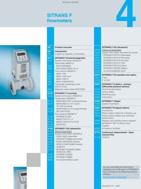
© Siemens AG 2007<strong>SITRANS</strong> F<strong>flowmeters</strong>4/2 Product overview4/8 Introduction4/8 Criteria for selection of flowmeter4/11 <strong>SITRANS</strong> F M (electromagnetic)4/11 System information MAGFLOTransmitter MAGFLO4/26 - MAG 5000/60004/38 - MAG 6000 I/6000 I Ex dFlow sensors MAGFLO4/41 - MAG 11004/48 - MAG 1100 Food4/57 - MAG 5100 W4/64 - MAG 3100/3100 Ex4/77 Transmitter Transmag 2 withsensor 911/E4/92 Magnetic water meter MAG 80004/105 <strong>SITRANS</strong> F C (coriolis)4/105 System information MASSFLOTransmitters MASSFLO4/111 - MASS 6000 IP67 compact/remote4/115 - MASS 6000 for 19“ insert/19“ wall mounting4/122 - MASS 6000 Ex-d compact/remote4/126 - SIFLOW FC070Flow sensors MASSFLO4/129 - <strong>SITRANS</strong> FC3004/133 - MASS 2100 DI 1.54/137 - MASS 2100 DI 3 to DI 404/146 - MASS MC14/152 <strong>SITRANS</strong> F US (ultrasonic)4/152 Wetted <strong>flowmeters</strong>4/152 System information SONOFLO4/159 - SONO 3000 transmitter4/163 - <strong>SITRANS</strong> FUS060 transmitter4/166 - SONO 3300/3000 Industry4/170 - SONO 3100/FUS060 Industry4/174 - SONOKIT4/179 - <strong>SITRANS</strong> FUS380/FUE380/SONOCAL 30004/190 - <strong>SITRANS</strong> FUE9504/196 - <strong>SITRANS</strong> FUS8804/201 - Accessories/Spare parts<strong>SITRANS</strong> F US (ultrasonic)4/209 Clamp-on <strong>flowmeters</strong>4/209 System information and selection guide4/221 - <strong>SITRANS</strong> FUS1010 (Standard)4/227 - <strong>SITRANS</strong> FUP1010 (Portable)4/231 - <strong>SITRANS</strong> FUE1010 (Energy)4/236 - <strong>SITRANS</strong> FUH1010 (Oil)4/241 - <strong>SITRANS</strong> FUG1010 (Gas)4/246 - <strong>SITRANS</strong> FUS1020 (Basic)4/249 - Accessories/Spare parts4/251 <strong>SITRANS</strong> F VA (variable area meter)4/251 Tubux4/259 F VA 2504/267 <strong>SITRANS</strong> F O delta p - primarydifferential pressure devices4/267 Technical description4/276 Orifice plates4/283 Metering pipes4/288 Calculation4/289 <strong>SITRANS</strong> F I (flaps)4/289 Gardex <strong>flowmeters</strong>4/294 <strong>SITRANS</strong> F R (liquid meters)4/294 Introduction4/310 Rotary-piston meters for industrial use4/319 Rotary-piston-meters and automaticbatchmeters4/339 Register and quantity preset registers4/344 <strong>SITRANS</strong> F RA110 electric flowregister4/346 Accessory modules5/176 Continuous measurement - Openchannel flow5/176 OCM IIIYou can download all instructions,catalogs and certificates for <strong>SITRANS</strong> Ffree of charge at the following Internetaddress:www.siemens.com/sitransfSiemens FI 01 · 2007
<strong>SITRANS</strong> F <strong>flowmeters</strong><strong>SITRANS</strong> F© Siemens AG 2007Product overview■ Overview4Application Description Catalogpage<strong>SITRANS</strong> F M electromagnetic <strong>flowmeters</strong>Choose MAG 5000/6000 for moredemanding applications where youneed the benefits of highly functional,accurate performance.MAG 6000 I and MAG 6000 I Ex d inrobust die-cast aluminium enclosurefor demanding applications and whereexplosion proof protection is necessary.Transmitter MAGFLO MAG 5000/6000• Superior signal resolution for optimumturn down ratio• Comprehensive self-diagnostic, for errorindication and logging• Multi-lingual display and keypad interface• Custody transfer approval: PTB, OIMLR75, OIML R117 and OIML R49Transmitter MAGFLO MAG6000 I/6000 I Ex d• Remote and compact mounting on allsensors• Explosion proof design: ATEX and FM• Multi-lingual display and touchpad keypad• Comprehensive self-diagnosticsSoftware forparameterization4/26 SIMATIC PDM4/38 SIMATIC PDMDesigned for the general industryenvironment. The obstructionless performanceof the MAG 1100 is unaffectedby the suspended solids,viscosity and temperature challenges.Flow sensors MAGFLO MAG 1100• Metering tube DN 2 ... DN100(1/12“ ... 4“) flangeless design.• Corrosion resistant AISI 316 stainlesssteel housing.• Highly resistant liner and electrodes fittingmost extreme process media.• Temperature rating up to 200 °C(390 °F)• ATEX approval4/41Specially designed for the food & beverageindustry.Flow sensors MAGFLO MAG1100 Food• AISI 316 stainless steel enclosure• Hygienic seal, 3A and EHEDG-approvedconstruction• Easy to clean• Supplied with connections accordingto your specification• ATEX approval4/48The MAG 5100 W with its patentedcomposite elastomer lining is suitablefor all water applications.Flow sensors MAGFLO MAG 5100 W• Metering tube DN 25 ... DN 1200(1"¨ ... 48")• NBR Hard Rubber or EPDM lining• Integral grounding electrodes as standard• Increased low flow accuracy for waterleak detection• Drinking water approvals, OIML R49and PTB4/574/2 Siemens FI 01 · 2007
© Siemens AG 2007<strong>SITRANS</strong> F <strong>flowmeters</strong><strong>SITRANS</strong> FProduct overviewApplication Description CatalogpageThe MAG 3100 series with its flexibilityin the choice of linings, electrodes andflange material allows the measurementof even the most extreme processmedia.Designed for heavy-duty applicationslike pulp & paper stock over 3%;heavy mining slurries and mining slurrieswith magnetic particles.Flow sensors MAGFLO MAG3100/3100 Ex• For a wide range of pipe dimensions:DN 15 ... DN 2000 (½” ... 78”)• Wide range of liner and electrode materials• High temperature version for applicationwith temperatures up to 180 °C(355 °F)• High pressure solutions• Approved according to PTB,OIML R75, OIML R117 and ATEXTransmitter Transmag 2• Magnetic flowmeter with a very strongpulsed AC magnetic field• PROFIBUS PA or HART communication• Self-test function4/64Software forparameterization4/77 SIMATIC PDM4Application in conjunction with transmitterTransmag 2Battery operated electromagneticwater meter for water applicationswithin abstraction, distribution network,revenue metering and irrigation.Flow sensor 911/E• Metering tube: DN 15 ... DN 600(½" ... 24")• Metering tube liner: rubber, PTFE,Novolak• Integral smartPLUG for storing of calibrationvalues• Temperature of medium:-20 ... +150 °C (-4 ... +300 °F)Water meter MAG 8000• Battery operated water meter• Metering tube DN 25 ... DN 600(1" ... 24")• Remote and compact installation IP68/NEMA 6P enclosure• Custody transfer approval: OIML R49• Drinking water approvals4/824/92 SIMATIC PDMand Flow Tool<strong>SITRANS</strong> F C mass <strong>flowmeters</strong>Measurement of liquids and gases.Measurement of mass flow, density,temperature and fraction e.g. °Brix or°Plato.Measurement of liquids and gases.Measurement of mass flow, density,temperature and fraction e.g. °Brix or°Plato.Flow sensors MASSFLO MASS 2100(Single tube design)• DI 1.5, DI 3, DI 6, DI 15, DI 25 and DI 40• Flow from 0.1 ... 52,000 kg/h• Pipe material: 1.4435 (316L); 2.4602Hastelloy C-22• Accuracy typically ≤ 0.1% of flow rate0.0005 g/cm 3 and 0.5 °C• Liquid temp./pressure: -50 ... +180°C(-58 ... +356 °F) / Up to 410 bar(5946 psi)• Approved according to ATEX EEx ia IICT3 ... T6Flow sensor MASSFLO MC1(Dual tube design)• DN 50, DN 65, DN 80, DN 100 andDN 150• Flow from 0 ... 192,000 kg/h• Pipe material 1.4571 (316 Ti);Hastelloy C4• Accuracy typically ≤ 0.15% of rate.Density extended ≤ 0.001 g/cm 3• Liquid temp./pressure: -50 ... +180 °C(-58 ... +356 °F)/Up to 100 bar (1450 psi)• Approved according to ATEX EEx em[ib] IIC T2 ... T64/1334/146Modification 01/2007Siemens FI 01 · 20074/3
<strong>SITRANS</strong> F <strong>flowmeters</strong><strong>SITRANS</strong> F© Siemens AG 2007Product overview4Application Description CatalogpageMeasurement of liquids and gasesMultiparameter transmitter for remoteor compact mounting measuring massflow, density, temperature and fractione.g. °Brix and °Plato<strong>SITRANS</strong> F US ultrasonic wetted <strong>flowmeters</strong>SONO 3000 is a transit time basedtransmitter designed for ultrasonicflowmetering on liquids of any pipe inthe SONO series up to DN 4000Transmitters MASS 6000 andMASS 6000 Ex d• Digital signal processing measuring30 times a second.• 3 current, 2 freq. and 2 relay outputs• Adaptive batch function• SENSORPROM memory unit making iteasy to start up the flowmeter.• Easy retrofitting of communicationmodules (AOM)• Approved according to ATEX [EEx ia]IIC / EEx de [ia/ib] IIC T6SONO 3000 transmitters• Selectable uni or bidirectional counting• Automatic reading of SENSORPROMdata for easy commissioning• Multiple functional output for processcontrol• Pulse/frequency and relay output (status,flow direction, limits)• Plug and play for all media4/122 SIMATIC PDM4/159Software forparameterization<strong>SITRANS</strong> FUS060 is a time basedtransmitter designed for ultrasonicflowmetering for any pipe in the SONOseries up to DN 4000The main application for SONO 3300ultrasonic <strong>flowmeters</strong> is to measurethe volume of:• Water and treated waste water• Oil and liquid gases• Hot water/cooling systemsThe main application for SONO 3100ultrasonic <strong>flowmeters</strong> is to measurethe volume of:• Water and treated waste water• Oil and liquid gases• Liquid cryogenic application• District heating systemsInstallation of one, two or four transducersets in existing concrete or steelpipes.<strong>SITRANS</strong> FUS060 transmitter• EEx approved according to ATEX• HART communication + 1 analog output,1 digital output for frequency orpulse and 1 relay output for alarms andflow direction• PROFIBUS PA communication with1 digital output for frequency or pulse• Multi-functional output for processcontrol• Easy menu based local operation withtwo-line displaySONO 3300/3000 Industry• DN 50 … DN 150 (2” … 6”) cast iron• DN 200, 250 and 300 (8”, 10”, 12”)welded steel• Flow 0.3 … 3200 m³/h• Transmitter can be compact or wallmounted• Signal cables from transmitter to transducerare highly protected from aggressiveenvironment by protection ofstainless steel pipesSONO 3100/FUS060 Industry• Replaceable transducers under pressure• ATEX approved• Measure of all liquids less than350 Cst, conductive or non-conductive• No pressure drop• 4-track on request• Special material on requestFlow sensor SONOFLO SONOKIT• DN 200 ... DN 4000 (8" ... 160")• Control and display unit• Temperature of medium:-20 ... +200 °C (-4 ... +395 °F)• Installation on empty pipes or pipes underpressure (hot-tap installation)4/1634/1664/1704/1744/4 Siemens FI 01 · 2007Modification 01/2007
© Siemens AG 2007<strong>SITRANS</strong> F <strong>flowmeters</strong><strong>SITRANS</strong> FProduct overviewApplication Description CatalogpageBattery or mains powered ultrasonicflowmeter for use within water baseddistrict heating, cooling systems andutility.<strong>SITRANS</strong> FUS380/SONOCAL 3000are designed to work with the<strong>SITRANS</strong> FUE950 energy calculatorUniversal thermal energy calculatorfordistrict heating and cooling applications.Battery operated ultrasonic retrofitflowmeter for water applications withinirrigation. Installation of one or twotransducer sets in existing PVC orconcrete pipes.<strong>SITRANS</strong> F US ultrasonic clamp-on <strong>flowmeters</strong>Dedicated <strong>flowmeters</strong> are suitable fora wide variety of liquid applications,including those in the:• Water Industry• Wastewater Industry•HVAC Industry• Power Industry• Processing Industry<strong>SITRANS</strong> FUS380/FUE380 Flow sensorand transmitter SONOCAL 3000• FUS380: DN 100 ... DN 800 (2" ... 32")• FUE380: Approved for custody transferaccording to EN 1434 Class 2 andOIML R 75 Class 2• SONOCAL 3000: DN 50, 65, 80, 900,1000, 1200 (2”, 2,5", 3", 36", 40", 42")• SONOCAL 3000: Approved for custodytransfer according to PTB Class C,OIML R75 Class 4• SONOCAL 3000: Only 115 ... 230 V ACpower supply• FUS380/SONOCAL 3000: Painted carbonsteel flanges and metering tube.AISI transducers• Water temperatures 3 … 200 °C(37 ... 392 °F)<strong>SITRANS</strong> FUE950• Choice of battery, 230 V AC +15%/-30% or 24 V AC• 24 months memory• Plug-in modules for data output, extrainput, M-Bus• Complete set with sensors and sensorpockets• Meets the requirements of OIML R 75and EN 1434<strong>SITRANS</strong> FUS880• Irrigation flowmeter FUS880• Battery operated or mains supply• DN 200 ... DN 1200 (8" ... 48")• Wetted transducer technology• Remote installation IP674/1794/1904/196<strong>SITRANS</strong> FUS1010 General purpose 4/221• Basic function dedicated meter• Full range of safety approvals, I/O'sand enclosure types available• Has wide applicability but not the specialfunctions found with FUH1010,FUG1010 and FUE1010 metersSoftware forparameterization4Portable <strong>flowmeters</strong> are suitable for awide variety of liquid applications,including those in the:• Water Industry• Wastewater Industry•HVAC Industry• Power Industry• Processing Industry<strong>SITRANS</strong> FUP1010 Portable• Basic function portable meter• Has all the capabilities of the FUS1010meter but in a battery powered, portableconfiguration• Ideal for high accuracy flow survey applications• Not available with hazardous area approvals4/227Portable and dedicated energymeters are ideal for thermal energy /power applications:• Chilled & hot water submetering• Condenser water, potable water• Glycol and brine solution• Thermal storage<strong>SITRANS</strong> FUE1010 Energy4/231• Accurate absolute and differential temperaturemeasurement with twomatched 1000 Ω RTD elements installedon supply and return side of theheating or cooling system• Efficiency calculation (kW/ton, EER orCOP) available in systems with optionalanalog inputModification 01/2007Siemens FI 01 · 20074/5
<strong>SITRANS</strong> F <strong>flowmeters</strong><strong>SITRANS</strong> F© Siemens AG 2007Product overviewApplication Description CatalogpageDedicated hydrocarbon <strong>flowmeters</strong>are ideal for crude oil, refined petroleumor liquefied gas. There are threeapplication areas:• Viscosity compensated volumetric<strong>flowmeters</strong>• Standard volume (Net) mass <strong>flowmeters</strong>• Interface detectors/density meters<strong>SITRANS</strong> FUH1010 Oil• Volumetric <strong>flowmeters</strong> output viscositycompensated gross volume to externalRTU’s or flow computers• Mass <strong>flowmeters</strong> output standard volume(net) mass flow, API, liquid identification,density, interface & pigdetection• Interface Detectors are used for liquididentification and API density output,but do not output flow4/236Software forparameterization4Dedicated gas <strong>flowmeters</strong> are idealfor most natural and process gasindustry applications, including:• Checkmetering• Allocation• Flow survey verification• Lost and unaccounted for (LAUF)gas analysis• Production<strong>SITRANS</strong> FUG1010 Gas• Suitable for most gases (natural gas,oxygen, nitrogen, carbon monoxide,etc.) with typical minimum operatingpressure of 10 barg (145 psig).• Standard volume or mass flow outputfor fixed gas compositions• Analog input for pressure and temperaturecompensation4/241Dedicated flowmeter is a basic optionfor many clean liquid applications inthe:• Water Industry• Wastewater Industry• HVAC & Power Industries• Processing Industry<strong>SITRANS</strong> FUS1020 Basic• Has FUS1010 system function but withoutthe same I/O capability or safetyapproval ratings• This basic meter is intended for singleliquid applications that do not requirethese features4/246<strong>SITRANS</strong> F VA variable area metersMeasurement of flow of transparentliquids and gases.Tubux• Glass flow tube with various float materials• Connections: G ¼" ... G 3", alternativelywith adhesive bushing• Temperature of medium: max. 150 °C(302 °F)• Optionally available with contacts4/251Measurement of flow of liquids andgases, also highly suitable for corrosivemedia, high temperatures andhigh pressures.<strong>SITRANS</strong> F O delta p - primary differential pressure devicesMeasurement of flow with orificeplates and metering pipes for mountingbetween flanges, e.g. togetherwith <strong>SITRANS</strong> P transmitters, DS IIIand DS III PA series.250• All-metal variable area meter with variousfloat materials• Connections: DN 15 ... DN 100(½" ... 4")• Temperature of medium:-20 °C ... +300 °C(-4 ... +572 °F)• Optionally available with analog outputor contacts• Nominal diameters DN 10 ... DN 1000(0.4" ... 40")• Temperature of medium:-200 ... +500 °C (-328 ... +932 °F) forvapors, gases and liquids.<strong>SITRANS</strong> P transmitters• DS III series• DS III PA series• DS III FF series4/2584/2674/6 Siemens FI 01 · 2007Modification 01/2007
© Siemens AG 2007<strong>SITRANS</strong> F <strong>flowmeters</strong><strong>SITRANS</strong> FProduct overviewApplication Description CatalogpageSoftware forparameterization<strong>SITRANS</strong> F I flap <strong>flowmeters</strong>Measurement of flow of liquids andgases, e.g. for use with domesticinstallations and heating systems.Gardex• Baffle plate flowmeter• Nominal diameters: DN 25 ... DN 300(1" ... 12")• Temperature of medium: max. 300 °C(572 °F)• Optionally available with analog outputor contacts4/289<strong>SITRANS</strong> F R liquid metersRotary-piston metersIndustrial design for measurement offlowing liquids• DN 15 ... DN 80 (½" ... 3") for industrialrequirements• DN 25 (1") as acid-resistant version• With the required registers and quantitypreset registers• Temperature of medium: from-30 ... +300 °C (-22 ... +572 °F)4/3104Automatic batchmeterAny quantity of liquid can be preselectedand filled automatically.• DN 25 ... DN 50 (1" ... 2")• Temperature of medium: from-30 ... +300 °C (-22 ... +572 °F)4/319Continuous level - Open channel flowHigh accuracy ultrasonic flow monitorfor open channels to complete systemstudiesOCM III• High accuracy on unique or non-standardweirs and flumes• AC and DC operation.• Automatically switches to battery operationfor uninterrupted power.• Low power remote monitoring5/170Siemens FI 01 · 20074/7
<strong>SITRANS</strong> F <strong>flowmeters</strong><strong>SITRANS</strong> F© Siemens AG 2007Introduction■ Overview4Criteria for selection of flowmeterEach method for measuring flow has specific properties, andeach flow measuring point is characterized by specific requirements.The table shown below compares the properties of thevarious measuring instruments and thus provides assistance inselection of the optimum device.This section of the field device catalog includes the following instrumentsfor measuring flow:• Electromagnetic• Coriolis mass flow• Ultrasonic• Variable area meter• Orifice plate• Flap• Rotary-piston meters and drum metersTo measure concentration in binary mixtures, it is possible toevaluate the sound velocity measurements of the ultrasonic flowmethod. The <strong>SITRANS</strong> F has been specially developed for usewith alcohol/water mixtures.Measuring principle Electromagnetic Coriolis Ultrasonic Orifice plate Rotary-pistonmeterMedium Liquid (conductive) Liquid or gas Liquid Liquid, vapor, LiquidgasNominal diameter DN 2 … 2000(0.08” … 78”)Temperaturerange°C (°F) -40 … +200(-40 … +392)Max. pressure bar (psi) 160 (2320), optionalhigher1.5 … 150 mm(0.06” … 6”)-50 … +180(-58 … +356)Up to 410(Up to 5950)DN 50 ... DN 4000(2" ... 160")-250 ... +200(-328 ... +490)40 (580)430 (6235)DN 10 … 1000(0.4” … 40”)-200 … +500(-328 … +932)DN 15 … 80(½” … 3”)-30 … +300(-22 … +572)Variable areameterLiquid or gasDN 10 … 100(0.4” … 4”)G½” … G3”-20 … +300(-4 … +572)315 (4569) 63 (914) 40 (580)Accuracy % ±0.25 or ±0.5 ±0.1 or ±0.15 ±0.5 … ±2 ±0.5 … ±2 ±0.2 … ±0.5 ±2Repeatability % 0.1 … 0.2 0.05 0.2 0.5 0.005 0.5Dynamic1:100 1:100 1:100 1:6 1:10 1:10responseStart-of-scale m/s (ft/s) 0 (0) 0 (0) 0.1 (0.33) R a > 500 0.3 (0.98) 0.2valueFull-scale value R e < 10 8• For liquids m/s (ft/s) 0 … 1010 (32.8) 10 (32.8) 3 3 3.5 (11.4)(0 … 33)• For vapors/gasesm/s (ft/s) Approx. 30050/2560 (197)(1000)(164/82)Measured values• Volume flow • • • • • •• Sound velocity•• Sound amplitude•• Density•• Mass flow•• Bidirectional• • • •measurementUse• For custody• • •transfer• As batchingsystem• • •• In viscosityrangemPa⋅s(cp)0.1 … 100,000(0.1 … 100,000)0 ... 100,000(0 ... 100,000)0 ... 350(0 ... 350)0 … 10(0 … 10)0.3 … 350,000(0.3 … 350,000)Power supply Mains or battery Mains Mains or battery 2-wire non non0.5 … 100(0.5 … 100)4/8 Siemens FI 01 · 2007Modification 01/2007
© Siemens AG 2007<strong>SITRANS</strong> F <strong>flowmeters</strong><strong>SITRANS</strong> FCommunication solutionsTransmitter HART PROFIBUS PA PROFIBUS DP Modbus RTURS485<strong>SITRANS</strong> F M MAG 5000 • 1) 2) 4)<strong>SITRANS</strong> F M MAG 6000 • 1) 2) 4) 5) • 1) 5) 6) 7) • 1) 5) 6) 7) 1) 5)•<strong>SITRANS</strong> F M MAG 6000 I • 1) 2) 4) 5) • 1) 5) 6) 7) • 1) 5) 6) 7) • 1) 5)<strong>SITRANS</strong> F M MAG 6000 I Ex-d • 1) 2) 4) 5) 1) 6) 7)•<strong>SITRANS</strong> F M Transmag 2 • 1) 4) 1) 7)•Modbus RTURS232IntroductionModbus RTUIrDA<strong>SITRANS</strong> FM MAG 8000 • 1) • 1) • 1) 3)<strong>SITRANS</strong> F C MASS 6000 • 1) 2) • 1) 6) 7) • 1) 6) 7) • 1)<strong>SITRANS</strong> F C MASS 6000 Ex-d • 1) 2) 1) 6) 7)•<strong>SITRANS</strong> FUS060 • 1) 1) 7)•<strong>SITRANS</strong> FUS080 (FUS380) • 1)<strong>SITRANS</strong> FUE080 (FUS380) • 1)1) Supports SIMATIC PDM2)Supports AMS3)Supports Siemens Flow Tool4)Supports HH275/3755) Pluggable add-on modules6)Profile 27)Profile 34Siemens FI 01 · 20074/9
<strong>SITRANS</strong> F <strong>flowmeters</strong><strong>SITRANS</strong> F© Siemens AG 2007Introduction4■ Technical specifications PROFIBUS PA/DPGeneral specificationsPROFIBUS device profile 3.00 Class BCertifiedYes, according to Profile for processcontrol devices v3.00.MS0 connections 1MS1 connections 1MS2 connections 2Electrical specification DPPhysical layer specificationsApplicable standard EN 50170 vol. 2Physical Layer (Transmission RS 485technology)Transmission speed≤ 1.5 Mbits/sNumber of stationsUp to 32 per line segment, (maximumtotal of 126)Cable specification (Type A)Cable designTwo wire twisted pairShieldingCU shielding braid or shielding braidand shielding foilImpedance35 up to 165 Ω at frequencies from3 ... 20 MHzCable capacity< 30 pF per meterCore diameter > 0.34 mm², corresponds to AWG 22Resistance< 110 Ω per kmSignal attenuationMax. 9 dB over total length of line sectionMax. bus length200 m at 1500 kbit/s, up to 1.2 km at93.75 kbit/s. Extendable by repeatersElectrical specification PAPhysical layer specificationsApplicable standard EN 50170Physical Layer (Transmission IEC-61158-2technology)Transmission speed31,25 Kbits/secondNumber of stationsUp to 32 per line segment, (maximumtotal of 126)Max. basic current [I B ] 14 mAFault current [I FDE ]0 mABus voltage9 ... 32 V (non Ex)Preferred cable specification (Type A)Cable designTwo wire twisted pairConductor area (nominal) 0.8 mm 2 (AWG 18)Loop resistance44 Ω/kmImpedance 100 Ω ± 20%Wave attenuation at 39 kHz 3 dB/kmCapacitive asymmetry2 nF/kmBus terminationPassive line termination at bothMax. bus lengthUp to 1.9 km. Extendable by repeatersIS (Intrinsic Safety) dataRequired sensor electronicsCompact mounted<strong>SITRANS</strong> F CMASSFLOMASS 6000 Ex-dFISCO Yes YesMax. U I 17.5 V 17.5 VMax. I I 380 mA 380 mAMax. P I 5.32 V 5.32 VMax. L I 10 µH 0 µHMax. C I 5 nF 0 nFMax. U o 1.3 V -Max. I o 50 µA -FISCO cable requirementsLoop resistance R C15 ... 150 Ω/kmLoop inductance L C0.4...1mH/kmCapacitance C C80 ... 200 nF/kmMax. Spur length in IIC and IIB 30 mMax. Trunk length in IIC 1 kmMax. Trunk length in IIB 5 kmPROFIBUS parameter supportThe following parameters are accessible using a MS0 relationshipfrom a Class 1 Master.MS0 specifies cyclic Data Exchange between a Master and aSlave.1) Requires a SENSORPROM containing valid fraction data.2) Value returned is dependent on the BATCH function.When ON, Batch progress is returned.When OFF, TOTALIZER 2 is returned.Compact orremote mounted<strong>SITRANS</strong> F MMAGFLOMAG 6000 IndustryEx-dCyclic services:Input (Master view) Parameter MAG 6000 MASS 6000Mass flow✓Volume flow ✓ ✓Temperature✓Density✓Fraction A 1)✓Fraction B 1)✓Pct Fraction A 1)✓Totalizer 1 ✓ ✓Totalizer 2 2) ✓ ✓Batch progress 2) ✓ ✓Batch setpoint ✓ ✓Batch compensation ✓ ✓Batch status✓✓(running...)Output (Master view) Set Totalizer 1+2 ✓ ✓Set Mode Totalizer ✓✓1+2Batch control✓✓(start, stop ...)Batch setpoint ✓ ✓Batch compensation ✓ ✓4/10 Siemens FI 01 · 2007
■ Overview<strong>SITRANS</strong> F M family<strong>SITRANS</strong> F M electromagnetic <strong>flowmeters</strong> are designed for measuringthe flow of electrically conductive mediums.■ Benefits© Siemens AG 2007<strong>SITRANS</strong> F <strong>flowmeters</strong><strong>SITRANS</strong> F MSystem information MAGFLOelectromagnetic <strong>flowmeters</strong>Easier to commissionAll MAGFLO electromagnetic <strong>flowmeters</strong> feature a uniqueSENSORPROM memory unit which stores sensor calibrationdata and transmitter settings for the lifetime of the product.At commissioning the flowmeter commences measurementwithout any initial programming.The factory settings matching the sensor size are stored in theSENSORPROM unit. Also customer specified settings are downloadedto the unit. Should the transmitter be replaced, the newtransmitter will upload all previous settings and resume measurementwithout any need for reprogramming.Further, the "fingerprint" used in connection with the MAGFLOVerificator is stored during the initial sensor calibration.Easier to serviceTransmitter replacement requires no programming.SENSORPROM automatically updates all settings after initialization.Room for growthUSM II the Universal Signal Module with "plug & play" simplicity,makes it easy to access and integrate the flow measurementwith almost any system and bus-protocol and it ensures the flowmeterwill be easy to upgrade to future communication/bus platforms.4■ ApplicationElectromagnetic <strong>flowmeters</strong> are suitable for measuring the flowof almost all electrically conducting liquids, pastes and slurries.A prerequisite is that the medium must have a minimum conductivityof 5 µS/cm. The temperature, pressure, density and viscosityhave no influence on the result.The main applications of the electromagnetic <strong>flowmeters</strong> can befound in the following sectors:• Water and waste water• Chemical and pharmaceutical industries• Food and beverage industry• Mining, aggregates and cements industries• Pulp and paper industry• Steel industry• Power; utility and chilled water industryThe wide variety of combinations and versions from the modularsystem means that ideal adaptation is possible to each measuringtask.Greater flexibility• Wide product program• Compact or remote installation using the same transmitter andsensor• USM II communication platform for easy integration with allsystemsSiemens FI 01 · 20074/11
<strong>SITRANS</strong> F <strong>flowmeters</strong><strong>SITRANS</strong> F MSystem information MAGFLOelectromagnetic <strong>flowmeters</strong>© Siemens AG 2007Please see Product selector onthe Internet, since some constrainsmight be related tosome of the featuresMAG3100MAG3100 ExMAG3100 HTMAG5100 WMAG1100MAG1100 ExMAG1100 HTMAG1100 FMAG1100 FEx911/E MAG80004IndustryWater / waste water X X X XXX X X XXChemical XXX XXX XXX X XX XXX XXX XX XXPharma XX XXX XX X X XX XX XXX XXX XXFood & beverage X X XX XXX X XXMining, aggregates & cement XXX X XX XXX XXHPI XX XX X X XX XX X XXOther XX XX XX XX XX XX XX XX XXX XXDesignCompact ● ● ● ● ● ● ● ● ●Remote ● ● ● ● ● ● ● ● ● ● ●Constant field (DC) ● ● ● ● ● ● ● ● ● ● ●Alternating field (AC)●Nominal diameterDN 2 (1/12“) ● ●DN 3 (1/8“) ● ●DN 6 (1/4“) ● ●DN 10 (3/8“) ● ● ● ●DN 15 (½“) ● ● ● ● ● ● ● ● ●DN 20 (3/4“)●DN 25 (1“) ● ● ● ● ● ● ● ● ● ● ●DN 32 (1¼“) ● ● ●DN 40 (1½“) ● ● ● ● ● ● ● ● ● ● ●DN 50 (2“) ● ● ● ● ● ● ● ● ● ● ●DN 65 (2½“) ● ● ● ● ● ● ● ● ● ● ●DN 80 (3“) ● ● ● ● ● ● ● ● ● ● ●DN 100 (4“) ● ● ● ● ● ● ● ● ● ● ●DN 125 (5“) ● ● ● ● ● ●DN 150 (6“) ● ● ● ● ● ●DN 200 (8“) ● ● ● ● ● ●DN 250 (10“) ● ● ● ● ● ●DN 300 (12“) ● ● ● ● ● ●DN 400 (16“) ● ● ● ● ●DN 450 (18“) ● ● ● ● ●DN 500 (20“) ● ● ● ● ●DN 600 (24“) ● ● ● ● ●DN 700 (28“) ● ● ●DN 750 (30“) ● ● ●DN 800 (32“) ● ● ●DN 900 (36“) ● ● ●DN 1000 (40“) ● ● ●DN 1050 (42“) ● ● ●DN 1100 (44“) ● ● ●DN 1200 (48“) ● ● ●DN 1400 (54“) ● ●DN 1500 (60“) ● ●DN 1600 (66“) ● ●DN 1800 (72“) ● ●DN 2000 (78“) ● ●● = available, X = can be used, XX = often used, XXX = most often used4/12 Siemens FI 01 · 2007Modification 01/2007
© Siemens AG 2007<strong>SITRANS</strong> F <strong>flowmeters</strong><strong>SITRANS</strong> F MSystem information MAGFLOelectromagnetic <strong>flowmeters</strong>Please see Product selector onthe Internet, since some constrainsmight be related tosome of the featuresMAG3100MAG3100 ExMAG3100 HTMAG5100 WMAG1100MAG1100 ExMAG1100 HTMAG1100 FMAG1100 FEx911/E MAG8000Process connectionWafer design ● ● ●Sanitary process connections ● ●Flanges ● ● ● ● ● ●Flange normsEN 1092-1 ● ● ● ● ● ●ANSI B 16.5 class 150 ● ● ● ● ● ●ANSI B 16.5 class 300 ● ● ● ●AWWA class D ● ● ●AS 2129 ● ● ●AS 4087, PN 16 ● ● ● ● ●AS 4087, PN 21 ● ● ●AS 4087, PN 35 ● ● ●JIS 10K 3)●Pressure rating 1)PN 6 ● ●PN 10 ● ● ● ● ● ●PN 16 ● ● ● ● ● ● ● ● ●PN 25 ● ● ● ●PN 40 ● ● ● ● ● ● ● ● ● ● ●PN 63 ● ●PN 100 ● ●Accuracy0.2% ●0.25% ● ● ● ● ● ● ● ● ●0.4% ●0.5% ● ● ●Grounding electrodes, incl. 2) ● ● ● ( ● ) ●Cable glandsPG 13.5●M20 ● ● ● ● ● ● ● ● ● ● ●½" NPT ● ● ● ● ● ● ● ● ● ●Materials:Liner material / max . temperaturesNBR Hard Rubber: 70 °C (158 °F)●Neoprene: 70 °C (158 °F) ● ● ●EPDM: 70 °C (158 °F) ● ● ● ● 7) ●PTFE: 100 °C (212 °F) ● ● ●PTFE: 180 °C (356 °F) ● 6) ( ● ) 4)Ebonite: 95 °C (203 °F) ● ●Linatex: 70 °C (158 °F) ● ●Ceramic: 150 °C (302 °F) ● ● 5) ● ● 5)Ceramic: 200 °C (392 °F)●PFA: 130 (150) °C (266 (302) °F) ● ●Novolak: 130 °C (266 °F)●● = available1) Pressure may be limited by the liner material chosen2) Not for PTFE liner and tantalum/platinum electrodes3) On request4) 150 °C (300 °F)5) Ex versions limited to 100 °C (212 °F)6) Also available in 130 °C (266 °F)7) 95 °C (203 °F)4Modification 01/2007Siemens FI 01 · 20074/13
<strong>SITRANS</strong> F <strong>flowmeters</strong><strong>SITRANS</strong> F MSystem information MAGFLOelectromagnetic <strong>flowmeters</strong>© Siemens AG 2007Please see Product selector onthe Internet, since some constrainsmight be related tosome of the featuresMAG3100MAG3100 ExMAG3100 HTMAG5100 WMAG1100MAG1100 ExMAG1100 HTMAG1100 FMAG1100 FEx911/E MAG80004Materials (continued):ElectrodesS/S AISI 316 Ti ● ● ● ●Hastelloy C ● ● ● ● ● ● ● ●Platinum ● ● ● ● ● ● ● ● ●Titanium ● ● ● ●Tantalum ● ● ● ●Monel●Flange/housing materialCarbon steel ● ● ● ● ● ●Stainless steel / carbon steel ● ● ● ●Polished stainless steel ● ● ● ● ● ● ● ●Approvals:Custody transferCold water -DANAK TS 22.36.001● ● ●● ●Cold water - OIML R 49 ● ●Cold water - PTB ● ● ● ● ● ● ●Hot water - OIML R 75 ● ● ● ● ●Hot water - PTB ● ● ● ● ●Other media than water -● ● ● ● ●OIML R 117Other media than water - PTB ● ● ● ● ●Hazardous areasATEX - zone 1 ● ● ●ATEX - zone 2 1) ● ● ● ●FM - class 1, div 2 ● ● ● ● ● ●CSA - class 1, div 22) 2)Hygienic3A ● ●EHEDG ● ●Drinking waterWRAS (WRc) - (UK ) ● ● ●NSF - (US ) ● ● ●ACS (FR) ● ●Belgaque (B) ● ●KTW (D) ● ●DVGW-W270 (D) ● ●OtherGOSS / GOST (Russia ) ● ● ● ● ● ● ● ● ●CRN (Canada) ● ● ● ● ● ● ● ● ● ●Other national approvals, see● ● ● ● ● ● ● ● ● ● ●internetMAGFLO Verificator compatible ● ● ● ● ● ●● = available1) Compact MAG 6000 I2) On request4/14 Siemens FI 01 · 2007
© Siemens AG 2007<strong>SITRANS</strong> F <strong>flowmeters</strong><strong>SITRANS</strong> F MSystem information MAGFLOelectromagnetic <strong>flowmeters</strong>Please see Product selectoron the Internet, since someconstrains might be relatedto some of the featuresMAG 5000 MAG 6000 MAG 6000 I MAG 6000 IEx dMAG 6000 +Ex barriereMAG 6000 +Cleaning unitTransmag 2 MAG 8000IndustryWater / waste water XXX XXX XX X XX XXXChemical X XX XX XXX X XXXPharma X XXX XX XXX X XXXFood & beverage XX XXX XX XXXMining, aggregates & cement XX X XX X XXX XXXHPI X X X XX XXXOther XX XX XX XX X XDesignCompact ● ● ● ● ● ●Remote ● ● ● ● ● ● ● ●Constant field (DC) ● ● ● ● ● ● ●Alternating field (AC)●Enclosure transmitterPolyamide, IP67 ● ●Die-cast aluminium ● ● ●Stainless steel ● ● 1)19“ rack ● ● ● ●Back of panel ● ● ● ●Panel mounting ● ● ● ●IP67 wall mounting ● ● ● ●Accuracy0.2% ●0.25% ● ● ● ● ●0.4% ●0.5% ● ●CommunicationHART ● ● ● ● ● ● ●PROFIBUS PA ● ● ● ● ● ●PROFIBUS DP ● ● ● ●MODBUS RTU/RS 485 ● ● ● ● ● 2)Batching ● ● ● ● ●Electrode cleaning●PG 13,5 ● ● ●M20 ● ● ● 4) ● 4) ● ●½" NPT ● ● ● ● ●Supply voltage24 V ● 3) ● 3) ● ● ● 3) ● 3)5)115 V - 230 V ● ● ● ● ● ● ● ● 5)Battery●● = available, X = can be used, XX = often used, XXX = most often used1) IP68 for MAG 8000 enclosure2) Modbus RTU also as serial RS2323) 12/24 V AC/DC4) M255) Main power with battery backup4Siemens FI 01 · 20074/15
<strong>SITRANS</strong> F <strong>flowmeters</strong><strong>SITRANS</strong> F MSystem information MAGFLOelectromagnetic <strong>flowmeters</strong>© Siemens AG 2007Please see Product selectoron the Internet, since someconstrains might be relatedto some of the featuresMAG 5000 MAG 6000 MAG 6000 I MAG 6000 IEx dMAG 6000 +Ex barriereMAG 6000 +Cleaning unitTransmag 2 MAG 80004Approvals:Custody transferCold water -●●DANAK TS 22.36.001Cold water - OIML R 49 ● ● ●Cold water PTB ● ● ●Hot water - OIML R 75 ● ●Hot water - PTB ● ●Other media than water -●●OIML R 117Other media than water - PTB ● ●Hazardous areasATEX - zone 1 ● ( ● )ATEX - zone 2 ● 1)FM - class 1, div 2 ● ● ●UL / cUL - general safety ● ● ● ●OtherC - tick (Australia ) ● ● ● ●GOSS / GOST (Russia ) ● ● ● ● ● ● ●Other national approvals, seeinternetMAGFLO Verificator compatible● ● pending● = available1)Compact version only■ Practical examples of ordering<strong>SITRANS</strong> F M compact installation<strong>SITRANS</strong> F M remote installation+ =+ =MAG 6000 transmitter MAG 3100 sensor MAG 6000 compactmounted on aMAG 3100 sensorExampleSensor7ME6310-3TC11-1AA1Pipe size DN 100LinerNeopreneElectrodes SS 316Flanges EN 1092-1, PN 16Transmitter 7ME6920-1AA10-0AA0Accuracy 0.25%Supply230 V ACNote:Transmitter and sensor are shipped in separate boxes.In orderto get a compact unit, it is necessary to order transmitter andsensor separately. These will be delivered individually packedand the final assembly takes place during installation at thecustomer's place.Please also see www.siemens.com/<strong>SITRANS</strong>Forderingfor practical examples of orderingWall bracket MAG 6000+ =MAG 3100 2 x cable MAG 3100 remoteinstallationExampleSensor7ME6310-3TC11-1AA1Pipe size DN 100LinerNeopreneElectrodes SS 316Flanges EN 1092-1, PN 16Transmitter7ME6920-1AA10-0AA0Accuracy 0.25%Supply230 V ACWall mounting kit FDK-085U1018Cable coils, 10 m FDK-083F0121Cable electrodes, 10 m FDK-083F01214/16 Siemens FI 01 · 2007
■ FunctionAll electromagnetic <strong>flowmeters</strong> are based on Faraday’s law of induction:U M = B ⋅ v ⋅ d ⋅ kU M = Measured voltage induced in the medium perpendicular tothe magnetic field and the flow direction. The voltage is tappedat two point electrodes.B = Magnetic flux density which permeates the flowing mediumperpendicular to the flow direction.v = flow velocity of mediumd = internal diameter of metering tubek = proportionality factor or sensor constant© Siemens AG 2007<strong>SITRANS</strong> F <strong>flowmeters</strong><strong>SITRANS</strong> F MSystem information MAGFLOelectromagnetic <strong>flowmeters</strong>MAGFLO diagnosticsThe diagnostic functions are all internal tools in the meter:• Identification in clear text and error log• Error categories: function; warning; permanent and fatalerrors• Transmitter self-check including all outputs and the accuracy• Sensor check: coil and electrode circuit test• Overflow• Empty pipe: partial filling; low conductivity; electrode foulingMAGFLO VerificatorThe MAGFLO Verificator is an external tool designed for allMAGFLO products to verify the entire product, the installationand the application.The goal is to improve the operation, reduce downtime andmaintain measurement accuracy as long as possible.Thus we have developed the SIEMENS MAGFLO Verificator ahighly advanced instrument to carry out the complex verificationand performance check of the entire flowmeter system, accordingto unique SIEMENS patented principles. The whole verificationtest is automated and easy to operate so there is no opportunityfor human error or influence. The system is traceable tointernational standards and tested by WRc (Water ResearchCouncil).4Function and measuring principle of electromagnetic measurementAn electromagnetic flowmeter generally consists of a magneticallynon-conducting metering tube with an internal electricallynon-conducting surface, magnet coils connected in series andmounted diametrically on the tube, and at least two electrodeswhich are inserted through the pipe wall and are in contact withthe measured medium. The magnet field coils through which thecurrent passes generate a pulsed electromagnetic field with themagnetic flux density B perpendicular to the pipe axis.This magnetic field penetrates the magnetically non-conductingmetering tube and the medium flowing through it, which musthave a minimum electrical conductivity.According to Faraday’s law of induction, a voltage U M is generatedin an electrically conducting medium, and is proportional tothe flow velocity v of the medium, the magnetic flux density B,and the distance between the electrodes d (internal diameter ofpipe).The signal voltage U M is tapped by the electrodes which are incontact with the medium, and passed through the insulatingpipe wall. The signal voltage U M which is proportional to the flowvelocity is converted by an associated transmitter into appropriatestandard signals such as 4 to 20 mA.MAGFLO VerificatorThe MAGFLO Verificator consists of:• a stand alone Verificator to measure a number of selected parametersin the flow sensor and a transmitter which affects theintegrity of the flow measurement• a Windows based PC programme enabling printing and managementof verification reports.Verification - StepsVerification of a <strong>SITRANS</strong> F M MAGFLO flowmeter consists of thefollowing test routines1. Transmitter test2. Flowmeter and cable insulation test3. Sensor magnetism testSiemens FI 01 · 20074/17
<strong>SITRANS</strong> F <strong>flowmeters</strong><strong>SITRANS</strong> F MSystem information MAGFLOelectromagnetic <strong>flowmeters</strong>1. Transmitter testThe transmitter test is the traditional way of on-site testing on themarket and checks the complete electronic system from signalinput to output.© Siemens AG 20074Transmitter testUsing the excitation power output, which is generated to drivethe magnetic field of the sensor, the verificator simulates flowsignal to the transmitter input. By measuring the transmitter outputsthe verificator calculates its accuracy against defined values.Test includes:• excitation power to drive the magnetic field• signal function from signal input to output• signal processing – gain, offset and linearity• test of analogue and frequency output2. Insulation testSignal disturbance coilFlowmeter insulation testThe verification test of the flowmeter insulation is a "cross-talk"test of the entire flowmeter which ensures that the flow signalgenerated in the sensor is not affected by any external influences.Signal disturbance outsideIn the "cross-talk" test the verificator generates a high voltagedisturbance within the coil circuit and then looks for any"crosstalk" induced in the flow signal circuit. By generating dynamicdisturbances close-coupled to the flow signal, the flowmeteris tested for noise immunity to a maximum level:• EMC influence on the flow signal• Moisture in sensor, connection and terminal box• Non-conductive deposit coating the electrodes within the sensor• Missing or poor grounding, shielding and cable connection.4/18 Siemens FI 01 · 2007
3. Sensor magnetism test© Siemens AG 2007<strong>SITRANS</strong> F <strong>flowmeters</strong><strong>SITRANS</strong> F MSystem information MAGFLOelectromagnetic <strong>flowmeters</strong>CertificateThe test certificate generated by a PC contains:• Test result with passed or failed• Installation specification• Flowmeter specification and configuration• Verificator specification with date of calibration ensuringtraceability to international standards.4Sensor magnetism testThe verification of the sensor magnetism is a "boost" test of themagnetic field coil. The test ensures that the magnetism behaviouris like the first time, by comparing the current sensor magnetismwith the "fingerprint" which was determined during initialcalibration and stored in the SENSORPROM memory unit.In the "Boost" test the verificator changes the magnetic field incertain pattern and with high voltage to get quick stable magneticcondition. This unique test is fulfilled without any interferenceor compensation of surrounding temperature or interconnectingcabling.• Changes in dynamic magnetic behaviour• Magnetic influence inside and outside the sensor• Missing or poor coil wire and cable connectionDescription Order No. SymbolMAGFLO Verificator• 24 V, 115 ... 230 V, 50 Hz FDK-083F5060• 24 V, 115 ... 230 V, 60 Hz FDK-083F5061Siemens FI 01 · 20074/19
<strong>SITRANS</strong> F <strong>flowmeters</strong><strong>SITRANS</strong> F MSystem information MAGFLOelectromagnetic <strong>flowmeters</strong>© Siemens AG 20074■ Technical specificationsFlowmeter uncertaintyTo ensure continuous accurate measurement, <strong>flowmeters</strong> mustbe calibrated. The calibration is conducted at SIEMENS flow facilitiesaccredited according to ISO/IEC 17025 by DANAK orUKAS.The accreditation bodies DANAK and UKAS have signed theILAC MRA agreement (International Laboratory AccreditationCorporation - Mutual Recognition Arrangement). Therefore theaccreditation ensures international traceability and recognitionof the test results in 39 countries world wide, including the US(NIST traceability).A calibration certificate is shipped with every sensor and calibrationdata are stored in the SENSORPROM memory unit.Reference conditionsReference conditions (ISO 9104 and DIN EN 29104)Temperature medium20 °C ± 5K (68°F ± 9°F)Temperature ambient20 °C ± 5K (68°F ± 9°F)Supply voltage U n ± 1%Warming-up time30 minutesIncorporation in conductive pipesection• Inlet section 10 x DN (DN ≤ 1200/48”)5 x DN (DN > 1200/48“)• Outlet section 5 x DN (DN ≤ 1200/48”)3 x DN (DN > 1200/48“)Flow conditionsFully developed flow profileAdditions in the event of deviations from reference conditionsCurrent outputEffect of ambient temperature• Display / frequency / pulse output• Current outputEffect of supply voltageRepeatabilityAs pulse output (± 0.1 % of actualflow + 0.05 % FSO)< ±0.003% / K act.< ±0.005% / K act.< 0.005% of measuring value on1% change± 0.1% of actual flow forv ≥ 0.5 m/s (1.5 ft/s) and conductivity> 10 µS/cmFlowmeter uncertainty:• MAG 5000,• MAG 6000 or MAG 6000 I used with MAG 1100 PFA± %E1. 5v ³ 0.5 m/s (1.5 ft/sec.) Þ E: ±0.25 % of measured value *)v < 0.5 m/s Þ E: ±(0.125 / v) % of measured value *)v < 1.5 ft/sec. Þ E: ±(0.41 / v) % of measured value *)10.50.2500.1 0.5 5 10 12 m/s0.3 1.5 15 30 36 ft/sec.v : Flow velocityE : Meter uncertainty as a percentage of measured value*) ±1.25 mm/s zero-point for MAG 5100 W with DN 350 ... DN 1200Flowmeter uncertainty:• MAG 6000 or MAG 6000 I used with MAG 3100, MAG 1100(Ceramic) or MAG 5100 W4/20 Siemens FI 01 · 2007
© Siemens AG 2007<strong>SITRANS</strong> F <strong>flowmeters</strong><strong>SITRANS</strong> F MSystem information MAGFLOelectromagnetic <strong>flowmeters</strong>Selection of sensorMetric4Sizing table (DN 2 … DN 2000)The table shows the relationship between flow velocity v, flowquantity Q and sensor dimension DN.Guidelines for selection of sensorMin. measuring range: 0 … 0.25 m/sMax. measuring range: 0 … 10 m/sNormally the sensor is selected so that the nominal flow velocityv lies within the measuring range 1 … 3 m/s.Flow velocity calculation formula Unitsv = 1273.24 ⋅ Q / DN 2 orv : [m/s], Q : [l/s], DN : [mm]v = 353.68 ⋅ Q / DN 2v : [m/s], Q : [m 3 /h], DN : [mm]Link to „Sizing program“: www.siemens.com/flow-productsizingModification 01/2007Siemens FI 01 · 20074/21
<strong>SITRANS</strong> F <strong>flowmeters</strong><strong>SITRANS</strong> F MSystem information MAGFLOelectromagnetic <strong>flowmeters</strong>Imperial© Siemens AG 20074Flow velocitySizing table ( 1 / 12 ” … 78”)The table shows the relationship between flow velocity v, flowquantity Q and sensor dimension size.Guidelines for selection of sensorMin. measuring range: 0 … 0.8 ft/sMax. measuring range: 0 … 33 ft/sNormally the sensor is selected so that the nominal flow velocityv lies within the measuring range 3 … 10 ft/s.Flow velocity calculation formula Unitsv = 0.408 ⋅ Q / (Pipe I.D.) 2 or v : [ft/s], Q : [GPM], Pipe I.D. :[inch]v = 283.67 ⋅ Q / (Pipe I.D.) 2 v : [ft/s], Q : [MGD], Pipe I.D. :[inch]Link to „Sizing program“: www.siemens.com/flow-productsizing4/22 Siemens FI 01 · 2007Modification 01/2007
Installation conditionsThe sensor must always be completely filled with liquid.© Siemens AG 2007<strong>SITRANS</strong> F <strong>flowmeters</strong><strong>SITRANS</strong> F MSystem information MAGFLOelectromagnetic <strong>flowmeters</strong>Installation in vertical pipesRecommended flow direction: upwards. This minimizes the effecton the measurement of any gas/air bubbles in the liquid.Install in pipelines which are always fullThe sensor must always be completely filled with liquid. Thereforeavoid:• Installation at the highest point in the pipe system• Installation in vertical pipes with free outletInstall in vertical pipes with upward flow directionInstallation in horizontal pipesThe sensor must be mounted as shown in the below figure. Donot mount the sensor as shown in the lower figure. This will positionthe electrodes at the top where there is possibility for airbubbles and at the bottom where there is possibility for mud,sludge, sand etc.445454545Do not install in pipelines which can run emptyFor partially filled pipes or pipes with downward flow and freeoutlet the flowmeter should be located in a U-Tube.If using empty pipe detection, the sensor can be tilted 45°.Install in U-tubes when pipe is partially filledSiemens FI 01 · 20074/23
-++<strong>SITRANS</strong> F <strong>flowmeters</strong><strong>SITRANS</strong> F MSystem information MAGFLOelectromagnetic <strong>flowmeters</strong>Measuring abrasive liquids and liquids containing particlesRecommended installation is in a vertical/inclined pipe to minimizethe wear and deposits in the sensor.© Siemens AG 2007Potential equalization4-Potential equalizationmin. 5 x D i min. 3 x D iInstall in vertical pipelines with upward flow direction if measuring abrasiveliquidsInlet and outlet conditionsThe electrical potential of the liquid must always be equal to theelectrical potential of the sensor. This can be achieved in differentways depending on the application:• Wire jumper between sensor and adjacent flange (MAG 1100,MAG 3100)• Direct metallic contact between sensor and fittings(MAG 1100 Food)• Build-in grounding electrodes (MAG 3100, MAG 3100 W,MAG 5100 W)• Optional grounding/protection flanges/rings (MAG 1100,MAG 3100)• Optional graphite gaskets on MAG 1100 (standard forMAG 1100 High Temperature)Vacuum+Installation between elbows, pumps and valves: standard inlet and outletpipe sectionsTo achieve maximum accurate flow measurement it is essentialto have straight length of inlet and outlet pipes and a certain distancebetween the flowmeter and pumps or valves.It is also important to center the flowmeter in relation to pipeflange and gaskets.Avoid a vaccum in the measuring pipe, since this can damage certain liners.Installation in large pipesaa £ 8°d1d2Reduction in nominal pipe diameterThe flowmeter can be installed between two reducers (e.g.DIN 28545). Assuming that at 8° the following pressure dropcurve applies. The curves are applicable to water.4/24 Siemens FI 01 · 2007
+ [psi] [mbar]© Siemens AG 2007Remote installation:<strong>SITRANS</strong> F <strong>flowmeters</strong><strong>SITRANS</strong> F MSystem information MAGFLOelectromagnetic <strong>flowmeters</strong>1.501000.5 0.6 0.7 0.8 0.9 10.750.600,450.30504030200.150.0750.0600.0450.030105432V=8m/s[25ft/sec.]V=7m/s[23ft/sec.]V=6m/s[20ft/sec.]V=5m/s[16ft/sec.]Remote installation-Standard cable40.0151V=4m/s[13ft/sec.][mS/cm]0.00750.00600.00450.50.40.3V=3m/s[10ft/sec.]V=2m/s[6ft/sec.]Conductivityof medium3002000.00300.2V=1.5m/s[5ft/sec.]1000.00150.10.50.6Pressure drop as function of diameter reduction between reducersExample:Flow velocity (v) of 3 m/s (10 ft/s) in a sensor with a diameter reductionDN 100 (4”) to DN 80 (3”) (d 1 /d 2 = 0.8) gives a pressuredrop of 2.9 mbar (0.04 psi).Ambient temperature0.70.8 0.9d 1 /d 2V=1m/s[3ft/sec.]1Conductivity of medium (using standard electrode cable)[mS/cm]5505 100 200 300 [m]150300 600 900 [ft]Cable lengthSpecial cableConductivity ofmedium403020 Max. ambient temperature as a function of temperature of mediumThe transmitter can be installed either compact or remote.With compact installation the temperature of medium must beaccording to the graph.Sensor cables and conductivity of mediumCompact installation:Liquids with an electrical conductivity ≥ 5 µS/cm.10550 100 200 300 400 500 [m]150 300 600 900 1200 1500 [ft]Cable lengthConductivity of medium (using special electrode cable)NoteFor detection of empty sensor the minimum sensor conductivitymust always be ≥ 20 µS/cm and the maximum length of electrodecable when remotely mounted is 50 m (150 ft). Specialshield cable must be used.For DN 2, DN 3 and for remote mounting in Ex applications specialcable cannot be used, empty sensor cannot be detectedand the conductivity must be ≥ 30 µS/cm. For remotely mountedCT installations the maximum cable length is 200 m (600 ft).For Ex installations with safety barriers, 25 m (75 ft) of cablecan be used in order to obtain ±0,25%, and 50 m (150 ft) to obtain±0.5%.Siemens FI 01 · 20074/25
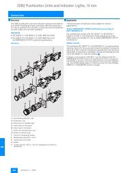
<strong>SITRANS</strong> F <strong>flowmeters</strong><strong>SITRANS</strong> F M© Siemens AG 2007Transmitter MAGFLO MAG 5000/60004■ OverviewTransmitter MAG 5000/6000 compact version (left) and 19“ insert version(right)The MAG 5000 and 6000 are microprocessor-based transmittersengineered for high performance, easy installation, commissioningand maintenance. The transmitters evaluate the signals fromthe <strong>SITRANS</strong> F M MAGFLO sensors type MAG 1100,MAG 1100 F, MAG 3100 and MAG 5100 W.Transmitter types:• MAG 5000: Max. measuring error 0.5% of rate (incl. sensor)• MAG 6000: Max. measuring error 0.25% of rate (incl. sensor,see also sensor specifications) and with additional featuressuch as: Plug & Play insert bus modules; integrated batchfunctions.■ Benefits• Superior signal resolution for optimum turn down ratio• Digital signal processing with many possibilities• Automatic reading of SENSORPROM data for easy commissioning• User configurable operation menu with password protection.• 3 lines, 20 characters display in 11 languages.• Flow rate in various units• Totalizer for forward, reverse and net flow as well as additionalinformation available• Multiple functional outputs for process control, minimum configurationwith analogue, pulse/frequency and relay output(status, flow direction, limits)• Comprehensive self-diagnostic for error indication and errorlogging (see under <strong>SITRANS</strong> F M MAGFLO diagnostics)• Batch control• Custody transfer approval: PTB, OIML R75, R117, R49• MAG 6000 with add-on bus modules for HART, MODBUSRTU/RS485, PROFIBUS PA and DP■ ApplicationThe MAG <strong>flowmeters</strong> are suitable for measuring the flow of almostall electrically conductive liquids, pastes and slurries. Themain applications can be found in:• Water and waste water• Chemical and pharmaceutical industries• Food & beverage industries• Power generation and utility■ DesignThe transmitter is designed as either IP67 NEMA 4X/6 enclosurefor compact or wall mounting or 19" version as a 19” insert as abase to be used in:• 19" rack systems• Panel mounting IP65/NEMA 4• Back of panel mounting IP20/NEMA 2• Wall mounting IP66/NEMA 4Several options on 19” versions are available such as:• Transmitters for EEx ATEX approved flow sensors (incl. barriers)• Transmitters with electrode cleaning unit■ FunctionThe MAG 5000/6000 are microprocessor-based transmitterswith a build-in alphanumeric display in several languages. Thetransmitters evaluate the signals from the associated electromagneticsensors and also fulfil the task of a power supply unitwhich provides the magnet coils with a constant current.Operating anddisplay panelHART communicationMasterTransmitterFurther information on connection, mode of operation and installationcan be found in the data sheets for the sensors.Displays and controlsOperation of the transmitter can be carried out using:• Control and display unit• HART communicator• PC/laptop and SIMATIC PDM software via HART communication• PC/laptop and SIMATIC PDM software using PROFIBUS communicationHART-CommunicatorPROFIBUS DPPROFIBUS PA communication+Coupler withpower supplyCouplingmodulePC/LaptopRS-232PROFIBUS PA.......Min. 230 WTransmitter withPROFIBUS PA interfaceTBusterminator4/26 Siemens FI 01 · 2007
© Siemens AG 2007<strong>SITRANS</strong> F <strong>flowmeters</strong><strong>SITRANS</strong> F MTransmitter MAGFLO MAG 5000/6000■ Technical specificationsDegree of protectionMode of operation and designMeasuring principleEmpty pipeElectromagnetic with pulsed constantfieldDetection of empty pipe (specialcable required in remote mountedinstallation)• Compact version• 19“ insertEMC performance• Emitted interferenceIP67/NEMA 4X/6 to IEC 529 andDIN 40050 (1 mH 2 O 30 min.)IP20/NEMA 2 to IEC 529 andDIN 40050To EN 50081-1 (Light industry)Excitation frequencyElectrode input impedanceInputSensor size dependingpulsating DC current> 1 x 10 14 Ω• Noise immunityDisplay and keypadTotalizerTo EN 50082-1 (Industry)Two eight-digit counters for forward,net or reverse flowDigital input• Activation time• CurrentOutputCurrent output• Signal range11 ... 30 V DC, R i = 4. 4 KΩ50 msI DC 11 V = 2.5 mA, I DC 30 V = 7 mA0 ... 20 mA or 4 ... 20 mADisplay• Time constantBackground illumination withalphanumeric text, 3 x 20 charactersto indicate flow rate, totalizedvalues, settings and faults;Reverse flow indicated by negativesignTime constant as current outputtime constant4• Load< 800 ΩDesign• Time constant0.1 … 30 s, adjustableEnclosure materialDigital output• Frequency• Pulse (active)• Pulse (passive)• Time constantRelay output• Time constant• LoadLow flow cut offGalvanic isolationMax. measuring error (incl. sensor)0 ... 10 kHz, 50% duty cycle(uni/bidirectional)DC 24 V, 30 mA, 1 KΩ ≤ R i ≤10 KΩ, short-circuit-protected(power supplied from flowmeter)DC 3…30 V, max. 110 mA, 200 Ω≤ R i ≤ 10 KΩ (powered from connectedequipment)0.1 … 30 s, adjustableChangeover relay, same as currentoutput42 V AC/2 A, 24 V DC/1 A0 ... 9.9% of maximum flowAll inputs and outputs are galvanicallyisolated• Compact version• 19“-insert• Back of panel• Panel mounting• Wall mountingDimensional drawings• Compact version• 19“ insertWeight• Compact version• 19“ insertFiber glass reinforced polyamide;optional (IP67 only):AISI 316 stainless steelStandard 19“ insert of aluminium/steel(DIN 41494), width:21 TE, height: 3 HEIP20/NEMA 2; AluminiumIP65/NEMA 4; ABS plasticIP66/NEMA 4; ABS plasticSee dimensional drawingsSee dimensional drawings0.75 kg (2 lb)See dimensional drawingsPower supply • 115 ... 230 V AC +10% -15%,50 ... 60 Hz, 17 VA• 11 ... 30 V DC or 11 ... 24 V AC• MAG 5000• MAG 6000Rated operation conditionsAmbient temperature0.5% of rate0.25% of ratePower consumption• 230 V AC: 17 VA•24VAC: 9W, I N = 380 mA,I ST =8A (30ms)• 12 V DC : 11 W, I N = 920 mA,I ST = 4 A (250 ms)• Operation• StorageMechanical load• Compact version• Display version:-20...+50°C(-4...+122°F)• Blind version:-20...+60°C(-4...+140°F)-40 ... +70 °C (-40 ... +158 °F)18 ... 1000 Hz, 3,17 G rms, sinusoidalin all directions toIEC 68-2-36Certificates and approvalsCustody transfer approval(MAG 5000/6000 CT)CommunicationStandardCE, ULc general purpose, C-tick;FM Class 1, div 2• PTB OIML R49 (cold water)• PTB and DANAK OIML R75 (hotwater)• PTB and DANAK OIML R117(cold water/milk, beer etc.)• 19“ insert1 ... 800 Hz, 1 G, sinusoidal in alldirections to IEC 68-2-36• MAG 5000Without serial communication orHART as option• MAG 6000Prepared for client mounted addonmodulesOptional (MAG 6000 only)HART, MODBUS RTU/RS485,PROFIBUS PA, PROFIBUS DP asadd-on modulesModification 01/2007Siemens FI 01 · 20074/27
<strong>SITRANS</strong> F <strong>flowmeters</strong><strong>SITRANS</strong> F M© Siemens AG 2007Transmitter MAGFLO MAG 5000/60004Safety barrier (ia/ib) DN ≤ 300 / 12”ApplicationEx approvalSafety barrier (e/ia) DN ≥ 350 / 14”ApplicationAs combined unit with MAG 6000 only and MAG 1100 Ex / MAG 3100 Ex in the sizerange DN 2 to 300 / 1/12” to 12”[EEx ia/ib] IIB, ATEX for MAG 3100 Ex and 1100 ExCable parameter Group Capacity in µF Inductance in mH• Electrode IIB ≤ 31 ≤ 80•Coil IIB ≤ 0.5 ≤ 8Ambient temperature• During operation -20 to +50 °C (-4 to +122 °F)• During storage-20 to +70 °C (-4 to +158 °F)Enclosure• Material Standard 19” insert in aluminium/steel (DIN 41494)• Width 21 TE (4.75”)• Height 3 HE (5.25”)• Rating IP 20 / NEMA 2 to EN 60529 and DIN 40050• Mechanical load 1 g, 1 … 800 Hz sinusoidal in all directions to EN 60068-2-36EMC performance• EmissionEN 50081-1 (Light industry)• ImmunityEN 50082-2 (Industry)Ex approvalCable parameter• ElectrodeFor use with MAG 5000/6000 19” and MAG 3100 Ex in the size range DN 350 to2000 / 14” to 78”[EEx e ia] IIC ATEXGroup Capacity in µF Inductance in mHIIC ≤ 4.1 ≤ 80IIB ≤ 45 ≤ 87IIA ≤ 45 ≤ 87Ambient temperature• During operation -20 to +50 °C (-4 to +122 °F)• During storage-20 to +70 °C (-4 to +158 °F)Enclosure• Material Standard 19” insert in aluminium/steel (DIN 41494)• Width 21 TE (4.75”)• Height 3 HE (5.25”)• Rating IP20 / NEMA 2 to EN 60529 and DIN 40050• Mechanical load 1 g, 1 … 800 Hz sinusoidal in all directions to EN 60068-2-36EMC performance• EmissionEN 50081-1 (Light industry)• ImmunityEN 50082-2 (Industry)4/28 Siemens FI 01 · 2007
© Siemens AG 2007<strong>SITRANS</strong> F <strong>flowmeters</strong><strong>SITRANS</strong> F MElectrode cleaning unitApplicationTransmitter MAGFLO MAG 5000/6000For use with transmitters MAG 5000 and 6000 19” to clean the electrodes on sensorsMAG 1100, MAG 3100 or MAG 5100 WNB: Must not be used with intrinsically safe ATEX sensorsCleaning voltageAC cleaning60 V ACDC cleaning30 V DCCleaning period60 s + 60 s pause periodRelay• Load42 V / 2 AOperationSwitch relay activated when cleaning is in progress• AutomaticYes• ManualNoIndicator lampsLEDs: “ON” and “CLEANING”Supply voltage and powerconsumption115 … 230 V AC, +10% … -15%, 50 … 60 Hz, 7 VA cleaning, 5 VA stand by11 … 30 V DC / 11 … 24 V AC, 50 … 60 Hz, 7 VA cleaning, 5 VA stand byAmbient temperature• During operation -20 to +50 °C (-4 to +122 °F)• During storage-20 to +70 °C (-4 to +158 °F)Enclosure• Material Standard 19” insert in aluminium/steel (DIN 41494)• Width 21 TE (4.75”)• Height 3 HE (5.25”)• Rating IP20 / NEMA 2 to EN 60529 and DIN 40050• Mechanical load 1 g, 1 … 800 Hz sinusoidal in all directions to EN 60068-2-364Cleaning unitThe Siemens cleaning unit can be used with MAG 5000 or 6000in 19” insert version.The cleaning unit can be used in applications where the linerand subsequently the electrodes may be coated with deposits.If the coating is electrically insulating, the electrode signal will bereduced. If the coating is electrically inductive, the electrode signalwill be partly short-circuited and in both cases the accuracyof the meter will decrease (dependent on coating type and thickness).Note:The cleaning unit cannot be used for inflammable or explosivemedia!Empty pipe detection and cleaning facility cannot be used atthe same time.Mode of operationThe cleaning unit cleans the electrodes electro-chemically byapplying a voltage to the electrodes for approx. 60 seconds.While cleaning, the transmitter stores and holds the latest measuredflow reading on the display and also the signal outputs. Afteran additional pausing period of 60 seconds the flowmeter resumesnormal measurement and the cleaning is now completed.The relay in the transmitter activates the cleaning cycle. In the relayoutput menu (under cleaning) the cleaning interval can beset between 1 hour and 24 hours.Cleaning should only take place with liquid in the pipe.This canbe detected via the empty pipe function. It is therefore recommendedto select “empty pipe detection” ON when using thecleaning.The cleaning sequence can also be controlled manually throughthe electrical input of the transmitter. Before this is done, ensurethat the measuring pipe is full.Siemens FI 01 · 20074/29
<strong>SITRANS</strong> F <strong>flowmeters</strong><strong>SITRANS</strong> F M© Siemens AG 2007Transmitter MAGFLO MAG 5000/6000AC cleaningi £ 80 mA4AC-cleaning is used to remove fatty deposits on the electrodes.These fatty deposits are seen in waste water applications, in abattoirsand water applications with oil residuals. During thecleaning process, the surface of the electrodes get warmer,which tends to soften grease particles and the gas bubbles generatedmechanically lift deposits away from the surface of theelectrodes.DC cleaningi £ 20 mADC-cleaning is used to eliminate electrically conductive depositsin the measuring pipe influencing the measuring accuracy.Particularly in district heating applications an electrically conductivedeposit (magnetite) may occur and short-circuit theelectrode signal. In this case the accuracy of the meter decreasesand the signal/noise conditions of the meter become inferior.The problem only arises if the conductivity of the water isless than approx. 250 µS/cm.During DC-cleaning electrolysis takes place where the flow ofelectrons removes the particle deposits from the electrode area.Note:Do not use DC-cleaning on sensors with tantalum electrodes.4/30 Siemens FI 01 · 2007
© Siemens AG 2007<strong>SITRANS</strong> F <strong>flowmeters</strong><strong>SITRANS</strong> F M■ Selection and Ordering DataTransmitter MAG 5000Description Order No. SymbolTransmitter MAG 5000 Blindfor compact and wall mounting;IP67/NEMA 4X, fibreglassreinforced polyamide• 11 ... 30 V DC /11 ... 24 V AC• 115/230 V AC, 50/60 HzTransmitter MAG 5000 Displayfor compact and wallmounting;IP67/NEMA 4X, fibre-glassreinforced polyamide• 11 ... 30 V DC /11 ... 24 V AC• 115/230 V AC, 50/60 Hz• 115/230 V AC, 50/60 Hz,with HARTTransmitter MAG 5000 CTfor compact and wall mounting,approved for custodytransfer;IP67/NEMA 4X, fibre-glassreinforced polyamide• 11 ... 30 V DC /11 ... 24 V AC• 115/230 V AC, 50/60 HzTransmitter MAG 60007ME6910-1AA30-0AA07ME6910-1AA10-0AA0} 7ME6910-1AA30-1AA0} 7ME6910-1AA10-1AA07ME6910-1AA10-1BA07ME6910-1AA30-1AB07ME6910-1AA10-1AB0Transmitter MAG 5000for 19” rack and wall mounting• 11 ... 30 V DC /11 ... 24 V AC• 115/230 V AC, 50/60 Hz7ME6910-2CA30-1AA07ME6910-2CA10-1AA0Description Order No. SymbolTransmitter MAG 6000 Blindfor compact and wall mounting;IP67/NEMA 4X, fibre-glassreinforced polyamide• 11 ... 30 V DC /11 ... 24 V AC• 115/230 V AC, 50/60 HzTransmitter MAG 6000for compact and wall mounting;IP67/NEMA 4X, fibre-glassreinforced polyamide• 11 ... 30 V DC /11 ... 24 V AC• 115/230 V AC, 50/60 HzIP67/NEMA 4X, AISI 316stainless steel(without S/S terminal box)• 11 ... 30 V DC /11 ... 24 V AC• 115/230 V AC, 50/60 Hz7ME6920-1AA30-0AA07ME6920-1AA10-0AA0} 7ME6920-1AA30-1AA0} 7ME6920-1AA10-1AA07ME6920-1QA30-1AA07ME6920-1QA10-1AA0Transmitter MAG 6000 CTfor compact and wall mounting,approved for custodytransfer;IP67/NEMA 4X, fibre-glassreinforced polyamide• 11 ... 30 V DC /11 ... 24 V AC• 115/230 V AC, 50/60 HzTransmitter MAG 6000 SVfor compact and wall mounting;special excitation 44 Hzsettings for Batch applicationDN ≤ 25/1“IP67/NEMA 4X, fibre-glassreinforced polyamide11 ... 30 V DC /11 ... 24 V ACTransmitter MAGFLO MAG 5000/6000Description Order No. Symbol7ME6920-1AA30-1AB07ME6920-1AA10-1AB07ME6920-1AB30-1AA0• 11 ... 30 V DC /11 ... 24 V AC• 115/230 V AC, 50/60 HzTransmitter MAG 6000 19“(DN ≤ 300/12“)Insert with safety barrier[EEx ia/ib] IIB ATEX• 11 ... 30 V DC /11 ... 24 V AC• 115/230 V AC, 50/60 HzTransmitter MAG 6000 SVfor 19“ rack and wall mounting;special excitation 44 Hzsettings, Batch applicationDN ≤ 25/1“• 11 ... 30 V DC /11 ... 24 V AC• 115/230 V AC, 50/60 HzMAG 6000 withIP66/NEMA 4X enclosure;115/230 V AC, 50/60 HzMAG 6000 with electrodecleaning unit, completemounted withIP66/NEMA 4X mountingenclosure• 11 ... 30 V DC /11 ... 24 V AC• 115/230 V AC, 50/60 Hz} Available ex stock115/230 V AC, 50/60 Hz 7ME6920-1AB10-1AA0Transmitter MAG 6000for 19“ rack and wall mounting7ME6920-2CA30-1AA07ME6920-2CA10-1AA07ME6920-2NA31-1AA07ME6920-2NA11-1AA07ME6920-2CB30-1AA07ME6920-2CB10-1AA07ME6920-2EA10-1AA07ME6920-2PA30-1AA07ME6920-2PA10-1AA04Siemens FI 01 · 20074/31
<strong>SITRANS</strong> F <strong>flowmeters</strong><strong>SITRANS</strong> F M© Siemens AG 20074Transmitter MAGFLO MAG 5000/6000Description Order No. SymbolMAG 6000 with electrodesafety barrier, completemounted withIP66/NEMA 4X wall mountingenclosure, ATEX,115/230 V AC, 50/60 Hz• DN ≤ 300/12“, [EEx ia/ib]IIB• DN ≥ 350/14“, [EEx e ia]IICMAG 6000 SV, 19” insert, inIP66/NEMA 4X , ABS plasticenclosure, excitation frequency44 Hz, Batchapplication DN ≤ 25/1“,11 … 30 V DC,11 … 24 V AC, 50/60 Hz7ME6920-2LA11-1AA07ME6920-2MA11-1AA07ME6920-2EB30-1AA0Accessories for MAG 5000 and MAG 6000Description Order No. SymbolWall mounting unit forIP67/NEMA 4X version,wall bracket, terminal box inpolyamide• 4 x M20 cable glands } FDK-085U1018• 4 x ½“ NPT cable glands } FDK-085U1053Cable for standard electrodeor coil, 3 x 1.5 mm² /18 gage with shield PVC•10m(33ft) } FDK-083F0121•20m(65ft) } FDK-083F0210• 40 m (130 ft) } FDK-083F0211• 60 m (200 ft) } FDK-083F0212• 100 m (330 ft)FDK-083F0213• 150 m (500 ft)FDK-083F3052• 200 m (650 ft)FDK-083F3053• 500 m (1650 ft)FDK-083F3054Electrode cable for emptypipe or low conductivity,double shielded,3 x 0.25 mm²•10m(33ft)FDK-083F3020•20m(65ft) } FDK-083F3095• 40 m (130 ft)FDK-083F3094• 60 m (200 ft)FDK-083F3093• 100 m (330 ft)FDK-083F3092• 150 m (500 ft)FDK-083F3056• 200 m (650 ft)FDK-083F3057• 500 m (1650 ft)FDK-083F3058Cable glands, for abovecable, 2 pcs.• M20A5E00822490•½“ NPTA5E00822501Description Order No. SymbolSealing screws for sensor/ FDK-085U0221transmitter, 2 pcsTerminal box, in polyamide,inclusive lid•M20 } FDK-085U1050•½" NPTFDK-085U1052Terminal box for MAG 6000,in stainless steel, inclusivelid•M20A5E00836867•½" NPTA5E00836868Terminal box (3A) in polyamide,inclusive lid•M20A5E00822478•½" NPTA5E00822479Potting kit for terminal box of } FDK-085U0220MAG sensors forIP68/NEMA 6P19“ cleaning unit for electrodecleaning (21TE) incl.back plate• 11 ... 30 V DC /11 ... 24 V AC• 115 ... 230 V AC, 50/60 Hz19“ safety barrier [EEx e ia]IIC for MAG 3100 Ex,DN 350 ... 2000 (14“ ... 78“)(21TE), incl. back platePanel mounting enclosurefor 19“ insert (21TE);IP65/NEMA 4 enclosure inABS plastic for front panelmountingPanel mounting enclosurefor 19“ insert (42TE);IP65/NEMA 4 enclosure inABS plastic for front panelmountingBack of panel mountingenclosure for 19“ insert(21TE); IP20/NEMA 2 enclosurein aluminiumBack of panel mountingenclosure for 19“ insert(42TE); IP20/NEMA 2 enclosurein aluminiumFDK-083F5039FDK-083F5036FDK-083F5034FDK-083F5030FDK-083F5031FDK-083F5032FDK-083F5033} Available ex stock4/32 Siemens FI 01 · 2007Modification 01/2007
© Siemens AG 2007<strong>SITRANS</strong> F <strong>flowmeters</strong><strong>SITRANS</strong> F MTransmitter MAGFLO MAG 5000/6000Description Order No. SymbolIP66/NEMA 4, wall mountingenclosure for 19“ inserts(without backplates)• 21TE FDK-083F5037Spare partsDescription Order No. SymbolConnection plate• 12 ... 24 VFDK-083F4149• 115 ... 230 VFDK-083F4148• 42TE } FDK-083F503819“ enclosure, 12 ... 24 V,115 ... 230 V•Transmitter FDK-083F4117Front cover (7TE)FDK-083F45254Back plates (if wall enclosure IP66 is used as part)Description Order No. SymbolWall unit enclosure IP66,12 ... 24 V, 115 ... 230 V• Transmitter FDK-083F4121• Transmitter ia and safetybarrier• Transmitter ia/ib and safetybarrier• Transmitter and cleaningunitFDK-083F4122FDK-083F4120FDK-083F4124Communication modules for MAG 6000Description Order No. SymbolHART} FDK-085U0226(not for MAG 6000 I)MODBUS RTU/RS485 } FDK-085U0234PROFIBUS PA Profile 3 } FDK-085U0236PROFIBUS DP Profile 3 } FDK-085U0237• Transmitter ia and safetybarrier• Transmitter ia/ib and safetybarrier• Transmitter and cleaningunitSENSORPROM memory unit(Sensor code and serialnumbers must be specifiedon order)• 2 kB(for MAG 5000/6000/MAG 6000 I)• 250 B(for MAG 2500/3000)Display unitfor MAG 5000/6000• black neutral front• Siemens front} Available ex stockFDK-083F4118FDK-083F4119FDK-083F4123FDK-085U1005FDK-085U1008FDK-085U1038FDK-085U1039Modification 01/2007Siemens FI 01 · 20074/33
<strong>SITRANS</strong> F <strong>flowmeters</strong><strong>SITRANS</strong> F M© Siemens AG 2007Transmitter MAGFLO MAG 5000/6000■ Dimensional drawingsTransmitter IP67/NEMA 4X/6 compact polyamide155 (6.10)6 (0.24)131 (5.16)128 (7.16)4Transmitter integral mountedTransmitter, 19” IP20/ NEMA 2 standard unitTransmitter wall mountedTransmitter, wall mounting IP66/NEMA 4, 21 TE210 (8.27)235 (9.25)22 (0.86)90 (3.54)13(0.51)90 (3.54)120 (4.72)146 (5.75)13 (0.51)192 (7.56)Weight excl. transmitter: 2.3 kg (5.0 lbs)4/34 Siemens FI 01 · 2007
© Siemens AG 2007<strong>SITRANS</strong> F <strong>flowmeters</strong><strong>SITRANS</strong> F MTransmitter MAGFLO MAG 5000/6000Transmitter, wall mounting IP66/NEMA 4, 42 TE13 (0.51) 90 (3.54) 120 (4.72)13 (0.51)357 (14.05)339 (13.35)Weight excl. transmitter: 2.9 kg (7.0 lbs)22 (0.87)90 (3.54) 146 (5.75)235 (9.25)4Transmitter, panel front IP65/NEMA 4, 21 TE197 (7.75)144 (5.67)184 (7.24) 198 (7.80) 50 (1.97)140 (5.51)Weight excl. transmitter: 1.2 kg (2.7 lbs)185 (7.28)Siemens FI 01 · 20074/35
<strong>SITRANS</strong> F <strong>flowmeters</strong><strong>SITRANS</strong> F M© Siemens AG 2007Transmitter MAGFLO MAG 5000/6000Transmitter, panel front IP65/NEMA 4, 42 TE294 (1.57)144 (5.67)4281 (1.06)198 (7.80) 50 (1.97)140 (5.51)Weight excl. transmitter: 1.6 kg (3.5 lbs)282 (1.10)Transmitter, back of panel IP20/NEMA 2, 21 TE163 (6.42)144 (5.67)218 (8.58)132 (5.20)57 (2.24)Weight: 0.7 kg (1.6 lbs)Transmitter, back of panel IP20/NEMA 2, 42 TE269 (10.59)253 (9.96)218 (8.58)132 (5.20)57 (2.24)Weight: 0.9 kg (2.0 lbs)4/36 Siemens FI 01 · 2007
© Siemens AG 2007<strong>SITRANS</strong> F <strong>flowmeters</strong><strong>SITRANS</strong> F MTransmitter MAGFLO MAG 5000/6000■ SchematicsElectrical connectionGroundingPE must be connected due to safety class 1 power supply.Mechanical countersWhen mounting a mechanical counter to terminals 57 and 58(active output), a 1000 µF capacitor must be connected to theterminals 56 and 58. Capacitor + is connected to terminal 56and capacitor - to terminal 58.Output cablesIf the output cable length is long in noisy environment, werecommend to use screened cable.41)Shield1) NoteSpecial cable with individual wire shields (shown as dotted lines)are only required when using empty pipe function or long cablesSiemens FI 01 · 20074/37
4<strong>SITRANS</strong> F <strong>flowmeters</strong><strong>SITRANS</strong> F MTransmitterMAGFLO MAG 6000 I/6000 I Ex d■ Overview© Siemens AG 2007The MAG 6000 I/6000 I Ex d is a microprocessor-based transmitterwith a build-in alphanumeric display in several languages.The transmitters evaluate the signals from the associated electromagneticsensors and also fulfil the task of a power supplyunit which provides the magnet coils with a constant current.Further information on connection, mode of operation and installationcan be found in the data sheets for the sensors.Displays and keypadsOperation of the transmitter can be carried out using:• Keypad and display unit• HART communicator• PC/laptop and SIMATIC PDM software via HART communication• PC/laptop and SIMATIC PDM software using PROFIBUS communicationThe <strong>SITRANS</strong> F M MAGFLO MAG 6000 I / I Ex d transmitter isdesigned for the demands in the process industry. The robustdie cast aluminium housing provides superb protection, even inthe most harsh industrial environments. Full input and outputfunctionality is given even in the Ex version.■ Benefits• Full range of ATEX rated <strong>flowmeters</strong> with intrinsically safe ratedinput and outputs• For compact or remote installation• HART, PROFIBUS PA/DP, MODBUS RTU/RS485 add-on communicationmodules available• Superior signal resolution for optimum turn down ratio• Digital signal processing with many possibilities• Automatic reading of SENSORPROM data for easy commissioning• User configurable operation menu with password protection- 3 lines, 20 characters display in 11 languages- Flow rate in various units- Totalizer for forward, reverse and net flow as well as muchmore information available.• Multiple functional outputs for process control, minimum configurationwith analogue, pulse/frequency and relay output(status, flow direction, limits)• Comprehensive self-diagnostic for error indication and errorlogging• Batch control■ DesignThe transmitter is designed for either compact or remote installationin non-hazardous or hazardous areas.■ FunctionThe following functions are available:• Flow rate• 2 measuring ranges• 2 totalizers• Low flow cut-off• Flow direction• Error system• Operating time• Uni-/bidirectional flow• Limit switches and pulse output• Batch control■ Technical specificationsMode of operation and designMeasuring principleEmpty pipeExcitation frequencyElectrode input impedanceInputDigital input• Activation time• CurrentOutputCurrent output• Signal range• Load• Time constantDigital output• Frequency• Time constant• Pulse (passive)• Time constantRelay output• Time constant• LoadLow flow cut offGalvanic isolationMax. measuring error• MAG 6000 IElectromagnetic with pulsed constantfieldDetection of empty pipe (specialcable required in separatemounted installation)Sensor size dependent pulsatingDC current> 1 x 10 14 ΩDC 11 ... 30 V, Ri = 4.4 kΩ50 msI DC 11 V = 2.5 mA, I DC 30 V = 7 mA0 ... 20 mA or 4 ... 20 mA (Active/passive)< 560 Ω0.1 … 30 s, adjustable0 … 10 kHz, 50% duty cycle (uni-/bidirectional)0.1 … 30 s, adjustable3 … 30 V DC, max 110 mA(30 mA Ex version), 200 Ω ≤ Ri ≤10 kΩ (powered from connectedequipment)0.1 … 30 s, adjustableChangeover relay, same as currentoutput42 V AC/2 A, 24 V DC/1 A0 … 9.9% of maximum flowAll inputs and outputs aregalvanic isolated0.25% of rate4/38 Siemens FI 01 · 2007
© Siemens AG 2007<strong>SITRANS</strong> F <strong>flowmeters</strong><strong>SITRANS</strong> F MTransmitterMAGFLO MAG 6000 I/6000 I Ex d■ Technical specifications (continued)Rated operation conditionsAmbient temperature• Operation-20 … +60 °C (-4 … +140 °F)• Storage-40 … +70 °C (-40 … +158 °F)Mechanical load18 … 1000 Hz, 1.14 G rms, sinusoidalin all directions toIEC 68-2-36Degree of protectionIP67/NEMA 4X to IEC 529 andDIN 40050 (1 mH 2 O 30 min.)EMC performance EN 61326Display and keypadTotalizerTwo eight-digit counters for forward,net or reverse flowDisplayBackground illumination withalphanumeric text, 3 x 20 charactersto indicate flow rate, totalizedvalues, settings and faults;Reverse flow indicated by negativesignKeypadCapacitive touch keypad withLED light for feedback indicationTime constantTime constant as current outputtime constantDesignEnclosure materialDie cast aluminium, painted• Wall mountingWall mounting bracket enclosedfor remote versionDimensional drawingsSee dimensional drawingsWeightSee dimensional drawingsPower supply• Non Ex d: 18 ... 90 V DC;115 ... 230 V AC; 50 ... 60 Hz• Ex d: 18 ... 30 V DC• Ex d: 115 ... 230 V AC;50 ... 60 HzPower consumption• 230 V AC: 21.5 VA• 24 V DC: 12 W, I N = 380 mA,I ST = 1 A (3 ms)Certificates and approvalsMAG 6000 I• CE•C-tick• FM Class 1, div 2• FM Class 1, Zone 2• CSA Class 1, div 2• CSA Class 1, Zone 2MAG 6000 I Ex-d ATEX category 2versions for compact and remotemounting DN 2 ... 300For use with MAG 3100 Ex sizesDN 350 ... 2000Cable entries• SIRA 03 ATEX 1503X• EX II 2 (1) G D• EEx d [ia] ia [ib] ib IIB, T6• SIRA 03 ATEX 2072X• EX II 2 (1) (2) G D• EEx d e [ia] ia [ib] ib IIC, T6Metric: M25/M16; (M20/M16,ATEX cat. 2 versions) ½ NPTCommunication• Non ATEX versions HART, MODBUS RTU/RS 485,PROFIBUS PA, PROFIBUS DPadd-on modules• ATEX category 2 versions HART, PROFIBUS PA available asintegrated versionSelection and Ordering data<strong>SITRANS</strong> F M TransmitterMAGFLO MAG 6000 I / Ex dRemote, local display, die cast aluminiumCommunication modules for MAG 6000 IAccessories MAG 6000 IOrder-No.7 M E 6 9 3 0 -2 B A 7 7 - 1 7 A 7Supply voltage115 ... 230 V AC, 50 ... 60 Hz; 18 ... 90 V DC 2ATEX, 18 ... 30 V DC 4ATEX, 115 ... 230 V AC, 50...60 Hz 5Ex approvalFM Class 1 div 2/No ATEX 0ATEX, ≤ 300 mm/12" sensor 1ATEX, > 300 mm/12" sensor 2CommunicationNone (add-on modules can be ordered separately,Asee below)HARTBPROFIBUS PA Profile 3FPROFIBUS DP Profile 3 (not Ex version)GMODBUS RTU/RS 485 (not Ex version)ECable gland entriesMetric 0½" NPT 2Description Order No. SymbolHARTFDK-085U0321(only for MAG 6000 I/Ex)MODBUS RTU/RS485 FDK-085U0234PROFIBUS PA Profile 3 FDK-085U0236PROFIBUS DP Profile 3 FDK-085U0237Description Order No. SymbolCable for standard electrodeor coil, 3 x 1.5 mm² /18 gage with shield PVC•10m(33ft) } FDK-083F0121•20m(65ft) } FDK-083F0210• 40 m (130 ft) } FDK-083F0211• 60 m (200 ft) } FDK-083F0212• 100 m (330 ft)FDK-083F0213• 150 m (500 ft)FDK-083F3052• 200 m (650 ft)FDK-083F3053• 500 m (1650 ft)FDK-083F3054Electrode cable for emptypipe or low conductivity,double shielded,3 x 0.25 mm²•10m(33ft)FDK-083F3020•20m(65ft) } FDK-083F3095• 40 m (130 ft)FDK-083F3094• 60 m (200 ft)FDK-083F3093• 100 m (330 ft)FDK-083F3092• 150 m (500 ft)FDK-083F3056• 200 m (650 ft)FDK-083F3057• 500 m (1650 ft)FDK-083F3058} Available ex stock4Modification 01/2007Siemens FI 01 · 20074/39
4<strong>SITRANS</strong> F <strong>flowmeters</strong><strong>SITRANS</strong> F MTransmitterMAGFLO MAG 6000 I/6000 I Ex dSpare partsDescription Order No. SymbolDisplayFDK-085U3122Accessory bag includingcable gland inserts coil & electrodeconnectorsFDK-085U3144Complete spare part PCB unitDescription Order No. SymbolNot ExFDK-085U3123Ex d version 18 ... 30 V DC FDK-085U3124for sensors ≤ DN 300 (12")Ex d version 115 ... 230 V AC FDK-085U3125for sensors ≤ DN 300 (12")MAG 6000 I Ex dA5E0101334018 ... 30 V DC Spare PCB unitfor sizes > DN 300MAG 6000 I Ex d115 ... 230 V AC Spare PCBunit for sizes > DN 300A5E01013127Please use online Product selector to get latest updates.Product selector link:www.pia-selector.com/its_main_en.aspPlease also see www.siemens.com/<strong>SITRANS</strong>Forderingfor practical examples of ordering■ Dimensional drawings© Siemens AG 2007■ Schematics Ω Ω Dimensions in mm (inch), weight: 6 kg (13.5 lbs)4/40 Siemens FI 01 · 2007Modification 01/2007
© Siemens AG 2007<strong>SITRANS</strong> F <strong>flowmeters</strong><strong>SITRANS</strong> F MMAGFLO MAG 1100■ Overview■ IntegrationThe complete flowmeter consists of a flow sensor and an associatedtransmitter <strong>SITRANS</strong> F M MAGFLO MAG 5000, 6000 or6000 I. The flexible communication concept USM II simplifies integrationand update to a variety of fieldbus systems such asHART, PROFIBUS DP & PA, MODBUS RTU/RS 485.The <strong>SITRANS</strong> F M MAGFLO MAG 1100 is an electromagneticflow sensor in a compact wafer design designed for flow applicationsin the process industry.■ Benefits• Sensor sizes: DN 2 to 100 (1/12” to 4”)• Compact wafer design meets EN 1092, DIN and ANSI flangestandards• Corrosion resistant AISI 316 stainless steel sensor housing• Highly resistant liner and electrodes fitting most extreme processmedia• Temperature rating up to 200 °C (390 °F)• Hose proof IP67/NEMA 4X/6 enclosure rating• Designed that patented in-situ verification can be conducted.Using SENSORPROM fingerprints.■ ApplicationThe main applications of the <strong>SITRANS</strong> F M MAGFLO electromagneticflow sensors can be found in the following fields:• Process industry• Chemical industry• Pharmaceutical industry• Water treatment like e.g. chemical dosing■ Design• Compact or remote mounting possible• Easy "plug & play" field changeability of transmitter• Simple on site upgrade to IP68/NEMA 6P• Ex ATEX version (MAG 1100 Ex only)■ Mode of operationThe flow measuring principle is based on Faraday’s law of electromagneticinduction were the sensor converts the flow into anelectrical voltage proportional to the velocity of the flow.■ Technical specificationsMeasuring principleElectromagnetic inductionExcitation frequencyDN 2 ... 65 (1/12“ … 2½”):12.5 HzDN 80, 100 (3”, 4”): 6.25 HzProcess connectionNominal size• MAG 1100 (Ceramic) DN 2 … DN 100 (1/12" … 4")• MAG 1100 (PFA) DN 10 … DN 100 (3/8" … 4")Mating flanges EN 1092-1 (DIN 2501),ANSI B 16.5 class 150 and 300 orequivalentOption:DN 2 ... 10 (1/12” ... 3/8”):G½” / NPT ½” pipe connectionadaptersRated operating conditionsAmbient conditionsAmbient temperature 1)• Remote transmitter-40 … +100 °C (-40 … +210 °F)• Compact transmitter-20 … +50 °C (-4 … +120 °F)MAG 5000/6000• Compact transmitter MAG 6000 I -20 … +60 °C (-4 … +140 °F)Temperature shock• MAG 1100 (Ceramic)- Duration ≤ 1 min, followed by10 min rest• MAG 1100 (PFA)Operating pressure• MAG 1100 (Ceramic)• MAG 1100 (PFA)Mechanical load• DN 2, 3 (1/12”, 1/8”)No limitations• DN 6, 10, 15, 25:Max. ∆T ≤ 80 °C/min(¼”, 3/8”, ½”, 1”:Max. ∆T ≤ 80 K/min)• DN 40, 50, 65:Max. ∆T ≤ 70 °C/min(1½”, 2”, 2½”:Max. ∆T ≤ 70 K/min)• DN 80, 100:Max. ∆T ≤ 60 °C/min(3”, 4”: Max. ∆T ≤ 60 K/min)Max. ±100 °C (210 °F) momentarily1) Conditions are also dependent on liner characteristicsDN 2 ... 65: 40 bar(1/12” … 2½”: 580 psi)DN 80: 37.5 bar (3”: 540 psi)DN 100: 30 bar (4”: 435 psi)Vacuum: 1 x 10 -6 bar(1.5 x 10 -5 psi)20 bar (290 psi)Vacuum: 0.02 bar (0.3 psi)10 … 1000 Hz random,3.17 G rms in all directions toEN 60068-2-36For compact installation with theMAG 6000 I, transmitter to besupported to avoid tension onsensor part.4Siemens FI 01 · 20074/41
<strong>SITRANS</strong> F <strong>flowmeters</strong><strong>SITRANS</strong> F M© Siemens AG 2007MAGFLO MAG 1100■ Technical specifications (continued)Degree of protection (enclosure)4• Standard• OptionMedium conditionsIP67 to EN 60529 (NEMA 4X/6),1mH 2 O for 30 minIP68 to EN 60529 (NEMA 6P),10 mH 2 O cont.Temperature medium• MAG 1100 (Ceramic)- Standard -20 … +150 °C (-4 … +300 °F)- High temperature version -20 … +200 °C (-4 … +390 °F)- Ex version • T4: -20 … +100°C (-4… +212°F)• T5: -20 … +82°C (-4 … +180°F)• T6: -20 … +67°C (-4 … +153°F)• MAG 1100 (PFA)- PFA -30 … +130 °C (-20 … +270 °F)Suitable for steam sterilization at150 °C (300 °F)EMC89/336 EECDesignWeightSee Dimensional drawingsMaterial• Enclosure- MAG 1100 Stainless steel AISI 316L (1.4404)• Terminal box- Standard Fibre glass reinforced polyamide- Option Stainless steel AISI 316 (1.4436)- High temperature and Ex (remoteversion only)Stainless steel AISI 316 (1.4436)• Fixing studs Stainless steel AISI 304 (1.4301),Number and size toEN 1092-1:2001• Gaskets- Standard EPDM (max. 150 °C, PN 40(max. 300 °F, 600 psi)- Optional • Graphite (max. 200 °C, PN 40(max. 390 °F, 600 psi)• PTFE (max. 130 °C, PN 25(max. 270 °F, 300 psi)• Metering tube connection DN 2, 3,6 and 10 (1/12“, 1/8“, ¼” and 3/8”)Stainless steel, AISI 316 orHastelloy, G½” tapered ISO 7-1 or½” NPT threadLiner• MAG 1100 (Ceramic) • DN 2, 3 (1/12“, 1/8“):Zirconium oxide (ZrO 2 )(ceramic)• DN 6 ... 100 (¼“ ... 4“):Aluminium oxide Al 2 O 3• MAG 1100 (PFA)Reinforced PFAElectrodes• MAG 1100 (Ceramic)Platinum with gold / Titaniumbrazing alloy• MAG 1100 (PFA)Hastelloy C276Cable entries4 x M20; ½" NPTCertificates and approvalsConforms toPED – 97/23 ECMAG 1100 (Ceramic)• ATEX EEx [ia] [ib] IIB T4-T6• FM Class 1 div 2MAG 1100 (PFA) • FM Class 1 div 24/42 Siemens FI 01 · 2007
© Siemens AG 2007<strong>SITRANS</strong> F <strong>flowmeters</strong><strong>SITRANS</strong> F MSelection and Ordering dataOrder No.Sensor <strong>SITRANS</strong> F MMAGFLO MAG 1100EPDM gaskets7 M E 6 1 1 0 -7 7 0A 7 0 - 7 7 7 7DiameterDN 2 (1/12“)} 1 DDN 3 (1/8“)} 1 HDN 6 (¼“)} 1 MDN 10 (3/8“)} 1 RDN 15 (½“)} 1 VDN 25 (1“)} 2 DDN 40 (1½“)} 2 RDN 50 (2“)} 2 YDN 65 (2½“)} 3 FDN 80 (3“)} 3 MDN 100 (4“)} 3 TLiner materialPFA - DN 10 ... 100 (3/8“ ... 4“)}1Ceramic } 2Electrode materialHastelloy C276 (only with PFA liner) } 1Platinum (only with ceramic liner) } 2TransmitterNo transmitter (can be ordered separately) } AMAG 6000 I, 18 V ... 90 V DC;C115 ... 230 V AC, 50 ... 60 HzCommunicationNo communication, add-on possible } AHARTBPROFIBUS PA Profile 3FPROFIBUS DP Profile 3GMODBUS RTU/RS 485ECable glands/terminal boxMetric: polyamid terminal box or 6000 I compact } 1½" NPT: polyamid terminal box or 6000 I compact 2Metric: SS terminal box 3½" NPT: SS terminal box 4} Available ex stockSelection and Ordering dataAdditional informationPlease add “-Z“ to Order No. and specify Ordercode(s) and plain text.Customer specific converter setupTag name plate, stainless steel fixed with SS wire(add plain text)Tag name plate, plastic (self adhesive)Factory certificate according to EN 10204-2.1Factory certificate according to EN 10204-2.2Sensor cables wired (specify cable order no.)Junction box potted to IP68 with wired cable (specifycable order no.)Other postproduction requirements (add desired text)Please also see www.siemens.com/<strong>SITRANS</strong>Forderingfor practical examples of orderingOrder codeY20Y17Y18C15C14Y40Y41Y99MAGFLO MAG 1100Selection and Ordering dataOrder No.Sensor <strong>SITRANS</strong> F MMAGFLO MAG 1100 Ex, ATEXCeramic liner, Platinum electrode, EPDM gaskets7 M E 6 1 3 0 -7 7 0A 2 0 - 2 7 7 7DiameterDN 2 (1/12“)1 DDN 3 (1/8“)1 HDN 6 (¼“)1 MDN 10 (3/8“)1 RDN 15 (½“)1 VDN 25 (1“)2 DDN 40 (1½“)2 RDN 50 (2“)2 YDN 65 (2½“)3 FDN 80 (3“)3 MDN 100 (4“)3 TTransmitterNo transmitter (can be ordered separately)AMAG 6000 I, 18 V ... 30 V DC, ATEXDMAG 6000 I, 115 V ... 230 V, ATEXECommunicationNo communication, add on possibleAHARTBPROFIBUS PA Profile 3FCable glands/terminal boxMetric: 6000 I, ATEX 1½" NPT: 6000 I, ATEX 2Metric: SS terminal box 3½" NPT: SS terminal box 4Selection and Ordering dataOrder No.Sensor <strong>SITRANS</strong> F MMAGFLO MAG 1100 High TemperatureCeramic liner, Platinum electrode,Graphite gaskets7 M E 6 1 2 0 -7 7 0A 2 0 - 2 A A 7DiameterDN 15 (½“)1 VDN 25 (1“)2 DDN 40 (1½“)2 RDN 50 (2“)2 YDN 80 (3“)3 MDN 100 (4“)3 TCable glands/terminal boxMetric: SS terminal box 3½" NPT: SS terminal box 4Selection and Ordering dataAdditional informationPlease add “-Z“ to Order No. and specify Ordercode(s) and plain text.Customer specific converter setupTag name plate, stainless steel fixed with SS wire(add plain text)Tag name plate, plastic (self adhesive)Factory certificate according to EN 10204-2.1Factory certificate according to EN 10204-2.2Sensor cables wired (specify cable order no.)Junction box potted to IP68 with wired cable (specifycable order no.)Order codeY20Y17Y18C15C14Y40Y41Please use online Product selector to get latest updates.Product selector link: www.pia-selector.com/its_main_en.asp4Siemens FI 01 · 20074/43
<strong>SITRANS</strong> F <strong>flowmeters</strong><strong>SITRANS</strong> F M© Siemens AG 2007MAGFLO MAG 11004AccessoriesOrder No.for MAGFLO MAG 1100 sensorPipe connection ½" external threadFor DN 2 ... 10 (1/12“ ... 3/8“) sensor2 pipe connections, 2 EPDM gaskets,12 pcs M4 x 12 screws• ½" G, ISO 7-1 tappered thread, SS 316 } FDK-083G0080• ½" G, ISO 7-1 tappered thread, Hastelloy C } FDK-083G4332• ½" NPT thread, SS 316 } FDK-083G4330• ½" NPT thread, Hastelloy C } FDK-083G4331EPDM gasketsMaterial: EPDM; each set includes:2 EPDM gaskets, 2 earthing wires,3 M6 screws• DN 2 ... 10, 1/12“ ... 3/8“FDK-083G3116• DN 15, ½“FDK-083G3117• DN 25, 1“FDK-083G3119• DN 40, 1½“FDK-083G3121• DN 50, 2“FDK-083G3122• DN 65, 2½“FDK-083G3123• DN 80, 3“FDK-083G3124• DN 100, 4“FDK-083G3125Accessoriesfor MAGFLO MAG 1100 sensorGrounding ring (Hastelloy C)Material: Hastelloy C; each set includes:1 grounding ring, 3 teflon gaskets, 1 earthstrap, 1 M6 screw• DN 2 ... 10, 1/12“ ... 3/8“• DN 15, ½“• DN 25, 1“• DN 40, 1½“• DN 50, 2“• DN 65, 2½“• DN 80, 3“• DN 100, 4“Studs and nutsfor DN 100 PN 25/40, 8 M20 studs,16 M20 nutsMaterial: AISI 304 (mat. no. 1.4305)• DN 100, 4“} Available ex stock.Order No.FDK-083G3256FDK-083G3257FDK-083G3259FDK-083G3261FDK-083G3262FDK-083G3263FDK-083G3264FDK-083G3265FDK-083G0226PTFE gasketsMaterial: PTFE; each set includes:2 gaskets, 2 earthing wires, 3 M6 screws• DN 2 ... 10, 1/12“ ... 3/8“• DN 15, ½“• DN 25, 1“• DN 40, 1½“• DN 50, 2“• DN 65, 2½“FDK-083G0156FDK-083G0157FDK-083G0159FDK-083G0161FDK-083G0162FDK-083G0163• DN 80, 3“• DN 100, 4“FDK-083G0164FDK-083G0165Graphite gasketsMaterial: Graphite;each set includes: 2 gaskets• DN 2 ... 10, 1/12“ ... 3/8“• DN 15, ½“• DN 25, 1“FDK-083G0116FDK-083G0117FDK-083G0119• DN 40, 1½“• DN 50, 2“• DN 65, 2½“FDK-083G0121FDK-083G0122FDK-083G0123• DN 80, 3“• DN 100, 4“FDK-083G0124FDK-083G0125Grounding ring (S/S)Material: AISI 316 (mat. no. 1.4436);each set includes: 1 grounding ring, 3 teflongaskets, 1 earth strap, 1 M6 screw• DN 2 ... 10, 1/12“ ... 3/8“• DN 15, ½“• DN 25, 1“FDK-083G0686FDK-083G0687FDK-083G0689• DN 40, 1½“• DN 50, 2“• DN 65, 2½“FDK-083G0691FDK-083G0692FDK-083G0693• DN 80, 3“• DN 100, 4“FDK-083G0694FDK-083G06954/44 Siemens FI 01 · 2007
© Siemens AG 2007<strong>SITRANS</strong> F <strong>flowmeters</strong><strong>SITRANS</strong> F MMAGFLO MAG 1100■ Dimensional drawingsSensor MAG 1100, compact/remotemin. 45(1.8)155(6.10)131(5.16)455(2.2)B 1A 1M20 (½" NPT)D GD PD iABLDSizeDNA 1)[mm]B 1)[mm]A 1[mm]B 1[mm]D[mm]D i3)[mm]D i (PFA)[mm]2 161 186 314 339 48.3 2 17.3 34 2.23 161 186 314 339 48.3 3 17.3 34 2.26 161 186 314 339 48.3 6 17.3 34 2.210 161 186 314 339 48.3 10 10 13.6 34 2.215 161 186 314 339 48.3 15 16 17.3 40 2.225 169 201 322 354 63.4 25 26 28.5 56 2.740 181 223 334 376 84.0 40 38 43.4 75 3.450 189 240 342 393 101.6 50 50 54.5 90 4.265 199 259 352 412 120.0 65 66 68.0 112 5.580 205 271 358 424 133.0 80 81 82.5 124 7.0100 218 297 371 450 159.0 100 100 107.1 145 10.0D P[mm]D G[mm]Weight 2)[kg]Size[inch]A 1)[inch]B 1)[inch]A 1[inch]B 1[inch]D[inch]D i3)[inch]D i (PFA)[inch]1) 13 mm / 0.5" shorter when the AISI terminal box is used (Ex or high temperature 200 °C (390 °F) version)2) With transmitter MAG 5000 or MAG 6000 installed, weight is increased by approximately 0.8 kg (1.8 lb).3) DN 2 (1/12“) and 3 (1/8“): Zirconium oxide (ZrO 2 ), DN 6 ...100 (¼“ ... 4“): Ceramic (Al 2 O 3 )D P[inch]D G[inch]1/12 6.34 7.33 12.36 13.35 1.90 0.08 0.68 1.34 4.81/8 6.34 7.33 12.36 13.35 1.90 0.12 0.68 1.34 4.8¼ 6.34 7.33 12.36 13.35 1.90 0.24 0.68 1.34 4.83/8 6.34 7.33 12.36 13.35 1.90 0.39 0.39 0.53 1.34 4.8½ 6.34 7.33 12.36 13.35 1.90 0.59 0.63 0.68 1.57 4.81 6.66 7.92 12.68 13.94 2.50 0.98 1.02 1.12 2.20 4.91½ 7.13 8.78 13.15 14.81 3.31 1.57 1.50 1.71 2.95 7.52 7.44 9.45 13.47 15.47 4.00 1.97 1.97 2.15 3.54 9.22½ 7.84 10.20 13.86 16.22 4.72 2.56 2.60 2.68 4.41 123 8.07 10.67 14.10 16.70 5.24 3.15 3.19 3.25 4.88 154 8.59 11.70 14.61 17.72 6.26 3.94 3.94 4.22 5.91 22Weight 2)[lbs]Siemens FI 01 · 20074/45
<strong>SITRANS</strong> F <strong>flowmeters</strong><strong>SITRANS</strong> F M© Siemens AG 2007MAGFLO MAG 1100Sensor MAG 1100/6000 I Compactmin. 45(1.8)208(8.19)155(6.10)2 x M25131(5.16)218(8.58)455(2.2)B 1A 1M20 (½“ NPT)AD GD PBD iLDImportant note: For compact installation with the MAG 6000 I, transmitter to be supported to avoid tension on sensor part.SizeDNA[mm]B[mm]A 11)[mm]B 11)[mm]D[mm]D i3)[mm]1) 7.6 mm (0.3 inch) higher in Ex version2) With transmitter MAG 6000 I weight is increased by approximately 5.5 kg (12.1 lb).3) DN 2 (1/12“) and 3 (1/8“): Zirconium oxide (ZrO 2 ), DN 6 ...100 (¼“ ... 4“): Ceramic (Al 2 O 3 )D i (PFA)[mm]2 161 186 312 336 48.3 2 17.3 34 2.23 161 186 312 336 48.3 3 17.3 34 2.26 161 186 312 336 48.3 6 17.3 34 2.210 161 186 312 336 48.3 10 10 13.6 34 2.215 161 186 312 336 48.3 15 16 17.3 40 2.225 169 201 319 351 63.4 25 26 28.5 56 2.740 181 223 329 371 84.0 40 38 43.4 75 3.450 189 240 338 389 101.6 50 50 54.5 90 4.265 199 259 347 407 120.0 65 66 68.0 112 5.580 205 271 354 420 133.0 80 81 82.5 124 7.0100 218 297 367 446 159.0 100 100 107.1 145 10.0Size[inch]A[inch]B[inch]A 11)[inch]B 11)[inch]D[inch]D i3)[inch]D i (PFA)[inch]D P[mm]D P[inch]D G[mm]D G[inch]1/12 6.34 7.33 12.28 13.23 1.90 0.08 0.68 1.34 4.81/8 6.34 7.33 12.28 13.23 1.90 0.12 0.68 1.34 4.8¼ 6.34 7.33 12.28 13.23 1.90 0.24 0.68 1.34 4.83/8 6.34 7.33 12.28 13.23 1.90 0.39 0.39 0.53 1.34 4.8½ 6.34 7.33 12.28 13.23 1.90 0.39 0.63 0.68 1.57 4.81 6.66 7.92 12.57 13.82 2.50 0.98 1.02 1.12 2.20 4.91½ 7.13 8.78 12.95 14.61 3.31 1.57 1.50 1.71 2.95 7.52 7.44 9.45 13.31 15.31 4.00 1.97 1.97 2.15 3.54 9.22½ 7.84 10.20 13.66 16.02 4.72 2.56 2.60 2.68 4.41 123 8.07 10.67 13.92 16.54 5.24 3.15 3.19 3.25 4.88 154 8.59 11.70 14.43 17.56 6.26 3.94 3.94 4.22 5.91 22Weight 2)[kg]Weight 2)[lbs]4/46 Siemens FI 01 · 2007
© Siemens AG 2007<strong>SITRANS</strong> F <strong>flowmeters</strong><strong>SITRANS</strong> F MMAGFLO MAG 1100The total build-in length “L” [mm] / [inch] before assembling depends on the gasket selectedSize EPDM Graphite PTFE (Teflon) Without gasket Earthing ringDN Inch [mm] [inch] [mm] [inch] [mm] [inch] [mm] [inch] [mm] [inch]2 ... 10 1) 1/12 ... 3/8 64 2.52 66 2.60 70 2.75 64 2.52 77 3.0315 ½ 65 2.56 66 2.60 70 2.75 64 2.52 77 3.0325 1 80 3.15 81 3.19 85 3.35 79 3.10 92 3.6240 1½ 95 3.74 96 3.78 100 3.94 94 3.70 107 4.2150 2 105 4.13 106 4.17 110 4.33 104 4.05 117 4.6165 2½ 130 5.12 131 5.15 135 5.31 129 5.05 142 5.6080 3 155 6.10 156 6.14 160 6.30 154 6.00 167 6.57100 4 185 7.28 186 7.31 190 7.48 184 7.20 197 7.761) Mounting between two flanges4Sensor MAG 1100 DN 2 ... 10 (1/12“ ... 3/8“) with adapters1/2" Thread20 (0.79)6 x M435 (1.38)52 (2.05)LThe MAG 1100 DN 2, 3, 6 and 10 (1/12“, 1/8“, ¼” and 3/8”) are prepared for assembly with the ½” pipe connections.The length “L“ varies dependent on the gasket choice.Without gasket EPDM Graphite Teflon[mm] [inch] [mm] [inch] [mm] [inch] [mm] [inch]150 5.9 150 5.9 152 6.0 156 6.1Important note:For compact installation with the MAG 6000 I, transmitter to be supported to avoid tension on sensor part.Siemens FI 01 · 20074/47
<strong>SITRANS</strong> F <strong>flowmeters</strong><strong>SITRANS</strong> F M© Siemens AG 2007MAGFLO MAG 1100 Food■ Overview■ IntegrationThe complete flowmeter consists of a sensor and an associatedtransmitter <strong>SITRANS</strong> F M MAGFLO MAG 5000, 6000 and 6000 I.The flexible communication concept USM II simplifies integrationand update to a variety of fieldbus systems such asPROFIBUS DP & PA, MODBUS RTU/RS485, HART.4The electromagnetic sensor <strong>SITRANS</strong> F M MAGFLOMAG 1100 Food is designed to meet applications in the foodand beverage industry.■ Benefits• Sensor sizes: DN 10 … DN 100 ( 3 / 8 ”…4”)• AISI 316 stainless steel enclosure• Hygienic connection, 3A and EHEDG authorized construction• Sanitary design for CIP / SIP cleaning• Conforms to FDA• Easy commissioning, the SENSORPROM unit automaticallyupdates settings• Hose proof IP67/NEMA 4X/6 enclosure rating• Designed that patented in-situ verification can be conducted.Using SENSORPROM fingerprints■ ApplicationThe main applications of the <strong>SITRANS</strong> F M MAGFLO electromagneticsensors can be found in the following fields:• Food industry• Beverage industry• Pharmaceutical industry■ Design• Unique mechanical design with a wide range of customerspecified sanitary connection• Compact or remote mounting possible easy "plug & play" fieldchangeable• Simple on site upgrade to IP68/NEMA 6P• Ex ATEX version for hazardous areas (MAG 1100 Food Exonly)■ Mode of operationThe flow measuring principle is based on Faraday’s law of electromagneticinduction were the sensor converts the flow into anelectrical voltage proportional to the velocity of the flow.■ Technical specificationsMeasuring principleElectromagnetic inductionExcitation frequencyDN 10 ... 65 (¼“ … 2½”): 12.5 HzDN 80 ... 100 (3”, 4”): 6.25 HzProcess connectionNominal size DN 10 … DN 100 (3/8" … 4")Process connectionHygienic adapters available for:• Direct welding onto pipe• Clamp fitting• Threaded fittingRated operating conditionsAmbient conditionsAmbient temperature 1)• Remote transmitter-40 … +100 °C (-40 … +212 °F)• Compact transmitter-20 … +50 °C (-4 … +122 °F)MAG 5000/6000• Transmitter MAG 6000 I-20 … +60 °C (-4 … +140 °F)Temperature shock• MAG 1100 Food- Duration ≤ 1 min, followed by10 min rest• MAG 1100 Food (PFA)Operating pressure• MAG 1100 Food (Ceramic)• MAG 1100 Food (PFA)Mechanical loadDegree of protection (enclosure)• Standard• DN 10, 15, 25:Max. ∆T ≤ 80 °C/min(3/8”, ½”, 1”:Max. ∆T ≤ 80 K/min)• DN 40, 50, 65:Max. ∆T ≤ 70 °C/min(1½”, 2”, 2½”: Max. ∆T ≤ 70K/min)• DN 80, 100:Max. ∆T ≤ 60 °C/min(3”, 4”: Max. ∆T ≤ 60 K/min)Max. ±100 °C (210 °F) momentarilyDN 10 ... 65: 40 bar (3/8” … 2½”:580 psi)DN 80: 37.5 bar (3”: 540 psi)DN 100: 30 bar (4”: 435 psi)Vacuum: 1 x 10 -6 bar(1.5 x 10 -5 psi)20 bar (290 psi)Vacuum: 0.02 bar (0.3 psi)18 … 1000 Hz random,3.17 G rms in all directions toEN 60068-2-36For compact installation with theMAG 6000 I, transmitter to besupported to avoid tension onsensor part.IP67, higher on requestIP67 to EN 60529 (NEMA 4X),1mH 2 O for 30 min• Option IP68 to EN 60529 (NEMA 6),10 mH 2 O cont.1) Conditions are also dependent on liner characteristics4/48 Siemens FI 01 · 2007
© Siemens AG 2007<strong>SITRANS</strong> F <strong>flowmeters</strong><strong>SITRANS</strong> F M■ Technical specifications (continued)Medium conditionsTemperature of medium• MAG 1100 Food (Ceramic)- Standard -20 … +150 °C (-4 … +300 °F)Suitable for steam sterilization- Ex version • T4: -20 … +100 °C(-4 … +212 °F)• T5: -20 … +82 °C(-4 … +180 °F)• T6: -20 … +67 °C(-4 … +153 °F)• MAG 1100 Food (PFA)-30 … +130 °C (-20 … +270 °F)Suitable for steam steralization at150 °C (300 °F)EMC89/336 EECDesignWeightSee Dimensional drawingsMaterial• Enclosure- MAG 1100 Food Stainless steel AISI 316L (1.4404)• Terminal box (remote version only)- Standard Fibre glass-reinforced polyamide- Option Stainless steel AISI 316 (1.4436)- Ex (remote version only) Stainless steel AISI 316 (1.4436)Liner• MAG 1100 Food (Ceramic) Aluminium oxide Al 2 O 3 (ceramics)• MAG 1100 Food (PFA)Reinforced PFA (teflon)Electrodes• MAG 1100 Food (Ceramic) Platinum with gold / Titaniumbrazing alloy• MAG 1100 Food (PFA)Hastelloy C276Cable entries4 x M20 / Compact 6000 I version2 x M25½” NPTCertificates and approvals• MAG 1100 Food (Ceramic) 3AEHEDGATEX EEx [ia] [ib] IIB T4-T6FM Class 1 div 2• MAG 1100 Food (PFA)3AEHEDG in preparationFM Class 1 div 2Conforms toPED – 97/23/ECFDAMAGFLO MAG 1100 FoodAccessoriesAdapterPipe connection/operating pressureAdapter for welding onto dairy pipe Tri-Clover ISP 2037, DIN 11850,SMS 3008, BS 4825-1• DN 10, 15, 25, 40, 50, 65 and 80 PN 40 (600 psi)(3/8”, ½”, 1”, 1½”, 2”, 2½” and 3”)• DN 100 (4”)PN 25 (350 psi)Clamp adapter Tri-Clamp ISP 2852, DIN 32676,SMS 3016, BS 4825-3• DN 10, 15, 25, 40 and 50 (3/8”, ½”, PN 16 (200 psi)1”, 1½”, and 2”)• DN 65, 80 and 100 (2½”, 3” and PN 10 (150 psi)4”)Thread adapter• DIN 11851- DN 10, 15, 25, and 40 (3/8”, ½”, PN 40 (600 psi)1”, and 1½”)- DN 50, 65, 80 and 100 (2”, 2½”, PN 25 (350 psi)3” and 4”)• ISO 2853, SS 3351, BS 4825-4- DN 10, 15, 25, 40, 50, 65 and 80 PN 16 (200 psi)(3/8”, ½”, 1”, 1½”, 2”, 2½ and 3”)• SMS 1145- DN 25, 40, 50, 65 and 80 (1”, PN 6 (80 psi)1½”, 2”, 2½” and 3”)DesignMaterial• AdapterStainless steel AISI 316/Stainlesssteel AISI 304 (ISO 2852)• Gasket- Standard EPDM (-20 ... +150 °C(-4 ... +302 °F))- Option NBR (-20 ... +100 °C(-4 ... +212 °F))Note:When combined sensor and adapter, the operating pressure isthe lower rated of the pair.4Siemens FI 01 · 20074/49
<strong>SITRANS</strong> F <strong>flowmeters</strong><strong>SITRANS</strong> F M© Siemens AG 20074MAGFLO MAG 1100 FoodSelection and Ordering dataOrder No.Sensor <strong>SITRANS</strong> F M MAGFLO MAG 1100 Food 7 M E 6 1 4 0 -7 7 7 7 7 - 7 7 7 7DiameterDN 10 (3/8“)} 1 RDN 15 (½“)} 1 VDN 25 (1“)} 2 DDN 40 (1½“)} 2 RDN 50 (2“)} 2 YDN 65 (2½“)} 3 FDN 80 (3“)} 3 MDN 100 (4“)} 3 TProcess connectionsNo adaptors (specials see accessories)AWeld inDIN 11850} BDS/ISO 2037 } CBS 4825-1 } DTri-Clover®EClamp typeDIN 32676GISO 2852HBS 4825-3JTri-Clamp®KThreaded typeDIN 11851MSMS 1145NLiner materialPFA } 1Ceramic } 2Gasket materialEPDM (FDA) }0NBR } 1Electrode materialHastelloy C276 (only with PFA liner) } 1Platinum (only with ceramic liner) } 2TransmitterNo transmitter (can be ordered separately) } AMAG 6000 I, 18 V ... 90 V DC; 115 ... 230 V AC,C50 ... 60 HzCommunicationNo communication, add-on possible } AHARTBPROFIBUS PA Profile 3FPROFIBUS DP Profile 3GMODBUS RTU/RS 485ECable glands/terminal boxMetric: polyamid terminal box (3A) or 6000 I compact1½" NPT: polyamid terminal box (3A)or 6000 I compact2Metric: SS terminal box 3½" NPT: SS terminal box 4} Available ex stock.Please use online Product selector to get latest updates.Product selector link: www.pia-selector.com/its_main_en.aspPlease also see www.siemens.com/<strong>SITRANS</strong>Forderingfor practical examples of orderingSelection and Ordering dataOrder No.Sensor <strong>SITRANS</strong> F M MAGFLOMAG 1100 Food Ex, ATEXCeramic liner, Platinum electrode7 M E 6 1 5 0 -7 7 7 2 7 - 2 7 7 7DiameterDN 10 (3/8“)1 RDN 15 (½“)1 VDN 25 (1“)2 DDN 40 (1½“)2 RDN 50 (2“)2 YDN 65 (2½“)3 FDN 80 (3“)3 MDN 100 (4“)3 TProcess connectionsNo adaptors (specials see accessories)AWeld inDIN 11850BDS/ISO 2037CBS 4825-1DTri-Clover®EClamp typeDIN 32676GISO 2852HBS 4825-3TJTri-Clamp®KThreaded typeDIN 11851MSMS 1145NGasket materialEPDM (FDA) 0NBR 1TransmitterNo transmitter (can be ordered separately)AMAG 6000 I Ex-d ATEX,18 V ... 30 V DCDMAG 6000 I Ex-d ATEX,115 V ... 230 V ACECommunicationNo communication, add-on possibleAHARTBPROFIBUS PA Profile 3FCable glands/terminal boxMetric: 6000 I, ATEX 1½" NPT: 6000 I, ATEX 2Metric: SS terminal box 3½" NPT: SS terminal box 4} Available ex stock.Selection and Ordering dataAdditional informationPlease add “-Z“ to Order No. and specify Ordercode(s) and plain text.Customer specific converter setupTag name plate, stainless steel fixed with SS wire(add plain text)Tag name plate, plastic (self adhesive)Factory certificate according to EN 10204-2.1Factory certificate according to EN 10204-2.2Sensor cables wired (specify cable order no.)Junction box potted to IP68 with wired cable (specifycable order no.)Other postproduction requirements (add desired text)Order codeY20Y17Y18C15C14Y40Y41Y994/50 Siemens FI 01 · 2007Modification 01/2007
© Siemens AG 2007<strong>SITRANS</strong> F <strong>flowmeters</strong><strong>SITRANS</strong> F MAccessoriesWeld in connection fittings forMAG 1100 FoodEach of the following accessory order nos.comprises:2 pcs. fittings2 pcs. clamps (to join flow sensor and fitting)2 pcs. EPDM gasketsDIN 11850AdapterSensorDN (mm) D o (mm) D i (mm) DN (mm)Order No.10 13 10 10 } FDK-083G211615 19 16 15 } FDK-083G211720 23 20 15 } FDK-083G211825 29 26 25 } FDK-083G211932 35 32 25 } FDK-083G212040 41 38 40 } FDK-083G212150 53 50 50 } FDK-083G212265 70 66 65 } FDK-083G212380 85 81 80 } FDK-083G2124100 104 100 100 } FDK-083G2125DS/ISO 2037AdapterSensorDN(mm)D o(mm)D i(mm)DN(mm)10 13 10 10 } FDK-083G211615 19 16 15 } FDK-083G211720 23 20 15 } FDK-083G211825 25.6 22.6 25 } FDK-083G210928 28.6 25.6 25 } FDK-083G210033.7 34.3 31.3 25 } FDK-083G211038 38.6 35.6 40 } FDK-083G211140 40.6 37.6 40 } FDK-083G210151 51.6 48.6 50 } FDK-083G211263.5 64.1 60.3 65 } FDK-083G211370 70.6 66.8 65 } FDK-083G210376.1 76.7 72.9 80 } FDK-083G211488.9 88.9 84.9 80 } FDK-083G2104101.6 102.5 97.6 100 } FDK-083G2115114.3 115.6 110.3 100 } FDK-083G2105SMS 3008AdapterSensorDN (mm) D o (mm) D i (mm) DN (mm)10 13 10 10 } FDK-083G211615 19 16 15 } FDK-083G211720 23 20 15 } FDK-083G211825 25.6 22.6 25 } FDK-083G210932 32 29.6 25 FDK-083G210233.7 34.3 31.3 25 } FDK-083G211038 38.6 35.6 40 } FDK-083G211151 51.6 48.6 50 } FDK-083G211263.5 64.1 60.3 65 } FDK-083G211376 76 72 65 FDK-083G210676.1 76.7 72.9 80 } FDK-083G211488.9 88.9 84.9 80 } FDK-083G2104101.6 102.5 97.6 100 } FDK-083G2115114.3 115.6 110.3 100 } FDK-083G2105DiDoMAGFLO MAG 1100 FoodAccessoriesOrder No.Weld in connection fittings forMAG 1100 FoodEach of the following accessory order nos.comprises:2 pcs. fittings2 pcs. clamps (to join flow sensor and fitting)2 pcs. EPDM gasketsBS 4825-1AdapterSensorDN (mm) D o (mm) D i (mm) DN (mm)10 13 10 10 } FDK-083G211615 19 16 15 } FDK-083G211720 23 20 15 } FDK-083G211825 25.6 22.6 25 } FDK-083G210938 38.6 35.6 40 } FDK-083G211151 51.6 48.6 50 } FDK-083G211263.5 64.1 60.3 65 } FDK-083G211376.1 76.7 72.9 80 } FDK-083G2114101.6 102.5 97.6 100 } FDK-083G2115114.3 115.6 110.3 100 } FDK-083G2105Tri-Clover ®AdapterSensorDN(mm)D o(mm)D i(mm)DN(mm)10 12.7 9.4 10 FDK-083G227615.9 19.05 15.75 15 FDK-083G227725 25.4 22.1 25 FDK-083G227938 38.1 34.8 40 FDK-083G228151 50.8 47.5 50 FDK-083G228263.5 63.5 60.2 65 FDK-083G228376.1 76.2 72.9 80 FDK-083G2284102 101.6 97.38 100 FDK-083G2285Tri-Clover ® is a registered trademark ofLadish Co.} Available ex stock.D o : outer diameterD i : inner diameter4Siemens FI 01 · 20074/51
<strong>SITRANS</strong> F <strong>flowmeters</strong><strong>SITRANS</strong> F M© Siemens AG 20074MAGFLO MAG 1100 FoodAccessoriesClamp-type connection fittings forMAG 1100 FoodSanitary pipe fittings for Clamp typesEach of the following accessory order nos.comprises:2 pcs. fittings2 pcs. clamps (to join flow sensor and fitting)2 pcs. EPDM gasketsDIN 32676AdapterSensorDN(mm)D o(mm)D i(mm)DN(mm)Order No.10 34 10 10 FDK-083G218615 34 16 15 FDK-083G218720 34 20 15 FDK-083G218825 50.5 26 25 FDK-083G217933.7 50.5 31.3 25 FDK-083G219040 50.5 38 40 FDK-083G218150 64 50 50 FDK-083G218265 91 66 65 FDK-083G218380 106 81 80 FDK-083G2184100 119 100 100 FDK-083G2185ISO 2852AdapterSensorDN(mm)D o(mm)D i(mm)DN(mm)10 34 10 10 FDK-083G218615 34 16 15 FDK-083G218720 34 20 15 FDK-083G218825 50.5 22.6 25 FDK-083G218925 50.5 26 25 FDK-083G217933.7 50.5 31.3 25 FDK-083G219038 50.5 35.6 40 FDK-083G219140 50.5 38 40 FDK-083G218151 64 48.6 50 FDK-083G219263.5 77.5 60.3 65 FDK-083G219376.1 91 72.9 80 FDK-083G2194101.6 119 97.6 100 FDK-083G2195SMS 3016AdapterSensorDN(mm)D o(mm)D i(mm)DN(mm)10 34 10 10 FDK-083G218615 34 16 15 FDK-083G218725 50.5 22.6 25 FDK-083G218933.7 50.5 31.3 25 FDK-083G219038 50.5 35.6 40 FDK-083G219151 64 48.6 50 FDK-083G219263.5 77.5 60.3 65 FDK-083G219376.1 91 72.9 80 FDK-083G2194101.6 119 97.6 100 FDK-083G2195DiDoAccessoriesClamp-type connection fittings forMAG 1100 FoodSanitary pipe fittings for Clamp typesEach of the following accessory order nos.comprises:2 pcs. fittings2 pcs. clamps (to join flow sensor and fitting)2 pcs. EPDM gasketsBS 4825-3AdapterSensorDN(mm)D o(mm)D i(mm)DN(mm)25 50.5 22.6 25 FDK-083G218938 50.5 35.6 40 FDK-083G219151 64 48.6 50 FDK-083G219263.5 77.5 60.3 65 FDK-083G219376.1 91 72.9 80 FDK-083G2194101.6 119 97.6 100 FDK-083G2195Tri-Clamp ®AdapterSensorDN(mm)D o(mm)D i(mm)DN(mm)Order No.10 34 10 10 FDK-083G228615 34 16 15 FDK-083G228725 50.5 22.6 25 FDK-083G228938 50.5 35.6 40 FDK-083G229151 64 48.6 50 FDK-083G229263.5 77.5 60.3 65 FDK-083G229376.1 91 72.9 80 FDK-083G2294101.6 119 97.6 100 FDK-083G2295Tri-Clamp ® is a registered trademark ofLadish Co.D o : outer diameterD i : inner diameter4/52 Siemens FI 01 · 2007
© Siemens AG 2007<strong>SITRANS</strong> F <strong>flowmeters</strong><strong>SITRANS</strong> F MMAGFLO MAG 1100 FoodAccessoriesThreaded type connection fittings forMAG 1100 FoodSanitary pipe fittings for Threaded typesEach of the following accessory order nos.comprises:2 pcs. fittings2 pcs. clamps (to join flow sensor and fitting)2 pcs. EPDM gasketsOrder No.AccessoriesThreaded type connection fittings forMAG 1100 FoodSanitary pipe fittings for Threaded typesEach of the following accessory order nos.comprises:2 pcs. fittings2 pcs. clamps (to join flow sensor and fitting)2 pcs. EPDM gasketsOrder No.DIN 11851SMS 1145AdapterSensorAdapterSensorDN (mm) D o (mm) D i (mm) DN (mm)DN (mm) D o (mm) D i (mm) DN (mm)DiDoDiDo410 28 10 10 FDK-083G215615 34 16 15 FDK-083G215720 44 20 15 FDK-083G215825 52 26 25 FDK-083G215932 58 32 25 FDK-083G216040 65 38 40 FDK-083G216150 78 50 50 FDK-083G216265 95 66 65 FDK-083G216380 110 81 80 FDK-083G2164100 130 100 100 FDK-083G2165ISO 2853AdapterSensorDN (mm) D o (mm) D i (mm) DN (mm)25 37 22.6 25 FDK-083G214938 51 35.6 40 FDK-083G215151 64 48.6 50 FDK-083G215263.5 78 60.3 65 FDK-083G215376.1 91 72.9 80 FDK-083G2154101.6 118 97.6 100 FDK-083G2155SS 3351AdapterSensorDN (mm) D o (mm) D i (mm) DN (mm)25 37 22.6 25 FDK-083G214938 51 35.6 40 FDK-083G215151 64 48.6 50 FDK-083G215263.5 78 60.3 65 FDK-083G215376.1 91 72.9 80 FDK-083G2154101.6 118 97.6 100 FDK-083G2155BS 4825-4AdapterSensorDN (mm) D o (mm) D i (mm) DN (mm)25 37 22.6 25 FDK-083G214938 51 35.6 40 FDK-083G215151 64 48.6 50 FDK-083G215263.5 78 60.3 65 FDK-083G215376.1 91 72.9 80 FDK-083G2154101.6 126 97.6 100 FDK-083G2145DiDo25 40 22.6 25 FDK-083G213932 48 29.6 25 FDK-083G214038 60 35.6 40 FDK-083G214151 70 48.6 50 FDK-083G214263.5 85 60.3 65 FDK-083G214376 98 72 65 FDK-083G2144D o : outer diameterD i : inner diameterSpare parts for MAG 1100 FoodOrder No.Gaskets(2 pcs., between flow sensor and adapter)Rubber: EPDM (FDA)•DN 10 } FDK-083G2206•DN 15 } FDK-083G2207•DN 25 } FDK-083G2209•DN 40 } FDK-083G2211•DN 50}FDK-083G2212•DN 65 } FDK-083G2213•DN 80 } FDK-083G2214• DN 100 } FDK-083G2215Rubber: NBR•DN 10 } FDK-083G2216•DN 15 } FDK-083G2217•DN 25 } FDK-083G2219•DN 40 } FDK-083G2221•DN 50 } FDK-083G2222•DN 65 } FDK-083G2223•DN 80 } FDK-083G2224• DN 100 } FDK-083G2225} Available ex stock.Siemens FI 01 · 20074/53
<strong>SITRANS</strong> F <strong>flowmeters</strong><strong>SITRANS</strong> F M© Siemens AG 2007MAGFLO MAG 1100 Food■ Dimensional drawingsSensor MAG 1100 Food compact/remote45 (1.8)155 (6.10) 131 (5.16)4B 1A 155 (2.2)AM20(½" NPT)BLDiDSizeDNL[mm]A[mm]A 1[mm]B[mm]B 1[mm]D[mm]D i(Al 2 O 3 )[mm]D iPFA[mm]Weight*)[kg]10 64 161 305 193.0 346.0 64.0 10 10 2.215 64 161 314 193.0 346.0 64.0 15 16 2.225 79 169 322 207.8 360.8 77.5 25 26 2.740 94 181 334 226.5 379.5 91.0 40 38 3.450 104 189 342 248.5 401.5 119.0 50 50 4.265 131 199 352 264.0 417.0 130.0 65 66 5.580 156 205 358 282.5 435.5 155.0 80 81 7.0100 186 218 371 309.5 462.5 183.0 100 100 10.0Size[inch]L[inch]A[inch]A 1[inch]B[inch]B 1[inch]D[inch]D i(Al 2 O 3 )[inch]D iPFA[inch]Weight*)[lb]3/8 2.52 6.34 11.96 7.60 13.63 2.52 0.39 0.39 4.8½ 2.52 6.34 11.96 7.60 13.63 2.52 0.59 0.63 4.81 3.11 6.66 12.29 8.18 14.21 3.05 0.98 1.02 4.91½ 3.70 7.13 12.83 8.92 14.94 3.58 1.57 1.50 7.52 4.09 7.44 12.97 9.79 15.81 4.68 1.97 1.97 9.22½ 5.16 7.84 13.48 10.40 16.42 5.12 2.56 2.60 12.03 6.14 8.07 13.50 11.13 17.15 6.10 3.15 3.19 15.04 7.32 8.59 13.97 12.19 18.21 7.20 3.94 3.94 22.0*) With transmitter MAG 5000 or MAG 6000 compact, weight is increased by approximately 0.8 kg (1.8 lb)4/54 Siemens FI 01 · 2007
© Siemens AG 2007<strong>SITRANS</strong> F <strong>flowmeters</strong><strong>SITRANS</strong> F MMAGFLO MAG 1100 FoodMAG 1100 Food / MAG 6000 I Compactmin. 45(1.8)208(8.19)155(6.10)2 x M25131(5.16)218(8.58)B 1A 1455(2.2)M20 (½“ NPT)ABLD iDImportant note:For compact installation with the MAG 6000 I, transmitter to besupported to avoid tension on sensor part.SizeDNL[mm]A[mm]A 1[mm]B[mm]B 1[mm]D[mm]D i(Al 2 O 3 )[mm]D iPFA[mm]Weight*)[kg]10 64 161 303.7 193.0 335.7 64.0 10 10 2.215 64 161 303.7 193.0 335.7 64.0 15 16 2.225 79 169 312.2 207.8 350.9 77.5 25 26 2.740 94 181 325.9 226.5 371.4 91.0 40 38 3.450 104 189 329.5 248.5 389,0 119.0 50 50 4.265 131 199 342.4 264.0 407.4 130.0 65 66 5.580 156 205 342.9 282.5 420.4 155.0 80 81 7.0100 186 218 354.9 309.5 446.4 183.0 100 100 10.0Size[inch]L[inch]A[inch]A 1[inch]B[inch]B 1[inch]D[inch]D i(Al 2 O 3 )[inch]D iPFA[inch]Weight*)[lb]3/8 2.52 6.34 11.96 7.60 13.22 2.52 0.39 0.39 4.8½ 2.52 6.34 11.96 7.60 13.22 2.52 0.59 0.63 4.81 3.11 6.66 12.29 8.18 13.81 3.05 0.98 1.02 4.91½ 3.70 7.13 12.83 8.92 14.62 3.58 1.57 1.50 7.52 4.09 7.44 12.97 9.79 15.31 4.68 1.97 1.97 9.22½ 5.16 7.84 13.48 10.40 16.04 5.12 2.56 2.60 12.03 6.14 8.07 13.50 11.13 16.55 6.10 3.15 3.19 15.04 7.32 8.59 13.97 12.19 17.57 7.20 3.94 3.94 22.0* ) With transmitter MAG 6000 I compact, weight is increased by approximately 5.5 kg (12.1 lb).Siemens FI 01 · 20074/55
<strong>SITRANS</strong> F <strong>flowmeters</strong><strong>SITRANS</strong> F M© Siemens AG 2007MAGFLO MAG 1100 FoodSensor MAG 1100 Food compact/separate – build-in length4ALSize A L 1)DN Inch [mm] [inch] [mm] [inch]10 3/8 99 3.90 146 5.7515 ½ 99 3.90 146 5.7525 1 113 4.45 161 6.3440 1½ 126 4.96 176 6.9350 2 154 6.06 186 7.3265 2½ 165 6.50 223 8.7880 3 200 7.87 258 10.16100 4 225 8.86 288 11.341) The total build-in length “L” is independent of the adapter type selected.4/56 Siemens FI 01 · 2007
© Siemens AG 2007<strong>SITRANS</strong> F <strong>flowmeters</strong><strong>SITRANS</strong> F M■ OverviewMAGFLO MAG 5100 W■ ApplicationThe main applications of the <strong>SITRANS</strong> F M MAGFLO electromagneticflow sensors can be found in the following fields:• Water abstraction• Water treatment• Water distribution network (leak detection management)• Custody transfer water meters• Irrigation• Waste water treatment• Filtration plant (e.g. reverse osmosis and ultra filtration)• Industrial water applications■ Mode of operationThe flow measuring principle is based on Faradays law of electromagneticinduction were the sensor converts the flow into anelectrical voltage proportional to the velocity of the flow.■ Function• Highly resistant to a wide range of chemicals- OIML R49 and PTB approved- conforms to ISO 4064 and EN 14154- MI 001 Custody Transfer approval for billing from 1th November2006• Meets EEC directives: PED, 97/23/EC pressure directive forEN1092-1 flanges• Simple onsite or factory upgrade to IP68 / NEMA 6P of a standardsensor.4The <strong>SITRANS</strong> F M MAGFLO MAG 5100 W is an electromagneticflow sensor designed to meet ground water, drinking water,waste water, sewage or sludge applications.■ Benefits• DN 25 to DN 1200 (1” to 48”)• Connection flanges EN 1092-1 (DIN 2501), ANSI, AWWA andAS.• NBR Hard Rubber liner for all water applications• Drinking water EPDM liner with approvals• Hastelloy integrated grounding and measuring electrodes• Increased low flow accuracy for water leak detection, due toconed liner design.• Drinking water approvals• Suitable for direct burial and constant flooding• Build-in length according to ISO 13359 - Please note newbuild-in length from DN 500 to DN 1200• Easy commissioning, SENSORPROM unit automatically uploadscalibration values and settings.• Designed that patented in-situ verification can be conducted.Using SENSORPROM fingerprint.■ IntegrationThe complete flowmeter consists of a flow sensor and an associatedtransmitter <strong>SITRANS</strong> F M MAGFLO MAG 5000,MAG 6000 or MAG 6000 I.The flexible communication concept USM II simplifies integrationand update to a variety of fieldbus systems, e.g. HART,PROFIBUS DP & PA, MODBUS RTU/RS485.Siemens FI 01 · 20074/57
<strong>SITRANS</strong> F <strong>flowmeters</strong><strong>SITRANS</strong> F M© Siemens AG 2007MAGFLO MAG 5100 W■ Technical specificationsDesign Full bore sensor Coned bore sensor Full bore sensorNominal size DN 25 ... 40 (1” ... 1½”) DN 50 ... 300 (2” ... 12”) DN 350 ... 1200 (14” ... 48”)4Measuring principleElectromagnetic inductionExcitation frequency 12.5 Hz • 50 ... 65 mm (2” ... 2½“): 12.5 Hz• 80 ... 150 mm (3” ... 6“): 6.25 Hz• 200 ... 300 mm (8” ... 12“):DN 350 ... 450 (14" ... 18"): 3.125 HzDN 500 ... 1200 (20" ... 48"):1.5625 Hz3.125 HzProcess connectionFlanges• EN 1092-1- Standard PN 40 (580 psi) • 50 ... 150 mm: PN 16PN 10 (145 psi)(2“ ... 6“: 230 psi)• 200 ... 300 mm: PN 10(8“ ... 12“: 145 psi)- Option -- • 200 ... 300 mm: PN 16PN 16 (230 psi)(8“ ... 12“: 230 psi)• ANSI B16.5 Class 150 lb Class 150 lb ~20 bar (290 psi) --• AWWA C-207 -- -- 28” ... 48”: Class D• AS4087PN 16 (230 psi) DN 50 ... 1200 (2" ... 48"), 14 bar (232 psi)Rated Operation conditionsAmbient temperature• Sensor-40 ... +70 °C (-40 ... +158 °F)• With compact transmitter -20 ... +50 °C (-4 ... +122 °F)MAG 5000/6000• With compact transmitter -20 ... +60 °C (-4 ... +140 °F)MAG 6000 IOperating pressure 0.01 ... 40 bar (0.15 ... 580 psi) 0.03 ... 20 bar (0.44 ... 290 psi) 0.01 ... 16 bar (0.15 ... 232 psi)Enclosure rating• StandardIP67 to EN 60529 / NEMA 4X/6 (1 mH 2 O for 30 minutes)• OptionIP68 to EN 60529 / NEMA 6P (10 mH 2 O continuously)Pressure drop at 3 m/s (10 ft/s) As straight pipe Max. 25 mbar (0.36 psi) As straight pipeMedium conditionsTemperature of medium• NBR-5 ... +70 °C (23 ... +158 °F)• EDPM-5 ... +70 °C (23 ... +158 °F)EMC89/336 EECDesignWeightSee dimensional drawingsMaterial• Housing and flangesCarbon steel ASTM A105• Measuring pipe AISI 304 (1.4301)• LinerNBR Hard Rubber/EPDM• ElectrodesHastelloy C276• Grounding electrodes standard Hastelloy C276Certificates and approvalsDrinking water approvals• EPDMNSF61 (Cold water, US)WRAS (WRc, BS6920 cold water, GB)ACS listed (F)KTW D1 & D2, DVGW W270 (D)Approvals PED – 97/23 EC 1) FM Class 1 div 21)For sizes larger than 600 mm (24”) PED conformity is available as a costadded option. The basic unit will carry the LVD (Low Voltage Directive) andEMC approval.4/58 Siemens FI 01 · 2007
© Siemens AG 2007<strong>SITRANS</strong> F <strong>flowmeters</strong><strong>SITRANS</strong> F MMAGFLO MAG 5100 WThe effect of temperature on working pressure MAG 5100 WPressure in bar (psi)Sizes 25 mm, 40 mm and > 300 mm (1”, 1½” and > 12”)TemperatureFlange spec. Flange rating ≤ 20 °C (68 °F) 50 °C (122 °F) / 70 °C (158 °F)EN 1092-1 PN 10 10.0 (145) 9.7 (141)PN 16 16.0 (232) 15.5 (225)PN 40 40.0 (580) 38.7 (561)ANSI B16.5 150 lbs 19.7 (286) 19.3 (280)AWWA C-207 Class D 10.3 (150) 10.3 (150)AS4087 1) PN 16 16 bar (235) 16 bar (235)Size 50 mm to 300 mm (2” to 12”)EN 1092-1 PN 10 10.0 (145) 10.0 (145)PN 16 16.0 (232) 16.0 (232)ANSI B16.5 150 lbs 19.7 (286) 19.7 (286)1)Sizes bigger than DN 3004Siemens FI 01 · 20074/59
<strong>SITRANS</strong> F <strong>flowmeters</strong><strong>SITRANS</strong> F M© Siemens AG 20074MAGFLO MAG 5100 WSelection and Ordering dataOrder No.<strong>SITRANS</strong> F M Flowsensor MAGFLO MAG 5100 WHastelloy electrodes, carbon steel flanges7 M E 6 5 2 0 -7 7 7 1 7 - 2 7 7 7DiameterDN 25 (1“) } 2 DDN 40 (1½“) } 2 RDN 50 (2“) } 2 YDN 65 (2½“) } 3 FDN 80 (3“) } 3 MDN 100 (4“) } 3 TDN 125 (5“) } 4 BDN 150 (6“) } 4 HDN 200 (8“) } 4 PDN 250 (10“) } 4 VDN 300 (12“) } 5 DDN 350 (14“) } 5 KDN 400 (16“) } 5 RDN 450 (18“) } 5 YNew short build-in lengthsDN 500 (20“) } 6 FDN 600 (24“) } 6 PDN 700 (28“) } 6 YDN 750 (30“) } 7 DDN 800 (32“) } 7 HDN 900 (36“) } 7 MDN 1000 (40“) } 7 R42“ } 7 U44“ } 7 VDN 1200 (48“) } 8 BFlange norm and pressure ratingto EN 1092-1PN 10 (DN 200 ... 1200/8“ ... 48“) } BPN 16 (DN 50 ... 1200/2“ ... 48“) } CPN 16, non PED (DN 700 ... 1200/28“ ... 48“)DPN 40 (DN 25 ... 40/1“ ... 1½“) } FSelection and Ordering dataAdditional informationPlease add “-Z“ to Order No. and specify Ordercode(s) and plain text.Customer specific converter setupTag name plate, stainless steel fixed with SS wire(add plain text)Tag name plate, plastic (self adhesive)Factory certificate according to EN 10204-2.1Factory certificate according to EN 10204-2.2Sensor cables wired (specify cable order no.)Junction box potted to IP68 with wired cable (specifycable order no.)Other postproduction requirements (add desired text),Description Order No. SymbolPotting kit for terminal box ofMAGFLO sensors forIP68/NEMA 6PFDK-085U0220Please use online Product selector to get latest updates.Product selector link: www.pia-selector.com/its_main_en.aspPlease also see www.siemens.com/<strong>SITRANS</strong>Forderingfor practical examples of orderingOrder codeY20Y17Y18C15C14Y40Y41Y99to ANSI B16.5class 150 (1“ ... 24“) } Jto AWWA C-207Class D (28“ ... 48“)Lto AS 4087PN 16NLiner materialEPDM 2Hard Rubber 3TransmitterNo transmitter (can be ordered separately) } AMAG 6000 I, 18 ... 90 V DC; 115 ... 230 V AC,C50 ... 60 HzCommunicationNone } AHARTBPROFIBUS PA Profile 3FPROFIBUS DP Profile 3GMODBUS RTU/RS 485ECable glands/terminal boxMetric: polyamid terminal box or 6000 I compact 1½" NPT: polyamid terminal box or 6000 I compact 2} Available ex stock.4/60 Siemens FI 01 · 2007Modification 01/2007
© Siemens AG 2007<strong>SITRANS</strong> F <strong>flowmeters</strong><strong>SITRANS</strong> F MMAGFLO MAG 5100 W■ Dimensional drawingsDN 25...40DN 350...1200A 153 (6.0)M20 (½" NPT)153 (6.0)AM20 (½" NPT)DN 50...3004LLNominal size A LPN 10 PN 16 PN 40 Class 150 / AWWA AS[mm] [inch] [mm] [inch] [mm] [inch] [mm] [inch] [mm] [inch] [mm] [inch] [mm] [inch]25 1 187 7.4 - - - - 200 7.9 200 7.9 200 7.8740 1½ 197 7.8 - - - - 200 7.9 200 7.9 200 7.8750 2 188 7.4 - - 200 7.9 - - 200 7.9 200 7.8765 2½ 194 7.6 - - 200 7.9 - - 200 7.9 200 7.8780 3 200 7.9 - - 200 7.9 - - 200 7.9 200 7.87100 4 207 8.1 - - 250 9.8 - - 250 9.8 250 9.84125 5 217 8.5 - - 250 9.8 - - 250 9.8 250 9.84150 6 232 9.1 - - 300 11.8 - - 300 11.8 300 11.81200 8 257 10.1 350 13.8 350 13.8 - - 350 13.8 350 13.78250 10 284 11.2 450 17.7 450 17.7 - - 450 17.7 450 17.72300 12 310 12.2 500 19.7 500 19.7 - - 500 19.7 500 19.69350 14 382 15.0 550 21.7 550 21.7 - - 550 21.7 550 21.65400 16 407 16.0 600 23.6 600 23.6 - - 600 23.6 600 23.62450 18 438 17.2 600 23.6 600 23.6 - - 600 23.6 600 23.62500 20 463 18.2 600 23.6 600 23.6 - - 600 23.6 600 23.6600 24 514 20.2 600 23.6 600 23.6 - - 600 23.6 600 23.6700 28 564 22.2 700 27.6 700 27.6 - - 700 27.6 700 27.6750 30 591 23.3 - - - - - - 750 29.5 750 -800 32 616 24.3 800 31.5 800 31.5 - - 800 31.5 800 31.5900 36 663 26.1 900 35.4 900 35.4 - - 900 35.4 900 35.41000 40 714 28.1 1000 39.4 1000 39.4 - - 1000 39.4 1000 39.442 714 28.1 - - - - - - 1000 39.4 - -44 765 30.1 - - - - - - 1100 43.3 - -1200 48 820 32.3 1200 47.2 1200 47.2 - - 1200 47.2 1200 47.2- not availableSiemens FI 01 · 20074/61
<strong>SITRANS</strong> F <strong>flowmeters</strong><strong>SITRANS</strong> F M© Siemens AG 2007MAGFLO MAG 5100 WMAG 3100 / 6000 I Compact218 (8.58)131 (5.16)208 (8.19) 208 (8.19)155 (6.10)155 (6.10)2 x M252 x M25M20 (½“ NPT)M20 (½“ NPT)41AA1AADLLNominal size A A 1 LPN 10 PN 16 PN 40 Class 150/AWWA AS[mm] [inch] [mm] [inch] [mm] [inch] [mm] [inch] [mm] [inch] [mm] [inch] [mm] [inch] [mm] [inch]25 1 187 7.4 340 13.4 - - - - 200 7.9 200 7.9 200 7.8740 1½ 197 7.8 350 13.8 - - - - 200 7.9 200 7.9 200 7.8750 2 188 7.4 341 13.4 - - 200 7.9 - - 200 7.9 200 7.8765 2½ 194 7.6 347 13.7 - - 200 7.9 - - 200 7.9 200 7.8780 3 200 7.9 353 13.9 - - 200 7.9 - - 200 7.9 200 7.87100 4 207 8.1 360 14.2 - - 250 9.8 - - 250 9.8 250 9.84125 5 217 8.5 370 14.6 - - 250 9.8 - - 250 9.8 250 9.84150 6 232 9.1 385 15.2 - - 300 11.8 - - 300 11.8 300 11.81200 8 257 10.1 410 16.1 350 13.8 350 13.8 - - 350 13.8 350 13.78250 10 284 11.2 437 17.2 450 17.7 450 17.7 - - 450 17.7 450 17.72300 12 310 12.2 463 18.2 500 19.7 500 19.7 - - 500 19.7 500 19.69350 14 382 15.0 535 21.1 550 21.7 550 21.7 - - 550 21.7 550 21.65400 16 407 16.0 560 22.1 600 23.6 600 23.6 - - 600 23.6 600 23.62450 18 438 17.2 591 23.3 600 23.6 600 23.6 - - 600 23.6 600 23.62500 20 463 18.2 616 24.3 600 23.6 600 23.6 - - 600 23.6 600 23.6600 24 514 20.2 667 26.3 600 23.6 600 23.6 - - 600 23.6 600 23.6700 28 564 22.2 717 28.2 700 27.6 700 27.6 - - 700 27.6 700 27.6750 30 591 23.3 744 29.3 - - - - - - 750 29.5 750 -800 32 616 24.3 779 30.7 800 31.5 800 31.5 - - 800 31.5 800 31.5900 36 663 26.1 826 32.5 900 35.4 900 35.4 - - 900 35.4 900 35.41000 40 714 28.1 877 34.5 1000 39.4 1000 39.4 - - 1000 39.4 1000 39.442 714 28.1 877 34.5 - - - - - - 1000 39.4 - -44 765 30.1 928 36.5 - - - - - - 1100 43.3 - -1200 48 820 32.3 983 38.7 1200 47.2 1200 47.2 - - 1200 47.2 1200 47.2- not available4/62 Siemens FI 01 · 2007
© Siemens AG 2007<strong>SITRANS</strong> F <strong>flowmeters</strong><strong>SITRANS</strong> F MMAGFLO MAG 5100 WWeightNominal size PN 10 PN 16 PN 40 Class 150/AWWA AS[mm] [inch] [kg] [lbs] [kg] [lbs] [kg] [lbs] [kg] [lbs] [kg] [lbs]25 1 - - - - 4 9 4 9 4 940 1½ - - - - 7 15 6 13 7 1550 2 - - 9 20 - - 8 20 9 2065 2½ - - 10.7 24 - - 11 24 10.7 2480 3 - - 11.6 26 - - 13 28 11.6 26100 4 - - 15.2 33 - - 19 41 15.2 33125 5 - - 20.4 45 - - 24 52 20.4 45150 6 - - 26 57 - - 29 64 26 57200 8 48 106 48 106 - - 56 124 48 106250 10 64 141 69 152 - - 79 174 69 152300 12 76 167 86 189 - - 110 243 86 189350 14 104 229 125 274 - - 139 307 115 254400 16 119 263 143 314 - - 159 351 125 277450 18 136 299 173 381 - - 182 400 141 311500 20 163 359 223 491 - - 225 495 189 418600 24 236 519 338 744 - - 320 704 301 664700 28 270 595 314 692 - - 273 602 320 704750 30 - - - - - - 329 725 - -800 32 346 763 396 873 - - 365 804 428 944900 36 432 951 474 1043 - - 495 1089 619 13621000 40 513 1130 600 1321 - - 583 1282 636 139942 - - - - - - 687 1512 - -44 - - - - - - 763 1680 - -1200 48 643 1415 885 1948 - - 861 1896 813 17894- not availableWith transmitter MAG 5000 and MAG 6000 compact, weight is increased by approximately 0.8 kg (1.8 lbs), with MAG 6000 I, weight is increased by 5.5 kg(12.1 lb).Siemens FI 01 · 20074/63
<strong>SITRANS</strong> F <strong>flowmeters</strong><strong>SITRANS</strong> F M© Siemens AG 2007MAGFLO MAG 3100/3100 Ex4■ Overview■ DesignThe sensor is built up of a stainless steel pipe, 2 coils, 2 electrodes,an isolated liner, a housing and one of different flangeconnections.• Ex ATEX version (MAG 3100 Ex only)• High temperature sensor for applications with temperaturesup to 180 °C (356 °F)• Approvals for PTB, OIML R75 and OIML R117• Meets EEC directives: PED, 97/23/EC pressure directive forEN1092-1 flanges• Build-in length according to ISO 13359 - Please note newbuild-in length DN 500 to DN 2000• Onsite or factory upgrade to IP68/NEMA 6P of a standard sensor.■ Mode of operationThe flow measuring principle is based on Faraday’s law of electromagneticinduction were the sensor converts the flow into anelectrical voltage proportional to the velocity of the flow.The <strong>SITRANS</strong> F M MAGFLO MAG 3100 is an electromagneticflow sensor in a large variety that meets the demands of almostevery flow application.■ Benefits• Wide range of sizes: DN 15 to DN 2000 (½” to 78”)• Wide pressure range: PN 6 to PN 100ANSI Class 150 / 300, AS 2129 / AS 4087. On request up to690 bar (10000 psi)• Wide range of electrode and liner material to fit even the mostextreme process media• Fully welded construction provides a ruggednes that suits thetoughest applications and environments• Easy commissioning, the SENSORPROM unit automaticallyupdates settings.• Designed to allow patented MAGFLO in-situ verification usingthe SENSORPROM fingerprints.■ ApplicationThe main applications of the <strong>SITRANS</strong> F M MAGFLO electromagneticflow sensors can be found in the following fields:• Process industry• Chemical industry• Steel industry• Mining• Utility• Power generation & distribution• Oil & gas / HPI• Water & waste water■ IntegrationThe complete flowmeter consists of a flow sensor and an associatedtransmitter MAG 5000, 6000 and 6000 I.The flexible communication concept USM II simplifies integrationand update to a variety of fieldbus systems such as HART,PROFIBUS DP & PA, MODBUS RTU/RS485.■ Technical specificationsMeasuring principleExcitation frequency• MAG 3100• MAG 3100 ExElectromagnetic induction• DN 15 ... 65 (½“ … 2½”):12.5 Hz• DN 80 ... 150 (3” ... 6”): 6.25 Hz• DN 200 ... 1200 (8” ... 48”):3.125 Hz• DN 1400 ... 2000 (54” ... 78”):1.57 Hz• DN 15 ... 65 (½“ … 2½”):6.25 Hz• DN 80 ... 100 (3” ... 4”):3.125 Hz• DN 125 ... 300 (5” ... 12”):1.063 Hz• DN 350 ... 1200 (14” ... 48”):3.125 Hz• DN 1400 ... 2000 (54" ... 78"):1.57 HzProcess connectionNominal size DN 15 … DN 2000 (½" … 78")Flanges• Standard EN 1092-1, raised face(EN 1092-1, DIN 2501 & BS 4504have the same mating dimensions)• DN 15 ... 50 (½“ … 2”):PN 40 (580 psi)• DN 65 ... 150 (2½“ … 6”):PN 16 (232 psi)• DN 200 ... 1000 (8“ … 40“):PN 10 (145 psi)• DN 1200 ... 2000 (48“ … 78”):PN 6 (87 psi)4/64 Siemens FI 01 · 2007Modification 01/2007
© Siemens AG 2007<strong>SITRANS</strong> F <strong>flowmeters</strong><strong>SITRANS</strong> F M■ Technical specifications (continued)• Option • DN 25 ... 80 (1“ … 3“): 1)PN 100 (1450 psi)• DN 50 ... 200 (2“ … 8“): 1)PN 63 (913 psi)• DN 65 ... 1000 (2½“ … 40”):PN 6 (87 psi)• DN 65 ... 150 (2½“ … 6”):PN 16 (232 psi)• DN 65 ... 600 (2½“ … 25”):PN 40 (580 psi)• DN 200 ... 600 (8“ … 24”):PN 25 (362 psi)• DN 200 ... 2000 (8“ … 78“):PN 16 (232 psi)• DN 1200 ... 2000 (48“ … 78“):PN 10 (145 psi)• ANSI B16.5 (~BS 1560), raisedface• AWWA C-207, flat face• AS 2129, raised face• AS 4087, raised face¾” ... 24”: Class 150 (20 bar(290 psi))¾” ... 24”: Class 300 (50 bar(725 psi))Higher ratings on request28” ... 78”: Class D (10 bar)¾” ... 48”: Table E• PN 16 (DN 50 ... 1200, 16 bar(232 psi))• PN 21 (DN 50 ... 600, 21 bar(304 psi))• PN 35 (DN 50 ... 600, 35 bar(508 psi))Rated operating conditionsAmbient conditionsAmbient temperature 2)• Remote transmitter-40 … +100 °C (-40 … +212 °F)• Compact transmitter- MAG 5000/MAG 6000 -20 … +50 °C (-4 … +122 °F)- MAG 6000 I -20 ... +60 °C (-4 ... +140 °F)Operating pressure [abs. bar](maximum operating pressuredecreases with increasing operatingtemperature and with stainlesssteel flanges)Liner• Neoprene0.01 ... 100 bar (0.15 ... 1450 psi)• EPDM0.01 ... 40 bar (0.15 ... 580 psi)• Linatex ®0.01 ... 40 bar (0.15 ... 580 psi)• Ebonite0.01 ... 100 bar (0.15 ... 1450 psi)• PTFE TeflonMAG 3100- DN 15 ... 600 (½“ … 24”) Max. 100 °C (212 °F):0.3 ... 50 bar (4 ... 725 psi)- DN 15 ... 300 (½“ … 12”) Max. 180 °C (356 °F):0.6 ... 50 bar (9 ... 725 psi)MAG 3100 Ex- DN 15 ... 600 (½“ … 24”) 0.3 … 40 bar (4…580 psi)Test pressure1.5 x PN (where applicable)Mechanical load18 … 1000 Hz random,3.17 G rms in all directions toEN 60068-2-36For compact installation with theMAG 6000 I, transmitter to besupported to avoid tension onsensor part.Enclosure rating• Standard IP67/NEMA 4X/6 to EN 60529,1mH 2 O for 30 min• Option IP68/NEMA 6P to EN 60529,10 mH 2 O cont.MAGFLO MAG 3100/3100 ExMedium conditionsTemperature of mediumMAG 3100• Liner- Neoprene 0 … 70 °C (32 … 158 °F)- EPDM (WRAS approved, tested -10…+70°C(14…158°F)by WRC (Water Research Council,UK))- Linatex ® (rubber) (for temperaturesbelow –10°C (15°F) AISI-40 … +70 °C (-40 … +158 °F)304 or 316 flanges must beused)- Ebonite 0 … 95 °C (32 … 203 °F)- PTFE -20 … +100 °C (-4 … +212 °F)- PTFE high temperature-20 … +180 °C (-4 … +356 °F)only for remote installationMAG 3100 Ex• DN 15 ... 300 (½" ... 12")- Neoprene T4, T5 & T6:0 … 70 ºC (32 … 158 ºF)- EPDM T4, T5 & T6:-5 … +70 ºC (-14 … +158 ºF)- Linatex T4, T5 & T6:-20 ... +70 ºC (-4 … +158 ºF)- Ebonite • T4: 0 ... 95 ºC (32 ... 203 ºF)• T5: 0 ... 87 ºC (32 ... 189 ºF)• T6: 0 ... 72 ºC (32 ... 162 ºF)- PTFE • T4: -20 … +100 ºC(-4 … +212 ºF)• T5: -20 … +87 ºC (-4 … +189 ºF)• T6: -20 … +72 ºC (-4 … +162 ºF)• DN 350 ... 2000 (14" ... 78")- Neoprene T3, T4, T5 & T6:0 … 70 ºC (32 ... 158 ºF)- EPDM T4, T5 & T6:-5 … +70 ºC (-14 … +158 ºF)- Linatex T3, T4, T5 & T6:-20 … +70 ºC (-4 … +158 ºF)- Ebonite • T3 & T4: 0 … 95 ºC (32 ... 203 ºF)• T5: 0 … 90 ºC (32 ... 194 ºF)• T6: 0 …75 ºC (32 … 167 ºF)- PTFE • T3 & T4:-20 … +100 ºC (-4 … +212 ºF)• T5: -20 ... +90 ºC (-4 ... +194 ºF)• T6: -20 ... +75 ºC (-4 ... +167 ºF)EMC89/336 EEC4Modification 01/2007Siemens FI 01 · 20074/65
<strong>SITRANS</strong> F <strong>flowmeters</strong><strong>SITRANS</strong> F M© Siemens AG 2007MAGFLO MAG 3100/3100 Ex4DesignWeightSee dimensional drawingsMaterial• Flange and housing- Standard Carbon steel ASTM A 105, withcorrosion resistant two componentepoxy coating (min. 150 µm)- Option • AISI 304 (1.4301) flanges andcarbon steel housing, coating asstandard• AISI 316 L (1.4404) flanges andhousing• Measuring pipe AISI 304 (1.4301)• Electrodes- Standard AISI 316 Ti (1.4571),Hastelloy C276, Platinum/Iridium,Titanium, Tantalum• Grounding electrodesMaterial as measuring electrodes(Exceptions - see ordering data)Cable entries (remote version) 4 x M20Certificates and approvalsDrinking water approvals• EPDM• NSF61 (Cold water, US)• WRAS (WRc, BS6920 coldwater, GB)• ACS listed (F)• KTW D1 & D2, DVGW W270 (D)Ex-approval sensorDN 15 ... 300: EEx d [ia] [ib] IIBT4 - T6DN 350 ... 2000: EEx e [ia] IICT3 - T6Conforms toPED – 97/23 ECFM Class 1 Div 2CSA Class 1, Div 21) Larger sizes on request2)Conditions are also dependent on liner characteristiques4/66 Siemens FI 01 · 2007Modification 01/2007
© Siemens AG 2007<strong>SITRANS</strong> F <strong>flowmeters</strong><strong>SITRANS</strong> F MSelection and Ordering dataSensor <strong>SITRANS</strong> F MOrder No.MAGFLO MAG 3100 7 M E 6 3 1 0 -7 7 7 7 7 - 7 7 7 7DiameterDN 15 (½“) (PTFE liner only) } 1 VDN 25 (1“) } 2 DDN 40 (1½“) } 2 RDN 50 (2“) } 2 YDN 65 (2½“) } 3 FDN 80 (3“) } 3 MDN 100 (4“) } 3 TDN 125 (5“) } 4 BDN 150 (6“) } 4 HDN 200 (8“) } 4 PDN 250 (10“) } 4 VDN 300 (12“)5 DDN 350 (14“)5 KDN 400 (16“)5 RDN 450 (18“)5 YNew short build-in lengthsDN 500 (20“)6 FDN 600 (24“)6 PDN 700 (28“)6 YDN 750 (30“)7 DDN 800 (32“)7 HDN 900 (36“)7 MDN 1000 (40“)7 RDN 1050 (42“)7 UDN 1100 (44“)7 VDN 1200 (48“)8 BDN 1400 (54“)8 FDN 1500 (60“)8 KDN 1600 (66“)8 PDN 1800 (72“)8 TDN 2000 (78“)8 YFlange norm and pressure ratingto EN 1092-1PN 6 (DN 65 ... 2000 (2½“ ... 78“))APN 10 (DN 200 ... 2000 (8“ ... 78“)) } BPN 16 (DN 65 ... 1200 (2½“ ... 48“)) } CPN 16, non PED (DN 700 ... 2000 (28“ ... 78“))DPN 25 (DN 200 ... 600 (8“ ... 24“))EPN 40 (DN 15 ... 600 (½“ ... 24“))FPN 63 (DN 50 ... 200 (2“ ... 8“)), not PTFEGPN 100 (DN 25 ... 80 (1“ ... 3“)), not PTFEHto ANSI B16.5Class 150 (½“ ... 24“)JClass 300 (½“ ... 24“)Kto AWWA C207Class D (28“ ... 78“)Lto AS2129, table E M4087, PN 16 (DN 50 ... 1200 (2“ ... 48“)) N4087, PN 21 (DN 50 ... 600 (2“ ... 24“)) P4087, PN 35 (DN 50 ... 600 (2“ ... 24“)) QFlange materialCarbon steel flanges ASTM A 105 } 1Stainless steel flanges, AISI 304 2Stainless steel flanges and sensor body, AISI 316L, 3polishedPlease also see www.siemens.com/<strong>SITRANS</strong>Forderingfor practical examples of orderingSelection and Ordering dataSensor <strong>SITRANS</strong> F MMAGFLO MAG 3100/3100 ExMAGFLO MAG 3100 7 M E 6 3 1 0 -7 7 7 7 7 - 7 7 7 7Liner materialNeoprene 1EPDM 2PTFE (DN ≤ 300, PN ≤ 50 bar /} 3≤ 12“, PN ≤ 725 psi),PTFE (350 ≤ DN ≤ 600, PN ≤ 40 bar /14“ ≤ DN ≤ 24“, PN ≤ 580 psi)Ebonite 4Linatex (PN ≤ 40 bar (580 psi) DN ≤ 600 (24“)) 5Electrode material(grounding electrodes not for PTFE or PN 100 liner)AISI 316 TI 1Hastelloy C276 } 2Platinum (DN ≤ 300/12") (no grounding electrodes) 3Titanium 4Tantalum (no grounding electrodes) 5TransmitterNo transmitter (can be ordered separately) } AMAG 6000 I, 18 ... 90 V DC, 115 ... 230 V AC,C50 ... 60 Hz, standardCommunicationNo communication, add-on possible } AHARTBPROFIBUS PA Profile 3FPROFIBUS DP Profile 3GMODBUS RTU/RS 485ECable glands/terminal boxMetric: polyamid terminal box or 6000 I compact 1½" NPT: polyamid terminal box or 6000 I compact 2Metric: SS terminal box 3½" NPT: SS terminal box 4} Available ex stock.Selection and Ordering dataAdditional informationPlease add “-Z“ to Order No. and specify Ordercode(s) and plain text.Customer specific converter setupTag name plate, stainless steel fixed with SS wire(add plain text)Tag name plate, plastic (self adhesive)Factory certificate according to EN 10204-2.1Factory certificate according to EN 10204-2.2Sensor cables wired (specify cable order no.)Junction box potted to IP68 with wired cable (specifycable order no.)Other postproduction requirements (add desired text)Description Order No. SymbolPotting kit for terminal box ofMAGFLO sensors forIP68/NEMA 6PFDK-085U0220Order No.Order codeY20Y17Y18C15C14Y40Y41Y99Please use online Product selector to get latest updates.Product selector link: www.pia-selector.com/its_main_en.asp4Modification 01/2007Siemens FI 01 · 20074/67
<strong>SITRANS</strong> F <strong>flowmeters</strong><strong>SITRANS</strong> F M© Siemens AG 20074MAGFLO MAG 3100/3100 ExSelection and Ordering dataSensor <strong>SITRANS</strong> F MOrder No.MAGFLO MAG 3100 High Temperature 7 M E 6 3 2 0 -7 7 7 7 7 - 7 A A 7DiameterDN 15 (½“)1 VDN 25 (1“)2 DDN 40 (1½“)2 RDN 50 (2“)2 YDN 65 (2½“)3 FDN 80 (3“)3 MDN 100 (4“)3 TDN 125 (5“)4 BDN 150 (6“)4 HDN 200 (8“)4 PDN 250 (10“)4 VDN 300 (12“)5 DFlange norm and pressure ratingto EN 1092-1PN 10 (DN 200 ... 300 (8“ ... 12“))BPN 16 (DN 65 ... 300 (2½“ ... 12“))CPN 25 (DN 200 ... 300 (8“ ... 12“))EPN 40 (DN 15 ... 300 (½“ ... 12“))Fto ANSI B16.5Class 150 (½“ ... 12“)JClass 300 (½“ ... 12“)Kto AS2129, table E M4087, PN 16 (DN 50 ... 300 (2“ ... 12“)) N4087, PN 21 (DN 50 ... 300 (2“ ... 12“)) P4087, PN 35 (DN 50 ... 300 (2“ ... 12“)) QFlange materialCarbon steel flanges ASTM A 105 1Stainless steel flanges, AISI 304 2Stainless steel flanges and sensor body,3AISI 316L, polishedLiner materialPTFE (130 °C (266 °F)) 2PTFE including type E protection rings AISI 3163(180 °C (356 °F))Electrode material (no grounding electrodes)AISI 316 TI 1Hastelloy C276 2Platinum 3Titanium 4Tantalum 5Cable glands/terminal boxMetric: polyamid terminal box1(only for PTFE (130 °C (266 °F)) liner)½" NPT: polyamid terminal box2(only for PTFE (130 °C (266 °F)) linerMetric: SS terminal box 3½" NPT: SS terminal box 4Selection and Ordering dataAdditional informationPlease add “-Z“ to Order No. and specify Ordercode(s) and plain text.Customer specific converter setupTag name made, stainless steel fixed with SS wire(add plain text)Tag name plate, plastic (self adhesive)Factory certificate according to EN 10204-2.1Factory certificate according to EN 10204-2.2Sensor cables wired (specify cable order no.)Other postproduction requirements (add desired text)Order codeY20Y17Y18C15C14Y40Y99Please use online Product selector to get latest updates.Product selector link: www.pia-selector.com/its_main_en.aspPlease also see www.siemens.com/<strong>SITRANS</strong>Forderingfor practical examples of ordering4/68 Siemens FI 01 · 2007Modification 01/2007
© Siemens AG 2007<strong>SITRANS</strong> F <strong>flowmeters</strong><strong>SITRANS</strong> F MSelection and Ordering dataSensor <strong>SITRANS</strong> F MOrder No.MAGFLO MAG 3100 Ex, ATEX 7 M E 6 3 3 0 -DiameterDN 15 (½“) (PTFE liner only)DN 25 (1“)DN 40 (1½“)DN 50 (2“)DN 65 (2½“)DN 80 (3“)DN 100 (4“)DN 125 (5“)DN 150 (6“)DN 200 (8“)DN 250 (10“)DN 300 (12“)DN 350 (14“)DN 400 (16“)DN 450 (18“)New short build-in lengthsDN 500 (20“)DN 600 (24“)DN 700 (28“)DN 750 (30“)DN 800 (32“)DN 900 (36“)DN 1000 (40“)DN 1050 (42“)DN 1100 (44“)DN 1200 (48“)DN 1400 (54“)DN 1500 (60“)DN 1600 (66“)DN 1800 (72“)DN 2000 (78“)Flange norm and pressure ratingto EN 1092-1PN 6 (DN 65 ... 2000 (2½“ ... 78“))PN 10 (DN 200 ... 2000 (8“ ... 78“))PN 16 (DN 65 ... 2000 (2½“ ... 78“))PN 16, non PED (DN 700 ... 2000 (28“ ... 78“))PN 25 (DN 200 ... 600 (8“ ... 24“))PN 40 (DN 15 ... 600 (½“ ... 24“))PN 63 (DN 50 ... 400 (2“ ... 16“)), not PTFEPN 100 (DN 25 ... 350 (1“ ... 12“)), not PTFEto ANSI B16.5Class 150 (½“ ... 24“)Class 300 (½“ ... 24“)to AWWA C207Class D (28“ ... 78“)7 7 7 7 7 - 7 7 7 71 V2 D2 R2 Y3 F3 M3 T4 B4 H4 P4 V5 D5 K5 R5 Y6 F6 P6 Y7 D7 H7 M7 R7 U7 V8 B8 F8 K8 P8 T8 Yto AS2129, table E M4087, PN 16 (DN 50 ... 1200 (2“ ... 48“)) N4087, PN 21 (DN 50 ... 600 (2“ ... 24“)) P4087, PN 35 (DN 50 ... 600 (2“ ... 24“)) QABCDEFGHJKLSelection and Ordering dataSensor <strong>SITRANS</strong> F MFlange materialMAGFLO MAG 3100/3100 ExCarbon steel flanges ASTM A 105 1Stainless steel flanges, AISI 304 2Stainless steel flanges and sensor body,3AISI 316L, polishedLiner materialNeoprene 1EPDM 2PTFE (DN ≤ 300, PN ≤ 50 bar /3≤ 12“, PN ≤ 725 psi),PTFE (350 ≤ DN ≤ 600, PN ≤ 40 bar /14“ ≤ DN ≤ 24“, PN ≤ 580 psi)Ebonite 4Linatex (PN ≤ 40 bar (580 psi)) DN ≤ 600/24“ 5Electrode material (grounding electrodes not forPTFE or PN 100)AISI 316 TI 1Hastelloy C276 2Platinum (DN ≤ 300/12") (no grounding electrodes) 3Titanium 4Tantalum (no grounding electrodes) 5TransmitterNo transmitter (can be ordered separately)AMAG 6000 I, 18 V ... 30 V DC, ATEXDMAG 6000 I, 115 V ... 230 V, ATEXECommunicationNo communicationAHARTBPROFIBUS PA Profile 3FCable glands/terminal boxMetric: 6000 I, ATEX 1½" NPT: 6000 I, ATEX 2Metric: SS terminal box 3½" NPT: SS terminal box 4Selection and Ordering dataAdditional informationPlease add “-Z“ to Order No. and specify Ordercode(s) and plain text.Customer specific converter setupTag name plate, stainless steel fixed with SS wire(add plain text)Tag name plate, plastic (self adhesive)Factory certificate according to EN 10204-2.1Factory certificate according to EN 10204-2.2Power cable wired (specify cable order no.)Junction box IP68 with wired cable (specify cable orderno.)Customer specific testOther postproduction requirements (add desired text)Order No.MAGFLO MAG 3100 Ex, ATEX 7 M E 6 3 3 0 -7 7 7 7 7 - 7 7 7 7Please also see www.siemens.com/<strong>SITRANS</strong>Forderingfor practical examples of orderingOrder codeY20Y17Y18C15C14Y40Y41Y90Y994Modification 01/2007Siemens FI 01 · 20074/69
<strong>SITRANS</strong> F <strong>flowmeters</strong><strong>SITRANS</strong> F M© Siemens AG 2007MAGFLO MAG 3100/3100 ExSelection and Ordering dataOptions and accessories for sensors MAG 3100AISI 304 Earthing and protection flanges type C for all liners except PTFEEN 1092-1 (DIN 2501) 4DN PN 06 PN 10 PN 16 PN 25 PN 40Order No. Order No. Order No. Order No. Order No.DN 25DN 40DN 50FDK-083N8361FDK-083N8362FDK-083N8344DN 65 FDK-083N8345 FDK-083N8345 FDK-083N8345DN 80 FDK-083N8347 FDK-083N8347 FDK-083N8347DN 100 FDK-083N8070 FDK-083N8025 FDK-083N8025DN 125 FDK-083N8071 FDK-083N8071 FDK-083N8071DN 150 FDK-083N8072 FDK-083N8008 FDK-083N8008DN 200 FDK-083N8074 FDK-083N8011 FDK-083N8011 FDK-083N8011 FDK-083N8075DN 250 FDK-083N8078 FDK-083N8013 FDK-083N8013 FDK-083N8013 FDK-083N8079DN 300 FDK-083N8080 FDK-083N8012 FDK-083N8012 FDK-083N8081 FDK-083N8082DN 350 FDK-083N8083 FDK-083N8039 FDK-083N8039 FDK-083N8084 FDK-083N8085DN 400 FDK-083N8099 FDK-083N8100 FDK-083N8100 FDK-083N8101 FDK-083N8102DN 450 FDK-083N8103 FDK-083N8103 FDK-083N8104 FDK-083N8104 FDK-083N8105DN 500 FDK-083N8107 FDK-083N8107 FDK-083N8108 FDK-083N8108 FDK-083N8109DN 600 FDK-083N8111 FDK-083N8111 FDK-083N8112 FDK-083N8112DN 700 FDK-083N8300 FDK-083N8294 FDK-083N8294DN 800 FDK-083N8303 FDK-083N8304 FDK-083N8304DN 900 FDK-083N8306 FDK-083N8307 FDK-083N8307DN 1000 FDK-083N8309 FDK-083N8310 FDK-083N8310DN 1100 - FDK-083N8367 FDK-083N8367DN 1200 FDK-083N8312 FDK-083N8313 FDK-083N8313Selection and Ordering dataOption and accessories for sensors MAG 3100AISI 304 Earthing and protection flanges type C for all liners exceptPTFESize ANSI AWWA C207Class 150 Class 300Order No. Order No. Order No.1“ FDK-083N8361 FDK-083N83611½“ FDK-083N8362 FDK-083N83622“ FDK-083N8344 FDK-083N83442½“ FDK-083N8345 FDK-083N83453“ FDK-083N8347 FDK-083N83474“ FDK-083N8025 FDK-083N80255“ FDK-083N8071 FDK-083N80716“ FDK-083N8008 FDK-083N80738“ FDK-083N8011 FDK-083N807610“ FDK-083N8013 FDK-083N807912“ FDK-083N8012 FDK-083N808214“ FDK-083N8039 FDK-083N808516“ FDK-083N8100 FDK-083N810218“ FDK-083N8104 FDK-083N810620“ FDK-083N8107 FDK-083N811024“ FDK-083N8113 FDK-083N811428“ FDK-083N830230“ FDK-083N836632“ FDK-083N830536“ FDK-083N830840“ FDK-083N831142“ FDK-083N839444“ FDK-083N839548“ FDK-083N8314Selection and Ordering dataOption and accessories for sensors MAG 3100AISI 304 Earthing and protection flanges typeC for all liners except PTFEAS2129, Table EDN 25DN 40DN 50DN 65DN 80DN 100DN 125DN 150DN 200DN 250DN 300DN 350DN 400DN 450DN 500DN 600DN 750DN 1100Order No.FDK-083N8361FDK-083N8362FDK-083N8344FDK-083N8346FDK-083N8347FDK-083N8025FDK-083N8071FDK-083N8008FDK-083N8011FDK-083N8013FDK-083N8012FDK-083N8039FDK-083N8100FDK-083N8104FDK-083N8108FDK-083N8113FDK-083N8366FDK-083N83674/70 Siemens FI 01 · 2007Modification 01/2007
© Siemens AG 2007<strong>SITRANS</strong> F <strong>flowmeters</strong><strong>SITRANS</strong> F MMAGFLO MAG 3100/3100 ExSelection and Ordering dataOption and accessories for sensors MAG 3100AISI 316 Earthing and protection flanges type E for all PTFE linersEN 1092-1 (DIN 2501)Note:For MAG 3100 high temperature version 7ME6320... - grounding ringtype E is included and factory mounted. DN PN 06 PN 10 PN 16 PN 25 PN 40DN 15DN 25DN 40Order No. Order No. Order No. Order No. Order No.FDK-083N8365FDK-083N8271FDK-083N8278DN 50FDK-083N8282DN 65 FDK-083N8284 FDK-083N8285 FDK-083N8286DN 80 FDK-083N8288 FDK-083N8289 FDK-083N8290DN 100 FDK-083N8116 FDK-083N8117 FDK-083N8118DN 125 FDK-083N8120 FDK-083N8121 FDK-083N8122DN 150 FDK-083N8124 FDK-083N8125 FDK-083N8126DN 200 FDK-083N8129 FDK-083N8130 FDK-083N8130 FDK-083N8131 FDK-083N8132DN 250 FDK-083N8135 FDK-083N8136 FDK-083N8137 FDK-083N8138 FDK-083N8139DN 300 FDK-083N8144 FDK-083N8144 FDK-083N8145 FDK-083N8146 FDK-083N8147DN 350 FDK-083N8152 FDK-083N8153 FDK-083N8154 FDK-083N8155 FDK-083N8156DN 400 FDK-083N8160 FDK-083N8161 FDK-083N8162 FDK-083N8163 FDK-083N8164DN 450 FDK-083N8168 FDK-083N8169 FDK-083N8170 FDK-083N8171 FDK-083N8172DN 500 FDK-083N8177 FDK-083N8178 FDK-083N8179 FDK-083N8180 FDK-083N8181DN 600 FDK-083N8186 FDK-083N8187 FDK-083N8188 FDK-083N8189Protection of PTFE liner use 2 pcs.Earthing of PTFE lined flowmeter use 1 pc.4Selection and Ordering dataOption and accessories for sensors MAG 3100AISI 316 Earthing and protection flanges type E for PTFE linersSizeANSIClass 150 Class 300Order No.Order No.½“ FDK-083N8365 FDK-083N83651“ FDK-083N8272 FDK-083N82721½“ FDK-083N8279 FDK-083N82792“ FDK-083N8283 FDK-083N82832½“ FDK-083N8287 FDK-083N82873“ FDK-083N8291 FDK-083N82924“ FDK-083N8118 FDK-083N81195“ FDK-083N8122 FDK-083N81236“ FDK-083N8126 FDK-083N81278“ FDK-083N8370 FDK-083N813310“ FDK-083N8140 FDK-083N814112“ FDK-083N8148 FDK-083N814914“ FDK-083N8157 FDK-083N815816“ FDK-083N8165 FDK-083N816618“ FDK-083N8173 FDK-083N817420“ FDK-083N8182 FDK-083N818324“ FDK-083N8190 FDK-083N8191Protection of PTFE liner use 2 pcs.Earthing of PTFE lined flowmeter use 1 pcs.Selection and Ordering dataOption and accessories for sensors MAG 3100AISI 316 Earthing and protection flanges typeE for PTFE linersAS2129, Table EDNDN 15DN 25DN 40DN 50DN 65DN 80DN 100DN 125DN 150DN 200DN 250DN 300DN 350DN 400DN 450DN 500DN 600Protection of PTFE liner use 2 pcs.Earthing of PTFE lined flowmeter use 1 pcs.Order No.FDK-083N8365FDK-083N8272FDK-083N8280FDK-083N8281FDK-083N8284FDK-083N8293FDK-083N8117FDK-083N8121FDK-083N8128FDK-083N8134FDK-083N8143FDK-083N8151FDK-083N8153FDK-083N8161FDK-083N8176FDK-083N8185FDK-083N8193Siemens FI 01 · 20074/71
<strong>SITRANS</strong> F <strong>flowmeters</strong><strong>SITRANS</strong> F M© Siemens AG 2007MAGFLO MAG 3100/3100 Ex■ Dimensional drawingsSensor MAG 3100 compact/remote, MAG 3100 Ex remote131(5.16)155(6.10)M20 (½" NPT)A 14AD 1DMetricDN A 1) A 1 B D 1 L 2) 3)T C3)T E Weight 4)EN 1092-1-201 ANSI 16.5 AS 2129 E AWWAPN 6, 10, PN 16 PN PN PN PN Class Class AS 4087 C-20716 PED non PED 25 40 63 100 150 300 PN 16, 21,35 Class D[mm] [mm] [mm] [mm] [mm] [mm] [mm] [mm] [mm] [mm] [mm] [mm] [mm] [mm] [mm] [mm] [mm] [kg]15 187 338 59 104 - - - 200 - - 200 200 200 - - 6 425 187 338 59 104 - - - 200 - 260 200 200 200 - 1.2 6 540 197 348 82 124 - - - 200 - 280 200 200 200 - 1.2 6 850 205 356 72 139 - - - 200 276 300 200 200 200 - 1.2 6 965 212 363 72 154 200 - - 200 320 350 200 272 200 - 1.2 6 1180 222 373 72 174 200 - - 272 323 340 272 272 200 5) - 1.2 6 12100 242 393 85 214 250 - - 250 380 - 250 310 250 - 1.2 6 16125 255 406 85 239 250 - - 250 420 - 250 335 250 - 1.2 6 19150 276 427 85 282 300 - - 300 415 - 300 300 300 - 1.2 6 27200 304 455 137 338 350 - 350 350 480 - 350 350 350 - 1.2 8 40250 332 483 157 393 450 - 450 450 - - 450 450 450 - 1.2 8 60300 357 508 157 444 500 - 500 500 - - 500 500 500 - 1.6 8 80350 362 513 270 451 550 - 550 550 - - 550 550 550 - 1.6 8 110400 387 538 270 502 600 - 600 600 - - 600 600 600 - 1.6 10 125450 418 569 310 563 600 - 600 600 - - 600 600 600 - 1.6 10 175500 443 594 350 614 600 - 625 680 - - 600 730 600 6) - 1.6 10 200600 494 645 430 715 600 - 750 800 - - 600 860 600 7) - 1.6 10 287700 544 695 500 816 875 700 - - - - - - 700 700 2.0 - 330750 571 722 556 869 - - - - - - - - 750 750 2.0 - 360800 606 757 560 927 1000 800 - - - - - - 800 800 2.0 - 450900 653 804 630 1032 1125 900 - - - - - - 900 900 2.0 - 5301000 704 906 670 1136 1250 1000 - - - - - - 1000 1000 2.0 - 6601100 755 906 770 1238 - - - - - - - - 1100 1100 2.0 - 11401200 810 961 792 1348 1500 1200 - - - - - - 1200 1200 2.0 - 11801400 925 1076 1000 1675 - 1400 - - - - - - - 1400 2.0 - 16001500 972 1123 1020 1672 - 1500 - - - - - - - 1500 3.0 - 24601600 1025 1176 1130 1915 - 1600 - - - - - - - 1600 3.0 - 21401800 1123 1274 1250 1974 - 1800 - - - - - - - 1800 3.0 - 29302000 1223 1374 1375 2174 - 2000 - - - - - - - 2000 3.0 - 36651)13 mm shorter with AISI terminal box (Ex and high temperature version)5)PN 35 DN 80 = 272 mm2)When earthing flanges are used, the thickness of the earthing flange must6)PN 35 DN 500 = 680 mm3)be added to the build-in length7)PN 35 DN 600 = 750 mmT C = Type C grounding ring, TE = Type E grounding ring (Included and factory- not available4)mounted on high temperature 180 °C (356 °F) PTFE sensor)Weights are approx. (for PN 16) without transmittersee flange tablesD = Outside diameter offlange,BLTETC4/72 Siemens FI 01 · 2007Modification 01/2007
© Siemens AG 2007<strong>SITRANS</strong> F <strong>flowmeters</strong><strong>SITRANS</strong> F MMAGFLO MAG 3100/3100 ExSensor MAG 3100 compact/remote, MAG 3100 Ex remoteImperialSize A 1) A 1 B D 1 L 2) AS 2129 EEN 1092-1-201 ANSI 16.5 AWWAAS 4087PN 16, 21,35PN 6, 10,16PN 16non PEDPN25PN40C-207Class D[inch] [inch] [inch] [inch] [inch] [inch] [inch] [inch] [inch] [inch] [inch] [inch] [inch] [inch] [inch] [in.] [in.] [lb]½ 7.36 13.31 2.32 4.09 - - - 7.87 - - 7.87 7.87 - 7.87 - 0.24 111 7.36 13.31 2.32 4.09 - - - 7.87 - 10.24 7.87 7.87 - 7.87 0.05 0.24 131½ 7.76 13.70 3.23 4.88 - - - 7.87 - 11.02 7.87 7.87 - 7.87 0.05 0.24 172 8.07 14.01 2.83 5.47 - - - 7.87 10.87 11.81 7.87 7.87 - 7.87 0.05 0.24 282½ 8.35 14.29 2.83 6.06 7.87 - - 7.87 12.60 13.78 7.87 10.71 - 7.87 0.05 0.24 303 8.74 14.69 2.83 6.85 7.87 - - 10.71 12.72 13.39 10.71 10.71 - 7.87 5) 0.05 0.24 334 9.53 15.47 3.35 8.43 9.84 - - 9.84 14.96 - 9.84 12.20 - 9.84 0.05 0.24 445 10.04 15.98 3.35 9.41 9.84 - - 9.84 16.54 - 9.84 13.10 - 9.84 0.05 0.24 556 10.87 16.81 5.39 11.10 11.81 - - 11.81 16.34 - 11.81 11.81 - 11.81 0.05 0.24 668 11.97 17.91 5.39 13.31 13.78 - 13.78 13.78 18.90 - 13.78 13.78 - 13.78 0.05 0.31 11010 13.07 19.02 6.18 15.47 17.72 - 17.72 17.72 - - 17.72 17.72 - 17.72 0.05 0.31 15512 14.05 20.00 6.18 17.48 19.69 - 19.69 19.69 - - 19.69 19.69 - 19.69 0.06 0.31 17614 14.25 20.20 10.63 17.76 21.65 - 21.65 21.65 - - 21.65 21.65 - 21.65 0.06 0.31 24216 15.24 21.18 10.63 19.76 23.62 - 23.62 23.62 - - 23.62 23.62 - 23.62 0.06 0.39 27518 16.45 22.40 12.20 22.16 23.62 - 23.62 23.62 - - 23.62 23.62 - 23.62 0.06 0.39 38520 17.44 23.39 13.78 24.17 23.62 - 24.61 26.77 - - 23.62 28.70 - 23.62 6) 0.06 0.39 33524 19.45 25.39 16.93 28.15 23.62 - 29.53 31.50 - - 23.62 33.80 - 23.62 7) 0.06 0.39 63028 21.42 27.36 19.69 32.13 34.45 27.56 - - - - - - 27.56 27.56 0.08 - 72530 22.48 28.43 21.89 34.21 - - - - - - - - 29.52 - 0.08 - 83032 23.86 29.80 22.05 36.50 39.37 31.50 - - - - - - 31.50 31.50 0.08 - 99036 25.71 31.65 24.80 40.63 44.29 35.43 - - - - - - 35.43 35.43 0.08 - 116040 27.72 35.67 26.38 44.72 49.21 39.37 - - - - - - 39.37 39.37 0.08 - 145342 27.72 35.67 26.38 44.72 - - - - - - - - 39.37 - 0.08 - 145344 29.72 35.67 30.31 48.74 - - - - - - - - 43.31 43.31 0.08 - -48 31.89 37.83 31.18 53.07 59.06 47.24 - - - - - - 47.24 47.24 0.08 - 259254 36.42 42.36 39.37 65.94 - 55.12 - - - - - - 55.12 - 0.12 - 294060 38.27 44.21 40.15 65.83 59.06 59.06 - - - - - - 59.06 - 0.12 - 342266 40.35 46.30 44.49 75.39 - 62.99 - - - - - - 63.00 - 0.12 - 390472 44.21 50.16 49.21 77.72 - 70.87 - - - - - - 70.87 - 0.12 - 484678 48.15 54.09 54.13 85.59 - 78.74 - - - - - - 78.74 - 0.12 - 68061)0.512 inch shorter with AISI terminal box (Ex and high temperature version)2)When earthing flanges are used, the thickness of the earthing flange must be added to the build-in length3)T C = Type C grounding ring, T E = Type E grounding ring (Included and factory mounted on high temperature 180 °C (356 °F) PTFE sensor)4)Weights are for ANSI 150 without transmitter5)PN 35 DN 80 = 10.70 inch6)PN 35 DN 500 = 26.77 inch7) PN 35 DN 600 = 29.53 inch- not availableD = Outside diameter of flange, see flange tablesPN63PN100Class150Class300T C3)T E3)Weight 4)4Modification 01/2007Siemens FI 01 · 20074/73
<strong>SITRANS</strong> F <strong>flowmeters</strong><strong>SITRANS</strong> F M© Siemens AG 2007MAGFLO MAG 3100/3100 Ex (½“ NPT) 4 DN A 1) A 5)1 B D 1 L 2) T 3)C T 3)E Weight 4)EN 1092-1-201 ANSI 16.5 AS 2129 E AWWAPN 6, 10, PN 16 PN PN PN PN Class ClassAS 4087 C-20716 PED non PED 25 40 63 100 150 300PN 16, 21, Class D35[mm] [mm] [mm] [mm] [mm] [mm] [mm] [mm] [mm] [mm] [mm] [mm] [mm] [mm] [mm] [mm] [mm] [kg]15 187 336.4 59 104 - - - 200 - - 200 200 200 - - 6 425 187 336.4 59 104 - - - 200 - 260 200 200 200 - 1.2 6 540 197 346.4 82 124 - - - 200 - 280 200 200 200 - 1.2 6 850 205 354.4 72 139 - - - 200 276 300 200 200 200 - 1.2 6 965 212 361.4 72 154 200 - - 200 320 350 200 272 200 - 1.2 6 1180 222 371.4 72 174 200 - - 272 323 340 272 272 200 6) - 1.2 6 12100 242 391.4 85 214 250 - - 250 380 - 250 310 250 - 1.2 6 16125 255 404.4 85 239 250 - - 250 420 - 250 335 250 - 1.2 6 19150 276 425.4 85 282 300 - - 300 415 - 300 300 300 - 1.2 6 27200 304 453.5 137 338 350 - 350 350 480 - 350 350 350 - 1.2 8 40250 332 481.4 157 393 450 - 450 450 - - 450 450 450 - 1.2 8 60300 357 506.4 157 444 500 - 500 500 - - 500 500 500 - 1.6 8 80350 362 511.1 270 451 550 - 550 550 - - 550 550 550 - 1.6 8 110400 387 536.4 270 502 600 - 600 600 - - 600 600 600 - 1.6 10 125450 418 567.4 310 563 600 - 600 600 - - 600 600 600 - 1.6 10 175500 443 592.4 350 614 600 - 625 680 - - 600 730 600 7) - 1.6 10 200600 494 643.4 430 715 600 - 750 800 - - 600 860 600 8) - 1.6 10 287700 544 693.4 500 816 875 700 - - - - - - 700 700 2.0 - 330750 571 720.4 556 869 - - - - - - - - 750 750 2.0 - 360800 606 755.4 560 927 1000 800 - - - - - - 800 800 2.0 - 450900 653 802.4 630 1032 1125 900 - - - - - - 900 900 2.0 - 5301000 704 853.4 670 1136 1250 1000 - - - - - - 1000 1000 2.0 - 6601100 755 904.4 770 1238 - - - - - - - - 1100 1100 2.0 - 11401200 810 959.4 792 1348 1500 1200 - - - - - - 1200 1200 2.0 - 11801400 925 1074.4 1000 1675 - 1400 - - - - - - - 1400 2.0 - 16001500 972 1121.4 1020 1672 - 1500 - - - - - - - 1500 3.0 - 24601600 1025 1174.4 1130 1915 - 1600 - - - - - - - 1600 3.0 - 21401800 1123 1272.4 1250 1974 - 1800 - - - - - - - 1800 3.0 - 29302000 1223 1372.4 1375 2174 - 2000 - - - - - - - 2000 3.0 - 36651)13 mm shorter with AISI terminal box (Ex and high temperature version)5)Ex version 8 mm higher2)When earthing flanges are used, the thickness of the earthing flange must6)PN 35 DN 80 = 272 mm3)T C = Type C grounding ring, TE = Type E grounding ring (Included and factory8)PN 35 DN 600 = 750 mmbe added to the build-in length7)PN 35 DN 500 = 680 mm4)mounted on high temperature 180 °C (356 °F) PTFE sensor)- not availableWeights are approx. (for PN 16) without transmitterD = Outside diameter of flange, see flange tables4/74 Siemens FI 01 · 2007Modification 01/2007
© Siemens AG 2007<strong>SITRANS</strong> F <strong>flowmeters</strong><strong>SITRANS</strong> F MMAGFLO MAG 3100/3100 ExSensor MAG 3100/ MAG 3100 Ex, integral or remote mount and separateSize A 1) 5)A 1 B D 1 L 2) AS 2129 EEN 1092-1-201 ANSI 16.5 AWWAAS 4087PN 16, 21,35PN 6,10, 16PN 16non PEDPN25PN40C-207Class D1)0.512 inch shorter with AISI terminal box (Ex and high temperature version)2)When earthing flanges are used, the thickness of the earthing flange must be added to the build-in length3)T C = Type C grounding ring, T E = Type E grounding ring (Included and factory mounted on high temperature 180 °C (356 °F) PTFE sensor)4)Weights are for ANSI 150 without transmitter5)PN 35 DN 80 = 10.70 inch6) PN 35 DN 500 = 26.77 inch7)PN 35 DN 600 = 29.53 inch- not availableD = Outside diameter of flange, see flange tablesPN63[inch] [inch] [inch] [inch] [inch] [inch] [inch] [inch] [inch] [inch] [inch] [inch] [inch] [inch] [inch] [inch] [inch] [lbs]½ 7.36 13.31 2.32 4.09 - - - 7.87 - - 7.87 7.87 - 7.87 - 0.24 111 7.36 13.31 2.32 4.09 - - - 7.87 - 10.24 7.87 7.87 - 7.87 0.05 0.24 131½ 7.76 13.70 3.23 4.88 - - - 7.87 - 11.02 7.87 7.87 - 7.87 0.05 0.24 172 8.07 14.01 2.83 5.47 - - - 7.87 10.87 11.81 7.87 7.87 - 7.87 0.05 0.24 282½ 8.35 14.29 2.83 6.06 7.87 - - 7.87 12.60 13.78 7.87 10.71 - 7.87 0.05 0.24 303 8.74 14.69 2.83 6.85 7.87 - - 10.71 12.72 13.39 10.71 10.71 - 7.87 5) 0.05 0.24 334 9.53 15.47 3.35 8.43 9.84 - - 9.84 14.96 - 9.84 12.20 - 9.84 0.05 0.24 445 10.04 15.98 3.35 9.41 9.84 - - 9.84 16.54 - 9.84 13.10 - 9.84 0.05 0.24 556 10.87 16.81 5.39 11.10 11.81 - - 11.81 16.34 - 11.81 11.81 - 11.81 0.05 0.24 668 11.97 17.91 5.39 13.31 13.78 - 13.78 13.78 18.90 - 13.78 13.78 - 13.78 0.05 0.31 11010 13.07 19.02 6.18 15.47 17.72 - 17.72 17.72 - - 17.72 17.72 - 17.72 0.05 0.31 15512 14.05 20.00 6.18 17.48 19.69 - 19.69 19.69 - - 19.69 19.69 - 19.69 0.06 0.31 17614 14.25 20.20 10.63 17.76 21.65 - 21.65 21.65 - - 21.65 21.65 - 21.65 0.06 0.31 24216 15.24 21.18 10.63 19.76 23.62 - 23.62 23.62 - - 23.62 23.62 - 23.62 0.06 0.39 27518 16.45 22.40 12.20 22.16 23.62 - 23.62 23.62 - - 23.62 23.62 - 23.62 0.06 0.39 38520 17.44 23.39 13.78 24.17 23.62 - 24.61 26.77 - - - 28.70 - 23.62 6) 0.06 0.39 33524 19.45 25.39 16.93 28.15 23.62 - 29.53 31.50 - - 23.62 33.80 - 23.62 7) 0.06 0.39 63028 21.42 27.36 19.69 32.13 34.45 27.56 - - - - - - 27.56 27.56 0.08 - 72530 22.48 28.43 21.89 34.21 - - - - - - - - 29.52 - 0.08 - 83032 23.86 29.80 22.05 36.50 39.37 31.50 - - - - - - 31.50 31.50 0.08 - 99036 25.71 31.65 24.80 40.63 44.29 35.43 - - - - - - 35.43 35.43 0.08 - 116040 27.72 35.67 26.38 44.72 49.21 39.37 - - - - - - 39.37 39.37 0.08 - 145342 27.72 35.67 26.38 44.72 49.21 - - - - - - - 39.37 - 0.08 - 145344 29.72 35.67 30.31 48.74 - - - - - - - - 43.31 43.31 0.08 - -48 31.89 37.83 31.18 53.07 59.06 47.24 - - - - - - 47.24 47.24 0.08 - 259254 36.42 42.36 39.37 65.94 - 55.12 - - - - - - 55.12 - 0.12 - 294060 38.27 44.21 40.15 65.83 59.06 59.06 - - - - - - 59.06 - 0.12 - 342266 40.35 46.30 44.49 75.39 - 62.99 - - - - - - 63.00 - 0.12 - 390472 44.21 50.16 49.21 77.72 - 70.87 - - - - - - 70.87 - 0.12 - 484678 48.15 54.09 54.13 85.59 - 78.74 - - - - - - 78.74 - 0.12 - 6806PN100Class150Class300T C3)T E3)Weight 4)4Modification 01/2007Siemens FI 01 · 20074/75
<strong>SITRANS</strong> F <strong>flowmeters</strong><strong>SITRANS</strong> F M© Siemens AG 2007MAGFLO sensor calibrationSelection and Ordering dataProduct designationOrder No.<strong>SITRANS</strong> FM MAGFLO -Electromagnetic <strong>flowmeters</strong>Calibrations/recalibration forMAG 1100, 1100 F, 5100 W and 3100Accessories for <strong>SITRANS</strong> F M FDK -Calibration O.R 2)Standard production calibration -Zero-point 2x25%, 2x90%4Standard production calibration -Matched pairSize < DN 350 (14")Size DN 300 ... 1200 (12“ ... 48")Larger sizesCustomer specified calibration up to10 point 1)Size ≤ DN 150 (6“)Size DN 200 ... 300 (8“ ... 12“)Size DN 350 ... 600 (14“ ... 24“)Size DN 700 ... 1100 (28“ ... 48“)Add-on: Matched pair of any aboveLarger sizesAccredited calibration ISO/IEC 17025 -Matched pair 1)Accredited calibration report with upto 21 points 1)Size ≤ DN 150 (6“)Size DN 200 ... 300 (8“ ... 12“)Size DN 350 ... 600 (14“ ... 24“)Size DN 700 ... 1100 (28“ ... 48“)Larger sizesCT-calibration and authority sealUp to DN 300 (12“) for PTB and DANAKSize ≤ DN 150 (6“)Size DN 200 ... 300 (8“ ... 12“)Larger sizesCustomer witnessed calibrationAny of above calibrationAdd-on price per sensorSize DN 200 ... 300 (8“ ... 12“)Daily rates available on request for largerproject.O.RO.RO.RO.RO.RO.RO.RO.RO.RO.RO.RO.RO.RO.RO.RO.RO.RO.R1)Size dependent restriction on maximum flow rates may apply.2) Ordering O.R. As we need dedicated information from the customer on theindividual sensor, we must have the calibration forms filed and senttogether with the order.4/76 Siemens FI 01 · 2007
© Siemens AG 2007<strong>SITRANS</strong> F <strong>flowmeters</strong><strong>SITRANS</strong> F MTransmitter Transmag 2 with sensor 911/E■ Overview■ DesignThe complete flowmeter consists of a flow sensor and an associatedtransmitter from the <strong>SITRANS</strong> F M Transmag 2 for pulsedalternating field. These are available as remote and compactversions (<strong>SITRANS</strong> F M 911/E compact version with Transmag 2only possible with nominal diameters DN 65 to DN 600 (2½" to24"). They operate according to Faradays law of induction wherean electric voltage is induced in a conductor moving through amagnetic field.<strong>SITRANS</strong> F M transmitter Transmag 2<strong>SITRANS</strong> F M Transmag 2 is a pulsed alternating field magneticflowmeter where the magnetic field strength is much higher thanconventional DC pulsed magnetic <strong>flowmeters</strong>.This makes it ideal for difficult applications like:• High concentrated paper stock > 3%• Heavy mining slurries• Mining slurries with magnetic particles.Transmag 2 is used with the <strong>SITRANS</strong> F M 911/E sensor, availablewith diameters of DN 15 to DN 600.■ Benefits• Fast signal processing with 16-bit technology• Automatic recognition of sensor type and calibration data asresult of SmartPLUG• PROFIBUS PA (profile 3.0) / HART communication• Simple menu operation with two-line display• Self-monitoring functions• Internal simulator (for all input and output functions)• Monitoring of sensor using magnetizing current and referencevoltage as well as wet electrode function• Analog output and digital outputs for pulses, device status,limits, flow direction, frequency output• Optional passive switch input for resetting the counter valuesor for switching off the measuring equipment (PZR)• With pulsed alternating field for minimum conductivity of0.1 µS/cm depending on the sensor• Split mode■ FunctionFunctionThe Transmag 2 is a microprocessor-based transmitter with abuild-in alphanumeric display in several languages. The transmittersevaluate the signals from the associated electromagneticsensors and also fulfil the task of a power supply unit which providesthe magnet coils with a constant current.The magnetic flux density in the sensor is additionally monitoredby reference coils.Further information on connection, mode of operation and installationcan be found in the data sheets for the sensors.Displays and keypadOperation of the Transmag 2 transmitter can be carried out using:• Keypad and display unit• HART communicator• PC/laptop and SIMATIC PDM software via HART communication• PC/laptop and SIMATIC PDM software using PROFIBUS PAcommunicationOperating anddisplay panelHARTcommunicatorHART communicationCouplingmodulePC/laptopRS-232Min. 230W4■ ApplicationThe main applications of the <strong>SITRANS</strong> F M transmitterTransmag 2 can be found in the following sectors:• Pulp & Paper Industry• Mining IndustryThe measuring procedure with pulsed alternating field patentedby Siemens AG is particularly suitable for media with a high solidscontent, or magnetically conducting media.MasterPROFIBUS DP+Coupler withpower supplyPROFIBUS PA.......Transmitter withPROFIBUS PA interfaceTBusterminatorPROFIBUS PA communicationModification 01/2007Siemens FI 01 · 20074/77
<strong>SITRANS</strong> F <strong>flowmeters</strong><strong>SITRANS</strong> F M© Siemens AG 2007Transmitter Transmag 2 with sensor 911/E4■ Technical specificationsMode of operation and designMeasuring principleMagnetic field excitationElectromagnetic with pulsed alternatingfield (PAC)Automatic power supply synchronization,or internal clock with DCpower supply- 50 Hz AC power supply Bipolar (16.7 Hz)Bipolar with prepulse (10 Hz)Unipolar (8.33 Hz)- 60 Hz AC power supply Bipolar (20 Hz)Bipolar with prepulse (12 Hz)Unipolar (10 Hz)OutputsElectrical isolationOutputs electrically isolated fromone another and from the powersupply, max. 60 V permissibleagainst PE/equipotential bondingCurrent output0/4 ... 20 mAOnly for 20 mA / HART devices(7ME5034-0…. or7ME5034-2….)• Signal- Upper limit 0/4 … 20 mA, selectable- Failure 20 … 22.5 mA• Load3.6; 20 or 24 mA- Output max. 600 Ω, max. load voltage15 V DC- For HART communication ≥ 250 ΩCommunicationVia analog output with PC couplingmodule or HART communicator• Protocol HART, version 5.1Digital outputSignalFor PROFIBUS devicesPROFIBUS PA (forPROFIBUS-devices 7ME5034-1….)• Communication• Bus voltage• Current consumption from busAccuracy under reference conditionsMeasuring tolerance of pulse output• With v > 0.25 m/s (0.82 ft/s)• With v < 0.25 m/s (0.82 ft/s)Measuring tolerance of analog outputRepeatabilityReference conditions• Process temperature• Ambient temperature• Warm-up time• Installation conditions• MediumLayer 1 and 2 according toPROFIBUS PATransmission according toIEC 1158-2Layer 7 (protocol layer) accordingto PROFIBUS PA and DP V1(EN 50170)Device class B, device profile 3.0Max. 4 simultaneous C2 connections9 ... 32 V DC permissible10 mA; limited to ≤ 15 mA in eventof fault by electrical current limitation≤ ±0.5% of measured value±0.0012 m/s (0.0039 ft/s)±0.0025 m/s (0.0082 ft/s)As pulse output plus ±0.1% conversionerror ±20 µA0.2% of measured value25 °C ±5 °C (77°F ±41 °F)25 °C ±5 °C (77°F ±41 °F)Min. 30 minInlet pipe section ≥ 10 x DNOutlet pipe section ≥ 5 x DNInstalled centered in pipeWater without gaseous or solidcomponents• OutputConfigurable as active or passivesignals- Active signal 24 V DC, ≤ 24 mA, R i = 170 Ω- Passive signal Open collector, max. 30 V DC,200 mAOutput configuration•Pulse- Pulse significance ≤ 5000 pulses/s- Pulse width ≥ 0.1 ms• Conductivity• Magnet current frequencyRated operating conditionsInstallation conditionsAmbient temperature• Remote design• Compact design> 200 µS/cmBipolar with prepulseSee also sensors-20 ... +60 °C (-4 ... +140 °F)-20 ... +60 °C (-4 ... +140 °F), processtemperature up to 60 °C (upto 140 °F)• Limit frequency≤ 10,000 Hz• Display module0 ... 50 °C (32 ... 122 °F)• LimitsDigital output 2 (relay)(only 7ME5034-0.…)Relay• Rating• Output configurationDigital input (optional to digital output2)(only 7ME5034-2.…)Limits for flow and quantity, flowdirection, alarmNC or NO functionMax. 5 W, max. 50 V AC/DC, max.200 mALimits for flow and quantity, flowdirection, alarmStorageDegree of protectionElectromagnetic compatibility(EMC)• Emitted interference• Noise immunity-25 ... +80 °C (-13 ... +176 °F)IP67 / NEMA 4XTo EN 61326 for use in industrialareasTo EN 61326 for use in industrialareasNAMUR NE21 for use in residentialareas• Input function configurable ashigh-active or low-activeSet measured value or counter tozero• Signal voltage Max. 30 V DC, R i = 3 k:High level: +11 ... +30 V DCLow level: -30 ... +5 V DC4/78 Siemens FI 01 · 2007
© Siemens AG 2007<strong>SITRANS</strong> F <strong>flowmeters</strong><strong>SITRANS</strong> F MTransmitter Transmag 2 with sensor 911/EMedium conditions• Process temperature with compactdesignMinimum conductivity of medium• With <strong>SITRANS</strong> F M 911/E sensorsDesignWeight of transmitterCompact versionsRemote versionMaximum cable lengthHousingDisplays and keypadGeneral displayMulti-display forKeypadPower supplycorresponding to rating plate-20 ... +130 °C (-4 ... 266 °F)depending on sensor and ambienttemperature≥ 1 µS/cm,on request 0.1 µS/cm dependingon medium4.4 kg (9.7 lb)Transmitter fixed onto meteringtubeTransmitter must be connected tosensor using shielded cable100 m (328 ft)Die-cast aluminium, paintedLCD, backlid, two lines with16 characters eachFlow, quantity, flow velocity4 keys for entering parameters• AC supply 100 ... 250 V AC ± 15%,47 ... 63 Hz• Power consumptionApprox. 120 ... 630 VA, dependingon sensorPower failureBridging of min. 1 power supplycycle (> 20 ms)Line fuse100 ... 230 V AC: T1.6AMagnet current fuseF5A / 250 VCertificates and approvalsPressure equipment directive Device is not subject to the pressureequipment directive4Siemens FI 01 · 20074/79
<strong>SITRANS</strong> F <strong>flowmeters</strong><strong>SITRANS</strong> F M© Siemens AG 20074Transmitter Transmag 2 with sensor 911/ESelection and Ordering data<strong>SITRANS</strong> F M electromagnetictransmitter Transmag 2for alternating fieldOrder No.7 M E 5 0 3 4 - 77777 - 7 A A 0Output/communication4 ... 20 mA with HART protocol 0PROFIBUS PA connection 14 ... 20 mA with HART protocol,2digital inputAuxiliary supply110 ... 230 V AC A AOperator display and keypadWithout 0With 1DesignRemote design 1Compact design (DN 65 and above) 2Cable glandsM20/M16 x 1.5 1½“ NPT 2Selection and Ordering dataAdditional informationPlease add “-Z“ to Order No. and specify Ordercode(s) and plain text.Strengthened mounting bracket for wall and pipelineinstallationRating plate inscription EnglishMeasuring range, specify in plain text:Y01: 0 to ... m 3 /hPulse significance, specify in plain text:Y02: 0 to ... pulses/lSetting of digital outputs, specify in plain text:Y03: Setting of digital outputs: ...Measuring-point number (max. 8 characters), specify inplain text:Y15: ..........Measuring-point description (max. 16 characters),specify in plain text:Y16: ..........Stainless steel tag plateSpecial design specify in plain text, state quotationOrder codeA02B11Y01Y02Y03Y15Y16Y17Y99Selection and Ordering data Order No. Order code<strong>SITRANS</strong> F M Transmag 2 and7 M E 5 9 3 0 -sensor 911/ECable for remote versions 77A 0 0 - 0 7 A 0 7 7 7• Without cable0A• Suitable for sensor 911/E with alternatingfield, IP67Magnet current cable 3 x 1.0 mm 2 (3 x0.0016 inch 2 ), electrode/reference cable7x0.5 mm 2 (7 x 0.0008 inch 2 )- Length: 5 m (16.4 ft) 5B- Length: 10 m (32.8 ft) 5C- Specify other length: in plain text 5Z J 1 YLater 3-point calibration certificate for<strong>SITRANS</strong> F M• WithoutA• For <strong>SITRANS</strong> 911E up to DN 600, 24“(please specifiy Comm.-No. in plain text)BSelection and Ordering dataAdditional informationPlease add “-Z“ to Order No. and specify Ordercode(s) and plain text.Tag plate of stainless steel• Y30 - tag number (max. 16 digits, specifiy in plain text• Special design, specify quotation No./date in plain textD) Subject to export regulations AL: N, ECCN: EAR99H.Order codeY17Y99Selection and Ordering dataOrder No.AccessoriesInstruction Manual for<strong>SITRANS</strong> F M Transmag 2GermanA5E00102774EnglishA5E00102775HART modem• with RS232 interface } 7MF4997-1DA D)• with USB interface } 7MF4997-1DB D)SIMATIC PDM See Section 9} Available ex stock4/80 Siemens FI 01 · 2007
© Siemens AG 2007<strong>SITRANS</strong> F <strong>flowmeters</strong><strong>SITRANS</strong> F MTransmitter Transmag 2 with sensor 911/E■ Dimensional drawings90(3.54)70(2.76)495(3.74)150(5.91)90(3.54)<strong>SITRANS</strong> F M transmitter Transmag 2 with standard mounting plate, dimensions in mm (inch)205(8.07)92(3.62)153(6.02)89(3.50)150(5.91)248(9.76)105(4.13)Ø 80(Ø 3.15)154(6.06)<strong>SITRANS</strong> F M transmitter Transmag 2 with optional mounting plate also for pipeline mounting, dimensions in mm (inch)Siemens FI 01 · 20074/81
<strong>SITRANS</strong> F <strong>flowmeters</strong><strong>SITRANS</strong> F M© Siemens AG 2007Transmitter Transmag 2 with sensor 911/E4■ Overview■ Benefits• Fully-welded steel fitting• Metering tube liners available made of hard/soft rubber, PTFEor Novolak• Various flange connections available to EN 1092-1, ANSIB16.5• Input amplifier with integral data component (smartPLUG) forall calibration values and customized settings if required.■ Technical specifications911/E sensorMode of operation and designMeasuring principlePulsed alternating fieldProcess connectionNominal diameters DN 15 ... 600 (½" ... 24")Metering tube connectionsEN 1092-1, ANSI B16.5, others onrequestRated operating conditionsInstallation conditionsSee system information• Minimum process temperature -20 °C (-4 °F)• With hard rubber linerMax. 90 °C (194 °F)Option: 100 °C (212 °F)• With PTFE liner• 150 °C (300 °F) at 25 bar(363 psi)• 100 °C (194 °F) at 40 bar(580 psi)• With Novolak liner130 °C (266 °F) at 40 bar(580 psi)Ambient temperature limits• Remote versions• -20 ... +65 °C (-4 ... +149 °F)• -20 ... +40 °C (-4 ... +104 °F)with a process temperature> 130 °C (> 266 °F)• Compact versions from DN 65(2½")Degree of protectionMedium conditionsMinimum conductivityMaximum flow velocity• -20 ... +65 °C (-4 ... +149 °F)with a process temperature≤ 60 °C (≤ 140 °F)• -20 ... +40 °C (-4 ... +104 °F)with a process temperature60 ... 130 °C (140 ... 266 °F),depends on used sensor and itslinerIP65 / NEMA 4, IP67 / NEMA 4XOptional IP68 / NEMA 6> 1 µS/cm, on request 0.1 µS/cmdepending on medium12 m/s (39.4 ft/s)Full scale value of flow velocity- Alternating field 0.15 ... 12 m/s (0.49 ... 39.4 ft/s)4/82 Siemens FI 01 · 2007
© Siemens AG 2007<strong>SITRANS</strong> F <strong>flowmeters</strong><strong>SITRANS</strong> F MProtection washers for linersFunction Protection of liner during transport.Contact withmediumMaterialYes, but the protection washers canbe removed prior to installation of thesensor in the pipeline if they are notresistant to the measured medium.Stainless steel mat. No.1.4571/316Ti, optionally Hastelloy C4mat. No. 2.4610Material thickness The overall length of the sensor isincreased by• 6 mm for DN 15 to DN 150(0.24“ for ½“ to 6“) or• 10 mm for DN 200 to DN 600(0.4“ for 8“ to 24“)Standard Yes, can be used for PTFE liners upto PN 10 (MWP 145 psi) and for softrubber; cannot be used for other liners.Order No. 7ME592x-....Transmitter Transmag 2 with sensor 911/ESensor cables between sensor and transmitterThe signal voltage proportional to the flow and present at theelectrodes of the EMF is only a few µV to mV. Superimposed onthis are electrochemical interferences resulting from the contactbetween the electrodes and liquid, and which can be up to severalVolt. Also frequently superimposed are line frequency interferences,interferences resulting from vibrations on the pipelinesor signal cables, as well as strong magnetic fields in the vicinity.Sufficient shielding must therefore be provided, as well as fixedrouting of the signal cables (electrode and magnet current cable)in the case of remote versions. This also applies to deviceswith integral preamplifier (smartPLUG). The cable length betweenthe sensor and transmitter must not exceed 50 m (164 ft).Attention must also be paid to the cable routing. Signal cablesmust be routed free of vibration, and protected against strongmagnetic and stray fields. In case of doubt, the sensor cablesmust be routed in earthed steel conduit.4Protection rings for linersFunctionContact withmediumMaterialTo protect the edges of liners fromabrasion (e.g. gravel, sand etc.).Used mainly with PTFE or soft rubberliners. Deformation of liners possibleat high temperatures from 100 to180 °C (212 to 356 °F) and pressuresup to 16 bar (232 psi) are avoided.Yes, please always check resistanceto measured medium.Stainless steel mat. No.1.4571/316Ti, optionally Hastelloy C4mat. No. 2.4610Material thickness The overall length of the sensor isincreased by• 6 mm for DN 15 to DN 150(0.24“ for ½“ to 6“) or• 10 mm for DN 200 to DN 600(0.4“ for 8“ to 24“)Standard No, optional for PTFE and soft rubberliners. They are required for PTFE linersof PN 16 (MWP 232 psi) or moreinstead of protection washers, andmust be ordered separately.Order No. 7ME591x-....Earthing washersFunctionContact withmediumMaterialElectrical reference and earthing ofthe medium. Required if the pipelinesare not electrically conducting or arelined (plastic pipelines, concretepipelines etc.). All earthing ringsmust be connected to the earthingscrew present on the sensor.Yes, please always check resistanceto measured medium.Stainless steel mat. No.1.4571/316Ti, or Hastelloy C4 mat.No. 2.4610Material thickness The overall length of the sensor isincreased by 2 mm (0.08“) per earthingring.Standard No, only optional. Required betweenthe medium and sensor for equipotentialbonding between non-conductingpipelines or lined pipelines.Order No. 7ME590x-....Siemens FI 01 · 20074/83
<strong>SITRANS</strong> F <strong>flowmeters</strong><strong>SITRANS</strong> F M© Siemens AG 2007Transmitter Transmag 2 with sensor 911/ENotes on pressure equipment directiveThe devices are designed for liquids of danger group "Gases offluid group 1". The categories differ according to the version,and are listed in the table below.The minimum temperature is defined at -10 °C (14 °F) for theflange materials C22.8 (1.0460) and ST52-5 (1.0570).The minimum temperature is defined at -20 °C (-4 °F) for theflange material 1.4571/316Ti.4Classification according to pressure equipment directive (PED 97/23/EC)Nominal diameter Nominal pressure Permissible media CategoryDN (inches) PN (MWP psi)15 ... 25 (½" ... 1") 10 ... 40 (145 ... 580) Gases fluid group 1 and liquids fluid group 1 Article 3.332 ... 100 (1¼" ... 4") 10 (145) Gases fluid group 1 and liquids fluid group 1 I32 ... 50 (1¼" ... 2") 16 (232) Gases fluid group 1 and liquids fluid group 1 I32 ... 40 (1¼" ... 1½") 25 (363) Gases fluid group 1 and liquids fluid group 1 I100 ... 350 (4" ... 12") 10 (145) Gases fluid group 1 and liquids fluid group 1 II65 ... 200 (2½" ... 8") 16 (232) Gases fluid group 1 and liquids fluid group 1 II50 ... 125 (2" ... 5") 25 (363) Gases fluid group 1 and liquids fluid group 1 II32 ... 80 (1¼" ... 3") 40 (580) Gases fluid group 1 and liquids fluid group 1 II350 ... 600 (14" ... 24") 10 (145) Gases fluid group 1 and liquids fluid group 1 III250 ... 600 (10" ... 24") 16 (232) Gases fluid group 1 and liquids fluid group 1 III150 ... 600 (6" ... 24") 25 (363) Gases fluid group 1 and liquids fluid group 1 III100 ... 600 (4" ... 24") 40 (580) Gases fluid group 1 and liquids fluid group 1 III4/84 Siemens FI 01 · 2007
© Siemens AG 2007<strong>SITRANS</strong> F <strong>flowmeters</strong><strong>SITRANS</strong> F MTransmitter Transmag 2 with sensor 911/ESelection and Ordering data Order No. Order code<strong>SITRANS</strong> F M 911/Eflow sensorRubber liner 7 M E 5 1 7 7 - 77777 - 777 0 7 7 7Selection and Ordering data Order No. Order code<strong>SITRANS</strong> F M 911/Eflow sensorRubber liner 7 M E 5 1 7 7 - 77777 - 777 0 7 7 7Nominal pressurePN 10 (MWP 145 psi) 1PN 16 (MWP 232 psi) 2PN 25 (MWP 363 psi) 3PN 40 (MWP 580 psi) 4DesignCompact, alternating field1from DN 65 (2½“)Remote, alternating field 3LinerHard rubber• VHE/H3b max. 90 °C (194 °F) 1• VHE/G312up to 100 °C (212 °F)• VHE/181 (potable water -3KTW)Soft rubber VWE/R61 4Neoprene BWE/DN 63 5Soft rubber VWE/16456(potable water - KTW)Nominal diameterDN 15 (½")ADN 20 (¾")BDN 25 (1")CDN 32 (1¼")DDN 40 (1½")EDN 50 (2")FDN 65 (2½")GDN 80 (3")HDN 100 (4")JDN 125 (5")KDN 150 (6")LDN 200 (8")MDN 250 (10")NDN 300 (12")PDN 350 (14")QDN 400 (16")RDN 500 (20")SDN 600 (24")TOther nominal diameters:ZJ 1 Yspecify in plain textConnection flangeDIN 2501/EN 1092-1, mat. No.A1.0460/1.0570 (mild steel)DIN 2501/EN 1092-1, mat. No.B1.4571/316TiANSI B 16.5 RF, mat. No.C1.0432/1.0570 (mild steel),to 10 bar (145 psi)ANSI 300 RF, steel,Dto 20 bar (290 psi)JIS 10 K, mat. No. 1.0570EOther connection form Z K 1 YElectrode materialMat. No. 1.4571/316Ti 1Hastelloy C4 (mat. No. 2.4610) 2Titanium 3Tantalum 4Monel 5Platinum head with shaft,7mat. No. 1.4571/316TiOther materials:specify in plain text9 L 1 YSealing materialViton 1EPDM 2Kalrez 3Protection washers, protectionringsWithout 0With protection washers1(only for soft rubber and Neoprene;order as accessory)With protection rings2(only for soft rubber and Neoprene;order as accessory)Cable gland½“ NPT BM16 x 1.5CDegree of protectionIP67/NEMA4XBIP68/NEMA6, cable length 5 mC(16.4 ft)IP68/NEMA6, cable length 10 mD(32.8 ft)IP68/NEMA6, other cableElengths (order as accessory7ME5930...)Selection and Ordering dataAdditional informationPlease add “-Z“ to Order No. and specify Ordercode(s) and plain text.One earthing (grounding) electrode made of mat No.1.4571/316Ti up to DN 300 (12")Two earthing (grounding) electrodes made of mat. No.1.4571/316Ti above DN 350 (14")One earthing (grounding) electrode made of HastelloyC4/2.4610 up to DN 300 (12")Two earthing (grounding) electrodes made of HastelloyC4/2.4610 above DN 350 (14")Replaceable electrodes above DN 100 (4")Replaceable electrodes above DN 100 (4"), replaceableunder pressureWith 3-point calibration certificateup to DN 600 (24") or Q max > 2000 m 3 /h (8805 USgpm)With 6-point calibration certificateup to DN 600 (24") or Q max > 2000 m 3 /h (8805 USgpm)Rating plate inscription in EnglishAcceptance test B to DIN 50049, Section 3.1 andEN 10204Factory certificate to EN 10204-2.2Silicone-free materialsMeasuring-point number (max. 16 char.), specify inplain text. Y15:....Measuring-point description (max. 27 char.), specify inplain text.Y16:....Stainless steel tag plateSpecial design, specify quotation No./date in plain textOrder CodeA01A02A03A04A05A06B06B07B11C12C14Y04Y15Y16Y17Y994Siemens FI 01 · 20074/85
<strong>SITRANS</strong> F <strong>flowmeters</strong><strong>SITRANS</strong> F M© Siemens AG 2007Transmitter Transmag 2 with sensor 911/ESelection and Ordering data Order No. Order code<strong>SITRANS</strong> F M 911/Eflow sensorNovolak liner 7 M E 5 2 7 7 - 0 7 777 - 777 0 7 7 7Selection and Ordering data Order No. Order code<strong>SITRANS</strong> F M 911/Eflow sensorNovolak liner 7 M E 5 2 7 7 - 0 7 777 - 777 0 7 7 74Nominal pressurePN 10 (MWP 145 psi) 1PN 16 (MWP 232 psi) 2PN 25 (MWP 363 psi) 3PN 40 (MWP 580 psi) 4DesignCompact, alternating field1from DN 65 (2½“)Remote, alternating field 3Nominal diameterDN 50 (2")DN 65 (2½")DN 80 (3")DN 100 (4")DN 125 (5")DN 150 (6")DN 200 (8")DN 250 (10")DN 300 (12")FGHJKLMNPDegree of protectionIP67/NEMA4XIP68/NEMA6, cable length 5 m(16.4 ft)IP68/NEMA6, cable length 10 m(32.8 ft)IP68/NEMA6, other cablelengths (order as accessory7ME5930...)Selection and Ordering dataAdditional informationPlease add “-Z“ to Order No. and specify Ordercode(s) and plain text.One earthing (grounding) electrode made of mat No.1.4571/316Ti up to DN 300 (12")Two earthing (grounding) electrodes made of mat. No.1.4571/316Ti above DN 350 (14")One earthing (grounding) electrode made of HastelloyC4/2.4610 up to DN 300 (12")BCDEOrder CodeA01A02A03DN 350 (14")QDN 400 (16")RDN 500 (20")SDN 600 (24")TOther nominal diameters:ZJ 1 Yspecify in plain textConnection flangeDIN 2501/EN 1092-1, mat. No.A1.0460/1.0570 (mild steel)DIN 2501/EN 1092-1, mat. No.B1.4571/316TiANSI B 16.5 RF, mat. No.C1.0432/1.0570 (mild steel),to 10 bar (145 psi)ANSI 300 RF, steel,Dto 20 bar (290 psi)JIS 10 K, mat. No. 1.0570EOther connection form Z K 1 YElectrode materialMat. No. 1.4571/316Ti 1Hastelloy C4 (mat. No. 2.4610) 2Titanium 3Tantalum 4Platinum head with shaft,7mat. No. 1.4571/316TiOther materials:specify in plain text9 L 1 YTwo earthing (grounding) electrodes made of HastelloyC4/2.4610 above DN 350 (14")Replaceable electrodes above DN 100 (4"), replaceableunder pressureWith 3-point calibration certificateup to DN 600 (24") or Q max > 2000 m 3 /h (8805 USgpm)With 6-point calibration certificateup to DN 600 (24") or Q max > 2000 m 3 /h (8805 USgpm)Rating plate inscription in EnglishAcceptance test B to DIN 50049, Section 3.1 andEN 10204Factory certificate to EN 10204-2.2Silicone-free materialsMeasuring-point number (max. 16 char.), specify inplain text. Y15:....Measuring-point description (max. 27 char.), specify inplain text.Y16:....Stainless steel tag plateSpecial design, specify quotation No./date in plain textA04A06B06B07B11C12C14Y04Y15Y16Y17Y99Sealing materialViton 1EPDM 2Kalrez 3Protection washers, protectionsringsWithout 0With protection rings2(order as accessory)Cable gland½“ NPT BM16 x 1.5C4/86 Siemens FI 01 · 2007
© Siemens AG 2007<strong>SITRANS</strong> F <strong>flowmeters</strong><strong>SITRANS</strong> F MTransmitter Transmag 2 with sensor 911/ESelection and Ordering data Order No. Order code<strong>SITRANS</strong> F M 911/Eflow sensorPTFE liner 7 M E 5 3 7 7 - 0 7 770 - 777 0 7 7 7Selection and Ordering data Order No. Order code<strong>SITRANS</strong> F M 911/Eflow sensorPTFE liner 7 M E 5 3 7 7 - 0 7 770 - 777 0 7 7 7Nominal pressurePN 10 (MWP 145 psi) 1PN 16 (MWP 232 psi) 2PN 25 (MWP 363 psi) 3PN 40 (MWP 580 psi) 4DesignCompact, alternating field1from DN 65 (2½“)Remote, alternating field 3Nominal diameterDN 25 (1")CDN 32 (1¼")DDN 40 (1½")EDN 50 (2")FDN 65 (2½")GDN 80 (3")HDN 100 (4")JDN 125 (5")KDN 150 (6")LDN 200 (8")MDN 250 (10")NDN 300 (12")PDN 350 (14")QDN 400 (16")RDN 500 (20")SDN 600 (24")TOther nominal diameters:ZJ 1 Yspecify in plain textConnection flangeDIN 2501/EN 1092-1, mat. No.A1.0460/1.0570 (mild steel)DIN 2501/EN 1092-1, mat. No.B1.4571/316TiANSI B 16.5 RF, mat. No.C1.0432/1.0570 (mild steel),to 10 bar (145 psi)ANSI 300 RF, steel,Dto 20 bar (290 psi)JIS 10 K, mat. No. 1.0570EOther connection form Z K 1 YElectrode materialMat. No. 1.4571/316Ti 1Hastelloy C4 (mat. No. 2.4610) 2Titanium 3Tantalum 4Platinum head with shaft,7mat. No. 1.4571/316TiOther materials:specify in plain text9 L 1 YProtection washers, protectionsringsWith protection washers1(included as standard withPTFE, mat. No. 1.4571/316Ti)With protection rings2required for PN 16 (MWP 232psi) and above, order asaccessory)With protection washers of3other material (order as accessory)Cable gland½“ NPT BM16 x 1.5CDegree of protectionIP67/NEMA4XBIP68/NEMA6, cable length 5 mC(16.4 ft)IP68/NEMA6, cable length 10 mD(32.8 ft)IP68/NEMA6, other cableElengths (order as accessory7ME5930...)Selection and Ordering dataAdditional informationPlease add “-Z“ to Order No. and specify Ordercode(s) and plain text.One earthing (grounding) electrode made of mat No.1.4571/316Ti up to DN 300 (12")Two earthing (grounding) electrodes made of mat. No.1.4571/316Ti above DN 350 (14")One earthing (grounding) electrode made of HastelloyC4/2.4610 up to DN 300 (12")Two earthing (grounding) electrodes made of HastelloyC4/2.4610 above DN 350 (14")Replaceable electrodes above DN 100 (4"), replaceableunder pressureWith 3-point calibration certificateup to DN 600 (24") or Q max > 2000 m 3 /h (8805 USgpm)With 6-point calibration certificateup to DN 600 (24") or Q max > 2000 m 3 /h (8805 USgpm)Rating plate inscription in EnglishAcceptance test B to DIN 50049, Section 3.1 andEN 10204Factory certificate to EN 10204-2.2Silicone-free materialsMeasuring-point number (max. 16 char.), specify inplain text. Y15:....Measuring-point description (max. 27 char.), specify inplain text.Y16:....Stainless steel tag plateSpecial design, specify quotation No./date in plain textOrder CodeA01A02A03A04A06B06B07B11C12C14Y04Y15Y16Y17Y994You can find accessories for <strong>SITRANS</strong> F M 911/E in the OnlineCatalog on the Internet at www.siemens.com/fi01.Siemens FI 01 · 20074/87
<strong>SITRANS</strong> F <strong>flowmeters</strong><strong>SITRANS</strong> F M© Siemens AG 20074Transmitter Transmag 2 with sensor 911/ESelection and Ordering data Order No. Order code<strong>SITRANS</strong> F Melectromagnetic flowmeterProtection washers for flow sensor 7 M E 5 9 12 12 - 7777 7 7 7911E (per pair)LinerHard rubber/soft rubber 1PTFE 0Nominal diameterMaterial 1.4571/316 TiDN 15 (½")A ADN 20 (¾")B ADN 25 (1")C ADN 32 (1¼")D ADN 40 (1½")E ADN 50 (2")F ADN 65 (2½")G ADN 80 (3")H ADN 100 (4")J ADN 125 (5")K ADN 150 (6")L ADN 200 (8")M ADN 250 (10")N ADN 300 (12")P AOther nominal diameters:Z A J 1 Yspecify in plain textMaterial Hastelloy C4/2.4610DN 15 (½")A BDN 20 (¾")B BDN 25 (1")C BDN 32 (1¼")D BDN 40 (1½")E BDN 50 (2")F BDN 65 (2½")G BDN 80 (3")H BDN 100 (4")J BDN 125 (5")K BDN 150 (6")L BDN 200 (8")M BDN 250 (10")N BDN 300 (12")P BOther nominal diameters:Z B J 1 Yspecify in plain textFlange designFlange to DIN 1Flange to ANSI 2Flange to JIS 3Selection and Ordering dataAdditional informationPlease add “-Z“ to Order No. and specify Ordercode(s) and plain text.Special design, specify quotation No./date in plain textOrder CodeY99Selection and Ordering data Order No. Order code<strong>SITRANS</strong> F Melectromagnetic flowmeterProtection rings for flow sensor 911E 7 M E 5 9 1 12 - 7777 7 7 7(per pair)LinerHard rubber/soft rubber 1Novolak 7PTFE 0Nominal diameterfor PTFE, material 1.4571/316 TiDN 15 (½")A ADN 20 (¾")B ADN 25 (1")C ADN 32 (1¼")D ADN 40 (1½")E ADN 50 (2")F ADN 65 (2½")G ADN 80 (3")H ADN 100 (4")J ADN 125 (5")K ADN 150 (6")L ADN 200 (8")M ADN 250 (10")N ADN 300 (12")P AOther nominal diameters:Z A J 1 Yspecify in plain textfor Hard/Soft rubber, Novolak material1.471/316 TiDN 15 (½")A BDN 20 (¾")B BDN 25 (1")C BDN 32 (1¼")D BDN 40 (1½")E BDN 50 (2")F BDN 65 (2½")G BDN 80 (3")H BDN 100 (4")J BDN 125 (5")K BDN 150 (6")L BDN 200 (8")M BDN 250 (10")N BDN 300 (12")P BOther nominal diameters:Z B J 1 Yspecify in plain textFlange designFlange to DIN 1Flange to ANSI 2Flange to JIS 3Selection and Ordering dataAdditional informationPlease add “-Z“ to Order No. and specify Ordercode(s) and plain text.Tag plate of stainless steel• Y30 - tag number (max. 16 digits, specifiy in plain text• Special design, specify quotation No./date in plain textOrder codeY17Y994/88 Siemens FI 01 · 2007
© Siemens AG 2007<strong>SITRANS</strong> F <strong>flowmeters</strong><strong>SITRANS</strong> F MSelection and Ordering data Order No. Order code<strong>SITRANS</strong> F Melectromagnetic flowmeterEarthing rings for flow sensor 911E 7 M E 5 9 0 2 - 7777 7 7 7(per unit)LinerHard rubber/soft rubber 1Novolak 7PTFE 0Nominal diameterMaterial 1.4571/316 TiDN 15 (½")A ADN 20 (¾")B ADN 25 (1")C ADN 32 (1¼")D ADN 40 (1½")E ADN 50 (2")F ADN 65 (2½")G ADN 80 (3")H ADN 100 (4")J ADN 125 (5")K ADN 150 (6")L ADN 200 (8")M ADN 250 (10")N ADN 300 (12")P ADN 350 (14")Q ADN 400 (16")R ADN 500 (20")S ADN 600 (24")T ADN 700 (28")U ADN 800 (32")V ADN 900 (36")WADN 1000 (40")X AOther nominal diameters:Z A J 1 Yspecify in plain textMaterial Hastelloy C4/2.4610DN 15 (½")A BDN 20 (¾")B BDN 25 (1")C BDN 32 (1¼")D BDN 40 (1½")E BDN 50 (2")F BDN 65 (2½")G BDN 80 (3")H BDN 100 (4")J BDN 125 (5")K BDN 150 (6")L BDN 200 (8")M BDN 250 (10")N BDN 300 (12")P BDN 350 (14")Q BDN 400 (16")R BDN 500 (20")S BDN 600 (24")T BOther nominal diameters:Z B J 1 Yspecify in plain textFlange designFlange to DIN 1Flange to ANSI 2Flange to JIS 3Transmitter Transmag 2 with sensor 911/ESelection and Ordering dataAdditional informationPlease add “-Z“ to Order No. and specify Ordercode(s) and plain text.Special design, specify quotation No./date in plain textOrder codeY99Selection and Ordering data Order No. Order code<strong>SITRANS</strong> F M Transmag 2 and7 M E 5 9 3 0 -sensor 911/ECable for remote versions 77A 0 0 - 0 7 A 0 7 7 7• Without cable0A• Suitable for sensor 911/E with alternatingfield, IP67Magnet current cable 3 x 1.0 mm 2 (3 x0.0016 inch 2 ), electrode/reference cable7x0,5 mm 2 (7 x 0.0008 inch 2 )- Length: 5 m (16.4 ft) 5B- Length: 10 m (32.8 ft) 5C- Specify other length: in plain text 5Z J 1 YLater 3-point calibration certificate for<strong>SITRANS</strong> F M• WithoutA• For <strong>SITRANS</strong> 911E up to DN 600, 24“(please specifiy Comm.-No. in plain text)BSelection and Ordering dataAdditional informationPlease add “-Z“ to Order No. and specify Ordercode(s) and plain text.Tag plate of stainless steel• Y30 - tag number (max. 16 digits, specifiy in plain text• Special design, specify quotation No./date in plain textOrder codeY17Y994Modification 01/2007Siemens FI 01 · 20074/89
<strong>SITRANS</strong> F <strong>flowmeters</strong><strong>SITRANS</strong> F M© Siemens AG 2007Transmitter Transmag 2 with sensor 911/E■ Dimensional drawings4<strong>SITRANS</strong> F M flow sensor 911/E, remote version, dimensions in mm(inches)Electrode placement4/90 Siemens FI 01 · 2007
© Siemens AG 2007<strong>SITRANS</strong> F <strong>flowmeters</strong><strong>SITRANS</strong> F MTransmitter Transmag 2 with sensor 911/E4<strong>SITRANS</strong> F M flow sensor 911/E, compact version, dimensions in mm (inches)Build-in-length 911/E [in mm and inches]Nominaldiameter1)DN15Hard rubberversionSoft rubber / 270neopren version(10.63)PTFE-liner withoutprotectionwashersPTFE-liner withprotectionwashersNovolak-versionHousing widthCHeight H withcompact versionDN20DN25DN32DN40DN50DN65Tolerance for Build-In-lenght: B + 0.0 mm (0.00 inches) /- 4.0 mm (-0.157 inches).With protection rings or washers for > DN25 + 6.0 mm, > DN200 + 10.0 mm (> 1” + 0.236 inches. > 8” + 0.394 inches)DN80DN100½“ ¾“ 1“ 1 ¼“ 1 ½“ 2“ 2 ½“ 3“ 4“ 5“ 6“ 8“ 10“ 12“ 14“ 16“ 20“ 24“Build-In-length B 1)270(10.83)280(11.02)280(11.02)330 340(12.99) (13.39)330 340(12.99) (13.39)DN125370(14.57)370(14.57)- 275 325 335 333 362(10.83) (12.79) (13.19) (13.11) (14.25)Dimensions of sensor housing170(6.69)281(11.06)Height H2 withremote version 175(6.89)Housingdiameter DWeight of PN10Version in kg(MWP 145 psiversion in lb)135(5.315)8.0(17.6)169(6.654)8.5 11.0(18.7) (24.3)11.5(25.4)DN150DN200DN250DN300DN350DN400DN500DN600410 470 500 550 600 650 780(16.14) (18.50) (19.68) (21.65) (23.62) (25.59) (30.71)410 470 500 550 600 650 780(16.14) (18.50) (19.68) (21.65) (23.62) (25.59) (30.71)401 460 489 538 588 638 772(15.79) (18.11) (19.25) (21.18) (23.15) (25.12) (30.39)240(9.45)306 360 412 552(12.05) (14.17) (16.22) (21.73)285 291 298 314 326 345 371 408 441 553 578 633 688(11.22) (11.46) (11.73) (12.36) (12.83) (13.58) (14.61) (16.06) (17.36) (21.77) (22.76) (24.92) (27.09)180(7.08)187.5(7.38)184 249(7.244) (9.803)25.0(55.1)26(57.3)195(7.68)215(8.46)230(9.06)252.5(9.94)285 330(11.22) (12.99)370 347 372 424 477(14.57) (13.66) (14.65) (16.69) (18.78)274 298 324 394 442 492 469 536 631 746(10.79) (11.73) (12.76) (15.51) (17.40) (19.37) (18.46) (21.10) (24.84) (29.37)28(61.7)34(75.0)38(83.8)68 80(149.9) (176.4)90 110 150(198.4) (242.5) (330.7)210(463)370(860)Siemens FI 01 · 20074/91
<strong>SITRANS</strong> F <strong>flowmeters</strong><strong>SITRANS</strong> F M© Siemens AG 2007Magnetic water meter MAG 8000■ OverviewIntelligent information, easy to access• Advanced information on site• Data logger for consumption profile• Advanced statistics and diagnostics• Add-on communication module4MAG 8000 is a battery powered electromagnetic water meterdesigned according to the global water meter standardOIML R49 and the European CEN EN 14154.The meter fulfills the special customer demands to water applicationswithin abstraction, distribution network, revenue meteringas well as irrigation. All functionalities integrated in one meterto optimize water supply and use of highly scanty resources.MAG 8000 is a comprehensive meter which intelligent informationand high performance measurement as well as the easy toinstall concept take cost of owner ship and customer service toa new level for water meter.Features like 6 years maintenance-free battery-powered operationand no moving parts provide long-term accuracy measurement.■ ApplicationMAG 8000 has been developed as a stand alone water meter forapplications within:• Abstraction• Distribution network (from treatment plant to customer)• Revenue metering (measuring water delivered for billing purpose)• Irrigation (measuring water delivered for billing purpose andwater consumption)■ DesignMAG 8000 is designed according to OIML R49 andCEN EN 14154 water meter standards with focus on minimizedpower consumption.The product program consists of• Basic version: For general water applications• Advanced version: With advanced information andfunctionality.• A Custody Transfer version for water billing, with type approvaland verified after OIML R49 for DN 50 ... DN 300• Sensor sizes from DN 25 … 600 (1" … 24")• Compact and remote installation in IP68/NEMA 6P enclosureand factory mounted cable• Flexible power supply; internal or external battery pack ormains power supply with battery back-up possibilities• Add-on communication modules• PC configuration SIMATIC PDM and Flow Tool PC configurationsoftware• Customer setting from factory■ BenefitsEasy to install• Compact or remote solution with factory mounted cable• IP68/NEMA 6P enclosure. Sensor can be buried• Flexible power supply - internal or external battery pack ormains power supply with battery back-up possibilitiesSuperior measurement• Down to 0.2% maximum uncertainty• OIML R49 type approval• Bi-directional measurementLong lasting performance/Cost of Ownership• No moving parts means less wear and tear• 6 years operation in typical revenue application• Robust construction build for the applicationAdd-on communication module (left), PC-IrDA connection (right)4/92 Siemens FI 01 · 2007
© Siemens AG 2007<strong>SITRANS</strong> F <strong>flowmeters</strong><strong>SITRANS</strong> F MMagnetic water meter MAG 8000■ Function■ Technical specificationsMAG 8000 is a microprocessor-based water meter with graphicaldisplay and key for optimum customer operation and infor-AccuracyMetermation on site. The transmitter drives the magnetic field in thesensor, evaluates the flow signal from the sensor and calculates • Standard calibration±0.4% of rate ±2mm/sthe volume passing through. It delivers the required information • Extended calibration±0.2% of rate ±2mm/svia the integrated pulse output or communication interfaces as• Custody Transfer OIML R49 for DN 50 ... DN 300,part of a system solution. Its intelligent functionality, informationClass 1 and 2 with turn down upand diagnostics ensure optimum meter performance and informationto optimize water supply and billing.to Q3/Q1 = 400 at Q2/Q1 =1.6Media conductivityClean water > 20 µs/cmTemperature• Ambient-20 ... +60 °C (-4 ... +140 °F)• Media0 ... 70 °C (32 ... +158 °F)• Storage-40 ... +70 °C (-22 ... +158 °F)EnclosureIP68/NEMA 6P rating;Cable glands mounted requiresSylgard potting kit to remainIP68/NEMA 6P, otherwiseIP67/NEMA 4 rating is obtained;Factory mounted cable providesIP68/NEMA 6P ratingApprovals• NSF 61 (cold water) USA, WRAS(BS 6920 cold water) UK, ACSListed France, KTW D1 & D2and DVGW W270 Germanydrinking water approval• OIML R49 pattern approval(PTB is pending)Conformity • CEN EN 14154, ISO 4064• PED: 97/23EC• EMC: EN 61000-6-3,EN 61000-6-2, EN 61326-1SensorMAG 8000 can be ordered as a Basic or an Advanced version. Size, flange and pressure rangeThe Basic version is selected for general water applications • EN 1092-1(DIN 2501) • DN 25 and DN 40: PN 40whereas the Advanced version is for more advanced functionalityand information. Both versions are configured to achieve• DN 50 … 150: PN 166 years battery operation in typical revenue applications.• DN 200 … 600: PN 10 or PN 16MAG 8000 CT is identical to the Basic and the Advanced versions.Only difference is that revenue parameters and data areprotected against manipulation. The Custody Transfer versionalso includes additional labels related to verification of the typeapproval.Some information is accessible via the display whereas all informationis accessible via the IrDA and communication interfacewith the PC Flow Tool or PDM software. Data and parameters areregistered in a EEprom. They can all be read, but changing theinformation demands a software password or a hardware key attachedto the printed circuit board.Features / Version MAG 8000 Basic MAG 8000 AdvancedMeasuring frequency inbattery power mode(Manually selected)Output1/15 or 1/30 Hz from 6.25 to 1/30 Hzdepending of sensorsize2 FW/RV/Al/CA (max.50 Hz pulse rate)Communication Add-on Add-onData logger Yes YesInsulation test - YesLeakage detection - YesMeter utilization - YesStatistics - YesTariff - YesSettle date (Revenue) - Yes2 FW/RV/Al/CA (max.100 Hz pulse rate)• ANSI 16.5 Class 150 lb• 1” … 2”: 580 psi• 2” … 6”: 230 psi• 8” … 24”: 145 or 230 psi• AS 4087 DN 50 … 600: PN 16Max. excitation frequency(Transmitter decide the selectedexcitation frequency)LinerElectrode and grounding electrodesTransmitterInstallationEnclosureCable entries• 6.25 Hz for sensor sizeDN 25 ... 150 (1” ... 7”)• 3.125 Hz for sensor sizeDN 200 … 600 (9” … 24”)EPDMHastelloy C276Integral (compact) or remote withfactory mounted cable in 5, 10,20 or 30 m lengths withIP68/NEMA 6P connectors.Connection is made at the transmitterbottom.Stainless steel top housing(AISI 316) and coated brass bottom.Remote wall mount bracketin stainless steel (AISI 304).2 x M20 (one gland for one cableof size 6 … 8 mm(0.02 ... 0.026 ft) is included in thestandard delivery)4Siemens FI 01 · 20074/93
<strong>SITRANS</strong> F <strong>flowmeters</strong><strong>SITRANS</strong> F M© Siemens AG 2007Magnetic water meter MAG 80004Display and key• Display with 8 digits for main information.Index, menu andstatus symbols for dedicatedinformation• Key for toggling through the informationand reset customer totalizerand call-up function• Selectable default informationand accessible menus:-Operator- Meter- Service- Data Logger- Statistic and leakage (onlyAdvanced version)- Revenue and Tariffs (onlyAdvanced version)• Totalized information can be displayedwith 1, 2, 3 decimals orautomatic adjustment for maximumresolutionFlow unit• Europe std.Power supplyAuto detection of power sourcewith display symbol for operationpower.Internal battery pack: 2 D-Cell3.6 V / 33 AhExternal battery pack: 4 D-Cell3.6 V / 66 AhMains Power supply (in preparation):• 12 ... 24 V AC/DC (10 … 32 V)2VA• 115 ... 230 V AC (85 … 264 V)2VABoth mains power supply systemsare upgradable for batterybackup via internal D-Cell (3.6 V16.5 Ah) or external battery pack.The power supply has 3 m (9.8 ft)power cable for external connectionto mains supply.FeaturesApplication IdentificationTag number (visible on display if numbers are selected) and meter location,up to 15 characters per information.Time and dateReal time clock and date (max. 15 min. change per year)Totalizer• 2 totalizer: Forward, Reverse, Bidirectional netflow calculation and freeselectable start value.• 1 customer totalizer, following totalizer 1 setting and resetable via displaykey or software with logging of date and time.Measurement• Free selectable volume and flow unit, where m 3 and m 3 /h is default indisplay. All other units are displayed with a display label.• Excitation frequency in battery operation (manually selected):- Basic, max. selectable excitation frequency of 1/15 Hz- Advanced, max. selectable excitation frequency of 6.25 Hz and sensorrelated- Default excitation frequency is selected for typically 6 years operationin a revenue application;1/15 Hz for DN 25 … 150 (1“ … 7“)1/30 Hz for DN 200 … 600 (8“ … 24“)• Excitation frequency with mains power follow maximum sensor excitationfrequency.• Filter constant is adjustable• Low flow cut off, % of Qn (Q3)• Empty pipe detection (active symbol on display when active)• Filter selection for mains power frequency (50/60 Hz)• Correction factor for change flow direction or to adjust flow measurementData logger• Logging of 26 records: selectable as daily, weekly or monthly logging• Each logging includes:- Consumption on totalizer 1- Consumption on totalizer 2- Alarm in current period (13 alarms)- Meter status (8 values)• Alarm on high or low consumption for selected logging period• Totalizer 1 values for all 26 periods can be read on the display• US std.• Australian std.Digital outputCommunicationVolume in m 3 and flow rate inm 3 /hVolume in Gallon and flow rate inGPMVolume in Ml and flow rate as Ml/dOther units selectable:• Volume: m 3 x 100, l x 100,G x 100, G x 1000, MG,CF x 100, CF x 1000, AF, Al, kl• Flow: m 3 /min, m 3 /d, l/s, l/min,GPS, GPH, GPD, MGD, CFS,CFM, CFH• Other units are ordered from factoryor manually configured onsiteby sticking a label on thedisplay and changing the scalingfactors• 2 passive outputs (MOS), individualgalvanically isolated• Maximum load ± 35 V DC,50 mA short circuit protected• Output A functionProgrammable as pulse volume– forward – reverse – forward/net– reverse/net• Output B functionProgrammable as pulse volume(like output A), alarm or call-up•OutputMax. pulse rate of 50 Hz (onlyBasic version) and 100 Hz (onlyAdvanced version), pulse widthof 5, 10, 50, 100, 500 msIrDA: Standard integrated infraredcommunication interface withMODBUS RTU protocolAdd-on modules:• RS 232 serial interface withMODBUS RTU (Rx/Tx/GND),point to point with max. 15 m cable• RS 485 serial interface withMODBUS RTU (+/-/GND), multidropwith up to 32 devices withmax. 1000 m cableMODBUS RTU protocol is anopen protocol (further informationavailable on request)Serial speed 1200, 2400, 4800,9600, 19200, 38400 Baud4/94 Siemens FI 01 · 2007Modification 01/2007
© Siemens AG 2007<strong>SITRANS</strong> F <strong>flowmeters</strong><strong>SITRANS</strong> F MAlarm• Active alarm is indicated on the display• Monitoring of all alarms with statistic recording on each alarm- Total hours an alarm has been active- Numbers of time the alarm has been activated- First time an alarm appears- Last time the alarm disappears• Fatal faults is monitored before each measurement and interrupt themeasurement, if active- Signal insulation – Flow signal immunity is influenced (only Advancedversion)- Coil current – Fault in driving magnetic sensor field- Amplifier – Fault in signal circuit- Check sum – Fault in calculation or handling of data• Warning faults- Low Power – customer selectable battery alarm level or power dropout- Flow overflow – Flow in sensor exceeds Q max (125% Q n (Q3))- Pulse overflow on output A and B – Selected pulse volume is too smallcompared to actual flow rate and max. output pulse rate.- Consumption – saved data logger consumption exceeds customerselected limit on high or low consumption- Leakage – Leakage detected based on customer settings (only Advancedversion)- Empty pipe – no water in the pipe / sensor- Low impedance - measured electrode impedance below customerlow impedance level- Flow limit – actual flow exceeds selected high flow limitedMeter status (tamper monitoring of revenue data)Monitoring of important revenue parameters and data• Changing totalizers 1 and 2• Changing Tariff totalizer• Changing Tariff settings• Changing date and time• Alarm has been active (see alarm log for details)• Fault log has been reset• Hardware Key has been broken• Meter has been repoweredData protection• All data stored in an EEPROM. Totalizers 1 and 2 are backed up every10 min, statistic every hour and power consumption and temperaturemeasurement every 4 hour.• Password protection of all parameters and hardware protection of calibrationand revenue parameters.Battery power management• Optimal battery information on remaining capacity.• Calculated capacity includes all consuming elements and availablebattery capacity is adjusted related to change in ambient temperature.• Numbers of power ups• Date and time registered for first and last time power alarm.Magnetic water meter MAG 8000Diagnostic• Continuous self test including- Coil current to drive the magnetic field- Signal input circuit- Data calculation, handling and storing•Features- Alarm statistics and logging for fault analyzing- Electrode impedance to check actual media contact- Flow simulation to check pulse and communication signal chain forcorrect scaling- Number of sensor measurements (excitations)- Transmitter temperature (battery capacity calculation)- Low impedance alarm for change in media- Flow alarm when defined high flow exceeds- Verification mode for fast measure performance check• Advanced version includes- Insulation „Cross-Talk“ test- Meter utilization- Consumption profile- Statistic flow and consumption dataInsulation test (only Advanced version)Test of signal immunity against disturbance and bad installation. Testinterval is selectable and measurement is interrupted during the testperiod of 4 min.Leakage detection (only Advanced version)Monitoring the lowest flow or volume during selected time window within24 hours. Leakage is detected over a selectable period where monitoredvalue exceed the possible leakage level. Min and max values arestored with date registration. Last store value visible on the display.Meter Utilization (only Advanced version)6 registers for monitoring total time the meter has operated in differentflow intervals. Registered intervals are free selectable as % of Qn (Q3)Tariff (only Advanced version)6 tariff registers count the volume delivered within the selected tariff windows,based on time of day or flow rates or a combination.Tariff can also be used for consumption profile where consumption isrelated to different time intervals or flow rates.Tariff values visible on the display.Settling date (only Advanced version)On a predefined date the totalizer 1 index value is stored. Old values arestored to show the latest two totalized 1 index values.Settling values visible on the display.Statistic (only Advanced version)• Min. flow rate with time and date registration• Max. flow rate with time and date registration• Min. daily consumption with date registration• Max. daily consumption with date registration• Latest 7 days total and daily consumption• Actual month consumption• Latest month consumptionPC Configuration Software• Flow Tool for parameter configuration and data collection via IrDA interface(free download from internet).- Meter configuration – online and offline mode- Own parameter settings- Parameter documentation- Print and export of data and parameters• Flow Tool meter device drivers- Versions 1.0, 2.0 and 3.0- Latest version downloadable from the Internet• PDM 6.0 Service Pack 1 – Basic and Online version4Siemens FI 01 · 20074/95
<strong>SITRANS</strong> F <strong>flowmeters</strong><strong>SITRANS</strong> F M© Siemens AG 20074Magnetic water meter MAG 8000MAG 8000 water meter uncertaintyTo ensure continuous accurate measurement, water metersmust be calibrated. Calibration is conducted at SIEMENS flowfacilities accredited according to ISO/IEC 17025 by DANAK andUKAS.The accreditation bodies DANAK and UKAS have signed theILAC MRA agreement (International Laboratory AccreditationCoorporation - Mutual Recognition Arrangement). Therefore theaccreditation ensures international traceability and recognitionof the test results in 39 countries world wide, including US (NISTtraceability).The selected calibration determines the accuracy of the meter.A standard calibration results in max ±0.4% uncertainty and anextended calibration ±0.2%. A calibration certificate follows everysensor and calibration data are stored in the meter unit.MAG 8000 CT (Revenue program) water meter type approvalMAG 8000 CT program is type approved and verified accordingto international water meter standard OIML R49. The CustodyTransfer program is approved as Class I and Class II, for the sensorprogram from DN 50 to DN 300, at different Q3 and Q3/Q1.Q2/Q1 = 1.6 and follows standard OIML R49 specification. OIML R49 Pattern approval specification for Class I (1%)Size 50 (2“) 65 (2½“) 80 (3“) 100 (4“) 125 (5“) 150 (6“) 200 (8“) 250 (10“) 300 (12“)„R“ Q3/Q1 250 250 250 250 250 250 250 250 160Q1 [m 3 /h] 0.25 0.40 0.63 1.00 1.60 2.50 4.00 6.40 10.0Q2 [m 3 /h] 0.40 0.64 1.00 1.60 2.50 4.00 6.40 10.0 16.0Q3 [m 3 /h] 63 100 160 250 400 630 1000 1600 1600Q4 [m 3 /h] 78.75 125 200 312.5 500 787.5 1250 2000 2000OIML R49 Pattern approval specification for Class II (2%)Size 50 (2“) 65 (2½“) 80 (3“) 100 (4“) 125 (5“) 150 (6“) 200 (8“) 250 (10“) 300 (12“)„R“ Q3/Q1 400 400 400 400 400 400 400 400 250Q1 [m 3 /h] 0.16 0.25 0.40 0.63 1.00 1.60 2.5 4.0 6.3Q2 [m 3 /h] 0.25 0.40 0.63 1.00 1.60 2.50 4.00 6.40 10.0Q3 [m 3 /h] 63 100 160 250 400 630 1000 1600 1600Q4 [m 3 /h] 78.75 125 200 312.5 500 787.5 1250 2000 2000Installation conditionsPlease refer to “System information MAGFLO electromagnetic<strong>flowmeters</strong>”.Battery packs must be installed with the top part in upwards directionto reach maximum capacity.4/96 Siemens FI 01 · 2007
© Siemens AG 2007<strong>SITRANS</strong> F <strong>flowmeters</strong><strong>SITRANS</strong> F MMagnetic water meter MAG 8000Output configurationFlowNet totalizerinmeter display(Bidirectional)Pulse output forwardUni-directionalmodeVolume [m 3 ]Pulse output netforwardBi-directionalmodeVolume [m 3 ]Volume[m 3 ]InternalcalculationDeliveredvolumeInternalcalculationDeliveredvolume0 - 0 0 0 310 - 10 0 104-2 - 0 -12 0 3Pulse volume: Output A/B configured as volume per pulse, theoutput delivers a pulse when the preset volume has passed theselected direction, calculated on forward/reverse or Net forward/reverseflow. The volume per pulse is freely scalable, from0.0001 to 10,000 meter-unit per pulse. PR = pulse rate and PF =pulse frequency. 318 - 20 -12+20= 8Total accounted volume[m 3 ]Forward/reverse18F - 30F 18FAlarm: The alarm will follow the internal alarm status.Battery operation time and calculationThe battery operation time depends on the connected batterypack as well as the operation condition of the meter. A programis available to calculate your expected operation time.MAG 8000 calculates the remaining capacity every 4 hours andincluded all consuming elements. Calculation compensates fortemperature influence on battery capacity (see drawing).Call up: The “call-up” output is active until manually reset via keyon display or via communication. The call-up function is activatedwhen an alarm is activated.MAG 8000 has a special net pulse output that includes bidirectionalflow calculations. This is special for installations where themeter is connected to a system with only one input. The exampleshows that over time, the net pulse output indicates the bidirectionaltotalized meter calculations. Same principle for forwardand reverse flow calculations. The effect from other temperatures can be seen from the figure.A variation in temperature from 15 °C to 55 °C (59 to 131 °F) reducesthe capacity by 17% in the table from 15 Ah to 12.5 Ah.At typical revenue scenario of expected battery operation timecan be seen in the table. For other scenario use the battery operationcalculation program (Download from the Internet).Siemens FI 01 · 20074/97
<strong>SITRANS</strong> F <strong>flowmeters</strong><strong>SITRANS</strong> F M© Siemens AG 2007Magnetic water meter MAG 8000The measurement is only completed if the system has no activefatal faults or the empty pipe is active. Maximum battery specificationis 10 years operation.Scenario - Revenue application4Output AOutput BMeter dialogAdd-comTemperature profileExcitation frequency(24 h operation)One D-Cell battery16.5 AhInternal mainsbackup for 10years operationTwo D-Cell battery33 AhInternalbattery packFour D-Cellbattery 66 AhExternalbattery packDN 25...200(1" ... 8")DN 250 … 600(10" ... 24")DN 25 ... 200(1" ... 8")DN 250 … 600(10" ... 24")DN 25 ... 200(1" ... 8")DN 250 ... 600(10" ... 24")Pulse rate max. 10 HzAlarm or call-up1 hour per monthNone• 5% @ 0 °C (32 °F)• 80% @ 15 °C (59 °F)• 15% @ 50 °C (122 °F)1/30 Hz 1/15 Hz 3,125 Hz 6,25 Hz1½ year 1 year 20 days 10 days1 year 8months10 days NA8 year 6 year 4months6 year 4 year 2months10 year 10 year 8months10 year 8 year 4months2monthsNA4monthsNAExternal battery pack can be used as battery backup for mainspower supply.Serial RS 232 / RS 485 add-on communication modules are designedfor mains powered systems as the battery operation timewill be reduced. At 1 hour communication per month (all meterdata collected 2 times per day) and the module is connected,the operation time is reduced to:• RS 232 at low excitation frequency to 10% and at high excitationfrequency to 80% of calculated operation time• RS 485 at low excitation frequency to 50% and at high excitationfrequency to 90% of calculated operation time4/98 Siemens FI 01 · 2007
© Siemens AG 2007<strong>SITRANS</strong> F <strong>flowmeters</strong><strong>SITRANS</strong> F MSelection and Ordering data<strong>SITRANS</strong> F MOrder-No.MAG 8000 water meter 7 M E 6 8 1 0 -DiameterDN 25 (1“)DN 40 (1½“)DN 50 (2“)DN 65 (2½“)DN 80 (3“)DN 100 (4“)DN 125 (5“)DN 150 (6“)DN 200 (8“)DN 250 (10“)DN 300 (12“)DN 350 (14“)DN 400 (16“)DN 450 (18“)DN 500 (20“)DN 600 (24“)Flange norm and pressure ratingEN 1092-1PN 10 (DN 200 ... 600 / 8" ... 24")PN 16 (DN 50 ... 600 / 2" ... 24")PN 40 (DN 25 ... 40 / 1" ... 1½“)ANSI B16.5Class 150AS4087PN 16Sensor versionEPDM liner and Hastelloy electrodesCalibration7 7 7 7 7 - 7 7 7 72 D2 R2 Y3 F3 M3 T4 B4 H4 P4 V5 D5 K5 R5 Y6 F6 PStandard ± 0.4% of rate ± 2 mm/s 1Extended ± 0.2% of rate ± 2 mm/s DN 25 ... 3002(1" ... 12")Region versionEurope (m 3 , m 3 /h, 50 Hz) 1USA (Gallon, GPM, 60 Hz) 2Australia (ML, l/h, 50 Hz) 3Transmitter type and installationBasic version integral on sensorABasic version remote, 5 m (16.4 ft) mounted cableBon sensor with IP68/NEMA 6P plugsDo - 10 m (32.8 ft)CDo - 20 m (65.6 ft)DDo - 30 m (98.4 ft)EAdvanced version integral on sensorKAdvanced version remote, 5 m mounted cable onLsensor with IP68/NEMA 6P plugsDo - 10 m (32.8 ft)MDo - 20 m (65.6 ft)NDo - 30 m (98.4 ft)PCommunication interfaceNo additional "add-on" communication moduleAinstalledSerial RS 485 with MODBUS RTUB(Terminated as end device)Serial RS 232 with MODBUS RTUCBCFJN3Magnetic water meter MAG 8000Selection and Ordering dataOrder-No.<strong>SITRANS</strong> F MMAG 8000 water meter 7 M E 6 8 1 0 -7 7 7 7 7 - 7 7 7 7Power supplyInternal battery (no battery included) 0Internal battery pack installed 1) 1External battery with 1.5 m (4.9 ft) power cable2with IP68/NEMA 6P plugs, no battery included12/24 V AC/DC power supply with battery backup3and 3 m (9.8 ft) power cable for external connection.(Battery not included) (in preparation)115/230 V AC power supply with battery backup4and 3 m (9.8 ft) power cable for external connection.(Battery not included) (in preparation)1) Lithium batteries are subject to special transportation regulations accordingto United Nations "Regulation of Dangerous Goods, UN 3090 and UN3091". Special transport documentation is required to observe these regulations.This may influence both transport time and costs.Selection and Ordering dataAdditional informationPlease add “-Z“ to Order No. and specify Ordercode(s) and plain text.Flow unitl/sMGDCFSl/minm 3 /minGPMCFMl/hm 3 /hGPHCFHGPSMl/dm 3 /dGPDTotalizerVolume calculation (default totalizer 1= forward andtotalizer 2 = reverse)Totalizer 1 = RV, reverse flowTotalizer 1 = NET, net flowTotalizer 2 = FW, forward flowTotalizer 2 = NET, net flowVolume unitm 3MlGAFl x 100m 3 x 100G x 100CF x 100MGG x 1000CF x 1000AIkIOrder CodeL00L01L02L03L04L05L06L07L08L09L10L11L12L13L14L20L22L30L31L40L41L42L43L44L45L46L47L48L49L50L51L524Siemens FI 01 · 20074/99
<strong>SITRANS</strong> F <strong>flowmeters</strong><strong>SITRANS</strong> F M© Siemens AG 20074Magnetic water meter MAG 8000Selection and Ordering dataAdditional informationPlease add “-Z“ to Order No. and specify Ordercode(s) and plain text.Pulse set up(default pulse A= forward and pulse B = Alarm)A function = RV, reverse flowA function = FWnet, forward net flowA function = RVnet, reverse net flowA function = OffVolume per pulse A = x 0.0001Volume per pulse A = x 0.001Volume per pulse A = x 0.01Volume per pulse A = x 0.1Volume per pulse A = x 1B function = FW, forward flowB function = RV, forward flowB function = FWnet, forward net flowB function = RVnet, reverse net flowB function = AlarmB function = Call upVolume per pulse B = x 0.0001Volume per pulse B = x 0.001Volume per pulse B = x 0.01Volume per pulse B = x 0.1Volume per pulse B = x 1VariousProtection of CT parametersData logger set up (default month logging)DataloggerInterval = DailyDataloggerInterval = WeeklyFactory mounted cablesL62L63L64L65L70L71L72L73L74L80L81L82L83L84L85L90L91L92L93L94M02M31M325 m (16.4 ft) pulse cable A+B M815 m (16.4 ft) communication cable RS 232/RS 485 terminatedM82as end device2 x 5 m (16.4 ft) pulse A+B and communication cable M8320 m (65.6 ft) pulse cable A+B M8420 m (65.6 ft) communication cable RS 232/RS 485 terminatedM85as end device2 x 20 m (65.6 ft) pulse A+B and communication cable M86Cello 2 channel, input cable 3 m (9.84 ft) withM87Brad Harrison micro-change 3 way connectorCello 2 channel, input cable 5 m (16.4 ft) withM89MIL-C-26482 spec. connectorsOrder CodeAccessoriesDescription Order No. SymbolPC Flow Tool on CD(Download for free fromwww.siemens.com/flow)FDK-087L6001IrDA infrared interfaceadapter with USB for dataacquisition with 1.2 m(3.9 ft) cableBattery backup for mainspower supply, one pc. D-cell(3.6 V, 16.5 Ah)Attention on note 1)Internal battery pack, oneset D-cell (3.6 V 33 Ah) andaccessories for replacementAttention on note 1)External battery packIP68/NEMA 6P with connector,four D-cell (3.6 V 66 Ah)Attention on note 1)Line power supply12 ... 24 V AC/DC with batterybackup and 3 m (9.8 ft)power cable for externalconnection (no batteryincluded)Mains power supply115 ... 230 V AC with batterybackup up and 3 m (9.8 ft)power cable for externalconnection (no batteryincluded)RS 232 add-on module,point to point communicationinterface with MODBUSRTU protocolRS485 add-on module, multidropcommunication interfacewith MODBUS RTUprotocolOne cable entry 6 ... 8 mm(0.02 ... 0.026 ft)M20 brass glands package(1 pc)FDK-087L4163FDK- 087L4201FDK-087L4150FDK-087L4151FDK-087L4210FDK-087L4211FDK-087L4212FDK-087L4213FDK-087L4196One cable entry 3.5 ... 5 mm(0.011 ... 0.016 ft)M12 brass glands with M20reduction. Package of10 pcsFDK-087L41544/100 Siemens FI 01 · 2007
© Siemens AG 2007<strong>SITRANS</strong> F <strong>flowmeters</strong><strong>SITRANS</strong> F MDescription Order No. SymbolOne cable entry 6 ... 8 mm FDK-087L4155(0.02 ... 0.026 ft)M20 brass glands package(10 pcs)One cable entry 8 ... 11 mm FDK-087L4156(0.026 ... 0.036 ft)M20 brass glands package(10 pcs)One cable entryFDK-087L415711 ... 15 mm(0.036 ... 0.049 ft)M20 brass glands package(10 pcs)Two cable entriesFDK-087L41583.5...5mm(0.011 ... 0.016 ft)M20 brass glands package(10 pcs)Two cable entriesFDK-087L41595.5 ... 7.5 mm(0.018 ... 0.024 ft)M20 brass glands package(10 pcs)IP68/NEMA 6P potting kit FDK-085U0220Magnetic water meter MAG 8000Description Order No. SymbolMAG 8000 (Advanced version)transmitter compactreplacement kit.System number specified byordering.No battery includedFDK-087L4203MAG 8000 (Advanced version)transmitter remotereplacement kit. Systemnumber specified by ordering. No battery included.MAG 8000 (Advanced version)transmitter PCBreplacement kitEnclosure top includingplastic lid, screws and blankproduct labelFDK-087L4204FDK-087L4168FDK-087L41674MAG 8000 Hardware key toaccess protected parametersFDK-087L4165Cable for external batterypack, 1.5 m (4.92 ft) withIP68/NEMA 6P connectorFDK-087L4152MAG 8000 demo - trainingunit pack operating on Alkalinebatteries. Transmitterwith Flow tool CD, IrDA interfaceadapter and hardwarekey (No dangerous goodslimitations)FDK-087L4080Service tool kit package withvarious component for serviceand replacement.FDK- 087L4162Alkaline battery for MAG8000 demo transmitter (3 V13 Ah)FDK- 087L4142(No dangerous goods limitations)1) Lithium batteries are subject to special transportation regulationsaccording to United Nations "Regulation of Dangerous Goods, UN 3090and UN 3091". Special transport documentation is required to observethese regulations. This may influence both transport time and costs.Spare partsDescription Order No. SymbolMAG 8000 (Basic version) FDK-087L4166transmitter compactreplacement kit.System number specified byordering.No battery includedMAG 8000 (Basic version)transmitter remote replacementkit. System numberspecified by ordering.No battery includedFDK-087L4202Remote cable set 5 m(16.4 ft) with IP68/NEMA 6PplugsRemote cable set 10 m(32.8 ft) with IP68/NEMA 6PplugsRemote cable set 20 m(65.6 ft) with IP68/NEMA 6PplugsRemote cable set 30 m(98.4 ft) with IP68/NEMA 6PplugsFDK- 087L4108FDK- 087L4109FDK- 087L4110FDK- 087L4111Siemens FI 01 · 20074/101
<strong>SITRANS</strong> F <strong>flowmeters</strong><strong>SITRANS</strong> F M© Siemens AG 2007Magnetic water meter MAG 8000■ Dimensional drawings4Nominal DNsizeA L, lenghts D, diameter Weight 1)EN 1092-1PN 10EN 1092-1PN 161) for remote version the sensor weight is reduced with 2 kg (4.5 lb)EN 1092-1PN 40ANSI 16.5Class 150AS 4087PN 16mm (inch) mm (inch) mm mm mm inch mm mm (inch) mm (inch) kg lbs25 (1) 194 (7.7) - - 200 7.9 200 25 (0.98) See flange table 6 1340 (1½) 204 (8.1) - - 200 7.9 200 40 (1.57) See flange table 9 2050 (2) 195 (7.7) - 200 - 7.9 200 42 (1.65) See flange table 11 2565 (2½) 201 (8) - 200 - 7.9 200 55 (2.17) See flange table 13 2980 (3) 207 (8.2) - 200 - 7.9 200 67 (2.64) See flange table 15 34100 (4) 214 (8.5) - 250 - 9.8 250 81 (3.19) See flange table 17 38125 (5) 224 (8.9) - 250 - 9.8 250 101 (3.98) See flange table 22 50150 (6) 239 (9.5) - 300 - 11.8 300 131 (5.16) See flange table 28 63200 (8) 264 (10.5) 350 350 - 13.8 350 169 (6.65) See flange table 50 113250 (10) 291 (11.5) 450 450 - 17.7 450 212 (8.35) See flange table 71 160300 (12) 317 (12.6) 500 500 - 19.7 500 265 (10.43) See flange table 88 198350 (14) 369 (14.6) 550 550 - 21.7 550 350 (13.78) See flange table 111 250400 (16) 394 (15.6) 600 600 - 23.6 600 400 (15.75) See flange table 126 284450 (18) 425 (16.8) 600 600 - 23.6 600 450 (17.72) See flange table 175 394500 (20) 450 (17.8) 600 600 - 26.8 600 500 (19.68) See flange table 225 507600 (24) 501 (19.8) 600 600 - 32.3 600 600 (23.62) See flange table 288 649DIDO4/102 Siemens FI 01 · 2007
© Siemens AG 2007<strong>SITRANS</strong> F <strong>flowmeters</strong><strong>SITRANS</strong> F MMagnetic water meter MAG 8000Remote version4Dimensions in mm (inch), weight 3.5 kg (8 lbs)External battery packDimensions in mm (inch), weight 2.0 kg (4.5 lbs)Battery pack has to be mounted in upwards direction to ensuremaximum battery capacity.Siemens FI 01 · 20074/103
<strong>SITRANS</strong> F <strong>flowmeters</strong><strong>SITRANS</strong> F M© Siemens AG 2007Magnetic water meter MAG 8000■ SchematicsElectrical installation and pulse output – Connection diagramRemote installation4 HL = Hardware lock key connectionV = Push button for verification modePulse wire connectionPassive outputOpen drainPositive logicV0VRemote solutions have factory mounted sensor cable with IP68/NEMA 6P plugs. Sensor cable has meter label (1) with systemnumber to ensure transmitter and sensor are correct matched.The dust cover on the cable end and on the transmitter bottommust be screwed together for future protection (2). The connectorsmust be clean and duly fastened to secure a good signaldetection (3+4).Output A56I < 50mA+V < 35 VDCSignal57RNegative logic66VOutput B670VI < 50mA+RV < 35 VDCSignalThe pulse output can be configured as volume, alarm or call-up.The output can be connected as positive or negative logic.R = pull up/down is selected in relation to the Vx power supplyand with a max. current I of 50 mA.Use shielded cable to avoid EMC problems. Make sure theshield is correct mounted under the cable clamp (no pig tail).4/104 Siemens FI 01 · 2007
© Siemens AG 2007<strong>SITRANS</strong> F <strong>flowmeters</strong><strong>SITRANS</strong> F CSystem informationMASSFLO coriolis mass <strong>flowmeters</strong>■ Overview<strong>SITRANS</strong> F C MASSFLO coriolis mass <strong>flowmeters</strong> are designedfor measurement of all kind of liquids and gases. The meter is amulti parameter device offering accurate measurement of massflow, volume flow, density, temperature and fraction.Transmitter Page CompactRemote Ex-ApprovalSensorPageMASS 6000 4/111 No Yes No FC300 DN 4 4/129IP67 PolyamideenclosureNo Yes No MASS 2100DI 1.54/133Yes Yes No MASS 2100 4/137DI 3 ... 40No Yes No MASS MC1 4/146DN 50 ... 150No Yes Yes MASS MC1-Ex 4/146DN 50 ... 150MASS 6000 19” 4/115 No Yes No FC300 DN 4 4/129No Yes No MASS 2100 4/133DI 1.5No Yes No MASS 2100 4/137DI 3 ...40No Yes No MASS MC1 4/146DN 50 ... 150No Yes Yes MASS MC1-Ex 4/146DN 50 ... 150MASS 6000 Ex 4/115 No Yes Yes FC300 DN 4 4/12919”No Yes Yes MASS 2100-Ex 4/133DI 1.5No Yes Yes MASS 2100-Ex 4/137DI 3 ... 40MASS 6000 4/122 No Yes Yes FC300 DN 4 4/129Ex-d Stainlesssteel enclosureNo Yes Yes MASS 2100-ExDI 1.54/133Yes Yes Yes MASS 2100-Ex 4/137DI 3 ... 40No Yes No MASS MC1DN 50 ... 1504/146■ BenefitsGreater flexibility• Wide product program• Uniform sensor interface enabling plug & play for all transmitters• Compact or remote installation using the same transmittersand sensorsEasier to commissionAll MASSFLO coriolis <strong>flowmeters</strong> feature a SENSORPROMmemory unit which stores sensor calibration data and transmittersettings for the lifetime of the product.At commissioning the flowmeter commences measurementwithout any initial programming.The factory settings matching the sensor size are stored in theSENSORPROM unit. Also customer specified settings are downloadedto the unit.Easier to service• Comprehensive self diagnosis and service menu enhancestrouble shooting and meter verification.• Transmitter replacement requires no programming.SENSORPROM automatically updates all settings after initialization.Room for growthUSM II the Universal Signal Module with „plug & play“ simplicitymakes it easy to access and integrate the flowmeter with almostany system and bus-protocol and it ensures the flowmeter will beeasy to upgrade to future communication/bus platforms.■ ApplicationCoriolis mass <strong>flowmeters</strong> are suitable for measuring liquids andgases. The measurement is independent of changes in processconditions/parameters such as temperature, density, pressure,viscosity, conductivity and flow profile.Due to this versatility the meter is easy to install. The coriolis flowmeteris recognized for its high accuracy in a wide turn downrange.The main applications of the coriolis flowmeter can be found in allindustries, such as:Chemical & pharmaDetergents, bulk chemicals, pharmaceuticals,acids, alkalisFood & beverageDairy products, beer, wine, softdrinks,plato/brix, fruit juices andpulps, bottling, CO 2 dosing, CIPliquidsAutomotiveFuel injection nozzle & pump testing,filling of AC units, engine consumption,paint robotsOil & gasFilling of gas bottles, furnace control,CNG-dispensers, Test separators,LPGWater & waste waterDosing of chemicals for watertreatment4Siemens FI 01 · 20074/105
<strong>SITRANS</strong> F <strong>flowmeters</strong><strong>SITRANS</strong> F CSystem informationMASSFLO coriolis mass <strong>flowmeters</strong>© Siemens AG 2007Please see Product selector on theInternet, since some constrains mightbe related to some of the features4MASS 2100DI 1.5MASS 2100DI 3 to 40FC300DN 4MC1DN 50 to 150MASS 6000IP67MASS 600019“MASS 6000Ex-dDesignCompact ● ● ●Remote ● ● ● ● ● ● ● ●Transmitter enclosurePolyamid, IP67/NEMA4X●Noryl (SIMATIC S7-300), IP20/NEMA 2●Stainless steel IP67/NEMA4X●19" rack IP20/NEMA2 aluminium ●Back of panel IP20/NEMA2 aluminium●Wall mounting IP66/NEMA4 ABS plastic●Front of panel IP66/NEMA4 ABS plastic●CommunicationHART ● ● ●PROFIBUS PA ● ● ●PROFIBUS DP ● ●MODBUS RTU / RS 485 ● ● ●MODBUS RTU / RS 232●Supply voltage24 V DC ●24 V AC/DC ● ● ●115/230 V AC ● ●Pipe sizeDI 1.5●DI 3●DN 4●DI 6●DI 15●DI 25●DI 40●DN 50●DN 65●DN 80●DN 100●DN 150●Process connection norms and pressurePipe threadNPT ANSI/ASME B.20.1; PN 100 ● ● ●ISO 228/1; PN 100 ● ● ●FlangeEN 1092-1 PN 40 ● ●EN 1092-1 PN 100 ● ● 1)ANSI B16.5 Class 150 ● ●ANSI B16.5 Class 300●ANSI B16.5 Class 600 ● ● 1)DairyDIN 11851 PN 25 ● ●DIN 11851 PN 40●Clamp ISO 2852 PN 16●ISO 2853 PN 16●DIN 32676 Tri-Clamp PN 10/PN 16●Others on request ● ● ● ●● = available1) Not available for DN 100 and DN 150 sensorsSIFLOWFC0704/106 Siemens FI 01 · 2007Modification 01/2007
© Siemens AG 2007<strong>SITRANS</strong> F <strong>flowmeters</strong><strong>SITRANS</strong> F CSystem informationMASSFLO coriolis mass <strong>flowmeters</strong>Please see Product selector on theInternet, since some constrains mightbe related to some of the featuresMASS 2100DI 1.5MASS 2100DI 3 to 40FC300DN 4MC1DN 50 to 150MASS 6000IP67MASS 600019“MASS 6000Ex-dPipe materialStainless steel 1.4435 (316L) ● ● ●Stainless steel 1.4571 (316 Ti)●Hastelloy C - 22 ● ● ●Hastelloy C - 4●With heating jacketInternal U - tube●Pressure ratingPN 10●PN 16 ● ●PN 25 ● ●PN 40 ● ●PN 100 ● ● ● ● 1)High pressure version 2) ● ● ●AccuracyFlow error ≤ 0.1% of rate ● ● ●Flow error ≤ 0.15% of rate●Density error ≤ 0.001 g/cm 3 ● ●Density error ≤ 0.0015 g/cm 3 ● 3) ●Density error ≤ 0.0005 g/cm 3●Cable glandsPG 13.5 ● ●½“ NPT ●M20 ● ●ApprovalsHarzardous areasATEX Zone 0 ● ● ●ATEX Zone 1 ● ● ● ● ●ATEX Zone 2 ● ● ● ● ● ● ● ●UL Class 1 Division 1 ● 4) ● 4) ● 4)UL Class 1 Division 2 ● 4) ● 4) ● 4) ● ● 5)CSA Class 1 Division 2 ● 4) ● 4) ● 4) ● ● 5)Type approvalsGOSS/Gost ( Russia) ● ● ● ● ● ●CRN ● ●● = available1)Not available for DN 100 and DN 150 sensors2)Please see technical specifications3)DI 3 and DI 64)Sensor pressure max. 100 bar (1450 psi)5) Only IP66 version approvedSIFLOWFC0704Modification 01/2007Siemens FI 01 · 20074/107
<strong>SITRANS</strong> F <strong>flowmeters</strong><strong>SITRANS</strong> F CSystem informationMASSFLO coriolis mass <strong>flowmeters</strong>© Siemens AG 2007■ FunctionThe flow measuring principle is based on coriolis law of movement.The flowmeter consists of a sensor type MASS 2100/FC300 or MC1 and a transmitter MASS 6000.4 The MASS 2100/FC300 or MC1 sensors are energized by anelectro mechanical driver circuit which oscillates the pipe at itsresonant frequency.Two pick-ups, 1 and 2 are placed symmetrically on both sides ofthe driver. When liquid or gas flows through the sensor, coriolisforce will act on the measuring pipe and cause a pipe deflectionwhich can be measured as a phase shift on pick-up 1 and 2. Thephase shift is proportional to the mass flow rate.The amplitude of the driver is automatically regulated via a„phase locked loop“, to ensure a stable output from the 2 pickupsin the region of 80 to 110 mV.The temperature of the sensor is measured by a Pt1000, in awheatstone configuration (4-wire).The flow proportional signal from the 2 pick-ups, the temperaturemeasurement and the driver frequency are fed into theMASS 6000 transmitter for calculations of mass, volume, fraction,temperature and density.The analog to digital conversion takes place in an ultra low noiseASIC with 23 bit signal resolution. The signal transfer function isbased on a patented DFT technology (Discrete Fourier Transformation).The ASIC is constructed as a state machine gate array,which enables fast signal processing and filtering.The ASIC has a built in noise filter, which can be used to improvethe meters performance if the installation and application conditionsare not ideal. Typically influence from process noise suchas pump pulsations, mechanical vibrations, oscillating valvescan be reduced considerably.For communication purposes the ASIC has a CAN interface witha Siemens specific protocol. This concept is known as theUSM II (Universal Signal Module) concept. The idea is that extraoutput modules or communication modules can be connected tothis bus, making it possible to configure the flowmeter for theprecise task in hand.When the internal CAN bus detects the installed module, it is automaticallyprogrammed to factory settings via theSENSORPROM memory unit, and the new menu gets visible inthe MASS 6000 display.SENSORPROM flow memory unitCurrently the USM platform handles all present and future communicationprotocols, e.g., PROFIBUS DP, PROFIBUS PA, HARTand MODBUS.■ IntegrationInstallation of MASS 2100/FC300 and MC1 sensorsInstallation requirements/System design informationThe <strong>SITRANS</strong> F C MASSFLO mass flowmeter is suitable for inandoutdoor installations. The standard instrument meets the requirementsof Protection Class IP67/NEMA 4X andIP66/NEMA 4. The flowmeter is bidirectional and can be installedin any orientation.It is important to ensure that the meter tubes are always completelyfilled with homogeneous fluid. Otherwise measuring errorsmay occur.The corrosion resistance of the fluid wetted materials must beevaluated.The pressure drop through the sensor is a function of the propertiesof the fluid and the flow rate. The Sizing Program (downloadfrom http://www.siemens.com/flow-productsizing) can beused to calculate the pressure drop.The following points are to be considered during installation:The preferred flow direction is indicated by the arrow on the flowmeter.Flow in this direction will be indicated as positive.Installation orientation• MASS 2100/FC300 – sensorsThe optimal installation orientation is horizontal.• MC1 – sensorsThe optimal installation orientation is vertical with the flow upwards.Supports• In order to support the weight of the flowmeter and to ensurereliable measurements when external effects exist (e.g. vibrations),the sensor should be installed in rigid pipelines. Twosupports or hangers should be installed symmetrically andstress free in close proximity to the process connections.Shut off devices• To conduct a system zero adjustment, shut off devices are requiredin the pipeline- in horizontal installations at the outlet for FC300 and MC1and the inlet for MASS 2100.- in vertical installations at the inlet.• When possible, shut off devices should be installed both upanddownstream of the flowmeter.4/108 Siemens FI 01 · 2007Modification 01/2007
Installation: straight run requirements• The mass flowmeter does not require any flow conditioning inletstraight sections. Care should be exercised to ensure thatany valves, gates, sight glasses etc. do not cavitate and arenot set into vibration by the flowmeter.System design information• The presence of gas bubbles in the fluid may result in erroneousmeasurements, particularly in the density measurement.Therefore the flowmeter should not be installed at the highestpoint in the system.Advantageous are installations in low pipeline sections, at thebottom of a U-section in the pipeline.• Long drop lines downstream from the flowmeter should beavoided to prevent the meter tube from draining.• The flowmeter should not come into contact with any other objects.Avoid attachments to the housing.• When the cross-section of the connecting pipeline is largerthan the sensor size, suitable standard reducers may be installed.• If strong vibrations exist in the pipeline, they should bedamped using elastic pipeline elements. The damping devicesmust be installed outside the supported flowmeter sectionand outside the section between the shut off devices. Thedirect connection of flexible elements to the sensor should beavoided.• Make sure that any dissolved gases, which are present inmany liquids, do not outgas. The back pressure at the outletshould be at least 0.1 to 0.2 bar (0.5 to 3 psi).• Assure that operation below the vapor pressure cannot occurwhen a vacuum exists in the meter tube or for fluids which boilreadily.• The sensor should not be installed in the vicinity of strong electromagneticfields, e.g. near motors, pumps, transformers etc.• When operating more than one meter in one or multiple interconnectedpipelines, the sensor should be spaced distantfrom each other or the pipelines should be decoupled to preventcross talk.Zero adjustment• In order to adjust the zero under operating conditions it mustbe possible to reduce the flow rate to „ZERO“ while the metertube is completely filled. A bypass line is optimal when theprocess cannot be shut down. It is important for accuratemeasurements that during the zero adjustment there are nogas bubbles in the flowmeter. It is also important that the pressureand temperature in the meter tube be the same as thatwhich exists during operation.© Siemens AG 2007<strong>SITRANS</strong> F <strong>flowmeters</strong><strong>SITRANS</strong> F CSystem informationMASSFLO coriolis mass <strong>flowmeters</strong>■ Technical specificationsFlowmeter uncertainty/specificationsTo ensure continuous accurate measurement, <strong>flowmeters</strong> mustbe calibrated. The calibration is conducted at SIEMENS flow facilitiesaccredited according to ISO/IEC 17025 by DANAK orUKAS.The accreditation bodies DANAK and UKAS have signed theILAC MRA agreement (International Laboratory AccreditationCorporation - Mutual Recognition Arrangement). Therefore theaccreditation ensures international traceability and recognitionof the test results in 39 countries world wide, including the US(NIST traceability).A calibration certificate is shipped with every sensor and calibrationdata are stored in the SENSORPROM memory unit.MASS 2100 sensors and MASS 6000 transmitters1.00.50.1-0.1-0.5-1.0Error in % of actual mass flow rate with 95% confidence (probability)5% 25% 50%5% 50% 100%DI 1.5 (1/16”) 1 kg/h 32.5 kg/h 65 kg/h (140 lb/h)DI 3 (1/8”) 12 kg/h 125 kg/h 250 kg/h (550 lb/h)DN 4 (1/6") 17.5 kg/h 175 kg/h 350 kg/h (770 lb/h)DI 6 (¼”) 50 kg/h 500 kg/h 1,000 kg/h (2,200 lb/h)DI 15 (½”) 280 kg/h 2,800 kg/h 5,600 kg/h (12,345 lb/h)DI 25 (1”) 1,250 kg/h 12,500 kg/h 25,000 kg/h (55,100 lb/h)DI 40 (1½”) 2,600 kg/h 26,000 kg/h 52,000 kg/h(114,600 lb/h)• For flow > 5% of the sensors max. flow rate, the error can beread directly from the curve.• For flow < 5% of the sensors max. flow rate, use the formula tocalculate the error.• The error curve is plotted from the formula:E = ± (0.10) 2 + ( z x 100qm ) 2E = Error [%]Z = Zero point error [kg/h]qm = Mass flow [kg/h]Actual mass flow rate75%100%FSO (sensorsmax. flow rate)4Sensor type FC300 MASS 2100Sensor size DN 4 (1/6") DI 1.5 (1/16”) DI 3 (1/8”) DI 6 (¼“) DI 15 (½“) DI 25 (1”) DI 40 (1½“)Number of measuring pipes 1 1 1 1 1 1 1Mass flowLinearity error % of rate 0.10 0.10 0.10 0.10 0.10 0.10 0.10Repeatability error % of rate 0.05 0.05 0.05 0.05 0.05 0.05 0.05Max. zero point [kg/h] 0.010 0.001 0.010 0.050 0.200 1.500 6.000errorDensityDensity error [g/cm 3 ] 0.0015 0.001 0.0015 0.0015 0.0005 0.0005 0.0005Repeatability error [g/cm 3 ] 0.0002 0.0002 0.0002 0.0002 0.0001 0.0001 0.0001Range [g/cm 3 ] 0 ... 2.9 0 ... 2.9 0 ... 2.9 0 ... 2.9 0 ... 2.9 0 ... 2.9 0 ... 2.9Modification 01/2007Siemens FI 01 · 20074/109
<strong>SITRANS</strong> F <strong>flowmeters</strong><strong>SITRANS</strong> F CSystem informationMASSFLO coriolis mass <strong>flowmeters</strong>© Siemens AG 2007Sensor type FC300 MASS 2100TemperatureError [°C (°F)] 0.5 (1) 0.5 (1) 0.5 (1) 0.5 (1) 0.5 (1) 0.5 (1) 0.5 (1)BrixError [°Brix] 0.3 0.2 0.3 0.3 0.1 0.1 0.14Sensor typeMASS MC1Sensor size DN 50 (2”) DN 65 (2½”) DN 80 (3”) DN 100 (4”) DN 150 (6”)Number of measuring pipes 2 2 2 2 2Mass flow:Linearity error % of rate 0.15 0.15 0.15 0.15 0.15Repeatability error % of rate 0.1 0.1 0.1 0.1 0.1Max. zero point [kg/h] 5.52 11.34 14.76 24.96 66.00errorDensityDensity error (Standard) [g/cm 3 ] 0.005 0.005 0.005 0.005 0.005(Extended) [g/cm 3 ] 0.001 0.001 0.001 0.001 Not availableRange [g/cm 3 ] 0 ... 3.5 0 ... 3.5 0 ... 3.5 0 ... 3.5 0 ... 3.5Repeatability error [g/cm 3 ] 0.0001 0.0001 0.0001 0.0001 0.0001TemperatureError [°C (°F)] 1.0 (1.8) 1.0 (1.8) 1.0 (1.8) 1.0 (1.8) 1.0 (1.8)Brix 1)Error [°Brix] 0.2 0.2 0.2 0.2 Not availableReference conditions (ISO 9104 and DIN/EN 29104)1) Extended density calibration required.Flowmeter uncertainty/specificationsE = ± (0.15) 2 + ( z x 100qm ) 2 act.Effect of supply voltage< 0.005% of measuring value on1% alterationMASS MC1 sensors and MASS 6000 transmittersFlow conditionsFully developed flow profileTemperature, medium20 °C ±2 K (68 °C ±3.6 °F)Error in % of actual mass flow rate with 95% confidence (probability)Temperature, ambient20 °C ±2 K (68 °C ±3.6 °F)Liquid pressure2 ± 1 barDensity 0.997 g/cm 3Brix40 °BrixSupply voltage U n ±1%Warming-up time30 min.Actual mass flow rateFSO (sensorsmax. flow rate) Cable length5 m between transmitter and sensor5% 50% 100%DN 50 (2”) 2.130 kg/h 21.300 kg/h 42.600 kg/h (93,900 lb/h)DN 65 (2½”) 4.350 kg/h 43.500 kg/h 87.000 kg/h (191,800 lb/h)Additions in the event of deviations from reference conditionsDN 80 (3”) 5.670 kg/h 56.700 kg/h 113.400 kg/h (250,000 lb/h)Current outputAs pulse output (± 0.1% of actualflow +0.05% FSO)DN 100 (4”) 9.600 kg/h 96.000 kg/h 192.000 kg/h (423,300 lb/h) Effect of ambient temperature • Display/frequency/pulse output:DN 150 (6”) 25.500 kg/h 255.000 kg/h 510.000 kg/h (1,124,000 lb/h)< ±0.003% / K act.• Current output: < ±0.005% / K1.00.50.15-0.15-0.5-1.05% 25% 50%E = Error [%]Z = Zero point error [kg/h]qm = Mass flow [kg/h]Q max. at 2 bar pressure loss at 1 g/cm 375%100%4/110 Siemens FI 01 · 2007
© Siemens AG 2007<strong>SITRANS</strong> F <strong>flowmeters</strong><strong>SITRANS</strong> F CMASSFLO MASS 6000 IP67 compact/remote■ Overview• Fraction flow computation based on 5 order algorithm matchingall applications• USM II platform enables fitting of add-on bus modules withoutloss of functionality.- All modules can be fitted as true "plug & play"- Module and transmitter are automatically configured throughthe SENSORPROM• Installation of the transmitter to the sensor is simple plug &play via the sensor pedestalMASS 6000 is based on the latest developments within digitalsignal processing technology – engineered for high performance,fast flow step response, fast batching applications, highimmunity against process noise, easy to install, commission andmaintain.The MASS 6000 transmitter delivers true multiparameter measurementsi.e. mass flow, volume flow, density, temperature andfraction.The MASS 6000 IP67 transmitter can be compact mounted on allsensors of type MASS 2100 DI 3 to DI 40, and can be used inremote version for all types of MASS 2100/MC1 and FC300 sensors.■ Benefits• Dedicated mass flow chip with the latest ASIC technology• Fast batching and flow step response with an update rate oftrue 30 Hz• Superior noise immunity due to a patented DFT (Discrete FourierTransformation) algorithm• Front end resolution better than 0.35 ns improves zero pointstability and enhances dynamic turn down ratio on flow anddensity accuracy• Advanced diagnosis and service menu enhances troubleshooting and meter verification• Built-in batch controller with compensation and monitoringcomprising 2 built in totalizers• Multi parameter outputs, individual configurable for mass flow,volume flow, density, temperature or fraction flow such as°BRIX or °PLATO• Digital input for batch-control, remote zero adjust or forcedoutput mode• All outputs can be forced to preset value for simulation, verificationor calibration purposes• User configurable operation menu with password protection- 3 lines, 20 characters display in 11 languages- Self explaining error handling/log in text format- Keypad can be used for controlling batch asstart/stop/hold/reset• SENSORPROM technology automatically configures transmitterat start up providing:- Factory pre-programming with calibration data, pipe size,sensor type, output settings- Any values or settings changed by users are storedautomatically- Automatically re-programming any new transmitter withoutloss of accuracy- Transmitter replacement in less than 5 minutes. True plug &play• 4-wire Pt1000 temperature measurement ensures optimumaccuracy on mass flow, density and fraction flow■ Application<strong>SITRANS</strong> F C MASSFLO mass <strong>flowmeters</strong> are suitable for all applicationswithin the entire process industry, where there is a demandfor accurate flow measurement. The meter is capable ofmeasuring both liquid and gas flow.The main applications for the MASS 6000 IP67 transmitter canbe found in:• Food and beverage industries• Pharmaceutical industries• Automotive industry• Oil and gas industry• Power generation and utility industry• Water and waste water industry■ DesignThe transmitter is designed in an IP67/NEMA 4X compactpolyamide enclosure which can be compact mounted on theMASS 2100 sensor range DI 3 to DI 40 (1/8" to 1½") and remotemounted for the entire sensor series.The MASS 6000 IP67 is available as standard with 1 current-,1 frequency/pulse- and 1 relay output and can be fitted withadd-on modules for bus communication.■ FunctionThe following functions are available:• Mass flow rate, volume flow rate, density, temperature, fractionflow• 1 current output, 1 frequency/pulse output, 1 relay output,1 digital input• All outputs can be individually configured with mass, volume,density etc.• 2 built in totalizes which can count positive, negative or net• Low flow cut-off• Density cut-off or empty pipe cut-off, adjustable• Flow direction adjustable• Error system consisting of error-log, error pending menu• Display of operating time• Uni/bidirectional flow measurement• Limit switches with 1 or 2 limits, programmable for flow, densityor temperature• Noise filter setting for optimization of measurement performanceunder non ideal application conditions• Full batch controller• Automatic zero adjustment menu, with zero point evaluationfeed back• Full service menu for effective and straight forward applicationand meter trouble shooting4Siemens FI 01 · 20074/111
<strong>SITRANS</strong> F <strong>flowmeters</strong><strong>SITRANS</strong> F C© Siemens AG 2007MASSFLO MASS 6000 IP67 compact/remote4■ Technical specificationsMeasurement ofCurrent output• Current• Load• Time constantDigital output• Frequency• Time constant• Active• PassiveRelay• Type• Load• FunctionsMass flow [kg/s (lbs/min)], volumeflow [l/s (gpm)], fraction [%],°Brix, density [kg/m 3 , (lbs/ft 3 )],temperature [°C (°F)]0 ... 20 mA or 4 ... 20 mA< 800 Ω0 ... 30 s adjustable0 ... 10 kHz, 50% duty cycle0 ... 30 s adjustable24 V DC, 30 mA,1 KΩ ≤ R load ≤ 10 KΩ,short-circuit-protected3 ... 30 V DC, max. 110 mA,1 KΩ ≤ R load ≤ 10 KΩChange-over relay42 V / 2 A peakError level, error number, limit,flow directionSupply voltage24 V version• Supply24 V DC/AC, 50 ... 60 Hz• Fluctuation18 ... 30 V DC20 ... 30 V AC• Power consumption10 W230 V version• Supply115/230 V AC, 50 ... 60 Hz• Fluctuation +10% ... -10%• Power consumption26 VAFuse• 230 V versionT400 mA, T 250 V (IEC 127) - Notto be changed by user• 24 V versionT1 A, T 250 V (IEC 127) - Not tobe changed by userEMC performance• EmissionEN 50081-1 (Light industry)• ImmunityEN 50082-2 (Industry)NAMURWithin the value limits accordingto "Allgemeine Anforderung" witherror criteria A in accordance withNE 21Digital input11 ... 30 V DC (R i = 13.6 KΩ)Evironment• FunctionalityGalvanic isolationCut-off• Low-flowLimit functionStart/hold/continue batch, zeropoint adjust, reset totalizer 1/2,force output, freeze outputAll inputs and outputs are galvanicallyisolated, isolation voltage500 V0 ... 9.9% of maximum flowMass flow, volume flow, fraction,density, sensor temperature• Environmental conditions acc. toUL 3101:MaintenanceCable glands• Altitude up to 2000 m• POLLUTION DEGREE 2The flowmeter has a built-in errorlog/pending menu which shouldbe inspected on a regular basisTwo types of cable gland areavailable in polyamide and brassin the following dimensions:M20-11-15 mmTotalizerTwo eight-digit counters for forward,net or reverse flowDisplay• Background illumination with alphanumericaltext, 3 × 20 charactersto indicate flow rate,totalized values, settings andfaults. Time constant as currentoutput 1• Reverse flow indicated by negativesignZero point adjustmentManual via keypad or remote viadigital inputAmbient temperature• Operation-20 ... +50 °C (-4 ... +122 °F),max. rel. humidity 80% to 31 °C(87.8 °F) decreasing to 50% at40 °C (104 °F) according toUL 3101• Storage-40 ... +70 °C (-40 ... +158 °F)(Humidity max. 95%)CommunicationAdd-on modules: HART,PROFIBUS PA & DP, MODBUSRTU RS 485Enclosure• MaterialFibre glass-reinforced polyamide• RatingIP67/NEMA 4X to IEC 529 andDIN 40050 (1 m w.g. for 30 min.)• Mechanical load18 ... 1000 Hz random,3.17G rms, in all directions, toIEC 68-2-364/112 Siemens FI 01 · 2007
© Siemens AG 2007<strong>SITRANS</strong> F <strong>flowmeters</strong><strong>SITRANS</strong> F CSelection and Ordering dataOrder-No.<strong>SITRANS</strong> F C MASSFLO MASS 6000 transmitter 7 ME 4 1 1 0 -Transmitter for wall mounting with wall mountingbracket, fibreglass reinforced polyamide (1 current 7 A A 7 0 - 7 7 A 0output, 1 frq./pulse output and 1 relay output)VersionRemote IP67/NEMA 4X enclosure 2Supply voltage115/230 V AC, 50...60 Hz 124 V AC/DC 2Display/Keypadwith display 1Serial communicationNo communicationAHARTBPROFIBUS PA Profile 3FPROFIBUS DP Profile 3GMODBUS RTU RS 485EPlease also see www.siemens.com/<strong>SITRANS</strong>Forderingfor practical examples of orderingAccessoriesCable glandsMASSFLO MASS 6000 IP67 compact/remoteDescription Order No. SymbolCable glands, screwed FDK-083G3140entries type Pg 13.5 innickel-plated brass, 2-offCable glands, screwed FDK-083G0228entries type Pg 13.5 inpolyamide (100 °C (212 °F))black, 2-offCable glands, screwedentries type in nickel-platedbrass 1-off M20-11-15 mmFDK-087L41574Spare parts for compact or remote IP67 versionDescription Version Power supply Order No. SymbolMASS 6000 transmitter 1 current output115/230 V AC, 50/60 Hz 7ME4110-1AA10-1AA0IP67/NEMA 4X, fibreglass 1 frq./pulse outputreinforced polyamide 1 relay output24 V AC/DC 7ME4110-1AA20-1AA0Description Order No. SymbolWall mounting unit forIP67/NEMA 4X version inwall bracket, 4 M 20 cableglandsFDK-085U1001Description Order No. SymbolTerminal box – lid in polyamideFDK-085U1003Connection board/PCBSupply voltage: 115/230 V /24 V AC/DCTerminal box kitWith this kit you are able tomount the MASS 6000IP67/NEMA 4X transmitter onthe MASS 2100 sensor andmake it to a compact system.(The kit consisting of aterminal box in polyamide,cable and connectorbetween PCB and sensorpiedestal, PCB, seal andscrews (4 pcs.) for mountingon sensor)Terminal box – in stainlesssteel AISI 316 with lidTerminal box – in polyamideexclusive lidFDK-083H4260FDK-083H3060FDK-085U1000FDK-085U1002Add-on moduleDescription Order No. SymbolHART FDK-085U0226PROFIBUS PA Profile 3 FDK-085U0236PROFIBUS DP Profile 3 FDK-085U0237MODBUS RTU RS 485 FDK-085U0234Siemens FI 01 · 20074/113
<strong>SITRANS</strong> F <strong>flowmeters</strong><strong>SITRANS</strong> F C© Siemens AG 2007MASSFLO MASS 6000 IP67 compact/remote■ Dimensional drawings■ SchematicsCompactElectrical connectionGroundingPE must be connected due to safety class 1 power supply.Mechanical countersWhen mounting a mechanical counter to terminals 57 and 58(active output), a 1000 µF capacitor must be connected to theterminals 56 and 58. Capacitor + is connected to terminal 56and capacitor - to terminal 58.Output cables4If long cables in noise environment, we recommend to usescreened cable.TransmitterMASS 2100Sensor size[DN (inch)]L 3[mm (inch)]H 5[mm (inch)]H 6[mm (inch)]H 5 + H 6[mm (inch)]3 (1/8) 75 (2.95) 82 (3.23) 246 (9.69) 328 (12.91)115/230 V AC18 ... 30 V DC20 ... 30 V AC6 (¼) 62 (2.44) 72 (2.83) 256 (10.08) 328 (12.91)15 (½) 75 (2.95) 87 (3.43) 267 (10.51) 353 (13.90)25 (1) 75 (2.95) 173 (6.81) 271 (10.67) 443 (17.44)40 (1½) 75 (2.95) 227 (8.94) 271 (10.67) 497 (19.57)Transmitter wall mountedCurrentoutputRelayRelay shown in de-energised conditionPE0/4 ... 20 mALoad 800 ΩRelay42 V AC/2A42 V DC/2APassive outputMax. 30 V/110 mAActive outputMax. 30 mACounter (plc)Digital input11 ... 30 V DC4/114 Siemens FI 01 · 2007
■ OverviewMASS 6000 is based on the latest developments within digitalsignal processing technology – engineered for high performance,fast flow step response, fast batching applications, highimmunity against process noise, easy to install, commission andmaintain.The MASS 6000 transmitter delivers true multi parameter measurementsi.e.: Mass flow, volume flow, density, temperature andfraction.The MASS 6000 19" transmitter can be connected to all sensorsof types MASS 2100/MC1/FC300 and are available in differentversions depending of number of output facilities, Ex protectionand grade of enclosure.■ Benefits• Dedicated mass flow chip with the latest ASIC technology• Fast batching and flow step response with an update rate oftrue 30 Hz• Superior noise immunity due to a patented DFT (Discrete FourierTransformation) algorithm• Front end resolution better than 0.35 ns improves zero pointstability and enhances dynamic turn down ratio on flow anddensity accuracy• Advanced diagnosis and service menu enhances troubleshooting and meter verification• Built in batch controller with compensation and monitoringcomprising 2 built in totalizers• Multi parameter outputs, individual configurable for mass flow,volume flow, density, temperature or fraction flow such as°BRIX or °PLATO• Many output capacities, up to 3 current outputs, 2 frequency/pulseand 2 relay (excludes the possibility of anadd-on module• Digital input for batch-control, remote zero adjust or forcedoutput mode• All outputs can be forced to preset value for simulation, verificationor calibration purposes• User configurable operation menu with password protection- 3 lines, 20 characters display in 11 languages- Self explaining error handling/log in text format- Keypad can be used for controlling batch asstart/stop/hold/reset© Siemens AG 2007<strong>SITRANS</strong> F <strong>flowmeters</strong><strong>SITRANS</strong> F CMASSFLO MASS 6000for 19" insert/19" wall mounting• SENSORPROM technology automatically configures transmitterat start up providing:- Factory pre-programming with calibration data, pipe size,sensor type, output settings- Any values or settings changed by users are stored automatically- Automatically re-programming any new transmitter withoutloss of accuracy- Transmitter replacement in less than 5 minutes. True plug &play• 4-wire Pt1000 temperature measurement ensures optimumaccuracy on mass flow, density and fraction flow• Fraction flow computation based on 5 order algorithm matchingall applications• USM II platform enables fitting of add-on bus modules withoutloss of functionality.- All modules can be fitted as true "plug & play"- Module and transmitter automatically configured through theSENSORPROM• Transmitter available with ATEX and UL approval• All electrical connections are easy accessible on the largeback plane PCB■ Application<strong>SITRANS</strong> F C MASSFLO coriolis mass <strong>flowmeters</strong> are suitablefor all applications within the entire process industry, where thereis a demand for accurate flow measurement. The meter canmeasure both liquids and gases.The main applications for the MASS 6000 19” transmitter can befound in:• Chemical and pharmaceutical industries• Food and beverage industries• Automotive industry• Oil and gas industry• Power generation and utility industry• Water and waste water industry■ DesignThe transmitter is designed as a 19" insert as base to be used in:• 19" rack system• Panel mounting IP66/NEMA 4• Back of panel mounting IP20/NEMA 1• Wall mounting IP66/NEMA 4The MASS 6000 19" is available as standard or as ATEX approvedtransmitter which is to be mounted in the safe area.4Siemens FI 01 · 20074/115
<strong>SITRANS</strong> F <strong>flowmeters</strong><strong>SITRANS</strong> F CMASSFLO MASS 6000for 19" insert/19" wall mounting© Siemens AG 20074■ FunctionThe following functions are available:• Mass flow rate, volume flow rate, density, temperature, fractionflow• 2 output versions available as standard:- 1 current output, 1 frequency/pulse output, 1 relay output,1 digital input- 3 current outputs, 2 frequency/pulse outputs, 2 relay outputs,1 digital input• All outputs can be individually configured with mass, volume,density etc.• 2 built in totalizers which can count positive, negative or net• Low flow cut-off• Density cut-off or empty pipe cut-off, adjustable• Flow direction• Error system consisting of error-log, error pending menu• Operating time• Uni/bidirectional flow measurement• Limit switches with 1 or 2 limits, programmable for flow, densityor temperature• Noise filter setting for optimization of measurement performanceunder non ideal application conditions• Full batch controller• Automatic zero adjustment menu, with zero point evaluationfeed back• Full service menu for effective and straight forward applicationand meter trouble shooting■ Technical specificationsMeasurement ofMass flow [kg/s (lbs/min)], volumeflow [l/s (gpm)], fraction [%],°Brix, density [kg/m 3 (lbs/ft 3 )],temperature [°C (°F)]Current output• Current0 ... 20 mA or 4 ... 20 mA• Load< 800 Ω• Time constant0 ... 30 s adjustableDigital output• Frequency0 ... 10 kHz, 50% duty cycle• Time constant0 ... 30 s adjustable• Active24 V DC, 30 mA,1 KΩ ≤ R load ≤ 10 KΩ, short-circuit-protected• Passive3 ... 30 V DC, max. 110 mA,1 KΩ ≤ R load ≤ 10 KΩRelay• TypeChange-over relay• Load42 V / 2 A peak• FunctionsError level, error number, limit,directionDigital input11 ... 30 V DC• FunctionalityStart/hold/continue batch, zeropoint adjust, reset totalizer 1/2,force output, freeze outputGalvanic isolationAll inputs and outputs are galvanicallyisolated, isolation voltage500 VCut-off• Low-flow0 ... 9.9% of maximum flowLimit functionMass flow, volume flow, fraction,density, sensor temperatureTotalizerTwo eight-digit counters for forward,net or reverse flowDisplay• Background illumination with alphanumericaltext, 3 × 20 charactersto indicate flow rate, totalizedvalues, settings andfaults• Reverse flow indicated by negativesignZero point adjustmentManual via keypad or remote viadigital inputAmbient temperature• Operation-20 ... +50°C (-4 ... +122 °F)• Storage-40 ... +70°C (-40 ... +158 °F)(Humidity max. 95%)CommunicationAdd-on modules: HART,PROFIBUS PA & DP, MODBUSRTU RS 485Enclosure 19”• Material Aluminium/steel (DIN 41494)• RatingIP20/NEMA 1 to IEC 529 andDIN 40050 (1 m w.g. for 30 min.)• Mechanical load18 ... 1000 Hz random,3.17G rms, in all directions, toIEC 68-2-36Supply voltage • 115/230 V AC +10% ... -10%,50 ... 60 Hz• 18 ... 30 V DC or 20 ... 30 V ACPower consumption• 230 V AC9 VA max.•24VDC 6W I N = 250 mA, I ST =2A(30 ms)EMC performance• EmissionEN 50081-1 (Light industry)• ImmunityEN 50082-2 (Industry)Ex approval[EEx ia] IIC, DEMKO 03 ATEX135251XMaintenanceThe flowmeter has a built-in errorlog/pending menu which shouldbe inspected on a regular basisFuseT 400 mA, T 250 V (IEC 127), notreplaceable by operatorCable•Max. 300m• C: max. 300 [pF/m]; L C /R C :max. 100 [µH/Ω]• The total cable capacity must bemax. 200 nFCable glandsThe cable gland is available inpolyamide, in dimension: PG 13.54/116 Siemens FI 01 · 2007Modification 01/2007
Selection and Ordering data<strong>SITRANS</strong> F C MASSFLO MASS 6000 transmitterTransmitter for rack and wall mountingAccessoriesEnclosureOrder-No.7 ME 4 1 1 0 -2 7 7 7 7 - 7 7 A 0Enclosure19 inch insert IP20/NEMA 1 (rack) C19 inch insert in IP66/NEMA 4 (wall mounting) EOutput configuration1 current, 1 frequency, 1 relay A3 current, 2 frequency, 2 relay CSupply voltage115/230 V AC, 50/60 Hz 124 V AC/DC 2Ex ApprovalsStandard (No Ex-approval) 0ATEX 1UL Class 1, Div. 2 (only IP66/NEMA 4 version) 5Display/KeypadWith display 1Serial communication (Only possible to connectto MASS 6000 version with 1 current output)No communicationAHARTBPROFIBUS PA Profile 3FPROFIBUS DP Profile 3GMODBUS RTU RS 485EAttention (Ex applications)!MC1 Ex version sensors must only be connected to MASS 6000 standard.The MASS 6000 connector board must be replaced by a connectionboard approved FDK-083H4294 or FDK-083H4295 (seeconnection boards/PCB for MASS 6000 and MC1 sensors).Please also see www.siemens.com/<strong>SITRANS</strong>Forderingfor practical examples of orderingDescription Order No. SymbolEnclosure in ABS plastic forfront panel mountingIP66/NEMA 4, for one 19”transmitter insert (21 TE)FDK-083F5030© Siemens AG 2007Cable glands<strong>SITRANS</strong> F <strong>flowmeters</strong><strong>SITRANS</strong> F CMASSFLO MASS 6000for 19" insert/19" wall mountingDescription Order No. SymbolCable glands, screwed FDK-083G3140entries type Pg 13.5 innickel-plated brass, 2-offCable glands, screwedentries type Pg 13.5 inpolyamide (100 °C (212 °F))black, 2-offFDK-083G0228Spare parts 19” versionsEnclosure (without PCB, connection board)Description Order No. SymbolEnclosure in ABS plastic forwall mountingIP66/NEMA 4, for one 19”transmitter insert (21 TE)FDK-083F5037Enclosure in ABS plastic forwall mountingIP66/NEMA 4, for two 19”transmitter inserts (42 TE)FDK-083F5038Add-on moduleNote:Only possible to connect to MASS 6000 versions with 1 currentoutputDescription Order No. SymbolHART FDK-085U0226PROFIBUS PA Profile 3 FDK-085U0236PROFIBUS DP Profile 3 FDK-085U0237MODBUS RTU RS 485 FDK-085U02344Enclosure in ABS plastic forfront panel mountingIP66/NEMA 4, for two 19”transmitter inserts (42 TE)FDK-083F5031Enclosure in aluminium forback of panel mountingIP20/NEMA 1, for one 19”transmitter insert (21 TE)FDK-083F5032Enclosure in aluminium forback of panel mountingIP20/NEMA 1, for two 19”transmitter inserts (42 TE)FDK-083F5033Front cover (7 TE)FDK-083F4525Modification 01/2007Siemens FI 01 · 20074/117
<strong>SITRANS</strong> F <strong>flowmeters</strong><strong>SITRANS</strong> F CMASSFLO MASS 6000for 19" insert/19" wall mountingConnection boards/PCB for MASS 6000 and MASS 2100 sensorsDescription Version Order No. SymbolConnection board MASS 600024 VFDK-083H4272for 19“ rack mounting version115/230 VConnection board MASS 6000 EEx [ia] IIC for 19“ rackmounting version24 V115/230 V© Siemens AG 2007FDK-083H4273Connection board MASS 6000for 19“ wall mounting version24 V115/230 VFDK-083H42744Connection board MASS 6000 EEx [ia] IIC for 19“ wallmounting version24 V115/230 VFDK-083H4275Connection boards/PCB for MASS 6000 and MC1 sensorsDescription Version Order No. SymbolConnection board MASS 600024 VFDK-083H4272for 19“ rack mounting version115/230 VConnection board MASS 6000 for Ex application 1) and19“ rack mounting version(connection board MASS 6000 to MC1 sensors Exapproved)24 V115/230 VFDK-083H4294Connection board MASS 6000for 19“ wall mounting versionConnection board MASS 6000 for Ex application 1) and19“ wall mounting version (connection boardMASS 6000 to MC1 sensors Ex approved)24 V115/230 V24 V115/230 VFDK-083H4274FDK-083H42951) Attention (Ex application): MC1 Ex version sensors must only be connected to connection board FDK-083H4294 or FDK-083H4295.Description Order No. SymbolWall mounting enclosure forMASS 6000 19” versionIP66/NEMA 4 (21 TE) withconnection board/PCB forEx application connectedto MC1 Ex sensorsFDK-083H42964/118 Siemens FI 01 · 2007
© Siemens AG 2007<strong>SITRANS</strong> F <strong>flowmeters</strong><strong>SITRANS</strong> F CMASSFLO MASS 6000for 19" insert/19" wall mounting■ Dimensional drawingsTransmitter 19” insert4Transmitter 19“ wall mounting210 (8.27)235 (9.25)90 (3.54)13(0.51)22 (0.86)90 (3.54)120 (4.72)146 (5.75)13 (0.51)192 (7.56)Weight excl. transmitter: 2.3 kg (5.0 lbs)Siemens FI 01 · 20074/119
<strong>SITRANS</strong> F <strong>flowmeters</strong><strong>SITRANS</strong> F CMASSFLO MASS 6000for 19" insert/19" wall mountingTransmitter 19“ front of panel© Siemens AG 2007197 (7.75)144 (5.67)4184 (7.24) 198 (7.80) 50 (1.97)140 (5.51)Weight excl. transmitter: 1.2 kg (2.7 lbs)185 (7.28)Transmitter back of panel163 (6.42)144 (5.67)218 (8.58)132 (5.20)57 (2.24)Weight: 0.7 kg (1.6 lbs)Transmitter back of panel, 42 TE269 (10.59)253 (9.96)218 (8.58)132 (5.20)57 (2.24)Weight: 0.9 kg (2.0 lbs)4/120 Siemens FI 01 · 2007
© Siemens AG 2007<strong>SITRANS</strong> F <strong>flowmeters</strong><strong>SITRANS</strong> F CMASSFLO MASS 6000for 19" insert/19" wall mounting■ SchematicsElectrical connectionGroundingPE must be connected due to safety class 1 power supply.Mechanical countersWhen mounting a mechanical counter to terminals 57 and 58(active output), a 1000 µF capacitor must be connected to theterminals 56 and 58. Capacitor + is connected to terminal 56and capacitor - to terminal 58.Output cablesIf long cables in noise environment, we recommend to usescreened cable.Safe area4MASS 6000NLN1115/230 V ACL 218-30 V DC20-30 V AC.CurrentoutputRelayPassive outputMax. 30 V/110 mA+-PE3132444546565758PEPE+-Relay shown in de-energised conditionActive outputMax. 30 mA+56- +57 +-24 V 58 -PE0/4-20 mALoad ≤ 800 ΩRelay42 V AC/2 A42 V DC/2 ACounter (plc)Digital input7778+-11-30 V DCCurrentoutput 291 +92 -0/4-20 mALoad ≤ 800 ΩCurrentoutput 393 +94 -0/4-20 mALoad ≤ 800 ΩExtendedversionPassive output 2Max. 30 V/110 mA+-95 +96 -97+-Active output 2Max. 30 mA24 V959697+-Counter (plc)Relay 29899100Relay shown in de-energised condition(Relay 2 only avoilable in 19" version)Relay42 V AC/2 A42 V DC/2 ASiemens FI 01 · 20074/121
4<strong>SITRANS</strong> F <strong>flowmeters</strong><strong>SITRANS</strong> F CMASSFLO MASS 6000 Ex-dcompact/remote■ OverviewMASS 6000 is based on the latest developments within digitalsignal processing technology – engineered for high performance,fast flow step response, fast batching applications, highimmunity against process noise, easy to install, commission andmaintain.The MASS 6000 transmitter delivers true multiparameter measurementsi.e.: Mass flow, volume flow, density, temperature andfraction flow.The MASS 6000 Ex-d transmitter is manufactured in stainlesssteel (AISI 316L) and able to withstand harsh installation conditionsin hazardous applications within the process and chemicalindustry. The conservative choice of material guarantees theuser a low cost of ownership and a long troublefree lifetime.The Ex-d can be compact mounted on all sensors of typeMASS 2100 DI 3 to DI 40, and can be used in remote version forall types of MASS 2100.■ Benefits• Fully stainless steel flameproof EEx-d enclosure, ensuring optimumcost of ownership• Intrinsically safe keypad and display directly programmable inhazardous area• ATEX approved transmitter which can be mounted in harzardousarea Zone 1 or Zone 2• Sensor and transmitter interface intrinsically safe EEx ia IIC• Exchange of transmitter directly in hazardous area withoutshut down of process pipe line due to ia IIC sensor/transmitterinterface• Dedicated mass flow chip with the latest ASIC technology• Fast batching and flow step response with an update rate oftrue 30 Hz• Superior noise immunity due to a patented DFT (Discrete FourierTransformation) algorithm• Front end resolution better than 0.35 ns improves zero pointstability and enhances dynamic turn down ratio on flow anddensity accuracy• Advanced diagnosis and service menu enhances troubleshooting and meter verification• Built in batch controller with compensation and monitoringcomprising 2 built in totalizers• Multi parameter outputs, individual configurable for mass flow,volume flow, density, temperature or fraction flow such as°BRIX or °PLATO• 1 current output, 1 frequency/pulse and 1 relay as standardoutput• Current output can be selected as passive or active output© Siemens AG 2007• Digital input for batch-control, remote zero adjust or forcedoutput mode• All outputs can be forced to preset value for simulation, verificationor calibration purposes• User configurable operation menu with password protection- 3 lines, 20 characters display in 11 languages- Self explaining error handling/log in text format- Keypad can be used for controlling batch asstart/stop/hold/reset• SENSORPROM technology automatically configures transmitterat start up providing:- Factory pre-programming with calibration data, pipe size,sensor type, output settings- Any values or settings changed by users are stored automatically- Automatically re-programming any new transmitter withoutloss of accuracy- Transmitter replacement in less than 5 minutes. True plug &play• 4-wire Pt1000 temperature measurement ensures optimumaccuracy on mass flow, density and fraction flow• Fraction flow computation based on 5 order algorithm matchingall applications• USM II platform enables fitting of add-on bus modules withoutloss of functionality- All modules can be fitted as true "plug & play"- Module and transmitter automatically configured through theSENSORPROM• Installation of the transmitter to the sensor is simple plug &play via the sensor pedestal■ Application<strong>SITRANS</strong> F C MASSFLO mass <strong>flowmeters</strong> are suitable for all applicationswithin the entire process industry where there is a demandfor accurate flow measurement in hazardous area. Themeter can measure both liquids and gases.The main applications for the MASS 6000 Ex-d transmitter canbe found in:• Chemical process industry• Pharmaceutical industries• Automotive industry• Oil and gas industry• Power generation and utility industry■ DesignThe transmitter is designed in an Ex-d compact stainless steelenclosure which can be compact mounted on the MASS 2100sensor range DI 3 to DI 40, and remote mounted for the entiresensor series.The MASS 6000 Ex-d is available as standard with 1 current-,1 frequency/pulse- and 1 relay output and can be fitted with addonmodules for bus communication• Flameproof „d“ enclosure• Enclosure stainless steel, IP67/NEMA 4X as compact andIP66/NEMA 4 as remote• Supply voltage 24 V AC/DC.• MASS 6000 Ex-d is ATEX approved together with allMASS 2100 sensors4/122 Siemens FI 01 · 2007
© Siemens AG 2007<strong>SITRANS</strong> F <strong>flowmeters</strong><strong>SITRANS</strong> F CMASSFLO MASS 6000 Ex-dcompact/remote■ FunctionThe following functions are available:• Mass flow rate, volume flow rate, density, temperature, fractionflow• 1 current output, 1 frequency/pulse output, 1 relay output,1 digital input• All outputs can be individually configured with mass, volume,density etc.• 2 built in totalizers which can count positive, negative or net• Low flow cut-off• Density cut-off or empty pipe cut-off, adjustable• Flow direction• Error system consisting of error-log, error pending menu• Operating time• Uni/bidirectional flow measurement• Limit switches with 1 or 2 limits, programmable for flow, densityor temperature• Noise filter setting for optimization of measurement performanceunder non ideal application conditions• Full batch controller• Automatic zero adjustment menu, with zero point evaluationfeed back• Full service menu for effective and straight forward applicationand meter trouble shooting■ Technical specificationsMeasurement ofMass flow [kg/s (lbs/min)], volumeflow [l/s (gpm)], fraction [%],°Brix, density [kg/m 3 (lbs/ft 3 )],temperature [°C (°F)]Current outputClassified EEx ia, selectable asactive or passive outputs. Defaultsetting is active mode.• Current0 ... 20 mA or 4 ... 20 mA• Load< 350 Ω• Time constant0.1 ... 30 s adjustableCurrent characteristicsActive modeU o =24V, I o =82mA,P o =0.5W, C o = 125 nF,L o =2.5mHPassive mode (max input fromexternal barrier)Digital output• Frequency• Time constant• PassiveOutput characteristicsActive modePassive mode (max input fromexternal barrier)Relay• Type• Load• Functionality• Output characteristicsU i =30V, I i = 100 mA,P i = 0.75 W, C i =52nF,L i = 100 µH0 ... 10 kHz, 50% duty cycle0.1 ... 30 s adjustable6 ... 30 V DC, max. 110 mA,1 KΩ ≤ R load ≤ 10 KΩNot availableU i =30V, I i = 100 mA,P i = 0.75 W, C i =52nF,L i = 100 µHChange-over relay30 V / 100 mAError level, error number, limit,directionU i =30V, I i = 100 mA,P i = 0.75 W, C i =0nF, L i =0mHDigital input11 ... 30 V DC (R i = 13.6 KΩ)• FunctionalityStart/hold/continue batch, zeropoint adjust, reset totalizer 1/2,force output, freeze output• Output characteristicsU i =30V, I i =3.45mA,P i = 0.10 W, C i =0nF, L i =0mHGalvanic isolationAll inputs and outputs are galvanicallyisolated, isolation voltage500 VCut-off• Low-flow0 ... 9.9% of maximum flow• Empty pipeDetection of empty sensor• Density 0 ... 2.9 g/cm 3TotalizerTwo eight-digit counters for forward,net or reverse flowDisplay• Background illumination with alphanumericaltext, 3 × 20 charactersto indicate flow rate, totalizedvalues, settings andfaults. Time constant as currentoutput• Reverse flow indicated by negativesignZero point adjustmentManual via keypad or remote viadigital inputAmbient temperature• Operation-20 ... +50 °C (-4 ... +122 °F)• Storage-40 ... +70 °C (-40 ... +158 °F)(Humidity max. 95%)CommunicationAdd-on modules: HART,PROFIBUS PAHARTActive modeU o =6.88V, I o =330mA,P o = 0.57 W, C o =20nF,L o = 100 µHPassive mode (max input fromexternal barrier)PROFIBUS PAActive modePassive modeU i =10V, I i =200mA, P i =0.5W,C i =0nF, L i =0µHNot availableU i = 17.5 V, I i = 380 mA,P i = 5.32 W, C i =5nF, L i =10µHEnclosure• Material Stainless steel AISI 316 W1.4435• Rating• Compact mounted on sensor:IP67/NEMA 4X to IEC 529 andDIN 40050• Remote mounted: IP66/NEMA 4to IEC 529 and DIN 40050• Load18 ... 1000 Hz random,1.14 G rms, in all directions, toIEC 68-2-36, Curve E4Siemens FI 01 · 20074/123
<strong>SITRANS</strong> F <strong>flowmeters</strong><strong>SITRANS</strong> F CMASSFLO MASS 6000 Ex-dcompact/remote© Siemens AG 20074■ Technical specifications (continued)Supply voltage24 V AC• Range20 ... 30 V AC• Power consumption 6 VA I N = 250 mA, I ST =2A(30 ms)• Power supplyThe power supply shall be from asafety isolating transformer. Maximalcable core is 1.5 mm 224 V DC• Range18 ... 30 V DC• Power consumption 6 VA I N = 250 mA, I ST =2A(30 ms)• Power supplyThe power supply shall be from asafety isolating transformer. Maximalcable core is 1.5 mm 2EMC performance• EmissionEN 50081-1 (Light industry)• ImmunityEN 50082-2 (Industry)NAMURWithin the value limits accordingto "Allgemeine Anforderung" witherror criteria A in accordance withNE 21Ex approval EEx-de [ia/ib] IIC T6, DEMKO 03ATEX 135253XTemperature class:Process liquid temperature:• T6• T < 85 °C (185 °F)• T5 • 85 °C < T < 100 °C(185 °F < T < 212 °F)• T4 • 100 °C < T < 135 °C(212 °F < T < 275 °F)• T3 • 135 °C < T < 180 °C(275 °F < T < 356 °F)Selection and Ordering data<strong>SITRANS</strong> F C MASSFLO MASS 6000 transmitterTransmitter Ex-d for remote mounting inclusive wallmounting kitOrder-No.7 ME 4 1 1 0 -Please also see www.siemens.com/<strong>SITRANS</strong>Forderingfor practical examples of ordering2 7 7 2 7 - 7 7 A 0EnclosureEx-d SS with 5 m (16.5 ft) cableGEx-d SS with 10 m (32.8 ft) cableHEx-d SS with 25 m (82.0 ft) cableJOutput configuration1 current, 1 frequency, 1 relay AEx approvalsATEX 1Display/KeypadWith display 1Serial communicationNo communicationAHARTBPROFIBUS PA Profile 3FNote:Only communication modules with Ex approvalsare allowed.■ Selection and ordering dataSpare parts for MASS 6000 Ex-dDescription Version Power supply Order No. SymbolMASS 6000 Ex-d transmitter 1 current output 24 V AC/DC 7ME4110-1FA21-1AA01 frq./pulse output1 relay outputDescriptionWall mounting kit for remote Ex-dinclusive sensor cable of 5 mWall mounting kit for remote Ex-dinclusive sensor cable of 10 mWall mounting kit for remote Ex-dinclusive sensor cable of 25 mOrder No.FDK-083H0231FDK-083H0232FDK-083H0233Add-on module for remote and compact MASS 6000 Ex-dDescription Order No. SymbolHART FDK-085U0226PROFIBUS PA Profile 3 FDK-085U0236Description Order No. SymbolEx-d transmitter insert FDK-083H3061Front lidSrews and washers betweenpiedestal and sensor(4 pcs.), seal (1 pc.)Package display unitFDK-085U2373FDK-085U2374FDK-083H02354/124 Siemens FI 01 · 2007
© Siemens AG 2007<strong>SITRANS</strong> F <strong>flowmeters</strong><strong>SITRANS</strong> F CMASSFLO MASS 6000 Ex-dcompact/remote■ Dimensional drawingsMASS 6000 Ex-d compact version■ SchematicsElectrical connection compact or remoteSensor size[DN (inch)]L 3[mm (inch)]H 5[mm (inch)]H 6[mm (inch)]H 5 + H 6[mm (inch)]3 (1/8) 75 (2.95) 82 (3.23) 307 (12.1) 389 (15.32)6 (¼) 62 (2.44) 72 (2.83) 317 (12.48) 389 (15.32)15 (½) 75 (2.95) 87 (3.43) 328 (12.91) 414 (16.30)425 (1) 75 (2.95) 173 (6.81) 332 (13.07) 504 (19.84)40 (1½) 75 (2.95) 227 (8.94) 332 (13.07) 558 (21.97)MASS 6000 Ex-d remote versionWeight: 3 kg (6.6 lbs) Siemens FI 01 · 20074/125
<strong>SITRANS</strong> F <strong>flowmeters</strong><strong>SITRANS</strong> F C© Siemens AG 2007SIFLOW FC0704■ OverviewSIFLOW FC070 is based on the latest developments within thedigital processing technology – engineered for high performance,fast flow step response, immunity against process generatednoise, easy to install, commission and maintain.The SIFLOW FC070 transmitter delivers true multi-parametermeasurements i.e. mass flow, volume flow, density, temperatureand fraction.SIFLOW FC070 is designed for integration in a variety of automationsystems, i.e.• Central mounted in S7-300, C7• Decentralized in ET 200M for use with S7-300 and S7-400 asPROFIBUS DP masters• Decentralized in ET 200M for use with any automation systemusing standardized PROFIBUS DP masters• Stand-alone via a MODBUS RTU master, i.e. SIMATIC PDMThe SIFLOW FC070 transmitter can be connected to all sensorsof types MASS 2100, MC1 and FC300.■ Benefits• Easy integration in SIMATIC S7 and PCS7• Support of SIMATIC PDM configuration tool via MODBUS• Dedicated mass flow chip with high performance ASIC technology• True 30 Hz update rate securing fast batching and step response• Superior noise immunity due to a patented DFT (Discrete FourierTransformation) algorithm• Front end resolution better than 0.35 ns improves zero pointstability and enhances dynamic turn down ratio on flow anddensity accuracy• Advanced diagnostics enhancing trouble shooting and meterverification• Built-in batch controller with two-stage control and compensation• Digital outputs for direct batch control, frequency/pulse• MODBUS RTU RS 232/485 interface for connection toSIMATIC PDM or any other MODBUS master• Digital input for batch control, zero adjust• Extensive simulation options for measurement values, I/O anderrors easy communication/fault finding• Multiple LED’s for easy indication of flow, error and I/O state• SENSORPROM technology automatically configures thetransmitter during start-up providing:- Factory pre-programming with calibration data, pipe size,sensor type and I/O settings- Any values or settings changed by the user is stored automatically- Automatically re-programming of a new transmitter, withoutloss of settings and accuracy- Transmitter replacement in less than 30 seconds• Four-wire Pt1000 measurement ensuring optimum accuracymass flow, density and fraction flow• Fraction flow computation based on 5th order algorithmmatching all applications■ ApplicationSIFLOW FC070 mass <strong>flowmeters</strong> are suitable for all applicationswithin the entire process industry, where a there is a demand foraccurate flow measurement. The meters are suitable for measuringon liquid and gas.The main applications for the SIFLOW FC070 transmitter can befound in the following industries:• Food and beverage• Pharmaceutical• Automotive• Oil and gas• Power generation and utility• Water and waste water■ DesignSIFLOW FC070 is designed in an IP20 SIMATIC S7-300 enclosureand for use in central and de-central cabinets where sensors:FC300, MASS 2100 and MC1 are remotely mounted.■ FunctionThe following key functionality is available:• Mass flow rate, volume flow rate, density, temperature andfraction flow• Two built-in totalizers which can freely be set for countingmass, volume or fraction• 1 frequency/pulse/batch output, 1 two-stage batch output,1 digital input• Low flow cut-off• Empty pipe detection• Noise filter settings for different applications• Simulation• Two-stage batch controller• Automatic zero point adjustment with zero point evaluationfeed back• Limit functionality• Comprehensive status and error reporting4/126 Siemens FI 01 · 2007Modification 01/2007
© Siemens AG 2007<strong>SITRANS</strong> F <strong>flowmeters</strong><strong>SITRANS</strong> F C■ Technical specificationsMeasurement ofMeasurement functions• Totalizer 1• Totalizer 2• Single and 2-stage batch function• 4 programmable limitsDigital inputFunctionsHigh signalLow signalInputSwitchingDigital output 1 and 2Mass flow, volume flow, density,sensor temperature, fraction Aflow, fraction B flow, fraction A in%Totalization of mass flow, volumeflow,fraction A, fraction BTotalization of mass flow, volumeflow,fraction A, fraction BBatching function with the use ofone or two outputs for dosing inhigh and low speed4 programmable high/low limitsfor mass flow, volume flow density,sensor temperature, fractionA flow, fraction B flow, fraction Ain %. Limits will generate an alarmif reached.Start batch, stop batch, start/stopbatch, hold/continue batch,reset totalizer 1, reset totalizer 2,reset totalizer 1 and 2, zeroadjust, force frequency output,freeze frequency output• Nominal voltage: 24 V DC• Lower limit: 15 V DC• Upper limit: 30 V DC• Current: 2 ... 15 mA• Nominal voltage: 0 V DC• Lower limit: -3 V DC• Upper limit: 5 V DC• Current: -15 ... 15 mAApprox. 10 KΩMax. 100 Hz.Functions • Output 1:Pulse, frequency, quadraturepulse, quadrature frequency 2-stage batch, batch• Output 2:Quadrature pulse, quadraturefrequency, 2-stage batchVoltage supply3 ... 30 V DC (passive output)Switching currentMax. 30 mA at 30 V DCVoltage drop≤ 3 V DC at max. currentLeakage current≤ 0.4 mA at max. voltage 30 V DCLoad resistance1 KΩ to 10 KΩSwitching frequency0 ... 12 KHz 50% duty cycleFunctionsPulse, frequency, quadraturepulse, quadrature frequency2-stage batch, batchCommunicationMODBUS RS 232C• Max. baudrate: 115.200 baud• Max. line length: 15 m at115.200 baud• Signal level: according toEIA-RS 232CSIFLOW FC070MODBUS RS 485• Max. baudrate: 115.200 baud• Max. line length: 1200 m at115.200 baud• Signal level: according toEIA-RS 485• Bus termination: Integrated. Canbe enabled by inserting wirejumpers.Galvanic isolationAll inputs, outputs and communicationinterfaces are galvanicallyisolated. Isolation voltage: 500 VPowerSupply24 V DC nominalTolerance20.4 V DC ... 28.8 V DCConsumptionMax. 6 WFuseT1 A/125 V, not to be changed byuserEnvironmentAmbient temperature • Storage -40 ... +70 °C(-40 ... +158 °F)• Operation 0 ... +60 °C(32...140°F)Operation conditionsHorizontally mounted rail. For verticallymounted rail, the maximumoperating temperature is +45°C(+113 °F).Altitude• Operation: -1000 ... 2000 m(pressure 795 ... 1080 hPa)EnclosureMaterialNoryl, color: athraciteRatingIP20/NEMA 2 according toIEC 60529Mechanical loadAccording to SIMATIC standards(S7-300 devices)ApprovalsCE, cULus, ATEX II 3G EEx nA IICElectromagnetic compatibility Requirements of EMC law;Noise immunity according toIEC 61000-6-2, tested accordingto: IEC 61000-4-2, 61000-4-3,IEC 61000-4-4, IEC 61000-4-5,IEC 61000-4-6Emitted interference according toEN 50081-2, tested according toEN 55011, class A, group 1NAMURWithin the limits according to“Allgemeine Anforderung” witherror criteria A in accordance withNE21Programming toolsSIMATIC S7Configuration trough backplaneP-BUS and PLC programSIMATIC PCS7Configuration trough backplaneP-BUS and PLC/WinCC faceplatesSIMATIC PDMThrough MODBUS port RS 232Cand RS 4854Modification 01/2007Siemens FI 01 · 20074/127
<strong>SITRANS</strong> F <strong>flowmeters</strong><strong>SITRANS</strong> F C© Siemens AG 2007SIFLOW FC070■ Selection and Ordering Data■ Dimensional drawingsDescriptionOrder No.SIFLOW FC070 flow transmitterRemember to order 40 pin frontplug connector.7ME4120-2DH20-0EA0 40 pin front plug with screw contacts6ES7392-1AM00-0AA0Accessories4DescriptionCable with multiplug for connectingMASS 2100 and FC300 sensors• 5 m (16.4 ft)• 10 m (32.8 ft)Order No.FDK-083H3015FDK-083H3016• 25 m (82 ft)• 50 m (164 ft)• 75 m (246 ft)• 150 m (492 ft)FDK-083H3017FDK-083H3018FDK-083H3054FDK-083H3055X 23 47ME4 120-2DH20-0EA0SIFLOW FC070, dimensions in mm (inch)Cable without multiplug for connectingMC1 sensors• 5 m (16.4 ft)FDK-083H3001■ Schematics• 25 m (82 ft)FDK-083H3002• 75 m (246 ft)• 150 m (492 ft)SIMATIC S7-300 railThe mechanical mounting rack ofthe SIMATIC S7-300• 160 mm (6.3")• 482 mm (18.9")• 530 mm (20.8")• 830 mm (32.7")• 2000 mm (78.7")Shield connecting elementFor mounting on S7-300 rail.80 mm wide with 2 rows for4 shield terminal elements each(no shield terminal elementsincluded)Shield terminal element for 1 cablewith 3 to 8 mm in dia. 2 piecesShield terminal element for 1 cablewith 4 to 13 mm in dia. 2 piecesFDK-083H3003FDK-083H30046ES7 390-1AB60-0AA06ES7 390-1AE80-0AA06ES7 390-1AF30-0AA06ES7 390-1AJ30-0AA06ES7 390-1BC00-0AA06ES7390-5AA00-0AA06ES7390-5BA00-0AA06ES7390-5CA00-0AA0 4/128 Siemens FI 01 · 2007
© Siemens AG 2007<strong>SITRANS</strong> F <strong>flowmeters</strong><strong>SITRANS</strong> F C<strong>SITRANS</strong> FC300■ Overview<strong>SITRANS</strong> FC300 is a new range of compact coriolis mass <strong>flowmeters</strong>sensors suitable for flow measurement of all kind of liquidsand gases.The sensor offers superior performance in terms of flow accuracy,turn-down range and density accuracy. The ease of installationthrough a plug & play interface ensures optimum performanceand operation.A new designed encapsulation in stainless steel with a surprisinglylow weight of only 3.5 kg (7.7 lb), ensures a rigid and robustsensor performance for a wide range of applications.■ Benefits• High accuracy better than 0.1% of mass flow rate• Large dynamic turn down range better than 100:1• Densitometer performance available through a density accuracybetter than 0.001 g/cm 3 (0.000036 lb/inch 3 ) with a repeatabilitybetter than 0.0002 g/cm 3 (0.0000072 lb/inch 3 )• One tube without internal welds, reductions or flow splitters offersoptimal hygiene, safety and CIP cleanability forfood & beverage and pharmaceutical applications• Markets biggest wall thickness, ensuring optimal lifetime andcorrosion resistance and high pressure durability• Balanced pipe design with little mechanical energy-loss, ensuresoptimal performance and stability under non ideal andunstable process conditions (pressure, temperature, densitychangesetc.)• 4-wire Pt1000 temperature measurement ensures optimumaccuracy on mass flow, density and fraction flow• Multi-plug electrical connector & SENSORPROM enabletrue plug & play. Installation and commissioning in less than10 min.• Intrinsically safe Ex-design ia IIC as standard• Sensor pipe available in high quality AISI 316L stainless steel1.4435 or Hastelloy C22 2.4602 offering optimum corrosion resistance• Rugged and space saving sensor design in stainless steelmatching all applications• High pressure program as standard• The sensor calibration factor is also valid for gas measurement■ ApplicationThe industry today has an increasing demand for mass <strong>flowmeters</strong>with a reduced physical size without loss of performance.The meters must be suitable for installation in traditional processindustry environment as well as OEM equipment for instancewithin automotive or appliance industry. Independent of industryapplication the meter must deliver accurate and reliable measurements.The new and versatile design of the FC300 offers thisflexibility and the main applications for the <strong>SITRANS</strong> FC300 DN 4can be found in:Chemical industryLiquid and gas measurement innormal as well as corrosive environmentsCosmetic industryDosing of essence & fragrancesPharmaceutical industryHigh speed dosing and coatingof pills, filling of ampuls/injectorsFood & beverage industry Filling, dosing of flavorings, colorsand additives, in-line densitymeasurementMeasurement and dosing of liquidor gaseous CO 2Automotive industryFuel injection nozzle & pump testing,filling of AC units, engineconsumption, paint robots, ABStest-beds■ DesignThe FC300 sensor consists of a single tube bended in doubleomega pipe geometry, welded directly to the process connectorsat each end. The sensor is available in 2 material configurations,AISI 316L or Hastelloy C22 with ¼”-NPT or G¼”-ISO processconnections.The enclosure is made of stainless steel AISI 316L 1.4409 with agrade of encapsulation of IP66/NEMA4. The enclosure has avery robust design and with an overall size of 130 x 200 x 60 mm(5.12“ x 7.87“ x 2.36“) the sensor is very compact and requiresonly little installation space.The sensor can be delivered in a standard version with a maximumliquid temperature of 115 °C (239 °F) or a high temperatureversion, with raised electrical connector for 180 °C (356 °F).The sensor can be installed in horizontal or vertical position. Thesensor can be mounted directly on any given plane surface or ifdesired with the enclosed quick release clamp fitting which,along with its compact design and multi-plug electrical connector,will keep installation costs and time to a minimum.■ FunctionThe measuring principle is based on coriolis force of movement,see “System information MASSFLO coriolis mass <strong>flowmeters</strong>”.■ IntegrationThe sensor can be connected to all MASS 6000 transmitters forremote installation only.All sensors are delivered with a SENSORPROM containing all informationabout calibration data, identity and factory pre-programmingof transmitter settingsInstallation guidelines for <strong>SITRANS</strong> FC300 sensorHorizontal installation as shown in figure A is recommended withgas or liquid applications.This installation is also recommended when the flow is low or theliquid contains solid particles or air bubbles.Horizontal installation as shown in figure B can be used for liquidapplications especially where the flow velocity exceeds 1 m/s.4Siemens FI 01 · 20074/129
<strong>SITRANS</strong> F <strong>flowmeters</strong><strong>SITRANS</strong> F C© Siemens AG 2007<strong>SITRANS</strong> FC3004Vertical installation as shown in figure C can be used for liquid orgas applications.For liquid applications upwards flow is recommended to facilitatethe removal of air bubbles and to avoid partly emptying ofthe sensor.For gas applications we recommend to place the flow inlet highon the sensor and the outlet low to remove impurities and oilfilms.• To ensure that the sensor does not become partly empty, theremust be a sufficient counter-pressure on the unit min. 0.1 to0.2 bar.• Mount the sensor on a vibration free and plane wall or steelframe• Locate the sensor low in the system in order to avoid underpressurein the sensor separating air/gas in the liquid.• Ensure that the sensor is not emptied of liquid (during normaloperation) otherwise incorrect measurement will occur.Horizontal mounting (fig. A)Liquid or gas and low flow applicationsHorizontal mounting (fig. B)Liquid applicationsVertical mounting (fig. C)■ Technical specificationsSensor size DN 4 (1/6“)Mass flowMeasuring range0 ... 350 kg/h (0 ... 772 lb/h)Accuracy, mass flow0.1% of rateRepeatability0.05 of rateMax. zero point error0.010 kg/h (0.022 lb/h)DensityDensity range 0 ... 2.9 g/cm 3(0 ... 0.105 lb/inch 3 )Density error 0.0015 g/cm 3(0.000036 lb/inch 3 )Repeatability error 0.0002 g/cm 3(0.0000072 lb/inch 3 )TemperatureStandard-40 ... +115 °C (-40 ... +239 °F)High temperature version-40 ... +180 °C (-40 ... +356 °F)Temperature error 0.5 °CBrixMeasuring range0 ... 100 BrixBrix error0.3 BrixInside pipe diameterStainless steel version 3.5 mm (0.14“)Hastelloy version 3.0 mm (0.12“)Pipe wall thicknessStainless steel version 0.25 mm (0.0098“)Hastelloy version 0.5 mm (0.0196“)Liquid pressure measuring pipe 1)Stainless steel 130 bar (1885 psi) at 20 °C(68 °F)Hastelloy C22 410 bar (5945 psi) at 20 °C(68 °F)Materials1.4435 (AISI 316L) Stainless steelMeasuring pipe and connection 2.4602 (Hastelloy C22)Enclosure 2)Material1.4404 (AISI 316L) Stainless steelEnclosure gradeIP67/NEMA4Connection threadISO 228/1G¼” maleANSI/ASME B1.20.1 ¼” NPT maleEx approvalEEx ia IIC T3-T605ATEX138072XUL/CSA (under preparation)Weight3.5 kg (7.7 lb)Dimensions135 x 205 x 58 mm(5.31“ x 8.07“ x 2.28“)1) According to DIN 2413, DIN 174572) Housing is not rated for pressure containment.Liquid and gas applications4/130 Siemens FI 01 · 2007
© Siemens AG 2007<strong>SITRANS</strong> F <strong>flowmeters</strong><strong>SITRANS</strong> F C<strong>SITRANS</strong> FC300Selection and Ordering data<strong>SITRANS</strong> F C Flow sensors<strong>SITRANS</strong> FC300 DN 4 (1/6“) sensor, withoutheating jacket 1)Pipe material and temperatureStainless steel 1.4435/316LOrder-No. Order code7 ME 4 4 0 0 -7 777 7 - 7 A 7 7 7 7 7■ Characteristic curvesPressure drop115 °C (239 °F) 1 G180 °C (356 °F) 1 H2.4602/Hastelloy C22115 °C (239 °F) 2 G180 °C (356 °F) 2 HPressurePN 100DPN 130 (316L)GPN 410 (C-22)Q4Process connectionPipe threadG ¼“ male 1 0¼“ NPT male 1 1ConfigurationStandard 1Density 2Brix/Plato 3Stainless steel 316LFraction (specification required) 9 N 0 YCableNo cableA5 m (16 ft) cable B10 m (32 ft) cable C25 m (82 ft) cable D50 m (164 ft) cable E75 m (246 ft) cable F150 m (492 ft) cable GCalibrationStandard calibration 3 flow x 2 points 1Standard calibration matched pair 3 flow x22 pointsAccredited calibration matched pair 5 flow x32 points (DANAK)Extended calibration customer specifiedselect Y60, Y61, Y62 or Y63 (see additionalinformation)81)Not possible to order DN 4 sensor with heating jacketSelection and Ordering dataAdditional informationPlease add “-Z“ to Order No. and specify Ordercode(s) and plain text.Pressure testing certificate PED: 97/23/ECMaterial certificate EN 10204-3.1BWelding certificate NDT-Penetrant: ISO 3452Factory certificate according to EN 10204 2.2Factory certificate according to EN 10204 2.1Tag name plate, stainless steelTag name plate, plasticCustomer specific transmitter setupCustomer specified, matched pair (5x2)Customer specified calibration (5x2)Customer specified, matched pair (10x1)Customer specified calibration (10x1)Special versionOrder codeC11C12C13C14C15Y17Y18Y20Y60Y61Y62Y63Y99Hastelloy C22Spare partsDescriptionMultiple plug for cable mountingOrder No.FDK-083H5056Description Length Order No.Cable with multiple plug5 m (16.4 ft) FDK-083H3015Standard blue cable between 10 m (32.8 ft) FDK-083H3016MASS 6000 and MASS 2100,5 x 2 x 0,34 mm 2 twisted and 25 m (82 ft) FDK-083H3017screened in pairs.Temperature range -20°C ... +110°C50 m (164 ft) FDK-083H3018(-4°F ... +230°F)75 m (246 ft) FDK-083H3054150 m (492 ft) FDK-083H3055Description2 kB SENSORPROM unit(Sensor Serial No. and Order No. must be specifiedby ordering)Order No.FDK-083H4410Siemens FI 01 · 20074/131
<strong>SITRANS</strong> F <strong>flowmeters</strong><strong>SITRANS</strong> F C© Siemens AG 2007<strong>SITRANS</strong> FC300■ Dimensional drawings4 <strong>SITRANS</strong> FC300, dimensions in mm (inch)4/132 Siemens FI 01 · 2007
© Siemens AG 2007<strong>SITRANS</strong> F <strong>flowmeters</strong><strong>SITRANS</strong> F CMASSFLO MASS 2100 DI 1.5■ OverviewMASS 2100 DI 1.5 is suitable for low flow measurement applicationsfor all kind of liquids and gases.The sensor offers superior performance in terms of flow accuracy,turn-down range and density accuracy. The ease of installationthrough a plug & play mechanical and electrical interfaceensures optimum performance and operation.The sensor delivers true multiparameter measurements i.e.:Mass flow, volume flow, density, temperature and fraction.■ Benefits• High accuracy better than 0.1% of mass flow rate• Large dynamic turn down range better than 500:1, from65 kg/h to a few g/h• Densitometer performance available through a density accuracybetter than 0.001 g/cm 3 with a repeatability better than0,0002 g/cm 3• Single tube without internal welds, reductions or flow splittersoffers optimal hygiene, safety and CIP cleanability for food &beverage and pharmaceutical applications• Market’s biggest wall thickness, ensuring optimal lifetime andcorrosion resistance and high pressure durability• Balanced pipe design with little mechanical energy-loss, ensuresoptimal performance and stability under non ideal andunstable process conditions (pressure, temperature, densitychangesetc.)• 4-wire Pt1000 temperature measurement ensures optimumaccuracy on mass flow, density and fraction flow• Multi-plug electrical connector & SENSORPROM enables trueplug & play. Installation and commissioning in less than10 min.• Intrinsically safe EEx ia design as standard• Sensor pipe available in high quality AISI 316L stainless steel1.4435 or Hastelloy C 22 2.4602 offering optimum corrosionresistance• Dual-drive pick-up and driver construction facilitate ultra lowweightpipe construction giving the markets smallest and moststable zero point• Rugged and space saving sensor design in stainless steelmatching all environments• High pressure program as standard• The sensor calibration factor is also valid for gas measurement■ ApplicationIn many industries such as the food & beverage or pharamceuticalindustry, accurate recipe control means everything. TheMASS 2100 DI 1.5 has demonstrated superiour performance innumerous applications and field trails relating to accuracy andturn down ratio. It is today the prefeered meter for research anddevelopment and mini-plant applications for liquid or gas measurement,where measuring small quantities is important.The main applications for the MASS 2100 DI 1.5 sensor can befound in:Chemical industryLiquid and gas measurementwithin Miniplant and R&D, dosingof additives and catalystsCosmetic industryDosing of essence & fragrancesPharmaceutical industry High speed dosing and coating ofpills, filling of ampuls/injectorsFood & beverage industry Dosing of flavourings, colours andadditives, density measurement,in-lineMeasurement of liquid or gaseousCO 2Automotive industryFuel injection nozzle & pump testing,filling of AC units, engine consumption,paint robots, ABS testbeds■ DesignThe MASS 2100 sensor consists of a single bent tube in a doubleomega pipe configuration, welded directly to the process connectorsat each end.The sensor is available in 2 material configurations, AISI 316L orHastelloy C22 with ¼” NPT or ¼” ISO process connections.The enclosure is made in stainless steel AISI 316L 1.4404 with agrade of encapsulation of IP65/NEMA 4.The sensor can be delivered in a standard version with a maximumliquid temperature of 125 °C (257 °F) or a high temperatureversion, with raised electrical connector for 180 °C (356 °F).The sensor can be installed in horizontal or vertical position. Theenclosed single quick release clamp fitting which, along with itscompact design and single multi-plug electrical connector, willkeep installation costs and time to a minimum as shown below.4Siemens FI 01 · 20074/133
<strong>SITRANS</strong> F <strong>flowmeters</strong><strong>SITRANS</strong> F C© Siemens AG 2007MASSFLO MASS 2100 DI 1.54■ FunctionThe measuring principle is based on coriolis force of movement,see “System information MASSFLO coriolis mass <strong>flowmeters</strong>”.■ Technical specificationsVersionsInside pipe diameter (sensor consistsDI 1.5 (1/16“)1.5 mm (0.06”)■ Integrationof one continuous pipe)Pipe wall thickness 0.25 mm (0.010”)The sensor can be connected to all MASS 6000 transmitters forremote installation only.Mass flow measuring rangeDensity0 ... 65 kg/h (0 ... 143 lb/h)0 ... 2.9 g/cm 3 (0 ... 0.10 lb/inch 3 )Fraction e.g.0 ... 100 °BrixAll sensors are delivered with a SENSORPROM containing all informationabout calibration data, identity and factory pre-programmingTemperatureof transmitter settingsInstallation guidelines MASS 2100 DI 1.5 (1/16“)StandardHigh temperature version-50 ... +125 °C (-58 ... +257 °F)-50 ... +180 °C (-58 ... +356 °F)Liquid pressure measuring pipe 1)Installation of MASS 2100 sensorStainless steel 230 bar (3336 psi) at 20 °C• The optimal installation is horizontal.(68 °F)If vertical mounting is necessary, upward flow is recommendedto facilitate the removal of air bubbles. To remove the(68 °F)Hastelloy C-22 365 bar (5294 psi) at 20 °Cair from the sensor the flow speed in the sensor must be atMaterialsleast 1 m/s.If there are solid particles in the liquid, especially in connectionwith low flow, it is recommended that the sensor beMeasuring pipe and connection 1.4435 (AISI 316L)(stainless steel)mounted horizontally with inlet flange uppermost so that particles2.4602 (Hastelloy C-22)are more easily flushed out. To ensure that the sensor Enclosure and enclosureIP66/NEMA 4 and 1.4404does not become partially empty, there must be sufficient material 2) (AISI 316L) (stainless steel)counter-pressure on the unit min. 0.1 to 0.2 bar (1.45 toConnection thread2.9 psi).• ISO 228/1G¼” male• Mount the sensor on a vibration-free wall or steel frame.• ANSI/ASME B1.20.1¼” NPT male• Locate the sensor low in the system in order to avoid an underpressurein the sensor separating air/gas in the liquid.sor 5x2x0.35mm 2 twisted andCable connectionMultiple plug connection to sen-• Ensure that the sensor is not emptied of liquid (during normaloperation) otherwise incorrect measurement will occur.HorizontalEx-versionscreened in pairs, ext. Ø 12 mmEEx ia IIC T3-T6,DEMKO 03ATEX 135252XWeight approx.2.6 kg (5.73 lb)1) According to DIN 2413, DIN 174572) Housing is not rated for pressure containment.For accuracy specifications see “System informationMASSFLO”.Pressure dropLiquid and gas applicationVertical∆p [bar]100Viscosity [cSt]10005002001001050201051.01Liquid application (left), gas application (right)0.10.010.1 1 10 70Mass flow [kg/h]MASS 2100 DI 1.5 (1/16“), pressure drop for density = 1000 kg/m 34/134 Siemens FI 01 · 2007
© Siemens AG 2007<strong>SITRANS</strong> F <strong>flowmeters</strong><strong>SITRANS</strong> F CSelection and Ordering data<strong>SITRANS</strong> F C Flow sensors1) Not possible to order DI 1.5 sensor with heat jacketOrder-No. Order codeMASSFLO 2100 DI 1.5 (1/16“) sensor,without heating jacket 1) 7 ME 4 1 0 0 -7777 7 - 7 A 7 7 7 7 7DiameterStainless steel 1.4435/316LDI 1,5, max. 125 °C (257 °F)1 ADI 1,5, max. 180 °C (356 °F)1 B2.4602/Hastelloy C22DI 1,5, max. 125 °C (257 °F)2 ADI 1,5, max. 180 °C (356 °F)2 BPressurePN 100DPN 230 (316L)LPN 365 (C-22)PProcess connection/flangePipe threadG ¼“ male 1 0¼“ NPT male 1 1ConfigurationStandard 1Density 2Brix/Plato 3Fraction (specification required) 9 N 0 YCableNo cableA5 m (16 ft) cable B10 m (32 ft) cable C25 m (82 ft) cableD50 m (164 ft) cable E75 m (246 ft) cable F150 m (492 ft) cable GCalibrationStandard calibration 3 flow x 2 points 1Standard calibration matched pair 3 flow x22 pointsAccredited calibration matched pair 5 flow x32 points (DANAK)Extended calibration customer specified8select Y60, Y61, Y62 or Y63 (see additionalinformation)Please also see www.siemens.com/<strong>SITRANS</strong>Forderingfor practical examples of orderingSelection and Ordering dataAdditional informationPlease add “-Z“ to Order No. and specify Ordercode(s) and plain text.Pressure testing certificate PED: 97/23/ECMaterial certificate EN 10204-3.1BWelding certificate NDT-Penetrant: ISO 3452Factory certificate according to EN 10204 2.2Factory certificate according to EN 10204 2.1Tag name plate, stainless steelTag name plate, plasticCustomer specific transmitter setupCustomer specified, matched pair (5x2)Customer specified calibration (5x2)Customer specified, matched pair (10x1)Customer specified calibration (10x1)Special versionSpare partsDescriptionMultiple plug for cable mountingMASSFLO MASS 2100 DI 1.5Order codeC11C12C13C14C15Y17Y18Y20Y60Y61Y62Y63Y99Order No.FDK-083H5056Description Length Order No.Cable with multiple plug5 m (16.4 ft) FDK-083H3015Standard blue cable between 10 m (32.8 ft) FDK-083H3016MASS 6000 and MASS 2100,5 x 2 x 0,34 mm 2 twisted and 25 m (82 ft) FDK-083H3017screened in pairs.Temperature range -20°C ... +110°C50 m (164 ft) FDK-083H3018(-4°F ... +230°F)75 m (246 ft) FDK-083H3054150 m (492 ft) FDK-083H3055Description2 kB SENSORPROM unit(Sensor Serial No. and Order No. must be specifiedby ordering)Order No.FDK-083H44104Siemens FI 01 · 20074/135
<strong>SITRANS</strong> F <strong>flowmeters</strong><strong>SITRANS</strong> F C© Siemens AG 2007MASSFLO MASS 2100 DI 1.5■ Dimensional drawingsMASS 2100 DI 1.5 (1/16“)4MASS 2100 DI 1.5 High temperature version to 180 °C (356 °F) 4/136 Siemens FI 01 · 2007
© Siemens AG 2007<strong>SITRANS</strong> F <strong>flowmeters</strong><strong>SITRANS</strong> F CMASSFLO MASS 2100 DI 3 to DI 40■ Overview■ ApplicationCoriolis mass <strong>flowmeters</strong> are suitable for measuring all liquidsand gases. The measurement is independent of changes in processconditions/parameters such as temperature, density, pressure,viscosity, conductivity and flow profile.Due to this versatility the meter is easy to install and the coriolisflowmeter is recognized for its high accuracy in a wide turn downrange which is a paramount in many applications.MASS 2100 DI 3 to DI 40 is suitable for accurate mass flow measurementfor all kind of liquids and gases.The sensor offers superior performance in terms of flow accuracy,turn-down range and density accuracy. The ease of installationthrough a plug & play mechanical and electrical interfaceensures optimum performance and operation.The sensor delivers true multi parameter measurements i.e.:Mass flow, volume flow, density, temperature and fraction.■ Benefits• High accuracy better than 0.1% of mass flow rate• Large dynamic turn down range better than 500:1• Densitometer performance available through a density accuracybetter than 0.0005 g/cm 3 with a repeatability better than0.0001 g/cm 3• Single tube without internal welds, reductions or flow splittersoffers optimal hygiene, safety and CIP clean-ability for food &beverage and pharmaceutical applications• Markets biggest wall thickness, ensuring optimal lifetime andcorrosion resistance and high pressure durability• Full bore design provides lower pressure loss due to same internaldiameter throughout the entire sensor.• Balanced pipe design with little mechanical energy-loss, ensuresoptimal performance and stability under non ideal andunstable process conditions (pressure, temperature, densitychangesetc.)• 4-wire Pt1000 temperature measurement ensures optimumaccuracy on mass flow, density and fraction flow• Multi-plug electrical connector & SENSORPROM enables trueplug&play. Installation and commissioning in less than 10 min.• Intrinsically safe Ex-design ia IIC as standard, making servicein hazardous area possible without having to demount thesensor if a compact Ex-d transmitter needs service• Sensor pipe available in high quality AISI 316L stainless steel1.4435 or Hastelloy C 22 2.4602 offering optimum corrosionresistance• Centre-block design decouples process noise from the environmentsuch as vibrations, pulsations, pressure shocks etc.making installation flexible and versatile• Rugged and space saving sensor design in stainless steelmatching all environments• High pressure program as standard• The sensor calibration factor is also valid for gas measurement• Uniform sensor interface matching all transmitter versions atthe same time whether it is compact IP67/NEMA 4X, compactEx-d or remote installation, one sensor fits allThe main applications of the coriolis flowmeter can be found in allindustries, such as:Chemical & pharmaDetergents, bulk chemicals, pharmaceuticals,acids, alkalisFood & beverageDairy products, beer, wine, softdrinks,plato/brix, fruit juices andpulps, bottling, CO 2 dosing, CIPliquidsAutomotiveFuel injection nozzle & pump testing,filling of AC units, engine consumption,paint robotsOil & gasFilling of gas bottles, furnace control,CNG-dispensers, test separators,LPGWater & waste waterDosing of chemicals for watertreatmentThe wide varity of combinations and versions from the modularsystem means that ideal adaptation is possible to each measuringtask.■ DesignThe MASS 2100 sensor consists of a single bent tube in a doublebent pipe configuration, welded directly to the process connectorsat each end.The centre-block is brazed onto the sensor pipes from the outsideacting as a mechanical low pass filter.The sensor is available in 2 material configurations, AISI 316L orHastelloy C 22 with a wide variety of process connections.The enclosure is made in stainless steel AISI 316L 1.4404 with agrade of encapsulation of IP66/NEMA 4.The sensor is as standard EEx ia approved, intrinsically safeThe sensor can be installed in horizontal or vertical position. Inhorizontal position the sensor is self draining.Heating Jacket: All the sensors MASS 2100, Di 3 to Di 40, canoptionally be equipped with a heating coil to avoid solidificationof sensitive fluids during down time or period between discontinuingprocesses. This feature gives the user an alternative tothe costly electrical heating normally used, as gives the freedomto choose either hot water, superheated steam or hot oil, to maintaina constant temperature inside the sensor.4Siemens FI 01 · 20074/137
<strong>SITRANS</strong> F <strong>flowmeters</strong><strong>SITRANS</strong> F C© Siemens AG 2007MASSFLO MASS 2100 DI 3 to DI 404■ FunctionThe measuring principle is based on coriolis law of movement,see “System information MASSFLO coriolis mass <strong>flowmeters</strong>”.■ IntegrationThe sensor can be connected to all MASS 6000 transmitters forcompact as well as remote installation.All sensors are delivered with a SENSORPROM containing all informationabout calibration data, identity and factory pre-programmingof transmitter settings.Installation guidelines MASS 2100 DI 3 ... DI 40 (1/8” ... 1½”)Installation of sensorCross talkCross talk between sensors mounted close to each other maydisturb the measurement. To avoid cross talk never mount morethan one meter on each frame and mount flexible hose connectionsbetween the sensors as shown.Horizontal (self-draining)With low flow, horizontal mounting is recommended, as in thisposition air bubbles are easier to remove.Zero point adjustmentTo facilitiate zero point adjustment a shut-off valve should alwaysbe mounted in connection with the sensor as a proper zero pointsetting is essential for a good accuarcy.VerticalIf the liquid is volatile or contains solid particles, vertical mountingis not recommended.VibrationAlways locate the flowmeter as far away as possible from componentsthat generate mechanical vibration in the piping.4/138 Siemens FI 01 · 2007
© Siemens AG 2007<strong>SITRANS</strong> F <strong>flowmeters</strong><strong>SITRANS</strong> F CMASSFLO MASS 2100 DI 3 to DI 40■ Technical specificationsVersions mm (inch) DI 3 (1/8) DI 6 (¼) DI 15 (5/8) DI 25 (1) DI 40 (1½)Inside pipe diameter (sensormm (inch) 3.0 (0.12) 6.0 (0.24) 14.0 (0.55) 29.7 (1.17) 43.1 (1.70)consists of one continu-ous pipe)Pipe wall thickness mm (inch) 0.5 (0.02) 1.0 (0.04) 1.0 (0.04) 2.0 (0.08) 2.6 (0.10)Mass flow measuringrangekg/h (lb/h) 0 ... 250 (0 ... 550) 0 ... 1,000(0 ... 2,200)0 ... 5,600(0 ... 12,345)0 ... 25,000(0 ... 55,100)0 ... 52,000(0 ... 114,600)Density g/cm 3 0 ... 2.9 (0 ... 0.10)(lb/inch 3 )Fraction e.g. °Brix 0 ... 100TemperatureStandard °C (°F) -50 ... +180 °C (-58 ... +356 °F)Liquid pressure measuringpipe 1)Stainless steel bar (psi) 230 (3336) 265 (3844) 130 (1885) 110 (1595) 105 (1523)Hastelloy C-22 bar (psi) 350 (5076) 410 (5946) 200 (2900) 185 (2683) not availableMaterialsMeasuring pipe, flange andthread connection1.4435 (AISI 316L) (Stainless steel)2.4602 (Hastelloy C-22) not availableEnclosure and enclosureIP65 (NEMA 4) and 1.4404 (AISI 316L) (Stainless steel), housing is not rated for pressure containmentmaterialProcess connections 2)Flange• EN 1092-1, PN 40 DN 10 DN 15 DN 25 DN 40• ANSI B16.5, Class 150 ½” ½” 1” 1½”• ANSI B16.5, Class 600½” ½” 1” 1½”(Class 300)Dairy screwed connection(PN 16/25/40) 3)• DIN 11851 DN 10 DN 15 DN 32 DN 40• ISO 2853/BS 4825 part 425 mm 25 mm 38 mm 51 mm(SS3351)Dairy clamp connection(PN 16) 3)• ISO 2852/BS 4825 part 325 mm 25 mm 38 mm 51 mm(SMS3016)Thread• ISO 228/1, PN 100 G¼” female G¼” male G½” male G1“ male G2“ male• ANSI/ASME B1.20.1,¼” NPT female ¼” NPT male ½” NPT male 1“ NPT male 2“ NPT malePN 100Cable connectionMultiple plug connection to sensor 5 x 2 x 0.35 mm 2 twisted and screened in pairs, ext. Ø 12 mmEx-versionEEx ia IIC T3-T6, DEMKO 03 ATEX 135252XWeight approx. kg (lb) 4 (8.8) 8 (17.6) 12 (26.5) 48 (105.8) 70 (154.5)41) Max. at 20 °C (68 °F), DIN 2413, DIN 174572) Other connections to order, see “Selection and Ordering data”3) Material, 1.4401 or correspondingFor accuracy specification see “System information MASSFLO”.Siemens FI 01 · 20074/139
2050<strong>SITRANS</strong> F <strong>flowmeters</strong><strong>SITRANS</strong> F C© Siemens AG 2007MASSFLO MASS 2100 DI 3 to DI 40Pressure drop∆p [bar]101000Viscosity (cSt)5002001005020∆p [ bar]10Viscosity [cSt]100050010200100521141.01.00.13 10 100 300Mass flow [kg/h]0.160 100 1000 6000Mass flow [kg/h]MASS 2100 DI 15 (½”), pressure drop for density = 1000 kg/m 3MASS 2100 DI 3 (1/8”), pressure drop for density = 1000 kg/m 3MASS 2100 DI 6 (¼“), pressure drop for density = 1000 kg/m 3 MASS 2100 DI 25 (1”), pressure drop for density = 1000 kg/m 3∆p [bar]Viscosity [cSt]∆p [ bar]Viscosity [cSt]10101.01.00.10.110 100 1000300 1000 10000 30000Mass flow [kg/h]Mass flow [kg/h]1000500200502010012050110005002001004/140 Siemens FI 01 · 2007
50020050© Siemens AG 2007<strong>SITRANS</strong> F <strong>flowmeters</strong><strong>SITRANS</strong> F CMASSFLO MASS 2100 DI 3 to DI 40∆p [ bar]Viscosity [cSt]1010001001.020140.1500 1000 10000 50000Mass flow [kg/h]MASS 2100 DI 40 (1½”), pressure drop for density = 1000 kg/m 3Siemens FI 01 · 20074/141
<strong>SITRANS</strong> F <strong>flowmeters</strong><strong>SITRANS</strong> F C© Siemens AG 20074MASSFLO MASS 2100 DI 3 to DI 40Selection and Ordering data<strong>SITRANS</strong> F C sensorsOrder-No. Order codeMASS 2100 without heating jacket 7 ME 4 1 0 0 -MASS 2100 heated, DN 15 connection 7 ME 4 2 0 0 -MASS 2100 heated, ½ inch, ANSI B16.5connection7 ME 4 2 1 0 -7 777 7 - 7 7 7 7 7 7 7DiameterStainless steel 1.4435/316LDI 3 (PN 100/PN 230)1 CDI 61 DDI 151 EDI 251 FDI 401 G2.4602/Hastelloy C22DI 3 (PN 100/PN 350)2 CDI 62 DDI 152 EDI 252 FPressurePN 16 (DI 6, DI 15, DI 25 and DI 40)APN 25 (DI 6, DI 15, DI 25 and DI 40)BPN 40 (DI 6, DI 15, DI 25 and DI 40)CPN 100 (DI 3, DI 6, DI 15, DI 25 and DI 40) DPN 105 (DI 40, 2“, 316L)EPN 110 (DI 25, 1“, 316L)FPN 130 (DI 15, ½“, 316L)GPN 185 (DI 25, 1“, Hastelly C-22)JPN 200 (DI 15, ½“, Hastelly C-22)KPN 230 (DI 3, ¼“, 316L)LPN 265 (DI 6, ¼“, 316L)MPN 350 (DI 3, ¼“, Hastelloy C-22)NPN 410 (DI 6, ¼“, Hastelloy C-22)QClass 150 (DI 6, DI 15, DI 25 and DI 40)RClass 600 (DI 6, DI 15, DI 25 and DI 40)SProcess connection/flangePipe threadG ¼“ 1 0¼“ NPT 1 1G ½“ 1 2½“ NPT 1 3G 1 1 41“ NPT 1 5G 2“ 1 62“ NPT 1 7Flange EN1092-1DN 10 (PN 40/PN 100) 2 0DN 15 (PN 40/PN 100) 2 1DN 25 (PN 40/PN 100) 2 2DN 40 (PN 40/PN 100) 2 3DN 50 (PN 40/PN 100) 2 4Flange ASME/ANSI B 16.5½“ (class 150/class 600) 3 03/4“ (class 150/class 600) 3 11“ (class 150/class 600) 3 21 ½“ (class 150/class 600) 3 32 “ (class 150/class 600) 3 4Selection and Ordering dataOrder-No. Order code<strong>SITRANS</strong> F C sensorsMASS 2100 without heating jacket 7 ME 4 1 0 0 -MASS 2100 heated, DN 15 connection 7 ME 4 2 0 0 -MASS 2100 heated, ½ inch, ANSI B16.5 7 ME 4 2 1 0 -connection7 777 7 - 7 7 7 7 7 7 7Dairy screwed connection DIN 11851DN 10 (PN 40) 4 0DN 15 (PN 40) 4 1DN 25 (PN 40) 4 2DN 32 (PN 40) 4 3DN 40 (PN 25) 4 4DN 50 (PN 25) 4 5DN 65 (PN 25) 4 6Dairy clamp connection ISO 285225 mm (PN 16) 5 038 mm (PN 16) 5 151 mm (PN 16) 5 2Dairy screwed connection ISO 285325 mm (PN 16) 6 038 mm (PN 16) 6 151 mm (PN 16) 6 2ConfigurationStandard 1Density 2Brix/Plato 3Fraction (specification required) 9 N 0 YTransmitter compact mounted on sensorNo transmitter, sensor onlyAMASS 6000, Ex-d, stainless steel enclosure,B1 current, 1 freq./pulse and1 relay output, 24 V AC/DC with EEx-de [ia/ib]T3 -T6 Ex-approval.MASS 6000, IP67, Polyamide enclosure,C1 current, 1 freq./pulse and 1 relay output,24 V AC/DC.MASS 6000, IP67, Polyamide enclosure,D1 current, 1 freq./pulse and 1 relay output,115/230 V AC 50/60 HzCableNo cableA5 m (16 ft) cable B10 m (32 ft) cable C25 m (82 ft) cableD50 m (164 ft) cable E75 m (246 ft) cable F150 m (492 ft) cable GCalibrationStandard calibration 3 flow x 2 points 1Standard calibration matched pair 3 flow x22pointsAccredited calibration matched pair 5 flow x32 points (DANAK)Extended calibration customer specified8select Y60, Y61, Y62 or Y63 (see additionalinformation)Please also see www.siemens.com/<strong>SITRANS</strong>Forderingfor practical examples of ordering4/142 Siemens FI 01 · 2007
© Siemens AG 2007<strong>SITRANS</strong> F <strong>flowmeters</strong><strong>SITRANS</strong> F CDairy MLFB exampleMASS 2100 7 ME 4 1 0 0 - 7 7 C 7 7 1 7 A 7Stainless stell, DI 151 EDairy screwed connection4 1DIN 11851, DN 15MASS 6000 IP67 compact mountedDStandard calibration 1Selection and Ordering dataAddtional informationPlease add “-Z“ to Order No. and specify Ordercode(s) and plain text.Pressure testing certificate PED: 97/23/ECMaterial certificate EN 10204-3.1BWelding certificate NDT X-ray: EN 25817/BDI 3 sensor only: NDT-Penetrant: ISO 3452Factory certificate according to EN 10204 2.2Factory certificate according to EN 10204 2.1Tag name plate, stainless steelTag name plate, plasticCustomer specific transmitter setupCustomer specified, matched pair (5x2)Customer specified calibration (5x2)Customer specified, matched pair (10x1)Customer specified calibration (10x1)Special versionOrder codeC11C12C13C14C15Y17Y18Y20Y60Y61Y62Y63Y99MASSFLO MASS 2100 DI 3 to DI 40■ Selection and Ordering dataAccessoriesDescription Dimension Order No.Mating parts for hygienic fittings DN 10 FDK-085U1016DIN 11851DN 15 FDK-085U1017Includes:• 2 unionsDN 25 FDK-085U1019• 2 mating parts (for welding in)• 2 EPDM gasketsDN 32 FDK-085U1020DN 40 FDK-085U1021DN 50 FDK-085U1022DN 65 FDK-085U1023Mating parts for hygienic clamp 25 mm FDK-085U1029ISO 285240 mm FDK-085U1031Includes:• 2 clamps50 mm FDK-085U1032• 2 mating parts• 2 EPDM gasketsGaskets for MASS 2100Description Dimension Order No.2 EPDM gaskets with collar for DN 10 FDK-085U1006mounting set DIN 11851DN 15 FDK-085U1007DN 25 FDK-085U1009DN 32 FDK-085U1010DN 40 FDK-085U1011DN 50 FDK-085U1012DN 65 FDK-085U1013Spare partsDescription Length Order No.Multiple plug for cable mountingFDK-083H5056Cable with multiple plug5 m (16.4 ft) FDK-083H3015Standard blue cable between 10 m (32.8 ft) FDK-083H3016MASS 6000 and MASS 2100,5 x 2 x 0,34 mm 2 twisted and 25 m (82 ft) FDK-083H3017screened in pairs.Temperature range -20°C ... +110°C50 m (164 ft) FDK-083H3018(-68°F ... +230°F)75 m (246 ft) FDK-083H3054150 m (492 ft) FDK-083H3055Adapter for MASS 2100FDK-083L88892 kB SENSORPROM unitFDK-083H4410(Sensor Serial No. and Order No. must be specifiedby ordering)4Modification 01/2007Siemens FI 01 · 20074/143
<strong>SITRANS</strong> F <strong>flowmeters</strong><strong>SITRANS</strong> F C© Siemens AG 2007MASSFLO MASS 2100 DI 3 to DI 40■ Dimensional drawingsMASS 2100 sensor 4 SensorsizeDI 3(1/8“)DI 6(¼“)DI 15(½“)DI 25(1“)DI 40(1½“)ConnectionsL1mmType Pressure rating SizePipe thread ISO 228/1 - G¼ PN 100 ¼” 400 280 75.0 60 0 21.3 104 - - -Pipe thread ANSI/ASME B 1.20.1 - PN 100 ¼” 400 280 75.0 60 0 21.3 104 - - -¼” NPTFlange EN 1092-1 PN 40 DN 10 560 390 62.0 40 12 17.0 104 90.0 60.0 14.0Flange ANSI B16.5 Class 150 ½“ 624 390 62.0 40 12 17.0 104 88.9 60.5 15.7Flange ANSI B16.5 Class 600 ½“ 608 390 62.0 40 12 17.0 104 95.3 66.5 15.7Screwed connection DIN 11851 PN 40 DN 10 532 390 62.0 40 12 17.0 104 - - -Clamp ISO 2852 PN 16 25 mm 570 390 62.0 40 12 17.0 104 - - -Flange EN 1092-1 PN 40 DN 15 620 444 75.0 44 20 21.3 129 95.0 65.0 14.0Flange ANSI B16.5 Class 150 ½“ 639 444 75.0 44 20 21.3 129 88.9 60.5 15.7Flange ANSI B16.5 Class 600 ½“ 660 444 75.0 44 20 21.3 129 95.3 66.5 15.7Screwed connection DIN 11851 PN 40 DN 15 586 444 75.0 44 20 21.3 129 - - -Clamp ISO 2852 PN 16 25 mm 624 444 75.0 44 20 21.3 129 - - -Flange EN 1092-1 PN 40 DN 25 934 700 74.5 126 25 33.7 219 115.0 85.0 14.0Flange ANSI B16.5 Class 150 1“ 967 700 74.5 126 25 33.7 219 108.0 79.2 15.7Flange ANSI B16.5 Class 600 1“ 992 700 74.5 126 25 33.7 219 124.0 88.9 19.1Screwed connection DIN 11851 PN 40 DN 32 922 700 74.5 126 25 33.7 219 - - -Clamp ISO 2852 PN 16 38 mm 940 700 74.5 126 25 33.7 219 - - -Flange EN 1092-1 PN 40 DN 40 1064 850 71.5 180 0 48.3 273 150.0 110.0 18.0Flange ANSI B16.5 Class 150 1½“ 1100 850 71.5 180 0 48.3 273 127.0 98.6 15.7Flange ANSI B16.5 Class 600 1½“ 1128 850 71.5 180 0 48.3 273 155.4 114.3 22.4Screwed connection DIN 11851 PN 25 DN 50 1090 850 71.5 180 0 48.3 273 - - -Clamp ISO 2852 PN 16 51 mm 1062 850 71.5 180 0 48.3 273 - - -L2mmL3mmH1mmB1mmD1mmD2mmD3mmD4mmD5mm4/144 Siemens FI 01 · 2007
© Siemens AG 2007<strong>SITRANS</strong> F <strong>flowmeters</strong><strong>SITRANS</strong> F CMASSFLO MASS 2100 DI 3 to DI 40MASS 2100 sensor with “heating jacket” Sensor size ConnectionsL5 L3 H3 B2 D6 D7 D8heatedType Pressure rating Size mm mm mm mm mm mm mmDI 3 (1/8“) EN 1092-1 PN 40 DN 15 234 75.0 122.0 22.0 95.0 65.0 14.0ANSI B16.5 Class 150 ½" 234 75.0 131.6 22.0 88.9 60.5 15.7DI 6 (¼“) EN 1092-1 PN 40 DN 15 234 62.0 112.0 22.7 95.0 65.0 14.0ANSI B16.5 Class 150 ½" 234 62.0 121.6 22.7 88.9 60.5 15.7DI 15 (½“) EN 1092-1 PN 40 DN 15 234 75.0 126.5 31.5 95.0 65.0 14.0ANSI B16.5 Class150 ½" 234 75.0 136.1 31.5 88.9 60.5 15.7DI 25 (1“) EN 1092-1 PN 40 DN 15 420 74.5 213.6 60 95.0 65.0 14.0ANSI B16.5 Class 150 ½" 420 74.5 223.2 60 88.9 60.5 15.7DI 40 (1½“) EN 1092-1 PN 40 DN 15 500 71.5 267.5 43 95.0 65.0 14.0ANSI B16.5 Class 150 ½" 500 71.5 277.1 43 88.9 60.5 15.7MASS 2100 and MASS 6000 Ex-d compact versionMASS 2100 and MASS 6000 IP67 compact version4Sensor size[DN (inch)]L 3[mm (inch)]H 5[mm (inch)]H 6[mm (inch)]H 5 + H 6[mm (inch)]3 (1/8) 75 (2.95) 82 (3.23) 307 (12.1) 389 (15.32)6 (¼) 62 (2.44) 72 (2.83) 317 (12.48) 389 (15.32)15 (½) 75 (2.95) 87 (3.43) 328 (12.91) 414 (16.30)25 (1) 75 (2.95) 173 (6.81) 332 (13.07) 504 (19.84)40 (1½) 75 (2.95) 227 (8.94) 332 (13.07) 558 (21.97)Sensor size[DN (inch)]L 3[mm (inch)]H 5[mm (inch)]H 6[mm (inch)]H 5 + H 6[mm (inch)]3 (1/8) 75 (2.95) 82 (3.23) 246 (9.69) 328 (12.91)6 (¼) 62 (2.44) 72 (2.83) 256 (10.08) 328 (12.91)15 (½) 75 (2.95) 87 (3.43) 267 (10.51) 353 (13.90)25 (1) 75 (2.95) 173 (6.81) 271 (10.67) 443 (17.44)40 (1½) 75 (2.95) 227 (8.94) 271 (10.67) 497 (19.57)Siemens FI 01 · 20074/145
<strong>SITRANS</strong> F <strong>flowmeters</strong><strong>SITRANS</strong> F C© Siemens AG 2007MASSFLO MASS MC14■ OverviewMASS 2100 MC1 DN 50 to DN 150 (2” to 6”) is suitable for accuratemass flow measurement for all kind of liquids and gases.The sensor offers superior performance in terms of flow accuracy,turn-down range and density accuracy. The very compactsensor construction makes installation and commissioning ofeven the largest sizes very straight forward and easy.The sensor delivers true multi parameter measurements i.e.:Mass flow, volume flow, density, temperature and fraction flow.■ Benefits• High accuracy better than 0.15% of mass flow rate• Large dynamic turn down range• Densitometer performance available through a density accuracybetter than 0.001 g/cm 3• Space saving split-flow sensor design facilitating low pressureloss• Parallel S-tube design and optimal oriented inductive sensorsenhances accuracy and turn-down range• Self draining in both horizontal and vertical position• Rigid enclosure design reduces the influence from pipeline vibrationand thermal stress• 4-wire Pt100 temperature measurement ensures optimum accuracyon mass flow, density and fraction flow• SENSORPROM enables true plug & play. Installation andcommissioning in less than 10 min.• Safe Ex-design EEx em [ib] IIC• Sensor pipe available in high quality AISI 316L stainless steel1.4571 or Hastelloy C 4 2.4610 offering optimum corrosion resistance• The sensor calibration factor is also valid for gas measurement■ ApplicationCoriolis mass <strong>flowmeters</strong> are suitable for measuring all liquidsand gases. The measurement is independent of changes in processconditions/parameters such as temperature, density, pressure,viscosity, conductivity and flow profile.Due to this versatility the meter is easy to install and the coriolisflowmeter is recognized for its high accuracy in a wide turndownrange which is a paramount in many applications.The main applications of the coriolis flowmeter can be found in allindustries, such as:Chemical & pharmaDetergents, bulk chemicals, pharmaceuticals,acids, alkalisFood & beverageDairy products, beer, wine, softdrinks,plato/brix, fruit juices andpulps, bottling, CO 2 dosing, CIPliquidsOil & gasWater & waste waterThe wide varity of combinations and versions from the modularsystem means that ideal adaptation is possible to each measuringtask.■ DesignGas measurement, furnace control,test separators, LPG, oil bunkeringDosing of chemicals for watertreatmentThe MC1 sensor consists of 2 parallel measuring pipes, weldeddirectly onto a flow-splitter at each end to eliminate a direct couplingto the process connectors and significantly reduce effectsfrom external vibrations.The flow-splitters are welded onto a rigid sensor housing whichacts as a mechanical low pass filter.The sensor is available in 2 material configurations, AISI 316L orHastelloy C4 with a wide variety of process connections.The enclosure is made of stainless steel AISI 304 1.4301 with agrade of encapsulation of IP67/NEMA 4.The sensor is Ex-approved EEx em [ib] IICThe sensor can be installed in horizontal or vertical position, andis self draining in both positions.Due to the increased safety concept used on the bigger sizedsensors, the MASS 6000 19" or MASS 6000 IP67 standard versionscan be connected but has to be remote mounted in thesafe area. For all non hazardous applications the completeMASS 6000 transmitter program can be used.Hazardous areaZone 1 + 2Safe area4/146 Siemens FI 01 · 2007
© Siemens AG 2007<strong>SITRANS</strong> F <strong>flowmeters</strong><strong>SITRANS</strong> F C■ FunctionThe measuring principle is based on coriolis law of movement,see “System information MASSFLO coriolis mass <strong>flowmeters</strong>”.■ IntegrationInstallation guidelines MC1 DN 50 ... DN 150Installation of sensorThe optimal installation orientation is a vertical installation with anupward flow as shown in the following figure. This has the advantagethat any solids contained in the fluid will settle downwardand gas bubbles will move upward out of the meter tube whenthe flow rate is zero. Additionally, it is easy to drain the metertube. Deposits can thereby be avoided.Vertical orientation:MASSFLO MASS MC1Installation in a drop lineThe installation recommendation shown in the following figure isonly possible if a pipeline reduction or orifice with a smaller crosssection can be installed to prevent the sensor from being partiallydrained during the measurements.Supply ReservoirFlowmeter Primary4OrificePipe ConstrictionValveProductReservoirVertical installation self-draining (upward flow)Horizontal orientationInstallation in a drop lineDifficult installation locationsThe accumulation of air or gas bubbles in the meter tube canlead to increased inaccuracies. Some difficult installations areshown in the following figure.Installations at the highest point in the system (figure A) can resultin the formation of air pockets which can lead to appreciableinaccuracies.Another difficult installation condition is immediately upstream ofa free discharge (figure B) in a drop line.Horizontal installationHorizontal orientation, self-drainingHorizontal orientation, self-draining, α 2° ... 4°Difficult installation locationsSiemens FI 01 · 20074/147
<strong>SITRANS</strong> F <strong>flowmeters</strong><strong>SITRANS</strong> F C© Siemens AG 2007MASSFLO MASS MC14■ Technical specificationsVersions mm (inch) 50 (2) 65 (2½) 80 (3) 100 (4) 150 (6)Inside pipe diameter 2 x mm (inch) 25.0 (0.98) 33.7 (1.33) 38.0 (1.49) 48.3 (1.90) 76.1 (2.99)Pipe wall thickness mm (inch) 1.5 (0.06) 1.5 (0.06) 2.0 (0.08) 2.6 (0.10) 3.2 (0.13)Mass flow measuring range at pressuredrop of 2 bar (29 psi) at 1 g/cm 3(0.036 lb/inch 3 )kg/h(lb/h)42,600(93,900)For accuracy specifications see „System information MASSFLO“.Pressure drop87,000(192,000)113,400(250,000)192,000(423,300)510,000(1,124,300)Density g/cm 3 (lb/inch 3 ) 0 ... 3.5 (0 ... 0.126)Fraction e.g. Brix °Brix 0 ... 100 Not possibleTemperatureStandard-version °C (°F) -50 ... +180 °C (-58 ... +356 °F)Ex-version °C (°F) -20 ... +180 °C (-4 ... +356 °F)Liquid pressure measuring pipeStainless steel (DIN 2413, 20 °C (68 °F)) bar (psi) 100 (1450) 100 (1450) 100 (1450) 40 (580) 40 (580)MaterialsMeasuring pipeSS 1.4571 or Hastelloy C4FlangeSS 1.4571 or Hastelloy C4EnclosureIP67Enclosure material/connection box1.4301 / aluminiumProcess connectionsSee dimensional drawingsElectrical connections Screw terminals, M 20Cable length5 x 2 x 0.35 mm 2 twisted and screened in pairs, ext. Ø 12 mmEx-versionATEX 1388XII 1/2 EEx em [ib] IIC T2-T6Weight approx. kg (lb) 35 (77) 49 (108) 59 (130) 92 (202) 260 (572) 4/148 Siemens FI 01 · 2007
© Siemens AG 2007<strong>SITRANS</strong> F <strong>flowmeters</strong><strong>SITRANS</strong> F CSelection and Ordering dataOrder-No. Order code<strong>SITRANS</strong> F C flow sensorsMASSFLO MC1 7 ME 4 3 0 0 -7 777 7 - 7777 777Nominal diameterW 1.4571/316TiDN 501 ADN 651 BDN 801 CDN 1001 DDN 1501 EHastelloy C4DN 502 ADN 652 BDN 802 CDN 1002 DDN 1502 ENominal pressurePN 40APN 100BClass 150CClass 300DClass 600EClamps/screwed-connectionsFProcess connectionsFlange EN 1092-1DN 50 (PN 40/PN 100) 2 0DN 65 (PN 40/PN 100) 2 1DN 80 (PN 40/PN 100) 2 2DN 100 (PN 40) 2 3DN 150 (PN 40) 2 4Flange ASME/ANSI2“ (class 150/300/600) 3 02 ½“ (class 150/300/600) 3 13“ (class 150/300/600) 3 24“ (class 150/300) 3 36“ (class 150/300) 3 4Dairy screwed connection to DIN 11851DN 50 (PN 25) 4 0DN 65 (PN 25) 4 1DN 80 (PN 25) 4 2DN 100 (PN 25) 4 3Dairy clamp connection DIN 32676 Tri-clamp50 mm clamp (PN 16) 5 066 mm clamp (PN 10) 5 181 mm clamp (PN 10) 5 2100 mm clamp (PN 10) 5 3ConfigurationFlow and density (5 kg/m 3 ) 1Flow, Brix/Plato and density (1 kg/m 3 ) 1)2Flow and density (1 kg/m 3 ) 1) 5Flow, fraction (specified by customer) and9 N0 Ydensity (1 kg/m 3 ) 1)Ex-approvalWithout explosion protectionAWith explosion protectionBCableNo cable (see accessories)ACalibrationStandard 1Matched pair 2MASSFLO MASS MC1Please also see www.siemens.com/<strong>SITRANS</strong>Forderingfor practical examples of orderingDairy MLFB exampleMASS MC1 sensor 7 ME 4 3 0 0 - 7 7 A 7 7 - 1 A B 1Stainless steel, DN 801 CDairy screwed connection4 2DIN 11851, DN 80MASS 6000 IP67 remote mountedSelection and Ordering dataAdditional informationPlease add “-Z“ to Order No. and specify Ordercode(s) and plain text.Pressure testing certificate PED: 97/23/ECMaterial certificate EN 10204-31BWelding certificate NDT X-ray: EN 25817/BFactory certificate according to EN 10204 2.2Factory certificate according to EN 10204 2.1Tag name plate, stainless steelTag name plate, plasticCustomer specific transmitter setupCustomer specified, matched pair (5x2)Customer specified calibration (5x2)Customer specified, matched pair (10x1)Customer specified calibration (10x1)Special versionAccessoriesSpare partsDescription2 kB SENSORPROM unit(Sensor Serial No. and Order No. must be specifiedby ordering)Order codeC11C12C13C14C15Y17Y18Y20Y60Y61Y62Y63Y99DescriptionOrder No.Cables from MC1 sensor toMASS 6000 transmitter10 m (32 ft) FDK-083H300125 m (80 ft) FDK-083H300275 m (240 ft) FDK-083H3003150 m (480 ft) FDK-083H3004Order No.FDK-083H441041)Extended density and fraction not possible with DN 150Siemens FI 01 · 20074/149
<strong>SITRANS</strong> F <strong>flowmeters</strong><strong>SITRANS</strong> F C© Siemens AG 2007MASSFLO MASS MC1■ Dimensional drawingsRemote design, flanged construction, DIN/ANSI4Meter sizeProcess connectionsizeL[mm]Inch DN Inch DN DIN 2635 DIN 2637 ANSI ANSI ANSIPN 40 PN 100 CL 150 CL 300 CL 6002 502 50 940 979 970 980 1001 403 148 80 110 342½ 65 1100 1148 1218 1228 1166 403 148 80 110 382½ 65 2 50 1220 1259 1250 1260 1281 429 164 97 130 432½ 65 1100 1148 1218 1228 1249 429 164 97 130 473 80 1220 1260 1240 1260 1282 429 164 97 130 503 80 2½ 65 1330 1256 1365 1375 1396 456 186 108 140 563 80 1220 1260 1240 1260 1282 456 186 108 140 584 100 1480 N/A 1500 1520 N/A 456 186 108 140 694 100 3 80 1640 N/A 1660 1680 N/A 500 215 131 170 844 100 1480 N/A 1500 1520 N/A 500 215 131 170 916 150 1778 N/A On req. N/A N/A 500 215 131 170 1206 150 6 150 2040 N/A 2070 2090 N/A 613 285 190 260 2601) For EEx add 54 mmRemote design, food industry fittings, DIN 11851G 1)[mm]F[mm]B[mm]A[mm]WeightkgMeter size Process connection size L [mm] g [mm] G 1) [mm] F [mm] B [mm] A [mm] R [mm] WeightKgInch DN(50) 2 50 Rd 78 x 1/6 918 7 403 148 80 110 177 302½ 65 Rd 95 x 1/6 1081 8 403 148 80 110 254 34(65) 2 50 Rd 78 x 1/6 1197 7 429 164 97 130 291 402½ 65 Rd 95 x 1/6 1081 8 429 164 97 130 227 443 80 Rd 110 x 1/6 1200 8 429 164 97 130 281 47(80) 2½ 65 Rd 95 x 1/6 1310 8 456 186 108 140 319 543 80 Rd 110 x 1/6 1200 8 456 186 108 140 258 564 100 Rd 130 x ¼ 1463 10 456 186 108 140 381 60(100) 3 80 Rd 95 x 1/6 1618 8 500 215 131 170 401 824 100 Rd 130 x ¼ 1463 10 500 215 131 170 314 861) For EEx add 54 mm4/150 Siemens FI 01 · 2007
© Siemens AG 2007<strong>SITRANS</strong> F <strong>flowmeters</strong><strong>SITRANS</strong> F CMASSFLO MASS MC1Remote design, Tri-clamp ISO 28524Meter size1) For EEx add 54 mmProcess connectionsizeInch DNL [mm]±3G 1) [mm] F [mm] B [mm] A [mm] R [mm] Weight[kg](50) 2 50 913 403 148 80 110 225 262½ 65 1073 403 148 80 110 305 272 50 1192 429 164 97 130 335 36(65)2½ 65 1073 429 164 97 130 275 373 80 1180 429 164 97 130 328 382½ 65 1302 456 186 108 140 378 45(80)3 80 1180 456 186 108 140 296 444 100 1448 456 186 108 140 430 463 80 1598 500 215 131 170 440 71(100)4 100 1448 500 215 131 170 365 69Siemens FI 01 · 20074/151
<strong>SITRANS</strong> F <strong>flowmeters</strong><strong>SITRANS</strong> F USSystem info and selection guideUltrasonic <strong>flowmeters</strong>© Siemens AG 2007■ OverviewSiemens offers two types of ultrasonic <strong>flowmeters</strong>, wetted <strong>flowmeters</strong>and clamp-on <strong>flowmeters</strong>. This offers the end user themaximum flexibility to choose the technology that best fits hisneeds.4<strong>SITRANS</strong> F US SONOFLO wetted ultrasonic <strong>flowmeters</strong> measure <strong>SITRANS</strong> F US clamp-on ultrasonic <strong>flowmeters</strong> provide highlyflow of electrically conductive and non-conductive liquids. accurate measurement of liquids and gases while minimizing installationtime and maintenance expense.■ Application■ ApplicationWetted ultrasonic <strong>flowmeters</strong> are suitable for measuring the flowof liquids with good acoustic permeability, independant of conductivity,viscosity, temperature, density and pressure.Clamp-on ultrasonic <strong>flowmeters</strong> have six product families:FUS1010 and FUP1010 General purpose <strong>flowmeters</strong> are suitablefor a wide variety of liquid applications, including:• max. 2% solids• max. 2% air and gas• Water and wastewater: raw water, potable water, sludges,• max. 350 cStchemicals, raw sewage, effluent and mixed liquorThe main applications can be found in the following sectors: • HVAC: chillers, condensers, hot & cold water systems• Raw water intake for water treatment plants• Power: nuclear, fossil, hydroelectric• Treated waste water• Processing: process control, batching, rate indication, volumetricand mass measurement• Power generation and utility• Oil and gas industry and petrochemical industryFUE1010 Energy <strong>flowmeters</strong> are ideally suited to thermal• Irrigation systemsenergy/power industry applications, including:• Cooling water plants within the industry and in power stations • Chilled & hot water sub-metering• Plants transporting non-conductive liquids• Condenser water, potable water• HART/4 to 20 mA output• Glycol and brine solution, thermal storage• PROFIBUS PA• ATEX■ BenefitsThe <strong>SITRANS</strong> F US ultrasonic wetted <strong>flowmeters</strong> are used tomeasure liquids with good acoustic permeability, independantof conductivity, viscosity, temperature, density and pressure.• Sensor sizes from DN 50 to 1200 mm (2“ to 48“)• Standard with verifications certificate• Wetted retrofit as 1 and 2 track up to DN 4000 (160“)• Dedicated transmitter portfolio for HVAC, power generation,utility• and general industry as well as more demanding applications• Custody transfer approvals within district heating• Compact and remote transmitter installation• Comprehensive self-diagnostic for error indication and logging• Exchange of the transducers without interrupting operation• HART and PROFIBUS PA communication• ATEXFUH1010 Hydrocarbon <strong>flowmeters</strong> are ideal for applicationscarrying crude oil, refined petroleum or liquefied gas:• Interface detectors / density meters• Viscosity compensated volumetric <strong>flowmeters</strong>• Standard volume (net) mass <strong>flowmeters</strong>FUG1010 Gas <strong>flowmeters</strong> suit most natural and process gas applications,including: checkmetering, allocation, flow surveyverification, lost & unaccounted for (LAUF) analysis, production,storage.FUS1020 Basic <strong>flowmeters</strong> are suitable for many clean liquidapplications in the water & wastewater, chemical feed, HVACand power industries.■ Benefits• Easy installation; no need to cut pipe or stop flow• Minimal maintenance; external transducers do not requireperiodic cleaning - and no moving parts to wear or foul• No pressure drop or energy loss - and wide turn-down ratio• Single, dual or multiple channel versions and a variety of enclosures- to suit your operating conditions and requirements4/152 Siemens FI 01 · 2007Modification 01/2007
© Siemens AG 2007<strong>SITRANS</strong> F <strong>flowmeters</strong><strong>SITRANS</strong> F USSystem info and selection guideUltrasonic <strong>flowmeters</strong>SONO3300/3000IndustrySONO 3100/FUS060 IndustrySONOKITretrofit<strong>SITRANS</strong>FUS380/SONOCAL 3000<strong>SITRANS</strong>FUS880IndustryWater, treated waste water, power stations ● ● ■Utility, district heating water, cooling power staions ● ● ▲ ■Utillity, district heating, approvals required■Irrigation ● ● ▲ ▲ 3) ■HPI, Oil & liquid gas ■ ■ ●Chemical ● ● ●Cryogenic fluids●Offshore, 2- and 4-track▲DesignPipe/electronic calibrated on test rig ● ● ●Replaceable transducers under pressure ● ●Retrofit on existing steel pipes/concrete/●●non weldable pipes/hot tapCompact ● ● 3)Separate ● ● ● ● ●Transmitter type SONO 3000 FUS060 FUS060 FUS080 FUS080DimensionDN 50 2" ● ● 2)DN 65 2½" ● ● 2)DN 80 3" ● ● 2)DN 100 4" ● ● ●DN 125 5" ● ● ●DN 150 6" ● ● ●DN 200 8" ● ● ● ● ●DN 225 9" ● ● ● ● ●DN 250 10" ● ● ● ● ●DN 300 12" ● ● ● ● ●DN 350 14" ● ● ● ●DN 400 16" ● ● ● ●DN 500 20" ● ● ● ●DN 600 24" ● ● ● ●DN 700 28" ● ● ● ●DN 800 32" ● ● ● ●DN 900 36" ● ● ● 2) ●DN 1000 40" ● ● ● 2) ●DN 1200 48" ● 1) ● ● 2) ●DN 4000 max. 160“ ●Number of tracks1-track ● ●2-track ● ● ● ● ●4-track (on request) ● ●Flanges NormEN 1092-1 ● ● ●EN 1759-1 ● ●ANSI B16.5Flangeless version●● = can be used, ▲ = often used, ■ = most often used1) Bigger sizes on request2) SONOCAL 30003) For/with transmitter FUS0804Modification 01/2007Siemens FI 01 · 20074/153
<strong>SITRANS</strong> F <strong>flowmeters</strong><strong>SITRANS</strong> F USSystem info and selection guideUltrasonic <strong>flowmeters</strong>© Siemens AG 20074SONO3300/3000IndustrySONO 3100/FUS060 IndustrySONOKITretrofit<strong>SITRANS</strong>FUS380/SONOCAL 3000<strong>SITRANS</strong>FUS880Pressure ratingPN 6 ● ● ●PN 10 ● ● ● ● 2)PN 16 ● ● ● ●PN 25 ● ● ●PN 40 ● ● ● ●Class 150 ● ●Class 300 ● ●PN 160●Class 2500●Pipe and flange materialCarbon steel ● ● ●Stainless steel●Other materials on request●Hot zinc galvanisedTemperature range°C °F-200 -328 O-20 -4 ● ●-10 +14 ● ● ● ● 2)0 +32 ● ● ● ● ●+50 +122 ● ● ● ● ●+120 +248 ● ● ● ●+160 +320 ● ● ● ●+200 +392 ● ● ●+250 +482 OPower supplyBattery ● 3) ●AC 115 … 230 V ● ● ● ● 1)DC 24 V ● ● ●National approvalsOIML R 75 (Heat meter approval)●EN 1434 class 2 (Heat meter approval) ● 3)Country specific type approval available●EEx-d (no ATEX)●EEx ATEX ● ●OthersDisplay with keypad ● ● ● ● 3) ●● = can be usedO = special transducersFUS380: 100 ... 250 V ACSONOCAL 3000For/with transmitter FUS0804/154 Siemens FI 01 · 2007Modification 01/2007
■ FunctionDirect signal processingIn the <strong>SITRANS</strong> F US SONOFLO ultrasonic flowmeter programthe signal is sent directly and without deflection to the bore wallfrom the transmitter to the receiver. The advantage gained sendingsignals from point to point is an extremely good signalstrength for the signal processing avoiding a suddenly <strong>flowmeters</strong>top.Physical principle© Siemens AG 2007B<strong>SITRANS</strong> F <strong>flowmeters</strong><strong>SITRANS</strong> F USSystem info and selection guideUltrasonic <strong>flowmeters</strong>Ultrasonic flowmetering based on batterySiemens offers a solution based on a 3.6 V lithium cell batterywith a lifetime of up to 8 years. As the electronics is optimised tooperate at extremely low power consumption, the electronics islimited in function and services. The battery powered ultrasonicflowmeter finds its application mainly in power generation, utilityand irrigation where mains supply is out of reach.Pipe geometry with 2-track solution21CD44AB3AAVelocity distribution along sound pathA sound wave traveling in the same direction as the liquid flowarrives at point B from point A in a shorter time than the soundwave traveling against the direction of flow (from point B to A).The difference in sound transit time indicates the flow velocity inthe pipe.Since delay time is measured at short intervals both in andagainst flow direction, viscosity and temperature have no influenceon measurement accuracy.Measuring principleIn <strong>SITRANS</strong> F US SONOFLO <strong>flowmeters</strong> the two ultrasonic transducersare placed at an angle θ in relation to the pipe axis. Thetransducers function as transmitters and receivers of the ultrasonicsignals. Measurement is performed by determining thetime the ultrasonic signal takes to travel with and against theflow. The principle can be expressed as follows:v = K ⋅ (t A,B – t B,A ) / (t A,B ⋅ t B,A ) = K ⋅ ∆t/t²v = Average flow velocityt = Transit timeK = Proportional flow factorThis measuring principle offers the advantage that it is independentof variations in the actual sound velocity of the liquid, i.e. independentof the temperature. Proportional factor K is determinedby wet calibration.BThe accuracy of all <strong>flowmeters</strong> static or mechanical depends onthe pipe geometry before and after the flowmeter and the numberof ultrasonic measuring tracks.When water flows through a pipe, it has a tendency to swirland/or flow with different velocities inside the pipe, dependingon the pipe design.Therefore 2-tracks or more is the most reliable technology today.2-track systems offer• less sensitivity to upstream obstruction like bends, pumps orvalves.• high security in the measurements as the meter continues tomeasure even if, for some reason, one track stops working.Typical straight inlet requirements are upstream 10 x D i (D i = diameterof the flowmeter) and downstream 3 x D i .Typical accuracy that can be reached with 2-track ultrasonicflowmetering is ±0.5% with installations according to above demands.4-track ultrasonic <strong>flowmeters</strong>Some applications require accuracy under extreme short inletconditions and swirl that cannot be obtained with 2-track solutions.For these applications we can offer a 4-track solution – customerspecified – according to actual inlet conditions.Please contact Siemens Flow Instruments for specific applications.Siemens FI 01 · 20074/155
<strong>SITRANS</strong> F <strong>flowmeters</strong><strong>SITRANS</strong> F USSystem info and selection guideUltrasonic <strong>flowmeters</strong>© Siemens AG 2007■ Technical specifications4MGD(US)5002001005020105213m /h10550204105020310500200DN 4000 (157")DN 2800 (110")DN 2400 (94")DN 2000 (79")DN 1600 (63")DN 1400 (55")DN 1100 (44")DN 900 (36")DN 700 (28")DN 500 (20")DN 400 (16")DN 300 (12")DN 200 (8")DN 3000 (118")DN 2600 (102")DN 2200 (87")DN 1800 (71")DN 1500 (59")DN 1200 (48")DN 1000 (40")DN 800 (32")DN 600 (24")DN 450 (18")DN 350 (14")DN 250 (10")DN 150 (6")l/min.6105020105502010450l/s20410502031050020010050GPM(US)205105020410502010 30.50.20.10.050.021005020105DN 125 (5")DN 80 (3")DN 65 (2.5")DN 50 (2")DN 100 (4")2031050020010050201052150020010050200.0120.5100.00510.50.250.30.51 m/s1,52510 m/s20100.25Nominal size and flow1 f/s 1.5 2510 f/s 15 20 33 f/s4/156 Siemens FI 01 · 2007
© Siemens AG 2007<strong>SITRANS</strong> F <strong>flowmeters</strong><strong>SITRANS</strong> F USSystem info and selection guideUltrasonic <strong>flowmeters</strong>Guidelines for selection of sensorMin. measuring range: 0 … 0.25 m/sMax. measuring range: 0 … 10 m/sNormally the sensor is selected so that nominal flow velocity iswithin the measuring range 1 … 3 m/s.Flow velocity calculation formula:v = (4 x Q max ) / (π x D i ² x 3600 )v in m/s, Q max in m³/h, D i in mInlet and outlet conditionsThe sensor must always be completely filled with liquid.!min. 10 x Dimin. 3 x DiInstall in completely filled pipesThe following installations should be avoided:• Installation at the highest point of the pipe system• Installation in vertical pipes with free outlet4min. 20 x Dimin. 40 x DiRecommended inlets and outletsTo maximize performance inlet and outlet must be straight. Theremust be a certain distance between flowmeter and bends,pumps and valves. It is also important to centre the flowmeter inrelation to pipe flanges and gaskets.Valves must always be installed after the flowmeter. The only exceptionis installation of the sensor in a vertical pipe. In this casea valve below the sensor is necessary to allow zero point adjustment.It is important to select a valve which does not alter theflow when fully open.Recommended inlet/outletSONO3300/3100SONOKIT2-trackSONOCAL 30002-track<strong>SITRANS</strong>FUS380SONOKIT1-track90° bend 10 x D i 10 x D i 20 x D iFully opened 10 x D i 10 x D i 20 x D ivalvePartially opened 40 x D i 40 x D i 40 x D ivalve2 x 90° bends in 15 x D i 15 x D i 25 x D isame plane2 x 90° bends in 20 x D i 20 x D i 40 x D itwo planesDo not install at the highest point or in vertical pipes with free outletWith partially full pipes or pipes with free outlet the <strong>flowmeters</strong>hould be located in a U-shaped tube.!Install in U-shaped tube if pipe is partially filledInstalling the transducers in horizontal position is recommended.Outlet 3 x D i 3 x D i 3 x D iModification 01/2007Siemens FI 01 · 20074/157
<strong>SITRANS</strong> F <strong>flowmeters</strong><strong>SITRANS</strong> F USSystem info and selection guideUltrasonic <strong>flowmeters</strong>© Siemens AG 2007Additional effects of deviations from reference conditions• Current output: As frequency output ±(0.1% of actual flow+0.05% FSO)• Effect of ambient temperature: Frequency/pulse output:< 0.005% SPAN/K• Current output: < ± 0.0075% SPAN/K• Effect of supply voltage: 0.005% of measuring value at 1%change4 Install transducer in horizontal positionTo ensure maximum accuracy sensor and transmitter must becalibrated together.SONO 3000 consists of an electronic device and a separateSENSORPROM. Flowmeter calibration data are stored in theSENSORPROM, and in the internal EPROM. The SENSORPROMcontains all necessary information for a quick startup.The system accuracy refers to the following systems:SONO 3300/3000, SONO 3100/FUS060 1) .Reference conditions FluidWaterFluid temperature 22 ± 5°CAmbient temperature 22 ± 5°CSupply voltage AC 115/230 V +10 … -15%DC 24 V +25 … -15%,AC 24 V ± 15%Straight inlet length20 x D iRangeability0 … 1 m/s to 0 … 10 m/sRepeatabiltyBetter than 0.25% in the range0.5 … 10 m/sLinearity• Reynolds numberBetter than 1%1000 < Re < 5000• Reynolds number > 5000 Better than 0.5%1) Only systems with SONO 3000. For FUS060 see page 4/164.4/158 Siemens FI 01 · 2007Modification 01/2007
© Siemens AG 2007<strong>SITRANS</strong> F <strong>flowmeters</strong><strong>SITRANS</strong> F USSONOFLO SONO 3000 transmitter■ Overview■ DesignThe transmitter is available in 2 different enclosure to fit any demands:• IP67 (NEMA 4X/6) enclosure for compact or wall mounting• IP65 (NEMA 4) enclosure in stainless steel for EEx applicationSONO 3000 is a transit time based transmitter designed for ultrasonicflowmetering on any pipe in the SONO series up toDN 4000.SONO 3000 is a microprocessor based transmitter engineeredfor high performance, easy installation, commissioning andmaintenance, suitable for 1, 2 or 4 track <strong>flowmeters</strong>.■ Benefits• Superior signal resolution for optimum turn down ratio• Unique correlation signal ensures realiable signal detection• Digital processing with many possibilities• Automatic reading of SENSORPROM data for easy commissioning• User configurable operation menu with password protection• Multiple functional output for process control, minimum configuration• Pulse/frequency and relay output (status, flow direction, limits)• Comprehensive self diagnostic for error indication and errorlogging■ ApplicationThe SONO 3000 ultrasonic transmitter is suitable for processingthe flow of any conductive or nonconductive liquids with max.2% solids, 2% air and gas and a viscosity of max. 350 cSt.The main application can be found in:• Water and waste water industries• Chemical and pharmaceutical industries• District heating applications• Cooling water plants• Oil and refinery• Cryogenics• Utility■ FunctionSettings are stored automatically in the transmitter and in theSENSORPROM flow memory unit. The values remain stored inthe event of power failure and when a transmitter is replaced.Operation of any key illuminates the display. The light is automaticallyturned off 10 minutes after last key operation.■ Technical specificationsSONO 3000 transmitterTechnical specifications for all versionsAnalog outputIndividually galvanically isolated,isolation voltage 500 VMeasurement of (optional via menu) Volume flowSound velocityCurrent0/4 … 20 mALoad< 800 ΩTime constant0.8 … 30 s, adjustableFrequency/pulse outputIndividually galvanically isolated,isolation voltage 500 VMeasurement of (optional via menu)FrequencyTime constantPulse widthOutput mode• Active• PassiveRelayLoadTime constant / HysteresisCut-offSupply voltage and power consumptionInternal counters (totalizers)Measurement of:Volume flowSound velocityTotal volumeTotal mass0 … 10 kHz0.8 … 30 s, adjustable50 µs, 500 µs, 5 ms, 20 ms,50 ms, 100 ms, 500 ms, 1 s, 5 s24 … 30 V DC / 25 mA max.(pulse width : 50 µs …5s)(50 ms electromechanicalcounter, 75 mA max. if f < 1 Hz)24 … 30 V DC / 50 mA max.(f: 500 Hz … 10 kHz)5 ... 30 V DC / 200 mA max.Change over relay (error indication,flow direction, sound velocitylimit)42 V, 0.5 A5 s / 0.5% F.S.O.Low Flow, 0 … 9.9% F.S.O.115 … 230 V AC +10/-15%,50 … 60 Hz, 10 … 20 VA24 V DC +25/-15%, 24 V AC± 15%, 10 VA2, selectable uni- or bidirectionalcounting (net flow)Total volumeDisplay Back-lit, alphanumeric, 2 x 16digitFor indication of: measured values,totalization, settings, errorcodes and alarms4Siemens FI 01 · 20074/159
<strong>SITRANS</strong> F <strong>flowmeters</strong><strong>SITRANS</strong> F US© Siemens AG 2007SONOFLO SONO 3000 transmitter■ Technical specifications (continued)SONO 3000 transmitter, IP67 (NEMA 4X/6)SONO 3000 transmitter, EEx-d version, wall mounting4Enclosure IP67 (NEMA 4X/6) to IEC 60529 and DIN 40050MaterialFibre glass reinforced polyamideMechanical vibration2 g, 1 … 800 Hz, sinusoidal in alldirections to IEC 68-2-6Ambient temperature•Operation-20…+55°C(-4…+131°F)• Storage-40 … +85 °C (-40 … +185 °F)DimensionsSee dimensional drawingCE-mark• EMC Emission EN 61000-6-4Immunity EN 61000-6-2• Low voltage According to EN 61010-1Supply voltage and power consumption115 … 230 V AC +10/-15%,50 … 60 Hz, 10 … 20 VA24 V DC +25/-15%, 24 V AC± 15%, 10 VACable impedance < 7 Ω at 24 VEnclosure EEx-d version, wall mountingSeparate mountedIP65 (NEMA 4) to IEC 60529 andDIN 40050MaterialAISI 316 and DuplexMechanical vibration2 g, 1 … 800 Hz, sinusoidal in alldirections to IEC 68-2-6Ambient temperature• Operation-20 … +55 °C (-4 … +131 °F)• Storage-40 … +85 °C (-40 … +185 °F)DimensionsSee dimensional drawingWeightca. 11 kg (24.25 lb)Supply voltage and power consumptionEx-approval (no ATEX)24 V DC +25/-15%, 24 V AC± 15%, 10 VACable impedance < 10 Ω at 24 VEEx de [ia/ib] II C T6Flameproof Enclosure “d”Outputs intrinsically safe class“ia”Display/keypad intrinsically safeclass “ib”Power and sensor connectionsare increased safe “e”Separate version: DEMKO No.94C.113341XCE-mark• EMC Emission EN 61000-6-4Immunity EN 61000-6-2• Low voltage According to EN 61010-1Factory settingsEvery transmitter is delivered with a SENSORPROM programmedwith default settings according to flowmeter size.The range for each setting is given. Detailed information seeOperating Manual.4/160 Siemens FI 01 · 2007
© Siemens AG 2007<strong>SITRANS</strong> F <strong>flowmeters</strong><strong>SITRANS</strong> F USSONOFLO SONO 3000 transmitter■ Dimensional drawingsTransmitter IP67 for wall mounting71 (2.8)8 (0.3)12 (0.47)8 (0.3)13 (0.51)13 (0.51)71 (2.8)240 (9.45)154 (6.06)105 (4.13)10 (0.4)4190 (7.45)170 (6.69)Transmitter IP65 EEx-dSiemens FI 01 · 20074/161
<strong>SITRANS</strong> F <strong>flowmeters</strong><strong>SITRANS</strong> F US© Siemens AG 2007SONOFLO SONO 3000 transmitter■ SchematicsElectrical diagram compact version IP67:SONO 3000 IP67 compact mounted≤Ω4I≥ ΩΩ≥ ΩElectrical diagram remote version IP67:SONO 3000 IP67 remote mounted +-≤Ω ≥ ΩΩ≥ ΩConnect coax cable to 81, 83, 85 and 87.4/162 Siemens FI 01 · 2007
© Siemens AG 2007<strong>SITRANS</strong> F <strong>flowmeters</strong><strong>SITRANS</strong> F US<strong>SITRANS</strong> FUS060 transmitter■ OverviewDisplays and keypadOperation of the <strong>SITRANS</strong> FUS060 transmitter can be carried outusing:• Keypad and display unit• HART communicator• PC/laptop and SIMATIC PDM software via HART communication• PC/laptop and SIMATIC PDM software using PROFIBUS PAcommunicationMin. 230W4Operating anddisplay panelPC/laptop<strong>SITRANS</strong> FUS060 transmitter<strong>SITRANS</strong> FUS060 is a transit time based transmitter designedfor ultrasonic flowmetering for any pipe in the SONO series up toDN 4000. <strong>SITRANS</strong> FUS060 is engineered for high performanceand suitable for 1-, 2- and 4-tracks <strong>flowmeters</strong>.HARTcommunicatorCouplingmoduleRS-232■ Benefits• Superior signal resolution for optimum turn down ratio• Simple menu-based local operation with two-line display andfour optical input elements, for unlimited use in potentially explosiveatmospheres• Self-monitoring and diagnosis• Operate up to 4-tracks• ATEX II 2G EEx de IIC T6 (HART version only)• ATEX II 2G EEx d [ia] IIC T6• Remote transmitter up to 15 m away• 1 analog output (4 to 20 mA) with HART-protocol, 1 digital frequencyor pulse output, 1 relay output for limit, alarms, flow direction• PROFIBUS PA Profile 2 add-on module, 1 digital frequency orpulse output■ DesignThe transmitter is designed for remote installation in non-hazardousor hazardous areas.HART communicationMasterPROFIBUS PA communication■ FunctionPROFIBUS DP+Coupler withpower supplyPROFIBUS PATBusterminatorThe operating and display panel permits simple operation withoutsupplementary equipment. It is not necessary to open thehousing. All changes to a setting can therefore also be carriedout in the potentially explosive atmosphere........Transmitter withPROFIBUS PA interfaceOperating and display panelThe individual functions and parameters are selected using a hierarchical,multi-language input menu and four infrared keys.The parameters can be specifically selected and modified usingcodes, e.g.:Modification 01/2007Siemens FI 01 · 20074/163
<strong>SITRANS</strong> F <strong>flowmeters</strong><strong>SITRANS</strong> F US© Siemens AG 20074<strong>SITRANS</strong> FUS060 transmitter• Operating parameters such as measuring range, physical dimensions,device information• Limits for flow, totalizer, ultrasonic velocity or ultrasonic amplitude• Noise suppression using damping, error stages and hysteresis• Display parameters (freely-configurable display)• Display in volume or mass dimensions• Density as constant input value for conversion of volume intomass dimensions• Forward/backward measurement• Flow direction• Diagnostics functions and control values• Functions of the PROFIBUS PA output:flow, net quantity (volume or mass), ultrasonic velocity, ultrasonicamplitude, forward quantity (volume or mass), backwardquantity (volume or mass)• Functions of the analog output:flow, ultrasonic velocity or ultrasonic amplitude• Functions of digital output 1:pulse output, frequency output, limit, flow direction or devicestatus• Functions of digital output 2:limit, flow direction or device status• Simulation of output signal via analog output, digital output 1and digital output 2The HART protocol is implemented via the analog output (currentoutput). Using this communication facility, the device can beparameterized with a PC/laptop and SIMATIC PDM software inaddition to local operation.In the <strong>SITRANS</strong> F version with PROFIBUS PA, the analog outputis replaced by the digital PROFIBUS PA output. The device canthen be parameterized via PROFIBUS communication and withSIMATIC PDM in addition to local operation.■ Technical specificationsInputNominal diameters and measuring 2-track DN 50 ... DN 4000rangesMax. cable length15 m (49.2 ft) (screened cable)OutputAnalog output• Signal range4 ... 20 mA• Upper limit20 ... 22.5 mA, adjustable• Signal on alarm3.6 mA, 22 mA, or 24 mA• Load Max. 600 Ω;≥ 230 Ω for HART communication• Only PROFIBUS PA version: Analog output omitted, isreplaced by digital PROFIBUS PAinterfaceDigital output 1• Active or passive signal,can be configured with positiveor negative logic• For explosion protection (ATEXversion)• Only PROFIBUS PA version:• Output function, configurableActive: DC 24 V, ≤ 24 mA,R i = 300 ΩPassive: open collector,DC 30 V, ≤ 200 mAPassive: open collectorDC 30 V, ≤ 100 mAOnly passive signals for digitaloutput 1Pulse output• Adjustable pulse significance≤ 5,000 pulses/s• Adjustable pulse width≥ 0.1 msFrequency response•f END selectable up to 10 kHzLimit for flow, tolaliziers,ultrasonicvelocity or ultrasonic amplitudedevice status, flow directionDigital output 2• Relay, NC or NO contact• For explosion protection (ATEXversion)• Output function, configurable• Only PROFIBUS PA version:Communication viaanalog output 4 ... 20 mA• PC/laptop or HART communicatorwith <strong>SITRANS</strong> F flowmeter- Load with connection ofcoupling module- Load with connection ofHART communicatorSwitching capacity max. 5 WMax. DC 50 V, max. DC 200 mASelf-resetting fuse,R i = 9 ΩMax. DC 30 V, max DC 100 mA,AC 50 mA (cf. EC-Type Examinationcertificate)Limit forflow, ultrasonic velocity or ultrasonicamplitudeflow directiondevice statusDigital output 2 omitted230 ... 500 Ω230 ... 600 Ω- Cable 2-wire screened≤ 3 km (≤ 1.86 miles)Multi-core screened≤ 1.5 km (≤ 0.93 miles)- Protocol HART, version 5.1Communication viaPROFIBUS PA interface• Power supply• Current consumption from busElectrical isolationAccuracyError in measurement(at reference conditions)• Pulse output• Analog output• RepeatabilityReference conditions• Process temperature• Ambient temperature• Warming-up timeInstallation conditionsLayers 1 + 2 according toPROFIBUS PACommunication system accordingto IEC 1158-2Layer 7 (protocol layer) accordingto PROFIBUS DP, EN 50170 standardSeparate supply, four-wire devicePermissible bus voltage 9 ... 32 VSee certificates and approvals10 mA; ≤15 mA in event of errorwith electronic current limitingOutputs electrically isolated frompower supply and from oneanother≤ ± 0.5% of measured value at0.5 ... 10 m/s or≤ ± 0.25/V[m/s]% of measuredvalue at flow < 0.5 m/sAs pulse output plus ± 0.1% ofmeasured value, ± 20 µA≤ ± 0.25% of measured value at0.5 ... 10 m/s25 °C ± 5 °C (77 °F ± 9 °F)25 °C ± 5 °C (77 °F ± 9 °F)30 min.Upstream section > 10x DN anddownstream section > 5x DN4/164 Siemens FI 01 · 2007Modification 01/2007
© Siemens AG 2007<strong>SITRANS</strong> F <strong>flowmeters</strong><strong>SITRANS</strong> F US<strong>SITRANS</strong> FUS060 transmitterRated operation conditions■ Dimensional drawingsAmbient conditionsAmbient temperature• Operation• -20 ... +50 °C (-4 ... +122 °F)• In potentially explosiveObserve temperature classesatmospheres• Storage-25 ... +80 °C (-13 ... +176 °F)Enclosure rating IP65 (NEMA 4)Electromagnetic compatibility For use in industrial environments• Emitted interferenceTo EN 61000-6-3 (Light industry)• Noise immunityTo EN 61000-6-2 (Industry)Medium conditions• Process temperature-20 ... +200° C (-4 ... +392 °F)• Gases/solidsInfluence accuracy of measurement(approx. max. 2% gases orsolids)<strong>SITRANS</strong> FUS060 con standard mounting bracket, dimensions in mmDesign(inch)Separate versionTransmitter is connected to thetransducers via 3 m or 15 m (9.8 ft or 49.2 ft) long specially shieldedcables (coaxial cable)Enclosure materialDie-cast aluminum, paintedElectrical connectionCable glands: 2x M20 or2x ½“-NPTand transducers: 2/4x M16 or2/4x ½" NPTDisplays and controlsDisplayLCD, two lines with 16 characterseach• Multi-display:2 freely-selectable values are displayedsimultaneously in two linesOperationFlow, volume, mass flow, mass,flow velocity, speed of sound,ultrasonic signal information, current,frequency, alarm information4 infrared keys,hierarchical menu prompting withcodesPower supplySupply voltage 120 ... 230 V AC ± 15%(50/60 Hz) or 19 ... 30 V DC/21 ... 26 V AC• Power failureNo effect for at least 1 period(> 20 ms)• Power consumptionApprox. 8 VA / 6 WCertificates and approvalsExplosion protection• ATEX version w. HARTII 2G EEx d [e] ib IIC T6• ATEX version w. PROFIBUS PA II 2G EEx d [ia] ib IIC T6<strong>SITRANS</strong> FUS060 con optional special mounting bracket, dimensions inmm (inch)■ Schematics3 4 5 6 7 8 1 2+ – + –20 mALL+ N L– 4Electrical connection <strong>SITRANS</strong> FUS060Modification 01/2007Siemens FI 01 · 20074/165
<strong>SITRANS</strong> F <strong>flowmeters</strong><strong>SITRANS</strong> F US© Siemens AG 2007SONOFLO SONO 3300/3000 Industry4■ OverviewThe combination of sensor SONO 3300 sensor and SONO 3000transmitter is ideal for applications within the general industry.Measurements are independent of liquid temperature, density,pressure and conductivity. Transducers cannot be changed.■ Benefits• Compact / remote design• Robust design for industrial applications• Measures all liquids less than 350 cSt, conductive or non conductive• No pressure drop• Reliable and accurate flow measurements• Long time stability■ ApplicationThe main application for SONO 3300 / 3000 ultrasonic flowmeteris measurement of volume.SONO 3300 / 3000 can be used for water and treated waste water,oil and liquid gases, hot water / cooling systems.■ DesignThe SONO 3300 / 3000 consists of a casted sensor(DN 50 ... 150 (2” … 6”)), welded pipes (DN 200 … 300(8” … 12”)) and the transmitter SONO 3000.The transmitter can be compact or wall mounted.The signal cables from transducers to transmitter are highly protectedfrom aggressive environment by protection of stainlesssteel pipes.Sensor installationSee system information■ Technical specifications2-track sensor with flanges and integrated transducersError in measurementError in measurement at referenceconditions; % of measured valueMax. flow velocityv > 0.5...10 m/s,
© Siemens AG 2007<strong>SITRANS</strong> F <strong>flowmeters</strong><strong>SITRANS</strong> F USSONOFLO SONO 3300/3000 IndustryCoaxial cable between sensor and transmitterCoaxial cable (75 Ω) for SONO 3300/30001 x Ø 0.8 mm (0.03”) copper conductor withshieldDiameter 5.8 mm (0.23”)LengthMax. 250 m (820 ft)between sensor andtransmitterMaterial (outside Black PEjacket)Ambient temperature -10 … +75 °C(+14 ... +167 °F)1 x Ø 0.65 mm (0.026“) copper conductor withshieldDiameter 5.3 mm (0.21“)LengthMax. 100 m (328 ft)between sensor andtransmitterMaterial (outside Brown FEP (Teflon)jacket)Ambient temperature -200 … +200 °C(-328 ... +392 °F)4Siemens FI 01 · 20074/167
<strong>SITRANS</strong> F <strong>flowmeters</strong><strong>SITRANS</strong> F US© Siemens AG 2007SONOFLO SONO 3300/3000 Industry4Standard FDK number availableAll 2-track, painted steel, flanges, AISI 316 transducers, wet calibrated.SensorenclosureIP67 1)standardIP67 2) ,EEx de IICT3-T6,no ATEXIP67 3) ,EEx de[ia/ib] IICT5-T6,no ATEXCertificatesCertificateof conformityMaterialcertificateMaterialcertificate+ weldinginspectionCertificateof conformityMaterialcertificateMaterialcertificate+ weldinginspectionCertificateof conformityMaterialcertificateMaterialcertificate+ weldinginspectionPressureSizeDN 50/2“ DN 65/2½“ DN 80/3“ DN 100/4“ DN 125/5“ DN 150/6“ DN 200/8“ DN 250/10“ DN 300/12“FDK- FDK- FDK- FDK- FDK- FDK- FDK- FDK- FDK-PN 10 085L3020 085L3025 085L3030PN 16 085L3125 085L3012 085L3013 085L3014 085L3021 085L3026 085L3031PN 40 085L3000 085L3001 085L3002 085L3003 085L3004 085L3005 085L3022 085L3027 085L3032ANSIclass 150085L3121 085L3182 085L3131 085L3015 085L3016 085L3023 085L3028 085L3033ANSIclass 300085L3006 085L3007 085L3008 085L3009 085L3010 085L3011 085L3024 085L3029 085L3034PN 10085L3174PN 16 085L3140 085L3116 085L3135 085L3136 085L3134 085L3171PN 40 085L3141 085L3128 085L3129 085L3145 085L3122 085L3146 085L3132 085L3144ANSIclass 150085L3179085L3161ANSI085L3166085L3165class 300PN 16 085L3151 085L3152 085L3153 085L3154 085L3120 085L3155PN 40 085L3149 085L3150 085L3163 085L3130 085L3138 085L3158ANSIclass 150085L3123PN 10 085L3100 085L3105 085L3110PN 16 085L3137 085L3092 085L3093 085L3094 085L3101 085L3106 085L3111PN 40 085L3080 085L3081 085L3082 085L3083 085L3084 085L3085 085L3102 085L3107 085L3112ANSIclass 150085L3156 085L3178 085L3139 085L3095 085L3096 085L3103 085L3108 085L3113ANSIclass 300085L3086 085L3087 085L3088 085L3089 085L3090 085L3091 085L3104 085L3109 085L3114PN 16 085L3126 085L3118PN 40 085L3169 085L3160 085L3168ANSIclass 150085L3177ANSIclass 300085L3147ANSIclass 300085L3127PN 10 085L3060 085L3065 085L3070PN 16 085L3164 085L3052 085L3053 085L3054 085L3061 085L3066 085L3071PN 40 085L3040 085L3041 085L3042 085L3043 085L3044 085L3045 085L3062 085L3067 085L3072ANSIclass 150085L3124 085L3119 085L3142 085L3143 085L3055 085L3056 085L3063 085L3068 085L3073ANSIclass 300085L3046 085L3047 085L3048 085L3049 085L3050 085L3051 085L3064 085L3069 085L3074PN 40 085L3115 085L3167ANSIclass 150085L3173 085L3172 085L3175 085L3159 085L3157ANSIclass 300085L3176 085L3180 085L3181PN 40085L31701) Transmitter SONO 3000 IP67(NEMA 4X/ 6) can be mounted compact, other transmitter remote mounted.Transmitter, cables and wall mounting kit have to be ordered separately2) Transmitter SONO 3000 remote mounted in safe area or SONO 3000 Ex d wall mountedTransmitter, cables and wall mounting kit have to be ordered separately3) Transmitter SONO 3000 Ex d inclusive and compact mounted on the sensor4/168 Siemens FI 01 · 2007Modification 01/2007
ORRe g.byS IMENSA / S© Siemens AG 2007<strong>SITRANS</strong> F <strong>flowmeters</strong><strong>SITRANS</strong> F USSONOFLO SONO 3300/3000 Industry■ Dimensional drawings<strong>SITRANS</strong> F US SONOFLOSONO 3000SONO FLA3 4SONO 3300/3000 industryDN DIN 2632 / DIN 2633 / DIN 2635PN 10 PN 16 PN 40L D D i L D D i L D D imm inch mm inch mm inch mm inch mm inch mm inch mm inch mm inch mm inch50 475 18.70 165 6.50 52.60 2.0765 475 18.70 185 7.28 62.70 2.4780 380 14.96 200 7.87 78.00 3.07 400 15.75 200 7.87 78.00 3.07100 355 14.72 220 8.66 102.40 4.00 400 15.75 235 9.25 102.40 4.00125 375 14.72 250 9.84 128.30 5.05 400 15.75 270 10.63 128.30 5.05150 360 14.17 285 11.22 154.20 6.07 400 15.75 300 11.81 154.20 6.07200 400 15.75 340 13.39 207.30 8.16 400 15.75 340 13.39 207.30 8.16 450 17.72 375 14.76 206.50 8.13250 400 15.75 395 15.55 260.40 10.25 400 15.75 405 15.94 260.40 10.25 500 19.69 450 17.72 258.80 10.19300 400 15.75 445 17.52 309.70 12.19 420 16.54 460 18.11 309.70 12.19 500 19.69 515 20.28 307.90 12.12DN ANSI withoutSONO 3000withSONO 3000Weight 1)150 Ib 300 Ib DINL D D i L D D i A A1 A3(PN 40)ANSICL 300mm inch mm inch mm inch mm inch mm inch mm inch mm inch mm inch mm inch kg lbs kg lbs50 510 20.08 152 5.98 52.6 2.07 520 20.47 165 6.50 52.6 2.07 180 7.09 272 10.71 234 9.21 14 30.9 17 37.565 510 20.08 178 7.01 62.7 2.47 520 20.47 190 7.48 62.7 2.47 186 7.32 278 10.94 240 9.45 16 35.3 20 4480 420 16.54 191 7.52 78.0 3.07 440 17.32 210 8.27 78.0 3.07 193 7.60 283 11.14 245 9.65 19 42 23 51100 420 16.54 229 9.01 102.4 4.03 440 17.32 254 10 102.4 4.03 205 8.07 297 11.69 259 10.20 25 55 35 78125 440 17.32 254 10.00 128.3 5.05 460 18.11 279 10.98 128.3 5.05 218 8.58 310 12.20 272 10.71 29 64 40 89150 430 16.93 279 10.98 154.2 6.07 450 17.71 318 12.52 154.2 6.07 232 9.13 324 12.76 286 11.26 35 78 50 111200 480 18.90 343 13.50 202.7 7.98 500 19.69 381 15 202.7 7.98 256 10.08 348 13.70 310 12.20 54 119 72 160250 490 19.29 406 15.98 254.5 10.02 520 20.47 444 17.48 254.5 10.03 283 11.14 375 14.76 337 13.27 85 189 98 217300 550 21.65 483 19.02 306.3 12.06 580 22.83 521 20.51 306.3 12.06 309 12.17 401 15.79 363 14.49 115 256 142 3221) When mounting the transmitter, the weight increases by 2 kg (4.4 lb), with the EEx transmitter, the weight increases by 10 kg (48.5 lb).Siemens FI 01 · 20074/169
<strong>SITRANS</strong> F <strong>flowmeters</strong><strong>SITRANS</strong> F US© Siemens AG 2007SONOFLO SONO 3100/FUS060 Industry■ Overview■ Technical specifications4The SONO 3100 sensor and the FUS060 transmitter is an idealcombination for applications where process shut down is impossibleduring service and where there is a need for extremehigh/low temperatures and pressures.Transducers can easily be changed without interrupting operation.SONO 3100 can be delivered as a option in 4-track solutionfor absolute best performance and accuracy.■ Benefits• Replaceable transducers under pressure• Measure on all liquids less than 350 Cst, conductive or nonconductive• No pressure drop• Reliable and accurate flow measurements• Long time stability• On request:- Special sensor material, e.g. Duplex- High/low temperature sensor version: +250 °C (+482 °F) /-200 °C (-328 °F) sensors- Pressure rating 430 bar (6235 psi)- 4 track sensor technology■ ApplicationThe main application for SONO 3100 in combination withFUS060 ultrasonic flowmeter is to measure volume within.• Petrochemical industry• Power engineering• Water and waste water• Oil and liquid gases<strong>SITRANS</strong> FUS060 holds ATEX for hazardous areas, HART andPROFIBUS PA. SONO 3100 holds ATEX Ex approval.■ DesignThe SONO 3100 in combination with FUS060 consists of aSONO 3100 sensor, transducers with O-rings or flanges dependingon selection - and a FUS060 transmitter.SONO 3100 is basically supplied in a 2-track solution with andwithout flanges in sizes from DN 100 to DN 1200.4 track version is avaible on request.SONO 3100 is as standard available in carbon/stainless steelfrom DN 100 to DN 1200.FUS060 is designed for wall mounting only.2-track sensor fitted with four SONO 3200 transducersError in measurementError in measurement at referenceconditions; % of measured valueMax flow velocityv>0.5...10m/s,
© Siemens AG 2007<strong>SITRANS</strong> F <strong>flowmeters</strong><strong>SITRANS</strong> F USSelection and Ordering data Order-No. Order code<strong>SITRANS</strong> F US SONO 3100 sensor7 ME 3 1 0 0 -2-track7777 7 - 7 7 7 7 777DiameterQn [m 3 /h]DN 100 / 4" 28 1 NDN 100 / 4" 100 1 PDN 100 / 4" 220 1 RDN 125 / 5" 44 1 SDN 125 / 5" 150 1 TDN 125 / 5" 350 1 VDN 150 / 6" 64 2 ADN 150 / 6" 220 2 BDN 150 / 6" 500 2 DDN 200 / 8" 110 2 EDN 200 / 8" 380 2 FDN 200 / 8" 900 2 HDN 250 / 10" 180 2 JDN 250 / 10" 600 2 KDN 250 / 10" 1300 2 MDN 300 / 12" 250 2 NDN 300 / 12" 850 2 PDN 300 / 12" 2000 2 RDN 350 / 14" 350 2 SDN 350 / 14" 1000 2 TDN 350 / 14" 2800 2 VDN 400 / 16" 450 3 ADN 400 / 16" 1300 3 BDN 400 / 16" 3600 3 DDN 500 / 20" 1300 3 JDN 500 / 20" 2200 3 KDN 500 / 20" 4200 3 MDN 600 / 24" 1300 3 SDN 600 / 24" 3200 3 TDN 600 / 24" 4200 3 VDN 700 / 28" 2000 4 EDN 700 / 28" 4200 4 FDN 800 / 32" 4200 4 NDN 800 / 32" 5500 4 PDN 900 / 36" 4200 5 ADN 900 / 36" 7500 5 BDN 1000 / 40" 4200 5 JDN 1000 / 40" 9000 5 KDN 1200 / 48" 4200 5 SDN 1200 / 48" 13200 5 TFlange norm and pressure rating(All sizes are not available in all pressure ratings)EN 1092-1PN 10BPN 16CPN 25DPN 40EANSI B16.5class 150Hclass 300Jpipe without flangesPN 10PPN 16QPN 25RPN 40SSONOFLO SONO 3100/FUS060 IndustrySelection and Ordering data Order-No. Order code<strong>SITRANS</strong> F US SONO 3100 sensor7 ME 3 1 0 0 -2-track7777 7 - 7 7 7 7 777Pipe and flange materialCarbon steel 1Stainless steel 2Transducer type and approvalIP67 (NEMA 4X/6) PA housing, PN 40,1O-ring, 50 mm, 100 °C (212 °F)IP68 SS housing, PN 40, O-ring, 50 mm,2200 °C (392 °F)IP67 (NEMA 4X/6) PA housing, PN 40,4flange, 88 mm, 100 °C (212 °F)IP68 SS housing, PN 40, flange, 88 mm,5200 °C (392 °F)IP68 SS housing, PN 40, O-ring, 50 mm,7190 °C (374 °F), EEx i IIC T3, M20 gland,ATEX approvalIP68 SS housing, PN 40, flange, 88 mm,8190 °C (374 °F), EEx i IIC T3, M20 gland,ATEX approvalCable gland entiresCable glands M20 in transducers and in1transmitter M25/20/16 x 1.5Cable glands ½“ NPT in transducers and in2transmitterTransmitter <strong>SITRANS</strong> FUS060IP65 (NEMA 4), 120/230 V ACNIP65 (NEMA 4), 24 V AC/DCPIP65 (NEMA 4), 24 V AC/DC ATEX Ex-dQModuleHART, 1 pulse output, 1 relayBHART EEx e, 1 pulse output, 1 relayCPROFIBUS PA,1 pulse/frequencyDPROFIBUS PA, EEx [ia],E1 pulse/frequencyTransducer coax cable4 x 3 meter, max. 70 °C (158 °F) 04 x 15 meter, max. 70 °C (158 °F) 1FEP cable 4 x 3 meter, max. 200 °C (392 °F) 7FEP cable 4 x 15 meter, max. 200 °C8(392 °F)Please also see www.siemens.com/<strong>SITRANS</strong>Forderingfor practical examples of ordering4Modification 01/2007Siemens FI 01 · 20074/171
<strong>SITRANS</strong> F <strong>flowmeters</strong><strong>SITRANS</strong> F US© Siemens AG 2007SONOFLO SONO 3100/FUS060 Industry4Selection and Ordering dataAdditional informationPlease add „-Z“ to Order No. and specify Order code(s)and plain text.CalibrationProduction calibration DN 100 ... DN 1200Theoritical calibration DN 500 ... DN 1200Match pair calibration 2 x 3 pointsMax. flow 250 ... 1300 m 3 /h depending on dimension(DN 100 ... DN 500)Match pair calibration 2 x 3 pointsMax. flow 1400 ... 4200 m 3 /h depending on dimension(DN 300 ... DN 700)Match pair calibration 2 x 3 pointsMax. flow 4200 m 3 /h depending on dimension(DN 800 ... DN 1200)Accredited Siemens ISO/IEC 17025 calibrationMax. flow 250 ... 1300 m 3 /h depending on dimension(DN 100 ... DN 500)Accredited Siemens ISO/IEC 17025 calibrationMax. flow 1400 ... 4200 m 3 /h depending on dimension(DN 300 ... DN 700)Accredited Siemens ISO/IEC 17025 calibrationMax. flow 4200 m 3 /h depending on dimension(DN 800 ... DN 1200)Accredited - Third party ISO/IEC 17025 calibrationMax. flow 250...1300 m 3 /h depending on dimension(DN 100 ... DN 500)Accredited - Third party ISO/IEC 17025 calibrationMax. flow 1400...4200 m 3 /h depending on dimension(DN 300 ... DN 700)Accredited - Third party ISO/IEC 17025 calibrationMax. flow 4300...7000 m 3 /h depending on dimension(DN 800 ... DN 1200)EN 10204-3.1.BEN 10204-3.1.B and 100% NDT on weldings,DN 100 ... DN 400EN 10204-3.1.B and 100% NDT on weldings,DN 500 ... DN 700EN 10204-3.1.B and 100% NDT on weldings,DN 800 ... DN 1200Pressure certificateEN 10204-2.3Tag name plateStainless steel tag with 12 mm characters,max. 15 characters (add plain text)Self-adhesive plastic tag with 8 mm characters, max.15 characters (add plain text)Please also see www.siemens.com/<strong>SITRANS</strong>Forderingfor practical examples of orderingOrder codeIncludedD03D06D07D08D21D22D23D31D32D33F10F11F12F13F21Y17Y184/172 Siemens FI 01 · 2007
© Siemens AG 2007<strong>SITRANS</strong> F <strong>flowmeters</strong><strong>SITRANS</strong> F USSONOFLO SONO 3100/FUS060 Industry■ Dimensional drawings Θ4EN 1092-1PN10 PN16 PN25 PN40DN D U L B q H W 1)10 D 10Flangediam.1) Wall thicknessL 10 W 1)16 D 16Flangediam.L 16 W 1)25 D 25Flangediam.L 25 W 1)40 D 40Flangediam.[mm] [mm] [mm] [°] [mm] [mm] [mm] [mm] [mm] [mm] [mm] [mm] [mm] [mm] [mm] [mm] [mm]100 114.3 860 305 30 48.2 3.6 220 960 3.6 220 960 3.6 235 990 3.6 235 990125 139.7 862 325 30 59.3 4.0 250 970 4.0 250 970 4.0 270 990 4.0 270 990150 168.3 862 350 30 71.7 4.5 285 970 4.5 285 970 4.5 300 1010 4.5 300 1010200 219.1 668 430 45 92.9 6.3 340 790 6.3 340 790 6.3 360 820 6.3 375 840250 273.0 714 480 45 117.2 6.3 395 850 6.3 405 850 7.1 425 890 7.1 450 920300 323.9 607 525 45 139.4 7.1 445 740 7.1 460 760 8.0 485 790 8.0 515 830350 355.6 639 550 45 152.8 7.1 405 770 8.0 520 800 8.0 555 840 8.8 580 880400 406.4 703 600 45 175.7 7.1 565 850 8.0 580 875 8.8 620 925 11.1 660 975500 508.0 797 690 45 222.2 7.1 670 950 8.0 715 980 10.0 730 1050 14.2 755 1080600 610.0 912 705 60 268.1 7.1 780 1075 8.8 840 1105 11.0 845 1165 - - -700 711.0 937 895 60 312.8 8.0 895 1100 8.8 910 1140 12.5 960 1190 - - -800 813.0 967 985 60 358.7 8.0 1015 1150 10.0 1025 1180 14.2 1085 1240 - - -900 914.0 1007 1070 60 402.3 10.0 1115 1200 10.0 1125 1230 16.0 1185 1300 - - -1000 1016.0 1060 1160 60 448.2 10.0 1230 1250 10.0 1255 1300 17.5 1320 1370 - - -1200 1220.0 1100 1350 60 539.1 11.0 1455 1330 12.5 1485 1360 - - - - - -A**) Add-on space required for replacement of SONO 3100 O-ring transducer with special tool: 700 mm. See "<strong>SITRANS</strong> FUS Accessories" on page 4/206.SONO 3100, 2-trackNominal diam.Weight [kg] ([lbs])DN PN 10 PN 16 PN 25 PN 40100 32 (70.5) 32 (70.5) 35 (77.2) 35 (77.2)125 38 (83.8) 38 (83.8) 44 (97.0) 44 (97.0)150 45 (99.2) 45 (99.2) 52 (114.6) 52 (114.6)200 59 (130.0) 58 (127.9) 70 (154.3) 79 (174.2)250 73 (161.0) 75 (163.3) 96 (211.6) 117 (257.9)300 83 (183.0) 92 (202.8) 114 (251.3) 151 (332.9)350 98 (216.0) 113 (249.1) 145 (332.9) 191 (421.1)400 119 (262.4) 141 (310.9) 191 (421.1) 275 (606.3)500 153 (337.3) 207 (456.4) 284 (626.0) 379 (836.0)600 193 (425.5) 276 (608.5) 363 (800.3) -700 262 (577.6) 303 (668.0) 480 (1058) -800 329 (725.3) 400 (881.8) 650 (1433) -900 428 (943.6) 475 (1047) 835 (1841) -1000 500 (1002) 594 (1010) 1078 (2377) -1200 732 (1614) 902 (1989) - -L 40Modification 01/2007Siemens FI 01 · 20074/173
<strong>SITRANS</strong> F <strong>flowmeters</strong><strong>SITRANS</strong> F US© Siemens AG 2007SONOFLO SONOKIT4■ OverviewSONOKIT is a transit time based ultrasonic flowmeter for retrofittingon existing pipelines.The kit includes all necessary parts and special tools to makethe installation as 1- or 2-track flowmeter.The set is made for installation on empty pipes or pipes underpressure without process shut-down (hot-tap).Please contact Siemens for further information on hot-tap toolsand instructions.SONOKIT has wetted transducers (in contact with media) whichassure superior accuracy and performance.■ Benefits• Cost-effective solution – contains all the necessary componentsfor retrofitting• SONOKIT is easy to install in pipeline sizes DN 200 toDN 4000 (8” to 160”) 1-track DN 100 to DN 2400 (4” to 96”) –without process shut-down or flow interruption• No bypass installation necessary – withstands pressures up to40 bar (580 psi) and media temperatures between -20 °C and+200 °C (-4 °F and +392 °F)• High accuracy – the bigger the pipe, the more accurate the result• Solid construction and no moving parts for a 100% maintenanceand obstruction free flowmeter• The SONOKIT comes with transducers in IP68 enclosure• Available in a robust version that can be buried and withstandsconstant flooding• Wetted transducers assure superior accuracy and performance• Automatic calculation of the calibration factor when pipe geometrydata are entered in the transmitter• Transmitter versions with HART or PROFIBUS PA■ Application• Raw water intake for water treatment plants• Water distribution systems• Irrigation systems• Power generation (energy and water)• District heating plants• Cooling water plants within the industry and in power stations• Systems within the oil and refinery business• Sewage treatment plants• Plants transporting non-conductive liquids■ DesignThe SONOKIT set contains all necessary parts to build a ultrasonicflowmeter on existing pipes depending on choices at ordering:• Papers to wrap around pipes for alignment of sensors• Transducer alignment tools• Mounting plates and <strong>SITRANS</strong> FUS060 transmitter typeaccording to ordering• Cables• 4 track version is available on request• Wall mounting■ Technical specificationsAccuracyTypical, depending on accuracy of • 2-Track: ≤ ± (0.5 … 1.5%)measurements of installation• 1-Track: ≤ ± (1 … 3%)Note:Accuracy depends on the accuracy of the measurements taken at location.This means that inaccurate measurements of angles, distance betweentransducers, wall thickness and pipe diameter have a direct effecton the accuracy. Values measured are entered into the memory of theFUS060 transmitter.Requirements for pipesRequirements for pipesSize DN 100 … DN 4000 (4” … 160”)Line pressuremax 40 bar (580 psi)Liquid temperature• Standard version:-20 … +200 °C (-4 … +392 °F)• ATEX version: -20 ... +195 ºC(-4 ... +383 ºF)EnclosureStandard versionIP68Ex approvalATEXEEx i IIC T3MaterialsTerminal box Standard version: PA 6.6, 100 °C(212 °F) andAISI 316, 200 °C (392 °F)Transducer element Standard version: AISI 316,200 °C (392 °F)Materials of existing pipelineSteelTransducer holder: EN 10273 orEN 10216 (P235GH)Mounting plates: EN 10273 orEN 10216 (P235GH)ConcreteTransducer holder: AISI 316 orsimilarMounting plates: (not included)Stainless steelTransducer holder: AISI 316 orsimilarMounting plates: AISI 316 or similarPipe wall thicknessSteel pipe (AISI 316 and St. 37.2 orcorresponding material)Concrete pipeDimension on the box (L x B x H)Transducer and holder availablein length L = 160, allowing a pipewall thickness up to 20 mm(0.79“)Transducer and holder availablein length L = 230, allowing a pipewall thickness up to 200 mm(7.9“)820 x 410 x 360 mm(32.3“ x 16.1“ x 14.2“)4/174 Siemens FI 01 · 2007Modification 01/2007
DN© Siemens AG 2007<strong>SITRANS</strong> F <strong>flowmeters</strong><strong>SITRANS</strong> F USSONOFLO SONOKITInstallation requirementsThe space requirements (in mm) around the pipe for retrofitting a<strong>SITRANS</strong> F US ultrasonic flowmeter type SONOKIT are given below:min. (1 x DN) + 1000min. (1 x DN) + 10004min. 100min ( 1 x DN ) + 1500min ( 1 x DN ) + 1500min. 1400min. 1400min. 500min. 500min. 100Hot-tap installationEmpty pipe installationModification 01/2007Siemens FI 01 · 20074/175
<strong>SITRANS</strong> F <strong>flowmeters</strong><strong>SITRANS</strong> F US© Siemens AG 20074SONOFLO SONOKITSelection and Ordering dataOrder-No.<strong>SITRANS</strong> F US SONOKIT1-track sensor7 ME 3 2 1 0 -7777 7 - 7 7 7 7DiameterQn [m 3 /h]DN 100 / 4" 100 1 PDN 125 / 5" 150 1 TDN 150 / 6" 220 2 BDN 200 / 8" 380 2 FDN 250 / 10" 600 2 KDN 300 / 12" 850 2 PDN 350 / 14" 1000 2 TDN 400 / 16" 1300 3 BDN 450 / 18" 1700 3 FDN 500 / 20" 2200 3 KDN 550 / 22" 2600 3 PDN 600 / 24" 3200 3 TDN 650 / 26" 3600 4 BDN 700 / 28" 4200 4 FDN 750 / 30" 4800 4 KDN 800 / 32" 5500 4 PDN 900 / 36" 7500 5 BDN 1000 / 40" 9000 5 KDN 1100 / 44" 10000 5 PDN 1200 / 48" 13200 5 TDN 1300 / 52" 14000 6 ADN 1400 / 56" 16800 6 CDN 1500 / 60" 19000 6 EDN 1600 / 64" 22800 6 GDN 1700 / 68" 25000 6 JDN 1800 / 72" 27600 6 LDN 1900 / 76" 31000 6 NDN 2000 / 80" 36000 6 QDN 2100 / 84" 37000 6 SDN 2200 / 88" 42000 6 UDN 2300 / 92" 45000 6 WDN 2400 / 96" 51000 7 AInstallation methodEmpty pipeAHot tap, mounting under pressureBTapping band (to be ordered separately)CTransducer holderNone (for tapping band) 0Carbon steel, length = 160 mm, mounting plates in 1carbon steelStainless steel, length = 160 mm, mounting plates 2in stainless steelStainless steel, length = 230 mm, for concrete pipe 3Selection and Ordering data<strong>SITRANS</strong> F US SONOKIT1-track sensorTransmitter <strong>SITRANS</strong> FUS060IP65 (NEMA 4), 120/230 V ACIP65 (NEMA 4), 24 V AC/DCIP65 (NEMA 4), 24 V AC/DC ATEX Ex-dModule (FUS060 only)HART, 1 pulse output, 1 relayHART EEx e, 1 pulse output, 1 relayPROFIBUS PA, 1 pulse/frequencyDPROFIBUS PA, EEx [ia],E1 pulse/frequencyTransducer coax cable2 x 3 meter, 70 °C (158 °F) 02 x 15 meter, 70 °C (158 °F) 12 x 3 meter, high temperature 200 °C (392 °F) 72 x 15 meter, high temperature 200 °C (392 °F) 8Selection and Ordering dataAdditional informationPlease add „-Z“ to Order No. and specify Order code(s)and plain text.Material certificateEN 10204-3.1.B, transducer body materialEN 10204-3.1.B, transducer holder materialEN 10204-3.1.B, mounting plate materialTag name plateStainless steel tag with 12 mm characters(max. 15 characters) (add plain text)Self-adhesive plastic tag with 8 mm characters(max. 15 characters) (add plain text)Please also see www.siemens.com/<strong>SITRANS</strong>Forderingfor practical examples of orderingOrder-No.7 ME 3 2 1 0 -7777 7 - 7 7 7 7NPQBCOrder codeF30F31F32Y17Y18Transducer type and approvalIP67 (NEMA 4X/6) PA housing, PN 40, O-ring,100 °C (212 °F), no approvalIP68 PA housing, Sylgard potting kit, PN 40,O-ring, 100 °C (212 °F), no approvalIP68 SS housing, Sylgard potting kit, PN 40,O-ring, 200 °C (392 °F), no approvalIP68 SS housing, PN 40, SS, O-ring, 190 °C(374 °F), EEx i IIC T3, M20 gland, ATEX approvalCable gland entiresCable glands M20 in transducers and in transmitterM25/20/16 x 1.5Cable glands ½“ NPT in transducers and in transmitter1345124/176 Siemens FI 01 · 2007Modification 01/2007
© Siemens AG 2007<strong>SITRANS</strong> F <strong>flowmeters</strong><strong>SITRANS</strong> F USSelection and Ordering dataOrder-No.<strong>SITRANS</strong> F US SONOKIT2-track sensor7 ME 3 2 2 0 -7777 7 - 7 7 7 7DiameterQn [m 3 /h]DN 200 / 8" 380 2 FDN 250 / 10" 600 2 KDN 300 / 12" 850 2 PDN 350 / 14" 1000 2 TDN 400 / 16" 1300 3 BDN 450 / 18" 1700 3 FDN 500 / 20" 2200 3 KDN 550 / 22" 2600 3 PDN 600 / 24" 3200 3 TDN 650 / 26" 3600 4 BDN 700 / 28" 4200 4 FDN 750 / 30" 4800 4 KDN 800 / 32" 5500 4 PDN 900 / 36" 7500 5 BDN 1000 / 40" 9000 5 KDN 1100 / 44" 10000 5 PDN 1200 / 48" 13200 5 TDN 1300 / 52" 14000 6 ADN 1400 / 56" 16800 6 CDN 1500 / 60" 19000 6 EDN 1600 / 64" 22800 6 GDN 1700 / 68" 25000 6 JDN 1800 / 72" 27600 6 LDN 1900 / 76" 31000 6 NDN 2000 / 80" 36000 6 QDN 2100 / 84" 37000 6 SDN 2200 / 88" 42000 6 UDN 2300 / 92" 45000 6 WDN 2400 / 96" 51000 7 ADN 2500 / 100" 53000 7 CDN 2600 / 104" 60000 7 EDN 2700 / 108" 62000 7 GDN 2800 / 112" 72000 7 JDN 2900 / 116" 71000 7 LDN 3000 / 120" 78000 7 NDN 3100 / 124" 82000 7 QDN 3200 / 128" 85000 7 SDN 3300 / 132" 92000 7 UDN 3400 / 136" 100000 7 WDN 3500 / 140" 100000 8 ADN 3600 / 144" 110000 8 CDN 3700 / 148" 120000 8 EDN 3800 / 152" 130000 8 GDN 3900 / 156" 130000 8 JDN 4000 / 160" 144000 8 LInstallation methodEmpty pipeAHot tap, mounting under pressureBTapping band (to be ordered separately)CTransducer holderNone (for tapping band) 0Carbon steel, length = 160 mm, mounting plates in 1carbon steelStainless steel, length = 160 mm, mounting plates 2in stainless steelStainless steel, length = 230 mm, for concrete pipe 3SONOFLO SONOKITSelection and Ordering dataOrder-No.<strong>SITRANS</strong> F US SONOKIT7 ME 3 2 2 0 -2-track sensor7777 7 - 7 7 7 7Transducer type and approvalIP67 (NEMA 4X/6) PA housing, PN 40, SS, O-ring,1100 °C (212 °F), no approvalIP68 PA housing, Sylgard potting kit, PN 40, SS,3O-ring, 100 °C (212 °F), no approvalIP68 SS housing, Sylgard potting kit, PN 40, SS,4O-ring, 200 °C (392 °F), no approvalIP68 SS housing, PN 40, SS, O-ring, 190 °C5(374 °F), EEx i IIC T3, M20 gland, ATEX approvalCable gland entiresCable glands M20 in transducers and in transmitterM25/20/16 x 1.51Cable glands ½“ NPT in transducers and in transmitter2Transmitter <strong>SITRANS</strong> FUS060IP65 (NEMA 4), 120/230 V ACNIP65 (NEMA 4), 24 V AC/DCPIP65 (NEMA 4), 24 V AC/DC ATEX Ex-dQModule (FUS060 only)HART, 1 pulse output, 1 relayBHART EEx e, 1 pulse output, 1 relayCPROFIBUS PA, 1 pulse/frequencyDPROFIBUS PA, EEx [ia],E1 pulse/frequencyTransducer coax cable4 x 3 meter, 70 °C (158 °F) 04 x 15 meter, 70 °C (158 °F) 14 x 3 meter, high temperature 200 °C (392 °F) 74 x 15 meter, high temperature 200 °C (392 °F) 8Selection and Ordering dataAdditional informationPlease add „-Z“ to Order No. and specify Order code(s)and plain text.Material certificateEN 10204-3.1.B, transducer body materialEN 10204-3.1.B, transducer holder materialEN 10204-3.1.B, mounting plate materialTag name plateStainless steel tag with 12 mm characters(max. 15 characters) (add plain text)Self-adhesive plastic tag with 8 mm characters(max. 15 characters) (add plain text)Please also see www.siemens.com/<strong>SITRANS</strong>Forderingfor practical examples of orderingOrder codeF30F31F32Y17Y184Siemens FI 01 · 20074/177
<strong>SITRANS</strong> F <strong>flowmeters</strong><strong>SITRANS</strong> F US© Siemens AG 20074SONOFLO SONOKIT■ AccessoriesTapping bandSONOKIT tapping band is made specially for SONOKIT1- or 2-track in order to be mounted outside on existing pipelines.SONOKIT tapping bands are particularly designed to bemounted on non-weldable pipes, casted pipes, plastic pipes orconcrete pipes.Retrofitting of tapping band can be done on pressure raised andempty pipesDesignSONOKIT tapping bands are made of stainless steel AISI 316.A complete tapping band for SONOKIT contains, depending onsize, 2–8 segments, sealing material, bolts and pre-mountedtransducer holdersOrderingTapping band for SONOKIT is ordered according to numbers oftracks, outer diameter of pipe and wall thickness. SONOKIT tappingband is not available ex stock.For further information regarding installation methods and specialinstallation without pressure shut-down (Hot-tapping) pleasesee product manuals for SONOKIT or call the Siemens sales office.Ordering:For ordering tapping bands - please contact Siemens FlowInstruments marketing department.4/178 Siemens FI 01 · 2007
© Siemens AG 2007<strong>SITRANS</strong> F <strong>flowmeters</strong><strong>SITRANS</strong> F US<strong>SITRANS</strong> FUS380/FUE380/SONOCAL 3000■ Overview <strong>SITRANS</strong> FUS380flow sensor pipe, 4 transducers/transducer cables and a transmitter<strong>SITRANS</strong> FUS080.The unit is available in a compact or a remote version with up to30 meter distance from flowmeter to transmitter. When orderinga compact version the transducer cables are pre-mounted andready for installation.Compact mounting is only possible up to 120 °C (248 °F). Thesensor must be isolated to protect transmitter from heat. Thetransmitter is available in an IP67/NEMA 4X/6 enclosure.■ IntegrationThe flowmeter digital output is often used as input for an energymeter or as input for digital systems for remote reading.<strong>SITRANS</strong> FUS380 has two digital output functions that can be individuallyselected, and optional MODBUS RTU communicationmodules.Pulse output rate is defined when ordering.If the flowmeter forms part of an energy meter system for custodytransfer, no further approvals are needed, except eventuallylocal approvals on the flowmeter.4■ Overview SONOCAL 3000The 2-track flowmeter <strong>SITRANS</strong> FUS380 comes as battery ormains powered and is designed to measure water flow in districtheating plants, local networks, boiler stations, substations,chiller plants and other general water applications.The flowmeter is approved according to heat meter standardsEN 1434 class 2 and OIML R75 class 2 and metrological parametersare protected against manipulation. The type approvedflowmeter is named <strong>SITRANS</strong> FUE380.Technically the meter types <strong>SITRANS</strong> FUS380 and<strong>SITRANS</strong> FUE380 are completely identical, only difference is thecalibration limit.■ Benefits• Battery powered up to 6 years• 115/230 V main powered with back-up battery option in caseof main power failure• Fast measuring frequency 20 Hz/0.5 Hz (230 V AC/Battery)• Easy one button straight forward display• 2-track measuring principle for optimum accuracy• Compact or remote mounting• Measures on all district water qualities and water conductivities• No pressure drop• Long-term stability• 2 galvanic isolated digital outputs for easy connection to a calculator(potential free)• Bidirectional measurement (FUS380), with 2 totalizers andoutputs• Dynamic range Q min :Q max up to 1:400• MODBUS RTU/RS 232, RS 485■ ApplicationThe main application for <strong>SITRANS</strong> FUS380 is measurement ofwater flow or water flow in heat meter systems in district heatingnetworks or chilled water.Combined with an energy calculator and a pair of temperaturesensors, <strong>SITRANS</strong> FUE380 can be used as part of an energymeter system. For this purpose Siemens offers energy calculator<strong>SITRANS</strong> FUE950.■ DesignThe 2-track design of <strong>SITRANS</strong> FUS380 ensures maximum accuracyunder short inlet conditions. The flowmeter consists of aSONOCAL 3000 ultrasonic <strong>flowmeters</strong> are designed with blinddisplay and 115 to 230 V power supply only and approved forcustody transfer according to PTB, class C, OIML R75, class 4and a number of local country approvals.■ Benefits• No pressure drop• Reliable and accurate flow measurements• Long-term stability with excellent performance• Can measure on all district water independent of water qualityand conductivity• Low cost of ownership• Matched pair calibration of complete system• Local country approvals• Outputs: one analog, pulse and relay■ DesignThe SONOCAL 3000 ultrasonic <strong>flowmeters</strong> consist of a sensortype SONO 3300 CT, transmitter SONO 3000 CT without displayincl. remote mounting device and 4 pcs 10 m coaxial cables forconnecting the sensor and the transmitter.The sensor is a 2-track direct shot sensor type with flanges andintegrated transducers.The transmitter is only available in the shown IP67 (NEMA 4X/6)version.All systems are sealed for custody transfer.Modification 01/2007Siemens FI 01 · 20074/179
<strong>SITRANS</strong> F <strong>flowmeters</strong><strong>SITRANS</strong> F US© Siemens AG 2007<strong>SITRANS</strong> FUS380/FUE380/SONOCAL 30004■ Configuration <strong>SITRANS</strong> FUS380Selection guide <strong>SITRANS</strong> FUS380, standard versionFlowmeter size nominal to EN 1092-1 DN 100 DN 125 DN 150 DN 200 DN 250 DN 300 DN 350 DN 400 DN 500 DN 600 DN 700 DN 800Flow range 1) Q max (q s ) m 3 /h 240 400 560 900 1400 2100 2800 3600 5500 8000 10800 14200Q min (q i ) m 3 /h 0.6 1.0 1.5 2.5 4.0 5.6 7.0 9.5 14.75 21.50 29.0 38.0Dyn. range q i :q s 1:400 1:400 1:373 1:360 1:350 1:375 1:400 1:379 1:373 1:372 1:372 1:373Selection guide <strong>SITRANS</strong> FUE380, type approved versionAccording to EN 1434, class 2, flowmeter valuesFlowmeter size nominal to EN 1092-1 DN 100 DN 125 DN 150 DN 200 DN 250 DN 300 DN 350 DN 400 DN 500 DN 600 DN 700 DN 800Flow range 1) Q max (q s ) m 3 /h 120 or180200 or280300 or420500 or700According to OIML R75, class 2, flowmeter valuesFlowmeter size nominal to EN 1092-1 DN 100 DN 125 DN 150 DN 200 DN 250 DN 300 DN 350 DN 400 DN 500 DN 600 DN 700 DN 800Flow range 1) Q max (qs) m 3 /h 180 280 420 700 1120 1560 2100 2660 4160 6020 8120 10640Q nom (q p ) m 3 /h 120 200 300 500 800 1120 1500 1900 2950 4300 5800 7600Q min (q i ) m 3 /h 1.2 2.0 3.0 5.0 8.0 11.2 15.0 19.5 29.5 43.0 58.0 76.0Pulse value 2) l/pulse 2.5 2.5 10 10 10 50 50 50 100 100 100 100Dynamic range q i :q p : better than 1:100 according to EN 1434 and OIML R75 class 2Low flow cut off: 0.2% of q p (nominal)In order to obtain best pulse output resolution in the range Q min - Q max of approx. 100 Hz at q s , two or three values for every dimensioncan be selected at ordering.1) Other flow ranges - see MLFB ordering table2) In connection with <strong>SITRANS</strong> FUE950 - other pulse values - see MFLB ordering table800 or11201120 or15601500 or21001900 or26602950 or41304300 or60205800 or8120Q nom (q p ) m 3 /h 60 100 150 250 400 560 750 950 1475 2150 2900 3800Q min (q i ) m 3 /h 0.6 1.0 1.5 2.5 4.0 5.6 7.5 9.5 14.75 21.5 29.0 38.0Pulse value 2) l/pulse 2.5 2.5 10 10 10 50 50 50 100 100 100 1007600 or10640■ Technical specifications <strong>SITRANS</strong> FUS380Pipe design2-track sensor with flanges andintegrated transducers wet calibratedfrom factoryNominal size welded version DN 100, 125, 150, 200, 250, 300,350, 400, 500, 600, 700, 800Pressure rate PN 16, PN 25, PN 40 EN 1092-1Pipe material Carbon Steel EN 1.0345 /p235 GHTransducer designIntegrated version welded ontothe pipeTransducer material Stainless steel AISI 316Sensor operating conditionsStorage-40 … +85 °C (-40 … +185 °F)Liquid temperature • Remote: 2 … 200 °C(35.6 … 392 °F)• Compact: 2 … 120 °C(35.6 … 248 °F)Degree of protectionSensor connectionIP67/NEMA 4X/6Max. flow velocity DN 100 … 800:• FUS380: 8 m/s (26.2 ft/s)• FUE380: 6 m/s (19.7 ft/s)TransmitterDisplayPush buttonCommunicationLCD, 8 digits, additional 2 digitsand symbols for status informationOne push button for display informationIrDA – optical communicationinterface with MODBUS RTU protocolAdd-on modules:• RS 232 serial interface withMODBUS RTU (Rx/Tx/GND),point to point with max. 15 m cable• RS 485 serial interface withMODBUS RTU (+/-/GND), multidropwith up to 32 devices withmax. 1000 m cableMODBUS RTU protocol is anopen protocol (further informationavailable on request)Serial speed 1200, 2400, 4800,9600, 19200, 38400 Baud4/180 Siemens FI 01 · 2007
© Siemens AG 2007<strong>SITRANS</strong> F <strong>flowmeters</strong><strong>SITRANS</strong> F US<strong>SITRANS</strong> FUS380/FUE380/SONOCAL 3000EnclosureIP67/NEMA 4X/6 to EN 60529 andDIN 40050Temperature ambient0 … 60 °C (32 … 140 °F)Temperature storage-40 … +85 °C (-40 … +185 °F)(battery included)Installation Compact on sensor: max. 120 °C(248 °F),Separate: max. 30 m (98.4 ft) fromtransmitterMechanical vibration2 g, 1 … 800 Hz sinusoidal in alldirections to IEC 68-2-6DesignFibre-glass reinforced polyamidePower supply• Battery: replaceable 3.6 VLiSOCl (Lithium Thionyl Chloride)battery pack 32 Ah• Mains: 87 … 265 V AC(50 … 60 Hz)Measuring rateBattery mode: 0.5 HzMains supply: 20 HzBack-up mode: 0.5 Hz (at mainssupply drop)Digital outputTwo passive individual galvanicallyisolated MOS relay outputs,A and B, max. ±35 V AC/DC,50 mAMax pulse frequency100 HzAlarm indicationTrack 1 (F1), track 2 (F2), Lowbattery indication (F5), qs overflow(F6), pulse overflow (F7)Cable lengthMax. 30 m (98.4 ft) betweentransmitter and sensorEMC • Emission EN 61000-6-4• Immunity EN 61000-6-2Approvals EN 1434 and OIML R75 Class 2(EN version from 1. july 2002)<strong>SITRANS</strong> FUE380 uncertaintyTo ensure continuous accurate measurement, <strong>flowmeters</strong> mustbe calibrated. The calibration is conducted at SIEMENS flow facilitiesaccredited according to ISO/IEC 17025 by DANAK orUKAS.The accreditation bodies DANAK and UKAS have signed theILAC MRA agreement (International Laboratory AccreditationCorporation - Mutual Recognition Arrangement). Therefore theaccreditation ensures international traceability and recognitionof the test results in 39 countries world wide, including the US(NIST traceability).A calibration certificate is shipped with every <strong>SITRANS</strong> FUS380/FUE380.Accuracy <strong>SITRANS</strong> FUS380:Standard calibration: Better than 0.5% of rate, 0.5 m/s < v < 8 m/sv < 0.5 m/s, 0.5 + 0.25/v [%]Volume unit setup Preset: m 3 Preset: m 3 Type dependent settingsFUS380FUE380Typical accuracy <strong>SITRANS</strong> FUE380:Flow valuePredefined settings Predefined accordingaccording to dimension to EN 1434 / OIML R750.5 + 0.02 q p /q [%]q p according to EN 1434/OIML requirements.Approval No approval Country specific Example: DN 100, q p = 60 m 3 /h at q = 1.2 m 3 /h:Flow rate v f 0.02 … 8 m/s0.02 … 6 m/sAccuracy = typical 1.5 %(0.065 … 26.2 ft/s) (0.065 … 19.7 ft/s)Output A Forward / reverse Preset: ForwardOutput B Preset: Alarm Preset: AlarmOutput B, function Reverse pulse, alarm, Preset: Alarmcall-upPulse value A & B 0.5 l/p 1 l/p 2.5 l/p 10 Preset: See scheme -(depending on DN l/p 50 l/p 100 l/p 250 l/p previous pagevalue)500 l/p 1 m 3 /p 2.5 m 3 /p5 m 3 /p 10 m 3 /p 25 m 3 Preset for <strong>SITRANS</strong>/p50 m 3 /p 100 m 3 FUE950 or free selectable/p250 m 3 /p 500 m 3 /p1000 m 3 /pPulse width 5/10/20/50/100/200/ Preset: 5 ms500 ms Flow unit setup Preset: m 3 /h Preset: m 3 /h4<strong>SITRANS</strong> FUE380 fulfils the requirementsE f = ±(2 + 0.02 q p /q i ) max. ± 5%, according to EN 1434 andOIML R75, class 2 revised 1. July 2002Siemens FI 01 · 20074/181
<strong>SITRANS</strong> F <strong>flowmeters</strong><strong>SITRANS</strong> F US© Siemens AG 2007<strong>SITRANS</strong> FUS380/FUE380/SONOCAL 30004Output configuration <strong>SITRANS</strong> FUS380/FUE380Pulse volume: output A/B configured as volume per pulse, calculatedon forward/reverse or net forward/reverse flow. Thevolume per pulse is free scaleable (FUS380 only).Pulse output B can be used as stated above or as alarm or callup functionCall up: the call up output is active until manually reset by use ofPDM program. The callup function is activated when an alarm isactivated.■ Technical specifications SONOCAL 3000SONO 3300 CT flow sensorAccuracyError in measurement at referenceconditions; % of measured valueDynamic range• 1:20 Pulse output ≤ ± 0.5%• 1:50 Pulse output ≤ ± 3%Repeatability ≤ ± 0.25%Maximum flow velocity10 m/s (32 ft/s)Nominal size DN 50, 65, 80, 900, 1000, 1200(2“, 2,5", 3", 36", 40", 48")Liquid temperature-10 … +200 °C (14 … 392 °F)depending on approvalAmbient temperature-10 … +160 °C (14 … 320 °F)depending on approvalEnclosureIP67 (NEMA 4X/6)Process connectionsPN designated,EN 1092-1, type 11, BTransducersCoaxial cable• PN 16 (DN 50, 65, 80, 900,1000, 1200 (2”, 2,5", 3", 36", 40",48"))• PN 25 (DN 900, DN 1000 (36”,40”))• PN 40 (DN 50, 65, 80 (2” ... 3”))Integrated version welded into thepipeMaterialsPipe • DN 50 ... DN 80 (2” ... 3”):Steel GS-16 Mn5, mat. No.1.1131• DN 900 ... DN 1200 (36” ... 48”):Steel EN 1.0345Flange • DN 50, 65, 80, 900, 1000, 1200(2”, 2,5", 3", 36", 40", 48"):Steel EN 1.0025-S235JRG2TranducersStainless steel AISI 316 or similarCertificates and approvalsMaterial certificatesThe sensor is supplied with aSiemens Certificate of ConformityCustody transfer PTB class C, OIML R75 class 4,many other local approvalsThe sensors are approved according to EU Directive 97/23/EC dated 29May 1997 regarding fluid in group 1, classified in category III.Design EN 13480.The first 0.5 m (19.7 inch) of thecoaxial cableDiameter 5.3 mm (0.21”)Length 0.5 m (19.7”)MaterialPTFEAmbient temperature -200 … +200 °C (-328 ... +392 F)Coaxial cable > 0.5 m (19.7 inch)Diameter 5.8 mm (0.23”)Length9.5 m (30.4 ft)Total max. length 10 m (32 ft)MaterialPEAmbient temperature-40 … +70 °C (-40 ... +158 °F)4/182 Siemens FI 01 · 2007
© Siemens AG 2007<strong>SITRANS</strong> F <strong>flowmeters</strong><strong>SITRANS</strong> F USSONO 3000 CT transmitter without displayOutputAnalog output• Measurement of• Current• Load• Time constantPulse output• Measurement of• Pulse widthPulse valuesOutput mode• PassiveRelay output• Time constant/hysteresis• Change-over relay• LoadCut-off: low flowIndividually galvanically isolated,isolation voltage 500 VVolume flow4 ... 20 mA< 800 Ω5 sIndividually galvanically isolated,isolation voltage 500 VVolume flow5 ms1-2.5-100 l/pulse depending onsize, see selection guide5 ... 30 V/max. 200 mA5 s/0.5% F.S.O.Error indication42 V, 0.5 A0.8% F.S.O.<strong>SITRANS</strong> FUS380/FUE380/SONOCAL 3000Rated operation conditionsAmbient temperature• IP67 (NEMA 4X/6) version- Storage -40 ... +85 °C (-40 ... +185 °F)Mechanical vibrations2 g, 1 .. 800 Hz sinusoidal in alldirections to IEC 68-2-6Degree of protection (enclosure) IP67 (NEMA 4X/6) to EN 60529and DIN 40050DesignEnclosure materialFibre glass reinforced polyamideDimensional drawings and weight See dimensional drawingsPower supplySupply voltage and power consumptionCertificates and approvals115 … 230 V +10%/-15%,50 ... 60 Hz, 10 ... 20 VAEMC Emission EN 61000-6-4Immunity EN 61000-6-2Low voltage According to EN 61010-1ApprovalsIP67 (NEMA 4X/6) version PTB, class C, OIML R75, class 44Selection guide <strong>SITRANS</strong> F US SONOCAL series 3000 flow part (DN 50, 65, 80, 900, 1000, 1200) with standard settingsFlowmeter size nominal to EN 1092-1 DN 50 DN 65 DN 80 DN 900 DN 1000 DN 1200Flow range Q max (Qs) m 3 /h 45 72 120 6000 6000 7200Q n (Qp) m 3 /h 36 60 100 5000 5000 6000Q min m 3 /h 0.31 0.44 0.7 112 112 162Flowrate at 20 mA Q 20mA m 3 /h 36 60 100 5000 5000 6000Pulse output l/pulse 1 1 2.5 100 100 100Siemens FI 01 · 20074/183
<strong>SITRANS</strong> F <strong>flowmeters</strong><strong>SITRANS</strong> F US© Siemens AG 20074<strong>SITRANS</strong> FUS380/FUE380/SONOCAL 3000Selection and Ordering data Order-No. Order codeFlowmeter <strong>SITRANS</strong> FUS380 (standard) 7 ME 3 4 0 0 -Flowmeter <strong>SITRANS</strong> FUE380 (type approved) 7 ME 3 4 1 0 -Flowmeter <strong>SITRANS</strong> F US SONOCAL 3000 7 ME 3 3 2 0 -<strong>SITRANS</strong> FUS380 (standard) 7ME3400DiameterQp [m 3 /h] Qs [m 3 /h]DN 100 / 4" 60 60 1 NDN 100 / 4" 60 180 1 QDN 100 / 4" 120 240 1 RDN 125 / 5" 100 100 1 SDN 125 / 5" 100 280 1 UDN 125 / 5" 200 400 1 VDN 150 / 6" 150 150 2 ADN 150 / 6" 150 420 2 CDN 150 / 6" 300 560 2 DDN 200 / 8" 250 250 2 EDN 200 / 8" 250 700 2 GDN 200 / 8" 500 900 2 HDN 250 / 10" 400 400 2 JDN 250 / 10" 400 1120 2 LDN 250 / 10" 800 1400 2 MDN 300 / 12" 560 560 2 NDN 300 / 12" 560 1560 2 QDN 300 / 12" 1120 2100 2 RDN 350 / 14" 750 750 2 SDN 350 / 14" 750 2100 2 UDN 350 / 14" 1500 2800 2 VDN 400 / 16" 950 950 3 ADN 400 / 16" 950 2660 3 CDN 400 / 16" 1900 3600 3 DDN 500 / 20" 1475 1475 3 JDN 500 / 20" 1475 4130 3 LDN 500 / 20" 2950 5500 3 MDN 600 / 24" 2150 2150 3 SDN 600 / 24" 2150 6020 3 UDN 600 / 24" 4300 8000 3 VDN 700 / 28" 2900 2900 4 EDN 700 / 28" 2900 8120 4 GDN 700 / 28" 5800 10800 4 HDN 800 / 32" 3800 3800 4 NDN 800 / 32" 3800 10640 4 QDN 800 / 32" 7600 14200 4 R<strong>SITRANS</strong> FUE380 (type approved) 7ME3410DiameterQp [m 3 /h] Qs [m 3 /h]DN 100 / 4" 60 1) 120 1 PDN 100 / 4" 60 1) 180 1 QDN 100 / 4" 120 2) 180 1 RDN 125 / 5" 100 1) 200 1 TDN 125 / 5" 100 1) 280 1 UDN 125 / 5" 200 2) 280 1 VDN 150 / 6" 150 1) 300 2 BDN 150 / 6" 150 1) 420 2 CDN 150 / 6" 300 2) 420 2 DDN 200 / 8" 250 1) 500 2 FDN 200 / 8" 250 1) 700 2 GDN 200 / 8" 500 2) 700 2 HDN 250 / 10" 400 1) 800 2 KDN 250 / 10" 400 1) 1120 2 LDN 250 / 10" 800 2) 1120 2 MDN 300 / 12" 560 1) 1120 2 PDN 300 / 12" 560 1) 1560 2 QDN 300 / 12" 1120 2) 1560 2 R7777 7 - 7 7 7 7 777Selection and Ordering data Order-No. Order codeFlowmeter <strong>SITRANS</strong> FUS380 (standard) 7 ME 3 4 0 0 -Flowmeter <strong>SITRANS</strong> FUE380 (type approved) 7 ME 3 4 1 0 -Flowmeter <strong>SITRANS</strong> F US SONOCAL 3000 7 ME 3 3 2 0 -7777 7 - 7 7 7 7 777DiameterQp [m 3 /h] Qs [m 3 /h]DN 350 / 14" 750 1) 1500 2 TDN 350 / 14" 750 1) 2100 2 UDN 350 / 14" 1500 2) 2100 2 VDN 400 / 16" 950 1) 1900 3 BDN 400 / 16" 950 1) 2660 3 CDN 400 / 16" 1900 2) 2660 3 DDN 500 / 20" 1475 1) 2950 3 KDN 500 / 20" 1475 1) 4130 3 LDN 500 / 20" 2950 2) 4130 3 MDN 600 / 24" 2150 1) 4300 3 TDN 600 / 24" 2150 1) 6020 3 UDN 600 / 24" 4300 2) 6020 3 VDN 700 / 28" 2900 1) 5800 4 FDN 700 / 28" 2900 1) 8120 4 GDN 700 / 28" 5800 2) 8120 4 HDN 800 / 32" 3800 1) 7600 4 PDN 800 / 32" 3800 1) 10640 4 QDN 800 / 32" 7600 2) 10640 4 R<strong>SITRANS</strong> F US SONOCAL 3000 7ME3320DiameterQp [m 3 /h] Qs [m 3 /h]Cast steel, mat. no 1.1131/GS-16Mn5DN 50 36 45 1 CDN 65 60 72 1 GDN 80 100 120 1 LCarbon steel, mat. no 1.0345/P235GHDN 900 5000 6000 5 CDN 1000 5000 6000 5 LDN 1200 6000 7200 5 UFlange norm and pressure ratingNo pipe (only FUS080)AEN 1092-1PN 16 (DN 50 ... 1200)CPN 25 (DN 200 ... 1000)PN 40 (DN 50 ... 250)DECompact / remote connectionCompact version, max. 120 °C (248 °F)0FUS380/FUE380 onlyRemote version, SONOCAL 3000 with 10 m 1(32.8 ft) cableRemote version, max. 200 °C (392 °F)5m (16.4ft) 210 m (32.8 ft) 320 m (65.6 ft) 430 m (98.4 ft) 54/184 Siemens FI 01 · 2007
© Siemens AG 2007<strong>SITRANS</strong> F <strong>flowmeters</strong><strong>SITRANS</strong> F USSelection and Ordering data Order-No. Order codeFlowmeter <strong>SITRANS</strong> FUS380 (standard) 7 ME 3 4 0 0 -Flowmeter <strong>SITRANS</strong> FUE380 (type approved) 7 ME 3 4 1 0 -Flowmeter <strong>SITRANS</strong> F US SONOCAL 3000 7 ME 3 3 2 0 -7777 7 - 7 7 7 7 777Approvals / pulse outputWithout approval (neutral)Selectable pulse output (SONOCAL 30000standard)Only FUE380 and SONOCAL 3000With approval marks1Selectable pulse output (SONOCAL 3000standard)With approval marks and seal2Selectable pulse output (SONOCAL 3000standard)Without approval (neutral) (FUE380 only)3Preset pulse output for FUE950 energy meterWith approval marks (FUE380 only)4Preset pulse output for FUE950 energy meterWith approval marks and seal (FUE380 only) 5Preset pulse output for FUE950 energy meterPulse value for <strong>SITRANS</strong> FUE9501 l/pulse (SONOCAL 3000 DN 50...DN 65) 22.5 l/pulse (SONOCAL 3000 DN 80)3(DN 100, DN 125 <strong>SITRANS</strong> FUE380)10 l/pulse4(DN 150 ... DN 250 <strong>SITRANS</strong> FUE380)50 l/pulse5(DN 300 ... DN 400 <strong>SITRANS</strong> FUE380)100 l/pulse (SONOCAL DN 900...1200)6(DN 500 ... DN 800 <strong>SITRANS</strong> FUE380)Pulse value FUS380/FUE380250 l/pulse 71 m 3 /pulse 80.5 l/pulse 9 N 0 B5 l/pulse 9 N 0 C25 l/pulse 9 N 0 D500 l/pulse 9 N 0 E2.5 m 3 /pulse 9 N 0 F5 m 3 /pulse 9 N 0 G10 m 3 /pulse 9 N 0 H25 m 3 /pulse 9 N 0 J50 m 3 /pulse 9 N 0 K100 m 3 /pulse 9 N 0 L250 m 3 /pulse 9 N 0 M500 m 3 /pulse 9 N 0 N1000 m 3 /pulse 9 N 0 PTransmitter Blind SONO 3000 CTIP67/NEMA4X/6, 115 ... 230 V ACASONOCAL 3000Transmitter <strong>SITRANS</strong> FUS080/FUE080IP67/NEMA 4X/6 115 ... 230 V ACBIP67/NEMA 4X/6 (3.6 V battery supply)DIP67/NEMA 4X/6 115 ... 230 V AC,Eincluding 3.6 V battery back upIP67/NEMA 4X/6 3.6 V battery versionG(no battery included) 3)Country / approval type 4)No approval markAOnly FUE380Denmark, EN 1434/OIML R75EFinland, EN 1434/OIML R75FRussia, EN 1434/OIML R75MUkraine, EN1434/OIML R75P<strong>SITRANS</strong> FUS380/FUE380/SONOCAL 3000Selection and Ordering data Order-No. Order codeFlowmeter <strong>SITRANS</strong> FUS380 (standard) 7 ME 3 4 0 0 -Flowmeter <strong>SITRANS</strong> FUE380 (type approved) 7 ME 3 4 1 0 -Flowmeter <strong>SITRANS</strong> F US SONOCAL 3000 7 ME 3 3 2 0 -7777 7 - 7 7 7 7 777Country/ Approval-type SONOCAL 3000onlyAustria / OE01 C 050BCroatia / HR Q-1-1002CCzech Republic / TCM 142/97-2741DDenmark / TS 27.01 076 (OIML R75)EFinlandFGermany / 2216 9802 (PTB)GHungary /Th-8290/4/2004HLatviaJPoland / ZT 597/2003KRomania / RO 176/98LRussia / 16373/1 (OIML R75)MSwitzerland / ZW 138NUkrainePYugoslavia / Q-2-17QChina Z Q 0 CSlovak Republic Z Q 0 LPulse width setup5 ms (always for SONOCAL 3000) 05 ms (standard for <strong>SITRANS</strong> FUE950) 210 ms 320 ms 450 ms 5100 ms 6200 ms 7500 ms 81)EN 1434 flow values2)OIML R75 flow values3) Lithium batteries are subject to special transportation regulations accordingto United Nations "Regulation of Dangerous Goods, UN 3090 andUN 3091". Special transport documentation is required to observe theseregulations. This may influence both transport time and costs.4) Other countries in progressPlease also see www.siemens.com/<strong>SITRANS</strong>Forderingfor practical examples of ordering.4Modification 01/2007Siemens FI 01 · 20074/185
<strong>SITRANS</strong> F <strong>flowmeters</strong><strong>SITRANS</strong> F US© Siemens AG 2007<strong>SITRANS</strong> FUS380/FUE380/SONOCAL 30004Selection and Ordering dataAdditional informationPlease add „-Z“ to Order No. and specify Order code(s)and plain text.Verification FUE380Verification certificate 2 x 3 points. Max. flow 50 ... 250m 3 /h depending on dimensionVerification certificate 2 x 3 points. Max flow 250 ...1300 m 3 /h depending on dimensionVerification certificate 2 x 3 points. Max flow 1400 ...4200 m 3 /h depending on dimensionAccredited Siemens calibration FUS380/FUE380Accredited Siemens ISO/IEC 17025 calibration.Max. flow 50 ... 250 m 3 /h, depending on dimensionAccredited Siemens ISO/IEC 17025 calibrationMax. flow 250 ... 1300 m 3 /h depending on dimensionAccredited Siemens ISO/IEC 17025 calibrationMax. flow 1400 ... 4200 m 3 /h depending on dimensionVerification SONOCAL 3000Verification certificate: 2 x 3 points, DN 50 ... DN 80(Max. flow 36 ... 180 m 3 /h depending on dimension)Verification certificate: 2 x 3 points, DN 900 ... DN 1200(Max. flow 4300 m 3 /h)Accredited Siemens calibration SONOCAL 3000Accredited Siemens ISO/IEC 17025 calibrationDN 50 ... DN 80, (Max. flow 36 ... 180 m 3 /h dep. on dim.)Accredited Siemens ISO/IEC 17025 calibrationDN 900 ... DN 1200, (Max. flow 4300 m 3 /h)Accredited third party calibration SONOCAL 3000Accredited third party calibration SONOCAL 3000Accredited - Third party ISO/IEC 17025 calibrationDN 50 ... DN 80, (Max. flow 36 ... 180 m 3 /h dep. on dim.)Accredited - Third party ISO/IEC 17025 calibrationDN 900 ... DN 1200, (Max. flow 7000 m 3 /h)Material certificateEN 10204-3.1.BTag name plateStainless steel tag with 12 mm characters,max. 15 characters (add plain text)Self-adhesive plastic tag with 8 mm characters, max.15 characters (add plain text)Order codeD10 1)D11 1)D12 1)D20D21D22D10D12D20D22D30D32F10Y17Y181)Only selectable in <strong>SITRANS</strong> FUE380■ MLFB Ordering exampleCustomer requires a flowmeter for custody transfer:• DN 250, PN 25, compact version (media temperature max.120 °C), battery version.• Type approved according to EN 1434, verified and sealed.• Pulse output for energymeter <strong>SITRANS</strong> FUE950.Ordering:FUE380: 7ME3410-2KD05-4DE2Example of appropriate energy meter:Energy meter type: FUE950-03110-0R1CB-10300-DK2-000124/186 Siemens FI 01 · 2007
© Siemens AG 2007<strong>SITRANS</strong> F <strong>flowmeters</strong><strong>SITRANS</strong> F US<strong>SITRANS</strong> FUS380/FUE380/SONOCAL 3000■ Dimensional drawingsTransmitter IP67/NEMA 4X/6, wall mounting71 (2.8)8 (0.3)12 (0.47)8 (0.3)13 (0.51)13 (0.51)71 (2.8)240 (9.45)154 (6.06)105 (4.13)10 (0.4)4190 (7.45)170 (6.69)Pipe DimensionsSize PN 16 PN 25 PN 40L Weight L Weight L Weight A1 D D 1 Lift hugDN mm kg mm kg mm kg mm mm mm100 350+0-2 20 - - 350+0-3 16.5 361 220 180 No125 350+0-2 23 - - 350+0-3 53 374 250 210 No150 500+0-3 26 - - 500+0-3 32 388 285 240 Yes200 500+0-3 38 500+0-3 47 500+0-3 55 414 340 295 Yes250 600+0-3 60 600+0-3 76 600+0-3 91 440 405 355 Yes300 500+0-3 66 500+0-3 81 - - 466 460 410 Yes350 550+0-3 94 550+0-3 121 - - - - - -400 550+0-3 124 550+0-3 153 - - 507 580 525 Yes500 625+0-3 190 625+0-3 244 - - 558 715 650 Yes600 750+0-3 303 750+0-3 365 - - 609 840 770 Yes700 875+0-3 361 875+0-3 552 - - 660 910 840 Yes800 1000+0-3 494 1000+0-3 770 - - 710 1025 950 YesWeight electronics 1.5 kg (3.3 lb)Size PN 16 PN 25 PN 40L Weight L Weight L Weight A1 D D 1 Lift huginch inch lb inch lb inch lb inch inch inch4 13.77+0-0.08 44 - - 13.77+0-0.12 36 14.21 8.66 7.09 No5 13.77+0-0.08 50 - - 13.77+0-0.12 117 14.72 9.84 8.27 No6 19.68+0-0.12 57 - - 19.68+0-0.12 71 15.28 11.22 9.45 Yes8 19.68+0-0.12 84 19.68+0-0.12 104 19.68+0-0.12 121 16.30 13.39 11.61 Yes10 23.62+0-0.12 132 23.62+0-0.12 168 23.62+0-0.12 201 17.32 15.94 13.98 Yes12 19.68+0-0.12 146 19.68+0-0.12 179 - - 18.35 18.11 16.14 Yes14 21.65+0-0.12 207 21.65+0-0.12 267 - - - - - -16 21.65+0-0.12 273 21.65+0-0.12 337 - - 19.96 22.83 20.67 Yes20 24.61+0-3 419 24.61+0-3 538 - - 21.97 28.15 25.59 Yes24 29.53+0-0.12 668 29.53+0-0.12 805 - - 23.98 33.07 30.31 Yes28 34.45+0-0.12 796 34.45+0-0.12 1217 - - 25.98 35.83 33.07 Yes32 39.37+0-0.12 1089 39.37+0-0.12 1698 - - 27.95 40.35 37.40 YesWeight electronics 1.5 kg (3.3 lb)- Means not availableSiemens FI 01 · 20074/187
<strong>SITRANS</strong> F <strong>flowmeters</strong><strong>SITRANS</strong> F US© Siemens AG 2007<strong>SITRANS</strong> FUS380/FUE380/SONOCAL 3000SONO 3300 CT sensor flow part4Size Build-in length L between the flanges DoOutside diameterDN PN 16[mm]PN 25[mm]PN 40[mm][mm]Pipe wallthickness for 1)PN 16[mm]PN 25[mm]50 465 ±3 475 ±3 475 ±3 66.6 7.0 7.0 7.065 460 ±3 475 ±3 475 ±3 78.0 7.0 7.0 7.080 380 ±3 400 ±3 400 ±3 92.0 7.0 7.0 7.0900 1230 ±6 1300 ±6 - 914.0 8.8 13.3 -1000 1300 ±6 1370 ±6 - 1016.0 9.7 14.3 -1200 1360 ±6 - - 1220.0 11.3 - -PN 40[mm]1) The stated wall thickness for DN 200 ... DN 1200 are minimum values according to the EC Directive on the Pressure Equipment 97/23/EC.Weight of SONO 3300 CT sensorSizeWeightPN 16 PN 25 PN 40DN inch kg lbs kg lbs kg lbs50 2 13 28.6 14 30.8 14 30.865 2½ 15 33 16 35.3 16 35.380 3 18 39.7 19 42 19 42900 36 475 1047 835 1841 - -1000 40 594 1309 1078 2377 - -1200 48 732 1614 - - - -SONO 3000 CT transmitter, IP67 (NEMA 4X/6), wall mounting71 (2.8)8 (0.3)12 (0.47)8 (0.3)13 (0.51)13 (0.51)71 (2.8)240 (9.45)154 (6.06)105 (4.13)10 (0.4)190 (7.45)170 (6.69)Add approximately 30 mm (1.18 inch) on each side for cabling, approx. 2 kg (4.4 lb).4/188 Siemens FI 01 · 2007
© Siemens AG 2007<strong>SITRANS</strong> F <strong>flowmeters</strong><strong>SITRANS</strong> F US<strong>SITRANS</strong> FUS380/FUE380/SONOCAL 3000■ Schematics <strong>SITRANS</strong> FUS380■ Schematics SONOCAL 3000Flow directionUpDown8182838485868788ABCD4ErrorFreq/PulseSupply voltage3132444546505152PE21Electrical connections+-(Relay shown inde-energised condition)NL115/230 V a.c.4 ... 20 mALoad £ 800 W5 6 7 8 9 10 11TH 5 6 7 8 T + CThe scheme shows the transducer cable connections betweentransmitter terminals and respective transducer and the electricalconnection of the energy calculator <strong>SITRANS</strong> FUE950.Siemens FI 01 · 20074/189
sss<strong>SITRANS</strong> F <strong>flowmeters</strong><strong>SITRANS</strong> F US© Siemens AG 2007<strong>SITRANS</strong> FUE950 energy calculator■ Overview■ ApplicationEnergy calculation in:• District heating applications• Chilled water applications• Combined cooling/heating applicationsApplication<strong>SITRANS</strong> FUE950 is able to handle 3 types of applications:Type: OF/OR:4<strong>SITRANS</strong> FUE950 is a universal thermal energy calculator, whichmeets the requirements of OIML R75 class 4 and EN 1434.<strong>SITRANS</strong> FUE950 has been developed for the<strong>SITRANS</strong> F US SONOCAL 3000 flow part, <strong>SITRANS</strong> FUE380 andalternative MAG 5000/6000. <strong>SITRANS</strong> FUE950 is modular in construction and can by orderbe fitted with optional modules depending on the application.<strong>SITRANS</strong> FUE950 can be used for up to 25,000 m 3 /h.Hot water applicationsType: CF/CR:■ BenefitsBasic functions• High accuracy thermal energy metering• Optical data reading in accordance with EN 1434• Choice of battery, 230 V AC or 24 V AC• Instantaneous values for energy/volume flow• 24 months memory• Error logging with date and time Additional functions• Battery back up of real time clock in the event of power failure• Tariff functions• Read-out of account dateChilled water applicationsType: SF/SR:Add-on modules• Plug-in module with data output, pulse output for accumulatedenergy and water or output signal for failure• Plug-in module with data output and 2 extra pulse inputs• Plug-in module for M-bus communication and 2 extra pulse inputs Advanced functions for cooling/heating applications• Separate totalizer registers for cooling/heating applications• Zero point calibration of ∆θ for cooling systemsCombined cooling/heating applications4/190 Siemens FI 01 · 2007
© Siemens AG 2007<strong>SITRANS</strong> F <strong>flowmeters</strong><strong>SITRANS</strong> F US<strong>SITRANS</strong> FUE950 energy calculator■ Design<strong>SITRANS</strong> FUE950 has an easy-read 8-digit LCD display with associatedpictograms for the various functions. As the display hasbeen made for several applications, there will be figures/ symbolswhich are not used for normal district heating applications.<strong>SITRANS</strong> FUE950 has only one operating button. The display willalways be configured for the application chosen, and for the selecteddisplay settings. In normal operation, the display willshow cumulative energy values.Zero point calibration of differential temperature(only types CF/CR)Cooling systems always operate with a small ∆t and a relativelyhigh flow rate. For technical reasons no sensor pair providescompletely accurate temperature difference measurementswhen the sensor temperature difference between forward andreturn flow is close to zero.<strong>SITRANS</strong> FUE950 type CF/CR contains a special zero point calibrationroutine that can be activated in order to minimize thetemperature difference measuring failure.Normally the zero point calibration is not needed, but can be activatedout in order to obtain maximum accuracy in the energycalculation.The zero point calibration function requires a short circuit betweenforward and return sensor in the cooling system – e.g. byinstalling a valve V1 (See application drawing). Optical output<strong>SITRANS</strong> FUE950 is fitted with an optical infra-red send/receive port in accordance with IEC 61107.Protocol standard, EN 60870-3 (M-bus protocol). A reader head with a permanent magnet in accordance withEN 1434 can be used for programming/altering programming ofreadout data, configuration data, etc. The reader head can alsobe used to change measuring data.■ FunctionAdd-on modulesBUS communicationTechnical<strong>SITRANS</strong> FUE950 needs a special adapter cable to communicatewith a PC. To access the terminals, it is necessary to useCalculation of energy is based on the following formula:Energy = Volume x (T Hot - T Cold ) x K factor (T i )one of the supplementary modules – pulse output or input module,which, in addition to specific terminals - both have 3 termi-Volume: Volume [m 3 ] of a given amount of waternals for connection to a PC.T Hot : Measured temperature in the flowT Cold : Measured temperature in the returnPulse output moduleModule contains 3 terminals for DATA, REQUEST and GND.K factor (T i ): Thermal coefficient of enthalpy and heat content There are also 2 x 2 terminals for CE, CV/Alarm. Both outputs aregalvanically separated.The energy calculation is made by a counter and depends onPulse sequence CE: 1 pulse per change in the least significantflowmeter size, pulse frequency and legal requirements.digit in the energy unit and resolution selected.The calculator always carries out at least one energy calculation Pulse sequence CV: 1 pulse per change in the least significantevery 10 minutes if the flowmeter has not sent enough pulses to digit in the volume unit and resolution selected.prompt an energy calculation.Pulse input module/flow 2Permanent memory/account date readingIf flowmeter 2 is used in a heating system, flowmeter 1 must alwaysbe placed in the flow and flowmeter 2 in the return.The LOG of the calculator is read every 10 minutes with all cumulativevalues: Date, Σ energy, Σ water, Σ records 1 and 2,peak values of energy or flow, counter records A and B,The module contains 3 terminals for flowmeter 2. 3 terminals fordate/time and info code.DATA, REQUEST and GND.2 x 2 terminals for counters A and B, and 3 terminals for flowEnergy/volumeMaximumEnergy and volume can be outputted for the previous threemonths with associated dates when the maximum power occurred.Integration time can be set to 15, 30 or 60 minutes.Standard factory setting: peak volume: 15 minutes.; peak energy:60 minutes.Error handlingIf <strong>SITRANS</strong> FUE950 records an error, this will be indicated by a”!”.The following errors can be detected:• F1 Forward temperature sensor is interrupted or short-circuited.• F2 Return temperature sensor is interrupted or short-circuited.2 input.M-bus moduleThe M-bus protocol is in accordance with EN 1434-3 andEN 60870-5.For communication with an M-bus, it is necessary to fit<strong>SITRANS</strong> FUE950 with an add-on module.The M-bus module contains, in addition to terminals for BUSconnection, terminals for counter inputs A and B.Fitting /Installation<strong>SITRANS</strong> FUE950 can only be wall mounted or panel mounted.■ Integration<strong>SITRANS</strong> FUE950 is a multi-purpose energy calculator whichmeets the requirements of EN 1434. Further, the energy calculatorhas been specially developed to receive volume pulses from• F3 Internal equipment error.SONOCAL 3000 flow part and <strong>SITRANS</strong> FUE380, alternative• F4 Differential temperature high and no flow for 48 hours. MAG 5000/6000.• F5 Water flow exceeds preset Q s .4Siemens FI 01 · 20074/191
<strong>SITRANS</strong> F <strong>flowmeters</strong><strong>SITRANS</strong> F US© Siemens AG 2007<strong>SITRANS</strong> FUE950 energy calculator■ Technical specificationsApproved in accordance withHeat meterEN 1434Chilled waterEN 1434 pr. A1Temperature range θ: 0 ... 170 °C ∆θ: 2 ... 20KDifferential temperature θ: 3 ... 150 K ∆θ: 2 ... 20KAccuracy Max. ± (0.5 + 3K/∆θ) [%]Flow range Q n (qp) ≤ 25,000 m 3 /hEnvironment classA4Temperature inputMeasuring rangeDifferential temperatureSensor typeSensor connectionMeasurement resolutionFlow input 1Pulse/frequencyPulse ON timePulse OFF timeBus outputProtocol EN 60870-5ConnectionOptical connection0 ... 170 °C (32 … 338 °F)1 ... 170 K (1.8 … 306 °F)Pt5002 wire0.01 °C (0.018 °F)≤ 400 Hz (The combined pulse frequencyat flow 1, in A and B maynot exceed 400 Hz, whether theyare used one at a time or simultaneously.)≤ 0.5 ms≤ 1.5 msOpen collector, 2400/300 baud,3.6 VDimensionss Protocol EN 60870-5Connection Optical eye, 600 baud, EN 61107Pulse output CE and CV/AlarmON time> 30msON Current≤ 10 mAExternal supply≤ 24 V DCOFF time with alarmApprox. 1 hourAccuracy curves<strong>SITRANS</strong> FUE950Supply dataInternal voltage3.6 +0.1/-0.4 V DCCurrent consumption Typically 45 µABattery3.6 V lithium D cellBattery lifetimeTypically 8 years, 10 years withindependently powered flowmeterPower supply230 V AC +15/-30% 50/60 Hz24 V ACBattery backup3.0 V CR 2032 cell (only in calculatorswith extra functions - MM =0A,T0,TA) Environment/safetyGenerally EN 1434Ambient temperature5 ... 55 °C (41 °F … 131 °F)Storage temperature-25 ... +70 °C (-13 … +158 °F)Enclosure IP54 in accordance with IEC 529Vibrations1g, 1 & 1000 Hz in accordance withIEC 68-2-34Free fall IEC 68-2-34EMC EN 1434 (EN 50081-1 / 50082-1)Wall mountingPersonal safety EN 60730MaterialsTop PC Lexan 141R Transparent 111Pipe/wall fittingPA 6,6 GF25Other plastic partsGasketsABS Cycolac GPM500NeoprenRubber bushing EPDM 50ØPanel mounting4/192 Siemens FI 01 · 2007
© Siemens AG 2007<strong>SITRANS</strong> F <strong>flowmeters</strong><strong>SITRANS</strong> F US■ Selection and Ordering dataNote:<strong>SITRANS</strong> FUE950 is not listed in the standard SIEMENS ordering set-up.Therefore, when placing an order for <strong>SITRANS</strong> FUE950, the build-upcode mentioned below must be used and sent to order management atSelection and Ordering data Build-up codeCalculator for SONOCAL 1) <strong>SITRANS</strong> FUE950 -777 7 7 - 777 7 7 - 7 7 7 7 7 - 777Size Q n : m 3 /h l/pulseDN 50 36 1 03000DN 65 60 1 03010DN 80 100 2.5 03030DN 900 5000 100 03200DN 1000 5000 100 03200DN 1200 6000 100 03210Calculator for<strong>SITRANS</strong> FUE380 1)DN 100 60 ... 180 2.5 03060DN 125 100 ... 280 2.5 03070DN 150 150 ... 420 10 03090DN 200 250 ... 700 10 03110DN 250 400 ... 1120 10 03120DN 300 560 ... 1560 50 03130DN 350 750 ... 2100 50 03140DN 400 950 ... 2730 50 03150DN 500 1475 ... 4130 100 03170DN 600 2150 ... 6020 100 03210DN 700 2900 ... 8120 100 03220DN 800 3800 ... 10640 100 03220Calculator for MAGFLO 1)Sizel/pulseDN 6 ... DN 15 1 00010 000DN 25 ... DN 50 10 00100 000DN 65 ... DN 150 100 00260 000DN 200 ... DN 500 1000 00310 000CalculatorFor district heating, flowmeter inforward pipeOFFor district heating, flowmeter inORreturn pipeFor chilled water, flowmeter inCFforward pipe (cold pipe) 1)For chilled water, flowmeter inCRreturn pipe (hot pipe) 1)For combined cooling/heating,SFflowmeter in forward pipe (hotpipe in winter) 1)For combined cooling/heating,SRflowmeter in return pipe (coldpipe in winter) 1)Sensor typePt500, no sensor included 10Pt100, no sensor included 30Pt500, 2-wire, pocket sensor, 6 mm:• 1.5 m cable1C• 3 m cable1D•5 m cable 1E• 10 m cable1F• 20 m cable1GTemperature sensor pocket setsNo pockets 0Brass pocket 40 mmABrass pocket 85 mmBBrass pocket 120 mmCSteel pocket 85 mmKSteel pocket 120 mmLSteel pocket 155 mmMSteel pocket 210 mmN<strong>SITRANS</strong> FUE950 energy calculatorSiemens Flow Instruments (SFI). SFI generates an FDK or No. that holdsthe required data for the order and for the logistics treatment via the orderhandling system.Selection and Ordering data Build-up codeCalculator for SONOCAL 1) <strong>SITRANS</strong> FUE950 -777 7 7 - 777 7 7 - 7 7 7 7 7 - 777Voltage supplyNo power supply 03.6 V battery supply 1230 V AC supply 224 V AC supply 3Optional modulesNo modules 0Data input, input A & B 1Data output, 2 pulse output 2M-bus module and input A & B 3Display unitsGJ 1KWh (only DN 50) 2MWh 3Gcal 4Extra functionsStandard (no extra functions) 0 0Accounting date0 ATariff function T 0Tariff and accounting dateT ACountry codeNeutral 00country code 2)XXVerificationWithout type approval mark 0With type approval mark (country1specific)With approval mark and verification 2With approval mark, verification3and certificate1)No approvals are available for chilled water applications.2)Available approvals for <strong>SITRANS</strong> FUE950 energy calculator:DK (Denmark), DE (Germany), HR (Croatia)Please also see www.siemens.com/<strong>SITRANS</strong>Forderingfor practical examples of ordering.4Modification 01/2007Siemens FI 01 · 20074/193
<strong>SITRANS</strong> F <strong>flowmeters</strong><strong>SITRANS</strong> F US© Siemens AG 2007<strong>SITRANS</strong> FUE950 energy calculator■ Ordering example4Example:Calculator for a DN 1000 Qn = 5000 m 3 /h SONOCAL 3000 flow part.• DN 1000• District heating, <strong>flowmeters</strong> in forward• PT 500, 2 wire, pocket sensor with 1.5 m cable• 210 mm stainless steel• 230 V AC supply• Data output and 2 pcs. pulse output• MWh as unit in the display• No extra functions• DE (Germany) as country code• With approval mark and verificationPlease note that <strong>SITRANS</strong> FUE950 is not a part of the MLFB structure.The build-up code has to be mailed to our customer service in Nordborgand you will get a FDK- numberback which can be used to placethe order.Build up code: <strong>SITRANS</strong> FUE950-03210-0F1CN-22300-DE24/194 Siemens FI 01 · 2007
© Siemens AG 2007<strong>SITRANS</strong> F <strong>flowmeters</strong><strong>SITRANS</strong> F US<strong>SITRANS</strong> FUE950 energy calculator■ SchematicsElectrical connection for <strong>SITRANS</strong> FM MAGFLO electromagnetic<strong>flowmeters</strong> MAG 5000/6000 and <strong>SITRANS</strong> FUE950 incombination2 resistors are required to obtain a correct transmission ofpulses, when MAG 5000/6000 is connected together with a<strong>SITRANS</strong> FUE950 as a heat meter.The 2 resistors are to be mounted between terminals 57 and 58in the MAG terminal socket. Moreover, the resistors used are respectively10 kΩ and 1.5 kΩ.Resistors are not part of our accessories list.Electrical connection for SONOCAL series 3000 flow part ≤Ω 4Electrical connection for <strong>SITRANS</strong> FUS380/FUE950 1A1B2AThe diagram shows the correct connection between <strong>SITRANS</strong> FUE950and MAG 5000/6000.2B5 6 7 8 9 10 1156575 6 7 8THTC+6667L 1NSiemens FI 01 · 20074/195
<strong>SITRANS</strong> F <strong>flowmeters</strong><strong>SITRANS</strong> F US© Siemens AG 2007<strong>SITRANS</strong> FUS880■ Overview■ Application• Irrigation systems• Irrigation distribution systems• Pumping stations• Canal laterals• On-farm outlets• Water well production• Drip and sprinkler irrigation• Center pivot systems• Potable water4The <strong>SITRANS</strong> FUS880 is a battery-powered irrigation flowmeter,designed for pipes measuring from DN 200 up to DN 1200(8" up to 48") in diameter. The <strong>SITRANS</strong> FUS880 gives you theability to install the flowmeter underground retrofitting onto existingpipelines. This ultrasonic transient time irrigation flowmeter isused for full pipe flow measurements. Pipe material may be PVCor concrete and pipe construction may be single wall or doublewall, smooth or corrugated.The flowmeter produces a signal proportional to the velocity ofthe flow (flow rate) as the liquid flows past the ultrasonic sensors.<strong>SITRANS</strong> FUS880 has transducers in the flow (wetted) which assuressuperior aides in accuracy and superior performancewhen compared to doppler or many other types of flow measurementsystems.■ Benefits• Cost-effective solution - contains all the necessary componentsfor retrofitting onto existing pipe• Battery operated - Maintenance free up to 6 years• <strong>SITRANS</strong> FUS880 is easy to install in pipeline sizes fromDN 200 up to DN 1200 (8" up to 48") in diameter• The transmitter display shows both accumulated volume andinstantaneous flow rate• The flowmeter provides a digital signal that can be sent directlyto a PLC / RTU / DCS• Solid construction with no moving parts for a 100% maintenanceand obstruction free flowmeter• The <strong>SITRANS</strong> FUS880 transmitter comes within an IP67 enclosure• Sensor can easily be buried and withstand constant flooding• Automatic calculation of the calibration factor when pipegeometry data are entered in the signal transmitter• Pipe material may be polyvinylchloride (PVC) or concrete• Pipe construction may be single wall or double wall, smooth orcorrugated■ DesignThe <strong>SITRANS</strong> FUS880 set contains all necessary parts to buildup an ultrasonic flowmeter on existing pipes depending onchoices at ordering:• Templates to wrap around pipes for alignment of sensors• Transducer threading tool• Thread adapters• Transducer alignment tools• Mounting plugs or saddles as well as FUS880 transmitter dependantupon the specifics at time of ordering and requiredmounting hardware• Cables■ Technical specifications<strong>SITRANS</strong> FUS880AccuracyTypical ≤ ± 2.0%, dependant upon the accuracy of measurements oftube diameter and during installationNote:Flow system measurement performance depends on the accuracy ofthe measurements taken at time of installation. This means that inaccuratemeasurements of angles, distance between transducers, wall thicknessand pipe diameter have a direct effect on the accuracy as thesevalues measured are entered into the memory of the FUS880 transmitterand used in part of the calculation of flow rate.Requirements for pipesSize DN 200 ... DN 1200 (8" ... 48" )Transmitter EnclosureRatingIP67 rated enclosureMaterialFiberglass reinforced polyamideTerminal boxPA 6.6, 100 °C (212 °F)Transducer element AISI 316 Stainless Steel 200 °C(392 °F)2000 Corrugated PVC Transducer holder: Polyvinyl chlorideMounting saddle: Polyvinyl chloride• Line pressure max.Pressure rating per spec. ASTMD-1784 (5.5 bar (80 psi))• Liquid temperature max. Temperature rating per spec. ASTMD-1784 (60 °C (140 °F))Pro21 Corrugated PVC Transducer holder: Polyvinyl chlorideMounting saddle: Polyvinyl chloride• Line pressure max.Pressure rating per spec. ASTMD-1784 (5.5 bar (80 psi))• Liquid temperature max. Temperature rating per spec. ASTMD-1784 (60 °C (140 °F))4/196 Siemens FI 01 · 2007
© Siemens AG 2007<strong>SITRANS</strong> F <strong>flowmeters</strong><strong>SITRANS</strong> F USPVC Solid PIP 80Transducer holder: Polyvinyl chlorideMounting saddle: Polyvinyl chloride• Line pressure max.Pressure rating per spec. ASTMD-1784 (5.5 bar (80 psi))• Liquid temperature max. Temperature rating per spec. ASTMD-1784 (60 °C (140 °F))ConcreteTransducer holder: Polyvinyl chlorideMounting saddle: Polyvinyl chloride• Line pressure max.Pressure rating per spec. ASTMD-1784 (5.5 bar (80 psi))• Liquid temperature max. Temperature rating per spec. ASTMD-1784 (60 °C (140 °F))Structural Epoxy joint meets spec.ASTM D1002 (118 bar or 1710 psi)Pipe wall thicknessA2000 Corrugated PVC 25 ... 50 mm (1" ... 2")Pro21 Corrugated PVC 25 ... 50 mm (1" ... 2")PVC Solid PIP 80 Less than 25 mm (1")Concrete • 51 ... 57 mm (2“ ... 2.25“)• 57 ... 64 mm (2.25“ ... 2.5“)• 70 ... 76 mm (2.75“ ... 3“)• 76 ... 83 mm (3“ ... 3.25“)• 89 ... 95 mm (3.5“ ... 3.75“)• 95 ... 100 mm (3.75“ ... 4“)• 108 ... 114 mm (4.25“ ... 4.50“)<strong>SITRANS</strong> FUS880■ More informationInstallation requirementThe space requirements around the pipe for retrofitting an ultrasonicflowmeter type <strong>SITRANS</strong> FUS880 are given below:It is important to prepare excavation site for a safe and efficientinstallation. An underground pipe needs to be exposed so thatthere is a minimum of 1.52 m (5 ft) or more of working space oneither side of the pipe. The length of the trench should exceedthe template length by 1.83 m (6 ft) or more.Pipe support:Ensure that an unearthed pipe has sufficient support beneath itto prevent deformation or breakage.Cave-in:Always brace trench walls. Follow all applicable (e.g. municipal,company, customer, site, union) construction guidelines.Epoxy:Follow all safety recommendations listed by the epoxy manufacturer.Use proper protection equipment, such as gloves, safetyglasses, clothing, etc. Read the labels on the epoxy cans beforemixing. Note all safety related statements and temperature recommendationsin particular. For additional information, see theepoxy manufacturer's internet site.Pipe template:Templates are printed on a durable material, such as Mylar, andare resistant to normal contaminants. Do not expose the templateto excessive moisture or excessive periods of sunlight,heat and cold temperatures. Always roll and store the templatein its' shipping tube. Do not stretch or fold as this could permanentlydamage the template.Installation overview:Installation stepsInstallation of the <strong>SITRANS</strong> FUS880 is accomplished with the followingsteps.1. Expose and clean the pipe.2. Mark a centerline on the pipe.3. Place the template on the pipe and tape it securely to thepipe.4. Mark the locations of the sensor mounting holes on the pipe.5. Drill the sensor mounting holes in the pipe.6. Clean and de-burr the sensor mounting area.7. Measure up the pipe circumference C, the wall thickness WTand calculate OD and ID.8. Epoxy and screw the saddle sensor holder to the pipe.9. Assemble and install the sensors-holders.10. Measure up the actual sensor-location to see if re-calibrationis needed.11. Assemble and install the sensors.12. Install sensor wiring and conduit.13. Install the transmitter and connect the sensor wiring.14. Check the transmitter configuration.15. Test the installation thoroughly and run a flow test.16. Fill in the "Site Acceptance Form".17. Cover the pipe.For detailed instruction in installation please refer to User ManualOrder no.: FDK:521HAP0553.4Siemens FI 01 · 20074/197
<strong>SITRANS</strong> F <strong>flowmeters</strong><strong>SITRANS</strong> F US© Siemens AG 20074<strong>SITRANS</strong> FUS880Selection and Ordering dataOrder-No.<strong>SITRANS</strong> F US SONOFLO Ultrasonic <strong>flowmeters</strong><strong>SITRANS</strong> FUS880 PVC (Solid) (PIP80)SONOKIT7 ME 3 4 4 0 -7777 7 - 7 7 7 7Battery poweredPipe diameterDN 200(8")2 FDN 250 (10")2 KDN 300 (12")2 PDN 380 (15")2 VDN 450 (18")3 FDN 530 (21")3 MDN 600 (24")3 TDN 680 (27")4 DWall thicknessLess than 25 mm (1“)BPipe materialPVC (Solid) (PIP80) 1Track configuration1-track 12-track X-configuration 3Region versionEU, US 2Transmitters<strong>SITRANS</strong> FUS080, IP67, Battery poweredDTemplateStandardACable length20 m (65.6 ft) with gland 4Selection and Ordering dataFurther designsPlease add „-Z“ to Order No. and specify Order code(s).Add on units of measureFlow unit GPMFlow unit CFSFlow unit m 3 /hFlow unit MGDVolume unit US GalVolume unit m 3 /hVolume unit US Gal x 100Volume unit US Gal x 1000Volume unit US MgalVolume unit AcF (Acre Feet)Volume unit AcI (Acre Inch)Order codeL01L02L03L05L42L44L46L49L48L43L51Selection and Ordering dataOrder-No.<strong>SITRANS</strong> F US SONOFLO Ultrasonic <strong>flowmeters</strong> 7 ME 3 4 4 0 -<strong>SITRANS</strong> FUS880 A2000 Corrugated PVC7777 7 - 7 7 7 7SONOKIT 1-trackBattery poweredPipe diameterDN 380 (15")2 VDN 450 (18")3 FDN 530 (21")3 MDN 600 (24")3 TDN 750 (30")4 KDN 900 (36")5 BWall thickness25 ... 50 mm (1“ ... 2“) CPipe materialPVC Corrugated A2000 3Track configuration1-track 1Region versionEU, US 2Transmitter<strong>SITRANS</strong> FUS080, IP67, Battery poweredDTemplateStandardACable length20 m (65.6 ft) with gland 4Selection and Ordering dataFurther designsPlease add „-Z“ to Order No. and specify Order code(s).Add on units of measureFlow unit GPMFlow unit CFSFlow unit m 3 /hFlow unit MGDVolume unit US GalVolume unit m 3 /hVolume unit US Gal x 100Volume unit US Gal x 1000Volume unit US MgalVolume unit AcF (Acre Feet)Volume unit AcI (Acre Inch)Order codeL01L02L03L05L42L44L46L49L48L43L514/198 Siemens FI 01 · 2007
© Siemens AG 2007<strong>SITRANS</strong> F <strong>flowmeters</strong><strong>SITRANS</strong> F USSelection and Ordering dataOrder-No.<strong>SITRANS</strong> F US SONOFLO Ultrasonic <strong>flowmeters</strong> 7 ME 3 4 4 0 -<strong>SITRANS</strong> FUS880 Pro21 Corrugated PVC7777 7 - 7 7 7 7SONOKIT 1-trackBattery poweredPipe diameterDN 750 (30")4 KDN 840 (33")4 PDN 900 (36")5 BDN 1050 (42")5 MDN 1200 (48")5 TWall thickness25 ... 50 mm (1“ ... 2“) CPipe materialPVC Pro21 Corrugated 2Track configuration1-track 1Region versionEU, US 2Transmitter<strong>SITRANS</strong> FUS080, IP67, battery poweredDTemplateStandardACable length20 m (65.6 ft) with gland 4Selection and Ordering dataFurther designsPlease add „-Z“ to Order No. and specify Order code(s).Add on units of measureFlow unit GPMFlow unit CFSFlow unit m 3 /hFlow unit MGDVolume unit US GalVolume unit m 3 /hVolume unit US Gal x 100Volume unit US Gal x 1000Volume unit US MgalVolume unit AcF (Acre Feet)Volume unit AcI (Acre Inch)Order codeL01L02L03L05L42L44L46L49L48L43L51<strong>SITRANS</strong> FUS880Selection and Ordering dataOrder-No.<strong>SITRANS</strong> F US SONOFLO Ultrasonic <strong>flowmeters</strong><strong>SITRANS</strong> FUS880 ConcreteSONOKIT 1-track7 ME 3 4 4 0 -7777 7 - 7 7 7 7Battery poweredPipe diameterDN 300 (12")2 PDN 380 (15")2 VDN 450 (18")3 FDN 530 (21")3 MDN 600 (24")3 TDN 680 (27")4 DDN 750 (30")4 KDN 900 (36")5 BDN 1050 (42")5 MWall thickness51 ... 57 mm (2“ ... 2.25“) D57 ... 64 mm (2.25“ ... 2.5“) E70 ... 76 mm (2.75“ ... 3“) F76 ... 83 mm (3“ ... 3.25“) G89 ... 95 mm (3.5“ ... 3.75“) H95 ... 100 mm (3.75“ ... 4“) J108 ... 114 mm (4.25“ ... 4.5“) KPipe materialConcrete 4Track configuration1-track 1Region versionEU, US 2Transmitter<strong>SITRANS</strong> FUS080, IP67, battery poweredDTemplateStandardACable length20 m (65.6 ft) with gland 4Selection and Ordering dataFurther designsPlease add „-Z“ to Order No. and specify Order code(s).Add on units of measureFlow unit GPMFlow unit CFSFlow unit m 3 /hFlow unit MGDVolume unit US GalVolume unit m 3 /hVolume unit US Gal x 100Volume unit US Gal x 1000Volume unit US MgalVolume unit AcF (Acre Feet)Volume unit AcI (Acre Inch)Order codeL01L02L03L05L42L44L46L49L48L43L514Siemens FI 01 · 20074/199
<strong>SITRANS</strong> F <strong>flowmeters</strong><strong>SITRANS</strong> F US© Siemens AG 20074<strong>SITRANS</strong> FUS880Selection and Ordering dataAccessories and Spare parts<strong>SITRANS</strong> F US SONOFLO Ultrasonic<strong>flowmeters</strong>FUS880 transmitterincludes 2 transducers and 20 m (65.6 ft)of cableFUS880 Installation pipe templateTemplate, PCV. PIP 80DN 250 (10“)DN 300 (12“)DN 380 (15“)DN 450 (18“)DN 530 (21“)DN 600 (24“)DN 680 (27“)Template, ConcreteDN 300 (12“)DN 380 (15“)DN 400 (16“)DN 450 (18“)DN 530 (21“)DN 600 (24“)DN 680 (27“)DN 750 (30“)DN 900 (36“)DN 1050 (42“)Template, pipe DN 900 (36“) PVC, A2000corrugatedTemplate, pipe DN 1050 (42“) Pro21 corrugatedOrder-No.7ME3440-0AA01-2DA4TGX:16347-80TGX:16347-81TGX:16347-82TGX:16347-83TGX:16347-84TGX:16347-85TGX:16347-86TGX:16347-90TGX:16347-91TGX:16347-89TGX:16347-92TGX:16347-93TGX:16347-94TGX:16347-95TGX:16347-96TGX:16347-97TGX:16347-98TGX:16347-100TGX:16347-101FUS880 Installation spare kitConcrete kit, Sensor mounting51 ... 57 mm (2“ ... 2.25“) TGX:16347-213K57 ... 64 mm (2.25“ ... 2.5“) TGX:16347-214K70 ... 76 mm (2.75“ ... 3“) TGX:16347-215K76 ... 83 mm (3“ ... 3.25“) TGX:16347-216K89 ... 95 mm (3.5“ ... 3.75“) TGX:16347-217K95 ... 100 mm (3.75“ ... 4“) TGX:16347-218K108 ... 114 mm (4.25“ ... 4.5“) TGX:16347-212KPVC kit, Sensor MountingDN 300 (12“)TGX:16347-219KDN 380 (15“)TGX:16347-220KDN 450 (18“)TGX:16347-221KDN 530 (21“)TGX:16347-222KDN 600 (24“)TGX:16347-223KDN 680 (27“)TGX:16347-224KCorrugated PVC kit, DN 900 (36“) A2000 TGX:16347-225KCorrugated PVC kit, DN 1050 (42“’) Pro21 TGX:16347-226KFUS880 sparesHolder - SaddleDN 250 (10“) PIP 80 PVC SaddleTGX:16347-165DN 300 (12“) PIP 80 PVC SaddleTGX:16347-166DN 380 (15“) PIP 80 PVC SaddleTGX:16347-168DN 450 (18“) PIP 80 PVC SaddleTGX:16347-170DN 530 (21“) PIP 80 PVC SaddleTGX:16347-174DN 600 (24“) PIP 80 PVC SaddleTGX:16347-175DN 680 (27“) PIP 80 PVC SaddleTGX:16347-177Selection and Ordering dataOrder-No.Holder - Plug51 ... 57 mm (2“ ... 2.25“) Cement sensor TGX:16347-120holder, PVC57 ... 64 mm (2.25“ ... 2.5“) Cement sensor TGX:16347-121holder, PVC70 ... 76 mm (2.75“ ... 3“) Cement sensor TGX:16347-122holder, PVC76 ... 83 mm (3“ ... 3.25“) Cement sensor TGX:16347-123holder, PVC89 ... 95 mm (3.5“ ... 3.75“) Cement sensor TGX:16347-124holder, PVC102 ... 108 (4" ... 4.25") Cement sensor TGX:16347-125holder, PVC108 ... 114 mm (4.25“ ... 4.5“) Cement TGX:16347-127sensor holder, PVCA2000 - DN 900 (36“) IDTGX:16347-134PRO-21 - DN 1050 (42“) IDTGX:16347-135Straps -KitsStrap kit for -134 & -135 plugsTGX:16347-235Strap kit for -120, -121, -122, -123 plugs TGX:16347-236Strap kit for -124 & -125 plugsTGX:16347-237Strap kit for -127 plugTGX:16347-238Adhesive1 lb epoxy A6X30004048AdapterConduit adapterA6X30003981ToolsSensor WrenchTGX:16347-111Alignment ToolTGX:16347-137DocumentationManualFDK:521HAP0553ConverterFUS880 converter kit for 2 track SYS 7ME3440-0AA03-2DA4Note:Installation spares kit include:Concrete kit:2 transducer mounting plugs, 2 straps, mounting hardware, epoxy,conduit adapter, installation guidePVC kit:2 transducer mounting saddles, mounting hardware, epoxy, conduitadapter, installation guide4/200 Siemens FI 01 · 2007
© Siemens AG 2007<strong>SITRANS</strong> F <strong>flowmeters</strong><strong>SITRANS</strong> F USAccessories / Spare parts■ Accessories/Spare partsSpare part<strong>SITRANS</strong> FUS060 transmitter, available standard versionsDescription Version Enclosure Supply Order No. SymbolFUS060, 230 V, HART, MetricFUS060, 230 V, HART, ImperialFUS060, 230 V, PROFIBUS,MetricFUS060, 230 V, PROFIBUS,ImperialFUS060, 24 V, HART, MetricFUS060, 24 V, HART, ImperialAccessories for FUS transmitterTransmitter for remoteconnectionTransmitter for remoteconnectionTransmitter for remoteconnectionTransmitter for remoteconnectionTransmitter for remoteconnectionTransmitter for remoteconnectionFUS060, 24 V, PROFIBUS, Metric Transmitter for remoteconnectionFUS060, 24 V, PROFIBUS,ImperialTransmitter for remoteconnectionIP65 (NEMA 4) 115 … 230 V AC 7ME3050-2BA10-1BA150/60 HzIP65 (NEMA 4) 115 … 230 V AC 7ME3050-2BA10-1BA250/60 HzIP65 (NEMA 4) 115 … 230 V AC 7ME3050-2BA10-1DA150/60 HzIP65 (NEMA 4) 115 … 230 V AC 7ME3050-2BA10-1DA250/60 HzIP65 (NEMA 4) 18 ... 30 V DC 7ME3050-2BA20-1BA1IP65 (NEMA 4) 18 ... 30 V DC 7ME3050-2BA20-1BA2IP65 (NEMA 4) 18 ... 30 V DC 7ME3050-2BA20-1DA1IP65 (NEMA 4) 18 ... 30 V DC 7ME3050-2BA20-1DA24Description Order No. SymbolSpecial wall-/pipe mounting bracket kit for <strong>SITRANS</strong> FUS060 transmitter on requestNote:More accessories/spare parts for FUS060 and SONO 3100 see page 4/208.SONO 3000 transmitter, available standard versionsDescription Version Enclosure Supply Order No. SymbolSONO 3000 transmitter for compactand wall mounting1 current output1 frequency/pulse output1 relay outputIP67(NEMA 4X/6)Fibre glass reinforcedpolyamid115 … 230 V AC 7ME3150-1AA10-1AA050/60 Hz24 V AC/DC 7ME3150-1AA20-1AA0SONO 3000 transmitter for 19”rack and panel mountingSONO 3000 transmitter 19” insertassembly complete with wallmounting enclosureSONO 3000 transmitter Ex-dseparate wall mounting,EEx de [ia/ib] IIC T5 ... T6,no ATEX approval,cable gland PG 13.51 current output1 frequency/pulse output1 relay output3 current outputs2 frequency/pulse outputs2 relay outputs1 current output1 frequency/pulse output1 relay output3 current outputs2 frequency/pulse outputs2 relay outputs1 current output1 frequency/pulse output1 relay outputIP00IP00IP65 (NEMA 4)ABS plasticIP65 (NEMA 4)ABS plasticIP65 (NEMA 4)AISI 316/Duplex115/230 V AC50/60 Hz7ME3150-2CA10-1AA0115/230 V AC 7ME3150-2CC10-1AA050/60 Hz24 V AC/DC 7ME3150-2CC20-1AA0115/230 V AC 7ME3150-2EA10-1AA050/60 Hz115/230 V AC 7ME3150-2EC10-1AA050/60 Hz24 V AC/DC 7ME3150-2EC20-1AA024 V AC/DC 7ME3150-2FA22-1AA0Modification 01/2007Siemens FI 01 · 20074/201
<strong>SITRANS</strong> F <strong>flowmeters</strong><strong>SITRANS</strong> F US© Siemens AG 2007Accessories / Spare partsAccessories/Spare partsAccessories for SONO 3000 transmitterDescription Order No. SymbolWall mounting kit for 7ME3150-1AA10-1AA0 and 7ME3150-1AA20-1AA0, using 4 x coaxial sensor FDK- 085F5027cables, wall brackets, PG 13.5 cable glands.Wall mounting kit for 7ME3150-1AA10-1AA0 and 7ME3150-1AA20-1AA0, using 4 x coaxial sensor FDK-085F5028cables, wall brackets, M20 cable glands.4SENSORPROM memory unit for all transmittersDescription Order No. SymbolSENSORPROM memory unit for <strong>SITRANS</strong> F US systems with transmitter type SONO 3000 FDK- 085B5329When ordering: Inform on sensor Order No. and Serial No.Spare parts for SONO 3000 transmitterDescription Order No. SymbolSONO 3000 EEx-d insert, FDK- 085F5210no ATEXSONO 3000 19” back print forIP65 (NEMA 4) wall mounting230 V versionSONO 3000 assembly plate forcoax connectionsFDK- 085F5327FDK- 085L1023Spare parts/accessories SONOCAL 3000 and SONO CTDescriptionOrder No.SONO 3000 CT transmitter, IP67 7ME3150-2AA10-1AC0(NEMA 4X/6) (incl. wall mountingkit) 1)2)SONO 3000 CT transmitter, IP65 7ME3150-2EA10-1AC0(NEMA 4) 1)2)SONO 3000 CT transmitter, IP65 7ME3150-2EA20-1AC0(NEMA 4),24 V AC/DC 1)SONO 3000 CT transmitter, IP20 7ME3150-2DA10-1AC0(NEMA 1) 2)Coax cable with transducer connection1 x 10 m (32.8 ft) FDK-085L24001 x 20 m (65.6 ft) FDK-085L24011 x 30 m (98.4 ft) FDK-085L2402SONO 3000 assembly baseplateFDK- 085L10151) All transmitters have 1 current output, 1 frq/pulse output and 1 relay each.2) 115/230 V AC, 50 ... 60 HzImportant:Due to CT-requirements exchange of one of the above componentsrequires new verification of the entire system at authorisedlaboratories.SONO 3000 EEx-d, front glasincl. frameFDK- 085U2109SONO 3000 EEx-d, gaskets fortransmitter housingFDK- 085U20024/202 Siemens FI 01 · 2007Modification 01/2007
© Siemens AG 2007<strong>SITRANS</strong> F <strong>flowmeters</strong><strong>SITRANS</strong> F USAccessories / Spare partsSONO 3100SONO 3200 transducer complete unit with PG 13.5 cable glandsTransducertypeMaterial GasketPressureratingTerminalhousingApproval Temperature range[°C(°F)]O-ring 316 SS O-ring PN 40 Plastic PA 6.6 -20 … +100(-4 ... +212)O-ring 316 SS O-ring 1) PN 40 316 SS -20 … +200(-4 ... +392)O-ring 316 SS O-ring 1) PN 40 316 SS EExd 2) -20 … +200(-4 ... +392)Length Order No.[mm (inch)]50 (1.97) FDK-085B530650 (1.97) FDK-085B530050 (1.97) FDK-085B5312SymbolFlange 316 SS Graphite PN 40 Plastic PA 6.6 -20 … +100(-4 ... +212)Flange 316 SS Graphite PN 40 316 SS -20 … +200(-4 ... +392)Flange 316 SS Graphite PN 40 316 SS EExd 2) -20 … +200(-4 ... +392)Flange 316 SS Graphite PN 160 316 SS EExd 2) -20 … +200(-4 ... +392)Flange 316 SS Copper PN 40 316 SS -200…+100(-328 ... +212)88 (3.47) FDK-085B541188 (3.47) FDK-085B532188 (3.47) FDK-085B542588 (3.47) FDK-085B543288 (3.47) on request41)2)Chemical resistant O-ringNo ATEXSONO 3200 transducer complete unit with M20 cable glandsTransducerMaterial Gasket Pressure Terminal Approval Temperature rangetyperating housing[°C (°F)]O-ring 316 SS O-ring PN 40 Plastic PA 6.6 -20 … +100(-4 ... +212)O-ring 316 SS O-ring 1) PN 40 316 SS -20 … +200(-4 ... +392)O-ring 316 SS O-ring 1) PN 40 316 SS EExd 2) -20 … +195(-4 ... +383)Length[mm (inch)]Order No.50 (1.97) FDK-085B545350 (1.97) FDK-085B545050 (1.97) FDK-085B5451SymbolFlange 316 SS Graphite PN 40 Plastic PA 6.6 -20 … +100(-4 ... +212)Flange 316 SS Graphite PN 40 316 SS -20 … +200(-4 ... +392)Flange 316 SS Graphite PN 40 316 SS EExd 2) -20 … +195(-4 ... +383)Flange 316 SS Graphite PN 160 316 SS EExd 2) -20 … +195(-4 ... +383)Flange 316 SS Copper PN 40 316 SS -200…+100(-328 ... +212)88 (3.47) FDK-085B546188 (3.47) FDK-085B546288 (3.47) FDK-085B546388 (3.47) FDK-085B546588 (3.47) on request1)2)Chemical resistant O-ringATEX (Ex) IIC 2G EEx d IIC T3 ... T6SONO 3200 transducer insertTemperature range [°C (°F)] Length [mm (inch)] Order No. Symbol-20…+200 (-4 ... +392) 50 (1.97) FDK-085B1411-20…+200 (-4 ... +392) 88 (3.47) FDK-085B1459Modification 01/2007Siemens FI 01 · 20074/203
<strong>SITRANS</strong> F <strong>flowmeters</strong><strong>SITRANS</strong> F US© Siemens AG 2007Accessories / Spare partsSONO 3200 transducer (Transducer body with insert)Temperature range [°C (°F)] Gasket Pressure rating Length [mm (inch)] Order No. Symbol-20…+200 (-4 ... +392) O-ring1) 1) PN 40 50 (1.97) FDK-085B1405-20…+200 (-4 ... +392) Graphite PN 40 88 (3.47) FDK-085B1464-20 … +200 (-4 ... +392) Graphite PN 160 88 (3.47) FDK-085B551241)Chemical resistant O-ringSONOKITSONO 3200 transducer complete unit with PG13.5 cable glandsTransducerMaterial Gasket Pressure Terminal Approval Temperature rangetyperating housing[°C (°F)]O-ring 316 SS O-ring PN 40 Plastic PA 6.6 -20 … +100(-4 ... +212)O-ring 316 SS O-ring PN 40 316 SS -20 … +200 1)(-4 ... +392)O-ring 316 SS O-ring PN 40 Plastic PA 6.6 -20 … +100(-4 ... +212)O-ring 316 SS O-ring 2) PN 40 316 SS EEx d 3) -20 … +200(-4 ... +392)O-ring 316 SS O-ring PN 40 316 SS -20 … +200(-4 ... +392)Length[mm (inch)]Order No.160 (6.3) FDK-085B5307160 (6.3) FDK-085B5301230 (9.41) FDK-085B5308160 (6.3) FDK-085B5313230 (9.41) FDK-085B5319Symbol1)2)3)316 SS housing for -20 ... +200 °C (-4 ... +392 °F) but cable glands only for -20 ... +100 °C (-4 ... +212 °F)Chemical resistant O-ringNo ATEXSONO 3200 transducer complete unit with M20 cable glandsTransducertypeMaterial GasketPressureratingTerminalhousingApproval Temperature range[°C (°F)]O-ring 316 SS O-ring PN 40 Plastic PA 6.6 -20 … +100(-4 ... +212)O-ring 316 SS O-ring PN 40 316 SS1) 2)-20 … +200(-4 ... +392)O-ring 316 SS O-ring PN 40 Plastic PA 6.6 -20 … +100(-4 ... +212)O-ring 316 SS O-ring PN 40 316 SS EEx d 2) -20 … +195(-4 ... +383)O-ring 316 SS O-ring PN 40 316 SS -20 … +200 1)(-4 ... +392)Length Order No.[mm (inch)]160 (6.3) FDK-085B5454160 (6.3) FDK-085B5455230 (9.41) FDK-085B5458160 (6.3) FDK-085B5452230 (9.41) FDK-085B5459Symbol1) ATEX (Ex) IIC 2G EEx d IIC T3 ... T62)No ATEXSONO 3200 transducer insertTemperature range [°C (°F)] Length [mm (inch)] Order No. Symbol-20 … +200 (-4 ... +392) 90 (3.54) FDK-085B1100-20 … +200 (-4 ... +392) 160 (6.3) FDK-085B1419-20 … +200 (-4 ... +392) 230 (9.41) FDK-085B14204/204 Siemens FI 01 · 2007Modification 01/2007
© Siemens AG 2007<strong>SITRANS</strong> F <strong>flowmeters</strong><strong>SITRANS</strong> F USAccessories / Spare partsSONO 3200 transducer (Transducer body with insert)Temperature range [°C (°F)] Gasket Length [mm (inch)] Order No. Symbol-20 … +200 (-4 ... +392) O-ring 90 (3.54) FDK-085B1101-20 … +200 (-4 ... +392) O-ring 1)160 (6.3) FDK-085B1406-20 … +200 (-4 ... +392) O-ring 160 (6.3) FDK-085B5510-20 … +200 (-4 ... +392) O-ring 230 (9.41) FDK-085B55111)Chemical resistant O-ringTerminal housing with PG 13.5 cable glandsType Order No. SymbolMaterial: PA 6.6, Temperature range: -20 … +100 °C (-4 ... +212 °F)FDK-085B1403Material: AISI 316, Temperature range: -20 … +200 °C (-4 ... +392 °F)FDK-085B14024Terminal housing with M20 cable glandsType Order No. SymbolMaterial: PA 6.6, Temperature range: -20 … +100 °C (-4 ... +212 °F)FDK-085B5501Material: AISI 316, Temperature range: -20 … +200 °C (-4 ... +392 °F)FDK-085B5504Material: AISI 316, Ex-d, Temperature range: -20 … +195 °C (-4 ... +383 °F) 1)FDK-085B55051)ATEX (Ex) IIC 2G EEx d IIC T3 ... T6Transducer SONO 3200 gasketType Pressure rating Material Temperature range Order No.[°C (°F)]Gasket O-ring (3 pcs. for complete transducer) PN 40 FFKM 1) /FKM -20…+200 (-4 ... +392) FDK-085B1089Gasket flange PN 40/160 Graphite -20…+200 (-4 ... +392) FDK-085B1080Gasket and 12 mm (0.47“) bolts and nuts for flange transducersPN 40 Graphite, 316 SS -20…+200 (-4 ... +392) FDK-085B1083Gasket and 16 mm (0.63“) bolts and nuts for flange transducersPN 160 Graphite, 316 SS -20…+200 (-4 ... +392) FDK-085B1084Gasket cryogenics PN 40 Copper, O-ring -200…+100 (-328 ... +212) on request1)Chemical resistant O-ringPotting kitType/description Order No. SymbolPotting kit, IP68, 10 m (289 ft) w.g. ratingFDK- 085L2403Modification 01/2007Siemens FI 01 · 20074/205
<strong>SITRANS</strong> F <strong>flowmeters</strong><strong>SITRANS</strong> F US© Siemens AG 20074Accessories / Spare partsToolsType/description Order No. SymbolExtraction tool for replacementof SONO 3200 O-ring transducersunder pressure (hottap)Transducer length:• 50 mm (1.97“)FDK- 085B5331• 160 mm (6.3“)FDK- 085B5333• 230 mm (9.1“)FDK- 085B5335Angle measurement tool forSONOKITFDK-085B5330Hot-tap drilling tool forSONOKITAlignment tool for SONOKITFDK-085B5392FDK-085B5393Cables (each 1 pcs.)Type/description Order No. SymbolStandard 75 Ω coax cable,T max = 75 °C (167 °F)• 15 m (49.2 ft)FDK- 085B1373• 30 m (98.4 ft)FDK- 085B1374• 60 m (196.8 ft)FDK- 085B1375• 100 m (328 ft)FDK- 085B1376High temperature (FEP) 75 Ωcoax cable, T max = 200 °C(392 °F)• 5 m (16.4 ft)FDK- 085B1378• 15 m (49.2 ft)FDK- 085B1379Cables for SONO 3100 with FUS060 (each 1 pcs.)Type/description Order No. SymbolTransducer holder for SONOKITType/description Order No. Symbol1-track• 230 mm (9.1“) for concrete FDK-085L1656pipe 60°, DN 600 … DN 4000(24“ ... 160“)• 160 mm (6.3“) stainless steel FDK-085L110560°, DN 300 … DN 4000(12“ ... 160“)• 160 mm (6.3“) carbon steel FDK-085L110460°, DN 300 … DN 4000(12“ ... 160“)2-track• 230 mm (9.1“) for concrete FDK-085L1111pipe 60°, DN 600 … DN 4000(24“ ... 160“)• 160 mm (6.3“) stainless steel FDK-085L110960°, DN 300 … DN 4000(12“ ... 160“)• 160 mm (6.3“) carbon steel FDK-085L110860°, DN 300 … DN 4000(12“ ... 160“)The part which is welded onto the pipe is either stainless steel orcarbon steel.Mounting plate for SONOKITType/descriptionOrder No.1-track• 160 mm (6.3“), stainless steel, FDK-085L111560°, DN 300 … DN 4000(12“ ... 160“)• 160 mm (6.3“), carbon steel, FDK-085L111460°, DN 300 … DN 4000(12“ ... 160“)2-track• 160 mm (6.3“), stainless steel, FDK-085L111960°, DN 300 … DN 4000(12“ ... 160“)• 160 mm (6.3“), carbon steel, FDK-085L111860°, DN 300 … DN 4000(12“ ... 160“)The mounting plates are either completely in stainless steel orcarbon steel.Transducer cable - standard2 x 15 m (49 ft)Transducer cable - high temperature2 x 5 m (16.4 ft)Transducer cable - high temperature2 x 15 m (49 ft)A5E00861432A5E00861438A5E008614354/206 Siemens FI 01 · 2007Modification 01/2007
© Siemens AG 2007<strong>SITRANS</strong> F <strong>flowmeters</strong><strong>SITRANS</strong> F USCable connection boxesType/description Order No. SymbolJunction box for coax cable• IP68 metal box for 2 coax FDK- 085B1360cables• IP68 metal box for 4 coax FDK- 085B1361cables• IP68 EEx-e plastic box for FDK- 085B13622 coax cables, no ATEXapproval• IP68 EEx-e plastic box for4 coax cables, no ATEXapprovalFDK- 085B1363Cable glands (each 1 pcs.)Type Material Temperaturerange [°C (°F)]PG 13.5 Chrome platedbrass1) ATEX approved2) No ATEX-20 ... +100(-4 .... +212)PG 13.5 Stainless steel -20 ... +200(-4 .... +392)PG 13.5 Stainless steel -20 ... +200(-4 .... +392)M20 Plastic -40 ... +100(-40 .... +212)M20Chrome platedbrass-20 ... +100(-4 .... +212)M20 Stainless steel -20 ... +200(-4 .... +392)M20 Stainless steel -20 ... +195(-4 .... +383)Calculator <strong>SITRANS</strong> FUE950Approval Order No.Ex d 2)Ex d 1)Please also see www.siemens.com/<strong>SITRANS</strong>Forderingfo practical examples of ordering.FDK-085B1381FDK-085B1385FDK-085B1387FDK-085B1317FDK-085B1394FDK-085B1399FDK-085B1315Type/descriptionOrder No.Accessories for calculatorData/pulse input moduleFDK-087H0111Data/pulse output moduleFDK-087H0110M-bus slave module/input moduleFDK-087H0109Infrared optical head for data acquisitionFDK-087H0108Bracket for <strong>SITRANS</strong> FUE950 wall mounting FDK-087H0117(12 pcs)Cable for data aquisition PC/D-sub 9F/3 wire FDK-087H0121Verification equipment for calculatorFDK-087H01223.6 V DC-cell for <strong>SITRANS</strong> FUE950 FDK-087H0113230 V AC supply module for <strong>SITRANS</strong> FUE950 FDK-087H011424 V AC supply module for <strong>SITRANS</strong> FUE950 FDK-087H01153.0 V battery CR 2032 for <strong>SITRANS</strong> FUE950 FDK-087H0116(10 pcs.)Re-programming tool (complete set)FDK-087H0134Pocket for temperature sensor Pt500 (2 pcs.)Brass pocket G½B x 40 mm (PN 16)FDK-087H0104Brass pocket G½B x 85 mm (PN 16)FDK-087H0105Brass pocket G½B x 120 mm (PN 16)FDK-087H0106Stainless steel pocket G½B x 85 mm (PN 25) FDK-087H0100Stainless steel pocket G½B x 120 mm (PN 25) FDK-087H0101Stainless steel pocket G½B x 155 mm (PN 25) FDK-087H0102Stainless steel pocket G½B x 210 mm (PN 25) FDK-087H0103<strong>SITRANS</strong> FUS380/FUE380 - Spare partsAccessories / Spare partsType/description Order No. SymbolDual battery pack (6 year lifetime)FDK-087H225533AhSingle battery back-up to mainsupply 13.5 AhBattery cover for transmitterFUS080PG 13.5 set (2 pcs.) for maincable/pulse cablePG 13.5 set (2 pcs.) for dualcoax cable (6 mm)Wall mounting kit for remotemounting including printed circuitboard (DN 100 ... 800(4” ... 32”) only)Terminal box for compactmounting including printed circuitboardBrace (holder) for optical IrDAeyeIrDA infrared interface adapterwith USB for data acquisitionwith 1.2 m (3.9 ft) cableRS 232 add-on module, pointto point communication interfacewith MODBUS RTU protocolRS 485 add-on module, multidropcommunication interfacewith MODBUS RTU protocolFDK-087L4201A5E00694468FDK-083G0228A5E00694500A5E00694509A5E00694660A5E00695277FDK-087L4163FDK-087L4212FDK-087L42134Modification 01/2007Siemens FI 01 · 20074/207
<strong>SITRANS</strong> F <strong>flowmeters</strong><strong>SITRANS</strong> F US© Siemens AG 2007Accessories / Spare partsType/description Order No. SymbolCable set (4 pcs.) for remote A5E00695476mounting 5 m (16.4 ft)Cable set (4 pcs.) for remote A5E00695479mounting 10 m (32.8 ft)Cable set (4 pcs.) for remote A5E00695480mounting 20 m (65.6 ft)Cable set (4 pcs.) for remote A5E00695483mounting 30 m (98.4 ft)Cable set (4 pcs.) for compact A5E00695486version 1 m (3.28 ft)4Process Device Manager SIMATIC PDMSIMATIC PDM Single PointV6.0For operation and parameterizationof one field devide,communication usingPROFIBUS DP/PA or HARTmodem, incl. 1 TAGCannot be expanded by furtherfunctions or TAGoption/power-pack 5 languages(German, English,French, Spanish, Italian) executeswith Windows 2000 Professionalor Windows XPProfessional6ES7 658-3HX06-0YA5Downloads for DEVICE description FUE380http:/support.automation.siemens.com/WW/view/en/17320235<strong>SITRANS</strong> FUS060/SONO 3100Type/descriptionOrder No.Electronics cover with glass plate7ME5933-0AC01Cover for sensor cable + gasket7ME5933-0AC02Cover for mains supply/communication7ME5933-0AC03Mounting plate for wall mounting7ME5933-0AC04Safety clamp for 7ME5933-0AC017ME5933-0AC06Transducer cable - standard 2 x 15 m (49 ft) A5E00861432Transducer cable - high temperature 2 x 5 m A5E00861438(16.4 ft)Transducer cable - high temperature 2 x 15 m (49 ft) A5E008614354/208 Siemens FI 01 · 2007
© Siemens AG 2007<strong>SITRANS</strong> F <strong>flowmeters</strong><strong>SITRANS</strong> F USClamp-on ultrasonic <strong>flowmeters</strong>System information and selection guide■ Overview<strong>SITRANS</strong> F US clamp-on ultrasonic <strong>flowmeters</strong> provide highlyaccurate measurement while minimizing installation time andmaintenance expense.■ Benefits• Easy installation; no need to cut pipe or stop flow• Minimal maintenance; external transducers do not require periodiccleaning• No moving parts to foul or wear• No pressure drop or energy loss• Wide turn-down ratio• Choice of single, dual or multiple channel versions and a varietyof enclosures - to suit your operating conditions and requirements■ Application<strong>SITRANS</strong> F US clamp-on ultrasonic <strong>flowmeters</strong> have six productfamilies, each targeting specific applications:FUS1010 and FUP1010 General purpose <strong>flowmeters</strong> are suitablefor a wide variety of liquid applications, including the following:• Water industryRaw waterPotable waterSludgesChemicals• Wastewater industryRaw sewageEffluentSludgesMixed liquorChemicals• HVAC industryChillersCondensersHot & cold water systems• Power industryNuclearFossilHydroelectric• Processing industryProcess controlBatchingRate indicationVolumetric and mass measurementFUE1010 Energy <strong>flowmeters</strong> are ideally suited to thermalenergy / power industry applications, including:• Chilled water sub-metering• Hot water sub-metering• Condenser water• Glycol• Thermal storage• Lake source coolingFUH1010 Oil <strong>flowmeters</strong> are ideal for applications carryingcrude oil, refined petroleum or liquefied gas. There are three applicationareas: Interface detectors, volumetric <strong>flowmeters</strong> andmass or standard volume <strong>flowmeters</strong>Interface detectors / density meters• Precise identification of interfaces on multi-liquid pipelines• Rapid and precise scraper "pig" indication• Product identification• Density indicationViscosity compensated volumetric <strong>flowmeters</strong>• Applications with multiple liquids having a wide viscosityrange• Automatic gross volume compensation due to viscositychangesStandard volume (net) mass <strong>flowmeters</strong>• Standard (net) volume flow measurement• Suitable for use in leak detection systems• Mass flow output measurement• Interface detection• Scraper („pig“) detection• Chemical and petrochemical processingFUG1010 Gas <strong>flowmeters</strong> are ideal for most natural and processgas industry applications, including:• Checkmetering• Allocation• Flow survey verification• Lost and unaccounted for (LAUF) analysis• Production• StorageFUS1020 General purpose <strong>flowmeters</strong> are suitable for mostclean liquid applications, including the following:• Water & wastewater industryPotable waterWastewater, influent & effluentProcessed sewage, sludge• Chemical feed industrySodium hypochloriteSodium hydroxide• HVAC & power industriesCoolant flowFuel flow• Process controlChemicalsPharmaceuticals4Änderung 01/2007Siemens FI 01 · 20074/209
4<strong>SITRANS</strong> F <strong>flowmeters</strong><strong>SITRANS</strong> F USClamp-on ultrasonic <strong>flowmeters</strong>System information and selection guideSystem information and selection guide<strong>SITRANS</strong> F US Clamp-on metersFUS1010(Standard)© Siemens AG 2007FUS1020(Basic)FUP1010(Portable)FUE1010(Energy)FUH1010(Oil)FUG1010(Gas)Application - Fluid typeWater and aqueous solutions X X XUtility district heating, cooling X X XChemical X 4) X 4) X 4)Hydrocarbons/Petrochemical, multiple products orXvarying viscosity, liquefied gases, net and gross volumeHydrocarbons (Single product with limited viscosityXXrange) gross volumeVery low flow ( 120 °C (248 °F) X 1) X 1) X 1) X 1) X 1)Aerospace or hydraulic test X 2) X 2)Refrigeration liquids X X X XFood products X X XFlare gas X 3)Unique featuresField clamp-on (non-intrusive) X X X X X XDoppler (Reflexor) hybrid capability X X XWall thickness gauge (accessory) X X 5)Standard volume or mass flow; per API 2540XInterface detectionXDensity outputXStandard volume or mass flow; per AGA 8XMass flow capability (UniMass) X XDifferential temperature w/ energy calculationXTemperature measurement X X X X XAnalog input X X X X XLarge graphics display (optional) X X X X XDiagnostic PC software (DataView) X X X X X XNumber of acoustic beams and channels1-channel X X X X X X2-path X X X X X X2-channel w/ arithmetic function X X X X4-path / (special order) X X X4-channel w/ sum of active channelsXEnclosure ratingsIP65 (NEMA 4)XIP65 (NEMA 4X) X X X XIP67 (NEMA 6)XIP40 (NEMA 12) X XIP65 (NEMA 7) Compact X X XIP66 (NEMA 7) Wall mount X X X1) Special order high temperature clamp-on transducer2)Special order Aerospace clip-on transducer recommended3) Special order insertion style gas transducer required4) May require special order FlowTube in-line transducer for very low flow rates5)Available with portable energy systems4/210 Siemens FI 01 · 2007
© Siemens AG 2007<strong>SITRANS</strong> F <strong>flowmeters</strong><strong>SITRANS</strong> F USClamp-on ultrasonic <strong>flowmeters</strong>System information and selection guide<strong>SITRANS</strong> F US Clamp-on metersFUS1010(Standard)FUS1020(Basic)FUP1010(Portable)FUE1010(Energy)FUH1010(Oil)FUG1010(Gas)Agency approvalsFM / CSA CLASS 1 DIV 1 X X X XATEX X X XUL / ULc X XStandard pipe outer diameter range (larger sizes are available as special order)6.5 ... 1220 mm (0.25“ ... 48“) X X X38 ... 1220 mm (1.5“ ... 48“) X X XPower SupplyInternal battery operation X X 1)Battery charger (90 ... 240 V AC 50 ... 60 Hz) with countryX X 1)specific line cord90 ... 240 V AC, 50 ... 60 Hz X X X X X9...36VDC X X X X X41) Available with portable energy systemsTransducer type selection guideApplication condition. Note all that apply beforemaking selectionStandard transducers supported in MLFBStandardclamp-onHigh precisionStandardclamp-onStandard Doppler(Reflexor)UniversalMediaGeneral survey (clean liquids) on steel andXOnon-steel pipesGeneral survey (clean liquids) on a limitedXOrange of steel pipesModerately aerated liquid or slurryXHighly aerated liquid or slurry O O X High temperature Doppler transducers alsoavailable as special orderPermanent installation on steel pipe (cleanXOliquids)Installation in offshore or corrosive environment O O O Transducers available with corrosion resistanceas special orderVery low flow rates in pipes less thanO O O Flow tubes available as special orderDN 25 (1“). See accuracy graphLiquid temperature greater than 120 °C (248 °F) O O O High temp metal block transducers available asspecial order (to 230 °C (446 °F))Operation on single pipeline flowing multipleXOproductsNatural gas or process gas X O O Consult sales specialist for all gas applicationsPipe materialSteel pipe with liquid temperature > 60 °C(140 °F)Steel X OSteel pipe with diameter/wall thickness ratio 25.4 mm (1“) O XO = not suitable X = preferred choiceNotesO X Special order high precision transducers canbe request for temps > 60 °C but < 120 °C(248 °F)O X High precision transducers can also be usedon plastic and aluminum pipesSiemens FI 01 · 20074/211
4<strong>SITRANS</strong> F <strong>flowmeters</strong><strong>SITRANS</strong> F USClamp-on ultrasonic <strong>flowmeters</strong>System information and selection guide■ FunctionOperating PrincipleThe <strong>SITRANS</strong> FUS1010 system is a transit-time ultrasonic meterthat provides exceptional performance using a non-invasiveclamp-on approach. Ultrasonic transducers transmit and receiveacoustic signals directly though the existing pipe wall,where the fluid refraction angle is governed by Snell’s law of refraction.© Siemens AG 2007any sonically conductive pipe material (including steel) makingit well suited for portable survey applications. Universal transducersare selected based on the pipe diameter range alone, sowall thickness is not important to the selection process.The second transducer type is the patented WideBeam transducer(called high precision), which utilizes the pipe wall as akind of loudspeaker to optimize the signal to noise ratio and providea wider area of vibration. This makes this kind of transducerless sensitive to any change in the fluid medium.The WideBeam transducer is designed for steel pipes, but canalso be used with aluminum, titanium and plastic pipe. It is thepreferred transducer for HPI and gas applications. Note that unlikethe universal type, this transducer selection is dependentonly on the pipe’s wall thickness.Automatic Zero Drift Correction (ZeroMatic Path)When WideBeam transducers are installed in the “Reflect” modeconfiguration shown below, the acoustic signal travels in two differentpaths between transducers A and B. One path “ACB”travels through the pipe wall and fluid, while the other path “AB”never enters the fluid medium.Clamp-on transducer mounted in a reflect configurationThe beam refraction angle is calculated as follows:sinθ = c / V φc = Velocity of sound in fluidV ϕ = Phase velocity (a constant in the pipe wall)The flowmeter automatically compensates for any change influid sound velocity (or beam angle) in response to variations inthe average transit-time between transducers A and B. By subtractingthe computed fixed times (within the transducers andpipe wall) from the measured average transit-time, the meter canthen infer the required transit-time in the fluid (T Fluid ).The Sound waves traveling in the same direction as flow (T A,B )arrive earlier than sound waves traveling against the direction offlow (T B,A ). This time difference (∆t) is used to compute the lineintegrated flow velocity (v) as shown in the equation below:v = V ϕ / 2 ⋅ ∆t / T FluidOnce the raw flow velocity is determined, the fluid Reynoldsnumber (Re) must be determined to properly correct for fullydeveloped flow profile. This requires the entry of the fluid’s kinematicviscosity (visc) as shown in the equations below, where Qrepresents the final flow profile compensated volumetric flowrate.Re = Di ⋅ v / visc ⋅ Q = K(Re) ⋅ ( π / 4 ⋅ Di 2 ) ⋅ vv = Flow velocityvisc = µ / ρ = (dynamic viscosity / density)K(Re) = Reynold flow profile compensationIn all wetted type ultrasonic <strong>flowmeters</strong> the meter constants areconfigured prior to leaving the factory. As this is not possible withclamp-on meters, the settings must be made by the customer atthe time of installation. These settings include pipe diameter, wallthickness, liquid viscosity, etc.<strong>SITRANS</strong> Clamp-On meters that include temperature sensingcan be configured to dynamically infer changes in fluid viscosityfor the purpose of computing the most accurate flow profile compensation(K Re ).Ultrasonic Transducer TypesTwo basic types of Clamp-On transducers can be selected foruse with the <strong>SITRANS</strong> FUS1010 flowmeter. The lower cost “universal”transducer is the most common type in the industry andis suitable for most single liquid application where the sound velocitydoes not vary much. This transducer type can be used onThis later path provides the meter with a reference signal thatis completely independent of flow rate and can therefore beused as a measure of transducer “mis-match”. By continuallyanalyzing this pipe wall signal the FUS1010 meter can dynamicallycorrect for flow errors caused by zero drift.Multi-Channel FlowmetersFor improved flow profile averaging, redundancy, or better costper measurement, Clamp-On meters can be supplied with 1 or2 measurement channel, with 4 channel meters supplied as specialorder.In the standard FUS, FUP, FUE systems, these channels can beinstalled on separate independent lines or in a multi-beam installationas shown below. This choice is made during meter setup,where either a multi-beam (two beams on same pipe) or multichannelinstallation can be selected.Dual Beam installation example4/212 Siemens FI 01 · 2007
Doppler (Reflexor®) OperationThe Doppler measurement technique relies on the reflection ofsound energy off tiny gas bubbles or suspended particles tocreate a doppler shift in the fixed frequency acoustic transmitsignal, as shown below.When de-demodulated using FFT signal processing, this dopplershifted frequency (∆f) can be used to measure the flow rateas described in the associated doppler equations below.Although the standard transit-time measurement system is verytolerant of high levels of liquid aeration and high solids content,there will be cases where insufficient signal will be available foroperation with transit-time mode. For these cases the FUS, FUPand FUE meters can be ordered with this optional doppler capability,which requires an additional doppler transducer.<strong>SITRANS</strong> meter family description<strong>SITRANS</strong> FUS1010 <strong>flowmeters</strong>The FUS1010 system is a basic function permanent (or dedicated)clamp-on meter that is available with a full range of safetyapprovals, I/Os and enclosure types. This meter can be used ina wide range of applications but does not include the specialfunctions found in the hydrocarbon FUH and energy FUE <strong>flowmeters</strong>.The FUS1010 meter is typically programmed with a fixed viscosityand specific gravity entry, which can limit the mass flow andvolumetric flow accuracy when highly variable (multi-product)liquid properties flow through the same pipeline.If this meter is ordered with the Type 3 hardware and programconfiguration, it will have the ability to accommodate clamp-onRTDs, or an analog input from a temperature transmitter. With anactive measurement of liquid temperature the meter can then beprogrammed to compensate for changes in liquid density andviscosity by mean of a “UniMass” table (for advanced users).<strong>SITRANS</strong> FUS1020 <strong>flowmeters</strong>The FUS1020 system has the same basic function of theFUS1010 system, but does not include the same I/O capabilityor safety approval rating of the FUS1010. This basic meter is intendedfor single liquid applications that do not require these additionalfeatures.<strong>SITRANS</strong> FUP1010 Portable metersThe FUP1010 meter has all the capabilities of the FUS1010meter, but in a battery powered portable configuration. Thismeter is ideal for general flow survey work where high accuracyis required. Note that the FUP meter is not available with hazardousareas approvals.© Siemens AG 2007<strong>SITRANS</strong> F <strong>flowmeters</strong><strong>SITRANS</strong> F USClamp-on ultrasonic <strong>flowmeters</strong>System information and selection guide<strong>SITRANS</strong> FUE1010 Energy metersBy combining clamp-on transit-time flow measurement with accuratetemperature differential measurement, the FUE1010 systemprovides a solution to thermal energy metering with no interruptionof service. Energy measurement can be provided forwater, ethylene glycol and brine solutions or steam condensate.Absolute and differential temperature measurement is accomplishedwith the use of 2 matched 1 kΩ RTD elements installedon the supply and return side of the heating or cooling system.Efficiency calculation (kW/ton, EER or COP) is also available insystems with the optional analog input capability, which allow themeter to accept a power meter output.The FUE1010 system is available in both dedicated (IP65(NEMA 4X)) and portable configurations.<strong>SITRANS</strong> FUG1010 Gas metersThis unique Clamp-On gas meter uses the same WideBeamtransit-time operating principle described above. However, dueto the very low density and sound velocity characteristics ofgases, this meter requires a high gain signal amplifier and the installationof a pipe damping material.The pipe damping material consists of an adhesive backed viscoelasticfilm that is designed to attenuate any stray acoustictransmit energy that may otherwise interfere with the transit-timegas signal. Damping material installation requires a clean(grease free) pipe surface with well bonded paint.The Clamp-On gas meter is capable of operation on most gases(natural gas, oxygen, nitrogen, carbon monoxide, etc) with a typicalminimum operating pressure of 10 barg (145 psig). Low molecularweight gases such as helium or hydrogen can also bemeasured, but at a higher minimum pressure. Be sure tocontact a Siemens clamp-on specialist before placing a gassystem order.Standard volume computation: The FUG1010 gas meter is notdesigned with the same capabilities of a volume compensatingflow computer but it can provide a standard volume or mass flowoutput for fixed gas compositions. All FUG1010 Gas meters includeanalog input capability that can be used for pressure andtemperature compensation. With the installation of an AGA8lookup table this meter can dynamically adjust the compressibilityfactor (Z act ) in response to changes in gas pressure and temperature,as indicate below:Std. Rate = Q act * P act /P base * T base /T act * Z base /Z act<strong>SITRANS</strong> FUH1010 Hydrocarbon metersThere are two models of <strong>flowmeters</strong> included in the 1010FUHfamily, a viscosity compensated model, used for applicationsthat will flow a wide range of viscosity, and a standard volume(Mass) model. Both models rely on a variable referred to as “liquident”,which is used to infer the liquid’s viscosity and optionallythe liquid’s density. This variable represents the measured liquidsonic velocity compensated by the operating temperature andpressure, so for a given liquid product the measured liquidentoutput will remain constant over a wide range of pressure or temperature.PV (Viscosity Compensation) Option:This is the lower cost FUH meter option that uses the liquidentvariable to infer only the actual liquid viscosity. This meter doesNOT provide the standard volume, mass flow, liquid identificationor density output available in the DV meter option describedbelow. The PV meter is suitable for any petroleum applicationwhere actual volume required as the input to an external RTU orflow computer.4Siemens FI 01 · 20074/213
4<strong>SITRANS</strong> F <strong>flowmeters</strong><strong>SITRANS</strong> F USClamp-on ultrasonic <strong>flowmeters</strong>System information and selection guideDV (Standard Volume) Option:This Liquident variable can also be used to identify the liquid’sname (gasoline, fuel oil, crude oil, etc) as well as it’s physicalproperties (specify gravity, API, viscosity and compressibility) atbase conditions. With this information the meter can be configuredto output a temperature and pressure compensated (Standard)volume flow rate using the API 2540 and API MPMS chapter11.2.1 methods as shown below.© Siemens AG 2007Correction for Temperature:Compute Thermal Expansion Coefficient (α b ):α b = KO / ρ 2 b + K1 / ρ bwhere: KO and K1 are constants dependent on type of liquidand ρb is the liquid density at base conditionsCompute temperature correction factor (K T ):K T = ρ b * EXP (- α b ∆T (1 + 0.8 α b ∆T))where: ∆T = (T – base temperature)Correction for Pressure:Compute Compressibility Factor (F):2F = EXP(A + B T + (C + D T) / ρ bwhere: A, B, C and D are constants, and “T” is liquidtemperatureCompute pressure correction factor (K p ):K p = 1 / (1 – F (P act – P base ) * 10 -4 )Final Volume Correction: Q std = Q act * K t * K pAvailable outputs from this meter include: API, Density, MassFlowrate, Standard Volume Flowrate and Liquid Identification.B (Interface Detection) Option:This meter option is designed to provide all the Non-Flow capabilitiesof a DV meter, making it an ideal non-intrusive alternativeto a densitometer, interface detector or pig detector. Be awarethat this meter does NOT measure flow rate.General Installation Guidelines for transit-time Clamp-OnTransducers• Minimum measuring range: 0 to ± 0.3 m/s velocity (see meteraccuracy graph below for more detail)• Maximum measuring range: 0 to ± 12 m/s (± 30 m/s for highprecision transducers). Final flow range determination requiresapplication review• For very low flow rates on small diameter lines (< DN 25 or1 inch) a special order inline FlowTube may be recommended.Consult sales specialist for details• Pipe must be completely full within the transducer installationvolume for accurate flow measurement!• Typical MINIMUM straight pipe requirements are: 10 Diametersupstream / 5 Diameters downstream. Additional straightrun is required for double out-of-plane elbows and partiallyopen valves. A minimum of 20 upstream diameters is recommendedfor clamp-on gas systems• Transducers should be installed at least 20° off vertical for horizontalpipes. This reduces the chance of beam interferencefrom gas buildup at the top of the pipe• Operation inside the Reynolds transition region, between1000 < Re < 5000 should be avoided for best accuracy• Submersible and direct burial installations can be accommodated.Consult sales representative for details• Ultrasonic coupling compound is provided with all transducerorders. Insure that a permanent coupling compound is usedfor long term installations• Refer to the “Transducer type selection guide” to insure properapplication of the equipment4/214 Siemens FI 01 · 2007
© Siemens AG 2007<strong>SITRANS</strong> F <strong>flowmeters</strong><strong>SITRANS</strong> F USClamp-on ultrasonic <strong>flowmeters</strong>System information and selection guide■ Dimensional drawingsFUS1010, FUH1010 and FUG1010 IP65 (NEMA 4X) Enclosure 4 Note:FUS1010, FUH1010 and FUG1010 IP65 (NEMA 7) Compact explosion proof enclosure Note:Siemens FI 01 · 20074/215
MENUHELPCLRENTDATAALTLOG<strong>SITRANS</strong> F <strong>flowmeters</strong><strong>SITRANS</strong> F USClamp-on ultrasonic <strong>flowmeters</strong>System information and selection guide© Siemens AG 2007FUS1010, FUH1010 and FUG1010 IP66 (NEMA 7) Wall mount explosion proof enclosure7 8 94 5 61 2 3 CTL0 F1 F2F3 F4System 1010UltrasonicFlowMeter4 32(1.25)32(1.25)44(1.75)32(1.25) Single / Dual channel flowmeterMulti-channel flowmeterNote:4/216 Siemens FI 01 · 2007
POWERON/OFF© Siemens AG 2007FUP1010 IP67/63 (NEMA 6/3R) Weatherproof impact resistant enclosure<strong>SITRANS</strong> F <strong>flowmeters</strong><strong>SITRANS</strong> F USClamp-on ultrasonic <strong>flowmeters</strong>System information and selection guideWeatherproofMultifunctionClamp-OnFlowmeterUniversal Multifunction Flowmeter7 8 94 5 61 2 30MENUHELPCLRCTLALTENTDATALOGF1 F2 F3 F44INPUT/OUTPUTCHANNEL 2FLOW XDCRTESTCHANNEL 1RS232T1CHARGE STATUSTEMPERATURE10.5-18.5 VDCT2Note:Siemens FI 01 · 20074/217
<strong>SITRANS</strong> F <strong>flowmeters</strong><strong>SITRANS</strong> F USClamp-on ultrasonic <strong>flowmeters</strong>System information and selection guide© Siemens AG 2007FUP1010 IP40 (NEMA 12) Standard portable enclosure4 Note:4/218 Siemens FI 01 · 2007
FUE1010 IP40 (NEMA 12) Portable impact resistant enclosure© Siemens AG 2007<strong>SITRANS</strong> F <strong>flowmeters</strong><strong>SITRANS</strong> F USClamp-on ultrasonic <strong>flowmeters</strong>System information and selection guide 4 View "A-A"Note:Siemens FI 01 · 20074/219
<strong>SITRANS</strong> F <strong>flowmeters</strong><strong>SITRANS</strong> F USClamp-on ultrasonic <strong>flowmeters</strong>System information and selection guideFUS1020 IP65 (NEMA 4) Wall mount enclosure© Siemens AG 2007ULTRASONIC FLOWMETER4UltrasonicFlowmeterSingle channelDual channel Notes:4/220 Siemens FI 01 · 2007
© Siemens AG 2007<strong>SITRANS</strong> F <strong>flowmeters</strong><strong>SITRANS</strong> F US<strong>SITRANS</strong> FUS1010 Standard clamp-on■ Overview<strong>SITRANS</strong> FUS1010 is the most versatile clamp-on ultrasonicflowmeter available today. It can operate in either WideBeamTransit-Time or Reflexor (Doppler) mode, making it suitable forvirtually any liquid, even those with high aeration or suspendedsolids.<strong>SITRANS</strong> FUS1010 is available in single, dual channel/dual pathand optional four channel/four path configurations. You have achoice of IP65 (NEMA 4X), IP65 (NEMA7) and IP66 (NEMA) 7)explosion proof enclosures.■ Benefits• Versatility; there is no need to change meters when operatingconditions change• Easy installation; no need to cut pipe or stop flow• Minimal maintenance; external transducers do not require periodiccleaning• No moving parts to foul or wear• No pressure drop or energy loss• Wide turn-down ratio• Choice of single channel or dual channel/dual path, with dopplercapability. Four channel/four beam optional.- Optional four channels allow measurement of four independentpipes at the same time, reducing overall ownershipcosts- Dual mode allows for transit time and reflexor operation atthe same time on the same pipe- Dual path allows for two sets of transducers to be set up onone pipe and averaged for higher accuracy• Zeromatic Path automatically sets zero without stopping flowand reduces zero drift, even at low flow■ ApplicationFUS1010 is suitable for a wide variety of liquid applications, includingthe following:• Water industry- Raw water- Potable water- Sludges- Chemicals• Wastewater industry-Raw sewage- Effluent- Sludges- Mixed liquor- Chemicals• HVAC industry- Chillers- Condensers- Hot and cold water systems• Power industry- Nuclear- Fossil- Hydroelectric• Processing industry- Process control-Batching- Rate indication- Volumetric and mass measurement■ DesignFUS1010 is available in three configurations:• IP65 (NEMA 4X) enclosure- Single channel- Dual channel / dual path- Four channel (optional)• IP65 (NEMA 7) Compact explosion proof enclosure- Single channel- Dual channel / dual path• IP66 (NEMA 7) Wall mount explosion proof enclosure- Single channel- Dual channel / dual path- Four channel (optional)■ Function• IP65 (NEMA 4X) and IP66 (NEMA 7) flow display computershave integral 33 button keypads and large (128 x 240 pixel)graphic displays visible up to 12 m (40 ft) away• IP65 (NEMA 7) compact flow display computer has a 2 x 16Alphanumeric LCD display• Current, voltage, status alarm, frequency and RS232 outputs(see specification section for details)• Optional current, voltage and temperature inputs (see specificationsection for details)• Zeromatic Path automatically sets zero• Bidirectional flow operation• 1 MByte data logger with both site and data logger storage• English, Spanish, German, Italian and French language options4Änderung 01/2007Siemens FI 01 · 20074/221
<strong>SITRANS</strong> F <strong>flowmeters</strong><strong>SITRANS</strong> F US© Siemens AG 20074<strong>SITRANS</strong> FUS1010 Standard clamp-on■ Technical specifications<strong>SITRANS</strong> FUS1010, IP65 (NEMA 4X) Flow display computerEnclosure IP65 (NEMA 4X)InputFlow range± 12 m/s (± 40 ft/s), bidirectionalPipe size 6.4 mm ... 9.14 m (0.25“ ... 360“)Optional inputsSingle channelOutputOutputsSingle channelAccuracyAccuracyBatch repeatability• Current: 2x 4 … 20 mA DC• Voltage: 2x 0 … 10 V DC• Temperature: 2x 4 wire 1 kΩ RTD• Current: 2x 4 … 20 mA DC (1 kΩat 30 V DC)• Voltage: 2x 0 … 10 V DC (5 kΩmin.)• Status Alarm: 4x SPDT relays• Frequency: 2x 0 … 5 kHz• RS232± 0.5% ... 1.0% of flow,for velocities greater than 0.3 m/s(1 ft/s)± 0.0015 ... 0.003 m/s (± 0.005 ...0.01 ft/s),for velocities less than 0.3 m/s(1 ft/s)± 0.15% of flow,for velocities greater than 0.3 m/s(1 ft/s)± 0.0005 m/s (± 0.0015 ft/s),for velocities less than 0.3 m/s(1 ft/s)5 HzData refresh rateRated operation conditionsDegree of protection IP65 (NEMA 4X)Liquid temperature• Standard-40 ... +120 °C (-40 ... +250 °F)• Optional-40 ... +230 °C (-40 ... +450 °F)Ambient temperature-18 … +60 °C (0 … 140 °F)DesignDimensionssee <strong>SITRANS</strong> F US Clamp-on„System info and selection guide“WeightPower supplysee diagrams90 ... 240 V AC, 50 ... 60 Hz,30 VA or9 ... 36 V DC, 12 WIndication and operationData logger memory1 MByteDisplay128 x 240 pixel LCD with backlightKeypad33 keypad buttons with tactilefeedbackLanguage optionsEnglish, Spanish, German, Italian,FrenchCertificates and approvalsFM and CSA ratings I.S. Class 1, 2, Div 1N-I Class 1, Div 2S Class 2, Div 2 (FM only)ATEX ratings• Flow display computerEx II (1) G [EEx ia] IICEx II 3 (1) G EEx nC [ia] IIC T5• TransducersEx II 1 G EEx ia IIC T5Ex II 2 G EEx m II T5(for use with flowmeter in safearea)CCOE ratingEEx (ia)CEPEL ratings• Flow display computer [BR-Ex ia] IIC T6 (pending on 4channel)BR-Ex nC [ia] IIC T6 (pending)• TransducersBR-Ex ia IIC T6 IP65GoST ratings• Flow display computer[Exia]IIC• Transducers0ExiaIICT54/222 Siemens FI 01 · 2007Änderung 01/2007
© Siemens AG 2007<strong>SITRANS</strong> F <strong>flowmeters</strong><strong>SITRANS</strong> F US<strong>SITRANS</strong> FUS1010, IP65 (NEMA 7) Compact explosion proofEnclosure IP65 (NEMA 7)InputFlow range± 12 m/s (± 40 ft/s), bidirectionalPipe size 6.4 mm ... 9.14 m (0.25“ ... 360“)Optional inputs• Current: 1x 4 … 20 mA DCsingle channel• Temperature: 2x 4 wire 1 kΩ RTDOutputOutputssingle channel• Current (externally powered): 1x4 … 20 mA DC(1 kΩ at 30 V DC)• Status Alarm: 1x Isolated opencollector• Frequency: 2x 0 … 5 kHz• RS232AccuracyCalibratable accuracy0.1% (API proving method)Intrinsic accuracy± 0.5% ... 1.0% of flow,for velocities greater than 0.3 m/s(1 ft/s)± 0.0015 ... 0.003 m/s (± 0.005 ...0.01 ft/s),for velocities less than 0.3 m/s(1 ft/s)Batch repeatability± 0.15% of flow,for velocities greater than 0.3 m/s(1 ft/s)± 0.0005 m/s (± 0.0015 ft/s),for velocities less than 0.3 m/s(1 ft/s)Data refresh rate5 HzRated operation conditionsDegree of protection IP65 (NEMA 7)Liquid temperature• Standard-40 ... +120 °C (-40 ... +250 °F)• Optional-40 ... +230 °C (-40 ... +450 °F)Ambient temperature-18 … +60 °C (0 … 140 °F)DesignDimensionssee <strong>SITRANS</strong> F US Clamp-on„System info and selection guide“Weightsee diagramsPower supply90 ... 240 V AC, 50 ... 60 Hz,15 VA or9 ... 36 V DC, 10 W<strong>SITRANS</strong> FUS1010 Standard clamp-onIndication and operationData logger memory1 MByteDisplay2 x 16 alphanumeric LCD displayKeypad5 Magnetic hall effect switchesLanguage optionsEnglish, Spanish, German, Italian,FrenchCertificates and approvalsFM and CSA ratings Ex Class 1, Div 1D-I Class 2, Div 1I.S. Class 1, Div 1N-I Class 1, Div 2S Class 2, Div 2 (FM only)ATEX ratings• Flow display computerEx II 2 (1) G EEx d [ia] IIC T5• TransducersEx II 1 G EEx ia IIC T5CCOE ratingEEx dCEPEL ratings• Flow display computerBR-Ex d [ia] IIC T6• TransducersBR-Ex ia IIC T6 IP654Änderung 01/2007Siemens FI 01 · 20074/223
<strong>SITRANS</strong> F <strong>flowmeters</strong><strong>SITRANS</strong> F US© Siemens AG 20074<strong>SITRANS</strong> FUS1010 Standard clamp-on<strong>SITRANS</strong> FUS1010, IP66 (NEMA 7) Wall mount explosion proofenclosureEnclosure IP66 (NEMA 7)InputFlow range± 12 m/s (± 40 ft/s), bidirectionalPipe size 6.4 mm ... 9.14 m (0.25“ ... 360“)Optional Inputssingle channelOutputOutputssingle channelAccuracyAccuracyBatch repeatability• Current: 2x 4 … 20 mA DC• Voltage: 2x 0 … 10 V DC• Temperature: 2x 4 wire 1 kΩ RTD• Current: 2x 4 … 20 mA DC (1 kΩat 30 V DC)• Voltage: 2x 0 … 10 V DC (5 kΩmin.)• Status Alarm: 4x SPDT Relays• Frequency: 2x 0 … 5 kHz• RS232± 0.5% ... 1.0% of flow,for velocities greater than 0.3 m/s(1 ft/s)± 0.0015 ... 0.003 m/s (± 0.005 ...0.01 ft/s),for velocities less than 0.3 m/s(1 ft/s)± 0.15% of flow,for velocities greater than 0.3 m/s(1 ft/s)± 0.0005 m/s (± 0.0015 ft/s),for velocities less than 0.3 m/s(1 ft/s)5 HzData refresh rateRated operation conditionsDegree of protection IP66 (NEMA 7)Liquid temperature• Standard-40 ... +120 °C (-40 ... +250 °F)• Optional-40 ... +230 °C (-40 ... +450 °F)Ambient temperature-18 … +60 °C (0 … 140 °F)DesignDimensionssee <strong>SITRANS</strong> F US Clamp-on„System info and selection guide“WeightPower supplysee diagrams90 ... 240 V AC, 50 ... 60 Hz,30 VA or9 ... 36 V DC, 12 WIndication and operationData logger memory1 MByteDisplay128 x 240 pixel LCD with backlightKeypad33 keypad buttons with tactilefeedbackLanguage optionsEnglish, Spanish, German, Italian,FrenchCertificates and approvalsFM and CSA ratings Ex Class 1, Div 1D-I Class 2, Div 1I.S. Class 1, Div 1N-I Class 1, Div 2S Class 2, Div 2 (FM only)ATEX ratings• Flow display computerEx II (1) G [EEx ia] IICEx II 3 (1) G EEx nC [ia] IIC T5Ex II 2 (1) G EEx d [ia IIC] IIB T5Ex II 2 (1) G EEx d [ia IIC] IIB +H2 T5• TransducersEx II 1 G EEx ia IIC T5CEPEL ratings• Flow display computer[BR-Ex ia] IIC T6 (pending)BR-Ex nC [ia] IIC T6 (pending)BR-Ex d [ia] IIC T6 (pending)• TransducersBR-Ex ia IIC T6 IP654/224 Siemens FI 01 · 2007Änderung 01/2007
© Siemens AG 2007<strong>SITRANS</strong> F <strong>flowmeters</strong><strong>SITRANS</strong> F USSelection and Ordering data Order-No. Ord. code<strong>SITRANS</strong> FUS1010 Standard clamp-on• IP65 (NEMA 4X) 7 ME 3 5 3 0 -• IP65 (NEMA 7) compact 7 ME 3 5 3 1 -• IP66 (NEMA 7) wall mounted 7 ME 3 5 3 2 -Number of channels/ultrasonic beams7777 0 - 7 7 7 7 7 7 7Single channel 1Dual channel / Dual beam 2Special: Four channel / Four Beam (NEMA 9 H 1 Y4X and NEMA 7 wall mount only)Flowmeter functions and I/O configurationsincludes graphic or digital display andReflexor capability for all except IP65(NEMA 7) compact unitsIP65 (NEMA 4X) and IP66 (NEMA 7 wallmounted ) units• Type 1 StandardA- 2x 0 ... 10 V- 2x 4 ... 20 mA- 2x pulse output- 4x relay C type• Type 3 option adderC- UniMass capability with 2x RTD input and- 4x 4 ... 20 mA analog inputIP65 (NEMA 7) compact units• Type 1 StandardD- 1x 4 ... 20 mA (Loop) and 1x status (opencollector) per channel- 1x pulse output for single channel unitsonly• Type 3 option adderF- UniMass capability with 1 RTD input and- 1x analog input per channel• Other version (Expanded I/O and/or MercuryZJ 1 Ywetted relays)Add order code and plain text.Meter power options90 ... 240 V AC A9 ... 36 V DC (except compact NEMA 7) B9 ... 36 V DC negative GND (compact only) J9 ... 36 V DC positive GND (compact only) KCommunication optionsRS232 (standard) 0MODBUS (dedicated only, excludes1NEMA 7 compact)Ethernet (dedicated only, excludes NEMA 7 2compactSpecial: Dial up Modem (dedicated only,9 L 1 Yexcludes compact NEMA 7)RTD temperature sensor(includes mounting hardware for pipesbetween 1.5“ and 24“ outer diameter)No RTDs 01x standard clamp-on RTD 12x standard clamp-on RTD 21x submersible clamp-on RTD 32x submersible clamp-on RTD 4Special (for insert style RTDs) 9 N 1 Y<strong>SITRANS</strong> FUS1010 Standard clamp-onSelection and Ordering data Order-No. Ord. code<strong>SITRANS</strong> FUS1010 Standard clamp-on• IP65 (NEMA 4X) 7 ME 3 5 3 0 -• IP65 (NEMA 7) compact 7 ME 3 5 3 1 -• IP66 (NEMA 7) wall mounted 7 ME 3 5 3 2 -7777 0 - 7 7 7 7 7 7 7Transducer for channel 1(includes pipe mounting kit and spacer barfor indicated max. OD listed)See „Transducer selection charts“ for specifications.no transducerAA2 universal to 3“/track mount BB3 universal to 5“/track mount CC3 universal to 13“/mounting frame DD3 universal to 24“/mounting frame EE2 universal to 48“/mounting frame FA1H (high precision) to 3“/track mount GA2H (high precision) to 3“/track mount HA3H (high precision) to 3“/track mount JB1H (high precision) to 5“/track mount KB2H (high precision) to 5“/track mount LC1H (high precision) to 24“/mounting frame MC2H (high precision) to 24“/mounting frame ND1H (high precision) to 48“/mounting frame PD2H (high precision) to 48“/mounting frame QD4H (high precision) to 48“/mounting frame RDopplerto 12“ with strap kitS(not for IP65 (NEMA 7))Other versions (different size, type, mount,Z P 1 Ytemperature range, or corrosion resistant),add Order code and plain text.Transducer for channel 2(includes pipe mounting kit for indicatedmax. OD listed)See „Transducer selection charts“ for specifications.no transducerAA2 universal to 3“/track mount BB3 universal to 5“/track mount CC3 universal to 13“/mounting frame DD3 universal to 24“/mounting frame EE2 universal to 48“/mounting frame FA1H (high precision) to 3“/track mount GA2H (high precision) to 3“/track mount HA3H (high precision) to 3“/track mount JB1H (high precision) to 5“/track mount KB2H (high precision) to 5“/track mount LC1H (high precision) to 24“/mounting frame MC2H (high precision) to 24“/mounting frame ND1H (high precision) to 48“/mounting frame PD2H (high precision) to 48“/mounting frame QD4H (high precision) to 48“/mounting frame RDopplerto 12“ with chain orSstrap kit (not for IP65(NEMA 7))Other versions (different size, type, mount,Z Q 1 Ytemperature range, or corrosion resistant),add Order code and plain text.Approvalsno approval 0FM/CSA 1ATEX EEx ia 2CEPEL 3Special ATEX EEx m9 R 1 Yadd Order code and plain text:Length of integral cable: .....4Siemens FI 01 · 20074/225
<strong>SITRANS</strong> F <strong>flowmeters</strong><strong>SITRANS</strong> F US© Siemens AG 20074<strong>SITRANS</strong> FUS1010 Standard clamp-onSelection and Ordering dataFurther designsPlease add „-Z“ to Order No. and specify Order code(s).Cable assembly for transducers (add for No. of channels)See „Transducer cable selection chart“Cable assembly for RTDs (add for No. of RTDs)See „RTD cable selection chart“Cable termination kit (for one cable pair)• Termination for standard, plenum and armored transducercable• Termination for submersible transducer cable• RTD cable termination kit for standard RTD• RTD cable termination kit for submersible RTDLanguages (Meter, Labels and Documentation)•German• French• Spanish•ItalianWet flow transfer calibration• Standard In-house 6 point calibration(up to 6“ or DN 150)Tag name plate• Stainless steel with 12 mm characters (max 15 char.)• Stainless steel with 8 mm characters (max 15 char.)Order code■ MLFB exampleApplication exampleA clamp-on meter is required for a 12“ carbon steel jet fuel line,with a wass thickness of 12.7 mm (0.5“). Meter electronics is tobe located in a Class 1 Div 2 area only 18 m (60 ft) from the pipeline.12 V DC power is available at the site.Dual beam operation is desired for improved accuracy and redundantmeasurement.MLFB Order No.: 7ME3530-2AB00-0QQ1-ZK03 + K03K..R..T01T11T21T31B10B12B13B14D10Y17Y19Selection and Ordering data Order-No. Ord. codeFUS1010 meter family 7 M E 3 5 3 7 - 7777 0 - 7 7 7 7 7 7 7IP65 (NEMA 4X) enclosure 0Dual Beam 2Standard I/O option9 ... 36 V DC power option BRS232 Standard 0No RTD required 0Transducer code for path 1Transducer code for path 2FM approval required 130 m (100 ft) transducer cable forpath 130 m (100 ft) transducer cable forpath 2AQQK 0 3K 0 3Transducer selection chartsUniversal transducers for any pipe materialOrderCodeOuter diameter range(mm)Transducer cable selection chartRTD cable selection chartRTD cable codes for length and typeCable length m (ft) Standard (teflonwrapped)-40 ... +200 °C(-40 … +392 °F)Order code6 (20) R01 R1115 (50) R02 R1230 (100) R03 R1346 (150) R04 R1461 (200) R05 R1591 (300) R06 R16Outer diameter range(inches)Size code min. max. min. max.A2 B 12.7 50.8 0.5 2B3 C 19 127 0,75 5C3 D 51 305 2 12D3 E 203 610 8 24E2 F 254 6096 10 240High precision transducers for steel pipe with outer diameter/wallthickness ratio >10TransducerTransducerOrderCodePipe wall (mm)Pipe wall (inches)Size code min. max. min. max.A1H G 0.64 1.02 0.025 0.04A2H H 1.02 1.52 0.04 0.06A3H J 1.52 2.03 0.06 0.08B1H K 2.03 3.05 0.08 0.12B2H L 3.05 4.06 0.12 0.16C1H M 4.06 5.84 0.16 0.23C2H N 5.84 8.13 0.23 0.32D1H P 8.13 11.18 0.32 0.44D2H Q 11.18 15.75 0.44 0.62D4H R 15.75 31.75 0.62 1.25Transducer cable codes for length and type optionsCable lengthm (ft)Standard(PVCjacket)-40…+80 °C(-40…+176 °F)Submersible(polyethylenejacket)-40…+80 °C(-40…+176 °F)Plenum Rated(teflon jacket)-40…+200 °C(-40…+392 °F)ArmoredOrder code6 (20) K01 K11 K21 K3115 (50) K02 K12 K22 K3230 (100) K03 K13 K23 K3346 (150) K04 K14 K24 K3461 (200) K05 K15 K25 K3591 (300) K06 K16 K26 K36-40…+80 °C(-40…+176 °F)Submersible(extruded jacket)-40 ... +200 °C(-40 … +392 °F)4/226 Siemens FI 01 · 2007
© Siemens AG 2007<strong>SITRANS</strong> F <strong>flowmeters</strong><strong>SITRANS</strong> F US■ Overview<strong>SITRANS</strong> FUP1010 clamp-on non-intrusive ultrasonic flowmeteroffers maximum versatility plus battery power for portable fielduse. It can operate in either WideBeam Transit-Time or reflexor(Doppler) mode, making it suitable for virtually any liquid, eventhose with high aeration or suspended solids.<strong>SITRANS</strong> FUP1010 is available in single and dual channel ordual path configurations, with your choice of IP67/63 (NEMA6/3R) waterproof or IP40 (NEMA 12) enclosures.■ Application<strong>SITRANS</strong> FUP1010 Portable clamp-onFUP1010 is suitable for a wide variety of liquid applications, includingthe following:• Water industry- Raw water- Potable water- Sludges- Chemicals• Wastewater industry-Raw sewage- Effluent- Sludges- Mixed liquor- Chemicals• HVAC industry- Chillers- Condensers- Hot and cold water systems- Thermal energy rate and total• Power industry- Nuclear- Fossil- Hydroelectric• Processing industry- Process control-Batching- Rate indication- Volumetric and mass measurement4■ Benefits• Battery power facilitates field use; the meter is easily transportedfrom one installation to another – saving time for surveys,monitoring and temporary installations• Weatherproof model can be used outdoors and left in placewithout concern for rain damage• Weatherproof model’s rugged plastic case enables it to withstandrough treatment that would destroy most other meters• Versatility - there is no need to change meters when operatingconditions change• Easy installation; no need to cut pipe or stop flow• Minimal maintenance; external transducers do not require periodiccleaning• No moving parts to wear or foul• No pressure drop or energy loss• Wide turn-down ratio• Choice of single or dual channel models minimizes total cost• Zeromatic Path automatically sets zero without stopping flowand reduces zero drift, even at low flow■ DesignFUP1010 is available in two configurations:• IP40 (NEMA 12) Enclosure- Single channel- Dual channel / dual path• IP67/63 (NEMA 6/3R) Weatherproof / Impact resistant enclosure- Single channel- Dual channel / dual path■ Function• Integral 33 button keypad and large (128 x 240 pixel) graphicdisplay visible up to 12 m (40 ft) away• Current, voltage, frequency and RS232 outputs (see specificationsection for details)• Optional current, voltage and temperature inputs (see specificationsection for details)• Zeromatic Path automatically sets zero• Bi-directional flow operation• 1 MByte data logger with both site and data logger storage• English, spanish, german, italian and french language options• Optional pipe wall thickness gaugeÄnderung 01/2007Siemens FI 01 · 20074/227
<strong>SITRANS</strong> F <strong>flowmeters</strong><strong>SITRANS</strong> F US© Siemens AG 2007<strong>SITRANS</strong> FUP1010 Portable clamp-on■ Technical specifications<strong>SITRANS</strong> FUP1010Input4Flow range± 12 m/s (± 40 ft/s), bidirectionalPipe size 6.4 mm … 9.14 m (0.25“ … 360“)Optional inputs,• Current: 2x 4 … 20 mA DCsingle channel• Voltage: 2x 0 … 10 V DC• Temperature: 2x 4 wire 1 kΩ RTDOutputOutputs,single channelAccuracyAccuracyBatch repeatability• Current: 2x 4 … 20 mA DC(1 kΩ at 30 V DC)• Voltage: 2x 0 … 10 V DC(5 kΩ minimum)• Status Alarm: 4x SPDT Relays• Frequency: 2x 0 … 5000 Hz• RS232± 0.5% … 2% of flow,for velocities greater than 0.3 m/s(1 ft/s)± 0.0015 … 0.006 m/s (±0.005 … 0.02 ft/s),for velocities less than 0.3 m/s(1 ft/s)± 0.15% of flow,for velocities greater than 0.3 m/s(1 ft/s)± 0.0005 m/s (± 0.0015 ft/s),for velocities less than 0.3 m/s(1 ft/s)Rated operation conditionsDegree of protection• Standard portable enclosure • IP40 (NEMA 12)• Weatherproof/impact resistant • IP67/63 (NEMA 6/3R)Liquid temperature• Standard-40 … +120 °C (-40 … +250 °F)• Optional-40 … +230 °C (-40 … +450 °F)Ambient temperature-18 … +60 °C (0 … 140 °F)DesignDimensionssee <strong>SITRANS</strong> F US Clamp-on„System info and selection guide“Weightsee diagramsPower supplyPowerInternal NiCd batteryBattery operation4 hoursIndication and operationData logger memory1 MByteSite storage memory50 sites minimumDisplay128 x 240 pixel LCD with backlightKeypad33 keypad buttons with tactilefeedbackLanguage optionsEnglish, Spanish, German, Italian,FrenchCertificates and approvalsSafety ratingsULULcCE:• LVD IEC 61010-1• EMC EN61000-6-2, -44/228 Siemens FI 01 · 2007
© Siemens AG 2007<strong>SITRANS</strong> F <strong>flowmeters</strong><strong>SITRANS</strong> F USSelection and Ordering data Order-No. Ord. code<strong>SITRANS</strong> FUP1010 Portable clamp-on• IP67 (NEMA 6) weather proof battery powered7 ME 3 5 1 0 -• IP40 (NEMA 12) battery powered 7 ME 3 5 1 1 -Number of channels/ultrasonic beamsSingle channel 1Dual channel / Dual beam 277777 - 0 7 7 0 7 7 7Standard flowmeter types and I/O configurations• Type 1 StandardA- Reflexor capable- Graphic display- 2x 0 ... 10 V- 2x 4 ... 20 mA- 2x pulse outputs- 4x status logic• Type 3 option adderC- 2x 4 ... 20 mA analog in- 2x RTDTransducer cables(select proper quantity for active channels)no transducer cableA1x Plenum rated, length 6 m (20 ft)B(for NEMA 6) 1)2x Plenum rated, length 6 m (20 ft)C(for NEMA 6) 1)1x Plenum rated, length 15 m (50 ft)D(for NEMA 6) 1)2x Plenum rated, length 15 m (50 ft)E(for NEMA 6) 1)1x PVC jacket, length 6 m (20 ft)F(for NEMA 12) 2)2x PVC jacket, length 6 m (20 ft)G(for NEMA 12) 2)1x PVC jacket, length 15 m (50 ft)H(for NEMA 12) 2)2x PVC jacket, length 15 m (50 ft)J(for NEMA 12) 2)Other versionsZK 1 Yadd Order code and plain text.RTD temperature sensor(for type 3 meter only, mounting hardwareand cable included)No RTDs 01x standard clamp-on RTD (NEMA 12) with6 m (20 ft) cable 1) 12x standard clamp-on RTD (NEMA 12) with6 m (20 ft) cable 1) 21x standard clamp-on RTD (NEMA 12) with15 m (50 ft) cable 1) 32x standard clamp-on RTD (NEMA 12) with15 m (50 ft) cable 1) 41x standard clamp-on RTD (NEMA 6) with 6m (20 ft) cable 1) 52x standard clamp-on RTD (NEMA 6) with 6m (20 ft) cable 1) 61x standard clamp-on RTD (NEMA 6) with15 m (50 ft) cable 1) 72x standard clamp-on RTD (NEMA 6) with15 m (50 ft) cable 1) 8Other versionsadd Order code and plain text.9 L 1 Y1) -40 ... +200 °C (-40 ... +392 °F)2) -40 ... +80 °C (-40 ... +176 °F)<strong>SITRANS</strong> FUP1010 Portable clamp-onSelection and Ordering data Order-No. Ord. code<strong>SITRANS</strong> FUP1010 Portable clamp-on• IP67 (NEMA 6) weather proof battery powered7 ME 3 5 1 0 -• IP40 (NEMA 12) battery powered 7 ME 3 5 1 1 -77777 - 0 7 7 0 7 7 7Battery charger optionsno battery charger 0Charger Type A for Europe (CEE7/7) 1Charger Type C for Australia (AS3112) 2Charger Type D for U.K. (BS1363) 3Charger Type J for Japan (JIS8303) 4Charger Type K for U.S. (NEMA 5-15P) 5Charger Type L for Switzerland (SEV1011) 6Special: External battery for extended service,9 M 1 Yadd Order code and plain text.Transducer for channel 1(includes pipe mounting kit and spacer barfor indicated max. outer diameter listed)See „Transducer selection charts“ for specifications.no transducerAA2 universal to 3“/track mount BB3 universal to 5“/track mount CC3 universal to 13“/mounting frame DD3 universal to 24“/mounting frame EE2 universal to 48“/mounting frame FA1H (high precision) to 3“/track mount GA2H (high precision) to 3“/track mount HA3H (high precision) to 3“/track mount JB1H (high precision) to 5“/track mount KB2H (high precision) to 5“/track mount LC1H (high precision) to 24“/mounting frame MC2H (high precision) to 24“/mounting frame ND1H (high precision) to 48“/mounting frame PD2H (high precision) to 48“/mounting frame QD4H (high precision) to 48“/mounting frame RDoppler to 12“ with chain kit SOther versions (different size, type, mount,Z P 1 Ytemperature range, or corrosion resistant),add Order code and plain text.Transducer for channel 2(includes pipe mounting kit and spacer barfor indicated max. outer diameter listed)See „Transducer selection charts“ for specifications.no transducerAA2 universal to 3“/track mount BB3 universal to 5“/track mount CC3 universal to 13“/mounting frame DD3 universal to 24“/mounting frame EE2 universal to 48“/mounting frame FA1H (high precision) to 3“/track mount GA2H (high precision) to 3“/track mount HA3H (high precision) to 3“/track mount JB1H (high precision) to 5“/track mount KB2H (high precision) to 5“/track mount LC1H (high precision) to 24“/mounting frame MC2H (high precision) to 24“/mounting frame ND1H (high precision) to 48“/mounting frame PD2H (high precision) to 48“/mounting frame QD4H (high precision) to 48“/mounting frame RDoppler to 12“ with chain kit SOther versions (different size, type, mount,temperature range, or corrosion resistant),add Order code and plain text.Z Q 1 Y4Siemens FI 01 · 20074/229
<strong>SITRANS</strong> F <strong>flowmeters</strong><strong>SITRANS</strong> F US© Siemens AG 20074<strong>SITRANS</strong> FUP1010 Portable clamp-onSelection and Ordering dataFurther designsPlease add „-Z“ to Order No. and specify Order code(s).Languages (Meter, Labels and Documentation)•German• French• Spanish•ItalianWet flow transfer calibration• Standard In-house 6-point calibration(up to DN 150 or 6“)Tag name plate• Stainless steel with 12 mm characters (max. 15 characters)Order codeB10B12B13B14D10Y17Y19■ MLFB exampleApplication exampleA general survey portable flowmeter is required for pipes sizesranging from 76 ... 500 mm (3“ ... 20“) with both cast iron andsteel material. Doppler may be required as liquid may be moderatelyaerated.Requires language support for German.MLFB Order No.: 7ME3510-2AB01-0DE0-ZB10Transducer Selection ChartsUniversal transducers for any pipe materialOrderCodeOuter diameter range(mm)Outer diameter range(inches)min max min maxA2 B 12.7 50.8 0.5 2B3 C 19 127 0.75 5C3 D 51 305 2 12D3 E 203 610 8 24E2 F 254 6096 10 240High precision transducers for steel pipe with outer diameter/wallthickness ratio > 10• Stainless steel with 8 mm characters (max. 15 characters)TransducerSize CodeTransducerOrderCodePipe wall (mm)Pipe wall (inches)Size Code min max min maxA1H G 0.635 1.016 0.025 0.04A2H H 1.016 1.524 0.04 0.06A3H J 1.524 2.032 0.06 0.08B1H K 2.032 3.048 0.08 0.12B2H L 3.048 4.064 0.12 0.16C1H M 4.064 5.842 0.16 0.23C2H N 5.842 8.128 0.23 0.32D1H P 8.128 11.176 0.32 0.44D2H Q 11.176 15.748 0.44 0.62D4H R 15.748 31.75 0.62 1.25Selection and Ordering data Order-No. Ord. codeFUP1010 meter family 7 M E 3 5 1 7 - 77777 - 0 7 7 0 7 7 7IP67 (NEMA 6) weather proof 0Dual channel 2Portable Type 1 I/O withADoppler capable2 Plenum rated transducerBcables 20 ftNo RTDs required 0Charger Type A for Europe1(CEE7/7)Transducer for DN 50 ... DN 300D(2“ ... 12“) pipesTransducer for DN 200 ... DN 600E(8“ ... 24“) pipesGerman language support B 1 04/230 Siemens FI 01 · 2007
© Siemens AG 2007<strong>SITRANS</strong> F <strong>flowmeters</strong><strong>SITRANS</strong> F US<strong>SITRANS</strong> FUE1010 Energy clamp-on■ Overview■ ApplicationFUE1010 is ideally suited to thermal energy / power industry applications,including:• Chilled water sub-metering• Hot water sub-metering• Condenser water• Glycol• Thermal storage• Lake source cooling<strong>SITRANS</strong> FUE1010 is a highly accurate clamp-on non-intrusiveultrasonic flowmeter for revenue grade thermal energy sub-meteringand energy efficiency distribution monitoring, with a realtime coefficient of performance (COP) for HVAC systems.<strong>SITRANS</strong> FUE1010 is available in single and dual channel ordual path configurations, with your choice of IP65 (NEMA 4X)dedicated wall mount or IP40 (NEMA 12) portable enclosures.■ Benefits• Measures energy rate and total consumption with highest accuracyavailable• Accurately measures at both low flow rates and low differentialtemperatures• Easy installation; no need to cut pipe or stop flow• Minimal maintenance; external transducers do not require periodiccleaning• No moving parts to foul or wear• No pressure drop or energy loss• Wide turn-down ratio• Choice of single or dual channel / dual path or dual mode operation:- Dual channel operation reduces the cost for the system on aper channel measurement basis and permits measuring hotand chilled water lines at the same time- Dual path capability insures high flow measurement accuracyon installations with less than desirable piping runs• Ability to operate in either Wide-Beam Transit-time or reflexor(Doppler) mode for applications with high aeration• Zeromatic Path automatically sets zero without stopping flowand reduces zero drift, even at low flow■ DesignFUE1010 is available in three configurations:• IP65 (NEMA 4X) Enclosure- Single channel- Dual channel / dual path• IP40 (NEMA 12) Portable Enclosure- Single channel• IP40 (NEMA 12) Portable Impact Resistant Enclosure- Dual channel / dual path■ Function• Flow display computer has an integral 33 button keypad andlarge (128 x 240 pixel) graphic display visible up to 12 m(40 ft) away• 4-wire 1000 Ω platinum RTD’s for supply and return temperaturemeasurements are precision matched to within 0.01 °C(0.02 °F)• Temperature is factory calibrated with built-in field calibrator• Built-in energy/BTU mode• Detection of aeration and cavitation caused by worn or damagedimpellers, misaligned shafts, etc.• Reverse flow and empty pipe detection• Chiller efficiency analysis: accepts an independent analog inputrepresenting kW usage for calculation of the followingfunctions which can be selected for data logging or outputpurposes:- Cooling load (kW/ton)- Coefficient of performance (COP)- Energy efficiency ratio (EER)• Optional current inputs• Digital communication options:- MODBUS / Metasys N2 (IP65 (NEMA 4X) only)- Dial-up modem (IP65 (NEMA 4X) only)- RJ45 TCP/IP addressable Ethernet (IP65 (NEMA 4X) only)- RS232 Serial digital port (standard)• Zeromatic Path automatically sets zero• Bi-directional flow operation• 1 MByte data logger with both site and data logger storage• English, Spanish, German, Italian and French language options4Änderung 01/2007Siemens FI 01 · 20074/231
<strong>SITRANS</strong> F <strong>flowmeters</strong><strong>SITRANS</strong> F US© Siemens AG 20074<strong>SITRANS</strong> FUE1010 Energy clamp-on■ Technical specifications<strong>SITRANS</strong> FUE1010InputFlow range0 … 12 m/s (0 … 40 ft/s), bi-directional0.0003 m/s (0.001 ft/s)Flow sensitivityPipe size 6.4 mm … 9.14 m (0.25“ … 360“)Optional Inputs,single channelOutputOutputs,single channelAccuracyAccuracyBatch repeatabilityRated operation conditionsDegree of protectionLiquid Temperature• Standard• OptionalTransducer temperature• Standard• OptionalAmbient temperatureDesignDimensionsWeightPower supplyIndication and operationData logger memoryDisplayKeypadLanguage options• Current: 2x 4 … 20 m• Voltage: 2x 0 … 10 V DC• Temperature: 2x 4 wire 1 kΩ RTD• Totalizer commands (clear/hold)• Current: 2x 4 … 20 mA DC (1 kΩat 30 V DC)• Voltage: 2x 0 … 10 V DC (5 kΩminimum)• Status Alarm: 4x SPDT Relays• Frequency: 2x 0 … 5000 Hz• RS232± 0.5% ... 1.0% of flow,for velocities greater than 0.3 m/s(1 ft/s)± 0.0015 ... 0.003 m/s (± 0.005 ...0.01 ft/s),for velocities less than 0.3 m/s(1 ft/s)± 0.15% of flow,for velocities greater than 0.3 m/s(1 ft/s)± 0.0005 m/s (± 0.0015 ft/s),for velocities less than 0.3 m/s(1 ft/s)Dedicated wall mount enclosure:IP65 (NEMA 4X)Portable enclosures:IP40 (NEMA 12)-40 … +120 °C (-40 … +250 °F)-40 … +230 °C (-40 … +450 °F)-40 … +120 °C (-40 … +250 °F)-62 … +232 °C (-80 … +450 °F)-18 ... +60 °C (0 ... 140 °F)see <strong>SITRANS</strong> F US Clamp-on„System info and selection guide“see diagrams90 … 240 V AC, 50-60 Hz, 30 VAor9 … 36 V DC, 12 W1 Mbyte of storage128 x 240 pixel LCD with backlight33 keypad buttons with tactilefeedbackEnglish, Spanish, German, Italian,FrenchCertificates and approvalsSafety ratings• Dedicated wall mountenclosure• Portable enclosuresFMFMcCE• LVD IEC 61010-1• EMC EN61000-6-2, -4ULULcCE• LVD IEC 61010-1• EMC EN61000-6-2, -44/232 Siemens FI 01 · 2007
© Siemens AG 2007<strong>SITRANS</strong> F <strong>flowmeters</strong><strong>SITRANS</strong> F USSelection and Ordering data Order-No. Ord. code<strong>SITRANS</strong> FUE1010 Energy clamp-on• DedicatedIP65 (NEMA 4X) 7 ME 3 5 0 0 -• PortablesIP40 (NEMA 12) battery powered 7 ME 3 5 0 2 -77777 - 0 7 7 7 7 7 7Number of channels/ultrasonic beamsDedicated meterDedicated meterSingle channel 1Dual channel / Dual beam 2PortablesSingle channel 3Dual channel / Dual beam 4Flowmeter functions and I/O configurations• Portable Type 1 StandardA- Reflexor capability- Graphic display- 2x 0 ... 10 V- 2x 4 ... 20 mA- 2x pulse output- 4x status logic• Portable Type 3 option adderC- Energy efficiency COP/EER output- 2x 4 ... 20 mA analog input• Dedicated Type 1 StandardD- Reflexor capability- Graphic display- 2x 0 ... 10 V- 2x 4 ... 20 mA- 2x pulse output- 4x relay C type• Dedicated Type 3 option adderF- Reflexor capability- Energy efficiency COP/EER output- 2x 4 ... 20 mA analog input• Specials (Expanded I/O and or Mercury ZJ 1 Ywetted relays for dedicated only)Add Order code and plain text.Meter power options90 ... 230 V AC (Dedicated only) A9 ... 36 V DC (Dedicated only) BCharger Type A for Europe (CEE7/7)CCharger Type C for Australia (AS3112)DCharger Type D for U.K. (BS1363)ECharger Type J for Japan (JIS8303)FCharger Type K for U.S. (NEMA 5-15P)GCharger Type L for Switzerland (SEV1011) HNo ChargerJOther versions (External battery forZK 1 Yextended service with portable meter)Add Order code and plain text.Communication optionsRS232 (standard) 0MODBUS (dedicated only) 1Ethernet (dedicated only) 2Other versions (Dial up Modem (dedicatedonly))Add Order code and plain text.9 L 1 Y<strong>SITRANS</strong> FUE1010 Energy clamp-onSelection and Ordering data Order-No. Ord. code<strong>SITRANS</strong> FUE1010 Energy clamp-on• DedicatedIP65 (NEMA 4X) 7 ME 3 5 0 0 -• PortablesIP40 (NEMA 12) battery powered 7 ME 3 5 0 2 -77777 - 0 7 7 7 7 7 7RTD temperature sensor(includes mounting hardware for pipesabove 1.5“ outer diameter)No RTDs (Note: temperature input is0required for energy system)1x pair standard clamp-on RTD (NEMA 4X1only)2x pair standard clamp-on RTD (for dual2channel NEMA 4X only)1x pair standard clamp-on RTD (NEMA 123portable)2x pair standard clamp-on RTD (for dual4channel NEMA 12 portable)1x pair submersible clamp-on RTD5(NEMA 4X only)2x pair submersible clamp-on RTD (for dual6channel NEMA 4X only)Special (for insert style RTDs) 9 M 1 YTransducer for channel 1(includes pipe mounting kit and spacer barfor indicated max. outer diameter listed)See „Transducer selection charts“ for specifications.no transducerAA2 universal to 3“/track mount BB3 universal to 5“/track mount CC3 universal to 13“/mounting frame DD3 universal to 24“/mounting frame EE2 universal to 48“/mounting frame FA1H (high precision) to 3“/track mount GA2H (high precision) to 3“/track mount HA3H (high precision) to 3“/track mount JB1H (high precision) to 5“/track mount KB2H (high precision) to 5“/track mount LC1H (high precision) to 24“/mounting frame MC2H (high precision) to 24“/mounting frame ND1H (high precision) to 48“/mounting frame PD2H (high precision) to 48“/mounting frame QD4H (high precision) to 48“/mounting frame RDopplerto 12“ with chain orSstrap kitOther versions (different size, type, mount,temperature range, or corrosion resistant),add Order code and plain text.Z P 1 Y4Siemens FI 01 · 20074/233
<strong>SITRANS</strong> F <strong>flowmeters</strong><strong>SITRANS</strong> F US© Siemens AG 20074<strong>SITRANS</strong> FUE1010 Energy clamp-onSelection and Ordering data Order-No. Ord. code<strong>SITRANS</strong> FUE1010 Energy clamp-on• DedicatedIP65 (NEMA 4X) 7 ME 3 5 0 0 -• PortablesIP40 (NEMA 12) battery powered 7 ME 3 5 0 2 -77777 - 0 7 7 7 7 7 7Transducer for channel 2(includes pipe mounting kit for indicatedmax. outer diameter listed)See „Transducer selection charts“ for specifications.no transducerAA2 universal to 3“/track mount BB3 universal to 5“/track mount CC3 universal to 13“/mounting frame DD3 universal to 24“/mounting frame EE2 universal to 48“/mounting frame FA1H (high precision) to 3“/track mount GA2H (high precision) to 3“/track mount HA3H (high precision) to 3“/track mount JB1H (high precision) to 5“/track mount KB2H (high precision) to 5“/track mount LC1H (high precision) to 24“/mounting frame MC2H (high precision) to 24“/mounting frame ND1H (high precision) to 48“/mounting frame PD2H (high precision) to 48“/mounting frame QD4H (high precision) to 48“/mounting frame RDopplerto 12“ with chain orSstrap kitOther versions (different size, type, mount,Z Q 1 Ytemperature range, or corrosion resistant),add Order code and plain text.Approvalsno approval 0FM / Dedicated 1UL / Portable 2■ MLFB exampleApplication exampleA dedicated clamp-on energy meter is required for two separatereturns lines. Both will use clamp-on RTDs for the supply and returnlines. AC power is available and data access will be viaMODBUS communication.Pipe 1 is a DN150 (6“) schedule 40 carbon steel linePipe 2 is a DN 300 (12“) ductile iron lineMLFB Order No.: 7ME3500-2DA10-2NE0-ZK03 + K05 + R03 + R05 + R02 + R03Selection and Ordering data Order-No. Ord. codeFUE1010 meter family 7 M E 3 5 0 7 - 7777 0 - 7 7 7 7 7 7 7IP65 (NEMA 4X) enclosure 0Dual channel 2Dedicated Type 1 I/O optionD90 ... 230 V AC power option AMODBUS option 12 pairs of clamp-on RTDs 2Transducer code for 6“ pipeNTransducer code for 12“ pipeENo approval required 030 m (100 ft) transducer cableK 0 3for channel 161 m (200 ft) transducer cableK 0 5for channel 130 m (100 ft) cable for RTD 1 R 0 361 m (200 ft) cable for RTD 2 R 0 515 m (50 ft) cable for RTD 3 R 0 230 m (100 ft) cable for RTD 4 R 0 3Selection and Ordering dataFurther designsPlease add „-Z“ to Order No. and specify Order code(s).Cable assembly for transducers (add for # of channels)See „Transducer cable selection chart“Cable assembly for RTDs (add for # of RTDs)See „RTD cable selection chart“Cable termination kit (for one cable pair)• Termination for standard, plenum and armored transducercable• Termination for submersible transducer cable• RTD cable termination kit for standard RTD• RTD cable termination kit for submersible RTDLanguages (Meter, Labels and Documentation)•German• French• Spanish•ItalianWet flow transfer calibration• Standard In-house 6 point calibration (up to 6“ orDN 150)Tag name plate• Stainless steel with 12 mm characters (max 15 char.)• Stainless steel with 8 mm characters (max 15 char.)Order codeK..R..T01T11T21T31B10B12B13B14D10Y17Y184/234 Siemens FI 01 · 2007
© Siemens AG 2007<strong>SITRANS</strong> F <strong>flowmeters</strong><strong>SITRANS</strong> F US<strong>SITRANS</strong> FUE1010 Energy clamp-onTransducer selection chartsUniversal transducers for any pipe materialOrdercodeOuter diameter range(mm)Outer diameter range(inches)Size code min max min maxA2 B 12.7 50.8 0.5 2B3 C 19 127 0.75 5C3 D 51 305 2 12D3 E 203 610 8 24E2 F 254 6096 10 240High precision transducers for steel pipe with outer diameter/wallthickness ratio > 10TransducerTransducerOrderCodePipe wall (mm)Pipe wall (inches)Size code min max min maxA1H G 0.635 1.016 0.025 0.04A2H H 1.016 1.524 0.04 0.06A3H J 1.524 2.032 0.06 0.08B1H K 2.032 3.048 0.08 0.12B2H L 3.048 4.064 0.12 0.16C1H M 4.064 5.842 0.16 0.23C2H N 5.842 8.128 0.23 0.32D1H P 8.128 11.176 0.32 0.44D2H Q 11.176 15.748 0.44 0.62D4H R 15.748 31.75 0.62 1.254Transducer cable selection chartTransducer cable codes for length and type optionsCable lengthm (ft)1)Standard(PVCjacket)-40…+80 °C(-40…+176 °F)Submersible 1)(polyethylenejacket)-40…+80 °C(-40…+176 °F)Plenum Rated(teflon jacket)-40…+200 °C(-40…+392 °F)Order code6 (20) K01 K11 K21 K3115 (50) K02 K12 K22 K3230 (100) K03 K13 K23 K3346 (150) K04 K14 K24 K3461 (200) K05 K15 K25 K3591 (300) K06 K16 K26 K36Submersible and armored transducer cable is not available for portableversions.RTD cable selection chartRTD cable codes for length and typeCable length m (ft) Standard (teflonwrapped)-40 ... +200 °C(-40 … +392 °F)Order code6 (20) R01 R1115 (50) R02 R1230 (100) R03 R1346 (150) R04 R1461 (200) R05 R1591 (300) R06 R16Armored 1)-40…+80 °C(-40…+176 °F)Submersible 1)(extruded jacket)-40 ... +200 °C(-40 … +392 °F)1)Submersible RTD cable is not available for portable versions.Siemens FI 01 · 20074/235
<strong>SITRANS</strong> F <strong>flowmeters</strong><strong>SITRANS</strong> F US© Siemens AG 2007<strong>SITRANS</strong> FUH1010 Oil clamp-on■ Overview• Density and API outputs provided• Scraper („pig“) detection provided4<strong>SITRANS</strong> FUH1010 clamp-on non-intrusive ultrasonic flowmeteris ideal for applications carrying crude oil, refined petroleum orliquefied gas.<strong>SITRANS</strong> FUH1010 has three application areas: Interface detectors,volumetric <strong>flowmeters</strong> and mass or standard volume <strong>flowmeters</strong>.■ ApplicationInterface detectors / Density meters• Precise identification of interfaces on multi-liquid pipelines• Rapid and precise scraper “pig” indication• Product identification• Density indicationViscosity compensated volumetric <strong>flowmeters</strong>• Applications with multiple liquids having a wide viscosityrange• Automatic gross volume compensation due to viscositychangesStandard volume (net) mass <strong>flowmeters</strong>• Standard (net) volume flow measurement• Suitable for use in leak detection systems• Mass flow output measurement• Interface detection• „Pig“ detection• Chemical and petrochemical processing■ BenefitsFor all FUH1010 products• Easy installation; no need to cut pipe or stop flow• Minimal maintenance; external transducers do not require periodiccleaning• No moving parts to foul or wear• No pressure drop or energy loss• Wide turn-down ratio, 30:1• Choice of single, dual, or optional, three or four beam versions.- Single beam version reduces initial investment- Two or optional three and four beam versions provide higheraccuracy, especially where limited straight run or poor flowprofile exists• Wide-Beam technology- Helps provide improved accuracy over a wide range of liquidconditions and flow rates- Accommodates pipelines transporting multiple liquid products• Zeromatic Path automatically corrects for zero drift withoutstopping flowInterface detectors / Density meters (“interface detector”)• Outputs liquid density and API as a direct replacement for intrusivedensitometers• Exceptional repeatability is maintained, independent ofchanges in temperature, pressure or viscosity• No need for straight runViscosity compensated volumetric <strong>flowmeters</strong> (“precisionvolume”)• Moderate cost• Precise measurement is maintained with automatic „ReynoldsNumber“ compensation for temperature and viscositychangesStandard volume (net) mass <strong>flowmeters</strong> (“standard volume /mass”)• Exceptional repeatability is maintained, independent ofchanges in temperature, density or viscosity• Batch interface and product quality diagnostics provided■ DesignFUH1010 is available in three enclosures:• IP65 (NEMA 4X) Enclosure- Single beam- Dual beam- Optional four beam• IP65 (NEMA 7) Compact explosion proof enclosure- Single beam- Dual beam (option)• IP66 (NEMA 7) Wall mount explosion proof enclosure, waterproof- Single beam- Dual beam- Four beam (optional)■ Function• IP65 (NEMA 4X) and IP66 (NEMA 7) flow display computershave integral 33 button keypads and large (128 x 240 pixel)graphic displays visible up to 12 m (40 ft) away• IP65 (NEMA 7) compact flow display computer has a 2 x 16alphanumeric LCD display• Current, voltage, status alarm, frequency and RS232 outputs(see specification section for details)• Analog inputs (see specification section for details)• Zeromatic Path automatically corrects for zero drift• Bidirectional flow operation• 1 MByte data logger with both site and data logger storage• English, Spanish, German, Italian and French language options4/236 Siemens FI 01 · 2007Änderung 01/2007
© Siemens AG 2007<strong>SITRANS</strong> F <strong>flowmeters</strong><strong>SITRANS</strong> F US■ Technical specifications<strong>SITRANS</strong> FUH1010Specifications for interface detectorsAccuracyAccuracy± 0.05 of API No.Repeatability± 0.01 of API No.Specifications for volumetric and mass <strong>flowmeters</strong>InputFlow range± 12 m/s (± 40 ft/s), bidirectionalFlow sensitivity0.0003 m/s (0.001 ft/s), flow rateindependentAccuracyCalibratable accuracy± 0.15% … 0.3% of flow, dependingon versionBatch repeatability± 0.05% of flow, maximumSpecifications for all FUH1010 productsInputPipe size 6.4 mm ... 9.14 m (0.25“ ... 360“)Analog inputs• Current: 4x 4 ... 20 mA (IP65(NEMA 7) enclosure has (2))OutputOutputs• Current: 2x 4 … 20 mA (1 kΩ at30 VDC)• Voltage: 2x 0 … 10 V DC (5 kΩminimum) (None for IP65(NEMA 7) enclosure)• 1x 0 ... 5 kHz Pulse Rate, DigitalQuad. (None for IP65 (NEMA 7)enclosure)• RS232 Serial PortOptional outputs • MODBUS (not for IP65 (NEMA 7)enclosure)• Ethernet (not for IP65 (NEMA 7)enclosure)• RS232 standard• Telephone modem (not for IP65(NEMA 7) enclosure)• Up to 4x additional 4 ... 20 mA(not for IP65 (NEMA 7) enclosure)• 4x Mercury wetted relays (not forIP65 (NEMA 7) enclosure)• Up to 4x digital pulse (not forIP65 (NEMA 7) enclosure)Status/Alarm I/OAccuracyZero DriftData refresh rate<strong>SITRANS</strong> FUH1010 Oil clamp-on• 4x Programmable relays(not for IP65 (NEMA 7) enclosure)• 2x Optically coupled output logicgates (for IP65 (NEMA 7) enclosure,only)• 1x Totalizer clear switch input(not for IP65 (NEMA 4X) enclosure)1)• 1x Totalizer hold switch input(not for IP65 (NEMA 7) enclosure)1)• 1x Opto iso. totalizer clearswitch input (for IP65 (NEMA 7)enclosure, only) 1)• 1x Opto iso. totalizer hold switchinput (for IP65 (NEMA 7) enclosure,only) 1)0.0003 m/s (0.001 ft/s), with Zero-Matic Path active(not provided for interface detector)5 Hz (80 Hz output for flow rateavailable on special order)Rated operation conditionsDegree of protection• Wall mount enclosure IP65 (NEMA 4X)• Compact explosion proof IP65 (NEMA 7)• Wall mount explosion proof IP66 (NEMA 7)Liquid temperature• Standard-40 ... +120 °C (-40 ... +250 °F)• Optional-40 ... +230 °C (-40 ... +450 °F)Ambient temperature-18 ... +60 °C (0 ... 140 °F)DesignDimensionssee <strong>SITRANS</strong> F US Clamp-on„System info and selection guide“Weightsee diagramsPower supply• IP65 (NEMA 4X) andIP66 (NEMA 7) Wall Mount• IP65 (NEMA 7) CompactIndication and operationData logger memoryDisplay• IP65 (NEMA 4X) andIP66 (NEMA 7) Enclosures• IP65 (NEMA 7) EnclosureKeypad• IP65 (NEMA 4X) andIP66 (NEMA 7) Enclosures• IP65 (NEMA 7) EnclosureLanguage options90 ... 240 V AC, 50 … 60 Hz,30 VA or 9 ... 36 V DC, 12 W90 ... 240 V AC, 50 ... 60 Hz,15 VA or 9 ... 36 V DC, 10 W1 MByte128 x 240 pixel LCD with backlight2 x 16 Alphanumeric LCD Display33 keypad buttons with tactilefeedback5 Magnetic hall effect switchesEnglish, Spanish, German, Italian,French1) Totalizer switch inputs are not provided for the interface detector4Siemens FI 01 · 20074/237
<strong>SITRANS</strong> F <strong>flowmeters</strong><strong>SITRANS</strong> F US© Siemens AG 2007<strong>SITRANS</strong> FUH1010 Oil clamp-onCertificates and approvalsIP65 (NEMA 4X) flow display computer ratingsFM and CSA ratings I.S. Class 1, 2, Div 1N-I Class 1, Div 2S Class 2, Div 2 (FM only)4ATEX ratings• Flowmeter:Ex II (1) G [EEx ia] IICEX II 3 (1) G EEx nC [ia] IIC T5• Transducers:Ex II 1 G EEx ia IIC T5Ex II 2 G EEx m II T5(For use with flowmeter in safearea only)CCOE ratingEEx (ia)CEPEL Ratings• Flowmeter:[BR-Ex ia] IIC T6 (pending on 4channel)BR-Ex nC [ia] IIC T6 (pending)• Transducers:BR-Ex ia IIC T6 IP65GoST ratingsFlowmeter: [Exia]IICTransducers: 0ExiaIICT5IP65 (NEMA 7) compact explosion proof enclosure ratingsFM and CSA ratings Ex Class 1, Div 1D-I Class 2, Div 1I.S. Class 1, Div 1N-I Class 1, Div 2S Class 2, Div 2 (FM only)ATEX ratings• Flowmeter:Ex II 2 (1) G EEx d [ia] IIC T5• Transducers:Ex II 1 G EEx ia IIC T5Ex II 2 G EEx m II T5CCOE ratingEEx dCEPEL ratings• Flowmeter:BR-Ex d [ia] IIC T6• Transducers:BR-Ex ia IIC T6 IP65IP66 (NEMA 7) wall mount explosion proof enclosure ratingsFM and CSA ratings Ex Class 1, Div 1D-I Class 2, Div 1I.S. Class 1, Div 1N-I Class 1, Div 2S Class 2, Div 2 (FM only)ATEX ratings• Flowmeter:Ex II (1) G [EEx ia] IICEx II 3 (1) G EEx nC [ia] IIC T5Ex II 2 (1) G EEx d [ia IIC] IIB T5Ex II 2 (1) G EEx d [ia IIC] IIB+H2T5• Transducers:Ex II 1 G EEx ia IIC T5CEPEL ratings• Flowmeter:[BR-Ex ia] IIC T6 (pending)BR-Ex nC [ia] IIC T6 (pending)BR-Ex d [ia] IIC T6 (pending)• Transducers:BR-Ex ia IIC T6 IP654/238 Siemens FI 01 · 2007
© Siemens AG 2007<strong>SITRANS</strong> F <strong>flowmeters</strong><strong>SITRANS</strong> F USSelection and Ordering data Order-No. Ord. code<strong>SITRANS</strong> FUH1010 Oil clamp-on• IP65 (NEMA 4X) 7 ME 3 6 0 0 -• IP65 (NEMA 7) compact 7 ME 3 6 0 1 -• IP66 (NEMA 7) wall mounted 7 ME 3 6 0 2 -Number of ultrasonic beams / meter type7777 0 - 7 7 7 7 7 7 7Single beam (precision volume) 0Single beam (interface detector) 1Dual channel/Dual beam (interface detector) 2Dual beam (precision volume) 3Dual beam (standard volume / mass) 4Special: Four beam (NEMA 4X and NEMA 7 9 H 1 Ywall mount only)Flowmeter functions and I/O configurationsIncludes graphic or digital displayIP65 (NEMA 4X) and IP66 (NEMA 7 wallmounted) units• StandardA- Graphic display- 4x 4 ... 20 mA analog input- 2x 0 ... 10 V- 2x 4 ... 20 mA analog output- 2x pulse output- 4x relay C type- 2x RTD input• Custody TransferC- additional 2x 4 ... 20 mA outputs- Mercury wetted relays- 4x digital pulse outputs (2x open collectorand 2x 0 ... 5 V TTL)IP65 (NEMA 7) compact units• StandardD- Digital display- 2x 4 ... 20 mA (Loop)- 2x 4 ... 20 mA analog input- 2x status (open collector)- 1x RTD input• Custody TransferF- 1x digital pulse open collector output• Other version (Expanded I/O for non-custodyZJ 1 Ymeters or dry contact relays for custody)Add order code and plain textMeter power options90 ... 240 V AC A9 ... 36 V DC (except compact NEMA 7) B9 ... 36 V DC negative GND (compact only) J9 ... 36 V DC positive GND (compact only) KCommunication optionsRS232 (standard) 0MODBUS (excludes NEMA 7 compact) 1Ethernet (excludes compact NEMA 7) 2Special: Dial up Modem (excludes compactNEMA 7)9 L 1 Y<strong>SITRANS</strong> FUH1010 Oil clamp-onSelection and Ordering data Order-No. Ord. code<strong>SITRANS</strong> FUH1010 Oil clamp-on• IP65 (NEMA 4X) 7 ME 3 6 0 0 -• IP65 (NEMA 7) compact 7 ME 3 6 0 1 -• IP66 (NEMA 7) wall mounted 7 ME 3 6 0 2 -7777 0 - 7 7 7 7 7 7 7RTD temperature sensor(includes mounting hardware for pipesabove 1.5“ OD)No RTDs (Note: temperature input is0required for FUH systems)1x standard clamp-on RTD 12x standard clamp-on RTD 21x submersible clamp-on RTD 32x submersible clamp-on RTD 4Special (for insert style RTDs) 9 N 1 YTransducer for channel/beam 1(includes pipe mounting kit and spacer barfor indicated max. outer diameter listed)See „Transducer selection charts“ for specificationsno transducerAA1H (high precision) to 3“/track mount GA2H (high precision) to 3“/track mount HA3H (high precision) to 3“/track mount JB1H (high precision) to 5“/track mount KB2H (high precision) to 5“/track mount LB3H (high precision) to 5“/track mount TC1H (high precision) to 24“/mounting frame MC2H (high precision) to 24“/mounting frame ND1H (high precision) to 48“/mounting frame PD2H (high precision) to 48“/mounting frame QD3H (high precision) to 48“/mounting frame UD4H (high precision) to 48“/mounting frame ROther versions (different size, mount, type ofZ P 1 Ypipe larger than DN 600 (24“) or corrosionresistant), add Order code and plain text.Transducer for channel/beam 2(includes pipe mounting kit and spacer barfor indicated max. outer diameter listed)See „Transducer selection charts“ for specificationsno transducerAA1H (high precision) to 3“/track mount GA2H (high precision) to 3“/track mount HA3H (high precision) to 3“/track mount JB1H (high precision) to 5“/track mount KB2H (high precision) to 5“/track mount LB3H (high precision) to 5“/track mount TC1H (high precision) to 24“/mounting frame MC2H (high precision) to 24“/mounting frame ND1H (high precision) to 48“/mounting frame PD2H (high precision) to 48“/mounting frame QD3H (high precision) to 48“/mounting frame UD4H (high precision) to 48“/mounting frame ROther versions (different size, mount, type ofZ Q 1 Ypipe larger than DN 600 (24“) or corrosionresistant), add Order code and plain text.ApprovalsFM/CSA (default) 1ATEX EEx ia 2CEPEL 3Special ATEX EEx m9 R 1 Yadd Order code and plain text:Length of integral cable: .....4Siemens FI 01 · 20074/239
<strong>SITRANS</strong> F <strong>flowmeters</strong><strong>SITRANS</strong> F US© Siemens AG 20074<strong>SITRANS</strong> FUH1010 Oil clamp-onSelection and Ordering dataFurther designsPlease add „-Z“ to Order No. and specify Order code(s).Cable assembly for transducers (add for # of beams)See „Transducer cable selection chart“Cable assembly for RTDs (add for # of RTDs)See „RTD cable selection chart“Cable termination kit (for one cable pair)• Termination for standard, plenum and armored transducercable• Termination for submersible cable• RTD cable termination kit for standard RTD• RTD cable termination kit for submersible RTDLanguages (Meter, Labels and Documentation)•German• French• Spanish•ItalianTag name plate• Stainless steel with 12 mm characters (max 15 char.)• Stainless steel with 8 mm characters (max 15 char.)Order code■ MLFB exampleApplication exampleA clamp-on meter is required for a 12“ carbon steel hydrocarbonline flowing multiple products, with a wall thickness of 12.7 mm(0.5“). Meter electronics is to be located in a Class 1 Div 2 areaonly 60 ft from the pipeline. 12 V DC power is available at thesite.Dual beam operation is desired for improved accuracy and redundantmeasurement. Pulse output will be primary flow datasource.MLFB Order No.: 7ME3600-3CB00-3QQ1-ZK03 + K03 + R03K..R..T01T11T21T31B10B12B13B14Y17Y19Transducer Selection ChartsHigh precision transducers for steel pipe with outer diameter/wallthickness ratio >10TransducerOrderCodePipe wall (mm)Transducer Cable Selection ChartTransducer cable codes for length and type optionsPipe wall (inches)Size code min. max. min. max.A1H G 0.64 1.02 0.025 0.04A2H H 1.02 1.52 0.04 0.06A3H J 1.52 2.03 0.06 0.08B1H K 2.03 3.05 0.08 0.12B2H L 3.05 4.06 0.12 0.16C1H M 4.06 5.84 0.16 0.23C2H N 5.84 8.13 0.23 0.32D1H P 8.13 11.18 0.32 0.44D2H Q 11.18 15.75 0.44 0.62D4H R 15.75 31.75 0.62 1.25B3H T 2.7 3.3 0.106 0.128D3H U 7.4 9.0 0.293 0.354Cable lengthm (ft)Standard(PVCjacket)-40…+80 °C(-40…+176 °F)Order codeSubmersible(polyethylenejacket)-40…+80 °C(-40…+176 °F)Plenum Rated(teflon jacket)-40…+200 °C(-40…+392 °F)Armored6 (20) K01 K11 K21 K3115 (50) K02 K12 K22 K3230 (100) K03 K13 K23 K3346 (150) K04 K14 K24 K3461 (200) K05 K15 K25 K3591 (300) K06 K16 K26 K36-40…+80 °C(-40…+176 °F)Selection and Ordering data Order-No. Ord. codeFUH1010 meter family 7 M E 3 6 0 7 - 7777 0 - 7 7 7 7 7 7 7IP65 (NEMA 4X) enclosure 0Dual beam precision volume 3Custody Transfer option withCdigital pulse9 ... 36 V DC power option BRS232 Standard 0RTD required for viscosity comp 3Transducer code for path 1QTransducer code for path 2QFM approval required 130 m (100 ft) transducer cable forK 0 3path 130 m (100 ft) transducer cable forK 0 3path 230 m (100 ft) cable for RTD R 0 3RTD Cable Selection ChartRTD cable codes for length and typeCable length m (ft)Standard (teflonwrapped)-40 ... +200 °C(-40 … +392 °F)Order code6 (20) R01 R1115 (50) R02 R1230 (100) R03 R1346 (150) R04 R1461 (200) R05 R1591 (300) R06 R16Submersible(extruded jacket)-40 ... +200 °C(-40 … +392 °F)4/240 Siemens FI 01 · 2007
© Siemens AG 2007<strong>SITRANS</strong> F <strong>flowmeters</strong><strong>SITRANS</strong> F US<strong>SITRANS</strong> FUG1010 Gas clamp-on■ Overview■ Application<strong>SITRANS</strong> FUG1010 is ideal for most natural and process gasindustry applications, including:• Checkmetering• Allocation• Flow survey verification• Lost and unaccounted for (LAUF) gas analysis• Production• Storage<strong>SITRANS</strong> FUG1010 clamp-on non-intrusive ultrasonic flowmeteris ideal for natural and process gas applications, includingcheckmetering, allocation, production, storage and gas firedpower station applications.<strong>SITRANS</strong> FUG1010 is available in single, dual and optional fourbeam configurations, with your choice of IP65 (NEMA 4X) orIP65 (NEMA 7) and IP66 (NEMA 7) explosion proof enclosures.■ Benefits• Easy installation; no need to cut pipe or stop flow• Minimal maintenance; external transducers do not requireperiodic cleaning• No moving parts to foul or wear as found in turbine and PDmeters• Eliminates the pressure drop or energy loss in orifice metering• Wide turn-down ratio• Choice of single, dual or optional four beam versions- Single beam version reduces initial investment- Multiple beam versions provide higher accuracy, especiallywith limited straight run and poor flow profile conditions- In diametric reflect mode configuration, the meter is lesssensitive to crossflow and swirl• Wide-Beam technology provides improved accuracy over awide range of flow velocity and operating pressure• Zeromatic Path automatically sets zero without stopping flowand reduces zero drift, even at low flow• Tolerant of most wet gas conditions• Immune to most pressure reducing valve noise• Optional rugged stainless steel transducer enclosure permitspermanent and direct burial installations• Easy to use “DataView” diagnostic software■ DesignFUG1010 is available in three enclosures:• IP65 (NEMA 4X) enclosure- Single beam- Dual beam- Four beam (optional)• IP65 (NEMA 7) Compact explosion proof enclosure- Single beam- Dual beam• IP66 (NEMA 7) Wall mount explosion proof enclosure- Single beam- Dual beam- Four beam (optional)■ Function• IP65 (NEMA 4X) and IP66 (NEMA 7) flow display computershave integral 33 button keypads and large (128 x 240 pixel)graphic displays visible up to 12 m (40 ft) away• IP65 (NEMA 7) compact flow display computer has a 2x 16alphanumeric LCD display• Current, voltage, frequency and RS232 outputs (see specificationsection for details)• Analog inputs for pressure and temperature• Zeromatic Path automatically compensates for zero flow drift• Bidirectional flow operation• 1 Mbyte data logger with both site and data logger storage• English, Spanish, German, Italian and French language options• Internal AGA-8 table for fixed gas composition is available forstandard volume computation• Complete application and operation diagnostics, to assurecalibration and operational integrity• Upward compatibility and compliance with expected AGA-10speed of sound measurement practice4Änderung 01/2007Siemens FI 01 · 20074/241
<strong>SITRANS</strong> F <strong>flowmeters</strong><strong>SITRANS</strong> F US© Siemens AG 2007<strong>SITRANS</strong> FUG1010 Gas clamp-on■ Technical specifications<strong>SITRANS</strong> FUG1010InputAccuracyTypical accuracy1% … 2% of actual volume reading(higher accuracy is pipe conditionand flow profile dependent)4Flow rangeFlow sensitivityMinimum pressurePipe sizeAnalog inputsOutputOutputsOptional outputsStatus/Alarm I/O± 30 m/s (± 100 ft/s), bidirectional0.0003 m/s (0.001 ft/s), flow rateindependent7 … 10 bar (100 … 145 psi), typical(gas composition and applicationdependent; plastic pipessupport operation at atmosphericpressure)25 mm … 1.52 m (1“ … 60“) (forother sizes, consult factory)Current: 4x 4 … 20 mA, programmable(IP65 (NEMA 7) enclosure has(2x))• Current: 2x 4 … 20 m, a programmable,standardAdditional 2x optional, exceptIP65 (NEMA 7)• Voltage: 2x 0 … 10 V DC, menuprogrammable(None for IP65 (NEMA 7) enclosure)• 2x Open collector digital pulses(quadrature)(None for IP65 (NEMA 7) enclosure)• 2x 0 … 5 kHz, TTL pulse squarewave +(None for IP65 (NEMA 7) enclosure)• 1x Optically isolated digitalpulse & source, IP65 (NEMA 7)enclosure only• RS232 Serial Port• MODBUS (RS485/422/232)(not for IP65 (NEMA 7)• Ethernet (not for IP65 (NEMA 7)• Telephone modem (not for IP65(NEMA 7))• 4x programmable form C relays(not for IP65 (NEMA 7) enclosure)• 4x programmable N.O. Mer.Wet. Relays optional (not forIP65 (NEMA 7) enclosure)• 2x Optically coupled output logicgates(for IP65 (NEMA 7) enclosure,only)• 1 Totalizer clear switch input(not for IP65 (NEMA 7))• 1 Totalizer hold switch input(not for IP65 (NEMA 7) enclosure)• 1x Opto iso. totalizer clearswitch input(for IP65 (NEMA 7) enclosure,only)• 1x Opto iso. totalizer hold switchinput(for IP 65 (NEMA 7) enclosure,only)Repeatability0.05% … 0.1%, of actual volumereading, for 1.5 … 30 m/s(5 … 100 ft/s) velocities (pipecondition dependent)Zero drift0.0003 m/s (0.001 ft/s), with Zero-Matic Path activeData refresh rate5 Hz (80 Hz optional)Rated operation conditionsDegree of protection• Wall mount enclosure IP65 (NEMA 4X)• Compact explosion proof IP65 (NEMA 7)• wall mount explosion proof IP66 (NEMA 7)Gas temperature-40 … +60 °C (-40 … +140 °F)(for higher temperatures consultfactory)Ambient temperature-18 … +60 °C (0 … 140 °F)DesignDimensionssee <strong>SITRANS</strong> F US Clamp-on„System info and selection guide“Weightsee diagramsPower supply• For IP65 (NEMA 4X) andIP66 (NEMA 7)• For IP65 (NEMA 7):Indication and operationData logger memoryDisplay• IP65 (NEMA 4X) and IP66(NEMA 7) enclosures• IP65 (NEMA 7) enclosureKeypad• IP65 (NEMA 4X) and IP66(NEMA 7) Enclosures• IP65 (NEMA 7) EnclosureLanguage options• 90 … 240 V AC,50 … 60 Hz (30 VA) or9 … 36 V DC (12 W)• 90 … 240 V AC,50 … 60 Hz (15 VA) or9 … 36 V DC (10 W)1 Mbyte, programmable for17 data functions128 x 240 pixel LCD with backlight2 x 16 alphanumeric LCD display33 keypad buttons with tactilefeedback5 magnetic hall effect switchesEnglish, Spanish, German, Italian,French4/242 Siemens FI 01 · 2007
© Siemens AG 2007<strong>SITRANS</strong> F <strong>flowmeters</strong><strong>SITRANS</strong> F US<strong>SITRANS</strong> FUG1010 Gas clamp-onCertificates and approvalsIP65 (NEMA 4X) flow display computer ratingsFM and CSA ratings I.S. Class 1, 2, Div 1N-I Class 1, Div 2S Class 2, Div 2 (FM only)ATEX ratings• Flowmeter:Ex II (1) G [EEx ia] IICEx II 3 (1) G EEx nC [ia] IIC T5• Transducers:Ex II 1 G EEx ia IIC T5Ex II 2 G EEx m II T5 (for use withflowmeter in safe area)CCOE ratingEEx (ia)CEPEL ratings• Flowmeter:[BR-Ex ia] IIC T6 (pending on 4channel)• Transducers:BR-Ex ia IIC T6 IP65GoST ratings• Flowmeter:0ExiaIICT5• Transducers:[Exia]IICIP65 (NEMA 7) compact explosion proof enclosure ratingsFM and CSA ratings Ex Class 1, Div 1D-I Class 2, Div 1I.S. Class 1, Div 1N-I Class 1, Div 2S Class 2, Div 2 (FM only)ATEX ratings• Flowmeter:Ex II 2 (1) G EEx d [ia] IIC T5• Transducers:Ex II 1 G EEx ia IIC T5CCOE ratingEEx dCEPEL ratings• Flowmeter:BR-Ex d [ia] IIC T6• Transducers:BR-Ex ia IIC T6 IP65IP66 (NEMA 7) wall mount explosion proof enclosure ratingsFM and CSA ratings Ex Class 1, Div 1D-I Class 2, Div 1I.S. Class 1, Div 1N-I Class 1, Div 2S Class 2, Div 2 (FM only)ATEX ratings• Flowmeter:Ex II (1) G [EEx ia] IICEx II 3 (1) G EEx nC [ia] IIC T5Ex II 2 (1) G EEx d [ia IIC] IIB T5Ex II 2 (1) G EEx d [ia IIC] IIB+H2 T5• Transducers:Ex II 1 G EEx ia IIC T5CEPEL ratings• Flowmeter:[BR-Ex ia] IIC T6 (pending)BR-Ex nC [ia] IIC T6 (pending)BR-Ex d [ia IIC] IIB T6 (pending)BR-Ex d [ia IIC] IIB+H2 T6(pending)• Transducers:BR-Ex ia IIC T6 IP654Siemens FI 01 · 20074/243
<strong>SITRANS</strong> F <strong>flowmeters</strong><strong>SITRANS</strong> F US© Siemens AG 20074<strong>SITRANS</strong> FUG1010 Gas clamp-onSelection and Ordering data Order-No. Ord. code<strong>SITRANS</strong> FUG1010 Gas meter clamp-on• IP65 (NEMA 4X) 7 ME 3 6 1 0 -• IP 65 (NEMA 7) compact 7 ME 3 6 1 1 -• IP66 (NEMA 7) wall mounted 7 ME 3 6 1 2 -Number of channels/ultrasonic beams7777 0 - 7 7 7 7 7 7 7Single beam 1Dual beam 2Special: Four beam (NEMA 4X and NEMA 7 9 H 1 Ywall mount only)Flowmeter functions and I/O configurations(includes graphic or digital display)IP65 (NEMA 4X) and IP66 (NEMA 7 wallmounted) units• Standard (all but Compact NEMA 7)A- Graphic display- 4x 4 ... 20 mA analog input- 2x 0 ... 10 V- 2x 4 ... 20 mA analog output- 2x pulse output- 4x relay C type- 2x RTD input• Custody transfer optionB- additional 2x 4 ... 20 mA- Mercury wetted relays- 4x digital pulse outputs (2x open collectorand 2x 0 ... 5 V TTL)IP65 (NEMA 7) compact units• StandardD- Digital display- 2x 4 ... 20 mA (loop)- 2x 4 ... 20 mA analog input- 2x status (open collector)- 1x RTD input• Custody transfer optionE- 1x digital pulse open collector output• Other version (Expanded I/O for non-custodyZJ 1 Ymeters or dry contact relays for custody)Add order code and plain text.Meter power options90 ... 240 V AC A9 ... 36 V DC (except compact NEMA 7) B9 ... 36 V DC negative GND (Compact only) J9 ... 36 V DC positive GND (Compact only) KCommunication optionsRS232 (standard) 0MODBUS (excludes NEMA 7 Compact) 1Ethernet (excludes NEMA 7 Compact) 2Special: Dial up Modem (excludes compact 9 L 1 YNEMA 7)RTD temperature sensor(includes mounting hardware for pipesabove 1.5“ outer diameter)No RTDs 01x standard clamp-on RTD 12x standard clamp-on RTD 21x submersible clamp-on RTD 32x submersible clamp-on RTD 4Special (for insert style RTDs) 9 N 1 YSelection and Ordering data Order-No. Ord. code<strong>SITRANS</strong> FUG1010 Gas meter clamp-on• IP65 (NEMA 4X) 7 ME 3 6 1 0 -• IP 65 (NEMA 7) compact 7 ME 3 6 1 1 -• IP66 (NEMA 7) wall mounted 7 ME 3 6 1 2 -7777 0 - 7 7 7 7 7 7 7Transducer for channel 1(includes pipe mounting kit and spacer barfor indicated max. outer diameter listed)See „Transducer selection chart“ for specifications.no transducerAB1H (high precision) to 5“/track mount KB2H (high precision) to 5“/track mount LB3H (high precision) to 5“/track mount TC1H (high precision) to 24“/mountingMframeC2H (high precision) to 24“/mountingNframeD1H (high precision) to 48“/mountingPframeD2H (high precision) to 48“/mountingQframeD3H (high precision) to 48“/mountingUframeD4H (high precision) to 48“/mountingRframeOther versions (different size, mount, type ofZ P 1 Ypipe larger than DN 600 (24“) or corrosionresistant), add Order code and plain text.Transducer for channel 2(includes pipe mounting kit and spacer barfor indicated max. outer diameter listed)See „Transducer selection chart“ for specifications.no transducerAB1H (high precision) to 5“/track mount KB2H (high precision) to 5“/track mount LB3H (high precision) to 5“/track mount TC1H (high precision) to 24“/mountingMframeC2H (high precision) to 24“/mountingNframeD1H (high precision) to 48“/mountingPframeD2H (high precision) to 48“/mountingQframeD3H (high precision) to 48“/mountingUframeD4H (high precision) to 48“/mountingRframeOther versions (different size, mount, type ofZ Q 1 Ypipe larger than DN 600 (24“) or corrosionresistant), add Order code and plain text.ApprovalsFM/CSA (default) 1ATEX EEx ia 2CEPEL 3Special ATEX EEx m9 R 1 YAdd Order code and plain text:Length of integral cable: .....4/244 Siemens FI 01 · 2007
© Siemens AG 2007<strong>SITRANS</strong> F <strong>flowmeters</strong><strong>SITRANS</strong> F USSelection and Ordering dataFurther designsPlease add „-Z“ to Order No. and specify Order code(s).Cable assembly for transducers (add for # of beams)See „Transducer cable selection chart“Cable assembly for RTDs (add for # of RTDs)See „RTD cable selection chart“Cable termination kit (for one cable pair)• Termination for standard, plenum and armored transducercable• Termination for submersible transducer cable• RTD cable termination kit for standard RTD• RTD cable termination kit for submersible RTDLanguages (Meter, Labels and Documentation)•German• French• Spanish•ItalianTag name plate• Stainless steel with 12 mm characters (max 15 char.)• Stainless steel with 8 mm characters (max 15 char.)Order code■ MLFB exampleApplication exampleA clamp-on meter is required for a 300 mm (12“) carbon steelgas line with a wall thickness of 12.7 mm (0.5“). Meter electronicsis to be located in a Class 1 Div 2 area only 18 m (60 ft) fromthe pipeline. 12 V DC power is available at the site.Dual beam operation is desired for improved accuracy and redundantmeasurement. Pulse output will be primary flow datasource.MLFB Order No.: 7ME3610-2BB00-0QQ1-ZK03 + K03K..R..T01T11T21T31B10B12B13B14Y17Y19Selection and Ordering data Order-No. Ord. codeFUG1010 meter family 7 M E 3 6 1 7 - 7777 0 - 7 7 7 7 7 7 7IP65 (NEMA 4X) enclosure 0Dual beam 2Custody Transfer option withBdigital pulse9 ... 36 V DC power option BRS232 Standard 0No RTD required 0Transducer code for path 1QTransducer code for path 2QFM approval required 130 m (100 ft) transducer cable forK 0 3path 130 m (100 ft) transducer cable forK 0 3path 2Transducer Selection ChartTransducer Cable Selection Chart<strong>SITRANS</strong> FUG1010 Gas clamp-onHigh precision transducers for steel pipe with outer diameter/wallthickness ratio >10TransducerOrderCodePipe wall (mm)Pipe wall (inches)Size code min. max. min. max.B1H K 2.0 3.0 0.08 0.12B2H L 3.0 4.1 0.12 0.16B3H T 2.7 3.3 0.106 0.128C1H M 4.1 5.8 0.16 0.23C2H N 5.8 8.1 0.23 0.32D1H P 8.1 11.2 0.32 0.44D2H Q 11.2 15.7 0.44 0.62D3H U 7.4 9.0 0.293 0.354D4H R 15.7 31.8 0.62 1.25Transducer cable codes for length and type optionsCable lengthm (ft)Standard(PVCjacket)-40…+80 °C(-40…+176 °F)Submersible(polyethylenejacket)-40…+80 °C(-40…+176 °F)Plenum Rated(teflon jacket)-40…+200 °C(-40…+392 °F)ArmoredOrder code6 (20) K01 K11 K21 K3115 (50) K02 K12 K22 K3230 (100) K03 K13 K23 K3346 (150) K04 K14 K24 K3461 (200) K05 K15 K25 K3591 (300) K06 K16 K26 K36-40…+80 °C(-40…+176 °F)RTD Cable Selection ChartRTD cable codes for length and typeCable length m (ft) Standard (teflon Submersiblewrapped)(extruded jacket)-40 … +200 °C -40 … +200 °C(-40 … +392 °F) (-40 … +392 °F)Order code6 (20) R01 R1115 (50) R02 R1230 (100) R03 R1346 (150) R04 R1461 (200) R05 R1591 (300) R06 R164Siemens FI 01 · 20074/245
<strong>SITRANS</strong> F <strong>flowmeters</strong><strong>SITRANS</strong> F US© Siemens AG 2007<strong>SITRANS</strong> FUS1020 Basic clamp-on■ Overview■ Design• IP65 (NEMA 4) wall mount flow display computer with separatetransducers and cables• Single and dual channel versions are available4<strong>SITRANS</strong> FUS1020 offers reliable flow-measurement at a muchlower cost than other clamp-on ultrasonic <strong>flowmeters</strong>, with flowrate accuracy of 1% or better for most applications.■ Benefits• Easy installation; no need to cut pipe or stop flow• Minimal maintenance; external transducers do not requireperiodic cleaning• No moving parts to wear or foul• No pressure drop or energy loss• Compact, integral design reduces installation cost• Wide turn-down ratio• Choice of single or dual channel operation• Transducers are matched to the pipe material and have menudrivenlocation• Wide-Beam technology ensures high performance• Zeromatic Path automatically sets zero without stopping flowand eliminates zero drift■ ApplicationFUS1020 is suitable for most clean liquid applications, includingthe following:• Water & wastewater industryPotable waterWastewater, influent & effluentProcessed sewage, sludge• Chemical feed industrySodium hypochloriteSodium hydroxide• HVAC & power industriesCoolant flowFuel flow• Process controlChemicalsPharmaceuticals■ Function• 2x16 integral alphanumeric display and 5 key keypad for installationmenu and data display• Assignable 4 ... 20 mA isolated loop-powered output• TTL flow pulse rate output• RS232 digital communication port• DB9 connector for PC communication• Assignable open collector alarm output (40 V DC max)• Batch totalizer start-stop control line• Internal calibration security switch• Remote PC installation menu• Zeromatic Path automatically sets zero• Bidirectional flow operation• 1 MByte data logger with both site & data logger storage■ Technical specifications<strong>SITRANS</strong> FUS1020InputFlow RangeFlow SensitivityOutputsOutputsOptional outputStatus/Alarm I/O± 12 m/s (± 40 ft/s), bi-directional0.0003 m/s (0.001 ft/s) flow rate independent• Current: 4 ... 20 mA1x for single channel2x for dual channel• 1x 0 ... 5 kHz pulse rate, digital isolated,single channel only• RS232 serial port• Current:1x 4 ... 20 mA, programmable, singlechannel only• Programmable form a relays (optional)1x for single channel2x for dual channel• Optically coupled totalizer holdswitch inputs1x for single channel2x for dual channel• Optically isolated totalizer resetswitch, single channel onlyAccuracyAccuracy± 0.5% ... 1.0% of flowBatch repeatability ± 0.15%Zero Drift0.1% of rate; 0.0003 m/s (0.001 ft/s),with zeromatic path activeData refresh rate5 HzRated operation conditionsDegree of protection IP65 (NEMA 4)DesignWeight1.4 kg (3.0 lbs)Dimensions (W x H x D) 197 x 103 x 109 mm(7.77 x 4.06 x 4.3 inches)Power supply110 ... 240 V AC @ 15 VA or9 ... 36 V DC @ 10 WCertificates and approvalsCertificationsUL ListingULc Listing4/246 Siemens FI 01 · 2007Modification 01/2007
© Siemens AG 2007<strong>SITRANS</strong> F <strong>flowmeters</strong><strong>SITRANS</strong> F USSelection and Ordering data Order-No. Ord. code<strong>SITRANS</strong> FUS1020 Basic clamp-on, IP65(NEMA 4)7 ME 3 5 7 0 -777 0 0 - 0 7 7 7 7 7 7Number of channels/ultrasonic beamsSingle channel 1Dual channel / Dual beam 2Flowmeter functions and I/O configurations• Blind systemA- 1x 4 ... 20 mA per channel- 1x pulse out (for single channel only)• With displayE• With display and 1x additional analog outputF(single channel only)• With display and with SPST relayG• With display and 1x additional analog outputHand SPST relay (single channel only)Meter power options90 ... 240 V AC A9 ... 36 V DC BTransducer for channel 1(includes pipe mounting kit for indicatedmax. outer diameter listed)See „Transducer selection charts“ for specifications.no transducerAA2 universal to 3“/track mounting BB3 universal to 5“/track mounting CC3 universal to 13“/mounting frame DD3 universal to 24“/mounting frame EE2 universal to 48“/mounting frame FA1H (high precision) to 3“/trackless mount. GA2H (high precision) to 3“/trackless mount. HA3H (high precision) to 3“/trackless mount. JB1H (high precision) to 5“/trackless mount. KB2H (high precision) to 5“/trackless mount. LC1H (high precision) to 24“/trackless mount. MC2H (high precision) to 24“/trackless mount. ND1H (high precision) to 48“/trackless mount. PD2H (high precision) to 48“/trackless mount. QOther versions (different size, type, mountingor temperature range), add Order codeand plain text.Z P 1 Y<strong>SITRANS</strong> FUS1020 Basic clamp-onSelection and Ordering data Order-No. Ord. code<strong>SITRANS</strong> FUS1020 Basic clamp-on, IP65 7 ME 3 5 7 0 -(NEMA 4)777 0 0 - 0 7 7 7 7 7 7Transducer for channel 2(includes pipe mounting kit for indicatedmax. outer diameter listed)See „Transducer selection charts“ for specifications.no transducerAA2 universal to 3“/track mounting BB3 universal to 5“/track mounting CC3 universal to 13“/mounting frame DD3 universal to 24“/mounting frame EE2 universal to 48“/mounting frame FA1H (high precision) to 3“/trackless mount. GA2H (high precision) to 3“/trackless mount. HA3H (high precision) to 3“/trackless mount. JB1H (high precision) to 5“/trackless mount. KB2H (high precision) to 5“/trackless mount. LC1H (high precision) to 24“/trackless mount. MC2H (high precision) to 24“/trackless mount. ND1H (high precision) to 48“/trackless mount. PD2H (high precision) to 48“/trackless mount. QOther versions (different size, type, mountingZ Q 1 Yor temperature range), add Order Codeand plain text.Approvalsno approval options 0Selection and Ordering dataFurther designsPlease add „-Z“ to Order No. and specify Order code(s).Cable assembly for transducers (add for # of channels)See „Transducer cable selection chart“Cable termination kit (for one cable pair)• Transducer cable termination for standard and plenumcableLanguages (Meter, Labels and Documentation)•German•French• Spanish• ItalianWet flow transfer calibration• Standard In-house 6 point calibration(up to DN 150 (6“)) availableTag name plate• Stainless steel with 12 mm characters (max 15 char.)• Stainless steel with 8 mm characters (max 15 char.)Order codeK..T01B10B12B13B14D10Y17Y194Siemens FI 01 · 20074/247
<strong>SITRANS</strong> F <strong>flowmeters</strong><strong>SITRANS</strong> F US© Siemens AG 2007<strong>SITRANS</strong> FUS1020 Basic clamp-on4■ MLFB exampleApplication exampleA basic clamp-on meter is required for a DN 150 (6“ schedule40) carbon steel waste water line, with a pipe wall thickness of7.1 mm (0.28“). Meter electronics is to be located in an instrumentationshed with available AC power. 36 m (120 ft) of transducercable is needed to reach pipe location.Single beam is sufficient for 3% accuracy requirement and a localdisplay with only one 4 ... 20 mA analog output is specified.MLFB Order No.: 7ME3570-1EA00-0NA0-ZK04Selection and Ordering data Order-No. Ord. codeFUS1020 meter family 7 M E 3 5 7 7 - 777 0 0 - 0 7 7 0 7 7 7IP65 (NEMA 4) enclosure 0Single channel 1Standard I/O option90 ... 240 V AC power option ATransducer code for channel 1Second transducer not required46 m (150 ft) transducer cable K 0 4ENATransducer selection chartsUniversal transducers for any pipe materialTransducer type(universal)OrderCodeOuter diameterrange (mm)Transducer cable selection chartTransducer cable codes for length and type optionsOuter diameterrange (inches)min. max. min. max.A2 B 12.7 50.8 0.5 2B3 C 19 127 0.75 5C3 D 51 305 2 12D3 E 203 610 8 24E2 F 254 6096 10 249High precision transducers for steel pipe with outer diameter/wallthickness ratio > 10Transducer type Order Pipe Wall (mm) Pipe Wall (inches)(high precision) Codemin. max. min. max.A1H G 0.635 1.016 0.025 0.04A2H H 1.016 1.524 0.04 0.06A3H J 1.524 2.032 0.06 0.08B1H K 2.032 3.048 0.08 0.12B2H L 3.048 4.064 0.12 0.16C1H M 4.064 5.842 0.16 0.23C2H N 5.842 8.128 0.23 0.32D1H P 8.128 11.176 0.32 0.44D2H Q 11.176 15.748 0.44 0.62Cable lengthm (ft)Standard (PVC jacket)-40 ... + 80 °C(-40 ... +176 °F)Order Code6 (20) K01 K2115 (50) K02 K2230 (100) K03 K2346 (150) K04 K2461 (200) K05 K2591 (300) K06 K26Plenum rated (Teflon jacket)-40 ... + 200 °C(-40 ... +392 °F)4/248 Siemens FI 01 · 2007
© Siemens AG 2007<strong>SITRANS</strong> F <strong>flowmeters</strong><strong>SITRANS</strong> F USSelection and Ordering dataSpare parts (System)Order-No.<strong>SITRANS</strong> FUS clamp-on 7 ME 3 9 4 0 - 7 7 777Meter designIP65 (NEMA 4X) or IP66 (NEMA 7 Wall mount) 0IP65 (NEMA 4) FUS1020 1IP65 (NEMA 7) Compact 2IP66 (NEMA 6) Weather proof portable 3IP40 (NEMA 12) Portable 4Power supplies, batteries and chargersPower supply 110 ... 230 V AC• for IP65 (NEMA 4X) or IP66 (NEMA7 Wallmount)• for FUS1020• for IP65 (NEMA 7) CompactPower supply 9 ... 36 V DC• for IP65 (NEMA 4X) or IP66 (NEMA7 Wallmount)• for FUS1020• negative ground for NEMA 7 Compact• positive ground for NEMA 7 CompactInternal battery (Portable meters only)IP66 Portable meter charger• Type A for Europe (CEE7/7)• Type C for Australia (AS3112)• Type D for UK (BS1363)• Type J for Japan (JIS8303)• Type K for US (NEMA 5-15P)• Type L for Switzerland (SEV1011)IP40 Portable meter charger• Type A for Europe (CEE7/7)• Type C for Australia (AS3112)• Type D for UK (BS1363)• Type J for Japan (JIS8303)• Type K for US (NEMA 5-15P)• Type L for Switzerland (SEV1011)System computer modulesTemperature module circuit board (NEMA 4Xand 7 wall mount only)Temperature module circuit board for dualchannel energy (excluding portable energy)0 P A001 P A002 P A000 P B001 P B002 P J002 P K003 P P003 P C003 P D003 P E003 P F003 P G003 P H004 P C004 P D004 P E004 P F004 P G004 P H000 S A004 S B00Accessories/Spare parts for clamp-onSelection and Ordering dataOrder-No.Spare parts (Transducers)<strong>SITRANS</strong> FUS clamp-onMeter typeDedicated (FUS, FUG, FUH, FUE) 7 ME 3 9 5 0 - 77777Portable (FUP, FUE) 7 ME 3 9 5 1 - 77777Approvals(select no approvals for FUS1020 or portabletransducers)No approval 0FM /CSA 1ATEX EEx ia (not for RTDs) 2CEPAL (not for (RTDs) 3Spare transducer codeLiquid flow transducersA2 universalL B00B3 universalL C00C3 universalL D00D2 universalL E00E2 universalL F00A1H (high precision)L G00A2H (high precision)L H00A3H (high precision)L J00B1H (high precision)L K00B2H (high precision)L L00B3H (high precision)L T00C1H (high precision)L M00C2H (high precision)L N00D1H (high precision)L P00D2H (high precision)L Q00D3H (high precision)L U00D4H (high precision)L R00DopplerL S00FUS1020 High precision liquid flow transducersA1H (high precision FUS1020)L G10A2H (high precision FUS1020)L H10A3H (high precision FUS1020)L J10B1H (high precision FUS1020)L K10B2H (high precision FUS1020)L L10C1H (high precision FUS1020)L M10C2H (high precision FUS1020)L N10D1H (high precision FUS1020)L P10D2H (high precision FUS1020)L Q10Gas flow transducersB1H (high precision)G K00B2H (high precision)G L00B3H (high precision)G T00C1H (high precision)GM00C2H (high precision)G N00D1H (high precision)G P00D2H (high precision)GQ00D3H (high precision)G U00D4H (high precision)G R00Clamp-on RTD and thickness gaugetransducersStandard clamp-on RTDT A00Submersible clamp-on RTD (not for FUP or FUE)T B00Thickness gauge transducer (IP66 portable)T G00Thickness gauge transducer (IP40 portable)T G104Siemens FI 01 · 20074/249
<strong>SITRANS</strong> F <strong>flowmeters</strong><strong>SITRANS</strong> F US© Siemens AG 20074Accessories/Spare parts for clamp-onSelection and Ordering dataSpare parts (Miscellaneous)Order-No.<strong>SITRANS</strong> FUS clamp-on 7 ME 3 9 6 0 - 7 7 777Meter designIP65 (NEMA 4X) or IP66 (NEMA 7 Wall mount) 0IP65 (NEMA 4) FUS1020 1IP65 (NEMA 7) Compact 2IP66 (NEMA 6) Weather proof portable 3IP40 (NEMA 12) Portable 4Transducer mounting hardware• Mounting hardware for- Portable Universal transducer size A or B 3 M A00- Portable high precision transducer3 M B00size A or B- Portable Universal transducer size C, D or E 3 M C00- Portable high precision transducer3 M D00size C or D• RTD mounting hardware for portable systems3 M R00• Mounting hardware for- Dedicated Universal transducer size A or B 0 M A00- Dedicated high precision transducer0 M B00size A or B- Dedicated Universal transducer0 M C00size C, D or E- Dedicated high precision transducer0 M D00size C or D• RTD mounting hardware for dedicated system• Spacer bar for portable transducers, size C,D or E0 M R003 M S00• Dedicated spacer bar for pipes- to DN 200 (liquid), DN 600 (gas) 0 M S10- to DN 500 (liquid), DN 1200 (gas) 0 M S20- to DN 800 (liquid) 0 M S30Dedicated transducer cables(Use „Transducer cable selection chart“ tocomplete Order No. with ##)• Dedicated transducer cable code0 C K##• FUS1020 transducer cable code1 C K##Dedicated RTD cables(Use „RTD cable selection chart“ to completeOrder No. with ##)• RTD cable code0 C R##Dedicated cable termination kits• Termination for standard, plenum and armoredtransducer cable0 C T01• Termination for submersible transducer cable0 C T11• RTD cable termination kit for standard RTD0 C T21• RTD cable termination kit for submersible RTD0 C T31Ultrasonic couplants• Temporary water based (for portable systems)0 U C10-34 ... +38 °C (-30 ... +100 °F)• Permanent synthetic polymer based0 U C20-40 ... +190 °C (-40 ... +375 °F)• Permanent high temperature fluoroether0 U C30-40 ... +230 °C (-40 ... +450 °F)Pipe damping films for FUG gas systems• Pipe damping film for- B1, B2, B3, C1 and C2 transducers 0 D M1 0- D1 and D3 transducers 0 D M2 0- D2 transducer 0 D M3 0- D4 transducer 0 D M4 0Selection and Ordering dataOrder-No.Spare parts (Miscellaneous)<strong>SITRANS</strong> FUS clamp-on 7 ME 3 9 6 0 - 7 7 777Serial RS232 Cables and I/O Adapters• RS232 Cable for all dedicated meters0 C S00• RS232 Cable for IP66 Weather Proof3 C S00Portabled meter• RS232 Cable for IP40 Portabled meter4 C S00• I/O adapter for IP66 Weather Proof Portabled3 A D00meterPortable (battery powered) Printers andPrinter Cables• Portable Printer with 115 V AC charger3 P P00• Portable Printer with 230 V AC charger3 P P10• Serial Printer Cable for IP66 Weather Proof3 P C00Portabled meter• Serial Printer Cable for IP40 Portabled meter4 P C00• Thermal Printer Paper (Roll)0 P R00Portable Meter Carrying Case3 C C00Universal Transducer Test Blocks• Test Block for size A and B universal transducers0 T B10• Test Block for size C and D universal transducers0 T B20Transducer cable selection chartTransducer cable codes for length and type optionsCable lengthm (ft)Standard-40…+80 °C(-40…+176 °F)RTD cable selection chartSubmersible-40…+80 °C(-40…+176 °F)Plenum-40…+200 °C(-40…+392 °F)Order code6 (20) K01 K11 1) K21 K31 1)15 (50) K02 K12 1) K22 K32 1)30 (100) K03 K13 1) K23 K33 1)46 (150) K04 K14 1) K24 K34 1)61 (200) K05 K15 1) K25 K35 1)91 (300) K06 K16 1) K26 K36 1)1)Armored-40…+80 °C(-40…+176 °F)Armored or submersible transducer cable is not available for FUP1010,FUE1010 portable systems or FUS1020 systems.RTD cable codes for length and typeCable length m (ft) Standard-40 … +200 °C(-40 … +392 °F)Submersible-40 … +200 °C(-40 … +392 °F)Order code6 (20) R01 R11 1)15 (50) R02 R12 1)30 (100) R03 R13 1)46 (150) R04 R14 1)61 (200) R05 R15 1)91 (300) R06 R16 1)1)Submersible RTD cable is not available for FUP1010, FUE1010 pootablesystems or FUS1020 systems.4/250 Siemens FI 01 · 2007
© Siemens AG 2007<strong>SITRANS</strong> F <strong>flowmeters</strong><strong>SITRANS</strong> F VATubux variable area meter■ Overview■ Design and operationThe main components of the <strong>SITRANS</strong> F VA Tubux variable areameters are the glass variable-area flow tube with float, the fittingand the connection parts. The flow is displayed directly on thescale present on the flow tube (e.g. in l/h) and is read at the positionof the float’s widest diameter.<strong>SITRANS</strong> F VA Tubux variable area meter■ ApplicationThe <strong>SITRANS</strong> F VA Tubux variable area meters are used to measurethe volume of transparent liquids and gases passingthrough closed piping. The variable area meters can also beused for flow monitoring if they are equipped with one or moreswitching contacts. Standard scales are available for liquids witha density of 1 kg/l (62.43 lb/cu.ft). The scales must be recalculatedfor all other media depending on the physical characteristics.The flow tube is also optionally available with a percentage or2-mm (0.078 inch) scale.■ Benefits• Product scales for liquids and gases• Rugged versions with various materials• Can be used for high pressures and temperature• Short delivery times for standard versions.■ Connection and mode of operationFor certain variable area meter sizes, the float is packed in aplastic net for transport purposes. Prior to fitting, this must be removedout of the variable area meter from the top.The locking rod must be pulled upwards out of the variable areameter.In versions with a float guide rod, the float is usually held in placeat the top by a rubber buffer. Push this buffer down to the bottomlimit by pressing on the float.The variable area meter must be fitted vertically and without tension.Control elements or reductions/extensions in the pipe diameterupstream or downstream of the variable area meter haveno influence on the accuracy when measuring liquids. However,when measuring gases, the variable area meter should be installedupstream of valves to prevent pulsations resulting fromcompression. Since variable area meters respond extremelysensitively to changes in flow, control elements should always beadjusted slowly.The calibration has been carried out for defined media conditions.Deviations in the density, pressure or temperature ofgases, or in the density or viscosity of liquids, result in measurementerrors. It is essential to observe the calibration conditions.When ordering, it is therefore essential to provide data on themedium, density and viscosity at the operating temperature andpressure. With gases, it is additionally necessary to specify theexact reference point for the pressure (pressure above atmospheric,or absolute pressure).Retrofitting of switching contacts is only possible if variable areameters with magnets are used and if the fitting is made of stainlesssteel (see Table on page 4/255). When using for the firsttime, move the float completely past the contact to permit polarization.4■ Float guide rod(see tables on page 4/253 and 4/254)The float guide rod prevents the float from making contact withthe glass flow tube.The option is recommended to increase the operational safetyand to protect against glass breakages in the case of operatingconditions such as solenoid valve control. The option is not possiblein conjunction with floats with magnets and weightedPVC/PVDF floats.LiquidsStandard: flow tube E 4000 to H 25000Option: flow tube C 125 and upwardsGasesStandard: flow tube D 2500 to H 25000Option: flow tube C 125 and upwardsSiemens FI 01 · 20074/251
<strong>SITRANS</strong> F <strong>flowmeters</strong><strong>SITRANS</strong> F VA© Siemens AG 2007Tubux variable area meter4■ Technical specificationsApplication See page 4/251Mode of operation See page 4/251Measuring principleFloatInputFlowVertically upwardsPressure limit with threadedconnection• ≤ G¾Max. 10 bar (145 psi)• G1Max. 8 bar (116 psi)• G1¼ to G3Max. 5 bar (73 psi)Rated operating conditionsTemperature limits• With float made ofmat. No. 1.4305 / 303 ,1.4571 / 316Ti or aluminium -10 to +150 °C (14 to 302 °F)• With float made of PVDF-10 to +100 °C (14 to 212 °F)• With float made of PVC-10 to +50 °C (14 to 122 °F)• With fitting made of PVC-10 to +50 °C (14 to 122 °F)Etched scale is necessary withmedium temperature > 90 °C(194 °F)Medium conditions• AccuracyClass 1.6 (according toVDE/VDI 3513, sheet 2)• Measuring rangeDependent on flow tube, seeTables on pages 4/253 and 4/254- For liquids 0.1 l/h to 25 m 3 /h(0.00044 to 110 USgpm)- For gases 1.6 l/h to 400 m 3 /h(0.0009 to 235 scfm)A special scale must be providedfor liquids with a density otherthan 1 kg/l (62.43 lb/cu.ft)and allgases• Dimensions for measured variable l/h (up to flow tube D2500)m 3 /h (flow tube D3000 andabove)DesignConnectionsScrewed gland G¼ to G3Material• Flow tubeBorosilicate glass(length 300 mm (11.8 inch))• ConnectionCast iron, stainless steel,mat. No. 1.4571, steel/PVC /316Ti, steel PVC• FloatStainless steel, mat. No.1.4305/303, mat. No. 1.4571, PVCand PVDF, aluminium/316Ti• Float guide rod Stainless steel, mat. No. 1.4571 /316Ti• GasketBuna N up to 90 °C (194 °F),Viton up to 150 °C (302 °F),EPDM (for potable water plants)up to 150 °C (302 °F)• LimitSprings made of stainless steel fornon-guided floats, otherwise rubberbuffers for guided floatsWeight• With threaded connection G½ 2.5 kg (5.51 lb)• With threaded connection G1 5.5 kg (12.12 lb)• With threaded connection G2 9 kg (19.8 lb)• With threaded connection G3 24 kg (52.9 lb)■ Classification according to PED 97/23/ECOrder No. Permissible media Category7ME5810-G¼ to G3 xxxax-xxxx; a ≠ 2 Gases of fluid group Article 3.32 and liquids of fluidgroup 1≤ DN 25 xxxax-xxxx; a = 2 Gases of fluid group Article 3.3(G¼ to G1)1 and liquids of fluidgroup 1> DN 25 xxxax-xxxx; a = 2 Gases of fluid group I(G1¼ to G3)1 and liquids of fluidgroup 1■ Technical specifications of contactsSwitching principleMagnetic contact unit, bistableDesignation• Flow tube size C 125 to H 25000 K 17 A, K17 B• Flow tube size D 650 to H 25000 K 23Housing/plug PP/PA 6Contact materialRhodiumDegree of protection IP 65Ambient temperature-20 to +80 °C (-4 to +176 °F)Max. switching frequency5/minMax. rating• K 17AC 250 V/0.5 A/10 VADC 250 V/0.5 A/5 W• K 23AC 250 V/1 A/150 VADC 250 V/1 A/100 WRating data apply to resistiveloads; a suppressor circuit isrequired for inductive loads■ Selection of floatThere are three versions of floats:• Non-guided float• Guided float• Viscosity-compensated float.Use of the viscosity-compensated float is necessary above thefollowing viscosities:Flow tubemPa s•C 125 to C 500 ≥ 3D 650 to D 3000 ≥ 5E 4000 to F 10000 ≥ 8G 12500 to H 25000 ≥ 10Non-guidedfloatFloat versionsGuidedfloatViscosity-compensatedfloat4/252 Siemens FI 01 · 2007
© Siemens AG 2007<strong>SITRANS</strong> F <strong>flowmeters</strong><strong>SITRANS</strong> F VATubux variable area meter■ Measuring ranges for liquidsConnection Flow tube Pressure loss Max. measuring range for the selected floatsFemalethreadG, NPT(G¼),(G 3 / 8 ),G½(G½),(G 3 / 4 ),G1(G1¼),(G1½),G2(G2),(G2½),G3PVCadhesivebushingUp to flow tube B100,mat. No.1.4305,1.4571Viscosity-compensated,mat. No.With magnet,mat. No.303, 316Ti 1.4571 316Ti 1.4571 316TiPVC weightedmmmbar (psi) l/h (USgpm) l/h (USgpm) l/h (USgpm) l/h (USgpm)(inch)20 A 1 10 (0.145) 1 (0.0044) - - - - - -(0.79) A 3 3 (0.013) - - - - - -A 5 5 (0.022) - - - - - -A 10 10 (0.044) - - - - - -A 25 25 (0.110) - - - - - -B 30 30 (0.132) - - - - 11 (0.048)B 40 40 (0.176) - - - - 15 (0.066)B 50 50 (0.22) - - - - 20 (0.088)B 65 65 (0.29) - - - - 25 (0.110)B 80 80 (0.35) - - - - 32 (0.140)B 100 100 (0.44) - - - - 40 (0.176)C 125 20 (0.290) 125 (0.55) 100 * (0.44) * 120 (0.53) 65 (0.29)C 160 160 (0.70) 125 * (0.55) * 150 (0.66) 90 (0.40)C 200 200 (0.88) 160 * (0.70) * 180 (0.79) 110 (0.48)C 250 250 (1.10) 200 * (0.88) * 240 (1.06) 140 (0.62)C 315 40 (0.58) 315 (1.39) 240 * (1.06) * 300 (1.32) 175 (0.77)C 400 400 (1.76) 300 * (1.32) * 360 (1.59) 220 (0.97)C 500 500 (2.20) 360 * (1.59) * 480 (2.11) 250 (1.10)32 D 650 19 (0.28) 650 (2.86) 400 * (1.76) * 600 (2.64) 500 (2.20)(1.26) D 800 800 (3.52) 500 * (2.20) * 750 (3.30) 600 (2.64)D 1000 1000 (4.4) 600 * (2.64) * 950 (4.18) 750 (3.30)D 1250 1250 (5.5) 750 * (3.30) * 1200 (5.3) 1000 (4.40)D 1600 24 (0.35) 1600 (7.0) 1000 * (4.40) * 1500 (6.6) 1250 (5.50)D 2000 2000 (8.8) 1200 * (5.30) * 1800 (7.9) 1600 (7.0)D 2500 33 (0.48) 2500 (11.0) 1400 * (6.20) * 2400 (10.6) 2000 (8.8)D 3000 3000 (13.2) 1800 * (7.9)* 2800 (12.3) 2400 (10.6)63 E 4000 25 (0.36) 4000 * (17.6)* 2500 * (11.0)* 3800 * (16.7)* 3200 (14.0)(2.48) E 5000 5000 * (22.0)* 3000 * (13.2)* 4800 * (21.1)* 3800 (16.7)E 6500 6500 * (28.6)* 4000 * (17.6)* 6400 * (28.2)* 5000 (22.0)F 8000 8000 * (35.2)* 4500 * (19.8)* 7500 * (33.0)* 6400 (28.0)F 10000 10000 * (44.0)* 5500 * (24.2)* 9500 * (41.8)* 7500 (33.0)- G 12500 34 (0.49) 12500 * (55.0)* 7000 * (30.8)* 12000 * (52.8)* - -G 16000 16000 * (70.4)* 9000 * (39.6)* 16000 * (70.4)* - -H 20000 38 (0.55) 20000 * (88.0)* 11000 * (48.4)* 18000 * (79.2)* - -H 25000 25000 * (110.0)* 14000 * (61.6)* 24000 * (105.6)* - -4Standard measuring range for liquid (ρ = 1 kg/l (62.43 lb/cu.ft), viscosity 1 mPa·s (1 cp)) (dynamic range 1:10)Remarks* Guided float.Non-standard sizes for the thread are listed in brackets.Standard versions are bold printed.Siemens FI 01 · 20074/253
<strong>SITRANS</strong> F <strong>flowmeters</strong><strong>SITRANS</strong> F VA© Siemens AG 2007Tubux variable area meter■ Measuring ranges for air4ConnectionFemalethreadG, NPT(G¼),(G 3 / 8 ),G½(G½),(G 3 / 4 ),G1(G1¼),(G1½),G2(G2),(G2½),G3PVCadhesivebushingmm(inch)20(0.79)FlowtubePressure lossAluminium,mat. No. 3.1645Max. measuring range for the selected floatsAluminium,mat. No. 3.1645with magnetPVC PVDF PVC with magnetmbar (psi) l/h (scfm) l/h (scfm) l/h (scfm) l/h (scfm) l/h (scfm)A 1 4 (0.058) 16 (0.009) - - 10 (0.006) 10 (0.006) - -A 3 50 (0.029) - - 25 (0.015) 25 (0.015) - -A 5 80 (0.047) - - 50 (0.029) 50 (0.029) - -A 10 160 (0.094) - - 80 (0.047) 80 (0.047) - -A 25 400 (0.235) - - 250 (0.147) 250 (0.147) - -B 30 500 (0.294) - - 320 (0.188) 360 (0.212) - -B 40 650 (0.383) - - 450 (0.265) 500 (0.294) - -B 50 800 (0.471) - - 550 (0.324) 650 (0.383) - -B 65 1100 (0.647) - - 750 (0.441) 800 (0.471) - -B 80 1400 (0.824) - - 900 (0.530) 1000 (0.589) - -B 100 1600 (0.942) - - 1100 (0.647) 1250 (0.736) - -C 125 6.5 (0.094) 2000 (1.18) 2500 (1.47) 1400 (0.824) 1500 (0.883) 2200 (1.29)C 160 3000 (1.77) 3200 (1.88) 1800 (1.06) 2000 (1.18) 3000 (1.77)C 200 3600 (2.12) 4000 (2.35) 2200 (1.29) 2500 (1.47) 3600 (2.12)C 250 4000 (2.35) 5000 (2.94) 2800 (1.65) 3000 (1.77) 4500 (2.65)C 315 15 (0.218) 5000 (2.94) 6400 (3.77) 3400 (2.00) 3600 (2.12) 6000 (3.53)C 400 6400 (3.77) 8000 (4.71) 4000 (2.35) 5000 (2.94) 7000 (4.12)C 500 8000 * (4.71)* - - 5000 * (2.94)* 5500 * (3.24)* - -D 650 7 (0.102) 10000 (5.89) 12000 (7.06) 7000 (4.12) 8000 (4.71) 10000 (5.89)D 800 13000 (7.65) 15000 (8.83) 9000 (5.30) 9000 (5.30) 12000 (7.06)D 1000 16000 (9.42) 20000 (11.77) 11000 (6.47) 12000 (7.06) 16000 (9.42)D 1250 20000 (11.77) 24000 (14.13) 14000 (8.24) 15000 (8.83) 20000 (11.77)D 1600 9 (0.131) 28000 (16.48) 32000 (18.83) 18000 (10.59) 20000 (11.77) 25000 (14.71)D 2000 36000 (21.19) 40000 (23.54) 22000 (12.95) 25000 (14.71) 32000 (18.83)D 2500 12 (0.174) 40000 * (23.54)* - - 28000 * (16.48)* 30000 * (17.66)* - -D 3000 50000 * (29.43)* - - 32000 * (18.83)* 36000 * (21.19)* - -E 4000 10 (0.145) 64000 * (37.67)* 75000 * (44.14)* 45000 (26.49) 50000 (29.43) 60000 (35.31)E 5000 80000 * (47.09)* 100000 * (58.86)* 55000 (32.37) 65000 (38.26) 80000 (47.09)E 6500 100000 * (58.86)* 125000 * (73.57)* 75000 (44.14) 80000 (47.09) 100000 (58.86)F 8000 140000 * (82.40)* 150000 * (88.29)* 90000 (52.97) 100000 (58.86) 125000 (73.57)F 10000 160000 * (94.17)* 180000 * (105.9)* 120000 (70.63) 125000 (73.57) 160000 (94.17)- G 12500 13 (0.189) 200000 * (117.7)* 220000 * (129.5)* 130000 * (76.52)* 150000 * (88.29)* 175000 * (103.0)*G 16000 280000 * (164.8)* 300000 * (176.6)* 180000 * (105.9)* 200000 * (117.7)* 240000 * (141.3)*H 20000 14 (0.203) 320000 * (188.3)* 360000 * (211.9)* 220000 * (129.5)* 250000 * (147.1)* 300000 * (176.6)*H 25000 400000 * (235.4)* 450000 * (264.9)* 280000 * (164.8)* 300000 * (176.6)* 360000 * (211.9)*32(1.26)63(2.48)Standard measuring range for air (p abs = 1.013 bar (14.69 psi) at T = 20 °C (68 °F)) (dynamic range 1:10)Remarks* Guided float.Non-standard sizes for the thread are listed in brackets.Standard versions are bold printed.4/254 Siemens FI 01 · 2007
© Siemens AG 2007<strong>SITRANS</strong> F <strong>flowmeters</strong><strong>SITRANS</strong> F VATubux variable area meter■ VersionsEight standard versions are defined in the price list using different combinations of fittings, connection materials and floats (the typenumber corresponds to the 4th digit of the second block of the order number).Version Type 1 Type 2 Type 3 Type 4 Type 5 Type 6 Type 7 Type 8Can be used for liquids gasesFitting Steel Mat. No.1.4571/316TiConnectionFloatSteel(cast iron)Mat. No.1.4571/316Ti/1.4305/303Mat. No.1.4571/316TiMat. No.1.4571/316TiSteel PVC Mat. No.1.4571/316Ti/steelMat. No.1.4571/316TiMat. No.1.4571/316TiPVC Steel Steel(cast iron)PVC weightedMat. No.1.4571/316TiSteel Steel Mat. No.1.4571/316Ti/steelMat. No.1.4571/316TiAluminium(PVC and PVDF as specialversion)Steel(cast iron)Aluminium(PVC as specialversion)Magnet - - - - X - - XFlow tube, A and B X X X X - X X -sizeC to F X X X X X X X XG and H X - X - X X X X4Standard variable area meter versions■ Contact assemblyThe bistable contact assembly consists of a contact spring setsealed in a glass tube filled with protective gas.Three contacts can be selected:• K 17 A: contact closes when the limit is fallen below• K 17 B: contact closes when the limit is exceeded• K 23: changeover contact.76,5 (3.0)56,5 (2.22)80 (3.15)Contact K17, dimensions in mm (inches)75 (2.95)134 (5.3)Changeover contact K 23, dimensions in mm (inches)Siemens FI 01 · 20074/255
<strong>SITRANS</strong> F <strong>flowmeters</strong><strong>SITRANS</strong> F VA© Siemens AG 20074Tubux variable area meter<strong>SITRANS</strong> F VA Tubux, dimensions in mm (inch)Selection and Ordering data Order No. Order code<strong>SITRANS</strong> F VA variable area meterType TubuxGlass flow tube7 M E 5 8 1 0 -7 7 7 7 7 - 77 7 7 7 7 7Flow tube sizeA 11 AA 32 AA 53 AA 104 AA 255 AB 301 BB 402 BB 503 BB 654 BB 805 BB 1006 BC 1251 CC 1602 CC 2003 CC 2504 CC 3155 CSelection and Ordering data Order No. Order code<strong>SITRANS</strong> F VA variable area meterType TubuxGlass flow tube7 M E 5 8 1 0 -7 7 7 7 7 - 77 7 7 7 7 7C 4006 CC 5007 CD 6501 DD 8002 DD 10003 DD 12504 DD 16005 DD 20006 DD 25007 DD 30008 DE 40001 EE 50002 EE 65003 EF 80001 FF 100002 FG 125001 GG 160002 GH 200001 HH 250002 HStandard versionsaccording to Table page 4/255Flow tube• Size A, B 1)A•Size CC•Size DD•Size E, FE2) 4)• Size G, H GVersion• Type 11Fitting: steelConnection: steel (cast iron)Float: 1.4571/316Ti, 1.4305/303• Type 22Fitting, connection, float: 1.4571/316Ti• Type 33Fitting: steelConnection, float: 1.4571/316Ti• Type 44Fitting, connection: PVCFloat: PVC, weighted• Type 55Fitting: 1.4571/steel, 316TiConnection: steel (cast iron)Float: 1.4571/316Ti with magnet• Type 66Float: aluminium, PVC 3 ) or PVDF 3)Fitting: steelConnection: steel (cast iron)• Type 77Float: aluminium, PVC 3) or PVDF 3)Fitting: steelConnection: 1.4571/316Ti• Type 88Fitting: 1.4571/steel, 316TiConnection: steel (cast iron)Float: aluminium or PVC 3) with magnetSpecial versionZ 9K 1 YSpecify Order code and plain text:Flow tube: ...; Version: ...Gasket material• Buna N (standard) 1•Viton 4• EPDM 84/256 Siemens FI 01 · 2007
© Siemens AG 2007<strong>SITRANS</strong> F <strong>flowmeters</strong><strong>SITRANS</strong> F VASelection and Ordering data Order No. Order code<strong>SITRANS</strong> F VA variable area meterType TubuxGlass flow tube7 M E 5 8 1 0 -7 7 7 7 7 - 77 7 7 7 7 7Contacts (only with magnetic float)• Without contact 0• Contact K17/A (closes when limit is fallenbelow) 1• Contact K17/B (opens when limit is fallenbelow) 2• 2 contacts K17/A 3• 2 contacts K17/B 4• Changeover contact K 23 5• 1 per contact K17/A and K17/B 6Connection size(see Tables on pages 4/253 and 4/254)• PVC adhesive bushingA(for plastic pipe only)• Female thread G1/4B• Female thread G3/8C• Female thread G1/2D• Female thread G3/4E• Female thread G1F• Female thread G1 1/4G• Female thread G1 1/2H• Female thread G2J• Female thread G2 1/2K• Female thread G3LConnection type• Female thread DIN ISO 228 5)A• Adhesive bushing (only for type 4)B• Female thread (NPT) 5)CFloat version• Standard 0•Guided 2• Float viscosity-compensated for liquids(SV) 3• PVC for gases 4• PVC with magnet for gases 5• PVDF for gases 6• PVC guided 7• PVDF guided 8• Special versionsSpecify Order code and plain text:Float: ...9 R 1 Y1) Not available for the types 5 and 8.2) Not available for the type 4.3) Available as special version.4) Not available for the type 2.5) With type 4: material PVCSelection and Ordering dataFurther designsPlease add „-Z“ to Order No. and specify Order code(s).Measured mediumAlways required, specify in plain text:Medium, measuring range with dimension, density withdimension, viscosity with dimension, operating temperature,operating pressureWith etched scale(>90 °C (194 °F))Silicone-free versionMedium: waterViscosity: 1 mPa·s (1 cp)Density: 1 kg/l (62.43 lb/cu.ft)Special version: specify in plain textOrder codeY01Y02Y04Y05Y99Tubux variable area meterSelection and Ordering dataOrder No.<strong>SITRANS</strong> F VA variable area meter, Glass flowtube as spare part for Tubux7 M E 5 8 9 0 -7 7 7 7 7 - 7 77 0Flow tubeWithout flow tube0 AA 11 AA 32 AA 53 AA 104 AA 255 AA 356 AB 301 BB 402 BB 503 BB 654 BB 805 BB 1006 BC 1251 CC 1602 CC 2003 CC 2504 CC 3155 CC 4006 CC 5007 CD 6501 DD 8002 DD 10003 DD 12504 DD 16005 DD 20006 DD 25007 DD 30008 DE 40001 EE 50002 EE 65003 EF 80001 FF 100002 FG 125001 GG 160002 GH 200001 HH 250002 HFloat materialWithout float A 0 8Flow tube: size/materialA / mat. No. 1.4571/316Ti A 1A / aluminium A 3A / PVDF, not weighted A 7A / PVC, not weighted A 8B / mat. No. 1.4571/316Ti B 1B / aluminium B 3B / PVC, weighted B 7B / PVC, not weighted B 8C / mat. No. 1.4305/303 C 1C / mat. No. 1.4571/316Ti C 2C / aluminium C 3C / PVC, weighted C 7C / PVC, not weighted C 8D / mat. No. 1.4305/303 D 1D / mat. No. 1.4571/316Ti D 2D / aluminium D 3D / PVC, weighted D 7D / PVC, not weighted D 84Siemens FI 01 · 20074/257
<strong>SITRANS</strong> F <strong>flowmeters</strong><strong>SITRANS</strong> F VA© Siemens AG 20074Tubux variable area meterSelection and Ordering data<strong>SITRANS</strong> F VA variable area meter, Glass flowtube as spare part for TubuxE, F / mat. No. 1.4305/303 E 1E, F / mat. No. 1.4571/316Ti E 2E, F / aluminium E 3E, F / PVC, weighted E 7E, F / PVC, not weighted E 8G, H / mat. No. 1.4571/316Ti F 2G, H / aluminium F 3G, H / PVC, weighted F 4G, H / PVC, not weighted F 5Order No.7 M E 5 8 9 0 -7 7 7 7 7 - 7 77 0Float design• Standard 0• With magnet 1•Guided 2• With magnet and guided (only for flow tube sizesE, F, G, H) 3• Version without float 8Gasket material (only together with declarationof flow tube)Without gaskets0 AFor TubuxFlow tube: size / materialA, B / buna N 1 AC / buna N2 AD / buna N3 AE, F / buna N 5 AG, H / buna N 7 AFor UnoxFlow tube: size / materialA, B, C / buna N 1 BD up to D1000 / buna N3 BD for D1250 and above / buna N4 BE / buna N5 BF / buna N6 BG / buna N7 BH / buna N8 BFor TubuxFlow tube: size / materialA, B / Viton 1 CC / Viton2 CD / Viton3 CE, F / Viton 5 CG, H / Viton 7 CFor UnoxFlow tube: size / materialA, B, C / Viton 1 DD up to D1000 / Viton3 DD for D1250 and above / Viton4 DE / Viton5 DF / Viton6 DG / Viton7 DH / Viton8 DAccessoriesWithout accessoriesA2 stainless steel limit springs for:Flow tube size A, BBFlow tube size CCFlow tube size DDFloat guide rod and buna N limits for TubuxFlow tube size C, DEFlow tube size E, FFFlow tube size G, HGSelection and Ordering data<strong>SITRANS</strong> F VA variable area meter, Glass flowtube as spare part for Tubux2 stainless steel limits with float guide rod andbuna N limits for UnoxFlow tube size CFlow tube size DFlow tube size EFlow tube size FFlow tube size GFlow tube size HSelection and Ordering dataFurther designsPlease add „-Z“ to Order No. and specify Order code(s).Calibration certificateMeasured mediumAlways required, specify in plain text:Medium, measuring range with dimension, density withdimension, viscosity with dimension, operating temperature,operating pressureWith etched scale(>90 °C (194 °F))Silicone-free versionMedium: waterViscosity: 1 mPa·s (1 cp)Density: 1 kg/l (62.43 lb/cu.ft)Special version:specify quotation number/date in plain textOrder No.7 M E 5 8 9 0 -7 7 7 7 7 - 7 77 0HJKLMNOrder codeB06Y01Y02Y04Y05Y994/258 Siemens FI 01 · 2007
© Siemens AG 2007<strong>SITRANS</strong> F <strong>flowmeters</strong><strong>SITRANS</strong> F VA<strong>SITRANS</strong> FVA250 variable area meter■ Overview■ Design and mode of operationLike the other units in the <strong>SITRANS</strong> F VA range, the <strong>SITRANS</strong>FVA250 operates according to the variable-area flow tube principle:the flowing medium lifts the conical float in the flow tube.The annular gap is then increased until there is an equilibriumbetween the buoyant force of the medium and the force due tothe weight of the float. The height of the float is directly proportionalto the flow quantity. The movement of the float is transmittedby a magnet to a slave magnet in the display unit outside theflow tube.4<strong>SITRANS</strong> FVA250 variable area meter■ ApplicationThe <strong>SITRANS</strong> FVA250 variable area meters with a standardlength of 250 mm (9.84 inch) and their completely metal designcan be used to measure many different types of liquids andgases passing through closed piping. The robust design meansthat they can also be used in harsh conditions. Different types offlanges, liners and float materials satisfy the requirements of thepharmaceutical and chemical industries.The measured value is displayed directly on the scale, and outputvia a switch contact or as a current output (HART orPROFIBUS PA).The <strong>SITRANS</strong> FVA250 is primarily used in the following industries:• Chemical industry• Water• Power generation and distribution.Flow tube/tube angle■ Special features• Standard design available at short notice• Robust all-metal fitting with impact-resistant housing cover• Can also be used for corrosive and flammable media• Use possible at high pressures and temperatures• Product and percentage scales• Can be optionally fitted with heating and cooling sheaths• Contamination-insensitive guiding of float.Siemens FI 01 · 20074/259
<strong>SITRANS</strong> F <strong>flowmeters</strong><strong>SITRANS</strong> F VA© Siemens AG 20074<strong>SITRANS</strong> FVA250 variable area meter■ Technical specificationsApplication See page 4/259Design and mode of operation See page 4/259Measuring principleVariable area flowmeterInputMeasuring range See table on page 4/262Pressure ratingPN 10 to PN 40 (145 to 580 psi)depending on version (see tableon page 4/262)FlowupwardsDimensions for mesured variables l/h, from 4000 l/h (17.6 USgpm)in m³/hRated conditionsMountingverticalAmbient temperature• With local display-40 ... +80 °C (-40 ... +176 °F)• With limit transmitter-40 ... +65 °C (-40 ... +149 °F)• With HART, PA output-40 ... +70 °C (-40 ... +158 °F)Medium conditions• Messuring accuracy- For liquids ± 1.6%- For gases ± 2.0%• Temperature of medium See page 4/262Viscosity limitsQ maxQ maxViscositym 3 /h(USgpm) mPa·s (cp)≤ 0.1 (≤ 0.44)> 0.1 ... 0.5 (> 0.44 ... 2.20)> 0.5 ... 3 (> 2.20 ... 13)> 3 ... 10 (> 13 ... 44)> 10 ... 25 (> 44 ... 110)> 25 ... 50 (> 110 ... 220)> 50 ... 100 (> 220 ... 440)> 100 (> 440)DesignFlangesMaterial• Fitting1.01.0 ... 3.01.0 ... 5.01.0 ... 8.01.0 ... 101.0 ... 151.0 ... 251.0 ... 50EN 1092-1, ANSIStainless steel, mat. No.1.4404/316L• FloatStainless steel, mat.No.1.4404/316L, Hastelloy, PTFE• Wetted parts materialsStainless steel mat. No.1.4404/316L, PTFE, C 22.8,Hastelloy depending on versionDegree of protection (display unit)• Display unit made of aluminium IP65• Display unit made of stainless IP66steelElectromagnetic immunity• EN 61000-6-2: 1999Interference immunity industrialenvironment• EN 50081-1Interference immunity residentialenvironment• EN 55011: 1998 + A1: 1999 Group 1, Class B• NAMUR recommendation NE 21)■ Classification according to pressure equipment directive(DGRL 97/23/EG)Order No. Permissible mediaCategory7ME5822-7ME5823-DN 15 xAxxx-xxxxArticle 3.3DN 20 xFxxx-xxxx Article 3.3DN 25 xBxxx-xxxx Article 3.3DN 32 xGxxx-xxxx IIIDN 40 xHxxx-xxxxGases of fluid group 1 andliquids of fluid group 1IIIDN 50 xCxxx-xxxx IIIDN 65 xJxxx-xxxx IIIDN 80 xDxxx-xxxx IIIDN 100 xExxx-xxxx III■ Technical specifications of contactsLimit transmitterSwitching principleInductive contact, single contactand twin contactConnectionM20x1.5Auxiliary power supplyDC 8 VSelf-inductance 500 µHSelf-capacitance80 nFAmbient temperature• When used in non-hazardous locations-40 ... +65 °C (-40 ... +149 °F)Explosion protectionII 2G EEx ia IIC T6 - T4EC-Type Examination Certificate for PTB 99 ATEX 2219 XDirective 94/9/EGElectric remote transmitter, signal output HARTConnection2 wire connectionAuxiliary power supplyDC 14 ... 30 VOutput4 ... 20 mALoadmin. 250 ΩAmbient temperature• When used in non-hazardous locations-40 ... +70 °C (-40 ... +158 °F)Explosion protectionATEX II 2G EEx ia IIC T6EC-Type Examination Certificate for DMT 00 ATEX E 075Directive 94/9/EGElectric remote transmitter, signal output PROFIBUS PAAuxiliary power supplyDC 10 ... 25 VBasic current< 16.5 mAFault current< 18 mATransfer rate31.25 kBaudAmbient temperature• When used in non-hazardous locations-40 ... +70 °C (-40 ... +158 °F)Explosion protectionATEX II 2G EEx ia IIC T6EC-Type Examination Certificate for DMT 00 ATEX E 075Directive 94/9/EG4/260 Siemens FI 01 · 2007
© Siemens AG 2007<strong>SITRANS</strong> F <strong>flowmeters</strong><strong>SITRANS</strong> F VA<strong>SITRANS</strong> FVA250 variable area meterInductive contactSingle contactInductive contactTwin contact+-21maxmin-++-9821 <strong>SITRANS</strong> FVA250, contact, terminal assignment Transmitter (HART) with 4 ... 20 mA output and pulse output and limit contact,connection diagram 4Transmitter (HART) with 4 ... 20 mA output and 2 limit contacts, connectiondiagramSiemens FI 01 · 20074/261
<strong>SITRANS</strong> F <strong>flowmeters</strong><strong>SITRANS</strong> F VA© Siemens AG 2007<strong>SITRANS</strong> FVA250 variable area meter4■ Measuring ranges for liquids/gasesPossible flangeconnections toEN 1092-1gray = Type CF-SandType EF-HX = Type FF-PDesign CF-S EF-H FF-P 1)Wetted partsMat. No. 1.4404/316L Hastelloy C PTFEmaterialsFitting Mat. No. 1.4404/316L Mat. No. 1.4571/316Ti Mat. No. 1.4571/316Tiwith PTFE linerFlange Mat. No. 1.4404/316L ≤ DN 25: Hastelloy> DN 25: Hastelloy/stainless steelFloat/flow tube Mat. No. 1.4404/316L Hastelloy PTFEMax. temperature ofmedium200 °C (392 °F)optional 350 °C (662 °F)Nominal pressure DN15 ... DN 80(½ ... 3 inch):PN 40 (580 psi)DN100 (4 inch): PN 16(232 psi)optional up to 400 bar(5800 psi)200 °C (392 °F)optional 350 °C (662 °F)DN15 ... DN 80(½ ... 3 inch):PN 40 (580 psi)DN100 (4 inch): PN 16(232 psi)optional up to 400 bar(5800 psi)Mat. No. 1.4571/316Tiwith PTFE liner120 °C (248 °F)PN 16 (232 psi)DN 15 2)DN 20DN 25DN 32DN 40DN 50DN 65DN 80DN 100Pressure loss [mbar]in relation to full-scalevalueOrder code in MLFB1) The measuring range dynamics is always 1:10. For type FF-P, the measuring range dynamics 1:5 for small flow rates.2) Not available in ANSI ½“ for type FF-P; rated size available: ANSI ¾“.Liquidl/h40 Z + K1A 5 0.15 – – – –40 Z + K1B 10 0.30 – – – –40 A 16 0.48 – – – –40 B 25 0.75 – – – –40 C 40 1.3 – – – –X X 40 Z + K1C 50 1.5 50 1.5 50 1) 1.5 1)X X 40 D 70 2.1 70 2.1 70 1) 2.1 1)X X 60 E 100 3.0 100 3.0 100 1) 3.0 1)X X 60 F 160 4.6 160 4.6 160 4.6X X 60 G 250 7.0 250 7.0 250 7.0X X 70 H 400 11.0 400 11.0 400 11.0X X 80 J 600 17.0 600 17.0 600 17.0X 60 K 1000 30.0 1000 30.0 1000 30.0X 70 L 1600 46.0 1600 46.0 1600 46.0X DN < 40: 100M 2500 70.0 2500 70.0 2500 70.0DN ≥ 40: 50X DN < 40: 240N 4000 110.0 4000 110.0 4000 110.0DN ≥ 40: 80X DN < 40: 180P 6000 170.0 6000 170.0 6000 170.0DN ≥ 40: 90X 110 Q 10000 290.0 10000 290.0 10000 290.0X X DN < 80: 230R 16000 460.0 16000 460.0 16000 460.0DN ≥ 80: 70X DN < 80: 230S 20000 550.0 20000 550.0 – –DN ≥ 80: 70X DN < 80: 500T 25000 700.0 25000 700.0 25000 700.0DN ≥ 80: 100X DN < 80: 350U 40000 1100.0 40000 1100.0 40000 1100.0DN ≥ 80: 120X DN < 80: 350V 50000 1350.0 50000 1350.0 50000 1500.0DN ≥ 80: 120360 W 60000 1700.0 60000 1700.0 – –600 Z + K1D 80000 2400.0 80000 2400.0 – –600 X 100000 3000.0 100000 3000.0 – –Gasm³/hLiquidl/hGasm³/hLiquidl/hGasm³/h4/262 Siemens FI 01 · 2007
© Siemens AG 2007<strong>SITRANS</strong> F <strong>flowmeters</strong><strong>SITRANS</strong> F VA■ Installation and operating instructionsThe main information for installation and startup is listed below.Further information can be obtained from VDI/VDE 3513, sheet3, installation recommendations for variable area meters.Installation instructionsThe variable area meter is delivered protected in a PVC sleeve,and is ready for operation. It has been checked for correct functioningprior to delivery. Before installing, check that the floatmoves freely: the float must slide smoothly in the flow tube withoutsticking or tilting. The pointer must smoothly follow the movementof the float. In the rest position (zero flow), the pointer mustpoint to the marked reference point (first scale line). In the endposition of the float, the pointer must be positioned above thefull-scale value.The variable area meter must be fitted into the piping verticallyand without tension. Magnetic fields from other equipment mayinfluence the result. If several variable area meters are installednext to one another, the following minimum distances must beobserved between the main axes of the variable area meters:• DN 15 to 50 (½ to 2 inch): 250 mm (9.84 inch)• DN 80 to 100 (3 to 4 inch): 400 mm (15.74 inch).The flange screws of the PTFE-lined fittings must only be tightenedwith the following maximum torques:• DN 15 to 25 (½ to 2 inch): 14 Nm• DN 50 (2 inch): 25 Nm• DN 80 (3 inch): 35 Nm• DN 100 (4 inch): 42 Nm.Interference-free inlet and outlet pipe sections are not usually required.However, additional measures (inlet pipe sections, flowstabilizers) may be meaningful to retain the measuring accuracyin the case of highly asymmetric flow profiles.To prevent pulsations resulting from compression when measuringgases, a throttle should be positioned directly downstream of<strong>SITRANS</strong> FVA250 variable area meterthe variable area meter. To avoid faulty measurements, the arrangementshould be selected such that the pressure in the variablearea meter corresponds to the reference pressure for thecalibration.The device may only be used within the pressure and voltagelimits specified on the identification plate.Startup1. When starting up new plants, material residues (e.g. weldingspatter) are carried over in the medium and could be depositedon the variable area meter. In such cases it is recommendableto clean the variable area meter after a short periodof operation.2. The float must not be exposed to sudden pressures. It istherefore recommendable to start with a closed valve whichis then slowly regulated to the operating pressure. Liquidsshould be vented carefully to prevent pressure surges resultingfrom gas bubbles.3. The variable area meter outputs values in all scale ranges accordingto its accuracy class. Each time a flow is started, permitthe variable area meter to settle. When measuring in thelowest range, initially set a higher flow for a short time.Maintenance and repairDepending on the medium, contamination, abrasion or chemicalreactions may attack the orifice and the float, thus influencingthe accuracy of the measurement. In such cases it is recommendableto dismount the variable area meter and to clean it, includingthe float, with appropriate agents. The orifice and floatmust not be damaged mechanically or by aggressive cleaningagents. If erosion is noticed on the orifice or float, recalibrationor replacement is necessary. Following all maintenance andcleaning operations, carry out a function test of the variable areameter before using it again.4 <strong>SITRANS</strong> F VA 250, Maße in mm (inch)Siemens FI 01 · 20074/263
<strong>SITRANS</strong> F <strong>flowmeters</strong><strong>SITRANS</strong> F VA© Siemens AG 2007<strong>SITRANS</strong> FVA250 variable area meter4Selection and Ordering data Order-No. Order Code<strong>SITRANS</strong> FVA250 variable area meter, made completely of metal• for the measurement of liquids 7 M E 5 8 2 2 - 7 7 7 0 7 - 7777 7 7 7• for the measurement of gases 7 M E 5 8 2 3 - 7 7 7 0 7 - 7777 7 7 7DesignType: CF-S (standard)2Fitting: Stainless steel 1.4404/316L,Flange: Stainless steel 1.4404/316Lfloat: Stainless steel 1.4404/316LType: EF-H4Fitting: Stainless steel 1.4404/316L,Flange: 1.4404/316L with PTFE linerfloat: HastelloyType: FF-P5Fitting: Stainless steel 1.4404/316L,Flange: 1.4404/316L with PTFE linerfloat: PTFENominal diameter/flange connectionFlange to DIN 2501DN 15, PN 40ADN 20, PN 40FDN 25, PN 40BDN 32, PN 40GDN 40, PN 40HDN 50, PN 40CDN 65, PN 16JDN 65, PN 40 Z J 1 ADN 80, PN 40DDN 100, PN 16EDN 100, PN 40 Z J 1 BFlanges to ASME½“ ANSI 150 RF B16.5 (not for DN15 with type FF-P) K½“ ANSI 300 RF B16.5 (not for DN15 with type FF-P) Z J 2 A¾“ ANSI 150 RF B16.5 L¾“ ANSI 300 RF B16.5 Z J 2 B1“ ANSI 150 RF B16.5 M1“ ANSI 300 RF B16.5 Z J 2 C1¼“ ANSI 150 RF B16.5 N1¼“ ANSI 300 RF B16.5 Z J 2 D1½“ ANSI 150 RF B16.5 P1½“ ANSI 300 RF B16.5 Z J 2 E2“ ANSI 150 RF B16.5 Q2“ ANSI 300 RF B16.5 Z J 2 F2½“ ANSI 150 RF B16.5 R2½“ ANSI 300 RF B16.5 Z J 2 G3“ ANSI 150 RF B16.5 S3“ ANSI 300 RF B16.5 Z J 2 H4“ ANSI 150 RF B16.5 T4“ ANSI 300 RF B16.5 Z J 2 J4/264 Siemens FI 01 · 2007Modification 01/2007
© Siemens AG 2007<strong>SITRANS</strong> F <strong>flowmeters</strong><strong>SITRANS</strong> F VA<strong>SITRANS</strong> FVA250 variable area meterSelection and Ordering data Order-No. Order Code<strong>SITRANS</strong> FVA250 variable area meter, made completely of metal• for the measurement of liquids 7 M E 5 8 2 2 - 7 7 7 0 7 - 7777 7 7 7• for the measurement of gases 7 M E 5 8 2 3 - 7 7 7 0 7 - 7777 7 7 7Flow tubeMeasuring range forliquids l/hMeasuring rangefor gases m³/hNominal diametersFF-P EF-H CF-S0.5 ... 5 0.015 ... 0.15 – – DN 15 ... 25 Z K 1 A1 ... 10 0.03 ... 0.3 – – DN 15 ... 25 Z K 1 B1.6 ... 16 0.045 ... 0.48 – – DN 15 ... 25 A2.5 ... 25 0.075 ... 0.75 – – DN 15 ... 25 B4 ... 40 0.13 ... 1.3 – – DN 15 ... 25 C5 ... 50 0.15 ... 1.5 DN 15 ... 25 DN 15 ... 25 DN 15 ... 25 Z K 1 C7 ... 70 0.2 ... 2.1 DN 15 ... 25 DN 15 ... 25 DN 15 ... 25 D10 ... 100 0.3 ... 3.0 DN 15 ... 25 DN 15 ... 25 DN 15 ... 25 E16 ... 160 0.5 ... 4.6 DN 15 ... 25 DN 15 ... 25 DN 15 ... 25 F25 ... 250 0.7 ... 7.0 DN 15 ... 25 DN 15 ... 25 DN 15 ... 25 G40 ... 400 1.0 ... 11 DN 15 ... 25 DN 15 ... 25 DN 15 ... 25 H60 ... 600 1.7 ... 17 DN 15 ... 25 DN 15 ... 25 DN 15 ... 40 J100 ... 1000 3 ... 30 DN 25 DN 15 ... 25 DN 15 ... 40 K160 ... 1600 4 ... 46 DN 25 DN 15 ... 25 DN 15 ... 40 L250 ... 2500 7 ... 70 DN 25 DN 15 ... 25 DN 15 ... 40 M400 ... 4000 11 ... 110 DN 50 DN 25 ... 65 DN 25 ... 65 N600 ... 6000 17 ... 170 DN 50 DN 40 ... 65 DN 40 ... 65 P1000 ... 10000 29 ... 290 DN 50 DN 50 ... 65 DN 50 ... 65 Q1600 ... 16000 46 ... 460 DN 50 ... 80 DN 50 ... 80 DN 50 ... 80 R2000 ... 20000 55 ... 550 – DN 50 ... 80 DN 50 ... 80 S2500 ... 25000 70 ... 700 DN 80 DN 50 ... 80 DN 50 ... 80 T4000 ... 40000 110 ... 1100 DN 100 DN 80 ... 100 DN 80 ... 100 U5000 ... 50000 135 ... 1350 DN 100 DN 80 ... 100 DN 80 ... 100 V6000 ... 60000 170 ... 1700 – DN 100 DN 100 W8000 ... 80000 240 ... 2400 – DN 100 DN 100 Z K 1 D10000 ... 100000 300 ... 3000 – DN 100 DN 100 XTemperature shield/degree of protectionStandard up to 150 °C for electric output /200 °C for local display 0Standard, with displaced display 2Stainless steel IP66 for process temperature 150 °C 5Stainless steel IP66 preferred 6Heating/cooling sheathWithout (standard) 0H/C with flange connection 2H/C without flange connection 3DisplayWith local displayA AWith local display and an inductive contact, SJ 3.5N (1 NC for downward violation of a limit value)C JWith local display and two inductive contacts, SJ 3.5NC LWith HART protocol, 4 ... 20 mA, EEx iaF AWith HART protocol, 4 ... 20 mA, EEx ia with two inductive contacts, SJ 3.5N (1 NO contact for downwardG Lviolation of a limit value, 1 NO contact for upward violation of a limit value)With HART protocol, 4 ... 20 mA, EEx ia with one inductive contact, SJ 3.5N and a pulse output (1 NCH Jcontact for downward violation of a limit value)Electric transmitter with PROFIBUS PA, EEx iaP ACalibrationStandard calibration• Without calibration certificate 0• With calibration certificate 14Siemens FI 01 · 20074/265
<strong>SITRANS</strong> F <strong>flowmeters</strong><strong>SITRANS</strong> F VA© Siemens AG 2007<strong>SITRANS</strong> FVA250 variable area meter4Selection and Ordering dataFurther designs for measurement of liquids and gasesAdd "-Z" to Order No. and specify Order Code.Rating plate in EnglishFactory certificate 2.2Acceptance test Bto DIN 50 049, Section 3.1 and EN 10 204Measured mediumspecify in plain text (always required) Medium, measuring range, dimension,density, density dimension, viscosity, viscosity dimension, operatingtemperature, operating pressureSilicone-free versionStainless steel tag plateSpecify special version in plain textOrder CodeB11C11C12Y01Y04Y17Y99Note:For all possible combinations of nominal diameters and flow tubes, see the table on page 4/262Selection and Ordering dataOrder CodeFurther designs for measurement of liquidsAdd "-Z" to Order No. and specify Order CodeLimit stop and damping DN 15 DN 20 DN 25 DN 32 DN 40 DN 50 DN 65 DN 80 DN 100Type CF-S with liquid damping D01 D02 D03 D04 D05 D06 D07 D08 D09Type EF-H with liquid damping E01 E02 E03 E04 E05 E06 E07 E08 E09Type FF-P with liquid damping P01 – P03 – – P06 – P08 P09Note: The overall length for the FF-P version is 5 mm(0.2“) longer.Selection and Ordering dataOrder CodeFurther designs for measurement of gasesAdd "-Z" to Order No. and specify Order Code.Limit stop and damping DN 15 DN 20 DN 25 DN 32 DN 40 DN 50 DN 65 DN 80 DN 100Type CF-Swith gas damping D11 D12 D13 D14 D15 D16 D17 D18 D19with spring stop for gas D21 D22 D23 D24 D25 D26 D27 D28 D29with gas damping and spring stop D31 D32 D33 D34 D35 D36 D37 D38 D39Type EF-Hwith gas damping E11 E12 E13 E14 E15 E16 E17 E18 E19with spring stop for gas E21 E22 E23 E24 E25 E26 E27 E28 E29with gas damping and spring stop E31 E32 E33 E34 E35 E36 E37 E38 E39Type FF-P with gas damping P11 – P13 – – P16 – P18 P19with spring stop for gas P21 – P23 – – P26 – P28 P29with gas damping and spring stop P31 – P33 – – P36 – P38 P39Note: The overall length for the FF-P version is 5 mm(0.2“) longer.4/266 Siemens FI 01 · 2007
© Siemens AG 2007<strong>SITRANS</strong> F <strong>flowmeters</strong><strong>SITRANS</strong> F O delta p - Primary differential pressure devicesPrimary differential devices according to DIN 1952, July 1982/DIN EN ISO 5167Technical descriptionNominal diametersOrifice plates with annular chambers DN 50 ... DN 1000(2” … 40”)Nominal pressuresPN 6 ... PN 100(MWP 87 … 1450 psi)Orifice plates with single tappings DN 50 ... DN 500(2” … 20”)PN 6 ... PN 315(MWP 87 … 4570 psi)Metering pipes• Orifice plate with annular chambers,mounted between flanges• Orifice plate with single tappings,mounted between flangesDN 10 ... DN 50(3/8” … 2”)DN 10 ... DN 50(3/8” … 2”)PN 10 ... PN 100(MWP 145 … 1450 psi)PN 10 ... PN 160(MWP 145 … 1450 psi)4■ OverviewPrimary differential pressure devices are standardized, mechanicalflow sensors.Through constriction of the line diameter in the device the flowcreates a differential pressure that is converted with the help ofa differential pressure transmitter into a proportional current signalor flow value. The assignment of differential pressure to flowis created by means of an orifice plate calculation.Primary differential pressure devices are suitable for singlephasemedia such as gas, vapor and liquids without solid components.On lines with small nominal diameters (DN 10 to DN 50) the measurementsare influenced by the wall roughness and diametertolerances of the pipes. These influences are counteracted byusing metering pipes with fitting inlet and outlet pipe sectionsmade of precision pipes. The flow coefficient C must be determinedby experiment to permit exact measurements with meteringpipes.Precondition for ordering a primary differential pressuredeviceThe orifice plate calculation and the classification according tothe pressure equipment directive (PED) are necessary preconditionsfor placing an order. The complete data of the measuringpoint are thus required. Details of installation conditions, flowconditions, corrosiveness/resistance and properties of the mediaare needed in addition. Pressure conditions, permissiblepressure losses and accuracy requirements must be considered.The order must be accompanied by a filled-in calculation sheet("Questionnaire for calculation of a primary differential pressuredevice according to DIN EN ISO 5167) and the questionnaire onthe pressure equipment directive "Questionnaire for manufactureaccording to the pressure equipment directive (PED), directive97/23/EC".You will find the questionnaires under "Questionnaire for calculationof a primary differential pressure device according toDIN EN ISO 5167) and "Questionnaire for manufacture accordingto the pressure equipment directive (PED), 97/23/EC".More information is available under "Calculation of primary differentialpressure devices" and "Pressure equipment directive97/23/EC".■ Benefits• Primary differential pressure devices are very robust and canbe used in a wide range of nominal diameters.• Suitable for wide ranges of temperature and pressure.• No calibration required as the process is standardized.• The electronics required in addition can be used over a longdistance from the measuring location.• The differential pressure method is well known and has a largeinstalled base.• The electronics is easy to parameterize anew if process datashould change. Adaptation is by recalculation and reparameterizationof the transmitter or, in the case of the version withannular chamber orifice plate, by using a new orifice disk.■ ApplicationPower stationsMeasurement of steam, condensate and water.Petrochemical industryMeasurement of water, steam and liquid and gas hydrocarbons.Chemical industryMeasurement of various liquid and gas media.■ DesignAnnular chamber orificeOrifice plates on the version with annular chamber orifice plateconsist of two support rings which are connected to the inside ofthe pipe by way of an annular chamber and an annular gap. Tappingsockets direct the differential pressure from the supportrings through shut-off fittings and differential pressure lines to thedifferential pressure transmitter.Inserted between the supported rings is the orifice disk with agasket.Orifice plate with single tappingsOn the version of the orifice plate with single tappings the orificeplate is one unit. The inside of the tube is connected to the tappingsockets by two single tappings.The orifice plate is installed between two flanges in the pipeline.Siemens FI 01 · 20074/267
<strong>SITRANS</strong> F <strong>flowmeters</strong><strong>SITRANS</strong> F O delta p - Primary differential pressure devicesTechnical description© Siemens AG 2007■ FunctionMode of operationThe orifice plate creates a differential pressure. The pressure istransferred through the vertical columns of medium in the differentialpressure lines to the measuring cell of the differential pressuretransmitter. The transmitter converts the pressure signalwith square-root characteristic into a flow-proportional current orinto a digital signal, e.g. PROFIBUS.Types of primary differential pressure devicesWelding spigotfor pipe 21,3 x 6,321,31230Welding spigotfor pipe 24 x 7,124133048,7for liquids and gasesPN 100 to PN 400,for steam PN 1009,8for liquids and gasesover PN 400,for steam over PN 100Shapes of the orifice disk apertureThe primary differential pressure devices are manufactured accordingto DIN EN ISO 5167. According to this, the applicationrange of the standard orifice disk aperture form A is limited bythe Reynolds number. The limits depend on the diameter ratioβ = d/D. (D: internal diameter of pipe).In the case of Reynolds numbers from approx. 10 3 ... 10 5 , the orificedisk aperture form B (quarter circle) can be used for slightlyless accurate measurements. The profile radius r depends onthe diameter ratio ß and results from the calculation of the diameterof the orifice disk aperture d.The cylindrical orifice disk aperture form D is used for measurementsin both flow directions.Tapping socketsType of threaded connections and welding connections dependenton the measured medium and the nominal pressure of theshut-off fittingThe type of socket connections depends on the measured mediumand the nominal pressure of the shut-off fittings; the socketlength depends on the nominal diameter (pipe diameter) of theprimary differential pressure device and the operating temperature(because of the thermal insulation!); the socket position dependson the measured medium and the flow direction.Other connections on request.Welding connections of tapping sockets, dimensions in mmPosition of the tapping socketsThe arrangement of the tapping sockets is optional when measuringliquids and gases; the compensation vessels must be atthe same height when measuring steam.• Horizontal steam linesHorizontal pipe in front of a wall with primary differential pressure deviceand valve combination; with annular chamber orifice plate or single partorifice plate with special length of 65 mmIn the case of horizontal steam lines, straight sockets are arrangedopposite each other or, if the pipe is close to a wall, bentsockets on one side.• Vertical steam linesG1/218,511 h113430R224Vertical steam line with primary differential pressure device and valvecombinationIn the case of vertical and inclined steam pipes, the lower socketis bent upwards so that the connection flanges and compensationvessels are also at the same height in this case.8,721,3For liquids and gasesPN 160for steam PN 100Threaded connections of tapping socket, dimensions in mm4/268 Siemens FI 01 · 2007
© Siemens AG 2007<strong>SITRANS</strong> F <strong>flowmeters</strong><strong>SITRANS</strong> F O delta p - Primary differential pressure devicesTechnical descriptionExtract from DIN 19 205, Part 1, August 1988No.Pipe position and flowdirectionPositionofthe tappingsocketsApplication1 Horizontal → 180° With compensationvessels2 1)2) 0°3 1) 2)4 Vertical Rising ↑ 90°5 Falling ↓6 Rising ↑ 180°7 Falling ↓10 Horizontal →
<strong>SITRANS</strong> F <strong>flowmeters</strong><strong>SITRANS</strong> F O delta p - Primary differential pressure devicesTechnical description© Siemens AG 20074■ IntegrationThe orifice plate is installed between flanges in the pipeline. Usingcompensation vessels (for steam) and initial shut-off valvesthe differential pressure of the high-pressure side and low-pressureside is directed through differential pressure lines to a multiplevalve manifold and on to the differential pressure transmitter.For media with extreme pressure and temperaturefluctuations it makes sense to take an additional measurement ofthe pressure and temperature in order to correct the flow signalof the transmitter in a subsequent correction computer.Selection of mounting pointThe flow measuring regulations DIN EN ISO 5167 do not onlyconsider the design of primary differential pressure devices, butalso assume that their installation is in accordance with the standardso that the specified tolerances can be retained. Installationin accordance with the standard should already be consideredwhen planning the pipeline. Particular attention must bepaid to ensure that the primary device can be fitted in a sufficientlylong straight section of pipe. Bends, valves and similarmust be fitted so far upstream of the primary device that their effectshave died away. Primary devices with a large diameter ratioare particularly sensitive to interferences.Design of measuring pointThe design of the measuring point depends on the medium andon the spatial conditions. The designs for gas and water only differin the arrangement of the tapping sockets (see the figure "Arrangement");compensation vessels must additionally be providedfor steam.■ Options• ASME versions in plain text with extra charge• Other overall lengths in plain text• Other materials on request• Sealing face with recess of groove in plain text with extracharge• Flushing rings in addition in plain text with extra charge• Other tapping sockets on request, multiple tappings on request• Material acceptance test certificates or cold water pressuretest on request■ Characteristic curvesThe orifice plate has a square-law relationship between differentialpressure and flow. A square-root transmitter is requiredtherefore to create a linear flow characteristic.q 0 1 3 5 8 10 15 20 30 40 50 60 70 80 90 100 %∆p 0 0.01 0.09 0.25 0.64 1 2.25 4 9 16 25 36 49 64 81 100 %Setting range for application point of square-rooted charateristicfor <strong>SITRANS</strong> P differential pressure transmitterRelationship between flow q and differential pressure ∆p■ More information• Standards• Instruction Manual <strong>SITRANS</strong> P• Installation Instructions4/270 Siemens FI 01 · 2007
© Siemens AG 2007<strong>SITRANS</strong> F <strong>flowmeters</strong><strong>SITRANS</strong> F O delta p - Primary differential pressure devicesTechnical description1 Annular chamber orifice plate DN 80, PN 107ME1110-1JE12-1AA1-ZA112 2 x threaded flange pairs2 x 7FM9007-4CA3 2 x primary shut-off valves2 x 7MF9017-1BA4 Three-spindle valve manifold7MF9411-5BA-ZK16 + M125 Differential pressure transmitter7MF4433-1DA02-1BB6-ZY02Detail A:1 Orifice plate with tapping sockets2 Threaded flange pair:2a Hexagon nut2b Gasket2c Threaded flange2d Hexagon bolt3 Primary shut-off valve4 1) 54see detail A332a2b2c2dDetail A112Note:The transmitter is mounted on the valve manifold.The valve manifold is mounted on the pipe (or wall).1) Pipe union of the differential pressure line on the valve manifold must be provided by the customer.(screwed gland ½ NPT to 12 mm (0.47 in) differential pressure line; 12 mm (0.47 in) differential pressure line must be provided by the customer)Design of measuring point with gas measurement as example (non-corrosive, non-hazardous)State of medium Liquid Gas VaporArrangement1 Orifice4 Valve manifold5 TransmitterArrangement■ Technical specificationsThe technical properties of the orifice plates depend on the device:• Nominal diameters• Nominal pressure• Materials• Mass• Temperature limits■ Accessories• Compensation vessels• Threaded flange pairs• Primary shut-offs• Valve manifold• Differential pressure lines (to be provided by the plant owner)• Gaskets, bolts, screws (to be provided by the plant owner)• Differential pressure transmitterSiemens FI 01 · 20074/271
<strong>SITRANS</strong> F <strong>flowmeters</strong><strong>SITRANS</strong> F O delta p - Primary differential pressure devicesPressure equipment directive 97/23/EC© Siemens AG 20074■ OverviewThe pressure equipment directive 97/23/EC applies to the alignmentof the statutory orders of the European member states forpressure equipment. Such equipment in the sense of the directiveincludes vessels, pipelines and accessories with a maximumpermissible pressure of more than 0.5 bar above atmospheric.The pressure equipment directive can be used starting November29, 1999 and is compulsory starting May 29, 2002.Division according to the danger potentialEquipment is divided in line with the pressure equipment directiveaccording to the danger potential (medium/pressure/volume/nominaldiameter) into the categories I to III or Article 3Paragraph 3.The following criteria are decisive for assessment of the dangerpotential and are also shown in the diagrams (see "Characteristics").Fluid group Group 1 or 2Aggregate stateLiquid or gaseousType of pressurized equipment• PipelineNominal diameter, pressure orproduct of pressure and nominaldiameter (PS * DN)NoteLiquids according to Article 3 are those liquids whose steampressure is not more than 0.5 bar above standard atmosphericpressure (1013 mbar) at the maximum permissible temperature.The maximum permissible temperature for the used liquids is themaximum process temperature which can occur, as defined bythe user. This must be within the limits defined for the equipment.Division of media (liquid/gaseous) into the fluid groupsFluids are divided according to Article 9 into the following fluidgroups:Group 1Conformity ratingPressure equipment of categories I to IV must comply with thesafety requirements of the directive and be assigned the CEsymbol.They must comply with a conformity rating procedure accordingto Appendix III of the directive.Pressure equipment according to Article 3 Paragraph 3 must bedesigned and manufactured in agreement with the sound engineeringpractice SEP applying in a member country and mustnot be assigned a CE symbol (CE symbols from other directivesare not affected).The manufacturer issues a declaration of conformity if the orificeplates are produced for use in the area covered by the PED andare assignable to the categories I, II, III or IV.Following information is mandatory:• PS (maximum permissible pressure (not PN)) of the plant• TS (maximum permissible temperature (not operating temperature))of the plant• DN• FluidNotesEquipment designed for media with a high danger potential (e.g.gases of fluid group 1) may also be used for media with a lowerdanger potential (e.g. gases of fluid group 2 or liquids of fluidgroups 1 and 2).The pressure equipment directive according to Article 1Paragraph 3 does not apply to equipment such as: mobile offshoreplants, ships, aircraft, water supply and waste water networks,nuclear plants, rockets and pipelines outside industrialplants.PotentiallyexplosiveR phrases:e.g.: 2, 3 (1, 4, 5,6, 9, 16, 18, 19,44)Highly combustibleR phrases:e.g.: 12 (17)Highly toxicR phrases:e.g.: 26, 27, 28,39 (32)ToxicR phrases:e.g.: 23, 24, 25(29, 31)Readily flammableR phrases:e.g.: 11, 15, 17(10, 30)Fire stimulatingR phrases:e.g.: 7, 8, 9 (14,15, 19)Flammable if the maximum permissible temperature is above the flashpoint.Group 2All fluids not belonging to Group 1.Also applies to fluids which are e.g. dangerous to the environment, corrosive,dangerous to health, irritant or carcinogenic (if not highly toxic).4/272 Siemens FI 01 · 2007
© Siemens AG 2007<strong>SITRANS</strong> F <strong>flowmeters</strong><strong>SITRANS</strong> F O delta p - Primary differential pressure devicesPressure equipment directive 97/23/EC■ Characteristic curvesGases of fluid group 1Liquids of fluid group 1PS[bar]PS[bar]10001001010,5Article 3Paragraph 3DN=25DN=100 DN=100IIPS*DN=1000IPS*DN=3500DN=350IIIPS=0,510001001050010,5Article 3Paragraph 3DN=25PS*DN=2000IIIIIIPS=500PS=10PS=0,5425 3500,1 1 10 100 1000 10000DN2540000,1 1 10 100 1000 10000DNPipelines according to Article 3 Number 1.3 Letter a) First dashException: Unstable gases belonging to Categories I and II mustbe included in Category III.Gases of fluid group 2Pipelines according to Article 3 Number 1.3 Letter b) First dashLiquids of fluid group 2PS[bar]1000DN=32IDN=100IIDN=250IIIPS[bar]1000500DN=200IIPS=50010010Article 3Paragraph 310010Article 3Paragraph 3PS*DN=5000IPS=10PS*DN=3500PS*DN=1000PS*DN=5000110,5PS=0,50,5PS=0,5320,1 1 10 100 1000 100002502000 7000DN2000,1 1 10 100 1000 10000DNPipelines according to Article 3 Number 1.3 Letter a) SeconddashException: Liquids at temperatures > 350 °C belonging to CategoryII must be included in Category III.Pipelines according to Article 3 Number 1.3 Letter b) SeconddashSiemens FI 01 · 20074/273
© Siemens AG 2007Questionnaire for calculation of a primary differentialpressure device to DIN EN ISO 5167-1sTag (e.g. measuring-point number): __ __ __ __ __ __ __ __ __ __ __ __ _Company: __ __ __ __ __ __ __ __ __ __ __ __ _____________________________________________________________________________________________________________________Measured medium:_ __ __ __ __ __ __ __ __ __ __ __ __ __ __ __ __ __ __ __ __ __ __ __ __ __ __ __ __ __ __ __ __ __Design fluid acc. to PED Group 1 Group 2Design pressure (PS): __ __ __ _ bar psi; Design temperature (TS): __ __ __ __ __ °C °FOnly for liquids: steam pressure ____________ bar psi at TS4When manufacturing without the pressure equipment directive, it is essential to specify the reason:Use outside the scope of the pressure equipment directiveCustomer with users’ testing agency____________________________________________________________________________________________________________________LiquidVapor ⇒ overheated; saturated ρ 1 ; saturated t 1 ; steamGas ⇒ dry moist____________________________________________________________________________________________________________________Absolute pressure p 1 : ___________________ bar psi Design pressure (PS):________________ bar psi(gauge pressure on upstream side plus atmospheric pressure at location)Operating temperature t 1 : _____________ °C °F Design temperature (TS): ____________ °C °FDensity: _____________ kg/m 3 ....... standard cond. operating cond.Dynamic viscosity: _____________ Pa · s cp____________________________________________________________________________________________________________________Boiling pressure (p 1 ) : ______________________________ bar psiBoiling temperature (t 1 ) :______________________________ °C °FIsentropic exponent (only for gas and vapor): _________________________________________________________________________________________________________________________________Specific gas constant Z n : _____________ Z 1 : _____________ (without data: Z n,1 = 1)Relative humidity: ϕ _____________ %____________________________________________________________________________________________________________________Material of primary device: __________________________________ Material no.: _ _ _ _ _ _ _ _ _ _ _ _Material of pipeline: __________________________________ Material no.: _ _ _ _ _ _ _ _ _ _ _ _Pipe roughness: __________________________________ mm InchInternal pipe diameter: __________________________________ mm Inch____________________________________________________________________________________________________________________Primary device:Kind of tapping/kind of deviceOrifice ⇒ Corner tap D, D/2 tap Flange tap Segmental dev.Nozzle ⇒ ISA 1932 Long radius Quarter circle VenturiVenturi tube ⇒ Raw cast Machined Sheet weldedother ⇒ ____________________________________ C: ___________ ; ε:_______________________________________________________________________________________________________________________________Calculation of: "d"; diff. pressure; flowDesign: 2/3 max. flow; max. flow____________________________________________________________________________________________________________________Max. flow: ________________________ q m kg/h ......... (mass flow for all media)q v m 3 /h ......... (volume flow for liquids and gases)q n m 3 /h ......... (volume flow for gases at standard cond.)____________________________________________________________________________________________________________________Differential pressure: ________________________ mbar ........Orifice hole "d": _______________________ mm InchMax. ____________________________________________________________________________________________________________________permanent pressure loss: mbar ........Uncertainties to be allowed for calculation in % (without data: 0 %)Operating temp. _____________; abs. pressure _____________; diff. pressure_____________;operating density _____________; additional uncer. _________________________________________________________________________________________________________________________________For clarification of any questions:Name: ________________________________ ☎ ________________________________ Fax: ________________________________Note: The delivery time will be delayed if the data are incomplete.4/274 Siemens FI 01 · 2007
s© Siemens AG 2007Questionnaire for manufacture according to the pressureequipment directive (PED) 97/23/ECArticle 3 - technical requirementConformity evaluation procedure: data can only be provided by ownerThe possible conformity evaluation procedures are determined from article 3 in association with appendix (see „Pressure equipmentdirective 97/23/EC) depending on:• Maximum permissible pressure (not PN) PS _ __ __ __ __ __ __ __ __ __ __ _ bar psi• Nominal diameter DN _ __ __ __ __ __ __ __ __ __ __ _ [-]• Fluid (batch material) __ __ __ __ __ __ __ __ __ __ __ __ _ Name- At the maximum permissible temperature TS _ __ __ __ __ __ __ __ __ __ __ _ °C °F• Additionally for liquids:- Dependent on steam pressure __ __ __ __ __ __ __ __ __ __ __ __ _ bar psi4The fluids are divided into 2 groups:• Dangerous fluids - Explosive Group 1- Slightly or highly combustible- Fire stimulating- Toxic, very toxic• All others Group 2Liquids with a steam pressure of more than 0.5 bar (7.25 psi) above normal atmospheric pressure are handled like gases.Appendix II of the PED contains 4 diagrams with which the associated category of the primary differential pressure devices can bedetermined.Article 3, paragraph 3 Without > "Sound engineering practice"Category I With > ManufacturerCategory II With > and No. of named pointCategory III With > and No. of named pointPressure equipment with a > marking must have a conformity declaration from the manufacturer.Siemens FI 01 · 20074/275
<strong>SITRANS</strong> F <strong>flowmeters</strong><strong>SITRANS</strong> F O delta p - Primary differential pressure devicesAnnular chamber orifice■ Application© Siemens AG 20074Suitable for non-corrosive and corrosive gases, vapors and liquids;permissible operating temperature -60 to +550 °C.■ Design• Two support rings with replaceable orifice disk form A, B or D(see types of primary differential pressure devices in "Technicaldescription", "Function"); see Ordering data for materials.• Graphite gasket with foil insert between support rings and orificedisks.Overall length65 mm to DIN 19205Nominal diametersDN 50 to DN 1000Nominal pressurePN 6 to PN 100Sealing face to the mating flanges• Plane, sealing face turned, N10/N12 to DIN ISO 1302, for softgasket (PN 6 to PN 40)• Plane, sealing face turned, N8 to DIN ISO 1302, for groovedgasket to DIN 2697 (PN 63 to PN 100)Tapping sockets straight or bent• With pipe thread G½ DIN ISO 228/1, connection dimensionsto DIN 19207 form V, see "Dimension drawings" or• with welding connection Ø 21.3 mm.See "Technical description", "Function" for position of the tappingsockets.Tapping socket: Socket length is fixed in accordance with thepressure and nominal diameter (DIN 19 205, Part 2).Versions for steam lines: See "Technical description", "Function"for position of the tapping sockets.■ Dimensional drawingsOrifice plate with annular chamber (left); tapping socket with threadedconnection, dimensions in mm4/276 Siemens FI 01 · 2007
© Siemens AG 2007<strong>SITRANS</strong> F <strong>flowmeters</strong><strong>SITRANS</strong> F O delta p - Primary differential pressure devicesAnnular chamber orificeDN Int. diameter External diameter d 4 / sealing face: PlanePN6 PN10 PN16 PN25 PN40 PN63 PN10050 43 ... 55 96 107 107 107 107 113 11965 59 ... 71 116 127 127 127 127 138 14480 73 ... 85 132 142 142 142 142 148 154100 90 ... 108 152 162 162 168 168 174 180125 114 ... 132 182 192 192 194 194 210 217150 142 ... 160 20 218 218 224 224 247 257200 185 ... 211 262 273 273 284 290 309 324250 237 ... 262 317 328 329 340 352 364 391300 285 ... 314 373 378 384 400 417 424 458350 328 ... 362 423 438 444 457 474 486 512400 380 ... 408 473 489 495 514 546 543 –500 477 ... 514 578 594 617 624 628 – –600 581 ... 610 679 695 734 731 – – –700 686 ... 710 784 810 804 833 – – –800 776 ... 810 890 917 911 942 – – –900 876 ... 910 990 1017 1011 1042 – – –1000 976 ... 1010 1090 1124 1128 1154 – – –Orifice plates with annular chambers for use with EN flanges, dimensions in mm and weights4DN b E Weight (approx. in kg)PN 6 PN 10 ... PN 25 PN 40 PN 63 ... PN 100 PN 6 ... PN 100 With smallestnominal pressureWith largestnominal pressure50 79 79 79 79 2±0.1 2.5 4.565 96 96 96 96 2±0.1 3.4 6.480 115 115 115 115 4±0.2 4.3 6.9100 137 137 137 137 4±0.2 4.7 8.6125 164 164 164 164 4±0.2 6.3 12.4150 193 193 193 193 4±0.2 7.0 17.0200 247 247 247 247 4±0.2 10.3 26.2250 302 302 302 302 4±0.2 13.1 36.6300 354 354 354 354 4±0.2 17.3 49.0350 403 403 403 403 4±0.2 25.0 63.0400 452 452 452 452 4±0.2 28.0 73.8500 553 553 553 – 6±0.2 36.2 65.9600 659 659 – – 6±0.2 42.5 75.6700 757 757 – – 8±0.2 51.8 89.5800 869 869 – – 8±0.2 61.7 109900 969 969 – – 8±0.2 68.3 1231000 1071 1071 – – 10±0.2 74.0 148Orifice plates with annular chambers for use with EN flanges, dimensions in mm and weights (continued)Siemens FI 01 · 20074/277
<strong>SITRANS</strong> F <strong>flowmeters</strong><strong>SITRANS</strong> F O delta p primary differential pressure devicesAnnular chamber orifice© Siemens AG 2007Selection and Ordering dataOrifice plate with annular chambersOrder No.7 M E 1 1 1 0 — 77777 — 7777— ZSelection and Ordering dataOrifice plate with annular chambersOrder No.7 M E 1 1 1 0 — 77777 — 7777— Z4for mounting between flangesSealing faces to the matingflanges: plane.Nominal diameter DN 50•PN 6• PN 10 ... PN 40•PN 63• PN 100Nominal diameter DN 65•PN 6• PN 10 ... PN 40•PN 63• PN 100Nominal diameter DN 80•PN 6• PN 10 ... PN 40•PN 63• PN 100Nominal diameter DN 100•PN 6• PN 10 and PN 16• PN 25 and PN 40•PN 63• PN 100Nominal diameter DN 125•PN 6• PN 10 and PN 16• PN 25 and PN 40•PN 63• PN 100Nominal diameter DN 150•PN 6• PN 10 and PN 16• PN 25 and PN 40•PN 63• PN 100Nominal diameter DN 200•PN 6• PN 10 and PN 16•PN25•PN 40•PN 63• PN 100Nominal diameter DN 250•PN 6•PN 10•PN 16•PN25•PN 40•PN 63• PN 100Nominal diameter DN 300•PN 6•PN 10•PN 16•PN25•PN 40•PN 63• PN 100Nominal diameter DN 350•PN 6•PN 10•PN 16•PN251GA1GE1GF1GG1HA1HE1HF1HG1JA1JE1JF1JG2AA2AC2AE2AF2AG2BA2BC2BE2BF2BG2CA2CC2CE2CF2CG2EA2EC2ED2EE2EF2EG2FA2FB2FC2FD2FE2FF2FG2GA2GB2GC2GD2GE2GF2GG2HA2HB2HC2HD•PN 402HE•PN 632HF• PN 1002HGNominal diameter DN 400•PN 62JA•PN 102JB•PN 162JC•PN252JD•PN 402JE•PN 632JFNominal diameter DN 500•PN 62KA•PN 102KB•PN 162KC•PN252KD•PN 402KENominal diameter DN 600•PN 63AA•PN 103AB•PN 163AC•PN253ADNominal diameter DN 700•PN 63BA•PN 103BB•PN 163BC•PN253BDNominal diameter DN 800•PN 63CA•PN 103CB•PN 163CC•PN253CDNominal diameter DN 900•PN 63DA•PN 103DB•PN 163DC•PN253DDNominal diameter DN 1000•PN 63EA•PN 103EB•PN 163EC•PN253EDFor non-corrosive media• Support rings made of P250GH,1 2mat. No. 1.0460 or P265GH, mat.No. 1.0425tapping socket made ofP235G1TH, material No. 1.0305;orifice disk made of X 6 CrNiMoTi17-12-2, material No. 1.4571;permissible operating temp.–10 to +400 °CFor corrosive media• Support rings, tapping socket1 4and orifice disk made ofX 6 CrNiMoTi 17-12-2, materialNo. 1.4571; permissible operatingtemp. –60 to +550 °CTapping sockets• with threaded connection G½;for liquids and gases PN 160, forsteam PN 100- Opposite one another, straight 1 A- Opposite one another, bent-up,1 Bfor vertical pipes- Arranged on one side, for horizontal1 Cpipes4/278 Siemens FI 01 · 2007
© Siemens AG 2007<strong>SITRANS</strong> F <strong>flowmeters</strong><strong>SITRANS</strong> F O delta p primary differential pressure devicesAnnular chamber orificeSelection and Ordering data Order No.Orifice plate with annular chambers 7 M E 1 1 1 0 — 77777 — 7777— Z• with welding connection∅ 21.3 mm; for liquids andgases PN 100 to PN 400,for steam PN 100- Opposite one another, straight 1 D- Opposite one another, bent-up,1 Efor vertical pipes- Arranged on one side, for horizontalpipes1 FShape of orifice disk aperture(see figure "Shapes of orifice diskaperture")• for flow in one direction- Orifice plate form A A- Quarter-circle nozzle form B B• for flow in both directions- Cylindrical orifice plate form D DManufacture according topressure equipment directive(see "Questionnaire for manufactureaccording to the pressure equipmentdirective (PED) 97/23/EC")• without 1) 0• according to Article 3, Paragraph 3 1• according to category 1 2• according to category 2 3• according to category 3 4Further designs Order code 2)Please add "-Z" to Order No. andspecify Order code(s) and plaintext.Calculation of orifice disk A11apertureEnclose a calculation sheet"Questionnaire for calculation of aprimary differential pressuredevice according toDIN EN ISO 5167 with the order!Orifice plate without calculation Y01Specify in plain text:Diameter of orifice disk apertured = ... mmInternal diameter of pipeD = ... mmRadius of quarter-circle nozzlerr = ... mmOrifice plate degreasedA12for oxygen measurementsNote: Cleaned and foil-packed.When using, note that the orificeplate must be completelydegreased when fitted in the pipe.Orifice disk including gasket On requestVersion to ASME(20% extra charge)Other materials on requestAcceptance test certificate B toEN 10204, cold water pressuretest at 1.5 × PN (extra charge)Flushing rings(25% extra charge)Support rings made of 1.7335(20% extra charge)Sealing face of orifice plate withrecess or groove(5% extra charge)1)2)Only possible outside Europe (manufacturing is carried out acc. toArticle 3, Paragraph 3 of the pressure equipment guideline,without CE identification).Order codes additive, any sequence.Note on orderingEnclose a filled-in calculation sheet "Questionnaire for calculationof a primary differential pressure device according toDIN EN ISO 5167 with the order (necessary for deviceselection)!Scope of deliveryTwo support rings with tapping sockets, one orifice disk, onegasket between orifice disk and support ring.Graphite flat gasket with foil insert (1.4401, 0.1 mm). Applicationfor liquids, steam, gases, liquidgases, acids, hydrocarbons, oilsand oil products.AccessoriesSee "<strong>SITRANS</strong> P measuring instruments for pressure".4Siemens FI 01 · 20074/279
<strong>SITRANS</strong> F <strong>flowmeters</strong><strong>SITRANS</strong> F O delta p primary differential pressure devicesOrifice plate with single tappings© Siemens AG 20074■ ApplicationSuitable for non-corrosive and corrosive gases, vapors and liquids;permissible operating temperature -60 to +570 °C.■ DesignOne-piece orifice plate, orifice disk form A, B or D (see types ofprimary differential pressure devices in "Technical description","Function"); see Ordering data for materials.Overall length40 mm to DIN 19205Nominal diametersDN 50 to DN 500Nominal pressurePN 6 to PN 315Sealing face to the mating flanges• Plane, sealing face turned, N10/N12 to DIN ISO 1302, for softgasket (PN 6 to PN 40)• Plane, sealing face turned, N8 to DIN ISO 1302, for groovedgasket to DIN 2697 (PN 63 to PN 400)Straight tapping sockets• With pipe thread G½ DIN ISO 228/1, connection dimensionsto DIN 19 207 form V (see "Annular chamber orifice plate", "Dimensiondrawings") or• Welding connection, Ø 21.3 mm or Ø 24 mmConnection sizeThe connection size depends on the operating pressure, thetemperature of the medium (DIN 19 207 and 19 211) and the medium,e.g.• For liquids and gases- PN 6 to PN 160: Thread G½, welding connection Ø 21.3 mm- PN 250 and PN 315: Welding connection Ø 21.3 mm• For steam- PN 6 to PN 100: Thread G½, welding connection Ø 21.3 mm- PN 160 to PN 315: Welding connection Ø 24 mmSee "Technical description", "Function" for position of the tappingsockets.■ Dimensional drawingsTapping socket: Socket length is fixed in accordance with thepressure and nominal diameter (DIN 19 205, Part 2).Versions for steam lines: See "Technical description", "Function"for position of the tapping sockets.DNInternaldiameterExternal diameter d 4 / sealing face: PlaneOrifice plates with single tappings for use with EN flanges, dimensions in mm, weights in kgWeight (approx. in kg)PN 6 PN 10 PN 16 PN 25 PN 40 PN 63 PN 100 PN 160 PN 250 PN 315 With smallestnominal pressure50 45 ... 55 96 107 107 107 107 113 119 119 124 134 1.6 4.065 61 ... 71 116 127 127 127 127 138 144 144 154 170 2.2 6.380 77 ... 85 132 142 142 142 142 148 154 154 170 190 2.9 7.8100 94 ... 108 152 162 162 168 168 174 180 180 202 229 3.2 11.5125 117 ... 132 182 192 192 194 194 210 217 217 242 274 4.3 15.9150 144 ... 160 207 218 218 224 224 247 257 257 284 311 4.7 20.6200 188 ... 211 262 273 273 284 290 309 324 324 358 398 7.0 33.7250 240 ... 262 317 328 329 340 352 364 391 388 442 488 9.0 50.6300 292 ... 314 373 378 384 400 417 424 458 458 538 – 12.3 37.3350 331 ... 362 423 438 444 457 474 486 512 – – – 17.7 44.6400 383 ... 408 473 489 495 514 546 543 – – – – 19.8 43.1500 480 ... 514 578 594 617 624 628 – – – – – 25.6 46.6With largest nominalpressure4/280 Siemens FI 01 · 2007
© Siemens AG 2007<strong>SITRANS</strong> F <strong>flowmeters</strong><strong>SITRANS</strong> F O delta p primary differential pressure devicesOrifice plate with single tappingsSelection and Ordering dataOrifice plate with single tappingsOrder No.7 M E 1 1 2 0 — 77777 — 7777— ZSelection and Ordering dataOrifice plate with single tappingsOrder No.7 M E 1 1 2 0 — 77777 — 7777— Zfor mounting between flangesSealing faces to the matingflanges: plane.Nominal diameter DN 50•PN 6• PN 10 ... PN 40•PN 63• PN 100 and PN 160• PN 250• PN 315Nominal diameter DN 65•PN 6• PN 10 ... PN 40•PN 63• PN 100 and PN 160• PN 250• PN 315Nominal diameter DN 80•PN 6• PN 10 ... PN 40•PN 63• PN 100 and PN 160• PN 250• PN 315Nominal diameter DN 100•PN 6• PN 10 and PN 16• PN 25 and PN 40•PN 63• PN 100 and PN 160• PN 250• PN 315Nominal diameter DN 125•PN 6• PN 10 and PN 16• PN 25 and PN 40•PN 63• PN 100 and PN 160• PN 250• PN 315Nominal diameter DN 150•PN 6• PN 10 and PN 16• PN 25 and PN 40•PN 63• PN 100 and PN 160• PN 250• PN 315Nominal diameter DN 200•PN 6• PN 10 and PN 16•PN25•PN 40•PN 63• PN 100 and PN 160• PN 250• PN 3151GA1GE1GF1GH1GJ1GK1HA1HE1HF1HH1HJ1HK1JA1JE1JF1JH1JJ1JK2AA2AC2AE2AF2AH2AJ2AK2BA2BC2BE2BF2BH2BJ2BK2CA2CC2CE2CF2CH2CJ2CK2EA2EC2ED2EE2EF2EH2EJ2EKNominal diameter DN 250•PN 6• PN 10 and PN 16•PN25•PN 40•PN 63• PN 100 and PN 160• PN 250• PN 315Nominal diameter DN 300•PN 6•PN 10•PN 16•PN25•PN 40•PN 63• PN 100 and PN 160Nominal diameter DN 350•PN 6•PN 10•PN 16•PN25•PN 40•PN 63• PN 100Nominal diameter DN 400•PN 6•PN 10•PN 16•PN25•PN 40•PN 63Nominal diameter DN 500•PN 6•PN 10•PN 16•PN25•PN 40For non-corrosive media• Orifice plate and tapping socketmade of 13 CrMo 4-5, materialNo. 1.7335; metering edge withX 5 CrNiMoNb 19 12, materialNo.1.4576, welded as ordered;permissible operating temp.–10 to +570 °CFor corrosive media• Orifice plate and tapping socketsmade of X 6 CrNiMoTi 17-12-2,material No. 1.4571;permissible operating temp.–200 to +550 °C2FA2FC2FD2FE2FF2FH2FJ2FK2GA2GB2GC2GD2GE2GF2GH2HA2HB2HC2HD2HE2HF2HG2JA2JB2JC2JD2JE2JF2KA2KB2KC2KD2KE2 42 24Siemens FI 01 · 20074/281
<strong>SITRANS</strong> F <strong>flowmeters</strong><strong>SITRANS</strong> F O delta p primary differential pressure devicesOrifice plate with single tappings© Siemens AG 20074Selection and Ordering data Order No.Orifice plate with single tappings 7 M E 1 1 2 0 — 77777 — 7777— ZTapping sockets• with threaded connection G½;for liquids and gases PN 160,for steam PN 100- Opposite one another, straight 1 A- Opposite one another, bent-up,1 Bfor vertical pipes- Any arrangement of tapping1 Gsockets (specify angle in plaintext)• with welding connection ∅ 21.3 mm;for liquids and gases PN 100 toPN 400, for steam PN 100 or∅ 24 mm; for liquids and gases overPN 400, for steam over PN 100- Opposite one another, straight 1 D- Opposite one another, bent-up,1 Efor vertical pipes- Any arrangement of tapping1 Hsockets (specify angle in plaintext)Shape of orifice disk aperture(see figure "Shapes of orifice diskaperture")• for flow in one direction- Orifice plate form A A- Quarter-circle nozzle form B B• for flow in both directions- Cylindrical orifice plate form D DManufacture according topressure equipment directive(see "Questionnaire for manufactureaccording to the pressure equipmentdirective (PED) 97/23/EC")• without 1) 0• according to Article 3,1Paragraph 3• according to category 1 2• according to category 2 3• according to category 3 4Further designs Order code 2)Please add "-Z" to Order No. andspecify Order code(s) and plaintext.Calculation of orifice disk A11apertureAdd calculation sheet "Questionnairefor calculation of a primarydifferential pressure deviceto DIN EN ISO 5167-1 to theorder!Orifice plate without calculation Y01Specify in plain text:Diameter of orifice disk apertured = ... mmInternal diameter of pipeD = ... mmRadius of quarter-circle nozzlerr = ... mmOrifice plate degreasedA12for oxygen measurementsNote: Cleaned and foil-packed.When using, note that the orificeplate must be completelydegreased when fitted in the pipe.Angle between tapping sockets Y02(specify in plain text)Version to ASME(20% extra charge)Other materials on requestSelection and Ordering dataOrifice plate with single tappingsOverall length 65 mm(required for tapping socketsarranged on one side)(20% extra charge)Acceptance test certificate B toEN 10 204, cold water pressuretest at 1.5 × PN (extra charge)Flushing rings(25% extra charge)Support ring made of 1.7225(20% extra charge)Sealing face of orifice platewith recess or groove(5% extra charge)Orifice plate made of othermaterials (on request)Order No.7 M E 1 1 2 0 — 77777 — 7777— Z1)Only possible outside Europe (manufacturing is carried out acc. toArticle 3, Paragraph 3 of the pressure equipment guideline, without CEidentification).2) Order codes additive, any sequence.Note on orderingEnclose a filled-in calculation sheet "Questionnaire for calculationof a primary differential pressure device according toDIN EN ISO 5167 with the order (necessary for deviceselection)!Scope of delivery:One-part orifice plate with tapping socketsAccessories:See "<strong>SITRANS</strong> P measuring instruments for pressure".4/282 Siemens FI 01 · 2007
© Siemens AG 2007<strong>SITRANS</strong> F <strong>flowmeters</strong><strong>SITRANS</strong> F O delta p primary differential pressure devicesMetering pipe with annular chamber orifice■ ApplicationSuitable for non-corrosive and corrosive gases, vapors and liquids;permissible operating temperature -10 to +400 °C.■ DesignOrifice plate with annular chambers consisting of two supportrings with replaceable orifice disk form A or B (see types of primarydifferential pressure devices in "Technical description","Function"); flanged between inlet and outlet pipe sections withlengths according to DIN 19 205.Nominal diameters• DN 10 to DN 50Nominal pressure• PN 10 to PN 100Sealing face of the end flanges• Plane, sealing face turned, N10/N12 to DIN ISO 1302, for softgasket (PN 10 to PN 40)• Plane, sealing face turned, N8 to DIN ISO 1302, for groovedgasket to DIN 2697 (PN 63 to PN 100)Straight tapping sockets• With pipe thread G½ DIN ISO 228/1, connection dimensionsto DIN 19 207 form VSee "Technical description", "Function" for position of the tappingsockets. Tapping socket length for all metering pipesl = 120 mm.Design for flow in both directions (orifice disk aperture form D),special lengths on request.End flanges to ASME on request.■ Technical specificationsPermissible operating temperature –10 to +400 °CPipes and tapping sockets made of P235G1TH, material No. 1.0305ST37.4, material No. 1.0255 orP235GH, material No. 1.0345Flanges made of P250GH, material No. 1.0460Support rings made ofP250GH, materialNo. 1.0460/1.4571Orifice disk made ofX 6 CrNiMoTi 17 12-2, materialNo. 1.45714■ Dimensional drawingsDN PN a b k End flange F 1) Pipe D a x s Weight Approx. kg10 10 and 1625 and 4063 and 10015 10 and 1625 and 4063 and 10020 10 and 1625 and 4025 10 and 1625 and 4063 and 10032 10 and 1625 and 4040 10 and 1625 and 4063 and 10050 10 and 1625 and 4063100400 218 320320295550 368 325325300DIN 2633DIN 2635DIN 2637DIN 2633DIN 2635DIN 2637700 488 335 DIN 2633DIN 2635900 638 310 DIN 2633DIN 2635DIN 26371100 788 320 DIN 2633DIN 26351300 988 3303303351500 1188 340340345345DIN 2633DIN 2635DIN 2637DIN 2633DIN 2635DIN 2636DIN 263716 x 3 4.556.520 x 2.5 55.57.525 x 2.5 6.5730 x 2.5 891438 x 3 11.512.550 x 5 13152560 x 5 20223434Metering pipes for mounting between EN flanges, orifice plates with annular chambers flanged; dimensions in mm and weights1)Flange standard replaced by EN 1092-1Siemens FI 01 · 20074/283
<strong>SITRANS</strong> F <strong>flowmeters</strong><strong>SITRANS</strong> F O delta p primary differential pressure devicesMetering pipe with annular chamber orifice© Siemens AG 20074Selection and Ordering data Order No.Metering pipe for mounting 7 M E 1 3 1 0 — 77777 — 7777— Zbetween flangesfor non-corrosive mediaOrifice plate with annular chambersmounted between flangesSealing faces to the matingflanges: plane (with recess or withgroove on request).Nominal diameter DN 10• PN 10 and PN 16 1AC 3 2• PN 25 and PN 40 1AE 3 2•PN 63 1AF 3 2• PN 100 1AG 3 2Nominal diameter DN 15• PN 10 and PN 16 1BC 3 2• PN 25 and PN 40 1BE 3 2•PN 63 1BF 3 2• PN 100 1BG 3 2Nominal diameter DN 20• PN 10 and PN 16 1CC 3 2• PN 25 and PN 40 1CE 3 2Nominal diameter DN 25• PN 10 and PN 16 1DC 3 2• PN 25 and PN 40 1DE 3 2•PN 63 1DF 3 2• PN 100 1DG 3 2Nominal diameter DN 32• PN 10 and PN 16 1EC 3 2• PN 25 and PN 40 1EE 3 2Nominal diameter DN 40• PN 10 and PN 16 1FC 3 2• PN 25 and PN 40 1FE 3 2•PN 63 1FF 3 2• PN 100 1FG 3 2Nominal diameter DN 50• PN 10 and PN 16 1GC 3 2• PN 25 and PN 40 1GE 3 2•PN 63 1GF 3 2• PN 100 1GG 3 2Shape of orifice disk aperture(see figure "Shapes of orifice diskaperture")• Orifice plate form A1 A A• Quarter-circle nozzle form B1 A BManufacture according topressure equipment directive(see "Questionnaire for manufactureaccording to the pressure equipmentdirective (PED) 97/23/EC")• without 1)0• according to Article 3, Paragraph 3 1• according to category 1 2• according to category 2 31)Only possible outside Europe (manufacturing is carried out acc. toArticle 3, Paragraph 3 of the pressure equipment guideline, without CEidentification).Selection and Ordering data Order code 1)Further designsPlease add "-Z" to Order No. andspecify Order code(s) and plaintext.Calculation of orifice disk A11apertureAdd calculation sheet "Questionnairefor calculation of a primarydifferential pressure deviceto DIN EN ISO 5167-1 to theorder!Orifice plate without calculation Y01Specify in plain text:Diameter of orifice disk apertured = ... mmInternal diameter of pipeD = ... mmRadius of quarter-circle nozzlerr = ... mmOuter flange version acc. toASME (10% extra charge); for allflanges acc. to ASME (20% extracharge)Other materials on requestAcceptance test certificate B toEN 10204, cold water pressuretest at 1.5 × PN (extra charge)Metering pipes for corrosivemedia (on request)1) Order codes additive, any sequence.Note on orderingEnclose a filled-in calculation sheet "Questionnaire for calculationof a primary differential pressure device according toDIN EN ISO 5167 with the order (necessary for deviceselection)!Scope of delivery:Orifice plate comprised of two support rings with tappingsockets and an orifice disk; flanged between inlet and outletpipes, with gaskets between orifice plate and support ring andbetween support rings and flanges of the inlet and outlet pipes,including bolts and nuts.Graphite flat gasket with foil insert (1.4401, 0.1 mm). applicationfor liquids, steam, gases, liquid gases, acids, hydrocarbons, oilsand oil products.Accessories:See "<strong>SITRANS</strong> P measuring instruments for pressure".4/284 Siemens FI 01 · 2007
© Siemens AG 2007<strong>SITRANS</strong> F <strong>flowmeters</strong><strong>SITRANS</strong> F O delta p primary differential pressure devicesMetering pipe with orifice platewith single tappingsStraight tapping sockets■ Application• 120 mm long- With pipe thread G½ DIN ISO 228/1, connection dimensionsto DIN 19 207 form V or- with welded connectionSee "Technical description", "Function" for position of the tappingsockets.Connection sizeThe connection size depends on the operating pressure, thetemperature of the medium (DIN 19 207 and 19 211) and the medium,e.g.• For liquids and gases,- PN 10 to PN 160: Thread G½; welding connectionSuitable for non-corrosive and corrosive gases, vapors andØ 21.3 mmliquids; permissible operating temperature -10 to +400 °C • For steam- PN 10 to PN 100: Thread G½; welding connection■ DesignØ 21.3 mm- PN 160: Welding connection Ø 24 mmOrifice plate with single tappings, orifice disk aperture form A orDesign for flow in both directions (orifice disk aperture form D),B (see types of primary differential pressure devices in "Technicaldescription"); flanged between standard inlet and outlet pipespecial lengths on request.sections with lengths according to DIN 19 205.End flanges to ASME on request.Nominal diameters■ Technical specifications• DN 10 to DN 50Permissible operating temperature –10 to +400 °CNominal pressurePipes and tapping sockets made of P235G1TH, material No. 1.0305,• PN 10 to PN 160ST37.4, material No. 1.0255 orP235GH, material No. 1.0345Sealing face of the end flangesFlanges made of P250GH, material No. 1.0460• Plane, sealing face turned, N10/N12 to DIN ISO 1302, for softgasket (PN 10 to PN 40)Support ring made ofP250GH, materialNo. 1.0460/1.4571• Plane, sealing face turned, N8 to DIN ISO 1302, for groovedgasket to DIN 2697 (PN 63 to PN 160)Orifice plate made ofX 6 CrNiMoTi 17 12-2, materialNo. 1.45714Siemens FI 01 · 20074/285
© Siemens AG 2007<strong>SITRANS</strong> F <strong>flowmeters</strong><strong>SITRANS</strong> F O delta p primary differential pressure devicesMetering pipe with orifice platewith single tappings■ Dimensional drawings4DN PN a b k End flange F 1) PipeD a x s10 10 and 1625 and 4063 and 10016015 10 and 1625 and 4063 and 10016020 10 and 1625 and 4025 10 and 1625 and 4063 and 10016032 10 and 1625 and 4040 10 and 1625 and 4063 and 10016050 10 and 1625 and 4063100160400 229229229230550 379379379380Metering pipes for mounting between EN flanges, orifice plates with single tappings flanged; dimensions in mm and weights1) Flange standard replaced by EN 1092-1322322295335325325300340DIN 2633DIN 2635DIN 2637DIN 2638DIN 2633DIN 2635DIN 2637DIN 2638700 499 300 DIN 2633DIN 2535900 649310DIN 2633649649650310310350DIN 2635DIN 2637DIN 26381100 799 310 DIN 2633DIN 25351300 999320DIN 263399999910001500 11991199119911991200320320372332332332332380DIN 2635DIN 2637DIN 2638DIN 2633DIN 2635DIN 2636DIN 2637DIN 263816 x 3 4.556.56.520 x 2.5 55.57.57.525 x 2.5 6.5730 x 2.5 89141438 x 3 11.512.550 x 5 13152522.560 x 5 2022343435WeightApprox. kg4/286 Siemens FI 01 · 2007
© Siemens AG 2007<strong>SITRANS</strong> F <strong>flowmeters</strong><strong>SITRANS</strong> F O delta p primary differential pressure devicesMetering pipe with orifice platewith single tappingsSelection and Ordering data Order No.Metering pipe for mounting 7 M E 1 3 2 0 — 77777 — 7777— Zbetween flangesfor non-corrosive mediaOrifice plate with single tappings,flangedSealing faces to the matingflanges: plane (with recess or withgroove on request).Tapping socket:Tapping sockets opposite oneanother w180°; specify otherangles in plain text.Nominal diameter DN 10threaded connection• PN 10 and PN 16 1AC 3 5 1 A• PN 25 and PN 40 1AE 3 5 1 A•PN 63 1AF 3 5 1 A• PN 100 1AG 3 5 1 A• PN 160 1AH 3 5 1 Awelded connection• PN 160 1AH 3 5 1 DNominal diameter DN 15threaded connection• PN 10 and PN 16 1BC 3 5 1 A• PN 25 and PN 40 1BE 3 5 1 A•PN 63 1BF 3 5 1 A• PN 100 1BG 3 5 1 A• PN 160 1BH 3 5 1 Awelded connection• PN 160 1BH 3 5 1 DNominal diameter DN 20threaded connection• PN 10 and PN 16 1CC 3 5 1 A• PN 25 and PN 40 1CE 3 5 1 ANominal diameter DN 25threaded connection• PN 10 and PN 16 1DC 3 5 1 A• PN 25 and PN 40 1DE 3 5 1 A•PN 63 1DF 3 5 1 A• PN 100 1DG 3 5 1 A• PN 160 1DH 3 5 1 Awelded connection• PN 160 1DH 3 5 1 DNominal diameter DN 32threaded connection• PN 10 and PN 16 1EC 3 5 1 A• PN 25 and PN 40 1EE 3 5 1 ANominal diameter DN 40threaded connection• PN 10 and PN 16 1FC 3 5 1 A• PN 25 and PN 40 1FE 3 5 1 A•PN 63 1FF 3 5 1 A• PN 100 1FG 3 5 1 A• PN 160 1FH 3 5 1 Awelded connection• PN 160 1FH 3 5 1 DNominal diameter DN 50threaded connection• PN 10 and PN 16 1GC 3 5 1 A• PN 25 and PN 40 1GE 3 5 1 A•PN 63 1GF 3 5 1 A• PN 100 1GG 3 5 1 A• PN 160 1GH 3 5 1 Awelded connection• PN 160 1GH 3 5 1 DSelection and Ordering data Order No.Metering pipe for mounting 7 M E 1 3 2 0 — 77777 — 7777— Zbetween flangesfor non-corrosive mediaShape of orifice disk aperture(see figure "Shapes of orifice diskaperture")• Orifice plate form AA• Quarter-circle nozzle form BBManufacture according topressure equipment directive(see "Questionnaire for manufactureaccording to the pressure equipmentdirective (PED) 97/23/EC")• without 1) 0• according to Article 3, Paragraph 3 1• according to category 1 2• according to category 2 3Further designs Order Code 2)Please add "-Z" to Order No. andspecify Order code(s) and plaintext.Calculation of orifice disk A11apertureEnclose a calculation sheet "Questionnairefor calculation of a primarydifferential pressure device accordingto DIN EN ISO 5167 with theorder!Orifice plate without calculation Y01Specify in plain text:Diameter of orifice disk apertured = ... mmInternal diameter of pipeD = ... mmRadius of quarter-circle nozzlerr = ... mmTapping sockets not oppositeone other; angle to DIN 19 205Specify in plain text: Anglebetween the tapping sockets ...°External flange design toASME(10% extra charge)with all external flanges to ASME(20% extra charge)Other materials on requestAcceptance test certificate B toEN 10204, cold water pressuretest at 1.5 × PN (extra charge)Metering pipes for corrosivemedia (on request)1)2)Only possible outside Europe (manufacturing is carried out acc. toArticle 3, Paragraph 3 of the pressure equipment guideline, without CEidentification).Order codes additive, any sequence.Note on orderingEnclose a filled-in calculation sheet "Questionnaire for calculationof a primary differential pressure device according toDIN EN ISO 5167 with the order (necessary for deviceselection)!Scope of delivery:One-piece orifice plate with tapping sockets flanged betweeninlet and outlet pipes, with gaskets between orifice plate andflanges of the inlet and outlet pipes, including bolts and nuts.Graphite flat gasket with foil insert (1.4401, 0.1 mm). applicationfor liquids, steam, gases, liquid gases, acids, hydrocarbons, oilsand oil products.Accessories:See "<strong>SITRANS</strong> P measuring instruments for pressure".4Siemens FI 01 · 20074/287
<strong>SITRANS</strong> F <strong>flowmeters</strong><strong>SITRANS</strong> F O delta p primary differential pressure devicesCalculation of primary differential pressuredevices■ OverviewWhen ordering a primary differential pressure device, the calculationcan be ordered at the same time.Add the Order code "A11" to the Order No. of the primary device,and enclose a filled-in calculation sheet ("Questionnaire for calculationof a primary differential pressure device according toDIN EN ISO 5167) with the order.If the calculation sheet is not filled in completely, an extra chargewill be made for the additionally required calculations.© Siemens AG 20074Selection and Ordering data Order No.Calculation of orifice disk 7ME1910–0A–Zapertureof an orifice plate, orifice platewithout support rings,ISA 1932 nozzle or Venturi nozzle(without measuring sheet or sketch)Calculation of differential 7ME1910–0D–Zpressure or flowon an existing primary deviceFurther designsOrder CodePlease add "-Z" to Order No. andspecify Order code(s) and plaintext.Enclose a calculation sheet "Questionnairefor calculation of a primaryY01differential pressure device accordingto DIN EN ISO 5167 with theorder!4/288 Siemens FI 01 · 2007
© Siemens AG 2007<strong>SITRANS</strong> F <strong>flowmeters</strong><strong>SITRANS</strong> F IGardex flowmeter■ Overview■ Design and mode of operationThe sensor of the <strong>SITRANS</strong> F I Gardex flowmeter consists of abaffle plate with balance beam and operates according to theeflection method. The baffle plate (b) causes a back-pressure inthe medium and the balance beam (c) is deflected. This movementis transmitted via the beam to the indicator mechanism (e)using a bellows bushing (d). A gear unit (f) converts the deflectionof the balance beam into a rotary movement of the pointer(h). The pointer movement is damped by an eddy-current brake(g). The bellows bushing isolates the measured medium from thedisplay unit.<strong>SITRANS</strong> F I Gardex flowmeter■ ApplicationThe <strong>SITRANS</strong> F I Gardex flowmeter is a robust device for measuringand monitoring the flow of liquid and gaseous media inany flow direction. The measured value is indicated on a scale,and is optionally available via contact switches or a current output.Standard scales are available for liquids with a density of1 kg/l (62.43 lb/cu.ft). The accuracy corresponds to ± 3% of thefull-scale value. When selecting the size, it is recommendable forthe normal flow (operating point) to be approx. 75% of the maximumflow listed in Table on page 4/292.■ Benefits• Product scale for liquids and gases• Simple installation resulting from rugged sandwich design• Can be optionally fitted with limit contact and remote transmitter.■ Connection and installation instructionsThe flowmeter can be used for any flow direction and in anymounting position. However, because of the possibility of contaminationof the bellows, installation with the indicator pointingdownwards should be avoided. The desired flow direction mustalready be specified when ordering so that the weight of the sensor(baffle plate) can be taken into consideration in the calibration.Subsequent changing of the flow direction may result inlarger inaccuracies and may necessitate a subsequent correctionof the zero point.The calibration is carried out at defined conditions of the medium.Deviations in the density, pressure or temperature ofgases or changes in the density or viscosity of liquids, result inerrors. It is therefore essential to observe the calibration conditionswhich are specified on the scale. Therefore the measuredmedium, density and viscosity at operating temperature andpressure must be specified when ordering. With gases, it is additionallynecessary to specify the exact pressure referencepoint (pressure above atmospheric or absolute pressure).To avoid oscillations of the baffle plate when measuring gases,the full static pressure must be applied to the device. The valvemust therefore be installed downstream of the flowmeter. The positionof the valve is unimportant when measuring liquids. Therecommended inlet and outlet pipe sections must always be provided.The ring (sandwich design) is installed, centered and screwedtight together with the corresponding gaskets between twoflanges of the pipeline. The arrow on the device indicates theflow direction for the medium.4<strong>SITRANS</strong> F I Gardex, designModification 01/2007Siemens FI 01 · 20074/289
<strong>SITRANS</strong> F <strong>flowmeters</strong><strong>SITRANS</strong> F I© Siemens AG 2007Gardex flowmeter4■ Contact assembly■ Technical specificationsVarious contacts/remote transmitters are available:Application See page 4/289• Magnet spring contacts as twin contactsDesign and mode of operation See page 4/289• Inductive contacts as single or twin contactsMeasuring principleBaffle plate• Current outputInputMeasuring rangeSee table on page 4/292• For liquids0.4 to 1350 m■ /hMaintenance(1.76 to 5944 USgpm)• For gases12 to 40500 mNo maintenance work is necessary./h(0.007 to 23.84 scfm)Dynamic range 1 : 5■ Zero correctionDimension of measured variable m 3 /hA corresponding correction can be made if the pointer zero is Max. permissible pressureoffset (e.g. resulting from a changed mounting position). The • DN 25 to DN 150 / 1 to 6 inch 16 bar (232 psi)flowmeter need not be dismounted to do this.• DN 200 / 8 inch10 bar (145 psi)• DN 250 / 10 inch6 bar (87 psi)Remove the housing cover to the front by loosening the three • DN 300 / 12 inch4 bar (58 psi)screws and rotating. You can then adjust the zero point using the • Option: ANSI B 16.5screw (j, ).It is recommendable to first bring the pointer into aRated operation conditionspositive indication and to then turn it back until it rests properlyon the limit pin.Mounting positionVertical or horizontalIt is recommendable to subsequently check the function. To do Flow directionNo limitationsthis, apply a flow to move the indicator up to 60 to 100%. Alternatively,you can press in the bushing rod. With a zero flow, theInlet and outlet pipe sections• DN 25/1" to DN 150/6“At least 5 D (with v < 2.5 m/spointer must again rest on the limit pin.(8.2 ft/s)), otherwise 10 D• DN 200/8" to DN 300/12"At least 10 D (with v < 2.5 m/s(8.2 ft/s)), otherwise 20 DMedium conditions• AccuracyTemperature of medium• Standard version• With temperature shieldViscosity limitsQ maxm 3 /h(USgpm)≤ 0.1 (≤ 0.44)> 0.1 to 0.5 (> 0.44 to 2.20)> 0.5 to 3 (> 2.20 to 13.2)> 3 to 10 (> 13 to 44)> 10 to 25 (> 44 to 110)> 25 to 50 (> 110 to 220)> 50 to 100 (> 220 to 440)> 100 (> 440)Design± 3% of full-scale value;± 5% of full-scale value withmagnet spring contact andelectric remote transmitterDependent on gasket materialand version≤ 90 °C (194 °F)≤ 130 to 250 °C (266 to 482 °F)ViscositymPa·s (cp)1.01.0 to 3.01.0 to 5.01.0 to 8.01.0 to 101.0 to 151.0 to 251.0 to 50Ring connection DN 25 to DN 300: DIN 25011" to 12": ANSI B 16.5 RFMaterial• Indicator housing Mat. No. 1.4301/304• Ring and transverse pipe, baffleplate, balance beam, bellows andgasket See Table on page 4/292Degree of protection (indicator unit)• Standard designIP65• Version with contact/remotetransmitterIP54Weight See Table on page 4/292Certificates and approvalsClassification according to PED97/23/ECFor gases of fluid group 1 and liquidsof fluid group 1; complieswith requirements of article 3,paragraph 3 (sound engineeringpractice SEP)4/290 Siemens FI 01 · 2007Modification 01/2007
© Siemens AG 2007<strong>SITRANS</strong> F <strong>flowmeters</strong><strong>SITRANS</strong> F IGardex flowmeter■ Technical specifications of contactsSwitching principleMagnet spring contact, twincontactConnection Pg 9Hysteresis± 3% of full-scale valueDegree of protection IP 54Ambient temperature-20 to +70 °C (-4 to 158 °F)Max. switching frequency5/minMax. ratingAC 250 V / 1 A / 50 VADC 250 V / 1 A / 30 WRating data apply to resistive loads;a suppressor circuit is required forinductive loadsSwitching principleInductive contact, single contactand twin contactConnectionPg9Rated voltageDC 8 VDegree of protection IP 65Self-inductance 100 µHSelf-capacitance30 nFAmbient temperature-20 to +70 °C (-4 to 158 °F)■ Technical specifications of contactsSwitching principleRotation angle transmitterConnection Appliance plug with Pg 7Rated voltage DC 24 V (-5 to +25%)Self-capacitance 1 µFShort-circuit currentMax. 100 mAOutput, three-wire system0 to 20 mA or 4 to 20 mALoad at 24 VMax. 750 ΩAmbient temperature-20 to +80 °C (-4 to 176 °F)Ex approvalNoneRemarkTo comply with EN 50 082-2 (EMC),a screened cable must be usedwhich is earthed at one end4<strong>SITRANS</strong> F I Gardex, dimensions in mm (inch)Siemens FI 01 · 20074/291
<strong>SITRANS</strong> F <strong>flowmeters</strong><strong>SITRANS</strong> F I© Siemens AG 2007Gardex flowmeter4■ Measuring ranges, pressure losses and dimensions (liquids and gases)Nom. diameterof pipeDNFull-scale valuefor water[m 3 /h]Measuring rangeFull-scale valuefor air[m 3 /h]Measuring rangeMin. inletpressure[bar]Pressureloss *)[mbar]PN 10/16dimensions[mm]Small Medium Large Small Medium Large L A25 2 4 6 60 120 180 0.6 270-380 280 71 6.540 3 9 15 90 270 450 0.5 100-250 295 92 7.550 9 27 45 270 810 1350 0.4 50-150 305 106 8.565 12 36 60 360 1080 1800 0.4 50-150 315 126 9.580 18 54 90 540 1620 2700 0.4 50-150 325 142 10.5100 30 90 150 900 2700 4500 0.4 50-150 330 162 11.5125 55 160 270 1650 4875 8100 0.4 50-150 345 192 13.5150 70 205 345 2100 6225 10350 0.3 40-120 365 217 15.5200 120 360 600 3600 10800 18000 0.3 40-120 390 273 19.5250 200 585 975 6000 17625 29250 0.3 40-120 425 327 23.5300 270 810 1350 8100 24300 40500 0.3 40-120 450 377 (PN 10)385 (PN 16)27.0Weight[kg]■ Measuring ranges, pressure losses and dimensions (liquids and gases)Nom. diameterof pipeinchStandard measuring ranges for liquid (ρ = 1 kg/l (62.43 lb/cu.ft), viscosity 1 mPa·s (1 cp)) and air (Pe = 0 bar above atmospheric, T = 20 °C (68 °F))(dynamic range 1:5)*) The pressure loss defines the range from the small to the large measuring range.■ <strong>SITRANS</strong> F I Gardex versions<strong>SITRANS</strong> F I Gardex, versionsFull-scale valuefor water[USgpm]Measuring rangeFull-scale valuefor air[scfm]Measuring rangeMin. inletpressure[psi]Pressureloss *)[psi]PN 10/16dimensions[inch]Small Medium Large Small Medium Large L A1 8.8 17.6 26 0.035 0.071 0.106 8.7 3.9-5.5 11.02 2.80 14.31½ 13.2 40 66 0.053 0.159 0.265 7.25 1.45-3.6 11.61 3.62 16.52 40 119 198 0.159 0.477 0.795 5.8 0.73-2.2 12.01 4.17 18.72½ 53 159 264 0.212 0.636 1.06 5.8 0.73-2.2 12.40 4.96 20.93 79 238 396 0.318 0.954 1.59 5.8 0.73-2.2 12.80 5.59 23.14 132 396 660 0.530 1.59 2.65 5.8 0.73-2.2 12.99 6.38 25.45 242 704 1189 0.971 2.87 4.77 5.8 0.73-2.2 13.58 7.56 29.86 308 903 1519 1.24 3.66 6.09 4.4 0.58-1.74 14.37 8.54 34.28 528 1585 2642 2.12 6.36 10.59 4.4 0.58-1.74 15.35 10.75 43.010 881 2576 4293 3.53 10.37 17.22 4.4 0.58-1.74 16.73 12.87 51.812 1189 3566 5944 4.77 14.30 23.84 4.4 0.58-1.74 17.72 14.8 (PN 10)15.2 (PN 16)59.5Version Type 1 Type 2 Type 3 Type 4 Type 5Ring and transverse pipeSteelStainless steelSteelDN 25 to 40 (1 to 1½") ST-37 Mat. No.DN 25 to 40 (1 to 1½") ST-37DN 50 to 65 (2 to 2½") ST-52.3 1.4571/316TiDN 50 to 65 (2 to 2½") ST-52.3DN 80 (3") and above ST-37ab DN 80 (3") and above ST-37Liner - Hard rubber Hastelloy CBaffle plate, balance beam,bellowsGasket (between transversepipe flange and cast housing)Stainless steel, mat. No. 1.4571/316TiBuna NVitonKlinger SIL C 4500up to 90 °C (194 °F)up to 160 °C (320 °F)up to 250 °C (482 °F)Stainless steel, mat.No. 1.4571/316TiBuna NVitonHastelloy Cup to 90 °C (194 °F)up to 90 °C (194 °F)Weight[lb]Hastelloy CPTFEup to 160 °C(320 °F)4/292 Siemens FI 01 · 2007
© Siemens AG 2007<strong>SITRANS</strong> F <strong>flowmeters</strong><strong>SITRANS</strong> F ISelection and Ordering data Order No. Order code<strong>SITRANS</strong> F I flowmeterGardex7 M E 5 8 4 2 -7 7 7 7 7 - 77 7 7 7 7 7Version (according to Table on page 4/292)• Type 10Ring: steelBaffle plate: stainless steel 1.4571/316Ti• Type 21Ring: stainless steel 1.4571/316TiBaffle plate: stainless steel 1.4571/316Ti• Type 32Ring: steel with rubber linerBaffle plate: stainless steel 1.4571/316Ti• Typ 43Ring: steel with rubber linerBaffle plate: Hastelloy• Type 54Ring: steel with Hastelloy linerBaffle plate: HastelloyNominal diameter• DN 25 (1“ ANSI)A• DN 40 (1½“ ANSI)B• DN 50 (2“ ANSI)C• DN 65 (2½“ ANSI)D• DN 80 (3“ ANSI)E• DN 100 (4“ ANSI)F• DN 125 (5“ ANSI)G• DN 150 (6“ ANSI)H• DN 200 (8“ ANSI)J• DN 250 (10“ ANSI)K• DN 300 (12“ ANSI)LMeasuring ranges(acc. to Table on page 4/292)Liquid measurement•SmallA•MediumB• LargeCGas measurement•SmallD•MediumE• LargeF• Special measuring rangeZK 1 Y(specify in plain text)Flange connection standardDIN 2501 (BS 4504)• DN 25 ... 250 PN 10/161(DN 300 only with PN 10)• ANSI B16.5, 150 lb/sqinch 2• Other flanges9 L 1 Yspecify in plain textTemperature shield• Without (standard) 0• With stainless steel temperature shield2(130 ... 250 °C (266 ... 482 °F))Gasket material• Buna N (standard) 1•Viton 4• Klinger SIL C 8200 5Display• With local display (standard)A• With magnet spring contactB• With inductive contactC• With electr. remote transmitter (0 ... 20 mA)D• With electr. remote transmitter (4 ... 20 mA)ESelection and Ordering dataFurther designsPlease add „-Z“ to Order No. and specify Order code(s).With calibration certificate(not with electric remote transmitter)Special scaleSpecify in plain text:Medium, measuring range, dimension, density, densitydimension, viscosity, viscosity dimension, operatingtemperature, operating pressureSilicone-free versionMedium: waterViscosity: 1 mPa·s (cp)Density: 1 kg/l (62.43 lb/cu.ft)Special version: specify in plain textGardex flowmeterSelection and Ordering data Order No. Order code<strong>SITRANS</strong> F I flowmeter7 M E 5 8 4 2 -Gardex7 7 7 7 7 - 77 7 7 7 7 7Contact functionNo contact (standard)AMagnetic spring contact (twin contact):1 NO cont. for downward viol. of limit D1 NO contact for upward violation of limit1 NC cont. for downward viol. of limit E1 NC contact for upward violation of limit1 NO cont. for downward viol. of limit G1 NC contact for upward violation of limit1 NC cont. for downward viol. of limit H1 NO contact for upward violation of limitInductive contact (single contact):1 NC cont. for downward viol. of limit J1 NO contact for upward violation of limit KInductive contact (twin contact):1 NO cont. for downward viol. of limit L1 NO contact for upward violation of limit1 NC cont. for downward viol. of limit M1 NC contact for upward violation of limit1 NO cont. for downward viol. of limit N1 NC contact for upward violation of limit1 NC cont. for downward viol. of limit P1 NO contact for upward violation of limitFlow direction• Downwards (vertical piping) 1• Upwards (vertical piping) 2• From left to right (horizontal piping) 3• From right to left (horizontal piping) 4Order codeB06Y01Y04Y05Y994Siemens FI 01 · 20074/293
<strong>SITRANS</strong> F <strong>flowmeters</strong><strong>SITRANS</strong> F RRotary-piston metersIntroduction© Siemens AG 2007■ OverviewMechanical registers, automatic batchmeters and digital registers with current and pulse output4Rotary-piston meter DN 15 (½“) with single-pointer dial type 01 withoutacceccoriesAcid resistant rotary-piston meter DN 25 (1“) with single-pointer dialtype 01 without acceccoriesRotary-piston meter DN 25 (1“) with single-pointer dial type 01Rotary-piston meter DN 50 (2") with mech. Single-pointer dial type 01,with accessories (here: cooling attachment and pulser)Rotary piston meter with electric flow register in compact formAutomatic batch meter DN 50 (2“), with rotary-piston meter, quantity presetregister and shut-off valve4/294 Siemens FI 01 · 2007
© Siemens AG 2007<strong>SITRANS</strong> F <strong>flowmeters</strong><strong>SITRANS</strong> F RRotary-piston meters - IntroductionApplication■ Benefits• High measuring accuracy (approved for custody transfer)• Suitable for flow rates up to 1000 l/min (264 USgpm)• Wide flow rate range• Low dependence on viscosity• Low pressure drop• Simple compact design• High reliability• Advantages with extremely high viscosity since pressuredrops up to 3 bar (43.5 psi) permissible• Advantages with very low viscosity (e.g. liquefied gas) sinceonly low pressure drops occur because of the light-weightmechanism with good running characteristics• Wide range of available materials, e.g. plastic lining for particularlycorrosive liquids• Easy service as a result of simple design• Liquid temperatures up to 300 °C• Also available with external heater• Metering and dispensing without a power supply• No inlet or outlet pipe sections required• Independent of flow profile, conductivity and dampingRotary-piston meters are characterized by:• Accuracy• Reliability• Robust design■ ApplicationFor use in closed liquid circuits at pressures up to PN 63(MWP914 psi) and liquid temperatures up to 300 °C (572 °F).• For all liquids ranging from lubricating oils up to corrosive acids,viscosity ≤ 0.2 mPa s (cp) and for pasty, viscous liquids(e.g. colors for offset printing with 350 000 mPa s (cp))• For measurements requiring an accuracy associated withcustody transfer.A prerequisite for exact measurements is that the liquid is homogeneouswithout coarse solid impurities or gas inclusions.Rotary-piston meters are mainly used in the petroleum industry,the raw material industries, the chemical industry, the foodstuffsand beverage industries and in power stations and district heatingstations:In the basic version (meter mechanism and register) for meteringin the production, distribution and consumption of liquids.• With quantity preset register and mechanical shut-off valve asan automatic batchmeter without a power supply• With accessories (pulser etc.) for flow rate measurement, remotemetering and digital data processingThey complement one another with respect to the flow rateranges but have particular advantages for specific applications.Rotary-piston meters are approved for custody transfer in theEuropean Union and in many other countries.4Rotary-piston meterIndustrial designDN 25 (1“) ... DN 80 (3“)PN 4, 6, 10, 16Automatic batchmeterRotary-piston meter with mechanicalshut-off valve and quantity presetregisterDN 25 (1“), PN 10DN 25 (2“), PN 6Industrial designDN 15 (½“) ... DN 80 (3“)PN 25, 40, 63Acid-resistant modelDN 25 (1“), PN 10For industrial liquids such as: Alcohols,bitumen, dispersions, paints,greases, liquid gases, adhesives,lacquers, alkalis, solvents, mineraloils, acids etc.Ratedflowl/min(USgpm)RatedsizeDNmm(inch)20 (5.3) 15(½“)100(26.4)25(1“)Order No. Page7MR10207MR10307MR11107MR11207MR11307MR1140For industrial liquids such as: Alcohols,bitumen, dispersions, paints,greases, liquid gases, adhesives,lacquers, alkalis, solvents, mineraloils, acids etc.Ratedflowl/min(USgpm)RatedsizeDNmm(inch)Order No. Page4/310 500 (132) 50 (2“) 7MR14107MR14207MR14307MR14404/312 1000(264)80 (3“) 7MR16107MR16207MR16307MR1640For particularly corrosive liquidssuch as: Phosphoric acid, hydrochloricacid, dilute sulfuric acid,etc.Ratedflowl/min(USgpm)RatedsizeDNmm(inch)OrderNo.PageFor industrial liquids such as: Alcohols,bitumen, dispersions, paints,greases, liquid gases, adhesives,lacquers, alkalis, solvents, mineraloils, acids etc.Ratedflowl/min(USgpm)RatedsizeDNmm(inch)OrderNo.Page4/314 100 (26) 25 (1) 7MR1111 4/318 100 (26) 25 (1) 7MR1112 4/3197MR11134/316 500(132)50 (2) 7MR1412 4/3207MR1413Siemens FI 01 · 20074/295
4<strong>SITRANS</strong> F <strong>flowmeters</strong><strong>SITRANS</strong> F RRotary-piston meters - IntroductionFunction and Design© Siemens AG 2007■ FunctionMeasuring principleWhen metering flowing liquids, either the volume V is recordedover a given time t or the momentary flow rate q is determined.The relationship between these variables is V = q ⋅ t.In accordance with these two measuring principles, a differentiationis made between:• direct volumetric meters, also referred to as positive displacementmeters. These include rotary-piston meters.• indirect volumetric meters such as velocity meters, where theflow velocity v represents a direct measure of the flow rate q ata given cross-section F according to the relationship q = v ⋅ A.Examples include electromagnetic <strong>flowmeters</strong> and <strong>flowmeters</strong>operating according to the differential pressure principle.■ DesignRotary-piston meters are direct volumetric meters: They operateaccording to the positive displacement principle. Their operationis based on the continuous limitation of defined portions of thevolumetric flow in the mechanism by continuous filling and emptyingof the measurement space. This consists of the walls of themeasuring chamber and the moving part, i.e. the rotary-piston.The rotary-piston is driven by the pressure difference in the meteredliquid between the inlet and outlet. The meters are basicallypurely mechanical devices operating without a power supply.The incoming liquid fills the sickle-shaped spaces, attempts toenlarge them and thus turns the piston until the volumes V 1 undV 2 are reached in succession. With the further movement of thepiston, this filled space is connected to the outlet and emptied.Since the two sickle-shaped spaces – the inner and outer – aredisplaced with respect to one another, no deadpoint occurs duringthe movement of the piston. The piston moves continuouslyaccording to the flow of the metered liquid.The rotary movement of the piston guide-pin is picked up by adrive member and transmitted via a gland-free (industrial designonly) permanent magnetic coupling to the register. One revolutionof the piston pin corresponds to the passage of the capacityof the measuring chamber (V 1 +V 2 ) through the meter. A gearunit converts the revolutions into a decimal value of e.g. 10 l,100 l, 1 m 3 or gallons.Measuring process in the rotary-pistonThe rotary-piston (6) which has a double T-shaped cross sectionis guided by its gudgeon or guide pin (3) in an annular space inthe base of the measuring chamber and also by its slot on thebarrier (1).The inlet port (2) and outlet port (7) are located on either side ofthe barrier. They are continuously sealed by the rotary-pistonand the barrier.Metering mechanism of a rotary-piston meter DN 25/PN 10(1“/MWP 145 psi) (industrial model)The measuring chamber is inserted into the case for the ratedpressure classes PN 25, PN 40 and PN 63 (MWP 363, 580 and914 psi). The meters for rated pressures PN 4, PN 6 and PN 10(MWP 58, 87 and 145 psi) have a measuring chamber machinedto the lower part of the case.All components of the meters are made of wear-resistant materials.Several materials are available for the parts which comeinto contact with the metered liquid (see Selection and Orderingdata). The most suitable combination can be selected taking intoaccount the corrosion resistance with respect to the liquid to bemeasured as well as the running characteristics and the permissibletemperatures; the summary on aids selection.4/296 Siemens FI 01 · 2007
© Siemens AG 2007<strong>SITRANS</strong> F <strong>flowmeters</strong><strong>SITRANS</strong> F RRotary-piston meters - IntroductionFunction and DesignMechanical displays withoutcurrent/pulse outputDigital display withcurrent/pulse output andprotective coverDigital display withcurrent/pulse output andmounting bracketAs separate modelCompact version7 7 7 7 7 7 77 7 7 7 7 7 7 7 7 7 7 77 7 7 7 7 7 7 7 74Rotary-piston meter configurationsSiemens FI 01 · 20074/297
4<strong>SITRANS</strong> F <strong>flowmeters</strong><strong>SITRANS</strong> F RRotary-piston meters - IntroductionConfiguration■ ConfigurationPlanning a liquid metering systemWhen planning a liquid metering system, it is first necessary toclarify the operational and measuring requirements:• Purpose of the system, e.g. plant supervision, closed-loop oropen-loop process control or metering for accounting• purposes• Designation, composition and viscosity of the metered liquid;flow rate, operating pressure and temperature• Minimum and maximum quantities to be measured• Distances between storage tank, metering point and quantitylimitation point.Intended use of the systemThis determines the operating mode, which can be continuousor intermittent.• Continuous operationThe consumption of the measured liquid depends on the plantdemand. An example is the metering of the oil flow to a firingplant. The decisive factor is that a specific heating power isproduced. The measured values are used for plant supervisionor as a slave variable in a closed-loop control system.• Intermittent operationUp to 4 h daily or 1500 h/year, the quantity to be measured isoften fixed in advance; with metering for accounting purposes,for example, according to the capacity of the transporttank; in process engineering for example in the apportioningof solvents for paint manufacture according to a recipe. Themeasurement thus determines the sequence of the process.The type of volumetric meter to be used and the design of themeasuring system also depends on the intended use.• The type and size of the volumetric meter must also be clarifiedbefore planning begins. Their fundamental relationshipswith the system design will be dealt with in more detail below.Although the numerical ranges must be greater in systems forcontinuous measurements, the registers for this mode of operationcan be simpler.The system design also becomes much simpler for continuousoperation. For example, there is no need to consider the problemsof quantity limitation as in the case of intermittent operation.In the latter type of systems, the reliable separation of the liquidremaining in the metering system from the metered quantity - thequantity limitation - is one of the most important conditions for theaccuracy of the system.The distances between storage tanks, metering point and quantitylimitation pointThe distances are mostly determined by fixed local conditions.In this case it is often necessary to find a means of reaching apractical compromise between system engineering and operationalnecessities.Design of a liquid metering systemA liquid metering system can consist of:• Filters• Gas separators• Volumetric meterLike the filter and gas separator, the meter should also be installedin the pipe such that it always remains filled with liquid.Errors in measurement and corrosion due to the ingress of air areavoided in this manner.• Rotary-piston metersThese volumetric meters consist of a metering mechanismand a register combined into one unit. The register is selectedaccording to the forms in which the measured values are to bepresented. Any accessories used depend on the intendeduse of the metering system.© Siemens AG 2007• Metering mechanismWhen determining the rated size of the meter, the flow rate requiredfor the operation of the system, the viscosity of the meteredliquid and the permissible pressure loss in the meter aredecisive factors. These three values depend on one another.They must be taken into account jointly when selecting therated size of the meter and adapted to one another if necessary.It is not necessary to consider the rated size of the installedpipe during this determination.The decisive factors for the choice of materials are the natureand temperature of the liquid.• RegistersPointer dials, quantity preset registers and flow registers areavailable as registers For descriptions and technical data, see"Registers and quantity preset registers" page 4/340.• AccessoriesThe normal range of the rotary-piston meters can be extendedusing accessories. Example of accessories available:- Electrical transmitters for remote metering,- Electrical and electronic instruments for flow measurements- Thermal insulation attachments.All the meters, displays and accessories are designed on amodular basis, and therefore all have the same connectingflanges.Shut-off deviceThe flow of liquid is interrupted using this device - valve, gate,tap, etc. - when the intended quantity has been delivered.In order to prevent harmful pressure surges (water hammer) andlarge overshoot quantities, the flow should be throttled continuouslyor in several stages before the final shut-off. Our quantitypreset register with mechanical shut-off valve operates with fourshut-off stages (cf. page 4/340).The <strong>SITRANS</strong> F RA110 current or pulse output can also be usedto control electric shut-off valves.Quantity limitationWhen the metered liquid has flowed through the metering system,it passes either into the process plant or into a vessel for furthertransport. The transition point from the metering system issignificant from a measuring viewpoint and is referred to as thequantity limitation. If exact measurements are to be achieved,the metering system - from the gas separator to the quantity limitation- must always be filled with measurement material. A differentiationis made between two modes of operation dependingon the location of the quantity preset limitation:• empty-hose installations or systems and• filled-hose installations or systems.Minimum delivery quantity and value per revolutionWhen planning systems for batch operations it is important totake account of the “minimum delivery quantity” which can bemeasured and indicated with insufficient accuracy by the selectedregister. The regulations for metering systems for custodytransfer can serve as a guideline:The minimum delivery quantity is the smallest quantity which canbe measured in one operation with permissible error limit.It is also dependent on the value per revolution of the fastest elementof the register. The value per revolution corresponds tothat quantity which is indicated by a full revolution of this element(pointer or drum).The minimum delivery quantities generally have the following relationshipsto the values per revolution:• for pointer dial type 01: 1 x value per revolution.• for all other pointer dials: 0.5 x value per revolution• for all drum-type counters: 1 x value per revolution.4/298 Siemens FI 01 · 2007
Certain values per revolution or certain values of the minimumdelivery quantity are assigned to each rated size of the individualmeter types. These values have been selected such that theyalmost always represent the best solutions to the metering problems.Should it be found during the planning of a system that theminimum delivery quantity attainable with the value per revolutionstated in the catalogue does not correspond to the operationalrequirements, please contact us.Viscosity, densityViscosity in the CGS and SI systemsViscosity is a measure of the internal friction of a liquid. A differentiationis made between dynamic and kinematic viscosity. Dynamicviscosity is the decisive factor for the use of volumetricmeters. Common viscometers generally determine the kinematicviscosity. The dynamic viscosity can be calculated from it as follows:Dynamic viscosity = kinematic viscosity x density1 mPa⋅s = 1 mm²/s x 1 g/cm³© Siemens AG 2007<strong>SITRANS</strong> F <strong>flowmeters</strong><strong>SITRANS</strong> F RRotary-piston meters - IntroductionConfiguration4Conventional viscosity unitsIn practice, calculations were frequently carried out with commonengineering units based on the flow times of liquids fromstandard orifices. The most common units of this kind were• in Germany Engler-Grade °E• in Great Britain Redwood-seconds R• in the USA Saybolt-seconds SIn figure Fig. “Conversion … into common engineering units”shows these common units in comparison with mm 2 /s values ofthe kinematic viscosity of the CGS system.Note: The temperature to which the value refers must bespecified with each viscosity value.Conversion of the kinematic viscosity into common engineering units, waterat 17 °C (68.2 °F) has a dynamic viscosity h = 1.09 mPa ⋅ s (cp)Conversion of the kinematic viscosity-unit mm 2 /s into other unitsConversion of the density unit g/cm 3 into other unitsSiemens FI 01 · 20074/299
<strong>SITRANS</strong> F <strong>flowmeters</strong><strong>SITRANS</strong> F RRotary-piston meters - IntroductionConfiguration - Recommended materialsPressure loss© Siemens AG 20074Pressure loss depending on the flow and viscosity of the measured liquidin a rotary-piston meter DN 15 (½“)0,3(4.4)bar(psi)0,2(2.9)0,1(1.5)DN 25(1”)DN 50(2”)00 100(26)200(53)300(79)400(107)500(132)q in l/min (q in USgpm)600(159)700(185)DN 80(3”)800(211)900(238)1000(264)Pressure loss ∆p for liquid gas with 0.25 mPa⋅s (cp), approx. 16 °C(60.8 °F) and PN 16 (MWP 232 psi) (values for liquid gas authorized bythe German calibration authorities: 100, 400 and 800 I/min (26.4, 106 and211 USgpm))Operating ranges for rotary-piston meters DN 25 (1“), 50 (2“) and 80 (3“);pressure loss depending on the flow and viscosity of the measured liquid.NotesThe following limitation applies to the automatic batchmeter becauseof the higher flow resistance through the associated shutoffvalve:• with the same q, ∆p is increased by approx. 30%;• with the same ∆p, q is reduced by approx. 20%.1 mPa⋅s = 1 cpRecommended materials for rotary-piston meters and automaticbatchmetersSeveral materials are available for the rotary-piston meters frompage 4/310 of this catalog for the parts which come into contactwith metered liquid. These materials must be combined with dueregard to the corrosion resistance against the metered liquid.The following summary shows combinations of materials for anumber of liquids.In order to keep the summary as simple as possible, only theminimum version is listed in each case. However, higher qualitymaterials can also be used for metered liquids. If this is requiredby the customer, e.g. for multipurpose use of the meter, pleaseinquire in case of doubt.The data is based for the greatest part on our many years of experience.Because of the complexity of the corrosion problem,however, the data should only be considered as recommendations.It does not constitute a guarantee.4/300 Siemens FI 01 · 2007
© Siemens AG 2007<strong>SITRANS</strong> F <strong>flowmeters</strong><strong>SITRANS</strong> F RRotary-piston meters - IntroductionConfiguration - Recommended materialsRestrictions of the application range for the recommended materials imposed by the casing gasketRotary-piston meter Casing gasket Permissible temperature rangeOrder No. Nominal size Rated pressureNominal size ASME B16.5 1) Type Material °C °F(DIN)(DIN) (ASME)7MR1020 DN 15 PN 25 (½”) (300 … 600) Flat gasket AFM 34 2) -10 ... +250, up to 300 (14 ... 482, up to 5727MR1030 PN 40for short timefor short time)7MR1110 DN 25 PN 10/PN 16 (1”) (150)7MR1120 PN 25 (300 … 600)7MR1140 PN 63 (900 … 1500)7MR1410 DN 50 PN 6/PN 10 (2”) (150)7MR1420 PN 25 (300 … 600)7MR1440 PN 63 (900 … 1500)7MR1610 DN 80 PN 4/PN 6 (3”) (150)7MR1620 PN 25 (300 … 600)7MR1640 PN 63 (900 … 1500)7MR1130 DN 25 PN 40 (1”) (300 … 600) O-Ring FPM 3) -10 … +260 (14 … 500)7MR1130 O-Ring FEP-FPM 4) -10 … +200 (14 … 392)7MR1430 DN 50 PN 40 (2”) (300 … 600) O-Ring FPM 3) -10 … +260 (14 … 500)7MR1430 O-Ring FEP-FPM 4) -10 … +200 (14 … 392)7MR1630 DN 80 PN 40 (3”) (300 … 600) O-Ring FPM 3) -10 … +260 (14 … 500)7MR1630 O-Ring FEP-FPM 4) -10 … +200 (14 … 392)1)The flanges are drilled according to ANSI B16.5. The pressure data according to DIN are maximum permissible pressures up to approx. 100 °C (212 °F).The maximum permissible pressure is reduced at higher temperatures. When ordering, the data of the ANSI pressure classification must be specified inplain text.2)AFM 34: Aramide fibers with inorganic fillers and synthetic elastomers3) FPM: Fluorine rubber (Viton)4)FEP-FPM: Fluorine rubber (FEP-Viton), with tetrafluoroethylene-hexafluoropropylene imposed by the casing gasket4Directions for use of the following summary.The recommended material combinations are marked with “•”. Ifseveral materials are listed for one metered liquid, these are alternativesfor the casing and the measuring chambers sincepossible limitations apply to the minimum version (see footnotes).In case of several recommendations for rotary-pistons, the runningcharacteristics and the permissible temperatures havebeen taken into account. No preference is expressed, the choiceshould be made according to the customers wishes.The data in the summary generally applies to a liquid temperatureof 20 °C (68 °F) with the exception of substances which canonly be metered, when heated, e.g. bitumen or cocoa paste.The suffix “solution” always denotes an aqueous solution.Siemens FI 01 · 20074/301
<strong>SITRANS</strong> F <strong>flowmeters</strong><strong>SITRANS</strong> F RRotary-piston meters - IntroductionConfiguration - Recommended materials© Siemens AG 20074Medium to be measuredMaterialsCasing and measuringchamberCast ironor caststeelWithenamelliningRotary-pistonCatironCrNiMosteelNi-ResistCarbon Hard(synth.) rubber to40 °C(104 °F)PCTFEto 40 °C(104 °F)PTFE/Graphite to90 °C(194 °F)Casing gasketPN4/6/10/25/63AFM 34PN 40FPM FEP-FPMAcetaldehyde • • • • •Acetone • 1) • • • •Acrylnitrile • • • •Aluminium sulphate solution • • • • • •Formic acid • • •Ammonia solution• Discoloration possible • • • • • •• No discoloration • • • •Ammonium chloride solution • • • • • •Amyl acetate • • • •Amyl alcohol • • • • • • •Aniline • 1) • • • •Barium chloride solution • • • • • • •Benzaldehyde • 1) • • • •Benzene • 1) • • • •Benzol • 1) • • • •Bitumen (heat meter) • • • • •Lead acetate solution • • • • • • •Lead chloride solution • • • •Boric acid ≤5%, ≤50 °C (122 °F) • • • • • • •Butane • 1) • • • •Butyric acid • • • • • • •Butyl acetate • 1) • • •Calcium chloride solution • 2) • • • • • • •Caprolactam • • • •Cellosolves • 1) • • • • •Chlorbenzene (anhydrous) • 1) • • • •Chloroform • • • •Choline chloride solution • • • • •Chromium sulfaph. solution
© Siemens AG 2007<strong>SITRANS</strong> F <strong>flowmeters</strong><strong>SITRANS</strong> F RRotary-piston meters - IntroductionConfiguration - Recommended materialsMedium to be measuredMaterialsCasing and measuringchamberCast ironor caststeelWithenamelliningMalt • • • •Masut • • •Molasses (alkaline) • • • • • • • • • •Molasses (acid) • • • • • • •Methanol (methyl alcohol) • 1)3) • • • • •Methyl chloride • 3) • 3) • 6) • • • • •Methylene chloride • • • •Naphtalene • • • • • • • •Sodium acetate solution • • • • • • •Sodium chloride solution (alkaline) • • • • • • •Sodium chloride solution (basic)•Sodium nitrite solution • • • • • • • • • •Caustic soda• • • • • • • • •e. g. 30%, 20 °C (68 °F)e. g. 50%, 50 °C (122 °F) • • • • • •Nitrobenzene • 1) • • • •Oleum ≤40%, 60 ... 70% • • •Paraffin oil • • • •Permutite process water • • • • •Petroleum • • • • •Vegatable oil• Neutralized • • • • • • ••Crude • • • • •Phenol • • • • • •Phosphoric acid • 7) • 6)7) • • • • •Phosphorous tricloride • 6) • • • •Castor oil • • • • • •Soot oil • • • •Nitric acid• • •max. 65%, 40 °C (104 °F)Hydrochloric acid • • •Chocolate compound • • • • • •Sulfur (liquid) • • •Carbon bisulfide • 1) • • • • • •Sulfuric acid • • • • •• To 80%, max. 80 °C (176 °F) • • • • •• 80 to 85%, max. 40 °C (104 °F) • • • • •• 86 to 97%, max. 25 °C (77 °F) • • • • •• 98 to 100%, max. 50 °C (122 °F) • • • •Sea water • 2) • • • • • •Soap (Liquid) • • • •Soap solution • • • • • •Silicium tetrachloride • 2) • • • • •Starch solution • • • • • •Carbon tetrachloride • 1) • 2) • • • •Toluene • 1) • • • •Transformer oil • • • •Trichlorethylene • 2) • • • •Vinyl chloride • • • •Water, demineralized • • • • • •Hydrogen peroxide • 8) • •Plasticizer • • • • •Wine • • • • • •Xylene • 1) • • • •Zinc chloride solution • 2) • • • • •Sugar solution • • • • •Sugar syrup • • • • •1)With metered liquids with a strong degreasing action, rust can occur.2)Pitting may occur3)Butane, propane, propylene4)Not resistant for freon 21, 22, 31, 325)Resistant < 30%6)Duroplast/Tantalum design l7)Without addition of chlorine and fluorineRotary-pistonCatironCrNiMosteelNi-Resist8)Carbon Hard(synth.) rubber to40 °C(104 °F)To be pickled and passivatedPCTFEto 40 °C(104 °F)PTFE/Graphite to90 °C(194 °F)Casing gasketPN4/6/10/25/63AFM 34PN 40FPM FEP-FPM4Siemens FI 01 · 20074/303
4<strong>SITRANS</strong> F <strong>flowmeters</strong><strong>SITRANS</strong> F RRotary-piston meters - IntroductionConfiguration - Recommended materialsDefinitionsFlow rateq min is the smallest flow rate which must be present if readingswithin the stated tolerance are to be obtained under the givenoperating conditions. The q min value primarily depends on theviscosity of the liquid.Attention must also be paid to the weight and material runningcharacteristics of the moving parts of the metering mechanism.Data on q min as a function of the above mentioned factors arelisted in the technical specifications of the respective mechanism.q max is limited by• The maximum permissible speed which can be expected ofthe moving parts of the mechanism (rotary piston) without thelife (long-term accuracy) of the meter being shortened to anunacceptable extent. For this reason, the permissible q maxvalue for continuous operation is restricted to approx. half ofthe q max for batch operation (approx. 1500 h/year).• The pressure loss, i.e. the pressure difference occurring in themechanism through hydraulic losses. A maximum value of3 bar (43.5 psi) is permissible. This value is only reached withvery high viscosities and large flow rates. The meter size andthe viscosity of the liquid are decisive factors for the actualpressure loss which occurs.Values for q max cont. and q max batch (dependent on viscosity) arelisted in the technical specifications.Theory of the error curve for volumetric metersOn the basis of the German Standards and Weights and MeasuresRegulations (also EC and OIML recommendations), themeasuring error in volumetric meters, i.e. the difference betweenthe registered quantity (A, actual reading) and the actual quantity(N, correct value) is defined as follows: a positive errormeans an indication which is too large, a negative error an indicationwhich is too small, compared to the actual quantity (N).To calculate the percentage error, the following applies:f = (A - N)/N ⋅ 100 in % of the correct valueThe primary cause of measuring errors is the gap loss whichcannot be completely avoided despite the highest manufacturingprecision for the parts of the mechanism - a flow which doesnot produce a corresponding rotary movement in the mechanismand is thus not recorded.© Siemens AG 2007The total gap loss is made up of two components:• A component with a hyperbolic function which results from thevarying influence of mechanical friction (this influence decreaseswith increasing flow rate after the friction at rest hasbeen overcome) and• A loss component which increases linearly with the flow rateand is due to the increasing flow resistance and thus thehigher pressure difference in the mechanism.The total curve can be formed from these two effects. It is characteristicfor all positive displacement meters. The illustration“Error curves of volumetric meters” is greatly enlarged to simplifyunderstanding.Error curves of rotary-piston metersThe shape of the error curve is also affected by the viscosity ofthe metered liquid. The error in measurement increases with decreasingviscosity, especially at the beginning and towards theend of the flow rate range.By appropriate regulation, i.e. changing a pair of gear-wheelsbetween the meter mechanism and the register, the position ofthe error curve can be displaced parallel to the zero line andthus the meter can be optimally calibrated. The appropriate pairof replacement gears can be read off from a table or determinedwith the aid of a calculating disk.The illustration “Error curves of volumetric meters” shows errorcurves without any regulation having been carried out.Error in correctvalue%0,50-0,5%0Meas. range 1 : 5 (with liquid gas)Measuring range 1 : 10100 mPa • s5 mPa • s1 mPa • s0,5 mPa • s0,25mPa • s10 25 50 75 100 %Flow rate q maxExamples of rotary-piston meters DN 25 (1”) and DN 50 (2”)Diagram to illustrate the theory of the error curve for volumetric metersIf it is assumed that other external influences, e.g. gas inclusionsin the liquid to be measured, are eliminated by appropriate measures,the following simplified statement can be made on theform of the error curve:Gap losses always lead to negative errors (positive delivery errorcorresponds to a negative indication error).Error curves of volumetric meters dependent in shape and location on theflow rate and the viscosity of the liquidNote: 1 mPa⋅s = 1 cpMeasuring accuracyThe rotary-piston meters are approved in the European Communityand in many other countries for the custody transfer.The following error limits apply between 0.2% and 0.5% of thecorrect value (depending on the liquid, the measuring range andthe relevant calibration specifications).The stated error limits in % of the correct value apply to the wholeflow rate and for any delivery quantity greater than the smallestpermissible quantity.This is an important difference compared to other measuring instrumentswhose errors are related to the full-scale value andthus only reach the stated accuracy at one point - full-scale deflection.The minimum flow rate should not fall below 10% of themaximum flow rate in order to remain within the stated accuracylimit. This explains why the usual flow rate range for volumetricmeters is 1:10.4/304 Siemens FI 01 · 2007
© Siemens AG 2007<strong>SITRANS</strong> F <strong>flowmeters</strong><strong>SITRANS</strong> F RRotary-piston meters - IntroductionNote: The measuring system of the rotary-piston meter must alwaysbe filled with the liquid to be measured in order to achievea high measuring accuracy.Service life (long-term accuracy)The service life of a volumetric meter, i.e. the operating time untilan overhaul or recalibration becomes necessary, is determinedby the mechanical abrasion of the moving parts of the mechanismswhich occurs because of forces from the metered liquid.As well as the nature of the materials used (running characteristics),the service life is dependent on the lubricating propertiesof the metered liquid, the service is dependent on the lubricatingproperties of the metered liquid, the daily operating time and thecube of the flow rate (speed of rotation). The last factor is one ofthe reasons why only half of the maximum flow rate specified forthe batch operation is permissible for continuous operation.Since the above factors can hardly be determined exactly withindustrial use of the meter, unequivocal statements on the servicelife (long-term accuracy) are not possible.Recalibration is required every two years by law (in Germany) formeters used for custody transfer. On the basis of this regulation,it is recommended that meters which are not used for custodytransfer be checked and recalibrated if necessary, at intervals oftwo to three years. Even this recommendation is based on average,“normal” operating conditions. A period of three years is tooshort, for example, for a meter used for the batch dispensing oflubricating oil, it will still work within the stated error limits evenafter five years or more4Siemens FI 01 · 20074/305
<strong>SITRANS</strong> F <strong>flowmeters</strong><strong>SITRANS</strong> F RRotary-piston meters - IntroductionTechnical specifications© Siemens AG 20074■ Technical specificationsMeter sizes (DN), pressure stages (PN) and permissible flow rates (q) for rotary-piston meters and automatic batchmetersDesign DN PN Rated flow rate Permissible flow rateWith viscositymm (inch) bar (psi) l/min (USgpm) mPa⋅s(cp)Rotaty-piston meter for industrial use15 5) (½) 5) 254025 (1) 101625406350 (2) 61025406380 (3) 6254063(363)(580)(145)(232)(363)(580)(914)(87)(145) 8)(363)(580)(914)(58)(87) 8)(363)(580)(914)20 (5.3) ≤ 1< 58002000500010000 7) 1,51,00,20,20,20,2100 (26.4) 0,320000 7) 10,61261 55 3800 15000 110000 1500 (132) 0,30,615800500010000200001000 (264) 0,30,615800500010000Rotary-piston meter acid-resistant mode25 (1) 10 (145) 100 (26.4) 0,615Min. 1) with continuous2) operationMax. with intermittent 3)4)operationMax. with continuousoperationl/min (USgpm) l/min (USgpm) l/min (USgpm)402018102222603525105520000 7)551084(0.26)(0.2)(0.05)(0.03)(0.03)(0.03)(3.2)(1.6)(1.3)(0.8)(0.26)(0.26)(0.26)(0.26)(11)(5.3)(4.8)(2.6)(0.53)(0.53)(0.53)(0.53)(16)(9.3)(6.6)(2.6)(1.3)(1.3)(1.3)(1.3)(2.6)(2.1)(1.0)10 6)2020104110010010010010080705050050050050050035030015010001000100010001000700600300100100100(5.3)(5.3)(5.3)(1.3)(0.53)(0.26)(26)(26)(26)(26)(26)(13)(5.3)(2.6)(106)(132)(132)(132)(106)(53)(21)(11)(211)(264)(264)(264)(211)(93)(40)(20)(26)(26)(26)1010105218080808080605030350350350350350250180100700700700700500350250150505050(2.6)(2.6)(2.6)(1.3)(0.53)(0.26)(13)(13)(13)(13)(13)(13)(5.3)(2.6)(44)(44)(44)(44)(44)(44)(21)(11)(93)(93)(93)(93)(93)(93)(40)(20)(13)(13)(13)Automatic batchmeter (Rotary-piston meter with quantity preset register and mechanical shut-off valve)25 (1) 10 (145) 100 (26.4) 0,30,615800 9) 126531(3.2)(1.6)(1.3)(0.8)(0.26)100100100100100(26)(26)(26)(26)(26)– –50 (2) 610(87)(145) 8) 500 132 0,30,615800 9) 402018102(11)(5.3)(4.8)(2.6)(0.53)500500500500400(106)(132)(132)(132)(106)– –1)For metal rotary-pistons: increase by a factor of 2, for PCTFE and PTFE/graphite filling rotary-pistons: increase by a factor of 3.2)Continuous operation: up to 8 hours a day.3)For metal pistons: reduce by a factor ≈0.8 to extend service life.4)Intermittent operation: up to 4 hours a day5)Note: When using pistons made of carbon, there is danger of break in the case of liquid hammers6)When using pistons made of carbon.7)Flow rates for higher viscosities on request; we have experience of up to 350 000 mPa⋅s (cp).8)Values in brackets apply to casing in CrNiMo steel.9)Max. permissible viscosity for exact closing of the shut-off valve and for exact dispensing: viscosities up to 4 000 mPa⋅s (cp) possible.Note:In order to extend the service life of the pulse sensor, rotary-piston meters with current and/or pulse output (without intermediate gear)should only be operated at max. 60% of the permissible flow.4/306 Siemens FI 01 · 2007
Piston materials1)2)For 120 min max. 65 °C (149 °F); for 20 min max. 90 °C (194 °F), e. g. for cleaning proceduresError limit max. 1%; at 90°C (194 °F) max. 2%<strong>SITRANS</strong> F <strong>flowmeters</strong><strong>SITRANS</strong> F RRotary-piston meters - IntroductionTechnical specificationsPiston material Design Permissible liquid temperature Max. perm. dyn. viscosity Order No. code.°C °F mPa⋅s (cp)Carbon -10 ... 300 14 ... 572 25 KCast iron (mat. No. GG 25)Cast iron (mat. No. GG 25)Ni-Resist (mat. No. 0.6660)Ni-Resist (mat. No. 0.6660)Hard rubberHard rubberPTFE/graphite fillingPTFE/ graphite fillingPTFE/ graphite fillingPTFE/ graphite fillingPCTFEPCTFEGni steel with carbon contact surface (DN 25(1“) only)Gni steel with PTFE contact surface (DN 25 (1“)only)with slottingwith slottingwith slottingwith slottingwith slottingwith slotting© Siemens AG 2007-10 ... 300-10 ... 300-10 ... 300-10 ... 300Collar piston -10 ... +200-10 ... +4014 ... 57214 ... 57214 ... 57214 ... 572-10 ... 40 1)-10 ... 40 1) 14 ... 104 1)14 ... 104 1) 50500...40 2) 32 ... 104 2) 1200...90 2) 32 ... 194 2) 1200...40 2) 32 ... 104 2) 1200...90 2) 32 ... 194 2) 120-10 ... +40 2) 14 ... 104 2) 120-10 ... +40 2) 14 ... 104 2) 12014 ... 39214 ... 104> 10> 10EBNCGDFLRMHJST4Siemens FI 01 · 20074/307
4<strong>SITRANS</strong> F <strong>flowmeters</strong><strong>SITRANS</strong> F RRotary-piston meters - IntroductionTechnical specificationsFurther technical specificationsMaterials and max. permissibleliquid temperaturesHousing (also lining with acid resistantmeters) and measuring cham-Temperature rangeber• Cast iron, spheroidal graphite, cast -30 ... +300 °C (-22 ... +572 °F)steel, Cranium steel• Cast iron/enamel, Duroplast measuringchamber-20 ... +80 °C (-4 ... +176 °F)General dataError limitsBetween 0.2% and 0.5% of thecorrect value (depending on themetered fluid, the measuringrange and the relevant calibrationregulations) except forrotary-piston meters DN 15 (½“)and acid-resistant meters withPCTFE pistons; where 1% of theactual value applies.Reproducibility Within 0.05%Adjustment In steps from 0.01%Pressure dropMax. permissible 3 bar(43.5 psi), max. 0.5 bar (7.25 psi)for acid resistant metersTransmission from wet to dry space Gland-free, via permanent magnetcouplingInstallation position (axis of metermechanism)• Rotary-piston meter for industrialuse- Acid-resistant model Any- Automatic batchmeter Vertical• Special designs- Rotary-piston meter for oil fuels Any- Rotary-piston meter for liquid gas Meter axis verticalSpecial inlet and outlet pipe sectionsNot necessaryPipe connection Flanges drilled to DIN 2501,DIN 2547 (PN 63 only)Filter size (mesh width)0.8 mm (0.031 inch) for rotarypistonmeter© Siemens AG 2007NoteThe material combinations which can be supplied are listed inthe Selection and Ordering data.The maximum permissible liquid temperature is determined bythe “weakest link” in the particular combination (the PCTFE rotary-piston,for example, in a meter made of Cranium steel).Automatic batchmeterWith this meter, the maximum permissible liquid temperature isalso limited by the operation and design of the shut-off valve.The following temperatures are permissible for valves with maintenancefree• Gland seal: -10 ... +200 °C (14 ... 392 °F)• Bellows seals: -10 ... + 40 °C, max. 3 bar (14 ... 104 °F, max.43.5 psi)Models for higher liquid temperatures on request. The installationof cooling attachments also necessitates a correspondingincrease in length of the mechanical shut-off valve.The following restriction applies to the automatic batchmetersbecause of the higher flow resistance through the associatedshut-off valve:• with the same value q, ∆p is increased by approx. 30%• with the same value ∆p, q is reduced by approx. 20%In case of a dynamic viscosity 60 mPa⋅s (cp), constructional detailsof the shut-off valve cone must be changed.Furthermore, installation of a filter is omitted for 800 mPa⋅s (cp)and above.4/308 Siemens FI 01 · 2007
© Siemens AG 2007<strong>SITRANS</strong> F <strong>flowmeters</strong><strong>SITRANS</strong> F RRotary-piston metersOrdering exampleOrdering example 1The following is required:A rotary-piston meter for heavy fuel oil for flow measurements andmonitoring of consumption in a power station.Pipe connection flanges to DIN,flow direction downwards,with display for flow and total value.Flow-proportional output signal at full-scale value20 mA, at start-of-scale value 4 mA.Measuring range 400 to 2000 l/h (6 to 33 l/min.),operating pressure 40 bar,max. temperature of fuel oil 120 °C,viscosity of fuel oil in working condition 25 mPa · sSelected:Acc. to application (page 4/295) and rated flow rate (page 4/306),rotary-piston meter DN 25 for industrial use (page 4/312),rated pressure PN 63 according to operating pressure,materials cast steel and cast iron according to the materialrecommendations (page 4/300)Order No. according to7 M R 1 1 4 0 - 7 E E 7 7 7 7 7 7 - Zpage 4/312Flow direction downwards 0With current output 4 ... 20 mA 4 7Accessories mounted (necessary0 Bfor the flow-proportional outputsignal and due to liquidtemperature)Works testAPlane flanges, drilled to DIN 0Liquid data acc. to page 4/322Temperature 120°CViscosity 25 mPa·s, rounded up to 30 mPa·sMax. flow rate 2000 l/h ≈ 34 l/minTrade nameOrder codeC12G03K34Y01Liquid: heavyfuel oil SAccessory modules1 Pulser with inductive pick-up, fitted directly on rotary piston meter,100 pulses per revolution (technical specifications on page 4/348)1 cooling attachment model 05 (page 4/350) as separate model acc. to(page 4/297)Additionally required1 electric flow register <strong>SITRANS</strong> F RA110 (technical specifications on page4/344)Order as follows:1 Rotary-piston meter DN 25 7MR1140-0EE47-0BA0-ZC12 + G03 + K34 + Y01Liquid: heavy fuel oil S1 Accessory model 70 7MV3070-1XA001 Electric flow register7MV1070-1BC10-0AA0<strong>SITRANS</strong> F RA110Mechanical registers andquantity preset registers(page 4/339)• Heating of mechanism through external heater tubesor electric heater cables on request.Ordering example 2The following is required:Pipe connection flanges to DIN,flow direction from left to right,with display of flow and total value,Flow-proportional output signal at full-scale value20 mA, at start-of-scale value 4 mA.Measuring range 500 to 5000 l/h (6 to 100 l/min.),operating pressure 9 bar,max. temperature of fuel oil 60 °C,viscosity of fuel oil in working condition 10 mPa·sSelected:acc. to application (page 4/295) and rated flow rate (page 4/306),rotary-piston meter DN 25 for industrial use (page 4/312),rated pressure PN 10 according to operating pressure,Material, cast iron acc. to material recommendation (page 4/300)Order No. according topage 4/3127 M R 1 1 1 0 - 7 E E 7 7 - 7 7 7 7 - Zflow direction from left to right 1With current output 4 ... 20 mA 6 6Accessories mounted (necessary0 Bfor the flow-proportional outputsignal)Works testAPlane flanges, drilled to DIN 0Liquid data acc. to page 4/322Temperature 60 °CViscosity 10 mPa·sMax. flow rate 6000 l/h≈ 100 l/minTrade nameOrder codeC06G01L01Y01Liquid: light oilAccessory modules1 Pulser with inductive pick-up, fitted directly on rotary piston meter,100 pulses per revolution (technical specifications on page 4/348)Additionally required1 electric flow register <strong>SITRANS</strong> F RA110 (page 4/344) withmounting bracket mounted on pulserOrder as follows:1 Rotary-piston meter DN 25 7MR1110-1EE66-0BA0-ZC06 + G01 + L01 + Y01Liquid: light oil1 Electric flow register7MV1070-1BC10-0AA0<strong>SITRANS</strong> F RA110Mechanical registers andquantity preset registers(page 4/339)• Heating of mechanism through external heater tubesor electric heater cables on requestWhen ordering a rotary-piston meter with digital display and pulse/current output you now only need two order items:• Rotary-piston meter 7MR1…-…..-…. with pulser, poss. with coolingattachments, protective cover and mounting bracketand• Electrical flow register <strong>SITRANS</strong> F RA110 7MV1070 -......-....4Modification 01/2007Siemens FI 01 · 20074/309
<strong>SITRANS</strong> F <strong>flowmeters</strong><strong>SITRANS</strong> F RRotary-piston meters – Ordering dataDN 15 (½"), rated flow rate 20 l/min (5.3 USgpm)© Siemens AG 20074Selection and Ordering data Order No. Order codeRingkolbenzähler DN 15 (½“)Nom. MaterialsCasing gasket Can be heated Weightpress.using 2 thread appr. kg (lb)connectionsHousing Meas. chamber Rotary pistonPN 25 Cast iron Cast iron • • Flat gasket R 3 / 4 “ 9.0 (19.8) 7 M R 1 0 2 0 - 7 E 7 7 7 7 7 7 7 7 7 7(363 psi)CrNiMo steel CrNiMo steel • • • • AFM 34no 9.0 (19.8) 7 M R 1 0 2 0 - 7 S 7 7 7 7 7 7 7 7 7 7PN 40 Cast steel Cast iron • • Flat gasket R 3 / 8 “ 11 (24.2) 7 M R 1 0 3 0 - 7 E 7 7 7 7 7 7 7 7 7 7(580 psi)Cast steel CrNiMo steel • • AFM 34R 3 / 8 “ 11,5 (25.4) 7 M R 1 0 3 0 7 D 7 7 7 7 7 7 7 7 7 7↓ ↓ ↓ ↓Rotary piston materialMax. permissibleliquid temperatureCarbon • 300 °C (572 °F) KCast iron • 300 °C (572 °F) EHard rubber • 40 °C (104 °F) GPCTFE • 40 °C (104 °F) HFlow directionMechanism shaft vertical From left to right 1From right to left 2From front to back 3From back to front 4Mechanism shaft horizontal From left to right 5From right to left 6Upwards 7Downwards 0Mechanical registersSingle- pointer dial• Type 01 0 1Double-pointer dial (note mounting position! see description on page 4/341)• Type 11, vertical mounting 1 1• Typ e12, horizontal mounting 1 2Value per• 1 l (0.26 USg)1Fastest pointer or fastest drum (without intermediate gear)Accessory modules• NoneA• mountedBDigital register with current/pulse outputAs separate model: Pulser (page 4/347) mounted on the rotary-piston meter and locked with protectivecover; <strong>SITRANS</strong> F RA110 (order separately, see product description on page 4/344)10 pulses/revolution• max. material temperature 80 °C (176 °F), without cooling attachment 4 1 0 B• max. material temperature 180 °C (356 °F), one cooling attachment 4 3 0 B• max. material temperature 260 °C (500 °F), two cooling attachments 4 5 0 B100 pulses/revolution• max. material temperature 80 °C (176 °F), without cooling attachment 4 6 0 B• max. material temperature 180 °C (356 °F), one cooling attachment 4 7 0 B• max. material temperature 260 °C (500 °F), two cooling attachments 4 8 0 BCompact version: Pulser mounted on the rotary-piston meter and locked with mounting bracket;<strong>SITRANS</strong> F RA110 (order separately, see product description on page 4/344) mounted on mounting bracket.10 pulses/revolution• max. material temperature 80 °C (176 °F), without cooling attachment 6 1 0 B• max. material temperature 180 °C (356 °F), one cooling attachment 6 3 0 B• max. material temperature 260 °C (500 °F), two cooling attachments 6 5 0 B100 pulses/revolution• max. material temperature 80 °C (176 °F), without cooling attachment 6 6 0 B• max. material temperature 180 °C (356 °F), one cooling attachment 6 7 0 B• max. material temperature 260 °C (500 °F), two cooling attachments 6 8 0 BTestsWorks testAWorks test certificateBFlangesPlane, drilled to EN 1092-1 0Plane, drilled to specification 9 R 1 YWith sealing ridge to specification 9 R 2 YThe data of the liquid are always required: Temperature of the liquid, density, min. and max. flow rate, viscosityPlease always specify in plain text or with Order code according to Selection and Ordering data table on page 4/322Heating systems on request4/310 Siemens FI 01 · 2007
© Siemens AG 2007<strong>SITRANS</strong> F <strong>flowmeters</strong><strong>SITRANS</strong> F RRotary-piston meters – Ordering dataDN 15 (½"), rated flow rate 20 l/min (5.3 USgpm)■ Informations relevant for orderingThe informations relevant for ordering can be found in section„Introduction“ at the beginning of the chapter:Application: see page 4/295Function and design: see page 4/296Configuration: see page 4/298 ff.Operating limits: Permissible liquid temperatures and furthertechnical specifications see page 4/306 ff.Dimensional drawings: see page 4/323 (dimensions of flanges)and pages 4/324 ff.Mounting position: as desired; note mounting position of register!Certificates and approvalsClassification according to pressure equipment directive(DGRL 97/23/EG):Fliquids of fluid group1; complies with requirements of article 3,paragraph 3 (sound engeneering practice SEP)Ordering example see page 4/3094Siemens FI 01 · 20074/311
<strong>SITRANS</strong> F <strong>flowmeters</strong><strong>SITRANS</strong> F RRotary-piston meters – Ordering dataDN 25 (1"), rated flow rate 100 l/min (26.5 USgpm)© Siemens AG 20074Selection and Ordering data Order No Order codeRotary-piston meter DN 25 (1“)Nom. press. Materials Casing gasket Weightappr. kg (lb)Housing Meas. chamber Rotary pistonPN 10 (145 psi) Cast iron Cast iron • • • • • Flat gasket 10,5 (23.2) 7 M R 1 1 1 0 - 7 E 777 - 7777 7 7 7CrNiMo steel • • • • • AFM 347 M R 1 1 1 0 - 7 D 7 7 7 7 7 7 7 7 7 7PN 16 (232 psi) CrNiMo steel CrNiMo steel • • • • • • 7 M R 1 1 1 0 - 7 S 7 7 7 7 7 7 7 7 7 7PN 25 (363 psi) Cast iron Cast iron • • • • • 20 (44.1) 7 M R 1 1 2 0 - 7 E 7 7 7 7 7 7 7 7 7 7CrNiMo steel • • • • • • • 7 M R 1 1 2 0 - 7 D 7 7 7 7 7 7 7 7 7 7PN 40 (580 psi) Cast steel Cast iron • • • • • FPM (O-ring) 24 (52.9) 7 M R 1 1 3 0 - 7 E 7 7 7 7 7 7 7 7 7 7• • • • • FEP-FPM (O-ring) 7 M R 1 1 3 0 7 F 7 7 7 7 7 7 7 7 7 7PN 63 (914 psi) Cast steel Cast iron • • • • • Flat gasket 30 (66.1) 7 M R 1 1 4 0 - 7 E 7 7 7 7 7 7 7 7 7 7AFM 34↓ ↓ ↓ ↓ ↓ ↓ ↓Rotary piston materialMax. permissibleliquid temperatureWeightappr. kg (lb)Carbon • 0,15 (0.33) KCast iron • 0,55 (1.21) ECast iron, grooved • 0,5 (1.1) BNi-resist • 0,55 (1.21) NNi-resist,0,5 (1.1) C•groovedHard rubber • 40 °C (104 °F) 0,1 (0.2) GHard rubber, grooved • 40 °C (104 °F) DPTFE with graphite filling • 40 °C (104 °F) 0,3 (0.66) FPTFE with graphite filling, grooved • 40 °C (104 °F) LPTFE with graphite filling • 90 °C (194 °F) RPTFE with graphite filling, grooved • 90 °C (194 °F) MCrNiMo steel with carbon bearing• 0,45 (0.99) SsurfaceCrNiMo steel with PTFE bearing0,46 (1.01) T•surfacePCTFE • 0,16 (0.35) HPCTFE, grooved • JFlow directionMechanism shaft vertical From left to right 1From right to left 2From front to back 3From back to front 4Mechanism shaft horizontal From left to right 5From right to left 6Upwards 7Downwards 0Mechanical registers/quantity preset registersWeightapprox. kg(lb)Single- pointer dial• Type 01 0,8 (1.76) 0 1Double-pointer dial (note mounting position! see description on page 4/341)• Type 11, vertical mounting 1,5 (3.3) 1 1• Type 12, horizontal mounting 2,5 (5.5) 1 2Quantity preset register(only for vertical mechanism shaft, flow direction according to codes 1 ... 4)• Type 30 11 (24.3) 3 0• Type 54, with electric switch 13,2 (29.1) 5 4Value per revolution• 1 l (0.26 USg) 11 (24.3) 1• 10 l (2.65 USg) 13,2 (29.1) 2Accessory modules• NoneA• MountedB4/312 Siemens FI 01 · 2007
© Siemens AG 2007<strong>SITRANS</strong> F <strong>flowmeters</strong><strong>SITRANS</strong> F RRotary-piston meters – Ordering dataDN 25 (1"), rated flow rate 100 l/min (26.5 USgpm)Selection and Ordering data (continued) Order No Order codeRotary-piston meter DN 25 (1“) 7 M R 1 1 7 0 - 7 7 7 7 7 - 7777 7 7 7Digital register with current/pulse outputAs separate model: Pulser mounted on the rotary-piston meter and locked with protective cover;<strong>SITRANS</strong> F RA110 (order separately, for product description, see page 344)10 pulses/revolution• max. material temperature 80 °C (176 °F), without cooling attachment 4 1 0 B• max. material temperature 180 °C (356 °F), one cooling attachment 4 3 0 B• max. material temperature 260 °C (500 °F), two cooling attachments 4 5 0 B100 pulses/revolution• max. material temperature 80 °C (176 °F), without cooling attachment 4 6 0 B• max. material temperature 180 °C (356 °F), one cooling attachment 4 7 0 B• max. material temperature 260 °C (500 °F), two cooling attachments 4 8 0 BCompact version: Pulser (page 4/347) mounted on the rotary-piston meter and locked with mountingbracket; <strong>SITRANS</strong> F RA110 (order separately, see product description on page 4/344) mounted on mountingbracket.10 pulses/revolution• max. material temperature 80 °C (176 °F), without cooling attachment 6 1 0 B• max. material temperature 180 °C (356 °F), one cooling attachment 6 3 0 B• max. material temperature 260 °C (500 °F), two cooling attachments 6 5 0 B100 pulses/revolution• max. material temperature 80 °C (176 °F), without cooling attachmentk 6 6 0 B• max. material temperature 180 °C (356 °F), one cooling attachment 6 7 0 B• max. material temperature 260 °C (500 °F), two cooling attachments 6 8 0 BTestsWorks testAWorks test certificateBPreliminary official test (only for vertical mechanism shaft and mech. register and quantity preset register)DPreliminary official test (only for vertical mechanism shaft and mech. register or quantity preset register andEpulser (double pick-up) for current/pulse output);(not currently available in connection with <strong>SITRANS</strong> F RA110)FlangesPlane, drilled to EN 1092-1 0Plane, drilled to specification 9 R 1 YWith sealing ridge to specification 9 R 2 YThe data of the liquid are always required: Temperature of the liquid, density, min. and max. flow rate, viscosityPlease always specify in plain text or with Order code according to Selection and Ordering data table on page 4/322Heating systems on request4AccessoriesInstruction Manual7MR1110...•German•English7MR1120... and 7MR1140•German•English7MR1130...•German•EnglishOrder No.C73000-B5100-C15C73000-B5176-C15C73000-B5100-C23C73000-B5176-C23C73000-B5100-C30C73000-B5176-C30■ Informations relevant for orderingThe informations relevant for ordering can be found in section„Introduction“ at the beginning of the chapter:Application: see page 4/295Function and design: see page 4/296Configuration: see page 4/298 ff.Operating limits: Permissible liquid temperatures and furthertechnical specifications see page 4/306 ff.Dimensional drawings: see page 4/323 (dimensions of flanges)and pages 4/324 ff.Mounting position: as desired; note mounting position of register!Certificates and approvalsClassification according to pressure equipment directive(DGRL 97/23/EG):Fliquids of fluid group1; complies with requirements of article 3,paragraph 3 (sound engeneering practice SEP)Ordering example see page 4/309Siemens FI 01 · 20074/313
<strong>SITRANS</strong> F <strong>flowmeters</strong><strong>SITRANS</strong> F RRotary-piston meters – Ordering dataDN 50 (2"), rated flow rate 500 l/min (132 USgpm)© Siemens AG 20074Selection and Ordering data Order No. Order codeRotary piston meter DN 50 (2“)Nom. press. Materials Casing gasket Weight appr.kg (lb)Housing Meas. chamber Rotary pistonPN 6 (87 psi) Cast iron Cast iron • • • • • Flat gasket AFM 34 31 (68,3) 7 M R 1 4 1 0 - 7 E 777 - 7777 7 7 7CrNiMo steel • • • • • 7 M R 1 4 1 0 - 7 D 7 7 7 7 7 7 7 7 7 7PN 16 (232 psi) CrNiMo steel CrNiMo steel • • • • • 7 M R 1 4 1 0 - 7 S 7 7 7 7 7 7 7 7 7 7PN 25 (363 psi) Spher. cast iron Cast iron • • • • • 45 (99.2) 7 M R 1 4 2 0 - 7 E 7 7 7 7 7 7 7 7 7 7CrNiMo steel • • • • • • 7 M R 1 4 2 0 - 7 D 7 7 7 7 7 7 7 7 7 7PN 40 (580 psi) Cast steel Cast iron • • • • • FPM (O-ring) 60 (132) 7 M R 1 4 3 0 - 7 E 7 7 7 7 7 7 7 7 7 7• • • • • FEP-FPM (O-ring) 7 M R 1 4 3 0 7 F 7 7 7 7 7 7 7 7 7 7PN 63 (914 psi) Cast steel Cast iron • • • • • Flat gasket AFM 34 94 (207) 7 M R 1 4 4 0 - 7 E 7 7 7 7 7 7 7 7 7 7↓ ↓ ↓ ↓ ↓ ↓Rotary piston materialMax. permissibleliquid temperatureWeight appr.kg (lb)Carbon • 0,9 (2.0) KCast iron • 3,5 (7.7) ECast iron, grooved • 3,4 (7.5) BNi-resist • 3,5 (7.7) NNi-resist,3,4 (7.5) C•groovedHard rubber • 40 °C (104 °F) 0,7 (1.5) GHard rubber, grooved • 40 °C (104 °F) DPTFE with graphite filling • 40 °C (104 °F) 0,5 (1.1) FPTFE with graphite filling, grooved • 40 °C (104 °F) LPTFE with graphite filling • 90 °C (194 °F) RPTFE with graphite filling, grooved • 90 °C (194 °F) MFlow directionMechanism shaft vertical From left to right 1From right to left 2From front to back 3From back to front 4Mechanism shaft horizontal From left to right 5From right to left 6Upwards 7Downwards 0Mechanical registers/quantity preset registersWeight appr.kg (lb)Single- pointer dial• Type 01 0,8 (1.76) 0 1Double-pointer dial (note mounting position! see description on page 4/341)1,5 (3.3) 1 1• Type 11, vertical mounting• Type 12, horizontal mounting 2,5 (5.5) 1 2Quantity preset register(only for vertical mechanism shaft, flow direction according to codes 1 ... 4• Type 30 11 (24.3) 3 0• Type 54, with electric switch 13,2 (29.1) 5 4Value per revolution• 10 l (2.65 USg) 2• 100 l (26.5 USg) 3Accessory modules• NoneA• MountedB4/314 Siemens FI 01 · 2007
© Siemens AG 2007<strong>SITRANS</strong> F <strong>flowmeters</strong><strong>SITRANS</strong> F RRotary-piston meters – Ordering dataDN 50 (2"), rated flow rate 500 l/min (132 USgpm)Selection and Ordering data (continued) Order No. Order codeRotary piston meter DN 50 (2“) 7 M R 1 4 7 0 - 7 7 777 - 7777 7 7 7Digital register with current/pulse outputAs separate model: Pulser mounted on the rotary-piston meter and locked with protective cover;<strong>SITRANS</strong> F RA110 (order separately, for product description, see page 4/344)10 pulses/revolution• max. material temperature 80 °C (176 °F), without cooling attachment 4 1 0 B• max. material temperature 180 °C (356 °F), one cooling attachment 4 3 0 B• max. material temperature 260 °C (500 °F), two cooling attachments 4 5 0 B100 pulses/revolution• max. material temperature 80 °C (176 °F), without cooling attachment 4 6 0 B• max. material temperature 180 °C (356 °F), one cooling attachment 4 7 0 B• max. material temperature 260 °C (500 °F), two cooling attachments 4 8 0 BCompact version: Pulser (page 4/347) mounted on the rotary-piston meter and locked with mountingbracket; <strong>SITRANS</strong> F RA110 (order separately, see product description on page 4/344) mounted on mountingbracket.10 pulses/revolution• max. material temperature 80 °C (176 °F), without cooling attachment 6 1 0 B• max. material temperature 180 °C (356 °F), one cooling attachment 6 3 0 B• max. material temperature 260 °C (500 °F), two cooling attachments 6 5 0 B100 pulses/revolution• max. material temperature 80 °C (176 °F), without cooling attachment 6 6 0 B• max. material temperature 180 °C (356 °F), one cooling attachment 6 7 0 B• max. material temperature 260 °C (500 °F), two cooling attachments 6 8 0 BTestsWorks testAWorks test certificateBPreliminary official test (only for vertical mechanism shaft and mech. register and quantity preset register)DPreliminary official test (only for vertical mechanism shaft and mech. register or quantity preset registerEand pulser (double pick-up) for current/pulse output);(not currently available in connection with <strong>SITRANS</strong> F RA110)FlangesPlane, drilled to EN 1092-1 0Plane, drilled to specification 9 R 1 YWith sealing ridge to specification 9 R 2 YThe data of the liquid are always required: Temperature of the liquid, density, min. and max. flow rate, viscosityPlease always specify in plain text or with Order code according to Selection and Ordering data table on page 4/322Heating systems on request4AccessoriesInstruction Manual7MR1410...•German•English7MR1420... and 7MR1440•German•English7MR1430...•German•EnglishOrder No.C73000-B5100-C15C73000-B5176-C15C73000-B5100-C23C73000-B5176-C23C73000-B5100-C30C73000-B5176-C30■ Informations relevant for orderingThe informations relevant for ordering can be found in section„Introduction“ at the beginning of the chapter:Application: see page 4/295Function and design: see page 4/296Configuration: see page 4/298 ff.Operating limits: Permissible liquid temperatures and furthertechnical specifications see page 4/306 ff.Dimensional drawings: see page 4/323 (dimensions of flanges)and pages 4/324 ff.Mounting position: as desired; note mounting position of register!Certificates and approvalsClassification according to pressure equipment directive(DGRL 97/23/EG):• 7MR1410 and 7MR1420: for liquids of group 1; complies withrequirements of article 3, paragraph 3 (sound engeneeringpractice SEP)• 7MR1430 and 7MR1440: for liquids of group 2; complies withrequirements of article 3, paragraph 3 (sound engeneeringpractice SEP);For liquids of fluid group 1 on request.Ordering example see page 4/309Siemens FI 01 · 20074/315
<strong>SITRANS</strong> F <strong>flowmeters</strong><strong>SITRANS</strong> F RRotary-piston meters – Ordering dataDN 80 (3"), rated flow rate 1000 l/min (264 USgpm)© Siemens AG 20074Selection and Ordering data Order No. Order codeRotary piston meter DN 80 (3“)Nom. press. Materials Casing gasket Weight appr.kg (lb)HousingMeas. chamberPN 6 (87 psi) CrNiMo steel CrNiMo steel • • • Flat gasket 34 54 (119) 7 M R 1 6 1 0 - 7 S 7 7 7 7 7 7 7 7 7 7PN 25 (363 psi) Spher. cast iron Cast iron • • • • 108 (238) 7 M R 1 6 2 0 - 7 E 7 7 7 7 7 7 7 7 7 7CrNiMo steel • • • • 7 M R 1 6 2 0 - 7 D 7 7 7 7 7 7 7 7 7 7PN 40 (580 psi) Cast steel Cast iron • • • • FPM (O-ring) 150 (331) 7 M R 1 6 3 0 - 7 E 7 7 7 7 7 7 7 7 7 7• • • • FEP-FPM (O-ring) 7 M R 1 6 3 0 7 F 7 7 7 7 7 7 7 7 7 7PN 63 (914 psi) Cast steel Cast iron • • • • Flat gasket 34 186 (410) 7 M R 1 6 4 0 - 7 E 7 7 7 7 7 7 7 7 7 7↓ ↓ ↓ ↓Rotary piston materialMax. permissibleliquid temperatureWeight appr.kg (lb)Carbon • 2 (4.4) KCast iron • 9,5 (21) ECast iron, grooved • 9,4 (20.7) BNi-resist • 10 (22) NNi-resist,9,6 (21.2) C•groovedHard rubber • 40 °C (104 °F) 2 (4.4) GHard rubber, grooved • 40 °C (104 °F) 1,8 (4) DFlow directionMechanism shaft vertical From left to right 1From right to left 2From front to back 3From back to front 4Mechanism shaft horizontal From left to right 5From right to left 6Upwards 7Downwards 0Mechanical registers/quantity preset registersWeight appr.kg (lb)Single- pointer dial• Type 01 0,8 (1.76) 0 1Double-pointer dial (note mounting position! see description on page 4/341)• Type 11, vertical mounting 1,5 (3.3) 1 1• Type 12, horizontal mounting 2,5 (5.5) 1 2Quantity preset register(only for vertical mechanism shaft, flow direction according to codes 1 ... 4)• Type 30 11 (24.3) 3 0• Type 54, with electric switch 13,2 (29.1) 5 4Value per revolution• 100 l (26.5 USg) 3• 1000 l (265 USg) 4Accessory modules• NoneA• MountedB4/316 Siemens FI 01 · 2007Modification 01/2007
© Siemens AG 2007<strong>SITRANS</strong> F <strong>flowmeters</strong><strong>SITRANS</strong> F RRotary-piston meters – Ordering dataDN 80 (3"), rated flow rate 1000 l/min (264 USgpm)Selection and Ordering data (continued) Order No. Order codeRotary piston meter DN 80 (3“) 7 M R 1 6 7 0 - 7 7 777 - 7777 7 7 7Digital register with current/pulse outputAs separate model: Pulser mounted on the rotary-piston meter and locked with protective cover;<strong>SITRANS</strong> F RA110 (order separately, for product description, see page 4/344)10 pulses/revolution• max. material temperature 80 °C (176 °F), without cooling attachment 4 1 0 B• max. material temperature 180 °C (356 °F), one cooling attachment 4 3 0 B• max. material temperature 260 °C (500 °F), two cooling attachments 4 5 0 B100 pulses/revolution• max. material temperature 80 °C (176 °F), without cooling attachment 4 6 0 B• max. material temperature 180 °C (356 °F), one cooling attachment 4 7 0 B• max. material temperature 260 °C (500 °F), two cooling attachments 4 8 0 BCompact version: Pulser (page 4/347) mounted on the rotary-piston meter and locked with mountingbracket; <strong>SITRANS</strong> F RA110 (order separately, see product description on page 4/344) mounted on mountingbracket.10 pulses/revolution• max. material temperature 80 °C (176 °F), without cooling attachment 6 1 0 B• max. material temperature 180 °C (356 °F), one cooling attachment 6 3 0 B• max. material temperature 260 °C (500 °F), two cooling attachments 6 5 0 B100 pulses/revolution• max. material temperature 80 °C (176 °F), without cooling attachment 6 6 0 B• max. material temperature 180 °C (356 °F), one cooling attachment 6 7 0 B• max. material temperature 260 °C (500 °F), two cooling attachments 6 8 0 BTestsWorks testAWorks test certificateBPreliminary official test (only for vertical mechanism shaft and mech. register and quantity preset register)DPreliminary official test (only for vertical mechanism shaft and mech. Register or quantity preset registerEand pulser (double pick-up) for current/pulse output);(not currently available in connection with <strong>SITRANS</strong> F RA110FlangesPlane, drilled to EN 1092-1 0Plane, drilled to specification 9 R 1 YWith sealing ridge to specification 9 R 2 YThe data of the liquid are always required: Temperature of the liquid, density, min. and max. flow rate, viscosityPlease always specify in plain text or with Order code according to Selection and Ordering data table on page 4/322Heating systems on request4AccessoriesInstruction Manual7MR1610...•German•English7MR1620... and 7MR1640•German•English7MR1630...•German•EnglishOrder No.C73000-B5100-C15C73000-B5176-C15C73000-B5100-C23C73000-B5176-C23C73000-B5100-C30C73000-B5176-C30■ Informations relevant for orderingThe informations relevant for ordering can be found in section„Introduction“ at the beginning of the chapter:Application: see page 4/295Function and design: see page 4/296Configuration: see page 4/298 ff.Operating limits: Permissible liquid temperatures and furthertechnical specifications see page 4/306 ff.Dimensional drawings: see page 4/323 (dimensions of flanges)and pages 4/324 ff.Mounting position: as desired; note mounting position of register!Certificates and approvalsClassification according to pressure equipment directive(DGRL 97/23/EG):• 7MR1610-7 E 777 and 7MR1610-7 D 777, cast iron housing:for liquids of fluid group 2; complies with requirements ofarticle 3, para. 3 (sound engineering practice SEP)• 7MR1610-7 S 777, stainless steel housing: for liquids of fluidgroup 1; complies with requirements of article 3, para. 3 ( SEP)• 7MR1620, 7MR1630 and 7MR1640: for liquids of fluid group2; complies with requirements of article 3, para. 3 (SEP)Ordering example see page 4/309Modification 01/2007Siemens FI 01 · 20074/317
<strong>SITRANS</strong> F <strong>flowmeters</strong><strong>SITRANS</strong> F RRotary-piston meters – Ordering data – DN 25 (1"),acid-resistant, rated fl. rate 100 l/min (26.5 USgpm)© Siemens AG 20074Selection and Ordering dataOrder No.Rotary-piston meter DN 25 (1“), acid-resistantNom. press. MaterialsMax. permissible Weight approx.Measuringliquid temperature kg (lb)Housing chamber 1) Rotary pistonPN 10 (145 psi) Cast iron Duroplast Carbon 40 °C (104 °F) 28 (61.7) 7 M R 1 1 1 1 - 7 P K 7 7 - 7777 - ZPCTFE 80 °C (176 °F) 7 M R 1 1 1 1 - 7 P H 7 7 7 7 7 7 - ZFlow directionMechanism shaft vertical From left to right 1From right to left 2From front to back 3From back to front 4RegisterWeight approx. kg(lb)Single pointer dial• Type 01 0.8 (1.76) 0 1Double pointer dial (note mounting position! Description on page 4/341)• Type 11 1.5 (3.3) 1 1• Type 12 2.5 (5.5) 1 2Quantity preset register(only for vertical mechanism shaft, flow direction according to codes 1 ... 4)• Type 30 11 (24.3) 3 0• Type 54 13.2 (29.1) 5 4Electric flow register <strong>SITRANS</strong> F RA110 (product description on page 4/344) 2)7 0 0Without register• With protective cover 8 6• Without protective cover 8 7Value per revolution1 l (0.26 USg) 110 l (2.65 USg) 3)2Fastest pointer or fastest drum (without intermediate gear) 8Accessories (description on page 4/346)WithoutAMounted (separate Order No. required)BTestsWorks testAWorks test certificateBGasketViton 4)1Kalrez 21)2)3)4)In order to avoid the measurement chamber components becoming misshapen, the pressure loss should not exceed 0.5 bar (7.25 psi).Separate Order No. required (see Selection and Ordering data table on page 4/345)Not possible with rotary-piston meters with quantity preset register!Consider durability of Viton!AccessoriesInstruction Manual7MR1111...•German•EnglishOrder No.C73000-B5100-C23C73000-B5176-C23■ Informations relevant for orderingThe informations relevant for ordering can be found in section„Introduction“ at the beginning of the chapter:Application: see page 4/295Function and design: see page 4/296Configuration: see page 4/298 ff.Operating limits: Permissible liquid temperatures and furthertechnical specifications see page 4/306 ff.Dimensional drawings: see page 4/323 (dimensions of flanges)and pages 4/324 ff.Mounting position: as desired; note mounting position of register!Certificates and approvalsClassification according to pressure equipment directive(DGRL 97/23/EG):Fliquids of fluid group1; complies with requirements of article 3,paragraph 3 (sound engeneering practice SEP)Ordering example see page 4/3094/318 Siemens FI 01 · 2007Modification 01/2007
© Siemens AG 2007<strong>SITRANS</strong> F <strong>flowmeters</strong><strong>SITRANS</strong> F RRotary-piston meters - Ordering dataAutomatic batchmeter DN 25 (1")Selection and Ordering data Order No. Order codeAutomatic batchmeter DN 25 (1“)With mechanical shut-off valve downstream of metering mechanism (upstream of metering mechanism seepage 4/322)Nom. press. Materials Weightappr. kg (lb)Housing Meas. chamber Rotary pistonPN 10 (145 psi) Cast iron Cast iron • • • • • 38 (83.8) 7 M R 1 1 1 7 - 7 E 777 - 7777 7 7 7CrNiMo steel • • • • • • 7 M R 1 1 1 7 - 7 D 7 7 7 7 7 7 7 7 7 7CrNiMo steel CrNiMo steel • • • • • • 7 M R 1 1 1 7 - 7 S 7 7 7 7 7 7 7 7 7 7↓ ↓ ↓ ↓ ↓ ↓ ↓Rotary piston materialMax. permissible Weight appr.liquid temperature kg (lb)Carbon • 0,15 (0.3) KCast iron • 0,55 (1.2) ECast iron, grooved • 0,5 (1.1) BNi-resist • 0,55 (1.2) NNi-resist, grooved • 0,5 (1.1) CHard rubber • 40 °C (104 °F) 0,1 (0.2) GHard rubber, grooved • 40 °C (104 °F) DPTFE with graphite filling • 40 °C (104 °F) 0,3 (0.7) FPTFE with graphite filling, grooved • 40 °C (104 °F) LPTFE with graphite filling • 90 °C (194 °F) RPTFE with graphite filling, grooved • 90 °C (194 °F) MPCTFE • 40 °C (104 °F) 0,16 (0.4) HPCTFE, grooved • 40 °C (104 °F) JCrNiMo with carbon contact surface • 0,4 (0.9) SCrNiMo with PTFE contact surface • TTappet bushing• With maintenance-free sealed bushing 2• With bellows 1)3Flow directionMechanism shaft always vertical • From left to right, valve right 1• From right to left, valve left 2Quantity preset register(description on page 4/341) • Type 30 3 0• Type 30, ex-protected switch 5 6Value per revolution and adjustment step1 l/0,1 : 0,1 l 110 l/1 : 1 l 2Accessories (description on page 4/346)WithoutAMounted (separate Order No. required, see Selection and Ordering data table on page 4/321)BTestsWorks testAWorks testBcertificatePreliminary official test up to 50 l/min (13.2 USgpm)CFlangesPlane, drilled to EN 1092-1 0Plane, drilled to specification 9 R 1 YWith sealing ridge to specification 9 R 2 YThe data of the liquid are always required: Temperature of the liquid, density, min. and max. flow rate, viscosityPlease always specify in plain text or with Order code according to Selection and Ordering data table on page 4/322.Note: If pressure impacts are likely, the valve should be before the automatic batchmeter in the direction of flow.(See supplement A04, page 4/322)41)Restricted operating conditions (max. 40 °C (104 °F), max. 3 bar (43.5 psi))AccessoriesInstruction Manual7MR111...•German•EnglishOrder No.C73000-B5100-C20C73000-B5176-C20■ Informations relevant for orderingsee page 4/321Siemens FI 01 · 20074/319
<strong>SITRANS</strong> F <strong>flowmeters</strong><strong>SITRANS</strong> F RRotary-piston meters - Ordering dataAutomatic batchmeter DN 50 (2")© Siemens AG 20074Selection and Ordering data Order No. Order codeAutomatic batchmeter DN 50 (2“)With mechanical shut-off valve downstream of the metering mechanism (upstream of the meteringmechanism see page 4/322)Nom. press. Materials Weight appr.kg (lb)Housing Meas. chamber Rotary pistonPN 6 (87 psi) 1) Cast iron Cast iron • • • • 58,5 (129) 7 M R 1 4 1 7 - 7 E 777 - 7777 7 7 7CrNiMo steel • • • • • 7 M R 1 4 1 7 - 7 D 7 7 7 7 7 7 7 7 7 7PN 10 (145 psi) CrNiMo steel CrNiMo steel • • • • • 7 M R 1 4 1 7 - 7 S 7 7 7 7 7 7 7 7 7 7↓ ↓ ↓ ↓ ↓ ↓Rotary piston materialMax. permissible liquidtemperatureWeight appr.kg (lb)Carbon • 0,9 (2.0) KCast iron • 3,5 (5.7) ECast iron, grooved • 3,4 (7.5) BNi-resist • 3,5 (5.7) NNi-resist, grooved • 3,4 (7.5) CHard rubber • 40 °C (104 °F) 0,7 (1.5) GHard rubber, grooved • 40 °C (104 °F) DPTFE with graphite filling • 40 °C (104 °F) 0,5 (1.1) FPTFE with graphite filling, grooved • 40 °C (104 °F) LPTFE with graphite filling • 90 °C (194 °F) RPTFE with graphite filling, grooved • 90 °C (194 °F) MTappet bushing• With maintenance-free sealed bushing 2• With bellows 2)3Flow directionMechanism shaft always vertical • From left to right, valve right 1• From right to left, valve left 2Quantity preset register(description on page 4/341) • Type 30 3 0• Type 30, ex-protected switch 5 6Value per revolution and adjustment step10 l/1 : 1 l 2100 l/10 : 1 l 3Accessories (description in section „Accessories“)WithoutAMounted (separate Order No. required, see Selection and Ordering data table „Accessories“, page 4/321)BTestsWorks testAWorks test certificateBPreliminary official test up to 100 l/min (26.5 USgpm)DFlangesPlane, drilled to EN 1092-1 0Plane, drilled to specification 9 R 1 YWith sealing ridge to specification 9 R 2 YThe data of the liquid are always required: Temperature of the liquid, density, min. and max. flow rate, viscosityPlease always specify in plain text or with Order code according to Selection and Ordering data table on page 4/322.Note: If pressure impacts are likely, the valve should be before the automatic batchmeter in the direction of flow.(See supplement A04, page 4/322)1) Flange connections drilled to PN 10/16 (MWP 145/232 psi)2)Separate Order No. required (see Selection and Ordering data table „Accessories“)AccessoriesInstruction Manual7MR141...•German•EnglishOrder No.C73000-B5100-C20C73000-B5176-C20■ Informations relevant for orderingsee page 4/3214/320 Siemens FI 01 · 2007
© Siemens AG 2007<strong>SITRANS</strong> F <strong>flowmeters</strong><strong>SITRANS</strong> F RRotary-piston meters - Ordering dataAccessories for automatic batchmetersAccessories for automatic batchmetersOrder No.4DesignQuantity presetregisterPulser withNAMUR output(8 V DC supply requiredfrom external unit)Number of cooling Weight appr. kg (lb)attachmentsPermissible liquidtemperature80 °C (176 °F)180 °C (356 °F)300 °C (572 °F)To order as accessoryWith Without 0 80 °C (176 °F) Included in meter21 With Without 1 180 °C (356 °F) 1.3 (2.9) 7 M V 3 0 2 1 - 1 X X 0 021 With Without 2 300 °C (572 °F) 2.6 (5.7) 7 M V 3 0 2 1 - 2 X X 0 022 With With 0 80 °C (176 °F) 1.2 (2.7) 7 M V 3 0 2 2 - 0 X 7 0 023 With With 1 180 °C (356 °F) 2.6 (5.7) 7 M V 3 0 2 3 - 1 X 7 0 023 With With 2 300 °C (572 °F) 2.5 (5.5) 7 M V 3 0 2 3 - 2 X 7 0 0Pulser (with inductive pick-up, page 4/347)mounted between rotary-piston meter and quantity •1 pick-up Apreset register• 2 pick-upsB10 pulses/revolution•1 pick-up C• 2 pick-upsD■ Informations relevant for orderingThe informations relevant for ordering can be found in section„Introduction“ at the beginning of the chapter:Application: see page 4/295Function and design: see page 4/296Configuration: see page 4/298 ff.Operating limits:• DN 25 (1“), flow rate 100 l/min (26.5 USgpm)• DN 50 (2“), flow rate 500 l/min (132 USgpm)Perm. liquid temp. and further Technical spec. see page 4/306 ff.Dimensional drawings: see page 4/323 (dimensions of flanges)and pages 4/337 ff.Mounting position: mechanism shaft verticalCertificates and approvalsClassification according to pressure equipment directive(DGRL 97/23/EG):For liquids of fluid group 1; complies with requirements of article3, paragraph 3 (sound engeneering practice SEP)Ordering example see page 4/309Siemens FI 01 · 20074/321
<strong>SITRANS</strong> F <strong>flowmeters</strong><strong>SITRANS</strong> F RRotary-piston meters - Ordering dataInformation on liquid / Further designs© Siemens AG 20074Information on liquidOrder No. of rotary-piston meter according to pages 4/310 ff.7MR17 7 7 - 7 7 7 7 7 - 7 7 7 7 - ZOrder codes 7 7 7 + 7 77 + 7 7 7 + 7 7 7Temperature°C (°F)In operating condition 10 (50) C0120 (68) C0230 (86) C03····In steps of ten up to 300 (572) C30Viscosity 1)mPa·s (cp)In operating condition 0.1 F01(1 mPa·s = 1 cp) 0.2 F020.3 F03····In steps of 0.1 up to 9.9 F99Further designsOrder No. of the rotary-piston meter according to page4/310 ff.; 7MR17 7 7 - 7 7 7 7 7 - 7 7 7 7 - ZMechanical shut-off valveIn flow direction in front of the rotary-piston meter (onlywith the automatic batchmeters 7MR1117... and7MR1417..., if pressure surges are to be expected)Material acceptance test to EN 10 204-3.1 BOrder codeA04E0110 G0120 G0230 G03····In steps of 10 up to 990 G991000 H012000 H023000 H03····In steps of 1000 up to 99000 H99> 99000 mPa · s (cp) on requestMax. flow ratel/min (USgpm)1 (0.26) K012 (0.53) K023 (0.79) K03····In steps of 1 up to 99 (26.2) K99100 (26.4) L01200 (52.8) L02300 (79.2) L03····In steps of 100 up to 1000 (264) L101)If the viscosity exceeds 60 mPa . s (cp) (order code G06 ... G99),constructional details of the shut-off valve cone must be changed.4/322 Siemens FI 01 · 2007
<strong>SITRANS</strong> F <strong>flowmeters</strong><strong>SITRANS</strong> F RRotary-piston meters - Dimensional drawingsDimension of flanges■ Dimensional drawingsDimensions of flangesd 2d 4Økbf© Siemens AG 2007DDimensions of flangesDimensions of flanges drilled according to ENDimensions of flanges with plain sealing Additional dimensions forflanges with raised faceOrder No. Material Nom. diameter DN Nom. pressure PN Ø D Ø k n Ød 2 b Ø d 4 fholesmm mm mm mm mm mm mm mm7MR1020 E/D/S 15 25 95 65 4 14 16 45 27MR1030 E/D 407MR1110/1117 E/D/S 25 10 115 85 4 14 16 68 27MR1120 E/D 25 187MR1130 E/D 407MR1140 E/D 63 140 100 4 18 24 68 27MR1410/1417 E/D 50 6 165 125 4 18 17 102 37MR1410/1417 S 167MR1420 E/D/C 25 207MR1430 E/D 407MR1440 E 63 180 135 4 22 26 – –7MR1610/1617 E/D 80 4 190 150 4 18 18 128 37MR1610/1617 S 67MR1620 E/D 25 200 160 8 18 22 138 37MR1630 E/D 407MR1640 E 63 215 170 8 22 28 138 3Dimensions of flanges drilled according to ASMEDimensions of flanges with plain sealing Additional dimensions forflanges with raised faceOrder No. Material Nom. diameter Rated pressure ØD Øk n Ød 2 b Ø d 4 fMWPholesinch inch inch inch inch inch inch inch7MR1020 E/D/S1 / 2 300 … 600 3 3 / 4 2 5 / 8 45 / 8 16 1 3 / 8 1 / 167MR1030 E/D47MR1110/1117 E/D/S 1 150 4 1 / 4 3 1 / 8 4 5 / 8 16 2 1 / 167MR1120 E/D 300 … 600 4 7 / 8 3 1 / 2 43 / 4 18 21 / 167MR1130 E/D7MR1140 E/D 900 … 1500 5 7 / 8 4 4 1 24 21 / 47MR1410/1417 E/D/S 2 150 6 4 3 / 4 4 3 / 4 17 3 5 / 8 1 / 167MR1420 E/D/C 300 … 600 6 1 / 2 5 83 / 4 20 3 5 / 8 1 / 167MR1430 E/D7MR1440 E 900 … 1500 8 1 / 2 6 1 / 2 8 1 26 3 5 / 8 1 / 47MR1610/1617 E/D/S 3 150 7 1 / 2 6 43 / 4 18 51 / 167MR1620 E/D 300 … 600 8 1 / 4 6 5 / 8 8 7 / 8 22 5 1 / 167MR1630 E/D7MR1640 E 900 … 1500 10 1 / 2 8 8 1 1 / 4 28 5 1 / 4Siemens FI 01 · 20074/323
<strong>SITRANS</strong> F <strong>flowmeters</strong><strong>SITRANS</strong> F RRotary-piston meters - Dimensional drawingsRotary-piston meter DN 15 (½")Rotary-piston meter DN 15 (½“)Rotary-piston meter DN 15 (½“) without accessories© Siemens AG 20074Rotary-piston meter with single-pointer dial type 01,(PN 25 (MWP 363 psi))Dimensions Heating systemwithwithoutPN 25(MWP 363 psi)PN 25(MWP 363 psi)PN 40(MWP 580 psi)mm (inch) mm (inch) mm (inch)a 1 224 (8.82) 247 (9.72) 249 (9.80)a 2 177 (6.97) 200 (7.87) 202 (7.95)a 3 140 (5.51) 163 (6.42) 165 (6.50)c 1 50 (1.97) 66 (2.60) 68 (2.68)c 2 83,5 (3.29) 106 (4.17) 108 (4.25)g - 100 (3.94) 92 (3.62)h - G¾ G 3 / 8h A 37 (1.46) 37 (1.46) 37 (1.46)l - 22 (0.87) 26 (1.02)Dimensions of flanges see page 4/323Rotary-piston meter DN 15 (½“) with single-pointer dial type 01, withoutheating device, dimensions in mm (inch)Rotary-piston meter DN 15 (½“) with double-pointer dial, dimensions in mm (inch)4/324 Siemens FI 01 · 2007
Rotary-piston meter DN 15 (½") with accessories, otherheights/footprints also available© Siemens AG 2007<strong>SITRANS</strong> F <strong>flowmeters</strong><strong>SITRANS</strong> F RRotary-piston meters - Dimensional drawingsRotary-piston meter DN 15 (½")a3Rotary piston meter DN 15 (½“) without accessoriesMechanical registersIn addition to dimension a 3 (lower part to top part of enclosure,cf. table on page 4/324), the following dimensions need to beadded (dimensions in mm (inch)) for extra add-on components.Addition of a 3 +Intermediate gear 37 (1.46)Single-pointer dial type 01 47 (1.85)Double-pointer dial type 11 58 (2.28)Double-pointer dial type Typ 12 250 (9.84)Pulser 82 (3.23)1 additional insulation attachment (up to 159 (6.26)180°C (176°F))2 additional insulation attachments 318 (12.52)4Digital displays with current/pulse outputIn addition to dimension a 3 (lower part to top part of enclosure,cf. table on page 4/324), the following dimensions need to beadded (dimensions in mm (inch)) for extra add-on components.Addition of a 3 +Pulser and protective cover 85 (3.35)Pulser, mounting bracket and260 (10.24)<strong>SITRANS</strong> F RA1101 additional insulation attachment 159 (6.26)2 additional insulation attachments 318 (12.52)Siemens FI 01 · 20074/325
<strong>SITRANS</strong> F <strong>flowmeters</strong><strong>SITRANS</strong> F RRotary-piston meters - Dimensional drawingsRotary-piston meter DN 25 (1")Rotary-piston meter DN 25 (1“)Rotary-piston meter DN 25 (1“) without accessoriesFor PN 10 and PN 16 (MWP 145 psi and 232 psi)© Siemens AG 20074Rotary-piston meter DN 25 (1“) for PN 10 and PN 16 (MWP 145 psi and 232 psi) with single-pointer, with quantity preset register, dimensions in mm(inch)Rotary-piston meter DN 25 (1“) for PN 10 and PN 16 (MWP 145 psi and 232 psi) with double pointer dial, dimensions in mm (inch)Rotary-piston meter DN 25 (1“) for PN 10 and PN 16 (MWP 145 psi and 232 psi) without accessories, dimensions in mm (inch)With single-pointer dial type 01 or with double pointer diala 1 a 2 a 3 c d 1 e g h h A L237 (9.33) 190 (7.48) 153 (6.02) 90 (3.54) 14 (0.55) 115 (4.53) 155 (6.10) 140 (5.51) 48 (1.89) 210 (8.27)With quantity preset register type 54a 2 a 3 a 5 c g h h A L z190 (7.48) 153 (6.02) 440 (17.32) 90 (3.54) 155 (6.10) 140 (5.51) 48 (1.89) 210 (8.27) 54 (2.10) for electric switchDimension of flanges see page 4/3234/326 Siemens FI 01 · 2007
© Siemens AG 2007For rated pressure PN 25, PN 40 and PN 63 (MWP 363 psi, 580 psi and 914 psi)<strong>SITRANS</strong> F <strong>flowmeters</strong><strong>SITRANS</strong> F RRotary-piston meters - Dimensional drawingsRotary-piston meter DN 25 (1")4Rotary-piston meters DN 25 (1“) for PN 25, PN 40 and PN 63 (MWP 363 psi, 580 psi and 914 psi) with single-pointer dial or with quantity preset register,dimensions in mm (inch)Rotary-piston meter DN 25 (1“) for PN 25, PN 40 and PN 63 (MWP 363 psi, 580 psi and 914 psi) with double pointer dial, dimensions in mm (inch)Rotary-piston meters DN 25 (1“) for PN 25, PN 40 and PN 63 (MWP 363 psi, 580 psi and 914 psi) without accessories, dimensions in mm(inch)With single-pointer dial type 01 or with double pointer diala 1 a 2 a 3 c 1 c 2 g L• PN 25, PN 40292 (11.50) 245 (9.65) 208 (8.19) 80 (3.15) 144 (5.67) 205 (8.07) 270 (10.63)(MWP 363 psi, 580 psi)• PN 63 (MWP 914 psi) 308 (12.13) 261 (10.28) 224 (8.82) 82 (3.23) 157 (6.18) 230 (9.06) 300 (11.81)With quantity preset register type 54a 2 a 3 a 5 c 1 c 2 g L z• PN 25, PN 40(MWP 363 psi, 580 psi)245 (9.65) 208 (8.19) 495 (19.48) 80 (3.15) 144 (5.67) 205 (8.07) 270 (10.63) 54 (2.10) for electricswitch• PN 63 (MWP 914 psi) 261 (10.28) 224 (8.82) 511 (20.12) 82 (3.23) 157 (6.18) 230 (9.06) 300 (11.81) 54 (2.10) for electricswitchDimension of flanges see page 4/323Siemens FI 01 · 20074/327
<strong>SITRANS</strong> F <strong>flowmeters</strong><strong>SITRANS</strong> F RRotary-piston meters - Dimensional drawingsRotary-piston meter DN 25 (1")Rotary-piston meter DN 25 (1") with accessories, other heights/footprints also availableFor rated pressure PN 10 and PN 16 (MWP 145 psi and232 psi)© Siemens AG 2007For rated pressure PN 25, PN 40 and PN 63 (MWP 363 psi,580 psi and 914 psi)a3a34Rotary piston meter DN 25 (1“) without accessoriesMechanical registersIn addition to dimension a 3 (lower part to top part of enclosure,cf. table on page 4/326), the following dimensions need to beadded (dimensions in mm (inch)) for extra add-on components.Addition of a 3 +Intermediate gear 37 (1.46)Single-pointer dial type 01 47 (1.85)Double-pointer dial type 11 58 (2.28)Double-pointer dial type Typ 12 250 (9.84)Pulser 82 (3.23)1 additional insulation attachment (up to 159 (6.26)180°C (176°F))2 additional insulation attachments 318 (12.52)Intermediate gear 287 (11.30)Digital displays with current/pulse outputIn addition to dimension a 3 (lower part to top part of enclosure,cf. table on page 4/326), the following dimensions need to beadded (dimensions in mm (inch)) for extra add-on components.Addition of a 3 +Pulser and protective cover 85 (3.35)Pulser, mounting bracket and260 (10.24)<strong>SITRANS</strong> F RA1101 additional insulation attachment 159 (6.26)2 additional insulation attachments 318 (12.52)Rotary piston meter DN 25 (1“) without accessoriesMechanical registersIn addition to dimension a 3 (lower part to top part of enclosure,cf. table on page 4/327), the following dimensions need to beadded (dimensions in mm (inch)) for extra add-on components.Addition of a 3 +Intermediate gear 37 (1.46)Single-pointer dial type 01 47 (1.85)Double-pointer dial type 11 58 (2.28)Double-pointer dial type Typ 12 250 (9.84)Pulser 82 (3.23)1 additional insulation attachment (up to 159 (6.26)180°C (176°F))2 additional insulation attachments 318 (12.52)Intermediate gear 287 (11.30)Digital displays with current/pulse outputIn addition to dimension a 3 (lower part to top part of enclosure,cf. table on page 4/327), the following dimensions need to beadded (dimensions in mm (inch)) for extra add-on components.Addition of a 3 +Pulser and protective cover 85 (3.35)Pulser, mounting bracket and260 (10.24)<strong>SITRANS</strong> F RA1101 additional insulation attachment 159 (6.26)2 additional insulation attachments 318 (12.52)4/328 Siemens FI 01 · 2007
Rotary-piston meter DN 50 (2“)Rotary-piston meter DN 50 (2“) without accessoriesFor rated pressure PN 6 and PN 16 (MWP 87 psi and 232 psi)© Siemens AG 2007<strong>SITRANS</strong> F <strong>flowmeters</strong><strong>SITRANS</strong> F RRotary-piston meters - Dimensional drawingsRotary-piston meter DN 50 (2")4Rotary-piston meter DN 50 (2“) for PN 6 and PN 16 (MWP 87 psi and 232 psi) with single-pointer dial bzw. with quantity preset register, dimensions inmm (inch)Rotary-piston meter DN 50 (2“) for PN 6 and PN 16 (MWP 87 psi and 232 psi) with double-pointer dial, dimensions in mm (inch)Rotary-piston meter DN 50 (2“) for PN 6 and PN 16 (MWP 87 psi and 232 psi) without accessories, dimensions in mm (inch)with single-pointer dial Typ 01 bzw. with double-pointer diala 1 a 2 a 3 c d 1 e g h h A L289 (11.38) 242 (9.53) 205 (8.07) 147 (5.79) 18 (0.71) 165 (6.50) 275 (10.83) 250 (9.84) 75 (2.95) 325 (12.80)with quantity preset register Typ 54a 2 a 3 a 5 c g h h A L z242 (9.53) 205 (8.07) 492 (19.37) 147 (5.79) 275 (10.83) 250 (9.84) 75 (2.95) 325 (12.80) 54 (2.10) for electric switchDimension of flanges see page 4/323Siemens FI 01 · 20074/329
<strong>SITRANS</strong> F <strong>flowmeters</strong><strong>SITRANS</strong> F RRotary-piston meters - Dimensional drawingsRotary-piston meter DN 50 (2")© Siemens AG 2007For rated pressure PN 25, PN 40 and PN 63 (MWP 363 psi, 580 psi and 914 psi)4Rotary-piston meter DN 50 (2“) for PN 25, PN 40 and PN 63 (MWP 363 psi, 580 psi and 914 psi) with single-pointer dial bzw. with quantity presetregister, dimensions in mm (inch)Rotary-piston meter DN 50 (2“) for PN 25, PN 40 and PN 63 (MWP 363 psi, 580 psi and 914 psi) with double-pointer dial, dimensions in mm (inch)Rotary-piston meter DN 50 (2“) for PN 25, PN 40 and PN 63 (MWP 363 psi, 580 psi and 914 psi) without accessories,dimensions in mm (inch)with single-pointer dial Typ 01 bzw. with double-pointer diala 1 a 2 a 3 c 1 c 2 g L• PN 25, PN 40 347 (13.66) 300 (11.81) 263 (10.35) 120 (4.7) 205 (8.1) 330 (12.99) 400 (15.75)(MWP 363 psi, 580 psi)• PN 63 (MWP 914 psi) 369 (14.53) 322 (12.68) 285 (11.22) 120 (4.7) 230 (9.1) 385 (15.16) 470 (18.50)with quantity preset register Typ 54a 2 a 3 a 5 c 1 c 2 g L z• PN 25, PN 40 300 (11.8) 263 (10.4) 550 (21.7) 120 (4.7) 205 (8.1) 330 (12.99) 400 (15.8) 54 (2.10) for electric switch(MWP 363 psi, 580 psi)• PN 63 (MWP 914 psi) 332 (12.7) 285 (11.2) 572 (22.5) 120 (4.7) 230 (9.1) 385 (15.2) 400 (15.8) 54 (2.10) for electric switchDimension of flanges see page 4/3234/330 Siemens FI 01 · 2007
Rotary-piston meter DN 50 (2") with accessories, other heights/footprints also availableFor rated pressure PN 6 and PN 16 (MWP 87 psi and 232 psi)© Siemens AG 2007<strong>SITRANS</strong> F <strong>flowmeters</strong><strong>SITRANS</strong> F RRotary-piston meters - Dimensional drawingsRotary-piston meter DN 50 (2")For rated pressure PN 25, PN 40 and PN 63 (MWP 363 psi,580 psi and 914 psi)a3a3Rotary piston meter DN 50 (2“) without accessoriesMechanical registersIn addition to dimension a 3 (lower part to top part of enclosure,cf. table on page 4/329), the following dimensions need to beadded (dimensions in mm (inch)) for extra add-on components.Addition of a 3 +Intermediate gear 37 (1.46)Single-pointer dial type 01 47 (1.85)Double-pointer dial type 11 58 (2.28)Double-pointer dial type Typ 12 250 (9.84)Pulser 82 (3.23)1 additional insulation attachment (up to 159 (6.26)180°C (176°F))2 additional insulation attachments 318 (12.52)Intermediate gear 287 (11.30)Digital displays with current/pulse outputIn addition to dimension a 3 (lower part to top part of enclosure,cf. table on page 4/329), the following dimensions need to beadded (dimensions in mm (inch)) for extra add-on components.Addition of a 3 +Pulser and protective cover 85 (3.35)Pulser, mounting bracket and260 (10.24)<strong>SITRANS</strong> F RA1101 additional insulation attachment 159 (6.26)2 additional insulation attachments 318 (12.52)Rotary piston meter DN 50 (2“) without accessoriesMechanical registersIn addition to dimension a 3 (lower part to top part of enclosure,cf. table on page 4/330), the following dimensions need to beadded (dimensions in mm (inch)) for extra add-on components.Addition of a 3 +Intermediate gear 37 (1.46)Single-pointer dial type 01 47 (1.85)Double-pointer dial type 11 58 (2.28)Double-pointer dial type Typ 12 250 (9.84)Pulser 82 (3.23)1 additional insulation attachment (up to 159 (6.26)180°C (176°F))2 additional insulation attachments 318 (12.52)Intermediate gear 287 (11.30)Digital displays with current/pulse outputIn addition to dimension a 3 (lower part to top part of enclosure,cf. table on page 4/330), the following dimensions need to beadded (dimensions in mm (inch)) for extra add-on components.Addition of a 3 +Pulser and protective cover 85 (3.35)Pulser, mounting bracket and260 (10.24)<strong>SITRANS</strong> F RA1101 additional insulation attachment 159 (6.26)2 additional insulation attachments 318 (12.52)4Siemens FI 01 · 20074/331
<strong>SITRANS</strong> F <strong>flowmeters</strong><strong>SITRANS</strong> F RRotary-piston meters - Dimensional drawingsRotary-piston meter DN 80 (3")Rotary-piston meter DN 80 (3“) without accessoriesFor rated pressure PN 6 (MWP 58 psi and 87 psi)© Siemens AG 20074Rotary-piston meter DN 80 (3“) for PN 6 (MWP 58 psi and 87 psi) with single-pointer dial bzw. with quantity preset register, dimensions in mm (inch)Rotary-piston meter DN 80 (3“) for PN 6 (MWP 58 psi and 87 psi) with double-pointer dial, dimensions in mm (inch)Rotary-piston meter DN 80 (3“) for PN 4 and PN 6 (MWP 58 psi and 87 psi) without accessories, dimensions in mm (inch)with single-pointer dial Typ 01 bzw. with double-pointer diala 1 a 2 a 3 c d 1 e g h L328 (12.91) 281 (11.06) 244 (9.61) 185 (7.28) 18 (0.71) 190 (7.48) 365 (14.37) 340 (13.39) 410 (16.14)with quantity preset register Typ 54a 2 a 3 a 5 c e g h L z281 (11.06) 244 (9.61) 531 (20.91) 185 (7.28) 190 (7.48) 365 (14.37) 340 (13.39) 410 (16.14) 54 (2.10) for electric switchDimension of flanges see page 4/3234/332 Siemens FI 01 · 2007
© Siemens AG 2007For rated pressure PN 25, PN 40 and PN 63 (MWP 363 psi, 580 psi and 914 psi)<strong>SITRANS</strong> F <strong>flowmeters</strong><strong>SITRANS</strong> F RRotary-piston meters - Dimensional drawingsRotary-piston meter DN 80 (3")4Rotary-piston meter DN 80 (3“) for PN 25, PN 40 and PN 63 (MWP 363 psi, 580 psi and 914 psi) with single-pointer dial bzw. with quantity presetregister, dimensions in mm (inch)Rotary-piston meter DN 80 (3“) for PN 25, PN 40 and PN 63 (MWP 363 psi, 580 psi and 914 psi) with double-pointer dial, dimensions in mm (inch)Rotary-piston meter DN 80 (3“) for PN 25, PN 40 and PN 63 (MWP 363 psi, 580 psi and 914 psi) without accessories, dimensions in mm(inch)with single-pointer dial Typ 01 bzw. with double-pointer diala 1 a 2 a 3 c 1 c 2 g L• PN 25, PN 40 415 (16.34) 368 (14.49) 331 (13.03) 155 (6.10) 271 (10.67) 450 (17.72) 540 (21.26)(MWP 363 psi, 580 psi)• PN 63 (MWP 914 psi) 471 (18.54) 424 (16.69) 387 (15.24) 177 (6.97) 312 (12.28) 515 (20.28) 600 (23.62)with quantity preset register Typ 54a 2 a 3 a 5 c 1 c 2 g L z• PN 25, PN 40(MWP 363 psi, 580 psi)368 (14.48) 331 (13.03) 618 (24.33) 155 (6.10) 271 (10.67) 450 (17.72) 540 (21.26) 54 (2.10) for electricswitch• PN 63 (MWP 914 psi) 424 (16.69) 387 (15.24) 674 (26.54) 177 (6.97) 312 (12.28) 515 (20.28) 600 (23.62) 54 (2.10) for electricswitchDimension of flanges see page 4/323Siemens FI 01 · 20074/333
<strong>SITRANS</strong> F <strong>flowmeters</strong><strong>SITRANS</strong> F RRotary-piston meters - Dimensional drawingsRotary-piston meter DN 80 (3")© Siemens AG 2007Rotary-piston meter DN 80 (3") with accessories, other heights/footprints also availableFor rated pressure PN 6 and PN 16 (MWP 87 psi and 232 psi) For rated pressure PN 25, PN 40 and PN 63 (MWP 363 psi,580 psi and 914 psi)a3a34Rotary piston meter DN 80 (3“) without accessoriesMechanical registersIn addition to dimension a 3 (lower part to top part of enclosure,cf. table on page 4/332), the following dimensions need to beadded (dimensions in mm (inch)) for extra add-on components.Addition of a 3 +Intermediate gear 37 (1.46)Single-pointer dial type 01 47 (1.85)Double-pointer dial type 11 58 (2.28)Double-pointer dial type Typ 12 250 (9.84)Pulser 82 (3.23)1 additional insulation attachment (up to 159 (6.26)180°C (176°F))2 additional insulation attachments 318 (12.52)Intermediate gear 287 (11.30)Digital displays with current/pulse outputIn addition to dimension a 3 (lower part to top part of enclosure,cf. table on page 4/332), the following dimensions need to beadded (dimensions in mm (inch)) for extra add-on components.Addition of a 3 +Pulser and protective cover 85 (3.35)Pulser, mounting bracket and260 (10.24)<strong>SITRANS</strong> F RA1101 additional insulation attachment 159 (6.26)2 additional insulation attachments 318 (12.52)Rotary piston meter DN 80 (3“) without accessoriesMechanical registersIn addition to dimension a 3 (lower part to top part of enclosure,cf. table on page 4/333), the following dimensions need to beadded (dimensions in mm (inch)) for extra add-on components.Addition of a 3 +Intermediate gear 37 (1.46)Single-pointer dial type 01 47 (1.85)Double-pointer dial type 11 58 (2.28)Double-pointer dial type Typ 12 250 (9.84)Pulser 82 (3.23)1 additional insulation attachment (up to 159 (6.26)180°C (176°F))2 additional insulation attachments 318 (12.52)Intermediate gear 287 (11.30)Digital displays with current/pulse outputIn addition to dimension a 3 (lower part to top part of enclosure,cf. table on page 4/333), the following dimensions need to beadded (dimensions in mm (inch)) for extra add-on components.Addition of a 3 +Pulser and protective cover 85 (3.35)Pulser, mounting bracket and260 (10.24)<strong>SITRANS</strong> F RA1101 additional insulation attachment 159 (6.26)2 additional insulation attachments 318 (12.52)4/334 Siemens FI 01 · 2007
Acid resistant rotary-piston meter DN 25 (1“)Acid resistant rotary-piston meter DN 25 (1“) without accessories© Siemens AG 2007<strong>SITRANS</strong> F <strong>flowmeters</strong><strong>SITRANS</strong> F RRotary-piston meters - Dimensional drawingsAcid resistant rotary-piston meter DN 25 (1")4Acid resistant rotary-piston meter DN 25 (1“) for PN 10 (MWP 145 psi) with single-pointer dial or quantity preset register, dimensions in mm (inch),dimensions of flanges see page 4/323Acid resistant rotary-piston meter DN 25 (1“) for PN 10 (MWP 145 psi) with double-pointer dial, dimensions in mm (inch), dimensions of flanges seepage 4/323Siemens FI 01 · 20074/335
<strong>SITRANS</strong> F <strong>flowmeters</strong><strong>SITRANS</strong> F RRotary-piston meters - Dimensional drawingsAcid resistant rotary-piston meter DN 25 (1")Acid resistant rotary-piston meter DN 25 (1“) with accessories,other heights/footprints also available© Siemens AG 2007a34Rotary piston meter DN 80 (3“) without accessoriesMechanical registersIn addition to dimension a 3 (lower part to top part of enclosure,cf. fig. on page 4/335), the following dimensions need to be added(dimensions in mm (inch)) for extra add-on components.Addition of a 3 +Intermediate gear 37 (1.46)Single-pointer dial type 01 47 (1.85)Double-pointer dial type 11 58 (2.28)Double-pointer dial type Typ 12 250 (9.84)Pulser 82 (3.23)1 additional insulation attachment (up to 159 (6.26)180°C (176°F))2 additional insulation attachments 318 (12.52)Intermediate gear 287 (11.30)Digital displays with current/pulse outputIn addition to dimension a 3 (lower part to top part of enclosure,cf. fig. on page 4/335), the following dimensions need to be added(dimensions in mm (inch)) for extra add-on components.Addition of a 3 +Pulser and protective cover 85 (3.35)Pulser, mounting bracket and260 (10.24)<strong>SITRANS</strong> F RA1101 additional insulation attachment 159 (6.26)2 additional insulation attachments 318 (12.52)4/336 Siemens FI 01 · 2007
Automatic batchmeter DN 25 (1“)© Siemens AG 2007<strong>SITRANS</strong> F <strong>flowmeters</strong><strong>SITRANS</strong> F RRotary-piston meters - Dimensional drawingsAutomatic batchmeter DN 25 (1")4Automatic batchmeter DN 25 (1“) for PN 10 (MWP 145 psi) with quantitypreset register, dimensions in mm (inch)Automatic batchmeter DN 25 (1“) for PN 10 (MWP 145 psi) with quantity preset register type 30, without accessories,dimensions in mm (inch)c g h h A h 1 L m p z90 (3.54) 155 (6.10) 140 (5.51) 48 (1.89) 440 (17.32) 210 (8.27) 241 (9.49) 345 (13.58) 54 (2.1) for electric switchSee page 4/323 for flange dimensionsAutomatic batchmeter DN 25 (1") with accessories; dimensions in mm (inch)Model 21 Model 22 Model 23Dimension a for automatic batchmeter with 1 heat insulation attachment599 (23.58) 522 (20.55) 681 (26.81)Dimension a for automatic batchmeter with 2 heat insulation attachments758 (29.84) - 840 (33.07)Siemens FI 01 · 20074/337
<strong>SITRANS</strong> F <strong>flowmeters</strong><strong>SITRANS</strong> F RRotary-piston meters - Dimensional drawingsAutomatic batchmeter DN 50 (2")Automatic batchmeter DN 50 (2“)© Siemens AG 20074Automatic batchmeter DN 50 (2") with quantity preset register;dimensions in mm (inch)Automatic batchmeter DN 50 (2“) for PN 6 and PN 10 (MWP 87 psi and 145 psi) with quantity preset register type 30, without accessories,dimensions in mm (inch)c g h h A h 1 L m p z147 (5.79) 275 (10.83) 250 (9.84) 75 (2.96) 492 (19.37) 325 (12.80) 318 (12.52) 500 (19.68) 54 (2.1) for electric switchSee page 4/323 for flange dimensionsAutomatic batchmeter DN 50 (2“) for PN 6 and PN 10 (MWP 87 psi and 145 psi), with accessories, dimensions in mm (inch)Model 21 Model 22 Model 23Dimension a for automatic batchmeter with 1 heat insulation attachment651 (25.63) 574 (22.60) 733 (28.86)Dimension a for automatic batchmeter with 2 heat insulation attachments810 (31.89) - 892 (35.12)4/338 Siemens FI 01 · 2007
© Siemens AG 2007<strong>SITRANS</strong> F <strong>flowmeters</strong><strong>SITRANS</strong> F RRotary-piston metersRegisters and quantity preset registers■ OverviewRegister and quantity preset registersRegistersSingle-pointer dial Type 01• Non-resettable pointer dial• Non-resettable 5-digit drum-type counter4Double-pointer dial Type 11Type 12• Resettable pointer dial• Non-resettable 5-digit totalizerAccessories• Hand lever• Electric and pneumatic switchesQuantity preset registers4-digit quantity preset registerResettable 6-digit drum-type counterType 30Type 54Electric flow registers <strong>SITRANS</strong> F RA110• Large LCD for displaying the current value, total valueand accumulated total• Remote designType 70Siemens FI 01 · 20074/339
4<strong>SITRANS</strong> F <strong>flowmeters</strong><strong>SITRANS</strong> F RRotary-piston metersRegisters and quantity preset registers■ DesignAutomatic batchmeter for solvent in a chemical plantAll registers and quantity preset registers have a transmissionratio of 1:1 and differ only in the scale inscriptions (value per revolution).The dimension of the value per revolution correspondsto the scale inscription. The value per revolution is formed by aseparate intermediate gear belonging to the meter mechanism.The intermediate gears are normally assembled with the meteringmechanism into one unit - the meter. The registers and quantitypreset registers are also available as separate instrumentssince they are often installed separately from the meteringmechanism, e.g. in a central control room.All registers and quantity preset registers have a standardmounting flange which fits all metering mechanisms and accessories.The registers and quantity preset registers can bemounted in four positions, displaced at 90° around the line joiningthe register (quantity preset register) to the metering mechanism.The following types are available:• Pointer dials• Quantity preset registers© Siemens AG 2007Quantity preset register4-digit preset register with resettable 6-digit drum-type counter.The graduations on the fifth number drum make it possible todisplay an exact figure. When the filling processes is complete,the graduation is transferred by activation of the lever on thesixth number drum (graduation drum) and at the same time allthe number drums are lined up exactly.This guarantees optimum readability. The green/red status displayindicates whether the volume meter is available or not.A non-resettable 8-digit totalizer adds all the output volumes onan ongoing basis (control function).The quantity preset register can be mounted individually withelectric signal transmitters for separate shut-off valves or on themeter with a mechanical shut-off valve.The latter version – the automatic batchmeter – enables anyquantity of liquid to be preselected and automatically deliveredwithout the need for an additional power supply. In this case, thequantity to be delivered is preset on the register before metering.The drum-type counter is at zero. Delivery commences when theshut-off valve is opened. The quantity preset register runs backwardstowards zero, the drum-type counter counts forwards. Theflow rate is throttled automatically, step by step, down to approx.15% of the initial value when the preset quantity has almost beenreached. The valve closes completely when the preset quantityhas been reached.In emergencies, the filling process can be interrupted by pressinga stop button.It is often necessary to locate the valve separate from the quantitypreset register. In this case, the turn-on and turn-off movementsof the quantity preset register must be transmitted to thevalve by a control unit and a supplementary force.Desiccant deviceQuantity preset registers are always supplied with a desiccantdevice. This consists of a desiccant chamber and a replaceabledesiccant cartridge. The cartridge contains silica gel.The color of the silica gel changes from blue to pinkish red assoon as moisture is absorbed. The shade indicates the degreeof saturation of the cartridge.Pointer dialsThe following 2 types are available.Non-resettable single-pointer dial with 5-digit drum-typecounter: One revolution of the pointer corresponds to an advanceof one figure on the fastest roller of the drum-type counter.Individual quantities are determined from the difference of tworeadings.Resettable double-pointer dial with non-resettable 5-digit drumtypecounter:The small pointer indicates the full value per revolution of thelarge pointer. One revolution of the large pointer corresponds toone revolution of the fastest roller of the totalizer.Quantity preset register with desiccant cartridge removed4/340 Siemens FI 01 · 2007
© Siemens AG 2007<strong>SITRANS</strong> F <strong>flowmeters</strong><strong>SITRANS</strong> F RRotary-piston metersRegisters and quantity preset registersRegisters, Technical specifications and Selection and Ordering dataNon-resettable single-pointer dial Scale diameter 100 mm (3.94 inch), permissible operating temperature 90 °C(194 °F), any mounting position, weight approx. 0.8 kg (1.76 lb)Type 01 Single-pointer dial Drum-type counter47(1.85)ø121 (4.76)Value per revolution Minimum deliveryof the pointer quantityValue per revolution End valueof fastest rollerOrder No.1 l 0.01 l 10 l 99.999 l 7MV1001-1A10 l 0.1 l 100 l 999.999 l 7MV1001-2A100 l 1 l 1000 l 9.999.999 l 7MV1001-3A1 m³ 0.01 m³ 10 m³ 99.999 m³ 7MV1001-4AResettable double-pointer dial Scale diameter 200 mm (7.87 inch), permissible operating temperature 60 °C(140 °F), without return flow lockType 11Scale vertical, any mounting position, weight approx. 1.5 kg (3.3 lb)Double-pointer counterTotalizerType 12250 (9.84)6 (0.24)58(2.28)92(3.62)ø250 (9.84)ø240 (9.45)25 (0.98)6 (0.24)ø250 (9.84)ø240 (9.45)25 (0.98)Value per revolution Smallest scalelarge/small pointer divisionValue per revolution End valueof fastest roller1/50 l 0.005 l 10 l 9.999 l 7MV1011-0A10/500 l 0.05 l 100 l 99.999 l 7MV1011-1A100/5000 l 0.5 l 1000 l 999.999 l 7MV1011-2A1/50 m³ 0.005 m³ 10 m³ 9.999.9 m³ 7MV1011-3AScale vertical, mounting with axis of mechanism vertical, weight approx. 2.5 kg(5.5 lb)Double-pointer counterTotalizerValue per revolution Smallest scalelarge/small pointer divisionValue per revolution End valueof fastest roller1/50 l 0.005 l 10 l 9.999 l 7MV1012-0A10/500 l 0.05 l 100 l 99.999 l 7MV1012-1A100/5000 l 0.5 l 1000 l 999.999 l 7MV1012-2A1/50 m³ 0.005 m³ 10 m³ 9.999.9 m³ 7MV1012-3A4Siemens FI 01 · 20074/341
<strong>SITRANS</strong> F <strong>flowmeters</strong><strong>SITRANS</strong> F RRotary-piston metersRegisters and quantity preset registers© Siemens AG 20074Quantity preset register, Technical specifications and Selection and Ordering dataOrder No.4-digit preset register; 4-digit resettable drum-type counter and 7-digit non-resettable totalizerDrum-type counter and totalizer run synchronously. One desiccant cartridge is included in delivery.Permissible operating temperature max. 60 °C (140 °F), scale inclined at 45°, mounting with axis of mechanism vertical• Type 30: Without accessories (order accessories of choice with separate Order No. acc. to page 4/343), weight appr. 10 kg 7MV1030- 7 7(22 lb)• Type 54: With electrical switch (explosion-proof) (see page4/343), weight approx. 10.6 kg (23.4 lb) 7MV1054- 7 7170160 155Preset registerTotalizer(6.69)(6.30) (6.10)Value per Adjustment stepLargest setting Value per222 (8.74)revolution ofquantity revolution ofEnd valuefastest drumfastest drum1 l 0.1 : 0.1 l 999.9 l 1 l 999.999 l 1 A10 l 1 : 1 l 9.999 l 10 l 9.999.999 l 2 A100 l 10 : 10 l 99.990 l 100 l 99.999.990 l 3 A1 m³ 100 : 100 l 999 m³ 1 m³ 999.999.9 m³ 4 ANotes:The stated mounting position relates to the connecting line from register or quantity preset register to mechanism (axis of mechanism).Step sheets can be supplied printed or unprinted and are easy to replace. Operator notices are available in various languages.Should a register or quantity preset register be ordered together with an intermediate gear, then the value per revolution must be specified in plaintext in order to obtain the correct decimal indication.Ordering of spare partsShould a register or quantity preset register be ordered separately, then a separate intermediate gear (see page 4/349) should be ordered with it.This intermediate gear is to be selected in accordance with the existing meter mechanism size and the desired value per revolution.250 (9.84)45°AccessoriesOrder No.Instruction Manual German EnglishPointer dials• 7MV1001- ... C73000-B5100-C8 C73000-B5176-C8• 7MV101. -... C73000-B5100-C16 C73000-B5176-C16Quantity preset register• 7MV1030-... and7MV1054-...C73000-B5100-C6 C73000-B5176-C64/342 Siemens FI 01 · 2007
© Siemens AG 2007<strong>SITRANS</strong> F <strong>flowmeters</strong><strong>SITRANS</strong> F RRotary-piston metersRegisters and quantity preset registersAccessory devices for quantity preset registers with mechanical shut-off valve (automatic batchmeter)4Selection and Ordering dataHand leverTo initiate the filling process, the control shaft of the quantity preset countermust be turned to the initial position with the hand lever, while the shut-offvalve is opened through a control unit.The hand lever is mounted on the right. The hand lever is not required if thequantity preset counter is equipped with a pneumatic multi-stage switch ora mechanical shut-off valve (automatic batchmeter).Order No.C70428-A17-B160.» 55 (2.17)Electrical switch (explosion-protected)Degree of protectionEC-Type Examination CertificatePTB 00 ATEX 1093XEEx 2G EEx d IICOne normally-open contactMax. 380 V ACMax. 6 AContactSwitching voltageSwitching currentElectrical connection Screwed gland Pg 16Ambient temperatureMax. 60 °C (140 °F)Mounting On the left C74315-A19-A21On the rightC74315-A19-A22Siemens FI 01 · 20074/343
<strong>SITRANS</strong> F <strong>flowmeters</strong><strong>SITRANS</strong> F RRotary-piston metersElectric flow register <strong>SITRANS</strong> F RA110■ Overview© Siemens AG 2007The menu language of the displays can be set to German orEnglish.4■ ApplicationThe display of the electric flow register is a universal LCD forconverting the measured value and displaying the current value,total value and accumulated total. Depending on the design, theflow register can be provided with a scaleable pulse output forthe total value and/or a current output of 0/4 to 20 mA.■ DesignThe electric flow register is fitted with a large, extremely clearLCD (90 x 40 mm in size), where the flow and total value are displayedwith seven 17 mm digits and 8 mm digits respectively.Units, time units, flow trend and device status are displayed inaddition.The electronics is fitted in a rugged aluminium housing (IP67)with three large keys. The alphanumeric menu structure inEnglish or German permits simple configuring and can be usedfor many applications.Models 61, 63 and 65 are supplied with the electric flow registeralready mounted on the pulser.■ FunctionThe flow register of the <strong>SITRANS</strong> F RA110 receives, e.g. from apulser, information on the current flow. This information is convertedinto the flow per second, minute, hour or day using a programmable7-digit K-factor. Conversion is also carried out for thetotal values and accumulated totals. The units for the flow andaccumulated total are completely independent.The total value can be reset by pressing the "CLEAR" key twice.The accumulated total cannot be reset and is displayed with11 digits.The standard configuration displays the total value (17 mm digits)and the flow (8 mm digits) simultaneously. It is also possibleto output the current value on the 17 mm digits. In this case, thetotal value is displayed by pressing "SELECT". The electric registerhas inputs for Namur sensors. Connection is possible topractically every available sensor system.The active and passive 0/4 to 20 mA analog output has a resolutionof 12 bits and can be connected to a load of 750 Ohm .The pulse output can be exactly defined, e.g. to generate onepulse per 3.5 liters. The pulse lengths can be set to 1 to 9999 ms.The maximum output frequency is limited to 500 Hz. The transistorcan switch max. 50 V DC/ 300 mA.All configuration parameters are saved in an EEPROM. The totalvalue and the accumulated total are saved once a minute, sothat only a minimum amount of information is lost in the event ofa power failure.The <strong>SITRANS</strong> F RA110 can be ordered with powerful LED backgroundlighting for use under unfavorable viewing conditions.■ Technical specificationsInputPulse inputFrequencySensor supplyOutputPulse outputAnalog outputFunctionalityOperatorTotal valueAccumulated totalFlow rateNAMUR signalNAMUR: 0 ... 500 Hz8.2 V or 24 V DCMax. frequency 500 Hz, pulsewidth 1 ... 9999 ms adjustable.Type: Transistor output, max. load24 V DC/170 mA (active) and50 V DC/300 mA (passive)Range 0/4 ... 20 mA,accuracy: < ± 0.1%,resolution 12 bit,response time (10 ... 90%):100 ms,load max. 750 Ω,active or passive,function: flow 0/4 ... 20 mA freelyadjustableThe total value and flow are displayed.The total value is deleted by double-pressingthe "CLEAR" key.The total value and the accumulatedtotal are displayed by pressingthe "SELECT" key.17 mm (0.67 inch) high, 7 digits,max. 3 decimal places; the totalvalue can not be deleted.Units: l, m 3 , gal, USg, kg, lb, bblor noneK-factor: 7-digit 0.000010 to9,999,999Settings independent of flow8 mm high (0.31 inch),max. 11 digits, max. 3 decimalplaces,the accumulated total cannot bereset8 mm (0.31 inch) or 17 mm(0.65 inch) high, max. 7 digits,max. 3 decimal placesUnits: ml, l, m 3 , mg, g, kg, ton, NI,Nm³, scf, ref, cf, lb, bbl, gal ornoneTime units: second, minute, hour,dayRated conditionsOperating temperature-40 ... +80 °C (-40 ... +176 °F)Degree of protection IP67 (NEMA 4)DesignMaterialHousing: aluminium, UV-resistantpowder coatingWindow: PolycarbonateGasket material: SiliconeDimensionsSee dimensional drawingsPower supplyPower supply with24 V AC/DC ± 10% or115/230 V AC ± 10%Certificate and approvalsEx protectionIn preparationFor official calibration inspections In preparation4/344 Siemens FI 01 · 2007
© Siemens AG 2007<strong>SITRANS</strong> F <strong>flowmeters</strong><strong>SITRANS</strong> F RRotary-piston metersElectric flow register <strong>SITRANS</strong> F RA110Selection and Ordering dataElectric flow register<strong>SITRANS</strong> F RA110Electric register in aluminium housing for display offlow and total quantity, 7-digit LCD, IP67 (NEMA 4),without explosion protection, menu languageGerman/EnglishOrder No.7 M V 1 0 7 0 -7 7 7 7 7 - 0 7 A 0■ Dimensional drawingsSignal inputNAMUR signal 1Power supplyIncl. sensor supply 8.2 V DC24 V AC/DC A230 V AC BFunction (output)Display of flow and total value A 04Additonal active pulse output B 1Additonal passive pulse output B 2Additonal active pulse output and current output C 1Additonal passive pulse output and current output C 2InstallationFor wall mounting 0LED background lightingwithoutAwith background lightingNote:Cable glands for M20 are not included in delivery.BElectric flow register <strong>SITRANS</strong> F RA110, dimensions in mm (inch)Siemens FI 01 · 20074/345
<strong>SITRANS</strong> F <strong>flowmeters</strong><strong>SITRANS</strong> F RRotary-piston metersAccessory modules© Siemens AG 2007■ OverviewAccessory modulesPulser with inductive pick-up• For quantity measurements in conjunction with electromechanicaland electronic pulse counters• As transmitter with output signal for further electronic processing• As transmitter for measuring points in potentially explosive atmospheres4Intermediate gear 1) and protective coverIs employed if, for example: Several accessories with different valuesper revolution are driven by one mechanism.The protective cover is used to cover the pulser if no register isemployed.1)always required with mechanical displaysCooling attachment• For preventing heat transfer from the metering mechanism to the dialmechanism or pulserNo diagramExtension shafts• For shut-off valves4/346 Siemens FI 01 · 2007
■ Overview© Siemens AG 2007<strong>SITRANS</strong> F <strong>flowmeters</strong><strong>SITRANS</strong> F RRotary-piston meters - Accessory modulesPulser with inductive pick-upThe quantitative value associated with one pulse depends onthe value per revolution of the drive (pulses per liter or gallon) oron the respective volume of the measuring chamber of the drive.The selection of the pulser – whether 10 or 100 pulses per driverevolution – is to be made according to the desired resolution.Pulsers with two inductive pick-ups are available for systems forcustody transfer since at present the PTB regulations specify aduplicated transmission system with pulse comparison.Pulse valence with flow rate measurementsConversion of metered quantities into electrical pulses4Pulser with inductive pick-upThe pulser is used for quantity metering in conjunction with electromechanicalpulse counters as a transmitter with output signalsfor electronic data processing.Using the pulser, quantity measurements from volumetric meterscan be converted into electrical pulses for remote transmission.■ Design• Electronic design• High pulse frequency (≤ 3000 Hz)• Electronic output- 170 mA, 24 V DC (delivering current) for electromechanicalpulse counters- 2 mA, 24 V DC (absorbing current) for electronic processing■ FunctionPulse valence with quantity measurementsConversion of metered quantities into electrical pulsesMeasuring system for flow-rate measurementDuring flow measurements, the change in resistance is convertedto pulses by <strong>SITRANS</strong> F RA110. Each pulse correspondsto a given quantity of metered liquid. The number of pulses perunit in time (the frequency) is a measure of the flow rate.<strong>SITRANS</strong> F RA110 converts the incoming NAMUR signals intoload-independent direct current.The electric pulser is available for 10 or 100 pulses per revolution.The choice depends on the smallest flow rate still to be indicated.Measuring system for remote metering and digital data processingThe metering shaft of the volumetric meter drives a pulse disk.The vanes of the pulse disk successively enter the air gap of aninductive pick-up, thus changing the coupling between twocoils. This causes a change in resistance that is converted intoa pulse by the subsequent pulse amplifier, which also powersthe pick-up.The pulser operates without contacts. No measurable force isexerted on the disk. Hence the system is free from feed-backs.Depending on the design, 10 or 100 pulses are produced foreach revolution of the drive. The pulse amplifier amplifies the incomingpulses. A timing circuit prevents a continuous outputpulse.Siemens FI 01 · 20074/347
<strong>SITRANS</strong> F <strong>flowmeters</strong><strong>SITRANS</strong> F RRotary-piston meters - Accessory modulesPulser with inductive pick-up© Siemens AG 20074■ Technical specificationsSlot initiatorPower supply (from pulse amplifier)Change in current consumption onpulsePermissible line impedancebetween pick-up and amplifierNumber of pulses per revolution ofthe drivePhase position of the channels ofthe double pick-upSensor SJ 3,5 -N-K378 V DC, R i approx. 1 kΩ(DIN 19234) C i = 40 nF;L i = 160 µH≤ 1 mA/ ≤ 3 mA (DIN 19234)≤ 50 Ω (DIN 19234)10 or 100Duty factor 1 : 1 ± 17%Max. pulse frequency3000 Hz180° : 180° ± 30°Electrically offset 90° ± 30°Selection and Ordering dataPulser with inductive pick-upWeight approx. 1.2 kg (2.65 lb)Single pick-up• 10 pulses/revolution• 100 pulses/revolutionDouble pick-up 1)(for custody transfer installations)• 10 pulses/revolution• 100 pulses/revolutionInstruction ManualGerman/English1)Pulse channels electrically offset by 90°Order No.7MV1105-1AA007MV1105-2AA007MV1105-3AA017MV1105-4AA01C73000-B5174-C25Pulse valenceDependent on value per revolutionof the drive of the respectivemeterPermissible ambient temperature-25 ... +100 °C (-13 ... +212 °F)Degree of protectionIP43 to EN 60529 with registerP65 to EN 60529 with protectivecoverThis pulser has the EC-TypeExamination Certificate PTB 99ATEX 2219X.Mounting positionAnyWeight approx.1.2 kg (2.65 lb)■ Dimensional drawings124 (4.96)85 (3.40)82 (3.28)3141(0.16)45°2ø7(0.28)116 (4.64)102 (4.08)PG16M650 (2)1 Gear wheel supplied(brass)2 Standard connectionfor measuring chambercover, intermediate gearand cooling attachments3 Standard connectionfor register, quantitypreset register, protectivecover or mounting bracketPulser with inductive pick-up, dimension in mm (inch)■ SchematicsPulser with inductive pick-up, connection diagram for clockwise rotation;pick-up l to terminals 3 and 4 for counter-clockwise rotation4/348 Siemens FI 01 · 2007
© Siemens AG 2007<strong>SITRANS</strong> F <strong>flowmeters</strong><strong>SITRANS</strong> F RRotary-piston meters - Accessory modulesIntermediate gear and protective cover■ Overview■ OverviewIntermediate gearThe capacity of the measuring chamber, which differs accordingto the meter size, can be adapted to the decimal values per revolutionusing the intermediate gear. The intermediate gear is includedin the delivery of the meter mechanism.The intermediate gear is also suitable for the installation of otherratios, e.g. factor X : 1, kg indication, etc.Separate ordering is necessary• if a register is ordered as a spare part or• if accessories (pulsers) are subsequently ordered to extendthe system and the meter mechanism does not yet have aseparate modular intermediate gear.■ Dimensional drawingsProtective cover for pulser without registerThe protective cover can be used to cover a pulser when noregister is used.Selection and Ordering dataProtective coverOrder No.C70401-A26-C18445°22°30’28 (0.31)ø7 (0.28) M6ø116 (4.57)ø102 (4.02)37(1.46)8 (0.31) 11 Standard connection for measuring chamber cover2 Standard connection for pulser, cooling attachment,register or quantity preset registerIntermediate gear, dimensions in mm (inch)Selection and Ordering dataOrder No.Intermediate gear for rotary-piston meterWeight approx. 0.6 kg (1.32 lb)Power supply Value per revolution(output drive intermediategear)DN 15 (½“) 1 l (0.26 USg) 7MV1211-1BDN 25 (1“) 1 l (0.26 USg) 7MV1211-2B10 l (2.6 USg) 7MV1211-3BDN 50 (2“) 10 l (2.6 USg) 7MV1211-4B100 l/0.1 m³ (26.4 USg) 7MV1211-5BDN 80 (3“) 100 l/0.1 m³ (26.4 USg) 7MV1211-6B1 m³ (264 USg) 7MV1211-7BSiemens FI 01 · 20074/349
<strong>SITRANS</strong> F <strong>flowmeters</strong><strong>SITRANS</strong> F RRotary-piston meters - Accessory modulesCooling attachment■ Overview© Siemens AG 2007■ Dimensional drawings4Cooling attachmentWhen liquids are metered at high temperatures, the transmissionof heat from the meter mechanism to the register or accessorycan be reduced by the cooling attachment and thus the operatingtemperature of these units can be kept within the permissiblelimits.The housing is comprised of cast light alloy with cooling fins. Thelower flange is equipped with a projecting disk for protectionagainst radiant heat.If an existing meter has to be modified at a later date, the replaceablegearwheel of the meter mechanism must be replacedby the coupling disk supplied and mounted at the top of the shaftof the insulation attachment.Cooling attachment, dimensions in mm (inch)■ Technical specificationsAttached accessory or registerPulser with inductive pick-up, all registersexcept type 01Max. permissible liquidtemperatureCooling attachmentWithout 1 280 °C(176 °F)Single-pointer dial type 01 90 °C(194 °F)180 °C(356 °F)250 °C(482 °F)300 °C(572 °F)300 °C(572 °F)The above limits only apply if the meter mechanism is insulated(lagged) for liquid temperatures ≥ 150 °C (302 °F) (this applies to anambient temperature up to 40 °C (104 °F).Weight approx.1.3 kg (2.9 lb)Selection and Ordering dataCooling attachmentOrder No.7MV3001-1XX004/350 Siemens FI 01 · 2007
© Siemens AG 2007<strong>SITRANS</strong> F <strong>flowmeters</strong><strong>SITRANS</strong> F RRotary-piston meters - Accessory modulesExtension shaft for shut-off valves■ OverviewFor extending the actuator linkage of the mechanical shut-offvalve on the automatic batchmeter, which is directly connectedto the quantity preset register. The extension is always neededwhen accessories such as a cooling attachment or pulser are installedbetween the quantity preset register and the meteringmechanism.■ Dimensional drawingsaM24x1,5(0.06)7 (0.28)13 (0.51)a4M662 (2.44)50(1.97)62 (2.44)95 (3.74)Extension for mechanical shut-off valve DN 25 (1“) and DN 50 (2“),dimensions in mm (inch)Selection and Ordering dataOrder No.Extension for shut-off valveDN 25 (1“) and DN 50 (2“)Overall height „a“in mm (inch)Weight approx. in kg(lb)• 82 (3.2) 1.0 (2.2) C70144-A336-A35• 159 (6.3) 1.4 (3.1) C70144-A336-A377Siemens FI 01 · 20074/351
<strong>SITRANS</strong> F <strong>flowmeters</strong>© Siemens AG 200744/352 Siemens FI 01 · 2007