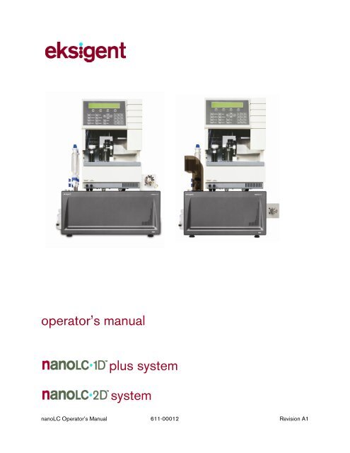
NanoLC 1D Plus and 2D System Operator's Manual - Eksigent
NanoLC 1D Plus and 2D System Operator's Manual - Eksigent
NanoLC 1D Plus and 2D System Operator's Manual - Eksigent
- No tags were found...

Create successful ePaper yourself
Turn your PDF publications into a flip-book with our unique Google optimized e-Paper software.
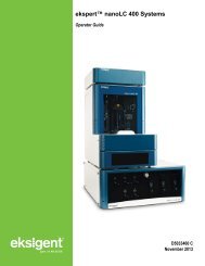
operator’s manualplus systemsystemnanoLC Operator’s <strong>Manual</strong> 611-00012 Revision A1
NoticeSupportAt <strong>Eksigent</strong> Technologies, we are committed to providing the highest level of support to our users. To obtainanswers to questions about any of our products, report problems, or suggest improvements, please visitwww.<strong>Eksigent</strong>.com. For on-site service, support <strong>and</strong> training, please contact your local <strong>Eksigent</strong> Technologiessales representative or customer service representative or send an e-mail to support@eksigent.com.NoticeThe information in this document is subject to change without notice <strong>and</strong> should not be construed as acommitment by <strong>Eksigent</strong> Technologies. <strong>Eksigent</strong> Technologies assumes no responsibility for any errors that mayappear in this document. This document is believed to be complete <strong>and</strong> accurate at the time of publication. Inno event shall <strong>Eksigent</strong> Technologies be liable for incidental or consequential damages in connection with orarising from the use of this document.ii<strong>Eksigent</strong> Technologies makes no warranties or representations as to the fitness of this equipment for anyparticular purpose <strong>and</strong> assumes no responsibility or contingent liability, including indirect or consequentialdamages, for any use to which the purchaser may put the equipment described herein, or for any adversecircumstances arising therefrom.This document is provided to customers who have purchased <strong>Eksigent</strong> Technologies equipment to use in theoperation of such equipment. This document is copyright protected <strong>and</strong> any reproduction of this document orany part of this document is strictly prohibited, except as <strong>Eksigent</strong> Technologies may authorize in writing.Equipment described in this document is protected under one or more patents filed in the United States<strong>and</strong> other countries. Additional patents are pending.Software described in this document is furnished under a license agreement. It is against the law to copy,modify, or distribute the software on any medium, except as specifically allowed in the license agreement.Furthermore, the license agreement may prohibit the software from being disassembled, reverse engineered, ordecompiled for any purpose.Portions of this document may make reference to other manufacturers ' products, which may contain parts thatare patented <strong>and</strong> may contain parts whose names are registered as trademarks <strong>and</strong>/or function as trademarks.Any such usage is intended only to designate <strong>and</strong> describe those manufacturer ' s products <strong>and</strong> does not implyany right <strong>and</strong>/or license use or permit others to use such product names as trademarks. All products <strong>and</strong>company names mentioned herein may be the trademarks of their respective owners.<strong>Eksigent</strong> ® is a registered trademark owned by <strong>Eksigent</strong> Technologies in the United States <strong>and</strong> certain othercountries.For Research Use Only. Not for use in diagnostic procedures.<strong>Eksigent</strong> Technologies5875 Arnold Rd.Dublin, CA 94568tel: 925-560-2600 fax: 925-560-2700web: www.eksigent.comCopyright © 2007 <strong>Eksigent</strong> Technologies LLC. All rights reserved.Printed in the United States of AmericananoLC Operator’s <strong>Manual</strong> 611-00012 Revision A1
iiiTable of ContentsChapter 1. Safety <strong>and</strong> Site Requirements .....................................11.1 Safety Conventions ....................................................................................................11.2 nanoLC Safety Practices ..........................................................................................11.3 nanoLC Autosampler Safety Practices..................................................................21.4 Site Requirements ......................................................................................................41.4.1 nanoLC Power Requirements ....................................................................41.4.2 nanoLC Autosampler Power Requirements ...........................................41.4.3 Air Supply Requirements.............................................................................41.4.4 Bench Space Requirement.........................................................................51.4.5 Environment Requirements.........................................................................5Chapter 2. <strong>System</strong> Installation ........................................................72.1 nanoLC <strong>System</strong> Overview ........................................................................................72.2 Unpacking the nanoLC <strong>System</strong>...............................................................................72.3 Placement of the <strong>System</strong> ..........................................................................................82.4 Connecting to the Air Supply...................................................................................82.5 Connecting the PC.....................................................................................................92.6 Connecting the nanoLC to Power ..........................................................................92.7 Installing Software <strong>and</strong> Instrument Settings...................................................... 102.8 Configuring the nanoLC <strong>System</strong>.......................................................................... 112.9 Configuring the nanoLC Autosampler ................................................................ 13Chapter 3. <strong>System</strong> Initialization....................................................153.1 Hardware Components <strong>and</strong> Functions............................................................... 153.2 Loading Mobile Phases .......................................................................................... 153.3 Preparing the nanoLC Autosampler.................................................................... 193.4 Flushing the Autosampler Syringe <strong>and</strong> Liquid Path......................................... 203.5 Connecting the nanoLC to the nanoLC Autosampler..................................... 203.6 Verifying the Flow Rate........................................................................................... 21Chapter 4. Routine Maintenance ..................................................234.1 Recommended Maintenance ................................................................................ 234.2 Disposing of Waste................................................................................................. 244.3 Changing the Sample Loop................................................................................... 244.4 Replacing Capillary Connections......................................................................... 254.5 Zeroing the Pressure Transducers ...................................................................... 264.6 Checking Flow Stability.......................................................................................... 284.7 Autotuning Flow Controllers.................................................................................. 284.8 Calibrating the Flow Meters .................................................................................. 294.9 Cleaning <strong>and</strong> Inspecting the Instrument............................................................. 31nanoLC Operator’s <strong>Manual</strong> 611-00012 Revision A1
Chapter 5. Quick-start Guide .........................................................335.1 Powering-up the <strong>System</strong>........................................................................................ 335.2 Purging <strong>and</strong> Flushing with New Solvents .......................................................... 345.3 Equilibrating the <strong>System</strong>......................................................................................... 355.4 Creating an Autosampler Method........................................................................ 375.5 Creating an LC Method- Channel 1 .................................................................... 405.6 Creating an LC Method- Channel 2 .................................................................... 435.7 Creating the Run Table........................................................................................... 455.8 Starting a Run........................................................................................................... 465.9 Viewing the Collected Data Files......................................................................... 47Chapter 6. Diagnostics <strong>and</strong> Troubleshooting .............................496.1 Overview of Hardware Diagnostics..................................................................... 496.2 Calibration Values.................................................................................................... 506.3 General Troubleshooting Guidelines .................................................................. 516.4 Troubleshooting Checklist ..................................................................................... 526.5 Error Messages <strong>and</strong> <strong>System</strong> Alerts ..................................................................... 58Appendix A Spare Parts <strong>and</strong> Consumables .................................59A.1 Consumables: nanoLC-<strong>1D</strong>+ <strong>and</strong> nanoLC-<strong>2D</strong> .................................................. 59A.2 Replacement Parts: nanoLC-<strong>1D</strong>, nanoLC-<strong>1D</strong>+ <strong>and</strong> nanoLC-<strong>2D</strong>................. 60A.3 Replacement Parts: AS-1 Autosampler.............................................................. 61Appendix B External Interface.........................................................63B.1 Interface Connections............................................................................................. 63B.1.1 Remote Interface ........................................................................................ 64B.2 Valve Connectors..................................................................................................... 65B.2.1 Remote Interface ........................................................................................ 65B.3 Connecting to Other Instruments ........................................................................ 65B.3.1 Other Autosamplers .................................................................................. 66B.3.2 Triggering MS Data Collection ............................................................... 66B.3.3 Triggering Peak Parking ........................................................................... 67B.3.4 Ready Out.................................................................................................... 67Appendix C Valve Configuration Diagrams...................................69Appendix D Quick Start Guides .......................................................73D.1 Quick Start guide: Direct to Column Injection.................................................. 73D.2 Quick Start guide: Dual Trap Column Method ................................................. 77Appendix E Replacing Internal Instrument Filters.......................83Index.......................................................................................................85vnanoLC Operator’s <strong>Manual</strong> 611-00012 Revision A1
Chapter 1.Safety <strong>and</strong> Site RequirementsChapter 1 describes safety conventions, safety procedures <strong>and</strong> site requirements necessary for properoperation of the nanoLC-<strong>1D</strong> plus <strong>and</strong> nanoLC-<strong>2D</strong> systems. Topics covered in this chapter include:• safety conventions (Section 1.1)• nanoLC safety practices (Section 1.2)• nanoLC Autosampler safety practices (Section 1.3)• site requirements (Section 1.4)1.1 Safety ConventionsThe following symbols are used in the manual:This label calls attention to a procedure, which, if not correctly executed, could result in injury or lossof life. Do not proceed beyond a ‘DANGER’ sign until the indicated conditions are fully understood<strong>and</strong> met.This label calls attention to a procedure, which, if not correctly executed, could result in personalinjury. Do not proceed beyond a ‘WARNING’ sign until the indicated conditions are fully understood<strong>and</strong> met.This label calls attention to a procedure, which, if not correctly executed, could result in damage to theequipment. Do not proceed beyond a ‘CAUTION’ sign until the indicated conditions are fullyunderstood <strong>and</strong> met.This label calls attention to important information. Read this information before continuing.1.2 nanoLC Safety PracticesThe following safety practices apply to the nanoLC system:Use of this equipment in a manner not approved by Exsigent Technologies may inhibit its safetyprotection.Perform periodic leak checks on all lines <strong>and</strong> fittings.nanoLC Operator’s <strong>Manual</strong> 611-00012 Revision A1
2 Operator’s <strong>Manual</strong>When replacing capillaries or fittings on the nanoLC system, exposure to solvents may occur. It is thereforerecommended that appropriate safety procedures be followed <strong>and</strong> personal protective equipment be used,according to the applicable material safety data sheets supplied by the solvent vendor.Do not allow flammable <strong>and</strong>/or toxic solvents to accumulate. Follow a regulated, approved waste disposalpro gram. Never dispose of flammable <strong>and</strong>/or toxic solvents into a municipal sewage system.1.3 nanoLC Autosampler Safety PracticesThe following safety practices apply to the optional nanoLC AS1 Autosampler system:Changes or modifications to this unit not expressly approved by Exsigent Technologies could void theinstrument warranty <strong>and</strong> render the system inoperable.Use of this equipment in a manner not approved by Exsigent Technologies may inhibit its safety protection.When you use the nanoLC Autosampler system, follow generally accepted procedures for quality control <strong>and</strong>methods development.When you use the nanoLC Autosampler system for chromatographic analyses <strong>and</strong> observe a change in theretention of a particular compound, the resolution between two compounds or peak shapes, immediatelydetermine the reason for the changes. Do not rely on the analytical results until the cause of the change isdetermined.Only use fuses of the type <strong>and</strong> current rating specified. Do not use repaired fuses or by-pass the fuseholder.The supplied power cord must be used with a power outlet containing a protective ground contact.Do not change the external or internal grounding connections. Tampering with or disabling these connectionscould create a safety hazard <strong>and</strong>/or damage the nanoLC Autosampler system. The instrument, as shipped,is properly grounded in accordance with normal safety regulations.The combination of a nanoLC Autosampler system with a LC/MS system may require additional safetymeasures as described by the LC/MS system vendor. Detailed instructions for the safe grounding on theLC/MS system are outlined in the corresponding vendor ’ s operating/installation manual.Exsigent Technologies recommends using a grounding cable connected between the injection valve ’ ssample loop <strong>and</strong> an appropriate grounding point at the LC/MS source. This supplementary grounding willreinforce the safety configuration specified by the LC/MS system vendor.nanoLC Operator’s <strong>Manual</strong> 611-00012 Revision A1
Safety <strong>and</strong> Site Requirements 3Do not turn the instrument on if you suspect that it has incurred any kind of electrical damage.Instead, disconnect the power cord <strong>and</strong> contact an Exsigent Technologies representative for a productevaluation. Do not attempt to use the instrument until it has been inspected <strong>and</strong> approved for use.Electrical damage may have occurred if the system shows visible signs of damage, exposure to liquids or ofhaving been transported under severe stress.Damage can also result if the instrument is stored for prolonged periods under extreme conditions (e.g.subjected to heat, water, etc.).Disconnect the power cord from its power supply before attempting any type of maintenance.Continue to exercise caution as capacitors inside the instrument may still be charged even after theinstrument has been turned off.To avoid damaging electrical parts, do not disconnect an electrical assembly while power is applied to thenanoLC Autosampler system. Once the power is turned off, wait approximately 30seconds beforedisconnecting an assembly.This instrument contains a number of sensitive electronic components that may be damaged if exposed toexcessive line voltage fluctuations <strong>and</strong>/or power surges.There are no operator-serviceable or replaceable parts inside the nanoLC Autosampler system or its powersupply. If either unit is not functioning, contact an <strong>Eksigent</strong> Technologies representative.Never try to repair or replace any of the instrument’s components not described in the manual without theassistance of an Exsigent Technologies representative.To avoid injury during nanoLC Autosampler system operation, keep h<strong>and</strong>s <strong>and</strong> loose objects away from theautosampler arm <strong>and</strong> syringe assembly.Do not operate the nanoLC Autosampler system without the safety shield properly installed.At all times, observe safe laboratory practices when h<strong>and</strong>ling solvents, changing tubing or operating thenanoLC Autosampler system in order to avoid injury. Know the physical <strong>and</strong> chemical properties of thesolvents you use. See the solvent manufacturer ’ s Material Safety Data Sheets for any solvent being used.Use caution when working with any polymer tubing under pressure:• Always wear proper eye protection when near pressurized polymer tubing.• Do not use polymer tubing that has been severely stressed or kinked.• Do not use polymer tubing, in particular PEEK or DuPont Tefzel tubing, with tetrahydrofuran (THF),dimethylsulfoxide (DMSO), chlorinated organic solvents, concentrated mineral acids, such as nitric,phosphoric or sulfuric acids, or any related compounds.An on board lithium battery maintains the autosampler firmware when the instrument is turned off. Becauseit is hard-wired in place, it should only be replaced a factory authorized service engineer.nanoLC Operator’s <strong>Manual</strong> 611-00012 Revision A1
4 Operator’s <strong>Manual</strong>1.4 Site RequirementsThis section describes the requirements for power, air, space <strong>and</strong> environment for operation of yourinstrument.1.4.1 nanoLC Power RequirementsThe nanoLC is powered by a 24 VDC external power supply. Only the universal AC/DC adapter <strong>and</strong>power cord supplied with the instrument should be used.The external adapter permits operation from any line voltage between 100–240 VAC, 47–63 Hz <strong>and</strong>4A.1.4.2 nanoLC Autosampler Power RequirementsLine voltage:• 115 VAC; + 15/-20 %; 50 Hz/60 Hz; 250 VA• 230 VAC; + 15/-20 %; 50 Hz/60 Hz; 250 VAFuses:• For 115 VAC; two 5.0 AT-fuses• (¼” x 1¼”, UL/CSA)• For 230 VAC; two 2.5 AT-fuses• (5 x 20 mm, IEC 127)• All fuses UL-listed <strong>and</strong> CSA-certified1.4.3 Air Supply RequirementsOperation of the instrument requires connection to a source of 100 psi (6.9 bar) regulated clean, dry airor nitrogen. The instrument site should be within about 6 m (20 ft) of the air/nitrogen regulator. Whenusing compressed air, Exsigent Technologies strongly recommends an air supply having a dew point ofless than 4.5 C (40 °F). When using dry nitrogen or compressed air, Exsigent Technologies stronglyrecommends the use of air filtration to 5 µm (e.g. for compressed gas supplied at less than 150 psi, aWilkerson F18 filter) <strong>and</strong> regulation to a working pressure of 100 psi (e.g. for compressed gas suppliedat less than 150 psi, a Wilkerson R18 regulator or a Wilkerson B18 combination regulator/filter). Ifhydrocarbons are suspected in the air supply (i.e. air supplied from an oiled compressor). ExsigentTechnologies strongly recommends the regulator be followed with a coalescing filter suitable forparticle removal to 0.01 µm (e.g. a Wilkerson M18 coalescing filter).Note: Always follow manufacturer’s specifications in selecting <strong>and</strong> operating gas filters <strong>and</strong> regulators.Note: Always follow manufacturer’s specifications for connecting, mounting <strong>and</strong> orienting gas filters<strong>and</strong> regulators.Note: Always perform proper maintenance of traps, filters <strong>and</strong> coalescing filters per manufacturer’sspecifications. Liquids collected in filters <strong>and</strong> coalescing filters must be drained before the liquid levelexceeds the manufacturer’s specifications.nanoLC Operator’s <strong>Manual</strong> 611-00012 Revision A1
1.4.4 Bench Space RequirementSafety <strong>and</strong> Site Requirements 5The nanoLC system requires clear bench space of at least the following dimensions.• nanoLC-<strong>1D</strong> plus TM : 21” (53 cm) wide × 20” (51 cm) deep × 19” (48 cm) high (allowing excessspace for cables).• nanoLC-<strong>2D</strong> TM : 21” (53 cm) wide × 24” (61 cm) deep × 19” (48 cm) high (allowing excess spacefor cables).With the nanoLC Autosampler the height requirement for both systems is 27”(69 cm).This bench space requirement does not accommodate the computer, keyboard, mouse <strong>and</strong> monitor.1.4.5 Environment RequirementsThe instrument is designed to operate in an environment with ambient temperatures between 20 <strong>and</strong>30 °C (68–86 °F) <strong>and</strong> non-condensing humidity.nanoLC Operator’s <strong>Manual</strong> 611-00012 Revision A1
Chapter 2.<strong>System</strong> InstallationChapter 2 describes the recommended procedure for unpacking <strong>and</strong> installing the nanoLC system.Topics covered in this chapter include:• nanoLC system overview (Section 2.1)• unpacking the nanoLC system (Section 2.2)• placement of the system (Section 2.3)• connecting to the air supply (Section 2.4)• connecting the PC (Section 2.5)• installing the nanoLC Autosampler (Section 2.6)• connecting the nanoLC to power (Section 2.7)• installing software <strong>and</strong> instrument settings (Section 2.8)• configuring the nanoLC system (Section 2.9)• configuring the nanoLC Autosampler (Section 2.10)2.1 nanoLC <strong>System</strong> OverviewThe nanoLC systems are designed for HPLC applications that employ direct pumping at flow rates ofseveral hundred nL/min. The fully integrated system includes binary gradient pumps, an additional pumpor second binary gradient pump system, temperature-controlled flow modules, <strong>and</strong> a column switchingvalve. The system is compatible with the nano LC Autosampler. This chapter introduces the hardware<strong>and</strong> software features of the nanoLC systems.2.2 Unpacking the nanoLC <strong>System</strong>step 1step 2step 3step 4Inspect the shipping cartons for damage or evidence of mish<strong>and</strong>ling. If external damage is evident,notify the carrier before opening the cartons.Cut the tape <strong>and</strong> open the flaps on the top of the nanoLC system shipping box. Remove the outershipping box.Open the inner shipping box <strong>and</strong> remove the foam packing material from the top of the nanoLCsystem.Carefully lift the nanoLC system out of the box. Grasp the sides of the instrument; do not use theprotective bag to lift the instrument. A second person may be needed to help slide the carton <strong>and</strong>foam inserts off the instrument.nanoLC Operator’s <strong>Manual</strong> 611-00012 Revision A1
8 Operator’s <strong>Manual</strong>step 5step 6step 7step 8Place the instrument on a lab bench.Check the contents of the accessory kit against the contents checklist in Appendix A to confirm thatall items are included.The checklist for parts included with the nanoLC Autosampler is included in the nanoLCAutosampler manual.Unpack the computer <strong>and</strong> monitor <strong>and</strong> verify that no parts are missing or damaged.2.3 Placement of the <strong>System</strong>Place the nanoLC system on a lab bench in a location with convenient access to power <strong>and</strong> a source of100 psi (6.9 bar) regulated clean, dry air or nitrogen. The front of the instrument should be accessibleat all times. The sides <strong>and</strong> back of the instrument should be clear to accommodate mobile phasereservoir placement <strong>and</strong> attachment, <strong>and</strong> computer cable attachments2.4 Connecting to the Air SupplyOperation of the instrument requires connection to a source of 100 psi (6.9 bar) regulated clean, dry airor nitrogen as described in the section on Site Requirements.Figure 2-1. Rear Panel - Air ConnectionRequired tools <strong>and</strong> materials:• Clean, dry source of air or nitrogen at 100 psi (6.9 bar)• In-line moisture trap with ¼” end-fittings• 6 mm or ¼” air supply line (included)• Quick-connect adaptor to 6 mm or ¼” supply line (included)step 1step 2step 3Connect the supplied air line to a source of 100 psi (6.9 bar) regulated clean, dry air or nitrogenusing the supplied quick-connect adaptor. Connect the other end of the air line to the air connectionon the back of the nanoLC system (see Figure 2-1).Turn on the air source to the nanoLC system.Test for air leaks. Turn off air supply <strong>and</strong> repair any air leaks that are found.nanoLC Operator’s <strong>Manual</strong> 611-00012 Revision A1
<strong>System</strong> Installation 92.5 Connecting the PCRequired materials:• Computer, keyboard <strong>and</strong> mouse• nanoLC system serial cable (included)Figure 2-2. Rear Panel — PC I/O ConnectorConnect one end of the RS-232 cable to an available COM port connector on the computer. COM1 isrecommended as it is selected as the default in the software configuration.The other end of the cable should be connected to the 9-pin connector labeled PCI/O on the rearpanel of the nanoLC system (see Figure 2-2). Tighten the retaining screws at both ends to secure thecable in place.2.6 Connecting the nanoLC to PowerRequired materials:• 24 VDC power supply (included)Insert the supplied 24 VDC power supply’s plug into the connector located on the back of theinstrument (Figure 2-3). Plug the line voltage cord into an appropriately grounded line voltage outlet.Turn the nanoLC on using power switch on the back of the unit.24 VAC PowerFigure 2-3. Rear Panel — Power ConnectionnanoLC Operator’s <strong>Manual</strong> 611-00012 Revision A1
10 Operator’s <strong>Manual</strong>2.7 Installing Software <strong>and</strong> Instrument SettingsRequired materials:• CD with control software• disk with system settingsstep 1step 2step 3step 4Insert the CD into the CD drive <strong>and</strong> install the Control Software (see software manual for additionalinformation on installation).After installing software, but before starting the software, insert the disk with the system settings(shipped with new instrument).Locate the file titled ‘EKsetting.reg’ in the Settings subfolder.Double click on the file ‘EKsettings.reg’ to install the instrument settings into the registry of thecomputer. A window will pop up asking you if you really want to write to the registry (Figure 2-4).Figure 2-4. First Registry Prompt Windowstep 5step 6step 7Click Yes. A second window will popup indicating that you have successfully written to the registry(Figure 2-5).Click OK.The factory settings for your instrument should now be loaded into the registry. You should stillconfigure the system (section 2.9) in case the COM port or other settings need to be adjusted fromthe factory defaults.Figure 2-5. Second Registry Prompt WindownanoLC Operator’s <strong>Manual</strong> 611-00012 Revision A1
<strong>System</strong> Installation 112.8 Configuring the nanoLC <strong>System</strong>Launch the Control Software from your computer’s Programs menu or from the Control Software iconon the desktop.If you did not connect the serial cable to COM1, or the instrument power is not turned on, a COM Errordialog box (Figure 2-6) will appear:Figure 2-6. Serial Port Communications ErrorNote: If the nanoLC system is connected to the PC’s COM1 port <strong>and</strong> the error message still appears,re-boot the PC <strong>and</strong> re-start the software.If the nanoLC is connected to a communications port other than COM 1, the instrument configurationwill need to be changed.step 1 Launch the control software. The COM error in Figure 2-8 will appear. Click on ‘Cancel.’ A secondwindow will appear (see Figure 2-7). Click on ‘OK’ to enter the software in DEMO MODE.Figure 2-7. Running the Software in Demo Modestep 2 Select <strong>System</strong> > Instrument Config… from the Control Software’s Acquisition Window to accessthe Instrument Configuration Window (see Figure 2-8).The Instrument Configuration Window (Figure 2-8) is used to indicate which components areinstalled. It also sets the communications protocol <strong>and</strong> configures the system to work with otherconnected devices. Several instrument performance parameters are also set in this window.nanoLC Operator’s <strong>Manual</strong> 611-00012 Revision A1
12 Operator’s <strong>Manual</strong>Figure 2-8. Instrument Configuration Windowstep 3 Select the appropriate COM port for the nanoLC from the dropdown list.step 4 Exit from the Control software.step 5 Launch the control software.The Instrument Configuration Window (Figure 2-8) is used to indicate which components areinstalled. It also sets the communications protocol <strong>and</strong> configures the system to work with otherconnected devices. Several instrument performance parameters are also set in this window.Select <strong>System</strong> > Instrument Config… from the Control Software’s Acquisition Window to access theInstrument Configuration Window.Make sure that one of the following systems is selected in the Device field.• nanoLC-<strong>1D</strong> plus• nanoLC-<strong>2D</strong>The computer is configured at the factory to use COM1 to communicate with the nano LC system. If theserial cable is connected to a different serial port, change the setting in the on this page to indicate thecorrect COM port.In the Injection Valve field, select <strong>Eksigent</strong> Internal.If an auxiliary A/D input (such as a UV detector) is connected to the system, specify the voltage rangethe external device will provide under Aux A/D.In the Advanced Options box, type an acceptable idle time after which the system will be shut-down<strong>and</strong> then check the box.Select the appropriate signal input <strong>and</strong> output settings based on the requirements of the otherinstruments connected to the <strong>Eksigent</strong> nano LC system.nanoLC Operator’s <strong>Manual</strong> 611-00012 Revision A1
<strong>System</strong> Installation 13Flow Stabilization Limits specifies the degree of flow rate stability required before a gradient willbegin. For most applications, a setting of 100 nL/min should be sufficient. However for high sensitivityapplications, this parameter should be set closer to 20 nL/min.The Pressure Limits box allows for the specification of a maximum system pressure. If the columnpressure exceeds this limit, the run will be automatically stopped <strong>and</strong> no further injections will takeplace. There is no loss of sample if the system shuts down. For most applications a value of 3500 psi isrecommended.Click OK to go back to the Acquisition Window.2.9 Configuring the nanoLC AutosamplerClick on the Run Manager button to bring up the Run Manager Window for configuring theautosampler (Figure 2-9).Figure 2-9. Run Manager WindowSelect Devices > Autosampler Type > <strong>NanoLC</strong>-AS1 <strong>and</strong> the following message will appear:Figure 2-10. Run Manager shutdown promptClick Yes to close the program.Click on Run Manager again, <strong>and</strong> Select Devices > Autosampler Device Settings. Set the COM portfor the AutosamplernanoLC Operator’s <strong>Manual</strong> 611-00012 Revision A1
14 Operator’s <strong>Manual</strong>Figure 2-11. Autosampler Device SettingsThe system is not yet configured for operation. You must first complete the instructions in <strong>System</strong>Initialization prior to system operation.nanoLC Operator’s <strong>Manual</strong> 611-00012 Revision A1
Chapter 3.<strong>System</strong> InitializationChapter 3 describes procedures used to prepare a system for initial operation or for operation followingan extended period of non-use. Topics covered in this chapter include:• hardware components <strong>and</strong> functions (Section 3.1)• loading mobile phases (Section 3.2)• preparing the nanoLC Autosampler (Section 3.3)• flushing the sample loop <strong>and</strong> sample needle (Section 3.4)• connecting the nanoLC to the nanoLC Autosampler (Section 3.5)• verifying the flow rate (Section 3.6)3.1 Hardware Components <strong>and</strong> FunctionsThis section provides a general description of the key components of the nanoLC systems <strong>and</strong> theirvarious functions.Mobile phase outlets are located on the right side of the nanoLC system. Each channel has onemobile phase outlet which can be connected to the autosampler <strong>and</strong> a 10-port column switching valve.The 10-port Column Switching Valve is used to switch between reverse phase traps that are connectedto the valve for rapid sample loading. Refer to Appendix D for different valve configurations.An Optional 6-port injection valve is available instead of the nano LC Autosampler for manual sampleloading. Refer to Appendix D for valve configurations.3.2 Loading Mobile PhasesThe procedure for loading mobile phases will be described for a single binary gradient system forreverse phase chromatography.If you have a <strong>NanoLC</strong>-<strong>2D</strong> system, complete this procedure for both channels 1 <strong>and</strong> 2. It is suggestedthat you use mobile phase A described below in both reservoirs of channel 1 <strong>and</strong> use the suggested A<strong>and</strong> B mobile phases for the low flow gradient in channel 2.If you have a nanoLC-<strong>1D</strong> system, complete this procedure for channel 1 using the mobile phasesdescribed below. It is suggested that you use mobile phase A in the single reservoir for channel 2 forhigh flow sample loading.nanoLC Operator’s <strong>Manual</strong> 611-00012 Revision A1
16 Operator’s <strong>Manual</strong>Required tools <strong>and</strong> materials:• Mobile phase reservoirs (p/n 800-00105)• Clean, degassed HPLC-grade mobile phase A (water with 2% acetonitrile <strong>and</strong> 0.1% formic acidsuggested).• Clean, degassed HPLC-grade mobile phase B (acetonitrile with 2% water <strong>and</strong> 0.1% formic acidsuggested).• nanoLC priming tool (p/n 801-00003)• 15 mL centrifuge tubestep 1step 2Clean all 50 mL mobile phase reservoirs with appropriate solvents.Close the orange valve on the reservoir by turning it to the perpendicular position.step 3 Fill reservoir A with mobile phase A <strong>and</strong> reservoir B with mobile phase B.step 4Install both reservoirs <strong>and</strong> open each valve by rotating to a vertical position.Purging <strong>and</strong> flushing the pumps are critical operations to get maximum performance from a newinstrument. Purging rapidly replaces the solvent in the pumps while flushing replaces the solvent inthe capillaries connecting the pumps to the sample injector.Mobile PhaseReservoir 2AMobile PhaseReservoir 1BFigure 3-1. Top Panel — Reservoirs for the <strong>NanoLC</strong>-<strong>2D</strong> <strong>System</strong>step 5Select <strong>System</strong> > Mobile Phases from the main window of the control software to present theMobile Phases dialog box (Figure 3-2).nanoLC Operator’s <strong>Manual</strong> 611-00012 Revision A1
<strong>System</strong> Initialization 17step 6 Set the composition for mobile phase A: Enter the correct solvent composition for Mobile Phase A.the A mobile phase will generally be mostly water.step 7 Set the composition for mobile phase B: Enter the correct solvent composition for Mobile Phase B.the B mobile phase will generally be mostly acetonitrile.Figure 3-2. Mobile Phases Windowstep 8 Click the More… button to present the purge <strong>and</strong> flush settings (Figure 3-3).Figure 3-3. Mobile Phases Window — Advancedstep 9Purge the bubbles from each pump using the priming tool using the following steps:a. Under Purge Settings, select only one pump to purge, i.e. channel 1 A. Set the number ofpurge cycles to 20.b. Click Purge Now. The pump will begin to execute purge cycles. While the pump is purging,insert the priming tool all the way into the pump <strong>and</strong> depress the check valve.nanoLC Operator’s <strong>Manual</strong> 611-00012 Revision A1
18 Operator’s <strong>Manual</strong>Hold down the primingtool, <strong>and</strong> look for slightrise in the liquid in thebottle.When no more bubblescome out, remove thetubing <strong>and</strong> let the pumppurge a few more times.Figure 3-3. Priming Tool Usagec. After bubbles cease to come up into the bottle, allow the pump to continue purging for the restof the 20 cycles.d. Repeat steps a-c for all the pumps separately to ensure each pump is adequately primed.step 10 Enter 10 for purge cycles, select Side A <strong>and</strong> de-select Side B.step 11 Click Purge Now to purge the A pump.step 12 Collect the purge output in a 15 mL graduated centrifuge tube. The pump should deliver a total ofapproximately 6 mL of solvent (600 µL per purge cycle × 10 cycles).step 13 Next de-select Side A <strong>and</strong> select Side B.step 14 Click the Purge Now button to purge the B pump.step 15 Collect the purge output for pump B <strong>and</strong> verify that the total volume is approximately 6 mL.step 16 Enter 100 for the µL Flush volume <strong>and</strong> select a flow rate appropriate for the maximum flow of thechannel. For high flow channels, select 10 for the µL/min Total Flow rate. For low flow channels,select 6500 for the nL/min Total Flow rate. Ensure that the outlets of the pump aredisconnected before proceeding. Flushing the system with a column connected could overpressurethe system <strong>and</strong> create leaks.step 17 Click the Flush Now button.step 18 Repeat the above steps for the other channel.step 19 After the flush sequence ends, click OK to close the Mobile Phases window.nanoLC Operator’s <strong>Manual</strong> 611-00012 Revision A1
3.3 Preparing the nanoLC Autosampler<strong>System</strong> Initialization 19The nanoLC Autosampler is the st<strong>and</strong>ard autosampler installed with nanoLC system. The autosamplershould be pre-assembled <strong>and</strong> aligned by a qualified <strong>Eksigent</strong> Technologies service representative.Refer to the nanoLC Autosampler User <strong>Manual</strong> for a detailed description on its operation.Required tools <strong>and</strong> materials:• Clean HPLC-grade water• Clean HPLC-grade isopropanolFigure 3-4. <strong>Eksigent</strong> nanoLC-<strong>1D</strong>+ Shown with Nano LC Autosamplerstep 1step 2Fill the wash bottle with a 20/80 mixture of isopropanol/water that has been degassed.Place the wash bottles on the wash station bracket <strong>and</strong> insert the Teflon tubing.nanoLC Operator’s <strong>Manual</strong> 611-00012 Revision A1
<strong>System</strong> Initialization 21step 5step 6step 7Open the Direct Control Window (Fig. 3-5) by clicking <strong>System</strong> > Direct Control from the Controlsoftware’s Acquisition Window.Set solvent A <strong>and</strong> B to 50/50 <strong>and</strong> Total flow rate to 20 µL/min. (for <strong>NanoLC</strong>-<strong>1D</strong>+, use 100%A).Click Start to flush the valve ports <strong>and</strong> capillary. Flush for 10 minutes.Figure 3-5. Direct Control Window — Flushing CH1 Autosampler Connectionstep 8Stop the flow by clicking Stop.3.6 Verifying the Flow RateBefore operating the system it is suggested that you verify that the flow rate is properly calibrated. Thisis done by measuring the time it takes to move a liquid front through a graduated capillary of knownvolume.Required tools:• Flow calibration assembly (p/n 801-00002) for high flow rate channel (includes 20 µL pipettes)• Flow calibration assembly (p/n 910-00006) for low flow rate channel (includes 5 µL graduatedpipettes)step 1 Re-initialize the pressure transducers (see section 4.5).step 2 Attach the appropriate flow calibration assembly to the outlet of channel 1 or 2.step 3Select <strong>System</strong> > Direct Control from the <strong>Eksigent</strong> Control Software Acquisition Window.step 4 Set channel A to 100% <strong>and</strong> an appropriate flow rate for that channel (Figure 3-6).• 5 µL/min for high flow channel• 500 nL/min for low flow channelnanoLC Operator’s <strong>Manual</strong> 611-00012 Revision A1
22 Operator’s <strong>Manual</strong>step 5step 6step 7Click the Start button <strong>and</strong> begin timing. With the high flow calibration assembly, the time it takes forthe meniscus or an air bubble to transit from the black stripe to the end of the capillary should be 4minutes. With the low flow calibration assembly, the time it takes for the meniscus or an air bubble totransit across two segments of the capillary (2 µL) should be 4 minutes. Press Stop when the fluidfront reaches the end of the pipetteIf the flow rate falls outside of the acceptable range (> ±5%) , re-calibrate the flow meters per theprocedure found in Section 4.8Disconnect the calibration assembly <strong>and</strong> blow out the liquid inside the pipette using a pipette bulb orcan of compressed air.Figure 3-6. Direct Control Window — Flow Rate Checkstep 8 Set channel B to 100% <strong>and</strong> repeat steps 5 <strong>and</strong> 6 to verify the flow rate for pump B.step 9Disconnect the calibration assembly.nanoLC Operator’s <strong>Manual</strong> 611-00012 Revision A1
24 Operator’s <strong>Manual</strong>4.2 Disposing of WasteThe user will need to properly dispose of the contents of any effluent waste in an appropriate chemicalwaste container. For typical nanospray experiments, waste from the 10-port column switching valve dueto high flow sample loading will be collected in a waste vial.The pump purge waste container located on the left side of the instrument will also need to be emptiedperiodically. Unscrew the thumbscrew holding the clamp around the waste bottle. Remove the bottlefrom the clamp <strong>and</strong> unscrew the cap from the bottle. Pour the contents into an appropriate chemicalwaste container.Always follow appropriate safety procedures when h<strong>and</strong>ling or disposing waste chemicals. See the solventMaterial Safety Data Sheets for more information.4.3 Changing the Sample LoopRequired tools <strong>and</strong> materials:• Laboratory wipes• Clean HPLC-grade methanol• 1/4” open end wrench• Sample loop• Two 1/16” HPLC fittings (p/n 920-00006 <strong>and</strong> 910-00023)Note: This sample loop may be on the optional 6-port sample injection valve or on the nano LCAutosampler.step 1 Use the 1/4” wrench (or fingertight fittings) to remove the installed sample loop.step 2 Insert one end of the new sample loop through a 1/16” fitting <strong>and</strong> ferrule <strong>and</strong> into the injection valveport. Make sure the end of sample loop is flat <strong>and</strong> fully inserted into the valve port. Do not reusefittings from other valves as the port depth can vary from valve to valve.step 3 Attach the other end of the sample loop to the opposite valve port.step 4 Open the Direct Control Window by clicking <strong>System</strong> > Direct Control from the Control software’sAcquisition Window.step 5 Set solvent A to 50, solvent B to 50 <strong>and</strong> Total flow rate to 6 µL/min (Figure 4-1).step 6 Click Start.step 7 Toggle the injection valve between the load <strong>and</strong> the inject position several times to flush out anyloose particles.step 8 Look for any signs of leakage indicating a loose connection. Remake any connections that indicate aleak.step 9 Click Stop.nanoLC Operator’s <strong>Manual</strong> 611-00012 Revision A1
Routine Maintenance 254.4 Replacing Capillary ConnectionsRequired tools <strong>and</strong> materials:• Laboratory wipes• Clean HPLC-grade methanol• 1/4” Allen wrench• Transfer capillary• For the high flow channel, use 50 µm ID (p/n 910-00002)• For the low flow channel, use 25 µm ID (p/n 910-00008)• Microtight fitting• Green PEEK sleeve (p/n 910-00025)• Black microtight ferrule (p/n 920-00002)• Tan microtight nut (p/n 920-00003)• 1/16” sleeved fitting• 1/16” OD Orange PEEK sleeve (p/n 910-00024)• 1/16” PEEK fitting nut (p/n 920-00006)• 1/16” PEEK fitting ferrule (p/n 910-00023)step 1step 2step 3step 4step 5step 6step 7step 8Use the 1/4” Allen wrench or your fingers to remove the current fitting, ferrule, <strong>and</strong> sleeve.Remove the fitting <strong>and</strong> ferrule from the capillary <strong>and</strong> discard the old capillary.Cut the capillary to the appropriate length. Ensure a clean end cut <strong>and</strong> clean with methanol.Insert one end of a new capillary through the appropriate PEEK sleeve.Slide the end of the capillary <strong>and</strong> the PEEK sleeve through the compression fitting <strong>and</strong> ferrule. Makesure the sleeve extends through the ferrule.Slide the capillary, sleeve <strong>and</strong> fitting into the port until both bottom out.While lightly pressing the capillary <strong>and</strong> sleeve into the fitting with one h<strong>and</strong>, use the other h<strong>and</strong> or the1/4” wrench to tighten the fitting.Open the Direct Control window by clicking <strong>System</strong> > Direct Control from the Control software’sAcquisition Window (Figure 4-1).nanoLC Operator’s <strong>Manual</strong> 611-00012 Revision A1
26 Operator’s <strong>Manual</strong>Figure 4-1. Direct Control Windowstep 9Set solvent A to 50, solvent B to 50 <strong>and</strong> Total flow rate to an appropriate value for the channel youare connecting.step 10 Click the Start button <strong>and</strong> flush the capillary for 5 minutes.4.5 Zeroing the Pressure TransducersBefore zeroing the pressure transducers, it is advisable to open the outlet fittings from the mixing teeson all channels. This will ensure there is no residual pressure on the outlet of the system.Zeroing the pressure transducers should be performed on a monthly basis. To initiate thepressure transducer zeroing procedure, start the Control software <strong>and</strong> access the diagnostics screenby selecting <strong>System</strong> > Hardware Diagnostics.It is very important that the instructions below are followed precisely. Attempting to zero the pressuretransducers while there is still residual pressure on the system will lead to inaccurate flow rates.nanoLC Operator’s <strong>Manual</strong> 611-00012 Revision A1
Routine Maintenance 27Figure 4-2. Hardware Diagnostics Window -Reinitialize Transducersstep 1step 2In diagnostics, check the Re-Initialize Transducers box.Click Start Diagnostics. A message will appear (Fig. 4-3) warning that the procedure should only beperformed if there is no residual pressure on the system.Figure 4-3. Residual Pressure Warningstep 3Once the system indicates that it is at ambient pressure, click OK <strong>and</strong> a status window will indicatethat auto-zero is in progress (Figure 4-4).nanoLC Operator’s <strong>Manual</strong> 611-00012 Revision A1
28 Operator’s <strong>Manual</strong>Figure 4-4. Auto-zero Status Windowstep 4step 5When the auto-zeroing process is complete, exit the diagnostics window <strong>and</strong> return to theAcquisition Window.Repeat for both channels (if not conducted simultaneously).4.6 Checking Flow StabilityThe flow stability of the A <strong>and</strong> B channels can be determined in a similar fashion to the procedure usedfor zeroing pressure transducers as described in Section 4.5 by selecting the Check Flow Stabilitydiagnostic test. Two screens will be observed during the running of the test (Figure 4-5). Initially theprocess requires the controllers to stabilize for 60 seconds. This is then followed by a 30 secondexamination of the control.Step 1 Step 2Figure 4-5. Checking Flow Stability ProgressionRepeat this for both channels.4.7 Autotuning Flow ControllersThe flow controller autotune should be run on a monthly basis to optimize the performance of thesystem.To avoid the possibility of overpressure, disconnect the capillary at the mixing tee fitting prior toperforming the autotune procedure.step 1When the Autotune button is selected in the diagnostic window, the system’s response to changesin flow rate is monitored <strong>and</strong> adjustments are made to the controllers PID (proportional/integral/derivative) loop.step 2 A prompt window alerts you that the autotune is about to begin (Figure 4-6).nanoLC Operator’s <strong>Manual</strong> 611-00012 Revision A1
Routine Maintenance 29Figure 4-6. Autotune Promptstep 3This is followed by status windows (Figure 4-7) which alert you that the system is preparing to Autotune<strong>and</strong> then performing the autotune.These adjustments improve the system’s response time <strong>and</strong> flow rate accuracy.Figure 4-7. Autotune Status Bars — Channel Astep 4step 5Upon completion, close the diagnostics window <strong>and</strong> return to the main screen.Repeat for both channels (if not conducted simultaneously).Note: The slider below the Auto Tune Controllers button is used to change the pump time response.Moving the slider to the right will change the pump to respond faster (under-damped). Moving theslider to the left will change the pump to respond slower (over-damped).4.8 Calibrating the Flow MetersThe flow meters should be calibrated quarterly or when the gradient separation performance seems tobe drifting. Calibration of the flow meters consists of measuring the velocity of a liquid front in a tube ofknown diameter. Selecting the Calibrate Flow meters test will bring up a dialog box with step-by-stepinstructions for performing the test.Required tools:• flow calibration assembly (p/n 801-00002 or 801-00006)Note: If calibrating the low flow channel using the 801-00002 assembly, you can save time by connectingthe pipette to the system <strong>and</strong> prefilling the pipette to approximately 5 µm before the first blackline using either Direct Control or the Mobile Phases > Flush Now feature.step 1Select <strong>System</strong> > Hardware Diagnostics from the Control software Acquisition Window. Selectingthe Calibrate Flow meter test will bring up a dialog box with step-by-step instructions for performingthe test.nanoLC Operator’s <strong>Manual</strong> 611-00012 Revision A1
30 Operator’s <strong>Manual</strong>Figure 4-8. Flow Calibration Windowstep 2step 3step 4step 5Verify that mobile phases specified are correct. If incorrect, click Cancel to close the Flow meterCalibration Window. Make the necessary changes in the Mobile Phases Window, perform step 1again <strong>and</strong> then click Next.Attach the flow calibration assembly, with appropriate pipette to either the mixing tee or after thevalve or column. Select the appropriate pipette size <strong>and</strong> flow rate for calibrating that channel (seetable 4-2).20 µL/division in the pipette size to set the calibration flow rate to 5 µL/min for the highflow channel or 1 µL/division in the pipette size to set the calibration flow rate to 500 nL/min for thelow flow channel.Click Next to start the flow in channel A. Enter the appropriate volume requested in step 3 of theFlow Calibration Window dialog (Fig. 4-8). Wait until the liquid front travels to the black line mark onthe pipette <strong>and</strong> press Start to begin timing. For Channel 1, time how long it takes for the liquid frontto travel 20 µL. For Channel 2, time how long it takes for the liquid front to travel 2 µL. Press Stopwhen the fluid front reaches the end of the pipette, or the appropriate mark. Then click Next. Ifnecessary disconnect the calibration assembly <strong>and</strong> dry out the liquid inside the capillary.Repeat the measurement for calibration of the B channel flow meter.step 6Verify that the instructions were followed exactly <strong>and</strong> that all values entered are correct <strong>and</strong> then clickfinish.nanoLC Operator’s <strong>Manual</strong> 611-00012 Revision A1
Routine Maintenance 31step 7Use Table 4-2 to choose the proper calibration pipettes when calibrating the high flow <strong>and</strong> low flowchannels of the nanoLC.Table 4-2. Calibration Pipette GuideHigh Flow ChannelLow Flow ChannelCalibrated Pipette Size 20 µL 1 µL/division (5µL total)Calibration Flow Rate 5 µL/min 500 nL/minCalibration Volume 20 µL/side 2 µL/sideFigure 4-9. Flow Calibration Pipettes4.9 Cleaning <strong>and</strong> Inspecting the InstrumentUnplug the external power supply from the power source before cleaning <strong>and</strong> internal inspection.step 1step 2step 3Clean the outside of the instrument by wiping down with a cloth slightly dampened with water <strong>and</strong> asmall amount of liquid dish soap.Visually inspect the system fluidics <strong>and</strong> electronic connectors on a quarterly basis. Look for evidenceof fluid leaks by checking all fluid connections. Also look for dried deposits that may indicate a slowleak.Identify <strong>and</strong> correct the source of any leaks if found. If a fluidic connection is broken, replace thefitting <strong>and</strong> re-flush the system. Inspect the new connection to ensure that no leaks are present.Dabbing a laboratory wipe around fluid connections is a good method to identify slow leaks.nanoLC Operator’s <strong>Manual</strong> 611-00012 Revision A1
Chapter 5.Quick-start GuideChapter 5 offers a brief tutorial which should be useful in underst<strong>and</strong>ing the normal operation of the<strong>Eksigent</strong> nano LC. The procedures described in this chapter presume that the system has already beenproperly installed <strong>and</strong> initialized as described in chapters 2 <strong>and</strong> 3. Topics in this chapter include:• powering-up the system (Section 5.1)• purging <strong>and</strong> flushing with new solvents (Section 5.2)• equilibrating the system (Section 5.2)• creating an autosampler method (Section 5.3)• creating an LC method (Section 5.4)• creating a run table (Section 5.5)• starting a run (Section 5.6)• viewing the collected data file (Section 5.7)5.1 Powering-up the <strong>System</strong>If the system is not already on, turn on the nanoLC power switch mounted on the rear panel. The greenLED on the front of the instrument should illuminate <strong>and</strong> the injection valve should initialize.If the autosampler is not already on, turn on the power switch on the nanoLC Autosampler.Turn on the computer, log-in to Windows <strong>and</strong> launch the Control Software by double clicking thesoftware icon.After initialization, the Control software’s Acquisition Window of the Control software will be displayed(Figure 5-1).Note: On multichannel systems: Both the nanoLC-<strong>1D</strong> plus <strong>and</strong> the <strong>NanoLC</strong>-<strong>2D</strong> instrument have twochannels of fluid control. They are denoted in this manual <strong>and</strong> in the software as channel numbers 1<strong>and</strong> 2. Throughout the software common windows are used to display or control these channels. Toselect the channel appropriate to that window (when available) simply click on the up or down arrowsnext to the channel number display in the upper right of the window.nanoLC Operator’s <strong>Manual</strong> 611-00012 Revision A1
34 Operator’s <strong>Manual</strong>Figure 5-1. Acquisition Window5.2 Purging <strong>and</strong> Flushing with New SolventsIf solvent has been sitting for more than 2 weeks, the solvent should be replaced with fresh solvent,then purged <strong>and</strong> flushed. If the solvent is less than two weeks old, proceed to step 5.3.step 1 To discard old solvent in the reservoir bottles, one of two methods can be used: remove the bottle<strong>and</strong> pour out the old solvent, or purge the old solvent through to waste (Figure 5-2).nanoLC Operator’s <strong>Manual</strong> 611-00012 Revision A1
Quick-start Guide..35CloseLoosenGripstopcockpullupEmptyReplaceFigure 5.2- Emptying Solvent Reservoirsstep 2 Pour new mobile phase into the bottle. Purge the HPLC at least 10 times. Depress the check valvewhile purging to dislodge bubbles in the pump head, as shown in figure 3.3.1.step 3 After the pump is thoroughly purged, flush. Select <strong>System</strong> > Mobile Phases from the main controlwindow. Click More <strong>and</strong> flush the system 100uL on Channel 1 <strong>and</strong> Channel 2. See section 3.2 formore information on flushing.5.3 Equilibrating the <strong>System</strong>The Control software’s Direct Control window (Figure 5-3) can be used to equilibrate the systemfollowing system power-up, a change of solvent or change of column. The injection valve can also betoggled between load <strong>and</strong> inject positions to flush the injection valve loop <strong>and</strong> interconnecting ports.Select <strong>System</strong> > Direct Control from the main Control software Acquisition Window.nanoLC Operator’s <strong>Manual</strong> 611-00012 Revision A1
36 Operator’s <strong>Manual</strong>Figure 5-3. Direct Control Windowstep 1 Ensure that the Conserved Flow radio button is selected, set A (%) to 50 <strong>and</strong> B (%) to 50. This willbe the mobile phase composition used for equilibration.step 2 Set the Total flow rate to 300 (nL/min).step 3 Click on Start to start the pumps <strong>and</strong> begin equilibration.step 4 Flush the switching valve (or an injection valve connected directly to the <strong>Eksigent</strong> nano LCinstrument) by alternately clicking on the Load Position <strong>and</strong> Inject Position buttons in the Valve<strong>Manual</strong> Control area. To switch the valve in the nano LC Autosampler, use the Autosampler directcontrol in the run manager under Devices > Autosampler Device Settings > Direct Control Tab(Figure 5-5).Figure 5-5. Autosampler Configuration Windowstep 5 Allow the system to equilibrate for approximately 10 minutes.nanoLC Operator’s <strong>Manual</strong> 611-00012 Revision A1
5.4 Creating an Autosampler MethodQuick-start Guide..37The parameters used for loading the sample into the injection valve <strong>and</strong> for rinsing the autosamplersyringe <strong>and</strong> sample needle are stored in the autosampler method. This section will review anautosampler method appropriate for loading a trap with Channel 1, <strong>and</strong> running a gradient with Channel2.step 1 Place the sample vial containing the st<strong>and</strong>ard test mixture in vial position A1 of autosampler 48-vialtray.step 2 Click Run Manager in the Acquisition Window to open the Run Manager display (Figure 5-6).Figure 5-6. Run Manager Windowstep 3 If you do not see a picture of the 48-vial tray in the Run Manager Window select the Devices >Autosampler Device Settings menu to set the tray type. You will need to restart the Run Managerafter changing the tray type.step 4 If you do not see the columns shown in Figure 5-6, choose Edit > Choose Column… from themenu <strong>and</strong> select the appropriate columns for display.step 5 Click Autosampler Methods to bring up the Autosampler Method Editor Window (Figure 5-7).nanoLC Operator’s <strong>Manual</strong> 611-00012 Revision A1
38 Operator’s <strong>Manual</strong>Figure 5-7. Autosampler Method Editor Windowstep 6 Select a method from the drop down method similar to the one above. Highlight the name of themethod, rename it, <strong>and</strong> click Save to create a new method.step 7 All <strong>Eksigent</strong> autosampler methods should contain the following steps in the same order. Thevolumes can be modified but the general format should remain the same for a given method type. Inthis example, a trap loading autosampler method is indicated:nanoLC Operator’s <strong>Manual</strong> 611-00012 Revision A1
Quick-start Guide..39Table 5.1. Template for Micropickup Injection, Trap Loading Autosampler MethodStep # Operation Volume Parameter Speed Height Description1 Output 1- Off Ensure output 1 relay is in off state2 Output 2- Off Ensure output 2 relay is in off state3 Valve Injector Load Place autosampler valve in loadposition4 Aspirate 19uL Reagent -1 1 0 Aspirate from Reagent 1 vialposition5 Aspirate 1uL Sample 1 (1-5) Aspirate from Sample vial- useappropriate height for sample vial.1= closest to bottom, 5= 5 mm frombottom of vial.6 Aspirate 5uL Reagent -1 1 0 Aspirate from Reagent 1 vialposition7 Output 1-On Send Output 1 relay signal to LCChannel 1, signaling LC Channel 1to start the method8 Wait for input 1 - Low Wait for an input signal (injectionsignal) from Channel 1 beforecontinuing autosampler method.9 Valve Injector Inject Place autosampler valve in the injectposition10 Wait for input 1- High Wait for injection signal from LCChannel 1 to turn off, indicating theloop injection is complete.11 Valve Injector Load Place autosampler valve in the loadposition12 Output 2- On Send Output 2 relay signal to LCChannel 2, signaling LC Channel 2to start the gradient method.13 Dispense 25uL Waste 5 0 Dispense aspirated volume towaste. Total aspirate <strong>and</strong> dispensevolumes must be equal.14 Needle wash 50uL Perform 50uL needle wash15 End Method endstep 8 To modify method steps, click on the step <strong>and</strong> change the volume by typing over. Modify theoperation or parameter by clicking on the step <strong>and</strong> choosing a new value in the drop-down menu.step 9 Add new steps by clicking on the >> arrows to the left of the line. Delete a step by clicking on theX.Note: for an autosampler configured with the st<strong>and</strong>ard 25uL syringe,nanoLC Operator’s <strong>Manual</strong> 611-00012 Revision A1
40 Operator’s <strong>Manual</strong>step 10 Change the Needle Wash volume to 100 µL.step 11 Needle Wash 100 µL.step 12 Type Autosampler Test in the Name field <strong>and</strong> click on Save next to the name to store the method.step 13 Click OK button to close the Autosampler Method Editor Window5.5 Creating an LC Method- Channel 1The conditions used for separating the sample are stored in the LC method. This section will create ananalysis method called LC Test. LC methods are accessed for editing by clicking on LC Method Editorlocated in the Run Manager window.Note: For the <strong>NanoLC</strong>-<strong>2D</strong>. If ‘<strong>NanoLC</strong>-<strong>2D</strong> Parallel’ is chosen in the <strong>System</strong> > InstrumentConfiguration menu, then the LC Method editor appears as described in this section. If ‘<strong>NanoLC</strong>-<strong>2D</strong>is chosen, then the <strong>2D</strong> Editor will appear. This editor allows for the easy <strong>and</strong> rapid con-figuration ofmulti-step, on-line <strong>2D</strong> methods. Each multi-step experiment is saved as a single method file <strong>and</strong> canbe programmed on a single line of the Run Table. Please see both the <strong>2D</strong> section of the softwaremanual as well as Appendix C for further description of the <strong>2D</strong> valve configurations.step 1 Click LC Methods on the Run Manager window to display the Method Settings dialog box (Figure5-8).Figure 5-8. LC Method Editor-Summary TabnanoLC Operator’s <strong>Manual</strong> 611-00012 Revision A1
step 2 To create a new method, type over the name of the method <strong>and</strong> click Save.Quick-start Guide..41step 3 If you wish, enter any column information appropriate for your experiment. This information isinformation-al <strong>and</strong> stored with the LC method file.step 4 Click on the Run Conditions tab of the LC Method Editor window to obtain the Run Conditions tab(Figure 5-9).Figure 5-9. LC Method Editor — Run Conditions Tabstep 5 Put a check mark in the Pre-Run Flush column check box <strong>and</strong> specify a time of 0.1 minutes to flushthe column using 100% of the initial flow rate conditions.step 6 Select St<strong>and</strong>ard: in the Sample Injection region. This will cause the injection valve to be placed inthe inject position for the duration of the Channel 1 run.step 7 Leave the check mark box for Post-Run Flush column empty.step 8 Click on the Flow Table tab to set the gradient parameters.step 9 Enter the flow rate, time <strong>and</strong> percentages of A <strong>and</strong> B that are appropriate. For a <strong>2D</strong> system that hasthe same mobile phase present for Channel 1 A <strong>and</strong> B, use 50% A <strong>and</strong> 50%B. For a <strong>1D</strong>+ system,use 100%A.nanoLC Operator’s <strong>Manual</strong> 611-00012 Revision A1
42 Operator’s <strong>Manual</strong>Figure 5-10. LC Method Editor — Flow Table Tabstep 10 Select the Flow Profile tab to present the Flow Profile dialog box (Figure 5-8).Figure 5-11. LC Method Editor — Flow Profile TabnanoLC Operator’s <strong>Manual</strong> 611-00012 Revision A1
Quick-start Guide..43step 11 The mobile phase composition can also be set by clicking <strong>and</strong> dragging points on the graph or bysetting the % of A or B in the Profile Editor region.step 12 Once the method is complete, click Save to save the analysis method.5.6 Creating an LC Method- Channel 2step 1 Open the LC Method editor <strong>and</strong> type over the name of the method to create a new method. ClickSave.step 2 If you wish, enter any column information appropriate for your experiment. This information isinformation-al <strong>and</strong> stored with the LC method file.step 3 Click on the Run Conditions tab of the LC Method Editor window to obtain the Run Conditions tab(Figure 5-12).Figure 5-12. LC Method Editor — Run Conditions Tabstep 4 Put a check mark in the Pre-Run Flush column check box <strong>and</strong> specify a time of 0 minutes to flushthe column using 100% of the initial flow rate conditions.step 5 Select St<strong>and</strong>ard: in the Sample Injection region. This will cause the 10-port valve to be placed inthe inject position for the duration of the Channel 2 run.step 6 Leave the check mark box for Post-Run Flush column empty.step 7 Click on the Flow Table tab to set the gradient parameters.step 8 Enter the gradient parameters you wish to run. Add new steps by clicking on the >> to the left of thetable. Delete steps by clicking on the X. Set the overall flow rate on the right side.nanoLC Operator’s <strong>Manual</strong> 611-00012 Revision A1
44 Operator’s <strong>Manual</strong>Figure 5-13. LC Method Editor — Flow Table Tabstep 9 Select the Flow Profile tab to present the Flow Profile dialog box (Figure 5-8)Figure 5-14. LC Method Editor — Flow Profile TabnanoLC Operator’s <strong>Manual</strong> 611-00012 Revision A1
Quick-start Guide..45step 10 Use the flow profile tab to survey the gradient you created to make sure it is correct. The mobilephase composition can also be set by clicking <strong>and</strong> dragging points on the graph or by setting the %of A or B in the Profile Editor region.step 11 Once the method is complete, click Save to save the analysis method. Click OK to close the editor.5.7 Creating the Run TableThe Run Table ties together an autosampler <strong>and</strong> one or more LC method with a sample vial <strong>and</strong> trayposition. You can also enter descriptive information related to the sample or analysis. This section willcreate a Run Table to run two samples with a trap <strong>and</strong> elute method.step 1 If not already in the Run Manager, click the Run Manager button located on the <strong>Eksigent</strong> ControlSoftware’s Acquisition Window. (Figure 5-1).step 2 Create a new, blank Run Table by selecting Edit > Erase Table (Figure 5-15).Figure 5-15. Creating a New Run Tablestep 3 Select File > Save As… <strong>and</strong> type trap loading in the File name field.step 4 Click Save.step 5 In the first line in the Run Table double click on the Autosampler Method field <strong>and</strong> select theautosampler method micropickup_1uL_trap loading from the drop down menu.step 6 Next, enter 1 for the tray <strong>and</strong> A1 for the sample Vial location. Alternatively, vial location can beentered by clicking at the vial on the picture of the vial tray in the Run Manager window.step 7 Double click on the LC Method field <strong>and</strong> select CH1 Trap Loading. Indicate Channel 1 under theChannel column.step 8 In line 2, leave the autosampler method, tray <strong>and</strong> vial location blank. Double click on the LC Methodfield <strong>and</strong> choose CH2 gradient. Indicate Channel 2 under the channel column.step 9 For each sample you wish to run, duplicate these two lines in succession. In Figure 5-16, twosample injections are indicated.nanoLC Operator’s <strong>Manual</strong> 611-00012 Revision A1
46 Operator’s <strong>Manual</strong>Figure 5-16. Run Manager Window — Two Samplesstep 10 Check all the lines you wish to run under the Run column.step 11 Run the sequence in Sequential mode. Click Flush/Equilibrate when Idle to start all the pumps if youwish. Note: If you need to edit the first two lines, un-check flush/equilibrate to do so.step 12 Now that the run table has been defined (Figure 5-16), save it by selecting File > Save.5.8 Starting a RunSamples to be analyzed are selected by placing a check mark in the box to the right of the appropriaterow numbers in the Run Table. For this series of runs make sure there are check marks in the boxes forthe first four rows of the Test Table created in the previous section.Checking the Flush/Equilibrate when Idle will initiate the pre-run flush for the first method. With thisoptions selected, the system will continue to flush at the end of the sequence.Initiate the sequence of analyses by clicking on Start. After the start button has been pressed, it willchange to a red ‘Stop’ button that can be used to abort the run at any point during the analysis.Once the flow rate has stabilized, the sample injection process will begin. Channel 1 will run first, thenChannel 2 will start at the conclusion of the Channel 1 run.While the run is in progress, the Acquisition Window can display the specified flow profiles for solventsA <strong>and</strong> B as well as their actual flow rates (Qa <strong>and</strong> Qb). Traces can be added or deleted from thedisplay by clicking on <strong>System</strong> > Appearance in the Acquisition Window (Figure 5-1) <strong>and</strong> selecting thedesired items.To zoom in on a particular area of the chromatogram, click on the display <strong>and</strong> drag a box around thearea of interest. This will enlarge that area of the chromatogram. To zoom back out, right click <strong>and</strong>select Zoom Out or Back.nanoLC Operator’s <strong>Manual</strong> 611-00012 Revision A1
Quick-start Guide..47Figure 5-17. Acquisition Window — Flow ProfilesStatus information such as %A, %B <strong>and</strong> Time Remaining are also displayed at the bottom of thescreen during the run. Status bars at the top of the screen display the actual flow rate for pump A (Qa)<strong>and</strong> pump B (Qb) in nL/min, <strong>and</strong> pressure, in psi, for pump A (Pa), pump B (Pb) <strong>and</strong> column (Pc).5.9 Viewing the Collected Data FilesPreviously collected data files can be re-opened, reviewed <strong>and</strong> re-processed.step 1 To view the data file collected from the first chromatogram, click on File > Open… then select thedata file. The nanoLC has an option to collect an external signal (e.g. a UV detector) through the A/Dinput on the 12-pin I/O connector. This data will be stored, along with the flow profile data, in thedata file. The Control software also includes a data analysis package <strong>and</strong> this analysis can be appliedto the collected A/D signal. See the software manual for further instructions on analyzing data fileswith the software.nanoLC Operator’s <strong>Manual</strong> 611-00012 Revision A1
Chapter 6.Diagnostics <strong>and</strong> TroubleshootingChapter 6 describes the built-in diagnostic capabilities of the nanoLC system along with the mostcommon troubleshooting procedures. Topics covered in this chapter include:• overview of hardware diagnostics (Section 6.1)• calibration values (Section 6.3)• general troubleshooting guidelines (Section 6.4)• troubleshooting checklist (Section 6.5)• error messages <strong>and</strong> system alerts (Section 6.6)6.1 Overview of Hardware DiagnosticsThe nanoLC system includes a number of diagnostic capabilities designed to maintain peak systemperformance. The status bars <strong>and</strong> the text displayed in the Control software acquisition window providegeneral diagnostic capability for routine operation. It is a good practice to keep track of Pc pressurereadings for the desired chromatographic method. Running the Hardware diagnostics is part of routineinstrument maintenance <strong>and</strong> should be performed in the following schedule:• Every Month: Re-initialize pressure transducers• Every three months: Autotune the controllers• Every three months: Calibrate the flow metersRefer to section 4.5, 4.7 <strong>and</strong> 4.8 for details on running these diagnostics.nanoLC Operator’s <strong>Manual</strong> 611-00012 Revision A1
50 Operator’s <strong>Manual</strong>6.2 Calibration ValuesThe Calibration Values tab of the Hardware Diagnostics Window summarizes the current K values ofthe flow meter, the gain <strong>and</strong> zero offsets of pressure transducers <strong>and</strong> the PID parameters for thepumps. The following settings are typical for a nanoLC <strong>and</strong> are shown for example only. The window onthe left is for channel 1 <strong>and</strong> the window on the right is for channel 2,Figure 6-1. Hardware Diagnostics — Calibration Values TabThe values should be documented before <strong>and</strong> after as part of maintaining a good instrument log, <strong>and</strong>noting changes. These values should be very similar from diagnostic to diagnostic; large changes canindicate a problem.nanoLC Operator’s <strong>Manual</strong> 611-00012 Revision A1
Quick-start Guide..516.3 General Troubleshooting GuidelinesTo avoid the possibility of electric shock, never disconnect an electrical assembly while power isapplied to the system. After turning power off, wait about ten seconds before disconnecting anassembly.To prevent injury, always observe good laboratory practices when you h<strong>and</strong>le solvents, changetubing, or operate the system. Know the physical <strong>and</strong> chemical properties of the solvents. Refer tothe Material Safety Data Sheets for the solvents in use.There are no user serviceable components or assemblies inside the nanoLC. Service or anyinternal parts or assemblies requires a Factory Qualified Service Technician.When troubleshooting the nanoLC system, follow these safety practices:The basic steps for nanoLC system troubleshooting are:step 1step 2Step back <strong>and</strong> look at the overall system. Is something obvious causing the problem? For example, isan instrument unplugged or improperly connected?Compare current system operation with the way the system operated before the problem started.Identify conditions (pressures, power settings, flow rates) that are different than they were when thesystem was operating normally.For example, if the output pressure is usually 500 psi with a certain method, is the system pressurecurrently in the same range, or drastically higher (possibly caused by a plug) or lower (possiblycaused by a leak)?step 3Identify in the order listed below the symptom that varies from normal system operation:• <strong>System</strong> power on <strong>and</strong> initialization (initialization fails)• <strong>System</strong> diagnostics (flow stability, controller tuning)• Flow rate in each channel (high, low, erratic)• Output pressure (high, low, erratic)step 4step 5For each isolated symptom, identify a list of possible causes using the troubleshooting checklist below.The troubleshooting in section 6.5 allows you to narrow down the possible causes of a symptom<strong>and</strong> find suggested corrective actions.If this process does not correct the problem, contact <strong>Eksigent</strong> Technologies Technical Support.nanoLC Operator’s <strong>Manual</strong> 611-00012 Revision A1
52 Operator’s <strong>Manual</strong>6.4 Troubleshooting Checklist<strong>System</strong> Initialization…Table 6-1. Troubleshooting ChecklistSymptom Possible Cause Corrective ActionPower LED on front panel is noton.Power cord not connectedNo power at outletPower LED has failed but systemresponse OKConnect power cord.Repair electrical outlet.Contact <strong>Eksigent</strong> TechnologiesTechnical Support for assistance.Front panel power LED is on butsoftware fails to recognize theinstrument’s presence.Communication error betweencomputer <strong>and</strong> an LC systemVerify that the instrument’s serial cableis securely connected to the computer’sCOM1 serial port. (see Section2.5) Reboot computer <strong>and</strong> cycle poweron instrument.Contact <strong>Eksigent</strong> TechnologiesTechnical Support for assistance.Liquid leaking at the bottom of themobile phase reservoirsThe reservoirs were not placed inthe pump adapter properlyVerify the stopcock is placed properly<strong>and</strong> tightly screwed in.Loud hissing sound from theinstrumentAir leaks from the air inlet fittingVerify the air tubing is connectedproperly to the gas fitting.Tighten the air inlet gas fitting.Contact <strong>Eksigent</strong> TechnologiesTechnical Support for assistance.nanoLC Operator’s <strong>Manual</strong> 611-00012 Revision A1
Quick-start Guide..53Flow Control <strong>System</strong>…Table 6-1. (cont.) Troubleshooting ChecklistSymptom Possible Cause Corrective Action<strong>System</strong> pressure (Pc) <strong>and</strong>/orpump pressures (Pa & Pb) showpressure even though the flow isoffPressure transducers zero offsetsare incorrectZero pressure transducers (Section4.5)No liquid out of waste line whenpurgingAir trap in the pumpInternal filters are pluggedLeak in the system prior to thepurge valvePrime the pump (Section 3.2).Contact <strong>Eksigent</strong> TechnologiesTechnical Support for assistance.Check all connections.Pump restrokes frequently- Pumphas reached end of stroke errormessage occursPump does not restroke at the endof a runAir trapped in the pumpPump remains on long enough toprompt a re-strokeCheck valve is leakingPump restroke delay is too shortPrime the pump (Section 3.2).Check the duration of time between restrokesto see if the pump re-strokewas appropriate.Contact <strong>Eksigent</strong> TechnologiesTechnical support for assistance.Contact <strong>Eksigent</strong> TechnologiesTechnical Support for assistance.Pump flushes out quickly but doesnot deliver ~600 µL per stroke.Leak in instrumentContact <strong>Eksigent</strong> TechnologiesTechnical Support for assistance.Purge output drips out slowly Internal filters are plugged Contact <strong>Eksigent</strong> TechnologiesTechnical Support for assistance.No flow rate with 100% powerindicated. <strong>System</strong> pressure (Pc)<strong>and</strong> pump pressures (Pa & Pb)are all lowNo air to system<strong>System</strong> not properly primed <strong>and</strong>flushedConnect 100 psi clean, dry air to theinstrument’s air inlet.Prime <strong>and</strong> flush system (Section 3.2).Inability to reach desired flow rateInternal filters are pluggedFlow rate set point too high forsystem back pressureAir pressure too lowContact local <strong>Eksigent</strong> TechnologiesTechnical Support to replace internalfilters.Reset flow rate to a lower level.Establish correct air pressure (100 psi).nanoLC Operator’s <strong>Manual</strong> 611-00012 Revision A1
54 Operator’s <strong>Manual</strong>Table 6-1. (cont.) Troubleshooting ChecklistSymptom Possible Cause Corrective ActionFlow rate will not initialize at startof runFlow rate set point too high forsystem back pressureErratic flow rate due to bubbles insystemReset flow rate to a lower level.Prime <strong>and</strong> flush system (Section 3.2).Unable to meet required flow ratewithin specified toleranceOne or both of the Internal solventfilters may be pluggedRelax flow tolerance setting (section3.2).Run the flow stability diagnostic toverify flow control (Section 4.6)Autotune flow controllers. [<strong>System</strong> >Hardware Diagnostics > Auto TuneControllers] (Section 4.7)Flush system if flow is unstable(Section 3.2).If flow is still unstable, calibrate flowmeters(Section 4.8)Contact <strong>Eksigent</strong> TechnologiesTechnical Support for assistance.Flow rate will not stabilize during arunErratic flow rate due to bubbles insystemIncorrect mobile phase settingPump controller is out of tuneFlow temperature is not stablePrime <strong>and</strong> flush system (Section 3.2).Check the Mobile Phases setting(Section 3.2).Autotune flow controllers (Section 4.7).Contact <strong>Eksigent</strong> TechnologiesTechnical Support for assistance.<strong>System</strong> responds sluggishly whenchanging flow ratesIncorrect mobile phase settingPump controller is out of tune Flowtemperature is not stableCheck the Mobile Phases setting(section 3.2).Autotune flow controllers. [<strong>System</strong> >Hardware Diagnostics > Auto TuneControllers] (see section 4.7)Inaccurate flow rate with nosigns of leakageIncorrect mobile phase settingIncorrect k-valuesCheck the Mobile Phases setting(section 3.2).Perform flow meter calibration. [<strong>System</strong>> Hardware Diagnostics > CalibrateFlow meter] (see Section 4.8)<strong>System</strong> pressure (Pc) is unusuallylow but flow rate is OKLoose connection after mixing teeCheck all connections for leaks.<strong>System</strong> pressure (Pc) is low <strong>and</strong>the flow rate is OK but pumppressures (Pa & Pb) are highIncorrect k-valuesFlow module is pluggedPerform flow meter calibration. [<strong>System</strong>> Hardware Diagnostics > CalibrateFlow meter] (Section 4.8)Contact <strong>Eksigent</strong> TechnologiesTechnical Support for assistance.nanoLC Operator’s <strong>Manual</strong> 611-00012 Revision A1
Quick-start Guide..55Excess flow noisesTable 6-1. (cont.) Troubleshooting ChecklistSymptom Possible Cause Corrective ActionTrapped air in the pumpPump controller is out of tunePrime the pump (Section 3.2).Autotune flow controllers. [<strong>System</strong> >Hardware Diagnostics > Auto TuneControllers] (Section 4.7)Measured flow does not follow theflow profilePump controller is out of tunePump time response is setincorrectlyAutotune flow controllers. [<strong>System</strong> >Hardware Diagnostics > Auto TuneControllers] (Section 4.7)Adjust the pump time response inHardware Diagnostics.Pa <strong>and</strong> Pb maximized to < 5300psi with 100% pump power.Incorrect gain setting for pressureIncorrect zero setting for pressuresensorsInline Air pressure too lowCheck the setting in Calibration ValuesWindow in Hardware Diagnostic menu(1200 for 6000 psi transducers, seeSection 6.3).Check the setting in Service menu(should be 500±200, see Section 6.3).Check the air pressure (~100 psi).nanoLC Operator’s <strong>Manual</strong> 611-00012 Revision A1
56 Operator’s <strong>Manual</strong>Autosampler…Table 6-1. (cont.) Troubleshooting ChecklistSymptom Possible Cause Corrective ActionSoftware does not recognize nanoLC Autosampler when RunManager is startedCommunication error betweencomputer <strong>and</strong> nano LCAutosamplerVerify that the RS-232 cable is securelyconnected to the S2 In port on nanoLC Autosampler (see Section 2.6).Software may be configured to usea different COM portnano LC Autosampler is not inserial modeVerify that the software is configured fornano LC Autosampler to connect to thecorrect COM port (see Section 2.6).Using the front panel of nano LCAutosampler, set it to serial mode.[Menu > Serial] (see Section 2.6).nano LC Autosampler does nottrigger instrument to start a runOutput cable is not connectedproperlyLoose wire connection at theinstrument I/O plugVerify the output cable is connected toP1 connector at the back of nano LCAutosampler.Make sure the wire ends are securelyscrewed in the I/O plug.Software does not trigger nano LCAutosampler to switch valvepositionInput cable is not connectedproperlyLoose wire connection at theinstrument I/O plugVerify the input cable is connected toP6 connector at the back of nano LCAutosamplerMake sure the wire ends are securelyscrewed in the I/O plug.Injection Valve…Injection valve does not switchpositionsValve is not connected to theactuatorValve is connected to the wrongchannelValve is not configured in nanoLCsoftwareFaulty actuator (LED is not on)Connect the cable from valve toactuator at the back of the instrument.Check <strong>and</strong> reconnect cable fromactuator to the correct channelIn Instrument Configuration, setinjection valve as internal (Section 2.9).Replace actuator.No flow coming out from the portThe valve is plumbed incorrectlyThe ports are pluggedVerify the plumbing configuration <strong>and</strong>reconnect if needed (see Appendix C).<strong>Manual</strong>ly flush each port with cleaningsolvent using a syringe. If flushing doesnot clean the port, contact <strong>Eksigent</strong>Technologies Service Representative toreplace the valve.nanoLC Operator’s <strong>Manual</strong> 611-00012 Revision A1
Quick-start Guide..57Table 6-1. (cont.) Troubleshooting ChecklistSymptom Possible Cause Corrective ActionThe ports are plugged<strong>System</strong> pressure (Pc) with nocolumn connected is unusuallyhighThe ends of fused silica connectedto the port might be crushed or notcut properly<strong>Manual</strong>ly flush each port with cleaningsolvent using a syringe. If flushing doesnot clean the port, contact <strong>Eksigent</strong>Technologies Service Representative toreplace the valve.Check the ends under a microscope.Cut the ends if needed.Fluid leaking from the valveFerrule was not seated properly inthe portRotor seal is scratchedCheck the tubing connection <strong>and</strong> makesure the ferrule is seated properly.Contact <strong>Eksigent</strong> TechnologiesTechnical Support for assistance.Inconsistent flow rateInternal leakage in the valveValve tubing connections are notmade correctly (gap/dead volumebetween sleeves <strong>and</strong> port)The ports are pluggedContact <strong>Eksigent</strong> TechnologiesTechnical Support for assistanceCheck tubing connections. Make surethe cuts at the end of the capillaries aresquare.<strong>Manual</strong>ly flush each port with cleaningsolvent using a syringe, or contact your<strong>Eksigent</strong> Technologies ServiceRepresentative to replace the valve.Bubbles in the flow streamBubbles trapped in the valveValve tubing connections are notmade correctly (gap/dead volumebetween sleeves <strong>and</strong> port)Attach a high restrictor at the port toflush out the trapped air bubbles.Check tubing connection.<strong>System</strong> does not initiate aninjection<strong>System</strong> flow is unstableFlow stabilization is set too lowAutosampler is configured with waitfor injection but the LC method isused with no injectionPurge both pumps <strong>and</strong> re-equilibratesystem (Section 3.2).Set the Flow Stabilization Limit ininstrument configuration to > 100 nL/min. [<strong>System</strong> > InstrumentConfiguration] (Section 2.9)Change LC method to with injection orchange the AS method without wait forinjection comm<strong>and</strong> (see Sections 5.3<strong>and</strong> 5.4).nanoLC Operator’s <strong>Manual</strong> 611-00012 Revision A1
58 Operator’s <strong>Manual</strong>6.5 Error Messages <strong>and</strong> <strong>System</strong> Alerts<strong>System</strong> alerts can be displayed by selecting View > <strong>System</strong> Logs > Alerts. These alerts (Figure 6-4) arereminders of an action that needs to be taken; such as to run the diagnostic tests or refill the reagentstorage loops. Pressing Clear Alerts will erase all alerts. Note: that this does not mean that therecommended alert action has been completed.Figure 6-4. <strong>System</strong> Alerts WindownanoLC Operator’s <strong>Manual</strong> 611-00012 Revision A1
Appendix ASpare Parts <strong>and</strong> ConsumablesA.1 Consumables: nanoLC-<strong>1D</strong>+ <strong>and</strong> nanoLC-<strong>2D</strong>part numberdescription800-00006 Accessories kit for <strong>1D</strong>. Includes calibration kit, syringe, fittings, capillary tubing <strong>and</strong> cables.801-00025 Accessories kit for <strong>1D</strong>plus <strong>and</strong> <strong>2D</strong>. Includes mobile phase reservoirs, calibration kits, priming tool <strong>and</strong> syringe,fittings, capillary tubing <strong>and</strong> cables.801-00002 Flow rate calibration kit with 20 μL calibrated pipettes (10) for 1 – 30 μL/min flow rate801-00020 Replacement calibration pipettes, 20 μL, for 1-30 μL/min, 10/pkg801-00006 Flow rate calibration kit with 5 μL calibration pipettes (5) for 50 – 1000 nL/min flow rate910-00007 Replacement calibration pipettes, 5 μL, for 50 – 1000 nL/min, 10/pkg801-00003 Pump priming tool kit, includes 10 mL syringe (<strong>1D</strong>)910-00020 Fitting, FingerTight, 1/16”, PEEK, 10/pkg910-00021 Fitting, hex, 1/16”, SS, 0.43” long, 10/pkg920-00006 PEEK hex nut, 10/pkg910-00023 Ferrule, 1/16”, PEEK, 10/pkg910-00026 Ferrule, 1/16”, SS, 10/pkg920-00004 Fitting, hex, 1/16", SS, 3/4" long, 10/pkg920-00005 Fitting, hex, 1/16”, PEEK, ¾” long, 10/pkg920-00008 Sleeve, FEP, green, 395 μm ID, 1/16" OD, 10/pkg200-00165 Fitting, NanoTight 1/16”, PEEK, 0.90” long, with Tefzel ferrule910-00022 Fitting, MicroTight, 0.025”, PEEK, 10/pkg920-00002 Ferrule, MicroTight, for 0.025", 10/pkg200-00002 MicroTight union, PEEK200-00044 Plug, MicroTight, PEEK, black920-00003 Nut, female, MicroTight, 10/pkg910-00043 Sleeve, PEEK, yellow, 180 μm ID, 0.025" OD, 10/pkg910-00024 Sleeve, PEEK, orange,405 μm ID, 1/16" OD, 10/pkg910-00025 Sleeve, PEEK, green, 395 μm ID, 0.025" OD, 10/pkg200-00138 Mixing tee ferrule for 365 μm OD capillary, 1/pkgnanoLC Operator’s <strong>Manual</strong> 611-00012 Revision A1
60 Operator’s <strong>Manual</strong>A.2 Replacement Parts: nanoLC-<strong>1D</strong>, nanoLC-<strong>1D</strong>+ <strong>and</strong>nanoLC-<strong>2D</strong>part numberdescription200-00020 Internal pump filter element200-00032 Internal pump filter holder <strong>and</strong> element200-00047 Replacement rotor for 6 port PEAK injection valve (0.25 mm)200-00048 Replacement stator 6 port PEAK injection valve (0.25 mm)200-00058 Syringe adapter fill port, PEEK, <strong>NanoLC</strong>-<strong>1D</strong> injection valve200-00061 PEEK sample loop, 2 μL200-00092 PEEK sample loop, 5 μL200-00164 PEEK sample loop, 10 μL200-00093 PEEK sample loop, 20 μL200-00063 PEEK sample loop, 50 μL200-00074 Syringe adapter fill port, SS, <strong>NanoLC</strong>-<strong>2D</strong> injection valves200-00083 10-port valve, titanium stator200-00130 Replacement stator for Titanium 10-port valve200-00212 Replacement stator for PAEK 10-port valve200-00131 Replacement stator for Titanium 6-port valve200-00159 Replacement rotor for Titanium 10-port valve200-00211 Replacement rotor for PAEK 10-port valve200-00160 Replacement rotor for Titanium 6-port valve200-00167 Front panel mixing tee with fittings <strong>and</strong> ferrules300-00000 Solvent waste/seal wash bottle, 250 mL400-00104 Power supply, input 100 – 240VAC /3A, output 24VDC /4A, <strong>NanoLC</strong>-<strong>1D</strong> plus & <strong>NanoLC</strong>-<strong>2D</strong>620-00060 Power cable, North America400-00078 Power cable, European920-00020 1.25 A fuses 5/pkg800-00020 Flow meter module, st<strong>and</strong>ard for <strong>NanoLC</strong>-<strong>1D</strong>800-00223 Flow meter module <strong>1D</strong>plus channel 2, 1-20 μL/min800-00054 Flow meter module, st<strong>and</strong>ard for <strong>NanoLC</strong>-<strong>2D</strong> channel 1A & 1B800-00055 Flow meter module, st<strong>and</strong>ard for <strong>NanoLC</strong>-<strong>2D</strong> channel 2A & 2B800-00076 Flow meter module, st<strong>and</strong>ard for <strong>NanoLC</strong>-<strong>1D</strong>+ channel 2A & 2B800-00077 Flow meter module, st<strong>and</strong>ard for <strong>NanoLC</strong>-<strong>1D</strong>+ channel 1A & 1B910-00066 Replacement capillaries kit <strong>1D</strong> <strong>Plus</strong>. Includes all SS/fused silica capillaries used in a <strong>1D</strong> <strong>Plus</strong>, with fittings.910-00067 Replacement capillaries kit <strong>2D</strong>. Includes all SS <strong>and</strong> fused silica capillaries used in a <strong>2D</strong>, with necessary fittings.910-00063 Replacement capillaries kit <strong>1D</strong> <strong>Plus</strong>. Includes all SS capillaries used in a <strong>1D</strong> <strong>Plus</strong>, with necessary fittings.910-00064 Replacement capillaries kit <strong>2D</strong>. Includes all SS capillaries used in a <strong>2D</strong>, with necessary fittings.800-00058 Waste reservoir clamp <strong>and</strong> thumbscrew800-00105 Solvent reservoir, 50mL, clearnanoLC Operator’s <strong>Manual</strong> 611-00012 Revision A1
Spare Parts <strong>and</strong> Consumables 61800-00141 Solvent reservoir, 50 mL, amber800-00194 Solvent reservoir, 100 mL, clear800-00200 Connector, 12-pin electrical, I/O, green400-00196 Connector, 4-pin electrical, switching valve, green400-00106 Serial cable for instrument control <strong>and</strong> data collection800-00056 External control synchronization cable910-00001 Line, air supply, 25', 1/4"300-00007 Internal air line, black, polyethylene, 18"100-00041 Fitting, air supply, 1/4" compression920-00088 Luer-lock fitting for mobile phase valve (set of 2) (<strong>1D</strong>)A.3 Replacement Parts: AS-1 Autosamplerpart numberdescription801-00044 PM kit for AS-1 with Titanium valve. Includes pre-puncturing needle, fused silica needle, 25 µL syringe <strong>and</strong> rotor801-00045 PM kit for AS-1 with PAEK valve. Includes pre-puncturing needle, fused silica needle, 25 µL syringe <strong>and</strong> rotor620-00005 Wash bottle bracket620-00021 Air/pre-puncturing needle800-00044 Fused silica needle 2.4 µL Bio620-00139 PEEKsil needle 2.5 µL800-00045 Fused silica needle 5.4 µL Bio620-00027 Wash solvent vial with cap & screws200-00208 PEEKSil sample loop, 1 μL620-00039 PEEKSil sample loop, 10 μL620-00052 Belt 25.0 x 1.2620-00053 Syringe valve #5-4 & #5620-00059 Power cable Europe620-00060 Power cable USA620-00064 Syringe 25 μL620-00140 Teflon seal between syringe <strong>and</strong> syringe valve910-00045 Replacement tip for 25 µL syringe, 5/pkg620-00065 Syringe 100 μL620-00072 48 vial adapter800-00059 <strong>NanoLC</strong>-AS1 P6 input cable800-00060 <strong>NanoLC</strong>-AS1 P1 output cable800-00063 Buffer tubing, 500 μL800-00064 Buffer tubing, 50 μLnanoLC Operator’s <strong>Manual</strong> 611-00012 Revision A1
Appendix BExternal InterfaceB.1 Interface ConnectionsAppendix B describes the external interface to other instrumentation in order to synchronize sampleinjection with data collection. The connector pin assignments are described below. The connector islocated on the rear panel of the nanoLC.Figure B-1. Rear Panel — External Interface <strong>and</strong> Valve ConnectorsnanoLC Operator’s <strong>Manual</strong> 611-00012 Revision A1
64 Operator’s <strong>Manual</strong>B.1.1 Remote InterfaceAn enlarged drawing of the External Interface Connector shows that 12 lines are available (Figure B-2).These will be described in turn.A/D inGNDRun outPRK outRDY outVLV outABS outRUN inPRK inThe A/D in is a 24-bit A/D input for collecting the signal from an external detector usingthe nanoLC’s data system.GND is a system ground connection used in combination with other contacts such asRUN out.The RUN out contact is used to trigger an external device at the time the gradient isstarted. Its polarity is configurable from within the Control software. The logic statechanges at the be-ginning of the gradient (end of injection when using metered injectionmode) <strong>and</strong> stays in on-state during gradient.The PRK out contact changes state when the peak parking function is actuated. Itspolarity is configurable from within the Control software.The RDY out contact changes state when the pump is ready to start run (e.g. at end ofprerun flush). Its polarity is configurable from within the Control software.The VLV out contact goes to 0V (closes) when the injection valve moves from the Loadposition to the Inject position. Its polarity is NOT software configurable.The ABS out contact outputs an analog signal corresponding to the nanoLC’s detectorabsorbance. The wavelength monitored <strong>and</strong> the voltage- per-absorbance unit isconfigurable from within the Control software.The RUN in contacts allows remote starting of a method. Its polarity is configurable fromwithin the Control software. The external trigger should be a pulse-type <strong>and</strong> does not needto be held in the trigger state.The PRK in contact allows remote triggering of the peak parking function. The instrumentwill re-main in the peak parking state until the contact’s state is changed. Its input polarityis configurable from within the Control software.123456789101112Figure B-2. External Interface ConnectorAUX inGNDThe first AUX in contact is included for future expansion but is not currently used. AUX inThe second AUX in contact is also included for future expansion.The GND contact is a system ground connection used in combination with other contactssuch as ABS out.nanoLC Operator’s <strong>Manual</strong> 611-00012 Revision A1
External Interface 65B.2 Valve ConnectorsB.2.1 Remote InterfaceThe rear panel also features a Valve connector used as an electrical interface between the nanoLC <strong>and</strong>various valves (Figure B-3).24 V The 24V contact supplies the 24V power for the valve actuator.Figure B-3. External Valve ConnectorGNDVLV1VLV2The GND contact is a system ground for the valve connection. It is shared between thepower sup-ply for the valve actuator <strong>and</strong> the trigger lines.The VLV1 contact is the trigger line to move the valve to position 1 (the LOAD position bydefault). It is held low (0 V) momentarily to trigger valve actuation to this position.The VLV2 contact is the trigger line to move the valve to position 2 (the INJECT positionby de-fault). It is held low (0 V) momentarily to trigger valve actuation to this position.B.3 Connecting to Other InstrumentsOther Autosamplers The active state (TTL low = 0 V or TTL high = 5 V) can be set for most I/Oconnections in the Instrument Configuration menu. It is important that the ground lead of the peripheralbe connected to the ground connection on the nano LC. In addition, use of the nanoLC Autosamplerprovides a number of additional I/O signals with additional programming flexibility.Note: For all of the methods provided with the nanoLC <strong>and</strong> nanoLC Autosampler, <strong>and</strong> for all of theconfigurations discussed in this document, it is assumed that all of the inputs <strong>and</strong> outputs areconfigured as contact closures that are active in the closed state.nanoLC Operator’s <strong>Manual</strong> 611-00012 Revision A1
66 Operator’s <strong>Manual</strong>B.3.1 Other AutosamplersThe nanoLC can be integrated with autosamplers from other vendors through the use of contactclosures. A variety of configurations are possible using the inputs <strong>and</strong> outputs of the nanoLC describedabove. One suggested configuration is described here.Setup up the injection method <strong>and</strong> sample sequence using the autosampler interface (front panel orother software). Setup a matching sequence of chromatographic methods in the Run Manager of thenanoLC. Also make sure that LC Wait for Contact Closure is checked under the <strong>System</strong> menu in theRun Manager Window. Make sure that the analysis time per sample (time between autosamplerinjections) in the autosampler method is long enough to allow for the nanoLC method run time plus anypre-run flush equilibration for the next run.Connect the inject marker out from the autosampler to the Run Input (pin 8) <strong>and</strong> Ground (pin 7) of thenanoLC. Start the sequence by starting the Run Manager sequence <strong>and</strong> then the autosampler. After theautosampler initiates its own sequence for dispensing sample it will trigger the nanoLC to start itschromatographic run.The nanoLC also provides a Ready Out (pin 5) which can be used as an input to other autosamplers tosynchronize runs <strong>and</strong> error check operation.Note: The optimized injection routines that can be utilized with the nanoLC Autosampler will, ingeneral, not be available with other autosamplers. While the rapid inject or metered injection routinesof the nanoLC method can be used to increase the flow rate during sample loading, one will not beable to switch the sample loop out of the flow path during the gradient. The may lead to significantlyincreased gradient delay times <strong>and</strong> decreased response times of the system.B.3.2 Triggering MS Data CollectionWhile integrated control of the nanoLC system through the Xcalibur <strong>and</strong> Analyst software packages willbe available, most MS systems will allow synchronization of data collection through the use of contactclosures. The following describes the general configuration for this synchronization.In the MS software package, choose the option to start data collection with an external contact closure.This can be applied for a single MS run or to a sequence or batch of data collection methods. Whenconducting multiple runs in a sequence table, please configure the Run Manager of the nanoLCsoftware with the corresponding sequence of methods.Set the Run Output configuration to contact closure (box checked) in the nanoLC soft-ware (menu).One must then identify the hardware interface for the MS contact closure input. This is typically either aterminal block mounted on the side of the MS instrument, or a pair of wires in an interface cablesupplied with the MS.To synchronize MS data with the beginning of the gradient (after the injection), connect the Run Out(pin 3) <strong>and</strong> the Ground terminals to the MS contact closure. If one lead of the MS trigger is ground,make sure to connect it to the Ground connection of the nanoLC. For most applications, thisconnection will be made to the channel 2 (low flow gradient) side of the instrument.One can also choose to synchronize MS data with the beginning of the injection. To do this, connectthe Valve Out (pin 6) <strong>and</strong> the Ground terminals to the MS contact closure.nanoLC Operator’s <strong>Manual</strong> 611-00012 Revision A1
External Interface 67B.3.3 Triggering Peak ParkingPeak parking on the nanoLC system can also be triggered externally using the back panel I/Oconnectors. Connect the ground of the triggering contact closure to a Ground terminal on the backpanel <strong>and</strong> connect the second wire of the contact closure to the Park In terminal (pin 9). The Park Outterminal (pin 4) can also be used to monitor the state of Peak Parking. The Peak Parking Toolbox inthe nanoLC software is used to configure the Peak Parking flow rate, flow rate reference (typically‘column’), <strong>and</strong> provide for hold <strong>and</strong> lockout times on triggering.Peak Parking can be configured on ThermoFinnigan MS systems that provide a configurable con-tactclosure output. This variable contact closure can be configured in the Xcalibur software to be activatedbased on selected criteria including ion intensities <strong>and</strong> ion inclusion lists. A number of systems may alsoallow a fixed time or duration contact closure that can be configured in the MS software to trigger peakparking. These may be useful for well defined experiments that will benefit from peak parking at a knowntime (not MS-dependent signals).B.3.4 Ready OutWhen using the nanoLC Autosampler, one can also h<strong>and</strong>shake with other components, such as a MSdetector, using the Ready Out from that device. This will allow the LC queue to stop if the peripheral isnot ready. To do this, connect the Ready Out from the peripheral to the In 3 <strong>and</strong> Gnd of the AS1 Input(P6) cable. Add the following line to the beginning of the AS1 method.‘Wait for Input 3-LOW’Note: If the Ready Out from the peripheral is a TTL high trigger instead of TTL low or contact closure,change the line to 3-HIGH.The AS method will not proceed beyond the first line until it has received a ready signal. If youdisconnect the peripheral, be sure to remove this line from the AS method or to short In 3 to ground.nanoLC Operator’s <strong>Manual</strong> 611-00012 Revision A1
Appendix CValve Configuration DiagramsThis Appendix will show several possible configurations for the nanoLC. These sketches can be usedas guides when configuring the plumbing for your own instrument.Figure C-1 shows an automated <strong>2D</strong> configuration with 2 parallel traps. The flow on the traps isunidirectional.Figure C-1. <strong>2D</strong> Configuration with 2 Parallel TrapsnanoLC Operator’s <strong>Manual</strong> 611-00012 Revision A1
70 Operator’s <strong>Manual</strong>Figure C-2 shows a rapid sample loading configuration with 2 parallel traps. The flow on the traps isunidirectional.Figure C-2. Loading Configuration with 2 Parallel Traps
Valve Configuration Diagrams 71Figure C-3 shows a rapid sample loading configuration with 1 trap. The flow on the traps isunidirectional.Figure C-3. Loading configuration with 1 trap — unidirectional
72 Operator’s <strong>Manual</strong>Figure C-4 shows a rapid sample loading configuration with 1 parallel trap. The flow on the traps isbidirectional.Figure C-4. Loading configuration with 1 trap — bidirectional
Appendix DQuick Start GuidesD.1 Quick Start guide: Direct to Column InjectionDirect to column sample injection: Plumbing schematicFrom CH2 Pump OutletMS InterfaceColumnAutosampler 6-portValveTo start a run in <strong>Eksigent</strong> software, open the Run Manager:To start a sample run, click RunManager.nanoLC Operator’s <strong>Manual</strong> 611-00012 Revision A1
74 Operator’s <strong>Manual</strong>Select: Autosampler method, Tray, Vial, LC Method <strong>and</strong> Channel 2.Click on Flush/Equilibrate when Idle to start equilibrating pumps at initial gradientconditions.Click Flush/Equilibrateto start equilibrating atinitial gradientconditionsOnce system isready, click Start
Default methods: Direct injection to column with Channel 2.Quick Start Guides 75Autosampler:
76 Operator’s <strong>Manual</strong>Default methods: Direct injection to column with Channel 2.Pump: Channel 2
Quick Start Guides 77D.2 Quick Start guide: Dual Trap Column MethodFrom CH1 PumpOutletTrap 1ColumnMSInterfaceAutosampler 6-portValve32415109876WasteFrom CH2 PumpOutletTrap 2To start a run in <strong>Eksigent</strong> software, open the Run Manager:To start a sample run, click RunManager.
78 Operator’s <strong>Manual</strong>Run in Synchronized Multi-Channel mode.Sequence line 1: Load trap 2Line 2: Gradient Trap 1Line 3: Load trap 1Line 4: Gradient trap 2Click on Flush/Equilibrate when Idle to start equilibrating pumps at initial gradientconditions.Click Flush/Equilibrateto start equilibrating atinitial gradientconditionsOnce system isready, click Start
Default methods: Dual Trap column configurationQuick Start Guides 79Autosampler:
80 Operator’s <strong>Manual</strong>Default methods: Dual Trap Column Configuration:Pump: Channel 1
Default methods: Dual Trap Column Configuration:Pump: Channel 2, Trap 1Quick Start Guides 81
82 Operator’s <strong>Manual</strong>Default methods: Dual Trap Column Configuration:Pump: Channel 2, Trap 1Same as previous method- except injection = NONE instead of injection = St<strong>and</strong>ard.Hints for Dual Trap columns:1. Channel 1 <strong>and</strong> 2 methods should run the same length of time.2. If pre-washing traps is desired, change Channel 1 sample injection type toNONE <strong>and</strong> use timed events:a. VLV TTL low starts the injectionb. VLV TTL high ends the injection3. Contact <strong>Eksigent</strong> Technologies Support for guidance with complex HPLCmethods.
Appendix EReplacing Internal Instrument FiltersReplace solvent filters <strong>and</strong> check for leaksstep 1step 2step 3step 4step 5step 6step 7step 8Power off AS-1 autosampler <strong>and</strong> remove output, input, serial <strong>and</strong> power cables. Disconnecttubing connections from the autosampler valve, <strong>and</strong> remove the waste tubing from the wastecontainer. Remove the autosampler from the top of the nanoLC <strong>and</strong> set aside.Power off the nanoLC.Open the cover of the nanoLC <strong>and</strong> visually check for any signs of leaks, corrosion, etc. If anyof the pumps appear to have leaked, follow the procedure to replace the pump seals found inAppendix A of this document.Remove the internal instrument filter assemblies with a 9/16” <strong>and</strong> ¼” wrench.Open the filter assemblies <strong>and</strong> remove the filter frits. Rinse the filter assemblies withmethanol <strong>and</strong> replace with new filter frits. Tighten the filter frits in place finger tight + ¼ turnwith two 7/16” wrenches.Re-install the filter assemblies <strong>and</strong> tighten the stainless steel tubing connections into the filterassemblies.Turn on the power to the nanoLC <strong>and</strong> establish communication.Purge out or remove the old solvent from the mobile phase reservoirs. Refill with new solvent<strong>and</strong> purge at least 20 times on each pump.step 9 Disconnect any tubing at the outlet of Channel 1 <strong>and</strong> Channel 2.step 10 Flush 100uL through Channel 1 <strong>and</strong> Channel 2.step 11 Test the nanoLC for leaks:a. Plug the outlet of CH1 <strong>and</strong> CH2b. In the service menu, ramp the power in steps: 25%, 50%, 100%. Check system forleaks in fittings inside the box. Repair any leaks, then ramp the power again to test.c. Hold the system at 100% power for 10 minutes. Repair any leaks <strong>and</strong> then stop theflow.
IndexFlow Rate Verification, 21AFlow StabilityChecking, 28Acquisition Window, 47 Flow Table, 44Air Supply Requirements, 4 Flushing, 34Autosampler Configuration Window, 36 Flushing the Autosampler Liquid Path, 20Autosampler Method Flushing the Autosampler Syringe, 20Creating, 37Autosampler Method Editor Window, 38HAutosampler Safety Practices, 2Hardware Diagnostics, 49C Hardware Diagnostics Window, 27Calibration Pipette Guide, 31Calibration Values, 50ICalibration Values Tab, 50 Initialization, 15Capillary Connections (Replacing), 25 Inspecting, 31Cleaning, 31 Installation, 7Configuring nanoLC <strong>System</strong>, 11 Installing Software, 10Configuring the nanoLC Autosampler, 13 Instrument Configuration Window, 11Connecting Power, 9 Instrument Settings, 10Connecting the PC, 9 Interface Connections, 63Consumables, 59Creating a New Run Table, 45LDDEMO MODE, 1<strong>1D</strong>iagnostics, 49Direct Control window, 35Direct Control Window, 26EEquilibrating the <strong>System</strong>, 35Error Messages, 58External Interface, 63FFlow Calibration Window, 30Flow ControllersAutotuning, 28Flow MetersCalibrating, 29Flow Profile Tab, 42, 44LC MethodCreating, 40, 43LC Method Editor, 40Loading Mobile Phases, 15MMaintenance, 23MS Data CollectionTriggering, 66NnanoLC AutosamplerConnecting, 20Preparing, 19OOther Autosamplers, 66Other InstrumentsConnecting, 65nanoLC Operator’s <strong>Manual</strong> 611-00012 Revision A1
86 Operator’s <strong>Manual</strong>PPC, 9Valve ConfigurationPeak Parking Diagrams, 69Triggering, 67 Valve Connectors, 65Placement, 8 Verifying Flow Rate, 21Power Requirements, 4 Viewing Data Files, 47Powering-up, 33Pressure TransducersWZeroing, 26Purging, 34Waste Disposal, 24QQuick-start Guide, 33RReady Out, 67Remote Interface, 64Replacement Parts, 60Run Conditions, 43Run Conditions Tab, 41Run Manager Window, 13Two Samples, 46Run TableCreating, 45SSafety, 1Safety Conventions, 1Sample Loop (Changing), 24Site Requirements, 1Spare Parts, 59Starting a Run, 46Support, 3<strong>System</strong> Alerts, 58TTemplate for Micropickup Injection, 39Troubleshooting, 49Troubleshooting Checklist, 52Troubleshooting Guidelines, 51UUnpacking, 7V65