System pro M compact® - Piti Group
System pro M compact® - Piti Group
System pro M compact® - Piti Group
- No tags were found...

You also want an ePaper? Increase the reach of your titles
YUMPU automatically turns print PDFs into web optimized ePapers that Google loves.
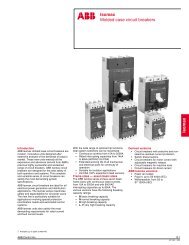
Technical catalogue <strong>System</strong> <strong>pro</strong> M compact ®and other modular devices for lowvoltage installation2CSC400002D0207 Edition 2009
SUMMARYIntroductionMiniature circuit-breakersResidual current devicesAuxiliary elements and accessories1234OthermodulardevicesProtection devicesCommand devicesLoad management devicesMeasurement devicesOther functions56789Technical detailsApplication sheetsOverall dimensionsWorldwide marks and ap<strong>pro</strong>vals10111213
“New entries”:. NE1A new range of DC main switchfor photovoltaic applications.S800 PV <strong>pro</strong>vides safe disconnectionof photovoltaic arrays.:. NEWThe new S2C-OVP: monitoringvoltage between the neutral andphase; when an overvoltagereaches the threshold value theycause the tripping of the associatedMCB or RCCB.:. NEWThe SN 201 range of circuitbreakersis the new ABB range of1P+N single-module MCBs.:. NEWNew RD3 MRCD (modular residualcurrent devices) togetherwith toroidal transformers candetect leakage current.:. NEWThe new F2C-ARH recloses theassociated residual current device,only after having checked thatthere are no effective faults in thethe system:. NEW :. NEWThe new E 90 series of fuse holdersis designed for connectingand disconnecting circuits underload, <strong>pro</strong>viding <strong>pro</strong>tection againstshort circuits and overloads.:. NEW ENTRIES1/2 ABB
W ENTRIES“New entries”1The new E 210 are specificallymade for commanding loads andsignalling electrical conditions.They are available in half moduleor 1 module, depending on thecontact-layout.:. NEWThe MTME series of networkanalysers measure the true rmsvalue of the principal electricalquantitites, they monitor in realtime the energy quality on thesystem and prevent possibledamage to equipment.:. NEWThe RD residual-current relays forfront panels installation in electricswitchboards.:. NEWThe DMTME series instrumentsare digital multimeters that performtrue rms value measurementof the main electrical quantities.Measured values are displayedlocally on four red-LED displays.:. NEWThe ABB range of modular instrumentshas been expanded withthe introduction of the new digitalinstruments with alarm relay.:. NEWABB has extended its range offront panel devices with the newANR electrical network analysers- measuring instrumentsthat permit advanced analysis ofsingle and three-phase electricaldistribution networks.:. NEW:. NEW ENTRIESABB 1/3
11A wide <strong>pro</strong>duct range suitablefor all applications in residential,industrial and commercialinstallations.Thanks to the compatibilitybetween the new <strong>System</strong> <strong>pro</strong>M compact range and the <strong>System</strong><strong>pro</strong> M range, ABB offersmany additional functionalitieslike:- <strong>pro</strong>tection and switching- checking and monitoring- control and <strong>pro</strong>gramming.Shape and dimensions of thenew series allow both preciseadapting in already existinginstallations and continuity interms of <strong>pro</strong>file and appearance.Time saving in cross-wiringwithin groups and combinationsof devices is anotheradvantage.The technologically innovativebidirectional cylinder-liftterminal enables synchronousclosing of the front and rearwiring input.Highest safety standard forthe installer thanks to <strong>pro</strong>tectionagainst electric shockaccording toEN 41140.Marking of devices is reliableand clear.Both supply and connectionwith busbars from top orbottom is admitted.1/4 ABB
11The <strong>System</strong> <strong>pro</strong> Mcompact rangen MCBs:- circuit-breakersn RCDs:- residual current circuitbreakers(RCCBs)- RCD-blocks- residual current circuitbreakerswith overcurrent<strong>pro</strong>tection (RCBOs)n Auxiliary elements:- a whole range aof accessoriesand auxiliaryelementsn MRCDs-Modular residualcurrent devicesA range of electronic residualcurrent relays <strong>pro</strong>vidingresidual current <strong>pro</strong>tectionand monito-ring functions.n MDRCs-Surge <strong>pro</strong>tectivedevicesn MDRCs-Protection devicesIn addition to MCBs andRCDs, ABB supplies othermodular devices for <strong>pro</strong>tectionsuch as residual currentrelays and fuse holders.n MDRCs-Command devicesThis category includesdevices that are operatedmanually to command theelectric system: contactors,latching relays, switch-isolators,switches, pushbuttonsetc. Typically they areinstalled to control lightsfrom severeal points of thesame circuit or to pilot userdevices with a high numberof operations.n MDRCs-Loadmanagement devicesOverload relays, loadmanagement switches,anti black-out lamps, timeswitches and the othermodular devices in thiscategory react automaticallyto variations of parametersand other events in thesystem to allow for plantoptimisation.n MDRCs-MeasurementdevicesThe range of devices inthis category is very wide,including a great numberof auxiliary componentsand accessories that makeinstallation in switchboardsand consumer units practicaland economic.n MDRCs-Other devicesThe range of ABB MDRCsalso includes bells, transformersetc.n Various accessoriesABB1/5
112CSC400131F02012CSC400270F02012CSC400259F02012CSC400192F02012CSC400114F0001MCBs are also available withan integrated auxiliary contact(1 NO or 1 NC). Existinginstallations can be easilyupgraded to include auxiliaryswitch functionality.Availability of a quite wide rangeof factory fitted RCBOs.RCD-blocks DDA 200 2P,3P, 4P up to 40 A fit into twomodules. Versions in 63 Asizes are supplied with twoadditional terminals for remotetripping.Universal signal/auxiliary andauxiliary contacts fit on S 200,F 200 and DS 200.2CSC400225F00012CSC400553F00012CSC400229F0001Without busbars two terminalspaces can be used forcables with different crosssections: incoming supplywith supplementary terminalup to 50 mm 2 from the frontside.Safety connections betweenDDA 200 and S 200 thanks toa safe plastic key system.Special quick fastening for aneasy removal of the devicesfrom the assembly pressingupwards, both for MCBs S200 and RCCBs F 200: theonly in the market that can beremoved without a screwdriver.More working space betweencomponent rows.1/6 ABB
112CSC400132F00012CSC400230F0001New <strong>System</strong> <strong>pro</strong> Mcompact range is compatiblewith the <strong>System</strong><strong>pro</strong> M range, thanks to theconfiguration of new vs oldterminals.Supply from top or bottomeither with cables or busbars.Safe terminal technology: theterminals offer <strong>pro</strong>tection frommisconnection.ABB1/7
2CSC400556F02012CSC400259F02012CSC400133F02012CSC400395F02012/2 ABB SACE
Miniature circuit-breakers2IndexGeneral features and breaking capacities ...................................................................... 2/2S 200 <strong>System</strong> <strong>pro</strong> M compact MCBs ............................................................................... 2/5SN 201 MCBs 1P+N in 1 module .................................................................................... 2/47S 280, S 290 and S800 MCBs .......................................................................................... 2/55ABB SACE2/1
<strong>System</strong><strong>pro</strong> M compact ®General featuresand breaking capacitiesMCBs2NOTE: All the MCBs of S200 series presenttwo values of breaking capacities markedon the <strong>pro</strong>duct:on the front I cnaccording to IEC/EN 60898on the side I cu/I csaccording to IEC/EN60947-2dependig on the rated current.Value of breaking capacity of S2 K, Z characteristicsmarked on the front of the MCBs,refers to the standard VDE 0660.S 200SeriesCharacteristicsB,C,D,K,ZRated current [A] 0.5 In 63Breaking capacity [kA]Reference standard Nr. poles Ue[V]S 200 MB,C,D,K,Z0.5 In 63B,C,D,K,Z0.5 In 25S 200 PB,C,D,K,Z32 In 40 only up to 40 A; 10 kA up to 50/63 A only for “D” characteristic values are not for all rated currents 800 V DC2/2 ABBB,C,D,K,Z50 In 63S 200 US 200 UPSN 201 LSN 201SN 201 MK,Z K,Z K,Z K,Z B,C B,C,D B,CIEC 23-3/EN 60898 Icn 230/400 6 10 25 15 15 4.5 6 10IEC/EN 60947-2 Icu 1, 1P+N 133 20 25 40 25 25 40 25 25 40 10 15 20Alternating current230 10 15 25 15 15 25 15 15 25 6 10 102, 3, 4 230 20 25 40 25 25 40 25 25 40400 10 15 25 15 15 25 15 15 252, 3, 4 500690Ics 1, 1P+N 133 15 18.7 20 18.7 18.7 20 18.7 18.7 20 6 10 10230 7.5 11.2 12.5 11.2 7.5 12.5 11.2 11.2 12.5 4.5 6 7.52, 3, 4 230 15 18.7 20 18.7 18.7 20 18.7 18.7 20400 7.5 11.2 12.5 11.2 7.5 12.5 11.2 11.2 12.52, 3, 4 500690IEC/EN 60947-2 Icu 1, 1P+N 24 20Direct current60 10 10 15 10 10 15 10 10 15 10 15 15T=I/R5ms for allseries,125250except S280 UC and 2 48 20S800S-UC,125 10 10 15 10 10 15 10 10 15 10 15 15where T=I/R
<strong>System</strong><strong>pro</strong> M compact ®General featuresand breaking capacitiesMCBsS 280S 280 UCS 290S800SS800NS800CS800US800PV-SSS800PV-M2B,C B,K,Z C,D,K B,C,D K KM UCB UCK B,C,D B,C,D,K Z,K PV-S80 In 1000.5 In 4050 In 6380 In 12510 In 12510 In 12520 In 6310 In 12510 In 12510 In 12510 In 12510 In 10050 50 50 50 50 36 25 30, 50 510 In 12532631256 10 25 20 1515 10 66 6 4.5 20 (15) 50 50 50 36 25 3010 10 6 25 50 50 50 36 25 506 6 4.5 20 (15) 50 50 50 36 25 5015 15 15 10 6 6 6 4.515 7.5 66 6 4.5 10 (7.5) 40 40 40 30 18 2510 7.5 6 12.5 40 40 40 30 18 406 6 4.5 10 (7.5) 40 40 40 30 1811 11 11 8 4 4 4 310 256 4.5 30 30 30 20 1050 50106 4.5 30 30 30 20 1050 5030 30 30 30 30 20 10 30 30 30 30 30 20 10 50 505510 12.56 4.5 30 30 30 20 1050 50106 4.5 30 30 30 20 1050 5030 30 30 30 30 20 10 30 30 30 30 30 20 10 50 5051451450.40.630505 1200 V DC 3 poles 4 polesABB1.51.52/3
2MCBs <strong>pro</strong>tect installationsagainst overload and shortcircuit,warranting reliabilityand safety for operations.New <strong>System</strong> <strong>pro</strong> M compactS 200 series satisfies mostcommon requirements interms of MCBs, allowing theusage of them for domestic,industrial and commercialapplications.Three series – S 200, S 200M and S 200 P – with threedifferent breaking capacitiesup to 25 kA are available, inall characteristics (B, C, D, Kand Z) and configurations (1P,1P+N, 2P, 3P, 3P+N and 4P),in all the sizes up to 63 A.All these MCBs comply toIEC/EN 60898 and IEC/EN60947-2 Standards. Therange includes also the newS 200 U and S 200 UP inaccordance to UL 489/CSA-C22.2 N 05 Standard.It is also available the newintegrated auxiliary contacton the bottom side which permitsto save 50% space.Thought to be advanced,MCBs range also offers allthe “plus” advantages whichcharacterized the wholenew <strong>System</strong> <strong>pro</strong> M compactrange.S 200 series devices obtaineda lot of marks and ap<strong>pro</strong>vals,so they can be used in allworld’s markets.2CSC400261F02012CSC400259F02012CSC400230F02012CSC400260F02012/4 ABB SACE
<strong>System</strong> Technical featuresS 200<strong>pro</strong> M compact MCBs S 200 series®2StandardsElectrical Rated current In Afeatures PolesRated voltage Ue IEC 1P, 1P+N VIEC 2P, 3P, 3P+N, 4P VUL/CSA 1P, 1P+N VUL/CSA 2P, 3P, 3P+N, 4P VInsulation voltage UiVMax. operating voltage Ub max. IEC AC VUL/CSA ACIEC/UL/CSA DC 1P VIEC/UL/CSA DC 2P VMin. operating voltage Ub min.VRated frequencyHzRated breaking capacity acc. to IEC/EN 60898 ultimate Icn ARated breaking capacity ultimate Icu kAacc. to IEC/EN 60947-2service IcskA1P, 1P+N @ 230 VAC 2P, 3P, 3P+N, 4P@ 400 VACRated impulse withstand voltage (1.2/50) UimpkVDielectric test voltage at ind. freq. for 1 min.kVOvervoltage categoryPollution degreeThermomagnetic releaseB: 3 In Im 5 IncharacteristicC: 5 In Im 10 InD: 10 In Im 20 InK: 10 In Im 14 InZ: 2 In Im 3 InMechanical Togglefeatures Electrical lifeMechanical life/operationsProtection degree/operationsInstallationhousingterminalsMechanical shock resistanceResistance to vibrations acc. to IEC/EN 60068-2-6Tropicalization humid heat °C/RHacc. to IEC/EN 60068-2 constant climatic conditions °C/RHvariable climatic conditionsReference temperature for setting of thermal element °CAmbient temperature (with daily average +35 °C) IEC °CStorage temperature °C2/6 ABB°C/RHTerminal typeTerminal size top/bottom for cable IEC mm 2UL/CSAAWGTerminal size top/bottom for busbar IEC mm 2UL/CSAAWGTightening torque IEC N*mUL/CSAin-lbs.ToolMountingMounting positionConnectionDimensions Pole dimensions (H x D x W) mmand weigth Pole weight gCombination Combinable with: auxiliary contactwith auxiliaryelemenyssignal contact/auxiliary switchshunt tripundervoltage release supplementary <strong>pro</strong>tection branch circuit <strong>pro</strong>tection for S 200 acc. to UL 1077: -25...+70 °C prior to connection of aluminium conductors ( 4 mm 2 ) ensure that their contact points are cleaned, brushed and coated with grease
<strong>System</strong> Technical featuresS 200<strong>pro</strong> M compact MCBs S 200 series®2S 200 S 200 M S 200 P S 200 U S 200 UPIEC / EN 60898, IEC / EN 60947-2, VDE 0641 Part 11, UL 1077 , CSA 22.2 No. 235 UL 489 , CSA22.2 No.5 , IEC/EN 60947-20.5 In 63 0.5 In 63 0.5 In 25 32 In 40 50 In 63 0.5 In 63 0.2 In 251P, 1P+N, 2P, 3P, 3P+N, 4P 1P, 2P, 3P, 4P230 - 240230/400 - 240/415120 - 240 - 277 120 - 240 - 277 120- 240 120 - 240 - 277480Y/277 480Y/277 120- 240 480Y/277250254/440480Y/277 480Y/277 240 480Y/27760VDC125VDC12VAC - 12VDC12VAC50…606000 10000 25000 15000 15000 - -10 15 25 15 15 10 107.5 11.2 12.5 11.2 11.2 7.5 7.552.8III2n n n n nn n n n nn n n n nn n n n n n nn n n n n n nblack sealable in ON-OFF position1000020000IP4XIP2X30 g - 3 shocks - duration 11 ms5 g - 20 cycles at frequency 5…150…5 Hz with load 0.8 In28 cycles with 55/95…10023/83 - 40/93 - 55/2025/95 - 40/9530 (20 for characteristics K,Z) 25-25…+55-40…+70failsafe bi-directional cylinder-lift terminal (shock <strong>pro</strong>tected) 25/2518-410/1018-82.825Nr. 2 Pozidrivon DIN rail EN 60715 (35 mm) by means of fast clip deviceoptionalfrom top and bottom85 x 68 x 17.5 88 x 68 x 17.5 100 x 68 x 17.5125 140yesyesyesyesnoABB2/7
<strong>System</strong> Selection tablesS 200-B<strong>pro</strong> M compact MCBs S 200 series®6000BWith disconnecting neutral NANumber Rated Order Bbn Price Price Weight Packof poles current details 4016779 1 piece group 1 piece unit2CSC400421F0201In A Type code Order code EAN kg pc.1 6 S 201-B 6 NA 2CDS 251 103 R0065 53158 0 0.250 5+ 10 S 201-B 10 NA 2CDS 251 103 R0105 53159 7 0.250 5NA 13 S 201-B 13 NA 2CDS 251 103 R0135 53160 3 0.250 5U Bmax253 V 72 V ...16 S 201-B 16 NA 2CDS 251 103 R0165 53161 0 0.250 520 S 201-B 20 NA 2CDS 251 103 R0205 53162 7 0.250 525 S 201-B 25 NA 2CDS 251 103 R0255 53163 4 0.250 532 S 201-B 32 NA 2CDS 251 103 R0325 53164 1 0.250 540 S 201-B 40 NA 2CDS 251 103 R0405 53165 8 0.250 550 S 201-B 50 NA 2CDS 251 103 R0505 53615 8 0.250 563 S 201-B 63 NA 2CDS 251 103 R0635 53614 1 0.250 522CSC400418F02013 6 S 203-B 6 NA 2CDS 253 103 R0065 53228 0 0.500 1+ 10 S 203-B 10 NA 2CDS 253 103 R0105 53229 7 0.500 1NA 13 S 203-B 13 NA 2CDS 253 103 R0135 53230 3 0.500 1U Bmax440 V 16 S 203-B 16 NA 2CDS 253 103 R0165 53231 0 0.500 120 S 203-B 20 NA 2CDS 253 103 R0205 53232 7 0.500 125 S 203-B 25 NA 2CDS 253 103 R0255 53233 4 0.500 132 S 203-B 32 NA 2CDS 253 103 R0325 53234 1 0.500 140 S 203-B 40 NA 2CDS 253 103 R0405 53235 8 0.500 150 S 203-B 50 NA 2CDS 253 103 R0505 53616 5 0.580 163 S 203-B 63 NA 2CDS 253 103 R0635 53617 2 0.580 1 suitable for flow-type heaters 12 kW suitable for flow-type heaters 18 kW suitable for flow-type heaters 21, 24 and 27 kWTechnical details ............................ pag. 10/2 Overall dimensions ........................ pag. 12/2ABB2/9
<strong>System</strong> Selection tablesS 200-C<strong>pro</strong> M compact MCBs S 200 series®60002CS 200 C characteristicFunction: <strong>pro</strong>tection and control of the circuits against overloads and short-circuits; <strong>pro</strong>tection forresistive and inductive loads with low inrush current.Applications: residential, commercial and industrial.Standard: IEC/EN 60898, IEC/EN 60947-2Icn=6 kANumber Rated Order Bbn Price Price Weight Packof poles current details 4016779 1 piece group 1 piece unitIn A Type code Order code EAN kg pc.2CSC400409F0201 2CSC400408F02011 0.5 S 201-C 0.5 2CDS 251 001 R0984 52329 5 0.125 101 S 201-C 1 2CDS 251 001 R0014 52331 8 0.125 101.6 S 201-C 1.6 2CDS 251 001 R0974 52330 1 0.125 102 S 201-C 2 2CDS 251 001 R0024 52332 5 0.125 103 S 201-C 3 2CDS 251 001 R0034 52333 2 0.125 104 S 201-C 4 2CDS 251 001 R0044 52334 9 0.125 106 S 201-C 6 2CDS 251 001 R0064 46400 0 0.125 108 S 201-C 8 2CDS 251 001 R0084 46410 9 0.125 1010 S 201-C 10 2CDS 251 001 R0104 46420 8 0.125 1013 S 201-C 13 2CDS 251 001 R0134 46430 7 0.125 1016 S 201-C 16 2CDS 251 001 R0164 46440 6 0.125 1020 S 201-C 20 2CDS 251 001 R0204 46450 5 0.125 1025 S 201-C 25 2CDS 251 001 R0254 46460 4 0.125 1032 S 201-C 32 2CDS 251 001 R0324 46470 3 0.125 10U Bmax253 V 72 V ...40 S 201-C 40 2CDS 251 001 R0404 46480 2 0.125 1050 S 201-C 50 2CDS 251 001 R0504 55100 7 0.125 1063 S 201-C 63 2CDS 251 001 R0634 55101 4 0.125 102 0.5 S 202-C 0.5 2CDS 252 001 R0984 52335 6 0.250 51 S 202-C 1 2CDS 252 001 R0014 52336 3 0.250 51.6 S 202-C 1.6 2CDS 252 001 R0974 52337 0 0.250 52 S 202-C 2 2CDS 252 001 R0024 52338 7 0.250 53 S 202-C 3 2CDS 252 001 R0034 52339 4 0.250 54 S 202-C 4 2CDS 252 001 R0044 52340 0 0.250 56 S 202-C 6 2CDS 252 001 R0064 46550 2 0.250 58 S 202-C 8 2CDS 252 001 R0084 46560 1 0.250 510 S 202-C 10 2CDS 252 001 R0104 46570 0 0.250 513 S 202-C 13 2CDS 252 001 R0134 46580 9 0.250 516 S 202-C 16 2CDS 252 001 R0164 46590 8 0.250 520 S 202-C 20 2CDS 252 001 R0204 46600 4 0.250 525 S 202-C 25 2CDS 252 001 R0254 46610 3 0.250 5U Bmax440 V 125 V ...32 S 202-C 32 2CDS 252 001 R0324 46620 2 0.250 540 S 202-C 40 2CDS 252 001 R0404 46630 1 0.250 550 S 202-C 50 2CDS 252 001 R0504 55104 5 0.250 563 S 202-C 63 2CDS 252 001 R0634 55105 2 0.250 52CSC400412F02013 0.5 S 203-C 0.5 2CDS 253 001 R0984 52341 7 0.375 11 S 203-C 1 2CDS 253 001 R0014 52342 4 0.375 11.6 S 203-C 1.6 2CDS 253 001 R0974 52343 1 0.375 12 S 203-C 2 2CDS 253 001 R0024 52344 8 0.375 13 S 203-C 3 2CDS 253 001 R0034 52345 5 0.375 14 S 203-C 4 2CDS 253 001 R0044 52346 2 0.375 16 S 203-C 6 2CDS 253 001 R0064 46750 6 0.375 18 S 203-C 8 2CDS 253 001 R0084 46760 5 0.375 110 S 203-C 10 2CDS 253 001 R0104 46780 3 0.375 113 S 203-C 13 2CDS 253 001 R0134 46790 2 0.375 116 S 203-C 16 2CDS 253 001 R0164 46800 8 0.375 120 S 203-C 20 2CDS 253 001 R0204 46810 7 0.375 125 S 203-C 25 2CDS 253 001 R0254 46820 6 0.375 132 S 203-C 32 2CDS 253 001 R0324 46830 5 0.375 140 S 203-C 40 2CDS 253 001 R0404 46840 4 0.375 1U Bmax440 V 50 S 203-C 50 2CDS 253 001 R0504 55106 9 0.375 163 S 203-C 63 2CDS 253 001 R0634 55107 6 0.375 1Technical details ............................ pag. 10/2 Overall dimensions ........................ pag. 12/22/10 ABB
<strong>System</strong> Selection tablesS 200-C<strong>pro</strong> M compact MCBs S 200 series®6000C2CSC400418F0201 2CSC400421F0201 2CSC400419F02014 0.5 S 204-C 0.5 2CDS 254 001 R0984 52911 2 0.500 11 S 204-C 1 2CDS 254 001 R0014 52912 9 0.500 11.6 S 204-C 1.6 2CDS 254 001 R0974 52913 6 0.500 12 S 204-C 2 2CDS 254 001 R0024 52914 3 0.500 13 S 204-C 3 2CDS 254 001 R0034 52915 0 0.500 14 S 204-C 4 2CDS 254 001 R0044 52916 7 0.500 16 S 204-C 6 2CDS 254 001 R0064 52917 4 0.500 18 S 204-C 8 2CDS 254 001 R0084 52918 1 0.500 110 S 204-C 10 2CDS 254 001 R0104 52919 8 0.500 113 S 204-C 13 2CDS 254 001 R0134 52920 4 0.500 116 S 204-C 16 2CDS 254 001 R0164 52921 1 0.500 120 S 204-C 20 2CDS 254 001 R0204 52922 8 0.500 125 S 204-C 25 2CDS 254 001 R0254 52923 5 0.500 132 S 204-C 32 2CDS 254 001 R0324 52924 2 0.500 1U Bmax 40 S 204-C 40 2CDS 254 001 R0404 52925 9 0.500 1440 V 50 S 204-C 50 2CDS 254 001 R0504 55110 6 0.500 1125 V ... 63 S 204-C 63 2CDS 254 001 R0634 55111 3 0.500 1 suitable for flow-type heaters 12 kW suitable for flow-type heaters 18 kWWith disconnecting neutral NANumber Rated Order Bbn Price Price Weight Packof poles current details 4016779 1 piece group 1 piece unitIn A Type code Order code EAN kg pc.1 0.5 S 201-C 0.5 NA 2CDS 251 103 R0984 53166 5 0.250 5+ 1 S 201-C 1 NA 2CDS 251 103 R0014 53167 2 0.250 5NA 1.6 S 201-C 1.6 NA 2CDS 251 103 R0974 53168 9 0.250 5U Bmax253 V 72 V ... suitable for flow-type heaters 21, 24 and 27 kW U Bmax125 V ... with 2 poles connected in series2 S 201-C 2 NA 2CDS 251 103 R0024 53169 6 0.250 53 S 201-C 3 NA 2CDS 251 103 R0034 53170 2 0.250 54 S 201-C 4 NA 2CDS 251 103 R0044 53172 6 0.250 56 S 201-C 6 NA 2CDS 251 103 R0064 53173 3 0.250 58 S 201-C 8 NA 2CDS 251 103 R0084 53174 0 0.250 510 S 201-C 10 NA 2CDS 251 103 R0104 53175 7 0.250 513 S 201-C 13 NA 2CDS 251 103 R0134 53176 4 0.250 516 S 201-C 16 NA 2CDS 251 103 R0164 53177 1 0.250 520 S 201-C 20 NA 2CDS 251 103 R0204 53178 8 0.250 525 S 201-C 25 NA 2CDS 251 103 R0254 53179 5 0.250 532 S 201-C 32 NA 2CDS 251 103 R0324 53180 1 0.250 540 S 201-C 40 NA 2CDS 251 103 R0404 53181 8 0.250 550 S 201-C 50 NA 2CDS 251 103 R0504 55102 1 0.290 563 S 201-C 63 NA 2CDS 251 103 R0634 55103 8 0.290 53 0.5 S 203-C 0.5 NA 2CDS 253 103 R0984 53236 5 0.500 1+ 1 S 203-C 1 NA 2CDS 253 103 R0014 53237 2 0.500 1NA 1.6 S 203-C 1.6 NA 2CDS 253 103 R0974 53238 9 0.500 12 S 203-C 2 NA 2CDS 253 103 R0024 53240 2 0.500 13 S 203-C 3 NA 2CDS 253 103 R0034 53241 9 0.500 14 S 203-C 4 NA 2CDS 253 103 R0044 53242 6 0.500 16 S 203-C 6 NA 2CDS 253 103 R0064 53243 3 0.500 18 S 203-C 8 NA 2CDS 253 103 R0084 53244 0 0.500 110 S 203-C 10 NA 2CDS 253 103 R0104 53245 7 0.500 113 S 203-C 13 NA 2CDS 253 103 R0134 53246 4 0.500 116 S 203-C 16 NA 2CDS 253 103 R0164 53247 1 0.500 120 S 203-C 20 NA 2CDS 253 103 R0204 53248 8 0.500 125 S 203-C 25 NA 2CDS 253 103 R0254 53249 5 0.500 132 S 203-C 32 NA 2CDS 253 103 R0324 53250 1 0.500 140 S 203-C 40 NA 2CDS 253 103 R0404 53251 8 0.500 1U Bmax50 S 203-C 50 NA 2CDS 253 103 R0504 55108 3 0.580 1440 V 63 S 203-C 63 NA 2CDS 253 103 R0634 55109 0 0.580 12 suitable for flow-type heaters 12 kW suitable for flow-type heaters 21, 24 and 27 kW suitable for flow-type heaters 18 kWTechnical details ............................ pag. 10/2 Overall dimensions ........................ pag. 12/2ABB2/11
<strong>System</strong> Selection tablesS 200-D<strong>pro</strong> M compact MCBs S 200 series®60002DS 200 D characteristicFunction: <strong>pro</strong>tection and control of the circuits against overloads and short-circuits; <strong>pro</strong>tectionfor circuits which supply loads with high inrush current at the circuit closing (LV/LV transformers,breakdown lamps).Applications: residential, commercial and industrial.Standard: IEC/EN 60898, IEC/EN 60947-2Icn=6 kANumber Rated Order Bbn Price Price Weight Packof poles current details 4016779 1 piece group 1 piece unit2CSC400409F0201 2CSC400408F02012CSC400412F0201In A Type code Order code EAN kg pc.1 0.5 S 201-D 0.5 2CDS 251 001 R0981 52993 8 0.125 101 S 201-D 1 2CDS 251 001 R0011 52994 5 0.125 101.6 S 201-D 1.6 2CDS 251 001 R0971 52995 2 0.125 102 S 201-D 2 2CDS 251 001 R0021 52996 9 0.125 103 S 201-D 3 2CDS 251 001 R0031 52997 6 0.125 104 S 201-D 4 2CDS 251 001 R0041 52998 3 0.125 106 S 201-D 6 2CDS 251 001 R0061 52999 0 0.125 108 S 201-D 8 2CDS 251 001 R0081 53000 2 0.125 1010 S 201-D 10 2CDS 251 001 R0101 53001 9 0.125 1013 S 201-D 13 2CDS 251 001 R0131 53002 6 0.125 1016 S 201-D 16 2CDS 251 001 R0161 53003 3 0.125 1020 S 201-D 20 2CDS 251 001 R0201 53004 0 0.125 1025 S 201-D 25 2CDS 251 001 R0251 53005 7 0.125 1032 S 201-D 32 2CDS 251 001 R0321 53006 4 0.125 10U Bmax253 V 72 V ...40 S 201-D 40 2CDS 251 001 R0401 53007 1 0.125 1050 S 201-D 50 2CDS 251 001 R0501 55199 1 0.125 1063 S 201-D 63 2CDS 251 001 R0631 55200 4 0.125 102 0.5 S 202-D 0.5 2CDS 252 001 R0981 53048 4 0.250 51 S 202-D 1 2CDS 252 001 R0011 53049 1 0.250 51.6 S 202-D 1.6 2CDS 252 001 R0971 53050 7 0.250 52 S 202-D 2 2CDS 252 001 R0021 53051 4 0.250 53 S 202-D 3 2CDS 252 001 R0031 53052 1 0.250 54 S 202-D 4 2CDS 252 001 R0041 53053 8 0.250 56 S 202-D 6 2CDS 252 001 R0061 53054 5 0.250 58 S 202-D 8 2CDS 252 001 R0081 53055 2 0.250 510 S 202-D 10 2CDS 252 001 R0101 53058 3 0.250 513 S 202-D 13 2CDS 252 001 R0131 53060 6 0.250 516 S 202-D 16 2CDS 252 001 R0161 53061 3 0.250 520 S 202-D 20 2CDS 252 001 R0201 53063 7 0.250 525 S 202-D 25 2CDS 252 001 R0251 53064 4 0.250 532 S 202-D 32 2CDS 252 001 R0321 53065 1 0.250 5U Bmax40 S 202-D 40 2CDS 252 001 R0401 53066 8 0.250 5440 V 50 S 202-D 50 2CDS 252 001 R0501 55203 5 0.250 5125 V ...63 S 202-D 63 2CDS 252 001 R0631 55204 2 0.250 53 0.5 S 203-D 0.5 2CDS 253 001 R0981 53081 1 0.375 11 S 203-D 1 2CDS 253 001 R0011 53082 8 0.375 11.6 S 203-D 1.6 2CDS 253 001 R0971 53083 5 0.375 12 S 203-D 2 2CDS 253 001 R0021 53084 2 0.375 13 S 203-D 3 2CDS 253 001 R0031 53085 9 0.375 14 S 203-D 4 2CDS 253 001 R0041 53086 6 0.375 16 S 203-D 6 2CDS 253 001 R0061 53088 0 0.375 18 S 203-D 8 2CDS 253 001 R0081 53089 7 0.375 110 S 203-D 10 2CDS 253 001 R0101 53090 3 0.375 113 S 203-D 13 2CDS 253 001 R0131 53091 0 0.375 116 S 203-D 16 2CDS 253 001 R0161 53092 7 0.375 120 S 203-D 20 2CDS 253 001 R0201 53093 4 0.375 125 S 203-D 25 2CDS 253 001 R0251 53094 1 0.375 132 S 203-D 32 2CDS 253 001 R0321 53095 8 0.375 140 S 203-D 40 2CDS 253 001 R0401 53096 5 0.375 1U Bmax440 V 50 S 203-D 50 2CDS 253 001 R0501 55205 9 0.375 163 S 203-D 63 2CDS 253 001 R0631 55206 6 0.375 1Technical details ............................ pag. 10/2 Overall dimensions ........................ pag. 12/22/12 ABB
<strong>System</strong> Selection tablesS 200-D<strong>pro</strong> M compact MCBs S 200 series®6000D2CSC400421F0201 2CSC400419F02014 0.5 S 204-D 0.5 2CDS 254 001 R0981 53112 2 0.500 11 S 204-D 1 2CDS 254 001 R0011 53113 9 0.500 11.6 S 204-D 1.6 2CDS 254 001 R0971 53114 6 0.500 12 S 204-D 2 2CDS 254 001 R0021 53115 3 0.500 13 S 204-D 3 2CDS 254 001 R0031 53116 0 0.500 14 S 204-D 4 2CDS 254 001 R0041 53117 7 0.500 16 S 204-D 6 2CDS 254 001 R0061 53118 4 0.500 18 S 204-D 8 2CDS 254 001 R0081 53119 1 0.500 110 S 204-D 10 2CDS 254 001 R0101 53120 7 0.500 113 S 204-D 13 2CDS 254 001 R0131 53121 4 0.500 116 S 204-D 16 2CDS 254 001 R0161 53122 1 0.500 120 S 204-D 20 2CDS 254 001 R0201 53123 8 0.500 125 S 204-D 25 2CDS 254 001 R0251 53129 0 0.500 132 S 204-D 32 2CDS 254 001 R0321 53130 6 0.500 1U Bmax 40 S 204-D 40 2CDS 254 001 R0401 53131 3 0.500 1440 V 125 V ...50 S 204-D 50 2CDS 254 001 R0501 55209 7 0.500 1 63 S 204-D 63 2CDS 254 001 R0631 55210 3 0.500 1 suitable for flow-type heaters 12 kW suitable for flow-type heaters 18 kWWith disconnecting neutral NANumber Rated Order Bbn Price Price Weight Packof poles current details 4016779 1 piece group 1 piece unitIn A Type code Order code EAN kg pc.1 0.5 S 201-D 0.5 NA 2CDS 251 103 R0981 53197 9 0.250 5+ 1 S 201-D 1 NA 2CDS 251 103 R0011 53199 3 0.250 5NA 1.6 S 201-D 1.6 NA 2CDS 251 103 R0971 53198 6 0.250 52 S 201-D 2 NA 2CDS 251 103 R0021 53200 6 0.250 53 S 201-D 3 NA 2CDS 251 103 R0031 53201 3 0.250 54 S 201-D 4 NA 2CDS 251 103 R0041 53202 0 0.250 56 S 201-D 6 NA 2CDS 251 103 R0061 53203 7 0.250 58 S 201-D 8 NA 2CDS 251 103 R0081 53204 4 0.250 510 S 201-D 10 NA 2CDS 251 103 R0101 53205 1 0.250 513 S 201-D 13 NA 2CDS 251 103 R0131 53206 8 0.250 516 S 201-D 16 NA 2CDS 251 103 R0161 53209 9 0.250 520 S 201-D 20 NA 2CDS 251 103 R0201 53210 5 0.250 525 S 201-D 25 NA 2CDS 251 103 R0251 53211 2 0.250 532 S 201-D 32 NA 2CDS 251 103 R0321 53212 9 0.250 5U Bmax253 V 72 V ... suitable for flow-type heaters 21, 24 and 27 kW U Bmax125 V ... with 2 poles connected in series40 S 201-D 40 NA 2CDS 251 103 R0401 53213 6 0.250 550 S 201-D 50 NA 2CDS 251 103 R0501 55201 1 0.290 563 S 201-D 63 NA 2CDS 251 103 R0631 55202 8 0.290 522CSC400418F02013 0.5 S 203-D 0.5 NA 2CDS 253 103 R0981 53276 1 0.500 2+ 1 S 203-D 1 NA 2CDS 253 103 R0011 53278 5 0.500 2NA 1.6 S 203-D 1.6 NA 2CDS 253 103 R0971 53277 8 0.500 22 S 203-D 2 NA 2CDS 253 103 R0021 53279 2 0.500 23 S 203-D 3 NA 2CDS 253 103 R0031 53280 8 0.500 24 S 203-D 4 NA 2CDS 253 103 R0041 53281 5 0.500 26 S 203-D 6 NA 2CDS 253 103 R0061 53282 2 0.500 28 S 203-D 8 NA 2CDS 253 103 R0081 53283 9 0.500 210 S 203-D 10 NA 2CDS 253 103 R0101 53284 6 0.500 213 S 203-D 13 NA 2CDS 253 103 R0131 53286 0 0.500 216 S 203-D 16 NA 2CDS 253 103 R0161 53287 7 0.500 220 S 203-D 20 NA 2CDS 253 103 R0201 53288 4 0.500 225 S 203-D 25 NA 2CDS 253 103 R0251 53289 1 0.500 232 S 203-D 32 NA 2CDS 253 103 R0321 53290 7 0.500 2U Bmax440 V 40 S 203-D 40 NA 2CDS 253 103 R0401 53291 4 0.500 250 S 203-D 50 NA 2CDS 253 103 R0501 55207 3 0.580 263 S 203-D 63 NA 2CDS 253 103 R0631 55208 0 0.580 2 suitable for flow-type heaters 12 kW suitable for flow-type heaters 18 kW suitable for flow-type heaters 21, 24 and 27 kWTechnical details ............................ pag. 10/2 Overall dimensions ........................ pag. 12/2ABB2/13
<strong>System</strong> Selection tablesS 200-K<strong>pro</strong> M compact MCBs S 200 series®6000K2CSC400421F0201 2CSC400419F02014 0.5 S 204-K 0.5 2CDS 254 001 R0157 52926 6 0.500 11 S 204-K 1 2CDS 254 001 R0217 52927 3 0.500 11.6 S 204-K 1.6 2CDS 254 001 R0257 52928 0 0.500 12 S 204-K 2 2CDS 254 001 R0277 52929 7 0.500 13 S 204-K 3 2CDS 254 001 R0317 52930 3 0.500 14 S 204-K 4 2CDS 254 001 R0337 52931 0 0.500 16 S 204-K 6 2CDS 254 001 R0377 52932 7 0.500 18 S 204-K 8 2CDS 254 001 R0407 52933 4 0.500 110 S 204-K 10 2CDS 254 001 R0427 52934 1 0.500 113 S 204-K 13 2CDS 254 001 R0447 52935 8 0.500 116 S 204-K 16 2CDS 254 001 R0467 52936 5 0.500 120 S 204-K 20 2CDS 254 001 R0487 52937 2 0.500 125 S 204-K 25 2CDS 254 001 R0517 52938 9 0.500 132 S 204-K 32 2CDS 254 001 R0537 52939 6 0.500 1U 40 S 204-K 40 2CDS 254 001 R0557 52940 2 0.500 1Bmax440 V 50 S 204-K 50 2CDS 254 001 R0577 55122 9 0.500 160 V ... 63 S 204-K 63 2CDS 254 001 R0607 55123 6 0.500 1 U Bmax125 V ... with 2 poles connected in seriesWith disconnecting neutral NANumber Rated Order Bbn Price Price Weight Packof poles current details 4016779 1 piece group 1 piece unitIn A Type code Order code EAN kg pc.1 0.5 S 201-K 0.5 NA 2CDS 251 103 R0157 53182 5 0.250 5+ 1 S 201-K 1 NA 2CDS 251 103 R0217 53183 2 0.250 5NA 1.6 S 201-K 1.6 NA 2CDS 251 103 R0257 53184 9 0.250 52 S 201-K 2 NA 2CDS 251 103 R0277 53185 6 0.250 53 S 201-K 3 NA 2CDS 251 103 R0317 53186 3 0.250 54 S 201-K 4 NA 2CDS 251 103 R0337 53187 0 0.250 56 S 201-K 6 NA 2CDS 251 103 R0377 53188 7 0.250 58 S 201-K 8 NA 2CDS 251 103 R0407 53189 4 0.250 510 S 201-K 10 NA 2CDS 251 103 R0427 53190 0 0.250 513 S 201-K 13 NA 2CDS 251 103 R0447 53191 7 0.250 516 S 201-K 16 NA 2CDS 251 103 R0467 53192 4 0.250 520 S 201-K 20 NA 2CDS 251 103 R0487 53193 1 0.250 525 S 201-K 25 NA 2CDS 251 103 R0517 53194 8 0.250 5U Bmax253 V 72 V ...32 S 201-K 32 NA 2CDS 251 103 R0537 53195 5 0.250 540 S 201-K 40 NA 2CDS 251 103 R0557 53196 2 0.250 550 S 201-K 50 NA 2CDS 251 103 R0577 55114 4 0.250 563 S 201-K 63 NA 2CDS 251 103 R0607 55115 1 0.250 522CSC400418F02013 0.5 S 203-K 0.5 NA 2CDS 253 103 R0157 53261 7 0.500 1+ 1 S 203-K 1 NA 2CDS 253 103 R0217 53262 4 0.500 1NA 1.6 S 203-K 1.6 NA 2CDS 253 103 R0257 53263 1 0.500 12 S 203-K 2 NA 2CDS 253 103 R0277 53264 8 0.500 13 S 203-K 3 NA 2CDS 253 103 R0317 53265 5 0.500 14 S 203-K 4 NA 2CDS 253 103 R0337 53266 2 0.500 16 S 203-K 6 NA 2CDS 253 103 R0377 53267 9 0.500 18 S 203-K 8 NA 2CDS 253 103 R0407 53268 6 0.500 110 S 203-K 10 NA 2CDS 253 103 R0427 53269 3 0.500 113 S 203-K 13 NA 2CDS 253 103 R0447 53270 9 0.500 116 S 203-K 16 NA 2CDS 253 103 R0467 53271 6 0.500 120 S 203-K 20 NA 2CDS 253 103 R0487 53272 3 0.500 125 S 203-K 25 NA 2CDS 253 103 R0517 53273 0 0.500 132 S 203-K 32 NA 2CDS 253 103 R0537 53274 7 0.500 1U Bmax440 V 40 S 203-K 40 NA 2CDS 253 103 R0557 53275 4 0.500 150 S 203-K 50 NA 2CDS 253 103 R0577 55120 5 0.500 163 S 203-K 63 NA 2CDS 253 103 R0607 55121 2 0.500 1Technical details ............................ pag. 10/2 Overall dimensions ........................ pag. 12/2ABB2/15
<strong>System</strong> Selection tablesS 200-Z<strong>pro</strong> M compact MCBs S 200 series®60002ZS 200 Z characteristicFunction: <strong>pro</strong>tection and control of the electronic circuits against weak and long duration overloadsand short-circuits.Applications: commercial and industrial.Standard: IEC/EN 60947-2, VDE 0660 Part 101Icu=6 kA (acc. to VDE 0660 Part 101)Number Rated Order Bbn Price Price Weight Packof poles current details 4016779 1 piece group 1 piece unitIn A Type code Order code EAN kg pc.2CSC400416F0201 2CSC400423F02011 0.5 S 201-Z 0.5 2CDS 251 001 R0158 53030 9 0.125 10U Bmax253 V 72 V ...1 S 201-Z 1 2CDS 251 001 R0218 53033 0 0.125 101.6 S 201-Z 1.6 2CDS 251 001 R0258 53034 7 0.125 102 S 201-Z 2 2CDS 251 001 R0278 53035 4 0.125 103 S 201-Z 3 2CDS 251 001 R0318 53036 1 0.125 104 S 201-Z 4 2CDS 251 001 R0338 53037 8 0.125 106 S 201-Z 6 2CDS 251 001 R0378 53040 8 0.125 108 S 201-Z 8 2CDS 251 001 R0408 53041 5 0.125 1010 S 201-Z 10 2CDS 251 001 R0428 53042 2 0.125 1016 S 201-Z 16 2CDS 251 001 R0468 53043 9 0.125 1020 S 201-Z 20 2CDS 251 001 R0488 53044 6 0.125 1025 S 201-Z 25 2CDS 251 001 R0518 53045 3 0.125 1032 S 201-Z 32 2CDS 251 001 R0538 53046 0 0.125 1040 S 201-Z 40 2CDS 251 001 R0558 53047 7 0.125 1050 S 201-Z 50 2CDS 251 001 R0578 55191 5 0.125 1063 S 201-Z 63 2CDS 251 001 R0608 55192 2 0.125 102 0.5 S 202-Z 0.5 2CDS 252 001 R0158 53068 2 0.250 5U Bmax440 V 125 V ...1 S 202-Z 1 2CDS 252 001 R0218 53067 5 0.250 51.6 S 202-Z 1.6 2CDS 252 001 R0258 53069 9 0.250 52 S 202-Z 2 2CDS 252 001 R0278 53070 5 0.250 53 S 202-Z 3 2CDS 252 001 R0318 53071 2 0.250 54 S 202-Z 4 2CDS 252 001 R0338 53072 9 0.250 56 S 202-Z 6 2CDS 252 001 R0378 53073 6 0.250 58 S 202-Z 8 2CDS 252 001 R0408 53074 3 0.250 510 S 202-Z 10 2CDS 252 001 R0428 53075 0 0.250 516 S 202-Z 16 2CDS 252 001 R0468 53076 7 0.250 520 S 202-Z 20 2CDS 252 001 R0488 53077 4 0.250 525 S 202-Z 25 2CDS 252 001 R0518 53078 1 0.250 532 S 202-Z 32 2CDS 252 001 R0538 53079 8 0.250 540 S 202-Z 40 2CDS 252 001 R0558 53080 4 0.250 550 S 202-Z 50 2CDS 252 001 R0578 55193 9 0.250 563 S 202-Z 63 2CDS 252 001 R0608 55194 6 0.250 52CSC400417F02013 0.5 S 203-Z 0.5 2CDS 253 001 R0158 53097 2 0.375 1U Bmax440 V 1 S 203-Z 1 2CDS 253 001 R0218 53098 9 0.375 11.6 S 203-Z 1.6 2CDS 253 001 R0258 53099 6 0.375 12 S 203-Z 2 2CDS 253 001 R0278 53100 9 0.375 13 S 203-Z 3 2CDS 253 001 R0318 53101 6 0.375 14 S 203-Z 4 2CDS 253 001 R0338 53102 3 0.375 16 S 203-Z 6 2CDS 253 001 R0378 53103 0 0.375 18 S 203-Z 8 2CDS 253 001 R0408 53104 7 0.375 110 S 203-Z 10 2CDS 253 001 R0428 53105 4 0.375 116 S 203-Z 16 2CDS 253 001 R0468 53106 1 0.375 120 S 203-Z 20 2CDS 253 001 R0488 53107 8 0.375 125 S 203-Z 25 2CDS 253 001 R0518 53108 5 0.375 132 S 203-Z 32 2CDS 253 001 R0538 53109 2 0.375 140 S 203-Z 40 2CDS 253 001 R0558 53110 8 0.375 150 S 203-Z 50 2CDS 253 001 R0578 55195 3 0.375 163 S 203-Z 63 2CDS 253 001 R0608 55196 0 0.375 1Technical details ............................ pag. 10/2 Overall dimensions ........................ pag. 12/22/16 ABB
<strong>System</strong> Selection tablesS 200-Z<strong>pro</strong> M compact MCBs S 200 series®6000Z2CSC400421F0201 2CSC400419F02014 0.5 S 204-Z 0.5 2CDS 254 001 R0158 53024 8 0.500 11 S 204-Z 1 2CDS 254 001 R0218 53132 0 0.500 11.6 S 204-Z 1.6 2CDS 254 001 R0258 53144 3 0.500 12 S 204-Z 2 2CDS 254 001 R0278 53143 6 0.500 13 S 204-Z 3 2CDS 254 001 R0318 53133 7 0.500 14 S 204-Z 4 2CDS 254 001 R0338 53134 4 0.500 16 S 204-Z 6 2CDS 254 001 R0378 53135 1 0.500 18 S 204-Z 8 2CDS 254 001 R0408 53136 8 0.500 110 S 204-Z 10 2CDS 254 001 R0428 53137 5 0.500 116 S 204-Z 16 2CDS 254 001 R0468 53138 2 0.500 120 S 204-Z 20 2CDS 254 001 R0488 53139 9 0.500 125 S 204-Z 25 2CDS 254 001 R0518 53140 5 0.500 132 S 204-Z 32 2CDS 254 001 R0538 53141 2 0.500 1U Bmax40 S 204-Z 40 2CDS 254 001 R0558 53142 9 0.500 1440 V 50 S 204-Z 50 2CDS 254 001 R0578 55197 7 0.500 1125 V ...63 S 204-Z 63 2CDS 254 001 R0608 55198 4 0.500 1 U Bmax125 V ... with 2 poles connected in seriesWith disconnecting neutral NANumber Rated Order Bbn Price Price Weight Packof poles current details 4016779 1 piece group 1 piece unitIn A Type code Order code EAN kg pc.1 0.5 S 201-Z 0.5 NA 2CDS 251 103 R0158 53214 3 0.260 5+ 1 S 201-Z 1 NA 2CDS 251 103 R0218 53215 0 0.260 5NA 1.6 S 201-Z 1.6 NA 2CDS 251 103 R0258 53216 7 0.260 5U Bmax253 V 72 V ...2 S 201-Z 2 NA 2CDS 251 103 R0278 53217 4 0.260 53 S 201-Z 3 NA 2CDS 251 103 R0318 53218 1 0.260 54 S 201-Z 4 NA 2CDS 251 103 R0338 53219 8 0.260 56 S 201-Z 6 NA 2CDS 251 103 R0378 53220 4 0.260 58 S 201-Z 8 NA 2CDS 251 103 R0408 53221 1 0.260 510 S 201-Z 10 NA 2CDS 251 103 R0428 53222 8 0.260 516 S 201-Z 16 NA 2CDS 251 103 R0468 53223 5 0.260 520 S 201-Z 20 NA 2CDS 251 103 R0488 53224 2 0.260 525 S 201-Z 25 NA 2CDS 251 103 R0518 53225 9 0.260 532 S 201-Z 32 NA 2CDS 251 103 R0538 53226 6 0.260 540 S 201-Z 40 NA 2CDS 251 103 R0558 53227 3 0.260 550 S 201-Z 50 NA 2CDS 251 103 R0578 55212 7 0.320 563 S 201-Z 63 NA 2CDS 251 103 R0608 55213 4 0.320 522CSC400418F02013 0.5 S 203-Z 0.5 NA 2CDS 253 103 R0158 53292 1 0.520 1+ 1 S 203-Z 1 NA 2CDS 253 103 R0218 53293 8 0.520 1NA 1.6 S 203-Z 1.6 NA 2CDS 253 103 R0258 53294 5 0.520 1U Bmax440 V 2 S 203-Z 2 NA 2CDS 253 103 R0278 53295 2 0.520 13 S 203-Z 3 NA 2CDS 253 103 R0318 53297 6 0.520 14 S 203-Z 4 NA 2CDS 253 103 R0338 53298 3 0.520 16 S 203-Z 6 NA 2CDS 253 103 R0378 53299 0 0.520 18 S 203-Z 8 NA 2CDS 253 103 R0408 53300 3 0.520 110 S 203-Z 10 NA 2CDS 253 103 R0428 53301 0 0.520 116 S 203-Z 16 NA 2CDS 253 103 R0468 53302 7 0.520 120 S 203-Z 20 NA 2CDS 253 103 R0488 53305 8 0.520 125 S 203-Z 25 NA 2CDS 253 103 R0518 53306 5 0.520 132 S 203-Z 32 NA 2CDS 253 103 R0538 53307 2 0.520 140 S 203-Z 40 NA 2CDS 253 103 R0558 53308 9 0.520 150 S 203-Z 50 NA 2CDS 253 103 R0578 55214 1 0.640 163 S 203-Z 63 NA 2CDS 253 103 R0608 55216 5 0.640 1Technical details ............................ pag. 10/2 Overall dimensions ........................ pag. 12/2ABB2/17
<strong>System</strong><strong>pro</strong> M compact ®Selection tablesMCBs S 200 series M10000S 200 M-B2BS 200 M-B characteristicFunction: <strong>pro</strong>tection and control of the circuits against overloads and short-circuits; <strong>pro</strong>tection forpeople and big length cables in TN and IT systems.Applications: residential, commercial and industrial.Standard: IEC/EN 60898, IEC/EN 60947-2Icn=10 kANumber Rated Order Bbn Price Price Weight Packof poles current details 4016779 1 piece group 1 piece unitIn A Type code Order code EAN kg pc.2CSC400413F0201 2CSC400411F02011 6 S 201 M-B 6 2CDS 271 001 R0065 54942 4 0.125 10U Bmax253 V 72 V ...10 S 201 M-B 10 2CDS 271 001 R0105 54943 1 0.125 1013 S 201 M-B 13 2CDS 271 001 R0135 54944 8 0.125 1016 S 201 M-B 16 2CDS 271 001 R0165 54945 5 0.125 1020 S 201 M-B 20 2CDS 271 001 R0205 54946 2 0.125 1025 S 201 M-B 25 2CDS 271 001 R0255 54947 9 0.125 1032 S 201 M-B 32 2CDS 271 001 R0325 54948 6 0.125 1040 S 201 M-B 40 2CDS 271 001 R0405 54949 3 0.125 1050 S 201 M-B 50 2CDS 271 001 R0505 54381 1 0.125 1063 S 201 M-B 63 2CDS 271 001 R0635 54382 8 0.125 102 6 S 202 M-B 6 2CDS 272 001 R0065 54958 5 0.250 5U Bmax440 V 125 V ...10 S 202 M-B 10 2CDS 272 001 R0105 54959 2 0.250 513 S 202 M-B 13 2CDS 272 001 R0135 54960 8 0.250 516 S 202 M-B 16 2CDS 272 001 R0165 54961 5 0.250 520 S 202 M-B 20 2CDS 272 001 R0205 54962 2 0.250 525 S 202 M-B 25 2CDS 272 001 R0255 54963 9 0.250 532 S 202 M-B 32 2CDS 272 001 R0325 54964 6 0.250 540 S 202 M-B 40 2CDS 272 001 R0405 54965 3 0.250 550 S 202 M-B 50 2CDS 272 001 R0505 54385 9 0.250 563 S 202 M-B 63 2CDS 272 001 R0635 54386 6 0.250 52CSC400415F02013 6 S 203 M-B 6 2CDS 273 001 R0065 54966 0 0.375 1U Bmax440 V 10 S 203 M-B 10 2CDS 273 001 R0105 54967 7 0.375 113 S 203 M-B 13 2CDS 273 001 R0135 54968 4 0.375 116 S 203 M-B 16 2CDS 273 001 R0165 54969 1 0.375 120 S 203 M-B 20 2CDS 273 001 R0205 54970 7 0.375 125 S 203 M-B 25 2CDS 273 001 R0255 54971 4 0.375 132 S 203 M-B 32 2CDS 273 001 R0325 54972 1 0.375 140 S 203 M-B 40 2CDS 273 001 R0405 54973 8 0.375 150 S 203 M-B 50 2CDS 273 001 R0505 54387 3 0.375 163 S 203 M-B 63 2CDS 273 001 R0635 54388 0 0.375 12CSC400443F02014 6 S 204 M-B 6 2CDS 274 001 R0065 54982 0 0.500 1U Bmax440 V 125 V ...10 S 204 M-B 10 2CDS 274 001 R0105 54983 7 0.500 113 S 204 M-B 13 2CDS 274 001 R0135 54984 4 0.500 116 S 204 M-B 16 2CDS 274 001 R0165 54985 1 0.500 120 S 204 M-B 20 2CDS 274 001 R0205 54986 8 0.500 125 S 204 M-B 25 2CDS 274 001 R0255 54987 5 0.500 132 S 204 M-B 32 2CDS 274 001 R0325 54988 2 0.500 140 S 204 M-B 40 2CDS 274 001 R0405 54989 9 0.500 150 S 204 M-B 50 2CDS 274 001 R0505 54391 0 0.500 163 S 204 M-B 63 2CDS 274 001 R0635 54392 7 0.500 1 suitable for flow-type heaters 12 kW suitable for flow-type heaters 18 kW suitable for flow-type heaters 21, 24 and 27 kW U Bmax125 V ... with 2 poles connected in seriesTechnical details ............................ pag. 10/2 Overall dimensions ........................ pag. 12/22/18 ABB
<strong>System</strong><strong>pro</strong> M compact ®Selection tablesMCBs S 200 series M10000S 200 M-BBWith disconnecting neutral NANumber Rated Order Bbn Price Price Weight Packof poles current details 4016779 1 piece group 1 piece unit2CSC400421F0201In A Type code Order code EAN kg pc.1 6 S 201 M-B 6 NA 2CDS 271 103 R0065 54950 9 0.250 5+ 10 S 201 M-B 10 NA 2CDS 271 103 R0105 54951 6 0.250 5NA 13 S 201 M-B 13 NA 2CDS 271 103 R0135 54952 3 0.250 5U Bmax253 V 72 V ...16 S 201 M-B 16 NA 2CDS 271 103 R0165 54953 0 0.250 520 S 201 M-B 20 NA 2CDS 271 103 R0205 54954 7 0.250 525 S 201 M-B 25 NA 2CDS 271 103 R0255 54955 4 0.250 532 S 201 M-B 32 NA 2CDS 271 103 R0325 54956 1 0.250 540 S 201 M-B 40 NA 2CDS 271 103 R0405 54957 8 0.250 550 S 201 M-B 50 NA 2CDS 271 103 R0505 54383 5 0.250 563 S 201 M-B 63 NA 2CDS 271 103 R0635 54384 2 0.250 522CSC400418F02013 6 S 203 M-B 6 NA 2CDS 273 103 R0065 54974 5 0.500 1+ 10 S 203 M-B 10 NA 2CDS 273 103 R0105 54975 2 0.500 1NA 13 S 203 M-B 13 NA 2CDS 273 103 R0135 54976 9 0.500 1U Bmax440 V 16 S 203 M-B 16 NA 2CDS 273 103 R0165 54977 6 0.500 120 S 203 M-B 20 NA 2CDS 273 103 R0205 54978 3 0.500 125 S 203 M-B 25 NA 2CDS 273 103 R0255 54979 0 0.500 132 S 203 M-B 32 NA 2CDS 273 103 R0325 54980 6 0.500 140 S 203 M-B 40 NA 2CDS 273 103 R0405 54981 3 0.500 150 S 203 M-B 50 NA 2CDS 273 103 R0505 54389 7 0.500 163 S 203 M-B 63 NA 2CDS 273 103 R0635 54390 3 0.580 1 suitable for flow-type heaters 12 kW suitable for flow-type heaters 18 kW suitable for flow-type heaters 21, 24 and 27 kWTechnical details ............................ pag. 10/2 Overall dimensions ........................ pag. 12/2ABB2/19
<strong>System</strong><strong>pro</strong> M compact ®Selection tablesMCBs S 200 series M10000S 200 M-C2CS 200 M-C characteristicFunction: <strong>pro</strong>tection and control of the circuits against overloads and short-circuits; <strong>pro</strong>tection forresistive and inductive loads with low inrush current.Applications: residential, commercial and industrial.Standard: IEC/EN 60898, IEC/EN 60947-2Icn=10 kANumber Rated Order Bbn Price Price Weight Packof poles current details 4016779 1 piece group 1 piece unitIn A Type code Order code EAN kg pc.2CSC400425F0201 2CSC400424F02011 0.5 S 201 M-C 0.5 2CDS 271 001 R0984 54990 5 0.125 101 S 201 M-C 1 2CDS 271 001 R0014 54992 9 0.125 101.6 S 201 M-C 1.6 2CDS 271 001 R0974 54991 2 0.125 102 S 201 M-C 2 2CDS 271 001 R0024 54993 6 0.125 103 S 201 M-C 3 2CDS 271 001 R0034 54994 3 0.125 104 S 201 M-C 4 2CDS 271 001 R0044 54995 0 0.125 106 S 201 M-C 6 2CDS 271 001 R0064 54996 7 0.125 108 S 201 M-C 8 2CDS 271 001 R0084 54997 4 0.125 1010 S 201 M-C 10 2CDS 271 001 R0104 54998 1 0.125 1013 S 201 M-C 13 2CDS 271 001 R0134 54999 8 0.125 1016 S 201 M-C 16 2CDS 271 001 R0164 55000 0 0.125 1020 S 201 M-C 20 2CDS 271 001 R0204 55001 7 0.125 1025 S 201 M-C 25 2CDS 271 001 R0254 55002 4 0.125 10U Bmax253 V 72 V ...32 S 201 M-C 32 2CDS 271 001 R0324 55003 1 0.125 1040 S 201 M-C 40 2CDS 271 001 R0404 55004 8 0.125 1050 S 201 M-C 50 2CDS 271 001 R0504 54393 4 0.125 1063 S 201 M-C 63 2CDS 271 001 R0634 54394 1 0.125 102 0.5 S 202 M-C 0.5 2CDS 272 001 R0984 55020 8 0.250 51 S 202 M-C 1 2CDS 272 001 R0014 55022 2 0.250 51.6 S 202 M-C 1.6 2CDS 272 001 R0974 55021 5 0.250 52 S 202 M-C 2 2CDS 272 001 R0024 55023 9 0.250 53 S 202 M-C 3 2CDS 272 001 R0034 55024 6 0.250 54 S 202 M-C 4 2CDS 272 001 R0044 55025 3 0.250 56 S 202 M-C 6 2CDS 272 001 R0064 55026 0 0.250 58 S 202 M-C 8 2CDS 272 001 R0084 55027 7 0.250 510 S 202 M-C 10 2CDS 272 001 R0104 55028 4 0.250 513 S 202 M-C 13 2CDS 272 001 R0134 55029 1 0.250 516 S 202 M-C 16 2CDS 272 001 R0164 55030 7 0.250 520 S 202 M-C 20 2CDS 272 001 R0204 55031 4 0.250 5U Bmax440 V 125 V ...25 S 202 M-C 25 2CDS 272 001 R0254 55032 1 0.250 532 S 202 M-C 32 2CDS 272 001 R0324 55033 8 0.250 540 S 202 M-C 40 2CDS 272 001 R0404 55034 5 0.250 550 S 202 M-C 50 2CDS 272 001 R0504 54397 2 0.250 563 S 202 M-C 63 2CDS 272 001 R0634 54398 9 0.250 52CSC400426F02013 0.5 S 203 M-C 0.5 2CDS 273 001 R0984 55035 2 0.375 11 S 203 M-C 1 2CDS 273 001 R0014 55037 6 0.375 11.6 S 203 M-C 1.6 2CDS 273 001 R0974 55036 9 0.375 12 S 203 M-C 2 2CDS 273 001 R0024 55038 3 0.375 13 S 203 M-C 3 2CDS 273 001 R0034 55039 0 0.375 14 S 203 M-C 4 2CDS 273 001 R0044 55040 6 0.375 16 S 203 M-C 6 2CDS 273 001 R0064 55041 3 0.375 18 S 203 M-C 8 2CDS 273 001 R0084 55042 0 0.375 110 S 203 M-C 10 2CDS 273 001 R0104 55043 7 0.375 113 S 203 M-C 13 2CDS 273 001 R0134 55044 4 0.375 116 S 203 M-C 16 2CDS 273 001 R0164 55045 1 0.375 120 S 203 M-C 20 2CDS 273 001 R0204 55046 8 0.375 125 S 203 M-C 25 2CDS 273 001 R0254 55047 5 0.375 132 S 203 M-C 32 2CDS 273 001 R0324 55048 2 0.375 1U Bmax440 V 40 S 203 M-C 40 2CDS 273 001 R0404 55049 9 0.375 150 S 203 M-C 50 2CDS 273 001 R0504 54399 6 0.375 163 S 203 M-C 63 2CDS 273 001 R0634 54400 9 0.375 1Technical details ............................ pag. 10/2 Overall dimensions ........................ pag. 12/22/20 ABB
<strong>System</strong><strong>pro</strong> M compact ®Selection tablesMCBs S 200 series M10000S 200 M-CC2CSC400420F0201 2CSC400443F02014 0.5 S 204 M-C 0.5 2CDS 274 001 R0984 55065 9 0.500 11 S 204 M-C 1 2CDS 274 001 R0014 55067 3 0.500 11.6 S 204 M-C 1.6 2CDS 274 001 R0974 55066 6 0.500 12 S 204 M-C 2 2CDS 274 001 R0024 55068 0 0.500 13 S 204 M-C 3 2CDS 274 001 R0034 55069 7 0.500 14 S 204 M-C 4 2CDS 274 001 R0044 55070 3 0.500 16 S 204 M-C 6 2CDS 274 001 R0064 55071 0 0.500 18 S 204 M-C 8 2CDS 274 001 R0084 55072 7 0.500 110 S 204 M-C 10 2CDS 274 001 R0104 55073 4 0.500 113 S 204 M-C 13 2CDS 274 001 R0134 55074 1 0.500 116 S 204 M-C 16 2CDS 274 001 R0164 55075 8 0.500 120 S 204 M-C 20 2CDS 274 001 R0204 55076 5 0.500 125 S 204 M-C 25 2CDS 274 001 R0254 55077 2 0.500 1U Bmax440 V 125 V ...With disconnecting neutral NANumber Rated Order Bbn Price Price Weight Packof poles current details 4016779 1 piece group 1 piece unitIn A Type code Order code EAN kg pc.1 0.5 S 201 M-C 0.5 NA 2CDS 271 103 R0984 55005 5 0.250 5+ 1 S 201 M-C 1 NA 2CDS 271 103 R0014 55007 9 0.250 5NA 1.6 S 201 M-C 1.6 NA 2CDS 271 103 R0974 55006 2 0.250 52 S 201 M-C 2 NA 2CDS 271 103 R0024 55008 6 0.250 53 S 201 M-C 3 NA 2CDS 271 103 R0034 55009 3 0.250 54 S 201 M-C 4 NA 2CDS 271 103 R0044 55010 9 0.250 56 S 201 M-C 6 NA 2CDS 271 103 R0064 55011 6 0.250 58 S 201 M-C 8 NA 2CDS 271 103 R0084 55012 3 0.250 510 S 201 M-C 10 NA 2CDS 271 103 R0104 55013 0 0.250 513 S 201 M-C 13 NA 2CDS 271 103 R0134 55014 7 0.250 516 S 201 M-C 16 NA 2CDS 271 103 R0164 55015 4 0.250 520 S 201 M-C 20 NA 2CDS 271 103 R0204 55016 1 0.250 525 S 201 M-C 25 NA 2CDS 271 103 R0254 55017 8 0.250 5U Bmax253 V 72 V ...32 S 204 M-C 32 2CDS 274 001 R0324 55078 9 0.500 140 S 204 M-C 40 2CDS 274 001 R0404 55079 6 0.500 150 S 204 M-C 50 2CDS 274 001 R0504 54403 0 0.500 163 S 204 M-C 63 2CDS 274 001 R0634 54404 7 0.500 1 suitable for flow-type heaters 12 kW suitable for flow-type heaters 18 kW suitable for flow-type heaters 21, 24 and 27 kW U Bmax125 V ... with 2 poles connected in series32 S 201 M-C 32 NA 2CDS 271 103 R0324 55018 5 0.250 540 S 201 M-C 40 NA 2CDS 271 103 R0404 55019 2 0.250 550 S 201 M-C 50 NA 2CDS 271 103 R0504 54395 8 0.250 563 S 201 M-C 63 NA 2CDS 271 103 R0634 54396 5 0.250 522CSC400418F02013 0.5 S 203 M-C 0.5 NA 2CDS 273 103 R0984 55051 2 0.500 1+ 1 S 203 M-C 1 NA 2CDS 273 103 R0014 55052 9 0.500 1NA 1.6 S 203 M-C 1.6 NA 2CDS 273 103 R0974 55050 5 0.500 12 S 203 M-C 2 NA 2CDS 273 103 R0024 55053 6 0.500 13 S 203 M-C 3 NA 2CDS 273 103 R0034 55054 3 0.500 14 S 203 M-C 4 NA 2CDS 273 103 R0044 55055 0 0.500 16 S 203 M-C 6 NA 2CDS 273 103 R0064 55056 7 0.500 18 S 203 M-C 8 NA 2CDS 273 103 R0084 55057 4 0.500 110 S 203 M-C 10 NA 2CDS 273 103 R0104 55058 1 0.500 113 S 203 M-C 13 NA 2CDS 273 103 R0134 55059 8 0.500 116 S 203 M-C 16 NA 2CDS 273 103 R0164 55060 4 0.500 120 S 203 M-C 20 NA 2CDS 273 103 R0204 55061 1 0.500 125 S 203 M-C 25 NA 2CDS 273 103 R0254 55062 8 0.500 132 S 203 M-C 32 NA 2CDS 273 103 R0324 55063 5 0.500 1U Bmax440 V 40 S 203 M-C 40 NA 2CDS 273 103 R0404 55064 2 0.500 150 S 203 M-C 50 NA 2CDS 273 103 R0504 54401 6 0.580 163 S 203 M-C 63 NA 2CDS 273 103 R0634 54402 3 0.580 1 suitable for flow-type heaters 12 kW suitable for flow-type heaters 18 kW suitable for flow-type heaters 21, 24 and 27 kWTechnical details ............................ pag. 10/2 Overall dimensions ........................ pag. 12/2ABB2/21
<strong>System</strong><strong>pro</strong> M compact ®Selection tablesMCBs S 200 series M10000S 200 M-D2DS 200 M-D characteristicFunction: <strong>pro</strong>tection and control of the circuits against overloads and short-circuits; <strong>pro</strong>tection forcircuits which supply loads with high inrush current at the circuit closing (LV/LV transformers, breakdownlamps).Applications: residential, commercial and industrial.Standard: IEC/EN 60898, IEC/EN 60947-2Icn=10 kANumber Rated Order Bbn Price Price Weight Packof poles current details 4016779 1 piece group 1 piece unitIn A Type code Order code EAN kg pc.2CSC400425F0201 2CSC400424F02011 0.5 S 201 M-D 0.5 2CDS 271 001 R0981 59983 2 0.125 101 S 201 M-D 1 2CDS 271 001 R0011 50031 3 0.125 101.6 S 201 M-D 1.6 2CDS 271 001 R0971 59982 5 0.125 102 S 201 M-D 2 2CDS 271 001 R0021 59933 7 0.125 103 S 201 M-D 3 2CDS 271 001 R0031 59935 1 0.125 104 S 201 M-D 4 2CDS 271 001 R0041 59935 7 0.125 106 S 201 M-D 6 2CDS 271 001 R0061 59939 9 0.125 108 S 201 M-D 8 2CDS 271 001 R0081 59940 5 0.125 1010 S 201 M-D 10 2CDS 271 001 R0101 59942 9 0.125 1013 S 201 M-D 13 2CDS 271 001 R0131 66326 7 0.125 1016 S 201 M-D 16 2CDS 271 001 R0161 59945 0 0.125 1020 S 201 M-D 20 2CDS 271 001 R0201 50046 7 0.125 1025 S 201 M-D 25 2CDS 271 001 R0251 59949 8 0.125 1032 S 201 M-D 32 2CDS 271 001 R0321 59956 6 0.125 10U Bmax253 V 72 V ...40 S 201 M-D 40 2CDS 271 001 R0401 59961 0 0.125 1050 S 201 M-D 50 2CDS 271 001 R0501 59970 2 0.125 1063 S 201 M-D 63 2CDS 271 001 R0631 59981 8 0.125 102 0.5 S 202 M-D 0.5 2CDS 272 001 R0981 60088 0 0.250 51 S 202 M-D 1 2CDS 272 001 R0011 60036 1 0.250 51.6 S 202 M-D 1.6 2CDS 272 001 R0971 60087 3 0.250 52 S 202 M-D 2 2CDS 272 001 R0021 60038 5 0.250 53 S 202 M-D 3 2CDS 272 001 R0031 60040 8 0.250 54 S 202 M-D 4 2CDS 272 001 R0041 60042 2 0.250 56 S 202 M-D 6 2CDS 272 001 R0061 60044 6 0.250 58 S 202 M-D 8 2CDS 272 001 R0081 60045 3 0.250 510 S 202 M-D 10 2CDS 272 001 R0101 60047 7 0.250 513 S 202 M-D 13 2CDS 272 001 R0131 66327 4 0.250 516 S 202 M-D 16 2CDS 272 001 R0161 60050 7 0.250 520 S 202 M-D 20 2CDS 272 001 R0201 60051 4 0.250 525 S 202 M-D 25 2CDS 272 001 R0251 60054 5 0.250 5U Bmax440 V 125 V ...32 S 202 M-D 32 2CDS 272 001 R0321 60061 3 0.250 540 S 202 M-D 40 2CDS 272 001 R0401 60066 8 0.250 550 S 202 M-D 50 2CDS 272 001 R0501 60075 0 0.250 563 S 202 M-D 63 2CDS 272 001 R0631 60086 6 0.250 52CSC400426F02013 0.5 S 203 M-D 0.5 2CDS 273 001 R0981 60141 2 0.375 11 S 203 M-D 1 2CDS 273 001 R0011 60089 7 0.375 11.6 S 203 M-D 1.6 2CDS 273 001 R0971 60140 5 0.375 12 S 203 M-D 2 2CDS 273 001 R0021 60091 0 0.375 13 S 203 M-D 3 2CDS 273 001 R0031 60093 4 0.375 14 S 203 M-D 4 2CDS 273 001 R0041 60095 8 0.375 16 S 203 M-D 6 2CDS 273 001 R0061 60097 2 0.375 18 S 203 M-D 8 2CDS 273 001 R0081 60098 9 0.375 110 S 203 M-D 10 2CDS 273 001 R0101 60100 9 0.375 113 S 203 M-D 13 2CDS 273 001 R0131 66328 1 0.375 116 S 203 M-D 16 2CDS 273 001 R0161 60103 0 0.375 120 S 203 M-D 20 2CDS 273 001 R0201 60104 7 0.375 125 S 203 M-D 25 2CDS 273 001 R0251 60107 8 0.375 132 S 203 M-D 32 2CDS 273 001 R0321 60114 6 0.375 140 S 203 M-D 40 2CDS 273 001 R0401 60119 1 0.375 1U Bmax440 V 50 S 203 M-D 50 2CDS 273 001 R0501 60128 3 0.375 163 S 203 M-D 63 2CDS 273 001 R0631 60139 9 0.375 1Technical details ............................ pag. 10/2 Overall dimensions ........................ pag. 12/22/22 ABB
<strong>System</strong><strong>pro</strong> M compact ®Selection tablesMCBs S 200 series M10000S 200 M-DD2CSC400420F0201 2CSC400443F02012CSC400418F02014 0.5 S 204 M-D 0.5 2CDS 274 001 R0981 60214 3 0.500 11 S 204 M-D 1 2CDS 274 001 R0011 60163 4 0.500 11.6 S 204 M-D 1.6 2CDS 274 001 R0971 60213 6 0.500 12 S 204 M-D 2 2CDS 274 001 R0021 60165 8 0.500 13 S 204 M-D 3 2CDS 274 001 R0031 60167 2 0.500 14 S 204 M-D 4 2CDS 274 001 R0041 60169 6 0.500 16 S 204 M-D 6 2CDS 274 001 R0061 60171 9 0.500 18 S 204 M-D 8 2CDS 274 001 R0081 60172 6 0.500 110 S 204 M-D 10 2CDS 274 001 R0101 60174 0 0.500 113 S 204 M-D 13 2CDS 274 001 R0131 66329 8 0.500 116 S 204 M-D 16 2CDS 274 001 R0161 60177 1 0.500 120 S 204 M-D 20 2CDS 274 001 R0201 60178 8 0.500 125 S 204 M-D 25 2CDS 274 001 R0251 60181 8 0.500 132 S 204 M-D 32 2CDS 274 001 R0321 60188 7 0.500 1U Bmax 40 S 204 M-D 40 2CDS 274 001 R0401 60193 1 0.500 1440 V 125 V ...50 S 204 M-D 50 2CDS 274 001 R0501 60201 3 0.500 1 63 S 204 M-D 63 2CDS 274 001 R0631 60212 9 0.500 1 suitable for flow-type heaters 12 kW suitable for flow-type heaters 18 kWWith disconnecting neutral NANumber Rated Order Bbn Price Price Weight Packof poles current details 4016779 1 piece group 1 piece unitIn A Type code Order code EAN kg pc.1 0.5 S 201 M-D 0.5 NA 2CDS 271 103 R0981 60035 4 0.250 5+ 1 S 201 M-D 1 NA 2CDS 271 103 R0011 59984 9 0.250 5NA 1.6 S 201-M D 1.6 NA 2CDS 271 103 R0971 60034 7 0.250 52 S 201 M-D 2 NA 2CDS 271 103 R0021 59986 3 0.250 53 S 201 M-D 3 NA 2CDS 271 103 R0031 59988 7 0.250 54 S 201 M-D 4 NA 2CDS 271 103 R0041 59990 0 0.250 56 S 201 M-D 6 NA 2CDS 271 103 R0061 59992 4 0.250 58 S 201 M-D 8 NA 2CDS 271 103 R0081 59993 1 0.250 510 S 201 M-D 10 NA 2CDS 271 103 R0101 59994 8 0.250 513 S 201 M-D 13 NA 2CDS 271 103 R0131 66330 4 0.250 516 S 201 M-D 16 NA 2CDS 271 103 R0161 59997 9 0.250 520 S 201 M-D 20 NA 2CDS 271 103 R0201 59998 6 0.250 525 S 201 M-D 25 NA 2CDS 271 103 R0251 60001 9 0.250 532 S 201 M-D 32 NA 2CDS 271 103 R0321 60008 8 0.250 5U Bmax253 V 72 V ...40 S 201 M-D 40 NA 2CDS 271 103 R0401 60013 2 0.250 550 S 201 M-D 50 NA 2CDS 271 103 R0501 60022 4 0.290 563 S 201 M-D 63 NA 2CDS 271 103 R0631 60033 0 0.290 53 0.5 S 203 M-D 0.5 NA 2CDS 273 103 R0981 66331 1 0.500 2+ 1 S 203 M-D 1 NA 2CDS 273 103 R0011 66332 8 0.500 2NA 1.6 S 203 M-D 1.6 NA 2CDS 273 103 R0971 66333 5 0.500 22 S 203 M-D 2 NA 2CDS 273 103 R0021 66334 2 0.500 23 S 203 M-D 3 NA 2CDS 273 103 R0031 66335 9 0.500 24 S 203 M-D 4 NA 2CDS 273 103 R0041 66336 6 0.500 26 S 203 M-D 6 NA 2CDS 273 103 R0061 66337 3 0.500 28 S 203 M-D 8 NA 2CDS 273 103 R0081 663380 0.500 210 S 203 M-D 10 NA 2CDS 273 103 R0101 66339 7 0.500 213 S 203 M-D 13 NA 2CDS 273 103 R0131 66340 3 0.500 216 S 203 M-D 16 NA 2CDS 273 103 R0161 66341 0 0.500 220 S 203 M-D 20 NA 2CDS 273 103 R0201 66342 7 0.500 225 S 203 M-D 25 NA 2CDS 273 103 R0251 66343 4 0.500 232 S 203 M-D 32 NA 2CDS 273 103 R0321 66344 1 0.500 2U Bmax440 V suitable for flow-type heaters 21, 24 and 27 kW U Bmax125 V ... with 2 poles connected in series40 S 203 M-D 40 NA 2CDS 273 103 R0401 66345 8 0.500 250 S 203 M-D 50 NA 2CDS 273 103 R0501 66346 5 0.580 263 S 203 M-D 63 NA 2CDS 273 103 R0631 66347 2 0.580 22 suitable for flow-type heaters 12 kW suitable for flow-type heaters 18 kW suitable for flow-type heaters 21, 24 and 27 kWTechnical details ............................ pag. 10/2 Overall dimensions ........................ pag. 12/2ABB2/23
<strong>System</strong><strong>pro</strong> M compact ®Selection tablesMCBs S 200 series M10000S 200 M-K2KS 200 M-K (power) characteristicFunction: <strong>pro</strong>tection and control of the circuits like motors, transformer and auxiliary circuits, againstoverloads and short-circuits.Advantages: no nuisance tripping in the case of functional peak currents up to 10xIn, dependingon the series; through its highly sensitive thermostatic bimetal trip, the K-type characteristic offers<strong>pro</strong>tection to damageable elements in the overcurrent range; it also <strong>pro</strong>vides the best <strong>pro</strong>tection tocables and lines.Applications: commercial and industrial.Standard: IEC/EN 60947-2, VDE 0660 Part 101Icu=10 kA (acc. to VDE 0660 Part 101)2CDC021171F0006 2CSC400424F02012CSC400426F0201Number Rated Order Bbn Price Price Weight Packof poles current details 4016779 1 piece group 1 piece unitIn A Type code Order code EAN kg pc.1 0.5 S 201 M-K 0.5 2CDS 271 001 R0157 59943 6 0.125 101 S 201 M-K 1 2CDS 271 001 R0217 59947 4 0.125 101.6 S 201 M-K 1.6 2CDS 271 001 R0257 59950 4 0.125 102 S 201 M-K 2 2CDS 271 001 R0277 59952 8 0.125 103 S 201 M-K 3 2CDS 271 001 R0317 59954 2 0.125 104 S 201 M-K 4 2CDS 271 001 R0337 59957 3 0.125 106 S 201 M-K 6 2CDS 271 001 R0377 59959 7 0.125 108 S 201 M-K 8 2CDS 271 001 R0407 59962 7 0.125 1010 S 201 M-K 10 2CDS 271 001 R0427 59964 1 0.125 1013 S 201 M-K 13 2CDS 271 001 R0447 65939 0 0.125 1016 S 201 M-K 16 2CDS 271 001 R0467 59966 5 0.125 1020 S 201 M-K 20 2CDS 271 001 R0487 59968 9 0.125 1025 S 201 M-K 25 2CDS 271 001 R0517 59971 9 0.125 10U Bmax253 V 72 V ...32 S 201 M-K 32 2CDS 271 001 R0537 59973 3 0.125 1040 S 201 M-K 40 2CDS 271 001 R0557 59975 7 0.125 1050 S 201 M-K 50 2CDS 271 001 R0577 59977 1 0.125 1063 S 201 M-K 63 2CDS 271 001 R0607 59979 5 0.125 102 0.5 S 202 M-K 0.5 2CDS 272 001 R0157 60048 4 0.250 51 S 202 M-K 1 2CDS 272 001 R0217 60052 1 0.250 51.6 S 202 M-K 1.6 2CDS 272 001 R0257 60055 2 0.250 52 S 202 M-K 2 2CDS 272 001 R0277 60057 6 0.250 53 S 202 M-K 3 2CDS 272 001 R0317 60059 0 0.250 54 S 202 M-K 4 2CDS 272 001 R0337 60062 0 0.250 56 S 202 M-K 6 2CDS 272 001 R0377 60064 4 0.250 58 S 202 M-K 8 2CDS 272 001 R0407 60067 5 0.250 510 S 202 M-K 10 2CDS 272 001 R0427 60069 9 0.250 513 S 202 M-K 13 2CDS 272 001 R0447 65940 6 0.250 516 S 202 M-K 16 2CDS 272 001 R0467 60071 2 0.250 520 S 202 M-K 20 2CDS 272 001 R0487 60073 6 0.250 525 S 202 M-K 25 2CDS 272 001 R0517 60076 7 0.250 5U 32 S 202 M-K 32 2CDS 272 001 R0537 60078 1 0.250 5Bmax440 V 40 S 202 M-K 40 2CDS 272 001 R0557 60080 4 0.250 5125 V ... 50 S 202 M-K 50 2CDS 272 001 R0577 60082 8 0.250 5 63 S 202 M-K 63 2CDS 272 001 R0607 60084 2 0.250 53 0.5 S 203 M-K 0.5 2CDS 273 001 R0157 60101 6 0.375 11 S 203 M-K 1 2CDS 273 001 R0217 60105 4 0.375 11.6 S 203 M-K 1.6 2CDS 273 001 R0257 60108 5 0.375 12 S 203 M-K 2 2CDS 273 001 R0277 60110 8 0.375 13 S 203 M-K 3 2CDS 273 001 R0317 60112 2 0.375 14 S 203 M-K 4 2CDS 273 001 R0337 60115 3 0.375 16 S 203 M-K 6 2CDS 273 001 R0377 60117 7 0.375 18 S 203 M-K 8 2CDS 273 001 R0407 60120 7 0.375 110 S 203 M-K 10 2CDS 273 001 R0427 60122 1 0.375 113 S 203 M-K 13 2CDS 273 001 R0447 65941 3 0.375 116 S 203 M-K 16 2CDS 273 001 R0467 60124 5 0.375 120 S 203 M-K 20 2CDS 273 001 R0487 60126 9 0.375 125 S 203 M-K 25 2CDS 273 001 R0517 60129 0 0.375 132 S 203 M-K 32 2CDS 273 001 R0537 60131 3 0.375 140 S 203 M-K 40 2CDS 273 001 R0557 60133 7 0.375 1U Bmax50 S 203 M-K 50 2CDS 273 001 R0577 60135 1 0.375 1440 V 63 S 203 M-K 63 2CDS 273 001 R0607 60137 5 0.375 1Technical details ............................ pag. 10/2 Overall dimensions ........................ pag. 12/22/24 ABB
<strong>System</strong><strong>pro</strong> M compact ®Selection tablesMCBs S 200 series M10000S 200 M-KK2CDC021170F0006 2CSC400443F02014 0.5 S 204 M-K 0.5 2CDS 274 001 R0157 60175 7 0.500 11 S 204 M-K 1 2CDS 274 001 R0217 60179 5 0.500 11.6 S 204 M-K 1.6 2CDS 274 001 R0257 60182 5 0.500 12 S 204 M-K 2 2CDS 274 001 R0277 60184 9 0.500 13 S 204 M-K 3 2CDS 274 001 R0317 60186 3 0.500 14 S 204 M-K 4 2CDS 274 001 R0337 60189 4 0.500 16 S 204 M-K 6 2CDS 274 001 R0377 60191 7 0.500 18 S 204 M-K 8 2CDS 274 001 R0407 60194 8 0.500 110 S 204 M-K 10 2CDS 274 001 R0427 60196 2 0.500 113 S 204 M-K 13 2CDS 274 001 R0447 65942 0 0.500 116 S 204 M-K 16 2CDS 274 001 R0467 60198 6 0.500 120 S 204 M-K 20 2CDS 274 001 R0487 60200 6 0.500 125 S 204 M-K 25 2CDS 274 001 R0517 60202 0 0.500 132 S 204 M-K 32 2CDS 274 001 R0537 60204 4 0.500 1U 40 S 204 M-K 40 2CDS 274 001 R0557 60206 8 0.500 1Bmax440 V 50 S 204 M-K 50 2CDS 274 001 R0577 60208 2 0.500 1125 V ... 63 S 204 M-K 63 2CDS 274 001 R0607 60210 5 0.500 1 U Bmax125 V ... with 2 poles connected in seriesWith disconnecting neutral NANumber Rated Order Bbn Price Price Weight Packof poles current details 4016779 1 piece group 1 piece unitIn A Type code Order code EAN kg pc.22CSC400418F02011 0.5 S 201 M-K 0.5 NA 2CDS 271 103 R0157 59995 5 0.250 5+ 1 S 201 M-K 1 NA 2CDS 271 103 R0217 59999 3 0.250 5NA 1.6 S 201 M-K 1.6 NA 2CDS 271 103 R0257 60002 6 0.250 52 S 201 M-K 2 NA 2CDS 271 103 R0277 60004 0 0.250 53 S 201 M-K 3 NA 2CDS 271 103 R0317 60006 4 0.250 54 S 201 M-K 4 NA 2CDS 271 103 R0337 60009 5 0.250 56 S 201 M-K 6 NA 2CDS 271 103 R0377 60011 8 0.250 58 S 201 M-K 8 NA 2CDS 271 103 R0407 60014 9 0.250 510 S 201 M-K 10 NA 2CDS 271 103 R0427 60016 3 0.250 513 S 201 M-K 13 NA 2CDS 271 103 R0447 65943 7 0.250 516 S 201 M-K 16 NA 2CDS 271 103 R0467 60018 7 0.250 520 S 201 M-K 20 NA 2CDS 271 103 R0487 60020 0 0.250 525 S 201 M-K 25 NA 2CDS 271 103 R0517 60023 1 0.250 5U Bmax253 V 72 V ...32 S 201 M-K 32 NA 2CDS 271 103 R0537 60025 5 0.250 540 S 201 M-K 40 NA 2CDS 271 103 R0557 60027 9 0.250 550 S 201 M-K 50 NA 2CDS 271 103 R0577 60029 3 0.250 563 S 201 M-K 63 NA 2CDS 271 103 R0607 60031 6 0.250 53 0.5 S 203 M-K 0.5 NA 2CDS 273 103 R0157 65944 4 0.500 1+ 1 S 203 M-K 1 NA 2CDS 273 103 R0217 65045 1 0.500 1NA 1.6 S 203 M-K 1.6 NA 2CDS 273 103 R0257 65946 8 0.500 12 S 203 M-K 2 NA 2CDS 273 103 R0277 65947 5 0.500 13 S 203 M-K 3 NA 2CDS 273 103 R0317 65948 2 0.500 14 S 203 M-K 4 NA 2CDS 273 103 R0337 65949 9 0.500 16 S 203 M-K 6 NA 2CDS 273 103 R0377 65950 5 0.500 18 S 203 M-K 8 NA 2CDS 273 103 R0407 65951 2 0.500 110 S 203 M-K 10 NA 2CDS 273 103 R0427 65952 9 0.500 113 S 203 M-K 13 NA 2CDS 273 103 R0447 65953 6 0.500 116 S 203 M-K 16 NA 2CDS 273 103 R0467 65954 3 0.500 120 S 203 M-K 20 NA 2CDS 273 103 R0487 65955 0 0.500 125 S 203 M-K 25 NA 2CDS 273 103 R0517 65956 7 0.500 132 S 203 M-K 32 NA 2CDS 273 103 R0537 65957 4 0.500 1U Bmax440 V 40 S 203 M-K 40 NA 2CDS 273 103 R0557 65958 1 0.500 150 S 203 M-K 50 NA 2CDS 273 103 R0577 65960 4 0.500 163 S 203 M-K 63 NA 2CDS 273 103 R0607 65961 1 0.500 1Technical details ............................ pag. 10/2 Overall dimensions ........................ pag. 12/2ABB2/25
<strong>System</strong><strong>pro</strong> M compact ®Selection tablesMCBs S 200 series M10000S 200 M-Z2ZS 200 M-Z characteristicFunction: <strong>pro</strong>tection and control of the electronic circuits against weak and long duration overloadsand short-circuits.Applications: commercial and industrial.Standard: IEC/EN 60947-2, VDE 0660 Part 101Icu=10 kA (acc. to VDE 0660 Part 101)Number Rated Order Bbn Price Price Weight Packof poles current details 4016779 1 piece group 1 piece unitIn A Type code Order code EAN kg pc.2CDC021205F0006 2CSC400424F02011 0.5 S 201 M-Z 0.5 2CDS 271 001 R0158 59944 3 0.125 10U Bmax253 V 72 V ...1 S 201 M-Z 1 2CDS 271 001 R0218 59948 1 0.125 101.6 S 201 M-Z 1.6 2CDS 271 001 R0258 59951 1 0.125 102 S 201 M-Z 2 2CDS 271 001 R0278 59953 5 0.125 103 S 201 M-Z 3 2CDS 271 001 R0318 59955 9 0.125 104 S 201 M-Z 4 2CDS 271 001 R0338 59958 0 0.125 106 S 201 M-Z 6 2CDS 271 001 R0378 59960 3 0.125 108 S 201 M-Z 8 2CDS 271 001 R0408 59963 4 0.125 1010 S 201 M-Z 10 2CDS 271 001 R0428 59965 8 0.125 1016 S 201 M-Z 16 2CDS 271 001 R0468 59967 2 0.125 1020 S 201 M-Z 20 2CDS 271 001 R0488 59969 6 0.125 1025 S 201 M-Z 25 2CDS 271 001 R0518 59972 6 0.125 1032 S 201 M-Z 32 2CDS 271 001 R0538 59974 0 0.125 1040 S 201 M-Z 40 2CDS 271 001 R0558 59976 4 0.125 1050 S 201 M-Z 50 2CDS 271 001 R0578 59978 8 0.125 1063 S 201 M-Z 63 2CDS 271 001 R0608 59980 1 0.125 102 0.5 S 202 M-Z 0.5 2CDS 272 001 R0158 60049 1 0.250 51 S 202 M-Z 1 2CDS 272 001 R0218 60053 8 0.250 51.6 S 202 M-Z 1.6 2CDS 272 001 R0258 60056 9 0.250 52 S 202 M-Z 2 2CDS 272 001 R0278 60058 3 0.250 53 S 202 M-Z 3 2CDS 272 001 R0318 60060 6 0.250 54 S 202 M-Z 4 2CDS 272 001 R0338 60063 7 0.250 56 S 202 M-Z 6 2CDS 272 001 R0378 60065 1 0.250 58 S 202 M-Z 8 2CDS 272 001 R0408 60068 2 0.250 510 S 202 M-Z 10 2CDS 272 001 R0428 60070 5 0.250 516 S 202 M-Z 16 2CDS 272 001 R0468 60072 9 0.250 520 S 202 M-Z 20 2CDS 272 001 R0488 60074 3 0.250 525 S 202 M-Z 25 2CDS 272 001 R0518 60077 4 0.250 532 S 202 M-Z 32 2CDS 272 001 R0538 60079 8 0.250 5U Bmax440 V 40 S 202 M-Z 40 2CDS 272 001 R0558 60081 1 0.250 5125 V ... 50 S 202-M Z 50 2CDS 272 001 R0578 60083 5 0.250 5 63 S 202 M-Z 63 2CDS 272 001 R0608 60085 9 0.250 52CSC400426F02013 0.5 S 203 M-Z 0.5 2CDS 273 001 R0158 60102 3 0.375 1U Bmax440 V 1 S 203 M-Z 1 2CDS 273 001 R0218 60106 1 0.375 11.6 S 203 M-Z 1.6 2CDS 273 001 R0258 60109 2 0.375 12 S 203 M-Z 2 2CDS 273 001 R0278 60111 5 0.375 13 S 203 M-Z 3 2CDS 273 001 R0318 60113 9 0.375 14 S 203 M-Z 4 2CDS 273 001 R0338 60116 0 0.375 16 S 203 M-Z 6 2CDS 273 001 R0378 60118 4 0.375 18 S 203 M-Z 8 2CDS 273 001 R0408 60121 4 0.375 110 S 203 M-Z 10 2CDS 273 001 R0428 60123 8 0.375 116 S 203 M-Z 16 2CDS 273 001 R0468 60125 2 0.375 120 S 203 M-Z 20 2CDS 273 001 R0488 60127 6 0.375 125 S 203 M-Z 25 2CDS 273 001 R0518 60130 6 0.375 132 S 203 M-Z 32 2CDS 273 001 R0538 60132 0 0.375 140 S 203 M-Z 40 2CDS 273 001 R0558 60134 4 0.375 150 S 203 M-Z 50 2CDS 273 001 R0578 60136 8 0.375 163 S 203 M-Z 63 2CDS 273 001 R0608 60138 2 0.375 1Technical details ............................ pag. 10/2 Overall dimensions ........................ pag. 12/22/26 ABB
<strong>System</strong><strong>pro</strong> M compact ®Selection tablesMCBs S 200 series M10000S 200 M-ZZ2CDC021204F0006 2CSC400443F02012CSC400418F02014 0.5 S 204 M-Z 0.5 2CDS 274 001 R0158 60176 4 0.500 11 S 204 M-Z 1 2CDS 274 001 R0218 60181 0 0.500 11.6 S 204 M-Z 1.6 2CDS 274 001 R0258 60183 2 0.500 12 S 204 M-Z 2 2CDS 274 001 R0278 60185 6 0.500 13 S 204 M-Z 3 2CDS 274 001 R0318 60187 0 0.500 14 S 204 M-Z 4 2CDS 274 001 R0338 60190 0 0.500 16 S 204 M-Z 6 2CDS 274 001 R0378 60192 4 0.500 18 S 204 M-Z 8 2CDS 274 001 R0408 60195 5 0.500 110 S 204 M-Z 10 2CDS 274 001 R0428 60197 9 0.500 116 S 204 M-Z 16 2CDS 274 001 R0468 60199 3 0.500 120 S 204 M-Z 20 2CDS 274 001 R0488 65962 8 0.500 125 S 204 M-Z 25 2CDS 274 001 R0518 60203 7 0.500 132 S 204 M-Z 32 2CDS 274 001 R0538 60205 1 0.500 1U Bmax40 S 204 M-Z 40 2CDS 274 001 R0558 60207 5 0.500 1440 V 50 S 204 M-Z 50 2CDS 274 001 R0578 60209 9 0.500 1125 V ...63 S 204 M-Z 63 2CDS 274 001 R0608 60211 2 0.500 1 U Bmax125 V ... with 2 poles connected in seriesWith disconnecting neutral NANumber Rated Order Bbn Price Price Weight Packof poles current details 4016779 1 piece group 1 piece unitIn A Type code Order code EAN kg pc.1 0.5 S 201 M-Z 0.5 NA 2CDS 271 103 R0158 59996 2 0.260 5+ 1 S 201 M-Z 1 NA 2CDS 271 103 R0218 60000 2 0.260 5NA 1.6 S 201 M-Z 1.6 NA 2CDS 271 103 R0258 60003 3 0.260 5U Bmax253 V 72 V ...2 S 201 M-Z 2 NA 2CDS 271 103 R0278 60005 7 0.260 53 S 201 M-Z 3 NA 2CDS 271 103 R0318 60007 1 0.260 54 S 201 M-Z 4 NA 2CDS 271 103 R0338 60010 1 0.260 56 S 201 M-Z 6 NA 2CDS 271 103 R0378 60012 5 0.260 58 S 201 M-Z 8 NA 2CDS 271 103 R0408 60015 6 0.260 510 S 201 M-Z 10 NA 2CDS 271 103 R0428 60017 0 0.260 516 S 201 M-Z 16 NA 2CDS 271 103 R0468 60019 4 0.260 520 S 201 M-Z 20 NA 2CDS 271 103 R0488 60021 7 0.260 525 S 201 M-Z 25 NA 2CDS 271 103 R0518 60024 8 0.260 532 S 201 M-Z 32 NA 2CDS 271 103 R0538 60026 2 0.260 540 S 201 M-Z 40 NA 2CDS 271 103 R0558 60028 6 0.260 550 S 201 M-Z 50 NA 2CDS 271 103 R0578 60030 9 0.320 563 S 201 M-Z 63 NA 2CDS 271 103 R0608 60032 3 0.320 53 0.5 S 203 M-Z 0.5 NA 2CDS 273 103 R0158 60147 4 0.520 1+ 1 S 203 M-Z 1 NA 2CDS 273 103 R0218 60148 1 0.520 1NA 1.6 S 203 M-Z 1.6 NA 2CDS 273 103 R0258 60149 8 0.520 1U Bmax440 V 2 S 203 M-Z 2 NA 2CDS 273 103 R0278 60150 4 0.520 13 S 203 M-Z 3 NA 2CDS 273 103 R0318 60151 1 0.520 14 S 203 M-Z 4 NA 2CDS 273 103 R0338 60152 8 0.520 16 S 203 M-Z 6 NA 2CDS 273 103 R0378 60153 5 0.520 18 S 203 M-Z 8 NA 2CDS 273 103 R0408 60154 2 0.520 110 S 203 M-Z 10 NA 2CDS 273 103 R0428 60155 9 0.520 116 S 203 M-Z 16 NA 2CDS 273 103 R0468 60156 6 0.520 120 S 203 M-Z 20 NA 2CDS 273 103 R0488 60157 3 0.520 125 S 203 M-Z 25 NA 2CDS 273 103 R0518 60158 0 0.520 132 S 203 M-Z 32 NA 2CDS 273 103 R0538 60159 7 0.520 140 S 203 M-Z 40 NA 2CDS 273 103 R0558 60160 3 0.520 150 S 203 M-Z 50 NA 2CDS 273 103 R0578 60161 0 0.640 163 S 203 M-Z 63 NA 2CDS 273 103 R0608 60162 7 0.640 12Technical details ............................ pag. 10/2 Overall dimensions ........................ pag. 12/2ABB2/27
<strong>System</strong><strong>pro</strong> M compact ®Selection tablesMCBs S 200 series P25000 - 15000S 200 P-B2BS 200 P-B characteristicFunction: <strong>pro</strong>tection and control of the circuits against overloads and short-circuits; <strong>pro</strong>tection forpeople and big length cables in TN and IT systems.Applications: commercial and industrial.Standard: IEC/EN 60898Icn=25 kA for 0.5 AIn25 AIcn=15 kA for 32 AIn63 ANumber Rated Order Bbn Price Price Weight Packof poles current details 4016779 1 piece group 1 piece unitIn A Type code Order code EAN kg pc.2CSC400057F0201 2CSC400056F02011 6 S 201 P-B 6 2CDS 281 001 R0065 589574 0.14 1010 S 201 P-B 10 2CDS 281 001 R0105 589581 0.14 1013 S 201 P-B 13 2CDS 281 001 R0135 589598 0.14 1016 S 201 P-B 16 2CDS 281 001 R0165 589260 0.14 1020 S 201 P-B 20 2CDS 281 001 R0205 589604 0.14 1025 S 201 P-B 25 2CDS 281 001 R0255 589611 0.14 1032 S 201 P-B 32 2CDS 281 001 R0325 589628 0.14 10U Bmax 40 S 201 P-B 40 2CDS 281 001 R0405 589635 0.14 10253 V 72 V ...50 S 201 P-B 50 2CDS 281 001 R0505 589659 0.14 1063 S 201 P-B 63 2CDS 281 001 R0635 589666 0.14 102 6 S 202 P-B 6 2CDS 282 001 R0065 589673 0.28 510 S 202 P-B 10 2CDS 282 001 R0105 589680 0.28 513 S 202 P-B 13 2CDS 282 001 R0135 589697 0.28 516 S 202 P-B 16 2CDS 282 001 R0165 589703 0.28 520 S 202 P-B 20 2CDS 282 001 R0205 589710 0.28 525 S 202 P-B 25 2CDS 282 001 R0255 589727 0.28 5U Bmax32 S 202 P-B 32 2CDS 282 001 R0325 589734 0.28 5440 V 40 S 202 P-B 40 2CDS 282 001 R0405 589741 0.28 5125 V ... 50 S 202 P-B 50 2CDS 282 001 R0505 589758 0.28 563 S 202 P-B 63 2CDS 282 001 R0635 589765 0.28 52CSC400058F02013 6 S 203 P-B 6 2CDS 283 001 R0065 589772 0.42 110 S 203 P-B 10 2CDS 283 001 R0105 589789 0.42 113 S 203 P-B 13 2CDS 283 001 R0135 589796 0.42 116 S 203 P-B 16 2CDS 283 001 R0165 589802 0.42 120 S 203 P-B 20 2CDS 283 001 R0205 589819 0.42 125 S 203 P-B 25 2CDS 283 001 R0255 589826 0.42 132 S 203 P-B 32 2CDS 283 001 R0325 589833 0.42 140 S 203 P-B 40 2CDS 283 001 R0405 589840 0.42 1U Bmax 50 S 203 P-B 50 2CDS 283 001 R0505 589857 0.42 1440 V 63 S 203 P-B 63 2CDS 283 001 R0635 589864 0.42 12CSC400059F02014 6 S 204 P-B 6 2CDS 284 001 R0065 589871 0.56 110 S 204 P-B 10 2CDS 284 001 R0105 589888 0.56 113 S 204 P-B 13 2CDS 284 001 R0135 589895 0.56 116 S 204 P-B 16 2CDS 284 001 R0165 589901 0.56 120 S 204 P-B 20 2CDS 284 001 R0205 589918 0.56 125 S 204 P-B 25 2CDS 284 001 R0255 589925 0.56 1U Bmax32 S 204 P-B 32 2CDS 284 001 R0325 589932 0.56 1440 V 40 S 204 P-B 40 2CDS 284 001 R0405 589949 0.56 1125 V ... 50 S 204 P-B 50 2CDS 284 001 R0505 589956 0.56 163 S 204 P-B 63 2CDS 284 001 R0635 589963 0.56 1 U Bmax125 V ... with 2 poles connected in seriesTechnical details ............................ pag. 10/2 Overall dimensions ........................ pag. 12/22/28 ABB
<strong>System</strong><strong>pro</strong> M compact ®Selection tablesMCBs S 200 series P25000 - 15000S 200 P-BBWith disconnecting neutral NANumber Rated Order Bbn Price Price Weight Packof poles current details 4016779 1 piece group 1 piece unit2CSC400062F0201 2CSC400060F0201In A Type code Order code EAN kg pc.1 6 S 201 P-B 6 NA 2CDS 281 103 R0065 589970 0.28 5+ 10 S 201 P-B 10 NA 2CDS 281 103 R0105 589987 0.28 5NA 13 S 201 P-B 13 NA 2CDS 281 103 R0135 589994 0.28 5U Bmax253 V 72 V ...16 S 201 P-B 16 NA 2CDS 281 103 R0165 590006 0.28 520 S 201 P-B 20 NA 2CDS 281 103 R0205 590013 0.28 525 S 201 P-B 25 NA 2CDS 281 103 R0255 590020 0.28 532 S 201 P-B 32 NA 2CDS 281 103 R0325 590037 0.28 540 S 201 P-B 40 NA 2CDS 281 103 R0405 590044 0.28 550 S 201 P-B 50 NA 2CDS 281 103 R0505 590051 0.28 563 S 201 P-B 63 NA 2CDS 281 103 R0635 590068 0.28 53 6 S 203 P-B 6 NA 2CDS 283 103 R0065 590075 0.56 1+ 10 S 203 P-B 10 NA 2CDS 283 103 R0105 590082 0.56 1NA 13 S 203 P-B 13 NA 2CDS 283 103 R0135 590099 0.56 1U Bmax440 V 16 S 203 P-B 16 NA 2CDS 283 103 R0165 590105 0.56 120 S 203 P-B 20 NA 2CDS 283 103 R0205 590112 0.56 125 S 203 P-B 25 NA 2CDS 283 103 R0255 590129 0.56 132 S 203 P-B 32 NA 2CDS 283 103 R0325 590136 0.56 140 S 203 P-B 40 NA 2CDS 283 103 R0405 590143 0.56 150 S 203 P-B 50 NA 2CDS 283 103 R0505 590150 0.56 163 S 203 P-B 63 NA 2CDS 283 103 R0635 590167 0.56 12Technical details ............................ pag. 10/2 Overall dimensions ........................ pag. 12/2ABB2/29
<strong>System</strong><strong>pro</strong> M compact ®Selection tablesMCBs S 200 series P25000 - 15000S 200 P-C2CS 200 P-C characteristicFunction: <strong>pro</strong>tection and control of the circuits against overloads and short-circuits; <strong>pro</strong>tection forresistive and inductive loads with low inrush current.Applications: commercial and industrial.Standard: IEC/EN 60898Icn=25 kA for 0.5 AIn25 AIcn=15 kA for 32 AIn63 ANumber Rated Order Bbn Price Price Weight Packof poles current details 4016779 1 piece group 1 piece unit2CSC400057F0201 2CSC400056F02012CSC400058F0201In A Type code Order code EAN kg pc.1 0.5 S 201 P-C 0.5 2CDS 281 001 R0984 590174 0.14 101 S 201 P-C 1 2CDS 281 001 R0014 590181 0.14 101.6 S 201 P-C 1.6 2CDS 281 001 R0974 590198 0.14 102 S 201 P-C 2 2CDS 281 001 R0024 590204 0.14 103 S 201 P-C 3 2CDS 281 001 R0034 590211 0.14 104 S 201 P-C 4 2CDS 281 001 R0044 590228 0.14 106 S 201 P-C 6 2CDS 281 001 R0064 590235 0.14 108 S 201 P-C 8 2CDS 281 001 R0084 590242 0.14 1010 S 201 P-C 10 2CDS 281 001 R0104 590259 0.14 1013 S 201 P-C 13 2CDS 281 001 R0134 590266 0.14 1016 S 201 P-C 16 2CDS 281 001 R0164 590273 0.14 1020 S 201 P-C 20 2CDS 281 001 R0204 590280 0.14 1025 S 201 P-C 25 2CDS 281 001 R0254 590297 0.14 10U Bmax253 V 72 V ...32 S 201 P-C 32 2CDS 281 001 R0324 590303 0.14 1040 S 201 P-C 40 2CDS 281 001 R0404 590310 0.14 1050 S 201 P-C 50 2CDS 281 001 R0504 590327 0.14 1063 S 201 P-C 63 2CDS 281 001 R0634 590334 0.14 102 0.5 S 202 P-C 0.5 2CDS 282 001 R0984 590341 0.28 51 S 202 P-C 1 2CDS 282 001 R0014 590358 0.28 51.6 S 202 P-C 1.6 2CDS 282 001 R0974 590365 0.28 52 S 202 P-C 2 2CDS 282 001 R0024 590372 0.28 53 S 202 P-C 3 2CDS 282 001 R0034 590389 0.28 54 S 202 P-C 4 2CDS 282 001 R0044 590396 0.28 56 S 202 P-C 6 2CDS 282 001 R0064 590402 0.28 58 S 202 P-C 8 2CDS 282 001 R0084 590419 0.28 510 S 202 P-C 10 2CDS 282 001 R0104 590426 0.28 513 S 202 P-C 13 2CDS 282 001 R0134 590433 0.28 516 S 202 P-C 16 2CDS 282 001 R0164 590440 0.28 520 S 202 P-C 20 2CDS 282 001 R0204 590457 0.28 5U Bmax440 V 125 V ...25 S 202 P-C 25 2CDS 282 001 R0254 590464 0.28 532 S 202 P-C 32 2CDS 282 001 R0324 590471 0.28 540 S 202 P-C 40 2CDS 282 001 R0404 590488 0.28 550 S 202 P-C 50 2CDS 282 001 R0504 590495 0.28 563 S 202 P-C 63 2CDS 282 001 R0634 590501 0.28 53 0.5 S 203 P-C 0.5 2CDS 283 001 R0984 590518 0.42 11 S 203 P-C 1 2CDS 283 001 R0014 590525 0.42 11.6 S 203 P-C 1.6 2CDS 283 001 R0974 590532 0.42 12 S 203 P-C 2 2CDS 283 001 R0024 590549 0.42 13 S 203 P-C 3 2CDS 283 001 R0034 590556 0.42 14 S 203 P-C 4 2CDS 283 001 R0044 590563 0.42 16 S 203 P-C 6 2CDS 283 001 R0064 590570 0.42 18 S 203 P-C 8 2CDS 283 001 R0084 590587 0.42 110 S 203 P-C 10 2CDS 283 001 R0104 590594 0.42 113 S 203 P-C 13 2CDS 283 001 R0134 590600 0.42 116 S 203 P-C 16 2CDS 283 001 R0164 590617 0.42 120 S 203 P-C 20 2CDS 283 001 R0204 590624 0.42 125 S 203 P-C 25 2CDS 283 001 R0254 590631 0.42 132 S 203 P-C 32 2CDS 283 001 R0324 590648 0.42 1U Bmax440 V 40 S 203 P-C 40 2CDS 283 001 R0404 590655 0.42 150 S 203 P-C50 2CDS 283 001 R0504 590662 0.42 163 S 203 P-C63 2CDS 283 001 R0634 590679 0.42 1Technical details ............................ pag. 10/2 Overall dimensions ........................ pag. 12/22/30 ABB
<strong>System</strong><strong>pro</strong> M compact ®Selection tablesMCBs S 200 series P25000 - 15000S 200 P-CC2CSC400060F0201 2CSC400059F02014 0.5 S 204 P-C 0.5 2CDS 284 001 R0984 590686 0.56 11 S 204 P-C 1 2CDS 284 001 R0014 590693 0.56 11.6 S 204 P-C 1.6 2CDS 284 001 R0974 590709 0.56 12 S 204 P-C 2 2CDS 284 001 R0024 590716 0.56 13 S 204 P-C 3 2CDS 284 001 R0034 590723 0.56 14 S 204 P-C 4 2CDS 284 001 R0044 590730 0.56 16 S 204 P-C 6 2CDS 284 001 R0064 590747 0.56 18 S 204 P-C 8 2CDS 284 001 R0084 590754 0.56 110 S 204 P-C 10 2CDS 284 001 R0104 590761 0.56 113 S 204 P-C 13 2CDS 284 001 R0134 590778 0.56 116 S 204 P-C 16 2CDS 284 001 R0164 590785 0.56 120 S 204 P-C 20 2CDS 284 001 R0204 590792 0.56 125 S 204 P-C 25 2CDS 284 001 R0254 590808 0.56 1U 32 S 204 P-C 32 2CDS 284 001 R0324 590815 0.56 1Bmax440 V 40 S 204 P-C 40 2CDS 284 001 R0404 590822 0.56 1125 V ... 50 S 204 P-C 50 2CDS 284 001 R0504 590839 0.56 1 63 S 204 P-C 63 2CDS 284 001 R0634 590846 0.56 1 suitable for flow-type heaters 12 kW suitable for flow-type heaters 18 kWWith disconnecting neutral NANumber Rated Order Bbn Price Price Weight Packof poles current details 4016779 1 piece group 1 piece unitIn A Type code Order code EAN kg pc.1 0.5 S 201 P-C 0.5 NA 2CDS 281 103 R0984 590853 0.28 5+ 1 S 201 P-C 1 NA 2CDS 281 103 R0014 590860 0.28 5NA 1.6 S 201 P-C 1.6 NA 2CDS 281 103 R0974 590877 0.28 52 S 201 P-C 2 NA 2CDS 281 103 R0024 590884 0.28 53 S 201 P-C 3 NA 2CDS 281 103 R0034 590891 0.28 54 S 201 P-C 4 NA 2CDS 281 103 R0044 590907 0.28 56 S 201 P-C 6 NA 2CDS 281 103 R0064 590914 0.28 58 S 201 P-C 8 NA 2CDS 281 103 R0084 590921 0.28 510 S 201 P-C 10 NA 2CDS 281 103 R0104 590938 0.28 513 S 201 P-C 13 NA 2CDS 281 103 R0134 590945 0.28 516 S 201 P-C 16 NA 2CDS 281 103 R0164 590952 0.28 520 S 201 P-C 20 NA 2CDS 281 103 R0204 590969 0.28 525 S 201 P-C 25 NA 2CDS 281 103 R0254 590976 0.28 5U Bmax253 V 72 V ... suitable for flow-type heaters 21, 24 and 27 kW U Bmax125 V ... with 2 poles connected in series32 S 201 P-C 32 NA 2CDS 281 103 R0324 590983 0.28 540 S 201 P-C 40 NA 2CDS 281 103 R0404 590990 0.28 550 S 201 P-C 50 NA 2CDS 281 103 R0504 591003 0.28 563 S 201 P-C 63 NA 2CDS 281 103 R0634 591010 0.28 522CSC400062F02013 0.5 S 203 P-C 0.5 NA 2CDS 283 103 R0984 591027 0.56 1+ 1 S 203 P-C 1 NA 2CDS 283 103 R0014 591034 0.56 1NA 1.6 S 203 P-C 1.6 NA 2CDS 283 103 R0974 591041 0.56 12 S 203 P-C 2 NA 2CDS 283 103 R0024 591058 0.56 13 S 203 P-C 3 NA 2CDS 283 103 R0034 591065 0.56 14 S 203 P-C 4 NA 2CDS 283 103 R0044 591072 0.56 16 S 203 P-C 6 NA 2CDS 283 103 R0064 591089 0.56 18 S 203 P-C 8 NA 2CDS 283 103 R0084 591096 0.56 110 S 203 P-C 10 NA 2CDS 283 103 R0104 591102 0.56 113 S 203 P-C 13 NA 2CDS 283 103 R0134 591119 0.56 116 S 203 P-C 16 NA 2CDS 283 103 R0164 591126 0.56 120 S 203 P-C 20 NA 2CDS 283 103 R0204 591133 0.56 125 S 203 P-C 25 NA 2CDS 283 103 R0254 591140 0.56 132 S 203 P-C 32 NA 2CDS 283 103 R0324 591157 0.56 1U Bmax440 V 40 S 203 P-C 40 NA 2CDS 283 103 R0404 591164 0.56 150 S 203 P-C 50 NA 2CDS 283 103 R0504 591171 0.56 163 S 203 P-C 63 NA 2CDS 283 103 R0634 591188 0.56 1Technical details ............................ pag. 10/2 Overall dimensions ........................ pag. 12/2ABB2/31
<strong>System</strong><strong>pro</strong> M compact ®Selection tablesMCBs S 200 series P25000 - 15000S 200 P-D2DS 200 P-D characteristicFunction: <strong>pro</strong>tection and control of the circuits against overloads and short-circuits; <strong>pro</strong>tectionfor circuits which supply loads with high inrush current at the circuit closing (LV/LV transformers,breakdown lamps).Applications: commercial and industrial.Standard: IEC/EN 60898Icn=25 kA for 0.5 AIn25 AIcn=15 kA for 32 AIn63 ANumber Rated Order Bbn Price Price Weight Packof poles current details 4016779 1 piece group 1 piece unit2CSC400057F0201 2CSC400056F02012CSC400058F0201In A Type code Order code EAN kg pc.1 0.5 S 201 P-D 0.5 2CDS 281 001 R0981 591195 0.14 101 S 201 P-D 1 2CDS 281 001 R0011 591201 0.14 101.6 S 201 P-D 1.6 2CDS 281 001 R0971 591218 0.14 102 S 201 P-D 2 2CDS 281 001 R0021 591225 0.14 103 S 201 P-D 3 2CDS 281 001 R0031 591232 0.14 104 S 201 P-D 4 2CDS 281 001 R0041 591249 0.14 106 S 201 P-D 6 2CDS 281 001 R0061 591256 0.14 108 S 201 P-D 8 2CDS 281 001 R0081 591263 0.14 1010 S 201 P-D 10 2CDS 281 001 R0101 591270 0.14 1013 S 201 P-D 13 2CDS 281 001 R0131 591287 0.14 1016 S 201 P-D 16 2CDS 281 001 R0161 591294 0.14 1020 S 201 P-D 20 2CDS 281 001 R0201 591300 0.14 1025 S 201 P-D 25 2CDS 281 001 R0251 591317 0.14 10U Bmax253 V 72 V ...32 S 201 P-D 32 2CDS 281 001 R0321 591324 0.14 1040 S 201 P-D 40 2CDS 281 001 R0401 591331 0.14 1050 S 201 P-D 50 2CDS 281 001 R0501 591348 0.14 1063 S 201 P-D 63 2CDS 281 001 R0631 591355 0.14 102 0.5 S 202 P-D 0.5 2CDS 282 001 R0981 591362 0.28 51 S 202 P-D 1 2CDS 282 001 R0011 591379 0.28 51.6 S 202 P-D 1.6 2CDS 282 001 R0971 591386 0.28 52 S 202 P-D 2 2CDS 282 001 R0021 591393 0.28 53 S 202 P-D 3 2CDS 282 001 R0031 591409 0.28 54 S 202 P-D 4 2CDS 282 001 R0041 591416 0.28 56 S 202 P-D 6 2CDS 282 001 R0061 591423 0.28 58 S 202 P-D 8 2CDS 282 001 R0081 591430 0.28 510 S 202 P-D 10 2CDS 282 001 R0101 591447 0.28 513 S 202 P-D 13 2CDS 282 001 R0131 591454 0.28 516 S 202 P-D 16 2CDS 282 001 R0161 591461 0.28 520 S 202 P-D 20 2CDS 282 001 R0201 591478 0.28 5U Bmax440 V 125 V ...25 S 202 P-D 25 2CDS 282 001 R0251 591485 0.28 532 S 202 P-D 32 2CDS 282 001 R0321 591492 0.28 540 S 202 P-D 40 2CDS 282 001 R0401 591508 0.28 550 S 202 P-D 50 2CDS 282 001 R0501 591515 0.28 563 S 202 P-D 63 2CDS 282 001 R0631 591522 0.28 53 0.5 S 203 P-D 0.5 2CDS 283 001 R0981 591539 0.42 11 S 203 P-D 1 2CDS 283 001 R0011 591546 0.42 11.6 S 203 P-D 1.6 2CDS 283 001 R0971 591553 0.42 12 S 203 P-D 2 2CDS 283 001 R0021 591560 0.42 13 S 203 P-D 3 2CDS 283 001 R0031 591577 0.42 14 S 203 P-D 4 2CDS 283 001 R0041 591584 0.42 16 S 203 P-D 6 2CDS 283 001 R0061 591591 0.42 18 S 203 P-D 8 2CDS 283 001 R0081 591607 0.42 110 S 203 P-D 10 2CDS 283 001 R0101 591614 0.42 113 S 203 P-D 13 2CDS 283 001 R0131 591621 0.42 116 S 203 P-D 16 2CDS 283 001 R0161 591638 0.42 120 S 203 P-D 20 2CDS 283 001 R0201 591645 0.42 125 S 203 P-D 25 2CDS 283 001 R0251 591652 0.42 132 S 203 P-D 32 2CDS 283 001 R0321 591669 0.42 1U Bmax440 V 40 S 203 P-D 40 2CDS 283 001 R0401 591676 0.42 150 S 203 P-D50 2CDS 283 001 R0501 591683 0.42 163 S 203 P-D63 2CDS 283 001 R0631 591690 0.42 1Technical details ............................ pag. 10/2 Overall dimensions ........................ pag. 12/22/32 ABB
<strong>System</strong><strong>pro</strong> M compact ®Selection tablesMCBs S 200 series P25000 - 15000S 200 P-DD2CSC400060F0201 2CSC400059F02014 0.5 S 204 P-D 0.5 2CDS 284 001 R0981 591706 0.56 11 S 204 P-D 1 2CDS 284 001 R0011 591713 0.56 11.6 S 204 P-D 1.6 2CDS 284 001 R0971 591720 0.56 12 S 204 P-D 2 2CDS 284 001 R0021 591737 0.56 13 S 204 P-D 3 2CDS 284 001 R0031 591744 0.56 14 S 204 P-D 4 2CDS 284 001 R0041 591751 0.56 16 S 204 P-D 6 2CDS 284 001 R0061 591768 0.56 18 S 204 P-D 8 2CDS 284 001 R0081 591775 0.56 110 S 204 P-D 10 2CDS 284 001 R0101 591782 0.56 113 S 204 P-D 13 2CDS 284 001 R0131 591799 0.56 116 S 204 P-D 16 2CDS 284 001 R0161 591805 0.56 120 S 204 P-D 20 2CDS 284 001 R0201 591812 0.56 125 S 204 P-D 25 2CDS 284 001 R0251 591829 0.56 1U Bmax440 V 125 V ...With disconnecting neutral NANumber Rated Order Bbn Price Price Weight Packof poles current details 4016779 1 piece group 1 piece unitIn A Type code Order code EAN kg pc.1 0.5 S 201 P-D 0.5 NA 2CDS 281 103 R0981 591874 0.28 5+ 1 S 201 P-D 1 NA 2CDS 281 103 R0011 591881 0.28 5NA 1.6 S 201 P-D 1.6 NA 2CDS 281 103 R0971 591898 0.28 52 S 201 P-D 2 NA 2CDS 281 103 R0021 591904 0.28 53 S 201 P-D 3 NA 2CDS 281 103 R0031 591911 0.28 54 S 201 P-D 4 NA 2CDS 281 103 R0041 591928 0.28 56 S 201 P-D 6 NA 2CDS 281 103 R0061 591935 0.28 58 S 201 P-D 8 NA 2CDS 281 103 R0081 591942 0.28 510 S 201 P-D 10 NA 2CDS 281 103 R0101 591959 0.28 513 S 201 P-D 13 NA 2CDS 281 103 R0131 591966 0.28 516 S 201 P-D 16 NA 2CDS 281 103 R0161 591973 0.28 520 S 201 P-D 20 NA 2CDS 281 103 R0201 591980 0.28 525 S 201 P-D 25 NA 2CDS 281 103 R0251 591997 0.28 5U Bmax253 V 72 V ...32 S 204 P-D 32 2CDS 284 001 R0321 591836 0.56 140 S 204 P-D 40 2CDS 284 001 R0401 591843 0.56 150 S 204 P-D 50 2CDS 284 001 R0501 591850 0.56 163 S 204 P-D 63 2CDS 284 001 R0631 591867 0.56 1 suitable for flow-type heaters 12 kW suitable for flow-type heaters 18 kW suitable for flow-type heaters 21, 24 and 27 kW U Bmax125 V ... with 2 poles connected in series32 S 201 P-D 32 NA 2CDS 281 103 R0321 592000 0.28 540 S 201 P-D 40 NA 2CDS 281 103 R0401 592017 0.28 550 S 201 P-D 50 NA 2CDS 281 103 R0501 592024 0.28 563 S 201 P-D 63 NA 2CDS 281 103 R0631 592031 0.28 522CSC400062F02013 0.5 S 203 P-D 0.5 NA 2CDS 283 103 R0981 592048 0.56 1+ 1 S 203 P-D 1 NA 2CDS 283 103 R0011 592055 0.56 1NA 1.6 S 203 P-D 1.6 NA 2CDS 283 103 R0971 592062 0.56 12 S 203 P-D 2 NA 2CDS 283 103 R0021 592079 0.56 13 S 203 P-D 3 NA 2CDS 283 103 R0031 592086 0.56 14 S 203 P-D 4 NA 2CDS 283 103 R0041 592093 0.56 16 S 203 P-D 6 NA 2CDS 283 103 R0061 592109 0.56 18 S 203 P-D 8 NA 2CDS 283 103 R0081 592116 0.56 110 S 203 P-D 10 NA 2CDS 283 103 R0101 592123 0.56 113 S 203 P-D 13 NA 2CDS 283 103 R0131 592130 0.56 116 S 203 P-D 16 NA 2CDS 283 103 R0161 592147 0.56 120 S 203 P-D 20 NA 2CDS 283 103 R0201 592154 0.56 125 S 203 P-D 25 NA 2CDS 283 103 R0251 592161 0.56 132 S 203 P-D 32 NA 2CDS 283 103 R0321 592178 0.56 1U Bmax440 V 40 S 203 P-D 40 NA 2CDS 283 103 R0401 592185 0.56 150 S 203 P-D 50 NA 2CDS 283 103 R0501 592192 0.56 163 S 203 P-D 63 NA 2CDS 283 103 R0631 592208 0.56 1Technical details ............................ pag. 10/2 Overall dimensions ........................ pag. 12/2ABB2/33
<strong>System</strong><strong>pro</strong> M compact ®Selection tablesMCBs S 200 series P25000 - 15000S 200 P-K2KS 200 P-K characteristicFunction: <strong>pro</strong>tection and control of the circuits like motors, transformers and auxiliary circuits, againstoverloads and short-circuits.Advantages: no nuisance tripping in the case of functional peak currents up to 8xIn, dependingon the series; through its highly sensitive thermostatic bimetal trip, the K-type characteristic offers<strong>pro</strong>tection to damageable elements in the overcurrent range; it also <strong>pro</strong>vides the best <strong>pro</strong>tection tocables and lines.Applications: commercial and industrial.Standard: IEC/EN 60947-2, VDE 0660 Part 101Icu=25 kA for 0.5 AIn25 A; Icu=15 kA for 32 AIn63 A (acc. to VDE 0660 Part 101)Number Rated Order Bbn Price Price Weight Packof poles current details 4016779 1 piece group 1 piece unit2CSC400004F0201 2CSC400002F02012CSC400128F0201In A Type code Order code EAN kg pc.1 0.2 S 201 P-K 0.2 2CDS 281 001 R0087 592215 0.14 100.3 S 201 P-K 0.3 2CDS 281 001 R0117 592222 0.14 100.5 S 201 P-K 0.5 2CDS 281 001 R0157 592239 0.14 100.75 S 201 P-K 0.75 2CDS 281 001 R0187 592246 0.14 101 S 201 P-K 1 2CDS 281 001 R0217 592253 0.14 101.6 S 201 P-K 1.6 2CDS 281 001 R0257 592260 0.14 102 S 201 P-K 2 2CDS 281 001 R0277 592277 0.14 103 S 201 P-K 3 2CDS 281 001 R0317 592284 0.14 104 S 201 P-K 4 2CDS 281 001 R0337 592291 0.14 106 S 201 P-K 6 2CDS 281 001 R0377 592307 0.14 108 S 201 P-K 8 2CDS 281 001 R0407 592314 0.14 1010 S 201 P-K 10 2CDS 281 001 R0427 592321 0.14 1013 S 201 P-K 13 2CDS 281 001 R0447 592338 0.14 1016 S 201 P-K 16 2CDS 281 001 R0467 592345 0.14 1020 S 201 P-K 20 2CDS 281 001 R0487 592352 0.14 1025 S 201 P-K 25 2CDS 281 001 R0517 592369 0.14 1032 S 201 P-K 32 2CDS 281 001 R0537 592376 0.14 10U Bmax253 V 72 V ...405063S 201 P-K 40S 201 P-K 50S 201 P-K 632CDS 281 001 R0557 5923832CDS 281 001 R0577 5923902CDS 281 001 R0607 5924060.140.140.141010102 0.2 S 202 P-K 0.2 2CDS 282 001 R0087 592413 0.28 50.3 S 202 P-K 0.3 2CDS 282 001 R0117 592420 0.28 50.5 S 202 P-K 0.5 2CDS 282 001 R0157 592437 0.28 50.75 S 202 P-K 0.75 2CDS 282 001 R0187 592444 0.28 51 S 202 P-K 1 2CDS 282 001 R0217 592451 0.28 51.6 S 202 P-K 1.6 2CDS 282 001 R0257 592468 0.28 52 S 202 P-K 2 2CDS 282 001 R0277 592475 0.28 53 S 202 P-K 3 2CDS 282 001 R0317 592482 0.28 54 S 202 P-K 4 2CDS 282 001 R0337 592499 0.28 56 S 202 P-K 6 2CDS 282 001 R0377 592505 0.28 58 S 202 P-K 8 2CDS 282 001 R0407 592512 0.28 510 S 202 P-K 10 2CDS 282 001 R0427 592529 0.28 513 S 202 P-K 13 2CDS 282 001 R0447 592536 0.28 516 S 202 P-K 16 2CDS 282 001 R0467 592543 0.28 520 S 202 P-K 20 2CDS 282 001 R0487 592550 0.28 525 S 202 P-K 25 2CDS 282 001 R0517 592567 0.28 5U Bmax440 V 125 V ...32 S 202 P-K 32 2CDS 282 001 R0537 592574 0.28 540 S 202 P-K 40 2CDS 282 001 R0557 592581 0.28 550 S 202 P-K 50 2CDS 282 001 R0577 592598 0.28 563 S 202 P-K 63 2CDS 282 001 R0607 592604 0.28 53 0.2 S 203 P-K 0.2 2CDS 283 001 R0087 592611 0.42 10.3 S 203 P-K 0.3 2CDS 283 001 R0117 592628 0.42 10.5 S 203 P-K 0.5 2CDS 283 001 R0157 592635 0.42 10.75 S 203 P-K 0.75 2CDS 283 001 R0187 592642 0.42 11 S 203 P-K 1 2CDS 283 001 R0217 592659 0.42 11.6 S 203 P-K 1.6 2CDS 283 001 R0257 592666 0.42 12 S 203 P-K 2 2CDS 283 001 R0277 592673 0.42 13 S 203 P-K 3 2CDS 283 001 R0317 592680 0.42 14 S 203 P-K 4 2CDS 283 001 R0337 592697 0.42 16 S 203 P-K 6 2CDS 283 001 R0377 592703 0.42 18 S 203 P-K 8 2CDS 283 001 R0407 592710 0.42 110 S 203 P-K 10 2CDS 283 001 R0427 592727 0.42 113 S 203 P-K 13 2CDS 283 001 R0447 592734 0.42 1U Bmax440 V 1620S 203 P-K 16S 203 P-K 202CDS 283 001 R0467 5927412CDS 283 001 R0487 5927580.420.4211Technical details ............................ pag. 10/2 Overall dimensions ........................ pag. 12/22/34 ABB
<strong>System</strong><strong>pro</strong> M compact ®Selection tablesMCBs S 200 series P25000 - 15000S 200 P-KK25 S 203 P-K 25 2CDS 283 001 R0517 592765 0.42 132 S 203 P-K 32 2CDS 283 001 R0537 592772 0.42 140 S 203 P-K 40 2CDS 283 001 R0557 592789 0.42 150 S 203 P-K 50 2CDS 283 001 R0577 592796 0.42 163 S 203 P-K 63 2CDS 283 001 R0607 592802 0.42 12CSC400003F0201 2CSC400132F02012CSC400132F02014 0.2 S 204 P-K 0.2 2CDS 284 001 R0087 592819 0.56 10.3 S 204 P-K 0.3 2CDS 284 001 R0117 592826 0.56 10.5 S 204 P-K 0.5 2CDS 284 001 R0157 592833 0.56 10.75 S 204 P-K 0.75 2CDS 284 001 R0187 592840 0.56 11 S 204 P-K 1 2CDS 284 001 R0217 592857 0.56 11.6 S 204 P-K 1.6 2CDS 284 001 R0257 592864 0.56 12 S 204 P-K 2 2CDS 284 001 R0277 592871 0.56 13 S 204 P-K 3 2CDS 284 001 R0317 592888 0.56 14 S 204 P-K 4 2CDS 284 001 R0337 592895 0.56 16 S 204 P-K 6 2CDS 284 001 R0377 592901 0.56 18 S 204 P-K 8 2CDS 284 001 R0407 592918 0.56 110 S 204 P-K 10 2CDS 284 001 R0427 592925 0.56 113 S 204 P-K 13 2CDS 284 001 R0447 592932 0.56 116 S 204 P-K 16 2CDS 284 001 R0467 592949 0.56 120 S 204 P-K 20 2CDS 284 001 R0487 592956 0.56 125 S 204 P-K 25 2CDS 284 001 R0517 592963 0.56 132 S 204 P-K 32 2CDS 284 001 R0537 592970 0.56 1U Bmax440 V 60 V ...With disconnecting neutral NANumber Rated Order Bbn Price Price Weight Packof poles current details 4016779 1 piece group 1 piece unitIn A Type code Order code EAN kg pc.1 0.2 S 201 P-K 0.2 NA 2CDS 281 103 R0087 593014 0.28 5+ 0.3 S 201 P-K 0.3 NA 2CDS 281 103 R0117 593021 0.28 5NA 0.5 S 201 P-K 0.5 NA 2CDS 281 103 R0157 593038 0.28 50.75 S 201 P-K 0.75 NA 2CDS 281 103 R0187 593045 0.28 51 S 201 P-K 1 NA 2CDS 281 103 R0217 593052 0.28 51.6 S 201 P-K 1.6 NA 2CDS 281 103 R0257 593069 0.28 52 S 201 P-K 2 NA 2CDS 281 103 R0277 593076 0.28 53 S 201 P-K 3 NA 2CDS 281 103 R0317 593083 0.28 54 S 201 P-K 4 NA 2CDS 281 103 R0337 593090 0.28 56 S 201 P-K 6 NA 2CDS 281 103 R0377 593106 0.28 58 S 201 P-K 8 NA 2CDS 281 103 R0407 593113 0.28 510 S 201 P-K 10 NA 2CDS 281 103 R0427 593120 0.28 513 S 201 P-K 13 NA 2CDS 281 103 R0447 593137 0.28 516 S 201 P-K 16 NA 2CDS 281 103 R0467 593144 0.28 520 S 201 P-K 20 NA 2CDS 281 103 R0487 593151 0.28 525 S 201 P-K 25 NA 2CDS 281 103 R0517 593168 0.28 532 S 201 P-K 32 NA 2CDS 281 103 R0537 593175 0.28 5U Bmax253 V 72 V ...40 S 201 P-K 40 NA 2CDS 281 103 R0557 593182 0.28 550 S 201 P-K 50 NA 2CDS 281 103 R0577 593199 0.28 563 S 201 P-K 63 NA 2CDS 281 103 R0607 593205 0.28 53 0.2 S 203 P-K 0.2 NA 2CDS 283 103 R0087 593212 0.56 2+ 0.3 S 203 P-K 0.3 NA 2CDS 283 103 R0117 593229 0.56 2NA 0.5 S 203 P-K 0.5 NA 2CDS 283 103 R0157 593236 0.56 20.75 S 203 P-K 0.75 NA 2CDS 283 103 R0187 593243 0.56 21 S 203 P-K 1 NA 2CDS 283 103 R0217 593250 0.56 21.6 S 203 P-K 1.6 NA 2CDS 283 103 R0257 593267 0.56 22 S 203 P-K 2 NA 2CDS 283 103 R0277 593274 0.56 23 S 203 P-K 3 NA 2CDS 283 103 R0317 593281 0.56 24 S 203 P-K 4 NA 2CDS 283 103 R0337 593298 0.56 26 S 203 P-K 6 NA 2CDS 283 103 R0377 593304 0.56 28 S 203 P-K 8 NA 2CDS 283 103 R0407 593311 0.56 210 S 203 P-K 10 NA 2CDS 283 103 R0427 593328 0.56 213 S 203 P-K 13 NA 2CDS 283 103 R0447 593335 0.56 216 S 203 P-K 16 NA 2CDS 283 103 R0467 593342 0.56 220 S 203 P-K 20 NA 2CDS 283 103 R0487 593359 0.56 225 S 203 P-K 25 NA 2CDS 283 103 R0517 593366 0.56 232 S 203 P-K 32 NA 2CDS 283 103 R0537 593373 0.56 240 S 203 P-K 40 NA 2CDS 283 103 R0557 593380 0.56 2U Bmax440 V 40 S 204 P-K 40 2CDS 284 001 R0557 592987 0.56 150 S 204 P-K 50 2CDS 284 001 R0577 592994 0.56 163 S 204 P-K 63 2CDS 284 001 R0607 593007 0.56 1 U Bmax125 V ... with 2 poles connected in series50 S 203 P-K 50 NA 2CDS 283 103 R0577 593397 0.56 263 S 203 P-K 63 NA 2CDS 283 103 R0607 593403 0.56 22Technical details ............................ pag. 10/2 Overall dimensions ........................ pag. 12/2ABB2/35
<strong>System</strong><strong>pro</strong> M compact ®Selection tablesMCBs S 200 series P25000 - 15000S 200 P-Z2ZS 200 P-Z characteristicFunction: <strong>pro</strong>tection and control of the electronic circuits against weak and long duration overloadsand short-circuits.Applications: commercial and industrial.Standard: IEC/EN 60947-2, VDE 0660 Part 101Icu=25 kA for 0.5 AIn25 A; Icu=15 kA for 32 AIn63 A (acc. to VDE 0660 Part 101)Number Rated Order Bbn Price Price Weight Packof poles current details 4016779 1 piece group 1 piece unitIn A Type code Order code EAN kg pc.2CSC400004F0201 2CSC400002F02011 0.5 S 201 P-Z 0.5 2CDS 281 001 R0158 593410 0.14 10U Bmax253 V 72 V ...1 S 201 P-Z 1 2CDS 281 001 R0218 593427 0.14 101.6 S 201 P-Z 1.6 2CDS 281 001 R0258 593434 0.14 102 S 201 P-Z 2 2CDS 281 001 R0278 593441 0.14 103 S 201 P-Z 3 2CDS 281 001 R0318 593458 0.14 104 S 201 P-Z 4 2CDS 281 001 R0338 593465 0.14 106 S 201 P-Z 6 2CDS 281 001 R0378 593472 0.14 108 S 201 P-Z 8 2CDS 281 001 R0408 593489 0.14 1010 S 201 P-Z 10 2CDS 281 001 R0428 593496 0.14 1016 S 201 P-Z 16 2CDS 281 001 R0468 593502 0.14 1020 S 201 P-Z 20 2CDS 281 001 R0488 593519 0.14 1025 S 201 P-Z 25 2CDS 281 001 R0518 593526 0.14 1032 S 201 P-Z 32 2CDS 281 001 R0538 593533 0.14 1040 S 201 P-Z 40 2CDS 281 001 R0558 593540 0.14 1050 S 201 P-Z 50 2CDS 281 001 R0578 593557 0.14 1063 S 201 P-Z 63 2CDS 281 001 R0608 593564 0.14 102 0.5 S 202 P-Z 0.5 2CDS 282 001 R0158 593571 0.28 51 S 202 P-Z 1 2CDS 282 001 R0218 593588 0.28 51.6 S 202 P-Z 1.6 2CDS 282 001 R0258 593595 0.28 52 S 202 P-Z 2 2CDS 282 001 R0278 593601 0.28 53 S 202 P-Z 3 2CDS 282 001 R0318 593618 0.28 54 S 202 P-Z 4 2CDS 282 001 R0338 593625 0.28 56 S 202 P-Z 6 2CDS 282 001 R0378 593632 0.28 58 S 202 P-Z 8 2CDS 282 001 R0408 593649 0.28 510 S 202 P-Z 10 2CDS 282 001 R0428 593656 0.28 516 S 202 P-Z 16 2CDS 282 001 R0468 593663 0.28 520 S 202 P-Z 20 2CDS 282 001 R0488 593670 0.28 525 S 202 P-Z 25 2CDS 282 001 R0518 593687 0.28 532 S 202 P-Z 32 2CDS 282 001 R0538 593694 0.28 5U Bmax440 V 40 S 202 P-Z 40 2CDS 282 001 R0558 593700 0.28 5125 V ... 50 S 202 P-Z 50 2CDS 282 001 R0578 593717 0.28 5 63 S 202 P-Z 63 2CDS 282 001 R0608 593724 0.28 52CSC400128F02013 0.5 S 203 P-Z 0.5 2CDS 283 001 R0158 593731 0.42 1U Bmax440 V 1 S 203 P-Z 1 2CDS 283 001 R0218 593748 0.42 11.6 S 203 P-Z 1.6 2CDS 283 001 R0258 593755 0.42 12 S 203 P-Z 2 2CDS 283 001 R0278 593762 0.42 13 S 203 P-Z 3 2CDS 283 001 R0318 593779 0.42 14 S 203 P-Z 4 2CDS 283 001 R0338 593786 0.42 16 S 203 P-Z 6 2CDS 283 001 R0378 593793 0.42 18 S 203 P-Z 8 2CDS 283 001 R0408 593809 0.42 110 S 203 P-Z 10 2CDS 283 001 R0428 593816 0.42 116 S 203 P-Z 16 2CDS 283 001 R0468 593823 0.42 120 S 203 P-Z 20 2CDS 283 001 R0488 593830 0.42 125 S 203 P-Z 25 2CDS 283 001 R0518 593847 0.42 132 S 203 P-Z 32 2CDS 283 001 R0538 593854 0.42 140 S 203 P-Z 40 2CDS 283 001 R0558 593861 0.42 150 S 203 P-Z 50 2CDS 283 001 R0578 593878 0.42 163 S 203 P-Z 63 2CDS 283 001 R0608 593885 0.42 1Technical details ............................ pag. 10/2 Overall dimensions ........................ pag. 12/22/36 ABB
<strong>System</strong><strong>pro</strong> M compact ®Selection tablesMCBs S 200 series P25000 - 15000S 200 P-ZZ2CSC400003F0201 2CSC400132F02014 0.5 S 204 P-Z 0.5 2CDS 284 001 R0158 593892 0.56 11 S 204 P-Z 1 2CDS 284 001 R0218 593908 0.56 11.6 S 204 P-Z 1.6 2CDS 284 001 R0258 593915 0.56 12 S 204 P-Z 2 2CDS 284 001 R0278 593922 0.56 13 S 204 P-Z 3 2CDS 284 001 R0318 593939 0.56 14 S 204 P-Z 4 2CDS 284 001 R0338 593946 0.56 16 S 204 P-Z 6 2CDS 284 001 R0378 593953 0.56 18 S 204 P-Z 8 2CDS 284 001 R0408 593960 0.56 110 S 204 P-Z 10 2CDS 284 001 R0428 593977 0.56 116 S 204 P-Z 16 2CDS 284 001 R0468 593984 0.56 120 S 204 P-Z 20 2CDS 284 001 R0488 593991 0.56 125 S 204 P-Z 25 2CDS 284 001 R0518 594004 0.56 132 S 204 P-Z 32 2CDS 284 001 R0538 594011 0.56 1U Bmax40 S 204 P-Z 40 2CDS 284 001 R0558 594028 0.56 1440 V 125 V ... 50 S 204 P-Z 50 2CDS 284 001 R0578 594035 0.56 1 63 S 204 P-Z 63 2CDS 284 001 R0608 594042 0.56 1 U Bmax125 V ... with 2 poles connected in seriesWith disconnecting neutral NANumber Rated Order Bbn Price Price Weight Packof poles current details 4016779 1 piece group 1 piece unitIn A Type code Order code EAN kg pc.1 0.5 S 201 P-Z 0.5 NA 2CDS 281 103 R0158 594059 0.28 5+ 1 S 201 P-Z 1 NA 2CDS 281 103 R0218 594066 0.28 5NA 1.6 S 201 P-Z 1.6 NA 2CDS 281 103 R0258 594073 0.28 5U Bmax253 V 72 V ...2 S 201 P-Z 2 NA 2CDS 281 103 R0278 594080 0.28 53 S 201 P-Z 3 NA 2CDS 281 103 R0318 594097 0.28 54 S 201 P-Z 4 NA 2CDS 281 103 R0338 594103 0.28 56 S 201 P-Z 6 NA 2CDS 281 103 R0378 594110 0.28 58 S 201 P-Z 8 NA 2CDS 281 103 R0408 594127 0.28 510 S 201 P-Z 10 NA 2CDS 281 103 R0428 594134 0.28 516 S 201 P-Z 16 NA 2CDS 281 103 R0468 594141 0.28 520 S 201 P-Z 20 NA 2CDS 281 103 R0488 594158 0.28 525 S 201 P-Z 25 NA 2CDS 281 103 R0518 594165 0.28 532 S 201 P-Z 32 NA 2CDS 281 103 R0538 594172 0.28 540 S 201 P-Z 40 NA 2CDS 281 103 R0558 594189 0.28 550 S 201 P-Z 50 NA 2CDS 281 103 R0578 594196 0.28 563 S 201 P-Z 63 NA 2CDS 281 103 R0608 594202 0.28 523 0.5 S 203 P-Z 0.5 NA 2CDS 283 103 R0158 594219 0.56 12CSC400132F0201+ 1 S 203 P-Z 1 NA 2CDS 283 103 R0218 594226 0.56 1NA 1.6 S 203 P-Z 1.6 NA 2CDS 283 103 R0258 594233 0.56 1U Bmax440 V 2 S 203 P-Z 2 NA 2CDS 283 103 R0278 594240 0.56 13 S 203 P-Z 3 NA 2CDS 283 103 R0318 594257 0.56 14 S 203 P-Z 4 NA 2CDS 283 103 R0338 594264 0.56 16 S 203 P-Z 6 NA 2CDS 283 103 R0378 594271 0.56 18 S 203 P-Z 8 NA 2CDS 283 103 R0408 594288 0.56 110 S 203 P-Z 10 NA 2CDS 283 103 R0428 594295 0.56 116 S 203 P-Z 16 NA 2CDS 283 103 R0468 594301 0.56 120 S 203 P-Z 20 NA 2CDS 283 103 R0488 594318 0.56 125 S 203 P-Z 25 NA 2CDS 283 103 R0518 594325 0.56 132 S 203 P-Z 32 NA 2CDS 283 103 R0538 594332 0.56 140 S 203 P-Z 40 NA 2CDS 283 103 R0558 594349 0.56 150 S 203 P-Z 50 NA 2CDS 283 103 R0578 594356 0.56 163 S 203 P-Z 63 NA 2CDS 283 103 R0608 594363 0.56 1Technical details ............................ pag. 10/2 Overall dimensions ........................ pag. 12/2ABB2/37
<strong>System</strong><strong>pro</strong> M compact ®Selection tablesMCBs S 200 series U10000S 200 U-K2KS 200 U-K characteristicFunction: <strong>pro</strong>tection and control of the electronic circuits against weak and long duration overloadsand short-circuits.Applications: commercial and industrial.Standard: IEC/EN 60947-2, UL 489, CSA 22.2 No. 5Number Rated Order Bbn Price Price Weight Packof poles current details 4016779 1 piece group 1 piece unitIn A Type code Order code EAN kg pc.2CSC400015F0201 2CSC400014F02011 0.2 S 201 U-K 0.2 2CDS 271 417 R0087 619226 0.14 100.3 S 201 U-K 0.3 2CDS 271 417 R0117 619233 0.14 100.5 S 201 U-K 0.5 2CDS 271 417 R0157 619240 0.14 100.75 S 201 U-K 0.75 2CDS 271 417 R0187 619257 0.14 101 S 201 U-K 1 2CDS 271 417 R0217 619264 0.14 101.6 S 201 U-K 1.6 2CDS 271 417 R0257 619271 0.14 102 S 201 U-K 2 2CDS 271 417 R0277 619288 0.14 103 S 201 U-K 3 2CDS 271 417 R0317 619295 0.14 104 S 201 U-K 4 2CDS 271 417 R0337 619301 0.14 105 S 201 U-K 5 2CDS 271 417 R0357 619318 0.14 106 S 201 U-K 6 2CDS 271 417 R0377 619325 0.14 108 S 201 U-K 8 2CDS 271 417 R0407 619332 0.14 1010 S 201 U-K 10 2CDS 271 417 R0427 619349 0.14 1013 S 201 U-K 13 2CDS 271 417 R0447 619356 0.14 1015 S 201 U-K 15 2CDS 271 417 R0457 619363 0.14 1016 S 201 U-K 16 2CDS 271 417 R0467 619370 0.14 1020 S 201 U-K 20 2CDS 271 417 R0487 619387 0.14 1025 S 201 U-K 25 2CDS 271 417 R0517 619394 0.14 1030 S 201 U-K 30 2CDS 271 417 R0527 619400 0.14 1032 S 201 U-K 32 2CDS 271 417 R0537 619417 0.14 1040 S 201 U-K 40 2CDS 271 417 R0557 619424 0.14 1050 S 201 U-K 50 2CDS 271 417 R0577 619431 0.14 1060 S 201 U-K 60 2CDS 271 417 R0587 619448 0.14 1063 S 201 U-K 63 2CDS 271 417 R0607 619455 0.14 102 0.2 S 202 U-K 0.2 2CDS 272 417 R0087 619462 0.28 50.3 S 202 U-K 0.3 2CDS 272 417 R0117 619479 0.28 50.5 S 202 U-K 0.5 2CDS 272 417 R0157 619486 0.28 50.75 S 202 U-K 0.75 2CDS 272 417 R0187 619493 0.28 51 S 202 U-K 1 2CDS 272 417 R0217 619509 0.28 51.6 S 202 U-K 1.6 2CDS 272 417 R0257 619516 0.28 52 S 202 U-K 2 2CDS 272 417 R0277 619523 0.28 53 S 202 U-K 3 2CDS 272 417 R0317 619530 0.28 54 S 202 U-K 4 2CDS 272 417 R0337 619547 0.28 55 S 202 U-K 5 2CDS 272 417 R0357 619554 0.28 56 S 202 U-K 6 2CDS 272 417 R0377 619561 0.28 58 S 202 U-K 8 2CDS 272 417 R0407 619578 0.28 510 S 202 U-K 10 2CDS 272 417 R0427 619585 0.28 513 S 202 U-K 13 2CDS 272 417 R0447 619592 0.28 515 S 202 U-K 15 2CDS 272 417 R0457 619608 0.28 516 S 202 U-K 16 2CDS 272 417 R0467 619615 0.28 520 S 202 U-K 20 2CDS 272 417 R0487 619622 0.28 525 S 202 U-K 25 2CDS 272 417 R0517 619639 0.28 530 S 202 U-K 30 2CDS 272 417 R0527 619646 0.28 532 S 202 U-K 32 2CDS 272 417 R0537 619653 0.28 540 S 202 U-K 40 2CDS 272 417 R0557 619660 0.28 550 S 202 U-K 50 2CDS 272 417 R0577 619677 0.28 560 S 202 U-K 60 2CDS 272 417 R0587 619684 0.28 563 S 202 U-K 63 2CDS 272 417 R0607 619691 0.28 5Technical details ............................ pag. 10/2 Overall dimensions ........................ pag. 12/22/38 ABB
<strong>System</strong><strong>pro</strong> M compact ®Selection tablesMCBs S 200 series U10000S 200 U-KK2CSC400016F02013 0.2 S 203 U-K 0.2 2CDS 273 417 R0087 619707 0.42 30.3 S 203 U-K 0.3 2CDS 273 417 R0117 619714 0.42 30.5 S 203 U-K 0.5 2CDS 273 417 R0157 619721 0.42 30.75 S 203 U-K 0.75 2CDS 273 417 R0187 619738 0.42 31 S 203 U-K 1 2CDS 273 417 R0217 619745 0.42 31.6 S 203 U-K 1.6 2CDS 273 417 R0257 619752 0.42 32 S 203 U-K 2 2CDS 273 417 R0277 619769 0.42 33 S 203 U-K 3 2CDS 273 417 R0317 619776 0.42 34 S 203 U-K 4 2CDS 273 417 R0337 619783 0.42 35 S 203 U-K 5 2CDS 273 417 R0357 619790 0.42 36 S 203 U-K 6 2CDS 273 417 R0377 619806 0.42 38 S 203 U-K 8 2CDS 273 417 R0407 619813 0.42 310 S 203 U-K 10 2CDS 273 417 R0427 619820 0.42 313 S 203 U-K 13 2CDS 273 417 R0447 619837 0.42 315 S 203 U-K 15 2CDS 273 417 R0457 619844 0.42 316 S 203 U-K 16 2CDS 273 417 R0467 619851 0.42 320 S 203 U-K 20 2CDS 273 417 R0487 619868 0.42 325 S 203 U-K 25 2CDS 273 417 R0517 619875 0.42 330 S 203 U-K 30 2CDS 273 417 R0527 619882 0.42 332 S 203 U-K 32 2CDS 273 417 R0537 619899 0.42 340 S 203 U-K 40 2CDS 273 417 R0557 619905 0.42 350 S 203 U-K 50 2CDS 273 417 R0577 619912 0.42 360 S 203 U-K 60 2CDS 273 417 R0587 619929 0.42 363 S 203 U-K 63 2CDS 273 417 R0607 619936 0.42 322CSC400017F02014 0.2 S 204 U-K 0.2 2CDS 274 417 R0087 619943 0.56 20.3 S 204 U-K 0.3 2CDS 274 417 R0117 619479 0.56 20.5 S 204 U-K 0.5 2CDS 274 417 R0157 619967 0.56 20.75 S 204 U-K 0.75 2CDS 274 417 R0187 619974 0.56 21 S 204 U-K 1 2CDS 274 417 R0217 619509 0.56 21.6 S 204 U-K 1.6 2CDS 274 417 R0257 619998 0.56 22 S 204 U-K 2 2CDS 274 417 R0277 620000 0.56 23 S 204 U-K 3 2CDS 274 417 R0317 620017 0.56 24 S 204 U-K 4 2CDS 274 417 R0337 620024 0.56 25 S 204 U-K 5 2CDS 274 417 R0357 620031 0.56 26 S 204 U-K 6 2CDS 274 417 R0377 620048 0.56 28 S 204 U-K 8 2CDS 274 417 R0407 620055 0.56 210 S 204 U-K 10 2CDS 274 417 R0427 620062 0.56 213 S 204 U-K 13 2CDS 274 417 R0447 620079 0.56 215 S 204 U-K 15 2CDS 274 417 R0457 620086 0.56 216 S 204 U-K 16 2CDS 274 417 R0467 620093 0.56 220 S 204 U-K 20 2CDS 274 417 R0487 620109 0.56 225 S 204 U-K 25 2CDS 274 417 R0517 620116 0.56 230 S 204 U-K 30 2CDS 274 417 R0527 620123 0.56 232 S 204 U-K 32 2CDS 274 417 R0537 620130 0.56 240 S 204 U-K 40 2CDS 274 417 R0557 620147 0.56 250 S 204 U-K 50 2CDS 274 417 R0577 620154 0.56 260 S 204 U-K 60 2CDS 274 417 R0587 620161 0.56 263 S 204 U-K 63 2CDS 274 417 R0607 620178 0.56 2Technical details ............................ pag. 10/2 Overall dimensions ........................ pag. 12/2ABB2/39
<strong>System</strong><strong>pro</strong> M compact ®Selection tablesMCBs S 200 series U10000S 200 U-Z2ZS 200 U-Z characteristicFunction: <strong>pro</strong>tection and control of the electronic circuits against weak and long duration overloadsand short-circuits.Applications: commercial and industrial.Standard: IEC/EN 60947-2, UL 489, CSA 22.2 No. 5Number Rated Order Bbn Price Price Weight Packof poles current details 4016779 1 piece group 1 piece unitIn A Type code Order code EAN kg pc.2CSC400014F02011 0.5 S 201 U-Z 0.5 2CDS 271 417 R0158 620185 0.14 101 S 201 U-Z 1 2CDS 271 417 R0218 620192 0.14 101.6 S 201 U-Z 1.6 2CDS 271 417 R0258 620208 0.14 102 S 201 U-Z 2 2CDS 271 417 R0278 620215 0.14 103 S 201 U-Z 3 2CDS 271 417 R0318 620222 0.14 104 S 201 U-Z 4 2CDS 271 417 R0338 620239 0.14 105 S 201 U-Z 5 2CDS 271 417 R0358 620246 0.14 106 S 201 U-Z 6 2CDS 271 417 R0378 620253 0.14 108 S 201 U-Z 8 2CDS 271 417 R0408 620260 0.14 1010 S 201 U-Z 10 2CDS 271 417 R0428 620277 0.14 1015 S 201 U-Z 15 2CDS 271 417 R0458 620291 0.14 1016 S 201 U-Z 16 2CDS 271 417 R0468 620307 0.14 1020 S 201 U-Z 20 2CDS 271 417 R0488 620314 0.14 1025 S 201 U-Z 25 2CDS 271 417 R0518 620321 0.14 1030 S 201 U-Z 30 2CDS 271 417 R0528 622851 0.14 1032 S 201 U-Z 32 2CDS 271 417 R0538 620345 0.14 1040 S 201 U-Z 40 2CDS 271 417 R0558 620352 0.14 1050 S 201 U-Z 50 2CDS 271 417 R0578 620369 0.14 1060 S 201 U-Z 60 2CDS 271 417 R0588 620376 0.14 1063 S 201 U-Z 63 2CDS 271 417 R0608 620383 0.14 102CSC400015F02012 0.5 S 202 U-Z 0.5 2CDS 272 417 R0158 620390 0.28 51 S 202 U-Z 1 2CDS 272 417 R0218 620406 0.28 51.6 S 202 U-Z 1.6 2CDS 272 417 R0258 620413 0.28 52 S 202 U-Z 2 2CDS 272 417 R0278 620420 0.28 53 S 202 U-Z 3 2CDS 272 417 R0318 620437 0.28 54 S 202 U-Z 4 2CDS 272 417 R0338 620444 0.28 55 S 202 U-Z 5 2CDS 272 417 R0358 620451 0.28 56 S 202 U-Z 6 2CDS 272 417 R0378 620468 0.28 58 S 202 U-Z 8 2CDS 272 417 R0408 620475 0.28 510 S 202 U-Z 10 2CDS 272 417 R0428 620482 0.28 515 S 202 U-Z 15 2CDS 272 417 R0458 620505 0.28 516 S 202 U-Z 16 2CDS 272 417 R0468 620512 0.28 520 S 202 U-Z 20 2CDS 272 417 R0488 620529 0.28 525 S 202 U-Z 25 2CDS 272 417 R0518 620536 0.28 530 S 202 U-Z 30 2CDS 272 417 R0528 620543 0.28 532 S 202 U-Z 32 2CDS 272 417 R0538 620550 0.28 540 S 202 U-Z 40 2CDS 272 417 R0558 620567 0.28 550 S 202 U-Z 50 2CDS 272 417 R0578 620574 0.28 560 S 202 U-Z 60 2CDS 272 417 R0588 620581 0.28 563 S 202 U-Z 63 2CDS 272 417 R0608 620598 0.28 5Technical details ............................ pag. 10/2 Overall dimensions ........................ pag. 12/22/40 ABB
<strong>System</strong><strong>pro</strong> M compact ®Selection tablesMCBs S 200 series UP10000S 200 UP-K2KS 200 UP-K characteristicFunction: <strong>pro</strong>tection and control of the electronic circuits against weak and long duration overloadsand short-circuits.Applications: commercial and industrial.Standard: IEC/EN 60947-2, UL 489, CSA 22.2 No. 5Number Rated Order Bbn Price Price Weight Packof poles current details 4016779 1 piece group 1 piece unitIn A Type code Order code EAN kg pc.2CSC400019F0201 2CSC400018F02011 0.2 S 201 UP-K 0.2 2CDS 271 317 R0087 615631 0.14 100.3 S 201 UP-K 0.3 2CDS 271 317 R0117 615648 0.14 100.5 S 201 UP-K 0.5 2CDS 271 317 R0157 615655 0.14 100.75 S 201 UP-K 0.75 2CDS 271 317 R0187 615662 0.14 101 S 201 UP-K 1 2CDS 271 317 R0217 615679 0.14 101.6 S 201 UP-K 1.6 2CDS 271 317 R0257 615686 0.14 102 S 201 UP-K 2 2CDS 271 317 R0277 615693 0.14 103 S 201 UP-K 3 2CDS 271 317 R0317 615709 0.14 104 S 201 UP-K 4 2CDS 271 317 R0337 615716 0.14 105 S 201 UP-K 5 2CDS 271 317 R0357 615723 0.14 106 S 201 UP-K 6 2CDS 271 317 R0377 615730 0.14 108 S 201 UP-K 8 2CDS 271 317 R0407 615747 0.14 1010 S 201 UP-K 10 2CDS 271 317 R0427 615754 0.14 1013 S 201 UP-K 13 2CDS 271 317 R0447 615761 0.14 1015 S 201 UP-K 15 2CDS 271 317 R0457 615778 0.14 1016 S 201 UP-K 16 2CDS 271 317 R0467 615785 0.14 1020 S 201 UP-K 20 2CDS 271 317 R0487 615792 0.14 1025 S 201 UP-K 25 2CDS 271 317 R0517 615808 0.14 102 0.2 S 202 UP-K 0.2 2CDS 272 317 R0087 615877 0.28 50.3 S 202 UP-K 0.3 2CDS 272 317 R0117 615884 0.28 50.5 S 202 UP-K 0.5 2CDS 272 317 R0157 615891 0.28 50.75 S 202 UP-K 0.75 2CDS 272 317 R0187 615907 0.28 51 S 202 UP-K 1 2CDS 272 317 R0217 615914 0.28 51.6 S 202 UP-K 1.6 2CDS 272 317 R0257 615921 0.28 52 S 202 UP-K 2 2CDS 272 317 R0277 615938 0.28 53 S 202 UP-K 3 2CDS 272 317 R0317 615945 0.28 54 S 202 UP-K 4 2CDS 272 317 R0337 615952 0.28 55 S 202 UP-K 5 2CDS 272 317 R0357 615969 0.28 56 S 202 UP-K 6 2CDS 272 317 R0377 615976 0.28 58 S 202 UP-K 8 2CDS 272 317 R0407 615983 0.28 510 S 202 UP-K 10 2CDS 272 317 R0427 615990 0.28 513 S 202 UP-K 13 2CDS 272 317 R0447 616003 0.28 515 S 202 UP-K 15 2CDS 272 317 R0457 616010 0.28 516 S 202 UP-K 16 2CDS 272 317 R0467 616027 0.28 520 S 202 UP-K 20 2CDS 272 317 R0487 616034 0.28 525 S 202 UP-K 25 2CDS 272 317 R0517 616041 0.28 5Technical details ............................ pag. 10/2 Overall dimensions ........................ pag. 12/22/42 ABB
<strong>System</strong><strong>pro</strong> M compact ®Selection tablesMCBs S 200 series UP10000S 200 UP-KK2CSC400021F02013 0.2 S 203 UP-K 0.2 2CDS 273 317 R0087 616119 0.42 30.3 S 203 UP-K 0.3 2CDS 273 317 R0117 616126 0.42 30.5 S 203 UP-K 0.5 2CDS 273 317 R0157 616133 0.42 30.75 S 203 UP-K 0.75 2CDS 273 317 R0187 616140 0.42 31 S 203 UP-K 1 2CDS 273 317 R0217 616157 0.42 31.6 S 203 UP-K 1.6 2CDS 273 317 R0257 616164 0.42 32 S 203 UP-K 2 2CDS 273 317 R0277 616171 0.42 33 S 203 UP-K 3 2CDS 273 317 R0317 616188 0.42 34 S 203 UP-K 4 2CDS 273 317 R0337 616195 0.42 35 S 203 UP-K 5 2CDS 273 317 R0357 616201 0.42 36 S 203 UP-K 6 2CDS 273 317 R0377 616218 0.42 38 S 203 UP-K 8 2CDS 273 317 R0407 616225 0.42 310 S 203 UP-K 10 2CDS 273 317 R0427 616232 0.42 313 S 203 UP-K 13 2CDS 273 317 R0447 616249 0.42 315 S 203 UP-K 15 2CDS 273 317 R0457 616256 0.42 316 S 203 UP-K 16 2CDS 273 317 R0467 616263 0.42 320 S 203 UP-K 20 2CDS 273 317 R0487 616270 0.42 325 S 203 UP-K 25 2CDS 273 317 R0517 616287 0.42 322CSC400022F02014 0.2 S 204 UP-K 0.2 2CDS 274 317 R0087 616355 0.56 20.3 S 204 UP-K 0.3 2CDS 274 317 R0117 616362 0.56 20.5 S 204 UP-K 0.5 2CDS 274 317 R0157 616379 0.56 20.75 S 204 UP-K 0.75 2CDS 274 317 R0187 616386 0.56 21 S 204 UP-K 1 2CDS 274 317 R0217 616393 0.56 21.6 S 204 UP-K 1.6 2CDS 274 317 R0257 616409 0.56 22 S 204 UP-K 2 2CDS 274 317 R0277 616416 0.56 23 S 204 UP-K 3 2CDS 274 317 R0317 616423 0.56 24 S 204 UP-K 4 2CDS 274 317 R0337 616430 0.56 25 S 204 UP-K 5 2CDS 274 317 R0357 616447 0.56 26 S 204 UP-K 6 2CDS 274 317 R0377 616454 0.56 28 S 204 UP-K 8 2CDS 274 317 R0407 616461 0.56 210 S 204 UP-K 10 2CDS 274 317 R0427 616478 0.56 213 S 204 UP-K 13 2CDS 274 317 R0447 616485 0.56 215 S 204 UP-K 15 2CDS 274 317 R0457 616492 0.56 216 S 204 UP-K 16 2CDS 274 317 R0467 616508 0.56 220 S 204 UP-K 20 2CDS 274 317 R0487 616515 0.56 225 S 204 UP-K 25 2CDS 274 317 R0517 616522 0.56 2Technical details ............................ pag. 10/2 Overall dimensions ........................ pag. 12/2ABB2/43
<strong>System</strong><strong>pro</strong> M compact ®Selection tablesMCBs S 200 series UP10000S 200 UP-Z2ZS 200 UP-Z characteristicFunction: <strong>pro</strong>tection and control of the electronic circuits against weak and long duration overloadsand short-circuits.Applications: commercial and industrial.Standard: IEC/EN 60947-2, UL 489, CSA 22.2 No. 5Number Rated Order Bbn Price Price Weight Packof poles current details 4016779 1 piece group 1 piece unitIn A Type code Order code EAN kg pc.2CSC400018F02011 0.5 S 201 UP-Z 0.5 2CDS 271 317 R0158 616591 0.14 101 S 201 UP-Z 1 2CDS 271 317 R0218 616607 0.14 101.6 S 201 UP-Z 1.6 2CDS 271 317 R0258 616614 0.14 102 S 201 UP-Z 2 2CDS 271 317 R0278 616621 0.14 103 S 201 UP-Z 3 2CDS 271 317 R0318 616638 0.14 104 S 201 UP-Z 4 2CDS 271 317 R0338 616645 0.14 105 S 201 UP-Z 5 2CDS 271 317 R0358 616652 0.14 106 S 201 UP-Z 6 2CDS 271 317 R0378 616669 0.14 108 S 201 UP-Z 8 2CDS 271 317 R0408 616676 0.14 1010 S 201 UP-Z 10 2CDS 271 317 R0428 616683 0.14 1013 S 201 UP-Z 13 2CDS 271 317 R0448 616690 0.14 1015 S 201 UP-Z 15 2CDS 271 317 R0458 616706 0.14 1016 S 201 UP-Z 16 2CDS 271 317 R0468 616713 0.14 1020 S 201 UP-Z 20 2CDS 271 317 R0488 616720 0.14 1025 S 201 UP-Z 25 2CDS 271 317 R0518 616737 0.14 102CSC400019F02012 0.5 S 202 UP-Z 0.5 2CDS 272 317 R0158 616805 0.28 51 S 202 UP-Z 1 2CDS 272 317 R0218 616812 0.28 51.6 S 202 UP-Z 1.6 2CDS 272 317 R0258 616829 0.28 52 S 202 UP-Z 2 2CDS 272 317 R0278 616836 0.28 53 S 202 UP-Z 3 2CDS 272 317 R0318 616843 0.28 54 S 202 UP-Z 4 2CDS 272 317 R0338 616850 0.28 55 S 202 UP-Z 5 2CDS 272 317 R0358 616867 0.28 56 S 202 UP-Z 6 2CDS 272 317 R0378 616874 0.28 58 S 202 UP-Z 8 2CDS 272 317 R0408 616881 0.28 510 S 202 UP-Z 10 2CDS 272 317 R0428 616898 0.28 513 S 202 UP-Z 13 2CDS 272 317 R0448 616904 0.28 515 S 202 UP-Z 15 2CDS 272 317 R0458 616911 0.28 516 S 202 UP-Z 16 2CDS 272 317 R0468 616928 0.28 520 S 202 UP-Z 20 2CDS 272 317 R0488 616935 0.28 525 S 202 UP-Z 25 2CDS 272 317 R0518 616942 0.28 5Technical details ............................ pag. 10/2 Overall dimensions ........................ pag. 12/22/44 ABB
<strong>System</strong><strong>pro</strong> M compact ®Selection tablesMCBs S 200 series UP10000S 200 UP-ZZ2CSC400021F02013 0.5 S 203 UP-Z 0.5 2CDS 273 317 R0158 617017 0.42 31 S 203 UP-Z 1 2CDS 273 317 R0218 617024 0.42 31.6 S 203 UP-Z 1.6 2CDS 273 317 R0258 617031 0.42 32 S 203 UP-Z 2 2CDS 273 317 R0278 617048 0.42 33 S 203 UP-Z 3 2CDS 273 317 R0318 617055 0.42 34 S 203 UP-Z 4 2CDS 273 317 R0338 617062 0.42 35 S 203 UP-Z 5 2CDS 273 317 R0358 617079 0.42 36 S 203 UP-Z 6 2CDS 273 317 R0378 617086 0.42 38 S 203 UP-Z 8 2CDS 273 317 R0408 617093 0.42 310 S 203 UP-Z 10 2CDS 273 317 R0428 617109 0.42 313 S 203 UP-Z 13 2CDS 273 317 R0448 617116 0.42 315 S 203 UP-Z 15 2CDS 273 317 R0458 617123 0.42 316 S 203 UP-Z 16 2CDS 273 317 R0468 617130 0.42 320 S 203 UP-Z 20 2CDS 273 317 R0488 617147 0.42 325 S 203 UP-Z 25 2CDS 273 317 R0518 617154 0.42 322CSC400022F02014 0.5 S 204 UP-Z 0.5 2CDS 274 317 R0158 617222 0.56 21 S 204 UP-Z 1 2CDS 274 317 R0218 617239 0.56 21.6 S 204 UP-Z 1.6 2CDS 274 317 R0258 617246 0.56 22 S 204 UP-Z 2 2CDS 274 317 R0278 617253 0.56 23 S 204 UP-Z 3 2CDS 274 317 R0318 617260 0.56 24 S 204 UP-Z 4 2CDS 274 317 R0338 617277 0.56 25 S 204 UP-Z 5 2CDS 274 317 R0358 617284 0.56 26 S 204 UP-Z 6 2CDS 274 317 R0378 617291 0.56 28 S 204 UP-Z 8 2CDS 274 317 R0408 617307 0.56 210 S 204 UP-Z 10 2CDS 274 317 R0428 617314 0.56 213 S 204 UP-Z 13 2CDS 274 317 R0448 617321 0.56 215 S 204 UP-Z 15 2CDS 274 317 R0458 617338 0.56 216 S 204 UP-Z 16 2CDS 274 317 R0468 617345 0.56 220 S 204 UP-Z 20 2CDS 274 317 R0488 617352 0.56 225 S 204 UP-Z 25 2CDS 274 317 R0518 617369 0.56 2Technical details ............................ pag. 10/2 Overall dimensions ........................ pag. 12/2ABB2/45
22CSC400133F02012CSC400129F02012CSC400005F0201The SN 201 range of circuitbreakersis the new ABBrange of 1P+N single-moduleMCBs.These circuit-breakers areavailable with rated currentsfrom 2 to 40 A, in the versionwith C characteristic, andwith rated currents from 6 to40 A, in the version with Band D characteristics.For each current there arealso three different breakingcapacities available: 4.5 kA(SN 201 L series), 6 kA (SN 201series) and 10 kA (SN 201 Mseries).The circuit-breakers havebeen designed to ensure,in the final closing section,that the closing speed of thecontacts is independent ofthe speed at which the knobrotated.The trip mechanism (ABBinternational patent) ensuresperfect closure every time,thereby considerablyim<strong>pro</strong>ving the performance ofthese devices and extendingtheir average lifetime.A redesigned red/green togglemakes the ON/OFF statusimmediately apparent.With the practical label carrierfitted in the new SN 201circuit-breakers it’s possibleto give maximum visibility tothe information relating to the<strong>pro</strong>tected loads.The larger neutral hole allowsthe use of an insulatedscrewdriver to tighten thescrews of both wire terminals,2CSC400134F0201ensuring maximum safety ofthe operation.Due to larger size of the DINrail fixing system, made with2 bistable fixing devices, thesame screwdriver used fortightening the terminals canalso be used for assemblingand disassembling thedevice.All versions are equippedwith high capacity cage typeterminals (16 mm 2 ).The SN 201 range circuitbreakers have been designedfor wiring with the ABB B SACEUnifix rapid system.The SN 201 fully integrateswith the range of <strong>System</strong><strong>pro</strong> M compact ® miniaturecircuit-breakers, sharing thewide selection of accessoriesavailable through a dedicated dicatedinterface (half module), whichalso can be used as auxiliarycontact.2/46 ABB
Miniature circuit-breakersSN 201 series2IndexTechnical features of MCBs SN 201 series ................................................................... 2/48Selection tables of MCBs SN 201 seriesSN 201 L-B ......................................................................................................................... 2/50SN 201 L-C ......................................................................................................................... 2/50SN 201-B ............................................................................................................................ 2/51SN 201-C ............................................................................................................................ 2/51SN 201-D ............................................................................................................................ 2/52SN 201 M-B ....................................................................................................................... 2/53SN 201 M-C ....................................................................................................................... 2/532/47
<strong>System</strong><strong>pro</strong> MTechnical featuresMCBs SN 201 seriesSN 2012TECHNICAL FEATURESStandardsRated current InAPolesRated voltage UeVInsulation voltage UiVMax. operating voltage Ub max. AC VDC 1PVDC 1P+NVMin. operating voltage Ub min.VRated frequencyHzRated breaking capacity acc. to IEC/EN 60898 ultimate Icn ARated making and breaking capacity of an individual pole Icn1 kARated breaking capacity ultimate Icu kAacc. to IEC 947-2 1P+N - 230 V service Ics kARated impulse withstand voltage (1,2/50) UimpkVDielectric test voltage at ind. freq. for 1 min.kVOvervoltage categoryThermal-magnetic releasecharacteristicToggleElectrical lifeMechanical lifeProtection degreeB: 3 In Im 5 InC: 5 In Im 10 InD: 10 In Im 20 InhousingterminalsTropicalization humid heat °C/RHacc. to IEC 68-2 constant climate conditions °C/RHvariable climate conditions °C/RHReference temperature for calibration of thermal element °CAmbient temperature (with daily average +35°C) °CStorage temperature °CTerminal size upper/lower per cable mm 2Tightening torqueN*mMountingPole dimensions (H x D x W)Pole weightmmg2/48 ABB
<strong>System</strong><strong>pro</strong> MTechnical featuresMCBs SN 201 seriesSN 2012SN 201 L SN 201 SN 201 MIEC/EN 608982 In 40 1P+N2305002546012512VAC - 12VDC50…604500 6000 100004.5 6 66 10 104.5 6 7.552.5III■ ■ ■■ ■ ■■black sealable in ON-OFF position1000020000IP4XIP2X28 cycles with 55/95…10023/83 - 40/93 - 55/2025/95 - 40/9530-25…+55-40…+7016/161,2on DIN rail EN 60715 (35mm) by means of rapid fixing device85 x 68.9 x 17.6110 SN201 and SN201M series in B and D characteristic are available for rated current In > 6 AABB2/49
<strong>System</strong><strong>pro</strong> MSelection tablesSN 201 L series MCBs4500SN 201 L BSN 201 L C2BSN 201 L - B characteristicFunction: overload and short-circuit <strong>pro</strong>tection of circuits in final distribution; <strong>pro</strong>tection of long cablelengths in TN and IT systems.Applications: residential.Standard: IEC/EN 60898Icn: 4.5 kANumber Rated Order details Bbn Price Price Weight Packof poles current 8012542 1 piece group 1 piece unitIn A Type Order code EAN kg pc.1+N 2 SN201 L B2 2CSS245101R0025 087366 0.110 64 SN201 L B4 2CSS245101R0045 087465 0.110 66 SN201 L B6 2CSS245101R0065 087564 0.110 610 SN201 L B10 2CSS245101R0105 087663 0.110 616 SN201 L B16 2CSS245101R0165 087762 0.110 620 SN201 L B20 2CSS245101R0205 087861 0.110 625 SN201 L B25 2CSS245101R0255 087960 0.110 632 SN201 L B32 2CSS245101R0325 088066 0.110 640 SN201 L B40 2CSS245101R0405 088165 0.110 6CSN 201 L - C characteristicFunction: overload and short-circuit <strong>pro</strong>tection of circuits in final distribution; <strong>pro</strong>tection of resistiveand inductive loads with low inrush current.Applications: residential.Standard: IEC/EN 60898Icn: 4.5 kANumber Rated Order details Bbn Price Price Weight Packof poles current 8012542 1 piece group 1 piece unitIn A Type Order code EAN kg pc.1+N 2 SN201 L C2 2CSS245101R0024 088264 0.110 64 SN201 L C4 2CSS245101R0044 088363 0.110 66 SN201 L C6 2CSS245101R0064 088462 0.110 610 SN201 L C10 2CSS245101R0104 088561 0.110 616 SN201 L C16 2CSS245101R0164 088660 0.110 620 SN201 L C20 2CSS245101R0204 088769 0.110 625 SN201 L C25 2CSS245101R0254 088868 0.110 632 SN201 L C32 2CSS245101R0324 088967 0.110 640 SN201 L C40 2CSS245101R0404 089063 0.110 6Technical details ............................ pag. 10/2 Overall dimensions ........................ pag. 12/32/50 ABB
<strong>System</strong><strong>pro</strong> MSelection tablesSN 201 series MCBs6000SN 201 BSN 201 CBSN 201 - B characteristicFunction: overload and short-circuits <strong>pro</strong>tection of circuits in final distribution; <strong>pro</strong>tection of long cablelengths in TN and IT systems.Applications: residential and commercial.Standard: IEC/EN 60898Icn: 6 kANumber Rated Order details Bbn Price Price Weight Packof poles current 8012542 1 piece group 1 piece unitIn A Type Order code EAN kg pc.1+N 6 SN201 B6 2CSS255101R0065 090762 0.110 610 SN201 B10 2CSS255101R0105 090861 0.110 616 SN201 B16 2CSS255101R0165 090960 0.110 620 SN201 B20 2CSS255101R0205 091066 0.110 625 SN201 B25 2CSS255101R0255 091165 0.110 632 SN201 B32 2CSS255101R0325 091264 0.110 640 SN201 B40 2CSS255101R0405 091363 0.110 62CSN 201 - C characteristicFunction: overload and short-circuit <strong>pro</strong>tection of circuits in final distribution; <strong>pro</strong>tection of resistiveand inductive loads with low inrush current.Applications: residential and commercial.Standard: IEC/EN 60898Icn: 6 kANumber Rated Order details Bbn Price Price Weight Packof poles current 8012542 1 piece group 1 piece unitIn A Type Order code EAN kg pc.1+N 2 SN201 C2 2CSS255101R0024 091462 0.110 64 SN201 C4 2CSS255101R0044 091561 0.110 66 SN201 C6 2CSS255101R0064 091660 0.110 610 SN201 C10 2CSS255101R0104 091769 0.110 613 SN201 C13 2CSS255101R0134 091868 0.110 616 SN201 C16 2CSS255101R0164 091967 0.110 620 SN201 C20 2CSS255101R0204 092063 0.110 625 SN201 C25 2CSS255101R0254 092162 0.110 632 SN201 C32 2CSS255101R0324 092261 0.110 640 SN201 C40 2CSS255101R0404 092360 0.110 6Technical details ............................ pag. 10/2 Overall dimensions ........................ pag. 12/3ABB2/51
<strong>System</strong><strong>pro</strong> MSelection tablesSN 201 series MCBs6000SN 201 D2DSN 201 - D characteristicFunction: <strong>pro</strong>tection and control of the circuits against overloads and short-circuits in final distribution;<strong>pro</strong>tection for circuits which supply loads with high inrush current at the circuit closing.Applications: residential and commercial.Standard: IEC/EN 60898Icn: 6 kANumber Rated Order details Bbn Price Price Weight Packof poles current 8012542 1 piece group 1 piece unitIn A Type Order code EAN kg pc.1+N 6 SN201 D6 2CSS255101R0061 092469 0,110 610 SN201 D10 2CSS255101R0101 092568 0,110 616 SN201 D16 2CSS255101R0161 092667 0,110 620 SN201 D20 2CSS255101R0201 092766 0,110 625 SN201 D25 2CSS255101R0251 092865 0,110 632 SN201 D32 2CSS255101R0321 092964 0,110 640 SN201 D40 2CSS255101R0401 093060 0,110 6Technical details ............................ pag. 10/2 Overall dimensions ........................ pag. 12/32/52 ABB
<strong>System</strong><strong>pro</strong> MSelection tablesSN 201 M series MCBs10000SN 201 M BSN 201 M CBSN 201 M - B characteristicFunction: overloads and short-circuit <strong>pro</strong>tection of circuits in final distribution; <strong>pro</strong>tection of long cablelengths in TN and IT systems.Applications: residential and commercial.Standard: IEC/EN 60898Icn: 10 kANumber Rated Order details Bbn Price Price Weight Packof poles current 8012542 1 piece group 1 piece unitIn A Type Order code EAN kg pc.1+N 6 SN201 M B6 2CSS275101R0065 093152 0.110 610 SN201 M B10 2CSS275101R0105 093251 0.110 616 SN201 M B16 2CSS275101R0165 093350 0.110 620 SN201 M B20 2CSS275101R0205 093459 0.110 625 SN201 M B25 2CSS275101R0255 093558 0.110 632 SN201 M B32 2CSS275101R0325 093657 0.110 640 SN201 M B40 2CSS275101R0405 093756 0.110 62CSN 201 M - C characteristicFunction: overload and short-circuit <strong>pro</strong>tection of circuits in final distribution; <strong>pro</strong>tection of resistiveand inductive loads with low inrush current.Applications: residential and commercial.Standard: IEC/EN 60898Icn: 10 kANumber Rated Order details Bbn Price Price Weight Packof poles current 8012542 1 piece group 1 piece unitIn A Type Order code EAN kg pc.1+N 2 SN201 M C2 2CSS275101R0024 093862 0.110 64 SN201 M C4 2CSS275101R0044 093961 0.110 66 SN201 M C6 2CSS275101R0064 094067 0.110 610 SN201 M C10 2CSS275101R0104 094166 0.110 616 SN201 M C16 2CSS275101R0164 094265 0.110 620 SN201 M C20 2CSS275101R0204 094364 0.110 625 SN201 M C25 2CSS275101R0254 094463 0.110 632 SN201 M C32 2CSS275101R0324 094562 0.110 640 SN201 M C40 2CSS275101R0404 094661 0.110 6Technical details ............................ pag. 10/2 Overall dimensions ........................ pag. 12/3ABB2/53
2MCBs for heavy-duty industrial<strong>pro</strong>tection consist of threedifferent ranges.2CSC400395F02012CSC400396F0201S 280 series, which includesthe 80 A and 100 A ratedcurrent versions (one pole, onemodule), available in B and Ccharacteristics, 6 kA breakingcapacity according to IEC/EN60898 Standard and 35 mm 2size of the terminals. The rangeincludes also the S 280 UCseries that <strong>pro</strong>tects directcurrent circuits with highvoltages.In all circuit-breakers of therange there is no specificmechanical constraint betweenthe case and the internalmechanical componentswhich form three independentfunctional blocks: in this way,any distortion of the case, inthe event of thermal shock,does not affect the correctfunctioning of the circuit-breaker.The supply lines of the <strong>pro</strong>tectedcircuit can be connectedto either the upper or lowerterminals of the circuit-breakers(reversibility of connections).The double terminal of thesecircuit-breakers enablessimultaneous connectionof cables and busbars.S 290 series, for the use inswitchboards and consumerunits for modular devices with45 mm slotting and ratedcurrents up to 125 A. Theycan be mounted alongsidestandard modular circuitbreakersbecause of theirmodular design and ability tobe installed on 35 mm DIN EN50022 rails.The circuit-breakers areavailable in 1-2-3-4 poleversions with a width equal to1 module and a half per pole(27 mm); the characteristiccurves are C, D and K.The extensive S800 range offersthe right high performanceMCBs with high-rated breakingcapacities and various trippingcharacteristics. The units of theS 800 S series, both AC andDC types, operate in a nominalcurrent range of between 10and 125 A covering breakingcapacities of up to 50 kA.The S800 N is the ideal solutionfor applications of up to 36kA; of course also for currentratings of between 10 and125 A.The high-rated breakingcapacities of up to 50 kA allowelectrical distribution systemsto be configured and operatedsafely in an uncomplicatedmanner.Compact dimensions ensurethat energy distribution systemscan be set up in a spacesavingway. S800 MCBs satisfyall the main standards andap<strong>pro</strong>vals.For the photovoltaic marketABB supply the new S800PV range allowing complete<strong>pro</strong>tection in such innovativeplants.2CSC400556F02012/54 ABB SACE
Miniature circuit-breakersS 280, S 290 and S800 series2IndexTechnical features of MCBs S 280 series 80-100 A ...................................................... 2/56Selection tables of MCBs S 280 series 80-100 AS 280 80-100 A-B ............................................................................................................. 2/57S 280 80-100 A-C ................................................................................................................2/57Technical features of MCBs S 280 UC series ................................................................ 2/58Selection tables of MCBs S 280 UC seriesS 280-UC B ........................................................................................................................ 2/59S 280-UC K ...........................................................................................................................2/60S 280-UC Z ...........................................................................................................................2/62Technical features of MCBs S 290 series ...................................................................... 2/64Selection tables of MCBs S 290 seriesS 290-C .............................................................................................................................. 2/65S 290-D .................................................................................................................................2/66S 290-K .................................................................................................................................2/67Technical features of MCBs S800 series ....................................................................... 2/68Selection tables of MCBs S800 seriesS800S-B ............................................................................................................................. 2/73S800S-C ............................................................................................................................. 2/75S800S-D ............................................................................................................................. 2/77S800S-K ............................................................................................................................. 2/79S800S-KM .......................................................................................................................... 2/81S800S-UCB ........................................................................................................................ 2/82S800S-UCK ........................................................................................................................ 2/84S800N-B ............................................................................................................................. 2/86S800N-C ............................................................................................................................. 2/87S800N-D ............................................................................................................................. 2/88S800C-B ............................................................................................................................. 2/89S800C-C ............................................................................................................................. 2/90S800C-D ............................................................................................................................. 2/91S800C-K ............................................................................................................................. 2/92S800U-Z ............................................................................................................................. 2/93S800U-K ............................................................................................................................. 2/94S800PV-S ........................................................................................................................... 2/96S800PV-M .......................................................................................................................... 2/972/55
<strong>System</strong><strong>pro</strong> MTechnical featuresMCBs S 280 series 80-100 AS 2802TECHNICAL FEATURESS 280 80- 100AStandards IEC/EN 60898; IEC/EN 60947-2Electrical Rated current In A 80 In 100feature Poles 1P, 2P, 3P, 4PRated voltage Ue IEC AC 1P V 230-240IEC AC 2P, 3P, 4P V 230/400-240/415Insulation voltage Ui V 500Max. operating voltage Ub max. IEC AC V 254/440IEC DC 1P V 60IEC DC 2P, 3P, 4P V 125Min. operating voltage Ub min. V 12 VAC - 12 VDCRated frequency Hz 50...60Rated breaking capacity acc. ultimate Icn A 6000to IEC/EN 60898Rated breaking capacity ultimate Icu kA 6acc. to IEC/EN 60947-2 1P @ 230 VAC service Ics kA 62P, 3P, 4P@ 400 VACRated impulse withstand voltagekV 5(1.2/50) UimpDielectric test voltage at ind. freq. forkV 2.51 min.Overvoltage categoryIIIThermomagnetic release B: 3 In Im 5 In ncharacteristic C: 5 In Im 10 In nMechanical Toggle black sealable in ON- OFF positionfeature Electrical life 4000Mechanical life 10000Protection degree housing IP4XterminalsIP2XMechanical shock resistance30 g, minimum of 2 impacts, duration of shocks 13 msResistance to vibrations acc. to IEC/EN60068-2-65 g - 20 cycles at frequency 5…150…5 Hz with load0.8 InTropicalization humid heat °C/RH 28 cycles with 55/95…100acc. to IEC/EN 60068-2 constant climatic conditions °C/RH 23/83 - 40/93 - 55/20variable climatic conditions °C/RH 25/95 - 40/95Reference temperature for setting°C 30of thermal elementAmbient temperature°C -25…+55(with daily average +35°C)Storage temperature °C -40…+70Installation Terminal type cage (shock <strong>pro</strong>tected)Terminal size top/bottom for cable mm 2 35/35Tightening torque N*m 2.5Mountingon DIN rail EN 60715 (35 mm) by means of fast clipdeviceConnectionfrom top and bottomDimensions Pole dimensions (H x D x W) mm 90 x 68 x 17.5and weight Pole weight g 160Combination Combinable with: signal contact/auxiliary switch yeswith auxiliary shunt trip yeselements undervoltage release yes2/56 ABB
<strong>System</strong><strong>pro</strong> MSelection tablesMCBs S 280 series 80-100 A6000S 280 B and CB & C2CSC400475F0201 2CSC400474F0201S 280 80-100A B characteristicFunction: <strong>pro</strong>tection and control of the circuits against overloads and short-circuits; <strong>pro</strong>tection forpeople and big length cables in TN and IT systems.Applications: commercial and industrial.Standard: IEC/EN 60898, IEC/EN 60947-2Icn=6 kANumber Rated Order Bbn Price Price Weight Packof poles current details 8012542 1 piece group 1 piece unitIn A Type code Order code EAN kg pc.1 80 S281 B80 GHS2810001R0805 499503 0.140 1/6100 S281 B100 GHS2810001R0825 499602 0.140 1/62 80 S282 B80 GHS2820001R0805 500100 0.275 1/3100 S282 B100 GHS2820001R0825 500209 0.275 1/33 80 S283 B80 GHS2830001R0805 500704 0.400 1/2100 S283 B100 GHS2830001R0825 500803 0.400 1/224 80 S284 B80 GHS2840001R0805 518006 0.525 1100 S284 B100 GHS2840001R0825 518105 0.525 12CSC400476F0201S 280 80-100A C characteristicFunction: <strong>pro</strong>tection and control of the circuits against overloads and short-circuits; <strong>pro</strong>tection forresistive and inductive loads with low inrush current.Applications: commercial and industrial.Standard: IEC/EN 60898, IEC/EN 60947-2Icn=6 kANumber Rated Order Bbn Price Price Weight Packof poles current details 8012542 1 piece group 1 piece unit2CSC400477F0201In A Type code Order code EAN kg pc.1 80 S281 C80 GHS2810001R0804 499305 0.140 1/6100 S281 C100 GHS2810001R0824 499404 0.140 1/62 80 S282 C80 GHS2820001R0804 499909 0.275 1/3100 S282 C100 GHS2820001R0824 500001 0.275 1/33 80 S283 C80 GHS2830001R0804 500506 0.400 1/2100 S283 C100 GHS2830001R0824 500605 0.400 1/24 80 S284 C80 GHS2840001R0804 517801 0.525 1100 S284 C100 GHS2840001R0824 517900 0.525 1Technical details ............................ pag. 10/2 Overall dimensions ........................ pag. 12/4ABB2/57
<strong>System</strong><strong>pro</strong> MTechnical featuresMCBs S 280 series UCS 280 UC2TECHNICAL FEATURESS 280 UCStandardsIEC/EN 60947-2, UL1077 , CSA22.2 No.235 Electrical Rated current In A 0.5 In 40 50 In 63features Poles 1P, 2PRated voltage Ue IEC DC 1P V 220IEC DC 2P, 3P, 4P V 440UL/CSA DC 1P V 250UL/CSA DC 2P, 3P, 4P V 500Insulation voltage Ui V 500Max. operating voltage Ub max. IEC AC V 254/440UL/CSA AC V 480 Y/277IEC/UL/CSA DC 1P V 250IEC/UL/CSA DC 2P, 3P, 4P V 500Min. operating voltage Ub min. V 12 VAC - 12 VDCRated frequency Hz 50...60Rated breaking capacityultimate Icu kA 6 4.5acc. to IEC/EN 60947-2 1P@ 220 VDC service Ics kA 6 4.52P, 3P, 4P@ 440 VDCRated interrupting capacityIR kA (RMS) 10acc. to UL1077, CSA22.2 No.2351P@60 VDC 2P,3P,4P@125 VDCRated impulse withstand voltagekV 5(1.2/50) UimpDielectric test voltage at ind. freq. forkV 2.51 min.Overvoltage categoryIIIThermomagnetic release B: 3 In Im 5 In n ncharacteristic K: 8 In Im 14 In n nZ: 2 In Im 3 In n nMechanical Toggle black sealable in ON- OFF positionfeatures Electrical life 10000Mechanical life 20000Protection degree housing IP4XterminalsIP2XMechanical shock resistanceResistance to vibrations acc. to IEC/EN60068-2-6Tropicalization humid heat °C/RH 28 cycles with 55/95…100acc. to IEC/EN 60068-2 constant climatic conditions °C/RH 23/83 - 40/93 - 55/20variable climatic conditions °C/RH 25/95 - 40/9530 g, minimum of 2 impacts, duration of shocks 13 ms5 g - 20 cycles at frequency 5…150…5 Hz withload 0,8 InReference temperature for setting of°C 30 (20 for characteristics K,Z)thermal elementAmbient temperatureIEC °C -25…+55(with daily average +35°C) UL/CSA °C -25…+70Storage temperature °C -40…+70Installation Terminal type cage (shock <strong>pro</strong>tected)Terminal size top/bottom for cable IEC mm 2 25/25UL/CSA AWG 18-16Tightening torque IEC N*m 2UL/CSA in-lbs. 17.5ToolNo. 2 PosidrivMountingon DIN rail EN 60715 (35 mm) by means of fast clip deviceConnectionfrom top or bottom, according to the position ofload (see wiring diagrams)Dimensions Pole dimensions (H x D x W) mm 90 x 68 x 17.5and weight Pole weight g 140Combination Combinable with: signal contact/auxiliary switch yeswith auxiliary shunt trip yeselements undervoltage release yes2/58 ABB
<strong>System</strong><strong>pro</strong> MBSelection tablesS 280 UC BMCBs S 280 series UCmax voltage 220 V DC 1 pole, 440 V DC 2, 3 and 4 polesS 280 series UC B characteristicFunction: <strong>pro</strong>tection and control of the circuits against overloads and short-circuits; <strong>pro</strong>tection forpeople and big length cables in TN and IT systems; version dedicated to application in direct currentcircuits for voltages up to 220 V DC 1 pole and 440 V DC 2, 3 and 4 poles.Applications: industrial.Standard: IEC/EN 60947-2Icn=6 kA22CSC400475F0201 2CSC400474F0201Number Rated Order Bbn Price Price Weight Packof poles current details 4016779 1 piece group 1 piece unitIn A Type code Order code EAN kg pc.1 6 S281-UC B 6 GHS2810164R0065 162302 0.130 10/4010 S281-UC B10 GHS2810164R0105 162401 0.130 10/40UBmax 16 S281-UC B16 GHS2810164R0165 162500 0.130 10/40440 V~ 20 S281-UC B20 GHS2810164R0205 162609 0.130 10/40220 V –... 25 S281-UC B25 GHS2810164R0255 162708 0.130 10/402 6 S282-UC B 6 GHS2820164R0065 162807 0.260 5/2010 S282-UC B10 GHS2820164R0105 162906 0.260 5/20UBmax 16 S282-UC B16 GHS2820164R0165 163002 0.260 5/20440 V~ 20 S282-UC B20 GHS2820164R0205 163101 0.260 5/20440 V –... 25 S282-UC B25 GHS2820164R0255 163200 0.260 5/20Technical details ............................ pag. 10/2 Overall dimensions ........................ pag. 12/4ABB2/59
<strong>System</strong><strong>pro</strong> MSelection tablesS 280 UC KMCBs S 280 series UCmax voltage 220 V DC 1 pole, 440 V DC 2, 3 and 4 poles2K2CSC400474F0201S 280 series UC K (power) characteristicFunction: <strong>pro</strong>tection and control of the circuits like motors and auxiliary circuits, against overloadsand short-circuits; version dedicated to application in direct current circuits for voltages up to 220 VDC 1 pole and 440 V DC 2, 3 and 4 poles.Advantages: no nuisance tripping in the case of functional peak currents up to 8xIn, dependingon the series; through its highly sensitive thermostatic bimetal trip, the K-type characteristic offers<strong>pro</strong>tection to damageable elements in the overcurrent range; it also <strong>pro</strong>vides the best <strong>pro</strong>tection tocables and lines.Applications: industrial.Standard: IEC/EN 60947-2, VDE 0660 Part 101Icn=6 kANumber Rated Order Bbn Price Price Weight Packof poles current details 4012233 1 piece group 1 piece unitIn A Type code Order code EAN kg pc.1 0.2 S 281 UC-K 0.2 GHS2810164R0087 634200 0.130 10/400.3 S 281 UC-K 0.3 GHS2810164R0117 634309 0.130 10/400.5 S 281 UC-K 0.5 GHS2810164R0157 634408 0.130 10/400.75 S 281 UC-K 0.75 GHS2810164R0187 635504 0.130 10/401 S 281 UC-K 1 GHS2810164R0217 634606 0.130 10/401.6 S 281 UC-K 1.6 GHS2810164R0257 634705 0.130 10/402 S 281 UC-K 2 GHS2810164R0277 634804 0.130 10/403 S 281 UC-K 3 GHS2810164R0317 634903 0.130 10/404 S 281 UC-K 4 GHS2810164R0337 635009 0.130 10/406 S 281 UC-K 6 GHS2810164R0377 635207 0.130 10/408 S 281 UC-K 8 GHS2810164R0407 635108 0.130 10/4010 S 281 UC-K 10 GHS2810164R0427 635306 0.130 10/4016 S 281 UC-K 16 GHS2810164R0467 635405 0.130 10/4020 S 281 UC-K 20 GHS2810164R0487 635603 0.130 10/4025 S 281 UC-K 25 GHS2810164R0517 635702 0.130 10/4032 S 281 UC-K 32 GHS2810164R0537 635801 0.130 10/40_UBmax 40 S 281 UC-K 40 GHS2810164R0557 635900 0.130 10/40440 V~ 50 S 281 UC-K 50 GHS2810164R0577 636006 0.160 10/40220 V –... 63 S 281 UC-K 63 GHS2810164R0607 636105 0.160 10/402CSC400475F02012 0.2 S 282 UC-K 0.2 GHS2820164R0087 636204 0.260 5/200.3 S 282 UC-K 0.3 GHS2820164R0117 636303 0.260 5/200.5 S 282 UC-K 0.5 GHS2820164R0157 636402 0.260 5/200.75 S 282 UC-K 0.75 GHS2820164R0187 636501 0.260 5/201 S 282 UC-K 1 GHS2820164R0217 636600 0.260 5/201.6 S 282 UC-K 1.6 GHS2820164R0257 636709 0.260 5/202 S 282 UC-K 2 GHS2820164R0277 652808 0.260 5/203 S 282 UC-K 3 GHS2820164R0317 636808 0.260 5/204 S 282 UC-K 4 GHS2820164R0337 636907 0.260 5/206 S 282 UC-K 6 GHS2820164R0377 637003 0.260 5/208 S 282 UC-K 8 GHS2820164R0407 637102 0.260 5/2010 S 282 UC-K 10 GHS2820164R0427 637201 0.260 5/2016 S 282 UC-K 16 GHS2820164R0467 637300 0.260 5/2020 S 282 UC-K 20 GHS2820164R0487 637409 0.260 5/2025 S 282 UC-K 25 GHS2820164R0517 637508 0.260 5/2032 S 282 UC-K 32 GHS2820164R0537 637607 0.260 5/20_UBmax 40 S 282 UC-K 40 GHS2820164R0557 637706 0.260 5/20440 V~ 50 S 282 UC-K 50 GHS2820164R0577 637904 0.320 5/20440 V –... 63 S 282 UC-K 63 GHS2820164R0607 638000 0.320 5/20Technical details ............................ pag. 10/2 Overall dimensions ........................ pag. 12/42/60 ABB
<strong>System</strong><strong>pro</strong> MSelection tablesS 280 UC KMCBs S 280 series UCmax voltage 220 V DC 1 pole, 440 V DC 2, 3 and 4 polesK32CSC400478F02010.2 S 283 UC-K 0.2 GHS2830164R0087 738106 0.390 3/120.3 S 283 UC-K 0.3 GHS2830164R0117 738205 0.390 3/120.5 S 283 UC-K 0.5 GHS2830164R0157 738304 0.390 3/120.75 S 283 UC-K 0.75 GHS2830164R0187 738403 0.390 3/121 S 283 UC-K 1 GHS2830164R0217 738502 0.390 3/121.6 S 283 UC-K 1.6 GHS2830164R0257 738601 0.390 3/122 S 283 UC-K 2 GHS2830164R0277 738700 0.390 3/123 S 283 UC-K 3 GHS2830164R0317 738809 0.390 3/124 S 283 UC-K 4 GHS2830164R0337 738908 0.390 3/126 S 283 UC-K 6 GHS2830164R0377 739004 0.390 3/128 S 283 UC-K 8 GHS2830164R0407 739103 0.390 3/1210 S 283 UC-K 10 GHS2830164R0427 739202 0.390 3/1216 S 283 UC-K 16 GHS2830164R0467 739301 0.390 3/1220 S 283 UC-K 20 GHS2830164R0487 739400 0.390 3/1225 S 283 UC-K 25 GHS2830164R0517 739509 0.390 3/1232 S 283 UC-K 32 GHS2830164R0537 739608 0.390 3/12_UBmax 40 S 283 UC-K 40 GHS2830164R0557 739707 0.390 3/12440 V~ 50 S 283 UC-K 50 GHS2830164R0577 739806 0.480 3/12440 V –... 63 S 283 UC-K 63 GHS2830164R0607 739905 0.480 3/1224 0.2 S 284 UC-K 0.2 GHS2840164R0087 741601 0.520 22CSC400479F02010.3 S 284 UC-K 0.3 GHS2840164R0117 741700 0.520 20.5 S 284 UC-K 0.5 GHS2840164R0157 741809 0.520 20.75 S 284 UC-K 0.75 GHS2840164R0187 741908 0.520 21 S 284 UC-K 1 GHS2840164R0217 742004 0.520 21.6 S 284 UC-K 1.6 GHS2840164R0257 742103 0.520 22 S 284 UC-K 2 GHS2840164R0277 742202 0.520 23 S 284 UC-K 3 GHS2840164R0317 742301 0.520 24 S 284 UC-K 4 GHS2840164R0337 742400 0.520 26 S 284 UC-K 6 GHS2840164R0377 742509 0.520 28 S 284 UC-K 8 GHS2840164R0407 742608 0.520 210 S 284 UC-K 10 GHS2840164R0427 742707 0.520 216 S 284 UC-K 16 GHS2840164R0467 742806 0.520 220 S 284 UC-K 20 GHS2840164R0487 743001 0.520 225 S 284 UC-K 25 GHS2840164R0517 743100 0.520 232 S 284 UC-K 32 GHS2840164R0537 743209 0.520 2_UBmax 40 S 284 UC-K 40 GHS2840164R0557 743308 0.520 2440 V~ 50 S 284 UC-K 50 GHS2840164R0577 743407 0.640 2440 V –... 63 S 284 UC-K 63 GHS2840164R0607 743506 0.640 2Technical details ............................ pag. 10/2 Overall dimensions ........................ pag. 12/4ABB2/61
2<strong>System</strong><strong>pro</strong> MZ2CSC400481F0201 2CSC400480F0201Selection tablesS 280 UC ZMCBs S 280 series UCmax voltage 220 V DC 1 pole, 440 V DC 2, 3 and 4 polesS 280 series UC Z characteristicFunction: <strong>pro</strong>tection and control of the electronic circuits against weak and long duration overloadsand short-circuits; version dedicated to application in direct current circuits for voltages up to 220 VDC 1 pole and 440 V DC 2, 3 and 4 poles.Applications: industrial.Standard: IEC/EN 60947-2, VDE 0660 Part 101Icn=6 kANumber Rated Order Bbn Price Price Weight Packof poles current details 4012233 1 piece group 1 piece unitIn A Type code Order code EAN kg pc.1 0.5 S 281 UC-Z 0.5 GHS2810164R0158 638604 0.130 10/401 S 281 UC-Z 1 GHS2810164R0218 638703 0.130 10/401.6 S 281 UC-Z 1.6 GHS2810164R0258 638802 0.130 10/402 S 281 UC-Z 2 GHS2810164R0278 638901 0.130 10/403 S 281 UC-Z 3 GHS2810164R0318 639007 0.130 10/404 S 281 UC-Z 4 GHS2810164R0338 639106 0.130 10/406 S 281 UC-Z 6 GHS2810164R0378 639205 0.130 10/408 S 281 UC-Z 8 GHS2810164R0408 639403 0.130 10/4010 S 281 UC-Z 10 GHS2810164R0428 639502 0.130 10/4016 S 281 UC-Z 16 GHS2810164R0468 639601 0.130 10/4020 S 281 UC-Z 20 GHS2810164R0488 639700 0.130 10/4025 S 281 UC-Z 25 GHS2810164R0518 639809 0.130 10/4032 S 281 UC-Z 32 GHS2810164R0538 639908 0.130 10/40_UBmax 40 S 281 UC-Z 40 GHS2810164R0558 640003 0.130 10/40440 V~ 50 S 281 UC-Z 50 GHS2810164R0578 640102 0.160 10/40220 V –... 63 S 281 UC-Z 63 GHS2810164R0608 640201 0.160 10/402 0.5 S 282 UC-Z 0.5 GHS2820164R0158 640300 0.260 5/201 S 282 UC-Z 1 GHS2820164R0218 640409 0.260 5/201.6 S 282 UC-Z 1.6 GHS2820164R0258 642304 0.260 5/202 S 282 UC-Z 2 GHS2820164R0278 641000 0.260 5/203 S 282 UC-Z 3 GHS2820164R0318 641109 0.260 5/204 S 282 UC-Z 4 GHS2820164R0338 641208 0.260 5/206 S 282 UC-Z 6 GHS2820164R0378 641307 0.260 5/208 S 282 UC-Z 8 GHS2820164R0408 641406 0.260 5/2010 S 282 UC-Z 10 GHS2820164R0428 641505 0.260 5/2016 S 282 UC-Z 16 GHS2820164R0468 641604 0.260 5/2020 S 282 UC-Z 20 GHS2820164R0488 641703 0.260 5/2025 S 282 UC-Z 25 GHS2820164R0518 641802 0.260 5/2032 S 282 UC-Z 32 GHS2820164R0538 641901 0.260 5/20_UBmax 40 S 282 UC-Z 40 GHS2820164R0558 642007 0.260 5/20440 V~ 50 S 282 UC-Z 50 GHS2820164R0578 642106 0.320 5/20440 V –... 63 S 282 UC-Z 63 GHS2820164R0608 642205 0.320 5/20Technical details ............................ pag. 10/2 Overall dimensions ........................ pag. 12/42/62 ABB
<strong>System</strong><strong>pro</strong> MSelection tablesS 280 UC ZMCBs S 280 series UCmax voltage 220 V DC 1 pole, 440 V DC 2, 3 and 4 polesZ2CSC400478F02013 0.5 S 283 UC-Z 0.5 GHS2830164R0158 740000 0.390 3/121 S 283 UC-Z 1 GHS2830164R0218 740109 0.390 3/121.6 S 283 UC-Z 1.6 GHS2830164R0258 740208 0.390 3/122 S 283 UC-Z 2 GHS2830164R0278 740307 0.390 3/123 S 283 UC-Z 3 GHS2830164R0318 740406 0.390 3/124 S 283 UC-Z 4 GHS2830164R0338 740505 0.390 3/126 S 283 UC-Z 6 GHS2830164R0378 740604 0.390 3/128 S 283 UC-Z 8 GHS2830164R0408 740703 0.390 3/1210 S 283 UC-Z 10 GHS2830164R0428 740802 0.390 3/1216 S 283 UC-Z 16 GHS2830164R0468 740901 0.390 3/1220 S 283 UC-Z 20 GHS2830164R0488 741007 0.390 3/1225 S 283 UC-Z 25 GHS2830164R0518 741106 0.390 3/1232 S 283 UC-Z 32 GHS2830164R0538 741205 0.390 3/12_UBmax 40 S 283 UC-Z 40 GHS2830164R0558 741304 0.390 3/12440 V~ 50 S 283 UC-Z 50 GHS2830164R0578 741403 0.480 3/12440 V –... 63 S 283 UC-Z 63 GHS2830164R0608 741502 0.480 3/1224 0.5 S 284 UC-Z 0.5 GHS2840164R0158 743605 0.520 21 S 284 UC-Z 1 GHS2840164R0218 743704 0.520 21.6 S 284 UC-Z 1.6 GHS2840164R0258 743803 0.520 22 S 284 UC-Z 2 GHS2840164R0278 743902 0.520 22CSC400479F02013 S 284 UC-Z 3 GHS2840164R0318 744008 0.520 24 S 284 UC-Z 4 GHS2840164R0338 744107 0.520 26 S 284 UC-Z 6 GHS2840164R0378 744206 0.520 28 S 284 UC-Z 8 GHS2840164R0408 744305 0.520 210 S 284 UC-Z 10 GHS2840164R0428 744404 0.520 216 S 284 UC-Z 16 GHS2840164R0468 744503 0.520 220 S 284 UC-Z 20 GHS2840164R0488 744602 0.520 225 S 284 UC-Z 25 GHS2840164R0518 744701 0.520 232 S 284 UC-Z 32 GHS2840164R0538 744800 0.520 2_UBmax 40 S 284 UC-Z 40 GHS2840164R0558 744909 0.520 2440 V~ 50 S 284 UC-Z 50 GHS2840164R0578 745005 0.640 2440 V –... 63 S 284 UC-Z 63 GHS2840164R0608 745104 0.640 2Technical details ............................ pag. 10/2 Overall dimensions ........................ pag. 12/4ABB2/63
<strong>System</strong><strong>pro</strong> MTechnical featuresMCBs S 290 seriesS 2902TECHNICAL FEATURES S 290StandardsIEC / EN 60898, IEC / EN 60947-2, UL 1077 Rated current In A 80 In 125Poles1P, 2P, 3P, 4PRated voltage Ue IEC AC 1P V 230-240IEC AC 2P, 3P, 4P V 230/400-240/415UL AC 1P V 277UL AC 2P, 3P, 4P V 480 Y/277Insulation voltage Ui V 500Max. operating voltage Ub max. IEC AC V 250/440UL AC 1P V 480 Y/277IEC/UL DC 1P V 60IEC/UL DC 2P, 3P, 4P V 125Min. operating voltage Ub min. V 24VAC - 24VDCRated frequency Hz 50…60Rated breaking capacity acc. to IEC/EN 60898 ultimate Icn A 10000Rated breaking capacity acc. to IEC/EN ultimate Icu kA 20 (15 for D characteristic)60947-2 1P @ 230 VAC 2P, 3P, 4P@ 400 VAC service Ics kA 10 (8 for D characteristic)Rated interrupting capacity acc. to UL1077, IR kA (RMS) 5CSA22.2 No.235 1P@277 VAC 2P,3P,4P@480VACRated impulse withstand voltage (1.2/50) Uimp kV 5Dielectric test voltage at ind. freq. for 1 min. kV 2.5Overvoltage categoryIIIThermomagnetic release C: 5 In Im 10 In ncharacteristic D: 10 In Im 20 In nK: 10 In Im 14 In nToggleblack sealable in ON-OFF positionElectrical life 10000Mechanical life 20000Protection degree housing IP4XterminalsIP2XMechanical shock resistance5 g, 2 impact shock, half wave form, duration 11 msResistance to vibrations acc. to IEC/EN 60068-2-65 g - 20 cycles at frequency 5…150…5 Hz with load 0.8 InTropicalization humid heat °C/RH 28 cycles with 55/95…100acc. to IEC/EN 60068-2 constant climatic conditions °C/RH 23/83 - 40/93 - 55/20variable climatic conditions °C/RH 25/95 - 40/95Reference temperature for setting of thermal°C 30 (20 for characteristics K)elementAmbient temperature (with dailyIEC/UL °C -25…+45average +35 °C)Storage temperature °C -40…+70Terminal typecage (shock <strong>pro</strong>tected)Terminal size top/bottom for cable IEC mm 2 50/50UL AWG 14-1Tightening torque IEC N*m 3.0...3.5UL in-lbs. 35ToolNo. 2 PosidrivMountingon DIN rail EN 60715 (35 mm) by means of fast clip deviceConnectionfrom top and bottomPole dimensions (H x D x W) mm 90 x 70 x 26.25Pole weight g 258Combinable with: signal contact/auxiliary switch yesshunt tripyesundervoltage releaseyes supplementary <strong>pro</strong>tection2/64 ABB
<strong>System</strong><strong>pro</strong> MSelection tablesMCBs S 290 series10000S 290 CCS 290 C characteristicFunction: <strong>pro</strong>tection and control of the circuits against overloads and short-circuits when high nominalcurrents are required; <strong>pro</strong>tection for resistive and inductive loads with low inrush current.Applications: commercial and industrial.Standard: IEC/EN 60898, IEC/EN 60947-2Icn=10 kANumber Rated Order Bbn Price Price Weight Packof poles current details 4016799 1 piece group 1 piece unit2In A Type code Order code EAN kg pc.2CSC400010F0201 2CSC400020F02011 80 S291 C 80 GHS2912001R0804 570541 0.267 1/6100 S291 C100 GHS2912001R0824 570572 0.267 1/6125 S291 C125 GHS2912001R0844 570602 0.267 1/62 80 S292 C 80 GHS2922001R0804 570626 0.534 1/3100 S292 C100 GHS2922001R0824 570657 0.534 1/3125 S292 C125 GHS2922001R0844 570688 0.534 1/33 80 S293 C 80 GHS2932001R0804 570701 0.801 1/2100 S293 C100 GHS2932001R0824 570732 0.801 1/2125 S293 C125 GHS2932001R0844 570763 0.801 1/22CSC400011F02014 80 S294 C 80 GHS2942001R0804 570787 1.068 1100 S294 C100 GHS2942001R0824 570732 1.068 1125 S294 C125 GHS2942001R0844 570848 1.068 12CSC400012F0201Technical details ............................ pag. 10/2 Overall dimensions ........................ pag. 12/4ABB2/65
<strong>System</strong><strong>pro</strong> MSelection tablesMCBs S 290 series10000S 290 D2DS 290 D characteristicFunction: <strong>pro</strong>tection and control of the circuits against overloads and short-circuits when high nominalcurrent are required; <strong>pro</strong>tection for circuits which supply loads with high inrush current at the circuitclosing (motors, LV / LV transformers, breakdown lamps).Applications: commercial and industrial.Standard: IEC/EN 60898, IEC/EN 60947-2Icn=10 kANumber Rated Order Bbn Price Price Weight Packof poles current details 4016799 1 piece group 1 piece unit2CSC400010F0201 2CSC400020F0201In A Type code Order code EAN kg pc.1 80 S291 D 80 GHS2912001R0801 120807 0.267 1/6100 S291 D100 GHS2912001R0821 120906 0.267 1/62 80 S292 D 80 GHS2922001R0801 121002 0.534 1/3100 S292 D100 GHS2922001R0821 121507 0.534 1/33 80 S293 D 80 GHS2932001R0801 121705 0.801 1/2100 S293 D100 GHS2932001R0821 121804 0.801 1/22CSC400011F02014 80 S294 D 80 GHS2942001R0801 121200 1.068 1100 S294 D100 GHS2942001R0821 121309 1.068 12CSC400012F0201Technical details ............................ pag. 10/2 Overall dimensions ........................ pag. 12/42/66 ABB
<strong>System</strong><strong>pro</strong> MSelection tablesMCBs S 290 series10000S 290 KK2CSC400010F0201 2CSC400020F0201S 290 K (power) characteristicFunction: <strong>pro</strong>tection and control of the circuits like motors, transformer and auxiliary circuits, againstoverloads and short-circuits when high nominal current are required.Advantages: no nuisance tripping in the case of functional peak currents up to 8xIn, dependingon the series; through its highly sensitive thermostatic bimetal trip, the K-type characteristic offers<strong>pro</strong>tection to damageable elements in the overcurrent range; it also <strong>pro</strong>vides the best <strong>pro</strong>tection tocables and lines.Applications: commercial and industrial.Standard: IEC/EN 60947-2, VDE 0660 Part 101Icn=10 kANumber Rated Order Bbn Price Price Weight Packof poles current details 4016799 1 piece group 1 piece unitIn A Type code Order code EAN kg pc.1 80 S291 K 80 GHS2912001R0807 570558 0.267 1/6100 S291 K100 GHS2912001R0827 570589 0.267 1/62 80 S292 K 80 GHS2922001R0807 570633 0.534 1/3100 S292 K100 GHS2922001R0827 570664 0.534 1/323 80 S293 K 80 GHS2932001R0807 570718 0.801 1/2100 S293 K100 GHS2932001R0827 570749 0.801 1/22CSC400011F02014 80 S294 K 80 GHS2942001R0807 570794 1.068 1100 S294 K100 GHS2942001R0827 570824 1.068 12CSC400012F0201Technical details ............................ pag. 10/2 Overall dimensions ........................ pag. 12/4ABB2/67
<strong>System</strong><strong>pro</strong> M compact ®Technical featuresMCBs S800 seriesS8002TECHNICAL FEATURESS800SCharacteristics available B, C, D K KM UCB, UCKMax. rated continuous current I n[A] 10...125 10...125 20...63 10...125Poles 1...4 1...4 3 1...4Rated operating voltage U e(AC) 50/60Hz [V] 400/690 400/690 400/690 -(DC)/pole [V] max. 125 max. 125 max. 125 250Rated insulation voltage U i[V] 690 690 690 250 Rated impulse withstand voltage U imp[kV] 8 8 8 8Ultimate short-circuit breaking capacity I cuin accordance with IEC 60947-2(AC) 50/60Hz 240/415V [kA] 50 50 50 -(AC) 50/60Hz 254/440V (10...80A) [kA] 30 30 30 -(AC) 50/60Hz 254/440V (100...125A) [kA] 30 30 30 -(AC) 50/60Hz 289/500V (10...63A) [kA] 15 15 15 -(AC) 50/60Hz 289/500V (80A) [kA] 15 15 15 -(AC) 50/60Hz 289/500V (100...125A) [kA] 10 10 10 -(AC) 50/60Hz 400/690V (10...80A) [kA] 6 6 6 -(AC) 50/60Hz 400/690V (100...125A) [kA] 4.5 4.5 4.5 -(DC) 125V (1-pole) [kA] 30 30(DC) 250V (1-pole) [kA] - - - 50(DC) 250V (2-pole) [kA] 30 30(DC) 375V (3-pole) [kA] 30 30 30(DC) 500V (2-pole) [kA] - - - 50(DC) 500V (4-pole) [kA] 30 30(DC) 750V (3-pole) [kA] - - - 50(DC) 750V (4-pole) [kA] - - - 50Rated short-circuit breaking capacity I cnEN 60898-1(AC) 50/60Hz 240/415V (up to 80A) [kA] 25 - - -Service short-circuit breaking capacity I csin accordance with IEC 60947-2 - -(AC) 50/60Hz 240/415V [kA] 40 40 40 -(AC) 50/60Hz 254/440V (10...80A) [kA] 22.5 22.5 22.5 -(AC) 50/60Hz 254/440V (100...125A) [kA] 15 15 15 -(AC) 50/60Hz 289/500V (10...63A) [kA] 11 11 11 -(AC) 50/60Hz 289/500V (80A) [kA] 8 8 8 -(AC) 50/60Hz 289/500V (100...125A) [kA] 5 5 5 -(AC) 50/60Hz 400/690V (10...80A) [kA] 4 4 4 -(AC) 50/60Hz 400/690V (100...125A) [kA] 3 3 3 -(DC) 125V (1-pole) [kA] 30 30(DC) 250V (1-pole) [kA] - - - 50(DC) 250V (2-pole) [kA] 30 30(DC) 375V (3-pole) [kA] 30 30 30(DC) 500V (2-pole) [kA] - - - 50(DC) 500V (4-pole) [kA] 30 30(DC) 750V (3-pole) [kA] - - - 50(DC) 750V (4-pole) [kA] - - - 50Service short-circuit breaking capacity I csin accordance with EN 60898-1(AC) 50/60Hz 240/415V (up to 80A) [kA] 12.5 - - -Rated frequency [Hz] 50/60, (16 2⁄3) 50/60, (16 2⁄3) 50/60 -Total breaking time (240/415V; 50kA) [ms] 2.5Mounting positionanyDisconnector <strong>pro</strong>perties according to IEC 60947-2yesStandards IEC 60947-2EN 60898-1 - - -Connections CU (10...32A) [mm 2 ] 1...25 strand 1...25 strand 1...25 strand 1...25 strand1...35 cable 1...35 cable 1...35 cable 1...35 cableConnections CU (40...125A) [mm 2 ] 6...50 strand 6...50 strand 6...50 strand 6...50 strand6...70 cable 6...70 cable 6...70 cable 6...70 cableTightening torque [Nm] min. 3 / max. 4AC/DC supplyanyMounting on DIN top hat rail EN 60715Permissible ambient temperature for operations [°C] -25...+60Storage temperature [°C] -40...+70Type of <strong>pro</strong>tectionIP20, IP40 (only actuation side)Classification in accordance with NF-16-101, NF16-102I3F2Resistance to vibrationIEC 60068-2-27; IEC 60068-2; EN 61373 Cat.1/class B On request (DC)/pole2/68 ABB
<strong>System</strong><strong>pro</strong> M compact ®Technical featuresMCBs S800 seriesS8002TECHNICAL FEATURESS800NCharacteristics availableB, C, DMax. rated continuous current I n[A] 10...125Poles 1...4Rated operating voltage U e(AC) 50/60Hz [V] 400/690(DC)/pole [V] max. 125Rated insulation voltage U i[V] 690Rated impulse withstand voltage U imp[kV] 8Ultimate short-circuit breaking capacity I cuin accordance withIEC 60947-2(AC) 50/60Hz 240/415V [kA] 36(AC) 50/60Hz 254/440V (10...80A) [kA] 20(AC) 50/60Hz 254/440V (100...125A) [kA] 20(AC) 50/60Hz 289/500V (10...63A) [kA] 10(AC) 50/60Hz 289/500V (80A) [kA] 10(AC) 50/60Hz 289/500V (100...125A) [kA] 10(AC) 50/60Hz 400/690V (10...80A) [kA] 4.5(AC) 50/60Hz 400/690V (100...125A) [kA] 4.5(DC) 125V (1-pole) [kA] 20(DC) 250V (2-poles) [kA] 20(DC) 375V (3-poles) [kA] 20(DC) 500V (4-poles) [kA] 20Rated short-circuit breaking capacity I cnEN 60898-1(AC) 50/60Hz 240/415V (up to 80A) [kA] 20Service short-circuit breaking capacity I csin accordance withIEC 60947-2(AC) 50/60Hz 240/415V [kA] 30(AC) 50/60Hz 254/440V (10...80A) [kA] 15(AC) 50/60Hz 254/440V (100...125A) [kA] 10(AC) 50/60Hz 289/500V (10...63A) [kA] 8(AC) 50/60Hz 289/500V (80A) [kA] 5(AC) 50/60Hz 289/500V (100...125A) [kA] 5(AC) 50/60Hz 400/690V (10...80A) [kA] 3(AC) 50/60Hz 400/690V (100...125A) [kA] 3(DC) 125V (1-pole) [kA] 20(DC) 250V (2-pole) [kA] 20(DC) 375V (3-pole) [kA] 20(DC) 500V (4-pole) [kA] 20Service short-circuit breaking capacity I csin accordance withEN 60898-1(AC) 50/60Hz 240/415V (up to 80A) [kA] 10Rated frequency [Hz] 50/60Total breaking time (240/415V; 50kA) [ms] 2.5Mounting positionanyDisconnector <strong>pro</strong>perties according to IEC 60947-2yesStandards IEC 60947-2, EN 60898-1Connections CU (10...32A) [mm 2 ] 1...25 strand1...35 cableConnections CU (40...125A) [mm 2 ] 6...50 strand6...70 cableTightening torque [Nm] min. 3 / max. 4Supply ACanyMounting on DIN top hat rail EN 60715Permissible ambient temperature for operations [°C] -25...+60Storage temperature [°C] -40...+70Type of <strong>pro</strong>tectionIP20, IP40 (only actuation side)Classification in accordance with NF-16-101, NF16-102I3F2ABB2/69
<strong>System</strong><strong>pro</strong> M compact ®Technical featuresMCBs S800 seriesS8002TECHNICAL FEATURESS800CCharacteristics availableB, C, D, KMax. rated continuous current I n[A] 10...125Poles 1...4Rated operating voltage U e(AC) 50/60Hz [V] 254/440(DC)/pole [V] max. 125Rated insulation voltage U i[V] 500Rated impulse withstand voltage U imp[kV] 8Ultimate short-circuit breaking capacity I cuin accordance withIEC 60947-2(AC) 50/60Hz 240/415V [kA] 25(AC) 50/60Hz 254/440V [kA] 15(DC) 125V (1-pole) [kA] 10(DC) 250V (2-pole) [kA] 10(DC) 375V (3-pole) [kA] 10(DC) 500V (4-pole) [kA] 10Rated short-circuit breaking capacity I cnEN 60898-1(AC) 50/60Hz 230/400V (characteristic: B, C, D ) [kA] 15Service short-circuit breaking capacity I csin accordance withIEC 60947-2(AC) 50/60Hz 240/415V [kA] 18(AC) 50/60Hz 254/440V [kA] 10(DC) 125V (1-pole) [kA] 10(DC) 250V (2-pole) [kA] 10(DC) 375V (3-pole) [kA] 10(DC) 500V (4-pole) [kA] 10Service short-circuit breaking capacity I csin accordance withEN 60898-1(AC) 50/60Hz 230/400V (characteristic: B, C, D ) [kA] 7.5Rated frequency [Hz] 50/60Total breaking time (240/415V; 25kA) [ms] 2.5Mounting positionanyDisconnector <strong>pro</strong>perties according to IEC 60947-2yesStandards IEC 60947-2Connections CU (10...32A) [mm 2 ] 1...25 strand1...35 cableConnections CU (40...125A) [mm 2 ] 6...50 strand6...70 cableTightening torque [Nm] min. 3 / max. 4Supply ACanyMounting on DIN top hat rail EN 60715Permissible ambient temperature for operations [°C] -25...+60Storage temperature [°C] -40...+70Type of <strong>pro</strong>tectionIP20IP40 (only actuation side)Classification in accordance with NF-16-101, NF16-102I3F2 (DC) 100A; S800C-D125 only IEC 60947-22/70 ABB
<strong>System</strong><strong>pro</strong> M compact ®Technical featuresMCBs S800 seriesS8002TECHNICAL FEATURES S800U-Z S800U-KStandards UL489, CSA 22.2 No. 5-02Characteristics available Z KRated current I n[A] 10...100Poles 1...4Rated operating voltage U e(AC) 50/60Hz [V] 240Rated interrupting in accordance with UL4891-pole [kA] 302...4-pole [kA] 50Ultimate short-circuit breaking capacity Icu in accordance with IEC 60947-2(AC) 50/60 Hz 240/415V 1-pole [kA] 30(AC) 50/60 Hz 240/415V 2 ...4-pole [kA] 50Service short-circuit capacity Ics in accordance with IEC 60947-2(AC) 50/60 Hz 240/415V 1-pole [kA] 25(AC) 50/60 Hz 240/415V 2 ...4-pole [kA] 40Conductor typeSingle conductor copper onlyWire range 10...30A14-2AWGWire range 40...100A8-1AWGTightening torque31 in.lbs. (3.5Nm)Mounting positionanyType of <strong>pro</strong>tectionIP20IP40 (only actuation side)Plastic materialhalogen freeContactscadmium freeCertifications UL listed circuit breaker (File 312425)Standards CSA 22.2 No. 5-02 Magnetic release 4xI n Magnetic release 8xI nABB2/71
<strong>System</strong><strong>pro</strong> M compact ®Technical featuresMCBs S800 seriesS8002TECHNICAL FEATURES S800PV-S S800PV-MCharacteristics available PV-S -Max. rated continuous current I n[A] 10...125 32, 63, 125Poles 2...4 2...4Rated operating voltage U e(AC) 50/60Hz [V] -(DC)/pole [V] 400 10...80 A 100, 125 A 32, 63, 125 A(DC)/2 pole [V] 800 600 800(DC)/3 pole [V] 1200 1000 1200(DC)/4 pole [V] 1200 1200 1200Rated insulation voltage U i[V] 1500Rated impulse withstand voltage U imp[kV] 8Ultimate short-circuit breaking capacity I cuin accordance withIEC 60947-2(DC) 800V (2-pole) [kA] 5 -(DC) 1200V (3-pole) [kA] 5 -(DC) 1200V (4-pole) [kA] 5 -Service short-circuit breaking capacity I csin accordance with IEC60947-2(DC) 800V (2-pole) [kA] 5 -(DC) 1200V (3-pole) [kA] 5 -(DC) 1200V (4-pole) [kA] 5 -Rated short-time withstand current I cwin accordance with IEC60947-3(DC) 800V (2-pole) [kA] - 1.5(DC) 1200V (3-pole) [kA] - 1.5(DC) 1200V (4-pole) [kA] - 1.5Rated short-circuit making capacity I cmin accordance with IEC60947-3(DC) 800V (2-pole) [kA] - 0.5(DC) 1200V (3-pole) [kA] - 0.5(DC) 1200V (4-pole) [kA] - 0.5Mounting positionanyDisconnector <strong>pro</strong>perties according to IEC 60947-2yesStandards IEC 60947-2 IEC 60947-3Connections CU (10...32A) [mm 2 ] 1...25 strand1...35 cableConnections CU (40...125A) [mm 2 ] 6...50 strand6...70 cableTightening torque [Nm] min. 3 / max. 4DC supplyanyMounting on DIN top hat rail EN 60715Permissible ambient temperature for operations [°C] -25...+60Storage temperature [°C] -40...+70Type of <strong>pro</strong>tectionIP20IP40 (only actuation side)Resistance to vibration IEC 60068-2-6; EN 61373 Cat. 1/Class 3Utilisation category A DC-21APollution degree 2Overvoltage categoryIII 4-pole 1200VDC2/72 ABB
<strong>System</strong><strong>pro</strong> M compact ®Selection tablesHigh performance MCBwith cage terminalS800S-BBS800S-B characteristicFunction: <strong>pro</strong>tection and control of the circuits against overloads and short-circuits when a highbreaking capacity is required; <strong>pro</strong>tection for people and big length cables in TN and IT systems; veryuseful when selectivity is needed vs an MCCB or back-up vs other MCBs wired downstream.Applications: commercial and industrial.Standard: IEC/EN 60898, IEC/EN 60947-2Icn=25 kAIcu=50 kA2Numberof polesRatedcurrentOrderdetailsBbn7612271Price1 piecePricegroupWeight1 piecePackunitIn A Type code Order code EAN kg pc.1 10 S801S-B10 2CCS861001R0105 200008 0.245 113 S801S-B13 2CCS861001R0135 200015 0.245 116 S801S-B16 2CCS861001R0165 200022 0.245 120 S801S-B20 2CCS861001R0205 200039 0.245 125 S801S-B25 2CCS861001R0255 200046 0.245 132 S801S-B32 2CCS861001R0325 200053 0.245 140 S801S-B40 2CCS861001R0405 200060 0.245 150 S801S-B50 2CCS861001R0505 200077 0.245 163 S801S-B63 2CCS861001R0635 200084 0.245 180 S801S-B80 2CCS861001R0805 200091 0.245 1100 S801S-B100 2CCS861001R0825 200107 0.245 1125 S801S-B125 2CCS861001R0845 200114 0.245 12 10 S802S-B10 2CCS862001R0105 200121 0.49 113 S802S-B13 2CCS862001R0135 200138 0.49 116 S802S-B16 2CCS862001R0165 200145 0.49 120 S802S-B20 2CCS862001R0205 200152 0.49 125 S802S-B25 2CCS862001R0255 200169 0.49 132 S802S-B32 2CCS862001R0325 200176 0.49 140 S802S-B40 2CCS862001R0405 200183 0.49 150 S802S-B50 2CCS862001R0505 200190 0.49 163 S802S-B63 2CCS862001R0635 200206 0.49 180 S802S-B80 2CCS862001R0805 200213 0.49 1100 S802S-B100 2CCS862001R0825 200220 0.49 1125 S802S-B125 2CCS862001R0845 200237 0.49 13 10 S803S-B10 2CCS863001R0105 200244 0.735 113 S803S-B13 2CCS863001R0135 200251 0.735 116 S803S-B16 2CCS863001R0165 200268 0.735 120 S803S-B20 2CCS863001R0205 200275 0.735 125 S803S-B25 2CCS863001R0255 200282 0.735 132 S803S-B32 2CCS863001R0325 200299 0.735 140 S803S-B40 2CCS863001R0405 200305 0.735 150 S803S-B50 2CCS863001R0505 200312 0.735 163 S803S-B63 2CCS863001R0635 200329 0.735 180 S803S-B80 2CCS863001R0805 200336 0.735 1100 S803S-B100 2CCS863001R0825 200343 0.735 1125 S803S-B125 2CCS863001R0845 200350 0.735 14 10 S804S-B10 2CCS864001R0105 200367 0.98 113 S804S-B13 2CCS864001R0135 200374 0.98 116 S804S-B16 2CCS864001R0165 200381 0.98 120 S804S-B20 2CCS864001R0205 200398 0.98 125 S804S-B25 2CCS864001R0255 200404 0.98 132 S804S-B32 2CCS864001R0325 200411 0.98 140 S804S-B40 2CCS864001R0405 200428 0.98 150 S804S-B50 2CCS864001R0505 200435 0.98 163 S804S-B63 2CCS864001R0635 200442 0.98 180 S804S-B80 2CCS864001R0805 200459 0.98 1100 S804S-B100 2CCS864001R0825 200466 0.98 1125 S804S-B125 2CCS864001R0845 200473 0.98 1Technical details ............................ pag. 10/2 Overall dimensions ........................ pag. 12/4ABB2/73
<strong>System</strong><strong>pro</strong> M compact ®Selection tablesHigh performance MCBwith ring terminal cable connectionS800S-B2BS800S-B characteristicFunction: <strong>pro</strong>tection and control of the circuits against overloads and short-circuits when a highbreaking capacity is required; <strong>pro</strong>tection for people and big length cables in TN and IT systems; veryuseful when selectivity is needed vs an MCCB or back-up vs other MCBs wired downstream.Applications: commercial and industrial.Standard: IEC/EN 60898, IEC/EN 60947-2Icn=25 kAIcu=50 kANumberof polesRatedcurrentOrderdetailsBbn7612271Price1 piecePricegroupWeight1 pieceIn A Type code Order code EAN kg pc.1 10 S801S-B10-R 2CCS861002R0105 209636 0,245 113 S801S-B13-R 2CCS861002R0135 209643 0,245 116 S801S-B16-R 2CCS861002R0165 209650 0,245 120 S801S-B20-R 2CCS861002R0205 209667 0,245 125 S801S-B25-R 2CCS861002R0255 209674 0,245 132 S801S-B32-R 2CCS861002R0325 209681 0,245 140 S801S-B40-R 2CCS861002R0405 206826 0,245 150 S801S-B50-R 2CCS861002R0505 206833 0,245 163 S801S-B63-R 2CCS861002R0635 206840 0,245 180 S801S-B80-R 2CCS861002R0805 206857 0,245 1100 S801S-B100-R 2CCS861002R0825 206864 0,245 1125 S801S-B125-R 2CCS861002R0845 206871 0,245 1Packunit2 10 S802S-B10-R 2CCS862002R0105 209698 0,49 113 S802S-B13-R 2CCS862002R0135 209704 0,49 116 S802S-B16-R 2CCS862002R0165 209711 0,49 120 S802S-B20-R 2CCS862002R0205 209728 0,49 125 S802S-B25-R 2CCS862002R0255 209735 0,49 132 S802S-B32-R 2CCS862002R0325 209742 0,49 140 S802S-B40-R 2CCS862002R0405 206888 0,49 150 S802S-B50-R 2CCS862002R0505 206895 0,49 163 S802S-B63-R 2CCS862002R0635 206901 0,49 180 S802S-B80-R 2CCS862002R0805 206918 0,49 1100 S802S-B100-R 2CCS862002R0825 206925 0,49 1125 S802S-B125-R 2CCS862002R0845 206932 0,49 13 10 S803S-B10-R 2CCS863002R0105 209759 0,735 113 S803S-B13-R 2CCS863002R0135 209766 0,735 116 S803S-B16-R 2CCS863002R0165 209773 0,735 120 S803S-B20-R 2CCS863002R0205 209780 0,735 125 S803S-B25-R 2CCS863002R0255 209797 0,735 132 S803S-B32-R 2CCS863002R0325 209803 0,735 140 S803S-B40-R 2CCS863002R0405 206949 0,735 150 S803S-B50-R 2CCS863002R0505 206956 0,735 163 S803S-B63-R 2CCS863002R0635 206963 0,735 180 S803S-B80-R 2CCS863002R0805 206970 0,735 1100 S803S-B100-R 2CCS863002R0825 206987 0,735 1125 S803S-B125-R 2CCS863002R0845 206994 0,735 14 10 S804S-B10-R 2CCS864002R0105 209810 0,98 113 S804S-B13-R 2CCS864002R0135 209827 0,98 116 S804S-B16-R 2CCS864002R0165 209834 0,98 120 S804S-B20-R 2CCS864002R0205 209841 0,98 125 S804S-B25-R 2CCS864002R0255 209858 0,98 132 S804S-B32-R 2CCS864002R0325 209865 0,98 140 S804S-B40-R 2CCS864002R0405 207007 0,98 150 S804S-B50-R 2CCS864002R0505 207014 0,98 163 S804S-B63-R 2CCS864002R0635 207021 0,98 180 S804S-B80-R 2CCS864002R0805 207038 0,98 1100 S804S-B100-R 2CCS864002R0825 207045 0,98 1125 S804S-B125-R 2CCS864002R0845 207052 0,98 1Technical details ............................ pag. 10/2 Overall dimensions ........................ pag. 12/42/74 ABB
<strong>System</strong><strong>pro</strong> M compact ®Selection tablesHigh performance MCBwith cage terminalS800S-CCS800S-C characteristicFunction: <strong>pro</strong>tection and control of the circuits against overloads and short-circuits when a highbreaking capacity is required; <strong>pro</strong>tection for resistive and inductive loads with low inrush current; veryuseful when selectivity is needed vs an MCCB or back-up vs other MCBs wired downstream.Applications: commercial and industrial.Standard: IEC/EN 60898, IEC/EN 60947-2Icn=25 kAIcu=50 kANumberof polesRatedcurrentOrderdetailsBbn7612271Price1 piecePricegroupWeight1 pieceIn A Type code Order code EAN kg pc.1 10 S801S-C10 2CCS861001R0104 200480 0.245 113 S801S-C13 2CCS861001R0134 200497 0.245 116 S801S-C16 2CCS861001R0164 200503 0.245 120 S801S-C20 2CCS861001R0204 200510 0.245 125 S801S-C25 2CCS861001R0254 200527 0.245 132 S801S-C32 2CCS861001R0324 200534 0.245 140 S801S-C40 2CCS861001R0404 200541 0.245 150 S801S-C50 2CCS861001R0504 200558 0.245 163 S801S-C63 2CCS861001R0634 200565 0.245 180 S801S-C80 2CCS861001R0804 200572 0.245 1100 S801S-C100 2CCS861001R0824 200589 0.245 1125 S801S-C125 2CCS861001R0844 200596 0.245 1Packunit22 10 S802S-C10 2CCS862001R0104 200602 0.49 113 S802S-C13 2CCS862001R0134 200619 0.49 116 S802S-C16 2CCS862001R0164 200626 0.49 120 S802S-C20 2CCS862001R0204 200633 0.49 125 S802S-C25 2CCS862001R0254 200640 0.49 132 S802S-C32 2CCS862001R0324 200657 0.49 140 S802S-C40 2CCS862001R0404 200664 0.49 150 S802S-C50 2CCS862001R0504 200671 0.49 163 S802S-C63 2CCS862001R0634 200688 0.49 180 S802S-C80 2CCS862001R0804 200695 0.49 1100 S802S-C100 2CCS862001R0824 200701 0.49 1125 S802S-C125 2CCS862001R0844 200718 0.49 13 10 S803S-C10 2CCS863001R0104 200725 0.735 113 S803S-C13 2CCS863001R0134 200732 0.735 116 S803S-C16 2CCS863001R0164 200749 0.735 120 S803S-C20 2CCS863001R0204 200756 0.735 125 S803S-C25 2CCS863001R0254 200763 0.735 132 S803S-C32 2CCS863001R0324 200770 0.735 140 S803S-C40 2CCS863001R0404 200787 0.735 150 S803S-C50 2CCS863001R0504 200794 0.735 163 S803S-C63 2CCS863001R0634 200800 0.735 180 S803S-C80 2CCS863001R0804 200817 0.735 1100 S803S-C100 2CCS863001R0824 200824 0.735 1125 S803S-C125 2CCS863001R0844 200831 0.735 14 10 S804S-C10 2CCS864001R0104 200848 0.98 113 S804S-C13 2CCS864001R0134 200855 0.98 116 S804S-C16 2CCS864001R0164 200862 0.98 120 S804S-C20 2CCS864001R0204 200879 0.98 125 S804S-C25 2CCS864001R0254 200886 0.98 132 S804S-C32 2CCS864001R0324 200893 0.98 140 S804S-C40 2CCS864001R0404 200909 0.98 150 S804S-C50 2CCS864001R0504 200916 0.98 163 S804S-C63 2CCS864001R0634 200923 0.98 180 S804S-C80 2CCS864001R0804 200930 0.98 1100 S804S-C100 2CCS864001R0824 200947 0.98 1125 S804S-C125 2CCS864001R0844 200954 0.98 1Technical details ............................ pag. 10/2 Overall dimensions ........................ pag. 12/4ABB2/75
<strong>System</strong><strong>pro</strong> M compact ®Selection tablesHigh performance MCBwith ring terminal cable connectionS800S-C2CS800S-C characteristicFunction: <strong>pro</strong>tection and control of the circuits against overloads and short-circuits when a highbreaking capacity is required; <strong>pro</strong>tection for resistive and inductive loads with low inrush current; veryuseful when selectivity is needed vs an MCCB or back-up vs other MCBs wired downstream.Applications: commercial and industrial.Standard: IEC/EN 60947-2, IEC/EN 60898Icn=25 kAIcu=50 kANumberof polesRatedcurrentOrderdetailsBbn7612271Price1 piecePricegroupWeight1 pieceIn A Type code Order code EAN kg pc.1 10 S801S-C10-R 2CCS861002R0104 209872 0,245 113 S801S-C13-R 2CCS861002R0134 209889 0,245 116 S801S-C16-R 2CCS861002R0164 209896 0,245 120 S801S-C20-R 2CCS861002R0204 209902 0,245 125 S801S-C25-R 2CCS861002R0254 209919 0,245 132 S801S-C32-R 2CCS861002R0324 209926 0,245 140 S801S-C40-R 2CCS861002R0404 207069 0,245 150 S801S-C50-R 2CCS861002R0504 207076 0,245 163 S801S-C63-R 2CCS861002R0634 207083 0,245 180 S801S-C80-R 2CCS861002R0804 207090 0,245 1100 S801S-C100-R 2CCS861002R0824 207106 0,245 1125 S801S-C125-R 2CCS861002R0844 207113 0,245 1Packunit2 10 S802S-C10-R 2CCS862002R0104 209933 0,49 113 S802S-C13-R 2CCS862002R0134 209940 0,49 116 S802S-C16-R 2CCS862002R0164 209957 0,49 120 S802S-C20-R 2CCS862002R0204 209964 0,49 125 S802S-C25-R 2CCS862002R0254 209971 0,49 132 S802S-C32-R 2CCS862002R0324 209988 0,49 140 S802S-C40-R 2CCS862002R0404 207120 0,49 150 S802S-C50-R 2CCS862002R0504 207137 0,49 163 S802S-C63-R 2CCS862002R0634 207144 0,49 180 S802S-C80-R 2CCS862002R0804 207151 0,49 1100 S802S-C100-R 2CCS862002R0824 207168 0,49 1125 S802S-C125-R 2CCS862002R0844 207175 0,49 13 10 S803S-C10-R 2CCS863002R0104 209995 0,735 113 S803S-C13-R 2CCS863002R0134 210007 0,735 116 S803S-C16-R 2CCS863002R0164 210014 0,735 120 S803S-C20-R 2CCS863002R0204 210021 0,735 125 S803S-C25-R 2CCS863002R0254 210038 0,735 132 S803S-C32-R 2CCS863002R0324 210045 0,735 140 S803S-C40-R 2CCS863002R0404 207182 0,735 150 S803S-C50-R 2CCS863002R0504 207199 0,735 163 S803S-C63-R 2CCS863002R0634 207205 0,735 180 S803S-C80-R 2CCS863002R0804 207212 0,735 1100 S803S-C100-R 2CCS863002R0824 207229 0,735 1125 S803S-C125-R 2CCS863002R0844 207236 0,735 14 10 S804S-C10-R 2CCS864002R0104 210052 0,98 113 S804S-C13-R 2CCS864002R0134 210069 0,98 116 S804S-C16-R 2CCS864002R0164 210076 0,98 120 S804S-C20-R 2CCS864002R0204 210083 0,98 125 S804S-C25-R 2CCS864002R0254 210090 0,98 132 S804S-C32-R 2CCS864002R0324 210106 0,98 140 S804S-C40-R 2CCS864002R0404 207243 0,98 150 S804S-C50-R 2CCS864002R0504 207250 0,98 163 S804S-C63-R 2CCS864002R0634 207267 0,98 180 S804S-C80-R 2CCS864002R0804 207274 0,98 1100 S804S-C100-R 2CCS864002R0824 207281 0,98 1125 S804S-C125-R 2CCS864002R0844 207298 0,98 1Technical details ............................ pag. 10/2 Overall dimensions ........................ pag. 12/42/76 ABB
<strong>System</strong><strong>pro</strong> M compact ®Selection tablesHigh performance MCBwith cage terminalS800S-DDS800S-D characteristicFunction: <strong>pro</strong>tection and control of the circuits against overloads and short-circuits when a highbreaking capacity is required; <strong>pro</strong>tection for circuits which supply loads with high inrush current atthe circuit closing (motors, LV / LV transformers, breakdown lamps); very useful when selectivity isneeded vs an MCCB or back-up vs other MCBs wired downstream.Applications: commercial and industrial.Standard: IEC/EN 60898, IEC/EN 60947-2Icn=25 kAIcu=50 kANumberof polesRatedcurrentOrderdetailsBbn7612271Price1 piecePricegroupWeight1 pieceIn A Type code Order code EAN kg pc.1 10 S801S-D10 2CCS861001R0101 200961 0.245 113 S801S-D13 2CCS861001R0131 200978 0.245 116 S801S-D16 2CCS861001R0161 200985 0.245 120 S801S-D20 2CCS861001R0201 200992 0.245 125 S801S-D25 2CCS861001R0251 201005 0.245 132 S801S-D32 2CCS861001R0321 201012 0.245 140 S801S-D40 2CCS861001R0401 201029 0.245 150 S801S-D50 2CCS861001R0501 201036 0.245 163 S801S-D63 2CCS861001R0631 201043 0.245 180 S801S-D80 2CCS861001R0801 201050 0.245 1100 S801S-D100 2CCS861001R0821 201067 0.245 1125 S801S-D125 2CCS861001R0841 201074 0.245 1Packunit22 10 S802S-D10 2CCS862001R0101 201081 0.49 113 S802S-D13 2CCS862001R0131 201098 0.49 116 S802S-D16 2CCS862001R0161 201104 0.49 120 S802S-D20 2CCS862001R0201 201111 0.49 125 S802S-D25 2CCS862001R0251 201128 0.49 132 S802S-D32 2CCS862001R0321 201135 0.49 140 S802S-D40 2CCS862001R0401 201142 0.49 150 S802S-D50 2CCS862001R0501 201159 0.49 163 S802S-D63 2CCS862001R0631 201166 0.49 180 S802S-D80 2CCS862001R0801 201173 0.49 1100 S802S-D100 2CCS862001R0821 201180 0.49 1125 S802S-D125 2CCS862001R0841 201197 0.49 13 10 S803S-D10 2CCS863001R0101 201203 0.735 113 S803S-D13 2CCS863001R0131 201210 0.735 116 S803S-D16 2CCS863001R0161 201227 0.735 120 S803S-D20 2CCS863001R0201 201234 0.735 125 S803S-D25 2CCS863001R0251 201241 0.735 132 S803S-D32 2CCS863001R0321 201258 0.735 140 S803S-D40 2CCS863001R0401 201265 0.735 150 S803S-D50 2CCS863001R0501 201272 0.735 163 S803S-D63 2CCS863001R0631 201289 0.735 180 S803S-D80 2CCS863001R0801 201296 0.735 1100 S803S-D100 2CCS863001R0821 201302 0.735 1125 S803S-D125 2CCS863001R0841 201319 0.735 14 10 S804S-D10 2CCS864001R0101 201326 0.98 113 S804S-D13 2CCS864001R0131 201333 0.98 116 S804S-D16 2CCS864001R0161 201340 0.98 120 S804S-D20 2CCS864001R0201 201357 0.98 125 S804S-D25 2CCS864001R0251 201364 0.98 132 S804S-D32 2CCS864001R0321 201371 0.98 140 S804S-D40 2CCS864001R0401 201388 0.98 150 S804S-D50 2CCS864001R0501 201395 0.98 163 S804S-D63 2CCS864001R0631 201401 0.98 180 S804S-D80 2CCS864001R0801 201418 0.98 1100 S804S-D100 2CCS864001R0821 201425 0.98 1125 S804S-D125 2CCS864001R0841 201432 0.98 1Technical details ............................ pag. 10/2 Overall dimensions ........................ pag. 12/4ABB2/77
<strong>System</strong><strong>pro</strong> M compact ®Selection tablesHigh performance MCBwith ring terminal cable connectionS800S-D2DS800S-D characteristicFunction: <strong>pro</strong>tection and control of the circuits against overloads and short-circuits when a highbreaking capacity is required; <strong>pro</strong>tection for circuits which supply loads with high inrush current atthe circuit closing (motors, LV / LV transformers, breakdown lamps); very useful when selectivity isneeded vs an MCCB or back-up vs other MCBs wired downstream.Applications: commercial and industrial.Standard: IEC/EN 60947-2, IEC/EN 60898Icn=25 kAIcu=50 kANumberof polesRatedcurrentOrderdetailsBbn7612271Price1 piecePricegroupWeight1 pieceIn A Type code Order code EAN kg pc.1 10 S801S-D10-R 2CCS861002R0101 210113 0,245 113 S801S-D13-R 2CCS861002R0131 210120 0,245 116 S801S-D16-R 2CCS861002R0161 210137 0,245 120 S801S-D20-R 2CCS861002R0201 210144 0,245 125 S801S-D25-R 2CCS861002R0251 210151 0,245 132 S801S-D32-R 2CCS861002R0321 210168 0,245 140 S801S-D40-R 2CCS861002R0401 207304 0,245 150 S801S-D50-R 2CCS861002R0501 207311 0,245 163 S801S-D63-R 2CCS861002R0631 207328 0,245 180 S801S-D80-R 2CCS861002R0801 207335 0,245 1100 S801S-D100-R 2CCS861002R0821 207342 0,245 1125 S801S-D125-R 2CCS861002R0841 207359 0,245 1Packunit2 10 S802S-D10-R 2CCS862002R0101 210175 0,49 113 S802S-D13-R 2CCS862002R0131 210182 0,49 116 S802S-D16-R 2CCS862002R0161 210199 0,49 120 S802S-D20-R 2CCS862002R0201 210205 0,49 125 S802S-D25-R 2CCS862002R0251 210212 0,49 132 S802S-D32-R 2CCS862002R0321 210229 0,49 140 S802S-D40-R 2CCS862002R0401 207366 0,49 150 S802S-D50-R 2CCS862002R0501 207373 0,49 163 S802S-D63-R 2CCS862002R0631 207380 0,49 180 S802S-D80-R 2CCS862002R0801 207397 0,49 1100 S802S-D100-R 2CCS862002R0821 207403 0,49 1125 S802S-D125-R 2CCS862002R0841 207410 0,49 13 10 S803S-D10-R 2CCS863002R0101 210236 0,735 113 S803S-D13-R 2CCS863002R0131 210243 0,735 116 S803S-D16-R 2CCS863002R0161 210250 0,735 120 S803S-D20-R 2CCS863002R0201 210267 0,735 125 S803S-D25-R 2CCS863002R0251 210274 0,735 132 S803S-D32-R 2CCS863002R0321 210281 0,735 140 S803S-D40-R 2CCS863002R0401 207427 0,735 150 S803S-D50-R 2CCS863002R0501 207434 0,735 163 S803S-D63-R 2CCS863002R0631 207441 0,735 180 S803S-D80-R 2CCS863002R0801 207458 0,735 1100 S803S-D100-R 2CCS863002R0821 207465 0,735 1125 S803S-D125-R 2CCS863002R0841 207472 0,735 14 10 S804S-D10-R 2CCS864002R0101 210298 0,98 113 S804S-D13-R 2CCS864002R0131 210304 0,98 116 S804S-D16-R 2CCS864002R0161 210311 0,98 120 S804S-D20-R 2CCS864002R0201 210328 0,98 125 S804S-D25-R 2CCS864002R0251 210335 0,98 132 S804S-D32-R 2CCS864002R0321 210342 0,98 140 S804S-D40-R 2CCS864002R0401 207489 0,98 150 S804S-D50-R 2CCS864002R0501 207496 0,98 163 S804S-D63-R 2CCS864002R0631 207502 0,98 180 S804S-D80-R 2CCS864002R0801 207519 0,98 1100 S804S-D100-R 2CCS864002R0821 207526 0,98 1125 S804S-D125-R 2CCS864002R0841 207533 0,98 1Technical details ............................ pag. 10/2 Overall dimensions ........................ pag. 12/42/78 ABB
<strong>System</strong><strong>pro</strong> M compact ®Selection tablesHigh performance MCBwith cage terminalS800S-KKS800S-K characteristicFunction: <strong>pro</strong>tection and control of the circuits like motors, transformer and auxiliary circuits, againstoverloads and short-circuits when a high breaking capacity is required; very useful when selectivityis needed vs an MCCB or back-up vs other MCBs wired downstream.Advantages: no nuisance tripping in the case of functional peak currents up to 10xIn, dependingon the series; through its highly sensitive thermostatic bimetal trip, the K-type characteristic offers<strong>pro</strong>tection to damageable elements in the overcurrent range; it also <strong>pro</strong>vides the best <strong>pro</strong>tection tocables and lines.Applications: commercial and industrial.Standard: IEC/EN 60947-2Icu=50 kANumberof polesRatedcurrentOrderdetailsBbn7612271Price1 piecePricegroupWeight1 pieceIn A Type code Order code EAN kg pc.1 10 S801S-K10 2CCS861001R0427 201449 0.245 113 S801S-K13 2CCS861001R0447 201456 0.245 116 S801S-K16 2CCS861001R0467 201463 0.245 120 S801S-K20 2CCS861001R0487 201470 0.245 125 S801S-K25 2CCS861001R0517 201487 0.245 132 S801S-K32 2CCS861001R0537 201494 0.245 140 S801S-K40 2CCS861001R0557 201500 0.245 150 S801S-K50 2CCS861001R0577 201517 0.245 163 S801S-K63 2CCS861001R0597 201524 0.245 180 S801S-K80 2CCS861001R0627 201531 0.245 1100 S801S-K100 2CCS861001R0637 201548 0.245 1125 S801S-K125 2CCS861001R0647 201555 0.245 1Packunit22 10 S802S-K10 2CCS862001R0427 201562 0.49 113 S802S-K13 2CCS862001R0447 201579 0.49 116 S802S-K16 2CCS862001R0467 201586 0.49 120 S802S-K20 2CCS862001R0487 201593 0.49 125 S802S-K25 2CCS862001R0517 201609 0.49 132 S802S-K32 2CCS862001R0537 201616 0.49 140 S802S-K40 2CCS862001R0557 201623 0.49 150 S802S-K50 2CCS862001R0577 201630 0.49 163 S802S-K63 2CCS862001R0597 201647 0.49 180 S802S-K80 2CCS862001R0627 201654 0.49 1100 S802S-K100 2CCS862001R0637 201661 0.49 1125 S802S-K125 2CCS862001R0647 201678 0.49 13 10 S803S-K10 2CCS863001R0427 201685 0.735 113 S803S-K13 2CCS863001R0447 201692 0.735 116 S803S-K16 2CCS863001R0467 201708 0.735 120 S803S-K20 2CCS863001R0487 201715 0.735 125 S803S-K25 2CCS863001R0517 201722 0.735 132 S803S-K32 2CCS863001R0537 201739 0.735 140 S803S-K40 2CCS863001R0557 201746 0.735 150 S803S-K50 2CCS863001R0577 201753 0.735 163 S803S-K63 2CCS863001R0597 201760 0.735 180 S803S-K80 2CCS863001R0627 201777 0.735 1100 S803S-K100 2CCS863001R0637 201784 0.735 1125 S803S-K125 2CCS863001R0647 201791 0.735 14 10 S804S-K10 2CCS864001R0427 201807 0.98 113 S804S-K13 2CCS864001R0447 201814 0.98 116 S804S-K16 2CCS864001R0467 201821 0.98 120 S804S-K20 2CCS864001R0487 201838 0.98 125 S804S-K25 2CCS864001R0517 201845 0.98 132 S804S-K32 2CCS864001R0537 201852 0.98 140 S804S-K40 2CCS864001R0557 201869 0.98 150 S804S-K50 2CCS864001R0577 201876 0.98 163 S804S-K63 2CCS864001R0597 201883 0.98 180 S804S-K80 2CCS864001R0627 201890 0.98 1100 S804S-K100 2CCS864001R0637 201906 0.98 1125 S804S-K125 2CCS864001R0647 201913 0.98 1Technical details ............................ pag. 10/2 Overall dimensions ........................ pag. 12/4ABB2/79
<strong>System</strong><strong>pro</strong> M compact ®Selection tablesHigh performance MCBwith ring terminal cable connectionS800S-K2KS800S-K characteristicFunction: <strong>pro</strong>tection and control of the circuits like motors, transformer and auxiliary circuits, againstoverloads and short-circuits when a high breaking capacity is required; very useful when selectivityis needed vs an MCCB or back-up vs other MCBs wired downstream.Advantages: no nuisance tripping in the case of functional peak currents up to 10xIn, dependingon the series; through its highly sensitive thermostatic bimetal trip, the K-type characteristic offers<strong>pro</strong>tection to damageable elements in the overcurrent range; it also <strong>pro</strong>vides the best <strong>pro</strong>tection tocables and lines.Applications: commercial and industrial.Standard: IEC/EN 60947-2Icu=50 kANumberof polesRatedcurrentOrderdetailsBbn7612271Price1 piecePricegroupWeight1 pieceIn A Type code Order code EAN kg pc.1 10 S801S-K10-R 2CCS861002R0427 209391 0,245 113 S801S-K13-R 2CCS861002R0447 209407 0,245 116 S801S-K16-R 2CCS861002R0467 209414 0,245 120 S801S-K20-R 2CCS861002R0487 209421 0,245 125 S801S-K25-R 2CCS861002R0517 209438 0,245 132 S801S-K32-R 2CCS861002R0537 209445 0,245 140 S801S-K40-R 2CCS861002R0557 207540 0,245 150 S801S-K50-R 2CCS861002R0577 207557 0,245 163 S801S-K63-R 2CCS861002R0597 207564 0,245 180 S801S-K80-R 2CCS861002R0627 207571 0,245 1100 S801S-K100-R 2CCS861002R0637 207588 0,245 1125 S801S-K125-R 2CCS861002R0647 207595 0,245 1Packunit2 10 S802S-K10-R 2CCS862002R0427 209452 0,49 113 S802S-K13-R 2CCS862002R0447 209469 0,49 116 S802S-K16-R 2CCS862002R0467 209476 0,49 120 S802S-K20-R 2CCS862002R0487 209483 0,49 125 S802S-K25-R 2CCS862002R0517 209490 0,49 132 S802S-K32-R 2CCS862002R0537 209506 0,49 140 S802S-K40-R 2CCS862002R0557 207601 0,49 150 S802S-K50-R 2CCS862002R0577 207618 0,49 163 S802S-K63-R 2CCS862002R0597 207625 0,49 180 S802S-K80-R 2CCS862002R0627 207632 0,49 1100 S802S-K100-R 2CCS862002R0637 207649 0,49 1125 S802S-K125-R 2CCS862002R0647 207656 0,49 13 10 S803S-K10-R 2CCS863002R0427 209513 0,735 113 S803S-K13-R 2CCS863002R0447 209520 0,735 116 S803S-K16-R 2CCS863002R0467 209537 0,735 120 S803S-K20-R 2CCS863002R0487 209544 0,735 125 S803S-K25-R 2CCS863002R0517 209551 0,735 132 S803S-K32-R 2CCS863002R0537 209568 0,735 140 S803S-K40-R 2CCS863002R0557 207663 0,735 150 S803S-K50-R 2CCS863002R0577 207670 0,735 163 S803S-K63-R 2CCS863002R0597 207687 0,735 180 S803S-K80-R 2CCS863002R0627 207694 0,735 1100 S803S-K100-R 2CCS863002R0637 207700 0,735 1125 S803S-K125-R 2CCS863002R0647 207717 0,735 14 10 S804S-K10-R 2CCS864002R0427 209575 0,98 113 S804S-K13-R 2CCS864002R0447 209582 0,98 116 S804S-K16-R 2CCS864002R0467 209599 0,98 120 S804S-K20-R 2CCS864002R0487 209605 0,98 125 S804S-K25-R 2CCS864002R0517 209612 0,98 132 S804S-K32-R 2CCS864002R0537 209629 0,98 140 S804S-K40-R 2CCS864002R0557 207724 0,98 150 S804S-K50-R 2CCS864002R0577 207731 0,98 163 S804S-K63-R 2CCS864002R0597 207748 0,98 180 S804S-K80-R 2CCS864002R0627 207755 0,98 1100 S804S-K100-R 2CCS864002R0637 207762 0,98 1125 S804S-K125-R 2CCS864002R0647 207779 0,98 1Technical details ............................ pag. 10/2 Overall dimensions ........................ pag. 12/42/80 ABB
<strong>System</strong><strong>pro</strong> M compact ®Selection tablesHigh performance MCBS800S-KMS800S-KM-RKMS800S-KM characteristic with cage terminalFunction: <strong>pro</strong>tection and control of the circuits against overloads and short-circuits when a highbreaking capacity is required; only magnetic version dedicated to <strong>pro</strong>tect motors; very useful whenselectivity is needed vs an MCCB or back-up vs other MCBs wired downstream; version dedicatedto application in direct current circuits.Applications: commercial and industrial.Standard: IEC/EN 60947-2Icu=50 kA2Numberof polesRatedcurrentOrderdetailsBbn7612271Price1 piecePricegroupWeight1 piecePackunitIn A Type code Order code EAN kg pc.3 20 S803S-KM20 2CCS863001R0486 202194 0.735 125 S803S-KM25 2CCS863001R0516 202200 0.735 132 S803S-KM32 2CCS863001R0536 202217 0.735 140 S803S-KM40 2CCS863001R0556 202224 0.735 150 S803S-KM50 2CCS863001R0576 202231 0.735 163 S803S-KM63 2CCS863001R0596 202248 0.735 1KMS800S-KM-R characteristic with ring terminal cable connectionFunction: <strong>pro</strong>tection and control of the circuits against overloads and short-circuits when a highbreaking capacity is required; only magnetic version dedicated to <strong>pro</strong>tect motors; very useful whenselectivity is needed vs an MCCB or back-up vs other MCBs wired downstream; version dedicatedto application in direct current circuits.Applications: commercial and industrial.Standard: IEC/EN 60947-2Icu=50 kANumberof polesRatedcurrentOrderdetailsBbn7612271Price1 piecePricegroupWeight1 piecePackunitIn A Type code Order code EAN kg pc.3 20 S803S-KM20-R 2CCS863002R0486 210830 0,735 125 S803S-KM25-R 2CCS863002R0516 210847 0,735 132 S803S-KM32-R 2CCS863002R0536 210854 0,735 140 S803S-KM40-R 2CCS863002R0556 207786 0,735 150 S803S-KM50-R 2CCS863002R0576 207793 0,735 163 S803S-KM63-R 2CCS863002R0596 207809 0,735 1Technical details ............................ pag. 10/2 Overall dimensions ........................ pag. 12/4ABB2/81
<strong>System</strong><strong>pro</strong> M compact ®Selection tablesHigh performance MCBwith cage terminalS800S-UCB2BS800S-UCB characteristicFunction: <strong>pro</strong>tection and control of the circuits against overloads and short-circuits when a highbreaking capacity is required; <strong>pro</strong>tection for people and big length cables in TN and IT systems; veryuseful when selectivity is needed vs an MCCB or back-up vs other MCBs wired downstream; versiondedicated to application in direct current circuits.Applications: commercial and industrial.Standard: IEC/EN 60947-2Icu=50 kANumberof polesRatedcurrentOrderdetailsBbn7612271Price1 piecePricegroupWeight1 pieceIn A Type code Order code EAN kg pc.1 10 S801S-UCB10 2CCS861001R1105 202842 0.245 113 S801S-UCB13 2CCS861001R1135 202859 0.245 116 S801S-UCB16 2CCS861001R1165 202866 0.245 120 S801S-UCB20 2CCS861001R1205 202873 0.245 125 S801S-UCB25 2CCS861001R1255 202880 0.245 132 S801S-UCB32 2CCS861001R1325 202897 0.245 140 S801S-UCB40 2CCS861001R1405 202903 0.245 150 S801S-UCB50 2CCS861001R1505 202910 0.245 163 S801S-UCB63 2CCS861001R1635 202927 0.245 180 S801S-UCB80 2CCS861001R1805 202934 0.245 1100 S801S-UCB100 2CCS861001R1825 202941 0.245 1125 S801S-UCB125 2CCS861001R1845 202958 0.245 1Packunit2 10 S802S-UCB10 2CCS862001R1105 202965 0.49 113 S802S-UCB13 2CCS862001R1135 202972 0.49 116 S802S-UCB16 2CCS862001R1165 202989 0.49 120 S802S-UCB20 2CCS862001R1205 202996 0.49 125 S802S-UCB25 2CCS862001R1255 203009 0.49 132 S802S-UCB32 2CCS862001R1325 203016 0.49 140 S802S-UCB40 2CCS862001R1405 203023 0.49 150 S802S-UCB50 2CCS862001R1505 203030 0.49 163 S802S-UCB63 2CCS862001R1635 203047 0.49 180 S802S-UCB80 2CCS862001R1805 203054 0.49 1100 S802S-UCB100 2CCS862001R1825 203061 0.49 1125 S802S-UCB125 2CCS862001R1845 203078 0.49 13 10 S803S-UCB10 2CCS863001R1105 203085 0.735 113 S803S-UCB13 2CCS863001R1135 203092 0.735 116 S803S-UCB16 2CCS863001R1165 203108 0.735 120 S803S-UCB20 2CCS863001R1205 203115 0.735 125 S803S-UCB25 2CCS863001R1255 203122 0.735 132 S803S-UCB32 2CCS863001R1325 203139 0.735 140 S803S-UCB40 2CCS863001R1405 203146 0.735 150 S803S-UCB50 2CCS863001R1505 203153 0.735 163 S803S-UCB63 2CCS863001R1635 203160 0.735 180 S803S-UCB80 2CCS863001R1805 203177 0.735 1100 S803S-UCB100 2CCS863001R1825 203184 0.735 1125 S803S-UCB125 2CCS863001R1845 203191 0.735 14 10 S804S-UCB10 2CCS864001R1105 203207 0.98 113 S804S-UCB13 2CCS864001R1135 203214 0.98 116 S804S-UCB16 2CCS864001R1165 203221 0.98 120 S804S-UCB20 2CCS864001R1205 203238 0.98 125 S804S-UCB25 2CCS864001R1255 203245 0.98 132 S804S-UCB32 2CCS864001R1325 203252 0.98 140 S804S-UCB40 2CCS864001R1405 203269 0.98 150 S804S-UCB50 2CCS864001R1505 203276 0.98 163 S804S-UCB63 2CCS864001R1635 203283 0.98 180 S804S-UCB80 2CCS864001R1805 203290 0.98 1100 S804S-UCB100 2CCS864001R1825 203306 0.98 1125 S804S-UCB125 2CCS864001R1845 203313 0.98 1Technical details ............................ pag. 10/2 Overall dimensions ........................ pag. 12/42/82 ABB
<strong>System</strong><strong>pro</strong> M compact ®Selection tablesHigh performance MCBwith ring terminal cable connectionS800S-UCBBS800S-UCB characteristicFunction: <strong>pro</strong>tection and control of the circuits against overloads and short-circuits when a highbreaking capacity is required; <strong>pro</strong>tection for people and big length cables in TN and IT systems; veryuseful when selectivity is needed vs an MCCB or back-up vs other MCBs wired downstream; versiondedicated to application in direct current circuits.Applications: commercial and industrial.Standard: IEC/EN 60947-2Icu=50 kANumberof polesRatedcurrentOrderdetailsBbn7612271Price1 piecePricegroupWeight1 pieceIn A Type code Order code EAN kg pc.1 10 S801S-UCB10-R 2CCS861002R1105 210359 0,245 113 S801S-UCB13-R 2CCS861002R1135 210366 0,245 116 S801S-UCB16-R 2CCS861002R1165 210373 0,245 120 S801S-UCB20-R 2CCS861002R1205 210380 0,245 125 S801S-UCB25-R 2CCS861002R1255 210397 0,245 132 S801S-UCB32-R 2CCS861002R1325 210403 0,245 140 S801S-UCB40-R 2CCS861002R1405 208424 0,245 150 S801S-UCB50-R 2CCS861002R1505 208431 0,245 163 S801S-UCB63-R 2CCS861002R1635 208448 0,245 180 S801S-UCB80-R 2CCS861002R1805 208455 0,245 1100 S801S-UCB100-R 2CCS861002R1825 208462 0,245 1125 S801S-UCB125-R 2CCS861002R1845 208479 0,245 1Packunit22 10 S802S-UCB10-R 2CCS862002R1105 210410 0,49 113 S802S-UCB13-R 2CCS862002R1135 210427 0,49 116 S802S-UCB16-R 2CCS862002R1165 210434 0,49 120 S802S-UCB20-R 2CCS862002R1205 210441 0,49 125 S802S-UCB25-R 2CCS862002R1255 210458 0,49 132 S802S-UCB32-R 2CCS862002R1325 210465 0,49 140 S802S-UCB40-R 2CCS862002R1405 208486 0,49 150 S802S-UCB50-R 2CCS862002R1505 208493 0,49 163 S802S-UCB63-R 2CCS862002R1635 208509 0,49 180 S802S-UCB80-R 2CCS862002R1805 208516 0,49 1100 S802S-UCB100-R 2CCS862002R1825 208523 0,49 1125 S802S-UCB125-R 2CCS862002R1845 208530 0,49 13 10 S803S-UCB10-R 2CCS863002R1105 210472 0,735 113 S803S-UCB13-R 2CCS863002R1135 210489 0,735 116 S803S-UCB16-R 2CCS863002R1165 210496 0,735 120 S803S-UCB20-R 2CCS863002R1205 210502 0,735 125 S803S-UCB25-R 2CCS863002R1255 210519 0,735 132 S803S-UCB32-R 2CCS863002R1325 210526 0,735 140 S803S-UCB40-R 2CCS863002R1405 208547 0,735 150 S803S-UCB50-R 2CCS863002R1505 208554 0,735 163 S803S-UCB63-R 2CCS863002R1635 208561 0,735 180 S803S-UCB80-R 2CCS863002R1805 208578 0,735 1100 S803S-UCB100-R 2CCS863002R1825 208585 0,735 1125 S803S-UCB125-R 2CCS863002R1845 208592 0,735 14 10 S804S-UCB10-R 2CCS864002R1105 210533 0,98 113 S804S-UCB13-R 2CCS864002R1135 210540 0,98 116 S804S-UCB16-R 2CCS864002R1165 210557 0,98 120 S804S-UCB20-R 2CCS864002R1205 210564 0,98 125 S804S-UCB25-R 2CCS864002R1255 210571 0,98 132 S804S-UCB32-R 2CCS864002R1325 210588 0,98 140 S804S-UCB40-R 2CCS864002R1405 208608 0,98 150 S804S-UCB50-R 2CCS864002R1505 208615 0,98 163 S804S-UCB63-R 2CCS864002R1635 208622 0,98 180 S804S-UCB80-R 2CCS864002R1805 208639 0,98 1100 S804S-UCB100-R 2CCS864002R1825 208646 0,98 1125 S804S-UCB125-R 2CCS864002R1845 208653 0,98 1Technical details ............................ pag. 10/2 Overall dimensions ........................ pag. 12/4ABB2/83
<strong>System</strong><strong>pro</strong> M compact ®Selection tablesHigh performance MCBwith cage terminalS800S-UCK2KS800S-UCK characteristicFunction: <strong>pro</strong>tection and control of the circuits like motors, transformer and auxiliary circuits, againstoverloads and short-circuits when a high breaking capacity is required; very useful when selectivity isneeded vs an MCCB or back-up vs other MCBs wired downstream; version dedicated to applicationin direct current circuits.Advantages: no nuisance tripping in the case of functional peak currents up to 10xIn, dependingon the series; through its highly sensitive thermostatic bimetal trip, the K-type characteristic offers<strong>pro</strong>tection to damageable elements in the overcurrent range; it also <strong>pro</strong>vides the best <strong>pro</strong>tection tocables and lines.Applications: commercial and industrial.Standard: IEC/EN 60947-2Icu=50 kANumberof polesRatedcurrentOrderdetailsBbn7612271Price1 piecePricegroupWeight1 pieceIn A Type code Order code EAN kg pc.1 10 S801S-UCK10 2CCS861001R1427 203320 0.245 113 S801S-UCK13 2CCS861001R1447 203337 0.245 116 S801S-UCK16 2CCS861001R1467 203344 0.245 120 S801S-UCK20 2CCS861001R1487 203351 0.245 125 S801S-UCK25 2CCS861001R1517 203368 0.245 132 S801S-UCK32 2CCS861001R1537 203375 0.245 140 S801S-UCK40 2CCS861001R1557 203382 0.245 150 S801S-UCK50 2CCS861001R1577 203399 0.245 163 S801S-UCK63 2CCS861001R1597 203405 0.245 180 S801S-UCK80 2CCS861001R1627 203412 0.245 1100 S801S-UCK100 2CCS861001R1637 203429 0.245 1125 S801S-UCK125 2CCS861001R1647 203436 0.245 1Packunit2 10 S802S-UCK10 2CCS862001R1427 203443 0.49 113 S802S-UCK13 2CCS862001R1447 203450 0.49 116 S802S-UCK16 2CCS862001R1467 203467 0.49 120 S802S-UCK20 2CCS862001R1487 203474 0.49 125 S802S-UCK25 2CCS862001R1517 203481 0.49 132 S802S-UCK32 2CCS862001R1537 203498 0.49 140 S802S-UCK40 2CCS862001R1557 203504 0.49 150 S802S-UCK50 2CCS862001R1577 203511 0.49 163 S802S-UCK63 2CCS862001R1597 203528 0.49 180 S802S-UCK80 2CCS862001R1627 203535 0.49 1100 S802S-UCK100 2CCS862001R1637 203542 0.49 1125 S802S-UCK125 2CCS862001R1647 203559 0.49 13 10 S803S-UCK10 2CCS863001R1427 203566 0.735 113 S803S-UCK13 2CCS863001R1447 203573 0.735 116 S803S-UCK16 2CCS863001R1467 203580 0.735 120 S803S-UCK20 2CCS863001R1487 203597 0.735 125 S803S-UCK25 2CCS863001R1517 203603 0.735 132 S803S-UCK32 2CCS863001R1537 203610 0.735 140 S803S-UCK40 2CCS863001R1557 203627 0.735 150 S803S-UCK50 2CCS863001R1577 203634 0.735 163 S803S-UCK63 2CCS863001R1597 203641 0.735 180 S803S-UCK80 2CCS863001R1627 203658 0.735 1100 S803S-UCK100 2CCS863001R1637 203665 0.735 1125 S803S-UCK125 2CCS863001R1647 203672 0.735 14 10 S804S-UCK10 2CCS864001R1427 203689 0.98 113 S804S-UCK13 2CCS864001R1447 203696 0.98 116 S804S-UCK16 2CCS864001R1467 203702 0.98 120 S804S-UCK20 2CCS864001R1487 203719 0.98 125 S804S-UCK25 2CCS864001R1517 203726 0.98 132 S804S-UCK32 2CCS864001R1537 203733 0.98 140 S804S-UCK40 2CCS864001R1557 203740 0.98 150 S804S-UCK50 2CCS864001R1577 203757 0.98 163 S804S-UCK63 2CCS864001R1597 203764 0.98 180 S804S-UCK80 2CCS864001R1627 203771 0.98 1100 S804S-UCK100 2CCS864001R1637 203788 0.98 1125 S804S-UCK125 2CCS864001R1647 203795 0.98 1Technical details ............................ pag. 10/2 Overall dimensions ........................ pag. 12/42/84 ABB
<strong>System</strong><strong>pro</strong> M compact ®Selection tablesHigh performance MCBwith ring terminal cable connectionS800S-UCKKS800S-UCK characteristicFunction: <strong>pro</strong>tection and control of the circuits like motors, transformer and auxiliary circuits, againstoverloads and short-circuits when a high breaking capacity is required; very useful when selectivity isneeded vs an MCCB or back-up vs other MCBs wired downstream; version dedicated to applicationin direct current circuits.Advantages: no nuisance tripping in the case of functional peak currents up to 10xIn, dependingon the series; through its highly sensitive thermostatic bimetal trip, the K-type characteristic offers<strong>pro</strong>tection to damageable elements in the overcurrent range; it also <strong>pro</strong>vides the best <strong>pro</strong>tection tocables and lines.Applications: commercial and industrial.Standard: IEC/EN 60947-2Icu=50 kANumberof polesRatedcurrentOrderdetailsBbn7612271Price1 piecePricegroupWeight1 pieceIn A Type code Order code EAN kg pc.1 10 S801S-UCK10-R 2CCS861002R1427 210595 0,245 113 S801S-UCK13-R 2CCS861002R1447 210601 0,245 116 S801S-UCK16-R 2CCS861002R1467 210618 0,245 120 S801S-UCK20-R 2CCS861002R1487 210625 0,245 125 S801S-UCK25-R 2CCS861002R1517 210632 0,245 132 S801S-UCK32-R 2CCS861002R1537 210649 0,245 140 S801S-UCK40-R 2CCS861002R1557 208660 0,245 150 S801S-UCK50-R 2CCS861002R1577 208677 0,245 163 S801S-UCK63-R 2CCS861002R1597 208684 0,245 180 S801S-UCK80-R 2CCS861002R1627 208691 0,245 1100 S801S-UCK100-R 2CCS861002R1637 208707 0,245 1125 S801S-UCK125-R 2CCS861002R1647 208714 0,245 1Packunit22 10 S802S-UCK10-R 2CCS862002R1427 210656 0,490 113 S802S-UCK13-R 2CCS862002R1447 210663 0,490 116 S802S-UCK16-R 2CCS862002R1467 210670 0,490 120 S802S-UCK20-R 2CCS862002R1487 210687 0,490 125 S802S-UCK25-R 2CCS862002R1517 210694 0,490 132 S802S-UCK32-R 2CCS862002R1537 210700 0,490 140 S802S-UCK40-R 2CCS862002R1557 208721 0,490 150 S802S-UCK50-R 2CCS862002R1577 208738 0,490 163 S802S-UCK63-R 2CCS862002R1597 208745 0,490 180 S802S-UCK80-R 2CCS862002R1627 208752 0,490 1100 S802S-UCK100-R 2CCS862002R1637 208769 0,490 1125 S802S-UCK125-R 2CCS862002R1647 208776 0,490 13 10 S803S-UCK10-R 2CCS863002R1427 210717 0,735 113 S803S-UCK13-R 2CCS863002R1447 210724 0,735 116 S803S-UCK16-R 2CCS863002R1467 210731 0,735 120 S803S-UCK20-R 2CCS863002R1487 210748 0,735 125 S803S-UCK25-R 2CCS863002R1517 210755 0,735 132 S803S-UCK32-R 2CCS863002R1537 210762 0,735 140 S803S-UCK40-R 2CCS863002R1557 208783 0,735 150 S803S-UCK50-R 2CCS863002R1577 208790 0,735 163 S803S-UCK63-R 2CCS863002R1597 208806 0,735 180 S803S-UCK80-R 2CCS863002R1627 208813 0,735 1100 S803S-UCK100-R 2CCS863002R1637 208820 0,735 1125 S803S-UCK125-R 2CCS863002R1647 208837 0,735 14 10 S804S-UCK10-R 2CCS864002R1427 210779 0,98 113 S804S-UCK13-R 2CCS864002R1447 210786 0,98 116 S804S-UCK16-R 2CCS864002R1467 210793 0,98 120 S804S-UCK20-R 2CCS864002R1487 210809 0,98 125 S804S-UCK25-R 2CCS864002R1517 210816 0,98 132 S804S-UCK32-R 2CCS864002R1537 210823 0,98 140 S804S-UCK40-R 2CCS864002R1557 208844 0,98 150 S804S-UCK50-R 2CCS864002R1577 208851 0,98 163 S804S-UCK63-R 2CCS864002R1597 208868 0,98 180 S804S-UCK80-R 2CCS864002R1627 208875 0,98 1100 S804S-UCK100-R 2CCS864002R1637 208882 0,98 1125 S804S-UCK125-R 2CCS864002R1647 208899 0,98 1Technical details ............................ pag. 10/2 Overall dimensions ........................ pag. 12/4ABB2/85
<strong>System</strong><strong>pro</strong> M compact ®Selection tablesHigh performance MCBwith cage terminalS800N-B2BS800N-B characteristicFunction: <strong>pro</strong>tection and control of the circuits against overloads and short-circuits when a highbreaking capacity is required; <strong>pro</strong>tection for people and big length cables in TN and IT systems; veryuseful when selectivity is needed vs an MCCB or back-up vs other MCBs wired downstream.Applications: commercial and industrial.Standard: IEC/EN 60898, IEC/EN 60947-2Icn=20 kAIcu=36 kANumberof polesRatedcurrentOrderdetailsBbn7612271Price1 piecePricegroupWeight1 pieceIn A Type code Order code EAN kg pc.1 10 S801N-B10 2CCS891001R0105 203801 0.24 113 S801N-B13 2CCS891001R0135 203818 0.24 116 S801N-B16 2CCS891001R0165 203825 0.24 120 S801N-B20 2CCS891001R0205 203832 0.24 125 S801N-B25 2CCS891001R0255 203849 0.24 132 S801N-B32 2CCS891001R0325 203856 0.24 140 S801N-B40 2CCS891001R0405 203863 0.24 150 S801N-B50 2CCS891001R0505 203870 0.24 163 S801N-B63 2CCS891001R0635 203887 0.24 180 S801N-B80 2CCS891001R0805 203894 0.24 1100 S801N-B100 2CCS891001R0825 203900 0.24 1125 S801N-B125 2CCS891001R0845 203917 0.24 1Packunit2 10 S802N-B10 2CCS892001R0105 203924 0.48 113 S802N-B13 2CCS892001R0135 203931 0.48 116 S802N-B16 2CCS892001R0165 203948 0.48 120 S802N-B20 2CCS892001R0205 203955 0.48 125 S802N-B25 2CCS892001R0255 203962 0.48 132 S802N-B32 2CCS892001R0325 203979 0.48 140 S802N-B40 2CCS892001R0405 203986 0.48 150 S802N-B50 2CCS892001R0505 203993 0.48 163 S802N-B63 2CCS892001R0635 204006 0.48 180 S802N-B80 2CCS892001R0805 204013 0.48 1100 S802N-B100 2CCS892001R0825 204020 0.48 1125 S802N-B125 2CCS892001R0845 204037 0.48 13 10 S803N-B10 2CCS893001R0105 204044 0.72 113 S803N-B13 2CCS893001R0135 204051 0.72 116 S803N-B16 2CCS893001R0165 204068 0.72 120 S803N-B20 2CCS893001R0205 204075 0.72 125 S803N-B25 2CCS893001R0255 204082 0.72 132 S803N-B32 2CCS893001R0325 204099 0.72 140 S803N-B40 2CCS893001R0405 204105 0.72 150 S803N-B50 2CCS893001R0505 204112 0.72 163 S803N-B63 2CCS893001R0635 204129 0.72 180 S803N-B80 2CCS893001R0805 204136 0.72 1100 S803N-B100 2CCS893001R0825 204143 0.72 1125 S803N-B125 2CCS893001R0845 204150 0.72 14 10 S804N-B10 2CCS894001R0105 204167 0.96 113 S804N-B13 2CCS894001R0135 204174 0.96 116 S804N-B16 2CCS894001R0165 204181 0.96 120 S804N-B20 2CCS894001R0205 204198 0.96 125 S804N-B25 2CCS894001R0255 204204 0.96 132 S804N-B32 2CCS894001R0325 204211 0.96 140 S804N-B40 2CCS894001R0405 204228 0.96 150 S804N-B50 2CCS894001R0505 204235 0.96 163 S804N-B63 2CCS894001R0635 204242 0.96 180 S804N-B80 2CCS894001R0805 204259 0.96 1100 S804N-B100 2CCS894001R0825 204266 0.96 1125 S804N-B125 2CCS894001R0845 204273 0.96 1Technical details ............................ pag. 10/2 Overall dimensions ........................ pag. 12/42/86 ABB
<strong>System</strong><strong>pro</strong> M compact ®Selection tablesHigh performance MCBwith cage terminalS800N-CCS800N-C characteristicFunction: <strong>pro</strong>tection and control of the circuits against overloads and short-circuits when a highbreaking capacity is required; <strong>pro</strong>tection for resistive and inductive loads with low inrush current; veryuseful when selectivity is needed vs an MCCB or back-up vs other MCBs wired downstream.Applications: commercial and industrial.Standard: IEC/EN 60898, IEC/EN 60947-2Icn=20 kAIcu=36 kANumberof polesRatedcurrentOrderdetailsBbn7612271Price1 piecePricegroupWeight1 pieceIn A Type code Order code EAN kg pc.1 10 S801N-C10 2CCS891001R0104 204280 0.24 113 S801N-C13 2CCS891001R0134 204297 0.24 116 S801N-C16 2CCS891001R0164 204303 0.24 120 S801N-C20 2CCS891001R0204 204310 0.24 125 S801N-C25 2CCS891001R0254 204327 0.24 132 S801N-C32 2CCS891001R0324 204334 0.24 140 S801N-C40 2CCS891001R0404 204341 0.24 150 S801N-C50 2CCS891001R0504 204358 0.24 163 S801N-C63 2CCS891001R0634 204365 0.24 180 S801N-C80 2CCS891001R0804 204372 0.24 1100 S801N-C100 2CCS891001R0824 204389 0.24 1125 S801N-C125 2CCS891001R0844 204396 0.24 1Packunit22 10 S802N-C10 2CCS892001R0104 204402 0.48 113 S802N-C13 2CCS892001R0134 204419 0.48 116 S802N-C16 2CCS892001R0164 204426 0.48 120 S802N-C20 2CCS892001R0204 204433 0.48 125 S802N-C25 2CCS892001R0254 204440 0.48 132 S802N-C32 2CCS892001R0324 204457 0.48 140 S802N-C40 2CCS892001R0404 204464 0.48 150 S802N-C50 2CCS892001R0504 204471 0.48 163 S802N-C63 2CCS892001R0634 204488 0.48 180 S802N-C80 2CCS892001R0804 204495 0.48 1100 S802N-C100 2CCS892001R0824 204501 0.48 1125 S802N-C125 2CCS892001R0844 204518 0.48 13 10 S803N-C10 2CCS893001R0104 204525 0.72 113 S803N-C13 2CCS893001R0134 204532 0.72 116 S803N-C16 2CCS893001R0164 204549 0.72 120 S803N-C20 2CCS893001R0204 204556 0.72 125 S803N-C25 2CCS893001R0254 204563 0.72 132 S803N-C32 2CCS893001R0324 204570 0.72 140 S803N-C40 2CCS893001R0404 204587 0.72 150 S803N-C50 2CCS893001R0504 204594 0.72 163 S803N-C63 2CCS893001R0634 204600 0.72 180 S803N-C80 2CCS893001R0804 204617 0.72 1100 S803N-C100 2CCS893001R0824 204624 0.72 1125 S803N-C125 2CCS893001R0844 204631 0.72 14 10 S804N-C10 2CCS894001R0104 204648 0.96 113 S804N-C13 2CCS894001R0134 204655 0.96 116 S804N-C16 2CCS894001R0164 204662 0.96 120 S804N-C20 2CCS894001R0204 204679 0.96 125 S804N-C25 2CCS894001R0254 204686 0.96 132 S804N-C32 2CCS894001R0324 204693 0.96 140 S804N-C40 2CCS894001R0404 204709 0.96 150 S804N-C50 2CCS894001R0504 204716 0.96 163 S804N-C63 2CCS894001R0634 204723 0.96 180 S804N-C80 2CCS894001R0804 204730 0.96 1100 S804N-C100 2CCS894001R0824 204747 0.96 1125 S804N-C125 2CCS894001R0844 204754 0.96 1Technical details ............................ pag. 10/2 Overall dimensions ........................ pag. 12/4ABB2/87
<strong>System</strong><strong>pro</strong> M compact ®Selection tablesHigh performance MCBwith cage terminalS800N-D2DS800N-D characteristicFunction: <strong>pro</strong>tection and control of the circuits against overloads and short-circuits when a highbreaking capacity is required; <strong>pro</strong>tection for circuits which supply loads with high inrush current atthe circuit closing (motors, LV / LV transformers, breakdown lamps); very useful when selectivity isneeded vs an MCCB or back-up vs other MCBs wired downstream.Applications: commercial and industrial.Standard: IEC/EN 60898, IEC/EN 60947-2Icn=20 kAIcu=36 kANumberof polesRatedcurrentOrderdetailsBbn7612271Price1 piecePricegroupWeight1 pieceIn A Type code Order code EAN kg pc.1 10 S801N-D10 2CCS891001R0101 204761 0.245 113 S801N-D13 2CCS891001R0131 204778 0.245 116 S801N-D16 2CCS891001R0161 204785 0.245 120 S801N-D20 2CCS891001R0201 204792 0.245 125 S801N-D25 2CCS891001R0251 204808 0.245 132 S801N-D32 2CCS891001R0321 204815 0.245 140 S801N-D40 2CCS891001R0401 204822 0.245 150 S801N-D50 2CCS891001R0501 204839 0.245 163 S801N-D63 2CCS891001R0631 204846 0.245 180 S801N-D80 2CCS891001R0801 204853 0.245 1100 S801N-D100 2CCS891001R0821 204860 0.245 1125 S801N-D125 2CCS891001R0841 204877 0.245 1Packunit2 10 S802N-D10 2CCS892001R0101 204884 0.49 113 S802N-D13 2CCS892001R0131 204891 0.49 116 S802N-D16 2CCS892001R0161 204907 0.49 120 S802N-D20 2CCS892001R0201 204914 0.49 125 S802N-D25 2CCS892001R0251 204921 0.49 132 S802N-D32 2CCS892001R0321 204938 0.49 140 S802N-D40 2CCS892001R0401 204945 0.49 150 S802N-D50 2CCS892001R0501 204952 0.49 163 S802N-D63 2CCS892001R0631 204969 0.49 180 S802N-D80 2CCS892001R0801 204976 0.49 1100 S802N-D100 2CCS892001R0821 204983 0.49 1125 S802N-D125 2CCS892001R0841 204990 0.49 13 10 S803N-D10 2CCS893001R0101 205003 0.735 113 S803N-D13 2CCS893001R0131 205010 0.735 116 S803N-D16 2CCS893001R0161 205027 0.735 120 S803N-D20 2CCS893001R0201 205034 0.735 125 S803N-D25 2CCS893001R0251 205041 0.735 132 S803N-D32 2CCS893001R0321 205058 0.735 140 S803N-D40 2CCS893001R0401 205065 0.735 150 S803N-D50 2CCS893001R0501 205072 0.735 163 S803N-D63 2CCS893001R0631 205089 0.735 180 S803N-D80 2CCS893001R0801 205096 0.735 1100 S803N-D100 2CCS893001R0821 205102 0.735 1125 S803N-D125 2CCS893001R0841 205119 0.735 14 10 S804N-D10 2CCS894001R0101 205126 0.98 113 S804N-D13 2CCS894001R0131 205133 0.98 116 S804N-D16 2CCS894001R0161 205140 0.98 120 S804N-D20 2CCS894001R0201 205157 0.98 125 S804N-D25 2CCS894001R0251 205164 0.98 132 S804N-D32 2CCS894001R0321 205171 0.98 140 S804N-D40 2CCS894001R0401 205188 0.98 150 S804N-D50 2CCS894001R0501 205195 0.98 163 S804N-D63 2CCS894001R0631 205201 0.98 180 S804N-D80 2CCS894001R0801 205218 0.98 1100 S804N-D100 2CCS894001R0821 205225 0.98 1125 S804N-D125 2CCS894001R0841 205232 0.98 1Technical details ............................ pag. 10/2 Overall dimensions ........................ pag. 12/42/88 ABB
<strong>System</strong><strong>pro</strong> M compact ®Selection tablesHigh performance MCBwith cage terminalS800C-BBS800C-B characteristicFunction: <strong>pro</strong>tection and control of the circuits against overloads and short-circuits when a highbreaking capacity is required; <strong>pro</strong>tection for people and big length cables in TN and IT systems; veryuseful when selectivity is needed vs an MCCB or back-up vs other MCBs wired downstream.Applications: commercial and industrial.Standard: IEC/EN 60947-2, IEC/EN 60898Icu=25 kAIcn=15kANumberof polesRatedcurrentOrderdetailsBbn7612271Price1 piecePricegroupWeight1 pieceIn A Type code Order code EAN kg pc.1 10 S801C-B10 2CCS881001R0105 212087 0.245 113 S801C-B13 2CCS881001R0135 212247 0.245 116 S801C-B16 2CCS881001R0165 212407 0.245 120 S801C-B20 2CCS881001R0205 212568 0.245 125 S801C-B25 2CCS881001R0255 212728 0.245 132 S801C-B32 2CCS881001R0325 212889 0.245 140 S801C-B40 2CCS881001R0405 213046 0.245 150 S801C-B50 2CCS881001R0505 213206 0.245 163 S801C-B63 2CCS881001R0635 213367 0.245 180 S801C-B80 2CCS881001R0805 213527 0.245 1100 S801C-B100 2CCS881001R0825 213688 0.245 1125 S801C-B125 2CCS881001R0845 213848 0.245 1Packunit22 10 S802C-B10 2CCS882001R0105 212094 0.49 113 S802C-B13 2CCS882001R0135 212254 0.49 116 S802C-B16 2CCS882001R0165 212414 0.49 120 S802C-B20 2CCS882001R0205 212575 0.49 125 S802C-B25 2CCS882001R0255 212735 0.49 132 S802C-B32 2CCS882001R0325 212896 0.49 140 S802C-B40 2CCS882001R0405 213053 0.49 150 S802C-B50 2CCS882001R0505 213213 0.49 163 S802C-B63 2CCS882001R0635 213374 0.49 180 S802C-B80 2CCS882001R0805 213534 0.49 1100 S802C-B100 2CCS882001R0825 213695 0.49 1125 S802C-B125 2CCS882001R0845 213855 0.49 13 10 S803C-B10 2CCS883001R0105 212100 0.735 113 S803C-B13 2CCS883001R0135 212261 0.735 116 S803C-B16 2CCS883001R0165 212421 0.735 120 S803C-B20 2CCS883001R0205 212582 0.735 125 S803C-B25 2CCS883001R0255 212742 0.735 132 S803C-B32 2CCS883001R0325 212902 0.735 140 S803C-B40 2CCS883001R0405 213060 0.735 150 S803C-B50 2CCS883001R0505 213220 0.735 163 S803C-B63 2CCS883001R0635 213381 0.735 180 S803C-B80 2CCS883001R0805 213541 0.735 1100 S803C-B100 2CCS883001R0825 213701 0.735 1125 S803C-B125 2CCS883001R0845 213862 0.735 14 10 S804C-B10 2CCS884001R0105 212117 0.98 113 S804C-B13 2CCS884001R0135 212278 0.98 116 S804C-B16 2CCS884001R0165 212438 0.98 120 S804C-B20 2CCS884001R0205 212599 0.98 125 S804C-B25 2CCS884001R0255 212759 0.98 132 S804C-B32 2CCS884001R0325 212919 0.98 140 S804C-B40 2CCS884001R0405 213077 0.98 150 S804C-B50 2CCS884001R0505 213237 0.98 163 S804C-B63 2CCS884001R0635 213398 0.98 180 S804C-B80 2CCS884001R0805 213558 0.98 1100 S804C-B100 2CCS884001R0825 213718 0.98 1125 S804C-B125 2CCS884001R0845 213879 0.98 1Technical details ............................ pag. 10/2 Overall dimensions ........................ pag. 12/4ABB2/89
<strong>System</strong><strong>pro</strong> M compact ®Selection tablesHigh performance MCBwith cage terminalS800C-C2CS800C-C characteristicFunction: <strong>pro</strong>tection and control of the circuits against overloads and short-circuits when a highbreaking capacity is required; <strong>pro</strong>tection for people and big length cables in TN and IT systems; veryuseful when selectivity is needed vs an MCCB or back-up vs other MCBs wired downstream.Applications: commercial and industrial.Standard: IEC/EN 60947-2, IEC/EN 60898Icu=25 kA, Icn=15kANumberof polesRatedcurrentOrderdetailsBbn7612271Price1 piecePricegroupWeight1 pieceIn A Type code Order code EAN kg pc.1 10 S801C-C10 2CCS881001R0104 212124 0.245 113 S801C-C13 2CCS881001R0134 212285 0.245 116 S801C-C16 2CCS881001R0164 212445 0.245 120 S801C-C20 2CCS881001R0204 212605 0.245 125 S801C-C25 2CCS881001R0254 212766 0.245 132 S801C-C32 2CCS881001R0324 212926 0.245 140 S801C-C40 2CCS881001R0404 213084 0.245 150 S801C-C50 2CCS881001R0504 213244 0.245 163 S801C-C63 2CCS881001R0634 213404 0.245 180 S801C-C80 2CCS881001R0804 213565 0.245 1100 S801C-C100 2CCS881001R0824 213725 0.245 1125 S801C-C125 2CCS881001R0844 213886 0.245 1Packunit2 10 S802C-C10 2CCS882001R0104 212131 0.49 113 S802C-C13 2CCS882001R0134 212292 0.49 116 S802C-C16 2CCS882001R0164 212452 0.49 120 S802C-C20 2CCS882001R0204 212612 0.49 125 S802C-C25 2CCS882001R0254 212773 0.49 132 S802C-C32 2CCS882001R0324 212933 0.49 140 S802C-C40 2CCS882001R0404 213091 0.49 150 S802C-C50 2CCS882001R0504 213251 0.49 163 S802C-C63 2CCS882001R0634 213411 0.49 180 S802C-C80 2CCS882001R0804 213572 0.49 1100 S802C-C100 2CCS882001R0824 213732 0.49 1125 S802C-C125 2CCS882001R0844 213893 0.49 13 10 S803C-C10 2CCS883001R0104 212148 0.735 113 S803C-C13 2CCS883001R0134 212308 0.735 116 S803C-C16 2CCS883001R0164 212469 0.735 120 S803C-C20 2CCS883001R0204 212629 0.735 125 S803C-C25 2CCS883001R0254 212780 0.735 132 S803C-C32 2CCS883001R0324 212940 0.735 140 S803C-C40 2CCS883001R0404 213107 0.735 150 S803C-C50 2CCS883001R0504 213268 0.735 163 S803C-C63 2CCS883001R0634 213428 0.735 180 S803C-C80 2CCS883001R0804 213589 0.735 1100 S803C-C100 2CCS883001R0824 213749 0.735 1125 S803C-C125 2CCS883001R0844 213909 0.735 14 10 S804C-C10 2CCS884001R0104 212155 0.98 113 S804C-C13 2CCS884001R0134 212315 0.98 116 S804C-C16 2CCS884001R0164 212476 0.98 120 S804C-C20 2CCS884001R0204 212636 0.98 125 S804C-C25 2CCS884001R0254 212797 0.98 132 S804C-C32 2CCS884001R0324 212957 0.98 140 S804C-C40 2CCS884001R0404 213114 0.98 150 S804C-C50 2CCS884001R0504 213275 0.98 163 S804C-C63 2CCS884001R0634 213435 0.98 180 S804C-C80 2CCS884001R0804 213596 0.98 1100 S804C-C100 2CCS884001R0824 213756 0.98 1125 S804C-C125 2CCS884001R0844 213916 0.98 1Technical details ............................ pag. 10/2 Overall dimensions ........................ pag. 12/42/90 ABB
<strong>System</strong><strong>pro</strong> M compact ®Selection tablesHigh performance MCBwith cage terminalS800C-DDS800C-D characteristicFunction: <strong>pro</strong>tection and control of the circuits against overloads and short-circuits when a highbreaking capacity is required; <strong>pro</strong>tection for people and big length cables in TN and IT systems; veryuseful when selectivity is needed vs an MCCB or back-up vs other MCBs wired downstream.Applications: commercial and industrial.Standard: IEC/EN 60947-2, IEC/EN 60898Icu=25 kA, Icn=15kANumberof polesRatedcurrentOrderdetailsBbn7612271Price1 piecePricegroupWeight1 pieceIn A Type code Order code EAN kg pc.1 10 S801C-D10 2CCS881001R0101 212162 0.245 113 S801C-D13 2CCS881001R0131 212322 0.245 116 S801C-D16 2CCS881001R0161 212483 0.245 120 S801C-D20 2CCS881001R0201 212643 0.245 125 S801C-D25 2CCS881001R0251 212803 0.245 132 S801C-D32 2CCS881001R0321 212964 0.245 140 S801C-D40 2CCS881001R0401 213121 0.245 150 S801C-D50 2CCS881001R0501 213282 0.245 163 S801C-D63 2CCS881001R0631 213442 0.245 180 S801C-D80 2CCS881001R0801 213602 0.245 1100 S801C-D100 2CCS881001R0821 213763 0.245 1125 S801C-D125 2CCS881001R0841 213923 0.245 1Packunit22 10 S802C-D10 2CCS882001R0101 212179 0.49 113 S802C-D13 2CCS882001R0131 212339 0.49 116 S802C-D16 2CCS882001R0161 212490 0.49 120 S802C-D20 2CCS882001R0201 212650 0.49 125 S802C-D25 2CCS882001R0251 212810 0.49 132 S802C-D32 2CCS882001R0321 212971 0.49 140 S802C-D40 2CCS882001R0401 213138 0.49 150 S802C-D50 2CCS882001R0501 213299 0.49 163 S802C-D63 2CCS882001R0631 213459 0.49 180 S802C-D80 2CCS882001R0801 213619 0.49 1100 S802C-D100 2CCS882001R0821 213770 0.49 1125 S802C-D125 2CCS882001R0841 213930 0.49 13 10 S803C-D10 2CCS883001R0101 212186 0.735 113 S803C-D13 2CCS883001R0131 212346 0.735 116 S803C-D16 2CCS883001R0161 212506 0.735 120 S803C-D20 2CCS883001R0201 212667 0.735 125 S803C-D25 2CCS883001R0251 212827 0.735 132 S803C-D32 2CCS883001R0321 212988 0.735 140 S803C-D40 2CCS883001R0401 213145 0.735 150 S803C-D50 2CCS883001R0501 213305 0.735 163 S803C-D63 2CCS883001R0631 213466 0.735 180 S803C-D80 2CCS883001R0801 213626 0.735 1100 S803C-D100 2CCS883001R0821 213787 0.735 1125 S803C-D125 2CCS883001R0841 213947 0.735 14 10 S804C-D10 2CCS884001R0101 212193 0.98 113 S804C-D13 2CCS884001R0131 212353 0.98 116 S804C-D16 2CCS884001R0161 212513 0.98 120 S804C-D20 2CCS884001R0201 212674 0.98 125 S804C-D25 2CCS884001R0251 212834 0.98 132 S804C-D32 2CCS884001R0321 212995 0.98 140 S804C-D40 2CCS884001R0401 213152 0.98 150 S804C-D50 2CCS884001R0501 213312 0.98 163 S804C-D63 2CCS884001R0631 213473 0.98 180 S804C-D80 2CCS884001R0801 213633 0.98 1100 S804C-D100 2CCS884001R0821 213794 0.98 1125 S804C-D125 2CCS884001R0841 213954 0.98 1Technical details ............................ pag. 10/2 Overall dimensions ........................ pag. 12/4ABB2/91
<strong>System</strong><strong>pro</strong> M compact ®Selection tablesHigh performance MCBwith cage terminalS800C-K2KS800C-K characteristicFunction: <strong>pro</strong>tection and control of the circuits against overloads and short-circuits when a highbreaking capacity is required; <strong>pro</strong>tection for people and big length cables in TN and IT systems; veryuseful when selectivity is needed vs an MCCB or back-up vs other MCBs wired downstream.Applications: commercial and industrial.Standard: IEC/EN 60947-2Icu=25 kANumberof polesRatedcurrentOrderdetailsBbn7612271Price1 piecePricegroupWeight1 pieceIn A Type code Order code EAN kg pc.1 10 S801C-K10 2CCS881001R0427 212209 0.245 113 S801C-K13 2CCS881001R0447 212360 0.245 116 S801C-K16 2CCS881001R0467 212520 0.245 120 S801C-K20 2CCS881001R0487 212681 0.245 125 S801C-K25 2CCS881001R0517 212841 0.245 132 S801C-K32 2CCS881001R0537 213008 0.245 140 S801C-K40 2CCS881001R0557 213169 0.245 150 S801C-K50 2CCS881001R0577 213329 0.245 163 S801C-K63 2CCS881001R0597 213480 0.245 180 S801C-K80 2CCS881001R0627 213640 0.245 1100 S801C-K100 2CCS881001R0637 213800 0.245 1125 S801C-K125 2CCS881001R0647 213961 0.245 1Packunit2 10 S802C-K10 2CCS882001R0427 212216 0.49 113 S802C-K13 2CCS882001R0447 212377 0.49 116 S802C-K16 2CCS882001R0467 212537 0.49 120 S802C-K20 2CCS882001R0487 212698 0.49 125 S802C-K25 2CCS882001R0517 212858 0.49 132 S802C-K32 2CCS882001R0537 213015 0.49 140 S802C-K40 2CCS882001R0557 213176 0.49 150 S802C-K50 2CCS882001R0577 213336 0.49 163 S802C-K63 2CCS882001R0597 213497 0.49 180 S802C-K80 2CCS882001R0627 213657 0.49 1100 S802C-K100 2CCS882001R0637 213817 0.49 1125 S802C-K125 2CCS882001R0647 213978 0.49 13 10 S803C-K10 2CCS883001R0427 212223 0.735 113 S803C-K13 2CCS883001R0447 212384 0.735 116 S803C-K16 2CCS883001R0467 212544 0.735 120 S803C-K20 2CCS883001R0487 212704 0.735 125 S803C-K25 2CCS883001R0517 212865 0.735 132 S803C-K32 2CCS883001R0537 213022 0.735 140 S803C-K40 2CCS883001R0557 213183 0.735 150 S803C-K50 2CCS883001R0577 213343 0.735 163 S803C-K63 2CCS883001R0597 213503 0.735 180 S803C-K80 2CCS883001R0627 213664 0.735 1100 S803C-K100 2CCS883001R0637 213824 0.735 1125 S803C-K125 2CCS883001R0647 213985 0.735 14 10 S804C-K10 2CCS884001R0427 212230 0.98 113 S804C-K13 2CCS884001R0447 212391 0.98 116 S804C-K16 2CCS884001R0467 212551 0.98 120 S804C-K20 2CCS884001R0487 212711 0.98 125 S804C-K25 2CCS884001R0517 212872 0.98 132 S804C-K32 2CCS884001R0537 213039 0.98 140 S804C-K40 2CCS884001R0557 213190 0.98 150 S804C-K50 2CCS884001R0577 213350 0.98 163 S804C-K63 2CCS884001R0597 213510 0.98 180 S804C-K80 2CCS884001R0627 213671 0.98 1100 S804C-K100 2CCS884001R0637 213831 0.98 1125 S804C-K125 2CCS884001R0647 213992 0.98 1Technical details ............................ pag. 10/2 Overall dimensions ........................ pag. 12/42/92 ABB
<strong>System</strong><strong>pro</strong> M compact ®Selection tablesHigh performance MCBwith cage terminalS800U-ZZS800U-Z characteristicFunction: <strong>pro</strong>tection and control of the circuits against overloads and short-circuits when a highbreaking capacity is required; <strong>pro</strong>tection for people and big length cables in TN and IT systems; veryuseful when selectivity is needed vs an MCCB or back-up vs other MCBs wired downstream.Applications: commercial and industrial.Standard: UL489, CSA 22.2 NO.5.1, IEC/EN 60898Icn: 15 kANumberof polesRatedcurrentOrderdetailsBbn7612271Price1 piecePricegroupWeight1 pieceIn A Type code Order code EAN kg pc.1 10 S801U-Z10 2CCS881017R0105 214487 0.245 115 S801U-Z15 2CCS881017R0155 214524 0.245 120 S801U-Z20 2CCS881017R0205 214562 0.245 125 S801U-Z25 2CCS881017R0255 214609 0.245 130 S801U-Z30 2CCS881017R0305 214647 0.245 140 S801U-Z40 2CCS881017R0405 214685 0.245 150 S801U-Z50 2CCS881017R0505 214722 0.245 160 S801U-Z60 2CCS881017R0605 214760 0.245 170 S801U-Z70 2CCS881017R0705 214807 0.245 180 S801U-Z80 2CCS881017R0805 214845 0.245 190 S801U-Z90 2CCS881017R0905 214883 0.245 1100 S801U-Z100 2CCS881017R0825 214920 0.245 1Packunit22 10 S802U-Z10 2CCS862017R0105 214494 0.49 115 S802U-Z15 2CCS862017R0155 214531 0.49 120 S802U-Z20 2CCS862017R0205 214579 0.49 125 S802U-Z25 2CCS862017R0255 214616 0.49 130 S802U-Z30 2CCS862017R0305 214654 0.49 140 S802U-Z40 2CCS862017R0405 214692 0.49 150 S802U-Z50 2CCS862017R0505 214739 0.49 160 S802U-Z60 2CCS862017R0605 214777 0.49 170 S802U-Z70 2CCS862017R0705 214814 0.49 180 S802U-Z80 2CCS862017R0805 214852 0.49 190 S802U-Z90 2CCS862017R0905 214890 0.49 1100 S802U-Z100 2CCS862017R0825 214937 0.49 13 10 S803U-Z10 2CCS863017R0105 214500 0.735 115 S803U-Z15 2CCS863017R0155 214548 0.735 120 S803U-Z20 2CCS863017R0205 214586 0.735 125 S803U-Z25 2CCS863017R0255 214623 0.735 130 S803U-Z30 2CCS863017R0305 214661 0.735 140 S803U-Z40 2CCS863017R0405 214708 0.735 150 S803U-Z50 2CCS863017R0505 214746 0.735 160 S803U-Z60 2CCS863017R0605 214784 0.735 170 S803U-Z70 2CCS863017R0705 214821 0.735 180 S803U-Z80 2CCS863017R0805 214869 0.735 190 S803U-Z90 2CCS863017R0905 214906 0.735 1100 S803U-Z100 2CCS863017R0825 214944 0.735 14 10 S804U-Z10 2CCS864017R0105 214517 0.98 115 S804U-Z15 2CCS864017R0155 214555 0.98 120 S804U-Z20 2CCS864017R0205 214593 0.98 125 S804U-Z25 2CCS864017R0255 214630 0.98 130 S804U-Z30 2CCS864017R0305 214678 0.98 140 S804U-Z40 2CCS864017R0405 214715 0.98 150 S804U-Z50 2CCS864017R0505 214753 0.98 160 S804U-Z60 2CCS864017R0605 214791 0.98 170 S804U-Z70 2CCS864017R0705 214838 0.98 180 S804U-Z80 2CCS864017R0805 214876 0.98 190 S804U-Z90 2CCS864017R0905 214913 0.98 1100 S804U-Z100 2CCS864017R0825 214951 0.98 1Technical details ............................ pag. 10/2 Overall dimensions ........................ pag. 12/4ABB2/93
<strong>System</strong><strong>pro</strong> M compact ®Selection tablesHigh performance MCBwith cage terminalS800U-K2KS800U-K characteristicFunction: <strong>pro</strong>tection and control of the circuits against overloads and short-circuits when a highbreaking capacity is required; <strong>pro</strong>tection for people and big length cables in TN and IT systems; veryuseful when selectivity is needed vs an MCCB or back-up vs other MCBs wired downstream.Applications: commercial and industrial.Standard: UL489, CSA 22.2 NO.5.1, IEC/EN 60898Icu: 30 kA (1-pole), 50 kA (2...4-pole)Numberof polesRatedcurrentOrderdetailsBbn7612271Price1 piecePricegroupWeight1 pieceIn A Type code Order code EAN kg pc.1 10 S801U-K10 2CCS881017R0427 214005 0.245 115 S801U-K15 2CCS881017R0457 214043 0.245 120 S801U-K20 2CCS881017R0487 214081 0.245 125 S801U-K25 2CCS881017R0517 214128 0.245 130 S801U-K30 2CCS881017R0527 214166 0.245 140 S801U-K40 2CCS881017R0557 214203 0.245 150 S801U-K50 2CCS881017R0577 214241 0.245 160 S801U-K60 2CCS881017R0587 214289 0.245 170 S801U-K70 2CCS881017R0707 214326 0.245 180 S801U-K80 2CCS881017R0627 214364 0.245 190 S801U-K90 2CCS881017R0907 214401 0.245 1100 S801U-K100 2CCS881017R0637 214449 0.245 1Packunit2 10 S802U-K10 2CCS862017R0427 214012 0.49 115 S802U-K15 2CCS862017R0457 214050 0.49 120 S802U-K20 2CCS862017R0487 214098 0.49 125 S802U-K25 2CCS862017R0517 214135 0.49 130 S802U-K30 2CCS862017R0527 214173 0.49 140 S802U-K40 2CCS862017R0557 214210 0.49 150 S802U-K50 2CCS862017R0577 214258 0.49 160 S802U-K60 2CCS862017R0587 214296 0.49 170 S802U-K70 2CCS862017R0707 214333 0.49 180 S802U-K80 2CCS862017R0627 214371 0.49 190 S802U-K90 2CCS862017R0907 214418 0.49 1100 S802U-K100 2CCS862017R0637 214456 0.49 1Technical details ............................ pag. 10/2 Overall dimensions ........................ pag. 12/42/94 ABB
<strong>System</strong><strong>pro</strong> M compact ®Selection tablesHigh performance MCBwith cage terminalS800U-KK310 S803U-K10 2CCS863017R0427 214029 0.735 115 S803U-K15 2CCS863017R0457 214067 0.735 120 S803U-K20 2CCS863017R0487 214104 0.735 125 S803U-K25 2CCS863017R0517 214142 0.735 130 S803U-K30 2CCS863017R0527 214180 0.735 140 S803U-K40 2CCS863017R0557 214227 0.735 150 S803U-K50 2CCS863017R0577 214265 0.735 160 S803U-K60 2CCS863017R0587 214302 0.735 170 S803U-K70 2CCS863017R0707 214340 0.735 180 S803U-K80 2CCS863017R0627 214388 0.735 190 S803U-K90 2CCS863017R0907 214425 0.735 1100 S803U-K100 2CCS863017R0637 214463 0.735 124 10 S804U-K10 2CCS864017R0427 214036 0.98 115 S804U-K15 2CCS864017R0457 214074 0.98 120 S804U-K20 2CCS864017R0487 214111 0.98 125 S804U-K25 2CCS864017R0517 214159 0.98 130 S804U-K30 2CCS864017R0527 214197 0.98 140 S804U-K40 2CCS864017R0557 214234 0.98 150 S804U-K50 2CCS864017R0577 214272 0.98 160 S804U-K60 2CCS864017R0587 214319 0.98 170 S804U-K70 2CCS864017R0707 214357 0.98 180 S804U-K80 2CCS864017R0627 214395 0.98 190 S804U-K90 2CCS864017R0907 214432 0.98 1100 S804U-K100 2CCS864017R0637 214470 0.98 1Technical details ............................ pag. 10/2 Overall dimensions ........................ pag. 12/4ABB2/95
<strong>System</strong><strong>pro</strong> M compact ®Selection tablesHigh performance MCBfor photovoltaic systemsS800PV-S2PV-SS800PV-S characteristicFunction: <strong>pro</strong>tection and control of photovoltaic strings against overloads and short-circuits. Idealreplacement for fuses due to comfortable string failure identification and signalisation.Applications: Photovoltaic systems.Standard: IEC 60947-2Icu: 5 kANumberof polesRatedcurrentOrderdetailsBbn7612271Price1 piecePricegroupWeight1 piecePackunitIn A Type code Order code EAN kg pc.2 10 S802PV-S10 2CCP842001R1109 210939 0.49 113 S802PV-S13 2CCP842001R1139 210946 0.49 116 S802PV-S16 2CCP842001R1169 210953 0.49 120 S802PV-S20 2CCP842001R1209 210960 0.49 125 S802PV-S25 2CCP842001R1259 210977 0.49 132 S802PV-S32 2CCP842001R1329 210984 0.49 140 S802PV-S40 2CCP842001R1409 210991 0.49 150 S802PV-S50 2CCP842001R1509 211004 0.49 163 S802PV-S63 2CCP842001R1639 211011 0.49 180 S802PV-S80 2CCP842001R1809 211028 0.49 1100 S802PV-S100 2CCP842001R1829 214968 0.49 1125 S802PV-S125 2CCP842001R1849 214999 0.49 13 10 S803PV-S10 2CCP843001R1109 211035 0.735 113 S803PV-S13 2CCP843001R1139 211042 0.735 116 S803PV-S16 2CCP843001R1169 211059 0.735 120 S803PV-S20 2CCP843001R1209 211066 0.735 125 S803PV-S25 2CCP843001R1259 211073 0.735 132 S803PV-S32 2CCP843001R1329 211080 0.735 140 S803PV-S40 2CCP843001R1409 211097 0.735 150 S803PV-S50 2CCP843001R1509 211103 0.735 163 S803PV-S63 2CCP843001R1639 211110 0.735 180 S803PV-S80 2CCP843001R1809 211127 0.735 1100 S803PV-S100 2CCP843001R1829 214975 0.740 1125 S803PV-S125 2CCP843001R1849 215002 0.740 14 10 S804PV-S10 2CCP844001R1109 211134 0.98 113 S804PV-S13 2CCP844001R1139 211141 0.98 116 S804PV-S16 2CCP844001R1169 211158 0.98 120 S804PV-S20 2CCP844001R1209 211165 0.98 125 S804PV-S25 2CCP844001R1259 211172 0.98 132 S804PV-S32 2CCP844001R1329 211189 0.98 140 S804PV-S40 2CCP844001R1409 211196 0.98 150 S804PV-S50 2CCP844001R1509 211202 0.98 163 S804PV-S63 2CCP844001R1639 211219 0.98 180 S804PV-S80 2CCP844001R1809 211226 0.98 1100 S804PV-S100 2CCP844001R1829 214982 0.98 1125 S804PV-S125 2CCP844001R1849 215019 0.98 1Technical details ............................ pag. 10/2 Overall dimensions ........................ pag. 12/42/96 ABB
<strong>System</strong><strong>pro</strong> M compact ®Selection tablesHigh performance MCBfor photovoltaic systemsS800PV-MS800PV-MFunction: DC main switch for photovoltaic applications. Safe disconnection of photovoltaic arrays.Applications: Photovoltaic systems.Standard: IEC 60947-32Numberof polesRatedcurrentOrderdetailsBbn7612271Price1 piecePricegroupWeight1 piecePackunitIn A Type code Order code EAN kg pc.1 32 32 S802PV-M32 2CCP812001R1329 211233 0.43 163 S802PV-M63 2CCD842001R1590 215026 0.65 1125 S802PV-M125 2CCP812001R1849 211240 0.43 12 43 32 S803PV-M32 2CCP813001R1329 211257 0.65 163 S803PV-M63 2CCD843001R1590 215033 0.65 1125 S803PV-M125 2CCP813001R1849 211264 0.65 11 352 464 32 S804PV-M32 2CCP814001R1329 211271 0.86 163 S804PV-M63 2CCD844001R1590 215040 0.86 1125 S804PV-M125 2CCP814001R1849 211288 0.86 11 35 72 46 8Technical details ............................ pag. 10/2 Overall dimensions ........................ pag. 12/4ABB2/97
32CSC400170F02012CSC400162F02012CSC400266F02012CSC400256F02012/2 ABB
Residual current devicesIndex3F 200, DDA 200, FS 201 and DS 200 <strong>System</strong> <strong>pro</strong> M compact RCDs ............................. 3/2DS 9.. and DS 271 RCBOs 1P+N .................................................................................... 3/43DDA 60, 70, 90 for S 290 MCBs, DDA 800 RCD-blocks and DS800 ............................ 3/59ABB3/1
3RCDs assure a <strong>pro</strong>tectionto people and installationsagainst fault current to earth.They are divided into threefamilies:- RCCBs, which are sensitiveonly to earth fault current(therefore they have to beconnected in series with aMCB or a fuse to <strong>pro</strong>tectthem against overcurrentsand short-circuits)- RCD-blocks, which aredevices to be assembledon a MCB with lower orequal rated current to<strong>pro</strong>vide <strong>pro</strong>tection againstboth earth-fault currentsand overload or shortcircuits- RCBOs, which combinesin a single device <strong>pro</strong>tectionagainst both earth-faultcurrents and overloads orshort-circuits.New RCDs <strong>System</strong> <strong>pro</strong> Mcompact range presents awide offer for all the threefamilies, respectively F 200,DDA 200 and DS 200 series.A large offer for standardinstantaneous and selectiveAC and A types is completedwith some configurations forspecial applications, like AP-Rtype against perturbations orAE type for emergency stop.All sizes up to 63 A with allthe sensitivity thresholds upto 1 A are offered in all thepossible pole configurations.The new F200 PV B isspecifically designed fordifferential <strong>pro</strong>tect againstearth-fault currents inphotovoltaic installation.ABB RCDs obtained a lotof marks and ap<strong>pro</strong>valsand offer the same “plus”advantages of the other<strong>System</strong> <strong>pro</strong> M compactdevices.2CSC400256F0201 2CSC400255F02012CSC400162F02012CSC400180F02012CSC400252F02012CSC400253F02012CSC400181F02012CSC400257F02012/2 ABB SACE
Residual current devicesF 200, DDA 200, FS 201 and DS 200seriesIndex3Technical features of RCCBs F 200 series ...................................................................... 3/4Selection tables of RCCBs F 200 seriesF 200 AC ................................................................................................................................ 3/6F 200 AC (for overseas market) ............................................................................................. 3/7F 200 A .................................................................................................................................. 3/8F 200 left neutral .................................................................................................................... 3/9F 200 AP-R AC .................................................................................................................... 3/11F 200 AP-R A ....................................................................................................................... 3/12F 200 AC S .......................................................................................................................... 3/13F 200 A S ............................................................................................................................. 3/14F 200 A 400 Hz .................................................................................................................... 3/15F 200 B ................................................................................................................................ 3/16F 200 B left neutral .............................................................................................................. 3/17F 200 PV B .......................................................................................................................... 3/18Technical features of RCD-blocks DDA 200 series ...................................................... 3/20Selection tables of RCD-blocks DDA 200 seriesDDA 200 AC ........................................................................................................................ 3/22DDA 200 A ........................................................................................................................... 3/23DDA 200 AE ......................................................................................................................... 3/24DDA 200 B ........................................................................................................................... 3/25DDA 200 AP-R ..................................................................................................................... 3/26DDA 200 AC S ..................................................................................................................... 3/28DDA 200 A S ....................................................................................................................... 3/29Technical features of RCBOs FS 201 and DS 200 series ............................................. 3/30Selection tables of RCBOs FS 201 series and DS 200 seriesFS 201 ................................................................................................................................. 3/32DS 200 AC B ....................................................................................................................... 3/34DS 200 AC C ....................................................................................................................... 3/35DS 200 A B .......................................................................................................................... 3/36DS 200 A C .......................................................................................................................... 3/37DS 200 M AC B ................................................................................................................... 3/38DS 200 M AC C ................................................................................................................... 3/39DS 200 M A B ...................................................................................................................... 3/40DS 200 M A C ...................................................................................................................... 3/41ABB SACE3/3
<strong>System</strong> Technical featuresF 200<strong>pro</strong> M compact ® RCCBs F 200 series3ElectricalfeaturesTECHNICAL FEATURESStandardsType (wave form of the earth leakage sensed)PolesRated current InARated sensitivity InARated voltage Ue IEC VUL/CSAVInsulation voltage UiVMax. operating voltage of circuit test IEC VUL/CSAVMin. operating voltage of circuit testVRated frequencyHzRated conditional short-circuit current Inc=Ic SCPD - fuse gL 100 A kARated residual breaking capacity Im=ImkARated impulse withstand voltage (1.2/50) UimpkVDielectric test voltage at ind. freq. for 1 min.kVOvervoltage categorySurge current resistance (wave 8/20)AMechanicalfeaturesInstallationToggleContact position indicator (CPI)Electrical lifeMechanical lifeProtection degreehousingterminalsTropicalization humid heat °C/RHacc. to IEC/EN 60068-2 constant climatic conditions °C/RHvariable climatic conditions°C/RHAmbient temperature (with daily average +35 °C) IEC °CUL/CSA °CStorage temperature °CTerminal typeTerminal size top/bottom for cable IEC mm 2UL/CSAAWGTerminal size top/bottom for busbar IEC mm 2UL/CSAAWGTightening torque IEC N*mUL/CSAin-lbs.ToolMountingConnectionWithdrawal from busbarDimensions Dimensions (H x D x W) 2P mmand weight 4P mmWeight 2P g4PgCombination Combinable with: auxiliary contactwith auxiliarysignal contact/auxiliary switchelementsshunt tripundervoltage release Ground-fault sensing and relaying equipment-component (up to 63 A) prior to connection of aluminium conductors ( 4 mm 2 ) ensure that their contact points are cleaned, brushed and coated with grease3/4 ABB
<strong>System</strong> Technical featuresF 200<strong>pro</strong> M compact ® RCCBs F 200 seriesF200 AC F200 A F200 AC AP-R F200 A AP-R F200 AC S F200 A S F200 A 400 Hz F200 BIEC/EN 61008, UL 1053 IEC/EN 61008 IEC/EN 61008,IEC 62423AC A AC A AC A A B2P, 4P (for 125 A only 4P) 4P 4P16, 25, 40, 63, 80, 100, 125 25, 40, 63 25, 40, 63, 80, 40, 63 40, 63, 80, 100, 25, 40 40, 63, 125100, 1251250.01-0.03-0.1-0.3-0.5 0.03 0.1-0.3-0.5-1 0.03 0.03-0.3-0.5230/400 - 240/415480Y/277 (up to 63 A) -500254 (440 for 125 A); 440 for F 200 left neutral 254 440277 (up to 63 A); 480 for F 200 left neutral -110 (185 for 125 A); 195 for F 200 left neutral 110 18550…60 50...400 50...6010 (for 125 A fuse is gL 125 A)1 (1.25 for 125 A)6 52.5III, disconnector abilities250 3000 5000 250 3000 (5000 forselective type)blue sealable in ON-OFF positionyesno10000 (2000 for 125 A) 10000 200020000 (5000 for 125 A) 20000 5000IP4XIP2X28 cycles with 55/95…10023/83 - 40/93 - 55/2025/95 - 40/95-25…+55 (-25...+40 for 125 A) -25...+55 -25...+40-35…+70 (up to 63 A) --40…+70failsafe bi-directional cylinder-lift terminal at top and bottom (shock <strong>pro</strong>tected) (cage for In > 63 A) 25/25 (35/35 single slot terminal for In > 63 A) 25/25 25/25(35/35 single slotterminal forIn > 63 A)18-4 (up to 63 A) -10/10 (not for In = 80-100 A) 10/10 -18-8 (up to 63 A) -2.8 (3 for In = 125 A) 2.8 325 (up to 63 A) -Nr. 2 Pozidrivon DIN rail EN 60715 (35 mm) by means of fast clip devicefrom top and bottomit is possible without using any tools only from the bottom (not for 125 A)85 x 69 x 3585 x 69 x 70 (85 x 69.5 x 72 for 125 A)-85 x 69 x 70 85 x 69.5 x 72200 -350 (380 for In = 80 and 100 A and 460 for In = 125A) 350 500yes (no for 125 A) yes noyes yes yesyes (no for 125 A) yes noyes (no for 125 A) yes no3ABB3/5
<strong>System</strong><strong>pro</strong> M compact ®Selection tablesRCCBs F 200 seriesAC typeF 200 ACACF 200 AC typeFunction: <strong>pro</strong>tection against the effects of sinusoidal alternating earth fault currents; <strong>pro</strong>tection againstindirect contacts and additional <strong>pro</strong>tection against direct (with In=30 mA) contacts.Application: residential, commercial, industrial.Standard: IEC/EN 61008Marking: according to EN 610083Number Rated Rated Order Bbn Price Price Weight Packof poles residual current details 8012542 1 piece group 1 piece unitcurrentIn mA In A Type code Order code EAN kg pc.2CSC400565F02012CSC400569F02012CSC400197F02012 10 16 F202 AC-16/0.01 2CSF202001R0160 779902 0.225 1/630 25 F202 AC-25/0.03 2CSF202001R1250 780007 0.225 1/640 F202 AC-40/0.03 2CSF202001R1400 780106 0.225 1/663 F202 AC-63/0.03 2CSF202001R1630 780205 0.225 1/680 F202 AC-80/0.03 2CSF202001R1800 914204 0.225 1/6100 F202 AC-100/0.03 2CSF202001R1900 914303 0.225 1/6100 25 F202 AC-25/0.1 2CSF202001R2250 780304 0.225 1/640 F202 AC-40/0.1 2CSF202001R2400 780403 0.225 1/663 F202 AC-63/0.1 2CSF202001R2630 780502 0.225 1/680 F202 AC-80/0.1 2CSF202001R2800 914402 0.225 1/6100 F202 AC-100/0.1 2CSF202001R2900 914501 0.225 1/6300 25 F202 AC-25/0.3 2CSF202001R3250 780601 0.225 1/640 F202 AC-40/0.3 2CSF202001R3400 780700 0.225 1/663 F202 AC-63/0.3 2CSF202001R3630 780809 0.225 1/680 F202 AC-80/0.3 2CSF202001R3800 914600 0.225 1/6100 F202 AC-100/0.3 2CSF202001R3900 914709 0.225 1/6500 25 F202 AC-25/0.5 2CSF202001R4250 780908 0.225 1/640 F202 AC-40/0.5 2CSF202001R4400 781004 0.225 1/663 F202 AC-63/0.5 2CSF202001R4630 781103 0.225 1/680 F202 AC-80/0.5 2CSF202001R4800 914808 0.225 1/6100 F202 AC-100/0.5 2CSF202001R4900 914907 0.225 1/64 30 25 F204 AC-25/0.03 2CSF204001R1250 781202 0.375 1/340 F204 AC-40/0.03 2CSF204001R1400 781301 0.375 1/363 F204 AC-63/0.03 2CSF204001R1630 781400 0.375 1/380 F204 AC-80/0.03 2CSF204001R1800 916604 0.405 1/3100 F204 AC-100/0.03 2CSF204001R1900 916703 0.405 1/3125 F204 AC-125/0.03 2CSF204001R1950 941507 0.500 1100 25 F204 AC-25/0.1 2CSF204001R2250 781509 0.375 1/340 F204 AC-40/0.1 2CSF204001R2400 781608 0.375 1/363 F204 AC-63/0.1 2CSF204001R2630 781707 0.375 1/380 F204 AC-80/0.1 2CSF204001R2800 916802 0.405 1/3100 F204 AC-100/0.1 2CSF204001R2900 916901 0.405 1/3125 F204 AC-125/0.1 2CSF204001R2950 941606 0.500 1300 25 F204 AC-25/0.3 2CSF204001R3250 781806 0.375 1/340 F204 AC-40/0.3 2CSF204001R3400 781905 0.375 1/363 F204 AC-63/0.3 2CSF204001R3630 782001 0.375 1/380 F204 AC-80/0.3 2CSF204001R3800 917007 0.405 1/3100 F204 AC-100/0.3 2CSF204001R3900 917106 0.405 1/3125 F204 AC-125/0.3 2CSF204001R3950 941705 0.500 1500 25 F204 AC-25/0.5 2CSF204001R4250 782100 0.375 1/340 F204 AC-40/0.5 2CSF204001R4400 782209 0.375 1/363 F204 AC-63/0.5 2CSF204001R4630 782308 0.375 1/380 F204 AC-80/0.5 2CSF204001R4800 917205 0.405 1/3100 F204 AC-100/0.5 2CSF204001R4900 917304 0.405 1/3125 F204 AC-125/0.5 2CSF204001R4950 941804 0.500 1Technical details .......................... pag. 10/78 Overall dimensions ........................ pag. 12/53/6 ABB
<strong>System</strong><strong>pro</strong> M compact ®Selection tablesRCCBs F 200 seriesAC type, for overseas marketsF 200 ACfor overseasmarketsACF 200 AC type (for overseas markets)Function: <strong>pro</strong>tection against the effects of sinusoidal alternating earth fault currents; <strong>pro</strong>tection againstindirect contacts and additional <strong>pro</strong>tection against direct (with In=30 mA) contacts.Application: residential, commercial, industrial.Standard: IEC/EN 61008Marking: according to IEC 61008Number Rated Rated Order Bbn Price Price Weight Packof poles residual current details 8012542 1 piece group 1 piece unitcurrentIn mA In A Type code Order code EAN kg pc.32CSC400565F02012CSC400569F02012 10 16 F202 AC-16/0.01 2CSF202005R0160 814603 0.225 1/630 25 F202 AC-25/0.03 2CSF202005R1250 814702 0.225 1/640 F202 AC-40/0.03 2CSF202005R1400 814801 0.225 1/663 F202 AC-63/0.03 2CSF202005R1630 814900 0.225 1/680 F202 AC-80/0.03 2CSF202005R1800 935902 0.225 1/6100 F202 AC-100/0.03 2CSF202005R1900 936008 0.225 1/6100 25 F202 AC-25/0.1 2CSF202005R2250 815006 0.225 1/640 F202 AC-40/0.1 2CSF202005R2400 815105 0.225 1/663 F202 AC-63/0.1 2CSF202005R2630 815204 0.225 1/680 F202 AC-80/0.1 2CSF202005R2800 936107 0.225 1/6100 F202 AC-100/0.1 2CSF202005R2900 936206 0.225 1/6300 25 F202 AC-25/0.3 2CSF202005R3250 815303 0.225 1/640 F202 AC-40/0.3 2CSF202005R3400 815402 0.225 1/663 F202 AC-63/0.3 2CSF202005R3630 815501 0.225 1/680 F202 AC-80/0.3 2CSF202005R3800 936305 0.225 1/6100 F202 AC-100/0.3 2CSF202005R3900 936404 0.225 1/6500 80 F202 AC-80/0.5 2CSF202005R4800 936503 0.225 1/6100 F202 AC-100/0.5 2CSF202005R4900 936602 0.225 1/64 30 25 F204 AC-25/0.03 2CSF204005R1250 817109 0.375 1/340 F204 AC-40/0.03 2CSF204005R1400 817208 0.375 1/363 F204 AC-63/0.03 2CSF204005R1630 817307 0.375 1/380 F204 AC-80/0.03 2CSF204005R1800 936701 0.405 1/3100 F204 AC-100/0.03 2CSF204005R1900 936800 0.405 1/3100 25 F204 AC-25/0.1 2CSF204005R2250 817406 0.375 1/340 F204 AC-40/0.1 2CSF204005R2400 817505 0.375 1/363 F204 AC-63/0.1 2CSF204005R2630 817604 0.375 1/380 F204 AC-80/0.1 2CSF204005R2800 936909 0.405 1/3100 F204 AC-100/0.1 2CSF204005R2900 937005 0.405 1/3300 25 F204 AC-25/0.3 2CSF204005R3250 817703 0.375 1/340 F204 AC-40/0.3 2CSF204005R3400 817802 0.375 1/363 F204 AC-63/0.3 2CSF204005R3630 817901 0.375 1/380 F204 AC-80/0.3 2CSF204005R3800 937104 0.405 1/3100 F204 AC-100/0.3 2CSF204005R3900 937203 0.405 1/3500 80 F204 AC-80/0.5 2CSF204005R4800 937302 0.405 1/3100 F204 AC-100/0.5 2CSF204005R4900 937401 0.405 1/3Technical details .......................... pag. 10/78 Overall dimensions ........................ pag. 12/5ABB3/7
<strong>System</strong><strong>pro</strong> M compact ®Selection tablesRCCBs F 200 seriesA typeF 200 AAF 200 A typeFunction: <strong>pro</strong>tection against the effects of sinusoidal alternating and direct pulsating earth faultcurrents; <strong>pro</strong>tection against indirect contacts and additional <strong>pro</strong>tection against direct (with In=30mA) contacts.Application: residential, commercial, industrial.Standard: IEC/EN 61008Marking: according to EN 610083Number Rated Rated Order Bbn Price Price Weight Packof poles residual current details 8012542 1 piece group 1 piece unitcurrentIn mA In A Type code Order code EAN kg pc.2CSC400565F02012CSC400569F02012 10 16 F202 A-16/0.01 2CSF202101R0160 782407 0.225 1/630 25 F202 A-25/0.03 2CSF202101R1250 782506 0.225 1/640 F202 A-40/0.03 2CSF202101R1400 782605 0.225 1/663 F202 A-63/0.03 2CSF202101R1630 782704 0.225 1/680 F202 A-80/0.03 2CSF202101R1800 915201 0.225 1/6100 F202 A-100/0.03 2CSF202101R1900 915300 0.225 1/6100 25 F202 A-25/0.1 2CSF202101R2250 786900 0.225 1/640 F202 A-40/0.1 2CSF202101R2400 787006 0.225 1/663 F202 A-63/0.1 2CSF202101R2630 787105 0.225 1/680 F202 A-80/0.1 2CSF202101R2800 915409 0.225 1/6100 F202 A-100/0.1 2CSF202101R2900 915508 0.225 1/6300 25 F202 A-25/0.3 2CSF202101R3250 782803 0.225 1/640 F202 A-40/0.3 2CSF202101R3400 782902 0.225 1/663 F202 A-63/0.3 2CSF202101R3630 783008 0.225 1/680 F202 A-80/0.3 2CSF202101R3800 915607 0.225 1/6100 F202 A-100/0.3 2CSF202101R3900 915706 0.225 1/6500 25 F202 A-25/0.5 2CSF202101R4250 783107 0.225 1/640 F202 A-40/0.5 2CSF202101R4400 783206 0.225 1/663 F202 A-63/0.5 2CSF202101R4630 783305 0.225 1/680 F202 A-80/0.5 2CSF202101R4800 915805 0.225 1/6100 F202 A-100/0.5 2CSF202101R4900 915904 0.225 1/62CSC400197F02014 30 25 F204 A-25/0.03 2CSF204101R1250 783404 0.375 1/340 F204 A-40/0.03 2CSF204101R1400 783503 0.375 1/363 F204 A-63/0.03 2CSF204101R1630 783602 0.375 1/380 F204 A-80/0.03 2CSF204101R1800 917809 0.405 1/3100 F204 A-100/0.03 2CSF204101R1900 917908 0.405 1/3125 F204 A-125/0.03 2CSF204101R1950 941903 0.500 1100 25 F204 A-25/0.1 2CSF204101R2250 787204 0.375 1/340 F204 A-40/0.1 2CSF204101R2400 787303 0.375 1/363 F204 A-63/0.1 2CSF204101R2630 787402 0.375 1/380 F204 A-80/0.1 2CSF204101R2800 918004 0.405 1/3100 F204 A-100/0.1 2CSF204101R2900 918103 0.405 1/3125 F204 A-125/0.1 2CSF204101R2950 942009 0.500 1300 25 F204 A-25/0.3 2CSF204101R3250 783701 0.375 1/340 F204 A-40/0.3 2CSF204101R3400 783800 0.375 1/363 F204 A-63/0.3 2CSF204101R3630 783909 0.375 1/380 F204 A-80/0.3 2CSF204101R3800 918202 0.405 1/3100 F204 A-100/0.3 2CSF204101R3900 918301 0.405 1/3125 F204 A-125/0.3 2CSF204101R3950 942108 0.500 1500 25 F204 A-25/0.5 2CSF204101R4250 784005 0.375 1/340 F204 A-40/0.5 2CSF204101R4400 784104 0.375 1/363 F204 A-63/0.5 2CSF204101R4630 784203 0.375 1/380 F204 A-80/0.5 2CSF204101R4800 918400 0.405 1/3100 F204 A-100/0.5 2CSF204101R4900 918509 0.405 1/3125 F204 A-125/0.5 2CSF204101R4950 942207 0.500 1Technical details .......................... pag. 10/78 Overall dimensions ........................ pag. 12/53/8 ABB
<strong>System</strong><strong>pro</strong> M compact ®Selection tablesRCCBs F 200 seriesAC type left neutralF 200 left neutralACN 1/2N 2/13/4 5/64/3 6/52CSC400571F02012CSC400197F0201F 200 AC type with neutral pole on the leftFunction: <strong>pro</strong>tection against the effects of sinusoidal alternating earth fault currents; <strong>pro</strong>tection againstindirect contacts and additional <strong>pro</strong>tection against direct (with In=30 mA) contacts. Product helpfulwhere for installation habits, for wiring with busbars or cables, for special needs neutral on the leftis needed.Application: residential, commercial, industrial.Standard: IEC/EN 61008Marking: according to EN 61008Number Rated Rated Order Bbn Price Price Weight Packof poles residual current details 8012542 1 piece group 1 piece unitcurrentIn mA In A Type code Order code EAN kg pc.4 30 25 F204 AC-25/0.03 2CSF204023R1250 815907 0.375 1/340 F204 AC-40/0.03 2CSF204023R1400 816003 0.375 1/363 F204 AC-63/0.03 2CSF204023R1630 816102 0.375 1/380 F204 AC-80/0.03 2CSF204023R1800 917403 0.405 1/3100 F204 AC-100/0.03 2CSF204023R1900 917502 0.405 1/3125 F204 AC-125/0.03 2CSF204023R1950 975106 0.500 1100 25 F204 AC-25/0.1 2CSF204023R2250 816201 0.375 1/340 F204 AC-40/0.1 2CSF204023R2400 816300 0.375 1/363 F204 AC-63/0.1 2CSF204023R2630 816409 0.375 1/3300 25 F204 AC-25/0.3 2CSF204023R3250 816508 0.375 1/340 F204 AC-40/0.3 2CSF204023R3400 816607 0.375 1/363 F204 AC-63/0.3 2CSF204023R3630 816706 0.375 1/380 F204 AC-80/0.3 2CSF204023R3800 917601 0.405 1/3100 F204 AC-100/0.3 2CSF204023R3900 917700 0.405 1/3125 F204 AC-125/0.3 2CSF204023R3950 975304 0.500 1500 25 F204 AC-25/0.5 2CSF204023R4250 816805 0.375 1/340 F204 AC-40/0.5 2CSF204023R4400 816904 0.375 1/363 F204 AC-63/0.5 2CSF204023R4630 817000 0.375 1/33Technical details .......................... pag. 10/78 Overall dimensions ........................ pag. 12/5ABB3/9
<strong>System</strong><strong>pro</strong> M compact ®Selection tablesRCCBs F 200 seriesA type left neutralF 200 left neutral3AN 1/2N 2/13/4 5/64/3 6/52CSC400197F0201 2CSC400571F0201F 200 A type with neutral pole on the leftFunction: <strong>pro</strong>tection against the effects of sinusoidal alternating and direct pulsating earth fault currents;<strong>pro</strong>tection against indirect contacts and additional <strong>pro</strong>tection against direct (with In=30 mA)contacts. Product helpful where for installation habits, for wiring with busbars or cables, for specialneeds neutral on the left is needed.Application: residential, commercial, industrial.Standard: IEC/EN 61008Marking: according to EN 61008Number Rated Rated Order Bbn Price Price Weight Packof poles residual current details 8012542 1 piece group 1 piece unitcurrentIn mA In A Type code Order code EAN kg pc.4 30 25 F204 A-25/0.03 2CSF204123R1250 820109 0.375 1/340 F204 A-40/0.03 2CSF204123R1400 820208 0.375 1/363 F204 A-63/0.03 2CSF204123R1630 820307 0.375 1/380 F204 A-80/0.03 2CSF204123R1800 918608 0.405 1/3100 F204 A-100/0.03 2CSF204123R1900 918707 0.405 1/3125 F204 A-125/0.03 2CSF204123R1950 967705 0.500 1100 25 F204 A-25/0.1 2CSF204123R2250 820406 0.375 1/340 F204 A-40/0.1 2CSF204123R2400 820505 0.375 1/363 F204 A-63/0.1 2CSF204123R2630 820604 0.375 1/3300 25 F204 A-25/0.3 2CSF204123R3250 820703 0.375 1/340 F204 A-40/0.3 2CSF204123R3400 820802 0.375 1/363 F204 A-63/0.3 2CSF204123R3630 820901 0.375 1/380 F204 A-80/0.3 2CSF204123R3800 918806 0.405 1/3100 F204 A-100/0.3 2CSF204123R3900 918905 0.405 1/3125 F204 A-125/0.3 2CSF204123R3950 967804 0.500 1500 25 F204 A-25/0.5 2CSF204123R4250 821007 0.375 1/340 F204 A-40/0.5 2CSF204123R4400 821106 0.375 1/363 F204 A-63/0.5 2CSF204123R4630 821205 0.375 1/3Technical details .......................... pag. 10/78 Overall dimensions ........................ pag. 12/53/10 ABB
<strong>System</strong><strong>pro</strong> M compact ®Selection tablesRCCBs F 200 seriesAC type, AP-R (high immunity)F 200 AC AP-RAC2CSC400565F0201F 200 AP-R, AC typeFunction: <strong>pro</strong>tection against the effects of sinusoidal alternating earth fault currents, <strong>pro</strong>viding thebest com<strong>pro</strong>mise between safety and continuity in the service thanks to the resistance to unwantedtrippings; <strong>pro</strong>tection against indirect contacts and additional <strong>pro</strong>tection against direct (In=30 mA)contacts.Application: residential, commercial, industrial.Standard: IEC/EN 61008Surge current resistance (wave 8/20)=3000 AMarking: according to EN 61008Number Rated Rated Order Bbn Price Price Weight Packof poles residual current details 8012542 1 piece group 1 piece unitcurrentIn mA In A Type code Order code EAN kg pc.2 30 25 F202 AC-25/0.03 AP-R 2CSF202301R1250 785705 0.225 1/640 F202 AC-40/0.03 AP-R 2CSF202301R1400 823704 0.225 1/663 F202 AC-63/0.03 AP-R 2CSF202301R1630 785804 0.225 1/632CSC400569F02014 30 25 F204 AC-25/0.03 AP-R 2CSF204301R1250 785903 0.375 1/340 F204 AC-40/0.03 AP-R 2CSF204301R1400 823803 0.375 1/363 F204 AC-63/0.03 AP-R 2CSF204301R1630 786009 0.375 1/3Technical details .......................... pag. 10/78 Overall dimensions ........................ pag. 12/5ABB3/11
<strong>System</strong><strong>pro</strong> M compact ®Selection tablesRCCBs F 200 seriesA type, AP-R (high immunity)F 200 A AP-R3A2CSC400565F0201F 200 AP-R, A typeFunction: <strong>pro</strong>tection against the effects of sinusoidal alternating and direct pulsating earth faultcurrents, <strong>pro</strong>viding the best com<strong>pro</strong>mise between safety and continuity in the service thanks tothe resistance to unwanted trippings; <strong>pro</strong>tection against indirect contacts and additional <strong>pro</strong>tectionagainst direct (In=30 mA) contacts.Application: residential, commercial, industrial.Standard: IEC/EN 61008Surge current resistance (wave 8/20)=3000 AMarking: according to EN 61008Number Rated Rated Order Bbn Price Price Weight Packof poles residual current details 8012542 1 piece group 1 piece unitcurrentIn mA In A Type code Order code EAN kg pc.2 30 25 F202 A-25/0.03 AP-R 2CSF202401R1250 785101 0.225 1/640 F202 A-40/0.03 AP-R 2CSF202401R1400 785200 0.225 1/663 F202 A-63/0.03 AP-R 2CSF202401R1630 785309 0.225 1/680 F202 A-80/0.03 AP-R 2CSF202401R1800 916406 0.225 1/6100 F202 A-100/0.03 AP-R 2CSF202401R1900 916505 0.225 1/62CSC400569F02014 30 25 F204 A-25/0.03 AP-R 2CSF204401R1250 785408 0.375 1/340 F204 A-40/0.03 AP-R 2CSF204401R1400 785507 0.375 1/363 F204 A-63/0.03 AP-R 2CSF204401R1630 785606 0.375 1/380 F204 A-80/0.03 AP-R 2CSF204401R1800 919407 0.405 1/3100 F204 A-100/0.03 AP-R 2CSF204401R1900 919506 0.405 1/3125 F204 A-125/0.03 AP-R 2CSF204401R1950 967903 0.500 12CSC400197F0201Technical details .......................... pag. 10/78 Overall dimensions ........................ pag. 12/53/12 ABB
<strong>System</strong><strong>pro</strong> M compact ®Selection tablesRCCBs F 200 seriesAC type, selectiveF 200 AC SAC2CSC400565F0201F 200 AC selective typeFunction: <strong>pro</strong>tection against the effects of sinusoidal alternating earth fault currents with an intentionaltripping delay, which permits to realize the selectivity with downstream instantaneous devices (formore information about selectivity see the technical guide); <strong>pro</strong>tection against indirect contacts.Application: commercial, industrial.Standard: IEC/EN 61008Surge current resistance (wave 8/20)=5000 AMarking: according to EN 61008Number Rated Rated Order Bbn Price Price Weight Packof poles residual current details 8012542 1 piece group 1 piece unitcurrentIn mA In A Type code Order code EAN kg pc.2 100 40 F202 AC S-40/0.1 2CSF202901R2400 821304 0.225 1/663 F202 AC S-63/0.1 2CSF202901R2630 821403 0.225 1/6300 40 F202 AC S-40/0.3 2CSF202901R3400 821502 0.225 1/663 F202 AC S-63/0.3 2CSF202901R3630 821601 0.225 1/6500 40 F202 AC S-40/0.5 2CSF202901R4400 821700 0.225 1/663 F202 AC S-63/0.5 2CSF202901R4630 821809 0.225 1/61000 40 F202 AC S-40/1 2CSF202901R5400 821908 0.225 1/663 F202 AC S-63/1 2CSF202901R5630 822004 0.225 1/632CSC400569F02014 100 40 F204 AC S-40/0.1 2CSF204901R2400 822103 0.375 1/363 F204 AC S-63/0.1 2CSF204901R2630 822202 0.375 1/3300 40 F204 AC S-40/0.3 2CSF204901R3400 822301 0.375 1/363 F204 AC S-63/0.3 2CSF204901R3630 822400 0.375 1/3500 40 F204 AC S-40/0.5 2CSF204901R4400 822509 0.375 1/363 F204 AC S-63/0.5 2CSF204901R4630 822608 0.375 1/31000 40 F204 AC S-40/1 2CSF204901R5400 822707 0.375 1/363 F204 AC S-63/1 2CSF204901R5630 822806 0.375 1/3Technical details .......................... pag. 10/78 Overall dimensions ........................ pag. 12/5ABB3/13
<strong>System</strong><strong>pro</strong> M compact ®Selection tablesRCCBs F 200 seriesA type, selectiveF 200 A S3A2CSC400565F0201F 200 A selective typeFunction: <strong>pro</strong>tection against the effects of sinusoidal alternating and direct pulsating earth faultcurrents with an intentional tripping delay, which permits to realize the selectivity with downstreaminstantaneous devices (for more information about selectivity see the technical guide); <strong>pro</strong>tectionagainst indirect contacts.Application: commercial, industrial.Standard: IEC/EN 61008Surge current resistance (wave 8/20)=5000 AMarking: according to EN 61008Number Rated Rated Order Bbn Price Price Weight Packof poles residual current details 8012542 1 piece group 1 piece unitcurrentIn mA In A Type code Order code EAN kg pc.2 100 40 F202 A S-40/0.1 2CSF202201R2400 822905 0.225 1/663 F202 A S-63/0.1 2CSF202201R2630 823001 0.225 1/6100 F202 A S-100/0.1 2CSF202201R2900 916000 0.225 1/6300 40 F202 A S-40/0.3 2CSF202201R3400 784302 0.225 1/663 F202 A S-63/0.3 2CSF202201R3630 784401 0.225 1/6100 F202 A S-100/0.3 2CSF202201R3900 916109 0.225 1/6500 40 F202 A S-40/0.5 2CSF202201R4400 784500 0.225 1/663 F202 A S-63/0.5 2CSF202201R4630 784609 0.225 1/6100 F202 A S-100/0.5 2CSF202201R4900 916208 0.225 1/61000 40 F202 A S-40/1 2CSF202201R5400 823100 0.225 1/663 F202 A S-63/1 2CSF202201R5630 823209 0.225 1/6100 F202 A S-100/1 2CSF202201R5900 916307 0.225 1/62CSC400569F02012CSC400197F02014 100 40 F204 A S-40/0.1 2CSF204201R2400 823308 0.375 1/363 F204 A S-63/0.1 2CSF204201R2630 823407 0.375 1/3100 F204 A S-100/0.1 2CSF204201R2900 919001 0.405 1/3300 40 F204 A S-40/0.3 2CSF204201R3400 784708 0.375 1/363 F204 A S-63/0.3 2CSF204201R3630 784807 0.375 1/3100 F204 A S-100/0.3 2CSF204201R3900 919100 0.405 1/3125 F204 A S-125/0.3 2CSF204201R3950 968207 0.500 1500 40 F204 A S-40/0.5 2CSF204201R4400 784906 0.375 1/363 F204 A S-63/0.5 2CSF204201R4630 785002 0.375 1/3100 F204 A S-100/0.5 2CSF204201R4900 919209 0.405 1/3125 F204 A S-125/0.5 2CSF204201R4950 968405 0.500 11000 40 F204 A S-40/1 2CSF204201R5400 823506 0.375 1/363 F204 A S-63/1 2CSF204201R5630 823605 0.375 1/3100 F204 A S-100/1 2CSF204201R5900 919308 0.405 1/3Technical details .......................... pag. 10/78 Overall dimensions ........................ pag. 12/53/14 ABB
<strong>System</strong><strong>pro</strong> M compact ®Selection tablesRCCBs F 200 seriesA type for high frequencyF 200 A 400 HzAF 200 A type for high frequency (400 Hz)Function: <strong>pro</strong>tection against the effects of sinusoidal alternating and direct pulsating earth faultcurrents; <strong>pro</strong>tection against indirect contacts and additional <strong>pro</strong>tection against direct (with Idn=30mA) contacts.Advantages: increasing the frequency generates an increase of the magnetic reluctance of the toroidaltransformer of standard RCCB and what follows is the value of the increasing operating residualcurrent at 400 Hz reaching values 3 or more times higher than those of the residual current at 50Hz.The RCCB F 200 400 Hz guarantees <strong>pro</strong>tection against indirect contacts and additional <strong>pro</strong>tectionagainst direct (with Idn=30 mA) contacts considering that the operating residual current doesn’tincrease with the increase of the network frequency.Application: commercial, industrial.Standard: IEC/EN 61008Marking: according to EN 6100832CSC400569F0201Number Rated Rated Order Bbn Price Price Weight Packof poles residual current details 8012542 1 piece group 1 piece unitcurrentIn mA In A Type code Order code EAN kg pc.4 30 25 F204 A-25/0.03 400Hz 2CSF204197R1250 968603 0.375 1/340 F204 A-40/0.03 400Hz 2CSF204197R1400 968702 0.375 1/3Technical details .......................... pag. 10/78 Overall dimensions ........................ pag. 12/5ABB3/15
<strong>System</strong><strong>pro</strong> M compact ®Selection tablesRCCBs F 200 seriesB typeF 200 BBF 200 B type for smooth DC earth fault currentFunction: <strong>pro</strong>tection against the effects of sinusoidal alternating, direct pulsating and pulsating DC orsmooth DC earth fault currents; <strong>pro</strong>tection against indirect contacts and additional <strong>pro</strong>tection againstdirect (with In=30 mA) contacts.Application: industrial.Standard: IEC/EN 61008, IEC 62423Marking: according to EN 6100832CSC400197F0201Number Rated Rated Order Bbn Price Price Weight Packof poles residual current details 8012542 1 piece group 1 piece unitcurrentIn mA In A Type code Order code EAN kg pc.4 30 40 F204 B-40/0.03 2CSF204501R1400 988403 0.500 163 F204 B-63/0.03 2CSF204501R1630 988502 0.500 1300 63 F204 B-63/0.3 2CSF204501R3630 989004 0.500 11 3 5 NInputT2 4 6 NOutputF 200 B selective type for smooth DC earth fault currentFunction: <strong>pro</strong>tection against the effects of sinusoidal alternating, direct pulsating and pulsating DCor smooth DC earth fault currents with an intentional tripping delay, which permits to realize theselectivity with downstream instantaneous devices (for more information about selectivity see thetechnical guide); <strong>pro</strong>tection against indirect contacts.Application: industrial.Standard: IEC/EN 61008, IEC 62423Surge current resistance (wave 8/20)=5000AMarking: according to EN 610082CSC400197F0201Number Rated Rated Order Bbn Price Price Weight Packof poles residual current details 8012542 1 piece group 1 piece unitcurrentIn mA In A Type code Order code EAN kg pc.4 300 63 F204 B S-63/0.3 2CSF204801R3630 989301 0.500 11 3 5 NInputT2 4 6 NOutputTechnical details .......................... pag. 10/78 Overall dimensions ........................ pag. 12/53/16 ABB
<strong>System</strong><strong>pro</strong> M compact ®Selection tablesRCCBs F 200 seriesB typeF 200 BB2CSC400197F0201F 200 B type for smooth DC earth fault current with neutral poleon the leftFunction: <strong>pro</strong>tection against the effects of sinusoidal alternating, direct pulsating and pulsating DC orsmooth DC earth fault currents; <strong>pro</strong>tection against indirect contact and additional <strong>pro</strong>tection againstdirect (with In=30 mA) contact.The <strong>pro</strong>duct is useful in installations which require a neutral on the left for busbar or cable connections.Application: industrial.Standard: IEC/EN 61008, IEC 62423Marking: according to EN 61008Number Rated Rated Order Bbn Price Price Weight Packof poles residual current details 8012542 1 piece group 1 piece unitcurrentIn mA In A Type code Order code EAN kg pc.3N 3 5 7Input4 30 125 F204 B-125/0.03 2CSF204523R1950 988700 0.500 1300 125 F204 B-125/0.3 2CSF204523R3950 989202 0.500 1500 125 F204 B-125/0.5 2CSF204523R4950 730439 0.500 1TN 4 6 8Output2CSC400197F0201F 200 B selective type for smooth DC earth fault current with neutralpole on the leftFunction: <strong>pro</strong>tection against the effects of sinusoidal alternating, direct pulsating and pulsating DCor smooth DC earth fault currents with an intentional trip time delay, for achieving selectivity withinstantaneous downstream devices (for more information about selectivity see the technical guide);<strong>pro</strong>tection against indirect contact.The <strong>pro</strong>duct is useful in installations which require a neutral on the left for busbar or cable connections.Application: industrial.Standard: IEC/EN 61008, IEC 62423Surge current resistance (wave 8/20)=5000AMarking: according to EN 61008TN 3 5 7InputNumber Rated Rated Order Bbn Price Price Weight Packof poles residual current details 8012542 1 piece group 1 piece unitcurrentIn mA In A Type code Order code EAN kg pc.4 300 125 F204 B S-125/0.3 2CSF204823R3950 989509 0.500 1500 125 F204 B S-125/0.5 2CSF204823R4950 731238 0.500 1N 4 6 8OutputTechnical details .......................... pag. 10/78 Overall dimensions ........................ pag. 12/5ABB3/17
<strong>System</strong><strong>pro</strong> M compact ®Selection tablesRCCBs F 200 seriesPV B typeF 200 PV B3BT5 72CSC400197F0201F200 PV B type for smooth DC earth fault current for photovoltaicapplicationsFunction: <strong>pro</strong>tection against the effects of sinusoidal alternating, direct pulsanting and pulsantingDC or smooth DC earth fault currents; <strong>pro</strong>tection against indirect contacts and additional <strong>pro</strong>tectionagainst direct (with In=30mA) contacts.Where an electrical installation includes a PV power supply system without at least simple separationbetween the AC side and the DC side, an RCD installed to <strong>pro</strong>vide fault <strong>pro</strong>tection by automaticdisconnection of supply should be type B according to IEC 60755, amendment 2 (according to IEC60364-7 art. 712.413.1.1.1.2)Application: particularly suitable for use in solar energy (photovoltaic) systemsstandard: IEC/EN 61008, IEC 62423Marking: according to EN 61008Number Rated Rated Order Bbn Price Price Weight Packof poles residual current details 8012542 1 piece group 1 piece unitcurrentIn mA In A Type code Order code EAN kg pc.2 30 25 F202PV B-25/0,03 2CSF202601R1250 071235 0.500 163 F202PV B-63/0,03 2CSF202601R1630 368632 0.500 16 8Technical details .......................... pag. 10/78 Overall dimensions ........................ pag. 12/53/18 ABB
<strong>System</strong><strong>pro</strong> M compact ®Selection tablesRCCBs F 200 seriesPV B typeF 200 PV BTechnical DataRated current In 25A 63 ARated residual current InWorking frequency rangeRated voltage UnRated frequencyMin. operating voltagefor detecting type A/AC residual currentsfor detecting type B residual currentsOwn consumptionWorking range of test circuitNo. of poles:0.03 A0 - 1000 Hz230 V AC50 Hz0 V (mains voltage-independent)30 V ACmax. 1.2 W100 V AC – 250 V AC2-poleDissipated power Pv 1.2 W 7.2 WShort-circuit fuse to VDE 0636 / IEC 60269-1100 A/gLTripping times F200PV B type1xIn 300 ms; 5xIn 40 msRated breaking capacity Im 500 A 800 ARated fault breaking capacity Im 500 A 800 ARated short circuit current Inc10 kARated short circuit fault current Ic10 kASurge current resistanceRing wave 0.5 ms / 100 kHz: 200 A, impulse 8/20 μs: 3 kAImpact resistance20 g / 20 ms durationEnclosure <strong>pro</strong>tection typeIP40Input side Terminals 5, 7Ambient temperature -25°C to 40°CResistance to climate changes according to IEC 68-2-30damp / heat cyclic (25°C / 55°C; 93% / 97% rel.hum., 28 cycles)Cables max. size1x1.5-50 mm 2 (1-wire connect.); 2x1.5-16 mm 2 (2-wire connect.)Tightening torque of fastening screws3 NmService life, mechanical> 5000 switching cyclesService life, electrical> 2000 switching cyclesElectromagnetic compatibilityIEC 61453; DIN VDE 0664 Pt.30 (interference resistance-industrial environment)MountingOn DIN rail EN 60715 (35 mm) by means of fast clip device; any mounting positionToggleBlue sealable in ON/OFF position.Dimensions (H x D x W)85 x 69 x 72 mmWeight500 g3Technical details .......................... pag. 10/78 Overall dimensions ........................ pag. 12/5ABB3/19
<strong>System</strong> Technical featuresDDA 200<strong>pro</strong> M compact ® RCD-blocks DDA 200 series3ElectricalfeaturesTECHNICAL FEATURESStandardsOperating characteristic: typePolesRated sensitivity InSizeRated voltage U NInsulation voltage UiMax. operating voltage of circuit testMin. operating voltage of circuit testRated frequencyRated breaking capacity (Icn) acc. to IEC /EN 61009Rated breaking capacity (Icn) acc. to IEC/EN 60947-2Rated residual breaking capacity ImRated impulse withstand voltage (1.2/50) UimpDielectric test voltage at ind. freq. for 1 min.Surge current resistance (wave 8/20)AAVVVVHzAAkAkVkVAMechanicalfeaturesToggleElectrical lifeMechanical lifeProtection degreehousingterminalsTropicalization humid heat °C/RHacc. to IEC /EN 60068-2 constant climatic conditions °C/RHvariable climatic conditions°C/RHAmbient temperature (with daily average +35 °C) °CStorage temperature °CInstallation Terminal type 2P3P/4P In = 25 and 40 A3P/4P In = 63 ATerminal size for cables 2P mm 23P/4P In = 25 and 40 A mm 23P/4P In = 63 A mm 2Tightening torque 2P N*m3P/4P In = 25 and 40 AN*m3P/4P In = 63 AN*mMountingDimensions Dimensions (H x D x W) 2P mmand weight 3P/4P In = 25 and 40 A mm3P/4P In = 63 AmmWeight 2P g3P/4P In = 25 and 40 Ag3P/4P In = 63 AgCombination Combinable with: S 200with MCBsS 200 MS 200 P prior to connection of aluminium conductors ( 4 mm 2 ) ensure that their contact points are cleaned, brushed and coated with grease3/20 ABB
<strong>System</strong> Technical featuresDDA 200<strong>pro</strong> M compact ® RCD-blocks DDA 200 seriesDDA200 AC DDA200 A DDA200 A AE DDA200 B DDA200 AC AP-R DDA200 A AP-R DDA200 AC S DDA200 A SIEC/EN 61009 Ann.G (and IEC 62423 for B type)AC A A B AC A AC A2P, 3P, 4P 4P 2P, 3P, 4P0.01-0.03-0.1-0.3-0.5-1 0.03-0.3-0.5-1 0.03-0.3 0.03 0.1-0.3-0.5-125, 40, 63 63 25, 40, 63 63230/400 - 240/415500254 (440 for 3P and 4P) 264 (440 for 3P) 254 (440 for 3P and 4P)110 (195 for 3P and 4P) 184 (310 for 3P) 110 (195 for 3P and 4P)50…60Icn of the associated MCBIcu of the associated MCBIcn of the associated MCB52.5250 3000 (5000 for3000 5000selective type)blue1000020000IP4XIP2X28 cycles with 55/95…10023/83 - 40/93 - 55/2025/95 - 40/95-25...+55-40…+70failsafe bi-directional cylinder-lift terminal (shock <strong>pro</strong>tected) cage (shock <strong>pro</strong>tected)failsafe bi-directional cylinder-lift terminal (shock <strong>pro</strong>tected) (rigid and flexible) up to 25(rigid and flexible) up to 16(rigid and flexible) up to 252.81.22.8on DIN rail EN 60715 (35 mm) by means of fast clip device85 x 69 x 7085 x 69 x 7085 x 69 x 140175175325yesyesyes3ABB3/21
<strong>System</strong><strong>pro</strong> M compact ®Selection tablesRCD-blocks DDA 200 seriesAC typeDDA 200 ACACDDA 200 AC typeFunction: RCD-block for assembly on site with MCBs S 200 series. Protection against the effects ofsinusoidal alternating earth fault currents; <strong>pro</strong>tection against indirect contacts and additional <strong>pro</strong>tectionagainst direct (with In=30 mA) contacts.Application: residential, commercial, industrial.Standard: IEC/EN 61009 Ann. G32CSC400163F0201Number Rated Rated Order Bbn Price Price Weight Packof poles residual current details 8012542 1 piece group 1 piece unitcurrentIn mA In A Type code Order code EAN kg pc.2 10 25 DDA202 AC-25/0.01 2CSB202001R0250 791003 0.180 130 25 DDA202 AC-25/0.03 2CSB202001R1250 791102 0.180 140 DDA202 AC-40/0.03 2CSB202001R1400 791201 0.180 163 DDA202 AC-63/0.03 2CSB202001R1630 791300 0.180 1100 25 DDA202 AC-25/0.1 2CSB202001R2250 791409 0.180 140 DDA202 AC-40/0.1 2CSB202001R2400 791508 0.180 163 DDA202 AC-63/0.1 2CSB202001R2630 791607 0.180 1300 25 DDA202 AC-25/0.3 2CSB202001R3250 791706 0.180 140 DDA202 AC-40/0.3 2CSB202001R3400 791805 0.180 163 DDA202 AC-63/0.3 2CSB202001R3630 791904 0.180 1500 25 DDA202 AC-25/0.5 2CSB202001R4250 790200 0.180 140 DDA202 AC-40/0.5 2CSB202001R4400 792109 0.180 163 DDA202 AC-63/0.5 2CSB202001R4630 792208 0.180 11000 25 DDA202 AC-25/1 2CSB202001R5250 808305 0.180 140 DDA202 AC-40/1 2CSB202001R5400 808404 0.180 163 DDA202 AC-63/1 2CSB202001R5630 792307 0.180 12000 63 DDA202 AC-63/2 2CSB202001R6630 792406 0.180 1In=63 AY1 Y22/1 4/36/52CSC400164F02011 3 52 4 63 30 25 DDA203 AC-25/0.03 2CSB203001R1250 792505 0.220 140 DDA203 AC-40/0.03 2CSB203001R1400 792604 0.220 163 DDA203 AC-63/0.03 2CSB203001R1630 792703 0.260 1100 25 DDA203 AC-25/0.1 2CSB203001R2250 792802 0.220 140 DDA203 AC-40/0.1 2CSB203001R2400 792901 0.220 163 DDA203 AC-63/0.1 2CSB203001R2630 793007 0.260 1300 25 DDA203 AC-25/0.3 2CSB203001R3250 793106 0.220 140 DDA203 AC-40/0.3 2CSB203001R3400 793205 0.220 163 DDA203 AC-63/0.3 2CSB203001R3630 793304 0.260 1500 25 DDA203 AC-25/0.5 2CSB203001R4250 793403 0.220 140 DDA203 AC-40/0.5 2CSB203001R4400 793502 0.220 163 DDA203 AC-63/0.5 2CSB203001R4630 793601 0.260 11000 25 DDA203 AC-25/1 2CSB203001R5250 808503 0.220 140 DDA203 AC-40/1 2CSB203001R5400 808602 0.220 163 DDA203 AC-63/1 2CSB203001R5630 793700 0.260 12000 63 DDA203 AC-63/2 2CSB203001R6630 793809 0.260 12CSC400165F02014 30 25 DDA204 AC-25/0.03 2CSB204001R1250 793908 0.260 140 DDA204 AC-40/0.03 2CSB204001R1400 794004 0.260 163 DDA204 AC-63/0.03 2CSB204001R1630 794103 0.305 1100 25 DDA204 AC-25/0.1 2CSB204001R2250 794202 0.260 140 DDA204 AC-40/0.1 2CSB204001R2400 794301 0.260 163 DDA204 AC-63/0.1 2CSB204001R2630 794400 0.305 1300 25 DDA204 AC-25/0.3 2CSB204001R3250 794509 0.260 140 DDA204 AC-40/0.3 2CSB204001R3400 794608 0.260 163 DDA204 AC-63/0.3 2CSB204001R3630 794707 0.305 1500 25 DDA204 AC-25/0.5 2CSB204001R4250 794806 0.260 140 DDA204 AC-40/0.5 2CSB204001R4400 794905 0.260 163 DDA204 AC-63/0.5 2CSB204001R4630 795001 0.305 11000 25 DDA204 AC-25/1 2CSB204001R5250 808701 0.260 140 DDA204 AC-40/1 2CSB204001R5400 808800 0.260 163 DDA204 AC-63/1 2CSB204001R5630 795100 0.305 12000 63 DDA204 AC-63/2 2CSB204001R6630 795209 0.305 1 version with test button working at 115VAC - 127VAC is available on request <strong>pro</strong>vided with additional terminals for remote trippingTechnical details .......................... pag. 10/78 Overall dimensions ........................ pag. 12/63/22 ABB
<strong>System</strong><strong>pro</strong> M compact ®Selection tablesRCD-blocks DDA 200 seriesA typeDDA 200 AADDA 200 A typeFunction: RCD-block for assembly on site with MCBs S 200 series. Protection against the effects ofsinusoidal alternating and direct pulsating earth fault currents; <strong>pro</strong>tection against indirect contactsand additional <strong>pro</strong>tection against direct (with In=30 mA) contacts.Application: residential, commercial, industrial.Standard: IEC/EN 61009 Ann. G2CSC400163F0201Number Rated Rated Order Bbn Price Price Weight Packof poles residual current details 8012542 1 piece group 1 piece unitcurrentIn mA In A Type code Order code EAN kg pc.2 10 25 DDA202 A-25/0.01 2CSB202101R0250 795308 0.180 130 25 DDA202 A-25/0.03 2CSB202101R1250 795407 0.180 140 DDA202 A-40/0.03 2CSB202101R1400 795506 0.180 163 DDA202 A-63/0.03 2CSB202101R1630 795605 0.180 1100 25 DDA202 A-25/0.1 2CSB202101R2250 795704 0.180 140 DDA202 A-40/0.1 2CSB202101R2400 795803 0.180 163 DDA202 A-63/0.1 2CSB202101R2630 795902 0.180 1300 25 DDA202 A-25/0.3 2CSB202101R3250 796008 0.180 140 DDA202 A-40/0.3 2CSB202101R3400 796107 0.180 163 DDA202 A-63/0.3 2CSB202101R3630 796206 0.180 1500 25 DDA202 A-25/0.5 2CSB202101R4250 796305 0.180 140 DDA202 A-40/0.5 2CSB202101R4400 796404 0.180 163 DDA202 A-63/0.5 2CSB202101R4630 796503 0.180 11000 25 DDA202 A-25/1 2CSB202101R5250 808909 0.180 140 DDA202 A-40/1 2CSB202101R5400 809005 0.180 163 DDA202 A-63/1 2CSB202101R5630 796602 0.180 13In=63 AY1 Y21 3 52 4 62CSC400164F02013 30 25 DDA203 A-25/0.03 2CSB203101R1250 796701 0.220 140 DDA203 A-40/0.03 2CSB203101R1400 796800 0.220 163 DDA203 A-63/0.03 2CSB203101R1630 796909 0.260 1100 25 DDA203 A-25/0.1 2CSB203101R2250 797005 0.220 140 DDA203 A-40/0.1 2CSB203101R2400 797104 0.220 163 DDA203 A-63/0.1 2CSB203101R2630 797203 0.260 1300 25 DDA203 A-25/0.3 2CSB203101R3250 797302 0.220 140 DDA203 A-40/0.3 2CSB203101R3400 797401 0.220 163 DDA203 A-63/0.3 2CSB203101R3630 797500 0.260 1500 25 DDA203 A-25/0.5 2CSB203101R4250 797609 0.220 140 DDA203 A-40/0.5 2CSB203101R4400 797708 0.220 163 DDA203 A-63/0.5 2CSB203101R4630 797807 0.260 11000 25 DDA203 A-25/1 2CSB203101R5250 809104 0.220 140 DDA203 A-40/1 2CSB203101R5400 809203 0.220 163 DDA203 A-63/1 2CSB203101R5630 797906 0.260 12/1 4/36/52CSC400165F02014 30 25 DDA204 A-25/0.03 2CSB204101R1250 798002 0.260 140 DDA204 A-40/0.03 2CSB204101R1400 798101 0.260 163 DDA204 A-63/0.03 2CSB204101R1630 798200 0.305 1100 25 DDA204 A-25/0.1 2CSB204101R2250 798309 0.260 140 DDA204 A-40/0.1 2CSB204101R2400 798408 0.260 163 DDA204 A-63/0.1 2CSB204101R2630 798507 0.305 1300 25 DDA204 A-25/0.3 2CSB204101R3250 798606 0.260 140 DDA204 A-40/0.3 2CSB204101R3400 798705 0.260 163 DDA204 A-63/0.3 2CSB204101R3630 798804 0.305 1500 25 DDA204 A-25/0.5 2CSB204101R4250 798903 0.260 140 DDA204 A-40/0.5 2CSB204101R4400 799009 0.260 163 DDA204 A-63/0.5 2CSB204101R4630 799108 0.305 11000 25 DDA204 A-25/1 2CSB204101R5250 809302 0.260 140 DDA204 A-40/1 2CSB204101R5400 809401 0.260 163 DDA204 A-63/1 2CSB204101R5630 799207 0.305 1 version with test button working at 115 VAC-127 VAC is available on request <strong>pro</strong>vided with additional terminals for remote trippingTechnical details .......................... pag. 10/78 Overall dimensions ........................ pag. 12/6ABB3/23
<strong>System</strong><strong>pro</strong> M compact ®Selection tablesRCD-blocks DDA 200 seriesA type, AE (for emergency stop)DDA 200 AEADDA 200 AE, A typeFunction: RCD-block for assembly on site with MCBs S 200 series. Protection against the effects ofsinusoidal alternating and direct pulsating earth fault currents; the RCD-block is <strong>pro</strong>vided with twoadditional terminals to be used in emergency circuits for remote opening in positive safety; <strong>pro</strong>tectionagainst indirect contacts and additional <strong>pro</strong>tection against direct (with In=30 mA) contacts.Application: commercial, industrial.Standard: IEC/EN 61009 Ann. G32CSC400163F0201Number Rated Rated Order Bbn Price Price Weight Packof poles residual current details 8012542 1 piece group 1 piece unitcurrentIn mA In A Type code Order code EAN kg pc.2 30 63 DDA202 A-63/0.03 AE 2CSB202701R1630 801702 0.180 1300 63 DDA202 A-63/0.3 AE 2CSB202701R3630 801801 0.180 1500 63 DDA202 A-63/0.5 AE 2CSB202701R4630 801900 0.180 11000 63 DDA202 A-63/1 AE 2CSB202701R5630 802006 0.180 1Supply1 32 4Y1Y22 4Load2CSC400563F02013 30 63 DDA203 A-63/0.03 AE 2CSB203701R1630 802105 0.260 1300 63 DDA203 A-63/0.3 AE 2CSB203701R3630 802204 0.260 1500 63 DDA203 A-63/0.5 AE 2CSB203701R4630 802303 0.260 11000 63 DDA203 A-63/1 AE 2CSB203701R5630 802402 0.260 1Y1Y2Supply1 352 4 6Load2 462CSC400562F02014 30 63 DDA204 A-63/0.03 AE 2CSB204701R1630 802501 0.305 1300 63 DDA204 A-63/0.3 AE 2CSB204701R3630 802600 0.305 1500 63 DDA204 A-63/0.5 AE 2CSB204701R4630 802709 0.305 11000 63 DDA204 A-63/1 AE 2CSB204701R5630 802808 0.305 1Y1Y2Supply1 3572 4 6 8Load2 468Technical details .......................... pag. 10/78 Overall dimensions ........................ pag. 12/6 Application sheets ......................... pag. 11/43/24 ABB
<strong>System</strong><strong>pro</strong> M compact ®Selection tablesRCD-blocks DDA 200 seriesB typeDDA 200 BB2CSC400125F0201DDA 200 B type for smooth DC earth fault currentFunction: RCD-block for assembly on site with MCBs S 200 series. Protection against the effects ofsinusoidal alternating, direct pulsating and pulsating DC or smooth DC earth fault currents; <strong>pro</strong>tectionagainst indirect contacts and additional <strong>pro</strong>tection against direct (with Idn=30 mA) contacts.Application: industrial.Standard: IEC/EN 61009 Ann. G, IEC 62423Number Rated Rated Order Bbn Price Price Weight Packof poles residual current details 8012542 1 piece group 1 piece unitcurrentIn mA In A Type code Order code EAN kg pc.31 3574 30 63 DDA204 B-63/0.03 2CSB204501R1630 987505 0.325 1300 63 DDA204 B-63/0.3 2CSB204501R3630 987604 0.325 12 4 6 82/1 4/36/58/7B2CSC400125F0201DDA 200 B selective type for smooth DC earth fault currentFunction: RCD-block for assembly on site with MCBs S 200 series. Protection against the effectsof sinusoidal alternating, direct pulsating and pulsating DC or smooth DC earth fault currents withan intentional tripping delay, which permits to realize the selectivity with downstream instantaneousdevices (for more information about selectivity see the technical guide).Application: industrial.Standard: IEC/EN 61009 Ann. G, IEC 624231 3 5 72 4 6 8Number Rated Rated Order Bbn Price Price Weight Packof poles residual current details 8012542 1 piece group 1 piece unitcurrentIn mA In A Type code Order code EAN kg pc.4 300 63 DDA204 B S-63/0.3 2CSB204801R3630 987901 0.325 12/1 4/36/58/7Technical details .......................... pag. 10/78 Overall dimensions ........................ pag. 12/6ABB3/25
<strong>System</strong><strong>pro</strong> M compact ®Selection tablesRCD-blocks DDA 200 seriesAC type, AP-R (high immunity)DDA 200 AP-R3AC2CSC400163F0201DDA 200 AP-R, AC typeFunction: RCD-block for assembly on site with MCBs S 200 series. Protection against the effectsof sinusoidal alternating earth fault currents, <strong>pro</strong>viding the best com<strong>pro</strong>mise between safety andcontinuity in the service thanks to the resistance to unwanted trippings; <strong>pro</strong>tection against indirectcontacts and additional <strong>pro</strong>tection against direct (with In=30 mA) contacts.Application: residential, commercial, industrial.Standard: IEC/EN 61009 Ann. GSurge current resistance (wave 8/20)=3000 ANumber Rated Rated Order Bbn Price Price Weight Packof poles residual current details 8012542 1 piece group 1 piece unitcurrentIn mA In A Type code Order code EAN kg pc.2 30 25 DDA202 AC-25/0.03 AP-R 2CSB202301R1250 800507 0.180 140 DDA202 AC-40/0.03 AP-R 2CSB202301R1400 800606 0.180 163 DDA202 AC-63/0.03 AP-R 2CSB202301R1630 800705 0.180 1In=63 AY1 Y21 353 30 25 DDA203 AC-25/0.03 AP-R 2CSB203301R1250 810704 0.220 12 4 640 DDA203 AC-40/0.03 AP-R 2CSB203301R1400 810803 0.220 12/1 4/3 6/563 DDA203 AC-63/0.03 AP-R 2CSB203301R1630 810902 0.260 14 30 25 DDA204 AC-25/0.03 AP-R 2CSB204301R1250 800804 0.260 140 DDA204 AC-40/0.03 AP-R 2CSB204301R1400 800903 0.260 163 DDA204 AC-63/0.03 AP-R 2CSB204301R1630 801009 0.305 1 <strong>pro</strong>vided with additional terminals for remote trippingTechnical details .......................... pag. 10/78 Overall dimensions ........................ pag. 12/63/26 ABB
<strong>System</strong><strong>pro</strong> M compact ®Selection tablesRCD-blocks DDA 200 seriesA type, AP-R (high immunity)DDA 200 AP-RA2CSC400163F0201DDA 200 AP-R, A typeFunction: RCD-block for assembly on site with MCBs S 200 series. Protection against the effects ofsinusoidal alternating and direct pulsating earth fault currents, <strong>pro</strong>viding the best com<strong>pro</strong>mise betweensafety and continuity in the service thanks to the resistance to unwanted trippings; <strong>pro</strong>tection againstindirect contacts and additional <strong>pro</strong>tection against direct (with In=30 mA) contacts.Application: residential, commercial, industrial.Standard: IEC/EN 61009 Ann. GSurge current resistance (wave 8/20)=3000 ANumber Rated Rated Order Bbn Price Price Weight Packof poles residual current details 8012542 1 piece group 1 piece unitcurrent3In mA In A Type code Order code EAN kg pc.2 30 25 DDA202 A-25/0.03 AP-R 2CSB202401R1250 801108 0.180 140 DDA202 A-40/0.03 AP-R 2CSB202401R1400 801207 0.180 163 DDA202 A-63/0.03 AP-R 2CSB202401R1630 801306 0.180 1In=63 AY1 Y21 353 30 25 DDA203 A-25/0.03 AP-R 2CSB203401R1250 811008 0.220 12 4 640 DDA203 A-40/0.03 AP-R 2CSB203401R1400 811107 0.220 12/1 4/3 6/563 DDA203 A-63/0.03 AP-R 2CSB203401R1630 811206 0.260 14 30 25 DDA204 A-25/0.03 AP-R 2CSB204401R1250 801405 0.260 140 DDA204 A-40/0.03 AP-R 2CSB204401R1400 801504 0.260 163 DDA204 A-63/0.03 AP-R 2CSB204401R1630 801603 0.305 1 <strong>pro</strong>vided with additional terminals for remote trippingTechnical details .......................... pag. 10/78 Overall dimensions ........................ pag. 12/6ABB3/27
<strong>System</strong><strong>pro</strong> M compact ®Selection tablesRCD-blocks DDA 200 seriesAC type, selectiveDDA 200 AC S3ACDDA 200 AC selective typeFunction: RCD-block for assembly on site with MCBs S 200 series. Protection against the effects ofsinusoidal alternating earth fault currents with an intentional tripping delay, which permits to realizethe selectivity with downstream instantaneous devices (for more information about selectivity seethe technical guide).Application: commercial, industrial.Standard: IEC/EN 61009 Ann. GSurge current resistance (wave 8/20)=5000 ANumber Rated Rated Order Bbn Price Price Weight Packof poles residual current details 8012542 1 piece group 1 piece unitcurrentIn mA In A Type code Order code EAN kg pc.2CSC400163F02012 100 63 DDA202 AC S-63/0.1 2CSB202901R2630 809500 0.180 1300 63 DDA202 AC S-63/0.3 2CSB202901R3630 809609 0.180 1500 63 DDA202 AC S-63/0.5 2CSB202901R4630 809708 0.180 11000 63 DDA202 AC S-63/1 2CSB202901R5630 809807 0.180 12CSC400563F02013 100 63 DDA203 AC S-63/0.1 2CSB203901R2630 809906 0.260 1300 63 DDA203 AC S-63/0.3 2CSB203901R3630 810001 0.260 1500 63 DDA203 AC S-63/0.5 2CSB203901R4630 810100 0.260 11000 63 DDA203 AC S-63/1 2CSB203901R5630 810209 0.260 1In=63 AY1 Y21 352 4 62/1 4/36/52CSC400562F02014 100 63 DDA204 AC S-63/0.1 2CSB204901R2630 810308 0.305 1300 63 DDA204 AC S-63/0.3 2CSB204901R3630 810407 0.305 1500 63 DDA204 AC S-63/0.5 2CSB204901R4630 810506 0.305 11000 63 DDA204 AC S-63/1 2CSB204901R5630 810605 0.305 1Attention:All DDA 200 AC S are <strong>pro</strong>vided with additional terminals for remote trippingTechnical details .......................... pag. 10/78 Overall dimensions ........................ pag. 12/63/28 ABB
<strong>System</strong><strong>pro</strong> M compact ®Selection tablesRCD-blocks DDA 200 seriesA type, selectiveDDA 200 A SADDA 200 A selective typeFunction: RCD-block for assembly on site with MCBs S 200 series. Protection against the effects ofsinusoidal alternating and direct pulsating earth fault currents with an intentional tripping delay, whichpermits to realize the selectivity with downstream instantaneous devices (for more information aboutselectivity see the technical guide).Application: commercial, industrial.Standard: IEC/EN 61009 Ann. GSurge current resistance (wave 8/20)=5000 ANumber Rated Rated Order Bbn Price Price Weight Packof poles residual current details 8012542 1 piece group 1 piece unitcurrentIn mA In A Type code Order code EAN kg pc.32CSC400163F02012 100 63 DDA202 A S-63/0.1 2CSB202201R2630 799306 0.180 1300 63 DDA202 A S-63/0.3 2CSB202201R3630 799405 0.180 1500 63 DDA202 A S-63/0.5 2CSB202201R4630 799504 0.180 11000 63 DDA202 A S-63/1 2CSB202201R5630 799603 0.180 12CSC400563F02013 100 63 DDA203 A S-63/0.1 2CSB203201R2630 799702 0.260 1300 63 DDA203 A S-63/0.3 2CSB203201R3630 799801 0.260 1500 63 DDA203 A S-63/0.5 2CSB203201R4630 799900 0.260 11000 63 DDA203 A S-63/1 2CSB203201R5630 800002 0.260 1In=63 AY1 Y21 352 4 62/1 4/36/52CSC400562F02014 100 63 DDA204 A S-63/0.1 2CSB204201R2630 800101 0.305 1300 63 DDA204 A S-63/0.3 2CSB204201R3630 800200 0.305 1500 63 DDA204 A S-63/0.5 2CSB204201R4630 800309 0.305 11000 63 DDA204 A S-63/1 2CSB204201R5630 800408 0.305 1Attention:All DDA 200 A S are <strong>pro</strong>vided with additional terminals for remote trippingTechnical details .......................... pag. 10/78 Overall dimensions ........................ pag. 12/6ABB3/29
<strong>System</strong> Technical featuresFS 201<strong>pro</strong> M compact ® RCBOs FS 201 and DS 200 seriesDS 2003TECHNICAL CHARACTERISTICSStandardsElectrical Operating characteristic: type (wave form of the earth leakage sensed)features PolesRated sensitivity InARated current InARated voltage Un 1P+N V2P, 3P, 4P VRated residual operating currentAInsulation voltage UiVMax. operating voltage of circuit testVMin. operating voltage of circuit testVRated frequencyHzRated breaking capacity acc. to IEC/EN 61009 ultimate Icn ARated breaking capacity ultimate Icu kAacc. to IEC/EN 60947-2 1P+N @230 VAC, 2P, 3P, 4P @400 VAC service Ics kARated residual breaking capacity ImkARated impulse withstand voltage (1.2/50) UimpkVDielectric test voltage at ind. freq. for 1 min.kVOvervoltage categoryThermomagnetic releaseB: 3 In Im 5 IncharacteristicC: 5 In Im 10 InK: 8 In Im 14 InSurge current resistance (wave 8/20)AMechanical Toggle 1P+N, 2P, 3P, 4Pfeatures Electrical lifeMechanical lifeProtection degreehousingterminalsTropicalization humid heat °C/RHacc. to IEC /EN 60068-2 constant climatic conditions °C/RHvariable climatic conditionsReference temperature for setting of thermal element °CAmbient temperature (with daily average +35 °C) °CStorage temperature °CInstallation Terminal type topbottom1P+N/2P3P/4P In 40 A3P/4P 50 A In 63 ATerminal size top/bottom per cable 1P+N mm 22P mm 23P/4P In 40 A mm 23P/4P 50 A In 63 A mm 2Tightening torque top/bottom 1P+N N*m2PN*m3P/4P In 40 AN*m3P/4P 50 A In 63 AN*mMountingConnectionDimensions Dimensions (H x D x W) 1P+N mmand weight 2P mm3P In 40 Amm4P In 40 Amm3P 50 A In 63 Amm4P 50 A In 63 AmmWeight 1P+N g2Pg3P In 40 Ag4P In 40 Ag3P 50 A In 63 Ag4P 50 A In 63 AgCombination Combinable with: auxiliary contactwith auxiliarysignal contact/auxiliary switchelementsshunt tripundervoltage release prior to connection of aluminium conductors ( 4 mm 2 ) ensure that their contact points are cleaned, brushed and coated with grease3/30 ABB°C/RH
<strong>System</strong> Technical featuresFS 201<strong>pro</strong> M compact ® RCBOs FS 201 and DS 200 seriesDS 200FS 201 DS 200 AC DS 200 A DS 200 M AC DS 200 M AIEC/EN 61009, IEC/EN 60947-2A AC A AC A1P+N2P, 3P, 4P0.01-0.03-0.3 0.036, 10, 13, 16, 20, 25, 32, 40 6, 10, 13, 16, 20, 25, 32, 40, 50, 63230-240230/400 - 240/4150.01...0.3 0.03500254 (440 for 3P and 4P)110 (195 for 3P and 4P)50…606000 6000 6000 10000 1000010 10 10 15 157.5 7.5 7.5 11.2 11.26 6 6 10 1062.5III, disconnector abilitiesnnnnn250black sealable in ON-OFF positionblack (MCB) sealable in ON-OFF position + blue (RCD)1000020000IP4XIP2X28 cycles with 55/95…10023/83 - 40/93 - 55/2025/95 - 40/9530 (20 for characteristics K)-5…+40-25…+55-40…+70failsafe bidirectional cylinder-lift terminal (shock <strong>pro</strong>tected) failsafe bidirectional cylinder-lift terminal (shock <strong>pro</strong>tected) - cage (shock <strong>pro</strong>tected)- failsafe bidirectional cylinder-lift terminal (shock <strong>pro</strong>tected) (rigid and flexible) up to 16/16 -- (rigid and flexible) up to 25/25- (rigid and flexible) up to 25/16- (rigid and flexible) up to 25/252.5/2.5 -- 2.8/2.8- 2.8/1.2- 2.8/2.8on DIN rail EN 60715 (35 mm) by means of fast clip devicefrom top and bottom85 x 69 x 35 -- 85 x 69 x 70- 85 x 69 x 87.5- 85 x 69 x 105- 85 x 69 x 122.5- 85 x 69 x 140200 -- 475- 625- 775- 775- 925noyesnoyesnoyesnoyes3ABB3/31
<strong>System</strong><strong>pro</strong> M compact ®Selection tablesRCBOs FS 201 series6000- A typeFS 201BFS 201 A type, B, C and K characteristicsFunction: <strong>pro</strong>tection against overload and short-circuit currents; <strong>pro</strong>tection against the effects ofsinusoidal alternating and direct pulsating earth fault currents; <strong>pro</strong>tection against indirect contactsand additional <strong>pro</strong>tection against direct contacts.Application: commercial, industrial.Standard: IEC/EN 61009 and IEC/EN 60947-2Icn=6 kA312 N2CSC400422F0201Number Type/ Rated Rated Order Bbn Price Price Weight Packof poles class residual current details 8012542 1 piece group 1 piece unitcurrentIn mA In A Type code Order code EAN kg pc.1P+N A 10 10 FS 201-B 10/0.01 2CSR255101R0105 982609 0.200 113 FS 201-B 13/0.01 2CSR255101R0135 982708 0.200 116 FS 201-B 16/0.01 2CSR255101R0165 982807 0.200 130 6 FS 201-B 6/0.03 2CSR255101R1065 983408 0.200 110 FS 201-B 10/0.03 2CSR255101R1105 983705 0.200 113 FS 201-B 13/0.03 2CSR255101R1135 984009 0.200 116 FS 201-B 16/0.03 2CSR255101R1165 984306 0.200 120 FS 201-B 20/0.03 2CSR255101R1205 984603 0.200 125 FS 201-B 25/0.03 2CSR255101R1255 984900 0.200 132 FS 201-B 32/0.03 2CSR255101R1325 985204 0.200 140 FS 201-B 40/0.03 2CSR255101R1405 985501 0.200 1NC21N122CSC400422F02011P+N A 30 6 FS 201-C 6/0.03 2CSR255101R1064 983309 0.200 110 FS 201-C 10/0.03 2CSR255101R1104 983606 0.200 113 FS 201-C 13/0.03 2CSR255101R1134 983903 0.200 116 FS 201-C 16/0.03 2CSR255101R1164 984207 0.200 120 FS 201-C 20/0.03 2CSR255101R1204 984504 0.200 125 FS 201-C 25/0.03 2CSR255101R1254 984801 0.200 132 FS 201-C 32/0.03 2CSR255101R1324 985105 0.200 140 FS 201-C 40/0.03 2CSR255101R1404 985402 0.200 1300 6 FS 201-C 6/0.3 2CSR255101R3064 985907 0.200 110 FS 201-C 10/0.3 2CSR255101R3104 986102 0.200 113 FS 201-C 13/0.3 2CSR255101R3134 986300 0.200 116 FS 201-C 16/0.3 2CSR255101R3164 986508 0.200 120 FS 201-C 20/0.3 2CSR255101R3204 986706 0.200 125 FS 201-C 25/0.3 2CSR255101R3254 986904 0.200 132 FS 201-C 32/0.3 2CSR255101R3324 987109 0.200 140 FS 201-C 40/0.3 2CSR255101R3404 987307 0.200 121NTechnical details .......................... pag. 10/78 Overall dimensions ........................ pag. 12/73/32 ABB
<strong>System</strong><strong>pro</strong> M compact ®Selection tablesRCBOs FS 201 series6000- A typeFS 201K12 N2CSC400422F02011P+N A 10 16 FS 201-K 16/0.01 2CSR255101R0167 982906 0.200 130 1 FS 201-K 1/0.03 2CSR255101R1017 983002 0.200 12 FS 201-K 2/0.03 2CSR255101R1027 983101 0.200 14 FS 201-K 4/0.03 2CSR255101R1047 983200 0.200 16 FS 201-K 6/0.03 2CSR255101R1067 983507 0.200 110 FS 201-K 10/0.03 2CSR255101R1107 983804 0.200 113 FS 201-K 13/0.03 2CSR255101R1137 984108 0.200 116 FS 201-K 16/0.03 2CSR255101R1167 984405 0.200 120 FS 201-K 20/0.03 2CSR255101R1207 984702 0.200 125 FS 201-K 25/0.03 2CSR255101R1257 985006 0.200 132 FS 201-K 32/0.03 2CSR255101R1327 985303 0.200 1300 1 FS 201-K 1/0.3 2CSR255101R3017 985600 0.200 12 FS 201-K 2/0.3 2CSR255101R3027 985709 0.200 14 FS 201-K 4/0.3 2CSR255101R3047 985808 0.200 16 FS 201-K 6/0.3 2CSR255101R3067 986003 0.200 110 FS 201-K 10/0.3 2CSR255101R3107 986201 0.200 113 FS 201-K 13/0.3 2CSR255101R3137 986409 0.200 116 FS 201-K 16/0.3 2CSR255101R3167 986607 0.200 120 FS 201-K 20/0.3 2CSR255101R3207 986805 0.200 125 FS 201-K 25/0.3 2CSR255101R3257 987000 0.200 132 FS 201-K 32/0.3 2CSR255101R3327 987208 0.200 1321NTechnical details .......................... pag. 10/78 Overall dimensions ........................ pag. 12/7ABB3/33
<strong>System</strong><strong>pro</strong> M compact ®Selection tablesRCBOs DS 200 series6000- AC typeDS 200 AC BBDS 200 AC type, B characteristicFunction: <strong>pro</strong>tection against overload and short-circuit currents; <strong>pro</strong>tection against the effects ofsinusoidal alternating earth fault currents; <strong>pro</strong>tection against indirect contacts and additional <strong>pro</strong>tectionagainst direct contacts.Application: commercial, industrial.Standard: IEC/EN 61009 and IEC/EN 60947-2Icn=6 kA31/2 3/4 1/2 3/42CSC400191F0201Number Type/ Rated Rated Order Bbn Price Price Weight Packof poles class residual current details 8012542 1 piece group 1 piece unitcurrentIn mA In A Type code Order code EAN kg pc.2 AC 30 6 DS202 AC-B6/0.03 2CSR252001R1065 863502 0.440 110 DS202 AC-B10/0.03 2CSR252001R1105 863601 0.440 113 DS202 AC-B13/0.03 2CSR252001R1135 863700 0.440 116 DS202 AC-B16/0.03 2CSR252001R1165 863809 0.440 120 DS202 AC-B20/0.03 2CSR252001R1205 863908 0.440 125 DS202 AC-B25/0.03 2CSR252001R1255 864004 0.440 132 DS202 AC-B32/0.03 2CSR252001R1325 864103 0.440 140 DS202 AC-B40/0.03 2CSR252001R1405 864202 0.440 150 DS202 AC-B50/0.03 2CSR252001R1505 864301 0.440 163 DS202 AC-B63/0.03 2CSR252001R1635 864400 0.440 1In=50-63 AY1 Y21/2 3/4 5/61/2 3/4 5/62CSC400193F02013 AC 30 6 DS203 AC-B6/0.03 2CSR253001R1065 865506 0.610 110 DS203 AC-B10/0.03 2CSR253001R1105 865605 0.610 113 DS203 AC-B13/0.03 2CSR253001R1135 865704 0.610 116 DS203 AC-B16/0.03 2CSR253001R1165 865803 0.610 120 DS203 AC-B20/0.03 2CSR253001R1205 865902 0.610 125 DS203 AC-B25/0.03 2CSR253001R1255 866008 0.610 132 DS203 AC-B32/0.03 2CSR253001R1325 866107 0.610 140 DS203 AC-B40/0.03 2CSR253001R1405 866206 0.610 150 DS203 AC-B50/0.03 2CSR253001R1505 866305 0.650 163 DS203 AC-B63/0.03 2CSR253001R1635 866404 0.650 12/1 4/36/5In up to 40 A1/2 3/4 5/6 7/82CSC400194F02014 AC 30 6 DS204 AC-B6/0.03 2CSR254001R1065 867500 0.780 110 DS204 AC-B10/0.03 2CSR254001R1105 867609 0.780 113 DS204 AC-B13/0.03 2CSR254001R1135 867708 0.780 116 DS204 AC-B16/0.03 2CSR254001R1165 867807 0.780 120 DS204 AC-B20/0.03 2CSR254001R1205 867906 0.780 125 DS204 AC-B25/0.03 2CSR254001R1255 868002 0.780 132 DS204 AC-B32/0.03 2CSR254001R1325 868101 0.780 140 DS204 AC-B40/0.03 2CSR254001R1405 868200 0.780 150 DS204 AC-B50/0.03 2CSR254001R1505 868309 0.825 163 DS204 AC-B63/0.03 2CSR254001R1635 868408 0.825 1In=50-63 AY1 Y21/2 3/45/6 7/8 <strong>pro</strong>vided with additional terminals for remote tripping2/1 4/3 6/5 8/7Technical details .......................... pag. 10/78 Overall dimensions ....................... pag. 12/73/34 ABB
<strong>System</strong><strong>pro</strong> M compact ®Selection tablesRCBOs DS 200 series6000- AC typeDS 200 AC CCDS 200 AC type, C characteristicFunction: <strong>pro</strong>tection against overload and short-circuit currents; <strong>pro</strong>tection against the effects ofsinusoidal alternating earth fault currents; <strong>pro</strong>tection against indirect contacts and additional <strong>pro</strong>tectionagainst direct contacts.Application: commercial, industrial.Standard: IEC/EN 61009 and IEC/EN 60947-2Icn=6 kA1/2 3/4 1/2 3/42CSC400191F0201Number Type/ Rated Rated Order Bbn Price Price Weight Packof poles class residual current details 8012542 1 piece group 1 piece unitcurrentIn mA In A Type code Order code EAN kg pc.2 AC 30 6 DS202 AC-C6/0.03 2CSR252001R1064 869504 0.440 110 DS202 AC-C10/0.03 2CSR252001R1104 869603 0.440 113 DS202 AC-C13/0.03 2CSR252001R1134 869702 0.440 116 DS202 AC-C16/0.03 2CSR252001R1164 869801 0.440 120 DS202 AC-C20/0.03 2CSR252001R1204 869900 0.440 125 DS202 AC-C25/0.03 2CSR252001R1254 870005 0.440 132 DS202 AC-C32/0.03 2CSR252001R1324 870104 0.440 140 DS202 AC-C40/0.03 2CSR252001R1404 870203 0.440 150 DS202 AC-C50/0.03 2CSR252001R1504 870302 0.440 163 DS202 AC-C63/0.03 2CSR252001R1634 870401 0.440 13In=50-63 AY1 Y21/2 3/4 5/61/2 3/4 5/62CSC400193F02013 AC 30 6 DS203 AC-C6/0.03 2CSR253001R1064 871507 0.610 110 DS203 AC-C10/0.03 2CSR253001R1104 871606 0.610 113 DS203 AC-C13/0.03 2CSR253001R1134 871705 0.610 116 DS203 AC-C16/0.03 2CSR253001R1164 871804 0.610 120 DS203 AC-C20/0.03 2CSR253001R1204 871903 0.610 125 DS203 AC-C25/0.03 2CSR253001R1254 872009 0.610 132 DS203 AC-C32/0.03 2CSR253001R1324 872108 0.610 140 DS203 AC-C40/0.03 2CSR253001R1404 872207 0.610 150 DS203 AC-C50/0.03 2CSR253001R1504 872306 0.650 163 DS203 AC-C63/0.03 2CSR253001R1634 872405 0.650 12/1 4/36/5In up to 40 A1/2 3/4 5/6 7/82CSC400194F02014 AC 30 6 DS204 AC-C6/0.03 2CSR254001R1064 873501 0.780 110 DS204 AC-C10/0.03 2CSR254001R1104 873600 0.780 113 DS204 AC-C13/0.03 2CSR254001R1134 873709 0.780 116 DS204 AC-C16/0.03 2CSR254001R1164 873808 0.780 120 DS204 AC-C20/0.03 2CSR254001R1204 873907 0.780 125 DS204 AC-C25/0.03 2CSR254001R1254 874003 0.780 132 DS204 AC-C32/0.03 2CSR254001R1324 874102 0.780 140 DS204 AC-C40/0.03 2CSR254001R1404 874201 0.780 150 DS204 AC-C50/0.03 2CSR254001R1504 874300 0.825 163 DS204 AC-C63/0.03 2CSR254001R1634 874409 0.825 1In=50-63 AY1 Y21/2 3/45/6 7/8 <strong>pro</strong>vided with additional terminals for remote tripping2/1 4/3 6/5 8/7Technical details .......................... pag. 10/78 Overall dimensions ........................ pag. 12/7ABB3/35
<strong>System</strong><strong>pro</strong> M compact ®Selection tablesRCBOs DS 200 series6000- A typeDS 200 A BBDS 200 A type, B characteristicFunction: <strong>pro</strong>tection against overload and short-circuit currents; <strong>pro</strong>tection against the effects ofsinusoidal alternating and direct pulsating earth fault currents; <strong>pro</strong>tection against indirect contactsand additional <strong>pro</strong>tection against direct contacts.Application: commercial, industrial.Standard: IEC/EN 61009 and IEC/EN 60947-2Icn=6 kA31/2 3/4 1/2 3/42CSC400191F0201Number Type/ Rated Rated Order Bbn Price Price Weight Packof poles class residual current details 8012542 1 piece group 1 piece unitcurrentIn mA In A Type code Order code EAN kg pc.2 A 30 6 DS202 A-B6/0.03 2CSR252101R1065 857501 0.440 110 DS202 A-B10/0.03 2CSR252101R1105 857600 0.440 113 DS202 A-B13/0.03 2CSR252101R1135 857709 0.440 116 DS202 A-B16/0.03 2CSR252101R1165 857808 0.440 120 DS202 A-B20/0.03 2CSR252101R1205 857907 0.440 125 DS202 A-B25/0.03 2CSR252101R1255 858003 0.440 132 DS202 A-B32/0.03 2CSR252101R1325 858102 0.440 140 DS202 A-B40/0.03 2CSR252101R1405 858201 0.440 150 DS202 A-B50/0.03 2CSR252101R1505 858300 0.440 163 DS202 A-B63/0.03 2CSR252101R1635 858409 0.440 1In=50-63 AY1 Y21/2 3/4 5/61/2 3/4 5/62CSC400193F02013 A 30 6 DS203 A-B6/0.03 2CSR253101R1065 858508 0.610 110 DS203 A-B10/0.03 2CSR253101R1105 858607 0.610 113 DS203 A-B13/0.03 2CSR253101R1135 858706 0.610 116 DS203 A-B16/0.03 2CSR253101R1165 858805 0.610 120 DS203 A-B20/0.03 2CSR253101R1205 858904 0.610 125 DS203 A-B25/0.03 2CSR253101R1255 859000 0.610 132 DS203 A-B32/0.03 2CSR253101R1325 859109 0.610 140 DS203 A-B40/0.03 2CSR253101R1405 859208 0.610 150 DS203 A-B50/0.03 2CSR253101R1505 859307 0.650 163 DS203 A-B63/0.03 2CSR253101R1635 859406 0.650 12/1 4/36/5In up to 40 A1/2 3/4 5/6 7/82CSC400194F02014 A 30 6 DS204 A-B6/0.03 2CSR254101R1065 859505 0.780 110 DS204 A-B10/0.03 2CSR254101R1105 859604 0.780 113 DS204 A-B13/0.03 2CSR254101R1135 859703 0.780 116 DS204 A-B16/0.03 2CSR254101R1165 859802 0.780 120 DS204 A-B20/0.03 2CSR254101R1205 859901 0.780 125 DS204 A-B25/0.03 2CSR254101R1255 860006 0.780 132 DS204 A-B32/0.03 2CSR254101R1325 860105 0.780 140 DS204 A-B40/0.03 2CSR254101R1405 860204 0.780 150 DS204 A-B50/0.03 2CSR254101R1505 860303 0.825 163 DS204 A-B63/0.03 2CSR254101R1635 860402 0.825 1 <strong>pro</strong>vided with additional terminals for remote trippingIn=50-63 AY1 Y21/2 3/45/6 7/82/1 4/3 6/5 8/7Technical details .......................... pag. 10/78 Overall dimensions ........................ pag. 12/73/36 ABB
<strong>System</strong><strong>pro</strong> M compact ®Selection tablesRCBOs DS 200 series6000- A typeDS 200 A CCDS 200 A type, C characteristicFunction: <strong>pro</strong>tection against overload and short-circuit currents; <strong>pro</strong>tection against the effects ofsinusoidal alternating and direct pulsating earth fault currents; <strong>pro</strong>tection against indirect contactsand additional <strong>pro</strong>tection against direct contacts.Application: commercial, industrial.Standard: IEC/EN 61009 and IEC/EN 60947-2Icn=6 kA1/2 3/4 1/2 3/42CSC400191F0201Number Type/ Rated Rated Order Bbn Price Price Weight Packof poles class residual current details 8012542 1 piece group 1 piece unitcurrentIn mA In A Type code Order code EAN kg pc.2 A 30 6 DS202 A-C6/0.03 2CSR252101R1064 860501 0.440 110 DS202 A-C10/0.03 2CSR252101R1104 860600 0.440 113 DS202 A-C13/0.03 2CSR252101R1134 860709 0.440 116 DS202 A-C16/0.03 2CSR252101R1164 860808 0.440 120 DS202 A-C20/0.03 2CSR252101R1204 860907 0.440 125 DS202 A-C25/0.03 2CSR252101R1254 861003 0.440 132 DS202 A-C32/0.03 2CSR252101R1324 861102 0.440 140 DS202 A-C40/0.03 2CSR252101R1404 861201 0.440 150 DS202 A-C50/0.03 2CSR252101R1504 861300 0.440 163 DS202 A-C63/0.03 2CSR252101R1634 861409 0.440 13In=50-63 AY1 Y21/2 3/4 5/61/2 3/4 5/62CSC400193F02013 A 30 6 DS203 A-C6/0.03 2CSR253101R1064 861508 0.610 110 DS203 A-C10/0.03 2CSR253101R1104 861607 0.610 113 DS203 A-C13/0.03 2CSR253101R1134 861706 0.610 116 DS203 A-C16/0.03 2CSR253101R1164 861805 0.610 120 DS203 A-C20/0.03 2CSR253101R1204 861904 0.610 125 DS203 A-C25/0.03 2CSR253101R1254 862000 0.610 132 DS203 A-C32/0.03 2CSR253101R1324 862109 0.610 140 DS203 A-C40/0.03 2CSR253101R1404 862208 0.610 150 DS203 A-C50/0.03 2CSR253101R1504 862307 0.650 163 DS203 A-C63/0.03 2CSR253101R1634 862406 0.650 12/1 4/36/5In up to 40 A1/2 3/4 5/6 7/82CSC400194F02014 A 30 6 DS204 A-C6/0.03 2CSR254101R1064 862505 0.780 110 DS204 A-C10/0.03 2CSR254101R1104 862604 0.780 113 DS204 A-C13/0.03 2CSR254101R1134 862703 0.780 116 DS204 A-C16/0.03 2CSR254101R1164 862802 0.780 120 DS204 A-C20/0.03 2CSR254101R1204 862901 0.780 125 DS204 A-C25/0.03 2CSR254101R1254 863007 0.780 132 DS204 A-C32/0.03 2CSR254101R1324 863106 0.780 140 DS204 A-C40/0.03 2CSR254101R1404 863205 0.780 150 DS204 A-C50/0.03 2CSR254101R1504 863304 0.825 163 DS204 A-C63/0.03 2CSR254101R1634 863403 0.825 1 <strong>pro</strong>vided with additional terminals for remote trippingIn=50-63 AY1 Y21/2 3/45/6 7/82/1 4/3 6/5 8/7Technical details .......................... pag. 10/78 Overall dimensions ........................ pag. 12/7ABB3/37
<strong>System</strong><strong>pro</strong> M compact ®Selection tablesRCBOs DS 200 series M10000- AC typeDS 200 M AC BBDS 200 M AC type, B characteristicFunction: <strong>pro</strong>tection against overload and short-circuit currents; <strong>pro</strong>tection against the effects ofsinusoidal alternating earth fault currents; <strong>pro</strong>tection against indirect contacts and additional <strong>pro</strong>tectionagainst direct contacts.Application: commercial, industrial.Standard: IEC/EN 61009 and IEC/EN 60947-2Icn=10 kA31/2 3/4 1/2 3/42CSC400191F0201Number Type/ Rated Rated Order Bbn Price Price Weight Packof poles class residual current details 8012542 1 piece group 1 piece unitcurrentIn mA In A Type code Order code EAN kg pc.2 AC 30 6 DS202 M AC-B6/0.03 2CSR272001R1065 851509 0.440 110 DS202 M AC-B10/0.03 2CSR272001R1105 851608 0.440 113 DS202 M AC-B13/0.03 2CSR272001R1135 851707 0.440 116 DS202 M AC-B16/0.03 2CSR272001R1165 851806 0.440 120 DS202 M AC-B20/0.03 2CSR272001R1205 851905 0.440 125 DS202 M AC-B25/0.03 2CSR272001R1255 852001 0.440 132 DS202 M AC-B32/0.03 2CSR272001R1325 852100 0.440 140 DS202 M AC-B40/0.03 2CSR272001R1405 852209 0.440 150 DS202 M AC-B50/0.03 2CSR272001R1505 852308 0.440 163 DS202 M AC-B63/0.03 2CSR272001R1635 852407 0.440 1In=50-63 AY1 Y21/2 3/4 5/61/2 3/4 5/62CSC400193F02013 AC 30 6 DS203 M AC-B6/0.03 2CSR273001R1065 852506 0.610 110 DS203 M AC-B10/0.03 2CSR273001R1105 852605 0.610 113 DS203 M AC-B13/0.03 2CSR273001R1135 852704 0.610 116 DS203 M AC-B16/0.03 2CSR273001R1165 852803 0.610 120 DS203 M AC-B20/0.03 2CSR273001R1205 852902 0.610 125 DS203 M AC-B25/0.03 2CSR273001R1255 853008 0.610 132 DS203 M AC-B32/0.03 2CSR273001R1325 853107 0.610 140 DS203 M AC-B40/0.03 2CSR273001R1405 853206 0.610 150 DS203 M AC-B50/0.03 2CSR273001R1505 853305 0.650 163 DS203 M AC-B63/0.03 2CSR273001R1635 853404 0.650 12/1 4/36/5In up to 40 A1/2 3/4 5/6 7/82CSC400194F02014 AC 30 6 DS204 M AC-B6/0.03 2CSR274001R1065 853503 0.780 110 DS204 M AC-B10/0.03 2CSR274001R1105 853602 0.780 113 DS204 M AC-B13/0.03 2CSR274001R1135 853701 0.780 116 DS204 M AC-B16/0.03 2CSR274001R1165 853800 0.780 120 DS204 M AC-B20/0.03 2CSR274001R1205 853909 0.780 125 DS204 M AC-B25/0.03 2CSR274001R1255 854005 0.780 132 DS204 M AC-B32/0.03 2CSR274001R1325 854104 0.780 140 DS204 M AC-B40/0.03 2CSR274001R1405 854203 0.780 150 DS204 M AC-B50/0.03 2CSR274001R1505 854302 0.825 163 DS204 M AC-B63/0.03 2CSR274001R1635 854401 0.825 1In=50-63 AY1 Y21/2 3/45/6 7/8 <strong>pro</strong>vided with additional terminals for remote tripping2/1 4/3 6/5 8/7Technical details .......................... pag. 10/78 Overall dimensions ........................ pag. 12/73/38 ABB
<strong>System</strong><strong>pro</strong> M compact ®Selection tablesRCBOs DS 200 series M10000- AC typeDS 200 M AC CCDS 200 M AC type, C characteristicFunction: <strong>pro</strong>tection against overload and short-circuit currents; <strong>pro</strong>tection against the effects ofsinusoidal alternating earth fault currents; <strong>pro</strong>tection against indirect contacts and additional <strong>pro</strong>tectionagainst direct contacts.Application: commercial, industrial.Standard: IEC/EN 61009 and IEC/EN 60947-2Icn=10 kA1/2 3/4 1/2 3/42CSC400191F0201Number Type/ Rated Rated Order Bbn Price Price Weight Packof poles class residual current details 8012542 1 piece group 1 piece unitcurrentIn mA In A Type code Order code EAN kg pc.2 AC 30 6 DS202 M AC-C6/0.03 2CSR272001R1064 851509 0.440 110 DS202 M AC-C10/0.03 2CSR272001R1104 851608 0.440 113 DS202 M AC-C13/0.03 2CSR272001R1134 851707 0.440 116 DS202 M AC-C16/0.03 2CSR272001R1164 851806 0.440 120 DS202 M AC-C20/0.03 2CSR272001R1204 851905 0.440 125 DS202 M AC-C25/0.03 2CSR272001R1254 852001 0.440 132 DS202 M AC-C32/0.03 2CSR272001R1324 852100 0.440 140 DS202 M AC-C40/0.03 2CSR272001R1404 852209 0.440 150 DS202 M AC-C50/0.03 2CSR272001R1504 852308 0.440 163 DS202 M AC-C63/0.03 2CSR272001R1634 852407 0.440 13In=50-63 AY1 Y21/2 3/4 5/61/2 3/4 5/62CSC400193F02013 AC 30 6 DS203 M AC-C6/0.03 2CSR273001R1064 852506 0.610 110 DS203 M AC-C10/0.03 2CSR273001R1104 852605 0.610 113 DS203 M AC-C13/0.03 2CSR273001R1134 852704 0.610 116 DS203 M AC-C16/0.03 2CSR273001R1164 852803 0.610 120 DS203 M AC-C20/0.03 2CSR273001R1204 852902 0.610 125 DS203 M AC-C25/0.03 2CSR273001R1254 853008 0.610 132 DS203 M AC-C32/0.03 2CSR273001R1324 853107 0.610 140 DS203 M AC-C40/0.03 2CSR273001R1404 853206 0.610 150 DS203 M AC-C50/0.03 2CSR273001R1504 853305 0.650 163 DS203 M AC-C63/0.03 2CSR273001R1634 853404 0.650 12/1 4/36/5In up to 40 A1/2 3/4 5/6 7/82CSC400194F02014 AC 30 6 DS204 M AC-C6/0.03 2CSR274001R1064 853503 0.780 110 DS204 M AC-C10/0.03 2CSR274001R1104 853602 0.780 113 DS204 M AC-C13/0.03 2CSR274001R1134 853701 0.780 116 DS204 M AC-C16/0.03 2CSR274001R1164 853800 0.780 120 DS204 M AC-C20/0.03 2CSR274001R1204 853909 0.780 125 DS204 M AC-C25/0.03 2CSR274001R1254 854005 0.780 132 DS204 M AC-C32/0.03 2CSR274001R1324 854104 0.780 140 DS204 M AC-C40/0.03 2CSR274001R1404 854203 0.780 150 DS204 M AC-C50/0.03 2CSR274001R1504 854302 0.825 163 DS204 M AC-C63/0.03 2CSR274001R1634 854401 0.825 1In=50-63 AY1 Y21/2 3/45/6 7/8 <strong>pro</strong>vided with additional terminals for remote tripping2/1 4/3 6/5 8/7Technical details .......................... pag. 10/78 Overall dimensions ........................ pag. 12/7ABB3/39
<strong>System</strong><strong>pro</strong> M compact ®Selection tablesRCBOs DS 200 series M10000- A typeDS 200 M A BBDS 200 M A type, B characteristicFunction: <strong>pro</strong>tection against overload and short-circuit currents; <strong>pro</strong>tection against the effects ofsinusoidal alternating and direct pulsating earth fault currents; <strong>pro</strong>tection against indirect contactsand additional <strong>pro</strong>tection against direct contacts.Application: commercial, industrial.Standard: IEC/EN 61009 and IEC/EN 60947-2Icn=10 kA31/2 3/4 1/2 3/42CSC400191F0201Number Type/ Rated Rated Order Bbn Price Price Weight Packof poles class residual current details 8012542 1 piece group 1 piece unitcurrentIn mA In A Type code Order code EAN kg pc.2 A 30 6 DS202 M A-B6/0.03 2CSR272101R1065 845508 0.440 110 DS202 M A-B10/0.03 2CSR272101R1105 845607 0.440 113 DS202 M A-B13/0.03 2CSR272101R1135 845706 0.440 116 DS202 M A-B16/0.03 2CSR272101R1165 845805 0.440 120 DS202 M A-B20/0.03 2CSR272101R1205 845904 0.440 125 DS202 M A-B25/0.03 2CSR272101R1255 846000 0.440 132 DS202 M A-B32/0.03 2CSR272101R1325 846109 0.440 140 DS202 M A-B40/0.03 2CSR272101R1405 846208 0.440 150 DS202 M A-B50/0.03 2CSR272101R1505 846307 0.440 163 DS202 M A-B63/0.03 2CSR272101R1635 846406 0.440 1In=50-63 AY1 Y21/2 3/4 5/61/2 3/4 5/62CSC400193F02013 A 30 6 DS203 M A-B6/0.03 2CSR273101R1065 846505 0.610 110 DS203 M A-B10/0.03 2CSR273101R1105 846604 0.610 113 DS203 M A-B13/0.03 2CSR273101R1135 846703 0.610 116 DS203 M A-B16/0.03 2CSR273101R1165 846802 0.610 120 DS203 M A-B20/0.03 2CSR273101R1205 846901 0.610 125 DS203 M A-B25/0.03 2CSR273101R1255 847007 0.610 132 DS203 M A-B32/0.03 2CSR273101R1325 847106 0.610 140 DS203 M A-B40/0.03 2CSR273101R1405 847205 0.610 150 DS203 M A-B50/0.03 2CSR273101R1505 847304 0.650 163 DS203 M A-B63/0.03 2CSR273101R1635 847403 0.650 12/1 4/36/5In up to 40 A1/2 3/4 5/6 7/82CSC400194F02014 A 30 6 DS204 M A-B6/0.03 2CSR274101R1065 847502 0.780 110 DS204 M A-B10/0.03 2CSR274101R1105 847601 0.780 113 DS204 M A-B13/0.03 2CSR274101R1135 847700 0.780 116 DS204 M A-B16/0.03 2CSR274101R1165 847809 0.780 120 DS204 M A-B20/0.03 2CSR274101R1205 847908 0.780 125 DS204 M A-B25/0.03 2CSR274101R1255 848004 0.780 132 DS204 M A-B32/0.03 2CSR274101R1325 848103 0.780 140 DS204 M A-B40/0.03 2CSR274101R1405 848202 0.780 150 DS204 M A-B50/0.03 2CSR274101R1505 848301 0.825 163 DS204 M A-B63/0.03 2CSR274101R1635 848400 0.825 1 <strong>pro</strong>vided with additional terminals for remote trippingIn=50-63 AY1 Y21/2 3/45/6 7/82/1 4/3 6/5 8/7Technical details .......................... pag. 10/78 Overall dimensions ........................ pag. 12/73/40 ABB
<strong>System</strong><strong>pro</strong> M compact ®Selection tablesRCBOs DS 200 series M10000- A typeDS 200 M A CCDS 200 M A type, C characteristicFunction: <strong>pro</strong>tection against overload and short-circuit currents; <strong>pro</strong>tection against the effects ofsinusoidal alternating and direct pulsating earth fault currents; <strong>pro</strong>tection against indirect contactsand additional <strong>pro</strong>tection against direct contacts.Application: commercial, industrial.Standard: IEC/EN 61009 and IEC/EN 60947-2Icn=10 kA1/2 3/4 1/2 3/42CSC400191F0201Number Type/ Rated Rated Order Bbn Price Price Weight Packof poles class residual current details 8012542 1 piece group 1 piece unitcurrentIn mA In A Type code Order code EAN kg pc.2 A 30 6 DS202 M A-C6/0.03 2CSR272101R1064 848509 0.440 110 DS202 M A-C10/0.03 2CSR272101R1104 848608 0.440 113 DS202 M A-C13/0.03 2CSR272101R1134 848707 0.440 116 DS202 M A-C16/0.03 2CSR272101R1164 848806 0.440 120 DS202 M A-C20/0.03 2CSR272101R1204 848905 0.440 125 DS202 M A-C25/0.03 2CSR272101R1254 849001 0.440 132 DS202 M A-C32/0.03 2CSR272101R1324 849100 0.440 140 DS202 M A-C40/0.03 2CSR272101R1404 849209 0.440 150 DS202 M A-C50/0.03 2CSR272101R1504 849308 0.440 163 DS202 M A-C63/0.03 2CSR272101R1634 849407 0.440 13In=50-63 AY1 Y21/2 3/4 5/61/2 3/4 5/62CSC400193F02013 A 30 6 DS203 M A-C6/0.03 2CSR273101R1064 849506 0.610 110 DS203 M A-C10/0.03 2CSR273101R1104 849605 0.610 113 DS203 M A-C13/0.03 2CSR273101R1134 849704 0.610 116 DS203 M A-C16/0.03 2CSR273101R1164 849803 0.610 120 DS203 M A-C20/0.03 2CSR273101R1204 849902 0.610 125 DS203 M A-C25/0.03 2CSR273101R1254 850007 0.610 132 DS203 M A-C32/0.03 2CSR273101R1324 850106 0.610 140 DS203 M A-C40/0.03 2CSR273101R1404 850205 0.610 150 DS203 M A-C50/0.03 2CSR273101R1504 850304 0.650 163 DS203 M A-C63/0.03 2CSR273101R1634 850403 0.650 12/1 4/36/5In up to 40 A1/2 3/4 5/6 7/82CSC400194F02014 A 30 6 DS204 M A-C6/0.03 2CSR274101R1064 850502 0.780 110 DS204 M A-C10/0.03 2CSR274101R1104 850601 0.780 113 DS204 M A-C13/0.03 2CSR274101R1134 850700 0.780 116 DS204 M A-C16/0.03 2CSR274101R1164 850809 0.780 120 DS204 M A-C20/0.03 2CSR274101R1204 850908 0.780 125 DS204 M A-C25/0.03 2CSR274101R1254 851004 0.780 132 DS204 M A-C32/0.03 2CSR274101R1324 851103 0.780 140 DS204 M A-C40/0.03 2CSR274101R1404 851202 0.780 150 DS204 M A-C50/0.03 2CSR274101R1504 851301 0.825 163 DS204 M A-C63/0.03 2CSR274101R1634 851400 0.825 1 <strong>pro</strong>vided with additional terminals for remote trippingIn=50-63 AY1 Y21/2 3/45/6 7/82/1 4/3 6/5 8/7Technical details .......................... pag. 10/78 Overall dimensions ........................ pag. 12/7ABB3/41
32CSC400266F02012CSC400267F02012CSC400572F0201With the range of RCBOs DS9.. 1P+N ABB is able to <strong>pro</strong>videa <strong>pro</strong>tection solution for alltype of single-phase circuits inmodern applications.All the RCBOs are characterizedby an innovative design with asingle red/green two-coloroperating lever and residualcurrent trip signal on the frontof the apparatus.The DS 9.. range satisfiesall <strong>pro</strong>tection requirementsin two modules, offeringthe opportunity of choosingbetween three differentbreaking capacities, fivedifferent sensitivities, and foreach of these, the possibili-tyof choosing between type Aor type AC residual current<strong>pro</strong>tection.The DS 9.. range consists ofthree series, DS 941, DS 951and DS 971, with 4.5 kA, 6kA and 10 kA respectively ofbreaking capacity.All RCBOs are insensitive totemporary surge currentsgenerated by lightning,operations on the powernetwork, interferences, etc.RCBO DS 271 is a particularcombination of MCB+RCCBin a compact housing of only 1module. It <strong>pro</strong>tects both peopleand lines and equipments.2/42 ABB SACE
Residual current devicesDS 9.. and DS 271 seriesIndex3Technical features of RCBOs DS 9.. series ................................................................... 3/44Selection tables of RCBOs DS 9.. seriesDS 941 AC B ...................................................................................................................... 3/46DS 941 AC C ...................................................................................................................... 3/46DS 941 A B ......................................................................................................................... 3/47DS 941 A C ......................................................................................................................... 3/47DS 951 AC B ...................................................................................................................... 3/48DS 951 AC C ...................................................................................................................... 3/49DS 951 A B ......................................................................................................................... 3/50DS 951 AP-R A C ............................................................................................................... 3/50DS 951 A C ......................................................................................................................... 3/51DS 951 A K ......................................................................................................................... 3/51DS 971 AC B ...................................................................................................................... 3/52DS 971 AC C ...................................................................................................................... 3/52DS 971 A B ......................................................................................................................... 3/53DS 971 A C ......................................................................................................................... 3/53Technical features of RCBOs DS 271 series ................................................................. 3/54Selection tables of RCBOs DS 271 seriesDS 271 AC B ...................................................................................................................... 3/56DS 271 AC C ...................................................................................................................... 3/56DS 271 A B ......................................................................................................................... 3/57DS 271 A C ......................................................................................................................... 3/57ABB SACE3/43
<strong>System</strong><strong>pro</strong> MTechnical featuresRCBOs DS 9.. seriesDS 9..3ElectricalfeaturesMechanicalfeaturesTECHNICAL CHARACTERISTICSStandardsType (wave form of the earth leakage sensed)PolesRated current InARated sensitivity InARated voltage UeVInsulation voltage UiVMax. operating voltage of circuit testVMin. operating voltage of circuit testVRated frequencyHzRated breaking capacity acc. to IEC/EN 61009 ultimate Icn ARated breaking capacity ultimate Icu kAacc. to IEC/EN 60947-2 1P+N @230 VAC, 2P, 3P, 4P @400 VAC service Ics kARated impulse withstand voltage (1.2/50) UimpkVDielectric test voltage at ind. freq. for 1 min.kVThermomagnetic releaseB: 3 In Im 5 IncharacteristicC: 5 In Im 10 InK: 8 In Im 14 InSurge current resistance (wave 8/20)AToggleElectrical lifeMechanical lifeProtection degreehousingterminalsTropicalization humid heat °C/RHacc. to IEC /EN 60068-2 constant climatic conditions °C/RHvariable climatic conditions°C/RHReference temperature for setting of thermal element °CAmbient temperature (with daily average +35 °C) °CStorage temperature °CInstallation Terminal type topbottomTerminal size top/bottom for cables mm 2Tightening torque top/bottomN*mMountingConnectionDimensions Dimensions (H x D x W) 1P+N mmand weight Weight 1P+N gCombination Combinable with: auxiliary contactwith auxiliaryelementssignal contactshunt tripundervoltage release3/44 ABB
<strong>System</strong><strong>pro</strong> MTechnical featuresRCBOs DS 9.. seriesDS 9..DS 941 AC DS 941 A DS 951 AC DS 951 A DS 951 A AP-R DS 971 AC DS 971 AIEC / EN 61009, IEC / EN 60947-2AC A AC A A AC A1P+N6 In 40 6 In 320.03-0.3 0.01-0.03 0.03-0.1-0.3-1 0.01-0.03-0.1-0.3-0.5 0.03 0.03-0.1-0.3-1 0.03-0.1-0.3-0.5230-24050025411050…604500 6000 100006 10 104,5 6 7.552.5nnn n nn250 3000 250black sealable in ON-OFF position1000020000IP4XIP2X28 cycles with 55/95…10023/83 - 40/93 - 55/2025/95 - 40/9530-25…+55-40…+70cage (shock <strong>pro</strong>tected)cage (shock <strong>pro</strong>tected)(rigid and flexible) up to 16/161.2on DIN rail EN 60715 (35mm) by means of fast clip devicefrom top and bottom85 x 70 x 35.6200yesyesyesyes3ABB3/45
<strong>System</strong><strong>pro</strong> MSelection tablesRCBOs DS 941 series4500 AC typeDS 941 AC BDS 941 AC C3B2CSC400326F0201DS 941 AC type, B characteristicFunction: <strong>pro</strong>tection in terminal single-phase circuit against overload and short-circuit currents;<strong>pro</strong>tection against the effects of sinusoidal alternating earth fault currents; <strong>pro</strong>tection against indirectcontacts and additional <strong>pro</strong>tection against direct contacts (In=30 mA).Application: residential, commercial, industrial.Standard: IEC/EN 61009Icn=4.5 kANumber Rated Rated Order Bbn Price Price Weight Packof poles residual current details 8012542 1 piece group 1 piece unitcurrentIn mA In A Type code Order code EAN kg pc.1+N 30 6 DS 941 AC-B6/0.03 16020007 403005 0.200 510 DS 941 AC-B10/0.03 16020015 403104 0.200 516 DS 941 AC-B16/0.03 16020023 403203 0.200 520 DS 941 AC-B20/0.03 16020031 403302 0.200 525 DS 941 AC-B25/0.03 16020049 403401 0.200 532 DS 941 AC-B32/0.03 16020056 403500 0.200 540 DS 941 AC-B40/0.03 16020064 403609 0.200 5C2CSC400326F0201DS 941 AC type, C characteristicFunction: <strong>pro</strong>tection in terminal single-phase circuit against overload and short-circuit currents;<strong>pro</strong>tection against the effects of sinusoidal alternating earth fault currents; <strong>pro</strong>tection against indirectcontacts and additional <strong>pro</strong>tection against direct contacts (In=30 mA).Application: residential, commercial, industrial.Standard: IEC/EN 61009Icn=4.5 kANumber Rated Rated Order Bbn Price Price Weight Packof poles residual current details 8012542 1 piece group 1 piece unitcurrentIn mA In A Type code Order code EAN kg pc.1+N 30 6 DS 941 AC-C6/0.03 16020395 406501 0.200 510 DS 941 AC-C10/0.03 16020403 406600 0.200 516 DS 941 AC-C16/0.03 16020411 406709 0.200 520 DS 941 AC-C20/0.03 16020429 406808 0.200 525 DS 941 AC-C25/0.03 16020437 406907 0.200 532 DS 941 AC-C32/0.03 16020445 407003 0.200 540 DS 941 AC-C40/0.03 16020452 407102 0.200 5300 6 DS 941 AC-C6/0.3 16020536 407904 0.200 510 DS 941 AC-C10/0.3 16020544 408000 0.200 516 DS 941 AC-C16/0.3 16020551 408109 0.200 520 DS 941 AC-C20/0.3 16020569 408208 0.200 525 DS 941 AC-C25/0.3 16020577 408307 0.200 532 DS 941 AC-C32/0.3 16020585 408406 0.200 540 DS 941 AC-C40/0.3 16020593 408505 0.200 5Technical details .......................... pag. 10/78 Overall dimensions ........................ pag. 12/83/46 ABB
<strong>System</strong><strong>pro</strong> MSelection tablesRCBOs DS 941 series4500 A typeDS 941 A BDS 941 A CB2CSC400326F0201DS 941 A type, B characteristicFunction: <strong>pro</strong>tection in terminal single-phase circuit against overload and short-circuit currents; <strong>pro</strong>tectionagainst the effects of sinusoidal alternating and direct pulsating earth fault currents; <strong>pro</strong>tectionagainst indirect contacts and additional <strong>pro</strong>tection against direct contacts (In=30 mA).Application: residential, commercial, industrial.Standard: IEC/EN 61009Icn=4.5 kANumber Rated Rated Order Bbn Price Price Weight Packof poles residual current details 8012542 1 piece group 1 piece unitcurrentIn mA In A Type code Order code EAN kg pc.1+N 10 6 DS 941 A-B6/0.01 16023555 424000 0.200 510 DS 941 A-B10/0.01 16023563 424109 0.200 516 DS 941 A-B16/0.01 16023571 424208 0.200 530 6 DS 941 A-B6/0.03 16023753 424307 0.200 510 DS 941 A-B10/0.03 16023761 424406 0.200 516 DS 941 A-B16/0.03 16023779 424505 0.200 520 DS 941 A-B20/0.03 16023787 424604 0.200 525 DS 941 A-B25/0.03 16023795 424703 0.200 532 DS 941 A-B32/0.03 16023803 424802 0.200 540 DS 941 A-B40/0.03 16023811 424901 0.200 53C2CSC400326F0201DS 941 A type, C characteristicFunction: <strong>pro</strong>tection in terminal single-phase circuit against overload and short-circuit currents; <strong>pro</strong>tectionagainst the effects of sinusoidal alternating and direct pulsating earth fault currents; <strong>pro</strong>tectionagainst indirect contacts and additional <strong>pro</strong>tection against direct contacts (In=30 mA).Application: residential, commercial, industrial.Standard: IEC/EN 61009Icn=4.5 kANumber Rated Rated Order Bbn Price Price Weight Packof poles residual current details 8012542 1 piece group 1 piece unitcurrentIn mA In A Type code Order code EAN kg pc.1+N 30 6 DS 941 A-C6/0.03 16024108 427803 0.200 510 DS 941 A-C10/0.03 16024116 427902 0.200 516 DS 941 A-C16/0.03 16024124 428008 0.200 520 DS 941 A-C20/0.03 16024132 428107 0.200 525 DS 941 A-C25/0.03 16024140 428206 0.200 532 DS 941 A-C32/0.03 16024157 428305 0.200 540 DS 941 A-C40/0.03 16024165 428404 0.200 5Technical details .......................... pag. 10/78 Overall dimensions ........................ pag. 12/8ABB3/47
<strong>System</strong><strong>pro</strong> MSelection tablesRCBOs DS 951 series6000 AC typeDS 951 AC B3B2CSC400326F0201DS 951 AC type, B characteristicFunction: <strong>pro</strong>tection in terminal single-phase circuit against overload and short-circuit currents;<strong>pro</strong>tection against the effects of sinusoidal alternating earth fault currents; <strong>pro</strong>tection against indirectcontacts and additional <strong>pro</strong>tection against direct contacts (In=30 mA).Application: residential, commercial, industrial.Standard: IEC/EN 61009Icn=6 kANumber Rated Rated Order Bbn Price Price Weight Packof poles residual current details 8012542 1 piece group 1 piece unitcurrentIn mA In A Type code Order code EAN kg pc.1+N 30 6 DS 951 AC-B6/0.03 16021005 410003 0.200 510 DS 951 AC-B10/0.03 16021013 410102 0.200 516 DS 951 AC-B16/0.03 16021021 410201 0.200 520 DS 951 AC-B20/0.03 16021039 410300 0.200 525 DS 951 AC-B25/0.03 16021047 410409 0.200 532 DS 951 AC-B32/0.03 16021054 410508 0.200 540 DS 951 AC-B40/0.03 16021062 410607 0.200 5Technical details .......................... pag. 10/78 Overall dimensions ........................ pag. 12/83/48 ABB
<strong>System</strong><strong>pro</strong> MSelection tablesRCBOs DS 951 series6000 AC typeDS 951 AC CC2CSC400326F0201DS 951 AC type, C characteristicFunction: <strong>pro</strong>tection in terminal single-phase circuit against overload and short-circuit currents;<strong>pro</strong>tection against the effects of sinusoidal alternating earth fault currents; <strong>pro</strong>tection against indirectcontacts and additional <strong>pro</strong>tection against direct contacts (In=30 mA).Application: residential, commercial, industrial.Standard: IEC/EN 61009Icn=6 kANumber Rated Rated Order Bbn Price Price Weight Packof poles residual current details 8012542 1 piece group 1 piece unitcurrentIn mA In A Type code Order code EAN kg pc.1+N 30 6 DS 951 AC-C6/0.03 16021351 413509 0.200 510 DS 951 AC-C10/0.03 16021369 413608 0.200 516 DS 951 AC-C16/0.03 16021377 413707 0.200 520 DS 951 AC-C20/0.03 16021385 413806 0.200 525 DS 951 AC-C25/0.03 16021393 413905 0.200 532 DS 951 AC-C32/0.03 16021401 414001 0.200 540 DS 951 AC-C40/0.03 16021419 414100 0.200 5100 6 DS 951 AC-C6/0.1 16021427 414209 0.200 510 DS 951 AC-C10/0.1 16021435 414308 0.200 516 DS 951 AC-C16/0.1 16021443 414407 0.200 520 DS 951 AC-C20/0.1 16021450 414506 0.200 525 DS 951 AC-CB25/0.1 16021468 414605 0.200 532 DS 951 AC-C32/0.1 16021476 414704 0.200 540 DS 951 AC-C40/0.1 16021484 414803 0.200 5300 6 DS 951 AC-C6/0.3 16021492 414902 0.200 510 DS 951 AC-C10/0.3 16021500 415008 0.200 516 DS 951 AC-C16/0.3 16021518 415107 0.200 520 DS 951 AC-C20/0.3 16021526 415206 0.200 525 DS 951 AC-C25/0.3 16021534 415305 0.200 532 DS 951 AC-C32/0.3 16021542 415404 0.200 540 DS 951 AC-C40/0.3 16021559 415503 0.200 51000 6 DS 951 AC-C6/1 16021633 416302 0.200 510 DS 951 AC-C10/1 16021641 416401 0.200 516 DS 951 AC-C16/1 16021658 416500 0.200 520 DS 951 AC-C20/1 16021666 416609 0.200 525 DS 951 AC-C25/1 16021674 416708 0.200 532 DS 951 AC-C32/1 16021682 416807 0.200 540 DS 951 AC-C40/1 16021690 416906 0.200 53Technical details .......................... pag. 10/78 Overall dimensions ........................ pag. 12/8ABB3/49
<strong>System</strong><strong>pro</strong> MSelection tablesRCBOs DS 951 series6000 A typeDS 951 A BDS 951 AP-R A C3B2CSC400326F0201DS 951 A type, B characteristicFunction: <strong>pro</strong>tection in terminal single-phase circuit against overload and short-circuit currents; <strong>pro</strong>tectionagainst the effects of sinusoidal alternating and direct pulsating earth fault currents; <strong>pro</strong>tectionagainst indirect contacts and additional <strong>pro</strong>tection against direct contacts (In=30 mA).Application: residential, commercial, industrial.Standard: IEC/EN 61009Icn=6 kANumber Rated Rated Order Bbn Price Price Weight Packof poles residualC current details 8012542 1 piece group 1 piece unitcurrentIn mA In A Type code Order code EAN kg pc.1+N 10 10 DS 951 A-B10/0.01 16226776 968900 0.200 513 DS 951 A-B13/0.01 16226784 969006 0.200 516 DS 951 A-B16/0.01 16226792 969105 0.200 530 6 DS 951 A-B6/0.03 16024751 431305 0.200 510 DS 951 A-B10/0.03 16024769 431404 0.200 516 DS 951 A-B16/0.03 16024777 431503 0.200 520 DS 951 A-B20/0.03 16024785 431602 0.200 525 DS 951 A-B25/0.03 16024793 431701 0.200 532 DS 951 A-B32/0.03 16024801 431800 0.200 540 DS 951 A-B40/0.03 16024819 431909 0.200 5300 6 DS 951 A-B6/0.3A 16024892 432708 0.200 510 DS 951 A-B10/0.3A 16024900 432807 0.200 516 DS 951 A-B16/0.3A 16024918 432906 0.200 520 DS 951 A-B20/0.3A 16024926 433002 0.200 525 DS 951 A-B25/0.3A 16024934 433101 0.200 532 DS 951 A-B32/0.3A 16024942 433200 0.200 540 DS 951 A-B40/0.3A 16024959 433309 0.200 5CDS 951 AP-R, A type, C characteristicFunction: <strong>pro</strong>tection against the effects of sinusoidal alternating earth fault currents, <strong>pro</strong>viding thebest com<strong>pro</strong>mise between safety and continuity in the service thanks to the resistance to unwantedtrippings; <strong>pro</strong>tection against indirect contacts and additional <strong>pro</strong>tection against direct (In=30mA)contacts; <strong>pro</strong>tection and isolation of resistive and inductive loads.Application: residential,commercial, industrial.Standard: IEC/EN 61009Icn=6KASurge current resistance (wave 8/20)=3000ANumber Rated Rated Order Bbn Price Price Weight Packof poles residualC current details 8012542 1 piece group 1 piece unitcurrentIn mA In A Type code Order code EAN kg pc.1+N 30 6 DS951 A-C6/0,03 AP-R 16025626 008309 0.200 510 DS951 A-C10/0,03 AP-R 16025634 008408 0.200 516 DS951 A-C16/0,03 AP-R 16025642 008507 0.200 520 DS951 A-C20/0,03 AP-R 16025659 010005 0.200 525 DS951 A-C25/0,03 AP-R 16025667 010104 0.200 532 DS951 A-C32/0,03 AP-R 16025675 010203 0.200 5Technical details .......................... pag. 10/78 Overall dimensions ........................ pag. 12/83/50 ABB
<strong>System</strong><strong>pro</strong> MSelection tablesRCBOs DS 951 series6000 A typeDS 951 A CDS 951 A KCDS 951 A type, C characteristicFunction: <strong>pro</strong>tection in terminal single-phase circuit against overload and short-circuit currents; <strong>pro</strong>tection againstthe effects of sinusoidal alternating and direct pulsating earth fault currents; <strong>pro</strong>tection against indirect contacts andadditional <strong>pro</strong>tection against direct contacts (In=30 mA).Standard: IEC/EN 61009; Icn=6 kA2CSC400326F0201Number Rated Rated Order Bbn Price Price Weight Packof poles residual current details 8012542 1 piece group 1 piece unitcurrentIn mA In A Type code Order code EAN kg pc.1+N 10 10 DS 951 A-C10/0.01 16226800 969204 0.200 513 DS 951 A-C13/0.01 16226818 969303 0.200 516 DS 951 A-C16/0.01 16226826 969402 0.200 530 6 DS 951 A-C6/0.03 16025154 434801 0.200 510 DS 951 A-C10/0.03 16025162 434900 0.200 516 DS 951 A-C16/0.03 16025170 435006 0.200 520 DS 951 A-C20/0.03 16025188 435105 0.200 525 DS 951 A-C25/0.03 16025196 435204 0.200 532 DS 951 A-C32/0.03 16025204 435303 0.200 540 DS 951 A-C40/0.03 16025212 435402 0.200 5100 6 DS 951 A C6/0.1 16025220 435501 0.200 510 DS 951 A-C10/0.1 16025238 435600 0.200 516 DS 951 A-C16/0.1 16025246 435709 0.200 520 DS 951 A-C20/0.1 16025253 435808 0.200 525 DS 951 A-C25/0.1 16025261 435907 0.200 532 DS 951 A-C32/0.1 16025279 436003 0.200 540 DS 951 A-C40/0.1 16025287 436102 0.200 5300 6 DS 951 A-C6/0.3 16025295 436201 0.200 510 DS 951 A-BC10/0.3 16025303 436300 0.200 516 DS 951 A-BC16/0.3 16025311 436409 0.200 520 DS 951 A-C20/0.3 16025329 436508 0.200 525 DS 951 A-C25/0.3 16025337 436607 0.200 532 DS 951 A-C32/0.3 16025345 436706 0.200 540 DS 951 A-C40/0.3 16025352 436805 0.200 5500 6 DS 951 A-C6/0.5 16025360 436904 0.200 510 DS 951 A-C10/0.5 16025378 437000 0.200 516 DS 951 A-C16/0.5 16025386 437109 0.200 520 DS 951 A-C20/0.5 16025394 437208 0.200 525 DS 951 A-C25/0.5 16025402 437307 0.200 532 DS 951 A-C32/0.5 16025410 437406 0.200 540 DS 951 A-C40/0.5 16025428 437505 0.200 53K2CSC400326F0201DS 951 A type, K characteristicFunction: <strong>pro</strong>tection in terminal single-phase circuit against overload and short-circuit currents; <strong>pro</strong>tection againstthe effects of sinusoidal alternating earth fault currents; <strong>pro</strong>tection against indirect contacts and additional <strong>pro</strong>tectionagainst direct contacts (In=30 mA).Application: residential, commercial, industrial.Standard: IEC/EN 61009, IEC/EN 60947-2; Icn=6 kANumber Rated Rated Order Bbn Price Price Weight Packof poles residualC current details 8012542 1 piece group 1 piece unitcurrentIn mA In A Type code Order code EAN kg pc.1+N 30 6 DS 951 A-K6/0.03 16025501 519904 0.200 510 DS 951 A-K10/0.03 16025519 520009 0.200 516 DS 951 A-K16/0.03 16025527 520108 0.200 520 DS 951 A-K20/0.03 16025535 520207 0.200 525 DS 951 A-K25/0.03 16025543 520306 0.200 5300 6 DS 951 A-K6/0.3 16025568 520504 0.200 510 DS 951 A-K10/0.3 16025576 520603 0.200 516 DS 951 A-K16/0.3 16025584 520702 0.200 520 DS 951 A-K20/0.3 16025592 520801 0.200 525 DS 951 A-K25/0.3 16025600 520900 0.200 5Technical details .......................... pag. 10/78 Overall dimensions ........................ pag. 12/8ABB3/51
<strong>System</strong><strong>pro</strong> MSelection tablesRCBOs DS 971 series10000 AC typeDS 971 AC BDS 971 AC C3B2CSC400326F0201DS 971 AC type, B characteristicFunction: <strong>pro</strong>tection in terminal single-phase circuit against overload and short-circuit currents;<strong>pro</strong>tection against the effects of sinusoidal alternating earth fault currents; <strong>pro</strong>tection against indirectcontacts and additional <strong>pro</strong>tection against direct contacts (In=30 mA).Application: residential, commercial, industrial.Standard: IEC/EN 61009Icn=10 kANumber Rated Rated Order Bbn Price Price Weight Packof poles residual current details 8012542 1 piece group 1 piece unitcurrentIn mA In A Type code Order code EAN kg pc.1+N 30 6 DS 971 AC-B6/0.03 16021955 417002 0.200 510 DS 971 AC-B10/0.03 16021963 417101 0.200 516 DS 971 AC-B16/0.03 16021971 417200 0.200 520 DS 971 AC-B20/0.03 16021989 417309 0.200 525 DS 971 AC-B25/0.03 16021997 417408 0.200 532 DS 971 AC-B32/0.03 16022003 417507 0.200 5C2CSC400326F0201DS 971 AC type, C characteristicFunction: <strong>pro</strong>tection in terminal single-phase circuit against overload and short-circuit currents;<strong>pro</strong>tection against the effects of sinusoidal alternating earth fault currents; <strong>pro</strong>tection against indirectcontacts and additional <strong>pro</strong>tection against direct contacts (In=30 mA).Application: residential, commercial, industrial.Standard: IEC/EN 61009Icn=10 kANumber Rated Rated Order Bbn Price Price Weight Packof poles residual current details 8012542 1 piece group 1 piece unitcurrentIn mA In A Type code Order code EAN kg pc.1+N 30 6 DS 971 AC-C6/0.03 16023159 420507 0.200 510 DS 971 AC-C10/0.03 16023167 420606 0.200 516 DS 971 AC-C16/0.03 16023175 420705 0.200 520 DS 971 AC-C20/0.03 16023183 420804 0.200 525 DS 971 AC-C25/0.03 16023191 420903 0.200 532 DS 971 AC-C32/0.03 16023209 421009 0.200 5100 6 DS 971 AC-C6/0.1 16023225 421207 0.200 510 DS 971 AC-C10/0.1 16023233 421306 0.200 516 DS 971 AC-C16/0.1 16023241 421405 0.200 520 DS 971 AC-C20/0.1 16023258 421504 0.200 525 DS 971 AC-C25/0.1 16023266 421603 0.200 532 DS 971 AC-C32/0.1 16023274 421702 0.200 5300 6 DS 971 AC-C6/0.3 16023290 421900 0.200 510 DS 971 AC-C10/0.3 16023308 422006 0.200 516 DS 941 AC-C16/0.3 16023316 422105 0.200 520 DS 971 AC-C20/0.3 16023324 422204 0.200 525 DS 971 AC-C25/0.3 16023332 422303 0.200 532 DS 971 AC-C32/0.3 16023340 422402 0.200 51000 6 DS 971 AC-C6/1 16023431 423300 0.200 510 DS 971 AC-C10/1 16023449 423409 0.200 516 DS 971 AC-C16/1 16023456 423508 0.200 520 DS 971 AC-C20/1 16023464 423607 0.200 525 DS 971 AC-C25/1 16023472 423706 0.200 532 DS 971 AC-C32/1 16023480 423805 0.200 5Technical details .......................... pag. 10/78 Overall dimensions ........................ pag. 12/83/52 ABB
<strong>System</strong><strong>pro</strong> MSelection tablesRCBOs DS 971 series10000 A typeDS 971 A BDS 971 A CB2CSC400326F0201DS 971 A type, B characteristicFunction: <strong>pro</strong>tection in terminal single-phase circuit against overload and short-circuit currents; <strong>pro</strong>tectionagainst the effects of sinusoidal alternating and direct pulsating earth fault currents; <strong>pro</strong>tectionagainst indirect contacts and additional <strong>pro</strong>tection against direct contacts (In=30 mA).Application: residential, commercial, industrial.Standard: IEC/EN 61009Icn=10 kANumber Rated Rated Order Bbn Price Price Weight Packof poles residual current details 8012542 1 piece group 1 piece unitcurrentIn mA In A Type code Order code EAN kg pc.1+N 30 6 DS 971 A-B6/0.03 16025758 438304 0.200 510 DS 971 A-B10/0.03 16025766 438403 0.200 516 DS 971 A-B16/0.03 16025774 438502 0.200 520 DS 971 A-B20/0.03 16025782 438601 0.200 525 DS 971 A-B25/0.03 16025790 438700 0.200 532 DS 971 A-B32/0.03 16025808 438809 0.200 5300 6 DS 971 A-B6/0.3A 16025899 439707 0.200 510 DS 971 A-B10/0.3A 16025907 439806 0.200 516 DS 971 A-B16/0.3A 16025915 439905 0.200 520 DS 971 A-B20/0.3A 16025923 440000 0.200 525 DS 971 A-B25/0.3A 16025931 440109 0.200 532 DS 971 A-B32/0.3A 16025949 440208 0.200 53C2CSC400326F0201DS 971 A type, C characteristicFunction: <strong>pro</strong>tection in terminal single-phase circuit against overload and short-circuit currents; <strong>pro</strong>tectionagainst the effects of sinusoidal alternating and direct pulsating earth fault currents; <strong>pro</strong>tectionagainst indirect contacts and additional <strong>pro</strong>tection against direct contacts (In=30 mA).Application: residential, commercial, industrial.Standard: IEC/EN 61009Icn=10 kANumber Rated Rated Order Bbn Price Price Weight Packof poles residual current details 8012542 1 piece group 1 piece unitcurrentIn mA In A Type code Order code EAN kg pc.1+N 30 6 DS 971 A-C6/0.03 16026657 441809 0.200 510 DS 971 A-C10/0.03 16026665 441908 0.200 516 DS 971 A-C16/0.03 16026673 442004 0.200 520 DS 971 A-C20/0.03 16026681 442103 0.200 525 DS 971 A-C25/0.03 16026699 442202 0.200 532 DS 971 A-C32/0.03 16026707 442301 0.200 5100 6 DS 971 A-C6/0.1 16026723 442509 0.200 510 DS 971 A-C10/0.1 16026731 442608 0.200 516 DS 971 A-C16/0.1 16026749 442707 0.200 520 DS 971 A-C20/0.1 16026756 442806 0.200 525 DS 971 A-C25/0.1 16026764 442905 0.200 532 DS 971 A-C32/0.1 16026772 443001 0.200 5300 6 DS 971 A-C6/0.3 16026798 443209 0.200 510 DS 971 A-C10/0.3 16026806 443308 0.200 516 DS 941 A-C16/0.3 16026814 443407 0.200 520 DS 971 A-C20/0.3 16026822 443506 0.200 525 DS 971 A-C25/0.3 16026830 443605 0.200 532 DS 971 A-C32/0.3 16026848 443704 0.200 5500 6 DS 971 A-C6/0.5 16026863 443902 0.200 510 DS 971 A-C10/0.5 16026871 444008 0.200 516 DS 971 A-C16/0.5 16026889 444107 0.200 520 DS 971 A-C20/0.5 16026897 444206 0.200 525 DS 971 A-C25/0.5 16026905 444305 0.200 532 DS 971 A-C32/0.5 16026913 444404 0.200 5Technical details .......................... pag. 10/78 Overall dimensions ........................ pag. 12/8ABB3/53
<strong>System</strong><strong>pro</strong> MTechnical featuresRCBOs DS 271 seriesDS 2713ElectricalfeaturesMechanicalfeaturesTECHNICAL CHARACTERISTICSStandardsType (wave form of the earth leakage sensed)PolesRated current InARated sensitivity InARated voltage UeVInsulation voltage UiMax. operating voltageVMin. operating voltageVRated frequencyHzRated breaking capacity acc. to IEC/EN 61009 ultimate Icn ARated breaking capacity ultimate Icu kAacc. to IEC/EN 60947-2 1P+N @230 VAC, 2P, 3P, 4P @400 VAC service Ics kARated residual breaking capacity ImkARated impulse withstand voltage (1.2/50) UimpkVDielectric test voltage at ind. freq. for 1 min.kVThermomagnetic releaseB: 3 In Im 5 IncharacteristicC: 5 In Im 10 InSurge current resistance (wave 8/20)AToggleElectrical lifeMechanical lifeProtection degreehousingterminalsTropicalization humid heat °C/RHacc. to IEC /EN 60068-2 constant climatic conditions °C/RHvariable climatic conditions°C/RHReference temperature for setting of thermal element °CAmbient temperature (with daily average +35 °C) °CStorage temperature °CInstallation Terminal type topbottomTerminal size top/bottom for cables 1P+N mm 2line side mm 2load side mm 2Tightening torque top/bottom 1P+N N*mMountingDimensions Dimensions (H x D x W) 1P+N mmand weight Weight 1P+N gCombination Combinable with: auxiliary contactwith auxiliarysignal contactelementsshunt tripundervoltage release3/54 ABB
<strong>System</strong><strong>pro</strong> MTechnical featuresRCBOs DS 271 seriesDS 271DS 271 ACDS 271 AIEC 61009, BSEN 61009-2-2ACA1P+N6 In 320.01-0.03-0.1-0.3 0.01-0.03-0.1-0.3230-2405002548550…6010000-7.5652.5nn250black sealable in on-off position1000020000IP4XIP2X28 cycles with 55/95…10023/83 - 40/93 - 55/2025/95 - 40/9530-25…+55-25…+70cage (shock <strong>pro</strong>tected)cage (shock <strong>pro</strong>tected)-L1: 1up to 25; N: flexible 4; FE: flexible 0.5L1 and N: 1 up to 102 top; 1.2 bottomon DIN rail EN 60715 (35 mm) by means of fast clip device120 x 67.6 x 17.5205nononono3ABB3/55
<strong>System</strong><strong>pro</strong> MSelection tablesRCBOs DS 271 series10000 AC typeDS 271 AC BDS 271 AC CBDS 271 AC type, B and C characteristicsFunction: <strong>pro</strong>tection against overload and short-circuit currents; <strong>pro</strong>tection against the effects of sinusoidalalternating earth fault currents; <strong>pro</strong>tection against indirect contacts and additional <strong>pro</strong>tectionagainst direct contacts (In=30 mA).Application: residential, commercial, industrial.Standard: IEC 61009, BSEN61009-2-2Icn=10 kA32CSC400407F0201Character Rated Rated Order Bbn Price Price Weight Packistics/ residual current details 8012542 1 piece group 1 piece unitCurve currentIn mA In A Type code Order code EAN kg pc.B 10 6 DS271 AC-B6/0.01 ELN 2CSR175092R0065 036753 0.205 110 DS271 AC-B10/0.01 ELN 2CSR175092R0105 036852 0.205 116 DS271 AC-B16/0.01 ELN 2CSR175092R0165 036951 0.205 120 DS271 AC-B20/0.01 ELN 2CSR175092R0205 037057 0.205 125 DS271 AC-B25/0.01 ELN 2CSR175092R0255 037156 0.205 132 DS271 AC-B32/0.01 ELN 2CSR175092R0325 037255 0.205 130 6 DS271 AC-B6/0.03 ELN 2CSR175092R1065 037354 0.205 110 DS271 AC-B10/0.03 ELN 2CSR175092R1105 037453 0.205 116 DS271 AC-B16/0.03 ELN 2CSR175092R1165 037552 0.205 120 DS271 AC-B20/0.03 ELN 2CSR175092R1205 037651 0.205 125 DS271 AC-B25/0.03 ELN 2CSR175092R1255 037750 0.205 132 DS271 AC-B32/0.03 ELN 2CSR175092R1325 037859 0.205 1/20C2CSC400407F0201C 10 6 DS271 AC-C6/0.01 ELN 2CSR175092R0064 038559 0.205 110 DS271 AC-C10/0.01 ELN 2CSR175092R0104 038658 0.205 116 DS271 AC-C16/0.01 ELN 2CSR175092R0164 038757 0.205 1/2020 DS271 AC-C20/0.01 ELN 2CSR175092R0204 038856 0.205 125 DS271 AC-C25/0.01 ELN 2CSR175092R0254 038955 0.205 132 DS271 AC-C32/0.01 ELN 2CSR175092R0324 039051 0.205 1/2030 6 DS271 AC-C6/0.03 ELN 2CSR175092R1064 039150 0.205 110 DS271 AC-C10/0.03 ELN 2CSR175092R1104 039259 0.205 116 DS271 AC-C16/0.03 ELN 2CSR175092R1164 039358 0.205 120 DS271 AC-C20/0.03 ELN 2CSR175092R1204 039457 0.205 125 DS271 AC-C25/0.03 ELN 2CSR175092R1254 039556 0.205 132 DS271 AC-C32/0.03 ELN 2CSR175092R1324 039655 0.205 1100 6 DS271 AC-C6/0.1 ELN 2CSR175092R2064 039754 0.205 110 DS271 AC-C10/0.1 ELN 2CSR175092R2104 039853 0.205 1/2016 DS271 AC-C16/0.1 ELN 2CSR175092R2164 039952 0.205 1/2020 DS271 AC-C20/0.1 ELN 2CSR175092R2204 040057 0.205 1/2025 DS271 AC-C25/0.1 ELN 2CSR175092R2254 040156 0.205 132 DS271 AC-C32/0.1 ELN 2CSR175092R2324 040255 0.205 1300 6 DS271 AC-C6/0.3 ELN 2CSR175092R3064 040354 0.205 110 DS271 AC-C10/0.3 ELN 2CSR175092R3104 040453 0.205 116 DS271 AC-C16/0.3 ELN 2CSR175092R3164 040552 0.205 120 DS271 AC-C20/0.3 ELN 2CSR175092R3204 040651 0.205 125 DS271 AC-C25/0.3 ELN 2CSR175092R3254 040750 0.205 132 DS271 AC-C32/0.3 ELN 2CSR175092R3324 040859 0.205 1Technical details .......................... pag. 10/78 Overall dimensions ........................ pag. 12/83/56 ABB
<strong>System</strong><strong>pro</strong> MSelection tablesRCBOs DS 271 series10000 A typeDS 271 A BDS 271 A CBDS 271 A type, B and C characteristicsFunction: <strong>pro</strong>tection against overload and short-circuit currents; <strong>pro</strong>tection against the effects ofsinusoidal alternating and direct pulsating earth fault currents; <strong>pro</strong>tection against indirect contactsand additional <strong>pro</strong>tection against direct contacts (In=30 mA).Application: commercial, industrial.Standard: IEC 61009, BSEN61009-2-2Icn=10 kA2CSC400407F0201Character Rated Rated Order Bbn Price Price Weight Packistics/ residual current details 8012542 1 piece group 1 piece unitCurve currentIn mA In A Type code Order code EAN kg pc.B 10 6 DS271 A-B6/0.01 ELN 2CSR175192R0065 032557 0.205 110 DS271 A-B10/0.01 ELN 2CSR175192R0105 032656 0.205 116 DS271 A-B16/0.01 ELN 2CSR175192R0165 032755 0.205 120 DS271 A-B20/0.01 ELN 2CSR175192R0205 032854 0.205 125 DS271 A-B25/0.01 ELN 2CSR175192R0255 032953 0.205 132 DS271 A-B32/0.01 ELN 2CSR175192R0325 033059 0.205 130 6 DS271 A-B6/0.03 ELN 2CSR175192R1065 033158 0.205 110 DS271 A-B10/0.03 ELN 2CSR175192R1105 033257 0.205 116 DS271 A-B16/0.03 ELN 2CSR175192R1165 033356 0.205 120 DS271 A-B20/0.03 ELN 2CSR175192R1205 033455 0.205 125 DS271 A-B25/0.03 ELN 2CSR175192R1255 033554 0.205 132 DS271 A-B32/0.03 ELN 2CSR175192R1325 033653 0.205 13C2CSC400407F0201C 10 6 DS271 A-C6/0.01 ELN 2CSR175192R0064 034353 0.205 110 DS271 A-C10/0.01 ELN 2CSR175192R0104 034452 0.205 116 DS271 A-C16/0.01 ELN 2CSR175192R0164 034551 0.205 120 DS271 A-C20/0.01 ELN 2CSR175192R0204 034650 0.205 125 DS271 A-C25/0.01 ELN 2CSR175192R0254 034759 0.205 132 DS271 A-C32/0.01 ELN 2CSR175192R0324 034858 0.205 130 6 DS271 A-C6/0.03 ELN 2CSR175192R1064 034957 0.205 110 DS271 A-C10/0.03 ELN 2CSR175192R1104 035053 0.205 1/2016 DS271 A-C16/0.03 ELN 2CSR175192R1164 035152 0.205 1/2020 DS271 A-C20/0.03 ELN 2CSR175192R1204 035251 0.205 1/2025 DS271 A-C25/0.03 ELN 2CSR175192R1254 035350 0.205 132 DS271 A-C32/0.03 ELN 2CSR175192R1324 035459 0.205 1100 6 DS271 A-C6/0.1 ELN 2CSR175192R2064 035558 0.205 110 DS271 A-C10/0.1 ELN 2CSR175192R2104 035657 0.205 116 DS271 A-C16/0.1 ELN 2CSR175192R2164 035756 0.205 120 DS271 A-C20/0.1 ELN 2CSR175192R2204 035855 0.205 125 DS271 A-C25/0.1 ELN 2CSR175192R2254 035954 0.205 132 DS271 A-C32/0.1 ELN 2CSR175192R2324 036050 0.205 1300 6 DS271 A-C6/0.3 ELN 2CSR175192R3064 036159 0.205 110 DS271 A-C10/0.3 ELN 2CSR175192R3104 036258 0.205 116 DS271 A-C16/0.3 ELN 2CSR175192R3164 036357 0.205 120 DS271 A-C20/0.3 ELN 2CSR175192R3204 036456 0.205 125 DS271 A-C25/0.3 ELN 2CSR175192R3254 036555 0.205 132 DS271 A-C32/0.3 ELN 2CSR175192R3324 036654 0.205 1Technical details .......................... pag. 10/78 Overall dimensions ........................ pag. 12/8ABB3/57
3The range of DDA 60, 70 andselective 90 RCD blocks forthe S 290 series includes 100Adevices suitable for assemblywith MCBs in the S 290 seriesof type C only.The new DDA 800 RCDblocks for <strong>pro</strong>tecting peopleand electrical installationsare useful when a higherbreaking capacity is required.Assembling a DDA 800 RCDblock with an S 800 N or S800 S MCB creates an RCBOwith a breaking capacity of 36kA and 50 kA respectively. TheRCD-blocks must be mountedon the right side of the MCB, sothat the available accessoriescan be mounted on the leftside. DDA 800 RCD blocks areavailable in AC and A, A AP-R(high immunity) and A selectivetypes. DS 800 RCBOs areavailable, only in the size of 125A, in A, AP-R (high immunity)and A selective types.In compliance with IEC EN61009, which establishesthat the RCD blocks can beassembled with an MCB onlyonce, the S 290 series DDAblocks have a mechanical pinwhich prevents disassemblyonce inserted.In contrast, RCD blocks for theS 800 series which conformto IEC EN 60947-2 app. B donot have unlosable couplingelements.DDA RCD blocks for the S290 and S 800 series arenot sensitive to impulsiveatmospheric and operationaldischarges, therefore, theyare not subject to unwantedtripping in accordance with IECEN 61008, and IEC EN 61009,even with 8/20 μs wave up to250 A.2CSC400273F02012CSC400274F02012CSC400170F02012/58 ABB SACE
Residual current devicesDDA for S 290 and S800 seriesIndex3Technical features of RCDs-blocks for MCBs S 290 series ........................................ 3/60Selection tables of RCDs-blocks for MCBs S 290 seriesDDA 60, DDA 70 and DDA 90 for MCBs S 290 series ........................................................ 3/62Technical features of RCDs-blocks for MCBs S800 series ......................................... 3/64Selection tables of RCD-blocks for MCBs S800 seriesDDA 800 for MCBs S800 series .......................................................................................... 3/66Technical features of DS800 RCBOs series .................................................................. 3/70Selection tables of DS800 RCBOs seriesDS800 RCBOs series .......................................................................................................... 3/72ABB SACE3/59
<strong>System</strong><strong>pro</strong> M compact ®Technical featuresRCD-blocks for MCBs S 290 seriesDDA 60DDA 70DDA 903ElectricalfeaturesMechanicalfeaturesTECHNICAL FEATURESStandardsType (wave form of the earth leakage sensed)PolesRated current InRated sensitivity InRated voltage U NInsulation voltage UiMax. operating voltage of circuit testMin. operating voltage of circuit testRated frequencyRated breaking capacity (Icn) acc. to IEC /EN 61009Rated breaking capacity (Icn) acc. to IEC/EN 60947-2Rated residual breaking capacity ImRated impulse withstand voltage (1.2/50) UimpDielectric test voltage at ind. freq. for 1 min.Surge current resistance (wave 8/20)ToggleElectrical lifeMechanical lifeProtection degreehousingterminalsTropicalization humid heat °C/RHacc. to IEC /EN 60068-2 constant climatic conditions °C/RHvariable climatic conditions°C/RHAmbient temperature (with daily average +35 °C) °CStorage temperature °CInstallation Terminal size for cables mm 2Tightening torqueN*mMountingDimensions Dimensions (H x D x W) 2P mmand weight 3P/4P mmWeight 2P g3P/4PgCombinationwith auxiliaryelementsCombinable with:S 290 C characteristicS 290 D and K characteristicsAAVVVVHzAAkAkVkVA3/60 ABB
<strong>System</strong><strong>pro</strong> M compact ®Technical featuresRCD-blocks for MCBs S 290 seriesDDA 60DDA 70DDA 90DDA 60 DDA 70 DDA 90IEC/EN 61009 Ann. GAC A A - A selective2P, 4P1000.03-0.3 0.03-0.3 0.3-1230/400500240(2P), 415(4P)100(2P), 175(4P)50…60according to the breaking capacity of the associated MCBaccording to the breaking capacity of the associated MCB7.542.5250 1000 3000black operating from ON-OFF position1000020000IP4XIP2X28 cycles with 55/95…10023/83 - 40/93 - 55/2025/95 - 40/95-25…+45-40…+60503.5on DIN rail EN 60715 (35 mm) by means of rapid fixing device94 x 68 x 6194 x 68 x 90325600yesno3ABB3/61
2/14/36/58/7(N)<strong>System</strong><strong>pro</strong> M compact ®Selection tablesRCD-blocks DDA 60for MCBs S 290 seriesDDA 603AC2CSC400167F0201Y1 Y2 2 4/NDDA 60 AC type for MCBs S 290Function: RCD-block for assembly on site with MCBs S 290 series only in C characteristic. Protectionagainst the effects of sinusoidal alternating earth fault currents; <strong>pro</strong>tection against indirect contactsand additional <strong>pro</strong>tection against direct (with In=30 mA) contacts.Additional terminals for remote tripping are available.Application: commercial, industrial.Standard: IEC/EN 61009 Ann. GNumber Rated Rated Order Bbn Price Price Weight Packof poles residual current details 8012542 1 piece group 1 piece unitcurrentIn mA In A Type code Order code EAN kg pc.2 0.03 100 DDA62 100 30MA 36229002 183307 0.325 10.3 100 DDA62 100 300MA 36229010 183505 0.325 12/14/3(N)2CSC400169F02014 0.03 100 DDA 64 100 30MA 36229044 183901 0.600 10.3 100 DDA 64 100 300MA 36229051 184106 0.600 1Y1 Y2 2 4 6 8/NTechnical details .......................... pag. 10/78 Overall dimensions ........................ pag. 12/93/62 ABB
2/14/36/58/7(N)<strong>System</strong><strong>pro</strong> M compact ®Selection tablesRCD-blocks DDA 70 and DDA 90for MCBs S 290 seriesDDA 70DDA 90AY1 Y2 2 4/N2/14/3(N)Y1 Y2 2 4 6 8/N2/14/36/58/7(N)Y1 Y2 2 4/N2/14/3(N)2CSC400169F0201 2CSC400167F02012CSC400169F02012CSC400167F0201DDA 70 A type for MCBs S 290Function: RCD-block for assembly on site with MCBs S 290 series only in C characteristic. Protectionagainst the effects of sinusoidal alternating and direct pulsating earth fault currents; <strong>pro</strong>tection againstindirect contacts and additional <strong>pro</strong>tection against direct (with In=30 mA) contacts.Additional terminals for remote tripping are available.Application: commercial, industrial.Standard: IEC/EN 61009 Ann. GNumber Rated Rated Order Bbn Price Price Weight Packof poles residual current details 8012542 1 piece group 1 piece unitcurrentIn mA In A Type code Order code EAN kg pc.2 0.03 100 DDA 72 100 30MA 36229069 184304 0.325 10.3 100 DDA 72 100 300MA 36229077 184403 0.325 14 0.03 100 DDA 74 100 30MA 36229101 184700 0.600 10.3 100 DDA 74 100 300MA 36229119 184809 0.600 1DDA 90 A selective type for MCBs S 290Function: RCD-block for assembly on site with MCBs S 290 series (only in C characteristic). Protectionagainst the effects of sinusoidal alternating and direct pulsating earth fault currents with an intentionaltripping delay, which permits to realize the selectivity with downstream instantaneous devices (formore information about selectivity see the technical guide).Additional terminals for remote tripping are available.Application: commercial, industrial.Standard: IEC/EN 61009 Ann. G2 0.3 100 DDA 92 100 300MA S 36229127 185103 0.325 11 100 DDA 92 100 1A S 36229135 185509 0.325 14 0.3 100 DDA 94 100 300MA S 36229168 185905 0.600 11 100 DDA 94 100 1A S 36229176 186001 0.600 13Y1 Y2 2 4 6 8/NTechnical details .......................... pag. 10/78 Overall dimensions ........................ pag. 12/9ABB3/63
<strong>System</strong><strong>pro</strong> M compact ®Technical featuresRCD-blocks for MCBs S800 seriesDDA 8003ElectricalfeaturesMechanicalfeaturesTECHNICAL FEATURESStandardsType (wave form of the earth leakage sensed)PolesRated current InARated sensitivity InARated voltage UeVInsulation voltage UiVMax. operating voltage of circuit testVMin. operating voltage of circuit testVRated frequencyHzRated breaking capacity (Icn) acc. to IEC /EN 60947-2ARated residual breaking capacity Im with S 800 N kAwith S 800 SkARated impulse withstand voltage (1.2/50) UimpkVDielectric test voltage at ind. freq. for 1 min.kVSurge current resistance (wave 8/20)AToggleElectrical lifeMechanical lifeProtection degreehousingterminalsTropicalization humid heat °C/RHacc. to IEC /EN 60068-2 constant climatic conditions °C/RHvariable climatic conditions°C/RHAmbient temperature (with daily average +35 °C) °CStorage temperature °CTerminal size for cables flexible mm 2rigid mm 2Tightening torqueN*mMountingDimensions Dimensions (H x D x W) 2P mmand weight 3P mm4PmmWeight 2P g3Pg4PgCombination Combinable with: S 800 Nwith MCBsS 800 S3/64 ABB
<strong>System</strong><strong>pro</strong> M compact ®Technical featuresRCDs-blocks for MCBs S800 seriesDDA 800DDA 800 AC DDA 800 A DDA 800 A AP-R DDA 800 A SIEC/EN 60947-2 Ann. BAC A A A2P, 3P, 4P63 63 100 63-100 63 1000.03-0.3 0.03-0.3-0.5 0.3-0.5 0.03 0.3-1 0.3-0.5*-1230/400 - 240/415 - 400/69069069019550...60according to the breaking capacity of the associated MCBaccording to the Icu of the associated MCBaccording to the Icu of the associated MCB62.5250 3000 5000blue operating just from OFF position1000020000IP4XIP2X28 cycles with 55/95...10023/83 - 40/93 - 55/2025/95 - 40/95-25...+60-40...+706...506...70min. 3 / max. 4on DIN rail EN 60715 (35 mm) by means of rapid fixing device108.2 x 82.3 x 81108.2 x 82.3 x 117108.2 x 82.3 x 117300 for 63 A - 415 for 100 A400 for 63 A - 640 for 100 A460 for 63 A - 765 for 100 Ayesyes3* only on 3P and 4P versionsABB3/65
<strong>System</strong><strong>pro</strong> M compact ®Selection tablesRCD-blocks DDA 800AC typeDDA 800 ACACDDA 800 AC type for MCBs S800Function: RCD-block for assembly on site with MCBs S800 series up to 63A. Protection against theeffects of sinusoidal alternating earth fault currents; <strong>pro</strong>tection against indirect contacts and additional<strong>pro</strong>tection against direct (with In=30 mA) contacts.Application: commercial, industrial.3132CSC400177F0201Standard: IEC/EN 60947-2 Ann. BNumber Rated Rated Order Bbn Price Price Weight Packof poles residual current details 8012542 1 piece group 1 piece unitcurrentIn mA In A Type code Order code EAN kg pc.2 30 63 DDA802AC-63/0.03 2CSB802001R1630 919704 0.300 1300 63 DDA802AC-63/0.3 2CSB802001R3630 919902 0.300 1242/14/33 30 63 DDA803AC-63/0.03 2CSB803001R1630 922001 0.400 1300 63 DDA803AC-63/0.3 2CSB803001R3630 922209 0.400 12CSC400178F02014 30 63 DDA804AC-63/0.03 2CSB804001R1630 924401 0.460 1300 63 DDA804AC-63/0.3 2CSB804001R3630 924609 0.460 11352462/14/36/52CSC400179F0201135724682/1 4/3 6/5 8/7Technical details .......................... pag. 10/78 Overall dimensions ........................ pag. 12/93/66 ABB
<strong>System</strong><strong>pro</strong> M compact ®Selection tablesRCD-blocks DDA 800A typeDDA 800 AADDA 800 A type for MCBs S800Function: RCD-block for assembly on site with MCBs S800 up to 63A. Protection against the effectsof sinusoidal alternating and direct pulsating earth fault currents; <strong>pro</strong>tection against indirect contactsand additional <strong>pro</strong>tection against direct (with In=30 mA) contacts.Application: commercial, industrial.132CSC400177F0201Standard: IEC/EN 60947-2 Ann. BNumber Rated Rated Order Bbn Price Price Weight Packof poles residual current details 8012542 1 piece group 1 piece unitcurrentIn mA In A Type code Order code EAN kg pc.2 30 63 DDA802 A-63/0.03 2CSB802101R1630 920007 0.300 13300 63 DDA802 A-63/0.3 2CSB802101R3630 920205 0.300 124100 DDA802 A-100/0.3 2CSB802101R3000 545033 0.415 1500 63 DDA802 A-63/0.5 2CSB802101R4630 920403 0.300 12/14/3100 DDA802 A-100/0.5 2CSB802101R4000 542636 0.415 13 30 63 DDA803 A-63/0.03 2CSB803101R1630 922308 0.400 12CSC400178F0201300 63 DDA803 A-63/0.3 2CSB803101R3630 922506 0.400 1100 DDA803 A-100/0.3 2CSB803101R3000 544135 0.640 1500 63 DDA803 A-63/0.5 2CSB803101R4630 922704 0.400 1100 DDA803 A-100/0.5 2CSB803101R4000 541738 0.640 11 3 52 4 62/14/36/54 30 63 DDA804 A-63/0.03 2CSB804101R1630 924807 0.460 1300 63 DDA804 A-63/0.3 2CSB804101R3630 925002 0.460 1100 DDA804 A-100/0.3 2CSB804101R3000 547532 0.765 1500 63 DDA804 A-63/0.5 2CSB804101R4630 925200 0.460 1100 DDA804 A-100/0.5 2CSB804101R4000 544937 0.765 12CSC400179F0201135724682/1 4/3 6/5 8/7Technical details .......................... pag. 10/78 Overall dimensions ........................ pag. 12/9ABB3/67
<strong>System</strong><strong>pro</strong> M compact ®Selection tablesRCD-blocks DDA 800A type AP-R (high immunity)DDA 800 A AP-RADDA 800 A AP-R type for MCBs S800Function: RCD-block for assembly on site with MCBs S800 up to 63A. Protection against the effectsof sinusoidal alternating and direct pulsating earth fault currents, <strong>pro</strong>viding the best com<strong>pro</strong>misebetween safety and continuity in the service thanks to the resistance to unwanted trippings; <strong>pro</strong>tectionagainst indirect contacts and additional <strong>pro</strong>tection against direct (with In=30 mA) contacts.3132CSC400177F0201Application: commercial, industrial.Standard: IEC/EN 60947-2 Ann. BNumber Rated Rated Order Bbn Price Price Weight Packof poles residual current details 8012542 1 piece group 1 piece unitcurrentIn mA In A Type code Order code EAN kg pc.242 30 63 DDA802 A-63/0.03 AP-R 2CSB802401R1630 921400 0.300 1100 DDA802 A-100/0.03 AP-R 2CSB802401R1000 544630 0.415 12/14/33 30 63 DDA803 A-63/0.03 AP-R 2CSB803401R1630 923800 0.400 1100 DDA803 A-100/0.03 AP-R 2CSB803401R1000 542230 0.640 12CSC400178F02014 30 63 DDA804 A-63/0.03 AP-R 2CSB804401R1630 927709 0.460 1100 DDA804 A-100/0.03 AP-R 2CSB804401R1000 547136 0.765 11352462/14/36/52CSC400179F0201135724682/1 4/3 6/5 8/7Technical details .......................... pag. 10/78 Overall dimensions ........................ pag. 12/93/68 ABB
<strong>System</strong><strong>pro</strong> M compact ®Selection tablesRCD-blocks DDA 800A type selectiveDDA 800 A SADDA 800 A selective type for MCBs S800Function: RCD-block for assembly on site with MCBs S800 series up to 63A. Protection against theeffects of sinusoidal alternating and direct pulsating earth fault currents with an intentional trippingdelay, which permits to realize the selectivity with downstream instantaneous devices (for moreinformation about selectivity see the technical guide).132CSC400177F0201Application: commercial, industrial.Standard: IEC/EN 60947-2 Ann. BNumber Rated Rated Order Bbn Price Price Weight Packof poles residual current details 8012542 1 piece group 1 piece unitcurrentIn mA In A Type code Order code EAN kg pc.3242 300 63 DDA802 A S-63/0.3 2CSB802201R3630 920601 0.300 12/14/3100 DDA802 A S-100/0.3 2CSB802201R3000 542537 0.4151000 63 DDA802 A S-63/1 2CSB802201R5630 920809 0.300 1100 DDA802 A S-100/1 2CSB802201R5000 547433 0.415 12CSC400178F02013 300 63 DDA803 A S-63/0.3 2CSB803201R3630 922902 0.400 1100 DDA803 A S-100/0.3 2CSB803201R3000 544838 0.640 1500 100 DDA803 A S-100/0.5 2CSB803201R4000 542438 0.640 11000 63 DDA803 A S-63/1 2CSB803201R5630 923206 0.400 1100 DDA803 A S-100/1 2CSB803201R5000 547334 0.640 11352463 300 63 DDA804 A S-63/0.3 2CSB804201R3630 926207 0.460 1100 DDA804 A S-100/0.3 2CSB804201R3000 544739 0.765 12/14/36/5500 100 DDA804 A S-100/0.5 2CSB804201R4000 542339 0.765 11000 63 DDA804 A S-63/1 2CSB804201R5630 547235 0.460 1100 DDA804 A S-100/1 2CSB804201R5000 547334 0.765 12CSC400179F0201135724682/1 4/3 6/5 8/7Technical details .......................... pag. 10/78 Overall dimensions ........................ pag. 12/9ABB3/69
<strong>System</strong><strong>pro</strong> M compact ®Technical featuresRCBOs DS800 seriesDS8003ElectricalfeaturesMechanicalfeaturesTECHNICAL CHARACTERISTICSStandardsOperating characteristic: type (wave form of the earth leakage sensed)PolesRated sensitivity InARated current InARated voltage UeVInsulation voltage UiVMax. operating voltage of circuit testVMin. operating voltage of circuit testVRated frequencyHzShort-circuit breaking capacity 240/415 V kAultimate Icu 254/440 V kAacc. to IEC/EN 60947-2 289/500 V kA(AC) 50/60 Hz 400/690 V kAShort-circuit breaking capacity 240/415 V kAservice Ics 254/440 V kAacc. to IEC/EN 60947-2 289/500 V kA(AC) 50/60 Hz 400/690 V kARated impulse withstand voltage (1.2/50) UimpkVDielectric test voltage at ind. freq. for 1 min.kVThermomagnetic releaseB: 3 In Im 5 IncharacteristicC: 5 In Im 10 InD: 10 In Im 20 InK: 8 In Im 14 InSurge current resistance acc. to VDE 0432 Part 2 (wave 8/20)AToggleElectrical lifeMechanical lifeProtection degreehousingterminalsTropicalization humid heat °C/RHacc. to IEC /EN 60068-2 constant climatic conditions °C/RHvariable climatic conditions °C/RHAmbient temperature (with daily average + 35 °C) °CStorage temperature °CInstallation Terminal size for cables flexible mm2rigidmm2Tightening torqueN*mMountingDimensions Dimensions (H x D x W) 2P mmand weight 3P mm4PmmWeight 2P g3Pg4PgCombination Combinable with: auxiliary contactwith auxiliarysignal contact/auxiliary switchelementsshunt tripundervoltage release(*) 1A on 2P and 4P versions, while 0.3A only on 4P ones.3/70 ABB
<strong>System</strong><strong>pro</strong> M compact ®Technical featuresRCBOs DS800 seriesDS800DS800S A DS800N A DS800S A S DS800N A S DS800S A AP-R DS800N A AP-RIEC/EN 60947-2A A A2P, 3P, 4P 2P,4P 2P, 3P, 4P0.3 0.3-1(*) 0.03125230/400-240/415-400/69069069019550…6050 36 50 36 50 3630 20 30 20 30 2010 10 10 10 10 104.5 4.5 4.5 4.5 4.5 4.540 30 40 30 40 3015 10 15 10 15 105 5 5 5 5 53 3 3 3 3 362.5n n n n n nn n n n n nn n n n n nn n n250 250 5000 5000 3000 3000black (MCB) sealable in ON-OFF position + blue (RCD) operating just from OFF position1000020000IP4XIP2X28 cycles with 55/95…10023/83 - 40/93 - 55/2025/95 - 40/95-25…+60-40…+706…506…70min. 3 / max. 4on DIN rail EN 60715 (35 mm) by means of rapid fixing device108,2 x 82,3 x 133.5108,2 x 82,3 x 196108,2 x 82,3 x 22379011401440yesyesyesyes3ABB3/71
<strong>System</strong><strong>pro</strong> M compact ®Selection tablesRCBOs DS800 seriesA typeDS800S A31/23/42CCC413257F0001DS800S, A typeFunction: <strong>pro</strong>tection against overload and short-circuit currents; <strong>pro</strong>tection against the effects ofsinusoidal alternating earth fault currents; <strong>pro</strong>tection against indirect contacts; command and isolationof resistive and inductive loads.Application: industrial.Standard: IEC/EN 60947-2Icu=50 kANumber Curve Rated Rated Order Bbn Price Price Weight Packof poles residual current details 7612271 1 piece group 1 piece unitcurrentIn mA In A Type code Order code EAN kg pc.2 B 300 125 DS802S-B125/0.3A 2CCA862005R0845 211721 0.790 1C 300 125 DS802S-C125/0.3A 2CCA862005R0844 211738 0.790 1D 300 125 DS802S-D125/0.3A 2CCA862005R0841 211745 0.790 1K 300 125 DS802S-K125/0.3A 2CCA862005R0647 211752 0.790 11/23/45/62/1 4/32CCC413258F00013 B 300 125 DS803S-B125/0.3A 2CCA863005R0845 211769 1.14 1C 300 125 DS803S-C125/0.3A 2CCA863005R0844 211776 1.14 1D 300 125 DS803S-D125/0.3A 2CCA863005R0841 211783 1.14 1K 300 125 DS803S-K125/0.3A 2CCA863005R0647 211790 1.14 14 B 300 125 DS804S-B125/0.3A 2CCA864005R0845 211806 1.44 1C 300 125 DS804S-C125/0.3A 2CCA864005R0844 211813 1.44 1D 300 125 DS804S-D125/0.3A 2CCA864005R0841 211820 1.44 1K 300 125 DS804S-K125/0.3A 2CCA864005R0647 211837 1.44 12/14/3 6/52CCC413259F00011/2 3/4 5/6 7/82/1 4/3 6/5 8/7Technical details .......................... pag. 10/78 Overall dimensions ........................ pag. 12/93/72 ABB
<strong>System</strong><strong>pro</strong> M compact ®Selection tablesRCBOs DS800 seriesA typeDS800N A1/23/42CCC413257F0001DS800N, A typeFunction: <strong>pro</strong>tection against overload and short-circuit currents; <strong>pro</strong>tection against the effects ofsinusoidal alternating earth fault currents; <strong>pro</strong>tection against indirect contacts; command and isolationof resistive and inductive loads.Application: industrial.Standard: IEC/EN 60947-2Icu=36 kANumber Curve Rated Rated Order Bbn Price Price Weight Packof poles residual current details 7612271 1 piece group 1 piece unitcurrentIn mA In A Type code Order code EAN kg pc.2 B 300 125 DS802N-B125/0.3A 2CCA892005R0845 211844 0.790 1C 300 125 DS802N-C125/0.3A 2CCA892005R0844 211851 0.790 1D 300 125 DS802N-D125/0.3A 2CCA892005R0841 211868 0.790 131/23/45/62/1 4/32CCC413258F00013 B 300 125 DS803N-B125/0.3A 2CCA893005R0845 211875 1.14 1C 300 125 DS803N-C125/0.3A 2CCA893005R0844 211882 1.14 1D 300 125 DS803N-D125/0.3A 2CCA893005R0841 211899 1.14 14 B 300 125 DS804N-B125/0.3A 2CCA894005R0845 211905 1.44 1C 300 125 DS804N-C125/0.3A 2CCA894005R0844 211912 1.44 1D 300 125 DS804N-D125/0.3A 2CCA894005R0841 211929 1.44 12/14/3 6/52CCC413259F00011/2 3/4 5/6 7/82/1 4/3 6/5 8/7Technical details .......................... pag. 10/78 Overall dimensions ........................ pag. 12/9ABB3/73
<strong>System</strong><strong>pro</strong> M compact ®Selection tablesRCBOs DS800 seriesA type, selectiveDS800S A S31/23/42CCC413257F0001DS800S, A selective typeFunction: <strong>pro</strong>tection against overload and short-circuit currents; <strong>pro</strong>tection against the effects ofsinusoidal alternating earth fault currents with an intentional tripping delay, which allows to realizethe selectivity with downstream instantaneous devices (for more information about selectivity seethe technical guide); <strong>pro</strong>tection against indirect contacts; command and isolation of resistive andinductive loads.Application: industrial.Standard: IEC/EN 60947-2Icu=50 kANumber Curve Rated Rated Order Bbn Price Price Weight Packof poles residual current details 7612271 1 piece group 1 piece unitcurrentIn mA In A Type code Order code EAN kg pc.2 B 1000 125 DS802S-B125/1AS 2CCC862006R0845 211516 0.790 1C 1000 125 DS802S-C125/1AS 2CCC862006R0844 211523 0.790 1D 1000 125 DS802S-D125/1AS 2CCC862006R0841 211530 0.790 1K 1000 125 DS802S-K125/1AS 2CCC862006R0647 211547 0.790 12/1 4/31/2 3/4 5/6 7/82CCC413259F00014 B 300 125 DS804S-B125/0.3AS 2CCC864005R0845 211554 1.44 11000 125 DS804S-B125/1AS 2CCC864006R0845 211592 1.44 1C 300 125 DS804S-C125/0.3AS 2CCC864005R0844 211561 1.44 11000 125 DS804S-C125/1AS 2CCC864006R0844 211608 1.44 1D 300 125 DS804S-D125/0.3AS 2CCC864005R0841 211578 1.44 11000 125 DS804S-D125/1AS 2CCC864006R0841 211615 1.44 1K 300 125 DS804S-K125/0.3AS 2CCC864005R0647 211685 1.44 11000 125 DS804S-K125/1AS 2CCC864006R0647 211622 1:44 12/1 4/3 6/5 8/7Technical details .......................... pag. 10/78 Overall dimensions ........................ pag. 12/93/74 ABB
<strong>System</strong><strong>pro</strong> M compact ®Selection tablesRCBOs DS800 seriesA typeDS800N A S1/23/42CCC413257F0001DS800N, A selective typeFunction: <strong>pro</strong>tection against overload and short-circuit currents; <strong>pro</strong>tection against the effects ofsinusoidal alternating earth fault currents with an intentional tripping delay, which allows to realizethe selectivity with downstream instantaneous devices (for more information about selectivity seethe technical guide); <strong>pro</strong>tection against indirect contacts; command and isolation of resistive andinductive loads.Application: industrial.Standard: IEC/EN 60947-2Icu=36 kANumber Curve Rated Rated Order Bbn Price Price Weight Packof poles residual current details 7612271 1 piece group 1 piece unitcurrentIn mA In A Type code Order code EAN kg pc.2 B 1000 125 DS802N-B125/1AS 2CCC892006R0845 211639 0.790 1C 1000 125 DS802N-C125/1AS 2CCC892006R0844 211646 0.790 1D 1000 125 DS802N-D125/1AS 2CCC892006R0841 211653 0.790 132/1 4/32CCC413259F00014 B 300 125 DS804N-B125/0.3AS 2CCC894005R0845 211660 1.44 11000 125 DS804N-B125/1AS 2CCC894006R0845 211691 1.44 1C 300 125 DS804N-C125/0.3AS 2CCC894005R0844 211677 1.44 11000 125 DS804N-C125/1AS 2CCC894006R0844 211707 1.44 1D 300 125 DS804N-D125/0.3AS 2CCC894005R0841 211684 1.44 11000 125 DS804N-D125/1AS 2CCC894006R0841 211714 1.44 11/2 3/4 5/6 7/82/1 4/3 6/5 8/7Technical details .......................... pag. 10/78 Overall dimensions ........................ pag. 12/9ABB3/75
<strong>System</strong><strong>pro</strong> M compact ®Selection tablesRCBOs DS800 seriesA type, AP-R (high immunity)DS800S A AP-R31/23/42CCC413257F0001DS800S AP-R, A typeFunction: <strong>pro</strong>tection against the effects of sinusoidal alternating earth fault currents, <strong>pro</strong>viding thebest com<strong>pro</strong>mise between safety and continuity in the service thanks to the resistance to unwantedtrippings; <strong>pro</strong>tection against indirect contacts and additional <strong>pro</strong>tection against direct (In=30mA)contacts; <strong>pro</strong>tection and isolation of resistive and inductive loads.Application: industrial.Standard: IEC/EN 60947-2Icu=50 kANumber Curve Rated Rated Order Bbn Price Price Weight Packof poles residual current details 7612271 1 piece group 1 piece unitcurrentIn mA In A Type code Order code EAN kg pc.2 B 300 125 DS802SB125/.03AP-R 2CCB862004R0845 211301 0.790 1C 300 125 DS802SC125/.03AP-R 2CCB862004R0844 211318 0.790 1D 300 125 DS802SD125/.03AP-R 2CCB862004R0841 211325 0.790 1K 300 125 DS802SK125/.03AP-R 2CCB862004R0647 211332 0.790 11/23/45/62/1 4/32CCC413258F00013 B 300 125 DS803SB125/.03AP-R 2CCB863004R0845 211349 1.14 1C 300 125 DS803SC125/.03AP-R 2CCB863004R0844 211356 1.14 1D 300 125 DS803SD125/.03AP-R 2CCB863004R0841 211363 1.14 1K 300 125 DS803SK125/.03AP-R 2CCB863004R0647 211370 1.14 14 B 300 125 DS804SB125/.03AP-R 2CCB864004R0845 211387 1.44 1C 300 125 DS804SC125/.03AP-R 2CCB864004R0844 211394 1.44 1D 300 125 DS804SD125/.03AP-R 2CCB864004R0841 211400 1.44 1K 300 125 DS804SK125/.03AP-R 2CCB864004R0647 211417 1,44 12/14/3 6/52CCC413259F00011/2 3/4 5/6 7/82/1 4/3 6/5 8/7Technical details .......................... pag. 10/78 Overall dimensions ........................ pag. 12/93/76 ABB
<strong>System</strong><strong>pro</strong> M compact ®Selection tablesRCBOs DS800 seriesA type, AP-R (high immunity)DS800N A AP-R1/23/42CCC413257F0001DS800N AP-R, A typeFunction: <strong>pro</strong>tection against the effects of sinusoidal alternating earth fault currents, <strong>pro</strong>viding thebest com<strong>pro</strong>mise between safety and continuity in the service thanks to the resistance to unwantedtrippings; <strong>pro</strong>tection against indirect contacts and additional <strong>pro</strong>tection against direct (In=30mA)contacts; <strong>pro</strong>tection and isolation of resistive and inductive loads.Application: industrial.Standard: IEC/EN 60947-2Icu=36 kANumber Curve Rated Rated Order Bbn Price Price Weight Packof poles residual current details 7612271 1 piece group 1 piece unitcurrentIn mA In A Type code Order code EAN kg pc.2 B 300 125 DS802NB125/.03AP-R 2CCB892004R0845 211424 0.790 1C 300 125 DS802NC125/.03AP-R 2CCB892004R0844 211431 0.790 1D 300 125 DS802ND125/.03AP-R 2CCB892004R0841 211448 0.790 131/23/45/62/1 4/32CCC413258F00013 B 300 125 DS803NB125/.03AP-R 2CCB893004R0845 211455 1.14 1C 300 125 DS803NC125/.03AP-R 2CCB893004R0844 211462 1.14 1D 300 125 DS803ND125/.03AP-R 2CCB893004R0841 211479 1.14 14 B 300 125 DS804NB125/.03AP-R 2CCB894004R0845 211486 1.44 1C 300 125 DS804NC125/.03AP-R 2CCB894004R0844 211493 1.44 1D 300 125 DS804ND125/.03AP-R 2CCB894004R0841 211509 1.44 12/14/3 6/52CCC413259F00011/2 3/4 5/6 7/82/1 4/3 6/5 8/7Technical details .......................... pag. 10/78 Overall dimensions ........................ pag. 12/9ABB3/77
2CSC400189F02012CSC400187F02012CSC400263F02012/2 ABB SACE
Auxiliary elementsand accessoriesIndexAuxiliary elements and accessories forMCBs S 200 and SN 201, RCDs F 200 and DS 200 series .............................................. 4/24Auxiliary elements and accessories for RCBOs DS 9.. series ..................................... 4/35Auxiliary elements and accessories for MCBs S 280, S 290 andS800 series and for RCD-blocks DDA 800 .................................................................... 4/41ABB SACE4/1
New <strong>System</strong> <strong>pro</strong> M compactrange of auxiliary elementsand accessories is universal:in fact it is suitable for MCBsS 200 and SN 201 range, forRCDs F 200 range and alsofor RCBOs DS 200 range andit is useful in terms of stockmanagement.4The auxiliary elements range(composed by auxiliary andsignal contacts, shunt trips,undervoltage releases andautomatic reclosing units)is quite wide and there aredifferent possible schemesfor assemblage with devices.Thus MCBs and RCDsperformances are im<strong>pro</strong>ved,even because innovative andintegrated solutions can beused in every installation.The connection accessoriesrange (busbars, connectionterminals, feeder terminals)allows any kind of wiring. Therange of standard accessories(labels, covers) permits tocustomize the installation.2CSC400258F02012CSC400263F02014/2 ABB
Auxiliary elementsand accessories forMCBs S 200 and SN 201,RCDs F 200 and DS 200 seriesIndexSchemes for combination of auxiliary elementsand S 200, SN 201, F 200 and DS 200 series ................................................................... 4/44Technical features of auxiliary elements and accessoriesfor MCBs S 200 and SN 201, RCDs F 200 and DS 200 series ........................................ 4/6Selection tables of auxiliary elements and accessoriesfor MCBs S 200 and SN 201, RCDs F 200 and DS 200 seriesSignal/auxiliary contacts ....................................................................................................... 4/9Auxiliary contacts .................................................................................................................. 4/9Bottom-fitting auxiliary contacts for S 200, S 200 M, S 200 P ............................................. 4/9Signal contacts for SN 201 ................................................................................................... 4/9Auxiliary contact/interface module for SN 201...................................................................... 4/9Signal/auxiliary contacts for F 200 125 A and F 200 B ....................................................... 4/10Shunt trips ........................................................................................................................... 4/10Undervoltage releases ......................................................................................................... 4/10Overvoltage releases ........................................................................................................... 4/10Hand operated neutral ........................................................................................................ 4/11Accessories for S 200 U and S 200 UP .............................................................................. 4/11UL-ap<strong>pro</strong>ved busbar blocks................................................................................................ 4/11Mechanical tripping device ................................................................................................. 4/12Plug-in base ........................................................................................................................ 4/12Motor operating devices ..................................................................................................... 4/12Auto-reclosing units ............................................................................................................ 4/12Home automatic resetting unit ............................................................................................ 4/15Busbars ............................................................................................................................... 4/16Other accessories ............................................................................................................... 4/26ABB4/3
<strong>System</strong><strong>pro</strong> M compact ®Schemes for combinationAuxiliary elements and accessories for MCBs S 200and SN 201, RCDs F 200 and DS 200 seriesCombination of auxiliary elements with S 200, DDA 200 + S 200 or DS 200ST-LH-LorNTS 200H H HHH4DDA 200S/HH-BFSTorURorORH H HS/H(H)S/H(H)H Auxiliary contactS/H Signal/Auxiliary contactS/H (H) Signal/Auxiliary contact used as auxiliarycontactST Shunt trip for S 200 MCBUR Undervoltage releaseOR Overvoltage releaseAR Auto reclosing unitMOD-S* Motor operating deviceST-L Shunt trip for S 200 MCBs to be mountedon the leftH-L Auxiliary contact for S 200 MCBs to bemounted on the leftH-BF Auxiliary contact for MCBs bottom fitting(1 for each pole of MCB)BP Mechanical tripping deviceNT Switched neutral* in case of using S 200 coupled with DDA 200, MOD-S doesn’toperate in case of earth-leakage faultBPS/HHS/H(H)HS/H(H)Combination of S 200 with motor operating deviceCombination of auxiliary elements with SN 201SST-F/URHHMOD-SSN 201S/HS/H(H)S 200IHS/HS/H(H)ST Shunt trip for S 200 MCBMOD-S* Motor operating device* in case of using S 200 coupled with DDA 200, MOD-S doesn’toperate in case of earth-leakage faultSTMOD-SIHSHS/HS/H (H)ST-FURCoupling interface/auxiliary contactSignal contactAuxiliary contactSignal/auxiliary contactSignal/auxiliary contactused as auxiliary contactShunt trip of F200 RCDUndervoltage releaseHH4/4 ABB
<strong>System</strong><strong>pro</strong> M compact ®Schemes for combinationAuxiliary elements and accessories for MCBs S 200and SN 201, RCDs F 200 and DS 200 seriesCombination of home automatic resetting unit with F 200Combination of auxiliary elements with F 200HHorS/HF 200 *ARHF 200S/H(H)ST-ForURorORHorS/HH4ARH Home automatic resetting unit* F 202 30 mA, max 63 AHS/HS/H (H)URORARMOD-FST-FAR/MOD-FAuxiliary contactSignal/Auxiliary contactSignal/Auxiliary contact used as auxiliarycontactUndervoltage releaseOvervoltage releaseAuto reclosing unitMotor operating deviceShunt trip for F 200 RCCBS/H(H)Combination of auxiliary elements with F 200 125 AF 200 125 AS/HS/HSignal/Auxiliary contactABB4/5
<strong>System</strong><strong>pro</strong> M compact ®Technical featuresAuxiliary elements and accessories for MCBs S 200and SN 201, RCDs F 200 and DS 200 seriesAuxiliary contact and signal/auxiliary contactS2C-H6R, S2C-H11L, S2C-H20, S2C-H02 and S2C-S/H6RRated current A 10Min. rated voltage UBmin AC V 24DC V 24Min. rated operational current/voltage10 mA at 12 V; 5 mA at 24 VShort-circuit withstand capacity V 230 a.c. 100A with S201 K4Overvoltage categoryIIISurge voltage (1.2/50 ms) kV 4Connection cross section mm 2 0.75…2.5 (up to 2 x 1.5 mm 2 for S2C-H11L, S2C-H20L and S2C-H02L)Tightening torque Nm 1.2 (max. 0.8 for S2C-H11L, S2C-H20L and S2C-H02L)Contact stability in vibration test accordingto DIN IEC 68-2-65g, 20 sweep cycles 5…150…5 Hz at 24 V AC/DC, 5 mAautomatic reclosing < 10 msMechanical service life10000 operationsDimensions (H x D x W) mm 85 x 69 x 8.84Bottom-fitting auxiliary contactS 2C-H10 and S 2C-H01Contact complement1NO (1 make contact), 1NC (1 normally closed contact), leading make contact, late closingContact loadAC14 2 A/230 V - DC 12 identical DC13/DC13 1 A /50 V, 2 A/30 VMin. rated voltage V 12 AC/DC at 0.1 VAShort-circuit withstand capacity230 VAC 1000 A, fault <strong>pro</strong>tection with S 201-K2 or Z2Electrical serviceable life> 4000 switchover cyclesStandard VDE 0106 Part 101Connection cross-section mm 2 0.75 to 2.5Tightening torque N*m 0.5Signal auxiliary contact for F 200 125A and F 200 BF2 125A-S/HRated current AC A 6DC A 1Min. rated voltage Ub min AC V 230DC V 110Connection cross section mm 2 1...1.5Tightening torque Nm 0.8Dimensions (H x D x W) mm 85 x 69 x 8.8Shunt trip for S 200 MCBs S 2C-A1 S 2C-A2Rated voltage AC V 12…60 110…415DC V 12…60 110…250Max release duration ms
<strong>System</strong><strong>pro</strong> M compact ®Technical featuresAuxiliary elements and accessories for MCBs S 200and SN 201, RCDs F 200 and DS 200 seriesUndervoltage releaseS2C-UA S2C-UA S2C-UA S2C-UA S2C-UA S2C-UA S2C-UA S2C-UA S2C-UA S2C-UA12 DC 24 AC 24 DC 48 AC 48 DC 110 AC 110 DC 230 AC 230 DC 400 ACStandards IEC/EN 60947-1Rated voltage AC V 24 48 110 230 400DC V 12 24 48 110 230Frequency Hz 50…60Release trip V 0.35 Un V 0.7 UnTerminals mm 2 2x1.5Consumption VA 2.2 3.6 2 3.6 2.1 3.5 2.2 3.7 2.3 2.4Resistance to corrosion °C/RH constant atmosphere: 23/83 - 40/93 - 55/20; variable atmosphere: 25/95 - 40/93Protection degreeIPXXB/IP2XTightening torque Nm 0.4Dimensions (H x D x W) mm 85 x 69 x 17.5Overvoltage release S2C - OVP2 S2C - OVP1Rated voltage VAC 230Rated frequency Hz 50Max non-tripping voltage AC V 253Max tripping voltage AC V 290 275Tripping time @ 290V AC s t
<strong>System</strong><strong>pro</strong> M compact ®Technical featuresAuxiliary elements and accessories for MCBs S 200and SN 201, RCDs F 200 and DS 200 series4Auto-reclosing unit F2C-ARI F2C-ARI30Supply V 12 ... 30 V a.c. +10% - 15% (50-60Hz); 12 ... 48 V d.c. +10% - 15%Number of automatic reset attempts 3Time of reset of the auto-reset meter sec 16 45Power consumption during 12Va.c. VA < 15the operation 24Va.c. VA < 2230Va.c. VA < 2512 ... 48Vd.c. VA < 20Power consumption at rest VA < 1.5Waiting time between auto-reset attempts sec 3 30Closing time at ambient temperature sec < 1Opening time at ambient temperature sec < 0.5Number of operations < 20.000Operating temperature °C - 25 ... + 55Cables length of control circuit m < 1500Cables cross-section mm 2 < 2.5Signaling contact to signal a locked state following1NA + 1NC (change-over contact)three auto-reset attempts (terminals 3 – 4 – 5)Current carrying capacity5A (250V AC) (ohmic load)Auxiliary contact (terminals 6 – 7 – 8)1NA + 1NC (change-over contact)Current carrying capacity3A (250V AC) (ohmic load)Remote controlBy means of dry contactsRemote control terminalsTerminal 9 = closing and remote reset contact for locked state; Terminal 10 = opening contactTerminal 11 = common reference for control contacts, +5V d.c. (supplied by the motor operatingdevice)* After having powered the device, wait 5 seconds before activating the control functions.Home automatic resetting unitF2C-ARHPower supply VAC 230Number of automatic reclosing attempts 1Reset time for counter of automatic reclosing sec 12attemptsPower absorbed during the operation VA (t
<strong>System</strong><strong>pro</strong> M compact ®2CSC400465F0201Selection tablesAuxiliary elements S 200,Auxiliary elements for MCBs S 200, SN 201, F 200, DS 200SN 201, RCDs F 200 and DS 200 series and other seriesSignal/auxiliary contactsFunction S2C-S/H6R: choice through a selector between indication of the position of the device’scontacts and signalling of the fault (overcurrent/short-circuit for MCBs and RCBOs; earth fault for RC-CBs and RCBOs). Suitable for MCBs S 200 series, RCCBs F 200 series, RCBOs DS 200 series.Function S2C-H6R: indication of the position of the device’s contacts. Suitable for MCBs S200 series.To be mounted on the left side of the MCBs thanks to the special pin. They are not suitable to bemounted together with RCD-block DDA200.S2C-S/H6R Description Order Bbn Price Price Weight Packdetails 4016779 1 piece group 1 piece unitType code Order code EAN kg pc. Signal contact/auxiliary switch S 2C-S/H6R 2CDS200922R0001 563819 0.04 1Auxiliary contact S2C-H6R 2CDS200912R0001 563826 0.04 12CSC400324F0201Auxiliary contacts mounting on the left sideDescription Order Bbn Price Price Weight Packdetails 4016779 1 piece group 1 piece unitType code Order code EAN kg pc.4 Auxiliary contact 1 NO/1NC S2C-H11L 2CDS200936R0001 648820 0.04 1Auxiliary contact 2 NO S2C-H20L 2CDS200936R0002 648837 0.04 1Auxiliary contact 2 NC S2C-H02L 2CDS200936R0003 648844 0.04 1Bottom-fitting auxiliary contacts for S 200, S 200 M, S 200 P2CSC400155F02011 NC S 2C-H01 2CDS 200 970 R0001 64551 5 0.01 11 NO S 2C-H10 2CDS 200 970 R0002 64552 2 0.01 1packing unit 15 parts1 NC S 2C-H01 15x 2CDS 200 970 R0011 64677 2 0.01 151 NO S 2C-H10 15x 2CDS 200 970 R0012 64681 9 0.01 15Signal contact for SN201 MCBsFunction: indication of the device contact positions only after the automatic release of the MCBsdue to overcurrent.S2C-S/H6R Description Order Bbn Price Price Weight Packdetails 8012542 1 piece group 1 piece unitType code Order code EAN kg pc.Signal contact 1NO + 1 NC SN201-S 2CSS200924R0001 104957 0.040 1 Auxiliary contact / interface module for SN201 MCBsFunction: indication of the device contact positions. The auxiliary contact can be used as an interfacemodule between SN201 and other compact auxiliary elements. Description Order Bbn Price Price Weight Packdetails 8012542 1 piece group 1 piece unitType code Order code EAN kg pc.Interface module/Aux.Contact 1NO+1NC SN201-IH 2CSS200923R0001 104858 0.050 1Overall dimensions ...................... pag. 12/10ABB4/9
<strong>System</strong><strong>pro</strong> M compact ®Selection tablesAuxiliary elements S 200,Auxiliary elements for MCBs S 200, SN 201, F 200, DS 200SN 201, RCDs F 200 and DS 200 series and other series1214222111Signal/auxiliary contact for F 200 125A and F 200 BFunction: choice through a selector between indication of the position of the device’s contacts andsignalling of the earth fault. Suitable for RCCBs F 200 125A and F 200 B seriesDescription Order Bbn Price Price Weight Packdetails 4014712 1 piece group 1 piece unitType code Order code EAN kg pc.Signal/auxiliary contact F2 125A-S/H 2CSS200922R0001 076983 0.04 1Shunt tripsFunction: remote opening of the device when a voltage is applied. Suitable for MCBs S 200 seriesand RCBOs DS 200 series.42CSC400471F0201Rated voltage Order Bbn Price Price Weight Packdetails 4016779 1 piece group 1 piece unitType code Order code EAN kg pc.AC/DC 12…60 V S 2C-A1 2CDS200909R0001 570992 0.15 1AC 110…415 V/DC110…250 V S 2C-A2 2CDS200909R0002 571005 0.15 1Function: remote opening of the device when a voltage is applied. Suitable for RCCBs F 200 series.Rated voltage Order Bbn Price Price Weight Packdetails 8012542 1 piece group 1 piece unitType code Order code EAN kg pc.AC/DC 12...60V F2C-A1 2CSS200933R0011 974901 0.15 1AC 110...415V / DC 110...250V F2C-A2 2CSS200933R0012 975007 0.15 12CSC400325F0201Undervoltage releasesFunction: <strong>pro</strong>tection of the load in the event of a voltage drop (between 70% and 35% of its ratedvalue); positive safety (device’s tripping when the voltage is disconnected) emergency stop by meansof a button. Suitable for MCBs S 200 series, RCCBs F200 series and RCBOs DS 200 series.Rated voltage Order Bbn Price Price Weight Packdetails 8012542 1 piece group 1 piece unitType code Order code EAN kg pc.12VDC S2C-UA 12 DC 2CSS200911R0001 839705 0.09 124VAC S2C-UA 24 AC 2CSS200911R0002 839804 0.09 124VDC S2C-UA 24 DC 2CSS200911R0007 896401 0.09 148VAC S2C-UA 48 AC 2CSS200911R0003 839903 0.09 148VDC S2C-UA 48 DC 2CSS200911R0008 896500 0.09 1110VAC S2C-UA 110 AC 2CSS200911R0004 840008 0.09 1110VDC S2C-UA 110 DC 2CSS200911R0009 896609 0.09 1230VAC S2C-UA 230 AC 2CSS200911R0005 840107 0.09 1230VDC S2C-UA 230 DC 2CSS200911R0010 896708 0.09 1400VAC S2C-UA 400 AC 2CSS200911R0006 840206 0.09 1Overvoltage releasesFunction: monitoring voltage between the neutral and phase; when an overvoltage reaches thethreshold value, the OVP device causes the tripping of the associated MCB or RCCB.Suitable for MCBs of the S200 series up to 63 A, and RCCBs of the F200 series up to 100 A.Description Order Bbn Price Price Weight Packdetails 8012542 1 piece group 1 piece unitType code Order code EAN kg pc.Overvoltage release (maxtripping voltage AC: 275V) S2C-OVP1 2CSS200910R0005 748137 0.100 1/5Overvoltage release (maxtripping voltage AC: 290V) S2C-OVP2 2CSS200993R0005 952039 0.100 1/5Overall dimensions ...................... pag. 12/104/10 ABB
<strong>System</strong><strong>pro</strong> M compact ®Selection tablesAuxiliary elements S 200,Auxiliary elements for MCBs S 200, SN 201, F 200, DS 200SN 201, RCDs F 200 and DS 200 series and other series2CSC400023F02012CSC400055F0201Hand operated neutralThe hand operated neutral has to be mounted to the left side of the MCB and be snaped on theDIN rail. It is used for measuring duties where the neutral conductor must be in the open position.Due to the special design of the handle - when switching ON the MCB – the neutral will make beforethe MCB is closed.The S2C - Nt is not to switch with a tool (screw driver).Description Order Bbn Price Price Weight Packdetails 4016779 1 piece group 1 piece unitType code Order code EAN kg pc.Max 40A S2C-Nt 2CDS200918R0001 647625 0.06 1Accessories for S 200 U and S 200 UP acc. UL 489 and CSA-22.2 No. 5Auxiliary contact (switch)4S 2C-S6R U2CSC400024F0201only for range U and UP S 2C-H6R U 2CDS 200 914 R0001 61561 7 0.035 1Signal contact (bell alarm)only for range U and UP S 2C-S6R U 2CDS 200 924 R0001 64677 2 0.035 1Shunt trip only for range U and UPS 2C-A1 U2CSC400013F0201S 2C-H6R U12 - 60 V AC/DC S 2C-A1 U 2CDS 200 908 R0001 64472 3 0.15 1110-415 V AC,110-250V DC S 2C-A2 U 2CDS 200 908 R0002 64473 0 0.15 1Conn. Lenght No. of Order Bbn CuNo Price Price Weight Packcapacity poles details 4016779 1 piece 1 piece group 1 piece unitmm 2 mm Type code Order code EAN kg pc.2CSC400097F0201UL-ap<strong>pro</strong>ved busbar blocks (not to be cut)1 pole busbars, spacing 17.5 mm, UL 48916 6 1 PS 1/6/16 BP 2CDL 210 489 R1606 64496 9 0.035 0.058 116 12 1 PS 1/12/16 BP 2CDL 210 489 R1612 64497 6 0.070 0.108 116 18 1 PS 1/18/16 BP 2CDL 210 489 R1618 64498 3 0.105 0.163 1PS 3/6/16 BP2 pole busbars, spacing 17.5 mm, UL 48916 6 2 PS 2/6/16 BP 2CDL 220 489 R1606 64499 0 0.070 0.062 116 12 2 PS 2/12/16 BP 2CDL 220 489 R1612 64500 3 0.140 0.133 116 18 2 PS 2/18/16 BP 2CDL 220 489 R1618 64501 0 0.210 0.203 13 pole busbars, spacing 17.5 mm, UL 48916 6 3 PS 3/6/16 BP 2CDL 230 489 R1606 64502 7 0.110 0.066 116 12 3 PS 3/12/16 BP 2CDL 230 489 R1612 64503 4 0.221 0.152 116 18 3 PS 3/18/16 BP 2CDL 230 489 R1618 64504 1 0.332 0.237 1Overall dimensions ...................... pag. 12/10ABB4/11
<strong>System</strong><strong>pro</strong> M compact ®2CSC400573F0201Selection tablesAuxiliary elements S 200,Auxiliary elements for MCBs S 200, SN 201, F 200, DS 200SN 201, RCDs F 200 and DS 200 series and other seriesMechanical tripping deviceFunction: it causes the automatic tripping of the circuit-breakers which it is associated to, when thepanel or the door of the electrical switchboard are opened or removed.Suitable for MCBs S 200 series (on both sides of the devices) and for DS 200 (only on the right side,because on the left side there’s RCD-block DDA 200).Description Order Bbn Price Price Weight Packdetails 8012542 1 piece group 1 piece unitType code Order code EAN kg pc.Mechanical tripping device S2C-BP 2CSS200998R0001 940203 0.048 14Plug-in baseFunction: it is possible to transform a standard circuit-breaker of the S 200 and F 200 range in aplug-in device which can be pulled out of the circuit where it is installed in one operation.Suitable for MCBs S 200 series and for RCCBs F 200 series up to 63A.2CSC400247F0201 2CSC400248F0201 2CSC400568F0201Plug-in base S2C-EST 2CSS200999R0001 940708 0.115 1Motor operating devicesFunction: S2C-CM and F2C-CM allow the remote control (opening or closing) of the coupled device.Suitable for S 200 MCBs and F 200 RCCBs.Motor operating device for1P S200 MCBs S2C-CM1 2CSS201997R0013 026259 0,166 1Motor operating device for2P and 3P S200 MCBs S2C-CM2/3 2CSS203997R0013 026358 0,166 1Motor operating device for4P S200 MCBs S2C-CM4 2CSS204997R0013 026457 0,166 1Motor operating device for2P and 4P F200 RCCBs F2C-CM 2CSF200997R0013 026556 0,166 1Auto-reclosing unitsFunction: F2C-ARI and F2C-ARI30 allow the auto-reclosing of the coupled device in case of unwantedtripping. Suitable for F 200 RCCBs.Auto-reclosing unit for 2Pand 4P F200 RCCBs F2C-ARI 2CSF200996R0013 026655 0,166 1Auto-reclosing unit for 2Pand 4P F200 RCCBs (30”) F2C-ARI30 2CSF200995R0013 064350 0,166 1Overall dimensions ...................... pag. 12/104/12 ABB
<strong>System</strong><strong>pro</strong> M compact ®Selection tablesAuxiliary elements S 200,Auxiliary elements for MCBs S 200, SN 201, F 200, DS 200SN 201, RCDs F 200 and DS 200 series and other seriesWiring diagrams for S2C-CM and F2C-CM motor operating devicesLow voltage use: 12...30 V AC, 12...48 V DCN LFAULT12-30 V AC12-48 V DCUse at 230 V AC via a TM15/12 bell transformerN LFAULT1 2 3 4 5SIGN1 2 3 4 5SIGN5 6 7 8TM15/20 OFF0 OFF0 OFF0 OFF0 OFF0 OFF0 OFF0 OFFOFFAUX6 7 8 9 10 11OFFAUX6 7 8 9 10 111 2 3 4230 V AC4ONMAX 1500mopenclosedONMAX 1500mopenclosedLow voltage use of several motor operating devices: 12...30 V AC, 12...48 V DC12-48 V DC1 2 3 4 5SIGN1 2 3 4 5SIGN1 2 3 4 5SIGN0 OFF0 OFF0 OFF0 OFF0 OFF0 OFF0 OFF0 OFF0 OFF0 OFF0 OFF0 OFFAUXAUXAUX6 7 8 9 10 116 7 8 9 10 116 7 8 9 10 11closed1openclosed2openclosedopenn ...Use of several motor operating devices at 230 V AC via a single safety transformer12-30 V a.c. 230 V AC1 2 3 4 5SIGN1 2 3 4 5SIGN1 2 3 4 5SIGN0 OFF0 OFF0 OFF0 OFF0 OFF0 OFF0 OFF0 OFF0 OFF0 OFF0 OFF0 OFFAUXAUXAUX6 7 8 9 10 116 7 8 9 10 116 7 8 9 10 11openclosedopenclosedopenclosed1 2 n ...ABB4/13
<strong>System</strong><strong>pro</strong> M compact ®Selection tablesAuxiliary elements S 200,Auxiliary elements for MCBs S 200, SN 201, F 200, DS 200SN 201, RCDs F 200 and DS 200 series and other seriesWiring diagrams for F2C-ARI auto-reclosing unitLow voltage use: 12...30 V AC, 12...48 V DCUse at 230 V AC via a TM15/12 bell transformerN LLOCKED STATE12-30 V AC12-48 V DCN LLOCKED STATE1 2 3 4 51 2 3 4 5LOCKEDLOCKED5 6 7 8TM15/24OFFAUX6 7 8 9 10 11OFFAUX6 7 8 9 10 111 2 3 4230 V ACONMAX 1500mopenclosed / resetONMAX 1500mopenclosed / resetLow voltage use of several auto-reclosing units: 12-30 V AC, 12-48 V DC12-48 V DC1 2 3 4 5LOCKED1 2 3 4 5LOCKED1 2 3 4 5LOCKEDAUXAUXAUX6 7 8 9 10 116 7 8 9 10 116 7 8 9 10 11openclosed / resetopenclosed / resetopenclosed / reset1 2 n ...Use of several auto-reclosing units at 230 V AC via a single transformer12-30 V AC 230 V AC1 2 3 4 5LOCKED1 2 3 4 5LOCKED1 2 3 4 5LOCKEDAUXAUXAUX6 7 8 9 10 116 7 8 9 10 116 7 8 9 10 11openclosed / resetopenclosed / resetopenclosed / reset1 2 n ...4/14 ABB
<strong>System</strong><strong>pro</strong> M compact ®Selection tablesAuxiliary elements S 200,Auxiliary elements for MCBs S 200, SN 201, F 200, DS 200SN 201, RCDs F 200 and DS 200 series and other seriesHome automatic resetting unit(for domestic and similar applications)Function: recloses the associated residual current device (2-pole RCCBs up to 63A – 30 mA), onlyafter having checked that there are no effective faults in the the system <strong>pro</strong>tected by the RCCB.Suitable for 2-pole RCCB series with 30mA sensitivityDescription Order Bbn Price Price Weight Packdetails 8012542 1 piece group 1 piece unitType code Order code EAN kg pc.Home automatic resetting unit F2C-ARH 2CSF200992R0005 952039 0.200 14LNON1 2LOADOverall dimensions ...................... pag. 12/10ABB4/15
<strong>System</strong><strong>pro</strong> M compact ®Selection tablesAccessories S 200, SN 201,Busbars and accessories for MCBs S 200,SN 201, RCDs F 200 and DS 200 seriesF 200, DS 200and other seriesNo. of Phases mm 2 Order Bbn Price Price Cu-No. Weight Packpins details 4016779 1 piece group 1 piece unitType code Order code EAN kg kg pc.Pre-assembled busbars (not to be cut)PS 1/2 - PS 1/12SK 0027 B 991-phase busbars, pin distance 17.6 mm, end caps PS-END 02 1 10 PS1/2 2CDL 210 001 R1002 463003 0.01 0.01 1803 1 10 PS1/3 2CDL 210 001 R1003 514651 0.03 0.03 1204 1 10 PS1/4 2CDL 210 001 R1004 648233 0.03 0.03 1006 1 10 PS1/6 2CDL 210 001 R1006 463102 0.03 0.03 609 1 10 PS1/9 2CDL 210 001 R1009 463201 0.04 0.04 3012 1 10 PS1/12 2CDL 210 001 R1012 463300 0.05 0.05 304PS 3/6 - PS 3/12SK 0028 B 993-phase busbars, pin distance 17.6 mm6 3 10 PS3/6 2CDL 231 001 R1006 463409 0.04 0.04 609 3 10 PS3/9 2CDL 231 001 R1009 463508 0.07 0.07 3012 3 10 PS3/12 2CDL 231 001 R1012 463607 0.10 0.10 3012 3 10 PS3/12FI 2CDL 231 002 R1012 463706 0.10 0.09 50PS 1/57/62CDC 062 527 F0003Busbars suitable for cutting1-phase busbars, pin distance 17.6 mm, end caps PS-END 060 1 10 PS1/60 2CDL 210 001 R1060 514668 0.26 0.26 2060 1 16 PS1/60/16 2CDL 210 001 R1660 516655 0.41 0.41 205 1 30 PS1/5/30 2CDL 210 001 R3005 653244 0.04 0.04 1007 1 30 PS1/7/30 2CDL 210 001 R3007 653251 0.06 0.06 10010 1 30 PS1/10/30 2CDL 210 001 R3010 653268 0.09 0.09 10011 1 30 PS1/11/30 2CDL 210 001 R3011 653275 0.09 0.10 10014 1 30 PS1/14/30 2CDL 210 001 R3014 653282 0.120 0.120 5015 1 30 PS1/15/30 2CDL 210 001 R3015 653299 0.130 0.130 5018 1 30 PS1/18/30 2CDL 210 001 R3018 653305 0.150 0.150 5019 1 30 PS1/19/30 2CDL 210 001 R3019 653312 0.160 0.160 5060 1 30 PS1/60/30 2CDL 210 001 R3060 653596 0.520 0.520 20PS 3/57 FISK 0058 Z 02PS 3/9 FIPS 9/10 FIPS 3/12 FI (2 CDL 230…)1-phase busbars, connection of 1-pole devices with auxiliary, end caps PS-END 038 1 10 PS1/38H 2CDL 210 001 R1038 586139 0.27 0.27 3038 1 16 PS1/38/16H 2CDL 210 001 R1638 586146 0.45 0.45 301-phase busbars, connection of neutral (blue insulation), end caps END 1.1PS 4/12 NAPS 4/58 NPS 4/58/16 NPS 4/58/16 NASK 0065 Z 0228 1 10 PS1/28N 2CDL 210 001 R1028 629546 0.24 0.14 5028 1 16 PS1/28/16N 2CDL 210 001 R1628 629560 0.32 0.20 5057 1 10 PS1/57NA 2CDL 210 011 R1057 579728 0.24 0.14 5057 1 10 PS1/57N 2CDL 210 001 R1057 629539 0.24 0.14 5057 1 16 PS1/57/16NA 2CDL 210 011 R1657 579735 0.32 0.20 5057 1 16 PS1/57/16N 2CDL 210 001 R1657 629553 0.32 0.20 501-phase busbars, connection of auxiliaries, end caps END 1.1 except PS 1/57/6* rail with cutout for auxiliary switch** blue isolation coverNote:- PS 1/60 and PS 1/60/16 no endcap required- PS 2/.. and PS 3/.. use PS END- PS 4/.. use PS END 1 see alsowiring examples on the nextpage23 1 6 PS1/23/6 2CDL 210 005 R0623 584739 0.16 0.09 5029 1 6 PS1/29/6 2CDL 210 005 R0629 580823 0.14 0.10 5038 1 6 PS1/38/6 2CDL 210 005 R0638 580816 0.14 0.09 5057 1 6 PS1/57/6 2CDL 210 005 R0657 585309 0.11 0.08 50Overall dimensions ...................... pag. 12/15 inclusive of end caps4/16 ABB
<strong>System</strong><strong>pro</strong> M compact ®Selection tablesAccessories S 200, SN 201,Busbars and accessories for MCBs S 200,SN 201, RCDs F 200 and DS 200 seriesF 200, DS 200and other seriesNo. of Phases mm 2 Order Bbn Price Price Cu-No. Weight Packpins details 4016779 1 piece group 1 piece unitType code Order code EAN kg kg pc.2-phase busbars, pin distance 17.6 mm, end caps PS-END12 2 10 PS2/12 2CDL 220 001 R1012 556521 0.07 0.08 5012 2 10 PS2/12A 2CDL 220 010 R1012 584616 0.07 0.08 5012 2 16 PS2/12/16 2CDL 220 001 R1612 646918 0.11 0.09 5058 2 10 PS2/58 2CDL 220 001 R1058 556552 0.32 0.36 1058 2 16 PS2/58/16 2CDL 220 001 R1658 556569 0.55 0.49 1058 2 16 PS2/58/16A 2CDL 220 010 R1658 584746 0.55 0.49 1058 2 30 PS2/58/30 2CDL 220 010 R3058 654272 1.81 1.81 10Note: PS...A is a busbar with removable pin2-phase busbars, connection of 2-pole devices with auxiliary, end caps PS-END48 2 10 PS2/48H 2CDL 220 001 R1048 556538 0.47 0.35 1048 2 16 PS2/48/16H 2CDL 220 001 R1648 556545 0.68 0.48 1048 2 16 PS2/48/16HA 2CDL 220 012 R1648 584630 0.68 0.48 1043-phase busbars, pin distance 17.6 mm, end caps PS-END12 3 10 PS3/12 2CDL 230 001 R1012 576116 0.09 0.09 5012 3 10 PS3/12A 2CDL 230 010 R1012 584647 0.09 0.09 5012 3 16 PS3/12/16 2CDL 230 001 R1612 562805 0.16 0.12 5060 3 10 PS3/60 2CDL 230 001 R1060 514699 0.51 0.47 1060 3 10 PS3/60A 2CDL 230 010 R1060 563758 0.51 0.47 1060 3 16 PS3/60/16 2CDL 230 001 R1660 514705 0.76 0.65 1060 3 16 PS3/60/16A 2CDL 230 010 R1660 563765 0.76 0.65 1060 3 30 PS3/60/30 2CDL 230 001 R3060 654289 2.65 2.65 103-phase busbars, connection of 1-pole devices with auxiliary, end caps PS-END39 3 10 PS3/39H 2CDL 230 001 R1039 556590 0.51 0.43 1039 3 16 PS3/39/16H 2CDL 230 001 R1639 556606 0.76 0.60 103-phase busbars, connection of 2-pole devices (Phase+N) with auxiliary, end caps PS-END24 3 10 PS3/24H 2CDL 230 001 R1024 556576 0.80 0.41 103-phase busbars, connection of 2-pole devices (Phase+Phase) with auxiliary, end caps PS-END46 3 16 PS3/46/16H-IT 2CDL 230 001 R1646 662109 0.98 0.98 103-phase busbars, connection of 3-pole devices with auxiliary, end caps PS-END48 3 10 PS3/48H 2CDL 230 001 R1048 556613 0.51 0.43 1048 3 16 PS3/48/16H 2CDL 230 001 R1648 556644 0.76 0.60 1048 3 16 PS3/48/16HA 2CDL 230 012 R1648 584654 0.76 0.60 103-phase busbars, connection of 1+N or RCBOs, end caps PS-END30 3 10 PS3/30 2CDL 230 001 R1030 556583 0.50 0.42 103-phase busbars, N of the RCD omitted, end caps PS-END9 3 10 PS3/9FI 2CDL 230 002 R1009 517515 0.10 0.06 5010 3 10 PS3/10FI 2CDL 230 002 R1010 517522 0.10 0.07 5012 3 10 PS3/12FI 2CDL 230 002 R1012 571074 0.11 0.09 5057 3 10 PS3/57FI 2CDL 230 002 R1057 556651 0.55 0.46 10 removal of installed MCB not possible use end cap PS-END 3Overall dimensions ...................... pag. 12/15ABB4/17
<strong>System</strong><strong>pro</strong> M compact ®Selection tablesAccessories S 200, SN 201,Busbars and accessories for MCBs S 200,SN 201, RCDs F 200 and DS 200 seriesF 200, DS 200and other seriesNo. of Phases mm 2 Order Bbn Price Price Cu-No. Weight Packpins details 4016779 1 piece group 1 piece unitType code Order code EAN kg kg pc.3-phase busbars, N of the RCD omitted, with auxilary at RCD end caps PS-END12 3 10 PS3/12FIH 2CDL 230 003 R1012 571081 0.11 0.09 504-phase busbars, pin distance 17.6 mm, end caps PS-END 1412 4 10 PS4/12 2CDL 240 001 R1012 556668 0.12 0.11 3012 4 10 PS4/12A 2CDL 240 010 R1012 584678 0.12 0.11 3012 4 16 PS4/12/16 2CDL 240 001 R1612 556675 0.24 0.16 3060 4 10 PS4/60 2CDL 240 001 R1060 556682 0.80 0.64 1060 4 16 PS4/60/16 2CDL 240 001 R1660 556743 1.21 0.89 1060 4 16 PS4/60/16A 2CDL 240 010 R1660 584685 1.21 0.89 1060 4 30 PS4/60/30 2CDL 240 001 R3060 654296 3.37 3.37 10Note: PS...A is a busbar with removable pin4-phase busbars, connection of 4-pole devices with auxiliary, end caps PS-END 152 4 16 PS4/52/16H 2CDL 240 001 R1652 556699 1.30 0.78 1052 4 16 PS4/52/16HA 2CDL 240 012 R1652 584692 1.30 0.78 104-phase busbars, connection of 1+N or RCBOs, end caps PS-END 112 4 10 PS4/12NA 2CDL 240 013 R1012 584708 0.14 0.10 3058 4 10 PS4/58N 2CDL 240 001 R1058 556705 0.80 0.59 1058 4 16 PS4/58/16N 2CDL 240 001 R1658 556736 1.21 0.77 1058 4 16 PS4/58/16NA 2CDL 240 013 R1658 584715 1.21 0.77 104-phase busbars, connection of 1+N or RCBOs with auxiliary, end caps PS-END 148 4 16 PS4/48/16NHA 2CDL 240 014 R1648 584722 1.48 0.76 104-phase busbars, connection of 4-pole RCD with 1+N , end caps PS-END 158 4 10 PS4/58NNA 2CDL 240 010 R1058 563734 0.80 0.58 1058 4 16 PS4/58/16NNA 2CDL 240 010 R1658 563741 1.21 0.80 10Pre-assembled busbars (not to be cut) UL 4891-phase busbars, pin distance 17.6 mm, UL 4896 1 16 PS 1/6/16 BP 2CDL 210 489 R1606 644969 0.04 0.05 112 1 16 PS 1/12/16 BP 2CDL 210 489 R1612 644976 0.07 0.11 118 1 16 PS 1/18/16 BP 2CDL 210 489 R1618 644983 0.11 0.16 12-phase busbars, pin distance 17.6 mm, UL4896 2 16 PS 2/6/16 BP 2CDL 220 489 R1606 644990 0.07 0.06 112 2 16 PS 2/12/16 BP 2CDL 220 489 R1612 645003 0.14 0.13 118 2 16 PS 2/18/16 BP 2CDL 220 489 R1618 645010 0.21 0.20 13-phase busbars. pin distance 17.6 mm. UL 4896 3 16 PS 3/6/16 BP 2CDL 230 489 R1606 645027 0.11 0.07 112 3 16 PS 3/12/16 BP 2CDL 230 489 R1612 645034 0.22 0.15 118 3 16 PS 3/18/16 BP 2CDL 230 489 R1618 645041 0.33 0.24 1Overall dimensions ...................... pag. 12/15 removal of installed MCB not possible use end cap PS-END 3.14/18 ABB
<strong>System</strong><strong>pro</strong> M compact ® Selection tablesAccessories S 200, SN 201,Busbars and accessories for MCBs S 200, F 200, DS 200SN 201, RCDs F 200 and DS 200 series and other seriesNo. of Phases mm 2 Order Bbn Price Price Cu-No. Weight Packpins details 4016779 1 piece group 1 piece unitType code Order code EAN kg kg pc.Busbars (suitable for cutting) UL 10771-phase busbars, pin distance 17.6 mm, end caps PS-END 060 1 10 PS 1/60 2CDL 210 001 R1060 514668 0.26 0.26 2060 1 16 PS 1/60/16 2CDL 210 001 R1660 516655 0.41 0.41 201-phase busbars, connection of 1-pole devices with auxiliary, PS-END 038 1 10 PS 1/38H 2CDL 210 001 R1038 586139 0.27 0.27 3038 1 16 PS 1/38/16H 2CDL 210 001 R1638 586146 0.45 0.45 302-phase busbars, pin distance 17.6 mm, end caps PS-END SP458 2 10 PS 2/58 SP 2CDL 220 111 R1058 646413 0.42 1058 2 16 PS 2/58/16 SP 2CDL 220 111 R1658 646420 0.69 10Note: PS...A is a busbar with removable pin2-phase busbars, connection of 2-pole devices with auxiliary, end caps PS-END SP48 2 16 PS 2/48/16 SP 2CDL 220 112 R1648 646437 0.68 102CSC400097F02013-phase busbars, pin distance 17.6 mm, end caps PS-END SP60 3 10 PS 3/60 SP 2CDL 230 111 R1060 646444 0.68 1060 3 16 PS 3/60/16 SP 2CDL 230 111 R1660 646451 1.02 10PS3/6/16 BP3-phase busbars, connection of 3-pole devices with auxiliary, end caps PS-END SP48 3 16 PS 3/48/16 SP 2CDL 230 112 R1648 646468 1.16 104-phase busbars, pin distance 17.6 mm, PS-END 1 SP60 4 16 PS 4/60/16 SP 2CDL 240 111 R1660 646475 1.97 104-phase busbars, connection of 4-pole devices with auxiliary, end caps PS-END 1 SP52 4 16 PS 4/52/16 SP 2CDL 240 112 R1652 646482 1.90 104-phase busbars, connection of 1+N and RCBO, end caps PS-END 1 SP58 4 16 PS4/58/16N SP 2CDL 240 113 R1658 646499 1.86 10Overall dimensions ...................... pag. 12/15ABB4/19
<strong>System</strong><strong>pro</strong> M compact ®Selection tablesAccessories S 200, SN 201,Busbars and accessories for MCBs S 200,SN 201, RCDs F 200 and DS 200 seriesF 200, DS 200and other seriesNo. of Phases mm 2 Order Bbn Price Price Cu-No. Weight Packpins details 4016779 1 piece group 1 piece unitType code Order code EAN kg kg pc.Busbars (suitable for cutting) for DDA 200 and DS 200 – bottommounting (RCD)3-phase busbars, connection of DDA 202 and DS 202, end caps PSB-END 330 3 10 PS 3/30-DDA 202 2CDL 230 202 R1030 647472 0.97 0.41 1030 3 16 PS 3/30/16-DDA 202 2CDL 230 202 R1630 647502 1.46 0.55 1043-phase busbars, connection of DDA 202 and DS 202 with auxiliary, end caps PSB-END 326 3 16 PS 3/26/16H-DDA 202 2CDL 230 202 R1626 6489124-phase busbars, connection of DDA 204 63 A and DS 204 50 A and 63 A, end caps PSB-END 432 4 10 PS 4/32-DDA 204 2CDL 240 204 R1032 647458 1.41 0.56 1032 4 16 PS 4/32/16-DDA 204 2CDL 240 204 R1632 647465 2.12 0.77 10A = breakable pinsBusbars (suitable for cutting) for DDA 200 and DS 200 – top sidemounting (MCD)3-phase busbars, connection of DDA 202 and DS 202, end caps PSB-END 330 3 16 PS 3/30/16-DDA 202T 2CDL 033 202 R1630 652629 1.25 103-phase busbars, connection of DDA 202 and DS 202 with auxiliary, end caps PSB-END 328 3 16 PS 3/28/16H-DDA 202T 2CDL 034 202 R1628 652636 1.31 104-phase busbars, connection of DDA 202 and DS 202, end caps PSB-END 430 4 16 PS 4/30/16N-DDA 202T 2CDL 040 202 R1630 652852 1.67 104-phase busbars, connection of DDA 202 and DS 202 with auxiliary, end caps PSB-END 430 4 16 PS 4/30/16NH-DDA 202T 2CDL 041 202 R1630 652599 1.72 104-phase busbars, connection of DDA 204 25 A and 40 A and DS 204 up to 40 A,end caps PSB-END 440 4 16 PS 4/40/16-DDA 204T 2CDL 040 204 R1640 652605 1.79 104-phase busbars, connection of DDA 204 25 A and 40 A and DS 204 up to 40 A with auxiliary,end caps PSB-END 436 4 16 PS 4/36/16H-DDA 204T 2CDL 041 204 R1636 652612 1.73 10Overall dimensions ...................... pag. 12/154/20 ABB
<strong>System</strong><strong>pro</strong> M compact ® Selection tablesAccessories S 200, SN 201,Busbars and accessories for MCBs S 200, F 200, DS 200SN 201, RCDs F 200 and DS 200 series and other seriesConn. Module Phases Order Bbn Price Price Weight Packcapacity details 4016779 1 piece group 1 piece unitmm 2 Type code Order code EAN kg pc.End capsEND 1.1PS-END 0PS-END bbn-No. 4012233Main circuit breaker busbarEND 1.1 2CDL 200 011 R0011 638913 0.001 50PS-END 0 2CDL 200 001 R0004 652261 0.001 50PS-END 2CDL 200 001 R0001 514729 0.001 50PS-END 1 2CDL 200 001 R0002 570114 0.001 50PS-END SP 2CDL 200 110 R0001 646505 0.001 50PS-END 1 SP 2CDL 200 110 R0002 646512 0.001 50PS-END 3 2CDL 200 001 R3001 654302 0.001 50PS-END 3.1 2CDL 200 001 R3002 654319 0.001 50PSB-END 3 GHV0 361 325 R0001 556304 0.001 50PSB-END 4 GHV0 361 325 R0002 556403 0.001 503-phase busbar (10 mm 2 ) for connecting main circuit breaker E 463/3-KB and <strong>pro</strong> M compactdevices incl. end caps. No. of poles: 12 (1 x E 463/3-KB + 9 x S 201)12 3 PS 3/12 E463 2CDL230004R1012 51741 6 0.220 304Loads depending on supply point and required connection capacityEnd feedingcomb and oblong-hole busbars (type KS)busbar blocks(type PS/PSB )cross section/mm 2 10 12 20 24 36 10 16 30max. supply currentI S/phaseA 63 65 90 100 130* 63 80 120** If fed via the terminals, always ensure that the following values are not exceeded, irrespective of the current carrying capacity(I S) of the busbar:For S 200 and S 200M series: max. 110 A.For S 280 series: max. 140 A.Non-end feeding (center or elsewhere on the rail)comb and oblong-hole busbars (KS-type)busbar blocks(type PS/PSB)cross section/mm 2 10 12 20 24 36 10 16 30max. current in branchI E/phasemax. supply currentI E/phaseA 100 110 150* 170* 220* 100 120* 160*Adepends on cross section* If fed via the terminals, always ensure that the following values are not exceeded, irrespective of the current carrying capacity(I S) of the busbar:For S 200 and S 200M series: max. 110 A.For S 280 series: max. 140 A.Overall dimensions ...................... pag. 12/15ABB4/21
<strong>System</strong><strong>pro</strong> M compact ®Selection tablesAccessories S 200, SN 201,Busbars and accessories for MCBs S 200,SN 201, RCDs F 200 and DS 200 seriesF 200, DS 200and other seriesPS 1/...PS 1/.../16PS 1/.../30PS 1/57 N APS 1/57/16 N APS 3/...(2CDL 231 ...)PS 1/23/64PS 3/12 FI(2CDL 231 ...)PS 1/29/6PS 1/38 HPS 1/38/16 HPS 1/38/6PS 1/28 NPS 1/28/16 NPS 1/57/6 H(integratedaux. switch)PS 1/60PS 1/60/16PS 2/12PS 2/58PS 2/58/16PS 2/12 APS 2/58/16 APS 2/58 SPPS 2/58/16 SP4/22 ABB
<strong>System</strong><strong>pro</strong> M compact ®Selection tablesAccessories S 200, SN 201,Busbars and accessories for MCBs S 200,SN 201, RCDs F 200 and DS 200 seriesF 200, DS 200and other seriesPS 2/48 HPS 2/48/16 HPS 2/48/16 HPS2/48/16 SPPS 3/46/16 H-ITPS 3/11PS 3/9 FIPS 3/10 FIPS 3/12 FI(2CDL 230...)PS 3/574PS 3/12PS 3/12 APS 3/12/16PS 3/60PS 3/60/16PS 3/60 APS 3/60/16 APS 3/60 SPPS 3/60/16 SPPS 3/60/30PS 3/12 FI HPS 3/24 HPS 3/12 E 463PS 3/39 HPS 3/39/16 HPS 4/12PS 4/12/16PS 4/60PS 4/60/16PS 4/12 APS 4/60/16 APS 4/60/16 SPPS 4/60/30PS 3/48 HPS 3/48/16 HPS 3/48/16 HAPS 3/48/16 SPPS 4/12PS 4/12/16PS 4/60PS 4/60/16PS 4/12 APS 4/60/16 APS 4/60/16 SPPS 4/60/30ABB4/23
<strong>System</strong><strong>pro</strong> M compact ®Selection tablesAccessories S 200, SN 201,Busbars and accessories for MCBs S 200,SN 201, RCDs F 200 and DS 200 seriesF 200, DS 200and other seriesPS 4/52/16 HPS 4/52/16 HAPS 4/52/16 SPPS 1/28 NPS 3/304PS 4/12 NAPS 4/58 NPS 4/58/16 NPS 4/58/16 NAPS 4/58/16 N SPPS 4/48/16 NH APS 2/12PS 2/12/16PS 2/58PS 2/58/16PS 2/12 APS 2/58/16 APS 4/58 NN APS 4/58/16 NN APS 4/12PS 4/12/16PS 4/60PS 4/60/16PS 4/12 APS 4/60/16 APS 4/60/30Example foroverlappingPS 3/9 FIPS 3/10 FIPS 3/57 FIExample foroverlappingPS 3/11PS 3/12PS 3/12 APS 3/12/16PS 3/60PS 3/60/16PS 3/60 APS 3/60/16 A4/24 ABB
<strong>System</strong><strong>pro</strong> M compact ®Selection tablesAccessories S 200, SN 201,Busbars and accessories for MCBs S 200,SN 201, RCDs F 200 and DS 200 seriesF 200, DS 200and other seriesPS 3/30-DDA 202PS 3/30/16-DDA 202 DS 202 + DS 202 + (DDA 202 + S 202) + (DDA 202 + S 202) ...PS 4/30/16N-DDA 202 TDS 202 + DS 202 + (DDA 202 + S 202) ...PS 3/26/16H-DDA 202DS 202 + S2C-S/H6R + DS 202 + S2C-S/H6R + DDA 202+ S 202 + S2C-S/H6R + DDA 202 + S 202 + S2C-S/H6R ...PS 4/30/16NH-DDA 202 TDS 202 + S2C-S/H6R + DS 202 + S2C-S/H6R + (DDA 202 + S 202)+ S2C-S/H6R + (DDA 202 + S 202) + S2C-S/H6R ...4PS 4/32-DDA 204 PS 4/32/16-DDA 204DS 204 (50/63 A) + (DDA 204 (63 A) + S 204) ...PS 4/40/16-DDA 204 TDS 204 ( 40 A) + DS 204 ( 40 A) + DDA 204 ( 40 A) + S 204+ DDA 204 ( 40 A) + S 204 ...PS 3/30/16-DDA 202 TDS 202 + DS 202 + DA 202 + S 202 + DDA 202 + S 202 ...PS 4/36/16 H-DDA 204 TDS 204 ( 40 A) + S2C-S/H6R + DS 204 ( 40 A) + S2C-S/H6R+ DDA 204 ( 40 A) + S 204 + S2C-S/H6R + DDA 204 ( 40 A)+ S 204 + S2C-S/H6RPS 3/28/16 H-DDA 202 TDS 202 + S2C-S/H6R + (DDA 202 + S 202) + S2C-S/H6R ...ABB4/25
<strong>System</strong><strong>pro</strong> M compact ®Selection tablesAccessories for S 200, SN 201,F 200, DS 200 and other seriesAccessories S 200,SN 201, F 200, DS 200and other series4RV 3RV 4SZ-BSKBSKBSK BPSK 0120 Z 01identification label2CSC400427F0201 2CSC400450F02012CSC400097F0201SK 0121 Z 012CDC 061 095 F0007Rail connectorsFor wiring of component rails in the consumer unit, rail-to-rail clearance 125 mm. In the case of the4-pole connector, the color of the N conductor is blue.10 3-pole RV 3 GH V036 0504 R0023 512381 0.080 2510 4-pole RV 4 GH V036 0504 R0024 512244 0.114 25Auxiliary contact bridgeWire jumper for integrated auxiliary contact S 200 H for series connections (HKB) or parallelconnections (HKB1).1/2 mod. HKB GH V036 0504 R0100 523134 0.001 10001 mod. HKB 1 GH V036 0504 R0101 524209 0.001 1000Shock-<strong>pro</strong>tection caps for PS...5 parts SZ-BSK 2CDL 200 001 R0011 420006 0.003 105 parts BSK* 2CDL 200 001 R0012 649834 0.003 10* closed versionShock-<strong>pro</strong>tection caps for PS...BP (UL 489)3 parts BSK BP 2CDL 200 489 R0001 656368 0.001 10Labelling systemPackage comes with 40 labels, marked or blank. Blank labels can be labeled by hand with an indelible,water<strong>pro</strong>of pen or using a computerised labelling system (plotter).identification labels blank BS GH S200 1946 R0001 478106 0.004 30identification labels BS Pikto GH S200 1946 R0002 478205 0.004 30with pictogramsidentification labels BS 1/10 GH S200 1946 R0003 478304 0.004 30marked 4 x 1 – 10identification labels BS 1/20 GH S200 1946 R0004 478403 0.004 30marked 2 x 1 – 20identification labels BS 1/40 GH S200 1946 R0005 478502 0.004 30marked 1 – 40identification labels BS 41 – 80 GH S200 1946 R0006 585910 0.004 30marked 41 – 80identification labels BS 81 – 120 GH S200 1946 R0007 585927 0.004 30marked 81 – 120identification labels BS 121/160 GH S200 1946 R0008 585934 0.004 30marked 121 – 160Identification system ILSThe ILS individual identification sytem for labels is a DIN A5 polyester film for ink jet and laser printerswith high temperature resistance. (If laser printers are used, please check whether self-adhesive film withthickness of 250 μm can be fed.) Adhesive coating 3MTM9471 LE has obtained UL ap<strong>pro</strong>val (file No.MH 11410). There are two types of sheet: uncut for making individual labels or precut with 23 stripes(6 x 191 mm each) for labelling 11 devices (1-module width) per stripe. Word template can be downloadedfrom www.abb.de/stotz-kontakt. Can also be used as write-on labels (ink, ballpoint pen, pencil, marker).BS 1/10Sk 0103 Z991 sheet DIN A5 uncut ILS-L 2CDL 200 002 R0003 663076 0.011 1for laser printer1 sheet DIN A5 precut ILS-LS 2CDL 200 002 R0004 663083 0.011 1in 23 stripes (6 x 191 mm)for laser printer1 sheet DIN A5 uncut ILS-I 2CDL 200 002 R0005 663090 0.011 1for inkjet printer1 sheet DIN A5 precutin 23 stripes (6 x 191 mm)for inkjet printer IILS-IS 2CDL 200 002 R0006 663106 0.011 1Overall dimensions ...................... pag. 12/154/26 ABB
<strong>System</strong><strong>pro</strong> M compact ®Selection tablesAccessories for S 200, SN 201,F 200, DS 200 and other seriesAccessories S 200,SN 201, F 200, DS 200and other seriesConn. Terminal Type of Order Bbn Cu No. Price Price Weight Packcapacity Iug connection details 4016779 1 piece group 1 piece unitmm 2 LxW mm Type code Order code EAN kg pc.Ast 25/15 QSAst 25/15 QAst 25/30 QSAst 25/30 QAst 50/15 QSAst 50/15 QAst 50/18 QUAst 50/32 QSZ-Ast 95SZ-Ast 95 gkAst 25/15 SAst 50/15 SAst 50/15Ast 50/18 UTerminals, insulated with pin contact6-25 15/4 90° Ast 25/15 QS 2CDL200010R2515 656535 0.012 506-25 15/4 straight Ast 25/15 S 2CDL200011R2515 656542 0.012 506-25 15/6 90° Ast 25/15 Q 2CDL200000R2515 656474 0.012 506-25 30/4 90° Ast 25/30 QS 2CDL200010R2530 656481 0.012 506-25 30/6 90° Ast 25/30 Q 2CDL200000R2530 656498 0.014 506-50 15/4 90° Ast 50/15 QS 2CDL200000R5015 656504 0.014 506-50 15/4 straight Ast 50/15 S 2CDL200011R5015 656566 0.014 506-50 15/7 90° Ast 50/15 Q 2CDL200010R5015 656559 0.014 506-50 15/7 straight Ast 50/15 2CDL200001R5015 656511 0.014 505-50 17.5/7 90° Ast 50/18 QU 2CDL200100R5018 656580 0.019 506-50 17.5/7 straight Ast 50/18 U 2CDL200101R5018 656573 0.019 506-50 32/6 90° Ast 50/32 Q 2CDL200000R5032 656528 0.017 5025-95 21/6.5 straight SZ-Ast 95 gk* 2CDL360501R0012 622618 0.06 0.067 5025-95 21/6.5 straight SZ-Ast 95* 2CDL360501R0013 622625 0.06 0.067 50Abbreviations: Q terminal 90°S narrow connection pinU special for circuit breaker ranges S 200 U and S 200 UP* not for <strong>pro</strong> M compact4Technical featuresAst 50/32 QConnection capacity 6-25 mm 2 6-50 mm 2 25-95 mm 2Max. electrical load 63 A 100 A 225 AMax. operating voltage 600 V AC 600 V AC 690 V ACMax. tightening torque 2 Nm 3 Nm 19 NmSZ-ESK 2Feeder terminalsSingle-pole terminals can be mounted side by side with multipole terminals.SZ-ESK 36-35 SZ-ESK 2 2CDL200001R3501 646765 0.024 106-50 SZ-ESK 3 2CDL200003R5001 652575 0.025 106-50 SZ-ESK 3 S 2CDL200003R5003 652889 0.024 10SZ-ESK 3 SFlexible connecting wireswith fork-type cable lug (black)SZ-DB 121SZ-DB 232 NSZ-DB 125 N2CSC400038F0201Conn. Length Order Bbn Cu No. Price Price Weight Packcapacity details 4012233 1 piece group 1 piece unitmm 2 Type code Order code EAN kg pc.6 125 SZ-DB 121 GH V036 1425 R0001 55650 2 0.006 0.025 1000/5010 135 SZ-DB 122 N GH V036 1425 R0031 55670 0 0.010 0.02 500/256 260 SZ-DB 231 N GH V036 1425 R0032 55680 9 0.014 0.02 500/2510 SZ-DB 232 N GH V036 1425 R0033 55690 8 0.022 0.04 250/2510 330 SZ-DB 311 GH V036 1425 R0034 55700 4 0.029 0.05 100/25with fork-type cable lug and ultrasonic compacted cable ends (black)example 1wiring of devices consisting ofmodules with different lengths withSZ-DB 125 N or 3126 125 SZ-DB 123 GH V036 1425 R0006 55660 1 0.007 0.01 1000/5010 135 SZ-DB 124 N GH V036 1425 R0035 55710 3 0.012 0.02 500/256 260 SZ-DB 235 GH V036 1425 R0036 55720 2 0.014 0.02 500/2510 SZ-DB 236 GH V036 1425 R0037 55730 1 0.024 0.04 250/25Advantages:- smaller dimensions for the same cross-section (more space in terminal)- nearly no transition resistances- more reliability; conductor sleeves could be loosen under specific conditionsOverall dimensions ...................... pag. 12/15ABB4/27
<strong>System</strong><strong>pro</strong> M compact ®Selection tablesAccessories for S 200, SN 201,F 200, DS 200 and other seriesAccessories S 200,SN 201, F 200, DS 200and other serieswith ultrasonic compacted cable ends (black)6 125 SZ-DB 125 N GH V036 1425 R0038 55740 0 0.007 0.01 1000/506 260 SZ-DB 233 N GH V036 1425 R0039 55750 9 0.015 0.02 500/2510 135 SZ-DB 126 N GH V036 1425 R0040 55760 8 0.013 0.02 500/2510 260 SZ-DB 234 N GH V036 1425 R0041 55770 7 0.025 0.04 250/2510 330 SZ-DB 312 GH V036 1425 R0042 55780 6 0.032 0.05 100/25with ultrasonic compacted cable ends (blue)10 135 SZ-DB 10/135 N 2CDL 200 301 R0135 66352 6 0.013 0.02 2510 260 SZ-DB 10/260 N 2CDL 200 301 R0260 66353 3 0.025 0.04 2510 330 SZ-DB 10/330 N 2CDL 200 301 R0330 66354 0 0.032 0.05 254Advantages:- smaller dimensions for the same cross-section (more space in terminal)- nearly no transition resistances- more reliability; conductor sleeves could be loosen under specific conditionsSZ-6/3Input Output Order Bbn Price Price Weight Packdetails 4012233 1 piece group 1 piece unitmm 2 mm 2 Type code Order code EAN kg pc.SZ-KLB 8, 12, 16, 242CSC400438F0201SZ-KtrSZ-Ktr with KLBSZ-N6/3SZ-N11/32CSC400451F02012CSC400335F02012CSC400440F0201 2CSC400444F0201Neutral or <strong>pro</strong>tective-conductor terminals without insulationholder1 x 16 6 x to 16 SZ-6/3 GH V036 0876 R0003 50592 5 0.022 101 x 16 2 x to 16 SZ-KLB 8 GJ I232 0131 R0001 59660 7 0.025 306 x to 101 x 16 2 x to 16 SZ-KLB 12 GJ I232 0071 R0013 59530 3 0.035 3010 x to 101 x 35 4 x to 16 SZ-KLB 16 GJ I232 0072 R0017 59540 2 0.077 3012 x to 101 x 35 4 x to 16 SZ-KLB 24 GJ I232 0073 R0016 59550 1 0.100 3020 x to 10Holders for SZ-KLB terminalsScrew-fixingSZ-KLB 8 and 12 each 1 piece requiredSZ-KLB 16 and 24 each 2 pieces requiredSZ-Ktr GJ I202 4027 R0001 59450 4 0.003 100Neutral and <strong>pro</strong>tective-conductor terminals with insulation holderfor quick fastening onto DIN rails EN 50 022Neutral with blue insulation holder; type C finger safe, conductor opening closed on one side1 x 16 6 x 16 SZ-N 6/3 GH V036 0876 R0001 55570 3 0.027 201 x 16 11 x 16 SZ-N 11/3 GH V036 0876 R0002 55580 2 0.043 201 x 16 6 x 16 SZ-N 6/3 C GH V036 0876 R0011 57095 4 0.028 201 x 16 6 x 16 SZ-N 11/3 C GH V036 0876 R0012 57096 1 0.046 20Protective conductor with green/yellow insulation holder; type C finger safe, conductor openingclosed on one side1 x 16 6 x 16 SZ-PE 6/3 GH V036 0876 R0004 55600 7 0.027 201 x 16 11 x 16 SZ-PE 11/3 GH V036 0876 R0005 55610 6 0.043 201 x 16 6 x 16 SZ-PE 6/3 C GH V036 0876 R0014 57097 8 0.028 201 x 16 11 x 16 SZ-PE 11/3 C GH V036 0876 R0015 57098 5 0.046 20 bbn-No. 40 16779Overall dimensions ...................... pag. 12/154/28 ABB
<strong>System</strong><strong>pro</strong> M compact ®Selection tablesAccessories for S 200, SN 201,F 200, DS 200 and other seriesAccessories S 200,SN 201, F 200, DS 200and other series2CSC400146F0201Busbars for SN 201 rangeNo. pins Phases Cross Order Bbn Price Price Weight Packsection details 8012542 1 piece group 1 piece unitmm 2 Type code Order code EAN kg pc.12 1 10 BS9 1/12 2CSL910001R1012 047650 0.050 1012 1 10 BS9 1/12 NA 2CSL910011R1012 047759 0.050 1056 1 10 BS9 1/56 2CSL910001R1056 047353 0.140 1056 1 10 BS9 1/56 NA 2CSL910011R1056 047452 0.140 1012 3 10 BS9 3/12 2CSL930001R1012 047551 0.090 557 3 10 BS9 3/57 2CSL930001R1057 047858 0.470 52CSC400148F0201Busbars for F200/S200 and SN 201 range2 + 10 x 1+N 2 10 BF2-S9 UP 1N/12 2CSL920009R1012 046950 0,110 54 + 8 x 1+N 4 10 BF2-S9 UP 3N/12 2CSL940009R1012 047056 0,110 52 + 10 x 1+N 2 10 BF2-S9 DOWN 1N/122CSL920002R1012 047155 0,110 54 + 8 x 1+N 4 10 BF2-S9 DOWN 3N/122CSL940002R1012 047254 0,110 54Terminals, insulatedConn. Type of Terminal Order Bbn Price Price Weight Packcapacity connect. lug L details 8012542 1 piece group 1 piece unitmm 2 mm Type code Order code EAN kg pc.25 pin 15 FEED-IN 25/15 1P 2CSL980001R2515 047957 0.010 525 pin 30 FEED-IN 25/30 3P 2CSL980001R2530 048053 0.010 5End capsOrder Bbn Price Price Weight Packdetails 8012542 1 piece group 1 piece unitType code Order code EAN kg pc.BS9-END 3P 2CSL980001R0001 064251 0.001 20 In combination with BS9 3/57Example of application with SN 201 breakersFeed-in 25-15Feed-in 25-15BS9 1/12 NABS9 1/12BF2-S9 UP 1N/12L1 L2 L3 NL1 NBF2-S9 DOWN 3N/12Overall dimensions ...................... pag. 12/15ABB4/29
<strong>System</strong><strong>pro</strong> M compact ®Selection tablesAccessories for S 200, SN 201,F 200, DS 200 and other seriesAccessories S 200,SN 201, F 200, DS 200and other seriesLength Order Bbn Price Price Weight Packdetails 4012233 1 piece group 1 piece unitDSW 6mm Type code Order code EAN kg pc.4DSW 4DSW 3DSW 2DSW 1SKV-GTS 1SZ-SI 45.460SZ-TS 7.5 L2SZ-SI 45.4722CSC400048F0201 2CSC400049F0201 2CSC400047F0201 2CSC400046F0201 2CSC400045F0201 2CSC400449F0201DIN railsDIN rails (DIN EN 60 715 – 35 x 7.5) for individual installation with 2 screws on an even surface (1module = 17.5 mm)for 1 module DSW 1 GH S210 1926 R0001 13580 6 0.060 10for 2 modules DSW 2 GH S210 1926 R0002 13590 5 0.012 10for 3 modules DSW 3 GH S210 1926 R0003 13600 1 0.018 10for 4 modules DSW 4 GH S210 1926 R0004 13610 0 0.024 10for 6 modules DSW 6 GH S210 1926 R0006 13620 9 0.036 10DIN rail DIN EN 60 715, 35 x 7.5, material thickness 1 mm, surface <strong>pro</strong>tected, galvanised.241 SKV-GTS 1 GH L110 1915 R0001 04090 2 0.09 40DIN rails DIN EN 60 715, 35 x 7.5, material thickness 1 mm, surface galvanised.1000 SZ-SI 45.460 GJ I232 2218 R0001 59730 7 0.35 102000 SZ-TS 7.5 L2 GJ I232 2218 R0007 59760 4 0.70 20DIN rails DIN EN 60 715, 35 x 15, material thickness 1.5 mm, surface galvanised2000 SZ-SI 45.472 GJ I232 2218 R0010 59780 2 1.30 102000 SZ-TS 15 L2 GJ I232 2218 R0009 59770 3 0.78 10SZ-TS 15 L2SZ-FB 45.53-1SZ-FB 45.53-32CSC400448F0201Spring catch for mounting devices onto DIN rails (DIN EN 60 715, 35 x 7.5)for screw type M4 SZ-FB 45.53-3 GJ I184 2013 P0003 64560 2 0.03 50for screw type M5 SZ-FB 45.53-1 GJ I184 2013 P0004 64580 0 0.03 502CSC400108F02012CSC400107F02012CSC400529F0201False polesDescription Order Bbn Price Price Weight Packdetails 8012542 1 piece group 1 piece unitType code Order code EAN kg pc.False pole - 1 module FP1 16021765 061304 0.01 100False pole - 2 modules FP2 16021773 061403 0.014 50False pole - 4 modules FP4 16021781 061502 0.022 30False pole - 6 modules FP6 16021799 061601 0.031 20Support for false pole SFP 16021831 061700 0.012 100Overall dimensions ...................... pag. 12/154/30 ABB
<strong>System</strong><strong>pro</strong> M compact ®Selection tablesAccessories for S 200, SN 201,F 200, DS 200 and other seriesAccessories S 200,SN 201, F 200, DS 200and other seriesHeight of Width Order Bbn Price Price Weight Packcutout/color details 4012233 1 piece group 1 piece unitSZ-BP 1SZ-BSZ-BP 2SZ-BP 12 GSZ-BP RSZ-VP 15002CSC400041F0201 2CSC400050F0201mm mm Type code Order code EAN kg pc.Blanking platesFor device covers with materials of a thickness of 1 to 3 mm, width: 1 module = 17.5 mm; color:grey RAL 7035, white RAL 900146/grey 213 SZ-BP 1 GH L530 1904 R0001 06050 4 0.028 10046/white 17.5 SZ-BP GH S270 1913 R0001 12857 4 0.00546/grey 17.5 SZ-BP 2 GH S270 1913 R0002 12861 1 0.00546/grey 220 SZ-BP 12 G 2CDL 000 001 R1220 65227 8 0.022 5046/white 220 SZ-BP 12 W 2CDL 000 001 R2220 66355 7 0.020 50Description Order Bbn Price Price Weight Packdetails 4012233 1 piece group 1 piece unitType code Order code EAN kg pc.Locking devicesfor SZ-BP 12 G SZ-BP R 2CDL 000 001 R1001 652285 0.001 30Sealing plateSeal-<strong>pro</strong>of locking of stamped-out device covers.Detachable only from the inside of the device cover.Can be used for device covers with 1.5 to 3 mm material thickness.Height of Width Order Bbn Price Price Weight Packcutout/color details 4012233 1 piece group 1 piece unit4S2C-DH2CSC400064F0201mm mm Type code Order code EAN kg pc.46/grey 1500 SZ-VP 1500 GJ I995 9038 R0001 60290 2 0.366 10Rotary operating mechanism(for operation of MCBs in closet distribution boards)Suitable for S 2 classic and S 200 compact series to be combined with selection types handlesOH_ 2_ and consistent extended shafts OXS 5X_.2CSC400446F0201ENDSZ-FDT 2SZ-FST 2 + SZ-FDT 22CSC400054F0201 2CSC400042F0201End bracketS2C-DH GH S200 1901 R0003 57960 5 0.01 25Prevents lateral shifting of built-in devices mounted on DIN rails according to DIN EN 60 715, 35 x7.5 mm.Filling pieceEND GJ I100 1814 R0001 59090 2 0.02 50e.g. for heat dissipation of closely mounted devices that generate much heat. Width 8.75 mm, asspacer, two different heights, breakable, for DIN rails according to DIN EN 60 715, 35 x 7.5 mm.8.75 SZ-FST 2 GH L530 1908 R0002 06070 2 0.01 25Spring pieceHolder for device covers, various heights available (in connection with FST 2 filling piece)SZ-FDT 2 GH L530 1908 R0005 06080 1 0.002 25SZ-FST2CSC400043F0201Filling pieceTwo different heights, breakable, for DIN rails according to DIN EN 60 715, 35 x 7.5 mmfor MCBs S 220 (3 different heights)8.75 SZ-FST GH I148 0003 R0001 59410 8 0.01 25 bbn-Nr. 4016779Overall dimensions ...................... pag. 12/15ABB4/31
<strong>System</strong><strong>pro</strong> M compact ®Selection tablesAccessories for S 200, SN 201,F 200, DS 200 and other seriesAccessories S 200,SN 201, F 200, DS 200and other seriesSZ-ES 68/832CSC400447F0201Description Order Bbn Price Price Weight Packdetails 4012233 1 piece group 1 piece unitElevation pieceType code Order code EAN kg pc.Compensates for different size of built-in devices with a mounting height of 68 mm and power MCBsof series S 500 (83 mm)SZ-ES 68/83 GH V021 1425 R0001 53390 9 0.003 10042CSC400053F0201SA 1SA 22CSC400453F02012CSC400454F0201Locking device for MCBs and switchesPrevents unauthorised or dangerous operation of the operating lever. An adaptor makes it possibleto block the operating lever whether switched ON or OFF. The lever is blocked with a padlock havinga cross bar section of 3 or, as the case may be, 6 mm max. For multipole devices, one lock maybe fitted per pole.The lock adaptor can be used for all MCBs of the S 220, S 280 series as well as for switches E 220and 270.locking devices 3 mm SA 1 GJ F110 1903 R0001 58760 5 0.004 10for padlock bar 6 mm SA 1E GJ F110 1903 R0004 58790 2 0.004 10padlock with 2 keys SA 2 GJ F110 1903 R0002 58770 4 0.02 10padlock, identicallocking with 2 keys SA 2 i GJ F110 9999 R0001 96940 1 0.02 10lock adaptor incl. padlockwith 3 keysin transparent box SA 3 GJ F110 1903 R0003 58780 3 0.05 10Terminal cover KA 27Provides overall touch <strong>pro</strong>tection of live parts. Suitable for installations acc. to DIN EN 50274 (DINVDE 0660 Part 514) and BGV A2.End parts can be snapped onto mounting rails EN 60 715, 35 mm. Covers are 486 mm = 27 modules(18 mm each) long. Knockouts for each half module for individualised use.KA 27 H + KA 27 Scover, 1 piece KA 27 H GH S210 1933 R0001 13630 8 0.104 10end part, 1 piece KA 27 S GH S210 1934 R0001 13640 7 0.027 102CSC400435F0201Terminal covers with base plate, <strong>pro</strong>tection IP 40Material: high-impact and flame-retardant (UL 94 V-0), color: white (RAL 9001), glow-wire test 960°C according to IEC 695-2-1The base plate has an integrated top-hat rail for snap-on fixing of MCBs, RCDs, modular built-indevices, etc.PCD 2 NPCD 8 NPCD 4 N2CSC400437F0201for 2 modules PCD 2 N GH S270 1921 R0002 12402 6 0.09 1for 4 modules PCD 4 N GH S270 1921 R0004 12404 0 0.15 1for 6 modules PCD 6 N GH S270 1921 R0006 12406 4 0.2 1for 8 modules PCD 8 N GH S270 1921 R0008 12408 8 0.7 1Common terminals for terminal covers PCDfor PCD 4 N and 6 N KL-PCD 4/6 GH S270 1912 R0004 12502 3 0.017for PCD 8 N KL-PCD 8 GH S270 1912 R0008 12592 7 0.079 bbn-No. 80 00126Overall dimensions ...................... pag. 12/154/32 ABB
<strong>System</strong><strong>pro</strong> M compact ®Selection tablesAccessories for S 200, SN 201,F 200, DS 200 and other seriesAccessories S 200,SN 201, F 200, DS 200and other series2CSC400410F0201Insulated housings IP 55come with DIN rail according to DIN EN 60 715 and cable entry grommet without N + PE commonterminals (see SMO)Material: high-impact and flame-retardant (UL 94 V-0), color grey (RAL 7035), glow-wire test 960°C according to IEC 695-2-1Type with Enclosed Order Bbn Price Price Weight Packknock-outs cable details 8000126 1 piece group 1 piece unitgrommetsø in mm Type code Order code EAN kg pc.QES 4/3 Nhousings for 4 modules2 x Ø 27 2 QES 4/3 N GH L111 2304 R0013 12644 0 0.370 18housings for 6 modules42 x Ø 27 2 QES 6/3 N GH L111 2306 R0013 12646 4 0.440 12housings for 10 modules6 x Ø 32 3 QES 10/3 N GH L111 2310 R0013 12650 1 0.690 10N + PE common terminals for QES (IP 55)Neutral and <strong>pro</strong>tective-conductor terminals with insulation holder for screw-fixingDescription Order Bbn Price Price Weight Packdetails 4012233 1 piece group 1 piece unitType code Order code EAN kg pc.SMO...for QES 4/3 N SMO 4 GH L430 1910 R0004 12880 2 0.093 10for QES 6/3 N SMO 6 GH L430 1910 R0006 12882 6 0.125 10for QES 10/3 N SMO 10 GH L430 1910 R0010 12884 0 0.105 10Flanges2CSC400533F0201Description Order Bbn Price Price Weight Packdetails 8000126 1 piece group 1 piece unitType code Order code EAN kg pc.Flange for rear board fixing1 module - IP40 ME 1 16219300 304401 0.040 1Flange for rear board fixing2 modules - IP40 ME 2 16219318 304500 0.045 1Flange for rear board fixing3 modules - IP40 ME 3 16219326 304609 0.055 1Flange for rear board fixing4 modules - IP40 ME 4 16219334 304708 0.060 1Flange for rear board fixing6 modules - IP40 ME 6 16219342 304807 0.070 1Flange for rear board fixing8 modules - IP40 ME 8 16219359 304906 0.080 1Overall dimensions ...................... pag. 12/15ABB4/33
4For the RCBOs DS 9.. series,shunt trips, undervoltagereleases and contacts (auxiliaryand signal) are available.These elements <strong>pro</strong>videadditional functions and theyare all coupled directly to thecircuit-breaker without the useof other components such aspins or clips.The auxiliary contact isequipped with a green indicatorwhich shows the position of thecircuit-breaker (when the circuitbreakeris in the “open” positionthe indicator <strong>pro</strong>trudes). Thesame indicator also enables atest of the auxiliary circuit.The signal contact is equippedwith a yellow indicator which<strong>pro</strong>trudes out when the circuitbreakertrips. This indicatoralso resets manually the signalcircuit (RESET).The signal contact is alsoequipped with a test button(TEST) which tests the signalcircuit contact irrespective ofthe state of the MCB.Up to a maximum of 3 contactscan be used (the signal contact,if necessary, should be installeddirectly on the circuit-breakerand only one can be used).Shunt trips and undervoltagereleases are equipped witha <strong>pro</strong>truding red indicatorwhich shows opening of thecircuit-breaker (if caused bythe release).There are also two versionsof the undervoltage releasesequipped with a tripping delayof 100 ms (S 9-V24CA andS 9-V24CC types), whichprevents unwanted trippingcaused by microinterruptionor drop in the network voltagewhich lasts less than 100 ms.2CSC400189F02014/34 ABB
Auxiliary elements andaccessories for DS 9.. seriesIndexSchemes for combination of auxiliary elements and DS 9.. series ............................ 4/36Technical features of auxiliary elements for DS 9.. series ........................................... 4/374Selection tables of auxiliary elements and accessories for DS 9.. seriesShunt trips ........................................................................................................................... 4/38Signal/auxiliary contact ....................................................................................................... 4/38Undervoltage releases ......................................................................................................... 4/38Busbars ............................................................................................................................... 4/39ABB4/35
<strong>System</strong><strong>pro</strong> MSchemes for combinationBusbars and accessoriesfor DS 9.. seriesCombination between auxiliary elements and DS 9T4HSSTURAuxiliary contactSignal contactShunt tripUndervoltare releaseSTorURDS 941 NDS 951 NDS 971 NHorSHH4/36 ABB
<strong>System</strong><strong>pro</strong> MTechnical featuresBusbars and accessoriesfor DS 9.. seriesTechnical characteristics of shunt tripsType S9-T24 S9-T130 S9-T415Voltage [V] a.c. 12…24 48…130 220…415[V] d.c. 12…24 48…60 110…250Frequency [V] 50…60Consumptionon release [VA] 20 VA (12 V a.c.) 22 VA (48 V a.c.) 40 VA (220 V a.c.)90 VA (24 V a.c.) 200 VA (130 V a.c.) 130 VA (415 V a.c.)20 VA (12 V d.c.) 22 VA (48 V d.c.) 10 VA (110 V d.c.)90 VA (24 V d.c.) 20 VA (250 V d.c.)Terminals [mm 2 ] 2x1.5Technical characteristics of undervoltage releasesType S9-V24CA S9-V24CC S9-V48CA S9-V48CC S9-V230CAVoltage [V] a.c. 24 – 48 – 230[V] d.c. – 24 – 48 –Frequency [Hz] 50…60Consumption on release [VA] 6 2 4.3 2 4.3Terminals [mm 2 ] 2x1.54ABB4/37
<strong>System</strong><strong>pro</strong> MSelection tablesBusbars and accessoriesfor DS 9.. seriesAccessoriesfor DS 9..4C2 2Mounting only on the leftAutomaticS9-Sopening95 1 95 196 98 2 96 98 2S9-XAutomaticopening11 1 11 112 14 2 12 14 22CSC400329F0201 2CSC400327F0201 2CSC400328F0201Manualopening95 196 98 2Manualopening11 112 14 2Shunt tripsFunction: remote opening of the device when a voltage is applied.With transformer TM 30, 10 undervoltage releases S9-T24 at 12 V AC (TM 30/12) and 9 undervoltagereleases S9-T24 at 24 V AC (TM 30/24) can be fed.With transformer TM 40, 9 undervoltage releases S9-T24 at 12 V AC (TM 30/12) and 9 undervoltagereleases S9-T24 at 24 V AC (TM 30/24) can be fed.Suitable for RCBOs DS 941, DS 951 and DS 971 series.Description Order Bbn Price Price Weight Packdetails 8012542 1 piece group 1 piece unitType code Order code EAN kg pc.12-24 V a.c./d.c. S9-T24 16056191 402701 0.100 148-130 V a.c./48-60 d.c. S9-T130 16056209 402800 0.100 1220-415 V a.c./110-250 V d.c. S9-T415 16056217 402909 0.100 1Auxiliary contactFunction: indication of the position of the device’s contacts.Suitable for RCBOs DS941, DS951 and DS971 series.Signal contactFunction: indication of the position of the device’s contacts only after the automatic release of theRCBOs due to an overload or a short-circuit.Suitable for RCBOs DS 941, DS 951 and DS 971 series.Description Order Bbn Price Price Weight Packdetails 8012542 1 piece group 1 piece unitType code Order code EAN kg pc.aux. contact 1 NO + 1 NC S9-X 16056100 372202 0.040 1signal contact 1 NO + 1 NC S9-S 16056118 372301 0.040 1Undervoltage releasesFunction: <strong>pro</strong>tection of the load in the event of a voltage drop (between 70% and 35% of its ratedvalue); positive safety (device’s tripping when the voltage is disconnected) emergency stop by meansof a button.Suitable for RCBOs DS 941, DS 951 and DS 971 series.Description Order Bbn Price Price Weight Packdetails 8012542 1 piece group 1 piece unitType code Order code EAN kg pc.24 V a.c. with delay S9-V24CA 16056126 372400 0.100 124 V d.c. with delay S9-V24CC 16056134 372509 0.100 124 V a.c. S9-V48CA 16056142 372608 0.100 124 V d.c. S9-V48CC 16056159 372707 0.100 1230 V a.c. S9-V230CA 16056167 372806 0.100 1Overall dimensions ...................... pag. 12/134/38 ABB
<strong>System</strong><strong>pro</strong> MSelection tablesBusbars and accessoriesfor DS 9.. seriesAccessoriesfor DS 9..2CSC400146F02012CSC400148F0201Busbars for DS9 rangesNo. pins Phases Cross Order Bbn Price Price Weight Packsection details 8012542 1 piece group 1 piece unitmm 2 Type code Order code EAN kg pc.12 1 10 BS9 1/12 2CSL910001R1012 047650 0.050 1012 1 10 BS9 1/12 NA 2CSL910011R1012 047759 0.050 1056 1 10 BS9 1/56 2CSL910001R1056 047353 0.140 1056 1 10 BS9 1/56 NA 2CSL910011R1056 047452 0.140 1012 3 10 BS9 3/12 2CSL930001R1012 047551 0.090 557 3 10 BS9 3/57 2CSL930001R1057 047858 0.470 5Busbars for F200/S200 and DS9 range2 + 10 x 1+N 2 10 BF2-S9 UP 1N/12 2CSL920009R1012 046950 0,110 54 + 8 x 1+N 4 10 BF2-S9 UP 3N/12 2CSL940009R1012 047056 0,110 52 + 10 x 1+N 2 10 BF2-S9 DOWN 1N/122CSL920002R1012 047155 0,110 54 + 8 x 1+N 4 10 BF2-S9 DOWN 3N/122CSL940002R1012 047254 0,110 54Terminals, insulatedConn. Type of Terminal Order Bbn Price Price Weight Packcapacity connect. lug L details 8012542 1 piece group 1 piece unitmm 2 mm Type code Order code EAN kg pc.25 pin 15 FEED-IN 25/15 1P 2CSL980001R2515 047957 0.010 525 pin 30 FEED-IN 25/30 3P 2CSL980001R2530 048053 0.010 5End capsOrder Bbn Price Price Weight Packdetails 8012542 1 piece group 1 piece unitType code Order code EAN kg pc.BS9-END 3P 2CSL980001R0001 064251 0.001 20 In combination with BS9 3/57Example of application with DS 9.. breakersFeed-in 25-15Feed-in 25-15BS9 1/12 NABS9 1/12BF2-S9 UP 1N/12L1 L2 L3 NL1 NBF2-S9 DOWN 3N/12Overall dimensions ...................... pag. 12/13ABB4/39
4The S 280 and S 280 UCseries of MCBs are supportedby a whole group of auxiliaryelements with many functionsand configurations.Undervoltage releases, shunttrips, auxiliary contacts, signalcontacts, mechanical interlocksare available. A wide range ofauxiliary elements considerablyim<strong>pro</strong>ves the performance ofthe MCBs and enables inno-vativeand integrated solutions tobe used in every installation.The S 290 circuit-breakers aresupplied with special shunt trips,undervoltage releases andcontacts (auxiliary and signal).All the accessories are installedto the right of the circuitbreaker.The left part is used forinstalling RCD blocks.Also S800 MCBs series iscompleted with a wide rangeof accessories which includesauxiliary and signal contacts,separating neutral, rotary handlesand interchangeable adapterkits.All the auxiliary elements areinstalled to the left side of thecircuit breakers.The right part is used for installingDDA 800 RCD blocks.2CSC400188F02014/40 ABB
Auxiliary elements andaccessories for MCBsS 280, S 290 and S800 seriesand for RCD-blocks DDA 800IndexSchemes for combination of auxiliary elements and MCBs S 280 series .................. 4/42Technical features of auxiliary elements for MCBs S 280 series ................................ 4/434Selection tables of auxiliary elements for MCBs S 280 seriesShunt trips ........................................................................................................................... 4/44Auxiliary contacts ................................................................................................................ 4/44Signal/auxiliary contacts ..................................................................................................... 4/44Undervoltage releases ......................................................................................................... 4/45Hand operated neutral ........................................................................................................ 4/45Schemes for combination of auxiliary elements and MCBs S 290 series .................. 4/46Technical features of auxiliary elements for MCBs S 290 series ................................ 4/47Selection tables of auxiliary elements for MCBs S 290 seriesShunt trips ........................................................................................................................... 4/48Signal/auxiliary contact ....................................................................................................... 4/48Undervoltage releases ......................................................................................................... 4/48Schemes for combination of auxiliary elements and MCBs S800 series ................... 4/49Technical features of auxiliary elements for MCBs S800 series ................................. 4/50Selection tables of auxiliary elements and accessories for MCBs S800 series ......... 4/52Short-circuit current limiters with cage terminal ................................................................. 4/52Short-circuit current limiters with ring terminal cable connection ....................................... 4/52Auxiliary contact .................................................................................................................. 4/52Signal/auxiliary contact ....................................................................................................... 4/52Separating neutral ............................................................................................................... 4/52Accessories ......................................................................................................................... 4/53ABB4/41
<strong>System</strong><strong>pro</strong> MSchemes for combination andtechnical featuresAuxiliary elements for MCBs S 280 seriesCombination between auxiliary elements and S 280H4S/HS 280STSURURHSSTS/HSHSURSTAuxiliary contactSignal contactUndervoltare releaseShunt tripTechnical characteristics of auxiliary and signal contactsType S2-H11 IS2-H11 XS2-H20 IS2-H20 XS2-H02 IS2-H02 XS2-H21 S2-H12 S2-H30 S2-H03Description 1NO+1NC 2NO 2NC 2NO+1NC 1NO+2NC 3NO 3NCAlternating Ue [V] 240 415current Ie [A] 6 2Direct Ue [V] 24 60 110 250current Ie [A] 4 2 1.5 1Min.operatingvoltage [V] 12 a.c.-12 d.c.Min. operatingcurrent [mA] 12Terminals [mm 2 ] up to 2x1.5Dielectric strength [kV] 3Resistance to short-circuitat 240 V a.c. [A] 1000 (<strong>pro</strong>tected with S 2 breaker characteristic K - 6 A)Impulse voltage withstandcapacity [kV] 4Tightening torque [Nm] 0.7Dimensions (WxDxH) [mm] 8.75x68x90NB: the auxiliary contacts S2-H11 X, S2-H20 X, S2-H02 X differ from the contacts S2-H11, S2-H20, S2-H02 in that they do not have a terminal to tighten the cablewhich is replaced by a bayonet for the Faston connection.4/42 ABB
<strong>System</strong><strong>pro</strong> MTechnical featuresAuxiliary elements for MCBs S 280 seriesTechnical characteristics of shunt tripsType S2-A1 S2-A2Rated voltage [V]a.c. 12 - 60 110 - 415d.c. 12 - 60 110 - 250Max. release duration [ms]
<strong>System</strong><strong>pro</strong> MSelection tablesAuxiliary elementsAuxiliary elements for MCBs S 280and S 280 UC seriesfor S 280 andS 280 UC seriesDescription Order Bbn Price Price Weight Packdetails 4012233 1 piece group 1 piece unitType code Order code EAN kg pc.2CSC400495F0201Shunt tripsFunction: remote opening of the device when a voltage is appliedSuitable for MCBs S 280 and S 280 UC seriesS2-A1 I,S2-A2 IC111C112-60 VAC/VDC shunt trip S2-A1 GH S280 1909 R0001 42930 1 0.145 1110-415 VAC and110-250 VDC shunt trip S2-A2 GH S280 1909 R0002 42940 0 0.145 14C222C2Auxiliary contactsFunction: indication of the position of the device’s contactsSuitable for MCBs S 280 and S 280 UC series2CSC400498F0201 2CSC400497F02012CSC400499F0201Signal contactsFunction: indication of the position of the device’s contacts only after the automatic release of theMCBs and RCBOs due to an overload or a short-circuitSuitable for MCBs S 280 and S 280 UC seriesAuxiliary contact 1 NO +1 NC (1/2 module) S2-H11 GH S270 1916 R0001 61500 1 0.04 1Auxiliary contact 2 NO(1/2 module) S2-H20 GH S270 1916 R0002 61510 0 0.04 1Auxiliary contact 2 NC(1/2 module) S2-H02 GH S270 1916 R0003 61520 9 0.04 1Auxiliary contact 1 NO +1 NC (1/2 module) withFaston connections S2-H11X GH S270 1917 R0001 61530 8 0.04 1Auxiliary contact 2 NO(1/2 module) withFaston connections S2-H20X GH S270 1917 R0002 61540 7 0.04 1Auxiliary contact 2 NC(1/2 module) withFaston connections S2-H02X GH S270 1917 R0003 61550 6 0.04 1Auxiliary contact 2 NO +1 NC (1/2 module) S2-H21 GH S270 1936 R0001 01370 3* 0.05 1Auxiliary contact 1 NO +2 NC (1/2 module) S2-H12 GH S270 1936 R0002 01380 2 * 0.05 1Auxiliary contact 3 NO(1/2 module) S2-H30 GH S270 1936 R0003 01390 1* 0.05 1Auxiliary contact 3 NC(1/2 module) S2-H03 GH S270 1936 R0004 01400 7* 0.05 1Signal contact (1/2 module) S2-S GH S280 1902 R0008 12770 7* 0.07 1Signal contact + Auxiliarycontact (1/2 module) S2-S/H GH S280 1901 R0008 42900 4 0.05 1* Bbn 4016779S2-H11 S2-H20 S2-H02 S2-H21 S2-H12 S2-H30 S2-H03S2-h11 X S2-H20 X S2-H02 X13 21113 23111 21111 23 33111 21 33113 23 33111 21 31114 22214 24212 22212 24 34212 22 34214 24 34212 22 322S2-S951Automaticopening95 1Manualopening95 1S2-S/H95111Automaticopening95 11 1Manualopening95 11 196 98296 98296 98296 98 12 14296 98 12 14296 98 12 142Overall dimensions ...................... pag. 12/144/44 ABB
<strong>System</strong><strong>pro</strong> MSelection tablesAuxiliary elementsAuxiliary elements for MCBs S 280and S 280 UC seriesfor S 280 andS 280 UC series2CSC400503F0201Undervoltage releasesFunction: <strong>pro</strong>tection of the load in the event of a voltage drop (between 70% and 35% of its ratedvalue); positive safety (device’s tripping when the voltage is disconnected) emergency stop by meansof a button.Suitable for MCBs S 280 and S 280 UC seriesDescription Order Bbn Price Price Weight Packdetails 4012233 1 piece group 1 piece unitType code Order code EAN kg pc.Undervoltage release12V DC (1 module) S2-UA 12 GH S280 1911 R0001 42970 7 0.09 1Undervoltage release24V AC/DC (1 module) S2-UA 24 GH S280 1911 R0002 42980 6 0.09 1Undervoltage release48V AC/DC (1 module) S2-UA 48 GH S280 1911 R0003 79360 0 0.09 1Undervoltage release110V AC/DC (1 module) S2-UA 110 GH S280 1911 R0004 43000 0 0.09 1Undervoltage release220V AC/DC (1 module) S2-UA 220 GH S280 1911 R0005 43010 9 0.09 1Undervoltage release380V AC (1 module) S2-UA 380 GH S280 1911 R0006 79370 9 0.09 14Hand operated neutralThe hand operated neutral has to be mounted to the left side of the MCB and be snaped on theDIN rail. It is used for measuring duties where the neutral conductor must be in the open position.Due to the special design of the handle - when switching ON the MCB – the neutral will make beforethe MCB is closed.The S2C - Nt is not to switch with a tool (screw driver).Hand operated neutral S2-NT GH S270 1908 R0001 36610 1 0.06 1Overall dimensions ...................... pag. 12/14ABB4/45
<strong>System</strong><strong>pro</strong> MSchemes for combinationAuxiliary elements and accessoriesfor MCBs S 290 seriesCombination between auxiliary elements and S 290UR H S4DDAforS 290122,5S 290HorSHorSHSSTURAuxiliary contactSignal contactShunt tripUndervoltare releaseSThorSHorS4/46 ABB
<strong>System</strong><strong>pro</strong> MTechnical featuresAuxiliary elements and accessoriesfor MCBs S 290 seriesTechnical characteristics of shunt tripsType S 290 A1 S 290 A2Rated voltage[V]a.c. 110...415 24...48d.c. 110 24...48Max. release duration [ms]
<strong>System</strong><strong>pro</strong> MSelection tablesAuxiliary elementsfor MCBs S 290 seriesAuxiliary elementsfor S 290 seriesDescription Order Bbn Price Price Weight Packdetails 4016779 1 piece group 1 piece unitType code Order code EAN kg pc.2CSC400496F0201Shunt tripsFunction: remote opening of the device when a voltage is appliedSuitable for MCBs S 290 seriesS 290 A1S 290 A21 C1110-415V AC/110 DCshunt trip S 290 A1 GH S290 1909 R0011 57033 6 0,09 124-48V AC/DC S 290 A2 GH S290 1909 R0012 57034 3 0,09 142 C2M t i l d tS 290-H1113 21 1Automaticopening13 21 12CSC400500F0201Manualopening13 21 1Auxiliary contactFunction: indication of the position of the device’s contactsSuitable for MCBs S 290 seriesSignal contactFunction: indication of the position of the device’s contacts only after the automatic release of theMCBs and RCBOs due to an overload or a short-circuitSuitable for MCBs S 290 series14 22 2S 290 S13 21 114 22 2Automaticopening13 21 114 22 2Manualopening13 21 1Auxiliary contact 1 NO +1 NC (1/2 module) S 290 H11 GH S290 1916 R0011 57031 2 0,05 1Signal contact (1/2 module) S 290-S11 GH S290 1902 R0018 57032 9 0,05 114 22 214 22 214 22 22CSC400397F0201Undervoltage releasesFunction: <strong>pro</strong>tection of the load in the event of a voltage drop (between 70% and 35% of its ratedvalue); positive safety (device’s tripping when the voltage is disconnected) emergency stop by meansof a button.Suitable for MCBs S 290 seriesUndervolage release DC24 V S 290-UA 24 GH S290 1911 R0012 57035 0 0,09 1Undervolage release DC110 V S 290-UA 110 GH S290 1911 R0014 57036 7 0,09 1Undervolage release AC230 V S 290-UA 230 GH S290 1911 R0015 57037 4 0,09 1Overall dimensions ...................... pag. 12/144/48 ABB
<strong>System</strong><strong>pro</strong> M compact ®Schemes for combinationAuxiliary elements and accessoriesfor MCBs S800 seriesCombination between auxiliary elements and S800HorS/HH4S/HS800 NS800 SDDA 800HorS/HHSTorURS/HHS/HSTURAuxiliary contactSignal/Auxiliary contactShunt tripUndervoltare releaseABB4/49
<strong>System</strong><strong>pro</strong> M compact ®Technical featuresAuxiliary elementsfor MCBs S800 seriesAuxiliary elementsfor S800 series4Short circuit limiter S803S-SCLMax. rated continuous current In [A] 32, 63, 125Poles 3Rated operating voltage Ue[V] 400/690(AC) 50/60HzRated insulation voltage Ui [V] 690Rated impulse withstand voltage Uimp [kW] 8Ultimate short-circuit breaking capacity Icu inaccordance with IEC 60947-2400VAC [kA] 100440VAC [kA] 100690VAC [kA] 50Valid combination see: http://www.abb.com/<strong>pro</strong>ductLow Voltage Products and <strong>System</strong>s/Modular DIN Rail Products/HighPerformance Circuit Breakers HPCBs/SoftwareService short-circuit breaking capacity Ics in100% Icuaccordance with IEC 60947-2Rated frequency [Hz] 50/60Mounting positionanyDisconnector <strong>pro</strong>porties according to IEC 60947-2 yesStandard IEC 60947-2Connection Cu (10...32A)[mm 2 ] 1...25 strand1...35 cableConnection Cu (40...125A)[mm 2 ] 6...50 strand6...70 cableTightening torque [Nm] min. 3/max. 4SupplyanyMounting on DIN top hat rail EN 60715Permissible ambient temperature for operations [°C] -25...+60Storage temperature [°C] -40...+70Type of <strong>pro</strong>tectionIP20IP40 (onlyactuation side)Classification in accordance with NF-16-101,I3F2NF16-102Resistance to vibration IEC 60068-2-27;IEC 60068-2;EN 61373 Cat.1/class BRated current I nInternal resistance R iPower loss Pv[A] [m] [W]32 1.7 1.763 1.0 4.0125 0.6 9.4Auxiliary contact S800-AUXUtilisation category AC15 400/2AAC15 240/6ADC13 250/0.55ADC13 125V/1.1ADC13 60V/2ADC13 24V/4AContinuous thermal current In [A] 6Rated insulation voltage Ui [V] 690Number of contacts 2Rated impulse withstand voltage Uimp [kV] 6Pollution degree 3Function of contactChangeover contactsConnection Cu [mm 2 ] 1 x 2.52 x 1.5Tightening torque [Nm] 1AC/DC supplyanyMounting on DIN top hat rail EN 60715Type of <strong>pro</strong>tectionIP20Permissible ambient temperature for [°C] -25...+60operationsStorage temperature [°C] -40...+70Mech. device service life6000 switching cyclesIcu with S450E [A] 1000Resistance to vibration IEC 60068-2-6;EN 61373 Cat.1/class B5g, 20 frequency cycle5...150...5Hzat 24V AC/DC, 5mAbrief interrupt
<strong>System</strong><strong>pro</strong> M compact ®Technical featuresAuxiliary elementsfor MCBs S800 seriesAuxiliary elementsfor S800 seriesShunt Operation Release S800-SORS800-SOR24 S800-SOR130 S800-SOR250 S800-SOR400Rated voltage Ue [V AC/DC] 24 48...130 110...250 220...400Operating range [%] Ue 70...110Rated insulation voltage Ui [V] 690Coil pull in consumption [W/VA] 16.6 41.9...307.3 23...119 45...148.1Rated frequency [Hz] DC; 50/60Pollution degree 3Connection Cu [mm 2 ] 1...25 strand1...35 cableTightening torque [Nm] min.3/ max.4AC/DC supplyanyDIN top hat rail EN 60715Type of <strong>pro</strong>tectionIP20IP40 (only actuation side)Permissible ambient temperature of operations [°C] -25...+60Storage temperature [°C] -40...+70Resistance to vibrationIEC 60068-2-6; EN61373 Cat.1/class B4Undervoltage Release S800-UVRS800-UVR36 S800-UVR60 S800-UVR130 S800-UVR250Rated voltage Ue [V AC/DC] 24...36 48...60 110...130 220...250Operating rangeOperating opening [%] Ue 35...70Operating closing [%] Ue 85Rated insulation voltage Ui [V] 690Coil pull in consumption [W/VA] 1.11...1.14 1.14...1.25 1.3...1.41 1.71...1.91Rated frequency [Hz] DC; 50/60Pollution degree 3Standard IEC 60947-5-1Connection Cu [mm 2 ] 1...25 strand1...35 cableTightening torque [Nm] min.3/ max.4AC/DC supplyanyDIN top hat rail EN 60715Type of <strong>pro</strong>tectionIP20IP40 (only actuation side)Permissible ambient temperature of operations [°C] -25...+60Storage temperature [°C] -40...+70Resistance to vibrationIEC 60068-2-6; EN61373 Cat.1/class BBus-bar S803-BB250Max. rated continuous current InSide supply [A] 125Central supply [A] 250Conditional short circuit current Ip [kA eff] 100 <strong>pro</strong>tected by TmaxPoles 3Rated operating voltage Ue(AC) 50/60Hz [V] 400/690Rated insulation voltage Ui [V] 690Rated impulse withstand voltage [kV] 8UimpRated frequency [Hz] 50Standards EN 60439-2:2000Material of the barsE-Cu 58 half-hard rolled F25Material of the insulation <strong>pro</strong>file Cycoloy C 3600; UL94 V-0 at1.5mmMaterial of the end capsPolyamide PA66+PA6; UL94V-0 at 0.4mmFree of halogen and phosphorusBusbar cross-sections [mm 2 ] 60Overvoltage categoryIIIPolution degree 2ABBBus-bar Power Connector S803-BBPC120Max. rated continuous current In [A] 250Poles 3Rated operating voltage Ue [V] 400/690Rated frequency [Hz] 50Standards EN 60439-2:2000Material of the terminalsCuZn39Pb2; materialno.:2.0380Casing materialTightening torqueAt supply end [Nm] 19At busbar end [Nm] 3Connection cross-section [mm 2 ] 120Polution degree 2Polyamide PA66+PA6; UL94V-0 at 0.4mmFree of halogen and phosphorus4/51
<strong>System</strong><strong>pro</strong> M compact ®Selection tablesAuxiliary elementsfor MCBs S800 seriesAuxiliary elementsfor S800 seriesDescription Order Bbn Price Price Weight Packdetails 7612271 1 piece group 1 piece unit[A] Type code Order code EAN kg pc.Short-circuit current limiters with cage terminal32 S 803S-SCL32 2CCS800900R0291 208912 0.735 163 S 803S-SCL63 2CCS800900R0301 208929 0.735 1125 S 803S-SCL125 2CCS800900R0281 208905 0.735 14Short-circuit current limiters with ring terminal cable connection63 S 803S-SCL63-R 2CCS800900R0331 208950 0.735 1125 S 803S-SCL125-R 2CCS800900R0311 208936 0.735 1Description Order Bbn Price Price Weight Packdetails 7612271 1 piece group 1 piece unitType code Order code EAN kg pc.Auxiliary contactAuxiliary contact S 800-AUX 2CCS800900R0011 206802 0.049 1Combined auxiliary and signal contactAuxiliary/signal contact S 800-AUX/ALT 2CCS800900R0021 206819 0.050 1Separating neutralSeparating neutral 63A S 800-NT 2CCS800900R0061 208196 0.115 1Overall dimensions ...................... pag. 12/144/52 ABB
<strong>System</strong><strong>pro</strong> M compact ®Selection tablesAccessoriesfor MCBs S800 seriesAccessoriesfor S800 seriesDescription Order Bbn Price Price Weight Packdetails 7612271 1 piece group 1 piece unitType code Order code EAN kg pc.Shunt operation releases24VAC/DC S800-SOR24 2CCS800900R0191 208318 0.15 148...130VAC/DC S800-SOR130 2CCS800900R0221 208349 0.15 1110...250VAC/DC S800-SOR250 2CCS800900R0211 208332 0.15 1220...400VAC/DC S800-SOR400 2CCS800900R0231 208356 0.15 1Under voltage releases24...36VAC/DC S800-UVR36 2CCS800900R0241 208363 0.15 148...60VAC/DC S800-UVR60 2CCS800900R0251 208370 0.15 1110...130VAC/DC S800-UVR130 2CCS800900R0261 208387 0.15 1220...250VAC/DC S800-UVR250 2CCS800900R0271 208394 0.15 14Rotary drive adapter for 3-4-pole High Performance MCBRotary Drive S 800-RD 2CCS800900R0041 208172 0.080 1Description Order Bbn Price Price Weight Packdetails 8015644 1 piece group 1 piece unitType code Order code EAN kg pc.Anthracite/Standard rotary handle for door assemblyAnthracite rotary handle S 800-RHE-H 1SDA060150R1 625771 0.21 1Red/Emergency rotary handle for door assemblyRed rotary handle S 800-RHE-H-EM 1SDA060151R1 625764 0.21 1Axial extension of rotary drive – rotary handle 500mmRod 500mm for RHE S 800-RHE-S 1SDA060179R1 626242 0.19 1Overall dimensions ...................... pag. 12/14ABB4/53
<strong>System</strong><strong>pro</strong> M compact ®Selection tablesAccessories for MCBs S800Accessories for S800and RCD-blocksand RCD-blocks DDA 800 series DDA 800 seriesIP54 <strong>pro</strong>tection for rotary handleIP54 kit S 800-RHE-IP54 1SDA060180R1 626259 0.075 1Description Order Bbn Price Price Weight Packdetails 7612271 1 piece group 1 piece unitType code Order code EAN kg pc.Intermediate piece4Intermediate Piece 9mm S 800-IP9 2CCS800900R0031 20820 2 0.011 1Padlock devicePadlock Lever Lockwith 4mm hasp S 800-PLL 2CCS800900R0051 208189 0.0015 1Interchangeable adapter kitCage Terminal S800-CT232 2CCS800900R0451 208257 0.03 2Cage Terminal S800-CT432 2CCS800900R0441 208226 0.06 4Cage Terminal S800-CT2125 2CCS800900R0181 208264 0.03 2Cage Terminal S800-CT4125 2CCS800900R0151 208233 0.06 4Cage Terminal S800N-CT232 2CCS800900R0451 212025 0.03 2Cage Terminal S800N-CT432 2CCS800900R0441 212018 0.06 4Cage Terminal S800N-CT2125 2CCS800900R0471 212049 0.03 2Cage Terminal S800N-CT4125 2CCS800900R0461 212032 0.06 4Interchangeable adapter kitRing Terminal cable connection S800-RT232 2CCS800900R0431 211981 0.03 2Ring Terminal cable connection S800-RT432 2CCS800900R0421 211974 0.06 4Ring Terminal cable connection S800-RT2125 2CCS800900R0161 208240 0.03 2Ring Terminal cable connection S800-RT4125 2CCS800900R0131 208219 0.06 4Ring Terminal cable connection S800N-RT232 2CCS800900R0491 212001 0.03 2Ring Terminal cable connection S800N-RT432 2CCS800900R0481 211998 0.06 4Ring Terminal cable connection S800N-RT2125 2CCS800900R0391 210878 0.03 2Ring Terminal cable connection S800N-RT4125 2CCS800900R0401 210861 0.06 4Overall dimensions ...................... pag. 12/154/54 ABB
<strong>System</strong><strong>pro</strong> M compact ®Selection tablesAccessories for MCBs S800Accessories for S800and RCD-blocksand RCD-blocks DDA 800 series DDA 800 seriesBusbarBusbar 250A S 803-BB250 2CCS800900R0071 208288 1.5 1Supply blockBusbar PowerConnector 120mm 2 S 803-BBPC120 2CCS800900R0101 208301 0.46 1Contact <strong>pro</strong>tection capBusbar Isolation Cap S 800-BBIC 2CCS800900R0081 208967 0.02 12End capEnd cap S 800-END 2CCS800900R0091 208295 0.04 14S 800-ILSIdentification Labeling<strong>System</strong> 168x6x11.5mm S 800-ILS 2CCS800900R0121 208271 0.011 1Auxiliary elements and accessories for DDA 800 RCD-blocksDescription Order Bbn Price Price Weight Packdetails 8012542 1 piece group 1 piece unitType code Order code EAN kg pc.Ring tongue terminal kit DDA 800-RT 2CSB100913R0001 987406 0.01 1/12Overall dimensions ...................... pag. 12/15ABB4/55
6The following chapter showsother <strong>pro</strong>tection devices inaddition to the MCBs andRCDs ones.:Surge <strong>pro</strong>tective devicesOVR: they are aimed at<strong>pro</strong>tecting electrical andelectronic equipment againstovervoltages and impulsecurrents (such as switchingand lighting surges).SPDs feature the followingtwo functions:- they limit overvoltage toa level acceptable by theequipment to be <strong>pro</strong>tected- they divert surge currentsResidual current relaystogether with toroidaltransformers can detectleakage current.They are available in modularversion (RD2 range and thenew RD3 electronic residualcurrent relay range) and infront panel versions (RDrange).A common range of toroidaltransformers is available for allthe residual current relays.Fuse holders can <strong>pro</strong>tectagainst short circuits andoverload.They are available in thefollowing versions:- E90: fuse disconnectorsthat can disconnect circuitsunder load- E90h and E930 fuse holdersranges suitable for use withgG and aM cylindrical fuse- E90PV: fuse disconnectors,designed for operatingvoltages of 1000 V d.c. withutilization category DC-20BInsulation monitoringdevicesMoreover ABB offers a widerange of insulation monitoringdevices:For medical location- ISOLTESTER/ SELVTESTERinsulation monitoringdevices for medicallocations- QSD remote signalling panelFor industrial environments- ISL insulation monitoringdevices2/2 ABB SACE
Other modular devicesProtection devicesIndexTechnical features of OVR Surge Protective Devices .................................................... 5/2Selection tablesOVR Surge Protective Devices.............................................................................................. 5/6RD2 residual current monitors............................................................................................. 5/11RD3 residual current monitors............................................................................................. 5/12RD front panel residual current relays ................................................................................. 5/13TR toroidal transformers...................................................................................................... 5/14E 90 fuse holders................................................................................................................. 5/15E 930 fuse holders............................................................................................................... 5/20M2160-M2060 fuse switches.............................................................................................. 5/23ILTS switch-disconnectors.................................................................................................. 5/24ISOLTESTER-DIG insulation monitoring devices ................................................................ 5/26ISL industrial insulation monitoring devices........................................................................ 5/295ABB5/1
<strong>System</strong><strong>pro</strong> M compact ®Technical featuresOVR Surge Protective DevicesType 1 & Type 1+2SPDsTECHNICAL FEATURESTechnologyType 1OVR T1 25 TSTriggered spark-gap5Electrical featuresStandard IEC 61643-1 / EN 61643-11Type / test class1 / IPoles 1P - 1P - , 2P 2L , 3P 3L , 4P 4L 1P+N 1N 3P+N 3NTypes of networks IT - TNS - TNC TNS - TNC TT TTType of currentA.C.Nominal voltage Un V 400 230 230 230Max. cont. operating voltage Uc V 440 255 - -Max. cont. operating voltage Uc (L-N / N- ) V - 255 / 255 255 / 255Impulse current Iimp (10/350) per pole kA 25 25 - -Impulse current Iimp (10/350) (L-N / N- ) kA - 25 / 50 25 / 100Nominal discharge current In (8/20) per pole kA 25 25 - -Nominal discharge current In (8/20 (L-N / N- ) kA - 25 / 50 25 / 100Voltage <strong>pro</strong>tection level Up kV 2 2.5 - -Voltage <strong>pro</strong>tection level Up (L-N / N- ) kV - - 2.5 / 1.5 2.5 / 1.5Follow current interrupting rating If ikArms 50 50 - -Follow current interrupting rating If i(L-N / N- ) kArms - - 50 / 0.1 50 / 0.1TOV (Temporary overvoltage) withstand U T(5s.) V 690 400 - -TOV (Temporary overvoltage) withstand U T(L-N: 5s. / N- : 200ms.) V - - 400 / 1200 400 / 1200Continuous operating current Ic mA NoneShort-circuit withstand capability kArms 50Load current I load(for V-wiring) A 125Maximum back-up fuse gG/gLParrallel Connection A 125Serial Connection (V-wiring) A 125Mechanical featuresStocking and operating temperature °C -40 to +80Degree of <strong>pro</strong>tection IP 20Fire resistance according to UL 94V0Colour of Housing Polyarylamide grey RAL 7035State indicatorOption (with TS)TS remote indicatorOption (TS)InstallationWire range (L, N, )solid wire mm 2 2.5 ... 50stranded wire mm 2 2.5 ... 35Stripping length (L, N, ) mm 15Tightening torque (L, N, ) Nm 3.5TECHNICAL FEATURES OF THE INTEGRATED AUXILIARY CONTACT (TS)Electrical featuresContact complement1NO (1 normally open contact),+1NC (1 normally closed contact)Min. load6V D.C. - 10 mAMax. load250V A.C. - 5 AContinuous operating current mA 10InstallationConnection cross-section mm 2 1.55/2 ABB
<strong>System</strong><strong>pro</strong> M compact ®Technical featuresOVR Surge Protective DevicesType 1 & Type 1+2SPDsType 1 Type1+2 Type 1+2 Type 1+2OVR T1 25 255-7 OVR T1+2 25 255 TS OVR T1+2 15 255-7 OVR T1+2 7 275 s PTriggered spark-gap Triggered spark-gap/varistor Triggered spark-gap VaristorIEC 61643-1 / EN 61643-11 IEC 61643-1 / EN 61643-11 IEC 61643-1 / EN 61643-11 IEC 61643-1 / EN 61643-111 / I 1 / I 1 / I 1 / I1P - 3P+N 3N 1P - 3P+N 3N 1P - , 3P 3L, 4P 4L 1P+N 1N 3P+N 3NTNS - TNC TT TNS - TNC - TT TNS - TNC TT TNS - TNC TT TTA.C. A.C. A.C. A.C.230 230 230 230255 - 255 255 - 275 275 275 / 255- 255 / 255 - - 255 / 25525 - 25 15 - 7 - -- 25 / 100 - - 15 / 50 - 7 / 12 7 / 1225 - 25 15 - 6- 25 / 100 - - 15 / 50 - 6 62.5 - 1.5 1.5 - 0.9 - -- 2.5 / 1.5 - - 1.5 / 1.5 - 0.9 / 1.4 0.9 / 1.57 - 15 7 - NA - -- 7 / 0.1 - - 7 / 0.1 - NA / 0.1 NA / 0.1650 - 334 650 - 334 - -- 650 / 1200 - - 650 / 1200 - 334 / 1200< 2 (LED) < 1 (Varistor leakage) < 2 (LED) < 150 50 50 50- 125 - -5125 125 125 32NA 125 NA NA-40 to +80 -40 to +80 -40 to +80 -40 to +80IP 20 IP 20 IP 20 IP 20V0 V0 V0 V0Polyarylamide grey RAL 7035 Polyarylamide grey RAL 7035 Polyarylamide grey RAL 7035 PC grey RAL 7035Yes Yes Yes YesNo Yes No No2.5 ... 50 2.5 ... 50 2.5 ... 50 2.5 ... 252.5 ... 35 2.5 ... 35 2.5 ... 35 2.5 ... 1615 15 15 12.53.5 3.5 3.5 2.8- 1NO (1 normally open contact), - -- +1NC (1 normally closed contact)- 12V D.C. - 10 mA - -- 250V A.C. - 1 A - -- None - -- 1.5 - -ABB5/3
<strong>System</strong><strong>pro</strong> M compact ®Technical featuresOVR Surge Protective DevicesType 2SPDsTECHNICAL FEATURESTechnologyType 2 (pluggable)OVR T2Varistor5Electrical featuresStandard IEC 61643-1 / EN 61643-11Type / test class2 / IIPoles 1P - 1P - , 3P+N 3N 1P - , 3P 3L, 4P 4L 1P+N 1N, 3P+N 3NTypes of networks IT TT TNS - TNC TTType of current A.C. A.C. A.C. A.C.Nominal voltage Un V 400 230/400 230 230Max. cont. operating voltage Uc V 440 - 275 -Max. cont. operating voltage Uc (L-N / N- ) V - 440 / 255 - 275 / 255Maximum discharge current Imax (8/20) per pole kA 15 40 70 - - - 15 40 70 - - -Maximum discharge current Imax (8/20) (L-N / N- ) kA - - - 15 /70 40 /70 70 /70 - - - 15 /70 40 /70 70 /70Nominal discharge current In (8/20) per pole kA 5 20 30 - - - 5 20 30 - - -Nominal discharge current In (8/20) (L-N / N- ) kA - - - 5/30 20/30 30/30 - - - 5/30 20/30 30/30Voltage <strong>pro</strong>tection level Up kV 1.5 1.9 2 - - - 1 1.4 1.5 - - -Voltage <strong>pro</strong>tection level Up (L-N / N- ) kV - - - 1.5/1.4 1.9/1.4 1.9/1.4 - - - 1/1.4 1.4/1.4 1.5/1.4Follow current interrupting rating If ikArms NA - NA -Follow current interrupting rating If i(L-N / N- ) kArms - NA / 0.1 - NA / 0.1TOV (Temporary overvoltage) withstand U T(5s.) V 440 440 440 - 334 -TOV (Temporary overvoltage) withstand U T(L-N: 5s. / N- : 200ms.) V - 400 / 1200 - 334 / 1200Continuous operating current Ic mA < 1 < 1 < 1 < 1Short-circuit withstand capability kArms 50 50 50 50DisconnectorgG -gL fuse A 32 32 32 32curve C circuit breaker A 40 40 40 40Mechanical featuresStocking and operating temperature °C -40 to +80Degree of <strong>pro</strong>tection IP 20Fire resistance according to UL 94V0Material of Housing PC grey RAL 7035Pluggable cartridgeYesIntegrated thermal disconnectorYesState indicatorYesSafety reserveOption (s)TS remote indicatorOption (TS)InstallationWire range (L, N, )solid wire mm 2 2.5 ... 25stranded wire mm 2 2.5 ... 16Stripping length (L, N, ) mm 12.5Tightening torque (L, N, ) Nm 2.8TECHNICAL FEATURES OF THE INTEGRATED AUXILIARY CONTACT (TS)Electrical featuresContact complement1NO (1 make contact),+1NC (1 normally closed contact)Min. load12V D.C. - 10 mAMax. load250V A.C. - 1 AContinuous operating current mA NoneInstallationConnection cross-section mm 2 1.55/4 ABB
<strong>System</strong><strong>pro</strong> M compact ®Technical featuresOVR Surge Protective DevicesType 2SPDsType 2 (non pluggable) Type 2 Photovoltaic Telecom / DatalineOVR T2 275 OVR PV P (TS) OVR TC ... PVaristorVaristorIEC 61643-1 / EN 61643-11 IEC 61643-1 / EN 61643-11 IEC 61643-212 / II 2 / II TC1P - , 3P 3L, 4P 4L 3P+N 3N 2 3 1 pairTNS - TNC - TT PV <strong>System</strong>s Dataline / TelecomA.C. D.C. D.C. Low current230 600 1000 6 12 24 48 200 200275 700 1120 7 14 27 53 220 220- - 275 / 440 -15 40 - 40 40 10- - 40 / 70 - - -5 20 - 20 20 5- - 20 / 30 - - -1 1.4 - - - 15 20 35 70 700 300- - 1.4 / 1.4 2.8 / 1.4 3.8 -NA - - -- - - -334 - - -- - - -< 1 < 1 < 1 14050 - - -532 - - -40 - - --40 to +80 -40 to +80 -40 to +80IP 20 IP 20 IP 20V0 V0 V0PC grey RAL 7035 PC grey RAL 7035 PC grey RAL 7035No Yes YesYes Yes Yes Yes Yes Yes No YesYes Yes NoNo Option (s) NoNoNo2.5 ... 25 2.5 ... 25 0.5 ... 2.52.5 ... 16 2.5 ... 16 0.5 ... 2.512.5 12.5 -2.8 2.8 -- 1NO (1 make contact), -- +1NC (1 normally closed contact) -- 12V D.C. - 10 mA -- 250V A.C. - 1 A -- None -- 1.5 -ABB5/5
<strong>System</strong><strong>pro</strong> M compact ®Selection tablesOVR Surge Protective DevicesSPDs5T12CSC400313F0201 2CSC400313F02012CSC400316F0201 2CSC400315F0201 2CSC400315F0201 2CSC400306F0201Surge Protective Devices, Type 1 / Type 1+2Function: Type 1 and Type 1+2 SPDs are Lightning Current Arresters. They can handle and diverthigh energy from lightning.They are necessary when the installation is exposed to direct lightning (for example when the buildingis equipped with external lightning <strong>pro</strong>tection system or powered by aerial lines). They shall be installedat the line entrance of the installation (meter board or main distribution board).ABB Type 1 and Type 1+2 SPDs are tested with wave-shape 10/350. Additionnaly, Type 1+2 SPDsare also tested with wave-shape 8/20 to guarantee <strong>pro</strong>tection against overvoltage of low energyfrom remote lightning stroke or from switching operations.ABB Type 1+2 SPDs feature a better voltage <strong>pro</strong>tection level (Up) than Type 1 SPDs which make themsuitable for <strong>pro</strong>tection of most of electrical and electronic equipment situated within the <strong>pro</strong>tectivedistance (up to 30 meters).Type 1 Neutral SPDs are for TT networks when used in combination with phase SPDs Type 1 orType 1+2.Application: residential, commercial, industrialStandard: IEC 61643-1 / EN 61643-1110/350 current wave for SPDs Type 1, 10/350 & 8/20 for SPDs Type 1+2, spark-gap technology(no blow-out).Nb. of Impulse Follow Voltage Nominal Max. cont. Order Bbn Price Price Weight Packpoles current current <strong>pro</strong>tection voltage operating details 3660308 1 piece group 1 piece unitIimp interrupting level voltage(10/350) If iUp Un UckA kArms kV V V Type code Order code EAN kg pc.Type 1 (Ifi = 50 kA)TNS, TNC1 25 50 2.5 230 255 OVR T1 25 255 2CTB815101R0100 510877 0.25 1IT (230 / 400 V) & TNS, TNC (400 / 690 V)1 25 50 2 400 440 OVR T1 25 440-50 2CTB815101R9300 514929 0.27 1TNS (1 Ph+N)2 25 (2) 50 2.5 230 255 OVR T1 2L 25 255 2CTB815101R1200 510891 0.50 12 25 (2) 50 2.5 230 255 OVR T1 2L 25 255 TS (3) 2CTB815101R1100 510945 0.60 1TT (1 Ph+N)1+N 25/50 (1) 50/0.1 (1) 2.5/1.5 (1) 230 255/255 (1) OVR T1 1N 25 255 2CTB815101R1500 510921 0.50 11+N 25/50 (1) 50/0.1 (1) 2.5/1.5 (1) 230 255/255 (1) OVR T1 1N 25 255 TS (3) 2CTB815101R1000 510976 0.60 1TNC3 25 (2) 50 2.5 230 255 OVR T1 3L 25 255 2CTB815101R1300 510907 0.75 13 25 (2) 50 2.5 230 255 OVR T1 3L 25 255 TS (3) 2CTB815101R0600 510952 0.85 1TNS (3 Ph+N)4 25 (2) 50 2.5 230 255 OVR T1 4L 25 255 2CTB815101R1400 510914 1.00 14 25 (2) 50 2.5 230 255 OVR T1 4L 25 255 TS (3) 2CTB815101R0800 510969 1.10 1TT (3 Ph+N)3+N 25/100 (1) 50/0.1 (1) 2.5/1.5 (1) 230 255/255 (1) OVR T1 3N 25 255 2CTB815101R1600 510938 1.00 13+N 25/100 (1) 50/0.1 (1) 2.5/1.5 (1) 230 255/255 (1) OVR T1 3N 25 255 TS (3) 2CTB815101R0700 510983 1.10 1(1) L-N / N- .(2) per pole.(3) TS: telesignal contact for remote control of the status of the Surge Protective Device.Technical details ........................ pag. 10/115 Overall dimensions ...................... pag. 12/23 Application sheets ......................... pag. 11/55/6 ABB
<strong>System</strong><strong>pro</strong> M compact ®Selection tablesOVR Surge Protective DevicesSPDsT1Nb. of Impulse Follow Voltage Nominal Max. cont. Order Bbn Price Price Weight Packpoles current current <strong>pro</strong>tection voltage operating details 3660308 1 piece group 1 piece unitIimp 75% level voltage(10/350) If iUp Un UckA kArms kV V V Type code Order code EAN kg pc.2CSC400297F0201Type 1 (Ifi = 7 kA)TNS, TNC1 25 7 2.5 230 255 OVR T1 25 255-7 2CTB815101R8700 514110 0.12 12CSC400299F0201TT (3 Ph+N)3+N 25/100 (1) 7/0.1 (1) 2.5/1.5 (1) 230 255/255 (1) OVR T1 3N 25 255-7 2CTB815101R8800 514127 0.60 1T1+T22CSC400300F02012CSC400297F02012CSC400299F0201T1(N+PE)2CSC400306F0201Type 1+2 (Iimp = 25 kA)TNS, TNC, TT1 25 15 1.5 230 255 OVR T1+2 25 255 TS (3) 2CTB815101R0300 510884 0.30 1Type 1+2 (Iimp = 15 kA)TNS, TNC1 15 7 1.5 230 255 OVR T1+2 15 255-7 2CTB815101R8900 514134 0.12 1TT (3 Ph+N)3+N 15/50 (1) 7/0.1 (1) 1.5/1.5 (1) 230 255/255 (1) OVR T1+2 3N 15 255-7 2CTB815101R9000 514141 0.60 1Type 1+2 (Iimp = 7 kA)1 7 0 0.9 230 275 OVR T1+2 7 275s P 2CTB815101R3900 513403 0.12 12 7 0 0.9/1.4 230 275 OVR T1+2 1N 7 275s P 2CTB815302R1000 515728 0.27 14 7 0 0.9/1.5 230 275 OVR T1+2 3N 7 275s P 2CTB815502R1000 515735 0.5 13 7 0 0.9 230 275 OVR T1+2 3L 7 275s P 2CTB815101R4000 513410 0.4 14 7 0 0.9 230 275 OVR T1+2 4L 7 275s P 2CTB815101R4100 513427 0.5 1- 7 0 0.9 230 275 OVR T1+2 7 275s C 2CTB815101R3800 513458 0.1 1- 7 0 1.4 230 275 OVR T1+2 70 NC 2CTB815101R5100 515742 0.05 1Type 1 NeutralFor TT networks when used in combination with phase SPDs Type 1 or Type 1+21 50 0.1 1.5 - 255 OVR T1 50 N 2CTB815101R0400 510853 0.25 11 100 0.1 1.5 - 255 OVR T1 100 N 2CTB815101R0500 510860 0.25 1(1) L-N / N- .(3) TS: telesignal contact for remote control of the status of the Surge Protective Device.52CSC400306F0201Bus barFor TT (3Ph+N) networks, this bus bar can be used to connect four single pole Type 1 & Type 1+2 SPDs(except for Type 1 with Ifi = 7 kA)- - - - - - Bus bar 3N 2CTB815102R0400 516091 0.005 50Technical details ........................ pag. 10/115 Overall dimensions ...................... pag. 12/23 Application sheets ......................... pag. 11/5ABB5/7
<strong>System</strong><strong>pro</strong> M compact ®Selection tablesOVR Surge Protective DevicesSPDs5T22CSC400302F0201 2CSC400301F02012CSC400311F02012CSC400311F0201Surge Protective Devices, Type 2Function: Type 2 SPDs are surge arresters. They can handle energy from distant/ indirect lightningstrikes or from switching operations. Type 2 SPDs can not discharge high energies from directlightning like Type 1 SPDs but they feature lower <strong>pro</strong>tection level (Up). They are recommended atthe incoming of installation for locations with no exposure to direct lightning impulses.Application: residential, commercial, industrialStandard: IEC 61643-1 / EN 61643-118/20 current wave, varistor technology.Nb. of Maxi. Nominal Voltage Nom. Max. cont. Order Bbn Price Price Weight Packpoles discharge discharge <strong>pro</strong>tection voltage operating details 3660308 1 piece group 1 piece unitcurrent current level Un voltageImax In Up Uc(8/20) (8/20)kA kA kV V V Type code Order code EAN kg ppc.Type 2 (pluggable)TNS, TNC1 15 5 1.0 230 275 OVR T2 15 275 P 2CTB803851R2400 512840 0.12 11 40 20 1.4 230 275 OVR T2 40 275 P 2CTB803851R2300 512833 0.12 11 40 20 1.4 230 275 OVR T2 40 275s P 2CTB803851R2000 512826 0.12 11 40 20 1.4 230 275 OVR T2 40 275 P TS 2CTB803851R1700 514363 0.14 11 40 20 1.4 230 275 OVR T2 40 275s P TS (3) 2CTB803851R1400 512802 0.15 11 70 30 1.5 230 275 OVR T2 70 275 s P 2CTB803851R1900 512819 0.12 11 70 30 1.5 230 275 OVR T2 70 275s P TS (3) 2CTB803851R1300 512796 0.15 1IT (230 / 400 V)1 15 5 1.5 400 440 OVR T2 15 440 P 2CTB803851R1100 512772 0.12 11 40 20 1.9 400 440 OVR T2 40 440 P 2CTB803851R1200 512789 0.12 11 40 20 1.9 400 440 OVR T2 40 440 s P 2CTB803851R0800 512765 0.12 11 40 20 1.9 400 440 OVR T2 40 440 P TS 2CTB803851R0500 514370 0.14 11 40 20 1.9 400 440 OVR T2 40 440s P TS (3) 2CTB803851R0200 512741 0.15 11 70 30 2 400 440 OVR T2 70 440 s P 2CTB803851R0700 512758 0.12 11 70 30 2.0 400 440 OVR T2 70 440s P TS (3) 2CTB803851R0100 512734 0.15 1TT (1 Ph+N)1+N 15/70 (1) 5/30 (1) 1.0/1.4 (1) 230 275/255 (1) OVR T2 1N 15 275 P 2CTB803952R1200 513106 0.22 11+N 40/70 (1) 20/30 (1) 1.4/1.4 (1) 230 275/255 (1) OVR T2 1N 40 275 P 2CTB803952R1100 513250 0.27 11+N 40/70 (1) 20/30 (1) 1.4/1.4 230 275/255 OVR T2 1N 40 275s P 2CTB803952R0800 513090 0.27 11+N 40/70 (1) 20/30 (1) 1.4/1.4 (1) 230 275/255 (1) OVR T2 1N 40 275 P TS 2CTB803952R0500 514387 0.27 11+N 40/70 (1) 20/30 (1) 1.4/1.4 (1) 230 275/255 (1) OVR T2 1N 40 275s P TS (3) 2CTB803952R0200 513076 0.27 11+N 70/70 (1) 30/30 (1) 1.5/1.4 230 275/255 OVR T2 1N 70 275 s P 2CTB803952R0700 513083 0.27 11+N 70/70 (1) 30/30 (1) 1.5/1.4 (1) 230 275/255 (1) OVR T2 1N 70 275s P TS (3) 2CTB803952R0100 513069 0.27 1TNC3 15 (2) 5 (2) 1.0 230 275 OVR T2 3L 15 275 P 2CTB803853R3400 512987 0.35 13 40 (2) 20 (2) 1.4 230 275 OVR T2 3L 40 275 P 2CTB803853R2400 513366 0.35 13 40 (2) 20 (2) 1.4 230 275 OVR T2 3L 40 275sP 2CTB803853R2200 512963 0.35 13 40 (2) 20 (2) 1.4 230 275 OVR T2 3L 40 275 P TS 2CTB803853R2500 514400 0.40 13 40 (2) 20 (2) 1.4 230 275 OVR T2 3L 40 275s P TS (3) 2CTB803853R2300 512970 0.40 13 70 (2) 30 (2) 1.5 230 275 OVR T2 3L 70 275 s P 2CTB803853R4100 512994 0.35 13 70 (2) 30 (2) 1.5 230 275 OVR T2 3L 70 275s P TS (3) 2CTB803853R4400 513007 0.40 12CSC400304F0201TNS (3 Ph+N)4 15 (2) 5 (2) 1.0 230 275 OVR T2 4L 15 275 P 2CTB803853R6000 513038 0.45 14 40 (2) 20 (2) 1.4 230 275 OVR T2 4L 40 275 P 2CTB 803853R5600 513274 0.45 14 40 (2) 20 (2) 1.4 230 275 OVR T2 4L 40 275sP 2CTB803853R5400 513021 0.45 14 40 (2) 20 (2) 1.4 230 275 OVR T2 4L 40 275 P TS 2CTB803853R5200 514417 0.50 14 40 (2) 20 (2) 1.4 230 275 OVR T2 4L 40 275s P TS (3) 2CTB803853R5000 513014 0.50 14 70 (2) 30 (2) 1.5 230 275 OVR T2 4L 70 275 s P 2CTB803919R0200 513045 0.45 14 70 (2) 30 (2) 1.5 230 275 OVR T2 4L 70 275s P TS (3) 2CTB803919R0400 513052 0.50 12CSC400303F0201TT (3 Ph+N)3+N 15/70 (1) 5/30 (1) 1.0/1.4 (1) 230 275/255 (1) OVR T2 3N 15 275 P 2CTB803953R1200 513151 0.45 13+N 40/70 (1) 20/30 (1) 1.4/1.4 (1) 230 275/255 (1) OVR T2 3N 40 275 P 2CTB803953R1100 513267 0.45 13+N 40/70 (1) 20/30 (1) 1.4/1.4 230 275/255 OVR T2 3N 40 275sP 2CTB803953R0800 513144 0.45 13+N 40/70 (1) 20/30 (1) 1.4/1.4 (1) 230 275/255 (1) OVR T2 3N 40 275 P TS 2CTB803953R0500 514394 0.50 13+N 40/70 (1) 20/30 (1) 1.4/1.4 (1) 230 275/255 (1) OVR T2 3N 40 275s P TS (3) 2CTB803953R0200 513120 0.50 13+N 70/70 (1) 30/30 (1) 1.5/1.4 230 275/255 OVR T2 3N 70 275 s P 2CTB803953R0700 513137 0.45 13+N 70/70 (1) 30/30 (1) 1.5/1.4 (1) 230 275/255 (1) OVR T2 3N 70 275s P TS (3) 2CTB803953R0100 513113 0.50 1(1) L-N / N- . (2) per pole. (3) TS: telesignal contact for remote control of the status of the Surge Protective Device.The safety reserve (s) ensures a preventive maintenance of the installation.Technical details ........................ pag. 10/115 Overall dimensions ...................... pag. 12/23 Application sheets ......................... pag. 11/55/8 ABB
<strong>System</strong><strong>pro</strong> M compact ®Selection tablesOVR Surge Protective DevicesSPDsT22CSC400309F0201 2CSC400309F0201 2CSC400310F0201 2CSC400307F0201 2CSC400310F0201 2CSC400303F0201TCOVR TC P 200 Vin parallel3NOVR TC P / xx V /200 FR in seriesNb. of Maxi. Nominal Voltage Nom. Max. cont. Order Bbn Price Price Weight Packpoles discharge discharge <strong>pro</strong>tection voltage operating details 3660308 1 piece group 1 piece unitcurrent current level Un voltageImax In Up Uc(8/20) (8/20)kA kA kV V V Type code Order code EAN kg ppc.TT (3 Ph+N)3+N 15 5 1.5/1.4 (1) 230 440/255 (1) OVR T2 3N 15-440 P 2CTB803953R1300 3660308516800 0.45 13+N 40 20 1.9/1.4 (1) 230 440/255 (1) OVR T2 3N 40-440 P 2CTB803953R1400 3660308516817 0.45 13+N 40 20 1.9/1.4 (1) 230 440/255 (1) OVR T2 3N 40-440 P TS (3) 2CTB803953R1500 3660308516824 0.45 13+N 40 20 1.9/1.4 (1) 230 440/255 (1) OVR T2 3N 40-440s P TS (3) 2CTB803953R1600 3660308516831 0.45 13+N 70 30 1.9/1.4 (1) 230 440/255 (1) OVR T2 3N 70-440s P 2CTB803953R1700 3660308516848 0.45 13+N 70 30 1.9/1.4 (1) 230 440/255 (1) OVR T2 3N 70-440s P TS (3) 2CTB803953R1800 3660308516855 0.45 11 70 30 1.4 230 255 OVR T2 70N P 2CTB813812R2600 3660308516862 0.23 1Replacement cartridges for Surge Protective Devices Type 2Phase cartridge, 275 V- 15 5 1.0 230 275 OVR T2 15 275 C 2CTB803854R1200 513168 0.10 1- 40 20 1.4 230 275 OVR T2 40 275 C 2CTB803854R1000 513182 0.10 1- 40 20 1.4 230 275 OVR T2 40 275s C (1) 2CTB803854R0900 513199 0.10 1- 70 30 1.5 230 275 OVR T2 70 275s C (1) 2CTB803854R0700 513229 0.10 1Neutral cartridge for <strong>pro</strong>ducts OVR T2 1N (..) & OVR T2 3N (..), 275 V- 70 30 1.4 - 440 OVR T2 70 N C 2CTB803854R0000 513243 0.05 1Phase cartridge, 440 V- 15 5 1.5 400 440 OVR T2 15 440 C 2CTB803854R0600 513175 0.10 1- 40 20 1.9 400 440 OVR T2 40 440 C 2CTB803854R0400 513205 0.10 1- 40 20 1.9 400 440 OVR T2 40 440s C (1) 2CTB803854R0300 513212 0.10 1- 70 30 2.0 400 440 OVR T2 70 440s C (1) 2CTB803854R0100 513236 0.10 1Type 2 (non pluggable)1 15 5 1 230 275 OVR T2 15 275 2CTB804200R0100 514882 0.12 11 40 20 1.4 230 275 OVR T2 40 275 2CTB804201R0100 514103 0.12 11 40 20 1.4 230 275 OVR T2 3L 40 275 2CTB804601R0400 515964 0.35 11 40 20 1.4 230 275 OVR T2 4L 40 275 2CTB804211R0100 515612 0.45 11 40/40 20/20 1.4/1.4 230 275/255 OVR T2 3N 40 275 2CTB804301R0300 515940 0.45 1(1) The safety reserve (s) ensures a preventive maintenance of the installation.OVR Plus 1N 10 275 with integrated disconnector1+N 10/10 5/5 1/1.4 230 275/255 OVR Plus 1N 10 275 2CTB813812R2600 515770 0.2 1Surge Protective Devices, Low currentThe transmission line pluggable surge arresters (OVR TC P) <strong>pro</strong>vide <strong>pro</strong>tection against transient overvoltagesfor quipment connected to telephone lines (digital or analog), computer links or current loops, forapplications such as RS-485, or 4-20 mA.1 10 5 0.015 6 OVR TC 6V P 2CTB804820R0000 515230 0.05 11 10 5 0.02 12 OVR TC 12V P 2CTB804820R0100 515247 0.05 11 10 5 0.035 24 OVR TC 24V P 2CTB804820R0200 515254 0.05 11 10 5 0.07 48 OVR TC 48V P 2CTB804820R0300 515261 0.05 11 10 5 0.7 200 OVR TC 200V P 2CTB804820R0400 515278 0.05 11 10 5 0.3 200 OVR TC 200FR P 2CTB804820R0500 515285 0.05 1- 10 5 0.015 7 OVR TC 6V C 2CTB804821R0000 515292 0.02 1- 10 5 0.02 14 OVR TC 12V C 2CTB804821R0100 515308 0.02 1- 10 5 0.035 27 OVR TC 24V C 2CTB804821R0200 515315 0.02 1- 10 5 0.07 53 OVR TC 48V C 2CTB804821R0300 515322 0.02 1- 10 5 0.7 220 OVR TC 200V C 2CTB804821R0400 515339 0.02 1- 10 5 0.3 220 OVR TC 200FR C 2CTB804821R0500 515346 0.02 11 - - - - - Base OVR TC RJ11 2CTB804840R1000 515599 0.02 12 - - - - - Base OVR TC RJ45 2CTB804840R1100 515605 0.04 15Technical details ........................ pag. 10/115 Overall dimensions ...................... pag. 12/23 Application sheets ......................... pag. 11/5ABB5/9
<strong>System</strong>Selection tablesOVR Surge Protective DevicesSPDs<strong>pro</strong> M compact ® Nb. of Maxi. Nominal Voltage Nom. Max. cont. Order Bbn Price Price Weight Packpoles discharge discharge <strong>pro</strong>tection voltage operating details 3660308 1 piece group 1 piece unitPVcurrent current level Un voltageImax In Up Uc(8/20) (8/20)kA kA kV V V Type code Order code EAN kg ppc.Surge Protective Devices, PhotovoltaicThe photovoltaic pluggable surge arresters OVR PV <strong>pro</strong>vide <strong>pro</strong>tection for equipment on photovoltaicconnected system, against transient overvoltages that occur on the electrical network.OVR PV 600 V3 40 20 2.8/1.4 600 720 OVR PV 40 600 P 2CTC803953R5300 516511 0.27 13 40 20 2.8/1.4 600 720 OVR PV 40 600 P TS 2CTC803953R5400 516528 0.27 13 40 20 3.8 1000 1120 OVR PV 40 1000 P 2CTC803953R6400 516534 0.27 13 40 20 3.8 1000 1120 OVR PV 40 1000 P TS 2CTC803953R6500 516541 0.27 15Technical details ........................ pag. 10/115 Overall dimensions ...................... pag. 12/23 Application sheets ......................... pag. 11/55/10 ABB
<strong>System</strong><strong>pro</strong> M compact ®Selection tablesProtection devicesRD2 residual current monitorsRD2Residual current monitors (RCMs) with external transformer can detect leakage currents. Throughminidip you can set sensitivity and intervention time.RD2 residual current monitors2CSC400320F0201Operating Order Bbn Price Price Weight Packvoltage details 8012542 1 piece group 1 piece unitV Type code Order code EAN kg pc.230…400 a.c. RD2 2CSM142120R1201 058007 0.125 148…150 a.c./d.c. RD2-48 2CSM242120R1201 537809 0.125 15Technical featuresOperating voltage [V] 230÷400 a.c. (RD2) and48÷150 a.c./d.c. (RD2-48)TypeAFrequency [Hz] 50÷60Sensitivity settings In [A] 0.03; 0.1; 0.3; 0.5; 1; 2Intervention time [s] Fast (instantaneous); 0.3; 0.5; 1; 2; 5settingsContact capacity [A] 10 at 250 V a.c. (ohmic)Contact typeNC-C-NOOperatingtemperature [°C] -5…+40Modules [No.] 2Standards IEC/EN 62020Selection of calibrationIn(A) 0.03 0.1 0.3 0.5 1 20.030.10.30.512Fast 0.3 0.5 1 2 5Fast0.30.5125Time(sec.)IndicationsGreen LED: supply voltage presentRed LED: alarm statusMore functionsThe connection between the toroidal transformerand the residual current relay is continually checkedby the relay; if the connection interrupts, theresidual current relay enters the “alarm” status.The ”test” pushbutton simulates - internally to theRD2 - the residual current conditions for the RD2to operate. If pushed, the RD2 must enter thealarm status.The “reset” pushbutton allows the residual currentrelay to return to the starting condition.OEPM0295If the configuration is not ap<strong>pro</strong>priate, the devicewill automatically consider as valid the firstconfiguration (according to the diagram) andenter the maximum safety.Technical details ........................ pag. 10/101 Overall dimensions ...................... pag. 12/25ABB5/11
<strong>System</strong><strong>pro</strong> M compact ®Selection tablesProtection devicesRD3 residual current monitorsRD32CSC400691F0201RD3 residual current monitorsThe RD3 family of electronic residual current relays <strong>pro</strong>vides residual current <strong>pro</strong>tection and monitoringfunctions according to IEC/EN 60947-2:2006 annex M and can be used in conjunction with all S 200automatic devices and Tmax range moulded case devices up to T5, for industrial installations.The RD3P residual current relays can <strong>pro</strong>vide status indications through the LED bar and throughthe two output contacts.Operating Order Bbn Price Price Weight Packvoltage details 8012542 1 piece group 1 piece unitV Type code Order code EAN kg pc.2CSC400690F020112-48 a.c./d.c. RD3-48 2CSJ201001R0001 748236 0.13 1230-400 a.c. RD3 2CSJ201001R0002 734833 0.25 112-48 a.c./d.c. RD3M-48 2CSJ202001R0001 733935 0.13 1230-400 a.c. RD3M 2CSJ202001R0002 747031 0.25 112-48 a.c./d.c. RD3P-48 2CSJ203001R0001 734734 0.13 1230-400 a.c. RD3P 2CSJ203001R0002 733836 0.25 152CSC400689F0201Technical featuresRD3/RD3-48 RD3M/RD3M-48 RD3P/RD3P-48Operating voltage RD3: 230-400 Vac +10% / -15% RD3M: 230-400 Vac +10% / -15% RD3P: 230-400 Vac +10% / -15%RD3-48: 12-48 Vac/Vdc +10% / -15% RD3M-48: 12-48 Vac/Vdc +10% / -15% RD3P-48: 12-48 Vac/Vdc +10% / -15%Operating frequency 45-66 Hz 45-66 Hz 45-66 HzFrequency filter - 150 Hz fT = 400 Hz 150 Hz fT = 400 HzType A (up to In=5 A) A (up to In=5 A) A (up to In=5 A)Operating temperature -25….+70 °C -25….+70 °C -25….+70 °CMaximum power consumption
<strong>System</strong><strong>pro</strong> M compact ®Selection tablesProtection devicesFront panel residual current relaysRDRD front panel residual current relaysachieve their <strong>pro</strong>tective function in combination with an external toroidal transformer. Thanks to theexcellent electromagnetic <strong>pro</strong>perties of the core, the transformer works by adding the line currentstogether, detecting even the slightest earth fault. In the event of any leakage in the circuit, thetransformer <strong>pro</strong>duces a signal on one of its two windings and sends this to the residual current relay,which in turn achieves different selectivity levels with the residual current circuit breakers downstreamof the circuit: in particular, the sensitivity can be set between 0.025 A and 25 A, while the trippingtime can vary from 0.02 to 5 seconds.2CSC405060F00012CSC405160F0001During the routine tests that it is always advisable to perform on the device, the relay sends anelectronic earth fault signal to the transformer’s secondary winding, which detects it and returns it tothe relay to verify its timely and efficient tripping, thereby also checking the integrity of the connectionsbetween the two devices. Residual current relays are available in 48 mm x 48 mm, 72 mm x72 mm and 96 mm x 96 mm versions, all complete with accessories, and with special filters to ensureimmunity against any outside disturbances applied to the input circuit.Operating Order Bbn Price Price Weight Packvoltage details 8012542 1 piece group 1 piece unitV Type code Order code EAN kg pc.24, 48 V a.c./V d.c. RD148-24 2CSG452211R1201 540908 0.112 1115 V a.c./ d.c., 230 V a.c. RD148-230 2CSG252211R1201 541004 0.112 124, 48 V a.c./V d.c. RD172-24 2CSG452120R1201 747406 0.322 1115 V a.c./ d.c., 230 V a.c. RD172-230 2CSG252120R1201 747505 0.322 152CSC405061F00012CSC400692F020124, 48 V a.c./V d.c. RD272-24 2CSG452424R1201 742302 0.322 1115 V a.c./V d.c RD272-115 2CSG352424R1201 742401 0.322 1115, 230, 400 V a.c. RD272-230 2CSG152424R1201 742500 0.322 124, 48 V a.c./V d.c. RD196-24 2CSG452130R1201 541103 0.383 1115 V a.c./ d.c. and 230, 400 V a.c. RD196-230 2CSG252130R1201 541202 0.383 124, 48, 115 V a.c./ V d.c. RD296-24 2CSG452434R1201 541301 0.383 1115 V a.c./ V d.c. RD296-115 2CSG352434R1201 742906 0.383 1115 V a.c./ V d.c. and 230, 400 V a.c. RD296-230 2CSG152434R1201 541400 0.383 124, 48, 115 V a.c./ V d.c. RD296-S-24 2CSG452435R1201 541509 0.383 1115 V a.c./ V d.c. RD296-S-115 2CSG352435R1201 743002 0.383 1115 V a.c./ V d.c. and 230, 400 V a.c. RD296-S-230 2CSG152435R1201 541608 0.383 124, 48 V a.c./ V d.c. RD296-DIG-24 2CSG452436R1201 743101 0.383 1115 V a.c./V d.c. RD296-DIG-115 2CSG352436R1201 743200 0.383 1115, 230, 400 V a.c. RD296-DIG-230 2CSG152436R1201 743309 0.383 1Technical featuresRD148 RD172 RD272 RD196 RD296/RD296-S RD296-DIGType A A A A A AOperating voltage [V] 24, 48,115, 230 a.c./24, 48, 115 d.c.24, 48,115, 230 a.c./24, 48, 115 d.c.24, 48, 115230, 400 a.c./24, 48, 115 d.c.24, 48, 115,230, 400 a.c./24, 48, 115 d.c.24, 48, 115,230, 400 a.c./24, 48, 115 d.c.24, 48, 115,230, 400 a.c./24, 48, 115 d.c.Operating frequency [Hz] 50 – 60 50 – 60 50 – 60 50 – 60 50 – 60 50 – 60Current tripping thresholds In [A] from 0.025 to 25 from 0.025 to 25 from 0.025 to 25 from 0.025 to 25 from 0.025 to 25 from 0.025 to 25Tripping times [sec.] from 0.02 to 5 from 0.02 to 5 from 0.02 to 5 from 0.02 to 5 from 0.02 to 5 from 0.02 to 5Number of contacts [No.] 2 1 2 1 2 2Contact capacity [A] 5 (250 V a.c.) 5 (250 V a.c.) 5 (250 V a.c.) 5 (250 V a.c.) 5 (250 V a.c.) 5 (250 V a.c.)Contact type change over change over change over change over change over change overWorking temperature [°C] -10…+60 -10…+60 -10…+60 -10…+60 -10…+60 -10…+60Storage temperature [°C] -10…+70 -10…+70 -10…+70 -10…+70 -10…+70 -10…+70Dissipated power [W] 7 max. 7 max. 7 max. 7 max. 7 max. 7 max.Dimensions W x H [mm] 48 x 48 72 x 72 72 x 72 96 x 96 96 x 96 96 x 96Display - - - - - yesApplicable standards EN 62020IEC 62020EN 62020IEC 62020EN 62020IEC 62020Technical details ........................ pag. 10/106 Overall dimensions ...................... pag. 12/25EN 62020IEC 62020EN 62020IEC 62020EN 62020IEC 62020ABB5/13
<strong>System</strong><strong>pro</strong> M compact ®Selection tablesProtection devicesToroidal transformersTRToroidal transformers2CSC400494F0201Dimension Ø Order Bbn Price Price Weight Packdetails 8012542 1 piece group 1 piece unitmm Type code Order code EAN kg pc.29 (modular version) TRM 2CSM029000R1211 020707 0.170 135* TR1 2CSG035100R1211 020301 0.212 160* TR2 2CSG060100R1211 020400 0.274 180* TR3 2CSG080100R1211 020509 0.454 1110* TR4 2CSG110100R1211 020608 0.530 1110 (openable version)* TR4/A 2CSG110200R1211 743408 0.600 1160* TR160 2CSG160100R1211 743507 1.350 1160 (openable version)* TR160A 2CSG160200R1211 743606 1.600 1210* TR5 2CSG210100R1211 024804 1.534 1210 (openable version)* TR5/A 2CSG210200R1211 065708 1.856 1* Wiring terminals 1 and 25L1L2L3N1 2 3 4COM NO NC6 7 89 10Wire the terminals 9 and 10 ofthe RD2 to the terminals 1 and2 of the toroidal transformers.Do not use terminals 3 and 4,when present1 2 3 4 5OEPM0294Power supplyRD2: 230400 V a.c.RD2-48: 48150 V a.c./d.c.Technical details ........................ pag. 10/113 Overall dimensions ...................... pag. 12/265/14 ABB
<strong>System</strong><strong>pro</strong> M compact ®Selection tablesProtection devicesE 90 fuse-disconnectorsProductavailablestarting from2009E 902CSC400699F02012CSC400696F02012CSC400694F0201E 90 fuse-disconnectorsE 90 series fuse-disconnectors are designed for connecting and disconnecting circuits under load, <strong>pro</strong>viding<strong>pro</strong>tection against short circuits and overloads. The case is made of self-extinguishing thermoplastic materialresistant to high temperatures (all materials are UL listed) while the contact clips are in silver plated copper.E 90 fuse-disconnectors can be sealed or padlocked to ensure operator safety during maintenance.Versions with blown fuse indicator allow to check whether the fuse is still working correctly or not. Foreasy and quick installation E 90 range is fully compatible with connecting bars, terminals and caps ofS 200 MCBsE 90 fuse-disconnectors for 10.3 x 38 mm fuses (AC-22B)Poles Rated Modules Order Bbn Price Price Weight Packcurrent details 8012542 1 piece group 1 piece unitIn Type code Order code EAN kg pc.1 32 1 E 91/32 2CSM200923R1801 009238 0.061 61 32 1 E 91/32s 2CSM202483R1801 024835 0.062 61+N 32 2 E 91N/32 2CSM200893R1801 008934 0.130 32 32 2 E 92/32 2CSM200883R1801 008835 0.122 33 32 3 E 93/32 2CSM204753R1801 047537 0.183 23+N 32 4 E 93N/32 2CSM204733R1801 047339 0.252 14 32 4 E 94/32 2CSM204723R1801 047230 0.244 1N 32 - E 9N 2CSM277953R1801 779537 0.069 6s: version with blown fuse indicator lightE 90 fuse-disconnectors for 8.5 x 31.5 mm fuses (AC-22B)38 mm Ø 10.3 mm31.5 mm Ø 8.5 mm1 20 1 E 91/20 2CSM200983R1801 009832 0.061 61 20 1 E 91/20s 2CSM202423R1801 024231 0.062 62 20 2 E 92/20 2CSM200953R1801 009535 0.122 33 20 3 E 93/20 2CSM200943R1801 009436 0.183 2N 20 - E 9N 2CSM277953R1801 779537 0.069 6s: version with blown fuse indicator light5Technical featuresType E 90/20 E 90/32Fuse 8 x 32 10 x 38Kind of currentAC / DCRated frequency [Hz] = / 50-60Rated current [A] 20 32Tightening torque [Nm] PZ2 2-2.5Protection degreeIP20Padlocked (open)■Sealed (closed)■IEC 60947-3Rated operational voltage [V] 400 690Utilization categoryAC-22B / DC-20BPower consumption aM [W] 0.9 1.2per polecnsuption per pole gG [W] 2.5 3.0IEC 60269-1Rated voltage AC [V] 400 690Rated voltage DC [V] 400 690IEC 60269-2Fuse systemFRated voltage AC [V] 400 690Rated voltage DC [V] 250 440Minimum rated breaking capacity50 AC – 25 DCIEC 60269-3Fuse systemBRated voltage AC [V] 400Overall dimensions ...................... pag. 12/27ABB5/15
<strong>System</strong><strong>pro</strong> M compact ®Selection tablesProtection devicesE 90 fuse-disconnectorsProductavailablestarting from2009E 90MaterialsPlastic parts Case: Material PA 6 +30% glass fibreSelf extinguishing class: V2 (UL94)Temperature resistance: 130 °COpening handleMaterial PA 66 +25% glass fibreSelf-extinguishing class V0 (UL94)Temperature resistance: 140 °CMetal parts Clips Silver plated copperClip springTerminalsStainless steelGalvanized steelUtilization category5Current type Utilization category Typical applicationsAlternating current AC-20A - AC-20B Connecting and disconnecting under no load (in this case thedevices must be marked “Do not disconnect under load”)AC-21A - AC-21B Switching of resistive loads, including moderate overloadsAC-22A - AC-22B Switching of mixed resistive/inductive loads,including moderate overloadsAC-23A - AC-23B Switching of motors and other highly inductive loadsDirect current DC-20A - DC-20B Connecting and disconnecting under no load (in this casethe devices must be marked “Do not disconnect under load”)DC-21A - DC-21B Switching of resistive loads, including moderate overloadsDC-22A - DC-22B Switching of mixed resistive / inductive loads,including moderate overloadsDC-23A - DC-23B Switching of motors or other highly inductive loadsSuffix ASuffix BFrequent useInfrequent useElectrical symbolsN1P1P+N2P3P3P+N4PN11N13135135N135722242462462468Multi-pole coupling1 2 3 45/16 ABB
<strong>System</strong><strong>pro</strong> M compact ®Selection tablesProtection devicesE 90 class CC fuseholdersProductavailablestarting from2009E 902CSC400701F0201E 90 range class CC fuseholders are ap<strong>pro</strong>priate to <strong>pro</strong>tect against overloads and short circuits.They are designed for use with class CC cartridge fuses and they are available in 1P, 1P+N, 2P,3P, 3P+N, 4P an N poles. Fuseholders can be safetly locked in open position and sealed in closedposition. E 90 range assure maximum <strong>pro</strong>tection against direct contancts thanks to IP20 finger-safe<strong>pro</strong>tection degree. They are the ideal solution in industrial and <strong>pro</strong>cess control systems, automatedsystems, industrial systems and individual control circuits. Versions with blown fuse indicator allow tocheck whether the fuse is still working correctly or not.E 90 for class CC cartridge fuses38 mm Ø 10.4 mm2CSC400695F0201Poles Rated Modules Order Bbn Price Price Weight Packcurrent details 8012542 1 piece group 1 piece unitIn Type code Order code EAN kg pc.1 30 1 E 91/30 2CSM205833R1801 058335 0,061 61 30 1 E 91/30s 2CSM251533R1801 515333 0,062 61+N 30 2 E 91N/30 2CSM200693R1801 006930 0,13 32 30 2 E 92/30 2CSM202443R1801 024439 0,122 33 30 3 E 93/30 2CSM200683R1801 006831 0,183 23+N 30 4 E 93N/30 2CSM202433R1801 024330 0,252 14 30 4 E 94/30 2CSM200673R1801 006732 0,244 1N 30 1 E 9N 2CSM277953R1801 779537 0,069 6s: version with blown fuse indicator light52CSC400699F0201Accessories for E 90 disconnector fuseholdersOrder Bbn Price Price Weight Packdetails 8012542 1 piece group 1 piece unitType code Order code EAN kg pc.E 90/ACP 2CSM205823R1801 058236 0,050 1Technical features30ARated voltage Un [V] 600 AC/DCRated current In [A] 30Rated frequency [Hz] 50/60Fuse dimensions [mm] 10,4 x 38,1Tightening torque [lib-in] 18-22Rated temperature [°C] 75Sealability■Lockability■MarkingUL CSAStandards UL 512ABB5/17
<strong>System</strong><strong>pro</strong> M compact ®Selection tablesProtection devicesE 90h fuseholdersProductavailablestarting from2009E 90hE 90h fuseholdersE 90h fuseholders are suitable for <strong>pro</strong>tection against overloads and short circuits. Available in asingle module 1P+N version and in a three-module 3P+N version, they are designed for use withgG and aM cylindrical fuse links. The body is made from self-extinguishing material resistant to hightemperatures, while the contact clips are in silver-plated copper. E 90h fuseholders can be sealedor padlocked to assure operator safety during maintenance. Versions with blown fuse indicator allow tocheck whether the fuse is still working correctly or not.E 90h fuseholders for 10.3 x 38 mm fuses (AC-20B)38 mm Ø 10.3 mm2CSC400698F0201Poles Rated Modules Order Bbn Price Price Weight Packcurrent details 8012542 1 piece group 1 piece unitIn Type code Order code EAN kg pc.1+N 32 1 E 91hN/32 2CSM200913R1801 009139 0.070 61+N 32 1 E 91hN/32s 2CSM206573R1801 065739 0.071 63+N 32 3 E 93hN/32 2CSM204743R1801 047438 0.192 2s: version with blown fuse indicator light52CSC400695F0201E 90h fuseholders for 8.5 x 31.5 mm fuses (AC-20B)1+N 20 1 E 91hN/20 2CSM200963R1801 009634 0.070 61+N 20 1 E 91hN/20s 2CSM200703R1801 007036 0.071 63+N 20 3 E 93hN/20 2CSM200933R1801 009337 0.192 2s: version with blown fuse indicator lightAccessories for E90 fuse disconnectors and for E 90h fuseholders series31.5 mm Ø 8.5 mm- - - E 90/ACP 2CSM205823R1801 058236 0.118 1Fuse indicator LEDElectrical symbols1P+N3P+N12N 123456NTechnical featuresType E 90h/20 E 90h/32Fuse 8 x 32 10 x 38Kind of currentAC / DCRated frequency [Hz] = / 50-60Rated current [A] 20 32Power consumption aM [W] 0.9 1.2per polensuption per pole gG [W] 2.5 3.0Tightening torque [Nm] PZ2 2-2.5Protection degreeIP20Padlocked (open)Sealed (closed)IEC 60269-1Rated voltage AC [V] 400 690Rated voltage DC [V] 400 690IEC 60269-2Fuse systemFRated voltage AC [V] 400 690Rated voltage DC [V] 250 440Minimum rated breaking capacity50 AC – 25 DCIEC 60269-3Fuse systemBRated voltage AC [V] 400Overall dimensions ...................... pag. 12/275/18 ABB
<strong>System</strong><strong>pro</strong> M compact ®Selection tablesProtection devicesE 90 PV fuse-disconnectorsProductavailablestarting from2009E 90 PVE 90 PV fuse-disconnectorsE 90 PV series fuse-disconnectors, designed for operating voltages of 1000 V d.c. with utilizationcategory DC-20B, are particularly suited for <strong>pro</strong>tection against overcurrents of photovoltaic systems.The single-pole or two-pole E 90 PV disconnectors for 10.3 x 38 mm cylindrical fuse links offer areliable, compact and affordable solution for photovoltaic installations. Versions with blown fuseindicator allow to check whether the fuse is still working correctly or not.E 90 PV fuse-disconnectors for 10.3 x 38 mm fuses (DC-20B)38 mm Ø 10.3 mm2CSC400697F0201Poles Rated Modules Order Bbn Price Price Weight Packcurrent details 8012542 1 piece group 1 piece unitIn Type code Order code EAN kg pc.1 32 1 E 91/32 PV 2CSM204713R1801 047131 0,061 61 32 1 E 91/32 PVs 2CSM204693R1801 046936 0,062 62 32 2 E 92/32 PV 2CSM204703R1801 047032 0,122 3s: version with blown fuse indicator lightElectrical symbols1P2P121234Technical featuresTypeE 90/32 PVFuse 10 x 38Kind of currentDCRated frequency [Hz] = / 50-60Rated Current [A] 32Tightening Torque [Nm] PZ2 2-2.5Protection degreeIP20Padlocked (open)Sealed (closed)IEC 60947-3Rated operational voltage [V] 1000Utilization categoryDC-20BPower consumption aM [W] 1.2per poleuption per pole gG [W] 3.05Application example of fuse disconnectors in photovoltaic system+ -+ -+ -+ -Lines <strong>pro</strong>tectionE 90 PV fuse-disconnectors allow overload<strong>pro</strong>tection of each line, thus preventingdamage of critical plant components.OVR Surge Protective Device <strong>pro</strong>tectionE 90 PV fuse-disconnectors can beinstalled in field enclosure as back-up<strong>pro</strong>tection of Surge Protective Device.Inverter <strong>pro</strong>tectionIn small photovoltaic plants, inverter <strong>pro</strong>tectionagainst overload and short-circuitis possible by means of E 90 PV.Overall dimensions ...................... pag. 12/27ABB5/19
<strong>System</strong><strong>pro</strong> M compact ®Selection tablesProtection devicesE 930 fuseholdersE 930E 930 fuseholdersE 930 fuseholders are suitable for overload and short-circuit <strong>pro</strong>tection, and designed for use withgG and aM industrial cylindrical fuses with ratings of 20, 32, 50 and 125A.2CSC400540F02012CSC400539F0201E 930 fuseholders for 10.3 x 38 mm fusesPoles Rated Modules Order Bbn Price Price Weight Packcurrent details 8012542 1 piece group 1 piece unitIn Type code Order code EAN kg pc.1 32 1 E 931/32* 2CSM151510R1801 366003 0,100 61+N 32 1 E 931N/32 2CSM155510R1801 374602 0,150 62 32 2 E 932/32* 2CSM152510R1801 366201 0,200 33 32 3 E 933/32 2CSM153510R1801 366300 0,300 23+N 32 3 E 933N/32 2CSM157510R1801 374701 0,350 2* Product certified up to 1.000V d.c. according to IEC 60269-1, 3, 438 mm Ø 10.3 mm52CSC400541F0201E 930 fuseholders for 8.5 x 31.5 mm fuses31.5 mm Ø 8.5 mm1 20 1 E 931/20 2CSM131210R1801 365006 0,100 61+N 20 1 E 931N/20 2CSM135210R1801 374404 0,150 62 20 2 E 932/20 2CSM132210R1801 365204 0,200 33 20 3 E 933/20 2CSM133210R1801 365303 0,300 23+N 20 3 E 933N/20 2CSM137210R1801 374503 0,350 2Padlocked in open positionTechnical features20 A 32 ARated voltage Un [V] 400 AC/DCInsulation voltage [V] 8000Rated current In [A] 20 32Short circuit current Icc [kA] see fuse linkRated frequency [Hz] 50/60Fuse size [mm] 8 x 32 10 x 38Power consumption per poleSee technical detailsCan be sealed closed -Can be padlocked openMarkingsIMQ - LCIEMarine certifications -Standards IEC 60269-2Electrical symbols1P1P+N2P3P3P+N11N13135135N2224246246Technical details ........................ pag. 10/123 Overall dimensions ...................... pag. 12/275/20 ABB
<strong>System</strong><strong>pro</strong> M compact ®Selection tablesProtection devicesE 930 fuseholdersE 930E 930 fuseholders for 14 x 51 mm fuses (AC-20B)51 mm Ø 15 mm2CSC400212F0201Poles Rated Modules Order Bbn Price Price Weight Packcurrent details 8012542 1 piece group 1 piece unitIn Type code Order code EAN kg pc.1 50 1 E 931/50 2CSM361610R1801 446804 0,200 61+N 50 2 E 931N/50 2CSM365610R1801 446903 0,400 32 50 2 E 932/50 2CSM362610R1801 447009 0,400 33 50 3 E 933/50 2CSM363610R1801 447108 0,600 13+N 50 4 E 933N/50 2CSM367610R1801 447207 0,800 1E 930 fuseholders for 22 x 58 mm fuses (AC-20B)58 mm Ø 22 mm2CSC400210F02011 125 1 E 931/125 2CSM371710R1801 447504 0,200 61+N 125 2 E 931N/125 2CSM375710R1801 447603 0,400 32 125 2 E 932/125 2CSM372710R1801 447702 0,400 33 125 3 E 933/125 2CSM373710R1801 447801 0,600 13+N 125 4 E 933N/125 2CSM377710R1801 447900 0,800 1Accessories for series E 930 fuseholders1 50 1 E 930/MCR1P50 2CSM060019R1801 451006 0,030 13 50 3 E 930/MCR3P50 2CSM060029R1801 451105 0,030 11 125 1 E 930/MCR1P125 2CSM070019R1801 451204 0,030 13 125 3 E 930/MCR3P125 2CSM070029R1801 451303 0,030 1cap E 930/KIT 2CSM050018R1801 367000 0,020 5cap + microtube lamp(Un = 230 V) E 930/KIT+Lamp 2CSM050028R1801 539902 0,050 55Technical features50 A 125 ARated voltage Un [V] 690 AC/DCInsulation voltage [V] 8000Rated current In [A] 50 125Short circuit current Icc [A] see fuse linkRated frequency [Hz] 50/60Fuse size [mm] 14 x 51 22 x 58Utilization category AC-20B/DC-20B AC-20B/DC-20BPower consumption per poleSee technical detailsCan be sealed closedCan be padlocked openMarkingsUL, CSAMarine certifications -Standards IEC 60269-2, IEC 60947-3Electrical symbols1P1P+N2P3P3P+N11N13135135N2224246246ABB5/21
<strong>System</strong><strong>pro</strong> M compact ®Selection tablesProtection devicesE 930 fuseholdersE 930State of the microswitch contactClosed fuseholders with fuseOpen fuseholders without fuseMicroswitch functionsa - fuse blown : indicates fuse break condition5b - pre-opening: indicates when the fuseholders cover is openc - presence: indicates when the cover is closed but there is no fuse insidePadlocked in open positionMicroswitch assembly and disassembly steps1- assembly 2- disassemblyMulti-pole coupling5/22 ABB
<strong>System</strong><strong>pro</strong> M compact ®Selection tablesProtection devicesM2160 - M2060 fuse-switchesM2160M2060Fuse-switches are used in tertiary and small industrial plants to open/close under load circuits, allowing<strong>pro</strong>tection against short circuits and overloads. The contact tongs are of silver-plated copper (fuseis not <strong>pro</strong>vided).M2160: fuse-switches (8.5 x 31.5)2CSC400505F0201Poles Modules Order Bbn Price Price Weight Packdetails 8012542 1 piece group 1 piece unitType code Order code EAN kg pc.1 1 M 2161 2CSM131210R1811 026808 0.100 121+N 2 M 2161 Na 2CSM135210R1811 026907 0.200 62 2 M 2162 2CSM132210R1811 027003 0.200 63 3 M 2163 2CSM133210R1811 027201 0.300 43+N 4 M 2163 Na 2CSM137210R1811 027102 0.400 3M2060: fuse-switches (10.3 x 38)Poles Modules Order Bbn Price Price Weight Packdetails 8012542 1 piece group 1 piece unitType code Order code EAN kg pc.51 1 M 2061 2CSM131510R1811 027300 0.100 121+N 2 M 2061 Na 2CSM135510R1811 027409 0.200 62 2 M 2062 2CSM132510R1811 027508 0.200 63 3 M 2063 2CSM133510R1811 027607 0.300 43+N 4 M 2063 Na 2CSM137510R1811 027706 0.400 3Technical featuresRated voltage U n[V] 400 ACRated current I n[A] 20Rated frequency [Hz] 50/60Fuse dimension [mm] 8.5x31.5; 10.3x38Utilization categoryAC-22BPower consumptionsee technical detailsModules [No.] 1, 2, 3, 4Standards IEC 60947-3; IEC 60669-1IEC 60947-3The fuse can be inserted only with open switch.Technical details ........................ pag. 10/124 Overall dimensions ...................... pag. 12/28ABB5/23
<strong>System</strong><strong>pro</strong> M compact ®Selection tablesProtection devicesSwitch-disconnectorsILTSSwitch-disconnector ILTS for D0 2-63 A fuse links“Screw-clamp connection”ILTS 1SK 0139B 00The switch-disconnector is user-friendly and offers a high degree of safety: Switch-disconnector52CDC 051 406 F0003Poles Order Bbn Price Price Weight Packdetails 4016779 1 piece group 1 piece unitType code Order code EAN kg pc.1 ILTS 1 GHV0 271 001 R0011 512510 13 0.198 32 ILTS 2 GHV0 271 001 R0012 579599 13 0.406 23 ILTS 3 GHV0 271 001 R0013 512527 13 0.600 13+N* ILTS 3+N GHV0 271 001 R0014 524070 13 0.762 1* N conductor leading make contact, late closingILTS 2ILTS 3SK 0140 B 00Technical dataStandards:Ap<strong>pro</strong>val:No. of poles:Rated voltage:Operating current I n:Rated frequency:Rated short circuit capacity:Rated insulating voltage:Power loss:Utilization category:Ambient temperature:Casing material:Shock <strong>pro</strong>tection:Connection capacity:Pick-up torque: SK 0259 B 01ILTS 3+NCircuit2CDC 052 038 F0003Overall dimensions ...................... pag. 12/285/24 ABB
<strong>System</strong><strong>pro</strong> M compact ®Selection tablesProtection devicesSwitch-disconnectorsILTSSwitch-disconnector ILTS-E for D0 2-63 A fuse links “Drawer technology”ILTS-E12CDC 051 105 F0007User-friendly switch-disconnector in “drawer technology”: ILTS-E12CDC 051 106 F0007Switch-disconnectorPoles Order Bbn Price Price Weight Packdetails 4016779 1 piece group 1 piece unitType code Order code EAN kg pc.1 ILTS-E1 2CDE 101 001 R1901 65347 3 13 0.210 32 ILTS-E2 2CDE 102 001 R1901 65348 0 13 0.420 23 ILTS-E3 2CDE 103 001 R1901 65349 7 13 0.630 13+N* ILTS-E3+N 2CDE 103 101 R1901 65350 3 13 0.790 1Reducing piece ILTS-E/RE 2CDE 000 011 R1901 65407 4 13 0.001 20Auxiliary switch 1NO/1NC LTS-E/H11 2CDE 000 012 R1901 65671 9 13 0.050 15* N conductor leading make contact, late closingILTS-E32CDC 051 107 F0007Technical dataStandards:Ap<strong>pro</strong>val:No. of poles: Rated voltage: Operating current I n: Rated frequency: Rated short circuit capacity: ILTS-E/H112CDC 051 108 F0007Power loss:Utilization category:Leakage current resistance:Ambient temperature:Casing material: Fire classification: ILTS-E/RE2CDC 051 113 F0007Shock <strong>pro</strong>tection: Connection capacity: Pick-up torque: Auxiliary switch indicating contact positionContacts: CircuitContact rating: 2CDC 052 038 F0003ABB5/25
<strong>System</strong><strong>pro</strong> M compact ®Selection tablesProtection devicesInsulation monitoring devicesISOLTESTER-DIGAssuring operational continuity in medical environments, even in presence of first earthing fault, it’smandatory in operating theatre group 2 medical locations.For this reason an IT distribution system with insulating transformer is used to supply medical equipment.ISOLTESTER range of insulation monitoring device allows IT-M network monitoring, assuring safetyfor patients and medical personnel avoiding supply interruption in case of first earthing fault accordingto IEC 60364-7-710 Standard.2CSC400126F0201ISOLTESTER-DIGThe ISOLTESTER-DIG range assures safety to patients and medical personnel, signalling when afault to earth occurs. Thanks to its innovative technology it is used to sense the insulation status ofthe network by far more efficiently compared to traditional insulation monitoring devices.Advanced features Order details Bbn Price Price Weight Packing8012542 1 piece group 1 piece unitType code Order code EAN kg pc.5ISOLTESTER-DIG-RZ 2CSM244000R1501 884507 0.500 1RS485, Max-Min values,Programmable relay ISOLTESTER-DIG-PLUS 2CSM341000R1501 884606 0.500 1Functioning of the frontal operatorsDisplay to see the value of theparameters under control and of thesettingsLed to indicate the display of the resistanceinsulation (kW) parameter of thetransformer, flashing for parameter out ofthresholdLed to indicatethe device’s<strong>pro</strong>grammingstatusLed to indicatestatus of the auxiliaryrelays outputLed of alarmindication for aparameter’s valueout of thresholdLed to indicate alarmdue to an internalfault or to the missedwiring of the networkto be controlled or toa fault of the temperature<strong>pro</strong>beLed to indicate the display of theimpedance insulation of the transformer,flashing for parameter out of thresholdLed to indicate the display of the temperatureparameter of the transformer,flashing for parameter out of thresholdLed to indicate the display of the temperatureparameter for the second sensor,flashing for parameter out of thresholdLed to indicate the display of the currentnetwork parameter, flashing for parameterout of thresholdButtons toselect theparameter tobe seen andto <strong>pro</strong>gramthe device’ssettingsButton forthe access tothe device’s<strong>pro</strong>gram andconfirmation ofthe settingsButton to testthe device orthe remote signallingpanelsand to resetTechnical details ........................ pag. 10/125 Overall dimensions ...................... pag. 12/28 Application sheets ......................... pag. 11/65/26 ABB
<strong>System</strong><strong>pro</strong> M compact ®Selection tablesProtection devicesInsulation monitoring devicesISOLTESTER-DIGTechnical featuresISOLTESTER-DIG-PLUSISOLTESTER-DIG-RZRated110 - 230 V/50-60 HzNetwork voltage to be controlled24÷230 V a.c.Voltage max. measure24 VCurrent max. measure1 mAInsulation voltage2.5 kV/60 sec.Type of control’s signal Codified signal Direct component with digital filterSensed measuresMeasure range 0 ÷ 999 kohm/HIGH - resolution 1 kohmThermal-<strong>pro</strong>be temperature PT100 0÷250 °C, accuracy 2%Current measure from external T.A. with secondary 5 A , accuracy 2% (selectable statement value T.A. 1÷200)Impedance measure 0 ÷ 999 Kohm/HIGH -resolution 1 Kohm (codified composed signal)Impedance measure 0 ÷ 999 Kohm/HIGH -resolution 1 Kohm (test signal 2500 Hz)Intervention thresholdLow insulation 50 ÷ 500 kohm, accuracy 5%, hysteresis 5%, delay which can be settedOvertemperature 0 ÷200 °C, accuracy 2%Overload current 1 ÷ 999 A, accuracy 2%Low impedance (which can be disarmed)Link fail deviceAvailable outputMax. up to 4 QSD panels for remote signalling Max. up to 2 QSD panels for remote signallingProgrammable auxiliary relays output NA-C-NC, 5 A, 250 VACSerial output RS485, standard <strong>pro</strong>tocol Modbus-rtu -DisplaysInsulation resistance value with signalling of over fullscale value and direct earth faultValue of measured temperature 0 ÷ 200 °C per channel 1Value of measured temperature 0 ÷ 200 °C per channel 2Value of measured current 0 ÷ 999 AValue insulation impedanceValue of network capacity to earth -Setting parametersLink failRelays output statusMemorization of min. insulation -Max. temperature and current values -ConnectionMax. section 2.5 sqmmOperating temperature -10 ÷ 60 °CStorage temperature -25 ÷ 70 °C, humidity < 90%Dimensions6 modules DINWeight0.5 kgHousingPlastic self-extinguishing housing for 35 mm, with transparent sealable plateProtection degreeIP20Self-consumption5 VAReference standard IEC/EN 61557-8, EN 60255-65ABB5/27
<strong>System</strong><strong>pro</strong> M compact ®Selection tablesProtection devicesInsulation monitoring devicesSELVTESTERQSDSELVTESTER for measurement and testing of insulated networks at24 VAC/VDCIt is used to monitor permanently the insulation status of safety extremely low voltage circuits (upto 24V).2CSC400404F0201Function Order details Bbn Price Price Weight Packing8012542 1 piece group 1 piece unitType code Order code EAN kg pc.Insulation monitoring SELVTESTER-24 2CSM211000R1511 884705 0.250 1QSD remote signalling panelThey are installed in combination with insulation monitoring devices, to remotely report the signallinggenerated by these devices. Flush mounting box already included in the packaging.5Version Order details Bbn Price Price Weight Packing8012542 1 piece group 1 piece unitType code Order code EAN kg pc.Universal QSD-DIG 230/24 2CSM273063R1521 730637 0.800 1Technical features of SELVTESTERNetwork voltage and auxiliary power supply 24 V 50-60 Hz/d.c. ± 20%Max loss3 VA – 3 WMax measuring currentmax. 0,5 mAInternal impedance50 kohmActivation threshold setting<strong>pro</strong>grammable to 10 ÷ 50 kohm (4 levels using microswitches)Activation delayabout 1 secondSignals led ON, led ALARM +, led ALARM -Outputfor up to 2 QSD-230/24-C, max. 24 V 1 A remote panelsOperating / storage temperature -10 ÷ 60 °C / -20 ÷ 70 °CRelative humidity 95%Insulation test2,5 kV 60 sec. / 4 kV imp. 1,2/50μsTerminal cross section4 mm2Front degree of <strong>pro</strong>tectionIP40 with cover / IP20 containerModules 3Weightabout 200 gReference standards for safety IEC 60364-7-710, EN 61326-1, EN 61010-1Technical features of QSDSignalsgreen led network, red led overload ALARM, yellow led lowinsulation FAULT ALARM, acoustic signaller, emission 2400 Hzintermittence 2 Hz dBButtonsTEST and MUTE buttonsTerminal cross section2,5 mm2Degree of <strong>pro</strong>tectionIP30Installationuniversal fl ush-mounted boxWeight200 gOperating temperature -10 ÷ 60 °C, max. humidity 95%Storage temperature -25 ÷ +80 °CInsulation2500 Vrms 50 Hz per 60 secCables section0.35 mm 2 for 300 mReference standards safety EN 61010-1 <strong>pro</strong>duct EN 61557-8 /IEC 60364-7-710 /UNE 20615 electromagnetic compatibility EN 61326-1Technical details ........................ pag. 10/125 Overall dimensions ...................... pag. 12/29 Application sheets ......................... pag. 11/65/28 ABB
<strong>System</strong><strong>pro</strong> M compact ®Selection tablesProtection devicesISL industrial insulation monitoring devicesISL2CSC400704F02012CSC400705F0201Insulation monitoring devicesIn IT electrical distribution networks with isolated neutral, the high insulation impedance prevents earthfaults from generating currents that would dangerously elevate the potential of exposed conductiveparts. Therefore, in case of earth leakage in an IT network it is not necessary to interrupt the supply,but it is still essential to continually monitor the insulation level in order to detect faults and restoreoptimal functioning of the system.In industrial installations, IT networks are used when operational continuity is an intrinsic requirementof the <strong>pro</strong>duction <strong>pro</strong>cess, due to both technical and economic considerations. Such applicationsinclude: metalworking and chemical industries, explosion risk locations, railway lines and vehicles,uninterruptible power supplies, cinema sets, emergency lines, fi re water pumps and emergencylighting.Monitored Order Bbn Price Price Weight Packline voltage details 8012542 1 piece group 1 piece unitInsulation monitoring devices for a.c. networksType code Order code EAN kg pc.220-240 V a.c. ISL-C 230 2CSM444000R1500 942801 0.300 1380-415 V a.c. ISL-C 440 2CSM545000R1500 942900 0.300 1Insulation monitoring devices for d.c. networks100-144 V d.c ISL-A 115 2CSM222000R1500 942603 0.500 1220 V d.c. ISL-A 230 2CSM333000R1500 942702 0.500 1Insulation monitoring devices for a.c./d.c. networks24-28 V a.c./d.c. ISL-A 24-48 2CSM111000R1500 942504 0.300 1Insulation monitoring devices for voltageless network20-700 V a.c./d.c. ISL-MOT 1000 2CSM808000R1500 943204 0.300 15Technical featuresISL-A ISL-C ISL-MOT24-48 115 and 230 230 440 1000Power consumption [VA] 3 4 3 3 3ALARM threshold [k] 30 - 300TRIP threshold [k] 10 - 60 10 - 100 100 10 -150 0.1 - 1000LED indicationsON ■ ■ ■ ■ ■TRIP ■ ■ ■ ■ ■ALARM■+/- ■ ■Max trip delay [s] 0.2 2 1 4 0.2Max measuring current [mA] 0.5 1.8 0.1 0.1 0.0015Max measuring voltage [V] 12 20Internal impedance [k] 50 100 250 250 1500 d.c.TRIP relay output 1 NO-C-NC 2 NO-C-NC 1 NO-C-NC 1 NO-C-NC 1 NO-C-NCALARM relay output2 NO-C-NCRelay contact capacitymax 250V 5AProgrammed functionsAlarm output■Fail safe■Reset■Insulation test2.5 kV60 sec. / 4 kV imp 1.2/50 μsOperating temperature [°C] -10 ÷ 60Storage temperature [°C] -20 ÷ 70Relative humidity 95%Max terminal section [mm 2 ] 4 2.5 4 4 4Protection degreeIP40 front, IP20 enclosureModules 3 6 3 3 3Weight [g] 200 400 200 200 200Reference standards EN 61010-1, EN 61557-8, EN 61326-1Technical details ........................ pag. 10/128 Overall dimensions ...................... pag. 12/29 Application sheets ......................... pag. 11/7ABB5/29
Command devices can beoperated to command otherappliances.Families- E200 and E210 switches:these devices are suitablefor commanding loads andthey are realized accordingto the EN 60947-3 and EN60669-1 respectively.- ESB and EN seriescontactors: they aredevices suitable for loads tobe automatically controlledthrough high number ofoperations- E250, E260 latching relaysand E259 installation relaysTheir high performance inthe single or multi-pointcontrol of lamps make theman ideal solution for lightingcircuits.7- AT electro-mechanical, DTdigital and TW and TWAtwilight switches:They control circuit openingand closing according toscheduled <strong>pro</strong>grams (ATand DT) or scheduled levelof the ambient light (TW)or on the basis of the sunrising and setting (TWA)- E 232 staircase lightingtime-delay switches: theyare suitable to commandthe lighting in stairs inbuildings- ATT telephone attuator issuitable for remote controlof electrical loads2/2 ABB SACE
Other modular devicesCommand devicesIndexSelection tablesE 200 switches ...................................................................................................................... 6/2E 463/3, E 480/3 switches ..................................................................................................... 6/5E 220 switches, pushbuttons and indicator lamps ............................................................... 6/6E 210 switches, pushbuttons and indicator lamps ............................................................. 6/12SL luminous indicators for panel installation ....................................................................... 6/19ESB series contactors ......................................................................................................... 6/21ENseries contactors ........................................................................................................... 6/23E259 installation relays ....................................................................................................... 6/25E250 latching relays ........................................................................................................... 6/27FLR latching relays .............................................................................................................. 6/33E260 latching relays ........................................................................................................... 6/34STD dimmers ....................................................................................................................... 6/37E234 CT-D electronic timers ............................................................................................... 6/41ATelectro-mechanical time switches .................................................................................. 6/49DTdigital time switches ...................................................................................................... 6/53E232 staircase lighting time-delay switches ...................................................................... 6/61TWtwilight switches ............................................................................................................ 6/64THS modular thermostats ................................................................................................... 6/70ATT GSM modules .............................................................................................................. 6/73CL logic relays ..................................................................................................................... 6/756ABB6/1
<strong>System</strong><strong>pro</strong> M compact ®Selection tablesCommand devicesE 200 switchesE 2002CSC400070F0201E 200 switchesIsolator for panel installation onto DIN rail acc. to DIN EN 60715Mounting depth: 70mmMounting width: per pole = 17.5mm = 1moduleColour: grey, RAL 7035Colour of switch lever: red RAL 3000 (r); grey RAL 7000 (g)Special features- Fast removal without dismantling of the busbar- Captive screws with recessed/slotted head, Pozidriv size 2- Add-on of up to 3 auxiliary contact S2C-H6R possible- Integrated lay-on edge for labeling system ILS- Locking device as accessories for unauthorized ON/OFF- Ap<strong>pro</strong>val: VDE, CCC, KEMAPoles Rated Power Order Bbn Price Price Weight Packvoltage loss details 4016779 1 piece group 1 piece unitV AC W Type code Order code EAN kg pc.Rated current 16 A61NO 230V 0.15 E201/16g 2CDE281001R1016 645614 0.095 101NO 230V 0.15 E201/16r 2CDE281001R0016 645621 0.095 102NO 400V 0.30 E202/16g 2CDE282001R1016 645799 0.190 52NO 400V 0.30 E202/16r 2CDE282001R0016 645805 0.190 53NO 400V 0.45 E203/16g 2CDE283001R1016 645973 0.290 33NO 400V 0.45 E203/16r 2CDE283001R0016 645980 0.290 34NO 400V 0.60 E204/16g 2CDE284001R1016 646154 0.390 24NO 400V 0.60 E204/16r 2CDE284001R0016 646161 0.390 2Technical dataSwitching capacity 1.25 x I n; 1.1 x U n; cos = 0.3 acc. to DIN VDE 0632AC22-A/AC23-A acc. to VDE 0660 part 107,DIN EN 60947-3 resp. IEC 947-3DC21-B for applications up to 60 V DCPositive opening acc. to DIN VDE 0113Short-circuit withstand capacity 25 kA effin series with NH 00 100 A gL-gG;6 kA effin series with NH 00 125 A gL-gG and S 2.. 63 ARated voltage230/400 V AC; 50/60 HzSurge withstand capability U imp4 kV acc. to EN 60947-1Ambient temperature -25 °C to +55 °CStorage temperature -40 °C to +70 °CClimatic resistanceconstant climate 23/83, 40/93, 55/20 [°C/RH]alternating climate 25/95 - 40/93 [°C/RH]Mounting positionoptionalDegree of <strong>pro</strong>tectionIP10, IP40 in panelboardMechanical endurance20000 switching cyclesElectrical endurance1000 switching cyclesMin. voltage12 V AC/DC at 0.1 VAMin. contact loading24 V/4 mAWire range 2.5 to 50 mm 2Busbars cross section 16 mm 2Torque2,5 NmOverall dimensions ...................... pag. 12/306/2ABB
<strong>System</strong><strong>pro</strong> M compact ®Selection tablesCommand devicesE 200 switchesE 200Rated current 25 A2CSC400065F02011NO 230V 0.30 E201/25g 2CDE281001R1025 645638 0.095 101NO 230V 0.30 E201/25r 2CDE281001R0025 645645 0.095 102NO 400V 0.60 E202/25g 2CDE282001R1025 645812 0.190 52NO 400V 0.60 E202/25r 2CDE282001R0025 645829 0.190 53NO 400V 0.90 E203/25g 2CDE283001R1025 645997 0.290 33NO 400V 0.90 E203/25r 2CDE283001R0025 646000 0.290 34NO 400V 1.20 E204/25g 2CDE284001R1025 646178 0.390 24NO 400V 1.20 E204/25r 2CDE284001R0025 646185 0.390 2Rated current 32 A1NO 230V 0.50 E201/32g 2CDE281001R1032 645652 0.095 101NO 230V 0.50 E201/32r 2CDE281001R0032 645669 0.095 102NO 400V 0.95 E202/32g 2CDE282001R1032 645836 0.190 52NO 400V 0.95 E202/32r 2CDE282001R0032 645843 0.190 53NO 400V 1.40 E203/32g 2CDE283001R1032 646017 0.290 33NO 400V 1.40 E203/32r 2CDE283001R0032 646024 0.290 34NO 400V 1.90 E204/32g 2CDE284001R1032 646192 0.390 24NO 400V 1.90 E204/32r 2CDE284001R0032 646208 0.390 2Rated current 40 A1NO 230V 0.70 E201/40g 2CDE281001R1040 645676 0.095 101NO 230V 0.70 E201/40r 2CDE281001R0040 645683 0.095 102NO 400V 1.40 E202/40g 2CDE282001R1040 645850 0.190 52NO 400V 1.40 E202/40r 2CDE282001R0040 645867 0.190 53NO 400V 2.10 E203/40g 2CDE283001R1040 646031 0.290 33NO 400V 2.10 E203/40r 2CDE283001R0040 646048 0.290 34NO 400V 2.80 E204/40g 2CDE284001R1040 646215 0.390 24NO 400V 2.80 E204/40r 2CDE284001R0040 646222 0.390 26Rated current 45 A1NO 230V 0.90 E201/45g 2CDE281001R1045 645690 0.095 101NO 230V 0.90 E201/45r 2CDE281001R0045 645706 0.095 102NO 400V 1.80 E202/45g 2CDE282001R1045 645874 0.190 52NO 400V 1.80 E202/45r 2CDE282001R0045 645881 0.190 53NO 400V 2.65 E203/45g 2CDE283001R1045 646055 0.290 33NO 400V 2.65 E203/45r 2CDE283001R0045 646062 0.290 34NO 400V 3.50 E204/45g 2CDE284001R1045 646239 0.390 24NO 400V 3.50 E204/45r 2CDE284001R0045 646246 0.390 2Rated current 63 A1NO 230V 1.65 E201/63g 2CDE281001R1063 645713 0.095 101NO 230V 1.65 E201/63r 2CDE281001R0063 645720 0.095 102NO 400V 3.30 E202/63g 2CDE282001R1063 645898 0.190 52NO 400V 3.30 E202/63r 2CDE282001R0063 645904 0.190 53NO 400V 4.90 E203/63g 2CDE283001R1063 646079 0.290 33NO 400V 4.90 E203/63r 2CDE283001R0063 646086 0.290 34NO 400V 6,55 E204/63g 2CDE284001R1063 646253 0.390 24NO 400V 6.55 E204/63r 2CDE284001R0063 646260 0.390 2Overall dimensions ...................... pag. 12/30ABB 6/3
<strong>System</strong><strong>pro</strong> M compact ®Selection tablesCommand devicesE 200 switchesE 200Rated current 80 A1NO 230V 2.60 E201/80g 2CDE281001R1080 645737 0.095 101NO 230V 2.60 E201/80r 2CDE281001R0080 645744 0.095 102NO 400V 5.15 E202/80g 2CDE282001R1080 645911 0.190 52NO 400V 5.15 E202/80r 2CDE282001R0080 645928 0.190 53NO 400V 7.75 E203/80g 2CDE283001R1080 646093 0.290 33NO 400V 7.75 E203/80r 2CDE283001R0080 646109 0.290 34NO 400V 10.30 E204/80g 2CDE284001R1080 646277 0.390 24NO 400V 10.30 E204/80r 2CDE284001R0080 646284 0.390 2Rated current 100 A1NO 230V 3.95 E201/100g 2CDE281001R1100 645751 0.095 101NO 230V 3.95 E201/100r 2CDE281001R0100 645738 0.095 102NO 400V 7.90 E202/100g 2CDE282001R1100 645935 0.190 52NO 400V 7.90 E202/100r 2CDE282001R0100 645942 0.190 53NO 400V 11.85 E203/100g 2CDE283001R1100 646116 0.290 33NO 400V 11.85 E203/100r 2CDE283001R0100 646123 0.290 34NO 400V 15.80 E204/100g 2CDE284001R1100 646291 0.390 24NO 400V 15.80 E204/100r 2CDE284001R0100 646307 0.390 2Rated current 125 A61NO 230V 6.10 E201/125g 2CDE281001R1125 645775 0.095 101NO 230V 6.10 E201/125r 2CDE281001R0125 645782 0.095 102NO 400V 12.20 E202/125g 2CDE282001R1125 645959 0.190 52NO 400V 12.20 E202/125r 2CDE282001R0125 645966 0.190 53NO 400V 18.30 E203/125g 2CDE283001R1125 646130 0.33 33NO 400V 18.30 E203/125r 2CDE283001R0125 646147 0.33 34NO 400V 24.35 E204/125g 2CDE284001R1125 646314 0.44 24NO 400V 24.35 E204/125r 2CDE284001R0125 646321 0.44 2 without ap<strong>pro</strong>valsE 200DC switching capacity2CDC 052 131 F0005Overall dimensions ...................... pag. 12/306/4ABB
<strong>System</strong><strong>pro</strong> M compact ®Selection tablesCommand devicesE 463/3, E 480/3 switchesE 463/3-KBE 480/3-KBE 463/3-SLE 463/3-KB, E 480/3-KB, E 463/3-SL switches2CSC400458F0201Rated Power Order Bbn Price Price Weight Packcurrent loss details 7612270 1 piece group 1 piece unitA W Type code Order code EAN kg pc.63 5.4 E 463/3-KB 2CCE160300R0131 932528 0.190 163 5.5 E 463/3-SL 2CCE160301R0131 932535 0.195 180 9.9 E 480/3-KB 2CCE180300R0141 932542 0.210 1Padlock for E 463/3-SL with 2 keys2CSC400433F0201Order Bbn Price Price Weight Packdetails 7612270 1 piece group 1 piece unitType code Order code EAN kg pc.SA 2 GJF1101903R0002 587704 0.020 12CSC400455F02016Technical featuresSwitching capacity 1.25 In; 1.1 Un; cos = 0.6 according to DIN VDE 0632Rated voltage250/400 V a.c.Connection cross section 1 mm 2 stranded wire/0.5 mm 2 wire up to 25 mm 2Pick-up torque3 Nm max.Positive opening according to DIN VDE 0113Ambient temperature-25°C to +55°CStorage temperature-40°C to +70°CPoles3 NOShort-circuit withstanding capacity 10 kA, 400 V a.c.SK 0105 Z 97Overall dimensions ...................... pag. 12/30ABB 6/5
<strong>System</strong><strong>pro</strong> M compact ®Selection tablesCommand devicesE 220 switchesE 220E 220 switchesSuitable for underload operation and equipped with sealable control lever in both positions. All devicesare manufactured in a single module, through simple, quick and safe <strong>pro</strong>cedures. For correct operation,they need an upstream <strong>pro</strong>tection by devices against short-circuit and overload (fuses, MCBs).Type Rated Power Order Bbn Price Price Weight Packvoltage loss details 7612270 1 piece group 1 piece unitV AC W Type code Order code EAN kg pc.Control switchesRated current = 16 A2CSC400461F02012 NO+2 NC 250 1.92 E 221–22 2CCE 110 900 R0101 93256 6 0.070 103 NO+1 NC 400 1.92 E 221–31 2CCE 111 000 R0101 93257 3 0.070 101 NO+1 NC 250 0.96 E 221–11 2CCE 110 800 R0101 93255 9 0.070 10Rated current = 25 A1 NO+1 NC 250 2.26 E 222–11 2CCE 120 800 R0111 93262 7 0.070 106One-way switchesRated current = 16 A1 NO 250 0.48 E 221–10 2CCE 110 100 R0101 93234 4 0.055 102 NO 250 0.96 E 221–20 2CCE 110 200 R0101 93236 8 0.060 103 NO 400 1.44 E 221–30 2CCE 110 300 R0101 93238 2 0.065 104 NO 400 1.92 E 221–40 2CCE 110 400 R0101 93240 5 0.070 10Rated current = 25 A1 NO 250 1.13 E 222–10 2CCE 120 100 R0111 93241 2 0.055 102 NO 250 2.26 E 222–20 2CCE 120 200 R0111 93243 6 0.060 103 NO 400 3.39 E 222–30 2CCE 120 300 R0111 93245 0 0.065 104 NO 400 4.52 E 222–40 2CCE 120 400 R0111 93247 4 0.070 10Technical featuresSwitching capacity 1.25 I n; 1.1 U n; cos = 0.6 according to DIN VDE 0632,AC 22 according to VDE 0660 Part 107, IEC 947-3Short-circuit-withstand capacity 3 kA, 400 V, cos = 0.8Sealablein ON and OFF positionsClimatic resistance constant climate 40/92 DIN 50 015alternating climate SFW DIN 50 017Ambient temperature -25 °C / -13 °F to +55 °C / 131 °FStorage temperature -40 °C to +70 °CConnection capacity from 1 x 1 mm 2 to 1 x 6 mm 2 or 2 x 2.5 mm 2 massive; from 1 x 0.75 mm 2to 2 x 1.5 mm 2 flexible with connector sleeve or pin-end connectorPositive opening according to DIN VDE 0113Rated voltage250/400 V ACMinimum rated voltage24 V DC/ACOverall dimensions ...................... pag. 12/306/6ABB
<strong>System</strong><strong>pro</strong> M compact ®Selection tablesCommand devicesE 220 switchesE 220Type Rated Power Order Bbn Price Price Weight Packvoltage loss details 7612270 1 piece group 1 piece unitV AC W Type code Order code EAN kg pc.Rated current = 32 A1 NO 250 2.2 E 223–10 2CCE 130 100 R0121 93248 1 0.055 102 NO 250 4.4 E 223–20 2CCE 130 200 R0121 93249 8 0.060 103 NO 400 6.6 E 223–30 2CCE 130 300 R0121 93250 4 0.065 104 NO 400 8.8 E 223–40 2CCE 130 400 R0121 93251 1 0.070 102CSC400428F0201One-way switches with built-in pilot lamp for 230 V~Rated current = 16 A1 NO 250 0.5 E 221–10 x 2CCE 110 103 R0101 93235 1 0.060 102 NO 250 1.0 E 221–20 x 2CCE 110 203 R0101 93237 5 0.065 103 NO 400 1.5 E 221–30 x 2CCE 110 303 R0101 93239 9 0.087 10Rated current = 25 A1 NO 250 1.15 E 222–10 x 2CCE 120 103 R0111 93242 9 0.060 102 NO 250 2.30 E 222–20 x 2CCE 120 203 R0111 93244 3 0.065 103 NO 400 3.45 E 222–30 x 2CCE 120 303 R0111 93246 7 0.087 10Two-way switches6Rated current = 16 A1 CO 250 0.48 E 221–6 2CCE 110 500 R0101 93260 3 0.060 102 CO 250 0.96 E 221–6/2 2CCE 110 600 R0101 93261 0 0.070 10E 220 DC switching capacitySK 0079 Z00Overall dimensions ...................... pag. 12/30ABB 6/7
<strong>System</strong><strong>pro</strong> M compact ®Selection tablesCommand devicesE 220 switchesE 220Type Rated Power Order Bbn Price Price Weight Packvoltage loss details 7612270 1 piece group 1 piece unitV AC W Type code Order code EAN kg pc.2CSC400429F0201Rated current = 25 A1 CO 250 1.13 E 222–6 2CCE 120 500 R0121 932658 0.060 10Two-way switch with two off positions (I-O-II, manual-OFF-automatic)Rated current = 16 A1-pole 250 0.48 E 221–4 2CCE 110 502 R0101 93258 0 0.060 102-pole 250 0.96 E 221–4/2 2CCE 110 602 R0101 93259 7 0.070 10Rated current = 25 A1-pole 250 1.13 E 222–4 2CCE 120 520 R0111 93263 4 0.060 106Terminal assignmentcontrol switchSK 0170 Z 91one-way switch1 NO + 1 NC 2 NO +2 NC 3 NO + 1 NC2CDC 052 163 F0004one-way switch withpilot lamp1 NO 2 NO 3 NO 4 NO2CDC 052 164 F00041 NO 2 NO 3 NOtwo-way switch2CDC 052 165 F0004group switch2CDC 052 166 F00041 CO 2 CO 1-pole 2-poleOverall dimensions ...................... pag. 12/306/8ABB
<strong>System</strong><strong>pro</strong> M compact ®Selection tablesCommand devicesE 220 pushbuttons and indicator lampsE 2202CSC400439F0201E 220 pushbuttons and indicator lampsThe pushbuttons are used for remote control in every kind of electric installation (public, tertiary,industrial).The indicator lamps signal any event in every kind of electric installation (public, tertiary, industrial).Not lighted pushbuttons with contacts 1NO+1NCHood’s colour Order Bbn Price Price Weight Packdetails 7612270 1 piece group 1 piece unitType code Order code EAN kg pc.2CSC400442F0201grey E225-11 B 2CCE110810R0001 932665 0.055 10red E225-11 C 2CCE110820R0001 932672 0.055 10green E225-11 D 2CCE110830R0001 932689 0.055 10yellow E225-11 E 2CCE110840R0001 932696 0.055 10black E225-11 F 2CCE110850R0001 932702 0.055 10blue E225-11 G 2CCE110860R0001 932719 0.055 10no hood E225-11 Z 2CCE110804R0001 932726 0.053 102CSC400472F0201Lighted pushbuttons with contacts 1NO+1NCButton’s colour Order Bbn Price Price Weight Packdetails 7612270 1 piece group 1 piece unitType code Order code EAN kg pc.transparent E227-11 B 2CCE110870R0011 932740 0.055 10red E227-11 C 2CCE110820R0011 932757 0.055 10green E227-11 D 2CCE110830R0011 932764 0.055 10yellow E227-11 E 2CCE110840R0011 932771 0.055 10blue E227-11 G 2CCE110860R0011 932788 0.055 10no button - no lamp E227-11 Z 2CCE110804R0011 932795 0.045 1062CSC400436F0201Indicator lamps with 230 V a.c. bulbHood’s colour Order Bbn Price Price Weight Packdetails 7612270 1 piece group 1 piece unitType code Order code EAN kg pc.transparent E229-B 2CCE100070R0021 932801 0.045 10red E229-C 2CCE100020R0021 932818 0.045 10green E229-D 2CCE100030R0021 932825 0.045 10yellow E229-E 2CCE100040R0021 932832 0.045 10blue E229-G 2CCE100060R0021 932849 0.045 10no hood E229-Z 2CCE100004R0021 932856 0.040 10Technical featuresRated voltage Un [V] a.c. 250Rated current In [A] 16Rated frequency [Hz] 50/60Power consumption [W] see technical detailsModules [No.] 1Standards IEC EN 60669-1Ap<strong>pro</strong>valsCCC, UR, CSA, VDE, GOST, BBJ, KEMAOverall dimensions ...................... pag. 12/30ABB 6/9
<strong>System</strong><strong>pro</strong> M compact ®Selection tablesCommand devicesE 220 pushbuttons and indicator lampsE 220Hoods for not lighted pushbuttons E22562CSC400506F02012CSC400507F0201Hood’s colour Order Bbn Price Price Weight Packdetails 7612270 1 piece group 1 piece unitType code Order code EAN kg pc.grey E220-B 1 2CCE000015R0001 932948 0.002 100red E220-C 1 2CCE000025R0001 932979 0.002 100green E220-D 1 2CCE000035R0001 933006 0.002 100yellow E220-E 1 2CCE000045R0001 933037 0.002 100black E220-F 1 2CCE000055R0001 933051 0.002 100blue E220-G 1 2CCE000065R0001 933075 0.002 100Spare buttons for E227 indicator lampsButton’s colour Order Bbn Price Price Weight Packdetails 7612270 1 piece group 1 piece unitType code Order code EAN kg pc.transparent E220-B 2CCE000075R0011 932931 0.002 100red E220-C 2CCE000025R0011 932962 0.002 100green E220-D 2CCE000035R0011 932993 0.002 100yellow E220-E 2CCE000045R0011 933020 0.002 100blue E220-G 2CCE000065R0011 933068 0.002 100Spare hoods for E229 indicator lampsHood’s colour Order Bbn Price Price Weight Packdetails 7612270 1 piece group 1 piece unitType code Order code EAN kg pc.transparent E220-B 3 2CCE000075R0021 932955 0.002 100red E220-C 3 2CCE000025R0021 932986 0.002 100green E220-D 3 2CCE000035R0021 933013 0.002 100yellow E220-E 3 2CCE000045R0021 933044 0.002 100blue E220-G 3 2CCE000065R0021 933082 0.002 1005 71 3E225 pushbutton1NO + 1NCE227 lighted pushbutton1NO + 1NCIndicator lamp17171Max. 2WMax. 2W2 46 828282Overall dimensions ...................... pag. 12/306/10ABB
<strong>System</strong><strong>pro</strong> M compact ®Selection tablesCommand devicesE 220 pushbuttons and indicator lampsE 220Spare bulbsRated Order Bbn Price Price Weight Packvoltage details 4012233 1 piece group 1 piece unitV Type code Order code EAN kg pc.12 AC E 10/12 2CCE300005R0001 631605 0.004 10024 AC E 10/24 2CCE400005R0001 631803 0.004 10048 AC E 10/48 2CCE500005R0001 632008 0.004 10060 AC E 10/60 2CCE700005R0001 632107 0.004 100110 AC E 10/110 2CCE800005R0001 632206 0.003 100230 AC E 10/230 2CCE100005R0001 983704 0.003 100220 DC E 10/220 2CCE900005R0001 667307 0.003 100Lamp driverOrder Bbn Price Price Weight Packdetails 4011395 1 piece group 1 piece unitType code Order code EAN kg pc.E 220-LZ 2CCE000005R0001 002902 0.002 106Overall dimensions ...................... pag. 12/30ABB 6/11
<strong>System</strong><strong>pro</strong> M compact ®Selection tablesCommand devicesE 210 switches NEWProductavailablestarting from2nd quarter 2009E 210These devices are specifically made for commanding loads and signalling electrical conditions inany low-voltage switchboard. They are available in half module or 1 module, depending on thecontact-layout. The devices with indicator lights are equipped with a LED, which grants an optimalillumination with very low consumption.The functions of these devices are particularly switching, pushing and signalling electrical conditionsin any installations (low-voltage area)General new features Space-saving through 9mm modules All terminals equipped with Pozidrive 1 screws Safe connection due to cage-clamp LED with bright colours and available in three different voltage ranges Different lens and button colours Compliance to international standardsE 211-... ON-OFF switchesFor example, such devices are used to switch indicators or other electrical components (like fan’s,air-conditions, e.g.). The new On-Off switches distinguish themselves through simple handling,easy mounting and optimal functionality.6Contacts Rated Power Width Order Bbn Price Price Weight Packvoltage loss details 7612270 1 piece group 1 piece unitVAC W mm Type code Order code EAN EURO kg pc.2CCC441006F0001 2CCC441003F0001Rated current = 16A1 NO 250 0.32 9 E211-16-10 2CCA703000R0001 938575 0.035 102 NO 230/400 0.82 9 E211-16-20 2CCA703005R0001 938582 0.045 103 NO 230/400 1.14 18 E211-16-30 2CCA703010R0001 938599 0.080 104 NO 230/400 1.64 18 E211-16-40 2CCA703015R0001 938605 0.090 10Rated current = 25A1 NO 250 0.75 9 E211-25-10 2CCA703001R0001 938612 0.035 102 NO 230/400 1.95 9 E211-25-20 2CCA703006R0001 938629 0.045 103 NO 230/400 2.70 18 E211-25-30 2CCA703011R0001 938636 0.080 104 NO 230/400 3.90 18 E211-25-40 2CCA703016R0001 938643 0.090 10Rated current = 32A1 NO 250 1.12 9 E211-32-10 2CCA703002R0001 938650 0.035 102 NO 230/400 2.73 9 E211-32-20 2CCA703007R0001 938667 0.045 103 NO 230/400 3.85 18 E211-32-30 2CCA703012R0001 938674 0.080 104 NO 230/400 5.46 18 E211-32-40 2CCA703017R0001 938681 0.090 10Overall dimensions ...................... pag. 12/326/12ABB
<strong>System</strong><strong>pro</strong> M compact ®Selection tablesCommand devicesE 210 switches NEWProductavailablestarting from2nd quarter 2009E 210E 211X-... ON-OFF switches with yellow LED for contact indicationLED voltage 115-250 VAC2CCC441036F0001Contacts Rated Power LED Width Order Bbn Price Price Weight Packvoltage loss colour details 7612270 1 piece group 1 piece unitVAC W mm Type code Order code EAN EURO kg pc.Rated current = 16A1 NO 250 0.50 yellow 9 E211X-16-10 2CCA703100R0001 938872 0.040 102 NO 230/400 1.00 yellow 18 E211X-16-20 2CCA703110R0001 938889 0.050 103 NO 230/400 1.50 yellow 18 E211X-16-30 2CCA703115R0001 938896 0.060 102CCC441015F0001 2CCC441035F0001Rated current = 25A1 NO 250 1.15 yellow 9 E211X-25-10 2CCA703101R0001 938902 0.040 102 NO 230/400 2.30 yellow 18 E211X-25-20 2CCA703111R0001 938919 0.050 103 NO 230/400 3.45 yellow 18 E211X-25-30 2CCA703116R0001 938926 0.060 10E 213-... Change over switchesThe new change-over switches distinguish themselves through simple handling, easy mounting andoptimal functionality. Example applications include opening and closing of electrically operated flaps.Contacts Rated Power LED Width Order Bbn Price Price Weight Packvoltage loss colour details 7612270 1 piece group 1 piece unitVAC W mm Type code Order code EAN EURO kg pc.Rated current = 16A1 CO 250 0.32 - 9 E213-16-001 2CCA703040R0001 938698 0.041 102 CO 250 0.82 - 18 E213-16-002 2CCA703045R0001 938704 0.082 1062CCC441016F0001Rated current = 25A1 CO 250 0.40 - 9 E213-25-001 2CCA703041R0001 938711 0.041 102 CO 250 0.88 - 18 E213-25-002 2CCA703046R0001 938728 0.082 10Terminal assignmentON / OFF switch2CCC441010Z00012CCC441011Z00011 NO 2 NO 3 NO 4 NO2CCC441012Z00012CCC441013Z0001OFF switches with indicator lampsChange-over switches2CCC441014Z00012CCC441015Z00011 NO 2 NO 3 NO2CCC441016Z00012CCC441017Z00011 C/O 2 C/O2CCC441018Z0001Overall dimensions ...................... pag. 12/31ABB 6/13
<strong>System</strong><strong>pro</strong> M compact ®Selection tablesCommand devicesE 210 switches NEWE 214-... <strong>Group</strong> switches (I-0-II, manual-OFF-automatic)Productavailablestarting from2nd quarter 2009E 2102CCC441019F0001The new <strong>Group</strong> switches can be used to control the main installation of an emergency supply. Suchdevices distinguish themselves through simple handling, easy mounting and optimal functionality.Contacts Rated Power Width Order Bbn Price Price Weight Packvoltage loss details 7612270 1 piece group 1 piece unitVAC W mm Type code Order code EAN EURO kg pc.62CCC441023F0001 2CCC441020F0001Rated current = 16A1 CO 250 0.32 9 E214-16-101 2CCA703025R0001 938735 0.041 102 CO 250 0.82 18 E214-16-202 2CCA703030R0001 938742 0.082 10Rated current = 25A1 CO 250 0.40 9 E214-25-101 2CCA703026R0001 938759 0.041 102 CO 250 0.88 18 E214-25-202 2CCA703031R0001 938766 0.082 10E 218-... Control switchesThese devices can be used in distribution board for any control function. The new control switchesdistinguish themselves through simple handling, easy mounting and optimal functionality.Contacts Rated Power Width Order Bbn Price Price Weight Packvoltage loss details 7612270 1 piece group 1 piece unitVAC W mm Type code Order code EAN EURO kg pc.Rated current = 16A2CCC441024F00011NO+1NC 250 0.50 9 E218-16-11 2CCA703050R0001 938773 0.041 102NO+2NC 250 1.00 18 E218-16-22 2CCA703060R0001 938780 0.082 103NO+1NC 250 1.50 18 E218-16-31 2CCA703065R0001 938797 0.082 10Rated current = 25A1NO+1NC 250 0.75 18 E218-25-11 2CCA703051R0001 938803 0.041 10Terminal assignment<strong>Group</strong> switchesControl switches2CCC441019Z00012CCC441020Z00011-pole 2-pole 1 NO + 1 NC 2 NO + 2 NC 3 NO + 1 NC2CCC441021Z00012CCC441022Z00012CCC441023Z0001Overall dimensions ...................... pag. 12/316/14ABB
<strong>System</strong><strong>pro</strong> M compact ®Selection tablesCommand devicesE 210 switches NEWProductavailablestarting from2nd quarter 2009E 210Technical features - SwitchesSwitching capacity according to EN 60669-1Isolating <strong>pro</strong>perties according to EN 60669-2-4Short-circuit withstand capacity [kA] 3Rated voltage U n[V] 250/400Rated current I n[A] 16, 25, 32LED current [mA] 5Rated frequency [Hz] 50/60Modules [No] 0.5 or 1Sealablein ON and OFF positionClimatic resistanceaccording to IEC 60068-2-2 (Dry heat)IEC 60068-2-30 (Damp heat)IEC 60068-2-1 (Cold)Ambient temperature [°C/°F] -25°C/-13°F to +55°C/+131°FStorage temperature [°C] -40°C to +70°CConnection capacity [mm 2 ] from 1x1 mm 2 to 1x6 mm 2 or 2x2.5 mm 2 massive;Flexible up 1x0.75 mm 2 to 2x1.5 mm 2 with connectorsleve or pin-endconnectorTightening torque [Nm] 1.8Positive opening according to EN 60204-1Standards DIN EN 60669-1 *VDE 0632-1DIN EN 60669-2-4 *VDE 0632-2-4Ap<strong>pro</strong>valsVDE6E 210 DC switching capacityU (V)500400300200100706050403020101 2 3 4 5 6 7 10 16 20 30 4032 I (A)2CCC441028Z0001Resistive loadNO contactNC contactLoad with time constantt = 15ms (inductive load)NO contactNC contactOverall dimensions ...................... pag. 12/31ABB 6/15
<strong>System</strong><strong>pro</strong> M compact ®Selection tablesCommand devices NEWE 210 Pushbuttons with and without LEDsE 210Productavailablestarting from2nd quarter 2009E 215-... Pushbuttons (6 different button colours)2CCC441029F0001Pushbuttons without and with LEDThe new <strong>pro</strong>ducts are available in 9 mm widths (= 0.5 modules).The devices can be used in distribution boards and are all distinguished by their simple handling,ease of mounting and optimal functionality. The pushbuttons are used for remote control in allkinds of electrical installation (e.g. public, industrial). The range offers three different voltages.(Ranges: 12-48 V AC/DC; 115-250 V AC and 110-220 V DC).Rated current = 16AContacts Rated Power Button Width Order Bbn Price Price Weight Packvoltage loss colour details 7612270 1 piece group 1 piece unitVAC W mm Type code Order code EAN EURO kg pc.1NO+1NC 250 0.50 grey 9 E215-16-11B 2CCA703150R0001 938810 0.046 101NO+1NC 250 0.50 red 9 E215-16-11C 2CCA703151R0001 938827 0.046 101NO+1NC 250 0.50 green 9 E215-16-11D 2CCA703152R0001 938834 0.046 101NO+1NC 250 0.50 yellow 9 E215-16-11E 2CCA703153R0001 938841 0.046 101NO+1NC 250 0.50 black 9 E215-16-11F 2CCA703154R0001 938858 0.046 101NO+1NC 250 0.50 blue 9 E215-16-11G 2CCA703155R0001 938865 0.046 106E 217-... Luminous Pushbuttons (5 different LED colours)Rated current = 16A2CCC441048F0001Contacts Rated Power LED Width Order Bbn Price Price Weight Packvoltage loss colour details 7612270 1 piece group 1 piece unitVAC W mm Type code Order code EAN EURO kg pc.LED Voltage range = 115-250VAC1 NO 250 1.10 white 9 E217-16-10B 2CCA703160R0001 938988 0.050 101 NO 250 1.10 red 9 E217-16-10C 2CCA703161R0001 938995 0.050 101 NO 250 1.10 green 9 E217-16-10D 2CCA703162R0001 939008 0.050 101 NO 250 1.10 yellow 9 E217-16-10E 2CCA703163R0001 939015 0.050 101 NO 250 1.10 blue 9 E217-16-10G 2CCA703164R0001 939022 0.050 101 NC 250 1.10 white 9 E217-16-01B 2CCA703250R0001 939084 0.050 101 NC 250 1.10 red 9 E217-16-01C 2CCA703251R0001 939091 0.050 101 NC 250 1.10 green 9 E217-16-01D 2CCA703252R0001 939107 0.050 101 NC 250 1.10 yellow 9 E217-16-01E 2CCA703253R0001 939114 0.050 101 NC 250 1.10 blue 9 E217-16-01G 2CCA703254R0001 939121 0.050 10Overall dimensions ...................... pag. 12/316/16ABB
<strong>System</strong><strong>pro</strong> M compact ®Selection tablesCommand devices NEWE 210 Pushbuttons without and with LEDsE 217-... Luminous Pushbuttons (5 different LED colours)Rated current = 16AE 210Productavailablestarting from2nd quarter 20092CCC441048F0001Contacts Rated Power LED Width Order Bbn Price Price Weight Packvoltage loss colour details 7612270 1 piece group 1 piece unitVAC W mm Type code Order code EAN EURO kg pc.LED Voltage range = 12-48VAC/DC1 NO 250 0.72 white 9 E217-16-10B48 2CCA703170R0001 938933 0.050 101 NO 250 0.72 red 9 E217-16-10C48 2CCA703171R0001 938940 0.050 101 NO 250 0.72 green 9 E217-16-10D48 2CCA703172R0001 938957 0.050 101 NO 250 0.72 yellow 9 E217-16-10E48 2CCA703173R0001 938964 0.050 101 NO 250 0.72 blue 9 E217-16-10G48 2CCA703174R0001 938971 0.050 101 NC 250 0.72 white 9 E217-16-01B48 2CCA703260R0001 939039 0.050 101 NC 250 0.72 red 9 E217-16-01C48 2CCA703261R0001 939046 0.050 101 NC 250 0.72 green 9 E217-16-01D48 2CCA703262R0001 939053 0.050 101 NC 250 0.72 yellow 9 E217-16-01E48 2CCA703263R0001 939060 0.050 101 NC 250 0.72 blue 9 E217-16-01G48 2CCA703264R0001 939077 0.050 10LED Voltage range = 110-220VDC1 NO 250 1.50 white 9 E217-16-10B220 2CCA703165R0001 939138 0.050 101 NO 250 1.50 red 9 E217-16-10C220 2CCA703166R0001 939145 0.050 101 NO 250 1.50 green 9 E217-16-10D220 2CCA703167R0001 939152 0.050 101 NO 250 1.50 yellow 9 E217-16-10E220 2CCA703168R0001 939169 0.050 101 NO 250 1.50 blue 9 E217-16-10G220 2CCA703169R0001 939176 0.050 1061 NC 250 1.50 white 9 E217-16-01B220 2CCA703255R0001 939183 0.050 101 NC 250 1.50 red 9 E217-16-01C220 2CCA703256R0001 939190 0.050 101 NC 250 1.50 green 9 E217-16-01D220 2CCA703257R0001 939206 0.050 101 NC 250 1.50 yellow 9 E217-16-01E220 2CCA703258R0001 939213 0.050 101 NC 250 1.50 blue 9 E217-16-01G220 2CCA703259R0001 939220 0.050 10Overall dimensions ...................... pag. 12/31ABB 6/17
<strong>System</strong><strong>pro</strong> M compact ®Selection tablesCommand devices NEWE 210 Indicator Lights with LEDE 219-... Indicator Lights with LED (5 different colours)Productavailablestarting from2nd quarter 2009E 2102CCC441075F0001Indicator Lights with LEDThe new <strong>pro</strong>ducts are available in 9 mm width (= 0.5 modules) and can be used for indicating anyoperational condition such as signalling loss of a phase.The range offers three different voltages.(Ranges: 12-48 V AC/DC; 115-250 V AC and 110-220 V DC).LED Power Width Order Bbn Price Price Weight Packcolour loss details 7612270 1 piece group 1 piece unitW mm Type code Order code EAN EURO kg pc.LED Voltage range = 115-250VACwhite 0.47 9 E219-B 2CCA703400R0001 939282 0.04 10red 0.47 9 E219-C 2CCA703401R0001 939299 0.04 10green 0.47 9 E219-D 2CCA703402R0001 939305 0.04 10yellow 0.47 9 E219-E 2CCA703403R0001 939312 0.04 10blue 0.47 9 E219-G 2CCA703404R0001 939329 0.04 10LED Voltage range = 12-48VAC/DC6white 0.40 9 E219-B48 2CCA703420R0001 939237 0.04 10red 0.40 9 E219-C48 2CCA703421R0001 939244 0.04 10green 0.40 9 E219-D48 2CCA703422R0001 939251 0.04 10yellow 0.40 9 E219-E48 2CCA703423R0001 939268 0.04 10blue 0.40 9 E219-G48 2CCA703424R0001 939275 0.04 10LED Voltage range = 110-220VDCwhite 1.00 9 E219-B220 2CCA703405R0001 939336 0.04 10red 1.00 9 E219-C220 2CCA703406R0001 939343 0.04 10green 1.00 9 E219-D220 2CCA703407R0001 939350 0.04 10yellow 1.00 9 E219-E220 2CCA703408R0001 939367 0.04 10blue 1.00 9 E219-G220 2CCA703409R0001 939374 0.04 10Technical features - Pushbuttons and Indicator LightsRated Voltage U n[V] 250Rated current I n[A] 16LED current [mA] 5Rated frequency [Hz] 50/60Modules [No] 0.5Tightening torque [Nm] 1.8Standards EN 60669-1; EN 62094-1Ap<strong>pro</strong>valsVDETerminal assignmentPushbutton Luminous Pushbutton Indicator Light2CCC441024Z00012CCC441025Z00012CCC441026Z00012CCC441027Z0001Overall dimensions ...................... pag. 12/316/18ABB
<strong>System</strong><strong>pro</strong> M compact ®Selection tablesCommand devicesLuminous indicators for panel installationSLLuminous indicatorThese luminous indicator devices <strong>pro</strong>vide an intuitive and readily visible front panel display of thestate of an electrical line or load situated either remotely or inside the panel itself. The range ofluminous indicator includes devices with 3, 4 or 12 LEDs with various supply voltage ratings, andfully-customisable plain labels.The version with 115 V d.c. supply rating, is ideal for installation on medium voltage panels and fornon-standard applications, and complete an extensive range of easy-to-install indicator devices.Size Number Characteristics Label Order Bbn Price Price Weight Packof LEDs of the LEDs details 801254 1 piece group 1 piece unit2CSC445165F0001mm Type code Order code EAN kg pc.Indicator lamps 24 V a.c./d.c.48 3 not included neutral SL-3-24V/48 2CSG211010R3001 2659501 0.01 148 4 not included neutral SL-4-24V/48 2CSG221010R3001 2659600 0.01 148 3 red neutral SL-3-L1-L2-L3-24V/48 2CSG241020R3001 2659709 0.01 148 3 green, red, yellow in English SL-3-A-C-S-24V/48 2CSG251030R3001 2659808 0.01 148 4 green, red, in English SL-3-A-C-S-E-24V/48 2CSG251040R3001 2659907 0.01 1yellow, greenIndicator lamps 48 V a.c./d.c.48 3 not included neutral SL-3-48V/48 2CSG311010R3001 2660002 0.01 148 4 not included neutral SL-4-48V/48 2CSG321010R3001 2658603 0.01 148 3 red neutral SL-3-L1-L2-L3-48V/48 2CSG341020R3001 2658702 0.01 148 3 green, red, yellow in English SL-3-A-C-S-48V/48 2CSG351030R3001 2658801 0.01 148 4 green, red, in English SL-3-A-C-S-E-48V/48 2CSG351040R3001 2658900 0.01 1yellow, greenIndicator lamps 115 V a.c.648 3 not included neutral SL-3-115V/48 2CSG411010R3001 2659006 0.01 148 4 not included neutral SL-4-115V/48 2CSG421010R3001 2659105 0.01 148 3 green, red, yellow in English SL-3-A-C-S-115V/48 2CSG451030R3001 2659303 0.01 148 4 green, red, in English SL-4-A-C-S-E-115V/48 2CSG451040R3001 2659402 0.01 1yellow, greenIndicator lamps 115 V d.c.48 3 not included neutral SL-3-115V/48 2CSG411010R3001 2659006 0.01 148 4 not included neutral SL-4-115V/48 2CSG421010R3001 2659105 0.01 148 3 green, red, yellow in English SL-3-A-C-S-115V/48 2CSG451030R3001 2659303 0.01 148 4 green, red, in English SL-4-A-C-S-E-115V/48 2CSG451040R3001 2659402 0.01 1yellow, greenConnection diagramC 3 2 1a.c. supplyd.c. supplyN L L L– + + +Key:C = Common1 = Led 12 = Led 23 = Led 3Overall dimensions ...................... pag. 12/31ABB 6/19
<strong>System</strong><strong>pro</strong> M compact ®Selection tablesCommand devicesLuminous indicators for panel installationSLPanel Number Characteristics Label Order Bbn Price Price Weight Packdimens. of LEDs of the LEDs details 801254 1 piece group 1 piece unitmm Type code Order code EAN kg pc.Luminous indicators 230 V a.c.2CSC445169F000148 3 not included neutral SL-3-230V/48 2CSG511010R3001 2659501 0.01 148 4 not included neutral SL-4-230V/48 2CSG521010R3001 2659600 0.01 148 3 red neutral SL-3-L1-L2-L3-230V/48 2CSG541020R3001 2659709 0.01 148 3 green, red, yellow in English SL-3-A-C-S-230V/48 2CSG551030R3001 2659808 0.01 148 4 green, red, in English SL-3-A-C-S-E-230V/48 2CSG551040R3001 2659907 0.01 1yellow, green96 12 not included alarm SL-12-24V/96 2CSG274050R3001 2660002 0.03 196 12 not included alarm SL-12-48V/96 2CSG374050R3001 2660101 0.03 196 12 not included alarm SL-12-115V/96 2CSG474050R3001 2660200 0.03 196 12 not included alarm SL-12-230V/96 2CSG574050R3001 2660309 0.03 1144 12 not included alarm SL-12-24V/144 2CSG233050R3001 2660408 0.35 1144 12 not included alarm SL-12-48V/144 2CSG333050R3001 2660507 0.35 1144 12 not included alarm SL-12-115V/144 2CSG433050R3001 2660606 0.35 1144 12 not included alarm SL-12-230V/144 2CSG533050R3001 2660705 0.35 1Accessories for luminous indicators6red LED 2CSG500060R3001 2660804 0.05 5 pcsgreen LED 2CSG500070R3001 2660903 0.05 5 pcsyellow LED 2CSG500080R3001 2661009 0.05 5 pcsblue LED 2CSG500090R3001 2661108 0.05 5 pcswhite LED 2CSG500100R3001 2661207 0.05 5 pcsTechnical characteristicsElectrical characteristicsSupply [V] - a.c./d.c 24, 48- a.c. 115, 230- d.c. 115Frequency [Hz] 0-1000Power consumption [W] 0.5 max per inputTEST input consumption [W] 4 maxOther characteristicsOperating temperature [°C] -20 +60Storage temperature [°C] -20 +70Relative humidity 30-95%Overall dimensions [mm] 48 x 48 x 56 (SL-3 e SL-4)96 x 96 x 56 (SL...96)72 x 144 x 70 (SL...72-144)Weight [gr] 100 (SL-3 e SL-4),300 (SL-12-115V/96)350 (SL-12-115V/72-144)Protection degreeIP40Label dimensions [mm] 30 x 9Overall dimensions ...................... pag. 12/316/20ABB
<strong>System</strong><strong>pro</strong> M compact ®Selection tablesCommand devicesESB series contactorsESBFor loads to be automatically controlled through high number of operations; i.e, building automation,controlling of small pumps, ventilations, heating systems, lighting systems, and so on.ESB series contactorsThe series consists of various models differing in the number of contacts, rated current and controlcircuit voltage.ESB contactors (20 A)2CSC400479F0201Number Command Order Bbn Price Price Weight Packof circuit’s rated details 347152 1 piece group 1 piece unitcontacts voltage UcVAC Type code Order code EAN kg pc.1NO+1NC 12 ESB20-11/12 GHE3211302R1004 1231148 0.200 101NO+1NC 24 ESB20-11/24 GHE3211302R0001 0263515 0.200 101NO+1NC 48 ESB20-11/48 GHE3211302R0003 0263539 0.200 101NO+1NC 110 ESB20-11/110 GHE3211302R0004 1231049 0.200 101NO+1NC 230 ESB20-11/230 GHE3211302R0006 0263560 0.200 102CSC400480F02012NC 12 ESB20-02/12 GHE3211202R1004 1232145 0.200 102NC 24 ESB20-02/24 GHE3211202R0001 0236812 0.200 102NC 48 ESB20-02/48 GHE3211202R0003 0263836 0.200 102NC 110 ESB20-02/110 GHE3211202R0004 1232046 0.200 102NC 230 ESB20-02/230 GHE3211202R0006 0263867 0.200 102NO 12 ESB20-20/12 GHE3211102R1004 1230141 0.200 102NO 24 ESB20-20/24 GHE3211102R0001 0263218 0.200 102NO 48 ESB20-20/48 GHE3211102R0003 0263232 0.200 102NO 110 ESB20-20/110 GHE3211102R0004 1230042 0.200 102NO 230 ESB20-20/230 GHE3211102R0006 0263263 0.200 10ESB24 contactors (24 A)Number Command Order Bbn Price Price Weight Packof circuit’s rated details 401361 1 piece group 1 piece unitcontacts voltage UcVAC Type code Order code EAN kg pc.4NO 12 ESB24-40/12 GHE3291102R1004 4084478 0.280 54NO 24 ESB24-40/24 GHE3291102R0001 4084416 0.280 54NO 230 ESB24-40/230 GHE3291102R0006 4084454 0.280 56Technical characteristicsESB 20 ESB 24Rated voltage U n [V] a.c. 230 a.c. 400Rated current I n in AC1 [A] 20 24Rated power in AC3[kW]230V 1.3 2.2400V - 4Rated frequency [Hz] 50/60 40/450Control circuit voltage [V] a.c. 12, 24, 48, 110, 230 a.c./d.c. 12, 24, 230Mechanic operations [No.] 1 million 1 millionElectric operationsin AC1 [No.] 150000 130000in AC3 [No.] 150000 500000Power consumption [W] 1 per pole 1, 2 per poleModules [No.] 1 2Standards IEC 60947-4-1 IEC 60947-4-1IEC 61095 IEC 61095Overall dimensions ...................... pag. 12/32ABB 6/21
<strong>System</strong><strong>pro</strong> M compact ®Selection tablesCommand devicesESB series contactorsESBESB40 contactors (40 A)2CSC400481F0201Number Command Order Bbn Price Price Weight Packof circuit’s rated details 401361 1 piece group 1 piece unitcontacts voltage UcVAC Type code Order code EAN kg pc.4NO 24 ESB40-40/24 GHE3491102R0001 4084829 0.450 14NO 230 ESB40-40/230 GHE3491102R0006 4084867 0.450 1ESB63 contatctors (63 A)4NO 24 ESB63-40/24 GHE3691102R0001 4084935 0.450 14NO 230 ESB63-40/230 GHE3691102R0006 4084973 0.450 12CSC400482F0201Auxiliary elements and accessories available for ESB24/40/63,EN24/40Order Bbn Price Price Weight Packdetails 401361 1 piece group 1 piece unitType code Order code EAN kg pc.6Auxiliary elements2NO EH 04-20 GHE3401321R0001 4084768 0.230 11NO+1NC EH 04-11 GHE3401321R0002 4084775 0.230 1Other accessoriesSpacer ESB-DIS GHE3201902R0001 4085215 0.002 10Terminal covers for ESB24 ESB-PLK 24 GHE3201903R0001 0.003 10Terminal covers for ESB40/63 ESB-PLK 40/63 GHE3401903R0001 4085277 0.003 10Overall dimensions ...................... pag. 12/32Technical characteristicsESB 40 ESB 63Rated voltage U n [V] a.c. 400 a.c. 400Rated current I n in AC1 [A] 40 63Rated power in AC3[kW]230V 5.5 8.5400V 11 15Rated frequency [Hz] 40/450 40/450Control circuit voltage [V] a.c./d.c. 24, 230 a.c./d.c. 24, 230Mechanic operations [No.] 1 million 1 millionElectric operationsin AC1 [No.] 150000 150000in AC3 [No.] 170000 240000Power consumption [W] 3 per pole 6 per poleModules [No.] 3 3Standards IEC 60947-4-1 IEC 60947-4-1IEC 61095 IEC 61095Technical characteristics of the auxiliary contactThermal current Ith [A] 6Operating rated current Ie AC15 at< 240 V a.c. [A] 4< 380/415 V a.c. [A] 3< 500 V a.c. [A] 2Minimum load12 V, 300 mA6/22ABB
<strong>System</strong><strong>pro</strong> M compact ®Selection tablesCommand devicesEN series contactorsENEN series contactorsEquipped with front switch to select operation mode (override): permanent OFF, automatic operation,manual ON.2CSC400483F0201EN20 contactors (20 A)Number Command Order Bbn Price Price Weight Packof circuit’s rated details 347152 1 piece group 1 piece unitcontacts voltage UcVAC Type code Order code EAN kg pc.2NO 230 EN20-20/230 GHE3221101R0006 0265069 0.280 12CSC400484F0201EN24 contactors (24 A)Number Command Order Bbn Price Price Weight Packof circuit’s rated details 401361 1 piece group 1 piece unitcontacts voltage UcVAC Type code Order code EAN kg pc.3NO 230 EN24-30/230 GHE3261501R0006 4134319 0.280 14NO 230 EN24-40/230 GHE3261101R0006 4133688 0.280 162CSC400485F0201EN40 contactors (40 A)2NO 230 EN40-20/230 GHE3421401R0006 4129582 0.450 13NO 230 EN40-30/230 GHE3421501R0006 0.450 14NO 230 EN40-40/230 GHE3421101R0006 4133701 0.450 1Technical characteristicsEN 20 EN 24 EN 40Rated voltage U n [V] a.c. 230/400 a.c. 230/400 a.c. 230/400Rated current I n in AC1 [A] 20 24 40Rated output in AC3230 [kW] 1.3 2.2 5.5400 [kW] - 4 11Rated frequency [Hz] 50/60 40/450 40/450Control circuit voltage [V] a.c. 230Power consumption [W] 1 per pole 1.2 per pole 3 per poleModules [No.] 1 2 3Standards IEC/EN 61095 IEC/EN 61095 IEC/EN 61095Ap<strong>pro</strong>valsUTEOverall dimensions ...................... pag. 12/32ABB 6/23
<strong>System</strong><strong>pro</strong> M compact ®Selection tablesCommand devicesRelays selectionE 250E 2596Latching relaysInstallation relaysE250E259Contacts switching on each impulse sentto the control coil.Contacts maintained in switched position onlywhile the control coil is supplied.General characteristicsType of command Impulse (i.e. via pushbutton) Continuous (i.e. via switch)Energy consumption of command circuit Only on pickup For entire time contact switching is maintainedLocal control lever Yes TemporaryMain application Lighting command by pushbuttons Lighting command by switches, thermostats,time switchesRated current 16 A 32 A 16 ASingle phase lamps load characteristics Incandescent and halogen 3000 W 4000 W 1800 WFluorescent power factor corrected in series 3000 VA 4000 VA 1800 VAFluorescent power factor corrected in parallel 2500 VA 3200 VA 500 VAFluorescent uncorrected power factor 1800 VA 2200 VA 900 VAPower contacts1NA ■ ■ ■2NA ■ ■ ■Sequential■1NA+1NC ■ ■2NA+2NCwith E250CM113NA, 4NA with E250CM20 with E250-32 CM20 ■1C/O, 2C/O ■ ■3C/O, 4C/O with E250CM002 ■See technical details for information on each lamp typeAccessories for E250 series latching relaysAccessories for E259 installation relaysAuxiliary contactsmax. two perrelaywithout otheraccessoriesNo accessoryfor E255Auxiliary contactsmax one for E259 relaywith 3 or 4 contactsE250HAuxiliary contactmax one if therelay iscoupled withother accessoriesE250HCentralcommandmax oneper relayE257CMPowercontactmax oneper relayE250CME255E251E252E256E250HE2593 or 4contactsAuxiliary contactsmax two for E259relay with 1 or 2 contactsAccessories of E257C and E258C series latching relaysAuxiliary contactsmax one forE257 and E258relaysE250HE257C2 or morecontactsE258CAuxiliarycontactsmax two forE257 relay withsingle contactE250HE257C1 or 2contactsE250HE2591 or 2contactsOther accessories for E250 series latching relaysThese accessories do notrequire any mechanicalconnection and can beused with all the latchingrelays.Compensator moduleTo be connected inparallel with the commandcircuit if using illuminatedpushbuttons with twoterminals.See table for max. numberof installable pushbuttonsin technical details.E250CP<strong>Group</strong> moduleCan be connected to thecentral command circuit tocreate subgroups of relays.Suitable only for use withE257 and E258 devices, orwith E250 equipped withthe E257 CM accessory.See specific connectiondiagram.E250GM6/24ABB
<strong>System</strong><strong>pro</strong> M compact ®Selection tablesCommand devicesE 259 installation relaysE 259E 259 installation relaysE 259 Installation relays are 16 A contactors specifically engineered for residential and commercialapplications. Their high performance in the control of lamps makes them ideal for lighting circuitapplications.The front control lever indicates the position of the contacts and allows the relay to be commanded,for example for local testing of the circuit.In installations that require several E 259 relays side by side or which involve high temperatures,it is advisable to use half-module width spacer elements such as E 259-DIS for heat dissipation.E 259, 16 A2CSC400721F0201Contacts Coil voltage Order Bbn Price Price Weight Packdetails 8012542 1 piece group 1 piece unitType code Order code EAN kg pc.1NO 8 V AC E259 16-10/8 2CSM261123R0401 611233 0.100 1212 V AC / 6 V DC E259 16-10/12 2CSM273693R0401 736936 0.100 1224 V AC / 12 V DC E259 16-10/24 2CSM273603R0401 736035 0.100 1248 V AC / 24 V DC E259 16-10/48 2CSM273683R0401 736837 0.100 12230 V AC / 115 V DC E259 16-10/230 2CSM273593R0401 735939 0.100 121NO+1NC 8 V AC E259 16-11/8 2CSM273673R0401 736738 0.100 1212 V AC / 6 V DC E259 16-11/12 2CSM273583R0401 735830 0.100 1224 V AC / 12 V DC E259 16-11/24 2CSM273663R0401 736639 0.100 1248 V AC / 24 V DC E259 16-11/48 2CSM273573R0401 735731 0.100 12230 V AC / 115 V DC E259 16-11/230 2CSM273653R0401 736530 0.100 122NO 8 V AC E259 16-20/8 2CSM273563R0401 735632 0.100 1212 V AC / 6 V DC E259 16-20/12 2CSM273643R0401 736431 0.100 1224 V AC / 12 V DC E259 16-20/24 2CSM273553R0401 735533 0.100 1248 V AC / 24 V DC E259 16-20/48 2CSM273633R0401 736332 0.100 12115 V.AC / 48 V DC E259 16-20/115 2CSM273543R0401 735434 0.100 12230 V AC / 115 V DC E259 16-20/230 2CSM273623R0401 736233 0.100 1261CO 8 V AC E259 16-19/8 2CSM273533R0401 735335 0.100 1212 V AC / 6 V DC E259 16-19/12 2CSM273613R0401 736134 0.100 1224 V AC / 12 V DC E259 16-19/24 2CSM273523R0401 735236 0.100 1248 V AC / 24 V DC E259 16-19/48 2CSM274833R0401 748335 0.100 12230 V AC / 115 V DC E259 16-19/230 2CSM261113R0401 611134 0.100 122CO 12 V AC / 6 V DC E259 16-29/12 2CSM273513R0401 735137 0.100 1224 V AC / 12 V DC E259 16-29/24 2CSM273423R0401 734239 0.100 12230 V AC / 115 V DC E259 16-29/230 2CSM273503R0401 735038 0.100 12Auxiliary contacts24 212 222 124 28 628 64 242 3212 242 3222 122221214 224 1444 3414 244 3424 144441424212 1422 24 12 1442862864242 44 32 3412 1442 44 32 34 22 24 12 142 4242 412 14131112111317517531413111413121111 3131 311A1 A2A1 A2A1 A2A1 A2A1 A2A1 A2A1 A2A1 A2A1 A233313 11121 113 17 517 53 141 311141 3121 1111111E259 16-10 E259 16-20 E259 16-19 E259 16-29 E259 16-11E259 16-30 E259 16-40 E259 16-39 E259 16-49E250 H02 E250 H20 E250 H11 E250 H001Technical details ........................ pag. 10/132 Overall dimensions ...................... pag. 12/32 Application sheets ......................... pag. 11/8ABB 6/25
<strong>System</strong><strong>pro</strong> M compact ®Selection tablesCommand devicesE 259 installation relaysE 259Contacts Coil voltage Order Bbn Price Price Weight Packdetails 8012542 1 piece group 1 piece unitType code Order code EAN kg pc.3NO 230 V AC / 115 V DC E259 16-30/230 2CSM272983R0401 729839 0.200 62CSC400722F02014NO 12 V AC / 6 V DC E259 16-40/12 2CSM273413R0401 734130 0.200 624 V AC / 12 V DC E259 16-40/24 2CSM273493R0401 734932 0.200 648 V AC / 24 V DC E259 16-40/48 2CSM272993R0401 729938 0.200 6230 V AC / 115 V DC E259 16-40/230 2CSM273403R0401 734031 0.200 63CO 230 V AC / 115 V DC E259 16-39/230 2CSM274783R0401 747833 0.200 64CO 230 V AC / 115 V DC E259 16-49/230 2CSM273073R0401 730736 0.200 662CSC400723F0201Auxiliary contactsRated Current Order Bbn Price Price Weight Packdetails 8012542 1 piece group 1 piece unitA Type code Order code EAN kg pc.1NO+1NC 5 E 250 H11 2CSM004400R0201 534709 0.033 162NO 5 E 250 H20 2CSM002400R0201 536901 0.033 162NC 5 E 250 H02 2CSM008400R0201 536802 0.033 16Other accessoriesSpacer element for heat dissipation E 259-DIS 2CSM000800R0401 0.04 25Technical features1 - 2 contacts 3 - 4 contactsRated voltage Un [V] 250 400Rated frequency [Hz] 50 50Rated current in AC1/AC-7a [A] 16 16Control coil characteristics a.c. power supply voltage [V] 8, 12, 24, 48, 115, 230 12, 24, 48, 230d.c. power supply voltage [V] 6, 12, 24, 48, 115 6, 12, 24, 115d.c./ a.c. ratio 0.5 : 1 0.5 : 1Operation limits ±10% ±10%Power consumptiona.c. pick-up [VA] 3.4 6.7holding [VA] 1.8 3.4d.c. [W] 2.1 3.9Load specifications perphaseMaximum load AC-1 [kW] 3 8.5Maximum load AC-5b [kW] 1.8 1.8Maximum load AC-7b [kW] 0.9 -Maximum load AC-3 (400V) [kW] - 2.2Minimum load (under 5V) [W] 2 2Short circuit fuse <strong>pro</strong>tection [gL] [A] 20 20Lifetime in number of Electrical (in AC-1 at full load) [No.] 3 x 10 5 3 x 10 5operationsMechanical [No.] 2 x 10 6 2 x 10 6Max.lamp power Incandescent and halogen (40-200W) [W] 1800 1800Fluorescent Parallel p.f. correction (cos=0.9) [VA] 500 500p.f. uncorrected (cos=0.5) [VA] 900 900Width (number of DIN modules) [No.] 1 2Cable cross section (Ø min/max) [mm 2 ] 1.5 / 10 1.5 / 10Maximum torque on terminals [Nm] 1 1Min./Max. ambient T ° at installation point [°C] -20 … +45 -20 … +45Standard IEC EN 60947-4-1, IEC EN 61095 Control coil voltage: all the <strong>pro</strong>ducts work both in a.c. and d.c. (with the specified ratio) except the 115 V a.c. version that works at 48 d.c. See technical details for lamp typesTechnical details ........................ pag. 10/132 Overall dimensions ...................... pag. 12/32 Application sheets ......................... pag. 11/86/26ABB
<strong>System</strong><strong>pro</strong> M compact ®Selection tablesCommand devicesE 250 latching relaysE 250E 250 Latching relaysAllow switching of the contacts in response to each pulse sent to the coil via the normally openpushbuttons. Their high performance in the single or multi-point control of lamps make them anideal solution for lighting circuits. The manual control lever also gives an indication of the contactposition.The relays come in versions with different coil voltages and contact configurations. The basic modules,available in one-and two-contact versions, can be combined with two-pole power contact modulesto obtain three-contact and four-contact devices. They can also be <strong>pro</strong>vided with auxiliary signalcontacts.E 250, 16 A2CSC400147F0001Contacts Coil voltage Order Bbn Price Price Weight Packdetails 8012542 1 piece group 1 piece unitType code Order code EAN kg pc.1NO 8 V a.c. E 251-8 2CSM211000R0201 53050 3 0.114 1212 V a.c. / 6 V d.c. E 251-12 2CSM311000R0201 53020 6 0.114 1224 V a.c. / 12 V d.c. E 251-24 2CSM411000R0201 53040 4 0.114 1248 V a.c. / 24 V d.c. E 251-48 2CSM511000R0201 53060 2 0.114 12230 V a.c. / 115 V d.c. E 251-230 2CSM111000R0201 53030 5 0.114 121NO+1NC 8 V a.c. E 256-8 2CSM214000R0201 53190 6 0.116 1212 V a.c. / 6 V d.c. E 256-12 2CSM314000R0201 53160 9 0.116 1224 V a.c. / 12 V d.c. E 256-24 2CSM414000R0201 53180 7 0.116 1248 V a.c. / 24 V d.c. E 256-48 2CSM514000R0201 53200 2 0.116 12230 V a.c. / 115 V d.c. E 256-230 2CSM114000R0201 53170 8 0.116 1262NO 8 V a.c. E 252-8 2CSM212000R0201 53100 5 0.116 1212 V a.c. / 6 V d.c. E 252-12 2CSM312000R0201 53070 1 0.116 1224 V a.c. / 12 V d.c. E 252-24 2CSM412000R0201 53090 9 0.116 1248 V a.c. / 24 V d.c. E 252-48 2CSM512000R0201 53110 4 0.116 12230 V a.c. / 115 V d.c. E 252-230 2CSM112000R0201 53080 0 0.116 121CO 12 V a.c. / 6 V d.c. E 256.1-12 2CSM315000R0201 53720 5 0.115 1224 V a.c. / 12 V d.c. E 256.1-24 2CSM415000R0201 53740 3 0.115 12230 V a.c. / 115 V d.c. E 256.1-230 2CSM115000R0201 53730 4 0.115 122CO 12 V a.c. / 6 V d.c. E 256.2-12 2CSM316000R0201 53750 2 0.118 1224 V a.c. / 12 V d.c. E 256.2-24 2CSM416000R0201 53770 0 0.118 12230 V a.c. / 115 V d.c. E 256.2-230 2CSM116000R0201 53760 1 0.118 12E 251-ACONTACTSWITCHINGE 252-ABCONTACTSWITCHING120A0A12340A+B0A+BE 255-ABSEQUENCE OFCONTACTSWITCHINGE 256-ABCONTACTSWITCHING1 32 4BA+BA03 14 2BABAE 256-1E 256-2Technical details ........................ pag. 10/133 Overall dimensions ...................... pag. 12/32 Application sheets ......................... pag. 11/9ABB 6/27
<strong>System</strong><strong>pro</strong> M compact ®Selection tablesCommand devicesE 250 latching relaysE 250E 250, 32 AContacts Coil voltage Order Bbn Price Price Weight Packdetails 8012542 1 piece group 1 piece unit2CSC400202F0201Type code Order code EAN kg pc.1NO 8 V a.c. E 251-32/8 2CSM231000R0201 91200 2 0.114 1212 V a.c. / 6 V d.c. E 251-32/12 2CSM331000R0201 91210 1 0.114 1224 V a.c. / 12 V d.c. E 251-32/24 2CSM431000R0201 91220 0 0.114 1248 V a.c. / 24 V d.c. E 251-32/48 2CSM531000R0201 91230 9 0.114 12115 V a.c. / 48 V d.c. E 251-32/115 2CSM631000R0201 91240 8 0.114 12230 V a.c. / 115 V d.c. E 251-32/230 2CSM131000R0201 91250 7 0.114 122NO 8 V a.c. E 252-32/8 2CSM232000R0201 91260 6 0.116 1212 V a.c. / 6 V d.c. E 252-32/12 2CSM332000R0201 91270 5 0.116 1224 V a.c. / 12 V d.c. E 252-32/24 2CSM432000R0201 91280 4 0.116 1248 V a.c. / 24 V d.c. E 252-32/48 2CSM532000R0201 91290 3 0.116 12115 V a.c. / 48 V d.c. E 252-32/115 2CSM632000R0201 91300 9 0.116 12230 V a.c. / 115 V d.c. E 252-32/230 2CSM132000R0201 91310 8 0.116 12E 255, 16 A with 2 sequential contactsApplication sheets .......................... pag. 11/96This particular version is equipped with two sequential switching contacts. In the initial stable positionboth contacts are open: one pulse causes the first contact (A) to close; the next pulse causes thesecond contact to also close (B); a third pulse causes contact A to open and a final pulse completesthe cycle by also reopening contact B, thus returning both contacts to their initial state.The E255 relays cannot be combined with power contacts or auxiliary devices. They are equippedwith two LEDs that give an indication of the contact position.E 255Contacts Coil voltage Order Bbn Price Price Weight Packdetails 8012542 1 piece group 1 piece unitType code Order code EAN kg pc.2 8 V a.c. E 255-8 2CSM219000R0201 53150 0 0.121 120ABAB12 V a.c. / 6 V d.c. E 255-12 2CSM319000R0201 53120 3 0.121 1224 V a.c. / 12 V d.c. E 255-24 2CSM419000R0201 53140 1 0.121 12230 V a.c. / 115 V d.c. E 255-230 2CSM119000R0201 53130 2 0.121 1224 24 24 222 1212 22ON12 ON24 1414 2OFF14 OFF242424222 24 12 1412 14212 14BA1313131211111111A1 A2A1 A2A1 A2A1 A2A1 A2A1 A2A1 A2A1 A213 13 13 121 1111111E 251 E 252 E 255 E256 E 256.2E 256.1E 257 C10 E 257 C0014 2ON22 12 ON6 41ON32 22 12 ONOFF24 14 OFFOFF34 24 14 OFF4222 24 12 1464232 34 22 24 12 14312111531312111A1 A2A1 A2A1 A2A1 A23 121 115 3131 21 11E 257 C20E 257 C002E 257 C30E 257 C003Technical details ........................ pag. 10/133 Overall dimensions ...................... pag. 12/32 Application sheets ......................... pag. 11/96/28ABB
<strong>System</strong><strong>pro</strong> M compact ®Selection tablesCommand devicesE 250 latching relaysE 250Latching relays with central command function2CSC400203F0201The E 257 C and E 258 C versions are latching relays which integrate a central command function (ONand OFF) that allows multiple relays to be controlled from a pair of normally open push-buttons. Using theE 250 GM group module it is also possible to create sub-groups of relays, so as to implement centralcommand of individual subgroups as well as of the entire group of relays. The central command circuitcan be permanently supplied, but in that case the circuit of the local coil is excluded.On E 257 C the central (ON/OFF) command needs to be supplied on the same line as the localpushbuttons (see diagram below). This is not required for E 258 C, which can thus also be suppliedon the central command at a different voltage than the local pushbuttons circuit.E 257, 16 AContacts Coil voltage Order Bbn Price Price Weight Packdetails 8012542 1 piece group 1 piece unitType code Order code EAN kg pc.1NO 12 V a.c. / 6 V d.c. E 257 C10-12 2CSM311000R0211 53210 1 0.126 1224 V a.c. / 12 V d.c. E 257 C10-24 2CSM411000R0211 53230 9 0.126 12230 V a.c. / 115 V d.c. E 257 C10-230 2CSM111000R0211 53220 0 0.126 122NO 12 V a.c. / 6 V d.c. E 257 C20-12 2CSM312000R0211 53240 8 0.174 824 V a.c. / 12 V d.c. E 257 C20-24 2CSM412000R0211 53260 6 0.174 8230 V a.c. / 115 V d.c. E 257 C20-230 2CSM112000R0211 53250 7 0.174 83NO 12 V a.c. / 6 V d.c. E 257 C30-12 2CSM313000R0211 53480 8 0.240 624 V a.c. / 12 V d.c. E 257 C30-24 2CSM413000R0211 53500 3 0.240 6230 V a.c. / 115 V d.c. E 257 C30-230 2CSM113000R0211 53490 7 0.240 661CO 12 V a.c. / 6 V d.c. E 257 C001-12 2CSM315000R0211 54020 5 0.126 1224 V a.c. / 12 V d.c. E 257 C001-24 2CSM415000R0211 54010 6 0.126 12230 V a.c. / 115 V d.c. E 257 C001-230 2CSM115000R0211 54000 7 0.126 122CO 12 V a.c. / 6 V d.c. E 257 C002-12 2CSM316000R0211 54050 2 0.174 824 V a.c. / 12 V d.c. E 257 C002-24 2CSM416000R0211 54040 3 0.174 8230 V a.c. / 115 V d.c. E 257 C002-230 2CSM116000R0211 54030 4 0.174 83CO 12 V a.c. / 6 V d.c. E 257 C003-12 2CSM317000R0211 54080 9 0.240 624 V a.c. / 12 V d.c. E 257 C003-24 2CSM417000R0211 54070 0 0.240 6230 V a.c. / 115 V d.c. E 257 C003-230 2CSM117000R0211 54060 1 0.240 6E 257 - local and central command by push-buttonsEach local push-button controls a single relay.Pressing the central ON(/OFF) button puts all the relays in the ON (/OFF)position irrespective of their previous state.E 257 - permanently suppliedIt is possible to permanently supply the centralcommand, for example using a change-overswitch to control the relay.OFFONOFFONE257E257OFFONE257OFFONCentralLLocalLocalLNConnect the push-buttons on the same line for both local and central command.With alternating current use either the phase (L) or neutral (N)With direct current the positive (+) pole must be used.NIn this configuration a local actuatingcoil cannot be used.Technical details ........................ pag. 10/133 Overall dimensions ...................... pag. 12/32 Application sheets ....................... pag. 11/10ABB 6/29
<strong>System</strong><strong>pro</strong> M compact ®Selection tablesCommand devicesE 250 latching relaysE 250E 257, 32 AContacts Coil voltage Order Bbn Price Price Weight Packdetails 8012542 1 piece group 1 piece unit2CSC400204F0201Type code Order code EAN kg pc.1NO 12 V a.c. / 6 V d.c. E 257-32C10/12 2CSM331000R0211 91320 7 0.126 1224 V a.c. / 12 V d.c. E 257-32C10/24 2CSM431000R0211 91330 6 0.126 12230 V a.c. / 115 V d.c. E 257-32C10/230 2CSM131000R0211 91340 5 0.126 122NO 12 V a.c. / 6 V d.c. E 257-32C20/12 2CSM332000R0211 91350 4 0.174 824 V a.c. / 12 V d.c. E 257-32C20/24 2CSM432000R0211 91360 3 0.174 8230 V a.c. / 115 V d.c. E 257-32C20/230 2CSM132000R0211 91370 2 0.174 82CSC400205F02013NO 12 V a.c. / 6 V d.c. E 257-32C30/12 2CSM333000R0211 91380 1 0.240 624 V a.c. / 12 V d.c. E 257-32C30/24 2CSM433000R0211 91390 0 0.240 6230 V a.c. / 115 V d.c. E 257-32C30/230 2CSM133000R0211 91400 6 0.240 6E 258 C, 16 AContacts Order Bbn Price Price Weight Packdetails 8012542 1 piece group 1 piece unitType code Order code EAN kg pc.6Local coil voltage 230V AC / 115V DC, central ON/OFF 24V AC/DC1 NO E 258 C10-230/24 2CSM211000R0231 78910 9 0.226 62 NO E 258 C20-230/24 2CSM212000R0231 78830 0 0.235 61 NO + 1 NC E 258 C11-230/24 2CSM213000R0231 78870 6 0.232 61 NO + 1 NC +1 CO E 258 C111-230/24 2CSM215000R0231 78890 4 0.239 62 NO +1 CO E 258 C201-230/24 2CSM214000R0231 78850 8 0.241 62 CO E 258 C002-230/24 2CSM216000R0231 78960 4 0.25 63 CO E 258 C003-230/24 2CSM217000R0231 78990 1 0.256 6<strong>Group</strong>ed central command: connection diagram for E 250 GMThe E250 GM module allows the creation of subgroups of relays with a central command for each group of relaysand a general command. This function requires using an E 250 GM for each subgroup.NLE250 GM1OFFONE257 E257 E257A B COVROFFONMIn the case of verylong lines, it isrecommended to<strong>pro</strong>tect them withan OVR surgearrester.E250 GM2OFFONE257 E257 E257D E FLocal: each relay can be individually commanded from the local pushbuttons.<strong>Group</strong>: each group can be centrally commanded, therefore the ON/OFFwhile the ON/OFF 2 button controls relays D E F1 button controls relays A B CGeneral: the ON/OFF buttons M command both groups 1 2 at simultaneously, allowing all the relays to be commanded.Technical details ........................ pag. 10/133 Overall dimensions ...................... pag. 12/32 Application sheets ....................... pag. 11/106/30ABB
<strong>System</strong><strong>pro</strong> M compact ®Selection tablesCommand devicesE 250 latching relaysE 250Local coil voltage 230V AC / 115V DC, central ON/OFF 230V AC/DC1 NO E 258 C10-230/230 2CSM111000R0231 78920 8 0.233 62 NO E 258 C20-230/230 2CSM112000R0231 78840 9 0.243 61 NO + 1 NC E 258 C11-230/230 2CSM113000R0231 78880 5 0.24 61 NO + 1 NC +1 CO E 258 C111-230/230 2CSM115000R0231 78900 0 0.244 62 NO +1 CO E 258 C201-230/230 2CSM114000R0231 78860 7 0.247 62 CO E 258 C002-230/230 2CSM116000R0231 78970 3 0.257 63 CO E 258 C003-230/230 2CSM117000R0231 79000 6 0.262 6Local coil voltage 24V AC / 12V DC, central ON/OFF 24V AC/DC1 NO E 258 C10-24/24 2CSM411000R0231 79010 5 0.225 62 NO E 258 C20-24/24 2CSM412000R0231 78930 7 0.234 62 NO +1 CO E 258 C201-24/24 2CSM414000R0231 78940 6 0.241 62 CO E 258 C002-24/24 2CSM416000R0231 78950 5 0.249 63 CO E 258 C003-24/24 2CSM417000R0231 78980 2 0.256 6Auxiliary components and accessories for E 250Contacts Rated current Order Bbn Price Price Weight Packdetails 8012542 1 piece group 1 piece unitType code Order code EAN kg pc.Additional power contacts for all coil voltages2NO 16A E 250 CM20 2CSM012100R0201 53460 0 0.058 101NO+1NC 16A E 250 CM11 2CSM014100R0201 53450 1 0.058 102CO 16A E 250 CM002 2CSM016100R0201 53440 2 0.059 102NO 32A E 250-32 CM20* 2CSM032100R0201 91410 5 0.058 10* To be used only with 32A latching relaysAuxiliary contacts61NO+1NC 5A E 250 H11 2CSM004400R0201 53470 9 0.033 162NO 5A E 250 H20 2CSM002400R0201 53690 1 0.033 162NC 5A E 250 H02 2CSM008400R0201 53680 2 0.033 16Other accessoriescentral command forE251, E252 and E256 E 257 CM 2CSM000200R0211 53510 2 0.033 16group module E 250 GM 2CSM000600R0201 53700 7 0.058 12compensator module E 250 CP 2CSM000500R0201 53710 6 0.058 128 68 642 32ON22244 34OFF444868642 44 32 342 4242 4757541311 3131 333337 57 541 311111E 250 CM20 E 250 CM11 E 250 CM002E 257 CME 257 H02 E 250 H20 E 250 H11Technical details ........................ pag. 10/133 Overall dimensions ...................... pag. 12/32ABB 6/31
<strong>System</strong><strong>pro</strong> M compact ®Selection tablesCommand devicesE 250 latching relaysE 250Technical characteristics6E 255 E 250/E 251/E 252/E 256Rated voltage Un [V] 250 250 (1-2 contacts)400 (3-4 contacts)E 257 C250 (1-2 contacts)400 (3 contacts)Rated current In [A] 16 16-32 16-32Rated frequency [Hz] 50/60 50/60 50/60 Contacts motor module NO 1 + 1 1 - 2 1...3change-over - 1 - 2 1...3NO+NC - 1 + 1 -additional power contacts NO - 2 -change-over - 2 -NO+NC - 1+1 -Width (n° of DIN modules) motor module [mod.] 1 1 1 - 2with main contact block [mod.] - 2 -Control coilsupply voltage: d.c / a.c. ratio 0,5 : 1 0,5 : 1 0,5 : 1characteristics tolerance on supply voltage ±10% ±10% ±10%power consumption a.c. holding [VA] 11.0 11.0/11.5 11.0/14.5pick-up [VA] 14.5 14.5/16.5 11.0/14.5power consumption d.c. [W] 7.5 7.5/8 7.5/8Pulse durations minimum pulse duration (at Un) [s] 0.050 0.050 0.050minimum pulse duration (90% Un) [s] 0.100 0.100 0.100minimum interval between two pulses [s] 0.150 0.150 0.150maximum number of pulses per minute 250 250 250Lifetime in number of electrical (in AC-1 at full load) 3 x 10 5 4 x 10 5 /3 x 10 5 4 x 10 5 /3 x 10 5operations mechanical 2 x 10 6 2 x 10 6 2 x 10 6Load characteristics maximum load in AC-1 per phase [A] 20 20/32 20/32maximum load in DC (up to 30 V d.c.) [A] 16 16 16minimum load per phase (under 5 V) [W] 2 2 2short circuit <strong>pro</strong>tection fuse (gL) [A] 20 20/32 20/32Maximum number of lampsincandescent and halogen [W] 3000 3000/4000 3000/4000(10 3 operations/h) fluorescent, corrected series [VA] 3000 3000/4000 3000/4000power factor (cos = 0.9) parallel [VA] 2500 2500/3200 2500/3200fluorescent, uncorrected power factor [VA] 1800 1800/220 1800/2200(cos = 0.5)Maximum number of non illuminated unlimited unlimited unlimitedbuttonsilluminated 3 wires unlimited unlimited unlimited2 wires General characteristics DIN rail mount yes yes yeshooking on bistable DIN rail yes yes yestwo position knob - yes yescontact position indication yes yes yeslabel-holder yes yes yescage terminals yes yes yescaptive screws yes yes yessealable terminals yes yes yescable section (ø min./max.) [mm 2 ] 1.5/10 1.5/10 (2P: 6) 1.5/10min./max. operating temperature [°C] -20...+45 -20...+45 -20...+45 All latching relays can also be used at 60Hz. In this case and escluding E255, you can use maximum one auxiliary contact E250H but it is not possible to use power contactsE250CM. Supply voltage: all devices operate in both a.c. and d.c., with the specified voltage ratios, except for the 115 V a.c. version that operates at 48 V d.c.. The relays can withstand the “button stuck” condition. When the application calls for the relays to be permanently supplied, spacers must be used on either side,making sure that the duty cycle allows the device to cool down to ambient temperature. 1 cycle = 2 operations per pole (closing + opening) See table for use of the E 250 CP compensator modulesTechnical details ........................ pag. 10/133 Overall dimensions ...................... pag. 12/326/32ABB
<strong>System</strong><strong>pro</strong> M compact ®Selection tablesCommand devicesFLR latching relaysFLRFlush mounting latching relaysSpeed and ease of assembly, along with their compact size, make the FLR flush mounting latchingrelays suitable for installation inside flush mount or junction boxes. They are ideal for implementingmultipoint command of lighting systems in residential and commercial installations, so as to simplifyand reduce the cost of wiring.2CSC400720F0201Contacts Order Bbn Price Price Weight Packdetails 8012542 1 piece group 1 piece unitType code Order code EAN kg pc.1 FLR1-12 2CSM206365R0241 063650 0:06 201 FLR1-230 2CSM206375R0241 063759 0:06 202 FLR5-12 2CSM206385R0241 063858 0:06 202 FLR5-230 2CSM206395R0241 063957 0:06 20Technical featuresFLR1FLR5Contact type 1NO 2NONumber of sequences [No.] 2 4Rated voltage [V] 12 / 230 ACRated load10 A / 250 V ACMax. Peak current [A] 15Max. switching power [VA] 2500Max. switching voltage [V] 250 ACIncandescent lamp load [W] 805Fluorescent lamp load [W] 345Frequency [Hz] 50-60Type of operationsequential - mechanicalProtection degreeIP20Max. number of electrical operations [No.] 100000Max. number of mechanical operations [No.] 300000Insulation resistance [M] 100 (500 V DC)Dielectric strength (contacts) [V] 2000 ACDielectric strength (coil) [V] 3500 ACPower dissipation [VA] 4.5Operating temperature [°C] -25…+55Max. Cable section at terminals [mm²] 1...2.5TerminalsscrewInstallation typewall/flush mountingDimensions (LxWxH) [mm] 45 x 22 x 45Standards EN 60669-1 ; EN 60669-2-16Characteristicsof the contactTypeNo. ofpulsesFLR1-12 2Sequences1 2 3 4Connection diagramFLR1-12, FLR1-230LNFLR5-12, FLR5-230LNFLR1-230 2PA1A2C1PA1A2C1C2FLR5-12 21 3 4 21 3 4 2FLR5-230 2Overall dimensions ...................... pag. 12/33ABB 6/33
<strong>System</strong><strong>pro</strong> M compact ®Selection tablesCommand devicesE 260 latching relaysE 260E 260 electronic latching relaysThe electronic version of latching relays guarantees maximum reliability, life, and noiseless operation.The E 260 C version also allows centralized reset function (ON/OFF).Contacts Power Order Bbn Price Price Weight Packloss details 4016779 1 piece group 1 piece unitW Type code Order code EAN kg pc. Values in brackets indicate power loss when permanently excitated, rated voltage and rated contact loading.Latching relays with control electronicsCoil voltage U C= 24 V AC/DC1 NO 2.4 (3.0) E 261-24 2CDE441000R0301 57592 8 0.085 11 NO+1 NC 2.4 (3.5) E 266-24 2CDE444000R0301 57595 9 0.096 12 NO 2.4 (3.5) E 262-24 2CDE442000R0301 57593 5 0.096 162CSC400066F0201Coil voltage U C= 230 V AC1 NO 1.5 (2.0) E 261-230 2CDE141000R0301 57596 6 0.085 11 NO+1 NC 1.7 (3.6) E 266-230 2CDE144000R0301 57598 0 0.096 12 NO 1.7 (3.6) E 262-230 2CDE142000R0301 57597 3 0.096 1Connection examplesE 261-230E 261 C-230E 266 C-2302CDC 052 087 F00032CDC 052 089 F00032CDC 052 092 F0003E 261-24E 261 C-242CDC 052 086 F00032CDC 052 088 F0003* E 260 CCaution!The same electr. potential mustbe applied to terminals A1, B1and C1.Overall dimensions ...................... pag. 12/336/34ABB
<strong>System</strong><strong>pro</strong> M compact ®Selection tablesCommand devicesE 260 latching relaysE 260Latching relays with returning timeThey switch off automatically after expiry of preset delay time (1 to 60 min.) if the manual OFFcommand has not been received. Glow lamp current 50 mA.Coil voltage U C= 230 V AC1 NO 1.5 (2.0) E 261 SRV-230 2CDE111010R0301 48570 8 0.07 1Technical featuresE 260/E 260 CE 261 SRV-230Rated load at 250 V AC 8 A 16 AIncandescent lamp load 1000 W 1600 WFluorescent lamp load in twin-lamp circuit 1000 W 1000 WFluorescent lamp load shunt compensated 350 W 500 WFluorescent lamp load inductive or capacitive 500 W 1000 WElectronic ballast I on m 70 A/10 ms I on m 70 A/10 ms Inductive load, cos = 0.6/230 V ~ 5 A 5 AContact rating at DC 100 W 100 WMinimum contact rating 4 V AC/10 mA 4 V AC/10 mA6Contact gap/contact material 0.5 mm/Ag Sn0 2 0.5 mm/Ag Sn0 2Service life mecha nical switchover at 10 3 /h > 10 7 > 10 7Service life at rated load cos = 1 and 10 3 /h > 10 5 > 10 5Service life with filament lamps 1000 W and 10 3 /h > 10 5 > 10 5Service life at rated load cos = 0.6 and 10 3 /h > 10 4 > 10 4Max. switching rate 10 3 /h 10 3 /hBounce timeConnection capacity3 ms2 x 1.5 mm 2 with connector sleeve2 x 2.5 mm 2 without connector sleeveTightening torque 0.5 … 0.8 Nm 0.5 … 0.8 NmON duration at rated voltage 100 % 100 %Coil voltage range 0.9 to 1.1 U n 09. to 1.1 U nMinimum command time/intervalbetween commands 50/1000 ms 50 msAmbient temperature -20 °C / -4 °F to 50 °C / 122 °F -20 °C / - 4 °F to 50 °C / 122 °FControl current when controlled locally 230 V AC 115 mA, after 10s 8 mA ± 20 %24 V UC 140 mA, after 10s 80 mA ± 20 %Control current when controlled centrally 230 V AC 8 mA, after 10s 3 mA ± 20 %24 V UC 17 mA ± 20 %Max. parallel capacity of individualcontrol wire at 230 V ~ 0.7 μF (ca. 2000 m)Max. parallel capacity of centralcontrol wire at 230 V ~ 0.2 μF (ca. 700 m)Max. glow lamp current– parallel to 230 V control buttons 10 mA 10 mAMax. induced voltage at 230 V control inputs 0.2 U n 120 VOverall dimensions ...................... pag. 12/33Latching relays for lamp installations on request. E 260 C can not be used with fluorescent lamp load shunt compensated. In the case of electronic control gear, take into account a 40-fold inrush current.ABB 6/35
<strong>System</strong><strong>pro</strong> M compact ®Selection tablesCommand devicesE 260 latching relaysE 260Latching relays with control electronics for central ON/OFF switchThe central commands have always priority and reliably switch on/off any given number of devicesconnected in parallel, irrespective of their previous switching position. Local control inputs are blockedwhen a central command is received. Same potential at central / local control input.Contacts Power Order Bbn Price Price Weight Packloss details 4016779 1 piece group 1 piece unitW Type code Order code EAN kg pc. Values in brackets indicate power loss when permanently excitated, rated voltage and rated contact loading.Coil voltage U C= 24 V AC/DC1 NO 2.4 (3.0) E 261 C-24 2CDE441000R0311 57599 7 0.085 11 NO+1 NC 2.4 (3.5) E 266 C-24 2CDE444000R0311 57601 7 0.096 12 NO 2.4 (3.5) E 262 C-24 2CDE442000R0311 57600 0 0.096 1Coil voltage U C= 230 V AC1 NO 1.5 (2.0) E 261 C-230 2CDE141000R0311 57602 4 0.085 11 NO+1 NC 1.7 (3.0) E 266 C-230 2CDE144000R0311 57604 8 0.096 12 NO 1.7 (3.0) E 262 C-230 2CDE142000R0311 57603 1 0.096 16simple latching relayfunctionalityreturning timeOFFE 261-SRV2CDC 052 093 F0003Release2CDC 052 091 F0103Snap-onTerminal assignment2CDC 052 055 F00032CDC 052 066 F01032CDC 052 054 F0003E 266 CE 262 CE 261-SRVE 261 E 266E 261 C E 262SK 0018 Z 92E 261- E 266 E 262Overall dimensions ...................... pag. 12/336/36ABB
<strong>System</strong><strong>pro</strong> M compact ®Selection tablesCommand devicesSTD50 dimmersSTD50STD50 dimmers for the control of lamps and ballast2CSC400432F0201Description/ Power Order Bbn Price Price Weight Packapplication loss details 4016779 1 piece group 1 piece unitW Type code Order code EAN kg pc.Dimmer for brightness control of filament lamps , 230 V tungsten halogen lamps, lv halogenlamps with conventional transformers (phase control)5 STD 50-3 GH V021 1370 R0074 02790 8 0.155 1Dimmer for brightness control of filament lamps , 230 V tungsten halogen lamps, lv halogenlamps with ABB electronic transformers (reverse phase)4 STD 50-4 GH V021 1370 R0075 03300 8 0.105 1 power loss = 1% of connected load (4 or 5 W max)Technical featuresRated voltage230 V ~ 50 HzAmbient temperature 0 °C to + 35 °CInterference suppressionCE6Control power STD 50-3: 20-500 W/VASTD 50-4: 40-420 W/VAInfluence of ambient temperature on the control powerThe certified rated power is indicated on the dimmer.Where higher ambient temperatures occur, reduce values asis specified in the diagram.At 50 °C /122°F ambient temperature, the permissible loaddrops to 57%.SK 0043 Z 96Overall dimensions ...................... pag. 12/33ABB 6/37
<strong>System</strong><strong>pro</strong> M compact ®Selection tablesCommand devicesSTD50 dimmersSTD502CSC400445F0201Electronic potentiometer for electronic control gear with control input 0/1 - 10 V DC, controlcurrent 50 mA DCRated current (terminal 3 and 4) 4 A cos = 0.9; switching capacity 700 VADescription/ Power Order Bbn Price Price Weight Packapplication loss details 4016779 1 piece group 1 piece unitW Type code Order code EAN kg pc.5 STD-EP GH V021 1370 R0076 27050 2 0.073 1Memory touch controller for electronic control gearRated voltage/switching output 4 A (~ 10 electronic control gear units) cos = 0.9; 3 A cos = 0.5,switching capacity 700 VAfor electronic 1 STD-MTS GH V021 0881 R0004 27070 0 0.110 1control gearwith control input1 – 10 V DC controlcurrent 50 mA max. power loss = 1% of connected load (7 W max)6Electronic potentiometerDimmer STD 50-4 in two-way circuit,lv halogen lamps via electronictransformerSK 0189 Z 99SK 0190 Z 99SK 0190 Z 99Brightness control of fluorescent lampswith 1 -10 V control input. Control of more thanone memory touch controller STD-MTS via one pushbutton.Brightness control of a fluorescent lampwith 1 - 10 V DC control input withmemory touch controller STD-MTS withexternal pushbutton, e.g. E 225Overall dimensions ...................... pag. 12/336/38ABB
<strong>System</strong><strong>pro</strong> M compact ®Selection tablesSTDCommand devicesUniversal dimmer for phase control and reverse phase controlUniversal dimmer for phase control and reverse phase controlUniversal dimmer STD-500 U and the connected power extension unit STD-420 E are suitable forthe brightness control of:- glow lamps- 230 V halogen glow lamps- lv halogen glow lamps with conventional transformer (phase control)- electronic transformers for lv halogen glow lamps (reverse phase control) e.g.: ABB ETR-70-230,105-230, 150-230The STD-500 U dimmer can be operated by one or more unlit pushbuttons (N- or L-controlled) orvia a data line:- EIB control element SB/S- Powernet control element PSBPower unit STD-420 E is used to boost the connected load and is controlled exclusively by the presetcommand of the STD-500 U dimmer. The parallel connection of the outputs of the universal highperformancedimmer and the pertaining power extensions (up to 6 units; connection with enclosedRJ 12 line cut to length) allow for a dimming power of 3,000 W/VA max at one load line.Not suitable for dimming fluorescent lamps, transformers with current monitor and high-reactancetransformers.Description/applicationPowerlossOrderdetailsBbn4011395Price1 piecePricegroupWeight1 piecePack.unitW Type codeOrder codeEANkg pc.high-performancedimmer6 STD-500 U GJB0 006 590 A0178 06692 8 1extension 6 STD-420 E GJB0 006 590 A0179 06693 5 1rotary operationelement– STD-OCD GJB0 006 590 A0183 06698 0 1button operationelement– STD-OCP GJB0 006 590 A0181 06695 9 1timer operationelement– STD-OCT GJB0 006 590 A0185 07056 7 16Note: Load and control cables must not be laid in one cable.Technical featuresRated voltage230 V ~ ± 10%, 50/60 HzRated current STD U 2.17 ASTD E 1.83 AMax. connected load U 500 W/VAE 420 W/VAPower extension1 U + max. 6 E/phase = > max. 3 kVAMin. connected load STD U 60 W/VASTD E 200 W/VAMax. line length100 m pushbutton cable, 2 m data lineInterference suppressionCEAmbient temperature0 to + 45°C, higher temperatures reduce the powerElectronic <strong>pro</strong>tection against short circuit, overload, excessive temperature, automatic load recognition, soft-OFF function optional, memory function, minimum brightness control, visual overload indicationConnected load / ambient temperature diagram2CDC 052 081 F0207Overall dimensions ...................... pag. 12/33ABB 6/39
<strong>System</strong><strong>pro</strong> M compact ®Selection tablesSTDCommand devicesUniversal dimmer for phase control and reverse phase controlPlug-in operation elements:pushbutton operation element (STD-OCP)rotary operation element (STD-OCD)timer (STD-OCT)ApplicationRemove dimmer cap and snap on operation element to <strong>pro</strong>vide for control of dimmer with centralpushbutton or rotary operation. Local operation elements are still active.Apart from the manual local control feature, the timer also allows for time-<strong>pro</strong>grammed operations.Basic timer functions:- year time switch with 48 time <strong>pro</strong>grams- optional with/without decentralized pushbutton control- special <strong>pro</strong>grams: adjustable background brightness, cycle, display and emergency light, holiday<strong>pro</strong>gram- running reserve: 5 hours6STD-500 USTD-500 UUU2CDC 052 073 F02072CDC 052 129 F0208 2CDC 052 138 F0006STD-500 U, SB/S or PSB/S6/40ABB
<strong>System</strong><strong>pro</strong> M compact ®Selection tablesCommand devicesE 234 electronic timersE 234 electronic timersE 2342CDC 251 089 F0b06Rated Control Order Bbn Price Price Weight Packcontrol input details 1 piece group 1 piece unitvoltageV Type code Order code EAN kg pc.Multifunction timersE 234 CT-MFD: 7 functions 1) , 7 time ranges (0.05 s- 100 h), 2 c/o contacts, 2 LEDs12-240 AC/DC yes E 234 CT-MFD.21 1SVR 500 020 R1100 0.065 1E 234 CT-MFD: 7 functions 1) , 7 time ranges (0.05 s- 100 h), 1 c/o contact, 2 LEDs2CDC 251 088 F0b0624-48 DC,24-240 AC yes E 234 CT-MFD.12 1SVR 500 020 R0000 0.060 1ON-delay timersE 234 CT-ERD: 7 time ranges (0.05 s- 100 h), 2 c/o contacts, 2 LEDs24-48 DC,24-240 AC E 234 CT-ERD.22 1SVR 500 100 R0100 0.065 1E 234 CT-ERD: 7 time ranges (0.05 s- 100 h), 1 c/o contact, 2 LEDs62CDC 251 092 F0b0624-48 DC,24-240 AC E 234 CT-ERD.12 1SVR 500 100 R0000 0.060 1OFF-delay timersE 234 CT-AHD: 7 time ranges (0.05 s- 100 h), 2 c/o contacts, 2 LEDs24-48 DC,24-240 AC yes E 234 CT-AHD.22 1SVR 500 110 R0100 0.065 1E 234 CT-AHD: 7 time ranges (0.05 s- 100 h), 1 c/o contact, 2 LEDs24-48 DC,24-240 AC yes E 234 CT-AHD.12 1SVR 500 110 R0000 0.060 12CDC 251 093 F0b061)Functions: ON-delay, OFF-delay with auxiliary voltage, Impulse-ON, Impulse-OFF with auxiliary voltage,Flasher starting with ON, Flasher starting with OFF, PulseformerOverall dimensions ...................... pag. 12/34ABB 6/41
<strong>System</strong><strong>pro</strong> M compact ®Selection tablesCommand devicesE 234 electronic timersE 2342CDC 251 095 F0b06Rated Control Order Bbn Price Price Weight Packcontrol input details 1 piece group 1 piece unitvoltageV Type code Order code EAN kg pc.Impulse-ONE 234 CT-VWD: 7 time ranges (0.05 s- 100 h), 1 c/o contact, 2 LEDs24-48 V DC,24-240 V AC E 234 CT-VWD.12 1SVR 500 130 R0000 0.060 12CDC 251 096 F0b06Flasher, starting with the ON timeE 234 CT-EBD: 7 time ranges (0.05 s- 100 h), 1 c/o contact, 2 LEDs24-48 V DC,24-240 V AC E 234 CT-EBD.12 1SVR 500 150 R0000 0.060 1Pulse generatorsE 234 CT-TGD: 2x7 time ranges (0.05 s- 100 h) 2) , 2 c/o contacts, 2 LEDs624-48 V DC,24-240 V AC yes E 234 CT-TGD.22 1SVR 500 160 R0100 0.065 1E 234 CT-TGD: 2x7 time ranges (0.05 s- 100 h) 2) , 1 c/o contact, 2 LEDs2CDC 251 098 F0b0624-48 V DC,24-240 V AC yes E 234 CT-TGD.12 1SVR 500 160 R0000 0.060 1Star-delta change-overE 234 CT-SDD: 4 time ranges (0.05 s- 10 min), transition time 50 ms fixed, 2 n/o contacts,3 LEDs24-48 V DC,24-240 V AC E 234 CT-SDD.22 1SVR 500 211 R0100 0.065 12CDC 251 099 F0b06E 234 CT-SAD: 4 time ranges (0.05 s- 10 min), transition time adjustable, 2 n/o contacts,3 LEDs24-48 V DC,24-240 V AC E 234 CT-SAD.22 1SVR 500 210 R0000 0.065 12)ON and OFF times adjustable independently,2x7 time ranges 0.05 s - 100 hOverall dimensions ...................... pag. 12/346/42ABB
<strong>System</strong><strong>pro</strong> M compact ®Selection tablesCommand devicesE 234 electronic timersE 234Technical dataData at Ta = 25 °C and rated values, if nothing else indicatedType CT-D with 1 c/o contact CT-D with 2 c/o contactsInput circuit - Supply circuitRated control supply voltage U SA1-A2 24-240 V AC / 24-48 V DCA1-A2 - 12-240 V AC/DC(CT-MFD.21)Rated control supply voltage U Stolerance -15...+10 %Rated frequency AC/DC versions DC or 50/60 HzAC versions50/60 HzFrequency range AC/DC versions DC or 47/63 HzAC versions47/63 HzTypical power consumption 24 V DC 0.6 W on request230 V AC 1.3 VA on request115 V AC 1.3 VA on requestPower failure buffering time min. 20 ms min. 30 msInput circuit - Control circuitVoltage-related triggeringControl input, Control function A1-Y1/B1 start timing externalMaximum cable length to the control input50 m - 100 pF/mMinimum control pulse length30 msControl voltage potentialsee rated control supply voltageCurrent consumption of the control input max. 4 mA on requestParallel load / polarizedyes / yes6Timing circuitTime ranges 7 time ranges 0.05 s - 100 h 1.) 0.05-1 s 2.) 0.5-10 s 3.) 5-100 s4.) 0.5-10 min 5.) 5-100 min 6.) 0.5-10 h7.) 5-100 h4 time ranges 0.05 s - 10 min 1.) 0.05-1 s 2.) 0.5-10 s 3.) 5-100 s(CT-SDD, CT-SAD)4.) 0.5-10 minRecovery time< 50 msRepeat accuracy (constant parameters) t < ±0.5 %Accuracy within the rated control supply voltage tolerancet < 0.005 % / VAccuracy within the temperature range t < 0.06 % / °CStar-delta transition time CT-SDD fixed 50 msCT-SADadjustable: 20-100 ms in steps of 10 msStar-delta transition time tolerance CT-SDD, CT-SAD ±3 msIndication of operational statesControl supply voltage / timing U: green LED : control supply voltage applied: timingRelay status R: yellow LED : output relay 1 or 2 energizedOutput circuitKind of output 15-16/18 relay, 1 c/o contact -15-16/18; 25-26/28 - relay, 2 c/o contacts17-18; 17-28 relay, 2 n/o contacts (CT-SDD, CT-SAD)Contact materialCd-free, see data sheetRated operational voltage U e250 VMinimum switching voltage / minimum switching current12 V / 100 mAMaximum switching voltage / maximum switching currentsee load limit curvesRated operational current I eAC12 (resistive) at 230 V 6 A 5 A(IEC 60947-5-1 ) AC15 (inductive) at 230 V 3 A 3 A for category DC12 (resistive) at 24 V 6 A 5 ADC13 (inductive) at 24 V 2 A 3 A Mechanical lifetime30 x 10 6 switching cyclesElectrical lifetime at AC12, 230 V, 4 A 0.1 x 10 6 switching cyclesShort-circuit <strong>pro</strong>of / n/c contact 6 A fast-actingmaximum fuse rating (IEC/EN 60947-5-1) n/o contact 10 A fast-acting CT-MFD.2x on requestABB 6/43
<strong>System</strong><strong>pro</strong> M compact ®Selection tablesCommand devicesE 234 electronic timersE 234Technical dataData at Ta = 25 °C and rated values, if nothing else indicatedType CT-D with 1 c/o contact CT-D with 2 c/o contactsGeneral dataDuty time 100%Dimensions (W x H x D) 17.5 mm x 70 mm x 58 mm 17.5 mm x 80 mm x 58 mm(0.69 x 2.76 x 2.28 inches) (0.69 x 3.15 x 2.28 inches)Weightsee ordering detailsMounting DIN rail (EN 60715),snap-mounting without any toolMounting positionanyMinimum distance to other units horizontal / verticalno / noDegree of <strong>pro</strong>tection enclosure / terminalsIP50 / IP206Electrical connectionWire size fine-strand with wire end ferrule 2 x 0.5-1.5 mm 2 (2 x 20-16 AWG)1 x 0.5-2.5 mm 2 (1 x 20-14 AWG)without wire end ferrule2 x 0.5-1.5 mm 2 (2 x 20-16 AWG)1 x 0.5-2.5 mm 2 (1 x 20-14 AWG)rigid2 x 0.5-1.5 mm 2 (2 x 20-16 AWG)1 x 0.5-4 mm 2 (1 x 20-12 AWG)Stripping length7 mm (0.28 inches)Tightening torque0.5-0.8 NmEnvironmental dataAmbient temperature range operation -20 ... +60 °Cstorage -40 ... +85 °CDamp heat (cyclic) (IEC/EN 60068-2-30)6 x 24 h cycles, 55 °C, 95 % RHVibration (sinusoidal) (IEC/EN 60068-2-6)40 m/s 2 , 20 cycles, 10....150...10 HzShock (half-sine) (IEC/EN 60068-2-27)100 m/s 2 , 11 msIsolation dataRated impulse withstand voltage U imp4 kV; 1.2/50 μsbetween all isolated circuits (VDE 0110, IEC/EN 60664-1)Pollution category (IEC/EN 60664-1, VDE 0110, UL 508) 3Overvoltage category (IEC/EN 60664-1, VDE 0110, UL 508)IIIRated insulation voltage U iinput circuit / output circuit 300 Voutput circuit 1 / output circuit 2300 VBasic insulation (IEC/EN 61140) input circuit / output circuit300 VProtective separation input circuit / output circuit 250 V(VDE 0106 part 101 and part 101/A1; IEC/EN 61140)Test voltage between all isolated circuits (type test)2.5 kV, 50 Hz, 1 sStandardsProduct standard IEC 61812-1, EN 61812-1 + A11, DIN VDE 0435 part 2021Low Voltage Directive2006/95/ECEMC Directive2004/108/ECRoHS Directive2002/95/ECElectromagnetic compatibilityInterference immunity IEC/EN 61000-6-1, IEC/EN 61000-6-2electrostatic discharge (ESD) IEC/EN 61000-4-2 Level 3 (6 kV / 8 kV)electromagnetic field IEC/EN 61000-4-3 Level 3 (10 V/m)(HF radiation resistance)fast transients (Burst) IEC/EN 61000-4-4 Level 3 (2 kV / 5 kHz)powerful impulses (Surge) IEC/EN 61000-4-5 Level 4 (2 kV L-L)HF line emission IEC/EN 61000-4-6 Level 3 (10 V)Interference emission IEC/EN 61000-6-3, IEC/EN 61000-6-4electromagnetic field IEC/CISPR 22, EN 55022 B(HF radiation resistance)HF line emission IEC/CISPR 22, EN 55022 B6/44ABB
<strong>System</strong><strong>pro</strong> M compact ®Selection tablesCommand devicesE 234 electronic timersE 234Technical diagramsLoad limit curvesAC load (resistive)DC load (resistive)AC voltage [V]resistive load2CDC 252 044 F0207DC voltage [V]resistive load2CDC 252 045 F0207CT-D.1xAC current [A]CT-D.1xDC current [A]AC voltage [V]resistive load2CDC 252 122 F0206DC voltage [V]resistive load2CDC 252 121 F02066CT-D.2xAC current [A]CT-D.2xDC current [A]Derating factor FContact lifetimefor inductive AC loadDerating factor F1.00.90.80.72CDC 252 124 F0206Switching cycles250 Vresistive load2CDC 252 123 F02060.60.50.1 0.2 0.3 0.4 0.5 0.6 0.7 0.8 0.9 1.0cos Switching current [A]ABB 6/45
<strong>System</strong><strong>pro</strong> M compact ®Selection tablesCommand devicesE 234 electronic timersE 234Connection diagramsCT-MFD.21 CT-MFD.12 CT-ERD.22 CT-ERD.12Y1/B1A1A1A21515252516 18 26 2818 16 Y1/B128 26 A22CDC 252 113 F0b06A1Y1/B118A1A215161615Y1/B118A22CDC 252 114 F0b06A1A115152525A2 16 18 26 2818 1628 26 A22CDC 252 115 F0b06A1A1A218151516 1816 A22CDC 252 177 F0b05CT-AHD.22 CT-AHD.12 CT-VWD.12 CT-EBD.126Y1/B1A1A1A21515252516 18 26 2818 16 Y1/B128 26 A22CDC 252 116 F0b06A1Y1/B118A1A215161615Y1/B118A22CDC 252 117 F0b06A1A1A218151516 1816 A22CDC 252 179 F0b05A1A1A218151516 1816 A22CDC 252 180 F0b05CT-TGD.22 CT-TGD.12 CT-SDD.22 CT-SAD.22Y1/B1A1A1A21515252516 18 26 2818 16 Y1/B128 26 A22CDC 252 118 F0b06A1Y1/B118A1A215161615Y1/B118A22CDC 252 119 F0b06A1 17A1A2 18172828 18 A22CDC 252 160 F0b06A1 17A1A2 18172828 18 A22CDC 252 160 F0b06Wiring notes for devices with control inputA parallel load to the control input is possibleL(+)A1Y1/B12CDC 252 102 F0b06A2N(-)6/46ABB
<strong>System</strong><strong>pro</strong> M compact ®Selection tablesCommand devicesE 234 electronic timersE 234RemarksLegendControl supply voltage not applied / Output contact openControl supply voltage applied / Output contact closedA1-Y1/B1 Control input with voltage-related triggeringTerminal designations on the device and in the diagramsThe 1st c/o contact is always designated 15-16/18.The 2nd c/o contact is designated 25-26/28.The n/o contacts of the star-delta timers are designated with 17-18 and 17-28.Control supply voltage is always applied to terminals A1-A2.Function of the yellow LEDThe yellow LED R glows as soon as the output relay energizes and turnsoff when the output relay de-energizes.ON-delay(Delay on make)CT-ERD, CT-MFDThis function requires continuous control supply voltage for timing.Timing begins when control supply voltage is applied. The green LEDflashes during timing. When the selected time delay is complete, theout put relay energizes and the flashing green LED turns steady. If controlsupply voltage is interrupted, the output relay de-energizes and the timedelay is reset. Control input A1-Y1/B1 of the CT-MFD is disabled whenthis function is selected.OFF-delay with auxiliary voltage(Delay on break)CT-AHD, CT-MFDThis function requires continuous control supply voltage for timing. Ifcontrol input A1-Y1/B1 is closed, the output relay energizes immediately.If control input A1-Y1/B1 is opened, the time delay starts. The green LEDflashes during timing. When the selected time delay is complete, theoutput relay de-energizes and the flashing green LED turns steady. Ifcontrol input A1-Y1/B1 recloses before the time delay is complete, thetime delay is reset and the output relay does not change state. Timingstarts again when control input A1-Y1/B1 re-opens. If control supplyvoltage is interrupted, the output relay de-energizes and the time delayis reset.A1-A215-18, 25-2815-16, 25-26green LEDt = adjusted time delayt< t2CDC 252 106 F0206A1-A2A1-Y1/B115-18, 25-2815-16, 25-26green LEDt< t2CDC 252 107 F02066t = adjusted time delayImpulse-ON(Interval)CT-VWD, CT-MFDThis function requires continuous control supply voltage for timing. Theoutput relay energizes immediately when control supply voltage isapplied and de-energizes after the set pulse time is complete. The greenLED flashes during timing. When the selected pulse time is complete,the flashing green LED turns steady. If control supply voltage is interrupted,the output relay de-energizes and the time delay is reset. Controlinput A1-Y1/B1 of the CT-MFD is disabled when this function is selected.Impulse-OFF with auxiliary voltage(Trailing edge interval)CT-MFDThis function requires continuous control supply voltage for timing.If control supply voltage is applied, opening control input A1-Y1/B1energizes the output relay immediately and starts timing. The green LEDflashes during timing. When the selected pulse time is complete, theoutput relay de-energizes and the flashing green LED turns steady.Closing control input A1-Y1/B1, before the time delay is complete, deenergizesthe output relay and resets the time delay. If control supplyvoltage is interrupted, the output relay de-energizes and the time delayis reset.A1-A215-18, 25-2815-16, 25-26green LEDt = adjusted pulse timet< t2CDC 252 108 F0206A1-A2A1-Y1/B115-18, 25-2815-16, 25-26green LEDt< t2CDC 252 109 F0206t = adjusted pulse timeFlasher, starting with the ON time(Recycling equal times, ON first)CT-EBD, CT-MFDApplying control supply voltage starts timing with symmetrical ON & OFFtimes. The cycle starts with an ON time first. The ON & OFF times aredisplayed by the flashing green LED, which flashes twice as fast duringthe OFF time. If control supply voltage is interrupted, the output relayde-energizes and the time delay is reset. Control input A1-Y1/B1 of theCT-MFD is disabled when this function is selected.Flasher, starting with the OFF time(Recycling equal times, OFF first)CT-MFDApplying control supply voltage starts timing with symmetrical ON & OFFtimes. The cycle starts with an OFF time first. The ON & OFF times aredisplayed by the flashing green LED, which flashes twice as fast duringthe OFF time. If control supply voltage is interrupted, the output relayde-energizes and the time delay is reset. Control input A1-Y1/B1 of theCT-MFD is disabled when this function is selected.A1-A215-18, 25-2815-16, 25-26green LEDtt = adjusted flashing timet2CDC 252 029 F0206A1-A215-18, 25-2815-16, 25-26green LEDtt = adjusted flashing timet2CDC 252 030 F0206ABB 6/47
<strong>System</strong><strong>pro</strong> M compact ®Selection tablesCommand devicesE 234 electronic timersE 234Pulse former (Single shot)CT-MFDThis function requires continuous control supply voltage for timing.Closing control input A1-Y1/B1 energizes the output relay immediatelyand starts timing. Operating the control contact switch A1-Y1/B1 duringthe time delay has no effect. The green LED flashes during timing. Whenthe selected ON time is complete, the output relay de-energizes and theflashing green LED turns steady. After the ON time is complete, it can berestarted by closing control input A1-Y1/B1. If control supply voltage isinterrupted, the output relay de-energizes and the time delay is reset.Pulse generator, starting with the ON or OFF time(Recycling unequal times, ON or OFF first)CT-TGDThis function requires continuous control supply voltage for timing.Applying control supply voltage, with open control input A1-Y1/B1,starts timing with an ON time first. Applying control supply voltage, withclosed control input A1-Y1/B1, starts timing with an OFF time first. TheON & OFF times are displayed by the flashing green LED, which flashestwice as fast during the OFF time. The ON & OFF times are independentlyadjustable. If control supply voltage is interrupted, the output relayde-energizes and the time delay is reset.A1-A2A1-Y1/B115-18, 25-2815-16, 25-26green LEDtt2CDC 252 110 F0206A1-A2A1-Y1/B115-18, 25-2815-16, 25-26green LEDt 1 t 2 t 2t 12CDC 252 111 F0206t = adjusted pulse timet 1 = adjusted OFF timet 2 = adjusted ON time6Star-delta change-over(Star-delta starting)CT-SDD, CT-SADThis function requires continuous control supply voltage for timing.Applying control supply voltage to terminals A1-A2, energizes the starcontactor connected to terminals 17-18 and begins the set startingtime t 1. The green LED flashes during timing. When the starting time iscomplete, the first output contact de-energizes the star contactor.Now, the transition time t 2starts. When the transition time is complete,the second output contact energizes the delta contactor connected toterminals 17-28. The delta contactor remains energized as long ascontrol supply voltage is applied to the unit.A1-A217-1817-28green LEDt 1 t 2t 1 = adjusted starting timet 2 = transition timeCT-SDD: t2 = 50 msCT-SAD: t 2 adjustable2CDC 252 112 F0206L1F3F2S10959621222CDC 252 128 F0b06L1 L2 L31 3 5-F12 4 62CDC 252 012 F0b07IS213K214K1T535417181728K21314K11314-K2123456-K3123456-K1123456K32221K12221-F213524697989596A1A1A1A1K1T K1 K3 K2A2A2A2A2NY NControl circuit diagramW1V1U1-M1M3 ~Power circuit diagramW2V2U26/48ABB
<strong>System</strong><strong>pro</strong> M compact ®Selection tablesCommand devicesAT electro-mechanical time switchesAT2CSC400735F0001AT electro-mechanical time switchesThey control circuit opening and closing according to the scheduled <strong>pro</strong>gram. Available both on dailyand weekly version and equipped with a 16A contact, they can be set on the scheduled <strong>pro</strong>gramor on the permanent ON function (ON-OFF only for three modules versions). The AT1-R, AT3-R andAT3-7R versions are equipped with a built-in battery, generally charged by the network voltage, whichallows the devices to maintain the set time also in case of long (up to 200h) power supply failures.The <strong>pro</strong>ducts fit applications such as shop lighting systems, public buildings, schools, heating andirrigation systems and so forth.2CSC400732F0001Contacts Running Version Order Bbn Price Price Weight Packreserve details 8012542 1 piece group 1 piece unitType code Order code EAN kg pc.1NO - daily AT1 2CSM204205R0601 042051 0,095 11NO 200h daily AT1-R 2CSM204215R0601 042150 0,095 11CO - daily AT3 2CSM204225R0601 042259 0,180 11CO 200h daily AT3-R 2CSM204235R0601 042358 0,180 11CO 200h weekly AT3-7R 2CSM204245R0601 042457 0,180 1Technical featuresAT1 AT1-R AT3 AT3-R AT3-7RRated supply voltage [V] 230 AC + 10%Contact type 1NO 1NO 1CO 1 CO 1COSwitching capacityresistive load [A] 16inductive load [A] 4 4 3 3 3Rated frequency [Hz] 50-60Time basequartzMinimum switching time [min] 15 15 15 15 120Max number of commands96 96 96 96 84per cycleRunning reserve [h] - 200 - 200 200Accurary± 1sec / 24hPower consumption [VA] 0.5Max. switching power [W] 4000Terminal size for cable [mm²] 4Terminalsloss-<strong>pro</strong>of screwMountingon DIN railOperating temperature [°C] -10….+55Storage temperature [°C] -10...+55 -10...+55 -20 …+70 -10….+55 -10….+55Modules 1 1 3 3 3Reference standards EN 60730-1 ; EN 60730-2-76Connection schemeLNAT1, AT1-RAT3, AT3-R, AT3-7RLN432 41 3M2 4 6 10 12Overall dimensions ...................... pag. 12/34 Application sheets ....................... pag. 11/12ABB 6/49
<strong>System</strong><strong>pro</strong> M compact ®Selection tablesCommand devicesAT electro-mechanical time switchesATProgramming AT1 - AT1-RSwitching dialTime settingManual override2412315'1222411314I 025I 0I 0IIIII= automatic= ON permanentlyProgramming6I232421I 024I 043I232421I 0I 043Programming AT3 - AT3-R - AT3-7RSetting the timeProgram settingManual override3-position selector:2 4 6 2 4 60 = permanently OFF= automatic <strong>pro</strong>grammed operationI = permanently ON.6/50ABB
<strong>System</strong><strong>pro</strong> M compact ®Selection tablesCommand devicesAT2 electro-mechanical time switchesAT2CSC400734F0001AT2 electro-mechanical time switchesThe AT2 versions are particularly useful where there is the need to have a complete visibility of the<strong>pro</strong>grammable dial in only two modules.They control, as well as the AT1 and AT3 ones, circuit openingand closing according to a scheduled <strong>pro</strong>gram and are available both on daily and weekly versionwith a 16A change-over contact. They can be set on the scheduled <strong>pro</strong>gram or on permanent ONand the versions AT2-R and AT2-7R are equipped with a built-in battery, generally charged by thenetwork voltage, which allows the devices to maintain the set time also in case of long (up to 150h)power supply failures. The <strong>pro</strong>ducts fit applications such as store lighting system, public buildings,schools, heating and irrigation systems and so forth.2CSC400733F0001Contacts Running Version Order Bbn Price Price Weight Packreserve details 8012542 1 piece group 1 piece unitType code Order code EAN kg pc.1 CO - daily AT2 2CSM204105R0601 041054 0,118 11 CO 150h daily AT2-R 2CSM204115R0601 041153 0,118 11 CO 150h weekly AT2-7R 2CSM204125R0601 041252 0,118 1Technical featuresAT2 AT2-R AT2-7RRated supply voltage [V] 230 ACContact type1 COSwitching capacityresistive load [A] 16inductive load [A] 4Rated frequency [Hz] 50-60Time basequartzMinimum switching time [min] 30 30 210Max number of commands per cycle 48Running reserve [h] - 150 150Accuracy± 1sec / 24hPower consumption [VA] 0.5Potenza commutabile massima [W] 3500Terminal size for cable [mm²] 2.5Terminalsloss-<strong>pro</strong>of screwMountingon DIN railOperating temperature [°C] -10 …+50Storage temperature [°C] -10 …+50Modules 2Reference standards EN 60730-1 ; EN 60730-2-76Connection diagramOverall dimensions ...................... pag. 12/34 Application sheets ....................... pag. 11/12ABB 6/51
<strong>System</strong><strong>pro</strong> M compact ®Selection tablesCommand devicesAT2 electro-mechanical time switchesATTime settingAT2 - AT2-RAT2-7RGB Example: 3 = Wednesday 14:456ProgrammingType modeSwitching dial= Working according tothe scheduled <strong>pro</strong>gram1 = Permanent ON6/52ABB
<strong>System</strong><strong>pro</strong> M compact ®Selection tablesCommand devicesDT digital time switchesDT2CSC400726F0001DT digital time switchesThe digital versions, included in the range, are equipped with a permanent EEPROM memory whichallows them to respect the scheduled <strong>pro</strong>gram and the preservation of the data and hour settings alsoin the case of long power supply failures. The range, used for both daily and weekly <strong>pro</strong>gramming,includes single/double channels versions with a change-over contact with a switching capacity of16(10)A. The <strong>pro</strong>gramming key,available on versions DT..-..K, guarantees an easy and quick <strong>pro</strong>grammingof n switches avoiding the numbers of mistakes due to future modifications. The DT1-IK/DCF time switch can be combined with the antenna DT-DCF for the automatic synchronization ofone or more switches, even if mounted in unsupervised places, with Frankfurt DCF77 official time.The novelties regard the holiday mode that allows to force the ON-OFF output for a certain period,the random mode used to simulate the presence and the waiver one to carry out waivers remotelyor locally.Contacts Version Order Bbn Price Price Weight Packdetails 8012542 1 piece group 1 piece unit2CSC400729F0001Type code Order code EAN kg pc.1CO DT1 2CSM204255R0611 042556 0,160 11CO key DT1-K 2CSM204265R0611 042655 0,160 11CO key + pulse DT1-IK 2CSM204275R0611 042754 0,160 11CO 24VAC/DC + key DT1-IK/24 2CSM204285R0611 042853 0,160 1+ pulse1CO key + antenna DCF DT1-IK/DCF 2CSM204295R0611 042952 0,160 1+ pulse2 CO DT2 2CSM204305R0611 043058 0,160 12 CO key DT2-K 2CSM204315R0611 043157 0,160 12 CO key + pulse DT2-IK 2CSM204325R0611 043256 0,160 16Technical featuresDT1; DT1-K; DT1-IK DT1-IK/24 DT1-IK/DCF DT2; DT2-K; DT2-IKRated supply voltage [V] 230 AC ± 15% 12 AC/DC +20%-10%; 230 AC ± 15% 230 AC ± 15%24 AC/DC +10%-15%Contact type 1 CO 1 CO 1 CO 2 COSwitching capacity resistive load [A] 16inductive load [A] 10Rated frequency [Hz] 50-60Max. breaking capacity AC1 (250 V AC) [μA] 16DC1 (12 V DC) [μA] 4Min. breaking capacity AC1 (250 V AC) [mA] 100DC1 (12 V DC) [mA] 100Max. number of lamps incandescent and [W] 2300halogen fluorescentcompensated [W] 400(max. 45μF)non-compensated, [W] 1000series compensatedcompact fluorescent [W] 500Time basequartzMinimum time between two steps [min] 1Program steps 56Power reserve [years] 5Accuracy± 1 sec / 24hPower consumption [VA] 6 0.8 0.5 6Terminal size for cable flexible [mm²] 1 to 6rigid [mm²] 1.5 to 10Protection degree [IP] 20Terminalsloss-<strong>pro</strong>of screwMountingon DIN railOperating temperature [°C] -5…+45Storage temperature [°C] -20…+60Modules 2Reference standards EN 60730-1 ; EN 60730-2-7Overall dimensions ...................... pag. 12/34 Application sheets ....................... pag. 11/13ABB 6/53
<strong>System</strong><strong>pro</strong> M compact ®Selection tablesCommand devicesDT digital time switchesDTFeaturesDT1 DT1-K DT1-IK DT1-IK/24 DT1-IK/DCF DT2 DT2-K DT2-IKProgramming key ■ ■ ■ ■ ■ ■Pulse ■ ■ ■ ■Random mode ■ ■ ■ ■Holiday mode ■ ■ ■ ■Walver mode■Radiosynchronized■Backlit display ■ ■Keys6Connection diagramDT1, DT1-KLNL/+N/-DT1-IK, DT1-IK/24V1 3 5 71 3 5 72 4 6 82 4 6 8LNDT1-IK/DCFDT-DCFLNDT2, DT2-K, DT2-IK1 3 5 71 3 5 7C22 4 6 8C12 4 6 86/54ABB
<strong>System</strong><strong>pro</strong> M compact ®Selection tablesCommand devicesDT digital time switchesDTAccessories for DT digital time switchesThe whole switching <strong>pro</strong>gram can be operated directly on your PC using the HANDYTIMER software.The <strong>pro</strong>gram, once created, can be transferred in the DT-VK key in order to be quickly copied in ndigital time switches of the DT...-K range avoiding the errors due to future modifications. The versionDT-LK, on the other hand, allows to lock the keyboard to prevent possible manipulations. The DT1-IK/DCF time switch can use the antenna DT-DCF for the automatic synchronization of one or moreswitches, even if mounted in unsupervised places, with Frankfurt official time signal transmitted viaradio on long waves. The capacity of the DCF77 signal is around 2,000 km from Frankfurt.Version Order Bbn Price Price Weight Packdetails 8012542 1 piece group 1 piece unitType code Order code EAN kg pc.<strong>pro</strong>gramming key DT-VK 2CSM204335R0611 043355 0,005 1locking key DT-LK 2CSM204615R0611 046158 0,005 1software HANDYTIMER andsoftware plug-in adaptorwith USB cable DT-SW 2CSM204345R0611 043454 0,200 1antenna for DT1-IK/DCF DT-DCF 2CSM204355R0611 043553 0,150 1Programming with HANDYTIMER software6132Minimum requirements:- Microsoft Windows 95 or higher- 15Mb RAM1a - Plug the interface of the HANDYTIMER-plug adaptor into the USB port of yourPC1b - Install the HANDYTIMER software on your PC1c - Define the <strong>pro</strong>gram2a - Insert the <strong>pro</strong>gramming key in the HANDYTIMER plug-in adaptor2b - Copy the <strong>pro</strong>gram in the <strong>pro</strong>gramming key3 - Insert the <strong>pro</strong>gramming key in the time switch to transfer the <strong>pro</strong>gram4 - The <strong>pro</strong>gramming key can now serve as back-up or for <strong>pro</strong>gram transfer fromtime switch to time switchOverall dimensions ...................... pag. 12/34 Application sheets ....................... pag. 11/13ABB 6/55
<strong>System</strong><strong>pro</strong> M compact ®Selection tablesCommand devicesDT digital time switchesDTConnection diagramDT-DCF1 3 5 7 1 3 5 7 1 3 5 7DT1-IK/DCF DT1-IK/DCF DT1-IK/DCFThe DT-DCF antenna allows you to control up to 10 instruments. The polarity of the first instrumentis regardless, while the others have to respect the polarity of the first one.Antenna DT-DCF operation field6Mounting286/56ABB
<strong>System</strong><strong>pro</strong> M compact ®Selection tablesCommand devicesDTS digital time switchesDTSDTS digital time switchesDTS series yearly digital time switches are available in 3 or 4 channel versions. Used for more sophisticatedconfigurations, they are able to control multiple loads or even groups of independent loadsthat require time-differentiated commands, but with a common clock reference.An EPROM memory eliminates the risk of <strong>pro</strong>gram loss in the event of power failure, irrespective ofits duration.DTS yearly digital time switches are ideal in large buildings that have variable needs over the course ofthe year (public lighting, heating of public buildings, distribution chains, shopping centres, etc...).2CSC400141F0001Channels Order Bbn Price Price Unit Packdetails 8012542 1 piece group weight unitNo. Type ABB Code EAN kg pc.3 DTS7/3Y 2CSM133100R0601 507000 0.380 14 DTS7/4Y 2CSM134100R0601 538509 0.410 1Accessories for DTS yearly digital time switchesDTS time switches can be <strong>pro</strong>grammed directly from the user’s PC using the DTS/PRG-SW software,which allows quick and easy configuration. The <strong>pro</strong>gram can in fact be transferred from the PC to aportable memory unit, and then copied from there to multiple devices, thus avoiding re<strong>pro</strong>grammingerrors.DTS/PRG-SW software also allows the device to be used as a conventional astronomical time switch.By defining the latitude and longitude of the geographical place of installation, it is possible to automaticallycontrol the switching of circuits based on the time when the sun rises and sets.DTS/DCF antenna, used in conjunction with the device, enables it to be automatically synchronisedwith the official DCF77 Frankfurt time signal, broadcast via long wave radio. The range of the DCF77signal is about 2500 km from Frankfurt.6Order Bbn Bbn Price Price Unit Packdetails 8012542 1 piece group weight unitType ABB code EAN kg pc.DTS/DCF 2CSM000010R0601 538608 0.230 1DTS/PRG-SW 2CSM000050R0601 538707 0.350 1Technical characteristicsDTS7/3YDTS7/4YRated voltage Un 230 AC +10%/-15%Contact type 3CO 4COContact capacityohmic loads [A] 16inductive loads [A] 2.5Rated frequency [Hz] 50/60Time referencequartzMinimum ON/OFF setting unit [min] 1Max. operations per cycle 400Pulse duration1 sec … 99 minBattery life [years] 6Operating accuracy± 1 sec/dayPower consumption [W] 5Terminalscaptive screwInstallation typeDIN railProtection degree [IP] 20Storage temperature [°C] -25…+55Can be sealed■Modules 6StandardsEN 60730-1, IEC 730-1, CEI 107-70, VDE0633Overall dimensions ...................... pag. 12/34 Application sheets ....................... pag. 11/13ABB 6/57
<strong>System</strong><strong>pro</strong> M compact ®Selection tablesCommand devicesDTS digital time switchesDTSConnection diagramDTS/PRG-SW: simple installation6 Install the DTS/PRG-SW software on the PC. The system requirements are a 486 <strong>pro</strong>cessor or higher, with Windows95/98/2000/NT/XP and at least 4 MB free disk space. Connect one end of the serial cable to the PC serial port, and the other end to the portable memory unit. Using the DTS/PRG-SW software, copy the yearly <strong>pro</strong>gram from the PC to the portable memory unit. Disconnect the portable memory unit and insert it into the infrared slot on the device. Copy the <strong>pro</strong>gram from the portable memory unit to the device.At this point the portable memory unit can be removed from the device and the <strong>pro</strong>cedure repeated on another device.In addition to pasting <strong>pro</strong>grams onto multiple devices, it is also possible to copy a <strong>pro</strong>gram from a device to theportable memory unit.Removable control panelThe removable control panel allowsthe device to be conveniently <strong>pro</strong>grammedat the desk.6/58ABB
<strong>System</strong><strong>pro</strong> M compact ®Selection tablesCommand devicesDTS digital time switchesDTSTime switch controlsManual switchI/OI/OI/O123up to,for datefield+1 hset standard/daylightsaving timeDay Month Yearh m m/sIRClearselect:daymonthyearhoursminutesminutes/seconds andpulse/cycle functioncancelResetI/OReset41234567Day Prog. Prior.IR transmit / receiveprioritySelect daysof the week:1 = monday2 = tuesday3 = ...selectpulseselectcycleset currentdate, timestart<strong>pro</strong>grammingDisplayDay (US month)Pulse (minutes)Cycle (minutes)Month (US day)Pulse (seconds)Cycle (seconds)6Channel 1Channel 2Channel 3Channel 4YearBlock numberPrioritySummer time / winter time switchoverAutomatic operationDCF 77 radio receptionPulseCycleContinuous operationManual operationAutomatic operationSwitching state1234567 = day of the week12h/24h time displayMinuteHoursYear numberABB 6/59
<strong>System</strong><strong>pro</strong> M compact ®Selection tablesCommand devicesDTS digital time switchesDTSDTS/PRG-SW <strong>pro</strong>grammingThe DTS/PRG-SW <strong>pro</strong>gramming software makes it easy to set up a yearly <strong>pro</strong>gram that can subsequently be copied to the DTS7/3Y or DTS7/4Y digital timers.Programming in a few easy stepsPart one: Part two: 6The DTS/PRG-SW software can also be used for configuring the astronomicalfunction, for viewing a clear graphical representation of the entire yearly <strong>pro</strong>gram,with detail access to individual days, as well as for printing a summary of the<strong>pro</strong>gram to be kept for reference near the installed deviced or archived.Astronomical functionUsing the DTS/PRG-SW software, the DTS7/3Y and DTS7/4Y models can beconfigured to control one or more contacts based on the sunrise or sunsettimes of each day of the year, thus replacing the functions of a conventionaltwilight switch.The device will start to operate once the date, time and the latitude and longitudeof the place of installation have been entered.The astronomical function is ideal where:- The distance between the sensor and the time switch is more than 100 m, or ifan external sensor cannot be used (panel installed inside a basement...).- The external sensor cannot be installed away from light sources (amusementparks, campsites,...).- The external sensor cannot be installed because it is potentially subject tointerference from pollution or exposed to vandalism.Graphical representationIt is possible to view a clear representation of the yearly <strong>pro</strong>gram, and of thedays and weeks that have been defined. The active parts are highlighted indifferent colours, as can be seen in the example at left.Program summaryAfter setting up and checkingthe <strong>pro</strong>gram, it is possible toprint out a summary of the <strong>pro</strong>gramto keep near the installeddevice or as a reference. The<strong>pro</strong>gram printout shows thefollowing details: rations operations (requires correct entry of loadvalues)6/60ABB
<strong>System</strong><strong>pro</strong> M compact ®Selection tablesCommand devicesE 232 staircase lighting time-delay switchesE 2322CSC400470F0201E 232 staircase lighting time-delay switchesStaircase lighting time-delay switches are usually operated by pushbuttons, often fitted with a filamentlamp. Switches are designed for a glow lamp current of up to 150 mA and thus perfectly suitable forinstallations in multi-storey buildings.The E 232-230 staircase lighting time-delay switch includes an electro-mechanical timer with asynchronous motor drive to ensure high operational safety in whatever mounting position. The timerange is adjustable in increments of 15 seconds from 1 to seven minutes. Can be connected inseries after 30 seconds.E 232E–230N and E 232E-8/230N devices feature electronic time delays. A high switching capacity,150 mA glow lamp current parallel to the pushbuttons, steplessly adjustable time range from 0.5 to20 min, as well as low switching noise make these devices so special.Devices of the E 232E-230 Multi 10 and E 232E-8/230 Multi 10 series are multi-functional <strong>pro</strong>ductswith 10 functions to choose from that can be adjusted from the front. Through an electronicallycontrolled connection of the load at voltage zero, a very high switching capacity of 3,600 W (loadof filament lamp) is reached.The devices include an integrated warning feature (warning by blinking) according to DIN 18015-2as well as a 60 minute long-time function.The E 232E-8/230N and E 232E-8/230 Multi 10 staircase lighting time-delay switches offer an additionalmetallically separated control input for 8 … 240 V AC/DC.The electronic E 232-HLM half-light module is a supplementary device for staircase lighting time-delayswitches for semi-light control according to DIN 18015-2. The module switches filament lamps and230 V halogen lamps up to 2,300 W in the warning phase to an output voltage that is reduced by50%. Adjustable time range from 20 – 60 seconds.Technical features E 232-230 E 232E-230N E 232E-8/230N E 232E-230 Multi 10 E 232E-8/230 Multi 10 E 232E-HLMTime range (stepless)1 – 7 min.in 15 sec. increments0.5 – 20 min.stepless0.5 – 20 min.stepless0.5 – 20 min.stepless0.5 – 20 min.stepless20 – 60 sec.steplessControl voltage 230 V AC ■ ■ ■ ■ ■Universal voltage in addition 8 … 240 V AC/DC 8…240 V AC/DCGlow lamp load 50 mA 150 mA 150 mA 150 mA 150 mA3/4 conductor operated switches automatically automatically automatically automaticallyCan be connected in series ■ ■ ■ ■ ■Steady-light switch ■ ■ ■ ■ ■Advance warning acc. DIN 18015-2 ■ ■ ■Long-time range of 60 min. ■ ■Multi-functional device (10 functions) ■ ■Rated voltage 230 V AC 240 V AC 240 V AC 240 V AC 240 V AC 240 V AC50Hz 50 / 60 Hz 50 / 60 Hz 50 / 60 Hz 50 / 60 Hz 50 / 60 HzControl voltage range 0.9 ... 1.1 Un 0.85 ... 1.1 Un 0.85 ... 1.1 Un 0.85 ... 1.1 Un 0.85 ... 1.1 Un 0.9 ... 1.1 UnPower loss 1 VA 6 VA 6 VA 6 VA 6 VA 6 VARated switching capacity 16 A, 230 V AC 16 A, 230 V AC 16 A, 230 V AC 16 A, 230 V AC 16 A, 230 V AC 10 A, 230 V ACFilament lamp load 2,300 W 2,300 W 2,300 W 3,600 W 3,600 W 2,300 WHalogen lamp load 2,300 W 2,300 W 2,300 W 3,600 W 3,600 W 2,300 WFluorescent lamps series compensated / 2,300 VA 2,300 VA 2,300 VA 3,600 VA * 3,600 VA * not permitteduncorrectedFluorescent lamps inductive or capacitive 2,300 VA 2,300 VA 2,300 VA 3,600 VA * 3,600 VA * not permittedFluorescent lamps shunt compensated 1300 VA (70 μF) 400 VA (42 μF) 400 VA (42 μF) 1200 VA (120 μF) * 1200 VA (120 μF) * not permittedElectronic controlgear 9x7 W, 6x11 W 9x7 W, 7x11 W, 9x7 W, 7x11 W, 34x7 W, 27x11 W, 34x7 W, 27x11 W, not permitted5x15 W, 5x20 W 7x20 W, 7x23 W 7x20 W, 7x23 W 24x15 W, 22x23 W 24x15 W, 22x23 WInductive load (cos = 0.6/230 V AC) 2,300 2,300 2,300 2,300 2,300 not permittedContact material AgSnO2 AgSnO2 AgSnO2 AgSnO2 AgSnO2 AgSnO2Contact gap 3 mm < 3 mm < 3 mm < 3 mm < 3 mm < 3 mmMech. serviceable life > 10 6 > 10 7 10 7 10 7 10 7 > 10 7Serviceable life at rated load, cos =1 > 10 5 2x10 5 2x10 5 2x10 5 2x10 5 > 10 5Serviceable life at rated load, cos =0.6 > 10 4 4x10 4 4x10 4 4x10 4 4x10 4 > 10 4Terminal capacity 10.7 mm² 13 mm² 13 mm² 13 mm² 13 mm² 13.6 mm²Max. conductor capacity 6 mm² 4 mm² 4 mm² 4 mm² 4 mm² 6 mm²ON durationcan be connected in 100 % 100 % 100 % 100 % 100%series after 30 sec.Ambient temperature – 10 °C to + 50 °C – 25 °C to + 50 °C – 25 °C to + 50 °C – 25 °C to + 50 °C – 25 °C to + 50 °C – 10 °C to + 50 °CHousing and insulation materialheat resistant,self-extinguishingthermoplastheat resistant,self-extinguishingthermoplastheat resistant,self-extinguishingthermoplastheat resistant,self-extinguishingthermoplastControl current at 230 V AC 4.5 mA 26 mA 26 mA 26 mA (min. 8 mAat 8 V AC)Minimum command duration 10 ms 20 ms 20 ms 20 ms / 50 ms formulti voltage input* no disconnection advance warning possible for this application.heat resistant,self-extinguishingthermoplast26 mA (min. 8 mAat 8 V AC)20 ms / 50 ms formulti voltage inputheat resistant,self-extinguishingthermoplast6ABB 6/61
<strong>System</strong><strong>pro</strong> M compact ®Selection tablesCommand devicesE 232 staircase lighting time-delay switchesE 2322CDC051105F0201SK176B02Time Power Order Bbn Price Price Weight Packrange loss details 4013614 1 piece group 1 piece unitW Type code Order code EAN kg pc.1 … 7 min. 1 V A E 232-230 2CDE 110 000 R0501 54824 3 0.081 1020 min 6 V A E 232 E-230N 2CDE 110 003 R0511 65416 6 0.095 1020 min 6 V A E 232 E-8/230N 2CDE 010 003 R0511 65417 3 0.1 1020 min 6 V A E 232 E-230 Multi 10 2CDE 110 013 R0511 65418 0 0.095 1020 min 6 V A E 232 E-8/230 Multi 10 2CDE 010 013 R0511 65419 7 0.1 1020 … 60 sec. 6 V A E 232-HLM 2CDE 150 000 R0521 54828 1 0.075 10E 232E -230 Multi 10, 8/230 Multi 106Wiring diagramsE 232-230 3 conductorE 232-230 4 conductor2CDC 052 032 F00072CDC 052 034 F00072CDC 052 035 F00072CDC 052 030 F00072CDC 052 031 F0007E 232E-8/230 Multi 10 3 conductor E 232E-8/230 Multi 10 4 conductor E 232E-230 Multi 10 3 conductorOverall dimensions ...................... pag. 12/356/62ABB
<strong>System</strong><strong>pro</strong> M compact ®Selection tablesCommand devicesE 232 staircase lighting time-delay switchesE 232Wiring diagrams62CDC 052 214 F02032CDC 052 215 F02032CDC 052 033 F00072CDC 052 037 F0007E 232E-230 Multi 10 4 conductorE 232E-8/230 Multi 10 3 conductorE 232E 8/230 3 conductorE 232E 230 Multi 10 3 conductorE 232E 230 N 3 conductorE 232-230 3 conductorE 232E-8/230 Multi 10 4 conductorE 232E 8/230 4 conductorE 232E 230 Multi 10 4 conductorE 232E 230 N 4 conductorE 232-230 4 conductor2CDC 052 039 F0007Staircase lighting time-delayswitches E 232 HLME 232 HLM 3 conductorE 232 HLM 4 conductortiming of a staircase lighting time-delay switchwith semi-light module E 232-HLMwarning function of E 232E-8/230 PlusDIN 18015-2<strong>pro</strong>vides that "that the automatic disconnection of lighting equipment fitted in staircases of apartment buildings must <strong>pro</strong>videfor warning signals, e.g. dimming, in order to avoid sudden unexpected darkness".ABB 6/63
<strong>System</strong><strong>pro</strong> M compact ®Selection tablesCommand devicesTW twilight switchesTW62CSC40071F00012CSC400716F0001TW modular twilight switchesThey allow to switch on and switch off lighting devices according to a scheduled level of the ambientlight. They are used in combination with a sensor to detect if the ambient light is higher orlower than the set level. TW2/10K, equipped with three different types of adjustment range (2:100,2:1000, 2:10000), fits well the daylight applications where the Lux value is very high. The versionTW1-D, with built-in time switch, allows the control of the lighting system in relation to the set levelof the ambient light combined with a specific time planning. This range, thanks to its features, fitsall the applications (for example shop windows and lights) where the rationalization of the energyconsumption is required.Brightness Order Bbn Price Price Weight Packrange details 8012542 1 piece group 1 piece unitlxType code Order code EAN kg pc.2 : 100 TW1 2CSM204135R1341 041351 0.107 12 : 10.000 TW2/10K 2CSM204145R1341 041450 0.215 12 : 200 TW1/D* 2CSM204155R1341 041559 0.112 1* Digital timer integratedAccessories for TW modular twilight switchesThe photosensor is supplied in the same package of the switch, but it’s also available separatelyas spare part. The upper part of the external case (with screw locking), made up of thermoplasticmaterial, bears up against ultraviolet rays to guarantee an homogeneous diffusion of the daylightinternally. The photosensor, wall mounted, is supplied with a cable gland.Order Bbn Price Price Weight Packdetails 8012542 1 piece group 1 piece unitType code Order code EAN kg pc.LS-SP 2CSM204195R1341 041955 0.035 1Technical featuresTW1 TW2/10K TW1-DRated supply voltage [V] 230 ACContact type 1NO 1CO 1NOSwitching capacity resistive load [A] 16inductive load cos 0.6 [A] 3incandescent lamps cos 1 max 960 W max 1080 W max 960 Wfluorescent lamps cos 0.8 max 720 W max 720 W max 720 Wfluorescent - duo./electronic lamps cos 0.9 max 200 W max 200 W max 200 WRated frequency [Hz] 50-60Programs ON-OFF - - 1 for OFFSwitching delay ON [s] 8 ±10% 8 ±10% 20 ±10%OFF [s] 38 ±10% 38 ±10% 20 ±10%Brightness range [lx] 2:1002:100 2:1,000 2:2002:10,000Accuracy - - ±2 sec/dayProtection degree twilight switch IP20sensorIP65Operating temperature twilight switch [°C] 0…+55 0…+55 0…+50sensor [°C] -30...+65twilight switch [°C] -10...+65 -10...+65 -10...+50sensor [°C] -40...+75Power consumption [VA] 4.5 2.5 3Max. commutable power [W] 3500Terminal size for cable [mm²] 2.5Terminalsloss-<strong>pro</strong>of screwMountingon DIN railSwitching status indication/brightness range red Led / green Led LCD displayMax wiring length [m] 100Modules 1 2 1Reference standards EN 60669-1 ; EN 60669-2-1Overall dimensions ...................... pag. 12/35 Application sheets ....................... pag. 11/146/64ABB
<strong>System</strong><strong>pro</strong> M compact ®Selection tablesCommand devicesTW twilight switchesTWConnection diagramElectrical connection and fixing of the sensorTW1 - TW1/DCableretaining nutCableholder sealBase withcable holderTerminalsSensor-holdercard1 35 7!CableCoverLNL N Max 100 m230 V~Fixing bracketFixingscrewSealon baseSealon screwTW2/10K!13 5 L NTW1 and TW2/10K operating principleLN2 4 6 8 10230 V~Programmed thresholdRed contact LEDLuxOFF~10 secOFFONt6Green threshold LEDOFFONONTW1-D operating principleExample- Turn lights on at 30 Lux.- Turn lights off at 23:00Procedure- Adjust for the desired Lux value (30 Lux)- Enter the current time.- Enter the clock On time (e.g. 12:00 so that at 30 Lux the contact is closed).- Now enter the clock Off time at 23:00 (the contact opens).Functional diagram of the exampleTime bandOFFOFFOFFONVariable twilight depending on the season (summer-winter)ABB 6/65
<strong>System</strong><strong>pro</strong> M compact ®Selection tablesCommand devicesTWP pole mounting twilight switchTWPTWP pole mounting twilight switchThe TWP pole twilight switch, equipped internally with a preset sensor of 10 Lux, is the ideal solutionfor the management of external light systems such as the public ones. The sensor is extractable fromthe base and allows an easy and efficient maintenance without needing further wiring.Brightness Order Bbn Price Price Weight Packrange details 4016779 1 piece group 1 piece unitlx Type code Order code EAN kg pc.2 : 200 TWP 2CSM204165R1341 041658 0,155 1Accessory for TWP pole mounting twilight switchThe LS-65 sensor, supplied also individually as spare part, is equipped with internal connectionsFast-On which are fast to extract. The sensor, with the upper part of the external case made up ofthermoplastic material, bears up against ultraviolet rays to guarantee an homogeneous diffusion ofthe daylight internally.LS-65 2CSM204185R1341 041856 0,085 16Technical featuresTWPRated supply voltage [V] 230 ACContact type1NO polarizedSwitching capacityresistive load [A] 16inductive load cos 0.6 [A] 3incandescent lamps cos 1 max 960 Wfluorescent lamps cos 0.8 max 720 Wfluorescent - duo./electronic lamps cos 0.9 max 200 WRated frequency [Hz] 50-60Switching delayON [s] 25 ± 10%OFF [s] 25 ± 10%Brightness range [lx] 2:200Protection degreeIP65Operating temperature [°C] -30…+60Storage temperature [°C] -30…+65Power consumption [VA] 7.5Max. commutable power [W] 3500Terminal size for cable [mm²] 2.5TerminalsscrewMountingpoleSwitching status indication/brightness range- / red LedReference standards EN 60669-1 ; EN 60669-2-1Overall dimensions ...................... pag. 12/35 Application sheets ....................... pag. 11/146/66ABB
<strong>System</strong><strong>pro</strong> M compact ®Selection tablesCommand devicesTWP pole mounting twilight switchTWPConnection diagram( )ABL NL NLN230 V~L230 V~NSetting position6MountingABB 6/67
<strong>System</strong><strong>pro</strong> M compact ®Selection tablesCommand devicesTWA twilight switchesTWATWA twilight astronomical switchesThey allow to control automatically the light systems according to the hour when the sun rises and sets.The <strong>pro</strong>gramming is made defining the longitude and latitude parameters of the geographical area wherethe switch is mounted. Thanks to its features the TWA fits applications such as public lighting system,shop windows, monuments, signs and so forth and particularly when the external sensor is subjected tostrong external inconveniences like in area with high level of pollution or in area exposed to vandalic acts.2CSC400729F0001Contacts Order Bbn Price Price Weight Packdetails 8012542 1 piece group 1 piece unitType code Order code EAN kg pc.1 CO TWA-1 2CSM204365R1341 043652 0,160 12 CO TWA-2 2CSM204375R1341 043751 0,160 1Technical features6TWA-1TWA-2Rated supply voltage [V] 230 AC ± 15%Contact type 1CO 2 COSwitching capacityresistive load [A] 16inductive load cos 0.6 [A] 10Max. number of lampsincandescent and halogen fluorescent [W] 2300compensated (max. 45μF) [W] 400non-compensated, series compensated [W] 1000compact fluorescent [W] 500Rated frequency [Hz] 50-60Time basequartzMinimum time between two steps [min] 1Program steps 56Power reserve [years] 5Accuracy± 1,5sec / 24hAstronomical time accuracy [min] ± 10Power consumption [VA] 6Terminal size for cable 4flexible [mm²] 1 to 6rigid [mm²] 1.5 to 10Terminalsloss-<strong>pro</strong>of screwMountingon DIN railOperating temperature [°C] -10…+55Storage temperature [°C] -20…+60Protection degreeIP20Modules 2Reference standards NFC 15 100; IEC 60 634-1Connection diagramTWA-11 channelTWA-22 channelsL/+N/-LN1 3 5 71 3 5 72 4 6 82 4 6 8Overall dimensions ...................... pag. 12/35 Application sheets ....................... pag. 11/156/68ABB
75604530153045165150135120105907560453015HAWAIINISLANDS0K I R I B A T ICook Islands15Anchorage(FRANCE)0 500 1000 Kilometers0 500 1000 MilesDawsonILES MARQUISES(French Polynesia)Pitcairn IslandsLos AngelesEdmontonDenverWinnipegMexicoEaster IslandDallasRepulse BayChicagoGulf ofMexicoCUBABELIZEGUATEMALA HONDURASEL SALVADORNICARAGUACOSTA PANAMARICAGALAPAGOSISLANDSQuébecTorontoNew YorkECUADORLimaIqaluit(Frobisher Bay)ARCHIPIÉLAGOJUAN FERNÁNDEZSt. Pierreand MiquelonVENEZUELAGUYANAFrench GuianaSURINAMEBuenos AiresManausPARAGUAY São PauloURUGUAYFalkland Islands(Islas Malvinas)(administered by U.K.claimed by ARGENTINA)Nuuk (Godthåb)BrasiliaItseqqortoomiit(Scoresbysund)Jan Mayen015Svalbard(NORWAY)3045 60 7590105120 135 150 165 180FRANZ JOSEFLANDNOVAYAZEMLYAICELANDYakutskSt. PetersburgMagadan60EST.Perm'IzhevskLAT.DENMARKMoscowOmskUNITEDLITH.NovosibirskRUS.Lake BaikalIRELANDBELARUSKINGDOM NETH.SamaraPOLANDPetropavlovsk-U.S.GERMANYAstanaKamchatskiyLondon BEL.SakhalinCZ. REP.SLOV.UKRAINEParisAUS.HUNG.MOLDOVAAralFRANCESLO.SeaROMANIA45ITALYVladivostokBULGARIAGEORGIA CaspianRomeUZBEKISTAN KYRGYSTANALB.SeaPORTUGALARMENIABeijingAZERBAIJANNORTH Sea ofAZORESSPAINTURKMENISTANKOREA JapanGREECETAJIKISTANSOUTHMALTACYPRUS SYRIATehranKOREA TokyoMADEIRA CasablancaTUNISIAISLANDSLEB.IRAQAFGHANISTANISRAELMOROCCOJORDANShanghaiCANARY ISLANDSCairo30NEPALPAKISTANBHUTAN+ 5 3/4WesternSaharaBANGLADESHKolkata (Calcutta)BURMAHong Kong S.A.R.subtract 24 hours JohnstonOMANLAOSMacau S.A.RAtollMAURITANIAMumbaiNorthernCAPE VERDE(Bombay)MarianaIslandsERITREA YEMENTHAILANDadd 24 hours -10SENEGALManila15VIETNAMTHE GAMBIABURKINASocotraANDAMANCAMBODIAGuamGUINEA-BISSAUFASOISLANDSGUINEADJIBOUTIBENIN+ 5South ChinaTOGO NIGERIALAKSHADWEEP1/2SeaFEDERATED STATES OF MICRONESIASIERRA LEONE CÔTEETHIOPIANICOBARMARSHALLLagosCENTRAL+6ISLANDSLIBERIAAFRICAN REPUBLICPALAUISLANDSBRUNEISRICAMEROONMALDIVESEQUATORIAL GUINEASOMALIALANKAM A L A Y S I AGulf of GuineaKisangani UGANDAKIRIBATIREP. OFKENYA(GILBERT0GABON THERWANDANAURUISLANDS)NairobiK I R I B A T IAnnobonRAWAKIBURUNDI(PHOENIXKinshasaISLANDS)SOLOMONTANZANIAPAPUA-12ISLANDSTokelauAscension (St. Helena)(U.K.)SEYCHELLESNEW GUINEACocosEAST-10TUVALU(Keeling) IslandsTIMORCOMOROSMALAWISAMOAZAMBIA15St. HelenaVANUATUFIJI(St. Helena)MOZAMBIQUECoral SeaZIMBABWEMAURITIUSTONGAMozambiqueIslands-11NAMIBIAChannelNewBOTSWANAMADAGASCAR ReunionAlice SpringsCaledonia(FRANCE)Norffolk IslandSt. Helena11(U.K.)SWAZILANDKERMADEC30LESOTHOISLANDSPerthSydneyLord HoweIslandTRISTAN DA CUNHAGreat Australian(St. Helena)BightGough Island(St. Helena)Tasmania(FRANCE)CHATHAM45PRINCE EDWARDISLANDSILES CROZETISLANDS(Fr. S and Ant. Lands)(SOUTH AFRICA)ILES KERGUELEN+12(Fr. S and Ant. Lands)South Georgia and theSouth Sandwich Islands(administered by U.K.claimed by ARGENTINA)SEVERNAYAZEMLYANEW SIBERIAN ISLANDSWrangelIsland75<strong>System</strong><strong>pro</strong> M compact ®Selection tablesCommand devicesTWA twilight switchesTWAKeysTWA-1enter+menuTWA-2C1+C2enter menu24 3 1Keysmenuauto<strong>pro</strong>g<strong>pro</strong>gastro: selection of operating mode.: mode of running according to the <strong>pro</strong>gram selected.: new for <strong>pro</strong>gramming mode.: modif to modify an existing <strong>pro</strong>gram.: checking of the <strong>pro</strong>gram.: modification of time, date and selection ofthe winter/summer timechange mode: astronomical mode.: indicates that the channel is in astronomical mode.+ and - : navigation or setting of values.- (TWA-1)C1 , C2 (TWA-2) : in auto mode, selection of overrides,or waivers.DT-VKenter: to validate flashing information on display.: to return to the previous step.Programming example6Ex: RomeLoLaUDTLongitude 12° EASTLatitude 41° NORTH+ 1Universal DateTime = +1 hourLongitudeGreenwich meridianWESTNorth0TEAST180Latitude NorthNORTHT0SOUTH90EquatorT = Longitude 60 East90T = Latitude 45 NorthSouthSouthLo2+ 3+ 4+- 11 - 10 - 9 - 8 - 7 - 6 - 5 - 4 - 3 - 2 - 1 0 +1 5+ + 6 + 7 + 8 + 9 + 10 + 11 + 12 - 12 - 11A R C T I CN O R T HP A C I F I CO C E A NU.S.- 10LINE ISLANDSU.S.- 9- 12- 10F r e n c hO C E A NBeaufort Sea-9 1/2P o l y n e s i aScale 1:85,000,000 at 0Miller Cylindrical Projection- 8S O U T HHudsonBayC A N A D AU N I T E D S T A T E S- 7 - 6 - 5O C E A NMEXICOP A C I F I CBaffinBay- 5Caribbean SeaCOLOMBIA- 5PERUTHEBAHAMASCHILEQaanaaq(Thule)- 4BOLIVIAARGENTINADavisStraitLabradorSeaIsland ofNewfoundland- 31/2Greenland(DENMARK)- 3N O R T HA T L A N T I CO C E A N- 4B R A Z I LDenmarkStraitS O U T HA T L A N T I CO C E A NGreenlandSeaMALI0D'IVOIRE GHANANorwegianSeaNorthSeaALGERIASWEDENNORWAYNIGERUDTFINLANDMediterranean SeaLIBYACHAD+1CONGO DEM. REP.OF THE CONGOANGOLASOUTHAFRICABarents SeaBlack Sea.IstanbulTURKEYEGYPTSUDAN+ 2SAUDIARABIARedSea+ 3I R A N+ 31/2PersianGulfKAZAKHSTAN+ 6Kara SeaBritish IndianOcean Territory+ 6I N D I A NO C E A NFrench r Southern and Antarctic LandsLaptev Sea+ 9R U S S I A+ 7+ 8MONGOLIAC H I N A+ 4 1/2 + 8+ 5I N D I A + 6 1/2+ 5 1/2ArabianBay ofBengalSeaA R C T I CPhilippineSeaPHILIPPINESI N D O N E S I AJAPAN+ 9O C E A N+ 6 1/2 CoralSeaA U S T R A L I A+ 9 1/2+ 10East Siberian SeaBering SeaSeaof- 10Okhotsk+ 10occupied by the SOVIET UNION in 1945administered by RUSSIA, claimed by JAPAN11-10- 9- 7- 6- - 5- 4- 30- 8 - 2 + 1 + 2- 1 + 3 + 4 + 5 + 6 + 7 + 8 + 9 + 10 + 11 + 12 - 12 - 11WEST- 7- 6- 6- 3- 4- 1- 100Universal DayTime (UDT)+ 3+ 3+ 4+4+ 5+ 4+ 3+ 5+5+ 5+ 10+ 11KURIL ISLANDS+ 10+ 11EASTN O R T HP A C I F I CO C E A NTasmanSea+ 12+ 12ALEUTI ANInternational Date LineNEWZEALANDChukchiSeaI SLAN DSEastward across Date LineWestward across Date LineInternational Date Line- 9SOUTH NORTHLaABB 6/69
<strong>System</strong><strong>pro</strong> M compact ®Selection tablesCommand devicesTHS modular thermostatsTHS62CSC400718F0001 2CSC400719F0001THS modular thermostatsThe THS series modular thermostats are suited for a wide array of refrigeration and heating applications.The THS-C and THS-W models, both with a potential-free switching contact, are idealfor controlling temperature in heating systems, industrial settings or difficult-to-access locations,as well as for temperature regulation in refrigeration systems, refrigerated counters, greenhouses,dryers, etc....The THS-S model, with two independent potential-free contacts, allows regulation of cooling between+20 and +60 °C and anti-condensation between 0 and +10 °C. The THS-S thermostat is suppliedwith remote sensor and is ideal for temperature control of electrical cabinets.Temperature Order Bbn Price Price Weight Packdetails 8012542 1 piece group 1 piece unit°C Type code Order code EAN kg pc.-20…+40 THS-C 2CSM251163R1380 511632 10…+60 THS-W 2CSM207083R1380 070832 1*+20…+60 / 0…+10 THS-S 2CSM236803R1380 368038 1* cooling / anticondensationTemperature sensors for THS-C and THS-W thermostatsThe remote sensors (supplied separately) are used in conjunction with the THS-C and THS-Wseries thermostats to detect temperature overshoot or undershoot from the <strong>pro</strong>grammed setpoint.The THS-1 and THS-4 models work in a temperature range between -30 °C and +100 °C and arerespectively 1.5 and 4 metres long.Length Order Bbn Price Price Weight Packdetails 8012542 1 piece group 1 piece unitm Type code Order code EAN kg pc.1.5 THS-1 2CSM202033R1380 020332 0.035 14 THS-4 2CSM277603R1380 776031 0.035 1Technical featuresTHS-C THS-W THS-SRated voltage [V] 230 ACType of contact 1NO change-over 2NOContact capacityohmic load [A] 16inductive load cos 0.6 [A] 3Frequency [Hz] 50-60Number of temperature setpoints 1 continuously adjustable 2 continuously adjustableAdjustment range see <strong>pro</strong>duct data see <strong>pro</strong>duct tableMax switching power [VA] 3500Differential [°C] fixed t = 2 fixed t = 1Thermal gradient1 °K / 15 minutesType of operationON / OFF fixed differentialMax cable section at terminals [mm 2 ] 2.5Protection degreeIP20Relay ON/OFF indicationLED indicatorTemperature tolerance [°C] ± 0.5 ± 1T limits in operation [°C] 0 ÷ + 50 0 ÷ + 70Storage temperature [°C] -10 +60 -10 +70Type of installationDIN railCase / color thermoplastic / grey RAL 7035Power consumption [VA] 2 - 3Application typeservices / industrialProgramminggraduated scale with mechanical pointerOverall dimensions ...................... pag. 12/366/70ABB
<strong>System</strong><strong>pro</strong> M compact ®Selection tablesCommand devicesTHS modular thermostatsTHSConnection diagramTHS-C, THS-WHeatingCoolingTHS-SLN230 V~LN230 V~LN230 V~13 5 L NL3 5 L N13 5 L N2 4 6 8 102 4 6 8 102 4 6 8 10Controls and indicators6THS-C, THS-WYellow LED:“Sensor short-circuit indication”on = sensor short-circuitedgreen LED:“Load state indication”on = load connectedTemperature regulation knob(scale differs dependingon the model)2030405060THS-SGreen LED: coolingload state indicationon = connected device activeGreen LED: heatingload state indicationon = connected device active3020404 6C5060CCooling temperature setpoint knobAdjustment range: +20C to +60C28Heating temperature setpoint knobAdjustment range: 0C to +10C010ABB 6/71
<strong>System</strong><strong>pro</strong> M compact ®Selection tablesCommand devicesTHS modular thermostatsTHSMode of operationThe modular thermostats of the THS-C and THS-Wseries function by differential temperature regulationas shown in the figure.The thermostat closes contact 3 if the systemrequires heating (or closes contact 1 if the systemrequires cooling) and keeps the contact closed untilthe setpoint temperature is attained; it then opensthe contact and waits until the differential is exceededbefore reclosing the contact again.Sensor installationThe brass sensor, encapsulated in silicone rubber,is water<strong>pro</strong>of and resistant to high temperatures(130 °C); it can have a maximum length of 100 m.CLoad ON OFF ONDifferentialTime6Mode of operationThe THS-S series modular thermostat activates:Panel temp.- The fan when the temperature in the panel exceedsthe maximum setpoint <strong>pro</strong>grammed with theknob.Set: tMaxt = 2 C- The heating device when the panel temperaturefalls below the minimum setpoint <strong>pro</strong>grammed withthe knob.Set: tMint = 2 CSensor installationThe brass sensor, encapsulated in silicone rubber,is water<strong>pro</strong>of and resistant to high temperatures(130 °C); it can have a maximum length of 100 m.Cooling ON ONTimeHeating ON ON6/72ABB
<strong>System</strong><strong>pro</strong> M compact ®Selection tablesCommand devicesATT GSM modulesATT2CSC400731F0001ATT GSM modulesThe ATT modules are GSM telephone actuators for remotely controlling electrical loads over themobile phone network, which answer the installation requirements of a variety of application settings.In particular, the ATT-22 version consists of a control module with 2 outputs and 2 inputs for residential,services-sector and industrial installations, while the ATT-81 alarm module, with 8 inputs andone output, is suitable for status and alarm monitoring in industrial and services-sector installations.Instructions and alarms can be sent via SMS message, free phone call ring, fax or e-mail accordingto need. Configuration can be accomplished by SMS messages or using the ATT-Tool software.All the ATT modules are supplied with backup lithium battery, ATT-Tool <strong>pro</strong>gramming software andPC connecting cable. In addition, the ATT-22E and ATT-81E models are equipped with a pre-wiredexternal antenna – essential if the module is installed in locations that do not assure adequate GSMcoverage, such as cellars, enclosed metal structures, etc.The modules can be supplied with an ABB type TS 25/12-24 C modular transformer and are compatiblewith the GSM SIM cards of all mobile telephone operators.Inputs Outputs Order Price Price Weight Packdetails 1 piece group 1 piece unitType code ABB code Order code kg pc.2 analog or digital 2 NO ATT-22 2CSM322000R1371 M429449 0.200 18 digital 1 NO ATT-81 2CSM381000R1371 M429450 0.200 12 analog or digital 2 NO ATT-22E 2CSM208345R1371 M208345 0.200 18 digital 1 NO ATT-81E 2CSM208355R1371 M208355 0.200 16Technical characteristicsGSM moduleDual band EGSM900 and GSM1800 for data,sms, fax and voice applications. Full Type Ap<strong>pro</strong>vedconforming to ETSI GSM Phase 2+Output power Class 4 (2 W@900 MHz )Class 1 (1 W@1800 MHz )Commands sent bySMS, call rings, DTMF tones, GPRS connectionIncoming alarmsSMS, call rings, e-mail, faxInputs digital self-powered max. 20 V d.c., 2 mAanalog (only ATT-22) input voltage 0...10 Vinput impedance < 10 Kohm / 100 nFsampling rate 90 Ksps/secOutputs relay NO 4 A 250 V a.c. - max 2500 VAminimum load100 mA, 12 VGSM indicator LED OFFdevice not suppliedSTEADY ONdevice under power not connected to mobilenetwork, SIM pin code missing or incorrectSLOW BLINKdevice under power, connected to mobile networkFAST BLINKcommunication in <strong>pro</strong>gressPower supply [V] 12 ±10% a.c. /d.c.Power consumption when transmitting [W] 2.5in stand-by [W] 0.4Terminal section 2.5 mm 2Temperature ambient [°C] -20...55storage [°C] -30...85Relative humidity ambient 5...95% non condensingstorage5...95% only external condensationModules 4Protection degreeIP40Technical details ........................ pag. 10/135 Overall dimensions ...................... pag. 12/36 Application sheets ....................... pag. 11/16ABB 6/73
<strong>System</strong><strong>pro</strong> M compact ®Selection tablesCommand devicesATT GSM modulesATT6A: Power supply input2x2.5 mm 2 (AWG14)B: Input and output terminals14x2.5 mm 2 (AWG14)C: Red LED, input status indicatorD: Green LED, output status indicatorX: External antenna (type ATT22-E)RG174 + FME male jackS: GSM indicator LEDA: Power supply input2x2.5 mm 2 (AWG14)B: Input and output terminals14x2.5 mm 2 (AWG14)C: Red LED, input status indicatorD: Green LED, output status indicatorX: External antenna (type ATT-81E)RG174 + FME male jackS: GSM indicator LED6/74ABB
<strong>System</strong><strong>pro</strong> M compact ®Selection tablesCommand devicesLogic relays, display systemCLTechnical Data overviewLogic relays- 8 or 12 digital inputs- 4 or 6 digital relay outputs- optionally with 4 or 8 transistor outputs- 128 rungs- 3 contacts as n/o or n/c contacts in series plus 1 coil per rung- optionally with 2 or 4 analog inputs(not 100-240 V AC version)- power flow display for checking the circuit diagram (deviceswith display)- expansions for local or remote level- enclosure color RAL 7035- DIN rail mountingDisplay system- useable as compact HMI logic relay- fully graphic, backlit display module- 12 digital inputs- 4 digital relay outputs- optionally with 4 transistor outputs- 265 rungs- 4 contacts as n/o or n/c contacts in series plus 1 coil per rung- optionally with 4 analog inputs (not 100-240 V AC version)- networking-compatible via CL-NET- front panel mounting- expansion for localRemote display- Remote display up to a distance of 5 m- Illustration of text and status displays- Remote adjustment via keypad- Front panel mountingSoftware- 16 timing relays 0.01-99:59 h- 16 counting relays for up-, down counting- 8 weekly timer, 8 annual timers- 16 analog value comparators- 16 freely editable text display- 32 markers or auxiliary relaysConceptCL range logic relays are suitable for small and medium-sizedcontrol tasks and are able to substitute logic wiring in a quickand simple manner.They can be used for applications in control as well as for timingfunctions, e. g.- in buildings, lighting systems, air-conditioning systems,general control functions,- in small machines and systems or- as stand-alone control module for small applications.Steps to the application of CL range- CL range can be used easily, rapidly and comfortably withoutany time-consuming planning and <strong>pro</strong>gramming.- The user can discover the advantages and the benefit ofthese logic relays in no time at all.- CL range <strong>pro</strong>vides for the control statements according to asimple circuit diagram.- Setup, storage, simulation and documentation are performedusing the compact and user-friendly CL-SOFT software(CL-LAS.PS002).Software characteristics (CL-SOFT)- display on a PC monitor according to IEC, ANSI- up to 10 languages to choose from- easy installation on all Microsoft Windows TM operating systemsLogic links instead of wiringS1 K1 S4T1S5K1 K2 T1Further Documentation(download from the internet:www.abb.com/lowvoltage- Control Products- Electronic Relays and Controls)T1Technical catalogueElectronic Productsand RelaysS62CDC 110 004 C0205ManualsLogic relay manual 1SVC 440 795 M0100Remote display manual 1SVC 440 795 M2100Display system manual 1SVC 440 795 M11001SVC 110 000 F 05546ABB 6/75
<strong>System</strong><strong>pro</strong> M compact ®Selection tablesCommand devicesLogic relays, display systemCL<strong>System</strong> overviewLogic relaysDisplay system Compact HMI logic relay1aPower21b7104CL-NET...7948656, 8b8b8a956, 8b1a Logic relay CL-LS..1b Logic relay CL-LM..2 Power supply CL-LAS.SD00...3 I/O expansion CL-LER.., CL-LET.. for logic relays CL-LM..4 Coupler unit CL-LEC.. for remote expansion of logic relays CL-LM..5 Memory module CL-LAS.MD003for logic relays CL-LS.., CL-LM..6 Connecting cable CL-LAS.TK001, CL-LAS.TK002 to connect PC7 CL-LINK plug CL-LAS.TK011 to connect expansion to logic relays CL-LM..8a Remote display connection module CL-LDC.S..8b Connecting cable CL-LAD.TK007 to connect a remote displays to a logic relay9 Display module CL-LDD..432CDC 312 036 F0b075Stand alone with I/O module12362CDC 312 027 F0b0611 Display module CL-LDD..2 Display base module CL-LDC.LN..3 Display I/O module CL-LDR.., CL-LDT..4 Termination resistor CL-LAD.TK0095 I/O expansion CL-LER.., CL-LET..6 Coupler unit CL-LEC.. for remote expansion7 Memory module CL-LAD.MD004 for display base module8 Connecting cable CL-LAD.TK002, CL-LAD.TK003, CL-LAD.TK0049 Connecting cable CL-LAD.TK001, CL-LAD.TK011 to connect PC10 CL-LINK plug CL-LAS.TK011 for expansion of logic relays CL-LM..■ e.g. door of switchgear cabinet231 Display CL-LDD..2 Remote display connection moduleCL-LDC.S.. incl. connecting cable3 Display base module CL-LDC.L..1232CDC 312 025 F0b06Expansion of logic relaysCommunication via CL-NET15CL-NET...5 54432a2b2CDC 312 037 F0b071231232CDC 312 026 F0b061 Logic relay CL-LM..2 I/O expansion CL-LER.., CL-LET..2a local expansion2b remote expansion3 Coupler unit CL-LEC.. for remote expansion of logic relays CL-LM..4 CL-LINK plug CL-LAS.TK011for expansion of logic relays CL-LM..5 up to 30 m1 Display CL-LDD..2 Display base module CL-LDC.LN.. for CL-NET3 Display I/O module CL-LDR.., CL-LDT..4 Connecting cable CL-LAD.TK002, CL-LAD.TK003, CL-LAD.TK0045 Termination resistor CL-LAD.TK0096/76ABB
<strong>System</strong><strong>pro</strong> M compact ®Selection tablesCommand devicesLogic relaysCL2CDC 311 034 F0b06Display + KeypadRated Pack. Price Weightoperational unit 1 piece 1 pieceType voltage Order code pieces kg/lbTimerExpandableLogic relays – 8 inputs, 4 relay outputsCL-LSR2CDC 311 033 F0b06CL-LSR.C12AC1 CL-LSR.CX12AC1 CL-LSR.12AC2 CL-LSR.C12AC2 CL-LSR.CX12AC2 CL-LSR.C12DC1 CL-LSR.CX12DC1 CL-LSR.12DC2 CL-LSR.C12DC2 CL-LSR.CX12DC2 2CDC 311 036 F0b062CDC 311 035 F0b06CL-LSTCL-LMRLogic relays – 8 inputs, 4 transistor outputsCL-LST.C12DC2 CL-LST.CX12DC2 Logic relays – 12 inputs, 6 relay outputsCL-LMR.C18AC1 CL-LMR.CX18AC1 CL-LMR.C18AC2 CL-LMR.CX18AC2 CL-LMR.C18DC1 CL-LMR.CX18DC1 CL-LMR.C18DC2 CL-LMR.CX18DC2 Logic relays – 12 inputs, 8 transistor outputsCL-LMT.C20DC2 CL-LMT.CX20DC2 6CL-LMT2CDC 311 037 F0b06Rated Pack. Price Weightoperational unit 1 piece 1 pieceType voltage Order code pieces kg/lbExpansion – 2 relays outputsCL-LER.2O - 1SVR 440 709 R5000 1 0.07/0.15CL-LER2CDC 311 038 F0b06Expansions – 12 inputs, 6 relay outputsCL-LER.18AC2 100-240 V AC 1SVR 440 723 R0000 1 0.26/0.57CL-LER.18DC2 24 V DC 1SVR 440 721 R0000 1 0.22/0.49Expansion - 12 inputs, 8 transistor outputsCL-LET.20DC2 24 V DC 1SVR 440 721 R1000 1 0.21/0.46CL-LECCoupler unit for remote expansion with a distance of up to 30 mCL-LEC.CI000 - 1SVR 440 709 R0000 1 0.07/0.15Overall dimensions ...................... pag. 12/37ABB 6/77
<strong>System</strong><strong>pro</strong> M compact ®Selection tablesCommand devicesAccessories for logic relaysCL2CDC 311 012 F0b07Pack. Price Weightunit 1 piece 1 pieceType Description Order code pieces kg/lbSoftware CL-SOFT for <strong>pro</strong>gramming and control of CL range devicesCL-LAS.PS002 Installation CD-ROM 1SVR 440 799 R8000 1 0.10/0.21for Microsoft Windows TMMemory module for logic relaysCL-LAS.MD003 Memory size: 32 kB 1SVR 440 799 R7000 1 0.02/0.04CL-LAS.PS002Connecting cable with serial interface to connect PC and logic relay2CDC 311 013 F0b07CL-LAS.TK001 Length: 2 m 1SVR 440 799 R6000 1 0.10/0.22Connecting cable with USB interface to connect PC and logic relayCL-LAS.TK002 Length: 1SVR 440 799 R6100 1CL-LAS.MD003Connecting cable for point-to-point connection of remote-display connection moduleand logic relay62CDC 311 014 F0b07CL-LAD.TK007 Length: 5 m, adaptable 1SVR 440 899 R6600 1 0.20/0.44Fixing brackets for screw mounting of logic relay, expansion, display base moduleCL-LAS.FD001 content: 9 fixing brackets 1SVR 440 799 R5000 1 0.01/0.01CL-LAS.TK001Connecting plug CL-LINK for connection of logic relay to expansionCL-LAS.TK011 CL-LINK 1SVR 440 799 R5100 1 0.10/0.222CDC 311 031 F0b07CL-LAS.TK011Overall dimensions ...................... pag. 12/376/78ABB
<strong>System</strong><strong>pro</strong> M compact ®Selection tablesCommand devicesAccessories for logic relaysCLPack. Price WeightRated input Rated output unit 1 piece 1 pieceType voltage voltage/current Order code pieces kg/lbInput-/ output simulator with wall power supply, fits to CL-LSR and CL-LST2CDC 311 016 F0b07CL-LAS.TD001 100-240 V AC 24 V DC 1SVR 440 793 R0000 1 0.19/0.43Primary switch mode power suppliesCL-LAS.SD001 100-240 V AC 24 V DC / 0.35 A 1SVR 440 703 R0000 1 0.10/0.2212 V DC / 20 mACL-LAS.SD002 100-240 V AC 24 V DC / 1.25 A 1SVR 440 713 R0000 1 0.20/0.44CL-LAS.SD..Pack. Price Weightunit 1 piece 1 pieceType Rated operational voltage Order code pieces kg/lb2CDC 311 017 F0b07CL-LDC.S..Graphic display modules 132 x 64 pixelCL-LDD.XK without keyboard 1SVR 440 839 R4500 1 0.14/0.30CL-LDD.K with keyboard 1SVR 440 839 R4400 1 0.13/0.29Remote display connection modules to displace the display from the logic relay,incl. connecting cable CL-LAD.TK007, 5 m, length adaptableCL-LDC.SDC2 24 V DC 1SVR 440 841 R0000 1 0.16/0.36CL-LDC.SAC2 100-240 V AC 1SVR 440 843 R0000 1 0.16/0.366Overall dimensions ...................... pag. 12/37ABB 6/79
<strong>System</strong><strong>pro</strong> M compact ®Selection tablesCommand devicesDisplay systemCL2CDC 311 031 F0b06 2CDC 311 028 F0b06CL-LDD.KPack. Price Weightunit 1 piece 1 pieceType Rated operational voltage Order code pieces kg/lbGrafic Display modules 132 x 64 pixelCL-LDD.XK without keyboard 1SVR 440 839 R4500 1 0.14/0.30CL-LDD.K with keyboard 1SVR 440 839 R4400 1 0.13/0.29Display base modules - CPU / power supplyCL-LDC.LDC2 24 V DC 1SVR 440 821 R0000 1 0.16/0.36CL-LDC.LAC2 100-240 V AC 1SVR 440 823 R0000 1 0.16/0.36Display base modules - CPU / power supply, networking-compatible (CL-NET)CL-LDC.LNDC2 24 V DC 1SVR 440 821 R1000 1 0.17/0.38CL-LDC.LNAC2 100-240 V AC 1SVR 440 823 R1000 1 0.17/0.38Display I/O modules - 8 inputs, 4 relay outputsCL-LDR.16AC2 100-240 V AC 1SVR 440 853 R0000 1 0.17/0.38CL-LDR.16DC2 24 V DC 1SVR 440 851 R0000 1 0.17/0.3862CDC 311 032 F0b06CL-LDC.LN..Display I/O modules - 8 inputs, 4 relay outputs, 1 analog outputCL-LDR.17DC2 24 V DC 1SVR 440 851 R2000 1 0.17/0.38Display I/O module - 8 inputs, 4 transistor outputsCL-LDT.16DC2 24 V DC 1SVR 440 851 R1000 1 0.14/0.30Display I/O module - 8 inputs, 4 transistor outputs, 1 analog outputCL-LDT.17DC2 24 V DC 1SVR 440 851 R3000 1 0.14/0.30CL-LDROverall dimensions ...................... pag. 12/376/80ABB
<strong>System</strong><strong>pro</strong> M compact ®Selection tablesCommand devicesAccessories for display systemCL2CDC 311 018 F0b07Pack. Price Weightunit 1 piece 1 pieceType Description Order code pieces kg/lbMemory module for display base modulesCL-LAD.MD004 Memory size: 256 kB 1SVR 440 899 R7000 1 0.02/0.03Connecting cable with serial interface to connect PC and display base moduleCL-LAD.TK001 Length: 2 m 1SVR 440 899 R6000 1 0.11/0.23Connecting cable with USB interface to connect PC and display base moduleCL-LAD.MD004CL-LAD.TK011 Length: 1SVR 440 899 R6700 12CDC 311 021 F0b07Network cable (CL-NET) to connect 2 display base modulesCL-LAD.TK002 Length: 0.3 m 1SVR 440 899 R6100 1 0.05/0.12CL-LAD.TK003 Length: 0.8 m 1SVR 440 899 R6200 1 0.07/0.14CL-LAD.TK004 Length: 1.5 m 1SVR 440 899 R6300 1 0.08/0.18CL-LAD.TK009Connecting cable for point-to-point connection of remote display connection modulesand display base moduleCL-LAD.TK005 Length: 5 m, adaptable 1SVR 440 899 R6400 1 0.20/0.44Connecting cable for point-to-point connection of 2 display base modules, length adaptableCL-LAD.TK006 Length: 5 m 1SVR 440 899 R6500 1 0.12/0.266Termination resistorCL-LAD.TK009 content: 2 pieces 1SVR 440 899 R6900 1 0.01/0.02Protective covers, transparentCL-LAD.FD001 for harsh environmental 1SVR 440 899 R1000 1 0.03/0.07conditions and application inthe food industryCL-LAD.FD011 sealable 1SVR 440 899 R2000 1 0.03/0.07Assembly tool for mounting of display modulesCL-LAD.FD002 - 1SVR 440 899 R3000 1Overall dimensions ...................... pag. 12/37ABB 6/81
Modular devices in theload management devicescategory react automaticallyto variations of parametersand other events in thesystem to allow plantoptimization.- E 450 priority switches: thepriority switch disconnectsthe long-term load as longas the short-term consumeris switched on.- RAL overload relays:they monitor the powerconsumption in the systemand signals if the thresholdvalue is reached- LSS1/2 load sheddingswitch: it switches off amaximum of two nonprioritaryloads when thepreset threshold of powerconsumption is exceeded- SQZ3 phase and sequencerelay: it performs thecontinue monitoring inthree-phases networks forthe phase sequence, phasefailure, minimum voltage.8- E 236 undervoltagemonitoring relayscontrol the three-phaseundervoltage (each phaseto neutral) of switchgear.2/2 ABB SACE
Other modular devicesLoad management devicesIndexSelection tablesE 450 priority switches .......................................................................................................... 7/2RAL overload relays .............................................................................................................. 7/3LSS1/2 load shedding switch................................................................................................ 7/5E 235 mains disconnection relays ......................................................................................... 7/6SQZ3 phase and sequence relay .......................................................................................... 7/7RH/RL Maximum and minimum current/voltage relays ........................................................ 7/8E 236 undervoltage monitoring relays ................................................................................. 7/10LEE 230 extractable power failure signalling lamp.............................................................. 7/117ABB7/1
<strong>System</strong><strong>pro</strong> M compact ®Selection tablesLoad management devicesE 450 priority switchesE 450E 450 priority switchesThe priority switch is used in wiring systems where existing lead cross sections or the size of thepower supply service box do not allow for simultaneous operation of two powerful loads (e.g. storageheating and flow-type heater).The priority switch disconnects the long-term load (storage heating) for as long as the short-termconsumer (flow-type heater) is switched on.The coil of the priority switch is connected in series to the short-term load. When this load is switchedon, the NC contact of the priority switch disconnects e.g. the heating system contactor.2CSC400457F0201Rated Power Order Bbn Price Price Weight Packcurrent loss details 4016779 1 piece group 1 piece unitrangeW Type code Order code EAN kg pc.For pneumatically controlled flow-type heaters6,7 ... 39 A 2.4 E 451- 5.7 A 2CDE160000R0901 41590 3 0.1 10For electronically controlled flow-type heaters6.7 ... 39 A 2.4 E 452-5.7 A 2CDE160010R0901 20950 2 0.1 107SK 0078 Z 00Overall dimensions ...................... pag. 12/38Technical characteristics E 451-5.7 E 452-5.7Operating coilRange of rated current6.7 … 39 Aequivalent to1.5 … 9 kW at 230 V, 4.6 … 27 kW at 230/400 VThreshold current3.1 … 5.3 AOFF delay (max.) 0 main half waves 2 main half wavesMax. continuous current43 ATherm. continuous capacityat 40 °C/104 °F5 WContact assemblyControl contact1 NC contactRated contact current at 250 V1 AContact materialsolid silverMax. switching voltage400 VMax. switching capacity230 VAMax. switched current1 AMax. inrush current peak5 AElectr. service life> 10 5 operationsMechanical service lifeca. 2 x 10 6 operationsMax. electrical switching rateca. 1800 operations/hourON duration 100 %Ambient temperature – 20 °C/– 4 °F to + 40 °C/104 °FResponse time10 … 20 msRelease time 5 … 20 ms 20 msTest voltage contact/coil2.5 kVClearance and creepage distance C/250 V AC cording to IEC 669-1-23Degree of <strong>pro</strong>tection IP 40Protection against electric shock according to DIN VDE 0106 Part 100 (BGV A2)Terminal contact series coil up to 16 mm 2 , control contact up to 2.5 mm 27/2ABB
<strong>System</strong><strong>pro</strong> M compact ®Selection tablesLoad management devicesRAL overload relaysRALRAL overload relaysInstalled downstream of the main circuit-breaker in a single-phase system, they constantly comparethe actual power consumption to the preset threshold. An acoustic alarm alerts that some appliancesmust be switched off to avoid tripping the main circuit-breaker whenever the preset threshold isexceeded. The device calibration is 3 kW.2CSC400510F0201RAL built in relay output contact allows the following functions to be implemented:a) remote signalling (acoustic or lighting)b) opening a divisional circuit-breaker to disable a non essential electrical appliance.Function b) allows one or more appliances to be automatically switched off in order to keep thepower consumption within the preset limit and avoid unwanted tripping of the current-limiting deviceinstalled outside the home (e.g. in the basement). RAL must be reset manually.Adjustable Order Bbn Price Price Weight Packrange details 8012542 1 piece group 1 piece unitkW Type code Order code EAN kg pc.0/3 RAL 3 2CSM111200R1301 400509 0.200 10/6 RAL 6 2CSM121200R1301 400608 0.200 1Technical characteristics RAL3 RAL6Rated voltage U n [V] a.c. 230Rated current I n [A] 18.3 27.5Rated contact capacity I n [A] 12 cos=1; 4 cos=0.8Rated frequency [Hz] 50Adjustment ranges [A] 0 ...18.3 0…27.5Power consumption [W] 10Modules [No.] 2Intervention delayinstantaneous7Overall dimensions ...................... pag. 12/38 Application sheets ....................... pag. 11/18ABB 7/3
<strong>System</strong><strong>pro</strong> M compact ®Selection tablesLoad management devicesRAL overload relaysRALAcoustic warningN230 V~L3 kW max for RAL 36 kW max for RAL 6RAL overload relaycannot be connectedto a contactor.7Load releaseL230 V a.c.N5 6 8RAL1 2 35 6 7 8Main circuitbreakerLightsDedicatedsocketShunt trip(230 V a.c.)in case ofcircuit-breakertrippingOEPM0052 OEPM00517/4ABB
NPL1<strong>System</strong><strong>pro</strong> M compact ®Selection tablesLoad management devicesLSS1/2 load shedding switchLSS1/22CSC400512F0201LSS1/2 load shedding switchInstalled downstream of the main circuit-breaker, it compares the actual power consumptionof the system to a preset maximum permitted value, and prevents tripping of themain circuit-breaker by sequentially switching off a maximum of two non-prioritary loads(NPL1 and NPL2) when the preset threshold is exceeded. A green LED indicates the presenceof the supply voltage, and two red LEDs indicate the load OFF conditions. At presettime intervals, the device automatically attempts to reconnect the previously disabled loads.Note: In unbalanced threephase systems same function of LSS1/2 can be implemented via DMTMEmultimeters. Digital outputs of the multimeter can be set to trip with an user defined delay to switchoff - by means of external contactors - non prioritary loads of arbitrary consumption. See for detailspage 10/142.Order Bbn Price Price Weight Packdetails 8012542 1 piece group 1 piece unitType code Order code EAN kg pc.LSS1/2 2CSM112500R1311 274407 0.400 1Technical characteristicsRated voltage U n [V] a.c. 230Rated capacity I n [A] 90Rated contact capacity I n [A] 16 eachNPL1 and NPL2 (terminals 12 and 14)Rated frequency [Hz] 50/60Regulating thresholds [A] 5...3010...6015...90Load reinsertion delay5-7 min. (NPL1); 4-5, 50 min. (NPL2)Load disinsertion delayabout 2 sec.Indicators1 green LED = supply voltage available2 red LEDs = loads switched offLoad OFF remote signalling [A] 1 (terminals 11 and 13)Terminals Primary load 35 mm 2Non prioritary loads 10 mm 2Power consumption [W] 5Modules [No.] 57Single-phase wiring diagramN230V~LAuxiliaryforced NPL1and NPL2switch offAuxiliaryremotesignallingBalanced three-phase wiring diagramL1L2L3TA/5A380 V1 3 5 7 9 11 13 15220 VELe1Le22 4 6 8 10 12 14 161 3 5 7 9 11 13 15PLNPL1NPL2LOADPLNPL22 4 6 8 10 12 14 16- The device must be inserted into the network downstream of the main circuit breaker- PL= Primary Load- NPL= Non Prioritary LoadOverall dimensions ...................... pag. 12/38 Application sheets ....................... pag. 11/19ABB 7/5
<strong>System</strong><strong>pro</strong> M compact ®Selection tablesLoad management devicesE 235 mains disconnection relaysE 2352CSC400466F0201E 235 mains disconnection relays - BioswitchConstant exposure of electrical interference fields originating from live conductors - as is the casee.g. in bedrooms - may impair the well-being of people, experts say.With the extra base load adapter E235-GLA, the mains disconnection relays can be switched onmanually.For the permanent installation of loads that switch on independently of the supply voltage, such asfluorescent lamps, a E235-GLE PTC base load element is available.Description Order Bbn Price Price Weight Packdetails 4016779 1 piece group 1 piece unitType code Order code EAN kg pc.2CSC400467F0201mains disconnection relay E 235-NFS 2CDE110000R1701 571821 0.065 1base load element E 235-GLE 2CDE100500R1711 571814 0.001 1base load adapter E 235-GLA 2CDE100510R1711 571869 0.070 1Wiring diagram72CDC 052 106 F0003use with dimmer(potential-freeNO contact)2CDC 052 107 F0003Technical featuresShort circuit rupturing capacity16 A/230 V a.c.Rated frequency50/60 HzRange of control voltage0.9 to 1.1 UnLoad of filament lamps2300 WFluorescent lamp load:twin lamp circuit 100 Wshunt compensated 56 Welectronic ballast max. 36 W, dependent on manufacturerInduce load 6 A cos = 0.6Max. switching capacity (cos 0.5)3500 VAIntrinsic consumption ca.1 WControl voltage5 V a.c.Adjustable making capacity2 - 15 VABreaking capacity0.66 x making capacityON delay50 msOFF delayca. 3 sec.Contact assembly1 NO contactService life at rated load> 100000 switching cyclesAmbient temperature - 10 °C/14 °F to +45 °C/113 °FConnection capacity (clamping terminal) max 2.5 mm 2Overall dimensions ...................... pag. 12/397/6ABB
<strong>System</strong><strong>pro</strong> M compact ®Selection tablesLoad management devicesSQZ3 phase and sequence relaySQZ3SQZ3 phase and sequence relaySQZ3 relay performs the following continue monitoring functions on three-phase networks at400 V a.c.:- phase sequence- phase failure- minimum voltage (adjustable up to 70% of Vn).If one of the three failures is detected, the output relay (safety switching contact) intervenes with adelay adjustable from 2 to 20 seconds for minimum voltage only and controls the following:- acoustic alarms- motor controlling contactors- circuit-breakers with coils.2CSC400515F0201Order Bbn Price Price Weight Packdetails 8012542 1 piece group 1 piece unitType code Order code EAN kg pc.SQZ3 2CSM111310R1331 372004 0.300 1Wiring diagramL1L2L37L1L2L3Automaticcircuit breaker7 8 910 11 12SQZ3400V50-60Hz70% 100%OK Phases Sequence Min Voltage400V 50HzOKThree phasesOKMin Voltage2 20Delay (s)1 2 3 4 5 6OutputcontactNO NC C10 A 250 VThree-phasemotorOEPM0055Technical featuresSupply voltage [Vn] 400 V a.c.Frequency [Hz] 50/60Contact type [A] 1 CO, 250 V, 10 A (cos=1) safety switchingMinimum voltage adjustment trimmer [%] 100 to 70% of VnIntervention delay adjustment trimmer [s] 2 to 20 (only for min. voltage)Protection degree [IP] 20Operating temperature [°C] -10…+55Power consumption [W] 1.5Modules [No.] 3Overall dimensions ...................... pag. 12/39 Application sheets ....................... pag. 11/20ABB 7/7
<strong>System</strong><strong>pro</strong> M compact ®Selection tablesLoad management devicesMaximum and minimum current/voltage relaysRH/RLMaximum and minimum current/voltage relaysThese relays are used for monitoring current and voltage on single-phase electrical networks, toensure perfect <strong>pro</strong>tection of the devices installed on the system.The range includes: maximum current (RHI) and maximum voltage (RHV) relays. The control relay remains on aslong as the measured quantity stays below the preset threshold value. minimum current (RLI) and minimum voltage (RLV) relays. The control relay remains on as longas the measured quantity stays above a preset threshold value.Both types of relays have trimmers for adjusting the switch-off delay and the hysteresis (from 1 to45%).The 100 V and 5 A relay inputs allow indirect connection of external CTs and VTs for monitoringvoltage and current values exceeding the maximum device scale2CSC400513F0201Type Order Bbn Price Price Weight Packdetails 8012542 1 piece group 1 piece unitType code Order code EAN kg pc.maximum current relay RHI 2CSM121310R1321 334309 0.300 1maximum voltage relay RHV 2CSM111310R1321 334101 0.300 1minimum current relay RLI 2CSM122310R1321 334200 0.300 1minimum voltage relay RLV 2CSM112310R1321 334002 0.300 17Technical characteristicsRated voltage U n [V] a.c. 230Contact type1 CO, 250 V, 16 ARated frequency [Hz] 50/60Current relay alarm thresholds [A] 2, 5, 10Voltage relay alarm thresholds [V] 100, 300, 500Adj. calibration of In and Vn% [%] 30...100Adjustable hysteresis value [%] 1...45Time delay [s] 1...30Power consumption [W] 2Modules [No.] 3Control relay alarm indicationred LED on = alarmPower supply lighting indicationgreen LED on = ONAlarm indicationblinking green LED = alarmOverall dimensions ...................... pag. 12/397/8ABB
<strong>System</strong><strong>pro</strong> M compact ®Selection tablesLoad management devicesMaximum and minimum current/voltage relaysRH/RLC2A5A10AC100V300V500V7 8 9 10 11 127 8 9 10 11 12OEPM0059NSupply 230 V~LC NC NO1 2 3 4 5 6OutputOEPM0061RHI230 V~ 50...60Hz16A (cos 1)PowerONAlarm4530 40Hysteresis I %2010 13020Operatingtime (s)10170 90 10050 CurrentI %4030OEPM0060NSupply 230 V~LC NC NO1 2 3 4 5 6OutputOEPM0062RHV230 V~ 50...60Hz16A (cos 1)PowerONAlarm4530 40Hysteresis V %2010 13020Operatingtime (s)10170 90 10050 VoltageV %4030Maximum voltage relay (RHV) application exampleMonitoring a load with the following ratings:I n= 5 A (standard rated operating current)V n= 230 V a.c. (standard rated operating voltage)V max= 250 V a.c. (RHV relay intervention voltage)1. Connect as in the diagram (since V max=250 V).FNC7 8 9 10 11 12Network to be measured V max 250 V a.c.LOAD2. Set the “Voltage%” trimmer to 83.33%, since:250 (VV% = max)x100=83.33%300 (V set)being terminal 7-11 wired.3. Set the “hysteresis %” trimmer; choosing 5% gives a interventionrange from 237.5 to 250 V (250-5%=237.5 V).The relay will switch at 250 V and return to its normal state at 237.5 V4. Adjust the “delay” trimmer to select the desired relay interventiondelay (1…30 sec).During this delay the “Power ON” LED blinks; at the end of the delaythe “Alarm” LED becomes steadily lit and the relay intervenes.7RHVA1 2 3 4 5 6Vmax=250 V237.5 VVn=230 VSelectedhysteresis window=5%Supplyvoltage230 V a.c.AlarmNOTEGenerally connect terminals:7-10 if V maxis 100 V7-11 if V maxis >100 V and 300 V7-12 if V maxis >300 V and 500 VAlarm onRegularoperationAlarm on as within of thehysteresis windowAlarm off as out of thehysteresis windowABB 7/9
<strong>System</strong><strong>pro</strong> M compact ®Selection tablesLoad management devicesE 236 undervoltage monitoring relaysE 236E 236 undervoltage monitoring relays2CSC400462F02012CSC400463F0201FunctionThe green LED is lit when the supply voltage is applied. If each phase voltage exceeds 195 V (US1)or exceeds the preset threshold value (US2) with respect to the neutral including the hysteresis whenswitching the device on, the relay switches immediately into the working position. The yellow LEDis lit. If at least one phase voltage falls below the threshold value, the relay goes back into its normalposition and the yellow LED goes out.If also phase 2 fails, the green LED goes out, too.It is indispensable to connect the neutral conductor!ApplicationFor the control of three-phase undervoltage (each phase to neutral) of switchgear, also for installationsaccording to DIN VDE 0107 (power installations in hospitals and rooms used for medical purposesoutside of hospitals) and DIN VDE 0108 (power installations and safety supply in buildings wheremany people gather).US 1: 3 phases to neutral with fixed threshold at 195 V; hysteresis fixed 5 %US 2: 3 phases to neutral with fixed threshold at 160 – 240 V; hysteresis fixed 5 %Contact Order Bbn Price Price Weight Packdetails 4016779 1 piece group 1 piece unitType code Order code EAN kg pc.2CO E 236-US 1 2CDE165000R2001 511087 0.095 52CO E 236-US 2 2CDE165010R2001 511094 0.095 57E 236 US 1E 236 US 2SK 0148 Z 00Technical featuresRated voltage250 V a.c.Frequency48-63 HzMeasuring range: supply voltage 3N 400/230 V a.c. (terminals N-L1-L2-L3)overload capacity 3N 459/265 V a.c.Switching capacitydevice in series (distance < 5 mm): 750 VA (3 A/250 V a.c.);device not in series (distance > 5 mm): 1250 VA (5 A/250 V a.c.)Rated insulation voltage 250 V a.c. (corresponds with IEC 664-1)Rated surge voltage4 kVTripping delayca. 100 msClearence and creepage distance> 6 mm (between contact and electronics)Mechanical service life20 x 10 6 operationsElectrical service life at 10000 VA2 x 10 5 operationsMax. switching ratemax. 6/min (1000 VA Ohmic load);max. 60/min (100 VA Ohmic load)Ambient temperature -25 °C/-13 °F to +55 °C/131 °FOvervoltage categoryIIIAccuracy in non-changing environment:setting tolerance (US 2) 5 %repeat accuracy ±1 %temperature effect 0.1 %/°CTerminals up to 4 mm 2Specifications VDE 0110 and VDE 0435EMC tests EM 50081-1 and EN 50082-2DisplaysLED green= supply voltage applied; LED yellow= relay statusPower loss1.7 WOverall dimensions ...................... pag. 12/407/10ABB
<strong>System</strong><strong>pro</strong> M compact ®Selection tablesLEE 230Load management devicesLEE 230 extractable power failure signalling lampLEE 230 extractable power failure signalling lampThe LEE 230 lamp is an automatic electronic lamp that can be installed in any modular socket orwiring accessory socket conforming to the German VDE Schuko standard (e.g. ABB M1173 orM1175), to the Italian standard P11 10A, or to the 10/16 A italian dual standard.2CSC400265F0201The device functions both as a power failure signalling lamp and as a lighting device, to be used forexample during maintenance activities or when seeking faults in the panel.Pack Order Bbn Price Price Weight Packdetails 8012542 1 piece group 1 piece unitType code Order code EAN kg pc.Blister LEE-230 2CSM111000R1361 507406 0.100 1Technical characteristics2P 10 A plugdistance between pins 19 mm, pin ø 4 mmSupply [V] 230 a.c., 50-60 HzRecharge time [h] 24Endurance [h] 3Lighting level [mcd] 3000Operating temperature [°C] 0…+45Min. life cycle5 years (battery)7Additional technical featuresLEE-230 lamp automatically switches on when the voltage fails; the built-in rechargeable battery guaranteesthe supply.It is particularly useful thanks to its construction and functional characteristics:– it can be extracted from the socket and used as a torch with ON-OFF button on its frontal side– when necessary it can work with standard sockets– it can be moved when it is needed– it has a long operation endurance, up to three hours– it is ready to use, it does not require installation– with a screw (ø 3.5 mm, L 16 mm) it is possible to fix it preventing the extraction from the M1173 ABB socketswith central hole– the <strong>pro</strong>jecting part of the Schuko <strong>pro</strong>file is very small (8 mm).The two LEDs placed on the frontal side of the lamp indicate its operation condition:– the red LED indicates the recharge activity and that, in the case of a network voltage back-out, the lamp willremain off– the green LED indicates the recharge activity and that, in the case of a network voltage black-out, the lampwill switch on (it will automatically switch off when the voltage returns).By pushing the frontal pushbutton it is possible to change the status; if you do not use the lamp for a <strong>pro</strong>longedtime it is suggested to set the first condition in order to preserve the battery life.Overall dimensions ...................... pag. 12/40ABB 7/11
ABB offers a wide range ofanalogue voltmeters, ammeters,frequency meters, power factormeters, available in modular orfront panel version.Voltmeters, ammeters andfrequency meters are alsoavailable in a digital range(both modular and front panelversion) that also includesvoltmeters and ammetersequipped with output relay.ABB multimeters allow themeasurement of the mainelectrical parameters in threephase networks.The range is divided in:- DMTME - modular version- DMTME-72 andDMTME-96 - front panelversion also available withRS485 Modbus RTU portfor communicating themeasured parameters overa Modbus network.ABB offers a front panel rangeof network analyzers thatperform true rms value of theprincipal electrical quantititesin single and three phasenetworks.The range of networkanalyzers is divided into:- MTME measuring in TRMSof all electric quantities(V-I-P-Q-A-cos-Hz-kWhkVArhetc)- ANR which are able tomeasure and record networkparameters, information andalarms, routing data towardssupervision and monitoringsystems.ABB also <strong>pro</strong>vides a rangeof electronic energy metersfor single-phase (ODINsingleand DELTAsingle Meter) andthree-phase systems (ODINMeter and DELTAplus).For all these measurementdevices ABB <strong>pro</strong>vides awide range of accessorieslike current transformers (CTrange), voltage transformers(TV range) and shunts (SNT).92/2 ABB SACE
Other modular devicesMeasurement devicesIndexSelection tablesAnalogue instruments ............................................................................................................ 8/2Interchangeable scales for analogue instruments ................................................................. 8/4Front panel analogue instruments ......................................................................................... 8/5Interchangeable scales for front panel analogue instruments ............................................ 8/11Caps and terminal covers .....................................................................................................8/15Digital instruments ............................................................................................................... 8/16Digital measuring instruments with relay ............................................................................. 8/18MCV-MCA voltmetric and ammetric switches .................................................................... 8/20Front panel digital instruments ............................................................................................ 8/21QCV-QCA front panel voltmetric and ammetric switches ................................................... 8/24DMTME multimeters ............................................................................................................ 8/25DMTME front panel multimeters ......................................................................................... 8/27MTME network analysers .................................................................................................... 8/30ANRnetwork analysers ....................................................................................................... 8/33CUSserial converters .......................................................................................................... 8/36TMD temperature control units ........................................................................................... 8/38Current transformers ........................................................................................................... 8/39CTSM summing current transformers ................................................................................. 8/46TV voltage transformers ...................................................................................................... 8/47CONV current and voltage converters ................................................................................ 8/48CNVtransducers ................................................................................................................. 8/49Shunts ................................................................................................................................ 8/50E 233 hour counters ............................................................................................................ 8/51HMT hour counters ............................................................................................................. 8/52EMTelectronic energy meter .............................................................................................. 8/53ODINsingle electronic single phase energy meters ............................................................. 8/54ODIN Meter electronic three-phase energy meters ............................................................. 8/56DELTAsingle electronic single phase energy meters ........................................................... 8/58DELTAplus electronic three-phase energy meters .............................................................. 8/60Accessories for electronic energy meters .............................................................................8/628ABB8/1
<strong>System</strong><strong>pro</strong> M compact ®Selection tablesMeasurement devicesAnalogue instrumentsVLM, AMTFRZ and CSFThe range <strong>pro</strong>vided includes analogue and digital instruments. In addition to standard measurementdevices for electric quantities (voltmeters, ammeters, frequency meters, power factor meters), anda set of accessories are available, including ammetric transformers, which increase the functions ofthese instruments.Analogue instruments for alternated currentSuitable for direct or indirect measurement through the ap<strong>pro</strong>priate accessories.Scale Order Bbn Price Price Weight Packdetails 8012542 1 piece group 1 piece unitType code Order code EAN kg pc.2CSC400497F0201Direct voltmeters300 V VLM1/300 2CSM110190R1001 007906 0.200 1500 V VLM1/500 2CSM110220R1001 000006 0.200 1Direct ammeters2CSC400517F02015 A AMT1/5 2CSM310030R1001 000709 0.200 110 A AMT1/10 2CSM310040R1001 000105 0.200 115 A AMT1/15 2CSM310050R1001 000204 0.200 120 A AMT1/20 2CSM310060R1001 000303 0.200 125 A AMT1/25 2CSM310070R1001 000402 0.200 130 A AMT1/30 2CSM310080R1001 000501 0.200 1Ammeters without scale for C.T. (sec. 5 A)For scale SCL1 Order Bbn Price Price Weight Packdetails 8012542 1 piece group 1 piece unitType code Order code EAN kg pc.8A1 AMT1/A1 2CSM320250R1001 000600 0.200 1A5 AMT1/A5 2CSM320260R1001 000808 0.200 1100/280V 45-65 Hz frequency meter with scaleOrder Bbn Price Price Weight Packdetails 8012542 1 piece group 1 piece unitType code Order code EAN kg pc.FRZ1 2CSM810310R1001 008606 0.200 1Power factor meter with scale for transducer (1 mA input)CSF1 2CSM720310R1001 028000 0.300 1Technical featuresRated voltage Un [V] a.c. 300, 500; d.c. 100, 300Rated currents in a.c. Direct reading [A] full scale values 5...30Indirect reading full scale values 5...2500Rated currents in d.c. Direct reading [A] full scale values 0.1...30Indirect reading full scale values 5...500Frequency [Hz] 50/60Overload capacity [%] 20 compared to the voltage or to the rated currentAccuracy class [%] 1.5 (0.5 for frequency meters)Power consumption [W] see technical detailsModules [No.] 3Standards EN 60051Technical details ........................ pag. 10/140 Overall dimensions ...................... pag. 12/418/2ABB
<strong>System</strong><strong>pro</strong> M compact ®Selection tablesMeasurement devicesAnalogue instrumentsVLM, AMTFRZ and CSFAnalogue instruments for direct currentScale Order Bbn Price Price Weight Packdetails 8012542 1 piece group 1 piece unitType code Order code EAN kg pc.Direct voltmeters100 V VLM2/100 2CSM210130R1001 008002 0.200 1300 V VLM2/300 2CSM210190R1001 008101 0.200 1Direct ammeters10 mA AMT2/0.01 2CSM410330R1001 028307 0.200 1100 mA AMT2/0.1 2CSM410340R1001 028406 0.200 11000 mA AMT2/1 2CSM410020R1001 028505 0.200 15 A AMT2/5 2CSM410030R1001 028604 0.200 110 A AMT2/10 2CSM410040R1001 028703 0.200 115 A AMT2/15 2CSM410050R1001 028802 0.200 120 A AMT2/20 2CSM410060R1001 028901 0.200 125 A AMT2/25 2CSM410070R1001 029007 0.200 130 A AMT2/30 2CSM410080R1001 029106 0.200 1Ammeters without scale for shunt…/60 mVFor scale SCL2 Order Bbn Price Price Weight Packdetails 8012542 1 piece group 1 piece unitType code Order code EAN kg pc.AMT2 2CSM420270R1001 029205 0.200 18Wiring diagramsOEPM0065VAAA1 2 3 41 2 3 41 2 3 41 2 3 4L1L1L1S1P1S2P2+NNN–Direct insertionIndirect insertionthrough C.T.Insertion by shuntTechnical details ........................ pag. 10/140 Overall dimensions ...................... pag. 12/41ABB 8/3
<strong>System</strong><strong>pro</strong> M compact ®Selection tablesSCLMeasurement devicesInterchangeable scales for analogue instrumentsInterchangeable scales for analogue instrumentsScale Order Bbn Price Price Weight Packdetails 8012542 1 piece group 1 piece unitType code Order code EAN kg pc.Scales SCL 1 for analogue ammeters in a.c. AMT1SCL1/A1/100Full scale at 90°1002CSC400521F0201A1-5A SCL 1/5 2CSM110021R1041 001201 0.010 10A1-10A SCL 1/10 2CSM110032R1041 001300 0.010 10A1-20A SCL 1/20 2CSM110075R1041 001409 0.010 10A1-25A SCL 1/25 2CSM110096R1041 030706 0.010 10A1-30A SCL 1/30 2CSM110107R1041 001508 0.010 10A1-40A SCL 1/40 2CSM110128R1041 030805 0.010 10A1-50A SCL 1/50 2CSM110149R1041 001607 0.010 10A1-60A SCL 1/60 2CSM110159R1041 030904 0.010 10A1-75A SCL 1/75 2CSM110169R1041 031000 0.010 10A1-80A SCL 1/80 2CSM110179R1041 001706 0.010 10A1-100A SCL 1/100 2CSM110189R1041 001805 0.010 10A1-150A SCL 1/150 2CSM110209R1041 001904 0.010 10A1-200A SCL 1/200 2CSM110229R1041 002000 0.010 10A1-250A SCL 1/250 2CSM110249R1041 031109 0.010 10A1-300A SCL 1/300 2CSM110259R1041 002109 0.010 10A1-400A SCL 1/400 2CSM110279R1041 002208 0.010 10A1-500A SCL 1/500 2CSM110299R1041 002307 0.010 10A1-600A SCL 1/600 2CSM110309R1041 031208 0.010 10A1-800A SCL 1/800 2CSM110329R1041 002406 0.010 10A1-1000A SCL 1/1000 2CSM110339R1041 002505 0.010 10A1-1500A SCL 1/1500 2CSM110359R1041 274704 0.010 10A1-2000A SCL 1/2000 2CSM110379R1041 274803 0.010 10A1-2500A SCL 1/2500 2CSM110389R1041 274902 0.010 108090SCL1/A5/100Full scale at 78°(with extra scale)OEPM0068Scale SCL 1/A5 for analogue ammeters in a.c. AMT1A5-5A SCL 1/A5/5 2CSM120021R1041 031307 0.010 10A5-10A SCL 1/A5/10 2CSM120032R1041 031406 0.010 10A5-20A SCL 1/A5/20 2CSM120075R1041 031505 0.010 10A5-30A SCL 1/A5/30 2CSM120107R1041 031604 0.010 10A5-50A SCL 1/A5/50 2CSM120149R1041 031703 0.010 10A5-80A SCL 1/A5/80 2CSM120179R1041 031802 0.010 10A5-100A SCL 1/A5/100 2CSM120189R1041 031901 0.010 10A5-150A SCL 1/A5/150 2CSM120209R1041 032007 0.010 10100078Scales SCL 2 for analogue ammeters in d.c. AMT2A1-5A SCL 2/5 2CSM230025R1041 032106 0.010 10A1-6A SCL 2/6 2CSM230345R1041 032205 0.010 10A1-10A SCL 2/10 2CSM230035R1041 032304 0.010 10A1-20A SCL 2/20 2CSM230075R1041 032403 0.010 10A1-30A SCL 2/30 2CSM230105R1041 032502 0.010 10A1-50A SCL 2/50 2CSM230145R1041 032601 0.010 10A1-80A SCL 2/80 2CSM230179R1041 032700 0.010 10A1-100A SCL 2/100 2CSM230189R1041 032809 0.010 10A1-150A SCL 2/150 2CSM230209R1041 032908 0.010 10A1-200A SCL 2/200 2CSM230229R1041 033004 0.010 10A1-250A SCL 2/250 2CSM230249R1041 033103 0.010 10A1-300A SCL 2/300 2CSM230259R1041 033202 0.010 10A1-400A SCL 2/400 2CSM230279R1041 033301 0.010 10A1-500A SCL 2/500 2CSM230299R1041 033400 0.010 10Technical details ........................ pag. 10/140 Overall dimensions ...................... pag. 12/418/4ABB
<strong>System</strong><strong>pro</strong> M compact ®Selection tablesMeasurement devicesFront panel analogue instrumentsVLMAvailable in both alternating current and direct current versions, they come in three standard sizes,48 mm x 48 mm, 72 mm x 72 mm and 96 mm x 96 mm (special versions available on request). Thecode for the interchangeable scale to fit is specified for the ammeters without a scale.Analogue voltmeters for alternating currentSize Insertion Scale VT type Order Bbn Price Price Weight Packdetails 8012542 1 piece group 1 piece unitmm V a.c. Type code Order code EAN kg pc.2CSC445066F000148 D 50 VLM-1-50/48 2CSG111100R4001 541707 148 D 60 VLM-1-60/48 2CSG111110R4001 541806 148 D 80 VLM-1-80/48 2CSG111120R4001 541905 148 D 100 VLM-1-100/48 2CSG111130R4001 542001 148 D 150 VLM-1-150/48 2CSG111150R4001 542100 148 D 200 VLM-1-200/48 2CSG111160R4001 542209 148 D 250 VLM-1-250/48 2CSG111180R4001 542308 148 D 300 VLM-1-300/48 2CSG111190R4001 542407 148 D 400 VLM-1-400/48 2CSG111210R4001 542506 148 D 500 VLM-1-500/48 2CSG111220R4001 542605 148 D 600 VLM-1-600/48 2CSG111230R4001 542704 148 I 200 110/100 VLM1-TV-110-100/200/48 2CSG121140R4001 743705 148 I 300 230/100 VLM1-TV-230-100/300/48 2CSG121170R4001 542803 148 I 500 380/100 VLM1-TV-380-100/500/48 2CSG121200R4001 542902 148 I 500 400/100 VLM1-TV-400-100/500/48 2CSG121210R4001 743804 148 I 600 500/100 VLM1-TV-500-100/600/48 2CSG121220R4001 543008 148 I 800 600/100 VLM1-TV-600-100/800/48 2CSG121230R4001 743903 148 I 1100 1000/100 VLM1-TV-1000-100/1100/48 2CSG121240R4001 744009 12CSC445080F000172 D 50 VLM-1-50/72 2CSG112100R4001 544104 172 D 60 VLM-1-60/72 2CSG112110R4001 544203 172 D 80 VLM-1-80/72 2CSG112120R4001 544302 172 D 100 VLM-1-100/72 2CSG112130R4001 544401 172 D 150 VLM-1-150/72 2CSG112150R4001 544500 172 D 200 VLM-1-200/72 2CSG112160R4001 544609 172 D 250 VLM-1-250/72 2CSG112180R4001 544708 172 D 300 VLM-1-300/72 2CSG112190R4001 544807 172 D 400 VLM-1-400/72 2CSG112210R4001 544906 172 D 500 VLM-1-500/72 2CSG112220R4001 545002 172 D 600 VLM-1-600/72 2CSG112230R4001 545101 172 I 200 110/100 VLM1-TV-110-100/200/72 2CSG122140R4001 744108 172 I 300 230/100 VLM1-TV-230-100/300/72 2CSG122170R4001 545200 172 I 500 380/100 VLM1-TV-380-100/500/72 2CSG122200R4001 545309 172 I 500 400/100 VLM1-TV-400-100/500/72 2CSG122210R4001 744207 172 I 600 500/100 VLM1-TV-500-100/600/72 2CSG122220R4001 545408 172 I 800 600/100 VLM1-TV-600-100/800/72 2CSG122230R4001 744306 172 I 1100 1000/100 VLM1-TV-1000-100/1100/72 2CSG122240R4001 744405 1D: direct connectionI: indirect connection with VT, CT and shunt, according to the type8Technical details ........................ pag. 10/140 Overall dimensions ...................... pag. 12/41ABB 8/5
<strong>System</strong><strong>pro</strong> M compact ®Selection tablesMeasurement devicesFront panel analogue instrumentsVLM82CSC445066F0001Size Insertion Scale VT type Order Bbn Price Price Weight Packdetails 8012542 1 piece group 1 piece unitmm V a.c. Type code Order code EAN kg pc.96 D 50 VLM-1-50/96 2CSG113100R4001 546702 196 D 60 VLM-1-60/96 2CSG113110R4001 546801 196 D 80 VLM-1-80/96 2CSG113120R4001 546900 196 D 100 VLM-1-100/96 2CSG113130R4001 547006 196 D 150 VLM-1-150/96 2CSG113150R4001 547105 196 D 200 VLM-1-200/96 2CSG113160R4001 547204 196 D 250 VLM-1-250/96 2CSG113180R4001 547303 196 D 300 VLM-1-300/96 2CSG113190R4001 547402 196 D 400 VLM-1-400/96 2CSG113210R4001 547501 196 D 500 VLM-1-500/96 2CSG113220R4001 547600 196 D 600 VLM-1-600/96 2CSG113230R4001 547709 196 I 200 110/100 VLM1-TV-110-100/200/96 2CSG123140R4001 744504 196 I 300 230/100 VLM1-TV-230-100/300/96 2CSG123170R4001 547808 196 I 500 380/100 VLM1-TV-380-100/500/96 2CSG123200R4001 547907 196 I 500 400/100 VLM1-TV-400-100/500/96 2CSG123210R4001 744603 196 I 600 500/100 VLM1-TV-500-100/600/96 2CSG123220R4001 548003 196 I 800 600/100 VLM1-TV-600-100/800/96 2CSG123230R4001 744702 196 I 1100 1000/100 VLM1-TV-1000-100/1100/96 2CSG123240R4001 744801 1Analogue voltmeters for direct currentSize Insertion Scale Order Bbn Price Price Weight Packdetails 8012542 1 piece group 1 piece unitmm V d.c. Type code Order code EAN kg pc.48 D 10 VLM-2-10/48 2CSG211040R4001 549307 148 D 15 VLM-2-15/48 2CSG211050R4001 549406 148 D 25 VLM-2-25/48 2CSG211070R4001 549505 148 D 40 VLM-2-40/48 2CSG211090R4001 549604 148 D 60 VLM-2-60/48 2CSG211110R4001 549703 148 D 80 VLM-2-80/48 2CSG211120R4001 549802 148 D 100 VLM-2-100/48 2CSG211130R4001 549901 148 D 150 VLM-2-150/48 2CSG211150R4001 550006 148 D 200 VLM-2-200/48 2CSG211160R4001 550105 148 D 250 VLM-2-250/48 2CSG211180R4001 550204 148 D 400 VLM-2-400/48 2CSG211210R4001 550303 148 D 600 VLM-2-600/48 2CSG211230R4001 5504022CSC445080F000172 D 10 VLM-2-10/72 2CSG212040R4001 551003 172 D 15 VLM-2-15/72 2CSG212050R4001 551102 172 D 25 VLM-2-25/72 2CSG212070R4001 551201 172 D 40 VLM-2-40/72 2CSG212090R4001 551300 172 D 60 VLM-2-60/72 2CSG212110R4001 551409 172 D 80 VLM-2-80/72 2CSG212120R4001 551508 172 D 100 VLM-2-100/72 2CSG212130R4001 551607 172 D 150 VLM-2-150/72 2CSG212150R4001 551706 172 D 200 VLM-2-200/72 2CSG212160R4001 551805 172 D 250 VLM-2-250/72 2CSG212180R4001 551904 172 D 400 VLM-2-400/72 2CSG212210R4001 552000 172 D 600 VLM-2-600/72 2CSG212230R4001 55210996 D 10 VLM-2-10/96 2CSG213040R4001 552703 196 D 15 VLM-2-15/96 2CSG213050R4001 552802 196 D 25 VLM-2-25/96 2CSG213070R4001 552901 196 D 40 VLM-2-40/96 2CSG213090R4001 553007 196 D 60 VLM-2-60/96 2CSG213110R4001 553106 196 D 80 VLM-2-80/96 2CSG213120R4001 553205 196 D 100 VLM-2-100/96 2CSG213130R4001 553304 196 D 150 VLM-2-150/96 2CSG213150R4001 553403 196 D 200 VLM-2-200/96 2CSG213160R4001 553502 196 D 250 VLM-2-250/96 2CSG213180R4001 553601 196 D 400 VLM-2-400/96 2CSG213210R4001 553700 196 D 600 VLM-2-600/96 2CSG213230R4001 553809 1Technical details ........................ pag. 10/140 Overall dimensions ...................... pag. 12/418/6ABB
<strong>System</strong><strong>pro</strong> M compact ®Selection tablesMeasurement devicesFront panel analogue instrumentsAMTAnalogue ammeters for alternating current2CSC445065F0001Size Insertion Scale Order Bbn Price Price Weight Packdetails 8012542 1 piece group 1 piece unitmm A a.c. Type code Order code EAN kg pc.48 D 1 AMT1-A1-1/48 2CSG311020R4001 543107 148 D 5 AMT1-A1-5/48 2CSG311030R4001 543206 148 D 10 AMT1-A1-10/48 2CSG311040R4001 543305 148 D 15 AMT1-A1-15/48 2CSG311050R4001 543404 148 D 20 AMT1-A1-20/48 2CSG311060R4001 543503 148 D 25 AMT1-A1-25/48 2CSG311070R4001 543602 148 D 30 AMT1-A1-30/48 2CSG311080R4001 543701 148 D 40 AMT1-A1-40/48 2CSG311090R4001 543800 148 I 1In/5 AMT1-A1/48 2CSG321250R4001 543909 148 I 5In/5 AMT1-A5/48 2CSG321260R4001 544005 12CSC445068F000172 D 1 AMT1-A1-1/72 2CSG312020R4001 545507 172 D 5 AMT1-A1-5/72 2CSG312030R4001 545606 172 D 10 AMT1-A1-10/72 2CSG312040R4001 545705 172 D 15 AMT1-A1-15/72 2CSG312050R4001 545804 172 D 20 AMT1-A1-20/72 2CSG312060R4001 545903 172 D 25 AMT1-A1-25/72 2CSG312070R4001 546009 172 D 30 AMT1-A1-30/72 2CSG312080R4001 546108 172 D 40 AMT1-A1-40/72 2CSG312090R4001 546207 172 D 50 AMT1-A1-50/72 2CSG312100R4001 546306 172 D 60 AMT1-A1-60/72 2CSG312110R4001 546405 172 I 1In/5 AMT1-A1/72 2CSG322250R4001 546504 172 I 5In/5 AMT1-A5/72 2CSG322260R4001 546603 12CSC445064F000196 D 1 AMT1-A1-1/96 2CSG313020R4001 548102 196 D 5 AMT1-A1-5/96 2CSG313030R4001 548201 196 D 10 AMT1-A1-10/96 2CSG313040R4001 548300 196 D 15 AMT1-A1-15/96 2CSG313050R4001 548409 196 D 20 AMT1-A1-20/96 2CSG313060R4001 548508 196 D 25 AMT1-A1-25/96 2CSG313070R4001 548607 196 D 30 AMT1-A1-30/96 2CSG313080R4001 548706 196 D 40 AMT1-A1-40/96 2CSG313090R4001 548805 196 D 50 AMT1-A1-50/96 2CSG313100R4001 548904 196 D 60 AMT1-A1-60/96 2CSG313110R4001 549000 1896 I 1In/5 AMT1-A1/96 2CSG323250R4001 549109 196 I 5In/5 AMT1-A5/96 2CSG323260R4001 549208 1Technical details ........................ pag. 10/140 Overall dimensions ...................... pag. 12/41ABB 8/7
<strong>System</strong><strong>pro</strong> M compact ®Selection tablesMeasurement devicesFront panel analogue instrumentsVLMAnalogue ammeters for direct current2CSC445065F00012CSC445068F0001Size Insertion Scale Order Bbn Price Price Weight Packdetails 8012542 1 piece group 1 piece unitmm A d.c. Type code Order code EAN kg pc.48 D 0,5 AMT2-A2-0,5/48 2CSG411010R4001 550501 148 D 1 AMT2-A2-1/48 2CSG411020R4001 550600 148 D 5 AMT2-A2-5/48 2CSG411030R4001 550709 148 D 10 AMT2-A2-10/48 2CSG411040R4001 550808 148 I In/60mV AMT2-A2/48 2CSG421270R4001 550907 172 D 0,5 AMT2-A2-0,5/72 2CSG412010R4001 552208 172 D 1 AMT2-A2-1/72 2CSG412020R4001 552307 172 D 5 AMT2-A2-5/72 2CSG412030R4001 552406 172 D 10 AMT2-A2-10/72 2CSG412040R4001 552505 172 I In/60mV AMT2-A2/72 2CSG422270R4001 552604 12CSC445064F000196 D 0,5 AMT2-A2-0,5/96 2CSG413010R4001 553908 196 D 1 AMT2-A2-1/96 2CSG413020R4001 554004 196 D 5 AMT2-A2-5/96 2CSG413030R4001 554103 196 D 10 AMT2-A2-10/96 2CSG413040R4001 554202 196 I In/60mV AMT2-A2/96 2CSG423270R4001 554301 18Technical details ........................ pag. 10/140 Overall dimensions ...................... pag. 12/418/8ABB
<strong>System</strong><strong>pro</strong> M compact ®Selection tablesMeasurement devicesFront panel analogue instrumentsCOSFRZAnalogue power factor meters2CSC445076F00012CSC445069F0001Size Insertion Scale Order Bbn Price Price Weight Packdetails 8012542 1 piece group 1 piece unitmm V a.c. Type code Order code EAN kg pc.48 1mA 90° COS-90/48 2CSG721310R4001 555001 1transducer48 1mA 240° COS-240/48 2CSG721320R4001 555100 1transducer72 1mA 90° COS-90/72 2CSG722310R4001 555209 1transducer72 1mA 240° COS-240/72 2CSG722320R4001 555308 1transducer2CSC445075F000196 1mA 90° COS-90/96 2CSG723310R4001 555407 1transducer96 1mA 240° COS-240/96 2CSG723320R4001 555506 1transducer2CSC445078F00012CSC445071F0001Analogue frequency metersSize Insertion Scale Order Bbn Price Price Weight Packdetails 8012542 1 piece group 1 piece unitmm V a.c. Type code Order code EAN kg pc.48 D 90° FRZ-90/48 2CSG811310R4001 555605 172 D 90° FRZ-90/72 2CSG812310R4001 555704 172 D 240° FRZ-240/72 2CSG812320R4001 555902 12CSC445077F000196 D 90° FRZ-90/96 2CSG813310R4001 555803 196 D 240° FRZ-240/96 2CSG813320R4001 556008 18Technical details ........................ pag. 10/140 Overall dimensions ...................... pag. 12/41ABB 8/9
<strong>System</strong><strong>pro</strong> M compact ®Selection tablesMeasurement devicesFront panel analogue instrumentsTechnical featuresRated max. reference voltage for insulation [V] 650Test voltage [V] 2000 eff. (50 Hz/1 min)Precision class1.5 (0.5 for frequency meters)Overload capacity - ammetric windings up to In x 10/< sec. up to In x 2/permanent- voltmetric windings up to Un x 2/< 5 sec. up to Un x 1.2/permanentOperating temperature [°C] -20...+40Storage temperature [°C] -40...+70Average and max. relative 65% (yearly average)humidity (DIN 40040)85% (+35 °C/60 days a year)Vibration resistance (IEC 50-1) [g (9.81 m/s)] 0.08-1.8 (0.35 mm/10-55 Hz; 3 axis/6 h)Degree of <strong>pro</strong>tectionIP52 indoorsIP00 on the terminals (IEC 144. DIN 40050)IP40 with suitable terminal coversMaterials- cases and front edge self-extinguishing thermosetting materialin accordance with UL94 V-0, fungus and termiteresistant- pointers (DIN 43802) molded aluminium- terminals brassAssemblyvertical/horizontal with special screw-on brackets Dimensions W x H x D (DIN 43700/43718) [mm] 48 x 48 X 53 72 x 72 x 53 96 x 96 X 53Applicable standards IEC EN 61010-18 The overload can be greater for instruments enabled by a CT because the transformer generally keeps secondary currentpeaks to within 10 In. Tropicalization enables the instruments to withstand up to 95% max. relative humidity (+35 °C/60 days). In accordancewith DIN standard 40040, they must be <strong>pro</strong>tected against any penetration of humidity inside the device. Terminals, screws,washers, bolts and magnets are galvanically <strong>pro</strong>tected against rust, while the electrical circuits are painted with the specialMulticolor PC52 varnish. The pointer damping time is 1 second. The recorded values are cleared by pressing the control <strong>pro</strong>vided. With 0.5 mm -19 mm thick panels, the screws must be attached in the fixing position nearest to the front edge of the measuringdevice, whereas the 20 mm - 39 mm thick panels require the screws to be fixed in the position furthest away fromthe front edge.Voltmeter for alternating currentVoltmeter for direct currentDirect insertionInsertion via VTDirect insertionL1NL1N+-Ammeter for alternating currentAmmeter for direct currentDirect insertionInsertion via CTDirect insertionInsertion with ShuntS1S2P1P2L1L1++NN--8/10ABB
<strong>System</strong><strong>pro</strong> M compact ®Selection tablesSCLMeasurement devicesInterchangeable scales for front panel instrumentInterchangeable scalesScale Order Bbn Price Price Weight Packdetails 8012542 1 piece group 1 piece unitA a.c. Type code Order code EAN kg pc.2CSC445111F0001Scales 48 x 48 mm, SCL-A1 for AMT1-A1 a.c. ammeters1 SCL-A1-1/48 2CSG111010R5011 769408 0.010 105 SCL-A1-5/48 2CSG111021R5011 769507 0.010 1010 SCL-A1-10/48 2CSG111032R5011 769606 0.010 1015 SCL-A1-15/48 2CSG111054R5011 769705 0.010 1020 SCL-A1-20/48 2CSG111075R5011 769804 0.010 1025 SCL-A1-25/48 2CSG111096R5011 769903 0.010 1030 SCL-A1-30/48 2CSG111107R5011 770008 0.010 1040 SCL-A1-40/48 2CSG111128R5011 770107 0.010 1050 SCL-A1-50/48 2CSG111149R5011 770206 0.010 1060 SCL-A1-60/48 2CSG111159R5011 770305 0.010 1080 SCL-A1-80/48 2CSG111179R5011 770404 0.010 10100 SCL-A1-100/48 2CSG111189R5011 560500 0.010 10150 SCL-A1-150/48 2CSG111209R5011 560609 0.010 10200 SCL-A1-200/48 2CSG111229R5011 560708 0.010 10250 SCL-A1-250/48 2CSG111249R5011 560807 0.010 10300 SCL-A1-300/48 2CSG111259R5011 560906 0.010 10400 SCL-A1-400/48 2CSG111279R5011 561002 0.010 10500 SCL-A1-500/48 2CSG111299R5011 561101 0.010 10600 SCL-A1-600/48 2CSG111309R5011 561200 0.010 10800 SCL-A1-800/48 2CSG111329R5011 561309 0.010 101000 SCL-A1-1000/48 2CSG111339R5011 561408 0.010 101500 SCL-A1-1500/48 2CSG111359R5011 561507 0.010 102000 SCL-A1-2000/48 2CSG111379R5011 561606 0.010 102500 SCL-A1-2500/48 2CSG111389R5011 561705 0.010 103000 SCL-A1-3000/48 2CSG111399R5011 561804 0.010 104000 SCL-A1-4000/48 2CSG111409R5011 561903 0.010 105000 SCL-A1-5000/48 2CSG111419R5011 562009 0.010 106000 SCL-A1-6000/48 2CSG111429R5011 562108 0.010 108000 SCL-A1-8000/48 2CSG111439R5011 562207 0.010 1010000 SCL-A1-10000/48 2CSG111449R5011 562306 0.010 108Scales 48 x 48 mm, SCL-A5 for AMT1-A5 a.c. ammeters2CSC445111F00011 SCL-A5-1/48 2CSG121010R5011 770503 0.010 105 SCL-A5-5/48 2CSG121021R5011 770602 0.010 1010 SCL-A5-10/48 2CSG121032R5011 770701 0.010 1015 SCL-A5-15/48 2CSG121054R5011 770800 0.010 1020 SCL-A5-20/48 2CSG121075R5011 770909 0.010 1025 SCL-A5-25/48 2CSG121096R5011 771005 0.010 1030 SCL-A5-30/48 2CSG121107R5011 771104 0.010 1040 SCL-A5-40/48 2CSG121128R5011 771203 0.010 1050 SCL-A5-50/48 2CSG121149R5011 771302 0.010 1060 SCL-A5-60/48 2CSG121159R5011 771401 0.010 1080 SCL-A5-80/48 2CSG121179R5011 771500 0.010 10100 SCL-A5-100/48 2CSG121189R5011 562405 0.010 10150 SCL-A5-150/48 2CSG121209R5011 562504 0.010 10200 SCL-A5-200/48 2CSG121229R5011 262603 0.010 10250 SCL-A5-250/48 2CSG121249R5011 562702 0.010 10300 SCL-A5-300/48 2CSG121259R5011 562801 0.010 10400 SCL-A5-400/48 2CSG121279R5011 562900 0.010 10500 SCL-A5-500/48 2CSG121299R5011 563006 0.010 10600 SCL-A5-600/48 2CSG121309R5011 563105 0.010 10800 SCL-A5-800/48 2CSG121329R5011 563204 0.010 101000 SCL-A5-1000/48 2CSG121339R5011 563303 0.010 101500 SCL-A5-1500/48 2CSG121359R5011 563402 0.010 10ABB 8/11
<strong>System</strong><strong>pro</strong> M compact ®Selection tablesSCLMeasurement devicesInterchangeable scales for front panel instrumentScale Order Bbn Price Price Weight Packdetails 8012542 1 piece group 1 piece unitA a.c. Type code Order code EAN kg pc.2000 SCL-A5-2000/48 2CSG121379R5011 563501 0.010 102500 SCL-A5-2500/48 2CSG121389R5011 563600 0.010 103000 SCL-A5-3000/48 2CSG121399R5011 563709 0.010 104000 SCL-A5-4000/48 2CSG121409R5011 563808 0.010 105000 SCL-A5-5000/48 2CSG121419R5011 563907 0.010 106000 SCL-A5-6000/48 2CSG121429R5011 564003 0.010 108000 SCL-A5-8000/48 2CSG121439R5011 564102 0.010 1010000 SCL-A5-10000/48 2CSG121449R5011 564201 0.010 1082CSC445111F0001Scales 72 x 72 mm, SCL-A1 for AMT1-A1 a.c. ammeters1 SCL-A1-1/72 2CSG112010R5011 771609 0.010 105 SCL-A1-5/72 2CSG112021R5011 771708 0.010 1010 SCL-A1-10/72 2CSG112032R5011 771807 0.010 1015 SCL-A1-15/72 2CSG112054R5011 771906 0.010 1020 SCL-A1-20/72 2CSG112075R5011 772002 0.010 1025 SCL-A1-25/72 2CSG112096R5011 772101 0.010 1030 SCL-A1-30/72 2CSG112107R5011 772200 0.010 1040 SCL-A1-40/72 2CSG112128R5011 772309 0.010 1050 SCL-A1-50/72 2CSG112149R5011 772408 0.010 1060 SCL-A1-60/72 2CSG112159R5011 772507 0.010 1080 SCL-A1-80/72 2CSG112179R5011 772606 0.010 10100 SCL-A1-100/72 2CSG112189R5011 572305 0.010 10150 SCL-A1-150/72 2CSG112209R5011 572404 0.010 10200 SCL-A1-200/72 2CSG112229R5011 572503 0.010 10250 SCL-A1-250/72 2CSG112249R5011 572602 0.010 10300 SCL-A1-300/72 2CSG112259R5011 572701 0.010 10400 SCL-A1-400/72 2CSG112279R5011 572800 0.010 10500 SCL-A1-500/72 2CSG112299R5011 572909 0.010 10600 SCL-A1-600/72 2CSG112309R5011 573005 0.010 10800 SCL-A1-800/72 2CSG112329R5011 573104 0.010 101000 SCL-A1-1000/72 2CSG112339R5011 573203 0.010 101500 SCL-A1-1500/72 2CSG112359R5011 573302 0.010 102000 SCL-A1-2000/72 2CSG112379R5011 573401 0.010 102500 SCL-A1-2500/72 2CSG112389R5011 573500 0.010 103000 SCL-A1-3000/72 2CSG112399R5011 573609 0.010 104000 SCL-A1-4000/72 2CSG112409R5011 573708 0.010 105000 SCL-A1-5000/72 2CSG112419R5011 573807 0.010 106000 SCL-A1-6000/72 2CSG112429R5011 573906 0.010 108000 SCL-A1-8000/72 2CSG112439R5011 574002 0.010 1010000 SCL-A1-10000/72 2CSG112449R5011 574101 0.010 10Scales 72 x 72 mm, SCL-A5 for AMT1-A5 a.c. ammeters2CSC445111F00011 SCL-A5-1/72 2CSG122010R5011 772705 0.010 105 SCL-A5-5/72 2CSG122021R5011 772804 0.010 1010 SCL-A5-10/72 2CSG122032R5011 772903 0.010 1015 SCL-A5-15/72 2CSG122054R5011 773009 0.010 1020 SCL-A5-20/72 2CSG122075R5011 773108 0.010 1025 SCL-A5-25/72 2CSG122096R5011 773207 0.010 1030 SCL-A5-30/72 2CSG122107R5011 773306 0.010 1040 SCL-A5-40/72 2CSG122128R5011 773405 0.010 1050 SCL-A5-50/72 2CSG122149R5011 773504 0.010 1060 SCL-A5-60/72 2CSG122159R5011 773603 0.010 1080 SCL-A5-80/72 2CSG122179R5011 773702 0.010 10100 SCL-A5-100/72 2CSG122189R5011 574200 0.010 10150 SCL-A5-150/72 2CSG122209R5011 574309 0.010 10200 SCL-A5-200/72 2CSG122229R5011 574408 0.010 10250 SCL-A5-250/72 2CSG122249R5011 574507 0.010 10300 SCL-A5-300/72 2CSG122259R5011 574606 0.010 10400 SCL-A5-400/72 2CSG122279R5011 574705 0.010 108/12ABB
<strong>System</strong><strong>pro</strong> M compact ®Selection tablesSCLMeasurement devicesInterchangeable scales for front panel instrument2CSC445111F00012CSC445111F0001Scale Order Bbn Price Price Weight Packdetails 8012542 1 piece group 1 piece unitA a.c. Type code Order code EAN kg pc.500 SCL-A5-500/72 2CSG122299R5011 574804 0.010 10600 SCL-A5-600/72 2CSG122309R5011 574903 0.010 10800 SCL-A5-800/72 2CSG122329R5011 575009 0.010 101000 SCL-A5-1000/72 2CSG122339R5011 575108 0.010 101500 SCL-A5-1500/72 2CSG122359R5011 575207 0.010 102000 SCL-A5-2000/72 2CSG122379R5011 575306 0.010 102500 SCL-A5-2500/72 2CSG122389R5011 575405 0.010 103000 SCL-A5-3000/72 2CSG122399R5011 575504 0.010 104000 SCL-A5-4000/72 2CSG122409R5011 575603 0.010 105000 SCL-A5-5000/72 2CSG122419R5011 575702 0.010 106000 SCL-A5-6000/72 2CSG122429R5011 575801 0.010 108000 SCL-A5-8000/72 2CSG122439R5011 575900 0.010 1010000 SCL-A5-10000/72 2CSG122449R5011 576006 0.010 10Scales 96 x 96 mm, SCL-A1 for AMT1-A1 a.c. ammeters1 SCL-A1-1/96 2CSG113010R5011 773801 0.010 105 SCL-A1-5/96 2CSG113021R5011 773900 0.010 1010 SCL-A1-10/96 2CSG113032R5011 774006 0.010 1015 SCL-A1-15/96 2CSG113054R5011 774105 0.010 1020 SCL-A1-20/96 2CSG113075R5011 774204 0.010 1025 SCL-A1-25/96 2CSG113096R5011 774303 0.010 1030 SCL-A1-30/96 2CSG113107R5011 774402 0.010 1040 SCL-A1-40/96 2CSG113128R5011 774501 0.010 1050 SCL-A1-50/96 2CSG113149R5011 774600 0.010 1060 SCL-A1-60/96 2CSG113159R5011 774709 0.010 1080 SCL-A1-80/96 2CSG113179R5011 774808 0.010 10100 SCL-A1-100/96 2CSG113189R5011 584100 0.010 10150 SCL-A1-150/96 2CSG113209R5011 584209 0.010 10200 SCL-A1-200/96 2CSG113229R5011 584308 0.010 10250 SCL-A1-250/96 2CSG113249R5011 584407 0.010 10300 SCL-A1-300/96 2CSG113259R5011 584506 0.010 10400 SCL-A1-400/96 2CSG113279R5011 584605 0.010 10500 SCL-A1-500/96 2CSG113299R5011 584704 0.010 10600 SCL-A1-600/96 2CSG113309R5011 584803 0.010 10800 SCL-A1-800/96 2CSG113329R5011 584902 0.010 101000 SCL-A1-1000/96 2CSG113339R5011 585008 0.010 101500 SCL-A1-1500/96 2CSG113359R5011 585107 0.010 102000 SCL-A1-2000/96 2CSG113379R5011 585206 0.010 102500 SCL-A1-2500/96 2CSG113389R5011 585305 0.010 103000 SCL-A1-3000/96 2CSG113399R5011 585404 0.010 104000 SCL-A1-4000/96 2CSG113409R5011 585503 0.010 105000 SCL-A1-5000/96 2CSG113419R5011 585602 0.010 106000 SCL-A1-6000/96 2CSG113429R5011 585701 0.010 108000 SCL-A1-8000/96 2CSG113439R5011 585800 0.010 1010000 SCL-A1-10000/96 2CSG113449R5011 585004 0.010 10Scales 96 x 96 mm, SCL-A5 for AMT1-A5 a.c. ammeters1 SCL-A1-1/96 2CSG113010R5011 773801 0.010 105 SCL-A1-5/96 2CSG113021R5011 773900 0.010 1010 SCL-A1-10/96 2CSG113032R5011 774006 0.010 1015 SCL-A1-15/96 2CSG113054R5011 774105 0.010 1020 SCL-A1-20/96 2CSG113075R5011 774204 0.010 1025 SCL-A1-25/96 2CSG113096R5011 774303 0.010 1030 SCL-A1-30/96 2CSG113107R5011 774402 0.010 1040 SCL-A1-40/96 2CSG113128R5011 774501 0.010 1050 SCL-A1-50/96 2CSG113149R5011 774600 0.010 1060 SCL-A1-60/96 2CSG113159R5011 774709 0.010 1080 SCL-A1-80/96 2CSG113179R5011 774808 0.010 10100 SCL-A1-100/96 2CSG113189R5011 584100 0.010 108ABB 8/13
<strong>System</strong><strong>pro</strong> M compact ®Selection tablesSCLMeasurement devicesInterchangeable scales for front panel instrumentScale Order Bbn Price Price Weight Packdetails 8012542 1 piece group 1 piece unitA a.c. Type code Order code EAN kg pc.150 SCL-A1-150/96 2CSG113209R5011 584209 0.010 10200 SCL-A1-200/96 2CSG113229R5011 584308 0.010 10250 SCL-A1-250/96 2CSG113249R5011 584407 0.010 10300 SCL-A1-300/96 2CSG113259R5011 584506 0.010 10400 SCL-A1-400/96 2CSG113279R5011 584605 0.010 10500 SCL-A1-500/96 2CSG113299R5011 584704 0.010 10600 SCL-A1-600/96 2CSG113309R5011 584803 0.010 10800 SCL-A1-800/96 2CSG113329R5011 584902 0.010 101000 SCL-A1-1000/96 2CSG113339R5011 585008 0.010 101500 SCL-A1-1500/96 2CSG113359R5011 585107 0.010 102000 SCL-A1-2000/96 2CSG113379R5011 585206 0.010 102500 SCL-A1-2500/96 2CSG113389R5011 585305 0.010 103000 SCL-A1-3000/96 2CSG113399R5011 585404 0.010 104000 SCL-A1-4000/96 2CSG113409R5011 585503 0.010 105000 SCL-A1-5000/96 2CSG113419R5011 585602 0.010 106000 SCL-A1-6000/96 2CSG113429R5011 585701 0.010 108000 SCL-A1-8000/96 2CSG113439R5011 585800 0.010 1010000 SCL-A1-10000/96 2CSG113449R5011 585004 0.010 1082CSC445111F0001Scales 48 x 48 mm, SCL-A2 for AMT2-A2 d.c. ammeters20 SCL-A2-20/48 2CSG231075R5011 595908 0.010 10100 SCL-A2-100/48 2CSG231189R5011 596004 0.010 10150 SCL-A2-150/48 2CSG231209R5011 596103 0.010 10200 SCL-A2-200/48 2CSG231229R5011 596202 0.010 10250 SCL-A2-250/48 2CSG231249R5011 596301 0.010 10300 SCL-A2-300/48 2CSG231259R5011 596400 0.010 10400 SCL-A2-400/48 2CSG231279R5011 596509 0.010 10500 SCL-A2-500/48 2CSG231299R5011 596608 0.010 10600 SCL-A2-600/48 2CSG231309R5011 596707 0.010 10800 SCL-A2-800/48 2CSG231329R5011 596806 0.010 101000 SCL-A2-1000/48 2CSG231339R5011 596905 0.010 10Scales 72 x 72 mm, SCL-A2 for AMT2-A2 d.c. ammeters20 SCL-A2-20/72 2CSG232075R5011 597001 0.010 10100 SCL-A2-100/72 2CSG232189R5011 597100 0.010 10150 SCL-A2-150/72 2CSG232209R5011 597209 0.010 10200 SCL-A2-200/72 2CSG232229R5011 597308 0.010 10250 SCL-A2-250/72 2CSG232249R5011 597407 0.010 10300 SCL-A2-300/72 2CSG232259R5011 597506 0.010 10400 SCL-A2-400/72 2CSG232279R5011 597605 0.010 10500 SCL-A2-500/72 2CSG232299R5011 597704 0.010 10600 SCL-A2-600/72 2CSG232309R5011 597803 0.010 10800 SCL-A2-800/72 2CSG232329R5011 597902 0.010 101000 SCL-A2-1000/72 2CSG232339R5011 598008 0.010 10Scales 96 x 96 mm, SCL-A2 for AMT2-A2 d.c. ammeters20 SCL-A2-20/96 2CSG233075R5011 598107 0.010 10100 SCL-A2-100/96 2CSG233189R5011 598206 0.010 10150 SCL-A2-150/96 2CSG233209R5011 598305 0.010 10200 SCL-A2-200/96 2CSG233229R5011 598404 0.010 10250 SCL-A2-250/96 2CSG233249R5011 598503 0.010 10300 SCL-A2-300/96 2CSG233259R5011 598602 0.010 10400 SCL-A2-400/96 2CSG233279R5011 598701 0.010 10500 SCL-A2-500/96 2CSG233299R5011 598800 0.010 10600 SCL-A2-600/96 2CSG233309R5011 598909 0.010 10800 SCL-A2-800/96 2CSG233329R5011 599005 0.010 101000 SCL-A2-1000/96 2CSG233339R5011 599104 0.010 108/14ABB
<strong>System</strong><strong>pro</strong> M compact ®Selection tablesMeasurement devicesCaps and terminal coversCOP2CSC445131F0001Caps and terminal coversProviding <strong>pro</strong>tection against accidental bumping or contact, they also assure a degree of <strong>pro</strong>tectionto IP55.They come in three standard sizes, 48 mm x 96 mm, 72 mm x 72 mm and 96 mm x 96 mm.Size Description Order Bbn Price Price Weight Packdetails 8012542 1 piece group 1 piece unitmm Type code Order code EAN kg pc.Caps2CSC445130F000148 x 96 Trasparent cover COP-48-96 2CSG300000R5041 611608 1IP55 for instruments72 x 72 Trasparent cover COP-72 2CSG400000R5041 611707 1IP55 for instruments96 x 96 Trasparent cover COP-96 2CSG500000R5041 611806 1IP55 for instruments2CSC445224F00012CSC445090F0001Size Description Order Bbn Price Price Weight Packdetails 8012542 1 piece group 1 piece unitmm Type code Order code EAN kg pc.Terminal covers848 x 48 Terminal cover COP-M-48 2CSG300000R5051 619901 172 x 72 Terminal cover COP-M-72 2CSG400000R5051 620006 196 x 96 Terminal cover COP-M-96 2CSG500000R5051 620105 12CSC445222F00012CSC445223F0001ABB 8/15
<strong>System</strong><strong>pro</strong> M compact ®Selection tablesMeasurement devicesDigital instrumentsVLMD, AMTD,FRZ-DIGSuitable for direct or indirect measurement using ap<strong>pro</strong>priate accessories.Measurements are displayed through 3-digit digital indicator with out-of-scale signalling.As electronic instruments do not have parts subject to friction wear, they have a longer operationlife and high accuracy.Measuring instruments with digi tal display2CSC400527F0201Effective Power Order Bbn Price Price Weight Packrange loss details 8012542 1 piece group 1 piece unit0-... W Type code Order code EAN kg pc.Measuring instruments for alternating or direct voltage (direct measurement)600 V AC/DC 2.0 VLMD-1-2 2CSM110000R1011 62040 2 0.300 1Ammeter fot C.T. .../5A (alternating current)2CSC400528F020115-20-25-40-60 2.0 AMTD-1 2CSM320000R1011 62050 1 0.300 199.9-150-200250-400-600-999 AAmmeter for shunt (direct current)15-20-25-40-60 2.0 AMTD-2 2CSM420000R1011 62060 0 0.300 199.9-150-200250-400-600-999 A82CSC400748F0001Measuring instruments for frequencies (direct measurement)40 … 80 Hz 2.0 FRZ-DIG 2CSM710000R1011 62070 9 0.300 1Technical featuresRated voltage [V] a.c. 230Rated frequency [Hz] 50÷400Overload capacity [In/Vn] 1.2Accuracy rating [%] ±0.5 full scale ±1 digit at 25 °CMax. signal input value5 A a.c/60 mV d.cMeasurement fieldVLM-D1 VLM-D2 0…999 AAMTD1 AMTD2 0…999 AFRZ-DIG 40…80 Hz (0.5% rating)Selection of capacitycontinuous through menu pushbuttonsDisplay3-digit display+LED for out-of scale signallingOperating temperature [°C] -10…+55Storage temperature [°C] -40…+70Protection degree [IP] 20Power consumption [VA]
<strong>System</strong><strong>pro</strong> M compact ®Selection tablesMeasurement devicesDigital instrumentsVLMD, AMTD,FRZ-DIGWiring diagramsVLMD-1-2AMTD-1V1 2 3 4 5 6A1 2 3 4 5 6Power supplyinput230 V a.c.Signal inputmax. 600 Vd.c./a.c.Power supplyinput230 V a.c.S1P15 AmaxS2P2Signalinputmax. 5 AAMTD-2FRZ-DIGOEPM0066A1 2 3 4 5 6Hz1 2 3 4 5 68Power supplyinput230 V a.c.Signalinputmax. 60 mV d.c.Power supplyinput230 V a.c.Signalinputmax. 600 V a.c.Full scale calibrationPress the set up pushbutton for 3 seconds until the display blinks, then press repeatedlythe pushbutton until viewing the desired full scale (3 lines=5 A full scale). Then pressagain the pushbutton for 3 seconds for saving the selected setting.ABB 8/17
<strong>System</strong><strong>pro</strong> M compact ®Selection tablesMeasurement devicesDigital instruments with relayVLMDAMTDDigital instruments with alarm relayThe ABB range of modular instruments has been expanded with the introduction of the digital instrumentswith alarm relay.The range comprises 3 instruments that display and monitor a value, tripping a relay contact andsignalling an alarm condition if it over- or undershoots a <strong>pro</strong>grammable threshold. The alarm thresholdis <strong>pro</strong>grammable as either a minimum or maximum limit. The peak maximum and minimum valuesmeasured are stored in the non volatile instrument memory.2CSC400527F0201The contact type is N.O., so that the contact is open when the instrument is powered off, but it ispossible to obtain positive safety operation via a software setting which determines whether the alarmcondition is with an open or closed contact.The instrument with relay can be used as either a minimum or maximum relay, but not for bothfunctions simultaneously.Version Order Bbn Price Price Weight Packdetails 8012542 1 piece group 1 piece unitType code Order code EAN kg pc.2CSC400528F0201AC-DC digital voltmeter VLMD-1-2-R 2CSM274693R1011 746935 0.300 1AC digital ammeter AMTD-1-R 2CSM274773R1011 747734 0.300 1DC digital ammeter AMTD-2-R 2CSM261073R1011 610731 0.300 18Technical featuresRated frequency [Hz] 50÷400Ammeter full scale value [A] 5, 20, 25, 40, 60, 100, 150, 200, 250, 400, 600Voltmeter full scale value [V] 300, 500Tripping delay [s] 1, 5, 10, 20, 30Hysteresis [%] 5, 10, 20, 40 of set thresholdOutput pins 3-4Output relayNOOverload [In/Vn] 1, 2Accuracy rating [%] ±0.5 full scale±1digit at 25 °CMax. signal input value5 A a.c./60 mV d.c.Display3 digit display + LED for out-of-scale indicationOperating temperature [°C] -10…+55Storage temperature [°C] -40...+70Protection degree [IP] 20Power consumption [VA]
<strong>System</strong><strong>pro</strong> M compact ®Selection tablesMeasurement devicesDigital instruments with relayVLMDAMTDWiring diagramsVLMD-1-2 RAMTD-1 RVA1 2 3 4 5 61 2 3 4 5 6powersupply input230 V a.c.outputsignalinputmax. 600 V a.c./d.c.powersupply input230 V a.c.outputS1P15 AmaxS2P2signalinputmax. 5 AAMTD-2 RFRZD-1AHz1 2 3 4 5 61 2 3 4 5 6powersupply input230 V a.c.outputsignalinputmax. 60 mV d.c.Ingressoalimentazione230 V a.c.outputsignalinputmax. 600 V a.c.8Alarm activation logicDevice status NO polarity (default) NC polarityInstrument not suppliedInstrument supplied - no alarmInstrument supplied - alarmconditionABB 8/19
<strong>System</strong><strong>pro</strong> M compact ®Selection tablesMCV andMeasurement devicesMCAAccessories for analogue and digital instrumentsMCV - MCA voltmetric and ammetric switchesCam rotary switches are suitable for mounting on EN 50022 rail. In three-phase systems they enablethe use of a single measurement instrument (single-phase) for viewing the current or voltage valueset through the switch itself.2CSC400519F02012CSC400520F0201Range Power Order Bbn Price Price Weight Packloss details 4034656 1 piece group 1 piece unitVoltmeter changeover switchesW Type code Order code EAN kg pc.L1, L2, L3 0.5 MCV 4 1SCA 022 404 R4740 52246 9 0.095 1L1, L2, L3, N 0.5 MCV 7 1SCA 022 647 R7840 52243 8 0.110 1Ammeter changeover switches0-1-2-3 0.5 MCA 4 1SCA 022 404 R4821 52245 2 0.110 18Technical featuresInsulation voltage [V] 600Rated thermal current [A] 12Mechanic operations [n°] 1000000Power consumption [W] 0.23Modules [No.] 3MCV4 MCA4 MCV70L1-L2L1RL1R0L1RL1-N0L1-L2L2SL2-L3L2SL3L1L2SL2-NL2-L3L3TL3-L1L3TL2L3NTL3-NL3-L15 3 7V6 26 5 9 3A6 49 5 13V10 12OEPM0067Overall dimensions ...................... pag. 12/438/20ABB
<strong>System</strong><strong>pro</strong> M compact ®Selection tablesVLM-DMeasurement devicesAMT-DFront panel digital instruments for alternating currentFront panel digital instruments for alternating current2CSC445082F0001Size Digits Order Bbn Price Price Weight Packdetails 8012542 1 piece group 1 piece unitmm Type code Order code EAN kg pc.2CSC445082F0001VLM-D1 Digital voltmeters for alternating currentDigital voltmeters with 3-digit LED display, end of scale adjustable by minidip switches,100/600 V a.c.2CSC445085F000136x72 3 VLM-D1-3/36x72 2CSG111010R4011 556701 0.3 148x96 3 VLM-D1-3/48x96 2CSG113010R4011 557302 0.3 172x72 3 VLM-D1-3/72x72 2CSG114010R4011 557906 0.3 196x96 3 VLM-D1-3/96x96 2CSG115010R4011 558309 0.3 1AMT-D1 Digital ammeters for alternating currentDigital ammeter with 3 or 3 ½-digit LED display indirect insertion through CT…/5 A. It’s possible to setfollowing full scale: 15A, 25A, 40A, 60A, 100A, 150A, 250A, 400A, 600A, 999A.2CSC445087F000136x72 3 AMT-D1-3/36x72 2CSG321010R4011 556800 0.3 136x72 3 ½ AMT-D1-4/36x72 2CSG321020R4011 556909 0.3 148x96 3 AMT-D1-3/48x96 2CSG323010R4011 557401 0.3 148x96 3 ½ AMT-D1-4/48x96 2CSG323020R4011 557500 0.3 172x72 3 AMT-D1-3/72x72 2CSG324010R4011 558002 0.3 196x96 3 AMT-D1-3/96x96 2CSG325010R4011 558408 0.3 12CSC445088F0001Digital voltemeter/ammeter for alternating currentDigital voltmeter/ammeter with 3-digit LED display, end of scale 600 V a.c. and 999 A with CT…/5 A(96 mm x 96 mm)96x96 3 VLM-D1-AMT-D1-3/96x96 2CSG525010R4011 558705 0.3 18Technical details ........................ pag. 10/141 Overall dimensions ...................... pag. 12/42ABB 8/21
<strong>System</strong><strong>pro</strong> M compact ®Selection tablesVLM-DMeasurement devicesAMT-DFront panel digital instruments for direct currentFront panel digital instruments for direct current2CSC445082F0001Size Digits Order Bbn Price Price Weight Packdetails 8012542 1 piece group 1 piece unitmm Type code Order code EAN kg pc.2CSC445082F0001VLM-D2 Digital voltmeters for direct currentDigital voltmeters with 3-digit LED display, end of scale adjustable by minidip switches100/600 V d.c.2CSC445085F000136x72 3 VLM-D2-3/36x72 2CSG211010R4011 557005 0.3 148x96 3 VLM-D2-3/48x96 2CSG213010R4011 557609 0.3 172x72 3 VLM-D2-3/72x72 2CSG214010R4011 558101 0.3 196x96 3 VLM-D2-3/96x96 2CSG215010R4011 558507 0.3 1AMT-D2 Digital ammeters for direct currentDigital ammeters with 3 or 3 ½-digit LED display indirect insertion with shunt …/60 mV. It’s possibleto set following full scale: 15A, 25A, 40A, 60A, 100A, 150A, 250A, 400A, 600A, 999A.2CSC445087F000136x72 3 AMT-D2-3/36x72 2CSG421010R4011 557104 0.3 136x72 3 ½ AMT-D2-4/36x72 2CSG421020R4011 557203 0.3 148x96 3 AMT-D2-3/48x96 2CSG423010R4011 557708 0.3 148x96 3 ½ AMT-D2-4/48x96 2CSG423020R4011 557807 0.3 172x72 3 AMT-D2-3/72x72 2CSG424010R4011 558200 0.3 196x96 3 AMT-D2-3/96x96 2CSG425010R4011 558606 0.3 182CSC445088F0001Digital voltemeter/ammeter for direct currentDigital voltmeter/ammeter with 3-digit LED display, end of scale 600 V d.c. and 999 A withshunt…/60 mV96x96 3 VLM-D2-AMT-D2-3/96x96 2CSG625010R4011 558804 0.3 1Technical details ........................ pag. 10/141 Overall dimensions ...................... pag. 12/428/22ABB
<strong>System</strong><strong>pro</strong> M compact ®Selection tablesMeasurement devicesFront panel digital instrumentsTechnical featuresPower supply voltage [V] 230 a.c. (for all versions)Test voltage [V] 2000 rms (50 Hz/1 min)Max. signal inputMeasuring rangePrecision classVLM-D1 600 V a.c.; VLM-D2 600 V d.c.AMT-D1 5 A; AMT-D2 60 mVVLM-D1 and VLM-D2 600 V a.c./d.c.AMT-D1 and AMT-D2 from 15 A to 999 A(15-25-40-60-99.9-150-250-400-600-999 A)0.5 (± 1 digit)Operating temperature [°c] -10...+55 (±0.C6%)Storage temperature [°c] -40...+70Average and max. relativehumidity (DIN 40040) 65% (yearly average)85% (+35 °C/60 days a year)Vibration resistance UEC 50-1) [G] (9.81 m/s) 0.3-5 (0.35-3 mnv’5-60 Hz: 3 axes/6 h)Degree of <strong>pro</strong>tectionIP52 indoorsIP00 on the terminals (IEC 144, DIN 40050) can beraised to IP40 with suitable terminal coversMaterials- cases and front edge self-extinguishing thermosetting material fungus andtermite resistance according to UL94 V-0- indicators red LED. H 24 mm- terminals brass cable clamps for 72 mm x 72 mm devices/Faston 6.35 mm x 0.8 mm for 96 mm x 96 mm devicesAssemblyvertical/horizontal with special screw-on brackets Dimensions W x H x D (DIN 43700/43716) [mm] 72 x 36 x 8696 x 48 x 8672 x 72 x 5396 x 96 x 53Applicable standards IEC EN 61010-1 Tropicalization allows the instruments to withstand up to 95% relative humidity max {+35 °C/30 days a year) and 75% averagerelative humidity. When the LEDs read “EEE*, this means that the end of the scale has been reached. With 0.5 mm-19 mm thick panels, the screws must be attached in the fixing position nearest to the front edge of the measuringdevice, whereas the 20 mm-39 mm thick panels require the screws to be fixed in the position furthest away from thefront edge.8Wiring diagramsAmmeter and Voltmeter alternating connectionDouble Ammeter and Voltmeter alternating connectionInputPower supplysignal220 V ˜1 2 3 4Inputsignal1 25 6Power supply220 V ˜34S1S2220 V ˜S1S2220 V ˜L1P1P2L1P1P2NNABB 8/23
<strong>System</strong><strong>pro</strong> M compact ®Selection tablesMeasurement devicesFront panel voltage and current switchesQCVQCAFront panel QCV - QCA voltage and current switchesFor use in three-phase systems, to allow a single device to measure the voltage and current settingsadjusted by the switches.2CSC445148F0001Measure Position Order Bbn Price Price Weight Packdetails 4034656 1 piece group 1 piece unitType code Order code EAN kg pc.VLM-D1 Digital voltmeters for alternating current2CSC445150F0001Voltage 4 QCV-4/48 1SCA022780R0770 527990 0.150 1Current 4 QCA-4/48 1SCA022780R0690 528003 0.150 1Voltage 7 QCV-7/48 1SCA022780R0850 527983 0.150 1Wiring diagrams8QCV-4L1L2L3RST1 5 V2 6 4QCA-4L1L2L3RST1 3 A8 2 6QCV-7L1L2L3NRSTO10 12 V9 5 1 11Overall dimensions ...................... pag. 12/438/24ABB
<strong>System</strong><strong>pro</strong> M compact ®Selection tablesMeasurement devicesDMTME multimetersDMTMEDMTME multimetersThe instruments DMTME are digital multimeters that allow the measurement (in TRMS mode) of theprincipal electrical parameters in three-phase 230/400 Vac networks, including the max/min/averagedetection of the main electrical parameters and the active and reactive energy count. The differentmeasured variables are displayed locally on four red 7-segment LED displays <strong>pro</strong>viding easy readabilityand simultaneous display of multiples measures.The instruments DMTME combine also (in a single instrument) the functions of a voltmeter, ammeter,power factor meter, wattmeter, varmeter, frequency meter, active and reactive energy meters,allowing remarkable financial savings thanks to the reduction of space required for the panels andalso of time required for cabling.The DMTME-I-485 model is additionally equipped with two relays, fully <strong>pro</strong>grammable as either pulseoutputs for remote metering of energy consumption, or as alarm outputs.There is also an RS485 port for communicating the measured parameters over a Modbus network.All versions come complete with Mini CD containing the instruction manual, technical documentation,communication <strong>pro</strong>tocol and the DMTME-SW software.DMTME modular multimetersTRMS measure of VL-L, VL-N, A, W, Var, VA, kWh, kVar, PF in 230/400 V a.c. lines. Indirect connectionthrough CT …/5 A. Auxiliary supply at 110 V a.c. and 230 V a.c.2CSC400136F0201Type Order Bbn Price Price Weight Packdetails 8012542 1 piece group 1 piece unitType code Order code EAN kg pc.DMTME 2CSM170040R1021 975700 0.450 1RS485 Modbus RTU2 <strong>pro</strong>grammable outputs DMTME-I-485 2CSM180050R1021 975809 0.450 1Technical featuresDimensions (LxHxW)6 DIN rail model: 105 mm x 90 mm x 63 mmWeightAbout 350 gProtectionIP50 on the front panelIP20 on the terminal blocksPower-supply 230 V rms (+15% -10%)Voltage 240 V rms (+10% -15%)115 V rms (+15% -10%)120 V rms (+10% -15%)Frequency45 ÷ 65 HzPower consumption< 6 VAFuseFit external fuse T0,1 AVoltmeter inputs Range 5 ÷ 500 V rms (L-N)Max non-destructive value 550 V rmsL-N input impedance Greater than 8MAmmeter inputs (use always external CTs) Range 50 mA ÷ 5 A rmsOverload1.1 permanentMax dispersed power (with 1.4 VAImax = 5A rms), for eachphase inputType of measurementCurrent inputs through internal shunts and using external CTsDirection of CTs currentAutomatic detection of current directionMaximum value for the single-phase energy 4,294.9 MWh (MVArh) with KA = KV = 1Maximum value for the three-phase energy 4,294.9 MWh (MVArh) with KA = KV = 1Accuracy Class 1Operating temperature 0 °C ÷ 50 °CStorage temperature -10 °C ÷ 60 °CRelative humidity 90% max. (without condense) at 40 °CStandard IEC / EN 61010-18Technical details ........................ pag. 10/142 Overall dimensions ...................... pag. 12/44 Application sheets ....................... pag. 11/21ABB 8/25
<strong>System</strong><strong>pro</strong> M compact ®Selection tablesMeasurement devicesDMTME multimetersDMTMEWiring diagramsDMTME-I-485DMTME-I-4850 115 230RS485A BCDigital outputCOM01 02230/240 Vac0 115 230RS485A BCDigital outputCOM01 0219 20 21 22 23 24 25 26 27 28 29 30 31 32 33 34 35 36POWER SUPPLYDMTMEDMTME-I-4851 2 3 4 5 6 7 8 9 10 11 12 13 14 15 16 17 1819 20 21 22 23 24 25 26 27 28 29 30 31 32 33 34 35 36POWER SUPPLYDMTMEDMTME-I-4851 2 3 4 5 6 7 8 9 10 11 12 13 14 15 16 17 18S2 S1 S2 S1 S2 S1l1 l2 l3N VL1 VL2 VL3l1 l2 l3 VL1 VL2 VL3S1S2S1S2TV1TV3LOADThree phase direct connectionDMTME-I-485L1L2L3NLOADS2S1S2S1P1Three phase direct connection withoutneutral with 2 CTsP2P1P2L1L2L3RS485Digital output0 115 230A BCCOM01 0219 20 21 22 23 24 25 26 27 28 29 30 31 32 33 34 35 36POWER SUPPLYDMTMEDMTME-I-4851 2 3 4 5 6 7 8 9 10 11 12 13 14 15 16 17 18S2 S1l1N VL1 VL2 VL3LOADLN8Single phase direct connection8/26ABB
<strong>System</strong><strong>pro</strong> M compact ®Selection tablesMeasurement devicesFront panel DMTME multimetersDMTME-96DMTME-72Front panel DMTME multimetersThe DMTME series instruments are digital multimeters that perform true rms value measurementof the main electrical quantities on 230/400 V a.c. three-phase networks, with the ability to storein memory the maximum/minimum/average values of the main electrical parameters, and carry outactive and reactive energy metering.Measured values are displayed locally on four red-LED displays, which afford good legibility and allowmultiple quantities to be viewed at the same time.The DMTME meters incorporate the functions of a voltmeter, ammeter, power factor meter, wattmeter,varmeter, frequency meter and active and reactive energy meter into a single instrument, thus deliveringsignificant benefits in terms of reduced panel space occupation and faster wiring times.The DMTME-I-485-96 and DMTME-I-485-72 are additionally equipped with two relays, fully <strong>pro</strong>grammableas either pulse outputs for remote metering of energy consumption, or as alarm outputs. Thereis also an RS485 port for communicating the measured parameters over a Modbus network.All versions come complete with Mini CD containing the instruction manual, technical documentation,communication <strong>pro</strong>tocol and the DMTME-SW software.Communication Order Bbn Price Price Weight Packdetails 8012542 1 piece group 1 piece unitType code Order code EAN kg pc.2CSC400751F0001DMTME-96 panel multimetersTRMS measure of VL-L, VL-N, A, W, Var, VA, kWh, kVar, PF in 230/400 V a.c. lines. Indirect connectionthrough CT …/5 A. Size 96 mm x 96 mm. Auxiliary supply 230 V a.c. and 110 V a.c.DMTME-96 2CSG133030R4022 046752 0.450 1RS485 ModbusRTU2 <strong>pro</strong>grammable outputs DMTME-I-485-96 2CSG163030R4022 046851 0.450 12CSC400752F0001DMTME-72 panel multimetersTRMS measure of VL-L, VL-N, A, W, Var, VA, kWh, kVar, PF in 230/400 V a.c. lines. Indirect connectionthrough CT …/5 A. Size 72 mm x 72 mm. Auxiliary supply 230 V a.c. and 400 V a.c.DMTME-72 2CSG132030R4022 046554 0.450 1RS485 ModbusRTU2 <strong>pro</strong>grammable outputs DMTME-I-485-72 2CSG162030R4022 046653 0.450 18Technical details ........................ pag. 10/142 Overall dimensions ...................... pag. 12/44 Application sheets ....................... pag. 11/21ABB 8/27
<strong>System</strong><strong>pro</strong> M compact ®Selection tablesMeasurement devicesFront panel DMTME multimetersDMTME-96DMTME-72Technical characteristics8Rated voltage [V rms] 230 +15% - 10% DMTME-72 and DMTME-96[V rms] 400 + 10% - 10% DMTME-72[V rms] 115 +15% - 10% DMTME-96Frequency [Hz] 45…65Power consumption [VA] 8Current measuring inputs (only external CTs)Range [A rms] 0.05…5Overload1.1 permanentMeasurement accuracyVoltage±0.5% F.S. ±1 digit in rangeCurrent±0.5% F.S. ±1 digit in rangeActive power ±1% ±0.1% F.S. from cos = 0.3 to cos = -0.3Frequency±0.2% ±0.1Hz from 40.0 to 99.9 Hz±0.2% ±1Hz from 100 to 500 HzEnergy meteringMaximum metered value for single4,294.9 MWh (MVarh) with KA = KV = 1phaseMaximum metered value for three4,294.9 MWh (MVarh) with KA = KV = 1phaseAccuracy Class 1Max. power consumption [VA] 1.4 for each input (with Imax = 5A rms)Digital outputsPulse duration50 ms OFF (min)/ 50 ms ONVmax on contact48 V (d.c. or a.c. peak)Wmax dissipation450 mWMax frequency10 pulses/secImax contact100 mA (d.c. or a.c. peak value)Insulation750 VmaxProgrammable parameterskVT transformer ratio Vprim/Vsec 1…500kCT transformer ratio Iprim/Isec1…1,250Free hour counter [h] 0…10,000,000, resettableCountdown [h] 1…32,000Operating temperature [°C] 0…+50Storage temperature [°C] -10…+60Relative humidity 90% max. (non condensing) at 40°COverall dimensions [mm] 96x96x103 DMTME-96[mm] 72x72x90 DMTME-728/28ABB
<strong>System</strong><strong>pro</strong> M compact ®Selection tablesMeasurement devicesFront panel DMTME multimetersDMTMEWiring diagramsDMTME-72, DMTME-I-485-72DMTME-96, DMTME-I-485-96L1L2L3NLOADL1L2L3NLOADS2 S1 S2 S1 S2 S1I1 I2 I3CURRENTINPUTSPOWERSUPPLYVOLTAGEINPUTS400 230 0 L3 L2 L1 NThree phase connection with 3 CTs .../5A.L1L2L3NLOADL1L2L3NLOADS2 S1 S2 S1 S2 S1I1 I2 I3CURRENTINPUTSPOWERSUPPLYVOLTAGEINPUTS400 230 0 L3 L2 L1 NS1 S2 S1 S1TV1 TV3P1 P2 P1 P2POWERSUPPLYS2S1S2S1S2S1I1I2I3CURRENTIMPUTSVOLTAGEIMPUTS230 115 0 L3 L2 L1 NP1 P2 P1 P2TV1 TV3S1 S2 S1 S18230/240 V a.c.Three phase connection without neutral with 2 CTs and 2 VTsL1L2L3NLOADL1L2L3NLOADS2 S1 S2 S1 S2 S1I1 I2 I3CURRENTINPUTSS2S1S2S1S2S1I1I2I3POWERSUPPLYVOLTAGEINPUTS400 230 0 L3 L2 L1 NPOWERSUPPLYCURRENTIMPUTSVOLTAGEIMPUTS230 115 0 L3 L2 L1 NSingle phase connection with 1 CT .../5A.ABB 8/29
<strong>System</strong><strong>pro</strong> M compact ®Selection tablesMeasurement devicesNetwork AnalysersMTME-…-LCD-96Network analysersThe MTME series network analysers measure the true rms value of the principal electrical quantititesin 230/400 V a.c. three-phase networks, with memory storage of the maximum/minimum/averagevalues and metering of the active and reactive energy on total and partial counters. Measurement ofTHD (total harmonic distortion), in absolute value and percentage terms, makes it possible to monitorin real time the energy quality on the system and prevent possible damage to equipment. The MTMEnetwork analysers are additionally capable, depending on the versions, of managing load sheddingto conserve energy or optimise consumption, and of sisgnalling alarm conditions on a total of 34quantities via two relay outputs.The versions with RS 485 port allow local and remote monitoring of all the values measured by aninstrument or network of instruments.Values are displayed locally on a high-visibility backlit LCD display.Other features include:- Automatic recognition of the CT polarity (selectable)- Programmable main screen- Access password- Firmware updating via PCAll versions are supplied with a Mini CD containing the instruction manual, technical documentation,communication <strong>pro</strong>tocol and the DMTME-SW software.2CSC445225F0001MTME network analyzersTRMS measurement of all electric quantities: V-I-P-Q-A-cos-Hz-kWh-kVArh in 230/400 V a.c.networks, evaluation of THD harmonic distortion factor, load management, backlit LCD display. Size96 mm x 96 mmCommunication Order Bbn Price Price Weight Packdetails 8012542 1 piece group 1 piece unitType code Order code EAN kg pc.8MTME-SUI-LCD-96 2CSG233030R4021 940302 0.450 1RS485 ModbusRTU MTME-485-SUI-LCD-96 2CSG253030R4021 940401 0.450 1RS485 ModbusRTU2 <strong>pro</strong>grammable outputs MTME-485-LCD-96 2CSG283040R4021 559702 0.550 1Technical details ........................ pag. 10/142 Overall dimensions ...................... pag. 12/448/30ABB
<strong>System</strong><strong>pro</strong> M compact ®Selection tablesMeasurement devicesNetwork AnalysersMTME-…-LCD-96Technical featuresRated voltage [V rms] 230 +15% - 10%[V rms] 240 +15% - 10%[V rms] 115 +15% - 10%[V rms] 120 +15% - 10%Frequency [Hz] 45…65Power consumption [VA] 2Current measuring inputsRange [A rms] 0-0.5…5Overload1.1 permanentMeasurement accuracyVoltage±0.25% ±0.3% F.S.Current±0.25% ±0.3% F.S.Active power ±0.5% ±0.1% F.S. from cos = 0.3 to cos = -0.3Frequency±0.2% ±0.1Hz from 40.0 to 99.9 Hz±0.2% ±1Hz from 100 to 500 HzEnergy meteringMaximum metered value for4,294.9 MWh (MVarh) with KCT = KVT = 1single phaseMaximum metered value for4,294.9 MWh (MVarh) with KCT = KVT = 1three phaseDigital outputsPulse duration50 ms OFF (min)/ 50 ms ONVmax on contact48 V (d.c. or peak a.c.)Wmax dissipation450 mWMax frequency10 pulses/secImax contact100 mA (d.c. or a.c. peak)Insulation750 VmaxProgrammable parameterskVT transformer ratio 1…500kCT transformer ratio 1…1000Operating temperature [°C] 0…+50Storage temperature [°C] -10…+60Relative humidity 90% max. (non condensing) at 40 °COverall dimensions [mm] 96 x 96 x 1038ABB 8/31
<strong>System</strong><strong>pro</strong> M compact ®Selection tablesMeasurement devicesNetwork AnalysersMTME-…-LCD-96Wiring diagramsMTME-485-LCD-96MTME-SUI-LCD-96 and MTME-485-SUI-LCD-96(R) L1(S) L2(T) L3TA3TA2TA1LOADL1L2L3NLOADNCURRENTINPUTSS2-I3 S1-I3 S2-I2 S1-I2 S2-I1 S1-I1L3 L2 L1230 0 L3 L2 L1 NTVOnly for MTME-485-SUI-LCD-96 RS485 POWERSUPPLYVOLTAGEINPUTSB G A 230 115 0 L3 L2 L1 NInsertion with 3 CTs and 3 VTsInsertion with 3 CTs(R) L1TA1(S) L2(T) L3TA3LOADL1L2L3NLOADL3 L2 L1CURRENTINPUTSS2-I3 S1-I3 S2-I2 S1-I2 S2-I1 S1-I18230 0 L3 L2 L1 NTV1TV3TV230 VOnly for MTME-485-SUI-LCD-96 RS485 POWERSUPPLYVOLTAGEINPUTSB G A 230 115 0 L3 L2 L1 NInsertion with 2 CTs and 2 VTs230/240 V c.a.Insertion with 2 CTs and 2 VTs (Aron)(R) L1TA1(S) L2(T) L3NLOADL1L2L3S1S2S1S2L3 L2 L1CURRENTINPUTSS2-I3 S1-I3 S2-I2 S1-I2 S2-I1 S1-I1230 0 L3 L2 L1 NTV1TV3Balance system: 1 CTsOnly for MTME-485-SUI-LCD-96 RS485 POWERSUPPLYVOLTAGEINPUTSB G A 230 115 0 L3 L2 L1 N230/240 V c.a.Insertion with 3 CTs and 3VTs8/32ABB
<strong>System</strong><strong>pro</strong> M compact ®Selection tablesMeasurement devicesNetwork analyserANRANR Network analyserABB has extended its range of front panel devices with the introduction of the new ANR electricalnetwork analysers - measuring instruments that permit advanced analysis of single and three-phaseelectrical distribution networks.In particular, the ANR devices are able to measure and record network parameters, information andalarms, routing data towards supervision and monitoring systems.Available in 96 x 96 mm or 144 x 144 mm front panel format, they are equipped with a backlit graphicLCD display.The ANR analysers measure current and voltage in TRMS, frequency and temperature, calculateconcatenate voltage and three-phase system voltage and current, power factor and cos, apparent,active and reactive power, THD total harmonic distortion up to the 31 st harmonic, and measure activeenergy consumed and cogenerated, submetering the counters in total counter, <strong>pro</strong>grammable bythe user.All the parameters can be stored in the 128 kbyte internal memory, expandable to up to 1 Mbyte forthe ANR144 and ANR96P versions.The devices come with a mini-CD containing:- Instruction manual- Technical datasheet- SW-01 software for managing the recorded data.2CSC400754F00012CSC400753F0001Type Order Bbn Price Price Weight Packdetails 8012542 1 piece group 1 piece unitType code Order code EAN kg pc.Auxiliary supply 24 V a.c./d.c. ANR96-24 2CSG113000R4051 943402 0.430 1Auxiliary supply 230 V a.c./d.c. ANR96-230 2CSG213000R4051 943501 0.430 1Auxiliary supply 24 V a.c./d.c. -Memory 1 Mb - 4 digital outputs -2 digital inputs ANR96P-24 2CSG123000R4051 943600 0.430 1Auxiliary supply 230 V a.c./d.c. -Memory 1 Mb - 4 digital outputs -2 digital inputs ANR96P-230 2CSG223000R4051 943709 0.430 1Auxiliary supply 24 V a.c./d.c. -Accessories ANR144-24 2CSG114000R4051 943808 0.430 1Auxiliary supply 230 V a.c./d.c. -Accessories ANR144-230 2CSG214000R4051 943907 0.430 1Expandable range for versions ANR144-24 and ANR144-23081 Mb internal memory board ANR-1MB 2CSG000010R4051 944003 0.100 16 digital input board ANR-6I 2CSG000020R4051 944102 0.100 14 digital output board ANR-4O 2CSG000030R4051 944201 0.100 12 dig. input + 2 dig. output board ANR-2I2O 2CSG000040R4051 944300 0.100 12 analogue output board ANR-2AN 2CSG000050R4051 944409 0.100 14 analogue output board ANR-4AN 2CSG000060R4051 944508 0.100 1RS232/485 board ANR-CM2 2CSG000070R4051 944607 0.100 1Profibus DP board ANR-PRF 2CSG000080R4051 944706 0.100 1Ethernet Modbus RTU board ANR-LAN 2CSG000090R4051 944805 0.100 1Technical details ........................ pag. 10/142 Overall dimensions ...................... pag. 12/44 Application sheets ....................... pag. 11/22ABB 8/33
<strong>System</strong><strong>pro</strong> M compact ®Selection tablesMeasurement devicesNetwork analyserANRTechnical features8DimensionsOverall dimensions [mm] 96 x 96 x 130 - 144 x 144 x 66 IEC 61554Max cable section [mm 2 ] 2.5Protection degree IP52 on front - IP20 on terminal EN 60529Weight [g] 430DisplayGraphic LCDBacklit 128 x 128 pixel graphic LCD displayDisplay dimensions [mm] ANR96: 50 x 50 - ANR144: 70 x 70 IEC 60529Voltage (TRMS)Direct measurement [V] 10 - 600Ratio transformer range kVT [V] 0.01 - 5,000.00Max over voltage [V] 750, beyond this value must use VTConsumption [VA] 0.2Input resistor [M] >2Current (TRMS)3 isolated inputs with internal CT [A] 0.01 - 5Min current value [mA] 10Consumption [VA] 0.2Max over current [A] 10 (100 A for 1 second)Ratio transformer range kCT 0.01 - 5,000.00THDVoltage and currentUp to 31 st harmonicFrequencyRange [Hz] 30 - 500Accuracy classCurrent [%]
<strong>System</strong><strong>pro</strong> M compact ®Selection tablesMeasurement devicesNetwork analyserANRWiring diagrams ANR96 and ANR1444 wires insertion 3 wires insertionInsertion with 3 CTs and 3 VTsInsertion with 2 CTsInsertion with 3 CTsInsertion with 2 CTs and 2 VTs (Aron)8Insertion 3 CTS and 2 VTs ???ABB 8/35
<strong>System</strong><strong>pro</strong> M compact ®Selection tablesMeasurement devicesSerial converterCUSRS485 / RS232 serial converterThe CUS multifunction serial converter has applications in all those situations which require convertingor managing EIA -232 (RS-232) , EIA-485 (RS-485) or EIA-422 (RS-422) serial lines. The communicationlinks between devices that use these types of buses (for example PLCs, measurement andcontrol instruments, peripherals and computers running specific software applications, etc.) often callfor converting between different serial interfaces, ampliying the signal on the line, isolating differentparts of the communication network, etc. These diverse application requirements are readily met bythe CUS converter, thanks to its configurability and operational flexibility.The CUS assures galvanically-isolated interface conversion between the RS-232 side, the RS422-485 side and the power supply source.Its versatility permits following operating modes:- Full duplex conversion of RS-232 to RS-422- Half duplex conversion of RS-232 to single-pair RS-485- Half duplex conversion of RS-232 to two-pair RS-485- RS-485 repeater (and monitoring function on RS-232)The principal applications are:- Multipoint data transmission networks- Long distance serial links- Galvanic separation of peripherals- Extension of RS-485 linesCUS serial converter/serial repeaterVersion Order Bbn Price Price Weight Packdetails 8012542 1 piece group 1 piece unitType code Order code EAN kg pc.serial converter -signal repeater CUS 2CSM200000R1031 333807 0.5 18Technical featuresSupply voltage [V] 230 V ac ±20%Frequency [Hz] 50-60Power consumption [VA] 7 maxPower loss [W] 3.5Fuse500 mA internalSupply terminal dimensions [mm 2 ] 2.5 maxRS485-422 terminal dimensions [mm 2 ] 2.5 maxRS232 connectionSub-D 0 female poles (DB9)Max RS232 line length [m] 15Max RS485-422 line length [m] 1200Connection of multidrop units Max 32Operating temperature [°C] -20…+60Storage temperature [°C] -20...+80Modules [No.] 6Technical details ........................ pag. 10/144 Overall dimensions ...................... pag. 12/468/36ABB
SGN GND GND N LSGN GND GND N L<strong>System</strong><strong>pro</strong> M compact ®Selection tablesMeasurement devicesSerial converterCUSConnection diagramChannel 1RS485Channel 2RS485Auxsupply19 20 21 22 23 24 25 26 27 28 29 30 31 32 33 34 35 36C B A R C B A R CSGN GND GND N LCh1-RS485 Ch2-RS485 PE JumperDB9connector1 2 3 4 5 6 7 8 9 10 11 12 13 14 15 16 17 18pin 1 = not connectedpin 2 = TXD transmit datapin 3 = RXD receive datapin 4 = DTRpin 5 = GND signal groundpin 6 = DSRpin 7 = RTSpin 8 = CTSpin 9 = not connectedApplication exampleR19 20 21 22 23 24 25 26 27 28 29 30 31 32 33 34 35 3619 20 21 22 23 24 25 26 27 28 29 30 31 32 33 34 35 3619 20 21 22 23 24 25 26 27 28 29 30 31 32 33 34 35 361 2 3 4 5 6 7 8 9 10 11 12 13 14 15 16 17 181 2 3 4 5 6 7 8 9 10 11 12 13 14 15 16 17 18Line 1 - max 1200 m, 32 unitsLine 2 - max 1200 m, 32 units1 2 3 4 5 6 7 8 9 10 11 12 13 14 15 16 17 18Line 3 - max 1200 m, 32 units819 20 21 22 23 24 25 26 27 28 29 30 31 32 33 34 35 3619 20 21 22 23 24 25 26 27 28 29 30 31 32 33 34 35 36C B A R C B A R CCh1-RS485 Ch2-RS485 PE JumperRepeater1 2 3 4 5 6 7 8 9 10 11 12 13 14 15 16 17 181 2 3 4 5 6 7 8 9 10 11 12 13 14 15 16 17 1819 20 21 22 23 24 25 26 27 28 29 30 31 32 33 34 35 36C B A R C B A R CCh1-RS485 Ch2-RS485 PE JumperConverter1 2 3 4 5 6 7 8 9 10 11 12 13 14 15 16 17 182 (tx)3 (rx)5 (gnd)ABB 8/37
<strong>System</strong><strong>pro</strong> M compact ®Selection tablesTMDMeasurement devicesAccessories for analogue and digital instrumentsTemperature control unitsTMD are used to control the temperature levels and efficiency of forced air circulation aroundelectric machines, transformers, motors, etc.The temperature is measured by PT100 and RTD type sensors. Each measuring channel hastwo <strong>pro</strong>grammable alarm thresholds which trip two output relays to remotely signal that a criticaltemperature has been reached.The measured values and any alarm conditions are shown on the dual 3-digit display onthe front of the device, which also has five five <strong>pro</strong>gramming keys for configuring itsoperation.The control unit is also able to store in memory maximum values and a log of all trip-events.2CSC445170F0001Temperature measured Order Bbn Price Price Weight Packdetails 8012542 1 piece group 1 piece unitType code Order code EAN kg pc.2 TMD-T2/96 2CSG514000R2021 560302 0.8 14 TMD-4/96 2CSG524000R2021 560203 0.8 1Technical features8Aux. supply voltage [V] 100 … 125, 220 … 240, 380 … 415/50-60 HzMax. loss [VA] 4Measure inputs2 da RTD PT100Measure range [°C] 0 … +220 ±2 °CDelay – Hysteresis 5 s/2 °CMeasure displayOutputsOutput functionsProgrammable functions7 segmens LED display, numbers1 at 12 V d.c., 3 with relay NA-C-NC, 8 A resistive loadalarm, trip, ventilation, autodiagnosticALARM, TRIP, HOLD, FAN, T. MAXConnections withdrawable screws, max. section 2.5 mm 2Insulation [Vrms] 2500/50 Hz - 1 minProtection degreeIP52 front panelup to IP65 with optional capcod. 8012542611806IP20 rear panelOperation temperature [°C] -10 ... +55, max. humidity 90%Storage temperature [°C] -25 ... +80Reference standards CEI EN 50081-2, CEI EN 50082-2,CEI 14.1, CEI EN 60255Technical details ........................ pag. 10/157 Overall dimensions ...................... pag. 12/528/38ABB
<strong>System</strong><strong>pro</strong> M compact ®Selection tablesMeasurement devicesMeasurement modular current transformersTRF MModular current transformers with Ø 29 mm through primary, secondary .../5ATFR M are modular current transformers with through primary for measuring instruments. Theircompact size and quick DIN rail plug allow easy installation along with great measurement precision.2CSC400522F0201Primary Precision Order Bbn Price Price Weight Packrated class - Rating details 8012542 1 piece group 1 piece unitcurrent powerIprimA -VA Type code Order code EAN kg pc.40 3-1 TRFM/40 2CSM100050R1111 046912 0.721 460 1-2 TRFM/60 2CSM100070R1111 047018 0.744 4100 0.5-2 TRFM/100 2CSM100090R1111 047117 0.744 4150 0.5-3 TRFM/150 2CSM100100R1111 047216 0.712 4250 0.5-4 TRFM/250 2CSM100120R1111 047315 0.746 4400 0.5-6 TRFM/400 2CSM100140R1111 047407 0.780 4600 0.5-7 TRFM/600 2CSM100160R1111 047506 0.859 4Technical featuresFrequency50÷60 HzInsulation reference voltage0,72 kVTest voltage3 kV x 1’ 50 HzInsulation classBProtection degreeIP20Permanent overcurrent1,2 InThermal short-time current40 InOperating temperature -25 ÷ +50 °CStorage temperature -40 ÷ + 80 °CReference standards IEC EN 60044-1, IEC 61010-18Technical details ........................ pag. 10/146 Overall dimensions ...................... pag. 12/46ABB 8/39
<strong>System</strong><strong>pro</strong> M compact ®Selection tablesMeasurement devicesCurrent transformersCTCTACT and CTA current transformersUsed to transform primary currents (max. 6000 A) into .../5 A low secondary currents indirectly supplyingpower to analogue and digital measurement devices. They are available both with wound andthrough primary. In the first case they are <strong>pro</strong>vided along with the bar or the primary terminal; in thesecond case they have a hole to insert in the bar or the cable which forms the primary.8Technical featuresStandard secondary current [A] 5Max. voltage for operation [kV] 1.2Test voltage [kV] 6 at 50 Hz/1 min.Short circuit rated thermal current I min [IpN] 40 for 1 sec.Short circuit rated dynamic current I min [I ter] 2.5 for 1 sec.Permanent overload [IpN] 1.2Safety factor [Fs] 2 at 10 according to version and capacityFrequency [Hz] 50/60Air insulationTerminals HousingProtection degreeE classprimary = P1, P2 (K-L)secondary = s1, s2 (k-l)P1 (K)=primary wound inputP2 (L)=primary wound outputs1 (k)=secondary wound inputs2 (l)=secondary wound outputwith double ration on secondary s1-s2=lower ratio, s1-s3=higher ratioABS resinIP30Operating temperature [°C] -20…+50Max. temperature on bars [°C] +70Storage temperature [°C] -40…+80Relative humidity 80%Reference standard EN 61010, IEC-EN 60044-1 Max. voltage (effective value) the transformer can bear. Industrial frequency voltage in relation to insulation the transformer bears for 1 min. between the primary and the secondary. Max. primary current (effective value) the transformer bears for 1 sec. with counter-circuited secondary without overload-induced damages. Max. primary current (effective value) the transformer bears for 1 sec. with counter-circuited secondary without damaged due to electromagnetic efforts. Ratio between primary current causing nucleus saturation and the rated primary current value: the lower the Sf the higher the <strong>pro</strong>tection level on the transformer. Brass terminals CuZn37, M4x6 screws with torsion value 1.9 Nm, tensile value 440 N/mm 2 and elasticity limit 340 N/mm 2 .During the installation control the correct input (P1-K) and output (P2-L) direction of the primary cable.On versions with primary and secondary on terminals pay attention the connection of the primary with the secondary is not inverted.In the case of a detachment from measurement devices of the transformer in a connected plant counter-circuit the two terminals of the transformer.It is suggested to earth the transformers.8/40ABB
<strong>System</strong><strong>pro</strong> M compact ®Selection tablesCTAMeasurement devicesMeasurement current transformers with wound primaryStandard type current transformers …/5 A with wound primaryPrimary Precision Order Bbn Price Price Weight Packrated class - Rating details 8012542 1 piece group 1 piece unitcurrent powerIprimA -VA Type code Order code EAN kg pc.CTA seriesWound primary max section [mm]cable 8horizontal bar -vertical bar -CTA/252CSC400213F0201CTA/402CSC400214F0201CTA .../5 A series, wound primary with insertion on Ø8 MA bolt5 0.5-5 and 1-7 CTA/5 2CSG111020R1141 661306 0.290 110 0.5-5 and 1-7 CTA/10 2CSG111030R1141 661405 0.290 115 0.5-5 and 1-7 CTA/15 2CSG111040R1141 661504 0.290 120 0.5-5 and 1-7 CTA/20 2CSG111050R1141 661603 0.290 125 0.5-5 and 1-7 CTA/25 2CSG111060R1141 661702 0.290 140 0.5-5 and 1-7 CTA/40 2CSG111080R1141 661801 0.290 150 0.5-5 and 1-7 CTA/50 2CSG111090R1141 661900 0.290 160 0.5-5 and 1-7 CTA/60 2CSG111100R1141 662006 0.290 180 0.5-5 and 1-7 CTA/80 2CSG111110R1141 662105 0.290 1100 0.5-5 and 1-7 CTA/100 2CSG111120R1141 662204 0.290 1CTA1 seriesWound primary max section [mm]cable -horizontal bar 25vertical bar -CTA12CSC400214F0201CTA1 .../5 A series, wound primary with insertion on 25 mm bar5 0.5-10 and 1-20 CTA1/5 2CSG211020R1141 662303 0.440 110 0.5-10 and 1-20 CTA1/10 2CSG211030R1141 662402 0.440 115 0.5-10 and 1-20 CTA1/15 2CSG211040R1141 662501 0.440 120 0.5-10 and 1-20 CTA1/20 2CSG211050R1141 662600 0.440 125 0.5-10 and 1-20 CTA1/25 2CSG211060R1141 662709 0.440 140 0.5-10 and 1-20 CTA1/40 2CSG211080R1141 662808 0.440 150 0.5-10 and 1-20 CTA1/50 2CSG211090R1141 662907 0.440 160 0.5-10 and 1-20 CTA1/60 2CSG211100R1141 663003 0.440 180 0.5-10 and 1-20 CTA1/80 2CSG211110R1141 663102 0.440 1100 0.5-10 and 1-20 CTA1/100 2CSG211120R1141 663201 0.440 1150 0.5-10 and 1-20 CTA1/150 2CSG211130R1141 663300 0.440 1200 0.5-10 and 1-20 CTA1/200 2CSG211140R1141 663409 0.440 1250 0.5-10 and 1-20 CTA1/250 2CSG211150R1141 663508 0.440 1300 0.5-10 and 1-20 CTA1/300 2CSG211160R1141 663607 0.440 1400 0.5-10 and 1-20 CTA1/400 2CSG211170R1141 663706 0.440 1500 0.5-10 and 1-20 CTA1/500 2CSG211180R1141 663805 0.440 18CTA2 seriesWound primary max section [mm]cable -horizontal bar 25vertical bar -CTA22CSC400214F0201CTA2 .../5 A series, wound primary with insertion on 25 mm bar5 0.5-10 and 1-35 CTA2/5 2CSG311020R1141 663904 0.440 110 0.5-10 and 1-35 CTA2/10 2CSG311030R1141 664000 0.440 115 0.5-10 and 1-35 CTA2/15 2CSG311040R1141 664109 0.440 120 0.5-10 and 1-35 CTA2/20 2CSG311050R1141 664208 0.440 125 0.5-10 and 1-35 CTA2/25 2CSG311060R1141 664307 0.440 140 0.5-10 and 1-35 CTA2/40 2CSG311080R1141 664406 0.440 150 0.5-10 and 1-35 CTA2/50 2CSG311090R1141 664505 0.440 160 0.5-10 and 1-35 CTA2/60 2CSG311100R1141 664604 0.440 180 0.5-10 and 1-35 CTA2/80 2CSG311110R1141 664703 0.440 1100 0.5-10 and 1-35 CTA2/100 2CSG311120R1141 664802 0.440 1150 0.5-10 and 1-35 CTA2/150 2CSG311130R1141 664901 0.440 1200 0.5-10 and 1-35 CTA2/200 2CSG311140R1141 665007 0.440 1250 0.5-10 and 1-35 CTA2/250 2CSG311150R1141 665106 0.440 1300 0.5-10 and 1-35 CTA2/300 2CSG311160R1141 665205 0.440 1400 0.5-10 and 1-35 CTA2/400 2CSG311170R1141 665304 0.440 1500 0.5-10 and 1-35 CTA2/500 2CSG311180R1141 665403 0.440 1Technical details ........................ pag. 10/146 Overall dimensions ...................... pag. 12/47ABB 8/41
<strong>System</strong><strong>pro</strong> M compact ®Selection tablesMeasurement devicesCurrent transformersCTModularS200, S500S280, S800Breaker choiceTmaxT1,T2,T3,T4 T5 T6 T6EmaxE1, E2 E1 E2 E1 E2, E3 E2, E38Rated current choiceRated Current [A] CT3 CT4 CT6 CT8 CT8-V CT12 CT12-V402CSG121060R1101CT3/40502CSG121070R1101CT3/50602CSG121080R1101CT3/60802CSG121090R1101CT3/801002CSG121100R1101 2CSG221100R1101CT3/100CT4/1001502CSG121110R1101 2CSG221110R1101CT3/150CT4/1502002CSG121120R1101 2CSG221120R1101CT3/200CT4/2002502CSG121130R1101 2CSG221130R1101 2CSG421130R1101CT3/250 CT4/250 CT6/2503002CSG121140R1101 2CSG221140R1101 2CSG421140R1101 2CSG521140R1101CT3/300 CT4/300 CT6/300 CT8/3004002CSG221150R1101 2CSG421150R1101 2CSG521150R1101 2CSG631150R1101CT4/400 CT6/400 CT8/400 CT8-V/4005002CSG221160R1101 2CSG421160R1101 2CSG521160R1101 2CSG631160R1101 2CSG721160R1101CT4/500 CT6/500 CT8/500 CT8-V/500 CT12/5006002CSG221170R1101 2CSG421170R1101 2CSG521170R1101 2CSG631170R1101 2CSG721170R1101CT4/600 CT6/600 CT8/600 CT8-V/600 CT12/6008002CSG421180R1101 2CSG521180R1101 2CSG631180R1101 2CSG721180R1101 2CSG831180R1101CT6/800 CT8/800 CT8-V/800 CT12/800 CT12-V/80010002CSG421190R1101 2CSG521190R1101 2CSG631190R1101 2CSG721190R1101 2CSG831190R1101CT6/1000 CT8/1000 CT8-V/1000 CT12/1000 CT12-V/100012002CSG421200R1101 2CSG521200R1101 2CSG631200R1101 2CSG721200R1101 2CSG831200R1101CT6/1200 CT8/1200 CT8-V/1200 CT12/1200 CT12-V/120012502CSG831210R1101CT12-V/125015002CSG421220R1101 2CSG521220R1101 2CSG631220R1101 2CSG721220R1101 2CSG831220R1101CT6/1500 CT8/1500 CT8-V/1500 CT12/1500 CT12-V/150020002CSG421230R1101 2CSG521230R11012CSG721230R1101 2CSG831230R1101CT6/2000 CT8/2000 CT12/2000 CT12-V/200025002CSG721240R1101 2CSG831240R1101CT12/2500 CT12-V/250030002CSG721250R1101 2CSG831250R1101CT12/3000 CT12-V/300040002CSG831260R1101CT12-V/4000333310.50.50.50.50.50.50.50.50.50.50.50.50.50.50.50.5Throughprimary maxsection [mm]Primary choiceCT3 CT4 CT6 CT8 CT8-V CT12 CT12-V21 25 50 2x30 2x35 2x50 2x3530x10 40x10 60x20 80x30 - 125x50 -20x10 40x10 - - 3x80x5 - 4x125x5class8/42ABB
<strong>System</strong><strong>pro</strong> M compact ®Selection tablesCTMeasurement devicesMeasurement current transformers with through primaryStandard type current transformers …/5 A with through primaryCT3 seriesThrough primary max section [mm]cable 21horizontal barvertical barCT330x1020x102CSC400122F0201Primary Precision Order Bbn Price Price Weight Packrated class - Rating details 8012542 1 piece group 1 piece unitcurrent powerIprimA -VA Type code Order code EAN kg pc.CT3 .../5 A series, through primary40 3-1.5 CT3/40 2CSG121060R1101 602408 0.340 150 3-2 CT3/50 2CSG121070R1101 602507 0.340 160 3-2 CT3/60 2CSG121080R1101 602606 0.340 180 3-3 CT3/80 2CSG121090R1101 602705 0.340 1100 1-2.5 CT3/100 2CSG121100R1101 602804 0.340 1150 0.5-3 CT3/150 2CSG121110R1101 602903 0.340 1200 0.5-3 CT3/200 2CSG121120R1101 603009 0.340 1250 0.5-5 CT3/250 2CSG121130R1101 603108 0.340 1300 0.5-5 CT3/300 2CSG121140R1101 603207 0.340 1400 0.5-6 CT3/400 2CSG121150R1101 603306 0.340 1500 0.5-6 CT3/500 2CSG121160R1101 603405 0.340 1600 0.5-6 CT3/600 2CSG121170R1101 603504 0.340 1CT4 seriesThrough primary max section [mm]cable 32horizontal barvertical barCT440x1040x102CSC400126F0201CT4 .../5 A series, through primary100 1-3 CT4/100 2CSG221100R1101 603603 0.500 1150 1-3 CT4/150 2CSG221110R1101 603702 0.500 1200 1-4 CT4/200 2CSG221120R1101 603801 0.500 1250 1-6 CT4/250 2CSG221130R1101 603900 0.500 1300 0.5-6 CT4/300 2CSG221140R1101 604006 0.500 1400 0.5-10 CT4/400 2CSG221150R1101 604105 0.500 1500 0.5-10 CT4/500 2CSG221160R1101 604204 0.500 1600 0.5-10 CT4/600 2CSG221170R1101 604303 0.500 1800 0.5-10 CT4/800 2CSG221180R1101 604402 0.500 11000 0.5-10 CT4/1000 2CSG221190R1101 604501 0.500 18Technical details ........................ pag. 10/146 Overall dimensions ...................... pag. 12/47ABB 8/43
<strong>System</strong><strong>pro</strong> M compact ®Selection tablesCTMeasurement devicesMeasurement current transformers with through primaryPrimary Precision Order Bbn Price Price Weight Packrated class - Rating details 8012542 1 piece group 1 piece unitcurrent powerIprimA -VA Type code Order code EAN kg pc.CT6 seriesThrough primary max section [mm]cable 50horizontal bar60x20vertical bar -2CSC400124F0201CT6 .../5 A series, through primary250 0.5-5 CT6/250 2CSG421130R1101 605508 1.000 1300 0.5-5 CT6/300 2CSG421140R1101 605607 1.000 1400 0.5-6 CT6/400 2CSG421150R1101 605706 1.000 1500 0.5-6 CT6/500 2CSG421160R1101 605805 1.000 1600 0.5-10 CT6/600 2CSG421170R1101 605904 1.000 1800 0.5-10 CT6/800 2CSG421180R1101 606000 1.000 11000 0.5-20 CT6/1000 2CSG421190R1101 606109 1.000 11200 0.5-20 CT6/1200 2CSG421200R1101 606208 1.000 11500 0.5-30 CT6/1500 2CSG421220R1101 606307 1.000 12000 0.5-30 CT6/2000 2CSG421230R1101 606406 1.000 12500 0.5-30 CT6/2500 2CSG421240R1101 606505 1.000 1CT68CT8 seriesThrough primarycablehorizontal barmax section [mm]2x3080x30vertical bar -2CSC400125F0201CT8 .../5 A series, through primary300 0.5-5 CT8/300 2CSG521140R1101 606604 1.000 1400 0.5-6 CT8/400 2CSG521150R1101 606703 1.000 1500 0.5-10 CT8/500 2CSG521160R1101 606802 1.000 1600 0.5-10 CT8/600 2CSG521170R1101 606901 1.000 1800 0.5-10 CT8/800 2CSG521180R1101 607007 1.000 11000 0.5-10 CT8/1000 2CSG521190R1101 607106 1.000 11200 0.5-15 CT8/1200 2CSG521200R1101 607205 1.000 11500 0.5-20 CT8/1500 2CSG521220R1101 607304 1.000 12000 0.5-20 CT8/2000 2CSG521230R1101 607403 1.000 12500 0.5-20 CT8/2500 2CSG521240R1101 607502 1.000 13000 0.5-20 CT8/3000 2CSG521250R1101 607601 1.000 1CT8CT8-V seriesThrough primarycablemax section [mm]2x35horizontal bar -vertical bar 80x30 3x80x5CT8-V .../5 A series, through primary400 0.5-6 CT8-V/400 2CSG631150R1101 608707 0.800 1500 0.5-10 CT8-V/500 2CSG631160R1101 608806 0.800 1600 0.5-10 CT8-V/600 2CSG631170R1101 608905 0.800 1800 0.5-10 CT8-V/800 2CSG631180R1101 609001 0.800 11000 0.5-10 CT8-V/1000 2CSG631190R1101 609100 0.800 11200 0.5-10 CT8-V/1200 2CSG631200R1101 609209 0.800 11500 0.5-10 CT8-V/1500 2CSG631220R1101 609308 0.800 12000 0.5-20 CT8-V/2000 2CSG631230R1101 609407 0.800 12500 0.5-20 CT8-V/2500 2CSG631240R1101 609506 0.800 12CSC400159F0201CT8/VTechnical details ........................ pag. 10/146 Overall dimensions ...................... pag. 12/478/44ABB
<strong>System</strong><strong>pro</strong> M compact ®Selection tablesCTMeasurement devicesMeasurement current transformers with through primaryPrimary Precision Order Bbn Price Price Weight Packrated class - Rating details 8012542 1 piece group 1 piece unitcurrent powerIprimA -VA Type code Order code EAN kg pc.CT12 seriesThrough primarycablehorizontal barmax section [mm]2x50125x50vertical bar -2CSC400160F0201CT12 .../5 A series, through primary500 0.5-10 CT12/500 2CSG721160R1101 607700 1.600 1600 0.5-10 CT12/600 2CSG721170R1101 607809 1.600 1800 0.5-15 CT12/800 2CSG721180R1101 607908 1.600 11000 0.5-20 CT12/1000 2CSG721190R1101 608004 1.600 11200 0.5-20 CT12/1200 2CSG721200R1101 608103 1.600 11500 0.5-20 CT12/1500 2CSG721220R1101 608202 1.600 12000 0.5-30 CT12/2000 2CSG721230R1101 608301 1.600 12500 0.5-40 CT12/2500 2CSG721240R1101 608400 1.600 13000 0.5-40 CT12/3000 2CSG721250R1101 608509 1.600 14000 0.5-50 CT12/4000 2CSG721260R1101 608608 2.000 15000 0.5-50 CT12/5000 2CSG721270R1101 745600 3.000 16000 0.5-50 CT12/6000 2CSG721280R1101 745709 3.000 1CT12CT12-V seriesThrough primary max section [mm]cable3x35horizontal bar -vertical bar125x30 3x100x104x125x5CT12-V .../5 A series, through primary800 0.5-10 CT12-V/800 2CSG831180R1101 609605 0.700 11000 0.5-10 CT12-V/1000 2CSG831190R1101 609704 0.700 11200 0.5-10 CT12-V/1200 2CSG831200R1101 609803 0.700 11250 0.5-10 CT12-V/1250 2CSG831210R1101 609902 0.700 11500 0.5-12 CT12-V/1500 2CSG831220R1101 610007 0.700 12000 0.5-15 CT12-V/2000 2CSG831230R1101 610106 1.000 12500 0.5-20 CT12-V/2500 2CSG831240R1101 610205 1.000 13000 0.5-20 CT12-V/3000 2CSG831250R1101 610304 1.000 14000 0.5-20 CT12-V/4000 2CSG831260R1101 745808 1.000 182CSC400159F0201CT12/VTechnical details ........................ pag. 10/146 Overall dimensions ...................... pag. 12/47ABB 8/45
<strong>System</strong><strong>pro</strong> M compact ®Selection tablesCTSMMeasurement devicesAccessories for analogue and digital instrumentsSumming current transformers2CSC400119F0201They are used for calculating the vector sum of currents of two or more lines of a single voltagesystem. Installation on DIN rail. The insulation reference voltage is 0.72 kV – 3 kV.Summing current transformers…/5 A (6 DIN modules)Type Power Order Bbn Price Price Weight Packdetails 8012542 1 piece group 1 piece unitVA Type code Order code EAN kg pc.5+5=5A 6 CTSM-5-5 2CSM101010R1181 610403 0.300 15+5+5=5A 6 CTSM-5-5-5 2CSM101020R1181 610502 0.300 15+5+5+5=5A 6 CTSM-5-5-5-5 2CSM101030R1181 610601 0.300 18Technical details ........................ pag. 10/150 Overall dimensions ...................... pag. 12/508/46ABB
<strong>System</strong><strong>pro</strong> M compact ®Selection tablesMeasurement devicesAccessories for analogue and digital instrumentsTVVoltage transformersThey are used for transforming primary voltages up to 600 V into secondary voltages of…/100 Vmax. for indirect supply of analogue as well as digital measurement instruments.R3 voltage transformers are used in three-phase distribution systems with neutral.Voltage transformers with self-extinguishing plastic housing, precision class 12CSC400121F0201Primary/ Power Order Bbn Price Price Weight Packsecondary details 8012542 1 piece group 1 piece unitvoltageV/V VA Type code Order code EAN kg pc.100/100 3 TV-100/100 2CSG112010R5021 746805 1.000 1230/100 6 TV-230/100 2CSG112070R5021 610809 1.000 1380/100 6 TV-380/100 2CSG112090R5021 610908 1.000 1400/100 6 TV-400/100 2CSG112110R5021 611004 1.000 1440/100 3 TV-440/100 2CSG112130R5021 747000 1.000 1500/100 6 TV-500/100 2CSG112150R5021 611103 1.000 1100/100-3 1.5 TV-100R3/100 2CSG111020R5021 747604 1.000 1230/100-3 1.5 TV-230R3/100 2CSG111080R5021 747901 1.000 1380/100-3 1.5 TV-380R3/100 2CSG111100R5021 748007 1.000 1400/100-3 1.5 TV-400R3/100 2CSG111120R5021 748106 1.000 1440/100-3 1.5 TV-440R3/100 2CSG111140R5021 748205 1.000 1500/100-3 1.5 TV-500R3/100 2CSG111160R5021 748304 1.000 12CSC400127F0201Voltage transformers with metallic housing, precision class 0.5Primary/ Power Order Bbn Price Price Weight Packsecondary details 8012542 1 piece group 1 piece unitvoltageV/V VA Type code Order code EAN kg pc.100/100 10 TV2-100/100 2CSG324010R5021 729808 2.100 1230/100 10 TV2-230/100 2CSG324070R5021 730101 2.100 1380/100 10 TV2-380/100 2CSG324090R5021 730200 2.100 1400/100 10 TV2-400/100 2CSG324110R5021 730309 2.100 1440/100 10 TV2-440/100 2CSG324130R5021 730408 2.100 1500/100 10 TV2-500/100 2CSG324150R5021 730507 2.100 1600/100 10 TV2-600/100 2CSG324170R5021 730606 2.100 18100/100-3 5 TV2-100R3/100 2CSG323020R5021 730705 2.100 1230/100-3 5 TV2-230R3/100 2CSG323080R5021 731009 2.100 1380/100-3 5 TV2-380R3/100 2CSG323100R5021 731108 2.100 1400/100-3 5 TV2-400R3/100 2CSG323120R5021 731207 2.100 1440/100-3 5 TV2-440R3/100 2CSG323140R5021 731306 2.100 1500/100-3 5 TV2-500R3/100 2CSG323160R5021 731405 2.100 1600/100-3 5 TV2-600R3/100 2CSG323180R5021 731504 2.100 1100/100 50 TV4-100/100 2CSG528010R5021 733409 2.400 1230/100 50 TV4-230/100 2CSG528070R5021 733706 2.400 1380/100 50 TV4-380/100 2CSG528090R5021 733805 2.400 1400/100 50 TV4-400/100 2CSG528110R5021 733904 2.400 1440/100 50 TV4-440/100 2CSG528130R5021 734000 2.400 1500/100 50 TV4-500/100 2CSG528150R5021 734109 2.400 1600/100 50 TV4-600/100 2CSG528170R5021 734208 2.400 1100/100-3 25 TV4-100R3/100 2CSG527020R5021 734307 2.400 1230/100-3 25 TV4-230R3/100 2CSG527080R5021 734604 2.400 1380/100-3 25 TV4-380R3/100 2CSG527100R5021 734703 2.400 1400/100-3 25 TV4-400R3/100 2CSG527120R5021 734802 2.400 1440/100-3 25 TV4-440R3/100 2CSG527140R5021 734901 2.400 1500/100-3 25 TV4-500R3/100 2CSG527160R5021 735007 2.400 1600/100-3 25 TV4-600R3/100 2CSG527180R5021 735106 2.400 1Overall dimensions ...................... pag. 12/51ABB 8/47
<strong>System</strong><strong>pro</strong> M compact ®Selection tablesCONVMeasurement devicesAccessories for analogue and digital instrumentsCurrent and voltage convertersThey <strong>pro</strong>duce an output signal in direct current independent from the load that is directly <strong>pro</strong>portionalto the input current or voltage signal.Their electronic circuit guarantees high reliability and accuracy of operation, extension of the measurementfield, resistance to temperature changes and to vibrations, limited power absorption fromthe circuit to be measured.Thanks to their centralized data acquisition speed, even at high distances, and thanks to the availabilityof different output types (that can be selected by means of the adjusting minidips) they are ap<strong>pro</strong>priatefor plants requiring specific attention to <strong>pro</strong>duction, distribution and use of electric energy.Supply Modules Order Bbn Price Price Weight Packdetails 8012542 1 piece group 1 piece unitVAC Type code Order code EAN kg pc.2CSC400120F0201Current converters with a.c. supply with inputs 1 and 5 V a.c.and selectable outputs 1-5-10 V d.c. and 1-5-10-20-4…20 mA d.c.24 3 CONV-I-1-24CA 2CSG313000R5031 740902 0.400 1110 3 CONV-I-1-110CA 2CSG353000R5031 741107 0.400 1230 3 CONV-I-1-230CA 2CSG373000R5031 741206 0.400 1Current converters with a.c. supply with inputs 60 mV a.c.and selectable outputs 1-5-10 V d.c. and 1-5-10-20-4…20 mA d.c.24 3 CONV-I-2-24CA 2CSG414000R5031 741305 0.800 1110 3 CONV-I-2-110CA 2CSG454000R5031 741503 0.800 1230 3 CONV-I-2-230CA 2CSG474000R5031 741602 0.800 1Current converters with d.c. supply with inputs 1 and 5 V a.c.and selectable outputs 1-5-10 V d.c. and 1-5-10-20-4…20 mA d.c.824 3 CONV-I-1-24CC 2CSG323000R5031 741701 0.400 148 3 CONV-I-1-48CC 2CSG343000R5031 741800 0.400 1110 3 CONV-I-1-110CC 2CSG363000R5031 741909 0.400 1Current converters with d.c. supply with inputs 60 mV a.c.and selectable outputs 1-5-10 V d.c. and 1-5-10-20-4…20 mA d.c.24 6 CONV-I-2-24CC 2CSG424000R5031 742005 0.800 148 6 CONV-I-2-48CC 2CSG444000R5031 742104 0.800 1110 6 CONV-I-2-110CC 2CSG464000R5031 742203 0.800 1Overall dimensions ...................... pag. 12/528/48ABB
<strong>System</strong><strong>pro</strong> M compact ®Selection tablesCNVMeasurement devicesAccessories for analogue and digital instrumentsTransducers for angle phase metersThey are necessary for the indirect insertion of analogue angle phase meters. They operate with a 230 Vor 400 V supply and they are equipped with an electronic <strong>pro</strong>gramming pushbutton for the selection ofthe more suitable output out of the eight available outputs (1, 5, 10 V d.c. and 1, 5, 10, 20, 4/20 mAd.c.). They have a galvanic type separation between inputs and outputs.Phase Description Order Bbn Price Price Weight Packdetails 8012542 1 piece group 1 piece unitType code Order code EAN kg pc.2CSC400120F0201Transducers for angle phase meters 230/440 VAC supply1 (2 wires) CNV-C-1 2CSM310000R1131 600206 0.400 13 balanced without CNV-C-2 2CSM320000R1131 600305 0.400 1neutral (3 wires)8Overall dimensions ...................... pag. 12/52ABB 8/49
<strong>System</strong><strong>pro</strong> M compact ®Selection tablesSNTMeasurement devicesAccessories for analogue and digital instrumentsShuntsShunts have 60 mV voltage and must be used with a maximum load of 0.25 in combination withmeasurement instruments in d.c.2CSC400523F0201For an ap<strong>pro</strong>priate operation: consumption) nection against accidental contacts.Rated Order Bbn Price Price Weight Packcurrent details 8012542 1 piece group 1 piece unitA Type code Order code EAN kg pc.60 mV shunts85 SNT 1/5 2CSM100010R1121 047605 1.300 16 SNT 1/6 2CSM100020R1121 047704 1.800 110 SNT 1/10 2CSM100030R1121 047803 1.800 115 SNT 1/15 2CSM100040R1121 047902 1.800 120 SNT 1/20 2CSM100050R1121 048008 1.800 125 SNT 1/25 2CSM100060R1121 048107 1.800 130 SNT 1/30 2CSM100070R1121 048206 1.300 140 SNT 1/40 2CSM100080R1121 048305 1.300 150 SNT 1/50 2CSM100090R1121 048404 2.200 160 SNT 1/60 2CSM100100R1121 048503 2.200 180 SNT 1/80 2CSM100110R1121 048602 1.300 1100 SNT 1/100 2CSM100120R1121 048701 1.300 1150 SNT 1/150 2CSM100130R1121 048800 1.300 1200 SNT 1/200 2CSM100140R1121 048909 1.300 1250 SNT 1/250 2CSM100150R1121 049005 1.900 1400 SNT 1/400 2CSM100160R1121 049104 1.900 1500 SNT 1/500 2CSM100170R1121 049203 1.900 1600 SNT 1/600 2CSM100180R1121 049302 1.900 1800 SNT 1/800 2CSM100190R1121 049401 2.200 11000 SNT 1/1000 2CSM100200R1121 049500 2.000 11500 SNT 1/1500 2CSM100210R1121 049609 2.200 12000 SNT 1/2000 2CSM100220R1121 049708 2.200 12500 SNT 1/2500 2CSM100230R1121 049807 2.200 14000 SNT 1/4000 2CSM100240R1121 747109 2.200 16000 SNT 1/6000 2CSM100250R1121 747208 2.300 1GINSTRUMENTOEPM0070UTechnical featuresVoltage [mV] 60Current rating [A] from 5 to 2500 (on request up to 8000)Accuracy class0.5 (from 10 to 30 °C)Max. load ] 0.25Overload for 5 sec.from 10 to 500 A : 1xInfrom 600 to 2000 A: 5xInat 2500A: 2xInOverall dimensions ...................... pag. 12/538/50ABB
<strong>System</strong><strong>pro</strong> M compact ®Selection tablesMeasurement devicesE 233 hour countersE 233E 233 electro-mechanical hour countersHour counters are used to record operating times as well as to determine idle times and off timesof industrial machinery and plant, for commercial purposes or in domestic installations. No resetfunctionality.2CSC400459F0201Rated Order Bbn Price Price Weight Packvoltage details 4012233 1 piece group 1 piece unitType code Order code EAN kg pc.AC 230 V/50 Hz E 233-230 2CDE100000R1601 63000 4 0.05 10AC 24 V/50 Hz E 233-24 2CDE400000R1601 63010 3 0.05 10DC 12 V ... 48 V E 233-12/48 2CDE300010R1601 63020 2 0.05 10AC 240 V/60 Hz E 233-240/60 Hz* 2CDE100021R1601 36590 1 0.05 10AC 120 V/60 Hz E 233-120/60 Hz* 2CDE600021R1601 36600 7 0.05 10AC 24 V/60 Hz E 233- 24/60 Hz* 2CDE400021R1601 36610 6 0.05 10Other rated voltages upon request. Bbn No. 40 16779* U Lap<strong>pro</strong>valWiring diagramelapsed-time meter8SK 0011 Z 96SK 0129 Z 96E 233-12/48 DCTechnical featuresAC equipmentDC equipmentRated voltage 50 Hz: 24 V, 230 V DC 12 V ... 48 V60 Hz: 24 V, 120 V, 240 V*Voltage tolerance + 6% – 10 % ± 10 %Power consumption 1.5 VA ca. 20 mW (at 12 V DC)Ambient temperature – 15 °C/5 °F... + 50 °C/122 °F – 10 °C/14 °F ... + 50 °C/122 °FCounting capacity 100000 h 100000 hPrecision class 0.01 h 0.1 hOperation display fast running LED blinkingProtection against electric shock according to DIN VDE 0106 according to DIN VDE 0106Part 100 (BGV A2) Part 100 (BGV A2)Terminal size up to 10 mm 2 up to 10 mm 2* U Lap<strong>pro</strong>valOverall dimensions ...................... pag. 12/54ABB 8/51
-25T55<strong>System</strong><strong>pro</strong> M compact ®Selection tablesMeasurement devicesHMT hour countersHMTHMT electro-mechanical hour countersEquipped with 7-digit indicator (99.999,99) and available in two modules. They cannot be reset.2CSC400524F0201Rated Order Bbn Price Price Weight Packvoltage details 8012542 1 piece group 1 piece unitV AC Type code Order code EAN kg pc.24 HMT 1/24 2CSM111000R1601 030300 0.200 6110 HMT 1/110 2CSM121000R1601 030409 0.200 6220 HMT 1/220 2CSM131000R1601 030508 0.200 6230 HMT 11 2CSM133000R1601 030607 0.200 18Wiring diagramHMT 1 HMT 115 6 7 8HMT1h5 6 7 8HMT11hh1 2 3 41 2 3 4L230V 50HzNL230V 50HzNTechnical featuresRated voltage Un [V] a.c. 24a.c. 110a.c. 230d.c. 12...48Displayed digits (in hours) [n°] 99,999.9 (for HMT1 and HMT11)Accuracy class [%] 0.5Frequency [Hz] 50Power consumption [W] 1.1...2.2Modules [No.] 2Overall dimensions ...................... pag. 12/548/52ABB
<strong>System</strong><strong>pro</strong> M compact ®Selection tablesMeasurement devicesEMT electronic energy meterEMTEMT electronic energy meterHighly reliable single-phase meter for measuring active energy; it is ideal for all those applicationsthat do not require certified devices. EMT allows direct connection and indirect through C.T. Thisseries is equipped with local reset and analogue/digital micro<strong>pro</strong>cessor with 5 channels for currentand voltage measurement.2CSC400221F0201Description Order Bbn Price Price Weight Packdetails 8012542 1 piece group 1 piece unitType code Order code EAN kg pc.Single phase energymeter (local reset, direct/indirect reading) EMT 2CSM113000R1011 620808 0,320 1Technical featuresRated voltage Un [V] a.c. 230 ±10% single-phaseDirect insertion current [A] up to 25Indirect insertion current [A] through C.T. (by choise)/5AProtection fuse [A] max 25Rated frequency [Hz] 50/60Measurement range [kWh] 0…9999Overload capacity1.2 In/VnSet transformation ratios kCT 60/5, 100/5, 250/5, 600/5, 800/5, 1000/5Accuracy rating [%] 2Data storagethrough internal EE<strong>pro</strong>mPower consumption [W] 2Protection degree [IP] 20Operating temperature [°C] -40 +70Modules [No.] 3Standards EN 62053-218EMT wiring diagramsEMTEMTkWh A1 2 3 4 5 6kWh A1 2 3 4 5 6NLLNOverall dimensions ...................... pag. 12/55ABB 8/53
<strong>System</strong><strong>pro</strong> M compact ®Selection tablesMeasurement devicesODINsingle electronic energy metersODINsingleODINsingle electronic single phase energy metersODINsingle is intended for mounting on a DIN rail and is designed in accordance withthe ABB Pro M standard.General FeaturesODINsingle is an active energy, single phase meter for direct metering up to 65A. The LCD displayhas 6 digits, 6 mm high to ensure easy reading. ODINsingle is made compact, only 2 modules (35mm) to save space in the installation. A red LED at the front flashes <strong>pro</strong>portionally to the energyconsumed. ODINsingle has a temperature range from -25 to +55 (storage +70 °C)CommunicationODINsingle has 3 ways to communicate depending on type.- Display at front- Pulse output (option)- IR interface for serial communication (together with serial communication adapter)Type Ap<strong>pro</strong>valAll ODINsingle types are tested and ap<strong>pro</strong>ved according to MID, EN 50470-1, EN 50470-3 (Pls.see page 8/57), IEC 62052-11 and 62053-21 (technical data according to IEC are written withinparanthesis in the Technical features). These standards cover all technical aspects of the meter likeclimate conditions, electromagnetic compatibility (EMC), electrical requirements, mechanical requirementsand accuracy.Voltage Pulse output Order Bbn Price Price Weight Pack(V) frequency details 7392696 1 piece group 1 piece unitType code Order code EAN kg pc.OD1065 direct connected, single phase meter 65A230 - OD1065 2CMA131040R1000 0.145 1OD1365 direct connected, single phase meter 65A, pulse output and resetable8230 100 imp/kWh OD1365 2CMA131041R1000 0.145 1Technical featuresRated voltage Un [V] a.c. 230, -23% to +20%Direct insertion current [A] up to 65Protection fuse [A] 63Rated frequency [Hz] 50 (50/60)Starting current [mA] 20Pulse output frequency [imp] 100Pulse output max current [mA] 100Pulse output impulse length [ms] 100LED frequency [imp] 1000LED impulse length [ms] 40Accuracy class Cl. B (Cl. 1)Power consumption [W] 1.0 VAProtection degree [IP] 20Operating temperature [°C] -25 to +55Modules [No.] 2Standards EN 50470-1, EN 50470-3 (IEC 62052-11, IEC 62053-21)Overall dimensions ...................... pag. 12/558/54ABB
<strong>System</strong><strong>pro</strong> M compact ®Selection tablesMeasurement devicesODINsingle electronic energy metersODINsingleODINsingle wiring diagramsDirect connectionPulse output8ABB 8/55
<strong>System</strong><strong>pro</strong> M compact ®Selection tablesMeasurement devicesODIN Meter electronic energy metersODIN MeterODIN Meter electronic three-phase energy metersODIN Meter is a compact three-phase meter for measuring active energy, designed for mounting onDIN rail, on panel and for flush mounting in distribution switchboard or standard boxes.It is designed and developed to offer extremely easy application and it is equipped with terminals withtransparent scores and strong holding screws for connecting cables and terminal boards, phase busconnectors, easy to read 7-digit display, current direction indicator, clear mounting instructions withtext and diagrams on the device. ODIN Meter is a highly reliable and strong meter that maintains thehighest measuring accuracy in time.2CSC400280F0201Type Ap<strong>pro</strong>valAll ODIN Meter types are tested and ap<strong>pro</strong>ved according to MID, EN 50470-1, EN 50470-3 (Pls.see page 8/57), IEC 62052-11 and 62053-21 (technical data according to IEC standards are writtenwithin paranthesis in the Technical features). These standards cover all technical aspects of the meterlike climate conditions, electromagnetic compatibility (EMC), electrical requirements, mechanicalrequirements and accuracy.Active energy meter 3x230/400 (three-phase+N)Description Order Bbn Price Price Weight Packdetails 7392696 1 piece group 1 piece unitType code Order code EAN kg pc.direct up to 65A, impulsive OD4165 2CMA131024R1000 310246 0.38 1output 100 Imp./kWhindirect with CT/5A, impulsive OD4110 2CMA131025R1000 310253 0.40 1output 10 Imp./kWh8ODIN series wiring diagrams- Direct connection - Indirect connection (through C.T.)N L1 L2 L3L1P1P1L2P1S111 1 4 7L3P1N+ -PE11 3 6 920 212 5 8 11 1 4 7N L1 L2 L3P2S2+ -20 2111 3 6 9Overall dimensions ...................... pag. 12/56Technical featuresDirect measuring/connection Connection through A.T.Voltage 3x230/400 V, -20% to +15% 3x230/400 V, -20% to +15%Current 65 A 10 AFrequency 50 (50/60) Hz 50 (50/60) HzSelection of insertion currents through 5/5, 75/5, 100/5, 150/5, 200/5,C.T. 250/5, 300/5, 400/5, 500/5, 600/5,700/5, 750/5, 800/5, 900/5 AStarting current 25 mA 15 mAPulse output voltage 5...40 V ...40 VPulse output max. current 100 mA 100 mAPulse output impule length 100 ms 100 msLED frequency 100 imp/kWh 10 imp/kWhLED pulse length 40 ms 40 msAccuracy class Cl. A (Cl. 2) Cl. A (Cl. 2)Display 7-digit LCD 7-digit LCDProtection degree IP 20 IP 20Operating temperature -25 + 55 °C 25 + 55 °CStandards EN 50470-1, EN 50470-3 EN 50470-1, EN 50470-3IEC 62052-11 and IEC 62053-21 IEC 62052-11 and IEC 62053-218/56ABB
<strong>System</strong><strong>pro</strong> M compact ®Selection tablesMeasurement devicesODIN Meter electronic energy metersODIN MeterDirect measurementTypePhaseWiringdiagramOD4165LoadindicatorImpulseLEDPulseoutputIdentificationnumberThroughCT measurementTypeAdjustable transformer ratioWiringdiagramLoadindicatorImpulseLEDIdentificationnumber10 imp/kWh3k6PulseoutputPhase8ABB 8/57
<strong>System</strong><strong>pro</strong> M compact ®Selection tablesMeasurement devicesDELTAsingle electronic energy metersDELTAsingleDELTAsingle electronic single phase energy metersDELTAsingle is an electronic electricity meter for single phase metering. The meter has an internal clockfor handling of tariffs. The setting is done with push buttons. DELTAsingle is intended for mountingon a DIN rail and is designed in accordance with the ABB <strong>pro</strong> M standard.General FeaturesDELTAsingle is an active energy, single phase meter for direct metering up to 80 A. The LCD displayhas 6 digits, 6 mm high to ensure easy reading.DELTAsingle is made compact, only 4 modules (72 mm) to save space in the installation.In case of power failure, the meter is equipped with a Super Cap power backup that will run the clockfor 48 hours. A red LED at the front flashes <strong>pro</strong>portionally to the energy consumed.DELTAsingle has a temperature range from –40 to +55 (storage +70 °C)CommunicationDELTAsingle has 3 ways to communicate depending on type.- Display at front- Pulse output- IR interface for serial communication (together with serial communication adapter)ProgrammingSelection of information to be shown on the display is easily achieved by using push buttons. The<strong>pro</strong>gramming / push button can be sealed.TariffsThe DELTAsingle range includes 1, 2 and 4 tariffs meters.82CSC400142F0201Type Ap<strong>pro</strong>valAll DELTAsingle types are tested and ap<strong>pro</strong>ved according to MID, EN 50470-1, EN 50470-3 (Pls.see page 8/57), IEC 62052-11 and 62053-21 (technical data according to IEC standards are writtenwithin paranthesis in the Technical features). These standards cover all technical aspects of the meterlike climate conditions, electromagnetic compatibility (EMC), electrical requirements, mechanicalrequirements and accuracy.Description Order Bbn Price Price Weight Packdetails 7392696 1 piece group 1 piece unitType code Order code EAN kg pc.Without pulse output FBU 11200 2CMA180891R1000 808910 0.150 1With pulse output FBB 11200 2CMA180892R1000 808927 0.150 1Without pulse output FBU 11205 2CMA180893R1000 0.150 1With pulse output FBB 11205 2CMA180894R1000 0.150 1Without pulse output FBU 11206 2CMA180895R1000 0.150 1With pulse output FBB 11206 2CMA180896R1000 0.150 1Overall dimensions ...................... pag. 12/568/58ABB
<strong>System</strong><strong>pro</strong> M compact ®Selection tablesMeasurement devicesDELTAsingle electronic energy metersDELTAsingleTechnical featuresGeneral featuresVoltage [V] 230 ACVoltage range -23 % to +20 %Max current [A] 80Start current [mA] 40Power consumption of current circuit [VA] < 1.3Frequency [Hz] 50 (50/60) ± 5 %Accuracy class Cl. B (Cl. 1)Memory backupEE<strong>pro</strong>mClock backupSuper Cap. 48hClock accuracy IEC 62054-21Standard EN 50470-1 and EN 50470-3 (IEC 62052-11 and IEC 62053-21)Temperature range [°C] -40 to +55Material of front coverPolycarbonateMaterial of back coverPolycarbonate/glass fibreResistance to heat and fire IEC 60695-2-10Protection against penetration of dust and water [IP] 20Connection area in the current connecting terminals [mm 2 ] 1 - 25Weight [gr] 150Pulse outputConnection area in the connecting terminal [mm 2 ] 0.5 - 2.5External pulse voltage [V] 5 - 40 DCMax. current [mA] 100Pulse length [ms] 100Pulse frequency100 imp/kWhStandardIEC 62053-31 (S0)LEDPulse frequency1000 imp/kWhPulse length [ms] 408DisplayLCD with 6 digits, 6 mmABB 8/59
<strong>System</strong><strong>pro</strong> M compact ®Selection tablesMeasurement devicesDELTAplus electronic energy metersDELTAplusDELTAplus electronic three-phase energy metersDELTAplus meters are designed to offer extremely easy and simple application. Suitable for mountingon DIN rail, lightweight and small, they are ideal for the installation on switchboards, feederpanels and enclosed. The range includes devices for measuring active energy, reactive energy andthe combination of active and reactive energy.2CSC400549F02012CSC400161F0201Type Ap<strong>pro</strong>valAll DELTAplus types are tested and ap<strong>pro</strong>ved according to MID, EN 50470-1, EN 50470-3 (Pls. seepage 8/57), IEC 62052-11 and 62053-21 (technical data according to IEC standards are writtenwithin paranthesis in the Technical features). These standards cover all technical aspects of the meterlike climate conditions, electromagnetic compatibility (EMC), electrical requirements, mechanicalrequirements and accuracy.Description Order Bbn Price Price Weight Packdetails 7392696 1 piece group 1 piece unitType code Order code EAN kg pc.Active energy meter for direct connection up to 80 A3 x 100-500 V AC (3P) DBB 22 00 0 2CMA180802R1000 808026 0.338 13 x 100-500/57-288 V AC (3P+N) DBB 23 00 0 2CMA180800R1000 808002 0.338 13 x 100-500/57-288 V AC (3P+N)+ act/react DDB 13 00 0 2CMA180810R1000 808101 0.338 1Active energy meter for direct connection through C.T. /5 A3 x 100-500 V AC (3P) DAB 12 00 0 2CMA180807R1000 808071 0.304 13 x 100-500/57-288 V AC (3P+N) DAB 13 00 0 2CMA180806R1000 808064 0.304 13 x 100-500/57-288 V AC (3P+N)+ act/react DCB 13 00 0 2CMA180808R1000 808088 0.304 1Auxiliary elements/accessories8Long cover DELTA/CPL 2CMA132633R1000 326339 1DIN rail DELTA/DIN 2CMA132540R1000 325400 1Front mounting kit DELTA/FRQ 2CMA132635R1000 325417 1Overall dimensions ...................... pag. 12/56Technical featuresVoltage [V] 3 x 57-288 / 100-500 (4-wire, 3-element)3 x 100-500 (3 wire, 2-element)1 x 57-288 (Single phase)Current [A] 80 (direct connection); 6 (indirect connection through C.T.)Frequency [Hz] 50 (50/60)Starting current [mA] 20 (direct connection), 2 (C.T. connection)Pulse output frequency[imp/kWh] <strong>pro</strong>grammablePulse output inpulse length [ms] 100Frequency of blinking of LED [imp/kWh] 1000 (direct connection), 5000 (C.T. connection)Pulse output-max. current [mA] 100-max. voltage [Va.c./d.c.] 247-max. cable section [mm 2 ] 2.5-standardsIEC 62053-31 for pulse outputStandards EN 50470-1 and EN 50470-3(IEC 62052-11 and IEC 62053-21 for active energy meters;IEC 62053-23 for reactive energy meters)Accuracy class Cl. B or A (Cl. 1 or 2)DisplayLCD (liquid crystal) with 7 digits, h=7mmTerminal holder10 mm 2 (insertion through C.T.); 25 mm 2 (direct insertion)Protection degreeIP51 (IP20 on the terminal holder without cover)Operating temperature [°C] -40 +70Power consumption
<strong>System</strong><strong>pro</strong> M compact ®Selection tablesMeasurement devicesDELTAplus electronic energy metersDELTAplusWiring diagramsDBB 22 XX XXDAB 12 XX XXL 1L 2L 31 2 3 4 5 6 7 8 9Direct measurement up to Imax = 80 ADirect connection to the three-phase networkwithout neutral (3 cables) 230/400 VMax. cable section: 25 mm 21 2 3 4 5 6 7 8 9DDB 23 XX XXL 1L 2S1P1S2P2L 1L 2L 3N1 2 3 4 5 6 7 8 9 11Direct measurement up to Imax = 80 ADirect connection to the three-phase networkwith neutral (4 cables) 230/400 VMax. cable section: 25 mm 2L 3S1P1S2P2Secondary measurement for Imax < 6 AConnection through external currenttransformer to the three-phase network withoutneutral (3 cables) 230/400 VMax. cable section: 10 mm 2Adjustable transformation ratioDAB 13 XX XX1 2 3 4 5 6 7 8 9 11NotesFor connections through currenttransformer, C.T. must have 5 A or 1 Asecondary and be connectedaccording to correct polarities: P1->P2,S1->S2820 2122 2120L 1L 2L 3NS1P1S2P2S1P1S2P2S1P1S2P2kWhhVarh2-pole balanced or 3-pole unbalancedoutput for sending to a personalcomputer information from energymeter, encoded as numerical signal.Some types enable to connect anexternal voltage to control telesetkWhSecondary measurement for Imax > 6 AConnection through external current transformerto the three-phase network with neutral (4 cables)230/400 VMax. cable section: 10 mm 2Adjustable transformation ratioABB 8/61
<strong>System</strong>Selection tablesMeasurement devicesAccessories forelectronic energyAccessories for electronic energy meters meters<strong>pro</strong> M compact ® Module Protocol/Media Order Bbn Price Price Weight Packdetails 7392696 1 piece group 1 piece unitType code Order code EAN kg pc.Serial Communication AdapterM-bus M-Bus/M-Bus CTM04000 2CMA137090R1000 0.090 1Twisted pairRS232 M-Bus/RS232 CRM04000 2CMA137091R1000 0.090 1Ethernet M-Bus over TCP/IP CEM05000 2CMA137099R1000 0.090 1or UDP/IP/EthernetLON PLC A-band LONWorks/ CAL06000 2CMA137100R1000 0.189 1Power LineLON PLC C-band LONWorks/ CCL06000 2CMA137103R1000 0.189 1Power LineEIB/KNX EIB/KNX/Twisted Pair ZS7S 1.1 2CDG110083R1011 0.100 1SCA GSM/GPRS M-busThe GSM/GPRS communication adapter is a quard band GSM/GPRS device, which enables AMR withGSM or GPRS over GSM 850/900 and GSM 1800/1900 networks. Further more the ABB GSM/GPRS communicationadapter support remote configuration using Short Message Service (SMS) <strong>pro</strong>viding configurationand easy upgrading of the adapter. The adapter is powered with 100-240 VAC (-15/+10%).Module Protocol/Media Order Bbn Price Price Weight Packdetails 7392696 1 piece group 1 piece unitType code Order code EAN kg pc.Serial Communication Adapter8GSM/GPRS M-bus over CSD/GSM CGM05000 2CMA137104R1000 0.105 1M-bus over TCP orUDP/GPRSOverall dimensions ...................... pag. 12/568/62ABB
<strong>System</strong><strong>pro</strong> M compact ®Selection tablesMeasurement devicesAccessories forelectronic energyAccessories for electronic energy meters metersMID - Measuring Instrument DirectiveThe European parliament decided in 2004 to establish a new directive for measuring instruments.The MID directive took affect at the 30th of October 2006 and each member country has to takethis directive into the national legislation latest April 2006.The MID directive means:- Common testing rules based on IEC standards for all EU and EEA countries. EN 50470-1 andEN 50470-3.- No need for local testing/ap<strong>pro</strong>val. Test performed in one EU country must be accepted in allEU and EEA countries.- No special national requirements of any kind are allowed.On the <strong>pro</strong>duct as well as on the packing you find a label certifying that the ABB electricity meteris tested and ap<strong>pro</strong>ved according to MID directive.8ABB 8/63
TS-C safety transformerssuitable for general andcontinuos use.TM and TS fail safe belltransformers suitable fordriving loads that needdiscontinuous supplySM, RM, TSM and TSR bellsand buzzers are suitable forpublic and tertiary acousticsignalling.4Modular sockets allow theconnection of devices, toolsor electrical and electronicnon modular equipments incivil and industrial electricalswitchboards. They areavailable in Italian, French andGerman standards in greyversion or colored versions.Some versions are alsoequipped with fuse or a lightTI Insulation transformers formedical use: permanentlyconnected to an IT powersupply system they <strong>pro</strong>videgalvanic separation betweenthe distribution network andthe user load.QSO Complete electricalswitchboard for medicallocations : they are the idealsolution for distribution withingroup II medical locations,allowing monitoring of allnetwork parameters.3/2 ABB
Other modular devicesOther functionsIndexSelection tablesTS-C safety isolating transformers for general use ............................................................... 9/2TM fail safe bell transformers ................................................................................................ 9/4TS non-inherently short-circuit <strong>pro</strong>of bell transformers ........................................................ 9/5Bells and buzzers .................................................................................................................. 9/6CP-D primary switch mode power supplies.......................................................................... 9/8Modular sockets...................................................................................................................... 9/9MA1-8001 DIN rail adapter.................................................................................................. 9/11TI insulating transformers for medical locations .................................................................. 9/12QSO switchboards for medical locations ............................................................................ 9/139ABB9/1
<strong>System</strong><strong>pro</strong> M compact ®Selection tablesOther functionsModular transformer selectionTS-C, TM, TSSafety transformersfor general useBell transformersfor discontinuous useSeries TS-C TM TSReference standard IEC EN 61558-2-6 IEC EN 61558-2-8ClassificationNon-inherentlyshort-circuit <strong>pro</strong>ofFail safeNon-inherentlyshort-circuit <strong>pro</strong>ofThermal <strong>pro</strong>tection integrated in secondary ■ ■Rated powers 25, 40, 63 VA 10, 15, 30, 40 VA 8, 16, 24 VAOperation Continuous DiscontinuousPrimary circuit voltage ratings 230 V a.c. 230 V a.c. 230 V a.c.Secondary circuit characteristicsDouble insulation between primary and secondary winding ■ ■ ■Full power on all outputs■Safety secondary (no-load output voltage
<strong>System</strong><strong>pro</strong> M compact ®Selection tablesTS-COther functionsTS-C safety isolating transformers for general useTS-C safety isolating transformers for general useThese transformers are non-inherently short-circuit <strong>pro</strong>of. In fact they are equipped with a thermal<strong>pro</strong>tective device which automatically restores power when the transformer is sufficiently cooled down.So even during an overload or short-circuit they maintain their temperature below the specified limitsand they continue functioning after the fault has been removed.They are ideal for supplying permanent power to meters, auxiliary electronic devices (e.g. measurement,video-entry phone systems, BUS communication) and circuits with safety extremely-lowvoltage (SELV) for bathrooms and showers, lighting, fountains, electro-medical devices and suchlike.One important feature of these new devices is that they take up very little space in the 4-module sizefor the 25 and 40 VA versions and the 5-module size for the 63 VA versions.Rated Secondary Order details Bbn Price Price Weight Packpower rated 8012542 1 piece group 1 piece unit(continuous) voltageVA V Type code Order code EAN kg pc.25 12-24 TS 25/12-24 C 2CSM251043R0811 928508 0.920 140 12-24 TS 40/12-24 C 2CSM401043R0811 928607 1.000 163 12-24 TS 63/12-24 C 2CSM631043R0811 928706 1.150 1Technical featuresTS 25 C TS 40 C TS 63 CPrimary rated voltage Un [V] 230 AC 230 AC 230 ACSecondary rated voltage Un [V] 12 - 24 V AC 12 - 24 V AC 12 - 24 V ACRated frequency [Hz] 50/60 50/60 50/60Rated power (continuous use) [VA] 25 40 63Power loss [W] 5 10 16,7Modules [No.] 4 4 5Standards IEC/EN 61558-2-6Ap<strong>pro</strong>valsIMQ, VDE, GOST9Wiring diagrams and marking informationTS25/12-24 CTS40/12-24 CTS63/12-24 C3 ~ 50 Hz 230 V 73 ~ 50 Hz 230 V 73 ~ 50 Hz 230 V 725 VA10 12 1412 V~24 V~ 25 VAt 40 Ca40 VA10 12 1412 V~24 V~ 40 VAt 40 Ca63 VA10 12 1412 V~24 V~ 63 VAt 40 CaTechnical details ........................ pag. 10/159 Overall dimensions ...................... pag. 12/57ABB9/3
<strong>System</strong><strong>pro</strong> M compact ®Selection tablesOther functionsTM bell transformersTMTM fail safe bell transformersThese transformers, with safety extremely-low voltage secondary, are suitable for loads that requirea discontinuous supply, and in particular doorbells and chimes.Fail safe operation and excellent safety are assured thanks to the perfect isolation and separationbetween the primary and secondary circuits.2CSC400594F02012CSC400595F0201Maximum Secondary Order Bbn Price Price Weight Packrated voltage details 8012542 1 piece group 1 piece unitpower rating(discontin.)VA V a.c. Type code Order code EAN kg pc.10 4-8-12 TM10/12 2CSM101021R0801 367109 0.300 610 12-24 TM10/24 2CSM101041R0801 367208 0.300 615 4-8-12 TM15/12 2CSM151021R0801 367307 0.300 615 12-24 TM15/24 2CSM151041R0801 367406 0.300 630 4-8-12 TM30/12 2CSM301021R0801 367505 0.450 430 12-24 TM30/24 2CSM301041R0801 367604 0.450 440 4-8-12 TM40/12 2CSM401021R0801 367703 0.450 440 12-24 TM40/24 2CSM401041R0801 367802 0.450 4 See diagrams below for the rms power on each secondary output9Technical characteristicsRated primary voltage Un [V] 230 a.c.Rated secondary voltage Un [V] 4, 8, 12, 24Rated frequency [Hz] 50/60Rated power (discontinuous) [VA] 10, 15, 30, 40Power loss [W] 1…4Modules [No.] 2, 3Cable section (Ø min/max) [mm 2 ] 1.5 / 10Tightening torque [Nm] 1Protection degree IP 20Reference standards IEC/EN 61558-2-8Ap<strong>pro</strong>valsIMQ, GOSTTM10/12TM10/24TM15/12TM15/2412 V~ 10 VA24 V~ 10 VA12 V~ 15 VA24 V~ 15 VA58 V~74 V~86,66 VA 3,33 VA512 V~712 V~85VA 5VA58 V~74 V~810 VA 5VA512 V~712 V~87,5 VA 7,5 VA1 ~ 50 Hz 230 V 41 ~ 50 Hz 230 V 41 ~ 50 Hz 230 V 41 ~ 50 Hz 230 V 4ta40 C/BFta40 C/BFta40 C/BFta40 C/BFTM30/12TM30/24TM40/12TM40/2412 V~ 30 VA24 V~ 30 VA12 V~ 40 VA24 V~ 40 VA88 V~104 V~1120 VA 10 VA812 V~1012 V~1115 VA 15 VA88 V~104 V~1127 VA 13 VA812 V~1012 V~1120 VA 20 VA2 ~ 50 Hz 230 V 52 ~ 50 Hz 230 V 52 ~ 50 Hz 230 V 52 ~ 50 Hz 230 V 5ta40 C/BFta40 C/BFta40 C/BFta40 C/BFOverall dimensions ...................... pag. 12/579/4 ABB
<strong>System</strong><strong>pro</strong> M compact ®Selection tablesOther functionsTS bell transformersTS2CSC400597F0201TS non-inherently short-circuit <strong>pro</strong>of bell transformersThese transformers, with safety extremely-low voltage secondary, are suitable for driving loadsthat call for a discontinuous supply, and in particular doorbells and chimes. In addition to perfectisolation and separation between the primary and secondary circuits, the TS transformers have athermal <strong>pro</strong>tection device integrated into the secondary that makes them resistant to short circuitcurrents (non-inherently short-circuit <strong>pro</strong>of).In addition, the TS8/SW series is equipped with a switch for controlling loads connected to thesecondary.2CSC400598F02012CSC400596F0201Maximum Secondary Switch Order Bbn Price Price Weight Packrated voltage 0-1 details 8012542 1 piece group 1 piece unitpower rating(discontin.)VA V a.c. Type code Order code EAN kg pc.8 8 TS8/8 2CSM081301R0811 368007 0.355 68 12 TS8/12 2CSM081401R0811 368106 0.355 68 24 TS8/24 2CSM081501R0811 368205 0.355 68 8 ■ TS8/8 SW 2CSM081302R0811 368304 0.277 68 12 ■ TS8/12 SW 2CSM081402R0811 368403 0.277 68 4-6-8 ■ TS8/4-6-8 SW 2CSM081012R0811 368601 0.280 68 4-8-12 ■ TS8/4-8-12 SW 2CSM081022R0811 368700 0.280 616 8 TS16/8 2CSM161301R0811 368809 0.355 616 12 TS16/12 2CSM161401R0811 368908 0.355 616 24 TS16/24 2CSM161501R0811 369004 0.330 616 4-6-8 TS16/4-6-8 2CSM161011R0811 369103 0.333 616 4-8-12 TS16/4-8-12 2CSM161021R0811 369202 0.333 624 4-8-12 TS24/4-8-12 2CSM241021R0811 369301 0.465 424 8-12-24 TS24/8-12-24 2CSM241031R0811 369400 0.465 4 See diagrams below for the rms power on each secondary outputTechnical characteristicsRated voltage Un primary [V] 230 a.c.Rated voltage Un secondary [V] 4, 8, 12, 24Rated frequency [Hz] 50/60Rated power (discontinuous) [VA] 10, 15, 30, 40Power loss [W] 1…4Modules [No.] 2, 3Cable section (Ø min/max) [mm 2 ] 1.5 / 10Tightening torque [Nm] 1Protection degree IP 20Reference standards IEC/EN 61558-2-8Ap<strong>pro</strong>valsVDE, GOST9TS8/8TS8/12TS8/24TS8/8 SWTS8/12 SWTS8/4-6-8 SWTS8/4-8-12 SW5 ~ 8 V 8 VA 85 ~ 12 V 8VA 85 ~ 24 V 8VA 85 8 V~ 8VA 85 12 V~ 8VA 858 V~ 8 VA6 V~ 6VA4 V~ 4VA76812 V~ 8VA58 V~74 V~85,3 VA 2,7 VA1 ~ 50 Hz 230 V 41 ~ 50 Hz 230 V 41 ~ 50 Hz 230 V 41 ~ 50 Hz 230 V 41 ~ 50 Hz 230 V 41 ~ 50 Hz 230 V 44 ~ 50 Hz 230 V 4t 40 C/Bat 40 C/Bat 40 C/Bat 40 C/Bat 40 C/Bat 40 C/Bat 40 C/BaTS16/8TS16/12TS16/24TS16/4-6-8TS16/4-8-12TS24/4-8-12TS24/8-12-245 8 V~ 16 VA 85 12 V~16 VA 85 24 V~16 VA 858 V~16 VA6 V~12 VA 74 V~ 8VA 68512 V~16 VA8 V~10,6 VA 74 V~ 5,3 VA 68812 V~ 24 VA 118 V~ 16 VA 104 V~ 8VA 924 V~ 24 VA 1112 V~ 12 VA 108 V~ 8VA 981 ~ 50 Hz 230 V 41 ~ 50 Hz 230 V 41 ~ 50 Hz 230 V 41 ~ 50 Hz 230 V 41 ~ 50 Hz 230 V 42 ~ 50 Hz 230 V 52 ~ 50 Hz 230 V 5t 40 C/Bat 40 C/Bat 40 C/Bat 40 C/Bat 40 C/Bat 40 C/Bat 40 C/BaOverall dimensions ...................... pag. 12/57ABB9/5
<strong>System</strong><strong>pro</strong> M compact ®Selection tablesOther functionsBells and buzzersSM, RM,TSM and TSRBells and buzzersCharacterized by discontinuous use through one or more pushbuttons, bells and buzzers are suitablefor public and tertiary acoustic signalling.2CSC400473F0201Rated Order Bbn Price Price Weight Packvoltage details 8012542 1 piece group 1 piece unitV AC Type code Order code EAN kg pc.SM-1 electro-mechanical modular bells in 1 module (discontinuous use)12 SM1-12 2CSM111000R0821 886204 0.076 12230 SM1-230 2CSM131000R0821 886303 0.076 12SM-2 electro-mechanical modular bells in 1 module (continuous use)12 SM2-12 2CSM112000R0821 886600 0.076 1224 SM2-24 2CSM122000R0821 886709 0.076 12230 SM2-230 2CSM132000R0821 886808 0.076 12NL9SMRMTechnical featuresSM1-12 SM1-230 SM2-12 SM2-24 SM2-230RM1-12 RM1-230 RM2-12 RM2-24 RM2-230Rated Voltage Un [V a.c.] 8-12 230 12 24 230Rated frequency [Hz] - 50Power consunmption [VA] 2.5-6.5 4 4 4 4Sound level at 1 meter SM [dB] 82RM [dB] 80Max permanent [min] 15 - -Working time [h] - - 12Max cable cross-section [mm 2 ] - 10Protection degree - IP40Modules [No.] - 1Overall dimensions ...................... pag. 12/599/6 ABB
<strong>System</strong><strong>pro</strong> M compact ®Selection tablesOther functionsBells and buzzersSM, RM,TSM and TSRRM-1 modular buzzers in 1 module (discontinuous use)12 RM1-12 2CSM211000R0821 886419 0.076 12230 RM1-230 2CSM231000R0821 886518 0.076 122CSC400535F0201RM-2 modular buzzers in 1 module (continuous use)12 RM2-12 2CSM212000R0821 886907 0.076 1224 RM2-24 2CSM222000R0821 887003 0.076 12230 RM2-230 2CSM232000R0821 887102 0.076 12TSM modular electronic bell + 10 VA transformer (two-tones), 2 modules12 TSM 2CSM100000R0841 007005 0.300 62CSC400551F0201TSR bell + buzzer + transformer, 2 modules24 TSR 2CSM100000R0831 369608 0.300 19TSM5 6 7 8TSR5 6 7 824V24VNL1 2 3 4230VNL1 2 3 4230VOEPM0081Overall dimensions ...................... pag. 12/59ABB9/7
<strong>System</strong><strong>pro</strong> M compact ®Selection tablesOther functionsPrimary switch mode power suppliesCP-DPrimary switch mode power supplies2CDC 271 024 F0b07Rated output Pack. Price WeightRated input voltage / unit 1 piece 1 pieceType voltage current Order code pieces kg/lbCP-D 12/0.83 100-240 V AC 12 V DC / 0.83 A 1SVR 427 041 R1000 1 0.06/0.13CP-D 12/2.1 100-240 V AC 12 V DC / 2.1 A 1SVR 427 043 R1200 1 0.19/0.41CP-D 24/0.42 100-240 V AC 24 V DC / 0.42 A 1SVR 427 041 R0000 1 0.06/0.13CP-D 24/1.3 100-240 V AC 24 V DC / 1.3 A 1SVR 427 043 R0100 1 0.19/0.41CP-D 24/2.5 100-240 V AC 24 V DC / 2.5 A 1SVR 427 044 R0200 1 0.25/0.55CP-D 24/4.2 100-240 V AC 24 V DC / 4.2 A 1SVR 427 045 R0400 1 0.32/0.71CP-D 12/0.83,CP-D 24/0.422CDC 271 025 F0b07- Output voltages 12 V, 24 V- Adjustable output voltages (devices > 10 W)- Output currents 0.42 A / 0.83 A / 1.3 A / 2.1 A / 2.5 A / 4.2 A- Power range 10 W, 30 W, 60 W, 100 W- Wide range input 100-240 V AC (90-264 V AC, 120-370 V DC)- High efficiency of up to 89 %- Low power dissipation and low heating- Free convection cooling (no forced cooling with ventilators)- Ambient temperature range during operation -10...+70 °C- Open-circuit, overload and short-circuit stable- Integrated input fuse- U/I characteristic (fold-forward behaviour at overload – no switch-off)- LEDs for status indication- Light-grey enclosure in RAL 7035CP-D 12/2.1CP-D 24/1.392CDC 271 028 F0b07CP-D 24/2.52CDC 271 029 F0b07CP-D 24/4.2Overall dimensions ...................... pag. 12/589/8 ABB
<strong>System</strong><strong>pro</strong> M compact ®Selection tablesOther functionsModular socketsM1170, M1173Modular socketsModular sockets allow the connection of devices, tools or electrical and electronic non modularequipments in civil and industrial electrical switchboards.In addition to the grey-coloured version there are three other colours which are useful to indicatespecific socket uses:- green, for example to indicate a dedicated upstream <strong>pro</strong>tection device;- red, for example to indicate an UPS group that allows the socket to be used if the main powersupply fails;- black, to be combined with industrial and automation devices.The range is completed by versions with an integrated light to indicate the presence of voltage andversions with <strong>pro</strong>tection fuse.Color Description Bbn Weight Pack unit80122542 1 pieceType Order code EAN kgItalian/German dual standard modular socketsThe M1170 series takes Italian standard P11/P17 plugs and Schuko plugs up to 16 Agrey (RAL 7035) M1170 2CSM210000R0701 027454 0,120 4green (RAL 6029) M1170-G 2CSM220000R0701 027553 0,120 4red (RAL 3000) M1170-R 2CSM230000R0701 027652 0,120 4black (RAL 7012) M1170-B 2CSM240000R0701 027751 0,120 4Italian/German standard modular socketsThe M1173 series (IMQ certified) takes Italian standard plugs and Schuko plugs up to 16 Agrey (RAL 7035) M1173 2CSM110000R0701 004103 0,120 4green (RAL 6029) M1173-G 2CSM120000R0701 026754 0,120 4red (RAL 3000) M1173-R 2CSM130000R0701 026853 0,120 4black (RAL 7012) M1173-B 2CSM140000R0701 026952 0,120 4Italian/German standard modular sockets with integrated indicator lightgrey (RAL 7035) with light M1173-L 2CSM112000R0701 027058 0,140 4green (RAL 6029) with light M1173-L-G 2CSM122000R0701 027157 0,140 4red (RAL 3000) with light M1173-L-R 2CSM132000R0701 027256 0,140 4black (RAL 7012) with light M1173-L-B 2CSM142000R0701 027355 0,140 49Fuse detailIndicator light detailFront viewM1170M1173M1174M1175Overall dimensions ...................... pag. 12/59ABB9/9
<strong>System</strong><strong>pro</strong> M compact ®Selection tablesOther functionsModular socketsM1174, M1175French-standard modular socketsThe M1174 series (LCIE certified) takes standard French plugs up to 16 Agrey (RAL 7035) M1174 2CSM110000R0711 06602 0,140 4German-standard modular socketsThe M1175 series (VDE certified) takes Schuko standard plugs up to 16 A. Also available with cover,M1175-C.grey (RAL 7035) M1175 2CSM210000R0721 027850 0,120 4green (RAL 6029) M1175-G 2CSM220000R0721 027959 0,120 4red (RAL 3000) M1175-R 2CSM230000R0721 028055 0,120 4black (RAL 7012) M1175-B 2CSM240000R0721 028154 0,120 4grey (RAL 7035) with cover M1175-C 2CSM211000R0721 029052 0,140 4green (RAL 6029) with cover M1175-C-G 2CSM221000R0721 029151 0,140 4red (RAL 3000) with cover M1175-C-R 2CSM231000R0721 029250 0,140 4black (RAL 7012) with cover M1175-C-B 2CSM241000R0721 029359 0,140 4German-standard modular sockets with integrated indicator light and/or fusegrey (RAL 7035) with light M1175-L 2CSM212000R0721 028253 0,140 4green (RAL 6029) with light M1175-L-G 2CSM222000R0721 028352 0,140 4red (RAL 3000) with light M1175-L-R 2CSM232000R0721 028451 0,140 4black (RAL 7012) with light M1175-L-B 2CSM242000R0721 028550 0,140 4grey (RAL 7035)with light and fuse M1175-FL 2CSM214000R0721 028659 0,160 4green (RAL 6029)with light and fuse M1175-FL-G 2CSM224000R0721 028758 0,160 4red (RAL 3000)with light and fuse M1175-FL-R 2CSM234000R0721 028857 0,160 4black (RAL 7012)with light and fuse M1175-FL-B 2CSM244000R0721 028956 0,160 4Technical specifications9Rated voltage Un [V] 250 a.c.Rated current In [A] 16Rated frequency [Hz] 50/60Power loss [W] 0,6Modules [No.] 2,5Safety shuttersyes, on entire rangeTerminal typepositive safetyCable section (ø min./max.) [mm 2 ] 2.5 / 16Tightening torque [Nm] 1,2Temperaturestorage [°C] -40 … +70operating [°C] -25 … +35Protection degreeIP20 / IP30 versions with coverReference standardsCEI 23-50 (M1173), NF C 61 303 (M1174), DIN VDE 0620-1 (M1175)Ap<strong>pro</strong>valsIMQ (M1173), LCIE (M1174), CEBEC (M1174), VDE (M1175), GOSTIndicator light technical specificationsTypefluorescent torpedo-shaped lampFunctionindication of power supply presenceLight colourgreenPower consumption [W] 0.25Fuse technical specificationsType5 x 20 mm up to 6.3 A aMFunctionphase <strong>pro</strong>tectionOverall dimensions ...................... pag. 12/61 Application sheets ....................... pag. 11/239/10 ABB
<strong>System</strong><strong>pro</strong> M compact ®Selection tablesOther functionsMA1-8001 DIN rail adapterMA1-8001MA1-8001 DIN rail adapterThrough an ap<strong>pro</strong>priate kit, this <strong>pro</strong>duct born with the Modular Range of Pilot devices is the perfectcase for alongside Ø 22 mm pilot devices with “<strong>System</strong> <strong>pro</strong> M compact” <strong>pro</strong>ducts.The Ø 22 mm pilot devices can now find a greater use even within distribution or automation switchboardswith modular panels maintaining an high aesthetic level.The MA1-8001 offers a lot of advantages:- Fast and easy mounting- Simple wiring- Simple maintenance- Less depth of operators- Perfect harmony alongside the “<strong>System</strong> <strong>pro</strong> M compact” <strong>pro</strong>ductsUsing MA1-8001 it’s possible to put together “<strong>System</strong> <strong>pro</strong> M compact” <strong>pro</strong>ducts with LED pilot light,potentiometer, key selectors , toggle switches, selector switches, push- buttons, mushroom buttonsand emergency stop, illuminated or not.For detailed description of the industrial devices that can be installed using this kit, see technicalcatalogue 1SFC151001C0201Description Order Bbn Price Price Weight Packdetails 7320500 1 piece group 1 piece unitType code Order code EAN kg pc.DIN rail adapter (2 modules) (1) MA1-8001 1SFA611920R8001 357880 0,023 1(1)Can be used only with Modular range, pilot devices units; it cannot be used with the old CBK range or Compact range <strong>pro</strong>ducts.Technical notes– To assemble the new housing with push-buttons, selector switch and indicator lamps, contactblocks and lamp blocks for DIN rails must be used.– The MCBH-00 holder is not necessary, because the housing hooks directly to contact blocks.– To line up with “<strong>System</strong> <strong>pro</strong> M compact” <strong>pro</strong>ducts, a maximum of 3 blocks must be used.– In the configuration with 3 contacts, it is advisable to use securing pins to make the blocks moresolid.– In making up actuators or indicator lamps that use a single contact, one or two SK616009-B emptyblocks must be used.9Assembly instructionAfter hooking the contact and/or lamp blocks on the DIN rail, inserting the securing pins (ifnecessary) and wiring the terminals:1) Insert the push-button, selector or pilot light where desired2) tighten the locking nut using the specific tool3) hook the housing to the empty and/or contact blocks fixed on the DIN railOverall dimensions ...................... pag. 12/59ABB9/11
<strong>System</strong><strong>pro</strong> M compact ®Selection tablesOther functionsSwitchboards and devices for medical locationsTIInsulating transformers for medical locationsPermanently connected to an IT power supply system, single-phase medical insulating transformers<strong>pro</strong>vide galvanic separation between the distribution network and the user load in accordance withthe IEC standards EN 61558-1 and IEC EN 61558-2-15 concerning power supply group 2 medicallocations.Rated PT100 Order Bbn Price Price Weight PackOutput details 801254 1 piece group 1 piece unitKVA Type code Order code EAN kg pc.3 TI 3 2CSM110000R1541 2896005 29.5 15 TI 5 2CSM120000R1541 2896104 44.0 17.5 TI 7.5 2CSM130000R1541 2896203 50.5 110 TI 10 2CSM140000R1541 2521204 73.0 13 ■ TI 3-S 2CSM210000R1541 2521402 29.5 15 ■ TI 5-S 2CSM220000R1541 2521501 44.0 17.5 ■ TI 7.5-S 2CSM230000R1541 2521600 50.5 110 ■ TI 10-S 2CSM240000R1541 2521709 73.0 1Accessories for insulating transformers for medical locationsOrder Bbn Price Price Weight Packdetails 801254 1 piece group 1 piece unitType code Order code EAN kg pc.Shock absorber AMM 2CSM900000R1541 1 49Technical characteristicsRated output [KVA] 3 5 7,5 10Frequency [Hz] 50-60Electrical <strong>pro</strong>tection class 1Thermal insulation class [°C] B 130 B 130 F 155 F 155Operating temperature max [°C] 40Primary winding voltage [V] 230Secondary winding voltage [V] 230No load current [A] < 0.39 < 0.65 < 0.98 < 1.3Short circuit voltage drop
<strong>System</strong><strong>pro</strong> M compact ®Selection tablesQSOOther functionsSwitchboards and components for medical locationsElectrical switchboard for medical locationsElectrical switchboards for operating theatres incorporate all the latest ABB modular instrumentation.They are the ideal solution for distribution within group II medical locations, allowing monitoring ofall network parameters and control of the 24 V a.c. supply line to the scialytic lamp. ABB panelsare <strong>pro</strong>vided with declaration of conformity required for commissioning, thus guaranteeing installerscompliance with all regulations.Power PT100 Order Bbn Price Price Weight Packsensor details 801254 1 piece group 1 piece unitKVA Type code Order code EAN kg pc.Wall mounted electrical switchboard for medical locations3 QSO 3kVA 2CSM110000R1551 2376101 100.05 QSO 5kVA 2CSM120000R1551 2376200 104.57.5 QSO 7.5kVA 2CSM130000R1551 2376309 121.03 ■ QSO 3kVA-S 2CSM210000R1551 2526308 100.05 ■ QSO 5kVA-S 2CSM210000R1541 2526407 104.57.5 ■ QSO 7.5kVA-S 2CSM230000R1551 2526506 121.0Floor standing electrical switchboard for medical locations3 ■ QSO 3kVA-S-PV 2CSM310000R1551 2526605 161.55 ■ QSO 5kVA-S-PV 2CSM320000R1551 2526704 176.07.5 ■ QSO 7.5kVA-S-PV 2CSM330000R1551 2526803 182.510 ■ QSO 10kVA-S-PV 2CSM340000R1551 2526902 205.03 ■ QSO 3kVA-S-PV+24Vac 2CSM410000R1551 2614302 161.55 ■ QSO 5kVA-S-PV+24Vac 2CSM420000R1541 2614401 1767.5 ■ QSO 7.5kVA-S-PV+24Vac 2CSM430000R1551 2614500 182.510 ■ QSO 10kVA-S-PV+24Vac 2CSM440000R1551 2614609 205Technical characteristicsRated voltage [V] 230 ± 15% a.c.Rated frequency [Hz] 50Number of phases1 + N ~/ PEAuxiliary circuits rated voltage [V] 230 a.c.Insulation rated voltage [V] 300 - 2,500Distribution systemTT / TN-SMax short circuit current [kA] 6 RMS symMax altitude [m] 2000 a.s.lContamination level1 absent or only dry and non conductingResistance to impactIK09Protection degreeIP65 front with door - IP31 front without door - IP20 on topRelative humidity 50%Operating temperature [°C] - 5 / + 40Storage temperature [°C] - 25 / + 55Reference standardIEC 60364-7-710; EN60439-19Technical details ........................ pag. 10/160 Overall dimensions ...................... pag. 12/60ABB9/13
<strong>System</strong><strong>pro</strong> M compact ®Technical detailsIndexMCBsTripping characteristics ....................................................................................................... 10/2Limitation of specific let-through energy I 2 t ......................................................................... 10/3Peak current Ip .................................................................................................................. 10/14Coordination tables ........................................................................................................... 10/21MCBs internal resistance, power loss and max. permissible earth-fault loop impedance .. 10/67Performances at different ambient temperatures, altitudes and frequencies ................... 10/70Use of MCBs in direct current circuits .............................................................................. 10/72Particular supply sources and loads ................................................................................. 10/73Double tampoprinting of S 200 P ...................................................................................... 10/76Wiring diagrams of MCBs ................................................................................................. 10/77RCDsFunctions and classification criteria for RCDs .................................................................. 10/78Influence on RCDs of currents with DC components ...................................................... 10/81Coordination tables .............................................................................................................10/82Power loss, derating and performance in altitude ............................................................ 10/86Emergency stop using DDA 200 AE series ....................................................................... 10/87Unwanted tripping - AP-R solution ................................................................................... 10/88Unwanted tripping - F2C-ARH solution ............................................................................ 10/90Type B RCDs ..................................................................................................................... 10/91Use of 4P RCCBs in 3-phase system without neutral pole............................................... 10/93Operating voltage of test button ....................................................................................... 10/94Wiring diagrams of RCCBs, RCBOs and RCD-blocks ...................................................... 10/98MRCDsProtection devicesRD2 residual current monitors ......................................................................................... 10/101RD3 residual current devices .......................................................................................... 10/102RD front panel residual current monitors ........................................................................ 10/106Toroidal transformers ....................................................................................................... 10/113SPDsTerminology of SPD electrical characteristics ................................................................. 10/115Common mode and/or differential mode <strong>pro</strong>tection ....................................................... 10/116Principle of coordination for Surge Protective Devices ................................................... 10/117Operating diagrams of Surge Protective Devices ........................................................... 10/118Installation rules for SPDs: choice of associatedBreaking devices (fuse/circuit breaker) ........................................................................... 10/121Cabling and installation of Surge Protective Devices in an electrical panel .................... 10/122MDRCsProtection devicesE 930 fuse holders ........................................................................................................... 10/123M2160-M2060 fuse switches .......................................................................................... 10/124Insulation monitoring devices ......................................................................................... 10/125Command devicesE 259 installation relays ................................................................................................... 10/132E 250 latching relays ....................................................................................................... 10/133ATT-Tool ........................................................................................................................... 10/135Measurement devicesAnalogue and digital measurement instruments and accessories .................................. 10/140Other functionsModular transformers ...................................................................................................... 10/159QSO switchboard for medical locations.......................................................................... 10/16010ABB10/1
<strong>System</strong><strong>pro</strong> M compact ®Technical detailsTripping characteristicsMCBsTripping characteristicsThermal release Electromagnetic release Acc. to Tripping characteristic Current: Tripping time Currents: Tripping timeand rated current conventional conventional hold tripnon-tripping c. tripping c. current at least atsurgesIEC/EN 60898 B 6 to 63 A 1.13 · I n> 1 h 3 · I n> 0.1 s1.45 · I n< 1 h 5 · I n< 0.1 sC 0.5 to 63 A 1.13 · I n> 1 h 5 · I n> 0.1 s1.45 · I n< 1 h 10 · I n< 0.1 sD 0.5 to 63 A 1.13 · I n> 1 h 10 · I n> 0.1 s1.45 · I n< 1 h 20 · I n< 0.1 sDIN VDE 0660/9.82 K 0.5 to 63 A 1.05 · I n> 1 h1.2 · I n< 1 h not applicableIEC/EN 60947-2 1.05 · I n> 2 h 10 · I n> 0.2 sDIN VDE 0660 1.2 · I n< 1 h 14 · I n< 0.2 s8/69 1.5 · I n< 2 min. Part 101 6.0 · I n> 2 s (T1)DIN VDE 0660/9.82 Z 0.5 to 63 A 1.05 · I n> 1 h1.2 · I n< 1 h not applicableIEC/EN 60947-2 1.05 · I n> 2 h 2 · I n> 0.2 sDIN VDE 0660 1.2 · I n< 1 h 3 · I n< 0.2 s8/69 1.5 · I n< 2 min. Part 101 6.0 · I n> 2 s (T1) The indicated tripping values of electromagnetic tripping devices apply to afrequency range of 16 2/3...60 Hz. In the case of diverging frequencies or directcurrent, see paragraph “Variation of tripping threshold of MCBs, according tonetwork frequency” (page 6/7)Characteristics B, C, D The thermal releases are calibrated to a nominal reference ambient temperature;for Z and K, the value is 20 °C, for B and C = 30 °C. In the case of higher ambienttemperatures, the current values fall by ca. 6 % for each 10 K temperature rise. As from operating temperature (after I 1> 1 h or, as applicable, 2 h).Characteristics K, ZIEC-EN608981.451.13> 63 63> 32 321.2IEC-EN60947-2 1.051201206040604020201010646410Seconds Minutes9045301582140201064Seconds Minutes214020106422110.60.40.60.40.20.1B C D0.20.1ZK0.060.040.060.040.020.020.011 1.5 2 3 4 5 6 8 10 15 20 300.011 1.5 2 3 4 5 6 8 10 15 20 302.5510 20 30multiples of rated current10 14 18multiples of rated currentSelection tables ............................... pag. 2/210/2 ABB
<strong>System</strong><strong>pro</strong> M compact ®Technical detailsLimitation of specificlet-through energy I 2 tMCBsI 1UI 2Oscillogram of short-circuitbreaks on two circuit-breakers:1 = traditional non-currentlimiting circuit-breaker2 = current limiting circuitbreakeru B= arc voltage (red)u M= rest voltage (blue)IUI 2t vt = 0K Mu BShort-circuit currentred = effective short-circuitcurrent squaredblue = estimated short-circuitcurrent squared (shuntedcircuit-breaker)iK M= maximum values ofsymmetrical componentof short-circuit currentsquaredshaded inred = specific let-throughenergy in two casesi Ku MNon-current limiting circuit-breaker2t = 0iK Mt vu Bi Ku MCurrent limiting circuit-breakertttLimitation of specific let-through energyTripping of an installation circuit by circuit-breaker when there is a short-circuit requires a certainamount of time depending on the characteristics of the circuit-breaker and the entity of the short-circuitcurrent. During this period of time, some or all of the short-circuit current flows into the installation;the parameter I 2 t defines the “specific let-through energy”, ie. the specific energy that the breakerallows through when there is a short-circuit current Icc during the tripping time t.In this way, we can determine the capacity of a circuit-breaker to limit, ie. break high currents up tothe rated breaking power of the device, by reducing the peak value of the above-mentioned currentsto a value which is considerably lower than the estimated current.This can be achieved using mechanisms which open very rapidly and have the following advantages:- they limit the thermal and dynamic effects both on the circuit-breaker and on the <strong>pro</strong>tected circuit;- they reduce the dimensions of the current-limiting circuit-breaker without reducing breaking capacity;- they considerably reduce ionized gases and sparklers emitted during the short-circuit and thereforethey avoid the danger of ignition and fires.Irms = perspective simmetrical short-circuit currentMax. withstanding specific let-through energy of cablesSectionmm 2 PVC EPR HEPR50 33,062,500 39,062,500 51,122,50035 16,200,625 19,140,625 25,050,02525 8,265,625 9,765,625 12,780,62516 3,385,600 4,000,000 5,234,94410 1,322,500 1,562,500 2,044,9006 476,100 562,500 736,1644 211,600 250,000 327,1842.5 82,656 97,656 127,8061.5 29,756 35,156 46,010The selection of the cables depends both from the breakers’ specific let-through energy and from carrying capacity and voltagedrop of the line.Data of the previous table are referred to the following cables:PVC EPR HEPRFM9 H07RN-F N07G9-KFM9OZ1FTG10OM1N07V-KRG7ORFRORFG7OM1FG7ORDesignationCable’s reference to the standards harmonized Hnational cable recognized by CENELCARated voltage Uo/U 100/100 Uo/U < 300/300 01300/300 V 03300/500 V 05450/750 V 07750/1000 V 1Insulating materials and non-metallic sheath ethylene-vinylacetate GmineralMpolyvinyl chlorideVConductor’s shape flexible conductor of a cable for fixed installation KSome cables on the market are identified with different names according with the designation UNEL 35011.10Selection tables ............................... pag. 2/2ABB10/3
<strong>System</strong><strong>pro</strong> M compact ®Technical detailsLimitation of specificlet-through energy I 2 tMCBsI 2 t diagrams - Specific let-through energy value I 2 tThe I 2 t curves give the values of the specific let-through energy expressed in A 2 s (A=amps; s=seconds)in relation to the perspective short-circuit current (Irms) in kA.S 200-S 200 M-S 200 P, characteristics B and CDS 200-DS 200 M, characteristics B and C230/400 V let-through energy2.5 mm 297.656 EPR127.806 HEPR82.656 PVC10 550/60 A 32/40 A20/25 A1.5 mm 246.010 HEPR35.156 EPR13/16 A10 A29.756 PVC6 A10 44 AI 2 t [A 2 s]3 A10 32 A1.6 A1 A1020.1 110100Irms [kA]S 200 S 200 PDS 200S 200 MDS 200 MS 200-S 200 M-S 200 P, characteristics D-K230/400 V let-through energy10 6102.5 mm 21.5 mm 297.656 EPR127.806 HEPR82.656 PVC46.010 HEPR35.156 EPR10 550/63 A40 A 20/32 A20 A13/16 A10 A29.756 PVC6 AI 2 t [A 2 s]10 44 A3 A10 32 A1.6 A1 A1020.1 110100S 200 S 200 MS 200 PIrms [kA]Selection tables ............................... pag. 2/2For further information about the selection of the cable, please look at the table in page 10/310/4 ABB
<strong>System</strong><strong>pro</strong> M compact ®Technical detailsLimitation of specificlet-through energy I 2 tMCBsS 200 P, characteristic Z230/400 V let-through energy10 62.5 mm 21.5 mm 297.656 EPR127.806 HEPR82.656 PVC46.010 HEPR35.156 EPR29.756 PVC10 550/63 A32/40 A20/25 A13/16 A10 AI 2 t [A 2 s]10 46 A4 A3 A10 32 A1,6 A1 A1020,1 110100Irms [kA]S 200 PSN201 L-SN201-SN201 M, characteristics B230 V let-through energy2.5 mm 297.656 EPR127.806 HEPR82.656 PVC1.5 mm 246.010 HEPR35.156 EPR29.756 PVC40 A32 A25 A20 A16 ASpecific let-through energy I 2 t (A 2 s)10 5 SN201L10 410 36 A2 A10 A4 A1010 2 Perspective short-circuit current (kA)0.5 1.5 2.5 3.5 4.5 5.5 6.5 7.5 8.5 9.5 10.5SN201SN201MSelection tables ............................... pag. 2/2For further information about the selection of the cable, please look at the table in page 10/3ABB10/5
<strong>System</strong><strong>pro</strong> M compact ®Technical detailsLimitation of specificlet-through energy I 2 tMCBsSN201 L-SN201-SN201 M, characteristics C230 V let-through energy2.5 mm 297.656 EPR127.806 HEPR82.656 PVC1.5 mm 246.010 HEPR35.156 EPR29.756 PVC40 A32 A25 A20 A16 A10 A6 ASpecific let-through energy I 2 t (A 2 s)10 5 SN201L10 410 32 A4 A10 2 Perspective short-circuit current (kA)0.5 1.5 2.5 3.5 4.5 5.5 6.5 7.5 8.5 9.5 10.5SN201SN201MSN201, characteristics D230 V let-through energy2.5 mm 297.656 EPR127.806 HEPR82.656 PVC101.5 mm 246.010 HEPR35.156 EPR29.756 PVCSpecific let-through energy I 2 t (A 2 s)10 410 310 5 10 A40 A25 A16 A6 A32 A20 A10 2 0.5 1.5 2.5 3.5 4.5 5.5 6.5 7.5 8.5 9.5 10.5SN201Perspective short-circuit current (kA)Selection tables ............................... pag. 2/210/6 ABB
<strong>System</strong><strong>pro</strong> M compact ®Technical detailsLimitation of specificlet-through energy I 2 tMCBsS 280 80-100 A, characteristic B230/400 V let-through energy10I 2 t [A 2 s]1100 A2.5 mm 297.656 EPR127.806 HEPR82.656 PVC10 -180 A1.5 mm 246.010 HEPR35.156 EPR29.756 PVC10 -210 -310-41 10Irms [kA]S 280 80-100 A, characteristic C230/400 V let-through energy102.5 mm 2I 2 t [A 2 s]97.656 EPR127.806 HEPR82.656 PVC110 -1100 A80 A101.5 mm 246.010 HEPR35.156 EPR29.756 PVC10 -210 -310-41 10Irms [kA]Selection tables ............................... pag. 2/2For further information about the selection of the cable, please look at the table in page 10/3ABB10/7
<strong>System</strong><strong>pro</strong> M compact ®Technical detailsLimitation of specificlet-through energy I 2 tMCBsS 280 characteristics K, Z230/400 V let-through energy2.5 mm 297.656 EPR127.806 HEPR82.656 PVC2.5 mm 297.656 EPR127.806 HEPR82.656 PVC10 5 K6310 4K50K40K25K3210 510 4Z63Z40K16K10Z16Z101.5 mm 246.010 HEPR35.156 EPR29.756 PVC1.5 mm 246.010 HEPR35.156 EPR29.756 PVCI 2 t (A 2 s)10 3I 2 t (A 2 s)10 310 2K310 210 11Icc (kA)1010 11Icc (kA)10S 290 characteristics C, D230/400 V let-through energy10 6OEPM0098101.5 mm 2 I 2 t (A 2 s)2.5 mm 297.656EPR127.80682.65646.01035.15629.756HEPRPVCHEPREPRPVC10 510 7 1.5.10 4D 100/125 AD 80 AC 100/125 AC 80 A10 410 310 310 4Irms (kA)For further information about the selection of the cable, please look at the table in page 10/3Selection tables ............................... pag. 2/210/8 ABB
<strong>System</strong><strong>pro</strong> M compact ®Technical detailsLimitation of specificlet-through energy I 2 tMCBsS800 S characteristics B, C, K and D230 V let-through energyLet-through energy I 2 t [A 2 s]10 563 A80 ASine-shaped half-wave160 A125 A100 A1210 4 2 10 50200 A125 A80 A50 A32 A20 A13 A230 VAC/50 Hz60˚Prospective short current circuit Icc [kA]Let-through energy I 2 t [A 2 s]10 580 ASine-shaped half-wave63 A125 A100 A10 4 2 10 50160 A200 A100 A63 A40 A25 A16 A10 A10230 VAC/50 Hz60˚Prospective short current circuit Icc [kA] Min. pre-arching I 2 t, e.g. NH80 A gL/gG Max. let-through I 2 t, e.g. S801S-C20Selection tables ............................... pag. 2/2ABB10/9
<strong>System</strong><strong>pro</strong> M compact ®Technical detailsLimitation of specificlet-through energy I 2 tMCBsS800 S characteristics B, C, K and D400 V let-through energyLet-through energy I 2 t [A 2 s]10 563 A80 ASine-shaped half-wave160 A125 A100 A1210 4 2 10 50200 A125 A80 A50 A32 A20 A13 A400 VAC/50 Hz60˚Prospective short current circuit Icc [kA]10Let-through energy I 2 t [A 2 s]10 580 ASine-shaped half-wave63 A125 A100 A10 4 2 10 50160 A200 A100 A63 A40 A25 A16 A10 A400 VAC/50 Hz60˚Prospective short current circuit Icc [kA] Min. pre-arching I 2 t, e.g. NH80 A gL/gG Max. let-through I 2 t, e.g. S801S-C20Selection tables ............................... pag. 2/210/10 ABB
<strong>System</strong><strong>pro</strong> M compact ®Technical detailsLimitation of specificlet-through energy I 2 tMCBsS800 N characteristics B, C and D230 V let-through energyLet-through energy I 2 t [A 2 s]10 563 A80 ASine-shaped half-wave1100 A125 A2160 A200 A125 A80 A50 A32 A20 A13 A10 4 2 10 36230 VAC/50 Hz60˚Prospective short current circuit Icc [kA]200 A100 A10 5160 A63 A40 ALet-through energy I 2 t [A 2 s]63 A80 ASine-shaped half-wave100 A125 A25 A16 A10 A1010 4 2 10230 VAC/50 Hz60˚Prospective short current circuit Icc [kA]36 Min. pre-arching I 2 t, e.g. NH80 A gL/gG Max. let-through I 2 t, e.g. S801S-C20Selection tables ............................... pag. 2/2ABB10/11
<strong>System</strong><strong>pro</strong> M compact ®Technical detailsLimitation of specificlet-through energy I 2 tMCBsS800 N characteristics B, C and D400 V let-through energyLet-through energy I 2 t [A 2 s]10 563 A80 ASine-shaped half-wave1100 A125 A2160 A200 A125 A80 A50 A32 A20 A13 A10 4 2 10 36400 VAC/50 Hz60˚Prospective short current circuit Icc [kA]200 A100 A10 5160 A63 A40 A10Let-through energy I 2 t [A 2 s]63 A80 ASine-shaped half-wave100 A125 A25 A16 A10 A10 4 2 10400 VAC/50 Hz60˚Prospective short current circuit Icc [kA]36 Min. pre-arching I 2 t, e.g. NH80 A gL/gG Max. let-through I 2 t, e.g. S801S-C20Selection tables ............................... pag. 2/210/12 ABB
<strong>System</strong><strong>pro</strong> M compact ®Technical detailsLimitation of specificlet-through energy I 2 tMCBsDS 941 N-DS 951 N-DS 971 N, characteristics B and C230 V let-through energy2.5 mm 297.656 EPR127.806 HEPR82.656 PVC1.5 mm 246.010 HEPR35.156 EPR29.756 PVC10 5 4 A40 A25 A16 A32 A20 A10 ASpecific let-through energy I 2 t (A 2 s)10 410 36 A2 A10 2 Perspective short-circuit current (kA)0.5 1.5 2.5 3.5 4.5 5.5 6.5 7.5 8.5 9.5 10.5DS 941NDS 951NDS 971N10Selection tables ............................... pag. 2/2ABB10/13
<strong>System</strong><strong>pro</strong> M compact ®Technical detailsPeak current IpMCBsLimitation curves - Peak current valuesThe Ip curves give the values of the peak current, expressed in kA, in relation to the perspectivesimmetrical short-circuit current (kA).S 200-S 200 P, characteristics B-CDS 200-DS 200 M, characteristics B-C100502010550 63 A32 40 A20 25 A13 16 A8 10 AIp [kA]26 A4 A10.53 A2 A1,6 A0,5 1 A0.2000.2 0.5 1 2 5 10 20 50 100S 200 S 200 M S 200 PIrms [kA] DS 200 DS 200 MS 200-S 200 P, characteristics K-D1001050201050 63 A32 40 A20 25 AIp [kA]5213 16 A8 10 A6 A4 A10.53 A2 A1,6 A0,5 1 A0.2000.2 0.5 1 2 5 10 20 50 100Irms [kA] S 200 S 200 M S 200 P10/14 ABB
<strong>System</strong><strong>pro</strong> M compact ®Technical detailsPeak current IpMCBsS 200 P, characteristic Z10050201050 63 A32 40 A20 25 AIp [kA]5213 16 A8 10 A6 A4 A10.53 A2 A1,6 A0,5 1 A0.2000.2 0.5 1 2 5 10 20 50 100Irms [kA]S 200 PSN 201 L, SN 201, SN 201 M, characteristic B230 V100005000200040 A32 A25 A20 A16 A10 A10Ip [A]10006 A5002001001 23 4 5 6 7 8 9 10SN201 LIrms [kA]SN201SN201 MSelection tables ............................... pag. 2/2ABB10/15
<strong>System</strong><strong>pro</strong> M compact ®Technical detailsPeak current IpMCBsSN 201 L, SN 201, SN 201 M, characteristic C230 V100005000200040 A32 A25 A20 A16 A10 A6 AIp [A]10004 A2 A5002001001 23 4 5 6 7 8 9 10SN201 LIrms [kA]SN201SN201 MSN 201, characteristic D230 V10000105000200040 A32 A25 A20 A16 A10 A6 AIp [A]10005002001001 23 4 5 6 7 8 9 10Irms [kA]SN201Selection tables ............................... pag. 2/210/16 ABB
<strong>System</strong><strong>pro</strong> M compact ®Technical detailsPeak current IpMCBsS 280 80-100 A, characteristic B1005020105100 A80 AIp [kA]210.50.2000.2 0.5 1 2 5 10 20 50 100Irms [kA]S 280 80-100 A, characteristic C1005020105100 A80 A10Ip [kA]210.50.2000.2 0.5 1 2 5 10 20 50 100Irms [kA]Selection tables ............................... pag. 2/2ABB10/17
<strong>System</strong><strong>pro</strong> M compact ®Technical detailsPeak current IpMCBsS 800 S characteristics B, C, K and D Ip [kA] Irms [kA]10 Ip [kA] Irms [kA]Selection tables ............................... pag. 2/210/18 ABB
<strong>System</strong><strong>pro</strong> M compact ®Technical detailsPeak current IpMCBsS 800 N characteristics B, C and D Ip [kA] Irms [kA] 10Ip [kA] Irms [kA]Selection tables ............................... pag. 2/2ABB10/19
<strong>System</strong><strong>pro</strong> M compact ®Technical detailsPeak current IpMCBsDS 941-DS 951-DS 971 characteristics B and C230 V10050201032 A 40 AIp [kA]52120A 25 A13A 16 A10 A6 A4 A2 A0.50.2000.2 0.5 1 2 5 10 20 50 100Irms [kA]DS 941 DS 951DS 97110Selection tables ............................... pag. 2/210/20 ABB
<strong>System</strong><strong>pro</strong> M compact ®Technical detailsCoordination tablesMCBsBack-up <strong>pro</strong>tectionThe tables given <strong>pro</strong>vide the value (in kA, referring to the breaking capacity according to the IEC60947-2 Standard) for which the back-up <strong>pro</strong>tection among the combination of selected circuitbreakersis verified. The tables cover the possible combinations between ABB SACE Tmax seriesof moulded-case circuit-breakers and those between the above-mentioned circuit-breakers and theABB series of modular circuit-breakers.The values indicated in the tables refer to the voltage:– Vn of 230/240 V AC for coordination with modular SN 201 circuit-breakers– Vn of 400/415 V AC for all the other coordinations.400 VL1 L2 L3 N400 V400 V230 VL3 NSelective <strong>pro</strong>tectionThe tables given <strong>pro</strong>vide the value (in kA, referring to the breaking capacity according to the IEC60947-2 Standard) for which the selective <strong>pro</strong>tection is verified among the combination of selectedcircuit-breakers. The tables cover the possible combinations between ABB SACE Tmax series ofmoulded-case circuit-breakers, and the ABB series of modular circuit-breakers. The values in thetable represent the maximum value obtainable of discrimination between supply side circuit-breakerand load side circuit-breaker referring to the voltage:– Vn of 230/240 V AC for the SN 201 circuit-breakers and Vn of 400/415 V AC for the supply sidecircuit-breakers in the coordination between MCB with the modular SN 201 circuit-breakers(see picture).– Vn of 400/415 V AC for all the other coordinations.General prescriptions– Function I of the electronic releases of the supply side circuit-breakers must be excluded (I 3inOFF);– The magnetic trip of thermomagnetic (TM) or magnetic only (M) circuit-breakers placed on thesupply side must be 10 x In and regulated to the maximum threshold;– It is of prime importance to check that the settings made by the user for the electronic and thermomagneticrelays of circuit-breakers placed both on the load and supply side do not createintersections on the time-current curves.NoteThe following tables give the breaking capacities at 415 V AC for circuit-breakers SACE Tmax.Tmax @ 415 V ACVersionIcu [kA]B 16C 25N 36S 50H 70L (T2) 85L (T4, T5) 120V 20010CaptionMCB = miniature circuit-breakers (SN 201,S 2, S 800)MCCB = moulded-case circuit-breakers(Tmax)For moulded-case or air circuit-breakers:TM = thermomagnetic release– TMD (Tmax)– TMA (Tmax)M = magnetic only releaseFor solutions not shown in these tables, please consult the website:http://bol.it.abb.com or contact ABB SACE– MF (Tmax)– MA (Tmax)EL = electronic release– PR221DS - PR222DS (Tmax)For miniature circuit-breakers:B = trip characteristic (Im=3...5In)C = trip characteristic (Im=5...10In)D = trip characteristic (Im=10...20In)K = trip characteristic (Im=8...14In)Z = trip characteristic (Im=2...3In)Selection tables ............................... pag. 2/2ABB10/21
<strong>System</strong><strong>pro</strong> M compact ®Technical detailsCoordination tables:back-upMCBsMCB -MCB @240 VSupply s. S200 S200M S200P S200P S280 S290 S800S 25gL 40gL 50gL 63gL 80gL 100gLChar. B-C B-C B-C B-C B-C C-D B-C-D-KIcu[kA] 20 25 40 25 20 25 50Load s.In[A] 0,5…63 0,5…63 0,5…25 32…63 80…100 80…125 10…125SN 201 L/DS 941 B,C 6 2...40 20 25 40 25 15 15 50 35 25 20 15 10 10SN 201/DS 951 B,C,D 10 2...40 20 25 40 25 15 15 50 35 25 20 15 10 10SN 201 M/DS 971 B,C 10 2...40 20 25 40 25 15 15 50 35 25 20 15 10 10S 200 B,C,K,Z 20 0,5…63 25 40 25 50S 200 M B,C,D 25 0,5…63 40 50S 200 PB,C 40 0,5…25 50D,K,Z 25 32…63 50S 290 C,D,K 25 80,125S 800 B,C 100 10…125MCCB @415 V -MCB @240 V240 V Supply s. T1 T1 T1 T2 T3 T2 T3 T2 T2Char. Version B C N N N S S H L16 25 36 36 36 50 50 70 85Icu [kA]Load s.In [A]SN 201 L B-C 62...25 16 16 16 20 10 20 10 20 2032, 40 10 10 10 16 16 16 16SN 201 B-C-D 102...25 16 16 16 25 16 25 16 25 2532, 40 16 16 16 16SN 201 M B-C 102...25 16 16 16 25 16 25 16 25 2532, 40 16 16 16 16MCB -MCB @415 VSupply s. S200 S200M S200P S200P S 280 S 290 S 800 S S 800 NChar. B-C B-C B-C B-C B-C C B-C-D-K B-C-DIcu [kA ] 10 15 25 15 6 20 50 36Load s.In [A ] 0.5..63 0.5..63 0.5..25 32..63 80,100 80..125 10..125 10..125S 200 B,C,K,Z 10 0.5..63 15 25 15 15 50 36S 200 M B,C,D 15 0.5..63 25 50 36S 200 PB,C, 25 0.5..25 50 36D,K,Z 15 32..63 50 36S 280 B,C 6 80,100S 290 C,D,K 20 (15)* 80..125MCCB -MCB @415 V10Supply s. T1 T1 T1 T2 T3 T4 T2 T3 T4 T2 T4 T2 T4 T4Version B C N N N N S S S H H L L VLoad s. Char. In [A ] Icu [kA ] 16 25 36 36 36 36 50 50 50 70 70 85 120 200S 200 B,C,K,Z0.5..10 10 16 25 30 36 36 36 36 40 40 40 40 40 40 4013..63 10 16 25 30 36 16 36 36 16 40 40 40 40 40 40S 200 M B,C,D0.5..10 15 16 25 30 36 36 36 50 40 40 70 40 85 40 4013..63 15 16 25 30 36 25 36 50 25 40 60 40 60 40 40S 200 PB,C,D,K,Z0.5..10 25 30 36 36 36 50 40 40 70 40 85 40 4013..25 25 30 36 30 36 50 30 40 60 40 60 40 4032..63 15 16 25 30 36 25 36 50 25 40 60 40 60 40 40S 280 B,C 80,100 6 16 16 16 36 16 30 36 16 30 36 30 36 30 30S 290 C,D,K 80..125 20 (15)* 16 25 30 36 30 30 50 30 30 70 30 85 30 30S 800 S B,C,D,K 10..125 50 70 70 85 120 200S 800 N B,C,D 10..125 36 70 70 85 120 200*Only for D characteristicSelection tables ............................... pag. 2/210/22 ABB
<strong>System</strong><strong>pro</strong> M compact ®Technical detailsCoordination tables:back-upMCBsFuse gG, gL - MCB S 200, S 200 M240 V Supply s. Fuse gG, gLCharacteristicLoad s.In [A]S 200 B 6 63S 200 M 10...20 10025...32 10040 12550...63 160S 200 C 3...4 20S 200 M 6 408 6310...20 10025...32 10040 12550...63 160S 200 K 3 204 256...10 6316...20 8025...32 10040 12550...63 160S 200 Z 3...4 206 358 4010...16 6320...25 8032...40 10050...63 12510Selection tables ............................... pag. 2/2ABB10/23
<strong>System</strong><strong>pro</strong> M compact ®Technical detailsCoordination tables:selectivityMCBsSelective <strong>pro</strong>tectionSelectivity between SN 201 and S 200 upstream and downstream modular circuit-breakersIn the case, selectivity is amperometric and so the selectivity limit is given simply by the magneticthreshold of the upstream breaker, which is fixed. The selectivity value is obtained if a minimumratio of 1.6 (In upstream/In downstream > 1.6) is observed between the rated currents of the twobreakers.ExampleUpstream circuit-breakerDownstream circuit-breakerSelectivity limitS 200 P, curve D 50 ASN 201 L, curve B 10 A10 In=500 AMCB -SN 201 @230/240 VMCB - S 200 @ 400/415 V10Supply s.** S290Char. C DIcu [kA ] 25Load s.*In [A ] 80 100 125 80 1002 T T T T T4 5 T T T T6 4.5 5 T 5.5 T10 4 4.5 5 5 5SN 201 L B-C 6 16 2.5 3.5 3.5 4 4.520 1.5 2.5 2.5 3 4.525 0.5 0.5 1.5 2 432 0.5 0.5 0.5 1.5 3.540 0.5 0.5 0.5 1.5 3.52 6 8 9 7 84 5 6 7.5 6 76 4.5 5 6 5.5 610 4 4.5 5 5 5SN 201 B-C-D 10 16 2.5 3.5 3.5 4 4.520 1.5 2.5 2.5 3 4.525 0.5 0.5 1.5 2 432 0.5 0.5 0.5 1.5 3.540 0.5 0.5 0.5 1.5 3.52 6 8 9 7 84 5 6 7.5 6 76 4.5 5 6 5.5 610 4 4.5 5 5 5SN 201 M B-C 10 16 2.5 3.5 3.5 4 4.520 1.5 2.5 2.5 3 4.525 0.5 0.5 1.5 2 432 0.5 0.5 0.5 1.5 3.540 0.5 0.5 0.5 1.5 3.5*Load side circuit-breaker 1P+N (230/240 V)**For networks with 230/240 V AC ->two-pole circuit-breaker(phase +neutral)for networks at 400/415 V AC ->four-pole circuit-breaker (load sidecircuit branched between one phase and the neutral)Load s.S 200Supply s. S 290Char.DIcu [kA] 15In [A] 80 100 2 T TC 10 3 T T4 T T6 T T8 T T10 5 813 4.5 716 4.5 7B-C 10 20 3.5 525 3.5 532 4.5405063 2 T T3 T T4 T T6 T T8 T T10 5 8D 1013 3 516 3 520 3 525 432405063 2 T T3 T T4 T T6 T T8 T T10 5 8K 10 16 3 520 3 525 432405063 2 T T3 T T4 T T6 T T8 T T10 5 8Z 10 16 4.5 720 3.5 525 3.5 532 3 4.540 3 4.550 363Selection tables ............................... pag. 2/210/24 ABB
<strong>System</strong><strong>pro</strong> M compact ®Technical detailsCoordination tables:selectivityMCBsFuseMCB S 700SN 201 LSN 201SN 201 MImB-CB-C-DB-CIcu [kA]In [A] 25 32 40 50 63 80 100 1256 2 1.5 2.5 T T T T T T6 4 1 2 4.5 T T T T T6 6 1 1.5 4 4.5 T T T T6 10 - 1.2 3.5 4 T T T T6 16 - 1 3 3.5 5 T T T6 20 - 1 3 3.5 5 T T T6 25 - 1 2 3 4.5 T T T6 32 - 1 2 3 4.5 5 T T6 40 - - 1.5 2.5 4 5 T T10 2 1.5 2.5 5 T T T T T10 4 1 2 4.5 5 T T T T10 6 1 1.5 4 4.5 7 T T T10 10 - 1.2 3.5 4 6 T T T10 16 - 1 3 3.5 5 T T T10 20 - 1 3 3.5 5 8 T T10 25 - 1 2 3 4.5 6.5 T T10 32 - 1 2 3 4.5 5 8 T10 40 - - 1.5 2.5 4 5 6.5 T10 2 1.5 2.5 5 7 T T T T10 4 1 2 4.5 5 8 T T T10 6 1 1.5 4 4.5 7 T T T10 10 - 1.2 3.5 4 6 T T T10 16 - 1 3 3.5 5 9 T T10 20 - 1 3 3.5 5 8 T T10 25 - 1 2 3 4.5 6.5 9 T10 32 - 1 2 3 4.5 5 8 T10 40 - - 1.5 2.5 4 5 6.5 9SN 201 LSN 201SN 201 MIm E E E E E E E EIcu [kA] 30 30 30 30 30 30 30 30In [A] 20 25 35 40 50 63 80 1006 2 T T T T T T T T6 4 T T T T T T T T6 6 T T T T T T T T6 10 T T T T T T T TB-C 6 16 - T T T T T T T6 20 - - T T T T T T6 25 - - T T T T T T6 32 - - - - T T T T6 40 - - - - - T T T10 2 T T T T T T T T10 4 T T T T T T T T10 6 T T T T T T T T10 10 T T T T T T T TB-C-D 10 16 - T T T T T T T10 20 - - T T T T T T10 25 - - T T T T T T10 32 - - - - T T T T10 40 - - - - - T T T10 2 T T T T T T T T10 4 T T T T T T T T10 6 T T T T T T T T10 10 T T T T T T T TB-C 10 16 - T T T T T T T10 20 - - T T T T T T10 25 - - T T T T T T10 32 - - - - T T T T10 40 - - - - - T T T10Selection tables ............................... pag. 2/2ABB10/25
<strong>System</strong><strong>pro</strong> M compact ®Technical detailsCoordination tables:selectivityMCBsMCCB @415 V 4p - SN 201 @240 VLoad s. Char. Icu [kA ]SN 201 L B-C 6SN 201 B-C-D 10SN 201 M B-C 10Supply s. T1 T2Version B,C,N N, S, H, LRelease TMD TMD,MAIu [A] 160 160In [A] 16 20 25 32 40 50 63 80 100 125 160** 160 16 20 25 32 40 504 T T T T T T T T T T T T T T T T T T6 T T T T T T T T T T T T T T T T T T10 3 3 3 4.5 T T T T T T 3* 3 3 3 4.516 3 4.5 5 T T T T T 3* 3 4.520 3 5 6 T T T T 3* 325 5 6 T T T T 3*32 6 T T T T 3*40 T T T T4 T T T T T T T T T T T T T T T T T T6 6 6 6 6 6 6 T T T T T T T T T T T T10 3 3 3 4.5 7.5 8.5 T T T T 3* 3 3 3 4.516 3 4.5 5 7.5 T T T T 3* 3 4.520 3 5 6 T T T T 3* 325 5 6 T T T T 3*32 6 7.5 T T T 3*40 7.5 T T T4 T T T T T T T T T T T T T T T T T T6 6 6 6 6 6 6 12 T T T T T T T T T T T10 3 3 3 4.5 7.5 8.5 T T T T 3* 3 3 3 4.516 3 4.5 5 7.5 T T T T 3* 3 4.520 3 5 6 T T T T 3* 325 5 6 T T T T 3*32 6 7.5 T T T 3*40 7.5 T T TContinue in the table below10T2T3TMD, MA ELN,STMD,MAIu [A] 160 250Load s. Char. Icu [kA ] In [A] 63 80 100 125** 125 160** 160 10 25 63 100 160 63 80 100 125** 125 160** 160 200** 200 250** 2504 T T T T T T T T T T T T T T T T T T T T T T T6 T T T T T T T T T T T T T T T T T T T T T T10 T T T T T T T T T T T T T T T T T T T T T TSN 201 L B-C 616 5 T T T T T T T T T 5 T T T T T T T T T T20 5 T T T T T T T T T 5 T T T T T T T T T T25 5 T T T T T T T T T 5 T T T T T T T T T T32 T T T T T T T T T T T T T T T T T T T40 T* T T T T T T T* T T T T T T T T4 T T T T T T T T T T T T T T T T T T T T T T T6 T T T T T T T T T T T T T T T T T T T T T T10 7.5 8.5 T T T T T T T T T 7.5 8.5 T T T T T T T T TSN 201 B-C-D 1016 5 7.5 T 7.5 T T T T T T 5 7.5 T 7.5 T T T T T T T20 5 6 T 6 T T T T T T 5 6 T 6 T T T T T T T25 5 6 T 6 T T T T T T 5 6 T 6 T T T T T T32 6 7.5 6 T T T T T T 6 7.5 6 T T T T T T T40 6* 7.5 T T T T T 6* 7.5 T T T T T T T4 T T T T T T T T T T T T T T T T T T T T T T T6 T T T T T T T T T T T T T T T T T T T T T T10 7.5 8.5 T T T T T T T T T 7.5 8.5 T T T T T T T T TSN 201 M B-C 1016 5 7.5 T 7.5 T T T T T T 5 7.5 T 7.5 T T T T T T T20 5 6 T 6 T T T T T T 5 6 T 6 T T T T T T T25 5 6 T 6 T T T T T T 5 6 T 6 T T T T T T T32 6 7.5 6 T T T T T T 6 7.5 6 T T T T T T T40 6* 7.5 T T T T T 6* 7.5 T T T T T T TSupply side circuit-breaker 4P (load side circuit branched between one phase and the neutral)Load side circuit-breaker 1P+N (230/240 V)*Value valid only for magnetic only supply side circuit-breaker**Neutral 50%Selection tables ............................... pag. 2/210/26 ABB
<strong>System</strong><strong>pro</strong> M compact ®Technical detailsCoordination tables:selectivityMCBsMCB - S 200 @ 400/415 V400/415 V Supply s. S 290Char.DIcu [kA] 15Load s. In [A] 80 100S 200 C 10 2 T T3 T T4 T TB-C 10 6 T T8 T T10 5 813 4.5 716 4.5 720 3.5 525 3.5 532 4.5405063D 10 2 T T3 T T4 T T6 T T8 T T10 5 813 3 516 3 520 3 525 432405063400/415 V Supply s. S 290Char.DIcu [kA] 15Load s. In [A] 80 100S 200 K 10 2 T T3 T T4 T T6 T T8 T T10 5 816 3 520 3 525 432405063Z 10 2 T T3 T T4 T T6 T T8 T T10 5 816 4.5 720 3.5 525 3.5 532 3 4.540 3 4.550 363MCB - S 200 M @ 400/415 V400/415 V Supply s. S 290Char.DIcu [kA] 15Load s. In [A] 80 100S 200 M C 15 2 T T3 T T4 T TB-C 15 6 10.5 T8 10.5 T10 5 813 4.5 716 4.5 720 3.5 525 3.5 532 4.5405063D 15 2 T T3 T T4 T T6 10.5 T8 10.5 T10 5 816 3 520 3 525 432405063K 15 2 T T3 T T4 T T6 10.5 T8 10.5 T10 5 816 3 520 3 525 43240506310Selection tables ............................... pag. 2/2ABB10/27
<strong>System</strong><strong>pro</strong> M compact ®Technical detailsCoordination tables:selectivityMCBsMCB - S 200 P @ 400/415 V400/415 V Supply s. S 290Char.DIcu [kA] 15Load s. In [A] 80 100S 200 P B-C 25 2 T T3 T T4 T T6 10.5 T8 10.5 T10 5 813 4.5 716 4.5 720 3.5 525 3.5 515 32 4.5405063D 25 2 T T3 T T4 T T6 10.5 T8 10.5 T10 5 813 3 516 3 520 3 525 415 32405063400/415 V Supply s. S 290Char.DIcu [kA] 15Load s. In [A] 80 100S 200 P K 25 2 T T3 T T4 T T6 10.5 T8 10.5 T10 5 813 3 516 3 520 3 525 415 32405063Z 25 2 T T3 T T4 T T6 10.5 T8 10.5 T10 5 816 4.5 720 3.5 525 3.5 515 32 3 4.540 3 4.550 36310Selection tables ............................... pag. 2/210/28 ABB
<strong>System</strong><strong>pro</strong> M compact ®Technical detailsCoordination tables:selectivityMCBsS 800 S - S 200 @ 230/400 V230/400 V Supply s. S 800 SChar.BIcu [kA] 50Load s. In [A] 25 32 40 50 63 80 100 1256 0.4 0.5 0.7 1 1.5 2.610 0.4 0.6 0.7 1 1.413 0.5 0.7 0.9 1.316 0.7 0.9 1.3S 200 B 1020 0.9 1.325 0.9 1.332 0.8 1.140 0.8 1.150 163 0.9230/400 V Supply s. S 800 SChar.BIcu [kA] 50Load s. In [A] 25 32 40 50 63 80 100 1250.5 T T T T T T T T1 3.3 T T T T T T T1.6 0.6 1.3 T T T T T T2 0.4 0.7 1.3 T T T T T3 0.4 0.6 0.7 1.1 2.6 T T4 0.4 0.6 0.7 1 1.7 3.1 T6 0.4 0.5 0.7 1 1.5 2.68 0.4 0.6 0.7 1 1.4S 200 C 10 10 0.4 0.6 0.7 1 1.413 0.5 0.7 0.9 1.316 0.7 0.9 1.320 0.9 1.325 0.9 1.332 0.8 1.140 0.8 1.150 163 0.910ABB10/29
<strong>System</strong><strong>pro</strong> M compact ®Technical detailsCoordination tables:selectivityMCBs230/400 V Supply s. S 800 SChar.BIcu [kA] 50Load s. In [A] 25 32 40 50 63 80 100 1250.5 T T T T T T T T1 0.8 4.5 T T T T T T1.6 0.5 1 2.3 T T T T T2 0.3 0.5 0.7 2.3 T T T T3 0.4 0.5 0.7 1.2 2.5 T T4 0.4 0.4 0.7 1 1.7 3 T6 0.6 0.8 1.2 2 3.68 0.7 0.9 1.3 2S 200 D 10 10 0.9 1.3 213 1 1.516 1.520253240506310230/400 V Supply s. S 800 SChar.BIcu [kA] 50Load s. In [A] 25 32 40 50 63 80 100 1250.5 T T T T T T T T1 0.8 5 T T T T T T1.6 0.5 1 2.1 T T T T T2 0.3 0.5 0.7 2.1 T T T T3 0.4 0.5 0.7 1.2 2.5 T T4 0.4 0.4 0.7 1 1.7 3 T6 0.6 0.8 1.2 2 3.68 0.7 0.9 1.3 2S 200 K 10 10 0.9 1.3 213 1 1.516 1.5202532405063Selection tables ............................... pag. 2/210/30 ABB
<strong>System</strong><strong>pro</strong> M compact ®Technical detailsCoordination tables:selectivityMCBs230/400 V Supply s. S 800 SChar.CIcu [kA] 50Load s. In [A] 25 32 40 50 63 80 100 1256 0.4 0.5 0.7 0.9 1.4 2.4 4.810 0.3 0.4 0.5 0.7 0.9 1.3 213 0.3 0.4 0.5 0.7 0.9 1.3 1.916 0.3 0.4 0.5 0.7 0.9 1.3 1.9S 200 B 1020 0.4 0.5 0.7 0.9 1.2 1.825 0.4 0.5 0.7 0.9 1.2 1.832 0.5 0.6 0.8 1 1.440 0.6 0.8 1 1.450 0.7 0.9 1.363 0.9 1.2230/400 V Supply s. S 800 SChar.CIcu [kA] 50Load s. In [A] 25 32 40 50 63 80 100 1250.5 T T T T T T T T1 T T T T T T T T1.6 0.6 T T T T T T T2 0.5 1 T T T T T T3 0.3 0.5 0.7 1.2 2.1 T T T4 0.3 0.4 0.7 1 1.5 2.6 T T6 0.4 0.5 0.7 0.9 1.4 2.4 4.88 0.3 0.4 0.5 0.7 0.9 1.3 2S 200 C 10 10 0.3 0.4 0.5 0.7 0.9 1.3 213 0.3 0.4 0.5 0.7 0.9 1.3 1.916 0.3 0.4 0.5 0.7 0.9 1.3 1.920 0.4 0.5 0.7 0.9 1.2 1.825 0.4 0.5 0.7 0.9 1.2 1.832 0.5 0.6 0.8 1 1.440 0.6 0.8 1 1.450 0.7 0.9 1.363 0.9 1.2230/400 V Supply s. S 800 SChar.CIcu [kA] 50Load s. In [A] 25 32 40 50 63 80 100 1250.5 T T T T T T T T1 2.1 T T T T T T T1.6 0.8 2.3 T T T T T T2 0.4 0.7 2.3 T T T T T3 0.3 0.5 0.7 1.2 2.2 T T T4 0.3 0.4 0.7 1 1.4 2.6 T T6 0.4 0.6 0.8 1.1 1.8 3.2 T8 0.5 0.7 0.9 1.2 1.8 2.8S 200 D-K 10 10 0.7 0.9 1.2 1.8 2.813 0.7 1 1.4 216 1 1.4 220 1 1.425 1.432405063Selection tables ............................... pag. 2/2ABB10/3110
<strong>System</strong><strong>pro</strong> M compact ®Technical detailsCoordination tables:selectivityMCBs230/400 V Supply s. S 800 SChar.DIcu [kA] 50Load s. In [A] 25 32 40 50 63 80 100 1256 0.5 1 1.2 2 2.8 T T T10 0.4 0.6 0.8 1.1 1.4 2.8 3.9 T13 0.4 0.6 0.8 1.1 1.4 2.5 3.3 T16 0.6 0.8 1.1 1.4 2.5 3.3 5.6S 200 B 1020 0.8 1.1 1.3 2.3 3 4.725 0.8 1.1 1.3 2.3 3 4.732 0.9 1.1 1.9 2.4 3.740 1.1 1.9 2.4 3.750 1.5 1.9 2.363 1.7 2.3230/400 V Supply s. S 800 SChar.DIcu [kA] 50Load s. In [A] 25 32 40 50 63 80 100 1250.5 T T T T T T T T1 T T T T T T T T1.6 T T T T T T T T2 T T T T T T T T3 0.7 2.2 4.4 T T T T T4 0.7 1.3 2.2 4.4 T T T T6 0.5 1 1.2 2 2.8 T T T8 0.4 0.6 0.8 1.1 1.4 2.8 3.9 TS 200 C 10 10 0.4 0.6 0.8 1.1 1.4 2.8 3.9 T13 0.4 0.6 0.8 1.1 1.4 2.5 3.3 5.616 0.6 0.8 1.1 1.4 2.5 3.3 5.620 0.8 1.1 1.3 2.3 3 4.725 0.8 1.1 1.3 2.3 3 4.732 0.9 1.1 1.9 2.4 3.740 1.1 1.9 2.4 3.750 1.5 1.9 2.363 1.7 2.310230/400 V Supply s. S 800 SChar.DIcu [kA] 50Load s. In [A] 25 32 40 50 63 80 100 1250.5 T T T T T T T T1 T T T T T T T T1.6 T T T T T T T T2 2.3 T T T T T T T3 0.7 1.3 4.4 T T T T T4 0.7 1 2.2 4.4 T T T T6 0.6 0.8 1.5 2.5 3.6 T T T8 0.5 0.7 1.1 1.5 2 4 5.5 TS 200 D-K 10 10 0.5 0.7 1.1 1.5 2 4 5.5 T13 0.6 0.9 1.2 1.5 2.6 3.4 5.216 0.9 1.2 1.5 2.6 3.4 5.220 0.9 1.1 1.8 2.2 3.225 1.1 1.8 2.2 3.232 1.7 2 2.940 1.9 2.650 2.26310/32 ABB
<strong>System</strong><strong>pro</strong> M compact ®Technical detailsCoordination tables:selectivityMCBs230/400 V Supply s. S 800 SChar.BIcu [kA] 50Load s. In [A] 25 32 40 50 63 80 100 1256 0.4 0.5 0.7 1 1.5 2.610 0.4 0.6 0.7 1 1.413 0.5 0.7 0.9 1.316 0.7 0.9 1.3S 200 M B 1520 0.9 1.325 0.9 1.332 0.8 1.140 0.8 1.150 163 0.9230/400 V Supply s. S 800 SChar.BIcu [kA] 50Load s. In [A] 25 32 40 50 63 80 100 1250.5 T T T T T T T T1 3.3 T T T T T T T1.6 0.6 1.3 T T T T T T2 0.4 0.7 1.3 T T T T T3 0.4 0.6 0.7 1.1 2.6 T T4 0.4 0.6 0.7 1 1.7 3.1 T6 0.4 0.5 0.7 1 1.5 2.68 0.4 0.6 0.7 1 1.4S 200 M C 15 10 0.4 0.6 0.7 1 1.413 0.5 0.7 0.9 1.316 0.7 0.9 1.320 0.9 1.325 0.9 1.332 0.8 1.140 0.8 1.150 163 0.9230/400 V Supply s. S 800 SChar.BIcu [kA] 50Load s. In [A] 25 32 40 50 63 80 100 1250.5 T T T T T T T T1 0.8 5 T T T T T T1.6 0.5 1 2.3 T T T T T2 0.3 0.5 0.7 2.3 T T T T3 0.4 0.5 0.7 1.2 2.5 T T4 0.4 0.4 0.7 1 1.7 3 T6 0.6 0.8 1.2 2 3.68 0.7 0.9 1.3 2S 200 M D-K 15 10 0.9 1.3 213 1 1.516 1.520253240506310Selection tables ............................... pag. 2/2ABB10/33
<strong>System</strong><strong>pro</strong> M compact ®Technical detailsCoordination tables:selectivityMCBs230/400 V Supply s. S 800 SChar.CIcu [kA] 50Load s. In [A] 25 32 40 50 63 80 100 1256 0.4 0.5 0.7 0.9 1.4 2.4 4.810 0.3 0.4 0.5 0.7 0.9 1.3 213 0.3 0.4 0.5 0.7 0.9 1.3 1.916 0.3 0.4 0.5 0.7 0.9 1.3 1.9S 200 M B 1520 0.4 0.5 0.7 0.9 1.2 1.825 0.4 0.5 0.7 0.9 1.2 1.832 0.5 0.6 0.8 1 1.440 0.6 0.8 1 1.450 0.7 0.9 1.363 0.9 1.2230/400 V Supply s. S 800 SChar.CIcu [kA] 50Load s. In [A] 25 32 40 50 63 80 100 1250.5 T T T T T T T T1 T T T T T T T T1.6 0.6 T T T T T T T2 0.5 1 T T T T T T3 0.3 0.5 0.7 1.2 2.1 T T T4 0.3 0.4 0.7 1 1.5 2.6 T T6 0.4 0.5 0.7 0.9 1.4 2.4 4.88 0.3 0.4 0.5 0.7 0.9 1.3 2S 200 M C 15 10 0.3 0.4 0.5 0.7 0.9 1.3 213 0.3 0.4 0.5 0.7 0.9 1.3 1.916 0.3 0.4 0.5 0.7 0.9 1.3 1.920 0.4 0.5 0.7 0.9 1.2 1.825 0.4 0.5 0.7 0.9 1.2 1.832 0.5 0.6 0.8 1 1.440 0.6 0.8 1 1.450 0.7 0.9 1.363 0.9 1.210230/400 V Supply s. S 800 SChar.CIcu [kA] 50Load s. In [A] 25 32 40 50 63 80 100 1250.5 T T T T T T T T1 2.1 T T T T T T T1.6 0.8 2.3 T T T T T T2 0.4 0.7 2.3 T T T T T3 0.3 0.5 0.7 1.2 2.2 T T T4 0.3 0.4 0.7 1 1.4 2.6 T T6 0.4 0.6 0.8 1.1 1.8 3.2 T8 0.5 0.7 0.9 1.2 1.8 2.8S 200 M D-K 15 10 0.7 0.9 1.2 1.8 2.813 0.7 1 1.4 216 1 1.4 220 1 1.425 1.432405063Selection tables ............................... pag. 2/210/34 ABB
<strong>System</strong><strong>pro</strong> M compact ®Technical detailsCoordination tables:selectivityMCBs230/400 V Supply s. S 800 SChar.DIcu [kA] 50Load s. In [A] 25 32 40 50 63 80 100 1256 0.5 1 1.2 2 2.8 T T T10 0.4 0.6 0.8 1.1 1.4 2.8 3.9 T13 0.4 0.6 0.8 1.1 1.4 2.5 3.3 5.616 0.6 0.8 1.1 1.4 2.5 3.3 5.6S 200 M B 1520 0.8 1.1 1.3 2.3 3 4.725 0.8 1.1 1.3 2.3 3 4.732 0.9 1.1 1.9 2.4 3.740 1.1 1.9 2.4 3.750 1.5 1.9 2.363 1.7 2.3230/400 V Supply s. S 800 SChar.DIcu [kA] 50Load s. In [A] 25 32 40 50 63 80 100 1250.5 T T T T T T T T1 T T T T T T T T1.6 T T T T T T T T2 T T T T T T T T3 0.7 2.2 4.4 T T T T T4 0.7 1.3 2.2 4.4 7.7 T T T6 0.5 1 1.2 2 2.8 T T T8 0.4 0.6 0.8 1.1 1.4 2.8 3.9 TS 200 M C 15 10 0.4 0.6 0.8 1.1 1.4 2.8 3.9 T13 0.4 0.6 0.8 1.1 1.4 2.5 3.3 5.616 0.6 0.8 1.1 1.4 2.5 3.3 5.620 0.8 1.1 1.3 2.3 3 4.725 0.8 1.1 1.3 2.3 3 4.732 0.9 1.1 1.9 2.4 3.740 1.1 1.9 2.4 3.750 1.5 1.9 2.363 1.7 2.3230/400 V Supply s. S 800 SChar.DIcu [kA] 50Load s. In [A] 25 32 40 50 63 80 100 1250.5 T T T T T T T T1 T T T T T T T T1.6 T T T T T T T T2 2.3 T T T T T T T3 0.7 1.3 4.4 T T T T T4 0.7 1 2.2 4.4 7.7 T T T6 0.6 0.8 1.5 2.5 3.6 T T T8 0.5 0.7 1.1 1.5 2 4 5.5 TS 200 M D-K 15 10 0.5 0.7 1.1 1.5 2 4 5.5 T13 0.6 0.9 1.2 1.5 2.6 3.4 5.216 0.9 1.2 1.5 2.6 3.4 5.220 0.9 1.1 1.8 2.2 3.225 1.1 1.8 2.2 3.232 1.7 2 2.940 1.9 2.650 2.26310Selection tables ............................... pag. 2/2ABB10/35
<strong>System</strong><strong>pro</strong> M compact ®Technical detailsCoordination tables:selectivityMCBs230/400 V Supply s. S 800 SChar.BIcu [kA] 50Load s. In [A] 25 32 40 50 63 80 100 1256 0.4 0.5 0.7 1 1.5 2.610 0.4 0.6 0.7 1 1.42513 0.5 0.7 0.9 1.316 0.7 0.9 1.3S 200 P B20 0.9 1.325 0.9 1.332 0.8 1.11540 0.8 1.150 163 0.9230/400 V Supply s. S 800 SChar.BIcu [kA] 50Load s. In [A] 25 32 40 50 63 80 100 1250.5 T T T T T T T T1 3.3 T T T T T T T1.6 0.6 1.3 T T T T T T2 0.4 0.7 1.2 T T T T T3 0.4 0.6 0.7 1.1 2.6 8.8 T4 0.4 0.6 0.7 1 1.7 3.1 725 6 0.4 0.5 0.7 1 1.5 2.68 0.4 0.6 0.7 1 1.4S 200 P C10 0.4 0.6 0.7 1 1.413 0.5 0.7 0.9 1.316 0.7 0.9 1.320 0.9 1.325 0.9 1.332 0.8 1.11540 0.8 1.150 163 0.910230/400 V Supply s. S 800 SChar.BIcu [kA] 50Load s. In [A] 25 32 40 50 63 80 100 1250.2 T T T T T T T T0.3 T T T T T T T T0.5 T T T T T T T T0.75 T T T T T T T T1 0.8 5 T T T T T T1.6 0.5 1 2.3 T T T T T2 0.3 0.5 0.7 2.1 T T T T253 0.4 0.5 0.7 1.2 2.5 8.6 T4 0.4 0.4 0.7 1 1.7 3 7.7S 200 P K6 0.6 0.8 1.2 2 3.68 0.7 0.9 1.3 210 0.9 1.3 213 1 1.516 1.520253215405063Selection tables ............................... pag. 2/210/36 ABB
<strong>System</strong><strong>pro</strong> M compact ®Technical detailsCoordination tables:selectivityMCBs230/400 V Supply s. S 800 SChar.CIcu [kA] 50Load s. In [A] 25 32 40 50 63 80 100 1256 0.4 0.5 0.7 1 1.5 2.610 0.4 0.6 0.7 1 1.42513 0.5 0.7 0.9 1.316 0.7 0.9 1.3S 200 P B20 0.9 1.325 0.9 1.332 0.8 1.11540 0.8 1.150 163 0.9230/400 V Supply s. S 800 SChar.CIcu [kA] 50Load s. In [A] 25 32 40 50 63 80 100 1250.5 T T T T T T T T1 3.3 T T T T T T T1.6 0.6 1.3 T T T T T T2 0.4 0.7 1.3 T T T T T3 0.4 0.6 0.7 1.1 2.6 8.8 T4 0.4 0.6 0.7 1 1.7 3.1 725 6 0.4 0.5 0.7 1 1.5 2.68 0.4 0.6 0.7 1 1.4S 200 P C10 0.4 0.6 0.7 1 1.413 0.5 0.7 0.9 1.316 0.7 0.9 1.320 0.9 1.325 0.9 1.332 0.8 1.11540 0.8 1.150 163 0.9230/400 V Supply s. S 800 SChar.CIcu [kA] 50Load s. In [A] 25 32 40 50 63 80 100 1250.2 T T T T T T T T0.3 T T T T T T T T0.5 T T T T T T T T0.75 T T T T T T T T1 0.8 5 T T T T T T1.6 0.5 1 2.3 T T T T T2 0.3 0.5 0.7 2.3 T T T T253 0.4 0.5 0.7 1.2 2.5 8.6 T4 0.4 0.4 0.7 1 1.7 3 7.7S 200 P K6 0.6 0.8 1.2 2 3.68 0.7 0.9 1.3 210 0.9 1.3 213 1 1.516 1.52025321540506310Selection tables ............................... pag. 2/2ABB10/37
<strong>System</strong><strong>pro</strong> M compact ®Technical detailsCoordination tables:selectivityMCBs230/400 V Supply s. S 800 SChar.DIcu [kA] 50Load s. In [A] 25 32 40 50 63 80 100 1256 0.5 1 1.2 2 2.8 9.9 21.3 T10 0.4 0.6 0.8 1.1 1.4 2.8 3.9 7.42513 0.4 0.6 0.8 1.1 1.4 2.5 3.3 5.616 0.6 0.8 1.1 1.4 2.5 3.3 5.6S 200 P B20 0.8 1.1 1.3 2.3 3 4.725 0.8 1.1 1.3 2.3 3 4.732 0.9 1.1 1.9 2.4 3.71540 1.1 1.9 2.4 3.750 1.5 1.9 2.363 1.7 2.3230/400 V Supply s. S 800 SChar.DIcu [kA] 50Load s. In [A] 25 32 40 50 63 80 100 1250.5 T T T T T T T T1 T T T T T T T T1.6 T T T T T T T T2 T T T T T T T T3 0.7 2.2 4.4 T T T T T4 0.7 1.3 2.2 4.4 7.7 T T T25 6 0.5 1 1.2 2 2.8 9.9 22 T8 0.4 0.6 0.8 1.1 1.4 2.8 3.9 7.4S 200 P C10 0.4 0.6 0.8 1.1 1.4 2.8 3.9 7.413 0.4 0.6 0.8 1.1 1.4 2.5 3.3 5.616 0.6 0.8 1.1 1.4 2.5 3.3 5.620 0.8 1.1 1.3 2.3 3 4.725 0.8 1.1 1.3 2.3 3 4.732 0.9 1.1 1.9 2.4 3.71540 1.1 1.9 2.4 3.750 1.5 1.9 2.363 1.7 2.310230/400 V Supply s. S 800 SChar.DIcu [kA] 50Load s. In [A] 25 32 40 50 63 80 100 1250.2 T T T T T T T T0.3 T T T T T T T T0.5 T T T T T T T T0.75 T T T T T T T T1 T T T T T T T T1.6 T T T T T T T T2 2.3 T T T T T T T253 0.7 1.3 4.4 T T T T T4 0.7 1 2.2 4.4 7.7 T T TS 200 P K6 0.6 0.8 1.5 2.5 3.6 12.1 24.2 T8 0.5 0.7 1.1 1.5 2 4 5.5 9.910 0.5 0.7 1.1 1.5 2 4 5.5 9.913 0.6 0.9 1.2 1.5 2.6 3.4 5.216 0.9 1.2 1.5 2.6 3.4 5.220 0.9 1.1 1.8 2.2 3.225 1.8 2.2 3.232 1.7 2 2.91540 1.9 2.650 2.263Selection tables ............................... pag. 2/210/38 ABB
<strong>System</strong><strong>pro</strong> M compact ®Technical detailsCoordination tables:selectivityMCBsS 800 N - S 200 @ 230/400 V230/400 V Supply s. S 800 NChar.BIcu [kA] 36Load s. In [A] 25 32 40 50 63 80 100 1256 0.4 0.5 0.7 1 1.5 2.610 0.4 0.6 0.7 1 1.413 0.5 0.7 0.9 1.316 0.7 0.9 1.3S 200 B 1020 0.9 1.325 0.9 1.332 0.8 1.140 0.8 1.150 163 0.9230/400 V Supply s. S 800 NChar.BIcu [kA] 36Load s. In [A] 25 32 40 50 63 80 100 1250.5 T T T T T T T T1 3.3 T T T T T T T1.6 0.6 1.3 T T T T T T2 0.4 0.7 1.2 T T T T T3 0.4 0.6 0.7 1.1 2.6 T T4 0.4 0.6 0.7 1 1.7 3.1 T6 0.4 0.5 0.7 1 1.5 2.68 0.4 0.6 0.7 1 1.4S 200 C 10 10 0.4 0.6 0.7 1 1.413 0.5 0.7 0.9 1.316 0.7 0.9 1.320 0.9 1.325 0.9 1.332 0.8 1.140 0.8 1.150 163 0.910Selection tables ............................... pag. 2/2ABB10/39
<strong>System</strong><strong>pro</strong> M compact ®Technical detailsCoordination tables:selectivityMCBs230/400 V Supply s. S 800 NChar.BIcu [kA] 36Load s. In [A] 25 32 40 50 63 80 100 1250.5 T T T T T T T T1 0.8 5 T T T T T T1.6 0.5 1 2.3 T T T T T2 0.3 0.5 0.7 2.3 T T T T3 0.4 0.5 0.7 1.2 2.5 T T4 0.4 0.4 0.7 1 1.7 3 T6 0.6 0.8 1.2 2 3.68 0.7 0.9 1.3 2S 200 D-K 10 10 0.9 1.3 213 1 1.516 1.5202532405063230/400 V Supply s. S 800 NChar.CIcu [kA] 36Load s. In [A] 25 32 40 36 63 80 100 1256 0.4 0.5 0.7 0.9 1.4 2.4 4.810 0.3 0.4 0.5 0.7 0.9 1.3 213 0.3 0.4 0.5 0.7 0.9 1.3 1.916 0.3 0.4 0.5 0.7 0.9 1.3 1.9S 200 B 1020 0.4 0.5 0.7 0.9 1.2 1.825 0.4 0.5 0.7 0.9 1.2 1.832 0.5 0.6 0.8 1 1.440 0.6 0.8 1 1.450 0.7 0.9 1.363 0.9 1.210230/400 V Supply s. S 800 NChar.CIcu [kA] 36Load s. In [A] 25 32 40 36 63 80 100 1250.5 T T T T T T T T1 T T T T T T T T1.6 0.6 T T T T T T T2 0.5 1 T T T T T T3 0.3 0.5 0.7 1.2 2.1 T T T4 0.3 0.4 0.7 1 1.5 2.6 T T6 0.4 0.5 0.7 0.9 1.4 2.4 4.88 0.3 0.4 0.5 0.7 0.9 1.3 2S 200 C 10 10 0.3 0.4 0.5 0.7 0.9 1.3 213 0.3 0.4 0.5 0.7 0.9 1.3 1.916 0.3 0.4 0.5 0.7 0.9 1.3 1.920 0.4 0.5 0.7 0.9 1.2 1.825 0.4 0.5 0.7 0.9 1.2 1.832 0.5 0.6 0.8 1 1.440 0.6 0.8 1 1.450 0.7 0.9 1.363 0.9 1.2Selection tables ............................... pag. 2/210/40 ABB
<strong>System</strong><strong>pro</strong> M compact ®Technical detailsCoordination tables:selectivityMCBs230/400 V Supply s. S 800 NChar.CIcu [kA] 36Load s. In [A] 25 32 40 36 63 80 100 1250.5 T T T T T T T T1 2.1 T T T T T T T1.6 0.8 2.3 T T T T T T2 0.4 0.7 2.3 T T T T T3 0.3 0.5 0.7 1.2 2.2 T T T4 0.3 0.4 0.7 1 1.4 2.6 T T6 0.4 0.6 0.8 1.1 1.8 3.2 T8 0.5 0.7 0.9 1.2 1.8 2.8S 200 D-K 10 10 0.7 0.9 1.2 1.8 2.813 0.7 1 1.4 216 1 1.4 220 1 1.425 1.432405063230/400 V Supply s. S 800 NChar.DIcu [kA] 36Load s. In [A] 25 32 40 36 63 80 100 1256 0.5 1 1.2 2 2.8 T T T10 0.4 0.6 0.8 1.1 1.4 2.8 3.9 T13 0.4 0.6 0.8 1.1 1.4 2.5 3.3 5.616 0.6 0.8 1.1 1.4 2.5 3.3 5.6S 200 B 1020 0.8 1.1 1.3 2.3 3 4.725 0.8 1.1 1.3 2.3 3 4.732 0.9 1.1 1.9 2.4 3.740 1.1 1.9 2.4 3.750 1.5 1.9 2.363 1.7 2.3230/400 V Supply s. S 800 NChar.DIcu [kA] 36Load s. In [A] 25 32 40 36 63 80 100 1250.5 T T T T T T T T1 T T T T T T T T1.6 T T T T T T T T2 T T T T T T T T3 0.7 2.2 4.4 T T T T T4 0.7 1.3 2.2 4.4 T T T T6 0.5 1 1.2 2 2.8 T T T8 0.4 0.6 0.8 1.1 1.4 2.8 3.9 TS 200 C 10 10 0.4 0.6 0.8 1.1 1.4 2.8 3.9 T13 0.4 0.6 0.8 1.1 1.4 2.5 3.3 5.616 0.6 0.8 1.1 1.4 2.5 3.3 5.620 0.8 1.1 1.3 2.3 3 4.725 0.8 1.1 1.3 2.3 3 4.732 0.9 1.1 1.9 2.4 3.740 1.1 1.9 2.4 3.750 1.5 1.9 2.363 1.7 2.310Selection tables ............................... pag. 2/2ABB10/41
<strong>System</strong><strong>pro</strong> M compact ®Technical detailsCoordination tables:selectivityMCBs230/400 V Supply s. S 800 NChar.DIcu [kA] 36Load s. In [A] 25 32 40 36 63 80 100 1250.5 T T T T T T T T1 T T T T T T T T1.6 T T T T T T T T2 2.3 T T T T T T T3 0.7 1.3 4.4 T T T T T4 0.7 1 2.2 4.4 T T T T6 0.6 0.8 1.5 2.5 3.6 T T T8 0.5 0.7 1.1 1.5 2 4 5.5 TS 200 D-K 10 10 0.5 0.7 1.1 1.5 2 4 5.5 T13 0.6 0.9 1.2 1.5 2.6 3.4 5.216 0.9 1.2 1.5 2.6 3.4 5.220 0.9 1.1 1.8 2.2 3.225 1.1 1.8 2.2 3.232 1.7 2 2.940 1.9 2.650 2.263230/400 V Supply s. S 800 NChar.BIcu [kA] 36Load s. In [A] 25 32 40 50 63 80 100 1256 0.4 0.5 0.7 1 1.5 2.610 0.4 0.6 0.7 1 1.413 0.5 0.7 0.9 1.316 0.7 0.9 1.3S 200 M B 1520 0.9 1.325 0.9 1.332 0.8 1.140 0.8 1.150 163 0.910230/400 V Supply s. S 800 NChar.BIcu [kA] 36Load s. In [A] 25 32 40 50 63 80 100 1250.5 T T T T T T T T1 3.3 T T T T T T T1.6 0.6 1.3 T T T T T T2 0.4 0.7 1.2 T T T T T3 0.4 0.6 0.7 1.1 2.6 8.8 T4 0.4 0.6 0.7 1 1.7 3.1 76 0.4 0.5 0.7 1 1.5 2.68 0.4 0.6 0.7 1 1.4S 200 M C 15 10 0.4 0.6 0.7 1 1.413 0.5 0.7 0.9 1.316 0.7 0.9 1.320 0.9 1.325 0.9 1.332 0.8 1.140 0.8 1.150 163 0.9Selection tables ............................... pag. 2/210/42 ABB
<strong>System</strong><strong>pro</strong> M compact ®Technical detailsCoordination tables:selectivityMCBs230/400 V Supply s. S 800 NChar.BIcu [kA] 36Load s. In [A] 25 32 40 50 63 80 100 1250.5 T T T T T T T T1 0.8 5 T T T T T T1.6 0.5 1 2.3 T T T T T2 0.3 0.5 0.7 2.3 T T T T3 0.4 0.5 0.7 1.2 2.5 8.6 T4 0.4 0.4 0.7 1 1.7 3 7.76 0.6 0.8 1.2 2 3.68 0.7 0.9 1.3 2S 200 M D-K 15 10 0.9 1.3 213 1 1.516 1.5202532405063230/400 V Supply s. S 800 NChar.CIcu [kA] 36Load s. In [A] 25 32 40 36 63 80 100 1256 0.4 0.5 0.7 0.9 1.4 2.4 4.810 0.3 0.4 0.5 0.7 0.9 1.3 213 0.3 0.4 0.5 0.7 0.9 1.3 1.916 0.3 0.4 0.5 0.7 0.9 1.3 1.9S 200 M B 1520 0.4 0.5 0.7 0.9 1.2 1.825 0.4 0.5 0.7 0.9 1.2 1.832 0.5 0.6 0.8 1 1.440 0.6 0.8 1 1.450 0.7 0.9 1.363 0.9 1.2230/400 V Supply s. S 800 NChar.CIcu [kA] 36Load s. In [A] 25 32 40 36 63 80 100 1250.5 T T T T T T T T1 T T T T T T T T1.6 0.6 T T T T T T T2 0.5 1 T T T T T T3 0.3 0.5 0.7 1.2 2.1 6.4 T T4 0.3 0.4 0.7 1 1.5 2.6 6.1 T6 0.4 0.5 0.7 0.9 1.4 2.4 4.88 0.3 0.4 0.5 0.7 0.9 1.3 2S 200 M C 15 10 0.3 0.4 0.5 0.7 0.9 1.3 213 0.3 0.4 0.5 0.7 0.9 1.3 1.916 0.3 0.4 0.5 0.7 0.9 1.3 1.920 0.4 0.5 0.7 0.9 1.2 1.825 0.4 0.5 0.7 0.9 1.2 1.832 0.5 0.6 0.8 1 1.440 0.6 0.8 1 1.450 0.7 0.9 1.363 0.9 1.210Selection tables ............................... pag. 2/2ABB10/43
<strong>System</strong><strong>pro</strong> M compact ®Technical detailsCoordination tables:selectivityMCBs230/400 V Supply s. S 800 NChar.CIcu [kA] 36Load s. In [A] 25 32 40 36 63 80 100 1250.5 T T T T T T T T1 2.1 T T T T T T T1.6 0.8 2.3 T T T T T T2 0.4 0.7 2.3 T T T T T3 0.3 0.5 0.7 1.2 2.2 6.4 T T4 0.3 0.4 0.7 1 1.4 2.6 6.2 T6 0.4 0.6 0.8 1.1 1.8 3.2 6.48 0.5 0.7 0.9 1.2 1.8 2.8S 200 M D-K 15 10 0.7 0.9 1.2 1.8 2.813 0.7 1 1.4 216 1 1.4 220 1 1.425 1.432405063230/400 V Supply s. S 800 NChar.DIcu [kA] 36Load s. In [A] 25 32 40 36 63 80 100 1256 0.5 1 1.2 2 2.8 T T T10 0.4 0.6 0.8 1.1 1.4 2.8 3.9 7.413 0.4 0.6 0.8 1.1 1.4 2.5 3.3 5.616 0.6 0.8 1.1 1.4 2.5 3.3 5.6S 200 M B 1520 0.8 1.1 1.3 2.3 3 4.725 0.8 1.1 1.3 2.3 3 4.732 0.9 1.1 1.9 2.4 3.740 1.1 1.9 2.4 3.750 1.5 1.9 2.363 1.7 2.310230/400 V Supply s. S 800 NChar.DIcu [kA] 36Load s. In [A] 25 32 40 36 63 80 100 1250.5 T T T T T T T T1 T T T T T T T T1.6 T T T T T T T T2 T T T T T T T T3 0.7 2.2 4.4 T T T T T4 0.7 1.3 2.2 4.4 7.7 T T T6 0.5 1 1.2 2 2.8 9.9 T T8 0.4 0.6 0.8 1.1 1.4 2.8 3.9 7.4S 200 M C 15 10 0.4 0.6 0.8 1.1 1.4 2.8 3.9 7.413 0.4 0.6 0.8 1.1 1.4 2.5 3.3 5.616 0.6 0.8 1.1 1.4 2.5 3.3 5.620 0.8 1.1 1.3 2.3 3 4.725 0.8 1.1 1.3 2.3 3 4.732 0.9 1.1 1.9 2.4 3.740 1.1 1.9 2.4 3.750 1.5 1.9 2.363 1.7 2.3Selection tables ............................... pag. 2/210/44 ABB
<strong>System</strong><strong>pro</strong> M compact ®Technical detailsCoordination tables:selectivityMCBs230/400 V Supply s. S 800 NChar.DIcu [kA] 36Load s. In [A] 25 32 40 36 63 80 100 1250.5 T T T T T T T T1 T T T T T T T T1.6 T T T T T T T T2 2.3 T T T T T T T3 0.7 1.3 4.4 T T T T T4 0.7 1 2.2 4.4 7.7 T T T6 0.6 0.8 1.5 2.5 3.6 T T T8 0.5 0.7 1.1 1.5 2 4 5.5 TS 200 M D-K 15 10 0.5 0.7 1.1 1.5 2 4 5.5 T13 0.6 0.9 1.2 1.5 2.6 3.4 5.216 0.9 1.2 1.5 2.6 3.4 5.220 0.9 1.1 1.8 2.2 3.225 1.1 1.8 2.2 3.232 1.7 2 2.940 1.9 2.650 2.26310Selection tables ............................... pag. 2/2ABB10/45
<strong>System</strong><strong>pro</strong> M compact ®Technical detailsCoordination tables:selectivityMCBs230/400 V Supply s. S 800 NChar.BIcu [kA] 36Load s. In [A] 25 32 40 50 63 80 100 1256 0.4 0.5 0.7 1 1.5 2.610 0.4 0.6 0.7 1 1.42513 0.5 0.7 0.9 1.316 0.7 0.9 1.3S 200 P B20 0.9 1.325 0.9 1.332 0.8 1.11540 0.8 1.150 163 0.9230/400 V Supply s. S 800 NChar.BIcu [kA] 36Load s. In [A] 25 32 40 50 63 80 100 1250.5 T T T T T T T T1 3.3 T T T T T T T1.6 0.6 1.3 T T T T T T2 0.4 0.7 1.3 T T T T T3 0.4 0.6 0.7 1.1 2.6 8.8 T4 0.4 0.6 0.7 1 1.7 3.1 725 6 0.4 0.5 0.7 1 1.5 2.68 0.4 0.6 0.7 1 1.4S 200 P C10 0.4 0.6 0.7 1 1.413 0.5 0.7 0.9 1.316 0.7 0.9 1.320 0.9 1.325 0.9 1.332 0.8 1.11540 0.8 1.150 163 0.910230/400 V Supply s. S 800 NChar.BIcu [kA] 36Load s. In [A] 25 32 40 50 63 80 100 1250.2 T T T T T T T T0.3 T T T T T T T T0.5 T T T T T T T T0.75 T T T T T T T T1 0.8 5 T T T T T T1.6 0.5 1 2.3 T T T T T2 0.3 0.5 0.7 2.1 T T T T253 0.4 0.5 0.7 1.2 2.5 8.6 T4 0.4 0.4 0.7 1 1.7 3 7.7S 200 P K6 0.6 0.8 1.2 2 3.68 0.7 0.9 1.3 210 0.9 1.3 213 1 1.516 1.520253215405063Selection tables ............................... pag. 2/210/46 ABB
<strong>System</strong><strong>pro</strong> M compact ®Technical detailsCoordination tables:selectivityMCBs230/400 V Supply s. S 800 NChar.CIcu [kA] 36Load s. In [A] 25 32 40 50 63 80 100 1256 0.4 0.5 0.7 1 1.5 2.610 0.4 0.6 0.7 1 1.42513 0.5 0.7 0.9 1.316 0.7 0.9 1.3S 200 P B20 0.9 1.325 0.9 1.332 0.8 1.11540 0.8 1.150 163 0.9230/400 V Supply s. S 800 NChar.CIcu [kA] 36Load s. In [A] 25 32 40 50 63 80 100 1250.5 T T T T T T T T1 3.3 T T T T T T T1.6 0.6 1.3 T T T T T T2 0.4 0.7 1.3 T T T T T3 0.4 0.6 0.7 1.1 2.6 8.8 T4 0.4 0.6 0.7 1 1.7 3.1 725 6 0.4 0.5 0.7 1 1.5 2.68 0.4 0.6 0.7 1 1.4S 200 P C10 0.4 0.6 0.7 1 1.413 0.5 0.7 0.9 1.316 0.7 0.9 1.320 0.9 1.325 0.9 1.332 0.8 1.11540 0.8 1.150 163 0.9230/400 V Supply s. S 800 NChar.CIcu [kA] 36Load s. In [A] 25 32 40 50 63 80 100 1250.2 T T T T T T T T0.3 T T T T T T T T0.5 T T T T T T T T0.75 T T T T T T T T1 0.8 5 T T T T T T1.6 0.5 1 2.3 T T T T T2 0.3 0.5 0.7 2.3 T T T T253 0.4 0.5 0.7 1.2 2.5 8.6 T4 0.4 0.4 0.7 1 1.7 3 7.7S 200 P K6 0.6 0.8 1.2 2 3.68 0.7 0.9 1.3 210 0.9 1.3 213 1 1.516 1.52025321540506310Selection tables ............................... pag. 2/2ABB10/47
<strong>System</strong><strong>pro</strong> M compact ®Technical detailsCoordination tables:selectivityMCBs230/400 V Supply s. S 800 NChar.DIcu [kA] 36Load s. In [A] 25 32 40 50 63 80 100 1256 0.5 1 1.2 2 2.8 9.9 21.3 T10 0.4 0.6 0.8 1.1 1.4 2.8 3.9 7.42513 0.4 0.6 0.8 1.1 1.4 2.5 3.3 5.616 0.6 0.8 1.1 1.4 2.5 3.3 5.6S 200 P B20 0.8 1.1 1.3 2.3 3 4.725 0.8 1.1 1.3 2.3 3 4.732 0.9 1.1 1.9 2.4 3.71540 1.1 1.9 2.4 3.750 1.5 1.9 2.363 1.7 2.3230/400 V Supply s. S 800 NChar.DIcu [kA] 36Load s. In [A] 25 32 40 50 63 80 100 1250.5 T T T T T T T T1 T T T T T T T T1.6 T T T T T T T T2 T T T T T T T T3 0.7 2.2 4.4 T T T T T4 0.7 1.3 2.2 4.4 7.7 T T T25 6 0.5 1 1.2 2 2.8 9.9 22 T8 0.4 0.6 0.8 1.1 1.4 2.8 3.9 7.4S 200 P C10 0.4 0.6 0.8 1.1 1.4 2.8 3.9 7.413 0.4 0.6 0.8 1.1 1.4 2.5 3.3 5.616 0.6 0.8 1.1 1.4 2.5 3.3 5.620 0.8 1.1 1.3 2.3 3 4.725 0.8 1.1 1.3 2.3 3 4.732 0.9 1.1 1.9 2.4 3.71540 1.1 1.9 2.4 3.750 1.5 1.9 2.363 1.7 2.310230/400 V Supply s. S 800 NChar.DIcu [kA] 36Load s. In [A] 25 32 40 50 63 80 100 1250.2 T T T T T T T T0.3 T T T T T T T T0.5 T T T T T T T T0.75 T T T T T T T T1 T T T T T T T T1.6 T T T T T T T T2 2.3 T T T T T T T253 0.7 1.3 4.4 T T T T T4 0.7 1 2.2 4.4 7.7 T T TS 200 P K6 0.6 0.8 1.5 2.5 3.6 12.1 24.2 T8 0.5 0.7 1.1 1.5 2 4 5.5 9.910 0.5 0.7 1.1 1.5 2 4 5.5 9.913 0.6 0.9 1.2 1.5 2.6 3.4 5.216 0.9 1.2 1.5 2.6 3.4 5.220 0.9 1.1 1.8 2.2 3.225 1.1 1.8 2.2 3.232 1.7 2 2.91540 1.9 2.650 2.263Selection tables ............................... pag. 2/210/48 ABB
<strong>System</strong><strong>pro</strong> M compact ®Technical detailsCoordination tables:selectivityMCBsMCB S 700 - fuse gL/gGS 200B, C, DCurrent valuessmaller than 6 Aand 8 A, applyonly to C and DcharacteristicsS 200 MB, CCurrent valuessmaller than 6 Aand 8 A, applyonly to C characteristicsS 200KSelectivity valuesapply to Icuaccording to IEC947-2S 200ZSelectivity valuesapply to Icuaccording to IEC947-2Short circuit selectivity: In the case of a short circuit, selectivity exists up to the values indicated.short circuit discrimination in kAto main circuit breaker S 700 to fuse gL/gG (DIN VDE 0636; IEC 269/3)I nA 16 20 25 35 40 50 63 80 100 16 20 25 35 50 63 80 100 125 1602 15 15 15 15 15 15 15 15 15 1 1.2 4 15 15 15 15 15 15 153 10 10 10 10 10 10 10 8 8 0.3 0.7 1.2 4.6 6 6 6 6 6 64 10 10 10 10 10 10 10 8 8 0.3 0.6 0.9 2.8 6 6 6 6 6 66 10 10 10 10 10 10 10 8 8 0.2 0.5 0.8 2 3.3 5.5 6 6 6 68 10 10 10 10 10 10 10 8 8 0.2 0.4 0.7 1.7 2.8 4.5 6 6 6 610 10 10 10 10 10 10 10 8 8 0.2 0.4 0.7 1.5 2.5 3.5 5 6 6 613 10 10 10 10 10 10 10 8 8 0.7 1.5 2.5 3.5 5 6 6 616 10 10 10 10 10 10 10 8 8 1.3 2 2.9 4.1 6 6 620 10 10 10 10 10 10 8 8 1.8 2.6 3.5 5 6 625 10 10 10 10 10 8 8 1.8 2.6 3.5 5 6 632 10 10 10 10 8 8 2.2 3 4 6 640 ** 10 10 10 8 8 2.5 4 6 6 650/63 10 10 8 8 3,5 5 62 15 15 15 15 15 15 15 15 15 1 1.2 4 15 15 15 15 15 15 153 15 15 15 15 15 15 15 10 10 0.3 0.7 1.2 4.6 6 6 6 6 6 64 15 15 15 15 15 15 15 10 10 0.3 0.6 0.9 2.8 6 6 6 6 6 66 15 15 15 15 15 15 15 10 10 0.2 0.5 0.8 2 3.3 5.5 6 6 6 68 15 15 15 15 15 15 15 10 10 0.2 0.4 0.7 1.7 2.8 4.5 6 6 6 610 15 15 15 15 15 15 15 10 10 0.2 0.4 0.7 1.5 2.5 3.5 5 6 6 613 15 15 15 15 15 15 15 10 10 0.7 1.5 2.5 3.5 5 6 6 616 15 15 15 15 15 15 15 10 10 1.3 2 2.9 4.1 6 6 620 15 15 15 15 15 15 10 10 1.8 2.6 3.5 5 6 625 15 15 15 15 15 10 10 1.8 2.6 3.5 5 6 632 15 15 15 15 10 10 2.2 3 4 6 640 ** 15 15 15 10 10 2.5 4 6 650/63 15 15 10 10 3.5 5 62 15 15 15 15 15 15 15 15 15 0.3 1.2 4 15 15 15 15 15 15 153 10 10 10 10 10 10 10 10 10 0.3 0.7 1.2 4.6 6 6 6 6 6 64 10 10 10 10 10 10 10 10 10 0.3 0.6 0.9 2.8 6 6 6 6 6 66 10 10 10 10 10 10 10 10 10 0.7 1.7 3 5.9 6 6 6 68 10 10 10 10 10 10 10 10 10 1.3 2.2 3.6 6 6 6 610 10 10 10 10 10 10 10 10 10 1.7 2.5 4 6 6 616 10 10 10 10 10 10 10 10 10 2.2 3.1 4.6 6 620 10 10 10 10 10 10 10 10 3.1 4.6 6 625 10 10 10 10 10 10 10 2.6 3.5 6 632 10 10 10 10 10 10 3.5 6 640 ** 10 10 10 10 10 5.5 650/63 10 10 10 10 62 15 15 15 15 15 15 15 15 15 0.5 2 15 15 15 15 15 15 15 153 10 10 10 10 10 10 10 10 10 0.3 0.7 1.2 6 6 6 6 6 6 64 10 10 10 10 10 10 10 10 10 0.3 0.6 1.3 7 6 6 6 6 6 66 10 10 10 10 10 10 10 10 10 0.2 0.5 0.9 2.7 6 6 6 6 6 68 10 10 10 10 10 10 10 10 10 0.2 0.5 0.6 1.7 3.8 6 6 6 6 610 10 10 10 10 10 10 10 10 10 0.4 0.6 1.3 2.4 4 6 6 6 616 10 10 10 10 10 10 10 10 10 0.5 1.1 1.7 3 4.5 6 6 620 10 10 10 10 10 10 10 10 0.9 1.5 2.3 3.5 5.2 6 625 10 10 10 10 10 10 10 1.4 2 3 4 6 632 10 10 10 10 10 10 1.4 2 3 4 6 640 ** 10 10 10 10 10 2 3 4 6 650/63 10 10 10 10 2.2 3.5 5.8 6** Limited or no selectivity at all possible in the overload range (thermal tripping)10Selection tables ............................... pag. 2/2ABB10/49
<strong>System</strong><strong>pro</strong> M compact ®Technical detailsCoordination tables:selectivityMCBsTmax T1 - S 200 @ 400/415 V400/415 V Supply s. T1VersionB-C-NRelayTMIu [A] 160Load s. Char. Icu [kA] In [A] 16 20 25 32 40 50 63 80 100 125 160S 200 C 10 2 T T T T T T T T T T T3 T T T T T T T T T T T4 T T T T T T T T T T TB-C 10 6 5.5 5.5 5.5 5.5 5.5 5.5 T T T T T8 5.5 5.5 5.5 5.5 5.5 T T T T T10 3 3 3 4.5 7.5 8.5 T T T13 3 3 4.5 7.5 7.5 T T T16 3 4.5 5 7.5 T T T20 3 5 6 T T T25 5 6 T T T32 6 7.5 T T40 7.5 T T50 7.5 T63 TD 10 2 T T T T T T T T T T T3 T T T T T T T T T T T4 T T T T T T T T T T T6 5.5 5.5 5.5 5.5 5.5 5.5 T T T T T8 5.5 5.5 5.5 5.5 5.5 T T T T T10 3 3 3 3 5 8.5 T T T13 2 2 3 5 8 T T16 2 2 3 5 8 T T20 2 3 4.5 6.5 T T25 2.5 4 6 9.5 T32 4 6 9.5 T40 5 8 T50 5 9.563 9.510Selection tables ............................... pag. 2/210/50 ABB
<strong>System</strong><strong>pro</strong> M compact ®Technical detailsCoordination tables:selectivityMCBs400//415 V Supply s. T1B, C, NRelayTMIu [A] 160Load s. Char. Icu [kA] In [A] 16 20 25 32 40 50 63 80 100 125 160S 200 K 10 2 T T T T T T T T T T T3 T T T T T T T T T T T4 T T T T T T T T T T T6 5.5 5.5 5.5 5.5 5.5 5.5 T T T T T8 5.5 5.5 5.5 5.5 5.5 T T T T T10 3 3 3 3 6 8.5 T T T16 3 3 4.5 7.5 T T T20 3 3.5 5.5 6.5 T T25 3.5 5.5 6 9.5 T32 4.5 6 9.5 T40 5 8 T50 6 9.563 9.5Z 10 2 T T T T T T T T T T T3 T T T T T T T T T T T4 T T T T T T T T T T T6 5.5 5.5 5.5 5.5 5.5 5.5 T T T T T8 5.5 5.5 5.5 5.5 5.5 T T T T T10 3 3 3 4.5 8 8.5 T T T16 3 4.5 5 7.5 T T T20 3 5 6 T T T25 5 6 T T T32 6 7.5 T T40 7.5 T T50 7.5 T63 T10Selection tables ............................... pag. 2/2ABB10/51
<strong>System</strong><strong>pro</strong> M compact ®Technical detailsCoordination tables:selectivityMCBs10Tmax T1 - S 200 M @ 400/415 V400/415 V Supply s. T1VersionB-C-NRelayTMIu [A] 160Load s. Char. Icu [kA] In [A] 16 20 25 32 40 50 63 80 100 125 160S 200 M C 15 2 T T T T T T T T T T T3 T T T T T T T T T T T4 T T T T T T T T T T TB-C 15 6 5.5 5.5 5.5 5.5 5.5 5.5 10.5 T T T T8 5.5 5.5 5.5 5.5 5.5 10.5 T T T T10 3 3 3 4.5 7.5 8.5 T T T13 3 3 4.5 7.5 7.5 12 T T16 3 4.5 5 7.5 12 T T20 3 5 6 10 T T25 5 6 10 T T32 6 7.5 12 T40 7.5 12 T50 7.5 10.563 10.5D 15 2 T T T T T T T T T T T3 T T T T T T T T T T T4 T T T T T T T T T T T6 5.5 5.5 5.5 5.5 5.5 5.5 10.5 T T T T8 5.5 5.5 5.5 5.5 5.5 10.5 12 T T T10 3 3 3 3 5 8.5 T T T16 2 2 3 5 8 13.5 T20 2 3 4.5 6.5 11 T25 2.5 4 6 9.5 T32 4 6 9.5 T40 5 8 T50 5 9.563 9.5K 15 2 T T T T T T T T T T T3 T T T T T T T T T T T4 T T T T T T T T T T T6 5.5 5.5 5.5 5.5 5.5 5.5 10.5 T T T T8 5.5 5.5 5.5 5.5 5.5 10.5 12 T T T10 3 3 3 3 6 8.5 T T T16 3 3 4.5 7.5 10 13.5 T20 3 3.5 5.5 6.5 11 T25 3.5 5.5 6 9.5 T32 4.5 6 9.5 T40 5 8 T50 6 9.563 9.5Selection tables ............................... pag. 2/210/52 ABB
<strong>System</strong><strong>pro</strong> M compact ®Technical detailsCoordination tables:selectivityMCBsTmax T1 - S 200 P @ 400/415 V400/415 V Supply s. T1VersionB-C-NRelayTMIu [A] 160Load s. Char. Icu [kA] In [A] 16 20 25 32 40 50 63 80 100 125 160S 200 P C 25 2 T T T T T T T T T T T3 15 15 15 15 15 15 15 15 17* T T4 15 15 15 15 15 15 15 15 17* T TB-C 25 6 5.5 5.5 5.5 5.5 5.5 5.5 10.5 15 17* T T8 5.5 5.5 5.5 5.5 5.5 10.5 15 17* T T10 3 3 3 4.5 7.5 8.5 17* T T13 3 3 4.5 7.5 7.5 12 20* T16 3 4.5 5 7.5 12 20* T20 3 5 6 10 15 T25 5 6 10 15 T15 32 6 7.5 12 T40 7.5 12 T50 7.5 10.563 10.5D 25 2 T T T T T T T T T T T3 15 15 15 15 15 15 15 15 17* T T4 15 15 15 15 15 15 15 15 17* T T6 5.5 5.5 5.5 5.5 5.5 5.5 10.5 15 17* T T8 5.5 5.5 5.5 5.5 5.5 10.5 12 17* T T10 3 3 3 3 5 8.5 17* T T13 2 2 3 5 8 13.5 T16 2 2 3 5 8 13.5 T20 2 3 4.5 6.5 11 T25 2.5 4 6 9.5 T15 32 4 6 9.5 T40 5 8 T50 5 9.563 9.5* Choose the lowest value among those indicated and the rated ultimate short-circuit current of the supply side circuit breaker.10Selection tables ............................... pag. 2/2ABB10/53
<strong>System</strong><strong>pro</strong> M compact ®Technical detailsCoordination tables:selectivityMCBs400/415 V Supply s. T1VersionB-C-NRelayTMIu [A] 160Load s. Char. Icu [kA] In [A] 16 20 25 32 40 50 63 80 100 125 160S 200 P K 25 2 T T T T T T T T T T T3 15 15 15 15 15 15 15 15 17* T T4 15 15 15 15 15 15 15 15 17* T T6 5.5 5.5 5.5 5.5 5.5 5.5 10.5 15 17* T T8 5.5 5.5 5.5 5.5 5.5 10.5 12 17* T T10 3 3 3 3 6 8.5 17* T T13 3 3 5 7.5 10 13.5 T16 3 3 4.5 7.5 10 13.5 T20 3 3.5 5.5 6.5 11 T25 3.5 5.5 6 9.5 T15 32 4.5 6 9.5 T40 5 8 T50 6 9.563 9.5Z 25 2 T T T T T T T T T T T3 15 15 15 15 15 15 15 15 17* T T4 15 15 15 15 15 15 15 15 17* T T6 5.5 5.5 5.5 5.5 5.5 5.5 10.5 15 17* T T8 5.5 5.5 5.5 5.5 5.5 10.5 12 17* T T10 3 3 3 4.5 8 8.5 17* T T16 3 4.5 5 7.5 12 20* T20 3 5 6 10 15 T25 5 6 10 15 T15 32 6 7.5 12 T40 7.5 12 T50 7.5 10.563 10.5* Choose the lowest value among those indicated and the rated ultimate short-circuit current of the supply side circuit breaker.10Selection tables ............................... pag. 2/210/54 ABB
<strong>System</strong><strong>pro</strong> M compact ®Technical detailsCoordination tables:selectivityMCBsTmax T1 - S 800 S @400/415 VE. T1A. B, C, NReleaseTMIu [A] 160L. Char. Icu [kA] In [A] 16 20 25 32 40 50 63 80 100 125 16010 4.5 4.5 4.5 4.5 8 10 20* 25* 36*13 4.5 4.5 4.5 7.5 10 15 25* 36*16 4.5 4.5 7.5 10 15 25* 36*20 4.5 7.5 10 15 25* 36*25 6 10 15 20* 36*S 800 SB, C,32 7.5 10 20* 36*50D, K40 10 20* 36*50 15 36*63 36*80 36*100 36*125Tmax T1 - S 800 N @400/415 VE. T1A. B, C, NReleaseTMIu [A] 160L. Char. Icu [kA] In [A] 16 20 25 32 40 50 63 80 100 125 16010 4.5 4.5 4.5 4.5 8 10 20* 25* 36*13 4.5 4.5 4.5 7.5 10 15 25* 36*16 4.5 4.5 7.5 10 15 25* 36*20 4.5 7.5 10 15 25* 36*25 6 10 15 20* 36*S 800 N B, C, D 3632 7.5 10 20* 36*40 10 20* 36*50 15 36*63 36*80 36*100 36*125E. = supply side L. = load sideT = total selectivity up to breaking capacity of load side breakerSelectivity limits are specified in kA10Selection tables ............................... pag. 2/2ABB10/55
<strong>System</strong><strong>pro</strong> M compact ®Technical detailsCoordination tables:selectivityMCBsTmax T2 - S 200 @ 400/415 V400/415 V Supply s. T2VersionN-S-H-LRelay TM-M ELIu [A] 160 160Load s. Char. Icu [kA] In [A] 12.5 16 20 25 32 40 50 63 80 100 125 160 10 25 63 100 160S 200 C 10 2 T T T T T T T T T T T T T T T T T3 T T T T T T T T T T T T T T T T T4 T T T T T T T T T T T T T T T T TB-C 10 6 5.5* 5.5 5.5 5.5 5.5 5.5 5.5 T T T T T T T T T8 5.5 5.5 5.5 5.5 5.5 T T T T T T T T T10 3* 3 3 3 4.5 7.5 8.5 T T T T T T T13 3* 3 3 4.5 7.5 7.5 T T T T T T T16 3* 3 4.5 5 7.5 T T T T T T20 3* 3 5 6 T T T T T T25 3* 5 6 T T T T T T32 3* 6 7.5 T T T T T40 5.5* 7.5 T T T T50 3* 5* 7.5 T T T63 5* T TD 10 2 T T T T T T T T T T T T T T T T T3 T T T T T T T T T T T T T T T T T4 T T T T T T T T T T T T T T T T T6 5.5* 5.5 5.5 5.5 5.5 5.5 5.5 T T T T T T T T T8 5.5 5.5 5.5 5.5 5.5 T T T T T T T T T10 3* 3 3 3 3 5 8.5 T T T T T T T13 2* 2 2 3 5 8 T T T T T16 2* 2 2 3 5 8 T T T T T20 2* 2 3 4.5 6.5 T T T T T25 2* 2.5 4 6 9.5 T T T T32 4 6 9.5 T T T T40 3* 5 8 T T T50 2* 3* 5 9.5 9.5 9.563 3* 9.5 9.5* Value valid with supply side magnetic only circuit-breaker.10Selection tables ............................... pag. 2/210/56 ABB
<strong>System</strong><strong>pro</strong> M compact ®Technical detailsCoordination tables:selectivityMCBs400/415 V Supply s. T2VersionN-S-H-LRelay TM-M ELIu [A] 160 160Load s. Char. Icu [kA] In [A] 12.5 16 20 25 32 40 50 63 80 100 125 160 10 25 63 100 160S 200 K 10 2 T T T T T T T T T T T T T T T T T3 T T T T T T T T T T T T T T T T T4 T T T T T T T T T T T T T T T T T6 5.5* 5.5 5.5 5.5 5.5 5.5 5.5 T T T T T T T T T8 5.5 5.5 5.5 5.5 5.5 T T T T T T T T T10 3* 3 3 3 3 6 8.5 T T T T T T T16 2* 3 3 4.5 7.5 T T T T T T20 2* 3 3.5 5.5 6.5 T T T T T25 2* 3.5 5.5 6 9.5 T T T T32 4.5 6 9.5 T T T T40 3* 5 8 T T T50 2* 3* 6 9.5 9.5 9.563 3* 9.5 9.5Z 10 2 T T T T T T T T T T T T T T T T T3 T T T T T T T T T T T T T T T T T4 T T T T T T T T T T T T T T T T T6 5.5* 5.5 5.5 5.5 5.5 5.5 5.5 T T T T T T T T T8 5.5 5.5 5.5 5.5 5.5 T T T T T T T T T10 3* 3 3 3 4.5 8 8.5 T T T T T T T16 3* 3 4.5 5 7.5 T T T T T T20 3* 3 5 6 T T T T T T25 3* 5 6 T T T T T T32 3* 6 7.5 T T T T T40 5.5* 7.5 T T T T50 4* 5* 7.5 T T T63 5* T T* Value valid with supply side magnetic only circuit-breaker.10Selection tables ............................... pag. 2/2ABB10/57
<strong>System</strong><strong>pro</strong> M compact ®Technical detailsCoordination tables:selectivityMCBs10Tmax T2 - S 200 M @ 400/415 V400/415 V Supply s. T2VersionN-S-H-LRelay TM-M ELIu [A] 160 160Load s. Char. Icu [kA] In [A] 12.5 16 20 25 32 40 50 63 80 100 125 160 10 25 63 100 160S 200 M C 15 2 T T T T T T T T T T T T T T T T T3 T T T T T T T T T T T T T T T T T4 T T T T T T T T T T T T T T T T TB-C 15 6 5.5* 5.5 5.5 5.5 5.5 5.5 5.5 10.5 T T T T T T T T8 5.5 5.5 5.5 5.5 5.5 10.5 T T T T T T T T10 3* 3 3 3 4.5 7.5 8.5 T T T T T T T13 3* 3 3 4.5 7.5 7.5 12 T T T T T T16 3* 3 4.5 5 7.5 12 T T T T T20 3* 3 5 6 10 T T T T T25 3* 5 6 10 T T T T T32 3* 6 7.5 12 T T T T40 5.5* 7.5 12 T T T50 3* 5* 7.5 10.5 10.5 10.563 5* 10.5 10.5D 15 2 T T T T T T T T T T T T T T T T T3 T T T T T T T T T T T T T T T T T4 T T T T T T T T T T T T T T T T T6 5.5* 5.5 5.5 5.5 5.5 5.5 5.5 10.5 T T T T T T T T8 5.5 5.5 5.5 5.5 5.5 10.5 12 T T T T T T T10 3* 3 3 3 3 5 8.5 T T T T T T T16 2* 2 2 3 5 8 13.5 T T T T20 2* 2 3 4.5 6.5 11 T T T T25 2* 2.5 4 6 9.5 T T T T32 4 6 9.5 T T T T40 3* 5 8 T T T50 2* 3* 5 9.5 9.5 9.563 3* 9.5 9.5K 15 2 T T T T T T T T T T T T T T T T T3 T T T T T T T T T T T T T T T T T4 T T T T T T T T T T T T T T T T T6 5.5* 5.5 5.5 5.5 5.5 5.5 5.5 10.5 T T T T T T T T* Value valid with supply side magnetic only circuit-breaker.8 5.5 5.5 5.5 5.5 5.5 10.5 12 T T T T T T T10 3* 3 3 3 3 6 8.5 T T T T T T T16 2* 3 3 4.5 7.5 10 13.5 T T T T20 2* 3 3.5 5.5 6.5 11 T T T T25 2* 3.5 5.5 6 9.5 T T T T32 4.5 6 9.5 T T T T40 3* 5 8 T T T50 2* 3* 6 9.5 9.5 9.563 3* 9.5 9.5Selection tables ............................... pag. 2/210/58 ABB
<strong>System</strong><strong>pro</strong> M compact ®Technical detailsCoordination tables:selectivityMCBsTmax T2 - S 200 P @ 400/415 V400/415 V Supply s. T2VersionN-S-H-LRelay TM-M ELIu [A] 160 160Load s. Char. Icu [kA] In [A] 12.5 16 20 25 32 40 50 63 80 100 125 160 10 25 63 100 160S 200 P C 25 2 T T T T T T T T T T T T T T T T T3 15 15 15 15 15 15 15 15 15 17 T T T T T T T4 15 15 15 15 15 15 15 15 15 17 T T T T T T TB-C 25 6 5.5* 5.5 5.5 5.5 5.5 5.5 5.5 10.5 15 17 T T T T T T8 5.5 5.5 5.5 5.5 5.5 10.5 15 17 T T T T T T10 3* 3 3 3 4.5 7.5 8.5 17 T T T T T T13 3* 3 3 4.5 7.5 7.5 12 20 T T T T T16 3* 3 4.5 5 7.5 12 20 T T T T20 3* 3 5 6 10 15 T T T T25 3* 5 6 10 15 T T T T15 32 3* 6 7.5 12 T T T T40 5.5* 7.5 12 T T T50 3* 5* 7.5 10.5 10.5 10.563 5* 10.5 10.5D 25 2 T T T T T T T T T T T T T T T T T3 15 15 15 15 15 15 15 15 15 17 T T T T T T T4 15 15 15 15 15 15 15 15 15 17 T T T T T T T6 5.5* 5.5 5.5 5.5 5.5 5.5 5.5 10.5 15 17 T T T T T T8 5.5 5.5 5.5 5.5 5.5 10.5 12 17 T T T T T T10 3* 3 3 3 3 5 8.5 17 T T T T T T13 2* 2 2 3 5 8 13.5 T T T T16 2* 2 2 3 5 8 13.5 T T T T20 2* 2 3 4.5 6.5 11 T T T T25 2* 2.5 4 6 9.5 T T T T15 32 4 6 9.5 T T T T40 3* 5 8 T T T50 2* 3* 5 9.5 9.5 9.563 3* 9.5 9.5* Value valid with supply side magnetic only circuit-breaker.10Selection tables ............................... pag. 2/2ABB10/59
<strong>System</strong><strong>pro</strong> M compact ®Technical detailsCoordination tables:selectivityMCBs400/415 V Supply s. T2VersionN-S-H-LRelay TM-M ELIu [A] 160 160Load s. Char. Icu [kA] In [A] 12.5 16 20 25 32 40 50 63 80 100 125 160 10 25 63 100 160S 200 P K 25 2 T T T T T T T T T T T T T T T T T3 15 15 15 15 15 15 15 15 15 17 T T T T T T T4 15 15 15 15 15 15 15 15 15 17 T T T T T T T6 5.5* 5.5 5.5 5.5 5.5 5.5 5.5 10.5 15 17 T T T T T T8 5.5 5.5 5.5 5.5 5.5 10.5 12 17 T T T T T T10 3* 3 3 3 3 6 8.5 17 T T T T T T13 2* 3 3 5 7.5 10 13.5 T T T T T16 2* 3 3 4.5 7.5 10 13.5 T T T T20 2* 3 3.5 5.5 6.5 11 T T T T25 2* 3.5 5.5 6 9.5 T T T T15 32 4.5 6 9.5 T T T T40 3* 5 8 T T T50 2* 3* 6 9.5 9.5 9.563 3* 9.5 9.5Z 25 2 T T T T T T T T T T T T T T T T T3 15 15 15 15 15 15 15 15 15 17 T T T T T T T4 15 15 15 15 15 15 15 15 15 17 T T T T T T T6 5.5* 5.5 5.5 5.5 5.5 5.5 5.5 10.5 15 17 T T T T T T8 5.5 5.5 5.5 5.5 5.5 10.5 15 17 T T T T T T10 3* 3 3 3 4.5 8 8.5 17 T T T T T T16 3* 3 4.5 5 7.5 12 20 T T T T20 3* 3 5 6 10 15 T T T T25 3* 5 6 10 15 T T T T15 32 3* 6 7.5 12 T T T T40 5.5* 7.5 12 T T T50 4* 5* 7.5 10.5 10.5 10.563 5* 10.5 10.5* Value valid with supply side magnetic only circuit-breaker.10Tmax T2 - S 290 @ 400 V400V Supply s. T2VersionN-S-H-LRelay TM-M ELIu [A] 160 160Int.a valle Char. Icu [kA] In [A] 160 160S 290 C-D 20* 80 4100 4C 20* 125 4* 15 kA for D characteristic.Selection tables ............................... pag. 2/210/60 ABB
<strong>System</strong><strong>pro</strong> M compact ®Technical detailsCoordination tables:selectivityMCBsTmax T3 - S 200 @ 400/415 V400/415 V Supply s. T3VersionN-SRelayTM-MIu [A] 250Load s. Char. Icu [kA] In [A] 63 80 100 125 160 200 250S 200 C 10 2 T T T T T T T3 T T T T T T T4 T T T T T T TB-C 10 6 T T T T T T T8 T T T T T T T10 7.5 8.5 T T T T T13 7.5 7.5 T T T T T16 5 7.5 T T T T T20 5 6 T T T T T25 5 6 T T T T T32 6 7.5 T T T T40 7.5 T T T T50 5* 7.5 T T T63 5* 6* T T TD 10 2 T T T T T T T3 T T T T T T T4 T T T T T T T6 T T T T T T T8 T T T T T T T10 5 8.5 T T T T T13 3 5 8 T T T T16 3 5 8 T T T T20 3 4.5 6.5 T T T T25 2.5 4 6 9.5 T T T32 4 6 9.5 T T T40 5 8 T T T50 3* 5 9.5 T T63 3* 5* 9.5 T T* Value valid with supply side magnetic only circuit-breaker.10Selection tables ............................... pag. 2/2ABB10/61
<strong>System</strong><strong>pro</strong> M compact ®Technical detailsCoordination tables:selectivityMCBs400/415 V Supply s. T3VersionN-SRelayTM-MIu [A] 250Load s. Char. Icu [kA] In [A] 63 80 100 125 160 200 250S 200 K 10 2 T T T T T T T3 T T T T T T T4 T T T T T T T6 T T T T T T T8 T T T T T T T10 6 8.5 T T T T T16 4.5 7.5 T T T T T20 3.5 5.5 6.5 T T T T25 3.5 5.5 6 9.5 T T T32 4.5 6 9.5 T T T40 5 8 T T T50 3* 6 9.5 T T63 3* 5.5* 9.5 T TZ 10 2 T T T T T T T3 T T T T T T T4 T T T T T T T6 T T T T T T T8 T T T T T T T10 8 8.5 T T T T T16 5 7.5 T T T T T20 5 6 T T T T T25 5 6 T T T T T32 6 7.5 T T T T40 7.5 T T T T50 5* 7.5 T T T63 5* 6* T T T* Value valid with supply side magnetic only circuit-breaker.10Selection tables ............................... pag. 2/210/62 ABB
<strong>System</strong><strong>pro</strong> M compact ®Technical detailsCoordination tables:selectivityMCBsTmax T3 - S 200 M @ 400/415 V400/415 V Supply s. T3VersionN-SRelayTM-MIu [A] 250Load s. Char. Icu [kA] In [A] 63 80 100 125 160 200 250S 200 M C 15 2 T T T T T T T3 T T T T T T T4 T T T T T T TB-C 15 6 10.5 T T T T T T8 10.5 T T T T T T10 7.5 8.5 T T T T T13 7.5 7.5 12 T T T T16 5 7.5 12 T T T T20 5 6 10 T T T T25 5 6 10 T T T T32 6 7.5 12 T T T40 7.5 12 T T T50 5* 7.5 10.5 T T63 5* 6* 10.5 T TD 15 2 T T T T T T T3 T T T T T T T4 T T T T T T T6 10.5 T T T T T T8 10.5 12 T T T T T10 5 8.5 T T T T T16 3 5 8 13.5 T T T20 3 4.5 6.5 11 T T T25 2.5 4 6 9.5 T T T32 4 6 9.5 T T T40 5 8 T T T50 3* 5 9.5 T T63 3* 5* 9.5 T TK 15 2 T T T T T T T3 T T T T T T T4 T T T T T T T6 10.5 T T T T T T8 10.5 12 T T T T T10 6 8.5 T T T T T16 4.5 7.5 10 13.5 T T T20 3.5 5.5 6.5 11 T T T25 3.5 5.5 6 9.5 T T T32 4.5 6 9.5 T T T40 5 8 T T T50 3* 6 9.5 T T63 3* 5.5* 9.5 T T* Value valid with supply side magnetic only circuit-breaker.10Selection tables ............................... pag. 2/2ABB10/63
<strong>System</strong><strong>pro</strong> M compact ®Technical detailsCoordination tables:selectivityMCBsTmax T3 - S 200 P @ 400/415 V400/415 V Supply s. T3VersionN-SRelayTM-MIu [A] 250Load s. Char. Icu [kA] In [A] 63 80 100 125 160 200 250S 200 P C 25 2 T T T T T T T3 15 15 17 T T T T4 15 15 17 T T T TB-C 25 6 10.5 15 17 T T T T8 10.5 15 17 T T T T10 7.5 8.5 17 T T T T13 7.5 7.5 12 20 T T T16 5 7.5 12 20 T T T20 5 6 10 15 T T T25 5 6 10 15 T T T15 32 6 7.5 12 T T T40 7.5 12 T T T50 5* 7.5 10.5 T T63 5* 6* 10.5 T TD 25 2 T T T T T T T3 15 15 T T T T T4 15 15 T T T T T6 10.5 15 T T T T T8 10.5 12 T T T T T10 5 8.5 T T T T T13 3 5 8 13.5 T T T16 3 5 8 13.5 T T T20 3 4.5 6.5 11 T T T25 2.5 4 6 9.5 T T T15 32 4 6 9.5 T T T40 5 8 T T T50 3* 5 9.5 T T63 3* 5* 9.5 T T* Value valid with supply side magnetic only circuit-breaker.10Selection tables ............................... pag. 2/210/64 ABB
<strong>System</strong><strong>pro</strong> M compact ®Technical detailsCoordination tables:selectivityMCBs400/415 V Supply s. T3VersionN-SRelayTM-MIu [A] 250Load s. Char. Icu [kA] In [A] 63 80 100 125 160 200 250S 200 P K 25 2 T T T T T T T3 15 15 17 T T T T4 15 15 17 T T T T6 10.5 15 17 T T T T8 10.5 12 17 T T T T10 6 8.5 17 T T T T13 5 7.5 10 13.5 T T T16 4.5 7.5 10 13.5 T T T20 3.5 5.5 6.5 11 T T T25 3.5 5.5 6 9.5 T T T15 32 4.5 6 9.5 T T T40 5 8 T T T50 3* 6 9.5 T T63 3* 5.5* 9.5 T TZ 25 2 T T T T T T T3 15 15 17 T T T T4 15 15 17 T T T T6 10.5 15 17 T T T T8 10.5 15 17 T T T T10 8 8.5 17 T T T T16 5 7.5 12 20 T T T20 5 6 10 15 T T T25 5 6 10 15 T T T15 32 6 7.5 12 T T T40 7.5 12 T T T50 5* 7.5 10.5 T T63 5* 6* 10.5 T T* Value valid with supply side magnetic only circuit-breaker.10Selection tables ............................... pag. 2/2ABB10/65
<strong>System</strong><strong>pro</strong> M compact ®Technical detailsCoordination tables:selectivityMCBsTmax T3 - S 290 @ 400 V400 V Supply s. T3VersionN-SRelayTM-MIu [A] 250Load s. Char. Icu [kA] In [A] 160 200 250S 290 C-D 20* 80 4** 10 15100 4** 7.5** 15125 7.5*** 15 kA for D characteristic.** Value valid with supply side magnetic only circuit-breaker.Tmax T3 - S 800 S @400/415 VE. T3A. N, STMIu [A] 250L. Char. Icu In [A] 63 80 100 125 160 200 250S 800 SB, C,D, K5010 8 10 20* 25* 36* 36* T13 7.5 10 15 25* 36* 36* T16 7.5 10 15 25* 36* 36* T20 7.5 10 15 25* 36* 36* T25 6 10 15 20* 36* 36* T32 7.5 10 20* 36* 36* T40 10 20* 36* 36* T50 15 36* 36* T63 36* 36* T80 36* T100 T125 TTmax T3 - S 800 N @400/415 V* Choose the lowest value among those indicated and the rated ultimate short-circuit current of the supply side circuit breaker.E. T3A. N, STMIu [A] 250L. Char. Icu In [A] 63 80 100 125 160 200 25010 8 10 20* 25* T T T13 7.5 10 15 25* T T T16 7.5 10 15 25* T T T20 7.5 10 15 25* T T T25 6 10 15 20* T T TS 800 N B, C, D 3632 7.5 10 20* T T T40 10 20* T T T50 15 T T T63 T T T80 T T100 T125 T10Selection tables ............................... pag. 2/210/66 ABB
<strong>System</strong><strong>pro</strong> M compact ®Technical detailsMCBsMCBs internal resistance, power lossand max. permissible earth-fault loop impedanceInternal resistance and power loss of the miniature circuit-breakersInternal resistance per pole in m, power loss per pole in WType Rated current Device seriesB, C, D *SN201 LSN201SN201 MIn A m W2 520 2.14 147.5 2.46 64 2.310 19 1.916 14 3.620 12 4.825 7,1 4.432 6,5 6.740 4,7 7.5* Total power loss10Selection tables ............................... pag. 2/2ABB10/67
<strong>System</strong><strong>pro</strong> M compact ®Technical detailsMCBsMCBs internal resistance, power lossand max. permissible earth-fault loop impedanceInternal resistance and power loss of the miniature circuit-breakersInternal resistance per pole in m, power loss per pole in WType Rated Device seriescurrent B, C, D K ZI nA m W m W m WS 200 and 0.5 5500 1.4 6340 1.6 10100 2.51 1440 1.4 1550 1.6 2270 2.3S 200 M 1.6 630 1.6 695 1.8 1100 2.82 460 1.8 460 1.9 619 2.53 150 1.3 165 1.5 202 1.84 110 1.8 120 2.0 149 2.46 55 2.0 52 1.9 104 3.78 15 1.0 38 2.5 53.9 3.4510 13.3 1.3 12.6 1.26 17.5 1.713 13.3 2.3 12.6 1.26 – –16 7.0 1.8 7.7 2.0 10.9 2.820 6.25 2.5 6.7 2.7 6.0 2.425 5.0 3.2 4.6 2.9 4.1 2.632 3.6 3.7 3.5 3.6 2.8 2.940 3.0 4.8 2.8 4.5 2.5 4.150 1.3 3.25 1.25 2.9 1.8 4.463 1.2 4.8 0.7 5.2 1.3 5.2 Current intensities 0.5 – 4 apply exclusively to C-type trip characteristics.Maximum permissible earth-fault loop impedance ZS at U 0= 230 V~ to ensure compliance with the operation conditions pursuant to IEC 60364-4.Operating time < 0.4 s; at 400 V~ < 0.2 s and at > 400 V~ < 0.1 sThe instantaneous release of the MCB ensures an operating time of 0.1 s (TN system).Determined according to DIN VDE 0100-520 sheet 2:2002-11(source impedance = 300 m, c = 0.95 and conductor temperature70 °C = factor 0.8). The internal resistance of the MCB is already included.S 200 and S 200 MRated B C D K Zcurrent I nA max. Z Smax. Z Smax. Z Smax. Z Smax. Z S 100.5 – 46 33.0 33.0 153.31 – 23 16.5 16.5 76.71.6 – 14.4 10.3 10.3 47.92 – 11.5 8.2 8.2 38.33 – 7.7 5.5 5.5 25.64 – 5.8 4.1 4.1 19.26 7.7 3.8 2.7 2.7 12.88 – 2.8 2.1 2.1 9.510 4.6 2.2 1.6 1.6 7.713 3.5 1.7 1.2 1.2 –16 2.9 1.4 1.0 1.0 4.820 2.3 1.2 0.8 0.8 3.825 1.8 0.9 0.7 0.7 3.132 1.4 0.7 0.5 0.5 2.440 1.1 0.6 0.4 0.4 1.950 0.9 0.5 0.3 0.3 1.563 0.7 0.4 0.3 0.3 1.2 U 0= rated voltage against earthed conductor; for U 0= 240 V~ is Z S· 1.04; for U 0= 127 V~ is Z S· 0.55Take into account the voltage drop:e.g. in the case of a 1.5 mm 2 conductor, <strong>pro</strong>tected by a B 16 circuit-breaker, the maximum cable length is 82 m.If the voltage drop is below 3%, this would result in a maximum cable length (2-strand) of 17 m.For more details on this topic, get your own copy of the technical information leaflet “Maximum cable lengths”.Maximum cable lengths in the case of different voltages and cross sections on request.Selection tables ............................... pag. 2/210/68 ABB
<strong>System</strong><strong>pro</strong> M compact ®Technical detailsMCBsMCBs internal resistance, power lossand max. permissible earth-fault loop impedanceInternal resistance and power loss of the miniature circuit-breakersInternal resistance per pole in m, power loss per pole in WType Rated Device seriescurrent B, C, D K ZI nA m W m W m WS 200 P 0.2 – – 42500 1.7 – –0.3 – – 20000 1.8 – –0.5 5500 1.4 6340 1.6 10100 2.50.75 – – 2500 1.4 – –1 1440 1.4 1400 1.4 2270 2.31.6 630 1.6 625 1.6 1100 2.82 460 1.8 460 1.8 619 2.53 211 1.9 211 1.9 211 1.94 150 2.4 163 2.6 163 2.66 61 2.2 67 2.4 104 3.78 45 2.9 45 2.9 55 3.510 14 1.4 19 1.9 21 2.113 13.3 2.3 – – – –16 9.7 2.5 8.2 2.1 10.9 2.820 7.3 2.9 7.3 2.9 7.3 2.925 5.6 3.5 5.6 3.5 5.6 3.532 4.1 4.2 4.1 4.2 4.1 4.240 4.0 6.4 4.0 6.4 4.0 6.450 1.2 3.0 1.2 3.0 1.8 4.463 1.4 5.6 1.3 5.2 1.3 5.2 Current intensities 0.5 – 4 apply exclusively to C-type trip characteristics.Maximum permissible earth-fault loop impedance ZS at U 0= 230 V~ to ensure compliance with the operation conditions pursuant to IEC 60364-4.Operating time < 0.4 s; at 400 V~ < 0.2 s and at > 400 V~ < 0.1 sThe instantaneous release of the MCB ensures an operating time of 0.1 s (TN system).Determined according to DIN VDE 0100-520 sheet 2:2002-11(source impedance = 300 m, c = 0.95 and conductor temperature70 °C = factor 0.8). The internal resistance of the MCB is already included.S 200 PRated B C D K Zcurrent I nA max. Z Smax. Z Smax. Z Smax. Z Smax. Z S 0.2 – – 40 –0.3 – – 34.8 –0.5 – 46 27.4 26.5 1430.75 – – 19.4 –1 – 23 15 15 74.41.6 – 14.4 9.6 9.6 47.9102 – 11.5 7.8 7.8 38.33 – 7.7 11.8 5.3 25.34 – 5.8 8.8 4.1 19.16 7.6 3.8 5.9 2.7 12.78 – 2.8 5.7 2.0 9.510 4.6 2.3 3.5 1.6 7.613 3.5 1.7 2.7 – –16 2.9 1.4 2.2 1.0 4.720 2.3 1.1 1.7 0.8 3.825 1.8 0.9 1.4 0.6 3.032 1.4 0.7 1.1 0.5 2.440 1.1 0.6 0.9 0.4 1.950 0.9 0.5 0.7 0.3 1.563 0.7 0.4 0.6 0.25 1.1 U 0= rated voltage against earthed conductor; for U 0= 240 V~ is Z S· 1.04; for U 0= 127 V~ is Z S· 0.55Take into account the voltage drop (see the previous page)Selection tables ............................... pag. 2/2ABB10/69
<strong>System</strong><strong>pro</strong> M compact ®Technical detailsPerformances at different ambienttemperatures, altitudes and frequenciesMCBsDerating of load capability of MCBsDerating of MCBs load capability takes in consideration 3 factors:- ambient temperature- continuity (duration) of the load- influence of adjacent devicesThe 3 rules to obtain the effective value of I nare the following:1. Deviating ambient temperature:The rated value of the current of a miniature circuit-breaker refers to a temperature of 20 °C forcircuit-breakers with characteristics K and Z and 30 °C for characteristics B, C and D.The following tables contain the derating of load capability of S 200/M/P MCBs* with temperaturefrom -40 °C to 70 °C for the curves B, C, D and K, Z.Max. operating current depending on the ambient temperature of a circuit-breaker in load circuit of characteristics type B, C and DB, C and D Ambient temperature T (°C)In (A) - 40 - 30 - 20 - 10 0 10 20 30 40 50 60 700.5 0.67 0.65 0.62 0.60 0.58 0.55 0.53 0.50 0.47 0.44 0.41 0.371.0 1.33 1.29 1.25 1.20 1.15 1.11 1.05 1.00 0.94 0.88 0.82 0.751.6 2.13 2.07 2.00 1.92 1.85 1.77 1.69 1.60 1.51 1.41 1.31 1.192.0 2.67 2.58 2.49 2.40 2.31 2.21 2.11 2.00 1.89 1.76 1.63 1.493.0 4.0 3.9 3.7 3.6 3.5 3.3 3.2 3.0 2.8 2.6 2.4 2.24.0 5.3 5.2 5.0 4.8 4.6 4.4 4.2 4.0 3.8 3.5 3.3 3.06.0 8.0 7.7 7.5 7.2 6.9 6.6 6.3 6.0 5.7 5.3 4.9 4.58.0 10.7 10.3 10.0 9.6 9.2 8.8 8.4 8.0 7.5 7.1 6.5 6.010.0 13.3 12.9 12.5 12.0 11.5 11.1 10.5 10.0 9.4 8.8 8.2 7.513.0 17.3 16.8 16.2 15.6 15.0 14.4 13.7 13.0 12.3 11.5 10.6 9.716.0 21.3 20.7 20.0 19.2 18.5 17.7 16.9 16.0 15.1 14.1 13.1 11.920.0 26.7 25.8 24.9 24.0 23.1 22.1 21.1 20.0 18.9 17.6 16.3 14.925.0 33.3 32.3 31.2 30.0 28.9 27.6 26.4 25.0 23.6 22.0 20.4 18.632.0 42.7 41.3 39.9 38.5 37.0 35.4 33.7 32.0 30.2 28.2 26.1 23.940.0 53.3 51.6 49.9 48.1 46.2 44.2 42.2 40.0 37.7 35.3 32.7 29.850.0 66.7 64.5 62.4 60.1 57.7 55.3 52.7 50.0 47.1 44.1 40.8 37.363.0 84.0 81.3 78.6 75.7 72.7 69.6 66.4 63.0 59.4 55.6 51.4 47.080.0 112.6 107.2 102.1 97.2 92.6 88.2 84.0 80.0 76.0 72.2 68.6 65.2100.0 140.7 134.0 127.6 121.6 115.8 110.3 105.0 100.0 95.0 90.3 85.7 81.5125.0 175.9 167.5 159.5 151.9 144.7 137.8 131.3 125.0 118.8 112.8 107.2 101.8Max. operating current depending on the ambient temperature of a circuit-breaker in load circuit of characteristics type K and Z10K and Z Ambient temperature T (°C)In (A) - 40 - 30 - 20 - 10 0 10 20 30 40 50 60 700.5 0.66 0.64 0.61 0.59 0.56 0.53 0.50 0.47 0.43 0.40 0.35 0.311.0 1.32 1.27 1.22 1.17 1.12 1.06 1.00 0.94 0.87 0.79 0.71 0.611.6 2.12 2.04 1.96 1.88 1.79 1.70 1.60 1.50 1.39 1.26 1.13 0.982.0 2.65 2.55 2.45 2.35 2.24 2.12 2.00 1.87 1.73 1.58 1.41 1.223.0 4.0 3.8 3.7 3.5 3.4 3.2 3.0 2.8 2.6 2.4 2.1 1.84.0 5.3 5.1 4.9 4.7 4.5 4.2 4.0 3.7 3.5 3.2 2.8 2.46.0 7.9 7.6 7.3 7.0 6.7 6.4 6.0 5.6 5.2 4.7 4.2 3.78.0 10.8 10.2 9.8 9.4 8.9 8.5 8.0 7.5 6.9 6.3 5.7 4.910.0 13.2 12.7 12.2 11.7 11.2 10.6 10.0 9.4 8.7 7.9 7.1 6.113.0 17.2 16.6 15.9 15.2 14.5 13.8 13.0 12.2 11.3 10.3 9.2 8.016.0 21.2 20.4 19.6 18.8 17.9 17.0 16.0 15.0 13.9 12.6 11.3 9.820.0 26.5 25.5 24.5 23.5 22.4 21.2 20.0 18.7 17.3 15.8 14.1 12.225.0 33.1 31.9 30.6 29.3 28.0 26.5 25.0 23.4 21.7 19.8 17.7 15.332.0 42.3 40.8 39.2 37.5 35.8 33.9 32.0 29.9 27.7 25.3 22.6 19.640.0 52.9 51.0 49.0 46.9 44.7 42.4 40.0 37.4 34.6 31.6 28.3 24.550.0 66.1 63.7 61.2 58.6 55.9 53.0 50.0 46.8 43.3 39.5 35.4 30.663.0 83.3 80.3 77.2 73.9 70.4 66.8 63.0 58.9 54.6 49.8 44.5 38.6* the same tables contain derating of FS 201 and DS 200 RCBOs with temperature from -25 °C to55 °C for the curves B, C and K.Selection tables ............................... pag. 2/210/70 ABB
<strong>System</strong><strong>pro</strong> M compact ®Technical detailsPerformances at different ambienttemperatures, altitudes and frequenciesMCBs2. Multiply the rated current (equivalent) referring to the new temperature by another factor0.9 only for loads that last for more than an hour.3. Multiply the rated current (equivalent) referring to the new temperature by another factoronly in case of presence of several devices installed alongside each other; see table.Influence of adjacent devices1.00.9Fm Factor0.80.70.61 2 3 4 5 6 7 8 9Number of devicesOEPM0108Influence of adjacent devicesCorrection factor FmNo. of adjacent devices Fm1 12 0.953 0.94 0.865 0.826 0.7957 0.788 0.779 0.76>9 0.76Example: S 202 C 16 with T=35 °CType of use Values to use Formula Calculation ResultLoad less than an hour In (amb. t°) -see tables- In=15.43 ALoad more than an hour In (amb. t°) -see tables-, 0.9 In (amb. t°)x0.9 15.43x0.9 In=13.9 ALoad over an hour with 8 adj. devices In (amb. t°) -see tables-, 0.9, Fm (0.77) In (amb. t°)x0.9x0.77 15.43x0.9x0.77 In=10.7 A10Selection tables ............................... pag. 2/2ABB10/71
<strong>System</strong><strong>pro</strong> M compact ®Technical detailsUse of MCBs in direct current circuitsMCBsUse of S 200/S 200 M/S 200 P miniature circuit-breakers in directcurrent circuits 72 VDC/125 VDCIn DC systems up to 72 VDC or, as the case may be, series connection up to 125 VDC, customaryS 200/S 200 M series MCBs can be used. Polarity does not need to be taken into consideration,the outgoing circuit may be implemented from above or below the device.For higher direct voltage up to 440 VDC devices of the S 280 UC series must be used.Example for max. permissible voltages between conductors depending on the number ofpoles and type of connection.Examples for different voltages between a conductor and earth where voltages betweenconductors are identical:SK 0174 Z 99SK 0173 Z 99Performance in altitude of MCBsUp to the height of 2000 m, MCBs do not undergo any alterations in their rated performances. Overthis height the <strong>pro</strong>perties of the atmosphere change in terms of composition, dielectric capacity,cooling capacity and pressure, therefore the performances of the MCBs undergo derating, whichcan basically be measured in terms of variations in significant parameters, such as the maximumoperating voltage and the rated current.10S 200/M/PAltitude[m] 2000 3000 4000Rated service voltage Ue[V] 440 380 380Rated current In In 0.96xIn 0.93xInVariation of tripping thresholds of MCBs according to networkfrequencyThe circuit-breakers are calibrated for a current with a frequency range between 50 and 60 Hz.For other frequency values, the electro-magnetic tripping current varies according to the multiplicationfactor H.D.C. 100 Hz 200Hz 400HzH 1.5 1.1 1.2 1.5For the thermal trip, on the other hand, there is no variation because it is independent of the networkfrequency.Example:S 202 C10 supplied at 50-60 Hz, the electro-magnetic tripping current is: 50 AI m100 A;S 202 C10 supplied at 400 Hz, the electro-magnetic tripping current is: 75 AI m150 A.Selection tables ............................... pag. 2/210/72 ABB
<strong>System</strong><strong>pro</strong> M compact ®Technical detailsParticular supply sources and loadsMCBsLighting circuit <strong>pro</strong>tectionSelection of circuit-breakers for the <strong>pro</strong>tection of lighting circuit and calculation of their ratedcurrentTo select the correct circuit-breaker for use in the <strong>pro</strong>tection of lighting circuits you need to knowthe type of load based on which you will work out the breaker’s rated current. The <strong>pro</strong>tection circuitutilization current can be calculated simply starting with the rated power and the lighting voltage, orit may be supplied directly by the device manufacturer.Considering the utilization current, it is important to select the version of the breaker with a ratedcurrent just above the value calculated, defining the cable cross-section accordingly.The tables below show the rated current values of the circuit-breakers to be used according to thetype and power of the device connected.Table 1 High pressure discharge lamps230 V and 400 VAC three-phase with or without power factor correcting capacitors, star or deltaconnectionMercury vapour fluorescent lamp Pw [W]
<strong>System</strong><strong>pro</strong> M compact ®Technical detailsParticular supply sources and loadsMCBsFluorescent lamps. 230 VAC three-phase – Delta connectionType of lamp Tube diss. pwr. [W] Number of lamps per phaseSingle without capacitors 18 2 5 8 16 28 45 56 70 90 113 141 178 226 28336 1 2 4 8 14 22 28 35 45 56 70 89 113 14158 0 1 2 5 8 14 17 21 28 35 43 55 70 87Single with capacitors 18 4 8 12 24 40 64 81 101 127 162 203 255 324 40636 2 4 6 12 20 32 40 50 64 81 101 127 162 20358 1 2 3 7 12 20 25 31 40 50 63 79 100 126Double with capacitors 2x18=36 2 4 6 12 20 32 40 50 64 81 101 127 162 2032x36=72 1 2 3 6 10 16 20 25 32 40 50 63 81 1012x58=116 0 1 1 3 6 10 12 15 20 25 31 39 50 63In [A] - 3P circuit-break. 1 2 3 6 10 16 20 25 32 40 50 63 80 100Transformer <strong>pro</strong>tectionInsertion currentWhen the LV/LV transformers are powered up, very strong currents occur, which must be consideredwhen selecting the <strong>pro</strong>tective device. The peak value of the first current wave often reaches a valuebetween 10 and 15 times the transformer’s effective rated current.For power ratings below 50 kVA, it may reach between 20 and 25 times the rated current. This transientcurrent decreases very rapidly with a time constant T varying from several ms to 10, 20 ms.Main <strong>pro</strong>tection on the primary sideThe tables below are the result of a set of tests on co-ordination between circuit-breakers and BT/BTtransformers. The transformers used in the tests are normalized. The table, referring to a primarysupply voltage of 230 or 400 V and to single-phase and three-phase transformers, indicate whichcircuit-breaker should be used according to the transformer power rating.The transformers considered have the primary winding outside the secondary winding.The circuit-breakers suggested allow: 1. modular circuit-breakers with a high magnetic threshold, curve D or K2. circuit-breakers with magnetic only releaser; 10Protection on the secondary sideDue to the transformer’s high insertion current, the circuit-breaker on the primary winding may notguarantee thermal <strong>pro</strong>tection for the transformer and its feeder line on the primary side.This is typical of modular circuit-breakers which must have a higher rated current than the transformers.In such cases, in the event of a single-phase short-circuit at the transformer’s primary terminals(minimum Icc at end of line), check that the circuit-breaker’s magnetic releaser is tripped. In thenormal application in distribution panels, this condition is always satisfied <strong>pro</strong>vided that the lengthof the feeder lines is reduced.The transformer can be <strong>pro</strong>vided with thermal <strong>pro</strong>tection by installing a circuit-breaker with a ratedcurrent less than or equal to that of the transformer secondary winding immediately downstream ofthe LV/LV transformer.Selection tables ............................... pag. 2/210/74 ABB
<strong>System</strong><strong>pro</strong> M compact ®Technical detailsParticular supply sources and loadsMCBsIn lighting systems <strong>pro</strong>tection against overloads is not necessary if the number of light points is clearlydefined (no overloads).Moreover, the Standard in force for these systems recommends the omission of <strong>pro</strong>tection againstoverloads in circuits in which unwanted tripping may <strong>pro</strong>ve hazardous, e.g.: circuits which supplyfire-fighting equipment.Single-phase transformer (primary voltage 230 V)-1P and 1P+N MCBsPn [kVA] In [A] ucc (%) Circuit-breaker on primary side (1) and (2)0.1 0.4 13 S 2* D1 o K10.16 0.7 10.5 S 2* D2 o K20.25 1.1 9.5 S 2* D3 o K30.4 1.7 7.5 S 2* D4 o K40.63 2.7 7 S 2* D6 o K61 4.2 5.2 S 2* D10 o K101.6 6.8 4 S 2* D16 o K162 8.4 2.9 S 2* D16 o K162.5 10.5 3 S 2* D20 o K204 16.9 2.1 S 2* D40 o K405 21.1 4.5 S 2* D50 o K506.3 27 4.5 S 2* D63 o K638 34 5 S 290 D8010 42 5.5 S 290 D10012.5 53 5.5 S 290 D100Single-phase transformer (primary voltage 400 V)-2P MCBsPn [kVA] In [A] ucc (%) Circuit-breaker on primary side (1) and (2)1 2.44 8 S 2* D6 o K61.6 3.9 8 S 2* D10 o K102.5 6.1 3 S 2* D16 o K164 9.8 2.1 S 2* D20 o K205 12.2 4.5 S 2* D32 o K326.3 15.4 4.5 S 2* D40 o K408 19.5 5 S 2* D50 o K5010 24 5 S 2* D63 o K6312.5 30 5 S 2* D63 o K6316 39 5 S 290 D8020 49 5 S 290 D100Three-phase transformer (primary voltage 400 V)-3P, 3P+N and 4P MCBsPn [kVA] In [A] ucc (%) Circuit-breaker on primary side (1) and (2)5 7 4.5 S 2* D20 o K206.3 8.8 4.5 S 2* D20 o K208 11.6 4.5 S 2* D32 o K3210 14 5.5 S 2* D32 o K3212.5 17.6 5.5 S 2* D40 o K4016 23 5.5 S 2* D63 o K6320 28 5.5 S 2* D63 o K6325 35 5.5 S 290 D8031.5 44 5 S 290 D8040 56 5 S 290 D8050 70 4.5 S 290 D10010S 2*.. = S 200, S 200 M, S 200 P(1) With modular or magnetic only circuit-breakers, without thermal adjustment, thermal <strong>pro</strong>tection is required for the transformer’ssecondary winding.(2) Breaking capacity selected according to estimated Icc at the point where the breaker is installed.Selection tables ............................... pag. 2/2ABB10/75
<strong>System</strong><strong>pro</strong> M compact ®Technical detailsDouble tampoprinting of S 200 PMCBsDouble tampoprinting of S 200 PThe breaking capacityFor the modular circuit-breakers realized according to IEC/EN 60898 standard, the breaking capacityis expressed by the Icn quantity, indicated in Ampere, contained within a rectangle on the frontside of the device.The max value of rated short-circuit capacity (Icn) considered by this standardis 25000 A.Always according to IEC/EN 60898 standard, the ratio between the service short-circuit capacity(Ics) and the rated short-circuit capacity (Icn) – K factor – shall have to be conforming to the enclosedtable.IcnK< 6000 A 1> 6000 A< 10000 A 0.75 (*)>10000 A 0.5 (**)(*) Ics minimum value: 6000 A(**) Ics minimum value: 7500 ALimiting classThe Manufacturer of the circuit-breaker has the right to declare the energy limiting class of thedevice. According to IEC/EN 60898 standard, the Manufacturer classifies the circuit-breaker with alimiting class which ranges from 1 to 3 according to the I t values let though by the circuit-breakerfor rated current up to 16 A and rated currents exceeding 16 A up to 32 A included, accordingto the table below.Limited energy classesShort-circuit 1 2 3rated capacity I 2 t max (A 2 s) I 2 t max (A 2 s) I 2 t max (A 2 s)(A) B-C Type B Type C Type B Type C Type3000 No 31000 37000 15000 180004500 limits 60000 75000 25000 300006000 are 100000 120000 35000 4200010000 specified 240000 290000 70000 8400010Limited energy classesShort-circuit 1 2 3rated capacity I 2 t max (A 2 s) I 2 t max (A 2 s) I 2 t max (A 2 s)(A) B-C Type B Type C Type B Type C Type3000 No 40000 50000 18000 220004500 limits 80000 100000 32000 390006000 are 130000 160000 45000 5500010000 specified 310000 370000 90000 110000For instance, a circuit-breaker with rated current 16 A, B characteristic, with short-circuit ratedcapacity equal to 6 kA belongs to class 3 if it lets through max 35000 A 2 s of specific energy.The limiting class value (1, 2 or 3) is indicated on the front side of the device, within a square, inaddition to the breaking capacity.As regards the miniature circuit-breakers S200P series, two different breaking capacities areindicated on the front side of the device, contained in a rectangle.The breaking capacity indicated above the operating toggle is the one of the device, according toIEC/EN 60898 standard, the breaking capacity indicated under the lever is regarding the limitingclass which, according to the standard, can be expressed only for values up to 10000 A.Selection tables ............................... pag. 2/210/76 ABB
<strong>System</strong><strong>pro</strong> M compact ®Technical detailsWiring diagrams of MCBsMCBsS 201 S 202 S 203 S 204 S 201 Na S 203 Na10Selection tables ............................... pag. 2/2ABB10/77
<strong>System</strong><strong>pro</strong> M compact ®Technical detailsFunctions and classification criteriafor RCDsRCDsFunctions and classification criteria for RCDsA residual current operated circuit-breaker is an amperometric <strong>pro</strong>tection device which is trippedwhen the system leaks a significant current to earth.This device continuously calculates the vector sum of the single-phase or three-phase system linecurrents and while the sum is equal to zero allows electricity to be supplied. This supply is rapidlyinterrupted if the sum exceeds a value preset according to the sensitivity of the device.RCCBsResidual current operated circuit-breakers can be classed according to four parameters: Depending on the type of construction, RCDs may be classed as: RCD-blocksRCBOs combine, in a single device, the residual current function and the overcurrent <strong>pro</strong>tectionfunction typical of MCBs. RCBOs are tripped by both current leakage to earth and overloads andshort-circuits and they are self-<strong>pro</strong>tecting up to a maximum short-circuit current value indicated onthe label.RCCBs are only sensitive to current leakage to earth. They must be used in series with an MCBor fuse which <strong>pro</strong>tects them from the potentially damaging thermal and dynamic stresses of anyovercurrents.These devices are used in systems already equipped with MCBs which preferably limit the specificenergy passing through, also acting as the main disconnecting switches upstream of any derivedMCBs (e.g.: domestic consumer unit).RCBOsRCD blocks are residual current devices suitable for assembly with a standard MCB. IEC/EN61009 app. G only allows assembly of RCBOs once on site, that is to say outside the factory, usingadaptable RCD blocks and the ap<strong>pro</strong>priate MCBs. Any subsequent attempts to separate them mustleave permanent visible damage. The residual current operated circuit-breaker obtained in this waymaintains both the electrical characteristics of the MCB and those of the RCD block.10According to the wave form of the earth leakage currents they are sensitive to, the RCDs may beclassed as: current).AC type RCDs are suitable for all systems where users have sinusoidal earth current.They are not sensitive to impulsive leakage currents up to a peak of 250 A (8/20 wave form) such asthose which may occur due to overlapping voltage impulses on the mains (e.g.: insertion of fluorescentbulbs, X-ray equipment, data <strong>pro</strong>cessing systems and SCR controls).A type RCDs are not sensitive to impulsive currents up to a peak of 250 A (8/20 wave form).They are particularly suitable for <strong>pro</strong>tecting systems in which the user equipment has electronic devicesfor rectifying the current or phase cutting adjustment of a physical quantity (speed temperature, lightintensity, etc.) supplied directly by the mains without the insertion of transformers and insulated inclass I (class II is, by definition, free of faults to earth). These devices may generate a pulsating faultcurrent with DC components which the A type RCD can recognise.Selection tables ............................... pag. 3/210/78 ABB
<strong>System</strong><strong>pro</strong> M compact ®Technical detailsFunctions and classification criteriafor RCDsRCDsB type RCDs are recommended for use with drives and inverters for supplying motors for pumps,lifts, textile machines, machine tools, etc., since they recognise a continuous fault current with a lowlevel ripple.Type AC, A and B RCDs comply with IEC/EN 61008/61009, moreover type B is covered by IEC62423 Ed. 1 and by IEC/EN 60755 for residual current operated <strong>pro</strong>tective devices.According to tripping sensitivity (In value), RCDs may be divided into the following categories: n >0.03 A), not suitable for <strong>pro</strong>tection against direct contacts; co-ordinatedwith the earth system according to the formula In
<strong>System</strong><strong>pro</strong> M compact ®Technical detailsFunctions and classification criteriafor RCDsRCDsThe tripping time is not adjustable. It is set according to a predetermined time – current characteristicwith an intrinsic delay for small currents, tending to disappear as the current grows.IEC/EN 61008 and 61009 establish the tripping times relative to the type of RCD and the In.Type AC In [A] I [A] Tripping times (s)xcurrents1xI 2xI 5xI 500AGeneric Any Any 0.3 0.15 0.04 0.04S (selective) Any >0.030 0.13-0.5 0.06-0.2 0.05-0.15 0.04-0.15The indicated maximum tripping times are also valid for A type RCDs, but increasing the currentvalues of factor 1.4 for RCDs with In > 0.01 A and of factor 2 for RCDs with In 0.01 A.The range of ABB RCDs also includes AP-R (anti-disturbance) devices which trip according to thelimit times allowed by the Standards for instantaneous RCDs. This function is due to the slight trippingdelay (ap<strong>pro</strong>x. 10 ms) relative to the standard instantaneous ones.The graph shows the comparison of the qualitative tripping curves for: In=30 mA In=30 mA In=100 mA1000500500300300300200150 1501301501004040406050Selective (type S)Instantaneous AP-R10Tripping times (ms)10101010 100 0Instantaneous10 15 30 50 100150 200 500 1000Tripping current In (mA)Note: this is a qualitative chart; it is referred only to industrial frequencies of 50-60 Hz.Selection tables ............................... pag. 3/210/80 ABB
<strong>System</strong><strong>pro</strong> M compact ®Technical detailsInfluence on RCDs of currents with DCcomponentsRCDsFor many years the manufacturers of electrical appliances and other electrical equipment have beenusing electronic components to im<strong>pro</strong>ve the performance of their <strong>pro</strong>ducts, increase comfort andsave energy.Loads such as washing machines with variations in spin speed, variable-speed tools, thermostatsand dimmers operate at currents with varying wave shapes (pulsating currents with DC components,inverted currents, levelled currents).There are three different types of current (fig. A).Type I Inverted current with DC components, with value continuously greater than zero,caused by:- three-phase current- median point and three-phase current- jumper connection- unidirectional rectification with inductive and capacitive levelling- Villard type voltage doubling.Type II Pulsating current with DC components sometimes with zero value, caused byohmic load with:- unidirectional rectification without levelling- single-phase jumper connection with or without levelling- regulation of the symmetrical and asymmetrical phase operating angle (dimmers, RPMmeters).Type III Pulsating current with DC components passing through zero caused by inductiveloads with:- unidirectional rectification without levelling- single-phase jumper connection with or without levelling- symmetrical and asymmetrical regulation of the phase operating angle (dimmers, RPMmeters).If there is a fault current to earth after an insulation fault on live parts supplied with rectifiedcurrent, the contact voltages are the same size as in alternating current.Standard RCDs, which are designed to operate with alternating current at 50-60 Hz, areinsensitive to fault currents with DC components.Non-tripping of a RCD when there are fault currents with DC components may have twoconsequences:- it is dangerous for people and equipment (electrocution or fire)- it causes desensitivation of RCD due to excessive polarization of the transformer corethat is no longer able to send the necessary power supply to the releaser (figure B -hysteresis cycle 1).To avoid this <strong>pro</strong>blem, type A RCDs must be used. Thanks to the specific technology ofthe residual current transformer toroidal cores, the supply level is increased to a valuesufficient to trigger the releaser or tripping mechanism (figure B - hysteresis cycle 2).10The sensitivity of the tripping mechanism is further increased by its connection to anelectrical circuit sensitive to the wave shape of the current.In this way the tripping of the RCD is assured for any unidirectional pulsating wave shapeeven in case of overlapping of a DC component up to 6 mA.Selection tables ............................... pag. 3/2ABB10/81
<strong>System</strong><strong>pro</strong> M compact ®Technical detailsCoordination tables: F 200 RCCBsRCDsCoordination tables between Short Circuit Protection Devices (SCPD) and F 200RCCBsIf you are using an RCCB you must verify that the Short Circuit Protection Device (SCPD) <strong>pro</strong>tectsit from the effects of high current that arise under short-circuit conditions. The IEC/EN 61008<strong>pro</strong>vides some tests to verify the behaviour of RCCB in short-circuit conditions. The tables below<strong>pro</strong>vide the maximum withstanding short-circuit current expressed in eff. kA for which the RCCBsare <strong>pro</strong>tected thanks to the coordination with the SCPD installed upstream or downstream. Thetests are performed with SCPD with a rated current (thermal <strong>pro</strong>tection) less than or eqaul to therated current of the associated RCCB.F 202Single-phases 230-240 V circuit25 A 40 A 63 A 80 A 100 A 125 ASN201L/S201L Na 4.5 4.5SN201/S201 Na 6 6SN201M/S201M Na 10 10S202L 10 10S202 20 20 20S202M 25 25 25S202P 40 25 25S292 25 25 25 25 25 25S802N 36 36 36 36 36 36S802S 50 50 50 50 50 50Fuse 25gL 100Fuse 40gL 60 60Fuse 63gL 20 20 20Fuse 100gL 10 10 10 10 1010F 202400-415 V circuits with isolated neutral (IT) under double faults25 A 40 A 63 A 80 A 100 A 125 ASN201N/SN201/SN201M 3 3S201L/S201L Na/S202L 4.5 4.5S201/S201 Na/S202 6 6 6S201M/S201M Na/S202M 10 10 10S201P/S201P Na/S202P 25 15 15S291/S292 10 10 10 10 10 10S801N/S802N 20 20 20 20 20 20S801S/S802S 25 25 25 25 25 25F 204Three-phases circuits with neutral (y/) 230-240 V/400-415 V*25 A 40 A 63 A 80 A 100 A 125 ASN201L/S201L/S201LNa* 4.5 4.5SN201/S201/S201Na* 6 6SN201M/S201M/S201MNa* 10 10S202L* 10 10S202* 20 20 20S202M* 25 25 25S202P* 40 25 25S292* 25 25 25 25 25 25S802N* 36 36 36 36 36 36S802S* 50 50 50 50 50 50Fuse 25gL 100Fuse 40gL 60 60Fuse 63gL 20 20 20Fuse 100gL 10 10 10 10 10* The switches are considered between phase and neutral (230/240V)10/82 ABB
<strong>System</strong><strong>pro</strong> M compact ®Technical detailsCoordination tables: F 200 RCCBsRCDsF 204Three-phases circuits with neutral (y/) 230-240 V/400-415 V25 A 40 A 63 A 80 A 100 A 125 AS203L. S204L 4.5 4.5S203. S204 6 6 6S203M. S204M 10 10 10S203P. S204P 25 15 15S293. S294 10 10 10 10 10 10S803N. S804N 20 20 20 20 20 20S803S. S804S 25 25 25 25 25 25Fuse 25gL 50Fuse 40gL 30 30Fuse 63gL 20 20 20Fuse 100gL 10 10 10 10 10F 204Three-phases circuits with neutral (y/) 133-138V/230-240V25A 40A 63A 80A 100A 125ASN201L 10 10SN201 15 15S2010M 20 20S203L/S204L 10 10S203/S204 20 20 20S203M/S204M 25 25 25S203P/S204P 40 25 25S293/S294 25 25 25 25 25 25S803N-S804N 36 36 36 36 36 36S803S-S804S 50 50 50 50 50 50Fuse 25gL 100Fuse 40gL 60 60Fuse 63gL 20 20 20Fuse 100gL 10 10 10 10 1010Selection tables ............................... pag. 3/2ABB10/83
<strong>System</strong><strong>pro</strong> M compact ®Technical detailsCoordination tables: residual current<strong>pro</strong>tection selectivityRCDsSelectivityRCDs raise similar issue to those surrounding the installation of MCBs, and in particular the need toreduce to a minimum the parts of the system out of order in the event of a fault.For RCBOs the <strong>pro</strong>blem of selectivity in the case of short-circuit currents may be handled with thesame specific criteria as for MCBs.However, for correct residual current <strong>pro</strong>tection, the more important aspects are linked to trippingtimes. Protection against contact voltages is only effective if the maximum times indicated on thesafety curve are not exceeded.If an electrical system has user devices with earth leakage currents which exceed the normal values(e.g.: presence of capacitor input filters inserted between the device phase and earth cables) or ifthe system consists of many user devices, it is good practice to install various RCDs, on the mainbranches, with an upstream main residual current or non-residual current device instead of a singlemain RCD.Horizontal selectivityThe non-residual current main circuit-breaker <strong>pro</strong>vides “horizontal selectivity”, preventing an earthfault at any point on the circuit or small leakage from causing unwanted main circuit-breaker tripping,which would put the entire system out of order.However, in this way, section k of the circuit between the main circuit-breaker and the RCDs remainswithout “active” <strong>pro</strong>tection. Using a main RCD to <strong>pro</strong>tect it would lead to <strong>pro</strong>blems with “verticalselectivity”, which require tripping of the various devices to be co-ordinated, so that service continuityand system safety are not com<strong>pro</strong>mised. In this case, selectivity may be amperometric (partial) orchronometric (total).ABk10Vertical selectivityVertical selectivity may also be established for residual current tripping, bearing in mind that in workingback from system peripheral branches to the main electrical panels the risk of unskilled personscoming into contact with dangerous parts is significantly reduced.Selection tables ............................... pag. 3/2Amperometric (partial) selectivitySelectivity may be created by placing low-sensitivity RCDs upstream and higher-sensitivity RCDsdownstream.An essential condition which must be satisfied in order to achieve selective co-ordination is that theI1 value of the breaker upstream (main breaker) is more than double the I2 value of the breakerdownstream. The operative rule to obtain an amperometric (partial) selectivity is In of the upstreambreaker = 3 x In of the downstream breaker (e. g.: F 204, A type, 300 mA upstream; F 202, A type,100 mA downstream).In this case, selectivity is partial and only the downstream breaker trips for earth fault currentsI2< Im
<strong>System</strong><strong>pro</strong> M compact ®Technical detailsCoordination tables: residual current<strong>pro</strong>tection selectivityRCDsAI1 I1I1I2 I2I2BDubiousselectivityCertain Certainselectivity selectivityChronometric (total) selectivityTo achieve total selectivity, delayed or selective RCDs must be installed.The tripping times of the two devices connected in series must be co-ordinated so that the totalinterruption time t2 of the downstream breaker is less than the upstream breaker’s no-response limittime t1, for any current value. In this way, the downstream breaker completes its opening before theupstream one.To completely guarantee total selectivity, the I value of the upstream device must also be more thandouble that of the downstream device in accordance with IEC 64-8/563.3, comments. The operativerule to obtain an amperometric (partial) selectivity is In of the upstream breaker = 3 x In of the downstreambreaker (e. g.: F 204, S type, 300 mA upstream; F 202, A type, 100 mA downstream).For safety reasons, the delayed tripping times of the upstream breaker must always be below thesafety curve.t [s]LegendABI1t1I2t21234x I1 Theoretical safetycurve2 RCD A tripping characteristic3 No-response limittimes4 RCD B trippingcharacteristic10Table of RCD selectivitySelection tables ............................... pag. 3/2Upstream In 10 30 100 300 300 500 500 1000 1000[mA]Downstream In inst inst inst inst S inst S inst S[mA]10 inst n n n n n n n n30 inst n n n n n n n100 inst n n n n n n300 inst n n300 S n n500 inst500 S1000 inst1000 Sinst=instantaneous S=selective n=amperometric (partial) selectivity n=chronometric (total) selectivityABB10/85
<strong>System</strong><strong>pro</strong> M compact ®Technical detailsPower loss, derating andperformance in altitudePower loss of RCDsRCCBs F200 seriesRated currentPower loss WIn [A][W]2P 4P16 1.5 -25 1.0 1.340 2.4 3.263 3.2 4.480 8.8 33,3100 15.2 44,4125 - 28RCD-Blocks DDA200 seriesRated current Power loss W Ib*Ib [A][W]2P 3P,4P25 2.0 3.040 3.2 4.863 5.0 7.6*The power loss W Ibshown in the table refers to Ib. For usewith circuit-breakers with lower rated current In the power loss IbDDA for S290 seriesRated Rated Power loss Wcurrent residual currentIb [A] In [A] [W]2P 4P100 0.03 6 6100 0.03 - 1 5 5RCDsRCBO FS201-DS200 seriesRated current Power loss WIn [A][W]1P+N 2P 3P,4P1 1.8 - -2 1.8 - -4 1.8 - -6 2 4.1 6.210 2.1 2.9 4.413 3.7 5.2 7.716 4.5 4.5 6.620 4.8 6.4 9.325 6.3 8.5 12.432 8.8 10.9 15.740 9.9 15.0 21.650 - 11.4 18.463 - 17.4 28.2RCBO DS9 seriesRated currentPower loss WIn [A][W]1P+N6 2,510 213 3,316 3,320 325 432 5,740 5,1610Derating of load capability of RCBOs FS 201 and DS 200For FS 201 and DS 200 see tables for S 200 MCBs in technical details MCBs, within the range oftemperatures from -25 °C to +55 °C.Performance in altitude of RCDsThe functioning of ABB RCDs over 2000 m is guaranteed within the standard conditions for operationin service prescribed by the standard IEC/ EN 61008 and IEC/ EN 61009 shown below:Ambient temperature- 25 °C…+40 °C (with daily average temperature 35 °C)Relative humidity maximum value 40 °C 50%External magnetic fieldNot exceeding 5 times the earth’s magnetic field in any directionFrequency Reference value ±5 %Sinusoidal wave distortion Not exceeding 5 %Selection tables ............................... pag. 3/210/86 ABB
<strong>System</strong><strong>pro</strong> M compact ®Technical detailsEmergency stop usingDDA 200 AE seriesRCDsEmergency stop using DDA 200 AE series RCD blocksThe AE series RCD block combines the <strong>pro</strong>tection supplied by the RCBOs with a positive safetyemergency stop function for remote tripping.In the AE version, the DDA 200 AE series RCD blocks are available.Operating principle (patented)Two additional primary circuits powered with the same voltage and equipped with the same resistancehave been added to the transformer; under normal conditions the same current would flow through,but since they are wound by the same number of coils in opposite directions they cancel each otherout and do not <strong>pro</strong>duce any flow.One of these two windings acts as the remote control circuit: the emergency stop is obtained byinterrupting the current flow in this circuit.The positive safety is therefore obvious: an accidental breakage in the circuit is equivalent to operatingan emergency control button.AdvantagesCompared with the devices which are normally used in emergency circuits, DDA 200 AE blockshave the following advantages:- positive safety- no undesirable tripping if there is a temporary reduction or interruption of the mains voltage- efficient immediate operating even after long off-service periods of the installation.UseApplication of the DDA 200 AE blocks complies with the requirements of IEC/EN 60364-8. Theyare therefore suitable, for example, for escalators, lifts, hoists, electrically operated gates, machinetools, car washes and conveyor belts.No more than one DDA 200 AE can be controlled using the same control circuit. Each DDA 200 AErequires a dedicated control circuit.1 Polarized relay2 Sensor winding3 Induction toroid4 Supplementaryprimary windings5 Single or multiplepush-button unit6 Test button1 2 3 nØ ≥ 1,5 mm 210241NAERAE/2RAE/2RAE/2RAE/25Y1 Y2NAE36DDA 202 A AEDDA 203 A AEDDA 204 A AEL max = 230 mL max = 60 mL max = 230 mOEPM0121Selection tables ............................... pag. 3/2ABB10/87
<strong>System</strong><strong>pro</strong> M compact ®Technical detailsUnwanted tripping - AP-R solution(high immunity)RCDsUnwanted trippingIn the event of disturbance in the mains, the RCDs normally present in the system are tripped, breakingthe circuit even in the absence of a true earth fault.Disturbances of this kind are most often caused by:- operation overvoltages caused by inserting or removing loads (opening or closing <strong>pro</strong>tection ofcontrol devices, starting and stopping motors, switching fluorescent lighting systems on and off,etc.)- overvoltages of atmospheric origin, caused by direct or indirect discharges on the electrical line.Under these circumstances, breaker tripping is unwanted, since it does not satisfy the need to avoidthe risks due to direct and indirect contacts. On the contrary, the sudden and unjustified interruptionof the power supply may result in very serious <strong>pro</strong>blems.AP-R RCDsThe ABB range of AP-R anti-disturbance residual current circuit-breakers and blocks was designedto overcome the <strong>pro</strong>blem of unwanted tripping due to overvoltages of atmospheric or operationorigin.The electronic circuit in these devices can distinguish between temporary leakage caused bydisturbances on the mains and permanent leakage due to actual faults, only breaking the circuit inthe latter case.AP-R residual current circuit-breakers and blocks have a slight delay into the tripping time, but this doesnot com<strong>pro</strong>mise the safety limits set by the Standards in force (release time at 2 In=150 ms).Guaranteeing conventional residual current <strong>pro</strong>tection, their installation in the electrical circuit thereforeallows any unwanted tripping to be avoided in domestic and industrial systems in which servicecontinuity is essential.This delay makes the AP-R residual current devices especially suited for installations involving motorstarters/variable speed drives, fluorescent lamps or IT/electronic equipment.F 200 traditional30 mA residualcurrent breakerF 200 AP-R30 mA residualcurrent breaker10ThermalmagneticbreakerMax 20 electronic reactorsMax 50 electronic reactorsSelection tables ............................... pag. 3/2The use of multiple electronic reactors for the supply of fluorescent lamps instead generates permanentleakage currents and inrush currents that can <strong>pro</strong>voke nuisance tripping of a standard residualcurrent breaker.IT system loads and other electronic equipment (e.g. dimmers, computers, inverters) with capacitiveinput filters connected between the phases and ground can also generate permanent earth leakagecurrents whose sum may <strong>pro</strong>voke the nuisance tripping of a standard residual current breaker.For these situations, the AP-R breakers allow a greater number of devices to be connected to theinstallation.Soft-starters for motors are loads which can generate high-frequency capacitive currents (<strong>pro</strong>vokedby the harmonics) toward ground or fed into the network. Also in this case, the use of AP-R residualbreakers reduces the sensibility to nuisance tripping.10/88 ABB
<strong>System</strong><strong>pro</strong> M compact ®Technical detailsUnwanted tripping - AP-R solution(high immunity)RCDsTraditional ABBresidual currentbreakerType AP-R ABBresidual currentbreakerABBthermal-magneticbreakersABBSoftstarterABBInverterABBoverload cut-outLightingCoolingABB asynchronousmotorCompared with standard type breakers, AP-R residual current breakers are therefore characterised,for any given sensibility, by:- Higher residual trip current- Tripping time delay- Better resistance to overvoltages, harmonics and impulse disturbances.RegulationsThe tests set out in the IEC 61008 and IEC 61009 standards verify the resistance of residual currentbreakers to unwanted tripping <strong>pro</strong>voked by operation overvoltages, using a ring wave impulse shapeof 0.5 μs/100 kHz. All residual current circuit-breakers are required to pass this test with a peakcurrent value of 200 A.For what concerns atmospheric overvoltages, the IEC 61008 and 61009 standards prescribe the8/20 μs surge test with a 3000 A peak current, but limit the requirement to residual current devicesclassified as selective; no test is required for other types.The ABB range of AP-R anti-nuisance tripping breakers and blocks pass the general 0.5 μs/100kHz ring wave test and also withstand the 8/20 μs impulse test with the same peak current of 3000A prescribed for selective devices.Instantaneous AP-R SelectiveResistance to unwanted tripping caused by networkdisturbances with wave shape (0.5 μs/100 kHz) 250 250 250Resistance to nuisance tripping due to overvoltages(operational or atmospheric) peak (8/20 wave) 250 3000 500010Selection tables ............................... pag. 3/2ABB10/89
<strong>System</strong><strong>pro</strong> M compact ®Technical detailsUnwanted tripping - F2C-ARH solutionRCDsThe F2C-ARH is an auto-reclosing device particularly suited for household and similar uses. Unlikethe F2C-ARI auto-reclosing unit, it doesn’t require a separate low voltage power supply, but canbe supplied by the associated RCCBs (2 pole RCCBs up to 63 A – 30 mA ) at the 230 V a.c. ratedvoltage.Another feature that makes the <strong>pro</strong>duct ideal for home applications is an internal control unit thatchecks there are no insulation faults in the system before allowing the RCCB to reclose.This ensures that reclosing occurs only in case of unwanted tripping of the RCCB (i.e. overvoltagesinduced by electrical storms), thus assuring continuity of power supply also in these situations.Situation of temporary over-voltage, for example caused by a lightning, that causes RCCB’suntimely tripping.?ON!30 mA30 mA30 mAOFF0 3 sec0ON0When the RCCB operates in presence of an effective insulation fault, the auto-reclosing device doesn’tallow its reclosing and guarantees the system insulation.10Situation of permanent earth fault that causes RCCB’s tripping.?OFF!30 mA30 mA30 mAOFF0 3 sec0OFF01 2Selection tables ............................... pag. 3/210/90 ABB
<strong>System</strong><strong>pro</strong> M compact ®Technical detailsType B RCDsRCDsType B RCDsIn industrial electrical applications it is more and more common to use devices where in the event ofan earth fault current unidirectional direct currents or currents with a minimum residual ripple whichflow through the PE conductor can emerge. These devices can be for example inverters, medicalequipment (e.g. x-ray equipment and CAT), or UPS.Type A RCDs sensitive to pulsating currents (in addition to sinusoidal currents detected by RDCs oftype AC as well) cannot detect and break these earth fault direct currents or currents with a minimumlevel residual ripple. In case there are electrical appliances which generate this type of currents in theevent of an earth fault the use of RCDs of type AC or type A would not be ap<strong>pro</strong>priate.In order to meet these new demands, type B RCDs have been designed (which are able to detectthe same earth fault currents detected by type AC and type A RCDs).This type of RCD (type B) is not mentioned in the reference standards for RCDs (IEC 61008-1 andIEC 61009-1). An international standard has been introduced in 2007 an it specifies additional requirementsfor B type RCDs.This new standard, IEC 62423, can only be referred to together with IEC 61008-1 (for RCCBs) andIEC 61009-1 (for RCD-blocks and RCBOs), this means that B type RCDs have to be compliant toall the prescriptions of IEC 61008/9.As already said, type B RCDs are not only sensitive to alternating and pulsating earth fault currentswith DC components at a frequency of 50/60 Hz (type A), but they are also sensitive to:- alternating currents up to a frequency of 1000 Hz;- alternating and/or pulsating currents with DC components overlapping with a direct current;- earth fault currents generated by a rectifier with two or more phases;- direct earth fault currents without residual ripple...independently of the polarity or whether the earth fault current appears suddenly or increasesgradually.Type B RCDs must be marked with the following symbols highlighting the switches’ capacity todetect every type of current: .10Selection tables ............................... pag. 3/2ABB10/91
<strong>System</strong><strong>pro</strong> M compact ®Technical detailsType B RCDsRCDsConstruction featuresType B RCDs consist of one section for the detection of alternating earth fault currents and unidirectionalpulsating earth fault currents, which functions independently of the line voltage. For thedetection of direct earth fault currents or currents with a minimum residual ripple, type B RCDs havea second electronic section, the functioning of which depends on the line voltage.The structure of the <strong>pro</strong>duct is illustrated in the following diagram.1 357MTSETr1Tr22 4 6 82/1 4/36/58/7S ReleaseM Protection device mechanismE Electronics for the intervention with direct unidirectional earth fault currentsT Test deviceTr1 Residual current transformer for the detection of sinusoidal earth fault currentsTr2 Residual current transformer for the detection of direct unidirectional currents.The residual current transformer Tr1 monitors the presence of pulsating and alternating earth faultcurrents in the electronic installation while residual current transformer Tr2 measures the direct unidirectionalcurrents. In the event of a fault the second transformer transmits the opening commandto the release S via the (printed) circuit board E. In type B RCCBs, the section whose functioningdepends on the line voltage is supplied by all three-phase conductors and the neutral, so that thefunctioning as type B is guaranteed even if there is a voltage only in two of the 4 power conductors.In addition, the supply of the electronic section is sized in such a way that the device can safelyintervene even if there is a voltage drop of 70%.In this way an intervention takes place when direct unidirectional earth fault currents emerge, even inthe event of faults in the electric power supply grid, for example if there is no neutral conductor.10Direct or similar earth fault currentsAn increasing amount of industrial equipment is supplied by circuits which in the event of a faultgenerate direct earth fault currents with a very low residual ripple, which can be even less than 10%.For example with direct current supplied motor drives for pumps, elevators, textile machines etc. itis becoming more common to use inverters with a three-phase rectifier bridge.In the event of an earth fault current the wave of the earth fault is as indicated in the figure below.Three-phase rectifier bridge Three-phase wye rectifier Phase currents Earth fault currentL1 L2 L3NL1 L2 L3IBIBIBIIIttSelection tables ............................... pag. 3/210/92 ABB
<strong>System</strong><strong>pro</strong> M compact ®Technical detailsUse of 4P RCCBs in 3-phase system withoutneutral poleRCDsUse of a 4P RCCB in a 3-phase circuit without neutralThe test button circuit of these RCCBs 4P F 200 is wired inside the device between terminal 5/6and 7/8/N as indicated below, and has been sized for an operating voltage between 110 and254 V (110 and 277 V according tu UL 1053).1/2 3/4 5/6 7/8/N2/1 4/36/5 8/7/NIn case of installation in a 3 phase circuit without neutral, if the concatenate voltage is between 110and 254 V (277 V according to UL 1053) for the correct working of the test button there are twopossible solutions:1) To connect the 3 phases to the terminals 3/4 5/6 7/8/N and the terminals 4/3 6/5 8/7/N (supplyand load side respectively)2) To connect the 3 phases normally (supply to terminals 1/2 3/4 5/6 and load to terminals 2/14/3 6/5) and to bridge terminal 1/2 and 7/8/N in order to bring to the terminal 7/8/N the potentialof the first phase. In this way the test button is supplied with the phases’ concatenate voltage.If the circuit is supplied with a concatenate voltage higher than 254 V, as in the typical case of3 phase net with concatenate voltage of 400 V - or 480 V according to UL 1053 - (and voltagebetween phase and neutral of 230 V or 277 V according to UL 1053), it is not possible to use theseconnections because the circuit of the test button will be supplied at 400 V and could be damagedby this voltage.1/2 3/45/67/8/NIn [A]Rest []2/1 4/36/58/7/N0.03 33000.1 10000.3 3300.5 200RestIn order to allow the correct operation of the test button also in 3 phase nets at 400 V - 480 Vaccording to UL 1053 - (concatenate voltage) it is necessary to connect normally the phases (supplyto terminals 1/2 3/4 5/6 and load to terminals 2/1 4/3 6/5) and to jump terminal 4/3 and 8/7/N bymean of an electric resistance as indicated above.In this way the test button circuit is fed at 400 V - 480 V according to UL 1053 - but for examplein an RCCB with In=0.03 A there will be the R est=3.3 kOhm resistance in series to the testcircuit resistance. R estwill cause a voltage drop that leaves in the test circuit a voltage less than254 V - 277 V according to UL 1053. R estresistance must have a power loss higher than 4 W.In the normal operation of the RCCB (test circuit opened) the R estresistance is not fed so it does notcause any power loss.The solution RCCBs with neutral pole on left sideThe test button circuit of these RCCBs is wired inside the device between terminal 3/4 and 5/6 asindicated below, and it has been sized for an operating voltage between 195 V and 440 V - 480 Vaccording to UL 1053. In case of a three phase system without neutral with concatenate voltagebetween phases of 230 V or 400 V - 277 V or 480 V according to UL 1053 - it is enough to connectthe 3 phases normally (supply to terminals 1/2 3/4 5/6 and load to terminals 2/1 4/3 6/5) withoutany bridge.10N 1/23/45/6N 2/14/36/5Selection tables ............................... pag. 3/2ABB10/93
<strong>System</strong><strong>pro</strong> M compact ®Technical detailsOperating voltage of test buttonRCDsOperating voltage of test buttonThe operation of RCDs depends on the maximum and minimum operating voltage of the test button.Maximum and minimum operating voltage of DS 9 test buttonDS 9Ut = 110-254 V1/2NBetween the two terminals there is a rated voltage of 110-254 V2/1 NMaximum and minimum operating voltage of DS 200 and DDA 200 test buttonDDA 202 and DS 202In = 25-40 AUt = 110-254 V1/2 3/4DDA 203 and DS 203In = 25-40 AUt = 195-440 V1/2 3/4 5/6DDA 204 and DS 204In = 25-40 AUt = 195-440 V1/2 3/4 5/6 7/8102/1 4/3DDA 202 and DS 202In = 63 AUt = 110-254 V1/2 3/42/1 4/3 6/52/14/3 6/5 8/7DDA 204 and DS 203In = 63 AUt = 195-440 VDDA 204 and DS 204In = 63 AUt = 195-440 V1/2 3/4 5/61/2 3/45/6 7/82/1 4/32/1 4/3 6/52/1 4/36/5 8/7Selection tables ............................... pag. 3/210/94 ABB
<strong>System</strong><strong>pro</strong> M compact ®Technical detailsOperating voltage of test buttonRCDsMaximum and minimum operating voltage of DDA 200 AE test buttonDDA 202 AEIn = 63 AUt = 184-264 VDDA 203 AEIn = 63 AUt = 310-440 VDDA 204 AEIn = 63 AUt = 184-264 V1/2 3/41/2 3/4 5/61/2 3/45/6 7/82/1 4/32/1 4/3 6/52/1 4/36/5 8/7Maximum and minimum operating voltage of DDA 200 B type test buttonDDA 204 BIn = 63 AUt = 195-440 V1/23/45/6 7/82/14/36/5 8/710Selection tables ............................... pag. 3/2ABB10/95
<strong>System</strong><strong>pro</strong> M compact ®Technical detailsOperating voltage of test buttonRCDsMaximum and minimum operating voltage of F 200 standard test buttonF 202 standardIn = 100 AUt = 110-254 VF 204 standardIn = 100 AUt = 110-254 VF 204 standardIn = 125 AUt = 185-440 V1/2 3/41/2 3/4 5/6 7/8/N1/2 3/4 5/67/8/N2/14/3 2/1 4/3 6/5 8/7/N2/1 4/36/58/7/NMaximum and minimum operating voltage of F 200 B and F 200 B (N on the left) type test buttonF 204 BUt = 185-440 VF 204 B neutral on the leftUt = 185-440 V1/23/45/67/8/N7/8/N1/23/45/62/1 4/3 6/5 8/7/N8/7/N2/14/36/510Maximum and minimum operating voltage of F 200 (N on the left) test buttonF 204 neutal on leftIn = 100 AUt = 195-440 VR S T7/8/N 1/2 3/4 5/6For use in 3-phases circuit without neutral at 400 V it is possible toconnect the three phases R, S and T like in the figure.8/7/N 2/1 4/3 6/5R S TSelection tables ............................... pag. 3/210/96 ABB
<strong>System</strong><strong>pro</strong> M compact ®Technical detailsOperating voltage of test buttonRCDsMaximum and minimum operating voltage of DDA 60-70-90 test buttonDDA 62, DDA 72, DDA 92 with S 290In = 100 AUt = 100-240 V 1/2 3/4DDA 64, DDA 74, DDA 94 with S 290In = 100 AUt = 175-415 V1/2 3/4 5/6 7/82/1 4/32/1 4/3 6/5 8/7Maximum and minimum operating voltage of DDA 800 and DS800 test buttonDDA 802DS802IN 125 AUt = 195-690 V1/2 2/3DDA 803DS803IN 125 AUt = 195-690 V1/2 3/45/6DDA 804DS804IN 125 AUt = 195-690 V2/1 4/32/1 4/36/5101/2 3/4 5/6 7/82/14/3 6/58/7Selection tables ............................... pag. 3/2ABB10/97
<strong>System</strong><strong>pro</strong> M compact ®Technical detailsWiring diagrams of RCCBs, RCBOsand RCD-blocksRCDsRCDsF 202 F 204 F 204 Left neutral1/2 3/41/2 3/45/6 7/8/NN 1/23/45/62/1 4/32/1 4/36/5 8/7/NN 2/14/36/5F 204 B type1 3 5 NInputT2 4 6 NOutputRCD-blocksDDA 202 DDA 203 DDA 2041 31 351 357In=25-40 AIn=25-40 AIn=25-40 A2 42 4 62 4 6 82/1 4/32/1 4/36/52/1 4/36/58/710DDA 202 DDA 2031 3Y1 Y2In=63 A1 35In=63 A2 4 6Y1Y22 42/1 4/36/5DDA 2042/1 4/3Y1 Y2In=63 A1 3572 4 6 82/1 4/36/58/7Selection tables ............................... pag. 3/210/98 ABB
<strong>System</strong><strong>pro</strong> M compact ®Technical detailsWiring diagrams of RCCBs, RCBOsand RCD-blocksRCDsRCD-blocksDDA 202 AEDDA 203 AESupplyY1Y21 3Supply1 352 4Y1Y22 4 6Load2 46DDA 204 AE2 4LoadY1Y2Supply1 3572 4 6 8Load2 468DDA 204 B type1 3572 4 6 82/1 4/36/58/7DDA 802 DDA 8031 31 352 42 4 6102/1 4/32/1 4/36/5DDA 8041 3572 4 6 82/1 4/36/58/7Selection tables ............................... pag. 3/2ABB10/99
<strong>System</strong><strong>pro</strong> M compact ®Technical detailsWiring diagrams of RCCBs, RCBOsand RCD-blocksRCDsRCBOsFS 20112N21NDS 202 DS 203 DS 2041/2 3/41/2 3/4 5/61/2 3/45/67/8In up to 40 AIn up to 40 AIn up to 40 A2/1 4/32/1 4/36/52/1 4/36/58/710DS 202 DS 2031/2 3/4Y1 Y2In=50-63 AIn=50-63 A1/2 3/45/6Y1Y22/1 4/36/5DS 2042/1 4/3Y1 Y2In=50-63 A1/2 3/45/67/82/1 4/36/58/7Selection tables ............................... pag. 3/210/100 ABB
<strong>System</strong><strong>pro</strong> M compact ®Technical detailsRD2 residual current monitorsModularresidual currentdevicesRD2 RESIDUAL CURRENT MONITORSThey operate combined with ap<strong>pro</strong>priate toroidal transformers (in 9 different diameters) which performthe sum of line currents; any current leakage in the monitored circuit causes, in the secondary of thetoroidal transformer, a signal detected by the relay which intervenes.The relay can command the tripping of the <strong>pro</strong>tection circuit-breaker release, thus breaking thecircuit.According to the IEC 60755 Standard, these relays are sensitive to leakage sinusoidal currents andto leakage pulsating currents with direct components. Thus they can be defined as “A type”.Some electric circuits allow to adjust sensitivity and time; the values can be selected throughap<strong>pro</strong>priate minidips.More technical characteristicsCalibration tolerances - sensitivity +0% -50%- time +0% -50%Power consumption [W] 0.45 at 48 V AC/DC1.2 at 110 V AC/DC3.4 at 230 V AC11 at 400 V ACDielectric test voltageat ind. freq. for 1 min. [kV] 2.5Max. peak currentwith 8/20 μs wave [A] 5000Installation positionanyProtection degreeIP20L1L2L3N1 2 3 4COM NO NC6 7 89 10Wire the terminals 9 and 10 ofthe RD2 to the terminals 1 and2 of the toroidal transformers.Do not use terminals 3 and 4,when present101 2 3 4 5Power supplyRD2: 230400 V a.c.RD2-48: 48150 V a.c./d.c.Selection tables ............................. pag. 5/11ABB10/101
<strong>System</strong><strong>pro</strong> M compact ®Technical detailsRD3 residual current devicesModularresidual currentdevicesRD3 MODULAR RESIDUAL CURRENT DEVICE (MRCD)The RD3 is a residual current device that in combination with a toroidal transformer is able to detectand evaluate earth fault current. If used in combination with a shunt-trip or undervoltage release, itcan realize the opening of a circuit breaking performing earth leakage current <strong>pro</strong>tection.RD3RD3MRD3PToroid - relay connectionRemote ResetL1L2 L3 N PE10POWER SUPPLY1 2 3 4 5 6T2-T1 S2-S14 3 2 1l %20% 40% 60% 80%TR...ONFAULT10,50,30,10,03l n [A]23510300,50,30,20,060t [s]123510LOADTESTRESETPre AlarmAutoresetRD3PSelection tables ............................. pag. 5/1210/102 ABB
<strong>System</strong><strong>pro</strong> M compact ®Technical detailsRD3 residual current monitorsModularresidual currentdevicesTR toroid selection tableModel Transformer diam. max cable section (4x) max monitored current (1x)[mm] [mm 2 ] [A]TRM 29 25 65TR1 35 35 75TR2 60 50 85TR3 80 95 160TR4 110 240 400TR5 210 480 630TR160 160 400 25TR160/A 160 400 250TR4/A 110 240 400TR5/A 210 480 630Adjustment of residual operating current and trip time delay.Using the rotary selectors on the front of the device, it is possible to adjust the residual operatingcurrent and the trip time delay.10,50,30,10,03l n [A]23510300,50,30,20,060t [s]123510Adjustment of residual operatingcurrent (In [A]) and trip time delay(t [s]).Main featuresRD3Pre-alarmplacing the dip-switch in the ON positionenables the pre-alarm function: theoutput contact on terminals 7 8 9 willchange state in the event of a residualcurrent exceeding 60% I.Autoresetplacing the dip-switch in the ON positionenables the automatic Reset function:the Relay OUTPUT contacts revertto their original state once the faultcondition ceases.Fail-safeBuilt into the device (positive safety). Incase of absence of supply to the deviceRD3 the output contact on terminals 1011 12 will change state as shown in thefigure.RD3M ■ ■RD3P ■ ■ ■■10Pre AlarmAutoresetPre AlarmAutoresetOFFONOFFONONON7 8 9 10 11 127 8 910 11 127 8 910 11 12OUTPUT RelayPrealarm / TRIPOUTPUT RelayPrealarm / TRIPFAIL SAFEOUTPUT RelayTRIPFAIL SAFEOUTPUT RelayTRIPContact status when the device is switched off:7 8 9 10 11 12Selection tables ............................. pag. 5/12ABB10/103
<strong>System</strong><strong>pro</strong> M compact ®Technical detailsRD3 residual current monitorsModularresidual currentdevicesIndicatorsRD3 RD3M RD3Pl %Stand byONFAULTONPre AlarmFAULTON20% 40% 60% 80%FAULTl %20% 40% 60% 80%ONFAULTONPre AlarmFAULT20% 40% 60% 80%FaultONFAULT20% 40% 60% 80%20% 40% 60% 80%ONPre AlarmFAULT20% 40% 60% 80%20% 40% 60% 80%Absent connectionwith toroidONFAULTONPre AlarmFAULTONl %20% 40% 60% 80%FAULTFault condition10Remote ResetPOWER SUPPLY230-400 VAC12-48 VAC/DC1 2 3 4 5 6T2-T1 S2-S14 3 2 1LOADPERemote ResetPOWER SUPPLY230-400 VAC12-48 VAC/DC1 2 3 4 5 6T2-T1 S2-S14 3 2 1LOADPEl %20% 40% 60% 80%TR...l %20% 40% 60% 80%TR...ONFAULTONFAULT10,50,30,10,03l n [A]23510300,50,30,20,060t [s]123510Undervoltage release230V10,50,30,10,03l n [A]23510300,50,30,20,060t [s]123510Undervoltage release230VTEST RESETTest no Trip (3s)Pre Alarm RD3PAutoresetOFF ON IEC60947-2/M4 polescircuitbreakerTEST RESETTest no Trip (3s)Pre Alarm RD3PAutoresetOFF ON IEC60947-2/M4 polescircuitbreaker789 10 11 12789 10 11 12L1 L2 L3 NL1 L2 L3 NSelection tables ............................. pag. 5/1210/104 ABB
<strong>System</strong><strong>pro</strong> M compact ®Technical detailsRD3 residual current monitorsModularresidual currentdevicesTestTo perform the relay test, press the button on the front.The relay can be reset via the front button or a remote button, as shown in the figure:TestTESTFAULTFAULTOFFt [s]10 11 12RESETRemoteResetFAULTFAULTOFF10 11 12In the RD3P version, a no trip test can also be performed by simultaneously pressing the front testand reset buttons for 3 seconds. In this case, the output contacts will not switch, as shown in thefigure below:Test NO TRIPTESTRESETFAULTFAULTON3 sec.t [s]10 11 12RESETRemoteResetFAULTFAULTON10 11 12Timeselectiont[s]trippingtimeAssociated circuit breakers (and relative releasers)- Tmax range from T1 to T5, In up to 630 A, Ue up to 690 V, with UVR undervoltage release or SORshunt opening release- <strong>pro</strong> M Compact S200 range with In up to 63 A, Ue up to 440 V, with S 2C-A shunt trip or S 2C-UAundervoltage releaseTripping time (RD3 output relay switching time), cumulative time (with associate circuit breakers),non-trip time limit:In 2 In 5 In 10 Incumulative timewith associatecircuit breakertime limit fornon-trip[s]trippingtimecumulative timewith associatecircuit breaker[s][s][s][s][s][s][s][s]0 0.03 0.3 - 0.03 0.15 0.015 0.04 0.015 0.040.06 0.09 0.5 0.06 0.09 0.2 0.09 0.15 0.09 0.150.2 0.2+15% - 0.2 0.2+15% - 0.2+15% - 0.2+15% -0.5 0.5+15% - 0.5 0.5+15% - 0.5+15% - 0.5+15% -1 1+15% - 1 1+15% - 1+15% - 1+15% -2 2+15% - 2 2+15% - 2+15% - 2+15% -3 3+15% - 3 3+15% - 3+15% - 3+15% -5 5+15% - 5 5+15% - 5+15% - 5+15% -10 10+15% - 10 10+15% - 10+15% - 10+15% -trippingtimecumulative timewith associatecircuit breakertrippingtimecumulative timewith associatecircuit breaker10Selection tables ............................. pag. 5/12ABB10/105
<strong>System</strong><strong>pro</strong> M compact ®Technical detailsRD front panelresidual current monitorsModularresidual currentdevicesFRONT PANEL RESIDUAL CURRENT MONITORSFront operator functionsRD148FRONTPANEL7REAR PANEL1 628 911,5 0,2 0,30,50,251n (A)22,5ON TRIP 0,10,050,02t (sec)0,40,5RESETRESETautotx10In x1In x10offmantx1In x0,1onTESTFAIL SAFEearth leakage relay RD 1484 531 0A) tRESETautotx10In x1In x10offabcdeFAIL SAFEmantx1In x0,1on7 8 9 10 11 121 2 3 4 5101. Potentiometer for adjusting tripping currenttime2. Potentiometer for adjusting tripping time3. Programming microswitches:a) in position 1 automatic reset, in position 0manual resetb) choice of constant for calibrating the trippingtime; in position 1 ➔ K=10, in position 0 ➔K=1c) and d) choice of constant for calibrating thetripping current; c) and d) in position 0 ➔ K=0.1;c) in position 1 and d) in position 0 ➔ K=1; c)and d) in position 1 ➔ K=10e) in position 1, output relays normally deenergized;in position 0, output relays normallyenergized (positive safety)4. Test pushbutton5. Manual reset pushbutton6. Green LED indicating presence of auxiliarysupply7. Red LED indicating that the relay has beentripped8. Output terminals9. Terminals for auxiliary supply and connection toseparate toroidal transformer2CSC445008F0901Selection tables ............................. pag. 5/1310/106 ABB
<strong>System</strong><strong>pro</strong> M compact ®Technical detailsRD front panelresidual current monitorsModularresidual currentdevicesWiring diagramsAll phase conductors and the neutral conductor (if any) must pass through the separate toroidal transformer.The earthing conductor must not pass through the separate toroidal transformer.RD148Earthx x x xAuxWiring diagram with switch with opening coil and endrelays energized when tripped (FAIL SAFE OFF) touse in de-energized (FAIL SAFE ON) it’s necessary toconnect at the BA the terminals 7 - 8 (contact NO inthe condition of rest).The output contacts 10-11-12 can be used to signalat distance the relay tripped.* auxiliary supply VauxRD148*RD148-230- terminals 1 - 3 = 220-240 V a.c.- terminals 2 - 3 = 110-125 V a.c./d.c.TR...RD148-24- terminals 1 - 3 = 48 V a.c./d.c.- terminals 2 - 3 = 24 V a.c./d.c.Earthx x x xAuxWiring diagram with switch with undervoltage openingcoil and end relay enrgized when tripped (FAIL SAFEOFF) to use in de-energized (FAIL SAFE ON) it’s necessaryto connect at BM the terminals 8 - 9 (contactNO in the condition of rest).The output contacts 10-11-12 can be used to signalat distance the relay tripped.TR...RD148** auxyliary supply VauxRD148-230- terminals 1 - 3 = 220-240 V a.c.- terminals 2 - 3 = 110-125 V a.c./d.c.RD148-24- terminals 1 - 3 = 48 V a.c./d.c.- terminals 2 - 3 = 24 V a.c./d.c.10Selection tables ............................. pag. 5/13ABB10/107
<strong>System</strong><strong>pro</strong> M compact ®Technical detailsRD front panelresidual current monitorsModularresidual currentdevicesRD172, RD19610,521,520,25 2,51n (A)TEST6ON4 537TRIPRESETautomantx10tx1In x1In x0,1In x100,20,10,050,021t (sec)RESET0,30,40,5earth leakage relay RD 196autotx10In x1In x101 0RESETabcdmantx1In1. Potentiometer for adjusting tripping time2. Potentiometer for adjusting tripping current time3. Programming microswitches:a) in position 1 automatic reset, in position 0 manual resetb) choice of constant for calibrating the tripping time; in position1 ➔ K=10, in position 0 ➔ K=1c) and d) choice of constant for calibrating the tripping current; c)and d) in position 0 ➔ K=0.1; c) in position 1 and d) in position 0➔ K=1; c) and d) in position 1 ➔ K=104. Test pushbutton5. Manual reset pushbutton6. Green LED indicating presence of auxiliary supply7. Red LED indicating that the relay has been tripped2CSC445009F0901RD272, RD296, RD 296-S1010,521,520,25 2,51n (A)TEST68 9 7MEM.ON ALARM TRIPautomantx10tx1In x1In x0,1In x10offfs tripofffs alarmFAIL SAFE0,20,10,050,024 51t (sec)RESET0,30,40,5earth leakage relay RD 296S3autotx10In x1In x10offoff1 0abcdefA SAmantx1In x0,1fs tripfs alarm1. Potentiometer for adjusting tripping time2. Potentiometer for adjusting tripping current time3. Programming microswitches:a) in position 1 automatic reset, in position 0 manual resetb) choice of constant for calibrating the tripping time; in position1 ➔ K=10, in position 0 ➔ K=1c) and d) choice of constant for calibrating thetripping current; c)and d) in position 0 ➔ K=0.1; c) in position 1 and d) in position 0➔ K=1; c) and d) in position 1 ➔ K=10e) in position 1, TRIP output relay normally de-energized; in position0, TRIP output relay normally energized (positive safety)f) in position 1, ALARM output relay normally de-energized; in position0, ALARM output relay normally energized (positive safety)4. Test pushbutton5. Manual reset pushbutton6. Green LED indicating presence of auxiliary supply7. Red LED indicating that the relay has been tripped8. Red LED indicating an alarm9. Mechanical tripped relay indicator (for RD296-S)2CSC445007F0901Selection tables ............................. pag. 5/1310/108 ABB
<strong>System</strong><strong>pro</strong> M compact ®Technical detailsRD front panelresidual current monitorsModularresidual currentdevicesRD172, RD196Earthx x x xAuxWiring diagram with switch with opening coil.The outputcontact can be used to signal at distance the relaytripped, it isn’t connected at opening coils.* power supply UauxRD172-230, RD196-230- terminals 5 - 8 = 380-415 V a.c.- terminals 5 - 7 = 220-240 V a.c.- terminals 5 - 6 = 110-125 V a.c./ d.c.RD172-24, RD196-24- terminals 5 - 7 = 48 V a.c./ d.c.- terminals 5 - 6 = 24 V a.c./d.c.TR...*RD172RD196Earthx x x xAuxWiring diagram with switch with under voltage openingcoil. The output contact can be used to signalat distance the relay tripped, it isn’t connected atopening coils.* power supply UauxRD172-230, RD196-230- terminals 5 - 8 = 380-415 V a.c.- terminals 5 - 7 = 220-240 V a.c.- terminals 5 - 6 = 110-125 V a.c./d.c.TR...RD172-24, RD196-24- terminals 5 - 7 = 48 V a.c./d.c.- terminals 5 - 6 = 24 V a.c./d.c.10*RD172RD196Selection tables ............................. pag. 5/13ABB10/109
<strong>System</strong><strong>pro</strong> M compact ®RD272, RD296, RD 296-STechnical detailsRD front panelresidual current monitorsModularresidual currentdevicesEarthSUPPLYN L1 L2 L3x x x x*Aux161514131211109remoteRESET(auto reset)ouputrelayALARMouputrelayTRIPExample of wiring diagram: circuit breaker with undervoltagerelease with output relay energized (failsafe off).The output contacts can only be used for signalingthat the relay has been tripped. More specifically, theALARM relay signals that the current has exceeded60% of the <strong>pro</strong>grammed threshold (if ALARM ON isselected).TR...S2-S1T2-T187654321inputcurrentout testsignalV aux.RD272* auxiliary supply Vaux:RD272-230- terminals 2 - 3 = 100-125 V a.c.- terminals 1 - 2 = 220-240 V a.c.- terminals 1 - 3 = 380-415 V a.c.RD272-115- terminals 2 - 3 = 100-125 V a.c./d.c.- terminals 2 - 3 = 24 V a.c./d.c.RD272-24- terminals 1 - 3 = 48 V a.c./d.c.Connection to the toroidal transformer:Terminals 7-8 for connecting to the measurementwinding; terminals 5-6 for connecting tothe test winding.Connection for remote or auto-reset:Terminals 15-16 for connecting to a separatebutton with NO contact; short circuit the terminalsto obtain the automatic reset function.Connection of the output relay contacts:Terminals 9-10-11 for the TRIP relay; contact10-11 is normally closed if FAIL SAFE OFF isselected or with no auxiliary supply; with FAILSAFE TRIP ON, the contact will be normallyopen in the untripped condition.Terminals 12-13-14 for the ALARM relay(TRIP 2);contact 13-14 is normally closed if FAIL SAFEOFF is selected or with no auxiliary supply; withFAIL SAFE ALARM ON, the contact will benormally open in the untripped condition.Connection at toroidal current transformer:terminals 11-12 to connect at measure coilterminals 13-14 to connect at test coilEarthAuxExample of wiring diagram: switch with opening coilwith output relay energized (fail safe off).10TR...x x x x*inputcurrenttestsignaloutputremoteRESET(auto reset)11 12 13 14 15 16ouput relayALARM(TRIP 2)ouput relayTRIPRD296The output contacts can beused to signal the relaytripped. The ALARM relay allows to signal the currentbesides the 60% of threshold set (if ALARM ON isselected).* power supply Vaux:RD296-230- terminals 1 - 2 = 100-125 V a.c.- terminals 2 - 3 = 220-240 V a.c.- terminals 1 - 3 = 380-415 V a.c.RD296-115- terminals 1 - 2 = 100-125 V a.c./d.c.RD296-24- terminals 1 - 2 = 24 V a.c./d.c.- terminals 1 - 3 = 48 V a.c./d.c.Connection reset at distance or automaticreset:terminals 15-16to connect at a external bottonwith contact normally open to realize thefunction of automatic reset, to short-circuitthe terminalsConnection contacts output relay:terminals 7-8-9 of TRIP relay the contact 7-8is normally closed if FAIL-SAFE OFF is selectedor with out power supply with FAIL-SAFETRIP ON the contact will be normally openedin condition of rest terminals 4-5-6 of ALARMrelay (TRIP2) the contact 4-5 is normally closedif FAIL-SAFE OFF is selected or without powersupply with FAIL-SAFE ALARM ON the contactwill be normally opened in condition of restSelection tables ............................. pag. 5/1310/110 ABB
<strong>System</strong><strong>pro</strong> M compact ®Technical detailsRD front panelresidual current monitorsModularresidual currentdevicesRD296-DIGFRONTPANEL(A)1,5 20,210,62,50,10,3 3 ON ALARM TRIP 0,02n(A)alarm offalarm ontx10tx1x1x10x0,1TESTFS tripoffFS alarmoff210 7 9 8 10FAIL SAFEHOLDONOFF20A 200At (sec)RESETearth leakage relay RD296-DIG5 60,30,40,51ON20AHOLDghialarm offtx10x1x10tripalarm200A1 0abcdefOFFalarm ontx1x0,1offoffREARPANEL987654321output relayTRIPoutput relayALARM/TRIP* V aux005 AMADE IN ITALYRD296-DIG-230*V aux:1 - 2 = 110V ac2 - 3 = 230V ac1 - 3 = 400V acRD296-DIG-24*V aux:1 - 2 = 24V ac / dc1 - 3 = 48V ac / dcRD296-DIG-115*V aux1 - 2 = 110V ac / dcs.n.remoteRESET(autoreset)current transf. TR...input testcurrent signal1615141312113FAIL SAFE1. Potentiometer for adjusting tripping time2. Potentiometer for adjusting tripping current3. Six-way microswitcha) enable/disable alarmin position 1 alarm disabledin position 0 alarm enabledb) select constant for adjusting the timein position 1 K=10in position 0 K=1c) and d) select constant for adjusting the currentc,d in position 1 K=10c in position 1, d in position 0 K=1c,d in position 0 K=0.1e) enable/ disable positive safety on tripped relayin position 1 positive safety is enabledin position 0 negative safety is enabledf) enable/ disable positive safety on alarmin position 1 positive safety is enabledin position 0 negative safety is enabled4. Three-way microswitchg) enable/disable residual current memory on displayin position 1 memory is enabled (it stops the visualization ofthe tripping current)in position 0 memory is disabled (display values in real time)h) and i) select scale for ammeter displayh, i in position 1 selects the 20 A rangeh, i in position 0 selects the 200 A range5. Test button6. Manual reset button7. Green LED: indicates presence of the auxiliary supply8. Yellow LED: indicates that the relay has been tripped9. Red LED: indicates an alarm condition10. 4-digit display for residual current visualization102CSC445110F0901Selection tables ............................. pag. 5/13ABB10/111
<strong>System</strong><strong>pro</strong> M compact ®Technical detailsRD front panelresidual current monitorsModularresidual currentdevicesRD296-DIGINSERTION WITH UNDERVOLTAGE RELEASEINSERTION WITH SHUNT TRIPEarthSUPPLYVcEarthSUPPLYx x xxBA123456789Vaux:1-2=110-127Vac2-3=220-240Vac1-3=380-415VacALARM / TRIPTRIPx x xxVcBm123456789Vaux: 1-2=110-127Vac2-3=220-240Vac1-3=380-415VacALARM / TRIPTRIPTR...LOAD1 S-2 1 ST-2 T11INPUT1213TEST1415RESET16Remote reset(Autoreset)RD296-DIGTR...LOAD1 S-2 1 ST-2 T11INPUT1213TEST1415RESET16Remote reset(Autoreset)RD296-DIG2CSC445111F090110Selection tables ............................. pag. 5/1310/112 ABB
<strong>System</strong><strong>pro</strong> M compact ®Technical detailsToroidal transformersModularresidual currentdevicesToroidal transformersMore technical characteristicsTRM TR1 TR2 TR3 TR4 TR4A TR160 TR160A TR5 TR5ACore closed closed closed closed closed open closed open closed openAvailable internal diameter [mm] 29 35 60 80 110 110 160 160 210 210Weight [kg] 0.17 0.22 0.28 0.45 0.52 0.6 1.35 1.6 1.45 1.85Minimum measurable current [mA] 30 30 30 100 100 300 300 500 300 500Installation positionAnyOperating temperature [°C] -10…+70Storage temperature [°C] -20…+80Transformation ratio 500/1Dielectric test voltage atindustrial freq. for 1 min. [kV] 2.5Max. insulating voltage [V a.c.] 1000Max. thermal overload [kA] 40/1 sec.Connections Screw terminal boards, max. section 2.5 mm 2Protection degreeIP20GeneralityThey must be mounted with residual current monitors upstream the lines or loads to be <strong>pro</strong>tected;all active conductors (phases and neutral) of single-phase as well as of three-phases lines mustpass through them.In this way these devices perform the vector sum of line currents detecting the possible homopolardifferential currents that leak to earth: their core of sheet iron has high magnetic <strong>pro</strong>perties that allowto detect even very low leakage currents.The choice of a toroidal transformer depends on the conductor or on the bar to be used.It is suggested to use the open versions in case of revamping or upgrading of an existinginstallation.InstallationAll active conductors can be introduced in the toroidal transformers without the need of respectingany specific sense of introduction (P1-P2 or P2-P1). The output signal must be picked up fromterminals 1 (S1) and 2 (S2) and connected to the residual current monitor, while terminals 3 and4 must be connected to the test output of those relays of FPP range with this function. With RD2they must remain disconnected. For this connection it is better to use twisted or shielded cables,possibly far from busbars. The minimum recommended section of connection cables should havea maximum resistance of 3 ; anyway consider a maximum length of connection of 20 m for 0.5mm 2 and of 100 m for 2.5 mm 2 .For versions with openable core it is necessary to control that the contact surface of the two semi-coresis clean, that bolts are tight and that connection cables connections on both sides are intact.Connection cables with metallic shielding or armor must be earthed downstream the toroidaltransformer; if they run within the transformer they must be earthed in the opposite direction.10Selection tables ............................. pag. 5/14ABB10/113
<strong>System</strong><strong>pro</strong> M compact ®Technical detailsToroidal transformersModularresidual currentdevicesIn presence of line overcurrents (for ex. motor operation, energizing of transformers, etc.):- install the toroidal transformer on a straight cable segmentPECable metallicshieldingRSTNL1 L2 L3 N Cable externalinsulating coatingProtectionconductorProtectionconductorPE- center cable position within the transformer- use transformers with a diameter wider than minimum requirements, if necessary with a diameterup to 2 times wider than that of cables.Coordination table of toroidal transformers acc. to cable sectionCopper cables 3 ph + N10Max section per phaseToroidal Transformer16 mm 2 TRM25 mm 2 TR150 mm 2 TR295 mm 2 TR3240 mm 2 TR4 or TR4/A2 x 150 mm 2 TR160 or TR160/A2 x 185 mm 2 TR5 or TR5/ASelection tables ............................. pag. 5/1410/114 ABB
<strong>System</strong><strong>pro</strong> M compact ®Technical detailsOVR Surge Protective DevicesSPDsSURGE PROTECTIVE DEVICES OVR RANGETerminology of SPD electrical characteristics10/350 and 8/20 impulse wavesI10/350Type 1 Surge ArrestersI imp: current waveμs10/350 wave:Current waveform which passes through equipment when subjected to an overvoltage due to adirect lightning strike.Type 1 surge arrester:Surge arrester designed to run-off energy caused by an overvoltage comparable to that of a directlightning strike. It has successfully passed testing to the standard with the 10/350 wave (class Itest).I8/2010Type 2 Surge ArrestersI max: current waveμsSelection tables ............................... pag. 5/28/20 wave:Current waveform which passes through equipment when subjected to an overvoltage (low energy).Type 2 surge arrester:Surge arrester designed to run-off energy caused by an overvoltage comparable to that of an indirectlightning strike or an operating overvoltage. It has successfully passed testing to the standard withthe 8/20 wave (class II test).ABB10/115
<strong>System</strong><strong>pro</strong> M compact ®Technical detailsOVR Surge Protective DevicesSPDsCommon mode and/or differential mode <strong>pro</strong>tectionCommon modeCommon mode overvoltages appear between the live conductors and earth, e.g. phase/earth orneutral/earth.A live conductor not only refers to the phase conductors but also to the neutral conductor.This overvoltage mode destroys equipmaent connected to earth (class I equipment) and also equipmentnot connected to earth (class II equipment) which is located near an earthed mass and whichdoes not have sufficient electrical isolation (a few kilovolts).Class II equipment not located near an earthed mass is theoretically <strong>pro</strong>tected from this type ofattack.PhNI mcNote:Common modeovervoltages affectall earthing systems.UDifferential modeDifferential mode overvoltages circulate between live conductors: phase/phase or phase/neutral.These overvoltages have a potentially high damaging effect for all equipment connected to theelectrical network, especially ‘sensitive’ equipment.PhNNote:Differential mode overvoltages affectthe TT earthing system.These overvoltages also affectthe TN-S earthing system if thereis a considerabledifference in thelengths of theneutral cable and the<strong>pro</strong>tective cable (PE).10I mdSelection tables ............................... pag. 5/210/116 ABB
<strong>System</strong><strong>pro</strong> M compact ®Technical detailsOVR Surge Protective DevicesSPDsNote:The coordination of Type 2 surgearresters is analysed using theirrespective maximum dischargecurrents Imax (8/20) starting from theinstallation’s incoming switchboardand working towards the equipmentwhich is to be <strong>pro</strong>tected, taking intoaccount the <strong>pro</strong>gressive reductionin Imax.E.g. 70 kA followed by 40 kA.All ABB Type 2 surge arresterscoordinate between each other byrespecting a minimum distance of1m between them.Principle of coordination for Surge Protective DevicesAfter having defined the characteristics of the incoming surge arrester, the <strong>pro</strong>tection must becompleted with one or more additional surge arresters.The incoming surge arrester does not <strong>pro</strong>vide effective <strong>pro</strong>tection for the whole installationby itself.Certain electrical phenomena can double the <strong>pro</strong>tection’s residual voltage if cable lengthsexceed 10m.Surge arresters must be coordinated when they are installed (refer to the tables below).Coordination required if:The incoming surge arrester does not reach the <strong>pro</strong>tection voltage (Up) by itself.The incoming surge arrester is more than 10m away from the equipment to be <strong>pro</strong>tected.Recommended solutionUse of modular Type 2 surge arresters.Coordination between Type 1 and Type 2 surge arresterType 125 kA (10/350)I fi= 50 kA➤L > 0 m(0 m minimum between the two devices)➤Type 2Without SafetyReserve40 kA (8/20)Type 125 kA (10/350)I fi= 7 kA➤L > 5 m(5 m minimum between the two devices)➤Type 240 kA (8/20)10Coordination between Type 2 surge arrestersType 270 kA (8/20)➤L > 1 m(1 m minimum between the two devices)➤Type 240 kA (8/20)Selection tables ............................... pag. 5/2ABB10/117
<strong>System</strong><strong>pro</strong> M compact ®Technical detailsOVR Surge Protective DevicesSPDsOperating diagrams of Surge Protective DevicesType 1 internal schematicSingle pole Type 1 SPDLPENOVR T1 25 255OVR T1 25 440-50OVR T1 25 255-7OVR T1 50 NOVR T1 100 NMultipole Type 1 SPDOVR T1 1N 25 255 OVR T1 2L 25 255 OVR T1 3L 25 255OVR T1 3N 25 255 OVR T1 3N 25 255-710OVR T1 4L 25 255Multipole Type 1 SPD with remote indication (TS)OVR T1 1N 25 255 TS OVR T1 2L 25 255 TS OVR T1 3L 25 255 TSOVR T1 3N 25 255 TSOVR T1 4L 25 255 TSSelection tables ............................... pag. 5/210/118 ABB
<strong>System</strong><strong>pro</strong> M compact ®Technical detailsOVR Surge Protective DevicesSPDsPhotovoltaic SPDs - OVR PVOVR PV 1000 VOVR PV 600 VOVR PV 75 VLow Current SPDs - OVR TCOVR TC 200 V in parallelOVR TC / xx V / 200 FR in seriesType 1+2 internal schematicOVR T1+2 25 255 TS OVR T1+2 15 255-7 OVR T1+2 3N 15 255-7Type 1+2 / Type 2 internal schematicNon pluggable Type 2 SPDsL1 L2 L3 L1 L2 L3 N L1 L2 L3 N10OVR T2 40 275OVR T2 15 275OVR T2 3L 40 275OVR T2 4L 40 275OVR T2 3N 40 275Pluggable Type 1+2 / Type 2 SPDsSingle pole Type 2 SPDSingle pole Type 2 SPDwith safety reserve (s)Single pole Type 2 SPD withremote indication (TS)Single pole Type 2 SPDwith safety reserve (s)and remote indication (TS)OVR T2 15 275 POVR T2 40 275 POVR T2 15 440 POVR T2 40 440 POVR T2 40 275s POVR T2 70 275s POVR T2 40 440s POVR T2 70 440s POVR T1+2 7 275s POVR T2 15 275 P TSOVR T2 40 275 P TSOVR T2 15 440 P TSOVR T2 40 440 P TSOVR T2 40 275s P TSOVR T2 70 275s P TSOVR T2 40 440s P TSOVR T2 70 440s P TSSelection tables ............................... pag. 5/2ABB10/119
<strong>System</strong><strong>pro</strong> M compact ®Technical detailsOVR Surge Protective DevicesSPDsMultipole Type 2 SPDOVR T2 1N 15 275 POVR T2 1N 40 275 POVR T2 3L 15 275 POVR T2 3L 40 275 POVR T2 4L 15 275 POVR T2 4L 40 275 POVR T2 3N 15 275 POVR T2 3N 40 275 PMultipole Type 2 SPD with safety reserve (s)OVR T2 1N 40 275s POVR T2 1N 70 275s POVR T1+2 1N 7 275s POVR T2 3L 40 275s POVR T2 3L 70 275s POVR T1+2 3L 7 275s POVR T2 4L 40 275s POVR T2 4L 70 275s POVR T1+2 4L 7 275s POVR T2 3N 40 275s POVR T2 3N 70 275s POVR T1+2 3N 7 275s PMultipole Type 2 SPD with remote indication (TS)OVR T2 1N 15 275 P TSOVR T2 1N 40 275 P TSOVR T2 3L 15 275 P TSOVR T2 3L 40 275 P TSOVR T2 4L 15 275 P TSOVR T2 4L 40 275 P TSOVR T2 3N 15 275 P TSOVR T2 3N 40 275 P TSMultipole Type 2 SPD with safety reserve (s) and remote indication (TS)10OVR T2 1N 40 275s P TSOVR T2 1N 70 275s P TSOVR T2 3L 40 275s P TSOVR T2 3L 70 275s P TSOVR T2 4L 40 275s P TSOVR T2 4L 70 275s P TSOVR T2 3N 40 275s P TSOVR T2 3N 70 275s P TSSelection tables ............................... pag. 5/210/120 ABB
<strong>System</strong><strong>pro</strong> M compact ®Technical detailsOVR Surge Protective DevicesSPDsInstallation rules for SPDs: choice of associated breaking devices (fuse/circuitbreaker)Choice of disconnectorSurge arresters must be associated with upstream short-circuit <strong>pro</strong>tection and residual current <strong>pro</strong>tectionagainst indirect contact (usually already present in the installation).FunctionApplication Protection against If a residual current circuit-breaker is used, it is preferable to use a type S.indirect contactOtherwise there is a risk of nuisance tripping.This does not affect the effectiveness of the surge arrester,but may cause the circuit to be opened.orProtection againstfault currentsThe breaking device associated with the surge arrester canbe either a circuit breaker or a fuse.Its rating should take into consideration the surge arrester’scharacteristics and the short-circuit current of the installation.Thermal <strong>pro</strong>tectionThermal <strong>pro</strong>tection is integrated into the surge arrester.Maximum circuit-breaker or fuse<strong>pro</strong>tection rating depending onI maxand I impof the surge arrester.Type 1 surge arresters Circuit-breaker (curve C) Fuse (gG)25 kA (10/350): OVR T1 - < 125 AType 1+2 surge arresters Circuit-breaker (curve C) Fuse (gG)7 kA (10/350): OVR T1+2 I p= 300 A to 1 kA 40 A (1) 32 A I p= 1 kA and above 63 A (2) 32 AType 2 surge arresters Circuit-breaker (curve C) Fuse (gG)70 kA (8/20) I p= 300 A to 1 kA 40 A (1) 32 A I p= 1 kA and above 63 A (2) 32 A40 kA (8/20) I p= 300 A to 1 kA 40 A (1) 32 A I p= 1 kA and above 63 A (2) 32 A15 kA (8/20) I p= 300 A to 1 kA 40 A (1) 32 A I p= 1 kA and above 63 A (2) 32 A(1) Series S 200 L or SN 201 L.(2) Series S 200 L, S 200 / S 200 M and series S 200 P / S 500 / S800.10Selection tables ............................... pag. 5/2ABB10/121
<strong>System</strong><strong>pro</strong> M compact ®Technical detailsOVR Surge Protective DevicesSPDsCabling and installation of Surge Protective Devices in an electrical panel50 cm ruleRemember that a 10 kA lightning current passing through a 1 m length of cable generates1000 Volts. Equipment <strong>pro</strong>tected by a surge arrester is subjected to a voltage equal tothe sum of the Up voltage of the surge arrester, Ud of its disconnector and the sum ofthe inductive voltages of connecting cables (U1+U2+U3).It is therefore essential that the total length (L = L1+L2+L3) of the connecting cables isas short as possible (0.50 m).If this length (L = L1 + L2+L3) exceeds 0.50m, it is necessary to carry out oneof the following: adapt the combined Up value to the impulse withstand of the equipment to be <strong>pro</strong>tected.Wiring ring surfacesThe wires must be arranged in such a way that they are as close to each other as possible(see adjacent diagram) to avoid overvoltages induced by a ring surface between phases,the neutral and the PE conductor.Routing of clean cables and polluted cablesDuring installation, lay clean cables (<strong>pro</strong>tected) and polluted cables as shown in theadjacent diagrams.PollutedTo avoid magnetic coupling between the different cable types (clean and polluted), it is cablestrongly advised that they are kept apart (> 30 cm) and if a crossing cannot be avoided,it should be at right angles (90°).Polluted cables D > 30 cm ➤ Clean cables➤U1U DU2U PU3CleancableCrossingat 90°➤➤ ➤➤➤➤L1L2L3➤➤LMaincircuitbreakerRingsurfaceSurgearrestercircuitbreakerTerminal / MCBCleancablePollutedcable➤D > 30 cm➤10Feeder 1➤D < 30 cm➤MCB / SPDSPD / Earth terminalEquipotential grounding:It is critical to check the earth equipotentiality of the various items of equipment.Feeder 2NoteThe cross-section of the connectingcables is calculated accordingto the local short-circuitcurrent level (where the surgearrester is installed). It mustbe equal to the cross-sectionof the installation’s upstreamcables.The minimum cross-sectionfor the earth conductor is 4mm2 if there is not a lightningconductor and 10 mm2 if thereis a lightning conductor.Selection tables ............................... pag. 5/210/122 ABB
<strong>System</strong><strong>pro</strong> M compact ®Technical detailsE 930 fuse holdersProtectiondevicesE 930 FUSE HOLDERSMore technical characteristicsBreaking capacityDielectric test voltageat ind. freq. for 1 min.TerminalsProtection degreeRated voltage Unthat of the cartridge2.5 kVup to 32 A 10 mm 2up to 50 A 25 mm 2up to 125 A 35 mm 2IP20E930/32 (10.3x38 fuses) 400 V** E930/32 fuse holders comply with IEC EN 60269-3 Standard (fuse for domestic applications) and they have been releasedwith Un=400 V; by construction, they can be used up to 500 V.Power consumption in Watt at rated currentFuse rating Fuses Fuses FusesIn [A] 10.3x38 14x51 22x58gG gG gG1 0.272 0.50 0.804 1.05 0.95 1.456 1.10 1.30 1.608 1.20 1.60 2.1510 1.30 1.90 2.5012 1.50 2.10 2.7016 1.80 2.20 2.7520 2.00 2.30 2.9025 2.30 3.00 3.4032 2.60 3.30 3.6040 3.60 4.5045 4.10 4.8050 5.00 5.5063 6.3580 7.35100 8.75125 12.50Power consumption in Watt at rated currentFuse rating Fuses Fuses FusesIn [A] 10.3x38 14x51 22x58aM aM aM1 0.082 0.124 0.17 0.25 0.306 0.30 0.30 0.458 0.35 0.40 0.5510 0.40 0.50 0.6012 0.45 0.65 0.7516 0.70 0.90 0.9020 1.00 1.00 1.1025 1.20 1.20 1.3532 1.50 1.55 1.6040 2.10 1.9045 2.15 2.2050 2.50 3.0063 4.1080 5.20100 6.50125 7.8010Selection tables ............................. pag. 5/20ABB10/123
124681246<strong>System</strong><strong>pro</strong> M compact ®Technical detailsE 930 fuse holders andM2160-M2060 fuse switchesProtectiondevices10Maximum values of specificlet-through energy in A 2 sIn [A] gL fusesPre-arc Total1 3 152 5 304 15 1106 60 2008 80 33010 130 40012 250 70016 450 150020 800 270025 1400 450032 2200 700040 3500 1100045 4000 1500050 4500 1700063 9300 2700080 20000 65000100 40000 100000125 70000 160000Maximum values of specificlet-through energy in A 2 sIn [A] aM fusesPre-arc Total1 10 202 35 604 110 2706 200 6008 400 110010 800 200012 1000 280016 1200 450020 1700 700025 2700 1100032 5000 1900040 9000 2800045 14000 3700050 19000 4500063 30000 7000080 50000 110000100 80000 170000125 100000 185000gL type cylindrical fusesBlow-out time in secondsBlow-out time in seconds10 4 4210 3 4210 2 4210 1 A4210 0 B410 -1 2410 -2 24410 -1 2410 -2 240,160,250,50,63 4 5 10 2 3 4 50 100 2 3 4 500 1000 2 3 42 3 4 0.5 1 2 5Type aM cylindrical fuses100125Current intensityA: max. time for <strong>pro</strong>tection against short-circuitsB: max. time for <strong>pro</strong>tection against indirect contact for m=110 4 4210 3 4210 2 4210 1 A4210 0 B101216202532405063801001253 4 50 100 2 3 4 500 1000 2 3 4 5000 10000 2 3 42 3 4 5 10 2 5Current intensity810121620253240506380OEPM0142ABOEPM0142ABM2160 - M2060 FUSE SWITCHESAdditional technical featuresTypePowerconsumption[W]M2161 3.18M2161 Na 4.38M2162 6.38TypePowerconsumption[W]M2163 9.54M2163 Na 16.00M2061 3.18TypePowerconsumption[W]M2061 Na 4.38M2062 6.38TypePowerconsumption[W]M2063 9.54M2063 Na 16.00Selection tables ............................. pag. 5/2010/124 ABB
<strong>System</strong><strong>pro</strong> M compact ®Technical detailsInsulation monitoring devicesProtectiondevicesINSULATION MONITORING DEVICESWiring diagramsThe following schemes illustrate the ISOLTESTER-DIG-RZ and ISOLTESTER-DIG-PLUS wiring diagramswith the QSD-DIG 230/24 remote signalling panel in single- and three-phase networks, withor without central socket, and the SELVTESTER-24 wiring diagrams with QSD-DIG 230/24 remotesignalling panel.Wiring diagram with transformer with central socket (PC)19 20 21 22 23 24 25 26 27 28 29 30 31 32 33 34 35 36RS485seriale port(only PLUSversion)Input 2PT100sensorInput 1PT100sensorInputcurrentC.T. .../5 AOutputaux. relayV aux.*115 V 115 VV aux.*115 V 115 VLink failcontrolInsulationcontrolISOLTESTER-DIG-RZISOLTESTER-DIG-PLUSRemote control panelQSD-DIG 230/24Remote control panelQSD-DIG 230/241 2 3 41 2 3 4 5 6 7 8 9 10 11 12 13 14 15 16 17 181 2 3 4 5 6 7 8 9 10 11Power supplyV aux. 115 V ACPEPower supplyV aux. 230 V ACTo other QSD-DIGSSCurrent transformerLPCInsulated networkLoadsNInsulation transformer10Selection tables ............................. pag. 5/26ABB10/125
<strong>System</strong>Technical detailsInsulation monitoring devicesProtectiondevices<strong>pro</strong> M compact ® 19 20 21 22 23 24 25 26 27 28 29 30 31 32 33 34 35 36Wiring diagram with transformer without central socket (PC)RS485seriale port(only PLUSversion)Input 2PT100sensorInput 1PT100sensoreInputcurrentC.T. .../5 AOutputaux. relayV aux.*115 V 115 VLinl failcontrolInsulationcontrolISOLTESTER-DIG-RZISOLTESTER-DIG-PLUSRemote control panelQSD-DIG 230/24Remote control panelQSD-DIG 230/241 2 3 4 5 6 7 8 9 10 11 12 13 14 15 16 17 181 2 3 4 5 6 7 8 9 10 11PEPower supplyV aux. 230 V ACTo other QSD-DIGSSCurrent transformerLInsulated networkLoadsNInsulation transformerwithout PCWiring diagram with three-phase transformer19 20 21 22 23 24 25 26 27 28 29 30 31 32 33 34 35 3610RS485serial port(only PLUSversion)V aux.*115 V 115 VLink failcontrolInput 2PT100sensorInsulationcontrolInput 1PT100sensoreInputcurrentC.T. .../5 AISOLTESTER-DIG-RZISOLTESTER-DIG-PLUSRemote control panelQSD-DIG 230/24Outputaux. relayRemote control panelQSD-DIG 230/241 2 3 4 5 6 7 8 9 10 11 12 13 14 15 16 17 181 2 3 4 5 6 7 8 9 10 11PEPower supplyV aux. 230 V ACTo other QSD-DIGSSNL3L2L1Insulated three-phase networkLoadsInsulation transformerSelection tables ............................. pag. 5/2610/126 ABB
<strong>System</strong><strong>pro</strong> M compact ®Technical detailsInsulation monitoring devicesProtectiondevicesSELVTESTER-24Wiring diagram with transformer 220/24QSD-DIG 230/24Test button for thetesting QSDTESTQSD-DIG 230/24ONLED for signallingpresence ofnetwork voltageLED for signalling overtemperature of theinsulating transformer10Muting localacoustic signalMUTELED for signalling faultin case of lowinsulationSelection tables ............................. pag. 5/26ABB10/127
<strong>System</strong><strong>pro</strong> M compact ®Technical detailsInsulation monitoring devicesProtectiondevicesINSULATION MONITORING DEVICES ISL FOR INDUSTRIALAPPLICATIONSISL-A 24-48ISL-A 24-48V aux:*V control01 02 03 04 05 06 07 08 09 10 11 12AUX1 AUX2 RES- TEST OUT-NO OUT-C OUT-NC PE RES+TESTRESETPE-/N+/LINSULATED NETWORK 24-48 V a.c./d.c.LOADSMICROSWITCH SETTINGSThe front microswitches allow the insulation threshold level to be adjusted between 10 and 60 k,as shown below:10 k 20 k 30 k 40 k 60 k40 6040 6040 6040 6040 6030303030302020202020101010101010Selection tables ............................. pag. 5/2910/128 ABB
<strong>System</strong>Technical detailsInsulation monitoring devicesProtectiondevices<strong>pro</strong> M compact ® 01 02 03 04 05 06 07 08 09 10 11 12 13 14 15 16 17 18ISL-A 115 and ISL-A 230A1-NO A1-C A1NC A2-NO A2-C A2NC19 20 21 22 23 24 25 26 27 28 29 30 31 32 33 34 35 36ISL-A 115ISL-A 230V aux:*V controlV+ V- PE TEST RESET T1-NO T1-CT1NC T2-NO T2-C T2NCTESTTESTPE-+INSULATED NETWORK V d.c.LOADSMICROSWITCH SETTINGSThe front microswitches are used for adjusting the insulation threshold level, enabling the fail-safefunction and configuring the reset mode for both the alarm and trip thresholds.Microswitches A, B, C, D for <strong>pro</strong>gramming the trip and alarm thresholds:ALARMTRIP300 k: A=0, B=0, C=0, D=0 100 k: A=0, B=0, C=0, D=0150 k: A=1, B=0, C=0, D=0 60 k: A=1, B=0, C=0, D=080 k: A=1, B=1, C=0, D=0 40 k: A=1, B=1, C=0, D=050 k: A=1, B=1, C=1, D=0 20 k: A=1, B=1, C=1, D=030 k: A=1, B=1, C=1, D=1 10 k: A=1, B=1, C=1, D=1Microswitch E for configuring the FAIL SAFE modeE=0 fail safe mode disabledE=1 fail safe mode enabledMicroswitch F for configuring the RESET modeF=0 manual resetF=1 automatic reset300offman.ALARM kABCDEFRESET0 1150805030F.S. onauto100offman.TRIP kABCDEFRESET0 160402010F.S. onauto10Selection tables ............................. pag. 5/29ABB10/129
<strong>System</strong>Technical detailsInsulation monitoring devicesProtectiondevices<strong>pro</strong> M compact ® ISL-C 230ISL-C 230V aux01 02 03 04 05 06 07 08 09 10 11 12AUX1 AUX2 VC TEST OUT-NO OUT-C OUT-NC PEV aux:220-240 V a.c.optional:100-130 V a.c.PEMax 230 V L-NNL3L2L1LOADSISL-C 440ISL-C 440V aux01 02 03 04 05 06 07 08 09 10 11 12AUX1 AUX2 VC OUT-NO OUT-C OUT-NC PE10V aux:220-240 V a.c.optional:100-130 V a.c.PEMax 400 V L-NNL3L2L1LOADSMICROSWITCH SETTINGSThe front microswitches are used for adjusting the insulation threshold level between 10 and 150k, as shown below:10 k30 k50 k100 k150 k100 150100 150100 150100 150100 150505050505030303030301010101010Selection tables ............................. pag. 5/2910/130 ABB
<strong>System</strong><strong>pro</strong> M compact ®Technical detailsInsulation monitoring devicesProtectiondevicesISL-MOT 1000ISL-MOT 1000V aux01 02 03 04 05 06 07 08 09 10 11 12AUX1 AUX2 VC OUT-NO OUT-C OUT-NC PEV aux:220-240 V a.c.optional:100-130 V a.c.CPEMax 700 V L-LNL3L2L1LOADSMICROSWITCH SETTINGSThe front microswitches are used for adjusting the insulation threshold level between 0.1 and 10 M.A total of 7 microswitches are used, divided into two groups as shown below:10 M7.5 M5 M1010107.5 0.55 0.22.5 0.17.5 0.55 0.22.5 0.17.5 0.55 0.22.5 0.11112.5 M1 M0.5 M1010107.5 0.55 0.22.5 0.117.5 0.55 0.22.5 0.117.5 0.55 0.22.5 0.11100.25 M0.1 M10107.5 0.55 0.22.5 0.17.5 0.55 0.22.5 0.111Selection tables ............................. pag. 5/29ABB10/131
<strong>System</strong><strong>pro</strong> M compact ®Technical detailsE 259 installation relaysCommanddevicesE 259 INSTALLATION RELAYSInformation about lamp insertion between phase and neutralPower Number[W] of switchable lampsPower[W]Numberof switchable lamps10Incandescent lamps (230 V a.c.)15 12025 7240 4560 3075 24100 18150 12200 9300 6500 3Fluorescent lamps without power factor capacitors18 5036 2540 2358 1665 13Fluorescent lamps with power factor capacitors18 1736 1340 1258 865 7Fluorescent twin-lamps2 x 18 502 x 36 252 x 40 232 x 58 162 x 65 13Lamps with electronic reactor1 x 18 381 x 36 301 x 58 172 x 18 192 x 36 152 x 58 8Low pressure sodium vapor lamps (SOX)55 690 4135 3180 2185 2High pressure sodium vapor lamps (NAV)70 10150 5250 3400 21000 -Metal halide and high pressure mercury vapor lamps (HQL)50 1680 10125 7250 3400 21000 -230 V halogen lamps (HQI)150 12250 7300 6400 4500 31000 2Very low voltage halogen lamps (12 or 24 V AC)20 7250 2975 20100 15150 10200 7300 5Selection tables ............................. pag. 6/2510/132 ABB
<strong>System</strong><strong>pro</strong> M compact ®Technical detailsE 250 latching relaysCommanddevicesE 250 LATCHING RELAYSInformation about lamp insertion between phase and neutralPower Number of switchable lamps[W] E 250 - 16 A E 250 - 32 APower Number of switchable lamps[W] E 250 - 16 A E 250 - 32 AIncandescent lamps (230 V a.c.)15 200 26625 120 16040 75 10260 50 6575 40 52100 30 40150 20 26200 15 20300 9 12500 5 7Fluorescent lamps without power factor capacitors18 81 11036 44 5840 38 5358 29 3565 26 34Fluorescent lamps with power factor capacitors18 103 13236 63 8140 40 7758 41 5265 37 48Fluorescent twin-lamps2 x 18 82 1102 x 36 41 552 x 40 35 502 x 58 23 302 x 65 22 30Lamps with electronic reactor18 83 11236 46 6158 31 382 x 18 40 562 x 36 23 302 x 58 14 19Low pressure sodium vapor lamps (SOX)55 27 3690 16 22135 11 14180 8 11185 8 10High pressure sodium vapor lamps (NAV)70 15 18150 8 10250 4 6400 3 41000 1 1Metal halide and high pressure mercury vapor lamps (HQL)50 30 4080 18 25125 12 16250 6 8400 3 51000 1 2230 V halogen lamps (HQI)150 20 27250 12 16300 10 13400 7 10500 6 81000 3 4Very low voltage halogen lamps (12 or 24 V AC)20 116 16050 46 6475 31 42100 24 32150 15 21200 12 16300 7 1010Selection tables ............................. pag. 6/27ABB10/133
<strong>System</strong><strong>pro</strong> M compact ®Technical detailsE 250 latching relaysCommanddevicesUse of lighted pushbuttonsLatching relays can be controlled through lighted pushbuttons, without any limitations in terms ofconnection of three-terminal types.In two-terminals pushbuttons the current that flows through pushbutton lamps can trigger anunwanted activation; in order to avoid this there is the E 250 CP compensation module, installed inparallel on the coil.Number of E 250 CPNumber of connectable lighted pushbuttonscompensation modules1P – 2P types3P – 4P types0 8 91 18 222 45 38Maximum length of very low voltage connectionsToo long feeding cables can cause a drop in the supply voltage, which could be inadequate for guaranteeingstandard operating conditions of latching relays, in particular for very low voltage types.For this reason the wiring must not exceed the maximum lengths (outward and return) shown in thetable.U N 0.5 mm 2 0.75 mm 2 1 mm 2 1.5 mm 28 V~ 28 m 41 m 55 m 90 m12 V~ 68 m 102 m 136 m 224 m24 V~ 272 m 412 m 548 m 896 m48 V~ 1096 m 1640 m 2184 m 3584 m10Selection tables ............................. pag. 6/2710/134 ABB
<strong>System</strong><strong>pro</strong> M compact ®Technical detailsATT-ToolCommanddevicesATT-TOOLATT-Tool configuration and <strong>pro</strong>gramming software allows users to fully customise GSM ATT telephonemodule to their specific requirements. ATT-Tool has a simple and intuitive interface that allows ATTto be quickly configured without having to remember complicated <strong>pro</strong>gramming strings or consulta manual to learn the <strong>pro</strong>gramming syntax. ATT-Tool, available in all the main languages, makes itpossible to:- Add/remove up to 250 users authorised for complete or conditional use of ATT module.- Add/remove up to 100 recipients of call rings, sms messages, faxes or emails.- Configure the analog or digital activation mode of the inputs.- Configure the activation mode of the outputs.- Define actions to be performed at pre-established intervals.- Remotely track users and events.- Customise commands and alerts.- Perform <strong>pro</strong>gram debugging.ATT <strong>pro</strong>grammingThe following steps describe how to <strong>pro</strong>gram the device for receiving alarm notifications and remotelycontrolling loads via mobile phone.ToolbarMenu treeWork areaA B C10Status bar1. Preparing the device- Insert the SIM inside ATT, positioning it as described in the manual.- Connect ATT to the serial port of the PC using the cable supplied in the box.- Insert the battery inside ATT (alternatively, connect the device to a power supply).- Check the connection to the GSM network (fast constant blinking of “GSM Network” LED ).- Install ATT-Tool on the PC from the CD supplied in the box.- Start ATT-Tool software.- Right click with the mouse to select ATT model being used (A).- Right click wtih the mouse to select the language (B).- Right click with the mouse to select the serial port being used (C).Selection tables ............................. pag. 6/73ABB10/135
<strong>System</strong><strong>pro</strong> M compact ®Technical detailsATT-ToolCommanddevices2. Adding users- Right click on the “SIM Users” item in the menu tree and choose “Add”.- The symbol will appear inside the “SIM Users” section- Enter the user’s name (e.g. User 1)- Enter the user’s telephone number (e.g. +34314987536). Enter the number with the internationaldial prefix.- Right click on the “SIM Users” item in the menu tree and choose “Send”.- The symbol changes to to show that the user has successfully been added.10Selection tables ............................. pag. 6/7310/136 ABB
<strong>System</strong><strong>pro</strong> M compact ®Technical detailsATT-ToolCommanddevices3. Configuring the inputs- Click the “+” symbol on the “In settings” item in the menu tree and select “Input 1”.- Configure the functioning of the inputs: digital (ON/OFF type) or analog (available only for ATT-22and ATT-22E).DisabledNotification of changes in the inputs is disabled.DigitalAllows ATT to notify when ON/OFF type switching of the inputs occurs.Analog(for ATT-22 and ATT-22E)Allows ATT to monitor a continuous signal (e.g. temperature) across theinputs, and issue a notification when it exceeds a preset threshold- Right click on the “Input 1” item and choose “Send”- The symbol changes to to show that the input has been successfully configured.10Selection tables ............................. pag. 6/73ABB10/137
<strong>System</strong><strong>pro</strong> M compact ®Technical detailsATT-ToolCommanddevicesTo receive a call ringTo receive an SMSTo receive a FAX4. Configuring the recipients- Click on the “+” symbol next to the “Recipients” item in the menu tree.- Select the event to be notified (e.g. in1 Closing, the ATT notifies when contact 1 closes).- Enter the name of the recipient of the notification (e.g. User2). Note that the user does not haveto be the same one entered in step 2.- Enter the telephone number (e.g. +54689764) in the desired field, as follows:- Repeat the <strong>pro</strong>cedure to add other recipients or to set up notifications for other inputs.105. Transferring the data- Click on the “Write” symbol- Enter the PIN of the device and click “OK”. If the SIM does not have a personal PIN enter “0000”.- Enable all the fields and click “OK”.- When the data transfer is complete, ATT module is ready for use.Selection tables ............................. pag. 6/7310/138 ABB
<strong>System</strong><strong>pro</strong> M compact ®Technical detailsATT-ToolCommanddevicesRemote <strong>pro</strong>gramming via mobile phoneIt is also possible to perform quick configuration of ATT module without using ATT-Tool software. Usethe following <strong>pro</strong>cedure to remotely command the loads connected to ATT and receive notificationsin real time.1- Insert ATT SIM into your own mobile phone.2- Save onto that SIM the mobile phone number (administrator) from which ATT is to be controlled.3- Replace the SIM inside ATT.4- Install and wire ATT as shown in the electrical diagram (connecting the load to be monitored toinput 1)5- Send an SMS from the telephone number chosen in step 2 (administrator) to the number of theSIM inside ATT, containing the following text:+9, , , , SMS recipient number,01, , , ,Text example: +9, , , , +3984675,01, , , ,Alarm pump 1- In this case the administrator will be alerted with an “Alarm pump 1” SMS as soon as input 1 ofATT closes.- The administrator can also activate ATT output relay by :- Sending an SMS to ATT number, containing the text “S1” (to activate OUT1) or “S2” (toactivate OUT2).- A free call ring to ATT number to activate output 110Selection tables ............................. pag. 6/73ABB10/139
<strong>System</strong><strong>pro</strong> M compact ®Technical detailsAnalogue measurement instrumentsMeasurementdevicesANALOGUE MEASUREMENT INSTRUMENTSWiring diagramsPower factor meters with alternated current – Single-phase line1m A d.c.230 VCDirect insertionTERMINAL BOARD18 219cos+ -NL1N16 17 1923 240+Indirect insertion through C.T. (.../5 A)TERMINAL BOARD1 8 2 191 2 8L1NS1P1S2P2L1NS1P15 AS2P2VIndirect insertion through C.T. and V.T. (.../100 V)TERMINAL BOARD1 8 219Pushbutton for signal changeIt is placed next to the minidips – rear view and with lever to the right.Proportional to the phase angle (output in grades, for insertion with analogue reading device).L1NS1 S2P1 P2S1P1S2P22CSC445015F0901Alternated current power factor meters – Three-phase line without neutral (3 wires)1m A d.c.400 V 230 VCDirect insertionTERMINAL BOARD 1 210 1210cos+ -16 1721 23 24L1L2L3Indirect insertion through C.T. (.../5 A)0TERMINAL BOARD 1 210 12+1 2 10 12S1S2L1L2L3S1P15 AS2P2Pushbutton for signal changeIt is placed next to the minidips – rear view and with lever to the right.Proportional to the phase angle (output in grades, for insertion with analogue reading device).VL1L2L3P1P2Indirect insertion through C.T. and V.T. (.../100 V)TERMINAL BOARD 1 210 12L1L2L3S1 S2P1 P2S1P1S2P22CSC445016F0901Selection tables ............................... pag. 8/210/140 ABB
<strong>System</strong><strong>pro</strong> M compact ®Technical detailsDigital measurement instrumentsMeasurementdevicesDIGITAL MEASUREMENT INSTRUMENTS WITH RELAYSControl of a load with the following characteristics:In = 5 A (rated normal operating current)Vn = 230 V a.c. (rated normal operating voltage)Vmin = 200 V a.c. (RLV relay trip)To scroll through the menu items press briefly (3sec).1 Connect as shown in the diagram (Vmin = 200 V).2 Press and hold the key to enter the <strong>pro</strong>gramming menu.3 Scroll to the ACC menu item and confirm, then choose CC to select direct current operation, andconfirm.4 Set the full scale value to 300 V5 Set the alarm threshold at 70 and confirm.6 Adjust the Delay trimmer: scroll to the dLY menu item and confirm, then select the relay trippingdelay (1…30 sec).7 Program the alarm reset hysteresis (HySTeresis) at 10% of the threshold: scroll to the HSt menuitem, confirm, and select the value 10. This results in a trip window between 200 and 220 V. Therelay will be tripped at 200 V and return to normal operation at 220 V.8 Set the alarm output polarity: scroll to the OUt menu item and confirm, then choose whether thecontact opens or closes when an alarm is triggered (N.O. by default).VLMD-1-2-RV1 2 3 4 5 6Vn=230 V220 VVmin=200 VSelectedhysteresiswindow= 10%AlarmconditionNo alarm because outsidehysteresis windowpowersupply input230 V a.c.signalinputmax. 600 V a.c./d.c.NormaloperationAlarm because insidehysteresis windowVoltmeters menu layoutMENUACCACCCtHL/tHH 10...590dLY 15102030HSt 5102040Ammeters menu layoutMENUtA ---tHL/tHHdLY---...60015102030520254060100150200250HSt 510204040060010OUtnOOUtnOnCnCrESrESSelection tables ............................. pag. 8/16ABB10/141
<strong>System</strong><strong>pro</strong> M compact ®Technical detailsDigital measurement instrumentsMeasurementdevicesDMTME MULTIMETERSThe DMTME series instruments are digital multimetersthat measure the true rms value of theprincipal electrical quantities in 230/400 V a.c.networks, with the ability to store in memory themaximum/minimum/average measured values,and meter active and reactive energy.Four red LED displays <strong>pro</strong>vide a clear localreadout of multiple measurements simultaneously.The DMTME multimeters perform the functionsof a voltmeter, ammeter, power factor meter,wattmeter, varmeter, frequency meter, active and reactive energy meter in a single instrument, thussubstantially reducing installation space requirements and wiring time.The DMTME-I-485 version is additionally equipped with a pulse output and RS485 port for communicatingthe measured parameters via a Modbus network.All versions come with a mini CD containing the instruction manuals, technical documentation,communication <strong>pro</strong>tocol and the DMTME-SW software.The main innovations of the range are: making it error-<strong>pro</strong>of. with routine activities. The DMTME-SW software can perform real-time acquisition of all the readings of a multimeteror network of DMTME multimeters, with the values displayed in a single on-screen window. Themeasurements are shown in both numeric and “analog instrument” format.DMTME-SW also functions as a simple Modbus communication test instrument, allowing theinstaller to check the correct operation of the network prior to testing by the system integrator.Configuration example of networked DMTME multimeters10DMTME-I-485DMTME-I-485RS485RS232CUSDMTME-I-485-96DMTME-SWSelection tables ............................. pag. 8/2510/142 ABB
<strong>System</strong><strong>pro</strong> M compact ®Technical detailsDigital measurement instrumentsMeasurementdevicesDescription of the instrument Displays L1, L2, L3 for showing the electrical parameters of each phase, and the energy metersand hour counters. The illuminated dot to the right of the digits on the third display (L3) blinks duringthe RS485 communication (only for the DMTME-I-485 version). Fourth display for showing the electrical parameters of the three-phase system. Button for scrolling through the energy meters and the electrical parameters of each phase shownon displays L1, L2, L3 (); pressing and holding this button returns to the preceding value. Button for scrolling through the three-phase electrical parameters shown on the fourth display (),and the hour counters; pressing an holding down this button returns to the preceding value. Nine LEDs which identify the electrical parameters being shown on the first three displays L1,L2, L3. () Seven LEDs which identify the electrical parameters being shown on the fourth display (). Button for selecting whether to display the maximum values (MAX LED () lights up), minimumvalues (MIN LED () lights up) or average values over 15 minutes (AVERAGE, MIN and MAX LEDS ()simultaneously light up) of the electrical parameters. Once the LED indicating the selected display modelights up, buttons () and () can be used to scroll through the various electrical parameters. LED indicating the scale of the electrical parameters shown on displays () and () of the instrument(factors K= kilo, parameter x 1000, M = mega, parameter x 1,000,000.).10 LED indicating whether maximum, minimum or average values are being shown on displays ()and (). + Pressed at the same time invoke the configuration (set up) menu.Selection tables ............................. pag. 8/25ABB10/143
<strong>System</strong><strong>pro</strong> M compact ®Technical detailsDigital measurement instrumentsMeasurementdevicesCommunication networks with Modbus RTU <strong>pro</strong>tocolModbus is a serial communication <strong>pro</strong>tocol created for use with <strong>pro</strong>grammable logic controllers(PLC). It has become an industry standard and is the most widely used <strong>pro</strong>tocol for connecting ofindustrial electronic devices.Its principal benefits are:* Ease of use* Low resource requirements* Openly published and royalty-free* Allows communication between many devices connected to the same networkThe Modbus support was created for controlling transfer on the line and pipeline monitoring. Thesystem’s flexibility and reliability make it suitable for a wide variety of <strong>pro</strong>cesses and operations innearly every industry.Modbus determines how many MASTERS and SLAVES to recognise and connect together, howmany senders and receivers are identified, how many messages are exchanged in an orderly mannerand how many errors occur. Every peripheral that needs to communicate via Modbus is assigned aunique address. Any one of them can then send a Modbus command, although generally (necessarily,in the case of serial) only one peripheral acts as a master. A Modbus command contains the Modbusaddress of the peripheral it is intended for, and only that peripheral will act on the command, eventhough all the others receive it as well. All Modbus commands incorporate control information toensure that the received command is correct.Conventional I/O systemPlusField devices unaffected from wiring error caused by other devices thanks to indipendend wiringDevices are cheaperWell known technologyMinusHigher installation complexity caused by:point to point wiringmany terminal blocks, need additional rack space or more cabinetstroubleshouting on complex wiringincreased number of point of failurelonger initial check and start upExpensive installation10Modbus NetworkPlusWell known <strong>pro</strong>tocol, fully documentedMany PLC, DCS and <strong>pro</strong>cess systems are supporing this <strong>pro</strong>tocolMany facilities already use itOptimum choice when:Modbus network or devices are being usedModbus <strong>pro</strong>tocol is already used as a facility standardMinusDevice operations require separate powerLimited diagnostic capabilities (device applications)Limited use as a device busSelection tables ............................. pag. 8/3610/144 ABB
<strong>System</strong><strong>pro</strong> M compact ®Technical detailsDigital measurement instrumentsMeasurementdevicesUnicastmodeThe <strong>pro</strong>tocol has one Master and up to 247 Slaves on acommon line covering a maximum distance of 1200 metres.Only the Master initiates transactions. The transactions areof the request/reply type (addressed to a single Slave) or ofthe broadcast/reply type (addressed to all Slaves).Modbus is often used for connecting a supervisory computerwith a remote terminal unit (RTU) in supervisory control anddata acquisition systems (SCADA). There are two versions ofthe <strong>pro</strong>tocol: one for serial ports (RS232 by default, but alsoRS485) and one for Ethernet.SLAVE SLAVE SLAVE SLAVEModbus uses a compact hexadecimal data representation.The RTU format appends to commands/data a cyclic redundancychecksum (CRC) field, while the ASCII format uses anLRU type (longitudinal redundancy check) checksum.BroadcastmodeSLAVE SLAVE SLAVE SLAVEDMTME-I-485-96DMTME-I-48510Up to 1200 mUp to 247 devicesCUSANR96-230Selection tables ............................. pag. 8/36ABB10/145
<strong>System</strong><strong>pro</strong> M compact ®Technical detailsMeasurementMeasurement current transformers with devicesthrough primaryStandard type current transformerTYPECT-3 CT-4 CT-6 CT-8 CT-12 CT-8V CT-12V10OPERATIONCENTRAL SECTIONDIMENSIONSHORIZ. BARVERT. BARPrimarycurrent(A)151015202530405060801001502002503004005006008001000120015002000250030004000CABLE335566620x1030x102120x10Power(VA)Rating0.5 1 32.5Through primary1.522330x102530x10Power(VA)Rating0.5 1 361010101010334650x2060x2050Power(VA)Rating0.555661010202030303060x3080x302x30Power(VA)Rating0.55610101010152020202080x50100x50125x50Power(VA)5000 502x50 2x35 3x35min.80x30max.3x80x5Power(VA)min.100x10max.4x125x5Power(VA)Rating0.5 Rating0.5 Rating0.5610 1010 1015 10 1020 10 1020 10 1020 10 1030 20 1240 20 1540 2050 206000 50Height7587120 175 119 165Width5875105 125 180 109 109Depth444461 61.5 68.5 41 41Selection tables ............................. pag. 8/3910/146 ABB
<strong>System</strong><strong>pro</strong> M compact ®Technical detailsMeasurementMeasurement current transformers with devicesthrough primaryAssembly10Selection tables ............................. pag. 8/39ABB10/147
<strong>System</strong><strong>pro</strong> M compact ®Technical detailsMeasurementMeasurement current transformers with devicesthrough primaryPower consumption of copper cables between the device and the transformerFor 5 A secondaryCable sectionmm 21.52.54610Power (two-pole cable) VAVADistance1 m 2 m 4 m 6 m 8 m 10 m0.58 1.15 2.31 3.46 4.62 5.770.36 0.71 1.43 2.14 2.86 3.570.22 0.45 0.89 1.34 1.79 2.240.15 0.30 0.60 1.89 1.19 1.490.09 0.18 0.36 0.54 0.71 0.89For 1A secondaryCable sectionmm 211.52.54610Power (two-pole cable) VAVADistance10 m 20 m 40 m 60 m 80 m 100 m0.36 0.71 1.43 2.14 2.85 3.570.23 0.46 0.92 1.39 1.85 2.310.14 0.29 0.57 0.86 1.14 1.430.09 0.18 0.36 0.54 0.71 0.890.06 0.12 0.24 0.36 0.48 0.600.04 0.07 0.14 0.21 0.29 0.36Maximum load (A) on copper bars accordingto DIN 43670 and 4367110Bar dimensionsRated current (In) Amm 1 bar 2 bars 3 bars20x5 325 56020x10 427 925 118030x5 379 672 89630x10 573 1060 148040x5 482 836 109040x10 715 1290 177050x10 852 1510 204060x10 985 1720 230080x10 1240 2110 2790100x10 1490 2480 3260Rating Ratio fault limit in %0.05 In 0.2 In In 1.2 In0.5 1 0.75 0.5 0.51 2 1.5 1 13 From 0.5 In to 1.2 In = 3Rating Angle fault limit in %0.05 In 0.2 In In 1.2 In0.5 1.8 1.35 0.9 0.91 3.6 2.7 1.8 1.83 No prescriptionsAccuracy rating- 0.5 rating is required for power meters.- 1 rating is required for unofficial power measuresand power meters (measurements within thefirm).- 3 rating is required for relays and <strong>pro</strong>tectiondevices.According to DIN 185, VDE-0414 and UNIE-21028 current and angle fault limits shall complywith the value shown in the table.Selection tables ............................. pag. 8/3910/148 ABB
<strong>System</strong><strong>pro</strong> M compact ®Technical detailsMeasurementMeasurement current transformers with devicesthrough primaryFAULT CURVESF %543210-1-2-3-4-5-6-7-8-9-10-11-12-13-14-15Rated currentOvercurrent in <strong>pro</strong>tection transformersOvercurrent in measurementtransformers up to Sf 5NxRated current0,05 0,1 0,2 1 1,2 2 3 4 5 6 7 8 9 10Magnetic saturationFs 5 10 P5 10 P10Curve at 1/4 of rated impedanceRated impedance curveCable diameter calculationThe following formula applies for determining the diameters of a 95 mm 2 cable:- section=rxrx3.14 that is r 2 x3.14 from which r= section/3.14 r= 95/3.14=30.25=5.5 mm, so theradius is 5.5 mm- diameter=r+r so the diameter is 5.5+5.5 mm=11 mm (copper diameter to be added to the insulatingmaterial thickness, total ø about 20 mm).10With many insertion of the cable into the current transformer it is possible to halve the primary currentwhile performance and rating values remain unaltered.ExampleSelection tables ............................. pag. 8/39ABB10/149
<strong>System</strong><strong>pro</strong> M compact ®Technical detailsAccessories for measurementinstrumentsMeasurementdevicesSUMMING CURRENT TRANSFORMERSThe examples shown below refer to the connection to an ammetric phase. For the connection to twosystems (ARON) it is necessary to use two summing transformers and two ammetric transformers(respectively for phase L1 and for phase L3).For the connection to three systems it is necessary to use two summing transformers and threeammetric transformers (respectively for phase L1, for phase L2 and for phase L3).CTS-5- wiring diagram5 AS1-13P1-15P2-16L3L2L1FirstL3L2L1SecondS2-1P2-4P1-3CTS-5-5-5 wiring diagram5 AS1-13P1-15P2-16P1-3P2-4L3L2L1FirstL3L2L1ThirdS2-1P2-4P1-3L3L2L1SecondCTS-5-5-5-510P1-15P2-16L3L2L1First5 AS1-13P2-19P1-18L3L2L1ThirdS2-1P2-7P1-6L3L2L1FourthP2-4P1-3L3L2L1Second2CSC445010F0901Selection tables ............................. pag. 8/4610/150 ABB
<strong>System</strong><strong>pro</strong> M compact ®Technical detailsAccessories for measurementinstrumentsMeasurementdevicesCURRENT AND VOLTAGE CONVERTERSTechnical characteristicsAmmetric convertersVoltmetric convertersin a.c./d.c.in a.c./d.c.Auxiliary supply (separated) [V] a.c. 230 a.c. 230Input rated values 1-5 A 120-300-500 VOutput rated values [V d.c.] 1-5-10 1-5-10[mA d.c.] 1-5-10-4…20 1-5-10-4…20Ohmic load [ 700 700Measurement field 0±In 0±UnAccuracy rating 0.5 0.5OverloadPermanent 2 In 2 UnInstantaneous 10 In/1 sec. 10 Un/1 sec.Frequency [Hz] 50/60 50/60Time delay [ms] 300 300Alternated residue 1% 1%Self-consumption current 0,8 VA voltage 1 VAaux. supply 4 VAaux. supply 4 VAInput/output galvanic separationInput/output insulation, aux. supply 2 kV/50 Hz -1 min 2 kV/50 Hz -1 minCircuit/mass insulation 4 kV/50 Hz -1 min 4 kV/50 Hz -1 minOperating temperature [°C] 0…+55 0…+55Dimensions 3-6 DIN modules 3-6 DIN modulesWeight [kg] 0.30 0.30Current converters (a.c. input)10 V d.c.5 V d.c.1 V d.c.420 mA d.c.20 mA d.c.10 mA d.c.5 mA d.c.1 mA d.c.The output selection must be performed by movingthe <strong>pro</strong>gramming pushbuttons according to thespecific needs.SELECTABLE OUTPUTS- + - +7 8 9 10 11 12If a V output has been selected it is necessary toconnect terminals 7 and 8, while for mA outputsthe terminals 11 and 12 must be connected.101 2 3 4 5 6Supply1 AMAX+5 AMAXCInput signal (A)The input selection is performed by connecting theterminal of the common “C” (n. 6) to the terminal4, for a 1 A input, and to the terminal 5 for a 5 Ainput.Selection tables ............................. pag. 8/48ABB10/151
<strong>System</strong><strong>pro</strong> M compact ®Technical detailsAccessories for measurementinstrumentsMeasurementdevicesCurrent converters (d.c. input)10 V d.c.5 V d.c.1 V d.c.420 mA d.c.20 mA d.c.10 mA d.c.5 mA d.c.1 mA d.c.- + - +The output selection must be performed by movingthe <strong>pro</strong>gramming pushbuttons according to thespecific needs.SELECTABLE OUTPUTS13 14 17 18781012Supply+Inputsignal 60 mVVoltage converters (a.c. input)10 V d.c.5 V d.c.1 V d.c.420 mA d.c.20 mA d.c.10 mA d.c.5 mA d.c.1 mA d.c.The output selection must be performed by movingthe <strong>pro</strong>gramming pushbuttons according to thespecific needs.SELECTABLE OUTPUTS10- + - +7 8 9 10 11 12If a V output has been selected it is necessary toconnect terminals 7 and 8, while for mA outputsthe terminals 11 and 12 must be connected.1 2 3 4 5 6500 V+Supply300 V120 VCInput signal (V)The input selection is performed by connecting theterminal of the common “C” (6) to the terminal 5,for a 120 V input, or to the terminal 4 for a300 V input or to the terminal 3 for a 500 V input.Selection tables ............................. pag. 8/4810/152 ABB
<strong>System</strong><strong>pro</strong> M compact ®Technical detailsAccessories for measurementinstrumentsMeasurementdevicesVoltage converters (d.c. input)10 V d.c.5 V d.c.1 V d.c.420 mA d.c.20 mA d.c.10 mA d.c.5 mA d.c.1 mA d.c.- + - +The output selection must be performed by movingthe <strong>pro</strong>gramming pushbuttons according to thespecific needs.SELECTABLE OUTPUTS13 14 17 18781012INPUT SIGNAL SELECTION+SupplyInputsignal 60 mV120 V 300 V 500 VThe cables of the selected inputs mustbe connected to terminals 4 and 6.10Selection tables ............................. pag. 8/48ABB10/153
<strong>System</strong><strong>pro</strong> M compact ®Technical detailsAccessories for measurementinstrumentsMeasurementdevicesTRANSDUCERS FOR ANGLE PHASE METERSTechnical characteristics2CSC445093F0001Separated auxiliary supply [V] a.c. 230/400Input rated values [V] a.c. 230/400 (5 A)Output rated values (selectable)1, 5, 10 V d.c.1, 5, 10, 20, 4/20 mA d.c.Ohmic load [Ohm] 700Measurement field0÷Pn (0÷Qn)Conversion type<strong>pro</strong>portional to phase angle or to cosAccuracy rating 0.5Permanent overload2 In/1.2 UnInstantaneous overload10 In/2 Un for 1 sec.Operating frequency [Hz] 50/60Time delay [ms] 300Alternated residue 1%Self-consumptionvoltage=1 VA/curr.=0.8 VA/aux. supply=4 VAInput/output galvanic separationinput/output insulation, aux. supply 2 kV for 1 min./50 Hzcircuit/mass insulation 4 kV for 1 min./50 HzOperating temperature [°C] 0...55Dimensions6 DIN modulesWeight [kg] 0.49Single-phase line and input and output selection10 V d.c.5 V d.c.1 V d.c.420 mA d.c.20 mA d.c.10 mA d.c.5 mA d.c.1 mA d.c.1 mA d.c. (analogue signal)230 VCThe output selection must be performed by movingthe <strong>pro</strong>gramming pushbuttons according to thespecific needs.SELECTABLE OUTPUTS- + + -N13 14 16 17 1923 24If a V output has been selected it is necessary toconnect terminals 13 and 14, while for mA outputsthe terminals 16 and 17 must be connected. Forsupplying the device at 230 V connect the commonterminal “C” and the terminal 23.101 2 85 AVS1 S2Pushbutton for signal switchLeft<strong>pro</strong>portional to the cosRightProportional to the phaseangle (output in grades, forinsertion with analogue reading instrument).L1NP1P2Connect input voltage to terminal 8.Connect input current to terminals 1 and 2.2CSC445013F0901Selection tables ............................. pag. 8/4910/154 ABB
<strong>System</strong><strong>pro</strong> M compact ®Technical detailsAccessories for measurementinstrumentsMeasurementdevicesBalanced three-phase line without neutral (3 wires)10 V d.c.5 V d.c.1 V d.c.420 mA d.c.20 mA d.c.10 mA d.c.400 V 230 V5 mA d.c.1 mA d.c.1 mA CC (segnaleanalogico)CThe output selection must be performed bymoving the <strong>pro</strong>gramming pushbuttons accordingto the specific needs.SELECTABLE OUTPUTS- + + -13 14 16 1721 23 24If a V output has been selected it is necessaryto connect terminals 13 and 14, while for mAoutputs the terminals 16 and 17 must beconnected. For supplying the device at 230 Vconnect the common terminal “C” and theterminal 23, while for a 400 V supply it isnecessary to connect the common terminal “C”and the terminal 21.L1L2L31 2 10 125 AVS1 S2P1 P2Pushbutton for signal switchLeftProportional to the cos.RightProportional to the phase angle(output in grades, for insertionwith analogue reading instrument).Connect input voltage to terminals 10 and 12.Connect input current of L1 phase to terminals1 and 2.2CSC445014F0901Unbalanced three-phase line without neutral (3 wires)10 V DC5 V DC1 V DC-+420 mA DC20 mA DC10 mA DC5 mA DC1 mA DC+ -400V230V13 14 16 17 19 21 23 24CThe outputs must be selected by shifting the<strong>pro</strong>gramming keys depending on your needsat the time.If an output in V has been selected, you needto connect terminals 13 and 14 whereas youneed to connect terminals 16 and 17 if theselected output is in mA.To power the instrument on 230V connectthe common terminal “C” to terminal 23whereas to power it on 400V you mustconnect the common terminal “C” to terminal21.AVAILABLE OUTPUTS101 2 5 6 8 10 125A5AVS1S2S1S2L1L2L3P1P2P1P2Selection tables ............................. pag. 8/49ABB10/155
<strong>System</strong><strong>pro</strong> M compact ®Technical detailsAccessories for measurementinstrumentsMeasurementdevicesBalanced three-phase line with neutral (4 wires)10 V DC5 V DC1 V DC420 mA DC20 mA DC10 mA DC5 mA DC1 mA DC400V230VCThe outputs must be selected by shiftingthe <strong>pro</strong>gramming keys dependingon your needs at the time.- + + -13 14 16 17 19 21 23 24NIf an output in V has been selected, youneed to connect terminals 13 and 14whereas you need to connect terminals 16and 17 if the selected output is in mA.To power the instrument on 230V connectthe common terminal “C” to terminal 23whereas to power it on 400V you mustconnect the common terminal “C” to terminal21.AVAILABLE OUTPUTS1 2 85AVL1L2L3NS1P1S2P2Unbalanced three-phase line with neutral (4 wires)10 V DC5 V DC1 V DC420 mA DC20 mA DC10 mA DC5 mA DC1 mA DC400V230VCThe outputs must be selected by shiftingthe <strong>pro</strong>gramming keys depending onyour needs at the time.10- + + -13 14 16 17 19 21 23 24NIf an output in V has been selected,you need to connect terminals 13 and14 whereas you need to connectterminals 16 and 17 if the selectedoutput is in mA.To power the instrument on 230Vconnect the common terminal “C” toterminal 23; whereas to power it on400V you must connect the commonterminal “C” to terminal 21.AVAILABLE OUTPUTS1 2 3 4 5 6 8 10 125A5A5AVS1S2S1S2S1S2L1L2L3NP1P2P1P2P1P2Selection tables ............................. pag. 8/4910/156 ABB
<strong>System</strong><strong>pro</strong> M compact ®Technical detailsAccessories for measurementinstrumentsMeasurementdevicesTemperature control unitsTechnical featuresAuxiliary power supply voltage [V] 100 … 125, 220 … 240, 380 … 415/50-60 HzMax consumption [VA] 4Measuring inputs2 from RTD PT100Measurement range [°C] 0 … +220 ±2 °CTripping time lag – hysteresis 5 s/2 °CDisplay of measurementsLED, 7 segments, figuresOutputs1 at 12 V d.c., 3 to relay NO-C-NC, 8 A resistive loadOutput functionsalarm, trip, fan, self-testProgrammable functions ALARM, TRIP, HOLD, FAN, MAX T.Connections removable screw terminal board, max cross-section 2.5 mm 2Insulation [Vrms] 2500/50 Hz - 1 minDegree of <strong>pro</strong>tectionIP52 on front panelcan be raised to IP65 with optional covercode 2CSG300000R5041, 2CSG500000R5041IP20 on rear panelWorking temperature [°C] -10 … +55, max humidity 90%Storage temperature [°C] -25 … +80Standards CEI EN 50081-2, CEI EN 50082-2,CEI 14.1, CEI EN 602551234567 8 91 Display for viewing temperature values and settings2 ALARM LED for viewing alarm status of measuring channels3 TRIP LED for viewing trip status (second-level alarm) of measuring channels4 FAULT LED for indicating temperature control unit and sensor faults5 HOLD LED for indicating whether manual reset function is enabled6 FAN LED for indicating whether fan output is enabled7 MAX T. pushbutton for selecting to view the max temperature level8 ENTER/RESET pushbutton for confirming the <strong>pro</strong>grammed settings and for manually resettingany alarms that have been tripped9 +/- pushbuttons for selecting the measuring channels and for adjusting the <strong>pro</strong>grammingparameters10 SET pushbutton with status LED for accessing and <strong>pro</strong>gramming the device’s settings1010Selection tables ............................. pag. 8/38ABB10/157
<strong>System</strong><strong>pro</strong> M compact ®Technical detailsAccessories for measurementinstrumentsMeasurementdevicesTMD-T2Pt 100whiteredredAuxiliary supply*U aux25 - 26: 110 V a.c.25 - 27: 230 V a.c.25 - 28: 400 V a.c.Ch1 Ch21 2 3 4 5 6 7 8 9 10 11 12Pt 100 temperature sensor inputs25262728*U aux.ALARMTMD-T20Alarm OFFAlarm ONRelay outputsTo the secondindicator panel, ifany29 30 31 32 33 34 35 36 37 38 39 40TRIP FAN FAULT2CSC445089F0901TMD-T4Ch1Ch2Ch3Ch4Pt 100whiteredred1 2 3 4 5 6 7 8 9 10 11 12Pt 100 temperature sensor inputs10Auxiliary supply*U aux25 - 27: 24 230 V a.c./d.c.25262728*U aux.TMD-T4SerialOutputRS48541424344BAgnd45Relay outputs29 30 31 32 33 34 35 36 37 38 39 40ALARM TRIP FAN FAULT2CSC445090F0901Selection tables ............................. pag. 8/3810/158 ABB
<strong>System</strong><strong>pro</strong> M compact ®Technical detailsModular transformersOtherfunctionsMODULAR TRANSFORMERSThe range of <strong>System</strong> <strong>pro</strong> M compact modular transformers consists of a series of safety transformersfor general use, TS-C 25, 40 and 63 VA in accordance with the IEC-EN 61558-2-6 standard,the TM range of bell and chime transformers, with maximum secondary voltages of 12-24V and amaximum secondary power of 10-15-30-40VA, and the TS range of bell and chime transformers,with maximum secondary voltages of 8-12-24V and a maximum secondary power of 8-16-24VA(some versions of the TS transformers are available with an integrated ON/OFF switch), accordingto reference standard IEC-EN 61558-2-8.Modular safety transformers for general use, continuous functioningThe TS-C safety transformer is an insulation transformer for supplying SELV circuits (with extremelylow safety voltage) or PELV circuits (with extremely low <strong>pro</strong>tection voltage). In contrast to the belltransformers, TS-C transformers can be used to continuously supply low voltage loads and theyhave a reduced voltage drop value. Even after a short-circuit they maintain their temperature belowthe specified limits. In addition they are equipped with a thermal sensitive restoring device whichautomatically restores power when the transformer is sufficiently cooled down or the overload hasbeen removed.Bell transformers are available in 2 series:Fail <strong>pro</strong>of bell transformers TM seriesFollowing short-circuit or overload use it could be that they will not continue to operate, but they arenot dangerous to the user or to adjacent electric parts: the series includes 8 models with 10, 15, 30and 40 VA power and 4, 8, 12 and 24 V output voltages.Non-inherently short-circuit <strong>pro</strong>of bell transformers TS seriesEven after a short-circuit they maintain their temperature below the specified limits. In fact they areequipped with a thermal <strong>pro</strong>tection device which automatically restores power when the transformeris sufficiently cooled down or the overload has been removed. The TS series includes 10 models with8, 16, 24 VA power and output voltages of 4, 6, 8 and 12 and 24 V AC.The TS8/SW series is equipped with an ON-OFF switch on the front side that allows the control ofthe load connected to transformer’s secondary circuit. It includes 5 models with 8 VA power andoutput voltages of 4, 6, 8 and 12 V.10Selection tables ............................... pag. 9/2ABB10/159
<strong>System</strong><strong>pro</strong> M compact ®Technical detailsQSO switchboard for medical locationsOtherfunctionsQSO ELECTRICAL PANEL FOR OPERATING THEATRESLogical Operating DiagramsWall-mounted QSO switchboardsMain line123Output line 14665Output line 2QSD-DIG230Description 3 kVA 5 kVA 7,5 kVA1 Fuse holder E932/50 25 A gL 32 A gL 40 A gL2 Insulating transformer 3 kVA 5 kVA 7,5 kVA3 Miniature circuit breaker S202 L 16 A 25 A 40 A4 Fuse holder E931 N/32 2 A gL 2 A gL 2 A gL5 ISOLTESTER-DIG-RZ yes6 Temperature <strong>pro</strong>be PT100 S version S version S version10Selection tables ............................. pag. 9/1310/160 ABB
<strong>System</strong><strong>pro</strong> M compact ®Technical detailsQSO switchboard for medical locationsOtherfunctionsLogical Operating DiagramsFloor-standing QSO switchboardsMain line12 467111110QSD-DIG2303Id58Auxline99QSD230/24-C1214Line 24 V141414Output line 1Output line 2Output line....14Output line 10Description 3 kVA 5 kVA 7,5 kVA 10 kVA1 Disconnector, E202 100 A 100 A2 Miniature circuit breaker, S202 25 A - curve C 25 A - curve C3Surge <strong>pro</strong>tection device, OVR T2 1N 40 275s P 40kA - 275 V40 kA - 275 V4 Miniature circuit breaker, S202 L 16 A - curve C 16 A - curve C567RCBO circuit breaker, DS202 25 A 30 mA TypeAC- Curve CMiniature circuit breaker S202 20 A - curve D 32 -Curve D 50 - curve 2D 63 - curve DInsulating transformer IT ...(S) 3 kVA 5 kVA 7.5 kVA10 kVA25 A 30 mA - curve C20 A - curve D 32 - Curve D 50 - curve D 63 - curve D3 kVA 5 kVA 7,5 kVA 10 kVA8 Fuse holder, E932/50 50 A gL 50 A gL109 Fuse holder, E932/32 32 A gL 32 A gL 32 A gL 32 GL 2 A gL 2 A gL 2 A gL 2 GL10 ISOLTESTER-DIG-RZ yes11 Temperature <strong>pro</strong>be, PT100 yes12 Transformer, 220/24 1 kVA, 24 V version version 24 V13 Selvtester-24 version 24 V14 Miniature circuit breaker, S202 16 A - curve C 16 A - curve CSelection tables ............................. pag. 9/13ABB10/161
<strong>System</strong><strong>pro</strong> M compact ®Application sheetsIndexMRDCsDDA AE emergency stop ..................................................................................................... 11/4OVR Surge Protective Devices ............................................................................................ 11/5ISOLTESTER-DIG-PLUS insulation monitors ..................................................................... 11/6ISL insulation monitors ........................................................................................................ 11/7E 259 installation relays ....................................................................................................... 11/8E 255 latching relays with sequential contacts .................................................................... 11/9E 257 latching relays with central command ..................................................................... 11/10E 257 C10 electronic latching relays ................................................................................. 11/11AT electro-mechanical time switches ................................................................................. 11/12DT digital time switches .................................................................................................... 11/13TW1-D twilight switches .................................................................................................... 11/14TWA-1/TWA-2 twilight switches ......................................................................................... 11/15ATT-22 GSM terminal ........................................................................................................ 11/16ATT-81 GSM terminal ........................................................................................................ 11/17RAL overload alarms ......................................................................................................... 11/18LSS1/2 load shedding switches ......................................................................................... 11/19SQZ3 phase and sequence relays .................................................................................... 11/20DMTME-96 multimeter ...................................................................................................... 11/21ANR network analyser ....................................................................................................... 11/22M1173-L-R red modular soket with indicator light ............................................................. 11/23M1175-FL modular soket with fuse ................................................................................... 11/2411ABB11/1
Examples of applicationsResidential buildingsPublic buildingsCommercial buildingsIndustryHandicraft
<strong>System</strong>Application sheetsDDA AE Emergency stopRCD-blocks<strong>pro</strong> M compact ® DDA 200 AE S 200Operating principleThe blocks are <strong>pro</strong>vided with twoterminals that make it possible to insert,into one of the additional windings,one or more NC emergency buttonsto remotely command opening of thebreaker.Interrupting the current in the circuit ofthe additional winding by means of theemergency button will thus <strong>pro</strong>vokethe differential release of the breakerassociated with the block.The DDA AE blocks clearly guaranteepositive safety of the emergencyfunction, since any accidentalinterruption of the circuit will cause thebreaker to open as if the emergencybutton had been pressed.However, unlike an undervoltagerelease (the device normally used toimplement this type of function), thebreaker will not open if there is a lossof voltage on the line, for examplefollowing a black-out caused by astorm.Example of installationThe figures show an exampleapplication in which an emergencybutton is installed outside a heatingplant room, and connected to thedifferential circuit of the DDA AEblock which allows the interruptionof the electricity supply.Application environmentsThe DDA AE blocks offer theconventional residual-current <strong>pro</strong>tectionfunction, with the added possibility ofconstructing release circuits that arepositively safe.They are suitable for <strong>pro</strong>tectingmachinery, handling equipment, and ingeneral for all installations where thistype of solution is recommended.11RELEASE PUSHBUTTONCENTRALIZEDHEATINGSelection tables ............................. pag. 3/2411/4ABB
<strong>System</strong><strong>pro</strong> M compact ®Application sheetsOVR Surge Protective DevicesMDRCsOperating principleThe Surge Protective Devices (SPDs),suitable for residential, commercial andindustrial applications, are designed tolimit transient overvoltage and run-offlightning currents.Application environmentsApplication environmentsThe Surge Protective Devices (SPDs)are necessary in any environment wherethe lightning risk exists (direct lightningstrike or overvoltages may occur).Example of installationAs shown in the diagrams, one ofthe possible applications is to<strong>pro</strong>tect the equipment (TV,computer, ...) against overvoltagethanks to a Surge Protective Device(SPD) which ensures the <strong>pro</strong>tectivein common mode (Ph-PE / N-PE)and differential mode (Ph-N).L1 L2 L3 NEquipment<strong>pro</strong>tectedType 2 SPD11Selection tables ............................... pag. 5/6ABB 11/5
<strong>System</strong><strong>pro</strong> M compact ®Application sheetsISOLTESTER-DIG-PLUS Insulationmonitoring deviceMDRCsOperating principleISOLTESTER-DIG-PLUS uses anencoding measuring signal thatguarantees reliable measurements evenin the presence of strong harmonicdistortions.Without ISOLTESTER-DIG-PLUSWith ISOLTESTER-DIG-PLUSApplication environmentsThanks to the fact that it preventsnuisance tripping, ISOLTESTER-DIG-PLUS is ideal for all group 2 medicallocations that need high operationalcontinuity.Example of installationConventional CRT or LCD displays,portable oxygen delivery systems,X-ray and sterilizing equipment canall <strong>pro</strong>voke network disturbances.Unlike conventional insulationmonitoring devices ISOLTESTER-DIG-PLUS uses an encodedmeasuring signal that is notaffected by network disturbancesThe medical staff are thus able tocontinue working as normal,without any interruptions due tonuisance tripping.11L1NAUXISLOLTESTER-DIG-PLUSQSD 230/24PEL1L2PCMEDICALEQUIPMENTSelection tables ............................. pag. 5/2611/6ABB
<strong>System</strong><strong>pro</strong> M compact ®Application sheetsISL Insulation monitoring deviceMDRCsOperating principleIn IT electrical distribution systems thatsupply critical applications, whereoperational continuity is essential, ISLinsulation monitoring devices assurecontinuous surveillance to <strong>pro</strong>mptlydetect any insulation loss.Application environmentsAll IT distribution systems in whichoperational continuity is a critical factor,and in particular:- 24-28 V, 100-144 V and 220 V d.c.networks- 24-48 V, 100-144 V and 380-415 Va.c. networks- 20-700 V a.c./d.c. voltagelessnetworksExample of installationISL-MOT 1000 is suitable forpreventive <strong>pro</strong>tection of voltagelesscircuits such as alarm and firefightingsystems, pumps, etc.ISL-MOT 1000 continually monitorsthe insulation level between the lineand earth, to guarantee that thesystem will function correctly whenneeded.The trip threshold is <strong>pro</strong>grammable,and insulation loss can be signalledvia a change-over contact, whichcan also be used for switchingloads.>0.5 ML1N1ISL-MOT 100035 1111PEL1L2Selection tables ............................. pag. 5/29ABB 11/7
<strong>System</strong><strong>pro</strong> M compact ®Application sheetsE 259 installation relaysMDRCsOperating principleThe E 259 installation relays are 16 Acontactors specifically engineered forresidential and commercial applicationsand are available in a wide range ofcontact layouts and coil voltages.Application environmentsThe E 259 installation relays areparticularly indicated in residential andcommercial buildings for lighting control.Example of installationAs shown in the diagrams, one ofthe possible applications is tomount the E 259 16-11 installationrelay with a NO and a NC contactinside the electric system of ahospital ward. The first control sentthrough a switch to the commandcircuit of the relay will turn off theceiling lights and turn on thecorridor lamps, while the secondcommand returns to the previousstate.AUXILIARY L1 NE 259L10 11311AUXILIAR YS1E221-102C4CA1CA2E 259-R1 1NLIGHT UNIT1LIGHT UNIT2Selection tables ............................. pag. 6/2511/8ABB
<strong>System</strong><strong>pro</strong> M compact ®Application sheetsE 255 latching relayswith sequential contactsOperating principleThe two contacts of the E 255 latchingrelays switch indipendently their position(open/closed) at each impulseaccording to a preset sequence in thecontrol circuit.Application environmentsThe E 255 latching relays are particularlyindicated in environments and situationsrequiring the load sequential controlthrough a single pushbutton circuit(offices, restaurants, etc.).Example of installationMDRCsAs shown in the diagrams, one ofthe possible applications is tomount the E 255 latching relaysinside the lighting system of an artgallery. The first pushbuttonimpulse will switch on the ceilinglights, the second triggers the walllamps, the third switches off theceiling lights and the fourthswitches off the wall lamps.AUXILIARYL1NE255L11PP/A3PP/BE 225 relay switchingcyclesO11AUXILIARY24A+BBAA = diffused lightA1PPA2E 255B = intensive lightA+B = max lightingNWALLLAMPSCEILINGLIGHTSelection tables ............................. pag. 6/27ABB 11/9
<strong>System</strong><strong>pro</strong> M compact ®Application sheetsE 257 latching relay with central commandMDRCsOperating principleThe E257 relays have a centralcommand that allows the contacts of allthe relays to be brought to the sameposition by sending a pulse to the ON(or OFF) circuit.Application environmentsThe E257 relays are suitable forapplications in which loads (i.e. in alighting circuit) are controlled throughmultiple relays, commanded both locallyand through a central command forresetting all the relays.Example of installationAs illustrated in the diagrams, theE257 relays (installed in the panelof a yacht) allow loads to becontrolled from the main panelthrough pulses sent to the local coilof each E257.In the event of an accidental resetof the main control panel, it willlose track of the individual state ofthe E257 relays. For this reason, thereboot <strong>pro</strong>cedure requires all theE257 relays to be reset to OFF.The main control panelaccomplishes this by sending apulse to all the OFF contacts of theE257 relays, through a type E259support relay, thus bringing all therelays to the same state.11Selection tables ............................. pag. 6/2711/10ABB
<strong>System</strong><strong>pro</strong> M compact ®Application sheetsE 257 latching relay with central commandMDRCsOperating principleThe E 257 latching relay is controlledby two circuits. The first is operatedby a button and causes it to switch itscontacts (open/closed). The secondcircuit instead changes the state ofthe relay's contacts to open or closedirrespective of their previous state.Application environmentsThe E 257 latching relay with centralcommand is particularly suited tothose situations which require sendinga single command to switch on/off multiple loads irrespective ofthe preceding open/closed state oftheir circuits (lighting circuits in officecomplexes, hotels, museums, theatres,etc).Example of installationAs illustrated in the figures, oneexample application is to install theE 257 latching relay with centralcommand in the electrical systemof an office complex, in whichthe lights of individual offices canbe turned on or off either fromswitches in the various rooms,or by operating on all the circuitssimultaneously from the porter'slodge or other central location.AUSILIARIL1NONOFFONOFFA1A2 1E 257 C102L111P1P2ONOFF2PP12PP211AUXILIARIESON OFFA1ON OFFA1PP1E 257 C10PP2E 257 C10A2A2NCENTRALONCENTRALOFFLIGHTOFFICE 1LIGHTOFFICE 2Selection tables ............................. pag. 6/27ABB 11/11
<strong>System</strong>Application sheetsAT electro-mechanical time switchesMDRCs<strong>pro</strong> M compact ® AUXILIARY L1 NOperating principleThe AT electro-mechanical time switchesenable to control the circuit opening/closing according to a daily or weekly<strong>pro</strong>gram or to manually set permanentON/OFF operation.Application environmentsThe AT electro-mechanical time switchesare particularly indicated in anyenvironment and situation where it isnecessary to <strong>pro</strong>gram system loadoperation according to a daily or weeklyfrequency (shop lighting system, publicbuildings, heating systems, irrigationsystems, etc.).Example of installationAs shown in the diagrams, oneof the possible applications isto mount the AT3-7R electromechanicaltime switch inside thepower supply circuit of a golf field.In this case the device <strong>pro</strong>grammingenables the daily activation of theirrigation system at a preset timeO 1S1AT3 - 7RL111O 1E 221-106AT3-7RS1AUXILIARY41012AT3-7REVNIRRIGATIONSOLENOID VALVESelection tables ............................. pag. 6/4911/12ABB
<strong>System</strong><strong>pro</strong> M compact ®Application sheetsDT digital time switchesOperating principleThe DT two-channel digital timeswitches enable to open and closecircuits according to a daily or weekly<strong>pro</strong>gram, controlling single loads orgroup of loads even when they requiredifferent time controls with a commontime reference.In this example, the digital time switchDT2 allows the operation of heating aswell as lighting systems of a churchwhen services are performed; when noservice is performed, the device onlycontrols the heating system.Application environmentsThe DT2 two-channel digital timeswitches are particularly indicated inenvironments and situations requiringthe management of multiple loadsaccording to a time <strong>pro</strong>gram flexibleenough to include or exclude theirapplication based on the day of theweek (offices, schools, public areas,etc.).Example of installationAs shown in the diagrams, oneof the possible applications is tomount the DT2 two-channel digitaltime switch inside the power supplycircuit of a church, where in thedays when no service is performedonly the heating system is activated(<strong>pro</strong>grammed on one of the twochannels) at a preset time, whileon Sundays and when servicesare performed the lighting systemis also switched on (through a<strong>pro</strong>gram on the second channel).According to the controlled systempower, the activation is performedby an ESB contactor.AUXILIARY L1 NDT2L15DT26DT211AUXILIARY/824DT2NLIGHTINGHEATINGSelection tables ............................. pag. 6/53ABB 11/13
<strong>System</strong><strong>pro</strong> M compact ®Application sheetsTW1-D twilight switchesMDRCsOperating principleThe diagram shows the installation ofthe TW1-D twilight switches in thelighting system of a chemist’s. When theexternal light decreases below a certainlevel (i.e. shop opening during eveninghours), the device controls the lightingof windows and sign. When thechemist’s is opened during the night,the switch-on of all lights is set throughtime <strong>pro</strong>gramming.Application environmentsThe installation of TW1-D twilightswitches is suitable for any environmentand situation needing the rationalizationof power consumption (shops, officesand public passage areas, parking,parks, etc.).Example of installationAs shown in the diagrams, one ofthe possible applications is theinstallation of the TW1-D twilightswitches in the lighting system of achemist’s. When the external lightdecreases below a certain level(i.e. shop opening during eveninghours), the twilight switch controlsthe lighting of windows, sign andcross sign. The last one can havean intermittent switch-on/offbecause of E 234 TI time delay relayinstallation. When the chemist’s isopened during the night, the switchonof all lights (using the twilightswitch) is set through date and time<strong>pro</strong>gramming using time switch.When the chemist’s is closed, thetime switch <strong>pro</strong>gramming switchesoff the windows and cross signlights independently from twilightswitch (sign ON).AUXILIARYTW1-D E 234L11113TW1-DAUXILIARYA1A21518E234SENSOR57LNTW1-DNSIGNSelection tables ............................. pag. 6/5311/14ABB
<strong>System</strong>Application sheetsTWA-1/TWA-2 twilight switchesMDRCs<strong>pro</strong> M compact ® AUXILIARY L1 NOperating principleInstallation of a twilight astronomicalswitch in a system is particularly usefulin places and situations where lightsources or other environmentalconditions may cause changes in theLux level.In these cases, TWA-1 and TWA-2enable control of the lighting systemdepending on the time when the sunrises and sets, based on the geographiclocation where they are installed.Application environmentsThe TWA-1 and TWA-2 twilightastronomical switches are particularlysuitable for use in applications wherethe operation of a twilight switch withexternal sensor is potentially subject toalteration or damage from externalagents (e.g. smog, overexposure tolight, vandalism etc.).Example of installationOne cause of reductions in the levelof ambient light is atmosphericsmog. Particle deposits on theexternal sensor of a traditionaltwilight switch can over timecom<strong>pro</strong>mise its operation,preventing the activation of thelighting systems controlled. Asillustrated in the diagrams, itis possible to counter this typeof <strong>pro</strong>blem by installing a TWAtwilight astronomical switch, whichcontrols the lighting based on theambient light level calculated fromthe preset longitude and latitudeparameters.TWA-1L16AUXILIARY8TWA-11131TWA-1NLIGHTINGSelection tables ............................. pag. 6/53ABB 11/15
<strong>System</strong><strong>pro</strong> M compact ®Application sheetsATT-22 GSM modulesMDRCsOperating principleExample of installationATT-22OUT 2 OUT 1 IN 2 IN 13 4 5 6 7 8 10 9OUT2 1GSMNetwork2 11 2aux:12-24 Vac/dcINATT-22 module is a GSM terminal with2 outputs and 2 inputs for transmittingcommands and alarms via SMSmessage, free phone call ring, fax ore-mail. Configuration is accomplishedby means of SMS messages, or usingthe ATT-Tool software with ATT-22connected to a PC.Application environmentsThe ATT-22 module is especially suitedfor residential and services-sectorinstallations in which loads need tobe remotely monitored or controlled.ATT-22E version is equipped with a prewiredexternal antenna, indispensablewhen the module is installed in placesthat do not guarantee adequate GSMcoverage.The figures illustrate an exampleapplication in which ATT-22 moduleis installed in the control panel of asecond home in the mountains.With a cell phone call ring to ATT-22, it is possible to switch on theboiler just before arriving at thehouse, or to keep it continually inoperation. In the event of a <strong>pro</strong>blemwith the boiler, ATT-22 sends anotification SMS.L1NTS 25/12-24 C403020100Out 1-10-20In 1ATT-22ETimer-thermostatBoilerlockTimer-thermostatInputBoilerL1N11TS 25/12-24 C230 V24 VATT-222 1OUT 1 IN 114 13 8 7TIMER-THERMOSTATBOILERInput Auxiliartimer therm. lockSelection tables ............................. pag. 6/7311/16ABB
<strong>System</strong><strong>pro</strong> M compact ®Application sheetsATT-81 GSM modulesMDRCsOperating principleATT-81 module is a GSM terminal with8 inputs and one output for transmittingcommands and alarms via SMSmessage, free phone call ring, fax ore-mail. Configuration is accomplishedby means of SMS messages, or usingthe ATT-Tool software with ATT-81connected to a PC.Application environmentsATT-81 module is ideally suitedto industrial and services-sectorinstallations which require loads to beremotely monitored or controlled. ATT-81E version is <strong>pro</strong>vided with a pre-wiredexternal antenna, indispensable whenthe module is installed in places that donot assure adequate GSM coverage.Example of installationThe figures illustrate an exampleapplication in which ATT-81is installed in the circuit of anunsupervised facility.In the event of a power outage, ATT-81 sends an alarm notification tothe list of authorised users, while atthe same time actuating the motordrivencommand which reinstates thepower supply.L1NTS 25/12-24 C F 200ATT-81EF2C-ARIL1NTS 25/12-24 C230 V24 V11ATT-222 1OUT 1 OUT 2 IN 114 13 11 10 8 71 2 3 5LockedReset Open9 10 11F2C-ARISelection tables ............................. pag. 6/73ABB 11/17
<strong>System</strong><strong>pro</strong> M compact ®Application sheetsRAL overload alarmsMDRCsOperating principleThe RAL overload alarms constantlycompare the maximum preset powerconsumption value to effective systempower consumption.Ap<strong>pro</strong>aching allowed threshold, theysignal to disconnect one of the loadsthrough acoustic alarm avoiding themain circuit breaker tripping.Connecting the undervoltagerelease to the ap<strong>pro</strong>priate contact, theRAL overload alarms <strong>pro</strong>vide anacoustic alarm and simultaneouslyopens the circuit-breaker <strong>pro</strong>tecting oneor more not primary loads.Application environmentsThe installation of the RAL overloadalarms is suitable for any environmentand situation in order to avoid powerconsumption which could trip thelimiting circuit breaker of the system.Example of installationAs shown in the diagrams, one ofthe possible applications is theinstallation of the RAL overloadalarms in the domestic systemwhere the electric oven andwashing machine aresimultaneously switched onincreasing the power consumption.When the power consumptionap<strong>pro</strong>aches the preset thresholdvalues, an acoustic alarm isactivated and the washingmachine switches off automaticallythrough an undervoltage release.NL1AUXILIARYIdB.A.B.A.RALPRIMARYLOADSNOT PRIMARYLOADSL1N11IdAUXILIARY1RALRALBUILT-IN BELL3B.A.B.A.NOT PRIMARYLOADSPRIMARYLOADSNOT PRIMARYLOADSSelection tables ............................... pag. 7/311/18ABB
<strong>System</strong><strong>pro</strong> M compact ®Application sheetsLSS1/2 load shedding switchesMDRCsOperating principleLSS1/2 load shedding switches are usedin case of exceeding of consumptionthreshold allowed in the system byswitching off in sequence one or twoloads, if necessary. At preset intervalsand until current consumption is notbelow the reference level, the switch triesto reset the disconnected loads.Application environmentsThe installation of the LSS1/2 loadshedding switches is suitable for anyenvironment and situation where it isnecessary to control electric energyconsumption within consumption limitsallowed in the system.L1NExample of installationAs shown in the diagrams, one ofthe possible applications is theinstallation of the LSS1/2 loadshedding switches in a printingoffice system, where theconditioning switch-on causes theexceeding of the energyconsumption threshold defined withthe supplying company by contract.The LSS1/2 load shedding switchpreserves printing machinesoperation by switching off one ortwo primary loads automatically (i.e.night conditioning and lighting),where ON red leds indicatetemporary OFF. After a presetinterval, the switch checks thatcurrent consumption values fallwithin the limits again trying toreset the previously disconnectedloads.LSS1/2PRIMARYLOADSNOT PRIMARYLOADSNOT PRIMARYLOADSL1FIXED OFF –NOT PRIMARY LOADS11LSS1/23 5 7MAX 16AMAX 16A4 8 12 11 14 13SOCKETSSOCKETS LIGHT CONDITIONING BOILERPRIMARY LOADSNOT PRIMARY LOADSSelection tables ............................... pag. 7/5ABB 11/19
<strong>System</strong><strong>pro</strong> M compact ®Application sheetsSQZ3 phase and sequence relaysMDRCsOperating principleThrough an output relay with contactin safety switching, the SQZ3 phaseand sequence presence devices for400 V a.c. three-phase networksenable the phase and sequencepresence management monitoring alsothe minimum voltage (adjustable up to70% of Vn). In case of any defect, thedevice operates within a range from 2to 20 seconds, with the opportunity tocontrol the ap<strong>pro</strong>priate acoustic signals,motor controlling contactors or circuitbreakers.Example of installationAs shown in the diagrams, one ofthe possible applications is theinstallation of the SQZ3 phase andsequence presence relays in adepartment store, where theescalator supply circuit has a phasevariation determining the SQZ3relay intervention on the ESBcontactor and causing the motorblock and the alarm lightingindication.Application environmentsThe installation of the SQZ3 phase andsequence presence relays areparticularly suitable for any environmentand situation where it is necessary tocontrol the three-phase networkoperation <strong>pro</strong>mptly signalling anydefect.L1L2L3AUXILIARYMS225KKFOTOSQZ3ESBM3MOTORL1L2L311MS 225L15L2AUXILIARYSQZ3L3479SQZ311357KA1468HGKESBA2M3MOTORMOTORSelection tables ............................... pag. 7/711/20ABB
<strong>System</strong>Application sheetsDMTME-96 MultimeterMDRCsOperating principleIn addition to measuring the mainelectrical quantities, theDMTME-I-485-96 digital front panelmultimeter has a serial port forimplementing a communicationnetwork, and two digital outputs whichcan be configured as alarm outputs.Programmable alarm thresholds on allthe electrical parameters of the networkallow the user to continually monitor theentire installation.Application environmentsThe DMTME-I-485-96 multimeter isideal for those situations where usersmust remotely monitor their installation.The multimeter makes it possible toimplement system automation, preventmalfunctions due to overloads andundervoltages, manage maintenance,and monitor the functioning of theinstallation.Example of installationThe figures show an applicationexample in which theDMTME-I-485-96 is installed in amotorway tunnel panel, with analarm threshold <strong>pro</strong>grammed on thetotal power consumption of the rowof lights.If one or more lamps burn out, thetotal power consumption drops andtriggers an alarm.Remote acquisition of this data thusallows a maintenance techniciansto be sent out only when effectivelyneeded.TUNNEL - NORTHSWITCH ROOMNORTHDIRECTION1R<strong>pro</strong> M compact ® 2R 3R 4R 22R 23R 24R No.RTUNNEL - SOUTHSWITCH ROOMSOUTHDIRECTION111L2L 3L 4L 22L 23L 24L No.LHIGHWAYCONTROLROOMETHERNET TCP/IPSelection tables ............................. pag. 8/27ABB 11/21
<strong>System</strong><strong>pro</strong> M compact ®Application sheetsANR Network analyserMDRCsOperating principleThe ANR network analyser can performa variety of functions. In this examplethe ANR is used as a data concentrator,acquiring incoming data from othermeasuring devices and energy meters,and as a load manager.The digital outputs in fact allow alarmthresholds to be <strong>pro</strong>grammed which, ifbreached, will trigger audible and visiblealarm signals, or command theenergising of a relay coil or switch todisconnect a particular load, therebyimplementing effective automatedmanagement of energy consumption tocomply with the maximum power drawpermitted under the contract with theenergy supplier.Application environmentsANR is suitable for industrial andservices sector applications whichrequire implementing control of energyconsumption, optimising servicecontinuity and managing the quality ofthe network.Example of installationAs illustrated in the figures, theANR can be used to allocate powerconsumption among <strong>pro</strong>ductioncycles and track the share ofenergy costs in the total <strong>pro</strong>ductcost.Through its digital inputs, the ANRis able to acquire the pulse signalsoutput by various energy metersand thus keep track of their totals.11Selection tables ............................. pag. 8/3311/22ABB
<strong>System</strong><strong>pro</strong> M compact ®Application sheetsM1173-LR red modular socket withindicator lightMDRCsOperating principleThe colour-coded modular sockets aresuitable wherever the specific purposeof a socket must be clearly indicated tounequivocally distinguish it from theother sockets in the panel.The indicator light signals the presenceof the supply voltage, showingimmediately whether or not the socketis under power.Application environmentsThe modular sockets are suitable forinstallation in all electrical distribution orautomation panels, to allow theconnection of non-modular devicessuch as measuring or maintenanceinstruments, etc.Example of installationAs illustrated in the figures, amodular socket can be used to tosupply non modular devices directlyfrom the electrical panel.It is possible to use a red socket toindicate that it is supplied through aUPS and therefore should be usedonly in case of emergency.Using a socket with indicator lightalso <strong>pro</strong>vides a clear indication ofwhether the upstream supply isconnected.11Selection tables ............................. pag. 9/12ABB 11/23
<strong>System</strong><strong>pro</strong> M compact ®Application sheetsM1175-FL modular socket with fuseMDRCsOperating principleThe modular sockets with fuse are idealwherever continuity of service isessential. The embedded fuse<strong>pro</strong>tecting the phase prevents trippingof the main <strong>pro</strong>tection switch in theevent of a malfunction of the deviceplugged into the socket.Application environmentsThe modular sockets are suitable for allelectrical distribution or automationpanels, to allow connection of nonmodular equipment such as measuringand maintenance instruments etc.Example of installationAs illustrated in the figures, amodular socket makes it possible tosupply non modular devices directlyfrom the electrical panel.If the connected devicemalfunctions, there is the risk thatthe entire electrical system will beput out of service due to tripping ofan MCB.This is prevented by blowing of thefuse incorporated into the socket,thus assuring continuity of service.11Selection tables ............................. pag. 9/1211/24ABB
<strong>System</strong><strong>pro</strong> M compact ®Overall dimensionsIndexMCBsS 200 ............................................................... 12/2S 200 U-UP ..................................................... 12/3SN 201 ............................................................ 12/3S 280 ............................................................... 12/4S 290 ............................................................... 12/4S800 ................................................................ 12/4RCDsF 200 ............................................................... 12/5DDA 200 .......................................................... 12/6FS 201 ............................................................. 12/7DS 200 ............................................................. 12/7DS 9.. .............................................................. 12/8DS 271 ............................................................. 12/8DDA for S 290, S800 and DS800 series .......... 12/9Auxiliary elements and accessories forMCBs and RCDsAuxiliary elements and accessoriesfor S 200, F 200 and DS 200 series .............. 12/10Auxiliary elements and accessoriesfor SN 201 ....................................................... 12/13Auxiliary elements and accessoriesfor DS 9.. series ............................................. 12/13Auxiliary elements and accessoriesfor S 280, S 290 and S800 series .................. 12/14Other accessories.......................................... 12/15MDRCsSurge Protective DevicesOVR range ..................................................... 12/23Protection devicesRD2, RD3, RD residual current monitors andtoroidal transformers ...................................... 12/25E90, E 930 fuse holders ................................ 12/27M2160-M2060 fuse switches ......................... 12/28ILTS switch-disconnectors ............................. 12/28Insulation monitors ........................................ 12/28Command devicesE 200 switches .............................................. 12/30E463/3, E480/3 switches ............................... 12/30E 220 switches .............................................. 12/30E 220 pushbuttons and indicator lamps .......... 12/30E 210 switches .............................................. 12/31SL indicator lamps ........................................... 12/31ESB/EN series contactors ............................. 12/32E 259 installation relays ................................. 12/32E 250 latching relays ..................................... 12/32FLR pulse relays ............................................ 12/33E 260 latching relays ..................................... 12/33STD dimmers ................................................. 12/33E 234 CT-D electronic timers ......................... 12/34AT electro-mechanical time switches ............. 12/34DT digital time switches ................................. 12/34E 232 staircase lighting time delay relays ...... 12/35TW twilight switches ...................................... 12/35THS modular thermostats ............................. 12/36ATT GSM control and alarm monitors ........... 12/36CL logic relays ............................................... 12/37Load management devicesE 450 priority switches ................................... 12/38RAL overload alarms ..................................... 12/38LSS1/2 load shedding switch ........................ 12/38E 235 mains disconnection relays ................. 12/39SQZ3 phase and sequence relay .................. 12/39Max./min. current/voltage ammetric andvoltmetric relays ............................................. 12/39E 236 undervoltage monitoring relays ........... 12/40LEE 230 power failure signalling lamp ........... 12/40Measurement devicesAnalogue measurement instruments ............. 12/41Digital measurement instruments .................. 12/42MCV-MCA, QCA-QCV voltmetric andammetric switches ......................................... 12/43DMTME multimeters ...................................... 12/44MTME, ANR network analyzers .................... 12/44CUS serial converters.................................... 12/46TRF M ............................................................ 12/46CT current transformers .................................. 12/47CTSM summing current transformers ............. 12/50TV voltage transformers .................................. 12/51CONV current and voltage converters ............. 12/52CNV transducers for power factor meters........ 12/52TMD temperature control units ........................ 12/52Shunts ............................................................. 12/53E 233 hour counters ...................................... 12/54HMT hour counters ........................................ 12/54EMT electronic energy meter ........................ 12/55ODINsingle electronic single phaseenergy meters ................................................ 12/55ODIN Meter electronic three-phaseenergy meters ................................................ 12/55DELTAsingle electronic single phaseenergy meters ................................................ 12/56DELTAplus electronic three-phaseenergy meters ................................................ 12/56Other modular devicesTS-C safety isolating transformers forgeneral use .................................................... 12/57TM/TS bell transformers ................................ 12/57CP-D primary switch mode power supplies ... 12/58Bells and buzzers .......................................... 12/59Modular sockets............................................. 12/59MA1-8001 DIN rail adapter .............................. 12/59TI insulating transformers ................................ 12/60QSO electric panels for operating theatres ..... 12/6012ABB12/1
<strong>System</strong><strong>pro</strong> M compact ®Overall dimensionsS 200MCBsS 200S 201S 201 NAS 202S 203S 203 NAS 20417.5 35 52.5 70698885456.817.54422S 200 with bottom-fitting auxiliary contactS 201S 201 NAS 202S 203S 203 NAS 20417.5 35 52.5 70446910485456.817.5221712Selection tables ............................... pag. 0/012/2 ABB
<strong>System</strong><strong>pro</strong> M compact ®Overall dimensionsS 200 U-UPMCBsS 200 U-UPSN 2011P+N68.9588591.84517.643.575.712Selection tables ............................... pag. 0/0ABB12/3
<strong>System</strong><strong>pro</strong> M compact ®Overall dimensionsS 280, S 290 and S800MCBsS 280681P1P+N2P3P4P5843.574S 290691P 2P 3P 4P659045122.5 26.25 122.5 52.5 122.5 78.75 122.5 1051.5 modules 3 modules 4.5 modules 6 modules43.576S800 S - S800 N - S800 S-R - S800 PV1P2P3P4P 5288.582.5354595904517.5353552.5701 module 2 modules 2 modules 3 modules 4 modules26.55379.51061P2P3P4P5288.582.51235459514226.55379.5106Selection tables ............................... pag. 0/012/4 ABB
<strong>System</strong><strong>pro</strong> M compact ®Overall dimensionsF 200RCDsF 200F 200F 202 F 20435 70698885456.817.5 17.5 17.5 17.544F 204 B, F 204 125 A, F 200 PV B723169.568545446012Selection tables ............................... pag. 0/0ABB12/5
<strong>System</strong><strong>pro</strong> M compact ®Overall dimensionsDDA 200RCDsDDA 200In=25-40 ADDA 202 DDA 203 DDA 2043534.5 35 5235 69.569459.7 10.2510.2517.517.5 17.517.5 17.5 17.56.817.5 8.7512.959.28.14.858.19.28.144DDA 202 DDA 203 DDA 20435 34.5 70 52 70 69.593859385In=63 A9.717.510.2517.5 17.510.2517.5 17.5 17.517.5 8.75 26.2517.517.58.7517.517.517.512Selection tables ............................... pag. 0/012/6 ABB
<strong>System</strong><strong>pro</strong> M compact ®Overall dimensionsFS 201 and DS 200RCDsFS 201FS 201356985456.817.5 8.7544DS 200In up to 40 ADS 202 DS 203 DS 2043534.535 5235 69.5699385456.817.5 8.7512.959.28.14.858.19.28.144In=50-63 ADS 202 DS 203 DS 2043534.570 5270 69.593851217.5 8.7526.2517.517.58.7517.517.517.5Selection tables ............................... pag. 0/0ABB12/7
<strong>System</strong><strong>pro</strong> M compact ®Overall dimensionsDS 9.. and DS 271RCDsDS 9..35.67062T83454476.7DS 27112Selection tables ............................... pag. 0/012/8 ABB
<strong>System</strong><strong>pro</strong> M compact ®Overall dimensionsDDA for S 290, S800 and DS800 seriesRCDsDDA for S 290 seriesDDA 622P 100 ADDA 644P 100 A6590904561122,590DDA 800 for S800 and DS800 series133.58151.73545108.226.513.5402276.382.319622311711726.526.513.561222226.526.526.513.53922222212Selection tables ............................... pag. 0/0ABB12/9
<strong>System</strong><strong>pro</strong> M compact ®Overall dimensionsAuxiliary elementsand accessoriesAuxiliary elementsand accessoriesfor MCBs and RCDsAuxiliary elements for S 200 and F 200 seriesS 2C-A...S 2C-H11LS 2C-H20LS 2C-H02LS 2C-S/H 6 RS 2C-H 6 R17.5 698.8 8.86985458585456.86.84444S 2C-UA...F 2C-A...S 2C-OVP17.4 74F 2C 125A-SH19854545886.844708.81/2 moduleBottom-fitting auxiliary contact (with S 200 MCB)1217.517Selection tables ............................... pag. 0/012/10 ABB
<strong>System</strong><strong>pro</strong> M compact ®Overall dimensionsAuxiliary elementsand accessoriesAuxiliary elementsand accessoriesfor MCBs and RCDsS 2C-EST17.566.616459.8S 2C-BP68854517,5 44S 2C-CM35.515.4 25.412189451255 (SC2-CM1)70 (SC2-CM2/3)87 (SC2-CM4)15.530.550,380,5Selection tables ............................... pag. 0/0ABB12/11
<strong>System</strong><strong>pro</strong> M compact ®Overall dimensionsAuxiliary elementsand accessoriesF2C-ARI, F2C-CMAuxiliary elementsand accessoriesfor MCBs and RCDs35.515.5 25.412189455315.4 30.550.380.5F2C-ARH12Selection tables ............................... pag. 0/012/12 ABB
<strong>System</strong><strong>pro</strong> M compact ®Overall dimensionsAuxiliary elementsand accessoriesAuxiliary elements for SN 201 seriesAuxiliary elementsand accessoriesfor MCBs and RCDsSN201-S8.98.94.7458514458513,25.16.743.5682.8SN201-IH36.743.568.7Auxiliary elements for DS 9.. seriesS9-X S9-TS9-S S9-V9 184578838312Selection tables ............................... pag. 0/0ABB12/13
<strong>System</strong><strong>pro</strong> M compact ®Overall dimensionsAuxiliary elementsand accessoriesAuxiliary elementsand accessoriesfor MCBs and RCDsAuxiliary elements for S 280 and S 290 seriesS2-H..S2-SS2-S/HS2-A..S2-BM.S2-BPS2-BPS44S 290 H11S 290 SS 290 A1S 290 A2S 290 BM854590458.7517.51/2 module 1 module688.751/2 module17.51 module73S 800-AUX, S 800-AUX/ALT9682.576.546T2CCC413017Z000135459512Selection tables ............................... pag. 0/012/14 ABB
<strong>System</strong><strong>pro</strong> M compact ®Overall dimensionsAuxiliary elementsand accessoriesAuxiliary elementsand accessoriesfor MCBs and RCDsS 800-RD+S 800-RHE, S 800-NT, S 800-BB250, S 800-BBPC120S 800-RD+S 800-RHE76 81677648max. 500mm2CCC413023Z0001S 800-BB250S 800-NT679.86512776.5278 317.94635459573.252CCC413014Z0001S 800-BBPC12079 56.2527 302CCC413015Z00012CCC413020Z0001Terminal coversPCD 2 NPCD 4 N PCD 6 N PCD 8 N12Selection tables ............................... pag. 0/0ABB12/15
<strong>System</strong><strong>pro</strong> M compact ®Overall dimensionsAuxiliary elementsand accessoriesEnclosures of moulded-plasticAuxiliary elementsand accessoriesfor MCBs and RCDsN + PE common terminals for QESSMO 4 SMO 6SMO 10QES 10/3 N12Selection tables ............................... pag. 0/012/16 ABB
<strong>System</strong><strong>pro</strong> M compact ®Overall dimensionsAccessoriesAuxiliary elementsand accessoriesfor MCBs and RCDsFlush frameType Dim. L Max. No. of modules(1 module=17.5 mm)S 500 - ME 1 38 mm for 2 moduleS 500 - ME 2 88 mm for 5 moduleS 500 - ME 3 184 mm for 10 moduleMounting rails In the case of DSW 1,the drill holesare verticalName A A1DSW 17.5 15DSW 2 35 20DSW 3 52.5 37.5DSW 4 70 55DSW 6 105 9012Selection tables ............................... pag. 0/0ABB12/17
<strong>System</strong><strong>pro</strong> M compact ®Overall dimensionsBusbarsBusbarsAuxiliary elementsand accessoriesfor MCBs and RCDsPS 1/2L1...Spacing 17.518.8735.2 (PS 1/2)PS 1/6L1...Spacing 17.5PS 1/9L1...Spacing 17.518.87158.4 (PS 1/9)Spacing 17.518.8718.87105.6 (PS 1/6)PS 1/12L1...211.2 (PS 1/12)PS 3/60L1L2L3Spacing 17.52812Auxiliary contactbridge HKB0.75 mm 21056 (PS 3/60 and 3/60/16)1056 (PS 3/60A and 3/60/16A)9.11622124.5baredSelection tables ............................... pag. 0/012/18 ABB
<strong>System</strong><strong>pro</strong> M compact ®Overall dimensionsBusbarsAuxiliary elementsand accessoriesfor MCBs and RCDsPS 3/6L1L2L3Spacing 17.5PS 3/9L1L2L3Spacing 17.5158.4 (PS 3/9)PS 3/12 FI (2CDL 230 002 R1012)70.4L1L2L3L1 L2 L3Spacing 17.5292816.52816.5105.6 (PS 3/6)PS 3/12 (2CDL 230 001 R1012)L1L2 L3 Spacing 17.530216 (PS 3/12 and 3/12/16)1822212 (PS 3/12 FI)182312Selection tables ............................... pag. 0/0ABB12/19
<strong>System</strong><strong>pro</strong> M compact ®Overall dimensionsBusbarsAuxiliary elementsand accessoriesfor MCBs and RCDsPS 2/12L1L2 Spacing 17.629212 (PS 2/12 and 2/12/16)1822PS 2/58L1L2 Spacing 17.6281019 (PS 2/58 and 2/58/16)1622PS 2/48L1L2L1L2Spacing 17.6 (L1-L2)Spacing 44 (L1...L1)PS 3/39HL1L2 L3 Spacing 26.428281046 (PS 2/48H and 2/48/16H)15.5221020 (PS 3/39H and 3/39/16H)162212PS 3/48H28L1 L2L3L1Spacing 17.6 (L1-L2-L3)Spacing 61.6 (L1...L1)L2 L3975 (PS 3/48H)980 (PS 3/48/16H)1622Selection tables ............................... pag. 0/012/20 ABB
<strong>System</strong><strong>pro</strong> M compact ®Overall dimensionsBusbarsAuxiliary elementsand accessoriesfor MCBs and RCDsPS 3/12 FI H70.4L1L2L3L1 L2 L3Spacing 17.629212 (PS 3/12 FI H)1823PS 4/12L1 L2 L3 N Spacing 17.629212 (PS 4/12 and 4/12/16)23.526PS 4/60L1 L2 L3 N Spacing 17.6281056 (PS 4/60 and 4/60/16)2620.5(PS 4/60)22(PS 4/60/16)PS 4/58 NL1 N L2 N L3 N Spacing 17.6281019 (PS 4/58 N)1019 (PS 4/58/16N)2620.5(PS 4/58 N)22(PS 4/58/16 N)PS 3/12 E 463L1L2L3L1L2L32913.8 13.8 17Spacing 17.612200 (PS 2/12 E 463)1823Selection tables ............................... pag. 0/0ABB12/21
<strong>System</strong><strong>pro</strong> M compact ®Overall dimensionsBusbarsME flange for rear board mountingAuxiliary elementsand accessoriesfor MCBs and RCDsDEPHT D57 mm for S 240-S 250-S 270-S 280 circuit-breakers72 mm for S 210 circuit-breakersBATYPE A B CME 1 - 1 moduleME 2 - 2 modulesME 3 - 3 modulesME 4 - 4 modules183654724057.575.593506785103ME 6 - 6 modules 108 129 139ME 8 - 8 modules 144 164 172DØ 3.5+44772C680OH_2A_14 34103.2ø40M22x141.524.56522.512Selection tables ............................... pag. 0/012/22 ABB
<strong>System</strong><strong>pro</strong> M compact ®Overall dimensionsProtectiondevicesType 1 Surge Protective Devices581 pole 1 pole 2 poles 2 poles + TS35 3570.4 884585743.5OVR T1 25 255OVR T1 50/100 NOVR T1 25 440-50OVR T1 2L 25 255OVR T1 1N 25 255OVR T1 2L 25 255 TSOVR T1 1N 25 255 TS3 poles 1053 poles + TS122.5OVR T1 3L 25 255OVR T1 3L 25 255 TS4 poles 140 4 poles + TS157.5OVR T1 4L 25 255 and OVR T1 3N 25 255OVR T1 4L 25 255 TS and OVR T1 3N 25 255 TSType 1+2 Surge Protective Devices1 pole583585459343.57OVR T1+2 25 255 TSType 1 & Type 1+2 Surge Protective Devices641 pole 4 poles (3P+N)17.688124585743.5Selection tables ............................... pag. 0/0ABB12/23
<strong>System</strong><strong>pro</strong> M compact ®Overall dimensionsProtectiondevicesType 1 + 2 / Type 2 Surge Protective DevicesType 2 SPDs without TS58Type 2 SPDs with TS58854593854594.443.5743.571 pole12.51 pole17.52 poles (1P+N)35OVR TC 6V POVR T2 15OVR T2 40OVR T2 70OVR T1+2 7 275s POVR T2 1N 15OVR T2 1N 40OVR T2 1N 70OVR T1+2 1N 7 275s P3 poles52.5OVR PV 40 600OVR PV 40 10003 poles52.54 poles (4P+0)3 poles (3P+N)70 7012OVR T2 3L 15OVR T2 3L 40OVR T2 3L 70OVR T1+2 3L 7 275s POVR T2 4L 15OVR T2 4L 40OVR T2 4L 70OVR T1+2 4L 7 275s POVR T2 3N 15OVR T2 3N 40OVR T2 3N 70OVR T1+2 7 275s PSelection tables ............................... pag. 0/012/24 ABB
<strong>System</strong><strong>pro</strong> M compact ®Overall dimensionsProtectiondevicesRD2 residual current monitorsON TEST TRIP48963 20R35448444545721060 18R3718545352 modules5064.8RD front panel residual current monitors72727196 60 189696R3919112Selection tables ............................... pag. 0/0ABB12/25
<strong>System</strong><strong>pro</strong> M compact ®Overall dimensionsProtectiondevicesRD3 residual current monitorsToroidal transformersH8545A35E52.53 modules43.558GFHAEDDØ5CBTR5A5458558.26.82.857.913.7TRMTR1, TR2, TR3, TR4, TR160, TR160ATR4ATR5, TR5AAGFØ5CBKCFB12TypeDimensions (mm)A B C D E F G H KTR1 35 100 60 110 47 50 43 30 –TR2 60 100 60 110 47 50 43 30 –TR3 80 150 110 160 70 50 43 30 –TR4 110 150 110 160 70 50 43 30 –TR4A 110 145 110 150 75 45 38 25 180TR160 160 220 156 236 110 64 50 34 –TR160A 160 220 156 236 110 64 50 34 –TR5 210 310 240 290 145 260 280 36 55TR5A 210 310 240 290 145 260 280 36 55EGDHKSelection tables ............................... pag. 0/012/26 ABB
<strong>System</strong><strong>pro</strong> M compact ®Overall dimensionsProtectiondevicesE 90 fuse disconnectors and E 90h fuse holders1N1P (E91h) 1P+N, 2P3P, 3P+N (E93h) 3P+N, 4PE 930 fuse holders20 A, 32 A1P - 1P+N 2P 3P - 3P+N834517.5 35 52.57250 A76.51P5010745854517.53552.570641 module2 modules3 modules4 modules1 module 2 modules 3 modules1P+N, 2P3P3P+N, 4P26.55379.5Tipo Nr. poli Dim. fusibile A B/B aperto C D E/E aperto FE 931/20-32 1 8,5 x 31,5 (32A: 10,3 x 38) 83 72/107 17,5 45 65/102 44E 931N/20-32 1+N 8,5 x 31,5 (32A: 10,3 x 38) 83 72/107 17,5 45 65/102 76.5 44125 AE 932/20-32 2 8,5 x 31,5 (32A: 10,3 x 38) 83 72/107 35 45 65/102 441PE 933/20-321P+N, 2P33P8,5 x 31,5 (32A: 10,3 x 38) 833P+N, 4P72/107 52,5 45 65/102 5044E 933N/20-32 3+N 8,5 x 31,5 (32A: 10,3 x 38) 83 72/107 52,5 45 65/102 4410660E 931/50 1 14 x 51 107 76/104 21 45 60 50E 931N/50 1+N 14 x 51 107 76/104 42 45 60 50E 932/50 2 14 x 51 107 76/104 42 45 60 50E 933/50 3 14 x 51 107 76/104 63 45 60 50E 933N/50 3+N 14 x 51 107 76/104 84 45 60 50126.54512E 931/125 1 22 x 58 124 76/104 35 45 60 50E 931N/125 1+N 22 x 58 124 76/104 70 45 60 50E 932/125 2 22 x 58 124 76/104 70 45 60 50E 933/125 3 22 x 58 124 76/104 105 45 60 60 503570105140E 933N/125 3+N 22 x 58 124 76/104 140 45 60 50Selection tables ............................... pag. 0/0ABB12/27
<strong>System</strong><strong>pro</strong> M compact ®Overall dimensionsProtectiondevicesM2160 - M2060 fuse switches1P 1P+N2P3P3P+N17.5 35 52.5 703868451 module 2 modules 3 modules 4 modulesILTS switch-disconnectorsISOLTESTER-DIG-RZ/PLUSIsoltester-DIG1285456 modules10568Selection tables ............................... pag. 0/012/28 ABB
<strong>System</strong><strong>pro</strong> M compact ®Overall dimensionsProtectiondevicesSELVTESTER-24SelvtesterQSD remote signalling panels5578854552.53 modules6812117ISL industrial insulation monitoring devicesISL-A 115ISL-A 230ISL-A 24-28ISL-C 230ISL-C 440ISL-MOT 1000105584452,558447 8 910 11 1219 20 21 22 23 24 25 26 27 28 29 30 31 32 33 34 35 36904585,545121 2 3 4 5 6 7 8 9 10 11 12 13 14 15 16 17 181 2 3 4 5 66 modules 653 modules65Selection tables ............................... pag. 0/0ABB12/29
<strong>System</strong><strong>pro</strong> M compact ®Overall dimensionsCommanddevicesE 200 switches1 module 2 modules 3 modules 4 modulesE 463/3-KB, E 480/-KB, E 463/3-SL switches2.5 modulesE 220 switches, pushbuttons and indicator lamps17.544681285451 module1 moduleSelection tables ............................... pag. 0/012/30 ABB
<strong>System</strong><strong>pro</strong> M compact ®Overall dimensionsCommanddevicesE 210 switches67.967.559.55843.55843.55843.591864.70.5 module 1 moduleSL luminous indicators for panel installation48 48 7R348444545407255 9R314485458545854564.764.76713712Selection tables ............................... pag. 0/0ABB12/31
<strong>System</strong><strong>pro</strong> M compact ®Overall dimensionsCommanddevicesESB/EN contactorsESB 20 ESB 24 ESB 40 - ESB 63 ESB 04854517.535 54 91 module 2 modules 3 modules4458E 259 installation relays625843.51 module17.82 modules35.61/2 module8.9854565E 259 16-10E 259 16-20E 259 16-11E 259 16-19E 259 16-29E 259 16-30E 259 16-40E 259 16-39E 259 16-49E 250-HE 250 latching relays625843.52 modules 1,5 modules 1 module 1 module 1/2 module35.6 26.717.8 17.8 8.985451265E 257-C003E 257-C30E 257-C20E 257-C002E 251E 252E 256E 256.1E 256.2E 257-C10E 250 CME 250 CPE 250 GME 257-CME 250-HSelection tables ............................... pag. 0/012/32 ABB
<strong>System</strong><strong>pro</strong> M compact ®Overall dimensionsCommanddevicesFLR pulse relays39,8Ø 3,5304723 45E 260 latching relaysSTD dimmersSTD 50STD-EP3 modulesSTD-500 MASTD-MTS2 modules12Selection tables ............................... pag. 0/0ABB12/33
<strong>System</strong><strong>pro</strong> M compact ®Overall dimensionsCommanddevices2CDC 251 089 F0b06E 234 CT-D electronic timersCT-D with 1 c/o contactCT-D with 2 c/o contacts0.69“17.50.2“558 2.28“43.4 1.71“0.69“17.50.2“558 2.28“43.4 1.71“704580452.76“1.77“3.15“1.77“1 module1 moduleAT electro-mechanical time switchesAT1AT1-RAT2AT2-RAT2-7RAT3AT3-RAT3-7R441 3 5 L N88.5452 42 4 6 10 121 317.8355460DT digital time switchesDT1 - DT2DT-DCF35.843.865751 3 5 7408545122 4 6 89160Selection tables ............................... pag. 0/012/34 ABB
<strong>System</strong><strong>pro</strong> M compact ®Overall dimensionsCommanddevicesE 232 staircase lighting time delay relaysE 232-230E 232 EE 232 HLMTW twilight switchesTW1 - TW1/DTWA-1, TWA-217.56035.843.8131 3 5 75 790458545LN2 4 6 860TW2/10KLS-SP35604823281 3 5 L N9045562 4 6 8 1044201215Selection tables ............................... pag. 0/0ABB12/35
<strong>System</strong><strong>pro</strong> M compact ®Overall dimensionsCommanddevicesTHS modular thermostats35601 3 5 L N90452 4 6 8 102 moduleATT GSM modules7158904512Selection tables ............................... pag. 0/012/36 ABB
<strong>System</strong><strong>pro</strong> M compact ®Overall dimensionsCommanddevicesCL logic relays2CDC 311 034 F0b06CL-LSR, CL-LST10.75 50CL-LMR, CL-LMT16.2575 16.25M4CL-LER.2O7.59010211090102110901021104535.75M471.5107.5M435.57.54.547.556.5582CDC 312 013 F0b06CL-LDD.K + CL-LDC.L.. +(CL-LDR or CL-LDT)CL-LDD32 1786.522.33028.25 3028.256286.520 13.7CL-LDR, CL-LDTCL-LDC.S..905886.590107.588.220 43.233.72CDC 312 018 F0b062CDC 312 014 F0b0688.1 19 252CDC 312 016 F0b067586.529.3 36.265.52CDC 312 015 F0b0612Selection tables ............................... pag. 0/0ABB12/37
<strong>System</strong><strong>pro</strong> M compact ®Overall dimensionsE 450 priority switchesLoadmanagementdevicesE 451 …E 452 …RAL overload alarms3214585352 modules4458LSS1/2 load shedding switches85451287.55 modules58Selection tables ............................... pag. 0/012/38 ABB
<strong>System</strong><strong>pro</strong> M compact ®Overall dimensionsE 235 mains disconnection relaysLoadmanagementdevicesSQZ3 phase and sequence relays70% 100%OK Phases Sequence Min Voltage400V 50HzOK Three phases2 20OK Min VoltageDelay (s)45854452.53 modules58Max./min. current/voltage ammetric and voltmetric relays854552.53 modules5812Selection tables ............................... pag. 0/0ABB12/39
<strong>System</strong><strong>pro</strong> M compact ®Overall dimensionsE 236 undervoltage monitoring relaysLoadmanagementdevicesLEE 230 power failure signalling lamp42.58.542.527R119ø 38ø 412Selection tables ............................... pag. 0/012/40 ABB
<strong>System</strong><strong>pro</strong> M compact ®Overall dimensionsMeasurementdevicesAnalogue measurement instruments52.5V85200400453 modules58Front panel analogue measurement instruments48 53R34843450.1450.172 537267R368 0.768 0.796 539690R392 0.892 0.812Selection tables ............................... pag. 0/0ABB12/41
<strong>System</strong><strong>pro</strong> M compact ®Overall dimensionsMeasurementdevicesDigital measurement instrumentsVLMD-1-2, AMTD-1, AMTD-2, VLMD-1-2-R, AMTD-1-R, AMTD-2-R8545A52.53 modules58Front panel analogue measurement instruments72 86R333 0,836A3268 0,896 86R345 0,848A4392 0,872 537267R368 0,7A68 0,796 53129690R392 0,8A92 0,8Selection tables ............................... pag. 0/012/42 ABB
<strong>System</strong><strong>pro</strong> M compact ®Overall dimensionsMeasurementdevicesMCV - MCA voltmetric and ammetric switches75QCV - QCA front panel voltmetric and ammetric switchesDMTME multimeters10590457256...584552.5433 modules48 x 4836 x 3642 x 422853281...5126 modules58Selection tables ............................... pag. 0/0ABB12/43
<strong>System</strong><strong>pro</strong> M compact ®Overall dimensionsMeasurementdevicesDMTME-90 and DMTME-72 front panel multimeters961390R3MTME network analysers962790R39690929690929272108739R37268689212Selection tables ............................... pag. 0/012/44 ABB
<strong>System</strong><strong>pro</strong> M compact ®Overall dimensionsMeasurementdevicesANR network analysersANR 9696141069R396909292ANR 144144 33 277R3144134126138138Plug in accessories615489 1512Selection tables ............................... pag. 0/0ABB12/45
<strong>System</strong><strong>pro</strong> M compact ®Overall dimensionsMeasurementdevicesCUS serial converters10590456 modules58Modular current transformers with through primaryTRF M85452952.5 583 modules12Selection tables ............................... pag. 0/012/46 ABB
<strong>System</strong><strong>pro</strong> M compact ®Overall dimensionsMeasurementdevicesStandard type current transformers.../5 A with wound primaryCTAFrom 1 to 25 A45454040CTA1 and CTA2130105 M4103.5¿94x35CT350 213.74.518.5968383M10152from 40 to 100 A4.5152174.2465655634.24656556388¿4.269 6985 85Standard type current transformers...5 A with through primary30.5609721. 411.237.57510.8Central section13.921.41258 44Accessory for fixing on DIN railSelection tables ............................... pag. 0/0ABB12/47
<strong>System</strong><strong>pro</strong> M compact ®Overall dimensionsMeasurementdevicesCT4502118.53.7876040.711.110945.540.711,220253020.925.8754433Central sectionAccessory for fixing on DIN railCT675213.776.718.58212110064.751.320.422.51056154.4Central section12Selection tables ............................... pag. 0/012/48 ABB
<strong>System</strong><strong>pro</strong> M compact ®Overall dimensionsMeasurementdevicesCT850213.776.78212014218.582.534.632.512561.564.7Central sectionCT8-V502111980.614118.51094137.7Central section12Selection tables ............................... pag. 0/0ABB12/49
<strong>System</strong><strong>pro</strong> M compact ®Overall dimensionsMeasurementdevicesCT1250213.78418.5156.8196175127.358.354.356.318068.582.2102.3Central sectionCT12-V502112616518618.51094137.5Central sectionSumming current transformers124585105586 modulesSelection tables ............................... pag. 0/012/50 ABB
<strong>System</strong><strong>pro</strong> M compact ®Overall dimensionsMeasurementdevicesVoltage transformersTV76213.712191.218.5100578576TV2faston6.3x0.8104709066135160ø 4.7TV4faston6.3x0.81258090ø 4.710516818412Selection tables ............................... pag. 0/0ABB12/51
<strong>System</strong><strong>pro</strong> M compact ®Overall dimensionsMeasurementdevicesCONV and CNV4585458552.5105583 modules6 modulesTMD temperature control units9614106 9R39690929212Selection tables ............................... pag. 0/012/52 ABB
<strong>System</strong><strong>pro</strong> M compact ®Overall dimensionsMeasurementdevicesShuntsSNT1 25 A/60 mV828Ø915SNT30 200 A/60 mV33SNT250 350 A/60 mV1055SNT400 700 A/60 mV1055SNT750 1000 A/60 mV10651030604030303020302013578901158100 801014510510145 105165115SNT1200 1500 A/60 mV301010165659011521 21483010SNT2000 2500 A/60 mV106516512011530 30606015SNT4000 A/60 mV101656512011530 306012SNT5000 6000 A/60 mV13025151757015412525 2552 52Selection tables ............................... pag. 0/0ABB12/53
<strong>System</strong><strong>pro</strong> M compact ®Overall dimensionsMeasurementdevicesE 233 electro-mechanical hour countersHMT electro-mechanical hour countersHMT45854435582 modules12Selection tables ............................... pag. 0/012/54 ABB
<strong>System</strong><strong>pro</strong> M compact ®Overall dimensionsMeasurementdevicesEMT electronic single phase energy meters4552.53 modules58ODINsingle electronic single phase energy meters858535,75 63.4ODIN Meter electronic three-phase energy meters57.44485451210563.4Selection tables ............................... pag. 0/0ABB12/55
<strong>System</strong><strong>pro</strong> M compact ®Overall dimensionsMeasurementdevicesDELTAsingle electronic single phase energy meters72DELTAplus electronic three-phase energy meters9645122.564.87 modules12Selection tables ............................... pag. 0/012/56 ABB
<strong>System</strong><strong>pro</strong> M compact ®Overall dimensionsOtherfunctionsTS-C safety isolating transformers for general useTS25, TS40TS63TM/TS bell transformersTM10 TM15TS8...TS16TM30 TM40TS24854510045704 modules5 modules87.558352 modules52.53 modules5812Selection tables ............................... pag. 0/0ABB12/57
<strong>System</strong><strong>pro</strong> M compact ®Overall dimensionsOtherfunctionsCP-D primary switch mode power supplies2CDC 271 025 F0b0718.071.053.091.091.091.0CP-D 12/0.83,CP-D 24/0.42CP-D 24/2.5CP-D 12/2.1, CP-D 24/1.389.991.067.044.5CP-D 24/4.232.149.057.52CDC 272 014 F0b0712Selection tables ............................... pag. 0/012/58 ABB
<strong>System</strong><strong>pro</strong> M compact ®Overall dimensionsOtherfunctionsBells and buzzersSMRMTSMTSRSM - RM - TSMTSRModular sockets444460854585454517.5351 module 2 modules352 modules445844682.5 modulesMA1-8001 DIN rail adapter45 50352 modules4049,55712Selection tables ............................... pag. 0/0ABB12/59
<strong>System</strong><strong>pro</strong> M compact ®Overall dimensionsOtherfunctionsTI insulating transformersRated output [KVA]Dimensions 3 5 7,5 10hb [mm] 205 240 240 277c [mm] 170 170 170 176f [mm] 115 115 115 173h [mm] 340 380 380 380p [mm] 150 150 170 203fcWeight [kg] 29,5 44 50,5 73pbQSO electrical switchboard for medical locations700600210538365PV 406011231100100011512250PO 6069629751Top1302101306955612Selection tables ............................... pag. 0/012/60 ABB
<strong>System</strong><strong>pro</strong> M compact ®Worldwide marks and ap<strong>pro</strong>valsIndexWorldwide marks and ap<strong>pro</strong>vals.......................................................................................... 13/213ABB13/1
<strong>System</strong><strong>pro</strong> M compact ®Worldwide marks and ap<strong>pro</strong>valsMCBs and RCDsThis is the present situation regardingworldwide marks and ap<strong>pro</strong>vals for ABB<strong>System</strong> <strong>pro</strong> M compact range devices.Although some <strong>pro</strong>ducts already obtainedsome ap<strong>pro</strong>vals or certificates, they don’tnecessarily bear the related marks on the<strong>pro</strong>duct.AENOR - Spain BBJ - Poland BSMI - Taiwan CCC - ChinaS 200 ■ ■S 200 M ■ ■S 200 P ■ ■S 200 US 200 UPSN 201●S 280■S 290■S 800■F 200 ■ ■ ■ DDA 200FS 201DS 200DS 9..■DS 271DDA for S 290DDA 800F2C..S 290 accessoriesGOST - Ucraina IMQ - Italy IRAM - Argentina KEMA - NetherlandLegend:■ Ap<strong>pro</strong>ved● Waiting for ap<strong>pro</strong>val Supplementary <strong>pro</strong>tectionS 200 ■ ■S 200 M ■ ■S 200 P ■ ■S 200 US 200 UPSN 201 ■ ■S 280■S 290S 800F 200 ■ ■ ■ ■DDA 200 ■ ■FS 201■DS 200 ■ ■DS 9.. ■ ■ ■DS 271 ■ ■DDA for S 290 ■DDA 800 ■ Branch circuit <strong>pro</strong>tection DS 951SIQ - Slovenia SIRIM - Malaysia TICK - Australia UL - USA13 DS 951 - DS 971 Available for F200 type for overseas marketsIndicated ap<strong>pro</strong>vals are the whole of the ap<strong>pro</strong>vals for alldevices versions; contact your LSO to know which are theap<strong>pro</strong>vals obtained for each device versionThe F 200 range has obtained the EPD(Environmental Product Declaration),according to ISO 14040.This <strong>pro</strong>duct/service has aCERTIFIED ENVIRONMENTAL PRODUCT DECLARATIONdescribing information about environmental performance, contents and recyclingwhich has been controlled and verified by Rina according to MSR 1999:2Registration number: S-P 00080 and S-P 00081More information on the Internet : http//www.environdec.comS 200 ■ ■ ■ ■ S 200 M ■ ■ ■ ■S 200 P ■ ■ ■ ■ S 200 U■ S 200 UP■ SN 201S 280■S 290■S 800F 200 ■ ■ ■F 204 BDDA 200FS 201DS 200DS 9..■DS 271■DDA for S 290DDA 80013/2 ABB
<strong>System</strong><strong>pro</strong> M compact ®Worldwide marks and ap<strong>pro</strong>valsMCBs and RCDsCEBEC - Belgium CERTIF - Portugal CSA - Canada DEMKO - Denmark EZU - Czech Rep. FIMKO - Finland GOST - Russia■ ■ ■ ■ ■ ■ ■■ ■ ■ ■ ■ ■■ ■ ■ ( 25 A) ■ ■ ■ ■■ ■ ■■■■ ■ ■ ■ ■■■■ ■ ■■■LCIE - France NEMKO - Norway OVE - Austria PSB - Singapore SABS - South Africa SEMKO - Sweden SEV - Switzerland■ ■ ■ ■ ■ ■■ ■ ■ ■ ■■ ■ ■ ■ ■ ■■■■ ■ ■ ■ ■ ■ ■■■■■■■■VDE - Germany DNV - Norway GL - Germany LRS - Great Britain RINA - Italy RMRS - Russia■ ■ ■ ■ ■■ ■ ■ ■ ■■ ■ ■■■■■■■ ■ ■ ■ ■ ■■ ■ ■ ■13ABB13/3
<strong>System</strong><strong>pro</strong> M compact ®Worldwide marks and ap<strong>pro</strong>valsModular devicesCCC - China CEBEC - Belgium GOST - Russia GOST - Ucraina IMQ - Italy KEMA - Netherland LCIE - FranceOVR T1MS 225■E 90 ● ● ●E 930 .. .. ■ ■ ■E 200 ■ ■RS370E 220 ■ ■ ■E210 ● ●ESB■EN■E 259 ■ ■E 250 ■ ■E 260■E 234 ■ ■AT ■ ■DT ■ ■E 232■TW ■ ■RAL ■ ■LSS1/2 ■ ■RLI/RHI/RLV/RHV ■ ■SQZ3 ■ ■LEE 230 ■ ■CT / CTA / TRFM ■ ■TM ■ ■ ■ TS ■ ■TS-C ■ ■TSM/TSR ■ ■SM/RM ■ ■M1170■M1173 ■ ■ ■M1174 ■ ■ ■ ■M1175 ■ ■HMT■RD ■ ■MCA/MCV■TR-TRM ■ ■M20..-M21..■Legend:■ Ap<strong>pro</strong>ved whole range● Waiting for ap<strong>pro</strong>val Only E 930 32 A Except for ESB/EN 20 Except for TM40 Only 50 and 125 A1313/4 ABB
<strong>System</strong><strong>pro</strong> M compact ®Worldwide marks and ap<strong>pro</strong>valsModular devicesUL/CSA - USA/Canada VDE - Germany BV/F - France GL/D - Germany LRS - Great Britain RINA - Italy RMRS - Russia■■● ● ● ●■■■■■■■ ■ ■ ■ ■ ■ ■■■■■■■13ABB13/5
Notes13/66ABB
NotesABB 13/77
13/ 8Notes
In consideration of modifications to Standards and materials, the characteristicsand overall dimensions indicated in this catalogue may be considered binding onlyfollowing confirmation by ABB2CSC400002D0207 - January ’09Printed in Italy12.000 - CALABB SACE - A Division of ABB S.p.A.ABB STOTZ-KONTAKT GmbHhttp://www.abb.com