Altistart 22 - Schneider Electric
Altistart 22 - Schneider Electric
Altistart 22 - Schneider Electric
- No tags were found...

You also want an ePaper? Increase the reach of your titles
YUMPU automatically turns print PDFs into web optimized ePapers that Google loves.
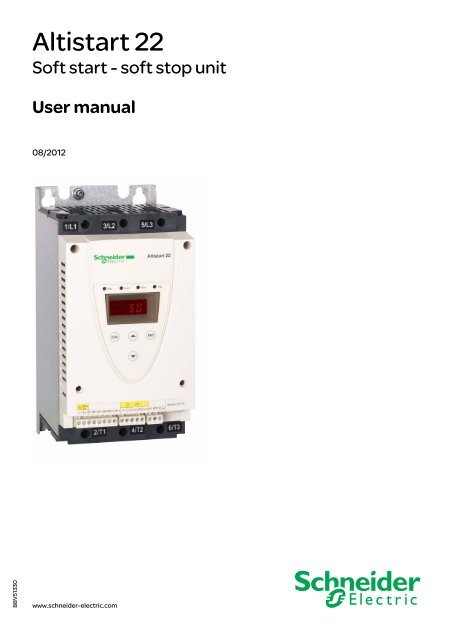
2354235 11/2008<strong>Altistart</strong> <strong>22</strong>Soft start - soft stop unitUser manual08/2012BBV51330www.schneider-electric.com
Important InformationNOTICERead these instructions carefully, and look at the equipment to become familiar with the device before trying to install, operate, or maintainit. The following special messages may appear throughout this documentation or on the equipment to warn of potential hazards or to callattention to information that clarifies or simplifies a procedure.The addition of this symbol to a Danger or Warning safety label indicates that an electrical hazard exists, which will result inpersonal injury if the instructions are not followed.This is the safety alert symbol. It is used to alert you to potential personal injury hazards. Obey all safety messages that followthis symbol to avoid possible injury or death.DANGERDANGER indicates an imminently hazardous situation, which, if not avoided, will result in death or serious injury.WARNINGWARNING indicates a potentially hazardous situation, which, if not avoided, can result in death, serious injury orequipment damage.CAUTIONCAUTION indicates a potentially hazardous situation, which, if not avoided, can result in injury or equipmentdamage.NOTICENOTICE, used without the safety alert symbol, indicates a potentially hazardous situation which, if not avoided, canresult in equipment damage.PLEASE NOTE<strong>Electric</strong>al equipment should be installed, operated, serviced, and maintained only by qualified personnel. No responsibility is assumed by<strong>Schneider</strong> <strong>Electric</strong> for any consequences arising out of the use of this product.© 2012 <strong>Schneider</strong> <strong>Electric</strong>. All Rights Reserved.4 BBV51330 08/2012
Documentation structureThe following <strong>Altistart</strong> <strong>22</strong> technical documents are available on the <strong>Schneider</strong> <strong>Electric</strong> website (www.schneider-electric.com).User manualThis manual describes how to install, commission, operate and program the soft starter.Quick Start guideThis document (S1A10388) is delivered with the soft starter, and you can download it on www.schneider-electric.com.Quick Start annexAnnex for UL 508 with SCCR (Short Circuit Current Ratings) and branch circuit protection).This document (S1A14738) is delivered with the soft starter, and you can download it on www.schneider-electric.com.6 BBV51330 08/2012
Accepted to the Information Systems Education Conference (ISECON 2006), November2-5, 2006, Dallas, Texas, USASubcategoryPerspectivesanddynamicsDevelopedunderstandingof differentperspectivesMotivationPedagogySocialrelationsHeterogeneityTable 1. Identified strengthsCondition:Semirandomlyformed projectgroupsPossibilitiesfor discussingdifferent perspectivesGroup dynamicsAuthenticFunConflict generativeOpportunitiesin meetingnew peopleDifferent preknowledgeand motivationConsequence:Effects onlearningPreparedstudents forworking lifeStimulatedlearningImprovedsocial skillsStudentswith lowerlearning capabilityhavelearned fromstudentswith a highercapabilityThe final sub-category “heterogeneity”means that mixing students with differentpre-knowledge and motivation has resultedin students with a lower learning capabilitylearning from more able ones. A dominantshare of the students (85 percent) agreedabout “semi -randomly formed projectgroups imply that students with lower preknowledgecan learn from students withhigher pre-knowledge”. The latter observationcan be seen as positive and negative,positive in the sense that students interactsocially in groups (cf. PBL above), constructknowledge and help each other to learn(Hartley, 1997). This observation also supportsthe fact that teachers in higher educationcannot take for granted that all studentswill share the same commitment or loyaltyto the project group (Hartley, 1997). This ispart of the negative side concerning differencesin knowledge and motivation that isfurther described below as free riding.Identified problemsWe have also identified a number of problemsexperienced (see Table 2). The identifiedsub-categories classified as problemsare “coordination”, “heterogeneity”, “motivation”and “social relations”.The first sub-category “coordination” has todo with the practical organization of PROW.Another way of forming student groups is tolet the students themselves form the groups.Often this way of forming groups results instudents that have the same gender, age,interest and living in the same area are joiningthe same group.An identified problem when creating projectgroups semi-randomly is that there are differentwishes about working times, there areconflicting activities outside the universityand a geographical distance between theproject members. Different wishes aboutworking times could be that some studentshave a family and therefore had problemswith late working times. Another differenceis that in our university some students liveon campus whereas others live in their ownhomes both in the city and in other cities.This means that some students have a largergeographical distance to the universityand therefore prefer to work with studentsthat live in the same area. These differentpreferences have obstructed learning andhave lead to group conflicts and a noncreativegroup climate.82 percent of the students claimed thatsemi-randomly formed project groups couldimply that project members have differentwishes about working hours and 78 percentagreed about different wishes about workingplaces. As a consequence, 81 percent of thestudents agreed that project groups havecoordination problems due to working hoursand working places and that this fact impliesan increased risk of group conflicts and reducedlearning. It is clear that differentwishes about working times, conflicting activitiesoutside the university and geographicaldistance between project members, obstructedlearning due to group conflicts andnon-creative group climate. The aspect ofcoordinating project group-work in time andspace is not exhaustively investigated in theliterature. Our findings show that this aspect
Receiving and handlingIntroductionThe ATS<strong>22</strong> offers acceleration and deceleration control of standard three-phase asynchronous induction (squirrel cage) motors. The ATS<strong>22</strong>controls the motor performance based on the motor torque rather than simple voltage or current based control. Advanced control algorithmsare incorporated to help smooth rotation throughout the starting ramp and reducing mechanical instability at the end of starting.A digital keypad display is provided for soft starter setup and motor performance display.The ATS<strong>22</strong> is available in 15 rated currents from 17 to 590 A. ATS<strong>22</strong> are rated for use from 208 to 600 V motors, and are self-adjusting fora 50 or 60 Hz supply frequency.This user manual covers the technical characteristics, specifications, installation, wiring, programming, and troubleshooting of ATS<strong>22</strong>.TerminologySome of the terms and acronyms used in this manual are defined in the table below:TermSoft starter FLAMotor FLAOCPDDefinitionSoft starter Full Load AmpsThis value is on the soft starter nameplate IcL.IcL: Soft starter rated currentMotor Full Load AmpsThis value is on the motor nameplate.The rated current of an induction motor at rated speed and load.Soft starter in line connection: In = rated current of the motor FLA.Soft starter inside delta connection: In = rated current of the motor FLA / 3.Overcurrent protective device.Receiving and Preliminary InspectionBefore installing the ATS<strong>22</strong> soft starter, read this manual and follow all precautions.Before removing the ATS<strong>22</strong> soft starter from its packing material, verify that the packing carton is not damaged from shipping. Damage tothe packing carton usually indicates improper handling. If any damage is found, notify the carrier and your <strong>Schneider</strong> <strong>Electric</strong> representative.After removing the ATS<strong>22</strong> soft starter from its packaging, inspect it for damage. If any shipping damage is found, notify the carrier and yoursales representative. Verify that the ATS<strong>22</strong> soft starter nameplate and label conform to the packing slip and corresponding purchase order.WARNINGDAMAGED SOFT STARTER EQUIPMENTDo not operate or install any soft starter that appears damaged.Failure to follow these instructions can result in death, serious injury, or equipment damage.Storing and ShippingIf the ATS<strong>22</strong> soft starter is not being immediately installed, store it in a clean, dry area where the ambient temperature is between -25° Cand +70°C (-13°F and +158°F).If the ATS<strong>22</strong> soft starter must be shipped to another location, use the original shipping material and carton to help protect it.Soft starter catalog numbersCatalog numbers are composed with:Soft starter rating (1)Power and control voltageProduct symbolA T S 2 2Q230-440 V, 230 Vac control supply, 24 Vdc logic inputsS6208-600 V, 230 Vac control supply, 24 Vdc logic inputsS6U208-600 V, 110 Vac control supply, 110 Vac logic inputs(1)The range is composed of 5 physical frame sizes distributed in 15 ratings from D17 to C59 (see page 11).8 BBV51330 08/2012
Receiving and handlingHandling the soft starterHoisting the ATS<strong>22</strong>The ATS<strong>22</strong> range comprises 5 frame sizes, with various weights and dimensions.Small soft starters can be removed from their packaging and installed without a handling device. A handling device must be used fromATS<strong>22</strong>C21ppp to ATS<strong>22</strong>C59ppp; for this reason they are supplied with lifting holes.WARNINGHANDLING AND LIFTING HAZARDKeep the area below any equipment being lifted clear of all personnel and property. Use the lifting method as shown below.Failure to follow these instructions can result in death, serious injury, or equipment damage.Do not remove the ATS<strong>22</strong> from the carton until it is at the final installation site. Handlethe soft starter carefully after removing it from the carton to avoid damage to theinternal components, frame, or exterior. Once removed from the carton, the soft startercan be handled:• With a hoist. When hoisting the soft starter, attach a spreader bar to the twolifting holes on top as shown below.• In a horizontal position, with the back of the soft starter resting on a pallet.45°maxiPackage content• Soft starter• Quick Install guide• Package of screws for frame sizes C, D and E• Allen key, supplied with size B productsBBV51330 08/2012 9
SelectionTorque characteristicTs and Is: Direct on line starting of an asynchronous motor.Ts1: Total torque range available with an <strong>Altistart</strong> <strong>22</strong>, which is dependent on thelimiting current ILt, page 51.The progression of the soft starter is controlled by the motor torque within this range.Tr: Resistive torque, which must always be less than the Ts1 torque.Soft starter selectionS1 motor duty corresponds to starting followed by operation at constant load enabling the thermal stability to be reached.S4 motor duty corresponds to a cycle comprising starting, operation at constant load and an idle period. This cycle is characterized by aload factor.The <strong>Altistart</strong> <strong>22</strong> must be selected depending on the type of application ("standard" or "severe") and the nominal power of the motor."Standard" or "severe" applications define the limiting values of the current and the cycle for motor duties S1 and S4. These duties aredescribed in the IEC 60034-1.Standard applicationExample: centrifugal pumpIn standard application, the <strong>Altistart</strong> <strong>22</strong> is designed to provide:• in S1 duty: starting at 3.5 In for 40 seconds from a cold state.• in S4 duty: a load factor of 90% and n starts per hour (see table below), with 3.5 In for 20 seconds or an equivalent thermal cycle.In this case, the motor thermal protection must conform to protection class 10.:Framesize In S4 duty, number ofstarts (1) per hourStandard With fanA 6 10B 6 10C 4 10D NA 4E NA 4(1) Note : in case of both soft starts and soft stops, the number of starts has to be divided by 2.Severe applicationThe <strong>Altistart</strong> <strong>22</strong> rated current is limited to 3.5 IcL, see table page 19.IcL is the nominal current of the <strong>Altistart</strong> <strong>22</strong>. If the applicationrequires a higher rated starting current (> 3.5 IcL), the soft starter must be oversized. See soft starter selection table, page 11.Soft starter sizing according to thermal protection classStarting currenty 3.5Inmax starting timeProtection classClass 10 Class 20 Class 30Nominal* Nominal + 1** Nominal + 2***16 s32 s48 s* Nominal = nominal size of the soft starter according to the nominal motor current (Motor FLA).** Nominal + 1 = oversize the soft starter by one rating compared to the nominal motor current (Motor FLA).*** Nominal + 2 = oversize the soft starter by 2 ratings compared to the nominal motor current (Motor FLA).10 BBV51330 08/2012
SelectionStandard application, <strong>Altistart</strong> <strong>22</strong>•••Q, 230/440 V supply,soft starter in line connectionMotor <strong>Altistart</strong> <strong>22</strong>pppQ, 230/440 V (+ 10% - 15%) - 50/60 Hz (+/- 10%)Nominal motor powerMotor nominal Soft starter rated Reference230 V 400 V 440 Vcurrent In current IcL(Motor FLA) (Soft starter FLA)kW kW kW A A4 7.5 7.5 14.8 17 ATS<strong>22</strong>D17Q7.5 15 15 28.5 32 ATS<strong>22</strong>D32Q11 <strong>22</strong> <strong>22</strong> 42 47 ATS<strong>22</strong>D47Q15 30 30 57 62 ATS<strong>22</strong>D62Q18.5 37 37 69 75 ATS<strong>22</strong>D75Q<strong>22</strong> 45 45 81 88 ATS<strong>22</strong>D88Q30 55 55 100 110 ATS<strong>22</strong>C11Q37 75 75 131 140 ATS<strong>22</strong>C14Q45 90 90 162 170 ATS<strong>22</strong>C17Q55 110 110 195 210 ATS<strong>22</strong>C21Q75 132 132 233 250 ATS<strong>22</strong>C25Q90 160 160 285 320 ATS<strong>22</strong>C32Q110 <strong>22</strong>0 <strong>22</strong>0 388 410 ATS<strong>22</strong>C41Q132 250 250 437 480 ATS<strong>22</strong>C48Q160 315 355 560 590 ATS<strong>22</strong>C59QThe nominal motor current In must not exceed the maximum permanent current in class 10.See wiring page 30.Maximum surrounding temperatureThe information in the table above is based on operation at a maximum ambient temperature of 40°C (104°F) and mini. -10°C (-50°F).The <strong>Altistart</strong> <strong>22</strong> can be used up to an ambient temperature of 60°C (140°F) as long as the max. permanent current in class 10 is deratedby 2.2% for each degree above 40°C (104°F).Example: ATS<strong>22</strong>D32Q at 50°C (1<strong>22</strong>°F) derated by 10 x 2.2% = <strong>22</strong>%, 32 A becomes 32 x (1-0.<strong>22</strong>) = 24.96 A (max. nominal motor current).BBV51330 08/2012 11
SelectionStandard application, <strong>Altistart</strong> <strong>22</strong>•••Q, 230/440 V supply,soft starter inside delta connectionOnly the <strong>Altistart</strong> <strong>22</strong>pppQ can be installed inside delta connection.NOTICERISK OF DAMAGE TO THE MOTORATS<strong>22</strong>pppS6 and ATS<strong>22</strong>pppS6U must not be installed inside delta connection.Failure to follow these instructions can result in equipment damage.Motor Soft starter 230/440 V (+ 10% - 15%) - 50/60 Hz (+/- 10%)Nominal motor power230 V 400 V 440 V(1)Line current is maximum 1.5 IcL. Also, the In setting must not exceed IcL.Example: for a 400 V - 110 kW motor with a line current of 195 A, the minimum soft starter rated current,IcL = 195/1.5 = 130 A.Thus select ATS<strong>22</strong>C14QThe nominal motor current In must not exceed the max. permanent current in class 10.See wiring page 26.Maximum surrounding temperatureLine current(Motor FLA) (1)In setting(Line current/3)Soft starterrated currentIcL(soft starter FLA)Soft starterreferencekW kW kW A A A5.5 11 15 25 14,4 17 ATS<strong>22</strong>D17Q11 <strong>22</strong> <strong>22</strong> 48 27,7 32 ATS<strong>22</strong>D32Q18.5 45 45 70 40,4 47 ATS<strong>22</strong>D47Q<strong>22</strong> 55 55 93 53,7 62 ATS<strong>22</strong>D62Q30 55 75 112 64,7 75 ATS<strong>22</strong>D75Q37 75 75 132 76,2 88 ATS<strong>22</strong>D88Q45 90 90 165 95,3 110 ATS<strong>22</strong>C11Q55 110 110 210 121,2 140 ATS<strong>22</strong>C14Q15 132 132 255 147,2 170 ATS<strong>22</strong>C17Q90 160 160 315 181,9 210 ATS<strong>22</strong>C21Q110 <strong>22</strong>0 <strong>22</strong>0 375 216,5 250 ATS<strong>22</strong>C25Q132 250 250 480 277,1 320 ATS<strong>22</strong>C32Q160 315 355 615 355,1 410 ATS<strong>22</strong>C41Q<strong>22</strong>0 355 400 720 415,7 480 ATS<strong>22</strong>C48Q250 400 500 885 511,0 590 ATS<strong>22</strong>C59QThe information in the table above is based on operation at a maximum ambient temperature of 40°C (104°F) and mini. -10°C (-50°F).The <strong>Altistart</strong> <strong>22</strong> can be used up to an ambient temperature of 60°C (140°F) as long as the max. permanent current in class 10 is deratedby 2.2% for each degree above 40°C (104°F).Example: ATS<strong>22</strong>D32Q at 50°C (1<strong>22</strong>°F) derated by 10 x 2.2% = <strong>22</strong>%, 48 A becomes 48 x 0.78 = 37.5 A (max. nominal motor current).12 BBV51330 08/2012
SelectionStandard application, 208/600 V supply, soft starter in line connectionMotor Soft starter 208/600 V (+ 10% - 15%) 50/60 Hz (+/- 10%)Nominal motor powerMotor Soft starter rated Soft starter208 V 230 V 230 V 400 V 440 V 460 V 500 V 575 V nominal currentIcL referencecurrent In(Motor FLA)(Soft starter FLA)HP HP kW kW kW HP kW HP A A3 5 4 7.5 7.5 10 9 15 14 17 ATS<strong>22</strong>D17S6 or S6U7.5 10 7.5 15 15 20 18.5 25 27 32 ATS<strong>22</strong>D32S6 or S6U(1) 15 11 <strong>22</strong> <strong>22</strong> 30 30 40 40 47 ATS<strong>22</strong>D47S6 or S6U15 20 15 30 30 40 37 50 52 62 ATS<strong>22</strong>D62S6 or S6U20 25 18.5 37 37 50 45 60 65 75 ATS<strong>22</strong>D75S6 or S6U25 30 <strong>22</strong> 45 45 60 55 75 77 88 ATS<strong>22</strong>D88S6 or S6U30 40 30 55 55 75 75 100 96 110 ATS<strong>22</strong>C11S6 or S6U40 50 37 75 75 100 90 125 124 140 ATS<strong>22</strong>C14S6 or S6U50 60 45 90 90 125 110 150 156 170 ATS<strong>22</strong>C17S6 or S6U60 75 55 110 110 150 132 200 180 210 ATS<strong>22</strong>C21S6 or S6U75 100 75 132 132 200 160 250 240 250 ATS<strong>22</strong>C25S6 or S6U100 125 90 160 160 250 <strong>22</strong>0 300 302 320 ATS<strong>22</strong>C32S6 or S6U125 150 110 <strong>22</strong>0 <strong>22</strong>0 300 250 350 361 410 ATS<strong>22</strong>C41S6 or S6U150 -(1) 132 250 250 350 315 400 414 480 ATS<strong>22</strong>C48S6 or S6U(1) 200 160 315 355 400 400 500 477 590 ATS<strong>22</strong>C59S6 or S6U(1)Value not indicated when there is no corresponding standardized motor.The nominal motor current In must not exceed the max. permanent current in class 10.Maximum surrounding temperatureThe information in the table above is based on operation at a maximum ambient temperature of 40°C (104°F) and mini. -10°C (-50°F).The <strong>Altistart</strong> <strong>22</strong> can be used up to an ambient temperature of 60°C (140°F) as long as the max. permanent current in class 10 is deratedby 2.2% for each degree above 40°C (104°F).Example: ATS<strong>22</strong>D32S6 at 50°C (1<strong>22</strong>°F) derated by 10 x 2.2% = <strong>22</strong>%, 27 A becomes 27 x 0.78 =21.06 A (max. nominal motor current).BBV51330 08/2012 13
Dimensions and weightsATS<strong>22</strong>D17 to D88For frame sizes D17 to D88, the fan is sold separately. (1)ATS<strong>22</strong>D17D32D47FramesizeAAAa b c c1 e H StandardGmm mm mm mm mm mm mm(in.) (in.) (in.) (in.) (in.) (in.) (in.)130(5.1)265(10.4)169(6.6)209(8.2)6.5(0.3)250(9.8)100(3.9)With fanG1mm(in.)65(2.6)Dmmmm(in.)7(0.28)Weightkg (lb)5.5(12.1)D62D75D88BBB145(5.7)295(11.6)207(8.1)247(9.7)10.5(0.4)276(10.9)115(4.5)80(3.15)7(0.28)7.8(17.2)c: dimension of the product alone.c1: dimension of the product with its fan.(1) The voltage of the fan has to match the control voltage of the soft starter:ATS<strong>22</strong>pppQ or ATS<strong>22</strong>pppS6 Fan 230V (VW3G<strong>22</strong>ppp, ppp = 400 for size A, 401 for size B or 402 for size C)ATS<strong>22</strong>pppS6U Fan 110V (VW3G<strong>22</strong>Uppp, ppp = 400 for size A, 401 for size B or 402 for size C)14 BBV51330 08/2012
Dimensions and weightsATS<strong>22</strong>C11 to C17For frame sizes C11 to C17, the fan is sold separately. (1)ATS<strong>22</strong>Framesize CC11C14C17a b c c1 e H G1 P Q Q1 S D1 D2 D3 Weightmm(in.)150(5.9)mm(in.)356(14)mm(in.)<strong>22</strong>9.5(9)mm(in.)269.5(10.6)mm(in.)10.5(0.41)mm(in.)331(13)mm(in.)120(4.7)mm(in.)40.5(1.6)mm(in.)34.5(1.3)mm(in.)5(0.2)mm(in.)20(0.8)mm(in.)9(0.35)mm(in.)7(0.28)mm(in.)6(0.23)kg(lb)12.2(26.9)c: dimension of the product alone.c1: dimension of the product with its fan.(1) The voltage of the fan has to match the control voltage of the soft starter:ATS<strong>22</strong>pppQ or ATS<strong>22</strong>pppS6 Fan 230V (VW3G<strong>22</strong>ppp, ppp = 400 for size A, 401 for size B or 402 for size C)ATS<strong>22</strong>pppS6U Fan 110V (VW3G<strong>22</strong>Uppp, ppp = 400 for size A, 401 for size B or 402 for size C)BBV51330 08/2012 15
Dimensions and weightsATS<strong>22</strong>C21 to C59For frame sizes C21 to C59, the fan is integrated.ATS<strong>22</strong>C21C25C32C41FramesizeDDDDa b c e H G1 P Q Q1 S D1 D2 Weightmm(in.)206(8.1)mm(in.)425(16.7)mm(in.)299(11.8)mm(in.)15(0.59)mm(in.)396(15.6)mm(in.)157(6.2)mm(in.)60(2.4)mm(in.)40(1.6)mm(in.)1.3(0.05)mm(in.)30(1.2)mm(in.)13.5(0.53)mm(in.)9(0.35)kg (lb)20.5(45.2)C48 E 304C59 E (11.9)455(17.9)339.7(13.4)15(0.59)426(16.8)264(10.4)94(3.7)55(2.2)1(0.04)40(1.6)13.5(0.53)9(0.35)33(73.3)16 BBV51330 08/2012
MountingMounting PrecautionsFollow these precautions when mounting the ATS<strong>22</strong> soft starter:• The soft starter is compliant with pollution Degree 2 as defined in NEMA ICS1-1 or IEC 60664-1.• For environment pollution degree 3 install the product inside a cabinet type 12 or IP54.DANGERHAZARD OF ELECTRIC SHOCK, EXPLOSION, OR ARC FLASHATS<strong>22</strong> soft starters are open devices and must be mounted in a suitable enclosure.Failure to follow these instructions will result in death or serious injury.• The ATS<strong>22</strong> soft starter generates heat and must be properly ventilated. Refer to "Thermal considerations for sizing enclosures” page19 to determine power dissipated.• When several soft starters are installed in a control panel, arrange them in a row. Do not stack soft starters. Heat generated from thebottom soft starter can adversely affect the ambient temperature around the top soft starter.• Install the ATS<strong>22</strong> vertically, within ± 10° (other positions are not allowed).• Do not place it close to heating elements. Leave sufficient free space so that the air required for cooling purposes can circulate fromthe bottom to the top of the unit.• <strong>Electric</strong>al current through the ATS<strong>22</strong> will result in heat losses that must be dissipated into the ambient air immediately surroundingthe soft starter. To help prevent a thermal fault, provide sufficient enclosure cooling and/or ventilation to limit the ambient temperaturearound the soft starter.S ≥ 100 mm (3.9 in)Note: For the soft starters mounted side-by-side, the free spacemust be ≥ 50 mm (1.95 in.)S ≥ 50 mm(1.95 in.)S ≥ 50 mm(1.95 in.)S ≥ 100 mm (3.9 in)DANGERHAZARD OF ELECTRIC SHOCK, EXPLOSION, OR ARC FLASHCheck that no liquid, dust or conductive object can fall into the soft starter (degree of protection IP00 from above).Failure to follow these instructions will result in death or serious injury.BBV51330 08/2012 17
MountingSoft starter ventilationOn soft starters installed with a cooling fan, the fan is factory set to switch on automatically as soon as the heatsink temperature reaches46°C (114.8°F).It is switched off when the heatsink temperature falls back to 43°C (109.4°F). This behavior can be modified by adjusting the FAnparameter in IO menu on page 61.Fan flow ratesReferenceFrame Unit Standard With optional fan kitsize110 V 230 V 110 V 230 VATS<strong>22</strong> D17, D32, D47 A m 3 /hour - - 28 31CFM (1) - - 16 18ATS<strong>22</strong> D62, D75, D88 B m 3 /hour - - 28 31CFM (1) - - 16 18ATS<strong>22</strong> C11, C14, C17 C m 3 /hour - - 108 108CFM (1) - - 64 64ATS<strong>22</strong> C21, C25, C32, C41 D m 3 /hour 148 148 - -CFM (1) 87 87 - -ATS<strong>22</strong> C48, C59 E m 3 /hour 148 148 - -CFM (1) 87 87 - -(1)Cubic Feet / MinuteMounting in a General Purpose Metal EnclosureObserve the mounting recommendations on the previous page.To help proper air circulation in the soft starter:• Install ventilation grilles.• Verify that ventilation is adequate: if not install a forced ventilation unit, with afilter if necessary.Derate the soft starter current IcL by 2.2% per °C for temperatures above 40°C upto 60°C (104°F up to 140°F).18 BBV51330 08/2012
MountingMounting in a dust and damp-proof metal enclosureVentilation for dust and damp- proof enclosureθ°i = internal ambient temperatureθ°e = external ambient temperatureFollow the instructions in this section in order to meet NEMA Type 12 (IP54) degree of protection.Do not use insulated or non-metallic enclosures as they have poor thermal conduction. Provide a stirring fan to circulate air inside theenclosure and to help prevent hot spots in the soft starter. This allows operation of the soft starter in an enclosure with a maximum internaltemperature of 60°C (140°F). Ensure that the ambient temperature around the soft starters does not exceed this limit.Derate the soft starter current IcL by 2.2% per °C for temperatures above 40°C up to 60°C (104°F up to 140°F).Thermal considerations for sizing enclosuresWhen mounting the ATS<strong>22</strong> soft starter in an enclosure, use the enclosure manufacturers’ recommendations for proper sizing based onthermal considerations. For this, it is necessary to sum the power dissipated by each device in the enclosure. Table hereafter lists the steadystate and starting power dissipations for the ATS<strong>22</strong> soft starter, operating at rated current.Power dissipated by the soft starters, at their nominal currentSoft starterPowerControl supplyreferenceFrame IcL During starting Steady state Electronics Shorting Fanssizetotal powerat 3.5 IcLtotal powerbypasscontactors(1)A W W W W WATS<strong>22</strong>D17 A 17 208 5ATS<strong>22</strong>D32 A 32 404 1020 - 14 (2)ATS<strong>22</strong>D47 A 47 562 14ATS<strong>22</strong>D62 B 62 781 19ATS<strong>22</strong>D75 B 75 1016 2320 - 20 (2)ATS<strong>22</strong>D88 B 88 1060 26ATS<strong>22</strong>C11 C 110 1345 33ATS<strong>22</strong>C14 C 140 1548 4<strong>22</strong>0 - 20 (2)ATS<strong>22</strong>C17 C 170 19<strong>22</strong> 51ATS<strong>22</strong>C21 D 210 2596 63ATS<strong>22</strong>C25 D 250 3275 75ATS<strong>22</strong>C32 D 320 3699 9620 14 20ATS<strong>22</strong>C41 D 410 5147 123ATS<strong>22</strong>C48 E 480 6396 144ATS<strong>22</strong>C59 E 590 7599 17720 14 40(1)For ATS<strong>22</strong>pppQ, ATS<strong>22</strong>pppS6 and ATS<strong>22</strong>pppS6U, frame sizes A, B and C the shorting contactor power is included in the electronics.(2)Optional fan kitExample: for an ATS<strong>22</strong>D47Power dissipated during starting: 562 WPower dissipated in steady state: 14 WPower for Control supply: 20 W without fan, 34 W with fanExample: for an ATS<strong>22</strong>C48Power dissipated during starting: 6396 WPower dissipated in steady state: 144 WPower for Control supply: 74 WBBV51330 08/2012 19
Mounting - Fan optionFan for frame sizes A, B and CConnections between the fan and the ATS<strong>22</strong>Tightening torque: 3.5 N·m (31 lb.in)* As 2 different fan options could be connected to the ATS<strong>22</strong>according to the fan voltage (matching the ATS<strong>22</strong> controlvoltage), the connector is different according to the voltage, tohelp avoid wrong assembly and misuse.(1) The voltage of the fan has to match the control voltage ofthe soft starter:ATS<strong>22</strong>pppQ or ATS<strong>22</strong>pppS6 Fan 230 VATS<strong>22</strong>pppS6U Fan 110 V20 BBV51330 08/2012
Mounting - Fan optionFan dimensions for frame sizes ATS<strong>22</strong>D17 to C17For frame sizes D17 to D88, the fan is sold separately. (1)Fan kit ATS<strong>22</strong> a b k e H G G1 X D WeightABCD17D32D47D62D75D88C11C14C17mm(in.)130(5.1)145(5.7)150(5.9)mm(in.)265(10.4)295(11.6)350(13.8)mm(in.)40(1.6)40(1.6)40(1.6)(1) The voltage of the fan has to match the control voltage of the soft starter.ATS<strong>22</strong>pppQ or ATS<strong>22</strong>pppS6 Fan 230V (VW3G<strong>22</strong>ppp, ppp = 400 for size A, 401 for size B or 402 for size C)ATS<strong>22</strong>pppS6U Fan 110V (VW3G<strong>22</strong>Uppp, ppp = 400 for size A, 401 for size B or 402 for size C)mm(in.)8.5(0.33)8.5(0.33)8.5(0.33)mm(in.)248(9.8)278(10.9)333(13.1)mm(in.)100(3.9)115(4.5)120(4.7)mm(in.)65(2.6)80(3.1)85(3.3)mm(in.)250(9.8)276(10.9)331(13)mm(in.)7(0.28)7(0.28)7(0.28)kg(lb)1.2(2.6)1.4(3.1)1.6(3.5)BBV51330 08/2012 21
Thermal protectionSoft starter thermal protectionThe thermal protection is provided by the temperature sensor installed on the heatsink.Motor thermal protectionStandard IEC 60947-4-2 defines the protection classes giving the starting capacities of the motor (warm or cold start) without thermal faults.Different protection classes are given for a COLD state (corresponding to a stabilized motor thermal state, switched off) and for a WARMstate (corresponding to a stabilized motor thermal state, at nominal power).• The soft starter is factory set to protection class 10.• This protection class can be modified using tHP parameter in SEt menu.• The motor thermal state is stored in memory. No estimate of motor cooling is calculated while power of the control part is off.• An overload alarm is activated if motor thermal state exceeds 110%.• A thermal trip OLFstops the motor if motor thermal state exceeds 125%.• If the thermal protection has not been disabled, the thermal trip can be indicated by a relay depending on output assignment.• After the motor has stopped or the soft starter has been switched off, the thermal state is saved. At next start or switch on, the thermalprotection value is restored.• If a special motor is used (explosion proof, submersible, etc.), the thermal protection should be provided by PTC probes.RISK OF DAMAGE TO THE MOTORNOTICEThe use of external overload protection is required under the following conditions:• Running multiple motors• Running motors rated at less than 40% of the nominal soft starter current• Using motor switching• Using special motor (explosion proof, submersible, etc...)Failure to follow these instructions can result in equipment damage.See Motor thermal protection with PTC probes, page 25.<strong>22</strong> BBV51330 08/2012
Thermal protectionCold curvest (s)Class 30Class 20Class 10Trip time for a standard application(class 10)Trip time for a severe application(class 20)Trip time for a severe application(class 30)3.5 In 3.5 In 3.5 In32 s 63 s 95 sBBV51330 08/2012 23
Thermal protectionWarm curvest (s)Class 30Class 20Class 10Trip time for a standard application(class 10)Trip time for a severe application(class 20)Trip time for a severe application(class 30)3.5 In 3.5 In 3.5 In16 s 32 s 48 s24 BBV51330 08/2012
Thermal protectionMotor thermal protection with PTC probesPTC probes integrated in the motor to measure its temperature can be connected to the control card terminals.Note:PTC probe protection does not deactivate the motor thermal protection provided by the soft starter calculation. Both types of protection canoperate in parallel.PTC wiring(1)(1) Shielded cable is optional.CharacteristicsTotal resistance of the probe circuit: 750 Ω at 25°C (77°F).Tripping: between 2700 Ω and 3100 Ω.BBV51330 08/2012 25
WiringInstallation PrecautionsDANGERHAZARD OF ELECTRIC SHOCK, EXPLOSION, OR ARC FLASH• Read and understand this manual before installing or operating the <strong>Altistart</strong> <strong>22</strong>. Installation, adjustment, repair, and maintenancemust be performed by qualified personnel.• The user is responsible for compliance with all international and national electrical code requirements with respect to grounding ofall equipment.• Many parts of this soft starter, including the printed circuit boards, operate at the line voltage. DO NOT TOUCH. Use only electricallyinsulated tools.• DO NOT touch unshielded components or terminal strip screw connections with voltage present.• Before servicing the soft starter:- Disconnect all power, including external control power that may be present.- Place a “DO NOT TURN ON” label on all power disconnects.- Lock all power disconnects in the open position.• Install and close all covers before applying power or starting and stopping the soft starter.Failure to follow these instructions will result in death or serious injury.Good wiring practice requires the separation of control circuit wiring from all power (line and load) wiring. Power wiring to the motor musthave the maximum possible separation from all other power wiring. Do not run them in the same conduit. This separation reduces thepossibility of coupling electrical noise between circuits.Follow these precautions when installing the ATS<strong>22</strong> soft starter:• Voltage and frequency specifications for the input line must match the soft starter configuration.• A disconnect switch must be installed between the input line and the soft starter.DANGERHAZARD OF ELECTRIC SHOCK, EXPLOSION, OR ARC FLASH• The solid state switches of the ATS<strong>22</strong> soft starter’s power circuit do not provide complete isolation from the AC line. Due to leakagecurrents through the solid-state switches, hazardous voltages can be present on the soft starter load-side power circuit wheneverpower is applied to the line side of the soft starter.• Disconnect all power before servicing the soft starter or motor.Failure to follow these instructions will result in death or serious injury.• When using an isolation contactor, the contactor must close before or at the same time as the application of the soft starter runcommand. If line power is not detected at the L1, L2, and L3 terminals of the soft starter within 500 ms of this run command, a PhaseFailure trip will occur.• External overcurrent protection devices (OCPD), either fuses or a circuit breaker, must be installed on the line-side connections ofthe ATS<strong>22</strong> soft starter. The maximum recommended OCPD rating, along with the associated soft starter short circuit withstand rating,is listed on the Quickstart S1A14738.26 BBV51330 08/2012
WiringWARNINGINADEQUATE OVERCURRENT PROTECTION• An overcurrent protective device must be installed on the line-side of the ATS<strong>22</strong> to achieve published short-circuit withstand ratings.• Do not exceed the maximum overcurrent protective device ratings shown on the Quickstart annex (S1A14738).• Do not connect the soft starter to a power feeder whose short circuit capacity exceeds the soft starter short circuit withstand ratingshown on the Quickstart annex (S1A14738).Failure to follow these instructions can result in death, serious injury, or equipment damage.• Power factor correction capacitors should not be connected to a motor controlled by an ATS<strong>22</strong> soft starter. If power factor correctionis required, the capacitors must be located on the line-side of the soft starter. A separate contactor should be used to switch thecapacitors off when the motor is off, or during acceleration and deceleration. Refer to bulletin No 8638PD9603.RISK OF DAMAGE TO THE SOFT STARTERNOTICE• Do not connect power factor correction capacitors to the load-side power circuit of the ATS<strong>22</strong>.• Do not connect loads other than motors (for example transformers and resistors are forbidden).Failure to follow these instructions can result in equipment damage.• The ATS<strong>22</strong> uses solid-state power switches to control motor power. When checking the condition of conductor or motor insulation,do not connect the high potential dielectric test equipment or insulation resistance tester to the soft starter since the test voltages usedmay damage the soft starter. Always disconnect the soft starter from the conductors or motor before performing such tests.RISK OF DAMAGE TO THE SOFT STARTERNOTICE• Do not perform high potential dielectric tests on circuits while the circuits are connected to the ATS<strong>22</strong> soft starter.• Any circuit requiring high potential dielectric tests must be disconnected from the soft starter prior to performing the test.Failure to follow these instructions can result in equipment damage.• The ATS<strong>22</strong> contains electronic circuitry to detect and signal when the solid-state switches have become inoperable.• Since the solid-state switches may be incapable of completely blocking the motor power should the soft starter detect a fault, auxiliaryisolation on the line side of the soft starter is required. Use either a circuit breaker equipped with a shunt trip coil or an electromagneticcontactor. Connect the isolation device to the detected fault relay of the soft starter so that it opens the soft starter power circuit in theevent of a soft starter trip. The isolation device must be capable of interrupting motor locked rotor current.BBV51330 08/2012 27
WiringRefer to application diagrams that display the logic controlling the isolation device via the detected fault relay.CAUTIONMOTOR OVERHEATING HAZARDIf the solid-state switches on the ATS<strong>22</strong> become inoperable, single-phase operation of the motor can result.• Use an isolation device consisting of either a circuit breaker equipped with a shunt trip coil or an electromagnetic contactor to openthe line-side of the soft starter.• The isolation device must be capable of interrupting the motor locked rotor current.• Connect the detected fault relay of the soft starter to open the isolation device in the event of a soft starter trip.Failure to follow these instructions can result in injury or equipment damage.WARNINGINADEQUATE SYSTEM GROUNDING- BRANCH CIRCUIT CONDUCTOR HAZARDIf system grounding is not adequate for ground fault levels, use properly coordinated external ground fault protection. Possible solutionsinclude:• Time delay fuses coordinated to 125% of motor FLA.• A properly coordinated external overload relay.Failure to follow these instructions can result in death, serious injury, or equipment damage.System GroundingIf system grounding is not adequate to handle ground trip levels which can exceed 1300% of motor full load amps (Motor FLA), then thisdevice may not protect the branch circuit conductors. In this case, external ground trip protection must be properly coordinated.Recommended solutions include:• Time delay fuses coordinated to 125% of motor FLA. The fuses listed in the chapter Branch circuit protection are sized to provideproper coordination and may be used for applications that do not require start times longer than 50 seconds at 300% current limit or20 seconds at 500% current limit.• External overload relay. For multi-motor applications, applications in which motor does not match the soft starter size, or applicationsthat use a full voltage bypass scheme, an external overload relay can be coordinated to protect conductors from a high-impedanceground trip.General wiring practicesWhen wiring ATS<strong>22</strong> soft starter, follow the wiring practices required by national and local electrical codes. In addition, follow theseguidelines:• Use metallic conduit for all soft starter wiring. Do not run control and power wiring in the same conduit.• Separate metallic conduits carrying power wiring or low-level control wiring by at least 80 mm (3 in).• Separate non-metallic conduits or cable trays used to carry power wiring from metallic conduit carrying low-level control wiring by atleast 305 mm (12 in).• Always cross power and control wiring at right angles.• Keep the control circuits away from the power cables.Adaptation to line inputThe control circuit is completely independent of the power circuit. To apply control voltage, follow the instructions on the label located onthe soft starter terminal strip. Connect single phase voltage of 110 or 230 Vac supply to terminals CL1 and CL2.The power circuit adapts automatically to the input line voltage and frequency over a range of 230 to 440 V for ATS<strong>22</strong>pppQ soft starters,and over a range of 208 to 600 V for ATS<strong>22</strong>pppS6 and ATS<strong>22</strong>pppS6U soft starters.28 BBV51330 08/2012
WiringPower RequirementsConnect the control supply (CL1-CL2), ensuring that it is off, according to the model number of the soft starter.ATS<strong>22</strong>pppQandATS<strong>22</strong>pppS6ATS<strong>22</strong>pppS6U230 V +10%<strong>22</strong>0 V –15%115 V +10%110 V –15%Connect the power line supply (1/L1-3/L2-5/L3), ensuring that it is off, according to the model number of the soft starter.ATS<strong>22</strong>pppQATS<strong>22</strong>pppS6orATS<strong>22</strong>pppS6U230 V440 V208 V600 V+10% –15%+10% –15%Connect the motor (2/T1 - 4/T2 - 6/T3), ensuring that its coupling corresponds to the supply voltage.Note: If the ATS<strong>22</strong>pppQ is used inside delta connection, follow the recommendations on page 12, and the diagrams on page 30.Bypass contactorNOTICERISK OF DAMAGE TO THE EQUIPMENTThe motor phase loss detection of the 3 phases is only active at the startup of the soft starter.It will not be detected if the loss occurred while the soft starter is already in running stateWhen downstream contactor is used in the sequence:- The contactor must be closed before to apply the run command to the soft starter.- Ensure that contactor will not be released while the soft starter is already running.Failure to follow these instructions can result in equipment damage.An internal bypass contactor is integrated into all ATS<strong>22</strong> soft starters.The bypass contactor is activated when :I motor < 120% InANDU motor = 100% input line voltageBlock diagram of the power part of the <strong>Altistart</strong> <strong>22</strong>ATS<strong>22</strong>pppQ rangeATS<strong>22</strong>pppS6 and ATS<strong>22</strong>pppS6U rangesBBV51330 08/2012 29
WiringThe ATS<strong>22</strong>pppQ range (230-440 V) can be connected in the motor supply line or inside delta connection of the motor.The <strong>Altistart</strong> <strong>22</strong> in line connectionThe motor connection depends on the supply voltage. Two possibilities are shown below: star connection and delta connection.ATS<strong>22</strong>MotorStar connectionDelta connectionThe <strong>Altistart</strong> <strong>22</strong> connected inside delta connectionATS<strong>22</strong>NOTICERISK OF DAMAGE TO THE SOFT STARTER• Only the ATS<strong>22</strong>pppQ range can be installed inside delta connection.• Ensure connection exactly as shown on the example.• Line voltage should not exceed 440 V.• The parameter dLtA must be set to dLt.Failure to follow these instructions can result in equipment damage.Note: Phase sequence must be 1 - 2 - 3Motor30 BBV51330 08/2012
WiringThe ATS<strong>22</strong>•••Q connected inside delta connectionATS<strong>22</strong>pppQ soft starters can be inserted inside delta connection of the motor.Only the ATS<strong>22</strong>pppQ range can be installed inside delta connection. Set the parameter dLtA to dLt.See the tables on page 12 for more information about soft starter-motor combinations.Note: To reverse the direction of the motor as shown on the figure:- reverse the two outputs U1 and V1,- reverse the two inputs L1 and L3.BBV51330 08/2012 31
Wiring - power terminalsPowerObserve the cable cross-sectional areas recommended in the standards.The soft starter must be grounded to conform to the regulations concerning leakage currents. If the installation involves several soft starterson the same line, each soft starter must be grounded separately.Keep the power cables separate from circuits in the installation with low-level signals (sensors, PLCs, measuring devices, video, telephone).Cage style connectors for frame sizes A and BGround connectionbottom view1L1 3L2 5L3Ground connections, screw sizeRdyComRunTrip2/T1 4/T2 6/T3Frame sizeAScrewM6BM6CM6DM10EM102T1 4T2 6T3Ground connectionPower connections, minimum and maximum wiring capabilities, tightening torqueFramesizeATS<strong>22</strong> IEC cable UL cable1/L1 3/L2 5/L3 and 2/T1 4/T2 6/T3power supply and output to motor1/L1 3/L2 5/L3 and 2/T1 4/T2 6/T3power supply and output to motorSize Tightening torque Strip Gauge Tightening torque Striplengthlengthmin. max min. max min. max min. maxmm² mm² N·m N·m mm AWG AWG lb·in lb·in in.A D17, D32, D47 2.5 16 3 3 10 12 4 26 26 0.4B D62, D75, D88 4 (a) 50 10 10 15 10 (a) 1/0 89 89 0.6(a) The cable gauge affects the IP protection of the soft starter. To keep IP20 value with a connected cable on frame B, the minimum cablegauge is: 16 mm² or 4 AWG.Allen key, supplied with size B productsDANGERFIRE HAZARD DUE TO LACK OF TIGHTENING TORQUE• Ensure correct connector tightening torque for power terminals.• For size B, use the Allen key provided with the product.Failure to follow these instructions will result in death or serious injury.32 BBV51330 08/2012
Wiring - power terminalsBus bar connections for frame sizes C to EGround connectionWidthDepthFrameSizeATS<strong>22</strong> 1/L1 3/L2 5/L3 and 2/T1 4/T2 6/T3power supply and output to motorBarFor more details, see Dimensions and weights paragraph page 14.Cable and coverWidth Depth Bolt Size Gauge Cover Tightening torquemm (in.) mm (in.) M mm² MCM Ref N·m lb·inC C11, C14, C17 20 (0.79) 5 (0.2) 8 (0.31) 95 250 LA9F702 18 159D C21, C25, C32, C41 30 (1.18) 5 (0.2) 12 (0.47) 2x150 2x250 LA9F703 57 503E C48, C59 40 (1.57) 5 (0.2) 12 (0.47) 2x240 2x500 LA9F703 57 503BBV51330 08/2012 33
Wiring - power terminalsPower connections, minimum required wiring sectionFrame Size ATS<strong>22</strong> IEC cablemm² (Cu 70°C/158 °F) (1)UL cableAWG (Cu 75°C/167 °F) (1)A D17 2.5 10D32 6 8D47 10 6B D62 16 4D75 25 3D88 35 2C C11 35 1/0C14 50 2/0C17 70 4/0D C21 95 300 MCMC25 120 350 MCMC32 185 2 x 3/0C41 2 x 150 2 x 250 MCME C48 2x 150 2 x 350 MCMC59 2 x 185 2 x 500 MCM(1)at max ambient temperature of 40°C (104 °F)34 BBV51330 08/2012
Wiring - control terminals<strong>Electric</strong>al characteristics for ATS<strong>22</strong>•••S6 and ATS<strong>22</strong>•••Q ranges (230 Vac with 24 Vdc logic input)Terminal Function CharacteristicsCL1230 Vac +10%ATS<strong>22</strong> control power supplyCL<strong>22</strong>20 Vac -15%R1B Relay1 normally closedR1C Relay1 commonMax switching capability:5 A- 250 Vac or 30 Vdc on resistive load ( p.f. =1)R1A Relay1 normally open2 A-250 Vac or 30 Vdc on inductive load ( p.f.=0.4)R2B Relay2 normally closedMinimimal commutation capability:R2C Relay2 common100 mA 12 VdcR2A Relay2 normally openLI1 Logic input 1 3 x 24 V logic inputs with 4.3 kΩ impedanceLI2 Logic input 2Umax = 30 V, Imax = 8 mALI3 Logic input 3state 1: U>11 V - I>5 mA+24 Vdc Float 24 Vdc(+) (1)state 0: U
Wiring - control terminals<strong>Electric</strong>al characteristics for ATS<strong>22</strong>•••S6U range (110 Vac with 110 Vac logic inputs)Terminal Function CharacteristicsCL1CL2ATS<strong>22</strong> control power supply 110 Vac +10% -15%R1B Relay1 normally closedR1C Relay1 commonMax switching capability:5 A- 250 Vac or 30 Vdc on resistive load ( p.f. =1)R1A Relay1 normally open2 A-250 Vac or 30 Vdc on inductive load ( p.f.=0.4)R2B Relay2 normally closedMinimimal commutation capability:R2C Relay2 common100 mA 12 VdcR2A Relay2 normally openLI1 Logic input 1 3 x 110 V logic inputs with 20 kΩLI2 Logic input 2impedanceLI3 Logic input 3Umax = 121 Vac, Imax = 5 mANC Not connectedstate 1: U>79 V - I>2 mAstate 0: U
Wiring - control terminalsTypes of commandLI1 stop behaviorLI1 assignment is stop and cannot be changed by HMI or serial link.This input is active on level (Low level (0) = stop).RUN and START managementRUN and START can only be assigned to LI2 (not LI3).In 2-wire controlOn power-up or on manual trip reset, the motor will restart if the RUN command is present.ControlsupplyLI2MotorIn 3-wire controlOn power-up or a manual trip reset or after a stop command, or a change of assignment, the motor can only be powered once the STARTinput has been opened (state 0) followed by a new pulse (state 1).When switching from remote command to local command, with Run order present on the terminal control, the motor doesn’t start in 3-wirecontrol: need to remove Run order and apply it again.ControlsupplyMotorBBV51330 08/2012 37
Wiring - in line connection - application diagramATS<strong>22</strong>•••Q and ATS<strong>22</strong>•••S6: 230 Vac control, logic Inputs (LI) 24 Vdc, 3-wire control(1)Check the operating limits of the contact, for example when connecting to high rating contactors. See “<strong>Electric</strong>al characteristics” page 35.(2)Select a voltage transformer in accordance with the mains voltage.3-wire control settingIn the menu Advanced I/OIO, set the following parameters:Parameter Value DescriptionLI2 Strt Logic Input 2 is set to startr2 trlP Trip relay is de-energized upon trip38 BBV51330 08/2012
Wiring - in line connection - application diagramATS<strong>22</strong>•••Q and ATS<strong>22</strong>•••S6: 230 Vac control, logic Inputs (LI) 24 Vdc,2-wire control, freewheel stop(1)Check the operating limits of the contact, for example when connecting to high rating contactors. See “<strong>Electric</strong>al characteristics” page 35.(2)Insert a voltage transformer if the power voltage is higher than the <strong>Altistart</strong> <strong>22</strong> acceptable value. Characteristics: min 100 VA page 13.2-wire control settingIn the menu Advanced I/O IO, set the following parameters:Parameter Value DescriptionLI2 rUn Logic Input 2 is set to Runr2 trlP Trip relay is de-energized upon tripNote: For UL508 schematics, see page 82.BBV51330 08/2012 39
Wiring - in line connection - application diagramATS<strong>22</strong>•••S6U: 110 Vac control, Logic Inputs (LI) 110 Vac, 3-wire control(1)Check the operating limits of the contact, for example when connecting to high rating contactors. See “<strong>Electric</strong>al characteristics” page 36.(2)Insert a voltage transformer if the power voltage is higher than the <strong>Altistart</strong> <strong>22</strong> acceptable value. Characteristics: min 100 VA page 13.3-wire control settingIn the menu Advanced I/O IO, set the following parameters:Parameter Value DescriptionLI2 Strt Logic Input 2 is set to startr2 trlP Trip relay is de-energized upon trip40 BBV51330 08/2012
Wiring - in line connection - application diagramATS<strong>22</strong>•••S6U: 110 Vac control, Logic Inputs (LI) 110 Vac, 2-wire control, freewheelstop(1)Check the operating limits of the contact, for example when connecting to high rating contactors. See “<strong>Electric</strong>al characteristics” page 36.(2)Insert a voltage transformer if the power voltage is higher than the <strong>Altistart</strong> <strong>22</strong> acceptable value. Characteristics: min 100 VA page 13.2-wire control settingIn the menu Advanced I/O IO, set the following parameters:Parameter Value DescriptionLI2 rUn Logic Input 2 is set to Runr2 trlP Trip relay is de-energized upon tripNote: For UL508 schematics, see page 83.BBV51330 08/2012 41
Display terminalFunctions of the keys and the display4 signaling LEDS4 seven segment displayScroll forwardESCExits to the previous levelENTEnters the menu or parameter, or savesthe displayed parameter valueScroll backwardSelection processParameter menuThe selection process takes you through three levels:1-Scroll to a parameter menu and press the ENT key.ESCENT2-Scroll to a specific parameter and press the ENT key.3-Scroll to a value and press the ENT key to save the value. Aparameter value becomes valid and takes effect immediately, beforeyou press the ENT key.ParameterThis means that, if for example you increase the current limit duringthe start process, the motor current will increase immediately (until15 seconds maximum). Once you find the correct value, you caneither decide to store it (press the ENT key) or return the <strong>Altistart</strong> <strong>22</strong>to its previous value (press the ESC key), or wait 15 seconds.ESCValueENTSpecial key combinationsSpecial keys combinations are used as shortcuts, see below.Save valueENTKey combinationDescriptionESC + +Displays UtIL menu (Utility)+Clear the trip message and reset the soft starterESC++Soft starter not locked (see Cod parameter)42 BBV51330 08/2012
Display terminalLED’s displayThe front cover of the control board contains four LEDs above the seven segment display that display the <strong>Altistart</strong> <strong>22</strong> status and activity.Name Location DescriptionRdyComRunTripGreen - front coverGreen - front coverYellow - front coverRed - front coverON = line and control suppliedOFF = no voltage on controlFlashing = control supplied but no power line nrdY or SnbreachedON = Modbus status OK; Communication present.OFF = Modbus status not OKON = motor runs at full voltage and bypass contactor onOFF = motor stoppedFlashing = ACC or DEC phaseON = trip with immediate stopOFF = no problemFlashing = alarm warning - no stopNOTE: see LED parameter, page 78.LEDs included inside the seven segment displayName Location DescriptionLCr1 Led upper left 7 segments Current phase 1 displayLCr2 Led middle left 7 segments Current phase 2 displayLCr3 Led down left 7 segments Current phase 3 displayExample: LCr1= 88 ANote1: When the soft starter is inside delta connection, LCr1, LCr2, LCr3 values are current inside the windings. The linecurrent = LCr x 3.Note:2 For ATS<strong>22</strong>pppQ, LCr2 displays "--" because there is no current sensor on phase 2.BBV51330 08/2012 43
Remote keypad display - optionThe VW3G<strong>22</strong>101 remote keypad IP54 or VW3G<strong>22</strong>102 remote keypad IP65 can be mounted on the door of the wall-mounted or floorstandingenclosure with a seal which offers IP65 protection. Any display restrictions applied to the soft starter by the remote terminal switchwill still be in force once the soft starter has been disconnected and even after it has been switched off.Note: Set the remote keypad with• Modbus rate = 19.2 Kbps, (see tbr)• Modbus format = 8E1, 8 bit, even parity, 1 stop bit (see For)1L1 3L2 5L3RdyComRunTripRJ45connector2T1 4T2 6T3RJ45connectorCable VW3A1104Rpp (pp = 10 or 30)44 BBV51330 08/2012
ProgrammingProgramming and setupPreliminary recommendationsLOSS OF CONTROLWARNING• The designer of any control scheme must- consider the potential failure modes of control paths and, for certain critical control functions,- provide a means to achieve a safe state during and after a path failure.Examples of critical control functions are emergency stop and overtravel stop.• Separate or redundant control paths must be provided for critical control functions.• System control paths may include communication links. Consideration must be given to the implications of unanticipatedtransmission delays or failures of the link. (1)• Each implementation of an ATS<strong>22</strong> soft starter must be individually and thoroughly tested for proper operation before being placedinto service.Failure to follow these instructions can result in death, serious injury, or equipment damage.(1)For additional information, refer to NEMA ICS 1.1 (latest edition), “Safety Guidelines for the Application, Installation, and Maintenanceof Solid State Control”.When changing the factory configuration, record your parameter settings in the Parameter Index and Modbus addresses table, startingpage 77.BBV51330 08/2012 45
ProgrammingMenu structureTwo menu levels are provided."Easy start up" level - factory settingAccess to basic parameters which define the characteristics of the application to manage: acceleration ramp, boost level."Advanced level"Access to dedicated parameters which define the characteristics of the motor protections, interface, communication,…This selection will add some menus and, in the particular case of Monitoring menu, it will add some parameters.Menu selection: "Easy start up" level or "Advanced" level1. Scroll up or down using the forward and backward keys until you reach conF menu and press the ENT key. This enters Configurationmenu.2. Scroll up or down using the forward and backward keys until you reach LAC setting in conF menu and press the ENT key.3. Select the desired parameter (oFF for the easy start up level or On for the advanced level) then press the ENT key. Repeat for eachlevel of submenus and parameters until you reach the desired parameter and value.4. Press the ENT key to save the value.Note: A parameter value becomes valid and takes effect immediately upon changing its value. If ESC is pressed, the value previously storedin the EEPROM is restored.Menu descriptionEasy start up levelAdvanced levelStatus (1)Actual DataStatus (1)Actual DataconFConfigurationconFConfigurationSEtSettingsSEtSettingsAdJAdvancedadjustmentsSEt2AdvancedSettingsPrOAdvancedprotectionsIOAdvancedI/OCOPAdvancedcommunicationSUPAdvancedmonitoringSUPAdvancedmonitoringUtILUtility(1)Status displays the state of the soft starter: rdY nrdY rUn.See next page for Status menu.46 BBV51330 08/2012
ProgrammingStatus and actual data monitoringStatusActual dataACCUSFnrdYrdYrUNLCr1LCr2Current phase 1 display, value in AmpCurrent phase 2 display, value in AmpLCr3LILoCurrent phase 3 display, value in AmpLogic input status:1=logic input ON Example: LI3 ON, LI2 OFF, LI1 OFF0=logic input OFFLogic Output relays status (r2 and r1):1=relay ONExample: R2 ON, R1 OFF0=relay OFFNote: When the soft starter is inside delta connection, LCr1, LCr2, LCr3 values are current inside the windings.The line current = LCr x 3.Status DescriptionACC During accelerationtbS The soft starter has tripped in SnbF, too many starts, see Diagnostics/Troubleshooting page 76.dEC During decelerationnrdY A stop command is present, with line and control power onLI1 = 0 and LI2 = 1 in 2-wire controlLI1 = 1 and LI2 = 1 at power up in 3-wire controlOr main power is switched offrdY Soft starter is ready to startrUn Steady state, the bypass contactor is closedFor the trip codes, see chapter Diagnostics / Troubleshooting page 75.BBV51330 08/2012 47
List of parametersParameters access control• R (Read): parameter value on read ONLY.• R/W (Read/Write): Parameter value can be changed when motor is running (except during soft start and soft stop when command isgiven by Modbus).• R/W* (Read/Write): parameter value can be changed only when the soft starter is stopped.Code Description R/W Code Description R/WActual data PrO Advanced Protections (continued) (1)LCr1 Current phase 1 display (p. 47) R PHr Phase sequence (p. 57) R/W*LCr2 Current phase 2 display (p. 47) R PHL Phase loss detection (p. 58) R/WLCr3 Current phase 3 display (p. 47) R USd Under voltage threshold (p. 58) R/WLI Logic input status (p. 47) R USt Under voltage time delay (p. 58) R/WLo Logic Output relays status (p. 47) R OSd Over voltage threshold (p. 59) R/WOSt Over voltage time delay (p. 59) R/WconF Configuration PtC PTC probes motor monitoring (p. 59) R/WIcL Soft starter rated current (p. 50) R ItH Overload protection (p. 59) R/W*dLtA Connection type (line or delta) (p. 50) R/W*Uln Line voltage (p. 50) R/W IO Advanced IO (1)In Motor rated current (p. 50) R/W* LI2 Logic input 2 (p. 60) R/W*Cod Setting lock (p. 50) R/W LI3 Logic input 3 (p. 60) R/W*LAC Advanced mode (p. 50) R/W r1 Relay 1 (p. 61) R/W*r2 Relay 2 (p. 61) R/W*SEt Settings FAn Fan management (p. 61) R/Wt90 Initial voltage (p. 51) R/WILt Current limit (p. 51) R/W COP Advanced communication (1)tLS Max start time (p. 51) R/W Add Modbus address (p. 62) R/W*ACC Acceleration time (p. 52) R/W tbr Modbus baudrate (p. 62) R/W*dEC Deceleration time (p. 52) R/W For Modbus format (p. 62) R/W*EdC End of deceleration (p. 52) R/W ttO Modbus time out (p. 62) R/W*tHP Motor thermal protection (p. 52) R/W CtrL Command channel (p. 62) R/W*AdJ Advanced adjustements (1)SUP Advanced monitoringSnb Number of starts (p. 53) R/W StPr Last starting time (p. 63) RSLG Starts period (p. 53) R/W SICL Last start maximum current (p. 63) RbSt Boost time (p. 53) R/W LFt Last trip (p. 63) RSSC Start-stop control (p. 54) R/W* dICL Trip current (p. 63) RSPCU Start-stop profile control voltage (p. 54) R/W* rnt Total run time (p. 63) RStnb Total number of starts (p. 63)RSEt2 Advanced settings (1) dEFt Total number of trips (p. 63) Rt92 2nd initial voltage (p. 55) R/W dEF1 Trip history 1 (p. 63) RILt2 2nd current limit (p. 55) R/W dEF2 Trip history 2 (1) (p. 63) RACC2 2nd acceleration time (p. 55) R/W dEF3 Trip history 3 (1) (p. 63) RdEC2 2nd deceleration time (p. 55) R/W dEF4 Trip history 4 (1) (p. 63) RIn2 2nd motor rated Current (p. 55) R/W* dEF5 Trip history 5 (1) (p. 63) RdEF6 Trip history 6 (1) (p. 63)RPrO Advanced Protections (1) dEF7 Trip history 7 (1) (p. 63) RUId Under current threshold (p. 56) R/W dEF8 Trip history 8 (1) (p. 63) RUIt Under current time delay (p. 56) R/W dEF9 Trip history 9 (1) (p. 63) ROId Overcurrent threshold (p. 56) R/WOIt Overcurrent time delay (p. 57) R/W UtIL Utility (2)Ubd Unbalance threshold (p. 57) R/W tESt Soft starter self test (p. 64) R/W*Ubt Unbalance time delay (p. 57) R/W UdP Soft starter software version (p. 64) RGrdd Ground leakage current threshold (p. 57) R/W FCS Back to factory settings (p. 64) R/W*Grdt Ground leakage current time delay (p. 57) R/W rPr Reset of trip history and counters (p. 64) R/W*(1)Only available when Advanced mode LAC page 50 is setto On(2) Accessible, except motor in run state, using the key shortcutESC +48 BBV51330 08/2012
Parameter settingsStructure of parameter tablesParameter tables contain the descriptions of the various menus and are exploitable as well with the remote terminal and with the integratedterminal.Example:conFCode Name/Description R/W Adjustment range Factory setting2Configuration menu1dLtA M Connection type R/W* 6Line5LInEdLtv In line connectionv Inside delta connectionUln4M Line voltage3Set to the nominal voltage of the mains.R/WQ range:200 to 440 VS6-S6U ranges:200 to 600 V7 Q range: 8400 VS6-S6U ranges:480 V1. Menu name2. Menu code on display3. Description of the parameter and complementary information4. Parameter code on display5. Parameter value code(s) on display6. Access control:• R (Read): parameter value on read ONLY• R/W (Read/Write): parameter value can be changed whenmotor is running (except during soft start and soft stop whencommand is given by Modbus).• R/W* (Read/Write): parameter value can be changed onlywhen the soft starter is stopped.• Write (R/W): parameter value can be changed when the softstarter is running7. If any, adjustment range of the parameter8. Factory setting of the parameter, if write is possible theparameter can be modified by the user.BBV51330 08/2012 49
Configuration menu (ConF)conFCode Name/Description R/W Adjustment range Factory settingConfiguration menuIcL M Soft starter rated current R According to the softstarter ratingdLtAMaximum rated continuous current of the soft starter (see pages 11 and on the Quickstart annex (S1A14738)).IcL value is on the soft starter nameplate (Soft starter FLA). Read only parameter between 17 A and 590 A.M Connection typeNOTICERISK OF DAMAGE TO THE SOFT STARTERR/W*• This parameter must be set in accordance with the wiring type, see page 30.• When dLtA is set to dLt:- Only the ATS<strong>22</strong>pppQ range can be installed inside delta connection.- Ensure connection exactly as shown page 30.- Line voltage should not exceed 440 V.Failure to follow these instructions can result in equipment damage.LInELInEdLtUlnInCodnLOCLOCLACoFFOnv Line: in line connectionv Inside delta connection of the motor.Parameters automatically set when dLtA = dLtParameter Set Descriptioncode valuebSt 0 Boost time, see page 53SSC oFF Start-stop control, see page 54SPCU 0 Start-stop profile control voltage, see page 54PHr 123 Phase sequence, see page 57EdC inactive End of deceleration, see page 52M Line voltageR/WQ range:200 to 440 VS6-S6U ranges:200 to 600 VQ range:400 VS6-S6U ranges:480 VSet to the nominal voltage of the mains.Note: Improper setting may cause unnecessary tripping, because Uln is the reference for over voltage and undervoltage protections.M Motor rated currentR/W*0.4 IcLup to IcL• Soft starter in line connection:In = rated current of the motor.• Soft starter inside delta connection:In = rated current of the motor / √3.M Setting lockR/WAccording to thesoft starter rating(pages 11 to <strong>22</strong>)nLOCUsed to enable or disable parameters modification on the displays.v not locked: all R/W parameters can be modified. Also accessible with key combinationv locked: all parameters are read only on local display or remote keypad display (the parameters can bestill modified by serial link and SoMove software).M Advanced modeAllows you to access to the Advanced level, see page 46 for detailed description.v off: Easy start up levelv on: Advanced levelNote: It also allows to display a longer trip history list:LAC set to oFF: Total number of trips dEFtand Trip history 1 dEF1, page 63.LAC set to On: Total number of trips dEFt and Trip history 1 dEF1 to Trip history 9 dEF9,page 63.R/WoFF*: Write only when the soft starter is stopped50 BBV51330 08/2012
Settings menu (SEt)Code Name/Description R/W Adjustment range Factory settingSEtSettings menut90 M Initial voltage R/W 10..50% of fullvoltage, byincrement of 530%Sets the motor’s initial starting voltage.Initial voltage should be set in order to produce motor rotation as soon as the voltage is applied to the motor.If set too low, the motor will rotate later after the "Run" signal.Voltage%t90 is set by increment of 5 with the HMI.And t90 is set by increment of 1 only with the communicationnetwork.Time (s)ILtRunM Current limitR/W200..700% of Inwith max 350% ofIcLSet the motor current limit applied during the soft start.With the maximum load, the ILt should be set to a high enough value to allow motor start.Current limit is not operating during Run and Soft stop.350%If the application requires more 350% IcL, the soft starter mustbe oversized.ILtTime (s)NOTICERISK OF DAMAGE TO THE SOFT STARTERBy communication network, do not set ILt above 350% of IcL.Failure to follow these instructions can result in equipment damage.tLS M Max start time R/W 1..250 s 15 sSet the maximum start time. The time calculation is between the "start" order and "Run" Led light on (motor runs atfull voltage and bypass contactor on).Used to prevent a longer start time than expected.Note: Check that ACC is lower than tLS.Example: jammed motorIf the starting time exceeds the value of tLS, the Soft starter displays StF “Too Long StartTime” trip, page 76.BBV51330 08/2012 51
Settings menu (SEt)Code Name/Description R/W Adjustment range Factory settingSEtSettings menu (continued)ACC M Acceleration time R/W 1..60 s 10 sDetermines motor’s voltage ramp up time, if SSC is set to OFF.Determines motor’s torque ramp up time, if SSC is set to ON.Run commanddEC M Deceleration time R/W FrEE, 1...60 s Free1 to 60FrEEDetermines motor’s voltage ramp down time, if SSC is set to OFF.Determines motor’s torque ramp down time, if SSC is set to ON.v Deceleration timev Freewheel deceleration%RunTime(s)EdCM End of decelerationR/W 0..10 0Threshold for changing to freewheel stop mode at the end of deceleration.Soft deceleration will end when the estimated torque falls below the EdC value.Note: Edc is inactive when dLtA = dLt. In this case, EdC value is not used and is not relevant.MotorvoltageMotorvoltageFreewheelFreewheeldECTime(s)tHPM Motor thermal protectionR/W 10102030To select the class of motor thermal protection, see explanations and curves page <strong>22</strong>.v IEC class 10v IEC class 20v IEC class 30 (heavy duty)Note: To activate the Motor thermal protection, set ItH to ErUn or On, page 5952 BBV51330 08/2012
Advanced adjustments menu (AdJ)Code Name/Description R/W Adjustment range Factory settingAdJ (1)Advanced adjustments menuSnb M Number of starts R/W oFF, 1..10 oFFSLGbStLimiting the number of soft starts and soft stops during an adjustable period of time. This period is set with SLG.When the number of soft starts and soft stops is above the Snb value, during SLG period, the trip message isSnbF or tbS.Example 1: Snb = 6, SLG = 30 min and dEC = Free6 starts are allowed in 30 min period. If you do 7 starts, you will have SnbF trip message.Example 2: Snb = 6, SLG = 30 min and dEC = 103 starts and 3 stops are allowed in 30 min period. If you do 4 starts, you will have SnbF trip message.M Starts periodSee Snb above.M Boost timeR/W 1..60 min 30 minR/W 0.0 .. 1.0by increment of 0.10 (no pulse)Intended to start high friction loads that require high starting torque for a short time.A pulse of 80% Uln, without current limit, is initiated to break the load free. Pulse duration is adjustable, 0.1 –1sec. After this pulse, the voltage is ramped down to the initial voltage setting, before ramping up again to fullvoltage according to start parameters settings.Voltage %Note: bSt is inactive (=0) when dLtA = dLt. In this case, bSt valueis not used and is not relevant.0.1 s on keypad becomes 1 with Modbus (1/10th s value with Modbus).Time (s)Run 0.1 to 1s(1)Only available when Advanced mode LAC page 50 is set to On.*: Write only when the soft starter is stoppedBBV51330 08/2012 53
Advanced adjustments menu (AdJ)Code Name/Description R/W Adjustment range Factory settingAdJ (1)Advanced adjustments menu (continued)SSC M Start-stop control R/W* OnOnoFFv On : Acceleration ACC and deceleration dEC are controlled by torque.When SSC=On the soft starter will set automatically the Start-stop profile control voltage, SPCUDEACTIVATED.This configuration is suitable for most of the applications, and especially pumps. However, other controlsare available with SPCU (activated when SSC=oFF)v OffParameters affected when SSC = oFFParameter StatusDescriptioncodeACC controlled by Acceleration time, see page 52.dEC voltage variation Deceleration time, see page 52.SPCU active Start-stop profile control voltageNote: SSC is set to oFF when dLtA =dLt. In this case, SSC value is not used and is not relevant.SPCU M Start-stop profile control voltage R/W* 0Acceleration and deceleration are controlled by voltage variationNote: SPCU is forced to "profile 0" when dLtA = dLt. SPCU is inactive When SSC = On.In these cases, SPCU values are not used and are not relevant.0123v Start-stop profile 0: open loop with simple voltage ramp-up.v Start-stop profile 1v Start-stop profile 2v Start-stop profile 3Profiles 1, 2 and 3, are controlling voltage ramp-up with reduction of the over-torque at the end of starting.Advice : evaluate behavior on the application from profile 0 up to profile 3. If the application is instable, come backto the previous profile.Torquetime(1)Only available when Advanced mode LAC page 50 is set to On.*: Write only when the soft starter is stopped54 BBV51330 08/2012
Advanced settings menu (SEt2)Code Name/Description R/W Adjustment range Factory settingSEt2 (1)Advanced settings menuSEt2 allows you to have a 2nd set for the 5 parameters below.These parameters have the same definition as SEt.They can be validated with 2 possibilities:• Remotely by communication.• With logic input.t92 M 2nd initial voltage R/W 10..50 % of full voltageUln, by increment of 5ILt2Same as Initial voltage t90 page 51.M 2nd current limitSame as Current limit ILt page 51.R/W200..700 of In2 withmax 350% IcL30%350%ACC2 M 2nd acceleration time R/W 1..60 s 10 sSame as acceleration time ACC page 52.dEC2 M 2nd deceleration time R/W FrEE, 1..60 s FrEEIn2Same as deceleration time dEC page 52.M 2nd motor rated CurrentSame as motor rated current In page 50.R/W* 0.4 IcL up to IcL According to the softstarter rating (seepages 11 to <strong>22</strong>)(1)Only available when Advanced mode LAC page 50 is set to On.BBV51330 08/2012 55
Advanced protections menu (PrO)Code Name/Description R/W Adjustment range Factory settingPrO (1)Advanced protections menuUId M Under current threshold R/W Off, 20..90 (%In) oFFTrips the soft starter when motor current drops below set level for a time longer than under current time delay (UIt).Active in running state.Note: Trip message is UCF.Current (A)UCFtrip messageTime (s)UIt M Under current time delay R/W 1..40 sby increment of 1 sOIdAdjusts the time delay linked with the parameter under current threshold UId.M Overcurrent thresholdR/W100..300 (%In)by increment of 5Trips the soft starter when motor current rises above a set level for a time longer than overcurrent time delay (OIt).Active in running state.Note: Trip message is OCF.Current (A)10 s200%Time (s)OCFTrip message(1)Only available when Advanced mode LAC page 50 is set to On.56 BBV51330 08/2012
Advanced protections menu (PrO)Code Name/Description R/W Adjustment range Factory settingPrO (1)Advanced protections menu (continued)OIt M Overcurrent time delay R/WAdjusts the time delay linked with the parameter OId.0.0 .. 5.0by increment of 0.10.5 sUbd M Unbalance threshold R/W Off,10..100 (% of In) 25UbtTrips the soft starter in case of motor current unbalance, between 2 or 3 phases.This is depending also to the soft starter range.This is linked with the unbalance time delay Ubt.Adjusts the motor current unbalance. Combined with unbalance delay Ubt.Note: Trip message is PHbd.M Unbalance time delayAdjusts the time of unbalance threshold Ubd.R/W1..60 sby increment of 110 sGrddGrdtM Ground leakage current thresholdOnly in the ATS<strong>22</strong>pppS6 range and ATS<strong>22</strong>pppS6U rangesAutomatically set to oFF on ATS<strong>22</strong>pppQ rangeCombined with Ground leakage current time delay (Grdt).Note: Trip message is GrdF.M Ground leakage current time delayAdjusts time delay of ground leakage current threshold Grdd.R/W Off, 10..100 % of In 25 for S6 and S6UoFF for QR/W 1..60 s 5 sPHr M Phase sequence R/W* oFF321123oFFv 3 2 1: reverse (L3 - L2 - L1)v 1 2 3: Forward (L1 - L2 - L3)v Off: not monitoringIf the line phases are not in the order configured, the soft starter trips and displays PIF.Note: When dLtA is set to dLt (the soft starter is connected Inside delta connection), PHr is forced to123.In this case, PHr value is not used and is not relevant.(1)Only available when Advanced mode LAC page 50 is set to On.*: Write only when the soft starter is stoppedBBV51330 08/2012 57
Advanced protections menu (PrO)Code Name/Description R/W Adjustment range Factory settingPrO (1)Advanced protections menu (continued)PHL M Phase loss detection R/W* OnOnoFFManage the input (or line) phase loss controls.v onv offNote: Trip message is PHF.RISK OF DAMAGE TO THE SOFT STARTERNOTICEThe motor phase loss detection of the 3 phases is only active at the startup of the soft starter.It will not be detected if the loss occurred while the soft starter is already in running stateWhen downstream contactor is used in the sequence:- The contactor must be closed before to apply the run command to the soft starter.- Ensure that contactor will not be released while the soft starter is already running.Failure to follow these instructions can result in equipment damage.USd M Under voltage threshold R/W 50..90 (% of ULn) 70%Trips the soft starter when the voltage drops below the set level for a time longer than under voltage time delay(USt).Line voltage (V)Note:Becomes operational only after start signal. When voltage drops to zero (voltage outage), the soft starter will tripimmediately, overriding the delay. Trip message is USF.USt M Under voltage time delay R/W 1..10 5 sAdjusts the time of under voltage threshold USd.Time(s)(1)Only available when Advanced mode LAC page 50 is set to On.(2)Only available by Modbus.58 BBV51330 08/2012
Advanced protections menu (PrO)Code Name/Description R/W Adjustment range Factory settingPrO (1)Advanced protections menu (continued)OSd M Over voltage threshold R/W* 110..125% of Uln 120%Trips the soft starter when mains voltage increases above the set level for a time longer than over voltage timedelay (OSt).Line voltage (V)Time(s)Note: Trip message is OSF. The trip appears only after a Run command.OSt M Over voltage time delay R/W 1..10 2 sTrips the soft starter when mains voltage increases above the set level for a time longer than overvolt delay.Note: Trip message is OSF.PtC M PTC probes motor monitoring R/W oFFoFFOnThe PTC probes on the motor must be connected to the correct analog input (see page 25).This protection is independent of the Motor thermal protection tHP.Both types of protection can be used simultaneously.v off (No PTC probes are not activated)v on (PTC probes activated. Wire the probes)Note: Trip message is OtF.ItH M Overload protection R/W* OnoFFErUnOnItH determines if and when the overload protection is activev off: the overload protection is disabledv Erun: the overload protection is enable only during the steady state (rUn)v On: the overload protection is always enable.Note: Trip message is OLF.ItH set to oFF resets the thermal state of the motor when the soft starter is stopped.CAUTIONRISK OF DAMAGE TO THE SOFT STARTER AND THE MOTOR• When ItH = oFF, it is recommended to use PtC probes to protect the motor against overheating.• When ItH = ErUn, it is recommended to set tLS to the maximum start time of the installation, to protectthe installation in case of motor stalling.Failure to follow these instructions can result in equipment damage.(1)Only available when Advanced mode LAC page 50 is set to On.*: Write only when the soft starter is stoppedBBV51330 08/2012 59
Advanced IO menu (IO)Code Name/Description R/W Adjustment range Factory settingIO (1)Advanced IO menuLI2 M Logic input 2 R/W* rUnStrtrUn2ndEtFrStFAnFILILv start: for a 3-wire controlv run: for a 2-wire controlv 2nd: 2nd set of parametersv EtF: external detected faultv rSt: remote resetv FAn: fan controlv FI: trip inhibition: assigned after a continuous press of ENTER key during 2s.v LIL: Forced local command (by control terminals)Note: the modification will be taken into account only at the next control power on.DANGERLOSS OF PERSONNEL AND EQUIPMENT PROTECTION• Enabling Logic input to FI will disable the soft starter protection features, except PIF, PHF, SCF, CFF, trAP.• It should not be enabled for typical applications of this equipment.• It should be enabled only in extraordinary situations where a thorough risk analysis demonstrates that thepresence of soft starter protection poses a greater risk than personnel injury or equipment damage.Failure to follow these instructions will result in death or serious injury.LI3 M Logic input 3 R/W* rSt2ndEtFrStFAnFILILv 2nd: 2nd set of parametersv EtF: external detected faultv rSt: remote resetv FAn: fan controlv FI: trip inhibition: assigned after a continuous press of ENTER key during 2s.v LIL: Forced local command (by control terminals)Note: the modification will be taken into account only at the next control power on.LOSS OF PERSONNEL AND EQUIPMENT PROTECTIONDANGER• Enabling Logic input to FI will disable the soft starter protection features, except PIF, PHF, SCF, CFF, trAP.• It should not be enabled for typical applications of this equipment.• It should be enabled only in extraordinary situations where a thorough risk analysis demonstrates that thepresence of soft starter protection poses a greater risk than personnel injury or equipment damage.Failure to follow these instructions will result in death or serious injury.(1)Only available when Advanced mode LAC page 50 is set to On.*: Write only when the soft starter is stopped60 BBV51330 08/2012
Advanced IO menu (IO)Code Name/Description R/W Adjustment range Factory settingIO (1)Advanced IO menu (continued)r1 M Relay 1 R/W* nStPUNINTENDED EQUIPMENT OPERATIONDANGERIt is mandatory that:- One of the relay (R1 or R2) must be set to trIP.- Relay R1 or R2 set to trip must be wired in order to command a line contactor as shown on page 38 through 41.Failure to follow these instructions will result in death or serious injury.StPdnStPStrtrUnrdYtrIpALrv stopped - Relay is energized at stopv not stopped - Relay is not energized at stop and is energized at all other timesv starting - Relay is energized during the start process until the bypass contactor is closedv running - Relay is energized when the bypass contactor is closedv ready - Relay is energized when the soft starter is ready to be started (mains is connected, no trip andthe maximum number of starts (Snb) is not reached)v trip - Relay is de-energized in case of tripv alarm - Relay is de-energized upon alarm, Overload alarm: thermal state of overload protection is above110%.Note: An alarm indicates the presence of non critical event.r2 M Relay 2 R/W* trIPSame as r1.FAn M Fan management R/W AUtoAUtoOnoFFHAndv auto: the soft starter manages automatically the fan.v on: always onv off: always oFFv Hand: manual Fan is controlled by a Logic input (LI2 or LI3)CAUTIONRISK OF DAMAGE TO THE SOFT STARTERWhen FAn is set to oFF or HAnd, ensure that the soft starter mets the mounting recommendations describedpage 18.Failure to follow these instructions can result in equipment damage.(1)Only available when Advanced mode LAC page 50 is set to On.*: Write only when the soft starter is stoppedBBV51330 08/2012 61
Advanced communication menu (COP)Code Name/Description R/W Adjustment range Factory settingCOPAdvanced communication menuAdd M Modbus address R/W* 1..247 oFFoFF1 to 247v offv Modbus addressNote: the modification will be taken into account only at the next control power on.tbr M Modbus baudrate R/W* 4.8, 9.6, 19.2 Kbps 19.2 KbpsNote: the modification will be taken into account only at the next control power on.With the remote keypad, set 19.2 KbpsFor M Modbus format R/W* 8E1ttO8o18E18n18n2v 8 bit, odd parity, 1 stop bitv 8 bit, even parity, 1 stop bitv 8 bit, no parity, 1 stop bitv 8 bit, no parity, 2 stop bitNote: the modification will be taken into account only at the next control power on.With the remote keypad, set 8E1M Modbus time outR/W* 0.1..60.0 s 5.0 sNote: 0.1s on keypad becomes 1 with Modbus (1/10th s value with Modbus).Trip message is SLF.LOSS OF CONTROLWARNINGCheck that the selection of Modbus time out will not endanger personnel or equipment in any way.Failure to follow this instruction can result in death or serious injury or equipment damage.CtrL M Command channel R/W* LCLLCLdbSv local command: with the control terminalsv remote command: ModbusNote: During soft start and soft stop, parameters values written by Modbus are not taken into account.LI1 must be activated (LI1 = 1) to allow the remote command.(1)Only available when Advanced mode LAC page 50 is set to On.*: Write only when the soft starter is stopped.62 BBV51330 08/2012
Advanced monitoring menu (SUP)SUPCode Name/Description R/W RangeAdvanced monitoring menuStPr M Last starting time R 0-999 sSICLLFtdICLrntStnbdEFtStarting time is the duration to start the motor.M Last start maximum currentDisplays last starting maximum current.M Last tripDisplays last trip message. See trip codes page 75.M Trip currentDisplays motor current value upon last trip.M Total run timeDisplays motor total run time.M Total number of startsDisplays total number of starts.M Total number of tripsDisplays total number of trips.dEF1 M Trip history 1Displays the trip message occurred before LFt.dEF2 M Trip history 2(1) Displays the trip message occurred before dEF1.dEF3 M Trip history 3(1) Displays the trip message occurred before dEF2.dEF4 M Trip history 4(1) Displays the trip message occurred before dEF3.dEF5 M Trip history 5(1) Displays the trip message occurred before dEF4.dEF6 M Trip history 6R 0-999 AR -R 0-999 AR hoursR -R -R -R -R -R -R -R -(1) Displays the trip message occurred before dEF5.dEF7 M Trip history 7(1) Displays the trip message occurred before dEF6.dEF8 M Trip history 8(1) Displays the trip message occurred before dEF7.dEF9 M Trip history 9R -R -R -(1) Displays the trip message occurred before dEF8.(1)Only available when Advanced mode LAC page 50 is set to On.BBV51330 08/2012 63
Utility menu (UtIL)Code Name/Description R/W Adjustment range Factory settingUtIL (1)Utility menutESt M Soft starter self test R/W* On oFFResultGoodBAd. Possible causes :- Improper internal voltage,- Checksum error,- Disconnected keyboard,- Disconnected heatsink thermal sensor,- Disconnected bypass relay (frame size C).If the detected fault persists, contact <strong>Schneider</strong> <strong>Electric</strong> product support.UdP M Soft starter software version R 0000..9999Two first digits: versionTwo last digits: sub versionFCS M Back to factory settings R/W*UNINTENDED EQUIPMENT OPERATIONDANGERCheck that the modification of the current configuration is compatible with the wiring diagram used.Failure to follow these instructions will result in death or serious injury.After press "Enter", SUrE is displayed. After press "Enter", parameters go back to factory settings.rPr M Reset of trip history and counters R/W*After press "Enter", SUrE is displayed. After press "Enter", trip history and counters are reset (rnt, dEF1to dEF9 in the SUP menu).*: Write only when the soft starter is stopped(1) Accessible, except motor in run state, using the key shortcutESC +64 BBV51330 08/2012
Command channelCommand channel: local or remote commandA command channel gives the possibility to command the motor by the soft starter (start, stop…).it can also read or write parameters.In local command mode, the <strong>Altistart</strong> <strong>22</strong> can be set from the display terminal:• Use the 4 keys to enter into the menu.In remote command, the <strong>Altistart</strong> <strong>22</strong> soft starter can be set from the remote keypad:• The remote keypad can be used in a similar way than the embedded keypad, it means that the HMI on the remote keypad has thesame behavior as the HMI on the product.Note: Some command channels can also read or write parameters.Priority stopSoft startercommandKeypadorPLCModbusActive channelCtrLconfiguration parameter(CtrL = Modbus)Forced local:LI3= LILorCommand word, bit 15 = 1In this example, LI3 is configured to forced local command (LIL).If CtrL = Modbus + forced local: it’s forced local in first.LOCAL mode: The soft starter is entirely controlled via the terminals. The parameters can be read and written via Modbus. The soft starterremains in LOCAL mode as long as the CtrL = 0.FORCED LOCAL mode: The soft starter is entirely controlled via the terminals. Write access to the parameters from the Modbus link isprohibited. Reading is possible.Note: LI1 must be activated (LI1 = 1) to allow the remote command.A switch can be used on LI1 if a local stop by the terminal is needed. In this case, the stop will be in freewheel.BBV51330 08/2012 65
Command channelBehavior on channel changeIn the COP menu (Advanced communication), the active channel can be changed via CtrL parameter:Code Name Range Default valueCtrL command channel 0: local command1: Remote command: Modbus0CtrL parameter is a configuration parameter that can be modified when the motor is stopped.In the IO menu (Advanced IO), a Logic input can be assigned to local command: :Code Name ValueLI2or LI3Logic input 2or logic input 3LIL: Forced Local commandThe local remote input is active at level 1.When the input local remote is active, the active command channel is the local channel.When the local force function is active from a Logic input, the parameters can only be written by the local HMI or the external keypad. Ifwritten by Modbus function 6 or 16, the exception 1 bad function is sent back.When the local force function is active, Modbus command word and parameters can be written also by Modbus.The Logic input assign to "Forced local command" has the priority on bit 15 from Modbus command word. If LI3 is assigned to LIL andLI3=1, even if bit 15=1 the "Forced local command" is active.When CTRL = Modbus and LI force local command activated, then a Modbus request 6 or 16 sends back an exception code 1 illegalfunction.When on Modbus, only LI1 stop is taken into account.Command wordThe control register write definition is changed as follows:The <strong>Altistart</strong> <strong>22</strong> incorporates one control register intended for controlling the <strong>Altistart</strong> <strong>22</strong>.Address: The control register address is: 752.In order to control the <strong>Altistart</strong> <strong>22</strong> using the control register:• Use Function 16 or function 6• Use Address_High (page) = 2• Use Address_Low = 240 (0F0H)• Write to one register only• Set comm_control (CtrL) to 1 for ModbusBit Function Commentbit 0 RUN/STOP Write "1" (On) to RUNWrite "0" (oFF) to STOP, in configured stop (DEC parameter)bit 1 reservedbit 2 reservedbit 3 trip reset Write "1" to resetbit 4 reservedbit 5 reservedbit 6 reservedbit 7 reservedbit 8 reservedbit 9 reservedbit 10 Freewheel stop Write "1" to set freewheel deceleration, linked with bit 0bit 11 2nd set of parameters Write "1" to enable second set of parametersbit 12 reservedbit 13 reservedbit 14 reservedbit 15 Forced local command Write "1" (On) forces local command66 BBV51330 08/2012
Command channelStatus wordThe Status register address is: 256• Use Function 3 only• Use Address_High (page) = 1• Use Address_Low = 0 (00H)• Read one register onlyBit Function Commentbit 0 ReadyAll the conditions that will permit the operation of a switching device by the remote host controller havebeen fulfilled.bit 1 OnThe main circuit contacts are closed or the semiconductor switches of semiconductor switching deviceare in the conducting state (ACC, DEC and BYPASS).bit 2 Trip A trip condition exists.bit 3 Warning A warning condition exists.bit 4 Reservedbit 5 LI3bit 6 LI2bit 7 LI1bit 8bit 9bit 10bit 11bit 12bit 13(Motor current in %)The motor current is expressed as a percentage of the motor rated current.Range is 0-200%.6 bits code200% = 63 (decimal) = 111111 (binary)bit 14 Local controlThe indication to a remote host controller that as a result of operator intervention, commands receivedwill not be accepted or acted upon (forced local command).bit 15 Ramping Accelerating or decelerating the motor.BBV51330 08/2012 67
Modbus FunctionThis section describes the connection to the bus or network, signaling, diagnostics, and configuration of the communication-specificparameters via the 7-segment LED display.It also describes the communication services of the Modbus protocol.Modbus ProtocolThe transmission mode used is RTU mode. The frame contains no message header byte, nor end of message bytes.It is defined as follows:SlaveaddressRequest code Data CRC16The data is transmitted in binary code.CRC16: cyclical redundancy check.The end of the frame is detected on a silence greater than or equal to 3 characters.PrincipleThe Modbus protocol is a master-slave protocol.MasterSlave i Slave j Slave kDirect slave-to-slave communications are not possible.Only one device can transmit on the line at any time.The master manages the exchanges and only it can takethe initiative.It interrogates each of the slaves in succession.No slave can send a message unless it is invited to do so.The master repeats the question when there is an incorrectexchange, and declares the interrogated slave absent if noresponse is received within a given time period.If a slave does not understand a message, it sends anexception response to the master. The master may or maynot repeat the request.For slave-to-slave communication, the application software must therefore be designed to interrogate a slave and send back data receivedto the other slave.Two types of dialogue are possible between master and slaves:• the master sends a request to a slave and waits for its response• the master sends a request to all slaves without waiting for a response (broadcasting principle)Addresses• The soft starter Modbus address can be configured from 1 to 247.• Address 0 coded in a request sent by the master is reserved for broadcasting. ATS<strong>22</strong> take account of the request, but do not respond to it.Supported Modbus functionsThe <strong>Altistart</strong> <strong>22</strong> supports the following Modbus functions.Function name Code Description RemarksRead holding registers 03 Read N output wordsMax PDU length : 63 words16#03Write one output word 0616#06Write multiple registers 1616#10(Sub-function)Read device Identification4316#2BWrite one output wordWrite N output wordRead device identificationMax PDU length : 61 words68 BBV51330 08/2012
Modbus FunctionThe following paragraphs describes each supported function.Read Holding registersRequestFunction code 1 Byte 0x03Starting Address 2 Bytes 0x0000 to 0xFFFFQuantity of Registers 2 Bytes 1 to 63 (0x 3F)ResponseFunction code 1 Byte 0x03Byte count 1 Byte 2 x N*Register valueN* x 2 Bytes*N: Quantity of RegistersErrorError code 1 Byte 0x83Exception code 1 Byte 01 or 02 or 03 or 04 (see details onpage 72)ExampleNote: Hi = high order byte, Lo = low order byte.This function can be used to read all ATS<strong>22</strong> words, both input words and output words.RequestSlaveno.03 No. of first word Number of words CRC16Hi Lo Hi Lo Lo Hi1 byte 1 byte 2 bytes 2 bytes 2 bytesResponseSlaveno.03 Number ofbytes readFirst word value ------- Last word value CRC16Hi Lo Hi Lo Lo Hi1 byte 1 byte 1 byte 2 bytes 2 bytes 2 bytesExample: read 2 words 'ACC and DEC at Modbus address 19 and 20 to W3105 (16#0013 to 16#0014) in slave 2, using function 3, where:• ACC - Acceleration = 10• DEC - Deceleration = 0Request 02 03 0019 0002 CRC16Response 02 03 04 000A 0000 CRC16Value of: W0019 W020Parameters: ACC DECBBV51330 08/2012 69
Modbus FunctionWrite one output wordRequestFunction code 1 Byte 0x06Register Address 2 Bytes 0x0000 to 0xFFFFRegister value 2 Bytes 0x0000 to 0xFFFFResponseFunction code 1 Byte 0x06Register Address 2 Bytes 0x0000 to 0xFFFFRegister value 2 Bytes 0x0000 to 0xFFFFErrorError code 1 Byte 0x86Exception code 1 Byte 01 or 02 or 03 or 04 (see details onpage 72)ExampleRequest and response (the frame format is identical)Slave06 Word number Value of word CRC16no.Hi Lo Hi Lo Lo Hi1 byte 1 byte 2 bytes 2 bytes 2 bytesExample: write value 16#0008 in word W00<strong>22</strong> (16#2329) in slave 2 Snb Number of starts 8.Request and response 02 06 0016 0008 CRC1670 BBV51330 08/2012
Modbus FunctionRead Device IdentificationID Name / Description Type0x00 VendorName ASCII String0x01 ProductCode ASCII String0x02 MajorMinorRevision ASCII StringExampleDefault values to be detailedRequestSlave 2B Type of MEI ReadDeviceId Object IdCRC16no.0E0100Lo1 byte 1 byte 1 byte 1 byte 1 byte 2 bytesHiResponseSlaveno.2BType of MEI0EReadDeviceId01Degree of conformity021 byte 1 byte 1 byte 1 byte 1 byte-------------- Number of additional frames00Next object Id00Number of objects031byte 1byte 1byte-------------- Id of object no. 100Length of object no. 112Value of object no. 1“<strong>Schneider</strong> <strong>Electric</strong>”1 byte 1 byte 18 bytes-------------- Id of object no. 201Length of object no. 20BValue of object no. 2“ATS<strong>22</strong>XXXXXX”1 byte 1 byte 11 bytes-------------- Id of object no. 302Length of object no. 304Value of object no. 3“0201”1byte 1byte 04 bytes-------------- CRC16LoHi1byte 1byteThe total response size equals 49 bytesThe three objects contained in the response correspond to the following objects:• Object no. 1:• Object no. 2:• Object no. 3:Manufacturer name (always “<strong>Schneider</strong> <strong>Electric</strong>”, ie. 18 bytes).Device reference (ASCII string; for example: “ATS<strong>22</strong>XXXXXX”, ie. 11 bytes).Device version, in “MMmm” format where “MM” represents the determinant and “mm” the subdeterminant (4-bytesASCII string; for example: “0201” for version 2.1).Note: The response to function 43 may be negative; in this case, the response located at the top of the next page is sent by the <strong>Altistart</strong> <strong>22</strong>rather than the response described above.BBV51330 08/2012 71
Modbus FunctionError managementException responsesAn exception response is returned by a slave when it is unable to perform the request which is addressed to it.Format of an exception response:Slave Response ErrorCRC16no.codecodeLo1 byte 1 byte 1 byte 2 bytesHiResponse code: request function code + 16#80.Error code:1 = The function requested is not recognized by the slave2 = The bit or word addresses indicated in the request do not exist in the slave3 = The bit or word values indicated in the request are not permissible in the slave4 = The slave has started to execute the request but cannot continue to process it completelyCRC16 calculationThe CRC16 is calculated on all the message bytes by applying the following method:Initialize the CRC (16-bit register) to 16#FFFF.Enter the first to the last byte of the message:CRC XOR —> CRCEnter8 timesMove the CRC one bit to the rightIf the output bit = 1, enter CRC XOR 16#A001—> CRCEnd enterEnd enterThe CRC obtained will be transmitted with the low order bytes sent first, followed by the high order ones (unlike the other data contained inModbus frames).XOR = exclusive OR.72 BBV51330 08/2012
Connection to RS485 busStandard schematicThe standard schematic corresponds to the Modbus specification published on the Modbus.org site in 2002(Modbus_over_serial_line_V1.pdf, Nov 2002) and in particular to the schematic of the 2-wire multidrop serial bus.The ATS<strong>22</strong> follows this specification.Schematic diagram:MasterSlave 1Slave nType of trunk cableMaximum length of busMaximum number of stations (withoutrepeater)Maximum length of tap linksBus polarisationLine terminatorCommon polarityShielded cable with 1 twisted pair and at least a 3 rd conductor1000 m at 19200 bps with the <strong>Schneider</strong> <strong>Electric</strong> TSX CSAppp cable32 stations, ie. 31 slaves• 20 m for one tap link• 40 m divided by the number of tap links on a multiple junction box• One 450 to 650 Ω pulldown resistor at 5 V (650 Ω recommended)• One 450 to 650 Ω pulldown resistor at the Common (650 Ω recommended)This polarization is recommended for the master.One 120 Ω 0.25 W resistor in series with a 1 nF 10 V capacitorYes (Common), connected to the protective ground at one or more points on the busBBV51330 08/2012 73
MaintenanceServicingIt is advisable to perform the following actions regularly:• Check the condition and tightness of connections.• Ensure that the temperature around the unit remains at an acceptable level and that ventilation is effective (average service life offans: 3 to 5 years depending on the operating conditions).• Ensure proper fan operation.• Remove any dust from the soft starter.• Check physical damages to the soft starter.Spare parts and repairsConsult <strong>Schneider</strong> <strong>Electric</strong> products support.74 BBV51330 08/2012
Diagnostics / TroubleshootingSoft starter does not start, no trip code displayed• No display:- check that the line supply is present on the control supply CL1/CL2,- check if a short circuit is not existing on the Modbus network cable (especially between RJ45 pin 7 and RJ45 pin3 or pin8. Seepages 35 and 36).• Check that the code displayed does not correspond to the normal state of the soft starter (see page 46).• Check for the presence of the RUN/STOP commands (see page 37).Soft starter does not start, trip code displayed• Trip code flashes on the display.• Storing of the last 7 trips, visible with SoMove software workshop.• The soft starter locks and the motor stops with to freewheel mode.DANGERHAZARD OF ELECTRIC SHOCK, EXPLOSION, OR ARC FLASH• Read and understand this manual before installing or operating the <strong>Altistart</strong> <strong>22</strong>. Installation, adjustment, repair, and maintenancemust be performed by qualified personnel.• The user is responsible for compliance with all international and national electrical code requirements with respect to grounding ofall equipment.• Many parts of this soft starter, including the printed circuit boards, operate at the line voltage. DO NOT TOUCH. Use only electricallyinsulated tools.• DO NOT touch unshielded components or terminal strip screw connections with voltage present.• Before servicing the soft starter:- Disconnect all power, including external control power that may be present.- Place a “DO NOT TURN ON” label on all power disconnects.- Lock all power disconnects in the open position.• Install and close all covers before applying power or starting and stopping the soft starter.Failure to follow these instructions will result in death or serious injury.Trip codeNameRemedydisplayedbPF Bypass contactor detected fault • Check for a welded bypass contactor or shorted SCR• Replace it if necessaryCFF Invalid configuration on power-up • Revert to the factory setting in the soft starter UtIL menu• Reconfigure the soft starterEtF External detected fault • Clear the cause of the detected faultGrdFGround leakage current detectedfault• Check the electrical insulation of the motor• Check the installation• Check the values of Grdd, Grdt parameters in PrO menu page 57InF Internal detected fault • Disconnect and reconnect the control supply. If the detected fault persists, contact<strong>Schneider</strong> <strong>Electric</strong> product supportOCF Motor overcurrent • Check the values of OId and OIt parameters in PrO menu page 56OHF Over heat detected fault • Check the sizing of the soft starter in relation to the motor and the mechanicalrequirement• Check the operation of the fan (if the <strong>Altistart</strong> <strong>22</strong> used has one), ensuring that the airpassage is not obstructed in any way and the heatsink is clean. Ensure that themounting recommendations are observed• Wait for the <strong>Altistart</strong> <strong>22</strong> cooling before restartingOLF Overload motor • Check the mechanism (wear, mechanical play, lubrication, blockages, etc.)• Check the sizing of the soft starter motor in relation to the mechanical requirement• Check the value of tHP parameter in SEt menu page 52 andIn parameter inconF menu page 50• Wait for the motor to cool before restartingOSF Overvoltage • Check ULn parameter in conF menu• Check the power supply circuit and voltage• Check OSd and OSt parameters in PrO menuDtFMotor Over Temperature• Motor thermal trip detected bythe PTC probes• Check the mechanism (wear, mechanical play, lubrication, blockages, etc.)• Check the sizing of the soft starter motor in relation to the mechanical requirement• Check the value of PtC setting in PrO menu page 59• Wait for the motor to cool before restartingBBV51330 08/2012 75
Diagnostics / TroubleshootingTrip codeNameRemedydisplayedPHbd Phase unbalance • Check the line voltage.• Check the values of Ubd, Ubt parameters in PrO menu page 57.PHF Loss of a line phase • Check the line voltage, the connection to the soft starter and any isolating deviceslocated between the line and the soft starter (contactors, fuses, circuit breakers, etc.).• Check the motor connection and any isolating devices located between the softstarter and the motor (contactors, circuit breakers, etc.).• Check the motor state.PIFLine frequency, out of toleranceThis detected fault can beconfigured in PrO menuPhase inversionLine phase inversion does notconform to the selection made byPHr in PrO menu• Check the line frequency.• Check the configuration of PHL.• Invert two lines phases or set PHr = oFF.trAP Trap code • Disconnect and reconnect the control supply. If the detected fault persists, contact<strong>Schneider</strong> <strong>Electric</strong> support.SCFShort circuit:• short-circuit on soft starteroutput• Switch the soft starter off.• Check the connecting cables and the motor insulation.• Check the thyristors.• Check the bypass contactor (contact stuck).SLF Modbus Time Out • Serial link detected fault. Check the RS485 connection.SnbF Too many starts • The number of soft starts has exceeded the maximum allowed by Snb in SLGperiod. See Snb page 53.SSCr Shorted thyristor or wrongconnection• Check the thyristors.• Check the bypass contactor (contact stuck).• Check the motor connections.StFStarting time detected fault• Too long start time• Check the mechanism (wear, mechanical play, lubrication, blockages, etc.)• Check that tLS (Max start time) is bigger than ACC (Acceleration time). SeeSEt menu page 51.• Check the sizing of the soft starter motor in relation to the mechanical requirement• Check ILt value : if the value is too low, the motor may not reach acceleration and fullspeed.tbS Too many starts • Wait 5 minutes for frame size A.• Wait 15 minutes for frame sizes B, C, D and E.tbS appears after SnbF trip message, when trying to reset the soft starter beforeend of the timer.UCF Motor underload (undercurrent) • Check the values of UId and UIt parameters in PrO menu page 57.USF Under voltage or no voltage • Check UIn, USd and USt parameters in PrO menu• Check line voltage.Remote keypad messagesDisplay Message DescriptionInIt On initializing itself Microcontroller initializing.Communication configuration searching.COME flashing CommunicationinterruptionIt has 50 ms time out.This message is shown after 20 times retrying.A-17 flashing Key alarm • Key has been held consecutively more than 10 seconds.• Membrane switch disconnected.• Keypad waked up while a key is holding.CLr flashing Confirm trip reset This is shown when :First time STOP key has been pressed while the soft starter has tripped in detectedfault.dEUE flashing Soft starter mismatch Soft starter type (brand) did not match with keypad type (brand).rOME flashing ROM trip Keypad ROM detected fault.rAME flashing RAM trip Keypad RAM detected fault.CPUE flashing CPU trip Keypad CPU detected fault.76 BBV51330 08/2012
Parameter Index and Modbus addressesCode Page Name UnitModbuscode andAdjustmentRange (1)DescriptionModbusaddressACC 52 Acceleration time s 1 to 60 - 19 10ACC2 55 2nd acceleration time s 1 to 60 - 42 10Add 62 Modbus address -bSt 53 Boost time sCod 50 Setting lock -CtrL 62 Command channel -dEC 52 Deceleration time sdEC2 55 2nd deceleration time s0 = oFF1 to 2470.0to1.00 = nLOC1 = LOC0 = LCL1 = dbS0 = FrEE1 to 600 = FrEE1 to 60offModbus addressFactorysetting80 oFF1 with Modbus = 0.1s 34 0not lockedlocked0 – Local (LCL)1 – Modbus (dbS)freewheel deceleration-freewheel deceleration-4 nLoc84 LCL20 FrEE43 FrEEdEF1 63 Trip history 1 -01 = UCF 01 = Motor underload (undercurrent)02 = OCF 02 = Motor overcurrent282 -dEF2 63 Trip history 2 -03 = PHbd04 = GrdF03 = Phase unbalance04 = Ground leakage current detected 283 -faultdEF3 63 Trip history 3 -05 = OLF 05 = Overload motor06 = OtF 06 = Motor Over Temperature284 -dEF4 63 Trip history 4 -07 = OHF08 = PIF07 = Over heat detected fault08 = Phase inversion285 -09 = PHF 09 = Loss of a line phasedEF5 63 Trip history 5 -10 = USF 10 = Under voltage or no voltage11 = OSF 11 = Over Voltage286 -dEF6 63 Trip history 6 -12 = StF13 = SnbF12 = Starting time detected fault13 = Too Many Starts287 -14 = SSCr 14 = Shorted thyristor or wrong connectiondEF7 63 Trip history 7 -15 = EtF 15 = External detected fault16 = InF 16 = Internal detected fault288 -dEF8 63 Trip history 8 -17 = SLF18 = trAp17 = Modbus Time Out18 = Trap code289 -19 = SCF 19 = Short-circuitdEF9 63 Trip history 9 - 20 = bPF 20 = Bypass contactor detected fault21 = CFF 21 = Invalid configuration on power-up290 -dEFt 63 Total number of trips - - - 278 -dICL 63 Trip current A 0 to 999 - 280 -dLtA 50 Connection type -0 = LInE1 = dLtin line connectioninside delta connection1 LInEEdC 52 End of deceleration - 0 to 10 - 21 0FAn 61 Fan management -FCS 64Back to factorysettings0 = AUto1 = On2 = oFF3 = HAndautoonoffmanual76 AUto- 1 = 1 to perform FCS 130 -Usersetting(1) Modbus code = Soft starter messageexample : oFF on the soft starter will be equivalent to "0" with Modbus protocol (remote command)* : parameter visible only with ModbusBBV51330 08/2012 77
Parameter Index and Modbus addressesCode Page Name UnitModbuscode andAdjustmentRange (1)DescriptionModbusaddressFactorysettingUsersettingFor 62 Modbus format -0 = 8o11 = 8E12 = 8n13 = 8n28 bit, odd parity, 1 stop bit8 bit, even parity, 1 stop bit8 bit, no parity, 1 stop bit8 bit, no parity, 2 stop bit82 8E1Freq* Frequency Hz - - 265 -Grdd 57Grdt 57IcL 50Ground leakagecurrentthresholdGround leakagecurrent timedelaySoft starterrated current%ofIn10 to 100101 = oFFIG* Integral gain % 0 to 100%ILt 51 Current limitILt2 55 2nd current limitIn 50In2 55ItH 59Motor ratedcurrent2nd motor ratedCurrentOverloadprotection-Off5425 for S6and S6UOFF for Qs 1 to 60 - 55 5A - - 0%ofIn%ofInLAC 50 Advanced mode -200 to 700%max. value:350% of IcL200 to 700%max. value:350% of IcLThis parameter is reserved forexpert mode.Active when SSC = OnRead fromthe powercard’s serialEEPROM38 20- 17 350- 41 350A 0.4 IcL to IcL - 3A 0.4 IcL to IcL - 44-0 = oFF1 = rUn2 = On0 = oFF1 = OnLCr1 47 LCr1 Phase 1 Current, Amp 257LCr2 47 LCr2 Phase 2 Current, Amp 258LCr3 47 LCr3 Phase 3 Current, Amp 259LED*LEDS Statusoffrunonoffond4: COMM LED (0=OFF,1=ON)d6: Ready LED (0=OFF,1=ON)d7: Run LED (0=OFF,1=ON). Flashing during soft start/ soft stop.d8: Trip LED (0=OFF,1=ON)Note: other bits are reserved.According tothe softstarter ratingAccording tothe softstarter rating63 On5 oFFLFt 63 Last trip - same as dEF1 to dEF9 279 -269(1) Modbus code = Soft starter messageexample : oFF on the soft starter will be equivalent to "0" with Modbus protocol (remote command)* : parameter visible only with Modbus78 BBV51330 08/2012
Parameter Index and Modbus addressesCode Page Name UnitLI*Logical inputsLI2 60 Logic input 2 -LI3 60 Logic input 3 -Lo 47OIt 57OId 56OSd 59OSt 58Logic Output relaysstatusOvercurrent timedelayOvercurrentthresholdOver voltagethresholdUnder voltage timedelays%ofIn%ofUlnModbuscode andAdjustmentRange (1)d0: Input 1. 0 – open, 1 – closed.d1: Input 2.d2: Input 3.d3...d15: Reserved0 = Strt1 = rUn2 = 2nd3 = EtF4 = rSt5 = FAn6 = FI7 = LIL2 = 2nd3 = EtF4 = rSt5 = FAn6 = FI7 = LILDescriptionstart:for a 3-wire controlrun:for a 2-wire control2nd set of parametersexternal detected faultremote resetfan controltrip inhibitionforced local command2nd set of parametersexternal detected faultremote resetfan controltrip inhibitionforced local commandd0: Relay 1. 0 – not energized, 1 - energizedd1: Relay 2d2...d15: reserved0 to 50 s100 to 300, byincrement of 5PG* Proportional gain % 0 to 100%PHL 58Phase lossdetectionPHr 57 Phase sequence -PtC 59PTC probes motormonitoring5 with Modbus = 0.5s50 with Modbus = 5.0sModbusaddress261Factorysetting72 rUn73 rSt26251 0.5- 50 200110 to 125 - 60 120s 1 to 10 - 61 2--0 = oFF1 = On0 = 1231 = 3212 = oFF0 = oFF1 = OnThis parameter is reservedfor expert mode.Active when SSC = Onoffon123321offoffon37 6057 On56 oFF62 oFFUsersetting(1) Modbus code = Soft starter messageexample : oFF on the soft starter will be equivalent to "0" with Modbus protocol (remote command)* : parameter visible only with ModbusBBV51330 08/2012 79
Parameter Index and Modbus addressesCode Page Name Unitr1 61 Relay 1 -Modbuscode andAdjustmentRange (1)0 = StPd1 = nStP2 = Strt3 = rUn4 = rdY5 = trIp6 = ALrDescriptionstoppednot stoppedstartingrunningreadytripalarmModbusaddressFactorysetting74 nStPr2 61 Relay 2 - as r1 as r1 75 trIPrnt 63 Total run time hours - - 273 -rPr 64Reset of trip historyand counters- - - NA -SICL 63Last start maximumcurrentA 0 to 999 - 276 -SLG 53 Starts period min 1 to 60 - 33 30Snb 53 Number of starts -SPCU 54Start-stop profilecontrol voltageSSC 54 Start-stop control --1 to 1011 = oFF01230 = oFF1 = OnNumber of startsoff0123offon32 oFF36 035 OnStnb 63 Total number of starts - - - 274 -StPr 63 Last starting time s 0 to 999 - 275 -t90 51 Initial voltage %t92 55 2nd initial voltage %10 to 50% of fullvoltage, byincrement of 510 to 50% of fullvoltage Uln, byincrement of 5- 16 30%- 40 30%Usersetting(1) Modbus code = Soft starter messageexample : oFF on the soft starter will be equivalent to "0" with Modbus protocol (remote command)* : parameter visible only with Modbus80 BBV51330 08/2012
Parameter Index and Modbus addressesCode Page Name Unittbr 62 Modbus baudrate KbpstESt 64 Soft starter self test -tHP 52Motor thermalprotection-Modbuscode andAdjustmentRange (1)0 = 4.81 = 9.62 = 19.2onoff1 = 102 = 203 = 30DescriptionModbusaddressFactorysetting- 81 19.2onoffclass 10class 20class 30 (heavy duty)NA -<strong>22</strong> 10tLS 51 Max start time s 1 to 250 - 18 15ttO 62 Modbus time out sUbd 57 Unbalance threshold% ofIn1 = 0.1 to600 = 60.0101 = oFF10 to 100%1 with Modbus = 0.1s600 withModbus = 60.0s83 5.0- 52 25Ubt 57 Unbalance time delay s 1 to 60 - 53 10UdP 64UId 56Soft starter softwareversionUnder currentthreshold- 0000 to 9999 - 317% ofInUln 50 Line voltage VUIt 56USd 58Under current timedelayUnder voltagethreshold0 = oFF20 to 90% of InQ range: 200 to 440S6-S6U ranges: 200 to600- 48 oFF- 2Q range: 400S6-S6Uranges: 480s 1 to 40 - 49 10% ofIn50 to 90% of Uln - 58 70USt 58Under voltage timedelays 1 to 10 - 59 5Voltage* Voltage V Line voltage, volts 260Usersetting(1) Modbus code = Soft starter messageexample : oFF on the soft starter will be equivalent to "0" with Modbus protocol (remote command)* : parameter visible only with ModbusBBV51330 08/2012 81
Annex 1: UL508 schematicsATS<strong>22</strong>•••Q or ATS<strong>22</strong>•••S6: 230 V, 2-wire control, freewheel stopZ1(1)Check the operating limits of the contact, for example when connecting to high rating contactors. See “<strong>Electric</strong>al characteristics” page 35.(2)Insert a voltage transformer if the power voltage is higher than the <strong>Altistart</strong> <strong>22</strong> acceptable value. Characteristics: min 100 VA page 13.2-wire control settingIn the menu Advanced I/O IO, set the following parameters:Parameter Value DescriptionLI2 rUn Logic Input 2 is set to Runr2 trlP Trip relay is de-energized upon trip82 BBV51330 08/2012
Annex 1: UL508 schematicsATS<strong>22</strong>•••S6U: 110V, 2-wire control, freewheel stopZ1(1)Check the operating limits of the contact, for example when connecting to high rating contactors. See “<strong>Electric</strong>al characteristics” page 36.(2)Insert a voltage transformer if the power voltage is higher than the <strong>Altistart</strong> <strong>22</strong> acceptable value. Characteristics: min 100 VA page 13.2-wire control settingIn the menu Advanced I/OIO, set the following parameters:Parameter Value DescriptionLI2 rUn Logic Input 2 is set to Runr2 trlP Trip relay is denergized upon tripBBV51330 08/2012 83
84 BBV51330 08/2012
ATS<strong>22</strong>_User Manual_EN_BBV51330_02BBV51330 08/2012