t CHAIN CTRIC HO I - Coffing Hoists, Coffing Hoist Parts
t CHAIN CTRIC HO I - Coffing Hoists, Coffing Hoist Parts
t CHAIN CTRIC HO I - Coffing Hoists, Coffing Hoist Parts
- No tags were found...

You also want an ePaper? Increase the reach of your titles
YUMPU automatically turns print PDFs into web optimized ePapers that Google loves.
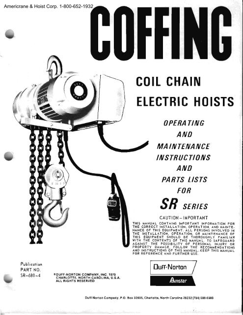
Americrane & <strong>Hoist</strong> Corp. 1-800-652-1932I00IHil0.. -- |-t!--c0lt <strong>CHAIN</strong>EtE<strong>CTRIC</strong> <strong>HO</strong>OPERATIIVGAIVDMAINTENANCEINSTRUCTt0wSANI)PANTS USTSFOBSB trr,rtCAUTION - II,{PORTANTrsTsTHIS MANUAL CONTAINS IMPORTANT INFORMATTON FORTHE CORRECT INSTALLATION, OPERATION, AND MAINfE-NANCE OF IIIIS EQUIPMENT. ALL PERSONS INVOLVED INTHE INSTALLATION, OPERATION, OR MATNTENANCE OFfHIS EQUIPMENT 5<strong>HO</strong>ULD BE T<strong>HO</strong>ROUGHLY FAi{ILIARWITH THE CONTENTs OF THIS MANUAL, TO SAFEGUARDAGAINST THE P05SIBILITY OF PERSONAL INJIJRY ORPROPERTY DAMAGE, FOLLOW THE RECOMMENDATIONSAND INSTRUCTIONs OF THIS MANUAL, (EEP THIS MANUALFOR REFERENCE ANO FURTHER IJsE.tPublicotionPART NO.sR-680-46oUFF-NOFTON COMPAI|Y, tNC. 1979CHAFLOIIE. NONTH CAFOLINA. U.S.A.ALL RIGHTS FESENVEDEuff-NortonDutnNorton Compriy, P.O. aor 32605, Ch.rlott€, North Carolina 28232 {704) 5a8,O3OO
Americrane & <strong>Hoist</strong> Corp. 1-800-652-1932SECTION tlPREPARATION FOR USE2_1. INSPECTION PRIOR TO INITIAL USE.2 2. Anv new or repdired hoisr, as well as tbe working area, sh.dl be oueiully inspected prior to initia.linstallation and use. Th€ rnspection shall be madeby or under the dir€ction of a lerson lirnljliaf sithhoist operations &rd industri!.1 s:1fety standards.2 ll. The lollo$ing inspeclion criteria are recoro'mended pdor to nriti:[ rnstdllarion Lrbd use. Additionaljnspectjon items should be.rdded to satisly localusage ard salety requitements. Ali inspe(tions olany kmd should be loggrid or ft:(iorded, daled, slgned,.urd filed ior reierence puDoses.lr. Ensrre tllat t|e lacjlity pow€r supply is adequare to Iumish voltage wjthin 10 percent of thalspeciiied for th€ hoist. A]so, thrt the iacility powerjs prcperly Iused lo prole(t the hoist lrom po1terb, Ensufe thd no live p l ol the clectdcir.IsJstem, ejther fucility or hojst, $ill be exposed toaccidental contirct undel nornd opn|:}ting condlljons,c. Ensure thut the hojst is elle(tively groLrnded.lf in doubt, reference Nrtional Elecldc&l Code ANSIc1.d, Ensure that the sLlpporlin!, s!rtKrlLrres lrestrong enough to cilrry the inlended loads. The supportingstnlcture shall h{ve ! safe load raling atleast equa.lo thst ol the hois!, The supporting slruciufemust be rigjd and not subject to weakenlrg dueto repealed stresses irom the lroist,e, Ensure llrili there is ,rdequate $olking spnceto pernrjt hoisloperrtjon in lhe hanging posltlononlyNomal operation shoLild not reqrire pulljtlg or tuggin!,around comers or obsirLrctions. Also, there nusl beadequate space to perni! lhe opelalor lo siarld cletl,tof the load ard ildilcenl slruclures.r. $r'.houl lbr mrkpshrfr or,ornptorr,iril|d pta'_tices eith€r duting instdlation oL subsequent operationof the lloist. Someiimes lhe "tempor y lix reroirinsuntil ,n accident occuls.g. Periorm both the ddly tud lhe petiodic irrspectiolsspecified herein on a repdred hoist pliorlo iniiial use. Perforro lhe daily inspections sp€c'iiied herein on a ne1l hoisi !dor I'o initid use2_4. INSTALLATION.2-5. On Hook Suspended <strong><strong>Hoist</strong>s</strong> secure the horst toa suitable supporting membel by use of the top lrook.Make sure that ihe hook larch is closed Applv asmall unount of lubtiplate ot equivalent belween thehook and supporting member.On Trolley Mounted <strong><strong>Hoist</strong>s</strong>. the kolley should beproperly r0ounted to allow for cleara.nce bet$eentfolley wheels and bean flange to avoid brnding.Beam shouid be free ol any obstructions, dirt orgrease, providing a lree and level plane oi movemenr. See lisures U-1 and 2-2.2-6. M*e o y tenrpotaly connections at the pov/elsource. Push the UP button of pull the UP conirolrope ,rnd observe the direction of hotton hook move_nrent. If t))€ hook raises, th€ phasing is correct andpemanent connelitions may be made at lhe powels,ource. II tl)e hook lowels, Ielease the button ot lopeimnedidiely, since lhe liirrit s\'ritclles will not opet_i|te to pf€vent hoist overiravel, To (prrect the loadhook directjon (phasmF), revelse any iro wiles (exceptthe green ground {ire) at the power source only.DO NOT CHANCE CONNECTIONS AT ANY OTHERLOCATION2-?, Alter eiechic:il connections are completed,secue iill protecljve covers ovel exposed I'rjdng,Test the hoist operdion as specjfied below prior to2-8. IESTrNG,2-9. Belbre placjug hoisl in operation, check lorproper lim swjtch operation. This cln be done byopelating the hoisr Iimil yoke (25, figure 7{j) man"ur.Ily. While the hoist is running in an unloadedcondilio[, pull doul on lhe looped end of the ljn0ityoke to slop the hook when in lhe UP directjon andpush up on the yoke to slop the hook when operatingin ihe DOWN direction The hook should stop immedirtely.Overtrrvel in eithe! direclion wi]l cause thehoisl to reverse ard move the load to a safe position.lf nranua.r opelirljon ol the Iimit yoke stops hook iravel.use the contlol butlon or tope to check for linitswilch automatic operalioD by nnrning the hook ineach dif€cljon ullil lhe li )it swltcues stop movereni.lf yorll hojs! js two-speed, check linxit switchoperdtions at botb sleeds.2-10. Atrach a lighl lod to the hook and check ihehoist (hrough a f€$' lifling and lowering cycles.Check ibr hook drift. The hook shi.ll noi drift moretIsI one inch. Ii brake operation is nohal with alight load, lest the hoisl for operation with ratedIoad, and then luih 125 perceni of !3ted ]oad. Thehoist sha.ll opelate snroothly and th€ br*e sha.l]lrevent hook dtift itr excess of one inch at both ratedloM md 125 percent oi fated load.vAme
I tIIr I I IYiFU'F6IoaaO^t-zN -9J - ,^ zO|!rr6l olrJanFIS:=z-ec-9= -9 =EPeeg-FEFq! P a e iifi [ g * ;E;it s: s Fsg; Ext :3gi:;?-;c5.Ig€E;frE:E!: Ei,IEa2F;!;;EiesEt{i,),'6E:1tis!;;3€:Es€qrE$8."*;! EfigsgiF:igg8;ih N 9 q r q c q o q 6 qLL;LbLN;.;;i";ErE- :Ea; aie EE A!..i c:i si E;E Ea -E;: E-" *EgE; EE El:;; c; ;i;is ;-' _:-:EEt :: .i.:e=" =-s E5;E; EE EcC,a_: t: Eg!isi :- 3=t ;,"!i E-4 as.:F ; e:= ;aE;=l; Sig+ !_E;E,==! 3EE= -E*: i=; = EqE."E jqz2;4zIAmericrane & <strong>Hoist</strong> Corp. 1-800-652-1932
II1I i I I I I I-j-2-!:111:::l:::l!FI;EFFf--caEq€eEg9EE$$rq3== za a-9 E.E.t z 3=i:='9RE:FrJ)o6(J-.r g:sIg;se:F' t:N o r + N o 6 6 9 : o 9eZ. E'B*r5 E FtE:I :EC iE:*aq p:;;H-EHgHe;.H:E ?i: iig;Ef:;:H TEf';:gq=H€€'* 3:i;;iiatE*fereii3ig$gr9iHHFEgS;n;6;d66;6;d;l!io;;tl';";;;;E6 6H E ;2=eE 9s ?E, E= azE :i -e!; E; ;EE3 es =oEt€ E:;a ='g :E;:; Ei :;Ce'. ;; ;c:-r:ii ;;€ !E:; :€ i:= :,it =i:iui II ia ; a-'-- :o; iE=: E=;! E:EE :ztrznzfii\,vAmericrane & <strong>Hoist</strong> Corp. 1-800-652-19324
Americrane & <strong>Hoist</strong> Corp. 1-800-652-1932sEcTtoN lllOPERATION3_1. SAFEIY CONSIDERATIONS.3-2. This hoist is designed for proper operationwithin the limits ot its rated capacity. This hoisrhas features designed to minlnize rhe porentia.l forinjury due to the failure ot ihe hoist itseif. How€ver,here ate some additional poiniers which should betollowed rn ordpr ro pnsure propar opFrarron.a- Do not overload the hoist.b. Do not make exireme side pulls with thehoisl. On trolley momted hoists !.lways posirionhoist direclly over the load belore lilting.c. Operate the holst only in a hanging positionwith adequate suppori. I\4ake €ure that the load doesnot contact any obsiructrons.d. Be sure there are no twists or kinks in tbeload chain as rt travels into lhe hoist housing. Thiscondition must be constantly checked on ihe doublechained hoists becruse it is possible for rhe loadblock !o be "capsized" or turned over o e or morelimes.e. Before raising a load, always check to seethat it is held securely in the hook or sling chsins,eic. Raise the load only until the load chain is rauiand then double check the rigging before conrinujngto raise the load, Never use the hoisi ioad chain insling fashion around the load.f. Make sLre that ihe slings and orhef rigginghave sufficient capacity to support the load, And areil, good condiljon.8. DO NOT STAND OR WALK BENEATH ALOAD. Do not move the load in such a firdane! as toendanger personnel,h. Never ledve 8 suspended load unattended.i. Do not loqer the load into areas *here visibilityis obscured unless someoo else is guidrng theoperatron,j. Use common sense at all times wheo operatinga hoisl.K. DO NOT USE THE <strong>HO</strong>IST TO L]FT, SUP.PORT OR TRANSPORT HUMANS.3 3. OPERATION.3-,1. The hojst should be operated by qu. ified per"sonnel or1y. Be sure to perform the daily inspecrjonsspecified herein pdor to first use each day. Pay paFticular atteniion io the limir slvirch operarion, rhebr.rkes, . d chain travel into ihe sheave. Avoid excessiveinching ard quick reversals, as these cancause accelerated brake wear and unnecessarystresses. Do not routlnely move tbe book so as toactuate the limit switches, as these are safety devicesonly. Avoid swinging the loador hook if the hoistis mounted on a trolley. Do not operate the hoist if itis functioning improperly, hqs been inadverientlyoverloaded. or is in obvious need of repair. Alwaysafix a warnjng or "Out-of-Order" tag to the controlstation of a suspect hoist until the proper inspection/repair has been made.3-5. LOWERING WIT<strong>HO</strong>UT POWER.CAUTIONT Do not allov the load to descend rapidly.This causes the motor !o race and serious damagemay result. Use severAl quick releases instead ofholding brake open continuously, Do no! exceed nor"mal lowedng sp€ed.3-6. If ihe power fails with a load suspended, thehoisr will automatjca.Ily srop a.1d hold the load sus:pended. In an energency, !h€ losd can be loweredwithout power. On the pendant rope models, puII iheDOIVN conirol rope ond lower the load in short increments(alproxrfiately 3 iDches), each iime releasingthe pull rope !o ullow the brake ro reset3-7. On the push-button shoe bral
Americrane & <strong>Hoist</strong> Corp. 1-800-652-1932SECTION IVMAINTENANCE, REPAIR, AND LUBRICATION4 1. BRAKE ADJUSTMENT.4 2. when properly adjusted the brake 1'il] reieasepromptty when energized, dnd \rill smooihly stopiurd securely hold any load up to the fated capacityol the hoist. lf the hoist develops either: (a) undesireable overlravel after the push buiton or contlolrope is released (this condition is llnst noticeablein the lowering direction). or (b) hesiiates to movethe load prcmpily when the push button or controlrope is actuated (this condition is most noticeablein rhe lilting directtoo) rhe brake should be adjusted.CAUTION: On lope controlled (pendart rope) modelsit is jnpoftant that colrect timing be maintained.The nptol must be enetgrzed belbre the brake re_leases Ibr proper load contlol. Aflel any brake ad'justment, check hoist operntion per p$aglaph 2-84-3. To adjust bfakes on the pendant rope nodelprcceed as follovsa, Remove any load and disconnect the hojstfrom po\ler supply.b. Inspect br!ke linings foI excessive wear.Linings worn to 0.06 inch or less should be leplacedbelbre proceeding.c, Loosen the locking nuts (A, figure 4-1) andback off the brske adjustjng sclews (B).d. Renrove lhe controll€r covel.e. Manually turn ihe contloller jn eithel dilec'lion until lhe Ioto! contrcts iust engu€ the ststion_uy linger contlcts. with the contmller ntdinll'ined inthis position, adjust each bla.lre tdjusting scle\u (B)until ihe sclew iust €ngages the brlke lelease cam(D). Tighten lhe locking nuts (A) being carefu.I notto rrove lhe bra.ke ddjustinA screws (B).t, Lubricrle lhe conttcting surlaces ol thebrake relelrse c.lnr (D).rnd ihe bli*e ddrustlngs.rews (B, urrh \lolvkorF C ' or hrb[plilPg. Reconnect the hoist to ibe pover supplv dndcheck brrke opelarion pef p |1grtlph 2-8.h. It greater braking is desired, it will be nec'essary to tighten the brake spring bolr (E) approtimatelyone-halt turn ai a time. After any adjustmentof lhe bra.ke spring bott check to see that the brakesprings (F) are not compressed to solid height. lflhe desired btakin8 is not achieved before the brakesprings (F) ale compressed to solid heigtri. eitherthe brake lininEs need replacing or the brake armassembly is woln or distorted.i. The brake adjustment is no!! completed. Reinstall cootroller covel.4-4. To adjust br!.kes on the push'button shoebrake model, proceed as iollo$rs:a- Remove any load and disconnect the hoistffom power supply.b. Remove the bra.ke cover and open the controlc. lnspect bra.ke Ijnings ior excessive wear.Linings $om !o 0.06 incb or less should be teplacedbelore proceeding.d. l,oosen the locking nuts (A, figure 4-g) andback off the btale adjustjng scre{s (B) until thesolenoid gup diminishes to approximalely 1/4 inch.e. Esrabljsh lhe solenojd gap at ?/16 inch byjnserting a ?,'16-inch block or gage between thesolenojd plungel and solenoid frame.f. Adjust the brake adjusting screws (B) individua.llyunril each just touches the corner oI thecdnted brake release cam (D) and iends to lift ihesolenoid plunger olf rhe 7/16-jnch block or gage.Tighien the Iockjne, nuts (A) beiog careful nor tonrove the brake adjusljrtg screws (B). Ailer this ad_justnlent, the cIeil|i]llce between bra,he adjustingscrews (B) llnd horizonrr.l canl (D) should be 0.050g. \!irh ihe 7,'16'iDch block or gage removed,nrrnuilly depress the solenoid plunger urtil theplunger serts on the solenoid ha.Te. The linkageF|GURE 4_1. BRAK€ ADJUST]MENT_PENDANT ROPEII4ODELo5o MtN. (aFTER aDJUsTl'IENT)FIGURE 4_2. BRAKE ADJUSTII'IENT_PUSH BUTTON]\,1ODEL (WITH S<strong>HO</strong>E ERAKE)I
jAmericrane & <strong>Hoist</strong> Corp. 1-800-652-1932must be free and not binding.h. Lubricate all joints in the linkage vith MolykoteC' .or lubdplate, including the contactingsurfaces of ihe brake release cJns (D) &nd the brakeadjusting screws(B). Do not under any circunstanceslubricate the solenoid PlunAer.i. With ihe solenoid plunger marually depress_ed, manrally rotate the brake drun. The br:le liningsmay drag slighlly at the heels.j. Ma.nuaUy depress the solenoid plmiaet againsnd observe the action of the brd(e linrngs to be sutethat they areopeningboth equa.Uy and sin taneously.k. Reconnect th€ hoist io the po$er suppll andcheck brake operation per patagraph 2-8. The sole_noid plunger must seat with a 'snap" and releasepfomplly when t|e push button is teleasedCAUTION: Disconnect the boist from po$et sourcebefore perfoming step l.L If greatef brakjng js desited, it will be nec'essaxy to tighren ttre brri(e sprina bolt (E) approximatelyoneholl turo at a time. Altel any adjuslmentof the brake spring bolt {E) maoually depress the so'Ienoid plunger Lntil the plunger seats ljrnly on thesolenoid fiame afld check to see that the bruke spungs(F) are not conrpressed to solid height. I1 the desiredbraking is not achieved beibre the brd{e springs (F)are co0rpressed to soljd heigh!, eitlre! the brakeIinings need replacing oI the bra.l{e un Nsembly is$grn or dislo(ed.m. The brake udjustment is now co plete. Reconnectpower, reinst,rll bra,ke cover, and close thecontrol enclosute.4-5. To adjust brakes on the push-burton disc brakemodel, proceed as follows:a. Remove any Ioad lrnd dlsconnect hoist lromp0\r)er supply.ADJUSTMENTSCR E\YIORQUE SPRINGLOCKNUTFIGURE 4_3. BRAKE ADJUSTIMENT-PUSH BUTTONIVIOD€L IWITH DISC BRAKE)b. Remove screws (11. risure ?-5B), washers(12) and brake covcr (10).c. in\p..r fri.ljon dis(s for px(.ssivc wear.The discs should be replaced wben cither disc haslvom 1/16 inch (one-third ol orisinal tbickncss).d. Turn the two adjusinent screws shown infigurc 4 l:l until nagnetic gap A reads 0.040 to 0.045lnch at nafiowest g{lp.e. Tba brake adjustment above should notcausegap B to ciose. Gap B rcpresents the cLoarance betweenarmature plate (26, figure 7-5B) and bracket(16). If thc proper setting for gap A can not be obtainedwithout closing gap B. th€n it is probablethat the friction discs need replacing.f. The brake adjustnent is now conplete. Reinstallcover. washers and scr€wsi reconnect powe..4_6. REIVIOVAL AND REPLACEI\4ENT OF TOP <strong>HO</strong>OITOR SUSPENSION LUG.4-?, The top book or suspensjon lug is secured tothe hoisr by the iwo sheave housings (31 and 33,figure 7-6). To remove the top hook or suspensionIug. ploceed as followsla. SR ard SBO Shoe Brake lllodels.(1) Disconneci hoist from power supply.Detach hoist lrom jts mounting and move ii to safe(2) Unlatch lhe conirol box cover (9, figure?-1) and swingthe cover do$n lo tully open position.(3) Remove brake cover (1, figure 7-1).(4) Remove luo screws, lockwashers andnuts (6,7, and 8, figute 7-1) thct secures the contmlbox !o rhe brake end back plate (4).(5) Remove tbe ieo round head scr€ws (noishown) on the extreme dght hand side of the conftolbox thai secures the control box to lhe hoist. Do notremove any other conltol box mounting hard\taresjnce lhe conlrol box will be subsequenlly movedclear together with ihe motor.(6) Disconneclthe Iimit yokeand alm a8sembly(25, figure 7-6) by temovine pin (40),(?) Remove the four motor mounting bolts(34, figure ?-1).(8) Slide lhe motor ard conirol box to theleft. It is not necessaty to disconneci any morewrnng.(9) Remove lhe lour bolts (35, figure ?-6)that hold the t\xo sheave houslngs (31 ard 33) tog€lher.(10) Remove the top hook or suspension lug.b. SR and SRD Disc Erake Push Button l\lodels.(1) Disconnect hoist lrom power supplv.(2) Move hoist to safe rrork area and lum(3) Remove t'ro brake cover screws, lock_washers and brake cover(10, 11, and 12, figure 7-5B).(4) Remove brtke bracket screws and lockwashers(8 and 28, figure 7-58). This will allow
Americrane & <strong>Hoist</strong> Corp. 1-800-652-1932@nrplete br*e iNsenrblv io be renloved fion thehoisr \rith lhe br*e interconrection cdble still(;) Rcno!,e the tvo rcund he:rd screws ihatn|ourt rhe co lrcl boxou the hoist. These two scle1lse locrted on the extrenre right hIuld side of thecoolrol box p nel.(6) Disconnect the lirniryoke rd aLn assem'bly by renroviog pin, Ilirt wirsher, und cotter pin (40,11. lmd l::. figue 7-6).(?) Reuove the ibuf nbtor nDunting bolts.(34. tjgure 7-1).(8) Slide notor and cootrcl box lssembly tothe lelt. Note thui it i$ not necess$ly to disconnect(9) Renpvc the lbul bolls (35, fiture 7-6)rh{t hold the hoLrsirg caslings logethet. The top hookor snspension lrls cltn now be removed ot lepllced.e. S and SD Pendant Rope lvlodels.(1) Discoonect hoist fronr power supply.(g) Move hoist to safe work droo ulld rurnupside down.(3) Renrove cotter pin lrDd Ildr vrsher. (3urd .1, figure ?-9B).(l) ReDDve two leversjntl swrtcb co tlolcover soeus (17, IigLue 7-9ts) x d(5) Renrove levelsinA switch irsseobly irwryfronr lrcist with condr t rrtached.((r) Re nve the lbul Dptor nDuntiug bolts(31, IjgLrre 7-1).(i) Siide nrotor rd reversilrA swjtch assemblyto the lefl. Note ihut it is not Decessury to dis.coDne(l uny wln[9.(8) Renbve tbc Ibur lrclrs (35, fig\ue 7-6)rhdi hold the housing clstiDgs together. The topIrook or suspersioD lult cm now be Iemoved or repldced.d, SR and SRD Pendant Ropg lvlodsls.(1) Disconnect hoist lrom power srpply.(:) [{ove hoist to siLte work drel :utd lutoLlpside down.(3) Remove cotler piu, tlLlt wirsher. arldconnectin$ pin (1, 3, nDd 4, ti!'ure 7-gA) thnt conneclsIinrjl yoke !sseNblyto level sing s\ritch brlcket,(4) Renlove two sclews irnd lockwlshers (9trnd 10, figure ?-94) thrt nount revels)rrg switch lohoisl. These two sclews are Iocilted on tighl hBrdside ol revelsiDs switclr brse plille.(5) RenDVe reversiig s\rilch nssenrbly a\trJtioN hoist with intefcofllection cable rtiJched.(6) Remove ihe lbu nroto! mormling iJolts(3.1, fi!.ufe ?-1).(?) Slide motor dndbly to tle lelt. Note that itconnect :!nv l'rttnil(8) RenrDve the lortrreversins s$itch dssemisnot necessary to disbolts(35. figure ?-6)that hold the housing castings together. The tophook or suspension lug can now be temoved ot teplrced.4-8. To instr.lt the top hook or suspension lug,reverse the removal pmcedlres \xith the followingadditions:d. Inspect the sheave housings (41 8nd 33,figure 7-6) for dirr. cracks, ot excessive weat.b. Apply a liFhi coat of Cofflng Cear LubricantNo. H?5??, or equivalent, to the nating sudaces ofbook or suspension lug and sheave housings.c. Replace any worn gasket, pin, ol hardvrered. Perlbrn an operational test upon completionof renssembly.4.9. INSTALLATION OF NEW <strong>CHAIN</strong> IN <strong>HO</strong>IST WIT<strong>HO</strong>LD <strong>CHAIN</strong> IN <strong>HO</strong>IST.{-10. To inst:r.Il a ne't chtrln in the hoist $,ith ach n dreadv inslalled, proceed fls ibllows:ir" R,dse the load hook assembly io wiihin afew inches of its top limit.b. Disconnocl the hoisi from the power supply.Instrll un "Out-of-Order" lag on the hoist.c. On single ch{i[ models, remove the loadbook dssenbly frcm the old chaio.On double charn models, remove load block assemulyirnd detuch end of cha]n by disconnecting al the limilyoke pivot pin (28, figrte ?-6),d. Make a"C"-sbr.ped link to ioin the eDd linksof both the ne\r ond old chdns. See figure 4-4. BESURE the welds of the \pstattding links of the newLOCATE 1VELD5 AWAYFROM LOAD 5H EAV E(,:OLD <strong>CHAIN</strong>LOAD SIIEAVE.'C''"SHAPED LINKNEW <strong>CHAIN</strong>FIGURE 4_4. <strong>CHAIN</strong> INSTALLATIONDEAD END
Americrane & <strong>Hoist</strong> Corp. 1-800-652-1932Ichainvare out away frcm ttle load sheave, and ihatproper orientation is observed for attachment oi thealead-end in step h. belowe.Reconnect the hoist to po$/er supply.i. Carefrnly joli the UP button or pendant ropeand run thejoined pieces ol chain inio the hoist untilabout 12 inches of ihe new charn emerges from theg. Disconnecl the hoist frcm the po$er supply.ll. Remove boihthe"C'!sh.rped link and the oldchain frcm the dead-end. Fasten the end link of thene$ chain to the clevjs of the derd end, observin8proper orientation oi the dead-end ot the chdn lvhensecured. It is ol utrnost inportance thai t$ists iD thecbain are avoided.i. On siryIechained hoists artach tbe bottomhook. Apply a light coat of Cofling Cear LubdcantNo. H-75?7, or equjvdent, to the nratjng surfaces olhook rd swivel ha.lves.j. On double-cha.rned hoists, feed the chainrhroush tbelol'd block and fasten the end of the chainto ti_c chlin shedder ut the linit yoke pivot pin. BESURE THA'I' THERE ARE NO TWISTS IN THE<strong>CHAIN</strong>.k, Lubric:lte e new chiliD und perfour an operational test of the hoist, Renbve the "Out-ol:Order"iag.4_11. INSTALLATION OF NEW <strong>CHAIN</strong> IN <strong>HO</strong>ISTWITH TlO <strong>CHAIN</strong> IN <strong>HO</strong>IST,4-12. To urstdl a new ohain in rhe hoisl rxirh nocharn u,I!eady iI the nojst, proceed &s IbllowstShoe Br6ke ll4od6lsa. Disco rect the hoist ftor the power supply,Install a$ Out-oi:Order" t{g on rhe hoist.b. Removo the brake end (iover. Relorse thebrake by eirher depressjng dre brlXe solenoid plLrDgeror by blocknrt lhe bruke rm in rhe open position.c. Il possible tur the hojst upside down.d. Starr th€ chain inro the hoisr on the side olthe load sheave closest to ihe hoist conrrol. Applyr lr'rench to lhe lock nut (23, figure ?-5A) which s$cures lhe bra.k€ drun and rotate lhe d|um in a qrunterclockwisedireciion. This Nill tolrte the sbe,lve mdleed the chain through the hoist. llake sure th$ tbelirsr link js upstarding or perpendicular to the axis olthe hoisl, with the chain weld out a$ay ho r the loadsheave. The second ljnk must iit llat in rhe pocket ofe. Contjnue turning the brake drum until about12 inches ol the chain etr'eL!.es Irom the othef side.i. Release the solenoid plunger or unblock theg- Fasten the end liok ol the ch n to the clevrsof the dead-end, observilrg proper orientltio of thedead-end of the chain wher secured. lt rs ol utmostinportance that twists i the ch.lin !Ie rvoided.b. On singlechained horsls attach the bunrpelspring and boiton hook. Apply a light cort ol CofiingOear Lubdcant No. H ?577, or equivalent, to themating surfaces of the hook and s$ivel ha.lves.i. On doublechained holsrs, teed rhe cbrinthroughtheload block and tasten the end ol the ch.rinlo tbe cbain shedder at the lin t voke pivor pjn. BESURE T}IAT THERE ARE NO TWISTS IN THE<strong>CHAIN</strong>.j. Lubricate the chain .ind perlorm Jn opellrtionaltest of the hoist. Remove rhe 'Out-of-Ordef' tag.Disc Brake Modelsa. Disconoect hoist ftom powef supply. lnsta.lla.n "Out of Order" tag on the hoist.b, Move hoist to a safe work irea ilrd turnupsid€ down.c, Remove two bra,he cover screws and washersand remove brake cover (10, 11, ard 12, figure ? 5B).Remove two bla.ke bracket scleps uld wasbers (8and 28, ligure 7-58). This llill dlow complete br|keassembly to be removed from the hoist with lbe brukeinterconnection cable still attilched.d. Start the new charn into the hoist on the sideof the load sheave closest to hoist control, Makesure the first link is upstanding or perpendicular iolbe ilxrs of the hoist, with the ohurn weld out awayhom the load sheave, The second Iink should liena! in the poc,ket of lhe lodd sheave, Rotate thethe brskc hub pjnion in d sounterclockwise direction.This MII rorute ihe load sheuve dnd feed ihe chainthrough the hoist,e, Turn the brake hub pinion uniil llboul 12inches ol the new chain comes out ol the horst.Fasten this end of the chuin to lhe deud-end clevis,observt g proper orientatjon ol the dead-eod ol thechain when $ecured aild avoidjng l,wists in ihe chai ,Reassemble the brale assembly and brake coverproperly,f, Att.rch the bumpe! spling and botiom hook onsinglechain hoist. On doLrble-chajn hoist, feed thechaj lhrough lhe load block uld lasten the end ol[he chaln to the chirilr slreddel tlt the lil]it yoke pivotpiD. BE SURE THER9 ARE N0 TWISTS iN THE<strong>CHAIN</strong>.g. Lubricrte lhe chnin trlld pe!lorm an opela'rional test of the hoist. Remove the out.olordef'tag..1-13. INSTALLAIION OF <strong>CHAIN</strong> CONTAINERASSE[4BLY.4-1:1. The chdin coDtarner is illusrared in iigure7-10. While relerencins lisure 7-10, pfoceed as lbllowsto irrstdl the ch in conrainer:a- Remove the moior nlount screo and linitswirch pin at the locatjon shown.b. Attrch tl,]o trrourturB brackels (5) to ch.rin([nrriner (l), usiug screws (10), vr.rshers (8), lockw shers (9), nuts (7), rd reinlbrcrng pads (4). Thenuis and reintbrcirg pads sbould be on rh€ outside olchain contarnet riih ihe washers (9) urder Lhe screw
Americrane & <strong>Hoist</strong> Corp. 1-800-652-1932t. Arrx.lr uroLrDr rs brr(ker 12) to chdiD contain'er rsing lllrdsnle ns slrown.'1. s"'I- oflo-r'- -IJ ol r{i.'k l 2' r" tr"i-.usjnir rhe nrotor n|ol|rt s(rew prcvrously ren'ov€d.e. Arrir(| Ihe rwo brrL(kels (i) ro li|rlit vokerssenrblv !irh hnrrt switch pto {6) d cotier pnrs( 11).CAUTION Tbe .hrin contrne! should noi be subjected to n open lldrle .lnd slrould not be used inurels where nnrbienl Ienrper|tures exceed 1750 F.I 1;. tNSPECTIONS..l-16. A pltuued inspedion routine should be esrablished Ior rhrs boist blsed npon Ireq ency ol use.seventv ol use, ind environmentd conditions. (RefereDc€ Anreuc.|n N.rtron. lt.lnd.rld ANSI 830.16.)Some inspections should be made frequently (daily iomonthly)and others periodically (monthly to ycarly).It is strongly recommendcd that an Inspection andMaintenance Check List and an Insp€ctor's Reportsimilar to those shown in Figures 4-5 and 4.6 be usedand filed for reference. All inspelti()ns should be madcby, or undcr lhe direciions of, a dcsjsnated inspe{tor.Special inspmtions shuulJ I'p made following rnysignificant repairs or any operating occurancc leadingone to suspe(t thal thc hoists capabilitics may havebeen jmpaired.4_1?. FREQUENT INSPECTIONS,4-18, Pe brm the lbllowinF, inspectjons d&ily pliorto initiir.l use ol ihe ho)st:CAUTION Ary unsrle cEudition disclosed by thejnspection shdll be corrected belole operation of lhehoist is resunred. Adjustnre ts irnd reprjrs shdl bedone only by designuted pelsorlnel.lr. Check the oper$iry coDirols ibl ploper opeFittion.b. Check tf ll|rxr swilches ibl proper operation.c. Check ihe bruj(es lbr pfoper operation.d. Inspect the hooks ibl delbrnlrlions, chemicl,ldamage, ol cracks. Hooks danaged fion chemlcs]s,defornBtion or crncksor having throalopenitlgs greaterrhxn those listed iD Table II must be replaced. lfthe hook is tvisted more lhan 10 degrees fron theplane ol the unbent hook, it Nust be feplaced.NOTE: Any hook !h:rl is tltisted or has throat open'ings in excess of those listed in Table ll indicrtesabuse or overloading oi lhe hoist. Other load bearingcornponentshould be inspecied rccordingly.e. Check that boitom hook swivels fteely.L lnspect load cNrying chains lbr 'real, t$rst,disrortion or imploper dead_ending. Also check tbrpresence of foteign maieria.l dnd adequatelubrication.4_19. PERIODIC INSPECTIONS.4-20. Ir is recommended that the ibllowin€i inspectionsbe perlormed ai 12 monlh intervals or as other_urise noted. This recommendation assumes the hoistis used lor a oneshift 40-houl week rmdef nornalenvironnental conditions. <strong><strong>Hoist</strong>s</strong> exposed to adverseenvironmental condiiions or having greaiet aclivitvshould be inspected more frequently.TABLE II. <strong>HO</strong>OK THBOAT OPENINGSsR -t 000-36sR-2000-185R-2000-365RD_4000-95R_4000-t85RD-6000-9l5/l5/'t5/'t5/THROAT OPENINGCAUTIONT Any unsafe condition disclosed by iheinspection shall be corrected before operation o[ thehoist is resumed. Adjustments Jnd repairs shall bedone only by designated personnol.a. Perlom all the daily inspeciions listed inparagraph 4-17.b. Check for loose, missing or corroded hudc.Check ior cracked or worn sheaves andblocks.d. Check for worn, corroded. cracked or distortedparts such trs 9ins, bearings. bushings, shafts,couplings, gea!s, rollers, and locking ard clampinge. Check for excessive wear on molor shafikeyways,f. Check brate linings for glazing, coniami'nirtion or excessrve wesr. See psra8raph 4,1. (BrakeAdjushen0 Ibr maxjroum permissible bra.ke liningg. hspect tlre chain for gouges, nicks, weldsplatter, corrosio and distoried ljnks. Slacken theclain and inspecl lbr $ear at the coninct points. If\rear is observed, or if strelchinB is suspecied, measur6the chain pet parasraph 4-23. ll any portion ofrhe chain is \rorn, nicked, twisted or stretched, replace ihe whole chajn.CAUTION: Do not attempt lo Ieweld sectroos ol tbechain md do not lty to add on to the chain, Use onlychain srpplied by our compa.iy: it is specia.lly nranuf;cluredto veiy close toletances of dlmension,composition ard heat treatment. A substitute chdrnmay danage the load sheave. Never use "missioghDks" because rhey wlll jmr in lhe load sheave orchrin guide.h. It|specr the hooks of suspension lugs lorcracking, checking, extreme wear or spreading.Replace hooks or suspension lugs arld au connec_tions showing ihese signs. Use dye penetrant, mag-l5/'15/l6r5/r6C10
Americrane & <strong>Hoist</strong> Corp. 1-800-652-1932netic particle or other suitable crack detecting method. lf the throat openings are spread wider rhanthose lisied in Table II the hooks hav€ been overstressed and nust be replaced. The method of re"retaining the load hook or suspension lug in rhe hookswivel, load block, and hoist frane should be inspectedperiodically. In the case ol threaded conneciionsthe hook and nut threads should be observedfor stripping or otber damage. In the case ol unthreadedpinned collars the pin should be removedand exa.nined for cracks or bending. This inspecrionshould be perlbrmed as often as practicable bur norl€ss than once every 6 months.i. Inspect limit switches ior signs of pitting ordeterioration, Ensure that they are secure ard conneciionsare tight,j, Inspect a.Il viung lnd terminals lot irayingand defecdve inslution. Check conneciions for tightness,lnspect crimp ard insulation on terminal blocks,k, on push button hoists, inspeci lhe conneclionson the cootact block and coil ol the magnetichorst conirol switch for trghtness. Check for burnedor prtted contacts. lf one contactor needs leplacement,i! is reconnrended tha! the contactors bereplac€d in sels.I. On pendant rcpe hoists, inspeci the connectionson ihe conlact block ibr tiShtness, Check forbulned or pitted contircts on the control switch.m. lnspeci all housings ior cracks (resullinglronr collisron. dropprrlg. erc,) ard abnormul openinc,sbetweelr housing seciions (resulting from overload"ing), ln either case il is recomnre ded lh: the hoistbe returned to the msnufacturet lbt repdt,Inspecthehousing, hook swivel, and lord block bolis ibr tiShi-0, l0spect tbesuppoftjnB structure lbr continuedability to crury the rated loads.o, Inspect dl naneplates, decills, urld warnrnglabels for s€curity of tltiachment and le8ibility.1_21. INSPECTION OF <strong>HO</strong>ISTS NOT IN REGULAffUSE,:l-Pe. Il a hoist has been idle lb!one month or rnore,but rot flore thun six nronths, pe brnr the jnspectionsper pdri$uph 4-17 prio! to use. Il the hoislhas be€r itlle n]ore th|rn six monlhs, perlbm the iDspectionsper pdraaraph 4-19.4_23. CHECKING <strong>CHAIN</strong> FOR WEAR.4-24. To check the ch.un for excessive wear, pfo_a- Select an unrlom, unstretched length ol chainll0m dle slack end.b. Suspend the chain verticrlly under rensionand, using a callper ttpe gaAe, measure the outsidelenelh oI dny conveniFnt numbcr of llnks approximately12 to 14 inches overall.c. Measure the same number oflinksin the usedse.|lons ud cJcularF rhe percenliLHe lncrFase tnrength.d. If the usedchain is 1-1l2 percent longer thanthe unused chain, replace the chain.4_25, CLEANING.4-26. Nonelectricrl pnrts mry be cleared \riih apressure spray ol acid-liee dry cle.ming solvent anddried $ith conrpressed air or clean, ]intless cloth.Wipe svitches, wi!inia, and other electrical componentswjth a cle!,i cloth dan)pcned lrith dry cleaningsolvent, Do not rmmerse any electrical part or brakeIinings in cleining solutions. Siubborn deposils oldirt ard gredse mdybe removed Irom geus, housings,chtrins, a.nd othel mechrnic!] puts by usinH a siitt:b.istled brush dipped in lhe dry cletlning solvent.CAUTION Ensure thdl adequare ven$lauon rs providedwhen using cleaning solutions. Wear proiectiveclotNng, and avoid prolonged conlact with solvenis.4'2?, LUSRICATION.4-28. Proper lubrication is necessary lbr a long andlel&tively irouble-hee hoist operiltion, Reler to thefollowing und to Ii8ure 4-7, Recommended LubricarionSchedule, lor lubrication points, iype ot lubricantIlnd fiequency ol lubdcatjon,4-29. LOAD <strong>CHAIN</strong>. Clean ihe load chsin evelyIew days with acid-free solvont and coai with ColfingChain Lubricant No. H-7595, ot equivalenl. WiDeexcess oil to prevenl dripping. ll the hoisi is usedin an aimosphete contsrning:rbrasive dust do notoil the cha]n. Never apply grease io the chain.4-30. CEARS. Thegear housingis packed at assemblywith one pound ol petmaneni t'!e grease, Il ihegeu *ousing is opened, remove the old grease, clea.nihe housjng, and repack $ith one pound of <strong>Coffing</strong>Gear Lubricani No. H-75?7, or equivalenl4-31. BEARINCS. AII bearings are lub cated althe factory rnd should noi require addiiional lubr!catron. Noisy or worn bearings should be replaced.4_32, BRAKE CAMS (S<strong>HO</strong>E BRAKES ONLY). APp]Ya Iieht cosl ol llrolykote "C" or lubriplate as fequired,but not l€ss than evety 30 days.4-33. <strong>HO</strong>OK BEARINGS. Apply a fe$ drops of oilbetween inside edge of shield and outside €dge ofbearing every 30 days.4_34- IDLER SHEAVE BEARING (BUSHINC),Djssamble load block and apply a light coat ol bighqua.liiy Eiease inside of bearing every sit months.4-35. LIMIT SWTCH LINKAGE. Applv a light coatof lubriplate at a.ll pivot points every 30 days.1I
Americrane & <strong>Hoist</strong> Corp. 1-800-652-1932INSPECIION AND MAINTENANCE CHECI{ LISIELECTNIC POI{ERED OVERHEAO <strong>CHAIN</strong> <strong>HO</strong>ISTORIGINAL INSTALLATION OA'EMANUFACTURER'S SERIAL NO.IITEMFR€OUENCI OF INSPTCTIONFREoUENT TpERroDrcAny der'c ency c.trs'ns rmp'oper operar,onAny deliciency caosins improp.r op€Erionslipp.se or excessive dritrGl6zins, cmlaminarion or etcessiv€ w€arExc€ssive rhrcar openlns, benr or rsisredmre rhan 10 des.ees, damsed hook ldrch,s6ar, chonica dafrago, wo.n hook b€arinscEcks luse dye penerdnr. magneridpanicle or orher su labl€ dereclionCracks, ercessive wear or othor damg€which mav impalr the srrcnsth ol rhe tuscracrs luse dy€ ponerrrnr, m.s.€ricp.(icl€ or oihor strirabls der€crinIn.d6qu.r6 lubricarion, 6xcossivs wsar orsr6roh, craoked, d.n69€d or rw srod links,corosion or lorci9n subslancecracks, b€idin9, srippod rhro6dsErc633iv€ w€ar, cordion, chcls,Looson€ss, stripp6d.nd &moad rhioodsOistodion. cra.ks. and dxd€ssiv. w63rF6y ne, deracrive iniut6liooLoose connecrion3, b0'ned or pidsdDahaga or wear wh ch resricrs abiriry roNOTE, n€te. ro Mainrenancc and lispecrion Sectios or rhe Hois.fiEOUENCY OF INSPECTIONFrequenr-lndicar€s nehs requi.iis insp€crion daily ro mnrhlMissins. dadqed ore0 b oloi t$iher derailsPeiodicInd'car6r irns rcqulrins inspecrion mnrhlv ro yearly. lispecriois ro 6e perlorned by or under rhe d rcct oi oj tprcperlv desisnared per$n. Ih€ eraci period ol inspection will depeid oi lreqrency and rypeot this p€riod sill be based on the user's erpeiienc€. h is recomhended rhar rhe usei besin wand .iond rho p€iods ro quanerly, shi annual y or annual y based on his mo.rhly experience.FIGUBE 4-6. RECOI!1I\,1ENDED INSPECTION AND IllAINTENANCE CHECK LISTNOTE: Thi3 inspectlon and nainlenalrce check list is ln accordance wlih our interpretation of the requirem€nts ofthe saf€tv Blanda(d for ov€rh€ad hoists ANcl 830.16-73. It is, however, th€ ulaimrte .esporsibitity ofth€ employe/uaerto ltrt€rpr€t and adh€r€ to th€ applicable requiremenls of this safety standard.\D12
Americrane & <strong>Hoist</strong> Corp. 1-800-652-1932tINSPECIOR'S REPORInEMARkS ( rSI Of fl Crf NCrtS Ar\D Fr Corvr llDrO AClrO\ jttNsPEClOiSSIGNATUSE INSPECT'D APPSOVEO BYFICURE 4_6. RECOMMENDED INSPECTOR S REPORT.!13
Americrane & <strong>Hoist</strong> Corp. 1-800-652-1932RECOMMENDED LUBRICATION SCHEDULE'MODEL SB ELE<strong>CTRIC</strong> POWEFGD CI1AIN <strong>HO</strong>ISTFICURE ANDINDEX NO.COMPONENT TYPE OF LUBRIC.ANI TYPE OF SER}IICE ANDFREQT'ENCY OF LUBRICATTON''C.fiiDaNo, H.?595pemtraLiDs oil eiLh ghphite orDailyAltemt€ - SAE 20 - S0 lrea oil'Coffine' No, H-757?Alt€@t€ - hdtiplrpoe lilhid25, FierE ?.6"Cofti.a' No. H.?595Alr€mare - sA! 20 - 30 ged oilMoncldy5, 13 Fig@ ?'B SAE m - 30 gld o013. 1,t, 16, 1?,SAE 20 - 30 gEd oil18, 19Mdcfnyt2, Figu€ ?€"Coffins Nd H.76?Att€m.te - multi purFe littdwai p.riodjc insFction (*4-6)Fie@Note: Atl bedin8i erept h@k ed idd shetre be.dreB e prllutaiet€d and .e6led.'This lubricaiion s.hedde i. b..€d d ! hoisc c'perating in rcrE t €llviffintd @ndrh@ Hobi8 oPe.ailng iD .d\€@ainFBpheE coniainine ex@ive heai. creiw furc o! v!Fr3, .b(6iE du.i, etc., .hdrl.l b6 lubri4t€d mF lrlqsibrFIGURE 4-7. RECOMMENDED LUBRICATION SCHEDUL,E
Americrane & <strong>Hoist</strong> Corp. 1-800-652-1932SECTION VTROUBLES<strong>HO</strong>OTING5_1. GENERAL.machinist-e"lectrician to do your repair $ork, web-2. .Use the following table as ai aid to irouble, recommend that you send your boist to an appioved. shoot rhe hoist. If you iio not have an experienced service center or to us lbr repairs'TNOUBLVPROBABLE CAUSEREIVEDY<strong>HO</strong>OK FAILS TO STOP AT END OF TRAVEL .1. Brake needs adiustment 1. Adjust brake (Section IV)-2. Limit switches not operating 2. Check connections agsinst siting dia€ram. Tigbten looae connections,or replace swiiches as required,3. Magnetic reversing s{itch 3. Check reverslng switch and wiring. Replace as reqLrjred,malfunction4. Brake linings worn, glazed, 4. lnspect linings. Clean or teplace as required.or contaminaled with oil<strong>HO</strong>IST DOES NOT RESPOND TO PUSH EUTTON OR CONTROL ROPE . .1. Power failute in supply lines t. "t*rt breakers, swiiches. and conneciions in power supplyil:::2. Wrong voliage or fiequency 2, Check voltage and fiequency of power supply altainsl ihe tating on thenam€plaie of the hoist.3, Brake does not release 3. Shoe Btake-Check connections io tbe solenoid coil. Check for open olshorl circuit. Check lbrce ol tltake sptjng. Check setiing of btake sdjuslmentscrews. Check tightness ol btake linksge to ihe solenoid.Disc Brakea. Check bra.ke vjsLrslly for broken or damaged paris.b. Check for broken lead$ire or bad eleclrical connection.c, Check for correct vollage. Vollage musi correspond to ihct lisled onbrake nameplate. If voltage is mole thsn 10% below figure stampedon nameplate, magnet will not pull in, causing coil io buln out. lfvoltage is more tban 10% above listed voltage, coil will overhestd. Check fo! bumed out coil. (Coil nray be charred or burned.)e. Check for failure of power supply io brake.f. Check fo! proper solenoid lead connections in hoist control (SeeWiring Diagram. Secrion VI.).4. Improper connections in4. Check aU conneclions at line connectors and on terminal block, Checkhoist or push-buttontelminal block on dualvoltage hoists for ploper voltage connections.5. Faulty magnetic hoist control 5. Check coils for open or shori circuit. Check all connections in controls1litchcircuii. Check for burned contacts. Replace as oeeded.<strong>HO</strong>OK DOES NOT STOP PROi'PTLY ,1. <strong>Hoist</strong> overloaded 1. Reduce ]oad to within rated capacity of hoist.2. Brake nol bolding 2. Shoe Brake-Check brake adjustnent (Parasraph 4-4).Disc Brakea. Check brake visually for broken or dama8ed parts.b. Check disc we: (Paragr.rph 4 5).c. Check for brokeo friction disc.d. llake cerfarn hub has nol shifted position on shaft, and that a.lltotating discs are fully erga.qed on hub.'15
Americrane & <strong>Hoist</strong> Corp. 1-800-652-1932TROUBLE/PROEABLE CAUSE<strong>HO</strong>O( FAILS TO STOP PROI4PTLY {Cont.).REIlIEDY3. Disc brak€ chilitering o. Disc Btakehumniqra- See that magnet fa.ies are clem. To renove dirt, insert I clearsheet ol paper beiween nragnet faces. Move paper around beiweenfaces to dislodge d1rt, then remove paper.b. See that magoet frces are pardlel in closed position.(1) Il not p.rrallel on{a length ol nr.r,gnet, check bushings (23,hgure 7-8) undef torqLre spnntas loI bnrding or excessive wear.(2) ll not parallel ucross width of magnet, adjust pjvot nut (21) onpost to obtain rrinjnnr magner hum. Aiter adiusting prvot nut,lo(ik in pl c€ with :djaoent lock nui. Check magnet gap '4"and adjusl il DecessarJ (See.rdiustment instructions, ParasraphLc. Check jl shadjng cojl (19) rs cracked, broken or out of position.d. Check ior low voltrse. tuaHnet wjll not pull in and coil will burn ouiri voltage is nore rhan 10:; below ligure stamped on nameplrte.<strong>HO</strong>OK IIIOVES IN WNONG DIRECTION.I Three.phase revers.rl1. ReveIS€ l}nv two wires (except lhe gree[ ground wire) at ihe po\|'elsoLuce (Par,rgr.lp h 2-6).2. Improper connecljons2. Check r11 connectionsgainst Witing Ditrgram.<strong>HO</strong>OK BAISES BUT I'VILL NOT LOIVER, .1, "Down" circult open 1. Che0k cirflril lot loose colrnectjons. Check "Down" limit swjtch lofnr[llundion.2, Broken condLl(ror iu pLlsh.burlon 2. Checii e{oh (iondLrctor iir the crtble. lf one is bloken. replace entire(lilr)le(:rnle,3. F!|llly nlFnetic l)oist conirol 3, Che(jli (:ojls fol open or shoft circujt, Check i].11 connedions in controlswitchcjrcujt. Che(k for hluned ooDlLrcts, Repldce as needed.<strong>HO</strong>OK LOWERS BUT WILL NOT RAISE.1. Horst overloirded 1. Rtxlu(ie ]orLd to wilhin rilred (up cirv.2. Low voltl8e 2. DdefiIjne ci:LLrse ol low voltilre uDd brinH up lo wjthjn llus or minus10'; ol ihe voltitge specilied on the hojsl.3. UP" clrcurr open 3. Chc(ik riir(Lril Ibr loose (rolrne(irions. Check "UP" ljnrit switch lorb1. Broken conducior rn lLrsh-butron .1. Che.k elch conductor jn lhe crbl0. If one js bloken, repl&ce eniirec.rblecrble.5. frLrltv nrngnctic hoist .ontrol 5. Che(:k .oils lof open or short cil.ujts. Clreck all connections in controlswrtdcjr.ruit. Chech for burr)ed contuits. Repla.e.rs needed.6. Motor js overhe.LriD8 6. See noie below.LACK OF PROPER LIFTING SPEED.1. <strong>Hoist</strong> overloaded lr Rednce loxd lo \rtlhjD rued r.Lp.rcrrv ol horsl.:. Br*e urms drr$ 2. Chcik brrkc rdjustnrenr screws lor ptoper cleulaoce. (See SedroD IV,)Check solenoid nrount screws Ibr tighlness nDd proper locatioD ol:1. Low voltrge rl. Brrng up volirge ro plLrs or rrnus l0'i, ol voli.rge specifi€d on horst.IIIOTOR ROTATES _<strong>HO</strong>IST DOES NOT LIFT OR LOWER .1. Broken sh. ling 1. Chdik ior broken rotor sh.rir. br.rko shrlt or lord she.rve shrlt.2. Sheared drjve keys2. Check lor she ed kevs in nrotor .oLrplirg or drjve plate.NOTE: Hojst nrotors on nrost l,rte nrodel hoists b.rve been provrd€d {rtl! theh)rlly rctrvaled (iuro11 swjrches toprotect agrinst overhertlrg ol the nloror wrrdmirs. The trrlpjrg ol rhrs prorecljve switch wlll d€'energjze rhe IJPcoutrol .rf ut nDd preveDt IurrheL hojsrlng. It wrll. houever. pernnr thu lol]d to be lowered. The (xrroii s\rjtch vjllresei :!utomiLlrcally !iter ihe nrorof winding has cooled. The crluse oi nrotor overherrrng shoDld be invesrrgat€d mdcolre.ted belole conrinulns the hoist opef.rtion.!
Americrane & <strong>Hoist</strong> Corp. 1-800-652-1932SECTION VIWIRING DIAGRAIIIS6_1, GENERAL.6-2. The wiing dia8rdns afe desj{.ned to nssisr you in identifying etecrncdm;iliuncrions ol your hoisr.FF 6c5m| ^ E9 g-E::z. z-u 1;E]Eo*CONNECT IDEIITICTL TERMI']AL5 TOGEIHERSINGLE SPEED S<strong>HO</strong> ERAKE WINING DIAGRAIVI-3 PHASEft2 - H3L].inn ""v-Y& !l.9l L!.rt-. I ll-:.:i I lluPDo,,! ll ltHt- -f;;-i lcoNNEcr tDErTrcaL TERMIN^LS rocErHERP) ql|llxr 12sl s2 |mL IIWO SPEED S<strong>HO</strong> ERAXE WIRING DIAGRAI\,1-3 PHA5Ell|l lrr2ll3l7
Americrane & <strong>Hoist</strong> Corp. 1-800-652-1932b6IB2If2BIB2TWO SPEED OISC BRA(E lllIRING DIAGRAIM - 3 PHASETB5t|c1c5m"F"i'mrtl3- ll=rr--G-l$-lnHo f 6I E391"; !qq lr; trX;cii ffFt2eECONI]ECT IOENTICAL TERITIN LS'TOGETIIER.ttT3 T5'r3SINGLE SPEEDISC BRAIG WIRING DIAGRAIV-3 PHASE!18
Americrane & <strong>Hoist</strong> Corp. 1-800-652-1932rtSECTION VIIILLUSTRATED PARTS LIST7-1, GENERAL. 7-3. <strong>HO</strong>W TO USE THE PARTS LISTS.7-2. Tbe illustrated pa-rts lists that follow are de 7-4. To identify a pa.rt from your hoist, locate thesgned to help you identity the partsofyour Colfing fiAure which illusirates that areaoflhe hoist wherehoisi. However, these lists do not contain part num- }our part is located. Exanple: tbe rotof and shaft ofbers. A1l part nurnbers will be fourd in the parts hsr. the motor would belocated inthe Motor <strong>Parts</strong> Figure.Sevefal diflereni models of hoists are covered by this At ihis time, it may be necessary to take into considmanua]and diiferences will be noted between your eration celtaln characteristics ol your hoists. Due tohoisL and tbe illustrations con[ained herein. However, configuratlon changes wirhin the electrica.l, limitthe parts list will show the correct replacenent part switch, controller ard push button aleas of the hoistfor lour model hoist.it was necessary to divide these ligures as follows:7-3A Contrcller Croup (Tvo Speed-Push Button)7-38 Cont|oller croup (Single Speed-Push Button wiih <strong>Hoist</strong> Model No. Beginning with SR of SRD)?-3C Electrical <strong>Parts</strong> (Single Speed-Push Burton wilh <strong>Hoist</strong> Model No. Beginning with S or SD)7-SA Btahe and Solenoid <strong>Parts</strong> (Shoe Tne)?-58 Brake and Solenoid Pafts (Disc Tnt,?-7A Push Bulion (Single Speed <strong><strong>Hoist</strong>s</strong> wilh Hoisi Model No Beginoing with SR or SRD)?-78 Push Bution (Two Speed <strong><strong>Hoist</strong>s</strong>)?-?C Push Button (Single Speed <strong><strong>Hoist</strong>s</strong> wilh <strong>Hoist</strong> Model No. Beginning wrth S or SD)7-8A Limit Swirch <strong>Parts</strong> (Push Burton Hoisis with <strong>Hoist</strong> Model No. Beginning wirh SR or SRD)?-8B Limit Switch <strong>Parts</strong> (Pusb Buiion Hoisrs with <strong>Hoist</strong> Model No, Beginniog with S or SD)?-gA Conircller <strong>Parts</strong> (Pendant Rope <strong><strong>Hoist</strong>s</strong> \rilh <strong>Hoist</strong> l\lodel No. Beginnjng wiih SR or SRD)?-9B Contloller <strong>Parts</strong> (Peodant Rope Hoisis {ith <strong>Hoist</strong> Model No. Beginning with S or SD)7-5. Therefore, wben determining the figure in which partt rhis number, which is the index number, will be,our part *ould be illustrated, take the above into found in rhe accompanyrng parrs lisr llith the psrtconsideratron.name. To obtain the correci part number for your pa$?-6, Study the illushation and Iocate the part you see page 1 of the current garts lisl.wish !o find. A number will be located adjacent to thev19
FIGURE 7_1. BASIC <strong>HO</strong>IST PARTSAmericrane & <strong>Hoist</strong> Corp. 1-800-652-1932bl-?.42Ji \k2 Il _ 3 0b2235)s22235b20
Americrane & <strong>Hoist</strong> Corp. 1-800-652-1932FIGURE 7-1. &ASIC <strong>HO</strong>IST PARISIIllaIILINDEXNO.PART NAME1 Cover, Brate Enil, Shoe B.ake2 Sc.ew, Cap3 Lock ll/asher4 Back Plate, Brahe End5 Casket, Back Plate6 Screw7 Lock Washgr8 NutI Conftol Box Asselnblyl0 Decal, Capaci[y11 Scrsw12 Ga8k€t, 17 Inch13 Hook, Top with Laich14 Hooh Assembly, Rigid with Larch15 Latch Kit18 Lug Assembly, Multi-Pueose, Swivsl17 Lug Assembly, l,hlii-Purpose, Rigtd18 guspensloh LuB, Rigtd19 Suspension Lug, Rigid20r, Gask€t, 93 hch (Us6d in Conkol Box2r2324252828*2930,182r,33'l343536,r,s738394041*Not lll$iraiedAsBembly and Brs&€ End Cover)Reisine!ScaewPower Cabl6Push Button CableNameplsieLubricani, ChainLubrica[i, OearDec&l, Moior EndDecal, <strong>Coffing</strong>Welning Tag, Thrse Ph.6eLobel, Pow€r CableLabel, Pow6r CableBolN, Motor MountingSlit WasherInBtuction TagCover, Disc BrakeScrewLoct WasherDisc Brake lnterconnection AssemblyD€cslFOR PART NUMBERSEE FICURE ?-1 OF CURRENT PAR,TS LIsT.27
FIGUBE 7_2. MOTOR PARISAmericrane & <strong>Hoist</strong> Corp. 1-800-652-1932t''.- 11d>\t r l14.- t7I O \INDEXNO.PART NAIVE1 Motor, Complete2 Bearing3 Endshield4 Bearing5 Rotor6 Bearing7 Stator8 EndbellI Thru-Bolr10 Lock Washer11 Screw12 Lock washer13 Conduit Box14 Scre\ry15 C,onnector16 Conduit Box Cover1? Conduit Box Cover Gasket18 Gasket (Conduit Box to Motot19 Lock Washer20 HoIe PlusFOR PART NUMBERS SEE FIGURE ?-2 OF CURRENT PARTS LIST.
Americrane & <strong>Hoist</strong> Corp. 1-800-652-1932FIGURE 7_3A. CONTROLLER GNOUP{TWO SPEED_PUSH BUTTONIINDEXNO.PART NAME1 Panel Plate2 Insulator3 Ttansformer4 Coniactor5 Screw6 Lock Washer? Insulalor, TermiDalScrewI Lock washer10* Wire Jump€r Assembly11* wire Jumper AssoDbly12L Splice Connector,rNot Illust.atedFOR, PAR,T NUMBERSED F'ICURE 7-3A OF CURRENT PARTS LIST.FIGURE 7-38. CONTROLLEF GNOUP(SINGLE SPEED-PUSH EUTTON WI]H <strong>HO</strong>ISl II4ODEL NO. BEGINNING WITH SR OR SRDIINDEXNO.PART NAME1 Psnel Plaie2 Insulator3 Transfomer4 Contacbl5 Screw6 Lock Washer? Insulator, Terminal8 Terminal BlockI Eyelet10 Screw11 Lock WasherFOR PART NUMBERS SEE FICURE ?_38 OF CURRENT PARTS LIST.2:t
FIGURE 7_3C. ELE<strong>CTRIC</strong>AL PARTS(SINGLE SPEED_PUSH EUTTON WITH <strong>HO</strong>ISI MODEL NO. EEGINNING WITH S OR SD)Americrane & <strong>Hoist</strong> Corp. 1-800-652-1932^fl.I L+ 18\3,r-"tj/ x20910nQ-"IINDEXNO.PART NAME1 covel2 Screw3 Lock Washer{ Coniaclor5 screw6 Lock Washer7 TransloherI screwI Clamp10 Screw11 Lock Washer12 Nut13 lnsulator14 Conduit, F\eiible (12 inches)*Not luustratedINDEXNO.PANT NAIIIE15 Conn€cior, Conduit16 Connector, Conduit17 Connector18 Connec[or19 Power Cablem Pla[€, Switch Base2l Tag, lnstruction22* Tag, Three Phase warning23 Brarkel24 Rivet25 D€ca.l26 Screw2? Lock Washer28 Lock WasherFOR PART NUMBERS SEE FIGURE ?-3C OF CUR,RENT PARTS LIST'24
Americrane & <strong>Hoist</strong> Corp. 1-800-652-1932FIGURE 7-4. fRANSIVISSION2*--_l-)o2sI - l2arc29,@INDEXNO. PANT NAIVE1 Pipe Plug2 Housing3 Coupiing4 Drive Shaft5 Key6 Drive Plaie Assembly7 Bearing8 Washer, SpacingI Screw, Bearing Retainer10 Washer11 Lock Washer12 Nut13 Spur Cear14 Bearin8INOEXNO.PART NAME15 Eccentric16 Key1? Bearing18 Plale, Cover19 Screwm Lock Washer21 Bushing, Shafl22 Oil Se€.I23 Wash€r, Bla.ke Drum24 Lock Washer25 Nut26 Rina Ceal2? Dowel Pin28 CounterbalanceAssembly29 pin30 Gear & Housing Assy (Includes Items 2. 26, 291FOR PART NUMBERS SEE FICURE ?_4 OF CURRENT PARTS LIST.
FIGURE 7_5A. BRAKE AND SOLENOID PAtrS {S<strong>HO</strong>E BRAKE)Americrane & <strong>Hoist</strong> Corp. 1-800-652-1932{'ory829:17v18INDEXNO,PAR] NAII,IE)q1 Pivot, Brake Release2 Spring Pin3 Spring Pin4 Link, Cam5 Bearing6 Ca"n, Brake Release7 Washer8 Cotter PinI Arn, Brake Release10 Solenoid Assembly11 Bra:ke Arm Assembly (Consists ofIndei Nos. 12-14)12 Brake Am13 Brake Lining14 Rivet15 Bolt, Bra.keINOEXNO.16l7l8l9202l2223242526272a29PART NAi'ESpring, Bra.ke Adjusiing.Pio, Brake HiogeRetainer RingYoke, Bra.ke HingeBrake DrunWasher, Brake DrumLock WasherNutLock washer, Interna.l ShalreProofNutScrew, Brake AdjusiingJam NutNulScrew, Solenoid MounlFOR PART NUMBERS SEE FICURE ?_5A OF CURRENT PARTS LIST.26
Americrane & <strong>Hoist</strong> Corp. 1-800-652-1932FIGURE 7-58. BRAKE AND SOLENOID PARTS {DISC BRAKE),a
FIGURE 7_6. <strong>CHAIN</strong>ING PARTSAmericrane & <strong>Hoist</strong> Corp. 1-800-652-1932714l8 rb28
Americrane & <strong>Hoist</strong> Corp. 1-800-652-1932FIGURE 7_6. <strong>CHAIN</strong>ING PASISINDEXNO.PART NAII,IE1 Bumper Spring Assenbly2 Swivel Halt3 Screw4 Nut5 Hook Assembly, Botrom, wirh Latch6 Key7 Hook Assembly, Bottom, Safeiy T,?€8 Chain9 Load Block Assembly, Doubl€ Chain,Plain Hook (Consisls of Index Nos. i0-p0)10 Super Shsave Assombly (Consists ofIndex Nos. 11 and t2)11 Sheave12 Sleeve B€aring13 Hook Assembly, Bofi,om, with Latch14 Larch Kir15 Idlef Shaft16 Frame, Super1? Cotter Pin18 Nut19 Lock Washer20 Bolt31 Shoave, Chain22 Pin, Desd End23 Cotter Pin24 Dead End, Chain25 Limii Yoke and Arm AssoDbly26 Shedder, Chuin27 Spacer28 Pin29 Cotier Pin30 PesrinB31 Housing, Sheave32 OiI Seel33 Housing, Sheave14 Dowel Pin35 Cap Screw36 Lock Washer37 Sclew38 Bearinia39 Dowel Pin40 Pit)42 Cotter Pin[,OR PART I\'I]MBERS SEE FICURE ?_6 OF CURRENT PARTS LIST.29
FIGUBE 7_7A. PUSH BIJTTONISINGLE SPEED <strong>HO</strong>ISTS WITH I'ODEL NO. gEGINNING WITH SR OR SRD)ISOUARE D TYPE}Americrane & <strong>Hoist</strong> Corp. 1-800-652-1932INDEXNO.t234567PART NAIMEPush Button andCable Assembly(Consists oI lndex No's 2_7.)Washer, SplitPush Button Cable AssemConnectorWsrning LabelPush Button ElementPush Button Siation Assem.c%_FOR PART NUMBERS SEEFICURE ?_?A OF CURRENT PARTS LIST'30
Americrane & <strong>Hoist</strong> Corp. 1-800-652-1932FIGURE 7-78. PUSH BUTTON(TWO SPEED <strong>HO</strong>ISTSIINDEXNO. PART NAMEI Washer, Spl2 Push BuitoD Cord Assembty3 Push Button Station (Consistsof Inder Nos. 4-19)Screw6 Enclosure,7 Wesher, Flet8 ScrewI Element10 Brackei11 Lock WasherLock Nut13 Sprintt4 WasherO&skei16 Push Buiton17 Cover18* Junper (Compound)19* Julnper (Siandard 8hd Flag)20 Warniu Label'rNot lllNtrstedFOR PART NUMBERS SEE FICURE ?-?B OF CURRENT PARTS LIST.
Americrane & <strong>Hoist</strong> Corp. 1-800-652-1932FIGURE 7_7C. PUSH BUITON{SINGLE SPEED <strong>HO</strong>ISTS WITH <strong>HO</strong>IS] MODEL NO. BEGINNING WITH SR OR SRD}{PISTOL GRIP TYPE)INDEXNO. PART NAIIE1 Washer, Spl2 Cord, Push Button3 Station, Push Button (Consists ofIndex Nos. 4-10)Cover5 ElenentScrewWasher, Flat78I1011Washer, FlatEnclosureWaming LabelFOR PART NUMBERS SEE FICURE ?_7C OF CURRENT PARTS LIST,32
Americrane & <strong>Hoist</strong> Corp. 1-800-652-1932FIGURE 7-7C. PUSH BUTTON(SINGLE SPEED <strong>HO</strong>ISTS WITH <strong>HO</strong>IST I'ODEL NO. BEGINNING WITH S OR SD}INDEXNO.12345678I10PART NAIIIEPush Botton and Cord Assembly(Consists of Index Nos. 2-9)ConnectorPush Button Cabl€Sirain Chain..s', HookConnectorH&nger BracketPush Button StationPush Builon ElemontWarning LsbelDOWNFOR PART NUMBERS SEE FICURE ?-?C OF CURRENT PARTS LIST.33
Americrane & <strong>Hoist</strong> Corp. 1-800-652-1932FIGURE 7-8A. LIMIT SWITCH PARTS{PUSH BU]TON <strong>HO</strong>ISTS WITH <strong>HO</strong>IST I!'IODEL NO. BEGINNING WTH SR OR SRD}FOR PART NUMBERS SEE FICURE ?-8A OF CURRENT PARTS LISTINDEXNO. PART NAI\4E1 Mounting Plate Assembly2 Limit Switch Block3 Operator4 Bushing5 Spring, Torsion6 Stud? Spring8 ShaftI SnaP Rine10 Sring Pin11 PIug Nut12 Lock Washel13 Nut14 Screw15 Arm, Llnkage16 Lock Washel17 Siop Nui18 Colter Pin19 Pin20 Washer21 Casket22 Nut23 \{ash€r24 Lock washer25 [,asher, PlainFIGURE 7-8S. LII\4IT SWITCH PARTS(PUSH SUTTON <strong>HO</strong>ISTS WITH <strong>HO</strong>IST IVODEL NO. BEGINNING WITH S OR SO)INDEXNO. PART NAI\4E1 Limit Switch2 screw3 Nut4 Spring, Equalizing5 Stud, Pivot6 screul? Lock washer8 WasherI Lock Washer10 Nut11 tum, Pivot12 Screw13 Lock washer14 Bracket, Limit Switch15 Twin T}?e Fast€n€t16 Pin1? Washer18 Cotter Pin19 Washer, Retaining20 Screw21 Washer./ c,, "FOR PART NUMBERS SEE FICURE ?_88 OF CURRENT PARTS LIST.34
Americrane & <strong>Hoist</strong> Corp. 1-800-652-1932FIGURE 7-3A. CONTROLLER PASTS(PENDANT BOPE <strong>HO</strong>ISTS W|TH <strong>HO</strong>IST IMODEL NO. EEGINNING IIITTH SN OR S8D)/"1R'IA-4ll)r/,$'tilrt\;ft#16 r-lJM>.fii3,3:t'Frffi: ?W,2@g24 ^-,/ ,ttwlrl,( K.
Americrane & <strong>Hoist</strong> Corp. 1-800-652-1932FIGURE 7_9A. CONTROLLER PANTS{PENDANT ROPE <strong>HO</strong>ISTS WITH <strong>HO</strong>IST MODEL NO. BEGINNING WITH SR OR SRD)INDEXNO. PARI NAME1 Pin2 Limit Switch Yoke Assy,3 Wastiel4 Cottef Pin56Control Hrndle (Dov )Control Hsndle (Up)7 Conhol Rope (Up)8 Control Rope (Do{rn)9 Screw10 Lock Washer11 S1!itch, Reversing(Con8lsts of Index Nos. 12-52)1g Connector13 Arc Shield14 Rope Lever15 Lever Cap16 Screw1? Top18 Wedge19 Spindle20 R€taining Ring91 Frame Assy.22 Spa.c6r23 Washor, FIat24 Ca.m (? Req.)25 washer96 Lock Washer27 Jam Nui28 Cov€r Assy.29 Scr6w30 Backplaie31 Fingsr Bosrda2 Finger Assy.33 Sring A68y.34 Lever and Roller A86Y.85 Frame Insulator36 Som screw With Lock Wasber37 Nut38 Hole PIug39 cotlar40 Cam41 Outor Tubing42 Contaci Shield43 Rotot Contacl44 Rotor Sleeve45 Botor Contact46 Contact Shield47 washer48 Washer49 Rotor Contact50 Ouier Tubing51 Screw52 Ctrp WasherFOR PART NUMBERS SEE FICURE ?-9A OF CURRENT PARTS LIST.36
Americrane & <strong>Hoist</strong> Corp. 1-800-652-1932FIGURE ?-98. CONfROLLER PAi'S(PENDANT ROPE <strong>HO</strong>ISTS WITH <strong>HO</strong>ISI IMODEL NO. BEGINN'NG WITH S OR SDI6\844,16tt-/37'382t-i'e9\{ i2 \ l)'.1 -+o3?
Americrane & <strong>Hoist</strong> Corp. 1-800-652-1932HGUAE 7-98. CONISOLLER PARISIPENDANT ROPE <strong>HO</strong>ISTS IIIITH <strong>HO</strong>IST IMODEL NO. SEGINNING WIIH S OR SDIINDEXNO. PART NAMEI Armp Link3 Washer, Plain4 Cotter Pin5 Handle, Down Contrcl6 Handle, Up Oontrol7* Ta8, Instrruction8 Linil Yoke Assy. (IncludesIndsx Nos. 9-11)Y r-lmll IoRs rln10 Limil Yoke Spacer11 Limit Yoke thoulder Pin12 Conlrol Rope (Up)13 Control Rope (Dow[)14"S" Hook15 Swi|ch, Rovorsing (Oonsisisl718192022232426272829303132333435363738394041424544of lndex Nos. 16-46)SpacorScr€wConirol SwitchLev€r As6y.Control Swiich CoverTop Assy. (llcludes Bushlngand Conduit Support)Spring Rstum PosiFram6 lnsulatolFinger Board Assy. (lncludesthree Fingers, Ihdex No, 24)FingorFing€r Board Roiaining ClipNuiLock WasherBrako Cam (8 req.)Frame BushiuSp4cerW4shelOuter Tubing (16/16 Inch)Rotor ConiactOuter Tubiu (3/4 Inch)tuc Shi€ldRotor ConteciOuier Tubing (5/8 Inch)Arc ShieldRotor ContactOuter Tubing (1-118 Inch)lnner TubingSplndle Assy.Spring DriverSpacerSprinetNot IllustratedFOR PART NUMBERS SEE FICURE 7_9B OF CURRENT PARTS LIST.38
Americrane & <strong>Hoist</strong> Corp. 1-800-652-1932FIGUNE 7-,I0. <strong>CHAIN</strong> CONTAINER ASSEMELY INSTNUCTIONS AND PARTS LISIH-2304INDEXNO.I23567I91011PANT NAMEBody, Chain ConiainerBrackei, MountingPad, ReinforcingStrap, ReinforcingBracket, MountingPin, Limit SMichNutWasher, PlainLock WasherScle!tCotter Pin2Llnli Yol. A...dblt310CAUTIONWhen applyirg chain conhiner, the losdhook shorld be run "Down" to itB lowestDosition befole placing the sl8ck cnd incoDhine!. The chsi, should then be fedinto contain€r by op(ratins hoisl in "U4'dir€ction. This will permit chain to Diletre€ly rnd elihin.t4 po$sibility of toulingwhich m5y occur if chain is plAced itlNolE: t s€ approved ohain cont.in.r only,Renove motot mount screw (lt-230J) and linit sRitch Dir (C-4-2). Attach t{o mountina brackets(in to the chain container {l) usins screws (10), Nashers(8), lock woshars (9),nuts(?)nndand reinforcing pads (4) The nuis turd reinforcins pads slrould bcor L\c outsidc of tlc chnincontainer with tlte washers (9) urder t"he scrov hcads. Atta€h mountins brdckct (2) l{) tha chrillconi?iner as cho$,n in the illustration. Assenble the chain containor asscrrblv to l-hl'j hoisr b!attaching bracket (2) with thc lt-230{ scre\'$h;ch Nas rcmoved previo sly. Attach t\vo lJrackets(5) to lirnit yoke assembly with linrit s\\.itch pin ((i) and cotter pios (ll).CAUTION: This containcr should not b€ subjected to sll open flanre snd should not bc uscd inaress where ambient temperatur exceeds 175 de$ees F.FOR PART NUMBERS SEE FICURE 7-10 OF CURRENT PARTS LIST.39
Americrane & <strong>Hoist</strong> Corp. 1-800-652-1932W itlltlo: lho sculpn€nt.hown In lhl! bull.tln l, Inlend€d lof Indulvld ul. onlyand thduld not be u!6d to llll, lupport, or oth.rwia6 Innlporl humm cargo.lIuff-NortonDull-Norlon Company, P O. 8or 32605Chadollo,No hcarclina28232(701) 58&0300 T6let: 57s188.sM 6/S3