
Create successful ePaper yourself
Turn your PDF publications into a flip-book with our unique Google optimized e-Paper software.
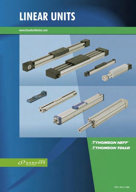
Linear Units<br />
<strong>LINEAR</strong> <strong>UNITS</strong><br />
www.DanaherMotion.com<br />
1<br />
ENG | March 2006
New Name, Established Brands<br />
Mechanical and Electro-Mechanical<br />
Product Solutions by Danaher Motion<br />
Danaher Motion’s wide range of motion control systems and components<br />
offer customers an unprecedented choice in selecting the right solution for<br />
their particular application requirements.<br />
Our product innovations have been improving the effi ciency and productivity<br />
of complex manufacturing operations for over 60 years through trusted brand<br />
names such as Dover, Kollmorgen, Pacifi c Scientifi c, Portescap and Thomson<br />
in industries as diverse as semiconductor, aerospace and defence, mobileoff-highway,<br />
packaging, medical and robotics.<br />
Our growing family of leading motion control products tells only half the story.<br />
With a worldwide service and support infrastructure, our fi eld service engineers<br />
and support teams are available when you need them.<br />
It is part of the Danaher Corporation’s unrelenting focus on you, our customer.<br />
That’s why more and more design engineers are turning to Danaher Motion<br />
to meet their motion control requirements.<br />
Danaher Motion Values<br />
• Application Expertise<br />
• Broad & Innovative Motion Control Products and Systems<br />
• Customer Focus<br />
• Customisable Products and Services<br />
• Motion Control Pioneers with Global Staying Power<br />
• Operational Excellence<br />
2<br />
Linear Units
Linear Units<br />
Table of Contents<br />
Introduction ..................................................................................................... 5<br />
Introduction ............................................................................................ 5<br />
How to choose unit ............................................................................6 - 7<br />
Technical introduction .....................................................................8 - 11<br />
Linear Units with Ball Screw Drive and Ball Guide .............................. 13<br />
Introduction ............................................................................................ 13<br />
Overview ..........................................................................................14 - 15<br />
WM40S .............................................................................................16 - 17<br />
WM40D .............................................................................................18 - 19<br />
WM60D .............................................................................................20 - 21<br />
WM60S .............................................................................................22 - 23<br />
WM60X .............................................................................................24 - 25<br />
WM80D .............................................................................................26 - 27<br />
WM80S .............................................................................................28 - 29<br />
WM120D ...........................................................................................30 - 31<br />
WV60 .................................................................................................32 - 33<br />
WV80 .................................................................................................34 - 35<br />
WV120 ...............................................................................................36 - 37<br />
MLSM60D .........................................................................................38 - 39<br />
MLSM80D .........................................................................................40 - 41<br />
2HBE10 ..............................................................................................42 - 43<br />
2HBE20 ..............................................................................................44 - 45<br />
Linear Units with Ball Screw Drive and Slide Guide ............................ 47<br />
Introduction ............................................................................................ 47<br />
Overview ..........................................................................................48 - 49<br />
WB40 .................................................................................................50 - 51<br />
M55 ....................................................................................................52 - 53<br />
M75 ....................................................................................................54 - 55<br />
M100 ..................................................................................................56 - 57<br />
M75D .................................................................................................58 - 59<br />
M100D ...............................................................................................60 - 61<br />
Linear Units with Belt Drive and Ball Guide ........................................... 63<br />
Introducti ..........................................................................................64 - 65<br />
WH40 .................................................................................................66 - 67<br />
M55 ....................................................................................................68 - 69<br />
M75 ....................................................................................................70 - 71<br />
M100 ..................................................................................................72 - 73<br />
MLSM80Z .........................................................................................74 - 75<br />
Linear Units with Belt Drive and Slide Guide ......................................... 77<br />
Introduction ............................................................................................ 77<br />
Overview ..........................................................................................78 - 79<br />
M50 ....................................................................................................80 - 81<br />
M55 ....................................................................................................82 - 83<br />
M75 ...................................................................................................84 - 85<br />
M100 ..................................................................................................86 - 87<br />
Table of Contents<br />
Linear Units with Belt Drive and Wheel Guide ...................................... 89<br />
Introduction ............................................................................................ 89<br />
Overview ..........................................................................................90 - 91<br />
WH50 .................................................................................................92 - 93<br />
WH80 .................................................................................................94 - 95<br />
WH120 ...............................................................................................96 - 97<br />
MLSH60Z ..........................................................................................98 - 99<br />
MLSH80Z ......................................................................................100 - 101<br />
Linear Lifting Units ..................................................................................... 103<br />
Introduction .......................................................................................... 103<br />
Overview ..................................................................................... 104 - 105<br />
WHZ50 ..........................................................................................106 - 107<br />
WHZ80 ..........................................................................................108 - 109<br />
Z2 ...................................................................................................110 - 111<br />
Z3 ...................................................................................................112 - 113<br />
ZB ..................................................................................................114 - 115<br />
Linear Rod Units ......................................................................................... 117<br />
Introduction .......................................................................................... 117<br />
Overview ......................................................................................118 - 119<br />
WZ60 .............................................................................................120 - 121<br />
T90 .................................................................................................122 - 123<br />
T130 ...............................................................................................124 - 125<br />
Accessories ................................................................................................. 127<br />
Accessory index .................................................................................. 127<br />
Mounting Kits ..............................................................................128 - 134<br />
Cover, Protection and Service Kits ..........................................135 - 137<br />
Motors, Gears and Transmission Kits .....................................138 - 163<br />
Electrical Feedback Devices ....................................................164 - 173<br />
Undriven Units .............................................................................174 - 179<br />
Dynamic Servo Actuators .................................................................. 180<br />
Multi Axis System Kits ........................................................................ 181<br />
Additional Technical Data ........................................................................ 183<br />
Additional Technical Data Tables ............................................183 - 187<br />
Drive Calculations .......................................................................188 - 189<br />
Deflection Calculations ..............................................................190 - 191<br />
Ordering ....................................................................................................... 193<br />
How to order ......................................................................................... 193<br />
Keys for Units with Ball Screw and Ball Guides ....................194 - 197<br />
Keys for Units with Ball Screw and Slide Guides ..................198 - 200<br />
Keys for Units with Belt Drive and Ball Guides ......................201 - 202<br />
Keys for Units with Belt Drive and Slide Guides ............................. 203<br />
Keys for Units with Belt Drive and Wheel Guides .................204 - 205<br />
Keys for Linear Lifting Units ......................................................206 - 207<br />
Keys for Linear Rod Units ................................................................... 208<br />
Keys for Undriven Units .............................................................209 - 210<br />
3
4<br />
Linear Units
Linear Units<br />
Introduction<br />
Danaher Motions linear units range consists of products from world known<br />
brands such as Thomson, Neff and Tollo. These three companies have been a part<br />
of the linear unit development elite for decades and are now forming one group of<br />
products offered to the market under the brand name Thomson.<br />
Regardless of your application you can be sure that Danaher Motion can offer you<br />
a product to match your linear motion needs.<br />
Neff<br />
Thomson<br />
Tollo<br />
Neff was founded in 1905 offering products for the linear motion<br />
market and over the decades Neff has become a market<br />
leader the ball screw technology. The fi rst linear unit from Neff<br />
was presented in 1981 at the FAMETA show in Stuttgart.<br />
Thomson dates back to the 1940s when the fi rst ball bushing<br />
bearing in the world was presented to the market. The product<br />
porfolio expanded and in the 1980s Thomson built their fi rst<br />
complete linear unit.<br />
Tollo was founded in 1981 and started as a lifting equipment<br />
manufacturer. The product potfolio grew rapidly and in 1982<br />
Tollo presented their fi rst linear unit at the Technical Fair in<br />
Stockholm.<br />
Introduction<br />
Thomson<br />
Danaher Motion has now selected the most competitive<br />
products from each brand resulting in a state of the art product<br />
range. The range covers the smallest and most compact<br />
linear units to the biggest and most robust. Danaher Motion<br />
can match your linear motion needs with a wide range of ball<br />
screw and belt driven units using a variety of guide technologies<br />
, designed to work in harsh environments, at high speeds<br />
or in high precision systems.<br />
5
How to Choose Unit<br />
How to Choose a Unit<br />
Thomson offer a wide range of linear units, each designed for a<br />
specific purpose and with its own unique features. You’ll find sizing<br />
and selection tools on our website to help you specify the unit<br />
you need, and our application engineers will be happy to help<br />
you with further technical advice.<br />
The diagrams shown here give you a brief overview of the key<br />
strengths of each group.<br />
Ball Screw Driven, Slide Guided Units<br />
Maintenance<br />
6<br />
Cost<br />
Noise<br />
Velocity<br />
Acceleration<br />
Designed for low cost, high thrust operations in demanding<br />
environments.<br />
• Cost efficient unit • Washdown protected versions<br />
• Durable guide system<br />
Linear Units<br />
Ball Screw Driven, Ball Guided Units<br />
Maintenance<br />
Cost<br />
Repeatability Maintenance<br />
Force<br />
Guide Robustness Load Torque<br />
Stiffness<br />
Noise<br />
Velocity<br />
Stiffness<br />
Units designed for high thrust, payload, high precision and<br />
stiffness.<br />
• Force up to 12000 N<br />
• Repeatability down to 0,005mm<br />
Belt Driven, Ball Guided Units<br />
Acceleration<br />
Guide Robustness Load Torque<br />
Cost<br />
Noise<br />
Velocity<br />
Acceleration<br />
Guide Robustness Load Torque<br />
Stiffness<br />
Repeatability<br />
Force<br />
Repeatability<br />
Force<br />
Smooth running units for dynamic applications with high speed,<br />
high acceleration and high loads requiring a long lifetime.<br />
• Speed up to 5 m/s<br />
• Accelartion up to 40 m/s 2
Linear Units<br />
Belt Driven, Slide Guided Units<br />
Maintenance<br />
Cost<br />
Units for dynamic applications requiring high speed, high acceleration,<br />
low maintenance and smooth travel.<br />
• Cost efficient guide system<br />
• Chemically protected versions<br />
Linear Lifting Units<br />
Load up to<br />
750 kg<br />
Speed up to<br />
10 m/s<br />
Noise<br />
Telescopic models<br />
available<br />
Ball, slide or<br />
wheel guided models<br />
Units for lifting applications. Often used in X-Y configurations in<br />
combination with other linear units.<br />
Belt Driven, Wheel Guided Units<br />
Velocity Velocity<br />
Developed for lifting applications<br />
Load torque<br />
up to 2000 Nm<br />
Acceleration<br />
Repeatability Maintenance<br />
Force<br />
Guide Robustness Load Torque<br />
Stiffness<br />
Models with ball<br />
screw or belt drive<br />
High<br />
repeatability<br />
Stroke up to<br />
3000 mm<br />
Large range<br />
of accessories<br />
Cost<br />
Units for dynamic applications with high speed, high acceleration,<br />
smooth motion and medium to high loads.<br />
• Speed up to 10 m/s<br />
• Acceleration up to 40 m/s 2<br />
Linear Rod Units<br />
Perfect for hydraulics<br />
replacement<br />
Load up to<br />
40 000 N<br />
Speed up<br />
to 2 m/s<br />
Noise<br />
Ball or slide<br />
guided models<br />
Stiffness<br />
Linear units with rod<br />
Models with<br />
IP65 sealing<br />
How to Choose Unit<br />
Acceleration<br />
Repeatability<br />
Force<br />
Guide Robustness Load Torque<br />
High accuracy<br />
ball screw drive<br />
High<br />
repeatability<br />
Stroke up to<br />
2000 mm<br />
Large range<br />
of accessories<br />
Units designed for lifting applications or for the replacement of<br />
hydraulic and pneumatic cylinders.<br />
7
Technical Introduction<br />
Technical Introduction<br />
Basic Linear Unit Terminology<br />
Screw Driven Unit Belt Driven Unit<br />
Ball Screw Drive<br />
A ball screw is made up of a rotating screw and a moving ball nut. The<br />
ball nut is attached to the carriage of the unit. It does not have a normal<br />
thread, instead balls circulate inside the nut making it work as an<br />
effi cient ball bearing that travels along the screw. Ball screws come<br />
in a large variety of leads, diameters and tolerance classes. The tolerance<br />
class (T3, T5, T7 or T9) indicates the lead tolerance of the screw.<br />
The lower the number, the higher the tolerance. High load capability and<br />
high accuracy are typical of ball screw driven units.<br />
8<br />
Drive shaft<br />
Double Carriages<br />
Front Bearing Housing<br />
Profi le<br />
Drive Station<br />
Rear Bearing Housing<br />
Cover Band<br />
Drive shaft<br />
Single Carriage<br />
T-slot/mounting groove<br />
Linear Units<br />
Tension Station<br />
Belt Drive<br />
A belt drive consists of a toothed belt which is attached to the carriage<br />
of the unit. The belt runs between two pulleys positioned at either end of<br />
the profi le. One pulley is attached to the motor while the other is mounted<br />
in a tensioning station. The belts are made of plastic reinforced with<br />
steel cords. High speeds, long stroke, low noise and low overall weight<br />
are typical features of belt driven units.
Linear Units<br />
Technical Introduction<br />
Ball Guides<br />
A ball guide consists of a ball rail and a ball bushing. The ball rail is<br />
made of hardened steel and runs along the inside of the profi le. The ball<br />
bushing is attached to the carriage of the unit and contains balls that<br />
roll against the rail. The balls in the bushing can be recirculating or have<br />
fi xed ball positions depending on the type of ball guide. The recirculating<br />
type has a longer life and better load capability while the fi xed type<br />
typically is much smaller. Thomson uses three major types of ball guides<br />
in its linear units. Either the compact single rail type with recirculating<br />
ball bushing (A), the stronger double rail type also with recirculating ball<br />
bushings (B) or the fi xed ball position ball bushings type (not shown)<br />
which require very little space and are used in the smallest units. Ball<br />
guides offer high accuracy, high loads and medium speed.<br />
A<br />
B<br />
Slide Guides<br />
A slide guide consist of a guide attached to the inside of the profi le and a<br />
slide bushing attached to the carriage. The guide can be made of different<br />
materials (e.g. polished hardened steel, anodized aluminium) while<br />
the bushing is made of a polymer material. There are two types of bushings,<br />
fi xed and prism. Prism bushings can move in relation to the guide<br />
which results in longer life and higher load capabilities. Slide bushings<br />
are silent, simple, reliable and robust and can be used in dirty and dusty<br />
environments. They are also resistant to shock loads, have a long life<br />
expectancy and require little or no maintenance.<br />
Technical Introduction<br />
Wheel Guides<br />
A wheel guide consists of ball bearing wheels that run on a hardened<br />
steel rail. Wheel guides are a simple and robust guiding method offering<br />
high speeds, high loads and medium accuarcy.<br />
Screw Supports<br />
Screw supports allow screw driven units to travel at high speed even<br />
when stroke becomes longer. The supports reduce the unsupported<br />
length of the screw, that otherwise would be subjected to vibrations.<br />
Screw supports come in single (one screw support on each side of the<br />
carriage) or double (two supports on each side) versions. Screw support<br />
units will have a slightly shorter stroke for a given overall length.<br />
Ball Screw Units with Double Ball Nuts<br />
Using double ball nuts will increase the repeatability of the unit. The<br />
ball nuts are installed so that they are pre-tensioned against each other<br />
eleminating the play between the nuts and the screw. A double nut unit<br />
will have a slightly shorter stroke for a given overall length.<br />
9
Technical Introduction<br />
Technical Introduction<br />
Single Carriage<br />
Single carriage units have one carriage. Some linear unit models also<br />
have the option of long or short single carriage. The long carriage handle<br />
higher loads but will have a longer overall length for a given stroke.<br />
Cover Band<br />
Cover bands are used on some units to protect then from the ingress of<br />
foreign objects through the opening in the profi le where the carriage<br />
runs. They are made of plastic (A) or stainless steel (B). In the case of<br />
plastic the cover band seals the profi le by snapping into small grooves<br />
running along the carriage opening. In the case of stainless steel the<br />
cover band seal the profi le magnetically using magnet strips mounted<br />
on each side of the carriage opening. Some units equipped with cover<br />
bands also have a self-adjusting cover band tensioning mechanism.<br />
This eleminates any slack in the cover band that can occur from temperaure<br />
changes, thus improving the sealing degree and the expected<br />
life of the cover band.<br />
10<br />
A<br />
B<br />
Linear Units<br />
Double Carriages<br />
Double carriage units have two carriages which gives them higher load<br />
capabilites than single carriage units. When ordering a double carriage<br />
unit the distance between the two carriages needs to be defi ned. This<br />
distance is called LA or Lc depending on the model.<br />
Theoretical Stroke and Practical Stroke<br />
The theoretical maximum stroke (S max) is the length that the carriage<br />
can travel from one end of the unit to the other. However, using the maximum<br />
stroke means that the carriage will collide with the ends of the<br />
profi le. The practical stroke is therefore shorter. We recommend that<br />
you specify a unit that have 100 mm longer stroke than the theoretical<br />
maximum stroke.<br />
Units with Left/right Moving Carriages<br />
Units with left/right moving carriages have two carriages moving in opposite<br />
directions when the drive shaft is rotated. This type of unit has a<br />
ball screw where half of the screw has a left hand thread and the other<br />
half a right hand thread.
Linear Units<br />
Technical Introduction<br />
Maintenance<br />
Most units require lubrication. General lubrication requirements can be<br />
found in the general specifications table on the product data pages. The<br />
lubrication intervals, grease qualities and specific lubrication instructions<br />
can be found in the installation and service manual of each unit. No other<br />
regular maintenance is needed except for normal cleaning and inspection.<br />
Units with a cover band may also require irregular cover band replacement<br />
due to wear. The belt in belt driven units should not require<br />
re-tensioning under normal operating conditions.<br />
Mounting Position<br />
Most units can be mounted in any direction. Any restrictions on mounting<br />
positions are shown on the product presentation pages at the beginning<br />
of each product category chapter. Even where units may be mounted in<br />
any direction there are some considerations. None of the units are selflocking<br />
which means that a vertical unit will drop the carriage/load if no<br />
external brake (such as a brake in the motor, etc.) is applied to the drive<br />
shaft of the unit. In the case of belt driven units care must be taken as the<br />
carriage/load will drop immediately in the case of a belt breakage. This is<br />
particularly important in vertical applications. All ball screw driven units<br />
are equipped with a safety nut to prevent the carriage/load being released<br />
in case of ball breakage.<br />
Working Environment<br />
All units are designed for use in normal industrial environments. Units<br />
which have an open profile (i.e. have no cover band) are more sensitive<br />
to dust, dirt and fluids. These units require some kind of cover if they are<br />
used in environments where dust, dirt or fluids are present. Optional bellows/shrouds<br />
are available for some of our open profile units. Enhanced<br />
wash-down or chemical protection can be ordered for our closed profile<br />
units. Please refer to the accessory pages. In all cases where a unit will<br />
be exposed to aggressive chemicals, heavy vibrations or other potentially<br />
harmful processes we recommend that you contact us for further advice.<br />
Duty Cycle<br />
All units are designed for a 100% duty cycle. However, where the unit runs<br />
at extreme load, speed, acceleration and temperature or for long operating<br />
periods the expected life time may be reduced.<br />
Operation and Storage Temperature<br />
Operational temperature limits can be found in the performance tables<br />
on the product data pages. Units can be stored or transported within the<br />
same temperature range. Please contact us if the unit will be exposed to<br />
higher/lower temperatures than recommended during storage or transportation<br />
Technical Introduction<br />
Load and Load Torque Values<br />
For some units the load and load torque values are given for both the complete<br />
unit and the guiding system. The values for the complete unit are<br />
the values under which the unit can operate. The values for the guiding<br />
system should only be used when comparing different units and do not<br />
describe the actual performance of the complete unit.<br />
Deflection of the Profile<br />
Some units require support along the whole profile whilst some are self<br />
supporting over a specified span. Further details can be found on the<br />
product data pages. The recommended support intervals should be followed<br />
to minimise deflection of the unit. The maximum distance between<br />
the support points is shown on the product data pages. The deflection of<br />
the unit can also be calculated using the information in the Additional data<br />
and calculations chapter.<br />
Lifetime Expectancy<br />
When determining the lifetime for a linear unit it is necessary to evaluate<br />
all forces and moments that are acting on the unit. The data and formulas<br />
given in this catalogue serve as a basis for this. For a more detailed<br />
lifetime calculation please use our sizing and selection software. Please<br />
contact us for further guidance.<br />
End of Stroke Limit Switches<br />
If a unit runs at speed to the ends of its stroke there is a risk of damage.<br />
Damage can be prevented by using end of stroke limit switches to detect<br />
and engage a break and/or cut power to the motor when the unit nears the<br />
end of the unit. You must ensure that there is sufficient distance between<br />
the end of stroke limit switch and the end of the unit, to allow the carriage<br />
to come to a complete stop before colliding with the end. The required<br />
stopping distance depends on the speed and the load and will have to be<br />
calculated for each application. The stopping distance must be taken into<br />
account when defining the necessary stroke.<br />
Position Feedback<br />
The position of the carriage/rod/lifting profile can be obtained in many<br />
ways. The most common way is to equip the unit with an encoder or to<br />
use a motor which has a built in feed back device (encoder, resolver, etc.).<br />
To many units there are encoders or/and encoder mounting kits available.<br />
See the accessory chapter.<br />
Packages and Multi Axis Kits<br />
Thomson can offer complete pre-defined packages (linear unit, gear and<br />
servo motor assembled and shipped with servo drive and cables) as well<br />
as mounting kits for the creation of two and three axis systems Please<br />
contact us for further information.<br />
11
12<br />
Linear Units
Linear Units<br />
Linear Units with Ball Screw Drive and Ball Guide<br />
PowerLine, ForceLine, Microstage, AccuSlide<br />
Maintenance<br />
Cost<br />
Noise<br />
Guide Robustness<br />
Typical Applications<br />
Velocity<br />
Stiffness<br />
Acceleration<br />
Repeatability<br />
Force<br />
Typical applications are where high accuracy and load capability is required but<br />
where speed is less important. Typical examples are machining operations and in<br />
the handling of heavy goods that need accurate positioning.<br />
Ball Screw Drive and Ball Guide<br />
Load Torque<br />
13
Ball Screw Drive and Ball Guide<br />
PowerLine WM<br />
14<br />
Linear Units<br />
Parameter WM40S WM40D WM60D WM60S WM60X WM80D WM80S WM120D<br />
Profi le size (width × height) [mm] 40 × 40 40 × 40 60 × 60 60 × 60 60 × 60 80 × 80 80 × 80 120 × 120<br />
Stroke length (S max), maximum [mm] 2000 2000 11000 5000 10340 11000 5000 11000<br />
Linear speed, maximum [m/s] 0,25 0,25 2,5 2,5 0,25 2,5 2,5 2,0<br />
Dynamic carriage load (Fz), maximum [N] 600 600 2000 1400 2000 3000 2100 6000<br />
Remarks single ball<br />
nut<br />
double ball<br />
nuts<br />
double ball<br />
nuts<br />
single ball<br />
nut<br />
left/right<br />
screw<br />
double ball<br />
nuts<br />
single ball<br />
nut<br />
Page 16 18 20 22 24 26 28 30<br />
PowerLine WV<br />
WV80<br />
WM40<br />
Parameter WV60 WV80 WV120<br />
Profi le size (width × height) [mm] 60 × 60 80 × 80 120 × 120<br />
Stroke length (S max), maximum [mm] 11000 11000 11000<br />
Linear speed, maximum [m/s] 2,5 2,5 2,0<br />
Dynamic carriage load (Fz), maximum [N] - - -<br />
Remarks double ball nuts<br />
the units has no guides<br />
double ball nuts<br />
the units has no guides<br />
double ball<br />
nuts<br />
double ball nuts<br />
the units has no guides<br />
Page 32 34 36<br />
ForceLine MLSM<br />
MLSM80D<br />
Features<br />
• Can be installed in all directions<br />
• Patented guide system<br />
• Patented self-adjusting plastic cover band<br />
• Patented screw support system<br />
Features<br />
• Can be installed in all directions<br />
• Patented self-adjusting plastic cover band<br />
• Patented screw support system<br />
• The units require external guides<br />
Features<br />
• Can be installed in all directions<br />
• Patented guide system<br />
• Patented plastic cover band<br />
• Patented screw support system<br />
Parameter MLSM60D<br />
MLSM80D<br />
Profi le size (width × height) [mm] 160 × 65 240 × 85<br />
Stroke length (S max), maximum [mm] 5500 5200<br />
Linear speed, maximum [m/s] 2,5 2,0<br />
Dynamic carriage load (Fz), maximum [N] 6000 8000<br />
Remarks double ball nuts double ball nuts<br />
Page 38 40
Linear Units<br />
AccuSlide 2HBE<br />
2HBE20<br />
Features<br />
Parameter 2HBE10 2HBE20<br />
Profile size (width × height) [mm] 100�× 33,5 200 × 44<br />
Stroke length (S max), maximum [mm] 850 2800<br />
Linear speed, maximum [m/s] 0,5 1,3<br />
Dynamic carriage load (Fz), maximum [N] 8250 38000<br />
Remarks no cover band, bellows or shrouds option<br />
available<br />
• Can be installed in all directions<br />
• High load capablities<br />
• Low profile height<br />
• Play free ball screw offer high repeatability<br />
no cover band, bellows or shrouds option<br />
available<br />
Page 42 44<br />
Ball Screw Drive and Ball Guide<br />
15
Ball Screw Drive and Ball Guide<br />
WM40S<br />
Ball Screw Drive, Ball Guide, Single Ball Nut<br />
General Specifications<br />
Parameter WM40S<br />
Profile size (w × h) [mm] 40 × 40<br />
Type of screw ball screw with single nut<br />
Carriage sealing system self-adjusting plastic cover band<br />
Screw supports<br />
Lubrication<br />
Performance Specifications<br />
Parameter WM40S<br />
Stroke length (S max), maximum [mm] 2000<br />
Linear speed, maximum [m/s] 0,25<br />
Acceleration, maximum [m/s 2 ] 20<br />
Repeatability [± mm] 0,02<br />
Input speed, maximum [rpm] 3000<br />
Operation temperature limits [°C] 0 – 80<br />
Dynamic load (Fx), maximum [N] 1000<br />
Dynamic load (Fy), maximum [N] 450 1 / 5300 2<br />
Dynamic load (Fz), maximum [N] 600 1 / 6790 2<br />
Dynamic load torque (Mx), maximum [Nm] 10 1 / 30 2<br />
Dynamic load torque (My), maximum [Nm] 30 1 / 230 2<br />
Dynamic load torque (Mz), maximum [Nm] 30 1 / 230 2<br />
Drive shaft force (Frd), maximum [N] 100<br />
Drive shaft torque (Mta), maximum [Nm] 3<br />
Ball screw diameter (d0) [mm] 12<br />
Ball screw lead (p) [mm] 5<br />
Weight<br />
of unit with zero stroke<br />
of every 100 mm of stroke<br />
of each carriage<br />
16<br />
included in all units that require<br />
screw supports<br />
central lubrication of all parts that<br />
require lubrication<br />
Included accessories 4 × mounting clamps<br />
1 Value for the complete unit<br />
2 Value for the ball guide only<br />
[kg]<br />
1,50<br />
0,30<br />
0,36<br />
Linear Units<br />
Carriage Idle Torque (M idle) [Nm]<br />
Input speed [rpm]<br />
Screw lead [mm]<br />
p = 5<br />
150 0,3<br />
1500 0,5<br />
3000 0,8<br />
» Ordering key - see page 194<br />
» Accessories - see page 127<br />
» Additional data - see page 183<br />
M idle = the input torque needed to move the carriage with no load on it.<br />
Deflection of the Profile<br />
A mounting clamp must be installed at least at every 750 mm to be able to operate the<br />
maximum load. Less clamps may be required if less load is being operated, see the additional<br />
technical data for more information.<br />
Critical Speed<br />
Definition of Forces
Linear Units<br />
WM40S<br />
Ball Screw Drive, Ball Guide, Single Ball Nut<br />
A1: depth 7<br />
A2: lubricating nipple on both sides DIN3405 D 1/A<br />
Stroke length (S max) [mm] A [mm] B [mm] C [mm]<br />
0 – 500 (0 – 450) 65 35 270 (320)<br />
501 – 1100 (451 – 1050) 65 45 280 (330)<br />
1101 – 2000 (1051 – 1950) 70 60 300 (350)<br />
Values between brackets = for units with long carriage<br />
Long Carriage<br />
Parameter WM40S<br />
Carriage length [mm] 210<br />
Dynamic load torque (My), maximum [Nm] 50<br />
Dynamic load torque (Mz), maximum [Nm] 50<br />
Weight [kg] 0,55<br />
Double Carriages<br />
Parameter WM40S<br />
Minimum distance between carriages (L A) [mm] 175<br />
Dynamic load (Fy), maximum [N] 900<br />
Dynamic load (Fz), maximum [N] 1200<br />
Dynamic load torque (My), maximum [Nm] L A 1 × 0,45<br />
Dynamic load torque (Mz), maximum [Nm] L A 1 × 0,6<br />
Force required to move second carriage [N] 40<br />
Total length (L tot) [mm] S max + C + L A<br />
1 Value in mm<br />
A3: socket cap screw ISO4762-M5×12 8.8<br />
A4: ENF inductive sensor rail option kit (optional)<br />
A1: depth 6<br />
Ball Screw Drive and Ball Guide<br />
17
Ball Screw Drive and Ball Guide<br />
WM40D<br />
Ball Screw Drive, Ball Guide, Double Ball Nuts, Long Carriage<br />
General Specifications<br />
Parameter WM40D<br />
Profile size (w × h) [mm] 40 × 40<br />
Type of screw ball screw with double nuts<br />
Carriage sealing system self-adjusting plastic cover band<br />
Screw supports<br />
Lubrication<br />
Performance Specifications<br />
Parameter WM40D<br />
Stroke length (S max), maximum [mm] 1950<br />
Linear speed, maximum [m/s] 0,25<br />
Acceleration, maximum [m/s 2 ] 20<br />
Repeatability [± mm] 0,01<br />
Input speed, maximum [rpm] 3000<br />
Operation temperature limits [°C] 0 – 80<br />
Dynamic load (Fx), maximum [N] 1000<br />
Dynamic load (Fy), maximum [N] 450 1 / 5300 2<br />
Dynamic load (Fz), maximum [N] 600 1 / 6790 2<br />
Dynamic load torque (Mx), maximum [Nm] 10 1 / 30 2<br />
Dynamic load torque (My), maximum [Nm] 30 1 / 230 2<br />
Dynamic load torque (Mz), maximum [Nm] 30 1 / 230 2<br />
Drive shaft force (Frd), maximum [N] 100<br />
Drive shaft torque (Mta), maximum [Nm] 3<br />
Ball screw diameter (d0) [mm] 12<br />
Ball screw lead (p) [mm] 5<br />
Weight<br />
of unit with zero stroke<br />
of every 100 mm of stroke<br />
of each carriage<br />
18<br />
included in all units that require<br />
screw supports<br />
central lubrication of all parts that<br />
require lubrication<br />
Included accessories 4 × mounting clamps<br />
1 Value for the complete unit<br />
2 Value for the ball guide only<br />
[kg]<br />
1,90<br />
0,30<br />
0,60<br />
Linear Units<br />
Carriage Idle Torque (M idle) [Nm]<br />
Input speed [rpm]<br />
Screw lead [mm]<br />
p = 5<br />
150 0,4<br />
1500 0,6<br />
3000 0,9<br />
M idle = the input torque needed to move the carriage with no load on it.<br />
Deflection of the Profile<br />
A mounting clamp must be installed at least at every 750 mm to be able to operate the<br />
maximum load. Less clamps may be required if less load is being operated, see the additional<br />
technical data for more information.<br />
Critical Speed<br />
Definition of Forces<br />
» Ordering key - see page 194<br />
» Accessories - see page 127<br />
» Additional data - see page 183
Linear Units<br />
WM40D<br />
Ball Screw Drive, Ball Guide, Double Ball Nuts, Long Carriage<br />
A1: depth 6<br />
A2: lubricating nipple on both sides DIN3405 D 1/A<br />
Double Long Carriages<br />
Parameter WM40D<br />
Minimum distance between carriages (L A) [mm] 225<br />
Dynamic load (Fy), maximum [N] 900<br />
Dynamic load (Fz), maximum [N] 1200<br />
Dynamic load torque (My), maximum [Nm] L A 1 × 0,45<br />
Dynamic load torque (Mz), maximum [Nm] L A 1 × 0,6<br />
Force required to move second carriage [N] 40<br />
Total length (L tot) [mm] S max + C + L A<br />
A3: socket cap screw ISO4762-M5×12 8.8<br />
A4: ENF inductive sensor rail option kit (optional)<br />
Stroke length (S max) [mm] A [mm] B [mm] C [mm]<br />
0 – 500 65 35 320<br />
501 – 1100 65 45 330<br />
1101 – 2000 70 60 350<br />
1 Value in mm<br />
Ball Screw Drive and Ball Guide<br />
19
Ball Screw Drive and Ball Guide<br />
WM60D<br />
Ball Screw Drive, Ball Guide, Double Ball Nuts<br />
General Specifications<br />
Parameter WM60D<br />
Profile size (w × h) [mm] 60 × 60<br />
Type of screw ball screw with double nut<br />
Carriage sealing system self-adjusting plastic cover band<br />
Screw supports<br />
Lubrication<br />
Performance Specifications<br />
Parameter WM60D<br />
Stroke length (S max), maximum<br />
screw lead 5, 20 mm<br />
screw lead 50 mm<br />
20<br />
[mm]<br />
11000<br />
5000<br />
Linear speed, maximum [m/s] 2,5<br />
Acceleration, maximum [m/s 2 ] 20<br />
Repeatability [± mm] 0,01<br />
Input speed, maximum [rpm] 3000<br />
Operation temperature limits [°C] 0 – 80<br />
Dynamic load (Fx), maximum [N] 4000<br />
Dynamic load (Fy), maximum [N] 2000 1 / 45980 2<br />
Dynamic load (Fz), maximum [N] 2000 1 / 42320 2<br />
Dynamic load torque (Mx), maximum [Nm] 100 1 / 740 2<br />
Dynamic load torque (My), maximum [Nm] 200 1 / 2990 2<br />
Dynamic load torque (Mz), maximum [Nm] 200 1 / 3250 2<br />
Drive shaft force (Frd), maximum [N] 500<br />
Drive shaft torque (Mta), maximum [Nm] 35<br />
Ball screw diameter (d0) [mm] 20<br />
Ball screw lead (p) [mm] 5, 20, 50<br />
Weight<br />
of unit with zero stroke<br />
of every 100 mm of stroke<br />
of each carriage<br />
included in all units that require<br />
screw supports<br />
central lubrication of all parts that<br />
require lubrication<br />
Included accessories 4 × mounting clamps<br />
1 Value for the complete unit<br />
2 Value for the ball guide only<br />
[kg]<br />
6,16<br />
0,65<br />
1,99<br />
Linear Units<br />
Carriage Idle Torque (M idle) [Nm]<br />
Input speed [rpm]<br />
Screw lead [mm]<br />
p = 5 p = 20 p = 50<br />
150 0,8 1,3 1,6<br />
1500 1,4 2,0 2,4<br />
3000 1,8 2,3 2,6<br />
M idle = the input torque needed to move the carriage with no load on it.<br />
Deflection of the Profile<br />
A mounting clamp must be installed at least at every 750 mm to be able to operate the<br />
maximum load. Less clamps may be required if less load is being operated, see the additional<br />
technical data for more information. Units with a profile length over 6300 mm consists of two<br />
profiles where the joint between the two profiles must be addequately supported on both<br />
sides.<br />
Definition of Forces<br />
» Ordering key - see page 194<br />
» Accessories - see page 127<br />
» Additional data - see page 183
Linear Units<br />
WM60D<br />
Ball Screw Drive, Ball Guide, Double Ball Nuts<br />
A1: depth 11<br />
A2: socket cap screw ISO4762-M6×20 8.8<br />
A3: ENF inductive sensor rail option kit (optional)<br />
Stroke length (S max) [mm] A [mm] B [mm] C [mm]<br />
0 - 695 (0 - 505) 115 65 460 (650)<br />
696 - 1335 (506 - 1145) 165 115 560 (750)<br />
1336 - 2075 (1146 - 1885) 185 135 600 (790)<br />
2076 - 2780 (1886 - 2590) 210 160 650 (840)<br />
Values between brackets = for units with long carriage<br />
Long Carriage<br />
Parameter WM60D<br />
Carriage length [mm] 450<br />
Dynamic load torque (My), maximum [Nm] 500<br />
Dynamic load torque (Mz), maximum [Nm] 500<br />
Weight [kg] 3,1<br />
Double Carriages<br />
Parameter WM60D<br />
Minimum distance between carriages (L A) [mm] 335<br />
Dynamic load (Fy), maximum [N] 4000<br />
Dynamic load (Fz), maximum [N] 4000<br />
Dynamic load torque (My), maximum [Nm] L A 1 × 2<br />
Dynamic load torque (Mz), maximum [Nm] L A 1 × 2<br />
Force required to move second carriage [N] 200<br />
Total length (L tot) [mm] S max + C + L A<br />
1 Value in mm<br />
A4: tapered lubricating nipple to DIN71412 AM6 on fixed-bearing side as standard feature<br />
A5: can be changed over to one of the three alternative lubricating points by the customer<br />
Stroke length (S max) [mm] A [mm] B [mm] C [mm]<br />
2781 - 3545 (2591 - 3355) 230 180 690 (880)<br />
3546 - 4285 (3366 - 4095) 250 200 730 (920)<br />
4286 - 5015 (4096 - 4825) 275 225 780 (970)<br />
5016 - 11000 (4826 - 10810) contact customer service<br />
A1: depth 11<br />
Ball Screw Drive and Ball Guide<br />
21
Ball Screw Drive and Ball Guide<br />
WM60S<br />
Ball Screw Drive, Ball Guide, Single Ball Nut, Short Carriage<br />
General Specifications<br />
Parameter WM60S<br />
Profile size (w × h) [mm] 60 × 60<br />
Type of screw ball screw with single nut<br />
Carriage sealing system self adjusting plastic cover band<br />
Screw supports<br />
Lubrication<br />
Performance Specifications<br />
Parameter WM60S<br />
Stroke length (S max), maximum [mm] 5000<br />
Linear speed, maximum [m/s] 2,5<br />
Acceleration, maximum [m/s 2 ] 10<br />
Repeatability [± mm] 0,02<br />
Input speed, maximum [rpm] 3000<br />
Operation temperature limits [°C] 0 – 80<br />
Dynamic load (Fx), maximum [N] 2800<br />
Dynamic load (Fy), maximum [N] 1400 1 / 25920 2<br />
Dynamic load (Fz), maximum [N] 1400 1 / 23860 2<br />
Dynamic load torque (Mx), maximum [Nm] 50 1 / 410 2<br />
Dynamic load torque (My), maximum [Nm] 100 1 / 320 2<br />
Dynamic load torque (Mz), maximum [Nm] 100 1 / 320 2<br />
Drive shaft force (Frd), maximum [N] 500<br />
Drive shaft torque (Mta), maximum [Nm] 35<br />
Ball screw diameter (d0) [mm] 20<br />
Ball screw lead (p) [mm] 5, 20, 50<br />
Weight<br />
of unit with zero stroke<br />
of every 100 mm of stroke<br />
of each carriage<br />
22<br />
included in all units that require<br />
screw supports<br />
central lubrication of all parts that<br />
require lubrication<br />
Included accessories 4 × mounting clamps<br />
1 Value for the complete unit<br />
2 Value for the ball guide only<br />
[kg]<br />
3,80<br />
0,65<br />
1,00<br />
Linear Units<br />
Carriage Idle Torque (M idle) [Nm]<br />
Input speed [rpm]<br />
Screw lead [mm]<br />
p = 5 p = 20 p = 50<br />
150 0,7 1,0 1,4<br />
1500 1,1 1,6 2,0<br />
3000 1,5 1,8 2,2<br />
M idle = the input torque needed to move the carriage with no load on it.<br />
Deflection of the Profile<br />
A mounting clamp must be installed at least at every 750 mm to be able to operate the<br />
maximum load. Less clamps may be required if less load is being operated, see the additional<br />
technical data for more information.<br />
Definition of Forces<br />
» Ordering key - see page 194<br />
» Accessories - see page 127<br />
» Additional data - see page 183
Linear Units<br />
WM60S<br />
Ball Screw Drive, Ball Guide, Single Ball Nut, Short Carriage<br />
A1: depth 11<br />
A2: socket cap screw ISO4762-M6×20 8.8<br />
A3: ENF inductive sensor rail option kit (optional)<br />
Stroke length (S max) [mm] A [mm] B [mm] C [mm]<br />
0 - 580 95 20 335<br />
581 - 1140 110 60 390<br />
1141 - 1805 130 80 430<br />
1806 - 2460 155 105 480<br />
Double Short Carriages<br />
Parameter WM60S<br />
Minimum distance between carriages (L A) [mm] 255<br />
Dynamic load (Fy), maximum [N] 2800<br />
Dynamic load (Fz), maximum [N] 2800<br />
Dynamic load torque (My), maximum [Nm] L A 1 × 1,4<br />
Dynamic load torque (Mz), maximum [Nm] L A 1 × 1,4<br />
Force required to move second carriage [N] 180<br />
Total length (L tot) [mm] S max + C + L A<br />
1 Value in mm<br />
Ball Screw Drive and Ball Guide<br />
A4: tapered lubricating nipple to DIN71412 AM6 on fixed-bearing side as standard feature<br />
A5: can be changed over to one of the three alternative lubricating points by the customer<br />
Stroke length (S max) [mm] A [mm] B [mm] C [mm]<br />
2461 - 3125 175 125 520<br />
3126 - 3780 200 150 570<br />
3781 - 4445 220 170 610<br />
4446 - 5000 240 190 650<br />
23
Ball Screw Drive and Ball Guide<br />
WM60X<br />
Ball Screw Drive, Ball Guide, Left/right Moving Carriages<br />
General Specifications<br />
Parameter WM60X<br />
Profile size (w × h) [mm] 60 × 60<br />
Type of screw ball screw with double nut<br />
Carriage sealing system self adjusting plastic cover band<br />
Screw supports<br />
Lubrication<br />
Performance Specifications<br />
Parameter WM60X<br />
Stroke length (S max), maximum [mm] 10340<br />
Linear speed, maximum [m/s] 0,25<br />
Acceleration, maximum [m/s 2 ] 20<br />
Repeatability [± mm] 0,01<br />
Input speed, maximum [rpm] 3000<br />
Operation temperature limits [°C] 0 – 80<br />
Dynamic load (Fx), maximum [N] 4000<br />
Dynamic load (Fy), maximum [N] 2000 1 / 45980 2<br />
Dynamic load (Fz), maximum [N] 2000 1 / 42320 2<br />
Dynamic load torque (Mx), maximum [Nm] 100 1 / 740 2<br />
Dynamic load torque (My), maximum [Nm] 200 1 / 2990 2<br />
Dynamic load torque (Mz), maximum [Nm] 200 1 / 3250 2<br />
Drive shaft force (Frd), maximum [N] 500<br />
Drive shaft torque (Mta), maximum [Nm] 35<br />
Ball screw diameter (d0) [mm] 20<br />
Ball screw lead (p) [mm] 5<br />
Weight<br />
of unit with zero stroke<br />
of every 100 mm of stroke<br />
of each carriage<br />
24<br />
included in all units that require<br />
screw supports<br />
central lubrication of all parts that<br />
require lubrication<br />
Included accessories 4 × mounting clamps<br />
1 Value for the complete unit<br />
2 Value for the ball guide only<br />
[kg]<br />
10,33<br />
0,65<br />
1,99<br />
Linear Units<br />
Carriage Idle Torque (M idle) [Nm]<br />
Input speed [rpm]<br />
Screw lead [mm]<br />
p = 5<br />
150 1,6<br />
1500 2,8<br />
3000 3,6<br />
M idle = the input torque needed to move the carriage with no load on it.<br />
Deflection of the Profile<br />
A mounting clamp must be installed at least at every 750 mm to be able to operate the<br />
maximum load. Less clamps may be required if less load is being operated, see the additional<br />
technical data for more information. Units with a profile length over 5400 mm consists of two<br />
profiles where the joint between the two profiles must be addequately supported on both<br />
sides.<br />
Definition of Forces<br />
» Ordering key - see page 194<br />
» Accessories - see page 127<br />
» Additional data - see page 183
Linear Units<br />
WM60X<br />
Ball Screw Drive, Ball Guide, Left/right Moving Carriages<br />
A1: depth 11<br />
A2: socket cap screw ISO4762-M6×20 8.8<br />
A3: ENF inductive sensor rail option kit (optional)<br />
Stroke length (S max) [mm] A [mm] B [mm] C [mm] X [mm] Y [mm] Z [mm]<br />
0 - 1390 (0 - 1200) 115 65 60 80 620 800<br />
1391 - 2670 (1201 - 2480) 165 115 210 230 770 1050<br />
2671 - 4150 (2481 - 3960) 185 135 250 270 810 1130<br />
4151 - 5560 (3961 - 5370) 210 160 300 320 860 1230<br />
5561 - 10340 (5371 - 10150) contact customer sevice<br />
Values between brackets = for units with long carriage<br />
Long Carriage<br />
Parameter WM60X<br />
Carriage length [mm] 450<br />
Dynamic load torque (My), maximum [Nm] 500<br />
Dynamic load torque (Mz), maximum [Nm] 500<br />
Weight [kg] 3,1<br />
A1: depth 11<br />
Ball Screw Drive and Ball Guide<br />
A4: tapered lubricating nipple to DIN71412 AM6 on fixed-bearing side as standard feature<br />
A5: can be changed over to one of the three alternative lubricating points by the customer<br />
25
Ball Screw Drive and Ball Guide<br />
WM80D<br />
Ball Screw Drive, Ball Guide, Double Ball Nuts<br />
General Specifications<br />
Parameter WM80D<br />
Profile size (w × h) [mm] 80 × 80<br />
Type of screw ball screw with double nuts<br />
Carriage sealing system self adjusting plastic cover band<br />
Screw supports<br />
Lubrication<br />
Performance Specifications<br />
Parameter WM80D<br />
Stroke length (S max), maximum<br />
screw lead 5, 10, 20 mm<br />
screw lead 50 mm<br />
26<br />
[mm]<br />
11000<br />
5000<br />
Linear speed, maximum [m/s] 2,5<br />
Acceleration, maximum [m/s 2 ] 20<br />
Repeatability [± mm] 0,01<br />
Input speed, maximum [rpm] 3000<br />
Operation temperature limits [°C] 0 – 80<br />
Dynamic load (Fx), maximum [N] 5000<br />
Dynamic load (Fy), maximum [N] 3000 1 / 57420 2<br />
Dynamic load (Fz), maximum [N] 3000 1 / 54950 2<br />
Dynamic load torque (Mx), maximum [Nm] 350 1 / 1360 2<br />
Dynamic load torque (My), maximum [Nm] 300 1 / 4230 2<br />
Dynamic load torque (Mz), maximum [Nm] 300 1 / 4220 2<br />
Drive shaft force (Frd), maximum [N] 700<br />
Drive shaft torque (Mta), maximum [Nm] 55<br />
Ball screw diameter (d0) [mm] 25<br />
Ball screw lead (p) [mm] 5, 10, 20, 50<br />
Weight<br />
of unit with zero stroke<br />
of every 100 mm of stroke<br />
of each carriage<br />
included in all units that require<br />
screw supports<br />
central lubrication of all parts that<br />
require lubrication<br />
Included accessories 4 × mounting clamps<br />
1 Value for the complete unit<br />
2 Value for the ball guide only<br />
[kg]<br />
11,57<br />
1,08<br />
4,26<br />
Linear Units<br />
Carriage Idle Torque (M idle) [Nm]<br />
Input speed [rpm]<br />
Screw lead [mm]<br />
p = 5 p = 10 p = 20 p = 50<br />
150 1,1 1,5 1,8 2,3<br />
1500 1,7 2.1 2,3 3,0<br />
3000 2,1 2,5 2,6 3,6<br />
M idle = the input torque needed to move the carriage with no load on it.<br />
Deflection of the Profile<br />
A mounting clamp must be installed at least at every 750 mm to be able to operate the<br />
maximum load. Less clamps may be required if less load is being operated, see the additional<br />
technical data for more information. Units with a profile length over 6300 mm consists of two<br />
profiles where the joint between the two profiles must be addequately supported on both<br />
sides.<br />
Definition of Forces<br />
» Ordering key - see page 194<br />
» Accessories - see page 127<br />
» Additional data - see page 183
Linear Units<br />
WM80D<br />
Ball Screw Drive, Ball Guide, Double Ball Nuts<br />
A1: depth 12 mm<br />
A2: socket cap screw ISO4762-M6×20 8.8<br />
A3: ENF inductive sensor rail option kit (optional)<br />
Stroke length (S max) [mm] A [mm] B [mm] C [mm]<br />
0 - 780 (0 - 610) 120 80 500 (670)<br />
781 - 1535 (611 - 1365) 170 125 595 (765)<br />
1536 - 2375 (1366 - 2205) 190 145 635 (805)<br />
2376 - 3205 (2206 - 3035) 215 170 685 (855)<br />
Values between brackets = for units with long carriage<br />
Long Carriage<br />
Parameter WM80D<br />
Carriage length [mm] 450<br />
Dynamic load torque (My), maximum [Nm] 750<br />
Dynamic load torque (Mz), maximum [Nm] 750<br />
Weight [kg] 6,4<br />
Double Carriages<br />
Parameter WM80D<br />
Minimum distance between carriages (L A) [mm] 360<br />
Dynamic load (Fy), maximum [N] 6000<br />
Dynamic load (Fz), maximum [N] 6000<br />
Dynamic load torque (My), maximum [Nm] L A 1 × 3<br />
Dynamic load torque (Mz), maximum [Nm] L A 1 × 3<br />
Force required to move second carriage [N] 250<br />
Total length (L tot) [mm] S max + C + L A<br />
1 Value in mm<br />
A4: tapered lubricating nipple to DIN71412 AM6 on fixed-bearing side as standard feature<br />
A5: can be changed over to one of three alternative lubrication points by customer<br />
Stroke length (S max) [mm] A [mm] B [mm] C [mm]<br />
3206 - 4045 (3036 - 3875) 235 190 725 (895)<br />
4046 - 4885 (3876 - 4715) 255 210 765 (935)<br />
4886 - 5000 (4716 - 4830) 280 235 815 (985)<br />
5001 - 11000 (4717 - 10830) contact customer service<br />
A1: depth 12 mm<br />
Ball Screw Drive and Ball Guide<br />
27
Ball Screw Drive and Ball Guide<br />
WM80S<br />
Ball Screw Drive, Ball Guide, Singel Ball Nut, Short Carriage<br />
General Specifications<br />
Parameter WM80S<br />
Profile size (w × h) [mm] 80 × 80<br />
Type of screw ball screw with single nut<br />
Carriage sealing system self adjusting plastic cover band<br />
Screw supports<br />
Lubrication<br />
Performance Specifications<br />
Parameter WM80S<br />
Stroke length (S max), maximum [mm] 5000<br />
Linear speed, maximum [m/s] 2,5<br />
Acceleration, maximum [m/s 2 ] 20<br />
Repeatability [± mm] 0,02<br />
Input speed, maximum [rpm] 3000<br />
Operation temperature limits [°C] 0 – 80<br />
Dynamic load (Fx), maximum [N] 3500<br />
Dynamic load (Fy), maximum [N] 2100 1 / 37440 2<br />
Dynamic load (Fz), maximum [N] 2100 1 / 35830 2<br />
Dynamic load torque (Mx), maximum [Nm] 150 1 / 890 2<br />
Dynamic load torque (My), maximum [Nm] 180 1 / 580 2<br />
Dynamic load torque (Mz), maximum [Nm] 180 1 / 600 2<br />
Drive shaft force (Frd), maximum [N] 700<br />
Drive shaft torque (Mta), maximum [Nm] 55<br />
Ball screw diameter (d0) [mm] 25<br />
Ball screw lead (p) [mm] 5, 10, 20, 50<br />
Weight<br />
of unit with zero stroke<br />
of every 100 mm of stroke<br />
of each carriage<br />
28<br />
included in all units that require<br />
screw supports<br />
central lubrication of all parts that<br />
require lubrication<br />
Included accessories 4 × mounting clamps<br />
1 Value for the complete unit<br />
2 Value for the ball guide only<br />
[kg]<br />
7,0<br />
1,1<br />
1,6<br />
Linear Units<br />
Carriage Idle Torque (M idle) [Nm]<br />
Input speed [rpm]<br />
Screw lead [mm]<br />
p = 5 p = 10 p = 20 p = 50<br />
150 0,9 1,1 1,3 2,0<br />
1500 1,3 1,5 1,8 2,4<br />
3000 1,7 1,8 2,0 2,9<br />
M idle = the input torque needed to move the carriage with no load on it.<br />
Deflection of the Profile<br />
A mounting clamp must be installed at least at every 750 mm to be able to operate the<br />
maximum load. Less clamps may be required if less load is being operated, see the additional<br />
technical data for more information.<br />
Definition of Forces<br />
» Ordering key - see page 194<br />
» Accessories - see page 127<br />
» Additional data - see page 183
Linear Units<br />
WM80S<br />
Ball Screw Drive, Ball Guide, Singel Ball Nut, Short Carriage<br />
A1: depth 12 mm<br />
A2: socket cap screw ISO4762-M6×20 8.8<br />
A3: ENF inductive sensor rail option kit (optional)<br />
Stroke length (S max) [mm] A [mm] B [mm] C [mm]<br />
0 - 680 95 35 350<br />
681 - 1310 125 80 425<br />
1311 - 2065 150 105 475<br />
2066 - 2830 170 125 515<br />
Double Carriages<br />
Parameter WM80S<br />
Minimum distance between carriages (L A) [mm] 280<br />
Dynamic load (Fy), maximum [N] 4200<br />
Dynamic load (Fz), maximum [N] 4200<br />
Dynamic load torque (My), maximum [Nm] L A 1 × 2,1<br />
Dynamic load torque (Mz), maximum [Nm] L A 1 × 2,1<br />
Force required to move second carriage [N] 225<br />
Total length (L tot) [mm] S max + C + L A<br />
1 Value in mm<br />
Ball Screw Drive and Ball Guide<br />
A4: tapered lubricating nipple to DIN71412 AM6 on fixed-bearing side as standard feature<br />
A5: can be changed over to one of three alternative lubrication points by customer<br />
Stroke length (S max) [mm] A [mm] B [mm] C [mm]<br />
2831 - 3590 195 150 565<br />
3591 - 4355 215 170 605<br />
4356 - 5000 235 190 645<br />
29
Ball Screw Drive and Ball Guide<br />
WM120D<br />
Ball Screw Drive, Ball Guide, Double Ball Nuts<br />
General Specifications<br />
Parameter WM120D<br />
Profile size (w × h) [mm] 120 × 120<br />
Type of screw ball screw with double nuts<br />
Carriage sealing system self adjusting plastic cover band<br />
Screw supports<br />
Lubrication<br />
Performance Specifications<br />
Parameter WM120D<br />
Stroke length (S max), maximum<br />
screw lead 5, 10, 20 mm<br />
screw lead 40 mm<br />
30<br />
[mm]<br />
11000<br />
5000<br />
Linear speed, maximum [m/s] 2,0<br />
Acceleration, maximum [m/s 2 ] 20<br />
Repeatability [± mm] 0,01<br />
Input speed, maximum [rpm] 3000<br />
Operation temperature limits [°C] 0 – 80<br />
Dynamic load (Fx), maximum<br />
screw lead 5, 10, 20 mm<br />
screw lead 40 mm<br />
[N]<br />
12000<br />
8000<br />
Dynamic load (Fy), maximum [N] 6000 1 / 74890 2<br />
Dynamic load (Fz), maximum [N] 6000 1 / 71670 2<br />
Dynamic load torque (Mx), maximum [Nm] 500 1 / 2890 2<br />
Dynamic load torque (My), maximum [Nm] 600 1 / 6660 2<br />
Dynamic load torque (Mz), maximum [Nm] 600 1 / 6960 2<br />
Drive shaft force (Frd), maximum [N] 1000<br />
Drive shaft torque (Mta), maximum [Nm] 80<br />
Ball screw diameter (d0) [mm] 32<br />
Ball screw lead (p) [mm] 5, 10, 20, 40<br />
Weight<br />
of unit with zero stroke<br />
of every 100 mm of stroke<br />
of each carriage<br />
included in all units that require<br />
screw supports<br />
central lubrication of all parts that<br />
require lubrication<br />
Included accessories 4 × mounting clamps<br />
1 Value for the complete unit<br />
2 Value for the ball guide only<br />
[kg]<br />
25,91<br />
1,93<br />
9,25<br />
Linear Units<br />
Carriage Idle Torque (M idle) [Nm]<br />
Input speed [rpm]<br />
Screw lead [mm]<br />
p = 5 p = 10 p = 20 p = 40<br />
150 1,4 2,0 2,3 2,4<br />
1500 2,5 3,0 3,3 3,8<br />
3000 3,0 3,7 4,0 4,3<br />
M idle = the input torque needed to move the carriage with no load on it.<br />
Deflection of the Profile<br />
A mounting clamp must be installed at least at every 750 mm to be able to operate the<br />
maximum load. Less clamps may be required if less load is being operated, see the additional<br />
technical data for more information. Units with a profile length over 5400 mm consists of two<br />
profiles where the joint between the two profiles must be addequately supported on both<br />
sides.<br />
Definition of Forces<br />
» Ordering key - see page 194<br />
» Accessories - see page 127<br />
» Additional data - see page 183
Linear Units<br />
WM120D<br />
Ball Screw Drive, Ball Guide, Double Ball Nuts<br />
A1: depth 22<br />
A2: socket cap screw ISO4762-M8×20 8.8<br />
Stroke length (S max) [mm] A [mm] B [mm] C [mm]<br />
0 - 890 (0 - 710) 155 100 595 (775)<br />
891 - 1695 (711 - 1515) 225 170 735 (815)<br />
1696 - 2625 (1516 - 2445) 260 205 805 (985)<br />
2626 - 3555 (2446 - 3375) 295 240 875 (1055)<br />
Values between brackets = for units with long carriage<br />
Long Carriage<br />
Parameter WM120D<br />
Carriage length [mm] 500<br />
Dynamic load torque (My), maximum [Nm] 1500<br />
Dynamic load torque (Mz), maximum [Nm] 1500<br />
Weight [kg] 14,2<br />
Double Carriages<br />
Parameter WM120D<br />
Minimum distance between carriages (L A) [mm] 450<br />
Dynamic load (Fy), maximum [N] 12000<br />
Dynamic load (Fz), maximum [N] 12000<br />
Dynamic load torque (My), maximum [Nm] L A 1 × 6<br />
Dynamic load torque (Mz), maximum [Nm] L A 1 × 6<br />
Force required to move second carriage [N] 300<br />
Total length (L tot) [mm] S max + C + L A<br />
1 Value in mm<br />
A3: tapered lubricating nipple to DIN71412 M8×1 on fixed-bearing side as standard feature<br />
A4: can be changed over to one of the three alternative lubricating points by the customer<br />
Stroke length (S max) [mm] A [mm] B [mm] C [mm]<br />
3556 - 4485 (3376 - 4305) 330 275 945 (1125)<br />
4486 - 5000 (4306 - 4820) 365 310 1015 (1195)<br />
5001 - 11000 (4307 - 10820) contact customer service<br />
A1: depth 22<br />
Ball Screw Drive and Ball Guide<br />
31
Ball Screw Drive and Ball Guide<br />
WV60<br />
Ball Screw Drive, No Guides<br />
General Specifications<br />
Parameter WV60<br />
Profile size (w × h) [mm] 60 × 60<br />
Type of screw ball screw with double nut<br />
Carriage sealing system self-adjusting plastic cover band<br />
Screw supports<br />
Lubrication<br />
Performance Specifications<br />
Parameter WV60<br />
Stroke length (S max), maximum<br />
screw lead 5, 20 mm<br />
screw lead 50 mm<br />
32<br />
[mm]<br />
11000<br />
5000<br />
Linear speed, maximum [m/s] 2,5<br />
Acceleration, maximum [m/s 2 ] 20<br />
Repeatability [± mm] 0,01<br />
Input speed, maximum [rpm] 3000<br />
Operation temperature limits [°C] 0 – 80<br />
Dynamic load (Fx), maximum [N] 4000<br />
Dynamic load (Fy), maximum [N] 0<br />
Dynamic load (Fz), maximum [N] 0<br />
Dynamic load torque (Mx), maximum [Nm] 0<br />
Dynamic load torque (My), maximum [Nm] 0<br />
Dynamic load torque (Mz), maximum [Nm] 0<br />
Drive shaft force (Frd), maximum [N] 500<br />
Drive shaft torque (Mta), maximum [Nm] 35<br />
Ball screw diameter (d0) [mm] 20<br />
Ball screw lead (p) [mm] 5, 20, 50<br />
Weight<br />
of unit with zero stroke<br />
of every 100 mm of stroke<br />
of each carriage<br />
included in all units that require<br />
screw supports<br />
central lubrication of all parts that<br />
require lubrication<br />
Included accessories 4 × mounting clamps<br />
[kg]<br />
4,72<br />
0,55<br />
1,42<br />
Linear Units<br />
Carriage Idle Torque (M idle) [Nm]<br />
Input speed [rpm]<br />
Screw lead [mm]<br />
p = 5 p = 20 p = 50<br />
150 0,7 0,9 1,1<br />
1500 1,3 1,5 1,5<br />
3000 1,7 1,9 2,1<br />
M idle = the input torque needed to move the carriage with no load on it.<br />
Deflection of the Profile<br />
A mounting clamp must be installed at least at every 750 mm to be able to operate the<br />
maximum load. Less clamps may be required if less load is being operated, see the additional<br />
technical data for more information. Units with a profile length over 6300 mm consists of two<br />
profiles where the joint between the two profiles must be addequately supported on both<br />
sides.<br />
Definition of Forces<br />
» Ordering key - see page 195<br />
» Accessories - see page 127<br />
» Additional data - see page 183
Linear Units<br />
WV60<br />
Ball Screw Drive, No Guides<br />
A1: depth 11<br />
A2: socket cap screw ISO4762-M6×20 8.8<br />
A3: ENF inductive sensor rail option kit (optional)<br />
Stroke length (S max) [mm] A [mm] B [mm] C [mm]<br />
0 - 690 130 80 430<br />
691 - 1415 155 105 480<br />
1416 - 2155 175 125 520<br />
2156 - 2885 200 150 570<br />
Ball Screw Drive and Ball Guide<br />
A4: tapered lubricating nipple to DIN71412 AM6 on fixed-bearing side as standard feature<br />
A5: can be changed over to one of the three alternative lubricating points by the customer<br />
Stroke length (S max) [mm] A [mm] B [mm] C [mm]<br />
2886 - 3625 220 170 610<br />
3626 - 4355 245 195 660<br />
4256 - 5095 265 215 700<br />
5096 - 11000 contact customer service<br />
33
Ball Screw Drive and Ball Guide<br />
WV80<br />
Ball Screw Drive, No Guides<br />
General Specifications<br />
Parameter WV80<br />
Profile size (w × h) [mm] 80 × 80<br />
Type of screw ball screw with double nuts<br />
Carriage sealing system self adjusting plastic cover band<br />
Screw supports<br />
Lubrication<br />
Performance Specifications<br />
Parameter WV80<br />
Stroke length (S max), maximum<br />
screw lead 5, 10, 20 mm<br />
screw lead 50 mm<br />
34<br />
[mm]<br />
11000<br />
5000<br />
Linear speed, maximum [m/s] 2,5<br />
Acceleration, maximum [m/s 2 ] 20<br />
Repeatability [± mm] 0,01<br />
Input speed, maximum [rpm] 3000<br />
Operation temperature limits [°C] 0 – 80<br />
Dynamic load (Fx), maximum [N] 5000<br />
Dynamic load (Fy), maximum [N] 0<br />
Dynamic load (Fz), maximum [N] 0<br />
Dynamic load torque (Mx), maximum [Nm] 0<br />
Dynamic load torque (My), maximum [Nm] 0<br />
Dynamic load torque (Mz), maximum [Nm] 0<br />
Drive shaft force (Frd), maximum [N] 700<br />
Drive shaft torque (Mta), maximum [Nm] 55<br />
Ball screw diameter (d0) [mm] 25<br />
Ball screw lead (p) [mm] 5, 10, 20, 50<br />
Weight<br />
of unit with zero stroke<br />
of every 100 mm of stroke<br />
of each carriage<br />
included in all units that require<br />
screw supports<br />
central lubrication of all parts that<br />
require lubrication<br />
Included accessories 4 × mounting clamps<br />
[kg]<br />
7,95<br />
0,99<br />
2,25<br />
Linear Units<br />
Carriage Idle Torque (M idle) [Nm]<br />
Input speed [rpm]<br />
Screw lead [mm]<br />
p = 5 p = 10 p = 20 p = 50<br />
150 0,9 1,1 1,3 1,4<br />
1500 1,6 1,9 2,1 2,3<br />
3000 2,0 2,4 2,6 3,0<br />
M idle = the input torque needed to move the carriage with no load on it.<br />
Deflection of the Profile<br />
A mounting clamp must be installed at least at every 750 mm to be able to operate the<br />
maximum load. Less clamps may be required if less load is being operated, see the additional<br />
technical data for more information. Units with a profile length over 6300 mm consists of two<br />
profiles where the joint between the two profiles must be addequately supported on both<br />
sides.<br />
Definition of Forces<br />
» Ordering key - see page 195<br />
» Accessories - see page 127<br />
» Additional data - see page 183
Linear Units<br />
WV80<br />
Ball Screw Drive, No Guides<br />
A1: depth 12 mm<br />
A2: socket cap screw ISO4762-M6×20 8.8<br />
A3: ENF inductive sensor rail option kit (optional)<br />
Stroke length (S max) [mm] A [mm] B [mm] C [mm]<br />
0 - 775 125 50 395<br />
776 - 1670 145 95 460<br />
1671 - 2505 170 115 505<br />
2506 - 3340 190 140 550<br />
Ball Screw Drive and Ball Guide<br />
A4: tapered lubricating nipple to DIN71412 AM6 on fixed-bearing side as standard feature<br />
A5: can be changed over to one of three alternative lubrication points by customer<br />
Stroke length (S max) [mm] A [mm] B [mm] C [mm]<br />
3341 - 4175 210 160 590<br />
4176 - 5015 235 180 635<br />
5016 - 11000 contact customer service<br />
35
Ball Screw Drive and Ball Guide<br />
WV120<br />
Ball Screw Drive, No Guides<br />
General Specifications<br />
Parameter WV120<br />
Profile size (w × h) [mm] 120 × 120<br />
Type of screw ball screw with double nuts<br />
Carriage sealing system self adjusting plastic cover band<br />
Screw supports<br />
Lubrication<br />
Performance Specifications<br />
Parameter WV120<br />
Stroke length (S max), maximum<br />
screw lead 5, 10, 20 mm<br />
screw lead 40 mm<br />
36<br />
[mm]<br />
11000<br />
5000<br />
Linear speed, maximum [m/s] 2,0<br />
Acceleration, maximum [m/s 2 ] 20<br />
Repeatability [± mm] 0,01<br />
Input speed, maximum [rpm] 3000<br />
Operation temperature limits [°C] 0 – 80<br />
Dynamic load (Fx), maximum<br />
screw lead 5, 10, 20 mm<br />
screw lead 40 mm<br />
[N]<br />
12000<br />
8000<br />
Dynamic load (Fy), maximum [N] 0<br />
Dynamic load (Fz), maximum [N] 0<br />
Dynamic load torque (Mx), maximum [Nm] 0<br />
Dynamic load torque (My), maximum [Nm] 0<br />
Dynamic load torque (Mz), maximum [Nm] 0<br />
Drive shaft force (Frd), maximum [N] 1000<br />
Drive shaft torque (Mta), maximum [Nm] 80<br />
Ball screw diameter (d0) [mm] 32<br />
Ball screw lead (p) [mm] 5, 10, 20, 40<br />
Weight<br />
of unit with zero stroke<br />
of every 100 mm of stroke<br />
of each carriage<br />
included in all units that require<br />
screw supports<br />
central lubrication of all parts that<br />
require lubrication<br />
Included accessories 4 × mounting clamps<br />
[kg]<br />
18,10<br />
1,94<br />
4,75<br />
Linear Units<br />
Carriage Idle Torque (M idle) [Nm]<br />
Input speed [rpm]<br />
Screw lead [mm]<br />
p = 5 p = 10 p = 20 p = 40<br />
150 1,0 1,1 1,4 1,5<br />
1500 2,1 2,2 2,5 2,8<br />
3000 2,4 2,6 3,0 3,5<br />
M idle = the input torque needed to move the carriage with no load on it.<br />
Deflection of the Profile<br />
A mounting clamp must be installed at least at every 750 mm to be able to operate the<br />
maximum load. Less clamps may be required if less load is being operated, see the additional<br />
technical data for more information. Units with a profile length over 5400 mm consists of two<br />
profiles where the joint between the two profiles must be addequately supported on both<br />
sides.<br />
Definition of Forces<br />
» Ordering key - see page 195<br />
» Accessories - see page 127<br />
» Additional data - see page 183
Linear Units<br />
WV120<br />
Ball Screw Drive, No Guides<br />
A1: depth 22<br />
A2: socket cap screw ISO4762-M8×20 8.8<br />
Stroke length (S max) [mm] A [mm] B [mm] C [mm]<br />
0 - 940 145 50 465<br />
941 - 1860 180 120 570<br />
1861 - 2790 215 155 640<br />
2791 - 3720 250 190 710<br />
Ball Screw Drive and Ball Guide<br />
A3: tapered lubricating nipple to DIN71412 M8×1 on fixed-bearing side as standard feature<br />
A4: can be changed over to one of the three alternative lubricating points by the customer<br />
Stroke length (S max) [mm] A [mm] B [mm] C [mm]<br />
3721 - 4650 285 225 780<br />
4651 - 5000 320 255 845<br />
5001 - 11000 contact customer service<br />
37
Ball Screw Drive and Ball Guide<br />
MLSM60D<br />
Ball Screw Drive, Ball Guide<br />
General Specifications<br />
Parameter MLSM60D<br />
Profile size (w × h) [mm] 160 × 65<br />
Type of screw ball screw with double nuts<br />
Carriage sealing system plastic cover band<br />
Screw supports<br />
Lubrication<br />
Performance Specifications<br />
Parameter MLSM60D<br />
Stroke length (S max), maximum [mm] 5500<br />
Linear speed, maximum [m/s] 2,5<br />
Acceleration, maximum [m/s 2 ] 20<br />
Repeatability [± mm] 0,01<br />
Input speed, maximum [rpm] 3000<br />
Operation temperature limits [°C] 0 – 80<br />
Dynamic load (Fx), maximum [N] 5000<br />
Dynamic load (Fy), maximum [N] 6000 1 / 55090 2<br />
Dynamic load (Fz), maximum [N] 6000 1 / 55090 2<br />
Dynamic load torque (Mx), maximum [Nm] 400 1 / 2890 2<br />
Dynamic load torque (My), maximum [Nm] 460 1 / 4490 2<br />
Dynamic load torque (Mz), maximum [Nm] 460 1 / 4490 2<br />
Drive shaft force (Frd), maximum [N] 350<br />
Drive shaft torque (Mta), maximum [Nm] 60<br />
Ball screw diameter (d0) [mm] 25<br />
Ball screw lead (p) [mm] 5, 10, 20, 50<br />
Weight<br />
of unit with zero stroke<br />
of every 100 mm of stroke<br />
of each carriage<br />
38<br />
included in all units that require<br />
screw supports<br />
central lubrication of all parts that<br />
require lubrication<br />
Included accessories 4 × mounting clamps<br />
1 Value for the complete unit<br />
2 Value for the ball guide only<br />
[kg]<br />
14,40<br />
1,65<br />
5,70<br />
Linear Units<br />
Carriage Idle Torque (M idle) [Nm]<br />
Input speed [rpm]<br />
Screw lead [mm]<br />
p = 5 p = 10 p = 20 p = 50<br />
150 1,0 1,6 1,9 2,7<br />
1500 1,6 2,2 2,3 3,4<br />
3000 2,0 2,6 2,6 4,0<br />
M idle = the input torque needed to move the carriage with no load on it.<br />
Deflection of the Profile<br />
A mounting clamp must be installed at least at every 750 mm to be able to operate the<br />
maximum load. Less clamps may be required if less load is being operated, see the additional<br />
technical data for more information.<br />
Definition of Forces<br />
» Ordering key - see page 196<br />
» Accessories - see page 127<br />
» Additional data - see page 183
Linear Units<br />
MLSM60D<br />
Ball Screw Drive, Ball Guide<br />
A1: depth 10<br />
A2: socket cap screw ISO4762-M6×20 8.8<br />
A3: ENF inductive sensor rail option kit (optional)<br />
Stroke length (S max) [mm] A [mm] B [mm] C [mm]<br />
0 - 750 (0 - 580) 90 45 435 (605)<br />
751 - 1220 (581 - 1050) 105 90 495 (665)<br />
1221 - 1980 (1051 - 1810) 125 110 535 (705)<br />
1981 - 2730 (1811 - 2560) 150 135 585 (765)<br />
Values between brackets = for units with long carriage<br />
Long Carriage<br />
Parameter MLSM60D<br />
Carriage length [mm] 450<br />
Dynamic load torque (My), maximum [Nm] 940<br />
Dynamic load torque (Mz), maximum [Nm] 940<br />
Weight [kg] 6,5<br />
Double Carriages<br />
Parameter MLSM60D<br />
Minimum distance between carriages (L A) [mm] 320<br />
Dynamic load (Fy), maximum [N] 12000<br />
Dynamic load (Fz), maximum [N] 12000<br />
Dynamic load torque (My), maximum [Nm] L A 1 × 6<br />
Dynamic load torque (Mz), maximum [Nm] L A 1 × 6<br />
Force required to move second carriage [N] 270<br />
Total length (L tot) [mm] S max + C + L A<br />
1 Value in mm<br />
A4: tapered lubricating nipple to DIN71412 AM6 on fixed-bearing side as standard feature<br />
A5: can be changed over to one of the three alternative lubricating points by the customer<br />
Stroke length (S max) [mm] A [mm] B [mm] C [mm]<br />
2731 - 3490 (2561 - 3320) 170 155 625 (795)<br />
3491 - 4240 (3321 - 4070) 195 180 675 (845)<br />
4241 - 5000 (4071 - 4830) 215 200 715 (885)<br />
5001 - 5500 (4831 - 5330) 235 220 755 (925)<br />
A1: depth 10<br />
Ball Screw Drive and Ball Guide<br />
39
Ball Screw Drive and Ball Guide<br />
MLSM80D<br />
Ball Screw Drive, Ball Guide<br />
General Specifications<br />
Parameter MLSM80D<br />
Profile size (w × h) [mm] 240 × 85<br />
Type of screw ball screw with double nuts<br />
Carriage sealing system plastic cover band<br />
Screw supports<br />
Lubrication<br />
Performance Specifications<br />
Parameter MLSM80D<br />
Stroke length (S max), maximum [mm] 5200<br />
Linear speed, maximum [m/s] 2,0<br />
Acceleration, maximum [m/s 2 ] 20<br />
Repeatability [± mm] 0,01<br />
Input speed, maximum [rpm] 3000<br />
Operation temperature limits [°C] 0 – 80<br />
Dynamic load (Fx), maximum<br />
screw lead 5, 10, 20 mm<br />
screw lead 40 mm<br />
40<br />
[N]<br />
12000<br />
8000<br />
Dynamic load (Fy), maximum [N] 8000 1 / 71860 2<br />
Dynamic load (Fz), maximum [N] 8000 1 / 71860 2<br />
Dynamic load torque (Mx), maximum [Nm] 780 1 / 5890 2<br />
Dynamic load torque (My), maximum [Nm] 900 1 / 6640 2<br />
Dynamic load torque (Mz), maximum [Nm] 900 1 / 6640 2<br />
Drive shaft force (Frd), maximum [N] 700<br />
Drive shaft torque (Mta), maximum [Nm] 85<br />
Ball screw diameter (d0) [mm] 32<br />
Ball screw lead (p) [mm] 5, 10, 20, 40<br />
Weight<br />
of unit with zero stroke<br />
of every 100 mm of stroke<br />
of each carriage<br />
included in all units that require<br />
screw supports<br />
central lubrication of all parts that<br />
require lubrication<br />
Included accessories 4 × mounting clamps<br />
1 Value for the complete unit<br />
2 Value for the ball guide only<br />
[kg]<br />
29,5<br />
2,7<br />
11,5<br />
Linear Units<br />
Carriage Idle Torque (M idle) [Nm]<br />
Input speed [rpm]<br />
Screw lead [mm]<br />
p = 5 p = 10 p = 20 p = 40<br />
150 1,6 2,2 2,5 2,8<br />
1500 2,7 3,2 3,4 4,0<br />
3000 3,2 4,0 4,2 4,5<br />
M idle = the input torque needed to move the carriage with no load on it.<br />
Deflection of the Profile<br />
A mounting clamp must be installed at least at every 750 mm to be able to operate the<br />
maximum load. Less clamps may be required if less load is being operated, see the additional<br />
technical data for more information.<br />
Definition of Forces<br />
» Ordering key - see page 196<br />
» Accessories - see page 127<br />
» Additional data - see page 183
Linear Units<br />
MLSM80D<br />
Ball Screw Drive, Ball Guide<br />
A1: depth 15<br />
A2: socket cap screw ISO4762-M8×20 8.8<br />
A3: ENF inductive sensor rail option kit (optional)<br />
Stroke length (S max) [mm] A [mm] B [mm] C [mm]<br />
0 - 750 (0 - 570) 100 90 530 (710)<br />
751 - 1140 (571 - 960) 130 120 590 (770)<br />
1141 - 1880 (961 - 1700) 160 150 650 (830)<br />
1881 - 2620 (1701 - 2440) 190 180 710 (890)<br />
Values between brackets = for units with long carriage<br />
Long Carriage<br />
Parameter MLSM80D<br />
Carriage length [mm] 500<br />
Dynamic load torque (My), maximum [Nm] 1750<br />
Dynamic load torque (Mz), maximum [Nm] 1750<br />
Weight [kg] 16<br />
Double Carriages<br />
Parameter MLSM80D<br />
Minimum distance between carriages (L A) [mm] 400<br />
Dynamic load (Fy), maximum [N] 16000<br />
Dynamic load (Fz), maximum [N] 16000<br />
Dynamic load torque (My), maximum [Nm] L A 1 × 8<br />
Dynamic load torque (Mz), maximum [Nm] L A 1 ×8<br />
Force required to move second carriage [N] 350<br />
Total length (L tot) [mm] S max + C + L A<br />
1 Value in mm<br />
A4: tapered lubricating nipple to DIN71412 M8×1 on fixed-bearing side as standard feature<br />
A5: can be changed over to one of the three alternative lubricating points by the customer<br />
Stroke length (S max) [mm] A [mm] B [mm] C [mm]<br />
2621 - 3360 (2441 - 3180) 220 210 770 (950)<br />
3361 - 4100 (3181 - 3920) 250 240 830 (1010)<br />
4101 - 4840 (3921 - 4660) 280 270 890 (1070)<br />
4841 - 5000 (4661 - 4820) 310 300 950 (1130)<br />
A1: depth 15<br />
Ball Screw Drive and Ball Guide<br />
41
Ball Screw Drive and Ball Guide<br />
2HBE10<br />
Ball Screw Drive, Ball Guide<br />
General Specifications<br />
Parameter 2HBE10<br />
Profile size (w × h) [mm] 100 × 33,5<br />
Type of screw ball screw with double nut<br />
Carriage sealing system none<br />
Screw supports<br />
42<br />
none<br />
Lubrication lubrication of<br />
screw and guides<br />
Included accessories none<br />
Performance Specifications<br />
Parameter 2HBE10<br />
Stroke length (S max), maximum [mm] 850<br />
Linear speed, maximum [m/s] 0,5<br />
Acceleration, maximum [m/s 2 ] 20<br />
Repeatability [± mm] 0,005<br />
Input speed, maximum [rpm] 3000<br />
Operation temperature limits [°C] -20 – 70<br />
Dynamic load (Fx), maximum [N] 2500<br />
Dynamic load (Fy), maximum [N] 8250 1 / 2065 2<br />
Dynamic load (Fz), maximum [N] 8250 1 / 2065 2<br />
Dynamic load torque (Mx), maximum [Nm] 290 1 / 395 2<br />
Dynamic load torque (My), maximum [Nm] 225 1 / 305 2<br />
Dynamic load torque (Mz), maximum [Nm] 225 1 / 305 2<br />
Drive shaft force (Frd), maximum [N] 0<br />
Drive shaft torque (Mta), maximum [Nm] 4,4<br />
Ball screw diameter (d0) [mm] 16<br />
Ball screw lead (p) [mm] 5, 10<br />
Weight<br />
of unit with zero stroke<br />
of every 100 mm of stroke<br />
of each carriage<br />
1 Value for the complete unit<br />
2 Value for the ball guide only<br />
[kg]<br />
-<br />
-<br />
0,4<br />
Deflection of the Profile<br />
Definition of Forces<br />
Linear Units<br />
» Ordering key - see page 197<br />
» Accessories - see page 127<br />
» Additional data - see page 183<br />
The unit must be continiously supported by a machined surface under its entire lenght.
Linear Units<br />
2HBE10<br />
Ball Screw Drive, Ball Guide<br />
A1: depth 10<br />
A2: depth 10 Heli coil<br />
Double Carriages<br />
Parameter 2HBE10<br />
Minimum distance between carriages (Lc) [mm] 112<br />
Dynamic load (Fy), maximum [N] 16500<br />
Dynamic load (Fz), maximum [N] 16500<br />
Dynamic load torque (My), maximum [Nm] Lc 1 × 8,25<br />
Dynamic load torque (Mz), maximum [Nm] Lc 1 × 8,25<br />
Force required to move second carriage [N] 12<br />
Ordering lenght (L order) [mm] S max + Lc + 125<br />
Total length (L tot] [mm] L order + 96,5<br />
Weight<br />
of unit with zero stroke<br />
of carriages<br />
1 Value in mm<br />
[kg]<br />
-<br />
-<br />
Ball Screw Drive and Ball Guide<br />
A3: lubrication nipple (using the unit with the nipple mounted makes stroke 10 mm shorter)<br />
43
Ball Screw Drive and Ball Guide<br />
2HBE20<br />
Ball Screw Drive, Ball Guide<br />
General Specifications<br />
Parameter 2HBE20<br />
Profile size (w × h) [mm] 200 × 44<br />
Type of screw ball screw with double nut<br />
Carriage sealing system none<br />
Screw supports<br />
44<br />
none<br />
Lubrication lubrication of<br />
screw and guides<br />
Included accessories none<br />
Performance Specifications<br />
Parameter 2HBE20<br />
Stroke length (S max), maximum [mm] 2800<br />
Linear speed, maximum [m/s] 1,3<br />
Acceleration, maximum [m/s 2 ] 20<br />
Repeatability [± mm] 0,005<br />
Input speed, maximum [rpm] 3000<br />
Operation temperature limits [°C] -20 – 70<br />
Dynamic load (Fx), maximum [N] 5000<br />
Dynamic load (Fy), maximum [N] 38000 1 / 9515 2<br />
Dynamic load (Fz), maximum [N] 38000 1 / 9515 2<br />
Dynamic load torque (Mx), maximum [Nm] 2760 1 / 3770 2<br />
Dynamic load torque (My), maximum [Nm] 2130 1 / 2910 2<br />
Dynamic load torque (Mz), maximum [Nm] 2130 1 / 2910 2<br />
Drive shaft force (Frd), maximum [N] 0<br />
Drive shaft torque (Mta), maximum [Nm] 22<br />
Ball screw diameter (d0) [mm] 25<br />
Ball screw lead (p) [mm] 5, 10, 25<br />
Weight<br />
of unit with zero stroke<br />
of every 100 mm of stroke<br />
of each carriage<br />
1 Value for the complete unit<br />
2 Value for the ball guide only<br />
[kg]<br />
-<br />
-<br />
2,7<br />
Deflection of the Profile<br />
Definition of Forces<br />
Linear Units<br />
» Ordering key - see page 197<br />
» Accessories - see page 127<br />
» Additional data - see page 183<br />
The unit must be continiously supported by a machined surface under its entire lenght.
Linear Units<br />
2HBE20<br />
Ball Screw Drive, Ball Guide<br />
A1: depth 12<br />
A2: depth 15 Heli coil<br />
Double Carriages<br />
Parameter 2HBE20<br />
Minimum distance between carriages (Lc) [mm] 210<br />
Dynamic load (Fy), maximum [N] 76000<br />
Dynamic load (Fz), maximum [N] 76000<br />
Dynamic load torque (My), maximum [Nm] Lc 1 × 38<br />
Dynamic load torque (Mz), maximum [Nm] Lc 1 × 38<br />
Force required to move second carriage [N] 17<br />
Ordering lenght (L order) [mm] S max + Lc + 240<br />
Total length (L tot] [mm] L order + 145<br />
Weight<br />
of unit with zero stroke<br />
of carriages<br />
1 Value in mm<br />
[kg]<br />
-<br />
-<br />
Ball Screw Drive and Ball Guide<br />
A3: lubrication nipple (using the unit with the nipple mounted makes stroke 10 mm shorter)<br />
45
46<br />
Linear Units
Linear Units<br />
Linear Units with Ball Screw Drive and Slide Guide<br />
BaseLine, Movopart<br />
Maintenance<br />
Cost<br />
Noise<br />
Typical Applications<br />
Velocity<br />
Stiffness<br />
Ball Screw Drive and Slide Guide<br />
Acceleration<br />
Typical applications are where low to medium loads needs to be moved at low to<br />
medium speed. These units are also suited for harsh environments. Typical ex-<br />
amples are all types of machines in the food, chemical, paper and wood working<br />
industry. Materials handling is another area where these units are ideal.<br />
Repeatability<br />
Force<br />
Guide Robustness Load Torque<br />
47
Ball Screw Drive and Slide Guide<br />
BaseLine WB<br />
Parameter WB40<br />
Profi le size (width × height) [mm] 40 × 37<br />
Stroke length (S max), maximum [mm] 1000<br />
Linear speed, maximum [m/s] 0,25<br />
Dynamic carriage load (Fz), maximum [N] 250<br />
Remarks Ball screw or lead screw drive<br />
Page 50<br />
Movopart M<br />
Parameter M55 M75 M100<br />
Profi le size (width × height) [mm] 58 × 55 86 × 75 108 × 100<br />
Stroke length (S max), maximum [mm] 3000 4000 6000<br />
Linear speed, maximum [m/s] 1 1,6 1,6<br />
Dynamic carriage load (Fz), maximum [N] 400 1485 3005<br />
Remarks single ball nut or<br />
composite nut<br />
48<br />
M75<br />
WB40<br />
Features<br />
• Can be installed in all directions<br />
• Plastic cover band<br />
• Robust slide guides<br />
• Ball screw or lead screw drive<br />
Features<br />
• Can be installed in all directions<br />
• Self-adjusting stainless steel cover band<br />
• Patented self-adjusting prism slide guides<br />
• Wash down protected versions available<br />
single ball nut or<br />
composite nut<br />
single ball nut or<br />
composite nut<br />
Page 52 54 56<br />
Linear Units
Linear Units<br />
Movopart MD<br />
M100D<br />
Features<br />
• Can be installed in all directions<br />
• Self-adjusting stainless steel cover band<br />
• Patented self-adjusting prism slide guides<br />
• Wash down protected versions available<br />
Parameter M75D M100D<br />
Profi le size (width × height) [mm] 86 × 75 108 × 100<br />
Stroke length (S max), maximum [mm] 3550 6000<br />
Linear speed, maximum [m/s] 1,6 1,6<br />
Dynamic carriage load (Fz), maximum [N] 1485 3005<br />
Remarks double ball nuts double ball nuts<br />
Page 58 60<br />
Ball Screw Drive and Slide Guide<br />
49
Ball Screw Drive and Slide Guide<br />
WB40<br />
Ball Screw or Lead Screw Drive, Slide Guide<br />
General Specifications<br />
Parameter WB40<br />
Profile size (w × h) [mm] 40 × 37<br />
Type of screw ball or lead screw with single nut<br />
Carriage sealing system plastic cover band<br />
Screw supports<br />
Lubrication<br />
Performance Specifications<br />
Parameter WB40<br />
Stroke length (S max), maximum [mm] 1000<br />
Linear speed, maximum [m/s] 0,25<br />
Acceleration, maximum [m/s 2 ] 5<br />
Repeatability [± mm] 0,05<br />
Input speed, maximum<br />
Ball screw units<br />
Lead screw units with composite nut<br />
50<br />
[rpm]<br />
3000<br />
1500<br />
Operation temperature limits [°C] 0 – 80<br />
Dynamic load (Fx), maximum<br />
ball screw units / lead screw units<br />
[N]<br />
200 / 500<br />
Dynamic load (Fy), maximum [N] 200 1<br />
Dynamic load (Fz), maximum [N] 250 1<br />
Dynamic load torque (Mx), maximum [Nm] 6 1<br />
Dynamic load torque (My), maximum [Nm] 15 1<br />
Dynamic load torque (Mz), maximum [Nm] 10 1<br />
Drive shaft force (Frd), maximum [N] 80<br />
Drive shaft torque (Mta), maximum [Nm] 1<br />
Screw diameter (d0) [mm] 12<br />
Screw lead (p)<br />
ball screw units / lead screw units<br />
Weight<br />
of unit with zero stroke<br />
of every 100 mm of stroke<br />
of each carriage<br />
[mm]<br />
[kg]<br />
none<br />
central lubrication of all parts that<br />
require lubrication<br />
Included accessories 4 × mounting clamps<br />
1 Value for the complete unit<br />
5 / 8<br />
1,07<br />
0,30<br />
0,45<br />
Linear Units<br />
Carriage Idle Torque (M idle) [Nm]<br />
Input speed [rpm]<br />
Screw lead [mm]<br />
p = 5 p = 8<br />
150 0,02 -<br />
1500 0,35 -<br />
3000 0,50 -<br />
M idle = the input torque needed to move the carriage with no load on it.<br />
Deflection of the Profile<br />
A mounting clamp must be installed at least at every 750 mm to be able to operate the<br />
maximum load. Less clamps may be required if less load is being operated, see the additional<br />
technical data for more information.<br />
Critical Speed<br />
1: For lead screw units<br />
2: For ball screw units<br />
Definition of Forces<br />
» Ordering key - see page 198<br />
» Accessories - see page 127<br />
» Additional data - see page 184
Linear Units<br />
WB40<br />
Ball Screw or Lead Screw Drive, Slide Guide<br />
A1: depth 10<br />
A2: lubricating nipple DIN3405 D 1/A<br />
A3: socket cap screw ISO4762-M5×20 8.8<br />
A4: ENF inductive sensor rail option kit (optional)<br />
Ball Screw Drive and Slide Guide<br />
51
Ball Screw Drive and Slide Guide<br />
M55<br />
Ball Screw Drive, Slide Guide<br />
General Specifications<br />
Parameter M55<br />
Profile size (w × h) [mm] 58 × 55<br />
Type of screw ball screw with single nut<br />
Carriage sealing system self-adjusting steel cover band<br />
Screw supports number of screw supports to be<br />
specified by customer at order<br />
Lubrication lubrication of ball screw<br />
Included accessories none<br />
Performance Specifications<br />
Parameter M55<br />
Stroke length (S max), maximum [mm] 3000<br />
Linear speed, maximum [m/s] 1,0<br />
Acceleration, maximum [m/s 2 ] 8<br />
Repeatability [± mm] 0,05<br />
Input speed, maximum<br />
ball nut units / composite nut units<br />
52<br />
[rpm]<br />
3000 / 1500<br />
Operation temperature limits [°C] -20 – 70<br />
Dynamic load (Fx), maximum<br />
ball nut units / composite nut units<br />
[N]<br />
1000 / 500<br />
Dynamic load (Fy), maximum [N] 400 1<br />
Dynamic load (Fz), maximum [N] 400 1<br />
Dynamic load torque (Mx), maximum [Nm] 9 1<br />
Dynamic load torque (My), maximum [Nm] 23 1<br />
Dynamic load torque (Mz), maximum [Nm] 23 1<br />
Drive shaft force (Frd), maximum [N] 200<br />
Drive shaft torque (Mta), maximum [Nm] 12<br />
Screw diameter (d0) [mm] 16<br />
Screw lead (p)<br />
ball nut units / composite nut units<br />
Weight<br />
of unit with zero stroke<br />
of every 100 mm of stroke<br />
of carriage<br />
of option single screw support<br />
of option double screw supports<br />
1 Value for the complete unit<br />
[mm]<br />
[kg]<br />
5, 5,08, 10, 20 / 32<br />
3,06<br />
0,44<br />
1,20<br />
0,83<br />
1,88<br />
Deflection of the Profile<br />
Definition of Forces<br />
Linear Units<br />
Carriage Idle Torque (M idle) [Nm]<br />
Input speed [rpm]<br />
Screw lead [mm]<br />
p = 5 p = 5,08 p = 10 p = 20 p = 32 1<br />
500 - no screw supports 0,10 0,10 0,15 0,30 0,80<br />
500 - with screw supports 0,13 0,13 0,27 0,45 1,00<br />
1 Value for cmposite nut.<br />
M idle = the input torque needed to move the carriage with no load on it.<br />
Critical Speed<br />
1: No screw support required<br />
2: Single screw support required<br />
3: Double screw supports required<br />
» Ordering key - see page 199<br />
» Accessories - see page 127<br />
» Additional data - see page 184
Linear Units<br />
M55<br />
Ball Screw Drive, Slide Guide<br />
A1: depth 7,5, Heli coil<br />
A2: lubrication holes<br />
Screw support configuration A [mm] B [mm] Ordering length (L order) [mm] Total length (L tot) [mm]<br />
No screw support 6 6 L order = S max + A + B + 184 L tot = L order + 70<br />
Single screw support 32 32 L order = S max + A + B + 184 L tot = L order + 70<br />
Double screw supports 83 83 L order = S max + A + B + 184 L tot = L order + 70<br />
Double Carriages<br />
Parameter M55<br />
Minimum distance between carriages (Lc) [mm] 200<br />
Dynamic load (Fy), maximum [N] 600<br />
Dynamic load (Fz), maximum [N] 600<br />
Dynamic load torque (My), maximum [Nm] Lc 1 × 0,3<br />
Dynamic load torque (Mz), maximum [Nm] Lc 1 × 0,3<br />
Force required to move second carriage [N] 35<br />
Weight<br />
of unit with zero stroke<br />
of carriages<br />
1 Value in mm<br />
[kg]<br />
5,14<br />
2,40<br />
A3: ø9,5/ø5,5 for socket head cap screw M5<br />
A4: depth 7,5, Heli coil<br />
Ball Screw Drive and Slide Guide<br />
Screw support configuration A [mm] B [mm] Ordering length (L order) [mm] Total length (L tot) [mm]<br />
No screw support 6 6 L order = S max + A + B + Lc + 184 L tot = L order + 70<br />
Single screw support 32 32 L order = S max + A + B + Lc + 184 L tot = L order + 70<br />
Double screw supports 83 83 L order = S max + A + B + Lc + 184 L tot = L order + 70<br />
53
Ball Screw Drive and Slide Guide<br />
M75<br />
Ball Screw Drive, Slide Guide<br />
General Specifications<br />
Parameter M75<br />
Profile size (w × h) [mm] 86 × 75<br />
Type of screw ball screw with single nut<br />
Carriage sealing system self-adjusting steel cover band<br />
Screw supports number of screw supports to be<br />
specified by customer at order<br />
Lubrication lubrication of ball screw<br />
Included accessories none<br />
Performance Specifications<br />
Parameter M75<br />
Stroke length (S max), maximum [mm] 4000<br />
Linear speed, maximum [m/s] 1,6<br />
Acceleration, maximum [m/s 2 ] 8<br />
Repeatability [± mm] 0,05<br />
Input speed, maximum<br />
ball nut units / composite nut units<br />
54<br />
[rpm]<br />
5000 / 1500<br />
Operation temperature limits [°C] -20 – 70<br />
Dynamic load (Fx), maximum<br />
ball nut units / composite nut units<br />
[N]<br />
2500 / 1250<br />
Dynamic load (Fy), maximum [N] 1485 1<br />
Dynamic load (Fz), maximum [N] 1485 1<br />
Dynamic load torque (Mx), maximum [Nm] 49 1<br />
Dynamic load torque (My), maximum [Nm] 85 1<br />
Dynamic load torque (Mz), maximum [Nm] 85 1<br />
Drive shaft force (Frd), maximum [N] 600<br />
Drive shaft torque (Mta), maximum [Nm] 30<br />
Screw diameter (d0) [mm] 20<br />
Screw lead (p)<br />
ball nut units / composite nut units<br />
Weight<br />
of unit with zero stroke<br />
of every 100 mm of stroke<br />
of carriage<br />
of option single screw support<br />
of option double screw supports<br />
1 Value for the complete unit<br />
[mm]<br />
[kg]<br />
5, 12,7, 20 / 5<br />
6,07<br />
0,82<br />
1,70<br />
1,70<br />
3,58<br />
Deflection of the Profile<br />
Definition of Forces<br />
Linear Units<br />
Carriage Idle Torque (M idle) [Nm]<br />
Input speed [rpm]<br />
Screw lead [mm]<br />
p = 5 p = 5 1 p = 12,7 p = 20<br />
500 - no screw supports 0,10 0,20 0,24 0,37<br />
500 - with screw supports 0,15 0,50 0,39 0,57<br />
1 Value for composite nut.<br />
M idle = the input torque needed to move the carriage with no load on it.<br />
Critical Speed<br />
1: No screw support required<br />
2: Single screw support required<br />
3: Double screw supports required<br />
» Ordering key - see page 199<br />
» Accessories - see page 127<br />
» Additional data - see page 184
Linear Units<br />
M75<br />
Ball Screw Drive, Slide Guide<br />
A1: depth 9, Heli coil<br />
A2: lubrication holes<br />
Screw support configuration A [mm] B [mm] Ordering length (L order) [mm] Total length (L tot) [mm]<br />
No screw support 5 5 L order = S max + A + B + 218 L tot = L order + 78<br />
Single screw support 60 60 L order = S max + A + B + 218 L tot = L order + 78<br />
Double screw supports 126 126 L order = S max + A + B + 218 L tot = L order + 78<br />
Double Carriages<br />
Parameter M75<br />
Minimum distance between carriages (Lc) [mm] 250<br />
Dynamic load (Fy), maximum [N] 2227<br />
Dynamic load (Fz), maximum [N] 2227<br />
Dynamic load torque (My), maximum [Nm] Lc 1 × 1,114<br />
Dynamic load torque (Mz), maximum [Nm] Lc 1 × 1,114<br />
Force required to move second carriage [N] 40<br />
Weight<br />
of unit with zero stroke<br />
of carriages<br />
1 Value in mm<br />
[kg]<br />
9,82<br />
3,40<br />
A3: ø13,5/ø8,5 for socket head cap screw M8<br />
A4: depth 8, Heli coil<br />
Ball Screw Drive and Slide Guide<br />
Screw support configuration A [mm] B [mm] Ordering length (L order) [mm] Total length (L tot) [mm]<br />
No screw support 5 5 L order = S max + A + B + Lc + 218 L tot = L order + 78<br />
Single screw support 60 60 L order = S max + A + B + Lc + 218 L tot = L order + 78<br />
Double screw supports 126 126 L order = S max + A + B + Lc + 218 L tot = L order + 78<br />
55
Ball Screw Drive and Slide Guide<br />
M100<br />
Ball Screw Drive, Slide Guide<br />
General Specifications<br />
Parameter M100<br />
Profile size (w × h) [mm] 108 × 100<br />
Type of screw ball screw with single nut<br />
Carriage sealing system self-adjusting steel cover band<br />
Screw supports number of screw supports to be<br />
specified by customer at order<br />
Lubrication lubrication of ball screw<br />
Included accessories none<br />
Performance Specifications<br />
Parameter M100<br />
Stroke length (S max), maximum [mm] 6000<br />
Linear speed, maximum [m/s] 1,6<br />
Acceleration, maximum [m/s 2 ] 8<br />
Repeatability [± mm] 0,05<br />
Input speed, maximum<br />
ball nut units / composite nut units<br />
56<br />
[rpm]<br />
4000 / 1500<br />
Operation temperature limits [°C] -20 – 70<br />
Dynamic load (Fx), maximum<br />
ball nut units / composite nut units<br />
[N]<br />
5000 / 2000<br />
Dynamic load (Fy), maximum [N] 3005<br />
Dynamic load (Fz), maximum [N] 3005<br />
Dynamic load torque (Mx), maximum [Nm] 117<br />
Dynamic load torque (My), maximum [Nm] 279<br />
Dynamic load torque (Mz), maximum [Nm] 279<br />
Drive shaft force (Frd), maximum [N] 1000<br />
Drive shaft torque (Mta), maximum [Nm] 45<br />
Screw diameter (d0) [mm] 25<br />
Screw lead (p)<br />
ball nut units / composite nut units<br />
Weight<br />
of unit with zero stroke<br />
of every 100 mm of stroke<br />
of carriage<br />
of option single screw support<br />
of option double screw supports<br />
1 Value for the complete unit<br />
[mm]<br />
[kg]<br />
5, 10, 25 / 10, 25<br />
12,87<br />
1,42<br />
3,50<br />
1,86<br />
4,42<br />
Deflection of the Profile<br />
Definition of Forces<br />
Linear Units<br />
Carriage Idle Torque (M idle) [Nm]<br />
Input speed [rpm]<br />
Screw lead [mm]<br />
p = 5 p = 10 p = 10 1 p = 25 p = 25 1<br />
500 - no screw supports 0,15 0,25 0,50 0,55 1,00<br />
500 - with screw supports 0,25 0,40 0,80 0,85 1,30<br />
1 Value for composite nut.<br />
M idle = the input torque needed to move the carriage with no load on it.<br />
Critical Speed<br />
1: No screw support required<br />
2: Single screw support required<br />
3: Double screw supports required<br />
» Ordering key - see page 199<br />
» Accessories - see page 127<br />
» Additional data - see page 184
Linear Units<br />
M100<br />
Ball Screw Drive, Slide Guide<br />
A1: depth 9, Heli coil<br />
A2: lubrication holes<br />
A3: ø17/ø10,5 for socket head cap screw M10<br />
Screw support configuration A [mm] B [mm] Ordering length (L order) [mm] Total length (L tot) [mm]<br />
No screw support 1 1 L order = S max + A + B + 306 L tot = L order + 88<br />
Single screw support 31 31 L order = S max + A + B + 306 L tot = L order + 88<br />
Double screw supports 86 86 L order = S max + A + B + 306 L tot = L order + 88<br />
Double Carriages<br />
Parameter M100<br />
Minimum distance between carriages (Lc) [mm] 350<br />
Dynamic load (Fy), maximum [N] 4508<br />
Dynamic load (Fz), maximum [N] 4508<br />
Dynamic load torque (My), maximum [Nm] Lc 1 × 2,254<br />
Dynamic load torque (Mz), maximum [Nm] Lc 1 × 2,254<br />
Force required to move second carriage [N] 45<br />
Weight<br />
of unit with zero stroke<br />
of carriages<br />
1 Value in mm<br />
[kg]<br />
21,34<br />
7,00<br />
A4: depth 10, Heli coil<br />
A5: 100 (L order 1 m)<br />
A6: 100 (L order 1 m)<br />
Ball Screw Drive and Slide Guide<br />
Screw support configuration A [mm] B [mm] Ordering length (L order) [mm] Total length (L tot) [mm]<br />
No screw support 1 1 L order = S max + A + B + Lc + 306 L tot = L order + 88<br />
Single screw support 31 31 L order = S max + A + B + Lc + 306 L tot = L order + 88<br />
Double screw supports 86 86 L order = S max + A + B + Lc + 306 L tot = L order + 88<br />
57
Ball Screw Drive and Slide Guide<br />
M75D<br />
Ball Screw Drive, Slide Guide, Double Ball Nuts<br />
General Specifications<br />
Parameter M75D<br />
Profile size (w × h) [mm] 86 × 75<br />
Type of screw ball screw with double nut<br />
Carriage sealing system self-adjusting steel cover band<br />
Screw supports number of screw supports to be<br />
specified by customer at order<br />
Lubrication lubrication of ball screw<br />
Included accessories none<br />
Performance Specifications<br />
Parameter M75D<br />
Stroke length (S max), maximum [mm] 3550<br />
Linear speed, maximum [m/s] 1,6<br />
Acceleration, maximum [m/s 2 ] 8<br />
Repeatability [± mm] 0,05<br />
Input speed, maximum [rpm] 5000<br />
Operation temperature limits [°C] -20 – 70<br />
Dynamic load (Fx), maximum [N] 2500 1<br />
Dynamic load (Fy), maximum [N] 1485 1<br />
Dynamic load (Fz), maximum [N] 1485 1<br />
Dynamic load torque (Mx), maximum [Nm] 49 1<br />
Dynamic load torque (My), maximum [Nm] 85 1<br />
Dynamic load torque (Mz), maximum [Nm] 85 1<br />
Drive shaft force (Frd), maximum [N] 600<br />
Drive shaft torque (Mta), maximum [Nm] 30<br />
Screw diameter (d0) [mm] 20<br />
Screw lead (p) [mm] 5, 20<br />
Weight<br />
of unit with zero stroke<br />
of every 100 mm of stroke<br />
of carriage<br />
of option single screw support<br />
of option double screw supports<br />
1 Value for the complete unit<br />
58<br />
[kg]<br />
6,57<br />
0,82<br />
1,70<br />
1,70<br />
3,58<br />
Deflection of the Profile<br />
Definition of Forces<br />
Linear Units<br />
Carriage Idle Torque (M idle) [Nm]<br />
Input speed [rpm]<br />
Screw lead [mm]<br />
p = 5 p = 20<br />
500 - no screw supports 0,15 0,5<br />
500 - with screw supports 0,2 0,8<br />
M idle = the input torque needed to move the carriage with no load on it.<br />
Critical Speed<br />
1: No screw support required<br />
2: Single screw support required<br />
3: Double screw supports required<br />
» Ordering key - see page 200<br />
» Accessories - see page 127<br />
» Additional data - see page 184
Linear Units<br />
M75D<br />
Ball Screw Drive, Slide Guide, Double Ball Nuts<br />
A1: depth 9, Heli coil<br />
A2: lubrication holes<br />
Screw support configuration A [mm] B [mm] Ordering length (L order) [mm] Total length (L tot) [mm]<br />
No screw support 5 76 L order = S max + A + B + 218 L tot = L order + 78<br />
Single screw support 60 151 L order = S max + A + B + 218 L tot = L order + 78<br />
Double screw supports 126 216 L order = S max + A + B + 218 L tot = L order + 78<br />
Double Carriages<br />
Parameter M75D<br />
Minimum distance between carriages (Lc) [mm] 250<br />
Dynamic load (Fy), maximum [N] 2227<br />
Dynamic load (Fz), maximum [N] 2227<br />
Dynamic load torque (My), maximum [Nm] Lc 1 × 1,114<br />
Dynamic load torque (Mz), maximum [Nm] Lc 1 × 1,114<br />
Force required to move second carriage [N] 40<br />
Weight<br />
of unit with zero stroke<br />
of carriages<br />
1 Value in mm<br />
[kg]<br />
6,92<br />
3,4<br />
A3: ø13,5/ø8,5 for socket head cap screw M8<br />
A4: depth 8, Heli coil<br />
Ball Screw Drive and Slide Guide<br />
Screw support configuration A [mm] B [mm] Ordering length (L order) [mm] Total length (L tot) [mm]<br />
No screw support 5 76 L order = S max + A + B + Lc + 218 L tot = L order + 78<br />
Single screw support 60 151 L order = S max + A + B + Lc + 218 L tot = L order + 78<br />
Double screw supports 126 216 L order = S max + A + B + Lc + 218 L tot = L order + 78<br />
59
Ball Screw Drive and Slide Guide<br />
M100D<br />
Ball Screw Drive, Slide Guide, Double Ball Nuts<br />
General Specifications<br />
Parameter M100D<br />
Profile size (w × h) [mm] 108 × 100<br />
Type of screw ball screw with double nut<br />
Carriage sealing system self-adjusting steel cover band<br />
Screw supports number of screw supports to be<br />
specified by customer at order<br />
Lubrication lubrication of ball screw<br />
Included accessories none<br />
Performance Specifications<br />
Parameter M100D<br />
Stroke length (S max), maximum [mm] 6000<br />
Linear speed, maximum [m/s] 1,6<br />
Acceleration, maximum [m/s 2 ] 8<br />
Repeatability [± mm] 0,05<br />
Input speed, maximum [rpm] 4000<br />
Operation temperature limits [°C] -20 – 70<br />
Dynamic load (Fx), maximum [N] 5000<br />
Dynamic load (Fy), maximum [N] 3005 1<br />
Dynamic load (Fz), maximum [N] 3005 1<br />
Dynamic load torque (Mx), maximum [Nm] 117 1<br />
Dynamic load torque (My), maximum [Nm] 279 1<br />
Dynamic load torque (Mz), maximum [Nm] 279 1<br />
Drive shaft force (Frd), maximum [N] 100<br />
Drive shaft torque (Mta), maximum [Nm] 45<br />
Screw diameter (d0) [mm] 25<br />
Screw lead (p) [mm] 5, 10, 25<br />
Weight<br />
of unit with zero stroke<br />
of every 100 mm of stroke<br />
of carriage<br />
of option single screw support<br />
of option double screw supports<br />
1 Value for the complete unit<br />
60<br />
[kg]<br />
13,87<br />
1,42<br />
3,50<br />
1,86<br />
4,42<br />
Deflection of the Profile<br />
Definition of Forces<br />
Linear Units<br />
Carriage Idle Torque (M idle) [Nm]<br />
Input speed [rpm]<br />
Screw lead [mm]<br />
p = 5 p = 10 p = 25<br />
500 - no screw supports 0,2 0,4 0,8<br />
500 - with screw supports 0,4 0,6 1,3<br />
M idle = the input torque needed to move the carriage with no load on it.<br />
Critical Speed<br />
1: No screw support required<br />
2: Single screw support required<br />
3: Double screw supports required<br />
» Ordering key - see page 200<br />
» Accessories - see page 127<br />
» Additional data - see page 184
Linear Units<br />
M100D<br />
Ball Screw Drive, Slide Guide, Double Ball Nuts<br />
A1: depth 9, Heli coil<br />
A2: lubrication holes<br />
A3: ø17/ø10,5 for socket head cap screw M10<br />
Screw support configuration A [mm] B [mm] Ordering length (L order) [mm] Total length (L tot) [mm]<br />
No screw support 1 59 L order = S max + A + B + 306 L tot = L order + 88<br />
Single screw support 31 117 L order = S max + A + B + 306 L tot = L order + 88<br />
Double screw supports 86 172 L order = S max + A + B + 306 L tot = L order + 88<br />
Double Carriages<br />
Parameter M100D<br />
Minimum distance between carriages (Lc) [mm] 350<br />
Dynamic load (Fy), maximum [N] 4508<br />
Dynamic load (Fz), maximum [N] 4508<br />
Dynamic load torque (My), maximum [Nm] Lc 1 × 2,254<br />
Dynamic load torque (Mz), maximum [Nm] Lc 1 × 2,254<br />
Force required to move second carriage [N] 45<br />
Weight<br />
of unit with zero stroke<br />
of carriages<br />
1 Value in mm<br />
[kg]<br />
15,43<br />
7,00<br />
A4: depth 10, Heli coil<br />
A5: 100 (L order 1 m)<br />
A6: 100 (L order 1 m)<br />
Ball Screw Drive and Slide Guide<br />
Screw support configuration A [mm] B [mm] Ordering length (L order) [mm] Total length (L tot) [mm]<br />
No screw support 1 59 L order = S max + A + B + Lc + 306 L tot = L order + 88<br />
Single screw support 31 117 L order = S max + A + B + Lc + 306 L tot = L order + 88<br />
Double screw supports 86 172 L order = S max + A + B + Lc + 306 L tot = L order + 88<br />
61
62<br />
Linear Units
Linear Units<br />
Linear Units with Belt Drive and Ball Guide<br />
SpeedLine, Movopart, ForceLine, Microstage<br />
Maintenance<br />
Cost<br />
Typical Applications<br />
Typical applications are where medium accuracy, speed and load capability is<br />
required. Typical examples are cutting, welding, glueing and assembly operations<br />
and in materials handling applications such as palletizing and pick and place<br />
operations.<br />
Noise<br />
Velocity<br />
Stiffness<br />
Acceleration<br />
Belt Drive and Ball Guide<br />
Repeatability<br />
Force<br />
Guide Robustness Load Torque<br />
63
ovopart M<br />
M75
Linear Units<br />
ForceLine MLSM<br />
Parameter MLSM80Z<br />
Profi le size (width × height) [mm] 240 × 85<br />
Stroke length (S max), maximum [mm] 5900<br />
Linear speed, maximum [m/s] 5,0<br />
Dynamic carriage load (Fz), maximum [N] 6400<br />
Remarks<br />
MLSM80Z<br />
Features<br />
• Can be installed in all directions<br />
• Patented plastic cover band<br />
• High load capabilities<br />
• Low profi le height<br />
Page 74<br />
Belt Drive and Ball Guide<br />
65
Belt Drive and Ball Guide<br />
WH40<br />
Belt Drive, Ball Guide<br />
General Specifications<br />
Parameter WH40<br />
Profile size (w × h) [mm] 40 × 40<br />
Type of belt 10 AT 5<br />
Carriage sealing system none<br />
Adjustable belt tensioning the belt can be retensioned<br />
by the customer if necessary<br />
Lubrication central lubrication of all parts that<br />
require lubrication<br />
Included accessories 4 × mounting clamps<br />
Performance Specifications<br />
Parameter WH40<br />
Stroke length (S max), maximum [mm] 2000<br />
Linear speed, maximum [m/s] 3,0<br />
Acceleration, maximum [m/s 2 ] 40<br />
Repeatability [± mm] 0,05<br />
Input speed, maximum [rpm] 1800<br />
Operation temperature limits [°C] 0 – 80<br />
Dynamic load (Fx), maximum [N] 315 1<br />
Dynamic load (Fy), maximum [N] 450 1 / 5300 2<br />
Dynamic load (Fz), maximum [N] 600 1 / 6790 2<br />
Dynamic load torque (Mx), maximum [Nm] 10 1 / 32 2<br />
Dynamic load torque (My), maximum [Nm] 30 1 / 190 2<br />
Dynamic load torque (Mz), maximum [Nm] 30 1 / 190 2<br />
Drive shaft force (Frd), maximum [N] 100<br />
Drive shaft torque (Mta), maximum [Nm] 6<br />
Pulley diameter [mm] 31,83<br />
Stroke per shaft revolution [mm] 100<br />
Weight<br />
of unit with zero stroke<br />
of every 100 mm of stroke<br />
of each carriage<br />
1 Value for the complete unit, also see diagram Force Fx<br />
2 Value for the ball guide only<br />
66<br />
[kg]<br />
1,19<br />
0,15<br />
0,28<br />
Linear Units<br />
Carriage Idle Torque, (M idle) [Nm]<br />
Input speed [rpm] Idle torque [Nm]<br />
150 0,1<br />
900 0,3<br />
1800 0,6<br />
M idle = the input torque needed to move the carriage with no load on it.<br />
Deflection of the Profile<br />
A mounting clamp must be installed at least at every 750 mm to be able to operate the<br />
maximum load. Less clamps may be required if less load is being operated, see the additional<br />
technical data for more information.<br />
Force Fx as a Function of the Speed<br />
Definition of Forces<br />
» Ordering key - see page 201<br />
» Accessories - see page 127<br />
» Additional data - see page 184
Linear Units<br />
WH40<br />
Belt Drive, Ball Guide<br />
A1: depth 10<br />
A2: depth 3<br />
A3: lubricating nipple on both sides<br />
Long Carriage<br />
Parameter WH40<br />
Carriage length [mm] 210<br />
Dynamic load torque (My), maximum [Nm] 50<br />
Dynamic load torque (Mz), maximum [Nm] 50<br />
Weight [kg] 0,43<br />
Double Carriages<br />
Parameter WH40<br />
Minimum distance between carriages (L A) [mm] 135<br />
Dynamic load (Fy), maximum [N] 900<br />
Dynamic load (Fz), maximum [N] 1200<br />
Dynamic load torque (My), maximum [Nm] L A 1 × 0,45<br />
Dynamic load torque (Mz), maximum [Nm] L A 1 × 0,60<br />
Force required to move second carriage [N] 2<br />
Total length (L tot) [mm] S max + 265 + L A<br />
1 Value in mm<br />
A4: socket cap screw ISO4762-M5×12 8.8<br />
A5: ENF inductive sensor rail option kit (optional)<br />
A1: depth 10<br />
Belt Drive and Ball Guide<br />
67
Belt Drive and Ball Guide<br />
M55<br />
Belt Drive, Ball Guide<br />
General Specifications<br />
Parameter M55<br />
Profile size (w × h) [mm] 58 × 55<br />
Type of belt 22-STD SM5-HP<br />
Carriage sealing system self-adjusting steel cover band<br />
Adjustable belt tensioning the belt can be retensioned<br />
by the customer if necessary<br />
Lubrication lubrication of ball<br />
guide carriages<br />
Included accessories none<br />
Performance Specifications<br />
Parameter M55<br />
Stroke length (S max), maximum [mm] 7000<br />
Linear speed, maximum [m/s] 5,0<br />
Acceleration, maximum [m/s 2 ] 40<br />
Repeatability [± mm] 0,1<br />
Input speed, maximum [rpm] 2850<br />
Operation temperature limits [°C] -20 – 70<br />
Dynamic load (Fx), maximum<br />
< 2,5 m/s<br />
> 2,5 m/s<br />
68<br />
[N]<br />
400<br />
200<br />
Dynamic load (Fy), maximum [N] 750 1 / 5435 2<br />
Dynamic load (Fz), maximum [N] 750 1 / 6968 2<br />
Dynamic load torque (Mx), maximum [Nm] 5 1 / 49 2<br />
Dynamic load torque (My), maximum [Nm] 29 1 / 212 2<br />
Dynamic load torque (Mz), maximum [Nm] 29 1 / 212 2<br />
Drive shaft force (Frd), maximum [N] 200<br />
Drive shaft torque (Mta), maximum [Nm] 12<br />
Pulley diameter [mm] 33,42<br />
Stroke per shaft revolution [mm] 105<br />
Weight<br />
of unit with zero stroke<br />
of every 100 mm of stroke<br />
of carriage<br />
1 Value for the complete unit<br />
2 Value for the ball guide only<br />
[kg]<br />
4,80<br />
0,53<br />
1,20<br />
Linear Units<br />
Carriage Idle Torque (M idle) [Nm]<br />
Input speed [rpm] Single Carriage Double Carriages<br />
150 1,0 1,9<br />
M idle = the input torque needed to move the carriage with no load on it.<br />
Deflection of the Profile<br />
Definition of Forces<br />
» Ordering key - see page 201<br />
» Accessories - see page 127<br />
» Additional data - see page 184
Linear Units<br />
M55<br />
Belt Drive, Ball Guide<br />
A1: depth 10, Heli coil<br />
A2: lubrication holes<br />
Double Carriages<br />
Parameter M55<br />
Minimum distance between carriages (Lc) [mm] 250<br />
Dynamic load (Fy), maximum [N] 1125<br />
Dynamic load (Fz), maximum [N] 1125<br />
Dynamic load torque (My), maximum [Nm] Lc 1 × 0,56<br />
Dynamic load torque (Mz), maximum [Nm] Lc 1 × 0,56<br />
Force required to move second carriage [N] 2<br />
Ordering lenght (L order) [mm] S max + Lc + 320<br />
Total length (L tot] [mm] L order + 52<br />
Weight<br />
of unit with zero stroke<br />
of carriages<br />
1 Value in mm<br />
[kg]<br />
7,06<br />
2,40<br />
A3: ø9,5/ø5,5 for socket head cap screw M5<br />
A4: depth 7,5 Heli coil<br />
Belt Drive and Ball Guide<br />
69
Belt Drive and Ball Guide<br />
M75<br />
Belt Drive, Ball Guide<br />
General Specifications<br />
Parameter M75<br />
Profile size (w × h) [mm] 86 × 75<br />
Type of belt STD5-40<br />
Carriage sealing system self-adjusting steel cover band<br />
Adjustable belt tensioning the belt can be retensioned<br />
by the customer if necessary<br />
Lubrication lubrication of ball<br />
guide carriages<br />
Included accessories none<br />
Performance Specifications<br />
Parameter M75<br />
Stroke length (S max), maximum [mm] 12000<br />
Linear speed, maximum [m/s] 5,0<br />
Acceleration, maximum [m/s 2 ] 40<br />
Repeatability [± mm] 0,1<br />
Input speed, maximum [rpm] 2300<br />
Operation temperature limits [°C] -20 – 70<br />
Dynamic load (Fx), maximum<br />
< 2,5 m/s<br />
> 2,5 m/s<br />
70<br />
[N]<br />
900<br />
450<br />
Dynamic load (Fy), maximum [N] 1750 1 / 16413 2<br />
Dynamic load (Fz), maximum [N] 1750 1 / 30968 2<br />
Dynamic load torque (Mx), maximum [Nm] 16 1 / 150 2<br />
Dynamic load torque (My), maximum [Nm] 84 1 / 743 2<br />
Dynamic load torque (Mz), maximum [Nm] 84 1 / 787 2<br />
Drive shaft force (Frd), maximum [N] 600<br />
Drive shaft torque (Mta), maximum [Nm] 30<br />
Pulley diameter [mm] 41,38<br />
Stroke per shaft revolution [mm] 130<br />
Weight<br />
of unit with zero stroke<br />
of every 100 mm of stroke<br />
of carriage<br />
1 Value for the complete unit<br />
2 Value for the ball guide only<br />
[kg]<br />
7,50<br />
0,88<br />
2,00<br />
Linear Units<br />
Carriage Idle Torque (M idle) [Nm]<br />
Input speed [rpm] Single Carriage Double Carriages<br />
150 1,0 1,9<br />
M idle = the input torque needed to move the carriage with no load on it.<br />
Deflection of the Profile<br />
Definition of Forces<br />
» Ordering key - see page 201<br />
» Accessories - see page 127<br />
» Additional data - see page 184
Linear Units<br />
M75<br />
Belt Drive, Ball Guide<br />
A1: depth 9, Heli coil<br />
A2: lubrication holes<br />
Double Carriages<br />
Parameter M75<br />
Minimum distance between carriages (Lc) [mm] 250<br />
Dynamic load (Fy), maximum [N] 2625<br />
Dynamic load (Fz), maximum [N] 2625<br />
Dynamic load torque (My), maximum [Nm] Lc 1 × 1,313<br />
Dynamic load torque (Mz), maximum [Nm] Lc 1 × 1,313<br />
Force required to move second carriage [N] 2<br />
Ordering lenght (L order) [mm] S max + Lc + 315<br />
Total length (L tot] [mm] L order + 52<br />
Weight<br />
of unit with zero stroke<br />
of carriages<br />
1 Value in mm<br />
[kg]<br />
11,67<br />
4,00<br />
A3: ø13,5/ø8,5 for socket head cap screw M8<br />
A4: depth 8, Heli coil<br />
Belt Drive and Ball Guide<br />
71
Belt Drive and Ball Guide<br />
M100<br />
Belt Drive, Ball Guide<br />
General Specifications<br />
Parameter M100<br />
Profile size (w × h) [mm] 108 × 100<br />
Type of belt STD8-50<br />
Carriage sealing system self-adjusting steel cover band<br />
Adjustable belt tensioning the belt can be retensioned<br />
by the customer if necessary<br />
Lubrication lubrication of ball<br />
guide carriages<br />
Included accessories none<br />
Performance Specifications<br />
Parameter M100<br />
Stroke length (S max), maximum [mm] 12000<br />
Linear speed, maximum [m/s] 5,0<br />
Acceleration, maximum [m/s 2 ] 40<br />
Repeatability [± mm] 0,1<br />
Input speed, maximum [rpm] 1700<br />
Operation temperature limits [°C] -20 – 70<br />
Dynamic load (Fx), maximum<br />
< 2,5 m/s<br />
> 2,5 m/s<br />
72<br />
[N]<br />
1250<br />
625<br />
Dynamic load (Fy), maximum [N] 4000 1 / 26378 2<br />
Dynamic load (Fz), maximum [N] 4000 1 / 49770 2<br />
Dynamic load torque (Mx), maximum [Nm] 43 1 / 283 2<br />
Dynamic load torque (My), maximum [Nm] 280 1 / 1742 2<br />
Dynamic load torque (Mz), maximum [Nm] 280 1 / 1846 2<br />
Drive shaft force (Frd), maximum [N] 1000<br />
Drive shaft torque (Mta), maximum [Nm] 45<br />
Pulley diameter [mm] 56,02<br />
Stroke per shaft revolution [mm] 176<br />
Weight<br />
of unit with zero stroke<br />
of every 100 mm of stroke<br />
of carriage<br />
[kg]<br />
11,61<br />
1,43<br />
2,20<br />
Linear Units<br />
Carriage Idle Torque (M idle) [Nm]<br />
Input speed [rpm] Single Carriage Double Carriages<br />
150 1,6 3,1<br />
M idle = the input torque needed to move the carriage with no load on it.<br />
Deflection of the Profile<br />
Definition of Forces<br />
» Ordering key - see page 201<br />
» Accessories - see page 127<br />
» Additional data - see page 184
Linear Units<br />
M100<br />
Belt Drive, Ball Guide<br />
A1: depth 9, Heli coil<br />
A2: lubrication hole<br />
Double Carriages<br />
Parameter M100<br />
Minimum distance between carriages (Lc) [mm] 350<br />
Dynamic load (Fy), maximum [N] 6000<br />
Dynamic load (Fz), maximum [N] 6000<br />
Dynamic load torque (My), maximum [Nm] Lc 1 × 3<br />
Dynamic load torque (Mz), maximum [Nm] Lc 1 × 3<br />
Force required to move second carriage [N] 2<br />
Ordering lenght (L order) [mm] S max + Lc + 405<br />
Total length (L tot] [mm] L order + 56<br />
Weight<br />
of unit with zero stroke<br />
of carriagess<br />
1 Value in mm<br />
[kg]<br />
18,92<br />
4,40<br />
A3: lubrication hole (no hole if L order is < 856 mm)<br />
A4: ø17/ø10,5 for socket head cap screw M10<br />
Belt Drive and Ball Guide<br />
73
Belt Drive and Ball Guide<br />
MLSM80Z<br />
Belt Drive, Ball Guide<br />
General Specifications<br />
Parameter MLSM80Z<br />
Profile size (w × h) [mm] 240 × 85<br />
Type of belt 75 ATL 10<br />
Carriage sealing system plastic cover band<br />
Adjustable belt tensioning the belt can be retensioned<br />
by the customer if necessary<br />
Lubrication central lubrication of all parts that<br />
require lubrication<br />
Included accessories 4 × mounting clamps<br />
Performance Specifications<br />
Parameter MLSM80Z<br />
Stroke length (S max), maximum [mm] 5900<br />
Linear speed, maximum [m/s] 5,0<br />
Acceleration, maximum [m/s 2 ] 20<br />
Repeatability [± mm] 0,05<br />
Input speed, maximum [rpm] 1500<br />
Operation temperature limits [°C] 0 – 80<br />
Dynamic load (Fx), maximum [N] 5000 3<br />
Dynamic load (Fy), maximum [N] 6400 1 / 71860 2<br />
Dynamic load (Fz), maximum [N] 6400 1 / 71860 2<br />
Dynamic load torque (Mx), maximum [Nm] 600 1 / 5890 2<br />
Dynamic load torque (My), maximum [Nm] 720 1 / 6640 2<br />
Dynamic load torque (Mz), maximum [Nm] 720 1 / 6640 2<br />
Drive shaft force (Frd), maximum [N] 700<br />
Drive shaft torque (Mta), maximum [Nm] 150<br />
Pulley diameter [mm] 63,66<br />
Stroke per shaft revolution [mm] 200<br />
Weight<br />
of unit with zero stroke<br />
of every 100 mm of stroke<br />
of each carriage<br />
1 Value for the complete unit<br />
2 Value for the ball guide only<br />
3 See diagram Force Fx<br />
74<br />
[kg]<br />
30,8<br />
2,2<br />
9,6<br />
Linear Units<br />
Carriage Idle Torque, (M idle) [Nm]<br />
Input speed [rpm] Idle torque [Nm]<br />
150 8,5<br />
750 12<br />
1500 14,5<br />
M idle = the input torque needed to move the carriage with no load on it.<br />
Deflection of the Profile<br />
A mounting clamp must be installed at least at every 750 mm to be able to operate the<br />
maximum load. Less clamps may be required if less load is being operated, see the additional<br />
technical data for more information.<br />
Force Fx as a Function of the Speed<br />
Definition of Forces<br />
» Ordering key - see page 202<br />
» Accessories - see page 127<br />
» Additional data - see page 184
Linear Units<br />
MLSM80Z<br />
Belt Drive, Ball Guide<br />
A1: depth 18<br />
A2: depth 4<br />
A3: depth 15<br />
A4: socket cap screw ISO4762-M8×20 8.8<br />
Long Carriage<br />
Parameter MLSM80Z<br />
Carriage length [mm] 500<br />
Dynamic load torque (My), maximum [Nm] 1400<br />
Dynamic load torque (Mz), maximum [Nm] 1400<br />
Weight [kg] 14<br />
Double Carriages<br />
Parameter MLSM80Z<br />
Minimum distance between carriages (L A) [mm] 400<br />
Dynamic load (Fy), maximum [N] 12800<br />
Dynamic load (Fz), maximum [N] 12800<br />
Dynamic load torque (My), maximum [Nm] L A 1 × 6,4<br />
Dynamic load torque (Mz), maximum [Nm] L A 1 × 6,4<br />
Force required to move second carriage [N] 350<br />
Total length (L tot) [mm] S max + 600 + L A<br />
1 Value in mm<br />
A5: ENF inductive sensor rail option kit (optional)<br />
A6: tapered lubricating nipple to DIN71412 M8×1 on fixed-bearing side as standard feature<br />
A7: can be changed over to one of the three alternative lubricating points by the customer<br />
A1: depth 15<br />
Belt Drive and Ball Guide<br />
75
76<br />
Linear Units
Linear Units<br />
Linear Units with Belt Drive and Slide Guide<br />
Movopart<br />
Maintenance<br />
Cost<br />
Noise<br />
Typical Applications<br />
Velocity<br />
Acceleration<br />
Belt Drive and Slide Guide<br />
Repeatability<br />
Force<br />
Guide Robustness Load Torque<br />
Stiffness<br />
Typical applications are where low loads need to be moved at medium speed and<br />
high acceleration at low cost. These units are suited to harsh environments. Typi-<br />
cal examples are for machines in the food, chemical, paper and wood working<br />
industry, in materials handling, cutting, scanning and printing applications.<br />
77
Belt Drive and Slide Guide<br />
Movopart M<br />
Parameter M50<br />
Profi le size (width × height) [mm] 50 × 50<br />
Stroke length (S max), maximum [mm] 5000<br />
Linear speed, maximum [m/s] 5,0<br />
Dynamic carriage load (Fz), maximum [N] 400<br />
Remarks no cover band<br />
Page 80<br />
78<br />
M50<br />
Features<br />
• Can be installed in all directions<br />
• Patented self-adjusting prism slide guides<br />
• Resistant to shock loads and vibrations<br />
• Low cost<br />
Linear Units
Linear Units<br />
Movopart M<br />
Parameter M55 M75 M100<br />
Profi le size (width × height) [mm] 58 × 55 86 × 75 108 × 100<br />
Stroke length (S max), maximum [mm] 7000 12000 12000<br />
Linear speed, maximum [m/s] 5,0 5,0 5,0<br />
Dynamic carriage load (Fz), maximum [N] 400 1485 3005<br />
Remarks<br />
M100<br />
Features<br />
• Can be installed in all directions<br />
• Self-adjusting stainless steel cover band<br />
• Patented self-adjusting prism slide guides<br />
Belt Drive and Slide Guide<br />
• Wash down and chemical protected versions available<br />
Page 82 84 86<br />
79
Belt Drive and Slide Guide<br />
M50<br />
Belt Drive, Slide Guide<br />
General Specifications<br />
Parameter M50<br />
Profile size (w × h) [mm] 50 × 50<br />
Type of belt GT 5MR<br />
Carriage sealing system none<br />
Adjustable belt tensioning the belt can be retensioned<br />
by the customer if necessary<br />
Lubrication lubricated for life<br />
Included accessories none<br />
Performance Specifications<br />
Parameter M50<br />
Stroke length (S max), maximum [mm] 5000<br />
Linear speed, maximum [m/s] 5,0<br />
Acceleration, maximum [m/s 2 ] 40<br />
Repeatability [± mm] 0,2<br />
Input speed, maximum [rpm] 2300<br />
Operation temperature limits [°C] -20 – 70<br />
Dynamic load (Fx), maximum<br />
< 2,5 m/s<br />
> 2,5 m/s<br />
80<br />
[N]<br />
400<br />
200<br />
Dynamic load (Fy), maximum [N] 400 1<br />
Dynamic load (Fz), maximum [N] 400 1<br />
Dynamic load torque (Mx), maximum [Nm] 5 1<br />
Dynamic load torque (My), maximum [Nm] 21 1<br />
Dynamic load torque (Mz), maximum [Nm] 21 1<br />
Drive shaft force (Frd), maximum [N] 350<br />
Drive shaft torque (Mta), maximum [Nm] 10<br />
Pulley diameter [mm] 41,38<br />
Stroke per shaft revolution [mm] 130<br />
Weight<br />
of unit with zero stroke<br />
of every 100 mm of stroke<br />
of carriage<br />
1 Value for the complete unit<br />
[kg]<br />
0,71<br />
0,96<br />
0,33<br />
Linear Units<br />
Carriage Idle Torque (M idle) [Nm]<br />
Input speed [rpm] Idle torque [Nm]<br />
150 2,1<br />
M idle = the input torque needed to move the carriage with no load on it.<br />
Deflection of the Profile<br />
Definition of Forces<br />
» Ordering key - see page 203<br />
» Accessories - see page 127<br />
» Additional data - see page 185
Linear Units<br />
M50<br />
Belt Drive, Slide Guide<br />
A1: depth 8,5<br />
A2: ø6,5 for M6 screw<br />
A3: depth 9, Heli coil<br />
Belt Drive and Slide Guide<br />
81
Belt Drive and Slide Guide<br />
M55<br />
Belt Drive, Slide Guide<br />
General Specifications<br />
Parameter M55<br />
Profile size (w × h) [mm] 58 × 50<br />
Type of belt 22-STD SM5-HP<br />
Carriage sealing system self-adjusting steel cover band<br />
Adjustable belt tensioning the belt can be retensioned<br />
by the customer if necessary<br />
Lubrication lubricated for life<br />
Included accessories none<br />
Performance Specifications<br />
Parameter M55<br />
Stroke length (S max), maximum [mm] 7000<br />
Linear speed, maximum [m/s] 5,0<br />
Acceleration, maximum [m/s 2 ] 40<br />
Repeatability [± mm] 0,2<br />
Input speed, maximum [rpm] 2850<br />
Operation temperature limits [°C] -20 – 70<br />
Dynamic load (Fx), maximum<br />
< 2,5 m/s<br />
> 2,5 m/s<br />
82<br />
[N]<br />
400<br />
200<br />
Dynamic load (Fy), maximum [N] 400 1<br />
Dynamic load (Fz), maximum [N] 400 1<br />
Dynamic load torque (Mx), maximum [Nm] 9 1<br />
Dynamic load torque (My), maximum [Nm] 21 1<br />
Dynamic load torque (Mz), maximum [Nm] 21 1<br />
Drive shaft force (Frd), maximum [N] 200<br />
Drive shaft torque (Mta), maximum [Nm] 7<br />
Pulley diameter [mm] 33,42<br />
Stroke per shaft revolution [mm] 105<br />
Weight<br />
of unit with zero stroke<br />
of every 100 mm of stroke<br />
of carriage<br />
1 Value for the complete unit<br />
[kg]<br />
4,10<br />
0,41<br />
1,10<br />
Linear Units<br />
Carriage Idle Torque (M idle) [Nm]<br />
Input speed [rpm] Single Carriage Double Carriages<br />
150 2,1 3,8<br />
M idle = the input torque needed to move the carriage with no load on it.<br />
Deflection of the Profile<br />
Definition of Forces<br />
» Ordering key - see page 203<br />
» Accessories - see page 127<br />
» Additional data - see page 185
Linear Units<br />
M55<br />
Belt Drive, Slide Guide<br />
A1: depth 10, Heli coil<br />
A2: lubrication holes<br />
Double Carriages<br />
Parameter M55<br />
Minimum distance between carriages (Lc) [mm] 200<br />
Dynamic load (Fy), maximum [N] 600<br />
Dynamic load (Fz), maximum [N] 600<br />
Dynamic load torque (My), maximum [Nm] Lc 1 × 0,3<br />
Dynamic load torque (Mz), maximum [Nm] Lc 1 × 0,3<br />
Force required to move second carriage [N] 35<br />
Ordering lenght (L order) [mm] S max + Lc + 260<br />
Total length (L tot] [mm] L order + 53<br />
Weight<br />
of unit with zero stroke<br />
of carriages<br />
1 Value in mm<br />
[kg]<br />
6,00<br />
2,20<br />
A3: ø9,5/ø5,5 for socket head cap screw M5<br />
A4: depth 7,5, Heli coil<br />
Belt Drive and Slide Guide<br />
83
Belt Drive and Slide Guide<br />
M75<br />
Belt Drive, Slide Guide<br />
General Specifications<br />
Parameter M75<br />
Profile size (w × h) [mm] 86 × 75<br />
Type of belt STD5-40<br />
Carriage sealing system self-adjusting steel cover band<br />
Adjustable belt tensioning the belt can be retensioned<br />
by the customer if necessary<br />
Lubrication lubricated for life<br />
Included accessories none<br />
Performance Specifications<br />
Parameter M75<br />
Stroke length (S max), maximum [mm] 12000<br />
Linear speed, maximum [m/s] 5,0<br />
Acceleration, maximum [m/s 2 ] 40<br />
Repeatability [± mm] 0,2<br />
Input speed, maximum [rpm] 2300<br />
Operation temperature limits [°C] -20 – 70<br />
Dynamic load (Fx), maximum<br />
< 2,5 m/s<br />
> 2,5 m/s<br />
84<br />
[N]<br />
900<br />
450<br />
Dynamic load (Fy), maximum [N] 1485 1<br />
Dynamic load (Fz), maximum [N] 1485 1<br />
Dynamic load torque (Mx), maximum [Nm] 49 1<br />
Dynamic load torque (My), maximum [Nm] 85 1<br />
Dynamic load torque (Mz), maximum [Nm] 85 1<br />
Drive shaft force (Frd), maximum [N] 600<br />
Drive shaft torque (Mta), maximum [Nm] 30<br />
Pulley diameter [mm] 41,38<br />
Stroke per shaft revolution [mm] 130<br />
Weight<br />
of unit with zero stroke<br />
of every 100 mm of stroke<br />
of carriage<br />
1 Value for the complete unit<br />
[kg]<br />
6,30<br />
0,67<br />
1,50<br />
Linear Units<br />
Carriage Idle Torque (M idle) [Nm]<br />
Input speed [rpm] Single Carriage Double Carriages<br />
150 2,2 4,0<br />
M idle = the input torque needed to move the carriage with no load on it.<br />
Deflection of the Profile<br />
Definition of Forces<br />
» Ordering key - see page 203<br />
» Accessories - see page 127<br />
» Additional data - see page 185
Linear Units<br />
M75<br />
Belt Drive, Slide Guide<br />
A1: depth 9, Heli coil<br />
A2: lubrication holes<br />
Double Carriages<br />
Parameter M75<br />
Minimum distance between carriages (Lc) [mm] 250<br />
Dynamic load (Fy), maximum [N] 2227<br />
Dynamic load (Fz), maximum [N] 2227<br />
Dynamic load torque (My), maximum [Nm] Lc 1 × 1,114<br />
Dynamic load torque (Mz), maximum [Nm] Lc 1 × 1,114<br />
Force required to move second carriage [N] 40<br />
Ordering lenght (L order) [mm] S max + Lc + 315<br />
Total length (L tot] [mm] L order + 53<br />
Weight<br />
of unit with zero stroke<br />
of carriages<br />
1 Value in mm<br />
[kg]<br />
9,50<br />
3,00<br />
A3: ø13,5/ø8,5 for socket head cap screw M8<br />
A4: depth 8, Heli coil<br />
Belt Drive and Slide Guide<br />
85
Belt Drive and Slide Guide<br />
M100<br />
Belt Drive, Slide Guide<br />
General Specifications<br />
Parameter M100<br />
Profile size (w × h) [mm] 108 × 100<br />
Type of belt STD8-50<br />
Carriage sealing system self-adjusting steel cover band<br />
Adjustable belt tensioning the belt can be retensioned<br />
by the customer if necessary<br />
Lubrication lubricated for life<br />
Included accessories none<br />
Performance Specifications<br />
Parameter M100<br />
Stroke length (S max), maximum [mm] 12000<br />
Linear speed, maximum [m/s] 5,0<br />
Acceleration, maximum [m/s 2 ] 40<br />
Repeatability [± mm] 0,2<br />
Input speed, maximum [rpm] 1700<br />
Operation temperature limits [°C] -20 – 70<br />
Dynamic load (Fx), maximum<br />
< 2,5 m/s<br />
> 2,5 m/s<br />
86<br />
[N]<br />
1250<br />
625<br />
Dynamic load (Fy), maximum [N] 3005 1<br />
Dynamic load (Fz), maximum [N] 3005 1<br />
Dynamic load torque (Mx), maximum [Nm] 117 1<br />
Dynamic load torque (My), maximum [Nm] 279 1<br />
Dynamic load torque (Mz), maximum [Nm] 279 1<br />
Drive shaft force (Frd), maximum [N] 1000<br />
Drive shaft torque (Mta), maximum [Nm] 45<br />
Pulley diameter [mm] 56,02<br />
Stroke per shaft revolution [mm] 176<br />
Weight<br />
of unit with zero stroke<br />
of every 100 mm of stroke<br />
of carriage<br />
1 Value for the complete unit<br />
[kg]<br />
11,10<br />
1,16<br />
2,40<br />
Linear Units<br />
Carriage Idle Torque (M idle) [Nm]<br />
Input speed [rpm] Single Carriage Double Carriages<br />
150 3,8 5,8<br />
M idle = the input torque needed to move the carriage with no load on it.<br />
Deflection of the Profile<br />
Definition of Forces<br />
» Ordering key - see page 203<br />
» Accessories - see page 127<br />
» Additional data - see page 185
Linear Units<br />
M100<br />
Belt Drive, Slide Guide<br />
A1: Depth 9, Heli coil<br />
A2: lubrication holes<br />
A3: ø17/ø10,5 for socket head cap screw M10<br />
Double Carriages<br />
Parameter M100<br />
Minimum distance between carriages (Lc) [mm] 350<br />
Dynamic load (Fy), maximum [N] 4508<br />
Dynamic load (Fz), maximum [N] 4508<br />
Dynamic load torque (My), maximum [Nm] Lc 1 × 2,254<br />
Dynamic load torque (Mz), maximum [Nm] Lc 1 × 2,254<br />
Force required to move second carriage [N] 45<br />
Ordering lenght (L order) [mm] S max + Lc + 375<br />
Total length (L tot] [mm] L order + 56<br />
Weight<br />
of unit with zero stroke<br />
of carriages<br />
1 Value in mm<br />
[kg]<br />
17,40<br />
4,80<br />
A4: depth 10, Heli coil<br />
A5: 170 (L order 1 m)<br />
A6: 186 (L order < = 1 m), 436 (L order > 1 m)<br />
Belt Drive and Slide Guide<br />
87
88<br />
Linear Units
Linear Units<br />
Linear Units with Belt Drive and Wheel Guide<br />
SpeedLine, ForceLine<br />
Maintenance<br />
Cost<br />
Noise<br />
Typical Applications<br />
Velocity<br />
Belt Drive and Wheel Guide<br />
Acceleration<br />
Repeatability<br />
Force<br />
Guide Robustness Load Torque<br />
Stiffness<br />
Typical applications are where low to medium loads needs to be moved at high<br />
speed and acceleration. Typical examples are in packaging, cutting, pick and<br />
place and materials handling applications where the cycle times are critical.<br />
89
Belt Drive and Wheel Guide<br />
SpeedLine WH<br />
Parameter WH50 WH80 WH120<br />
Profi le size (width × height) [mm] 50 × 50 80 × 80 120 × 110<br />
Stroke length (S max), maximum [mm] 3000 11000 11000<br />
Linear speed, maximum [m/s] 6,5 10,0 10,0<br />
Dynamic carriage load (Fz), maximum [N] 730 2100 9300<br />
Remarks external wheel guides<br />
no cover band<br />
90<br />
WH80<br />
Features<br />
• Can be installed in all directions<br />
• Speed up to 11 m/s<br />
• Acceleration up to 40 m/s 2<br />
• Stroke up to 11 m<br />
external wheel guides<br />
no cover band<br />
Linear Units<br />
external wheel guides<br />
no cover band<br />
Page 92 94 96
Linear Units<br />
ForceLine MLSH<br />
MLSH60Z<br />
Features<br />
• Can be installed in all directions<br />
• Patented plastic cover band<br />
• Speed up to 10 m/s<br />
• Low profi le height<br />
Parameter MLSH60Z MLSH80Z<br />
Profi le size (width × height) [mm] 160 × 65 240 × 85<br />
Stroke length (S max), maximum [mm] 5500 5900<br />
Linear speed, maximum [m/s] 10,0 10,0<br />
Dynamic carriage load (Fz), maximum [N] 3000 5000<br />
Remarks internal wheel guides internal wheel guides<br />
Page 98 100<br />
Belt Drive and Wheel Guide<br />
91
Belt Drive and Wheel Guide<br />
WH50<br />
Belt Drive, Wheel Guide<br />
General Specifications<br />
Parameter WH50<br />
Profile size (w × h) [mm] 50 × 50<br />
Type of belt 16ATL5<br />
Carriage sealing system none<br />
Adjustable belt tensioning the belt can be retensioned<br />
by the customer if necessary<br />
Lubrication lubrication og guiding surfaces<br />
Included accessories 4 × mounting clamps<br />
Performance Specifications<br />
Parameter WH50<br />
Stroke length (S max), maximum [mm] 3000<br />
Linear speed, maximum [m/s] 6,5<br />
Acceleration, maximum [m/s 2 ] 40<br />
Repeatability [± mm] 0,05<br />
Input speed, maximum [rpm] 3250<br />
Operation temperature limits [°C] 0 – 80<br />
Dynamic load (Fx), maximum [N] 670 3<br />
Dynamic load (Fy), maximum [N] 415 1 / 2820 2<br />
Dynamic load (Fz), maximum [N] 730 1 / 5080 2<br />
Dynamic load torque (Mx), maximum [Nm] 16 1 / 99 2<br />
Dynamic load torque (My), maximum [Nm] 87 1 / 500 2<br />
Dynamic load torque (Mz), maximum [Nm] 50 1 / 280 2<br />
Drive shaft force (Frd), maximum [N] 150<br />
Drive shaft torque (Mta), maximum [Nm] 17<br />
Pulley diameter [mm] 38,2<br />
Stroke per shaft revolution [mm] 120<br />
Weight<br />
of unit with zero stroke<br />
of every 100 mm of stroke<br />
of each carriage<br />
1 Value for the complete unit<br />
2 Value for the wheel guide only<br />
3 See diagram Force Fx<br />
92<br />
[kg]<br />
3,50<br />
0,44<br />
0,90<br />
Linear Units<br />
Carriage Idle Torque, (M idle) [Nm]<br />
Input speed [rpm] Idle torque [Nm]<br />
150 1,7<br />
1500 2,4<br />
3250 3,8<br />
M idle = the input torque needed to move the carriage with no load on it.<br />
Deflection of the Profile<br />
A mounting clamp must be installed at least at every 750 mm to be able to operate the<br />
maximum load. Less clamps may be required if less load is being operated, see the additional<br />
technical data for more information.<br />
Force Fx as a Function of the Speed<br />
Definition of Forces<br />
» Ordering key - see page 204<br />
» Accessories - see page 127<br />
» Additional data - see page 185
Linear Units<br />
WH50<br />
Belt Drive, Wheel Guide<br />
A1: depth 10<br />
A2: depth 3<br />
A3: funnel type lubricating nipple DIN3405-M6×1-D1<br />
Long Carriage<br />
Parameter WH50<br />
Carriage length [mm] 400<br />
Dynamic load torque (My), maximum [Nm] 130<br />
Dynamic load torque (Mz), maximum [Nm] 75<br />
Weight [kg] 1,47<br />
Double Carriages<br />
Parameter WH50<br />
Minimum distance between carriages (L A) [mm] 260<br />
Dynamic load (Fy), maximum [N] 830<br />
Dynamic load (Fz), maximum [N] 1460<br />
Dynamic load torque (My), maximum [Nm] L A 1 × 0,415<br />
Dynamic load torque (Mz), maximum [Nm] L A 1 × 0,73<br />
Force required to move second carriage [N] 16<br />
Total length (L tot) [mm] S max + 440 + L A<br />
1 Value in mm<br />
A4: socket cap screw ISO4762-M5×12 8.8<br />
A5: ENF inductive sensor rail option kit (optional)<br />
A1: depth 10<br />
Belt Drive and Wheel Guide<br />
93
Belt Drive and Wheel Guide<br />
WH80<br />
Belt Drive, Wheel Guide<br />
General Specifications<br />
Parameter WH80<br />
Profile size (w × h) [mm] 80 × 80<br />
Type of belt 32ATL10<br />
Carriage sealing system none<br />
Adjustable belt tensioning the belt can be retensioned<br />
by the customer if necessary<br />
Lubrication lubrication og guiding surfaces<br />
Included accessories 4 × mounting clamps<br />
Performance Specifications<br />
Parameter WH80<br />
Stroke length (S max), maximum [mm] 11000<br />
Linear speed, maximum [m/s] 10,0<br />
Acceleration, maximum [m/s 2 ] 40<br />
Repeatability [± mm] 0,05<br />
Input speed, maximum [rpm] 3000<br />
Operation temperature limits [°C] 0 – 80<br />
Dynamic load (Fx), maximum [N] 2700 3<br />
Dynamic load (Fy), maximum [N] 882 1 / 8150 2<br />
Dynamic load (Fz), maximum [N] 2100 1 / 14680 2<br />
Dynamic load torque (Mx), maximum [Nm] 75 1 / 480 2<br />
Dynamic load torque (My), maximum [Nm] 230 1 / 1610 2<br />
Dynamic load torque (Mz), maximum [Nm] 100 1 / 900 2<br />
Drive shaft force (Frd), maximum [N] 500<br />
Drive shaft torque (Mta), maximum [Nm] 100<br />
Pulley diameter [mm] 63,66<br />
Stroke per shaft revolution [mm] 200<br />
Weight<br />
of unit with zero stroke<br />
of every 100 mm of stroke<br />
of each carriage<br />
1 Value for the complete unit<br />
2 Value for the wheel guide only<br />
3 See diagram Force Fx<br />
94<br />
[kg]<br />
8,63<br />
0,93<br />
2,75<br />
Linear Units<br />
Carriage Idle Torque, (M idle) [Nm]<br />
Input speed [rpm] Idle torque [Nm]<br />
150 2,4<br />
1500 3,5<br />
3000 5,0<br />
M idle = the input torque needed to move the carriage with no load on it.<br />
Deflection of the Profile<br />
A mounting clamp must be installed at least at every 750 mm to be able to operate the<br />
maximum load. Less clamps may be required if less load is being operated, see the additional<br />
technical data for more information. Units with a profile length over 6300 mm consists of two<br />
profiles where the joint between the two profiles must be addequately supported on both<br />
sides.<br />
Force Fx as a Function of the Speed<br />
Definition of Forces<br />
» Ordering key - see page 204<br />
» Accessories - see page 127<br />
» Additional data - see page 185
Linear Units<br />
WH80<br />
Belt Drive, Wheel Guide<br />
A1: depth 16<br />
A2: depth 2,5<br />
A3: depth 12<br />
Long Carriage<br />
Parameter WH80<br />
Carriage length [mm] 450<br />
Dynamic load torque (My), maximum [Nm] 345<br />
Dynamic load torque (Mz), maximum [Nm] 150<br />
Weight [kg] 3,43<br />
Double Carriages<br />
Parameter WH80<br />
Minimum distance between carriages (L A) [mm] 300<br />
Dynamic load (Fy), maximum [N] 1764<br />
Dynamic load (Fz), maximum [N] 4200<br />
Dynamic load torque (My), maximum [Nm] L A 1 × 0,882<br />
Dynamic load torque (Mz), maximum [Nm] L A 1 × 2,1<br />
Force required to move second carriage [N] 20<br />
Total length (L tot) [mm] S max + 550 + L A<br />
1 Value in mm<br />
A4: funnel type lubricating nipple DIN3405-M6×1-D1<br />
A5: socket cap screw ISO4762-M6×20 8.8<br />
A6: ENF inductive sensor rail option kit (optional)<br />
A1: depth 12<br />
Belt Drive and Wheel Guide<br />
95
Belt Drive and Wheel Guide<br />
WH120<br />
Belt Drive, Wheel Guide<br />
General Specifications<br />
Parameter WH120<br />
Profile size (w × h) [mm] 120 × 110<br />
Type of belt 50ATL10<br />
Carriage sealing system none<br />
Adjustable belt tensioning the belt can be retensioned<br />
by the customer if necessary<br />
Lubrication lubrication og guiding surfaces<br />
Included accessories 4 × mounting clamps<br />
Performance Specifications<br />
Parameter WH120<br />
Stroke length (S max), maximum [mm] 11000<br />
Linear speed, maximum [m/s] 10,0<br />
Acceleration, maximum [m/s 2 ] 40<br />
Repeatability [± mm] 0,05<br />
Input speed, maximum [rpm] 2308<br />
Operation temperature limits [°C] 0 – 80<br />
Dynamic load (Fx), maximum [N] 5000 3<br />
Dynamic load (Fy), maximum [N] 4980 1 / 40500 2<br />
Dynamic load (Fz), maximum [N] 9300 1 / 64800 2<br />
Dynamic load torque (Mx), maximum [Nm] 500 1 / 3140 2<br />
Dynamic load torque (My), maximum [Nm] 930 1 / 5830 2<br />
Dynamic load torque (Mz), maximum [Nm] 500 1 / 3640 2<br />
Drive shaft force (Frd), maximum [N] 700<br />
Drive shaft torque (Mta), maximum [Nm] 200<br />
Pulley diameter [mm] 82,76<br />
Stroke per shaft revolution [mm] 260<br />
Weight<br />
of unit with zero stroke<br />
of every 100 mm of stroke<br />
of each carriage<br />
1 Value for the complete unit<br />
2 Value for the wheel guide only<br />
3 See diagram Force Fx<br />
96<br />
[kg]<br />
17,00<br />
1,64<br />
5,50<br />
Linear Units<br />
Carriage Idle Torque, (M idle) [Nm]<br />
Input speed [rpm] Idle torque [Nm]<br />
150 4,8<br />
1500 7,0<br />
2308 10,0<br />
M idle = the input torque needed to move the carriage with no load on it.<br />
Deflection of the Profile<br />
A mounting clamp must be installed at least at every 750 mm to be able to operate the<br />
maximum load. Less clamps may be required if less load is being operated, see the additional<br />
technical data for more information. Units with a profile length over 4900 mm consists of two<br />
profiles where the joint between the two profiles must be addequately supported on both<br />
sides.<br />
Force Fx as a Function of the Speed<br />
Definition of Forces<br />
» Ordering key - see page 204<br />
» Accessories - see page 127<br />
» Additional data - see page 185
Linear Units<br />
WH120<br />
Belt Drive, Wheel Guide<br />
A1: depth 20<br />
A2: depth 7<br />
A3: depth 12<br />
Long Carriage<br />
Parameter WH120<br />
Carriage length [mm] 520<br />
Dynamic load torque (My), maximum [Nm] 1395<br />
Dynamic load torque (Mz), maximum [Nm] 750<br />
Weight [kg] 8,67<br />
Double Carriages<br />
Parameter WH120<br />
Minimum distance between carriages (L A) [mm] 300<br />
Dynamic load (Fy), maximum [N] 9960<br />
Dynamic load (Fz), maximum [N] 18600<br />
Dynamic load torque (My), maximum [Nm] L A 1 × 4,98<br />
Dynamic load torque (Mz), maximum [Nm] L A 1 × 9,3<br />
Force required to move second carriage [N] 30<br />
Total length (L tot) [mm] S max + 605 + L A<br />
1 Value in mm<br />
A4: funnel type lubricating nipple DIN3405-M6×1-D1<br />
A5: socket cap screw ISO4762-M8×20 8.8<br />
A6: ENF inductive sensor rail option kit (optional)<br />
A1: depth 12<br />
Belt Drive and Wheel Guide<br />
97
Belt Drive and Wheel Guide<br />
MLSH60Z<br />
Belt Drive, Wheel Guide<br />
General Specifications<br />
Parameter MLSH60Z<br />
Profile size (w × h) [mm] 160 × 65<br />
Type of belt 32ATL5<br />
Carriage sealing system plastic cover band<br />
Adjustable belt tensioning the belt can be retensioned<br />
by the customer if necessary<br />
Lubrication no lubrication required<br />
Included accessories 4 × mounting clamps<br />
Performance Specifications<br />
Parameter MLSH60Z<br />
Stroke length (S max), maximum [mm] 5500<br />
Linear speed, maximum [m/s] 6,5<br />
Acceleration, maximum [m/s 2 ] 40<br />
Repeatability [± mm] 0,05<br />
Input speed, maximum [rpm] 3000<br />
Operation temperature limits [°C] 0 – 80<br />
Dynamic load (Fx), maximum [N] 1480 3<br />
Dynamic load (Fy), maximum [N] 3000 1 / 24760 2<br />
Dynamic load (Fz), maximum [N] 3000 1 / 24760 2<br />
Dynamic load torque (Mx), maximum [Nm] 165 1 / 1920 2<br />
Dynamic load torque (My), maximum [Nm] 310 1 / 2600 2<br />
Dynamic load torque (Mz), maximum [Nm] 310 1 / 2600 2<br />
Drive shaft force (Frd), maximum [N] 200<br />
Drive shaft torque (Mta), maximum [Nm] 45<br />
Pulley diameter [mm] 42,97<br />
Stroke per shaft revolution [mm] 135<br />
Weight<br />
of unit with zero stroke<br />
of every 100 mm of stroke<br />
of each carriage<br />
1 Value for the complete unit<br />
2 Value for the wheel guide only<br />
3 See diagram Force Fx<br />
98<br />
[kg]<br />
12,60<br />
1,33<br />
3,90<br />
Linear Units<br />
Carriage Idle Torque, (M idle) [Nm]<br />
Input speed [rpm] Idle torque [Nm]<br />
150 4,6<br />
1500 9,0<br />
3000 12,0<br />
M idle = the input torque needed to move the carriage with no load on it.<br />
Deflection of the Profile<br />
A mounting clamp must be installed at least at every 750 mm to be able to operate the<br />
maximum load. Less clamps may be required if less load is being operated, see the additional<br />
technical data for more information.<br />
Force Fx as a Function of the Speed<br />
Definition of Forces<br />
» Ordering key - see page 205<br />
» Accessories - see page 127<br />
» Additional data - see page 185
Linear Units<br />
MLSH60Z<br />
Belt Drive, Wheel Guide<br />
A1: depth 10<br />
A2: depth 4<br />
Long Carriage<br />
Parameter MLSH60Z<br />
Carriage length [mm] 450<br />
Dynamic load torque (My), maximum [Nm] 585<br />
Dynamic load torque (Mz), maximum [Nm] 585<br />
Weight [kg] 6<br />
Double Carriages<br />
Parameter MLSH60Z<br />
Minimum distance between carriages (L A) [mm] 290<br />
Dynamic load (Fy), maximum [N] 6000<br />
Dynamic load (Fz), maximum [N] 6000<br />
Dynamic load torque (My), maximum [Nm] L A 1 × 3<br />
Dynamic load torque (Mz), maximum [Nm] L A 1 × 3<br />
Force required to move second carriage [N] 100<br />
Total length (L tot) [mm] S max + 480 + L A<br />
1 Value in mm<br />
A3: socket cap screw ISO4762-M6x20 8.8<br />
A4: ENF inductive sensor rail option kit (optional)<br />
A1: depth 10<br />
Belt Drive and Wheel Guide<br />
99
Belt Drive and Wheel Guide<br />
MLSH80Z<br />
Belt Drive, Wheel Guide<br />
General Specifications<br />
Parameter MLSH80Z<br />
Profile size (w × h) [mm] 240 × 85<br />
Type of belt 75ATL10<br />
Carriage sealing system plastic cover band<br />
Adjustable belt tensioning the belt can be retensioned<br />
by the customer if necessary<br />
Lubrication no lubrication required<br />
Included accessories 4 × mounting clamps<br />
Performance Specifications<br />
Parameter MLSH80Z<br />
Stroke length (S max), maximum [mm] 5900<br />
Linear speed, maximum [m/s] 10,0<br />
Acceleration, maximum [m/s 2 ] 40<br />
Repeatability [± mm] 0,05<br />
Input speed, maximum [rpm] 3000<br />
Operation temperature limits [°C] 0 – 80<br />
Dynamic load (Fx), maximum [N] 5000 3<br />
Dynamic load (Fy), maximum [N] 5000 1 / 55090 2<br />
Dynamic load (Fz), maximum [N] 5000 1 / 55090 2<br />
Dynamic load torque (Mx), maximum [Nm] 350 1 / 2890 2<br />
Dynamic load torque (My), maximum [Nm] 450 1 / 4490 2<br />
Dynamic load torque (Mz), maximum [Nm] 450 1 / 4490 2<br />
Drive shaft force (Frd), maximum [N] 700<br />
Drive shaft torque (Mta), maximum [Nm] 150<br />
Pulley diameter [mm] 63,66<br />
Stroke per shaft revolution [mm] 200<br />
Weight<br />
of unit with zero stroke<br />
of every 100 mm of stroke<br />
of each carriage<br />
1 Value for the complete unit<br />
2 Value for the wheel guide only<br />
3 See diagram Force Fx<br />
100<br />
[kg]<br />
30,7<br />
2,4<br />
10,0<br />
Linear Units<br />
Carriage Idle Torque, (M idle) [Nm]<br />
Input speed [rpm] Idle torque [Nm]<br />
150 8,5<br />
1500 12,5<br />
3000 15,5<br />
M idle = the input torque needed to move the carriage with no load on it.<br />
Deflection of the Profile<br />
A mounting clamp must be installed at least at every 750 mm to be able to operate the<br />
maximum load. Less clamps may be required if less load is being operated, see the additional<br />
technical data for more information.<br />
Force Fx as a Function of the Speed<br />
Definition of Forces<br />
» Ordering key - see page 205<br />
» Accessories - see page 127<br />
» Additional data - see page 185
Linear Units<br />
MLSH80Z<br />
Belt Drive, Wheel Guide<br />
A1: depth 18<br />
A2: depth 4<br />
A3: depth 15<br />
Long Carriage<br />
Parameter MLSH80Z<br />
Carriage length [mm] 500<br />
Dynamic load torque (My), maximum [Nm] 700<br />
Dynamic load torque (Mz), maximum [Nm] 700<br />
Weight [kg] 14,1<br />
Double Carriages<br />
Parameter MLSH80Z<br />
Minimum distance between carriages (L A) [mm] 340<br />
Dynamic load (Fy), maximum [N] 10000<br />
Dynamic load (Fz), maximum [N] 10000<br />
Dynamic load torque (My), maximum [Nm] L A 1 × 5<br />
Dynamic load torque (Mz), maximum [Nm] L A 1 × 5<br />
Force required to move second carriage [N] 200<br />
Total length (L tot) [mm] S max + 570 + L A<br />
1 Value in mm<br />
A4: socket cap screw ISO4762-M8×20 8.8<br />
A5: ENF inductive sensor rail option kit (optional)<br />
A1: depth 15<br />
Belt Drive and Wheel Guide<br />
101
102<br />
Linear Units
Linear Units<br />
Linear Lifting Units<br />
SpeedLine, Movo Z<br />
Typical Applications<br />
Typical applications are found in most industries where light, medium or heavy<br />
loads needs to be lifted. Examples are pick and place operations, materials<br />
handling, electronic assembly and for lifting equipment in automotive assembly<br />
lines.<br />
Telescopic models<br />
available<br />
Load up to<br />
750 kg<br />
Speed up to<br />
10 m/s<br />
Ball, slide or<br />
wheel guided models<br />
Developed for lifting applications<br />
Load torque<br />
up to 2000 Nm<br />
Linear Lifting Units<br />
Models with ball<br />
screw or belt drive<br />
High<br />
Repeatability<br />
Stroke up to<br />
3000 mm<br />
Large range<br />
of accessories<br />
103
Linear Lifting Units<br />
SpeedLine WHZ Features<br />
Parameter WHZ50 WHZ80<br />
Profi le size (width × lenght) [mm] 50 × 50 80 × 80<br />
Stroke length (S max), maximum [mm] 1500 3000<br />
Linear speed, maximum [m/s] 6,5 10,0<br />
Dynamic load (Fx), maximum [N] 670 1480<br />
Remarks the load is always attached to the end of the<br />
lifting profi le<br />
104<br />
Linear Units<br />
the load is always attached to the end of the<br />
lifting profi le<br />
Page 106 108<br />
Movo Z<br />
WHZ50<br />
Z2<br />
• Can be installed in all directions<br />
• Belt drive<br />
• External wheel guides<br />
• Speed up to 10 m/s<br />
• Acceleration up to 40 m/s 2<br />
Features<br />
• Telescopic movement<br />
• Ball screw drive<br />
• Internal slide guides<br />
• Load up to 7500 N<br />
• Load torque up to 2000 Nm<br />
• Two end stop limit switches (Z2 only)<br />
Parameter Z2 Z3<br />
Profi le size (width × height) [mm] 188 × 150 188 × 150<br />
Stroke length (S max), maximum [mm] 1500 1500<br />
Linear speed, maximum [m/s] 1,25 1,25<br />
Dynamic load (Fz), maximum [N] 7500 7500<br />
Remarks Can be installed in any direction. The load must<br />
be attached at the end of the lifting profi le<br />
Can only be installed vertically. The load must<br />
be attached at the end of the lifting profi le.<br />
Page 110 112
Linear Units<br />
Movo ZB<br />
ZB<br />
Features<br />
• Can be installed in all directions<br />
• Belt drive<br />
• Internal ball guides<br />
• Stroke up to 2,5 m<br />
Parameter ZB<br />
Profi le size (width × height) [mm] 88 × 88<br />
Stroke length (S max), maximum [mm] 2500<br />
Linear speed, maximum [m/s] 3,0<br />
Dynamic load (Fz), maximum [N] 500<br />
Remarks the load is always attached to the end of the lifting profi le<br />
Page 114<br />
Linear Lifting Units<br />
105
Linear Lifting Units<br />
WHZ50<br />
Belt Drive, Wheel Guide<br />
General Specifications<br />
Parameter WHZ50<br />
Profile size (w × h) [mm] 50 × 50<br />
Type of belt 16 ATL 5<br />
Carriage sealing system none<br />
Adjustable belt tensioning the belt can be retensioned<br />
by the customer if necessary<br />
Lubrication lubrication of carriage and guide<br />
surfaces<br />
Included accessories -<br />
Performance Specifications<br />
Parameter WHZ50<br />
Stroke length (S max), maximum [mm] 1500<br />
Linear speed, maximum [m/s] 6,5<br />
Acceleration, maximum [m/s 2 ] 40<br />
Repeatability [± mm] 0,05<br />
Input speed, maximum [rpm] 3250<br />
Operation temperature limits [°C] 0 – 80<br />
Dynamic load (Fx), maximum [N] 670 3<br />
Dynamic load (Fy), maximum [N] 415 1 / 2820 2<br />
Dynamic load (Fz), maximum [N] 730 1 / 5080 2<br />
Dynamic load torque (Mx), maximum [Nm] 16 1 / 100 2<br />
Dynamic load torque (My), maximum [Nm] 87 1 / 500 2<br />
Dynamic load torque (Mz), maximum [Nm] 50 1 / 280 2<br />
Drive shaft force (Frd), maximum [N] 150<br />
Drive shaft torque (Mta), maximum [Nm] 17<br />
Pulley diameter [mm] 38,2<br />
Stroke per shaft revolution [mm] 120<br />
Weight<br />
of unit with zero stroke<br />
of every 100 mm of stroke<br />
of each drive station box<br />
1 Value for the complete unit<br />
2 Value for the wheel guide only<br />
3 See diagram Force Fx<br />
106<br />
[kg]<br />
4,50<br />
0,42<br />
2,90<br />
Linear Units<br />
Carriage Idle Torque, (M idle) [Nm]<br />
Input speed [rpm] Idle torque [Nm]<br />
150 1,7<br />
1500 2,4<br />
3250 3,8<br />
M idle = the input torque needed to move the carriage with no load on it.<br />
Force Fx as a Function of the Speed<br />
Definition of Forces<br />
» Ordering key - see page 206<br />
» Accessories - see page 127<br />
» Additional data - see page 186
Linear Units<br />
WHZ50<br />
Belt Drive, Wheel Guide<br />
A1: depth 12<br />
A2: depth 3,5<br />
A3: funnel type lubricating nipple DIN3405-M6×1-D1<br />
A4: depth 16<br />
Long Carriage<br />
Parameter WHZ50<br />
Carriage length [mm] 400<br />
Dynamic load torque (My), maximum [Nm] 130<br />
Dynamic load torque (Mz), maximum [Nm] 75<br />
Weight [kg] 3,3<br />
Double Carriages 2<br />
Parameter WHZ50<br />
Minimum distance between carriages (L A) [mm] 260<br />
Dynamic load (Fy), maximum [N] 830<br />
Dynamic load (Fz), maximum [N] 1460<br />
Dynamic load torque (My), maximum [Nm] L A 1 × 0,415<br />
Dynamic load torque (Mz), maximum [Nm] L A 1 × 0,73<br />
Force required to move second carriage [N] 16<br />
Total length (L tot) [mm] S max + 350 + L A<br />
1 Value in mm<br />
2 Second carriage is always a long carriage<br />
A5: depth 4<br />
A6: depth 8<br />
A7: ENF inductive sensor rail option kit (optional)<br />
A1: depth 12<br />
A2: depth 3,5<br />
Linear Lifting Units<br />
A3: funnel type lubricating nipple DIN3405-M6×1-D1<br />
A5: depth 4<br />
107
Linear Lifting Units<br />
WHZ80<br />
Belt Drive, Wheel Guide<br />
General Specifications<br />
Parameter WHZ80<br />
Profile size (w × h) [mm] 80 × 80<br />
Type of belt 32 ATL 5<br />
Carriage sealing system none<br />
Adjustable belt tensioning the belt can be retensioned<br />
by the customer if necessary<br />
Lubrication lubrication of carriage and guide<br />
surfaces<br />
Included accessories -<br />
Performance Specifications<br />
Parameter WHZ80<br />
Stroke length (S max), maximum [mm] 3000<br />
Linear speed, maximum [m/s] 10,0<br />
Acceleration, maximum [m/s 2 ] 40<br />
Repeatability [± mm] 0,05<br />
Input speed, maximum [rpm] 3000<br />
Operation temperature limits [°C] 0 – 80<br />
Dynamic load (Fx), maximum [N] 1480 3<br />
Dynamic load (Fy), maximum [N] 882 1 / 8160 2<br />
Dynamic load (Fz), maximum [N] 2100 1 / 14680 2<br />
Dynamic load torque (Mx), maximum [Nm] 75 1 / 480 2<br />
Dynamic load torque (My), maximum [Nm] 230 1 / 1610 2<br />
Dynamic load torque (Mz), maximum [Nm] 100 1 / 900 2<br />
Drive shaft force (Frd), maximum [N] 500<br />
Drive shaft torque (Mta), maximum [Nm] 50<br />
Pulley diameter [mm] 63,66<br />
Stroke per shaft revolution [mm] 200<br />
Weight<br />
of unit with zero stroke<br />
of every 100 mm of stroke<br />
of each drive station box<br />
1 Value for the complete unit<br />
2 Value for the wheel guide only<br />
3 See diagram Force Fx<br />
108<br />
[kg]<br />
11,20<br />
0,91<br />
6,65<br />
Linear Units<br />
Carriage Idle Torque, (M idle) [Nm]<br />
Input speed [rpm] Idle torque [Nm]<br />
150 2,4<br />
1500 3,5<br />
3000 5,0<br />
M idle = the input torque needed to move the carriage with no load on it.<br />
Force Fx as a Function of the Speed<br />
Definition of Forces<br />
» Ordering key - see page 206<br />
» Accessories - see page 127<br />
» Additional data - see page 186
Linear Units<br />
WHZ80<br />
Belt Drive, Wheel Guide<br />
A1: depth 20<br />
A2: depth 3,5<br />
A3: funnel type lubricating nipple DIN3405-M6×1-D1<br />
Long Carriage<br />
Parameter WHZ80<br />
Carriage length [mm] 450<br />
Dynamic load torque (My), maximum [Nm] 345<br />
Dynamic load torque (Mz), maximum [Nm] 150<br />
Weight [kg] 7,4<br />
Double Carriages 2<br />
Parameter WHZ80<br />
Minimum distance between carriages (L A) [mm] 300<br />
Dynamic load (Fy), maximum [N] 1764<br />
Dynamic load (Fz), maximum [N] 4200<br />
Dynamic load torque (My), maximum [Nm] L A 1 × 0,882<br />
Dynamic load torque (Mz), maximum [Nm] L A 1 × 2,1<br />
Force required to move second carriage [N] 20<br />
Total length (L tot) [mm] S max + 410 + L A<br />
1 Value in mm<br />
2 Second carriage is always a long carriage<br />
A4: depth 4<br />
A5: depth 15<br />
A6: ENF inductive sensor rail option kit (optional)<br />
A1: depth 20<br />
A2: depth 3,5<br />
Linear Lifting Units<br />
A3: funnel type lubricating nipple DIN3405-M6×1-D1<br />
A4: depth 4<br />
109
Linear Lifting Units<br />
Z2<br />
Ball Screw Drive, Slide Guide<br />
General Specifications<br />
Parameter Z2<br />
Profile size (w × h) [mm] 188 × 150<br />
Type of screw ball screw with single nut<br />
Sealing system none<br />
Screw supports none<br />
Lubrication lubrication of screw and slide<br />
surfaces<br />
Included accessories none<br />
Performance Specifications<br />
Parameter Z2<br />
Stroke length (S max), maximum [mm] 1500<br />
Linear speed, maximum [m/s] 1,25<br />
Acceleration, maximum [m/s 2 ] 8<br />
Repeatability [± mm] 0,1<br />
Input speed, maximum<br />
screw diameter/lead [mm] 25/10, 25/25<br />
screw diameter/lead [mm] 32/20<br />
110<br />
[rpm] 3000<br />
2500<br />
Operation temperature limits [°C] -20 – 70<br />
Dynamic load (Fz), maximum<br />
screw diameter/lead [mm] 25/10, 25/25<br />
screw diameter/lead [mm] 32/20<br />
[N]<br />
5000<br />
7500<br />
Dynamic load torque (Mx), maximum [Nm] 700 1<br />
Dynamic load torque (My), maximum [Nm] 700 1<br />
Dynamic load torque (Mz), maximum [Nm] 330 1<br />
Drive shaft force (Frd), maximum<br />
screw diameter/lead [mm] 25/10, 25/25<br />
screw diameter/lead [mm] 32/20<br />
Drive shaft torque (Mta), maximum<br />
screw diameter/lead [mm] 25/10, 25/25<br />
screw diameter/lead [mm] 32/20<br />
[N]<br />
[Nm]<br />
1000<br />
1200<br />
Screw versions, diameter (d0) / lead (p) [mm] 25/10, 25/25, 32/20<br />
Weight<br />
of unit with zero stroke, ball screw ø 25 mm<br />
of unit with zero stroke, ball screw ø 32 mm<br />
of every 100 mm of stroke, ball screw ø 25 mm<br />
of every 100 mm of stroke, ball screw ø 32 mm<br />
1 Value for the complete uniy<br />
[kg]<br />
45<br />
93<br />
19,00<br />
23,64<br />
2,50<br />
2,80<br />
Idle Torque (M idle) [Nm]<br />
Input speed [rpm]<br />
Screw diameter/lead [mm]<br />
Definition of Forces and Stroke<br />
Linear Units<br />
d0 = 25 / p = 10 d0 = 25 / p = 25 d0 = 32 / p = 20<br />
500 0,7 1,9 1,5<br />
M idle = the input torque needed to move the lifting profiles without any load.<br />
Critical Speed<br />
1: screw diameter 25 mm<br />
2: screw diameter 32 mm<br />
» Ordering key - see page 206<br />
» Accessories - see page 127<br />
» Additional data - see page 186<br />
** S max = maximum stroke between the mechanical ends of the unit. The practical stroke<br />
is normally 100 mm shorter to avoid running into the ends of the unit.
Linear Units<br />
Z2<br />
Ball Screw Drive, Slide Guide<br />
MGZ2K25<br />
screw ø25 mm<br />
A1: depth 9, Heli coil<br />
A2: T-slot<br />
MGZ2K32<br />
screw ø32 mm<br />
A1: depth 12, Heli coil<br />
A2: T-slot<br />
Type of unit Minimum retracted length (L min) [mm] Maximum extended length (L max) [mm]<br />
Standard L min = S max + 380 L max = L min + S max<br />
Elongated* L min = S max + 380 + Lx L max = L min + S max<br />
* Elongated versions have an extra length<br />
Linear Lifting Units<br />
111
Linear Lifting Units<br />
Z3<br />
Ball Screw Drive, Slide Guide<br />
General Specifications<br />
Parameter Z3<br />
Profile size (w × h) [mm] 188 × 150<br />
Type of screw ball screw with single nut<br />
Sealing system none<br />
Screw supports none<br />
Lubrication lubrication of screw and slide<br />
surfaces<br />
Included accessories none<br />
Performance Specifications<br />
Parameter Z3<br />
Stroke length (S max), maximum [mm] 1500<br />
Linear speed, maximum [m/s] 1,25<br />
Acceleration, maximum [m/s 2 ] 8<br />
Repeatability [± mm] 0,1<br />
Input speed, maximum<br />
screw diameter/lead [mm] 25/10, 25/25<br />
screw diameter/lead [mm] 32/20<br />
112<br />
[rpm] 3000<br />
2500<br />
Operation temperature limits [°C] -20 – 70<br />
Dynamic load (Fz), maximum<br />
screw diameter/lead [mm] 25/10, 25/25<br />
screw diameter/lead [mm] 32/20<br />
[N]<br />
5000<br />
7500<br />
Dynamic load torque (Mx), maximum [Nm] 2000 1<br />
Dynamic load torque (My), maximum [Nm] 2000 1<br />
Dynamic load torque (Mz), maximum [Nm] 330 1<br />
Drive shaft force (Frd), maximum<br />
screw diameter/lead [mm] 25/10, 25/25<br />
screw diameter/lead [mm] 32/20<br />
Drive shaft torque (Mta), maximum<br />
screw diameter/lead [mm] 25/10, 25/25<br />
screw diameter/lead [mm] 32/20<br />
[N]<br />
[Nm]<br />
1000<br />
1200<br />
Screw versions, diameter (d0) / lead (p) [mm] 25/10, 25/25, 32/20<br />
Weight<br />
of unit with zero stroke, ball screw ø 25 mm<br />
of unit with zero stroke, ball screw ø 32 mm<br />
of every 100 mm of stroke, ball screw ø 25 mm<br />
of every 100 mm of stroke, ball screw ø 32 mm<br />
1 Value for the complete uniy<br />
[kg]<br />
45<br />
93<br />
21,14<br />
22,65<br />
4,20<br />
4,50<br />
Idle Torque (M idle) [Nm]<br />
Input speed [rpm]<br />
Screw diameter/lead [mm]<br />
Linear Units<br />
d0 = 25 / p = 10 d0 = 25 / p = 25 d0 = 32 / p = 20<br />
500 1,1 2,7 2,2<br />
M idle = the input torque needed to move the lifting profiles without any load.<br />
Critical Speed<br />
1: screw diameter 25 mm<br />
2: screw diameter 32 mm<br />
» Ordering key - see page 206<br />
» Accessories - see page 127<br />
» Additional data - see page 186<br />
Definition of Forces and Stroke<br />
** S max = maximum stroke between the mechanical ends of the unit. The practical stroke<br />
is normally 100 mm shorter to avoid running into the ends of the unit.
Linear Units<br />
Z3<br />
Ball Screw Drive, Slide Guide<br />
MGZ3K25<br />
screw ø25 mm<br />
A1: depth 9, Heli coil<br />
A2: T-slot<br />
MGZ3K32<br />
screw ø32 mm<br />
A1: depth 12, Heli coil<br />
A2: T-slot<br />
Type of unit Minimum retracted length (L min) [mm] Maximum extended length (L max) [mm]<br />
Standard L min = S max + 170 L max = L min + S max<br />
Elongated* L min = S max + 170 + Lx L max = L min + S max<br />
* Elongated versions have an extra length<br />
Linear Lifting Units<br />
113
Linear Lifting Units<br />
ZB<br />
Belt Drive, Ball Guide<br />
General Specifications<br />
Parameter ZB<br />
Profile size (w × h) [mm] 88 × 88<br />
Type of belt 50 AT 10<br />
Carriage sealing system none<br />
Adjustable belt tensioning the belt can be retensioned<br />
by the customer if necessary<br />
Lubrication lubrication of drive station in two<br />
points<br />
Included accessories none<br />
Performance Specifications<br />
Parameter ZB<br />
Stroke length (S max), maximum [mm] 2500<br />
Linear speed, maximum [m/s] 3,0<br />
Acceleration, maximum [m/s 2 ] 40<br />
Repeatability [± mm] 0,1<br />
Input speed, maximum [rpm] 900<br />
Operation temperature limits [°C] -20 – 70<br />
Dynamic load (Fz), maximum [N] 500<br />
Dynamic load torque (Mx), maximum [Nm] 445 1 / 3340 2<br />
Dynamic load torque (My), maximum [Nm] 445 1 / 3340 2<br />
Dynamic load torque (Mz), maximum [Nm] 35 1 / 262 2<br />
Drive shaft force (Frd), maximum [N] 600<br />
Drive shaft torque (Mta), maximum [Nm] 34<br />
Pulley diameter [mm] 63,66<br />
Stroke per shaft revolution [mm] 200<br />
Weight<br />
of unit with zero stroke<br />
of every 100 mm of stroke<br />
of the drive station box<br />
1 Value for the complete unit<br />
2 Value for the ball guide only<br />
114<br />
[kg]<br />
15,50<br />
0,86<br />
16,20<br />
Idle Torque, (M idle) [Nm]<br />
Input speed [rpm] Idle torque [Nm]<br />
500 6,4<br />
Linear Units<br />
M idle = the input torque needed to move the lifting profile with no load on it.<br />
Definition of Forces<br />
» Ordering key - see page 207<br />
» Accessories - see page 127<br />
» Additional data - see page 186
Linear Units<br />
ZB<br />
Belt Drive, Ball Guide<br />
A1: depth 17<br />
A2: depth 20<br />
Linear Lifting Units<br />
115
116<br />
Linear Units
Linear Units<br />
Linear Rod Units<br />
VarioLine, Movotrak<br />
Perfect for hydraulics<br />
and pneumatics<br />
replacement<br />
Load up to<br />
40 000 N<br />
Speed up<br />
to 2 m/s<br />
Ball or slide<br />
guided models<br />
Typical Applications<br />
Linear units with rod<br />
Models with<br />
IP65 sealing<br />
High accuracy<br />
ball screw drive<br />
High<br />
repeatability<br />
Typical applications are where hydraulic and pneumatic cylinders needs to be<br />
replaced by an electrical solution or where a rod type unit is prefered. These units<br />
are also suited to harsh environments. Typical examples are valve control, ma-<br />
chines in the plastic industry and as a Z-axis in various types of machines.<br />
Stroke up to<br />
2000 mm<br />
Large range<br />
of accessories<br />
Linear Rod Units<br />
117
Linear Rod Units<br />
VarioLine WZ<br />
Parameter WZ60<br />
Profi le size (width × height) [mm] 60 × 60<br />
Stroke length (S max), maximum [mm] 400<br />
Linear speed, maximum [m/s] 1,5<br />
Dynamic carriage load (Fx), maximum [N] 2800<br />
Remarks<br />
Page 120<br />
118<br />
WZ60<br />
Features<br />
• Can be installed in all directions<br />
• Ball screw drive<br />
• Ball guides<br />
• Compact<br />
Linear Units
Linear Units<br />
Movotrak T<br />
T90<br />
Features<br />
• Can be installed in all directions<br />
• Ball screw drive<br />
• Slide guides<br />
• Load up to 40000 N<br />
• IP65 protection class<br />
• Wash down protected versions available<br />
Parameter T90 T130<br />
Profi le size (width × height) [mm] 90 × 92 130 × 130<br />
Stroke length (S max), maximum [mm] 1500 2000<br />
Linear speed, maximum [m/s] 2,0 2,0<br />
Dynamic carriage load (Fx), maximum [N] 20000 40000<br />
Remarks mounting accessories according to hydraulic<br />
cylinder standards available<br />
mounting accessories according to hydraulic<br />
cylinder standards available<br />
Page 122 124<br />
Linear Rod Units<br />
119
Linear Rod Units<br />
WZ60<br />
Ball Screw Drive, Ball Guide<br />
General Specifications<br />
Parameter WZ60<br />
Profile size (w × h) [mm] 60 × 60<br />
Type of screw single nut ball screw<br />
Lubrication<br />
Performance Specifications<br />
Parameter WZ60<br />
Stroke length (S max), maximum [mm] 400<br />
Linear speed, maximum [m/s] 1,5<br />
Acceleration, maximum [m/s 2 ] 20<br />
Repeatability [± mm] 0,02<br />
Input speed, maximum [rpm] 3000<br />
Operation temperature limits [°C] 0 – 80<br />
Dynamic load (Fx), maximum [N] 2800 2<br />
Dynamic load (Fy), maximum [N] 2000 2<br />
Dynamic load (Fz), maximum [N] 2000 1<br />
Dynamic load torque (Mx), maximum [Nm] 50 1<br />
Drive shaft force (Frd), maximum [N] 500<br />
Drive shaft torque (Mta), maximum [Nm] 30<br />
Ball screw diameter (d0) [mm] 20<br />
Ball screw lead (p) [mm] 5, 20, 50<br />
Weight<br />
of unit with zero stroke<br />
of every 100 mm of stroke<br />
of the rod with zero stroke<br />
of every 100 mm of rod<br />
120<br />
central lubrication of all parts that<br />
require lubrication<br />
Included accessories 4 × mounting clamps<br />
1 Value for the complete unit<br />
2 See diagram Maximum Rod Side Forces (Fy, Fz)<br />
[kg]<br />
4,5<br />
0,77<br />
1,8<br />
0,26<br />
Rod Idle Torque (M idle) [Nm]<br />
Input speed [rpm]<br />
Screw lead [mm]<br />
Linear Units<br />
p = 5 p = 20 p = 50<br />
150 0,7 1,0 1,4<br />
1500 1,1 1,6 2,0<br />
3000 1,5 1,8 2,2<br />
M idle = the input torque needed to move the rod with no load on it.<br />
Definition of Forces<br />
» Ordering key - see page 208<br />
» Accessories - see page 127<br />
» Additional data - see page 187
Linear Units<br />
WZ60<br />
Ball Screw Drive, Ball Guide<br />
A1: depth 13<br />
A2: locking plug for lubricating nipple<br />
A3: socket cap screw ISO4762-M6×20 8.8<br />
A4: tapered lubricating nipple to DIN71412 AM6 as standard feature<br />
Maximum Rod Side Forces (Fy, Fz)<br />
Torsion (ϕ) of Rod due to Mx<br />
Deflection (f) of Rod due to Fy and Fz<br />
1: Load = 2000 N<br />
2: Load = 1500 N<br />
3: Load = 1000 N<br />
4: Load = 500 N<br />
5: Load = 250 N<br />
6: Load = 125 N<br />
Linear Rod Units<br />
121
Linear Rod Units<br />
T90<br />
Ball Screw Drive, Slide Guide<br />
General Specifications<br />
Parameter T90<br />
Profile size (w × h) [mm] 90 × 92<br />
Type of screw ball screw with single nut<br />
Protection class IP65<br />
Lubrication One point lubrication of ballscrew<br />
Included accessories –<br />
Performance Specifications<br />
Parameter T90<br />
Stroke length (S max), maximum [mm] 1500<br />
Linear speed, maximum [m/s] 2,0<br />
Acceleration, maximum [m/s 2 ] 8<br />
Repeatability [± mm] 0,05<br />
Input speed, maximum<br />
screw diameter/lead 25/05 mm<br />
screw diameter/lead 25/10, 25/25 mm<br />
screw diameter/lead 32/20, 32/32 mm<br />
122<br />
[rpm]<br />
4000<br />
4800<br />
3750<br />
Operation temperature limits [°C] -20 – 70<br />
Dynamic load (Fx), maximum<br />
screw diameter 25 mm<br />
screw diameter 32 mm<br />
Dynamic load (Fy), maximum<br />
screw diameter 25 mm<br />
screw diameter 32 mm<br />
Dynamic load (Fz), maximum<br />
screw diameter 25 mm<br />
screw diameter 32 mm<br />
[N]<br />
[N]<br />
[N]<br />
10000<br />
20000<br />
300 1<br />
500 1<br />
300 1<br />
500 1<br />
Dynamic load torque (Mz, My), maximum [Nm] 150 1<br />
Drive shaft force (Frd), maximum<br />
screw diameter 25 mm<br />
screw diameter 32 mm<br />
Drive shaft torque (Mta), maximum<br />
screw diameter 25 mm<br />
screw diameter 32 mm<br />
1 Value for the complete unit<br />
[N]<br />
[Nm]<br />
1000<br />
1300<br />
48<br />
93<br />
Rod Idle Torque (M idle) [Nm]<br />
Input speed [rpm]<br />
Definition of Forces<br />
Screw lead [mm]<br />
Linear Units<br />
p = 5 p = 10 p = 20 p = 25 p = 32<br />
500 1,5 1,5 3,0 2,0 3,5<br />
M idle = the input torque needed to move the rod with no load on it.<br />
Performance Specifications<br />
Parameter T90<br />
Screw versions, diameter (d0) / lead (p) [mm] 25/05, 25/10, 25/25<br />
32/20, 32/32<br />
Weight of units<br />
with screw diameter 25 mm<br />
of unit with zero stroke<br />
of every 100 mm of stroke<br />
of the rod with zero stroke<br />
of every 100 mm of rod<br />
Weight of units<br />
with screw diameter 32 mm<br />
of unit with zero stroke<br />
of every 100 mm of stroke<br />
of the rod with zero stroke<br />
of every 100 mm of rod<br />
» Ordering key - see page 208<br />
» Accessories - see page 127<br />
» Additional data - see page 187<br />
[kg]<br />
[kg]<br />
8,16<br />
1,62<br />
0,52<br />
0,60<br />
10,64<br />
1,80<br />
0,55<br />
0,60
Linear Units<br />
T90<br />
Ball Screw Drive, Slide Guide<br />
T09-B25<br />
screw ø25 mm<br />
A1: depth 18<br />
A2: depth 33<br />
A3: outside thread<br />
T09-B32<br />
screw ø32 mm<br />
A1: depth 18<br />
A2: depth 43<br />
A3: outside thread<br />
A4: inside thread<br />
A5: T-slot<br />
A4: inside thread<br />
A5: T-slot<br />
Linear Rod Units<br />
123
Linear Rod Units<br />
T130<br />
Ball Screw Drive, Slide Guide<br />
General Specifications<br />
Parameter T130<br />
Profile size (w × h) [mm] 130 × 130<br />
Type of screw ball screw with single nut<br />
Protection class IP65<br />
Lubrication One point lubrication of ballscrew<br />
Included accessories –<br />
Performance Specifications<br />
Parameter T130<br />
Stroke length (S max), maximum [mm] 2000<br />
Linear speed, maximum [m/s] 2,0<br />
Acceleration, maximum [m/s 2 ] 8<br />
Repeatability [± mm] 0,05<br />
Input speed, maximum<br />
screw lead 10 mm<br />
screw lead 20, 40 mm<br />
124<br />
[rpm]<br />
2500<br />
3000<br />
Operation temperature limits [°C] - 20 – 70<br />
Dynamic load (Fx), maximum<br />
screw lead 10 mm<br />
screw lead 20 mm<br />
screw lead 40 mm<br />
[N]<br />
40000<br />
35000<br />
15000<br />
Dynamic load (Fy), maximum [N] 800 1<br />
Dynamic load (Fz), maximum [N] 800 1<br />
Dynamic load torque (My, Mz), maximum [Nm] 300 1<br />
Drive shaft force (Frd), maximum [N] 3000<br />
Drive shaft torque (Mta), maximum [Nm] 140<br />
Ball screw diameter (p) [mm] 40<br />
Ball screw leads (d0) [mm] 10, 20, 40<br />
Weight<br />
of unit with zero stroke<br />
of every 100 mm of stroke<br />
of the rod with zero stroke<br />
of every 100 mm of rod<br />
1 Value for the complete unit<br />
[kg]<br />
18,50<br />
3,00<br />
1,25<br />
0,77<br />
Rod Idle Torque (M idle) [Nm]<br />
Input speed [rpm]<br />
Definition of Forces<br />
Screw lead [mm]<br />
Linear Units<br />
p = 10 p = 20 p = 40<br />
500 4,5 4,5 5,5<br />
M idle = the input torque needed to move the rod with no load on it.<br />
» Ordering key - see page 208<br />
» Accessories - see page 127<br />
» Additional data - see page 187
Linear Units<br />
T130<br />
Ball Screw Drive, Slide Guide<br />
A1: depth 28<br />
A2: depth 20<br />
A3: outside thread<br />
A4: inside thread<br />
A5: T-slot<br />
Linear Rod Units<br />
125
126<br />
Linear Units
Linear Units<br />
Accessories<br />
Accessory index<br />
Accessories<br />
Mounting Kits.............................................................................................page 128<br />
• Mounting clamps ...............................................128 • T90/T130 mounting kits ...........................................................133<br />
• Mounting clamps for multi axis systems ........130<br />
• Adapter plates ....................................................131<br />
• T-slot bolts and nuts ..........................................132<br />
Cover, Protection and Service Kits..........................................................page 134<br />
• Felt pad wipers type FA .....................................134 • Shaft covers ............................................................................ 135<br />
• Environment protection type +S1 and +S2 .....134 • Service kits .............................................................................. 136<br />
• Bellows and shrouds .........................................135<br />
Motors, Gears and Transmission Kits...............................................................page 138<br />
• Oldham type couplings ...................................... 138 • Bevel gears type KRG ........................................................... 152<br />
• Bell house flanges for IEC motors ................... 139 • Planetary gears type Micron DT and DTR ......................... 156<br />
• Bell house flanges type MGK ........................... 140 • Intermediate shafts type VWZ and DSP ............................. 158<br />
• Worm gears type BS and TBS .......................... 142 • Servo motors type AKM and DLB ........................................ 162<br />
• Belt gears type RT and BGM ............................ 146<br />
Electrical Feedback Devices.............................................................................page 164<br />
• Limit switch brackets and limit switches ........ 164 • Sensor rails and kits type ENT, ENF and ENK ................... 168<br />
• Sensor brackets ................................................. 165 • Sensors and encoders ......................................................... 170<br />
• Limit switch kits type ES .................................... 166 • Encoder kits type ADG ......................................................... 172<br />
Undriven Units......................................................................................................page 174<br />
• WH series undriven units ................................... 174<br />
• WM series undriven units .................................. 176<br />
• M series undriven units ...................................... 179<br />
Dynamic Servo Actuators..................................................................................page 180<br />
• Presentation of Dynamic Servo Actuators ...... 180<br />
Multi Axis System Kits........................................................................................page 181<br />
• Presentation of multi axis system kits ................. 181<br />
127
Accessories<br />
Accessories<br />
Mounting Kits<br />
Mounting Clamps (single clamp)<br />
128<br />
Linear Units<br />
Unit type I I I I I I A B C D øE F øG H Screws Ms [Nm]<br />
WH40 – 890 885 0001 – 54 16 9,5 40 10 5,7 5,5 7 ISO4762-8.8 5,4<br />
WH50 – 890 885 0001 – 54 16 9,5 40 10 5,7 5,5 7 ISO4762-8.8 5,4<br />
WH80 – 890 190 02 – 68 17,5 17 50 11 6,5 6,6 7 ISO4762-8.8 9<br />
WH120 – 890 192 13 – 80 25 18 50 15 8,5 9 10 ISO4762-8.8 20<br />
WM40 / WB40 – 890 885 0001 – 54 16 9,5 40 10 5,7 5,5 7 ISO4762-8.8 5,4<br />
WM60 / WV60 / WZ60 – 890 885 0001 – 68 17,5 17 50 11 6,5 6,6 7 ISO4762-8.8 9<br />
WM80 / WV80 – 890 190 02 – 68 17,5 17 50 11 6,5 6,6 7 ISO4762-8.8 9<br />
WM120 / WV120 – 890 192 13 – 80 25 18 50 15 8,5 9 10 ISO4762-8.8 20<br />
MLS60 – 890 190 02 890 192 26 68/120 17,5 17 50 11 6,5 6,6 7 ISO4762-8.8 9<br />
MLS80 – 890 192 13 890 192 31 80/200 25 18 50 15 8,5 9 10 ISO4762-8.8 20<br />
M50 1 D312 248 – – 25 30 20 – – – 6,5 14 ISO4762-8.8 9,4<br />
M55 1 D313 403 D313 402 – 25/56 25,5 10,7 41 9,5 5,3 5,5 10,2 ISO4762-8.8 5,5<br />
M75 1 D312 747 D312 748 – 30/75 28,5 15 60 14 8,5 8,5 11 ISO4762-8.8 23<br />
M100 1 D312 339 D312 334 – 45/92 46,5 22 60 17 10,5 10,5 20 ISO4762-8.8 45<br />
1 no screws included in the shipment of these clamps<br />
Ms = tightening torque of screws
Linear Units Accessories<br />
Accessories<br />
Mounting Kits<br />
Mounting Clamps with Plate 1<br />
Unit type p/n A B C D E øF øG H<br />
M50 D312 117 7 20 105 35 30 6,5 11 –<br />
M55 D313 474 8,5 15 100 44 70 8,5 14 44<br />
M75 D312 718 8,5 15 134 44 80 8,5 14 44<br />
M100 D312 317 8,5 20 190 44 100 8,5 14 44<br />
1 two clamps of version II and screws to connect these to the plate are included in shipment<br />
129
Accessories<br />
Accessories<br />
Mounting Kits<br />
Mounting Clamps for Multi Axis Systems 1<br />
130<br />
Linear Units<br />
Unit type X-axis Unit type Y-axis I I I A B C D øE F øG H<br />
WM40 / WH40 WM40 / WH40 890 883 0028 – 40 16 9,5 26 10 5,7 5,5 7<br />
WM60 WM60 890 191 94 – 58 17,5 17 40 11 6,5 6,6 7<br />
M55 M55 D313 424 – 56 25,5 10,7 41 9,5 5,3 5,5 10,2<br />
M55 M75 – D313 470 5,5 15 134 76 80 5,5 9,5 41<br />
M75 M55 – D313 060 - 15 134 76 80 M5 × 7,5 - 41<br />
M75 M75 D312 719 – 75 28,5 15 60 14 8,5 8,5 11<br />
M75 M100 – D313 062 8,5 20 190 106 100 8,5 14 60<br />
M100 M75 – D313 292 - 20 190 106,5 100 M8 × 12 - 60<br />
M100 M100 D312 304 – 92 46,5 22 60 17 10,5 10,5 20<br />
1 all necessary screws are included in the shipment
Linear Units Accessories<br />
Accessories<br />
Mounting Kits<br />
Adapter Plates<br />
Unit type I I I A B C D E øF G<br />
M55 D313 422 D313 423 40 60 20 38 25,5 6,5 37<br />
M75 D312 746 – 40 – 26 - 45 6,5 51<br />
M75 – D312 745 – 60 - 39 45 7,5 51<br />
M100 D312 338 – 40 – 26 - 69 6,5 62<br />
M100 – D312 337 – 60 - 39 69 7,5 62<br />
Adapter plates are fitted in the grooves along<br />
the profile and can be used to attach objects like<br />
sensors, swithes, cable ducts etc. to the unit.<br />
131
Accessories<br />
Accessories<br />
Mounting Kits<br />
T-slot Bolts<br />
Unit type p/n øD H<br />
M50 D312 221 M5 14<br />
T90 D310 314 M6 18<br />
T90 D310 311 M6 26<br />
T130 D310 314 M6 18<br />
T130 D310 311 M6 26<br />
Z2 D800 089 M10 28<br />
Z3 D800 089 M10 28<br />
T-slot Nuts<br />
Unit type p/n A B C D øE F<br />
2HBE10 D16965-A-01 7 4 1,75 3 M3 9<br />
2HBE10 D16965-A-02-M4 9,5 5,5 2,25 4 M4 12<br />
2HBE20 D16965-A-01 7 4 1,75 3 M3 9<br />
132<br />
Linear Units<br />
2HBE20 D18063-A-04-M6 16,5 7,9 4,5 6 M6 7,9<br />
ZB D900 151 18 11 1,5 6,3 M6 25<br />
ZB D900 150 18 11 1,5 6,3 M8 25<br />
MLS60 920 303 0037 16 8 4 6 M6 16<br />
MLS80 920 303 0039 19,5 10 5,5 10,5 M8 20<br />
WH120 911 044 19 15 10 6 12 M8 15<br />
WM120 911 044 19 15 10 6 12 M8 15
Linear Units Accessories<br />
Accessories<br />
Mounting Kits<br />
Mounting Feet Kit (pair)<br />
Unit type p/n A B C D E F G<br />
T90 (T09-B25) D606 225 40 155 20 125 15 ø13 141<br />
T90 (T09-B32) D606 225 40 155 20 125 15 ø13 162<br />
T130 D606 157 60 220 30 176 22 ø17 216<br />
A1: T90 tightening torque = 78 Nm<br />
T130 tightening torque = 220 Nm<br />
Trunnion Mounting Kit (pair)<br />
The mounting feet includes all<br />
neccessary screws to attach the<br />
feet to the unit.<br />
Unit type p/n A B C øD E F G H<br />
T90 D606 030 150 45 240 20 f8 25 75 130 80<br />
T130 D606 155 210 53 316 35 f8 30 93 180 110<br />
133
Accessories<br />
Accessories<br />
Cover, Protection and Service Kits<br />
FA Felt Pad Wiper<br />
Unit type Number of carriages on the unit p/n X<br />
WH50 1 890 885 0064 6<br />
WH50 2 2 × 890 885 0064 6<br />
WH80 1 890 890 0069 7<br />
WH80 2 2 × 890 890 0069 7<br />
WH120 1 890 895 0058 8<br />
WH120 2 2 × 890 895 0058 8<br />
WHZ50 1 890 885 0064 6<br />
WHZ50 2 2 × 890 885 0064 6<br />
WHZ80 1 890 890 0069 7<br />
WHZ80 2 2 × 890 890 0069 7<br />
Environment Protection Option Type +S1 and +S2<br />
134<br />
Linear Units<br />
The felt pad wipers remove dust and dirt from the guides and are located<br />
on the carriage(s). They may increase the driving torque slightly but does<br />
not reduce the stroke of the unit. The felt pad wipers comes mounted<br />
from factory.<br />
Unit type Drive type Guide type +S1 +S2 Ordering<br />
M55 ball screw slide • see ordering key of the unit for order<br />
M55 belt drive<br />
slide • • see ordering key of the unit for order<br />
ball • see ordering key of the unit for order<br />
M75 ball screw slide • see ordering key of the unit for order<br />
M75 belt drive<br />
slide • • see ordering key of the unit for order<br />
ball • see ordering key of the unit for order<br />
M100 ball screw slide • see ordering key of the unit for order<br />
M100 belt drive<br />
+S1 - Wash down protection<br />
Typical places where +S1 is used are in slaughter houses, dairy plants,<br />
food plants or in any other light wash down application.<br />
slide • • see ordering key of the unit for order<br />
ball • see ordering key of the unit for order<br />
+S2 - Chemical protection<br />
Typical applications where +S2 is used are in wet areas in paper mills,<br />
galvanising equipment, chemical industry equipment or in any other<br />
application where water, acid and/or basic liquids are present.
Linear Units Accessories<br />
Accessories<br />
Cover, Protection and Service Kits<br />
Protective Bellows<br />
Unit type p/n B B2 H H1 H2 H4<br />
2HBE10 BEL-2H-10 103 81 26 11 10 0<br />
2HBE20 BEL-2H-20 199 167 48 30 15 5<br />
Protective Shrouds<br />
Unit type<br />
2HBE10 see ordering key of the unit for order<br />
2HBE20 see ordering key of the unit for order<br />
Shaft Protection Cover<br />
The protective bellows protect the entire unit from dust<br />
and dirt. Bellows option reduces the available stroke of<br />
the unit by about 28 %. Bellows can be ordered mounted<br />
from factory and in that case this is stated in the ordering<br />
key of the unit. It can also be ordered separately to be<br />
fitted by the customer. In this case the part number and<br />
the lenght of the bellows must be stated. For 2HBE10 the<br />
correct bellows lenght is max. stroke of the unit (Smax) +<br />
100 while it for 2HBE20 is the max. stroke (Smax) + 200.<br />
The protective shrouds are made of metal and protect<br />
the drive mechanism of the unit from dust and dirt but<br />
leaves the guides unprotected. Shrouds do not reduce<br />
the stroke of the unit but they will add 4 mm to the width<br />
of the unit. Shrouds are ordered mounted from factory<br />
and is stated in the ordering key of the unit.<br />
Unit type p/n A B<br />
M50 D312 201 126 35<br />
M55 D312 201 151 35<br />
M75 D700 178 198 45<br />
M100 D700 178 202 45<br />
The shaft protection cover is used to cover shafts which is not being<br />
used. The cover is fitted by the customer.<br />
135
Accessories<br />
Accessories<br />
Cover, Protection and Service Kits<br />
Complete Service Kit<br />
Unit type Content p/n<br />
M55, M75, M100 Service tools kit D350 050, spare parts kit D350 040, grease kit D350 060 D350 070<br />
Service Tools Kit<br />
Unit type Content p/n<br />
M55, M75, M100 see table below D350 050<br />
Content in kit D350 050 p/n Quantity<br />
Wooden service box D350 032 1<br />
Frequency meter Breco SM3 D350 023 1<br />
Socket head cap wrench set D350 024 1<br />
Mounting tube for M55 ball nut D350 018 1<br />
Mounting tube for M75 ball nut D350 017 1<br />
Mounting tube for M100 ball nut, s = 5, 10 D350 016 1<br />
Mounting tube for M100 ball nut, s = 25 D350 015 1<br />
Socket head cap wrench NV2 for M55, M75 D350 025 1<br />
Socket head cap wrench NV3 for M100 D350 026 1<br />
Hook spanner D350 027 1<br />
Withdrawing tool D350 028 1<br />
Lock ring tong for hole lock rings D350 029 1<br />
Lock ring tong for shaft lock rings D350 030 1<br />
136<br />
Linear Units<br />
Content in kit D350 050 p/n Quantity<br />
Grease gun D350 031 1<br />
Grease gun nipple D313 090 1<br />
Grease gun grease tube D313 091 1<br />
Crank handle D350 022 1<br />
Sleeve to crank handle for 20 mm shafts D350 021 1<br />
Sleeve to crank handle for 16 mm shafts D350 020 1<br />
Sleeve to crank handle for 11 mm shafts D350 019 1<br />
Ball guide rail piece for M55, L = 210 mm D313 330 1<br />
M55 belt drive profi le piece D313 332 4<br />
M55 screw drive profi le piece D313 300 4<br />
M75 profi le piece D312 700 4<br />
M100 profi le piece D312 309 4
Linear Units Accessories<br />
Accessories<br />
Cover, Protection and Service Kits<br />
Spare Parts Kit<br />
Unit type Content p/n<br />
M55, M75, M100 see table below D350 040<br />
Content in kit D350 040 p/n Quantity<br />
Coverband for M55 (M140) D311 310 10 m<br />
Coverband for M75 and M100 D310 210 10 m<br />
Prism guide bushings for M55 D312 196 8<br />
Prism guide bushings for M75 D312 831 8<br />
Prism guide bushings for M100 D312 431 8<br />
Cover band stretcher for M55 D313 434 2<br />
Cover band stretcher for M75 D312 800 2<br />
Cover band stretcher for M100 D350 873 2<br />
Saddle end for M55 D313 400 2<br />
Saddle end for M75 D312 832 2<br />
Saddle end for M100 D313 433 2<br />
Grease Kit<br />
Unit type Content p/n<br />
M55, M75, M100 see table below D350 060<br />
Content in kit D350 060 p/n Quantity<br />
Oil Klüber Constant GLY2100 D350 033 1 litre<br />
Spray Klüber Microlube GL261 D350 034 250 ml<br />
Grease Klüber Microlube GLY92 D350 035 400 g<br />
Grease Klüber Staburag NBU30 D350 036 400 g<br />
Grease SKF LGMT2/0,2 D350 037 200 g<br />
Grease Klüber Polylube GA352P D350 038 400 g<br />
137
Accessories<br />
Accessories<br />
Motors, Gears and Transmission Kits<br />
Oldham type coupling, dimensions<br />
138<br />
Linear Units<br />
p/n Unit øA B øC øD E F Mmax [Nm]<br />
MCM-OLD-08-23 2HBE10 6,35 32,4 8 25,4 11,6 9,2 3,4<br />
MCM-OLD-14-34 2HBE20 9,53 48,0 14 41,3 15,0 18,0 9,0<br />
Mmax = max. input torque<br />
The Oldham type coupling is used to mount NEMA 23 or 34 frame size<br />
motors on 2HBE10 and 2HBE20 type of units.
Linear Units<br />
Accessories<br />
Motors, Gears and Transmission Kits<br />
Bell House Flanges for IEC Motors<br />
Accessories<br />
Unit type IEC63 B14 A IEC71 B14 A IEC80 B14 A IEC90 B14 A IEC100/112 B14 A<br />
M50 D390 820 64 D390 821 71 – – – – – –<br />
M55 D390 820 64 D390 821 71 – – – – – –<br />
M75 – – D390 823 83 D390 912 1O1 D390 916 101 – –<br />
M100 (MG10K) – – D390 823 83 D390 913 1O1 D390 917 101 – –<br />
M100 (MG10B) – – D390 823 83 D390 912 1O1 D390 916 101 – –<br />
T90 (T09-B25) – – D390 823 83 D390 914 1O1 D390 918 101 – –<br />
T90 (T09-B32) – – – – D390 922 1O1 D390 924 108 – –<br />
T130 – – – – – – D606 180 115 D606 181 125<br />
The bell house flange includes a matching<br />
coupling.<br />
139
Accessories<br />
Accessories<br />
Motors, Gears and Transmission Kits<br />
MGK Bell House Flanges for AKM Servo Motors<br />
140<br />
Linear Units<br />
Unit type AKM3 • D-AN A AKM4 • D-AN A AKM5 • D-AN A AKM6 • D-AN A AKM7 • D-AN A<br />
WM40 on request 71 – – – – – – – –<br />
WB40 on request 63 – – – – – – – –<br />
WM60 / WV60 / WZ60 – – on request 89 on request 103 – – – –<br />
WM80 / WV80 / WZ80 – – – – on request 101 on request 117 – –<br />
WM120 / WV120 – – – – – – on request 121 on request 143<br />
MLSM60 – – – – on request 98 – – – –<br />
MLSM80 – – – – – – on request 111 on request 133<br />
M55 (MG06K) D390 930 73 D389 939 91,5 – – – – – –<br />
M75 (MG07K) – – D390 926 93 D390 909 107 – – – –<br />
M75 (MG07B) – – D390 926 93 D390 909 107 – – – –<br />
M100 (MG10K) – – D390 927 93 D390 910 107 – – – –<br />
M100 (MG10B) – – D390 926 93 D390 909 107 – – – –<br />
T90 (T09-B25) – – D390 928 93 on request 107 – – – –<br />
T90 (T09-B32) – – – – D390 906 107 – – – –<br />
T130 – – – – – – D390 907 125 – –<br />
The bell house flange includes a matching<br />
coupling. Flanges for other units or motor sizes<br />
available on request, contact customer service.
Linear Units<br />
Accessories<br />
Motors, Gears and Transmission Kits<br />
MGK Bell House Flanges for DBL Servo Motors<br />
Accessories<br />
Unit type DBL2H A DBL3H/M A DBL3N A DBL4N A DBL5N A DBL6N A<br />
WH40 – – 891 092 0441 61 – – 891 092 0931 90 – – – –<br />
WH50 – – – – – – 891 092 0081 81 – – – –<br />
WH80 – – – – – – 891 092 0077 88 891 092 0076 98 891 092 0046 113<br />
WH120 – – – – – – 891 092 0929 100 891 092 0086 110 – –<br />
WM40 891 092 0562 64 891 092 0429 64 – – 891 092 0932 87 – – – –<br />
WB40 – – 891 092 0429 56 – – – – – – – –<br />
WM60 / WV60 / WZ60 – – 891 092 0878 78 891 092 0991 78 890 200 0135 89 891 092 0193 103 – –<br />
WM80 / WV80 / WZ80 – – – – 891 092 0999 79 890 200 0136 91 891 092 0085 101 – –<br />
WM120 / WV120 – – – – – – 8910 920 930 103 891 092 0085 113 891 092 0088 113<br />
MLSH60 – – – – – – 891 092 0928 91 – – – –<br />
MLSM60 – – – – 891 092 0970 76 891 092 0893 88 891 092 0914 98 – –<br />
M75 (MG07K) – – – – – – D390 919 101 – – – –<br />
M75 (MG07B) – – – – – – D390 919 101 – – – –<br />
M100 (MG10K) – – – – – – D390 920 101 – – – –<br />
M100 (MG10B) – – – – – – D390 919 101 – – – –<br />
T90 (T09-B25) – – D390 890 82 – – D390 921 101 – – – –<br />
T90 (T09-B32) – – – – – – D390 925 108 – – – –<br />
T130 – – – – – – – – D606 182 115 – –<br />
The bell house flange includes a matching<br />
coupling. Flanges for other units or motor sizes<br />
available on request, contact customer service.<br />
141
Accessories<br />
Accessories<br />
Motors, Gears and Transmission Kits<br />
BS Worm Gears, dimensions<br />
Gear A B C D E F<br />
BS40 54 40 46 10 100 92<br />
BS50 57 50 48 10 124 98<br />
BS Worm Gears, compatability table<br />
Unit BS40 BS50 IEC71B14 IEC80B14 IEC90B14 A L<br />
T90 (T09-B32) • • 17 58<br />
T90 (T09-B32) • • 17 68<br />
T130 • • 17 78<br />
T130 • • 17 88<br />
T130 • • 17 98<br />
Z2 (MGZ2K32) • • 17 58<br />
Z2 (MGZ2K32) • • 17 68<br />
142<br />
Adaptor flange<br />
Linear Units<br />
The worm gear includes the gear,<br />
the bell house and a matching<br />
coupling.<br />
To be able to install the gear to the unit an adaptor flange must be<br />
used between the gear and the unit. The adaptor flange is ordered<br />
separately.
Linear Units<br />
Accessories<br />
Motors, Gears and Transmission Kits<br />
BS40 Worm Belt Gears, ordering key<br />
1 2 3<br />
Example BS40 -10 -71<br />
1. Type and size of worm gear<br />
BS40 = BS40 worm gear<br />
2. Gear ratio<br />
-3 = 3:1<br />
-5,5 = 5,5:1<br />
-7,5 = 7,5:1<br />
-10 = 10:1<br />
-15 = 15:1<br />
-20 = 20:1<br />
-24 = 24:1<br />
-30 = 30:1<br />
-40 = 40:1<br />
-48 = 48:1<br />
-60 = 60:1<br />
BS50 Worm Belt Gears, ordering key<br />
6. Motor size<br />
-71 = IEC71B14<br />
-80 = IEC80B14<br />
1 2 3<br />
Example BS50 -37 -90<br />
1. Type and size of worm gear<br />
BS50 = BS50 worm gear<br />
2. Gear ratio<br />
-8 = 8:1<br />
-10,5 = 10,5:1<br />
-14 = 14:1<br />
-21 = 21:1<br />
-24 = 24:1<br />
-32 = 32:1<br />
-37 = 37:1<br />
-42 = 42:1<br />
-54 = 54:1<br />
-64 = 64:1<br />
-81 = 81:1<br />
6. Motor size<br />
-71 = IEC71B14<br />
-80 = IEC80B14<br />
-90 = IEC90B14<br />
Adaptor flanges for BS40 and BS50 Worm Gears, part numbers<br />
Unit p/n<br />
T90 (T09-B32) D606 227<br />
T130 D606 187<br />
Z2 (MGZ2K32) D606 250<br />
Accessories<br />
143
Accessories<br />
Accessories<br />
Motors, Gears and Transmission Kits<br />
TBS4 Worm Gears, dimensions<br />
144<br />
Linear Units<br />
Gear A B C D E F øG H øI J K<br />
TBS40 54 40 46 10 100 125 6 45 65 M8 (4×) 25<br />
TBS Worm Gears, compatability table<br />
The worm gear is installed directly to<br />
the unit and require no intermediate<br />
coupling between the two.<br />
Unit TBS40 IEC71B14 IEC80B14 A L<br />
T90 (T09-B25) • • 32 58<br />
T90 (T09-B25) • • 32 68<br />
Z2 (MGZ2K25) • • 32 58<br />
Z2 (MGZ2K25) • • 32 68<br />
Z3 (MGZ3K25) • • 32 58<br />
Z3 (MGZ3K25) • • 32 68<br />
M75 • • 32 58<br />
M75 • • 32 68<br />
M100 • • 32 58<br />
M100 • • 32 68<br />
Bell house flange<br />
Shaft cover<br />
To be able to install the gear to the motor a bell house flange must be<br />
used between the gear and the motor. The bell house flange, which<br />
includes a matching coupling, is ordered separately. A shaft cover can<br />
be ordered to cover the second primary shaft on the gear in cases it is<br />
not being used.
Linear Units<br />
Accessories<br />
Motors, Gears and Transmission Kits<br />
TBS40 Worm Belt Gears, ordering key<br />
1 2 3<br />
Example TBS40 -3 -216<br />
1. Type and size of worm gear<br />
TBS40 = TBS40 worm gear<br />
2. Gear ratio<br />
-3 = 3:1<br />
-5,5 = 5,5:1<br />
-7,5 = 7,5:1<br />
-10 = 10:1<br />
-15 = 15:1<br />
-20 = 20:1<br />
-24 = 24:1<br />
-30 = 30:1<br />
-40 = 40:1<br />
-48 = 48:1<br />
-60 = 60:1<br />
3. Fixed code<br />
-216<br />
Bell house flanges for TBS40 Worm Gears, part numbers<br />
Motor size p/n<br />
IEC71B14 D701 011<br />
IEC80B14 D701 015<br />
Shaft Cover for TBS40 Worm Gears, part numbers<br />
Gear type p/n<br />
TBS40 D701 020<br />
Accessories<br />
145
Accessories<br />
Accessories<br />
Motors, Gears and Transmission Kits<br />
RT Belt Gears, dimensions<br />
Gear A B C D<br />
RT40 110 30 176 68<br />
RT60 175 74 345 170<br />
RT80 175 74 345 170<br />
RT40 RT60/80<br />
RT Belt Gears, data<br />
146<br />
Linear Units<br />
Gear i nmax [rpm] Mmax [Nm] M idle [Nm] η J [kgm 2 ] Weight [kg}<br />
RT40 1:1 3000 1,75 0,3 0,80 0,000025 0,62<br />
RT60 1:1 3000 15 0,7 0,85 0,000438 5,6<br />
RT60 2:1 3000 15 0,7 0,85 0,001011 7,1<br />
RT80 1:1 3000 30 0,7 0,85 0,000465 5,5<br />
RT80 2:1 3000 30 0,7 0,85 0,001038 7<br />
i = gear ratio M idle = idle torque<br />
nmax = max. input speed η = effeciency factor<br />
Mmax = max. input torque J = inertia
Linear Units<br />
Accessories<br />
Motors, Gears and Transmission Kits<br />
RT Belt Gears, compatability table<br />
Gear WH40 / WM40 WM60 / WV60 / WZ60 WM80 / WV80 MLSM60D<br />
RT40 •<br />
RT60 •<br />
RT80 • •<br />
RT Belt Gears, ordering key<br />
1 2 3 4 5<br />
Example RT80 -2 -• • • -P-N -05<br />
1. Type and size of belt gear<br />
RT40 = RT belt gear size 40<br />
RT60 = RT belt gear size 60<br />
RT80 = RT belt gear size 80<br />
2. Gear ratio<br />
-1 = 1:1<br />
-2 = 2:1<br />
3. Motor code<br />
- • • • = alphanumeric motor code (e.g. -AK5).<br />
There are several motors that fits each gear<br />
and the list of suitable motors is continiously<br />
being updated. Please contact customer support<br />
for help to see which motors currently<br />
are on the list or if your prefered motor can be<br />
added to the list.<br />
4. Type of mounting<br />
-P-M = gear supplied unmounted<br />
-P-N = gear supplied mounted to the unit<br />
5. Compatable unit type<br />
-01 = WH40<br />
-02 = WH50<br />
-03 = WH80<br />
-04 = WH120<br />
-05 = WM40<br />
-06 = WM60<br />
-07 = WM80<br />
-08 = WM120<br />
-09 = WV60<br />
-10 = WV80<br />
-11 = WV120<br />
-12 = WHZ50<br />
-13 = WHZ80<br />
-14 = WZ60<br />
-15 = WZ80<br />
-16 = MLSH60Z<br />
-17 = MLSH80Z<br />
-18 = MLSM80Z<br />
-19 = MLSM60D<br />
-20 = MLSM80D<br />
Accessories<br />
147
Accessories<br />
Accessories<br />
Motors, Gears and Transmission Kits<br />
BGM Belt Gears, dimensions<br />
148<br />
Linear Units<br />
Gear A B C D øE F G H I J<br />
BGM09 118,7 52 255 140 20 H9 95 115 60 – –<br />
BGM41 155,2 70 305 165 25 H9 122 147 70 – –<br />
BGM81 200 73 399 224 30 H9 134 159 90 90H14 170<br />
BGM09/41/81 - WITHOUT CLEVIS OPTION<br />
BGM09/41/81 - WITH CLEVIS OPTION TYPE S BGM81 - WITH CLEVIS OPTION TYPE R<br />
The belt gear comes in parts and is<br />
assembled to the unit and motor by<br />
the customer.
Linear Units<br />
Accessories<br />
Motors, Gears and Transmission Kits<br />
BGM Belt Gears, data<br />
BGM Belt Gears, Ordering Keys<br />
Accessories<br />
Gear i nmax [rpm] Mmax [Nm] η J [kgm 2 ] Weight [kg}<br />
BGM09 1,04:1 4000 3,3 0,85 0,000102 2<br />
BGM09 1,85:1 4000 3,3 0,85 0,000112 2,1<br />
BGM09 2,85:1 4000 3,3 0,85 0,000213 2,5<br />
BGM41 1:1 4000 16,6 0,85 0,000438 3,4<br />
BGM41 2:1 4000 9,7 0,85 0,000342 3,7<br />
BGM41 3:1 4000 9,7 0,85 0,000583 4,6<br />
BGM81 1:1 4000 32 0,85 0,000836 12,1<br />
BGM81 2,25:1 4000 30 0,85 0,001051 12,9<br />
BGM81 3,13:1 4000 28 0,85 0,001439 14<br />
BGM Belt Gears, compatability table<br />
i = gear ratio η = effeciency factor<br />
nmax = max. input speed J = inertia<br />
Mmax = max. input torque<br />
Gear WM/V/Z60 WM/V80 WM/V120 MLSM60D MLSM80D MLSH80Z M50 M55 M75 M100 Z2 T90 (T09-B25) T90 (T09-B32) T130<br />
BGM09 • • • • •<br />
BGM41 • • • • • • • • •<br />
BGM81 • • • • •<br />
See next page for ordering keys.<br />
149
Accessories<br />
Accessories<br />
Motors, Gears and Transmission Kits<br />
BGM 09 Belt Gears, ordering key<br />
150<br />
1 2 3 4 5 6 7<br />
Example BGM09 -2 -CC 063 P 050 X<br />
1. Type and size of belt gear<br />
BGM09 = BGM belt gear size 09<br />
2. Gear ratio<br />
-1 = 1,04:1<br />
-2 = 1,85:1<br />
-3 = 2,85:1<br />
3. Type of couplings<br />
-CC = conical couplings<br />
4. Motor size 1<br />
063 = IEC 63 B14<br />
071 = IEC 71 B14<br />
S80 = servo motor size 80<br />
AK4 = servo motor type AKM 4<br />
5. Type of mounting<br />
P = standard<br />
BGM 41 Belt Gears, ordering key<br />
6. Compatable unit type<br />
W06 = WM60, WV60, WZ60<br />
050 = M50<br />
060 = M55<br />
070 = M75<br />
09A = T90 (T09-B25)<br />
130 = T130<br />
7. Clevis option<br />
X = no clevis option<br />
S = clevis option type S<br />
Linear Units<br />
1 This is only a selection of all motors that fits<br />
this gear. Please contact customer support to<br />
see if your prefered motor fits the gear.<br />
1 2 3 4 5 6 7<br />
Example BGM41 -1 -CC 071 P 070 X<br />
1. Type and size of belt gear<br />
BGM41 = BGM belt gear size 41<br />
2. Gear ratio<br />
-1 = 1:1<br />
-2 = 2:1<br />
-3 = 3:1<br />
3. Type of couplings<br />
-CC = conical couplings<br />
4. Motor size 1<br />
071 = IEC 71 B14<br />
080 = IEC 80 B14<br />
S80 = servo motor size 80<br />
S95 = servo motor size 95<br />
AK5 = servo motor type AKM 5<br />
5. Type of mounting<br />
P = standard<br />
6. Compatable unit type<br />
W06 = WM60, WV60, WZ60<br />
W08 = WM80, WV80<br />
060 = M55<br />
070 = M75<br />
10B = M100 (MF/G10B)<br />
10K = M100 (MF/G10K/C/D)<br />
09A = T90 (T09-B25)<br />
09B = T90 (T09-B32)<br />
130 = T130<br />
7. Clevis option<br />
X = no clevis option<br />
S = clevis option type S<br />
1 This is only a selection of all motors that fits<br />
this gear. Please contact customer support to<br />
see if your prefered motor fits the gear.
Linear Units<br />
Accessories<br />
Motors, Gears and Transmission Kits<br />
BGM 81 Belt Gears, ordering key<br />
Accessories<br />
1 2 3 4 5 6 7<br />
Example BGM81 -1 -CC 090 P M6D X<br />
1. Type and size of belt gear<br />
BGM81 = BGM belt gear size 81<br />
2. Gear ratio<br />
-1 = 1:1<br />
-2 = 2,25:1<br />
-3 = 3,13:1<br />
3. Type of couplings<br />
-CC = conical couplings<br />
4. Motor size 1<br />
090 = IEC 90 B14<br />
100 = IEC 100/121 B14<br />
A20 = servo motor size A200<br />
AK6 = servo motor type AKM 6<br />
5. Type of mounting<br />
P = standard<br />
6. Compatable unit type<br />
W12 = WM120, WV120<br />
M6D = MLSM60D<br />
M8D = MLSM80D<br />
M8Z = MLSH80Z<br />
130 = T130<br />
7. Clevis option<br />
X = no clevis option<br />
S = clevis option type S<br />
R = clevis option type R<br />
1 This is only a selection of all motors that fits<br />
this gear. Please contact customer support to<br />
see if your prefered motor fits the gear.<br />
151
Accessories<br />
Accessories<br />
Motors, Gears and Transmission Kits<br />
KRG VL0/1/2-Ba40 Bevel Gears, dimensions<br />
Unit Gear Unit adaptor flange p/n<br />
152<br />
Bevel gear p/n<br />
i = 1:1 i = 2:1<br />
Linear Units<br />
A øB øC øD<br />
WM40 VL0-Ba40 89 10 92 05 20 89 01 50 33 – 65 44 44 12<br />
WM60 / WV60 / WZ60 VL0-Ba40 89 10 92 09 96 89 01 50 33 – 65 64,5 64,5 12<br />
WM60 / WV60 / WZ60 VL1-Ba40 89 10 92 00 59 03 27 05 00 21 03 27 05 00 22 90 90 60 18<br />
WM80 / WV80 VL1-Ba40 89 10 92 00 62 03 27 05 00 21 03 27 05 00 22 90 90 60 18<br />
WM120 / WV120 VL2-Ba40 89 10 92 00 65 03 27 05 00 25 03 27 05 00 26 120 120 80 25<br />
MLSM60D VL1-Ba40 89 10 92 08 69 03 27 05 00 21 03 27 05 00 22 90 90 60 18<br />
MLSM60D VL2-Ba40 89 10 92 08 70 03 27 05 00 25 03 27 05 00 26 120 120 80 25<br />
MLSM80D VL2-Ba40 89 10 92 10 20 03 27 05 00 25 03 27 05 00 26 120 120 80 25<br />
Bevel gear<br />
Unit<br />
Unit adaptor flange<br />
Motor adaptor flange<br />
Motor<br />
The bevel gear comes<br />
mounted from factory.<br />
To get a complete gear<br />
you must choose correct<br />
unit adaptor flange, bevel<br />
gear and motor adaptor<br />
flange. A matching coupling<br />
between the motor<br />
and the motor adaptor<br />
flange is included.
Linear Units<br />
Accessories<br />
Motors, Gears and Transmission Kits<br />
F G K L M P øT X Motor Motor adaptor flange p/n Y<br />
100 11,5 M6 26 2 22,5 54 113 DBL3N00300 89 10 92 09 97 143<br />
100 9,5 M6 26 2 22,5 54 121 DBL3N00300 89 10 92 09 97 143<br />
122 12 M8 35 2 35 75 144<br />
122 12 M8 35 2 35 75 144<br />
162 15 M10 45 2 50 100 185<br />
122 12 M8 35 2 35 75 143<br />
163 15 M10 45 2 50 100 170<br />
163 15 M10 45 2 50 100 170<br />
KRG VL0/1/2-Ba40 Bevel Gears, data<br />
Gear<br />
DBL4N 89 10 92 00 60 180<br />
DBL5N 89 10 92 00 79 190<br />
DBL7N 89 10 92 00 80 200<br />
DBL4N 89 10 92 00 60 180<br />
DBL5N 89 10 92 00 79 190<br />
DBL7N 89 10 92 00 80 200<br />
DBL4N 89 10 92 01 30 222<br />
DBL5N 89 10 92 00 66 232<br />
DBL7N 89 10 92 00 72 240<br />
DBL4N 89 10 92 00 60 180<br />
DBL5N 89 10 92 00 79 190<br />
DBL7N 89 10 92 00 80 200<br />
DBL4N 89 10 92 01 30 222<br />
DBL5N 89 10 92 00 66 232<br />
DBL7N 89 10 92 00 72 240<br />
DBL4N 89 10 92 01 30 222<br />
DBL5N 89 10 92 00 66 232<br />
DBL7N 89 10 92 00 72 240<br />
Mmax [Nm] nmax M idle<br />
J [kgm<br />
η<br />
[rpm] [Nm]<br />
2 ] Weight<br />
i = 1:1 i = 2:1 i = 1:1 i = 2:1 [kg]<br />
i = gear ratio<br />
VL0-Ba40 10 – 3000 0,1 0,97 0,000062 0,00002 2 10<br />
VL1-Ba40 28 28 3000 0,15 0,97 0,000358 0,000088 5,5 10<br />
VL2-Ba40 60 60 3000 0,3 0,97 0,001202 0,000421 12 10<br />
i = gear ratio<br />
nmax = max. input speed<br />
Mmax = max. input torque<br />
M idle = idle torque<br />
Backlash<br />
[arc min]<br />
η = effeciency factor<br />
J = inertia<br />
153
Accessories<br />
Motors, Gears and Transmission Kits<br />
KRG VL0/1/2-Ba53 Bevel Gears, dimensions<br />
Unit Gear Unit adaptor flange p/n<br />
154<br />
Bevel gear p/n<br />
i = 1:1 i = 2:1<br />
Accessories<br />
Linear Units<br />
A øB øC øD<br />
WM40 VL0-Ba53 89 10 92 05 20 03 27 05 00 29 – 65 44 44 12<br />
WM60 / WV60 / WZ60 VL0-Ba53 89 10 92 09 96 03 27 05 00 29 – 65 64,5 64,5 12<br />
WM60 / WV60 / WZ60 VL1-Ba53 89 10 92 00 59 03 27 05 00 23 03 27 05 00 24 90 90 60 18<br />
WM80 / WV80 VL1-Ba53 89 10 92 00 62 03 27 05 00 23 03 27 05 00 24 90 90 60 18<br />
WM120 / WV120 VL2-Ba53 89 10 92 00 65 03 27 05 00 27 03 27 05 00 28 120 120 80 25<br />
MLSM60D VL1-Ba53 89 10 92 08 62 03 27 05 00 23 03 27 05 00 24 90 90 60 18<br />
MLSM60D VL2-Ba53 89 10 92 08 70 03 27 05 00 27 03 27 05 00 28 120 120 80 25<br />
MLSM80D VL2-Ba53 89 10 92 10 20 03 27 05 00 27 03 27 05 00 28 120 120 80 25<br />
Bevel gear<br />
Unit<br />
Unit adaptor flange<br />
Motor adaptor<br />
flange<br />
Motor<br />
The bevel gear comes<br />
mounted from factory.<br />
To get a complete gear<br />
you must choose correct<br />
unit adaptor flange, bevel<br />
gear and motor adaptor<br />
flange. A matching coupling<br />
between the motor<br />
and the motor adaptor<br />
flange is included.
Linear Units<br />
F G K L M P øT X Motor Motor adaptor flange p/n Y<br />
100 11,5 M6 26 2 22,5 54 113 DBL3N00300 89 10 92 09 97 143<br />
100 9,5 M6 26 2 22,5 54 121 DBL3N00300 89 10 92 09 97 143<br />
122 12 M8 35 2 35 75 144<br />
122 12 M6 35 2 35 75 144<br />
162 15 M10 45 2 50 100 185<br />
122 12 M8 35 2 35 75 143<br />
163 15 M10 45 2 50 100 170<br />
163 15 M10 45 2 50 100 170<br />
KRG VL0/1/2-Ba53 Bevel Gears, data<br />
Gear<br />
Mmax [Nm] nmax M idle<br />
J [kgm<br />
η<br />
[rpm] [Nm]<br />
2 ] Weight<br />
i = 1:1 i = 2:1 i = 1:1 i = 2:1 [kg]<br />
VL0-Ba53 10 – 3000 0,2 0,97 0,000088 0,000043 2,5 10<br />
VL1-Ba53 28 28 3000 0,3 0,97 0,000396 0,000126 6,5 10<br />
VL2-Ba53 60 60 3000 0,5 0,97 0,001369 0,000288 15 10<br />
i = gear ratio<br />
nmax = max. input speed<br />
DBL4N 89 10 92 00 60 180<br />
DBL5N 89 10 92 00 79 190<br />
DBL7N 89 10 92 00 80 200<br />
DBL4N 89 10 92 00 60 180<br />
DBL5N 89 10 92 00 79 190<br />
DBL7N 89 10 92 00 80 200<br />
DBL4N 89 10 92 01 30 222<br />
DBL5N 89 10 92 00 66 232<br />
DBL7N 89 10 92 00 72 240<br />
DBL4N 89 10 92 00 60 180<br />
DBL5N 89 10 92 00 79 190<br />
DBL7N 89 10 92 00 80 200<br />
DBL4N 89 10 92 01 30 222<br />
DBL5N 89 10 92 00 66 232<br />
DBL7N 89 10 92 00 72 240<br />
DBL4N 89 10 92 01 30 222<br />
DBL5N 89 10 92 00 66 232<br />
DBL7N 89 10 92 00 72 240<br />
Mmax = max. input torque<br />
M idle = idle torque<br />
Backlash<br />
[arc min]<br />
η = effeciency factor<br />
J = inertia<br />
i = gear ratio<br />
155
Accessories<br />
Accessories<br />
Motors, Gears and Transmission Kits<br />
Micron DT, DTR Planetary Gears, dimensions<br />
156<br />
Linear Units<br />
Gear Unit i A B C D E Weight [kg] Backlash [arc min] Efficiency [%]<br />
DT60-SS WH50 3:1 - 10:1 89,7 60 – – – 1 8 90<br />
DT60-DS WH50 15:1 - 100:1 106,9 60 – – – 1,2 9 85<br />
DTR60-SS WH50 5:1 - 50:1 – – 110,2 104,1 60 2,5 9 90<br />
DTR60-DS WH50 60:1 - 500:1 – – 127,3 104,1 60 2,7 9 85<br />
DT90-SS WH80 3:1 - 10:1 110,9 90 – – – 3 9 90<br />
DT90-DS WH80 15:1 - 100:1 133,5 90 – – – 3,7 9 85<br />
DTR90-SS WH80 5:1 - 50:1 – – 145,4 138,2 90 4,8 9 90<br />
DTR90-DS WH80 60:1 - 500:1 – – 168,0 138,2 90 5,5 9 85<br />
DT115-SS WH120 3:1 - 10:1 136,4 110 – – – 12,7 8 90<br />
DT115-DS WH120 15:1 - 100:1 167,4 110 – – – 16,2 9 85<br />
DTR115-SS WH120 5:1 - 50:1 – – 185,7 173,5 115 11 8 90<br />
DTR115-DS WH120 60:1 - 500:1 – – 216,7 173,5 115 12 9 85<br />
Micron DT and DTR planetary gears comes mounted on the unit from factory.<br />
DT DTR<br />
Left side Right side Position 1 Position 2<br />
Position 3 Position 4<br />
i = gear ratio
Linear Units<br />
Accessories<br />
Motors, Gears and Transmission Kits<br />
Micron DT, DTR Planetary Gears, how to order<br />
1. Size of planetary gear<br />
DT60<br />
DT90<br />
DT115<br />
2. Type of gear<br />
-SS<br />
-DS<br />
3. Mounting side of the unit<br />
Left<br />
Right<br />
4. Gear ratio<br />
3:1 (only for -SS models)<br />
5:1 (only for -SS models)<br />
10:1 (only for -SS models)<br />
15:1 (only for -DS models)<br />
25:1 (only for -DS models)<br />
30:1 (only for -DS models)<br />
50:1 (only for -DS models)<br />
100:1 (only for -DS models)<br />
5. Motor<br />
Specify your choice of motor.<br />
1. Type and size of planetary gear<br />
DTR60<br />
DTR90<br />
DTR115<br />
2. Type of gear<br />
-SS<br />
-DS<br />
3. Mounting position of the gear<br />
Position 1<br />
Position 2<br />
Position 3<br />
Position 4<br />
4. Mounting side of the unitl<br />
Left<br />
Right<br />
5. Gear ratio<br />
5:1 (only for -SS models)<br />
6:1 (only for -SS models)<br />
9:1 (only for -SS models)<br />
10:1 (only for -SS models)<br />
12:1 (only for -SS models)<br />
15:1 (only for -SS models)<br />
20:1 (only for -SS models)<br />
25:1 (only for -SS models)<br />
30:1 (only for -SS models)<br />
40:1 (only for -SS models)<br />
50:1 (only for -SS models)<br />
60:1 (only for -DS models)<br />
75:1 (only for -DS models)<br />
90:1 (only for -DS models)<br />
100:1 (only for -DS models)<br />
120:1 (only for -DS models)<br />
125:1 (only for -DS models)<br />
150:1 (only for -DS models)<br />
200:1 (only for -DS models)<br />
250:1 (only for -DS models)<br />
300:1 (only for -DS models)<br />
400:1 (only for -DS models)<br />
500:1 (only for -DS models)<br />
6. Motor<br />
Specify your choice of motor.<br />
Accessories<br />
When ordering a DT or DTR planetary gear you need to state the size and type of gear, which side of the unit the gear shall be installed, the gear<br />
ratio and which motor that you wish to use. For DTR you also must state the prefered mounting position of the gear. With this information we can<br />
check if your choice of motor is possible or not and give you the correct ordering code for the gear.<br />
Micron DT, ordering data Micron DTR, ordering data<br />
157
Accessories<br />
Accessories<br />
Motors, Gears and Transmission Kits<br />
VWZ Intermediate Shafts, dimensions<br />
Shaft øA B C D øE F min. G<br />
VWZ-30 32 15 1,5 34 30 99 M4<br />
VWZ-40 42 17 1,5 46 40 133 M5<br />
VWZ-60 56 30 2 63 60 177 M6<br />
VWZ-60V 67 35 2 73 60 205 M8<br />
VWZ-80 82 40 2 84 80 249 M10<br />
VWZ-100 102 50 2 97 100 283 M12<br />
Critical Speed of Shaft<br />
VWZ Intermediate Shafts, data<br />
158<br />
Linear Units<br />
The VWZ intermediate shafts can be installed in two ways. Either<br />
directly to belt driven units (I) or to screw driven units using KRG<br />
bevel gears (II) of type VL0, VL1 or VL2. The intermediate shaft<br />
includes tube and couplings.<br />
1: VWZ-30<br />
2: VWZ-40<br />
3: VWZ-60 and VWZ-60V<br />
4: VWZ-80<br />
5: VWZ-100<br />
Shaft Mmax [Nm] Gs [kg/m] Gc [kg] Js [kgm 2 /m] Jc [kgm 2 ] Ms [Nm]<br />
VWZ-30 4,8 0,58 0,14 0,00011 0,00001 4<br />
VWZ-40 6,4 0,76 0,36 0,00020 0,00008 8<br />
VWZ-60 22,7 0,97 0,94 0,00080 0,00024 15<br />
VWZ-60V 60,6 0,97 1,42 0,00080 0,00046 35<br />
VWZ-80 122,7 2,00 2,98 0,00300 0,00240 70<br />
VWZ-100 169,7 2,47 4,62 0,00580 0,00600 120<br />
Mmax = max. shaft torque Gc = weight of coupling Jc = inertia of coupling<br />
Gs = weight of shaft Js = inertia of shaft Ms = tightening torque
Linear Units<br />
Accessories<br />
Motors, Gears and Transmission Kits<br />
VWZ Intermediate Shafts, compatability table<br />
Accessories<br />
Unit I I I VWZ-30 VWZ-40 VWZ-60 VWZ-60V VWZ-80 VWZ-100 AA [mm]<br />
WH40 • • AA = L + 56<br />
WH50 / WHZ50 • • AA = L + 54<br />
WH80 / WHZ80 • • AA = L + 84<br />
WH120 • • AA = L + 124<br />
MLSH60Z • • AA = L + 164<br />
WB40 / WM40 VL0 • AA = L + 170<br />
WM60 / WV60 / WZ60 VL1 • AA = L + 184<br />
WM80 / WV80 / MLSM60D VL1 • AA = L + 176<br />
MLSH80Z / MLSM80Z • • AA = L + 244<br />
WM120 / WV120 / MLSM60D / MLSM80D VL2 • AA = L + 244<br />
VWZ Intermediate Shafts, ordering key<br />
AA = C/C distance between units<br />
L = total length of shaft and coupling assembly<br />
1 2 3<br />
Example VWZ-060 -02 -0700<br />
1. Intermediate shaft size<br />
VWZ-030 = VWZ-30<br />
VWZ-040 = VWZ-40<br />
VWZ-060 = VWZ-60<br />
VWZ-06V = VWZ-60V<br />
VWZ-080 = VWZ-80<br />
VWZ-100 = VWZ-100<br />
2. Type of unit and type of mounting<br />
-01 = WH40 for type I mounting<br />
-02 = WH50 / WHZ50 for type I mounting<br />
-04 = WH80 / WHZ80 for type I mounting<br />
-05 = WH120 for type I mounting<br />
-07 = MLSH60Z for type I mounting<br />
-08 = WB40 / WM40 for type II mounting on VLO gears<br />
-10 = WM60 / WV60 / WZ60 for type II mounting on VL1 gears<br />
-11 = WM80 / WV80 / MLSM60D for type II mounting on VL1 gears<br />
-12 = MLSH80Z / MLSM80Z for type I mounting<br />
-13 = WM120 / WV120 / MLSM60D / MLSM80D for type II mounting on VL2 gears<br />
3. C/C distance between units (AA)<br />
- • • • • = distance in mm<br />
159
Accessories<br />
Accessories<br />
Motors, Gears and Transmission Kits<br />
DSP Intermediate Shafts, data<br />
Shaft Weight of shaft [kg] Max. speed [rpm] Shaft diameter [mm]<br />
DSP-05B 0,3 + 1,3 × Lm 1500 20<br />
DSP-06B 0,3 + 1,3 × Lm 1500 20<br />
DSP-07B 0,6 + 2,6 × Lm 1500 30<br />
DSP-10B 0,6 + 2,6 × Lm 1500 30<br />
DSB--ZB 0,6 + 2,6 × Lm 1500 30<br />
DSP-TBS 0,6 + 2,6 × Lm 1500 30<br />
Lm = C/C distance between units in cm<br />
DSP-05B/06B/07B/10B/-ZB DSP-TBS<br />
Critical Speed of Shaft<br />
1: No support bearing required<br />
2: Support bearing required for DSP-05B and DSP-06B<br />
3: Support bearing always required<br />
160<br />
Linear Units<br />
The DSP intermediate shaft can be installed directly between two<br />
belt driven units or between two screw driven units using a TBS<br />
worm gear. Couplings and tube is included in the shipment. Support<br />
bearings may need to be installed if the critical speed of the shaft<br />
is exceeded. See diagram. Support bearings can be ordered from<br />
your local bearing supplier.
Linear Units<br />
Accessories<br />
Motors, Gears and Transmission Kits<br />
DSP Intermediate Shafts, compatability table<br />
Accessories<br />
Unit Drive type DSP-05B DSP-06B DSP-07B DSP-10B DSP--ZB DSP-TBS<br />
M50 belt •<br />
M55 belt •<br />
M75 belt •<br />
M100 belt •<br />
ZB belt •<br />
M55 screw •<br />
M75 screw •<br />
M100 screw •<br />
DSP Intermediate Shafts, ordering key<br />
1 2<br />
Example DSP-06B -305<br />
1. Intermediate shaft size and type<br />
DSP-05B = for belt driven M50 units<br />
DSP-06B = for belt driven M55 units<br />
DSP-07B = for belt driven M75 units<br />
DSP-10B = for belt driven M100 units<br />
DSP--ZB = for belt driven ZB units<br />
DSP-TBS = for screw driven M55, M75 or M100 units with TBS worm gear<br />
2. C/C distance between units in cm (Lm)<br />
- • • • = lenght in cm<br />
161
Accessories<br />
Accessories<br />
Motors, Gears and Transmission Kits<br />
AKM Servo Motor with brake, dimensions<br />
162<br />
Linear Units<br />
Motor p/n øA øC øD E F øG K L<br />
AKM23D-AN<br />
See ordering data in motor catalogue<br />
40 63 9 58 90 4,8 124,2 20<br />
AKM32D-AN 60 75 14 70 109 5,8 140,8 30<br />
AKM42D-AN 80 100 19 84 123 7 147,8 40<br />
AKM43D-AN 80 100 19 84 123 7 176,8 40<br />
AKM52D-AN 110 130 24 108 147 9 158,5 50<br />
AKM53D-AN 110 130 24 108 147 9 189,5 50<br />
AKM63D-AN 130 165 32 138 177 11 178,7 58<br />
AKM64D-AN 130 165 32 138 177 11 203,7 58<br />
AKM72D-AN 180 215 38 188 227 13,5 192,5 80<br />
AKM74D-AN 180 215 38 188 227 13,5 226,5 80<br />
AKM Servo Motor with brake, data<br />
Motor Mo [Nm] Mn [Nm] Io [A] Jmot [kgm 2 ] Gmot [kg] Mbr [Nm] Ibr [A] Jbr [kgm 2 ] Gbr [kg]<br />
AKM23D-AN 1,16 0,92 2,19 0,000022 1,38 1,42 0,35 0,0000011 0,27<br />
AKM32D-AN 2,04 1,65 2,23 0,000059 2,23 2,5 0,42 0,0000011 0,35<br />
AKM42D-AN 3,42 2,81 2,74 0,00015 3,39 6 0,54 0,0000068 0,63<br />
AKM43D-AN 4,8 3,01 4,87 0,00021 4,35 6 0,54 0,0000068 0,63<br />
AKM52D-AN 8,6 3,9 9,3 0,00062 5,8 14,5 0,81 0,0000173 1,1<br />
AKM53D-AN 11,6 7,65 9,4 0,00091 7,4 14,5 0,81 0,0000173 1,1<br />
AKM63D-AN 16,8 14,9 9,9 0,0024 11,1 25 1,07 0,000061 2<br />
AKM64D-AN 21 15,6 12,8 0,0032 13,3 25 1,07 0,000061 2<br />
AKM72D-AN 29,4 20,1 18,7 0,0065 19,7 53 1,48 0,000164 2,1<br />
AKM74D-AN 41,6 28,5 19,5 0,0092 26,7 53 1,48 0,000164 2,1<br />
Mo = standstill torque<br />
Mn = nominal torque<br />
Io = standstill current<br />
Jmot = rotor inertia<br />
Gmot = weight of motor<br />
Mbr = brake torque<br />
Ibr = brake current<br />
Jbr = brake inertia<br />
Gbr = weight of brake
Linear Units<br />
Accessories<br />
Motors, Gears and Transmission Kits<br />
DBL Servo Motor, dimensions<br />
Accessories<br />
Motor p/n øA B øC øD E F øG H K without brake K with brake L<br />
DBL2H00040<br />
See ordering data in motor catalogue<br />
40 2,5 63 9 55 65 5,8 80 142 175 20<br />
DBL3H00130 60 2,5 90 11 75 70 5,8 80 157 190 23<br />
DBL3M00190 60 2,5 90 11 75 70 5,8 80 175 208 23<br />
DBL3N00300 60 2,5 90 14 75 70 5,8 80 218 251 30<br />
DBL4N00530 95 3 115 19 105 81 9 80 225 257 40<br />
DBL4N00750 95 3 115 19 105 81 9 80 270 302 40<br />
DBL5N01050 130 3,5 165 24 142 83 11 80 270 313 50<br />
DBL5N01700 130 3,5 165 24 142 83 11 80 321 364 50<br />
DBL6N02200 180 3,5 215 24 190 95 12 80 293 339 50<br />
DBL7N03200 180 4 215 32 190 – 14 – 321 365 58<br />
DBL Servo Motor, data<br />
Motor Mo [Nm] Mn [Nm] Io [A] Jmot [kgm 2 ] Gmot [kg] Mbr [Nm] Ibr [A] Jbr [kgm 2 ] Gbr [kg]<br />
DBL2H00040 0,4 0,34 0,93 0,000008 1,1 1,2 0,36 0,000007 0,3<br />
DBL3H00130 1,3 1,1 1,75 0,00008 2,3 2,5 0,6 0,000038 0,4<br />
DBL3M00190 1,9 1,6 1,5 0,0001 2,5 2,5 0,6 0,000038 0,4<br />
DBL3N00300 3 2,6 2,1 0,00017 4 2,5 0,6 0,000038 0,4<br />
DBL4N00530 5,3 4,6 3,2 0,00028 5,7 5 0,7 0,000106 0,8<br />
DBL4N00750 7,5 6,5 4,1 0,00043 7,6 5 0,7 0,000106 0,8<br />
DBL5N01050 10,5 8,5 6,5 0,00081 9,8 12 0,8 0,00036 1,5<br />
DBL5N01700 17 14 10,4 0,00113 14 12 0,8 0,00036 1,5<br />
DBL6N02200 22 16 15,1 0,00251 21,5 20 0,95 0,00095 2,8<br />
DBL7N03200 32 23 20 0,01141 32,5 20 0,95 0,00095 3,3<br />
Mo = standstill torque<br />
Mn = nominal torque<br />
Io = standstill current<br />
Jmot = rotor inertia<br />
Gmot = weight of motor<br />
Mbr = brake torque<br />
Ibr = brake current<br />
Jbr = brake inertia<br />
Gbr = weight of brake<br />
163
Accessories<br />
Accessories<br />
Electrical Feedback Devices<br />
Limit Switch Brackets 1<br />
164<br />
Linear Units<br />
Unit type I For limit switch type I I For limit switch type<br />
M50 D393 035 XCM-A115 – –<br />
M55 D313 427 XCK-M115 D313 428 XCK-M115<br />
M75 D312 860 XCK-M115 D312 861 XCK-M115<br />
M100 D312 330 XCK-M115 D312 331 XCK-M115<br />
1 no limit switches included in the shipment.<br />
Limit Switch Brackets for Z3<br />
Unit type p/n For limit switch type<br />
Z3 D800 042 XCK-M115<br />
Limit Switches<br />
The limit switch brackets are adjustable in height. The limit switches on the brackets are operated<br />
by the maximum extended and maximum retracted end of stroke bars on top of the Z3 units. Two<br />
brackets are required.<br />
Switch type p/n Protection degree Contacts Cable<br />
XCM-A115 D535 102 IP67 NO + NC 1 meter<br />
XCK-M115 D535 107 IP67 NO + NC –
Linear Units<br />
Accessories<br />
Electrical Feedback Devices<br />
Sensor Brackets for Cylindrical Sensors 1<br />
Unit type I For sensor diameter I I For sensor diameter<br />
M55 D313 429 12 D313 430 12<br />
M75 D312 862 18 D312 863 18<br />
M100 D312 332 18 D312 333 18<br />
1 no sensors included in the shipment<br />
Accessories<br />
165
Accessories<br />
Accessories<br />
Electrical Feedback Devices<br />
ES Limit Switch Option Kit<br />
166<br />
Linear Units<br />
Unit type I I I I I I A B C D E F G<br />
WH50 1 • 34 60,5 10 26 49 58,5 196<br />
WH80 • 31 76 10 39 49 78,5 196<br />
WH120 • 34 88 10 51 49 78,5 196<br />
WHZ50 • 34 61 10 26 49 58,5 196<br />
WHZ80 • 31 76 10 39 49 78,5 196<br />
WM60 • 40 69 32 38 50 63 200<br />
WM80 • 40 73 32 42 50 79 200<br />
WM120 • 40 89 32 58 50 94 200<br />
WV60 • 40 69 32 38 50 33 200<br />
WV80 • 40 73 32 42 50 39 200<br />
WV120 • 40 89 32 58 50 59 200<br />
MLSM60D • 40 73 32 32 50 79 200<br />
MLSH60Z • 40 73 32 42 50 79 200<br />
MLSM80D • 40 85 32 54 50 101 200<br />
MLSH80Z • 40 85 32 54 50 101 200<br />
MLSM80Z • 40 85 32 54 50 101 200<br />
WZ60 1 • 60 22,5 16 30 113 53 –<br />
WZ80 1 • 60 22,5 16 30 112 84 –<br />
1 limit switches for these units can not be moved. On all other units the switches can be re-positioned by the customer.<br />
The ES limit switch assembly is an option that is<br />
mounted at the factory. The limit switches are<br />
placed 10 mm from the mechanical ends of the unit.<br />
Each limit switch has one NO and one NC contact<br />
with positive opening action. Protection degree is<br />
IP67. Type I and II switches can be repositioned<br />
along the profile by the customer. Note! the ES limit<br />
switch option and any of the sensor rail options<br />
ENT14x16, ENF14x16 or ENK can not be mounted<br />
on the same side of the unit.
Linear Units<br />
Accessories<br />
Electrical Feedback Devices<br />
ES Limit Switch Option Kit, ordering key<br />
1 2 3 4<br />
Example ESK07 -L -01 -10<br />
1. Compatable unit<br />
ESK02 = WH50<br />
ESK03 = WH80<br />
ESK04 = WH120<br />
ESK05 = WM40<br />
ESK06 = WM60<br />
ESK07 = WM80<br />
ESK08 = WM120<br />
ESK09 = WV60<br />
ESK10 = WV80<br />
ESK11 = WV120<br />
ESK12 = WHZ50<br />
ESK13 = WHZ80<br />
ESK14 = WZ60<br />
ESK15 = WZ80<br />
ESK16 = MLSH60Z<br />
ESK17 = MLSH80Z<br />
ESK18 = MLSM80Z<br />
ESK19 = MLSM60D<br />
ESK20 = MLSM80D<br />
2. Mounting side of the unit<br />
-L = left side<br />
-R = right side<br />
3. Switch configuration on side A<br />
-00 = no switch on side A<br />
-01 = switch with 1 m cable<br />
-05 = switch with 5 m cable<br />
-10 = switch with 10 m cable<br />
4. Switch configuration on side B<br />
-00 = no switch on side B<br />
-01 = switch with 1 m cable<br />
-05 = switch with 5 m cable<br />
-10 = switch with 10 m cable<br />
Accessories<br />
167
Accessories<br />
Accessories<br />
Electrical Feedback Devices<br />
ENT14x16 Inductive Sensor Rail<br />
Unit type p/n<br />
WH40 / WH50 / WH80 / WH120 / WHZ50 / WHZ80 / WM40 / WM60 / WM80 / WV60 / WV80 / MLSM60D /<br />
MLSM80D / MLSH60Z / MLSH80Z / MLSM80Z<br />
168<br />
671 545 0283<br />
Linear Units<br />
The ENT14x16 inductive sensor rail is mounted to the side of an unit or along any type of beam or profile. In<br />
the rail inductive sensors of type EN2 can be mounted. The rail can also serve as a cable duct for the sensor<br />
cables. The rail is sealed with a cover which comes with the rail. The rail comes in lenghts of max. 3000 mm.<br />
Drilling in the profile of the unit is required when mounting the rail. When ordering, specify part number and<br />
lenght of the rail. Note1! WM120 and WV120 units do not require any rail as the EN2 sensors can be fitted<br />
directly to the profile of the units. Note2! ES limit switch option and ENT14x16 rail can not be mounted on the<br />
same side of the unit.<br />
ENF and ENK Inductive Sensor Rail Option Kit, compatability table<br />
Unit type ENF / ENK<br />
WH40 / WH50 / WH80 / WH120 / WHZ50 / WHZ80 / WM40 / WM60 / WM80 / WV60 / WV80 / MLSM60D /<br />
MLSM80D / MLSH60Z / MLSH80Z / MLSM80Z<br />
ENF<br />
ENK<br />
The ENF and ENK inductive sensor rail option kits<br />
are mounted at the factory. The ENF option consists<br />
of two 500 mm long ENT14x16 sensor rails mounted<br />
on in each end of the unit on the left or right side<br />
of the profile. In cases where the unit is to short<br />
to allow two 500 mm sensor rails to be mounted,<br />
then one rail is mounted along the entire profile of<br />
the unit. The ENK option also consists of ENT14x16<br />
sensor rails but the ENK option has sensor profiles<br />
that runs along the entire profile of the unit. In the<br />
shipment of both ENF and ENK the specified amount<br />
and type of EN2 sensors are included. The sensors<br />
are fitted to the sensor rail by the customer at the<br />
desired positions. Note1! WM120 and WV120 units<br />
do not require any ENF or ENF option as the EN2<br />
sensors can be fitted directly to the profile of the<br />
units. Note2! ES limit switch option and ENF rail can<br />
not be mounted on the same side of the unit.<br />
•
Linear Units<br />
Accessories<br />
Electrical Feedback Devices<br />
ENK and ENF Inductive Sensor Rail Option Kit, ordering key<br />
Accessories<br />
1 2 3 4 5 6 7 8<br />
Example ENK16 -S -04000 -R -2 -0 -1 -6<br />
1. Type of rail and compatable unit<br />
ENK01 = ENK rail for WH40<br />
ENK02 = ENK rail for WH50<br />
ENK03 = ENK rail for WH80<br />
ENK04 = ENK rail for WH120<br />
ENK05 = ENK rail for WM40<br />
ENK06 = ENK rail for WM60 / WV60<br />
ENK07 = ENK rail for WM80 / WV80<br />
ENK08 = ENK rail for WM120 / WV120<br />
ENK11 = ENK rail for WHZ50<br />
ENK12 = ENK rail for WHZ80<br />
ENK15 = ENK rail for MLSH60Z<br />
ENK16 = ENK rail for MLSH80Z<br />
ENK17 = ENK rail for MLSM80Z<br />
ENK18 = ENK rail for MLSM60D<br />
ENK19 = ENK rail for MLSM80D<br />
ENK20 = ENK rail for WB40<br />
ENF01 = ENF rail for WH40<br />
ENF02 = ENF rail for WH50<br />
ENF03 = ENF rail for WH80<br />
ENF04 = ENF rail for WH120<br />
ENF05 = ENF rail for WM40<br />
ENF06 = ENF rail for WM60 / WV60<br />
ENF07 = ENF rail for WM80 / WV80<br />
ENF08 = ENF rail for WM120 / WV120<br />
ENF11 = ENF rail for WHZ50<br />
ENF12= ENF rail for WHZ80<br />
ENF15 = ENF rail for MLSH60Z<br />
ENF16 = ENF rail for MLSH80Z<br />
ENF17 = ENF rail for MLSM80Z<br />
ENF18 = ENF rail for MLSM60D<br />
ENF19 = ENF rail for MLSM80D<br />
ENF20 = ENF rail for WB40<br />
2. Number of carriages<br />
-S = singel carriage<br />
-D = double carriages<br />
3. Total length of unit (L tot)<br />
- • • • • • = distance in mm<br />
4. Mounting side of the unit<br />
-L = left side<br />
-R = right side<br />
5. Number of EN2 sensors with NO contact and 2 m cable<br />
- • = 0 – 9 sensors / normally open / 2 m cable<br />
6. Number of EN2 sensors with NC contact and 2 m cable<br />
- • = 0 – 9 sensors / normally close / 2 m cable<br />
7. Number of EN2 sensors with N0 contact and 10 m cable<br />
- • = 0 – 9 sensors / normally open / 10 m cable<br />
8. Number of EN2 sensors with NC contact and 10 m cable<br />
- • = 0 – 9 sensors / normally close / 10 m cable<br />
169
Accessories<br />
Accessories<br />
Electrical Feedback Devices<br />
EN2 Inductive Sensors, data<br />
Parameter EN2<br />
Supply voltage [Vdc] 10 – 30<br />
Max. load current [A] 0,2<br />
Operating distance [mm) 2<br />
LED indicator for switch yes<br />
Protection class IP67<br />
Cable type screened<br />
Weight<br />
with cable L = 2 m<br />
with cable L= 10 m<br />
Magnetic Sensors, data<br />
Parameter<br />
170<br />
[kg]<br />
0,04<br />
0,19<br />
Max. power [W] 10<br />
Max. voltage [Vdc] 100<br />
Max. current [A] 0,5<br />
LED indicator for switch no<br />
Protection class IP67<br />
Cable lenght [m] 3<br />
Cable cross section [mm 2 ] 2 × 0,15<br />
Operating temperature limits [°C] -25 – 65<br />
Weight [kg] 0,050<br />
black<br />
blue<br />
black<br />
blue<br />
Linear Units<br />
EN2 Inductive Sensors, part numbers<br />
Sensor type Cable length [m] p/n<br />
Normally closed 2 671 545 0305<br />
Normally open 2 671 545 0304<br />
Normally closed 10 671 545 0307<br />
Normally open 10 671 545 0306<br />
To be able to mount the EN2 inductive sensors on a unit the ENT14x16<br />
sensor rail is required except for units WM120 and WV120 where they<br />
can be fitted directly to the profile of the unit.<br />
Magnetic Sensors, part numbers<br />
Sensor type suitable units p/n<br />
Normally closed M50, T90, T130 D535 071<br />
Normally open M50, T90, T130 D535 070<br />
The magnetic sensors are mounted directly in the sensor slot of the<br />
profiles of the units and require no mounting bracket. The sensor is fixed<br />
in position by two M3 size locking screws (A1). The cable (A2) is molded<br />
into the sensor.
Linear Units<br />
Accessories<br />
Electrical Feedback Devices<br />
IG602 Encoders, data<br />
Parameter IG602<br />
Supply voltage<br />
Type 1<br />
Type 2<br />
Output type<br />
Type 1<br />
Type 2<br />
Pulses per revolution<br />
Type 1<br />
Type 2<br />
Length (L)<br />
Type 1<br />
Type 2<br />
Weight<br />
Type 1<br />
Type 2<br />
[Vdc]<br />
[ppr]<br />
[mm]<br />
[kg]<br />
5 ±10%<br />
10 – 30<br />
line driver<br />
push-pull<br />
100 – 2500<br />
100 – 600<br />
51,5<br />
56,0<br />
0,36<br />
0,36<br />
The IG602 encoders comes with mounting screws but no coupling or<br />
connector. To be able to mount the encoder to the unit the unit must<br />
have a shaft for encoders. See the ordering keys of the units. The<br />
encoders can also be ordered mounted to the unit from factory. See<br />
ADG encoder option kit.<br />
IG602 Encoders, part numbers<br />
Encoder type Supply voltage<br />
[Vdc)<br />
Pulses per<br />
revolution<br />
STE001 Encoder Connector, data<br />
Accessories<br />
Type 1 5 100 671 521 0194<br />
Type 1 5 200 671 521 0195<br />
Type 1 5 500 671 521 0196<br />
Type 1 5 600 671 521 0197<br />
Type 1 5 1000 671 521 0198<br />
Type 1 5 1250 671 521 0199<br />
Type 1 5 1500 671 521 0200<br />
Type 1 5 2000 671 521 0192<br />
Type 1 5 2500 671 521 0201<br />
Type 2 10 – 30 100 671 521 0193<br />
Type 2 10 – 30 200 671 521 0202<br />
Type 2 10 – 30 500 671 521 0203<br />
Type 2 10 – 30 600 671 521 0204<br />
Parameter STE001<br />
Number of poles 12<br />
Protection class IP67<br />
Execution jack<br />
Cable entrance straight<br />
Weight [kg] 0,04<br />
Part number 6715600153<br />
Encoder Cable, data<br />
Parameter p/n<br />
5 m cable length 671 555 0068<br />
10 m cable length 671 555 0069<br />
The encoder cables come fitted with a STE001 encoder connector in<br />
one of the ends.<br />
p/n<br />
171
Accessories<br />
Accessories<br />
Electrical Feedback Devices<br />
ADG Encoder Option Kit<br />
Unit type Mounting type I Mounting type II A B øC D<br />
WH40 • 115 95 58,5 ø60<br />
172<br />
Linear Units<br />
WH50 / WHZ50 • 120 96 58,5 50 × 50<br />
WH80 / WHZ80 • 139 100 58,5 90 × 90<br />
WH120 • 153 93 58,5 100 × 100<br />
WM40 • 25 95 58,5 –<br />
WM60 • 31 95 58,5 –<br />
WM80 • 40 95 58,5 –<br />
WM120 • 74 95 58,5 –<br />
WB40 • 20,8 95 58,5 –<br />
MLSM60D • 37 95 58,5 –<br />
MLSM80D • 46 95 58,5 –<br />
MLSH60Z • 174,5 95 58,5 78 × 59<br />
MLSH80Z • 214,5 95 58,5 100 × 80<br />
MLSM80Z • 214,5 95 58,5 100 × 80<br />
The ADG encoder option kit is an option<br />
that is mounted to the unit at the factory. It<br />
includes an IG602 encoder, a STE001 encoder<br />
connector and an encoder mounting flange<br />
with coupling. Cable can also be supplied in<br />
5 or 10 meter length.
Linear Units<br />
Accessories<br />
Electrical Feedback Devices<br />
ADG Encoder Option Kit, ordering key<br />
1 2 3<br />
Example ADG-08 -05-0600 -00<br />
1. Compatable unit<br />
ADG-01 = WH40<br />
ADG-02 = WH50 / WHZ50<br />
ADG-03 = WH80 / WHZ80<br />
ADG-04 = WH120<br />
ADG-05 = WM40<br />
ADG-06 = WM60 / WV60<br />
ADG-07 = WM80 / WV80<br />
ADG-08 = WM120 / WV120<br />
ADG-11 = MLSH60Z<br />
ADG-12 = MLSH80Z<br />
ADG-13 = MLSM80Z<br />
ADG-14 = MLSM60D<br />
ADG-15 = MLSM80D<br />
ADG-16 = WB40<br />
2. Supply voltage and number of pulses<br />
-05-0100 = 5 volts, 100 pulses per revolution<br />
-05-0200 = 5 volts, 200 pulses per revolution<br />
-05-0500 = 5 volts, 500 pulses per revolution<br />
-05-0600 = 5 volts, 600 pulses per revolution<br />
-05-1000 = 5 volts, 1000 pulses per revolution<br />
-05-1250 = 5 volts, 1250 pulses per revolution<br />
-05-2000 = 5 volts, 2000 pulses per revolution<br />
-05-2500 = 5 volts, 2500 pulses per revolution<br />
-24-0100 = 10 - 30 volts, 100 pulses per revolution<br />
-24-0200 = 10 - 30 volts, 200 pulses per revolution<br />
-24-0500 = 10 - 30 volts, 500 pulses per revolution<br />
-24-0600 = 10 - 30 volts, 600 pulses per revolution<br />
3. Cable and connector configuation<br />
-00 = no cable only STE001 encoder connector<br />
-05 = 5 m cable with STE001 encoder connector in one of the ends<br />
-10 = 10 m cable with STE001 encoder connector in one of the ends<br />
Accessories<br />
173
Accessories<br />
Accessories<br />
Undriven Units<br />
WH40N<br />
A1: depth 10<br />
A2: lubricating nipple on both sides DIN3405 D 1/A<br />
WH50N<br />
A1: depth 10<br />
A2: funnel type lubricating nipple DIN3405-M6×1-D1<br />
174<br />
» Ordering key - see page 209<br />
» Technical data - see page 66<br />
A3: socket cap screw ISO4762-M5×12 8.8<br />
» Ordering key - see page 209<br />
» Technical data - see page 92<br />
A3: socket cap screw ISO4762-M5×12 8.8<br />
Linear Units
Linear Units<br />
Accessories<br />
Undriven Units<br />
WH80N<br />
A1: depth 12<br />
A2: funnel type lubricating nipple DIN3405-M6×1-D1<br />
WH120N<br />
A1: depth 12<br />
A2: funnel type lubricating nipple DIN3405-M6×1-D1<br />
» Ordering key - see page 209<br />
» Technical data - see page 94<br />
A3: socket cap screw ISO4762-M6×20 8.8<br />
» Ordering key - see page 209<br />
» Technical data - see page 96<br />
A3: socket cap screw ISO4762-M8×20 8.8<br />
Accessories<br />
175
Accessories<br />
Accessories<br />
Undriven Units<br />
WM40N<br />
A1: depth 7<br />
A2: lubricating nipple on both sides DIN3405 D 1/A<br />
WM60N<br />
A1: depth 11<br />
A2: socket cap screw ISO4762-M6×20 8.8<br />
176<br />
» Ordering key - see page 209<br />
» Technical data - see page 18<br />
A3: socket cap screw ISO4762-M5×12 8.8<br />
» Ordering key - see page 209<br />
» Technical data - see page 20<br />
Linear Units<br />
A3: tapered lubricating nipple to DIN71412 AM6<br />
A4: can be changed over to one of the three alternative lubricating points by the customer
Linear Units<br />
Accessories<br />
Undriven Units<br />
WM60N with Single Short Carriage<br />
A1: depth 11<br />
A2: socket cap screw ISO4762-M6×20 8.8<br />
WM80N<br />
A1: depth 12<br />
A2: socket cap screw ISO4762-M6×20 8.8<br />
» Ordering key - see page 209<br />
» Technical data - see page 22<br />
Accessories<br />
A3: tapered lubricating nipple to DIN71412 AM6<br />
A4: can be changed over to one of the three alternative lubricating points by the customer<br />
» Ordering key - see page 209<br />
» Technical data - see page 26<br />
A3: tapered lubricating nipple to DIN71412 AM6<br />
A4: can be changed over to one of the three alternative lubricating points by the customer<br />
177
Accessories<br />
Accessories<br />
Undriven Units<br />
WM80N with Single Short Carriage<br />
A1: depth 12<br />
A2: socket cap screw ISO4762-M6×20 8.8<br />
WM120N<br />
A1: depth 22<br />
A2: socket cap screw ISO4762-M8×20 8.8<br />
178<br />
» Ordering key - see page 209<br />
» Technical data - see page 28<br />
Linear Units<br />
A3: tapered lubricating nipple to DIN71412 AM6<br />
A4: can be changed over to one of the three alternative lubricating points by the customer<br />
» Ordering key - see page 209<br />
» Technical data - see page 30<br />
A3: tapered lubricating nipple to DIN71412 M8×1<br />
A4: can be changed over to one of the three alternative lubricating points by the customer
Linear Units<br />
Accessories<br />
Undriven Units<br />
M75N<br />
A1: lubrication holes ø6 (MG07N), ø10 (MF07N)<br />
A2: 150 (MG07N), 100 (MF07N)<br />
A3: 24 (MG07N), 43 (MF07N)<br />
M100N<br />
A1: lubrication holes ø6 (MG10N), ø10 (MF10N)<br />
A2: 100 if L order is equal or < 1 m, 200 if L order > 1 m (MG10N), 265 (MF10N)<br />
A3: 34,5 (MG10N), 56,5 (MF10N)<br />
» Ordering key - see page 210<br />
» Technical data - see page 54<br />
A4: 300 (MG07N), 320 (MF07N)<br />
A5: depth 8 Heli coil<br />
A6: ø13,5 / ø 8,5 for socket head cap screw M8<br />
» Ordering key - see page 210<br />
» Technical data - see page 56<br />
A4: 100 if L order is equal or < 1 m, 350 if L order > 1 m (MG10N)<br />
265 if L order is equal or > 0,7 m, no hole if L order < 0,7 m (MF10N)<br />
A5: depth 10 Heli coil<br />
A6: ø17 / ø 10,5 for socket head cap screw M10<br />
Accessories<br />
179
Accessories<br />
Accessories<br />
Dynamic Servo Actuators<br />
180<br />
Linear Units<br />
Thomson offers a range of “ready-to-run” linear actuators called Dynamic Servo Actuators.<br />
One part number will include everything: a linear actuator, a gear, a fl ange, necessary cou-<br />
plings, a servo motor and a servo drive. All necessary cables, a set of limit switches and a<br />
mounting kit are also included. This will signifi cantly reduce the time spent on engineering,<br />
component selection and comissioning for an application. A free user friendly sizing and selec-<br />
tion software is available to assist you in the process of getting the ultimate package for your<br />
specifi c application.
Linear Units Accessories<br />
Accessories<br />
Multi Axis System Kits<br />
Using the wide range of Thomson linear units it is easy to create complex robots or manipula-<br />
tors regardless of the application. We can offer solutions for most applications, whether it is<br />
a high-speed short cycle application, a high precision pick and place equipment, hydraulics<br />
replacement or a heavy load and long movements application in a harsh environment.<br />
We offer a wide range of brackets and fi xation components that enables you to design your<br />
complete linear unit motion system. And together with our Kollmorgen motor and drive pack-<br />
ages we can supply you the complete motion solution. For sizing and selection of a system<br />
please contact us for more detailed information.<br />
181
182<br />
Linear Units
Linear Units Additional Technical Data and Calculations<br />
Additional Technical Data<br />
Linear Units with Ball Screw Drive and Ball Guides<br />
Technical Data<br />
Parameter WM40S WM40D WM60D WM60S WM60X WM80D WM80S WM120D<br />
Geometrical moment of<br />
inertia of the profile (ly)<br />
Geometrical moment of<br />
inertia of the profile (lz)<br />
Friction factor of the<br />
guide system (µ)<br />
[mm 4 ]<br />
[mm 4 ]<br />
10,8 × 10 4 10,8 × 10 4 5,8 × 10 5 5,8 × 10 5 5,8 × 10 5 1,85 × 10 6 1,85 × 10 6 7,7 × 10 6<br />
13,4 × 10 4 13,4 × 10 4 5,9 × 10 5 5,9 × 10 5 5,9 × 10 5 1,94 × 10 6 1,94 × 10 6 9,4 × 10 6<br />
0,05 0,05 0,1 0,1 0,1 0,1 0,1 0,1<br />
Effiency of the unit 0,8 0,8 0,8 0,8 0,8 0,8 0,8 0,8<br />
Bending factor (b) 0,0003 0,0003 0,0003 0,0003 0,0003 0,0003 0,0003 0,0003<br />
Inertia of ball screw (jsp) [kgm 2 /m] 1,13 × 10 -5 1,13 × 10 -5 8,46 × 10 -5 8,46 × 10 -5 8,46 × 10 -5 2,25 × 10 -4 2,25 × 10 -4 6,34 × 10 -4<br />
Dynamic load rating of<br />
ball screw (Cx)<br />
05 mm lead<br />
10 mm lead<br />
20 mm lead<br />
40 mm lead<br />
50 mm lead<br />
Dynamic load rating of<br />
ball guide (Cy)<br />
Dynamic load rating of<br />
ball guide (Cz)<br />
Distance between ball<br />
guide carriages (Lx)<br />
Distance between ball<br />
guide carriages (Ly)<br />
[N]<br />
[N]<br />
[N]<br />
[mm]<br />
[mm]<br />
4400<br />
-<br />
-<br />
-<br />
-<br />
4400<br />
-<br />
-<br />
-<br />
-<br />
10500<br />
-<br />
11600<br />
-<br />
8400<br />
10500<br />
-<br />
11600<br />
-<br />
8400<br />
10500<br />
-<br />
-<br />
-<br />
-<br />
12300<br />
13200<br />
13000<br />
-<br />
15400<br />
12300<br />
13200<br />
13000<br />
-<br />
15400<br />
21500<br />
33400<br />
29700<br />
14900<br />
-<br />
2 × 2650 2 × 2650 4 × 11495 2 × 12964 4 × 11495 4 × 14356 2 × 18723 4 × 18723<br />
2 × 3397 2 × 3397 4 × 10581 2 × 11934 4 × 10581 4 × 13739 2 × 17919 4 × 17919<br />
87 136 141,7 - 141,7 154 - 186<br />
- - 35 35 35 49,75 49,75 80,75<br />
Parameter WV60 WV80 WV120 MLSM60D MLSM80D 2HBE10 2HBE20<br />
Geometrical moment of<br />
inertia of the profile (ly)<br />
Geometrical moment of<br />
inertia of the profile (lz)<br />
Friction factor of the<br />
guide system (µ)<br />
[mm 4 ]<br />
[mm 4 ]<br />
5,8 × 10 5 1,85 × 10 6 7,7 × 10 6 1,19 × 10 6 3,77 × 10 6 1,69 × 10 6 1,77 × 10 7<br />
5,9 × 10 5 1,94 × 10 6 9,4 × 10 6 1,08 × 10 7 4,71 × 10 7 1,3 10 5 5,95 × 10 5<br />
no guides no guides no guides 0,1 0,1 0,05 0,05<br />
Effiency of the unit 0,8 0,8 0,8 0,8 0,8 0,9 0,9<br />
Bending factor (b) 0,0003 0,0003 0,0003 0,0003 0,0003 0,0003 0,0003<br />
Inertia of ball screw (jsp) [kgm 2 /m] 8,46 × 10 -5 2,25 × 10 -4 6,34 × 10 -4 2,25 × 10 -4 6,34 × 10 -4 3,67 × 10 -5 2,28 × 10 -4<br />
Dynamic load rating of<br />
ball screw (Cx)<br />
05 mm lead<br />
10 mm lead<br />
20 mm lead<br />
25 mm lead<br />
40 mm lead<br />
50 mm lead<br />
Dynamic load rating of<br />
ball guide (Cy)<br />
Dynamic load rating of<br />
ball guide (Cz)<br />
Distance between ball<br />
guide carriages (Lx)<br />
Distance between ball<br />
guide carriages (Ly)<br />
[N]<br />
[N]<br />
[N]<br />
[mm]<br />
[mm]<br />
10500<br />
-<br />
11600<br />
-<br />
8400<br />
12300<br />
13200<br />
13000<br />
-<br />
15400<br />
21500<br />
33400<br />
29700<br />
14900<br />
-<br />
12300<br />
13200<br />
13000<br />
-<br />
-<br />
15400<br />
21500<br />
33400<br />
29700<br />
-<br />
14900<br />
-<br />
13000<br />
6000<br />
-<br />
-<br />
-<br />
-<br />
18300<br />
22800<br />
-<br />
10000<br />
-<br />
-<br />
no guides no guides no guides 4 × 13770 4 × 17965 4 × 2820 4 × 13000<br />
no guides no guides no guides 4 × 13770 4 × 17965 4 × 2820 4 × 13000<br />
no guides no guides no guides 163 185 54 112<br />
no guides no guides no guides 105 164 70 145<br />
183
Additional Technical Data and Calculations<br />
Additional Technical Data<br />
Linear Units with Ball Screw and Slide Guides<br />
Technical Data<br />
184<br />
Linear Units<br />
Parameter WB40 M55 M75 M100 M75D M100D<br />
Geometrical moment of<br />
inertia of the profile (ly)<br />
Geometrical moment of<br />
inertia of the profile (lz)<br />
Friction factor of the<br />
guide system (µ)<br />
Effiency<br />
ball nut unit<br />
composite nut unit<br />
[mm 4 ]<br />
[mm 4 ]<br />
1,04 × 10 5 4,27 × 10 5 1,9 × 10 6 5,54 × 10 6 1,9 × 10 6 5,54 × 10 6<br />
1,29 × 10 5 3,4 × 10 5 1,15 × 10 6 3,86 × 10 6 1,15 × 10 6 3,86 × 10 6<br />
0,3 0,15 0,15 0,15 0,15 0,15<br />
0,8<br />
-<br />
0,8<br />
0,5<br />
Bending factor (b) 0,0005 0,0005 0,0005 0,0005 0,0005 0,0005<br />
Inertia of ball screw (jsp) [kgm 2 /m] 1,13 × 10 -5 4,1 × 10 -5 1,6 × 10 -4 2,5 × 10 -4 1,6 × 10 -4 2,5 × 10 -4<br />
Dynamic load rating of<br />
ball screw (Cx)<br />
05 mm lead<br />
05,8 mm lead<br />
10 mm lead<br />
12,7 mm lead<br />
20 mm lead<br />
25 mm lead<br />
32 mm lead<br />
[N]<br />
4400<br />
-<br />
-<br />
-<br />
-<br />
-<br />
-<br />
4600<br />
5420<br />
4200<br />
-<br />
1900<br />
-<br />
2000<br />
Linear Units with Belt Drive and Ball Guides<br />
Technical Data<br />
Parameter WH40 M55 M75 M100 MLSM80Z<br />
Geometrical moment of<br />
inertia of the profile (ly)<br />
Geometrical moment of<br />
inertia of the profile (lz)<br />
Friction factor of the<br />
guide system (µ)<br />
[mm 4 ]<br />
[mm 4 ]<br />
0,8<br />
0,5<br />
10400<br />
-<br />
-<br />
17960<br />
10400<br />
-<br />
-<br />
0,8<br />
0,5<br />
12500<br />
-<br />
20600<br />
-<br />
-<br />
11800<br />
-<br />
0,8<br />
-<br />
10400<br />
-<br />
-<br />
-<br />
10400<br />
-<br />
-<br />
12,6 × 10 4 4,59 × 10 5 1,9 × 10 6 5,54 × 10 6 3,77 × 10 6<br />
15,3 × 10 4 3,56 × 10 5 1,15 × 10 6 3,86 × 10 6 4,71 × 10 7<br />
0,05 0,02 0,02 0,02 0,1<br />
Effiency of the unit 0,85 0,95 0,95 0,95 0,85<br />
Bending factor (b) 0,0005 0,0005 0,0005 0,0005 0,0005<br />
Specific mass of belt [kg/m] 0,032 0,09 0,16 0,31 0,517<br />
Inertia of pulleys (Jsyn) [kgm 2 ] 8,8 × 10 -6 1,7 × 10 -5 6,8 × 10 -5 8,5 × 10 -5 5,077 × 10 -4<br />
Dynamic load rating<br />
of ball guide (Cy)<br />
Dynamic load rating<br />
of ball guide (Cz)<br />
Distance between ball<br />
guide carriages (Lx)<br />
Distance between ball<br />
guide carriages (Ly)<br />
[N]<br />
[N]<br />
[mm]<br />
[mm]<br />
2 × 2650 2 × 2717 2 × 8206 2 × 13189 4 × 17965<br />
2 × 3397 2 × 3484 2 × 15484 2 × 24885 4 × 17965<br />
72 78 96 140 185<br />
- - - - 164<br />
0,8<br />
-<br />
12500<br />
-<br />
20100<br />
-<br />
-<br />
11800<br />
-
Linear Units Additional Technical Data and Calculations<br />
Additional Technical Data<br />
Linear Units with Belt Drive and Slide Guides<br />
Technical Data<br />
Parameter M50 M55 M75 M100<br />
Geometrical moment of<br />
inertia of the profile (ly)<br />
Geometrical moment of<br />
inertia of the profile (lz)<br />
Friction factor of the<br />
guide system (µ)<br />
[mm 4 ]<br />
[mm 4 ]<br />
2,61 × 10 5 4,59 × 10 5 1,9 × 10 6 5,54 × 10 6<br />
2,44 × 10 5 3,56 × 10 5 1,15 × 10 6 3,86 × 10 6<br />
0,15 0,15 0,15 0,15<br />
Effiency of the unit 0,85 0,85 0,85 0,85<br />
Bending factor (b) 0,0005 0,0005 0,0005 0,0005<br />
Specific mass of belt [kg/m] 0,086 0,09 0,16 0,31<br />
Inertia of pulleys (Jsyn) [kgm 2 ] 3,1 × 10 -5 1,7 × 10 -5 6,8 × 10 -5 8,5 × 10 -5<br />
Linear Units with Belt Drive and Wheel Guides<br />
Technical Data<br />
Parameter WH50 WH80 WH120 MLSH60Z MLSH80Z<br />
Geometrical moment of<br />
inertia of the profile (ly)<br />
Geometrical moment of<br />
inertia of the profile (lz)<br />
Friction factor of the<br />
guide system (µ)<br />
[mm 4 ]<br />
[mm 4 ]<br />
3,3 × 10 5 1,93 × 10 6 6,69 × 10 6 1,29 × 10 6 4,05 × 10 6<br />
2,65 × 10 5 1,8 × 10 6 6,88 × 10 6 1,2 × 10 7 4,84 × 10 7<br />
0,1 0,1 0,1 0,1 0,1<br />
Effiency of the unit 0,85 0,85 0,85 0,85 0,85<br />
Bending factor (b) 0,0005 0,0005 0,0005 0,0005 0,0005<br />
Specific mass of belt [kg/m] 0,055 0,21 0,34 0,119 0,517<br />
Inertia of pulleys (Jsyn) [kgm 2 ] 1,928 × 10 -5 2.473 × 10 -4 1,004 × 10 -3 4,604× 10 -5 5,077 × 10 -4<br />
Dynamic load rating<br />
of wheel guide (Cy)<br />
Dynamic load rating<br />
of wheel guide (Cz)<br />
Distance between<br />
carriage wheels (Lx)<br />
Distance between<br />
carriage wheels (Ly)<br />
[N]<br />
[N]<br />
[mm]<br />
[mm]<br />
- - - 4 × 1266 4 × 6192<br />
4 × 1270 4 × 3670 4 × 16200 4 × 1266 4 × 6192<br />
198 220 180 109 210<br />
39 65 97 102,5 155,5<br />
185
Additional Technical Data and Calculations<br />
Additional Technical Data<br />
Linear Lifting Units<br />
Technical Data<br />
Parameter WHZ50 WHZ80 Z2 Z3 ZB<br />
Geometrical moment of<br />
inertia of the profile (lx)<br />
Geometrical moment of<br />
inertia of the profile (ly)<br />
Geometrical moment of<br />
inertia of the profile (lz)<br />
Dynamic load rating of<br />
ball screw (Fx)<br />
Dynamic load rating of<br />
ball screw (Fz)<br />
ball screw ø 25 lead 10 mm<br />
ball screw ø 25 lead 25 mm<br />
ball screw ø 32 lead 10 mm<br />
Friction factor of the<br />
guide system (µ)<br />
186<br />
[mm 4 ]<br />
[mm 4 ]<br />
[mm 4 ]<br />
Linear Units<br />
- - 1,87 × 10 7 1,87 × 10 7 1,01 × 10 6<br />
3,3 × 10 5 1,93 × 10 6 2,19 × 10 7 2,19 × 10 7 1,7 × 10 6<br />
2,65 × 10 5 1,8 × 10 6 - - -<br />
[N] belt drive belt drive - - -<br />
[N<br />
21248<br />
11182<br />
47200<br />
21248<br />
11182<br />
47200<br />
belt drive<br />
0,1 0,1 0,15 0,15 0,02<br />
Effiency of the unit 0,85 0,85 0,8 0,8 0,95<br />
Specific mass of belt [kg/m] 0,055 0,119 - - 0,56<br />
Inertia of pulleys (Jsyn) [kgm 2 ] 6,906 × 10 -5 5,026 × 10 -4 - - 2,73 × 10 -3<br />
Inertia of ball screw (jsp)<br />
ball screw ø 25 lead 10<br />
ball screw ø 25 lead 25<br />
ball screw ø 32 lead 10<br />
Dynamic load rating<br />
of ball guide (Cx)<br />
Dynamic load rating<br />
of ball guide (Cy)<br />
Distance between ball<br />
guide carriages (Lx)<br />
Distance between ball<br />
guide carriages (Ly)<br />
Distance between ball<br />
guide carriages (Lz)<br />
Definition of forces<br />
[kgm 2 /m]<br />
[N]<br />
[N]<br />
[mm]<br />
[mm]<br />
[mm]<br />
-<br />
-<br />
-<br />
-<br />
-<br />
-<br />
2,1 × 10 -4<br />
2,6 × 10 -4<br />
6,43 × 10 -4<br />
2,1 × 10 -4<br />
2,6 × 10 -4<br />
6,43 × 10 -4<br />
- - slide guide slide guide 13100<br />
4 × 1270 4 × 3670 slide guide slide guide 13100<br />
198 220 - - 20<br />
39 65 slide guide slide guide 255<br />
- - slide guide slide guide 255<br />
-<br />
-<br />
-
Linear Units Additional Technical Data and Calculations<br />
Additional Technical Data<br />
Linear Rod Units<br />
Technical Data<br />
Parameter WZ60 T90 T130<br />
Geometrical moment of<br />
inertia of the profile (Iy)<br />
Geometrical moment of<br />
inertia of the profile (lz)<br />
Friction factor of the<br />
guide system (µ)<br />
[mm 4 ]<br />
[mm 4 ]<br />
5,8 × 10 5 3,05 × 10 6 1,19 × 10 7<br />
5,9 × 10 5 2,91 × 10 6 1,23 × 10 7<br />
0,1 0,15 0,15<br />
Effiency of the unit 0,8 0,8 0,8<br />
Inertia of ball screw (jsp)<br />
05 mm lead<br />
10 mm lead<br />
20 mm lead<br />
25 mm lead<br />
32 mm lead<br />
40 mm lead<br />
50 mm lead<br />
Dynamic load rating of<br />
ball screw (Cx)<br />
05 mm lead<br />
10 mm lead<br />
20 mm lead<br />
25 mm lead<br />
32 mm lead<br />
40 mm lead<br />
50 mm lead<br />
Dynamic load rating<br />
of ball guide (Cy)<br />
Dynamic load rating<br />
of ball guide (Cz)<br />
Distance between ball<br />
guide carriages (Lx)<br />
Distance between ball<br />
guide carriages (Ly)<br />
Dynamic rating of<br />
the ball bushing<br />
[kgm 2 /m]<br />
[N]<br />
[N]<br />
[N]<br />
[mm]<br />
[mm]<br />
[N]<br />
8,46 × 10 -5<br />
-<br />
8,46 × 10 -5<br />
-<br />
-<br />
-<br />
8,46 × 10 -5<br />
10500<br />
-<br />
11600<br />
-<br />
-<br />
-<br />
8400<br />
2,21 × 10 -4<br />
2,1 × 10 -4<br />
2,6 × 10 -4<br />
6,34 × 10 -4<br />
6,34× 10 -4<br />
-<br />
-<br />
13100<br />
22900<br />
47200<br />
13000<br />
20000<br />
-<br />
-<br />
-<br />
1,45 × 10 -3<br />
1,45 × 10 -3<br />
-<br />
-<br />
1,45 × 10 -3<br />
-<br />
-<br />
64900<br />
52200<br />
-<br />
-<br />
59700<br />
-<br />
2 × 12964 slide guides slide guides<br />
2 × 11943 slide guides slide guides<br />
- slide guides slide guides<br />
35 slide guides slide guides<br />
8300 slide guides slide guides<br />
187
Additional Technical Data and Calculations<br />
Drive Calculations<br />
Screw Driven Units<br />
Feed Force Formula [N]<br />
Fx = m × g × µ<br />
Acceleration Force Formula [N]<br />
Fa = m × a<br />
Power Formula [kW]<br />
P =<br />
188<br />
MA × nmax × 2 × 3,14<br />
60 × 1000<br />
Drive Moment Formulae [Nm]<br />
MA = Mload + Mtrans + Mrot + M idle<br />
Mload =<br />
Mtrans =<br />
Mrot = jsp ×<br />
Fx × p<br />
2 × 3,14 ×1000<br />
Fa × p<br />
2 × 3,14 ×1000<br />
2 × 3,14 × nmax × a × 2<br />
Vmax × 60 × 1000<br />
M idle = see table for unit in question<br />
Fx = feed force [N]<br />
m = total mass to be moved [kg] 1<br />
g = acceleration due to gravity [m/s 2 ]<br />
µ = friction factor specific for each unit<br />
Fa = acceleration force [N]<br />
m = mass to be operated [kg]<br />
a = acceleration [m/s 2 ) 2<br />
P = required power [kW]<br />
MA = required drive moment [Nm]<br />
nmax = maximum required rotational speed [rpm]<br />
MA = required drive moment [Nm]<br />
Mload = moment as a result of various loads [N]<br />
Mtrans = translational acceleration moment [Nm]<br />
Mrot = rotational acceleration moment [Nm]<br />
M idle = carriage/rod idle torque [Nm] 3<br />
Fx = feed force [N]<br />
p = screw lead [mm]<br />
Fa = maximum required acceleration force [N]<br />
jsp = inertia of ball screw per meter [kgm 2 /m] 4<br />
nmax = maximum required rotational speed [rpm]<br />
a =maximum required acceleration [m/s 2 )<br />
Vmax = maximum required linear speed [m/s]<br />
Linear Units<br />
1 The total mass is the mass of all masses to be moved (objects to<br />
be moved, carriage(s)/rod, screw).<br />
2 In vertical applications, the mass acceleration must be added to<br />
the acceleration due to gravity g (9,81 m/s 2 ).<br />
3 This value can be found in the carriage idle torque tables for each<br />
unit.<br />
4 This value can be found in the additional technical data tables.
Linear Units<br />
Drive Calculations<br />
Belt Driven Units<br />
Feed Force Formula [N]<br />
Fx = m × g × µ<br />
Acceleration Force Formula [N]<br />
Fa = m × a<br />
Power Formula [kW]<br />
P =<br />
Drive Moment Formulae [Nm]<br />
MA = Mload + Mtrans + Mrot + M idle<br />
Mload =<br />
Mtrans =<br />
MA × nmax × 2 × 3,14<br />
60 × 1000<br />
Fx × do<br />
1000 × 2<br />
Fa × do<br />
1000 × 2<br />
Mrot = Jsyn × 2 × 3,14 × nmax × a<br />
60 Vmax<br />
M idle = see table for unit in question<br />
Fx = feed force [N]<br />
m = total mass to be moved [kg] 1<br />
g = acceleration due to gravity [m/s 2 ]<br />
µ = friction factor specific for each unit<br />
Fa = acceleration force [N]<br />
m = mass to be operated [kg]<br />
a = acceleration [m/s 2 ] 2<br />
P = required power [kW]<br />
MA = required drive moment [Nm]<br />
nmax = maximum required rotational speed [rpm]<br />
MA = required drive moment [Nm]<br />
Mload = moment as a result of various loads [N]<br />
Mtrans = translational acceleration moment [Nm]<br />
Mrot = rotational acceleration moment [Nm]<br />
M idle = carriage/rod idle torque [Nm] 3<br />
Fx = feed force [N]<br />
do = pulley diameter [mm] 4<br />
Fa = maximum required acceleration force [N]<br />
Jsyn = idle torque of pulleys [kgm 2 ] 5<br />
nmax = maximum required rotational speed [rpm]<br />
a = maximum required acceleration [m/s 2 ]<br />
Vmax = maximum required linear speed [m/s]<br />
1 The total mass is the mass of all masses to be moved (objects to<br />
be moved, carriage(s)/rod, belt).<br />
2 In vertical applications, the mass acceleration must be added to<br />
the acceleration due to gravity g (9,81 m/s 2 ).<br />
3 This value can be found in the carriage idle torque tables.<br />
4 This value can be found in the performance specifications tables<br />
for each unit.<br />
Additional Technical Data and Calculations<br />
5 This value can be found in the additional technical data tables.<br />
189
Additional Technical Data and Calculations<br />
Deflection Calculations<br />
How to calculate the deflection of the profile<br />
Load Cases<br />
1. 2. 3.<br />
F F<br />
Profile supported in both ends.<br />
Profile fixed at both sides.<br />
190<br />
Profile supported in both ends.<br />
Profile fixed at one side.<br />
Permissible Profile Deflection Formula [mm]<br />
fh = Lf × b<br />
Profile Deflection Formulae [mm]<br />
Load Case 1.<br />
Load Case 2.<br />
Load Case 3.<br />
Lf<br />
4<br />
fmax = m’100 × g × Lf (mext<br />
+<br />
× mc) × g × Lf<br />
100 × 384 × EAl × Iy 192 × EAl × Iy<br />
fmax = m’100 × g × Lf (mext<br />
+<br />
× mc) × g × Lf<br />
100 × 185 × EAl × Iy 48 × 5 × EAl × Iy<br />
Conclusion Formulae<br />
fh > fmax = deflection OK<br />
4<br />
4<br />
fmax = m’100 × g × Lf (mext<br />
+<br />
× mc) × g × Lf<br />
100 × 8 × EAl × Iy 3 × EAl × Iy<br />
fh < fmax = deflection not OK, Lf must be shorter<br />
Lf<br />
3<br />
3<br />
3<br />
F<br />
Lf<br />
Profile supported in one end.<br />
Profile fixed at one side.<br />
Linear Units<br />
fh = permissible profile deflection [mm]<br />
Lf = lenght of profile being bent [mm]<br />
b = bending factor 1<br />
fmax = deflection of the profile [mm]<br />
m’100 = weight of every 100 mm of<br />
stroke [kg] 2<br />
mext = external load on carriage [kg]<br />
mc = weight of carriage(s) [kg] 2<br />
g = acceleration due to gravity [m/s 2 ]<br />
EAl<br />
= elastic modulus of aluminium<br />
(70000 N/mm 2 )<br />
Iy = geometrical moment of inertia of<br />
the profile in Y direction [mm 4 ] 1<br />
1 This value can be found in the additional<br />
technical data tables.<br />
2 This value can be found in the performance<br />
specifications tables for each unit.
Linear Units<br />
Deflection Calculations<br />
Examples of calculations of the profile deflection<br />
Example 1 Example 2 Example 3<br />
Type of linear unit:<br />
WH80<br />
Load case:<br />
Case 1 - profile supported in both ends and<br />
fixed at both sides.<br />
Load to be moved by carriage:<br />
mext = 150 kg<br />
Distance between supports:<br />
Lf = 600 mm<br />
Specific unit data:<br />
m’100 = 0,93 kg<br />
mc = 2,75 kg<br />
EAl = 70000 N/mm 2<br />
Iy = 1,93 × 10 6 mm 4<br />
b = 0,0005<br />
Calculated values:<br />
fh = 0,3 mm<br />
fmax = 0,013 mm<br />
Conclusion:<br />
fh > fmax = deflection OK<br />
Type of linear unit:<br />
M55 (MF06B)<br />
Load case:<br />
Case 2 - profile supported in both ends and<br />
fixed at one side.<br />
Load to be moved by carriage:<br />
mext = 100 kg<br />
Distance between supports:<br />
Lf = 600 mm<br />
Specific unit data:<br />
m’100 = 0,53 kg<br />
mc = 1,2 kg<br />
EAl = 70000 N/mm 2<br />
Iy = 4,59 × 10 5 mm 4<br />
b = 0,0005<br />
Calculated values:<br />
fh = 0,3 mm<br />
fmax = 0,063 mm<br />
Conclusion:<br />
fh > fmax = deflection OK<br />
Additional Technical Data and Calculations<br />
Type of linear unit:<br />
WM80<br />
Load case:<br />
Case 3 - profile supported and fixed at one<br />
end.<br />
Load to be moved by carriage:<br />
mext = 120 kg<br />
Distance between supports:<br />
Lf = 400 mm<br />
Specific unit data:<br />
m’100 = 1,08 kg<br />
mc = 4,26 kg<br />
EAl = 70000 N/mm 2<br />
Iy = 1,85 × 10 6 mm 4<br />
b = 0,0003<br />
Calculated values:<br />
fh = 0,12 mm<br />
fmax = 0,203 mm<br />
Conclusion:<br />
fh > fmax = deflection not OK<br />
191
192<br />
Linear Units
Linear Units<br />
Ordering<br />
How to Order<br />
Ordering<br />
When ordering a Thomson linear unit it is necessary to first make sure that the proper sizing<br />
and selection has been done. The demand on your system will impact on your choice of stroke<br />
length, profile size, belt or screw drive, environmental protection demands etc.<br />
The load and speed demand will tell you the configuration of gearboxes drive shafts and motor<br />
attachment accessories that are necessary. You will also need to evaluate what accessories<br />
that are necessary, such as mounting brackets, gearboxes, switches, sensors and feedback<br />
devices.<br />
We will assist you in the sizing and selection work and determining of part numbers but it is<br />
important that you are aware of the demand and need of your specific application in order to<br />
enable us to supply you with the correct linear unit.<br />
On the following pages you will find the ordering keys for the different linear units shown in ear-<br />
lier chapters. These keys are self-explanatory and by following the examples you can quickly<br />
and easily learn about the different options and versions available. Some of our sizing and<br />
selection software can help you with the part numbering process. Please visit our website or<br />
contact us for further support.<br />
193
Ordering<br />
Ordering Keys<br />
Linear Units with Ball Screw Drive and Ball Guides<br />
WM40S, WM40D, WM60S, WM60D, WM60X, WM80S, WM80D, WM120D<br />
Your Code<br />
194<br />
1 2 3 4 5 6 7<br />
Linear Units<br />
Example WM06D 010 -02545 -03715 A Z -0520<br />
1. Type of unit<br />
WM04S = WM40S unit with single ball nut<br />
WM04D = WM40D unit with double ball nuts<br />
WM06S = WM60S unit with single ball nut<br />
WM06D = WM60D unit with double ball nuts<br />
WM06X = WM60X unit with left/right screw<br />
WM08S = WM80S unit with single ball nut<br />
WM08D = WM80D unit with double ball nuts<br />
WM12D = WM120D unit with double ball nuts<br />
2. Screw lead 1<br />
005 = 5 mm<br />
010 = 10 mm<br />
020 = 20 mm<br />
040 = 40 mm<br />
050 = 50 mm<br />
Note! for ordering of options type EN, ES, KRG, RT, ADG and MGK, see accessory index on page 127.<br />
3. Maximum stroke (S max)<br />
- • • • • • = distance in mm<br />
4. Total length of unit (L tot)<br />
- • • • • • = distance in mm<br />
5. Drive shaft configuration 2<br />
A = single shaft without key way<br />
C = single shaft with key way<br />
G = double shafts, first without key way and<br />
second for encoder<br />
I = double shafts, first with key way and<br />
second for encoder<br />
6. Type of carriage 3<br />
N = single standard carriage<br />
S = single short carriage<br />
L = single long carriage<br />
Z = double standard carriages<br />
Y = double short carriages<br />
M = double long carriages<br />
7. Distance between double carriages<br />
- 0000 = always for single carriages<br />
- • • • • = distance in mm<br />
1 See teble below for available combinations<br />
of units and ball screw leads.<br />
Type of unit<br />
WM04S x<br />
WM04D x<br />
2 See below for the definition of shafts.<br />
3 See table below for available combinations<br />
of units and carriage types.<br />
Available screw leads [mm]<br />
5 10 20 40 50<br />
WM06S x x x<br />
WM06D x x x<br />
WM06X x<br />
WM08S x x x x<br />
WM08D x x x x<br />
WM12D x x x x<br />
Single Double<br />
Type of unit<br />
Available carriage types<br />
N S L Z Y M<br />
WM04S x x x<br />
WM04D x x<br />
WM06S x x<br />
WM06D x x x<br />
WM06X x x<br />
WM08S x x<br />
WM08D x x x<br />
WM12D x x x
Linear Units Ordering<br />
Ordering Keys<br />
Linear Units with Ball Screw Drive and Ball Guides<br />
WV60, WV80, WV120<br />
Your Code<br />
1 2 3 4 5 6 7<br />
Example WV08D 020 -02745 -03295 G N -0000<br />
1. Type of unit<br />
WV06D = WV60 unit<br />
WV08D = WV60 unit<br />
WV12D = WV120 unit<br />
2. Ball screw lead 1<br />
005 = 5 mm<br />
010 = 10 mm<br />
020 = 20 mm<br />
040 = 40 mm<br />
050 = 50 mm<br />
Note! for ordering of options type EN, ES, KRG, RT, ADG and MGK, see accessory index on page 127.<br />
3. Maximum stroke (S max)<br />
- • • • • •= distance in mm<br />
4. Total length of unit (L tot)<br />
- • • • • •= distance in mm<br />
5. Drive shaft configuration 2<br />
A = single shaft without key way<br />
C = single shaft with key way<br />
G = double shafts, first without key way and<br />
second for encoder<br />
I = double shafts, first with key way and<br />
second for encoder<br />
6. Type of carriage<br />
N = single standard carriage<br />
7. Distance between double carriages<br />
- 0000 = always for single carriages<br />
1 See table below for available combinations<br />
of units and ball screw leads.<br />
Type of unit<br />
Available screw leads [mm]<br />
5 10 20 40 50<br />
WV60 x x x<br />
WV80 x x x x<br />
WV120 x x x x<br />
2 See below for the definition of shafts.<br />
Single Double<br />
195
Ordering<br />
Ordering Keys<br />
Linear Units with Ball Screw Drive and Ball Guides<br />
MLSM60D, MLSM80D<br />
Your Code<br />
196<br />
1 2 3 4 5 6 7<br />
Linear Units<br />
Example MLSM06D 020 -03800 -04645 C L -0000<br />
1. Type of unit<br />
MLSM06D = MLSM60 unit<br />
MLSM08D = MLSM80 unit<br />
2. Ball screw lead<br />
005 = 5 mm<br />
010 = 10 mm<br />
020 = 20 mm<br />
040 = 40 mm<br />
050 = 50 mm<br />
3. Maximum stroke (S max)<br />
- • • • • • = distance in mm<br />
4. Total length of unit (L tot)<br />
- • • • • • = distance in mm<br />
5. Drive shaft configuration 2<br />
A = single shaft without key way<br />
C = single shaft with key way<br />
G = double shafts, first without key way and<br />
second for encoder<br />
I = double shafts, first with key way and<br />
second for encoder<br />
6. Carriage configuration<br />
N = single standard carriage<br />
L = single long carriage<br />
Z = double standard carriages<br />
7. Distance between double carriages<br />
- 0000 = always for single carriages<br />
- • • • • = distance in mm<br />
1 See table below for available combinations<br />
of units and ball screw leads.<br />
Type of unit<br />
2 See below for the definition of shafts.<br />
Single Double<br />
Available screw leads [mm]<br />
5 10 20 40 50<br />
MLSM06D x x x<br />
MLSM08D x x x x
Linear Units Ordering<br />
Ordering Keys<br />
Linear Units with Ball Screw Drive and Ball Guides<br />
2HBE10, 2HBE20<br />
Your Code<br />
1 2 3 4 5<br />
Example 2HBE10-YP H -N - L0525<br />
1. Type of unit<br />
2HBE10-YP = 2HBE10 unit<br />
2HBE20-YP = 2HBE20 unit<br />
2. Ball screw diameter and lead 1<br />
G = 16 mm, 5 mm<br />
H = 16 mm,10 mm<br />
M = 25 mm, 5 mm<br />
N = 25 mm, 10 mm<br />
W = 25 mm, 25 mm<br />
3. Drive shaft configuration<br />
-N = NEMA configuration<br />
4. Options<br />
- = no option<br />
B = bellows (reduces stroke by app. 28 %).<br />
S = shrouds<br />
5. Ordering length (L order)<br />
L • • • • = distance in mm<br />
1 See table below for available combinations of units and ball screw<br />
diameters and leads.<br />
Type of unit<br />
Available ball screw diameter and lead combinations<br />
2HBE10 x x<br />
G H M N W<br />
2HBE20 x x x<br />
197
Ordering<br />
Ordering Keys<br />
Linear Units with Ball Screw Drive and Slide Guides<br />
WB40<br />
Your Code<br />
198<br />
1 2 3 4 5 6 7<br />
Example WB40S 020 -00500 -00700 C N 0<br />
1. Type of unit<br />
WB04S = WB40 unit with ball screw<br />
WB04T = WB40 unit with lead screw<br />
2. Screw lead 1<br />
005 = 5 mm<br />
008 = 8 mm<br />
020 = 20 mm<br />
3. Maximum stroke (S max)<br />
- • • • • • = distance in mm<br />
4. Total length of unit (L tot)<br />
- • • • • • = distance in mm<br />
5. Drive shaft configuration 2<br />
A = single shaft without key way<br />
C = single shaft with key way<br />
G = double shafts, first without key way and<br />
second for encoder<br />
I = double shafts, first with key way and<br />
second for encoder<br />
6. Carriage configuration<br />
N = single standard carriage<br />
7. Number of screw supports<br />
0 = no screw supports<br />
Linear Units<br />
1 See table below for available combinations<br />
of units and screw leads.<br />
Type of unit<br />
2 Se below for the definition of shafts.<br />
Single Double<br />
Available screw leads [mm]<br />
5 8 20<br />
WB04S x x<br />
WB04T x
Linear Units Ordering<br />
Ordering Keys<br />
Linear Units with Ball Screw Drive and Slide Guides<br />
M55, M75, M100<br />
Your Code<br />
1 2 3 4 5 6 7<br />
Example MG07 K057 C 10 S 305 +S1<br />
1. Type of unit<br />
MG06 = M55 unit<br />
MG07 = M75 unit<br />
MG10 = M100 unit<br />
2. Ball screw type, lead and tolerance class 2<br />
C057 = composite nut, 5 mm, T7<br />
K057 = ball nut, 5 mm, T7<br />
KU57 = ball nut, 5,08 mm, T7<br />
C109 = composite nut, 10 mm, T9<br />
K107 = ball nut, 10 mm, T7<br />
K109 = ball nut, 10 mm, T9<br />
K129 = ball nut, 12,7 mm, T9<br />
K207 = ball nut, 20 mm, T7<br />
C257 = composite nut, 25 mm, T7<br />
K257 = ball nut, 25 mm, T7<br />
C329 = composite nut, 32 mm, T9<br />
3. Type of carriages<br />
A = single standard carriage<br />
C = double standard carriages<br />
4. Distance between carriages (Lc)<br />
00 = for all single standard carriage units<br />
• • = distance in cm between carriages<br />
5. Screw supports<br />
X = no screw supports<br />
S = single screw supports<br />
D = double screw supports<br />
6. Ordering length (L order)<br />
• • • = distance in cm<br />
7. Protection option 1<br />
+S1 = wash down protection<br />
1 Leave position blank if no additional protec-<br />
tion is required.<br />
2 See table below for available combinations of<br />
units and ball screw type, lead and tolerance.<br />
Ball<br />
screw<br />
type<br />
Type of unit<br />
M55 M75 M100<br />
C057 x<br />
K057 x x x<br />
KU57 x<br />
C109 x<br />
K107 x x<br />
K109 x<br />
K129 x<br />
K207 x x<br />
C257 x<br />
K257 x<br />
C329 x<br />
199
Ordering<br />
Ordering Keys<br />
Linear Units with Ball Screw Drive and Slide Guides<br />
M75D, M100D<br />
Your Code<br />
200<br />
1 2 3 4 5 6 7<br />
Example MG10 D109 A 00 X 355<br />
1. Type of unit<br />
MG07 = M75D unit<br />
MG10 = M100D unit<br />
2. Ball screw type, lead and tolerance class 2<br />
D057 = double ball nut, 5 mm, T7<br />
DU57 = double ball nut, 5,08 mm, T7<br />
D107 = double ball nut, 10 mm, T7<br />
D109 = double ball nut, 10 mm, T9<br />
D129 = double ball nut, 12,7 mm, T9<br />
D207 = double ball nut, 20 mm, T7<br />
D257 = double ball nut, 25 mm, T7<br />
3. Type of carriages<br />
A = single standard carriage<br />
C = double standard carriages<br />
4. Distance between carriages (Lc)<br />
00 = for all single standard carriage units<br />
• • = distance in cm between carriages<br />
5. Screw supports<br />
X = no screw supports<br />
S = single screw supports<br />
D = double screw supports<br />
6. Ordering length (L order)<br />
• • • = distance in cm<br />
7. Protection option 1<br />
+S1 = wash down protection<br />
Linear Units<br />
1 Leave position blank if no protection option<br />
required.<br />
2 See below table for available combinations of<br />
units and ball screw type, lead and tolerance.<br />
Ball<br />
screw<br />
type<br />
Type of unit<br />
M75 M100<br />
D057 x x<br />
DU57<br />
D107 x<br />
D109 x<br />
D129 x<br />
D207 x<br />
D257 x
Linear Units Ordering<br />
Ordering Keys<br />
Linear Units with Belt Drive and Ball Guides<br />
WH40<br />
Your Code<br />
1 2 3 4 5 6<br />
Example WH04Z100 -01400 -01755 H L -0400<br />
1. Type of unit<br />
WH04Z100 = WH40 unit<br />
2. Maximum stroke (S max)<br />
- • • • • • = distance in mm<br />
3. Total length of unit (L tot)<br />
- • • • • • = distance in mm<br />
4. Drive shaft configuration 1<br />
A = shaft on left side without key way<br />
B = shaft on right side without key way<br />
C = shaft on left side with key way<br />
D = shaft on right side with key way<br />
Note! for ordering of options type EN, ES, KRG, RT, ADG and MGK, see accessory index on page 127.<br />
M55, M75, M100<br />
Your Code<br />
E = shaft on left side without key way and<br />
shaft on right side with key way<br />
F = shaft on left side with key way and<br />
shaft on right side without key way<br />
G = shaft on left side without key way and<br />
shaft on right side for encoder<br />
H = shaft on left side for encoder and<br />
shaft on right side without key way<br />
I = shaft on left side with key way and<br />
shaft on right side for encoder<br />
J = shaft on left side for encoder and<br />
shaft on right side with key way<br />
L = shaft on both sides without key way<br />
M = shaft on both sides with key way<br />
5. Carriage configuration<br />
N = single standard carriage<br />
L = single long carriage<br />
Z = double standard carriages<br />
6. Distance between double carriages<br />
- 0000 = always for single carriages<br />
- • • • • = distance in mm<br />
1 See below for the definition of shafts.<br />
Left Right Both<br />
1 2 3 4 5 6<br />
Example MF06B105 A 00 X 450 +S1<br />
1. Type of unit<br />
MF06B105 = M55 unit<br />
MF07B130 = M75 unit<br />
MF10B176 = M100 unit<br />
2. Type of carriages<br />
A = single standard carriage<br />
C = double standard carriages<br />
3. Distance between carriages (Lc)<br />
00 = for all single standard carriage units<br />
• • = distance in cm between carriages<br />
4. Drive shaft configuration<br />
R = shaft on the side as shown in picture<br />
Q = shaft on the side as shown in picture<br />
X = shaft on both sides<br />
5. Ordering length (L order)<br />
• • • = distance in cm<br />
6. Protection option 1<br />
+S1 = wash down protection<br />
1 Leave blank if no protection option required.<br />
R Q X<br />
201
Ordering<br />
Ordering Keys<br />
Linear Units with Belt Drive and Ball Guides<br />
MLSM80Z<br />
Your Code<br />
202<br />
1 2 3 4 5 6<br />
Linear Units<br />
Example MLSM08Z200 -05000 -05570 A N -0000<br />
1. Type of unit<br />
MLSM08Z200 = MLSM80 unit<br />
2. Maximum stroke (S max)<br />
- • • • • • = distance in mm<br />
3. Total length of unit (L tot)<br />
- • • • • • = distance in mm<br />
4. Drive shaft configuration 1<br />
A = shaft on left side without key way<br />
B = shaft on right side without key way<br />
C = shaft on left side with key way<br />
D = shaft on right side with key way<br />
E = shaft on left side without key way and<br />
shaft on right side with key way<br />
F = shaft on left side with key way and<br />
shaft on right side without key way<br />
G = shaft on left side without key way and<br />
shaft on right side for encoder<br />
H = shaft on left side for encoder and<br />
shaft on right side without key way<br />
I = shaft on left side with key way and<br />
shaft on right side for encoder<br />
J = shaft on left side for encoder and<br />
shaft on right side with key way<br />
L = shaft on both sides without key way<br />
M = shaft on both sides with key way<br />
5. Carriage configuration<br />
N = single standard carriage<br />
L = single long carriage<br />
Z = double standard carriages<br />
6. Distance between double carriages<br />
- 0000 = always for single carriages<br />
- • • • • = distance in mm<br />
1 See below for the definition of shafts.<br />
Left Right Both
Linear Ordering Units<br />
Ordering Keys<br />
Linear Units with Belt Drive and Slide Guides<br />
M50<br />
Your Code<br />
1 2 3 4<br />
Example MG05B130 A00 R 560<br />
1. Type of unit<br />
MG05B130 = M50 unit<br />
2. Type of carriage<br />
A00 = single standard carriage<br />
M55, M75, M100<br />
Your Code<br />
3. Drive shaft configuration<br />
R = shaft on the side as shown in picture<br />
Q = shaft on the side as shown in picture<br />
X = shaft on both sides<br />
4. Ordering length (L order)<br />
• • • = distance in cm<br />
1 2 3 4 5 6<br />
Example MG06B105 A 00 X 450 +S2<br />
1. Type of unit<br />
MG06B105 = M55 unit<br />
MG07B130 = M75 unit<br />
MG10B176 = M100 unit<br />
2. Type of carriages<br />
A = single standard carriage<br />
C = double standard carriages<br />
3. Distance between carriages (Lc)<br />
00 = for all single standard carriage units<br />
• • = distance in cm between carriages<br />
4. Drive shaft configuration<br />
R = shaft on the side as shown in picture<br />
Q = shaft on the side as shown in picture<br />
X = shaft on both sides<br />
5. Ordering length (L order)<br />
• • • = distance in cm<br />
6. Protection option 1<br />
+S1 = wash down protection<br />
+S2 = chemical protection<br />
1 Leave blank if no protection option required.<br />
R Q X<br />
R Q X<br />
203
Ordering Keys<br />
Linear Units with Belt Drive and Wheel Guides<br />
WH50, WH80, WH120<br />
Your Code<br />
204<br />
1 2 3 4 5 6<br />
Linear Ordering Units<br />
Example WH08Z200 -02300 -02710 J L -0000<br />
1. Type of unit<br />
WH05Z120 = WH50 unit<br />
WH08Z200 = WH80 unit<br />
WH12Z260 = WH120 unit<br />
2. Maximum stroke (S max)<br />
- • • • • • = distance in mm<br />
3. Total length of unit (L tot)<br />
- • • • • • = distance in mm<br />
Note! for ordering of options type EN, ES, KRG, RT, ADG and MGK, see accessory index on page 127.<br />
4. Drive shaft configuration 1<br />
A = shaft on left side without key way<br />
B = shaft on right side without key way<br />
C = shaft on left side with key way<br />
D = shaft on right side with key way<br />
E = shaft on left side without key way and<br />
shaft on right side with key way<br />
F = shaft on left side with key way and<br />
shaft on right side without key way<br />
G = shaft on left side without key way and<br />
shaft on right side for encoder<br />
H = shaft on left side for encoder and<br />
shaft on right side without key way<br />
I = shaft on left side with key way and<br />
shaft on right side for encoder<br />
J = shaft on left side for encoder and<br />
shaft on right side with key way<br />
L = shaft on both sides without key way<br />
M = shaft on both sides with key way<br />
V = shaft on both sides for Micron DT/DTR<br />
planetary gear option<br />
5. Carriage configuration<br />
N = single standard carriage<br />
L = single long carriage<br />
Z = double standard carriages<br />
6. Distance between double carriages<br />
- 0000 = always for single carriages<br />
- • • • • = distance in mm<br />
1 See below for the definition of shafts.<br />
Left Right Both
Linear Ordering Units<br />
Ordering Keys<br />
Linear Units with Belt Drive and Wheel Guides<br />
MLSH60Z, MLSH80Z<br />
Your Code<br />
1 2 3 4 5 6<br />
Example MLSH06Z135 -04500 -05580 D Z -0600<br />
1. Type of unit<br />
MLSH06Z135 = MLSH60 unit<br />
MLSH08Z200 = MLSH80 unit<br />
2. Maximum stroke (S max)<br />
- • • • • • = distance in mm<br />
3. Total length of unit (L tot)<br />
- • • • • • = distance in mm<br />
4. Drive shaft configuration 1<br />
A = shaft on left side without key way<br />
B = shaft on right side without key way<br />
C = shaft on left side with key way<br />
D = shaft on right side with key way<br />
E = shaft on left side without key way and<br />
shaft on right side with key way<br />
F = shaft on left side with key way and<br />
shaft on right side without key way<br />
G = shaft on left side without key way and<br />
shaft on right side for encoder<br />
H = shaft on left side for encoder and<br />
shaft on right side without key way<br />
I = shaft on left side with key way and<br />
shaft on right side for encoder<br />
J = shaft on left side for encoder and<br />
shaft on right side with key way<br />
L = shaft on both sides without key way<br />
M = shaft on both sides with key way<br />
5. Carriage configuration<br />
N = single standard carriage<br />
L = single long carriage<br />
Z = double standard carriages<br />
6. Distance between double carriages<br />
- 0000 = always for single carriages<br />
- • • • • = distance in mm<br />
1 See below for the definition of shafts.<br />
Left Right Both<br />
205
Ordering Keys<br />
Linear Lifting Units<br />
WHZ50, WHZ80<br />
Your Code<br />
206<br />
1 2 3 4 5 6<br />
Linear Ordering Units<br />
Example WHZ08Z200 -01000 -01410 A N -0000<br />
1. Type of unit<br />
WHZ05Z120 = WHZ50 unit<br />
WHZ08Z200 = WHZ80 unit<br />
2. Maximum stroke (S max)<br />
- • • • • • = distance in mm<br />
3. Total length of unit (L tot)<br />
- • • • • • = distance in mm<br />
Note! for ordering of options type EN, ES, KRG, RT, ADG and MGK, see accessory index on page 127.<br />
Z2, Z3<br />
Your Code<br />
1 2 3 4<br />
Example MGZ3K 25259 250 450<br />
1. Type of unit<br />
MGZ2K = Z2 unit<br />
MGZ3K = Z3 unit<br />
2. Ball screw diameter, lead and tolerance class<br />
25109 = 25 mm, 10 mm, T9<br />
25259 = 25 mm, 25 mm, T9<br />
32207 = 32 mm, 20 mm, T7<br />
4. Drive shaft configuration 1<br />
A = shaft on left side without key way<br />
B = shaft on right side without key way<br />
C = shaft on left side with key way<br />
D = shaft on right side with key way<br />
E = shaft on left side without key way and<br />
shaft on right side with key way<br />
F = shaft on left side with key way and<br />
shaft on right side without key way<br />
G = shaft on left side without key way and<br />
shaft on right side for encoder<br />
H = shaft on left side for encoder and<br />
shaft on right side without key way<br />
I = shaft on left side with key way and<br />
shaft on right side for encoder<br />
J = shaft on left side for encoder and<br />
shaft on right side with key way<br />
L = shaft on both sides without key way<br />
M = shaft on both sides with key way<br />
3. Minimum retracted length (L min)<br />
• • • = distance in cm<br />
4. Maximum extended length (L max)<br />
• • • = distance in cm<br />
5. Carriage configuration<br />
N = single standard carriage<br />
L = single long carriage<br />
Z = double standard carriages<br />
6. Distance between double carriages<br />
- 0000 = always for single carriages<br />
- • • • • = distance in mm<br />
1 See below for the definition of shafts.<br />
Left Right Both
Linear Ordering Units<br />
Ordering Keys<br />
Linear Lifting Units<br />
ZB<br />
Your Code<br />
1 2 3<br />
Example MF-ZB200A00 X 150<br />
1. Type of unit<br />
MF-ZB200A00 = ZB unit<br />
2. Drive shaft configuration<br />
R = shaft on the side as shown in picture<br />
Q = shaft on the side as shown in picture<br />
X = shaft on both sides<br />
R Q X<br />
3. Ordering lenght (L order)<br />
• • • = distance in cm<br />
207
Ordering Keys<br />
Linear Rod Units<br />
WZ60<br />
Your Code<br />
208<br />
1 2 3 4 5 6<br />
Example WZ06S 20 -00350 -00780 C N<br />
1. Type of unit<br />
WZ06S = WZ60 unit<br />
2. Ball screw lead<br />
05 = 5 mm<br />
20 = 20 mm<br />
50 = 50 mm<br />
Note! for ordering of options type EN, ES, KRG, RT and MGK, see accessory index on page 127.<br />
T90, T130<br />
Your Code<br />
3. Maximum stroke (S max)<br />
- • • • • • = distance in mm<br />
4. Total length of unit (L tot)<br />
- • • • • = distance in mm<br />
5. Drive shaft configuration<br />
A = shaft without key way<br />
C = shaft with key way<br />
6. Extension tube configuration<br />
N = standard<br />
1 2 3 4 5 6<br />
Example T09-B 2525 M P 450 +S1<br />
1. Type of unit<br />
T09-B = T90 unit<br />
T13-B = T130 unit<br />
2. Ball screw diameter, lead and tolerance class<br />
2505 = 25 mm, 05 mm, T7 (only possible for T09-B)<br />
2510 = 25 mm, 10 mm, T7 (only possible for T09-B)<br />
2525 = 25 mm, 25 mm, T7 (only possible for T09-B)<br />
3220 = 32 mm, 20 mm, T7 (only possible for T09-B)<br />
3232 = 32 mm, 32 mm, T7 (only possible for T09-B)<br />
4010 = 40 mm, 10 mm, T7 (only possible for T13-B)<br />
4020 = 40 mm, 20 mm, T7 (only possible for T13-B)<br />
4040 = 40 mm, 40 mm, T7 (only possible for T13-B)<br />
3. Engineering unit<br />
M = metric<br />
4. Type of adapter<br />
N = M16 × 1,5 outside thread (only possible for T09-B25 • •)<br />
P = M16 × 2 inside thread (only possible for T09-B25 • •)<br />
Q = M20 × 1,5 outside thread (only possible for T09-B32 • •)<br />
R = M20 × 1,5 inside thread (only possible for T09-B32 • •)<br />
S = M27 × 2 outside thread (only possible for T13-B • •)<br />
T = M27 × 2 inside thread (only possible for T13-B • •)<br />
U = M33 × 2 outside thread (only possible for T13-B • •)<br />
V = M33 × 2 inside thread (only possible for T13-B • •)<br />
X = M30 × 2 inside thread (only possible for T13-B • •)<br />
5. Ordering length (L order)<br />
• • • = distance in cm<br />
6. Protection option 1<br />
+S1 = wash down protection<br />
1 Leave blank if no protection option required.<br />
Linear Ordering Units
Linear Ordering Units<br />
Ordering Keys<br />
Undriven Units<br />
WH40N, WH50N, WH80N, WH120N<br />
Your Code<br />
1 2 3 4 5 6<br />
Example WH04N000 -04500 -04640 K N -0000<br />
1. Type of unit<br />
WH04N000 = WH40N unit<br />
WH05N000 = WH50N unit<br />
WH08N000 = WH80N unit<br />
WH12N000 = WH120N unit<br />
2. Maximum stroke (S max)<br />
- • • • • • = distance in mm<br />
3. Total length of unit (L tot)<br />
- • • • • • = distance in mm<br />
4. Drive shaft configuration 1<br />
K = no shaft<br />
WM40N, WM60N, WM80N, WM120N<br />
Your Code<br />
5. Carriage configuration<br />
N = single standard carriage<br />
L = single long carriage<br />
Z = double standard carriages<br />
6. Distance between double carriages<br />
- 0000 = always for single carriages<br />
- • • • • = distance in mm<br />
1 2 3 4 5 6<br />
Example WM08N000 -07010 -07210 K N -0000<br />
1. Type of unit<br />
WM04N000 = WM40N unit<br />
WM06N000 = WM60N unit<br />
WM08N000 = WM80N unit<br />
WM12N000 = WM120N unit<br />
2. Maximum stroke (S max)<br />
- • • • • • = distance in mm<br />
3. Total length of unit (L tot)<br />
- • • • • • = distance in mm<br />
4. Drive shaft configuration<br />
K = no shaft<br />
5. Type of carriage 1<br />
N = single standard carriage<br />
S = single short carriage<br />
L = single long carriage<br />
Z = double standard carriages<br />
Y = double short carriages<br />
6. Distance between double carriages<br />
- 0000 = always for single carriages<br />
- • • • • = distance in mm<br />
1 See table below for available combinations<br />
of units and carriage types.<br />
Type of unit<br />
Available carriage types<br />
N S L Z Y<br />
WM04N000 x x x<br />
WM06N000 x x x x x<br />
WM08N000 x x x x x<br />
WM12N000 x x x<br />
209
Ordering Keys<br />
Undriven Units<br />
M75N, M100N<br />
Your Code<br />
210<br />
1 2 3 4 5 6<br />
Example MG10N000 A 00 X 450<br />
1. Type of unit<br />
MG07N000 = M75N unit with slide guides<br />
MG10N000 = M100N unit with slide guides<br />
MF07N000 = M75N unit with ball guides<br />
MF10N000 = M100N unit with ball guides<br />
2. Type of carriages<br />
A = single standard carriage<br />
C = double standard carriages<br />
3. Distance between carriages (Lc)<br />
00 = for all single standard carriage units<br />
• • = distance in cm between carriages<br />
4. Screw supports<br />
X = no screw supports<br />
5. Ordering length (L order)<br />
• • • = distance in cm<br />
6. Protection option 1<br />
+S1 = wash down protection<br />
Linear Ordering Units<br />
1 Leave blank if no protection option required.
Linear Units<br />
3
4<br />
* DANAHER MOTION is a trademark.<br />
Technical changes which improve the performance of the euipment may be made without prior notice! Printed in Germany.<br />
© 2006 Danaher Motion EU200502-03 TJ<br />
FOR IMMEDIATE ASSISTANCE:<br />
Internet: www.DanaherMotion.com<br />
United Kingdom: Danaher Motion<br />
Chartmoor Road, Chartwell Business Park<br />
Leighton Buzzard, Bedfordshire, LU7 4WG<br />
Phone: +44 (0)1525 243 243<br />
Fax: +44 (0)1525 243 244<br />
E-mail: uksales@danahermotion.com<br />
France: Danaher Motion<br />
C.P 80018<br />
12, Rue Antoine Becquerel – Z.I. Sud<br />
F – 72026 Le Mans Cedex 2<br />
Phone: +33 (0) 243 50 03 30<br />
Fax: +33 (0) 243 50 03 39<br />
E-mail: sales.france@tollo.com<br />
Germany: Danaher Linear GmbH<br />
Nürtinger Str. 70<br />
D-72649 Wolfschlugen<br />
Phone: +49 (0) 70 22 504-0<br />
Fax: +49 (0) 70 22 504-163<br />
E-mail: info@danahermotion.net<br />
Linear Units<br />
Italy: Danaher Motion srl<br />
Largo Brughetti<br />
I - 20030 Bovisio Masciago<br />
Phone: +39 0362 594260<br />
Fax: +39 0362 594263<br />
E-mail: info@danahermotion.it<br />
Sweden: Danaher Motion<br />
Box 9053<br />
SE-29109 Kristianstad<br />
Phone: +46 (0)44 24 67 00<br />
Fax: +46 (0)44 24 40 85<br />
Email: helpdesk@tollo.com<br />
Switzerland: Danaher Motion<br />
La Pierreire 2<br />
1029 Villars-Ste-Croix<br />
Switzerland<br />
Phone: +41 (0) 21 631 33 33<br />
Fax: +41 (0) 21 636 05 09<br />
E-mail: info@danaher-motion.ch