If Preferred -- Download The Entire Booklet - Spears Manufacturing ...
If Preferred -- Download The Entire Booklet - Spears Manufacturing ...
If Preferred -- Download The Entire Booklet - Spears Manufacturing ...

Create successful ePaper yourself
Turn your PDF publications into a flip-book with our unique Google optimized e-Paper software.
SPEARS ® THERMOPLASTIC VALVES & ACCESSORIES • PRODUCT GUIDE & ENGINEERING SPECIFICATIONS<strong>The</strong>rmoplasticValves &Actuated Valves &AccessoriesPRODUCT GUIDE & ENGINEERINGSPECIFICATIONSV-4-0112
<strong>Spears</strong> ® Quality PolicyIt is the policy and objective of <strong>Spears</strong> ® <strong>Manufacturing</strong> Company to produce asuperior quality product suitable for its intended use, with regard to functionality,structural integrity and conformance to established industry standards andpractices. It is the commitment of this Company to do so in a manner whichprovides consistency of product quality, optimum availability, and superiorcustomer service, while maintaining efficiency of operations and profitabilitynecessary to perpetuate product improvement and customer satisfaction.Furthermore, it is recognized that the attainment of these objectives is theresponsibility of all Company operations and personnel according to theirrespective functions.<strong>The</strong> information contained in this publication is based on current information and product design at the time of publication and is subjectto change without notification. Our ongoing commitment to product improvement may result in some variations. No representations,guarantees or warranties of any kind are made as to its accuracy, suitability for particular application or results to be obtained therefrom.For not contained herein, please contact <strong>Spears</strong> ® Technical Services Department [West Coast: (818) 364-1611 — East Coast: (678) 985-1263]. Reproduction of this publication in whole or in part is prohibited without the authorized consent of <strong>Spears</strong> ® <strong>Manufacturing</strong> Company,Sylmar, California.© Copyright 2012 <strong>Spears</strong> ® Manfacturing Company. All Rights Reserved. Printed in the United States of America.
TABLE OF CONTENTSPart I - <strong>The</strong>rmoplastic Valves & AccessoriesPage• Introduction to <strong>Spears</strong> ® Valves ......................................................................................... 1• Materials ............................................................................................................................... 4• Standards ............................................................................................................................. 8• True Union 2000 Ball Valves Overview ............................................................................. 9• True Union 2000 Industrial Ball Valves ........................................................................... 10• True Union 2000 Industrial 3-Way Ball Valves ................................................................ 12• True Union 2000 Industrial Tee-Style Ball Valves .......................................................... 16• True Union 2000 Industrial Ball Check Valves ............................................................... 20• True Union 2000 Standard Ball Valves ............................................................................ 22• True Union Ball Valves (Regular Style) ........................................................................... 24• True Union Ball Check Valves (Regular Style) ............................................................... 26• Compact 2000 Ball Valves ................................................................................................ 28• Compact Ball Valves ......................................................................................................... 30• Single Entry Ball Valves ................................................................................................... 32• Utility Ball Valves .............................................................................................................. 34• CWV Ball Valves ................................................................................................................ 36• CTS 1/4 Turn Angle Supply Stop ..................................................................................... 38• CTS Ball Valves ................................................................................................................. 39• Ball Valve Accessories ..................................................................................................... 40• Lab Ball Valves .................................................................................................................. 52• Needle Valves .................................................................................................................... 54• Plug Gate Valves ............................................................................................................... 56• Gate Valves ........................................................................................................................ 58• Globe Valves ...................................................................................................................... 62• Y-Pattern Valves ................................................................................................................ 64• Wafer Butterfly Valves ...................................................................................................... 66• Butterfly Valves ................................................................................................................. 68• Butterfly Valve Accessories ............................................................................................. 78• Diaphragm Valves ............................................................................................................. 82• Tee-Style “Zero Dead-Leg” Diaphragm Valves............................................................... 87• Industrial Swing Check Valves ........................................................................................ 89• Utility Swing & Spring Check Valves .............................................................................. 92• Compression Utility Swing Check Valves ...................................................................... 94• True Union Utility Swing & Spring Check Valves .......................................................... 96• Sump Pump Swing Check Valves ................................................................................... 98• Swing Check Ball Valves .................................................................................................. 99i
TABLE OF CONTENTSPage• Quiet Check Valves ......................................................................................................... 100• Y-Check Valves ................................................................................................................ 102• Butterfly Check Valves ................................................................................................... 104• Diaphragm Check Valves ............................................................................................... 107• In-Line Adjustable Spring Check Valves ....................................................................... 108• Backwater Valves ............................................................................................................ 110• Y-Strainer Valves .............................................................................................................112• Gauge Guards .................................................................................................................. 115• Basket Strainers ..............................................................................................................116• Suction Strainers ............................................................................................................. 118• T-Style Cartridge Filters .................................................................................................. 120• General Installation .........................................................................................................122• Solvent Cement Welded Joints ...................................................................................... 123• Threaded Connections ................................................................................................... 125• Flanged Connections ...................................................................................................... 126• Valve Service & Replacement Kits ................................................................................ 127• Ball Valve Troubleshooting Guide ................................................................................. 134Part II - Actuated <strong>The</strong>rmoplastic Valves• Actuated <strong>The</strong>rmoplastic Valves ..................................................................................... 137• <strong>Spears</strong> ® Actuated Valve Packages ............................................................................... 138• Electro Series Actuated Ball Valves .............................................................................. 139• Premium Actuated Valve Packages ............................................................................... 142• Electric Actuated True Union Ball Valves ..................................................................... 143• Pneumatic Actuated True Union Ball Valves ................................................................ 144• Electric Actuated Butterfly Valves ................................................................................. 145• Pneumatic Actuated Butterfly Valves ............................................................................ 146• Electric Actuated Diaphragm Valves ............................................................................. 147• Unitized Actuated Diaphragm Valves - Pneumatic with Plastic Housing .................. 148• Pneumatic Actuated Diaphragm Valves ........................................................................ 149• Electric Actuator Options & Accessories ..................................................................... 150• Pneumatic Actuator Options & Accessories For Ball Valves & Butterfly Valve ....... 155• Pneumatic Actuator Options & Accessories For Diaphragm Valves ......................... 158• Appendix A - Actuation Terminology & Definitions• Appendix B - Premium Actuated Valve Part Number Selection• Appendix C - Custom Actuated Valve Questionnaires• Limited Lifetime Warranty ................................................................ Inside Back Coverii
INTRODUCTION TO SPEARS ® VALVESSince 1969, <strong>Spears</strong> ® <strong>Manufacturing</strong> Company has developed high quality thermoplastic piping system components tobetter meet industry needs. <strong>Spears</strong> ® thermoplastic valves have been developed through years of product improvementtesting, combined with the latest in computer aided engineering and manufacturing technology. Today, <strong>Spears</strong> ® valvesare recognized for their quality, reliability and long service life. Backed by the best in customer service and productavailability, <strong>Spears</strong> ® valves are the first choice for use in a wide variety of applications, including Industrial &Chemical Processing, Turf & Irrigation, Pool & Spa, and numerous Original Equipment Manufacture products.Valve Function BasicsBall ValvesBall valves derive their name from the on/off function accomplished by means of a flow-controlling ball located inthe center of the valve body. A hole through the center of the ball (valve bore) connects the inlet and outlet sides ofthe valve for fluid stream transfer. <strong>The</strong> ball rotates 90° on an axis perpendicular to the fluid stream in order to blockflow in the “off” position. <strong>The</strong> ball is held in place between two valve seats, which serve as a “bubble tight” seal off,while providing lubrication during valve operation. Elastomer O-rings are used in the stem and seal carrier to preventfluid leakage. Pressure drop is virtually eliminated in the full-open position, since the valve bore is the same size asSchedule 80 system piping. <strong>The</strong> T-Style ball valve is a special configuration incorporating a Tee fitting at one end ofthe valve. This design maintains close proximity of the valve to the fluid mainline to minimize “dead leg” of potentialfluid accumulation, where required by specific application.3-Way Ball Valves3-Way ball valves are “diverter” style ball valves that provide an additional port to redirect the fluid stream. Valveconfigurations are either vertical (bottom branch port) or horizontal (side branch port). Multiple ball-port options areavailable in which different hole patterns in the valve ball provide alternative paths to divert flow. <strong>The</strong>se diverterstyle 3-Way ball valves have no shutoff on the branch ports.Check ValvesCheck valves are automatic valves that open with forward flow and close with reverse flow. Exact operation will varydepending on the type of check valve mechanism. <strong>The</strong>se include a ball (Ball Check), a swinging disc (Swing Check), a“double disc” (Butterfly Check), a weighted plug (Y-Check), and spring assisted types of check devices. <strong>The</strong>se includea spring assisted swinging disc (Spring Check) and a spring mounted linear disc (In-Line Spring Check). Regardlessof type, a check valve has a closure device positioned in the valve body between inlet and outlet so that the fluidstream is easily transmitted in the direction of flow, but is allowed to move against the check device in the event offlow in the reverse direction. Reversed flow is stopped or held in “check” by fluid backflow pressure which seats theclosure device against the valve body. Standard elastomer O-ring seals are used in all <strong>Spears</strong> ® Ball Check Valves andIndustrial Swing Check Valves. Utility Swing and Spring Check Valves, and Butterfly Check Valves use an elastomermembrane seal; In-Line Spring Check Valves and Y-Check valves use an elastomer seat. <strong>Spears</strong> ® Check Valves havebeen carefully engineered to minimize pressure drop and can be installed in either horizontal or vertical positions,within the limitations of the specific type of closure device. Ball Check Valves are well suited for general applicationsof fluids free from debris and entrained solids. Butterfly Check Valves have minimum space requirements and, alongwith Swing Check Valves, are better for use with fluids containing solids or debris. Swing Check Valves additionallyallow higher volume of fluid transmission. Industrial Swing Check models can be fitted with an optional counterbalance device to further control closing speed. <strong>The</strong> Utility Spring Check Valve (spring assisted Swing Check) aids invalve closing, while the In-Line Spring Check can be adjusted for resistance to opening pressure.Swing Check Ball ValvesSwing check ball valves are a special design that combines the basic function of a ball valve and a swing check valvefor use in general purpose applications where an in-line ball and check valve configuration is required.1
INTRODUCTION TO SPEARS ® VALVESGate ValvesGate valves perform an on/off function accomplished by means of a flow-controlling gate centered in the valve bodybetween the inlet and outlet sides of the valve. <strong>The</strong> gate moves along a vertical stem axis, perpendicular to the fluidstream, thereby blocking the flow in the closed position and variably increasing the flow as the gate is moved to thefull open position. <strong>Spears</strong> ® gate valves use either a cylindrical plug (Plug Gate Valves) or a wedge-shaped gate andsealing surface design (regular Gate Valves). Both provide positive shut off when engaged with the valve body in theclosed position and feature non-rising type stem. This provides vertical movement of the gate without extension ofthe stem above the valve body.Butterfly ValvesButterfly valves are rotary valves in which a disc is rotated 90° to open or close the flow passage. In the full closedposition, the disc seals against an elastomer seat. Flow control can be accomplished by varying the degree to whichthe disc is opened. <strong>Spears</strong> ® Standard and True Lug type Butterfly Valves utilize a special offset disc and low contactseat designed. <strong>Spears</strong> ® Wafer style Butterfly Valve incorporates a special low contact, disc-mounted seat and centereddisc. <strong>The</strong>se designs minimize operation torque and improve sealing capabilities over conventional rubber seated valves.Diaphragm ValvesDiaphragm valves utilize a moveable elastomeric membrane, or “diaphragm”, to constrict the flow passage throughthe valve, thereby controlling or throttling fluid flow. <strong>The</strong> diaphragm additionally isolates system fluids from internalmoving parts of the valve. In the Weir-Type design, a raised area in the center of the waterway serves as a seal-offpoint for the elastomeric diaphragm. When installed in a horizontal position, this additionally facilitates drainageof fluid from the valve. From the full-open position, operation of the valve is accomplished by rotating the handleto vertically move a compressor unit on a threaded shaft. This compresses the attached elastomeric diaphragm toconstrict the waterway and finally seal-off flow. <strong>Spears</strong> ® diaphragm valves provide an indicator in the center ofthe handle for 360° visibility of valve position, and a special stop on the compressor to prevent damage from overtightening.<strong>The</strong> T-Style “Zero Dead-Leg” Diaphragm Valve is a special configuration incorporating a Tee fitting atone end of the valve. This design maintains close proximity of the valve to the fluid mainline to minimize “dead leg”of potential fluid accumulation, where required by specific application.Globe Valves & Y-Pattern ValvesGlobe valves are characterized by a partition separating the two halves of the body with a center passage that isopened and closed by a screw-down/screw-up seat mounted at right angle to the body. <strong>The</strong> “Globe” name was derivedfrom the original spherical body design for these valves. Globe valves offer excellent flow regulating characteristics,but have a high resistance due to the turning flow path. <strong>The</strong> Y-Pattern Valve (aka, “oblique valves”) is a hybrid globevalve incorporating an angled stem. This less restrictive flow path design improves flow while maintaining the sameexcellent throttling characteristics as a globe valve.Needle ValvesNeedle valves are small sizes of globe valves fitted with a tapered plug. <strong>The</strong> tapered plug or “needle” is screwed in orout of a mating orifice in the body and thus controls the effective orifice size. Needle valves are excellent for meteringand other fine adjustment flow control applications. <strong>Spears</strong> ® Needle Valves use PTFE stem seals and no elastomersfor optimum chemical resistance. <strong>The</strong>se are produced in both a conventional “globe” pattern and convenient rightanglepattern design for application versatility.2
INTRODUCTION TO SPEARS ® VALVESISO 9001 Certified Design & <strong>Manufacturing</strong> Quality Program<strong>Spears</strong> ® Quality Management System is certified to the strict requirements of ISO 9001 for optimum control of productdesign, development, and production. Quality improvement and customer satisfaction are central to each stage of producing<strong>Spears</strong> ® valves from conception through final delivery.Development & Testing<strong>The</strong> foundation of <strong>Spears</strong> ® products is development, testing, and more testing. <strong>Spears</strong> ® valve development combines provenexperience with structural testing at the design level. Materials and design are correlated in computer engineering stress analysisto yield the optimum structure and function of each valve component. Resulting products are then subjected to numeroustests for performance validation of dimensional stability, sealing capability, hydrostatic burst pressure, operational torque,flow capacity, vacuum application suitability and cyclic pressure analysis. Once approved, production valves and componentsare routinely subjected to dimensional, functional and burst pressure verification tests.100% Sealing Capability VerificationAll <strong>Spears</strong> ® ball valves are air-tested for 100% verification ofpositive sealing during the manufacturing process.Hydrostatic Burst Pressure VerificationRepresentative valve samples are routinely subjected to aninternal hydrostatic pressure of 3.2 times their designatedpressure rating in a 60-70 second test per ASTM D 1599during each production run.Vacuum ServiceValidation of <strong>Spears</strong> ® valves rated for vacuum service isdetermined from 1-hour tests at 26 in. Hg vacuum with lessthan 1 in. Hg loss. A vacuum lubricant should be appliedto elastomer-seated valve seats, such as <strong>Spears</strong> ® ButterflyValve or True Union Ball Check Valve, to prevent the seatfrom drying out in vacuum service applications.<strong>Spears</strong> ® Valve InnovationsNot all plastic valves are the same. <strong>Spears</strong> ® valves incorporate several unique features not found in competitive products. <strong>The</strong>following are a few examples of <strong>Spears</strong> ® innovative improvements to conventional valve designs.<strong>Spears</strong> ® Safe-T-Shear ® StemThis important SAFETY FEATURE was developed to helpprevent line fluids from leaking out in the event of ball valvestem damage. Engineered for high strength, the stem incorporatesa special shear point to control accidental breakage.Over-torquing breaks occur above the stem O-ring leavingthe seal intact until repair or replacement can be made.<strong>Spears</strong> ® Heavy Buttress Thread ComponentsWhen it comes to handling the hydraulic force of high internalpressures, the brute strength of the buttress thread is clearlythe best. Its broad bearing surface with an angular backingprovide greater thrust support than conventional square-cut,ACME-type threads commonly used in similar ball valvecomponents. All <strong>Spears</strong> ® Ball Valve union nuts and seal carriersare designed with buttress threads for greater strength andpressure handling capabilities — one of the strongest in theplastic valve industry!Low Torque, Low Wear Butterfly Valve Seats<strong>Spears</strong> ® Butterfly Valves provide the lowest operating torqueavailable. Sealing contact between disc and seat takes placeonly at the close of the valve, allowing free travel throughthe full range of opening. This unique design eliminates seatcreep, extrusion and wear typical with conventional liner-typeseats. Exclusive design interlocks seat and body to preventwashout or blowout.Flow Balanced Ball Check ValvesImproper ball check valve design can significantly restrictflow, create ball-chatter and even result in reverse ball traveland open flow shutoff! As a result of extensive designtesting, <strong>Spears</strong> ® has engineered the internal flow characteristicsof the True Union Ball Check Valve to optimizefluid transmission and virtually eliminate ball-chatter.Special Reinforced (SR) FemalePlastic ThreadsThis patented Special Reinforced (SR) design is one of themost significant improvements in female plastic threadreliability. Not just an added reinforcing ring, this uniquepre-compression design compensates for expansion forcesgenerated from normal tapered pipe thread joint make-up.Radial stress is neutralized in normal installations andcontained in severe over tightening situations. <strong>Spears</strong> ® SRThreads are available on a variety of <strong>Spears</strong> ® industrialvalves using SS316 reinforcement for optimum chemicaland corrosion resistance. <strong>Spears</strong> ® SR Female SpigotAdapters are also available for quick conversion of anyslip-socket style valve end connector.3
MATERIALS<strong>Spears</strong> ® <strong>The</strong>rmoplastic Piping System MaterialsBenefits of <strong>Spears</strong> ®<strong>The</strong>rmoplastic System MaterialsUnlike metal, plastics never rust, scale, or pit — they virtuallylast forever. <strong>The</strong>rmoplastics are abrasion resistant, chemical andcorrosion resistant, nonconductive, lightweight, and operate atlower friction-loss levels than metals. Moreover, plastics arenontoxic and environmentally safe. Adding these benefits withease of installation at substantially lower costs, thermoplasticpiping system components are the proven choice for years ofmaintenance free system operations.Joining Methods for <strong>Spears</strong> ®<strong>The</strong>rmoplastic Systems<strong>Spears</strong> ® thermoplastic piping system products are designedaround primary components manufactured from PVC, CPVCor PP materials and their glass filled varieties. PVC and CPVCmaterials can be easily joined by solvent cement welding plusthreaded, flanged or mechanical coupled connections. <strong>Spears</strong> ®PP products are joined by using flanged or threaded connectionsfeaturing <strong>Spears</strong> ® patented Special Reinforced (SR)female plastic threads.Material Considerations inApplication and System DesignPVC, CPVC and PP thermoplastic piping system componentswill give years of trouble free service with proper attention toapplication and system design. To avoid problems, the followingkey points must be considered when selecting materialsfor an application and in designing a system for their use.1. Fluid incompatibility of certain chemicals, especially petroleumdistillates and derivatives, can cause environmentalstress cracking in different thermoplastic compounds.Chemical compatibility of all valve or system components,including solvent cements, must be verified before installation.Verification of fluid compatibility is at the discretionof the user.2. Temperature-pressure relationships must be considered.Product pressure ratings are based on use of water mediumsat 73°F. In general, product pressure ratings must be de-ratedas temperature increases (see Temperature Pressure Table forindividual valves).3. Expansion and contraction is greater in thermoplastic systemsthan in metal systems. As a result, system design must beflexible to allow for movement. Use of <strong>Spears</strong> ® <strong>The</strong>rmoplasticExpansion Joints is recommended.4. Extreme heat or cold where internal fluids may freeze orwhere temperatures may exceed thermoplastic design limitsmust be avoided, including consideration of storage locations.5. Direct sun exposure results in high thermal heat absorption,especially in darker color thermoplastic materials. A whitewater-based exterior latex paint can be applied to reduceheat buildup.6. Lower impact resistance of thermoplastic system componentsthan that of metal systems requires avoidance ofsharp, pointed objects in both above and below groundinstallations, including mounting devices and backfillingoperations.7. Proper installation is essential. Special attention must begiven to technique and instructions for making solventcemented connections, threaded connections, flanged connections,and for installation of valves and other individual systemcomponents. System design must also take into accountsupport, thrust blocking, transition to different materials andother installation related factors.8. Threaded joints require several considerations. First, pressurecapacities of threaded system components should bede-rated to 50% of the rating for corresponding type andsize of thermoplastic pipe. NOTE: Valves have individualpressure ratings and do not require de-rating for threadedconnections. Second, as with internal fluids, certain pastesealants may cause environmental stress cracking in thermoplasticmaterials, and compatibility should be verifiedbefore use. Finally, the leading cause of thread joint failuresis from over tightening female thermoplastic threads. Useof <strong>Spears</strong> ® Special Reinforced (SR) Threads is recommended.9. Hydraulic Shock (water hammer; surge pressure) in thermoplasticpiping systems can burst pipe, fittings, and valves.Anticipated surge pressures should be calculated and includedin maximum internal pressure ratings of system components(specified “Non-Shock” pressure rating for valves).Safeguards should be incorporated in system design to ventpressures and eliminate entrapped air. Fluid velocities shouldnot exceed a maximum of 5 feet per second in thermoplasticsystems.10. Non-liquid transport — WARNING: <strong>Spears</strong> ® <strong>Manufacturing</strong>Company DOES NOT RECOMMEND the use of thermoplasticpiping products for systems to transport or store compressedair or gases, or the testing of thermoplastic piping systems withcompressed air or gases in above or below ground locations.<strong>The</strong> use of <strong>Spears</strong> ® products in compressed air or gas systemsautomatically voids <strong>Spears</strong> ® warranty for such products, andtheir use against our recommendation is entirely the responsibilityand liability of the installer. <strong>Spears</strong> ® <strong>Manufacturing</strong>Company will not accept responsibility for damage or impairmentfrom its products, or other consequential or incidentaldamages caused by misapplication, incorrect assembly, and/orexposure to harmful substances or conditions.4
MATERIALSIndividual Materials Overview<strong>The</strong>rmoplasticsPVC — Poly Vinyl ChloridePVC is one of the most specified thermoplastics for pipingsystem components, including, valves, fittings, flanges, andmany specialty products. PVC has excellent chemical andcorrosion resistance to a broad range of fluids includingwater, deionized water, most mineral acids, bases, salts andparaffinic hydrocarbon solutions. PVC is not recommendedfor use with chlorinated or aromatic hydrocarbons, esters,or polar solvents such as ketones. <strong>Spears</strong> ® PVC materialsconform to ASTM Cell Classification 12454 (formerly designatedas Type I, Grade 1). <strong>The</strong> maximum recommendedservice temperature of PVC products is 140°F (60°C).Glass Reinforced PVC — Fiberloc ®Fiberloc ® is a registered trademark of PolyOne CorporationFiberloc ® is a glass fiber reinforced PVC composite material.While maintaining the traditional properties of PVC,Fiberloc ® increases its strength, stiffness, and dimensionalstability from glass fiber reinforcement. <strong>The</strong> maximumrecommended service temperature of Fiberloc ® products is140°F (60°C).CPVC — Chlorinated Poly Vinyl ChlorideChlorinated PVC is used for higher temperature applicationsthan PVC, especially for handling hot corrosiveliquids. With similar chemical and corrosion resistanceto PVC, increased chlorine content gives CPVC superiorthermal resistance. CPVC is not recommended for use withchlorinated or aromatic hydrocarbons, esters, or polar solventssuch as ketones. <strong>Spears</strong> ® CPVC materials conformto ASTM Cell Classification 23447 (formerly designatedas Type IV, Grade 1). <strong>The</strong> maximum recommended servicetemperature of CPVC products is 200°F (93°C).Glass Reinforced CPVCThis special composite compound has the basic propertiesof CPVC with additional strength, stiffness, and dimensionalstability from glass fiber reinforcement. <strong>The</strong> maximum recommendedservice temperature of glass reinforced CPVCproducts is 200°F (93°C).PP — PolypropylenePolypropylene is used in a variety of <strong>Spears</strong> ® valves wheredifferent chemical resistance and lower temperature impactresistance is required as compared to PVC or CPVC. <strong>The</strong>excellent impact resistance characteristics of polypropylenemake this polymer the choice for <strong>Spears</strong> ® valve handles.<strong>Spears</strong> ® PP products carry a maximum recommendedservice temperature of 180°F (82°C).Glass Reinforced PPGlass reinforced polypropylene is used in numerous valvesand valve accessories where additional strength or stiffnessis required over standard PP materials while maintainingbasically the same range of chemical resistance.PTFE/PFA — Polytetrafluoroethylene/Perfluoroalkoxy ResinPTFE is a ram extrusion process while PFA is a melt processedfluoroplastic. <strong>The</strong>se fluoroplastics are virtually inertto most chemicals, acids bases and solvents. Due to theirlow coefficient of friction, these materials are considered“self-lubricating” making them an excellent choice for valveseats, bearings and thrust washers. <strong>Spears</strong> ® proprietary processingof PTFE with other materials allows low frictioncharacteristics to be built into a variety of thermoplasticcomponents used in <strong>Spears</strong> ® valves. Fluoroplastics areserviceable to 500°F (260°C).PTFE/HDPE<strong>Spears</strong> ® proprietary composition of PTFE and High DensityPolyethylene is used in a variety of valve seats, bearingwashers, and other valve components requiring durabilityand improved lubricity. <strong>The</strong> chemical resistance of HDPE issomewhat higher than that of LDPE and generally exceedsthat of PVC and CPVC. HDPE has excellent resistance toacids, alcohols and bases. In comparison to PVC and CPVC,HDPE is somewhat less resistant to aliphatic hydrocarbonsand has more limited resistance to oxidizing agents. HDPEis serviceable to 230°F (110°C).Low Extractable PVCLow Extractable PVC material developed for use in UPW(Ultra Pure Water) and other high purity applications.Independently tested, Low Extractable PVC provides superiorresistance to regular PVC for leaching of anion, cation,and numerous trace metals when subjected to 18.2 megohmdeionized water while maintaining ease of installation. LowExtractable PVC has the same basic chemical resistance asregular PVC.ElastomersEPR (EPDM) — Ethylene propylene rubberUsed in O-ring seals, EPR is recommended for water, chlorinatedwater, dilute acids and alkalines, alcohols, and hasexcellent resistance to ozone. EPR is not recommended forpetroleum oils, di-ester lubricants, strong acids, or strongalkalines. <strong>The</strong> maximum recommended service temperatureof EPR is 300°F (149°C).5
MATERIALSFKM — FluoroelastomerFluoroelastomers are a special purpose fluorocarbon-basedsynthetic rubber categorized under the ASTM designationof “FKM”. <strong>The</strong> FKM O-ring is commonly referred to as a“Viton ® O-ring”. However, “Viton ® ” is only one of manyFKM brand names and is a registered trademark of DuPontPerformance Elastomers L.L.C. <strong>Spears</strong> ® uses general purposeType 1 FKM O-rings with a minimum of 66% fluorine contentfor the best balance of overall properties. FKM exhibits avery broad range of chemical resistance, including petroleumoils, di-ester based lubricants, silicate fluids and greases,halogenated hydrocarbons, and mineral acids. FKM is notrecommended for ketones, amines, anhydrous ammonia, hothydrofluoric or chlorosulfonic acids, or automotive brakefluids. <strong>The</strong> maximum recommended service temperature ofFKM is 400°F (204°C).Nitrile (Buna-N) — Nitrile elastomerUsed in O-ring seals, nitrile elastomers are recommendedfor petroleum oils and fluids, silicone oils and greases,di-ester based lubricants, ethylene glycol based fluids,and cold water. Nitrile is not recommended for phosphateester hydraulic fluids, halogenated hydrocarbons, strongacids, ketones, ozone or automotive brake fluids. <strong>The</strong>maximum recommended service temperature of nitrile is275°F (135°C).FFKM (Aegis, Kalrez ® ) — PerfluoroelastomerAegis is a trademark of ISC Freudenberg-NOK, Kalrez ®is a registered trademark of DuPont-Dow Elastomers.<strong>The</strong>se specialty materials are virtually inert and provide thegreatest range of chemical resistance found in an elastomer.However, be aware that perfluoroelastomers are substantiallymore expensive than other elastomer compounds.Perfluoroelastomer are serviceable to 600°F (360°C) andperformance is limited at very low temperatures.CSM (Hypalon ® ) — Chlorosulfonated PolyethyleneHypalon ® is a registered trademark of DuPont-DowElastomers. CSM is a close match to neoprene, but it hasimproved chemical resistance. This specialty compoundoffers good abrasion resistance with superior resistance toweather, ozone, sunlight and oxidation. CSM has excellentresistance to alcohols, alkalis and acids, very good color stabilitywith moderate resistance to oils and gasoline. CSM isnot recommended for use with aromatic solvents. CSM haslimited flexibility at low temperatures and relatively poorcompression set. As a result, CSM is not generally manufacturedas O-rings. CSM is serviceable to 300°F (149°C).Hypalon ® is offered as an alternative diaphragm elastomerin <strong>Spears</strong> ® Diaphragm Valves.PFA/FEP Encapsulated O-ringsO-ring encapsulation places a PFA or FEP material arounda FKM elastomer core to provide very high chemical resistance.However, this is not without a trade-off. <strong>The</strong> PFA/FEPencapsulation is far less resilient than an elastomer and maynot perform as well in certain O-ring applications. PFA/FEPencapsulated O-rings should be used only where an elastomerO-ring cannot meet requirements.Elastomer Backed PTFEUsed in <strong>Spears</strong> ® PTFE Diaphragm Valves, this chemicallybonded laminate provides the chemical resistance of PTFEwith improved resilience from a thick elastomer backingfor greater sealing capability than solid PTFE Diaphragms.Use of heavier, high grade EPDM or FKM backing materialseliminates the need for “gas barrier” PTFE Diaphragmdesigns.MetalsZinc Plated SteelZinc plated carbon steel is the standard for general purposebolts, nuts and fasteners. Zinc plated steel provides goodcorrosion resistance for most dry environment applicationsand normal operating conditions.Stainless SteelStainless Steel provides superior corrosion resistance thannatural or plated carbon steels. Common grade is 18-8,which is excellent for general purpose use in nuts, bolts andfasteners. SS302 and SS304 are commonly used in a varietyof sheet stock or deep drawn metal components. SS316 isthe preferred choice for harsh chemical and corrosion environmentsand is used in the majority of <strong>Spears</strong> ® industrialvalves and accessories where stainless steel is required.PTFE Coated Stainless SteelWhere very high chemical resistance is needed, <strong>Spears</strong> ® offersa special PTFE coated, stainless steel Butterfly Valve stem. Thistough, chemically bonded coating makes the stem virtuallyinert to most chemicals without loss of function or reliability.Special Alloys (Titanium, Hastaloy ® , Alloy 20, etc.)A variety of specialty metals can be obtained on a customorder basis for use in <strong>Spears</strong> ® products where specificchemical or corrosion resistance is required and specified byuser. Please note that custom components generally requireextended lead-time and may have significant costs.6
MATERIALSTemperature Pressure De-rating for PVC, CPVC & PP <strong>The</strong>rmoplastic MaterialsElevated temperature fluid mediums require a de-rating of thermoplastic pipe maximum internal pressure ratings at 73°F. Todetermine the maximum internal pressure rating at an elevated temperature, simply multiply the pipe pressure rating at 73°Fby the percentage specified for the desired temperature.PLEASE NOTE — Valves have different elevated temperature ratings than pipe & fittings. See individual valve recommendations.SystemOperatingTemperature°F (°C)73(23)80(27)90(32)100(38)110(43)120(49)130(54)140(60)150(66)160(71)170(77)180(82)190(88)200(93)210(99)PVC 100% 90% 75% 62% 50% 40% 30% 22% -0- -0- -0- -0- -0- -0- -0-CPVC 100% 100% 91% 82% 73% 65% 57% 50% 45% 40% 32% 25% 22% 20% -0-PP 100% 90% 75% 70% 65% 50% 42% 36% 30% 25% 20% 15% -0- -0- -0-Typical Physical Properties of PVC, CPVC & PP <strong>The</strong>rmoplastic Materials<strong>The</strong> following table lists typical physical properties of PVC, CPVC and PP thermoplastic materials. Variations may existdepending on specific compound and product.Properties ASTM Test Method PVC CPVC PP Natural*Mechanical Properties, 73°FSpecific GravityTensile Strength, psiModulus of Elasticity, psiCompressive Strength, psiFlexural Strength, psiIzod Impact, notched, ft-lb/inD 792D 638D 638D 695D 790D 2561.417,200440,0009,00013,200.651.558,000360,00010,10015,1001.50.9075,240231,000------3.02<strong>The</strong>rmal PropertiesHeat DeflectionTemperature, °Fat 66 psi<strong>The</strong>rmal Conductivity,BTU/hr/sq ft/°F/inCoefficient of LinearExpansion,in/in/°FD 648C 177D 6961652172013.1 x 10 -5 3.4 x 10 -5 5.42 x 10 -51.20.95FlammabilityLimiting Oxygen Index, %UL 94 RatingD 2863 4394V-060V-0, 5VB, 5VAHBOther PropertiesWater Absorption, % 24 hr.Industry Standard ColorASTM Cell ClassificationNSF ® Potable WaterApprovedD 570D 1784/D 4101.05Dark Gray / White12454Yes.03Medium Gray23447Yes.02Natural/BeigePP0112 B65242Yes* Glass filled PP will have slightly different values with higher tensile strength.7
STANDARDS<strong>Spears</strong> ® Valve StandardsStandards provide greater assurance of product performance and consistency, and are available to assist design engineersin system specification. <strong>The</strong> most frequently referenced industry standards for plastic piping systems are ASTM StandardSpecifications and Practices. Along with ASTM Standards, additional product specifications and certifications form the basisof product conformance to which <strong>Spears</strong> ® valves are manufactured.Individual Standards OverviewASTM — American Society for Testingand MaterialsASTM D 1784Specifies compound physical requirements for PVC andCPVC materials used in the manufacture of thermoplasticvalves, pipe, and fittings. <strong>The</strong> standard classifies compoundson the basis of several physical and chemical properties.Conformance to a particular material classification requiresmeeting the minimum requirements specified.ASTM D 1785 and F 441Specifies physical dimensions, test requirements, and maximumoperating pressures, for Schedule 40, 80 and 120 PVC(D 1785) and CPVC (F 441) pressure pipe.ASTM D 2466 and F 438Specifies physical dimensions, test requirements, and workmanshipfor Schedule 40 PVC (D 2466) and CPVC (F 438)pressure fittings.ASTM D 2464 and F 437<strong>The</strong>se standards have been incorporated into ASTM D 2467and F 439, respectively.ASTM D 2467 and F 439Specifies physical dimensions, test requirements, and workmanshipfor Schedule 80 PVC (D 2467) and CPVC (F 439)pressure fittings.ASTM D 2564, F 493, and F 656Specifies requirements for PVC (D 2564) and CPVC (F 493)solvent cement, including component compounds, minimumresin content, viscosity, and physical performance. StandardF 656 specifies requirements for primers to be used withPVC solvent cements.ASTM D 2846Specifies physical dimensions, test requirements, and workmanshipfor CPVC Hot-and-Cold Water Distribution Systems,commonly referred to as CTS (Copper Tube Size).ASTM D 2855Specifies standard practice and procedures for making PVCpipe and fitting joints with solvent cement.ASTM D 4101Specifies classification of injection molding and extrusiongrades of Polypropylene (PP) materials according to physicalcharacteristics. Conformance to a particular material classificationrequires meeting the minimum requirements specified.ASTM F 1498Specifies dimensions and gauging of tapered pipe threadson plastic pipe and fittings.ASTM F 1970Specifies performance criteria testing, and end connectiondimensions for products such as ball valves and check valves.ANSI — American National Standards InstituteANSI B1.20.1Specifies basic thread form, taper, and tolerances of generalpurpose tapered pipe threads (metal).ANSI B16.5Specifies standard bolt hole patterns and basic dimensionsfor Class 150 steel pipe flanges.NSF ® — National Sanitation FoundationNSF ® is a third party product approval agency which testsmanufacturer’s product against a variety of health and productperformance standards. <strong>The</strong>y are one of the most recognizedagencies for issuing approval of plastic piping system productsfor potable water use.NSF ® Standard 14Certifies product suitability for potable water use, productconformance to applicable ASTM standards, and establishesminimum requirements for manufacturer’s quality controlprograms through routine testing and facilities inspections.NSF ® Standard 14 Special EngineeringAppurtenance Program (S.E.)In addition to Standard 14 general requirements, the S.E. programestablishes product performance requirements whereno directly applicable ASTM specifications exist. NSF ® S.E.specifications are developed from a combination of applicableportions of ASTM specifications and manufacturer’s designspecifications as a standard for conformance verification.NSF ® Standard 61Developed to establish minimum requirements for the controlof potential adverse health effects from products in contactwith drinking water. Certifies product suitability for use inpotable water systems through toxicological testing for contaminatesor impurities. NSF ® Standard 61 compliance is aprerequisite to NSF ® Standard 14 certification.8
TRUE UNION 2000 BALL VALVESOne of the Most Versatile, Compact Valve Designs Available<strong>Spears</strong> ® True Union 2000 Ball Valves, 3-Way Ball Valves and Ball Check Valves provide maximum versatility with fully interchangeablevalve cartridges. Provides for easier system design modifications and upgrades in multiphase projects, or anywherechanges in valve types are desired. Simply exchange any True Union 2000 valve in-line using existing union nuts. Also mateswith <strong>Spears</strong> ® new 2000 Pipe Unions. All True Union 2000 valves feature a low profile, compact design for minimal spacerequirements. Additionally, <strong>Spears</strong> ® offers valve Retrofit Kits for easy in-line replacement of other valves and factory installedActuation Packages.True Union 2000Industrial Ball ValveTrue Union 2000Industrial Ball Check ValveTrue Union 2000Standard Ball ValveTrue Union 2000Industrial 3-Way HorizontalDiverter Ball ValveTrue Union 2000Industrial 3-Way VerticalBall ValveTrue Union 2000Industrial Tee-StyleBall Valve9
TRUE UNION 2000 INDUSTRIAL BALL VALVESFeatures – PVC, CPVCThis multi-featured, space saving quarter-turn shutoff valve is designed to meet thedemands of today's industrial and chemical processing applications. PVC and CPVCvalves are available in IPS sizes 1/2" through 6" with socket/regular thread, SR (SpecialReinforced) thread, flanged or spigot end connectors and 8" Venturied valve with socket orflanged ends. Also available in metric socket and BSP thread sizes 1/2" through 2".Sample Engineering SpecificationAll thermoplastic ball valves shall be True Union 2000 Industrial type manufacturedto ASTM F 1970 and constructed from PVC Type I, ASTM D 1784Cell Classification 12454 or CPVC Type IV, ASTM D 1784 Cell Classification23447. All O-rings shall be EPDM or FKM. All valves shall have Safe-T-Shear ®stem with double O-ring stem seals. All valve handles shall be polypropylenewith built-in lockout mechanism. All valve union nuts shall have Buttressthreads. All seal carriers shall be Safe-T-Blocked ® . All valve components shallbe replaceable. All EPDM valves shall be certified by NSF ® International foruse in potable water service. All 1/2" through 4" valves shall be pressure ratedto 235 psi, all 6" and 8" Venturied and all flanged valves shall be pressure ratedto 150 psi for water at 73°F.Quick-View Valve Selection ChartValveSizeO-ringMaterial SocketPVC Part Number 1,2Threaded SR Threaded Flanged Spigot1/2EPDM 1829-005 included 1821-005SR 1823-005 1827-005FKM 1839-005 included 1831-005SR 1833-005 1837-0053/4EPDM 1829-007 included 1821-007SR 1823-007 1827-007FKM 1839-007 included 1831-007SR 1833-007 1837-0071EPDM 1829-010 included 1821-010SR 1823-010 1827-010FKM 1839-010 included 1831-010SR 1833-010 1837-0101-1/4EPDM 1829-012 included 1821-012SR 1823-012 1827-012FKM 1839-012 included 1831-012SR 1833-012 1837-0121-1/2EPDM 1829-015 included 1821-015SR 1823-015 1827-015FKM 1839-015 included 1831-015SR 1833-015 1837-0152EPDM 1829-020 included 1821-020SR 1823-020 1827-020FKM 1839-020 included 1831-020SR 1833-020 1837-0202-1/2EPDM 1822-025 1821-025 1821-025SR 1823-025 1827-025FKM 1832-025 1831-025 1831-025SR 1833-025 1837-0253EPDM 1822-030 1821-030 1821-030SR 1823-030 1827-030FKM 1832-030 1831-030 1831-030SR 1833-030 1837-0304EPDM 1822-040 1821-040 1821-040SR 1823-040 1827-040FKM 1832-040 1831-040 1831-040SR 1833-040 1837-0406EPDM 1822-060 1821-060 1821-060SR 1823-060 1827-060FKM 1832-060 1831-060 1831-060SR 1833-060 1837-0608 3 EPDM 1822-080 — — 1823-080 —FKM 1832-080 — — 1833-080 —1) For CPVC, add the letter "C" following the size code of part number listed (e.g.,1829-005C,1821-005CSR)2) For Special Ball Vent Design, add the letter "V" before the dash separator (e.g.,1829V-005,1821V-005CSR)3) 8" Venturied Valves are 6" ball valves fitted with 6x8 end connector adapters.PressureRating235 psiNon-ShockWater@ 73°F(Flanged150 psiNon-Shock)Water@ 73°F150 psiNon-ShockWater@ 73°F• Chemical & Corrosion Resistant PVC orCPVC Construction• Also Available in <strong>Spears</strong> ® High Purity, LowExtractable PVC Material• Interchangeable with all True Union 2000Valves Mates with Union 2000 Pipe Unions• High Impact Polypropylene Handle• Built-in Handle Lockout• Schedule 80 Full-Bore Design• Strong, Buttress Thread Union Nuts• <strong>Spears</strong> ® Double O-ring Safe-T-Shear ®Stem Design• EPDM or FKM O-rings• <strong>Spears</strong> ® Safe-T-Blocked ® Seal Carrier• Self Adjusting PTFE Floating Seat Design• Fully Serviceable, Replaceable Components• Sizes 1/2" - 4" pressure rated to 235 psi@ 73°F. Sizes 6" and 8" Venturied and allFlanged to 150 psi @ 73°F.• EPDM Valves NSF ® Certified for PotableWater use• Suitable for Vacuum Service• Assembled with Silicone-Free, WaterSoluble Lubricants• Manufactured to ASTM F 1970Optional Vented Ball ValvesSame valve with special ball vent design forsodium hypochlorite (bleach) and other chemicalapplications where entrapped fluids may formcaustic crystalline residues and pressure build upfrom gases developed. Valve has a 1/8" vent holein ball to equalize internal fluid pressures. Installvalve with ball vent on the pressure (upstream)side when in closed position.Optional Accessories*• Retro-Fit End Connector Sets for ValveReplacement• Split-Nut Repair Kits for Union Nut Replacement• Supplemental End Connectors• Round Safety Handles• Handle Lockout Ring• Stem Extension Kits• Square Operator Nuts• Multi Mount Valve/Actuation Mounting Kits• Mini-Mount Actuation Mounting Kits* See “BALL VALVE ACCESSORIES” section for details ofindividual products.10
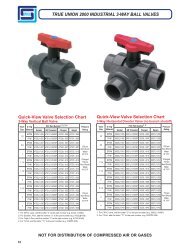
TRUE UNION 2000 INDUSTRIAL 3-WAY BALL VALVESQuick-View Valve Selection Chart3-Way Vertical Ball ValveValveSize1/23/411-1/41-1/222-1/234O-ringMaterialPVC Part Number1, 2, 3, 4PressureSocket SR Threaded Flanged SpigotEPDM 4722L1-005 4721L1-005SR 4723L1-005 4727L1-005FKM 4732L1-005 4731L1-005SR 4733L1-005 4737L1-005EPDM 4722L1-007 4721L1-007SR 4723L1-007 4727L1-007FKM 4732L1-007 4731L1-007SR 4733L1-007 4737L1-007EPDM 4722L1-010 4721L1-010SR 4723L1-010 4727L1-010FKM 4732L1-010 4731L1-010SR 4733L1-010 4737L1-010Rating235 psiNon-ShockWater@ 73°FEPDM 4722L1-012 4721L1-012SR 4723L1-012 4727L1-012(Flanged150 psiFKMEPDM4732L1-012 4731L1-012SR4722L1-015 4721L1-015SR4733L1-0124723L1-0154737L1-0124727L1-015Non-Shock)Water@ 73°FFKM 4732L1-015 4731L1-015SR 4733L1-015 4737L1-015EPDM 4722L1-020 4721L1-020SR 4723L1-020 4727L1-020FKM 4732L1-020 4731L1-020SR 4733L1-020 4737L1-020EPDM 4722L1-025 4721L1-025SR 4723L1-025 4727L1-025FKM 4732L1-025 4731L1-025SR 4733L1-025 4737L1-025EPDM 4722L1-030 4721L1-030SR 4723L1-030 4727L1-030FKM 4732L1-030 4731L1-030SR 4733L1-030 4737L1-030EPDM 4722L1-040 4721L1-040SR 4723L1-040 4727L1-040FKM 4732L1-040 4731L1-040SR 4733L1-040 4737L1-040150 psiNon-ShockWater@ 73°F1: For CPVC valve, add the letter “C” to the part number (e.g. 4722L1-005C)2: For Double L-Port, add the number “2” to the part number (e.g. 4722L2-005)3: For Triple L-Port, add the number “3” to the part number (e.g. 4722L3-005)4: For T-Port, add the letter “T1” to the part number (e.g. 4722T1-005)Quick-View Valve Selection Chart3-Way Horizontal Diverter Valve (no branch shutoff)ValveSize1/23/411-1/41-1/222-1/234O-ringMaterialPVC Part Number 1, 2Socket SR Threaded Flanged SpigotEPDM 5022L1-005 5021L1-005SR 5023L1-005 5027L1-005FKM 5032L1-005 5031L1-005SR 5033L1-005 5037L1-005EPDM 5022L1-007 5021L1-007SR 5023L1-007 5027L1-007FKM 5032L1-007 5031L1-007SR 5033L1-007 5037L1-007EPDM 5022L1-010 5021L1-010SR 5023L1-010 5027L1-010FKM 5032L1-010 5031L1-010SR 5033L1-010 5037L1-010PressureRating235 psiNon-ShockWater@ 73°FEPDM 5022L1-012 5021L1-012SR 5023L1-012 5027L1-012(Flanged150 psiFKMEPDM5032L1-0125022L1-0155031L1-012SR5021L1-015SR5033L1-0125023L1-0155037L1-0125027L1-015Non-Shock)Water@ 73°FFKM 5032L1-015 5031L1-015SR 5033L1-015 5037L1-015EPDM 5022L1-020 5021L1-020SR 5023L1-020 5027L1-020FKM 5032L1-020 5031L1-020SR 5033L1-020 5037L1-020EPDM 5022L1-025 5021L1-025SR 5023L1-025 5027L1-025FKM 5032L1-025 5031L1-025SR 5033L1-025 5037L1-025EPDM 5022L1-030 5021L1-030SR 5023L1-030 5027L1-030FKM 5032L1-030 5031L1-030SR 5033L1-030 5037L1-030EPDM 5022L1-040 5021L1-040SR 5023L1-040 5027L1-040FKM 5032L1-040 5031L1-040SR 5033L1-040 5037L1-0401: For CPVC valve, add the letter “C” to the part number (e.g. 5022L1-005C)2: For T-Port, add the letter “T1” to the part number (e.g. 5022T1-005)150 psiNon-ShockWater@ 73°FNOT FOR DISTRIBUTION OF COMPRESSED AIR OR GASES12
TRUE UNION 2000 INDUSTRIAL 3-WAY BALL VALVESFeatures – PVC, CPVCVersatile design provides multiple port and configuration options for controlling flow distribution in industrial and chemicalprocessing applications. Choose Vertical 3-Way (L-Port Diverter, T-Port Off) or Horizontal Diverter configurations with openbranch (no shutoff) design. Valves are available in IPS sizes 1/2" through 4" with socket, SR threaded (Special Reinforced),flanged or spigot end connectors. Venturied 6" (4" valves with 4 x 6 reducers) are also available with socket or flanged valveend connections.• Chemical & Corrosion Resistant PVC or CPVCConstruction• Vertical 3-Way or Horizontal Diverter Design (nobranch shutoff)• L-Port, Multi L-Port & T-Port Ball Configuration Options• Interchangeable with all True Union 2000 Valves,Mates with Union 2000 Pipe Unions• High Impact Polypropylene Handle• Built-in Handle Lockout• Strong, Buttress Thread Union Nuts• <strong>Spears</strong> ® Double O-ring Safe-T-Shear ® Stem Design• EPDM or FKM O-rings• <strong>Spears</strong> ® Safe-T-Blocked ® Seal Carrier• Self Adjusting PTFE Floating Seat Design• Fully Serviceable, Replaceable Components• Sizes 1/2" - 2" pressure rated to 235 psi @ 73°FSizes 2-1/2" - 4" and all Flanged to 150 psi @ 73°F• EPDM Valves NSF ® Certified for Potable Water use• Suitable for Vacuum Service• Assembled with Silicone-Free, Water SolubleLubricants• Manufactured to ASTM F 1970• Metric Socket and BSP Thread Available3-Way Port OptionsDiverter Valves have no shut-off on branch.Vertical 3-wayHorizontal DiverterOptional Accessories*• Retro-Fit End Connector Setsfor Valve Replacement• Split-Nut Repair Kits for UnionNut Replacement• Supplemental End Connectors• Stem Extension Kits• Square Operator Nuts• Multi Mount Valve/ActuationMounting KitsSingleL-PortDoubleL-PortTripleL-PortT-Port L-Port T-Port* See “BALL VALVE ACCESSORIES”section for details of individual products.Ball Port Options viewed from top of valve.Sample Engineering SpecificationAll thermoplastic ball valves shall be True Union 2000 3-Way [specify horizontal or vertical] type with [specify port option]manufactured to ASTM F 1970 and constructed from PVC Type I, ASTM D 1784 Cell Classification 12454, or CPVC TypeIV, ASTM D 1784 Cell Classification 23447. All O-rings shall be EPDM or FKM. All valves shall have Safe-T-Shear ®stem with double O-ring stem seals. All valve handles shall be polypropylene with built-in lockout mechanism. All valveunion nuts shall have Buttress threads. All seal carriers shall be Safe-T-Blocked ® . All valve components shall be replaceable.All EPDM valves shall be certified by NSF ® International for use in potable water service. All PVC and CPVC 1/2" through2" valves shall be pressure rated to 235 psi, all 2-1/2" through 4" and all flanged valves shall be pressure rated to 150 psi forwater at 73°F as manufactured by <strong>Spears</strong> ® <strong>Manufacturing</strong> Company.NOT FOR DISTRIBUTION OF COMPRESSED AIR OR GASES13
TRUE UNION 2000 INDUSTRIAL 3-WAY BALL VALVESReplacement PartsNo. Component Qty. Material1 End Connector 3 PVC/CPVC2 End Connector O-ring 3 EPDM/FKM3 Union Nut 3 PVC/CPVC4 Handle Lock 1 PP5 Handle 1 PP6 Stem 1 PVC/CPVC7 Screw 1 Stainless Steel8 Handle Cover 1 PP9 Stem O-ring 2 EPDM/FKM10 Stem Bearing* 1 PTFE11 Body 1 PVC/CPVC12 Ball 1 PVC/CPVC13 End Connector Collar 3 Stainless Steel14 Seat 2 PTFE15 Carrier O-ring 1 EPDM/FKM16 Seal Carrier 1 PVC/CPVCNote: Applies to both Vertical and Horizontal configurations.* For sizes 2-1/2, 3 & 4 only.NOTE: Diverter style valve has no shutoff on branch.Vertical 3-Way Ball Valves — Dimensions & Operating TorqueNominalSizeAVertical 3-Way Ball ValveB 1CFGD ESoc/SR Thd Spigot Socket SR Thd Spigot Socket SR Thread Spigot Soc/SR Thd SpigotOper. 2Torque(in. lbs.)1/2 1-7/8 2-7/16 2-15/16 4-1/4 3-27/32 4-3/4 2-9/16 2-13/16 2-3/4 2-9/16 2-13/16 1-11/16 2 123/4 2-1/4 2-3/4 3-5/16 4-3/4 4-1/4 5-3/8 2-7/8 3-5/16 3 2-3/4 3-5/16 2 2-5/16 121 2-1/2 2-7/8 3-1/2 5-1/8 4-11/16 5-3/4 3-1/8 3-7/16 3-1/4 3 3-9/16 2-1/8 2-7/16 201-1/4 3-1/16 3-1/4 3-13/16 5-3/4 5-3/16 6-5/16 3-5/8 3-13/16 3-3/4 3-3/8 4-1/16 2-3/8 2-13/16 251-1/2 3-1/2 3-1/2 4 6-1/4 5-7/16 6-3/4 4 4-3/16 4-3/16 3-13/16 4-1/2 2-3/16 3-1/8 402 4-1/4 4-3/4 5-3/16 7-3/4 6-3/4 8-1/4 4-1/2 5-1/8 5 4-1/2 5-5/16 3-1/2 3-3/4 672-1/2 5-3/8 5-7/8 7-13/16 9-5/16 8-1/2 11-3/8 5-1/8 6-1/4 5-7/8 5-1/2 6-7/16 4-1/8 5-5/16 1203 6-3/16 6-7/8 7-13/16 10-11/16 9-3/4 11-9/16 5-7/8 7-5/8 6-11/16 6-3/16 7-3/16 4-3/4 5-5/16 1204 7-1/2 7-1/4 8-1/4 11-13/16 10-1/4 12-13/16 6-3/4 9-3/16 7-1/8 6-3/4 8-3/4 5-7/8 6-1/2 3361: Valve Lay Length2: Torque required at valve maximum internal pressure rating, 5ft/sec. Flow velocity; due to adjustment differences during installation, actual values may vary.14NOT FOR DISTRIBUTION OF COMPRESSED AIR OR GASES
TRUE UNION 2000 INDUSTRIAL 3-WAY BALL VALVESNOTE: Diverter style valve has no shutoff on branchHorizontal Diverter 3-Way Ball Valves Dimensions & Operating TorqueNominalB 1CF G Oper. 2TorqueSize A Soc/SR Thread Spigot Socket SR Thread Spigot D E Socket SR Thread Spigot Soc/SR Thread Spigot (in. lbs.)1/2 1-3/16 2-7/16 2-15/16 4-3/16 3-13/16 4-3/4 2-9/16 2-13/16 2-9/16 2-3/8 2-13/16 1-11/16 2 123/4 2-1/4 2-3/4 3-15/16 4-3/4 4-1/4 5-3/8 2-7/8 3-5/16 3 2-3/4 3-5/16 2 2-5/16 121 2-1/2 2-7/8 3-1/2 5-1/8 4-11/16 5-3/4 3-1/8 3-7/16 3-1/4 3 3-9/16 2-1/8 2-7/16 201-1/4 3-1/16 3-1/4 3-13/16 5-3/4 5-3/16 6-5/16 3-5/8 3-13/16 3-3/4 3-3/8 4-1/16 2-3/8 2-13/16 251-1/2 3-1/2 3-1/2 4 6-1/4 5-7/16 6-3/4 4 4-3/16 4-3/16 3-13/16 4-1/2 2-3/16 3-1/8 402 4-1/4 4-3/4 5-3/16 7-3/4 6-3/4 8-1/4 4-1/2 5-1/8 5 4-1/2 5-5/16 3-1/2 3-3/4 672-1/2 5-3/8 5-7/8 7-13/16 9-5/16 8-1/2 11-3/8 5-1/8 6-1/4 5-7/8 5-1/2 6-7/16 4-1/8 5-5/16 1203 6-3/16 6-7/8 7-13/16 10-11/16 9-3/4 11-9/16 5-7/8 7-5/8 6-11/16 6-3/16 7-3/16 4-3/4 5-5/16 1204 7-1/2 7-1/4 8-1/4 11-13/16 10-1/4 12-13/16 6-3/4 9-3/16 7-1/8 6-3/4 8-3/4 5-7/8 6-1/2 3361: Valve Lay Length2: Torque required at valve maximum internal pressure rating, 5ft/sec. Flow velocity; due to adjustment differences during installation, actual values may vary.Temperature Pressure RatingValvePressureRatingpsi(MPa)System OperatingTemperature °F (°C)1/2" - 2"2-1/2" - 4"PVCCPVCPVCCPVC100(38)235(1.62)235(1.62)150(1.03)150(1.03)110(43)211(1.45)219(1.51)135(.93)140(.97)120(49)150(1.03)170(1.17)110(.76)130(.90)130(54)75(.52)145(1.00)75(.52)120(.83)140(60)50(.34)130(.90)50(.34)110(.76)150(66)-0-(-0-)110(.76)-0-(-0-)100(.70)160(71)-0-(-0-)90(.62)-0-(-0-)90(.62)170(77)-0-(-0-)80(.55)-0-(-0-)80(.55)180(82)-0-(-0-)70(.48)-0-(-0-)70(.48)190(88)-0-(-0-)60(.41)-0-(-0-)60(.41)200(93)-0-(-0-)50(.34)-0-(-0-)50(.34)210(99)-0-(-0-)-0-(-0-)-0-(-0-)-0-(-0-)NOTE: Flanged Valves have a base pressure rating of 150 psi.NOT FOR DISTRIBUTION OF COMPRESSED AIR OR GASES15
TRUE UNION 2000 INDUSTRIAL TEE-STYLE BALL VALVESTee x SocketFeatures – PVC, CPVC<strong>Spears</strong> ® True Union 2000 Industrial Tee-Style Ball Valve design integrates valve and Tee-fitting for direct branch take-offlaterals. <strong>The</strong> “Tee-Valve” provides a stronger, more compact connection by eliminating the need for a reducer, additionallength of pipe, and one of the end connections on the ball valve. Close proximity of valve to mainline emulates a “zero deadleg”design to minimize any areas of fluid stagnation. Custom produced to specified Tee and Valve connection sizes. Alsoavailable in metric sizes.• Chemical & Corrosion Resistant PVC, CPVC or Low ExtractablePVC materials• Multi-featured Industrial Grade• Built-in Handle Lockout• Fully Serviceable, Replaceable Components• <strong>Spears</strong> ® Dual O-ring Safe-T-Shear ® Stem• Self Adjusting PTFE Floating Seat• Sizes 1/2" - 2" Pressure Rated to 235 psi @ 73°F• EPDM Valves NSF ® Certified for Potable Water Use• Seal Carrier Adjustment Tool included• ISO Pattern Actuation Mounting OptionSample Engineering SpecificationAll lateral branch valve connections shall be made using integrated Tee-style ball valve and Tee fitting. Tee-style ball valvesshall be True Union 2000 Industrial type manufactured to ASTM F 1970 and constructed from PVC Type I, ASTM D 1784 CellClassification 12454 or CPVC Type IV, ASTM D 1784 Cell Classification 23447; or Low Extractable PVC, ASTM D 1784Cell Classification 12343. All O-rings shall be EPDM or FKM. All valves shall have Safe-T-Shear ® stem with double O-ringstem seals. All valve handles shall be polypropylene with built-in lockout. All valve union nuts shall have Buttress threads. Allseal carriers shall be Safe-T-Blocked ® . All valve components shall be replaceable. Mainline Tee fittings shall be Schedule 80manufactured in accordance with ASTM D 2467 for PVC or F 439 for CPVC. All EPDM valves shall be certified by NSF ®International for use in potable water service. All 1/2" through 2" valves shall be pressure rated to 235 psi for water at 73°F, asmanufactured by <strong>Spears</strong> ® <strong>Manufacturing</strong> Company.16
TRUE UNION 2000 INDUSTRIAL TEE-STYLE BALL VALVESQuick-View Valve Selection ChartT-Valves can be custom produced in any standard Tee and Valve size combinationSize(Tee x Valve Outlet)PVCCPVCEPDM FKM EPDM FKM1/2 182901-005 183901-005 182901-005C 183901-005C3/4 182901-007 183901-007 182901-007C 183901-007C1 182901-010 183901-010 182901-010C 183901-010C1-1/4 182901-012 183901-012 182901-012C 182901-012C1-1/2 182901-015 183901-015 182901-015C 183901-015C2 182901-020 183901-020 182901-020C 183901-020C3/4x1/2 182901-101 183901-101 182901-101C 183901-101C1x1/2 182901-130 183901-130 182901-130C 183901-130C1x3/4 182901-131 183901-131 182901-131C 183901-131C1-1/4x1/2 182901-166 183901-166 182901-166C 182901-166C1-1/4x3/4 182901-167 183901-167 182901-167C 183901-167C1-1/4x1 182901-168 183901-168 182901-168C 183901-168C1-1/2x1/2 182901-209 183901-209 182901-209C 183901-209C1-1/2x3/4 182901-210 183901-210 182901-210C 183901-210C1-1/2x1 182901-211 183901-211 182901-211C 183901-211C2x1/2 182901-247 183901-247 182901-247C 183901-247C2x3/4 182901-248 183901-248 182901-248C 183901-248C2x1 182901-249 183901-249 182901-249C 183901-249C2x1-1/2 182901-251 183901-251 182901-251C 183901-251C3x1/2 182901-333 183901-333 182901-333C 183901-333C3x1 182901-335 183901-335 182901-335C 183901-335C3x1-1/2 182901-337 183901-337 182901-337C 183901-337C3x2 182901-338 183901-338 182901-338C 183901-338C4x1 182901-417 183901-417 182901-417C 183901-417C4x1-1/2 182901-419 183901-419 182901-419C 183901-419C4x2 182901-420 183901-420 182901-420C 183901-420C6x2 182901-528 183901-528 182901-528C 183901-528C8x2 182901-578 183901-578 182901-578C 183901-578CAdditional Notes: For Low Extractable PVC valves, add the letters BL to the part number (e.g. 182901-005BL)Valve assembly includes debris plug in valve socket end (to be removed on installation) and cable-tie affixed spareend connector.17
TRUE UNION 2000 INDUSTRIAL TEE-STYLE BALL VALVES45 6 7 8 9101112Replacement PartsNo. Component Qty. Material3211 End Connector 1 PVC/CPVC2 End Connector O-ring 1 EPDM/FKM3 Seal Carrier 1 PVC/CPVC4 Union Nut 3 PVC/CPVC5 Handle Lock 1 PP6 Seat 2 PTFE7 Carrier O-ring 1 EPDM/FKM8 Stem O-ring 2 EPDM/FKM9 Handle 1 PP10 Stem 1 PVC/CPVC11 Ball 1 PVC/CPVC12 Body 1 PVC/CPVCTemperature Pressure RatingSystem OperatingTemperature °F (°C)100(38)110(43)120(49)130(54)140(60)150(66)160(71)170(77)180(82)190(88)200(93)210(99)ValvePressureRatingpsi(MPa)1/2" - 2"PVC235(1.62)CPVC 235(1.62)211(1.45)219(1.51)150(1.03)170(1.17)75(.52)145(1.00)50(.34)130(.90)-0-(-0-)110(.76)-0-(-0-)90(.62)-0-(-0-)80(.55)-0-(-0-)70(.48)-0-(-0-)60(.41)-0-(-0-)50(.34)-0-(-0-)-0-(-0-)18
TRUE UNION 2000 INDUSTRIAL TEE-STYLE BALL VALVESBCDimensions, Operating Torque & Cv ValuesNominalSizeADimensions Reference (inches, ± 1/16)Approx. Wt. (Lbs.)Oper. 1Torque(in. lbs.)Cv 2(Value only)BASocket ThreadedC PVC CPVC1/2 2-5/16 3-3/4 3-9/16 1-5/8 .48 .52 16 293/4 3-7/16 4-1/4 4 1-7/8 .70 .77 17 631 4 4-11/16 4-7/16 2-1/16 1.10 1.15 22 1201-1/4 4-1/4 5-5/16 5 2-7/16 1.64 1.73 28 2431-1/2 5-1/8 6-1/8 5-11/16 3 2.26 2.37 61 3572 5-7/8 7-5/16 6-13/16 3-7/16 3.72 3.82 77 5993/4x1/2 3-3/16 3-7/8 3-11/16 1-3/4 .51 .54 16 291x1/2 3-7/16 4 3-13/16 1-7/8 .58 .61 16 291x3/4 3-11/16 4-3/8 4-1/2 2 .78 .80 17 631-1/4x1/2 4-1/4 4 3-13/16 1-7/8 .77 .80 16 291-1/4x3/4 4-1/4 4-1/4 4 1-7/8 .90 .94 17 631-1/4x1 4-1/4 4-13/16 4-5/8 2-3/16 1.78 1.96 22 1201-1/2x1/2 4-3/8 4-1/4 4-1/16 2-1/8 .86 .89 16 291-1/2x3/4 4-1/8 4-5/8 4-3/8 2-3/16 .91 .94 16 631-1/2x1 4-1/2 5 4-13/16 2-3/8 1.37 1.51 16 1202x1/2 4-3/16 4-9/16 4-3/8 2-7/16 1.06 1.17 16 292x3/4 4-3/8 4-15/16 4-11/16 2-9/16 1.23 1.28 17 632x1 4-3/4 5-1/4 5-1/16 2-5/8 1.38 1.45 22 1202x1-1/2 5-7/8 6-1/16 5-7/8 2-15/16 2.33 2.63 61 293x1/2 5-1/2 5-1/8 4-15/16 3 1.60 1.66 16 293x1 5-1/2 5-7/8 5-11/16 3-1/4 2.19 2.25 22 1203x1-1/2 7-1/4 6-9/16 6-3/8 3-7/16 3.66 3.87 61 3573x2 6-11/16 7-11/16 7-3/16 3-13/16 4.61 4.86 77 5994x1 7-7/16 6-5/16 6-1/8 3-11/16 3.25 3.52 22 1204x1-1/2 7-3/8 7-5/16 7-1/8 4-3/16 4.01 4.37 61 3574x2 7-3/4 8-5/16 7-3/4 4-7/16 5.20 5.68 77 5996x2 10-3/16 9-5/8 9-1/8 5-3/4 9.26 11.68 77 5998x2 15-5/8 12-5/8 12-1/8 8-3/4 17.42 18.70 77 5991: Torque required at valve maximum internal pressure rating, 5ft/sec. Flow velocity; due to adjustment differences during installation, actual valves may vary.2: Gallons per minute at 1 psi pressure drop. Valves calculated from laying length, based on derivative of Hazen-Williams equation with surface roughness factor of C=150.Cv values are for basic Ball Valve only, excluding Tee end connection.19
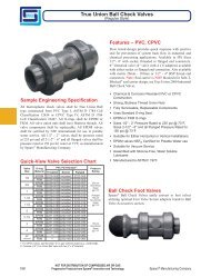
TRUE UNION 2000 INDUSTRIAL BALL CHECK VALVESFeatures – PVC, CPVCFlow tested design provides quick response with positiveseal for prevention of system back flow in industrial andchemical processing applications. Valves are availablein IPS sizes 1/2" through 6" with socket/regular thread,SR threaded (Special Reinforced), flanged or spigotend connectors and 8" venturied valve with socket orflanged ends. Also available in metric socket and BSPthread sizes 1/2" through 2".Sample Engineering SpecificationAll thermoplastic check valves shall be True Union 2000 IndustrialBall Check type manufactured to ASTM F 1970 and constructed fromPVC Type I, ASTM D 1784, Cell Classification 12454 or CPVC TypeIV, ASTM D 1784 Cell Classification 23447. All O-rings shall beEPDM or FKM. All valve union nuts shall have Buttress threads.All valve seats shall be a standard O-ring type. All seal carriers shallbe Safe-T-Blocked ® . All valve components shall be replaceable.All EPDM valves shall be listed by NSF ® for use in potable waterservice. All PVC and CPVC 1/2" through 4" valves shall be pressurerated to 235 psi, all 6" and 8" Venturied and all flanged valves shallbe pressure rated to 150 psi for water at 73°F as manufactured by<strong>Spears</strong> ® <strong>Manufacturing</strong> Company.Quick-View Valve Selection ChartValveSizeO-ringMaterial Socket ThreadedPVC Part Number 1SR Threaded Flanged Spigot1/2EPDM 4529-005 included 4521-005SR 4523-005 4527-005FKM 4539-005 included 4531-005SR 4533-005 4537-0053/4EPDM 4529-007 included 4521-007SR 4523-007 4527-007FKM 4539-007 included 4531-007SR 4533-007 4537-0071EPDM 4529-010 included 4521-010SR 4523-010 4527-010FKM 4539-010 included 4531-010SR 4533-010 4537-0101-1/4EPDM 4529-012 included 4521-012SR 4523-012 4527-012FKM 4539-012 included 4531-012SR 4533-012 4537-0121-1/2EPDM 4529-015 included 4521-015SR 4523-015 4527-015FKM 4539-015 included 4531-015SR 4533-015 4537-0152EPDM 4529-020 included 4521-020SR 4523-020 4527-020FKM 4539-020 included 4531-020SR 4533-020 4537-0202-1/2EPDM 4522-025 4521-025 4521-025SR 4523-025 4527-025FKM 4532-025 4531-025 4531-025SR 4533-025 4537-0253EPDM 4522-030 4521-030 4521-030SR 4523-030 4527-030FKM 4532-030 4531-030 4531-030SR 4533-030 4537-0304EPDM 4522-040 4521-040 4521-040SR 4523-040 4527-040FKM 4532-040 4531-040 4531-040SR 4533-040 4537-0406EPDM 4522-060 4521-060 4521-060SR 4523-060 4527-060FKM 4532-060 4531-060 4531-060SR 4533-060 4537-0608 2 EPDM 4522-080 — — 4523-080 —FKM 4532-080 — — 4533-080 —1: For CPVC valve, add the letter "C" to the part number (e.g., 4529-005C, 4521-005CSR)2: 8" Venturied Valves are 6" ball valves fitted with 6x8 end connector adaptersPressureRating235 psiNon-ShockWater@ 73°F(Flanged150 psiNon-Shock)Water@ 73°F150 psiNon-ShockWater@ 73°F• Chemical & Corrosion Resistant PVC orCPVC Construction• Also Available in <strong>Spears</strong> ® High Purity, LowExtractable PVC Material• Strong, Buttress Thread Union Nuts• <strong>Spears</strong> ® Safe-T-Blocked ® Seal Carrier• Uses Standard O-ring Seat• EPDM or FKM O-rings• Fully Serviceable, Replaceable Components• Sizes 1/2" - 4" Pressure Rated to 235 psi@ 73°F, Sizes 6" and 8" Venturied andall Flanged Pressure Rated to 150 psi @73°F• Suitable for Either Horizontal or VerticalInstallations• EPDM valves NSF ® Certified for PotableWater use• Suitable for Vacuum Service• Assembled with Silicone-Free, WaterSoluble LubricantsOptional Accessories*• Retro-Fit End Connector Setsfor Valve Replacement• Split-Nut Repair Kits for UnionNut Replacement• Supplemental End Connectors*See “BALL VALVE ACCESSORIES” section fordetails of individual products.Ball Check Foot Valves<strong>Spears</strong> ® Ball Check Valves easily convertto foot valves utilizing optional FootValve Screen adapters found in Ball ValveAccessories section.20
TRUE UNION 2000 INDUSTRIAL BALL CHECK VALVESDimensions, Weights, & Cv ValuesNominalSizeDimensions Reference (inches, ± 1/16)Temperature Pressure RatingApprox. Wt.(Lbs.)Replacement PartsNo. Component Qty. Material1 Seal Carrier 1 PVC/CPVC2 Seal Carrier Nut 1 PVC/CPVC3 Carrier O-ring 1 EPDM/FKM4 Seat Plate 1 PVC/CPVC5 Seat O-ring 1 EPDM/FKM6 Body 1 PVC/CPVC7 Ball 1 PVC/CPVC8 Union Nut 2 PVC/CPVC9 End Connector O-ring 2 EPDM/FKM10 End Connector 2 PVC/CPVCCv Values1: Valve Lay Length2: Gallons per minute at 1 psi pressure drop. Valves calculated from laying length, based on derivative of Hazen-Williams equation with surface roughness factor of C=150.3: 8" Venturied Valves are 6" ball valves fitted with 6x8 end connector adaptersHorizontalClosingAB 1CFeet ofF G PVC CPVC Soc/Thd Flange Spigot HeadSoc/Thd Spigot Socket Thread Spigot(water)1/2 1-7/8 2-7/16 2-7/8 4-3/16 3-13/16 4-5/8 3-1/2 2-31/32 .30 .33 6.3 6 6.3 1.6 .103/4 2-1/4 2-3/4 3-1/4 4-3/4 4-1/4 5-1/4 3-7/8 3-5/16 .46 .50 17 16 17 1.6 .101 2-1/2 2-7/8 3-1/2 5-1/8 4-11/16 5-3/4 4-1/4 3-5/8 .70 .74 25 24 25 1.6 .251-1/4 3-1/16 3-1/4 3-3/16 5-3/4 5-3/16 6-5/16 4-5/8 3-31/32 1.04 1.09 65 61 65 1.6 .401-1/2 3-1/2 3-1/2 4 6-1/4 5-7/16 6-3/4 5 4-3/8 1.37 1.45 86 82 86 1.6 .752 4-5/16 4-25/32 5-3/16 7-3/4 7-27/32 8-1/4 6 5-1/4 2.47 2.62 130 125 130 1.6 .752-1/2 6-3/16 5-7/8 7-13/16 9-5/16 8-1/2 11-3/8 7-1/2 6 6.80 7.25 200 193 200 1.0 1.503 6-3/16 6-7/8 7-13/16 10-11/16 9-3/4 11-9/16 7-1/2 6-13/16 6.98 7.35 275 268 275 1.0 4.004 7-3/4 7-5/16 8-1/4 11-13/16 10-1/4 12-3/4 9 7-1/2 12.13 12 .96 500 489 500 1.0 5.506 11-5/8 11-1/6 13 17-1/16 15-3/4 18-1/2 11-1/4 10-3/16 37.07 39.98 800 794 800 N/A N/A8 3 11-5/8 23-3/16 --- 31-7/8 --- --- 13-1/2 17-13/16 50.84 55.92 N/A N/A N/A N/A N/AGPM(minimum)System OperatingTemperature °F (°C)100(38)110(43)120(49)130(54)140(60)150(66)160(71)170(77)180(82)190(88)200(93)210(99)ValvePressureRatingpsi(MPa)1/2" - 4"6" and 8"PVCCPVCPVCCPVC235(1.62)235(1.62)150(1.03)150(1.03)211(1.45)219(1.51)135(.93)140(.97)150(1.03)170(1.17)110(.76)130(.90)75(.52)145(1.00)75(.52)120(.83)50(.34)130(.90)50(.34)110(.76)-0-(-0-)110(.76)-0-(-0-)100(.70)-0-(-0-)90(.62)-0-(-0-)90(.62)-0-(-0-)80(.55)-0-(-0-)80(.55)-0-(-0-)70(.48)-0-(-0-)70(.48)-0-(-0-)60(.41)-0-(-0-)60(.41)-0-(-0-)50(.34)-0-(-0-)50(.34)-0-(-0-)-0-(-0-)-0-(-0-)-0-(-0-)NOTE: Flanged valves have a base pressure rating of 150 psiGeneral Installation Information: Ball check valves may be installed in either horizontal or vertical position. A minimumof ten (10) pipe diameters distance maintained from any pump or other source of turbulence. Check valves MUST be installedwith the valves FLOW arrow pointing in the direction of flow.NOT FOR DISTRIBUTION OF COMPRESSED AIR OR GASES21
TRUE UNION 2000 STANDARD BALL VALVESSample Engineering SpecificationAll thermoplastic ball valves shall be True Union 2000Standard type manufactured to ASTM F 1970 and constructedfrom PVC Type I, ASTM D 1784 Cell Classification 12454or CPVC Type IV, ASTM D 1784 Cell Classification 23447.All O-rings shall be EPDM or FKM. All valves shall haveSafe-T-Shear ® stem with O-ring stem seal. All handles shallbe polypropylene. All union nuts shall have Buttress threads.All seal carriers shall be Safe-T-Blocked ® . All EPDM valvesshall be certified by NSF ® International for use with potablewater. All 1/2" - 2" valves shall be pressure rated to 235 psi, all2-1/2" - 4" and all flanged valves to 150 psi for water @ 73°F,as manufactured by <strong>Spears</strong> ® <strong>Manufacturing</strong> Company.Features – PVC, CPVCEconomical, low profile quarter-turn shutoff valve isexcellent for general purpose and many O.E.M applications.PVC and CPVC valves are available in IPS sizes1/2" through 4" with socket, regular thread, SR threaded(Special Reinforced), flanged or spigot end connectors.• Chemical & Corrosion Resistant PVC or CPVCConstruction• Interchangeable with all True Union 2000 Valves,Mates with Union 2000 Pipe Unions• High Impact Polypropylene Handle• Schedule 80 Full-Bore Design• Strong, Buttress Thread Union Nuts• <strong>Spears</strong> ® Single O-ring Safe-T-Shear ® Stem Design• <strong>Spears</strong> ® Safe-T-Blocked ® Seal Carrier• Replaceable PTFE/HDPE Floating Seat Design• EPDM or FKM O-rings• Sizes 1/2" - 2" pressure rated to 235 psi @ 73°F• Sizes 2-1/2" - 4" and all flanged pressure rated to150 psi @ 73°F• EPDM valves NSF ® Certified for Potable Water use• Suitable for Vacuum Service• Assembled with Silicone-Free, Water SolubleLubricants• Manufactured to ASTM F 1970Quick-View Valve Selection ChartValve O-ringPVC Part Number 1Size Material Socket Threaded SR Threaded Flanged Spigot1/2EPDM 3629-005 included 3621-005SR 3623-005 3627-005FKM 3639-005 included 3631-005SR 3633-005 3637-0053/4EPDM 3629-007 included 3621-007SR 3623-007 3627-007FKM 3639-007 included 3631-007SR 3633-007 3637-0071EPDM 3629-010 included 3621-010SR 3623-010 3627-010FKM 3639-010 included 3631-010SR 3633-010 3637-0101-1/4EPDM 3629-012 included 3621-012SR 3623-012 3627-012FKM 3639-012 included 3631-012SR 3633-012 3637-0121-1/2EPDM 3629-015 included 3621-015SR 3623-015 3627-015FKM 3639-015 included 3631-015SR 3633-015 3637-0152EPDM 3629-020 included 3621-020SR 3623-020 3627-020FKM 3639-020 included 3631-020SR 3633-020 3637-0202-1/2EPDM 3622-025 3621-025 3621-025SR 3623-025 3627-025FKM 3632-025 3631-025 3631-025SR 3633-025 3637-0253EPDM 3622-030 3621-030 3621-030SR 3623-030 3627-030FKM 3632-030 3631-030 3631-030SR 3633-030 3637-0304EPDM 3622-040 3621-040 3621-040SR 3623-040 3627-040FKM 3632-040 3631-040 3631-040SR 3633-040 3637-0401: For CPVC valve, add the letter "C" to the part number (e.g., 3629-005C, 3621-005CSR)PressureRating235 psiNon-ShockWater@ 73°F(Flanged150 psiNon-Shock)Water@ 73°F150 psiNon-ShockWater@ 73°FOptional Accessories*• Retro-Fit End ConnectorSets for Valve Replacement• Split-Nut Repair Kits forUnion Nut Replacement• Supplemental EndConnectors• Round Safety Handles• Stem Extension Kits• Square Operator Nuts• Multi Mount Valve/Actuation Mounting Kits• Mini-Mount ActuationMounting Kits* See “BALL VALVE ACCESSORIES”section for details of individual products.22NOT FOR DISTRIBUTION OF COMPRESSED AIR OR GASES
TRUE UNION 2000 STANDARD BALL VALVESReplacement PartsNo. Component Qty. Material1 Seal Carrier 1 PVC/CPVC2 Body 1 PVC/CPVC3 Carrier O-ring 1 EPDM/FKM4 Stem Bearing 1,2 1 PP5 Stem 1 PVC/CPVC6 Handle 1 PP7 Stem O-ring 1 EPDM/FKM8 Ball 1 PVC/CPVC9 Seat 2 PTFE/HDPE10 Union Nut 2 PVC/CPVC11 End Connector O-ring 2 EPDM/FKM12 End Connector 2 PVC/CPVC1: O-Ring up to 2"2: PTFE Thrust Bearing: 2-1/2", 3" & 4"Dimensions, Weights, Operating Torque & Cv ValuesNominalBAApprox. Wt.COper. 2 Cv ValuesD E F G (Lbs.) TorqueSizeSoc/Thd Spigot Socket Thread Spigot PVC CPVC (in. lbs.) Soc/Thd/Spig Flanged1/2 1-7/8 2-7/16 2-7/8 4-3/16 3-13/16 4-5/8 1-5/8 2-1/2 3-1/2 2-31/32 .33 .35 12 29 183/4 2-1/4 2-3/4 3-1/4 4-3/4 4-1/4 5-1/4 2 3 3-7/8 3-5/16 .51 .54 20 63 391 2-1/2 2-7/8 3-1/2 5-1/8 4-11/16 5-3/4 2-5/16 3-7/16 4-1/4 3-5/8 .71 .75 25 120 731-1/4 3-1/16 3-1/4 3-13/16 5-3/4 5-3/16 6-5/16 2-13/16 3-9/16 4-5/8 3-31/32 1.12 1.17 35 243 1511-1/2 3-1/2 3-1/2 4 6-1/4 5-7/16 6-3/4 3-1/16 3-7/8 5 4-3/8 1.47 1.53 45 357 2232 4-1/4 4-3/4 5-13/16 7-3/4 6-3/4 8-1/4 3-3/4 5 6 5-1/4 2.62 2.75 94 599 3952-1/2 6-3/16 7 7-13/16 10-1/2 8-1/2 11-3/8 5-7/8 7-5/8 7 6 7.42 7.70 120 856 5793 6-3/16 7 7-13/16 10-11/16 9-3/4 11-9/16 5-7/8 7-5/8 7-1/2 6-13/16 7.46 7.81 120 1416 9744 7-5/8 7-1/2 8-1/4 12-1/16 10-1/4 12-3/4 6-3/4 6-3/4 9-1/16 7-1/2 12.35 12.48 336 2865 19521: Valve Lay Length2: Torque required at valve maximum internal pressure rating, 5ft/sec. Flow velocity; due to adjustment differences during installation, actual valves may vary.3: Gallons per minute at 1 psi pressure drop. Valves calculated from laying length, based on derivative of Hazen-Williams equation with surface roughness factor of C=150.Temperature Pressure RatingSystem OperatingTemperature °F (°C)100(38)110(43)120(49)130(54)140(60)150(66)160(71)170(77)180(82)190(88)200(93)210(99)ValvePressureRatingpsi(MPa)1/2" - 2"2-1/2" - 4"PVCCPVCPVCCPVC235(1.62)235(1.62)150(1.03)150(1.03)211(1.45)219(1.51)135(.93)140(.97)150(1.03)170(1.17)110(.76)130(.90)75(.52)145(1.00)75(.52)120(.83)50(.34)130(.90)50(.34)110(.76)-0-(-0-)110(.76)-0-(-0-)100(.70)-0-(-0-)90(.62)-0-(-0-)90(.62)-0-(-0-)80(.55)-0-(-0-)80(.55)-0-(-0-)70(.48)-0-(-0-)70(.48)-0-(-0-)60(.41)-0-(-0-)60(.41)-0-(-0-)50(.34)-0-(-0-)50(.34)-0-(-0-)-0-(-0-)-0-(-0-)-0-(-0-)NOT FOR DISTRIBUTION OF COMPRESSED AIR OR GASES23
TRUE UNION BALL VALVES(REGULAR STYLE)Features – PVC, CPVCThis versatile, quarter-turn shutoff valve is well suitedfor industrial and chemical processing applications.Available in IPS Sizes 1/2"- 4" with socket, threaded orflanged end connectors. 6" Venturied valve (4" valve with4 x 6 adapter) available with either socket or flanged endconnection. Also available with metric 20mm - 110mmor 1/2" - 4" BSP threaded end connectors.Sample Engineering SpecificationAll thermoplastic ball valves shall be True Union typeconstructed from PVC Type I, ASTM D 1784 Cell Classification12454 or CPVC Type IV, ASTM D 1784 Cell Classification23447. All O-rings shall be EPDM or FKM. All valves shallhave Safe-T-Shear ® stem and double stop Polypropylenehandle. All valve union nuts shall have Buttress threads. All sealcarriers shall be Safe-T-Blocked ® . All valve components shallbe replaceable. All EPDM valves shall be certified by NSF ®International for use in potable water service. All 1/2" - 2"valves shall be pressure rated at 235 psi and all 2-1/2" - 6" andall flanged valves shall be pressure rated at 150 psi for waterat 73°F, as manufactured by <strong>Spears</strong> ® <strong>Manufacturing</strong> Company.Quick-View Valve Selection ChartValveSize1/23/411-1/41-1/222-1/2346 2venturiedO-ringMaterialPVC Part Number 1Threaded Socket FlangedEPDM 2329-005 included 2323-005FKM 2339-005 included 2333-005EPDM 2329-007 included 2323-007FKM 2339-007 included 2333-007EPDM 2329-010 included 2323-010FKM 2339-010 included 2333-010EPDM 2329-012 included 2323-012FKM 2339-012 included 2333-012EPDM 2329-015 included 2323-015FKM 2339-015 included 2333-015EPDM 2329-020 included 2323-020FKM 2339-020 included 2333-020EPDM 2321-025 2322-025 2323-025FKM 2331-025 2332-025 2333-025EPDM 2321-030 2322-030 2323-030FKM 2331-030 2332-030 2333-030EPDM 2321-040 2322-040 2323-040FKM 2331-040 2332-040 2333-040EPDM --- 2322-060 2323-060FKM --- 2332-060 2333-0601: For CPVC valves, add the letter “C” to part numbers listed (e.g., 2339-005C).2: Consists of 4" True Union Ball Valve with two 4" x 6" Adapters.• Chemical & Corrosion Resistant PVC or CPVCConstruction• Schedule 80 Full-Bore Design• Strong, Buttress Thread Union Nuts• Fully Serviceable, Replaceable Components• <strong>Spears</strong> ® Safe-T-Blocked ® Seal Carrier• Self Adjusting PTFE Floating Seat Design• EPDM or FKM O-rings• High Impact Polypropylene Handle• <strong>Spears</strong> ® Safe-T-Shear ® Stem Design• Sizes 1/2" - 2" Pressure Rated to 235 psi @ 73°F,Sizes 2-1/2" - 6" and all flanged Pressure Rated to150 psi @ 73°F• EPDM valves NSF ® Certified for Potable Water use• Suitable for Vacuum Service• Assembled with Silicone-Free, Water SolubleLubricants• Manufactured to ASTM F 1970PressureRating235 psiNon-ShockWater@ 73°F(Flanged150 psiNon-Shock)Water@ 73°F150 psiNon-ShockWater@ 73°FOptional Accessories*• Round Safety Handle• Stem Extension Kit• 2" Square / T-StyleOperator Nut* See “BALL VALVE ACCESSORIES” section for detailsof individual products.24
TRUE UNION BALL VALVES(REGULAR STYLE)11 12 E1 2 3456DReplacement PartsNo. Component Qty. Material1 Handle 1 PP2 Stem 1 PVC/CPVC3 Stem O-ring 1 EPDM/FKM4 Stem Bearing* 1 PP5 Union Nut 2 PVC/CPVCAF6 Seat** 2 PTFE7 Ball 1 PVC/CPVC8 Body 1 PVC/CPVC109 Carrier O-ring 1 EPDM/FKM10 Seal Carrier 1 PVC/CPVC9 8B711 End Connector 2 PVC/CPVC12 End Connector O-ring 2 EPDM/FKMCG* Sizes 1-1/4" and larger.** Seat O-ring (not shown) on sizes 2-1/2" and larger.Dimensions, Weights, Operating Torque & Cv ValuesDimension Reference (inches, ± 1/16) Approx. Wt. (Lbs.) Oper.NominalC 4Torque v ValuesSize A B 1 PVCCPVCC D E F GSoc/Thd Flanged Soc/Thd Flanged (in.-lb.) Soc/Thd Flanged1/2 2-9/16 3-7/16 5-3/16 2-13/32 2-23/32 3-1/2 3-15/32 1.05 1.23 .95 1.14 20 25 183/4 3-1/32 4-1/16 6-3/16 2-5/8 3-3/16 3-7/8 4 1.44 1.64 1.50 1.73 30 51 361 3-13/32 4-5/16 6-9/16 2-13/16 3-23/32 4-1/4 4-5/16 1.91 2.22 2.08 2.43 40 97 671-1/4 3-11/16 4-1/2 7-1/16 2-31/32 4-1/8 4-5/8 4-19/32 2.38 2.78 2.52 2.91 60 204 1421-1/2 4-3/8 5-5/16 8-1/32 3-9/32 4-15/32 5 5-9/32 3.63 4.00 3.82 4.26 80 285 2012 5-3/16 5-13/16 8-13/16 4-13/32 5-1/4 6 5-23/32 5.40 6.14 5.70 6.54 90 540 3812-1/2 7-7/16 8-3/8 11-7/8 4-29/32 9-7/8 7 7-3/16 12.87 14.26 13.44 15.85 300 712 5123 7-7/16 8-3/16 11-15/16 4-29/32 9-7/8 7-1/2 7-11/32 13.24 15.67 13.85 16.96 300 1294 9254 8-15/16 8-11/16 13-3/16 5-19/32 10-13/16 9-1/16 8-5/32 19.58 24.32 20.49 25.83 400 2629 18686 Socket 3 8-15/16 19-5/8 26-1/16 6-3/4 10-13/16 11-1/4 14-11/16 22.66 30.98 26.11 34.78 400 N/A N/A6 Flanged 3 11-3/16 29-3/8 N/A 6-3/4 10-13/16 11-1/4 14-11/16 N/A N/A N/A N/A 400 N/A N/A1: Valve Lay Lengths.2: Torque required at valve maximum internal pressure rating, 5 ft./sec. flow velocity.3: Consists of 4" True Union Ball Valve with two 4" x 6" Adapters.4: Gallons per minute at 1 psi pressure drop. Values calculated from valve laying length, based on derivative of Hazen-Williams equation with surface roughness factor of C=150.C v Valves for 6" venturied flange and socket valves are not available.Temperature Pressure RatingValvePressureRatingpsi(MPa)System OperatingTemperature °F (°C)1/2" - 2"2-1/2" - 6"PVCCPVCPVCCPVC100(38)235(1.62)235(1.62)150(1.03)150(1.03)110(43)211(1.45)219(1.51)135(.93)140(.97)NOTE: Flanged Valves have a base pressure rating of 150 psi.120(49)150(1.03)170(1.17)110(.76)130(.90)130(54)75(.52)145(1.00)75(.52)120(.83)140(60)50(.34)130(.90)50(.34)110(.76)150(66)160(71)170(77)180(82)190(88)200(93)210(99)-0-(-0-)110(.76)-0-(-0-)100(.70)-0-(-0-)90(.62)-0-(-0-)90(.62)-0-(-0-)80(.55)-0-(-0-)80(.55)-0-(-0-)70(.48)-0-(-0-)70(.48)-0-(-0-)60(.41)-0-(-0-)60(.41)-0-(-0-)50(.34)-0-(-0-)50(.34)-0-(-0-)-0-(-0-)-0-(-0-)-0-(-0-)NOT FOR DISTRIBUTION OF COMPRESSED AIR OR GASES25
TRUE UNION BALL CHECK VALVES(REGULAR STYLE)Features – PVC, CPVCFlow tested design provides quick response with positiveseal for prevention of system back flow in industrial andchemical processing applications. Available in IPS Sizes1/2"- 4" with socket, threaded or flanged end connectors.6" Venturied valve (4" valve with 4 x 6 adapters) availablewith either socket or flanged end connection. Also availablewith metric 20mm - 110mm or 1/2" - 4" BSP thread endconnectors. Note: Seal carrier is NOT blocked (for Safe-T-Blocked ® seal carrier design, see True Union 2000 IndustrialBall Check Valve).Sample Engineering SpecificationAll thermoplastic check valves shall be True Union Balltype constructed from PVC Type I, ASTM D 1784 CellClassification 12454 or CPVC Type IV, ASTM D 1784Cell Classification 23447. All O-rings shall be EPDM orFKM. All valve union nuts shall have Buttress threads. Allvalve components shall be replaceable. All EPDM valvesshall be certified by NSF ® International for use in potablewater service. All 1/2" - 2" valves shall be pressure ratedat 235 psi and all 2-1/2" - 6" and all flanged valves shall bepressure rated at 150 psi for water at 73°F, as manufacturedby <strong>Spears</strong> ® <strong>Manufacturing</strong> Company.Quick-View Valve Selection ChartValveSize1/23/411-1/41-1/222-1/2346 2venturiedO-ringMaterialPVC Part Number 1Threaded Socket FlangedEPDM 2229-005 included 2223-005FKM 2239-005 included 2233-005EPDM 2229-007 included 2223-007FKM 2239-007 included 2233-007EPDM 2229-010 included 2223-010FKM 2239-010 included 2233-010EPDM 2229-012 included 2223-012FKM 2239-012 included 2233-012EPDM 2229-015 included 2223-015FKM 2239-015 included 2233-015EPDM 2229-020 included 2223-020FKM 2239-020 included 2233-020EPDM 2221-025 2222-025 2223-025FKM 2231-025 2232-025 2233-025EPDM 2221-030 2222-030 2223-030FKM 2231-030 2232-030 2233-030EPDM 2221-040 2222-040 2223-040FKM 2231-040 2232-040 2233-040EPDM --- 2222-060 2223-060FKM --- 2232-060 2333-060PressureRating235 psiNon-ShockWater@ 73°F(Flanged150 psiNon-Shock)Water@ 73°F150 psiNon-ShockWater@ 73°F1: For CPVC valves, add the letter “C” to part numbers listed (e.g., 2239-005C).2: Consists of 4" True Union Ball Valve with two 4" x 6" Adapters.• Chemical & Corrosion Resistant PVC or CPVCConstruction• Strong, Buttress Thread Union Nuts• Fully Serviceable, Replaceable Components• Uses Standard O-ring Seat• EPDM or FKM O-rings• Sizes 1/2" - 2" Pressure Rated to 235 psi @ 73°F,Sizes 2-1/2" - 6" and all Flanged Pressure Rated to150 psi @ 73°F• Suitable for Either Horizontal or Vertical Installations• EPDM valves NSF ® Certified for Potable Water use• Suitable for Vacuum Service• Assembled with Silicone-Free, Water SolubleLubricants• Manufactured to ASTM F 1970Ball Check Foot Valves<strong>Spears</strong> ® Ball Check Valves easily convert to foot valvesutilizing optional Foot Valve Screen adapters found in BallValve Accessories section.26
TRUE UNION BALL CHECK VALVES(REGULAR STYLE)23 46 7 8 951Replacement PartsNo. Component Qty. MaterialABCGF1 Ball 1 PVC/CPVC2 Seal Carrier 1 PVC/CPVC3 Carrier O-ring 1 EPDM/FKM4 Seat Plate 1 PVC/CPVC5 Seat O-ring 1 EPDM/FKM6 Body 1 PVC/CPVC7 Union Nut 2 PVC/CPVC8 End Connector O-ring 2 EPDM/FKM9 End Connector 2 PVC/CPVCDimensions, Weights, C v Values & Horizontal Closing RequirementsNominalSizeDimension Reference (inches, ± 1/16) Approx. Wt. (Lbs.) Cv 3 Values Horizontal ClosingA B 1 C F G PVC CPVC1: Valve Lay Length2: Consists of 4" True Union Ball Check Valve with two 4" x 6" Adapters.3: Gallons per minute at 1 psi pressure drop.Cv Values for 6" venturied flange and socket valves are not available.Temperature Pressure RatingNOTE: Flanged Valves have a base pressure rating of 150 psi.Threaded/SocketFlangedFeet ofHead(water)1/2 2-9/16 3-5/16 5-1/8 3-1/2 3-7/16 .56 .61 11 10 1.6 .103/4 3 4 6-1/8 3-7/8 3-15/16 .91 .99 18 17 1.6 .101 3-7/16 4-1/4 6-1/2 4-1/4 4-3/8 1.20 1.30 32 30 1.6 .251-1/4 3-11/16 4-1/2 7 4-5/8 4-9/16 1.50 1.60 58 55 1.6 .401-1/2 4-3/8 5-5/16 8-1/16 5 5-1/4 2.50 2.70 94 89 1.6 .752 5-1/8 5-3/4 8-3/4 6 5-5/8 3.70 4.00 153 146 1.6 .752-1/2 7-3/8 8-5/16 11-7/8 7 7-1/4 11.10 12.21 159 155 1.0 1.503 7-3/8 8-1/8 11-7/8 7-1/2 7-1/2 10.84 11.91 378 361 1.0 4.004 8-15/16 8-1/4 12-15/16 9-1/16 8-1/8 17.60 19.36 551 537 1.0 5.506 Socket 2 8-15/16 19-5/8 26-1/16 N/A N/A 22.45 27.61 N/A N/A N/A N/A6 Flanged 2 11-3/16 29-3/8 N/A 11-1/4 14-3/4 31.21 37.07 N/A N/A N/A N/AValvePressureRatingpsi(MPa)System OperatingTemperature °F (°C)1/2" - 2"2-1/2" - 6"PVCCPVCPVCCPVC100(38)235(1.62)235(1.62)150(1.03)150(1.03)110(43)211(1.45)219(1.51)135(.93)140(.97)120(49)150(1.03)170(1.17)110(.76)130(.90)130(54)75(.52)145(1.00)75(.52)120(.83)General Installation Information: Ball check valves may be installed in either horizontal or vertical position. A minimumof ten (10) pipe diameters distance maintained from any pump or other source of turbulence. Ball Check valves MUST beinstalled with the valves FLOW arrow pointing in the direction of flow.140(60)50(.34)130(.90)50(.34)110(.76)150(66)160(71)170(77)180(82)190(88)200(93)210(99)GPM (minimum)-0-(-0-)110(.76)-0-(-0-)100(.70)-0-(-0-)90(.62)-0-(-0-)90(.62)-0-(-0-)80(.55)-0-(-0-)80(.55)-0-(-0-)70(.48)-0-(-0-)70(.48)-0-(-0-)60(.41)-0-(-0-)60(.41)-0-(-0-)50(.34)-0-(-0-)50(.34)-0-(-0-)-0-(-0-)-0-(-0-)-0-(-0-)NOT FOR DISTRIBUTION OF COMPRESSED AIR OR GASES27
COMPACT 2000 BALL VALVESFeatures – PVC, CPVCEconomical, low profile quarter-turn shutoff valve isexcellent for general purpose and many O.E.M applications.PVC and CPVC valves are available in IPS sizes1/2" through 2" with socket and regular thread.Sample Engineering SpecificationAll thermoplastic ball valves shall be 2000 Compact sealedunit type manufactured to ASTM F 1970 and constructed fromPVC Type I, ASTM D 1784 Cell Classification 12454 or CPVCType IV, ASTM D 1784 Cell Classification 23447. All O-ringsshall be EPDM or FKM. All valves shall have Safe-T-Shear ®stem with O-ring stem seal. All handles shall be polypropylene.All EPDM valves shall be certified by NSF ® International foruse with potable water. All 1/2" - 2" valves shall be pressurerated to 235 psi, for water @ 73°F, as manufactured by <strong>Spears</strong> ®<strong>Manufacturing</strong> Company.• Industrial Grade, Maintenance-Free Sealed Unit• New Actuator-Ready Body – Accepts <strong>Spears</strong> ®Improved Mini-Mount Actuator Mounting Kits• New Double O-ring Stem Seal• <strong>Spears</strong> ® Safe-T-Shear Stem• PTFE Self Adjusting Floating Seats• EPDM or FKM O-ring Seals• Full 235 psi Pressure Rating @ 73°F• EPDM valves NSF ® Certified for Use with PotableWater• Suitable for Vacuum Service• Produced in ASTM IPS sizes 1/2" - 2" with Socketor Threaded End Connectors.Optional Accessories*• Round Safety Handles• Stem Extension Kits• Square Operator Nuts• Multi Mount Valve/Actuation Mounting Kits• Mini-Mount Actuation Mounting Kits* See “BALL VALVE ACCESSORIES” section for details of individual products.Quick-View Valve Selection ChartValveSize1/23/411-1/41-1/22O-ringMaterialPVC Part Number 1SocketThreadedEPDM 6622-005 6621-005FKM 6632-005 6631-005EPDM 6622-007 6621-007FKM 6632-007 6631-007EPDM 6622-010 6621-010FKM 6632-010 6631-010EPDM 6622-012 6621-012FKM 6632-012 6631-012EPDM 6622-015 6621-015FKM 6632-015 6631-015EPDM 6622-020 6621-020FKM 6632-020 6631-0201: For CPVC Valves, add the letter "C" to part numbers listed. (e.g., 6622-005C)PressureRating235 psiNon-ShockWater@73°F28NOT FOR DISTRIBUTION OF COMPRESSED AIR OR GASES
COMPACT 2000 BALL VALVESEDABCDimensions, Weights, Operating Torque & Cv ValuesNominalSizeADimension Reference (inches, ± 1/16)Approx. Wt. (Lbs.) Oper. 2B 1 TorqueC D E(in.-lb.)Socket Threaded PVC CPVCCv 3Values1/2 1-7/16 1-1/4 1-5/8 3-1/16 1-5/8 1-5/8 .18 .20 10 423/4 1-13/16 1-1/2 2-1/16 3-9/16 2 2 .29 .31 20 871 2-1/16 1-3/4 2-3/16 4 2-5/16 2-5/16 .44 .46 25 1571-1/4 2-5/8 2-1/6 2-3/4 4-5/8 2-13/16 2-13/16 .68 .70 30 3111-1/2 3 2-1/2 3-3/8 5-5/16 3-1/16 3-1/16 .99 1.03 50 4292 3-5/8 3 4 6 3-3/4 3-3/4 1.64 1.70 90 7681: Valve Lay Length2: Torque required at valve maximum internal pressure rating, 5ft/sec. Flow velocity.3: Gallons per minute at 1 psi pressure drop. Valves calculated from laying length, based on derivative of Hazen-Williams equation with surface roughness factor of C=150.Temperature Pressure RatingSystem OperatingTemperature °F (°C)100(38)110(43)120(49)130(54)140(60)150(66)160(71)170(77)180(82)190(88)200(93)210(99)ValvePressureRatingpsi(MPa)1/2" - 2"PVCCPVC235(1.62)235(1.62)211(1.45)219(1.51)150(1.03)170(1.17)75(.52)145(1.00)50(.34)130(.90)-0-(-0-)110(.76)-0-(-0-)90(.62)-0-(-0-)80(.55)-0-(-0-)70(.48)-0-(-0-)60(.41)-0-(-0-)50(.34)-0-(-0-)-0-(-0-)NOT FOR DISTRIBUTION OF COMPRESSED AIR OR GASES29
COMPACT BALL VALVESSample Engineering SpecificationAll thermoplastic ball valves shall be Compact sealed unittype constructed from PVC Type I, ASTM D 1784 CellClassification 12454 or CPVC Type IV, Cell Classification23447. All O-rings shall be EPDM or FKM. All valves shallhave Safe-T-Shear ® stem and Polypropylene handle. AllEPDM valves shall be certified by NSF ® International for usein potable water service. All 1/2" - 2" valves shall be pressurerated at 235 psi, all 3" - 6" and all flanged valves shall bepressure rated at 150 psi for water at 73°F, as manufactured by<strong>Spears</strong> ® <strong>Manufacturing</strong> Company.Features – PVC, CPVCThis industrial grade, quarter turn shutoff valve is popularwhere maintenance-free installations are desired for a varietyof chemical processing, industrial and OEM applications.IPS Sizes 1/2" - 4" available with socket, threaded or flangedend connectors, 6" size available with socket or flanged endconnectors. 6" valve uses high-efficiency lever style handlefor easier operation.• Chemical & Corrosion Resistant PVC or CPVCConstruction• Maintenance-Free Sealed Unit• Schedule 80 Full-Bore Design• High Impact Polypropylene Handle• <strong>Spears</strong> ® Single O-ring Safe-T-Shear ® Stem Design• EPDM or FKM O-rings• Self Adjusting PTFE Floating Seat Design• Sizes 1/2" - 2" Pressure Rated to 235 psi @ 73°F,Sizes 3" - 6" and all Flanged Pressure Rated to 150psi @ 73°F• EPDM valves NSF ® Certified for Potable Water use• Suitable for Vacuum Service• Assembled with Silicone-Free, Water Soluble Lubricant• Manufactured to ASTM F 1970Note: Valve size 6" uses Lever Handle (not shown)Quick-View Valve Selection ChartValve O-ringPVC Part Numbers 1Size Material Socket Threaded Flanged1/2EPDM 2122-005 2121-005 2123-005FKM 2132-005 2131-005 2133-0053/4EPDM 2122-007 2121-007 2123-007FKM 2132-007 2131-007 2133-0071EPDM 2122-010 2121-010 2123-010FKM 2132-010 2131-010 2133-0101-1/4EPDM 2122-012 2121-012 2123-012FKM 2132-012 2131-012 2133-0121-1/2EPDM 2122-015 2121-015 2123-015FKM 2132-015 2131-015 2133-0152EPDM 2122-020 2121-020 2123-020FKM 2132-020 2131-020 2133-0203EPDM 2122-030 2121-030 2123-030FKM 2132-030 2131-030 2133-0304EPDM 2122-040 2121-040 2123-040FKM 2132-040 2131-040 2133-0406EPDM 2122-060 --- 2123-060FKM 2132-060 --- 2133-0601: For CPVC valves, add the letter "C" to the part numbers listed (e.g., 2131-005C).PressureRating235 psiNon-ShockWater@ 73°F(Flanged150 psiNon-Shock)Water@ 73°F150 psiNon-ShockWater@ 73°FOptional Accessories*• Round Safety Handle• Stem Extension Kit• Mini-Mount Actuation Mounting Kit• 2" Square/T-Style Operator Nut*See “BALL VALVE ACCESSORIES” sectionfor details of individual products.30
COMPACT BALL VALVESEDAFBGCDimensions, Weights, Operating Torque & C v ValuesNominalSizeDimension Reference (inches, ± 1/16)Approx. Wt.(Lbs.)Oper. 2Torque(in.-lb.)Cv 3 ValuesB 1AC D E 4 F GSocket Threaded PVC CPVC Soc/Thd Flanged1/2 1-11/16 1-5/8 1-7/8 3-3/8 2-5/16 2-3/4 3-1/2 2-17/32 .31 .32 20 36 203/4 2-1/8 1-15/16 2-7/16 4-1/16 2-11/16 3-1/4 3-7/8 2-27/32 .49 .52 30 74 421 2-7/16 2-1/16 2-3/8 4-7/16 2-7/8 3-3/4 4-1/4 3-1/16 .64 .69 40 141 801-1/4 2-13/16 2-3/8 3 4-15/16 3-5/16 4-1/8 4-5/8 3-13/32 .93 .98 60 284 1631-1/2 3-1/4 2-13/16 3-1/2 5-5/8 3-11/16 4-1/2 5 4 1.39 1.45 80 402 2292 4-1/16 3-3/8 4-7/16 6-1/2 4-3/8 5-1/4 5-7/8 4-13/32 2.33 2.45 90 706 4293 5-5/16 4-9/16 5-1/2 8-5/16 5-1/2 7-21/32 7-1/2 5-7/16 4.49 5.02 300 1660 10794 7-3/8 6-3/16 7-3/16 10-5/32 6-5/8 10-27/32 9-1/16 6-7/8 9.50 10.24 400 3104 20286 4 10-3/16 8 10-3/4 14-1/8 8-1/16 14-5/16 11-1/4 8-21/32 21.48 23.41 900 7942 52681: Valve Lay Length2: Torque required at valve maximum internal pressure rating, 5 ft./sec. flow velocity.3: Gallons per minutes at 1 psi pressure loss. Values calculated from valve laying length, based on derivative of Hazen-Williams equation with surface roughness factor of C =150.4: 6" valve has lever handle, dimension is from valve centerline (not illustrated)Temperature Pressure RatingSystem OperatingTemperature °F (°C)100(38)110(43)120(49)130(54)140(60)150(66)160(71)170(77)180(82)190(88)200(93)210(99)ValvePressureRatingpsi (MPa)1/2" - 2"3" - 6"PVCCPVCPVCCPVC235(1.62)235(1.62)150(1.03)150(1.03)211(1.45)219(1.51)135(.93)140(.97)150(1.03)170(1.17)110(.76)130(.90)75(.52)145(1.00)75(.52)120(.83)50(.34)130(.90)50(.34)110(.76)-0-(-0-)110(.76)-0-(-0-)100(.70)-0-(-0-)90(.62)-0-(-0-)90(.62)-0-(-0-)80(.55)-0-(-0-)80(.55)-0-(-0-)70(.48)-0-(-0-)70(.48)-0-(-0-)60(.41)-0-(-0-)60(.41)-0-(-0-)50(.34)-0-(-0-)50(.34)-0-(-0-)-0-(-0-)-0-(-0-)-0-(-0-)NOT FOR DISTRIBUTION OF COMPRESSED AIR OR GASES31
SINGLE ENTRY BALL VALVESSample Engineering SpecificationAll thermoplastic ball valves shall be Single Entry type constructedfrom PVC Type I, ASTM D 1784 Cell Classification12454. All O-rings shall be Buna-N, EPDM or FKM. Allvalves shall have Safe-T-Shear ® stem and double stopPolypropylene handle. All valve union nuts shall haveButtress threads. All valve components shall be replaceable.All EPDM valves shall be certified by NSF ® Internationalfor use in potable water service. All 1/2" - 2" valves shallbe pressure rated at 235 psi and all 3" - 4" valves shall bepressure rated at 150 psi for water at 73°F, as manufacturedby <strong>Spears</strong> ® <strong>Manufacturing</strong> Company.Quick-View Valve Selection ChartValveSize1/23/411-1/41-1/2234O-ringPVC Gray Part Numbers 1Material Socket ThreadedBuna-N 2412-005G 2411-005GEPDM 2422-005G 2421-005GFKM 2432-005G 2431-005GBuna-N 2412-007G 2411-007GEPDM 2422-007G 2421-007GFKM 2432-007G 2431-007GBuna-N 2412-010G 2411-010GEPDM 2422-010G 2421-010GFKM 2432-010G 2431-010GBuna-N 2412-012G 2411-012GEPDM 2422-012G 2421-012GFKM 2432-012G 2431-012GBuna-N 2412-015G 2411-015GEPDM 2422-015G 2421-015GFKM 2432-015G 2431-015GBuna-N 2412-020G 2411-020GEPDM 2422-020G 2421-020GFKM 2432-020G 2431-020GBuna-N 2412-030G 2411-030GEPDM 2422-030G 2421-030GFKM 2432-030G 2431-030GBuna-N 2412-040G 2411-040GEPDM 2422-040G 2421-040GFKM 2432-040G 2431-040G1: For PVC White valves, replace the letter “G” with the letter “W” at the end of the partnumber listed (e.g., 2421-005W).Features – PVC Gray & PVC WhiteThis quarter-turn shutoff valve is widely chosen for industrialand chemical processing, turf and irrigation, plus pool andspa applications. Available in PVC Gray or PVC White, IPSSizes 1/2"- 4" with socket or threaded end connectors. Note:Seal carrier is NOT blocked (see True Union 2000 Valves).• Chemical & Corrosion Resistant PVC Gray or PVCWhite Construction• Schedule 80 Full-Bore Design• Strong, Buttress Thread Union Nut• High Impact Polypropylene Handle• <strong>Spears</strong> ® Single O-ring Safe-T-Shear ® Stem Design• Buna-N, EPDM or FKM O-rings• Self Adjusting PTFE Floating Seat Design• Fully Serviceable, Replaceable Components• Sizes 1/2" - 2" Pressure Rated to 235 psi @ 73°F,Sizes 3" - 4" Pressure Rated to 150 psi @ 73°F• Valves with EPDM O-rings NSF ® Certified for PotableWater use• Suitable for Vacuum Service• Assembled with Silicone-Free, Water Soluble Lubricant• Manufactured to ASTM F 1970PressureRating235 psiNon-ShockWater@ 73°F150 psiNon-ShockWater@ 73°FOptional Accessories*• Round Safety Handle• Stem Extension Kit• 2" Square / T-Style Operator Nut*See “BALL VALVE ACCESSORIES” sectionfor details of individual products.32
SINGLE ENTRY BALL VALVESE1 2Replacement PartsA453DNo. Component Qty. Material1 Handle 1 PP2 Stem 1 PVC3 Stem O-ring 1 Buna-N/EPDM/FKM4 Union Nut 1 PVC5 Seat 2 PTFE6 Ball 1 PVC7 Body 1 PVC8 Carrier O-ring 1 Buna-N/EPDM/FKM9 End Connector 1 PVCSeat O-rings (not shown) on sizes 3" and larger.9876BCDimensions, Weights, Operating Torque & C v ValuesNominalSizeDimension Reference (inches, ± 1/16)Approx. Wt.(Lbs.)Oper. 2 Torque(in.-lb.)Cv 3ValuesC D EAB 1Socket Threaded1/2 1-15/16 1-1/4 1-5/8 3-1/16 1-5/8 2-1/2 .22 20 383/4 2-3/8 1-7/16 2-1/8 3-9/16 2 3 .36 30 761 2-5/8 1-5/8 2-1/8 3-7/8 2-5/16 3-15/16 .50 40 1461-1/4 3-1/8 1-15/16 2-1/4 4-1/8 2-13/16 3-1/2 .75 60 2921-1/2 3-9/16 2-3/8 2-3/4 4-5/8 3-1/16 3-7/8 1.00 80 4122 4-5/16 3-1/16 3-5/8 5-1/2 3-3/4 5 2.00 90 7203 6-3/16 4-3/8 5-3/8 8-1/8 5-1/2 7-5/8 7.00 300 16604 7-3/4 5-11/16 6-7/8 9-3/4 6-1/8 9-1/16 12.00 400 31041: Valve Lay Length2: Torque required at valve maximum internal pressure rating, 5 ft./sec. flow velocity; due to adjustment differences during installation, actual values may vary.3: Gallons per minute at 1 psi pressure drop. Values calculated from valve laying length, based on derivative of Hazen-Williams equation with surface roughness factor of C=150.Temperature Pressure RatingSystem Operating Temperature °F (°C)73(23)100(38)110(43)120(49)130(54)140(60)150(66)ValvePressure Ratingpsi (MPa)1/2" - 2" PVC3" - 4" PVC235(1.62)150(1.03)146(1.01)93(.64)118(.81)75(.52)94(.65)60(.41)71(.49)45(.31)52(.36)33(.23)-0-(-0-)-0-(-0-)NOT FOR DISTRIBUTION OF COMPRESSED AIR OR GASES33
UTILITY BALL VALVESPVCCPVCSample Engineering SpecificationAll thermoplastic ball valves shall be Utility sealed unittype constructed from PVC Type I, ASTM D 1784 CellClassification 12454 or CPVC Type IV, ASTM D 1784 CellClassification 23447. All O-rings shall be EPDM. All valvesshall have Safe-T-Shear ® stem and Polypropylene handle.All valves shall be certified by NSF ® International for usein potable water service. All valves shall be pressure ratedat 150 psi for water at 73°F, as manufactured by <strong>Spears</strong> ®<strong>Manufacturing</strong> Company.Features - PVC White, PVC Gray &CPVCA high quality, economical quarter-turn shutoff valvedesigned for irrigation, pool and spa, and general purposeapplications. IPS sizes 1/2" - 2" available in PVC White,PVC Gray or CPVC with socket or threaded end connectors.Sizes 3" - 4" available in PVC White with socket orthreaded end connectors. 6" size available in PVC Whitewith socket end connectors and high-efficiency lever stylehandle for easier operation.• Chemical & Corrosion Resistant PVC or CPVCConstruction• Economical Sealed Unit• Schedule 80 Full-Bore Design• High Impact Polypropylene Handle• <strong>Spears</strong> ® Single O-ring Safe-T-Shear ® Stem Design• EPDM O-rings• PTFE/HDPE Floating Seat Design• Sizes 1/2" - 6" Pressure Rated to 150 psi @ 73°F• NSF ® Certified for Potable Water use• Assembled with Silicone-Free, Water SolublelubricantNote: Valve sizes 2-1/2", 3", 4" and 6" are not available in CPVC.Refer to Compact Ball ValveValve size 6" uses Lever Handle (not shown)Quick-View Valve Selection ChartValveSizeO-ringMaterialPVC Part Number 1, 2SocketThreaded1/2 EPDM 2622-005 2621-0053/4 EPDM 2622-007 2621-0071 EPDM 2622-010 2621-0101-1/4 EPDM 2622-012 2621-0121-1/2 EPDM 2622-015 2621-0152 EPDM 2622-020 2621-0202-1/2 EPDM 2622-025 2621-0253 EPDM 2622-030 2621-0304 EPDM 2622-040 2621-0406 EPDM 2622-060 ---PressureRating150 psiNon-ShockWater@ 73°F1: For CPVC valves, add the letter “C” to part numbers listed (e.g., 2621-005C).2: For PVC Gray, add the letter “G” to part numbers listed (e.g. 2621-005G).34
UTILITY BALL VALVESDimensions, Weights & Cv ValuesDimension Reference (inches, ± 1/16)Approx. Wt. (Lbs.)Nominal SizeASocketB 1 C D E 3 PVC CPVCThreadedC v2 Values1/2 1-7/16 1-1/4 1-1/4 2-11/16 1-11/16 2-3/4 .16 .17 463/4 1-25/32 1-7/16 1-7/16 2-31/32 1-29/32 3-7/32 .25 .27 911 2-1/32 1-5/8 1-5/8 3-3/8 2-7/16 3-1/2 .34 .36 1601-1/4 2-9/16 1-31/32 1-31/32 3-7/8 2-13/16 3-3/4 .57 .60 3061-1/2 2-15/16 2-1/2 2-3/4 4-11/16 2-15/16 4-1/4 .88 .90 4292 3-9/16 2-27/32 3-3/16 5-5/32 3-13/16 4-31/32 1.34 1.34 7552-1/2 4-5/16 3-17/32 4-7/16 7-1/32 4-5/32 5-9/16 2.31 N/A 11263 5-5/16 4-5/32 5-1/8 7-15/16 5-9/16 7-21/32 4.78 N/A 16604 6-11/16 5-1/8 6-7/32 9-3/16 6-6/32 10-27/32 8.00 N/A 31296 3 10-3/16 8-3/32 --- 14-3/16 8-5/32 14-3/32 23.24 N/A 79421: Valve Lay Length2: Gallons per minute at 1 psi pressure drop. Values calculated from valve laying length, based on derivative of Hazen-Williams equation with surface roughness factor of C=150.3: 6" valve has lever handle, dimension is from valve stem centerline (not illustrated)Temperature Pressure RatingSystem OperatingTemperature °F (°C)73(23)100(38)110(43)120(49)130(54)140(60)150(66)160(71)170(77)180(82)190(88)Valve PressureRatingpsi (MPa)PVCCPVC150(1.03)150(1.03)93(.64)123(.85)75(.52)110(.76)60(.41)98(.68)45(.31)86(.58)33(.23)75(.52)-0-(-0-)68(.47)-0-(-0-)60(.41)-0-(-0-)48(.33)-0-(-0-)38(.26)-0-(-0-)-0-(-0-)NOT FOR DISTRIBUTION OF COMPRESSED AIR OR GASES35
CWV BALL VALVESFeatures - PVC WhiteA high quality, economical quarter-turn shutoff valvedesigned for irrigation, pool and spa, and generalpurpose applications. IPS sizes 1/2" - 2" available inPVC White.• Chemical & Corrosion Resistant PVC Construction• Economical Sealed Unit• High Impact Polypropylene Handle• <strong>Spears</strong> ® Single O-ring Safe-T-Shear ® Stem Design• EPDM O-rings• Sizes 1/2" - 2" Pressure Rated to 125 psi @ 73°F• NSF ® Certified for Potable Water use• Assembled with Silicone-Free, Water SolublelubricantSample Engineering SpecificationAll thermoplastic ball valves shall be CWV sealed unittype constructed from PVC Type I, ASTM D 1784 CellClassification 12454. All O-rings shall be EPDM. All valvesshall have Safe-T-Shear ® stem and Polypropylene handle.All valves shall be certified by NSF ® International for usein potable water service. All valves shall be pressure ratedat 125 psi for water at 73°F, as manufactured by <strong>Spears</strong> ®<strong>Manufacturing</strong> Company.Quick-View Valve Selection ChartValveSizeO-ringMaterialPVC Part NumberSocketThreaded1/2 EPDM 8722-005 8721-0053/4 EPDM 8722-007 8721-0071 EPDM 8722-010 8721-0101-1/4 EPDM 8722-012 8721-0121-1/2 EPDM 8722-015 8721-0152 EPDM 8722-020 8721-020PressureRating125 psiNon-ShockWater@ 73°F36
CWV BALL VALVEEDABCDimensionsSizeASocketBThreadedC D E1/2 1-5/16 1-7/32 1-7/32 2-5/8 1-9/16 2-5/83/4 1-5/8 1-15/32 1-7/16 2-15/16 1-15/16 2-7/81 1-7/8 1-5/8 1-5/8 3-7/16 2-1/4 3-3/81-1/4 2-3/8 2 2 3-7/8 2-3/4 3-7/81-1/2 2-3/4 2-7/16 2-3/4 4-5/8 3-1/8 4-1/22 3-11/32 2-25/32 2-25/32 5-1/8 3-23/32 4-31/32Temperature Pressure RatingSystem OperatingTemperature °F (°C)73(23)100(38)110(43)120(49)130(54)140(60)150(66)160(71)170(77)180(82)190(88)Valve PressureRatingpsi (MPa)PVC150(1.03)93(.64)75(.52)60(.41)45(.31)33(.23)-0-(-0-)-0-(-0-)-0-(-0-)-0-(-0-)-0-(-0-)37
CTS 1/4-TURN ANGLE SUPPLY STOPFeatures – CPVCUsed at plumbing fixtures to terminate and control hotand cold water, this all-plastic quarter-turn shutoff valveis specially designed for use with CTS (Copper TubeSize) CPVC Hot & Cold Water Distribution Systems.Available in 1/2" CTS Socket or <strong>Spears</strong> ® patented SpecialReinforced (SR) 1/2" FIPT female thread inlet x1/2" straight male thread outlet for connection to conventional1/2" FPT faucet or toilet supply lines withcaptive seals.Sample Engineering SpecificationAll thermoplastic Angle Supply Stops shall be Copper Tube Size(CTS) sealed unit type constructed from CPVC Type IV, ASTMD 1784 Cell Classification 23447. All O-rings shall be EPDM.All valves shall have Polypropylene handle. All Angle SupplyStops shall be pressure rated at 100 psi for water at 180°F, asmanufactured by <strong>Spears</strong> ® <strong>Manufacturing</strong> Company.Dimensions• Easy 1/4-Turn Shutoff• All Plastic Corrosion Proof Construction• CTS CPVC Tan Body with Tan Colored High ImpactPolypropylene Handle• High Quality EPDM Seals• NSF® Certified to ASTM F 1970 for use in ASTM D2846 Hot & Cold Water Distribution Systems rated to100 psi @ 180°FDDEAEA1/4-Turn Angle Supply StopSocket x NPTCNominalSizeA B C D E1/2 27/32 7/16 2-13/32 1 1-3/41/2 x 3/8 7/8 7/16 2-3/8 7/8 1-3/4B1/4-Turn Angle Supply StopSR Fipt x NPTCNominalSizeA B C D E1/2 1 15/32 2-21/32 1 1-3/41/2 x 3/8 1-1/32 15/32 2-5/8 31/32 1-3/4BQuick-View Valve Selection ChartValveSizeO-ringMaterialSocketPart NumberSR Threaded1/2 EPDM 7722-005 7721-005SR1/2 x 3/8 EPDM 7722-073 7721-073SRPressureRating100 psi Non-ShockWater @ 180°F100 psi Non-ShockWater @ 180°F38
CTS BALL VALVESSample Engineering SpecificationAll thermoplastic ball valves shall be Copper TubeSize (CTS) sealed unit type constructed from CPVCType IV, ASTM D 1784 Cell Classification 23447. AllO-rings shall be EPDM. All valves shall have double stopPolypropylene handle. All valves shall be certified byNSF ® International for use in potable water service. Allvalves shall be pressure rated at 100 psi for water at 180°F,as manufactured by <strong>Spears</strong> ® <strong>Manufacturing</strong> Company.Features – CPVCA high quality, quarter-turn shutoff valve designed for linestopuse in Copper Tube Size (CTS) CPVC hot and cold waterdistribution systems as specified in ASTM D 2846. Approvedby national, state and most municipal building codes for use inresidential and commercial structures, as well as recreationalvehicles, modular homes and mobile home applications.Check local codes for acceptability and restrictions. Availablein CTS sizes 1/2" - 2" with socket end connectors.• Chemical & Corrosion Resistant CPVC Construction• Maintenance-Free Sealed Unit• High Impact Polypropylene Handle• <strong>Spears</strong> ® Single O-ring Safe-T-Shear ® Stem Design• EPDM O-rings• PTFE/HDPE Floating Seat Design• Suitable for Commercial Hot Water Systems• Sizes 1/2" - 2" Pressure Rated to 100 psi @ 180°F• NSF ® Certified for Potable Water use• Assembled with Silicone-Free, Water Soluble Lubricant• Manufactured to ASTM F 1970Quick-View Valve Selection ChartEValveSizeO-ringMaterialPart NumberSocketPressureRating1/2 EPDM 1922-0053/4 EPDM 1922-0071 EPDM 1922-0101-1/4 EPDM 1922-0121-1/2 EPDM 1922-0152 EPDM 1922-020100 psiNon-ShockWater@ 180°FADDimensions, Weights & Cv ValuesBCNominal SizeDimension Reference (inches, ± 1/16)Approx. Wt.A B 1 C D E(Lbs.)C 2 v Values1/2 1-7/32 1-1/16 2-3/32 1-11/32 2 .09 373/4 1-9/16 1-11/32 2-25/32 1-3/4 2-23/32 .16 841 1-7/8 1-9/16 3-3/8 2-3/8 3-1/2 .27 1511-1/4 2-13/32 1-15/16 4-3/16 2-25/32 3-3/4 .47 2291-1/2 2-27/32 2-3/8 5-1/32 3-5/32 4-9/32 1.05 3302 3-17/32 2-3/4 6-3/16 3-27/32 5 1.38 5981: Valve Lay Length2: Gallons per minute at 1 psi pressure drop. Values calculated from valve laying length, based on derivative of Hazen-Williams equation with roughness factor of C=150.39
BALL VALVE ACCESSORIESTrue Union 2000 Retrofit KitsEasily converts any system over to all True Union 2000 stylevalves for consistent valve type and uniform maintenance.Special extended socket style End Connectors (2) allowretrofit replacement of older <strong>Spears</strong> ® and other brand valvesin existing piping systems with a new True Union 2000 valve.Simply cut out old valve according to specified dimension andinstall retrofit end connectors. End connectors are providedwith either EPDM or FKM O-rings.OVERALLLENGHTLBall Valve forReplacementPipe LayingLength AfterCuttingTrue Union 2000Ball Valve Installedwith Retrofit KitTrue Union Retrofit Kits -Other Brand Valves (Socket Style Only)KitEPDMFKMSize PVC CPVC PVC CPVC1/2 RFK2-005 RFK2-005C RFK3-005 RFK3-005C3/4 RFK2-007 RFK2-007C RFK3-007 RFK3-007C1 RFK2-010 RFK2-010C RFK3-010 RFK3-010C1-1/4 RFK2-012 RFK2-012C RFK3-012 RFK3-012C1-1/2 RFK2-015 RFK2-015C RFK3-015 RFK3-015C2 RFK2-020 RFK2-020C RFK3-020 RFK3-020C2-1/2 RFK2-025 RFK2-025C RFK3-025 RFK3-025C3 RFK2-030 RFK2-030C RFK3-030 RFK3-030C4 RFK2-040 RFK2-040C RFK3-040 RFK3-040CCut-Out DimensionsSize 1/2 3/4 1 1-1/4 1-1/2 2 2-1/2 3 4L 4-29/32 5-7/16 6-3/32 7-1/4 7-1/2 8-17/32 10-3/4 11-7/16 14-15/16OVERALLLENGTHLBall Valve forReplacementPipe LayingLength AfterCuttingTrue UnionBall Valve Installedwith Retrofit KitTrue Union Retrofit Kits - Older(Regular Style) <strong>Spears</strong> ® Valves(Socket Style Only)KitEPDMFKMSize PVC CPVC PVC CPVC1/2 RFKS2-005 RFKS2-005C RFKS3-005 RFKS3-005C3/4 RFKS2-007 RFKS2-007C RFKS3-007 RFKS3-007C1 RFKS2-010 RFKS2-010C RFKS3-010 RFKS3-010C1-1/4 RFKS2-012 RFKS2-012C RFKS3-012 RFKS3-012C1-1/2 RFKS2-015 RFKS2-015C RFKS3-015 RFKS3-015C2 RFKS2-020 RFKS2-020C RFKS3-020 RFKS3-020C2-1/2 RFKS2-025 RFKS2-025C RFKS3-025 RFKS3-025C3 RFKS2-030 RFKS2-030C RFKS3-030 RFKS3-030C4 RFKS2-040 RFKS2-040C RFKS3-040 RFKS3-040CCut-Out DimensionsSize 1/2 3/4 1 1-1/4 1-1/2 2 2-1/2 3 4L 5-5/16 6-1/4 6-11/16 7-1/8 8-3/16 8-15/16 12 12-1/16 13-3/1640
BALL VALVE ACCESSORIESAEBCFDGTrue Union 2000 Retrofit Ball Valve Completereplacement valve for older <strong>Spears</strong> ® 2300series Regular True Union Ball Valves.Retrofit valve consists of either <strong>Spears</strong> ® Standard or IndustrialTrue Union 2000 Ball Valve supplied with factory installedextended socket end connectors. Simply cut out old valve tospecified dimensions (see cut-out dimensions, page 40) andinstall Retrofit Valve end connectors.DimensionsSize A ± 1/16 B ± 1/16 C ± 1/16 D ± 1/16 E ± 1/16 F ± 1/16 G ± 1/161/2 1-7/8 5-5/16 7-1/16 2-9/16 2-13/16 2-1/2 1-5/83/4 2-1/4 6-1/4 8-1/4 2-7/8 3-5/16 3 21 2-1/2 6-11/16 8-15/16 3-1/8 3-7/16 3-7/16 2-5/161-1/4 3-1/16 7-1/8 9-3/4 3-5/8 3-13/16 3-9/16 2-13/161-1/2 3-1/2 8-3/16 10-15/16 4 4-3/16 3-7/8 3-1/162 4-1/4 8-15/16 11-15/16 4-1/2 5-1/8 5 3-3/42-1/2 6-3/16 12 15-1/2 5-1/8 6-1/4 7-5/16 5-7/83 6-3/16 12-1/16 15-7/8 5-7/8 7-5/8 7-5/16 5-7/84 7-5/8 13-3/16 19 6-3/4 9-3/16 8-3/8 6-3/4True Union 2000 Retrofit Ball Valve - Replaces Older (Regular Style) <strong>Spears</strong> ® ValvesTU 2000 Industrial Retrofit Ball ValvesTU 2000 Standard Retrofit Ball ValvesSizeEPDM FKM EPDM FKMPVC CPVC PVC CPVC PVC CPVC PVC CPVC1/2 1822RS-005 1822RS-005C 1832RS-005 1832RS-005C 3622RS-005 3622RS-005C 3632RS-005 3632RS-005C3/4 1822RS-007 1822RS-007C 1832RS-007 1832RS-007C 3622RS-007 3622RS-007C 3632RS-007 3632RS-007C1 1822RS-010 1822RS-010C 1832RS-010 1832RS-010C 3622RS-010 3622RS-010C 3632RS-010 3632RS-010C1-1/4 1822RS-012 1822RS-012C 1832RS-012 1832RS-012C 3622RS-012 3622RS-012C 3632RS-012 3632RS-012C1-1/2 1822RS-015 1822RS-015C 1832RS-015 1832RS-015C 3622RS-015 3622RS-015C 3632RS-015 3632RS-015C2 1822RS-020 1822RS-020C 1832RS-020 1832RS-020C 3622RS-020 3622RS-020C 3632RS-020 3632RS-020C2-1/2 1822RS-025 1822RS-025C 1832RS-025 1832RS-025C 3622RS-025 3622RS-025C 3632RS-025 3632RS-025C3 1822RS-030 1822RS-030C 1832RS-030 1832RS-030C 3622RS-030 3622RS-030C 3632RS-030 3632RS-030C4 1822RS-040 1822RS-040C 1832RS-040 1832RS-040C 3622RS-040 3622RS-040C 3632RS-040 3632RS-040CTrue Union 2000 CheckValve Seal Carrier ToolSize Part Number1/2 TSK-005033/4 TSK-007031 TSK-010031-1/4 TSK-012031-1/2 TSK-015032 TSK-020033 TSK-030034 TSK-040036 TSK-06003True Union 2000 BallValve Seal Carrier ToolSize Part Number1/2 TSK1-005033/4 TSK1-007031 TSK1-010031-1/4 TSK1-012031-1/2 TSK1-015032 TSK1-020033 TSK-030034 TSK-040036 TSK-0600341
BALL VALVE ACCESSORIESAEBCFSplit-Nut Repair Kits for All True Union 2000 Valves, Union 2000 PipeUnions and True Union Diaphragm Valves• Allows replacement of broken Union Nuts• No Reduction in Valve Operating Pressure• Kit includes 2-piece Split Nut and SS 316 Gear Clamp• Simply cut or remove broken nut, align Split-Nut halves around end connectorand secure with Gear Clamp. Thread nut onto valve to complete repair.Note: Split-Nut Repair Kit does NOT fit Regular Style True Union ValvesDGTrue Union 2000 Retrofit Ball Valve Completeuniversal replacement valve for domestic andimport PVC or CPVC valve.Retrofit consists of either <strong>Spears</strong> ® Standard or Industrial TrueUnion 2000 Ball Valve supplied with factory installed extendedsocket end connectors. Simply cut out old valve to specifieddimensions (see cut-out dimensions, page 40) and installRetrofit Valve end connectors.DimensionsSize A ± 1/16 B ± 1/16 C ± 1/16 D ± 1/16 E ± 1/16 F ± 1/16 G ± 1/161/2 1-7/8 4-15/16 6-11/16 2-9/16 2-13/16 2-1/2 1-5/83/4 2-1/4 5-7/16 7-1/2 2-7/8 3-3/8 3 21 2-1/2 6-1/16 8-5/16 3-1/8 3-7/16 3-7/16 2-5/161-1/4 3-1/16 7-5/16 9-7/8 3-5/8 3-7/8 3-9/16 2-13/161-1/2 3-1/2 7-1/2 10-5/16 4 4-3/16 3-7/8 3-1/162 4-1/4 8-1/2 11-1/2 4-1/2 5-1/8 5 3-3/42-1/2 6-3/16 10-7/8 14-3/8 5-7/8 7-5/8 7-5/16 5-7/83 6-3/16 11-1/2 15-3/16 5-7/8 7-5/8 7-5/16 5-7/84 7-5/8 14-3/8 18-15/16 6-3/4 9 8-3/8 6-3/4True Union 2000 Retrofit Ball Valve - Replaces Other Brand ValvesTU 2000 Industrial Retrofit Ball ValvesTU 2000 Standard Retrofit Ball ValvesSizeEPDM FKM EPDM FKMPVC CPVC PVC CPVC PVC CPVC PVC CPVC1/2 1822R-005 1822R-005C 1832R-005 1832R-005C 3622R-005 3622R-005C 3632R-005 3632R-005C3/4 1822R-007 1822R-007C 1832R-007 1832R-007C 3622R-007 3622R-007C 3632R-007 3632R-007C1 1822R-010 1822R-010C 1832R-010 1832R-010C 3622R-010 3622R-010C 3632R-010 3632R-010C1-1/4 1822R-012 1822R-012C 1832R-012 1832R-012C 3622R-012 3622R-012C 3632R-012 3632R-012C1-1/2 1822R-015 1822R-015C 1832R-015 1832R-015C 3622R-015 3622R-015C 3632R-015 3632R-015C2 1822R-020 1822R-020C 1832R-020 1832R-020C 3622R-020 3622R-020C 3632R-020 3632R-020C2-1/2 1822R-025 1822R-025C 1832R-025 1832R-025C 3622R-025 3622R-025C 3632R-025 3632R-025C3 1822R-030 1822R-030C 1832R-030 1832R-030C 3622R-030 3622R-030C 3632R-030 3632R-030C4 1822R-040 1822R-040C 1832R-040 1832R-040C 3622R-040 3622R-040C 3632R-040 3632R-040C42ValveSizePVC Kit CPVC Kit1/2 SNK-005 SNK-005C3/4 SNK-007 SNK-007C1 SNK-010 SNK-010C1-1/4 SNK-012 SNK-012C1-1/2 SNK-015 SNK-015C2 SNK-020 SNK-020C2-1/2 SNK-025 SNK-025C3 SNK-030 SNK-030C4 SNK-040 SNK-040C
BALL VALVE ACCESSORIESSupplemental End Connector Sets for All True Union2000 Valves, Union 2000 Pipe Unions and True UnionDiaphragm Valves• Allows easy conversion of valve end connections due to system change,modification, or inadvertent misorder of product.• Each set includes 2 each of either Socket, SR Threaded or Spigot Endconnectors with either EPDM or FKM O-rings installed.SocketEndConnectorSet (2)SR ThreadedEndConnectorSet (2)SpigotEndConnectorSet (2)ValvePVC Part NumberCPVC Part NumberSizeEPDM O-ring FKM O-ring EPDM O-ring FKM O-ring1/2 ECS2-005 ECS3-005 ECS2-005C ECS3-005C3/4 ECS2-007 ECS3-007 ECS2-007C ECS3-007C1 ECS2-010 ECS3-010 ECS2-010C ECS3-010C1-1/4 ECS2-012 ECS3-012 ECS2-012C ECS3-012C1-1/2 ECS2-015 ECS3-015 ECS2-015C ECS3-015C2 ECS2-020 ECS3-020 ECS2-020C ECS3-020C2-1/2 ECS2-025 ECS3-025 ECS2-025C ECS3-025C3 ECS2-030 ECS3-030 ECS2-030C ECS3-030C4 ECS2-040 ECS3-040 ECS2-040C ECS3-040C6 ECS2-060 ECS3-060 ECS2-060C ECS3-060CValvePVC Part NumberCPVC Part NumberSizeEPDM O-ring FKM O-ring EPDM O-ring FKM O-ring1/2 ECSRT2-005 ECSRT3-005 ECSRT2-005C ECSRT3-005C3/4 ECSRT2-007 ECSRT3-007 ECSRT2-007C ECSRT3-007C1 ECSRT2-010 ECSRT3-010 ECSRT2-010C ECSRT3-010C1-1/4 ECSRT2-012 ECSRT3-012 ECSRT2-012C ECSRT3-012C1-1/2 ECSRT2-015 ECSRT3-015 ECSRT2-015C ECSRT3-015C2 ECSRT2-020 ECSRT3-020 ECSRT2-020C ECSRT3-020C2-1/2 ECSRT2-025 ECSRT3-025 ECSRT2-025C ECSRT3-025C3 ECSRT2-030 ECSRT3-030 ECSRT2-030C ECSRT3-030C4 ECSRT2-040 ECSRT3-040 ECSRT2-040C ECSRT3-040C6 ECSRT2-060 ECSRT3-060 ECSRT2-060C ECSRT3-060CValvePVC Part NumberCPVC Part NumberSizeEPDM O-ring FKM O-ring EPDM O-ring FKM O-ring1/2 ECSP2-005 ECSP3-005 ECSP2-005C ECSP3-005C3/4 ECSP2-007 ECSP3-007 ECSP2-007C ECSP3-007C1 ECSP2-010 ECSP3-010 ECSP2-010C ECSP3-010C1-1/4 ECSP2-012 ECSP3-012 ECSP2-012C ECSP3-012C1-1/2 ECSP2-015 ECSP3-015 ECSP2-015C ECSP3-015C2 ECSP2-020 ECSP3-020 ECSP2-020C ECSP3-020C2-1/2 ECSP2-025 ECSP3-025 ECSP2-025C ECSP3-025C3 ECSP2-030 ECSP3-030 ECSP2-030C ECSP3-030C4 ECSP2-040 ECSP3-040 ECSP2-040C ECSP3-040C6 ECSP2-060 ECSP3-060 ECSP2-060C ECSP3-060CHandle Lockout Ring for True Union 2000 Industrial Ball Valves• Use with Built-in Handle LockoutDevice• Allows selective lockout position ofLock-Open Only or Lock-Closed Only• Simply remove valve handle and installring below handle lockout mechanismLock-Closed OnlyPositionLock-Open OnlyPositionValve Size Part Number1/2 TU2LR-0053/4 TU2LR-0071 TU2LR-0101-1/4 TU2LR-0121-1/2 TU2LR-0152 TU2LR-0202-1/2 & 3 TU2LR-0304 TU2LR-04043
BALL VALVE ACCESSORIESStem Extension Kits• Kits for True Union 2000 Valves and for Regular TrueUnion, Single Entry or Compact Ball Valves• Simple 2-Piece Kit for use with existing Valve Handleand Schedule 80 pipe, or can be ordered factoryassembled to desired length as 1-piece unit.• Kit includes 1 - Stem Adapter and 1 - Handle Adapter• Corrosion resistant PVC constructionTypical Application(VALVE AND RISER NOTINCLUDED)1. Cut pipe square to desiredlength (See Table Below).2. Bevel and deburr pipe ends.3. Align edge of print stringor mark each end of pipefor alignment; check dry fit.4. Solvent cementcomponents to pipemaking sure alignmentmarks are properly matched.5. Push valve handle ontoextension assembly.6. Position assembly overvalve stem and rotateinto place.DesiredPipeLength.HANDLECOMPONENTDesired HandleHeight(See Table Below)STEMCOMPONENT2-Piece Stem Extension KitValveSizeFor True Union 2000,Compact 2000 & SingleEntry Ball Valves 21: For factory assembled units replace last 3 zeros withlength code. See <strong>The</strong>rmoplastic Valves, Strainers &Accessories, Price Schedule V-1 for length codes.2: Not for use on True Union 2000 Industrial 3-Way BallValvesRequired for Assembly:• Two-Piece Stem Extension Kit• Desired Length of PVC Schedule 80 Pipe*• Saw & Miter Box or Wheel-Type Cutter• PVC Solvent Cement & Primer• Black Marker• RulerPart Numbers 1For Regular True Union &Compact Ball Valves1/2 BVSE2-005-000 BVSE-005-0003/4 BVSE2-007-000 BVSE-007-0001 BVSE2-010-000 BVSE-010-0001-1/4 BVSE2-012-000 BVSE-012-0001-1/2 BVSE2-015-000 BVSE-015-0002 BVSE2-020-000 BVSE-020-0002-1/2 & 3 BVSE2-030-000 BVSE-030-0004 BVSE2-040-000 BVSE-040-0006 BVSE2-060-000 N/A* NOT INCLUDEDUse the Schedule 80 pipe size listed for the appropriate valve sizeValve Size (in.) 1/2 3/4 1 1-1/4 1-1/2 2 2-1/2 3 4 6Required Sch 80Pipe Size3/4 1 1-1/2To calculate the length of Schedule 80 pipe needed,subtract the appropriate figure shown below from the desired handle heightFor True Union 2000 Industrial Ball Valves 1Valve Size (in.) 1/2 3/4 1 1-1/4 1-1/2 2 2-1/2 3 4 6Subtract (in.) 3-7/8 4 4-5/16 5 5-5/8 6-1/4 8-1/16 8-1/16 9-5/8 10-11/16Minimum Height (in.) 4-9/16 5-3/16 5-1/2 6-3/4 7-3/8 8 9-13/16 9-13/16 11-5/8 12-3/4For True Union 2000 Standard, Compact 2000 & Single Entry Ball ValvesValve Size (in.) 1/2 3/4 1 1-1/4 1-1/2 2 2-1/2 3 4 N/ASubtract (in.) 2-1/2 3-1/16 3-9/16 4-1/4 4-5/8 5-11/16 7-11/16 7-11/16 9 N/AMinimum Height (in.) 3-5/8 4-1/4 4-3/4 6 6-3/8 7-7/16 9-1/2 9-1/2 11 N/AFor Regular True Union & Compact Ball ValvesValve Size (in.) 1/2 3/4 1 1-1/4 1-1/2 2 2-1/2 3 4 N/ASubtract (in.) 3-5/16 4 4-5/16 5-1/8 5-5/8 6-1/16 7-1/8 7-1/8 8-3/8 N/AMinimum Height (in.) 4-1/2 5-1/4 5-1/2 7 7-1/2 8 9 9 10-1/2 N/A1: Stem Extension does not permit use of Handle Lockout on True Union 2000 Industrial Ball Valves.44
BALL VALVE ACCESSORIESRound Safety Handles• Handles for True Union 2000 Valves and for Regular TrueUnion, Single Entry or Compact Ball Valves• Helps prevent accidental operation of valve• Special design provides positive hand grip• Impact and corrosion resistant Polypropylene constructionNote: Round Handle does not allow use of Handle Lockout on True Union 2000Industrial Ball Valve. Not for use on True Union 2000 Industrial 3-Way Ball Valve.HANDLEDIAMETERHANDLEHEIGHTTypical Application(VALVE NOT INCLUDED)ValveSizeFor TU 2000, Compact 2000, & SingleEntry, & Utility Ball ValvesPart NumbersFor Regular True Union & Compact Ball ValvesHandleHeightHandleDiameter3-Slot Stem 1-Slot Stem 3-Slot Stem 1-Slot Stem Flat/2-D Stem1/2 RSH2-005 RSH5-005 RSH-005 RSH6-005 RSH4-005 1-13/32 2-1/23/4 RSH2-007 RSH5-007 RSH-007 RSH6-007 RSH4-007 1-9/16 2-7/81 RSH2-010 RSH5-010 RSH-010 RSH6-010 RSH4-010 1-9/16 3-1/41-1/4 RSH2-012 RSH5-012 RSH-012 RSH6-012 RSH4-012 1-13/16 3-9/161-1/2 RSH2-015 RSH5-015 RSH-015 RSH6-015 RSH4-015 1-15/16 4-3/162 RSH2-020 RSH5-020 RSH-020 RSH6-020 RSH4-020 2-1/4 5-1/162-1/2 & 3 RSH2-030 RSH5-030 NA NA RSH-030 2-3/4 6-11/164 RSH2-040 RSH5-040 NA NA RSH-040 3 8-1/82" Square / T-Style Operator Nuts• Operator Nuts for True Union 2000 Valves and for Regular True Union,Single Entry or Compact Ball Valves• Designed for use with standard 2" square drive or conventional “T”drive operatorsNote : Not for use on True Union 2000 Industrial 3-Way Ball ValvesValveSizeAll True Union (Reg./2000)Compact, Compact 2000& Single Entry Ball ValvesPart NumbersFor True Union 2000Industrial, Standard &Single Entry Ball ValvesFor Regular True Union& Compact Ball Valves1/2 VTN2-0053/4 VTN2-0071 VTN2-007N/AN/A1-1/4 VTN2-0121-1/2 VTN2-0152 VTN2-0202-1/2 & 3VTN2-030VTN-030N/A4 VTN2-040 VTN-04045
BALL VALVE ACCESSORIESMulti-Mount Valve Mounting Brackets• Separate Brackets for True Union 2000 Industrial & Standard BallValves and for Regular True Union Ball Valves.• Provides solid, versatile valve mounting to machinery supports,panels, etc.• Simple 2-piece clamp-on unit allows quick removal of valve formaintenance or servicing without altering position.• Includes mounting hardware.• Impact and corrosion resistant Polypropylene construction.• Easily adapts to actuator mount using optional Multi-Mount ActuatorMounting Platform.Notes:1) Bracket does not fit True Union 2000 Industrial 3-Way Ball Valves.2) True Union 2000 Valve brackets come with Stainless Steel hardware,Regular True Union brackets come with zinc-plated steel hardware.3) Will not fit with Low Profile Actuation Mounting Kit.BAEFCDMulti-Mount Valve Mounting BracketsTrue Union 2000 Industrial Ball Valve Regular True Union Ball ValveValve PartDimensionsSize Number A B C D E F1/2 TUMB2-005 2.38 1.19 1.04 1.72 2.46 3.543/4 TUMB2-007 2.82 1.41 1.10 1.81 2.75 3.541 TUMB2-010 2.98 1.49 1.04 2.00 2.90 3.541-1/4 TUMB2-012 3.60 1.80 1.25 2.00 3.50 4.131-1/2 TUMB2-015 4.00 2.00 1.38 2.15 3.90 4.532 TUMB2-020 5.00 2.50 1.50 2.50 4.50 5.102-1/2 & 3 TUMB2-030 6.30 3.15 2.00 3.25 6.25 7.004 TUMB2-040 8.25 4.12 2.00 4.10 7.72 8.50Valve PartDimensionsSize Number A B C D E F1/2 TUMB-005 2.92 1.46 0.68 1.55 2.25 4.443/4 TUMB-007 3.54 1.77 0.94 1.87 2.55 4.871 TUMB-010 3.56 1.78 1.05 2.00 2.87 5.121-1/4 TUMB-012 3.98 1.99 1.19 2.09 3.25 5.311-1/2 TUMB-015 4.54 2.27 1.47 2.47 3.84 5.902 TUMB-020 5.56 2.78 1.81 2.75 4.75 7.002-1/2 & 3 TUMB-030 7.54 3.77 2.47 3.75 6.87 9.474 TUMB-040 9.16 4.58 2.72 4.19 8.28 11.4146
BALL VALVE ACCESSORIESPart NumbersValveFor True Union 2000 For Regular True UnionSizeBall ValvesBall Valves1/2 MMP1-005 MMP-0053/4 MMP1-007 MMP-0071 MMP1-010 MMP-0101-1/4 MMP1-012 MMP-0121-1/2 MMP1-015 MMP-0152 MMP1-020 MMP-0202-1/2 & 3 MMP1-030 MMP-0304 MMP1-040 MMP-040Multi-Mount Actuator Mounting Platforms• Separate Platforms for True Union 2000 Valves and forRegular True Union Ball Valves.• Add-on actuator adapter for use with Multi-Mount ValveMounting Bracket (may also be purchased with bracket ascomplete kit).• Universal actuator mounting accepts ISO, MSS or comparablesquare bolt-pattern actuators.• Impact and corrosion resistant Polypropylene construction.• Includes hardware for mounting Platform to BracketNotes:1) True Union 2000 Valve platforms come with Stainless Steel hardware,Regular True Union platform come with zinc-plated steel hardware.2) See Complete Multi-Mount Actuation Mounting Kit for applicable dimensions.Complete Multi-Mount Actuation Mounting Kits• Separate Platforms for True Union 2000 Industrial Ball Valves & for True Union 2000Standard Ball Valves and for Regular True Union Ball Valves.• Combines Multi-Mount Valve Mounting Bracket and Multi-Mount Actuator Mounting Platforminto one complete kit.• Provides solid, fully supported valve and actuator mounting.• Impact and corrosion resistant Polypropylene construction.• Bracket and platform hardware includedNOTES: 1) True Union 2000 Valve kits come with Stainless Steel hardware, Regular True Union kits come with zinc-plated steel hardware.2) Does not fit True Union 2000 Industrial 3-way Ball Valves3) Actuator coupling not included (see Valve Stem Output Detail for design of user supplied drive coupling).ABOLT CIRCLEMAXBBOLT CIRCLEMINCDHOLEDIAMETEREASQUARETrue Union Regular TrueDimensionsValve2000 Ball Union BallTU 2000 Reg. TU TU 2000 Reg. TUTU 2000 Reg. TU Bolt BoltSizeCircle CircleValves Valves A B B C C D E E Max Min.1/2 TUAK1-005 TUAK-005 3.00 3.00 3.24 4.19 4.67 .87 3.54 4.44 2.50 1.413/4 TUAK1-007 TUAK-007 3.00 3.13 3.46 4.54 5.20 .87 3.54 4.87 2.50 1.411 TUAK1-010 TUAK-010 3.00 3.31 3.60 4.88 5.38 .87 3.54 5.12 2.50 1.411-1/4 TUAK1-012 TUAK-012 3.75 4.64 4.80 6.44 6.76 .90 4.13 5.31 3.00 1.411-1/2 TUAK1-015 TUAK-015 3.75 5.02 5.27 7.02 7.52 .90 4.53 5.90 3.00 1.412 TUAK1-020 TUAK-020 3.75 5.52 5.77 8.02 8.52 1.12 5.10 7.00 3.12 1.752-1/2 & 3 TUAK1-030 TUAK-030 5.25 6.34 6.91 9.49 10.63 1.37 7.00 9.47 5.00 2.204 TUAK1-040 TUAK-040 5.25 7.99 8.36 12.11 12.86 1.37 8.50 11.41 5.00 2.2047
BALL VALVE ACCESSORIESLow Profile Actuation Mounting Kits• Separate kits for True Union 2000 Industrial & Industrial 3-Way BallValves and for True Union 2000 Standard Ball Valves.• Compact bolt-on mount provides positive actuator support and alignment.• Universal actuator mounting plate accepts ISO, MSS or comparablesquare bolt-pattern actuators.• Impact and corrosion resistant Polypropylene construction.• Includes Stainless Steel hardware for mounting to valve.Notes: 1) Actuator coupling not included (see Valve Stem Output Detail for design of user supplieddrive coupling).2) Will not assemble with Multi-Mount Valve mounting bracket – See Mini-Mount ActuationMounting Kit or Mini-Mount Combo Actuation Mounting Kit.ABOLT CIRCLEMAXBOLT CIRCLEMINCBPATPENDDHOLEDIAMETERCBIndustrial Ball ValveASQUAREVIEW “A”Compact Ball ValveDimensionsValveSizeTrue Union2000 IndBall ValvesTrue Union2000 StdBall ValvesCompact66-SeriesATU 2000B66 SeriesBDimensionsTU 2000C66 SeriesCDBoltCircleMax.1/2 AMB5-005 AMB6-005 3.18 2.45 2.45 3.38 3.16 0.87 3.00 1.623/4 AMB5-007 AMB6-007 3.18 2.61 2.61 3.78 3.50 0.87 3.00 1.751 AMB5-010 AMB6-010 3.18 2.77 2.77 4.10 3.79 0.87 3.00 1.751-1/4 AMB5-012 AMB6-012 3.68 3.40 3.40 4.97 4.68 0.87 3.75 2.001-1/2 AMB5-015 AMB6-015 3.68 3.64 3.64 5.42 5.12 0.87 3.75 2.002 AMB5-020 AMB6-020 3.68 4.31 4.31 6.45 6.10 1.12 3.75 2.502-1/2 & 3 AMB5-030 AMB6-030 N/A 5.25 5.56 N/A 8.64 N/A 1.96 5.62 4.504 AMB5-040 AMB6-040 N/A 5.75 6.11 N/A 9.97 N/A 2.68 5.88 4.806 AMB5-060 N/A N/A 5.75 7.92 N/A 13.73 N/A 2.88 5.88 4.80BoltCircleMin.48
BALL VALVE ACCESSORIESMini-Mount Actuation Mounting Kits• Separate kits for True Union 2000 Industrial & Industrial 3-Way Ball Valvesand for True Union 2000 Standard Ball Valves.• Simple bolt-on mount provides positive actuator support and alignment.• Universal actuator mounting plate accepts ISO, MSS or comparablesquare bolt-pattern actuators.• Impact and corrosion resistant Polypropylene construction.• Includes Stainless Steel hardware for mounting to valve.Note: 1) Actuator coupling not included (see Valve Stem Output Detail for design of user supplieddrive coupling).ABOLT CIRCLEMAXCBBOLT CIRCLEMINCBPATPENDIndustrial Ball ValveASQUAREVIEW “A”Compact Ball ValveDimensionsValveSizeTU2000 IndBallValvesTU2000 StdBallValvesCompact66-SeriesCompact21-SeriesATU2000B66SeriesB21SeriesBDimensionsTU2000C66SeriesC21SeriesCDBoltCircleMax.1/2 AMB2-005 AMB3-005 AMB4-005 3.18 2.95 2.95 2.90 3.88 3.66 3.75 0.87 3.00 1.623/4 AMB2-007 AMB3-007 AMB4-007 3.18 3.36 3.36 3.47 4.53 4.25 4.51 0.87 3.00 1.751 AMB2-010 AMB3-010 AMB4-010 3.18 3.60 3.60 3.61 4.93 4.62 4.80 0.87 3.00 1.751-1/4 AMB2-012 AMB3-012 AMB4-012 3.68 4.37 4.37 4.30 5.94 5.65 5.71 0.87 3.75 2.001-1/2 AMB2-015 AMB3-015 AMB4-015 3.68 4.64 4.64 4.60 6.42 6.12 6.22 0.87 3.75 2.002 AMB2-020 AMB3-020 AMB4-020 3.68 5.47 5.47 5.32 7.61 7.26 7.38 1.12 3.75 2.502-1/2 & 3 AMB2-030 AMB3-030 N/A AMB4-030 5.25 6.15 N/A 5.87 9.23 N/A 8.87 1.96 5.62 4.504 AMB2-040 AMB3-040 N/A AMB4-040 5.75 6.92 N/A 6.91 10.78 N/A 10.59 2.68 5.88 4.806 AMB2-060 N/A N/A AMB2-060 5.75 8.31 N/A 8.31 14.12 N/A 13.39 2.88 5.88 4.85BoltCircleMin.49
BALL VALVE ACCESSORIESMini-Mount Combo Actuation Mounting Kits• Separate, complete actuation mounting kit specially designed for True Union2000 Industrial Ball Valve and for True Union 2000 Standard Ball Valve.• Combines Multi-Mount Bracket with Mini-Mount Actuation Mounting Kit foradditional mounting support.• Universal actuator mounting plate accepts ISO, MSS or comparable squarebolt-pattern actuators.• Impact and corrosion resistant Polypropylene construction.• Includes Stainless Steel hardware for mounting to valve.Notes: 1) Does not fit True Union 2000 Industrial 3-way Ball Valves2) Actuator coupling not included (see Valve Stem Output Detail for design of user supplieddrive coupling).ABOLT CIRCLEMAXBBOLT CIRCLEMINCDHOLEDIAMETERFDimensionsValveSizeTrue Union2000 IndustrialBall ValvesTrue Union2000 StandardBall ValvesASQUAREDimensionsA B C D E FBoltCircleMax.BoltCircleMin.1/2 TUAK2-005 TUAK3-005 3.18 2.95 4.14 .87 1.72 3.54 3.00 1.623/4 TUAK2-007 TUAK3-007 3.18 3.36 4.77 .87 1.81 3.54 3.00 1.751 TUAK2-010 TUAK3-010 3.18 3.60 5.09 .87 2.00 3.54 3.00 1.751-1/4 TUAK2-012 TUAK3-012 3.68 4.37 6.17 .87 2.00 4.13 3.75 2.001-1/2 TUAK2-015 TUAK3-015 3.68 4.64 6.64 .87 2.15 4.53 3.75 2.002 TUAK2-020 TUAK3-020 3.68 5.47 7.97 1.12 2.50 5.10 3.75 2.502-1/2 & 3 TUAK2-030 TUAK3-030 5.75 6.15 9.30 1.96 3.25 7.00 5.62 4.504 TUAK2-040 TUAK3-040 5.75 6.92 11.05 2.68 4.10 8.50 5.88 4.80E50
BALL VALVE ACCESSORIESValve Stem Output DetailFLAT (max.)For Regular True Union & Compact Ball ValvesSize A (max.) B (max.) C (max.) D (max.) E (max.) Flat (max.) Fig.1/2 1.48 .31 .52 .26 .213/4 1.88 .35 .56 .28 .211 2.18 .48 .62 .31 .231-1/4 2.66 .66 .56 .28 .19N/A 31-1/2 2.87 .67 .75 .37 .272 3.60 .89 .95 .47 .312-1/2 & 3 4.86 1.01 1.481.214 6.24 1.33 2.12 N/A N/A 1.92 16 7.53 1.33 2.12 1.92C (max.)FIG. 1B (max.)A (max.)For All True Union 2000, Compact 2000, &Single Entry Ball ValvesE (max.)Size A (max.) B (max.) C (max.) D (max.) E (max.) Flat (max.) Fig1/2 1.43 .26 .52 .26 .213/4 1.79 .33 .56 .28 .211 2.10 41 .62 .31 .2331-1/4 2.61 .55 .56 .28 .19N/A1-1/2 2.87 .62 .75 .37 .272 3.52 .65 .95 .47 .312-1/2 & 3 5.28 1.16 1.28 .63 .564 5.81 .91 1.86 .93 .7526 7.53 1.33 2.12 N/A N/A 1.92 1FIG. 2D (max.)45°45°FIG. 3D (max.)E (max.)Foot Valve Screens• Easily converts Ball Check Valve to a Foot Valve.• Standard IPS spigot connection fits slip-socket valveend connector.• Enlarged screen provides open area equivalent tovalve for optimum flow characteristics.• Chemical and corrosion resistant PVC or CPVCconstruction.C (max.)B (max.)A (max.)CBATypical Application(VALVE NOT INCLUDED)DimensionsSizePart Number A B CPVC CPVC ±1/16 ±1/32 ±1/161/2 FVS-005 FVS-005C 3-7/16 2-1/2 2-1/43/4 FVS-007 FVS-007C 3-1/2 2-7/16 2-5/161 FVS-010 FVS-010C 3-5/8 2-9/16 2-5/81-1/4 FVS-012 FVS-012C 3-7/8 2-9/16 2-5/81-1/2 FVS-015 FVS-015C 5-15/32 4-1/64 4-7/162 FVS-020 FVS-020C 5-1/2 4-1/64 4-7/162-1/2 FVS-025 FVS-025C 6-7/16 4-3/4 5-5/83 FVS-030 FVS-030C 6-5/8 4-3/4 5-11/164 FVS-040 FVS-040C 6-29/32 4-3/4 5-3/46 FVS-060 FVS-060C 7-3/8 4-11/16 7-3/1651
LAB BALL VALVESSample Engineering SpecificationAll thermoplastic valves shall be sealed unit Lab type constructedfrom PVC Type I, ASTM D 1784 Cell Classification12454 or CPVC Type IV, ASTM D 1784 Cell Classification23447. All O-rings shall be EPDM or FKM. All valves shallhave double stop Polypropylene handle. All 1/4" valvesshall have optional field installable male thread and tubingend connector adapters. All EPDM valves shall be certifiedby NSF ® International for use in potable water service. AllEPDM valves shall be pressure rated at 150 psi for water at73°F, as manufactured by <strong>Spears</strong> ® <strong>Manufacturing</strong> Company.Features – PVC, CPVCThis versatile quarter-turn shutoff valve is ideally suitedfor a variety of laboratory, system monitoring and OEMapplications. Available in IPS sizes 1/4" - 3/8" with socket orthreaded end connectors, plus 1/4" threaded Valve & AdapterKit to provide multiple connection options.• Chemical & Corrosion Resistant PVC or CPVCConstruction• Maintenance-Free Sealed Unit• Individual Valve or Multi-functional Valve & Adapter Kit• Schedule 80 Full-Bore Design• High Impact Polypropylene Handle• EPDM or FKM O-rings• PTFE Floating Seat Design• Sizes 1/4" - 3/8" Pressure Rated to 150 psi @ 73°F• EPDM Valves NSF ® Certified for Potable Water use• Assembled with Silicone-Free, Water SolubleLubricantQuick-View Valve Selection ChartValveSize1/43/8O-ringPVC Part Number 1,2Material Socket Threaded Threadedwith KitEPDM 1522-002 1521-002 1529-002FKM 1532-002 1531-002 1539-002EPDM 1522-003 1521-003 N/AFKM 1532-003 1531-003 N/A1: For CPVC Valves, add the letter “C” to part number listed (e.g., 1521-002C)2: For valves with 1/4" I.D. tubing adapters, add the letter “A” to the part number listed(e.g., 1529-002A)Valve & Adapter KitKit allows multiple connection options. Adapters use O-ring sealsfor easy connection to threaded valve. Complete Kit includes:1 – Threaded 1/4" Valve2 – O-ring Sealed 1/4" MPT x Mipt Adapters2 – EPDM or FKM O-rings (AS568-013 size)1 – End Connector WrenchPressureRating150 psiNon-ShockWater@ 73°F2 – O-ring Sealed 1/4" MPT x 3/8" I.D. Tubing Barb Adapters- OR -2 – O-ring Sealed 1/4" MPT x 1/4" I.D. Tubing Barb Adapters(Must Add “A” to Valve/Kit Part No.)LAB BALL VALVE WITH ADAPTER KITLab Ball Valve Adapter Kit OnlyValveSize1/4O-ringMaterialPVCPart NumberCPVCEPDM LVKE-002 LVKE-002CFKM LVKV-002 LVKV-002CKit Includes:2 – O-rings1 – End Connector Wrench2 – 1/4" MPT x Mipt Adapters2 – 1/4" MPT x 3/8" I.D. Tubing Barb Adapters52
LAB BALL VALVESBasic ValveValve with Adapter KitDimensions, Weights & Cv ValuesNominalSizeDimension Reference (inches, ± 1/16)Approx. Wt. (Lbs.)A B 1 C D E PVC CPVCC v2Values1/4 1-1/16 15/16 2-1/8 1-1/16 1-3/4 .10 .11 101/4 w/Kit 1-1/16 2-7/16 3-7/8 1-1/16 1-3/4 .14 .15 63/8 1-5/16 1 2-3/16 1-1/4 2 .12 .13 241: Valve Lay Length2: Gallons per minute at 1 psi pressure drop. Values calculated from valve laying length, based on derivative of Hazen-Williams equation with roughness factor of C=150.Temperature Pressure RatingSystem OperatingTemperature °F (°C)73(23)100(38)110(43)120(49)130(54)140(60)150(66)160(71)170(77)180(82)190(88)Valve PressureRatingpsi (MPa)PVCCPVC150(1.03)150(1.03)124(.85)140(.97)100(.69)130(.90)75(.52)120(.83)-0-(-0-)110(.76)-0-(-0-)100(.69)-0-(-0-)90(.62)-0-(-0-)80(.55)-0-(-0-)70(.48)-0-(-0-)60(.41)-0-(-0-)-0-(-0-)NOT FOR DISTRIBUTION OF COMPRESSED AIR OR GASES53
NEEDLE VALVESFeatures – PVC, CPVC & PPNeedle Valves provide proportional opening to needle travelfor more accurate metering applications and other fineadjustment flow control applications. Special design PTFEseal eliminates elastomer type seals or O-rings that cancontribute to chemical compatibility problems. PVC, CPVCand Polypropylene valves are available with 1/4", 3/8" and1/2" NPT female threaded ends in either standard GlobePattern or special Angle Pattern configuration that eliminatesneed for additional elbow in various system setups.Sample Engineering SpecificationAll thermoplastic Needle Valves shall be constructedfrom PVC, ASTM D 1784 Cell Classification 12454, CPVC,ASTM D 1784 Cell Classification 23447, or Polypropylene,ASTM D 4101. All valves shall be globe pattern or anglepattern body configuration with 1/4", 3/8" or 1/2" femaleNPT end connections. All valves shall have removablebonnet cap with replaceable PTFE seal. No elastomerseals shall be used. All valves shall have built-in panelmounting nut and high impact polypropylene handles. AllPVC and CPVC valves shall be pressure rated to 235 psiand all Polypropylene valves to 150 psi for water @ 73°F, asmanufactured by <strong>Spears</strong> ® <strong>Manufacturing</strong> Company.• Chemical & Corrosion Resistant PVC, CPVC or PPConstruction• Precision Metering Chamber• Globe & Angle Body Configurations• Removable Bonnet For Easy Disassembly & Cleaning• Solid PTFE Stem Seal - No Elastomer Seal or LubricantsUsed• Built-in Panel or Bracket Mounting Nut• Easy-Grip Polypropylene Handle• PVC & CPVC Pressure Rated to 235 psi @ 73°FPolypropylene Pressure Rated to 150 psi @ 73°FCv ValuesSize Globe Pattern Angle Pattern1/4" - 3/8" .310 .4261/2" .62 .78Gallons per minute at 1 psi pressure drop.Quick-View Needle Valve Selection ChartPVC Part Numbers 1,2ValveSizeGlobe PatternAngle PatternSocket SR Threaded Threaded Socket SR Threaded Threaded1/4" 5592-002 N/A 5591-002 5692-002 N/A 5691-0023/8" 5592-003 5591-003SR 5591-003 5692-003 N/A 5691-0031/2" 5592-005 5591-005SR 5591-005 5692-005 5691-005SR 5691-0051: For CPVC Valve, add the letter “C” to the part number (e.g. 5591-002C)2: For threaded Polypropylene Valve, add the letter “P” to the part number (e.g. 5591-002P, 5591-005PSR)Pressure RatingPVC & CPVC 235 psi,PP 150 psi Non-ShockWater @ 73°FTemperature Pressure RatingSystem OperatingTemperature °F (°C)ValvePVCPressureRating 1/4"-1/2"CPVCpsi(MPa)100(38)235(1.62)235(1.62)110(43)211(1.45)219(1.51)120(49)150(1.03)170(1.17)130(54)75(.52)145(1.00)140(60)50(.34)130(.90)150(66)-0-(-0-)110(.76)160(71)-0-(-0-)90(.62)170(77)-0-(-0-)80(.55)180(82)-0-(-0-)70(.48)190(88)-0-(-0-)60(.41)200(93)-0-(-0-)50(.34)PP 150 105 90 80 65 50 45 30 20 -0- -0- -0-210(99)-0-(-0-)-0-(-0-)54
NEEDLE VALVESPanel Mounting Instructions<strong>Spears</strong> ® Needle Valves may be easily mounted to panel or bracket ranging from 3/16" to 1/2" in thickness using theaccompanying template. Prepare mounting hole to panel opening dimensions. Slots may be cut in various positions to allowmore versatile orientation. Open valve partially. Remove Bonnet Cap with needle assembly (do not fully disassemble) andPanel Nut from valve body. Insert valve body through mounting hole and seat lugs. Reinstall Panel Nut and tighten snug.Carefully reinstall Bonnet Cap and needle assembly, tighten snug. Caution: Failure to partially open the valve or back theneedle off prior to re-assembly may damage needle when tightening Bonnet Cap.1Replacement Parts23No. Component Qty. Material1 Handle 1 PP2 Needle Stem 1 PVC/CPVC/PP3 Bonnet Cap 1 PVC/CPVC/PPPanel Opening456BodyOrifice4 Stem Nut 1 GFPP5 Panel Nut 1 PVC/CPVC/PP6 Seal 1 PTFE7 Body 1 PVC/CPVC/PPBody Orifice Dimensions1.250MIN.7/32" MIN.Valve SizeBody Orifice Ø1/4 3/16"Ø1.00 MIN.73/8 3/16"1/2 1/4"Globe PatternADimensionsØ 2"A1-9/16"3.00" MIN.3.50" MAX.1/8" MIN. PANELTHICKNESS3/16"21/32"ValveSize1/43/8EndConnectionABThreaded21/32Socket 9/161-3/16Threaded 9/16Socket 7/169/16"2-3/8"BA1-7/32"Threaded21/321/21-3/8Socket 1/2Threaded Valve Dimensions apply to bothStandard and SR Threads.Angle PatternØ 2"A1-9/16"3.00" MIN.3.50" MAX.3/16"1/8" MIN. PANELTHICKNESSNeedle Valve Adapter KitValveSizeO-ringMaterialPart NumberPVC CPVCB21/32"1/4EPDM LVKE-002 LVKE-002CFKM LVKV-002 LVKV-002C5/8" BA1-7/32"Kit Includes:2 – O-rings1 – End Connector Wrench2 – 1/4" MPT x Mipt Adapters2 – 1/4" MPT x 3/8" I.D. Tubing Barb Adapters55
PLUG GATE VALVESFeatures – PVC, CPVC<strong>Spears</strong> ® Plug Gate Valve utilizes a cylindrical “plugstyle”gate for more uniform sealing and positive shutoff.Low-profile, compact design and non-rising stem savesspace for the most demanding applications. <strong>Spears</strong> ®Strain-Equalizing stem/wedge design combined withimproved Polypropylene bonnet makes this one of themost reliable thermoplastic gate valves available. Valvesare produced from PVC or CPVC bodies in IPS sizes of1/2" - 2" with Socket & SR Threaded or 1/2" - 8" Flangedend connections.Sample Engineering SpecificationAll thermoplastic valves shall be Plug Gate style constructedfrom PVC Type I, ASTM D 1784 Cell Classification 12454or CPVC Type IV, ASTM D 1784 Cell Classification 23447,with Polypropylene bonnets and high impact Polypropylenehand wheel. All valves shall have non-rising stem andPlug-style Polyethylene gate with Strain-Equalizing thread.All valve components shall be replaceable. All 1/2" - 2"valves shall be pressure rated to 235 psi and all flanged valves1/2" - 8" to 150 psi for water @ 73°F, as manufactured by<strong>Spears</strong> ® <strong>Manufacturing</strong> Company.Quick-View Valve Selection ChartValveSize1/23/411-1/41-1/2268O-ringMaterialPVC Part Numbers1Socket SR Threaded FlangedBuna-N 5212-005 5211-005SR 5213-005EPDM 5222-005 5221-005SR 5223-005FKM 5232-005 5231-005SR 5233-005Buna-N 5212-007 5211-007SR 5213-007EPDM 5222-007 5221-007SR 5223-007FKM 5232-007 5231-007SR 5233-007Buna-N 5212-010 5211-010SR 5213-010EPDM 5222-010 5221-010SR 5223-010FKM 5232-010 5231-010SR 5233-010Buna-N 5212-012 5211-012SR 5213-012EPDM 5222-012 5221-012SR 5223-012FKM 5232-012 5231-012SR 5233-012Buna-N 5212-015 5211-015SR 5213-015EPDM 5222-015 5221-015SR 5223-015FKM 5232-015 5231-015SR 5233-015Buna-N 5212-020 5211-020SR 5213-020EPDM 5222-020 5221-020SR 5223-020FKM 5232-020 5231-020SR 5233-020EPDM --- --- 5223-060FKM --- --- 5233-060EPDM --- --- 5223-080FKM --- --- 5233-080PressureRating235 psiNon-ShockWater @ 73°F(Flanged150 psiNon-ShockWater @ 73°F)1: For CPVC valves, add the letter "C" to the part number (e.g; 5222-005C, 5211-005CSR)• Chemical & Corrosion Resistant PVC or CPVCConstruction with Polypropylene Bonnet• Polyethylene Plug-Style Gate Provides CylindricalInternal Seal• Non-Rising Stem with Patented Strain-EqualizingThreads• 6" and 8" Valves Features Built-in Position Indicator• High-Impact Polypropylene Hand Wheel• Fully Serviceable In-line with Repair Kits or Full InternalReplacement Cartridges• Buna-N, EPDM or FKM O-ring Seals• Sizes 1/2" – 2" Pressure Rated to 235 psi @ 73°FFlanged through 8" to 150 psi @ 73°F• Suitable for Vacuum Service• Assembled with Silicone-Free, Water Soluble Lubricants• Optional 2" Square/T-Style Operator Nut available.Plug Gate Valve O-ring Repair KitAll kits include Stem O-ring (2), Bonnet O-ring (1).ValvePart NumberSize Buna-N O-ring EPDM O-ring FKM O-ring1/2, 3/4 & 1 PGT-BRK-010 PGT-ERK-010 PGT-VRK-0101-1/4, 1-1/2 & 2 PGT-BRK-020 PGT-ERK-020 PGT-VRK-0206 --- PGT-ERK-060 PGT-VRK-0608 --- PGT-ERK-080 PGT-VRK-080Plug Gate Valve InternalReplacement CartridgeInternal Replacement Cartridge includes complete, fullyassembled Handle Nut, Stem O-ring, Bonnet O-ring,and Gate for direct insertion into existing valve body.ValveSizeBuna-NO-ringsCPVC w/Buna-NO-ringsPart NumberEPDMO-ringsCPVC w/EPDMO-ringsFKMO-ringsCPVC w/FKMO-rings1/2, 3/4 & 1 5210-010 5210-010C 5220-010 5220-010C 5230-010 5230-010C1-1/4, 1-1/2 & 2 5210-020 5210-020C 5220-020 5220-020C 5230-020 5230-020C6 --- --- 5220-060 5220-060C 5230-060 5230-060C8 --- --- 5220-080 5220-080C 5230-080 5230-080C56
PLUG GATE VALVES26" Plug Gate Valve 8" Plug Gate Valve1/2" - 2"Plug GateEValve2EE1234513D13DF67891011DAFFGBCReplacement PartsGReplacement PartsNo Component Qty. Material1 Handwheel 1 PP2 Nut 1 PVC3 Stem O-Ring 2 EPDM, FKMGNo Component Qty. Material1 Handwheel 1 PP2 Nut 1 PVC3 Stem 1 PP4 Bonnet Retainer 1 PVC5 Bonnet 1 PP6 Bonnet O-ring 1 Buna-N, EPDM, FKM7 Stem O-ring 2 Buna-N, EPDM, FKM8 Stem Support 1 PVC/CPVC9 Body 1 PVC/CPVC10 Gate 1 PE11 SS Collar 2 SS 316Dimensions & WeightsDimension Reference (inches)Approx. Wt. (Lbs.)NominalBPVCCPVCSize AC D E F GSocket SR Thread Soc/Thd Flanged Soc/Thd Flanged1/2 5 1-1/4 1-11/16 3-1/16 4-1/8 2-5/8 3-1/2 2-11/32 .38 .77 .39 .803/4 5 1-1/4 1-15/16 3-5/16 4-1/8 2-5/8 3-7/8 2-1/2 .40 .95 .41 .991 5 1-1/4 1-3/4 3-1/2 4-1/8 2-5/8 4-1/4 2-21/32 .43 1.21 .44 1.271-1/4 8-5/8 2-21/32 3-7/16 5-1/4 7-1/8 3-7/16 4-5/8 3-5/8 1.84 2.83 1.85 2.891-1/2 8-5/8 2-21/32 3-5/8 5-15/32 7-1/8 3-7/16 5 3-15/16 1.94 3.15 1.98 3.272 8-5/8 2-21/32 3-27/32 5-23/32 7-1/8 3-7/16 5-15/16 4-5/32 2.11 3.99 2.17 4.186 --- --- --- --- 15-5/8 10-7/8 11 5-1/4 --- 35.53 --- 43.568 --- --- --- --- 20-1/16 16 13-1/2 6-5/8 --- 54.59 --- 74.55Temperature Pressure RatingSystem OperatingTemperature °F (°C)ValvePressureRatingpsi(MPa)1/2" - 2"6" - 8"PVCCPVCPVCCPVC100( 38 )235(1.62)235(1.62)150(1.03)150(1.03)110( 43 )140(.97)219(1.51)130(.90)140(.97)120( 49 )130(.90)170(1.17)110(.76)130(.90)130( 54 )90(.62)145(1.00)60(.41)120(.83)140( 60 )50(.34)130(.90)50(.34)110(.76)150( 66 )-0-(-0-)110(.76)-0-(-0-)100(.69)160( 71 )-0-(-0-)95(.66)-0-(-0-)90(.62)170( 77 )-0-(-0-)80(.55)-0-(-0-)80(.55)180( 82 )-0-(-0-)70(.48)-0-(-0-)70(.48)190( 88 )-0-(-0-)60(.41)-0-(-0-)60(.41)200( 93 )-0-(-0-)50(.34)-0-(-0-)50(.34)210( 99 )-0-(-0-)-0-(-0-)-0-(-0-)-0-(-0-)57
GATE VALVESFeatures – PVC, CPVCThis solid, proven design is well suited for a variety of chemical, industrial and irrigation applications. <strong>Spears</strong> ® Gate Valvesare feature-packed with a variety of end connector options. Individual special features are found in each size range 1/2"through 2", 2-1/2" & 3", and in the full featured Heavy Industrial 4" valve. See <strong>Spears</strong> ® Plug Gate Valves for 6" size.• Heavy Bodied PVC & CPVC Construction• Tapered Wedge with Specially Designed SealingSurface• Non-Rising Stem Design• Patented Strain-Equalizing Stem/Wedge Thread• O-ring Stem Seals Instead of Packing - No RetighteningRequired• Buna-N, EPDM, or FKM O-ring Seals• Positive Grip, High Impact Polypropylene HandwheelOperator• Fully Serviceable, Replaceable Components - AccessibleWithout Valve Removal• EPDM Gate Valves NSF ® Certified for Potable Water use• Suitable for Vacuum Service• Assembled with Silicone-Free, Water Soluble Lubricants• Metric Socket and BSP Thread Available, 1/2" - 2"1/2" - 2" PVC & CPVC HeavyDuty Gate Valves• Available with socket, threaded orflanged end connectors.• Pressure rated to 200 psi @ 73°F.Flanged Valve Pressure Rated to150 psi @ 73°F2-1/2" & 3" PVC & CPVCHeavy Duty Gate Valves• Available with socket, SR Threaded(Special Reinforced) threaded orflanged end connectors.• Pressure rated to 150 psi @ 73°F.• Optional 2" Square/T-StyleOperator Nut available.Note: 2-1/2" size is a bushed down 3" valve.4" PVC & CPVCHeavy Industrial Gate Valves• Available with socket, SR Threaded(Special Reinforced) threaded orflanged end connectors.• Pressure rated to 235 psi @ 73°F.Flanged Valve Pressure Rated to 150psi @ 73°F• SS 316 Exterior Bonnet & Hardware• Built-in Quick-View Position Indicator• Optional 2" Square/T-Style OperatorNut available.Sample Engineering SpecificationAll thermoplastic Gate Valves shall be constructed from PVC Type I Cell Classification 12454 or CPVC Type IV CellClassification 23447. All O-rings shall be Buna-N, EPDM or FKM. All EPDM valves shall be NSF ® certified for potablewater use. All valves shall have non-rising stem and Polypropylene handwheel. All valve gate wedges shall have Strain-Equalizing threads. PVC valves shall have Polypropylene wedge and CPVC valves shall have CPVC wedge. All valvecomponents shall be replaceable. All 1/2" through 2" valves shall be pressure rated at 200 psi, all 2-1/2" through 3" and allflanged valves shall be pressure rated at 150 psi, and all 4" valves shall be pressure rated at 235 psi for water at 73°F, asmanufactured by <strong>Spears</strong> ® <strong>Manufacturing</strong> Company.58
GATE VALVESQuick-View Valve Selection ChartValveSize1/23/411-1/41-1/22O-ringMaterialPVC Part Numbers 1Socket Threaded FlangedBuna-N 2012-005 2011-005 2013-005EPDM 2022-005 2021-005 2023-005FKM 2032-007 2031-005 2033-005Buna-N 2012-007 2011-007 2013-007EPDM 2022-007 2021-007 2023-007FKM 2032-007 2031-007 2033-007Buna-N 2012-010 2011-010 2013-010EPDM 2022-010 2021-010 2023-010FKM 2032-010 2031-010 2033-010Buna-N 2012-012 2011-012 2013-012EPDM 2022-012 2021-012 2023-012FKM 2032-012 2031-012 2033-012Buna-N 2012-015 2011-015 2013-015EPDM 2022-015 2021-015 2023-015FKM 2032-015 2031-015 2033-015Buna-N 2012-020 2011-020 2013-020EPDM 2022-020 2021-020 2023-020FKM 2032-020 2031-020 2033-020PressureRating200 psiNon-ShockWater@ 73°F(Flanged150 psiNon-ShockWater@ 73°F)Cv ValuesNominalSizeCv 1Gallons/MinuteSocket/Threaded Flanged1/2 19 153/4 37 291 44 391-1/4 128 1051-1/2 144 1272 333 2792-1/2 See Note 23 335 3234 583 566Flanged valves calculated for additional laying length of flanged valve.1: Gallons per minute at 1 psi pressure drop.2: Size 2-1/2" is a reducer bushed down 3" valve, C v not available.2-1/234EPDM 2022-025 3 2021-025 3 2023-025 3150 psiFKM 2032-025 3 2031-025 3 2033-025 3 Non-ShockBuna-N 2012-025 3 2011-025 3 2013-025 3Buna-NEPDM2012-0302022-0302011-030SR2021-030SR2013-0302023-030Water@ 73°FFKM 2032-030 2031-030SR 2033-030Buna-N 2012-040 2011-040SR 2013-040 235 2 psiEPDM 2022-040 2021-040SR 2023-040Non-ShockWaterFKM 2032-040 2031-040SR 2033-040 @ 73°F1: For CPVC valves, add the letter “C” to the part numbers (e.g., 2031-005C).2: Flanged end connectors have a Maximum Internal Pressure Rating of 150 psi @ 73°F.3: Outlet sized with bushing.Temperature Pressure RatingSystem OperatingTemperature °F (°C)100( 38 )110( 43 )120( 49 )130( 54 )140( 60 )150( 66 )160( 71 )170( 77 )180( 82 )190( 88 )200( 93 )210( 99 )ValvePressureRatingpsi(MPa)1/2"-2"2-1/2"-3"PVCCPVCPVCCPVC200(1.38)200(1.38)150(1.03)150(1.03)135(.93)155(1.07)130(.90)140(.97)120(.83)140(.97)110(.76)130(.90)75(.52)125(.86)60(.41)120(.83)50(.34)110(.76)50(.34)110(.76)-0-(-0-)100(.69)-0-(-0-)100(.69)-0-(-0-)90(.62)-0-(-0-)90(.62)-0-(-0-)80(.55)-0-(-0-)80(.55)-0-(-0-)70(.48)-0-(-0-)70(.48)-0-(-0-)60(.41)-0-(-0-)60(.41)-0-(-0-)50(.34)-0-(-0-)50(.34)-0-(-0-)-0-(-0-)-0-(-0-)-0-(-0-)4"PVCCPVC235(1.62)235(1.62)140(.97)219(1.51)130(.90)170(1.17)90(.62)145(1.00)50(.34)130(.90)-0-(-0-)110(.76)-0-(-0-)95(.66)-0-(-0-)80(.55)-0-(-0-)70(.48)-0-(-0-)60(.41)-0-(-0-)50(.34)-0-(-0-)-0-(-0-)NOT FOR DISTRIBUTION OF COMPRESSED AIR OR GASES59
GATE VALVESE234FE512 3 4 5 6 7 8112691011A111078DA141312D9BBCCGGF1/2" - 2" Replacement PartsNo. Component Qty. Material1 Handle 1 PP2 Stem 1 PVC/CPVC3 Stem O-ring 1 Buna-N/EPDM/FKM4 Stem Bushing 1 PP5 Stem Nut 1 PVC/CPVC6 Stem Washer 1 PP7 Wedge Washer/O-ring 1 Buna-N/EPDM/FKM8 Wedge 1 PP/CPVC9 Body (Socket/Threaded) 1 PVC/CPVC10 Bonnet O-ring 1 Buna-N/EPDM/FKM11 Bonnet 1 PVC/CPVC12 Bonnet Nut 1 PVC/CPVC2-1/2" & 3" Replacement PartsNo. Component Qty. Material1 Handle 1 PP2 Stem 1 PVC/CPVC3 Stem Bearing 1 PP4 Stem O-ring 1 Buna-N/EPDM/FKM5 Stem Nut 1 PVC6 Stem Retaining Ring 1 SS 3167 Split Washer 1 PP8 Stem Bushing 1 PP9 Bonnet Retainer 1 PVC/CPVC10 Bonnet Half 2 PVC/CPVC11 Seal Carrier 1 PVC/CPVC12 Carrier O-ring 1 Buna-N/EPDM/FKM13 Wedge 1 PP/CPVC14 Body 1 PVC/CPVC60
GATE VALVES2FE3 45 64" Replacement PartsA1181716157891011121314DNo. Component Qty. Material1 Handle 1 PP2 Stem 1 PVC/CPVC3 Stem O-ring 1 Buna-N/EPDM/FKM4 Stem Bushing 1 PTFE/HDPE5 Stem Nut 1 PVC/CPVC6 Stem Washer 1 PP7 Indicator Cover 1 PVC Clear8 Indicator Nut 1 PP Yellow9 Bonnet Retainer 1 SS 31610 Retainer Bracket 2 SS 31611 Bracket Lock 1 SS 31612 Bonnet 1 PVC/CPVC13 Seal Carrier O-ring 1 Buna-N/EPDM/FKM14 Seal Carrier 1 PVC/CPVC15 Wedge 1 PP/CPVC16 Body 1 PVC/CPVC17 Locknut 12 SS 31618 Hex Bolt 12 SS 316HBCGDimensions & WeightsDimension Reference (inches, ± 1/16)Approx. Wt. (Lbs.)NominalSize A B 1 PVCCPVCC D E F G HSoc/Thd Flanged Soc/Thd Flanged1/2 5-1/8 1-1/4 2-13/16 4-1/8 2-5/8 2-11/16 2-3/8 3-1/2 .51 .92 .56 .983/4 5-1/8 1-1/4 2-13/16 4-1/8 2-5/8 2-11/16 2-1/2 3-7/8 .52 1.09 .57 1.161 5-13/32 1-1/4 3-5/16 4-5/16 2-5/8 2-15/16 2-3/4 4-1/4 .67 1.46 .73 1.541-1/4 8-1/16 1-9/16 3-9/16 6-9/16 3-7/16 3-15/16 3-1/16 4-5/8 1.61 2.58 1.73 2.741-1/2 8-1/16 1-9/16 3-3/4 6-9/16 3-7/16 3-15/16 3-7/16 5 1.63 2.81 1.75 3.032 8-9/16 1-11/16 3-15/16 6-7/8 3-7/16 4-7/16 3-5/8 6 1.95 3.81 2.15 4.092-1/2 14-5/16 3-3/8 7-3/8 11-7/8 6-11/16 7-1/4 5-1/8 7 9.48 11.91 9.60 12.893 14-5/16 2-15/16 6-11/16 11-7/8 6-11/16 7-1/4 4-15/16 7-1/2 9.03 12.21 9.43 13.404 16 3-3/8 7-15/16 13-1/4 8 7-9/16 4-7/8 9 13.67 18.39 14.66 19.751: Valve Lay Length2" Square / T-Style Operator Nuts• Fits <strong>Spears</strong> ® Gate Valves.• Combination design for use with either standard 2" square driveor conventional “T” drive operators.Size Part Number1/2, 3/4, 1 GTN-0051-1/4, 1-1/2, 2 GTN-0122-1/2 & 3 GTN-0304 GTN-04061
GLOBE VALVESSample Engineering SpecificationFeatures - PVC, CPVC<strong>Spears</strong> ® Globe Valves provide close throttling control throughout the entirerange of operation through positive shutoff. This makes the Globe Valve anexcellent choice for throttling applications where pressure drop is not critical.Valves are available in PVC and CPVC materials in larger IPS sizes of 2-1/2"through 6" with Flanged end connections.• Excellent Throttling Characteristics• Chemical & Corrosion Resistant PVC or CPVC Construction – NoWetted Metal Parts• Fully Serviceable In-line with Factory Assembled Internal Repair Kit• Buna-N, EPDM or FKM Seat & Seals• Sizes 2-1/2" – 6" Pressure Rated to 150 psi @ 73°F• Suitable for Vacuum Service• Assembled with Silicone-Free, Water Soluble LubricantsAll thermoplastic Globe valves shall be constructed from PVC Type I, ASTM D 1784 Cell Classification 12454 or CPVCType IV, ASTM D 1784 Cell Classification 23447. All seals shall be Buna-N, EPDM or FKM. All valves shall have a highimpact polypropylene handwheel. All PVC and CPVC 2-1/2" through 6" valves shall be pressure rated to 150 psi for waterat 73°F, as manufactured by <strong>Spears</strong> ® <strong>Manufacturing</strong> Company.Quick-View Valve Selection ChartValveSize2-1/234SealsPVC Part Numbers 1FlangedBuna-N 2 6013-025EPDM 6023-025FKM 6033-025Buna-N 2 6013-030EPDM 6023-030FKM 6033-030Buna-N 2 6013-040EPDM 6023-040FKM 6033-040PressureRating150 psiNon-ShockWater@ 73°FBuna-N 2 6013-0606 EPDM 6023-060FKM 6033-0601: For CPVC Globe Valves, add the letter "C" to the part number listed (e.g; 6023-025C).2: Valves with Buna-N seals available in PVC only.Globe Valve Internal Repair KitInternal Repair Kit includes: Bonnet O-ring (1) along with a factory assembled (required) internal component replacement unit consisting of Bonnetassembled with Stem O-rings, Seat and Seal Carrier components. Install in valve using existing valve Bolts, Nuts, Washers and Handle Nut.ValveSizeBuna-NO-ringEPDMO-ringPart NumberCPVCw/EPDM O-ringFKMO-ringCPVCw/FKM O-ring2-1/2 GL-BRK-025 GL-ERK-025 GL-ERK-025C GL-VRK-025 GL-VRK-025C3 GL-BRK-030 GL-ERK-030 GL-ERK-030C GL-VRK-030 GL-VRK-030C4 GL-BRK-040 GL-ERK-040 GL-ERK-040C GL-VRK-040 GL-VRK-040C6 GL-BRK-060 GL-ERK-060 GL-ERK-060C GL-VRK-060 GL-VRK-060C62
GLOBE VALVESE12345678DReplacement PartsNO. COMPONENT QTY. MATERIAL1 Handle Nut 1 PVC2 Handle 1 PP3 Stem Assembly 1 1 PVC/CPVC; BUNA-N/EPDM/FKM4 Hex Bolt 1 SS 316FBLIFT5 Flat Washer 1 SS 3166 Bonnet O-ring 1 BUNA-N/EPDM/FKM7 Hex Nut 1 SS 3168 Body 1 PVC/CPVCACGBolt HoleDiameterBolt CircleDiameter1 - Stem Assembly Includes: Stem (1), Bonnet (1), Stem O-rings (2), Dowel Pins (2),Dowel Pin Plugs (2), Seal Carrier (1), Seat (1), Seat Retainer (1)Cv ValuesNominal Size Cv 12-1/2 623 854 1256 2211: Gallons per minute at 1 psi pressure drop.DimensionsNominalSizeA B C D (Open) E F G LIFTBolt CircleDiameterBolt HoleDiameterNumber ofBolt Holes2-1/2 1-1/16 3-1/4 9-1/2 12-1/2 6-9/16 7-1/2 4-3/4 2-1/8 5-1/2 3/4 43 1-1/16 3-1/4 9-1/2 12-1/2 6-9/16 7-1/2 4-3/4 2-1/8 6 3/4 44 1-1/8 4-1/4 11-1/2 13-1/4 11 9 5-3/4 2-3/16 7-1/2 3/4 86 1-1/4 6-5/16 16-1/4 17-7/8 11 11 8-1/8 3-1/4 9-1/2 7/8 8Temperature Pressure RatingSystem OperatingTemperature °F (°C)Valve PressureRatingpsi (MPa)PVCCPVC73(23)150(1.03)150(1.03)100(38)124(.85)140(.97)110(43)100(.69)130(.90)120(49)75(.52)120(.83)130(54)140(60)150(66160(71)170(77)180(82)190(88)-0-(-0-)110(.76)-0-(-0-)100(.69)-0-(-0-)90(.62)-0-(-0-)80(.55)-0-(-0-)70(.48)-0-(-0-)60(.41)-0-(-0-)-0-(-0-)63
Y-PATTERN VALVESSample Engineering SpecificationAll thermoplastic valves shall be Y-Pattern configurationconstructed from PVC, ASTM D 1784 Cell Classification12454, or CPVC, ASTM D 1784 Cell Classification 23447.All valves shall have Buttress thread bonnet and standardO-ring type seating disc. All O-rings shall be EPDM orFKM. All valves shall have high impact polypropylenehandles. All 1/2" - 2" valves shall be pressure rated at 150psi and all 3" - 4" valves shall be pressure rated at 90 psi forwater at 73°F, as manufactured by <strong>Spears</strong> ® <strong>Manufacturing</strong>Company.Features - PVC Gray, PVC Clear &CPVC<strong>The</strong> Y-Pattern valve is a closing-down, globe type valve designthat provides proportional opening to seating disc travel. Assuch, Y-Pattern valves are ideally suited for flow regulatingapplications. <strong>The</strong> Y-pattern configuration reduces pressureloss over that of standard globe valves. Available in IPS Sizes1/2"- 4" with socket, SR threaded, flanged, socket union or SRthreaded union end connectors.• Chemical & Corrosion Resistant PVC Gray, PVC Clearor CPVC Construction• Buttress Thread Bonnet• Fully Serviceable, Replaceable Components• Standard O-ring Seal Seating Disc & Seals• EPDM or FKM O-rings• High Impact Polypropylene Handle• Assembled with Silicone-Free, Water SolubleLubricants• Sizes 1/2" - 2" Pressure Rated to 150 psi @ 73°F,Sizes 3" - 4" Pressure Rated to 90 psi @ 73°FQuick-View Valve Selection ChartValveSize1/23/411-1/41-1/2234O-ringMaterialSocketPVC Material 1,2,3SR Threaded FlangedSocketUnionSR ThreadedUnionEPDM 1722-005 1721-005SR 1723-005 172A-005 172B-005SRFKM 1732-005 1731-005SR 1733-005 173A-005 173B-005SREPDM 1722-007 1721-007SR 1723-007 172A-007 172B-007SRFKM 1732-007 1731-007SR 1733-007 173A-007 173B-007SREPDM 1722-010 1721-010SR 1723-010 172A-010 172B-010SRFKM 1732-010 1731-010SR 1733-010 173A-010 173B-010SREPDM 1722-012 1721-012SR 1723-012 172A-012 172B-012SRFKM 1732-012 1731-012SR 1733-012 173A-012 173B-012SRPressureRating150 psiNon-ShockWater@73°FEPDM 1722-015 1721-015SR 1723-015 172A-015 172B-015SRFKM 1732-015 1731-015SR 1733-015 173A-015 173B-015SREPDM 1722-020 1721-020SR 1723-020 172A-020 172B-020SRFKM 1732-020 1731-020SR 1733-020 173A-020 173B-020SREPDM 1722-030 1721-030SR 1723-030 172A-030 172B-030SR 90 psiFKM 1732-030 1731-030SR 1733-030 173A-030 173B-030SR Non-ShockEPDM 1722-040 1721-040SR 1723-040 172A-040 172B-040SR WaterFKM 1732-040 1731-040SR 1733-040 173A-040 173B-040SR@73°F1: For CPVC Y-Pattern, add the letter “C” to the part number (e.g. 1722-005C)2: For PVC Clear Y-Pattern, add the letters “CL” to the part number (e.g. 1722-005CL) or (e.g. 172A-005CL)3: For CPVC or Clear Special Reinforced Y-Pattern, (e.g. 1721-005CSR) or (e.g.1721-005CLSR)Replacement PartsNO. COMPONENT QTY. MATERIAL1 Body 1 (SOC/SR/FLG/UNION) 1 PVC/CLEAR/CPVC2 Stem Assembly 1 PVC/CPVC;EPDM/FKM3 Seal Carrier O-ring 1 EPDM/FKM4 Bonnet Nut 1 PVC/CPVC5 Bonnet 1 PVC/CPVC6 Handwheel 1 PP7 Stem Nut 1 PVC8 Union O-ring 2 EPDM/FKM9 Union Socket End 2 PVC/CPVC10 Union SR Thread End 2 PVC/CPVC1 - SR-Fipt Body Includes: Body (1), Spigot Adapters (2), SS Collars (2)- Flange Body Includes: Body (1), Spigot Hubs (2), Flange Rings (2)- Union Body Includes: Body (1), Spigot Ends (2), Nuts (2)2 - Stem Assembly Includes: Stem (1), Seat Retainer (1), Seat Plate (1),Seat (1), Seal Carrier (1), Retainer Plate (1) (Except 4"), Stem O-ring (1)Temperature Pressure Rating64System OperatingTemperature °F (°C)1/2" - 2"ValvePressureRating psi(MPa)3" - 4"PVCCPVCPVCCPVC100(38)150(1.03)150(1.03)90(.70)90(.70)110(43)135(.93)140(.97)85(.62)85(.62)120(49)110(.76)130(.90)75(.52)80(.55)130(54)75(.52)120(.83)60(.41)75(.52)140(60)50(.34)110(.76)40(.30)70(.48)150(66)160(71)170(77)180(82)190(88)200(93)210(99)100(.70)90(.62)80(.55)70(.48)60(.41)50(.34)-0- -0- -0- -0- -0- -0- -0--0-60(.41)50(.34)45(.31)40(.30)35(.24)30(.21)-0- -0- -0- -0- -0- -0- -0--0-Cv ValuesSize Values1/2 6.73/4 12.61 22.91-1/4 33.81-1/2 50.72 79.23 2354 387
Y-PATTERN VALVES1 2 3 4 5 6 7BCEDAA 1Socket Y-Pattern Dimensions & WeightsNominalSizeDimension Reference (inches, ± 1/16)A 1 A B C D EApprox. Wt. (Lbs.)SocketPVC CPVC1/2 6-3/8 4-9/16 1-5/8 3-3/8 4 2-3/8 .31 .333/4 7-1/2 5-1/4 2 4 4-9/16 2-3/8 .50 .531 6-15/16 5-7/8 2-1/2 4-3/4 5-1/8 2-3/8 .78 .901-1/4 10-15/16 7-5/8 3-1/16 5-9/16 6-1/2 3-1/2 1.21 1.281-1/2 12 8-5/8 3-9/16 6-5/16 7-1/2 3-1/2 1.66 1.762 13-13/16 9-15/16 4-1/2 7-1/2 8-1/2 3-1/2 2.96 3.103 20 14-1/2 6-9/16 10-5/16 12-7/16 6-5/8 5.34 5.644 25-1/2 18-1/4 8-5/8 13-1/8 15-5/8 7-15/16 9.97 10.45BCEDAA 1SR Threaded Y-Pattern Dimensions & WeightsNominalSizeDimension Reference (inches, ± 1/16)A 1 A B C D EApprox. Wt. (Lbs.)SR ThreadedPVC CPVC1/2 6-1/2 4-11/16 3-5/8 5-1/16 4 2-3/8 .31 .333/4 7-5/8 5-7/16 4-3/8 5-13/16 4-9/16 2-3/8 .50 .531 8-5/8 6-1/8 5-3/16 7 5-1/8 2-3/8 .85 .901-1/4 11-1/8 7-3/4 6 7-15/16 6-1/2 3-1/2 1.21 1.281-1/2 12-1/4 8-7/8 6-15/16 8-13/16 7-1/2 3-1/2 1.66 1.762 14-1/16 10-3/16 8-1/8 10-1/8 8-1/2 3-1/2 2.96 3.103 20 14-13/16 11 14-1/4 12-7/16 6-5/8 5.34 5.644 25-13/16 18-1/2 14 14-3/4 15-5/8 7-15/16 9.97 10.45Flanged Y-Pattern Dimensions & WeightsCBEDAA 1NominalSizeDimension Reference (inches, ± 1/16)A 1 A B C D EApprox. Wt. (Lbs.)FlangedPVC CPVC1/2 7-9/16 5-3/4 5-11/16 3-1/2 4 2-3/8 .82 .853/4 8-3/4 6-1/2 6-7/16 3-7/8 4-9/16 2-3/8 1.23 1.281 9-3/4 7-1/4 7-1/4 4-1/4 5-1/8 2-3/8 1.70 1.811-1/4 12-1/4 8-7/8 8-1/8 4-5/8 6-1/2 3-1/2 2.40 2.521-1/2 13-3/8 10 9-3/16 5 7-1/2 3-1/2 3.07 3.252 15-3/8 11-1/2 10-3/8 6 8-1/2 3-1/2 5.20 5.423 21-11/16 16-3/16 12-1/16 7-1/2 12-7/16 6-5/8 9.44 10.074 27-7/16 20-3/16 14-9/16 9-1/16 15-5/8 7-15/16 14.87 16.15Note: 4" flanged Y-Pattern use split flange ringEC (soc)B (soc)B (SR Thread)C (SR Thread)9 8 10D A A 1True Union Y-Pattern Dimensions & WeightsDimension Reference (inches, ± 1/16)Approx. Wt. (Lbs.)NominalSize A 1BCUnionAD ESocket SR Thread Socket SR Thread PVC CPVC1/2 7 5-3/16 5-1/8 5-1/2 6-7/8 7 4-1/4 2-5/8 .59 .623/4 8-3/16 6 5-7/8 6-7/16 7-7/8 7-7/8 4-7/8 2-5/8 .97 1.021 9-1/8 6-5/8 6-1/2 7-3/8 8-3/4 9 5-3/8 2-5/8 1.33 1.411-1/4 11-1/2 8-3/16 7-7/16 6-3/16 9-15/16 10-1/8 6-5/8 3-1/2 1.53 1.631-1/2 12-13/16 9-3/8 8-3/16 9 10-15/16 10-15/16 7-9/16 3-1/2 3.06 3.252 14-9/16 10-11/16 9-7/16 10-13/16 12-7/16 12-13/16 8-5/8 3-1/2 4.90 5.163 21-1/8 15-5/8 13-5/8 15-3/8 17-3/8 18-3/16 12-1/2 6-5/8 14.06 14.374 25 19-7/16 17-1/16 19-1/4 21-5/8 22-5/16 7-15/16 7-15/16 17.39 19.2365
WAFER BUTTERFLY VALVESSample Engineering SpecificationAll thermoplastic valves shall be Wafer Butterflytype constructed from PVC Type I Cell Classification12454 or CPVC Type IV Cell Classification 23447.All valve seats and O-rings shall be Buna-N, EPDMor FKM. Seat shall be a non-liner type mounted tothe valve disc. All valves shall have built-in Santoprene<strong>The</strong>rmoplastic Elastomer (TFE) flange gaskets.Wafer style valves shall be for mounting betweentwo flanges having bolt hole pattern that conform toANSI/ASME B16.5 CL 150. Disc shall be centeredwith Type 316L Stainless Steel Stem. Stem shall beisolated from the process medium for dry operation.Lever operated valves shall be equipped withhigh impact polypropylene handle having 7-positionstops and built-in lockout capability. Gear operatedvalves shall be equipped with position indicator andhigh impact polypropylene handwheel. Valves shallbe pressure rated at 150 psi for water at 73°F, asmanufactured by <strong>Spears</strong> ® <strong>Manufacturing</strong> Company.Features - PVC, CPVC<strong>Spears</strong> ® Wafer Butterfly Valve is a multi-featured designincorporating laying lengths that allow direct replacementof common Cast Iron valves such as Keystone Model 228and Bray Series 30 Butterfly Valves. Wafer Valves featurebuilt–in Santoprene <strong>The</strong>rmoplastic Elastomer (TPE)flange gaskets, easy operating disc-mounted seat, and fullyisolated stem design. Available in sizes 2" through 12",with choice of Buna-N, EPDM or FKM Seats.• Chemical & Corrosion Resistant PVC or CPVC Construction• Special Designed Laying Lengths for Direct Replacementof Common Cast Iron Butterfly Valves• Built-in Santoprene <strong>The</strong>rmoplastic Elastomer (TPE)Gaskets on Valve Flange Faces• Easy Operating Disc Mounted Seat in Choice of Buna-N,EPDM, or FKM• Fully Isolated (Dry) Solid Type 316L Stainless Steel Stem• Reversible High Impact Polypropylene Lever Handlewith 7-Position Stops and Built-in Lockout Capability• Optional High Efficiency Gear Operator with CastAluminum Housing, Polypropylene Handwheel andBuilt-in Position Indicator• Compatible with ANSI/ASME B16.5 Class 150 BoltPattern Flanges• Pressure Rated to 150 psi for water @ 73°F (23°C)PVC Quick-View Valve Selection ChartSTANDARD VALVE DESIGNValve O-ringPVC Part Number 1Size Materialw/Lever w/Gear ValveHandle Operator OnlyBuna-N 751311-020 751321-020 751301-0202 EPDM 752311-020 752321-020 752301-020FKM 753311-020 753321-020 753301-020Buna-N 751311-025 751321-025 751301-0202-1/2 EPDM 752311-025 752321-025 752301-025FKM 753311-025 753321-025 753301-025Buna-N 751311-030 751321-030 751301-0303 EPDM 752311-030 752321-030 752301-030FKM 753311-030 753321-030 753301-030Buna-N 751311-040 751321-040 751301-0404 EPDM 752311-040 752321-040 752301-040FKM 753311-040 753321-040 753301-040Buna-N 751311-060 751321-060 751301-0606 EPDM 752311-060 752321-060 752301-060FKM 753311-060 753321-060 753301-060Buna-N 751311-080 751321-080 751301-0808 EPDM 752311-080 752321-080 752301-080FKM 753311-080 753321-080 753301-080Buna-N 751311-100 751321-100 751301-10010 EPDM 752311-100 752321-100 752301-100FKM 753311-100 753321-100 753301-100Buna-N 751311-120 751321-120 751301-12012 EPDM 752311-120 752321-120 752301-120FKM 753311-120 753321-120 753301-120PressureRating150 psiNon-ShockWater@ 73°F1: For CPVC EPDM & FKM valves, add the letter “C” to part numbers listed (e.g., 752311-030C).General Installation Information<strong>Spears</strong> ® Wafer Butterfly Valves are designed for system connectionsbetween two flanges having ANSI B16.5 Class 150 bolt holepatterns. <strong>The</strong> valve handle (or gear operator) is reversible 180°foreither left or right side operation. Wafer Butterfly Valves have builtinflange gaskets and are designed for installation with user suppliedhex bolts, nuts and flat washers. <strong>The</strong> valve must be positioned withgasket areas evenly located between mating flange sealing surfaces.Valve Bolt Specification bolt lengths in table below are minimumsbased on use of two (2) <strong>Spears</strong> ® flanges, Valve with built-in gaskets,standard S.A.E. hex bolts and Standard Plate “W” Series flatwashers.Caution: <strong>Spears</strong> ® Wafer Butterfly Valves are designed for use withflanges or flanged equipment having minimum waterway insidediameter no less than that of Schedule 80 PVC pipe (ASTM D1785). Use of smaller inside diameter flange connections mayresult in obstruction and damage to the valve disc and seat.66
WAFER BUTTERFLY VALVESEIDiscClearanceDia.FDABoltHoleDia.JHGNOPMLKBCBolt Circle Dia.PVC & CPVC Wafer Butterfly Valve Bolt Specifications & DimensionsValve Size Bolt Diameter (in.) Bolt Length (in.) No. of Bolt Holes2 5/8 4-1/2 42-1/2 5/8 5 43 5/8 5 44 5/8 5-1/2 86 3/4 6 88 3/4 6-1/2 810 7/8 7 1212 7/8 7-1/2 12Size A B C D E FBoltCircleDia.No.ofBolts 1BoltHoleDia.DiscClearanceDia.2 8-5/8 1-11/16 3-3/4 5-9/16 9 4 4-13/16 4 13/16 1-1/22-1/2 9-5/8 1-13/16 4-1/2 6-1/16 9 4-1/2 5-9/16 4 13/16 1-15/163 10-1/8 1-13/16 5 6-7/16 9 4-7/8 6-1/8 4 7/8 2-3/44 11-13/16 2-1/16 6-1/4 6-15/16 9 5-3/8 7-5/16 4 (8) 15/16 3-7/166 14-7/8 2-3/16 8-9/16 9-3/8 11-7/8 7-1/8 9-7/16 4 (8) 7/8 5-7/168 17-7/16 2-9/16 10-3/4 10-5/8 13-13/16 8-7/16 11-11/16 4 (8) 15/16 7-3/161: Valve is positioned with 4 of 8 required Flange Bolts in sizes 4 to 8 inches.Size G H I J K L M N O P2 12-1/4 9-1/8 6-1/2 2-3/4 8 8-3/4 4-1/2 4-3/4 2-1/4 1-1/22-1/2 13-1/8 9-1/2 6-1/2 2-3/4 8 8-3/4 4-1/2 4-3/4 2-1/4 1-1/23 13-5/8 10 6-1/2 2-3/4 8 8-3/4 4-1/2 4-3/4 2-1/4 1-1/24 14-3/4 10-1/2 6-1/2 2-3/4 8 8-3/4 4-1/2 4-3/4 2-1/4 1-1/26 17-3/4 12-1/4 6-1/2 2-3/4 8 8-3/4 4-1/2 4-3/4 2-1/4 1-1/28 20-3/8 13-1/2 6-1/2 2-3/4 8 8-3/4 4-1/2 4-3/4 2-1/4 1-1/210 24 15-7/8 6-3/4 3 8 9-1/4 5-1/8 5-7/8 2-1/2 2-1/812 26-3/8 16-7/8 6-3/4 3 8 9-1/4 5-1/8 5-7/8 2-1/2 2-1/8Temperature Pressure RatingSystem OperatingTemperature °F (°C)100(38)110(43)120(49)130(54)140(60)150(66)160(71)170(77)180(82)190(88)200(93)210(99)ValvePressureRating psi(MPa)PVCCPVC150(1.03)150(1.03)135(.93)140(.97)110(.76)130(.90)75(.52)120(.83)50(.34)110(.76)-0-(-0-)100(.70)-0-(-0-)90(.62)-0-(-0-)80(.55)-0-(-0-)70(.48)-0-(-0-)60(.41)-0-(-0-)50(.34)-0-(-0-)-0-(-0-)NOT FOR DISTRIBUTION OF COMPRESSED AIR OR GASES67
BUTTERFLY VALVESStandard & True Lug DesignFeatures - PVC, CPVC<strong>Spears</strong> ® patented Butterfly Valve design departs fromtraditional liner-seat type valve to eliminate seat creep, reduceoperating torque and provide positive seal-off. Ideally suitedfor flow control or throttling, this high-performance valve isoffered with a full variety of options for greater applicationversatility in industrial and chemical processing applications.Available in IPS sizes 1-1/2" - 14" in Standard or 1-1/2" - 12"True Lug (factory installed lugs) style.Lever HandleGear OperatingTrue LugLug Insert Style14" StandardPVC & CPVCButterfly Valves• Special off-set Disc lifts quickly from seat to reduce wear andreduce operating torque.• Patented Limited Contact Seat design provides free travel -eliminates seat creep, extrusion and wear. Field replaceablewithout full valve disassembly.• Interlocking Body & Seat prevents wash-out or blow-out.• Buna-N, EPDM or FKM Seat & Seals• Fully Isolated Solid Type 316L Stainless Steel Stem• Reversible High Impact Polypropylene Lever Handle with7-Position stops & Built-in Lockout (standard handle on1-1/2" - 8" valves; not available on 10" & larger valves)• High Efficiency Gear Operator with Cast Aluminum Housing,Polypropylene Handwheel, and Built-in Position Indicator(available for all sizes; standard on 10" & larger valves)• Lug Insert Style valve has factory installed SS316 or zincplated steel lug inserts.• Standard valve accepts field-installable Lug Inserts Setoption• True Lug design has factory installed zinc plated or SS 316lugs and is specially designed for connection to either sideof valve.• Pressure Rated to 150 psi @ 73°F including Dead-EndService.• ANSI/ASME B16.5 Class 150 Bolt Pattern• Valves with EPDM Seals & Seats are NSF ® Certified forPotable water use.Sample Engineering SpecificationAll thermoplastic valves shall be Butterfly type constructedfrom PVC Type I Cell Classification 12454 or CPVCType IV Cell Classification 23447. All valve seats andO-rings shall be Buna-N, EPDM or FKM. Seat shallbe a non-liner type interlocked to valve body. Bolt holepatterns shall conform to ANSI/ASME B16.5 Class 150.Disc shall be offset design with fully isolated Type 316Lstainless steel stem and Type 316 stainless steel hardware.Lever operated valves shall be equipped with high impactpolypropylene handle having built-in lockout capability.Gear operated valves shall be equipped with positionindicator and high impact polypropylene handwheel. Valvebodies shall accept field installable lug inserts or shall befactory installed lug inserts, or be True Lug type. Lugsshall be stainless steel or zinc plated steel. Valves shall bepressure rated at 150 psi for water at 73°F through 12", asmanufactured by <strong>Spears</strong> ® <strong>Manufacturing</strong> Company.68Optional Accessories• PTFE Coated Stem• Stem Extension Kit• PTFE Seat Sleeve• Lever Handle Kit (standard on 1-1/2" - 8" valves)• Gear Operator Kit (standard on 10" & larger valves)• T-Handle Kit• Field Installable Lug Insert Sets (for Standard valve)• Speed Handle (for gear operated valves)• 2" Square/T-Style Operator Nut (for gear operated valves)• Chainwheel Operator Kit (for gear operated valves)• Positive Stem Stop (for gear operated valves)• Submersible Gear Operators* See “BUTTERFLY VALVE ACCESSORIES” section for details of individual products.
BUTTERFLY VALVESStandard & Lug Insert Style Quick-View Valve Selection ChartValveSize1-1/222-1/23468101214O-ringMaterialw/LeverHandleSTANDARD VALVE DESIGNPVC Part Number 1w/GearOperatorValveOnlyLUG INSERT VALVE DESIGNPVC Part Number 1 Installedwith 316 Stainless Steel Lug Inserts 2,3,4w/LeverHandlew/GearOperatorValveOnlyBuna-N 721311-015 721321-015 721301-015 721311G-015 721321G-015 721301G-015EPDM 722311-015 722321-015 722301-015 722311G-015 722321G-015 722301G-015FKM 723311-015 723321-015 723301-015 723311G-015 723321G-015 723301G-015Buna-N 721311-020 721321-020 721301-020 721311G-020 721321G-020 721301G-020EPDM 722311-020 722321-020 722301-020 722311G-020 722321G-020 722301G-020FKM 723311-020 723321-020 723301-020 723311G-020 723321G-020 723301G-020Buna-N 721311-025 721321-025 721301-025 721311G-025 721321G-025 721301G-025EPDM 722311-025 722321-025 722301-025 722311G-025 722321G-025 722301G-025FKM 723311-025 723321-025 723301-025 723311G-025 723321G-025 723301G-025Buna-N 721311-030 721321-030 721301-030 721311G-030 721321G-030 721301G-030EPDM 722311-030 722321-030 722301-030 722311G-030 722321G-030 722301G-030FKM 723311-030 723321-030 723301-030 723311G-030 723321G-030 723301G-030Buna-N 721311-040 721321-040 721301-040 721311G-040 721321G-040 721301G-040EPDM 722311-040 722321-040 722301-040 722311G-040 722321G-040 722301G-040FKM 723311-040 723321-040 723301-040 723311G-040 723321G-040 723301G-040Buna-N 721311-060 721321-060 721301-060 721311G-060 721321G-060 721301G-060EPDM 722311-060 722321-060 722301-060 722311G-060 722321G-060 722301G-060FKM 723311-060 723321-060 723301-060 723311G-060 723321G-060 723301G-060Buna-N 721311-080 721321-080 721301-080 721311G-080 721321G-080 721301G-080EPDM 722311-080 722321-080 722301-080 722311G-080 722321G-080 722301G-080FKM 723311-080 723321-080 723301-080 723311G-080 723321G-080 723301G-080Buna-N721321-100 721301-100721321G-100 721301G-100PressureRating150 psiNon-ShockWater@ 73°FEPDM 722321-100 722301-100 722321G-100 722301G-100FKM 10" AND 723321-100 723301-100 10" AND 723321G-100 723301G-100LARGER NOTLARGER NOTBuna-N 721321-120 721301-120 721321G-120 721301G-120AVAILABLEAVAILABLEEPDM 722321-120 722301-120 722321G-120 722301G-120WITH LEVERWITH LEVERFKM HANDLE 723321-120 723301-120 HANDLE 723321G-120 723301G-120EPDM 722321-140 722301-140 -- -- 100 psiFKM 723321-140 723301-140 -- --@ 73°F1: For CPVC valves, add the letter “C” to part numbers listed (e.g., 722311-030C).2: For factory installed Lug Insert Valve with Zinc Plated Lugs, substitute the letter “G” with the the letter “K” (e.g. 721311K-030)3: For True Lug Design Valve with Stainless Steel Lugs, substitute the letter “G” with the letter “L” (e.g. 721311L-030).4: For True Lug Design Valve with Zinc Plated Steel Lugs, substitute the letter “G” with the letter “Z” (e.g. 721311Z-030).Note: Optional BFV with submersible gear operators available, inquire with <strong>Spears</strong> ® .Temperature Pressure RatingSystem OperatingTemperature °F (°C)100(38)110(43)120(49)130(54)140(60)150(66)160(71)170(77)180(82)190(88)200(93)210(99)ValvePressureRating psi(MPa)PVCCPVC150(1.03)150(1.03)135(.93)140(.97)110(.76)130(.90)75(.52)120(.83)50(.34)110(.76)-0-(-0-)100(.70)-0-(-0-)90(.62)-0-(-0-)80(.55)-0-(-0-)70(.48)-0-(-0-)60(.41)-0-(-0-)50(.34)-0-(-0-)-0-(-0-)See dimensions and additional Technical Information on following pagesNOT FOR DISTRIBUTION OF COMPRESSED AIR OR GASES69
BUTTERFLY VALVESPolypropyleneSample Engineering SpecificationAll thermoplastic valves shall be Butterfly type constructedfrom Polypropylene, ASTM D 4101. All valve seats andO-rings shall be Buna-N, EPDM or FKM. Seat shall be anon-liner type interlocked to valve body. Bolt hole patternshall conform to ANSI/ASME B16.5 Class 150. Disc shallbe offset design with fully isolated, Type 316L stainless steelstem and Type 316 stainless steel hardware. Lever operatedvalves shall be equipped with high impact polypropylenehandle having built-in lockout capability. Gear operatedvalves shall be equipped with position indicator and highimpact polypropylene handwheel. Valves shall be pressurerated at [see table] for water at 73°F, as manufactured by<strong>Spears</strong> ® <strong>Manufacturing</strong> Company.Material Note: UV Stabilized Polypropylene with beige pigment sizes 1-1/2" - 12"are glass reinforced, sizes 14" - 24" are not.Features<strong>Spears</strong> ® patented Butterfly Valve design departs fromtraditional liner-seat type valve to eliminate seat creep, reduceoperating torque and provide positive seal-off. Broad rangeof chemical resistance makes Polypropylene well suited forindustrial and chemical processing applications. Designedfor flow control or throttling, this high-performance valve isoffered with a full variety of options for greater applicationversatility. Available in IPS sizes 1-1/2" - 24" with customproduced 30" to 60" valves available.• UV Stabilized Polypropylene Construction• Special off-set Disc lifts quickly from seat to reduce wearand reduce operating torque.• Patented Limited Contact Seat design provides freetravel - eliminates seat creep, extrusion and wear. Fieldreplaceable without full valve disassembly.• Interlocking Body & Seat prevents wash-out or blow-out.• Buna-N, EPDM or FKM Seat & Seals• Solid Type 316L Stainless Steel Stem, fully isolated fromprocess fluids• Reversible High Impact Polypropylene Lever Handle with7-Position stops & Built-in Lockout (standard handle on1-1/2" - 8" valves; not available on 10" & larger valves)• High Efficiency Gear Operator with Cast AluminumHousing, Polypropylene Handwheel, and Built-in PositionIndicator (available for all sizes; standard on 10" & largervalves)• Pressure ratings include Dead-End Service (See Chart).• ANSI/ASME B16.5 Class 150 Bolt PatternOptional Accessories• PTFE Coated Stem• Stem Extension Kit• PTFE Seat Sleeve (through 12" size)• Lever Handle Kit (standard on 1-1/2" - 8" valves)• Gear Operator Kit (standard on 10" & larger valves)• T-Handle Kit• Speed Handle (for gear operated valves)• 2" Square/T-Style Operator Nut (for gear operated valves)• Chainwheel Operator Kit (for gear operated valves)• Positive Stem Stop (for gear operated valves)• Submersible Gear Operators* See “BUTTERFLY VALVE ACCESSORIES” section for details of individual products.70See dimensions and additional Technical Information on following pages
BUTTERFLY VALVESPolypropylene Quick-View Valve Selection ChartValveSize1-1/222-1/2346810121416182024Note: 30" - 60" Polypropylene Butterfl y Valves produced to orderO-ringMaterialw/LeverHandlew/GearOperatorValveOnlyPressureRatingBuna-N 721311-015P Special Order 721301-015PEPDM 722311-015P Special Order 722301-015PFKM 723311-015P Special Order 723301-015PBuna-N 721311-020P 721321-020P 721301-020PEPDM 722311-020P 722321-020P 722301-020PFKM 723311-020P 723321-020P 723301-020PBuna-N 721311-025P 721321-025P 721301-025PEPDM 722311-025P 722321-025P 722301-025PFKM 723311-025P 723321-025P 723301-025PBuna-N 721311-030P 721321-030P 721301-030PEPDM 722311-030P 722321-030P 722301-030PFKM 723311-030P 723321-030P 723301-030PBuna-N 721311-040P 721321-040P 721301-040P150 psiNon-ShockEPDM 722311-040P 722321-040P 722301-040PWaterFKM 723311-040P 723321-040P 723301-040P@ 73°FBuna-N 721311-060P 721321-060P 721301-060PEPDM 722311-060P 722321-060P 722301-060PFKM 723311-060P 723321-060P 723301-060PBuna-N 721311-080P 721321-080P 721301-080PEPDM 722311-080P 722321-080P 722301-080PFKM 723311-080P 723321-080P 723301-080PBuna-N721321-100P 721301-100PEPDM 722321-100P 722301-100PFKM 723321-100P 723301-100PBuna-N 721321-120P 721301-120PEPDM 722321-120P 722301-120PFKM 723321-120P 723301-120PBuna-N —— —— 100 psiEPDM 722321-140P 722301-140P Non-Shock WaterFKM 10" and723321-140P 723301-140P@ 73°FBuna-N Larger not—— —— 85 psiEPDM available722321-160P 722301-160P Non-Shock WaterFKM with Lever723321-160P 723301-160P@ 73°FBuna-N Handle—— —— 70 psiEPDM 722321-180P 722301-180P Non-Shock WaterFKM 723321-180P 723301-180P@ 73°FBuna-N —— ——EPDM 722321-200P 722301-200P50 psiFKM 723321-200P 723301-200PNon-Shock WaterBuna-N —— ——@ 73°FEPDM 722321-240P 722301-240PFKM 723321-240P 723301-240PTemperature Pressure RatingSystem OperatingTemperature °F (°C)ValvePressureRatingpsi(MPa)1-1/2"-12"14"16"18"20"-24"100(38)150(1.03)100(.69)85(.59)70(.48)110(43)105(.72)70(.48)60(.41)49(.34)120(49)90(.62)60(.41)51(.35)42(.29)130(54)80(.55)53(.37)45(.31)37(.26)140(60)65(.45)43(.26)37(.26)30(.21)150(66)50(.34)33(.23)28(.19)23(.16)160(71)45(.31)30(.21)26(.18)21(.14)170(77)30(.21)20(.14)17(.12)14(.10)180(82)20(.14)13(.09)11(.08)9(.06)50 35 30 27 22 17 15 10 7(34) (.24) (.21) (.19) (.15) (.12) (.10) (.07) (.05)190(88)-0--0--0--0--0-71
BUTTERFLY VALVESSample Engineering SpecificationHigh Purity TFM LinedFeatures - CPVCThis advanced technology TFM Lined valve is specially designed and produced forapplications requiring high purity and maximum chemical resistance. <strong>Spears</strong> ® exclusivecomponent-interface seal fully isolates process media to disc and liner contact only. Customproduced in sizes 2" through 6".• Direct disc-to-liner seal between ECTFE fluoropolymer disc and TFM liner for positiveshut-off. Specially designed offset disc lifts quickly from sealing surface to minimize wearand reduce operating torque.• Special disc-to-liner interface isolates valve components from process media. Eliminatesstem and elastomer backing seal contact with process fluids. In the unlikely event of sealfailure, leakage is expelled externally to protect process integrity. TFM skirt is integrallyformed as part of the liner to isolate the CPVC body.• Solid, fully isolated type 316 stainless steel stem is additionally PTFE coated as asafeguard.• Lug style, chemical and corrosion resistant CPVC body features integrally moldedactuation mounting pad and provides increased temperature handling capability to 200°F.• 316 stainless steel Lug Inserts provide quick single-side valve installation and easy system add-on.• Low Profile Gear Operator features high efficiency worm gear drive with built-in position indicator and high impact polypropylenehandwheel. Operator housing is powder coated for improved cleanliness. Reversible for either right or left side operation.• 150 psi Maximum Internal Pressure rating at 73°F.All thermoplastic Butterfly Valves shall be constructed from CPVC Type IV Cell Classification 23447 with TFM liner andECTFE disc. Disc and liner interface shall isolate valve components and elastomeric seals from process media. Valve Stemshall be PTFE coated type 316 stainless steel. Body shall be lug style with 18-8 stainless steel or type 316 stainless steel lugs.Bolt hole patterns shall conform to ANSI/ASME B16.5 Class 150. Valve shall be gear operated with powder coated operatorhousing, position indicator, and high impact polypropylene handwheel. Valve shall be pressure rated at 150 psi for water at73°F, as manufactured by <strong>Spears</strong> ® <strong>Manufacturing</strong> Company.Factory ReconditioningIn the event of damage, this maintenance-free valve can be factory reconditioned in order to maintain optimum serviceabilityand assure proper component isolation function. Valve reconditioning is made on an exchange basis with original limitedwarranty. Contact <strong>Spears</strong> ® Technical Services for additional information.Material SpecificationsMedia Contact Components:Liner/seat TFM (Hostaflon ® — modified - PTFE)DiscECTFE (HALAR ® — ethylene chlorotrifluoroethylene)No Media-Contact Components:BodyCPVC (chlorinated polyvinylchloride)StemType 316 Stainless Steel, PTFE coatedO-ring Backing FKM (fluorocarbon)Bushings Glass Reinforced Polypropylene blend / PolyurethaneGear Operator Die Cast AluminumHandwheel PolypropyleneQuick-View ValveSelection ChartValve Size Part Number Pressure Rating2 253322-0203 253322-0304 253322-0406 253322-060150 psiNon-ShockWater@ 73°FNOTE: High Purity TFM Lined Butterfly Valve has the samebasic dimensions as <strong>Spears</strong> ® Standard Butterfly Valve.HALAR ® is a registered trademark of Ausimont, Inc.Hostaflon ® is a registered trademark of Hoechst Celanese Corporation.72
BUTTERFLY VALVESPVC Pool Butterfly ValvesFeatures - PVC WhiteDistinct White Body with Blue Handle readily identifies thishigh quality PVC Butterfly Valve specifically designed forchlorinated water applications such as swimming pools. Fullyisolated, non-wetted stainless steel stem with limited-contactEPDM seat provides maximum resistance to chlorinatedwater with superior ease of operation. Available in IPS sizes1-1/2" through 12".• White PVC Valve with Blue PP Handle provides easyapplication identification for chlorinated water• Type 316L non-wetted stainless steel stem is fully isolatedfrom system fluid, but still compatible with chlorinatedwaterSample Engineering SpecificationAll Pool Butterfly Valves shall be constructed from PVCwith EPDM seals suitable for chlorinated water applications.Valve body shall be white (gray disc) with blue handle forapplication identification. All handles shall be high impactpolypropylene. Lever handles shall have built-in lockoutcapability. Stem shall be Type 316L stainless steel and nonwetted.Valve bodies shall have ANSI/ASME B16.5 boltpatterns and accept optional field installable lug inserts.Valves shall be pressure rated at 150 psi for water at 73°F, asmanufactured by <strong>Spears</strong> ® <strong>Manufacturing</strong> Company.Quick-View Valve Selection ChartPVC Lever Handle with EPDM SeatSize Part Number Pressure Rating1-1/2 682311-0152 682311-0202-1/2 682311-0253 682311-0304 682311-0406 682311-0608 682311-080150 psiNon-ShockWater@ 73°FPVC Gear Operated with EPDM SeatSize Part Number Pressure Rating1-1/2 682321-0152 682321-0202-1/2 682321-0253 682321-0304 682321-0406 682321-0608 682321-08010 682321-10012 682321-120150 psiNon-ShockWater@ 73°F• Patented limited-contact seat is field replaceable• High-grade EPDM seat & seals• Blue polypropylene lever handle with built-in lockout (10" &12" valves are gear operated only)• Optional gear operated valve with powder coated castaluminum housing and Blue polypropylene handwheel• ANSI/ASME B16.5 Class 150 bolt pattern flange connection• All sizes pressure rated to 150 psi @ 73°F• Optional SS 316 field-installable Lug Inserts sets• Pneumatic or electric actuation availableCAUTION: THE POOL BUTTERFLY VALVE ISNEITHER INTENDED NOR WARRANTEDFOR INDUSTRIAL OR CHEMICAL PROCESSINGAPPLICATIONS73
BUTTERFLY VALVESReplacement Parts for 1-1/2" - 12"PVC & CPVC Standard, True Lugand Polypropylene ValvesNo Component Qty. Material1 Body 1 PVC/CPVC2 Stem Bearing 1 PTFE/GFPP3 Seal Carrier 1 PVC/CPVC/PP4 Seat 1 Buna-N, EPDM, FKM5 Disc 1 PVC/CPVC/PP6 Disc O-ring 2 Buna-N, EPDM, FKM7 Stem Bushing 1 PTFE/GFPP8 Stem Bushing O-ring 2 Buna-N, EPDM, FKM9 Stem O-ring 2 Buna-N, EPDM, FKM10 Stem Washer - Hex 1 PTFE11 Stem Washer - Slot* 1-2 SS 31612 Stem Washer - Round 1 PTFE/GFPP13 Stem 1 SS 31614 Stem Nut 1 PVC/CPVC15 Handle Body 1 PP16 Handle Grip 1 GFPVC17 Grip Pin 1 PP18 Lock Pin 1 PP19 Handle Lock 1 GFPVC20 Handle Spring 1 SS 31621 Handle Cover 1 PP22 Hex Bolt 1 SS 31623 Flat Washer 1 SS 31624 Handle Bushing 1 GFPVC25 Disc Timing Stop 1 CPVC26 Lug Insert 4-12 SS/Zinc Plated Steel27 Gear Operator Assembly 1 Cast Aluminum28 Hand Wheel 1 PPTrue Lug Only (not shown):Seal Carrier Flange Plate 1 PVC/CPVCLug & Nut 4-12 SS/Zinc Plated SteelPlate O-ring 1 Buna-N, EPDM, FKMNotes: *2-Slotted washers used on 6" & larger1: See 14"-24" PP valve illustration for Gear Operator Components, No. 8 - 1614"- 24" VALVES15 16 17 18 19 20 21 22 23 24 251-1/2"-12" VALVESNOTE: Refer to nextpage for numbers 26-28.Replacement Parts for 14" - 24"Polypropylene ValvesNo. Component Qty Material1 Body 1 PP2 Seal Carrier 1 PP3 Seat 1 EPDM/FKM4 Stem 1 SS 316L5 Disc 1 PP6 Stem O-ring 2 EPDM/FKM7 Set Screw 1 Steel8 Drive Bushing 1 Steel9 Gear Operator 1 Epoxy Coated Aluminum10 Flat Washer 4 SS 31611 Lock Washer 4 SS 31612 Hex Head Cap Screw 4 SS 31613 Handwheel Pin 1 SS 31614 Handwheel Adapter 1 GFPVC15 Handwheel Nut 1 PP16 Handwheel 1 PP17 Hex Bolts 6-12 Nylon18 Thread Insert 2 Steel19 Hex Head Cap Screws 2 SS 31620 Dowel Pin 1 Steel21 Tower 1 PP141312111098765432174
BUTTERFLY VALVESStandard, True Lug & PolypropyleneEJMIHGOPERATORSIDE26F DAOMOPENLNSHUTPKDimensionsCNominalPressureBRatingSizeA Standard, Lug Insert,(psi)& PolypropyleneTrue Lug C D E F G1-1/2 150 8-5/32 1-9/16 2-1/4 5 5-19/32 9-3/32 4-3/32 11-5/322 150 9-11/32 1-15/16 2-9/16 6 6-13/32 9 4-3/4 13-1/82-1/2 150 10-9/32 2 2-3/4 7 6-25/32 9-1/4 5-1/4 13-1/83 150 11-1/2 2-3/32 2-13/16 7-1/2 7-27/32 12 5-5/8 14-5/324 150 13 2-9/32 3 9 8-1/2 12 6-1/4 15-5/86 150 16-19/32 2-3/4 3-13/32 10-31/32 11-3/32 13-7/8 8-19/32 19-7/328 150 18-5/8 2-15/16 3-23/32 13-1/2 12 13-15/16 9-1/2 21-7/1610 150 N/A 3-1/4 4-1/4 16 N/A N/A 11 26-5/812 150 N/A 3-1/2 4-1/2 19 N/A N/A 12 29-1/814 100 2 N/A 6-1/4 N/A 21 N/A N/A 13-3/16 2916 85 2 N/A 6-3/4 N/A 23-1/2 N/A N/A 14-7/16 31-1/218 70 2 N/A 7-1/8 N/A 25 N/A N/A 15-3/16 3320 50 2 N/A 7-3/4 N/A 27-1/2 N/A N/A 16-7/16 35-1/224 50 2 N/A 8-7/16 N/A 32 N/A N/A 18-11/16 4030-60 Contact <strong>Spears</strong> ® for 30" to 60" Valve DimensionsB2728NominalSizeH I J K L M N O P1-1/2 8-21/32 6-7/16 2-3/8 8 8-13/16 4-13/16 5-3/16 2-13/16 1-27/322 10-1/8 6-7/16 2-3/8 8 8-13/16 4-13/16 5-3/16 2-13/16 1-27/322-1/2 9-5/8 6-7/16 2-3/8 8 8-13/16 4-13/16 5-3/16 2-13/16 1-27/323 10-17/32 6-7/16 2-3/8 8 8-13/16 4-13/16 5-3/16 2-13/16 1-27/324 11-1/8 6-7/16 2-3/8 8 8-13/16 4-13/16 5-3/16 2-13/16 1-27/326 13-23/32 6-7/16 2-13/32 7-15/16 8-7/8 4-27/32 5-5/32 2-7/32 1-27/328 14-11/16 6-7/16 2-13/32 7-15/16 8-7/8 4-27/32 5-3/16 2-7/32 1-27/3210 18-5/8 7-1/8 2-3/8 8 9-13/16 5-3/8 5-15/16 2-7/16 2-11/3212 19-5/8 7-1/8 2-3/8 8 9-13/16 5-3/8 5-15/16 2-7/16 2-11/3214 18-1/2 7-3/8 2-9/16 8 10-13/16 6-7/8 7-7/16 3-1/8 316 19-3/4 7-3/8 2-9/16 8 10-13/16 6-7/8 7-7/16 3-1/8 318 20-1/2 7-3/8 2-9/16 8 10-13/16 6-7/8 7-7/16 3-1/8 320 21-3/4 7-3/8 2-9/16 8 10-13/16 6-7/8 7-7/16 3-1/8 324 24 7-3/8 2-9/16 8 10-13/16 6-7/8 7-7/16 3-1/8 330-60 Contact <strong>Spears</strong> ® for 30" to 60" Valve Dimensions1: Maximum Internal Pressure Rating @ 73°F2: Additional pressure rating is possible with attention to flow direction.75
BUTTERFLY VALVESC v Values & Operating TorqueC 1 V Degrees Open Operating 2Valve SizeTorque15° 30° 45° 60° 75° 90°(in.-lbs.)1-1/2 2 8 20 36 61 81 1002 3 11 27 49 82 109 1102-1/2 5 19 48 86 144 192 2063 9 35 86 155 259 345 3604 10 41 103 185 308 411 4206 28 113 281 506 844 1125 7208 56 225 562 1012 1687 2249 120010 111 444 1110 1998 3330 4440 132012 158 631 1577 2839 4732 6309 192014 176 705 1762 3172 5286 704816 211 846 2114 3805 6341 845518 273 1092 2730 4914 8190 10920 See Notes20 355 1418 3545 6381 10635 1418024 467 1866 4665 8397 13995 186601: Gallons per minute at 1 psi pressure drop.2: Operating torque for large diameter valves varies significantly with system operating pressure, flow direction and velocity.Contact <strong>Spears</strong> ® for torque requirement based on application.Actuator Mounting Dimensions For Custom ActuationSizeBolt HoleSpacingBolt HoleDiameterBolt CircleDiameterHex Square Stem+.000 -.006 +.000 -.002HeightStandard Wafer Standard Wafer Standard Wafer Standard Wafer Standard Wafer1-1/2 1.95 N/A .34 N/A 2.75 N/A .375 N/A .75 N/A2 1.95 2.47 .34 .40 2.75 3.50 .500 .375 .75 1.302-1/2 1.95 2.47 .34 .40 2.75 3.50 .500 .375 .75 1.343 2.65 2.47 .41 .40 3.75 3.50 .563 .500 1.00 1.344 2.65 2.47 .41 .40 3.75 3.50 .625 .500 1.04 1.376 3.17 2.83 .41 .40 4.48 4.00 .875 .750 1.27 1.808 3.17 3.17 .41 .40 4.48 4.48 1.000 .875 1.29 1.9610 3.54 N/A .41 N/A 5.00 N/A 1.125 N/A 1.38 N/A12 3.54 N/A .41 N/A 5.00 N/A 1.250 N/A 1.38 N/A14 3.54 N/A .41 N/A 5.00 N/A 1.250 N/A 1.62 N/A16 3.54 N/A .41 N/A 5.00 N/A 1.250 N/A 1.75 N/A18 3.54 N/A .41 N/A 5.00 N/A 1.250 N/A 1.75 N/A20 3.93 N/A .41 N/A 5.56 N/A 1.250 N/A 1.75 N/A24 4.33 N/A .41 N/A 6.12 N/A 1.250 N/A 1.75 N/ABolt HoleSpacingBolt HoleDiameterNote: Standard = Standard, Lug & True Lug Style ValvesWafer = Wafer Style ValvesStem Height ±- .06HEXorSQRVALVEBolt CircleDiameter76
BUTTERFLY VALVESGeneral Installation Information<strong>Spears</strong> ® Butterfly Valves are designed for system connections either between two flanges, or with single-side (flange one-sideonly) connection for dead-end service using lug style valves. Lug Insert Valves require attention to flow direction, True Lugvalves may be installed either direction. <strong>The</strong> valve handle (or gear operator) is reversible 180° for either left or right sideoperation. <strong>Spears</strong> ® Butterfly Valves are designed for installation with user supplied 1/8" full-faced gaskets, hex bolts, nutsand flat washers.Caution: <strong>Spears</strong> ® Butterfly Valves are designed for use with flanges or flanged equipment having minimum waterway insidediameter no less than that of Schedule 80 PVC pipe (ASTM D 1785). Use of smaller inside diameter flange connections mayresult in obstruction and damage to the valve disc.PVC & CPVC Butterfly Valve Torque and Hardware RequirementsNo.Standard Valve Valve with Lug Inserts True Lug ValveValveBoltofSizeTorqueBolt Lengths 1 (in.) Bolt Bolt Flat Bolt Lenghts 1 (in.) Bolt Lug Flat Bolt Bolt Lug FlatBolt(in.)(ft.- lb.) Single Dual Diameter Threads Washer Single 2nd Diameter Threads Washer Lengths 2 Diameter Threads WasherHolesSide Flange 3 (in.) per inch O.D. (in.) Side Flange 2 (in.) per inch O.D. (in.) (in.) (in.) per inch O.D. (in.)1-1/2 4 12 3-1/4 4-1/4 1/2 13 1-3/8 1-3/4 1-1/2 1/2 13 1-3/8 1-1/2 7/16 14 1-1/42 4 25 3-3/4 4-3/4 5/8 11 1-3/4 2 1-3/4 5/8 11 1-3/4 1-1/2 1/2 13 1-3/82-1/2 4 25 4-1/4 5-1/4 5/8 11 1-3/4 2-1/4 2 5/8 11 1-3/4 1-3/4 1/2 13 1-3/83 4 25 4-1/4 5-1/2 5/8 11 1-3/4 2-1/4 2 5/8 11 1-3/4 2 1/2 13 1-3/84 8 25 4-1/2 5-3/4 5/8 11 1-3/4 2-1/2 2 5/8 11 1-3/4 2 1/2 13 1-3/86 8 40 5-1/4 6-3/4 3/4 10 2 3-1/4 2-1/4 3/4 10 2 2-1/4 5/8 11 1-3/48 8 40 5-3/4 7-1/4 3/4 10 2 3-3/4 2-1/4 3/4 10 2 2-1/4 5/8 11 1-3/410 12 64 6-1/2 8-1/4 7/8 9 2-1/4 4 3 7/8 9 2-1/4 2-3/4 3/4 10 212 12 95 6-3/4 8-1/2 7/8 9 2-1/4 4-1/4 3 7/8 9 2-1/4 2-3/4 3/4 10 21: Minimum bolt lengths based on use of <strong>Spears</strong> ® flanges, 1/8" full faced gaskets, standard S.A.E. hex bolts and Standard Plate Series flat washers.2: Specified bolt lengths are maximum allowable for maintaining proper clearance in initial Single-Side installation with Lugs where anticipated 2nd Flange installation option is to beretained without removal of valve.3: Minimum bolt length through 2-flanges, 2-gaskets, 2-flat washers and 1-valve body.Single-Side (flange one side) Installation Using Standard Valve with Lug Inserts (forfield installable Insert Sets or valves with factory installed Lug Inserts)CAUTION: Flange must be installed on side of valve oppositethe hex nut recesses for Single-Side Installation as illustrated.(Flange, bolts, nuts, washers and gaskets not included.Lug inserts may be ordered separately.)Polypropylene Butterfly Valve Torque and Hardware RequirementsValveSizeNo. ofBoltHolesBoltDiameter(in.)BoltTorque(ft.- lb.)Bolt LengthsValve LayLength1-1/2 4 1/2 121-9/16Bolt lengths will vary according to thickness of valve,2 4 5/8 25 mating flanges, nuts and gaskets used.1-7/82-1/2 4 5/8 25 2-1/16<strong>The</strong> following formula may be use to calculate bolt length3 4 5/8 25 for installation with mating flange each side.2-1/84 8 5/8 25 2-5/16L = V + 2 ( F + G + W ) + N6 8 3/4 40 38 8 3/4 40 Where: L = Minimum Bolt Length2-3/410 12 7/8 64 V = Valve Lay Length3-1/412 12 7/8 95F = Flange Thickness3-1/2G = Gasket Thickness14 12 1 110 6-1/4W = Washer Thickness16 16 1 110 6-3/4N = Nut Thickness18 16 1-1/8 110 7-1/820 20 1-1/8 110 7-3/424 20 1-1/4 110 8-1/277
BUTTERFLY VALVE ACCESSORIESLug Insert Sets• Field installable lugs for all <strong>Spears</strong> ® PVC & CPVCStandard Butterfly Valves only.• Allows easy single-side installation to mating flange.• Choice of high corrosion resistant 316 stainlesssteel or zinc plated steel construction.ValveSize316Stainless SteelPart NumberZincPlated SteelPart Number1-1/2 LUG1-015 LUG2-0152 & 2-1/2 LUG1-020 LUG2-0203 LUG1-030 LUG2-0304 LUG1-040 LUG2-0406 & 8 LUG1-080 LUG2-08010 & 12 LUG1-120 LUG2-120Lever Handle Kits• Exact replacement or conversion handle for <strong>Spears</strong> ®1-1/2" through 8" Butterfly Valves.• High impact polypropylene construction featuringquick-action reinforced polymer position stop andgrip with built-in lock-out capability.• Includes all components and hardware assembledfor quick installation.Valve Size Part Number1-1/2 BFH-0152 & 2-1/2 BFH-0203 BFH-0304 BFH-0406 BFH-0608 BFH-080T-Handle Kits• Specialty Handle for minimum space requirements.• High impact polypropylene construction featuringquick-action reinforced polymer position stop and gripwith built-in lock-out capability.Valve Size Part Number3 BFTH-0304 BFTH-040Speed Handle for Gear Operator• Quickly attaches to <strong>Spears</strong> ® Gear Operator Handleto allow rapid opening or closing of valve.Valve Size Part Number1-1/2 - 12 SH-120Positive Stem Stop forButterfly Valve withGear OperatorValve Size Part Number1-1/2 - 12 PSS-12014 - 24 PSS-240• Provides positive stop for Gear Operator shaft toavoid changes in the degree of opening for varyingflow conditions.78
BUTTERFLY VALVE ACCESSORIES2" Square / T-Style Operator Nuts• Allows operation with conventional 2" Square or T-Stylehandle wrenches.• Fits All <strong>Spears</strong> ® Butterfly Valve Gear Operators.(NOT FOR USE ON VALVE STEM)Valve Size Part Number1-1/2 - 24 GTN-040Gear Operator KitsFor Wafer Style Butterfly Valves replace the “GO” prefix with “GOW” in thepart number.• Bolt-on conversion or replacement unit for all <strong>Spears</strong> ® Butterfly Valves.• Cast aluminum construction with high efficiency worm gear drive, built-inposition indicator and easy-grip polypropylene handwheel.• Includes all components and hardware for direct mount to valve.Gear Operator KitsValve Size 1-1/2 2 2-1/2 3 4 6 8 10 12PartNumberGO-015 GO-020 GO-025 GO-030 GO-040 GO-060 GO-080 GO-100 GO-120Powder Coated Gear Operator KitsValve Size 1-1/2 2 2-1/2 3 4 6 8 10 12PartNumberGOP-015 GOP-020 GOP-025 GOP-030 GOP-040 GOP-060 GOP-080 GOP-100 GOP-120Extended Chemical Resistance Options<strong>Spears</strong> ® offers several options for extended chemical resistance in PVC, CPVC and Polypropylene Butterfly Valves, includingthose listed below. Contact <strong>Spears</strong> ® for additional ordering information.PTFE Seat Sleeves• PTFE envelope-type sleeve encases and isolates<strong>Spears</strong> ® standard elastomer seat for extended chemicalresistance while maintaining resiliency and sealingcapability.• Available for valve sizes 1-1/2" - 12"• Sold factory-installed in PVC, CPVC or PP valves.PTFE Coated Valve Stems• Durable, bonded PTFE coating over standard SS 316Lstem for extended chemical resistance.• Viable alternative to more costly special alloy stems.• Available for all valve sizes.• Sold factory installed in PVC, CPVC or PP valves.79
BUTTERFLY VALVE ACCESSORIES(VALVE NOT INCLUDED)DeterminingFloor-to-Chainwheel HeightTypical orientation is shown for valve in horizontalpiping system installation. Floor-to-Chainwheelheight is determined by subtracting the specified “C”dimension from the system centerline height (add“C” dimension if used with top-mount orientation).In vertical piping system installations, the Floor-to-Chainwheel height is the same as that for the centerlinelocation of the valve in the system.Chainwheel Operator KitsFor Wafer Style Butterfly Valves replace the “CO”prefix with “COW” in the part number.• Bolt-on conversion unit for all <strong>Spears</strong> ® Butterfly Valves.Includes all hardware for direct mount to valve.• Enables operation of <strong>Spears</strong> ® Butterfly Valves in high,normally out of reach locations. Makes valve openingor closing easy by means of a slight pull on thesprocket chain.• Unit consists of Cast Aluminum high efficiency GearOperator with Aluminum Alloy Sprocket Rim andChain Guide.• Chain options provide choice of 316 Stainless Steel,Hot-Dipped Galvanized or Brass. Order separately todesired length.Note: In horizontal system installations, Chainwheel Operators shouldbe generally mounted with operator below valve (inverted valve) tomaintain clearance between chain and system piping. Check foradequate clearance before installing an operator in a top-mountposition.ABA BCDEFFLOOR-TO-CHAINWHEELOPERATORValve Size Part Number2 CO-0202-1/2 CO-0253 CO-0304 CO-0406 CO-0608 CO-08010 CO-10012 CO-12014-24 CO-1402-1/2" and smaller kits available on specialorder basis.LOCK-LINK CHAINOPTIONSHot-Dip GalvanizedBrassStainless SteelHPartNumberGC-1BC-1SC-1GHow to Order ChainRequired chain length is based on chain drop at 3 ft. from floor.Floor-to-Chainwheel Height 7' 8' 9' 10' 11' 12' 13' 14' 15'Required Chain Length 10' 12' 14' 16' 18' 20' 22' 24' 26'3' 0"CHAIN DROPFLOOR LEVELChainwheel Operator Dimensions (Note: w denotes Wafer Style Butterfly Valve Dimensions)ValveSizeA A w B B w C C w D D w E E w F F w G G w H H w2 12-15/16 12-3/16 9-15/16 9-1/8 5-7/8 5-1/8 2-3/8 2-3/8 4-13/16 4-13/16 5-7/16 5-7/16 7-3/4 7-3/4 7-3/8 7-3/82-1/2 13-11/16 13-3/16 10-3/16 9-5/8 6-1/8 5-5/8 2-3/8 2-3/8 4-13/16 4-13/16 5-7/16 5-7/16 7-3/4 7-3/4 7-3/8 7-3/83 14-7/16 13-3/4 10-11/16 10-1/16 6-5/8 6-1/16 2-3/8 2-3/8 4-13/16 4-13/16 5-7/16 5-7/16 7-3/4 7-3/4 7-3/8 7-3/84 15-15/16 14-13/16 11-7/16 10-1/2 7-3/8 6-1/2 2-3/8 2-3/8 4-13/16 4-13/16 5-7/16 5-7/16 7-3/4 7-3/4 7-3/8 7-3/86 19-5/16 17-13/16 13-13/16 12-1/4 9-3/4 8-1/4 2-3/8 2-3/8 4-13/16 4-13/16 5-7/16 5-7/16 7-3/4 7-3/4 7-3/8 7-3/88 21-9/16 20-7/16 14-13/16 13-9/16 10-3/4 9-9/16 2-3/8 2-3/8 4-13/16 4-13/16 5-7/16 5-7/16 7-3/4 7-3/4 7-3/8 7-3/810 24-3/16 – 16-3/16 – 12-1/8 – 2-3/8 – 5-3/8 – 6-7/16 – 7-3/4 – 7-3/8 –12 26-11/16 – 17-3/16 – 13-1/8 – 2-3/8 – 5-3/8 – 6-7/16 – 7-3/4 – 7-3/8 –14 31 – 20-1/2 – 14-1/2 – 2-3/4 – 6-7/8 – 7-1/4 – 10-1/2 – 9 –16 33-1/2 – 21-3/4 – 15-3/4 – 2-3/4 – 6-7/8 – 7-1/4 – 10-1/2 – 9 –18 35 – 22-1/2 – 16-1/2 – 2-3/4 – 6-7/8 – 7-1/4 – 10-1/2 – 9 –20 37-1/2 – 23-3/4 – 17-3/4 – 2-3/4 – 6-7/8 – 7-1/4 – 10-1/2 – 9 –24 42 – 26 – 20 – 2-3/4 – 6-7/8 – 7-1/4 – 10-1/2 – 9 –80
BUTTERFLY VALVE ACCESSORIESDesiredStemExtensionHeightStem ExtensionsFor Wafer Style Butterfly Valves replace the “BFSE” prefixwith “BFSEW” in the part number.• Designed for use on <strong>Spears</strong> ® Butterfly Valves.• Corrosion Resistant PVC Housing.• Stainless Steel Internal Extension Shaft.• All Mounting Hardware Included.• Detailed Instructions for Quick Assembly.• Fabricated to Order in Standard 6" Increments.Typical Application (VALVE NOT INCLUDED)Gear Operator (shown) or Lever Handle Sold with ValveStemValve SizeExtensionHeight 1-1/2 2 & 2-1/2 3 4 6 8 1024 BFSE-015-240 BFSE-020-240 BFSE-030-240 BFSE-040-240 BFSE-060-240 BFSE-080-240 BFSE-100-24030 BFSE-015-300 BFSE-020-300 BFSE-030-300 BFSE-040-300 BFSE-060-300 BFSE-080-300 BFSE-100-30036 BFSE-015-360 BFSE-020-360 BFSE-030-360 BFSE-040-360 BFSE-060-360 BFSE-080-360 BFSE-100-36042 BFSE-015-420 BFSE-020-420 BFSE-030-420 BFSE-040-420 BFSE-060-420 BFSE-080-420 BFSE-100-42048 BFSE-015-480 BFSE-020-480 BFSE-030-480 BFSE-040-480 BFSE-060-480 BFSE-080-480 BFSE-100-48054 BFSE-015-540 BFSE-020-540 BFSE-030-540 BFSE-040-540 BFSE-060-540 BFSE-080-540 BFSE-100-54060 BFSE-015-600 BFSE-020-600 BFSE-030-600 BFSE-040-600 BFSE-060-600 BFSE-080-600 BFSE-100-60066 BFSE-015-660 BFSE-020-660 BFSE-030-660 BFSE-040-660 BFSE-060-660 BFSE-080-660 BFSE-100-66072 BFSE-015-720 BFSE-020-720 BFSE-030-720 BFSE-040-720 BFSE-060-720 BFSE-080-720 BFSE-100-72078 BFSE-015-780 BFSE-020-780 BFSE-030-780 BFSE-040-780 BFSE-060-780 BFSE-080-780 BFSE-100-78084 BFSE-015-840 BFSE-020-840 BFSE-030-840 BFSE-040-840 BFSE-060-840 BFSE-080-840 BFSE-100-84090 BFSE-015-900 BFSE-020-900 BFSE-030-900 BFSE-040-900 BFSE-060-900 BFSE-080-900 BFSE-100-90096 BFSE-015-960 BFSE-020-960 BFSE-030-960 BFSE-040-960 BFSE-060-960 BFSE-080-960 BFSE-100-960102 BFSE-015-1020 BFSE-020-1020 BFSE-030-1020 BFSE-040-1020 BFSE-060-1020 BFSE-080-1020 BFSE-100-1020108 BFSE-015-1060 BFSE-020-1080 BFSE-030-1080 BFSE-040-1080 BFSE-060-1080 BFSE-080-1080 BFSE-100-1080114 BFSE-015-1140 BFSE-020-1140 BFSE-030-1140 BFSE-040-1140 BFSE-060-1140 BFSE-080-1140 BFSE-100-1140120 BFSE-015-1200 BFSE-020-1200 BFSE-030-1200 BFSE-040-1200 BFSE-060-1200 BFSE-080-1200 BFSE-100-1200StemValve SizeExtensionHeight12 14 16 18 20 2424 BFSE-120-240 BFSE-140-240 BFSE-160-240 BFSE-180-240 BFSE-200-240 BFSE-240-24030 BFSE-120-300 BFSE-140-300 BFSE-160-300 BFSE-180-300 BFSE-200-300 BFSE-240-30036 BFSE-120-360 BFSE-140-360 BFSE-160-360 BFSE-180-360 BFSE-200-360 BFSE-240-36042 BFSE-120-420 BFSE-140-420 BFSE-160-420 BFSE-180-420 BFSE-200-420 BFSE-240-42048 BFSE-120-480 BFSE-140-480 BFSE-160-480 BFSE-180-480 BFSE-200-480 BFSE-240-48054 BFSE-120-540 BFSE-140-540 BFSE-160-540 BFSE-180-540 BFSE-200-540 BFSE-240-54060 BFSE-120-600 BFSE-140-600 BFSE-160-600 BFSE-180-600 BFSE-200-600 BFSE-240-60066 BFSE-120-660 BFSE-140-660 BFSE-160-660 BFSE-180-660 BFSE-200-660 BFSE-240-66072 BFSE-120-720 BFSE-140-720 BFSE-160-720 BFSE-180-720 BFSE-200-720 BFSE-240-72078 BFSE-120-780 BFSE-140-780 BFSE-160-780 BFSE-180-780 BFSE-200-780 BFSE-240-78084 BFSE-120-840 BFSE-140-840 BFSE-160-840 BFSE-180-840 BFSE-200-840 BFSE-240-84090 BFSE-120-900 BFSE-140-900 BFSE-160-900 BFSE-180-900 BFSE-200-900 BFSE-240-90096 BFSE-120-960 BFSE-140-960 BFSE-160-960 BFSE-180-960 BFSE-200-960 BFSE-240-960102 BFSE-120-1020 BFSE-140-1020 BFSE-160-1020 BFSE-180-1020 BFSE-200-1020 BFSE-240-1020108 BFSE-120-1080 BFSE-140-1080 BFSE-160-1080 BFSE-180-1080 BFSE-200-1080 BFSE-240-1080114 BFSE-120-1140 BFSE-140-1140 BFSE-160-1140 BFSE-180-1140 BFSE-200-1140 BFSE-240-1140120 BFSE-120-1200 BFSE-140-1200 BFSE-160-1200 BFSE-180-1200 BFSE-200-1200 BFSE-240-1200Basic Stem Extension height is 24" and is manufactured in standard 6" increments. Intermediate Stem Extension heights are available and are priced to thenext full 6" increment. For heights over 120", please contact your servicing <strong>Spears</strong> ® Regional Distribution Center.81
DIAPHRAGM VALVESFeatures – PVC, CPVC & PPThis full-featured valve is engineered to provide accuratethrottling control and shutoff for industrial, chemical andwater treatment applications. Weir-type design eliminatesentrapped fluids in valve and is excellent for handlingliquids with suspended solids, viscous fluids and slurries.Available in PVC, CPVC and Glass Filled Polypropylenewith a variety of Diaphragm material options. PVC & CPVC1/2" - 2" valves with Flanged Body, Spigot Body or TrueUnion style Socket & Threaded ends or Optional SpecialReinforced (SR) Threads, and sizes 2-1/2" - 8" with FlangedBody. Polypropylene 1/2" - 2" valves with True Union styleSpecial Reinforced (SR) Threaded ends and sizes 2-1/2" - 8"with Flanged Body. True Union style also available in metricsocket and BSP thread sizes 1/2" through 2".Sample Engineering SpecificationAll thermoplastic Diaphragm valves shall be Weir-typeconstructed from PVC Type I, ASTM D 1784 Cell Classification12454 or CPVC Type IV, ASTM D 1784 Cell Classification23447, or Polypropylene, ASTM D 4101. All diaphragmsshall be EPDM, FKM or PTFE with EPDM or FKMbacking. All valves shall have built-in position indicatorwith polypropylene handwheel. All True Union style valveunion nuts shall have Buttress threads. All PVC and CPVC1/2" through 2" valves shall be pressure rated to 235 psi,all 2-1/2" through 4" and all flanged valves and valves withPTFE backing shall be pressure rated to 150 psi, all 6" valvesshall be pressure rated to 100 psi, and all 8" valves shall bepressure rated to 75 psi for water at 73°F. All Polypropylenevalves shall be pressure rated to 150 psi for water at 73°F,as manufactured by <strong>Spears</strong> ® <strong>Manufacturing</strong> Company.• True Union Style with Buttress Thread Union Nuts - Matewith <strong>Spears</strong> ® True Union 2000 Ball valves and Union2000 Pipe Unions.• EPDM, FKM, or Elastomer (EPDM or FKM) BondedPTFE Diaphragms.• PVC & CPVC Sizes 1/2" - 2" Pressure Rated to 235 psi@ 73°F, Sizes 2-1/2" - 4" and all flanged Pressure Ratedto 150 psi @ 73°F, 6" Pressure Rated to 100 psi and 8" to75 psi @ 73°F• Polypropylene Sizes 1/2" - 4" Pressure rated to 150 psi@ 73°F• Easy-Grip, High Impact Polypropylene Handwheel• Built-in, Clear-View Position Indicator• Stainless Steel External Hardware• Fully Serviceable, Replaceable Components• Suitable for Vacuum Service• Assembled with Silicone-Free Lubricants(no lubricant in media contact area)Special Options• Hypalon ® (CSM) Diaphragms• Natural Polypropylene Body• Electric or Pneumatic Actuation82
DIAPHRAGM VALVESPVC, CPVC & PP Diaphragm Valve Quick-View Selection ChartSizeO-ring DiaphragmMaterial MaterialPVC Part Number 1PP Part NumberSoc/Thd SR Threaded Spigot Flanged SR Threaded FlangedPressureRating1/23/411-1/41-1/222-1/23468EPDMFKMEPDMFKMEPDMFKMEPDMFKMEPDMFKMEPDMFKMEPDMFKMEPDMFKMEPDMFKMEPDMFKMEPDMFKMEPDM 2729-005 2721-005SR 2727-005 2723-005 2721-005PSRPTFE 2 2729T-005 2721T-005SR 2797T-005 2793T-005 2721T-005PSRFKM 2739-005 2731-005SR 2737-005 2733-005 2731-005PSRPTFE 2 2739VT-005 2731VT-005SR 2797VT-005 2793VT-005 2731VT-005PSREPDM 2729-007 2721-007SR 2727-007 2723-007 2721-007PSRPTFE 2 2729T-007 2721T-007SR 2797T-007 2793T-007 2721T-007PSRFKM 2739-007 2731-007SR 2737-007 2733-007 2731-007PSRPTFE 2 2739VT-007 2731VT-007SR 2797VT-007 2793VT-007 2731VT-007PSREPDM 2729-010 2721-010SR 2727-010 2723-010 2721-010PSRPTFE 2 2729T-010 2721T-010SR 2797T-010 2793T-010 2721T-010PSRFKM 2739-010 2731-010SR 2737-010 2733-010 2731-010PSRPTFE 2 2739VT-010 2731VT-010SR 2797VT-010 2793VT-010 2731VT-010PSREPDM 2729-012 2721-012SR 2727-012 2723-012 2721-012PSRPTFE 2 2729T-012 2721T-012SR 2797T-012 2793T-012 2721T-012PSRFKM 2739-012 2731-012SR 2737-012 2733-012 2731-012PSRPTFE 2 2739VT-012 2731VT-012SR 2797VT-012 2793VT-012 2731VT-012PSREPDM 2729-015 2721-015SR 2727-015 2723-015 2721-015PSRPTFE 2 2729T-015 2721T-015SR 2797T-015 2793T-015 2721T-015PSRFKM 2739-015 2731-015SR 2737-015 2733-015 2731-015PSRPTFE 2 2739VT-015 2731VT-015SR 2797VT-015 2793VT-015 2731VT-015PSREPDM 2729-020 2721-020SR 2727-020 2723-020 2721-020PSRPTFE 2 2729T-020 2721T-020SR 2797T-020 2793T-020 2721T-020PSRFKM 2739-020 2731-020SR 2737-020 2733-020 2731-020PSRPTFE 2 2739VT-020 2731VT-020SR 2797VT-020 2793VT-020 2731VT-020PSREPDM 2723-025 2723-025PPTFE 2 2793T-025 2793T-025PFKM 2733-025 2733-025PPTFE 2 2793VT-025 2793VT-025PEPDM 2723-030 2723-030PPTFE 2 2793T-030 2793T-030PFKM 2733-030 2733-030PPTFE 2 2793VT-030 2793VT-030PEPDM 2723-040 2723-040PPTFE 2 2793T-040 2793T-040PFKM 2733-040 2733-040PPTFE 2 2793VT-040 2793VT-040PEPDM 2723-060 2723-060PPTFE 2 2793T-060 2793T-060PFKM 2733-060 2733-060PPTFE 2 2793VT-060 2793VT-060PEPDM 2723-080 2723-080PPTFE 2 2793T-080 2793T-080PFKM 2733-080 2733-080PPTFE 2 2793VT-080 2793VT-080P1: For CPVC valves, add the letter “C” to part numbers listed (e.g., 2729-005C). Custom end connections available upon request.2: Elastomer-backed PTFE (standard EPDM backed; special order FKM backed)True Union &Spigot Stylew/ ElastomerDiaphragms235 psiNon-ShockWater @73°FFlangedStyle &Valvesw/ PTFEDiaphragms150 psiNon-ShockWater @73°F100 psiNon-ShockWater @ 73°F75 psiNon-ShockWater @ 73°F83
DIAPHRAGM VALVES15141312Replacement PartsNo. Component Qty. Material1 Indicator Cover 1 PVC Clear2 Indicator 1 PE3 Retaining Ring 1 SS4 Handwheel 1 PP5 Compressor Bushing 1 PTFE/CPVC6 Compressor 1 CPVC7 Bonnet 1 GFPP8 Union Nut 1 PVC/CPVC/GFPP9 Union End 2 PVC/CPVC/GFPP10 Union End O-ring 2 EPDM/FKM11 Body 1 PVC/CPVC/GFPP12 Nut 4-16 SS13 Flat Washer 8-32 SS14 Bolt 4-16 SS15 Diaphragm 1 EPDM/FKM/PTFE1: Component applicable to True Union style valves only.2: True Union Socket/Threaded Valve illustratedTemperature Pressure RatingSystem OperatingTemperature °F (°C)100(38)110(43)120(49)130(54)140(60)150(66)160(71)170(77)180(82)190(88)200(93)210(99)ValvePressureRatingpsi (MPa)1/2" - 2"2-1/2" - 4"6"8"PVCCPVCPPPVCCPVCPPPVCCPVCPPPVCCPVCPP235(1.62)235(1.62)150(1.03)150(1.03)150(1.03)150(1.03)100(.70)100(.70)100(.70)75(.52)75(.52)75(.52)211(1.45)219(1.51)105(.72)135(.93)140(.97)105(.72)90(.62)95(.66)90(.62)70(.48)72(.49)62(.43)150(1.03)170(1.17)90(.62)110(.76)130(.90)90(.62)80(.55)90(.62)85(.59)65(.45)70(.48)60(.41)75(.52)145(1.00)80(.55)75(.52)120(.83)80(.55)65(.38)85(.59)75(.52)60(.41)67(.46)57(.39)50(.34)130(.90)75(.52)50(.34)110(.76)75(.52)50(.34)80(.55)70(.48)50(.34)65(.45)55(.38)110(.76)65(.45)90(.62)55(.38)80(.55)50(.34)70(.48)45(.31)60(.41)50(.34)-0- -0- -0- -0- -0- -0- -0--0--0- -0- -0-100(.70)65(.45)90(.62)55(.38)80(.55)50(.34)70(.48)45(.31)60(.41)50(.34)-0- -0- -0- -0- -0- -0- -0--0--0- -0- -0-75(.52)60(.41)70(.48)55(.38)65(.45)50(.34)60(.41)45(.31)55(.38)50(.34)-0- -0- -0- -0- -0- -0- -0--0--0- -0- -0--0- -0- -0- -0- -0- -0- -0-62(.43)52(.36)60(.41)50(.34)55(.38)47(.32)50(.34)45(.31)45(.31)40 -0--0- -0- -0-84NOT FOR DISTRIBUTION OF COMPRESSED AIR OR GASES
DIAPHRAGM VALVESCv Values PVC, CPVC & PPValvePERCENT OPENSize 100% 75% 50% 25%1/2 5.1 4.8 4.2 2.43/4 8.0 7.5 6.5 3.81 11.5 10.8 9.4 5.41-1/4 22.0 20.6 18.0 10.31-1/2 28.2 26.4 23.0 13.32 52.9 49.6 43.2 24.92-1/2 119.0 111.5 97.1 55.93 119.0 111.5 97.1 55.94 189.2 177.3 154.4 88.96 402.2 375.8 327.0 187.58 700.0 659.5 573.2 328.4Gallons per minute at 1 psi pressure drop.EDABCSocket, Threaded & SR Threaded End Connectors Dimension & WeightsDimension Reference (inches, ± 1/16)Approx. Wt. (Lbs.)NominalSizeA B 1 CD E PVC CPVCSocket Threaded1/2 1-15/16 3-7/8 5-9/16 5-3/16 3-11/32 2-7/8 1.12 1.143/4 2-1/2 4-1/2 6-7/16 5-15/16 3-3/4 3-1/8 1.37 1.361 2-9/16 4-15/16 7-3/16 6-13/16 4-7/16 3-3/8 2.35 2.431-1/4 3-5/16 5-1/2 8-7/8 8-1/4 5-5/8 3-7/8 3.91 4.031-1/2 3-17/32 6-5/16 9-5/16 8-7/16 5-5/8 4-5/8 4.08 4.212 4-7/32 7-1/2 10-9/16 9-1/2 7 6-5/8 7.06 7.251: Valve Lay Length.NOT FOR DISTRIBUTION OF COMPRESSED AIR OR GASES85
DIAPHRAGM VALVESEDSpigot Diaphragm Dimensions & WeightsBCNominal Dimension Reference (inches, ± 1/16)Approx. Wt. (Lbs.)Size B C D E PVC CPVC1/2 2-5/8 4-3/8 3-11/32 2-7/8 .61 .633/4 2-3/4 4-3/4 3-3/4 3-1/4 .79 .821 3-1/8 5-3/8 4-7/16 3-5/16 1.32 1.361-1/4 3-3/4 6-1/4 5-5/8 4-19/32 2.41 2.501-1/2 3-3/4 6-1/2 5-5/8 4-19/32 2.43 2.522 4-3/4 7-3/4 7 5-7/8 4.15 4.43EDFFlanged Diaphragm Dimensions & WeightsNominal Dimension Reference (inches, ± 1/16)Approx. Wt. (Lbs.)Size D E F G PVC CPVC1/2 3-11/32 2-7/8 3-1/2 2-5/16 .98 1.023/4 3-3/4 3-1/4 3-7/8 2-1/2 1.31 1.371 4-7/16 3-5/16 4-1/4 2-13/16 2.00 2.081-1/4 5-5/8 4-19/32 4-5/8 3-1/4 3.71 3.761-1/2 5-5/8 4-19/32 5 3-3/8 3.88 4.042 7 5-7/8 6 4 5.59 5.712-1/2 10-1/4 8-7/8 7-1/2 5-19/32 15.75 16.433 10-1/4 8-7/8 7-1/2 5-19/32 15.75 16.454 12-1/4 10-1/2 9 6-5/8 24.44 25.376 16-3/4 18-13/32 11 9-3/8 53.90 58.438 21 21-19/32 13-1/2 11-5/32 96.28 100.05G86
TEE - STYLE “ZERO DEAD-LEG” DIAPHRAGM VALVESTee x SpigotFeatures – PVC, LXT PVC & CPVC<strong>Spears</strong> ® Tee-Style “Zero-Dead-Leg” Diaphragm Valve design integrates valve and Tee-fittingfor direct branch take-off and eliminates the need for tees and reducing fittings normallyrequired for service drops and other tie-ins to the loop. <strong>The</strong> Tee-Style valve provides astronger, more compact connection enabling throttling, sampling, draining or diverting ofcritical process fluids. <strong>The</strong> “Zero Dead-leg” design is excellent for DI water and other criticalapplications. Close proximity of valve to mainline minimizes any areas of fluid stagnationby eliminating “dead leg” that can harbor bacterial growth and other contamination.Produced to order with Spigot, Socket & Threaded, or Special Reinforced (SR) Threadedend connection valve sizes 1/2" through 2", and specified Tee Socket connection sizes forvirtually any mainline connection size.Sample Engineering SpecificationAll lateral branch valve connections shall be made using Tee-style Diaphragm Valves. All valves shall be constructed fromPVC, ASTM D 1784 Cell Classification 12454; CPVC Type IV, ASTM D 1784 Cell Classification 23447; or Low ExtractableLXT PVC, ASTM D 1784 Cell Classification 12343. Diaphragms shall be EPDM, FKM or elastomer backed, bonded PTFE.All valves with elastomer diaphragms shall be pressure rated to 235 psi and all valves with PTFE diaphragms to 150 psi, forwater at 73°F, as manufactured by <strong>Spears</strong> ® <strong>Manufacturing</strong> Company.T-Style Valve Advantages• Chemical & Corrosion Resistant PVC, CPVC or LowExtractable LXT PVC materials• Minimizes Fluid Stagnation• Improves Branch Valve Connection Strength• Simplifies InstallationDiaphragm Valve Features• Multi-featured Industrial Grade• Built-in Position Indicator• EPDM, FKM, or Elastomer Backed PTFE Diaphragm• 235 psi Pressure Rating @ 73°F(150 psi for PTFE Diaphragms)• High Impact Polypropylene Handle• Fully Serviceable, Replaceable ComponentsQuick-View Selection Chart<strong>The</strong> following Base Part Numbers must be completed according to desired configuration size. Contact <strong>Spears</strong> ® for theappropriate Tee size x Valve size code designations to replace the “xxx” in each.DiaphragmMaterialPVC Base Part NumberSpigot Socket & Threaded SR ThreadedPressureRating @ 73°F(23°C)EPDM 2727ZD-xxx 2729ZD-xxx 2721ZD-xxxSR 1/2" – 2"FKM 2737ZD-xxx 2739ZD-xxx 2731ZD-xxxSR235 psiPTFE, EPDM Backing 2797TZD-xxx 2729TZD-xxx 2721TZD-xxxSR 1/2" – 2"PTFE/FKM Backing 2797VTZD-xxx 2739VTZD-xxx 2731VTZD-xxxSR150 psiDiaphragmMaterialCPVC Base Part NumberSpigot Socket & Threaded SR ThreadedPressureRating @ 73°F(23°C)EPDM 2727ZD-xxxC 2729ZD-xxxC 2721ZD-xxxCSR 1/2" – 2"FKM 2737ZD-xxxC 2739ZD-xxxC 2731ZD-xxxCSR235 psiPTFE, EPDM Backing 2797TZD-xxxC 2729TZD-xxxC 2721TZD-xxxCSR 1/2" – 2"PTFE/FKM Backing 2797VTZD-xxxC 2739VTZD-xxxC 2731VTZD-xxxCSR150 psiDiaphragmMaterialLow Extracable LXT PVC Base Part NumberSpigot Socket & Threaded SR ThreadedPressureRating @ 73°F(23°C)EPDM 2727ZD-xxxBL 2729ZD-xxxBL 2721ZD-xxxSRBL 1/2" – 2"FKM 2737ZD-xxxBL 2739ZD-xxxBL 2731ZD-xxxSRBL235 psiPTFE, EPDM Backing 2797TZD-xxxBL 2729TZD-xxxBL 2721TZD-xxxSRBL 1/2" – 2"PTFE/FKM Backing 2797VTZD-xxxBL 2739VTZD-xxxBL 2731VTZD-xxxSRBL150 psiNote: LXT PVC Valves are typically used with elastomer backed PTFE Diaphragms to maintain purity in most applications.87
TEE - STYLE “ZERO DEAD-LEG” DIAPHRAGM VALVESEFDAB1B2CDimensionsDimension Reference (±1/16)NominalSizeASpigotB1SocketThreadedB2C D E F1/2 1-15/16 2-3/16 2-1/2 3-13/16 3-5/16 2-7/8 4-5/163/4 2-3/8 2-3/8 2-3/4 4-1/8 3-3/4 3-1/4 4-9/161 2-5/8 2-11/16 3-1/16 4-5/8 4-7/16 3-5/16 5-3/41-1/4 3-3/16 3-1/8 3-1/2 5-3/8 5-5/8 4-5/8 7-1/41-1/2 3-9/16 3-1/4 3-3/4 5-5/8 5-5/8 4-5/8 7-7/162 4-5/16 4-7/8 4-3/8 6-3/4 7 5-7/8 9-3/16Temperature Pressure RatingNominalValveSize73°F to100°F110°F 120°F 130°F 140°F1/2" - 2" 150 135 110 75 50Valves have elevated temperature pressure ratings different than pipe, as shown in chartabove. Maximum PVC system service temperature is 140°F.Cv ValuesValvePERCENT OPENSize 100% 75% 50% 25%1/2 5.1 4.8 4.2 2.43/4 8.0 7.5 6.5 6.51 11.5 10.8 9.4 9.41-1/4 22.0 20.6 18.0 18.01-1/2 28.2 26.4 23.0 23.02 52.9 49.6 43.2 43.2Note: Cv values are for basic Diaphragm Valve only, excluding Tee endconnection.88
INDUSTRIAL SWING CHECK VALVESFeatures – PVC, CPVC & PPDesigned for optimum flow, quick response and positiveshutoff with minimum turbulence, this industrial gradeSwing Check Valve is used in a variety of industrial andchemical processing applications where high volume fluidtransfer is required. Suitable for horizontal or up-flowvertical applications. Available in PVC, CPVC and GlassFilled Polypropylene, IPS 3/4" - 8" with Flanged Body.Sample Engineering SpecificationAll thermoplastic check valves shall be flanged SwingCheck type constructed from PVC Type I, ASTM D 1784Cell Classification 12454 or CPVC Type IV, ASTM D 1784Cell Classification 23447, or Polypropylene, ASTM D 4101.All O-rings shall be EPDM or FKM. All valves componentsshall be replaceable. All valves shall have top-entry accesswith O-ring sealed drain plug for in-line servicing. All valvesshall have optional external Arrow Position Indicator oroptional external Counter Balance. All 3/4" - 4" valves shallbe pressure rated to 150 psi, all 6" valves to 100 psi, and all8" valves to 70 psi for water at 73°F, as manufactured by<strong>Spears</strong> ® <strong>Manufacturing</strong> Company.Quick-View Valve Selection ChartValve Size O-ring Material Part Number 1,2,3 Pressure Rating3/411-1/41-1/222-1/2EPDM 4423-007FKM 4433-007EPDM 4423-010FKM 4433-010EPDM 4423-012FKM 4433-012EPDM 4423-015FKM 4433-015EPDM 4423-020FKM 4433-020EPDM 4423-025FKM 4433-025150 psiNon-ShockWater@ 73°F3EPDM 4423-030FKM 4433-0304EPDM 4423-040FKM 4433-0406EPDM 4423-060FKM 4433-060100 psi @ 73°F8EPDM 4423-080FKM 4433-08070 psi @ 73°F1: For CPVC valves, add the letter "C" to part numbers listed (e.g. 4423-025C).2: For valve with Arrow Position Indicator, add the letter "I" before the dash separator (e.g., 4423I-025).3: For Polypropylene valves, add the letter "P" to the part number (e.g. 4423-025P).Engineered for Quick Response, Full-Flow Fluid Transfer• Heavy Bodied All-Plastic Interior Construction• Top Access & O-ring Sealed Drain Plug for In-lineServicing• Standard O-ring type Seat & Seals in EPDM or FKM• Sizes 3/4" - 4" Pressure Rated to 150 psi @ 73°F, 6"Pressure Rated to 100 psi and 8" to 70 psi @ 73°F• Stainless Steel External Hardware• Fully Serviceable, Replaceable Components• Suitable for Vacuum Service• Assembled with Silicone-Free, Water Soluble LubricantsOptions & Accessories• External Arrow Position Indicator 1• External Counter Balance 1• Natural Polypropylene Body1: Available as assembled valve or kit for installed valveGeneral Installation Information: IndustrialSwing check valves are designed for horizontal installations,but may be installed in up-flow only vertical position. Checkvalves MUST be installed with the valves FLOW arrowpointing in the direction of flow. Do not install valve upsidedown. Normal flange-bolt assembly in top holes of the valveflange requires bolt insertion through the companion flangewith nuts secured on Swing Check flange side. Certain systemconfigurations involving direct connection of a Swing CheckValve to other flanged equipment may require considerationof this bolt clearance.89
INDUSTRIAL SWING CHECK VALVESReplacement PartsNo. Component Qty. Material1 Body 1 PVC/CPVC/PP2 Plug 1 PVC/CPVC/PP3 Plug O-ring 1 EPDM/FKM4 Disc O-ring A 1 EPDM/FKM5 Disc 1 PVC/CPVC/PP6 Disc Ret. Clip 1 PP7 Disc O-ring B 1 EPDM/FKM8 Swing Arm 1 PVC/CPVC/PP9 Nut 12-30 SS 31610 Washer 24-60 SS 31611 Bolt 12-30 SS 31612 Bonnet 1 PVC/CPVC/PPNo. Component Qty. Material13 Seal Carrier 1 PVC/CPVC/PP14 Body O-ring 1 EPDM/FKM15 Arm Pin 1 PVC/CPVC/PP16 Arm Pin Seal 2 FKM17 Arm Pin Plug 1 PVC/CPVC/PP18 Arm Pin Washer 1 SS 31619 Arm Pin Bolt 1 SS 31620 Indicator 1 PP21 Counterbalance 1 PVC22 Weight Block 1 PVC23 Weight Block Bolt 2 SS 31624 Arm Pin Ret. Clip 1 PPDimensions & WeightsNominalSizeA B C D E F G1 G2 G3 H IApprox. Wt (Lbs.)PVC CPVC3/4 5-5/16 5-1/2 3-7/8 3/4 3-3/4 3-3/4 2-1/2 3 4 1-7/16 1/2 1.72 1.801 6-5/8 6-5/16 4-1/4 31/32 4-1/2 4-1/2 2-25/32 3-7/32 4-7/32 1-21/32 5/8 2.62 2.801-1/4 7-3/8 7-3/32 5 1-19/32 4-9/16 5-3/4 3-3/16 3-25/32 4-3/8 1-27/32 23/32 4.61 4.871-1/2 7-3/8 7-3/32 5 1-19/32 4-9/16 5-3/4 3-3/16 3-25/32 4-3/8 1-27/32 23/32 4.61 4.872 8-1/2 7-7/8 6 2 5-1/4 7 3-9/16 4-1/8 4-23/32 2-29/32 13/16 6.99 7.242-1/2 10-3/4 10-1/4 7-1/2 3-1/8 6-3/4 8-5/8 4-1/4 5 6-9/32 3-1/16 7/8 14.77 15.743 10-3/4 10-1/4 7-1/2 3-1/8 6-3/4 8-5/8 4-1/4 5 6-9/32 3-1/16 7/8 14.77 15.744 11-3/4 11-13/16 9 3-29/32 7-1/4 9-1/2 4-1/2 5-1/4 6-17/32 3-17/32 31/32 18.37 19.786 15-5/8 15-3/4 11 5-7/8 9-1/2 13-7/16 6 6-3/4 8-1/32 5-1/32 1 42.64 44.568 19-1/8 19-23/32 13-1/2 7-7/8 11-5/8 16-5/16 7 7-3/4 9-1/32 6-1/2 1-5/32 68.85 76.0590C v ValuesValve Size Cv 13/4 181 241-1/4 701-1/2 702 952-1/2 3003 3004 4806 11008 19001: Gallons per minute at 1 psi pressure drop.NominalSizeBolt CircleDiameterBolt HoleDiameterNumber ofBolt Holes3/4 2-3/4 5/8 41 3-1/8 5/8 41-1/4 3-1/2 5/8 41-1/2 3-7/8 5/8 42 4-3/4 3/4 42-1/2 5-1/2 3/4 43 6 3/4 44 7-1/2 3/4 86 9-1/2 7/8 88 11-3/4 7/8 8
INDUSTRIAL SWING CHECK VALVESTemperature Pressure RatingSystem OperatingTemperature °F (°C)ValvePressureRatingpsi(MPa)3/4" – 4"6"8"Arrow Position Indicator Kit<strong>Spears</strong> ® Swing Check Valve Indicator Kit is designed for fieldinstallation of external Indicator Arrow in <strong>Spears</strong> ® Swing CheckValves. This kit can be installed through the bonnet assembly andremoval of valve from line is not required.Kit Includes:1 - Extended Shaft2 - Shaft Cup Seals1 - Shaft Nut1 - Indicator Arrow1 - Retaining clipApplication of Counter BalanceSwing Check Valves operate in response to a fluid stream flow opening a swinging disc. As the fluid stream slows andreverses, the disc responds by swinging to the closed position. Sudden reversal of flow direction can result in “slamming”condition as the disc closes. <strong>The</strong> function of the Counter Balance mechanism is to start the disc closing earlier as the fluidstream begins to slow so that it is almost closed when flow reversal takes place, thereby eliminating slamming of the disc.Available as installed unit with valve or as a kit for adaptation of installed valves.Counter Balance Kits<strong>Spears</strong> ® Swing Check Valve Counter Balance Kit is designedfor field installation of counter balance mechanism in <strong>Spears</strong> ®Swing Check Valves. This kit can be installed through the bonnetassembly and removal of valve from line is not required.Kit Includes:1 - Extended Shaft2 - Shaft Cup Seals1 - Shaft Nut1 - Counter Balance1 - Retaining BoltPVCCPVCPPPVCCPVCPPPVCCPVCPP100(38)150(1.03)150(1.03)150(1.03)100(.70)100(.70)100(.70)70(.48)70(.48)70(.48)110(43)135(.93)140(.97)105(.72)90(.62)95(.66)90(.62)65(.45)65(.45)60(.41)120(49)110(.76)130(.90)90(.62)80(.55)90(.62)85(.59)60(.41)62(.43)57(.39)1 - Flat Washer1 - Extra Weight Plates(1-small & 1-large)1 - Plate Mounting Bolts(2-long & 2 short).130(54)75(.52)120(.83)80(.55)65(.38)85(.59)75(.52)50(.34)60(.41)55(.38)140(60)50(.34)110(.76)75(.52)50(.34)80(.55)70(.48)45(.31)57(.39)52(.36)150(66)160(71)170(77)180(82)190(88)200(93)210(99)100(.70)65(.45)90(.62)55(.38)80(.55)50(.34)70(.48)45(.31)60(.41)50(.34)-0- -0- -0- -0- -0- -0- -0--0--0- -0- -0-75(.52)60(.41)70(.48)55(.38)65(.45)50(.34)60(.41)45(.31)55(.38)50(.34)-0- -0- -0- -0- -0- -0- -0--0--0- -0- -0-55(.38)50(.34)52(.36)47(.32)50(.34)45(.31)45(.31)40(.28)42(.29)40(.28)-0- -0- -0- -0- -0- -0- -0--0--0- -0- -0-Valve SizePart NumbersPVC Kit CPVC Kit PP Kit3/4 I3K-007 I3K-007C I3K-007P1 I3K-010 I3K-010C I3K-010P1-1/4 & 1-1/2 I3K-015 I3K-015C I3K-015P2 I3K-020 I3K-020C I3K-020P2-1/2 & 3 I3K-030 I3K-030C I3K-030P4 I3K-040 I3K-040C I3K-040P6 I3K-060 I3K-060C I3K-060P8 I3K-080 I3K-080C I3K-080PValve SizePart NumbersPVC Kit CPVC Kit PP Kit3/4 CB3K-007 CB3K-007C CB3K-007P1 CB3K-010 CB3K-010C CB3K-010P1-1/4 & 1-1/2 CB3K-015 CB3K-015C CB3K-015P2 CB3K-020 CB3K-020C CB3K-020P2-1/2 & 3 CB3K-030 CB3K-030C CB3K-030P4 CB3K-040 CB3K-040C CB3K-040P6 CB3K-060 CB3K-060C CB3K-060P8 CB3K-080 CB3K-080C CB3K-080P91
UTILITY SWING & SPRING CHECK VALVESSample Engineering SpecificationAll thermoplastic check valves Shall be Utility Swing Checkor Utility Spring Check type constructed form PVC Type I,ASTM D 1784 Cell Classification 12454. All valves shallbe maintenance free seal unit construction with EPDMseat and weighted disc. All Spring Check Valves shall havestainless steel spring assisted operation. All valves shallhave external flow arrow direction designation. All valvesshall be certified by NSF ® International for use in potablewater service. All valves shall be pressure rated to 150 psifor water @ 73°F in full flow (open) position and to 75 psi@ 73°F back pressure (closed), as manufactured by <strong>Spears</strong> ®<strong>Manufacturing</strong> Company.Features - PVC White & PVC Clear<strong>Spears</strong> ® Utility Swing Check and spring assisted UtilitySpring Check Valves offer a compact, high performancecheck valve for Landscape & Irrigation, Pool & Spa,Aquaculture, OEM and many general purpose applications.<strong>The</strong>se maintenance free sealed units feature long-life EPDMelastomer seats with weighted disc for full-flow with minimalrestriction and positive shutoff. Spring assisted “SpringCheck” model incorporates a positive-pressure spring toassist in valve closing without slamming. Produced fromPVC White or PVC Clear material with Socket, Threadedor SR Threaded end connectors. Available in IPS Sizes 1/2"through 8" for Swing Check Valves and 1/2" through 4" forSpring Check Valves.• Chemical & Corrosion Resistant PVC White or HighVisibility PVC Clear Construction• No Metal Parts on Swing Check - Stainless SteelSpring on Spring Check• Maintenance Free Sealed Unit in a Compact SpaceSaving Design• Engineered for Maximum Flow, Quick Response &Positive Shutoff• Long-Life, High Grade EPDM Seat with Weighted Disc• Spring Assisted Spring Check Model Option forPositive Closing• Sizes 1/2" – 8" Pressure Rated to 150 psi @ 73°FFull-Flow (open) and 75 psi @ 73°F Back Pressure(closed)• Suitable for either Horizontal or Vertical Up-flowInstallations and Vacuum Service• NSF ® Certified for Potable Water Use• Silicone-Free AssemblyQuick-View Utility Swing CheckValve Selection ChartValve SeatPVC Material 1 PressureSize Material Socket Threaded SR Threaded Rating1/2 EPDM S1520-05 S1520-05F S1520-05FSR3/4 EPDM S1520-07 S1520-07F S1520-07FSR1 EPDM S1520-10 S1520-10F S1520-10FSR1-1/4 EPDM S1520-12 S1520-12F S1520-12FSR1-1/2 EPDM S1520-15 S1520-15F S1520-15FSR2 EPDM S1520-20 S1520-20F S1520-20FSR2-1/2 EPDM S1520-25 S1520-25F S1520-25FSR3 EPDM S1520-30 S1520-30F S1520-30FSR4 EPDM S1520-40 S1520-40F S1520-40FSR6 EPDM S1520-60 S1520-60F S1520-60FSR8 EPDM S1520-80 N/A N/A150 psi@ 73°FFull Flow(Open)75 psiBackPressure(Closed)1: For PVC Clear Swing Check, replace dash (-) separator with the letter “C” in thepart number (e.g. S1520C05), (e.g. S1520C05F) or (e.g. S1520C05FSR)Quick-View Utility Spring CheckValve Selection ChartValve SeatPVC Material 1 PressureSize Material Socket Threaded SR Threaded Rating1/2 EPDM S1580-05 S1580-05F S1580-05FSR150 psi@ 73°FFull Flow(Open)3/4 EPDM S1580-07 S1580-07F S1580-07FSR1 EPDM S1580-10 S1580-10F S1580-10FSR1-1/4 EPDM S1580-12 S1580-12F S1580-12FSR1-1/2 EPDM S1580-15 S1580-15F S1580-15FSR2 EPDM S1580-20 S1580-20F S1580-20FSR2-1/2 EPDM S1580-25 S1580-25F S1580-25FSR3 EPDM S1580-30 S1580-30F S1580-30FSR4 EPDM S1580-40 S1580-40F S1580-40FSR75 psiBackPressure(Closed)1: For PVC Clear Spring Check, replace dash (-) separator with the letter “C” in thepart number (e.g. S1580C05), (e.g. S1580C05F) or (e.g. S1580C05FSR)92
UTILITY SWING & SPRING CHECK VALVESUtility Swing Check ValveADBCBUtility Spring Check ValveFLOWADDimensionsBCDimension Reference (inches, ± 1/16)NominalBDSizeACSocket Threaded/SR Threaded Swing Spring1/2 1-3/8 2-19/32 2-5/8 4-3/32 2-1/8 2-5/83/4 1-3/8 2-5/32 2-1/16 4-1/16 2-1/8 2-5/81 1-11/16 2-5/16 2-15/16 4-9/16 2-5/8 2-5/81-1/4 2-1/16 2-15/16 3-5/8 5-1/2 3-3/8 3-3/81-1/2 2-7/16 3 3-11/16 5-5/8 3-3/8 3-3/82 3 3-5/8 4-3/8 6-3/8 4-1/4 4-1/42-1/2 3-9/16 4-3/8 5-1/4 7-7/8 5-1/8 5-1/83 4-5/16 4-11/16 5-5/8 8-7/16 5-3/4 5-3/44 5-1/4 6 7-1/16 10-1/16 6-3/8 6-3/86 7-11/16 8-1/2 11-5/16 14-9/16 9-1/4 N/A8 9-7/16 11-3/16 N/A 19-1/4 11-15/16 N/AGeneral Installation Information: Utility Swing check valves are designed for horizontal installations,but may be installed in up-flow only vertical position. Check valves MUST be installed with the valvesFLOW arrow pointing in the direction of the flow. Do not install valve upside down. Flow velocity shouldnot exceed 5ft./sec. Minimum opening pressure less than 0.5 psi.BTemperature Pressure RatingSystem OperatingTemperature °F (°C)100(38)110(43)120(49)130(54)140(60)150(66)160(71)170(77)180(82)190(88)200(93)210(99)ValvePressureRating psi(MPa)1/2" - 8" PVC150(1.03)150(1.03)135(.93)140(.97)110(.76)130(.90)75(.52)120(.83)50(.34)-110-(.76)-0-(-0-)-100-(.70)-0-(-0-)-90-(.62)-0-(-0-)-80-(.55)-0-(-0-)-70-(.48)-0-(-0-)-60-(.41)-0-(-0-)-50-(.34)-0-(-0-)-0-(-0-)93
COMPRESSION UTILITY SWING CHECK VALVESFeatures - PVC White & PVC Clear<strong>Spears</strong> ® Compression Utility Swing Check Valves offer acompact, high performance check valve with EPDM gasketedcompression-type ends for fast, convenient connection tovirtual and IPS size pipe, plastic or metal. Maintenance-freesealed unit design features long-life EPDM elastomer seatsand weighted disc for full flow with minimal restriction andpositive shutoff. Produced from PVC White or PVC Clearwith White compression end connectors and EPDM seats.Available in IPS Sizes 1/2" through 4".Sample Engineering SpecificationAll thermoplastic check valves Shall be Utility CompressionSwing Check type constructed form PVC Type I, ASTMD 1784 Cell Classification 12454. All valves shall bemaintenance free seal unit construction with EPDM seatand weighted disc. All valves shall have external flow arrowdirection designation. All valves shall be certified by NSF ®International for use in potable water service. All valves shallbe pressure rated to 150 psi for water @73°F in full flow(open) position and to 75 psi @ 73°F back pressure (closed),as manufactured by <strong>Spears</strong> ® <strong>Manufacturing</strong> Company.Quick-View Compression UtilitySwing Check Valve Selection ChartValveSizeSeatMaterial1/2 EPDM S1500-053/4 EPDM S1500-071 EPDM S1500-101-1/4 EPDM S1500-121-1/2 EPDM S1500-152 EPDM S1500-202-1/2 EPDM S1500-253 EPDM S1500-304 EPDM S1500-40PVC Material 1 PressureCompression Rating150 psi@ 73°FFull Flow (Open)75 psiBackPressure (Closed)1: For PVC Clear, replace dash (-) separator with the letter "C" in the part number(e.g. S1500C05).• Standard Swing Check Assembly Maintains aPositive Seal• Convenient Compression Ends for QuickConnections• Engineered for Maximum Flow, Quick Response &Positive Shutoff• Excellent for Pool & Spa, OEM and General PurposeApplications• Compact, Space-Saving Design• Replaceable PVC White or Clear Sealed Unit• High Grade EPDM Seat• Suitable for Horizontal or Vertical Up-flow Installations• Pressure Rated to 150 psi @73°F Full Flow (open),75 psi Back Pressure (closed)• Maximum Service Temperature 140°F(temperature/pressure de-ratings apply)Compression Coupling Nut WrenchesPart NumberSizeCCW-005 1/2CCW-007 3/4CCW-010 1CCW-012 1-1/4CCW-015 1-1/2CCW-020* 2CCW-030** 3* CCW-020 - Wrench also fits 2-1/2" Coupling Body**CCW-030 - Wrench also fits 4" Coupling BodyCompression Coupling Nut Wrench SetsPart NumberCCW-000SizeSetComplete Set of Wrenches, Sizes 1/2" - 3"94
COMPRESSION UTILITY SWING CHECK VALVESDABCFLOWWARNING: <strong>The</strong> compression joints provide a positive seal but do not restrain pipe from thrust and movement under pressure.Use of compression joint requires blocking of connecting pipe to prevent any movement. Failure to do so can result in systemfailure or severe personal injury. Use in cold water/fluid applications only.DimensionsNominalDimension Reference (inches, ± 1/16)SizeA B C D1/2 1-3/4 1-3/4 5-15/16 2-1/83/4 2-1/16 1-3/4 6 2-1/81 2-7/16 2-1/4 6-5/16 2-21/321-1/4 2-15/16 2-15/16 8-9/16 3-3/81-1/2 3-5/16 2-15/16 8-17/32 3-3/82 3-3/4 3-1/2 9-7/32 4-1/42-1/2 4-11/16 4-1/4 11-3/32 5-1/83 5-7/16 4-9/16 12-3/8 5-23/324 6-3/4 5-15/16 16-7/8 6-3/8General Installation Information: Swing check valves are designed for horizontal installations, butmay be installed in up-flow only vertical position. Check valves MUST be installed with the valve'sFLOW arrow pointing in the direction of the flow. Do not install valve upside down. Flow velocity shouldnot exceed 5 ft./sec. Minimum opening pressure less than 0.5 psi.Temperature Pressure RatingSystem OperatingTemperature °F (°C)100(38)110(43)120(49)130(54)140(60)150(66)160(71)170(77)180(82)190(88)200(93)210(99)ValvePressureRating psi(MPa)1/2" - 4" PVC150(1.03)150(1.03)135(.93)140(.97)110(.76)130(.90)75(.52)120(.83)50(.34)110(.76)-0-(-0-)100(.70)-0-(-0-)90(.62)-0-(-0-)80(.55)-0-(-0-)70(.48)-0-(-0-)60(.41)-0-(-0-)50(.34)-0-(-0-)-0-(-0-)95
TRUE UNION UTILITY SWING & SPRING CHECK VALVESSample Engineering SpecificationAll thermoplastic check valves Shall be True Union UtilitySwing Check or True Union Utility Spring Check type constructedform PVC Type I, ASTM D 1784 Cell Classification12454. All union nuts shall have Buttress threads coupledto a replaceable sealed unit with EPDM seat and weighteddisc. All Spring Check Valves shall have stainless steelspring assisted operation. All valves shall have externalflow arrow direction designation. All valves shall be certifiedby NSF ® International for use in potable waterservice. All valves shall be pressure rated to 150 psi forwater @73°F in full flow (open) position and to 75 psi@ 73°F back pressure (closed), as manufactured by <strong>Spears</strong> ®<strong>Manufacturing</strong> Company.Features - PVC White & PVC Clear<strong>Spears</strong> ® True Union Utility Swing Check and spring assistedTrue Union Utility Spring Check Valves offer a compact,high performance check valve for Landscape & Irrigation,Pool & Spa, Aquaculture, OEM 1 and many general purposeapplications. True Union design allows for easy in-linereplacement of maintenance free sealed units. <strong>The</strong>se valvesfeature long-life EPDM elastomer seats with weighted discfor full-flow with minimal restriction and positive shutoff.Spring assisted “Spring Check” model incorporates a positive-pressurespring to assist in valve closing without slamming.Produced from PVC White or PVC Clear materialwith Socket, Threaded or SR Threaded end connectors in IPSSizes 1/2" through 4".• Chemical & Corrosion Resistant PVC White or HighVisibility PVC Clear Construction• No Metal Parts on Swing Check - Stainless Steel Springon Spring Check• True Union style for Easy In-line Replacement ofSealed Unit• Strong Buttress Threaded Union Nuts• Engineered for Maximum Flow, Quick Response &Positive Shutoff• Long-Life, High Grade EPDM Seat with Weighted Disc• Spring Assisted Spring Check Model Option forPositive Closing• Pressure Rated to 150 psi @ 73°F Full-Flow (open)and 75 psi @ 73°F Back Pressure (closed)• Suitable for either Horizontal or Vertical Up-flowInstallations and Vacuum Service• NSF ® Certified for Potable Water Use• Silicone-Free AssemblyQuick-View True Union UtilitySwing Check Valve Selection ChartValve SeatPVC Material 1 PressureSize Material Socket Threaded SR Threaded Rating1/2 EPDM S1720-05 S1720-05F S1720-05FSR150 psi@ 73°FFull Flow(Open)3/4 EPDM S1720-07 S1720-07F S1720-07FSR1 EPDM S1720-10 S1720-10F S1720-10FSR1-1/4 EPDM S1720-12 S1720-12F S1720-12FSR1-1/2 EPDM S1720-15 S1720-15F S1720-15FSR2 EPDM S1720-20 S1720-20F S1720-20FSR2-1/2 EPDM S1720-25 S1720-25F S1720-25FSR3 EPDM S1720-30 S1720-30F S1720-30FSR4 EPDM S1720-40 S1720-40F S1720-40FSR75 psiBackPressure(Closed)1: For PVC Clear Swing Check, replace dash (-) separator with the letter "C" in the partnumber (e.g. S1720C05), (e.g. S1720C05F) or (e.g. S1720C05FSR)Quick-View True Union Utility SpringCheck Valve Selection ChartValve SeatPVC Material 1 PressureSize Material Socket Threaded SR Threaded Rating1/2 EPDM S1780-05 S1780-05F S1780-05FSR150 psi@ 73°FFull Flow(Open)3/4 EPDM S1780-07 S1780-07F S1780-07FSR1 EPDM S1780-10 S1780-10F S1780-10FSR1-1/4 EPDM S1780-12 S1780-12F S1780-12FSR1-1/2 EPDM S1780-15 S1780-15F S1780-15FSR2 EPDM S1780-20 S1780-20F S1780-20FSR2-1/2 EPDM S1780-25 S1780-25F S1780-25FSR3 EPDM S1780-30 S1780-30F S1780-30FSR4 EPDM S1780-40 S1780-40F S1780-40FSR75 psiBackPressure(Closed)1: For PVC Clear Spring Check, replace dash (-) separator with the letter "C" in the partnumber (e.g. S1780C05), (e.g. S1780C05F) or (e.g. S1780C05FSR)96
TRUE UNION UTILITY SWING & SPRING CHECK VALVESTrue Union Utility Swing Check ValveADBCBCTrue Union Utility Spring Check ValveFLOWADBCBCDimensionsDimension Reference (inches, ± 1/16)NominalDABCSizeSocket Threaded/SR Threaded Socket Threaded/SR Threaded Swing Spring1/2 1-7/8 3-7/16 3-1/2 5-3/16 4-13/16 2-1/8 2-5/83/4 2-1/4 3-9/16 3-9/16 5-1/2 4-15/16 2-1/8 2-5/81 2-9/16 4-1/8 4-5/16 6-7/16 6 2-5/8 2-5/81-1/4 3-1/8 4-7/8 5-1/16 7-7/16 6-13/16 3-3/8 3-3/81-1/2 3-9/16 4-9/16 4-3/4 7-3/8 6-1/2 3-3/8 3-3/82 4-5/16 5-5/8 5-3/4 8-5/8 7-9/16 4-1/4 4-1/42-1/2 6-3/16 7-7/16 7-9/16 10-15/16 10-3/16 5-11/16 5-11/163 6-13/16 7-7/16 7-1/2 11-3/16 10-1/4 5-11/16 5-11/164 7-3/4 9-3/4 9-7/8 14-5/16 12-3/4 7-1/4 7-1/4General Installation Information: True Union Swing Check valves are designed for horizontal installations,but may be installed in up-flow only vertical position. Check valves MUST be installed with thevalves FLOW arrow pointing in the direction of the flow. Do not install valve upside down. Flow velocityshould not exceed 5ft./sec. Minimum opening pressure less than 0.5 psi.Temperature Pressure RatingSystem OperatingTemperature °F (°C)100(38)110(43)120(49)130(54)140(60)150(66)160(71)170(77)180(82)190(88)200(93)210(99)ValvePressureRating psi(MPa)1/2" - 4" PVC150(1.03)150(1.03)135(.93)140(.97)110(.76)130(.90)75(.52)120(.83)50(.34)110(.76)-0-(-0-)100(.70)-0-(-0-)90(.62)-0-(-0-)80(.55)-0-(-0-)70(.48)-0-(-0-)60(.41)-0-(-0-)50(.34)-0-(-0-)-0-(-0-)97
SUMP PUMP SWING CHECK VALVESFeatures - PVC White & PVC Clear<strong>Spears</strong> ® Sump Pump Swing Check Valves provide a high performancespecialty valve engineered for use on sump pumpdischarge lines, as illustrated. This compact valve is a maintenancefree sealed Check Valve featuring long-life EPDMelastomer seats and weighted disc for full-flow with minimalrestriction and positive shutoff. Produced in PVC White withcompression type end connectors. Dual-fit design is availablewith Buna-N Gaskets for both 1-1/4" and 1-1/2" pipe.Sample Engineering SpecificationAll thermoplastic check valves shall be Sump Pump SwingCheck type constructed form PVC Type I, ASTM D 1784Cell Classification 12454. All valves shall be maintenancefree seal unit construction with EPDM seat and weighteddisc. All valves shall have external flow arrow directiondesignation. All valves shall be dual-fit design with Buna-N Compression Gaskets for use with either IPS sizes 1-1/4"or 1-1/2" pipe. All valves shall be pressure rated to 150 psifor water @ 73°F in full flow (open) position and to 75 psi@ 73°F back pressure (closed), as manufactured by <strong>Spears</strong> ®<strong>Manufacturing</strong> Company.• All Plastic Construction with Elastomer Seals – NoMetal Parts• Includes Compression End Connectors with Buna-NGaskets for Use on Either 1-1/4" or 1-1/2" Pipe• Angled Seat and Weighted Flapper for Low-PressureSeal• Pressure Rated to 150 psi @ 73°F Full-Flow (open) and75 psi @ 73°F Back Pressure (closed)• Suitable for Vertical Up-flow or Horizontal InstallationsTypicalSump PumpDimensionsSump PumpSwing Check ValveVerticalDischargeLine2- 7 82- 7165- 3 41- 5162- 1516General Installation Information: Sump PumpSwing Check Valves may be installed in either verticalup-flow (see illustration) or horizontal positions on pumpdischarge line. Check valves MUST be installed withthe valve's FLOW arrow pointing in the direction of theflow. In horizontal installations, the designated side mustbe positioned “up”. Do Not install Check Valve upsidedown.FLOWNOT FOR DISTRIBUTION OFCOMPRESSED AIR OR GASESQuick-View Sump Pump SwingCheck Valve Selection ChartValveSize1-1/4&1-1/2Seat PVC Material 1 PressureMaterial SocketRatingEPDM S1400-15150 psi @ 73°F Full Flow (Open)75 psi Back Pressure (Closed)1: For PVC Clear Sump Pump, replace dash (-) separator with the letter "C" in the partnumber (e.g., S1400C15)98
SWING CHECK BALL VALVESFeatures - PVC White<strong>Spears</strong> ® Swing Check Ball Valve offers a compact, highperformance one-piece combination valve for applicationsrequiring an in-line Ball Valve and Check Valve. This space,time and labor saving valve is designed for general purposeuse and in wastewater pumping applications, such as ejectorpits. Provides quick shut-off for easy pump or equipmentservicing. Fully serviceable Ball Valve with replaceable,maintenance free sealed Check Valve Cartridge featuringlong-life EPDM elastomer seats and weighted disc for fullflowwith minimal restriction and positive shutoff. Producedin PVC White with socket end connectors. Available in IPSsizes 1-1/2" and 2".Sample Engineering SpecificationAll thermoplastic check valves shall be Swing Check BallValve combination type constructed form PVC Type I,ASTM D 1784 Cell Classification 12454. All Ball Valve unitsshall have Safe-T-Shear ® stem, Safe-T-Blocked ® Seal Carrierand double stop Polypropylene handle. All valve componentsshall be replaceable. All Swing Check Units shall bemaintenance free seal unit construction with EPDM seatand weighted disc. All valves shall have external flow arrowdirection designation. All valves shall be pressure rated to150 psi for water @73°F in full flow (open) position and to75 psi @ 73°F back pressure (closed), as manufactured by<strong>Spears</strong> ® <strong>Manufacturing</strong> Company.ED• Compact, Space-Saving Design• Union Design Allows Easy Service and Cleaning• High Grade EPDM Seals• Replaceable PTFE/HDPE Ball Valve Seats• Safe-T-Blocked ® Seal Carrier on Ball Valve withSafe-T-Shear® Stem and High Impact PolypropyleneHandle• Replaceable Sealed Check Valve Cartridge withWeighted EPDM Seat• Pressure Rated to 150 psi @ 73°F Full-Flow (open)and 75 psi @ 73°F Back Pressure (closed)• Suitable for Horizontal or Vertical Up-flow InstallationsGeneral Installation Information: Swing CheckBall Valves are designed for horizontal installations, butmay be installed in up-flow only vertical position. <strong>The</strong>Check Valve portion MUST be installed with the valve'sFLOW arrow pointing in the direction of flow and withthe designated side up in horizontal installations. DoNot install Check Valve upside down. <strong>The</strong> Ball Valveportion may be rotated and installed in any position. Flowvelocity should not exceed 5 ft./sec. Minimum openingpressure is less than 0.5 psi.ABCFLOWQuick-View Swing Check Ball ValveSelection ChartValveSizeSeatMaterialPVC Material PressureSocketRating1-1/2 EPDM 7622-015 150 psi @ 73°F Full Flow (Open)2 EPDM 7622-020 75 psi Back Pressure (Closed)DimensionsSize A B C D ENOT FOR DISTRIBUTION OFCOMPRESSED AIR OR GASES1-1/2 3-7/8 5-3/4 8-1/4 3-3/16 4-1/42 4-7/16 6-11/16 9-3/8 3-7/8 5-1/1699
QUIET CHECK VALVEEliminates Noise in Sump Pump and Sewage EjectorCheck Valve OperationDirect SocketConnection<strong>Spears</strong> ® Quiet Check Valve has been designed to providequiet operation in sump pump or sewage ejector pumpsystems typically found in home basements. <strong>The</strong> backflow of the water column in the discharge pipe can slamconventional check valves closed, producing a disturbing“thump” when the pump shuts off. <strong>The</strong> Quiet Check Valveuses a spring controlled rate of closing to prevent slammingand eliminates the noise.True Union SocketConnectionEach <strong>Spears</strong> ® Quiet Check Valve contains both regularsocket ends for direct solvent cement connection of thevalve and True Union style end connectors for easy valveremoval or replacement.Produced in both 1-1/2" and 2" nominal sizes, the 2" size is the minimum recommended for a sewage dischargesystem (i.e., sewage ejector pump) while the 1-1/2" size can be used in an effl uent system (i.e., sump pump)discharge line to prevent back fl ow of liquid into sump basin.Quiet Check Valve(True Union Style)Pressure Rating @ 73°F (23°C), WaterFull Flow (open) 150 psiBack Pressure (closed) 75 psiMaximum Service Temperature140°F (60°C)Temperature/Pressure De-ratings ApplyDischargeEjectorPumpVentIntakeTypical Application100
QUIET CHECK VALVETechnical InformationDADABCBCFLOWPartNumberSize A B C D8622-015 1-1/2 3-3/8 7-1/8 9-15/16 3-1/28622-020 2 3-3/4 8-3/4 11-13/16 4-1/2PartNumberSize A B C D8622-015 1-1/2 2-3/4 3-13/16 6-1/2 3-1/28622-020 2 3-3/8 5-3/16 8 4-1/2Note: Includes Both True Union Sockets for Easy Servicing and Direct Socket Connection for Installation in Confined Space<strong>The</strong> check valve should be installed 12–18" above the pump discharge, or as recommended by the pump system manufacturer. Be surecheck valve installation complies with local codes.<strong>The</strong> Quiet Check Valve may be installed in either horizontal or vertical position. Check pump system manufacturer’s recommendations forhorizontal, vertical or angled positioning of check valve in discharge line. In horizontal installations, orient valve according to “This Side Up”marking for best operation. In all installations, valve MUST be installed in proper fl ow direction as indicated by the fl ow arrow on body.NOT FOR DISTRIBUTION OF COMPRESSED AIR OR GASES101
Y-CHECK VALVESSample Engineering SpecificationAll thermoplastic valves shall be Y-Check configurationmanufactured to ASTM F 1970 and constructed from PVC,ASTM D 1784 Cell Classification 12454, or CPVC, ASTMD 1784 Cell Classification 23447. All valves shall haveButtress thread bonnet and standard O-ring type seating disc.All O-rings shall be EPDM or FKM. All 1/2" - 2" valvesshall be pressure rated at 150 psi and all 3" - 4" valves shallbe pressure rated at 90 psi for water at 73°F, as manufacturedby <strong>Spears</strong> ® <strong>Manufacturing</strong> Company.Quick-View Valve Selection ChartValveSize1/23/411-1/41-1/2234O-ringMaterialPVC Part Number 1,2,3Socket SR Threaded Flanged Soc Union SR Thd UnionEPDM 1622-005 1621-005SR 1623-005 162A-005 162B-005SRFKM 1632-005 1631-005SR 1633-005 163A-005 163B-005SREPDM 1622-007 1621-007SR 1623-007 162A-007 162B-007SRFKM 1632-007 1631-007SR 1633-007 163A-007 163B-007SREPDM 1622-010 1621-010SR 1623-010 162A-010 162B-010SRFKM 1632-010 1631-010SR 1633-010 163A-010 163B-010SREPDM 1622-012 1621-012SR 1623-012 162A-012 162B-012SRFKM 1632-012 1631-012SR 1633-012 163A-012 163B-012SREPDM 1622-015 1621-015SR 1623-015 162A-015 162B-015SRFKM 1632-015 1631-015SR 1633-015 163A-015 163B-015SREPDM 1622-020 1621-020SR 1623-020 162A-020 162B-020SRFKM 1632-020 1631-020SR 1633-020 163A-020 163B-020SREPDM 1622-030 1621-030SR 1623-030 162A-030 162B-030SRFKM 1632-030 1631-030SR 1633-030 163A-030 163B-030SREPDM 1622-040 1621-040SR 1623-040 162A-040 162B-040SRFKM 1632-040 1631-040SR 1633-040 163A-040 163B-040SR1: For CPVC Y-Check, add the letter "C" to the part number (e.g. 1622-005C)2: For PVC Clear Y-Check, add the letters "CL" to the part number (e.g. 1622-005CL) or (e.g. 162A-005CL)3: For CPVC or PVC Clear Special Reinforced Y-Check, (e.g. 1621-005CSR) or (e.g.1621-005CLSR)Features - PVC Gray, PVC Clear & CPVC<strong>Spears</strong> ® Y-Check Valves are an angle type check valve thatautomatically stops reverse flow by the dead weight of thedisc plug. Y-checks are less affected by turbulent flow andtypically have lower shutoff characteristics than ball checks.Valves are available in PVC Gray, PVC Clear, and CPVCmaterials in IPS Sizes 1/2" through 4" with Socket, SRThreaded or Flanged end connections, plus True Union styleswith Socket and SR Threaded ends.• Chemical & Corrosion Resistant PVC, PVC Clear, andCPVC Construction• Improved Flow Characteristics Over Ball Checks,Outperforms Spring Loaded Designs• Easy Access Cap for In-Line Clean Out & Servicing• Optional True Union Design for Easy Valve ServiceReplacement• Standard O-ring type EPDM or FKM Seat & Seals• Sizes 1/2" – 2" Pressure Rated to 150psi @ 73°F,Sizes 3" – 4" Pressure Rated to 90 psi @ 73°F• Suitable for either Horizontal or Vertical Up-flowInstallations• Assembled with Silicone-Free, Water Soluble LubricantsPressureRating150 psiNon-ShockWater@ 73°F90 psiNon-ShockWater@ 73°FReplacement Parts (next page)NO. COMPONENT OTY. MATERIAL1 Body 1 (SOC/SR/FLG/UNION) 1 PVC/CLEAR/CPVC2 Seat 1 EPDM/FKM3 Compressor Assembly 2 1 PVC/CPVC4 Bonnet O-ring 1 EPDM/FKM5 Bonnet Nut 1 PVC/CPVC6 Bonnet 1 PVC/CPVC7 Retaining Clip 1 PP8 Plug O-ring 1 EPDM/FKM9 Plug 1 PVC/CPVC10 Union O-ring 2 EPDM/FKM11 Union Socket End 2 PVC/CPVC12 Union SR Threaded End 2 PVC/CPVC1 - Body Includes: Body (1), Spigot Adapters (2), SS Collars (2)- Flange Body Includes: Body (1), Spigot Hubs (2), Flange Rings (2)- Union Body Includes: Body (1), Spigot Ends (2), Nuts (2)2 - Compressor Assembly Includes: Compressor (1), Weight (1),Compressor Plug (1)Temperature Pressure RatingSystem OperatingTemperature °F (°C)1/2" - 2"ValvePressureRating psi(MPa)3" - 4"PVCCPVCPVCCPVC100(38)150(1.03)150(1.03)90(.70)90(.70)110(43)135(.93)140(.97)85(.62)85(.62)120(49)110(.76)130(.90)75(.52)80(.55)130(54)75(.52)120(.83)60(.41)75(.52)140(60)50(.34)110(.76)40(.30)70(.48)150(66)160(71)170(77)180(82)190(88)200(93)210(99)100(.70)90(.62)80(.55)70(.48)60(.41)50(.34)-0- -0- -0- -0- -0- -0- -0--0-60(.41)50(.34)45(.31)40(.30)35(.24)30(.21)-0- -0- -0- -0- -0- -0- -0--0-Cv ValuesSize Values1/2 6.73/4 12.61 22.91-1/4 33.81-1/2 50.72 79.23 2354 387102
Y-CHECK VALVES1 2 3 4 5 6 7 8 9CBSR ThreadSR Thread11 10 12Socket Y-Check Dimensions & WeightsDimension Reference (inches, ± 1/16)Approx. Wt. (Lbs.)NominalSize A 1 SocketA B C D EPVC CPVC1/2 4-1/32 3-5/32 1-19/32 3-11/32 2-19/32 1-5/8 .31 .333/4 4-27/32 3-27/32 2 4 3-5/32 2 .50 .531 5-5/8 4-1/2 2-15/32 4-23/32 3-5/8 2-1/4 .85 .901-1/4 6-1/2 5-5/16 3-1/32 5-9/16 4-9/32 2-13/16 1.21 1.281-1/2 7-17/32 6-1/32 3-19/32 6-5/16 4-7/8 3-5/32 1.66 1.762 8-15/32 6-29/32 4-31/32 7-1/2 5-1/2 3-23/32 2.96 3.103 12-15/32 9-21/32 6-9/16 10-11/32 7-9/16 5-1/4 5.34 5.644 15-17/32 12-11/16 8-5/8 13-1/8 9-25/32 6-17/32 9.97 10.45SR Threaded Y-Check Dimensions & WeightsNominalSizeDimension Reference (inches, ± 1/16)A 1 A B C D EApprox. Wt. (Lbs.)SR ThreadedPVC CPVC1/2 4-5/32 3-9/32 3-27/32 5-1/8 2-19/32 1-5/8 .31 .333/4 5 4 4-3/4 5-31/32 3-5/32 2 .50 .531 5-25/32 4-21/32 5-9/32 6-15/16 3-5/8 2-1/4 .85 .901-1/4 6-23/32 5-1/2 6-1/4 7-31/32 4-9/32 2-13/16 1.21 1.281-1/2 7-25/32 6-9/32 7-5/32 8-7/8 4-7/8 3-5/32 1.66 1.762 8-3/4 7-3/16 8-5/16 10-1/8 5-1/2 3-23/32 2.96 3.103 12-3/4 9-15/16 11-17/32 14-5/16 7-9/16 5-1/4 5.34 5.644 15-25/32 12-11/16 14-11/32 17-11/32 9-25/32 6-17/32 9.97 10.45Flanged Y-Check Dimensions & WeightsNominalSizeDimension Reference (inches, ± 1/16)A 1 A B C D EApprox. Wt. (Lbs.)FlangedPVC CPVC1/2 5-7/32 4-11/32 5-23/32 3-1/2 2-19/32 1-5/8 .82 .853/4 6-1/16 5-3/32 6-7/16 3-7/8 3-5/32 2 1.23 1.281 6-7/8 5-3/4 7-5/32 4-1/4 3-5/8 2-1/4 1.70 1.811-1/4 7-25/32 6-9/16 8-1/8 4-5/8 4-9/32 2-13/16 2.40 2.521-1/2 8-7/8 7-3/8 9-5/32 5 4-7/8 3-5/32 3.07 3.252 10-1/32 8-15/32 10-1/2 5-31/32 5-1/2 3-23/32 5.20 5.423 13-29/32 11-5/16 12-1/16 7-1/2 7-9/16 5-1/4 9.44 10.074 17-13/32 14-5/16 15-11/16 9-1/16 9-25/32 6-17/32 14.87 16.15Note: 4" flanged Y-Check use split flange ringTrue Union Y-Check Dimensions & WeightsNominalSizeA 1ADimension Reference (inches, ± 1/16)Approx. Wt. (Lbs.)BCUnionD ESocket SR Thread Socket SR Thread PVC CPVC1/2 4-3/8 3-1/2 5-3/32 5-1/2 6-7/8 7 2-19/32 1-5/8 .49 .533/4 5-5/16 4-9/32 5-7/8 6-13/32 7-29/32 8 3-5/32 2 .80 .851 6-1/16 4-29/32 6-15/32 7-5/16 8-3/4 9 3-5/8 2-1/4 1.13 1.201-1/4 7-1/16 5-13/16 7-7/16 8-7/32 10-1/8 10-5/32 4-9/32 2-13/16 1.84 1.901-1/2 8-1/8 6-5/8 8-1/4 9 11 11-1/16 4-7/8 3-5/32 2.44 2.522 9-7/32 7-5/8 9-13/32 10-13/16 12-7/16 12-13/16 5-1/2 3-23/32 4.33 4.453 13-7/16 10-5/8 13-5/8 15-11/32 17-13/32 18-7/32 7-9/16 5-1/4 10.35 10.554 16-3/4 13-5/8 17-3/32 19-9/32 21-21/32 22-5/16 9-25/32 6-17/32 18.51 18.80Drain Plug Tap SizeY-Check Size Tap Size (NPT)1/2 1/4 - 183/4 1/4 - 181 3/8 - 181-1/4 1/2 - 14Y-Check Size Tap Size (NPT)1-1/2 1-11-1/22 1-11-1/23 1-11-1/24 1-11-1/2103
BUTTERFLY CHECK VALVESFeatures – PVC, CPVCThis multi-purpose check valve provides an extremelylow profile and very quick response to back flow withoutslamming. Since most all components are internal, <strong>Spears</strong> ®Butterfly Check Valves require no more space than a pieceof pipe and fitting. Special design incorporates flexiblereinforced elastomer seal for long life and is suitable formounting in any position for greater versatility. Availablein IPS sizes 2" - 12" with Flanged, Spigot, Male Threaded,Grooved Pipe style & Wafer end connections, and 14" - 24"Flanged, Spigot, Grooved & Wafer end connections. Can becustom produced to virtually any standard pipe diameter.• Chemical Resistant PVC & CPVC Construction• No Metal Components• Quick Response Shut-off In Any Position• Replaceable Internal Components - Choice of ReinforcedEPDM or FKM• Suitable for Horizontal or Vertical Installation• Sizes 2" - 8" Pressure Rated to 150 psi for water at 73°FSizes 10" - 16" Pressure Rated to 100 psi for water at 73°FSample Engineering SpecificationAll thermoplastic Check Valves shall be Butterfly designconstructed from PVC Type I, ASTM D 1784 CellClassification 12454 or CPVC Type IV, ASTM D 1784Cell classification 23447. Valves shall be Flanged, Spigot,Male Threaded, Grooved end or Wafer style. All valve sealsshall be reinforced EPDM or FKM with replaceable internalcomponents. All 2" - 8" valves shall be pressure rated at150 psi, all 10" - 16" valves at 100 psi for water at 73°F, all18" - 24" valves at 50 psi for water at 73°F as manufacturedby <strong>Spears</strong> ® <strong>Manufacturing</strong> Company.• Sizes 18" - 24" Pressure Rated to 50 psi for water at 73°F• Assembled with Silicone-Free, Water Soluble Lubricants104
BUTTERFLY CHECK VALVESQuick-View Butterfly Check Valve Selection ChartValveSize22-1/2346810121416182024O-ringMaterialPVC Material 1Flanged Spigot Threaded Grooved WaferEPDM 5423-020 5427-020 5421A-020 542G-020 5420-020FKM 5433-020 5437-020 5431A-020 543G-020 5430-020EPDM 5423-025 5427-025 5421A-025 542G-025 5420-025FKM 5433-025 5437-025 5431A-025 543G-025 5430-025EPDM 5423-030 5427-030 5421A-030 542G-030 5420-030FKM 5433-030 5437-030 5431A-030 543G-030 5430-030EPDM 5423-040 5427-040 5421A-040 542G-040 5420-040FKM 5433-040 5437-040 5431A-040 543G-040 5430-040EPDM 5423-060 5427-060 5421A-060 542G-060 5420-060FKM 5433-060 5437-060 5431A-060 543G-060 5430-060EPDM 5423-080 5427-080 5421A-080 542G-080 5420-080FKM 5433-080 5437-080 5431A-080 543G-080 5430-080EPDM 5423-100 5427-100 5421A-100 542G-100 5420-100FKM 5433-100 5437100 5431A-100 543G-100 5430-100EPDM 5423-120 5427-120 5421A-120 542G-120 5420-120FKM 5433-120 5437-120 5431A-120 543G-120 5430-120EPDM 5423-140 5427-140 N/A 542G-140 5420-140FKM 5433-140 5437-140 N/A 543G-140 5430-140EPDM 5423-160 5427-160 N/A 542G-160 5420-160FKM 5433-160 5437-160 N/A 543G-160 5430-160EPDM 5423-180 5427-180 N/A 542G-180 5420-180FKM 5433-180 5437-180 N/A 543G-180 5430-180EPDM 5423-200 5427-200 N/A 542G-200 5420-200FKM 5433-200 5437-200 N/A 543G-200 5430-200EPDM 5423-240 5427-240 N/A 542G-240 5420-240FKM 5433-240 5437-240 N/A 543G-240 5430-2401: For CPVC valves add the letter "C" following the size code of the part number listed (e.g., 5423-020C)PressureRating150 psiNon-ShockWater@73°F100 psiNon-ShockWater@73°F50 psiNon-ShockWater@73°FC v ValuesSize Cv 12 912-1/2 1233 3654 6656 16958 299010 559512 849014 10,00016 13,00018 15,00020 18,00024 29,0001: Gallons perminute at 1 psipressure drop.Temperature Pressure RatingSystem OperatingTemperature °F (°C)2"- 8"PVCCPVC100(38)150(1.03)150(1.03)110(43)135(.93)140(.97)120(49)110(.76)130(.90)130(54)75(.52)120(.83)140(60)50(.34)110(.76)150(66)160(71)170(77)180(82)190(88)200(93)210(99)100(.70)90(.62)80(.55)70(.48)60(.41)50(.34)-0- -0- -0- -0- -0- -0- -0--0-ValvePressureRatingpsi (MPa)10" - 16"PVCCPVC100(.70)100(.70)90(.62)95(.66)80(.55)90(.62)65(.38)85(.59)50(.34)80(.55)75(.52)70(.48)65(.45)60(.41)55(.38)50(.34)-0- -0- -0- -0- -0- -0- -0--0-18" - 24"PVCCPVC50(.34)50(.34)45(.31)47(.32)40(.30)45(.31)35(.24)42(.83)30(.21)40(.30)37(.26)35(.24)30(.21)25(.17)20(.14)15(.10)-0- -0- -0- -0- -0- -0- -0--0-105
BUTTERFLY CHECK VALVESReplacement PartsNo. Component Qty. Material1 Body 1 PVC/CPVC2 Flapper 2 PVC/CPVC3 Flex Seal Gasket 1 EPDM/FKM4 Flapper Cover 2 PVC/CPVC5 Flapper Screws 6 PVC/CPVC6 Hinge Post Screws 3 Encapsulated SS7 Post Strip 1 PVC/CPVC8 Post Bolt 3PVC/CPVC(Steel Reinforced)9 O-ring 2 EPDM/FKM10 Hinge Post 1 PVC/CPVCBBBBBAAAAADimensionsSizeSpigot (Plain End) Valve, GroovedFlanged WaferEnd Valve & Threaded ValvePressureRating (psi)A B A B A B2 5-3/4 2-9/16 6-1/16 6 1-3/4 4 1502-1/2 5-3/4 3-3/32 6-1/8 7 2-3/8 4-3/4 1503 5-3/4 4-1/32 6-1/4 7-1/2 2-3/4 5-1/4 1504 6-3/4 4-13/16 7-1/4 9 3-5/8 6-5/8 1506 10-1/2 7-9/32 11-3/8 11 4-1/4 8-5/8 1508 14 10-7/32 14-9/16 13-1/2 6 11 15010 16 11-31/32 16-3/8 16 10 13-1/4 10012 16 14-1/32 17-1/4 19 12 16 10014 18 14-3/4 20 21 13 17-5/8 10016 19-3/4 16-17/32 21-1/4 23-1/2 13-1/2 20-1/8 10018 26-1/2 19-31/32 27 25 15-1/2 21-1/2 5020 28-7/8 21-25/32 40-7/8 27-1/2 17 23-3/4 5024 29-7/8 25-21/32 43-7/8 32 19 24 50As a general guideline, Opening & Closing Pressures will range from .2 to .5 psi for horizontal applications. Opening pressure tends todecrease in larger size valves. Valves installed in vertical up-flow applications will require slightly higher pressures.General Installation InformationButterfly Check Valve seating may be affected by normal system turbulence. Valves should be installed at least 5 pipediameters away from any fitting. <strong>If</strong> used as a foot valve, do not place near bottom of a tank. Butterfly type check valves shouldnot be used in continuous cycling applications, such as with reciprocating pumps. This can result in premature failure of sealingmembrane. In horizontal installations, always orient the Hinge Post Bolts visible on the external body in a vertical (top andbottom) position, perpendicular to flow. In vertical installations downstream from an elbow, flow velocities can be higher onthe outer radius of the elbow. To avoid uneven butterfly plate loading, the Hinge Post Bolts should align with crotch and outerradius of elbow and NOT from side to side of the elbow.Notes: Flanged valves are designed for mounting between two (2) ANSI Class 125/150 bolt pattern flanges using user supplied 1/8" full-faced gaskets, bolts, nuts and flat washers.Male thread ends are standard NPT tapered. Grooved ends are for use with mechanical coupler designed for thermoplastic pipe.106
ADIAPHRAGM CHECK VALVESFeatures – PVC, CPVC<strong>Spears</strong> ® Diaphragm Check Valves do not depend on gravity,springs, or even reverse flow to seat. Resilient thermoplasticelastomer (TPE) diaphragm is the only moving component,which automatically seats when flow stops. No sticking, nochatter. This specialty elastomer exhibits high flex and tearresistance to provide excellent durability and long life. Valvesare available in PVC and CPVC material size of 3/4" withsocket and threaded end connections.Sample Engineering SpecificationAll thermoplastic Diaphragm Check Valves shall be Diaphragmdesign constructed from PVC Type 1, ASTM D 1784 CellClassification 12454 or CPVC Type IV, ASTM D 1784 CellClassification 23447. Valves shall be socket or threaded ends.All diaphragms shall be Santoprene TPE material. Valvesshall be pressure rated at 150 psi full-flow (open), 100 psiback pressure (closed) for water @ 73°F, as manufactured by<strong>Spears</strong> ® <strong>Manufacturing</strong> Company.• “Normally Closed” operation is excellent for applicationswith low seating pressure• Low cracking pressure, 1 to 1-1/2 psi• Leak-free, silent operation• Installs just like a Union – in ANY position• Pressure rated to 150 psi full-flow (open), 100 psi backpressure (closed) for water @ 73°F• Santoprene TPE diaphragm seat provides extended lifeand durability – fully serviceable and replaceable• All materials are NSF ® Certified for use with potable waterQuick-View Diaphragm Check Valve Selection ChartValvePVC Material 1SizeSeat MaterialPresure RatingSocketThreaded3/4 SANTOPRENE 6562-007 6561-007 150 psi @ 73°F Full Flow (open) 100 psi Back Pressure1: For CPVC Diaphragm Check Valve, add the letter “C” to the part number (e.g. 6562-007C)1 2 34Replacement PartsNo. Component Qty Material1 Body Inlet 1 PVC/CPVC2 Diaphragm 1 Santoprene Rubber3 Nut 1 PVC/CPVC4 Body Outlet 1 PVC/CPVCDBCDimensions & WeightsFLOWDimension Reference (inches, ±1/16)NominalApprox. Wt. (Lbs.)BSizeACDSocket Threaded PVC CPVC3/4 1-7/16 2-1/8 2-5/8 4-1/8 2-21/32 .32 .34NOTE: Check valves MUST be installed with the valve’s FLOW arrow pointing in the direction of the flow. Flow velocityshould not exceed 5 ft./sec. Do not use Union Nut to draw together system components. Using a strap wrench, tighten handtightplus no more than 1/16 turn. Do not use conventional pipe wrenches.Santoprene is a trademark of Exxon Mobile Corporation107
IN-LINE ADJUSTABLE SPRING CHECK VALVESFeatures - PVCAdjustable feature allows control of back pressure in system,reduces water hammer, and prevents siphoning. Easilyadjusts to hold back from 5 to 32 feet of pressure head, 1 psi(2.3 feet of head) for each full turn of the adjustment screw.Ideal for landscape and irrigation applicators, quickly installswith space saving in-line design.• 2 - 14 lbs. Adjustable Spring Tension (5 to 32 feet of head)Factory Preset to Approx. 5 psi (12 feet of head)• Stainless Steel Adjustment Spring with EPDM SeatFLOW• Pressure Rated to 200 psi for Water @ 73°F• Standard Unit Available in 1/2", 3/4", 1" & 1/2" x 3/4" withFipt Inlet x Mipt Outlet Configuration• Plus, Popular Configuration Options of 1/2" Mipt Inlet x FiptOutlet & 3/4" Fipt Inlet x Fipt OutletSample Engineering SpecificationAll thermoplastic check valves shall be Adjustable SpringCheck type constructed from PVC Type I, ASTM D 1784Cell Classification 12454. All Valve Seats shall be EPDM.All valves shall have external Arrow Flow Indicator. Allvalves shall be pressure rated to 200 psi water at 73°F, asmanufactured by <strong>Spears</strong> ® <strong>Manufacturing</strong> Company.1 2 3 45 6 7 8 9Quick-View Valve Selection ChartStandard Unit - Female Inlet x Male OutletSize Part Number Configuration1/2 S1102-05 Fipt x Mipt (Inlet x Outlet)3/4 S1102-07 Fipt x Mipt (Inlet x Outlet)1 S1102-10 Fipt x Mipt (Inlet x Outlet)1/2 x 3/4 S1102-05-07 Fipt x Mipt (Inlet x Outlet)Male Inlet x Female Outlet OptionReplacement PartsNo. Component Qty. Material1 Screw 1 Stainless Steel2 Nut 1 Stainless Steel3 Belleville Washer 1 Stainless Steel4 Spring 1 Stainless Steel5 Seat 1 EPDM6 Washer - A 1 Stainless Steel7 O-ring 1 EPDM8 Washer - B 1 Stainless Steel9 Body 1 PVCSize Part Number Configuration1/2 S1101-05 Mipt x Fipt (Inlet x Outlet)Female Inlet x Female Outlet OptionSize Part Number Configuration3/4 S1100-07 Fipt x Fipt (Inlet x Outlet)108
IN-LINE ADJUSTABLE SPRING CHECK VALVESBBDCADCADCAEEEBFIG. IStandard Unit Female Inlet xMale OutletFIG. IIMale Inlet xFemale Outlet OptionFIG. IIIFemale Inlet xFemale Outlet OptionFLOWDimensionsSIZE INLET X OUTLET A ± 1/16 B ± 1/16 C ± 1/16 D ± 1/16 E ± 1/16 FIG.1/2 FIPT X MIPT 2-5/8 1-3/16 1-3/16 2-3/4 3/4 I3/4 FIPT X MIPT 2-5/8 1-3/8 1-3/16 2-15/16 3/4 I1 FIPT X MIPT 3-3/16 1-11/16 1-7/16 3-7/16 7/8 I1/2 x 3/4 FIPT X MIPT 2-5/8 1-3/8 1-3/16 2-15/16 3/4 I1/2 MIPT X FIPT 2-7/8 1-3/16 1-7/16 3-1/8 3/4 II3/4 FIPT X FIPT 2-5/8 1-3/8 1-3/16 2-15/16 3/4 IIITemperature Pressure RatingSystem OperatingTemperature °F (°C)100( 38 )110( 43 )120( 49 )130( 54 )140( 60 )150( 66 )160( 71 )170( 77 )180( 82 )190( 88 )200( 93 )210( 99 )ValvePressureRatingpsi (MPa)1/2"-1" PVC200(1.38)135(.93)120(.83)75(.52)50(.34)-0-(-0-)-0-(-0-)-0-(-0-)-0-(-0-)-0-(-0-)-0-(-0-)-0-(-0-)109
BACKWATER VALVESFeatures - PVC GrayBackwater Valves are designed to prevent backflow in numerousapplications where easy service access for maintenance and cleaningis needed. Excellent for use in sanitary or storm sewer drainagesystems to prevent waste back up due to inadequate drainage, forbalancing multi-level ponds, aquaculture features or storage tanksystems, and many other applications. <strong>Spears</strong> ® Backwater Valve hasbeen engineered for improved function and easier service, especiallyin buried service with use of optional Service-Access Extension Kit.Basic Valve• All PVC Construction with EPDM Flapper Seal• Threaded Top Plug for Convenient Service• Simple Snap-In Internal Flapper Assembly for EasyReplacement• Optional Factory Assembled Service-Access Extension Kits- External Housing with Internal Extension for ConvenientRemoval, Inspection or Replacement• Optional Extention Components Kits for Assembly withUser-Supplied Pipe• Available in Sizes 2", 3", 4" and 6" with Socket Ends• Direct Connection to ASTM D 2665 PVC DWV or otherIPS size pipe. <strong>Spears</strong> ® IPS x Sewer Adapters Available forConnection to ASTM 3034 Sewer• Conforms to ASME/ANSI A112.14.1 for Backwater Valves• Pressure Rated to 43 psi (100 feet of head) @ 73°FSample Engineering SpecificationAll thermoplastic valves shall be Backwater type constructedfrom PVC Type I, ASTM D 1784 Cell Classification 12454.All Valve Seats shall be EPDM. All valves shall have externalArrow Flow Indicator. All valves shall be pressure rated to43 psi (100 feet of Head) for water @ 73°F as manufacturedby <strong>Spears</strong> ® <strong>Manufacturing</strong> Company.Quick-View Backwater Valve SelectionChart Standard ValveValve withExtension KitPVC Service-AccessExtension Kit Options:Available as a complete unit, with or without valve, factoryassembled to internal flap assembly, extension pipe, andexternal extension housing with top access adapter inconvenient increments of 12", 16", 20", 24", 36", and48" (measured from top of valve to top of extension). Allextension kits can be cut shorter in the field for customfits. Also available as Extension Components Kits, withor without valve for assembly with user-supplied Class125 or Schedule 40 pipe. Kits without valve require useof existing valve top Access Plug, all kits require solventcement assembly to valve. Contact <strong>Spears</strong> ® for pricing oncustom cut lengths.Quick ViewExtension Components Kit OptionsExtension Adapters and Flap Assembly with or without valve. Mustbe assembled with user-supplied Class 125 or Schedule 40 Pipe.ValveSizeSeatMaterialPVC MaterialSocket2 EPDM S275P3 EPDM S375P4 EPDM S475P6 EPDM S675PPressure Rating43 psi(100 feet of Head)ValveSizeSocket ValveWith ExtensionComponent KitExtensionComponentKit Only2 S275P-AK S275P-ECK3 S375P-AK S375P-ECK4 S475P-AK S475P-ECK6 S675P-AK S675P-ECKPressureRating43 psi(100 feet ofhead)110
BACKWATER VALVESQuick View Backwater Valves withExtension Kit to Premade LengthsSocket Valve with complete Extension Assembly in precut lengths.Valve xExtensionSize 1SocketValve WithExtensionValve xExtensionSize 1SocketValve WithExtension2 x 12HT S275P-120 4 x 12HT S475P-1202 x 16HT S273P-160 4 x 16HT S473P-1602 x 20HT S275P-200 4 x 20HT S475P-2002 x 24HT S275P-240 4 x 24HT S475P-2402 x 36HT S275P-360 4 x 36HT S475P-3602 x 48HT S275P-480 4 x 48HT S475P-4803 x 12HT S375P-120 6 x 12HT S675P-1203 x 16HT S373P-160 6 x 16HT S673P-1603 x 20HT S375P-200 6 x 20HT S675P-2003 x 24HT S375P-240 6 x 24HT S675P-2403 x 36HT S375P-360 6 x 36HT S675P-3603 x 48HT S375P-480 6 x 48HT S675P-480PressureRating43 psi(100 feet ofhead)1 - Size designates nominal valve size x extension height (HT-top of valve totop of extension, inches).Quick View Service Access ExtensionKit Only In Premade Lengths (valve not included)Extension Assembly in precut lengths. Use exiting valve top Access Plug.Size 1PremadeExtensionSize 1PremadeExtension2 x 12HT SAEK-020-120 4 x 12HT SAEK-040-1202 x 16HT SAEK-020-160 4 x 16HT SAEK-040-1602 x 20HT SAEK-020-200 4 x 20HT SAEK-040-2002 x 24HT SAEK-020-240 4 x 24HT SAEK-040-2402 x 36HT SAEK-020-360 4 x 36HT SAEK-040-3602 x 48HT SAEK-020-480 4 x 48HT SAEK-040-4803 x 12HT SAEK-030-120 6 x 12HT SAEK-060-1203 x 16HT SAEK-030-160 6 x 16HT SAEK-060-1603 x 20HT SAEK-030-200 6 x 20HT SAEK-060-2003 x 24HT SAEK-030-240 6 x 24HT SAEK-060-2403 x 36HT SAEK-030-360 6 x 36HT SAEK-060-3603 x 48HT SAEK-030-480 6 x 48HT SAEK-060-480PressureRating43 psi(100 feet ofhead)1 - Size designates nominal valve size x extension height (HT-top of valveto top of extension, inches). All extension kits can be cut shorter in thefield for custom fits.STANDARD VALVEHEFStandard Valve DimensionsSize A B C E F G H I2 1-13/16 1-3/4 2-5/8 5/16 3-1/4 5-9/32 4-3/16 4-9/163 2-5/8 2 4-3/16 13/32 4-1/8 7-3/4 6 6-1/84 3-5/8 3-3/4 5-7/16 23/32 5-7/16 10-15/16 8-1/4 7-15/166 4-3/4 4-5/8 7-3/4 13/16 7-3/16 15-3/8 11-1/4 10-13/16BAICGFLOWVALVE WITH EXTENSION KITValve with ExtensionKit Dimensions (Inches)HEIGHT-D121620243648D = Top of plug Standard Valve totop of plug with ExtensionDFLOWRISERPIPE111
Y-STRAINERSFeatures - PVC Gray, PVC Clear& CPVC<strong>Spears</strong> ® Y-type sediment strainers are the perfect choicefor in-line removal of suspended solids, sediment, dirtand debris. Convenient removable strainer basket allowsquick cleaning with an assortment of screen mesh sizes tomeet a variety of application needs. <strong>Spears</strong> ® Y-Strainersare produced from PVC Gray, PVC Clear for fluid visibilityand CPVC Gray for higher temperatures. Availablewith socket, Special Reinforced (SR) threads, flanged, orTrue Union socket and SR threaded end connectors in IPSsizes 1/2" - 4".Sample Engineering SpecificationAll sediment strainers shall be Y-type constructed from PVCType I, ASTM D 1784 Cell Classification 12454 or CPVC TypeIV, ASTM D 1784 Cell Classification 23447. All O-rings shallbe EPDM or FKM. All Y-strainers shall have replaceable PVC,CPVC or Type 316 stainless steel screens and O-ring sealeddrain plugs with magnetic drain plug option. All threadedY-Strainers shall have Special Reinforced (SR) threads. AllY-Strainers, sizes 1/2"- 2" shall be pressure rated to 150 psi,sizes 3"- 4" to 90 psi for water at 73°F, as manufactured by<strong>Spears</strong> ® <strong>Manufacturing</strong> Company.• Provides In-line Protection of Process Equipment• PVC, CPVC or PVC Clear Construction• EPDM or FKM O-ring Seals• Removable Strainer Basket with O-ring Sealed Drain PlugAllows Quick-Flushing or Bleed-Off Valve Connection• Multiple Strainer Screen Options in PVC, CPVC, andType 316 Stainless Steel (see Mesh Code table)• Optional Magnetic Drain Plug for Ferrous Metal Pickup• Suitable for Horizontal or Vertical Installation• Sizes 1/2"- 2" Pressure Rated to 150 psi @ 73°FSizes 3"- 4" to 90 psi @ 73°F• Assembled with Silicone-Free, Water Soluble LubricantsQuick-View Y-Strainer Selection ChartValveSize1/23/411-1/41-1/2234Enter Mesh Code in part number blank as specified in table.(Contact <strong>Spears</strong> ® for additional strainer sizes).1: For CPVC body & strainer screen unit, replace the letter “P” before the dash separator with theletter “C” and add the letter “C” to the part number (e.g., YS22C8-020C)2: For stainless steel strainer screens, replace the letter “P” (or “C”) before the dash separator withthe letter “S” (e.g., YS22S8-020; YS22S8-020C)3: For PVC Clear Y-Strainer, add the letters “CL” to the part number (e.g., YS22P8-005CL)Note: End connections for PVC Clear threaded and fl anged Y-strainers are PVC Gray components.112O-ringMaterialPVC Material 1,2,3Socket SR Threaded Flanged Socket UnionSR ThreadedUnionEPDM YS22P__-005 YS21P__-005SR YS23P__-005 YS2AP__-005 YS2BP__-005FKM YS32P__-005 YS31P__-005SR YS33P__-005 YS3AP__-005 YS3BP__-005EPDM YS22P__-007 YS21P__-007SR YS23P__-007 YS2AP__-007 YS2BP__-007FKM YS32P__-007 YS31P__-007SR YS33P__-007 YS3AP__-007 YS3BP__-007EPDM YS22P__-010 YS21P__-010SR YS23P__-010 YS2AP__-010 YS2BP__-010FKM YS32P__-010 YS31P__-010SR YS33P__-010 YS3AP__-010 YS3BP__-010EPDM YS22P__-012 YS21P__-012SR YS23P__-012 YS2AP__-012 YS2BP__-012FKM YS32P__-012 YS31P__-012SR YS33P__-012 YS3AP__-012 YS3BP__-012EPDM YS22P__-015 YS21P__-015SR YS23P__-015 YS2AP__-015 YS2BP__-015FKM YS32P__-015 YS31P__-015SR YS33P__-015 YS3AP__-015 YS3BP__-015EPDM YS22P__-020 YS21P__-020SR YS23P__-020 YS2AP__-020 YS2BP__-020FKM YS32P__-020 YS31P__-020SR YS33P__-020 YS3AP__-020 YS3BP__-020EPDM YS22P__-030 YS21P__-030SR YS23P__-030 YS2AP__-030 YS2BP__-030FKM YS32P__-030 YS31P__-030SR YS33P__-030 YS3AP__-030 YS3BP__-030EPDM YS22P__-040 YS21P__-040SR YS23P__-040 YS2AP__-040 YS2BP__-040FKM YS32P__-040 YS31P__-040SR YS33P__-040 YS3AP__-040 YS3BP__-040PressureRating150 psiNon-ShockWater@73°F90 psiNon-ShockWater@73°FMesh Codes forPVC, CPVC & SSMeshQuick-ChangeStrainer ScreenAssemblySieveOpeningSize (in.)OptionalMesh ScreensAvailableOptionalMagneticPlugMeshCode8 Mesh 0.094 812 Mesh 0.062 1220 Mesh 0.033 2030 Mesh 0.024 30Additional Stainless Steel screensavailable to 320 mesh, custom ordered.
Y-STRAINERSCBEDAA 1Socket Y-Strainer Dimensions & WeightsNominalSizeDimension Reference (inches, ± 1/16)A 1 A B C D EApprox. Wt. (Lbs.)SocketPVC CPVC1/2 5 3-1/16 1-9/16 3-3/8 2-9/16 1-5/8 .31 .333/4 5-3/4 3-11/16 2 4 3 2 .50 .531 6-7/8 4-7/16 2-1/2 4-3/4 3-5/8 2-1/4 .85 .901-1/4 8-5/32 5-5/16 3-1/16 5-9/16 4-1/4 2-13/16 1.21 1.281-1/2 9-1/8 6 3-9/16 6-5/16 4-7/8 3-3/16 1.66 1.762 11-3/4 7-5/8 4-1/2 7-1/2 6-3/16 3-1/2 2.96 3.103 15 9-11/16 6-9/16 10-5/16 7-5/8 5-1/8 5.34 5.644 19-11/16 12-1/2 8-5/8 13-1/8 9-7/8 6-9/16 9.97 10.45SR Threaded Y-Strainer Dimensions & WeightsCBEDAA 1NominalSizeDimension Reference (inches, ± 1/16)A 1 A B C D EApprox. Wt. (Lbs.)SR ThreadedPVC CPVC1/2 6-1/2 4-11/16 3-5/8 5-1/16 4 2-3/8 .31 .333/4 7-5/8 5-7/16 4-3/8 5-13/16 4-9/16 2-3/8 .50 .531 8-5/8 6-1/8 5-3/16 7 5-1/8 2-3/8 .85 .901-1/4 11-1/8 7-3/4 6 7-15/16 6-1/2 3-1/2 1.21 1.281-1/2 12-1/4 8-7/8 6-15/16 8-13/16 7-1/2 3-1/2 1.66 1.762 14-1/16 10-3/16 8-1/8 10-1/8 8-1/2 3-1/2 2.96 3.103 20 14-13/16 11 14-1/4 12-7/16 6-5/8 5.34 5.644 25-13/16 18-1/2 14 14-3/4 15-5/8 7-15/16 9.97 10.45CBEDAA 1Flanged Y-Strainer Dimensions & WeightsNominalSizeDimension Reference (inches, ± 1/16)A 1 A B C D EApprox. Wt. (Lbs.)FlangedPVC CPVC1/2 5-13/16 4-3/16 5-11/16 3-1/2 2-1/2 1-5/8 .82 .853/4 7-1/8 5 6-7/16 3-7/8 3-1/8 2 1.23 1.281 8-3/16 5-3/4 7-1/4 4-1/4 3-5/8 2-1/4 1.70 1.811-1/4 9-7/16 6-9/16 8-1/8 4-5/8 4-9/32 2-13/16 2.40 2.521-1/2 10-7/16 7-3/8 9-3/16 5 4-7/8 3-3/16 3.07 3.252 13-1/4 9-1/8 10-3/8 6 6-3/16 3-1/2 5.20 5.423 16-21/32 11-3/8 12-1/32 7-1/2 7-5/8 5-1/8 9.44 10.074 21-19/32 14-5/16 14-9/16 9-1/16 9-7/8 6-9/16 14.87 16.15Note: 4" flanged Y-strainer uses split flange ringTrue Union Y-Strainer Dimensions & WeightsB (soc)C (soc)C (thread)B (thread)ED AA 1Dimension Reference (inches, ± 1/16)Approx. Wt. (Lbs.)NominalSize A 1BCUnionAD ESocket SR Thread Socket SR Thread PVC CPVC1/2 5 3-7/16 5-1/8 5-1/2 6-7/8 7 2-1/2 1-5/8 .49 .533/4 6-3/16 4-1/8 5-7/8 6-7/16 7-7/8 7-7/8 3 2 .80 .851 7-5/16 4-7/8 6-1/2 7-3/8 8-3/4 9 3-5/8 2-1/4 1.13 1.201-1/4 8-5/8 5-13/16 7-7/16 6-3/16 9-15/16 10-1/8 4-1/4 2-13/16 1.84 1.901-1/2 9-3/4 6-5/8 8-3/16 9 10-15/16 10-15/16 4-7/8 3-3/16 2.44 2.522 12-7/16 8-15/16 9-7/16 10-13/16 12-7/16 12-13/16 6-3/16 3-1/2 4.33 4.453 16-1/6 10-3/4 12-3/16 13-15/16 16 16-3/4 7-5/8 5-1/8 10.35 10.554 20-15/16 13-3/4 15-5/16 17-1/2 19-13/16 20-1/2 9-7/8 6-9/16 18.51 18.80113
Y-STRAINERS11 10121 2 3 4 5 6 7 8 9Replacement PartsNO. COMPONENT OTY. MATERIAL1 Body 1 (SOC/SR/FLANGE/UNION) 1 PVC/PVC CLEAR/CPVC2 Screen Support Ring 1 PVC/CPVC3 Screen 1 PVC/CPVC/SS 3164 Screen Support Housing 1 PVC/CPVC5 Housing O-ring 1 EPDM/FKM6 Bonnet Nut 1 PVC/CPVC7 Retaining Clip 1 PP8 Plug O-ring 1 EPDM/FKM9 Plug 1 PVC/CPVC10 Union O-ring 2 EPDM/FKM11 Union Socket End 2 PVC/CPVC12 Union SR Threaded End 2 PVC/CPVC1 - Body Includes: Body (1), Spigot Adapters (2), SS Collars (2)- Flange Body Includes: Body (1), Spigot Hubs (2), Flange Rings (2)- Union Body Includes: Body (1), Spigot Ends (2), Nuts (2)Temperature Pressure RatingSystem OperatingTemperature °F (°C)100(38)110(43)120(49)130(54)140(60)150(66)160(71)170(77)180(82)190(88)200(93)210(99)StrainerPressureRating psi(MPa)1/2" - 2"3" - 4"PVCCPVCPVCCPVC150(1.03)150(1.03)90(.70)90(.70)135(.93)140(.97)85(.62)85(.62)110(.76)130(.90)75(.52)80(.55)75(.52)120(.83)60(.41)75(.52)50(.34)110(.76)40(.30)70(.48)100(.70)90(.62)80(.55)70(.48)60(.41)50(.34)60(.41)50(.34)45(.31)40(.30)35(.24)30(.21)-0- -0- -0- -0- -0- -0- -0--0--0- -0- -0- -0- -0- -0- -0--0-Drain Plug Tap SizeY-Strainer Size Tap Size (NPT)1/2 1/4 - 183/4 1/4 - 181 3/8 - 181-1/4 1/2 - 141-1/2 1 - 11 - 1/22 1 - 11 - 1/23 1 - 11 - 1/24 1 - 11 - 1/2Y-Strainer CvNominal Plastic Strainer MeshSize 8 12 20 301/2 5.5 5.4 5.3 5.23/4 8.2 7.8 7.5 7.21 14.3 13.9 13.6 13.31-1/4 33.6 32.9 29.4 25.41-1/2 43.8 41.6 33.0 32.12 50.6 50.0 49.6 48.83 75.2 74.6 74.0 73.44 169.5 169.0 168.8 168.0Gallons per minute at 1 psi pressure drop.Plastic Strainers are perforated PVC or CPVC screens.Standard is mesh.114
GAUGE GUARDSFeatures - PVC, CPVC & PPGauge Guards isolate process pressure or vacuum gaugesfrom corrosive or other potentially damaging process mediaby use of a thin PTFE (standard) FKM, or EPDM diaphragm.This flexible membrane accurately transmits system pressureto gauge connection chamber when properly assembledwith gauge and liquid filled. Available in PVC, CPVC orPolypropylene construction with 1/2" x 1/4" or 1/4" x 1/4"inlet x outlet NPT connections.Optional gauge shown,not included with basic unitQuick View Gauge Guard SelectionPVC Part Numbers 1,2,3,4Inlet SizeDiaphragm(in.)PTFE EPDM FKM1/4 G0004-002 G0002-002 G0003-0021/2 G0004-005 G0002-005 G0003-0051: Gauge Guard only. Contact <strong>Spears</strong> ® for pre-filled Gauge &Gauge Guard combination units.2: For CPVC, add the letter “C” to the part number (e.g., G0004-002C)3: For PP, add the letter “P” to the part number (e.g., G0004-002P)4: For Special Reinforced add the letters “SR” to the part number (e.g., G0004-002SR)General Installation Information<strong>The</strong> Gauge Guard and gauge must be completely filled with asuitable liquid, such as glycerin or distilled water, on the gaugeside of the diaphragm in order to accurately transmit systempressure or vacuum. Follow packaged instructions for properfilling and installation. Factory installed Gauge & GaugeGuard units are pre-filled. (Contact <strong>Spears</strong> ® Technical Servicefor additional information). While PTFE diaphragms generallyhave a broader range of chemical resistance, FKM or EPDMelastomer diaphragms are more sensitive and should be used inlow pressure (i.e., 0-15 psi) and vacuum applications.• PTFE Diaphragm (Standard), FKM or EPDM Available• Type 316 Stainless Steel Fasteners• 1/4" NPT Gauge Port with O-ring Seal - No Thread SealantRequired• 1/4" or 1/2" NPT Pressure Inlet Featuring <strong>Spears</strong> ® PatentedSpecial Reinforced (SR) Female Plastic Thread - Suitablefor Either Plastic or Metal Male NPT Thread Connection• Pressure Rated to 235 psi @ 73°F, 16 Bar @ 22°C and FullVacuum Service• Mount in Any PositionNote: Elevated service temperatures require system pressure de-rating.Optional Pre-filled, Factory InstalledGauge & Gauge GuardGaugeTypePressureVacuumAvailableRange0-15 psi0-30 psi0-60 psi0-100 psi0-160 psi0-200 psi0-300 psi0-30 in-HgDial Connection HousingBlackmarkingon whiteface,blackdial1/4 NPTBrass,BottomMountSteelcased,EpoxyenamelfinishDimensions4-13/16"4-7/8"Top ViewU.S.A2-7/16"2-7/16"SPEARS2-1/2"HEXOptional gauge shown,not included with basic unit235 PSI MAX7/8"1-3/16"1/4" x 1/4" 1/2" x 1/4"115
BASKET STRAINERSSample EngineeringSpecificationAll thermoplastic Basket Strainers shall befabricated from PVC Type I, ASTM D 1784Cell Classification 12454 or CPVC Type IV,ASTM D 1784 Cell Classification 23447material. All O-rings shall be EPDM orFKM. Strainer baskets shall be perforatedPVC, CPVC, or type 316 stainless steel, ortype 316 stainless steel wire mesh. Standardstrainer perforations shall be 1/8" or 3/32"with a minimum open area ratio of 6:1, orspecified perforation/mesh opening. Basketstrainer sizes 1/2" - 8" shall have quick releaseclamp retained bonnet, sizes 10" - 12" shall have bolt-on bonnet. Allbasket Strainers shall have pressure release valve and safety pressuregauge. Unit shall be equipped with O-ring sealed drain plug at lowerend. Basket strainer sizes 1/2" - 8" shall be pressure rated at 150 psi,sizes 10" - 12" to 50 psi for water at 73°F, as manufactured by <strong>Spears</strong> ®<strong>Manufacturing</strong> Company.Quick-View Basket Strainer Selection ChartValveSizeO-ringMaterial SocketPVC Part Numbers 1,2,3Spigot Flanged1/2EPDM BS22P__-005 BS27P__-005 BS23P__-005FKM BS32P__-005 BS37P__-005 BS33P__-0053/4EPDM BS22P__-007 BS27P__-007 BS23P__-007FKM BS32P__-007 BS37P__-007 BS33P__-0071EPDM BS22P__-010 BS27P__-010 BS23P__-010FKM BS32P__-010 BS37P__-010 BS33P__-0101-1/4EPDM BS22P__-012 BS27P__-012 BS23P__-012FKM BS32P__-012 BS37P__-012 BS33P__-0121-1/2EPDM BS22P__-015 BS27P__-015 BS23P__-015FKM BS32P__-015 BS37P__-015 BS33P__-0152EPDM BS22P__-020 BS27P__-020 BS23P__-020FKM BS32P__-020 BS37P__-020 BS33P__-0202-1/2EPDM BS22P__-025 BS27P__-025 BS23P__-025FKM BS32P__-025 BS37P__-025 BS33P__-0253EPDM BS22P__-030 BS27P__-030 BS23P__-030FKM BS32P__-030 BS37P__-030 BS33P__-0304EPDM BS22P__-040 BS27P__-040 BS23P__-040FKM BS32P__-040 BS37P__-040 BS33P__-0406EPDM BS22P__-060 BS27P__-060 BS23P__-060FKM BS32P__-060 BS37P__-060 BS33P__-0608EPDM BS22P__-080 BS27P__-080 BS23P__-080FKM BS32P__-080 BS37P__-080 BS33P__-08010EPDM BS22P__-100 BS27P__-100 BS23P__-100FKM BS32P__-100 BS37P__-100 BS33P__-10012EPDM BS22P__-120 BS27P__-120 BS23P__-120FKM BS32P__-120 BS37P__-120 BS33P__-120PressureRating150 psiNon-ShockWater @73°F50 psiNon-ShockWater @73°FEnter Mesh Code in part number blank as specified in table.(Contact <strong>Spears</strong> ® for additional strainer sizes).1: For CPVC body & strainer screen unit, replace the letter "P" before the dash separator with the letter "C"and add the letter "C" to the part number (e.g., BS22C8-020C)2: For stainless steel strainer screens, replace the letter "P" (or "C") before the dash separator with the letter"S" (e.g., BS22S8-020; BS22S8-020C)3: For Basket Strainers with PTFE O-rings replace the number 2 with the number 5 (e.g. BS53P-010)Features – PVC, CPVC<strong>Spears</strong> ® fabricated Basket Strainers are constructedof heavy bodied PVC or CPVC. Available in IPSsizes 1/2" through 12" with choice of socket, spigotor flanged ends and EPDM, FKM or PTFE encapsulatedO-ring seals. A convenient quick release clampcap is equipped with safety pressure gauge and pressurerelease ball valve for safer system operationand strainer cleaning. Additional drain plug allowscomplete drain and flush of unit. Designed to removeunwanted solids from plastic or metal piping systems,<strong>Spears</strong> ® Basket Strainers are ideal for protectingvalves, filters, pumps, nozzles or other liquidcontrol devices in corrosive or non-corrosive fluidsystems.• Chemical & Corrosion Resistant PVC or CPVCConstruction• Convenient Quick-Release Clamp For easy BonnetRemoval (Bolt-on Bonnet on Sizes 10" & 12")• Includes Pressure Release Valve and 0-160 psiSafety Pressure Gauge 1 (O-ring sealed plugsprovided if valve/gauge not used)• O-ring Sealed Drain Plug• EPDM or FKM O-ring Seals• Perforated PVC & CPVC Strainer Baskets in aVariety of Sizes. Stainless Steel Available in perforationand Multiple Mesh Sizes• High Volume 6:1 Open Area Ratio• Sizes 1/2" - 8" Pressure Rated to 150 psi @ 73°FSizes 10" - 12" Pressure Rated to 50 psi @ 73°F• Assembled with Silicone-Free Seal Lubricants.1: Commercial bronze bourdon-tube type pressure gauge w/brass NPTinlet. Check for any chemical compatibility issues. Contact <strong>Spears</strong> ®for PVC, CPVC or PP Gauge Guard isolation devices available.Special Options• PTFE Encapsulated O-ring Seals• Bonnet Sight GlassPerforation Mesh CodesPerforationSize (in.)MeshCode1/16 123/32 81/8 63/16 41/4 33/8 2Example: BS22P6-020Additional perforation and mesh sizesavailable upon request.116
40 50 603070 802090psi101000406080 10012020140psi1600BASKET STRAINERS1011090807060504Replacement PartsNo. Component Quantity Material1 Drain Plug 1 PVC/CPVC2 Drain Plug O-ring 1 EPDM/FKM/PTFE3 Body 1 PVC/CPVC4 Strainer Basket 1 PVC/CPVC /316 Stainless Steel5 Bonnet Clamp 1 SS 3166 Bonnet O-ring 1 EPDM/FKM/PTFE7 Bonnet 1 PVC/CPVC8 Plug O-ring 2 EPDM/FKM/PTFE9 Gauge Port Plug 2 PVC/CPVC10 Pressure Gauge 1 0-160 psi11 Pressure Relief Valve 1 PVC/CPVCNotes: 1) Bolt-on Bonnet on Sizes 10" & 12".2) Port plugs for use when pressure gauge and relief valve are not installed.3) Valve O-rings correspond to Strainer Basket Specification.03Flanged StyleSocket StyleSpigot Style0201H 1HL 1LNL 2L 3Basket Strainer sizes 1/2" through 1" bonnetsare a threaded cap with O-ring seal.Dimensions, Weights & CV ValuesSize H H 1 L L 1 L 2 L 3 NApprox. Wt. (Lbs.)Socket/ Spigot FlangedCv1/2 5-7/8 4-9/16 10-7/16 9-1/4 6-13/16 9-9/16 5-1/8 2.97 3.35 4.53/4 5-7/8 4-9/16 10-7/16 9-1/4 6-7/16 9-7/16 4-7/16 2.99 3.44 101 5-7/8 4-9/16 10-7/16 10-3/8 6-13/16 10-1/16 4-1/2 3.02 3.50 151-1/4 10-1/4 7-7/8 18-1/8 8-9/16 10-1/16 10-1/4 7-9/16 3.20 3.60 301-1/2 10-1/4 7-7/8 18-1/8 8-3/4 11-1/8 11 8-1/8 3.50 3.75 462 10-1/4 7-7/8 18-1/8 8-3/4 12-1/8 11 8-5/8 11.00 11.40 722-1/2 10-1/4 7-7/8 18-1/8 8-3/4 12-3/8 12-7/8 8-3/8 12.30 12.60 1103 13-13/16 8-3/4 22-9/16 11-5/8 16-1/8 15 11-5/8 25.00 25.40 1724 17-5/16 8-3/4 26-1/16 12 18 17-1/2 13-1/2 25.70 26.80 2706 18-7/8 10-9/16 29-7/16 17-1/8 24-3/8 23-5/16 17-7/8 58.40 60.80 6308 24-1/2 11-9/16 36-1/16 20-1/2 30-1/2 27-1/2 22 93.60 96.00 75010 27-1/8 16-5/8 43-3/4 26 34-9/16 34-1/2 24-1/16 200.20 210.30 89312 34-7/8 17-3/16 52-1/16 28-1/8 38-3/4 36-1/4 26-1/4 229.30 239.80 1063Cv = Gallons per minute at 1 psi pressure drop.Temperature Pressure RatingValvePressureRatingpsi (MPa)System OperatingTemperature °F (°C)1/2" - 8"10" - 12"PVCCPVCPVCCPVC100(38)150(1.03)150(1.03)50(.34)50(.34)110(43)135(.93)140(.97)45(.31)47(.32)120(49)110(.76)130(.90)40(.30)45(.31)130(54)75(.52)120(.83)35(.24)42(.83)140(60)50(.34)110(.76)30(.21)40(.30)150(66)160(71)170(77)180(82)190(88)200(93)210(99)100(.70)90(.62)80(.55)70(.48)60(.41)50(.34)37(.26)35(.24)30(.21)25(.17)20(.14)15(.10)-0- -0- -0- -0- -0- -0- -0--0--0- -0- -0- -0- -0- -0- -0--0-117
SUCTION STRAINERSFeatures – PVC<strong>The</strong> Suction Strainer is a special Basket Strainer designthat reduces pressure drop, a critical element in suctionline applications. While same-size (inlet/outlet) unitsare available, the enlarged inlet on reducing sizesperform best in suction-line applications.• Chemical & Corrosion Resistant PVC Construction• Bolt-on Bonnet with Top Sight Glass, Standard• Stainless Steel Strainer Basket with 3/16" Perforation,Standard• Bottom-Drained Internal Strainer Basket for DirectFlushing• 360° Adjustable Side Mounted Flush-Discharge ValveAssembly• EPDM Seals Standard• Pressure rated to 50 psi @ 73°FContact <strong>Spears</strong> ® for additional Basket Mesh/Perforation, Elastomer sealoptions, or other custom requirements desired.Sample Engineering SpecificationAll thermoplastic Suction Strainers shall be fabricated fromPVC Type I Cell Classification 12454 material. All O-ringsshall be EPDM. Strainer basket shall be type 316 stainlesssteel. Standard strainer perforations shall be 3/16" with aminimum open area ratio of 6:1. Basket shall have bottom-draineddirect discharge with 360° adjustable side dischargeassembly, including Ball Valve at terminal end. Unitshall have bolt-on bonnet with built-in sight glass. Suctionstrainer shall be pressure rated at 50 psi for water at 73°F,as manufactured by <strong>Spears</strong> ® <strong>Manufacturing</strong> Company.Suction Strainer Stainless SteelBaskets 3/16" PerforationSizePart Number4 SSS4-0406 SSS4-0608 SSS4-08010 SSS4-10012 SSS4-120Quick-View Suction Strainer SelectionChartValveSizeO-ringMaterialPart NumbersFlanged4 EPDM SS23BS4SG-0404 x 2 EPDM SS23BS4SG-4204 x 2-1/2 EPDM SS23BS4SG-4214 x 3 EPDM SS23BS4SG-4226 EPDM SS23BS4SG-0606 x 4 EPDM SS23BS4SG-5328 EPDM SS23BS4SG-0808 x 4 EPDM SS23BS4SG-5828 x 6 EPDM SS23BS4SG-58510 EPDM SS23BS4SG-10010 x 6 EPDM SS23BS4SG-62610 x 8 EPDM SS23BS4SG-62812 EPDM SS23BS4SG-12012 x 8 EPDM SS23BS4SG-66812 x 10 EPDM SS23BS4SG-670PressureRating50 psiNon-ShockWater@73°F118
SUCTION STRAINERSH1LH2HL1GDimensionsSize G H H1 H2 L L14 14-13/16 13-13/16 15-9/16 16-7/16 31-1/2 12-7/84 x 2 14-13/16 13-13/16 15-9/16 16-7/16 31-1/2 13-1/24 x 2-1/2 14-13/16 13-13/16 15-9/16 16-7/16 31-1/2 12-1/24 x 3 14-13/16 13-13/16 15-9/16 16-7/16 31-1/2 12-9/166 14-13/16 16-7/8 16-7/8 19-15/16 35-7/8 15-7/86 x 4 14-13/16 17-15/16 15-13/16 19-15/16 35-7/8 15-7/88 17-15/16 22-1/4 21-13/16 27-7/8 46-1/4 188 x 4 17-15/16 24-5/16 19-3/4 27-7/8 46-1/4 188 x 6 17-15/16 23-1/4 20-13/16 27-7/8 46-1/4 18-1/810 17-15/16 27-13/16 19-11/16 31-11/16 49-11/16 23-15/1610 x 6 17-15/16 27-13/16 19-11/16 31-11/16 49-11/16 2310 x 8 17-15/16 27-13/16 19-11/16 31-11/16 49-11/16 22-7/812 20-3/16 27-3/16 21-5/8 31-3/16 50-13/16 3012 x 8 20-3/16 29-1/8 19-9/16 31-3/16 50-13/16 2912 x 10 20-3/16 28-1/16 20-5/8 31-3/16 50-13/16 29-3/4Temperature Pressure RatingSystem OperatingTemperature °F (°C)100(38)110(43)120(49)130(54)140(60)150(66)160(71)170(77)180(82)190(88)200(93)210(99)ValvePressureRatingpsi (MPa)4" - 12" PVC50(.34)45(.31)40(.30)35(.24)30(.21)-0- -0- -0- -0- -0- -0- -0-119
T-STYLE CARTRIDGE FILTERSFeatures – PVC, CPVCIn-line T-Style Cartridge Filters provide high capacityfiltration of suspended solids, dirt and debris with reusableType 304 stainless steel filter cartridges in a variety of meshsizes. Constructed from PVC or CPVC, this special T-styleconfiguration may be easily ganged in parallel for increasedflow and filtration capacity. Standard flow (internal-toexternal)filter traps sediment inside cartridge while optionalreverse flow (external-to-internal) filter traps sediment onoutside of cartridge, according to user preference. Availablein full-size TF Series or half-size MTF Series units withIPS size 2-1/2" socket - 3" spigot combination inlet/outletconnection that can be easily adapted to other sizes with useof reducer bushings or couplings.Sample Engineering SpecificationAll sediment filters shall be T-Style cartridge type constructedfrom PVC Type I, ASTM D 1784 Cell Classification 12454or CPVC Type IV, or ASTM D 1784 Cell Classification23447. All O-rings shall be EPDM or FKM. All filtersshall have removable Type 304 stainless steel cartridge with[specify from chart] mesh perforation or reinforced screen.All filters shall be pressure rated to 200 psi for water at 73°F,as manufactured by <strong>Spears</strong> ® <strong>Manufacturing</strong> Company.Quick View T-Style Cartridge FiltersSelection ChartPVC Part Numbers 1CartridgeTF Series (Full Size)FilterStandard Reverse Flow 2Mesh 2 EPDM FKM EPDM FKM16 TF2-16 TF3-16 TF2-16 TF3-1632 TF2-32 TF3-32 TF2-32 TF3-3250 TF2-50 TF3-50 TFR2-50 TFR3-5076 TF2-76 TF3-76 TFR2-76 TFR3-76100 TF2-100 TF3-100 TFR2-100 TFR3-100150 TF2-150 TF3-150 TFR2-150 TFR3-150200 TF2-200 TF3-200 TFR2-200 TFR3-200MTF Series (Half-Size)16 MTF2-16 MTF3-16 MTF2-16 MTF3-1632 MTF2-32 MTF3-32 MTF2-32 MTF3-3250 MTF2-50 MTF3-50 MTFR2-50 MTFR3-5076 MTF2-76 MTF3-76 MTFR2-76 MTFR3-76100 MTF2-100 MTF3-100 MTFR2-100 MTFR3-100150 MTF2-150 MTF3-150 MTFR2-150 MTFR3-150200 MTF2-200 MTF3-200 MTFR2-200 MTFR3-2001: For CPVC, Add the letter "C" to the part number (e.g., TF2-16C)2: Mesh sizes 16 and 32 are perforation cartridges. Same cartridge is usedfor Standard or Reverse Flow filtration. Mesh sizes 50 - 200 are wire clothscreen with perforated stainless steel reinforcement.• Provides In-line Protection of Process Equipment• PVC or CPVC Construction• EPDM or FKM O-ring Seals• Heavy, Reinforced Type 304 Stainless Steel Filter Cartridgesin Mesh Sizes 16, 32, 50, 76, 100, 150, or 200• Standard (Internal-to-External) or Reverse Flow(External-to-Internal) Cartridge Design Option• Bottom Cartridge Removal with Drain Plug for Cleaning, orBleed-Off Valve Connection• Installed Units in Parallel for Increased Filtration Capacity• Pressure Rated to 200 psi @ 73°F• Assemble with Silicone-Free, Water Soluble LubricantsCartridge Filtration AreaTF Series filter surface area = 214.9 in. 2 and MTF Seriesfilter surface area = 107.5 in. 2 . Mesh sizes 16 and 32 areperforated stainless steel, 50 to 200 mesh filters are stainlesssteel wire cloth with perforated stainless backing and internalwire coil to prevent filter collapse or screen blow-out.Replacement Filter CartridgesMeshSizeFull Size TF Filter Part No.StandardFlowReverseFlowHalf Size MTF Filter Part No.StandardFlowReverse Flow16 FL-16-1 same as Std. MFL-16-1 same as Std.32 FL-32-1 same as Std. MFL-32-1 same as Std.50 FL-50-1 FLR-50-1 MFL-50-1 MFLR-50-176 FL-76-1 FLR-76-1 MFL-76-1 MFLR-76-1100 FL-100-1 FLR-100-1 MFL-100-1 MFLR-100-1150 FL-150-1 FLR-150-1 MFL-150-1 MFLR-150-1200 FL-200-1 FLR-200-1 MFL-200-1 MFLR-200-1120
T-STYLE CARTRIDGE FILTERSDimensions9-3/8" 9-3/8"2-1/2" 3"Socket Spigot2-1/2" 3"Socket SpigotParallel Filter InstallationFor increased flow or filtration capacity, multiple filtersmay be installed in parallel as illustrated.18-3/4"30-3/4"24" Clearance forfilter removal5-7/8"12" Clearance forfilter removal5-7/8"Filter includes drain plug for 1-1/4"NPT outlet. Optional valve for blow-outor filter cap with 1/4" NPT outlet can bepurchased separately.General Installation InformationAvoid installation in direct sun exposure. <strong>If</strong> required, awhite, reflective latex paint coating may be applied toreduce heat absorption. Remove cartridge before solventcement assembly into system to avoid possible cementcontact with screen. Install with proper flow directionas indicated on top of the filter. Be sure to allow clearancein excess of specified space required for removal ofcartridge (see drawing notes). Filter drainage or blowdownshould be made in normal system flow direction toprevent screen damage. Do not “back flush” unit. Careshould be taken in cleaning cartridges to avoid damagingfilter screen.Pressure LossPressure Loss (psi)T-Style Cartridge Filter Pressure Loss(Clean Filter)2.01.91.81.71.61.51.41.31.21.11.00.90.80.70.60.50.40.30.20.10.00 5 10 15 20 25 30 35 40 45 50 55 60 65 70 75 80 85 90 95 100MTP-FilterTF-FilterTemperature Pressure RatingSystem OperatingTemperature °F (°C)100(38)110(43)120(49)130(54)140(60)150(66)160(71)170(77)180(82)190(88)200(93)210(99)FilterPressureRating psi(MPa)PVCCPVC200(1.38)200(1.38)135(.93)155(1.07)120(.83)140(.97)75(.52)125(.86)50(.34)110(.76)-0-(-0-)100(.69)-0-(-0-)90(.62)-0-(-0-)80(.55)-0-(-0-)70(.48)-0-(-0-)60(.41)-0-(-0-)50(.34)-0-(-0-)-0-(-0-)121
GENERAL INSTALLATIONEase of installation and maintenance is one of the major advantages of using thermoplastic valves. As with any product,certain procedures must be followed for successful installation, service and long life. This section specifies individual installationand maintenance service instructions for <strong>Spears</strong> ® valves. All applicable instructions and procedures should be readthoroughly before starting. Suitability of the intended service application should be determined prior to installation. Pleasereview “Material Considerations in Application and System Design”, in the “MATERIALS” section of this manualfor important additional considerations related valve installations.Plastic piping systems should be engineered, installed, operated and maintained in accordance with accepted standards andprocedures for plastic piping systems. It is absolutely necessary that all design, installation, operation and maintenance personnelbe trained in proper handling, installation requirements and precautions for installation and use of plastic piping systemsbefore starting.Individual valve installation instructions specific to each product type are packaged with product. <strong>The</strong> following sections ofthis manual contain safety precautions and procedures for making solvent cement, threaded or flanged joints.Precautions & Warnings for All Valve, Strainer & Accessories InstallationsCAUTION: <strong>The</strong> system shall be designed andinstalled so as not to pull the valve in any direction.Valve and strainers must be supported with conventionalpiping system support devices.Typical Valve Support ExampleCAUTION: All valve connectors and connecting pipeshould be inspected for any breaking, chipping, gougingor other visible damage before proceeding. All joiningcomponents must be clean and dry. All valves and pipeshall be removed from their packaging or containers andexposed to the environment for a minimum of one hourin order to thermally balance all components. Installationtemperatures should be between 40°F and 110°F.CAUTION: All valves with fixed socket end connectorsin the body must be installed in the open position to aidin evaporation of solvent vapors which can attack internalcomponents. WARNING: TAKE EXTRA CARE THATNO PRIMER OR SOLVENT CEMENT IS ALLOWEDTO COME IN CONTACT WITH THE BALL OR OTHERINTERNAL VALVE COMPONENTS.CAUTION: Threaded pipe connections require applicationof a quality grade thread sealant to seal jointassembly. Sealant should be applied to male pipethreads. WARNING: SOME PIPE JOINT COMPOUNDSOR PTFE PASTES MAY CONTAIN SUBSTANCESTHAT COULD CAUSE STRESS CRACKING INTHERMOPLASTIC MATERIALS.<strong>Spears</strong> ® <strong>Manufacturing</strong> Company recommends theuse of <strong>Spears</strong> ® BLUE 75 TM thread sealant which hasbeen tested for compatibility with <strong>Spears</strong> ® products.Please follow the sealant manufacturers’ application /installation instructions. Choice of an appropriate threadsealant other than those listed above is at the discretionof the installer.CAUTION: BEFORE THE VALVE IS CYCLED, alldirt, sand, grit or other material shall be flushed fromthe system. This is to prevent scarring of internal components;e.g., ball, cup, wedge, seats, etc.WARNING: Some Lubricants, including vegetableoils, are known to cause stress cracking in thermoplasticmaterials. All lubricants should be checked forcompatibility with PVC, CPVC or other thermoplasticproducts. Formulation changes by lubricant manufacturersmay alter compatibility of previously acceptablematerials and are beyond our control. Choice of lubricantis at the discretion of the installer.WARNING: DO NOT USE COMPRESSED AIR ORGAS TO TEST ANY PVC OR CPVC THERMOPLASTICPIPING PRODUCT OR SYSTEM, AND DO NOT USEDEVICES PROPELLED BY COMPRESSED AIR ORGAS TO CLEAR SYSTEMS. THESE PRACTICESMAY RESULT IN EXPLOSIVE FRAGMENTATION OFSYSTEM PIPING AND COMPONENTS CAUSINGSERIOUS OR FATAL BODILY INJURY. All air must bebled from the system during initial fluid fill. Pressuretesting of the system should not be made until all solventcement joints have properly cured. Initial pressuretesting should be made at approximately 10% of thesystem hydrostatic pressure rating to identify potentialproblems, prior to testing at higher pressures.WARNING: Systems should not be operated orflushed out at flow velocities greater than 5 feet persecond.122
SOLVENT CEMENT WELDED JOINTS<strong>Spears</strong> ® <strong>Manufacturing</strong> Company recommends following solvent cement manufacturer’s recommendations and readingASTM D 2855, “Standard Practice for Making Solvent-Cemented Joints with Poly Vinyl Chloride (PVC) Pipe and Fittings”.This method of joining valves and piping system components is very simple and reliable if procedures are followed correctly.Since variables of temperature, humidity, pipe size, time, and other conditions have a significant effect on solvent cementjoints, it is important to understand the principles of each step and make adjustments for actual conditions. Shortcuts orexcessive deviations may result in joint failures and / or frozen valve movements.Safety PrecautionsWARNING: Solvent cements and primers for pipe, fittingsand valves are flammable. Extinguish all smoking materials,flames, or other ignition sources in working or storageareas. Be sure to work only in a well-ventilated space. Avoideye and unnecessary skin contact with all cements, primersor solvents. Ingestion or intentional inhalation of solventvapors can be harmful or fatal. Additional safety precautionsmay apply, consult solvent cement manufacturer.Selection of Solvent CementA wide variety of solvent cements and primers are commerciallyavailable. Selection of specific type, grade and consistencyof solvent cement should take into account pipe type,size, installation conditions and chemical compatibility ofcement and system fluids. Contact solvent cement manufacturerfor additional information.Required MaterialsSaw & miter box or wheel-type cutterPipe deburring & beveling tool or mill fileSolvent Cement — PVC cement for PVC materials,CPVC cement for CPVC materials; heavy bodied, asmanufactured by <strong>Spears</strong> ® <strong>Manufacturing</strong> CompanyPrimer — as manufactured by <strong>Spears</strong> ® <strong>Manufacturing</strong>CompanyBrush or dauber type cement and primer applicators —select a size no less than 1/2 the pipe diameter (seechart below).Use containers — sealable metal or glass to holdcements and primersCotton cleaning ragsCleanup solvents — such as tetrahydrofuran (THF) ormethylethylketone (MEK)Recommended Applicator Sizefor Solvent Cement and PrimerApplicatorNominal Pipe Size (in.)Type &Size (in.) 1/2 3/4 1 1-1/4 1-1/2 2 2-1/2 3 4 5Brush* 1/2 1 1-1/2 2 3Dauber 3/4 1-1/2 Not RecommendedRoller Not Recommended 3General Procedure OutlineGeneral PreparationFor best results, installation should be made at temperaturesbetween 40°F and 110°F.All joint components should be inspected for any breaking,chipping, gouging or other visible damage before proceeding.All pipe and fittings should be removed from their packagingor containers and exposed to the installation environmentfor a minimum of one hour in order to thermally balance allcomponents.On True Union Ball, Check and Diaphragm valves, removeunion nuts and end connectors before priming and cementingconnections. With the threads facing the valve, slide the unionnut over the pipe to which the end connector socket is to becemented. Reinstall the valve body and union nuts only afterthe joint has fully cured.On valves with fixed socket connections in the body, be surethe valve is in the open position to aid in evaporation of solventvapors which can attack internal components. TAKE EXTRACARE THAT NO PRIMER OR SOLVENT CEMENT ISALLOWED TO COME IN CONTACT WITH THE BALLOR OTHER INTERNAL VALVE COMPONENTS.Step 1: Cut Pipe SquarePipe ends must be cut square, using a wheel-type cutteror saw & miter box. A fine-toothed hand saw (16-18teeth / inch) with little or no set is recommended. Apower cutoff saw with carbide blade is recommendedfor high volume cutting.Step 2: Deburr & Bevel PipeRegardless of cutting method used in step 1, burrs arecreated which must be removed from both the pipe I.D.and O.D. before joining. All pipe ends should be beveled10° to 15°. Commercially available deburring & bevelingtool is recommended, or a mill file may be used.Step 3: Clean Joint ComponentsWipe away all loose dirt and moisture from the pipeO.D. and fitting I.D. with a clean, dry cotton rag.DO NOT ATTEMPT TO JOIN WET SURFACES.Step 4: Check Joint Interference FitAn interference between pipe and fitting socket isnecessary for proper fusion of the joint. To check,lightly insert pipe into fitting socket. DO NOT FORCE.Interference between pipe and fitting should occurbetween 1/3 to 2/3 of the socket depth (full interferencefit) and the socket bottom (net fit). Do not use componentswhich improperly mate.123
SOLVENT CEMENT WELDED JOINTSStep 5: Apply PrimerPrimer is necessary to penetrate and soften both pipeand fitting socket surfaces in order for the solventcement to properly bond. THE MOST FREQUENTCAUSE OF JOINT FAILURES IS INADEQUATESOLVENT PENETRATION AND SOFTENING OFBONDING SURFACES DURING THE WELDINGOPERATION.1. Using a brush or applicator size no less than 1/2the pipe diameter, apply a liberal coat of primerwith a scrubbing motion to the fitting socket untilthe surface is softened and semi-fluid. This maytake 5 to 15 seconds depending on size and temperature(larger diameters and lower temperatureswill increase required time).2. Apply primer to pipe in the same manner, extendingapplication area to slightly more than the insertiondepth into the fitting socket.3. Apply a second coat to both the fitting socket andthe pipe.4. Check penetration and softening by scraping theprimed surfaces. A few thousandths of the semifluidsurface should be easily removed. Repeatprimer application if necessary.Step 6: Apply Solvent CementSolvent cement must be applied IMMEDIATELY toprimed surfaces before the primer dries in an alternating3-coat application. Using a brush or applicatorsize no less than 1/2 the pipe diameter, apply a liberalcoat of solvent cement to the primed pipe surface,then apply a light to medium coat to the primed fittingsocket. <strong>If</strong> a “net fit” was experienced during dry fitcheck (Step 4), apply an additional coat again to thepipe surface. BE SURE TO USE A VERY LIBERALAMOUNT OF SOLVENT CEMENT ON PIPE.VALVE INSTALLATION CAUTION: TAKE EXTRACARE THAT NO PRIMER OR SOLVENT CEMENTIS ALLOWED TO CONTACT THE BALL OR OTHERINTERNAL VALVE COMPONENTS.Step 7: Join ComponentsIMMEDIATELY following application of cement andbefore it starts to set, insert the pipe into the fittingsocket with a one-quarter turn, twisting motion toevenly distribute cement within the joint. A full beadof cement should form around the circumference ofthe joint. Hold joint together for approximately 30 secondsto make sure the pipe does not move or backout of the socket.CAUTION: ABSENCE OF BEAD FORMATION,VOIDS, OR GAPS IN THE BEAD ARE A SIGN OFINSUFFICIENT CEMENT APPLICATION. IF SUCHIS OBSERVED, IMMEDIATELY PULL THE JOINTAPART AND REAPPLY AN ADEQUATE AMOUNTOF CEMENT.Step 8: Remove Excess CementUsing a cloth, wipe clean all excess cement from theexterior juncture of the pipe and fitting.Step 9: Initial Set Time<strong>The</strong> joint must not be handled or moved for a minimumof 2 minutes, after which the joint must behandled carefully until the cement has gone througha set period. Recommended minimum set time:30 minutes minimum at 60° to 100°F (15° to 40°C)1 hour minimum at 40° to 60°F (5° to 15°C)2 hours minimum at 20° to 40°F (-5° to 5°C)4 hours minimum at 0° to 20°F (-20° to -5°C)Step 10: Joint Cure Time<strong>The</strong> joint must adequately cure prior to use (see“Joint Cure Schedule” table below). Required curetime depends on temperature, pipe diameter, andpressure application. <strong>The</strong> following table is based onthe guidelines of ASTM D 2855, “Standard Practicefor Making Solvent-Cemented Joints with Poly VinylChloride (PVC) Pipe and Fittings”. It is the user’sresponsibility and risk in determining that the joint hasproperly cured for handling, testing, and use.Joint Cure ScheduleTemperature 60° - 100°F 40° - 60°F 20° - 40°F 10° - 20°FNominal PipeSize (in.)Test Pressure (psi)0-180 181-315Test Pressure (psi)0-180 181-315Test Pressure (psi)0-180 181-315Test Pressure (psi)0-180 181-3151/2 to 1-1/4 1 hour 6 hours 2 hours 12 hours 6 hours 36 hours 8 hours 48 hours1-1/2 to 3 2 hours 12 hours 4 hours 24 hours 12 hours 72 hours 16 hours 96 hours3-1/2 to 5 6 hours 18 hours 12 hours 36 hours 36 hours 4 days 72 hours 8 days6 to 8 8 hours 24 hours 16 hours 48 hours 3 days 9 days 4 days 12 daysNOTE:Extreme caution should be used when solvent cementing joints at temperatures below 10°F, and many variables exist at temperatures below 20°F.Relative humidity greater than 50% will increase required cure times specified. Consult solvent cement manufacturer for additional information.124
THREADED CONNECTIONSThreaded joints are used where piping system dismantling for occasional cleaning or modification is anticipated. Since threadingreduces the effective wall thickness of pipe, pressure ratings of the pipe are reduced to one-half that of unthreaded pipeusing solvent cement welded joints. Valves, however, have individual pressure ratings substantially different from that ofpipe. As a result, no reduction in the valve’s specified pressure rating is necessary for threaded connections. Threaded systemsshould be made with Schedule 80 pipe only, threaded with an ANSI general purpose tapered pipe thread (NPT). Schedule 40pipe should not be threaded.General Procedure OutlineStep 1: Apply Joint SealantThreaded connections require application of a qualitygrade thread sealant to seal joint assembly.WARNING: SOME PIPE JOINT COMPOUNDSOR PTFE PASTES MAY CONTAIN SUBSTANCESTHAT COULD CAUSE STRESS CRACKING INTHERMOPLASTIC MATERIALS. <strong>Spears</strong> ® <strong>Manufacturing</strong>Company recommends the use of <strong>Spears</strong> ®BLUE 75 TM thread sealant which has been testedfor compatibility with <strong>Spears</strong> ® products. Please followthe sealant manufacturers’ application / installationinstructions. Choice of an appropriate thread sealantother than those listed above is at the discretion ofthe installer.Step 2: Assemble Joint by HandThreaded pipe and valves or fittings should be initiallyassembled “finger tight” (just enough to fully engagethread clearance).Step 3: Strap Wrench Make-UpThreaded plastic pipe and fitting components shouldalways be installed using commercially available strapwrenches. Do not use conventional pipe wrencheswhich can damage plastic piping materials.WARNING: THE SINGLE MOST COMMONCAUSE OF THREADED JOINT FAILURE IS OVERTIGHTENING. Tapered pipe threads produce radialstress in female fittings. Over tightening can exceedthe stress limits of thermoplastic materials, resultingin split fittings.Apply strap wrench make-up of no more than oneto two turns beyond finger tight thread engagement.Care should be taken in final positioning so as toavoid the need to “back-up” the wrenched assembly.125
FLANGED CONNECTIONSFlanges are used extensively for connections where removable system components are desired. Such includes periodic systemservicing, anticipated system modification or add-on, and temporary component hookups. Flanges are also the standard connectionfor industrial butterfly type valves.Pressure RatingsPlastic pipe flanges are designed for system maximum internalpressures of 150 psi, water at 73°F, which must be taken intoconsideration when using flanges with higher pressure ratedcomponents, such as pipe or valves. As with all thermoplasticpiping materials, pressure rating is a function of temperature.Refer to “Temperature Pressure Rating for 150 psiFlanges” chart below and that specified for individual products.Certain variations may exist according to product typeand size.Bolt Holes & PatternBolt patterns and number of bolt holes are the same as Class150 metal flanges per ANSI B16.5.GasketsFull faced, 1/8" thick elastomer gaskets with a Shore “A”Durometer of approximately 70 is recommended.Bolt TorqueRecommended Bolt torque requirements are shown below.Threads should be clean and well lubricated. Actual fieldconditions may require variations in these recommendations.CAUTION: UNNECESSARY OVER TORQUING WILLDAMAGE THE FLANGE.FlangeSize(in.)1/2 - 1-1/22 - 456 - 8101214 - 24RecommendedTorque(ft. lbs.)122530406495110Temperature Pressure RatingSystem OperatingTemperature °F (°C)FlangePressureRating psi(MPa)PVCCPVCPP100(38)150(1.03)150(1.03)150(1.03)110(43)135(.93)140(.97)105(.72)120(49)110(.76)130(.90)90(.62)130(54)75(.52)120(.83)80(.55)140(60)50(.34)110(.76)65(.45)Torque SequenceBolts should be tightened in a 180° opposing pattern.Recommended bolt torque sequence is shown in the followingtable.General Procedure OutlineOnce a flange is attached to the pipe or valve, the method ofjoining two flanges is as follows:Step 1: Piping runs joined to the flanges must be installed ina straight line position to the flange to avoid stress atthe flange due to misalignment. Piping must also besecured and supported to prevent lateral movementwhich can create stress and damage the flange.Step 2: With gasket in place, align the bolt holes of themating flanges by rotating the ring into position.(Consideration should be given to alignment of One-Piece Flange prior to joining with pipe.)Step 3: Insert all bolts, washers (two standard flat washersper bolt), and nuts.Step 4: Make sure the faces of the mating surfaces are flushagainst gasket prior to bolting down the flanges.Step 5: Tighten the nuts by hand until they are snug.Establish uniform pressure over the flange face bytightening the bolts in 5 ft.-lbs. increments accordingto the sequence shown in the above table followinga 180° opposing sequence.Step 6: Care must be taken to avoid “bending” the flangewhen joining a <strong>Spears</strong> ® flange to a “raised face”flange, or a wafer-style valve. Do not use bolts tobring together improperly mated flanges.150(66)-0-(-0-)100(.70)50(.34)160(71)-0-(-0-)90(.62)45(.31)170(77)-0-(-0-)80(.55)30(.21)180(82)-0-(-0-)70(.48)20(.14)190(88)-0-(-0-)60(.41)-0-(-0-)200(93)-0-(-0-)50(.34)-0-(-0-)210(99)-0-(-0-)-0-(-0-)-0-(-0-)126
VALVE SERVICE & REPLACEMENT KITSFor easy servicing and extended valve life, <strong>Spears</strong> ® provides numerous maintenance repair kits and replaceable componentsfor all repairable valves. Repair Kits generally include applicable seats, O-ring seals, diaphragms and other componentstypically subjected to normal operational wear.Full Cartridge Replacement Kits are available for all True Union style ball valves and ball check valves. <strong>The</strong>se includecomplete valve assembly, less union nuts and end connectors. Replacement Cartridges can be directly installed in place ofexisting valve unit using existing union nuts and end connectors.Individual valve replacement parts may be ordered from the factory. Complete maintenance service instructions for each valveare available. Please contact <strong>Spears</strong> ® Technical Services Department.True Union 2000 Industrial Ball ValveSeat & O-ring Repair KitAll kits include PTFE Seats (2), End Connector O-rings (2),Seal Carrier O-ring (1), Stem Bushing (1) and Stem O-rings(2). Sizes 2-1/2" & larger includes Seat O-rings (2).SizePart Numberw/EPDM O-rings w/FKM O-rings1/2 TU2-ERK-005 TU2-VRK-0053/4 TU2-ERK-007 TU2-VRK-0071 TU2-ERK-010 TU2-VRK-0101-1/4 TU2-ERK-012 TU2-VRK-0121-1/2 TU2-ERK-015 TU2-VRK-0152 TU2-ERK-020 TU2-VRK-0202-1/2 & 3 TU2-ERK-030 TU2-VRK-0304 TU2-ERK-040 TU2-VRK-0406 TU2-ERK-060 TU2-VRK-060True Union 2000 Industrial Ball ValveCartridge Replacement KitIncludes valve assembly, less union nuts and end connectors.SizePVC Part Number 1w/EPDM O-rings w/FKM O-rings1/2 1820-005 1830-0053/4 1820-007 1830-0071 1820-010 1830-0101-1/4 1820-012 1830-0121-1/2 1820-015 1830-0152 1820-020 1830-0202-1/2 & 3 1820-030 1830-0304 1820-040 1830-0406 1820-060 1830-0601: For CPVC Cartridge Kit, add the letter "C" to the part numbers listed (e.g. 1820-005C).True Union 2000 Standard Ball ValveSeat & O-ring Repair KitAll kits include PTFE/HDPE Seats (2), End Connector O-rings (2), Seal Carrier O-ring (1), and Stem O-rings (2).SizePart Numberw/EPDM O-rings w/FKM O-rings1/2 TU1-ERK-005 TU1-VRK-0053/4 TU1-ERK-007 TU1-VRK-0071 TU1-ERK-010 TU1-VRK-0101-1/4 TU1-ERK-012 TU1-VRK-0121-1/2 TU1-ERK-015 TU1-VRK-0152 TU1-ERK-020 TU1-VRK-0202-1/2 & 3 TU1-ERK-030 TU1-VRK-0304 TU1-ERK-040 TU1-VRK-040True Union 2000 Standard Ball ValveCartridge Replacement KitIncludes valve assembly, less union nuts and end connectors.SizePVC Part Number 1w/EPDM O-rings w/FKM O-rings1/2 3620-005 3630-0053/4 3620-007 3630-0071 3620-010 3630-0101-1/4 3620-012 3630-0121-1/2 3620-015 3630-0152 3620-020 3630-0202-1/2 & 3 3620-030 3630-0304 3620-040 3630-0401: For CPVC Cartridge Kit, add the letter "C" to the part numbers listed (e.g. 3620-005C).127
VALVE SERVICE & REPLACEMENT KITSTrue Union 2000 Industrial3-Way Ball ValveSeat & O-ring Repair Kit (Horizontal or Vertical)All kits include PTFE Seats (2-no branch seal), End ConnectorO-rings (3), Seal Carrier O-ring (1), Stem Bushing (1) and StemO-rings (2). Sizes 2-1/2" & larger includes Seat O-rings (2).SizePart Numberw/EPDM O-rings w/FKM O-rings1/2 TU3-ERK-005 TU3-VRK-0053/4 TU3-ERK-007 TU3-VRK-0071 TU3-ERK-010 TU3-VRK-0101-1/4 TU3-ERK-012 TU3-VRK-0121-1/2 TU3-ERK-015 TU3-VRK-0152 TU3-ERK-020 TU3-VRK-0202-1/2 & 3 TU3-ERK-030 TU3-VRK-0304 TU3-ERK-040 TU3-VRK-040True Union 2000 Industrial BallCheck ValveSeat & O-ring Repair KitAll kits include End Connector O-rings (2), Seal Carrier O-ring(1), Stem Bushing (1) and Stem O-rings (2). Sizes 2-1/2" &larger includes Seat O-rings (2).SizePart Numberw/EPDM O-rings w/FKM O-rings1/2 CK2-ERK-005 CK2-VRK-0053/4 CK2-ERK-007 CK2-VRK-0071 CK2-ERK-010 CK2-VRK-0101-1/4 CK2-ERK-012 CK2-VRK-0121-1/2 CK2-ERK-015 CK2-VRK-0152 CK2-ERK-020 CK2-VRK-0202-1/2 & 3 CK2-ERK-030 CK2-VRK-0304 CK2-ERK-040 CK2-VRK-0406 CK2-ERK-060 CK2-VRK-060Regular True Union Ball ValveSeat & O-ring Repair KitAll kits include End Connector O-rings (2), Seal Carrier O-ring(1), Stem Bushing (1) and Seat O-ring (1).SizePart Numberw/EPDM O-rings w/FKM O-rings1/2 TU-ERK-005 TU-VRK-0053/4 TU-ERK-007 TU-VRK-0071 TU-ERK-010 TU-VRK-0101-1/4 TU-ERK-012 TU-VRK-0121-1/2 TU-ERK-015 TU-VRK-0152 TU-ERK-020 TU-VRK-0202-1/2 & 3 TU-ERK-030 TU-VRK-0304 & 6 TU-ERK-040 TU-VRK-040True Union 2000 Industrial3-Way Ball ValveCartridge Replacement KitIncludes valve assembly, less union nuts and end connectors.SizeVertical PVCPart Number 1,2,5w/EPDMO-ringsw/FKMO-ringsHorizontal PVCPart Number 1,2,3,4w/EPDMO-ringsw/FKMO-rings1/2 4720L1-005 4730L1-005 5020L1-005 5030L1-0053/4 4720L1-007 4730L1-007 5020L1-007 5030L1-0071 4720L1-010 4730L1-010 5020L1-010 5030L1-0101-1/4 4720L1-012 4730L1-012 5020L1-012 5030L1-0121-1/2 4720L1-015 4730L1-015 5020L1-015 5030L1-0152 4720L1-020 4730L1-020 5020L1-020 5030L1-0202-1/2 & 3 4720L1-030 4730L1-030 5020L1-030 5030L1-0304 4720L1-040 4730L1-040 5020L1-040 5030L1-0401: For CPVC Cartridge Kit, add the letter "C" to the part numbers listed (e.g. 4720L1-005C).2: For Double L-Port, change "L1" portion of part number to L2 (e.g. 4720L2-005).3: For Tripple L-Port, change "L1" portion of part number to L3 (e.g. 4720L3-005).4: For T-Port, change "L1" portion of part number to "T" (e.g. 4720T-005).True Union 2000 Industrial BallCheck ValveCartridge Replacement KitIncludes valve assembly, less union nuts and end connectors.SizePVC Part Number 1w/EPDM O-rings w/FKM O-rings1/2 4520-005 4530-0053/4 4520-007 4530-0071 4520-010 4530-0101-1/4 4520-012 4530-0121-1/2 4520-015 4530-0152 4520-020 4530-0202-1/2 & 3 4520-030 4530-0304 4520-040 4530-0406 4520-060 4530-0601: For CPVC Cartridge Kit, add the letter "C" to the part numbers listed (e.g. 4520-005C).Regular True Union Ball Check ValveO-ring Repair KitIncludes ball seal O-ring (1), end-connector O-rings (2), andseal carrier O-ring (1).SizePart Numberw/EPDM O-rings w/FKM O-rings1/2 CK-ERK-005 CK-VRK-0053/4 CK-ERK-007 CK-VRK-0071 CK-ERK-010 CK-VRK-0101-1/4 CK-ERK-012 CK-VRK-0121-1/2 CK-ERK-015 CK-VRK-0152 CK-ERK-020 CK-VRK-0202-1/2 & 3 CK-ERK-030 CK-VRK-0304 CK-ERK-040 CK-VRK-040128
VALVE SERVICE & REPLACEMENT KITSRegular True Union Ball ValveCartridge Replacement KitIncludes valve assembly, less union nuts, and end connectors.SizePVC Part Number 1w/EPDM O-rings w/FKM O-rings1/2 2320-005 2330-0053/4 2320-007 2330-0071 2320-010 2330-0101-1/4 2320-012 2330-0121-1/2 2320-015 2330-0152 2320-020 2330-0202-1/2 & 3 2320-030 2330-0304 & 6 2320-040 2330-0401 For CPVC Cartridge Kit, add the letter “C” to part numbers listed (e.g., 2320-005C).Regular True Union Ball Check ValveCartridge Replacement KitIncludes valve assembly, less union nuts, and end connectors.SizePVC Part Number 1w/EPDM O-rings w/FKM O-rings1/2 2220-005 2230-0053/4 2220-007 2230-0071 2220-010 2230-0101-1/4 2220-012 2230-0121-1/2 2220-015 2230-0152 2220-020 2230-0202-1/2 & 3 2220-030 2230-0304 2220-040 2230-0401 For CPVC Cartridge Kit, add the letter “C” to part numbers listed (e.g., 2220-005C).Single Entry Ball ValveSeat & O-ring Replacement KitIncludes PTFE seats (2), seat O-rings (2), and seal carrier O-ring (1).Part NumberSizew/Buna-N O-rings w/EPDM O-rings w/FKM O-rings1/2 SE-BRK-005 SE-ERK-005 SE-VRK-0053/4 SE-BRK-007 SE-ERK-007 SE-VRK-0071 SE-BRK-010 SE-ERK-010 SE-VRK-0101-1/4 & 1-1/2 SE-BRK-015 SE-ERK-015 SE-VRK-0152 SE-BRK-020 SE-ERK-020 SE-VRK-0203 SE-BRK-030 SE-ERK-030 SE-VRK-0304 SE-BRK-040 SE-ERK-040 SE-VRK-040Gate ValveO-ring Repair Kit1/2" through 2" Kit includes stem O-ring (1), body O-ring (1), wedge O-ring or gasket (1), stem bushing (1) and stem washer (1).2" and 3" Kit includes seal carrier O-ring (1), stem O-ring (1), stem washer (1) and stem bushing (1).4" Kit includes carrier O-ring (1), stem O-ring (1) and stem bushing.SizePart Numberw/Buna-N O-rings w/EPDM O-rings w/FKM O-rings1/2 GT-BRK-005 GT-ERK-005 GT-VRK-0053/4 GT-BRK-007 GT-ERK-007 GT-VRK-0071 GT-BRK-010 GT-ERK-010 GT-VRK-0101-1/4 GT-BRK-012 GT-ERK-012 GT-VRK-0121-1/2 GT-BRK-015 GT-ERK-015 GT-VRK-0152 GT-BRK-020 GT-ERK-020 GT-VRK-0202-1/2 & 3 GT-BRK-030 GT-ERK-030 GT-VRK-0304 GT-BRK-040 GT-ERK-040 GT-VRK-040Gate ValveInternal Replacement CartridgeIncludes complete internal assembly with bonnet and handle.SizePart Number 1w/Buna-N O-rings w/EPDM O-rings w/FKM O-rings1/2 2010-005 2020-005 2030-0053/4 2010-007 2020-007 2030-0071 2010-010 2020-010 2030-0101-1/4 & 1-1/2 2010-015 2020-015 2030-0152 2010-020 2020-020 2030-0201 For CPVC Cartridge Kit, add the letter “C” to part numbers listed (e.g., 2010-005C).129
VALVE SERVICE & REPLACEMENT KITSButterfly ValveStandard & True Lug Seat Repair KitStandard Valve and True Lug Kit through 12" includes Buna-N,EPDM or FKM seat (1) and PVC or CPVC seal carrier (1).Sizes 14" and larger include EPDM or FKM seat only.SizePVC Part Number 1,2w/Buna-N w/EPDM w/FKM1-1/2 BF-BRK-015 BF-ERK-015 BF-VRK-0152 BF-BRK-020 BF-ERK-020 BF-VRK-0202-1/2 BF-BRK-025 BF-ERK-025 BF-VRK-0253 BF-BRK-030 BF-ERK-030 BF-VRK-0304 BF-BRK-040 BF-ERK-040 BF-VRK-0406 BF-BRK-060 BF-ERK-060 BF-VRK-0608 BF-BRK-080 BF-ERK-080 BF-VRK-08010 BF-BRK-100 BF-ERK-100 BF-VRK-10012 BF-BRK-120 BF-ERK-120 BF-VRK-12014 — BF-ERK-140 BF-VRK-14016 — BF-ERK-160 BF-VRK-16018 — BF-ERK-180 BF-VRK-18020 — BF-ERK-200 BF-VRK-20024 — BF-ERK-240 BF-VRK-2401: For CPVC Seat Replacement Kit, add a “C” to the end of the part number shown(e.g., BF-BRK-015C).2: For PP, add a “P” to the end of the part number (e.g., BF-BRK-015P).Butterfly ValveStandard Valve Overhaul KitFor standard sizes through 12" includes stem nut (1), stembushing (1), bushing O-ring (2), stem O-ring (2), stem washer- hex (1), stem washer - round (1), timing stop (1), seat (1),seal carrier (1), disc O-ring (2) and stem bearing (1).Sizes 14" and larger includes stem nut (1) 14" only, stembearing (1), bearing O-ring (1), stem bushing (1), bushingO-ring (3), seal carrier (1), seat (1) and stem O-ring (2) 16" andlarger only.SizePVC Part Number 1,2w/Buna-N w/EPDM w/FKM1-1/2 BF-BOK-015 BF-EOK-015 BF-VOK-0152 BF-BOK-020 BF-EOK-020 BF-VOK-0202-1/2 BF-BOK-025 BF-EOK-025 BF-VOK-0253 BF-BOK-030 BF-EOK-030 BF-VOK-0304 BF-BOK-040 BF-EOK-040 BF-VOK-0406 BF-BOK-060 BF-EOK-060 BF-VOK-0608 BF-BOK-080 BF-EOK-080 BF-VOK-08010 BF-BOK-100 BF-EOK-100 BF-VOK-10012 BF-BOK-120 BF-EOK-120 BF-VOK-12014 — BF-EOK-140 BF-VOK-14016 — BF-EOK-160 BF-VOK-16018 — BF-EOK-180 BF-VOK-18020 — BF-EOK-200 BF-VOK-20024 — BF-EOK-240 BF-VOK-2401: CPVC Standard Valve Overhaul Kit available through 12" only. Add a “C” to the endof the part number shown (e.g., BF-BOK-015C).2: For PP, add a “P” to the end of the part number (e.g., BF-BOK-015P).Important Repair & OverhaulKit NoteOngoing Butterfly Valve design improvements haveresulted in variations to repair kits. Standard catalogedkits are for current 72 part number series,dry-stem type valve revision. Kits for previous revisionsare available and can be determined by valveserial number. When ordering kits, please specifyvalve size, material (PVC, CPVC, PP), Standard orTrue Lug type valve, Buna-N, EPDM or FKM elastomermaterial, and valve serial number stampedon the bottom of the valve body to insure properkit selection. Stainless Steel Stems are normallynot replaced, but can be ordered separately onrequest.Butterfly ValveTrue Lug Valve Overhaul KitIncludes stem nut (1), stem bushing (1), bushing O-ring (1),stem O-ring (1), stem washer - hex (1), stem washer - round(1), timing stop (1), seat (1), seal carrier (1), seal carrier,flange O-ring (1), disc O-ring (2) and stem bearing (1).PVC Part Number 1Sizew/Buna-N w/EPDM w/FKM1-1/2 BFT-BOK-015 BFT-EOK-015 BFT-VOK-0152 BFT-BOK-020 BFT-EOK-020 BFT-VOK-0202-1/2 BFT-BOK-025 BFT-EOK-025 BFT-VOK-0253 BFT-BOK-030 BFT-EOK-030 BFT-VOK-0304 BFT-BOK-040 BFT-EOK-040 BFT-VOK-0406 BFT-BOK-060 BFT-EOK-060 BFT-VOK-0608 BFT-BOK-080 BFT-EOK-080 BFT-VOK-08010 BFT-BOK-100 BFT-EOK-100 BFT-VOK-10012 BFT-BOK-120 BFT-EOK-120 BFT-VOK-1201: For CPVC True Lug Valve Overhaul Kit, add a “C” to the end of the part numbershown (e.g., BFT-BOK-015C).130
VALVE SERVICE & REPLACEMENT KITSButterfly ValveStandard Valve Overhaul Kit with DiscFor standard sizes through 12" includes stem nut (1), stembushing (1), bushing O-ring (2), stem O-ring (2), stem washer- hex (1), stem washer - round (1), timing stop (1), seat (1), sealcarrier (1), disc (1), disc O-ring (2) and stem bearing (1).Sizes 14" and larger includes stem nut (1) 14" only, stembearing (1), bearing O-ring (1), stem bushing (1), bushingO-ring (3), disc (1), seal carrier (1), seat (1) and stemO-ring (2) 16" and larger only.SizePart Number 1,2w/Buna-N w/EPDM w/FKM1-1/2 BF-BOKD-015 BF-EOKD-015 BF-VOKD-0152 BF-BOKD-020 BF-EOKD-020 BF-VOKD-0202-1/2 BF-BOKD-025 BF-EOKD-025 BF-VOKD-0253 BF-BOKD-030 BF-EOKD-030 BF-VOKD-0304 BF-BOKD-040 BF-EOKD-040 BF-VOKD-0406 BF-BOKD-060 BF-EOKD-060 BF-VOKD-0608 BF-BOKD-080 BF-EOKD-080 BF-VOKD-08010 BF-BOKD-100 BF-EOKD-100 BF-VOKD-10012 BF-BOKD-120 BF-EOKD-120 BF-VOKD-12014 — BF-EOKD-140 BF-VOKD-14016 — BF-EOKD-160 BF-VOKD-16018 — BF-EOKD-180 BF-VOKD-18020 — BF-EOKD-200 BF-VOKD-20024 — BF-EOKD-240 BF-VOKD-2401: CPVC Standard Valve Overhaul Kit available through 12" only. Add a “C” to the endof the part number shown (e.g., BF-BOKD-015C).2: For PP, add a “P” to the end of the part number (e.g., BF-BOKD-O15P).Butterfly ValveTrue Lug Valve Overhaul Kit with DiscIncludes stem nut (1), stem bushing (1), bushing O-ring (1), stemO-ring (1), stem washer - hex (1), stem washer - round (1), timingstop (1), seat (1), seal carrier (1) seal carrier flange O-ring (1),disc (1), disc O-ring (2) and stem bearing (1).SizePart Number 1w/Buna-N w/EPDM w/FKM1-1/2 BFT-BOKD-015 BFT-EOKD-015 BFT-VOKD-0152 BFT-BOKD-020 BFT-EOKD-020 BFT-VOKD-0202-1/2 BFT-BOKD-025 BFT-EOKD-025 BFT-VOKD-0253 BFT-BOKD-030 BFT-EOKD-030 BFT-VOKD-0304 BFT-BOKD-040 BFT-EOKD-040 BFT-VOKD-0406 BFT-BOKD-060 BFT-EOKD-060 BFT-VOKD-0608 BFT-BOKD-080 BFT-EOKD-080 BFT-VOKD-08010 BFT-BOKD-100 BFT-EOKD-100 BFT-VOKD-10012 BFT-BOKD-120 BFT-EOKD-120 BFT-VOKD-1201: For CPVC True Lug Valve Overhaul Kit with Disc, add a “C” to the end of the part numbershown (e.g., BFT-BOKD-015C).Wafer Butterfly ValveOverhaul KitAll Kits include Seat (1), Flange Gaskets (2), Stem BushingO-rings (2), Bushing Washers (2), Stem Bushings (2).SizePart Numberw/Buna-N w/EPDM w/FKM2 BFW-BOK-020 BFW-EOK-020 BFW-VOK-0202-1/2 BFW-BOK-025 BFW-EOK-025 BFW-VOK-0253 BFW-BOK-030 BFW-EOK-030 BFW-VOK-0304 BFW-BOK-040 BFW-EOK-040 BFW-VOK-0406 BFW-BOK-060 BFW-EOK-060 BFW-VOK-0608 BFW-BOK-080 BFW-EOK-080 BFW-VOK-08010 BFW-BOK-100 BFW-EOK-100 BFW-VOK-10012 BFW-BOK-120 BFW-EOK-120 BFW-VOK-120Wafer Butterfly ValveOverhaul Kit w/DiscAll Kits include Seat (1), Flange Gaskets (2), Stem BushingO-rings (2), Stem Bushing Washers (2), Stem Bushings (2),Replacement Disc (1).SizePart Number 1w/Buna-N w/EPDM w/FKM2 BFW-BOKD-020 BFW-EOKD-020 BFW-VOKD-0202-1/2 BFW-BOKD-025 BFW-EOKD-025 BFW-VOKD-0253 BFW-BOKD-030 BFW-EOKD-030 BFW-VOKD-0304 BFW-BOKD-040 BFW-EOKD-040 BFW-VOKD-0406 BFW-BOKD-060 BFW-EOKD-060 BFW-VOKD-0608 BFW-BOKD-080 BFW-EOKD-080 BFW-VOKD-08010 BFW-BOKD-100 BFW-EOKD-100 BFW-VOKD-10012 BFW-BOKD-120 BFW-EOKD-120 BFW-VOKD-1201: For CPVC Overhaul Kits with Disc available in EPDM or FKM only. Add a “C” to theend of the part number shown (e.g., BFW-EOKD-020C).Wafer Butterfly ValveOverhaul KitAll Kits include Seat (1), Flange Gaskets (2).SizePart Numberw/Buna-N w/EPDM w/FKM2 BFW-BRK-020 BFW-ERK-020 BFW-VRK-0202-1/2 BFW-BRK-025 BFW-ERK-025 BFW-VRK-0253 BFW-BRK-030 BFW-ERK-030 BFW-VRK-0304 BFW-BRK-040 BFW-ERK-040 BFW-VRK-0406 BFW-BRK-060 BFW-ERK-060 BFW-VRK-0608 BFW-BRK-080 BFW-ERK-080 BFW-VRK-08010 BFW-BRK-100 BFW-ERK-100 BFW-VRK-10012 BFW-BRK-120 BFW-ERK-120 BFW-VRK-120131
VALVE SERVICE & REPLACEMENT KITSIndustrial Swing Check ValveSeat & O-ring Repair KitAll kits include Bonnet O-ring (1), Disc O-ring (1),Seat O-ring (1), Plug O-ring (1) and Arm Plug O-ring (1).Part NumberSizew/EPDM O-rings w/FKM O-rings3/4 SK-ERK-007 SK-VRK-0071 SK-ERK-010 SK-VRK-0101-1/4 SK-ERK-012 SK-VRK-0121-1/2 SK-ERK-015 SK-VRK-0152 SK-ERK-020 SK-VRK-0202-1/2 & 3 SK-ERK-030 SK-VRK-0304 SK-ERK-040 SK-VRK-0406 SK-ERK-060 SK-VRK-0608 SK-ERK-080 SK-VRK-080Butterfly Check Valve Repair KitRepair Kit Contains: 1-Flex Seal Gasket Seat, 1-Hinge Post,2-Flapper Plates, 2-Flapper Covers, 1-Post Strip, 2-Seat PostO-rings & Plastic Assembly Screws.Use Existing Hinge post BoltsSizePart Number 1w/EPDM O-rings w/FKM O-rings2 BFC-ERK-020 BFC-VRK-0202-1/2 BFC-ERK-025 BFC-VRK-0253 BFC-ERK-030 BFC-VRK-0304 BFC-ERK-040 BFC-VRK-0406 BFC-ERK-060 BFC-VRK-0608 BFC-ERK-080 BFC-VRK-08010 BFC-ERK-100 BFC-VRK-10012 BFC-ERK-120 BFC-VRK-1201: For CPVC Butterfly Check Valve Repair Kit, add a "C" to the end of the part number shown(e.g., BFC-ERK-020C).132
VALVE SERVICE & REPLACEMENT KITSY-Pattern Valve - Internal Repair KitInternal Repair Kit includes: Stem O-ring (1), Seal Carrier (1), along with a factory assembled (required) internal componentreplacement unit consisting of Stem assembled with Seat & Seal Carrier components. Install in valve using existing valve Bonnet,Bonnet Nut, and Handle/Nut. True Union style valve kits include an additional End Connector O-rings (2).Sizew/EPDMO-ringCPVC w/EPDM O-ringw/FKMO-ringCPVC w/FKMO-ringPart NumberUnion w/EPDM O-ringCPVC Union w/EPDM O-ringUnion w/FKM O-ringCPVC Union w/FKM O-ring1/2 YV-ERK-005 YV-ERK-005C YV-VRK-005 YV-VRK-005C YV-UERK-005 YV-UERK-005C YV-UVRK-005 YV-UVRK-005C3/4 YV-ERK-007 YV-ERK-007C YV-VRK-007 YV-VRK-007C YV-UERK-007 YV-UERK-007C YV-UVRK-007 YV-UVRK-007C1 YV-ERK-010 YV-ERK-010C YV-VRK-010 YV-VRK-010C YV-UERK-010 YV-UERK-010C YV-UVRK-010 YV-UVRK-010C1-1/4 YV-ERK-012 YV-ERK-012C YV-VRK-012 YV-VRK-012C YV-UERK-012 YV-UERK-012C YV-UVRK-012 YV-UVRK-012C1-1/2 YV-ERK-015 YV-ERK-015C YV-VRK-015 YV-VRK-015C YV-UERK-015 YV-UERK-015C YV-UVRK-015 YV-UVRK-015C2 YV-ERK-020 YV-ERK-020C YV-VRK-020 YV-VRK-020C YV-UERK-020 YV-UERK-020C YV-UVRK-020 YV-UVRK-020C3 YV-ERK-030 YV-ERK-030C YV-VRK-030 YV-VRK-030C YV-UERK-030 YV-UERK-030C YV-UVRK-030 YV-UVRK-030C4 YV-ERK-040 YV-ERK-040C YV-VRK-040 YV-VRK-040C YV-UERK-040 YV-UERK-040C YV-UVRK-040 YV-UVRK-040CY-Check Valve - Seat & O-ring Repair KitAll Kits include Seat (1), Bonnet O-ring (1), and Plug O-ring (1).All True Union Kits include Seat (1), Bonnet O-ring (1), Plug O-ring (1), and End Connector O-rings (2).SizePart Numberw/EPDM O-ring w/FKM O-ring Union w/EPDM O-ring Union w/FKM O-ring1/2 YC-ERK-005 YC-VRK-005 YC-UERK-005 YC-UVRK-0053/4 YC-ERK-007 YC-VRK-007 YC-UERK-007 YC-UVRK-0071 YC-ERK-010 YC-VRK-010 YC-UERK-010 YC-UVRK-0101-1/4 YC-ERK-012 YC-VRK-012 YC-UERK-012 YC-UVRK-0121-1/2 YC-ERK-015 YC-VRK-015 YC-UERK-015 YC-UVRK-0152 YC-ERK-020 YC-VRK-020 YC-UERK-020 YC-UVRK-0203 YC-ERK-030 YC-VRK-030 YC-UERK-030 YC-UVRK-0304 YC-ERK-040 YC-VRK-040 YC-UERK-040 YC-UVRK-040Diaphragm Valve - Diaphragm & End Connector O-ring Replacement KitIncludes diaphragm (1), and end connector O-rings (2).SizeEPDM O-ring &DIAPHRAGM KITEPDM O-ring & PTFE*DIAPHRAGM KITPart NumberFKM O-ring &DIAPHRAGM KITFKM O-ring & PTFE*DIAPHRAGM KITFKM O-ring & FKMBacked Diaphragm Kit1/2 DV-ERK-005 DV-TERK-005 DV-VRK-005 DV-TVRK-005 DV-VTVRK-0053/4 DV-ERK-007 DV-TERK-007 DV-VRK-007 DV-TVRK-007 DV-VTVRK-0071 DV-ERK-010 DV-TERK-010 DV-VRK-010 DV-TVRK-010 DV-VTVRK-0101-1/4 or 1-1/2 DV-ERK-015 DV-TERK-015 DV-VRK-015 DV-TVRK-015 DV-VTVRK-0152 DV-ERK-020 DV-TERK-020 DV-VRK-020 DV-TVRK-020 DV-VTVRK-020* Elastomer backed PTFE laminated diaphragm.Diaphragm Valve - Replacement DiaphragmSizePart NumberEPDM DIAPHRAGM FKM DIAPHRAGM PTFE* DIAPHRAGM FKM backed PTFE* DIAPHRAGM1/2 27-39-00541 27-39-00542 27-39-00565 27-39-00566A3/4 27-39-00741 27-39-00742 27-39-00765 27-39-00766A1 27-39-01041 27-39-01042 27-39-01065 27-39-01066A1-1/4 or 1-1/2 27-39-01541 27-39-01542 27-39-01565 27-39-015662 27-39-02041 27-39-02042 27-39-02065 27-39-020662-1/2 or 3 27-39-03041 27-39-03042 27-39-03065 27-39-030664 27-39-04041 27-39-04042 27-39-04065 27-39-040666 27-39-06041 27-39-06042 27-39-06065 27-39-060668 27-39-08041 27-39-08042 27-39-08065 27-39-08066* Elastomer backed PTFE laminated diaphragm.133
BALL VALVE TROUBLESHOOTING GUIDE<strong>Spears</strong> ® True Union, Single Entry and Compact Ball Valves are designed and produced for trouble-free operation and use.However, certain aspects of installation and application can result in valve malfunctions.This guide identifies some of the more common problems encountered and their necessary corrective actions. Such problemshave been categorized as External Leaks, Internal Leaks, Frozen Movements and Structural Breakage.External LeaksLocation Possible Cause Corrective ActionImproper solvent cementing.At Thread/SocketConnectionsReplace end connector(s) according to installationinstructions.Improper threads.Insufficient or improperly applied thread sealant;incompatible sealant (paste).Over-tightened thread joint splitting connector.Insufficient valve support splitting connector.Check threads for proper size; replace or reinstall.Reinstall thread connection according to properprocedures; check paste compatibility.Replace cracked end connector(s).Replace cracked end connector(s). Add support oneach side of valve.At Union NutsEnd connector misaligned.Displaced or damaged O-ring; particles in O-ringgroove.System contraction pulling end connectors;improper end connector spacing.Loose Union Nut.Displaced or pinched seal carrier O-ring.Check system alignment - end connector(s) must beparallel. Check for adequate valve support.Remove valve and inspect O-ring for physical orchemical damage. Check O-ring compatibility,replace accordingly. Clean and re-seat O-ring.Check thermal variations; anchor pipe each side ofvalve; install expansion loop. Correct spacing.Re-tighten nut.Remove and disassemble seal carrier; re-seat orreplace O-ring.At StemDamaged stem O-ring.Remove and disassemble valve stem; inspectfor physical or chemical damage. Check O-ringcompatibility, clean and replace accordingly.134
BALL VALVE TROUBLESHOOTING GUIDEInternal Leaks — In-line Leakage Past ValveBall obstructionPossible CauseCorrective ActionCheck that the valve is in its “full-closed” position. <strong>If</strong> not, remove valve and check forsolids blocking the ball port. Clean and reinstall valve.Broken StemSeal Carrier LoosePTFE Seat Damage or Debris LadenSeat O-ring Displaced, Damaged or DebrisLadenBall DamagedSolvent-Cement (glue) Contamination fromInstallation Spillage<strong>The</strong>rmal Damage(component distortion)Remove end connector and check for ball rotation while operating valve. Replace asnecessary.True Union Valves - remove valve; CAREFULLY tighten seal carrier (located on inlet endof body).Single Entry Valves - CAREFULLY tighten single Union Nut.IMPORTANT: Generally only a slight adjustment is required (either valve). A properlyadjusted valve should have significant resistance to operation without binding - AVOIDOVER-TIGHTENING!Remove and disassemble valve seats. Check for excessive debris and physical damage(nicks, cuts, scoring, etc.). Clean and replace as necessary.Remove and disassemble valve seat O-rings; check for physical or chemical damage.Check O-ring chemical compatibility; clean and replace accordingly. Check for excessivesystem flow rate.Remove and disassemble valve ball. Check for physical damage (excessive nicks, scoring,etc.) at seat sealing surface (perpendicular to ball port). Clean surface; replace ball if necessary.Check for chemical damage and valve material (PVC, CPVC) compatibility.Remove valve and check for glue deposits on ball or seat areas. Clean, if possible;excessive damage may require component replacement.Check system operating temperatures, external heat sources (including direct sun), andheat generated from system design or valve placement.Frozen Movements — unable, or very difficult, to open/close; sometimesaccompanied by stem break (shear)Possible CauseInternal Obstructions; Sediment or ParticleBuildup; Solvent Cement on BallOver-tight Seal CarrierChemical Attack (generally appears asdistortion, peeling, etching or bleachingof ball sealing surfaces or other internalcomponents)Corrective ActionRemove valve and check for solids, debris or solvent cement deposits blocking the ballor valve interior. Check for sediment particles lodged around ball-to-seat contact areas.Remove stem and check for the same. Clean and reinstall.True-Union Valves - remove valve; slightly loosen seal carrier (located on inlet end ofbody).Single Entry Valves - slightly loosen single Union Nut.IMPORTANT: Generally only a slight adjustment is required (either valve). A properlyadjusted valve should have significant resistance to operation without binding.Check valve material (PVC, CPVC) chemical compatibility with system fluids. Be sure toconsider operating temperatures with this determination.135
BALL VALVE TROUBLESHOOTING GUIDEStructural BreakageLocation Possible Cause Corrective ActionHandle brokenFrozen movements.See “Frozen Movements” section. Replace.Handle StrippedExternal impact.Overextending open/close range.Excessive exposure to direct-sunlight has softenedhandle material.Identify and correct source.Replace handle.Shield or screen valve from direct-sun exposure.Stem Sheared / Broken Frozen movements; external impact. See “Frozen Movements” section.Broken Union NutNut has been over tightened to draw-up or alignend-connectors; external impact.Inadequate valve supports.Excessive internal pressure / Hydraulic ShockAdjust spacing between end-connectors for propervalve lay-lengths. Check system alignment - endconnector(s) must be parallel.Provide system support on each side of valve.Check system pressures and surge pressures; checkfor entrapped air.End Connector BreakSystem misalignment; external impact.Over-tighten thread-joint connection.Inadequate valve support.Check system alignment - end connector(s) must beparallel.Install new end connector according to installationinstructions.Provide system support on each side of valve.Body BreakExternal impact.Excessive internal pressure.System misalignment.Inadequate valve support.Chemical attack.Identify and correct source.Check system pressures and surge pressures;check for entrapped air.Check system alignment - end connector(s) mustbe parallel.Provide system support on each side of valve.Check chemical compatibility of system fluids.NOTES: Certain corrective actions of this guide may not be feasible with the Compact BallValve (sealed unit).Improper system operating temperatures and chemical incompatibility can cause avariety of functional and structural failures. Be sure to use proper valve material-typesfor both temperature and chemical resistance.Most valve problems are traceable to improper system design or installation. Be sureto have all design performed by a qualified Engineer and installation made by properlytrained personnel.<strong>Spears</strong> ® valve Installation Instructions and Maintenance/Service Procedures should befollowed in conjunction with all corrective actions.136
ACTUATED THERMOPLASTIC VALVEPart II - Actuated <strong>The</strong>rmoplastic ValvesFull Line of Valve ActuationFrom basic on-off actuation to full feature, custom applications, <strong>Spears</strong> ® offers a wide variety of both pneumatic and Electricactuated valve packages for Ball Valves, Butterfly Valves and Diaphragm Valves. <strong>Spears</strong> ® maintains one of the broadest lines ofvalve options to select from in PVC, CPVC and Polypropylene materials.Pre-Matched Valve & Actuator Packages<strong>Spears</strong> ® makes actuation easy by matching each valve type and size with the appropriate actuator for proper operating torqueand cycle time to assure optimum performance.Custom Actuation Configurations<strong>Spears</strong> ® Premium Actuation Packages can be fully customized to user specifications by addition of selected control accessories.Select from our wide variety of accessories and options or contact <strong>Spears</strong> ® for virtually any special actuation need, even if notspecified.Factory Assembled - Ready for InstallationWhether standard or custom configured, actuation packages include valve, actuator mounting, coupling and factory assembledprecision actuator ready for installation. <strong>Spears</strong> ® uses only the finest materials in interfacing each valve and actuator to providereliable operation and long service life.How to Use This ManualThis manual provides technical information on <strong>Spears</strong> ® actuated valve packages and accessories. Actuation Packages are listedin separate sections by valve type (ball, butterfly, diaphragm) and actuation type (Electric, Pneumatic).Each section provides full package information including package description, standard valve specifications and options,package actuator specifications and options, a brief list of available accessories, plus a Sample Engineering Specification.Specifications for actuator Options & Accessories for custom actuation are described in additional sections according to actuatortype (Electric or Pneumatic). Each section includes an overview followed by a brief description of each option and accessory.<strong>The</strong> appendices provide additional information on general actuation terminology and definitions, and on <strong>Spears</strong> ® part numberingconvention for custom actuation for use at the user’s discretion. Part number formulation is not required to order valve packages from<strong>Spears</strong> ® , but is provided for those who wish to select the appropriate part number in preparation of a custom valve package order.Contact <strong>Spears</strong> ® for any desired accessories, options, functionsor special controls not listed in this guide.<strong>The</strong> information in this manual is believed to be accurate at the time of publication, but is subject to change without notice.137
SPEARS ® ACTUATED VALVE PACKAGESChoose from economical Electro Ball Valve packages, or one of <strong>Spears</strong> ® Premium Actuation packages which can be fullycustomized to user specifications with addition of custom feature and control accessories for <strong>Spears</strong> ® True Union and Compact2000 Ball Valves, Butterfly Valves or Diaphragm Valves. Retrofit actuation of existing <strong>Spears</strong> ® valve installations is alsoavailable. Contact factory for additional information.BasicValveIllustrationActuated Valve Packages OverviewValve TypeBasicValveMaterialBasic Valve OptionsSizeRange(inch)SealMaterialOptionsEndConnectorOptionsActuation Package AvailablePremiumElectricActuationPremiumPneumaticActuationElectroSeriesActuationTypical IllustrationTrue UnionBall ValvesPVC 1/2 - 6CPVC 1/2 - 6EPDMFKMPTFEEPDMFKMPTFESocketThreadedFlangedSocketThreadedFlangedXXXXX1/2" - 2"X1/2" - 2"Typical IllustrationCompact2000 BallValvesPVC 1/2 - 6CPVC 1/2 - 6EPDMFKMEPDMFKMSocketThreadedFlangedSocketThreadedFlangedXXXXX1/2" - 2"X1/2" - 2"PVC 1-1/2 - 12Buna-NEPDMFKMPTFEFlanged X XButterflyValvesCPVC 1-1/2 - 12Buna-NEPDMFKMPTFEFlanged X XTypical IllustrationPP 1-1/2 - 24 1 FKMEPDMPTFEFlanged X XPVC 1/2 - 8 2 FKMPTFEEPDMSocket 3Threaded 3Spigot 4FlangedXXDiaphragmValvesCPVC 1/2 - 8 2 FKMPTFEEPDMSocketThreadedSpigotFlangedXXTypical IllustrationNotes:PP 1/2 - 8 2 FKMEPDMPTFE1 - Butterfly Valves sizes 30" - 60" produced to order.2 - 2-1/2" to 8" Diaphragm Valves available in Flanged ends only.3 - 1/2" - 2" Socket and threaded Diaphragm Valves are True Union style.4 - Spigot Diaphragm Valves available in sizes 1/2" - 2" only.ThreadedFlanged X XContact <strong>Spears</strong> ® for Additional Custom Configurations to User Specifications138
ELECTRO SERIES ACTUATED BALL VALVES<strong>The</strong> Electro Actuated Ball Valve provides high quality, basic on-off electrical actuation at an economical price, with voltage optionsand special “2-wire” control available. This prepackaged combination is constructed with an all plastic NEMA 4X enclosuredirectly mounted to a PVC or CPVC valve body for lighter weight and a low profile design for minimal space requirements. AllElectro Series Ball Valves are pressure rated to 235 psi and suitable for vacuum service. Available in IPS sizes 1/2" - 2", withsocket, threaded, or flanged ends and choice of EPDM or FKM O-ring seals.Typical IllustrationELECTRO ACTUATEDCOMPACT 2000 BALL VALVECompact Electro Ball Valves are built around <strong>Spears</strong> ®industrial grade Compact 2000 Ball Valve. This heavybodied, sealed unit design is well suited for a multitude ofgeneral purpose, industrial, and OEM actuation needs.Typical IllustrationELECTRO ACTUATEDTRUE UNION BALL VALVE<strong>The</strong> Electro True Union Ball Valve utilizes <strong>Spears</strong> ® industrialgrade True Union Ball Valve. This fully repairable, doubleunion style allows easy in-line removal for servicing andis the valve of choice for many industrial and chemicalprocessing applications.ELECTRO 50 & 100 ACTUATOR SPECIFICATIONSMotor: Brushless, Non-Reversing, Shaded Pole,<strong>The</strong>rmally ProtectedOptional “2-Wire” Control:Control switch setup operates as a solenoid valve.Torque: ELECTRO-50 50 in./lbs. (1/2" - 1" Valves)ELECTRO-100 100 in./lbs. (1-1/4" - 2" Valves)Valve opens when control switch is open 5-secondsand closes when control switch is closed 5-seconds.Opening Time: 5 secondsUses 4-wire connection with 2 wires to line voltageClosing Time: 5 secondsand 2 wires to SPST control switch.Duty Cycle: 25% standard (optional 75% available)Limit Switch: Cam Operated, Omni Directional, SPDTVoltage Options:Housing:Indicator:Voltage:NEMA 4X (Weatherproof, Corrosion Proof),High Impact Polypropylene, SS 316 Fasteners1/2" NPT ConnectionVisual Open/Close - Standard115V standard (see Voltage Options)VoltageLoad AMPElectro-50Load AMPElectro-10012 VAC 2.40 N/A24 VAC 2.1 7.8115 VAC .6 1.9230 VAC .5 1.512 VDC .3 .224 VDC .2 .2Standard Wiring Diagram 115 VAC Wiring“2-Wire” Control Wiring DiagramELECTRO WIRING EXTERNAL WIRING ELECTRO WIRING EXTERNAL WIRING139
ELECTRO SERIES ACTUATED BALL VALVESCompact Ball ValveABCDH1/2"NPTFEGActuated Compact Ball Valve DimensionsValve Size A B C D E F G H1/2 2-7/8 2-1/2 2 2 3-3/8 5-5/8 2-5/16 6-5/83/4 2-7/8 2-1/2 2 2 3-9/16 5-5/8 2-5/16 6-7/81 2-7/8 2-1/2 2 2 3-5/8 5-5/8 2-5/16 7-1/161-1/4 3-5/8 2-7/16 2 2 4-3/4 5-7/8 2-7/16 7-5/81-1/2 3-5/8 2-7/16 2 2 5 5-7/8 2-7/16 7-7/82 3-5/8 2-7/16 2 2 5-1/2 5-7/8 2-7/16 8-3/8Valve:PVC or CPVC Industrial Grade Valve,Non-Repairable Sealed UnitPTFE SeatsEPDM or FKM O-ringsSocket, Threaded or Flanged End ConnectionVacuum Service RatedPressure rated to 235 psi water @ 73°F(Flanged to 150 psi)Sample Engineering SpecificationAll actuated ball valves shall be PVC or CPVC construction withdirect mount electric actuator. Valve shall be compact sealed unit type,pressure rated to 235 psi @ 73°F (150 psi for flanged), with PTFEseats, Safe-T-Shear ® Stem, EPDM or FKM O-rings, and socket,threaded or flanged end connections. Actuator shall be direct mount,with brushless non-reversing quarter turn motors and built in visualopen/close position indicator. Actuator housing shall be weather proofand corrosion proof (NEMA 4X) with type 316 stainless steel fasteners,as manufactured by <strong>Spears</strong> ® <strong>Manufacturing</strong> Company.140
ELECTRO SERIES ACTUATED BALL VALVESTrue Union Ball ValveABCDI. D. NO.136-126721/2 NPTHFEGActuated True Union Ball Valve DimensionsValve Size A B C D E F G H1/2 2-7/8 2-1/2 2 2 3-3/8 5-5/8 2-5/16 6-5/83/4 2-7/8 2-1/2 2 2 3-9/16 5-5/8 2-5/16 6-7/81 2-7/8 2-1/2 2 2 3-5/8 5-5/8 2-5/16 7-1/161-1/4 3-5/8 2-7/16 2 2 4-13/16 5-7/8 2-7/16 7-5/81-1/2 3-5/8 2-7/16 2 2 5 5-7/8 2-7/16 7-7/82 3-5/8 2-7/16 2 2 5-1/2 5-7/8 2-7/16 8-3/8Valve:PVC or CPVC Industrial Grade ValveDouble Union Style with Blocked Seal CarrierFully Repairable & AdjustablePTFE SeatsEPDM or FKM O-ringsSocket, Threaded or Flanged End ConnectionVacuum Service RatedPressure rated to 235 psi water @ 73°F(Flanged to 150 psi)Sample Engineering SpecificationAll actuated ball valves shall be PVC or CPVC construction withdirect mount electric actuator. Valve shall be True Union type, pressurerated to 235 psi @ 73°F (150 psi for flanged), with buttress threadedunion nuts, PTFE seats, Safe-T-Shear ® Stem, EPDM or FKMO-rings, and socket, threaded or flanged end connections. Actuator shallbe direct mount, with brushless non-reversing quarter turn motors andbuilt in visual open/close position indicator. Actuator housing shall beweather proof and corrosion proof (NEMA 4X) with type 316 stainlesssteel fasteners, as manufactured by <strong>Spears</strong> ® <strong>Manufacturing</strong> Company.141
PREMIUM ACTUATED VALVE PACKAGESTypicalIllustrationTypicalIllustrationElectric True UnionBall ValvePneumatic True UnionBall ValveTypicalIllustrationTypicalIllustrationElectric ActuatedButterfly ValvePneumatic ActuatedButterfly ValveTypicalIllustrationTypicalIllustrationTypicalIllustrationElectric ActuatedDiaphragm ValvePneumatic Actuated Diaphragm Valve142
ELECTRIC ACTUATED TRUE UNION BALL VALVES<strong>Spears</strong> ® True Union 2000 Ball Valve Premium Electric Actuation Package<strong>The</strong> compact design of True Union 2000 Ball Valves provides maximum versatilitywith minimum space requirements. Fully serviceable valve cartridge also mates with<strong>Spears</strong> ® Union 2000 Schedule 80 pipe unions. Both valves and unions utilize ButtressThread union nuts for superior strength. All ball valves feature <strong>Spears</strong> ® self adjustingFloating Seat design for extended service, and <strong>Spears</strong> ® Safe-T-Shear ® Stem withdouble O-ring stem seals for assurance of fluid containment in case of inadvertentvalve damage. Available in chemical and corrosion resistant PVC or CPVC withsocket, flanged or <strong>Spears</strong> ® Patented Special Reinforced (SR) threaded.Actuated package includes polypropylene valve mounting bracket for accurate valve/actuator alignment and support in any position. Premium electric actuator utilizes areversing type motor with UL approved, built in thermal overload protection. Geartrain is permanently lubricated. All hardware is stainless steel. Standard 115 VAC,60 HZ, with voltage options available.Declutchable Style ShownTypical IllustrationTrue Union 2000 Ball Valve SpecificationsStyleDouble union • 1/4 turn shut off• Double O-ring stem seals• Safe-T-Shear ® Stem• Blocked seal carrierMaterial PVC or CPVCSize Range 1/2" - 6" & 8" Venturied*Pressure Rating 1/2" - 4" = 235 psi @ 73°F6" - 8" & all flangedvalves = 150 psi @ 73°FVacuum Service To 26 in-HgSeatsPTFEO-ringsEPDM or FKMEnd ConnectorCertificationsSocket, SR Threaded, or FlangedEPDM Valves NSF ® Certified for potablewater use.*8" Venturied is 6" valve fitted with 8 x 6 adaptersStandard Actuator SpecificationsMotor<strong>The</strong>rmal OverloadProtectionVoltageLubricationReversing115 VAC, 60 HzPermanentCustom Electric ActuationOptions & Accessories• Modulating (variable positioning)• Heater & <strong>The</strong>rmostat• Additional Limit Switch sets• Position Indicator• LED Indicator lights• Torque Sensor• Declutchable Manual Override• Duty Cycle Upgrades (75% & 100%)• NEMA 4x, 7, & 9 Enclosures• Spring Return Operation (Fail Safe)• Voltage Options: 24 VAC, 230 VAC,12 VDC, 24 VDCNote: Modulation requires specialenclosure for 1/2" - 2" valves.Sample Engineering SpecificationAll ball valves shall be electrically actuated True Union 2000 type constructed fromPVC Type I Cell Classification 12454 or CPVC Type IV Cell Classification 23447. AllO-rings shall be EPDM or FKM. All valves shall have Safe-T-Shear ® stem and doubleO-ring stem seals. All valve union nuts shall have Buttress threads. All seal carriersshall be Safe-T-Blocked ® . All valve components shall be replaceable. All EPDMvalves shall be certified by NSF ® international for use in potable water service. All 1/2"through 4" valves shall be pressure rated at 235 psi and all 6" through 8" & all flangedvalves shall be pressure rated at 150 psi for water at 73°F. Electric Actuators shall befactory installed, 115 VAC with thermally protected, reversing motor. All mountingfasteners shall be stainless steel. Actuator shall be equipped with [selected options list],as manufactured by <strong>Spears</strong> ® <strong>Manufacturing</strong> Company.143
PNEUMATIC ACTUATED TRUE UNION BALL VALVES<strong>Spears</strong> ® True Union 2000 Ball Valve Premium Pneumatic Actuation Package<strong>The</strong> compact design of True Union 2000 Ball Valves provides maximum versatilitywith minimum space requirements. Fully serviceable valve cartridge also mates with<strong>Spears</strong> ® Union 2000 Schedule 80 pipe unions. Both valves and unions utilize ButtressThread union nuts for superior strength. All ball valves feature <strong>Spears</strong> ® self adjustingFloating Seat design for extended service, and <strong>Spears</strong> ® Safe-T-Shear ® Stem withdouble O-ring stem seals for assurance of fluid containment in case of inadvertentvalve damage. Available in chemical and corrosion resistant PVC or CPVC withsocket, flanged or <strong>Spears</strong> ® Patented Special Reinforced (SR) threaded.Actuated package includes polypropylene valve mounting bracket for accurate valve/actuator alignment and support in any position. Premium pneumatic actuator is anAir-to-Air (Double Acting; optional Spring Return) featuring twin piston rack andpinion operation with adjustable stops, and permanent lubrication. Manual override isstandard. Housing is hard anodized aluminum with epoxy coated aluminum end caps.Typical IllustrationTrue Union 2000 Ball Valve SpecificationsStyleDouble union • 1/4 turn shut off• Blocked seal carrier• Double O-ring stem seals• Safe-T-Shear ® StemMaterial PVC or CPVCSize Range 1/2" - 6" & 8" Venturied*Pressure Rating 1/2" - 4" = 235 psi @ 73°F6" - 8" & all flangedvalves = 150 psi @ 73°FVacuum Service To 26 in-HgSeatsPTFEO-rings EPDM or FKMEnd ConnectorCertificationsSocket, SR Threaded, or FlangedEPDM Valves NSF ® Certified for potablewater use.*8" Venturied is 6" valve fitted with 8 x 6 adaptersStandard 2-Position Actuator SpecificationsTypeDual piston • rack & pinion• adjustable stopStandard Operation Air-to-Air (double acting)Supply Pressure80 psiAir Connection 1/4" - 1/8"Custom Pneumatic ActuationOptions & Accessories• Spring Return Operation (Fail Safe)• 60 psi or 40 psi Operating Pressure• Declutchable Manual Override• Pneumatic & Electro Pneumatic Positioners• 3 & 4 Way Solenoid Valve12VDC, 24VDC, 24VAC, 115VAC, 230VACNEMA 4/4x & 7/9 rating• Dual Power Solenoids• Output Signal Limit Switches• Standard Limit Switches• Dome Position Indicator• Stainless Steel Gauge Sets• Customized ID TagsSample Engineering SpecificationAll ball valves shall be pneumatically actuated True Union 2000 typeconstructed from PVC Type I Cell Classification 12454 or CPVC Type IVCell Classification 23447. All O-rings shall be EPDM or FKM. All valvesshall have Safe-T-Shear ® stem and double O-ring stem seals. All valveunion nuts shall have Buttress threads. All seal carriers shall be Safe-T-Blocked ® . All valve components shall be replaceable. All EPDM valvesshall be Certified by NSF ® International for use in potable water service.All 1/2" through 4" valves shall be pressure rated at 235 psi and all 6"through 8" and all flanged valves shall be pressure rated at 150 psi forwater at 73°F. Pneumatic Actuators shall be factory installed, dual piston,rack & pinion design with adjustable stops. Operation shall be Air-to-Air(double acting) for 80 psi supply pressure. All mounting fasteners shallbe stainless steel. Actuator shall be equipped with [selected options list],as manufactured by <strong>Spears</strong> ® <strong>Manufacturing</strong> Company.144
ELECTRIC ACTUATED BUTTERFLY VALVES<strong>Spears</strong> ® Butterfly Valve Premium Electric Actuation Package<strong>Spears</strong> ® innovative patented seat design departs from traditional liner-seat type valvesto eliminate seat creep, reduce operating torque and provide positive seal off. Ideallysuited for flow control or throttling, this high performance valve offers a full varietyof options for greater application versatility. Fully isolated (Dry Stem), solid type316 stainless steel with optional PTFE coated stems available for extra protectionassurance. PVC and CPVC valves are available in Standard or True Lug style forsizes 1-1/2" through 14". Polypropylene valves are available in Standard valve stylefor sizes 1-1/2" through 24", plus sizes 30" through 60” produced to order. Premiumelectric actuator utilizes a reversing type motor with UL approved, built in thermaloverload protection. Gear train is permanently lubricated 1/2" NPT conduit outlet.Standard 115 VAC connection.Declutchable Style ShownTypical IllustrationButterfly Valve SpecificationsStyleFlangedMaterialPVC, CPVC, UV Stabilized PPSize Range PVC/CPVC = 1-1/2" - 12"PP = 1-1/2" - 24" (custom 30" - 60")Pressure Rating 1-1/2" - 12" =150 psi @ 73°F14" = 100 psi @ 73°F16" = 85 psi @ 73°F18" = 70 psi @ 73°F20" - 24" = 50 psi @ 73°FSeats & Seals Buna-N, EPDM or FKM onPVC/CPVC valves; EPDM or FKMon Polypropylene valvesBolt Pattern ANSI Class 125/150Special Valve Options & Accessories• PVC & CPVC True-Lug valves w/ factory installed lugs• PTFE coated stainless steel stem• Titanium & Hastaloy Stems• PTFE encased valve seat• Field installable Lug Insert sets forPVC/ CPVC valves through 12"• Stem Extensions• Seat & Seal Replacement Kits• 30"- 60" Polypropylene valves(contact <strong>Spears</strong> ® for details)Custom Electric ActuationOptions & Accessories• Modulating (variable positioning)• Heater & <strong>The</strong>rmostat• Additional limit switch sets• Position indicator• LED Indicator lights• Torque sensor• Declutchable Manual Override• Duty Cycle Upgrades (75% & 100%)• NEMA 4x, 7, & 9 Enclosures• Voltage Options: 24 VAC, 230 VAC,230 VAC 3-phase 60 Hz,460 VAC 3-phase 60 Hz, 12 VDC, 24 VDC(see Accessories & Options sectionfor limitations)• Custom ID TagsStandard 2-PositionActuator SpecificationsMotor Reversing<strong>The</strong>rmal OverloadProtectionVoltageLubrication115 VAC, 60 HzPermanentNote: Contact <strong>Spears</strong> ® for information on valve sizes 14" and larger.Sample Engineering SpecificationAll electrically actuated Butterfly valves shall be constructed from PVCType I Cell Classification 12454 or CPVC Type IV Cell Classification23447 or UV stabilized Polypropylene. All valve seats and O-rings shallbe Buna-N, EPDM or FKM. Seat shall be a non-liner type interlocked tovalve body. Bolt hole pattern shall conform to ANSI/ASME B16.5 CL125/150. Disc shall be offset design with Type 316 stainless steel stem.Valves shall be pressure rated at [select from specification] for water at73°F. Electric Actuators shall be factory installed, 115 VAC with thermallyprotected, reversing motor. Actuator shall be equipped with [selectedoptions list] as manufactured by <strong>Spears</strong> ® <strong>Manufacturing</strong> Company.145
PNEUMATIC ACTUATED BUTTERFLY VALVES<strong>Spears</strong> ® Butterfly Valve Premium Pneumatic Actuation Package<strong>Spears</strong> ® innovative patented seat design departs from traditional liner-seat type valves toeliminate seat creep, reduce operating torque and provide positive seal off. Ideally suited forflow control or throttling, this high performance valve offers a full variety of options forgreater application versatility. Fully isolated (Dry Stem), solid type 316 stainless steel stemswith optional PTFE coated stems available for extra assurance. PVC and CPVC valves areavailable in Standard or True Lug style for sizes 1-1/2" through 14". Polypropylene valvesare available in Standard valve style for sizes 1-1/2" through 24", plus sizes 30" through 60"produced to order. Premium pneumatic actuator is an Air-to-Air (Double Acting; optionalSpring Return) featuring twin piston rack and pinion operation with adjustable stops, andpermanent lubrication. Manual override is standard. Housing is hard anodized aluminum withepoxy coated aluminum end caps.Typical IllustrationButterfly Valve SpecificationsStyleFlangedMaterialPVC, CPVC, PPSize Range PVC/CPVC = 1-1/2" - 12"PP = 1-1/2"- 24" (custom 30" - 60")Pressure Rating 1-1/2" - 12" =150 psi @ 73°F14" = 100 psi @ 73°F16" = 85 psi @ 73°F18" = 70 psi @ 73°F20" - 24" = 50 psi @ 73°FSeats & Seals Buna-N, EPDM or FKM onPVC/CPVC valves; EPDM or FKMon Polypropylene valvesBolt Pattern ANSI Class 125/150Standard 2-Position Actuator SpecificationsTypeStandard OperationSupply PressureAir ConnectionDual piston • rack & pinion• adjustable stopAir-to-Air (double acting)80 psi1/4" - 1/8" Depends on ActuatorNote: Contact <strong>Spears</strong> ® for information on valve sizes 14" and larger.Special Valve Options & Accessories• “True-Lug” style factory installed lugs(PVC & CPVC valves only)• PTFE coated stainless steel stem• Titanium & Hastaloy Stems• PTFE encased valve seat• Field installable Lug Insert sets for PVC/CPVC valves through 12"• Stem Extensions• Seat & Seal Replacement Kits• 30" - 60" Polypropylene valves (contact <strong>Spears</strong> ® for details)Custom Pneumatic ActuationOptions & Accessories• Spring Return Operation (Fail Safe)• 60 psi or 40 psi Operating Pressure• Declutchable Manual Override• Pneumatic & Electro Pneumatic Positioners• 3 & 4 Way Solenoid Valves12VDC, 24 VDC, 24VAC, 115VAC, 230VACNEMA 4/4x & 4.4x.7/9 rating• Dual Power Solenoids• Output Signal Limit Switches• Standard Limit Switches• Dome Position Indicator• Stainless Steel Gauge Sets• Customized ID TagsSample Engineering SpecificationAll pneumatically actuated Butterfly valves shall be constructedfrom PVC Type I Cell Classification 12454 or CPVC Type IV CellClassification 23447 or UV stabilized Polypropylene. All valve seatsand O-rings shall be Buna-N, EPDM or FKM. Seat shall be a nonlinertype interlocked to valve body. Bolt hole pattern shall conform to ANSI/ASME B16.5 CL 125/150. Disc shall be offset design with Type 316stainless steel stem and hardware. Valves shall be pressure rated at [selectfrom specifications] for water at 73°F. Pneumatic Actuators shall befactory installed, dual piston, rack & pinion design with adjustable stops.Operation shall be Air-to-Air (double acting) for 80 psi supply pressure.Actuator shall be equipped with [selected options list], as manufacturedby <strong>Spears</strong> ® <strong>Manufacturing</strong> Company.146
ELECTRIC ACTUATED DIAPHRAGM VALVES<strong>Spears</strong> ® Diaphragm Valve Premium Electric Actuation PackageThis full-featured industrial grade valve is engineered to provide accurate throttlingand shut off for chemical processing, industrial, and water treatment applications. Weirtype design eliminates entrapped fluids in valve. Excellent for handling of liquids withsuspended solids, viscous materials and slurries. Premium electric actuator utilizes amulti-turn reversing motor with UL approved, built in thermal overload protection andpermanently lubricated gear train. 1/2" NPT conduit outlet. Standard 115 VAC, 60 Hz.Diaphragm Valve SpecificationsStyleDiaphragm • Weir type• fully repairableMaterialPVC, CPVC, UV Stabilized PPSize Range 1/2" - 8"Pressure Rating PVC & CPVC1/2" - 2" = 235 psi @ 73°F1/2" - 4" Flanged = 150 psi @ 73°F6" = 100 psi @ 73°F8" = 75 psi @ 73°FPP:1/2"- 4" = 150 psi @ 73°F6" = 100 psi @ 73°F8" = 75 psi @ 73°FWith PTFE Diaphragm:1/2" - 4" = 150 psi @ 73°FDiaphragm EPDM, FKM, or elastomerbacked PTFEEnd Connector PVC & CPVC =True Union socket/threaded, orSpigot Body (1/2" - 2")Flanged Body (1/2" - 8")PP:True Union threaded (1/2" - 2"),Flanged Body (sizes 2-1/2" - 8")Special Valve Options & Accessories• Diaphragm & O-ring Replacement Kits• Hypalon ® (CSM) Diaphragms• EPDM backed PTFE Diaphragms• FKM backed PTFE DiaphragmsCustom Electric ActuationOptions & Accessories• Declutchable Manual Override• Auxiliary Limit Switches• NEMA 7, 9 & NEMA 4X Enclosures• Position Indicator Lights (red/green)• Voltage Options: 12 VDC, 24 VDC,24 VAC, 230 VAC(see Accessories & Options section for limitations)• Custom ID TagsStandard 2-Position Actuator SpecificationsMotor Multi-turn reversing<strong>The</strong>rmal OverloadProtectionVoltageLubrication115 VAC, 60 HzPermanentTypical IllustrationSample Engineering SpecificationAll electrically actuated diaphragm valves shall be True Union Socket/Thread or Flanged or Spigot type constructed from PVC Type I CellClassification 12454 or CPVC Type IV Cell Classification 23447 orUV Stabilized PP. All valve diaphragms shall be EPDM or FKM orHypalon ® or elastomer backed PTFE. All True Union valve union nutsshall have Buttress threads. All valve components shall be replaceable.All 1/2" through 2" valves shall be pressure rated to 235 psi, all 2-1/2”through 4" valves, 1/2" - 4" flanged valves and 1/2" - 4" PTFE diaphragmvalves to 150 psi, all 6" valves to 100 psi, and all 8" valves to 75 psifor water at 73°F. Electric Actuators shall be factory installed, 115 VACwith thermally protected, reversing motor. Actuator shall be equippedwith [selected options list] as manufactured by <strong>Spears</strong> ® <strong>Manufacturing</strong>Company.147
UNITIZED ACTUATED DIAPHRAGM VALVES - PNEUMATIC WITH PLASTIC HOUSING<strong>Spears</strong> ® Unitized Pneumatic Actuated DiaphragmValve PackageIndustrial grade Weir-type design, excellent for throttling and use withviscous fluids or slurries.Compact, Light Weight DesignTrue Union Socket/Thread, SR Thread, or Spigot End Connections- sizes 1/2"-2" Pressure Rated to 235 psi @ 73°F (23°C)Flanged Ends (& PTFE diaphragms) - sizes 1/2" - 2" Pressure Rated to150 psi @ 73°F (23°C)Corrosion Resistant Plastic HousingStainless Steel Hardware90 psi Operating PressureLinear Action Operation with Preset StopsAir-Air, Air-Spring Closed, or Optional Air-Spring OpenNOTE: “Socket” valves include standard plastic thread end connectors.Typical IllustrationDiaphragm Valve SpecificationsStyleDiaphragm • Weir type• fully repairableMaterial PVC, CPVC, PPSize Range 1/2" - 2"Pressure Rating PVC & CPVC1/2" - 2" = 235 psi @ 73°FFlanged and PTFE Diaphragm1/2"- 2" = 150 psi @ 73°FPP:1/2"- 2" = 150 psi @ 73°FDiaphragm EPDM, FKM, or elastomerbacked PTFEEnd Connector PVC & CPVC =True Union socket/threaded/SRthreaded, orSpigot Body (1/2" - 2")Flanged Body (1/2" - 2")PP:True Union SR threaded (1/2" - 2")Special Valve Options & Accessories• Diaphragm & O-ring Replacement Kits• Hypalon ® (CSM) Diaphragms• EPDM backed PTFE Diaphragms• FKM backed PTFE DiaphragmsCustom Pneumatic ActuationOptions & Accessories• Pneumatic & Electro Pneumatic Positioners• 3 & 4 Way Solenoid Valves• Customized ID TagsStandard 2-Position Actuator SpecificationsValve Sizes 1/2" -2":TypeStandard OperationLinear actionAir-to-Air (double acting),Air-to-Spring Closed orAir-to-Spring OpenSupply Pressure90 psiAir Connection 1/8"BodyPolypropyleneVisual Position IndicatorSample Engineering SpecificationAll pneumatically actuated diaphragm valves shall be True UnionSocket/Thread or Flanged or Spigot type constructed from PVC TypeI Cell Classification 12454 or CPVC Type IV Cell Classification23447 or UV Stabilized PP. All valve diaphragms shall be EPDM,FKM or Hypalon ® or elastomer backed PTFE. All True Union valveunion nuts shall have Buttress threads. All valve components shall bereplaceable. All 1/2" through 2" valves shall be pressure rated to 235psi, 1/2" - 2" flanged valves and 1/2" - 2" PTFE diaphragm valves to150 psi. Pneumatic Actuators shall be factory installed, linear typewith preset stops. Operation shall be Air-to-Air (double acting), Air-to-Spring Closed or Air-to-Spring Open for 90 psi supply pressure rangeas selected. Actuator shall be equipped with [selected options list], asmanufactured by <strong>Spears</strong> ® <strong>Manufacturing</strong> Company.148
PNEUMATIC ACTUATED DIAPHRAGM VALVES<strong>Spears</strong> ® Diaphragm Valve Premium Pneumatic Actuation PackageThis full-featured industrial grade valve is engineered to provide accurate throttlingand shut off for chemical processing, industrial, and water treatment applications. Weirtype design eliminates entrapped fluids in valve. Excellent for handling of liquids withsuspended solids, viscous materials and slurries. Premium pneumatic actuators areAir-to-Air (double acting) or Air-to-Spring Closed (optional spring open) Actuator for1/2" - 2" valves features a packless/glandless linear piston design and one-piece actuator/bonnet constructed from high integrity PES (Polyethersulphone), chemically resistant tovirtually all acids, caustics, and solvents. Actuator for 2-1/2" - 4" valves features a lineardiaphragm design and chemical resistant Polyester coated housing.Typical IllustrationDiaphragm Valve SpecificationsStyleDiaphragm • Weir type• fully repairableMaterial PVC, CPVC, PPSize Range 1/2" - 6"Pressure Rating PVC & CPVC1/2" - 2" = 235 psi @ 73°F1/2" - 4" Flanged =150 psi @ 73°F6" = 100 psi @ 73°F8" = 75 psi @ 73°FPP:1/2" - 4" = 150 psi @ 73°F6" = 100 psi @ 73°F8" = 75 psi @ 73°FWith PTFE Diaphragm1/2"- 4" = 150 psi @ 73°FDiaphragm EPDM, FKM, or elastomerbacked PTFEEnd Connector PVC & CPVC =True Union socket/threaded, orSpigot Body (1/2" - 2")Flanged Body (1/2" - 6")PP:True Union threaded (1/2" - 2"),Flanged Body (2-1/2" - 6")Special Valve Options & Accessories• Diaphragm & O-ring Replacement Kits• Hypalon ® (CSM) Diaphragms• EPDM backed PTFE Diaphragms• FKM backed PTFE DiaphragmsCustom Pneumatic ActuationOptions & Accessories• Spring Return Operation (Fail Safe)• Visual Position Indicator• Pneumatic & Electro Pneumatic Positioners• 3 & 4 Way Solenoid Valves• Micro Limit Switches• Custom ID TagsStandard 2-Position Actuator SpecificationsValve Sizes 1/2" -2":TypeStandard OperationLinear actionAir-to-Air (double acting) orAir-to-Spring Closed (optional springopen)Supply Pressure80 psiAir Connection 1/8"BodyPES (Polyethersulphone)Valve Sizes 2-1/2" - 4":TypeStandard OperationStandard OperatingPressureAir ConnectionBodyLinear actionAir-to-Spring and Air to Air80 psi1/4" (3" & 4" valves)Polyester coatedSample Engineering SpecificationAll pneumatically actuated diaphragm valves shall be True UnionSocket/Thread or Flanged or Spigot type constructed from PVC TypeI Cell Classification 12454 or CPVC Type IV Cell Classification 23447or UV Stabilized PP. All valve diaphragms shall be EPDM, FKM orHypalon ® or elastomer backed PTFE. All True Union valve union nutsshall have Buttress threads. All valve components shall be replaceable.All 1/2" through 2" valves shall be pressure rated to 235 psi, all 2-1/2"through 4" valves, 1/2" - 4" flanged valves and 1/2" - 4" PTFE diaphragmvalves to 150 psi, all 6" valves to 100 psi. Pneumatic Actuators shall befactory installed, linear type with preset stops. Operation shall be Air-to-Air (double acting) or Air-to-Spring Closed (optional spring open) for80 psi supply pressure range. Actuator shall be equipped with [selectedoptions list], as manufactured by <strong>Spears</strong> ® <strong>Manufacturing</strong> Company.149
ELECTRIC ACTUATOR OPTIONS & ACCESSORIES<strong>The</strong> basic options and accessories listed in this section represent many of the most commonly used for electric actuation,factory configured to order on the actuation package. Contact <strong>Spears</strong> ® for any desired accessories, options, functions, or specialcontrols not listed.Options &AccessoriesOverview of Basic Options & AccessoriesElectro SeriesBall ValvesPremium ElectricTU Ball ValvesPremium ElectricButterfly ValvesPremium ElectricDiaphragm Valves24 VAC ✓ ✓ ✓ ✓230 VAC ✓ ✓ ✓ ✓230 VAC 3-phase, 60Hz -- ✓ ✓ ✓230 VAC 3-phase, 50 Hz -- ✓ ✓ ✓12 VDC ✓ ✓ ✓ ✓24 VDC ✓ ✓ ✓ ✓NEMA 4X, 7, 9 Rating (4X Standard) ✓ ✓ ✓Declutchable Manual Override -- ✓ ✓ ✓Duty Cycle Upgrade ✓ ✓ ✓ ✓Spring Return (Fail Safe) -- ✓ ✓ --Positioner Board (modulating) -- ✓ ✓ ✓Transmitter -- ✓ ✓ ✓“2-Wire” Control Relay ✓ ✓ ✓ --Position Indicator (Visual) ✓ ✓ ✓ --LED Indicator Lights -- ✓ ✓ ✓Heater & <strong>The</strong>rmostat -- ✓ ✓ ✓Limit Switch Sets -- ✓ ✓ ✓Torque Sensor -- ✓ ✓ ✓Speed Controller -- ✓ ✓ ✓Friction Brake -- ✓ ✓ --ID Tag - SS ✓ ✓ ✓ ✓Contact <strong>Spears</strong> ® for any desired accessories, options, functions,or special controls not listed in this guide.150
ELECTRIC ACTUATOR OPTIONS & ACCESSORIESStandard (2-position) Actuator Voltage OptionsVoltage options are listed for each type with 2-position (open/close) actuation. See Modulating Service Option for variableposition actuators and applicable voltages.Electro Series BallValves (All 1/2" - 2")True Union 2000Ball ValvesDiaphragmValvesButterflyValvesVoltage OptionsVoltage Options24 VACVoltage Options24 VACVoltage Options24 VAC12 VAC230 VAC230 VAC230 VAC24 VAC12 VDC12 VDC12 VDC230 VAC24 VDC24 VDC24 VDC12 VDC24 VDC115 VACEnclosure NEMA Rating OptionsStandard enclosures are a minimum of NEMA 4. <strong>The</strong> following NEMA ratings are available for all True Union Ball Valves,Butterfly Valves and Diaphragm Valves (see NEMA Ratings in Terminology & Definitions for additional description detail).Enclosure RatingGeneral DescriptionNEMA 4Watertight & Dust TightNEMA 4XWatertight & Dust Tight with corrosion resistanceNEMA 7 Explosion Proof (class I, division 1, groups A, B, C, D)NEMA 9 Explosion Proof (class II, division 1, groups E, F, G)Declutchable Manual Override OptionAvailable for all Premium Electric actuated valves.Valve TypeTrue Union 2000 Ball ValveButterfly ValveDiaphragm ValveSlightly different than straight manual override, Declutchable Manual Override disengages the actuator gear train for manualoperation of the valve. Valves with this option have a hand wheel mounted on top of the actuator for manual valve operation.Duty Cycle Upgrade OptionUpgrades in duty cycles use heavier motors to handle heat build up from extended operation. Contact <strong>Spears</strong> ® for specific DutyCycle information.Spring Return (Fail Safe) OptionAn internal spring in the actuator is configured to either open or close upon loss of power supply. Special gear clutch uncouplesmotor during spring return. Operation can be specified as either fail-open when spring return open is desired or fail-close whenspring return close is desired.151
ELECTRIC ACTUATOR OPTIONS & ACCESSORIES“2-Wire” Control RelaySpecial control switch setup operates the valve throughinternally mounted control relay. Valve opens when controlswitch is open and closes when control switch is closed. Uses4-wire connection with 2 wires to line voltage and 2 wires toSPST control switch. Available either in normally closed ornormally open configuration.LED Position Indicator LightsLED (light emitting diode) red/green indicator lights mountedon actuator enclosure to designate open/closed position.Positioner Board (Modulating)Modulation is used to control or throttle flow in responseto an external control signal. An internally mounted, solidstate positioner board accurately controls valve position fromopen to close. Available in the actuator voltages and inputsignals shown Note: Modulating Service option includesDuty Cycle Upgrade to a minimum of 75%.Heater and <strong>The</strong>rmostatMounted internally, heats the inside of the enclosure in lowtemperature environments to prevent condensation and keepinternal lubricants fluid. <strong>The</strong> thermostat activates the heaterwhen the enclosure internal temperature drops below the setpoint. <strong>The</strong>re are a variety of thermostats available and a setpoint must be specified at the time of ordering.Modulating ActuatorVoltageInput Signal115 VAC 4-20mA, 0 - 5 VDC, 0 - 10 VDC230 VAC 4-20mA, 0 - 5 VDC, 0 - 10 VDC24 VAC 4-20mA, 0 - 5 VDC, 0 - 10 VDC24 VDC 4-20mA, 0 - 5 VDC, 0 - 10 VDC152
ELECTRIC ACTUATOR OPTIONS & ACCESSORIESAuxiliary Limit Switches (Provided in sets of 2)Additional internally mounted single pole double throw limitswitch (SPDT) independent from the motor switches. Typicallyused for indicator lights, auxiliary equipment, etc. Actuationpackages accept from 1 to 2 additional sets of auxiliary limitswitches as indicated. When ordering replacement sets, specifyhole size of cams (either 3/8" or 1/2").Speed ControllerInternally mounted relays (not shown) and solid statetimer allow variable control of valve cycle time (speed) byselecting combinations of ON time and OFF time options.Rate may be slowed, but cannot exceed the standard cycletime specified for the actuator.Valve TypeAuxiliary Limit Switch SetsTrue Union Ball Valve1/2" - 2" 12-1/2" - 3" 14" - 6" 2Butterfly Valve1-1/2" 12" - 10" 212" 2Diaphragm Valve - all SizesTorque SensorInternally mounted sensor is adjustable to specific torque limitsto avoid damage to valve in the event of blockage.153
ELECTRIC ACTUATOR OPTIONS & ACCESSORIESTransmitter<strong>The</strong> Transmitter module is normally used with the 4-20mAPositioner Board and the board’s power supply. It can also beused as a stand alone feedback transmitter when no positioncontroller is used, but will require an external power supplyfor stand alone application. This internally mounted moduleprovides a 4-20mA output signal directly proportional to thePositioner Board feedback potentiometer. This signal can beused by a remote instrument to monitor or display actuatorposition. Zero and span adjustments allow adjustment of theTransmitter’s 4-20mA signal to correspond with the zero andspan positions set by the Positioner Board.Custom ID TagStainless steel valve/actuator ID Tag imprinted to userspecified identification criteria. Each tag is 1/2" x 3"and accommodates up to 3 lines of text, maximum of 12characters and spaces per line.Friction BrakeInternally mounted device which is used to eliminate mechanical“coast” of the actuator motor at the end of its cycle. Brakes arestandard on all electrically actuated Butterfly Valves and notapplicable to Diaphragm Valves.154
PNEUMATIC ACTUATOR OPTIONS & ACCESSORIESFor Ball Valves & Butterfly Valves<strong>The</strong> basic options and accessories listed in this section represent many of the most commonly used for Pneumatic actuationof Ball Valves and Butterfly Valves (see next section for Pneumatic Diaphragm Valves) factory configured to order on theactuation package. Contact <strong>Spears</strong> ® for any desired accessories, options, functions, or special controls not listed.Overview of Basic Options & Accessories AvailableStandard PneumaticActuator FeaturesPremium PneumaticTrue Union Ball ValvesPremium PneumaticButterfly ValvesSpring Return (Fail Safe) ✓ ✓40 or 60 psi Operating Pressure ✓ ✓Declutchable Manual Override ✓ ✓Pneumatic Positioner ✓ ✓Electro-Pneumatic Positioner ✓ ✓Transmitter ✓ ✓Dome Position Indicator ✓ ✓Mechanical Limit Switches ✓ ✓Output Signal Mechanical Limit Switches ✓ ✓Output Signal Proximity Limit Switches ✓ ✓3 & 4-Way Solenoid Valve ✓ ✓Dual Power 3 & 4-Way Solenoid Valve ✓ ✓Stainless Steel 3-Gauge Set ✓ ✓ID Tag - SS ✓ ✓Contact <strong>Spears</strong> ® for any desired accessories, options, functions,or special controls not listed in this guide.Spring Return (Fail Safe)(Air-to-Open or Air-to-Close) OptionAn internal spring in the actuator is configured to either openor close upon loss of air supply. Spring return can be specifiedas either Air-to-Open (fail-close) when spring return close isdesired or Air-to-Close (fail-open) when spring return openis desired.Operating Pressure OptionStandard ball and butterfly valve actuators require an 80 psisupply pressure. With this option, the actuator is configuredfor lower supply pressures of either 40 psi or 60 psi (mustspecify).155
PNEUMATIC ACTUATOR OPTIONS & ACCESSORIESFor Ball Valves & Butterfly Valves3 to 15 psi Pneumatic Positioner(for Ball & Butterfly Valves)Positioner is used to control or throttle flow by modulatingthe air to the actuator in response to an external 3-15 psicontrol signal input. Available with NEMA 4 or 4X ratedenclosure mounted on top of actuator with flat top green/black indicator or optional high visibility Dome Indicator.Includes pressure gauge set of one (1) input gauge 0-30 psiand two (2) output gauges 0-160 psi. Optional Stainless Steelgauge set available.Dome IndicatorDome style beacon with high visibility green/red indicatorfor improved viewing of valve position. Indicator only. Note:Dome indicators may be included with certain selections ofpositioners or limit switches.Electro-Pneumatic Positioner4-20mA, 0-5 VDC, or 0-10 VDCPositioner is used to control or throttle flow by modulatingthe air to the actuator in response to an external 4-20 milliamp(current), 0-5 VDC (resistive), or 0-10 VDC (resistive)control signal input which is converted to a proportional 3- 15 psi pneumatic signal used by the positioner. Availablewith NEMA 4, 4X, 7 or Intrinsically Safe NEMA 7 ratedenclosure mounted on top of actuator with flat top green/black indicator or dome indicator with green/red 180°highvisibility. Includes pressure gauge set of one (1) input gauge0-30 psi and two (2) output gauges 0-160 psi. OptionalStainless Steel gauge set available.3 & 4-Way Solenoid ValvesThis combination valve operates either as a 3-way or 4-way pilot valve mounted to the actuator. <strong>The</strong> 3-way valve is anormally closed poppet design to insure tight shut-off. <strong>The</strong>sevalves are designed for use with spring return actuators. <strong>The</strong>4-way valve can be used as either a 4-way 2 position designor a 3-way normally closed design merely by rotating a gasketlocated in the sub-base prior to assembly to the actuator. <strong>The</strong>3-way operation routes the exhaust pressure to the springside of the actuator to prevent corrosion problems withinthe actuator. An optional speed control can be purchased.Air inlet connection is 1/4" NPT. <strong>The</strong>rmoplastic compositeenclosure is NEMA 4, 4x (standard) or NEMA 4, 4x, 7, 9combination with 1/2" male conduit connection. Standard115 VAC with voltage options of 230 VAC, 24 VAC, 12VDC, and 24 VDC.156
PNEUMATIC ACTUATOR OPTIONS & ACCESSORIESFor Ball Valves & Butterfly ValvesDual Power Solenoid ValvesThis configuration of 3 & 4-way solenoid valves accepts twoseparate power sources, one to open and one to close thevalve, for use on Air-to-Air (double acting) actuators only.Limit Switch with IndicatorOutput Signal Limit SwitchesMechanical SPDT (2) or DPDT (2)Proximity SPDT (2) or DPDT (2)Set of two (2) auxiliary limit switches. Switches delivera specified output current signal of 4-20mA or resistivesignals of 0-5 or 0-10 VDC. Mechanical switches are SPDTor DPDT rated at 10 amp 125/250 VAC. Proximity (noncontact)switches are SPDT or DPDT rated at 1 amp 120VAC. <strong>The</strong>se limit switches are available with or without180° visual indicator. Switch enclosure is NEMA 4/4x orNEMA 7/9 rated.Stainless Steel Gauge SetThree (3) gauge set. Stainless steel gauge replacement for useon Pneumatic and Electro-Pneumatic Positioners. Includesone (1) input pressure gauge 0-30 psi, and two (2) outputpressure gauges 0-160 psi.Custom ID TagStainless steel valve/actuator ID Tag imprinted to userspecified identification criteria. Each tag is 1/2" x 3"and accommodates up to 3 lines of text, maximum of 12characters and spaces per line.Transmitter<strong>The</strong> Transmitter is an internally mounted module for use in thePositioner. <strong>The</strong> module is designed to give a 4-20 milliamplinear output signal with a 0-90° Positioner shaft rotation. <strong>The</strong>unit is environmentally sealed and loop powered. Transmitteris designed for use in General Purpose Locations and is notapproved for Hazardous Locations as classified by the NEC.157
PNEUMATIC ACTUATOR OPTIONS & ACCESSORIESFor Diaphragm Valves<strong>The</strong> basic options and accessories listed in this section represent many of the most commonly used for Pneumatic actuation ofPneumatic Diaphragm Valves (see previous section for Pneumatic Ball Valves and Butterfly Valves) factory configured to orderon the actuation package. Contact <strong>Spears</strong> ® for any desired accessories, options, functions, or special controls not listed.Overview of Basic Options & Accessories AvailablePneumatic Actuator FeaturesPremium Pneumatic Diaphragm ValvesSpring Return✓80 psi Operating Pressure ✓Declutchable Manual Override✓Pneumatic Positioner✓Electro-Pneumatic Positioner✓Micro Limit Switch Module✓3 & 4-Way Solenoid Valve ✓Stainless Steel 3-Gauge Set✓ID Tag - SS✓Contact <strong>Spears</strong> ® for any desired accessories, options, functions,or special controls not listed in this guide.Spring Return (Fail Safe)An internal spring in the actuator is configured to either openor close upon loss of air supply. Spring return can be specifiedas either Air-to-Open when spring return close is desired orAir-to-Close when spring return open is desired.Operating Pressure(for Diaphragm Valves)<strong>Spears</strong> ® Diaphragm Valves use a 80 to 90 psi standardoperating pressure. Other optional pressures are available.Specify pressure requirements at time of order.3 to 15 psi PneumaticPositioner(for Diaphragm Valves)Positioner is used to control or throttle flow by modulating theair to the actuator in response to an external 3-15 psi controlsignal input. Available with NEMA 4x enclosure mountedon top of actuator with 180° visual indicator. Positioner canbe top or bottom loading, with or without gauges. Gaugeset includes: 1 input pressure gauge 0-30 psi and 2 outputpressure gauges 0-160 psi. Optional Stainless Steel gaugeset available.158
PNEUMATIC ACTUATOR OPTIONS & ACCESSORIESFor Diaphragm ValvesElectro-Pneumatic Positioner(for Diaphragm Valves),not for air-to-air4 to 20 mAPositioner is used to control or throttle flow by modulatingthe air to the actuator in response to an external 4-20 milliampcontrol signal input which is converted to a proportional3-15 psi pneumatic signal used by the positioner. Availablewith NEMA 4x, enclosure mounted on top of actuator with180° visual indicator. Used with air-to-spring only3-Way Solenoid Valves4-Way Solenoid Valves(for Diaphragm Valves)Universal operation design allows pressure to any port.4-way solenoid valve is used for double acting (air-to-air)actuators. 3-way solenoid valve is used for spring return (failopen/fail close) actuators. Air inlet is 1/4" NPT. Enclosuresare molded epoxy NEMA 4, 4x (standard) or NEMA 4/4x/7/9combination with 1/2" conduit connection and brass body(stainless steel body available by special order). Standard115 VAC with voltage options of 230 VAC, 24 VAC, 12VDC, and 24 VDC.Custom ID TagStainless steel valve/actuator ID Tag imprinted to userspecified identification criteria. Each tag is 1/2" x 3"and accommodates up to 3 lines of text, maximum of 12characters and spaces per line.Micro Limit Switch Module(for Diaphragm Valves)SPDT (2) or DPDT (2)Module of two (2) auxiliary mechanical limit switches.Switches are SPDT rated at 10 amp 125/250 VAC. Switchmodule includes 180° visual indicator. Switch enclosure isNEMA 4/4x/7/9 rated.159
ADDITIONAL ACTUATED VALVE CONFIGURATION,OPTIONS & ACCESSORIES NOT SPECIFIED<strong>Spears</strong> ® can provide virtually any actuation need for <strong>Spears</strong> ® valves. <strong>The</strong> following actuated valve configurations, optionsand accessories not currently specified in this manual are a few of those available on a special order basis. See AppendixB: Premium Actuated Valve Part Number Selection for configuration and accessory options. Please contact <strong>Spears</strong> ® foradditional technical information or other custom actuation needs. Certain special order options and custom Actuation Packagesmay require extended lead times. Please contact <strong>Spears</strong> ® for details.Special Actuated Ball Valves• Compact 2000 Ball Valves• Single Entry Ball Valves• True Union 2000 3-Way Vertical & Horizontal Ball Valves• Vented Ball ValvesSpecial Actuated Butterfly Valves• Tandem 3-Way - two valves operated from one actuator, both closing or both opening at the same time.• Tandem Diverting - two valves operated from one actuator, one opening while the other closes.• “No Seat” actuated Butterfly Valves for duct (damper) applications.• Polypropylene 30" to 60" Actuated Valves (custom produced)Actuated Gate Valves• PVC & CPVC Construction• Sizes 1/2" - 4"• Socket, Threaded, Flanged End ConnectionsSpecial Actuator Options• Actuators Only• Actuator Brackets Only• Actuator Stem Extensions• Double Powder Coated Electric Enclosures• Stainless Steel Pneumatic Enclosures• Electric Spring Return Open or Close with No Override• Battery Back-up Electric ActuatorsSpecial Switch Sets & Solenoids• Single Limit Switch & Bracket Only (no actuator) for manual valves• Double Limit Switch & Bracket Only (no actuator) for manual valves• Dual Coil 5-Way Solenoid ValvesReplacement PartsMany replacement parts are available for <strong>Spears</strong> ® electric and pneumatic actuators and valves. Contact <strong>Spears</strong> ® for specificparts needed.160
Appendix A - Actuation Terminology & Definitions<strong>The</strong> following valve actuation terminology is provided for better understanding and elimination of miscommunications. Termsand definitions are grouped by related topics and listed in alphabetical order.GENERAL SYSTEM TERMSAmbient Temperature - <strong>The</strong> temperature of the air surrounding the actuator. Generally stated as a maximum and minimumfor proper actuator operation. Note that ambient temperature range for an actuator may exceed that of a plastic valve and shouldnot be considered to be the same as the service temperature.Maximum Line Pressure - <strong>The</strong> media pressure against which the valve will have to close.Maximum Service Temperature - Maximum temperature of the media. Service temperature should be considered inselection of the proper thermoplastic valve material for the application.Media - <strong>The</strong> material flowing through a valve.Modulating - Throttling or regulating the flow through a valve by varying the position between open and closed.On-Off Service - Basic full open or full closed operation to start or stop flow.Operating Torque - Force required to operate a valve, expressed in inch-pounds or foot-pounds.Supply Pressure - Facility air pressure supply required to operate pneumatic actuator.ACTUATOR TERMSDouble Acting - A Pneumatic actuator which uses air to both open and close the valve. Also referred to as “Air-to-Air”operation.Electric Actuator - An electromechanical device used to actuate (open, close or modulate) a valve. An electric motor andgear train is used to actuate the valve. Numerous application considerations must be made in using an electric actuator. <strong>The</strong>seinclude, duty cycle, cycle time, supply voltage, operating temperature and enclosure rating (NEMA) for use of electric devicesunder various environmental conditions.Fail-Closed - Spring return in a pneumatic actuator which closes the valve upon loss of air pressure. Also referred to as “Air-toSpring Close” or “Spring-to-Close” operation.Fail-Open - Spring return in a pneumatic actuator which opens the valve upon loss of air pressure. Also referred to as “Air-to-Spring Open” or “Spring-to-Open” operation.Pneumatic Actuator - An air operated mechanical device used to actuate (open, close or modulate) a valve. <strong>The</strong> actuatorconverts air pressure into mechanical force most commonly using either a piston or diaphragm. <strong>The</strong> mechanical force outputcan be either rotational, as in actuation of a ball valve, or linear as commonly used in actuation of a diaphragm valve. Pneumaticactuators are not significantly limited by duty cycles and cycle time (virtually instantaneous) found with electric actuators.However, they may require additional accessories to further control speed of operation and a voltage supply for certain electricsignal devices which may be desired.Spring Return - An actuator using a spring to return the valve to either an open or closed position upon loss of power.Spring returns are most commonly used with pneumatic actuators, but can be used on electric actuators where it isnecessary for the valve to open or close by design or by system failure (see also Fail-Close and Fail-Open terms).A 1
Appendix A - Actuation Terminology & DefinitionsACTUATOR ACCESSORY & RATING TERMSDuty Cycle - <strong>The</strong> capability of an Electric actuator motor to operate or “cycle” continuously - a 100% Duty Cycle. Ratingsless than 100% mean that the actuator motor is capable of intermittent operation, as is the case with most actuation applications.For example, a 25% Duty Cycle means that for each 1-minute of operation, 3-minutes of non-operation is required. Dutycycles greater than 25% are generally needed only when additional work loads are encountered, such as valve modulation orin actuation of larger butterfly valves.Limit Switches - Electrical switches which may be applied to either electric or Pneumatic actuators to supply a signal thatthe valve cycle has been completed. In Electric actuators, the primary limit switches are used to control the open and closedposition of the valve. Auxiliary limit switches may be used to perform other functions such as starting or stopping a pump.Limit switches are most often mechanical and are activated by physical contact with either a lever or plunger. Proximityswitches are electrically tripped without physical contact and may be used with certain computer or micro processor controls.NEMA Rating - National Electric Manufacturers Association standard for rating electrical component enclosures. <strong>The</strong> mostcommonly used NEMA ratings for electric actuator and electrical accessory enclosures are NEMA 4 and NEMA 4X.NEMA 1: General Purposes - for indoor use without unusual service conditions, primarily to protect components fromcontact.NEMA 2: Drip proof - for indoor use with degree of protection against limited amounts of falling water or dirt.NEMA 3: Rain tight - for outdoor use with protection from windblown dust, rain and sleet, and undamaged by ice formation.NEMA 4: Watertight and Dust tight - for indoor/outdoor use with a protection from windblown dust, rain or hose directed washdown environments.NEMA 4X: Watertight and Dust tight - same as NEMA 4 with addition of corrosion resistance.NEMA 7: Explosion Proof (class I, division 1, groups A, B, C, D) - designed to contain an internal explosion without causingan external hazard when installed in a designated environment group. Group A= atmospheres containing acetylene; Group B= atmospheres containing hydrogen; Group C = atmospheres containing ethyl-ether vapors, ethylene, or cyclopropane; GroupD = atmospheres containing gasoline, hexane, naphtha, benzene, butane, propane, alcohol, acetone, benzol, lacquer, solventvapors or natural gas.NEMA 9: Explosion Proof (class II, division 1, groups E, F, G) - Dust-ignition-proof enclosures designed to prevent bothentrance of dust and external heating capable of igniting dust on the enclosure or in the surrounding atmosphere.Group E= atmospheres containing metal dust including aluminum, magnesium, their commercial alloys, and other metals of similarhazardous characteristics; Group F = atmospheres containing carbon black, coal or coke dust; Group G = atmospheres containingflour, starch, or grain dust.Positioner - Attachment for either electric or Pneumatic actuators which provides automatic modulating control of the valveposition from open to closed. Electric positioners work by comparison of 2-currents, one derived from the input signal andone from the actuator. Pneumatic positioners increase, decrease and balance the air supply according to an input signal froman external control source. Input signals are generated by either a 3 to 15 psi pneumatic signal, or a 4 to 20 milliamp electropneumaticsignal.Solenoid Valve - An electro-magnetically operated valve which enables electrical control of air supply to a pneumaticactuator. Solenoids are wired to a manual switch or any electric controller. Double Acting actuators require a 4-way solenoid,Spring-Return actuators require a 3-way solenoid for proper air control. As electrical devices, solenoid valves are available invarious NEMA ratings.Transducer - A device that converts one signal type to another. In actuation controls, the most common use of a transducer isin conversion between electrical signals and pneumatic signals.A 2
Appendix B - Premium Actuated Valve Part Number Selection<strong>The</strong> section is provided for formulation of part numbers on custom actuated valve packages. A 3-step process is used to buildcustom actuated valve part numbers:Step 1 - Select the desired type, style, options and material of valve from appropriate Valve Selection Table. Specify nominalvalve size from Size Code available.Step 2 -Select the desired actuator style options from the Actuator Selection TablesStep 3 -Select desired actuator accessories (if any) from the Accessories Selection Tables.IMPORTANT: Custom accessories are ordered under a separate part number from the actuated Valve Package. Accessory partnumbers are ordered individually and factory assembled with selected Actuated Valve Package.<strong>If</strong> any accessories are being ordered, add the suffix, “- A” to the end of the Actuated Valve Package part number. This suffix isadded only if an Accessory(s) is being selected for add on to the initial Actuated Valve Package.ACTUATED VALVE PACKAGE PART NUMBER POSITIONSACTUATORACCESSORYVALVE CODE CODE SIZE CODE DESIGNATION - A1 - 2 - 3 - 4 - 5 6 - 7 - 8 - 9 10 - 11 - 12Optional Control Number(custom actuation only)Step 1: Valve & Size Code Selection<strong>Spears</strong> ® actuated valve selection table include Ball Valves (Selection Table 1) Butterfly Valves (Selection Table 2), DiaphragmValves (Selection Table 3) and Gate Valves (Selection Table 3A). Use the table information to complete the Valve Code in thepackage part number.Table 1: BALL VALVES(Valve Type - End Connector - O-ring - Special Options - Material – Size Selection)VALVE CODE RESERVED FOR ACTUATOR SIZE CODE - 1 - 2 - 3 - 4 - 5 6 - 7 - 8 - 9 10 - 11 - 12MaterialSize1 = PVC 005 =1/2"Valve Type 2 = CPVC 007 = 3/4"0 = Compact Ball 3 = PP (see note 1) 010 = 1"P = Compact 2000 4 = LXT PVC 012 = 1-1/4"1 = True Union Ball 015 = 1-1/2"2 = TU 2000 Ind.Ball Special Options 020 = 2"Z = TU 2000 Std Ball 0 = None 025 = 2-1/2"3 = Utility (Special) 1 = Lubricant Free (see note 2) 030 = 3"S = Single Entry (Special) 2 = Vented Ball 040 = 4"T= TU 2000 Ind Tandem O-ring 060 = 6"U = Hor 3-way L Tandem0 = Buna-NV = Hor 3-way T Tandem1 = EPDMW= Ver 3-way L Tandem 2 = FKMX= Ver 3-way 2L Tandem 3 = PTFE EncapsulatedY= Ver 3-way 3L Tandem 4 = SiliconeR= Ver 3-way T Tandem 5 = FKM/ETPA= Hor 3-way L-port 6 = AFLAS ® TFE/P (FEPM)B= Hor 3-Way T-port 7 = PTFE/FKMC= Ver 3-Way L-port End ConnectorD= Ver 3-Way 2L-port (see note 1)E= Ver 3-Way 3L-port 1 = SocketF= Ver 3-Way T-port 2 = Thread3 = SR Thread4 = Flanged5 = BSP Thread6 = DIN Plain7 = JIS Plain8 = Flange CL300 DrillingNotes:1 – PP valves available in regular True Union stylesizes 1/2" - 4" only, with threaded or SR threaded endconnectors only. 1/2" - 2" PVC & CPVC True Unionvalves ordered as “socket” come with both socket andregular threaded end connectors. 2-1/2" - 6" valvescome with socket only.2 – All Ball Valves are assembled with non-siliconelubricant.3 – Tandem (Diverting) part number includes twovalves operated from one actuator with one openingwhile the other closes.B 1
Appendix B - Premium Actuated Valve Part Number SelectionTable 2: BUTTERFLY VALVES(Valve Type - Stem - Seat & O-ring - Special Options - Material – Size Selection)VALVE CODE Reserved for Actuator SIZE CODE - 1 - 2 - 3 - 4 - 5 6 - 7 - 8 - 9 10 - 11 - 12Material Size (see note 5)Valve Type 1 = PVC (see note 1) 015 = 1-1/2"2 = CPVC 020 = 2"4 = Std. Butterfly 3 = PP (see note 2) 025 = 2-1/2"5 = True Lug Butterfly 030 = 3"6 = Tandem 3-Way 040 = 4"(see note 6) Special Options (see note 3) 060 = 6"7 = Tandem Diverting 080 = 8"(see note 7) 0 = None 100 = 10"8 = High Purity TFM 1 = Zinc plated Lugs (for True Lug) 120 = 12"J = Pool Butterfly - white 2 = SS 316 Lugs (for True Lug) 140 = 14"(see note 8) 3 = Non lubricated 160 = 16"K = Wafer Butterfly 4 = Zinc lug/ non lubricated 180 = 18"L = Shaved Std. Butterfly 5 = SS 316 lug/ non lubricated 200 = 20"6 = No Seat (duct application) 240 = 24"7 = Zinc plated Lug Inserts (for Std. Butterfly; see note 9)8 = SS Lug Inserts (for Std. Butterfly; see note 9)Stem Material1 = SS 3162 = PTFE Coated SS 3163 = Titanium Seat & O-ring (see note 4)4 = Hastaloy1 = Buna-N2 = EPDM3 = FKM4 = PTFE Sleeved5 = TFM6 = PTFE Sleeved EPDMNotes:1 – PVC and CPVC valves available through 14" only.2 – All PP and 14" PVC/CPVC valves available in Standard Butterfly style only.3 – Lugs specified with True Lug and Lug Insert styles only.4 – PP valves are standard with EPDM or FKM.5 – Actuated valve sizes 14" and larger are custom produced to order, contact <strong>Spears</strong> ® Technical Services.6 – Tandem 3-Way part number includes two valves operated from one actuator, both closing or both opening at the same time.7 – Tandem Diverting part number includes two valves operated from one actuator with one opening while the other closes.8 – Pool Butterfly Valves available in sizes 1-1/2" to 12" with SS316 Stem, EPDM Seats, PVC White only. No other options areavailable.9 – Lug Inserts are used when Lug Style valve is ordered for Tandem Diverting valve type.B 2
Appendix B - Premium Actuated Valve Part Number SelectionTable 3: DIAPHRAGM VALVES(Valve Type - End Connector - O-ring - Diaphragm - Material – Size Selection)VALVE CODE Reserved for Actuator SIZE CODE - 1 - 2 - 3 - 4 - 5 6 - 7 - 8 - 9 10 - 11 - 12Material (see note 1) Size (see note 1)Valve Type 1 = PVC 005 = 1/2"2 = CPVC 007 = 3/4"9 = Diaphragm Valve 3 = PP 010 = 1"H = Zero Dead Leg 4 = LXT PVC 012 = 1-1/4"5 = PVC/Hastaloy-C Bolts 015 = 1-1/2"6 = CPVC/Hastaloy-C Bolts 020 = 2"7 = PVC/Titanium Bolts 025 = 2-1/2"8 = CPVC/Titanium Bolts 030 = 3"040 = 4"End Connector Diaphragm 060 = 6"(see note 1) 080 = 8"1 = Socket (True Union) 1 = Buna-N2 = Thread (True Union) 2 = EPDM3 = SR Thread (True Union) 3 = FKM4 = Spigot 4 = Hypalon ® (CSM)5 = Flanged 5 = PTFE w/EPDM6 = DIN Plain 6 = PTFE w/FKM7 = JIS8 = BSP Thread O-ring (see note 2)0 = None1 = EPDM2 = FKM3 = PTFE Encapsulated7 = PTFE Encapsulated/FKMNotes:1 – All valves with socket, thread, or SR thread end connectors are True Union style only.Socket end connectors available on PVC and CPVC valve sizes 1/2" - 2" only.Thread and SR thread end connectors available on PVC, CPVC, and PP valve sizes 1/2" - 2" only.DIN, JIS, and BSP end connectors available on PVC and CPVC valve sizes 1/2" - 2" only.Flanged end connectors available on all sizes of PVC and CPVC valves.Flanged end connectors available on PP valve sizes 3" and larger only.Zero Dead Leg valves are Socket Tee x selected End Connector code.2 – O-rings are used on True Union style valves sizes 1/2" - 2" with socket, thread, or SR thread end connectors only.Enter “0” for all other end connectors.B 3
Appendix B - Premium Actuated Valve Part Number SelectionTable 3A: GATE VALVES (Special Order Only - Contact <strong>Spears</strong> ® for Availability)(Valve Type - End Connector - O-ring - Special Options - Material – Size Selection)VALVE CODE Reserved for Actuator SIZE CODE - 1 - 2 - 3 - 4 - 5 6 - 7 - 8 - 9 10 - 11 - 12MaterialSize(see note 2) (see note 4)Valve Type 1 = PVC 005 = 1/2"G = Gate Valve 2 = CPVC 007 = 3/4"010 = 1"Special Options 012 = 1-1/4"015 = 1-1/2"0 = None 020 = 2"1 = Lubricant Free (see note 3) 025 = 2-1/2"End Connector 030 = 3"(see note 1) O-ring 040 = 4"1 = Socket2 = Thread 1 = Buna-N3 = SR Thread 2 = EPDM4 = Flanged 3 = FKM5 = BSP Thread 4 = PTFE Encapsulated6 = DIN PlainNotes:1 – SR thread style available on 3" & 4" size only.Din Plain metric available in 20 mm - 63 mm only.2 – PVC valves have polypropylene gate wedge, CPVC valves have CPVC gate wedge.3 – Standard valves are assembled with non-silicone lubricant.4 – Valve size 2-1/2" is 3" valve with 2-1/2" reducer bushing.B 4
Appendix B - Premium Actuated Valve Part Number SelectionStep 2: Actuator Code Selection<strong>Spears</strong> ® actuated valves are available with either electric or pneumatic motors. Actuators are pre matched to each type and sizeof valve with proper operating torque and cycle time. Additional actuator accessories are selected and are factory installed on theActuated Valve Package in Step 3 instructions.Select the applicable options from either the Electric Actuators (Selection Table 4) or Pneumatic Actuators (Selection Table 5)and enter the designated Actuator Code portion of the package part number.Table 4: ELECTRIC ACTUATORS(Voltage - Enclosure Rating - Manual Override - Duty Cycle)ACTUATOR CODEOptional Control Number (not used on basic packages) - 1 - 2 - 3 - 4 - 5 6 - 7 - 8 - 9 10 - 11 - 12Reserved for ValveReserved for SizeVoltage (see note 1) Duty Cycle (see note 3)A = 115 VAC 60 Hz 1 = 25% 7 = 40%B = 230 VAC 60 Hz 2 = 75% 8 = 60%C = 230 VAC 3-phase 50 Hz (EU) 3 = 100% 9 = 20%D = 230 VAC 3-phase 60 Hz 4 = 50%E = 24 VAC5 = 70% (custom only)F = 12 VDC6 = 80% (custom only)G = 24 VDC Manual Override (see note 4)L = 460 VAC 3-Phase 50 Hz (EU)0 = NoneM = 460 VAC 3-Phase 60 Hz1 = Basic Manual OverrideR = 415 VAC 3-Phase 50 Hz (EU)2 = Declutchable Manual OverrideS = 230 VAC 50 Hz (EU) 3 = Spring Return Open with Declutchable Manual Override (see note 5)T = 575 VAC 3-Phase 60Hz (EU) 4 = Spring Return Close with Declutchable Manual Override (see note 5)U = 115 VAC 50 Hz (EU) 5 = Spring Return Open no override (see note 5)X = Single Indicator Switch Only (see note 2) 6 = Spring Return Close no override (see note 5)Y = Double Indicator Switch Only (see note 2)7 = RCE Battery Backup ActuatorZ = Actuator Bracket Only (see note 2) 8 = Spring Return Open with Basic Manual Override (see note 5)1 = 480 VAC 50 Hz 9 = Spring Return Close with Basic Manual Override (see note 5)2 = 480 VAC 60 Hz3 = 480 VAC 3-Phase 50 Hz4 = 480 VAC 3-Phase 60 Hz5 = 380 VAC 3-Phase 60 HzEnclosure1 = NEMA 4 4 = NEMA 9 7 = NEMA 7 Double Powder Coated 9 = AWWA2 = NEMA 4x 5 = NEMA 4 Double Powder Coated 8 = NEMA 9 Double Powder Coated B = NEMA 63 = NEMA 7 6 = NEMA 4x Double Powder Coated A = NEMA 7 Modulation enclosure C = NEMA 6P, prolonged(for 1/2"-2" modulated Ball Butterfly) submersion at limited depth.D = NEMA 8Notes:1 – 460 VAC available on Butterfly Valves only.2 – Bracket & Indicator Switch Only part numbers do not allow any other options (must be Z000, Y000, or X000)3 – Standard Duty Cycles vary according to valve type and size as indicated in chart below. Standard Duty Cycles can be upgraded only. Note:50% duty cycle available on non-standard, special order actuators only.Valve Type Size Range 25% Duty Cycle 75% Duty Cycle 100% Duty CycleBall Valve 1/2" - 2" XBall Valve 2-1/2" - 4" XButterfly Valve 1-1/2" - 10" XButterfly Valve 12" - 24" XDiaphragm Valve 1/2" - 8" X4 – Basic Manual Override is standard on Ball Valve sizes 1/2" – 3" with Declutchable Manual Override as an option.Declutchable Manual Override is standard on Ball Valve sizes 4" & larger and all Butterfly Valves.Standard Gate Valve and Diaphragm Valve packages have no override with Declutchable Manual Override as an option. Spring return notavailable on electric Diaphragm valves.5 – Electric Spring Return Actuators come standard with no type of override. Need to verify if either Declutchable Manual Override or BasicManual Overrides are available in all applications.B 5
Appendix B - Premium Actuated Valve Part Number SelectionActuator Only Part NumbersIndividual Premium Electric actuators can be ordered for specific <strong>Spears</strong> ® valve types and sizes. Includes actuator and mountinghardware for specified valve type and size. To specify valve type for actuator only, enter the first digit valve type code followed byzeros (“0”) for remaining 4-digits of the valve code section of the part number plus the applicable 3-digit valve size code (see valveselection Tables 1, 2, or 3). Complete the actuator code selection as described in this section. See Step 3 for any desired actuatoraccessories.Example: A 115 VAC electric actuator only with NEMA 4 enclosure, basic manual override and 75% duty cycle for 2" standardTrue Union Ball Valve would have the following part number: 10000A112-020Optional Control Numbers (custom use) – Electric Actuators1 = AUMA SA07.5-19A/ AUMA-115 Actuator w/remote pilot station2 = Rotork AQM105 Actuator3 = RCE15-5-4-1-15 Remote Control Station w/24 VAC Battery Back-up4 = RCE10-4-1-5-15 Remote Control Station w/24 VDC Battery Back-up5 = Oversize Housing6 = AUMA SG05.1 Actuator7 = AUMA SG05.1-2 ActuatorB = AUMA SG05.1-3 460VAC 3-phase Actuator, indicator lights, 4-20mA positioner, NEMA 4x8 = AUMA SA07.1-26B ActuatorH = AUMA SAO7.5-38A 115 VAC Single Phase Actuator, (2) Gear Train Limit Switches, Open / Close Torque Switches, SpaceHeater, Plug & Socket type terminals, Side Mounted hand wheel, Nema 4x enclosure, Reversing starters, Power Supply board,Interface Board - 110 VAC, 3 Push buttons O/S/C, Selector Switch L/O/R, 3 Lights open / fault / close9 = Actuator Upsize (one size to accommodate accessories)A = EIM Controls P2N1-3 (460 VA 3-phase Actuator)C = SURE 25-10, 115 VAC Actuator, Spring return close, w/ modulating 4-20 mA positioner boardD = AUMA SAR07.5-13B/GS63.3, 5000 in.-lb., 460 VAC 3-Phase 60HZ Actuator, indicator lights, 4-20mA positioner,NEMA4x.E = AUMA SG07.1, 2640 in.-lb., 120VAC Actuator, NEMA 4x/6F = RCE-40-410-4-115, 115 VAC actuator w/ battery backupG =Valvcon # IW150HS2DNZN115A. 1-1/2", w/ heater/thermostat, 2 aux limit switches, Device Net card, declutchable manualoverride, 115VACJ = RCE 15-5-4-15, 150 in. lb., 115VAC, 5 sec. cycle, 100% duty rating, NEMA 4x/7/9 enclosure, w/battery backupX = Actuator assembled with Double Containment Valve & Valve Box (for use in “actuator only” part number)Note: When control number is used on a package with accessories, the dash ( - ) is dropped before the “A” due to part numberlimitations.B 6
Appendix B - Premium Actuated Valve Part Number SelectionTable 5: PNEUMATIC ACTUATOR(Operation - Operating Pressure - Manual Override)ACTUATOR CODE Optional Control Number (not used on basic packages) 1 - 2 - 3 - 4 - 5 6 - 7 - 8 - 9 10 - 11 - 12Reserved for ValveReserved for SizeOperation ModeManual OverrideH = Air-to-AirN = Air-to Air, Extended Stops (see note 3)J = Air-to-Spring Close0 = NoneK = Air-to Spring Open1 = Basic Manual Override (no operator Hand wheel)O = Air-to-Spring Close, Extended Stops2 = Declutchable Manual Override (w/Hand wheel)P = Air-to Spring Open, Extended Stops3 = Manual Override (w/Hand wheel)W = 3-Way Ball Valve Actuator(see note 1)Operating (Supply) PressureSpecial Options(see note 2)1 = 80 psi 0 = None2 = 60 psi 1 = Polyester Powder Coated3 = 40 psi 2 = Stainless Steel Housing & Mounting4 = 20-100 psi specified (must use with optional Control Number below) 3 = Autocatalyticly Nickel Infused (ANI) housing5 = 140 psi (Diaphragm Valve only) 4 = Special Bracketing -TUMB26 = 150 psi 5 = Diaphragm w/Unitized Plastic Actuator7 = 120 psi Housing (1/2" - 2")8 = 90 psi (Diaphragm Valve w/ Plastic Housing, 1/2" - 2"Notes:1 – Bracket only part numbers do not allow any other options (must be Z000); available for Ball Valves only.2 – Operating pressures (1-2-3) apply to Ball valve actuators.3 – Basic Manual Override is standard on all Ball Valves and Butterfly Valves with Declutchable Manual Override as an option.Standard Diaphragm Valve package has no override. No manual override option sizes 1/2" - 2". Declutchable Manual Override arean option on valve sizes 2-1/2" & larger that are equipped with Air-to-Air and Air-to-Spring Closed or Open.Actuator Only Part NumbersIndividual Premium Pneumatic actuators can be ordered for specific <strong>Spears</strong> ® valve types and sizes. Includes actuator and mountinghardware for specified valve type and size. To specify valve type for actuator only, enter the first digit valve type code followed byzeros (“0”) for remaining 4-digits of the valve code section of the part number plus the applicable 3-digit valve size code (see valveselection Tables 1, 2, or 3). Complete the actuator code selection as described in this section. See Step 3 for any desired actuatoraccessories.Example: An 80 psi, air-to-air pneumatic actuator only with declutchable manual override for 2" standard Butterfly Valve wouldhave the following part number: 40000H102-020.Optional Control Numbers (custom use) – Pneumatic Actuators1 = Downsized actuator for vacuum application.2 = Habonin brand pneumatic actuator3 = Customer Requested Upsized Actuator (one size larger than standard)4 = Saunders 602-1/2 actuatorX = Actuator assembled with Double Containment Valve & Valve Box (for use in “actuator only” part number)Control Numbers for user specified pressure. Must be used with Operating (Supply) Pressure code 7, #4:A = 20 psi D = 50 psi G = 80 psiB = 30 psi E = 60 psi H = 90 psiC = 40 psi F = 70 psi J = 100 psiNote: When control number is used on a package with accessories, the dash ( - ) is dropped before the “A” due to part number limitations.B 7
Appendix B - Premium Actuated Valve Part Number SelectionStep 3: Actuator Accessory SelectionPremium actuator accessories are available for both Electric actuators (Selection Table 7) and Pneumatic actuators (Selection Table8 and 9). Actuator accessory options are selected and ordered separately as individual Accessory part numbers for the actuatedvalve. <strong>If</strong> accessory options are to be ordered, be sure the suffix, “- A ”, was added to the end of the selected Actuated Valve Packagepart number configured in Step 1 & 2 to designate that the accessories are assembled with the valve package.A separate part number is used for each accessory ordered. Select the desired Accessory Part Number from the selection tablesfor each accessory.Example: An electric actuated valve is desired with a heater and thermostat, an SPDT limit switch set and a 0-5 VDC signalpositioner board. From Table 7, the following Accessory part numbers should be ordered with the actuated valve package:Heater & <strong>The</strong>rmostat = A-H1Limit Switch Set = A-LS1Positioner Board = A-PB2Contact <strong>Spears</strong> ® for any desired accessories or functions not specified in the Accessory Selection TablesSelection Table 7: Premium Electric Actuator AccessoriesAccessoryDescriptionAccessory PartNumberHeater & <strong>The</strong>rmostat - On @ 41°F, Off @ 60.8°FA-H1HeaterHeater & <strong>The</strong>rmostat - On @ 62.6°F, Off @ 80.6°FA-H2Heater & <strong>The</strong>rmostat - On @ 69.8°F, Off @ 89.6°FA-H3120/220 VAC - Self Regulating A-H42-SPDT Limit Switch Set (1/2" shaft cam)A-LS1Auxiliary Limit Switches2-SPDT Limit Switch Set (3/8" shaft cam 3 )A-LS22-SPDT Limit Switch Set for Electric Spring ReturnA-LS3Position Indicators LED Indicator Lights A-P2ModulatingPositionerBoards115 VAC 4-20mA A-PB1115 VAC 0-5 VDC A-PB2115 VAC 0-10 VDC A-PB3230 VAC 4-20mA A-PB4230 VAC 0-5 VDC A-PB5230 VAC 0-10 VDC A-PB624 VAC 4-20mA A-PB724 VAC 0-5 VDC A-PB824 VAC 0-10 VDC A-PB924 VDC 4-20mA A-PB1024 VDC 0-5 VDC A-PB1124 VDC 0-10 VDC A-PB12115 VAC 4-20mA For Electric Spring Return Actuator A-PB13Transmitter 4-20mA A-T1Torque Sensor Adjustable Electronic Torque Sensor A-TS1Speed Controller Variable Speed Controller A-SC1Control Relay Switch Setup 115 VAC - Normally ClosedA-CR1Control Relay Switch Setup 115 VAC - NormallyOpenA-CR2Control Relay Switch Setup 24 VAC - Normally ClosedA-CR3Control Relay Switch Setup 24 VAC - Normally OpenA-CR42"-Wire Control 1(operates as solenoid valve)Control Relay Switch Setup 230 VAC - Normally ClosedControl Relay Switch Setup 230 VAC - NormallyOpenControl Relay Switch Setup 12 VDC - Normally ClosedControl Relay Switch Setup 12 VDC - Normally OpenControl Relay Switch Setup 12 VDC - Normally ClosedControl Relay Switch Setup 12 VDC - Normally OpenNotes:1 – “2-Wire” Control is not applicable to Diaphragm Valves2 – Friction Brake is standard on Butterfly Valves and not applicable to Diaphragm Valves3 – <strong>The</strong> A-LS2 is used on 1/2" - 2" basic Ball Valve packages; A-LS1 used on all others.A-CR5A-CR6A-CR7A-CR8A-CR9A-CR10B 8(CONTINUED NEXT PAGE)
Appendix B - Premium Actuated Valve Part Number Selection(Selection Table 7: Premium Electric Actuator Accessories - Continued)AccessoryDescriptionAccessory PartNumberFriction Brake 2 Mechanical Brake A-FB1Lockout Switch Power disconnect switch activated when n manual override is in use A-LK1Remote/Off/LocalRemote/off/local, open/close momentary contact push buttons, red (close)Control Switchand green (open) position indicating lightsA-RS1Special Hardware Titanium Bolts A-B1ID Tag Type 316 Stainless Steel ID Tag 1/2" x 3" (3-lines, 12-characters & spaces) TAG3-015Ball Valve Stem Extension 4A-BVSE-XXX-000Stem ExtensionTrue Union 2000 Ball Valve Stem ExtensionA-BVSE2-XXX-000Butterfly Valve Stem ExtensionA-BFSE-XXX-000Diaphragm Valve Stem ExtensionA-DESE-XXX-000Note:4 – Stem Extension Part Numbers: Enter size code for “xxx” in part number. Replace “000” with desired length code in part number; length is from top of valve tobottom of actuator.Selection Table 8: Ball Valve & Butterfly Valve Premium Pneumatic Actuator AccessoriesAccessoryPNEUMATICPOSITIONERSELECTROPNEUMATICPOSITIONERSWITHINDICATORSOLENOIDVALVESDescriptionAccessory PartNumber3-15 psi NEMA 4 Flat-Top Indicator A-PP13-15 psi NEMA 4 Dome Indicator A-PP23-15 psi NEMA 4 Dome Indicator, Integrated 2-SPDT Mech. Switches A-PP33-15 psi NEMA 4x Dome Indicator, 2-SPDT Switches, 4-20 Transmitter A-PP44-20mA NEMA 4 Flat-Top Indicator A-EP14-20mA NEMA 4 Dome Indicator A-EP24-20mA NEMA 4 Dome Indicator, Integrated 2-SPDT Mech. Switches A-EP34-20mA NEMA 7 Flat-Top Indicator A-EP44-20mA Intrinsically Safe (CSA/UL) Flat-Top Indicator A-EP54-20mA NEMA 7 Dome Indicator A-EP64-20mA Intrinsically Safe w/2-SPST Proximity Switches A-EP223 & 4-way 115 VAC NEMA 4/4x A-SV13 & 4-way 230 VAC NEMA 4/4x A-SV23 & 4-way 24 VAC NEMA 4/4x A-SV33 & 4-way 12 VDC NEMA 4/4x A-SV43 & 4-way 24 VDC NEMA 4/4x A-SV53 & 4-way 115 VAC 7/9 A-SV63 & 4-way 230 VAC 7/9 A-SV73 & 4-way 24 VAC 7/9 A-SV83 & 4-way 12 VDC 7/9 A-SV93 & 4-way 24 VDC 7/9 A-SV10Dual Coil 3 & 4-way 115 VAC NEMA 4/4x A-SV11Dual Coil 3 & 4-way 230 VAC NEMA 4/4x A-SV12Dual Coil 3 & 4-way 24 VAC NEMA 4/4x A-SV13Dual Coil 3 & 4-way 12 VDC NEMA 4/4x A-SV14Dual Coil 3 & 4-way 24 VDC NEMA 4/4x A-SV15Dual Coil 3 & 4-way 115 VAC NEMA 7/9 A-SV16Dual Coil 3 & 4-way 230 VAC NEMA 7/9 A-SV17Dual Coil 3 & 4-way 24 VAC NEMA 7/9 A-SV18Dual Coil 3 & 4-way 12 VDC NEMA 7/9 A-SV19Dual Coil 3 & 4-way 24 VDC NEMA 7/9 A-SV20Stainless Steel 3 & 4-way 115 VAC NEMA 4/4x A-SV213-Way 24 VDC Hi Temperature (Class H) NEMA 4xA-SV223 & 4-way 230 VAC NEMA 4/4x 1/2" NPT Din Connector A-SV23Note: Pneumatic and Electro-Pneumatic positioners include brass gauges: 1 input gauge @ 0-30 psi and 2 output gauges @ 0-160 psi. Stainless steel gauges may beordered separately.(CONTINUED NEXT PAGE)B 9
Appendix B - Premium Actuated Valve Part Number Selection(Table 8: Ball Valve & Butterfly Valve Premium Pneumatic Actuator Accessories - Continued)AccessoryDescriptionAccessoryPart Number4-20mA 2-SPDT NEMA 4/4x/7/9 A-LS20LIMIT 4-20mA 2-SPDT NEMA 4/4x/7/9 w/ Visual Indicator A-LS21SWITCH & 4-20mA 2-DPDT NEMA 4/4x/7/9 A-LS22TRANSMITTER 4-20mA 2-DPDT NEMA 4/4x/7/9 w/ Visual Indicator A-LS23COMBINATION 4-20mA 2-Proximity NEMA 4/4x/7/9 A-LS244-20mA 2-Proximity NEMA 4/4x/7/9 w/ Visual Indicator A-LS252-SPDT NEMA 4/4x Flat Top A-LS40LIMITSWITCHES2-SPDTNEMA 4/4x w/ Visual Indicator (requires user suppliedintrinsic barrier)A-LS412-SPDT NEMA 4/4x w/ Green/Red Dome Indicator A-LS41D2-SPDT NEMA 4/4x w/ Low Profile Indicator A-LS41L2-DPDT NEMA 4/4x A-LS422-DPDT NEMA 4/4x w/ Visual Indicator A-LS432-Proximity NEMA 4/4x Flat Top A-LS442-ProximityNEMA 4/4x w/Low Profile Indicator (source power requiresintrinsic safety barrier or amplifier)A-LS44L2-Proximity NEMA 4/4x w/ Visual Indicator A-LS452-Proximity NEMA 7/9 Flat Top A-LS462-Proximity NEMA 7/9 w/ Visual Indicator A-LS472-Proximity NEMA 7/9 w/ Low Profile Indicator A-LS47L2-SPDT NEMA 4/4x/7/9 Flat Top A-LS482-SPDT NEMA 4/4x/7/9 w/ Visual Indicator A-LS492-DPDT NEMA 4/4x/7/9 Flat Top A-LS502-DPDT NEMA 4/4x/7/9 w/ Visual Indicator A-LS514-SPDT NEMA 4/4x w/180°Indicator A-LS52INDICATORS Dome Indicator A-V2TRANSMITTER 4-20mA Output Transmitter A-PT1PRESSUREGAUGESETStainless steel case, 3-gauge set for use with positioners:1 - input pressure gauge 0-30 psi, 2 output gauges 0-160 psiPlastic case, 3-gauge set for use with positioners:1 - input pressure gauge 0-30 psi, 2 output gauges 0-160 psiStandard Sintered Bronze, 40 Micron 1/8" NPTA-M18AIR Standard Sintered Bronze, 40 Micron 1/4" NPTA-M14MUFFLERS Speed Control Muffler (Adjustable Air Flow) 1/8" NPTA-M2V18Speed Control Muffler (Adjustable Air Flow) 1/4" NPTA-M2V14ID TAG Type 316 Stainless Steel ID Tag 1/2" x 3" (3-lines, 12-characters & spaces) TAG3-015Ball Valve Stem Extension 1A-BVSE-xxx-000Stem ExtensionsTrue Union 2000 Ball Valve Stem Extension 1A-BVSE2-xxx-000Butterfly Valve Stem Extension 1A-BFSE-xxx-000Notes:1 – Stem Extension Part Numbers: Enter size code for “xxx” in part number. Replace “000” with the desired length code in part number; length is from top of valve tobottom of actuator.A-G1A-G2B 10
Appendix B - Premium Actuated Valve Part Number SelectionTable 9: Diaphragm Valve Premium Pneumatic Actuator AccessoriesAccessoryDescriptionAccessoryPart Number3-15 psi NEMA 4x w/Visual Indicator Top Loading (no gauge) A-DPP1PNEUMATIC 3-15 psi NEMA 4 x w/Visual Indicator Top Loading w/gauges (3) A-DPP2POSITIONERS 3-15 psi NEMA 4 x w/Visual Indicator Bottom Loading (no gauge) A-DPP33-15 psi NEMA 4 x w/Visual Indicator Bottom Loading w/gauges (3) A-DPP4ELECTROPNEUMATICPOSITIONERS3-WAYSOLENOIDVALVES4-WAYSOLENOIDVALVESMICRO 2 LIMITSWITCHESPROXIMITY LIMITSWITCHES4-20 mA (3-15 psi) NEMA 4 x w/Visual Indicator (up to 2") A-DEP14-20 mA (3-15 psi) NEMA 4 x w/Visual Indicator w/SS Gauges (up to 2") A-DEP24-20 mA (3-15 psi) NEMA 4 x w/Visual Indicator (2-1/2" & up) A-DEP34-20 mA (3-15 psi) NEMA 4 x w/Visual Indicator w/SS Gauges (2-1/2" & up) A-DEP44-20mA(3-15 psi) NEMA 4 x w/Dome Indicator w/2-SPDT Limited Switches(2-1/2" & up)A-DEP5115 VAC NEMA 4/4x A-DSV1230 VAC NEMA 4/4x A-DSV224 VAC NEMA 4/4x A-DSV312 VDC NEMA 4/4x A-DSV424 VDC NEMA 4/4x A-DSV5115 VAC NEMA 7/9 A-DSV6230 VAC NEMA 7/9 A-DSV724 VAC NEMA 7/9 A-DSV812 VDC NEMA 7/9 A-DSV924 VDC NEMA 7/9 A-DSV10115 VAC NEMA 4/4x A-DSV11230 VAC NEMA 4/4x A-DSV1224 VAC NEMA 4/4x A-DSV1312 VDC NEMA 4/4x A-DSV1424 VDC NEMA 4/4x A-DSV15115 VAC NEMA 7/9 A-DSV16230 VAC NEMA 7/9 A-DSV1724 VAC NEMA 7/9 A-DSV1812 VDC NEMA 7/9 A-DSV1924 VDC NEMA 7/9 A-DSV202-SPDT NEMA 4 w/180°Visual Indicator A-DLS202-SPDT NEMA 7/9 w/180°Visual Indicator A-DLS252-SPDT NEMA 4/4X A-DLS23LIMIT SWITCHES 3 2-SPDT NEMA 4 A-DLS24SPEEDCONTROLLERVariable Speed ControllerA-DPSC1ID TAG Type 316 Stainless Steel ID Tag 1/2" x 3" (3-lines, 12-characters & spaces) TAG3-015Stem Extensions Diaphragm Valve Stem Extension 1 A-DPSE-xxx-000HANDWHEELOVERRIDEHandwheel override for 2-1/2" to 6" Linear Diaphragm ActuatorsA-DHW2Notes: 1 – Stem Extension Part Numbers: Enter size code for “xxx” in part number. Replace “000” with the desired length code in part number; length is from top of valveto bottom of actuator.2 – Micro Limit Switches used on valve sizes 1/2" through 2".3 – Limit Switches are used on valve sizes 2-1/2" & LargerB 11
Appendix C - Ball Valve Actuation Questionnaire ChecklistReturn Fax To Tech Services: (818) 364-6945Progressive Products from <strong>Spears</strong> ® Innovation and Technology
Appendix C - Butterfly Valve Actuation Questionnaire ChecklistReturn Fax To Tech Services: (818) 364-6945Progressive Products from <strong>Spears</strong> ® Innovation and Technology
Appendix C - Diaphragm Valve Actuation Questionnaire ChecklistReturn Fax To Tech Services: (818) 364-6945Progressive Products from <strong>Spears</strong> ® Innovation and Technology
NOTES
NOTES
NOTES
NOTES
NOTES
NOTES
LIMITED LIFETIME WARRANTYExcept as otherwise mandated by law or herein provided, <strong>Spears</strong> ® <strong>Manufacturing</strong> Company (“Company”) warrants StandardCatalog Products (“Products”) which have been directly manufactured by them to be free from defects in material andworkmanship for as long as the original intended end user of the Products (“End User”) retains ownership and possessionof the Products and complies with this Warranty (“Warranty Period”). Each other person or entity acquiring or employingthe Products, including buyers, contractors and installers (“Buyer”) and End Users (“Buyer/End User”) agrees that thisWarranty shall be effective only during the Warranty Period so long as the Products are used solely for the normal purposesfor which they are intended and in conformance with industry established standards, engineering, installation, operating, andmaintenance specifications, recommendations and instructions including explicit instructions by the Company; the Productsare properly installed, operated and used, and have not been modified; and all the other terms of this Warranty are compliedwith. Any violation thereof shall void this Warranty and relieve Company from all obligations arising from this Warranty andthe Products.Upon receipt or discovery of any Products that appear questionable or defective each Buyer/End User shall promptly inspectand return any such Product to the Company at 15853 Olden Street, Sylmar, California 91342, accompanied by a letter statingthe nature of any problems. <strong>If</strong> the Products are determined by Company to be defective in materials or workmanship directlyprovided by Company, Company, at its sole option, may either repair or replace the defective Products, or reimburse applicableBuyer/End User for the cost of such Products. <strong>The</strong> applicable Buyer/End User shall bear all applicable shipping costs. THISSHALL BE BUYERS/END USERS’ SOLE REMEDY. EACH BUYER/END USER AGREES THAT COMPANY WILL NOTBE RESPONSIBLE FOR ANY OTHER OBLIGATIONS RELATING TO THE PRODUCTS, INCLUDING ANY OTHERMATERIALS OR LABOR COSTS, LOSS OF USE OR ANY OTHER ITEM OR FOR ANY DELAYS IN COMPLYINGWITH THIS WARRANTY BEYOND COMPANY’S REASONABLE CONTROL.COMPANY SHALL NOT BE LIABLE FOR, DOES NOT ASSUME, AND EXPRESSLY DISCLAIMS, ANY LIABILITY,RESPONSIBILITY AND DAMAGES: DUE TO ANY BUYER/END USER’S FAILURE TO COMPLY WITH THISWARRANTY, INCLUDING IMPROPER INSTALLATION, USE OR OPERATION; USE WITH PRODUCTS FROMOTHER MANUFACTURERS THAT DO NOT MEET ASTM OR OTHER APPLICABLE PRODUCT STANDARDS;IMPROPER CONTROL OF SYSTEM HYDRAULICS, IMPROPER WINTERIZATION PROCEDURES, IMPROPERVOLTAGE SUPPLY, CONTACT WITH INCOMPATIBLE MATERIALS OR CHEMICALS, EXCAVATION/DIGGING,EXCESSIVE WEIGHT, AND VANDALISM; DUE TO REASONABLE WEAR AND TEAR AND DUE TO ANY ACTSOF NATURE, INCLUDING LIGHTNING, EARTHQUAKES, GROUND MOVEMENT, FROST HEAVE, OR FLOODS.COMPANY EXTENDS ONLY THIS WARRANTY AND EXPLICITLY DISCLAIMS ALL OTHER WARRANTIES,WHETHER IMPLIED OR OTHERWISE EXPRESSED, WHETHER ORAL, STATUTORY OR OTHERWISE,INCLUDING ANY IMPLIED WARRANTIES OR AFFIRMATIONS FOR SUITABILITY, MERCHANTABILITY ORFITNESS FOR A PARTICULAR PURPOSE. NO AFFIRMATION BY COMPANY OR ANY OF ITS REPRESENTATIVES,BY WORDS, CONDUCT OR OTHERWISE, SHALL CONSTITUTE A WARRANTY. THIS WARRANTY MAY NOT BETRANSFERRED, EXTENDED, ALTERED OR OTHERWISE MODIFIED IN ANY MANNER, EXCEPT BY WRITTENAGREEMENT SIGNED BY COMPANY.BY ITS ACCEPTANCE OF THE PRODUCTS, EACH BUYER/END USER EXPRESSLY WAIVES ALL OTHER LIABILITYOR OBLIGATION OF ANY KIND OR CHARACTER OF COMPANY, INCLUDING LIABILITY PREDICATED UPONCONTRACT, TORT, STRICT LIABILITY OR OTHER LEGAL OR EQUITABLE GROUNDS, AND ALL, IF ANY,DAMAGES AND LOSSES AS A RESULT THEREOF, INCLUDING ALL, IF ANY, COMPENSATORY, GENERAL,SPECIAL, CONSEQUENTIAL, INCIDENTAL, OR PUNITIVE DAMAGES. WITH RESPECT TO SUCH WAIVERS,EACH BUYER/END USER EXPLICITLY WAIVES CALIFORNIA CIVIL CODE §1542 WHICH STATES “A GENERALRELEASE DOES NOT EXTEND TO CLAIMS WHICH THE CREDITOR DOES NOT KNOW OR SUSPECT TO EXIST INHIS FAVOR AT THE TIME OF EXECUTING THIS RELEASE, WHICH IF KNOWN BY HIM MUST HAVE MATERIALLYADVERSELY AFFECTED HIS SETTLEMENT WITH DEBTOR” AND ALL OTHER SIMILAR STATUTORY, COMMONAND CASE LAW RIGHTS, DEFENSES AND LIMITATIONS.Having previously independently inspected the Products, or a sample, as fully as desired, or having the opportunity to andhaving not done so, upon acceptance of delivery of the Products, and except as otherwise herein explicitly provided, eachBuyer/End User by acceptance or use of the Products accepts them in their “AS IS” and “WITH ALL FAULTS” conditionwithout any other warranty, expressed, implied or otherwise, and accepts and assumes the entire risk and cost of all servicing,remediation and consequences thereof. This Warranty shall be governed by California law and any unenforceable provisionssevered without affecting the remaining provisions. As used herein, “including” includes “without limitation.”
Watch forNEW PRODUCT SUPPLEMENTSfrom<strong>Spears</strong> ® Innovation and TechnologyPACIFIC SOUTHWEST15860 Olden St.Sylmar (Los Angeles), CA 91342(818) 364-1611 • (800) 862-1499Fax (818) 367-3014SPEARS ® MANUFACTURING COMPANY • CORPORATE OFFICE15853 Olden St., Sylmar, CA 91342 • PO Box 9203, Sylmar, CA 91392(818) 364-1611 • www.spearsmfg.comROCKY MOUNTAIN4880 Florence St.Denver, CO 80238(303) 371-9430 • (800) 777-4154Fax (303) 375-9546UTAH5395 West 1520 SouthSalt Lake City, UT 84104(303) 371-9430 • (800) 777-4154Fax (303) 375-9546SOUTHEAST4205 Newpoint Pl., Suite 100Lawrenceville (Atlanta), GA 30043(678) 985-1263 • (800) 662-6326Fax (678) 985-5642MIDWEST1 Gateway Ct., Suite ABolingbrook (Chicago), IL 60440(630) 759-7529 • (800) 662-6330Fax (630) 759-7515NORTHWEST4103 C St. NE Suite 200Auburn (Seattle), WA 98002(253) 939-4433 • (800) 347-7327Fax (253) 939-7557SOUTH CENTRAL1000 Lakeside ParkwayFlower Mound, TX 75028(469) 528-3000 • (800) 441-1437Fax (469) 528-3001NORTHEAST590 Industrial Dr., Suite 100Lewisberry (Harrisburg), PA 17339-9532(717) 938-8844 • (800) 233-0275Fax (717) 938-6547FLORIDA9563 Parksouth CourtOrlando, FL 32837(407) 843-1960 • (800) 327-6390Fax (407) 425-3563INTERNATIONAL SALES15853 Olden St.Sylmar (Los Angeles), CA 91342(818) 364-1611 • Fax (818) 898-3774Authorized Distributor© Copyright 2012 <strong>Spears</strong> ® <strong>Manufacturing</strong> Company. All Rights Reserved. Printed in the United States of America 01/12. V-4-0112