friction clutches - Arten Freios e Embreagens Industriais
friction clutches - Arten Freios e Embreagens Industriais
friction clutches - Arten Freios e Embreagens Industriais

Create successful ePaper yourself
Turn your PDF publications into a flip-book with our unique Google optimized e-Paper software.
Table of ContentsPRODUCTCAT ALOG10-060 BRAKES, CLUTCHES, CLUTCH/BRAKES,TENSION CONTROL CLUTCHES & BRAKES,SERVOMOTOR BRAKES, TORQUE LIMITERS,WEB TENSION & WEB AUXILIARY CONTROLS.Distribuidor Autorizado e Importador<strong>Arten</strong> <strong>Freios</strong> e <strong>Embreagens</strong> LtdaFone: (11) 5594-8333 • Fax (11) 5589-2422E-mail: arten@arten.com.br • Site: www.arten.com.br
Table of ContentsPRODUCTSPRODUCT PAGE NUMBER INDEXThis Section Contains: . . . . . . . .PageProduct Numbers 1876 to 801638 . . . . . . . . . . . . .4Product Numbers 801639 to 812500 . . . . . . . . . . .5Product Numbers 812600 to 828400 . . . . . . . . . . .6Product Numbers 828500 to 846974 . . . . . . . . . . .7Product Numbers 847000 to 912300 . . . . . . . . . . .8Product Numbers 912302 to 927432 . . . . . . . . . . .9Product Numbers 927434 to 963600 . . . . . . . . . .10Product Numbers 963700 to 965320 . . . . . . . . . .113
Table of Contents◗PRODUCT NUMBER INDEXPRODUCTSProductNumberPageNumbersProductNumberPageNumbersProductNumberPageNumbersProductNumberPageNumbers1876: 3441877: 3441878: 3441879: 3441880: 125, 3441881: 3441882: 3441883: 3441885: 3441887: 3442138: 2978365: 2979428: 2979429: 2979430: 29715596: 30317167: 29717168: 29730518: 303170012: 345170013: 345170014: 345170017: 345170020: 345170021: 345170023: 345170024: 345800000: 32-33800004: 32-33800100: 32-33, 137800107: 32-33800111: 32-33, 137800200:32800300: 32-33800400: 32-33800500: 32-33800900:32801200: 137801300: 156-157801305: 156-157801310: 156-157801321: 156801322: 156801323: 156801324: 156801331: 156801332: 156801333: 156801334: 156801335: 156801336: 156801337: 156801341: 156801342: 156801343: 156801344: 156801345: 156801350: 357801351: 357801352: 357801364: 224801365: 224801368: 225801400: 274-275801401: 358801402: 358801403: 274-275801405: 358801424: 274-275, 280-281,286-287801425: 274-275, 280-281,286-287801427: 274-275, 280-281,286-287801428: 358801430: 358801431: 226-227, 230-232,236-237, 240-241801432: 288801433: 280-281, 288801434: 280-281, 286-287801435: 280-281, 286-287801436: 358801440: 230-231801444: 280-281801445: 280-281, 286-287801447: 358801448: 358801451: 286-287801452: 286-287801454: 280-281, 286-287801455: 280-281, 286-287801458: 282-283, 288-289801460: 282-285, 288-291801463: 284-285, 290-291801464: 280-281801466: 286-287801467: 286-287801469: 286-287801470: 286-287801472: 288-289801473: 288-289801474: 358801475: 288-289801476: 288-289801477: 358801478: 290-291801479: 290-291801480: 230-231801481: 290-291801482: 290-291801484: 280-281801485: 281-283801487: 358801489: 240-241801493: 240-241801495: 282-283801496: 284-285801497: 284-285801498: 280-281, 286-287801499: 280-281, 286-287801500: 116801502: 112-113, 118801504: 116801506: 112-113, 118801508: 353801510: 116801512: 112-113, 118801516: 112-113, 118801518: 355801520: 116801522: 112-113, 118, 377801524: 116, 237801526: 112-113, 118801528: 353801530: 116801532: 112-113, 118801536: 112-113, 118801538: 355801540: 116801542: 112-113, 118801544: 116801546: 112-113, 118801548: 355801550: 116801552: 112-113, 118801554: 116801556: 112-113, 118801558: 355801560: 116801562: 112-113, 118801564: 116801566: 112-113, 118801568: 355801575: 282-283, 288-289801578: 111801579: 111801600: 234-235801601: 284-285, 290-291801602: 284-285, 290-291801603: 228-229, 234-235238-240801604: 358801605: 358801606: 234, 238801608: 282-283, 288-289801610: 276-277801613: 276-277801616: 278-279801619: 278-279801622: 234-235801623: 236-237, 381801624: 236-237801625: 238-239801626: 238-239801627: 276-277,282-283, 288-289801628: 276-277, 282-283288-289801629: 278-279, 284-285290-291801630: 278-279, 284-285290-291801631: 234801632: 276-277, 282-283,289801633: 276-279, 282-285,289-291801634: 278-279, 284-285,290-291801637: 358801638: 3584
Table of ContentsPRODUCTSPRODUCT NUMBER INDEX ◗ProductNumberPageNumbersProductNumberPageNumbersProductNumberPageNumbersProductNumberPageNumbers801639: 358801640: 358801644: 358801645: 358801646: 358801647: 358801648: 358801649: 358801650: 358801651: 358801652: 358801653: 358801654: 358801655: 234801656: 236801657: 236801658: 238801659: 238801660: 280-281801661: 358801662: 358801663: 280-281801664: 358801666: 282-283801669: 282-283801672: 284-285801675: 284-285801677: 232-233801680: 232-233801705: 226-227801706: 226-227801709: 228-229801711: 228-229801731: 234-235801802: 112801808: 355801812: 112801900:42802100:42802300:42802311:42802500: 34, 260, 264802600: 34, 260, 64802700: 34-35, 254260-261, 264-265802800:34802810: 34-35, 42264-265802820: 34-35, 42802830: 34-35, 42802840: 34-35, 42802850: 34-35, 42264-265802855: 34-35, 42264-265802864: 34-35802865: 34-35802870: 32-33, 137802880: 354802902: 114-115, 118802904: 120-121802906: 114-115, 118802908: 355802912: 114-115, 118802914: 120-121802916: 114-115, 118802918: 355802922: 114-115, 118802924: 120-121802926: 114-115, 118802928: 355802932: 114-115, 118802934: 120-121802936: 114-115, 118802938: 355802942: 114-115, 118802944: 120-121802946: 114-115, 118802948: 355803000:34803100: 34, 260, 264803351: 303803352: 303803353: 303803354: 303803355: 303803356: 303803900:42804000:42804300:42804513:42804600: 34, 266804700: 34, 266804800: 34, 266804900: 34-35, 258260-261, 266-267805000: 34, 266805100: 34, 266805200:34805210: 34-35, 42266-267805220: 34-35, 42805230: 34-35, 42805240: 34-35, 42805250: 34-35, 42805260: 34-35, 42805270: 34-35, 42266-267, 374805275: 34-35, 42266-267805280: 354805300:34805400:34805500:34805600: 36, 270805700: 152, 155805800: 152, 155805900: 152, 154806000: 152, 154806100:42806400:42806600:42806612:42806700: 36, 268806800: 36, 268806900: 36, 268807000: 36, 268807100: 36, 268807200: 36, 268807300: 36, 268807400: 36-37, 258,262-263, 268-269807500: 36, 268807600:36807610: 36-37, 42268-269807620: 36-37, 42807630: 36-37, 42807640: 36-37, 42807650: 36-37, 42,268-269 380807655: 36-37, 42,268-269807680: 354807700:36807800:36807900:36808000:36808100:36808200: 152, 154808300: 152, 154808400: 357808471: 357808500: 357808600:42808900:42809100:42809200: 36, 270809300: 36, 270809400: 36, 270809500: 36, 270809600: 36, 270809700: 36-37,262-263,270-271809900: 36, 270810000:36810010: 36-37, 42,270-271810020: 36-37, 42810030: 36-37, 42810040: 36-37, 42810050: 36-37, 42,270-271810055: 36-37, 42,270-271810080: 354810300:36810400:36810500:36810600:36810900: 40-41811100: 40-41811200:40811300:40811400:40811500:40811600:40811700: 40-41811800:40811900:40812000:405
Table of Contents◗PRODUCT NUMBER INDEXPRODUCTSProductNumberPageNumbersProductNumberPageNumbersProductNumberPageNumbersProductNumberPageNumbers812500: 152, 155812600: 152, 155812700: 357812771: 357812800: 357817700: 138-139, 142-143,146-147, 192-195,218-219818300: 138-139, 142-143,146-147, 192-195,218-219818800: 146818830: 194-195818861: 146-147818862: 146-147818865: 194-195818866: 194-195818870: 357818910: 356818971: 356818972: 356818974: 356-357818975: 356818976: 356819000: 142-143819001: 142-143819003: 142-143, 218819004: 142-143, 218819200: 138819300: 138819400: 138819900: 138-139 142-143,146-147, 192-195,218820000: 138820300: 146-147820330: 194-195820361: 146-147820362: 146-147820365: 194-195820366: 194-195820370: 357820510: 356820571: 356820572: 356820574: 356-357820575: 356820576: 356820577: 356820600: 142-143820601: 142-143820604: 142-143, 218820605: 142-143, 218820800: 72, 138820800: 72, 138820900: 72, 138821000: 72, 138821100: 72, 138821200: 72, 138821400: 138-139, 142-143,146-147, 192-195,218821800: 72, 138821900: 72, 138822465: 196-197822466: 196-197822470: 357822494: 146-147822495: 146-147822496: 146-147822500: 148-149822510: 144-145822514: 140-141822515: 140-141, 144-145,148-149822516: 140-141, 144-145,148-149822517: 140-141822518: 144-145822519: 140-141822520: 144-145822523: 141, 144-145822525: 140-141, 144-145,148-149822526: 140-141,144- 145,148-149822530: 196-197822561: 148-149822562: 148-149822565: 196-197822566: 196-197822570: 357822700: 72, 138822710: 148-149822713: 148-149822714: 148-149822720: 148-149822723: 148-149822724: 148-149822800: 72, 138822900: 72, 138823000: 72, 138823100: 72, 138823200: 72, 138823400: 138-139, 142-143,146-147, 192-193,196-197, 218823800: 72, 138824200: 142-143824201: 142-143824202: 142-143, 218824203: 142-143, 218824300: 144-145824301: 144-145824305: 144-145, 218824306: 144-145, 218824700: 72, 140824800: 72, 140824900: 72, 140825000: 72, 140825100: 72, 140825200: 72, 140825300: 72, 140825500: 140-141, 144-145,148-149, 192-193,196-197, 218825800: 72, 140825900: 72, 140826000: 254-255826050: 254-255826051: 254-255826070: 358826300: 138-139, 142-143,146-147, 192-193196-197, 218-219826700: 260-261, 375826800: 260-261826900: 260-261827100: 260-261827111: 260-261827200: 34, 260, 264827250: 225827251: 225, 232, 236827260: 225827261: 225, 232, 236827270: 225, 232, 236827272: 232-233827280: 225, 232, 236827282: 232-233827320: 150-151827323: 150-151827340: 150-151827343: 150-151827344: 150-151827360: 150-151827380: 150-151827410: 356827471: 356827472: 356827474: 356-357827475: 356827476: 356827477: 356827510: 356827571: 356827572: 356827574: 356-357827575: 356827576: 356827577: 356827578: 356827579: 356827800: 138-139827801: 138-139827810: 192-193827811: 192827818: 218827819: 218827820: 218827821: 218827900: 138-139827901: 138-139827904: 218827905: 218827907: 218827908: 218827910: 192-193827911: 192828000: 138-139828001: 138-139828006: 218828007: 2186
Table of ContentsPRODUCTSPRODUCT NUMBER INDEX ◗ProductNumberPageNumbersProductNumberPageNumbersProductNumberPageNumbersProductNumberPageNumbers828008: 218828010: 192-193828012: 192828023: 218828100: 140-141828101: 140-141828108: 218828109: 218828110: 192-193828111: 192828121: 218828122: 218828200: 140-141, 144-145,148-149. 192-193,196-197, 218-219828300: 260-261828400: 260-261828500: 260-261828600: 260-261828700: 260-261828800: 260-261828900: 260-261829000: 260829100: 260829200: 260830300: 262-263830400: 262-263830500: 262-263830600: 262-263830700: 262-263830800: 262-263830811: 262-263830900: 262831000: 262831100: 262831200: 262831300: 262832400: 262-263832500: 262-263832600: 262-263832700: 262-263832900: 262-263832913: 262-263833000: 262833100: 262833200: 262833300: 262833400: 262835000: 160, 264-271835030: 160835071: 160835111:73835112:73835113:73835120: 307835121:73835122: 203835123: 71, 203835124: 71, 203835125: 71, 203835127: 71, 203835128: 71, 203835129: 203835131: 158-159835132: 158-159835133: 158-159835134: 307835139: 71, 73835140:73835141:73835142:73835143:73835144:73835145:73835146:73835147:73835148:73835150:72835151:72835152:72835156:72835157:72835158:72835165: 203835166:71835168:71835175: 201835200: 162-163835210: 162-163835220: 164-165835230: 164-165835271: 356835272: 356835273: 356835274: 356835275: 356835400: 160, 264, 266,268, 270835401: 205835402: 205835403: 205835404: 205835405: 205835411: 207835412: 207835413: 207835414: 207835415: 207835416: 207835421: 209835422: 209835423: 209835424: 209835425: 209835426: 209835431: 211835432: 211835433: 211835434: 211835435: 211835436: 211, 209, 211835451: 205. 207, 209,211835463: 205, 207, 209,211835471: 205, 207, 209,211835491: 211835492: 211835493: 211835494: 211835495: 211835496: 211835500: 211835540: 213835541: 213835542: 213835543: 213835544: 213835545: 213835550: 213835551: 213835552: 213835553: 213835554: 213835555: 213835560: 213835570: 213835580: 213835581: 213835600: 356835601: 356835602: 356835631: 205, 207, 209,211835643: 205, 207, 209,211835650: 205835651: 205835652: 205835653: 205835654: 205835655: 205835656: 207835657: 207835658: 207835659: 207835660: 207835661: 207835662: 209835663: 209835664: 209835665: 209835666: 209835667: 209835668: 211835669: 211835670: 211835671: 211835672: 211835673: 211837000: 158-159837100: 158-159837400: 172-173837450: 170837471: 356837472: 356837473: 356837500: 172837600: 173841600: 176-177842000: 176-1777
Table of Contents◗PRODUCT NUMBER INDEXPRODUCTSProductNumberPageNumbersProductNumberPageNumbersProductNumberPageNumbersProductNumberPageNumbers842100: 176-177842300: 176-177843200: 176-177843600: 176-177,180-181843700: 176-177844000: 176-177, 180-181845100: 180-181845200: 178-179845300: 178-181845400: 180-181845500: 178-179845600: 178-181845700: 180-181846800: 354, 356846871: 354, 356846900: 354846971: 354846972: 354846974: 354847000: 354847071: 354847072: 354, 358847074: 354847100: 354847171: 354847172: 354, 358847174: 354847200: 354847271: 354847272: 354847274: 354847800: 358847900: 358848000: 358848100: 358848200: 354848271: 354848272: 354848273: 354853900: 354854000: 307, 344, 375855500: 160, 266-267855600: 160, 268-269855700: 160, 268-269855800: 160, 270-271855900: 264-265856000: 266-267856100: 160856200: 160856300: 160856700: 136856800: 31, 136857000: 158883000: 152-153, 155887000: 330887001: 330887002: 330887003: 330887005: 330887009: 330887010: 330887011: 330887012: 330887013: 330887014: 330887017: 330887111: 330887112: 330906700: 80-81906701: 96-97906703: 98-99906704:98906800: 80-81906802: 98-99906900: 80-81906902: 98-99907000: 80-81907002: 98-99907003:98907100: 80-81907101: 96-97907103: 98-99907104:98907200: 80-81907202: 98-99907300: 80-81907302: 98-99909900: 82-84909902: 100-101909903: 100909912: 82, 84909980: 64, 66-67, 8284-86, 88. 90-92,114, 118-119, 369909981: 64, 66-67, 82,84-86, 88, 90-92114, 118-119, 369909984: 66, 84, 90, 118909985: 66, 84, 90, 118910000: 82-84910002: 100-101910003: 100910011: 82, 84910080: 64, 66-67, 82,84-86. 88. 90-92114, 118-119, 369910081: 64, 66-67, 82,84-86, 88, 90-92,114, 118-119, 369910084: 66, 84, 90, 118910085: 66, 84, 90, 118910091: 96-97910093: 96-97910094: 96-97910100: 82-84910102: 100-101910103: 100910112: 82, 84910180: 64, 66-67, 82, 84-86, 88, 90-92, 369910181: 64, 66-67, 82, 84-86, 88, 90-92, 369910184: 66, 84, 90910185: 66, 84, 90910200: 82-84910202: 100-101910203: 100910204: 96-97910211: 82, 84910280: 64, 66-67, 82, 84-86, 88, 90-92, 114,118-119, 369910281: 64, 66-67, 82, 84-86, 88, 90-92, 114118-119, 369910284: 66, 84, 90910285: 66, 84, 90, 118910300: 82-84910302: 100-101910303: 100910304: 96-97910311: 82, 84910380: 64, 66-67, 8284-86, 88, 90-92,114, 118-119, 369910381: 64, 66-67, 82, 84-86, 88, 90-92, 114,118-119, 369910384: 66, 84, 90, 118910385: 66, 84, 90, 118910400: 82-84910402: 100-101910403: 100910404: 96-97910407: 96-97910480: 64, 66-67, 82,84-86, 88, 90-92,114, 118-119, 369910481: 64, 66-67, 82,84-86, 88, 90-92,114, 118-119, 369910484: 66, 84, 90910485: 66, 84, 90, 118910500: 82-84910503: 100-101910504: 100910580: 64, 66-67, 82,84-85, 88, 90-91,118-119, 369910581: 64, 66-67, 82,84-85, 88, 90-91,118-119, 369911300: 82-83911700: 82-84911702: 100-101911703: 100911780: 82, 84-85, 88,90-91, 118-119,369911781: 82, 84-85, 88, 90-91, 118-119, 369911784: 84, 90, 118911785: 84, 90, 118911889: 297911991: 297911995: 297911996: 297911998: 297911999: 297912000: 2978
Table of Contents◗PRODUCT NUMBER INDEXPRODUCTSProductNumberPageNumbersProductNumberPageNumbersProductNumberPageNumbersProductNumberPageNumbers927206: 217927207: 217927208: 357927209: 357927210: 217927211:77927240: 357927249: 357927250: 357927252: 357927407: 215927408: 215927409: 215927420: 215927421: 215927422: 215927423: 215927424: 215927425: 215927426: 215927427: 215927428: 215927429: 215927430: 215927431: 215927432: 215927434: 357927435: 357927521: 357927522: 357927523: 215927524: 215927525: 215927526: 215927527: 215927528: 215927529: 215927530: 215927531: 215927532: 215927533: 215927534: 215927535: 215927536: 215927537: 215927538: 215927539: 357927540: 357928000: 246, 249928100: 246, 248928400: 226-227, 230-233,236-237,240-241,246, 248928500: 246, 249, 382928600: 246, 248, 382928700: 246, 249928800: 246, 249929300: 246929600: 226-227, 230-233,236-237, 240-241,246, 248930000: 358930100: 358930200: 358930272: 358930276: 358930277: 358930278: 358930300: 358931000: 246932600: 152, 154932700: 152, 154932800: 346932900: 152, 155933000: 152, 154933100: 152, 154933200: 152, 155933500: 168-169 373933600: 166-167933800: 346933900: 356934000: 356934001: 356934200: 174-175 375934201: 174-175934202: 174-175934203: 174-175934204: 174-175934205: 174-175934206: 174-175934207: 174-175934219: 175934220: 175934221: 175934222: 175934223: 175934224: 175934225: 175934300: 174-175934400: 174-175935000: 228-229, 234-235,238-240, 247-248935041: 234, 238935100: 247-248 378935200: 247, 249, 378935300: 247, 249936000: 228-229, 234-235,238-240, 247-248936001: 234-235936041: 234, 238936100: 247-248936200: 247, 249936300: 247, 249936900: 247937000: 247, 251, 253937100: 358937200: 358937300: 358937400: 358937500: 358937600: 358937700: 358939101: 342, 374-378,380-383939201: 342, 374, 376-378, 380-383939300: 346, 375939400: 346, 374, 376-378, 381940001: 343, 374, 376-376, 380-383940011: 348940012: 350940013: 350940014: 350940017: 350940018: 349940019: 349940020: 351940021: 348940412: 346940425: 346944400: 347944900: 347945100: 347, 375945125: 347, 374, 376-378, 381948801: 344948802: 133, 150, 344948803: 344948804: 133, 150, 344948805: 133, 150948806: 133, 150948807: 133, 150948808: 133, 150948809: 133, 150948810: 133, 150949001: 344949002: 344, 374, 380-383949003: 344949004: 344950050: 38-39950061:38950070: 354950072: 354950150: 38-39950161:38950171: 354950172: 354950373: 354950250: 38-39950261:38950271: 354950272: 354950350: 38-39950361:38950371: 354950372: 354950700: 38-39951203: 120951213: 120951222: 121951223: 120951232: 121951233: 120951242: 121951243: 120951302: 120-12110
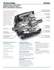
Table of Contents◗FAMILY OF PRODUCTS◗ AIR CHAMP ® FEATURES AND BENEFITSFor nearly one-half century, Nexen has been designing andmanufacturing Clutches, Brakes and other products to supportyour motion control requirements. Each product is a result ofyears of innovative design and engineering, precisemanufacturing and most importantly - understanding therequirements of motion control applications.Whether your application requirements are simple or extensive,you will find our Air Champ ® product family will service yourmotion control needs time and time again. You will findspecific product features, benefits and specifications for everyAir Champ ® product in this catalog. However, there is acommon thread of features and benefits throughout the AirChamp ® product line.Simple design, durability, efficiency and economy makeAir Champ ® products the best choice for your motioncontrol applications.“Air Champ” ®Simple DesignEasy to understand • Easy to installAir ActivatedIncreased efficiency and productivity • Inexpensive to operateHigh Thermal DissipationLess torque fade • High cyclic rates • Long product lifeSelf AdjustingAutomatic torque maintenance • Worry-free operationLow MaintenanceLong product life • Less down time • Easily servicedWide SelectionApplication and Operational versatility • Mounting flexibilityVersatile product characteristics • Imperial & Metric designsReady to ShipReadily available stock • Quick service12
Table of Contents“Air Champ” ®In accordance with Nexen’s establishedpolicy of constant product improvement,the specifications contained in this documentare subject to change without notice.Technical data listed in this document arebased on the latest information availableat the time of printing and are also subjectto change without notice. For currentinformation, please consult:www.nexengroup.comNEXEN FAMILY OF PRODUCTSThis Section Contains: . . . . .Page“AIR CHAMP” ® FAMILY OF PRODUCTSFriction Clutches . . . . . . . . . . . . . . . . . . . . .14Tooth Clutches . . . . . . . . . . . . . . . . . . . .14-15Multiple Disc Clutches . . . . . . . . . . . . . . . . .15Dual Plate Clutches & Brakes . . . . . . . . . . .16High Capacity Clutches & Brakes . . . . . . . . .16Overload Protection Devices . . . . . . . . . . . .17Flexible Couplings . . . . . . . . . . . . . . . . . . . .17Friction Brakes . . . . . . . . . . . . . . . . . . . . . . .18Caliper Brakes . . . . . . . . . . . . . . . . . . . . . . .18Drum Brakes . . . . . . . . . . . . . . . . . . . . . . . .18Spring Engaged Brakes . . . . . . . . . . . . . . . .19Thru-Shaft Mount Clutch-Brakes . . . . . . . . .19Clutch-Disc Caliper Brakes . . . . . . . . . . . . .20NEMA “C” Flange Clutch-Brakes . . . . . . . . .20Modular System forNEMA “C” Flange Clutch-Brakes . . . . . .21This Section Contains: . . . . .PageWEB PRODUCTS APPLICATION GUIDEWeb Products Application Guide . . . . . . . . .22Web Control Products,Everything you need . . . . . . . . . . . .23Tension Control Systems . . . . . . . . . . .24Web Tension Systems . . . . . . . . . . . . .25Tension Control Brakes and Clutches . .25Tension Meters and Amplifiers . . . . . . .26Web Guiding Systems . . . . . . . . . . . . . .26Web Guide Sensors and Controllers . . .27Auxiliary Products . . . . . . . . . . . . . . . . .2713
Table of Contents◗FAMILY OF PRODUCTSDISENGAGED“Air Champ” ®◗ DUAL PLATE CLUTCHES & BRAKESDual Plate Clutches and Brakes each come in 4 StandardModels, whose modular design makes custom design easyand less expensive. For applications requiring up to 36,000In Lb of torque, speeds up to 2200 rpm, thermal horsepowervalues up to 9.0, motor horsepower ratings from 5 hp to 150hp. Clutches are designed for either shaft-end mounting orthru-shaft mounting. Brakes can either mount rigidly or nonrigidly.As many as 8 Bore sizes per Clutch Model, 7 Boresizes per Brake Model with further customization possible.Sheave Mount options are also available for Clutches. DualPlate Clutches are perfect for these functions:◗ Controlled Acceleration◗ Inching/Jogging◗ Rapid Cycling/Indexing◗ Positioning◗ Reversing/Multiple Speed◗ Tension Control◗ Overload Protection◗ Torque LimitingDual Plate Brakes address these functions:◗ Controlled Deceleration◗ Stopping/HoldingDISENGAGED◗ HIGH CAPACITY CLUTCHES & BRAKES16 Standard Models of air-actuated Clutch & Brake Elementsare designed for heavy duty industrial applications thatrequire high torque and low inertia. Used as either Clutchesor Brakes, these elements are available in disc sizes from11.50 to 25 inches. Torque capacities for these elementsrange from 12,000 to 300,000 In Lb, with speeds up to 2200rpm and thermal horsepower values up to 14.7. Elements areavailable in two styles: Dual Faced Models, having single discassemblies; and Quad Faced Models, having double discassemblies. Each style is available in an S Model (standardcoefficient <strong>friction</strong> lining), and an H Model (high coefficient<strong>friction</strong> lining). Bore sizes range from 1to 6.50 inches. HighCapacity Clutches address these functions:◗ Controlled Acceleration◗ Inching/Jogging◗ Rapid Cycling/Indexing◗ Positioning◗ Reversing/Multiple SpeedHigh Capacity Brakes address these functions:◗ Stopping/Holding16
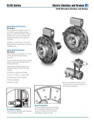
Table of Contents◗FAMILY OF PRODUCTS“Air Champ” ®ENGAGED◗ FRICTION BRAKESLow inertia, high thermal dissipation and self-adjustingfacings make these ideal for many applications. Choosebetween Straight or Tapered Bore units in a wide range ofoperational specifications. Each Model comes in a StandardBore size, with customization possible through the use ofBushings. You'll find 24 Standard Models and 4 MetricModels from which to choose. Friction Brakes address thesefunctions:◗ Controlled Deceleration◗ Rapid Cycling/Indexing◗ Positioning◗ Tension Control◗ Stopping/HoldingDISENGAGED◗ CALIPER BRAKES10 Standard Models address a wide range of Caliper Brakerequirements. Choose between Spring or Air Actuation, 10Disc diameters and a variety of design styles. Caliper spacingis movable and shoes are adjustable on many Models. CaliperBrakes address these functions:◗ Controlled Deceleration◗ Tension Control◗ Stopping/HoldingDISENGAGED◗ DRUM BRAKES7 Standard Models offer maximum efficiency anddependability. All can mount on the shaft, a few can alsobracket mount. 3 Models have a hinge top design for use withremovable brake drums. Drums available in Standard Boresizes or without bore customization. Operationalspecifications provide a wide range of application criteria.Drum Brakes address these functions:◗ Controlled Deceleration◗ Tension Control◗ Stopping/Holding18
Table of Contents“Air Champ” ®FAMILY OF PRODUCTS ◗◗ SPRING ENGAGED BRAKESSpring Engaged Brakes are available in 18 Standard Modelswith either Straight or Tapered Bore and 4 Metric Models witha Straight Bore. A variety of Standard Bore sizes are available,some Models provide bore size customization. Productspecifications cover a broad range of operational criteria.Spring Engaged Brakes address these functions:◗ Stopping/HoldingDISENGAGED◗ THRU-SHAFT MOUNT CLUTCH-BRAKESThru-Shaft Mounted Clutch/Brakes combine the features of aFriction Clutch with a Friction Brake into a single unit. 9Standard Models offer Pilot Mount, Sheave Mount and PilotMount with Coupling Half options. Pilot Mount units areavailable in 2 Standard Bores sizes with customizationpossible with Bushings and Couplings. Thru-Shaft Mountunits come in a range of bore sizes and Sheave styles.Operation specifications throughout the category will addressalmost any need. Thru-Shaft Mount Clutch-Brakes addressthese functions:◗ Controlled Acceleration◗ Controlled Deceleration◗ Inching/Jogging◗ Stopping/Holding◗ DisconnectCLUTCH DISENGAGEDBRAKE DISENGAGED19
Table of Contents◗APPLICATION GUIDEWeb ProductsWEB PRODUCTS APPLICATION GUIDEEverything you need to control web quality and productivityfrom unwind through windup, roll after roll.Nexen offers you a wide rangeof web control systems andcomponents, supported by ourexpert technical support andservice team.With Nexen, you can beassured of consistent, highqualityoutput from your webprinting or converting process.Nexen controls are usedsuccessfully with applicationsas diverse as:• paper • paperboard• film • metal strip• rubber • non-wovens• labels • foil• textiles • plastics• laminates • wirePrecise enough for thelaboratory, yet rugged enoughfor the mill, Nexen controlsystems are delivered andbacked by the recognizedleader in web controlequipment for almost 50 years.22
Table of Contents◗APPLICATION GUIDEWeb ProductsTENSION CONTROL SYSTEMSPneumatic BrakeElectric BrakePrecise tension control is vital to any web- or stripfedoperation, the product – whether paper, plastics,metal strip, rubber sheet or wire – must be fedunder tension, processed under tension and woundup again under tension.Factors such as poorly wound rolls, elasticity, rolldiameter change and irregularities in web thicknesscause significant variations in web tension.ClosedLoopLoad CellBrakeControlSystemsElectric ClutchPSSome applications require taper tension on windup.Winding begins at relatively high tension, with agradual reduction, or tapering, in tension as the rollbuilds in diameter.At the very least, your tension control systemmust compensate for the change in roll diameter. Forprecise control and high line speeds, it must alsobe capable of measuring and controlling tensionwithin very close tolerances.ClosedLoopLoad CellRewindControlSystemsMMCPneumatic ClutchPSNexen systems are available to control variablespeed motors and pneumatic and electric brakesand <strong>clutches</strong>.Load Cell Based Tension ControlNexen’s load cell based tension control system is aclosed loop system which senses tension in a web andcompares it to a set point, or desired tension level andautomatically adjusts air pressure to a pneumaticclutch or brake to maintain appropriate web tension.The load cell based system can also control electric<strong>clutches</strong> and brakes.ClosedLoopLoad CellInternalControlSystemsMMCPneumaticClutchMMCThe load cell based systems also can be used withvariable speed drives to maintain proper tension ininternal tension zones or at the windup stand.• Control accuracy of 1-2 percent –highest of any web control systems• Ideal for use with brakes, drives and <strong>clutches</strong>• Simple to operate –set the tension leveland let the controller do the rest• Allows remote computer to determinethe tension and set points for each jobOpen Loop Tension ControlThe open loop tension control system electronicallymeasures or estimates the diameter of the unwindor windup roll. It then modulates a brake to controlthe unwind, or a clutch or variable speed drive forwindup applications to maintain tension as thediameter varies. Accuracy is typically about8-10 percent.OpenLoopUnwindBrakeControlSystemsTensionRead OutRewindControlSystemsTROTension Read OutOptical EncoderPneumatic BrakeTRMCUMMCMotor ControllerTension SensorOpenLoopRewindControlSystemsOptical EncoderOutputControl*Electric BrakeProximity SwitchPP*For pneumatic clutch: I to DFor electric clutch: power supplyFor variable-speed motor: motor controlPPSOPPSMProximity SwitchPower SupplyOpen Loop ControlsMotorClosed Loop LoadCell Based ControllerI to P TransducerDancer PositionSensor24
Table of Contents◗APPLICATION GUIDETension MeterOften you need to only measurethe tension in a web, not controlit. Nexen has a variety of solutionsto meet these needs.Web ProductsTENSION METERS AND AMPLIFIERSTension MeterNexen tension meters preciselymeasure web tensions with adigital tension display on thefront panel. Their 0-10 VDC or4-20 mA analog output is alsowell suited as a proportional tensiondata signal to process controllers,data loggers and variable-speedmotor controls.You can also use one of thesensors for narrow webs, singlestrands of wire, or any other narrowmaterial where tension will notvary from one side to the other.Nexen tension meters are alsouseful as a tension readout-onlydevice to measure intermediatezonetension.Tension AmplifiersNexen tension amplifiers interfacewith load cell or straingauge sensors. They provide anexcitation signal to the sensorsand separately amplify the returnsignal from each sensor beforecombining them to provide asignal proportional to the totaltension.Tension amplifiers are ideal foraccurate, low-cost tensionmeasurement of a web processinterfaced with machine controlssuch as data loggers, processcontrollers, drive controls, hostcomputers and other applicationsrequiring a precise tensioninterface.Tension Amplifiers Offer:• Low cost signal conditioningfor LVDT or strain gaugetension sensors• Wide tension range forflexible installation• Ideal for use with machinecontrols where localreadout is not required• Includes both 0-10 VDCand 4-20 mA outputsControlled lateral alignment of the web isabsolutely essential to providing high qualityproduct and reducing scrap and waste.Nexen web guiding systems are designed,tested and proven to give you that alignmentWeb Guiding ApplicationsWEB GUIDING SYSTEMSUnwind Guiding (See Figure 1)As material is unwound and fed into amachine, it must be properly aligned with theprocess to be performed upon it.Unwind guiding is accomplished by sensingthe web as it enters the machine. The sensoris mounted as part of the main machineframe and placed so that its center is locatedat the desired position of the web. Thecontroller directs movement of the actuator,which moves the roll stand laterally acrossthe machine to bring the edge of the roll intothe center of the sensor.Intermediate GuidingThis method is normally used in the intermediatezone to make minor corrections inposition. The steering rolls pivot, directingthe web to the left or right to bring it intocenter position within the sensor.26Displacement Guides (See Figure 2)Displacement guides consist of a pair ofpivoting rollers with a pair of stationery idlerollers, one lead-in roller before the guideand a lead-out roller after the guide. Thistype of guide induces pure, out-of-planetwisting of the web, which is gentler on aweb than a steering guide. Much shorterfree spans are required before and afterguiding when compared to a steering guide.Displacement guides are often used onprinting presses and other applicationswhere space is at a premium.Windup Guiding (See Figure 3)The position of the web is monitored by asensor mounted on the moveable windup rollstand, positioned before the last roll on themachine. As the web shifts laterally, thecontroller signals the actuator to move thewindup roll into line with the web edge.Chase GuidingChase guiding is a technique used to alignthe edge of two or more webs or to align aprocess to a web. The sensor is moved bythe actuator to “chase” the edge of the web.In the case of aligning several web edges,the sensors for the second and subsequentwebs are aligned with the chase sensor andmove in tandem with it. This moves the targetor center of the sensor for allsubsequent webs, which in turn causes theguides to align their webs to the target.To align the process to the web, the sensoris mounted to the moveable processcomponent. The actuator then moves thecomponent, causing the sensor to chase theweb edge or printed line.
Table of ContentsWeb ProductsGUIDE SENSING OPTIONSWEB GUIDE SENSORS AND CONTROLLERSPosition Control ConfigurationsAPPLICATION GUIDE ◗Ultrasonic Web Guide SensorLED Infrared Web Guide SensorEdge Position ControlOne edge of the material isaligned with the process at alltimes. The position of this edgeremains constant throughout allprocesses. The opposite edge ispermitted to run free and iseventually edge-trimmed to meetthe final specified web width.Center Position ControlThis technique requires one sensoron each side of the web. Theobjective is to maintain the centerof the web on the mean centerlineof the machine. If the webvaries in width, center positioncontrol will maintain an equaledge trim on each side of theweb, to be removed later in theprocessing.Line Follower ControlLine follower control is alwaysemployed for previouslyprocessed materials, using asensor to follow a line or theedge of a pattern of print orcoating material previously laiddown on the web.Ultrasonic SensorsUltrasonic sensors are used particularlyfor edge or center controlof photosensitive materialssuch as photographic film andprint paper, and with transparentor translucent films bearing acoating, printing or an opaquesurface near the edge. A highfrequency sound is transmittedacross an air gap to a receivingunit. Interruption of the signal isinterpreted as a change in positionof the web material. Theycan also be used with opaquematerials.Infrared SensorsA pulsed LED transmits aninfrared signal across the webedge to a light sensitive sensor;edge position of the material isSplice Detector SystemSplice DetectorSystem ControllerThe Splice Detector System is avisible light system used tosense splices or double thicknessesin translucent materials.It provides both a visual indicationand a relay signal at each splice.determined from the amount oflight sensed at the receiving unit.Infrared sensors can also beconfigured in pairs for centerposition control. The infrared signalis not affected by ambientlight and is useful for processingof certain photosensitive materials.Infrared sensors are usedfor opaque materials only.Line Follower SensorsA line following sensor bounceslight off a web as it passesaround a transport roll in themachine. It is received by asensing element contained inthe same housing. This type ofsensor is normally used to followa printed line or the edge of aprinted pattern on the web.This system is ideally suited foruse where high nippingpressure in a machine must bemomentarily relaxed to allow asplice to pass through withoutdamaging the web, printing blanketor other components.This system typically does notrequire operator intervention. Achange in web thickness ofmore than three seconds durationwill cause the system’s controllerto recalibrate to the newweb thickness.Web Guide ControllerSelf ContainedWeb Guide ControllerAUXILIARY PRODUCTSPaper Checker SystemPaper CheckerThe Paper Checker Systemdetects web breaks and spliceson web machines.This system makes use of anultrasonic sensor to prevent thefalse triggering that can resultfrom the presence of print orWeb Guide ControllersA Nexen web guide controllerreceives signals from a webposition sensor and translatesthem into control signals for webposition drive motors. With theappropriate sensor, they offercontrol accuracy to within±0.004 inches (±0,01mm) of anedge or centerline position.The purpose of the controller isto provide automatic positioningof the web in relation to the sensor.Web position information fromthe sensor is fed to the webguide controller. The controller’smotor control drives anelectrical linear actuator tocorrect the web position byadjusting the roll stand or guideroll mechanism.other patterns on the web materialand for use with photo sensitivematerials. Each break orsplice is indicated by a separaterelay signal and front panel indicatorlights.This Nexen Paper CheckerSystem can be used on transparentto fully opaque webs andwith laminates of paper, film andfoil. It handles web speeds from30 to more than 3000 feet perminute, (10 to 1000 meters perminute).27
Table of Contents◗CLUTCHES“Air Champ” ®◗ PRODUCT FUNCTION/SELECTION CHARTProduct Groups Friction Tooth Multi-Disc Dual Plate High CapacityClutches Clutches Clutches Clutches ClutchesGeneral FeaturesNumber of Model Options 15 Standard 40 Standard 7 Standard 4 Standard 16 Standard5 Metric 35 Metric 0 Metric 0 Metric 0 MetricFunctionsControlled Acceleration Yes Yes YesInching/Jogging Yes Yes YesCycling/Indexing Yes Yes YesPositioning Yes Yes Yes Yes YesReversing/Multiple Speed Yes Yes Yes Yes YesTension Control, Rewind Yes YesOverload Protection Yes Yes YesDisconnect/Connect Yes Yes Yes Yes YesPositive DriveYes28
Table of Contents“Air Champ” ®In accordance with Nexen’s establishedpolicy of constant product improvement,the specifications contained in this documentare subject to change without notice.Technical data listed in this document arebased on the latest information availableat the time of printing and are also subjectto change without notice. For currentinformation, please consult:www.nexengroup.comFRICTION CLUTCHESThis Section Contains: . . . . .PageThis Section Contains: . . . . .PageCLUTCHESClutch Product Function/Selection Chart . . .28Friction Clutch Selection Chart . . . . . . . . . .30Micro Model (M) . . . . . . . . . . . . . . . . . . . . .31Bantam Weight (BW & B-275) . . . . . . . .32-33F-450 & L-600 Models . . . . . . . . . . . . .34-35M-800 & H-1000 Models . . . . . . . . . . . .36-37Extra Heavy Weight Models (XHW) . . . .40-41FW, LW, MW & HW Models . . . . . . . . . . . .42METRIC FRICTION CLUTCHESBW, B-275,F-450, L-600, M-800, H-1000 . . .38-39DUAL PLATE CLUTCHESDPC Selection Chart . . . . . . . . . . . . . . . . . .43DPC Model Overview . . . . . . . . . . . . . . .44-45DPC-9T Model . . . . . . . . . . . . . . . . . . . .46-47DPC-11T Model . . . . . . . . . . . . . . . . . . .48-49DPC-13T Model . . . . . . . . . . . . . . . . . . .50-51DPC-15T Model . . . . . . . . . . . . . . . . . . .52-53DFC-1650 & 2200 Models . . . . . . . . . . .54-55HIGH CAPACITY CLUTCHESDFE & QFE Model Overview . . . . . . . . . .56-57DFE Model Clutch & Brake Elements . . .58-59QFE Model Clutch & Brake Elements . . .60-61CONVEYOR CLUTCHESLSCC-32, 44, 54 Models Straight Bore . . .62-63MULTI-DISC CLUTCHES4HP Model Multe-Disc . . . . . . . . . . . . . .64-654HP Flexible Couplings . . . . . . . . . . . . . .66-6729
Table of Contents◗CLUTCHESFRICTION CLUTCH SELECTION CHARTFriction clutch recommendation is based upon air pressure of 50 psi, transmitted horsepower and speed.“Air Champ” ®1800 2200 2600 3000 3600100 200 300 400 500 600 700 800 900 1000 1100 1200 1300 1400 1500 1600 1700RPM1 ⁄ 36 M M M M M M M M M M M M M M M M M1 ⁄ 20BW /B-275BW /B-275 M M M M M M M M M M M M M M M1 ⁄ 18BW /B-275BW /B-275 M M M M M M M M M M M M M M M1 ⁄ 15BW /B-275BW /B-275 M M M M M M M M M M M M M M1 ⁄ 12BW /B-275BW /B-275 M M M M M M M M M M M M M M1 ⁄ 10BW /B-275BW /B-275BW /B-275 M M M M M M M M M M M M M1 ⁄ 9BW /B-275BW /B-275BW /B-275BW/ B-275 M M M M M M M M M M M MM M M M MM M M M MM M M M MM M M M MM M M M MM M M M MM M M M MTRANSMITTED HORSEPOWER1 ⁄ 8 F-450 F-450 BW /BW B-275 /B-275BW/BW B-275 / B-275 M M M M M M M M M M M1 ⁄ 6 F-450 F-450 F-450 BW /BW B-275 /BW B-275 /BW B-275 /BW B-275 / B-275 M M M M M M M M M1 ⁄ 4 L-600 F-450 F-450 F-450 BW /BW B-275 /BW B-275 /BW B-275 /BW B-275 /BW B-275 /BW B-275 /BW B-275 / B-275 M M M M M1 ⁄ 3 L-600 F-450 F-450 F-450 F-450 F-450 BW /BW B-275 /BW B-275 /BW B-275 /BW B-275 /BW B-275 /BW B-275 /BW B-275 /BW B-275 /BW B-275 /BW B-275 / B-275M M M M MM M M M MM M M M MM M M M M1 ⁄ 2 M-800 L-600 L-600 F-450 F-450 F-450 F-450 F-450 BW /BW BW/BW B-275 /BW B-275 /BW B-275 /BW B-275 /BW B-275 /BW B-275 /BW B-275 /BW B-275 / B-275 B-275 / B-275 M M M1 H-1000 H-1000 L-600 L-600 L-600 L-600 F-450 F-450 F-450 F-450 F-450 F-450 F-450 F-450 F-450 F-450 F-4502 H-1000 H-1000 M-800 M-800 M-800 L-600 L-600 L-600 L-600 L-600 L-600 L-600 L-600 L-600 L-600 L-600 L-6003 H-1000 H-1000 H-1000 M-800 M-800 M-800 M-800 M-800 L-600 L-600 L-600 L-600 L-600 L-600 L-600 L-600 L-6005 XHW H-1000 H-1000 H-1000 H-1000 M-800 M-800 M-800 M-800 M-800 M-800 M-800 M-800 M-800 L-600 L-600 L-600BW/ B-275BW/ B-275BW/ B-275BW/ B-275BW/ B-275F-450 F-450 F-450 F-450 F-450L-600 F-450 F-450 F-450 F-450L-600 L-600 L-600 L-600 F-4507 1 ⁄ 2 XHW H-1000 H-1000 H-1000 H-1000 H-1000 H-1000 M-800 M-800 M-800 M-800 M-800 M-800 M-800 M-800 M-80010 XHW XHW H-1000 H-1000 H-1000 H-1000 H-1000 H-1000 H-1000 H-1000 M-800 M-800 M-800 M-800 M-800 M-80015 XHW XHW H-1000 H-1000 H-1000 H-1000 H-1000 H-1000 H-1000 H-1000 H-1000 H-1000 H-1000 H-1000 H-100020 XHW XHW H-1000 H-1000 H-1000 H-1000 H-1000 H-1000 H-1000 H-1000 H-1000 H-1000 H-1000 H-1000M-800 L-600 L-600 L-600 L-600M-800H-1000H-100025 XHW XHW XHW H-1000 H-1000 H-1000 H-1000 H-1000 H-1000 H-1000 H-1000 H-1000 H-1000REFER TO DUAL PLATECLUTCH PRODUCTSPAGE 4330 XHW XHW XHW XHW40 XHW XHW XHW XHW50 XHW XHWH-1000REFER TO DUAL PLATE CLUTCHPRODUCTS PAGE 43IMPORTANT NOTES:1. For static torque ratings at different air pressures, refer to individual models to ensure conformity.2. For operating speeds over 1800 rpm, refer to individual models or consult Nexen to ensure conformity.3. Limited to peak thermal input rates of .9 HP T per square inch of interface area.4. Bars equal PSI x 0.0689.30
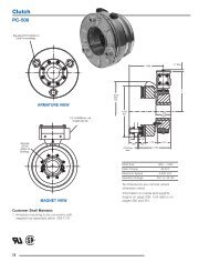
Table of Contents◗ MICRO FRICTION CLUTCHMounting Product Bore Shipping Wt.Style Number (In) (Lbs)Pilot 856800 0.375 3For Inertia Values of components, see page 359.Required shaft insertion into clutch hub = minimum of 1 inch from Pilot side.MICRO MODEL–APPROXIMATE DIMENSIONS (INCHES)◗ PILOT MOUNTØAJBF4 X AT 90°CWPRODUCT +.000 +.001NUMBER AJ AK -.001 BB BF CR CS CT CW CZ P PA PB U -.000CRCSPBB CZCS2 X .164-32SET SCREW.127-27 NPTAIR INLET“Air Champ” ®CTU PB5" FLEXIBLE HOSEMICRO FRICTION CLUTCHThe Micro Friction Clutch provideshigh performance in a smallpackage:◗ Static Torque capacity up to 18In. Lbs. @ 80 psi◗ Maximum Operating Speed up to3600 rpm◗ Transmitted Horsepower valuesfrom 0.06 to 0.50◗ Thermal Horsepower rating of0.06 @ 1800 rpm◗ Heat Sink capacity of 1900 Ft.Lbs.This Pilot Mount clutch mountseasily and comes with:◗ 0.375 inch Standard BoreCLUTCHES ◗◗ 5 inch hose with .190-32 by .125NPT included.856800 1.562 1.374 0.19 .138-32 2.27 0.09 0.72 0.32 0.20 1.75 0.59 0.88 0.375◗ TORQUE VS. AIR PRESSURE20.0Static Torque in Inch-Pounds15.010.05.00 10 20 30 40 50 60 70 80Air Pressure in PSINOTE: Dynamic torque is approximately 85% of static torque.31
Table of Contents◗CLUTCHES“Air Champ” ®BANTAM WEIGHT MODEL BWFRICTION CLUTCHThe BW Friction Clutch providesexcellent performance:◗ Static Torque capacity up to 100In. Lbs. @ 80 psi◗ Maximum Operating Speed up to3600 rpm◗ Transmitted Horsepower valuesfrom 0.05 to 1.00◗ Thermal Horsepower rating of0.13 @ 1800 rpm◗ Heat Sink capacity of 5650 Ft. Lbs.◗ Corrosion-Resistant Modelavailiable for damp environmentsThis clutch is thru-shaft mountedto provide design versatility in 5Models:◗ 4 Sheave Mount units provide1-“3V” or 1-“A” Groove options◗ 5 Pilot Mount units withdifferent standard bore sizes◗ Standard Bore sizes of 0.500and 0.625 inches◗ Customize the bore to your shaftdiameter with a Bushing orCoupling Half◗ Tapped holes provided for easymounting in applications withpulleys, sprockets or gears◗ 8.25 inch hose included◗ BW is equipped with ThrustBearings and a Single Key SplinedHub.◗ B-275 is equipped with Sealed,Radial Bearings and a Multi-toothSplined Hub.32◗ BW AND B-275 MODEL CLUTCHESProduct Sheave Bore Key Size Shipping Wt.Clutch Style Number Diameter (In) (SQ) (Lbs)Pilot Mount, BW 800100 -- 0.625 0.188 4Pilot Mount, BW 800111 -- 0.500 0.125 4Pilot Mount Corrosion-Resistant, BW 800107 -- 0.625 0.188 4Pilot Mount, B-275 802870 -- 0.625 0.188 4Pilot Mount, B-275 802871 -- 0.500 0.125 4Sheave Mount, B-275, 1-“A” 802872 3.00 PD 0.625 0.188 4Sheave Mount, B-275, 1-“3V” 802873 2.750 OD 0.625 0.188 4Sheave Mount, 1-“3V” 800000 2.750 OD 0.625 0.188 4Sheave Mount, 1-“A” 800004 3.000 PD 0.625 0.188 4Pilot w/Coupling Half Select a Pilot Mount and a Coupling Half to achieve this style of mount.For Inertia Values of components, see page 359.Keys are included. Required shaft insertion into clutch hub = minimum of 1.50 inches from Pilot side.◗ BUSHING OPTIONS (FOR 0.625 BORE CLUTCHES ONLY)Bushings fit within the bore of the clutch, reducing the bore to the amount indicated.Product Reduces Clutch Shipping Wt.Number Bore Size to (In) (Lbs)800200 0.500 1800900 No Bore/Customer machines 1◗ COUPLING HALF OPTIONSA Coupling Half is used for in-line applications. To achieve a Pilot Mount withCoupling Half mounting configuration:1. Select a Pilot Mount Clutch from above;2. Select a Coupling Half from the chart below which fits your shaft requirements;3. Order Clutch and Coupling Half separately.Product Key Size Shipping Wt.Number Bore Size (In) (SQ) (Lbs)800300 0.500 0.125 1800307 0.500 0.125 1 ➀800400 0.625 0.188 1800500 0.750 0.188 1➀ Nickle Plated◗ PULLEYS, SPROCKETS, GEARSTapped holes are provided for ease of mounting. Nexen does not furnish theseitems. For minimum sprocket requirements, see page 369.◗ TORQUE VS. AIR PRESSUREStatic Torque in Inch-Pounds112988470564228140 10 20 30 40 50 60 70 80Air Pressure in PSIB-275, BWNOTE: Dynamic torque is approximately 85% of static torque.
Table of Contents“Air Champ” ®CLUTCHES ◗BW AND B-275 MODEL CLUTCHES - APPROXIMATE DIMENSIONS (INCHES)◗ PILOT MOUNTØ A JB F4 X A T 9 0 °2 X .164-32S E T S C R E W SC WC SK LC RB BK E YC ZA KP APUP B8 . 2 5 " F L E X I B L E H O S E. 1 2 5 - 2 7 N P TA I R I N L E TPRODUCT KEY +.001NUMBER AJ AK ±.001 BB BF CR CS CT CW CZ KL (SQ) P PA PB U -.000800100 2.437 2.124 0.25 .190-32 3.51 0.11 0.50 0.49 0.18 0.62 0.188 2.89 0.98 1.19 0.625800107 2.437 2.124 0.25 .190-32 3.51 0.11 0.50 0.49 0.18 0.62 0.188 2.89 0.98 1.19 0.625800111 2.437 2.124 0.25 .190-32 3.51 0.11 0.50 0.49 0.18 0.62 0.125 2.89 0.98 1.19 0.500802870 2.437 2.124 0.25 .190-32 3.51 0.11 0.50 0.49 0.18 0.62 0.188 2.89 0.98 1.19 0.625802871 2.437 2.124 0.25 .190-32 3.51 0.11 0.50 0.49 0.18 0.62 0.125 2.89 0.98 1.19 0.500C T◗ PILOT MOUNTW/COUPLING HALFC O U P L I N GS H A F TK L 2K E Y 2P I L O T M O U N TC L U T C H S H A F TC XK L 12 X .164-32S E T S C R E W SK E Y 1C ZP A U 2U 1 P B P2 X .190 - 3 2S E T S C R E W SC SC W8 . 2 5 " F L E X I B L EH O S EC RCOUPLINGPRODUCT KEY 1 KEY 2 +.001 +.001NUMBER CR CS CW CX CZ KL1 KL2 (SQ) (SQ) P PA PB U1 -.000 U2 -.000800300 4.20 0.11 0.69 0.07 0.18 0.62 0.62 0.188 0.125 2.89 1.87 1.19 0.625 0.501800307 4.20 0.11 0.69 0.07 0.18 0.62 0.62 0.188 0.125 2.89 1.87 1.19 0.625 0.501800400 4.20 0.11 0.69 0.07 0.18 0.62 0.62 0.188 0.188 2.89 1.87 1.19 0.625 0.625800500 4.20 0.11 0.69 0.07 0.18 0.62 0.62 0.188 0.188 2.89 1.87 1.19 0.625 0.751◗ SHEAVE MOUNT2 X .164-32S E T S C R E W S. 1 2 5 - 2 7 N P TA I R I N L E TK LC WC SC RK E YC TC ZO DP DP AP B PUC X. 1 2 5 - 2 7 N P TA I R I N L E T8 . 2 5 " F L E X I B L EH O S EPRODUCT SHEAVE KEY +.001NUMBER BELT GROOVE OD PD CR CS CT CW CX CZ KL (SQ) P PA PB U -.000C T802872 “A” 1 3.250 3.000 3.51 0.11 0.50 0.18 0.55 0.18 0.62 0.188 2.89 0.98 1.19 0.625800000 “3V” 1 2.750 -- 3.51 0.11 0.50 0.24 0.58 0.18 0.62 0.188 2.89 0.98 1.19 0.625802873 “3V” 1 2.750 -- 3.51 0.11 0.50 0.25 0.59 0.18 0.62 0.188 2.89 0.98 1.19 0.625800004 “A” 1 3.250 3.000 3.51 0.11 0.50 0.17 0.54 0.18 0.62 0.188 2.89 0.98 1.19 0.62533
Table of Contents◗CLUTCHES“Air Champ” ®FRICTION CLUTCH MODELSF-450 & L-600◗ Static Torque capacity up to:F-450/140 In. Lbs. @ 80 psiL-600/370 In. Lbs. @ 80 psi◗ Maximum Operating Speed up to3600 rpm◗ Transmitted Horsepower values from:F-450/0.125 to 5.00L-600/0.25 to 10.00◗ Thermal Horsepower rating of:F-450/0.30 @ 3600 rpmL-600/0.75 @ 3600 rpm◗ Heat Sink capacity of:F-450/30,000 Ft. Lbs.L-600/60,000 Ft. Lbs.8 F-450 & 8 L-600 Models offer designflexibility:◗ Sheave Mount Units:F-450/4 in 1-“3V” or 1-“A” Groovestyles, each in 2 sizesL-600/6, 4 sizes of 2-“3V” and 2 sizesof 2-“A”◗ 2 Pilot Mount units with differentstandard bore sizes◗ 2 Rewind Clutches Half-Torque,Precise Interface. Standard or LOCOfacing, 0.875 bore size.◗ Standard Bore Sizes:F-450/0.750 and 0.875 inchesL-600/1.00 and 1.125 inches◗ Customize the bore to your shaft diameterwith a Bushing or Coupling Half◗ Includes:F-450/Air Inlet Adapter and 8.25 in. hose.L-600/8.25 inch hose.◗ 1 802864 & 802865Percision Interface Clutches.For reduced pulsation in tension controlapplications.◗ TORQUE VS. AIR PRESSUREF-450140Static Torque in Inch-Pounds3412010080604020F-450802864 1802865 1◗ F-450 & L-600 MODEL CLUTCHESProduct Bore Key Size Shipping Wt.Model Clutch Style Number Sheave Diameter (In) (SQ) (Lbs)F-450 Pilot Mount 802850 -- 0.875 0.188 12F-450 Pilot Mount, Rewind (Std) 802864 1 -- 0.875 0.188 10F-450 Pilot Mount, Rewind (LOCO) 802865 1 -- 0.875 0.188 10F-450 Pilot Mount 802855 -- 0.750 0.188 10F-450 Sheave Mount 1-“3V” 802810 3.35 OD 0.875 0.188 10F-450 Sheave Mount, 1-“3V” 802820 4.50 OD 0.875 0.188 11F-450 Sheave Mount, 1-“A” 802830 3.80 PD 0.875 0.188 10F-450 Sheave Mount, 1-“A” 802840 4.40 PD 0.875 0.188 10L-600 Pilot Mount 805270 -- 1.125 0.250 17L-600 Pilot Mount 805275 -- 1.000 0.250 17L-600 Sheave Mount, 2-“3V” 805210 4.50 OD 1.125 0.250 18L-600 Sheave Mount, 2-“3V” 805220 5.30 OD 1.125 0.250 19L-600 Sheave Mount, 2-“3V” 805230 6.00 OD 1.125 0.250 21L-600 Sheave Mount, 2-“3V” 805240 8.00 OD 1.125 0.250 25L-600 Sheave Mount, 2-“A” 805250 4.40 PD 1.125 0.250 18L-600 Sheave Mount, 2-“A” 805260 5.40 PD 1.125 0.250 20Both Pilot w/Coupling Half Select a Pilot Mount and a Coupling Half to achieve this style of mount.For Inertia Values of components, see page 359. Keys are included. Required shaft insertion into clutchhub = minimum of F-450/2.00 inches, L-600/2.50 inches from Pilot side.◗ BUSHING OPTIONS(FOR 0.875 & 1.125 BORE CLUTCHES ONLY)Bushings fit within the bore of theexisting clutch, reducing the bore tothe amount indicated.Bore Product Reduces Clutch ShippingSize Number Bore Size to (In) Wt. (Lbs)0.875 827200 0.500 10.875 802500 0.625 10.875 802600 0.750 10.875 803100 No Bore/Customer machines 11.125 805100 0.625 11.125 804600 0.750 11.125 804700 0.875 11.125 804800 1.000 11.125 805000 No Bore/Customer machines 1◗ PULLEYS, SPROCKETS AND GEARSThese can be attached to the clutch foroffset shaft applications. Tapped holes areprovided for ease of mounting. Nexen doesnot furnish these items. For minimumsprocket requirements, see page 369.0 10 20 30 40 50 60 70 800 10 20 30 40 50 60 70 80Air Pressure in PSIAir Pressure in PSINOTE: Dynamic torque is approximately 85% of static torque.Static Torque in Inch-Pounds40035030025020015010050L-600L-600◗ COUPLING HALF OPTIONS(SEE PAGE 367 FOR COUPLING SPECIFICATIONS)A Coupling Half is used for in-lineapplications. To achieve a Pilot Mountwith Coupling Half mountingconfiguration:1. Select a Pilot Mount Clutch;2. Order Clutch and Coupling Halfseparately.3. Coupling Half is less taper lockbushing. Use Dodge Taper Lock ®#1008/F-450, #1215/L-600,(0.500 to 1.000/F-450, 0.500 to1.125/L-600, inch bore range).Customer furnished.Product Maximum ShippingModel Number Bore Size (In) Wt. (Lbs)F-450 802700 1.000 3L-600 804900 1.125 64. Select a Shaft Extension when thedriving shaft is smaller in diameterand shorter than the length of theclutch. The Shaft Extension is thesame length as the clutch and engageswith the key on the pilot end. Extensionsfit the driving shaft diameter.Only for Product Driving Shaft ShippingBore Size Number DIA. Wt. (Lbs)0.875 802800 0.500 10.875 803000 0.625 11.125 805200 0.500 1.51.125 805300 0.625 1.51.125 805400 0.750 1.51.125 805500 0.875 1.5
Table of Contents“Air Champ” ®CLUTCHES ◗F-450 & L-600 MODEL CLUTCHES - APPROXIMATE DIMENSIONS (INCHES)◗ PILOT MOUNTS E T S C R E W SB F 22 A T 9 0 °6 A T 6 0 °Ø A J 2K E YK E YC W 1B B 1C SA K 2P AA K 1UC RK LPB F 14 A T 9 0 °Ø A J 1B B 2C W 2. 1 2 5 - 2 7 N P TA I R I N L E TC T ( D I S E N G A G E D )C T 1 ( M A X E N G A G E D )8 . 2 5 " F L E X I B L E H O S EMODELF-450F-450L-600L-600PRODUCT KEY SET +.001NUMBER AJ1 AJ2 AK1 ±.001 AK2 ±.001 BB1 BB2 BF1 BF2 CR CS CT CT1 CW1 CW2 KL (SQ) P PA SCREWS U -.000802850 3.000 4.000 2.498 3.498 0.60 0.19 .250-20 .190-24 4.75 0.25 1.33 1.42 1.04 1.23 1.062 0.188 4.56 1.38 .250-20 0.875802855 3.000 4.000 2.498 3.498 0.60 0.19 .250-20 .190-24 4.75 0.25 1.33 1.42 1.04 1.23 1.062 0.188 4.56 1.38 .250-20 0.750805270 3.500 5.500 2.998 4.498 0.62 0.07 .250-20 .190-24 5.56 0.25 1.79 1.94 1.23 1.55 1.37 0.250 6.06 1.84 .312-18 1.125805275 3.500 5.500 2.998 4.498 0.62 0.07 .250-20 .190-24 5.56 0.25 1.79 1.94 1.23 1.55 1.37 0.250 6.06 1.84 .312-18 1.000◗ PILOT MOUNTW/COUPLING HALFC WC W 1C RP BP AT A P E RL O C KC XC O U P L I N GS H A F TCOUPLINGDODGEPRODUCTTAPERMODEL NUMBER CR CW CW1 CX PA PB LOCK ®P I L O T M O U N TC L U T C H S H A F T◗ SHEAVE MOUNTB F 26 A T 6 0 °C XC YC X 1F-450 802700 6.45 0.12 2.75 0.70 2.62 3.50 #1008L-600 804900 7.70 0.94 3.37 0.64 2.62 4.38 #1215Ø A J 2O DP DA K 2B B 2C W 2PRODUCT SHEAVEMODEL NUMBER BELT G’VE OD PD AJ2 AK2 ±.001 BB2 BF2 CW2 CX CX1 CYF-450 802810 “3V” 1 3.35 -- 4.000 3.498 0.06 .190-24 1.22 0.75 -- 0.44F-450 802820 “3V” 1 4.50 -- -- -- -- -- -- 0.88 -- 0.44F-450 802830 “A” 1 4.05 3.80 -- -- -- -- -- 0.88 -- 0.44F-450 802840 “A” 1 4.65 4.40 -- -- -- -- -- 0.88 -- 0.44L-600 805210 “3V” 2 4.50 -- 5.500 4.498 0.29 .190-24 1.55 0.68 0.41 0.43L-600 805220 “3V” 2 5.30 -- -- -- -- -- -- 0.86 0.41 0.55L-600 805230 “3V” 2 6.00 -- -- -- -- -- -- 0.86 0.41 0.55L-600 805240 “3V” 2 8.00 -- -- -- -- -- -- 0.86 0.41 0.55L-600 805250 “A” 2 4.65 4.40 -- -- -- -- -- 0.62 0.63 0.24L-600 805260 “A” 2 5.65 5.40 -- -- -- -- -- 0.62 0.63 0.2435
Table of Contents◗CLUTCHES“Air Champ” ®FRICTION CLUTCH MODELSM-800 & H-1000◗ Static Torque capacity up to:M-800/975 In. Lbs. @ 80 psiH-1000/2800 In. Lbs. @ 80 psi◗ Maximum Operating Speed up to1800 rpm◗ Transmitted Horsepower values from:M-800/0.50 to 10.00H-1000/1.00 to 25.00◗ Thermal Horsepower rating of:M-800/1.00 @ 1800 rpmH-1000/2.25 @ 1800 rpm◗ Heat Sink capacity of:M-800/110,000 Ft. Lbs.H-1000/230,000 Ft. Lbs.6 M-800 & 6 H-1000 Models offerdesign flexibility:◗ Sheave Mount Units:M-800/2 sizes of 3-“3V” and 2 sizes of2-“B” Groove styles.H-1000/2 sizes of 3-“5V” and 2 sizesof 2-“B”◗ 2 Pilot Mount units with differentstandard bore sizes◗ Standard Bore Sizes:M-800/1.438 and 1.625 inchesH-1000/1.688 and 1.875 inches◗ Customize the bore to your shaft diameterwith a Bushing or Coupling Half◗ Includes:M-800/8.25 in. hose.H-1000/8.25 inch hose.◗ PULLEYS, SPROCKETS AND GEARSThese can be attached to the clutch foroffset shaft applications. Tapped holes areprovided for ease of mounting. Nexen doesnot furnish these items. For minimumsprocket requirements, see page 369.◗ TORQUE VS. AIR PRESSUREM-8001000 1000Static Torque in Inch-Pounds368757506255003752501258757506255003752501250M-800◗ M-800 & H-1000 MODEL CLUTCHESProduct Bore Key Size Shipping Wt.Model Clutch Style Number Sheave Diameter (In) (SQ) (Lbs)M-800 Pilot Mount 807650 -- 1.625 0.375 38M-800 Pilot Mount 807655 -- 1.438 0.375 38M-800 Sheave Mount, 3-“3V” 807610 5.30 OD 1.625 0.375 37M-800 Sheave Mount, 3-“3V” 807620 6.00 OD 1.625 0.375 40M-800 Sheave Mount, 2-“B” 807630 5.80 PD 1.625 0.375 39M-800 Sheave Mount, 2-“B” 807640 6.80 PD 1.625 0.375 43H-1000 Pilot Mount 810050 -- 1.875 0.500 61H-1000 Pilot Mount 810055 -- 1.688 0.375 63H-1000 Sheave Mount, 3-“5V” 810010 7.10 OD 1.875 0.500 69H-1000 Sheave Mount, 3-“5V” 810020 8.00 OD 1.875 0.500 74H-1000 Sheave Mount, 3-“B” 810030 7.40 PD 1.875 0.500 72H-1000 Sheave Mount, 3-“B” 810040 8.60 PD 1.875 0.500 82Both Pilot w/Coupling Half Select a Pilot Mount and a Coupling Half to achieve this style of mount.For Inertia Values of components, see page 359. Keys are included. Required shaft insertion into clutchhub = minimum of M-800/3.75inches, H-1000/4.00 inches from Pilot side.◗ BUSHING OPTIONS(FOR 1.625 & 1.875 BORE CLUTCHES ONLY)Bushings fit within the bore of theexisting clutch, reducing the bore tothe amount indicated.Bore Product Reduces Clutch ShippingSize Number Bore Size to (In) Wt. (Lbs)1.625 806700 1.000 21.625 806800 1.125 21.625 806900 1.188 21.625 807000 1.250 21.625 807100 1.375 21.625 807200 1.438 21.625 807300 1.500 21.625 807500 No Bore/Customer machines 21.875 805600 1.000 21.875 809200 1.375 21.875 809300 1.438 21.875 809400 1.500 21.875 809500 1.625 21.875 809600 1.750 21.875 809900 No Bore/Customer machines 20 0 10 20 30 40 50 60 70 800 10 20 30 40 50 60 70 80Air Pressure in PSIAir Pressure in PSINOTE: Dynamic torque is approximately 85% of static torque.Static Torque in Inch-Pounds300026252250187515001125750375H-1000H-1000◗ COUPLING HALF OPTIONS,SEE PAGE 367 FOR COUPLING SPECIFICATIONSA Coupling Half is used for in-lineapplications. To achieve a Pilot Mountwith Coupling Half mountingconfiguration:1. Select a Pilot Mount Clutch;2. Order Clutch and Coupling Halfseparately.3. Coupling Half is less taper lockbushing. Use Dodge Taper Lock ®#2517 (1.000 to 2.500 inch borerange). Customer furnished.Product Maximum ShippingModel Number Bore Size (In) Wt. (Lbs)M-800 807400 2.500 25H-1000 809700 2.500 334. Select a Shaft Extension when thedriving shaft is smaller in diameterand shorter than the length of theclutch. The Shaft Extension is thesame length as the clutch and engageswith the key on the pilot end. Extensionsfit the driving shaft diameter.Only for Product Driving Shaft ShippingBore Size Number DIA. Wt. (Lbs)1.625 807600 0.750 41.625 807700 0.875 41.625 807800 0.938 41.625 807900 1.000 41.625 808000 1.125 41.625 808100 1.250 41.875 810000 1.000 61.875 810300 1.125 61.875 810400 1.250 61.875 810500 1.375 61.875 810600 1.500 6
Table of Contents“Air Champ” ®CLUTCHES ◗M-800 & H-1000 MODEL CLUTCHES - APPROXIMATE DIMENSIONS (INCHES)◗ PILOT MOUNTS E T S C R E W SB F 22 A T 9 0 °6 A T 6 0 °Ø A J 2K E YC W 1B B 1C SA K 2P AA K 1UC RK LPB F 14 A T 9 0 °Ø A J 1B B 2C W 2. 1 2 5 - 2 7 N P TA I R I N L E TC T ( D I S E N G A G E D )C T 1 ( M A X E N G A G E D )8 . 2 5 " F L E X I B L E H O S EMODELPRODUCT KEY SET +.001NUMBER AJ1 AJ2 AK1 ±.001 AK2 ±.001 BB1 BB2 BF1 BF2 CR CS CT CT1 CW1 CW2 KL (SQ) P PA SCREWS U -.000M-800 807650 4.750 6.500 3.999 5.498 0.77 0.67 .312-18 .250-20 7.31 0.38 1.62 1.71 1.62 2.31 1.69 0.375 8.06 2.63 .375-16 1.625M-800 807655 4.750 6.500 3.999 5.498 0.77 0.67 .312-18 .250-20 7.31 0.38 1.62 1.71 1.62 2.31 1.69 0.375 8.06 2.63 .375-16 1.438H-1000 810050 5.625 9.000 4.873 7.098 1.47 0.12 .375-16 .250-20 8.50 0.31 1.92 2.14 1.97 2.90 2.56 0.500 10.06 3.25 .375-16 1.875H-1000 810055 5.625 9.000 4.873 7.098 1.47 0.12 .375-16 .250-20 8.50 0.31 1.92 2.14 1.97 2.90 2.56 0.375 10.06 3.25 .375-16 1.688◗ PILOT MOUNTW/COUPLING HALFC WC W 1C RP BP AT A P E RL O C KC XC O U P L I N GS H A F TP I L O T M O U N TC L U T C H S H A F TCOUPLINGDODGEPRODUCTTAPERMODEL NUMBER CR CW CW1 CX PA PB LOCK ®◗ SHEAVE MOUNTB F 26 A T 6 0 °C XC YC X 1M-800 807400 9.93 0.81 4.25 0.87 5.00 7.00 #2517H-1000 809700 11.43 0.63 4.90 1.18 5.00 8.00 #2517Ø A J 2O DP DA K 2B B 2C W 2PRODUCT SHEAVEMODEL NUMBER BELT G’VE OD PD AJ2 AK2 ±.001 BB2 BF2 CW2 CX CX1 CYM-800 807610 “3V” 3 5.30 -- 6.500 5.498 0.06 .250-20 2.30 0.96 0.41 0.68M-800 807620 “3V” 3 6.00 -- -- -- -- -- -- 0.96 0.41 0.68M-800 807630 “B” 2 6.15 5.80 -- -- -- -- -- 1.18 0.75 0.68M-800 807640 “B” 2 7.15 6.80 -- -- -- -- -- 1.18 0.75 0.68H-1000 810010 “5V” 3 7.10 -- 9.000 7.098 0.29 .250-20 2.90 0.91 0.69 0.47H-1000 810020 “5V” 3 8.00 -- -- -- -- -- -- 1.03 0.69 0.50H-1000 810030 “B” 3 7.75 7.40 -- -- -- -- -- 1.03 0.75 0.50H-1000 810040 “B” 3 8.95 8.60 -- -- -- -- -- 1.03 0.75 0.5037
Table of Contents◗CLUTCHES“Air Champ” ®METRIC SERIESFRICTION CLUTCHESThe Metric Model Friction ClutchSeries provides:◗ Static Torque capacity up to 330Nm◗ Maximum Operating Speed up to3600 rpm◗ Heat Sink capacity of 312,000Joules.This clutch comes in 5 Modelsfor design flexibility:◗ 6 Pilot Mount units withdifferent standard bore sizes◗ 6 Standard Bore sizes rangingfrom 15 to 50 millimeters◗ 4 Minimum Bore sizes rangingfrom 0 to 19 millimeters–youmachine and assemble◗ BW is equipped with ThrustBearings and a Single Key SplinedHub.◗ B-275 is equipped with Sealed,Radial Bearings and a Multi-tooth,Involute Spline.◗ METRIC SERIES FRICTION CLUTCHES, PILOT MOUNT ONLYStandard Bore Clutch:Speeds MIN. Shaft Heat SinkProduct Up to Bore Insertion into Hub Capacity Shipping Wt.Model Number RPM (mm) Key Size from Pilot Side (Joules) (kg)BW 950700 3600 15 5 x 5 38 7660 1,8B-275 950705 3600 15 5 x 5 38 7660 1,8F-450 950050 3600 20 6 x 6 51 41000 4,7L-600 950150 3600 25 7 x 8 64 81000 7,8M-800 950250 1800 40 8 x 12 95 149000 17H-1000 950350 1800 50 9 x 14 102 312000 28Keys are included.Minimum Bore Clutch:Minimum bore <strong>clutches</strong> are supplied unassembled with machinable hubs.Speeds MIN. Shaft Heat SinkProduct up to MIN. Bore Insertion into Hub Capacity Shipping Wt.Model Number RPM (mm) from Pilot Side (Joules) (kg)F-450 950061 3600 0 51 41000 4,7L-600 950161 3600 13 64 81000 7,8M-800 950261 1800 18 95 149000 17H-1000 950361 1800 19 102 312000 28◗ TORQUE VS. AIR PRESSUREStatic Torque in NmBW, B-275, F-450 & L-60048403224168L-600F-450B-275BWStatic Torque in Nm36030024018012060M-800 & H-1000H-1000M-8000 1 2 3 4 5 6Air Pressure in BarTorque (In. Lbs.) = Nm x 8.849PSI = Bar ÷ .06890 1 2 3 4 5 6Air Pressure in Bar38
Table of Contents“Air Champ” ®CLUTCHES ◗BW, B-275 PILOT MOUNT - APPROXIMATE DIMENSIONS (MILLIMETERS)PRODUCTKEYNUMBER AC AE AF D H7 (SQ) KL LD LE LG LH LK M S T N h8950700 73 25 30 15 5 16 89 3 13 13 5 63 M5 6 54950705 73 25 30 15 5 16 89 3 13 13 5 63 M5 6 54F-450, L600, M-800 & H-1000 PILOT MOUNT - APPROXIMATE DIMENSIONS (MILLIMETERS)Ø M 2S 26 A T 6 0 °S E T S C R E W S2 A T 9 0 °K E YL H 1T 1L EK LL DNN 2N 1A EDA CS 1 Ø M 14 A T 9 0 °L H 2T 2. 250 B S P TL G ( D I S E N G A G E D )L G 1 ( M A X E N G A G E D )A I R I N L E TMODELPRODUCTNUMBERSETAC AE D H7 KEY KL LD LE LG LG1 LH1 LH2 M1 M2 N1 h8 N2 h8 S1 S2 T1 T2 SCREWSF-450 950050L-600 950150M-800 950250H-1000 950350116 35 20 6 SQ 27 121 6 34 36 26 31 78.00 101.60 62.00 88.87 M6 M5 15 5 M6154 47 25 8 x 7 35 141 6 41 43 31 39 90.00 139.70 75.00 114.27 M6 M5 16 2 M6D205 67 40 12 x 8 43 186 10 46 50 42 58 120.00 165.10 100.00 139.67 M8 M6 19 16 M10256 83 50 14 x 9 65 216 9 49 54 50 73 144.00 228.60 120.00 180.31 M10 M6 37 3 M10NOTE: Drawings are expressed in third angle projection.39
Table of Contents◗CLUTCHES“Air Champ” ®XHW, EXTRA HEAVY-WEIGHTMODEL FRICTION CLUTCHThe XHW Friction Clutch provides:◗ Static Torque capacity up to5000 In. Lbs. @ 80 psi◗ Maximum Operating Speed up to1200 rpm◗ Transmitted Horsepower valuesfrom 5.00 to 50.00◗ Thermal Horsepower rating of2.25 @ 1200 rpm◗ Heat Sink capacity of 200,000 Ft.Lbs.2 Models offer design flexibility:◗ 1 Sheave Mount unit in a5-“5V” Groove design◗ 1 Pilot Mount unit◗ Standard Bore size of 2.375inches◗ Customize the bore to your shaftdiameter with a Bushing orCoupling Half◗ 8.25 inch hose included.◗ TORQUE VS. AIR PRESSUREStatic Torque in Inch-Pounds50004375375031252500187512506250 10 20 30 40 50 60 70 80XHW◗ XHW MODEL CLUTCHProduct Bore Key Size Shipping Wt.Clutch Style Number Sheave Diameter (In) (SQ) (Lbs)Pilot Mount 811100 -- 2.375 0.625 110Sheave Mount, 5-“5V” 810900 8.00 OD 2.375 0.625 110Pilot w/Coupling Half Select a Pilot Mount and a Coupling Half to achieve this style of mount.For Inertia Values of components, see page 359.Keys are included. Required shaft insertion into clutch hub = minimum of 5.625 inches from Pilot side.◗ BUSHING OPTIONS (FOR 2.375 BORE CLUTCHES ONLY)Bushings fit within the bore of the existing clutch, reducing it to the amount indicated.Product Reduces Clutch Shipping Wt.Number Bore Size to (In) (Lbs)811800 1.625 4811900 1.688 4811200 1.750 4811300 1.875 4811400 1.938 4812200 2.125 4811500 2.188 4811600 2.250 4812000 No Bore/Customer machines 4◗ COUPLING HALF OPTIONS, SEE PAGE 367 FOR COUPLING SPECIFICATIONSA Coupling Half used for in-line applications. To achieve a Pilot Mount withCoupling Half mounting configuration:1. Select a Pilot Mount Clutch from above;2. Order Clutch and Coupling Half separately.3. Coupling Half is less taper lock bushing. Use Dodge Taper Lock ® #3030(1.500–3.000 inch bore range). Customer furnished.Product Maximum Shipping Wt.Number Bore Size (In) (Lbs)811700 3.000 63◗ PULLEYS, SPROCKETS AND GEARSThese can be attached to the clutch for offset shaft applications. Tapped holes areprovided for ease of mounting. Nexen does not furnish these items.For minimum sprocket requirements, see page 369.Air Pressure in PSINOTE: Dynamic torque is approximately 85%of static torque.40
Table of Contents“Air Champ” ®CLUTCHES ◗XHW MODEL CLUTCH - APPROXIMATE DIMENSIONS (INCHES)◗ PILOT MOUNTS E T S C R E W S1 O V E R K E Y W A Y2 A T 1 2 0 °K E YC WB BC SK LC RC ZØ 0 . 5 0 ( F O RT O R Q U E P I N )A KP AUPØ A JB F 6 A T 6 0 °. 1 2 5 N P T A I R I N L E TPRODUCT KEY SET +.001NUMBER AJ AK ±.001 BB BF CR CS CT CW CZ KL (SQ) P PA SCREWS U -.000811100 8.500 6.997 1.94 .625-11 10.25 0.38 1.12 2.47 1.09 3.81 0.625 11.06 3.35 .375-16 2.3754 5 °C T8 . 2 5 " F L E X I B L EH O S E◗ PILOT MOUNTW/COUPLING HALFC WC W 1C RP BP AT A P E RL O C KC XC O U P L I N GS H A F TCOUPLINGPRODUCTDODGENUMBER CR CW CW1 CX PA PB TAPER LOCK ®P I L O T M O U N TC L U T C H S H A F T811700 14.72 1.63 6.69 1.47 6.00 10.00 #3030◗ SHEAVE MOUNTC YC XC X 1O DPRODUCT SHEAVENUMBER BELT GROOVE OD CX CX1 CY810900 “5V” 5 8.00 1.03 0.69 0.5341
Table of Contents◗CLUTCHES“Air Champ” ®FW, LW, MW & HWMODEL SERIESThe design of this Series FrictionClutches has been improved:◗ The comparable replacement canbe found in each table◗ Accessories for FW, LW, MW &HW Friction Clutches can befound on the comparable Clutchcatalog page.◗ Torque values are the same asthe replacement <strong>clutches</strong>.◗ FW, FLY-WEIGHT MODEL CLUTCH SERIESProduct Clutch Sheave Bore Shipping Comparable ComparableNumber Style DIA (IN) Wt. (Lbs) Model Product Number802300 Pilot Mount -- 0.875 7 F-450 802850802311 Pilot Mount -- 0.750 7 F-450 802855801900 Sheave Mount, 1-“3V” 3.35 OD 0.875 7 F-450 802810802200 Sheave Mount, 1-“3V” 4.50 OD 0.875 8 F-450 802820802100 Sheave Mount, 1-“A” 3.80 PD 0.875 8 F-450 802830-- Sheave Mount, 1-“A” 4.40 PD 0.875 -- F-450 802840Required shaft insertion into clutch hub = minimum of 2.00 inches from Pilot side.◗ LW, LIGHT-WEIGHT MODEL CLUTCH SERIESProduct Clutch Sheave Bore Shipping Comparable ComparableNumber Style DIA (IN) Wt. (Lbs) Model Product Number804513 Pilot Mount -- 1.000 11 L-600 805275804500 Pilot Mount -- 1.125 11 L-600 805270803900 Sheave Mount, 2-“3V” 4.50 OD 1.125 13 L-600 805210804000 Sheave Mount, 2-“3V” 5.30 OD 1.125 14 L-600 805220-- Sheave Mount, 2-“3V” 6.00 OD 1.125 -- L-600 805230-- Sheave Mount, 2-“3V” 8.00 OD 1.125 -- L-600 805240804300 Sheave Mount, 2-“A” 4.40 PD 1.125 13 L-600 805250-- Sheave Mount, 2-“A” 5.40 PD 1.125 -- L-600 805260Required shaft insertion into clutch hub = minimum of 2.50 inches from Pilot side.◗ MW, MIDDLE-WEIGHT MODEL CLUTCH SERIESProduct Clutch Sheave Bore Shipping Comparable ComparableNumber Style DIA (IN) Wt. (Lbs) Model Product Number806600 Pilot Mount -- 1.625 26 M-800 807650806612 Pilot Mount -- 1.437 26 M-800 807655806100 Sheave Mount, 3-“3V” 5.30 OD 1.625 27 M-800 807610-- Sheave Mount, 3-“3V” 6.00 OD 1.625 -- M-800 807620806400 Sheave Mount, 2-“B” 5.80 PD 1.625 29 M-800 807630-- Sheave Mount, 2-“B” 6.80 PD 1.625 -- M-800 807640Required shaft insertion into clutch hub = minimum of 3.75 inches from Pilot side.◗ HW, HEAVY-WEIGHT MODEL CLUTCH SERIESProduct Clutch Sheave Bore Shipping Comparable Comparableumber Style DIA (IN) Wt. (Lbs) Model Product Number809100 Pilot Mount -- 1.875 48 H-1000 810050809111 Pilot Mount -- 1.687 48 H-1000 810055808600 Sheave Mount, 3-“5V” 7.10 OD 1.875 55 H-1000 810010-- Sheave Mount, 3-“5V” 8.00 OD 1.875 -- H-1000 810020808900 Sheave Mount, 3-“B” 7.40 PD 1.875 60 H-1000 810030-- Sheave Mount, 3-“B” 8.60 PD 1.875 -- H-1000 810040Required shaft insertion into clutch hub = minimum of 4.00 inches from Pilot side.42
Table of Contents“Air Champ” ®CLUTCHES ◗DUAL PLATE FRICTION CLUTCH SELECTION CHARTFriction clutch recommendation is based upon air pressure of 50 psi, transmitted horsepower and speed.RPM100 200 300 400 500 600 700 800 900 1000 1100 1200 1300 1400 1500 1600 1700 1800TRANSMITTED HORSEPOWER57 1 ⁄ 21015202530405075100125150DPC-9TDPC-11TDPC-11TDPC-9TDPC-9TDPC-13T DPC-11T DPC-9T DPC-9TDPC-13T DPC-11T DPC-11T DPC-9T DPC-9TDPC-15T DPC-13T DPC-11T DPC-11T DPC-9T DPC-9T DPC-9TREFER TO FRICTION CLUTCH PRODUCTS ON PAGE 30 FOR SPECIFICATIONSIN THIS AREA OR HORSEPOWER RATINGS LESS THAN 5DPC-15T DPC-13T DPC-11T DPC-11T DPC-9T DPC-9T DPC-9T DPC-9T DPC-9T DPC-9T DPC-9T DPC-9T DPC-9T DPC-9T DPC-9T DPC-9T DPC-9T DPC-9TDPC-15T DPC-13T DPC-13T DPC-11T DPC-11T DPC-11T DPC-9T DPC-9T DPC-9T DPC-9T DPC-9T DPC-9T DPC-9T DPC-9T DPC-9T DPC-9T DPC-9T DPC-9TDPC-15T DPC-13T DPC-13T DPC-11T DPC-11T DPC-11T DPC-11T DPC-9T DPC-9T DPC-9T DPC-9T DPC-9T DPC-9T DPC-9T DPC-9T DPC-9T DPC-9TDPC-15T DPC-15T DPC-13T DPC-13T DPC-13T DPC-11T DPC-11T DPC-11T DPC-11T DPC-11T DPC-11T DPC-9T DPC-9T DPC-9T DPC-9T DPC-9T DPC-9TDPC-15T DPC-15T DPC-13T DPC-13T DPC-13T DPC-11T DPC-11T DPC-11T DPC-11T DPC-11T DPC-11T DPC-11T DPC-11T DPC-11T DPC-11T DPC-9TDPC-15T DPC-15T DPC-15T DPC-13T DPC-13T DPC-13T DPC-13T DPC-11T DPC-11T DPC-11T DPC-11T DPC-11T DPC-11T DPC-11T DPC-11TDPC-15T DPC-15T DPC-15T DPC-15T DPC-13T DPC-13T DPC-13T DPC-13T DPC-13T DPC-11T DPC-11T DPC-11T DPC-11T DPC-11T DPC-11TIMPORTANT NOTES:1. For static torque ratings at different air pressures, refer to individual models to ensure conformity.2. For operating speeds over 1800 rpm, refer to individual models or consult Nexen to ensure conformity.3. Limited to peak thermal input rates of .9 HP T per square inch of interface area.4. Bars equal PSI x 0.0689.43
Table of Contents◗CLUTCHES“Air Champ” ®DPC SERIESDUAL PLATE CLUTCHESThis Series, specified bycomponent, allows you to customdesign for specific applicationrequirements:◗ Static Torque capacity up to36,000 In. Lbs. @ 80 psi◗ Maximum Operating Speed up to2200 rpm◗ Thermal Horsepower values of3.3 to 9.0 at rated speeds◗ Components combine in a varietyof options to fit almost any need◗ Choose from Thru-Shaft orShaft-End Mounting◗ Choose between Sheave or Pilotstyle configurations◗ Rotary Air Union is included witheach Clutch Assembly.With the DPC Model Series, toughapplications are made easy. Each ofthe 4 Models and their manyoptions are detailed on the next fewpages.The DPC Series Clutches are designed for applications involving high inertia startsand stops. The Peak Input Rate may be the limiting factor in high inertia starts orstops, even though the Heat Sink Capacity is sufficient. The Peak Input Rate capacityis the rate at which the clutch absorbs heat at the <strong>friction</strong> interface during theacceleration period, while the interfaces are slipping or until the load and clutch areoperating at the same speed. See page 368 in the Engineering Data Section forinformation explaining how to calculate the Peak Input Rate and how to avoidpotential problems.◗ HOW TO SPECIFY AND ORDER DPC CLUTCHES:1. Determine if you require Shaft-End Mounting or Thru-Shaft Mounting;2. Determine if you require a Pilot Mount or Sheave Mount configuration;3. Determine which bore size you will need;4. Order each component individually, based upon your requirements.◗ MOTOR FRAME, SHAFT DIAMETERS & LENGTHSThis chart can be used for quick selection of many criteria.If you are using a standard motor frame and are within the rpm and horsepowerrequirements, the chart indicates a clutch and shaft to use.If you know the rpm, horsepower and desired clutch, the chart will indicate astandard motor frame and shaft to use.HORSEPOWER 600RPM 900RPM 1200RPM 1800RPM50 DPC13T DPC11T DPC9T DPC9TMotor Frame 445T 404T 365T 326TShaft DIA./LGTH 3.375 / 8.25 2.875 / 7.0 2.375 / 5.625 2.125 / 5.060 -- DPC11T DPC11T DPC9TMotor Frame -- 405T 404T 364TS, 364TShaft DIA./LGTH -- 2.875 / 7.0 2.875 / 7.0 2.375 / 5.62575 DPC13T DPC13T DPC11T DPC9TMotor Frame D5005 444T 405T 365TS, 365TShaft DIA./LGTH 3.5/ 10.25 3.375 / 8.25 2.875 / 7.0 2.375 / 5.625100 DPC15T DCP13T DPC13T DPC11TMotor Frame D5008 445T 444T 405TS, 404TShaft DIA./LGTH 4.0 / 11.75 3.375 / 8.25 3.375 / 8.25 2.875 / 7.0125 -- DPC13T DPC13T --Motor Frame -- D5005 444T --Shaft DIA./LGTH -- 3.5/ 10.25 3.375 / 8.25 --150 -- DPC15T DPC13T --Motor Frame -- D5005 445T, D5005 --Shaft DIA./LGTH -- 3.5/ 10.25 3.5/ 10.25 --◗ CLUTCH APPLICATION DATAMODEL DPC-9T DPC-11TPeak Input Rate 50 hp 84 hpEffective Friction Areas 55 in 2 93 in 2MODEL DPC-13T DPC-15TPeak Input Rate 131 hp 149 hpEffective Friction Areas 145 in 2 166 in 2◗ TORQUE VS. AIR PRESSUREStatic Torque in Inch-PoundsDPC-9T & DPC-11T12000105009000750060004500300015000 10 20 30 40 50 60 70 80DP-11TDP-9TStatic Torque in Inch-PoundsDPC-13T & DPC-15T40000DPC-15T35000300002500020000DPC-13T150001000050000 10 20 30 40 50 60 70 80Air Pressure in PSIAir Pressure in PSINOTE: Dynamic torque is approximately 85% of static torque.44
Table of Contents“Air Champ” ®CLUTCHES ◗◗ CLUTCH ASSEMBLYROTARY AIR UNION(SUPPLIED WITHCLUTCH ASSEMBLY)◗ DPC CLUTCHESShown are the typical components of aDPC Clutch:SHEAVE◗ SHAFT-END MOUNTINGSUPPORTBUSHINGCLUTCHASSEMBLYENDCAPQDBUSHINGAIR INLET◗ The Clutch Assembly comes with theRotary Air Union◗ Rotary Air Union, supplied with eachclutch, is required for both Shaft-End and Thru Shaft mounting◗ The optional End Cap is onlyrequired for Shaft-End Mounting◗ The customer supplied QD Bushingis required for both Shaft-End andThru-Shaft Mounting◗ The Support Bushing is usedwhenever the shaft size is less thanthe maximum clutch bore.AIR INLET CONNECTION:1. Attach the End Cap to the end of the Hubwith three cap screws.2. Install the Rotary Air union and elbowfittings in the End Cap.3. Connect the cylinder hoses to the elbowfittings.AIR INLET4. Use the flexible hose (supplied) toconnect air supply to the Rotary Air Union(do not use rigid pipe or tubing for thisconnection).5. Make sure that of these hoses do notinterfere with the rotating parts of the unit.◗ MOUNTING/AIR INLETCONNECTIONSDPC Clutches are very flexible unitsbecause of their many mounting possibilities.Four of the more common applicationsare shown at left. Also refer to the AirInlet Connection information (at left)for each mounting style.◗ THRU-SHAFT MOUNTINGAIR INLET CONNECTION:1. Drill a 0.375 inch diameter hole in thecenter of the shaft, long enough to reachthe air outlets.2. Tap drill the air outlet holes straightthrough the shaft, intersecting the 0.375diameter hole, and tap the 0.125-27 NPTon both ends.3. The air outlet holes should be located0.375 of an inch from the end of the Hub.4. Tap a .625-18 inch hole, 0.625 inchesdeep in the end of the shaft for the RotaryAir Union.5. Install the two elbow fittings in the airoutlet holes and connect the cylinderhoses to them.6. Install the Rotary Air Union in the end ofthe shaft and use the flexible hose(supplied) to connect the air supply to theshaft (do not use rigid pipe or tubing forthis connection).45
Table of Contents◗CLUTCHES“Air Champ” ®DPC-9T MODELDUAL PLATE CLUTCHThis Model, specified bycomponent, allows you to customdesign for specific applicationrequirements:◗ Static Torque capacity up to5500 In. Lbs. @ 80 psi◗ Maximum Operating Speed up to2200 rpm◗ Thermal Horsepower ratings upto 3.3 @ 2200 rpm◗ Pilot Mount clutch assemblywith standard support bushingbore of 2.375 inches◗ Sheave options: 5-“5V” or 4-“C” Groove◗ Support Bushings provide 6additional bore sizes rangingfrom 1.87 to 2.125 inches◗ Heat Sink capacity of 220,000 Ft. Lbs.◗ 8.25 inch hose included◗ Rotary Air Union is supplied withthe clutch assemblyReview the information on this andthe next page to determine therequired components to build yourclutch.REQUIRED COMPONENTS:Shaft-End Thru-ShaftMounting Mounting1 Clutch 1 ClutchAssembly Assembly1 End Cap 1 QD Bushing1 QD Bushing(QD Bushing customer furnished)OPTIONAL COMPONENTS:Shaft-EndMountingThru-ShaftMounting1 Support 1 SupportBushing Bushing1 Sheave 1 Sheave◗ DPC-9T, DUAL PLATE CLUTCHProduct Support Bushing Shaft Insertion Shipping Wt.Clutch Component Number Bore (O.D.)(In) MIN. MAX. (Lbs)Shaft-End Mounting (1 of each required)Clutch Assembly 960200 2.375 4.69 6.57 64End Cap 960700 -- -- -- 3QD Bushing Customer Supplied SK Bore Range = 0.500 - 2.375 inchesThru-Shaft Mounting (1 of each required)Clutch Assembly 960200 -- -- -- 64QD Bushing Customer Supplied SK Bore Range = 0.500 - 2.375 inches◗ SUPPORT BUSHING/BORE OPTIONSSupport Bushings are used to reduce the clutch bore for the driven shaft.Product Reduce Bore Shipping Wt.Clutch Component Number Size to/ (In) (Lbs)Support Bushing 960419 1.187 1Support Bushing 960423 1.437 1Support Bushing 960427 1.687 1Support Bushing 960430 1.875 1Support Bushing 960431 1.937 1Support Bushing 960434 2.125 1Bushing-Blank/No Bore 960400 1.131 ID MIN. 1◗ SHEAVE OPTIONSProduct Type of Shaft Insertion Shipping Wt.Clutch Component Number Sheave Groove MIN. MAX. (Lbs)Sheave, “5V” 956700 8.0 OD, 5-“5V” 5.32 7.20 16Sheave, “4C” 960600 9.0, OD, 4 “C” 5.51 7.39 22◗ PULLEYS, SPROCKETS, GEARSThese can be attached to the clutch for thru-shaft applications. Tapped holes areprovided for ease of mounting. Nexen does not supply these items.For minimum sprocket requirements, see page 369.◗ TORQUE VS. AIR PRESSUREStatic Torque in Inch-Pounds600050004000300020001000DPC-9T0 10 20 30 40 50 60 70 80Air Pressure in PSIDP-9TNOTE: Dynamic torque is approximately 85% of static torque.46
Table of Contents“Air Champ” ®CLUTCHES ◗DPC-9T, DUAL PLATE CLUTCH - APPROXIMATE DIMENSIONS (INCHES)◗ PILOT MOUNTC WC R 1C RQ DB U S H I N GB BE N DC A PPA KUC T. 2 5 0 N P TA I R I N L E T8 . 2 5 " F L E X I B L E H O S EB F6 A T 6 0 ° Ø A JS U P P O R TB U S H I N GS H A F TI N S E R T I O NW I T H E N D C A PH U B L E N G T HCLUTCHPRODUCT HUB SHAFT INSERTION +.002NUMBER AJ AK ±.001 BB BF CR CR1 CT CW P LENGTH MIN. MAX. U -.000960200 5.562 4.874 0.75 .375-16 7.42 10.76 0.38 1.62 10.75 6.82 4.69 6.57 2.375◗ SHEAVE MOUNT; CLUTCH AND SHEAVE COMBINEDO DP DC YC XC X 1SHEAVEPRODUCT SHEAVENUMBER BELT GROOVE OD PD CX CX1 CY956700 “5V” 5 8.00 -- 0.50 0.69 0.63960600 “C” 4 9.00 8.60 0.56 1.00 0.8247
Table of Contents◗CLUTCHES“Air Champ” ®DPC-11T MODELDUAL PLATE CLUTCHThis Model, specified bycomponent, allows you to customdesign for specific applicationrequirements:◗ Static Torque capacity up to11,000 In. Lbs. @ 80 psi◗ Maximum Operating Speed up to1800 rpm◗ Thermal Horsepower ratings upto 5.5 @ 1800 rpm◗ Pilot Mount clutch assemblywith standard support bushingbore of 2.875 inches◗ Sheave Mount option in the5-“5V” Groove design◗ Support Bushings provide 7additional bore sizes rangingfrom 1.188 to 2.500 inches◗ Heat Sink capacity of 360,000 Ft. Lbs.◗ Rotary Air Union is supplied withthe clutch assembly◗ 8.25 inch hose included.Review the information on this andthe next page to determine therequired components to build yourclutch.REQUIRED COMPONENTS:Shaft-EndMountingThru-ShaftMounting1 Clutch 1 ClutchAssembly Assembly1 End Cap 1 QD Bushing1 QD Bushing(QD Bushing customer furnished)OPTIONAL COMPONENTS:Shaft-EndMountingThru-ShaftMounting1 Support 1 SupportBushing Bushing1 Sheave 1 Sheave◗ DPC-11T, DUAL PLATE CLUTCHProduct Support Bushing Shaft Insertion Shipping Wt.Clutch Component Number Bore (O.D.) (In) MIN. MAX. (Lbs)Shaft -End Mounting (1 of each required)Clutch Assembly 961200 2.875 5.16 7.00 100End Cap 961700 -- -- -- 3QD Bushing Customer Supplied SF Bore Range = 1.500 - 2.875 inchesThru-Shaft Mounting (1 of each required)Clutch Assembly 961200 -- -- -- 100QD Bushing Customer Supplied SF Bore Range = 1.500 - 2.875 inches◗ SUPPORT BUSHING/ BORE OPTIONSSupport Bushings are used to reduce the clutch bore.Product Reduce Bore Shipping Wt.Clutch Component Number Size to: (In) (Lbs)Support Bushing 961430 1.875 2Support Bushing 961431 1.938 2Support Bushing 961434 2.125 2Support Bushing 961435 2.188 2Support Bushing 961438 2.375 2Support Bushing 961439 2.438 2Support Bushing 961440 2.500 2Bushing-Blank/No Bore 961400 1.375 ID MIN. 2◗ SHEAVE OPTIONSProduct Type of Shaft Insertion Shipping Wt.Clutch Component Number Sheave Groove MIN. MAX. (Lbs)Sheave, “5V” 961600 10.3 OD, 5-“5V” 5.58 7.42 25◗ PULLEYS, SPROCKETS, GEARSThese can be attached to the clutch for thru-shaft applications. Tapped holes areprovided for ease of mounting. Nexen does not supply these items.For minimum sprocket requirements, see page 369.◗ TORQUE VS. AIR PRESSUREStatic Torque in Inch-Pounds12000100008000600040002000DPC-11T0 10 20 30 40 50 60 70 80Air Pressure in PSIDP-11TNOTE: Dynamic torque is approximately 85% of static torque.48
Table of Contents“Air Champ” ®CLUTCHES ◗DPC-11T, DUAL PLATE CLUTCH - APPROXIMATE DIMENSIONS (INCHES)◗ PILOT MOUNTC WC R 1C RQ DB U S H I N GB BE N DC A PPA KUC T. 2 5 0 N P TA I R I N L E T8 . 2 5 " F L E X I B L E H O S EB F6 A T 6 0 ° Ø A JS U P P O R TB U S H I N GS H A F TI N S E R T I O NW I T H E N D C A PH U B L E N G T HCLUTCHPRODUCT HUB SHAFT INSERTION +.002NUMBER AJ AK ±.001 BB BF CR CR1 CT CW P LENGTH MIN. MAX. U -.000961200 6.500 5.748 0.75 .375-16 8.31 11.12 0.38 1.83 13.25 7.25 5.16 7.00 2.875◗ SHEAVE MOUNT; CLUTCH AND SHEAVE COMBINEDO DP DC YSHEAVEPRODUCT SHEAVENUMBER BELT GROOVE OD PD CX CX1 CYC XC X 1961600 “5V” 5 10.30 -- 0.50 0.69 0.4249
Table of Contents◗CLUTCHES“Air Champ” ®DPC-13T MODELDUAL PLATE CLUTCHThis Model, specified bycomponent, allows you to customdesign tor specific applicationrequirements:◗ Static Torque capacity up to18,000 In. Lbs. @ 80 psi◗ Maximum Operating Speed up to1200 rpm◗ Thermal Horsepower ratings upto 8.0 @ 1200 rpm◗ Pilot Mount clutch assemblywth standard support bushingbore of 3.500 inches◗ Sheave Mount option in the4-“8V” Groove design◗ Support Bushings provide 3additional bore sizes rangingfrom 2.938 to 3.438 inches◗ Heat Sink capacity of 690,000 Ft. Lbs.◗ Rotary Air Union is supplied withthe clutch assembly◗ 8.25 inch hose included.Review the information on this andthe next page to determine therequired components to build yourclutch.REQUIRED COMPONENTS:Shaft-EndMountingThru-ShaftMounting1 Clutch 1 ClutchAssembly Assembly1 End Cap 1 QD Bushing1 QD Bushing(QD Bushing customer furnished)OPTIONAL COMPONENTS:Shaft-EndMountingThru-ShaftMounting1 Support 1 SupportBushing Bushing1 Sheave 1 Sheave◗ DPC-13T, DUAL PLATE CLUTCHProduct Support Bushing Shaft Insertion Shipping Wt.Clutch Component Number Bore (O.D.) (In) MIN. MAX. (Lbs)Shaft-End Mounting (1 of each required)Clutch Assembly 962200 3.500 7.00 9.25 200End Cap 962700 -- -- -- 7QD Bushing Customer Supplied F Bore Range = 2.00 - 3.50 inchesThru-Shaft Mounting (1 of each required)Clutch Assembly 962200 -- -- -- 200QD Bushing Customer Supplied F Bore Range = 2.00 - 3.50 inches◗ SUPPORT BUSHING/BORE OPTIONSSupport Bushings are used to reduce the clutch bore.Product Reduce Bore Shipping Wt.Clutch Component Number Size to/ (In) (Lbs)Support Bushing 962447 2.938 2Support Bushing 962454 3.375 2Support Bushing 962455 3.438 2Bushing-Blank/No Bore 962400 2.25 ID MIN. 2◗ SHEAVE OPTIONSProduct Type of Shaft Insertion Shipping Wt.Clutch Component Number Sheave Groove MIN. MAX. (Lbs)Sheave, “8V” 962600 15.0 OD, 4-“8V” 7.94 9.94 75◗ PULLEYS, SPROCKETS, GEARSThese can be attached to the clutch for thru-shaft applications. Tapped holes areprovided for ease of mounting. Nexen does not supply these items.For minimum sprocket requirements, see page 369.◗ TORQUE VS. AIR PRESSUREStatic Torque in Inch-Pounds18000160001400012000100008000600040002000DPC-13T0 10 20 30 40 50 60 70 80Air Pressure in PSIDPC-13TNOTE: Dynamic torque is approximately 85% of static torque.50
Table of Contents“Air Champ” ®CLUTCHES ◗DPC-13T, DUAL PLATE CLUTCH - APPROXIMATE DIMENSIONS (INCHES)◗ PILOT MOUNTC WC R 1C RQ DB U S H I N GBBE N DC A PPA KUC T8 . 2 5 " FLEXIBLE HOSE. 2 5 0 N P T A I R I N L E TB F6 A T 6 0 °Ø A JS U P P O R TB U S H I N GS H A F TI N S E R T I O NW I T H E N D C A PH U B L E N G T HCLUTCHPRODUCT HUB SHAFT INSERTION +.002NUMBER AJ AK ±.001 BB BF CR CR1 CT CW P LENGTH MIN. MAX. U -.000962200 8.250 7.248 1.00 .500-13 9.52 13.63 0.38 2.24 15.75 8.42 7.25 9.25 3.500◗ SHEAVE MOUNT; CLUTCH AND SHEAVE COMBINEDO DC YSHEAVEPRODUCT SHEAVENUMBER BELT GROOVE OD CX CX1 CYC XC X 1962600 “8V” 4 15.00 0.75 1.13 0.6951
Table of Contents◗CLUTCHES“Air Champ” ®DPC-15T MODELDUAL PLATE CLUTCHThis Model, specified bycomponent, allows you to customdesign for specific applicationrequirements:◗ Static Torque capacity up to36,000 In. Lbs. @ 80 psi◗ Maximum Operating Speed up to900 rpm◗ Thermal Horsepower ratings upto 9.0 @ 900 rpm◗ Pilot Mount clutch assemblywith standard support bushingbore of 4.000 inches◗ Sheave Mount option in the4-“8V” Groove design◗ Support Bushings provide 2additional bore sizes rangingfrom 3.500 to 3.938 inches◗ Heat Sink capacity of 820,000 Ft. Lbs.◗ Rotary Air Union is supplied withthe clutch assembly◗ 8.25 inch hose included.Review the information on this andthe next page to determine therequired components to build yourclutch.REQUIRED COMPONENTS:Shaft-EndMountingThru-ShaftMounting1 Clutch 1 ClutchAssembly Assembly1 End Cap 1 QD Bushing1 QD Bushing(QD Bushing customer furnished)OPTIONAL COMPONENTS:Shaft-EndMountingThru-ShaftMounting1 Support 1 SupportBushing Bushing1 Sheave 1 Sheave◗ DPC-15T, DUAL PLATE CLUTCHProduct Support Bushing Shaft Insertion Shipping Wt.Clutch Component Number Bore (O.D.) (In) MIN. MAX. (Lbs)Shaft-End Mounting (1 of each required)Clutch Assembly 963200 4.000 7.00 9.50 254End Cap 963700 -- -- -- 8QD Bushing Customer Supplied J Bore Range = 2.125- 4.000 inchesThru-Shaft Mounting (1 of each required)Clutch Assembly 963200 -- -- -- 254QD Bushing Customer Supplied J Bore Range = 2.125-4.000 inches◗ SUPPORT BUSHING/BORE OPTIONSSupport Bushings are used to reduce the clutch bore.Product Reduce Bore Shipping Wt.Clutch Component Number Size to/ (In) (Lbs)Support Bushing 963456 3.500 2Support Bushing 963463 3.938 2Bushing-Blank/No Bore 963400 3.00 ID MIN. 2◗ SHEAVE OPTIONSProduct Type of Shaft Insertion Shipping Wt.Clutch Component Number Sheave Groove MIN. MAX. (Lbs)Sheave, “8V” 963600 18.0 OD, 4-“8V” 8.720 10.220 100◗ PULLEYS, SPROCKETS, GEARSThese can be attached to the clutch for thru-shaft applications. Tapped holes areprovided for ease of mounting. Nexen does not supply these items.For minimum sprocket requirements, see page 369.◗ TORQUE VS. AIR PRESSUREStatic Torque in Inch-Pounds400003500030000250002000015000100005000DPC-15T0 10 20 30 40 50 60 70 80Air Pressure in PSIDPC-15TNOTE: Dynamic torque is approximately 85% of static torque.52
Table of Contents“Air Champ” ®CLUTCHES ◗DPC-15T, DUAL PLATE CLUTCH - APPROXIMATE DIMENSIONS (INCHES)◗ PILOT MOUNTC WC R 1C RQ DB U S H I N GBBE N DC A PPA KUC T8 . 2 5 " FLEXIBLE HOSE. 2 5 0 N P T A I R I N L E TB F6 A T 6 0 °Ø A JS U P P O R TB U S H I N GS H A F TI N S E R T I O NW I T H E N D C A PH U B L E N G T HCLUTCHPRODUCT HUB SHAFT INSERTION +.002NUMBER AJ AK ±.001 BB BF CR CR1 CT CW P LENGTH MIN. MAX. U -.000963200 9.000 7.998 1.00 .500-13 9.61 13.72 0.38 2.21 18.00 8.13 7.81 9.38 4.000◗ SHEAVE MOUNT; CLUTCH AND SHEAVE COMBINEDO DC YC XC X 1SHEAVEPRODUCT SHEAVENUMBER BELT GROOVE OD CX CX1 CY963600 “8V” 4 18.00 0.75 1.13 0.7253
Table of Contents◗CLUTCHESDUAL-FACED FRICTIONCLUTCH MODELS DFC-1650& DFC-2200The DFC-1650 and DFC-2200 aretwo models of self contained, dualfaced,air-engaged <strong>friction</strong> <strong>clutches</strong>with a bearing mounted plate formounting pulleys or sprockets.The two models sizes fit shafts upto 3.375", and are designed forshaft-end mounts only.The DFC Clutches operate with anair-pressurized piston movingaxially to compress the <strong>friction</strong>facing against the inside of a dualfacedrotor, which is splined to ashaft-mounted hub. The rotor islocked with the pilot plate, under<strong>friction</strong>, to transmit power fromthe driving shaft to the drivenpulley or sprocket.◗ Static Torque capacity up to66,800 In. Lbs. @ 80 psi◗ Maximum Operating Speed up to1200 rpm◗ Thermal Horsepower rating of10.0 @ 900 rpm◗ Heat Sink capacity of 1,460,000Ft. Lbs.This clutch is shaft-end mountedto provide design versatility in 2Models:◗ 8 Sheaves provide 4-“5V” or4-“8V” Groove options◗ Standard Bore size of 3.375 inches◗ Lower cost O-ring design◗ Superior <strong>friction</strong> facing life◗ Excellent bearing life◗ Clutch envelope is within the motordiameter◗ For up to 250 horsepower drives“Air Champ” ®◗ DFC MODEL CLUTCHESProduct Sheave Bore Shipping Wt.Model Clutch Style Number Diameter (In) (Lbs)DFC-1650 Pilot Mount 964149 -- 3.375 350DFC-2200 Pilot Mount 964151 -- 3.375 500DFC-1650 Sheave, 6-“5V” 964152 15.00 ODDFC-1650 Sheave, 5-“5V” 964153 15.00 ODDFC-1650 Sheave, 4-“5V” 964154 14.00 ODDFC-2200 Sheave, 4-“8V” 964155 16.00 ODDFC-2200 Sheave, 6-“8V” 964156 16.00 ODDFC-2200 Sheave, 6-“8V” 964157 20.00 ODDFC-2200 Sheave, 10-“5V” 964158 14.50 ODDFC-2200 Sheave, 5-“8V” 964159 16.00 OD◗ DFC MODEL CLUTCHESStatic Torque Maximum Effective Peak Input Heat Sink HP tModel at 80 psi RPM Facing Area Rate (HP) Capacity (ft lbs.) up toDFC-1650 36,000 in. lbs. 1200 227 in 2 204 HP 870,000 8.0DFC-2200 66,800 in.lbs. 900 330 in 2 297 HP 1,460,000 10.054
Table of Contents“Air Champ” ®CLUTCHES ◗DUAL-FACED FRICTION MODEL CLUTCHES - APPROXIMATE DIMENSIONS (INCHES)◗ PILOT MOUNTCSCWBBCR1CPCRKWYOD P2P1 AJPAK UBF3/4 NPTAIR INLETCYCXMIN SHAFTINSERTIONMAX SHAFTINSERTIONWITH END CAPPRODUCT BF KWY SHAFT INSERT +.001MODEL NUMBER AJ AK ±.001 BB SIZE QTY CP CR CR1 CS CW WD DP P P1 P2 MIN MAX U -.000DFC-1650 964149 10.375 9.248 3.848 .500-13 12 1.10 19.27 13.23 0.62 5.54 0.875 0.437 18.85 11.57 11.38 6.44 12.62 3.375DFC-2200 964151 11.327 10.200 5.50 .500-13 8 0.40 21.21 14.79 0.62 7.19 0.875 0.437 24.50 12.45 12.45 6.94 14.21 3.375◗ SHEAVES (OPTIONAL)PRODUCTMODEL NUMBER GROOVE QTY OD CX CYDFC-1650 964152 5V 6 15.00 2.54 2.04DFC-1650 964153 5V 5 15.00 3.23 2.73DFC-1650 964154 5V 4 14.00 3.91 3.41PRODUCTMODEL NUMBER GROOVE QTY OD CX CYDFC-2200 964155 8V 4 16.00 1.31 0.56DFC-2200 964156 8V 6 16.00 0.81 0.06DFC-2200 964157 8V 6 20.00 0.81 0.06DFC-2200 964158 5V 10 14.50 0.53 0.03DFC-2200 964159 8V 5 16.00 1.31 0.5655
Table of Contents◗CLUTCHES“Air Champ” ®HEAVY DUTY CLUTCH & BRAKEELEMENTSDFE & QFE MODEL SERIESThis 16 Model Series ofair-actuated Dual Faced andQuad Faced Elements aredesigned for heavy duty industrialapplications requiring high torqueand low inertia:◗ Static Torque ratings up to302,000 In. Lbs. @ 80 psi (seechart page 60)◗ Maximum Operating Speed up to1600 rpm◗ Thermal Horsepower values upto 14.7 @ 1600 rpm◗ Bore range up to 6.500 inches◗ Thru-Shaft or Shaft-End MountBrake◗ Horizontal Shaft-End mountedClutch Element mounts to acustomer supplied flywheel, gearor pulley◗ Dual Faced Elements have singledisc assemblies, Quad FacedElements have double discassemblies◗ Available with either Standard orHigh coefficient <strong>friction</strong> linings◗ Single or Double DiscAssemblies available in 4 discsizes◗ Rugged design ensures longproduct life◗ Sealed O-ring piston & cylinderdesign reduces maintenancecosts◗ Air Union Bracket Assemblyincludes flexible hose.With this Heavy Duty Model Series, tough applications are made easy. Each of the16 Models are detailed on the next few pages.◗ PEAK INPUT RATEThe DFE and QFE Series of Clutches and Brakes are designed for applicationsrequiring high torque and low inertia. The peak input rate may be the limiting factorin high inertia starts or stops, even though the Heat Sink Capacity is efficient.The peak input rate capacity is the rate at which the clutch absorbs heat at the<strong>friction</strong> interface during the acceleration period while interfaces are slipping, or untilthe load and the clutch are operating at the same speed. See page 368 theEngineering Data Section for information explaining how to calculate the Peak InputRate and how to avoid potential problems.◗ HEAT SINK CAPACITIES & PEAK INPUT RATEHeat Sink Peak Input EffectiveModel Capacity (Ft Lbs) Rate (HP) Interface AreasDFE 1150-S/H 390,000 105 117 in 2DFE 1650-S/H 870,000 204 227 in 2DFE 2200-S/H 1,187,000 297 330 in 2DFE 2500-S/H 1,460,000 363 404 in 2QFE 1150-S/H 780,000 210 234 in 2QFE 1650-S/H 1,740,000 408 454 in 2QFE 2200-S/H 2,374,000 594 660 in 2QFE 2500-S/H 2,920,000 727 808 in 2◗ CONTINUOUS RATED THERMAL HORSEPOWER DISSIPATION VS. RPMThermal Horsepower12108642Dual Faced Elements0 200 400 600 800 1000 1200RPMDFE 2500DFE 2200DFE 1650DFE 1150Thermal Horsepower161412108642Quad Faced Elements0 200 400 600 800 1000 1200RPMQFE 2500QFE 2200QFE 1650QFE 1150Manufactured in the U.S.A. under licenseof Coremo Ocemea - Italy56
Table of Contents◗“Air Champ” ®CLUTCH ELEMENT MOUNTED TO BEARING SUPPORTED PULLEYCLUTCHES ◗◗ WHEN ELEMENT IS USED AS ACLUTCH:Element must be Shaft-End Mountedin a horizontal position.The housing is flange mounted to abearing supported component(flywheel, gear, pulley).The Hub is keyed to the shaft.Air is supplied through a Rotary AirUnion and flexible hoses.NOTE: Not suitable for Thru-Shaftmounting.◗CLUTCH AIR CONNECTIONAir InletAir InletClutch Air Connection:Attach the Rotary Air Union Bracket tothe cylinder with four cap screws.Install a flexible hose in the Rotary AirUnion and in the Air Union Bracket.Install elbow fittings in the cylinderand Air Union Bracket.Connect the cylinder hoses to thefittings.Do not use rigid pipe or tubing forthese connections.◗SHAFT-END MOUNTED BRAKE ELEMENTAir Supply◗ WHEN ELEMENT IS USED AS ABRAKE:Element must be Shaft-End Mountedin a horizontal position.The housing is flange mounted to themachine frame.The Hub is keyed to the shaft.Air is supplied directly at the cylinderair inlets.Brake Air Connection:Connect the air supply directly to thetwo air ports, located 180 degreesapart in the cylinder.See page 150-161 for Spring EngagedBrake.NOTE: DFE & QFE units are intendedfor horizontal mounting only.57
Table of Contents◗CLUTCHESDFE MODELCLUTCH & BRAKE ELEMENTSThis 8 Model Series of airactuatedDual Faced Elements aredesigned for heavy-duty industrialapplications requiring high torqueand low inertia:◗ Static Torque ratings up to151,000 In. Lbs. @ 80 psi (seechart)◗ Maximum Operating Speed up to1600 rpm◗ Thermal Horsepower values upto 10.9 @ 900 rpm◗ Bore range up to 6.500 inches◗ Shaft-End Mount Clutch◗ Thru-Shaft or Shaft-End MountBrake◗ Horizontal Shaft-End mountedClutch Element mounts to acustomer supplied flywheel, gearor pulley◗ Dual Faced Elements have singledisc assemblies◗ Available with either Standard orHigh coefficient <strong>friction</strong> linings◗ Single Disc Assemblies availablein 4 Disc sizes◗ Rugged design ensures longproduct life◗ Sealed O-ring piston and cylinderdesign reduces maintenancecosts◗ Air Union Bracket Assemblyincludes flexible hose.Manufactured in the U.S.A. under licenseof Coremo Ocemea - ItalyNOTE: Dynamic torque is approximately 85% ofstatic torque.58◗ HOW TO SPECIFY AND ORDER DFE CLUTCH & BRAKE ELEMENTS:1. Determine which bore size you will need;2. If you require a bore size other than the standard Hub bore, you can either orderthis special size from Nexen or machine it yourself;3. Order the matching Air Union Bracket Assembly for Shaft-End mounting applications.PILOT HUB BORE HUB BORE RANGE Speeds UpProduct Disc +.001/-.000 w/o Keyway (In) to RPM Shipping Wt.Model Number Size w/o Keyway MIN. MAX. Disc Housing (Lbs)Standard Coefficient Friction LiningsDFE 1150-S 964000 11.50 1.000 1.000 2.500 2200 1600 143DFE 1650-S 964003 16.50 2.000 2.000 4.000 1500 1200 252DFE 2200-S 964006 22.00 2.500 2.500 6.000 1100 900 439DFE 2500-S 964009 25.00 2.500 3.000 6.000 1000 800 542High Coefficient Friction LiningsDFE 1150-H 964001 11.50 1.000 1.000 2.500 2200 1600 143DFE 1650-H 964004 16.50 2.000 2.000 4.000 1500 1200 252DFE 2200-H 964007 22.00 2.500 2.500 6.000 1100 900 439DFE 2500-H 964010 25.00 2.500 3.000 6.000 1000 800 542Air UnionProduct Bracket Assembly Shipping Wt.Model Number Product Number NPT Size (Lbs)DFE 1150-S 964000 964012 0.250 1DFE 1650-S 964003 964013 0.750 2DFE 2200-S 964006 964014 0.750 3DFE 2500-S 964009 964015 0.750 3DFE 1150-H 964001 964012 0.250 1DFE 1650-H 964004 964013 0.750 2DFE 2200-H 964007 964014 0.750 3DFE 2500-H 964010 964015 0.750 3◗ TORQUE VS. AIR PRESSUREStatic Torque in Inch-PoundsStatic Torque in Inch-Pounds40000350003000025000200001500010000500018000157501350011250Standard Coefficient Linings0 10 20 30 40 50 60 70 80Air Pressure in PSI9000675045002250“Air Champ” ®High Coefficient Linings0 10 20 30 40 50 60 70 80Air Pressure in PSIDFE1650-SDFE1150-SDFE1150-HStatic Torque in Inch-PoundsStatic Torque in Inch-Pounds104000910007800065000520003900026000130001520001330001140009500076000570003800019000Standard Coefficient Linings0 10 20 30 40 50 60 70 80Air Pressure in PSIHigh Coefficient Linings0 10 20 30 40 50 60 70 80Air Pressure in PSIDFE2500-SDFE2200-SDFE2500-HDFE2200-HDFE1650-H
Table of Contents“Air Champ” ®CLUTCHES ◗DFE MODEL CLUTCH & BRAKE ELEMENTS - APPROXIMATE DIMENSIONS (INCHES)◗ DFE ELEMENT WITH AIR UNION BRACKET ASSEMBLYB EA GA I R I N L E T2 A T 1 8 0 °B DC TA KPUP I L O TB O R EB F 11 2 A T 3 0 °B F6 A T 6 0 °Ø A JB BH U B L E N G T HS H A F T I N S E R T I O NN P TA I R U N I O NC R( W I T H A I R U N I O NB R A C K E T I N S T A L L E D )AIRAIRPRODUCT INLET HUB UNION +.001MODEL NUMBER NPT LENGTH AG AJ AK ±.001 BB BD BE BF BF1 CR CT P NPT U -.000DFE 1150-S 964000 .250 3.90 6.36 14.750 11.376 0.38 16.00 0.63 0.69 -- 10.04 0.38 13.62 .250 1.000DFE 1150-H 964001 .250 3.90 6.36 14.750 11.376 0.38 16.00 0.63 0.69 -- 10.04 0.38 13.62 .250 1.000DFE 1650-S 964003 .500 4.70 6.74 20.000 16.251 0.38 21.25 0.62 -- 0.69 12.78 0.62 18.75 .750 2.000DFE 1650-H 964004 .500 4.70 6.74 20.000 16.251 0.38 21.25 0.62 -- 0.69 12.78 0.62 18.75 .750 2.000DFE 2200-S 964006 .500 6.00 7.19 25.500 21.376 0.31 27.00 0.75 -- 0.69 13.23 0.62 24.50 .750 2.500DFE 2200-H 964007 .500 6.00 7.19 25.500 21.376 0.31 27.00 0.75 -- 0.69 13.23 0.62 24.50 .750 2.500DFE 2500-S 964009 .500 6.00 7.22 28.750 24.376 0.25 30.00 0.75 -- 0.69 13.26 0.62 27.50 .750 2.500DFE 2500-H 964010 .500 6.00 7.22 28.750 24.376 0.25 30.00 0.75 -- 0.69 13.26 0.62 27.50 .750 2.500SHAFT INSERTIONMIN. MAX.3.90 5.523.90 5.524.70 5.914.70 5.916.00 6.476.00 6.476.00 6.506.00 6.50◗ DFE HUB ONLYMODELKWYK W YCSDFE 1150 0.44DFE 1650 0.62DFE 2200 0.75DFE 2500 0.75CSC SU◗ HUB BORE INFORMATIONAll standard Hubs are furnished in the bore listed in dimension “U” and withoutkeyway or set screw. The Hub bore can be increased to a size equal to the maximumdiameter indicated in the table. If you need to increase the bore size of the Hub, youhave two options:1. Nexen can supply you with a specified bore and matching keyway at your requestfor an extra charge.2. You can machine your own bore and keyway, with the limits listed in the table.The following table indicates bore sizes and corresponding key and set screw sizes.Bore Size Key Size (SQ) Set Screw Size1.000-1.250 0.250 0.312-181.312-1.375 0.312 0.375-161.437-1.750 0.375 0.375-161.812-2.250 0.500 0.500-132.312-2.750 0.625 0.500-132.812-3.250 0.750 0.625-113.312-3.750 0.875 0.750-103.812-4.500 1.000 0.750-104.562-5.500 1.250 0.875-95.562-6.500 1.500 1.000-859
Table of Contents◗CLUTCHESQFE MODELCLUTCH & BRAKE ELEMENTSThis 8 Model Series of airactuatedQuad Faced Elements aredesigned for heavy-duty industrialapplications requiring high torqueand low inertia:◗ Static Torque ratings up to302,000 In. Lbs. @ 80 psi (seechart)◗ Maximum Operating Speed up to1600 rpm◗ Thermal Horsepower values upto 14.7 @ 900 rpm◗ Bore range up to 6.500 inches◗ Shaft-End Mount Clutch◗ Thru-Shaft or Shaft-End MountBrake◗ Horizontal Shaft-End mountedClutch Element mounts to acustomer supplied flywheel, gearor pulley◗ Quad Faced Elements have singledisc assemblies◗ Available with either Standard orHigh coefficient <strong>friction</strong> linings◗ Double Disc Assemblies availablein 4 Disc sizes◗ Rugged design ensures longproduct life◗ Sealed O-ring piston and cylinderdesign reduced maintenancecosts◗ Air Union Bracket Assemblyincludes flexible hose.Manufactured in the U.S.A. under licenseof Coremo Ocemea - ItalyNOTE: Dynamic torque is approximately 85% ofstatic torque.60◗ HOW TO SPECIFY AND ORDER QFE CLUTCH & BRAKE ELEMENTS:1. Determine which bore size you will need;2. If you require a bore size other than the standard Hub bore, you can either orderthis special size from Nexen or machine it yourself;3. Order the matching Air Union Bracket Assembly for Shaft-End mounting applications.PILOT HUB BORE HUB BORE RANGE Speeds UpProduct Disc +.001/-.000 w/o Keyway (In) to RPM Shipping Wt.Model Number Size w/o Keyway MIN. MAX. Disc Housing (Lbs)Standard Coefficient Friction LiningsQFE 1150-S 964060 11.50 1.500 1.500 3.250 2200 1600 202QFE 1650-S 964063 16.50 2.000 2.000 5.000 1500 1200 358QFE 2200-S 964066 22.00 3.000 3.000 6.500 1100 900 643QFE 2500-S 964069 25.00 3.500 3.500 6.500 1000 800 787High Coefficient Friction LiningsQFE 1150-H 964061 11.50 1.500 1.500 3.250 2200 1600 202QFE 1650-H 964064 16.50 2.000 2.000 5.000 1500 1200 358QFE 2200-H 964067 22.00 3.000 3.000 6.500 1100 900 643QFE 2500-H 964070 25.00 3.500 3.500 6.500 1000 800 787Air UnionProduct Bracket Assembly NPT Shipping Wt. Max TorqueModel Number Product Number Size (Lbs) (in-lb)QFE 1150-S 964060 964012 0.250 1 24,600QFE 1650-S 964063 964013 0.750 2 72,000QFE 2200-S 964066 964014 0.750 3 133,000QFE 2500-S 964069 964015 0.750 3 208,000QFE 1150-H 964061 964012 0.250 1 35,800QFE 1650-H 964064 964013 0.750 2 104,900QFE 2200-H 964067 964014 0.750 3 194,600QFE 2500-H 964070 964015 0.750 3 302,000◗ TORQUE VS. AIR PRESSUREStatic Torque in Inch-PoundsStatic Torque in Inch-Pounds256002240019200160001280096006400320040000350003000025000200001500010000Standard Coefficient Linings0 10 20 30 40 50 60 70 80Air Pressure in PSI5000“Air Champ” ®High Coefficient Linings0 10 20 30 40 50 60 70 80Air Pressure in PSIQFE1150-SQFE1150-HStatic Torque in Inch-PoundsStatic Torque in Inch-Pounds2080001820001560001300001040007800052000260003020002642502265001887501510001132507550037750Standard Coefficient Linings0 10 20 30 40 50 60 70 80Air Pressure in PSIHigh Coefficient Linings0 10 20 30 40 50 60 70 80Air Pressure in PSIQFE2500-SQFE2200-SQFE1650-SQFE2500-HQFE2200-HQFE1650-H
Table of Contents“Air Champ” ®CLUTCHES ◗QFE MODEL CLUTCH & BRAKE ELEMENTS - APPROXIMATE DIMENSIONS (INCHES)◗ QFE ELEMENT WITH AIR UNION BRACKET ASSEMBLYB EA GA I R I N L E T2 A T 1 8 0 °B DB DA KPUP I L O TB O R EA I RU N I O NN P TC TØ A JB FB F 16 A T 6 0 °1 2 A T 3 0 °B BH U BL E N G T HS H A F TI N S E R T I O NC R( W I T H A I R U N I O N B R A C K E T INSTALLED)AIRAIRPRODUCT INLET HUB UNION +.001MODEL NUMBER NPT LENGTH AG AJ AK ±.001 BB BD BE BF BF1 CR CT P NPT U -.000QFE 1150-S 964060 .250 5.88 9.16 14.750 11.376 0.38 16.00 0.63 0.69 -- 12.83 0.38 13.62 .250 1.500QFE 1150-H 964061 .250 5.88 9.16 14.750 11.376 0.38 16.00 0.63 0.69 -- 12.83 0.38 13.62 .250 1.500QFE 1650-S 964063 .500 6.75 9.55 20.000 16.251 0.38 21.25 0.62 -- 0.69 15.60 0.63 18.75 .750 2.000QFE 1650-H 964064 .500 6.75 9.55 20.000 16.251 0.38 21.25 0.62 -- 0.69 15.60 0.63 18.75 .750 2.000QFE 2200-S 964066 .500 7.88 10.39 25.500 21.376 0.31 27.00 0.75 -- 0.69 16.43 0.63 24.50 .750 3.000QFE 2200-H 964067 .500 7.88 10.39 25.500 21.376 0.31 27.00 0.75 -- 0.69 16.43 0.63 24.50 .750 3.000QFE 2500-S 964069 .500 7.88 10.42 28.750 24.376 0.25 30.00 0.75 -- 0.69 16.46 0.63 27.50 .750 3.500QFE 2500-H 964070 .500 7.88 10.42 28.750 24.376 0.25 30.00 0.75 -- 0.69 16.46 0.63 27.50 .750 3.500SHAFT INSERTIONMIN. MAX.5.88 7.795.88 7.796.75 8.206.75 8.207.88 8.927.88 8.927.88 8.867.88 8.86◗ QFE HUB ONLYModelKWYK W YCSQFE 1150 0.50QFE 1650 0.75QFE 2200 0.75QFE 2500 0.75C SCSU◗ HUB BORE INFORMATIONAll standard Hubs are furnished in the bore listed in dimension “U” and withoutkeyway. The Hub bore can be increased to a size equal to the maximum diameterindicated in the table. If you need to increase the bore size of the Hub, you have twooptions:1. Nexen can supply you with a specified bore and matching keyway at your requestfor an extra charge.2. You can machine your own bore and keyway, within the limits listed in the table.The following table indicates bore sizes and corresponding key and screw sizes.Bore Size Key Size (SQ) Set Screw Size1.00-1.250 0.250 0.312-181.312-1.375 0.312 0.375-161.437-1.750 0.375 0.375-161.812-2.250 0.500 0.500-132.312-2.750 0.625 0.500-132.812-3.250 0.750 0.625-113.312-3.750 0.875 0.750-103.812-4.500 1.000 0.750-104.562-5.500 1.250 0.875-95.562-6.500 1.500 1.000-861
Table of Contents◗CLUTCHES“Air Champ” ®LSCC STRAIGHT BORECONVEYOR CLUTCHESNexen’s air-engaged, straight-boreseries of conveyor <strong>clutches</strong> offerhigh torque in a small package. TheLSCC line is ideal for soft starts onaccumulating, chain-driven live-roller,or in-line conveyor applications.With a maximum torque rating of 452Nm [4000 in-lb] and a bore rangefrom 12 to 38 mm [0.500-1.500 in],these products can outperform thecompetition at a lower cost. Nexen’sconveyor lines comes standard witha pilot designed for easy sprocketmounting or can be configured fora variety of mounting applications(double-single sprocket, timing beltsprocket, v-belt sheave, plate, etc.).◗ High torque: 452 Nm [4000 in-lb]at 5.5 bar [80 psi]◗ Bore range: 12-38 mm [0.500-1.500 in]◗ Through-shaft design with threeset screws for easy mounting◗ Variable mounting configurations:plate or double-single sprocket,timing belt sprocket, plate, or sheave◗ Open design, improved airflow,high thermal horsepower◗ Internal spline drive for troublefree disengagement performance◗ Shielded ball bearings for lowdisengagement drag-sealed bearings also available◗ No rotary air union required◗ Compact size◗ Spring biased for completedisengagement◗ Field repairable o-rings, facingsand springs◗ LSCC-32, 44, 54 STRAIGHT BORE CONVEYOR CLUTCH SPECIFICATIONSModel Torque Product Bore Mounting Sprocket Sprocket SprocketNm [in-lb] Number mm [in] Style Style Pitch TeethLSCC-32923553 22,2 [0.875] -- -- --923564 15,9 [0.625] Pilot -- -- --85 923565 19,1 [0.750] -- -- --[750] 923583 22,2 [0.875] Single 40 26923582 22,2 [0.875] Sprocket Single 60 19923566 19,1 [0.750] Double/Single 50 18923550 28,6 [1.250] -- -- --923554 30,2 [1.188] -- -- --923557 25,4 [1.00] Pilot -- -- --923562 28,6 [1.125] -- -- --LSCC-44 238 923590 28,0 [1.1] -- -- --[2110] 923556 25,4 [1.00]1950923567 25,4 [1.00]20Single Plate923569 30,2 [1.188]2160923563 25,4 [1.00]18Sprocket923586 25,4 [1.00] 40 24923568 25,4 [1.00]20Double/Single 50923587 28,6 [1.125] 22923581 30,2 [1.188] 60 21LSCC-54 452 923576 38,1 [1.500]-- -- --Pilot[4000] 923588 36,5 [1.4375] -- -- --◗SINGLE - TYPE ‘A’ SPROCKET SIZESSprocket Mounting Sizes Using Standard Single Strand Roller ChainModel Pilot Diameter Mounting Style Sprocket Pitch / Minimum Number of TeethLSCC-32LSCC-44LSCC-5463,5 mm [2.500 in]76,2 mm [3.000 in]101,6 mm [4.000 in]35 40-41 50 60 80Pilot Mount 33 26 21 ** --Intregral Sprocket 25 22 19 ** --Pilot Mount ** 31 25 22 **Intregral Sprocket ** 20 17 14 **Pilot Mount ** ** 32 26 21Intregral Sprocket ** ** 24 21 23Units can be configured with plate or double-single sprocket, timing belt sprocket, or v-beltsheave. Nexen can also configure an optional integral brake, Please consult factory for details.** Consult the Nexen Custom Business Unit at 800-843-7445 before using the starred chain sizes.◗ LSCC-32 & 44 SINGLE SPROCKET DIMENSIONSMODELøAP øAT CP CS CT D1 øU Key Length Pitch TeethPRODUCT NO.LSCC-32 97.44 112.22 10.4 5.76 12.0 12.36 22.22 4.78 109.2 #40 26923583 [3.836] [4.418] [0.41] [0.227] [0.47] [0.487] [0.875] [0.188] [4.30LSCC-32 103.83 125.60 163.72 5.76 12.0 14.59 22.22 4.78 109.2 #60 19923582 [4.088] [4.945] [6.446] [0.227] [0.47] [0.574] [0.875] [0.188] [4.30]LSCC-44 91.32 109.76 14.7 4.57 16.7 13.6 25.40 6.35 127.42 #50 20923567 [3.595] [4.321] [0.58] [0.180] [0.66] [0.53] [1.000] [0.250] [5.016]LSCC-44 115.90 137.83 14.7 4.57 16.7 15.2 30.162 6.35 127.42 #60 21923569 [4.563] [5.426] [0.58] [0.180] [0.66] [0.60] [1.1875] [0.250] [5.016]62
Table of Contents“Air Champ” ®CLUTCHES ◗STRAIGHT-BORE CONVEYOR CLUTCH - APPROXIMATE DIMENSIONS METRIC [INCHES]◗ LSCC-32,44, 54 PILOT MOUNTINGMODELPRODUCT NO.øAJ1 øAK CP CS CT CW CW1 CW2 øP øP1 øU Key LengthLSCC-32 76,20 63,50 10,4 5,76 12,0 2,54 15,24 24,00 89,4 88,4 22,22 4,80 109,2923553 [3.000] [2.500] [4.1] [0.227] [4.7] [0.10] [0.60] [0.945] [3.52] [3.52] [0.875] [0.189] [4.3]LSCC-32 76,20 63,50 10,4 5,76 12,0 2,54 15,24 24,00 89,4 88,4 15,88 4,80 109,2923564 [3.000] [2.500] [4.1] [0.227] [4.7] [0.10] [0.60] [0.945] [3.52] [3.52] [0.625] [0.189] [4.3]LSCC-32 76,20 63,50 10,4 5,76 12,0 2,54 15,24 24,00 89,4 88,4 19,05 4,80 109,2923565 [3.000] [2.500] [4.1] [0.227] [4.7] [0.10] [0.60] [0.945] [3.52] [3.52] [0.750] [0.189] [4.3]LSCC-44 88,90 76,20 14,7 4,57 16,7 5,70 19,05 28,4 115,8 101,6 31,75 6,35 127,42923550 [3.500] [3.000] [0.58] [0.180] [0.66] [0.22] [0.750] [1.12] [4.56] [4.00] [1.250] [0.250] [5.016]LSCC-44 88,90 76,20 14,7 4,57 16,7 5,70 19,05 28,4 115,8 101,6 30,162 6,35 127,42923554 [3.500] [3.000] [0.58] [0.180] [0.66] [0.22] [0.750] [1.12] [4.56] [4.00] [1.1875] [0.250] [5.016]LSCC-44 88,90 76,20 14,7 4,57 16,7 5,70 19,05 28,4 115,8 101,6 25,40 6,35 127,42923557 [3.500] [3.000] [0.58] [0.180] [0.66] [0.22] [0.750] [1.12] [4.56] [4.00] [1.000] [0.250] [5.016]LSCC-44 88,90 76,20 14,7 4,57 16,7 5,70 19,05 28,4 115,8 101,6 28,52 6,35 127,42923562 [3.500] [3.000] [0.58] [0.180] [0.66] [0.22] [0.750] [1.12] [4.56] [4.00] [1.125] [0.250] [5.016]LSCC-44 102,00 88,00 14,7 4,57 16,719,05 28,4 115,828,00 8,00 127,42923590 [4.016] [3.465] [0.58] [0.180] [0.66] N/A [0.750] [1.12] [4.56] N/A [1.102] [0.315] [5.016]LSCC-54 120,65 101,60 21,7 6,9 24,8 7,54 26,7 40,1 145,5 139,7 38,10 9,55 160.1923576 [4.750] [4.000] [0.85] [0.27] [0.98] [0.30] [1.05] [1.58] [5.73] [5.50] [1.500] [0.376] [6.30]LSCC-54 120,65 101,60 21,7 6,9 24,8 7,54 26,7 40,1 145,5 139,7 36,51 9,55 160,1923588 [4.750] [4.000] [0.85] [0.27] [0.98] [0.30] [1.05] [1.58] [5.73] [5.50] [1.438] [0.376] [6.30]◗ LSCC-32, 44 DOUBLE SPROCKETMODELPRODUCT NO.øAP øAT CP CT DB DL øP SW øU Key Length Pitch TeethLSCC-32 81,26 99,55 11,4 12,1 33,3 47,4 88,39 4,36 19,05 4,78 144,3923566 [3.199] [3.919] [0.45] [0.47] [1.31] [1.87] [3.480] [0.172] [0.750] [0.188] [5.68]#50 18LSCC-44 85,96 104,66 14,7 16,7 33,32 47,2 115,8 4,36 25,40 6,35 163,72 #50 19923556 [3.384] [4.120] [0.58] [0.66] [1.312] [1.86] [4.56] [0.172] [1.000] [0.250] [6.446]LSCC-44 97,79 119,46 14,7 16,7 37,54 51,4 115,8 5,79 25,40 6,35 163,72 #60 18923563 [3.85] [4.703] [0.58] [0.66] [1.478] [2.02] [4.56] [0.228] [1.000] [0.250] [6.446]LSCC-44 89,37 104,09 14,7 16,7 28,57 44,4 115,8 3,61 25,40 6,35 163,72 #40 24923586 [3.519] [4.089] [0.58] [0.66] [1.125] [1.75] [4.56] [0.142] [1.000] [0.250] [6.446]LSCC-44 91,32 109,76 14,7 16,7 33,33 47,2 115,8 4,36 25,40 6,35 163,72 #50 20923568 [3.595] [4.321] [0.58] [0.66] [1.312] [1.86] [4.56] [0.172] [1.000] [0.250] [6.446]LSCC-44 101,39 119,94 14,7 16,7 33,33 47,2 115,8 4,36 28,58 6,35 163,72 #50 22923587 [3.992] [4.722] [0.58] [0.66] [1.312] [1.86] [4.56] [0.172] [1.125] [0.250] [6.446]LSCC-44 115,90 137,83 14,7 16,7 37,69 51,4 115,8 5,79 30,175 6,35 163,72 #60 21923581 [4.563] [5.426] [0.58] [0.66] [1.484] [7.02] [4.56] [0.228] [1.188] [0.250] [6.446]63
Table of Contents◗CLUTCHES“Air Champ” ®Static Torque in Inch-Pounds4HP SERIES, MULTIPLE DISCCLUTCHESThe 4HP Series provides:◗ Static Torque up to 10,000 In.Lbs. @ 80 psi◗ Maximum Operating Speed up to1800 rpm◗ 12 Bore sizes ranging from0.750 to 2.188 inches◗ For in-line applications toaccommodate misalignment, werecommend use of Nexen Singleand Double Flexible Couplings7 Models offer design flexibility:◗ Clutch and Driving Shell as oneunit◗ 3 or 4 Friction Disc Packsprovide High Torque◗ Pilot Mount design with tappedmounting holes◗ Thru-shaft mounting design usesa full-length keyway◗ Ability to mount a pulley,sprocket, gear or Nexen FlexibleCouplingCAUTION! Do not use these <strong>clutches</strong> inapplications where soft starts, sustainedslipping or high cyclic performance isrequired. Such applications are besthandled by standard “Air Champ”Clutches, Brakes or Clutch-Brakes.◗ TORQUE VS. AIR PRESSURE6480080070070060060050050040040030030020020010010004H30P0 10 20 30 40 50 60 70 80Air Pressure in PSI4H30PStatic Torque in Inch-Pounds◗ 4HP SERIES, MULTIPLE DISC CLUTCHESCOUPLING ASSEMBLIESProduct Bore Key Size Shipping Wt. SINGLE FLEX DOUBLE FLEXModel Number (In) (SQ) (Lbs) Product Number Product Number4H30P 923412 0.750 0.188 6 909980 9099814H30P 923400 0.875 0.188 6 909980 9099814H35P 923511 1.000 0.250 9 910080 9100814H35P 923500 1.125 0.250 9 910080 9100814H40P 923611 1.188 0.250 12 910180 9101814H40P 923600 1.250 0.250 12 910180 9101814H45P 923712 1.438 0.375 16 910280 9102814H45P 923700 1.500 0.375 16 910280 9102814H50P 923812 1.688 0.375 19 910380 9103814H50P 923800 1.750 0.375 19 910380 9103814H60P 923900 1.938 0.500 32 910480 9104814H70P 924000 2.188 0.500 49 910580 910581Keys are customer furnished and must be full-length.◗ BUSHINGSBushings fit within the bore of the existing clutch, reducing the bore to the sizeindicated. Keys are provided with each Bushing.For quick selection of compatible Bushings, refer to the chart below.Product Reduces Clutch Bore Fits Clutch Shipping Wt.Number Size to (In) Product Number (Lbs.)920400 0.750 923400 1920500 1.000 923500 1920600 1.125 923600 1920700 1.375 923700 2920800 1.625 923800 2920900 1.750 923900 4921000 1.938 924000 5◗ ATTACHMENT OPTIONSFlexible Coupling AssembliesFlexible Coupling Assemblies are required for in-line coupling applications and areavailable in single or double flex designs to provide high misalignment capabilitieswith high torque. Turn to pages 66 and 67 for Flexible Coupling details.For quick selection of Flexible Couplings, refer to the chart above.Pulleys, Sprockets, GearsThese can be attached to the clutch for off set shaft applications. Tapped holes areprovided for ease of mounting. Nexen does not furnish these items.For minimum sprocket requirements, see pages 369.4H35P, 4H40P, 4H45P & 4H50P34004H50P297525502125170012758504250 10 20 30 40 50 60 70 80Air Pressure in PSI4H45P4H40P4H35PNOTE: Dynamic torque is approximately 85% of static torque.Static Torque in Inch-Pounds1000087507500625050003750250012504H60P & 4H70P0 10 20 30 40 50 60 70 800 10 20 30 40 50 60 70 80Air Pressure in PSI4H70P4H60P
Table of Contents“Air Champ” ®CLUTCHES ◗Study the Clutch Application Data, Torque Charts and RPM/Air Pressure information for these <strong>clutches</strong> carefully to ensure youhave selected the proper 4HP Model for your requirements. If not properly used, failure or poor performance can occur. Pleaseconsult Nexen if you are unsure of your applications suitability.Shown are maximum rpm values (based on 10,000 hours of bearing life) for various air pressures at which the 4HP Clutch Modelscan be run. For any other rpm at any other air pressure, please consult Nexen◗ CLUTCH APPLICATION DATAMAX. Ft. Lbs. of MAX. Ft. Lbs. ofEnergy per Energy per HP TMODEL Engagement Minute Up to4H30P 5900 2950 .094H35P 8100 4050 .124H40P 9590 4795 .154H45P 11800 5900 .184H50P 12540 6270 .194H60P 14750 7375 .224H70P 18440 9220 .28◗ MAXIMUM RPM FOR VARIOUS AIR PRESSURESAir PressureClutch SizesPSI 30 35 40 45 50 60 7080 1400 1200 800 1000 900 700 70070 1600 1400 1100 1400 1200 900 90060 1800 1800 1400 1800 1800 1200 120050 -- -- 1800 -- -- 1800 180040 -- -- -- -- -- -- --4HP SERIES, MULTIPLE DISC CLUTCHES - APPROXIMATE DIMENSIONS (INCHES)◗ PILOT MOUNTA.125 N P T P O R TG (M A X . E N G A G E D)KH (D I S E N G A G E D)JIPBSET SCREWS(2) AT 90°BOTH ENDSDEFCAG(REF FOR COUPLING LENGTH)NM (D I S E N G A G E D)L (E N G A G E D)+.001PRODUCT +.000 F -.000PMODEL NUMBER A AG B C D -.001 E MAX. BORE G H I J K L M N TAP B.C.4H30P 923412 4.88 3.88 4.00 4.29 2.875 1.38 0.750 1.26 0.93 0.12 0.32 1.00 2.02 1.68 0.32 (4) .250-20 3.4374H30P 923400 4.88 3.88 4.00 4.29 2.875 1.38 0.875 1.26 0.93 0.12 0.32 1.00 2.02 1.68 0.32 (4) .250-20 3.4374H35P 923511 5.25 4.22 4.50 4.88 3.500 1.77 1.000 1.29 0.94 0.12 0.29 1.03 2.03 1.69 0.29 (4) .250-20 4.0624H35P 923500 5.25 4.22 4.50 4.88 3.500 1.77 1.125 1.29 0.94 0.12 0.29 1.03 2.03 1.69 0.29 (4) .250-20 4.0624H40P 923611 5.25 4.22 5.00 5.00 3.500 1.77 1.188 1.32 0.94 0.12 0.29 1.03 2.06 1.69 0.29 (4) .250-20 4.254H40P 923600 5.25 4.22 5.00 5.00 3.500 1.77 1.250 1.32 0.94 0.12 0.29 1.03 2.06 1.69 0.29 (4) .250-20 4.254H45P 923712 5.65 4.50 5.75 5.91 4.125 2.36 1.438 1.33 0.95 0.12 0.32 1.16 2.18 1.80 0.32 (4) .250-20 4.7504H45P 923700 5.66 4.50 5.75 5.91 4.125 2.36 1.500 1.33 0.95 0.12 0.32 1.16 2.18 1.80 0.32 (4) .250-20 4.7504H50P 923812 6.02 4.86 6.25 6.25 4.500 2.56 1.688 1.20 1.03 0.16 0.38 1.16 2.39 2.07 0.38 (4) .312-18 5.2504H50P 923800 6.02 4.86 6.25 6.25 4.500 2.56 1.750 1.20 1.03 0.16 0.38 1.16 2.39 2.07 0.38 (4) .312-18 5.2504H60P 923900 6.81 5.59 7.25 6.94 5.250 2.95 1.938 1.61 1.17 0.16 0.38 1.22 2.77 2.33 0.38 (4) .312-18 6.1254H70P 924000 7.66 6.09 8.38 8.12 5.750 3.35 2.188 1.78 1.19 0.16 0.38 1.56 3.08 2.48 0.34 (4) .500-13 7.000SINGLE AND DOUBLE FLEXIBLE COUPLING ASSEMBLIESBoth Single and Double Flexible Couplings are available for the 4HP Multiple Disc Clutch. See the following pages for details.65
Table of Contents◗CLUTCHES“Air Champ” ®4HP CLUTCH FLEXIBLECOUPLING ASSEMBLIESCouple your shaft to a 4HPMultiple Disc Clutch with a FlexibleCoupling Assembly. There are 14Single Flex and 14 Double FlexCouplings, each designed to fit aspecific 4HP Clutch. Whatever thedesign style, you’ll get:◗ High Misalignment Capability◗ Torque ratings up to 10,000 In.Lbs. @ 80 psi◗ Nickel-plated surfaces◗ Coupling discs made fromcomposite materials provide thebenefits of both a steel disc andelastomeric coupling.Other benefits include:◗ Corrosion resistant◗ Requires no lubrication◗ Coupling adds no backlash to thedrive◗ Provides torsional stiffness◗ Dampens shock and vibrationthrough the power train◗ Reverse Bushing Tapers forbushing installation from theinside of the coupling.Find the Flexible Coupling thatmatches your clutch and yourapplication specifications on thispage.◗ 4HP CLUTCH SINGLE & DOUBLE FLEXIBLE COUPLING SELECTION CHART1.Determine the Clutch required for your application and find it on the chart below;2. Find the matching Flexible Coupling Assembly at the top of the column;3. Double check the Flexible Coupling specifications to ensure conformity with allmating components;4. A Taper Lock Bushing is required, see chart below for recommended part. This iscustomer furnished.5. Clutch and Flexible Coupling Assembly must be ordered separately.Single Flex #: 909980 910080 910180 910280 910380 910480 910580Double Flex #: 909981 910081 910181 910281 910381 910481 910581Model Size: 4H30P 4H35P 4H40P 4H45P 4H50P 4H60P 4H70PClutch 923412 923511 923611 923712 923812 923900 924000Product #: 923400 923500 923600 923700 923800◗ SINGLE & DOUBLE FLEXIBLE COUPLING PRODUCT DETAILSSingle Double Dodge Single Flex Single Double Flex DoubleFlex Flex Taper Lock ® BORE RANGE Shipping Flex Shipping FlexProduct Product Bushing MIN. MAX. Wt. Inertia Wt. InertiaNumber Number Number (In) (In) (Lbs) (lb-in/in) (Lbs) (lb-in/in)909980 909981 1215 0.500 1.250 8 2.6 10 3.2910080 910081 1615 0.500 1.625 10 6.7 13 8.2910180 910181 2012 0.500 2.000 12 14.2 15 17.5910280 910281 2517 0.500 2.500 14 30.2 16 36.3910380 910381 2517 0.500 2.500 22 54.3 25 64.3910480 910481 3030 0.938 3.000 29 240.7 34 285.7910580 910581 3535 1.188 3.938 70 254.0 82 629.3◗ SINGLE FLEXIBLE COUPLINGMISALIGNMENT CAPACITYProduct Angular Axial ParallelNumber (Degrees) (In) (In)909980 1.5 0.065 0.011910080 1.5 0.070 0.012910180 1.5 0.080 0.013910280 1.5 0.090 0.014910380 1.5 0.105 0.017910480 1.5 0.120 0.019910580 1.5 0.135 0.022◗ DOUBLE FLEXIBLE COUPLINGMISALIGNMENT CAPACITYProduct Angular Axial ParallelNumber (Degrees) (In) (In)909981 3.0 0.130 0.063910081 3.0 0.140 0.078910181 3.0 0.160 0.085910281 3.0 0.180 0.091910381 3.0 0.210 0.104910481 3.0 0.240 0.117910581 3.0 0.270 0.137NOTE: If parallel, angular and axial misalignment are all required, be certain that the combined percentageof each does not exceed 100%. For instance, if 100% of the parallel misalignment rating is required, noangular or axial misalignment is allowed. If 50% of the parallel misalignment rating is required, only 50%of the angular misalignment OR 50% of the axial rating will be available.◗ REVERSE BUSHING TAPERED COUPLINGSSingle Flex #: 909984 910084 910184 910284 910384 910484 910584Double Flex #: 909985 910085 910185 910285 910385 910485 910585Model Size: 4H30P 4H35P 4H40P 4H45P 4H50P 4H60P 4H70PClutch 923412 923511 923611 923712 923812 923900 924000Product #: 923400 923500 923600 923700 92380066
Table of Contents“Air Champ” ®CLUTCHES ◗4HP CLUTCH FLEXIBLE COUPLING ASSEMBLIES - APPROXIMATE DIMENSIONS (INCHES)◗ SINGLE FLEXT A P E RL O C KC O U P L I N GS H A F T( 1 )D B S EM I NP I L O T M O U N TC L U T C H S H A F TA KB F 26 A T 6 0 ˚Ø A J 2PP ADBSE (1) = Distance Between Shaft Ends.Less than MIN requires equipmentremoval for service; the MAX distance isdependent on the clutch.Ø A J 1C WC RA GB F 14 A T 9 0 ˚PRODUCT +001 HOLE SIZE BF1 BF2 DBSENUMBER AG AJ1 AJ2 AK -.000 BF1 BF2 BOLT SIZE BOLT SIZE CR CW P PA MIN. MAX.909980 3.88 3.437 3.562 2.875 0.265 0.327 .250-20 x 1.00 .312-18 x 1.25 2.95 1.50 5.75 3.25 0.39 2.59910080 4.22 4.062 4.062 3.500 0.265 0.327 .250-20 x 1.00 .312-18 x 1.25 3.17 1.50 6.38 3.88 0.52 2.23910180 4.22 4.250 4.250 3.500 0.265 0.327 .250-20 x 1.25 .312-18 x 1.25 2.97 1.25 6.75 4.38 0.59 1.76910280 4.50 4.750 4.750 4.125 0.265 0.390 .250-20 x 1.25 .375-16 x 1.50 3.70 1.75 7.25 4.88 0.59 1.75910380 4.86 5.250 5.375 4.500 0.327 0.515 .312-18 x 1.25 .500-13 x 1.50 4.61 2.50 8.38 5.00 0.86 1.45910480 5.59 6.125 6.125 5.250 0.327 0.515 .312-18 x 1.50 .500-13 x 1.75 5.31 3.00 9.50 5.75 0.88 1.47910580 6.09 7.000 7.000 5.750 0.515 0.640 .500-13 x 1.75 .625-11 x 2.00 6.23 3.53 11.38 6.75 1.02 —◗ DOUBLE FLEXC O U P L I N GS H A F TD B S EM I NP ( 2 )B L A D EP A I D( 1 )P I L O T M O U N TC L U T C H S H A F TA KØ A J 2B F 26 AT 6 0 °DBSE (1) = Distance Between Shaft Ends.Less than MIN requires equipmentremoval for service; the MAX distance isdependent on the clutch.(2) Blade ID is the diameter of the hole inthe intermediate memberØ A J 1T A P E RL O C KC WC RAGB F 14 A T 9 0 °PRODUCT +.001 HOLE SIZE BF1 BF2 BLADE DBSENUMBER AG AJ1 AJ2 AK -.000 BF1 BF2 BOLT SIZE BOLT SIZE CR CW P PA ID (2) MIN. MAX.909981 3.88 3.437 3.562 2.875 0.265 0.327 .250-20 x 1.00 .312-18 x 1.25 4.34 1.50 5.75 3.25 2.75 1.78 3.98910081 4.22 4.062 4.062 3.500 0.265 0.327 .250-20 x 1.00 .312-18 x 1.25 4.86 1.50 6.38 3.88 3.00 2.20 3.92910181 4.22 4.250 4.250 3.500 0.265 0.327 .250-20 x 1.25 .312-18 x 1.25 4.81 1.25 6.75 4.38 3.12 2.44 3.61910281 4.50 4.750 4.750 4.125 0.265 0.390 .250-20 x 1.25 .375-16 x 1.50 5.70 1.75 7.25 4.88 3.38 2.59 3.75910381 4.86 5.250 5.375 4.500 0.327 0.515 .312-18 x 1.25 .500-13 x 1.50 6.92 2.50 8.38 5.00 4.12 3.17 3.75910481 5.59 6.125 6.125 5.250 0.327 0.515 .312-18 x 1.50 .500-13 x 1.75 7.89 3.00 9.50 5.75 4.38 3.45 4.05910581 6.09 7.000 7.000 5.750 0.515 0.640 .500-13 x 1.75 .625-11 x 2.00 9.28 3.53 11.38 6.75 5.25 3.81 —67
Table of Contents◗CLUTCHESWeb Products◗ PRODUCT FUNCTION/SELECTION CHARTProduct Groups Friction Tooth Multi-Disc Dual Plate High CapacityClutches Clutches Clutches Clutches ClutchesGeneral FeaturesNumber of Model Options 15 Standard 40 Standard 7 Standard 4 Standard 16 Standard5 Metric 35 Metric 0 Metric 0 Metric 0 MetricFunctionsControlled Acceleration Yes Yes YesInching/Jogging Yes Yes YesCycling/Indexing Yes Yes YesPositioning Yes Yes Yes Yes YesReversing/Multiple Speed Yes Yes Yes Yes YesTension Control, Rewind Yes YesOverload Protection Yes Yes YesDisconnect/Connect Yes Yes Yes Yes YesPositive DriveYes68
Table of ContentsWeb ProductsIn accordance with Nexen’s establishedpolicy of constant product improvement,the specifications contained in this documentare subject to change without notice.Technical data listed in this document arebased on the latest information availableat the time of printing and are also subjectto change without notice. For currentinformation, please consult:www.nexengroup.comTENSION CONTROL CLUTCHESThis Section Contains: . . . . .PageTENSION CONTROL CLUTCHESProduct Overview . . . . . . . . . . . . . . . . . . . .70Straight Bore Rotor ModelsTCC7, TCC10, TCC14 & TCC20 . . . . . . .71Rotor Assemblies & Bushings ForModels TC10, TC14 & TC20 . . . . . . . . .72Tension Control Clutch Accessories . . . . . .73Tension Control Clutches Torque andThermal Dissipation Charts . . . . . . . . .74Recommended Tensions ForTypical Applications . . . . . . . . . . . . . . .75STB/STC 600 & 940Clutches and Brakes . . . . . . . . . . . .76-77Technical Evaluation For Clutches . . . . . . . .78Note:F-450 Rewind Clutches are found on page 3469
Table of Contents◗TENSION CONTROL CLUTCHESTCC 7, TCC 10,TCC 14 & TCC 20For nearly 50 years, Nexen hasbeen providing tensioncontrol equipment for the paper,printing and converting industries;building <strong>clutches</strong>, brakesand controls for operationsthat manufacture and/or handlepaper, foil, film, rubber, plasticsand fabrics.In fact, Nexen's very firstpneumatic <strong>clutches</strong> were designedfor the paper manufacturingindustry in North America, toprovide tension control forrewind and unwind stands.Since then, Nexen has becomea major supplier of all kinds of<strong>clutches</strong> to industry (and theworld) at large. But our rootsare still firmly anchored in thefield of tension control.Modular ConstructionNexen's innovative line ofModular Tension ControlClutches are designed to be themost flexible, maintenance-freepneumatic units available forcontinuous winding operations.Ruggedly built to endure thecontinuous drag and high heatload that tension control demands,yet extremely sensitive andresponsive to a wide range oftorque requirements.70Tailor-made designat off-rack prices..Today's tension controloperations may have standardhorsepower requirements, buttorque output needs that vary agreat deal. For example, a webprinting press may use a differentgrade and weight paper foreach printing job–and the tensionrequirements for each roll ofpaper can vary considerably.The ideal tension control clutchis capable of handling all thesechanges. And, the ideal clutch isthe Nexen Clutch.FeaturesThe Modular construction ofNexen TC Clutches lets acustomer custom design aclutch that satisfies a variety ofspecific needs:• A broad range of thermalhorsepower and torquecapacities.• A full selection of HousingAssemblies with variouscaliper positions.• Separate CaliperAssemblies.• .20, .35 and .45 CoefficientRated Friction Facings.• Rotary Air Unions.Web ProductsNexen Tension Control Clutches, The Ideal Selection.Design VersatilitySprockets or pulleys areattached to the TCC Clutchhousing pilot diameter. Torqueoutput is varied by selecting ahousing with the number ofcaliper positions that match thetorque requirements to aparticular rewind application.Three <strong>friction</strong> coefficients areavailable in facings to furtherfine tune the performancecharacteristics of a TC Clutch.The housing assembly and rotorassembly of the clutch bothrotate. Calipers are attached tothe clutch housing in equallyspaced positions to maintainproper clutch balance.Clutch housing productnumbers are set up with thecorrect number of caliperpositions for balance purposes.The rotary air union, with dualoutput ports, is attached to theshaft for connecting the airsupply to the calipers.Torque ranges from a minimumof 8 inch pounds ( 0.90 NewtonMeters) at 1 psi (7 kPa) percaliper set to a maximum of10,400 inch pounds (1160 NewtonMeters) at 80 psi. (550 kPa).It can stand the heat...The Nexen TC Units haveexcellent thermal capacity(required because of the constantdrag on the <strong>friction</strong> facings).Capacities of maximum heatdissipation range from 4.5 to16.5 thermal horsepower (3.4to 12.3 Kilowatts). Since theclutch is air operated and aircooled, it does not require anexpensive water cooling system.It's practicallycare-free...Only two parts of the TCClutch will ever need replacing;the diaphragm in the caliperassemblies (virtually never) andthe <strong>friction</strong> facing.The diaphragms will lastpractically forever. However, the<strong>friction</strong> facings need replacingbecause of wear and the desireto change the coefficient of<strong>friction</strong>. All it takes is a wrenchand screwdriver to remove fourcap screws and two machinescrews. The whole operationtakes about 2 minutes per facing.(Incidentally, Nexen’s facingshave been free of asbestos forover 20 years.)Sensitive, accurateair control...Each caliper assembly isconstructed with a diaphragminstead of a piston/O-ringassembly. This provides asmoother, more sensitiveresponse to the air pressureapplied in response to signalsfrom the control panel.Internal springs return thepiston to the disengagedposition to guarantee clearancebetween the <strong>friction</strong> facing andthe rotor when no air pressureis applied.Air is supplied to the TC clutchcalipers through a dual outputrotary air union which isattached to the shaft.
Table of ContentsWeb ProductsTENSION CONTROL CLUTCHES ◗Model TCC 7Ordering Information.25 [6.35] SQUARE KEYINCHES [MM]5.32 [135]4.38 [111].03 [.76]1.125 [29]BORE1.41 [36]±.0013.998 [102]2.41 [61]R 2.75 [70]Ø 9.83 [250]O.D..250-20 UNC-2B3 MOUNTING HOLES.28 [7]AT 120° ONA 4.750 [121] B.C..312-18 [8] UNC-2B3 MOUNTING HOLESAT 120°ROTARYTCC 7 AIR UNION4.04 [103] 3.35 [85]Pictured : TCC 7— with Straight Bore RotorAll dimensions are in inches [mm]AIR INClutchesSpeed Coefficient Bore Rotor HousingProduct Up To of in Inertia InertiaModel Number RPM Friction Inches [MM] lb.Ft 2 lb.Ft 2TCC 7 835166 1800 .35 (Std.) 1.125 [29] 0.229 0.267TCC 7 835168 1800 .22 (LOCO) 1.125 [29] 0.229 0.267Model TCC 10, 14, & 20AccessoriesFor ProductModel Number DescriptionTCC 7 835123 Bushing 3/4" [19,05 MM] Borewith 835124 Bushing 7/8" [22,23 MM] BoreStd. Bore 835125 Bushing 1" [25,40 MM] Bore835127 Facing Kit, Standard835128 Facing Kit, Loco835139 Rotary Air UnionCaliperDStraightBoreDia.GDia.B.C.FacingHSquareKeyJ SetScrewsE Min Shaft Length3.56[90]3.56[86]KSetScrewAC+.000-.002FRotorBLMRotaryAirUnionClutchHousingAssembly5/8-18UNF 28 Tap.78 DeepPictured : TCC 10 with Straight Bore Rotor7.44[189]2.06[53]2.19[56]Pilot3 ScrewsDia. at 120°Model A B C D E F G H J K L MTCC 10 13.50 10.00 3.625 1.375 9.15 4.31 4.250 .31 .375 - 16 (3) .375 - 16 (3) .375 - 16 (4) 2.21[343] [254] [92] [35] [232] [109] [108] [8] [56]TCC 14 17.50 14.00 5.249 1.937 10.09 4.63 6.250 .50 .375 - 16 (3) .500 - 13 (3) .500 - 13 (6) 2.49[445] [356] [133] [49] [254] [118] [159] [13] [63]TCC 20 23.50 20.00 8.000 2.937 12.31 5.66 9.000 .75 .375 - 16 (3) .750 - 10 (3) .500 - 13 (8) 3.34[597] [508] [203] [75] [313] [144] [229] [19] [85]71
Table of Contents◗TENSION CONTROL CLUTCHESWeb ProductsOrdering InformationRotor Assembly with Straight BoreQuantity Discription Shipping Wt.Lbs. [Kg]1 Housing Assembly See below1 Rotor Assembly with Straight Bore See below2–8 Caliper Assemblies as required See below2–8 Friction Facing Kits as required See below1 Rotary Air Union See belowROTORSStraight UnfinishedBore Bore HPt❶ Heat Sink Capacity Speed Inertia in Bore Range❷ Standard❸ Ship WT.Product Product [kW]❶ Ft. lbs Up to lb.ft 2 Bore Lbs.Model Number Number Up to [Joules] RPM [Kg.m 2 ] Min Max Inches [MM] [Kg]TC 10 835150 835156 4.5 663,000 ft. lbs. 1500 2.39 .750 1.375 1.375 28[3.36] [898907] [1,00] [19,05] [34,92] [34,92] [12,7]TC 14 835151 835157 9.5 998,000 ft. lbs. 1200 9.02 1.250 2.500 1.937 61[7] [1353106] [3,80] [31,75] [63,5] [49,19] [27,7]TC 20 835152 835158 16.5 1,535,000 ft. lbs. 900 38.12 2.500 4.500 2.937 168[12.3] [2081324] [1,61] [63,5] [114,3] [74,59] [76,2]❶Thermal Horsepower (Kilowatts) atmaximum rated rpm. See ThermalHorsepower (Kilowatts) vs RPMcurves for other speeds.❷ Bored-to-size TC Rotors availableon request. See Bore and KeywayDimensions❸ See bushing selection chart forbore reduction.BUSHINGSFor ProductModel Number DescriptionTC 10withStd.BoreTC 14withStd.BoreTC 20withStd.Bore821800 Bushing 3/4 in (19.05mm) Bore820800 Bushing 7/8 inch (22.23mm) Bore820900 Bushing 1.0 inch (25.40mm) Bore821000 Bushing 1 1/8 inch (28.58mm) Bore821100 Bushing 1 3/16 inch (30.15mm) Bore821200 Bushing 1 1/4 inch (31.75mm) Bore821900 Bushing–No Bore822700 Bushing 1.0 inch (25.40mm) Bore822800 Bushing 1 3/8 inch (34.93mm) Bore822900 Bushing 1 1/2 inch (38.10mm) Bore823000 Bushing 1 5/8 inch (41.28mm) Bore823100 Bushing 1 11/16 inch (42.85mm) Bore823200 Bushing 1 3/4 inch (44.45mm) Bore823800 Bushing – No Bore825800 Bushing 1 1/4 inch (31.75mm) Bore824700 Bushing 1 15/16 inch (49.21mm) Bore824800 Bushing 2.0 inch (50.80mm) Bore824900 Bushing 2 3/16 inch (55.55mm) Bore825000 Bushing 2 1/4 inch (57.15mm) Bore825100 Bushing 2 7/16 inch (61.91mm) Bore825200 Bushing 2 1/2 inch (63.50mm) Bore825300 Bushing 2 3/4 inch (69.85mm) Bore825900 Bushing – No BoreBORE AND KEYWAY DIMENSIONSBore Range* Key (Square) Keyway Tolerance.750 – .875 .188 +.002 –.000[19,05 – 22,23] [4,78] [+0,05 –0,0].937 – 1.250 0.250 +.002 –.000[23,80 – 29,21] [6,35] [+0,05 –0,0]1.312 – 1.375 0.312 +.002 –.000[33,32 – 34,92] [7,92] [+0,05 –0,0]1.437 – 1.750 0.375 +.002 –.000[36,50 – 44,45] [9,53] [+0,05 –0,0]1.812 – 2.250 0.500 +.003 –.000[46,02 – 57,15] [9,53] [+0,08 –0,0]2.312 – 2.750 0.625 +.003 –.000[58,72 – 69,85] [15,88] [+0,08 –0,0]2.812 – 3.250 0.750 +.003 –.000[71,42 – 82,55] [19,05] [+0,08 –0,0]3.312 – 3.750 0.875 +.004 –.000[84,12 – 95,25] [22,23] [+0,08 –0,0]3.812 – 4.500 1.000 +.004 –.000[96,82 – 114,3] [25,4] [+0,08 – 0,0]*Bore Tolerance +.002" -.000" [+0,05 –0,0]72
Table of ContentsWeb ProductsHousing Assembly–TCC (Tension Control Clutch)TENSION CONTROL CLUTCHES ◗AccessoriesNumber Speed Bore Shipof Up Inertia in Diameter Wt.Product Caliper To lb.ft 2 Inches lbs.Model Number Positions RPM [Kg.m 2 ] [MM] [Kg]TCC10-2 835140 2 1500 3.82 1.375 31[1,61] [34,9] [1,35]TCC 10-4 835141 4 1500 4.03 1.375 31[1,70] [ 34,9] [1,35]TCC 14-2 835142 2 1200 9.53 1.937 57[4,02] [49,2] [2,59]TCC 14-3 835143 3 1200 9.78 1.937 57[4,12] [ 49,2] [2,59]TCC 14-4 835144 4 1200 10.03 1.937 57[4,26] [49,2] [2,59]TCC 14-6 835145 6 1200 10.54 1.937 57[4,44] [ 49,2] [2,59]TCC 20-4 835146 4 900 27.28 2.937 110[1,15] [74,6] [4,99]TCC 20-6 835147 6 900 28.50 2.937 110[1,20] [ 74,6] [4,99]TCC 20-8 835148 8 900 29.71 2.937 110[1,25] [ 74,6] [4,99]Caliper AssembliesCaliper Assemblies are common to all TCmodels. Each Caliper assembly consists oftwo Caliper halves. Order one Caliperassembly for each Caliper position.Friction Facing KitsFriction Facing Kits contain two asbestosfree facings of the specific coefficient of<strong>friction</strong> selected. One facing kit is requiredper caliper assembly.Product Number ............................................835121 Coefficient Product NumberShip Wt.: ......................................2.5 lbs. [1,13 Kg}Air Chamber Volume per set: ......1.25 cu. in.........................................................................[1.97 cu. mm]HICO .45..............................................................835111STD .35.................................................................835112LOCO .20............................................................835113Ship Wt.: ................................. 1/2 lbs. [2,26 Kg]Rotary Air UnionThe dual output Rotary Air Union is used toconnect an air supply to the calipers for aTension Control Clutch (TCC) installation.The Rotary Air Union is attached to the endof the shaft where the clutch is mounted. A5/8-18 tapped hole, .78 deep is required.Product Number ............................................835139Ship Wt.: ................................ 1.2 lbs. [5,44 Kg]73
Table of Contents◗TENSION CONTROL CLUTCHESNumberofCalipersTCC TORQUE CHARTSTCC 7 TORQUE IN INCH POUNDS1 80 2 140 42 160 4 280 83 240 6 420 12NumberofCalipersNumberofCalipers74.20(LoCo)Coefficient of Friction.35(Std)80 PSI 1 PSI 80 PSI 1 PSITCC 7 TORQUE IN NEWTON METERS.20(LoCo)Coefficient of Friction.35(Std)550 kPa 7 kPa 550 kPa 7 kPa1 9 0,22 15,8 0,452 18 0,45 31,6 0,903 27,1 0,67 47,5 1,35TCC 10 TORQUE IN INCH POUNDSCoefficient of Friction.20(LoCo) .35(Std) .45(HiCo)80 PSI 1 PSI 80 PSI 1 PSI 80 PSI 1 PSI2 520 8 800 12 1060 144 1040 16 1600 24 2120 28NumberofCalipers2 59 0,9 90 1,4 120 1,64 118 1,8 180 2,7 240 3,2NumberofCalipersTCC 14 TORQUE IN INCH POUNDSCoefficient of Friction.20(LoCo) .35(Std) .45(HiCo)80 PSI 1 PSI 80 PSI 1 PSI 80 PSI 1 PSI2 800 12 1320 18 1700 243 1200 18 1980 27 2550 364 1600 24 2640 36 3400 486 2400 36 3960 54 5100 72NumberofCalipersTCC 10 TORQUE IN NEWTON METERSCoefficient of Friction.20(LoCo) .35(Std) .45(HiCo)550 kPa 7 kPa 550 kPa 7 kPa 550 kPa 7 kPaTCC 14 TORQUE IN NEWTON METERSCoefficient of Friction.20(LoCo) .35(Std) .45(HiCo)550 kPa 7 kPa 550 kPa 7 kPa 550 kPa 7 kPa2 90 1,4 149 2 192 2,73 136 2 224 3 288 44 181 2,7 298 4 384 5,46 271 4 447 6 576 8,1NumberofCalipersTCC 20 TORQUE IN INCH POUNDSCoefficient of Friction.20(LoCo) .35(Std) .45(HiCo)80 PSI 1 PSI 80 PSI 1 PSI 80 PSI 1 PSI4 2560 36 4000 56 5200 726 3840 54 6000 84 7800 1088 5120 72 8000 112 10400 144HP t21TCC 754Web ProductsThermal Dissipation Vs RPM0 00 1 2 3 4 5 6 7 8 9 10 11 12 13 14 15 16 17 18TCC 10RPM in 100's32.25HP t21.4910.750 00 1 2 3 4 5 6 7 8 9 10 11 12 13 14 15RPM in 100's118.20107.46HP t 96.7185.96Caution:75.22Do Not operate clutchTCC 14outside of shaded area.64.4753.73Data derived at indicatedambient temperature:42.98- - - - - - At 55° - 60° F.,32.2513°-16° C. Ambient,21.49______ At 75° - 80° F.,24°-27° C. Ambient 10.750 00 1 2 3 4 5 6 7 8 9 10 11 12RPM in 100's1813.421712.681611.93TCC 201511.191410.44139.69128.95118.20Warning:Caliper assemblies must107.46be equally spaced on clutch HP t96.71housings to maintain properbalance. Match the number85.96of calipers with a clutchhousing that has the same75.22number of caliper positions.64.47NumberofCalipersTCC 20 TORQUE IN NEWTON METERSCoefficient of Friction.20(LoCo) .35(Std) .45(HiCo)550 kPa 7 kPa 550 kPa 7 kPa 550 kPa 7 kPa4 289 4 452 6,3 588 8,16 434 6 678 9,5 881 12,28 578 8,1 904 12,6 11,75 16,3543210 00 1 2 3 4 5 6 7 8 9RPM in 100's1.490.75 kW3.732.983.732.982.251.490.75kWkWkW
Table of ContentsWeb ProductsTENSION CONTROL CLUTCHES ◗Recommended Tensions for Typical Converting ApplicationsPAPER PRODUCTSSuggested Tension Levels(Based upon 3000 ft 2 ream)WIND UNWINDBasis Pounds/Lineal Pounds/LinealWeight Inch Inch15 0.5 0.2520 0.75 0.530 1 0.7540 1.5 150 2 1.2560 2.5 1.7580 3 2100 4 3120 5 3.5150 6 4180 8 6200 10 7PAPER BOARD(Measures as Point = 0.001 inch)WIND UNWINDPounds/Lineal Pounds/LinealPoint Inch Inch8 3 212 4 2.7515 5 3.2520 7 4.7525 9 630 11 7.25FILMS AND FOILSMaterialPounds/Mil/InchAcetate 0.50Alum. Foil 1Cellophane 0.75Cellulose 0.5Cryovac 0.1Glassine 1.5Polyester 0.75Nylon 0.25Polyethylene 0.25Polystyrene 1Pliofilm 0.1Saran 0.1Vinyl 0.1Polypropylene 0.25WIREAWGTotal Tension (Lbs)8 3010 2012 1214 916 620 524 4.530 1.2536 0.2540 0.1Copper Use Chart ValueAluminum Use Chart Value x 0.6Multi-strand Use tension per strandx number of strandsPlease Note: This list is a guideline only. Actual tensions may vary depending upon thetype of operation, for example, slitting tensions may be slightly lower, while coating andlaminating tensions may be slightly higher than the values listed above.(METRIC)PAPER/PAPERBOARDWINDING UNWINDINGWeight Tension Tension(g/m2) (N/cm) (N/cm)25 1,3 0,830 1,8 1,050 2,6 1,665 3,5 2,3100 5,3 3,5130 7,0 4,6160 7,8 5,0200 8,8 5,8260 12,3 8,1325 16,0 10,5400 19,0 12,5FILMS/FOILSMaterialTension (N/u/mm)Aluminum Foil 0,70Cellophane 0,70Acetate 0,35Polyester (mylar) 0,50Polyethylene (PE) 0,20Polypropylene 0,20Polystyrene 0,70Saran 0,07Vinyl 0,07WIREDiameter (mm) Total Tension (Kgs)2,590 92,050 51,630 41,290 2,720,813 2,260,511 20,254 0,570,127 0,120,079 0,05Copper Use Chart ValueAluminum Use Chart Value x 0.6Multi-strand Use tension per strandx number of strands75
Table of Contents◗TENSION CONTROL CLUTCHESWeb ProductsSTC 600 AND 940 CLUTCHESSuperior tension control through a broad torque range.Diagram 1: Plumbing the 600/940with no valvesDiagram 2: Plumbing the 600/940with three valvesThe STC 600 and 940 Clutchesallow superior torque controlfor your web with Nexen’s lineof patented tension control<strong>clutches</strong>. Three different sizedpiston sets can be actuated singly,or in any combination for alarge number of torque-to-airpressure ranges.This unique design gives youprecise torque control withoutthe problems associated withoperating at low air pressures.Ventilated rotor keepsthe clutch and brake coolThe ventilated rotor creates anairflow path that draws coolerambient air into the center ofthe rotor. The flow path directsair past the interface anddissipates heat radially awayfrom the unit. This keeps theunit running cooler and longerfor better performance.Different piston sizesgive you the widest rangeNexen’s <strong>clutches</strong> actuate usinga piston / diaphragm combinationin three different sizes.There are no o-rings to stick,no seals to drag. There’snothing to hinder precisecontrol of torque at loweroperating pressures.By engaging and disengagingvarious combinations of small,medium and large piston sets,you’ll have a broad range oftorque vs. Air pressurecombinations. This gives youprecise control over a widerange of torques and airpressures and lets you run awider variety of materials onthe same machine.Features and benefits• Fine torque control forprecise tension control ofweb processes - 500:1tension control range• Field and dynamicprogramming of pressure/torque characteristics forflexible operations• Diaphragm operation — noseals to drag or o-rings tostick for great low pressureperformance• Different size piston sets• Through-shaft mounting• Compact size• No rotary air unionsrequired — eliminates"gun drilling" shaftsVariable torque rangesthrough the use of valvesUse air valves to engage combinationsof pistons as shownin Diagram 2. Read the torquevalue for each piston setdirectly from the Torque vs. AirPressure graph on the nextpage and add them.Example: STC 600Large piston set at 40 p.s.i. hasa rated torque of 95 in-lb.Medium piston set at 40 p.s.i.has a rated torque of 67 in-lb.Small piston set at 40 p.s.i. hasa rated torque of 41 in-lb.Total torque at 40 p.s.i.:Large + Medium =95 + 67 = 162 in-lb.Small only = 41 in-lb.The total torque range of theclutch will equal the sum of thetorques of the individual sets from0 to maximum air pressure.76
Table of ContentsWeb ProductsTENSION CONTROL CLUTCHES ◗STC 600 AND 940 CLUTCHESTorque vs. Air PressureThermal Horsepower vs. RPMSTC 600STC 940◗ SPECIFICATIONSMODEL PRODUCT NUMBER MAX. RPM TEE FITTING ELBOWS TUBING BORE DIAMETER SHIPPING WEIGHTSTC 600 927200 3600 5 3 60 Inch [1524 MM] 1.125* Inch [29 MM] 20.0 Lbs. [9 Kg]STC 940 927211 2400 5 3 60 Inch [1524 MM] 1.938* Inch [49 MM] 54.2 Lbs. [25 Kg]*With standard square keyways.. Consult factory for other bore size requirements◗ DIMENSIONSPRODUCT HUB KEY SET +.OO1MODEL NUMBER AJ1. AJ2 AK ±.OO1 BB BF CP CR CS CW1 CW2 LENGTH (SQ.) KL P P1 PA SCREW U -.O0OSTC 600 927200 4.000 3.800 3.500 1.50 .25-20 1.28 6.78 0.20 1.84 2.12 6.71 0.250 2.00 6.00 4.75 2.25 .312-18 1.125[102] [97] [89] [38] [6] [33] [172] [5] [47] [54] [170] [6] [51] [153] [121] [57] [8] [29]STC 940 927211 5.625 6.140 4.873 1.75 .375-16 1.75 9.04 0.37 2.37 3.18 8.97 0.500 3.00 9.40 6.62 2.94 .500-13 1.938[143] [156] [124] [44] [10] [44] [230] [9] [60] [81] [228] [13] [76] [239] [168] [75] [13] [49]77
Table of Contents◗TENSION CONTROL CLUTCHES1. Fill in data for Roll Diameter, Web Speed,Web Width and Tension (See chart onpage 75 for suggested tension levels forvarious materials).2. If tension is given as pounds per mil per inch,( as newtons per micron per mm,) then webthickness is also required data.3. Calculate maximum and minimum web tension(T w max and t w min).4. Calculate Torque Requirement maximumWeb ProductsTECHNICAL EVALUATION FOR CLUTCHES◗ GENERAL SELECTION CALCULATIONS IMPERIAL SYSTEM (METRIC SYSTEM) ◗ CLUTCH SELECTIONand minimum. (Calculate Web Power,Total Power and Thermal Power.)5. Some tension control systems feature a tapertension circuit to reduce tension as windup roll size increases. Calculate and usemaximum taper torque as a substitute formaximum torque when using these systems.6. Calculate Belted RPM.7. Calculate Web Horsepower (Power),Total Horsepower (Power) andThermal Horsepower (Power).(Refer to torque and horsepower charts onpages 74 and 77.)1. Clutch must dissipate thermal horsepower(Power) at Belted RPM.2. Clutch must be able to rotate at Belted RPM.3. Clutch must deliver both the maximum andminimum torque within its normal control range.◗ CLUTCH SELECTION DATA IMPERIAL SYSTEM (METRIC SYSTEM)Roll Diameter Web Width Web ThicknessMax._________ in. (_________ mm) (D) Max. _________ in. (_________ mm) (W) Max. _________ Mils (M) (_________ Micron) (µ)Min. _________ in. (_________ mm) (d) Min.__________ in. (_________ mm) (w) Min. _________ Mils (m) (_________ Micron) (µ)Web Speed Tension Data ClutchesMax._______ FPM (_______ mpm) (V) Max.____________ T ❏ total ❏ pli (N/mm) ❏ lb/mil/in (N/µ/mm) (T) _______ % TaperMin. _______ FPM (_______ mpm) (v) Min. ____________ t ❏ total ❏ pli (N/mm) ❏ lb/mil/in (N/µ/mm) (t) _______ % TaperWeb Tension (T W ) Calculation:Brake Torque Requirement (τ)If tension (T) is given as: τMax = T W Max x D ÷2Total Tension; T W = T = _______________ lb (N)t w = t = _______________ lb (N)__________ x __________ ÷ 2 = _____________ inch lbs.τMax = T W Max x D ÷(2000)__________ x __________ ÷ 2 = ______________ (Nm)τMin. = t w Min x d ÷ 2PLI (N/mm); T W = W x T = _______________ lb (N) __________ x __________ ÷ 2 = ______________ inch lbs.t w = w x t = _______________ lb (N)τMin. = t w Min x d ÷ (2000)Lb/mil/in; T W = W x M x T = _______________ lb __________ x __________ ÷ 2 = ______________ (Nm)t w = w x m x t = _______________ lbN/µ/mm; T W = W x µ x T = _______________ (N)Maximum Taper TorqueτMaxt = τMax (1– % taper )100t w = w x µ x t = _______________ (N) ___________ (1– __ ) = _____________ inch lbs. (Nm)Belted RPMV x 12 x 1.05d x π_______ x 12 x 1.05 = ____________RPMx 3.14or metricV x (1000) x 1.05d x π______ x (1000) x 1.05 = __________ RPMx 3.14Web Horsepower (HP w )T w Max x V33000__ x __ = ____________HP w33000or metricWeb Power (kW)T w Max x V(6000)___ x __ = (kW)____________(6000)Total Horsepower (HP)(Total Power)HP w (HP) x D x 1.05d___ x ___ x 1.05 = ___________ HP(kW)Thermal Horsepower (HP t )(Thermal Power (kW))HP-HP w__ – __ = ________ HP t_ ________(kW)◗ NEXEN ENGINEERING SERVICEFax or e-mail to your Nexen Applications Engineer (Numbers listed on back cover of catalog)Name _______________________________________ Title: __________ Date: __________ Phone: (_____)______________ Ext: ________78Company: _____________________________________________________Address: ______________________________________________________Fax or e-mail: _____________________________________________City:_____________________State: _____ Zip Code ___________
Table of Contents“Air Champ” ®In accordance with Nexen’s establishedpolicy of constant product improvement,the specifications contained in this documentare subject to change without notice.Technical data listed in this document arebased on the latest information availableat the time of printing and are also subjectto change without notice. For currentinformation, please consult:www.nexengroup.comTOOTH CLUTCHESThis Section Contains: . . . . .PageTOOTH CLUTCHES5H Model Flange Mount Multiposition . . .80-815HP Model Pilot Mount Multiposition . . .82-835HP & 5HP-E Flexible Couplings . . . . . .84-855HP-E EnclosedPilot Mount Multiposition . . . . . . . .86-875HP-SP Model Pilot Mount EnclosedSingle Position . . . . . . . . . . . . . . . .88-895HP-SP & 5HP-SP Single andDouble Flexible Couplings . . . . . . . .90-915HP-SP-E Model Enclosed Pilot MountSingle Position . . . . . . . . . . . . . . . .92-935HS Model Sprocket Tooth Clutches . . .94-955HP-SE Series Spring Engaged . . . . . . .96-97This Section Contains: . . . . .PageMETRIC TOOTH CLUTCHES5H Model Flange MountMultiposition . . . . . . . . . . . . . . . . . .98-995HP Model Pilot MountMultiposition . . . . . . . . . . . . . . . .100-1015HP-E EnclosedPilot Mount Multiposition . . . . . .102-1035HP-SP Pilot Mount EnclosedSingle Position . . . . . . . . . . . . . .104-1055HP-SP-E Model EnclosedPilot Mount Single Position . . . . .106-10779
Table of Contents◗TOOTH CLUTCHES“Air Champ” ®5H SERIES, FLANGE MOUNTTOOTH CLUTCHESThe 5H Series provides:◗ Instantaneous Torque up to17,500 In. Lbs. @ 80 psi◗ Maximum Operating Speed up to3,700 rpm◗ 7 Bore sizes ranging from0.875 to 2.188 inches◗ Positive engagements in multiplepositions◗ Immediate start-up with noslippage◗ Versatile mounting capability forbearing supported pulley,sprocket or gear7 Models offer design flexibility:◗ Sealed, radial ball bearings◗ Flange Mount design withtapped mounting holes◗ Thru-shaft mounting design usesa full-length keyway◗ 8.25 inch hose included.◗ 5H SERIES, FLANGE MOUNT TOOTH CLUTCHESProduct Speeds Up Bore Key Size # of Shipping Wt.Model Number to RPM (In) (Sq) Teeth (Lbs)5H30 906700 3700 0.875 0.188 91 75H35 906800 3200 1.125 0.250 106 95H40 906900 3000 1.250 0.250 122 115H45 907000 3000 1.500 0.375 137 155H50 907100 3000 1.750 0.375 152 185H60 907200 2400 1.938 0.500 183 285H70 907300 2000 2.188 0.500 214 40Bearing life is optimized at lower speeds and air pressure. For higher speeds consult factory.Keys are customer furnished and must be full-length.CAUTION!Tooth <strong>clutches</strong> are normally engaged when stationary. They are not intended for usein most cyclic applications or high speed engagement. In certain circumstances,tooth <strong>clutches</strong> can be engaged at differential speeds. Please consult Nexen if you areconsidering an application involving engagement at differential speeds.◗ TORQUE VS. AIR PRESSURETorque in Inch-Pounds375031252500187512506255H30, 5H35 & 5H405H405H355H30Torque in Inch-Pounds5H45, 5H50, 5H60 & 5H70180005H7015750135001125090006750450022505H605H505H450 10 20 30 40 50 60 70 80Air Pressure in PSI0 10 20 30 40 50 60 70 80Air Pressure in PSI80
Table of Contents“Air Champ” ®TOOTH CLUTCHES ◗◗ 5H SERIES, FLANGE MOUNT TOOTH CLUTCHES - APPROXIMATE DIMENSIONS (INCHES)B F4 A T 9 0 °. 3 7 5 - 1 61 8 0 ˚ F R O MA I R I N L E TK W YC RH U BL E N G T HC PC ZC SS E TS C R E W2 A T 9 0 ˚A KUPP AB DØ A JB B C T (D I S E N G A G E D)B EC T 1 (E N G A G E D)A I RI N L E T8 . 2 5 " F L E X I B L E H O S EPRODUCT AIR INLET HUB +.001MODEL NUMBER NPT LENGTH AJ AK -.000 BB BD ±.001 BE BF CP CR CS CT CT1 CZ P PA5H30 906700 .125 3.28 3.687 2.441 0.13 4.374 0.50 .250-20 -- 3.35 0.20 0.92 0.99 0.25 4.56 1.385H35 906800 .125 3.42 4.187 2.953 0.11 4.874 0.56 .250-20 -- 3.49 0.20 0.95 1.03 0.29 5.06 1.775H40 906900 .125 3.51 4.687 2.953 0.13 5.374 0.56 .250-20 -- 3.58 0.20 0.93 1.00 0.26 5.31 1.765H45 907000 .125 3.85 5.187 3.740 0.13 5.874 0.56 .250-20 -- 3.91 0.20 1.02 1.09 0.35 6.06 2.365H50 907100 .125 3.99 5.687 3.937 0.14 6.374 0.69 .375-16 -- 4.07 0.26 1.15 1.22 0.49 6.56 2.565H60 907200 .125 4.48 6.812 4.527 0.17 7.624 0.69 .375-16 -- 4.55 0.26 1.33 1.41 0.54 7.56 2.955H70 907300 .250 5.11 7.687 5.118 0.37 8.374 0.81 .375-16 1.61 5.18 0.26 1.41 1.51 0.62 8.31 3.34PRODUCT SET KEYWAY +.001MODEL NUMBER SCREW WD DP U -.0005H30 906700 .190-24 0.188 0.094 0.8755H35 906800 .190-24 0.250 0.125 1.1255H40 906900 .190-24 0.250 0.125 1.2505H45 907000 .190-24 0.375 0.188 1.5005H50 907100 .250-20 0.375 0.188 1.7505H60 907200 .250-20 0.500 0.250 1.9385H70 907300 .250-20 0.500 0.250 2.18881
Table of Contents◗TOOTH CLUTCHES“Air Champ” ®5HP SERIES, PILOT MOUNTTOOTH CLUTCHThe 5HP Series provides:◗ Instantaneous Torque up to55,000 In. Lbs. @ 80 psi◗ Maximum Operating Speed up to4,000 rpm◗ 15 Bore sizes ranging from0.625 to 3.938 inches◗ Positive engagement in randompositions◗ For in-line applications toaccommodate misalignment, werecommend use of Nexen Singleand Double Flexible Couplings.10 Models offer design flexibility:◗ Sealed, radial ball bearing◗ Pilot Mount design withtapped mounting holes◗ Thru-shaft mounting designuses a full-length keyway◗ Ability to mount a pulley,sprocket or gear on the clutch◗ Ability to use a Flexible ClutchCoupling for in-line shaftcoupling applications◗ 8.25 inch flexible hose included.◗ 5HP SERIES, PILOT MOUNT TOOTH CLUTCHESCOUPLING ASSEMBLIESSpeeds Shipping SINGLE FLEX DOUBLE FLEXProduct Up to Bore Key Size # of Wt. Product ProductModel Number RPM (In) WD x DP Teeth (Lbs) Number Number5H20P 911300 4000 0.625 0.188 x 0.188 64 6 -- --5H30P 909900 3700 0.875 0.188 x 0.188 91 7 909980 9099815H30P 909912 3700 0.750 0.188 x 0.188 91 7 909980 9099815H35P 910000 3200 1.125 0.250 x 0.250 106 10 910080 9100815H35P 910011 3200 1.000 0.250 x 0.250 106 10 910080 9100815H40P 910100 3000 1.250 0.250 x 0.250 122 12 910180 9101815H40P 910112 3000 1.188 0.250 x 0.250 122 12 910180 9101815H45P 910200 3000 1.500 0.375 x 0.375 137 16 910280 9102815H45P 910211 3000 1.438 0.375 x 0.375 137 16 910280 9102815H50P 910300 3000 1.750 0.375 x 0.375 152 19 910380 9103815H50P 910311 3000 1.688 0.375 x 0.375 152 19 910380 9103815H60P 910400 2400 1.938 0.500 x 0.500 183 30 910480 9104815H70P 910500 2000 2.188 0.500 x 0.500 214 45 910580 9105815H80P 911700 2000 2.938 0.750 x 0.500 244 70 911780 9117815H100P 913100 1000 3.938 1.000 x 0.750 328 170 -- --Keys are customer furnished and must be full- length.◗ ATTACHMENT OPTIONSFlexible Coupling AssembliesFlexible Coupling Assemblies are required for in-line coupling applications and areavailable in single or double flex designs to provide high misalignment capabilitieswith high torque. Turn to pages 84 and 85 for Flexible Coupling details.For quick selection of Flexible Couplings, refer to the chart above.Pulleys, Sprockets, GearsThese can be attached to the clutch for offset shaft applications. Tapped holes areprovided for ease of mounting. Nexen does not furnish these items.For minimum sprocket requirements, see page 369.CAUTION!Tooth <strong>clutches</strong> are normally engaged when stationary. They are not intended for usein most cyclic applications or high speed engagement. In certain circumstances,tooth <strong>clutches</strong> can be engaged at differential speeds. Please consult Nexen if you areconsidering an application involving engagement at differential speeds.◗ TORQUE VS. AIR PRESSURE5H20P, 5H30P, 5H35P & 5H40P5H45P, 5H50P, 5H60P, 5H70P5H80P & 5H100PTorque in Inch-Pounds40003500300025002000150010005005H40P5H35P5H30P5H20PTorque in Inch-Pounds1800015750135001125090006750450022505H70P5H60P5H50P5H45PTorque in Inch-Pounds6000052500450003750030000225001500075005H100P5H80P0 10 20 30 40 50 60 70 80Air Pressure in PSI0 10 20 30 40 50 60 70 80Air Pressure in PSI0 10 20 30 40 50 60 70 80Air Pressure in PSI82
Table of Contents“Air Champ” ®TOOTH CLUTCHES ◗5HP SERIES, PILOT MOUNT TOOTH CLUTCHES - APPROXIMATE DIMENSIONS (INCHES)◗ PILOT MOUNTS E T S C R E W 12 A T 9 0 °B F 14 A T 9 0 °C WB BC SH U BL E N G T HC RC PK W YA G ( R E F F O R COUPLING LENGTH)B F 3 (180° FROM AIR INLET)B DA KP BUP APØ A JS E T S C R E W 2B F 23 A T 1 2 0 ° 6 A T 6 0 °8 . 2 5 " F L E X I B L EH O S EA I R I N L E TC T (DISENGAGED)C T 1 (ENGAGED)PRODUCT AIR INLET HUBMODEL NUMBER NPT LENGTH AG AJ AK ±.001 BB BD BF1 BF2 BF3 CP CR CS CT5H20P 911300 .125 3.44 2.51 2.750 2.249 0.56 3.12 -- .190-24 -- -- 3.75 0.25 0.565H30P 909900 .125 3.89 2.95 3.437 2.874 0.69 3.88 .250-20 -- -- -- 3.85 0.20 0.715H35P 910000 .125 4.12 3.16 4.062 3.499 0.69 4.50 .250-20 -- -- -- 4.06 0.20 0.725H40P 910100 .125 4.20 3.22 4.250 3.499 0.69 4.88 .250-20 -- -- -- 4.17 0.20 0.705H45P 910200 .125 4.63 3.51 4.750 4.124 0.84 5.38 .250-20 -- -- -- 4.49 0.20 0.815H50P 910300 .125 4.76 3.60 5.250 4.499 0.78 6.00 .312-18 -- -- -- 4.61 0.26 0.815H60P 910400 .125 5.39 4.13 6.125 5.249 0.88 7.00 .312-18 -- -- -- 5.18 0.26 1.005H70P 910500 .250 5.96 4.35 7.000 5.749 1.19 8.25 .500-13 -- .375-16 1.19 5.76 0.26 0.995H80P 911700 .250 8.62 5.69 8.500 7.374 1.88 9.50 -- .500-13 .375-16 2.26 8.33 0.62 2.275H100P 913100 .250 10.51 7.46 11.000 8.999 2.00 12.00 -- .500-13 .500-13 3.00 9.46 0.62 3.00CT1 CW P PA PB0.62 0.93 3.69 0.98 1.500.78 0.94 4.56 1.38 1.380.80 0.96 5.06 1.77 1.770.76 0.98 5.31 1.76 1.760.88 1.12 6.06 2.36 2.360.88 1.16 6.56 2.56 2.561.08 1.26 7.56 2.95 2.951.10 1.61 8.31 3.34 3.342.37 2.93 9.25 3.74 5.003.07 3.05 12.25 6.50 6.50PRODUCT SET SCREW KEYWAY +.001MODEL NUMBER 1 2 WD DP U -.0005H20P 911300 .250-20 -- 0.188 0.094 0.6255H30P 909900 .190-24 -- 0.188 0.094 0.8755H35P 910000 .190-24 -- 0.250 0.125 1.1255H40P 910100 .190-24 -- 0.250 0.125 1.2505H45P 910200 .190-24 -- 0.375 0.188 1.5005H50P 910300 .250-20 -- 0.375 0.188 1.7505H60P 910400 .250-20 -- 0.500 0.250 1.9375H70P 910500 .250-20 -- 0.500 0.250 2.1875H80P 911700 -- .625-11 0.750 0.250 2.9375H100P 913100 -- .750-10 1.000 0.375 3.937SINGLE AND DOUBLE FLEXIBLE COUPLING ASSEMBLIESBoth Single and Double Flexible Couplings are available for the 5HP Pilot Mount Tooth Clutch. See the following pages for details.83
Table of Contents◗TOOTH CLUTCHES“Air Champ” ®5HP & 5HP-E CLUTCHFLEXIBLE COUPLING ASSEMBLIESCouple your shaft to a 5HP or5HP-E Series Tooth Clutch with aFlexible Coupling Assembly. Thereare 16 Single Flex and 16 DoubleFlex Couplings, each designed tofit a specific 5HP or 5HP-E ToothClutch. Whatever the design style,you’ll get:◗ High Misalignment Capability◗ Torque ratings up to 32,000 In.Lbs. @ 80 psi◗ Nickel-plated surfaces◗ Coupling discs made fromcomposite materials provide thebenefits of both a steel disc andelastomeric coupling.Other benefits include:◗ Corrosion resistant◗ Requires no lubrication◗ Coupling adds no backlash to thedrive◗ Provides torsional stiffness◗ Dampens shock and vibrationthrough the power train◗ Reverse Bushing Tapers forbushing installation from theinside of the coupling.Find the Flexible Coupling thatmatches your clutch and yourapplication specifications on this page.◗ 5HP, 5HP-E SINGLE & DOUBLE FLEXIBLE COUPLING SELECTION CHART1.Determine the Tooth Clutch required for your application and find it on the chart below;2. Find the matching Flexible Coupling Assembly at the top of the column;3. Double check the Flexible Coupling specifications to ensure conformity with allmating components;4. A Taper Lock Bushing is required, see chart below for recommended part. This iscustomer furnished;5. Clutch and Flexible Coupling Assembly must be ordered separately.Single Flex #: 909980 910080 910180 910280 910380 910480 910580 911780Double Flex #: 909981 910081 910181 910281 910381 910481 910581 911781Model Size: 5H30P 5H35P 5H40P 5H45P 5H50P 5H60P 5H70P 5H80PClutch 909900 910000 910100 910200 910300 910400 910500 911700Product #: 909912 910011 910112 910211 910311Model Size: 5H30P-E 5H35P-E 5H40P-E 5H45P-E 5H50P-E 5H60P-EClutch Product #: 913000 913010 913020 913030 913040 913050NOTE: There are no Flexible Couplings for the 5H20P or 5H100P Clutches.◗ SINGLE & DOUBLE FLEXIBLE COUPLING PRODUCT DETAILSSingle Double Dodge Single Flex Single Double Flex DoubleFlex Flex Taper Lock ® BORE RANGE Shipping Flex Shipping FlexProduct Product Bushing MIN. MAX. Wt. Inertia Wt. InertiaNumber Number Number (In) (In) (Lbs) (lb-in/in) (Lbs) (lb-in/in)909980 909981 1215 0.500 1.250 8 2.6 10 3.2910080 910081 1615 0.500 1.625 10 6.7 13 8.2910180 910181 2012 0.500 2.000 12 14.2 15 17.5910280 910281 2517 0.500 2.500 14 30.2 16 36.3910380 910381 2517 0.500 2.500 22 54.3 25 64.3910480 910481 3030 0.938 3.000 29 240.7 34 285.7910580 910581 3535 1.188 3.938 70 254.0 82 629.3911780 911781 4040 1.438 4.438 110 293.0 130 726.0◗ SINGLE FLEXIBLE COUPLINGMISALIGNMENT CAPACITYProduct Angular Axial ParallelNumber (Degrees) (In) (In)909980 1.5 0.065 0.011910080 1.5 0.070 0.012910180 1.5 0.080 0.013910280 1.5 0.090 0.014910380 1.5 0.105 0.017910480 1.5 0.120 0.019910580 1.5 0.135 0.022911780 1.5 0.155 0.026◗ DOUBLE FLEXIBLE COUPLINGMISALIGNMENT CAPACITYProduct Angular Axial ParallelNumber (Degrees) (In) (In)909981 3.0 0.130 0.063910081 3.0 0.140 0.078910181 3.0 0.160 0.085910281 3.0 0.180 0.091910381 3.0 0.210 0.104910481 3.0 0.240 0.117910581 3.0 0.270 0.137911781 3.0 0.310 0.170NOTE: If parallel, angular and axial misalignment are all required, be certain that the combined percentageof each does not exceed 100%. For instance, if 100% of the parallel misalignment rating is required, noangular or axial misalignment is allowed. If 50% of the parallel misalignment rating is required, only 50%of the angular misalignment OR 50% of the axial rating will be available.◗ REVERSE BUSHING TAPERED COUPLINGSSingle Flex #: 909984 910084 910184 910284 910384 910484 910584 911784Double Flex #: 909985 910085 910185 910285 910385 910485 910585 911785Model Size: 5H30P 5H35P 5H40P 5H45P 5H50P 5H60P 5H70P 5H80PClutch 909900 910000 910100 910200 910300 910400 910500 911700Product #: 909912 910011 910112 910211 910311Model Size: 5H30P-E 5H35P-E 5H40P-E 5H45P-E 5H50P-E 5H60P-EClutch Product #: 913000 913010 913020 913030 913040 913050NOTE: There are no Flexible Couplings for the 5H20P or 5H100P Clutches.84
Table of Contents“Air Champ” ®TOOTH CLUTCHES ◗5HP, 5HP-E SERIES FLEXIBLE COUPLING ASSEMBLIES - APPROXIMATE DIMENSIONS (INCHES)◗ SINGLE FLEXT A P E RL O C KC O U P L I N GS H A F T( 1 )D B S EM I NP I L O T M O U N TC L U T C H S H A F TA KB F 26 A T 6 0 ˚Ø A J 2PP AC WC RØ A J 1B F 14 A T 9 0 ˚DBSE (1) = Distance Between Shaft Ends.Less than MIN requires equipmentremoval for service; the MAX distance isdependent on the clutch.A GPRODUCT 5HP 5HP-E +.001 HOLE SIZE BF1 BF2 DBSENUMBER AG AG AJ1 AJ2 AK -.000 BF1 BF2 BOLT SIZE BOLT SIZE CR CW P PA MIN. MAX.909980 2.95 3.80 3.437 3.562 2.875 0.265 0.327 .250-20 x 1.00 .312-18 x 1.25 2.95 1.50 5.75 3.25 0.39 0.51910080 3.16 3.97 4.062 4.062 3.500 0.265 0.327 .250-20 x 1.00 .312-18 x 1.25 3.17 1.50 6.38 3.88 0.52 0.71910180 3.22 3.85 4.250 4.250 3.500 0.265 0.327 .250-20 x 1.25 .312-18 x 1.25 2.97 1.25 6.75 4.38 0.59 0.74910280 3.51 4.35 4.750 4.750 4.125 0.265 0.390 .250-20 x 1.25 .375-16 x 1.50 3.70 1.75 7.25 4.88 0.59 0.83910380 3.60 4.72 5.250 5.375 4.500 0.327 0.515 .312-18 x 1.25 .500-13 x 1.50 4.61 2.50 8.38 5.00 0.86 1.45910480 4.13 4.92 6.125 6.125 5.250 0.327 0.515 .312-18 x 1.50 .500-13 x 1.75 5.31 3.00 9.50 5.75 0.88 1.07910580 4.35 — 7.000 7.000 5.750 0.515 0.640 .500-13 x 1.75 .625-11 x 2.00 6.23 3.53 11.38 6.75 1.02 1.09911780 5.69 — 8.500 8.500 7.375 0.515 0.640 .500-13 x 2.50 .625-11 x 2.75 7.95 4.12 13.12 7.50 1.06 1.06◗ DOUBLE FLEXC O U P L I N GS H A F TD B S EM I NP ( 2 )B L A D EP A I DT A P E RL O C K( 1 )C R C WP I L O T M O U N TC L U T C H S H A F TA KAGØ A J 2B F 26 AT 6 0 °Ø A J 1B F 14 A T 9 0 °DBSE (1) = Distance Between ShaftEnds. Less than MIN requires equipmentremoval for service; the MAX distance isdependent on the clutch.(2) Blade ID is the diameter of the hole inthe intermediate member.PRODUCT 5HP 5HP-E +.001 HOLE SIZE BF1 BF2 BLADE DBSENUMBER AG AG AJ1 AJ2 AK -.000 BF1 BF2 BOLT SIZE BOLT SIZE CR CW P PA ID (2) MIN. MAX.909981 2.95 3.80 3.437 3.562 2.875 0.265 0.327 .250-20 x 1.00 .312-18 x 1.25 4.34 1.50 5.75 3.25 2.75 1.78 1.90910081 3.16 3.97 4.062 4.062 3.500 0.265 0.327 .250-20 x 1.00 .312-18 x 1.25 4.86 1.50 6.38 3.88 3.00 2.20 2.40910181 3.22 3.85 4.250 4.250 3.500 0.265 0.327 .250-20 x 1.25 .312-18 x 1.25 4.81 1.25 6.75 4.38 3.12 2.44 2.58910281 3.51 4.35 4.750 4.750 4.125 0.265 0.390 .250-20 x 1.25 .375-16 x 1.50 5.70 1.75 7.25 4.88 3.38 2.59 2.83910381 3.60 4.72 5.250 5.375 4.500 0.327 0.515 .312-18 x 1.25 .500-13 x 1.50 6.92 2.50 8.38 5.00 4.12 3.17 3.75910481 4.13 4.92 6.125 6.125 5.250 0.327 0.515 .312-18 x 1.50 .500-13 x 1.75 7.89 3.00 9.50 5.75 4.38 3.45 3.63910581 4.35 — 7.000 7.000 5.750 0.515 0.640 .500-13 x 1.75 .625-11 x 2.00 9.28 3.53 11.38 6.75 5.25 3.81 4.14911781 5.69 — 8.500 8.500 7.375 0.515 0.640 .500-13 x 2.50 .625-11 x 2.75 11.72 4.12 13.12 7.50 6.00 4.67 4.6785
Table of Contents◗TOOTH CLUTCHES“Air Champ” ®5HP-E SERIES, ENCLOSEDPILOT MOUNT TOOTHCLUTCHThe 5HP-E Series provides:◗ Water protection per NEMAstandard 1.26.5 (Water-proofmachine)◗ Instantaneous Torque up to12,000 In. Lbs. @ 80 psi◗ Maximum Operating Speed up to1,650 rpm◗ 6 Bore sizes ranging from0.875 to 1.938 inches◗ Positive engagements in randompositions◗ For in-line applications toaccommodate misalignment, werecommend use of Nexen Singleand Double Flexible Couplings6 Models offer design flexibility:◗ Sealed, radial ball bearings◗ Pilot Mount design with tappedmounting holes◗ Thru-shaft mounting design usesa full-length keyway◗ Ability to mount a pulley,sprocket or gear on the clutch◗ Ability to use a Flexible ClutchCoupling for the in-line shaftcoupling applications◗ 8.25 inch hose included.◗ Nickel-plated exterior◗ For additional corrosionprotection, contact the factory◗ 5HP-E, ENCLOSED PILOT MOUNT TOOTH CLUTCHES–MULTIPOSITIONCOUPLING ASSEMBLIESSpeeds Shipping SINGLE FLEX DOUBLE FLEXProduct Up to Bore Key Size # of Wt. Product ProductModel Number RPM (In) (Sq) Teeth (Lbs) Number Number5H30P-E 913000 1650 0.875 0.188 91 13 909980 9099815H35P-E 913010 1350 1.125 0.250 106 18 910080 9100815H40P-E 913020 1350 1.250 0.250 122 19 910180 9101815H45P-E 913030 1200 1.500 0.375 137 26 910280 9102815H50P-E 913040 1100 1.750 0.375 152 34 910380 9103815H60P-E 913050 1000 1.938 0.500 183 47 910480 910481Keys are customer furnished and must be full-length.◗ ATTACHMENT OPTIONSFlexible Coupling AssembliesFlexible Coupling Assemblies are required for in-line coupling applications and areavailable in single or double flex designs to provide high misalignment capabilitieswith high torque. Turn to pages 84 and 85 for Flexible Coupling details.For quick selection of Flexible Couplings, refer to the chart above.Pulleys, Sprockets, GearsThese can be attached to the clutch for offset shaft applications. Tapped holes areprovided for ease of mounting. Nexen does not furnish these items.For minimum sprocket requirements, see page 369.CAUTION!Tooth <strong>clutches</strong> are normally engaged when stationary. They are not intended for usein most cyclic applications or high speed engagement. In certain circumstances,tooth <strong>clutches</strong> can be engaged at differential speeds. Please consult Nexen if you areconsidering an application involving engagement at differential speeds.◗ TORQUE VS. AIR PRESSURETorque in Inch-Pounds5H30P-E, 5H35P-E & 5H40P-E40005H40P-E3500300025002000150010005000 10 20 30 40 50 60 70 80Air Pressure in PSI5H35P-E5H30P-ETorque in Inch-Pounds5H45P-E, 5H50P-E & 5H60P-E140001225010500875070005250350017500 10 20 30 40 50 60 70 80Air Pressure in PSI5H60P-E5H50P-E5H45P-E86
Table of Contents“Air Champ” ®TOOTH CLUTCHES ◗5HP-E SERIES, ENCLOSED PILOT MOUNT TOOTH CLUTCHES - APPROXIMATE DIMENSIONS (INCHES)◗ PILOT MOUNTB F 26 A T 6 0 °S E T S C R E W S3 A T 1 2 0 °B O T H E N D SSC WB BC RC ZA G (REF FOR COUPLING LENGTH)C SK W YA KUB DP APB F 14 A T 9 0 °A J 1A J 2C T (DISENGAGED). 1 2 5 - 2 7 N P TC T 1(ENGAGED)A I R I N L E T8 . 2 5 " F L E X I B L E HOSEPRODUCT +.000MODEL NUMBER AG AJ1 AJ2 AK -.001 BB BD BF1 BF2 CR CS CT CT1 CW CZ P5H30P-E 913000 3.80 3.437 3.562 2.875 0.69 4.12 .250-20 .312-18 4.83 0.23 1.06 1.12 1.03 0.38 5.035H35P-E 913010 3.97 4.062 4.062 3.500 0.69 4.50 .250-20 .312-18 5.10 0.25 1.05 1.12 1.13 0.39 6.165H40P-E 913020 3.85 4.250 4.250 3.500 0.69 4.88 .250-20 .312-18 4.97 0.26 1.12 1.18 1.12 0.45 6.165H45P-E 913030 4.35 4.750 4.750 4.125 0.84 5.40 .250-20 .375-16 5.71 0.31 1.19 1.27 1.36 0.52 6.665H50P-E 913040 4.72 5.250 5.375 4.500 0.78 6.12 .312-18 .500-13 5.97 0.31 1.22 1.33 1.25 0.51 7.665H60P-E 913050 4.92 6.125 6.125 5.250 0.87 7.00 .312-18 .500-13 6.40 0.37 1.45 1.54 1.48 0.66 8.41KEYWAY +.001PA WD DP U -.0001.34 0.188 0.094 0.8751.72 0.250 0.125 1.1251.72 0.250 0.125 1.2502.31 0.375 0.188 1.5002.51 0.375 0.188 1.7502.87 0.500 0.250 1.938PRODUCTMODEL NUMBER SET SCREW5H30P-E 913000 (2) .190-24 (4) .312-245H35P-E 913010 (2) .190-24 (4) .312-245H40P-E 913020 (2) .190-24 (4) .312-245H45P-E 913030 (2) .190-24 (4) .312-245H50P-E 913040 (2) .250-20 (4) .500-135H60P-E 913050 (2) .250-20 (4) .500-13SINGLE AND DOUBLE FLEXIBLE COUPLING ASSEMBLIESBoth Single and Double Flexible Couplings are available for the 5HP-E Pilot Mount Tooth Clutch. See the following pages for details.87
Table of Contents◗TOOTH CLUTCHES“Air Champ” ®5HP-SP SERIES, PILOTMOUNT TOOTH CLUTCHThe 5HP-SP Series provides:◗ Instantaneous Torque up to32,000 In. Lbs. @ 80 psi◗ Maximum Operating Speed up to3,700 rpm◗ 13 Bore sizes ranging from0.875 to 2.938 inches◗ Positive engagements foraccurate positioning andregistration◗ For in-line applications toaccommodate misalignment, werecommend use of Nexen Singleand Double Flexible Couplings.8 Models offer design flexibility:◗ Sealed, radial ball bearings◗ Pilot Mount design withtapped mounting holes◗ Thru-Shaft mounting designuses a full-length keyway◗ Ability to mount a pulley,sprocket or gear on the clutch◗ Ability to use a Flexible ClutchCoupling for in-line shaftcoupling applications◗ 8.25 inch hose included.◗ MIN. STATIC AIR PRESSURE FORENGAGEMENT VS. RPMAir Pressure in PSI8070605040302010Clutch will not engage inthis region0 20 40 60 80 100 120 140 160RPM◗ 5HP-SP SERIES, PILOT MOUNT TOOTH CLUTCHES–SINGLE POSITIONCOUPLING ASSEMBLIESSpeeds Shipping SINGLE FLEX DOUBLE FLEXProduct Up to Bore Key Size # of Wt. Product ProductModel Number RPM (In) WD x DP Teeth (Lbs) Number Number5H30PSP 912100 3700 0.875 0.188 x 0.188 91 7 909980 9099815H30PSP 912112 3700 0.750 0.188 x 0.188 91 7 909980 9099815H35PSP 912200 3200 1.125 0.250 x 0.250 106 10 910080 9100815H35PSP 912213 3200 1.000 0.250 x 0.290 106 10 910080 9100815H40PSP 912300 3000 1.250 0.250 x 0.250 122 12 910180 9101815H40PSP 912312 3000 1.188 0.375 x 0.375 122 12 910180 9101815H45PSP 912400 3000 1.500 0.375 x 0.375 137 16 910280 9102815H45PSP 912412 3000 1.438 0.375 x 0.375 137 16 910280 9102815H50PSP 912500 3000 1.750 0.375 x 0.375 152 20 910380 9103815H50PSP 912512 3000 1.688 0.375 x 0.375 152 20 910380 9103815H60PSP 912700 2400 1.938 0.500 x 0.500 183 30 910480 9104815H70PSP 912800 2000 2.188 0.500 x 0.500 214 45 910580 9105815H80PSP 912900 2000 2.938 0.750 x 0.500 244 70 911780 911781Keys are customer furnished and must be full-length.◗ ATTACHMENT OPTIONSFlexible Coupling AssembliesFlexible Coupling Assemblies are required for in-line coupling applications, and areavailable in single or double flex designs to provide high misalignment capabilitieswith high torque. Turn to pages 90 and 91 for Flexible Coupling details.For quick selection of Flexible Couplings, refer to the chart above.Pulleys, Sprockets, GearsThese can be attached to the clutch for offset shaft applications. Tapped holes areprovided for ease of mounting. Nexen does not furnish these items.For minimum sprocket requirements, see page 369.CAUTION!Tooth <strong>clutches</strong> are normally engaged when stationary. They are not intended for usein most cyclic applications or high speed engagement. In certain circumstances,tooth <strong>clutches</strong> can be engaged at differential speeds. Please consult Nexen if youare considering an application involving engagement at differential speeds.◗ TORQUE VS. AIR PRESSURETorque in Inch-Pounds5H30PSP, 5H35PSP & 5H40PSP40003500300025002000150010005000 10 20 30 40 50 60 70 80Air Pressure in PSI5H40PSP5H35PSP5H30PSPTorque in Inch-Pounds360003150027000225001800013500900045005H45PSP, 5H50PSP, 5H60PSP,5H70PSP & 5H80PSP0 10 20 30 40 50 60 70 80Air Pressure in PSI5H80PSP5H70PSP5H60PSP5H50PSP5H45PSPNOTE: Proper Single Position Tooth Clutch engagement depends upon 1) the allowable engagement speed with specific inertia loads and air pressure, and2) the acceptable speed and air pressure which allow the clutch to engage in one position.88
Table of Contents“Air Champ” ®TOOTH CLUTCHES ◗5HP-SP SERIES, PILOT MOUNT TOOTH CLUTCH - APPROXIMATE DIMENSIONS (INCHES)◗ PILOT MOUNTS E T S C R E W 12 A T 9 0 °B F 14 A T 9 0 °B F 26 A T 6 0 °C WB BC SC RH U BL E N G T HC PK W YA G ( R E F F O R COUPLING LENGTH). 3 7 5 - 1 6 180° FROM AIR INLET(MODEL SIZES 70 AND 80 ONLY)B DA KP BUP APØ A JS E T S C R E W 23 AT 120°A I R I N L E TC T (DISENGAGED)C T 1 (ENGAGED)8 . 2 5 " F L E X I B L E HOSEPRODUCT AIR INLET HUBMODEL NUMBER NPT LENGTH AG AJ AK ±.001 BB BD BF1 BF2 CP CR CS CTCT1 CW P PA PB5H30PSP 912100 .125 3.89 3.09 3.437 2.874 0.69 3.88 .250-20 -- -- 4.00 0.20 0.565H35PSP 912200 .125 4.12 3.25 4.062 3.499 0.69 4.50 .250-20 -- -- 4.21 0.20 0.575H40PSP 912300 .125 4.21 3.35 4.250 3.499 0.69 4.88 .250-20 -- -- 4.32 0.20 0.555H45PSP 912400 .125 4.63 3.52 4.750 4.124 0.84 5.38 .250-20 -- -- 4.64 0.20 0.655H50PSP 912500 .125 4.76 3.60 5.250 4.499 0.78 6.00 .312-18 -- -- 4.76 0.26 0.665H60PSP 912700 .125 5.39 4.08 6.125 5.249 0.87 7.00 .312-18 -- -- 5.34 0.26 0.845H70PSP 912800 .250 5.96 4.46 7.000 5.749 1.00 8.25 .500-13 -- -- 5.88 0.26 0.885H80PSP 912900 .250 8.60 5.74 8.500 7.374 1.88 9.50 -- .500-13 2.16 8.63 0.63 2.180.78 0.91 4.56 1.38 1.380.79 0.96 5.06 1.77 1.770.77 0.97 5.31 1.77 1.770.87 1.12 6.06 2.36 2.360.88 1.16 6.56 2.56 2.561.06 1.26 7.56 2.95 2.951.10 1.42 8.31 3.34 3.342.40 2.89 9.25 3.74 5.00PRODUCT SET SET KEYWAY +.001MODEL NUMBER SCREW 1 SCREW 2 WD DP U -.0005H30PSP 912100 .190-24 -- 0.188 0.094 0.8755H35PSP 912200 .190-24 -- 0.250 0.125 1.1255H40PSP 912300 .190-24 -- 0.250 0.125 1.2505H45PSP 912400 .190-24 -- 0.375 0.188 1.5005H50PSP 912500 .250-20 -- 0.375 0.188 1.7505H60PSP 912700 .250-20 -- 0.500 0.250 1.9375H70PSP 912800 .250-20 -- 0.500 0.250 2.1875H80PSP 912900 -- .625-11 0.750 0.250 2.937SINGLE AND DOUBLE FLEXIBLE COUPLING ASSEMBLIESBoth Single and Double Flexible Couplings are available for the 5HP-SP Pilot Mount Tooth Clutch. See the following pages for details.89
Table of Contents◗TOOTH CLUTCHES“Air Champ” ®5HP-SP & 5HP-SP-E CLUTCHFLEXIBLE COUPLING ASSEMBLIESCouple your shaft to a 5HP-SP or5HP-SP-E Series Tooth Clutch witha Flexible Coupling Assembly.There are 16 Single Flex and 16Double Flex Couplings, eachdesigned to fit a specific 5HP-SPor 5HP-SP-E Tooth Clutch.Whatever the design style, you’llget:◗ High Misalignment Capability◗ Torque ratings up to 32,000 In.Lbs. @ 80 psi◗ Coupling discs made fromcomposite materials provide thebenefits of both a steel disc andelastomeric coupling.Other benefits include:◗ Requires no lubrication◗ Coupling adds no backlash to thedrive◗ Provides torsional stiffness◗ Dampens shock and vibrationthrough the power train◗ Reverse Bushing Tapers forbushing installation from theinside of the coupling.Find the Flexible Coupling thatmatches your clutch and yourapplication specifications on this page.◗ Nickel-plated exterior◗ For additional corrosionprotection, contact the factory◗ 5HP-SP, 5HP-SP-E SINGLE & DOUBLE FLEXIBLE COUPLINGSELECTION CHART1.Determine the Tooth Clutch required for your application and find it on the chart below;2. Find the matching Flexible Coupling Assembly at the top of the column;3. Double check the Flexible Coupling specifications to ensure conformity with allmating components;4. A Taper Lock Bushing is required, see chart below for recommended part. This iscustomer furnished;5. Clutch and Flexible Coupling Assembly must be ordered separately.Single Flex #: 909980 910080 910180 910280 910380 910480 910580 911780Double Flex #: 909981 910081 910181 910281 910381 910481 910581 911781Model Size: 5H30PSP 5H35PSP 5H40PSP 5H45PSP 5H50PSP 5H60PSP 5H70PSP 5H80PSPClutch 912100 912200 912300 912400 912500 912700 912800 912900Product #: 912112 912213 912312 912412 912512Model Size: 5H30PSP-E 5H35PSP-E 5H40PSP-E 5H45PSP-E 5H50PSP-E 5H60PSP-EClutch Prod.#: 913002 913012 913022 913032 913042 913052◗ SINGLE & DOUBLE FLEXIBLE COUPLING PRODUCT DETAILSSingle Flex Double Flex Dodge BORE RANGE Single Flex Double FlexProduct Product Taper Lock ® MIN. MAX. Shipping ShippingNumber Number Bushing Number (In) (In) Wt. (Lbs) Wt. (Lbs)909980 909981 1215 0.500 1.250 8 10910080 910081 1615 0.500 1.625 10 13910180 910181 2012 0.500 2.000 12 15910280 910281 2517 0.500 2.500 14 16910380 910381 2517 0.500 2.500 22 25910480 910481 3030 0.938 3.000 29 34910580 910581 3535 1.188 3.938 70 82911780 911781 4040 1.438 4.438 110 130◗ SINGLE FLEXIBLE COUPLINGMISALIGNMENT CAPACITYProduct Angular Axial ParallelNumber (Degrees) (In) (In)909980 1.5 0.065 0.011910080 1.5 0.070 0.012910180 1.5 0.080 0.013910280 1.5 0.090 0.014910380 1.5 0.105 0.017910480 1.5 0.120 0.019910580 1.5 0.135 0.022911780 1.5 0.155 0.026◗ DOUBLE FLEXIBLE COUPLINGMISALIGNMENT CAPACITYProduct Angular Axial ParallelNumber (Degrees) (In) (In)909981 3.0 0.130 0.063910081 3.0 0.140 0.078910181 3.0 0.160 0.085910281 3.0 0.180 0.091910381 3.0 0.210 0.104910481 3.0 0.240 0.117910581 3.0 0.270 0.137911781 3.0 0.310 0.170NOTE: If parallel, angular and axial misalignment are all required, be certain that the combined percentageof each does not exceed 100%. For instance, if 100% of the parallel misalignment rating is required, noangular or axial misalignment is allowed. If 50% of the parallel misalignment rating is required, only 50%of the angular misalignment OR 50% of the axial rating will be available.◗ REVERSE BUSHING TAPERED COUPLINGSSingle Flex #: 909984 910084 910184 910284 910384 910484 910584 911784Double Flex #: 909985 910085 910185 910285 910385 910485 910585 91178590Model Size: 5H30PSP 5H35PSP 5H40PSP 5H45PSP 5H50PSP 5H60PSP 5H70PSP 5H80PSPClutch 912100 912200 912300 912400 912500 912700 912800 912900Product #: 912112 912213 912312 912412 912512Model Size: 5H30PSP-E 5H35PSP-E 5H40PSP-E 5H45PSP-E 5H50PSP-E 5H60PSP-EClutch Prod. #: 913002 913012 913022 913032 913042 913052
Table of Contents“Air Champ” ®TOOTH CLUTCHES ◗5HP-SP, 5HP-SP-E SERIES FLEXIBLE COUPLING ASSEMBLIES - APPROX. DIMENSIONS (INCHES)◗ SINGLE FLEXT A P E RL O C KC O U P L I N GS H A F T( 1 )D B S EM I NP I L O T M O U N TC L U T C H S H A F TA KB F 26 A T 6 0 ˚Ø A J 2PP ADBSE (1) = Distance Between Shaft Ends.Less than MIN requires equipmentremoval for service; the MAX distance isdependent on the clutch.C WC RØ A J 1B F 14 A T 9 0 ˚A GPRODUCT 5HP-SP 5HP-SP-E +.001 HOLE SIZE BF1 BF2 DBSENUMBER AG AG AJ1 AJ2 AK -.000 BF1 BF2 BOLT SIZE BOLT SIZE CR CW P PA MIN. MAX.909980 3.09 3.80 3.437 3.562 2.875 0.265 0.327 .250-20 x 1.00 .312-18 x 1.25 2.95 1.50 5.75 3.25 0.39 0.51910080 3.25 3.97 4.062 4.062 3.500 0.265 0.327 .250-20 x 1.00 .312-18 x 1.25 3.17 1.50 6.38 3.88 0.52 0.71910180 3.35 3.85 4.250 4.250 3.500 0.265 0.327 .250-20 x 1.25 .312-18 x 1.25 2.97 1.25 6.75 4.38 0.59 0.74910280 3.52 4.35 4.750 4.750 4.125 0.265 0.390 .250-20 x 1.25 .375-16 x 1.50 3.70 1.75 7.25 4.88 0.59 0.83910380 3.60 4.72 5.250 5.375 4.500 0.327 0.515 .312-18 x 1.25 .500-13 x 1.50 4.61 2.50 8.38 5.00 0.86 1.45910480 4.08 4.92 6.125 6.125 5.250 0.327 0.515 .312-18 x 1.50 .500-13 x 1.75 5.31 3.00 9.50 5.75 0.88 1.07910580 4.46 — 7.000 7.000 5.750 0.515 0.640 .500-13 x 1.75 .625-11 x 2.00 6.23 3.53 11.38 6.75 1.02 1.09911780 5.74 — 8.500 8.500 7.375 0.515 0.640 .500-13 x 2.50 .625-11 x 2.75 7.95 4.12 13.12 7.50 1.06 1.06◗ DOUBLE FLEXC O U P L I N GS H A F TD B S EM I NP ( 2 )B L A D EP A I D( 1 )P I L O T M O U N TC L U T C H S H A F TA KØ A J 2B F 26 AT 6 0 °DBSE (1) = Distance Between Shaft Ends.Less than MIN requires equipmentremoval for service; the MAX distance isdependent on the clutch.(2) Blade ID is the diameter of the hole inthe intermediate member.Ø A J 1T A P E RL O C KC R C WB F 14 A T 9 0 °AGPRODUCT 5HP-SP 5HP-SP-E +.001 HOLE SIZE BF1 BF2 BLADE DBSENUMBER AG AG AJ1 AJ2 AK -.000 BF1 BF2 BOLT SIZE BOLT SIZE CR CW P PA ID (2) MIN. MAX.909981 3.09 3.80 3.437 3.562 2.875 0.265 0.327 .250-20 x 1.00 .312-18 x 1.25 4.34 1.50 5.75 3.25 2.75 1.78 1.90910081 3.25 3.97 4.062 4.062 3.500 0.265 0.327 .250-20 x 1.00 .312-18 x 1.25 4.86 1.50 6.38 3.88 3.00 2.20 2.40910181 3.35 3.83 4.250 4.250 3.500 0.265 0.327 .250-20 x 1.25 .312-18 x 1.25 4.81 1.25 6.75 4.38 3.12 2.44 2.58910281 3.52 4.35 4.750 4.750 4.125 0.265 0.390 .250-20 x 1.25 .375-16 x 1.50 5.70 1.75 7.25 4.88 3.38 2.59 2.83910381 3.60 4.72 5.250 5.375 4.500 0.327 0.515 .312-18 x 1.25 .500-13 x 1.50 6.92 2.50 8.38 5.00 4.12 3.17 3.75910481 4.08 4.92 6.125 6.125 5.250 0.327 0.515 .312-18 x 1.50 .500-13 x 1.75 7.89 3.00 9.50 5.75 4.38 3.45 3.63910581 4.46 — 7.000 7.000 5.750 .515 .640 .500-13 x 1.75 .625-11 x 2.00 9.28 3.53 11.38 6.75 5.25 3.81 4.14911781 5.74 — 8.500 8.500 7.375 .515 .640 .500-13 x 2.50 .625-11 x 2.75 11.72 4.12 13.12 7.50 6.00 4.67 4.6791
Table of Contents◗TOOTH CLUTCHES“Air Champ” ®5HP-SP-E SERIES, ENCLOSEDPILOT MOUNT TOOTH CLUTCHThe 5HP-SP-E Series provides:◗ Water protection per NEMAstandard 1.26.5 (Water-proofmachine)◗ Instantaneous Torque up to12,000 In. Lbs. @ 80 psi◗ Maximum Operating Speed up to1,650 rpm◗ 6 Bore sizes ranging from0.875 to 1.938 inches◗ Positive engagement for accurateposition and registration◗ For in-line applications toaccommodate misalignment, werecommend use of Nexen Singleand Double Flexible Couplings.6 Models offer design flexibility:◗ Sealed, radial ball bearings◗ Pilot Mount design with tappedmounting holes◗ Thru-shaft mounting design usesa full-length keyway◗ Ability to mount a pulley,sprocket or gear on the clutch◗ Ability to use a Flexible ClutchCoupling for the in-line shaftcoupling applications◗ 8.25 inch hose included.◗ Nickel-plated exterior◗ For additional corrosionprotection, contact the factory92◗ 5HP-SP-E, ENCLOSED PILOT MOUNT TOOTH CLUTCHES–SINGLE POSITIONCOUPLING ASSEMBLIESShipping SINGLE FLEX DOUBLE FLEXProduct Speeds Up Bore Key Size # of Wt. Product ProductModel Number to RPM (In) (SQ) Teeth (Lbs) Number Number5H30PSP-E 913002 1650 0.875 0.188 91 7 909980 9099815H35PSP-E 913012 1350 1.125 0.250 106 10 910080 9100815H40PSP-E 913022 1350 1.250 0.250 122 12 910180 9101815H45PSP-E 913032 1200 1.500 0.375 137 16 910280 9102815H50PSP-E 913042 1100 1.750 0.375 152 20 910380 9103815H60PSP-E 913052 1000 1.938 0.500 183 30 910480 910481Keys are customer furnished and must be ful- length.◗ ATTACHMENT OPTIONSFlexible Coupling AssembliesFlexible Coupling Assemblies are required for in-line coupling applications and areavailable in single or double flex designs to provide high misalignment capabilitieswith high torque. Turn to pages 90 and 91 for Flexible Coupling details.For quick selection of Flexible Couplings, refer to the chart above.Pulleys, Sprockets, GearsThese can be attached to the clutch for off set shaft applications. Tapped holes areprovided for ease of mounting. Nexen does not furnish these items.For minimum sprocket requirements, see page 369.CAUTION!Tooth <strong>clutches</strong> are normally engaged when stationary. They are not intended for usein most cyclic applications or high speed engagement. In certain circumstances,tooth <strong>clutches</strong> can be engaged at differential speeds. Please consult Nexen if you areconsidering an application involving engagement at differential speeds.◗ TORQUE VS. AIR PRESSURE5H30PSP-E, 5H35PSP-E & 5H40PSP-ETorque in Inch-Pounds40003500300025002000150010005000 10 20 30 40 50 60 70 80Air Pressure in PSI5H40PSP-E5H35PSP-E5H30PSP-ETorque in Inch-Pounds5H45PSP-E, 5H50PSP-E & 5H60PSP-E14000122501050087507000525035001750◗ MIN. STATIC AIR PRESSURE FOR ENGAGEMENT VS. RPMAir Pressure in PSI8070605040302010Clutch will not engage inthis region0 20 40 60 80 100 120 140 160RPM0 10 20 30 40 50 60 70 80Air Pressure in PSI5H60PSP-E5H50PSP-E5H45PSP-ENOTE: Proper Single Position Tooth Clutch engagementdepends upon 1) the allowable engagementspeed with specific inertia loads and air pressure,and 2) the acceptable speed and air pressure whichallow the clutch to engage in one position.
Table of Contents“Air Champ” ®TOOTH CLUTCHES ◗5HP-SP-E SERIES, ENCLOSED PILOT MOUNT TOOTH CLUTCHES - APPROXIMATE DIMENSIONS (INCHES)◗ PILOT MOUNTB F 26 A T 6 0 °S E T S C R E W S3 A T 1 2 0 °B O T H E N D SC WB BC RC ZA G (REF FOR COUPLING LENGTH)C SK W YA KUB DP APB F 14 A T 9 0 °A J 1A J 21C T (DISENGAGED). 1 2 5 - 2 7 N P TC T 1(ENGAGED)A I R I N L E T8 . 2 5 " F L E X I B L E HOSEPRODUCT +.000MODEL NUMBER AG AJ1 AJ2 AK -.001 BB BD BF1 BF2 CR CS CT CT1 CW CZKEYWAY +.001P PA WD DP U -.0005H30PSP-E 913002 3.80 3.437 3.562 2.875 0.69 4.12 .250-20 .312-18 4.83 0.23 1.06 1.27 1.03 0.385H35PSP-E 913012 3.97 4.062 4.062 3.500 0.69 4.50 .250-20 .312-18 5.10 0.25 1.05 1.27 1.13 0.395H40PSP-E 913022 3.85 4.250 4.250 3.500 0.69 4.88 .250-20 .312-18 4.97 0.26 1.12 1.34 1.12 0.455H45PSP-E 913032 4.35 4.750 4.750 4.125 0.84 5.40 .250-20 .375-16 5.71 0.31 1.19 1.41 1.36 0.525H50PSP-E 913042 4.72 5.250 5.375 4.500 0.78 6.12 .312-18 .500-13 5.97 0.31 1.22 1.48 1.25 0.515H60PSP-E 913052 4.92 6.125 6.125 5.250 0.87 7.00 .312-18 .500-13 6.40 0.37 1.45 1.67 1.48 0.665.03 1.34 0.188 0.094 0.8756.16 1.72 0.250 0.125 1.1256.16 1.72 0.250 0.125 1.2506.66 2.31 0.375 0.188 1.5007.66 2.51 0.375 0.188 1.7508.41 2.87 0.500 0.250 1.938PRODUCTMODEL NUMBER SET SCREW5H30PSP-E 913002 (2) .190-24 (4) .312-245H35PSP-E 913012 (2) .190-24 (4) .312-245H40PSP-E 913022 (2) .190-24 (4) .312-245H45PSP-E 913032 (2) .190-24 (4) .312-245H50PSP-E 913042 (2) .250-20 (4) .500-135H60PSP-E 913052 (2) .250-20 (4) .500-13SINGLE AND DOUBLE FLEXIBLE COUPLING ASSEMBLIESBoth Single and Double Flexible Couplings are available for the 5HPSP-E Pilot Mount Tooth Clutch. See the following pages for details.93
Table of Contents◗TOOTH CLUTCHES“Air Champ” ®5HS SERIES, SPROCKETTOOTH CLUTCHESThe 5HS Series Provides:◗ Torque capacity up to 3500 In.Lbs. @ 80 psi◗ Maximum Operating Speed up to4000 rpm◗ 3 Bore sizes ranging from 0.625to 1.250 inches◗ Positive engagement withoutslippage◗ Bi-directional operation◗ Adjustable torque by varying airpressure◗ Sprocket mount capability◗ Static air pressure operation◗ Small, light weight durability◗ 5 inch or 8.25 inch hoseincluded3 Models offer design flexibility:◗ 1 Integral Single Sprocket design◗ 2 Integral Double/SingleSprocket designsThese <strong>clutches</strong> are ideal for in-line,zoned conveyor applications, aswell as other applications thatrequire bi-directional movement.◗ 5HS SERIES, SPROCKET TOOTH CLUTCHESProduct Bore Speeds Up Key Size SPROCKET SPECS # of Shipping Wt.Model Number Sprocket (In) to RPM (SQ) Chain Size Pitch Teeth (Lbs)5H20S 911386 single 0.625 4000 0.188 40 0.500 18 105H30S 911310 double/single 1.000 3700 0.250 50 0.625 20 185H40S 911320 double/single 1.250 3000 0.250 60 0.750 21 40Keys are customer furnished and must be full length.◗ TORQUE VS. AIR PRESSURE5H20S304Torque in Inch-Pounds26622819015211476380 10 20 30 40 50 60 70 80Air Pressure in PSI5H20STorque in Inch-Pounds40003500300025002000150010005005H30S & 5H40S0 10 20 30 40 50 60 70 80Air Pressure in PSI5H40S5H30S94
Table of Contents“Air Champ” ®TOOTH CLUTCHES ◗5HS SERIES, SPROCKET TOOTH CLUTCHES - APPROXIMATE DIMENSIONS (INCHES)◗ SPROCKET MOUNT5H20SKEYS E T S C R E W2 A T 9 0 °CSS1KLCRHUB LENGTHS3S4PAUPSPROCKET.125-27 NPT AIR INLET5" FLEXIBLE HOSECT (DISENGAGED)CT1 (ENGAGED)PRODUCT HUB SPROCKET SET KEY +.001MODEL NUMBER LENGTH CHAIN SIZE PITCH #OF TEETH SCREW CR CS CT CT1 (SQ) KL P PA S1 S3 S4 U -.0005H20S 911386 2.99 40 0.500 18 .250-20 3.05 0.25 0.40 0.46 0.188 1.44 2.88 1.50 0.82 3.14 2.30 0.625◗ SPROCKET MOUNT5H30S & 5H40SS 1S 2C RK W YC SS E T S C R E W2 A T 9 0 °S 3S 4P AUPD O U B L E / S I N G L ES P R O C K E T. 1 2 5 - 2 7 N P TA I R I N L E T8 . 2 5 " F L E X I B L E H O S EHUBLENGTHC T (D I S E N G A G E D)C T 1 (E N G A G E D)PRODUCT HUB SPROCKET SET KEYWAY +.001MODEL NUMBER LENGTH CHAIN SIZE PITCH # OF TEETH SCREW WD DP CR CS CT CT1 P PA S1 S2 S3 S4 U -.0005H30S 911310 4.17 50 0.625 20 .250-20 0.125 0.250 4.53 0.25 1.22 1.30 4.56 1.38 0.17 1.31 4.32 3.12 1.0005H40S 911320 4.48 60 0.750 21 .312-18 0.125 0.250 4.91 0.28 1.23 1.31 5.31 2.38 0.23 1.48 5.43 4.00 1.25095
Table of Contents◗TOOTH CLUTCHES“Air Champ” ®5HP-SE SERIES, SPRINGENGAGED TOOTH CLUTCHES,PILOT & FLANGE MOUNT MODELSThe 5HP-SE Series provides:◗ Spring engaged, Air released◗ Instantaneous Torque up to8,230 In. Lbs.◗ Maximum Operating Speed up to3,200 rpm, Pilot Mount and3,700 rpm, Flange Mount◗ Bore sizes:Pilot Mount: 8 sizes from .875 to1.938. Flange Mount: sizes 0.875and 1.750 inches◗ Positive engagements in multiplepositions◗ Immediate start-up with noslippage◗ Versatile mounting capability forbearing supported pulley,sprocket or gear◗ For Pilot Mount in-line applicationsto accommodate misalignment,we recommend use of NexenSingle and Double Flexible Couplings.10 Models offer design flexibility:◗ Designed with tapped mountingholes◗ Sealed, radial ball bearings◗ Thru-shaft mounting design usesa full-length keyway◗ Pilot Mount offers ability tomount a pulley, sprocket or gearon the clutch◗ Pilot Mount offers ability to use aFlexible Clutch Coupling for inlineshaft coupling applications◗ 8.25 inch hose included.◗ 5HP-SE SERIES, PILOT MOUNT SPRING ENGAGED TOOTH CLUTCHESSpeedsShippingProduct Up to Bore Key Size # of Wt. Torque DisengagementModel Number RPM (In) WD x DP Teeth (Lbs) (In. Lbs.) Pressure5H35PSE 910091 3200 1.000 0.250 x 0.250 106 10 1480 455H35PSE 910093 3200 .875 0.250 x 0.250 106 10 1480 455H35PSE 910094 3200 25mm 8mm x 8mm 106 10 1480 455H45PSE-E 910204 3000 1.500 0.375 x 0.375 137 16 3650 705H50PSE 910304 3000 1.500 0.375 x 0.375 152 19 8230 1055H60PSE 910404 2400 1.938 0.500 x 0.500 183 30 6790 405H60PSE 910407 2400 1.625 0.500 x 0.500 183 30 6790 405H60PSP-SE 912705 2400 1.938 0.500 x 0.500 183 30 6790 62Keys are customer furnished and must be full- length.◗ 5H-SE SERIES, FLANGE MOUNT SPRING ENGAGED TOOTH CLUTCHESProduct Speeds Up Bore Key Size # of Shipping Wt. TorqueModel Number to RPM (In) WD x DP Teeth (Lbs) (In. Lbs.)5H30SE 906701 3700 0.875 0.188 x 0.188 91 7 8805H50SE 907101 3000 1.750 0.375 x 0.375 152 18 8230Bearing life is optimized at lower speeds and air pressure. For higher speeds consult factory.Keys are customer furnished and must be full-length.◗ ATTACHMENT OPTIONS (PILOT MOUNT SERIES)Flexible Coupling AssembliesFlexible Coupling Assemblies are required for in-line coupling applications and areavailable in single or double flex designs to provide high misalignment capabilitieswith high torque. Turn to pages 84 and 85 for Flexible Coupling details.For quick selection of Flexible Couplings, refer to the chart above.Pulleys, Sprockets, GearsThese can be attached to the clutch for offset shaft applications. Tapped holes areprovided for ease of mounting. Nexen does not furnish these items.For minimum sprocket requirements, see page 369CAUTION!Tooth <strong>clutches</strong> are normally engaged when stationary. They are not intended for usein most cyclic applications or high speed engagement. In certain circumstances,tooth <strong>clutches</strong> can be engaged at differential speeds. Please consult Nexen if you areconsidering an application involving engagement at differential speeds.SINGLE AND DOUBLE FLEXIBLE COUPLING ASSEMBLIESBoth Single and Double Flexible Couplings are available for the 5HP Pilot MountTooth Clutch. See the following pages for details.96
Table of Contents“Air Champ” ®TOOTH CLUTCHES ◗5HP-SE SERIES, SPRING ENGAGED TOOTH CLUTCHES - APPROXIMATE DIMENSIONS (INCHES)◗ PILOT MOUNTS E T S C R E W 1 4 B F A 1T 9 0 °2 A T 9 0 °C WB BC SH U BL E N G T HC RC PK W YA G ( R E F F O R COUPLING LENGTH)B F 3 (180° FROM AIR INLET)B DA KP BUP APS E T S C R E W 23 A T 1 2 0 °Ø A J8 . 2 5 " F L E X I B L EH O S EA I R I N L E TC T (DISENGAGED)C T 1 (ENGAGED)PRODUCT AIR INLET HUBMODEL NUMBER NPT LENGTH AG AJ AK ±.001 BB BD BF1 CR CS CT CT1 CW P PA5H35PSE 910091 .125 4.37 3.16 4.062 3.499 0.69 4.50 .250-20 4.06 0.20 0.72 0.80 0.96 6.13 1.775H35PSE 910093 .125 4.37 3.16 4.062 3.499 0.69 4.50 .250-20 4.06 0.20 0.72 0.80 0.96 6.13 1.775H35PSE 910094 .125 4.37 3.16 4.062 3.499 0.69 4.50 .250-20 4.06 0.20 0.72 0.80 0.96 6.13 1.775H45PSE-E 910204 .125 5.40 3.51 4.750 4.124 0.84 5.38 .250-20 4.49 0.20 0.81 0.88 1.12 7.25 2.365H50PSE 910304 .125 4.76 3.60 5.250 4.499 0.78 6.00 .312-18 4.61 0.26 1.57 0.88 1.16 7.75 2.565H60PSE 910404 .125 5.39 4.13 6.125 5.249 0.88 7.00 .312-18 5.18 0.26 1.75 1.08 1.26 9.31 2.955H60PSE 910407 .250 5.39 4.13 6.125 5.249 0.88 7.00 .312-18 5.18 0.26 1.00 1.08 1.26 9.31 2.955H60PSP-SE 912705 .250 5.39 4.13 6.125 5.249 0.88 7.00 .312-18 5.18 0.62 1.00 1.08 1.26 9.31 2.95PRODUCT SET KEYWAY +.001MODEL NUMBER PB SCREW WD±.001 DP±.005 U -.0005H35PSE 910091 1.77 .190-24 0.250 .125 1.0005H35PSE 910093 1.77 .190-24 0.250 .125 0.8755H35PSE 910094 1.77 .190-24 8mm 4mm 25mm5H45PSE-E 910204 2.36 .190-24 0.375 .188 1.5005H50PSE 910304 2.56 .250-20 0.375 .188 1.5005H60PSE 910404 2.95 .250-20 0.500 .250 1.9385H60PSE 910407 2.95 .250-20 0.500 .250 1.6255H60PSP-SE 912705 2.95 .250-20 1.000 .250 1.938◗ FLANGE MOUNT. 3 7 5 - 1 61 8 0 ˚ F R O MA I R I N L E TB F4 A T 9 0 ° K W YC RH U BL E N G T HC PC ZC SS E TS C R E W2 A T 9 0 ˚A KUPP AB DØ A JB BB EA I RI N L E TC T (D I S E N G A G E D)C T 1 (E N G A G E D)8 . 2 5 " F L E X I B L E H O S EPRODUCT AIR INLET HUB +.001MODEL NUMBER NPT LENGTH AJ AK -.000 BB BD ±.001 BE BF CR CS CT CT1 CZ P PA5H30SE 906701 .125 3.28 3.687 2.441 0.14 4.374 0.50 .250-20 3.35 0.20 0.92 0.99 0.25 5.31 1.385H50SE 907101 .125 3.99 5.687 3.937 0.14 6.374 0.69 .375-16 4.07 0.26 1.15 1.22 0.49 7.75 2.56PRODUCT SET KEYWAY +.001MODEL NUMBER SCREW WD DP U -.0005H30SE 906701 .190-24 0.188 .094 0.8755H50SE 907101 .250-20 0.375 .188 1.75097
Table of Contents◗TOOTH CLUTCHES“Air Champ” ®METRIC 5H SERIES, FLANGEMOUNT TOOTH CLUTCHESThe Metric 5H Series provides:◗ Instantaneous Torque up to2,000 Nm◗ Maximum Operating Speed up to3700 rpm◗ 7 Standard Bore sizes rangingfrom 20 to 55 millimeters◗ 7 Minimum Bore sizes rangingfrom 12,7 to 47,6 millimeters–you machine and assemble◗ Positive engagement in multiplepositions◗ Immediate start-up with noslippage◗ Versatile Mounting Capability forbearing supported pulley,sprocket or gear.7 Models offer design flexibility:◗ Sealed, radial ball bearings◗ Pilot Mount design with tappedmounting holes◗ METRIC 5H SERIES, FLANGE MOUNT TOOTH CLUTCHES—MULTIPOSITIONStandard Bore Clutch:Product Speeds Up Bore KEYWAY # of Shipping Wt.Model Number to RPM (mm) WD x DP Teeth (kg)5H30 906703 3700 20 6 x 2,8 91 3,25H35 906802 3200 25 8 x 3,3 106 4,15H40 906902 3000 30 8 x 3,3 122 55H45 907002 3000 35 10 x 3,3 137 75H50 907103 3000 40 12 x 3,3 152 8,15H60 907202 2400 45 14 x 3,8 183 135H70 907302 2000 55 16 x 4,3 214 18Keys are customer furnished and must be full-length.Bearing life is optimized at lower speeds and air pressure.Minimum Bore Clutch:Minimum bore <strong>clutches</strong> are supplied unassembled with machinable hubs.Product Speeds Up Bore # of Shipping Wt.Model Number to RPM (mm) Teeth (kg)5H30 906704 3700 12,7 91 3,25H35 906803 3200 15,9 106 4,15H40 906903 3000 19,1 122 55H45 907003 3000 22,2 137 75H50 907104 3000 25,4 152 8,15H60 907203 2400 31,8 183 135H70 907303 2000 47,6 214 18Keys are customer furnished and must be full-length.CAUTION!Tooth <strong>clutches</strong> are normally engaged when stationary. They are not intended for usein most cyclic applications or high speed engagement. In certain circumstances,tooth <strong>clutches</strong> can be engaged at differential speeds. Please consult Nexen if you areconsidering an application involving engagement at differential speeds.◗ Thru-shaft mounting designuses a full-length keyway◗ 222 millimeter hose included.◗ TORQUE VS. AIR PRESSURE5H30, 5H35 & 5H404505H405H45, 5H50, 5H60 & 5H70240037520005H70Torque in Nm300225150755H355H30Torque in Nm160012008004005H605H505H450 1 2 3 4 5 6Air Pressure in BarTorque (In. Lbs.) = Nm x 8.849PSI = Bar ÷ .06890 1 2 3 4 5 6Air Pressure in Bar98
Table of Contents“Air Champ” ®TOOTH CLUTCHES ◗METRIC 5H SERIES, FLANGE MOUNT CLUTCH - APPROXIMATE DIMENSIONS (MILLIMETERS)Ø MS 13 A T 1 2 0 °S 24 A T 9 0 °L ATL DL LK W Y. 3 7 5 - 1 6 U N C1 8 0 ° F R O M A I R I N L E TL KPNDA EA CS 36 A T 6 0 °L G (D I S E N G A G E D). 2 5 0 - 1 9 B S P TA I R I N L E TH U BL E N G T HL G 1 (E N G A G E D)222 MM F L E X I B L E HOSEPRODUCT HUB KWYMODEL NUMBER AC AE D H7 LA LD LG LG1 LK LL M N H6 P h8 S1 S2 S3 T LENGTH WD x DP5H30 906703 116 35 20 13 79 17 19 0 -- 90 62 111 M6 M6 -- 3,4 77 6 X 2,85H35 906802 129 45 25 14 83 18 20 1,5 -- 110 75 124 M6 M6 -- 2,8 81 8 X 3,35H40 906902 135 45 30 14 85 17 19 0,3 -- 120 75 136 M6 M6 -- 3,2 83 8 X 3,35H45 907002 154 60 35 14 94 20 22 3,0 -- 130 95 149 -- M6 M6 3,2 92 10 X 3,35H50 907103 167 65 40 18 96 22 24 5,0 -- 140 100 162 -- M8 M8 3,5 94 12 X 3,35H60 907202 192 75 45 18 108 26 28 6,0 -- 170 115 194 -- M8 M8 4,4 106 14 X 3,85H70 907302 211 85 55 21 124 28 30 8,1 28 190 130 213 -- M10 M10 9,4 122 16 X 4,3NOTE: Drawings are expressed in third angle projection.99
Table of Contents◗TOOTH CLUTCHES“Air Champ” ®METRIC 5HP SERIES, PILOTMOUNT TOOTH CLUTCHESThe Metric 5HP Series provides:◗ Instantaneous Torque up to3,705 Nm◗ Maximum Operating Speed up to3700 rpm◗ 8 Standard Bore sizes rangingfrom 20 to 75 millimeters◗ 8 Minimum Bore sizes rangingfrom 12,7 to 47,6 millimeters–you machine and assemble◗ Positive engagement in randompositions.8 Models offer design flexibility:◗ Sealed, radial ball bearings◗ Pilot Mount design with tappedmounting holes◗ Thru-shaft mounting designuses a full-length keyway◗ Ability to mount a pulley,sprocket or gear on the clutch◗ 222 millimeter hose included.◗ METRIC 5HP SERIES, PILOT MOUNT TOOTH CLUTCHES—MULTIPOSITIONStandard Bore Clutch:Product Speeds Up Bore KEYWAY # of Shipping Wt.Model Number to RPM (mm) WD x DP Teeth (kg)5H30-P 909902 3700 20 6 x 2,8 91 3,25H35-P 910002 3200 25 8 x 3,3 106 4,55H40-P 910102 3000 30 8 x 3,3 122 5,65H45-P 910202 3000 35 10 x 3,3 137 7,15H50-P 910302 3000 40 12 x 3,3 152 8,85H60-P 910402 2400 45 14 x 3,8 183 13,55H70-P 910503 2000 55 16 x 4,3 214 215H80-P 911702 2000 75 20 x 4,9 244 32Keys are customer furnished and must be full-length.Minimum Bore Clutch:Minimum bore <strong>clutches</strong> are supplied unassembled with machinable hubs.Product Speeds Up Bore # of Shipping Wt.Model Number to RPM (mm) Teeth (kg)5H30-P 909903 3700 12,7 91 3,25H35-P 910003 3200 15,9 106 4,55H40-P 910103 3000 19,1 122 5,65H45-P 910203 3000 22,2 137 7,15H50-P 910303 3000 25,4 152 8,85H60-P 910403 2400 31,8 183 13,55H70-P 910504 2000 38,1 214 215H80-P 911703 2000 47,6 244 32Keys are customer furnished and must be full-length.◗ TORQUE VS. AIR PRESSURE4505H30P, 5H35P & 5H40P5H40P375CAUTION!Tooth <strong>clutches</strong> are normally engagedwhen stationary. They are not intendedfor use in most cyclic applications orhigh speed engagement. In certaincircumstances, tooth <strong>clutches</strong> can beengaged at differential speeds. Pleaseconsult Nexen if you are considering anapplication involving engagement atdifferential speeds.Torque in Nm3005H35P2255H30P150750 1 2 3 4 5 6Air Pressure in Bar5H45P, 5H50P,5H60P & 5H70P21005H70P72005H80PTorque (In. Lbs.) = Nm x 8.849PSI = Bar ÷ .0689Torque in Nm1750140010507003505H60P5H50P5H45PTorque in Nm600048003600240012005H80P0 1 2 3 4 5 6Air Pressure in Bar0 1 2 3 4 5 6Air Pressure in Bar100
Table of Contents“Air Champ” ®TOOTH CLUTCHES ◗METRIC 5HP-E ENCLOSED PILOT MOUNT CLUTCH - APPROXIMATE DIMENSIONS (MILLIMETERS)S E T S C R E W 1(O V E R K W YB O T H E N D S)S 24 A T 9 0 °S 36 A T 6 0 °L HL ETL DK W YL KL EPDNA EA CØ MS E T S C R E W 22 A T 1 2 0 ˚(B O T H E N D S)S 13 A T 1 2 0 °.2 5 0 B S P TA I R I N L E TL G (D I S E N G A G E D)L G 1 (E N G A G E D)222 MM FLEXIBLE HOSEPRODUCTSET SCREW KWYMODEL NUMBER AC AE D H7 LD LE LG LG1 LH LK M N h8 P S1 S2 S3 T 1 2 WD X DP5H30P-E 913005 128 34 20 123 6 27 29 26 10 88 72 105 M6 M6 -- 17,5 M5 M6 6 X 2,85H35P-E 913015 156 44 25 129 6 27 29 29 10 102 88 114 M6 M6 -- 17,5 M5 M6 8 X 3,35H40P-E 913025 156 44 30 126 7 28 30 29 11 108 88 124 M6 M6 -- 17,5 M5 M6 8 X 3,35H45P-E 913035 169 59 35 144 8 29 31 35 12 120 102 137 -- M6 M6 21,4 M5 M10 10 X 3,35H50P-E 913045 195 64 40 152 8 31 34 32 13 135 112 155 -- M8 M8 19,8 M6 M10 12 X 3,35H60P-E 913055 214 73 45 163 9 37 39 37 17 155 132 178 -- M8 M8 22,2 M6 M12 14 X 3,8NOTE: Drawings are expressed in third angle projection.103
Table of Contents◗TOOTH CLUTCHES“Air Champ” ®METRIC 5HP-SP SERIES,PILOT MOUNT TOOTHCLUTCHESThe Metric 5HP-SP Seriesprovides:◗ Instantaneous Torque up to3,705 Nm◗ Maximum Operating Speed up to3700 rpm◗ 8 Standard Bore sizes rangingfrom 20 to 75 millimeters◗ 8 Minimum Bore sizes rangingfrom 12,7 to 47,6 millimeters–you machine and assemble◗ Positive engagement foraccurate positions and perfectregistration◗ Accurate timing between twoshafts8 Models offer design flexibility:◗ Sealed, radial ball bearings◗ Pilot Mount design with tappedmounting holes◗ Thru-shaft mounting designuses a full-length keyway◗ Ability to mount a pulley,sprocket or gear on the clutch◗ 222 millimeter hose included.CAUTION!Tooth <strong>clutches</strong> are normally engagedwhen stationary. They are not intendedfor use in most cyclic applications orhigh speed engagement. In certaincircumstances, tooth <strong>clutches</strong> can beengaged at differential speeds. Pleaseconsult Nexen if you are considering anapplication involving engagement atdifferential speeds.NOTE: Proper Single Position Tooth Clutch engagementdepends upon 1) the allowable engagementspeed with specific inertia loads and air pressure,and 2) the acceptable speed and air pressure whichallow the clutch to engage in one position.Torque (In. Lbs.) = Nm x 8.849PSI = Bar ÷ .0689◗ METRIC 5HP-SP SERIES, PILOT MOUNT TOOTH CLUTCHES - SINGLE POSITIONStandard Bore Clutch:Product Speeds Up Bore KEYWAY # of Shipping Wt.Model Number to RPM (mm) WD x DP Teeth (kg)5H30P-SP 912102 3700 20 6 x 2,8 91 3,25H35P-SP 912202 3200 25 8 x 3,3 106 4,55H40P-SP 912302 3000 30 8 x 3,3 122 5,65H45P-SP 912402 3000 35 10 x 3,3 137 7,15H50P-SP 912502 3000 40 12 x 3,3 152 95H60P-SP 912703 2400 45 14 x 3,8 183 13,55H70P-SP 912802 2000 55 16 x 4,3 214 215H80P-SP 912902 2000 75 20 x 4,9 244 32Keys are customer furnished and must be full-length.Minimum Bore Clutch:Minimum bore <strong>clutches</strong> are supplied unassembled with machinable hubs.Product Speeds Up Bore # of Shipping Wt.Model Number to RPM (mm) Teeth (kg)5H30P-SP 912103 3700 12,7 91 3,25H35P-SP 912203 3200 15,9 106 4,55H40P-SP 912303 3000 19,1 122 5,65H45P-SP 912403 3000 22,2 137 7,15H50P-SP 912503 3000 25,4 152 95H60P-SP 912704 2400 31,8 183 13,55H70P-SP 912803 2000 38,1 214 215H80P-SP 912903 2000 47,6 244 32Keys are customer furnished and must be full-length.◗ MIN. STATIC AIR PRESSURE FORENGAGEMENT VS. RPMAir Pressure in Bar◗ TORQUE VS. AIR PRESSURETorque in Nm65432121001750140010500 20 40 60 80 100 120 140 160700350Clutch will not engage inthis regionRPM5H45PSP, 5H50PSP,5H60PSP & 5H70PSP0 1 2 3 4 5 6Air Pressure in Bar5H70PSP5H60PSP5H50PSP5H45PSP◗ TORQUE VS. AIR PRESSURETorque in NmTorque in Nm450037503000225015005H30PSP, 5H35PSP & 5H40PSP0450375530002255150075575000 1 2 3 4 5 6Air Pressure in Bar5H80PSP0 1 2 3 4 5 6Air Pressure in Bar5H40PSP5H35PSP5H30PSP5H80PSP104
Table of Contents“Air Champ” ®TOOTH CLUTCHES ◗METRIC 5HP-SP PILOT MOUNT CLUTCH - APPROXIMATE DIMENSIONS (MILLIMETERS)S 24 A T 9 0 °Ø MS E TS C R E WL HL EL DH U BL E N G T HL LT. 3 7 5 - 1 6 U N C1 8 0 ° F R O M A I R I N L E TK W YPNDA EA CS 36 A T 6 0 °S 13 A T 1 2 0 °. 2 5 0 - 1 9 B S P TA I R I N L E TL G (D I S E N G A G E D)L G 1 (E N G A G E D)222 MM F L E X I B L E H O S EPRODUCT HUB KWYMODEL NUMBER AC AE D H7 LD LE LG LG1 LH LL M N h8 P S1 S2 S3 T LENGTH WD X DP5H30P-SP 912102 116 35 20 102 5 14 20 23 -- 88 72 98 M6 M6 -- 17,5 99 6 X 2,85H35P-SP 912202 129 45 25 107 5 14 20 25 -- 102 88 114 M6 M6 -- 17,5 105 8 X 3,35H40P-SP 912302 135 45 30 110 5 14 20 25 -- 108 88 124 M6 M6 -- 17,5 107 8 X 3,35H45P-SP 912402 154 60 35 118 5 17 22 29 -- 120 102 137 -- M6 M6 21,4 118 10 X 3,35H50P-SP 912502 167 65 40 121 6 17 22 29 -- 135 112 152 -- M8 M8 19,8 121 12 X 3,35H60P-SP 912703 192 75 45 136 7,5 21 27 32 -- 155 132 178 -- M8 M8 22,2 137 14 X 3,85H70P-SP 912802 211 85 55 149 10 22 28 36 30 180 145 210 -- -- M10 25,4 151 16 X 4,35H80P-SP 912902 235 95 75 219 16 55 61 73 55 216 187 241 -- -- M12 47,6 219 20 X 4,9MODELSET SCREW5H30P-SP M6, 2 @ 90°5H35P-SP M6, 2 @ 90°5H40P-SP M6, 2 @ 90°5H45P-SP M6, 2 @ 90°5H50P-SP M8, 2 @ 90°5H60P-SP M10, 2 @ 90°5H70P-2P M12, 2 @ 90°5H80P-SP M20,3 @ 120°NOTE: Drawings are expressed in third angle projection.105
Table of Contents◗TOOTH CLUTCHES“Air Champ” ®METRIC 5HP-SP-E SERIES,ENCLOSED PILOT MOUNTTOOTH CLUTCHESThe Metric 5HP-SP-E Seriesprovides:◗ Water protection per NEMAstandard 1.26.5 (Water-proofmachine)◗ Instantaneous Torque up to1,300 Nm◗ Maximum Operating Speed up to1650 rpm◗ 6 Standard Bore sizes rangingfrom 20 to 45 millimeters◗ Positive engagement foraccurate position andregistration◗ Accurate timing between twoshafts.6 Models offer design flexibility:◗ Sealed, radial ball bearings◗ Pilot mount design with tappedmounting holes◗ Thru-shaft mounting designuses a full-length keyway◗ Ability to mount a pulley,sprocket or gear on the clutch◗ 222 millimeter hose included.◗ Nickel-plated exterior◗ For additional corrosionprotection, contact the factory◗ METRIC 5HP-SP-E SERIES, ENCLOSED PILOT MOUNT TOOTH CLUTCHES—SINGLE POSITIONStandard Bore Units:Product Speeds Up Bore KEYWAY # of Shipping Wt.Model Number to RPM (mm) WD x DP Teeth (kg)5H30P-SP-E 913004 1650 20 6 x 2,8 91 3,35H35P-SP-E 913014 1350 25 8 x 3,3 106 4,75H40P-SP-E 913024 1350 30 8 x 3,3 122 5,45H45P-SP-E 913034 1200 35 10 x 3,3 137 7,45H50P-SP-E 913044 1100 40 12 x 3,3 152 95H60P-SP-E 913054 1000 45 14 x 3,8 183 13,5Keys are customer furnished and must be full-length.CAUTION!Tooth <strong>clutches</strong> are normally engaged when stationary. They are not intended for usein most cyclic applications or high speed engagement. In certain circumstances,tooth <strong>clutches</strong> can be engaged at differential speeds. Please consult Nexen if you areconsidering an application involving engagement at differential speeds.◗ TORQUE VS. AIR PRESSURETorque in Nm5H30PSPE, 5H35PSPE & 5H40PSPE450375300225150750 1 2 3 4 5 6Air Pressure in BarTorque (In. Lbs.) = Nm x 8.849PSI = Bar ÷ .06895H40PSPE5H35PSPE5H30PSPETorque in Nm5H45PSPE, 5H50PSPE & 5H60PSPE150012501000◗ MIN. STATIC AIR PRESSURE FOR ENGAGEMENT VS. RPM657505002500 1 2 3 4 5 6Air Pressure in Bar5H60PSPE5H50PSPE5H45PSPEAir Pressure in Bar4321Clutch will not engage inthis region0 20 40 60 80 100 120 140 160RPMNOTE: Proper Single Position Tooth Clutch engagement depends upon 1) The allowable engagementspeed with specific inertia loads and air pressure, and 2) The acceptable speed and air pressure whichallow the clutch to engage in one position.106
Table of Contents“Air Champ” ®TOOTH CLUTCHES ◗METRIC 5HPSP-E ENCLOSED PILOT MOUNT CLUTCH - APPROXIMATE DIMENSIONS (MILLIMETERS)S E T S C R E W 1(O V E R K W YB O T H E N D S)S 24 A T 9 0 °S 36 A T 6 0 °L HL ETL DK W YL KL EPDNA EA CØ MS E T S C R E W 22 A T 1 2 0 ˚(B O T H E N D S)S 13 A T 1 2 0 °.2 5 0 B S P TA I R I N L E TL G (D I S E N G A G E D)L G 1 (E N G A G E D)222 MM FLEXIBLE HOSEPRODUCT SET SCREW KWYMODEL NUMBER AC AE D H7 LD LE LG LG1 LH LK M N h8 P S1 S2 S3 T 1 2 WD X DP5H30P-SP-E 913004 128 34 20 123 6 27 32 26 10 88 72 105 M6 M6 -- 17,5 M5 M6 6 X 2,85H35P-SP-E 913014 156 44 25 129 6 27 32 29 10 102 88 114 M6 M6 -- 17,5 M5 M6 8 X 3,35H40P-SP-E 913024 156 44 30 126 7 28 34 29 11 108 88 124 M6 M6 -- 17,5 M5 M6 8 X 3,35H45P-SP-E 913034 169 59 35 144 8 29 34 35 12 120 102 137 -- M6 M6 21,4 M5 M10 10 X 3,35H50P-SP-E 913044 195 64 40 152 8 31 38 32 13 135 112 155 -- M8 M8 19,8 M6 M10 12 X 3,35H60P-SP-E 913054 214 73 45 163 9 37 43 37 17 155 132 178 -- M8 M8 22,2 M6 M12 14 X 3,8NOTE: Drawings are expressed in third angle projection.107
Table of Contents◗OVERLOAD PROTECTION DEVICES“Air Champ” ®In accordance with Nexen’s establishedpolicy of constant product improvement,the specifications contained in this documentare subject to change without notice.Technical data listed in this document arebased on the latest information availableat the time of printing and are also subjectto change without notice. For currentinformation, please consult:www.nexengroup.comOVERLOAD PROTECTION DEVICESThis Section Contains: . . . . .PageTORQUE LIMITERSFeatures, Benefits, Functions . . . . . . . . . .110Air Pressure Control System . . . . . . . . . . .111SmartValve Controller . . . . . . . . . . . . . . . .111TL-A Torque Limiters, Set Screw Mt. .112-113TL-A-E Torque Limiters, Enclosed,Set Screw Mount . . . . . . . . . . . .114-115TL-AC Torque Limiters, Set Collar Mt . .116-117Torque Limiter Flexible Couplings . . .118-119METRIC TORQUE LIMITERSTL-A & TL-AE Set Screw Mounts . . . .120-121OVERLOAD PROTECTION SYSTEMOPS Chassis & Enclosed Versions . . .122-123MECHANICAL TORQUE LIMITERModels . . . . . . . . . . . . . . . . . . . . . . . . . . . .109Ordering Information . . . . . . . . . . . . . . . . .124108
Table of Contents“Air Champ” ®OVERLOAD PROTECTION DEVICESPMT Pilot Mount w/tapered collarPMK Pilot Mount w/keyed bore2CC Two Clamp Collar Coupling2TC Two Tapered Collars / CouplingPCC Press-fit / Two Clamp Collar CouplingECC Elastomer (spider) Coupling / Two Clamp CollarsNEXEN MECHANICAL TORQUE LIMITER FAMILYSINGLE POSITION RE-ENGAGEMENT:Standard VersionAfter the overload has been removed, the coupling will re-engage precisely 360° fromthe original disengaged position.Overload signal with a mechanical switch or a proximity sensor.Suitable for use in machine tools, packing machines and automation systems andother applications requiring precise timing.MULTI-POSITION RE-ENGAGEMENT:Coupling re-engages at multiple set angular intervals.Immediate availability of the machine as soon as the overload has been removed.Overload signal with a mechanical switch or a proximity sensor.Standard engagement every 60º.Engagement after 30, 45, 90 and 120º optional.FULL DISENGAGEMENT:Permanent separation of drive and driven face in the event of a torque overload.Overload signal with a mechanical switch or a proximity sensor.No residual <strong>friction</strong>.Coupling can be re-engaged manually (Engagement every 60º with other engagementoptions available including single position.)For use in high dynamic applications.DIMENSIONS:Go to the Nexen web site (nexengroup.com)Select “Find Products” -- “Product Search by Category” -- “Mechanical Torque Limiters”ORDERING INFORMATION: See Page 124109
Table of Contents◗OVERLOAD PROTECTION DEVICES“Air Champ” ®TORQUE LIMITERSNexen's line of Torque Limitersis designed to protect yourequipment by immediatelydisengaging the drive shaft whenexcessive torque occurs:◗ Single position, ball detentdesign assures re-engagement ofthe drive from a complete stop inthe same position every time,providing exact timing of bothcomponentsNexen's Air Pressure Circuitscomplete the package for totaloverall protection:◗ Single Air Pressure circuitallows for remote adjustment ofthe torque setting◗ Dual Air Pressure circuitpermits remote adjustment oftorque while allowing a higherpressure for startup (high inertialoads) and a lower pressure forrunning torque requirementsWhen used with Torque Limiters,Nexen Single or DoubleFlexible Couplings allow:◗ High shaft misalignment◗ Zero backlash◗ Excellent torsional stiffness◗ HOW A TORQUE LIMITER SYSTEM WORKS:1. Install Torque Limiter, Limit Switch and the Air Pressure Control System;2. Set the air pressure for the desired overload torque;3. If an overload occurs, the Torque Limiter interface separates, moving the cylinderto the disengaged position;4. The Limit Switch detects the cylinder movement and interrupts electrical power.Interruption of electrical power de-energizes the 3-way N.C. solenoid valve, whichexhausts air pressure from the Torque Limiter, causing it to disengage.5. When the machinery comes to a complete stop, re-engage the Torque Limiter byjogging the drive, thus allowing machine operation to continue.The following pages detail your Torque Limiter System options. You'll find informationon Air Pressure Control Systems, Torque Limiter designs and Flexible Couplings. Onceyou have determined your total system requirements, order each item separately.◗ AIR PRESSURE CONTROL SYSTEMS:Choose from 2 Air Pressure Control Systems–Single or Dual:The Single Air Pressure System provides basic protection:◗ A constant bleed type Air Regulator is set to an air pressure that will allow themachine to operate, but low enough for Torque Limiter disengagement in theevent of machine overload◗ The Air Regulator also provides a constant bleed to eliminate back pressure in theair line while precisely maintaining pressure within .05 psi.◗ Torque setting can be changed while the machine is running via the Air Regulator.The Dual Air Pressure System provides ultimate protection, allowing higher startuppressure (high inertia load) and lower pressure for running with overload protection:◗ Regulator #1 is set to an air pressure high enough to allow machine startup◗ After a pre-set period of time, the Time Delay Control de-energizes the 3-wayinline mount solenoid valve, allowing only the lower running air pressure tooperate the Torque Limiter◗ Regulator #2 is set to an air pressure that will allow the machine to operate, butlow enough for Torque Limiter disengagement in the event of a machine overload◗ Regulator #2 also provides a constant bleed to eliminate back pressure in the airline during overload◗ SMARTVALVE CONTROLLERThe Nexen SmartValve Controller is a microprocessor based pressurecontroller that is ideally suited for use with Nexen torque limiters, brakesand <strong>clutches</strong>. The SmartValve replaces much of the valves, regulators, airlines and plumbing needed to provide multiple pressures to Nexen’spneumatic products.◗ The SmartValve accepts pressure set points in two ways: analog and digital.A 0-10 analog signal caused the SmartValve to output a proportional 0-80 psig.◗ Four digital inputs allow the SmartValve to output 16 different pressures thatcorrespond to one of the standard or custom pressure tables stored onboard.◗ Another input is used to sense a switch closure that signals the SmartValve toexhaust the air pressure, such as in the case of a torque limiter overload.◗ A solid state relay output provides alarm indication during overload situations.110
Table of Contents◗ AIR PRESSURE CONTROL SYSTEMSControl Systems StyleProductNumber“Air Champ” ®Dual System 801579Consists of: (1) Air Regulator Air Gauge -Constant Bleed Type, 0-100 PSI, 125 NPT(2) Quick Exhaust Valve(2) Tee Fittings, 125 NPTF(1) Air Filter, regular duty, 250 NPT(1) Air Regulator/Gauge, 0-125 PSI, 250 NPT(2) 3-Way Inline Mount Solenoid Valve, N.C.(1) Adjustable Time Delay Control◗ RECOMMENDED AIR LINE CONNECTIONSAIR FILTER“NO. 2” CONSTANTBLEED TYPE AIRREGULATOROVERLOAD PROTECTION DEVICES ◗“NO. 1”REGULATOR/GAUGEN.C. 3-WAY INLINEMOUNT SOLENOIDVALVESHUTTLEVALVETIMER DELAYCONTROLN.C. 3-WAY INLETMOUNT SOLENOIDVALVERESET SWITCH(CUSTOMER SUPPLIED)NEUTRALPROXIMITYSENSORSingle System 801578Consists of: (1) Air Regulator Air Gauge -Constant Bleed Type, 0-100 PSI, 125 NPT(1) 3-Way Inline Mount Solenoid Valve N.C.(1) Quick Exhaust Valve(1) Tee Fitting, 125 NPTFAIR GAUGEAIR LINETORQUE LIMITERQUICK EXHAUST VALVENOTE:Areas colored tan, and italicized tan type and arrows indicate “single air pressuresystem” installation only. “Dual air pressure system” requires all components.GND◗ SMARTVALVE CONTROLLERControl Systems StyleProductNumberSmartValve Controller 964508115/230 VAC Power Supply 964509Specifications:DC Power, 24 VDC @ 500mA(Optional 24VDC CE, UL, CSA approved 115/230 VACpower supply available)Input Pressure Range, 85–150 PSIG (6–10 bar)Output Pressure Range, 0–80 PSIG (0–5.5 bar)Accuracy, ± .25% full scale @ 77°F (25°C)Cable, 6.5ft. (2m) cable included◗ APPROXIMATE DIMENSIONS◗ CIRCUIT DIAGRAM111
Table of Contents◗OVERLOAD PROTECTION DEVICES“Air Champ” ®TL-A SERIES TORQUE LIMITERS,SET SCREW MOUNTEDTL-A Series Set Screw Mounted,Open Design Torque Limitersprovide:◗ 16 Models to choose from◗ Torque up to 27,700 In. Lbs. @80 psi◗ Operating Speed up to 2000 rpm◗ Bore Sizes ranging from 0.625 to2.938 inches◗ Remote torque adjustment withNexen's Single and Double AirPressure Circuits◗ Many Models available in eitherhigh torque or low torqueversions◗ Limit Switch Assembly with 3 ft.cord and hardware included onall models◗ TL-A SERIES TORQUE LIMITERS - SET SCREW MOUNTTorqueProduct Speeds Up Up to Bore Key Size Shipping Wt.Model Number to RPM (In. Lbs.) (In) (WD X DP) (Lbs)TL10-A 801802 2000 185 0.625 0.188 SQ 5TL15-A 801812 2000 365 0.625 0.188 SQ 5TL20-A 801502 1800 860 0.875 0.188 SQ 16TL20-A/2 801506 1800 400 0.875 0.188 SQ 16TL30-A 801512 1650 2150 1.125 0.250 SQ 19TL30-A/2 801516 1650 800 1.125 0.250 SQ 19TL40-A 801522 1350 4190 1.625 0.375 SQ 29TL40-A/2 801526 1350 1500 1.625 0.375 SQ 29TL50-A 801532 1200 6230 1.750 0.375 SQ 38TL50-A/2 801536 1200 2200 1.750 0.375 SQ 38TL60-A 801542 1050 10820 1.938 0.500 SQ 52TL60-A/2 801546 1050 3800 1.938 0.500 SQ 52TL70-A 801552 950 15000 2.188 0.500 SQ 45TL70-A/2 801556 950 6700 2.188 0.500 SQ 45TL80-A 801562 850 27700 2.938 0.750 x 0.500 70TL80-A/2 801566 850 12000 2.938 0.750 x 0.500 70Minimum Shaft insertion halfway through Hub. Keys are customer furnished.Operating Speed: Disengaging speeds are limited to the maximum allowable feet per minute rating of therotary seal between the drive flange and drive ring. Torque Limiters are engaged when stationary.NOTE: For higher speeds-consult Nexen.◗ ATTACHMENT OPTIONSFlexible Coupling AssembliesFlexible Coupling Assemblies are required for in-line coupling applications, and areavailable in single or double flex designs to provide high misalignment capabilitieswith high torque. Turn to pages 118 and 119 for Flexible Coupling details.Pulleys, Sprockets, GearsThese can be attached to the clutch for offset shaft applications. Tapped holes areprovided for ease of mounting. Nexen does not furnish these items. For minimumsprocket requirements, see page 369.TL-A SERIES TORQUE LIMITERS - SET SCREW MOUNTED - APPROXIMATE DIMENSIONS (INCHES)◗ TL10-A & TL15-AS E T S C R E W SØ A J 2 A T 9 0 °C WC SC RH U BL E N G T HK W YB B. 1 2 5 - N P T A I R I N L E T(Q U I C K E X H A U S T S H U T T L E& 2 1 0 M M 8 . 25 ' F L E X I B L EH O S E N O T S H O W N )24 AWG LEADS2 METERS LONG6.5 FEETB DP P AA KUA BMODELB F6 A T 6 0 °C T P I N / A I R I N L E TD I S E N G A G E DC T 1 P I N / A I RI N L E T E N G A G E DC R 132,21.279,5.384 5 °ALTERNATESENSORMOUNTINGHOLESPRODUCT KEYWAY +.001NUMBER AB AJ AK ±.001 BB BD BF CR CR1 CS CT CT1 CW KL WD DP P PA U -.000HUB SETLENGTH SCREWTL10-ATL15-A801802 2.81 2.750 2.249 0.50 3.27 .190-24 4.22 4.41 0.18 0.87 0.94 0.65 3.13 0.188 0.094 3.69 0.98 0.625801812 2.81 2.750 2.249 0.50 3.27 .190-24 4.22 4.41 0.18 0.87 0.94 0.65 3.13 0.188 0.094 3.69 0.98 0.6253.91 .190-243.91 .190-24112
Table of Contents“Air Champ” ®OVERLOAD PROTECTION DEVICES ◗◗ TL-A SERIES TORQUE LIMITERS - SET SCREW MOUNTED - APPROXIMATE DIMENSIONSS E T S C R E W S2 A T 9 0 °B O T H E N D SC WB BC RC ZK W Y. 1 2 5 N P T A I R I N L E T( Q U I C K E X H A U S T S H U T T L E & 2 1 0 , 0(8 . 2 5 ") F L E X H O S E N O T S H O W N )Ø A JB F6 A T 6 0 °B DA KP AC SUC T , A I R I N L E TD I S E N G A G E DC T 1 , A I R I N L E TE N G A G E DA GC SP24 AWG LEADS2 METERS LONG6.5 FEET3 2 , 21. 2 7A BC T 2 , P I ND I S E N G A G E DC T 3 , P I N E N G A G E D9 , 5. 3 84 5 °ALTERNATESENSORMOUNTINGHOLESMODELTL20-ATL20-A/2TL30-ATL30-A/2TL40-ATL40-A/2TL50-ATL50-A/2TL60-ATL60-A/2TL70-ATL70-A/2TL80-ATL80-A/2PRODUCTKEYWAYNUMBER AB AG AJ AK ±.001 BB BD BF CP CR CS CT CT1 CT2 CT3 CW CZ WD DP P801502 3.22 4.24 3.562 2.874 0.69 4.12 .312-18 – 5.28 0.25 1.09 1.37 1.22 1.36 1.04 0.41 0.188 0.094 4.56801506 3.22 4.24 3.562 2.874 0.69 4.12 .312-18 – 5.28 0.25 1.09 1.31 1.22 1.44 1.04 0.41 0.188 0.094 4.56801512 3.53 4.21 4.062 3.499 0.74 4.50 .312-18 – 5.36 0.28 1.12 1.34 1.26 1.48 1.15 0.45 0.250 0.120 5.09801516 3.53 4.21 4.062 3.499 0.74 4.50 .312-18 – 5.36 0.28 1.12 1.34 1.26 1.48 1.15 0.45 0.250 0.120 5.09801522 3.98 4.66 4.750 4.124 0.96 5.40 .375-16 – 6.09 0.31 1.11 1.33 1.33 1.55 1.43 0.51 0.375 0.113 6.06801526 3.98 4.66 4.750 4.124 0.96 5.40 .375-16 – 6.09 0.31 1.11 1.33 1.33 1.55 1.43 0.51 0.375 0.113 6.06801532 4.28 5.15 5.375 4.499 0.82 6.12 .500-13 – 6.44 0.31 1.16 1.38 1.38 1.60 1.29 0.57 0.375 0.176 6.56801536 4.28 5.15 5.375 4.499 0.82 6.12 .500-13 – 6.44 0.31 1.16 1.38 1.38 1.60 1.29 0.57 0.375 0.176 6.56801542 4.78 5.47 6.125 5.249 0.88 6.87 .500-13 – 6.91 0.38 1.37 1.59 1.54 1.76 1.44 0.58 0.500 0.227 7.56801546 4.78 5.47 6.125 5.249 0.88 6.87 .500-13 – 6.91 0.38 1.37 1.59 1.54 1.76 1.44 0.58 0.500 0.227 7.56801552 5.03 6.39 7.000 5.749 0.88 7.90 .625-11 1.69 7.75 0.38 1.52 1.74 1.68 1.90 1.36 0.62 0.50 0.250 8.31801556 5.03 6.39 7.000 5.749 0.88 7.90 .625-11 1.69 7.75 0.38 1.52 1.74 1.68 1.90 1.36 0.62 0.50 0.250 8.31801562 6.02 7.16 8.500 7.374 1.88 9.50 .625-11 2.76 9.42 0.38 2.75 2.97 2.75 2.97 2.26 0.59 0.75 0.250 9.25801566 6.02 7.16 8.500 7.374 1.88 9.50 .625-11 2.76 9.42 0.38 2.75 2.97 2.75 2.97 2.26 0.59 0.75 0.250 9.25PRODUCT +.001 SETMODEL NUMBER PA U -.000 SCREWTL20-A 801502 1.38 0.875 .250-20TL20-A/2 801506 1.38 0.875 .250-20TL30-A 801512 1.75 1.125 .312-18TL30-A/2 801516 1.75 1.125 .312-18TL40-A 801522 2.36 1.625 .375-16TL40-A/2 801526 2.36 1.625 .375-16TL50-A 801532 2.56 1.750 .375-16TL50-A/2 801536 2.56 1.750 .375-16TL60-A 801542 2.95 1.938 .500-13TL60-A/2 801546 2.95 1.938 .500-13TL70-A 801552 3.35 2.188 .500-13TL70-A/2 801556 3.35 2.188 .500-13TL80-A 801562 3.74 2.938 .500-13TL80-A/2 801566 3.74 2.938 .500-13◗ ELECTRO/MECHANICAL LIMIT SWITCH OPTION FOR NEXEN TORQUE LIMITERSModels TL20-50A, A/2. . . . . . . . . . . . . . . . . . . . . . . Product Number 801571Models TL60-70A, A/2. . . . . . . . . . . . . . . . . . . . . . . Product Number 801572Models TL80A, A/2 . . . . . . . . . . . . . . . . . . . . . . . . . Product Number 801573◗ TORQUE VS. AIR PRESSURESee page 99.113
Table of Contents◗OVERLOAD PROTECTION DEVICES“Air Champ” ®TL-A-E SERIES TORQUELIMITERS, SET SCREWMOUNTTL-A-E Series Set Screw Mounted,Enclosed Torque Limiters provide:◗ 10 Models to choose from◗ Torque up to 10,820 In. Lbs. @80 psi◗ Operating Speed up to 1650 rpm◗ Bore Sizes ranging from 0.875 to1.938 inches◗ Remote torque adjustment withNexen's Single and Double AirPressure Circuits◗ Many Models available in eitherhigh torque or low torqueversions◗ Proximity Sensor with 3 ft. cordand hardware included on allmodels◗ Water protection per NEMAStandard 1.26.55 (waterproofmachines)◗ Nickel-plated exterior◗ For additional corrosionprotection, contact the factory◗ TL-A-E SERIES TORQUE LIMITERS - SET SCREW MOUNTMeets USDATorqueProduct & NEMA Speeds Up Up to Bore Key Size Shipping Wt.Model Number Specs to RPM (In. Lbs.) (In) (SQ) (Lbs)TL20A-E 802902 Yes 1650 860 0.875 0.188 7TL20A/2-E 802906 Yes 1650 400 0.875 0.188 7TL30A-E 802912 Yes 1350 2150 1.125 0.250 10TL30A/2-E 802916 Yes 1350 800 1.125 0.250 10TL40A-E 802922 Yes 1200 4190 1.500 0.375 16TL40A/2-E 802926 Yes 1200 1500 1.500 0.375 16TL50A-E 802932 Yes 1100 6230 1.750 0.375 20TL50A/2-E 802936 Yes 1100 2200 1.750 0.375 20TL60A-E 802942 Yes 1000 10820 1.938 0.500 30TL60A/2-E 802946 Yes 1000 3800 1.938 0.500 30Minimum Shaft insertion halfway through Hub. Keys are customer furnished.Operating Speed: Disengaging speeds are limited to the maximum allowable feet per minute rating ofthe rotary seal between the drive flange and drive ring. Torque Limiters are engaged when stationary.NOTE: For higher speeds-consult Nexen.COUPLING ASSEMBLIESSINGLE FLEXDOUBLE FLEXProduct Product ProductModel Number Number NumberTL20A-E 802902 909980 909981TL20A/2-E 802906 909980 909981TL30A-E 802912 910080 910081TL30A/2-E 802916 910080 910081TL40A-E 802922 910280 910281TL40A/2-E 802926 910280 910281TL50A-E 802932 910380 910381TL50A/2-E 802936 910380 910381TL60A-E 802942 910480 910481TL60A/2-E 802946 910480 910481◗ ATTACHMENT OPTIONSFlexible Coupling AssembliesFlexible Coupling Assemblies are required for in-line coupling applications, and areavailable in single or double flex designs to provide high misalignment capabilitieswith high torque. Turn to pages 118 and 119 for Flexible Coupling details.For quick selection of Flexible Couplings, refer to the chart above.Pulleys, Sprockets, GearsThese can be attached to the clutch for offset shaft applications. Tapped holes areprovided for ease of mounting. Nexen does not furnish these items. For minimumsprocket requirements, see page 369.◗ TORQUE VS. AIR PRESSURE12000010500High TorqueTL6040003500Low TorqueTL60-2Torque in Inch-Pounds900075006000450030001500TL50TL40TL30TL20Torque in Inch-Pounds30002500200015001000500TL50-2TL40-2TL30-2TL20-21140 10 20 30 40 50 60 70 800 10 20 30 40 50 60 70 80Air Pressure in PSI0 10 20 30 40 50 60 70 800 10 20 30 40 50 60 70 80Air Pressure in PSI
Table of Contents“Air Champ” ®K W YOVERLOAD PROTECTION DEVICES ◗TL-A-E SERIES TORQUE LIMITERS - SET SCREW MOUNT - APPROXIMATE DIMENSIONS (INCHES)◗ TLA-E & TLA-E/2S E T S C R E W 1O V E R K W YB O T H E N D SS E T S C R E W 22 A T 1 2 0 °B O T H E N D SC WC RB BC Z. 1 2 5 - 27 N P T A I R I N L E T(OUICK EXHAUST SHUTTLE& 209,6 (8.25") FLEX HOSENOT SHOWNC SB DP A KUC SP BP AA BB F Ø A J6 A T 6 0 °A G ( R E F F O RC T , A I R I N L E TD I S E N G A G E DC T 1 , A I R I N L E TE N G A G E DC O U P L I N G L E N G T H )24 AWG LEADS2 METERS LONG6.5 FEETC T 2 , P I ND I S E N G A G E DC T 3 , P I NE N G A G E D32,21.279,5.384 5 °ALTERNATESENSORMOUNTINGHOLESMODELPRODUCT +.000 KEYWAYNUMBER AB AG AJ AK -.001 BB BD BF CR CS CT CT1 CT2 CT3 CW CZ WD DPTL20A-ETL20A/2-ETL30A-ETL30A/2-ETL40A-ETL40A/2-ETL50A-ETL50A/2-ETL60A-ETL60A/2-E802902 3.22 3.79 3.562 2.875 0.69 4.12 .312-18 4.83 0.23 1.03 1.17 1.17 1.31 1.04 0.36 0.188 0.094802906 3.22 3.79 3.562 2.875 0.69 4.12 .312-18 4.83 0.23 1.03 1.17 1.17 1.31 1.04 0.36 0.188 0.094802912 3.53 3.97 4.062 3.500 0.74 4.50 .312-18 5.10 0.25 1.06 1.23 1.20 1.37 1.13 0.38 0.250 0.125802916 3.53 3.97 4.062 3.500 0.74 4.50 .312-18 5.10 0.25 1.06 1.23 1.20 1.37 1.13 0.38 0.250 0.125802922 3.99 4.44 4.750 4.125 0.79 5.40 .375-16 5.71 0.31 1.19 1.38 1.33 1.52 1.26 0.52 0.375 0.188802926 3.99 4.44 4.750 4.125 0.79 5.40 .375-16 5.71 0.31 1.19 1.38 1.33 1.52 1.26 0.52 0.375 0.188802932 4.28 4.59 5.375 4.500 0.86 6.12 .500-13 5.97 0.31 1.22 1.37 1.32 1.47 1.38 0.51 0.375 0.188802936 4.28 4.59 5.375 4.500 0.86 6.12 .500-13 5.97 0.31 1.22 1.37 1.32 1.47 1.38 0.51 0.375 0.188802942 4.78 4.97 6.125 5.250 0.77 7.00 .500-13 6.40 0.37 1.46 1.65 1.62 1.81 1.43 0.66 0.500 0.250802946 4.78 4.97 6.125 5.250 0.77 7.00 .500-13 6.40 0.37 1.46 1.65 1.62 1.81 1.43 0.66 0.500 0.250PRODUCT +.001 SET SETMODEL NUMBER P PA PB U -.000 SCREW 1 SCREW 2TL20A-E 802902 5.03 1.33 4.56 0.875 .190-24 .250-20TL20A/2-E 802906 5.03 1.33 4.56 0.875 .190-24 .250-20TL30A-E 802912 6.16 1.72 5.09 1.125 .190-24 .312-24TL30A/2-E 802916 6.16 1.72 5.09 1.125 .190-24 .312-24TL40A-E 802922 6.66 2.31 6.06 1.500 .190-24 .375-24TL40A/2-E 802926 6.66 2.31 6.06 1.500 .190-24 .375-24TL50A-E 802932 7.66 2.51 6.56 1.750 .250-20 .375-24TL50A/2-E 802936 7.66 2.51 6.56 1.750 .250-20 .375-24TL60A-E 802942 8.40 2.87 7.56 1.938 .250-20 .500-13TL60A/2-E 802946 8.40 2.87 7.56 1.938 .250-20 .500-13◗ ELECTRO/MECHANICAL LIMIT SWITCH OPTIONFOR NEXEN TORQUE LIMITERSModels TL20-50A, A/-E, A-E/2. . . Product Number 801571Models TL60A-E, A-E/2 . . . . . . . . Product Number 801572115
Table of Contents◗OVERLOAD PROTECTION DEVICES“Air Champ” ®TL-AC SERIES TORQUELIMITERS, SET COLLAR MOUNTEDTL-AC Series Torque Limitersprovide:◗ 14 Models to choose from◗ Torque up to 27,700 In. Lbs. @80 psi◗ Operating Speed up to 2000 rpm◗ Bore Sizes ranging from 0.875 to2.438 inches◗ Remote torque adjustment withNexen's Single and Double AirPressure Circuits◗ Many models available in eitherhigh torque or low torqueversions◗ Limit Switch Assembly with 3 ft.cord and hardware included onall models◗ TL-AC SERIES TORQUE LIMITERS, SET COLLAR MOUNTTorque MAX.Product Speeds Up Up to Bore Key Size Shipping Wt.Model Number to RPM (In. Lbs.) (In) (SQ) (Lbs)TL20-AC 801500 1800 860 0.875 0.188 7TL20-AC/2 801504 1800 400 0.875 0.188 7TL30-AC 801510 1650 2150 1.125 0.250 10TL30-AC/2 801514 1650 800 1.125 0.250 10TL40-AC 801520 1350 4190 1.625 0.375 16TL40-AC/2 801524 1350 1500 1.625 0.375 16TL50-AC 801530 1200 6230 1.750 0.375 20TL50-AC/2 801534 1200 2200 1.750 0.375 20TL60-AC 801540 1050 10820 1.938 0.500 30TL60-AC/2 801544 1050 3800 1.938 0.500 30TL70-AC 801550 950 15000 2.188 0.500 45TL70-AC/2 801554 950 6700 2.188 0.500 45TL80-AC 801560 800 27700 2.438 0.625 70TL80-AC/2 801564 800 12000 2.438 0.625 70Minimum Shaft insertion halfway through Hub. Keys are customer furnished.Operating Speed: Disengaging speeds are limited to the maximum allowable feet per minute rating of therotary seal between the drive flange and drive ring. Torque Limiters are engaged when stationary.NOTE: For higher speeds-consult Nexen.◗ ATTACHMENT OPTIONSPulleys, Sprockets, GearsThese can be attached to the clutch for offset shaft applications. Tapped holes areprovided for ease of mounting. Nexen does not furnish these items. For minimumsprocket requirements, see page 369.TL-AC SERIES TORQUE LIMITERS - SET COLLAR MOUNTED - APPROXIMATE DIMENSIONS (INCHES)◗ TLAC & TLAC/2PACWBBCR9,55+- 0,03.376+- .001BDAKJUP,P1AB44,151.738BF6 AT 60°AJCT3 ENGAGEDCT1 ENGAGEDCT2 DISENGAGEDCT DISENGAGED32,21.2724 AWG LEADS2 METERS LONG6.5 FEET9,5.3845°ALTERNATESENSORMOUNTINGHOLES.125.NPT AIR INLET(QUICK EXHAUST SHUTTLE AND210,0 (8.25') FLEX HOSE NOT SHOWN)MODELPRODUCT KEYWAY +.000NUMBER AB AJ AK ±.001 BB BD BF CR CT CT1 CT2 CT3 CW WD DP P P1 PA J U -.001TL20-ACTL20-AC/2TL30-ACTL30-AC/2TL40-ACTL40-AC/2TL50-ACTL50-AC/2TL60-ACTL60-AC/2TL70-ACTL70-AC/2TL80-ACTL80-AC/2116801500 3.22 3.562 2.875 0.69 4.12 .312-18 5.61 4.92 4.70 5.67 5.42 1.76 0.188 0.094 4.56 4.56 1.378 2.25 .875801504 3.22 3.562 2.875 0.69 4.12 .312-18 5.61 4.92 4.70 5.67 5.42 1.76 0.188 0.094 4.56 4.56 1.378 2.25 .875801510 3.53 4.062 3.500 0.75 4.50 .312-18 5.72 5.03 4.81 5.81 5.59 1.99 0.250 0.125 5.09 5.09 1.772 3.00 1.125801514 3.53 4.062 3.500 0.75 4.50 .312-18 5.72 5.03 4.81 5.81 5.59 1.99 0.250 0.125 5.09 5.09 1.772 3.00 1.125801520 3.98 4.750 4.125 0.96 5.37 .375-16 6.67 5.83 4.76 7.19 6.83 2.51 0.375 0.125 6.06 6.06 2.362 3.50 1.625801524 3.98 4.750 4.125 0.96 5.37 .375-16 6.67 5.83 4.76 7.19 6.83 2.51 0.375 0.125 6.06 6.06 2.362 3.50 1.625801530 4.28 5.375 4.500 0.83 6.12 .500-13 7.00 6.25 6.03 7.33 7.11 2.36 0.375 0.187 6.56 6.56 2.559 4.00 1.750801534 4.28 5.375 4.500 0.83 6.12 .500-13 7.00 6.25 6.03 7.33 7.11 2.36 0.375 0.187 6.56 6.56 2.559 4.00 1.750801540 4.78 6.125 5.250 0.88 7.00 .500-13 7.47 6.70 6.48 8.26 8.05 2.53 0.500 0.250 7.56 7.56 2.953 4.50 1.938801544 4.78 6.125 5.250 0.88 7.00 .500-13 7.47 6.70 6.48 8.26 8.05 2.53 0.500 0.250 7.56 7.56 2.953 4.50 1.938801550 5.03 7.000 5.750 0.88 8.06 .625-11 8.58 7.69 7.47 8.97 8.75 2.70 0.500 0.250 8.31 8.31 3.347 4.75 2.188801554 5.03 7.000 5.750 0.88 8.06 .625-11 8.58 7.69 7.47 8.97 8.75 2.70 0.500 0.250 8.31 8.31 3.347 4.75 2.188801560 6.02 8.500 7.375 1.88 – .625-11 10.19 8.02 7.80 9.50 9.28 3.62 0.625 0.312 9.25 9.50 3.741 5.00 2.438801564 6.02 8.500 7.375 1.88 – .625-11 10.19 8.02 7.80 9.50 9.28 3.62 0.625 0.312 9.25 9.50 3.741 5.00 2.438
Table of Contents“Air Champ” ®OVERLOAD PROTECTION DEVICES ◗◗ TORQUE VS. AIR PRESSURETorque in Inch-Pounds40035030025020015010050High TorqueTL15-ATL10-ATorque in Inch-Pounds24002100180015001200900600300High TorqueTL30-ATL30-ACTL20-ATL20-AC0 10 20 30 40 50 60 70 80Air Pressure in PSI0 10 20 30 40 50 60 70 80Air Pressure in PSITorque in Inch-Pounds1200010500900075006000450030001500High TorqueTL60-ATL60-ACTL50-ATL50-ACTL40-ATL40-ACTorque in Inch-Pounds3000030000262502625022500225001875018750150001500011250112507500750037503750High TorqueTL80-ATL80-ACTL70-ATL70-AC0 10 20 30 40 50 60 70 80Air Pressure in PSI00 10 20 30 40 50 60 70 80Air Pressure in PSITorque in Inch-Pounds800700600500400300200100Low TorqueTL30-A/2TL30-AC/2TL20-A/2TL20-AC/2Torque in Inch-Pounds4000350030002500200015001000500Low TorqueTL60-A/2TL60-AC/2TL50-A/2TL50-AC/2TL40-A/2TL40-AC/20 10 20 30 40 50 60 70 80Air Pressure in PSI0 10 20 30 40 50 60 70 80Air Pressure in PSI1200010500Low TorqueTL80-A/2TL80-AC/2Torque in Inch-Pounds900075006000450030001500TL70-A/2TL70-AC/2◗ ELECTRO/MECHANICAL LIMIT SWITCH OPTION FOR NEXEN TORQUE LIMITERSModels TL20-50AC, AC/2 . . . . . . . . . . . . . . . . . . . . Product Number 801571Models TL60-70AC, AC/2 . . . . . . . . . . . . . . . . . . . . Product Number 801572Models TL80AC, AC/2 . . . . . . . . . . . . . . . . . . . . . . . Product Number 8015730 10 20 30 40 50 60 70 800 10 20 30 40 50 60 70 80Air Pressure in PSI117
Table of Contents◗OVERLOAD PROTECTION DEVICES“Air Champ” ®TORQUE LIMITER FLEXIBLECLUTCH COUPLINGASSEMBLIESCouple your shaft to a TorqueLimiter with a Flexible CouplingAssembly. There are 14 SingleFlex and 14 Double Flex Couplings,each designed to fit a specificTorque Limiter. Whatever thedesign style you’ll get:◗ High Misalignment Capability◗ Torque ratings up to 12,000 In.Lbs. @ 80 psi◗ Coupling discs made fromcomposite materials provide thebenefits of both a steel disc andelastomeric couplingOther benefits include:◗ Requires no lubrication◗ Coupling adds no backlash to thedrive◗ Provides torsional stiffness◗ Dampens shock and vibrationthrough the power train◗ Reverse Bushing Tapers forbushing installation from theinside of the coupling.Find the Flexible Coupling thatmatches your Torque Limiter andyour application specifications onthis page.◗ Nickel-plated exterior◗ For additional corrosionprotection, contact the factory◗ TORQUE LIMITER SINGLE & DOUBLE FLEXIBLE COUPLING SELECTION CHART1.Determine the Torque Limiter required for your application and find it on the chart below;2. Find the matching Flexible Coupling Assembly at the top of the column;3. Double check the Flexible Coupling specifications to ensure conformity with allmating components;4. A Taper Lock Bushing is required; see chart below for recommended part. This iscustomer furnished.5. Clutch and Flexible Coupling Assembly must be ordered separately.Single Flex #: 909980 910080 910280 910380 910480 910580 911780Double Flex #: 909981 910081 910281 910381 910481 910581 911781Model Size: TL20 TL30 TL40 TL50 TL60 TL70 TL80 Modelor Torque LimiterSuffix:Product #: 801502 801512 801522 801532 801542 801552 801562 -A801506 801516 801526 801536 801546 801556 801566 -A/2802902 802912 802922 802932 802942 -- -- A-E802906 802916 802926 802936 802946 -- -- A-E/2◗ SINGLE & DOUBLE FLEXIBLE COUPLING PRODUCT DETAILSSingle Flex Double Flex Dodge BORE RANGE Single Flex Double FlexProduct Product Taper Lock ® MIN MAX Shipping ShippingNumber Number Bushing Number (In) (In) Wt. (Lbs) Wt. (Lbs)909980 909981 1215 0.500 1.250 8 10910080 910081 1615 0.500 1.625 10 13910280 910281 2517 0.500 2.500 14 16910380 910381 2517 0.500 2.500 22 25910480 910481 3030 0.938 3.000 29 34910580 910581 3535 1.188 3.938 70 82911780 911781 4040 1.438 4.000 110 130◗ SINGLE FLEXIBLE COUPLINGMISALIGNMENT CAPACITYProduct Angular Axial ParallelNumber (Degrees) (In) (In)909980 1.5 0.065 0.011910080 1.5 0.070 0.012910280 1.5 0.090 0.014910380 1.5 0.105 0.017910480 1.5 0.120 0.019910580 1.5 0.135 0.022911780 1.5 0.155 0.026◗ DOUBLE FLEXIBLE COUPLINGMISALIGNMENT CAPACITYProduct Angular Axial ParallelNumber (Degrees) (In) (In)909981 3.0 0.130 0.063910081 3.0 0.140 0.078910281 3.0 0.180 0.091910381 3.0 0.210 0.104910481 3.0 0.240 0.117910581 3.0 0.270 0.137911781 3.0 0.310 0.170NOTE: If parallel, angular and axial misalignment are all required, be certain that the combined percentage of eachdoes not exceed 100%. For instance, if 100% of the parallel misalignment rating is required, no angular or axial misalignmentis allowed. If 50% of the parallel misalignment rating is required, only 50% of the angular misalignment OR50% of the axial rating will be available.◗ REVERSE BUSHING TAPERED COUPLINGSSingle Flex #: 909984 910084 910280 910384 910480 910584 911784Double Flex #: 909985 910085 910285 910385 910485 910585 911785Model Size: TL20 TL30 TL40 TL50 TL60 TL70 TL80 Modelor Torque LimiterSuffix:Product #: 801502 801512 801522 801532 801542 801552 801562 -A801506 801516 801526 801536 801546 801556 801566 -A/2802902 802912 802922 802932 802942 -- -- A-E802906 802916 802926 802936 802946 -- -- A-E/2118
Table of Contents“Air Champ” ®OVERLOAD PROTECTION DEVICES ◗TL SERIES FLEXIBLE COUPLING ASSEMBLIES - APPROXIMATE DIMENSIONS (INCHES)◗ SINGLE FLEXT A P E RL O C KC O U P L I N GS H A F T( 1 )D B S EM I NP I L O T M O U N TC L U T C H S H A F TA KB F 26 A T 6 0 ˚Ø A J 2PP AC WC RA GØ A J 1B F 14 A T 9 0 ˚DBSE (1) = Distance Between Shaft Ends.Less than MIN requires equipmentremoval for service; The MAX distance isdependent on the torque limiter.PRODUCT +.001 HOLE SIZE TAPER TAPER LOCK BORE BF1 DBSE BF2NUMBER AG AJ1 AJ2 AK -.000 BF1 BF2 LOCK MIN. MAX. BOLT SIZE CR CW MIN. MAX. P PA BOLT SIZE909980 4.24 3.437 3.562 2.875 .265 .327 1215 0.500 1.250 .250-20 x 1.00 2.95 1.50 0.39 2.63 5.65 3.25 .312-18 x 1.25910080 4.21 4.062 4.062 3.500 .265 .327 1615 0.500 1.625 .250-20 x 1.00 3.17 1.50 0.52 2.23 6.38 3.88 .312-18 x 1.25910280 4.66 4.750 4.750 4.125 .265 .390 2517 0.500 2.500 .250-20 x 1.25 3.70 1.75 0.59 1.75 7.25 4.88 .375-16 x 1.50910380 5.15 5.250 5.375 4.500 .327 .515 2517 0.500 2.500 .312-18 x 1.25 4.61 2.50 0.86 1.33 8.38 5.00 .500-13 x 1.50910480 5.47 6.125 6.125 5.250 .327 .515 3030 0.938 3.000 .312-18 x 1.50 5.31 3.00 0.88 1.48 9.50 5.75 .500-13 x 1.75910580 6.39 7.000 7.000 5.750 .515 .640 3535 1.188 3.938 .500-13 x 1.75 6.23 3.53 1.02 — 11.38 6.75 .625-11 x 2.00911780 7.16 8.500 8.500 7.375 .515 .640 4040 1.438 4.438 .500-13 x 2.50 7.95 4.12 1.06 — 13.12 7.50◗ DOUBLE FLEXC O U P L I N GS H A F T( 1 )D B S EM I NP I L O T M O U N TC L U T C H S H A F TA KB F 26 AT 6 0 °Ø A J 2PP AT A P E RL O C KC WC RA GØ A J 1B F 14 A T 9 0 °DBSE (1) = Distance BetweenShaft Ends. Less than MINRequires equipment removalfor service; The MAX distanceis dependent on the torquelimiter.(2) Blade ID is the ID of theintermediate member.PRODUCT +.001 HOLE SIZE TAPER TAPER LOCK BORE BF1 DBSE BLADENUMBER AG AJ1 AJ2 AK -.000 BF1 BF2 LOCK MIN. MAX. BOLT SIZE CR CW MIN. MAX. P PA SIZE909981 4.24 3.437 3.562 2.875 .265 .327 1215 0.500 1.250 .250-20 x 1.00 4.34 1.50 1.78 4.02 5.65 3.25 2.75910081 4.21 4.062 4.062 3.500 .265 .327 1615 0.500 1.625 .250-20 x 1.00 4.86 1.50 2.20 3.92 6.38 3.88 3.00910281 4.66 4.750 4.750 4.125 .265 .390 2517 0.500 2.500 .250-20 x 1.25 5.70 1.75 2.59 3.47 7.25 4.88 3.38910381 5.15 5.250 5.375 4.500 .327 .515 2517 0.500 2.500 .312-18 x 1.25 6.92 2.50 3.17 3.64 8.38 5.00 4.12910481 5.47 6.125 6.125 5.250 .327 .515 3030 0.938 3.000 .312-18 x 1.50 7.89 3.00 3.45 4.06 9.50 5.75 4.38910581 6.39 7.000 7.000 5.750 .515 .640 3535 1.188 3.938 .500-13 x 1.75 9.28 3.53 3.81 — 11.38 6.75 5.25911781 7.16 8.500 8.500 7.375 .515 .640 4040 1.438 4.438 .500-13 x 2.50 11.72 4.12 4.69 — 13.12 7.50 6.00119
Table of Contents◗OVERLOAD PROTECTION DEVICES“Air Champ” ®METRIC TL-A & TL-AE SERIESTORQUE LIMITERS, SET SCREWMOUNTEDMetric TL-A & TL-AE SeriesTorque Limiters provide:◗ 12 Models to choose from◗ Torque up to 1350 Nm◗ Operating Speed up to 2000 rpm◗ Standard bore sizes ranging from15 to 75 millimeters◗ Minimum bore sizes rangingfrom 20 to 45 millimeters–youassemble and machine◗ Limit Switch Assembly with 0,91meters long cord and hardwareincluded on all models◗ TL-AE METRIC SERIES TORQUE LIMITERS, SET SCREW MOUNTTorqueProduct Speeds Up Up to Bore Shipping Wt.Model Number to RPM (Nm) (mm) Wt (kg)TL20-AE 802904 1800 100 20 3,2TL30-AE 802914 1650 260 25 4,5TL40-AE 802924 1350 500 35 7,1TL50-AE 802934 1200 750 40 9TL60-AE 802944 1050 1300 45 13,5Minimum Shaft insertion halfway through Hub. Keys are customer furnished.Operating Speed: Disengaging speeds are limited to the maximum allowable feet per minute rating of therotary seal between the drive flange and drive ring. Torque Limiters are engaged when stationary.NOTE: For higher speeds-consult Nexen.◗ MINIMUM BORED TL-A ARE NOT TOTALLY ENCLOSEDMinimum bore Models are supplied unassembled with machinable hubs.TorqueProduct Speeds Up Up to Bore Key Size Shipping Wt.Model Number to RPM (Nm) (mm) (WD X DP) Wt (kg)TL10-A 951302 2000 21 15 5 X 2,3 3,2TL15-A 951312 2000 41 15 5 X 2,3 3,2TL20-A 951203 1800 100 12,7 3,2TL30-A 951213 1650 260 15,9 4,5TL40-A 951223 1350 500 19,1 7,1TL50-A 951233 1200 750 25,4 9TL60-A 951243 1050 1300 31,8 13,5Minimum Shaft insertion halfway through Hub. Keys are customer furnished.Operating Speed: Disengaging speeds are limited to the maximum allowable feet per minute rating of therotary seal between the drive flange and drive ring. Torque Limiters are engaged when stationary.NOTE: For higher speeds-consult Nexen.◗ ATTACHMENT OPTIONSPulleys, Sprockets, GearsThese can be attached to the clutch for offset shaft applications. Tapped holes areprovided for ease of mounting. Nexen does not furnish these items. For minimumsprocket requirements, see page 369.◗ TORQUE VS. AIR PRESSURE6050High Torque120100High TorqueTL20-A13501125High TorqueTL60-ATorque in Nm40302010TL15-ATL10-ATorque in Nm80604020Torque in Nm900675450225TL50-ATL40-ATL30-A0 1 2 3 4 5 6Air Pressure in BAR0 1 2 3 4 5 6Air Pressure in BARTorque (In. Lbs.) = Nm x 8.849PSI = Bar ÷ .06890 1 2 3 4 5 6Air Pressure in BAR120
Table of Contents“Air Champ” ®OVERLOAD PROTECTION DEVICES ◗TL-A & TL-AE METRIC SERIES TORQUE LIMITERS, SET SCREW MOUNTED- APPROXIMATE DIMENSIONS (MILLIMETERS)◗ TL10-A, TL15-A, TL20-A, TL30-A,TL40-A, TL50A & TL60-AS E T S C R E W SØ A J 2 A T 9 0 °C WC SC RH U BL E N G T HK W YB B. 1 2 5 - N P T A I R I N L E T(Q U I C K E X H A U S T S H U T T L E& 2 1 0 M M 8 . 25 ' F L E X I B L EH O S E N O T S H O W N )24 AWG LEADS2 METERS LONG6.5 FEETB DP P AA KUA BB F6 A T 6 0 °C T P I N / A I R I N L E TD I S E N G A G E DC T 1 P I N / A I RI N L E T E N G A G E DC R 132,21.279,5.384 5 °ALTERNATESENSORMOUNTINGHOLESMODELPRODUCTKEYWAYNUMBER AB AJ AK h8 BB BD BF CR CR1 CS CT CT1 CW KL WD DP P PA U H7HUBLENGTHSETSCREWTL10-ATL15-ATL 20-ATL 30-ATL 40-ATL 50-ATL 60-A951302 71 70 57 13 83 M6 107 140 5 22 24 17 80 5 2,3 94 25 15951312 71 70 57 13 83 M6 107 140 5 22 24 17 80 5 2,3 94 25 15951202 82 90 72 18 104 M8 124 158 6 28 34 26 80 6 2,8 116 35 20951212 90 103 88 19 114 M8 125 160 7 29 35 29 80 8 3,3 129 45 25951222 101 122 104 24 137 M10 145 180 8 28 34 36 80 10 3,3 154 60 35951232 109 136 114 21 156 M12 149 184 8 29 35 33 80 12 3,3 167 65 40951242 121 160 133 22 174 M12 160 190 10 35 41 37 80 14 3,8 192 75 45NOTE: Drawings are expressed in third angle projection.100 M5100 M5134 M6136 M6155 M10164 M10175 M12◗ TL20-AE, TL30-AE, TL40-AE, TL50AE & TL60-AES E T S C R E W 1O V E R K W YB O T H E N D SS E T S C R E W 22 A T 1 2 0 °B O T H E N D SC WC RB BK W YC Z. 1 2 5 - 27 N P T A I R I N L E T(OUICK EXHAUST SHUTTLE& 209,6 (8.25") FLEX HOSENOT SHOWNMODELB F Ø A J6 A T 6 0 °A G ( R E F F O RC SB DP A KUC T , A I R I N L E TD I S E N G A G E DC T 1 , A I R I N L E TE N G A G E DC O U P L I N G L E N G T H )C T 2 , P I ND I S E N G A G E DC T 3 , P I NE N G A G E DPRODUCTKEYWAYNUMBER AB AC AD AE D H7 CZ LD LD1 CS LG LG1 LG2 LG3 LH M N h8 WD DP PC SP BP AA B24 AWG LEADS2 METERS LONG6.5 FEET32,21.279,5.384 5 °ALTERNATESENSORMOUNTINGHOLESSET SETSCREW SCREWPB S T 1 2TL20-AETL30-AETL40-AETL50-AETL60-AE802904 82 128 79 34 20 10 123 148 6 27 31 30 34 26 90 72 6 2,8 105802914 90 156 87 44 25 10 129 154 6 27 32 30 35 29 103 88 8 3,3 114802924 101 169 99 59 35 13 145 167 8 30 35 34 39 32 122 104 10 3,3 137802934 109 194 106 64 40 13 152 173 8 31 35 34 38 35 136 114 12 3,3 155802944 121 214 119 73 45 17 163 176 9 37 42 41 46 36 160 133 14 3,8 178NOTE: Drawings are expressed in third angle projection.◗ ELECTRO/MECHANICAL LIMIT SWITCH OPTION FOR NEXEN TORQUE LIMITERSModels TL20-50A-E, A-E/2 . . . . . . . . . . . . . . . . . . . Product Number 801571Models TL60A-E, A-E/2 . . . . . . . . . . . . . . . . . . . . . . Product Number 801572116 M8 18 M5 M6129 M8 19 M5 M6154 M10 20 M5 M10167 M12 22 M6 M10192 M12 20 M6 M12121
Table of Contents◗OVERLOAD PROTECTION DEVICES“Air Champ” ®OVERLOAD PROTECTION SYSTEMOverload Protection System (OPS)is a combination of a flangemounted,air engaged clutch andan electronic control thatelectronically detects clutch slip intorque overload conditions. Uponrecognition of the overload, thesystem disengages the clutch, andcan operate an external signallingdevice (i.e. warning light/alarm).OPS includes two proximitysensors: one mounted on theclutch input, and one mounted onthe clutch output. The controlcompares the signals from theindividual sensors and determinesif the clutch is slipping.◗ The clutch is re-engaged at anyspeed, and at any position of theclutch interface◗ The clutch torque is remotelyadjusted with a simple air regulator◗ The motor disconnects from theload when an overload occurs, sothe motor runs cooler and moreefficiently, without current surgesand blown fuses◗ The OPS also prevents the motorrotor inertia from contributing todamage caused by torque overloads◗ The FMCEclutch is self-containedand protected from dirt and debris◗ The controller is available in aNEMA Type 12 enclosure, or as astand-alone board for panel mounting◗ OPS operates on standard AC orDC voltages and frequencies◗ Quick connect/disconnect wireconnection coupling◗ Soft-start capabilities providesmore sensitive overload protectionthan ball-detent mechanisms122◗ OVERLOAD PROTECTION SYSTEM (OPS)Model: OPS - Chassis Version OPS - Enclosed VersionProduct Number: 964403 964404Input Power 12 VDC @ 800 mA 12VDC @ 800 mAOptions: 115 VAC @ 110 mA 115 VAC @ 110 mA230 VAC @ 57 mA 230 VAC @ 57 mAInputs: Inductive proximity sensors: Inductive proximity sensors:npn, open collector, current npn, open collector, currentsinking or NAMURsinking or NAMUROutputs: Relay: 28 VDC, 115/230 VAC Relay: 28 VDC, 115/230 VAC@ 2 Amps.@ 2 Amps.K1: 12 VDC @ .6 Amps K1: 12 VDC @ .6 Ampspower available, used topower available, used tooperate clutch solenoid.operate clutch solenoid.K2: available for auxiliary K2: available for auxiliaryuse. No power available.use. No power available.◗ NEMA MOTOR/FRAME SELECTION CHARTUse this chart as specification and operational criteria for your application.HP of Frame Motor Clutch-Brake HP of Frame Motor Clutch-BrakeMotor RPM Number Shaft (IN) Model Number Motor RPM Number Shaft (IN) Model Number1/4 1800 56C 0.625 FMCE-6251/4 1200 56C 0.625 FMCE-6251/3 1800 56C 0.625 FMCE-6251/3 1200 56C 0.625 FMCE-6251/2 1800 56C 0.625 FMCE-6251/2 1200 56C 0.625 FMCE-6251/2 900 143TC 0.875 FMCE-8753/4 1800 56C 0.625 FMCE-6253/4 1200 143TC 0.875 FMCE-8753/4 900 145TC 0.875 FMCE-8751 1800 56TC 0.625 FMCE-6251 1800 143TC 0.875 FMCE-8751 1200 145TC 0.875 FMCE-8751 900 182TC 1.125 FMCE-1125◗ TORQUE VS. AIR PRESSUREModel 625200Static Torque in Inch-PoundsStatic Torque in Inch-Pounds1751501251007550250 10 20 30 40 50 60 70 80Air Pressure in PSI72063054045036027018090Model 1125ClutchClutch1-1/2 1800 145TC 0.875 FMCE-8751-1/2 1200 182TC 1.125 FMCE-11251-1/2 900 184TC 1.125 FMCE-11252 1800 145TC 0.875 FMCE-8752 1200 184TC 1.125 FMCE-11252 900 213TC 1.375 FMCE-13753 1800 182TC 1.125 FMCE-11253 1200 213TC 1.375 FMCE-13753 900 215TC 1.375 FMCE-13755 1200 215TC 1.375 FMCE-13755 1800 184TC 1.125 FMCE-11257-1/2 1800 213TC 1.375 FMCE-137510 1800 215TC 1.375 FMCE-1375Static Torque in Inch-Pounds2962592221851481117437Model 8750 10 20 30 40 50 60 70 80Air Pressure in PSIModel 137512000 10 20 30 40 50 60 70 800 10 20 30 40 50 60 70 80Air Pressure in PSIAir Pressure in PSINOTE: Dynamic torque is approximately 85% of static torque.Static Torque in Inch-Pounds1050900750600450300150ClutchClutch
Table of Contents“Air Champ” ®OVERLOAD PROTECTION DEVICES ◗OVERLOAD PROTECTION SYSTEM - APPROXIMATE DIMENSIONS (INCHES)◗ MODELS 625, 875, 1125 & 1375SET SCREWSQ KWYBB2KL2CSCCTAHBB120°.190-32AIR INLETU2AK1BDAJPAK2U1AJBC4 AT 90°BE2BE1BFA AT 90°MODELPRODUCT +.000 +.002 KEY KEYWAY +.000 +.001NUMBER AH AJ AK1 -.002 AK2 -.000 BB1 BB2 BE1 BE2 BF C CS CT KL1 KL2 P (SQ) WD DP U1 -.001 U2 -.00062587511251375964405 2.06 5.875 4.498 4.502 0.31 0.16 .31 .38 .406 5.55 1.43 0.75 1.38 2.13 6.30 0.188 0.188 0.094 0.625 0.625964406 1.98 5.875 4.498 4.502 0.39 0.19 .39 .56 .406 5.98 1.47 0.94 1.38 2.24 7.81 0.188 0.188 0.094 0.875 0.875964407 2.58 7.250 8.498 8.502 0.54 0.19 .54 .37 .562 8.01 1.75 1.09 2.00 2.90 9.63 0.250 0.250 0.125 1.125 1.125964408 3.08 7.250 8.498 8.502 1.12 0.19 1.12 .37 .531 9.04 1.96 1.44 2.56 3.39 10.38 0.250 0.250 0.125 1.375 1.375◗ OPS CONTROLLER – CHASSIS VERSIONPRODUCTMODEL NUMBER A B C D E F G H J K L M N O POPS Chassis 964403 6.50 5.00 6.00 4.50 3.00 2.25 0.25 0.25 #6-32UNC-2B.38DP 5X 3.03 3.44 1.88 1.38 0.06 0.41◗ OPS CONTROLLER – ENCLOSED VERSION®PRODUCTMODEL NUMBER A B C D E F G H J K L M N O POPS Enclosed 964404 9.50 8.25 8.25 7.00 8.75 6.00 0.62 0.57 0.31 HOLE 4X 4.25 3.69 0.07 0.50 0.62 0.37123
Table of Contents◗Overload Protection Devices“Air Champ” ®Order By Model Description MTLXXX - XXX - XX - XXX - XX/XX - XXX - XXMechanical Torque Limiter (MTL)Size (15 - 2500TypeFunctionMTLMechanical Torque LimiterSize 15 - 2500Type PMT Pilot Mount w/tapered collar 2TC Two Tapered Collars / CouplingPMK Pilot Mount with keyed bore PCC Press-fit / Two Clamp Collar Coupling2CC Two Clamp Collars / Coupling ECC Elastomer (spider) Coupling / Two Clamp CollarsBore Diameter “D” or “D1” * Include a second Bore field “D2” for coupling adaptersFunction SP Single PositionMP Multiple PositionFD Full DisengagementFinishNo Designation - Standard Finish - Black OxideSS Stainless SteelRP Rust ProtectionAdjustable Torque Range (Newton Meters)Size 15 30 60 150 200 300 500 800 1500 2500Single or 5-15 5-20 10-30 20-70 30-90 100-200 80-200 400-650 600-800 1500-2000Multiposition 8-20 2 10-30 25-80 45-150 1 60-160 150-240 200-350 500-800 700-1200 2000-2500(Nm) 12-25 1 20-60 1 50-115 80-180 2 140-280 300-500 2 320-650 650-950 1000-1800 2300-280020-40 2 50-100 1 80-225 1 250-400 1 220-440 1Full 7-15 8-20 10-30 20-60 80-140 120-180 50-150 200-400 1000-1250 1400-2200Disengagement 16-30 20-40 40-80 130-200 130-300 100-300 450-850 1250-1500 1800-2700(Nm) 30-60 80-150 250-5001 PMT and PMK only 2 2CC and ECC onlyMaximum Bore (mm)Size 15 30 60 150 200 300 500 800 1500 2500Tapered Bore 22 23 29 37 44 56 60 60 70 100Clamp Collar Bore 22 25 32 38 45 56 60 75 80 - -Adjustable Torque Range (in-lbs)FinishTorque SettingTorque Range (Newton Meters)Bore Diameter *Size 15 30 60 150 200 300 500 800 1500 2500Single or 44-133 44-177 85-265 175-620 256-795 855-1770 705-1770 3540-5750 5305-7080 13275-17700Multiposition 71-177 2 88-265 210-705 1 390-1325 530-1770 1325-2125 1770-3095 4425-7080 6194-10620 17700-22125(in-lbs) 106-221 1 177-531 1 708-1593 2 705-1990 1240-2475 2655-4425 2 2830-5750 5750-8405 8850-15925 20350-24775117-354 2 442-885 1 442-1018 1 2212-3540 1 1945-3895 1Full 60-130 70-175 85-265 175-530 705-1240 1060-1590 440-1325 1770-3540 8850-11060 12390-19470Disengagement 140-265 175-350 350-705 1150-1770 1150-2655 885-2650 3980-7520 11060-13275 15925-23890(in-lbs) 265-530 705-1325 2210-4425Maximum Bore (in)1 PMT and PMK only 2 2CC and ECC onlySize 15 30 60 150 200 300 500 800 1500 2500Tapered Bore 0.875 0.906 1.125 1.437 1.750 2.125 2.250 2.250 2.750 3.938Clamp Collar Bore 0.875 1.000 1.125 1.500 1.750 2.125 2.250 2.937 3.125 - -Keyed Bore 0.750 1.375 1.187 1.500 1.750 1.937 2.250 2.312 2.875 3.750Order Example:Select a single position torque limiter / tapered bushing to fit a 1.875 diameter shaft and a trip torque of 1200 in-lbs.MTL Selection: MTL300 - PMT - SP - 1.875 - 1060/1590 - 1200124
Table of Contents“Air Champ” ®In accordance with Nexen’s establishedpolicy of constant product improvement,the specifications contained in this documentare subject to change without notice.Technical data listed in this document arebased on the latest information availableat the time of printing and are also subjectto change without notice. For currentinformation, please consult:www.nexengroup.comFRICTION BRAKESThis Section Contains: . . . .PageECLIPSE MOTOR BRAKESProduct Overview . . . . . . . . . . . . . .126-127Servomotor BrakesModels 2, 3, 4, 5 . . . . . . . . . . . . 128-129Servomotor BrakesModels 7, 9, 11 . . . . . . . . . . . . .130-131Linear Stage &Linear Motion Brakes . . . . . . . . . . . . .131Spring-set Motor Brakes, NEMA . . 132-133Spring-set Motor Brakes, IEC B5 . . 134-135FRICTION BRAKESMicro Model (M) . . . . . . . . . . . . . . . . . .136Bantam Weight (BW) . . . . . . . . . . . . . . .137Straight Bore,S-450, S-600, S-800 . . . . . . . . . .138-139Straight Bore,S-1000, S-1200, S-1400 . . . . . .140-141Tapered Bore, Models T-450, T-450A,T-600, T-600A, T-800, T-800A . . .142-143Tapered Bore, T-1000, T-1000A,T-1200, T-1400 . . . . . . . . . . . . .144-145SPRING ENGAGED BRAKESTapered Bore, ModelsTSE-450, TSE-600, TSE-800 . . .146-147Tapered Bore, ModelsTSE-1000, TSE-1200, TSE-1400 . .148-149FMBES C-Faced Motor Brakes . . . .150-151SE Model Spring Engaged . . . . . . . .152-155MB Model Spring Set . . . . . . . . . . .156-157This Section Contains: . . . .PageCALIPER BRAKESSingle Puck Drag Brakes . . . . . . . . .158-159DB, DBSE Model Disc Caliper . . . . .160-161BC Model Air Actuated Caliper . . . .162-163BC Model Spring Actuated Caliper .164-165BD Model Air Actuated Caliper . . . .166-167BD Model Spring Actuated Caliper .168-169VC500 Single Post Brake Caliper . . . . .170-171SPC Air Actuated Post Caliper . . . . . . . .172SPC Spring Actuated Post Caliper . . . . .173Caliper Brake Discs & QD Bushings . .174-175DRUM BRAKESModel J & K Drum Brakes . . . . . . . .176-177Model 8K & 12K Standard . . . . . . .178-179Model 4K, 8K & 12K Hinge Top . . .180-181DUAL PLATE BRAKESDPB-9T & 11T Models . . . . . . . . . .182-183DPB-13T & 15T Models . . . . . . . . .184-185HIGH CAPACITY BRAKESDFB & QFB Series Overview . . . . . .186-187DFB Model Spring Engaged . . . . . .188-189QFB Model Spring Engaged . . . . . .190-191METRIC BRAKESStraight Bore, S-450, S-600, andS-800 & S-1000 . . . . . . . . . . . .192-193Spring Engaged Straight Bore,SSE-450 & SSE-600 . . . . . . . . . . .194-195Spring Engaged Straight Bore,SSE-800 & SSE-1000 . . . . . . . . . .196-197125
Table of Contents◗SERVOMOTOR BRAKESEclipse SERVOMOTOR BRAKESHigh-torque, Spring-engaged, Power-off BrakesECLIPSE PRODUCTSServomotor BrakeNexen has an Eclipse brake for every servo motor. Flanges rangein size from 57 mm [2.25 in] up to 265 mm [10.43 in] square withshaft diameters from 6,35 mm [0.25 in] up to 48 mm [1.89 in].Brake torque is four times that of servo motor internal brakes andranges from 2,25 Nm [20 in-lb] to 125 Nm [1100 in-lb].These low inertia brakes provide the holding power needed forevery application.Nexen Spring-engaged, Air-released ProductsEmergency stop, spring-engaged brakes to fit every servo,stepper or alternating current motor up to 20 horsepower.Eclipse brakes are designed to match NEMA and IEC flangeand shaft dimensions.Safety BrakeNexen’s Eclipse brakes function to safely hold a load in placein power-off situations. These units hold the load stationary untilthe motor moves again, helping to:• Provide worker safety • Function during power failures• Prevent machine damage • Reduce machine coasting time• Perform emergency stops • Provide safety during lock-• Protect productout/tag-out proceduresAC Motor Brake, NEMA and IEC flangedNexen’s motor brakes mount directly to the face of NEMA motorframe sizes 56C to 254TC and IEC motor frame sizes 80 to 132 M.These holding brakes provide torque up to 125 Nm [1100 in-lb].Linear Stage BrakeThe Eclipse Stage Brake mounts to support end of a ball screwor belt drive linear stage. The brake is available in NEMA 23,34 and 42 frame sizes with holding capacities up to 22 Nm[200 in-lb] torque.Cool OperationHolding brakes are typically disengagedwith air or electricity.Brakes using air have severaltimes more torque than similarsized electric brakes. When electricbrakes remain disengaged forlong periods of time, the electriccoil is on and consuming energy.This energy, in the form of heat, isabsorbed by the brake and canrob the brake of efficiency whenit’s called on to stop and/or holdthe load. Conversely, when an airbrake remains disengaged, asmall amount of compressed air isdead-headed into an air chamberkeeping the springs from engagingthe brake. No energy is consumedand the brake remainscool until it is applied which dramaticallyreduces the chance ofbrake fade (loss of torque).SERVOMOTOR BRAKE, INSTALLED, ISOMETRIC AND END VIEWS126
Table of ContentsEclipse SERVOMOTOR BRAKES ◗SERVOMOTOR BRAKESHigh-torque, Spring-engaged, Power-off BrakesECLIPSE SERVOMOTOR BRAKEThe Eclipse Servomotor Brake family now includes a line ofspring-engaged servomotor brakes equipped with a split hub,clamp collar for attachment to the servomotor shaft. With superior torque outputs, these brakes provide rugged durability fordynamic stopping applications. Eclipse brakes offer consistentlong-lasting performance with no maintenance needed. Nexen’sservomotor brakes deliver at least 20-50% more torque thancompetitive brakes and provide safe, simple operation.The easy-to-use, flange-mounted Eclipse brakes solve many ofthe problems associated with brake motors. Use them with standardmotors for brake motor functionality and off-the-self availability.Nexen offers servomotor brakes in a variety of input and outputflange/shaft combinations, all designed to increase the safetyof your machines.Servo Motor Brake withNEMA output flange• Simple installation with split hub,shaft collar• Spring-engaged, air-released• True pilot mounting• High torque when compared toelectric brakes• Zero backlash for precision holding• Bidirectional braking• Long facing life• Cool operation, high efficiency, lessenergy consumption• Designed for horizontal or verticalapplications• Strong enough to stall the servo motor• Quick, safe emergency stoppingand holding• Remains engaged and holds loadduring motor change-outs• Ideal for use with linear ball-screwstages and belt drives• Field Serviceable• Low inertia• Output flange replicates motor flange• Quick exhaust valve included• High torsional rigidity• High overhung load capacity• Meets IP67 dust and waterproof standardsOptional Solenoid Valve allows for:• Visual disengagement indication• Manual disengagement on valve• Simple connections with 24VDCcontrol and 80 PSIG shop airPRODUCT NUMBER 964650ECLIPSE MODELS 2, 3, 4, 5, CUTAWAY VIEWECLIPSE MODELS 7, 9, 11, CUTAWAY VIEW127
Table of Contents◗SERVOMOTOR BRAKESEclipse SERVO MOTOR BRAKES Models 2, 3, 4, 5DIMENSIONS MM [IN]MAX MIN BOLT SLOT MIN -BORE SHAFT MAX PILOT - MAX TAP/ QUICK SHAFT SHAFT OR TAPPED MAXPRODUCT NEMA DIA. INSERT PILOT DEPTH BCD FLANGE SLOT LENGTH EXHAUST DIA. LENGTH FLANGE HOLE PILOT BC KEYWAYNUMBER SIZES (A) (B) (C) (D) (E – F) (G) (H) (J) (K) (L) (M) (N) (P) (Q) (R - S) (T)SIZE 2964605 23 0.375 35,9 38,1 — 66,7 57,2 #10-24 70,3 50,6 0.375 31,8 57,2 #10-24 38,1 66,7 no key[1.41] [1.50] [2.625] [2.25] [2.77] [2] [1.25] [2.25] [1.50] [2.625]964606 23 0.250 24,9 38,1 — 66,7 57,2 #10-24 70,3 50,6 0.250 20,6 57,2 #10-24 38,1 66,7 no key[0.97] [1.50] [2.625] [2.25] [2.77] [2] [0.81] [2.25] [1.50] [2.625]SIZE 3964717 13,0 37,0 73,0 4,0 85,0-108,7 92,0 7,0 77,7 65,0 13,0 30,0 92,0 5,6 73,0 98,4-108,7 no key[0.51] [2.87] [2.88] [0.16] [3.35-4.28] [3.6] [0.28] [3.06] [2.60] [0.51] [1.18] [3.6] [0.22] [2.88] [3.87-4.28]964713 14,0 37,0 50,0 5,0 95,0-108,7 92,0 7,0 77,7 65,0 14,0 30,0 92,0 7,0 50,0 95,0-108,7 no key[0.55] [1.46] [1.97] [0.20] [3.74-4.28] [3.6] [0.82] [3.06] [2.60] [0.55] [1.18] [3.6] [0.28] [1.97] [3.74-2.28]964714 14,0 37,0 70,0 4,0 85,0-108,7 92,0 7,0 77,7 65,0 14,0 30,0 92,0 7,0 70,0 85,0-108,7 no key[0.55] [1.46] [2.76] [0.16] [3.35-4.28] [3.6] [0.28] [3.06] [2.60] [0.55] [1.18] [3.6] [0.28] [2.76] [3.34-4.28]964718 14,0 37,0 73,0 4,0 85,0-108,7 92,0 7,0 77,7 65,0 14,0 30,0 92,0 5,6 73,0 98,4-108,7 5,0[0.55] [1.46] [2.88] [0.16] [3.35-4.28] [3.6] [0.28] [3.06] [2.60] [0.55] [1.18] [3.6] [0.22] [2.88] [3.88-4.28] [0.20]964709 14,0 42,3 80,0 5,0 90,0-108,7 92,0 7,1 77,7 65,0 14,0 30,0 92,0 7,0 80,0 100,0-109,0 5,0[0.55] [1.67] [3.15] [0.2] [3.54-4.28] [3.6] [0.28] [3.06] [2.6] [0.55] [1.20] [3.6] [0.28] [3.10] [3.9-4.29] [0.2]1964710 14,0 42,3 80,0 5,0 90,0-108,7 92,0 7,1 77,7 65.0 14,0 30,0 92,0 7,0 80,0 100,0-109 5,0[0.55] [1.67] [3.15] [0.2] [3.54-4.28] [3.6] [0.28] [3.06] [2.6] [0.55] [1.20] [3.6] [0.28] [3.10] [3.9-4.29] [0.2]2964711 16,0 45 80,0 5,0 90,0-108,7 92,0 7,1 70,0 65,0 16,0 40,0 92,0 7,0 70,0 90,0-109,0 5,0[0.63] [1.77] [3.15] [0.2] [3.54-4.28] [3.6] [0.28] [2.76] [2.6] [0.63] [1.57] [3.6] [0.28] [2.76] [3.54-4.29] [0.20]964716 15,88 37,0 80,0 5,0 90,0-108,7 92,0 7,1 77,7 65,0 15,9 30,0 92,0 5,6 73,0 98,4-108,7 4,8[0.27] [1.46] [3.15] [0.20] [3.54-4.28] [3.62] [0.28] [3.06] [2.60] [0.63] [1.18] [3.6] [0.22] [2.88] [3.88-4.28] [0.19]964712 16,0 40,0 80,0 5,0 90,0-108,7 92,0 7,1 77,0 65,0 16,0 40,0 92,0 7,0 70,0 90,0-109,0 5,0[0.63] [1.57] [3.15] [0.2] [3.54-4.28] [3.6] [0.28] [3.06] [2.6] [0.63] [1.57] [3.6] [0.28] [2.76] [3.54-4.29] [0.20]964715 16,0 40,0 80,0 5,0 90,0-108,7 92,0 7,1 77,7 65,0 16,0 40,0 92,0 7,0 80,0 100,0-108,7 5,0[0.63] [1.57] [3.15] [0.20] [3.54-4.28] [3.6] [0.28] [3.06] [2.60] [0.63] [1.58] [3.6] [0.28] [3.15] [3.94-4.28] [0.20]964719 19,1[0.75]40,7[1.60]73,0[2.88]5,0[0.20]90,0-108,7[3.54-4.28]92,0[3.6]7,1[0.28]77,7[3.06]65,0[2.60]16,0[0.63]40,0[1.58]92,0[3.6]7,0[0.28]70,0[2.76]90,0-108,7[3.54-4.28]5,0[0.20]SIZE 4964824 14,0 55.5 80,0 3,5 115,0-150,0 125,0 10,0 105,7 82,0 14,0 30,0 125,0 10,0 80,0 115,0-150,0 5,0[0.55] [2.19] [3.15] [0.14] [4.53-5.90] [4.9] [0.39] [4.16] [3.20] [0.55] [1.20] [4.9] [0.39] [3.10] [4.53-5.90] [0.20]964819 3 19,0 59,1 110,0 3,5 125,72-150,0 125,0 10,0 106,5 82,0 19,0 50,0 125,0 10,0 110,0 130,0-150,0 6,0[0.75] [2.33] [4.33] [0.14] [4.95-5.90] [4.9] [0.39] [4.19] [3.2] [0.75] [1.97] [4.9] [0.39] [4.33] [5.12-5.90] [0.24]964814 19,0 59,1 110,0 3,5 125,7-150,0 125,0 10,0 106,5 82,0 19,0 50,0 125,0 10,0 110,0 130,0-150,0 6,0[0.75] [2.33] [4.33] [0.14] [4.95-5.90] [4.9] [0.39] [4.19] [3.2] 0.75] [1.97] [4.9] [0.39] [4.33] [5.12-5.90] [0.24]964823 19,0 55,5 95,0 3,5 115,0-150,0 125,0 10,0 105,7 82,0 19,0 40,0 125,0 10,0 96,0 115,0-150,0 6,0[0.75] [2.19] [3.74] [0.14] [4.53-5.90] [4.9] [0.39] [4.16] [3.20] [0.75] [1.58] [4.9] [0.39] [3.78] [4.53-5.90] [0.24]1. Holding Torque: 6 Nm [55 in-lb], Release Pressure: 4,3 bar [62 psi] 2. Bore with 5,0 mm [0.2 in] Keyway 3. Holding Torque: 14 Nm [125 in-lb], Release Pressure: 3,4 bar [50 psi] 4. Bore with 8 mm [0.31 in] Keyway128
Table of ContentsEclipse SERVOMOTOR BRAKESDIMENSIONS MM [IN]SERVO MOTOR BRAKES Models 2, 3, 4, 5MAX MIN BOLT SLOT MIN -BORE SHAFT MAX PILOT - MAX TAP/ QUICK SHAFT SHAFT OR TAPPED MAXPRODUCT NEMA DIA. INSERT PILOT DEPTH BCD FLANGE SLOT LENGTH EXHAUST DIA. LENGTH FLANGE HOLE PILOT BC KEYWAYNUMBER SIZES (A) (B) (C) (D) (E – F) (G) (H) (J) (K) (L) (M) (N) (P) (Q) (R - S) (T)SIZE 4 continued964818 19,0 95,0 96,0 3,5 115,0-150,0 125,0 10,0 105,7 82,0 19,0 40,0 125,0 10,0 95,0 115,0-150,0 6,0[0.75] [3.74] [3.78] [0.14] [4.53-5.90] [4.9] [0.39] [4.16] [3.2] [0.75] [1.57] [4.9] [0.39] [3.74] [4.53-5.90] [0.24]964816 143/145 TC OUTPUT [0.75] 19,0 [1.69] 42,9 [3.74] 95,0 [0.12] 3,0 125,72-150,0 [4.95-5.90] 125,0 [4.9] [0.39] 10,0 [4.09] 104,0 [4.6] 82,0 [0.875] 22,2 [2.13] 54,0 125,0 [4.9] 3/8 - 16114,3[4.50]149,2-150,0[5.875-5.90]4,80[0.189]964826 15.9 56.3 114.3 3.5 149.2 125.0 10.3 106.5 82.0 19.0 40.0 125,0 10.0 110.0 130.0-150.0 6.0[0.63] [2.22] [4.50] [0.14] [5.88] [4.9] [0.41] [4.19] [3.20] [0.75] [1.58] [4.9] [0.39] [4.33] [5.12-5.90] [0.24]964817 24,0 55,5 110,0 3,5 126,0-150,0 125,0 10,0 106,5 82,0 24,0 50,0 125,0 10,0 110,0 130,0-150,0 8,0[0.94 [2.19] [4.33] [0.14] [4.95-5.90] [4.9] [0.39] [4.19] [3.2] [0.94] [1.97] [4.9] [0.39] [4.33] [5.12-..90] [0.31]964815 143/145 24,0 55,9 110,0 4,0 150,0-186,3 125,0 12,0 105,0 82,0 22,2 53,97 125,0 3/8 - 16 114,3 149,2-150,0 4,80TC OUTPUT [0.94] [2.20] [4.33] [0.16] [5.9-7.33] [4.9] [0.47] [4.13] [3.2] [0.88] [2.12] [4.9] [4.50] [5.875-5.90] [0.189]964820 22,0 59,1 110,0 3,5 126,0-150,0 125,0 10,0 105,6 82,0 15,9 52,4 125,0 3/8 - 16 114,3 149,2 4,80[0.866] [2.33] [4.33] [0.14] [4.96-5.91] [4.9] [0.39] [4.16] [3.2] [0.625] [2.063] [4.9] [4.500] [5.875] [0.189]964821 22,0 67,1 110,0 3,5 126,0-150,0 125,0 10,0 99,2 82,0 22,0 50,0 125,0 10,0 110,0 130,0-150,0 6,0[0.866] [2.64] [4.33] [0.14] [4.96-5.91] [4.9] [0.39] [3.91] [3.2] [0.866] [1.97] [4.9] [0.39] [4.33] [5.12-5.90] [0.24]964830 24,0 54,7 95,0 3,5 115,0-150,0 125,0 10,0 105,7 82,0 24,0 45,0 125,0 7,0 95,0 115,0-149,9 8,0[0.95] [2.15] [3.74] [0.14] [4.53-5.90] [4.9] [0.39] [4.16] [3.20] [0.95] [1.77] [4.9] [0.28] [3.74] [4.53-5.90] [0.32]964825 24,0 54,7 95,0 3,5 115,0-150,0 125,0 10,0 105,7 82,0 24,0 50,0 125,0 10,0 95,0 115,0-149,9 8,0[0.95] [2.15] [3.74] [0.14] [4.53-5.90] [4.9] [0.39] [4.16] [3.20] [0.95] [1.97] [4.9] [0.39] [3.74] [4.53-5.90] [0.32]964829 24.0 55,5 110.0 3.5 126,0-150.0 125.0 10.0 106.5 82.0 24.0 50.0 125,0 10.0 110.0 130.0-150.0 8.0[0.95] [2.19] [4.33] [0.14] [4.95-5.90] [4.9] [0.39] [4.19] [3.20] [0.95] [1.97] [4.9] [0.39] [4.33] [5.12-5.90] [0.32]SIZE 5964907 24,0 58,2 131,0 6,2 150,0-186,0 150,4 12,0 132,5 95,0 24,0 50,0 150,0 12,0 130,0 165,0-186,3 8,0[0.94] [2.29] [5.16] [0.24] [5.9-7.3] [5.92] [0.47] [5.22] [3.7] [0.945] [1.97] [5.9] [0.47] [5.12] [6.5-7.33] [0.31]964906 32,0 65,7 130,0 4,0 215,0 150,4 15,0 140,5 95,0 22,2 54,0 150,0 3/8 -16 114,3 149,2 4,80[1.26] [2.59] [5.12] [0.16] [8.46] [5.92] [0.59] [5.53] [3.7] [0.875] [2.125] [5.9] [4.50] [5.875] [0.189]964908 24,0 58,2 131,0 6,15 150,0-186,3 150,4 12,0 132,5 95,0 24,0 50,0 150,0 12,0 130,0 165,0-186,3 8,0[0.95] [2.29] [5.16] [0.24] [5.91-7.33] [5.92] [0.47] [5.22] [3.70] [0.95] [1.97] [5.9] [0.47] [5.12] [6.50-7.33] [0.32]964909 24,0 58,2 110,0 6,2 150,0-186,0 150,4 12,0 132,5 95,0 24,0 50,0 150,0 12,0 110,0 165,0-186,3 8,0[0.94] [2.29] [4.33] [0.24] [5.9-7.3] [5.92] [0.47] [5.22] [3.7] [0.945] [1.97] [5.9] [0.47] [4.33] [6.5-7.33] [0.31]4964912 24,0 66,7 131,0 6,2 150,0-186,0 150,4 12,0 132,5 95,0 24,0 50,0 150,0 12,0 131,0 165,0-186,3 8,0[0.94] [2.63] [5.16] [0.24] [5.9-7.3] [5.92] [0.47] [5.22] [3.7] [0.945] [1.97] [5.9] [0.47] [5.16] [6.5-7.33] [0.31]964913 24.0 58,2 110.0 6.15 150.0-186.3 150.4 12.0 132.5 95.0 24.0 50.0 150,0 12.0 110.0 165.0-186.3 8.0[0.95] [2.29] [4.33] [0.24] [5.91-7.33] [5.92] [0.47] [5.22] [3.70] [0.95] [1.97] [5.9] [0.47] [4.33] [6.50-7.33] [0.32]964915 28,0 66,7 131,0 6,2 150,0-186,3 150,4 12,0 132,5 95,0 28,0 60,0 150,0 12,0 130,0 165,0-186,3 8,0[1.10] [2.63] [5.16] [0.24] [5.91-7.33] [5.92] [0.47] [5.22] [3.70] [1.10] [2.36] [5.9] [0.47] [5.12] [6.50-7.33] [0.32]1. Holding Torque: 6 Nm [55 in-lb], Release Pressure: 4,3 bar [62 psi] 2. Bore with 5,0 mm [0.2 in] Keyway 3. Holding Torque: 14 Nm [125 in-lb], Release Pressure: 3,4 bar [50 psi] 4. Bore with 0,31 mm [8.0 in] KeywaySPECIFICATIONSSIZE MIN HOLDING MAX ENGAGE (ON) RELEASE (OFF) TORSIONAL INERTIA OVERHUNGTORQUE RPM TIME, Ms TIME, Ms RIGIDITY Kg. m 2 [lb. ft 2 ] LOAD2 2.25 Nm 10,000 8 92 6180 Nm/rad 0,00002 [0.0005] 833 N 1.1 kg[20 in-lb] [4550 lb-ft/rad] [190 lbs] [2.4 lbs]3 8 Nm 10,000 12 75 6613 Nm/rad 0,00005 [0.0012] 1070 N 1.5 kg[70 in-lb] [7090 lb-ft/rad] [240 lbs] [3.2 lbs]4 22 Nm 10,000 50 80 2381 Nm/rad 0,00031 [0.0074] 2334 N 3.0 kg[200 in-lb] [17550 lb-ft/rad] [525 lbs] [8.5 lbs]5 45 Nm 10,000 60 100 22562 Nm/rad 0,00114 [0.0271] 2447 N 6.3 kg[400 in-lb] [16640 lb-ft/rad] [550 lbs] [13.8 lbs]WEIGHT1/8 NPT quick exhaust .03 orifice, 3-way valve129
Table of Contents◗SERVOMOTOR BRAKESEclipse SERVO MOTOR BRAKES Models 7, 9, 11QDIMENSIONS MM [IN]PRODUCT BORE PILOT BOLT BOLT SHAFT SHAFT BOLT BOLTNUMBER DIA. PILOT DEPTH CIRCLE FLANGE HOLE LENGTH DIA. LENGTH FLANGE HOLE PILOT CIRCLE KEYWAY(A) (C) (D) (F) (G) (H) (J) (L) (M) (N) (P) (Q) (S) (T)SIZE 7965004 32,0 130,0 6,1 215,0 192,0 15,0 102,3 32,0 60,0 192,0 15,0 130,0 215,0 10.0[1.26] [5.12] [0.24] [8.46] [7.56] [0.59] [4.03] [1.26] [2.36] [7.56] [0.59] [5.12] [8.47] [0.39]965008 24,0 130,0 6,1 165,0 192,0 M10 102,3 24,0 50,0 192,0 12,0 130,0 80,0 8,0[0.95] [5.12] [0.24] [6.50] [7.56] [4.03] [0.95] [1.97] [7.56] [0.47] [5.12] [7.10] [0.32965010 32,0 130,0 6,1 165,0 192,0 M10 102,3 32,0 60,0 192,0 15,0 130,0 215,0 10.0[1.26] [5.12] [0.24] [6.50] [7.56] [4.03] [1.26] [2.36] [7.56] [0.59] [5.12] [8.47] [0.39]96500096500113032,0 130,0 6,1 215,0 192,0 15,0 102,3 32,0 60,0 192,0 15,0 130,0 215,0 10,0[1.26] [5.12] [0.24] [8.46] [7.56] [.591] [4.03] [1.26] [2.36] [7.56] [.591] [5.12] [8.46] [0.39]32,0 180,0 6,1 215,0 192,0 15,0 102,3 32,0 60,0 192,0 15,0 180,0 215,0 10,0[1.26] [7.09] [0.24] [8.46] [7.56] [.591] [4.03] [1.26] [2.36] [7.56] [.591] [7.09] [8.46] [0.39]32,0 180,0 6,1 215,0 192,0 15,0 102,3 32,0 60,0 192,0 15,0 180,0 215,0 10,0965006 ➀ [1.26] [7.09] [0.24] [8.46] [7.56] [.591] [4.03] [1.26] [2.36] [7.56] [.591] [7.09] [8.46] [.394]Z965007 32,0 180,0 6,1 215,0 228,6 15,0 102,3 34,9 85,6 192,0 12,7 215,9 184,2 8,0[1.26] [7.09] [0.24] [8.46] [9.00] [0.59] [4.03] [1.38] [3.37] [7.56] [0.50] [8.50] [7.25] [0.31]965003 35,0 114,3 6,1 200,0 174,0 M12 102,3 35,0 79,0 192,0 13,5 114,3 200,0 10,0[1.38] [4.50] [0.24] [7.87] [6.85] x1.75 [4.03] [1.38] [3.11] [0.53] [4.50] [7.87] [0.39] [0.39]96500535,0 114,3 6,1 200,0 174,0 12,0 102,3 35,0 79,0 174,0 M12 114,3 200,0 10,0[1.38] [4.50] [0.24] [7.874] [6.85] [0.47] [4.03] [1.38] [3.11] [6.85] [0.47] [4.50] [7.874] [0.39]965002 35,0 114,3 6,1 200,0 192,0 13,0 102,3 35,0 80,0 192,0 13,0 114,3 200,0 10,0[1.38] [4.50] [0.24] [7.87] [7.56] [0.51] [4.03] [1.38] [3.15] [7.56] [0.51] [4.50] [7.87] [0.39]965009 42,0 114,1 5,0 200,0 174,0 12,8 128,2 35,0 79,0 174,0 12,5 114,3 200,0 10,0[1.85] [4.49] [0.20] [7.87] [6.85] [0.50] [5.05] [1.38] [3.11] [6.85] [0.53] [4.50] [7.87] [0.39]SIZE 9965102 38,0 180,0 4,1 215,0 214,0 13,0 102,3 38,0 60,0 214,0 13,0 180,0 215,0 12,0[1.50] [7.09] [0.16] [8.47] [8.43] [0.51] [4.03] [1.50] [2.36] [8.43] [0.51] [7.09] [8.47] [0.47]96510196510038,0 180,0 4,1 215,0 214,0 M12 102,3 34,9 60,0 214,0 M12 180,0 215,0 no key[1.50] [7.09] [0.16] [8.46] [8.43] [0.47] [4.03] [1.375] [2.36] [8.43] [0.47] [7.09] [8.46]38,0 180,0 4,1 215,0 214,0 13,0 102,3 38,0 60,0 214,0 13,0 180,0 215,0 12,0[1.50] [7.09] [0.16] [8.46] [8.43] [.512] [4.03] [1.50] [2.36] [8.43] [.512] [7.09] [8.46] [.472]965105 42,0 200,0 5,0 235,0 220,0 13,5 102,3 42,0 116,0 214,0 13,5 200,0 235,0 12.0[1.65] [7.87] [0.20] [9.25] [8.66] [0.53] [4.03] [1.65] [4.57] [8.43] [0.53] [7.87] [9.25] [0.47]SIZE 1196520048,0 250,0 9,4 300,0 265,0 15,0 123,3 48,0 60,0 265,0 15,0 250,0 300,0 14,0[1.89] [9.84] [.37] [11.81] [10.43] [.591] [4.85] [1.89] [2.36] [10.43] [.591] [9.84] [11.81] [0.55]965201 35,0 230,0 9,1 265,0 262,9 M12 123,3 35,0 92,0 265,0 14,0 230,0 265,0 no key[1.38] [9.06] [0.36] [10.43] [10.35] x1.75 [4.85] [1.38] [3.62] [10.43] [0.55] [9.06] [10.43]➀ Holding Torque: 99 Nm [880 in-lb], Release Pressure: 4,4 bar [64 psi]
Table of ContentsEclipse LINEAR MOTION BRAKES ◗SPECIFICATIONS MM [IN]SIZESERVO MOTOR BRAKES Models 7, 9, 11MIN HOLDING MAX TORSIONAL INERTIATORQUE RPM RIGIDITY Kg. m 2 [lb. ft 2 ]WEIGHT7 125 Nm 5,000 54,772 Nm/rad 0,00344 [0.0816] 13,6 kg[1,100 in-lb] [40,390 lb-ft/rad ] [30 lbs]9 125 Nm 5,000 102,733 Nm/rad 0,00344 [0.0816] 16,1 kg[1,100 in-lb] [75,757 lb-ft/rad] [35.5 lbs]11 125 Nm 5,000 211,695 Nm/rad 0,00344 [0.0816] 28,5 kg[1,100 in-lb] [156,108 lb-ft/rad] [63 lbs]LINEAR STAGE AND LINEAR MOTION BRAKESECLIPSE LINEAR STAGE BRAKENEMA 23 sizes (NEMA 34 and 42 sizes available on request)Designed with ease of installation, precision and security in mind, the Nexen StageBrake provides simple mounting procedures that permit both vertical and horizontalholding for installation on the non-driven end of ball screw stages. This type of installationreduces the risks associated with motor shaft/coupling failure. A true zero backlashbrake, it also allows high lead on ball screw stages with-out fear of back-drive.SPECIFICATIONSNexen Size USED IN:Product Shaft Thompson Super Slide, PowerslideNumber "A" and Ball Screw Assembly964630 0.1875 in 2DB08964631 0.25 in 2AB08, 2CB08, 2CB12, 2DB12, 2EB08, 2BSA08, BSDAM12964632 0.375 in 2AB12, 2EB12, BSA12, BSAM20964633 8 mm 2HBM10, 2RBM12964634 10 mm 2NBM20, 2RBM16964635 12 mm 2HEM10, 2NEM20, 2REM12, 2REM16• Emergency holding andstopping for increased safety• Designed for vertical andhorizontal applications• Simple pneumatic valve foreasy installation• Zero backlash allows forprecision holding• 2.25 Nm [20 in-lb] of torque• EconomicalDIMENSIONS MM [IN]131
Table of Contents◗NEMA AC MOTOR BRAKESEclipse SPRING-SET MOTOR BRAKES For 1 to 20 HP NEMA TC Flange MotorsECLIPSE SPRING-SET MOTOR BRAKEFor 1 to 20 HP NEMA Flange MotorsThe Nexen flange mounted Eclipse Spring-Set Motor Brake isdesigned for use with 1—20 HP NEMA C-faced motors. Thispower-off brake is ideal for use in cycling, emergency stoppingand holding applications. Low wear rate on the <strong>friction</strong> materialcombined with high thermal capabilities make this Motor Brakeideal for dynamic stopping applications. All Nexen spring-setpneumatic brakes run cooler and last longer than electricalspring-set brakes. Replace your double shafted brake motorwith a standard motor and a Nexen Spring-Set Motor brakefor off-the-shelf availability.NEMA TC Flange Motor Brake• Spring-set, air-released brake for holding applications• Power-off brakes for emergency and dynamic stopping functions• Fits 1 to 20 Horsepower NEMA TC flange motors• High torque capacity• Operating speed up to 5000 rpm• Continuous thermal horsepower up to 0.30 HP t [0,22 kW]• Low inertia rotor/shaft• Easy to install, completely assembled• Vertical or horizontal mounting configuration• Totally enclosed• Exterior finish: black paintNEMA MOTOR/FRAME SELECTION CHARTUse this chart as specification and operational criteria for your application.HP of Motor RPM Frame Number Motor Shaft in[mm] Clutch Brake Model Number1 900 182TC 1.125 [28,58] EMB 11251 1 ⁄2 1200 182TC 1.125 [28,58] EMB 11251 1 ⁄2 900 184TC 1.125 [28,58] EMB 11252 1200 184TC 1.125 [28,58] EMB 11252 900 213TC 1.375 [34,93] EMB 13753 1800 182TC 1.125 [28,58] EMB 11253 1200 213TC 1.375 [34,93] EMB 13753 900 215TC 1.375 [34,93] EMB 13755 1800 184TC 1.125 [28,58] EMB 11255 1200 215TC 1.375 [34,93] EMB 13757 1 ⁄2 1800 213TC 1.375 [34,93] EMB 137510 1800 215TC 1.375 [34,93] EMB 137515 1800 254TC 1.625 [41,28] EMB 162520 1800 254TC 1.625 [41,28] EMB 1625132
Table of ContentsEclipse NEMA AC MOTOR BRAKES ◗SPRING-SET MOTOR BRAKES For 1 to 20 HP NEMA TC Flange MotorsSet ScrewAccess Hole2 @ 180˚Accepts Square KeyKeyway Length.312-24 UNFSet ScrewØ 7.250184.15Ø P.2456.2DCAH.2506.35KLIKeyØ U1INCHMMØ PØ 7.250184.15KLKeyØ .500-134 at 90˚Ø .53113.494 at 90˚+ .001-215.93 + .000- .00.03Ø 8.501+ .000-215.90 + .001- .00.03Ø 8.50045˚Ø U2.125-27 NPT Air Inlet45˚DIMENSIONS IN [MM]MODEL+ .000 + .000SQUARE KEYWAY BORE - .001 - .001U1KEY LENGTH U2 + .03 P D C AH KLI+ .03 K L- .00 - .00EMB 1125 0.250 1.875 1.126 9.00 4.038 6.924 2.885 1.750 1.125 0.81 0.41[6.35] [47.50] [28.60] [228.6] [102.58] [175.87] [73.29] [44.45] [28.57] [20.6] [10.3]EMB 1375 0.312 2.500 1.376 9.00 4.038 7.408 3.369 2.250 1.375 0.98 0.49[7.94] [63.50] [34.95] [228.6] [102.58] [188.15] [85.58] [57.15] [34.93] [25.0] [12.5]EMB 1625 0.375 3.000 1.626 10.00 4.638 8.639 4.000 3.000 1.625 1.21 0.61[9.53] [76.20] [41.30] [254.0] [117.82] [219.43] [101.61] [76.20] [41.27] [30.7] [15.5]SPECIFICATIONS IN [MM]MODEL PRODUCT NEMA MOTOR MIN HOLDING HP T INERTIA/COUPLING MAX MIN DISENGAGEMENT SHIPPINGNUMBER FRAME TORQUE ➁ TO UP Kg. m 2 x 10 –4 [lb. in. s 2 x 10 –3 ] RPM AIR PRESSURE WEIGHTEMB 1125 965300 182/184 55 ft-lb .30 39,0 [34.5] 5000 48 psi 36 lbs[75 Nm] [3,3 bar] [16 kg]EMB 1375 965310 213/215 73 ft-lb .30 39,0 [34.5] 5000 64 psi 37 lbs[100 Nm] [4,4 bar] [17 kg]EMB 1625 965320 254/256 ➀ 92 ft-lb .30 44,0 [38.9] 5000 80 psi 50 lbs[125 Nm] [5,5 bar] [23 kg]➀ Consult factory for 20 HP applications. HP T = Continuous Thermal HP ➁ For other than specified holding torque, contact Nexen.3-way Air Control - Normally ClosedVOLTS INLINE AIR INLET OPERATING EFFECTIVE PORT POWERMOUNT MOUNT RANGE ORIFICE SIZE CONSUMPTIONPRODUCT NO. PRODUCT NO. (PSI [BAR]) (IN [MM]) (NPT) (WATTS)24 VDC 948805 948808 0-150 [0-10,3] 0.0468 [1,189] 0.125 690 VDC 948806 948809 0-150 [0-10,3] 0.0468 [1,189] 0.125 6120 VAC 948802 948804 0-150 [0-10,3] 0.0468 [1,189] 0.125 6240 VAC 948807 948810 0-150 [0-10,3] 0.0468 [1,189] 0.125 6133
Table of Contents◗METRIC AC MOTOR BRAKESEclipse SPRING-SET MOTOR BRAKES For 0,37 to 7,5 kW IEC B5 Flange MotorsECLIPSE SPRING-SET MOTOR BRAKEFor 0,37 to 7,5 kW IEC B5 Flange MotorsThe Nexen flange mounted Eclipse Spring-Set Motor Brake isdesigned for use with 0,37 — 7,5 kW IEC B5 faced motors. Thispower-off brake is ideal for use in cycling, emergency stoppingand holding applications. Low wear rate on the <strong>friction</strong> materialcombined with high thermal capabilities make this Motor Brakeideal for dynamic stopping applications. All Nexen spring-setpneumatic brakes run cooler and last longer than electricalspring-set brakes. Replace your double shafted brake motorwith a standard motor and a Nexen Spring-Set Motor brakefor off-the-shelf availability.IEC B5 Flange Motor Brake• Simple installation with split hub and shaft collar• Spring-set, air-released brake for holding applications• Power-off brakes for emergency and dynamic stopping functions• Fits 0,37 to 7,5 kilowatt IEC B5 flange motors• High torque capacity• Operating speed up to 5000 rpm• Continuous thermal horsepower up to 0,22 kW {0.30 HP t ]• Low inertia rotor/shaft• Easy to install, completely assembled• Vertical or horizontal mounting configuration• Totally enclosed• Exterior finish: black paintIEC MOTOR/FRAME SELECTION CHARTUse this chart as specification and operational criteria for your application.134kW of Motor RPM Frame Number Motor Shaft (mm) Brake Model Number0,37 1000 80 19 EMB 130-190,55 1000, 1500 80 19 EMB 130-190,75 1000 90S 24 EMB 130-240,75 1500, 3000 80 19 EMB 130-191,1 1000 90L 24 EMB 130-241,1 1500 90S 24 EMB 130-241,5 1500, 3000 90L, 90S 24 EMB 130-241,5 1000 100L 28 EMB 180-282,2 1000 112M 28 EMB 180-282,2 1500, 3000 100L, 90L 28 EMB 180-283,0 1000 132S 38 EMB 230-383,0 1500, 3000 100L 28 EMB 180-284,0 1500, 3000 112M 28 EMB 180-285,5 1500, 3000 132S 38 EMB 230-384,0 1000 132M 38 EMB 230-385,5 1000 132M 38 EMB 230-387,5 1500, 3000 132M, 132S 38 EMB 230-38
Table of ContentsEclipse METRIC AC MOTOR BRAKESSPRING-SET MOTOR BRAKES For 0,37 to 7,5 kW IEC B5 Flange MotorsAccepts Square KeyKeyway LengthMØ PCD AHT 2 T 1KeyKLIØ PMKLKeyS 14 AT 90°N 2 G7Ø U 1N 1 j645˚ Ø U 2S 24 AT 90°.125-27 BSPT Air Inlet45˚DIMENSIONS MMMODEL KEY AH C D M N 1N 2P S 1S 2T 1T 2U 1U 2KL1 K LEMB 130-19 6 40 185 145 165 130 130 200 12 M10 3,5 5 19 19 33 14 7EMB 130-24 8 50 195 145 165 130 130 200 12SLOT 12SLOT 3,5 5 24 24 35 18 9EMB 180-28 8 60 163 103 215 180 180 250 M8 9 6,4 6,2 28 28 45 20 10EMB 230-38 10 80 185 105 265 230 230 300 15 M14 4,0 4,4 38 38 51 25 12,5Tolerances / Subscript “1” = j6 “2” = G7SPECIFICATIONS MMkW THERMALMODEL PRODUCT IEC B5 MOTOR MIN HOLDING DISSIPATION INERTIA/COUPLING MAX MIN DISENGAGEMENT SHIPPINGNUMBER FRAME TORQUE TO UP Kg. m 2 x 10 –4 [lb. in. s 2 x 10 –3 ] RPM AIR PRESSURE WEIGHTEMB 130-19 964910 80 45 Nm 0,22 14,0 [12.4] 10000 5,5 bar 7 kgEMB 130-24 964911 90L, 90S 45 Nm 0,22 14,0 [12.4] 10000 5,5 bar 7 kgEMB 180-28 965301 100L, 112M 100 Nm 0,22 39,0 [34.5] 5000 4,4 bar 17 kgEMB 230-38 965303 132M 125 Nm 0,22 44,0 [38.9] 5000 5,5 bar 23 kgConsult factory for 11 kW applications.For other than specified holding torque, contact Nexen.135
Table of Contents◗FRICTION BRAKES“Air Champ” ®MICRO FRICTION BRAKEThe Micro Friction Clutch and aFlange Adapter combine to form abrake assembly which provides:◗ Maximum Operating Speed up to3600 rpm◗ Thermal Horsepower rating of0.06 at 3600 rpm◗ Static Torque capacity up to 18In. Lbs. @ 80 psi◗ Heat Sink capacity of 1900 Ft.Lbs.◗ 0.375 inch Standard Bore◗ 5 inch hose assembly with 0.125NPT includedThe Brake and Flange Adaptermust be ordered separately. Usethe slot in the Flange Adapter toanchor the pilot.◗ MICRO FRICTION BRAKEProduct Shipping Wt.Component Number Bore (In) (Lbs)Micro Clutch 856800 0.375 3Flange Adapter 856700 -- 1Set Screw for shaft included.Required shaft insertion into clutch hub = minimum of 1 inch. From flange adapter end.MICRO MODEL - APPROXIMATE DIMENSIONS (INCHES)◗ PILOT MOUNTØ A JS L O T2 2 . 5 °B DB EC SA KB F4 A T 9 0 ° °. 1 2 5 - 2 . 71 N 2 5 P - T2 7 N P TA I R I N L E TP APRODUCT +.001NUMBER AJ AK ±.002 BD BE BF CR CS CT CZ P PA PB U -.000C RH U BL E N G T HC SC Z2 X . 1 6 4 - 3 2S E T S C R E W SP BUC TP5 " F L E X I B L EH O S E856800 2.125 1.382 2.50 0.19 0.190 2.33 0.09 0.72 0.20 1.75 0.59 0.88 0.375PRODUCT HUB SLOTNUMBER LENGTH WD DP856800 2.27 0.19 0.38◗ TORQUE VS. AIR PRESSURE2017.5Micro1512.5107.552.50 10 20 30 40 50 60 70 80Static Torque in Inch-PoundsAir Pressure in PSINOTE: Dynamic torque is approximately 85% of static torque.136
Table of Contents◗ BW MODEL BRAKES“Air Champ” ®Product Key Size Shipping Wt.Component Number Bore (In) (SQ) (Lbs)BW Clutch 800111 0.500 0.125 4BW Clutch 800100 0.625 0.188 4B-275 Clutch 802871 0.500 0.125 4B-275 Clutch 802870 0.625 0.188 4Flange Adapter 801200 -- -- 1Keys are included.Required shaft insertion into clutch hub = minimum of 1.50 inches from Pilot side.◗ TORQUE VS. AIR PRESSUREStatic Torque in Inch-Pounds112988470564228140 10 20 30 40 50 60 70 80BW MODEL BRAKES - APPROXIMATE DIMENSIONS (INCHES)◗ PILOT MOUNTAir Pressure in PSINOTE: Dynamic torque is approximately 85% of static torque.2 X . 1 6 4 - 3 2S E TS C R E W SS L O TBWC Z 2K LC PC SC RK E YC Z 1FRICTION BRAKES ◗BANTAM WEIGHT MODEL BWFRICTION BRAKEThe BW Friction Brake and FlangeAdapter combine to form a brakeassembly which provides:◗ Maximum Operating Speed upto 3600 rpm◗ Thermal Horsepower rating of0.13 @ 3600 rpm◗ Static Torque capacity up to 100In. Lbs. @ 80 psi◗ Heat Sink capacity of 5,650 Ft.Lbs.◗ Standard Bore sizes of 0.500and 0.625 inches◗ 8.5 inch hose included .The Brake and Flange Adaptermust be ordered separately. Usethe slot in the Flange Adapter toanchor the pilot.◗ BW is equipped with sealed,radial bearings and a single keysplined hub.◗ B-275 is equipped with sealed,radial bearings and a multitoothsplined hub.P CP AP BUP. 1 2 5 - 2 7 N P TA I R I N L E T8 . 5 " F L E XH O S EPRODUCT +.001 KEY SLOTNUMBER CP CR CS CT CZ1 CZ2 KL P PB PC U -.000 (SQ) WD DP PA800100 0.25 3.51 0.11 0.50 0.18 0.24 0.62 2.89 1.19 2.75 0.625 0.188 0.375 0.250 .984800111 0.25 3.51 0.11 0.50 0.18 0.24 0.62 2.89 1.19 2.75 0.500 0.125 0.375 0.250 .984C T137
Table of Contents◗FRICTION BRAKES“Air Champ” ®STRAIGHT BORE FRICTIONBRAKES MODELSS-450, S-600 & S-800◗ Static Torque capacity up to:S-450/440 In. Lbs. @ 80 psiS-600/840 In. Lbs. @ 80 psiS-800/1600 In. Lbs. @ 80 psi◗ Maximum Operating Speed up to 1800 rpm◗ Thermal Horsepower rating of:S-450/0.515 @ 1800 rpmS-600/1.300 @ 1800 rpmS-800/2.230 @ 1800 rpm◗ Heat Sink capacity of:S-450/30,000 Ft. Lbs.S-600/60,000 Ft. Lbs.S-800/125,000 Ft. Lbs.◗ Standard or Low Coefficient FacingsThese self-adjusting air cooled brakesmount easily and come with:◗ Standard Bore Sizes:S-450/1.125 inchesS-600/1.375 inchesS-800/1.938 inches◗ Split <strong>friction</strong> facings for easyreplacement without brake removal ordisassembly◗ Thru-shaft design can be flange mountedor shaft mounted with a torque pinOptions and Accessories include:◗ Bushings That allow you to customizethe bore to your shaft diameterS-450/4 SizesS-600/7 SizesS-800/7 Sizes◗ Torque Pin Bracket allows you to anchorthe housing◗ Brake Safety Guard for protection◗ S-450, S-600 & S-800 MODEL STRAIGHT BORE FRICTION BRAKES ➀Product Max. Bore with Inertia In Key Size Shipping Wt.Model Brake Number Standard Keyseat (In) (Lb.In 2 ) (SQ) (Lbs)S-450 Standard Facing 827800 1.125 4.74 0.250 14S-450 Low Coefficient Facing 827801 1.125 4.74 0.250 14S-600 Standard Facing 827900 1.375 20.16 0.312 14S-600 Low Coefficient Facing 827901 1.375 20.16 0.312 14S-800 Standard Facing 828000 1.938 114.48 0.500 24S-800 Low Coefficient Facing 828001 1.938 114.48 0.500 24Keys are included.◗ BUSHING OPTIONSThe purpose of Bushings is to reduce the brake bore size.Bushings fit into the bore of the existing brake, reducing it to the size indicated.Keys are provided with each Bushing.Product Reduces Brake ShippingModel Number Bore Size to (In) Wt. (Lbs)S-450 819200 0.750 1S-450 819300 0.875 1S-450 819400 1.000 1S-450 820000 No Bore/Customer machines 1S-600 821800 0.750 2S-600 820800 0.875 2S-600 820900 1.000 2S-600 821000 1.125 2S-600 821100 1.188 2◗ ACCESSORIESProduct Shipping Wt.Model Component Number (Lbs)S-450 Torque Pin Bracket 819900 1S-450 Brake Safety Guard 817700 2S-600 Torque Pin Bracket 821400 2S-600 Brake Safety Guard 818300 2S-800 Torque Pin Bracket 823400 2S-800 Brake Safety Guard 826300 3Product Reduces Brake ShippingModel Number Bore Size to (In) Wt. (Lbs)S-600 821200 1.250 2S-600 821900 No Bore/Customer machines 2S-800 822700 1.000 2S-800 822800 1.375 2S-800 822900 1.500 2S-800 823000 1.625 2S-800 823100 1.688 2S-800 823200 1.750 2S-800 823800 No Bore/Customer machines 5➀ Nexen’s Advanced Performance‘S’ Series Brakes provide highthermal capacity for unwindtension applications.See pages 218 and 219Static Torque in Inch-Pounds13844038533027522016511055S-4500 10 20 30 40 50 60 70 80Air Pressure in PSIS-450Static Torque in Inch-Pounds◗ TORQUE VS. AIR PRESSURE880770660550440330220110S-600S-6000 10 20 30 40 50 60 70 800 10 20 30 40 50 60 70 80Air Pressure in PSIAir Pressure in PSINOTE: Dynamic torque is approximately 85% of static torque.Static torqueis 60% of standard facing torque with LOCO <strong>friction</strong> facings.Static Torque in Inch-Pounds1800157513501125900675450225S-800S-800
Table of Contents“Air Champ” ®FRICTION BRAKES ◗S-450, S-600 & S-800 MODEL STRAIGHT BORE FRICTION BRAKES - APPROXIMATE DIMENSIONS (INCHES)9 0 ˚S L O TF L A N G EN T I N G 1 5 ° K E YØ A J 2B F 14 A T 9 0 ˚F O R F L A N G EM O U N T I N GØ A J 1K LC RH U BL E N G T HC SS E TS C R E W3 A T 1 2 0 ˚B DPUP A4 5 °. 2 5 0 - 1 8 N P TA C T U A T I N G A I R I N L E T4 X . 1 9 0 - 2 4F O R O P T LB R A K E G U A R DB EC TPRODUCT KEY SET +.001 SLOT HUBMODEL NUMBER AJ1 BD BE BF1 BF2 CR CS CT (SQ) KL P PA SCREWS U -.000 WD DP LENGTHS-450 827800 5.310 5.94 0.25 0.28 -- 2.51 0.18 0.44 .250 0.88 4.56 1.88 .250-20 1.125 0.38 0.65 2.50S-450 827801 5.310 5.94 0.25 0.28 -- 2.51 0.18 0.44 .250 0.88 4.56 1.88 .250-20 1.125 0.38 0.65 2.50S-600 827900 6.500 7.19 0.38 0.359 -- 3.20 0.25 0.41 .312 3.12 6.06 2.63 .375-16 1.375 0.63 0.66 3.13S-600 827901 6.500 7.19 0.38 0.359 -- 3.20 0.25 0.41 .312 3.12 6.06 2.63 .375-16 1.375 0.63 0.66 3.13S-800 828000 8.380 9.00 0.38 .406 -- 3.63 0.38 0.44 .500 3.56 8.06 3.75 .500-13 1.938 0.75 0.69 3.57S-800 828001 8.380 9.00 0.38 .406 -- 3.63 0.38 0.44 .500 3.56 8.06 3.75 .500-13 1.938 0.75 0.69 3.57NOTE: Mating surface must be perpendicular to shaft within .010◗ BRAKE SAFETYGUARD60°CT H I S S U R F A C E M O U N T S T O B R A K E F L A N G E1 2 0 °ABDB O L TC I R C L EPRODUCTMODEL NUMBER A B C D4 x .190 - 2 4 x .38 (I N C H E S) P H I L L I P S , P A N H E A DS C R E W S W I T H I N T E R N A L T O O T H L O C K W A S H E R SS-450 817700 6.56 1.652 2.69 5.25S-600 818300 7.87 2.00 3.28 6.75S-800 826300 9.69 2.75 3.66 8.37◗ TORQUE PINBRACKETABCE, 2 HOLESDFGHLKJ (MIN)PRODUCTMODEL NUMBER A B C D E F G H J K LS-450 819900 0.75 1.50 2.25 2.00 0.406 0.25 1.50 0.50 0.75 1.00 2.00S-600 821400 1.00 2.00 3.00 2.50 0.406 0.25 1.625 .625 1.12 1.00 2.00S-800 823400 1.12 2.25 3.50 3.00 0.469 0.31 2.00 0.75 1.19 1.38 2.50139
Table of Contents◗FRICTION BRAKES“Air Champ” ®STRAIGHT BORE FRICTIONBRAKES MODELSS-1000, S-1200 & S-1400◗ Static Torque capacity up to:S-1000/3450 In. Lbs. @ 80 psiS-1200/ 5500 In. Lbs. @ 80 psiS-1400/ 10,000 In. Lbs. @ 80 psi◗ Maximum Operating Speed up to1800 rpm◗ Thermal Horsepower rating of:S-1000/ 3.0 @ 1800 rpmS-1200/ 6.3 @ 1800 rpmS-1400/ 12.5 @ 1800 rpm◗ Heat Sink capacity of:S-1000/200,000 Ft. Lbs.S-1200/ 555,000 Ft. Lbs.S-1400/ 650,000 Ft. Lbs.◗ Standard or Low Coefficient FacingsThese self-adjusting air cooled brakesmount easily and come with:◗ Standard Bore Sizes:S-1000/ 2.938 inchesS-1200/ 3.375 inchesS-1400/3.750 inches◗ Split <strong>friction</strong> facings for easyreplacement without brake removal ordisassembly◗ Thru-shaft design can be flangemounted or shaft mounted with atorque pinOptions and Accessories include:◗ Bushings That allow you to customizethe bore to your shaft diameterS-1000/9 Sizes◗ Torque Pin Bracket allows you to anchorthe housing◗ Brake Safety Guard for protection◗ S-1000, S-1200 & S-1400 MODEL STRAIGHT BORE FRICTION BRAKES ➀Product Max. Bore with Inertia In Key Size Shipping Wt.Model Brake Number Standard Keyseat (In) (Lb.In 2 ) (SQ) (Lbs)S-1000 Standard Facing 828100 2.938 282.24 0.750 44S-1000 Low Coefficient Facing 828101 2.938 282.24 0.750 44S-1200 Standard Facing 822514 3.375 478.40 0.875 95S-1200 Low Coefficient Facing 822517 3.375 478.40 0.875 95S-1400 Standard Facing 822519 3.750 991.00 0.875 110S-1400 Low Coefficient Facing 822524 3.750 991.00 0.875 110Keys are included.◗ BUSHING OPTIONS FOR S-1000 BRAKEThe purpose of Bushings is to reduce the brake bore size.Bushings fit into the bore of the existing brake, reducing it to the size indicated.Keys are provided with each Bushing.Product Reduces Brake ShippingModel Number Bore Size to (In) Wt.(Lbs)S-1000 825800 1.250 4S-1000 824700 1.938 4S-1000 824800 2.000 4S-1000 824900 2.188 4S-1000 825000 2.250 4S-1000 825100 2.438 4S-1000 825200 2.500 4S-1000 825300 2.750 4S-1000 825900 No Bore/Customer machines 4◗ S-1200 AND S-1400Bore diameters smaller than standard are bored-to-order.◗ ACCESSORIESProduct Shipping Wt.Model Component Number (Lbs)S-1000 Torque Pin Bracket 825500 4S-1000 Brake Safety Guard 828200 4S-1200 Torque Pin Bracket 822515 6S-1200 Brake Safety Guard 822516 7S-1400 Torque Pin Bracket 822525 6S-1400 Brake Safety Guard 822526 7➀ Nexen’s Advanced Performance‘S’ Series Brakes provide highthermal capacity for unwindtension applications.See pages 218 and 219Static Torque in Inch-Pounds140360031502700225018001350900450S-10000 10 20 30 40 50 60 70 80Air Pressure in PSIS-1000Static Torque in Inch-Pounds◗ TORQUE VS. AIR PRESSURE6000525045003750300022501500750S-1200S-12000 10 20 30 40 50 60 70 800 10 20 30 40 50 60 70 80Air Pressure in PSIAir Pressure in PSINOTE: Dynamic torque is approximately 85% of static torque.Static torqueis 60% of standard facing torque with LOCO <strong>friction</strong> facings.Static Torque in Inch-Pounds100008750750062505000375025001250S-1400S-1400
Table of Contents“Air Champ” ®FRICTION BRAKES ◗S-1000, S-1200 & S-1400 MODEL STRAIGHT BORE FRICTION BRAKES - APPROXIMATE DIMENSIONS (INCHES)B F 24 A T 9 0 ˚S L O TK E YB F 14 A T 9 0 ˚F O R F L A N G EM O U N T I N GØ A J 1K LC RH U BL E N G T HC SS E TS C R E W3 A T 1 2 0 ˚B DPUP A4 5 °. 2 5 0 - 1 8 N P TA C T U A T I N G A I R I N L E TPRODUCT KEY SET +.001 SLOT HUBMODEL NUMBER AJ1 BD BE BF1 BF2 CR CS CT (SQ) KL P PA SCREWS U -.000 WD DP LENGTHS-1000 828100 10.937 11.88 0.50 0.531 0.531 4.03 0.38 0.72 0.75 3.94 10.06 5.00 .500-13 2.938 0.88 0.91 3.97S-1000 828101 10.937 11.88 0.50 0.531 0.531 4.03 0.38 0.72 0.75 3.94 10.06 5.00 .500-13 2.938 0.88 0.91 3.97S-1200 822514 12.500 13.76 .70 .562 – 4.52 0.50 0.85 0.875 3.94 11.55 5.50 .500-13 3.375 1.00 1.10 4.95S-1200 822517 12.500 13.76 .70 .562 – 4.52 0.50 0.85 0.875 3.94 11.55 5.50 .500-13 3.375 1.00 1.10 4.95S-1400 822519 15.000 16.48 .82 .656 – 4.81 0.50 1.35 0.875 5.50 13.55 6.50 .500-13 3.750 1.13 1.31 5.50S-1400 822523 15.000 16.48 .82 .656 – 4.81 0.50 1.35 0.875 5.50 13.55 6.50 .500-13 3.750 1.13 1.31 5.50NOTE: Mating surface must be perpendicular to shaft within .010◗ BRAKE SAFETYGUARD4 X . 1 9 0 - 2 4F O R O P T LB R A K E G U A R DB EC T60°CT H I S S U R F A C E M O U N T S T O B R A K E F L A N G E1 2 0 °ABDB O L TC I R C L EPRODUCTMODEL NUMBER A B C D4 x .190 - 2 4 x .38 (I N C H E S) P H I L L I P S , P A N H E A DS C R E W S W I T H I N T E R N A L T O O T H L O C K W A S H E R SSTAND OFFS INCLUDED, (IF REQUIRED) S-1200 AND S-1400T-1000 828200 12.44 3.75 5.09 11.12T-1200 822516 14.18 3.75 4.73 12.75T-1400 822526 16.77 4.30 4.77 15.00◗ TORQUE PINBRACKETDFGHABLKCE, 2 HOLESPRODUCTMODEL NUMBER A B C D E F G H J K LJ (MIN)T-1000 825500 1.25 2.50 4.00 4.00 0.53 0.375 2.50 .875 1.375 1.625 3.00T-1200 822515 1.50 3.00 4.50 4.60 0.67 0.375 3.84 .920 1.750 1.910 3.45T-1400 822525 1.50 3.00 4.50 4.60 0.67 0.375 3.84 .980 1.750 1.910 3.45141
Table of Contents◗FRICTION BRAKES“Air Champ” ®TAPERED BORE FRICTIONBRAKES MODELST-450, T-450A, T-600,T-600A & T-800, T-800A◗ Static Torque capacity up to:T-450, T-450A/440 In. Lbs. @ 80 psiT-600, T-600A/840 In. Lbs. @ 80 psiT-800, T-800A/1600 In. Lbs. @ 80 psi◗ Maximum Operating Speed up to1800 rpm. Refer to “Thermal Capacity”.◗ Thermal Horsepower rating of:T-450/0.515 @ 1800 rpmT-450A/1.800 @ 1800 rpmT-600/1.300 @ 1800 rpmT-600A/4.500 @ 1800 rpmT-800/2.230 @ 1800 rpmT-800A/5.000 @ 1800 rpm◗ Heat Sink capacity of:T-450/30,000 Ft. Lbs.T-600/60,000 Ft. Lbs.T-800/125,000 Ft. Lbs.◗ Standard or Low Coefficient FacingsThese self-adjusting air cooled brakesmount easily and come with:◗ Tapered bore to accept QD Bushings formounting flexibility◗ Single plate finned <strong>friction</strong> discs providehigh heat dissipation◗ High dynamic torque capacity ensuresfast load response◗ Split <strong>friction</strong> facing for easy replacementwithout brake removal or disassemblyOptions and Accessories include:◗ Torque Pin Bracket allows you to anchorthe housing◗ Brake Safety Guard for protection◗ Tapered Bore accepts standard QDBushings;T-450/Size JA, T-600/Size SH &T-800/Size SK–NOT SUITABLE FOR FLANGE MOUNTINGStatic Torque in Inch-PoundsStatic Torque in Inch-Pounds◗ T-450, T-450A, T-600A, T-600 & T-800, T-800 MODELTAPERED BORE FRICTION BRAKESShipping InertiaProduct Product Wt InModel Brake Number Model Brake Number .(Lbs) (Lb.In 2 )T-450 Standard Facing 819000 T-450A Standard Facing 819003 14 4.74T-450 LoCo* Facing 819001 T-450A LoCo* Facing 819004 14 4.74T-600 Standard Facing 820600 T-600A Standard Facing 820604 14 20.16T-600 LoCo Facing 820601 T-600A LoCo Facing 820605 14 20.16T-800 Standard Facing 824200 T-800A Standard Facing 824202 24 114.48T-800 LoCo Facing 824201 T-800A LoCo Facing 824203 24 114.48*Low Coefficient◗ QD MOUNTING BUSHINGSQuick Detachable “QD” Bushings are customer furnished. Bushings fit into thetapered bore of the brake, changing the bore to the size selected.CAUTION: QD Bushings must be capable of carrying the torque produced by thebrake. Check with the QD Bushing manufacturer for bushing torque ratings.◗ TORQUE VS. AIR PRESSURET-450, T-450A440385330275220165110550 10 20 30 40 50 60 70 80Air Pressure in PSI880770660550440330220110T-600, T-600AT-450,T-450AStandardFacing◗ ACCESSORIESProduct ShippingModel Component Number Wt. (Lbs)T-450, T-450A Torque Pin Bracket 819900 1T-450, T-450A Brake Safety Guard 817700 2T-600, T-600A Torque Pin Bracket 821400 2T-600, T-600A Brake Safety Guard 818300 2T-800, T-800A Torque Pin Bracket 823400 2T-800, T-800A Brake Safety Guard 826300 3Static Torque in Inch-Pounds1800157513501125900675450225T-800, T-800A0 10 20 30 40 50 60 70 80Air Pressure in PSI0 10 20 30 40 50 60 70 80Air Pressure in PSIThermal Capacity for Tapered Bore Advanced Brakes644,5◗ THERMAL CAPACITYHPT543T-450,T-450ALoCoFacingT-600,T-600AStandardFacingT-600,T-600ALoCoFacingT-800AT-600AT-800,T-800AStandardFacingT-800,T-800ALoCoFacing33,733,022,2Kw21T-450A1,500,71420200 600 1000 1400 1800RPM0
Table of Contents“Air Champ” ®FRICTION BRAKES ◗T-450, T-450A, T-600, T-600A & T-800, T-800A MODEL TAPERED BORE FRICTION BRAKES- APPROXIMATE DIMENSIONS (INCHES)B F 24 A T 9 0 ˚N O T I N T E N D E DF O R F L A N G EM O U N T I N GØ A J 21 5 °S L O TB F 14 A T 9 0 ˚N O T I N T E N D E DF O R F L A N G EM O U N T I N GØ A J 1C ZC R. 1 2 / . 2 5B E 2PB DU *P A4 5 °. 2 5 0 - 1 8 N P TA C T U A T I N GA I R I N L E T4 X . 1 9 0 - 2 4F O R O P T LB R A K EG U A R DB E 1C TC PA GQ D B U S H I N GPRODUCT PRODUCT QD SLOTMODEL NUMBER MODEL NUMBER AG AJ1 BD BE1 BE2 BF1 CR CT CZ P PA BUSHING U * WD DPT-450 819000 T-450A 819003 2.51 5.310 5.94 0.25 0.31 0.281 2.50 0.44 0.03 4.56 2.00 JA 1.000 0.38 0.65T-450 819001 T-450A 819004 2.51 5.310 5.94 0.25 0.31 0.281 2.50 0.44 0.03 4.56 2.00 JA 1.000 0.38 0.65T-600 820600 T-600A 820604 3.01 6.500 7.19 0.38 0.44 0.359 3.01 0.41 0.07 6.06 2.62 SH 1.375 0.63 0.66T-600 820601 T-600A 820605 3.01 6.500 7.19 0.38 0.44 0.359 3.01 0.41 0.07 6.06 2.62 SH 1.375 0.63 0.66T-800 824200 T-800A 824202 3.42 8.380 9.00 0.38 0.56 0.406 3.28 0.44 0.14 8.06 3.88 SK 2.125 0.75 0.69T-800 824201 T-800A 824203 3.42 8.380 9.00 0.38 0.56 0.406 3.28 0.44 0.14 8.06 3.88 SK 2.125 0.75 0.69* Maximum Bushing bore with standard keyway.◗ BRAKE SAFETYGUARD60°CT H I S S U R F A C E M O U N T S T O B R A K E F L A N G EPRODUCTMODEL NUMBER A B C DT-450, T-450A 817700 6.56 1.62 2.69 5.25T-600, T-600A 818300 7.875 2.00 3.281 6.75T-800, T-800A 826300 9.69 2.75 3.66 8.371 2 0 °ABDB O L TC I R C L E4 x .190 - 2 4 x .38 (I N C H E S) P H I L L I P S , P A N H E A DS C R E W S W I T H I N T E R N A L T O O T H L O C K W A S H E R S◗ TORQUE PINBRACKETGHABCE, 2 HOLESDFLKJ (MIN)PRODUCTMODEL NUMBER A B C D E F G H J K LT-450, T-450A 819900 0.75 1.50 2.25 2.00 0.406 0.25 1.50 0.50 0.75 1.00 2.00T-600, T-600A 821400 1.00 2.00 3.00 2.50 0.406 0.25 1.625 .625 1.125 1.00 2.00T-800, T-800A 823400 1.12 2.25 3.50 3.00 0.469 0.31 2.00 0.75 1.19 1.38 2.50143
Table of Contents◗FRICTION BRAKES“Air Champ” ®TAPERED BORE FRICTIONBRAKES MODELS T-1000,T-1000A, T-1200 & T-1400◗ Static Torque capacity up to:T-1000/3450 In. Lbs. @ 80 psiT-1000A/3450 In. Lbs. @ 80 psiT-1200/5500 In. Lbs. @ 80 psiT-1400/10,000 In. Lbs. @ 80 psi◗ Maximum Operating Speed up to1800 rpm◗ Thermal Horsepower rating of:T-1000/3.0 @ 1800 rpmT-1000A/5.5 @ 1800 rpmT-1200/6.3 @ 1800 rpmT-1400/12.5 @ 1800 rpm◗ Heat Sink capacity of:T-1000/200,000 Ft. Lbs.T-1200/ 555,000 Ft. Lbs.T-1400/ 650,000 Ft. Lbs.◗ Standard or Low Coefficient FacingsThese self-adjusting air cooled brakesmount easily and come with:◗ Tapered bore to accept QD Bushings formounting flexibility◗ Single plate finned <strong>friction</strong> discs providehigh heat dissipation◗ High dynamic torque capacity ensuresfast load response◗ Split <strong>friction</strong> facing for easy replacementwithout brake removal or disassemblyOptions and Accessories include:◗ Torque Pin Bracket allows you to anchorthe housing◗ Brake Safety Guard for protection◗ Tapered Bore accepts standard QDBushings;T-1000/Size E, T-1000A/Size E,T-1200/Size E & T-1400/Size F–NOT SUITABLE FOR FLANGE MOUNTING◗ T-1000, T-1000A, T-1200 & T-1400 MODEL TAPERED BORE FRICTION BRAKESProduct Product Shipping Wt. Inertia InModel Brake Number Model Number (Lbs) (Lb.In 2 )T-1000 Standard Facing 824300 T-1000A 824305 44 282.24T-1000 Low Coefficient Facing 824301 T-1000A 824306 44 282.24T-1200 Standard Facing 822510 95 478.40T-1200 Low Coefficient Facing 822518 95 478.40T-1400 Standard Facing 822520 110 991.00T-1400 Low Coefficient Facing 822523 110 991.00◗ QD MOUNTING BUSHINGSQuick Detachable “QD” Bushings are customer furnished. Bushings fit into thetapered bore of the brake, changing the bore to the size selected.CAUTION: QD Bushings must be capable of carrying the torque produced by thebrake. Check with the QD Bushing manufacturer for bushing torque ratings.◗ ACCESSORIESProduct Shipping Wt.Model Component Number (Lbs)T-1000, T-1000A Torque Pin Bracket 825500 4T-1000, T-1000A Brake Safety Guard 828200 4T-1200 Torque Pin Bracket 822515 6T-1200 Brake Safety Guard 822516 7T-1400 Torque Pin Bracket 822525 6T-1400 Brake Safety Guard 822526 7◗ TORQUE VS. AIR PRESSURET-1000, T-1000AStatic Torque in Inch-PoundsStatic Torque in Inch-Pounds3600315027002250180013509004501000087507500625050003750250012500 10 20 30 40 50 60 70 80Air Pressure in PSIT-14000 10 20 30 40 50 60 70 80Air Pressure in PSIT-1000T-1000AStandardFacingT-1000T-1000ALOCOFacingT-1400StandardFacingT-1400LOCOFacingStatic Torque in Inch-Pounds6000525045003750300022501500750T-12000 10 20 30 40 50 60 70 80Air Pressure in PSIT-1200StandardFacingT-1200LOCOFacing144
Table of Contents“Air Champ” ®FRICTION BRAKES ◗T-1000, T-1000A, T-1200 & T-1400 MODEL TAPERED BORE FRICTION BRAKES - APPROXIMATEDIMENSIONS (INCHES)B F 24 A T 9 0 ˚N O T I N T E N D E DF O R F L A N G EM O U N T I N GØ A J 21 5 °S L O TB F 14 A T 9 0 ˚N O T I N T E N D E DF O R F L A N G EM O U N T I N GC ZC R. 1 2 / . 2 5B E 2Ø A J 1PB DU *P A4 5 °. 2 5 0 - 1 8 N P TA C T U A T I N GA I R I N L E T4 X . 1 9 0 - 2 4F O R O P T LB R A K EG U A R DB E 1C TC PA GQ D B U S H I N GPRODUCT QD SLOTMODEL NUMBERS AG AJ1 AJ2 BD BE1 BE2 BF1 CR CT CZ P PA BUSHING U * WD DPT-1000 824300 & 824301 4.00 10.937 11.000 11.88 0.50 0.88 0.531 4.22 0.72 0.09 10.06 6.00 E 2.875 0.88 0.91T-1000A 824305 & 824306 4.00 10.937 11.000 11.88 0.50 0.88 0.531 4.22 0.72 0.09 10.06 6.00 E 2.875 0.88 0.91T-1200 822510 & 822518 4.70 12.500 12.500 13.76 0.70 0.88 0.562 4.10 0.85 – 11.55 6.00 E 2.875 1.00 1.10T-1400 822520 & 822523 5.59 15.000 15.000 16.48 0.82 1.00 0.656 4.81 1.35 – 13.55 6.62 F 3.250 1.125 1.31Maximum Bushing bore with standard keyway.◗ BRAKE SAFETYGUARD60°CT H I S S U R F A C E M O U N T S T O B R A K E F L A N G E1 2 0 °ABDB O L TC I R C L E4 x .190 - 2 4 x .38 (I N C H E S) P H I L L I P S , P A N H E A DS C R E W S W I T H I N T E R N A L T O O T H L O C K W A S H E R SPRODUCTMODEL NUMBER A B C DSTAND OFFS INCLUDED, (IF REQUIRED) T-1200 AND T-1400T-1000, T-1000A 828200 12.44 3.75 5.09 11.12T-1200 822516 14.18 3.75 4.73 12.75T-1400 822526 16.77 4.30 4.77 15.00◗ TORQUE PINBRACKETABCE, 2 HOLESDFGHLKJ (MIN)PRODUCTMODEL NUMBER A B C D E F G H J K LT-1000, T-1000A 825500 1.25 2.50 4.00 4.00 0.53 0.375 2.50 .875 1.375 1.625 3.00T-1200 822515 1.50 3.00 4.50 4.60 0.67 0.375 3.84 .920 1.750 1.910 3.45T-1400 822525 1.50 3.00 4.50 4.60 0.67 0.375 3.84 .980 1.750 1.910 3.45145
Table of Contents◗SPRING ENGAGED BRAKES“Air Champ” ®TAPERED BORE SPRINGENGAGED BRAKES MODELSTSE-450, TSE-600 & TSE-800◗ Static Torque capacity up to:TSE-450/450 In. Lbs.TSE-600/985 In. Lbs.TSE-800/2500 In. Lbs.◗ Maximum Operating Speed up to1800 rpm◗ Thermal Horsepower rating of:TSE-450/0.515 @ 1800 rpmTSE-600/1.300 @ 1800 rpmTSE-800/2.230 @ 1800 rpm◗ Heat Sink capacity of:TSE-450/30,000 Ft. Lbs.TSE-600/60,000 Ft. Lbs.TSE-800/125,000 Ft. Lbs.These spring engaged, air disengagedbrakes mount easily and come with:◗ Open spring sockets that allow you to addor remove springs to fit your torque needs◗ Tapered bore to accept QD Bushings formounting flexibility◗ Single plate finned <strong>friction</strong> discs providehigh heat dissipation◗ High dynamic torque capacity ensuresfast load response◗ Split <strong>friction</strong> facing for easy replacementwithout brake removal or disassembly◗ Flow restrictor valve controlsdisengagement air to prevent shock loadon brake componentsOptions and Accessories include:◗ Torque Pin Bracket allows you to anchorthe housing◗ Brake Safety Guard for protection◗ Tapered Bore accepts standard QDBushings;TSE-450/Size JA, TSE-600/Size SH& TSE-800/Size SK–NOT SUITABLE FOR FLANGE MOUNTING◗ TSE-450, TSE-600 & TSE-800 MODEL TAPERED BORE SPRING ENGAGED BRAKESNumberMINProduct of Inertia In Torque Rating Disengagement Shipping Wt.Model Component Number Springs (Lb.In 2 ) (In Lb ± -10%) Air Pressure ± 10% (Lbs)TSE-450 Brake 818862 6 4.74 240 50 PSI 13TSE-450 Brake 818800 8 4.74 360 72 PSI 13TSE-450 Brake 818861 10 4.74 450 90 PSI 13TSE-600 Brake 820362 6 20.16 520 50 PSI 19TSE-600 Brake 820300 8 20.16 785 72 PSI 19TSE-600 Brake 820361 10 20.16 985 90 PSI 19TSE-800 Brake 822495 6 114.48 1300 50 PSI 31TSE-800 Brake 822494 8 114.48 2000 72 PSI 31TSE-800 Brake 822496 10 114.48 2500 90 PSI 31◗ QD MOUNTING BUSHINGSQuick detachable “QD” Bushings are customer furnished. The brake bore is easilyadapted to many shaft sizes with use of QD Bushing and the proper key. Bushings fitinto the bore of the brake, changing the bore to the size selected.◗ ACCESSORIESProduct Shipping Wt.Model Component Number (Lbs)TSE-450 Torque Pin Bracket 819900 1TSE-450 Brake Safety Guard 817700 2TSE-600 Torque Pin Bracket 821400 2TSE-600 Brake Safety Guard 818300 2TSE-800 Torque Pin Bracket 823400 2TSE-800 Brake Safety Guard 826300 3◗ TORQUE VS. AIR PRESSUREStatic Torque in Inch-PoundsStatic Torque in Inch-Pounds4504003503002502001501005026002275TSE-45010 SPRINGS8 SPRINGS6 SPRINGS0 10 20 30 40 50 60 70 80 9022751950195016251625130013009759756506503253250Air Pressure in PSITSE-80010 SPRINGS8 SPRINGS6 SPRINGS0 10 20 30 40 50 60 70 80Air Pressure in PSIStatic Torque in Inch-Pounds990880770660550440330220110TSE-60010 SPRINGS8 SPRINGS6 SPRINGS0 10 20 30 40 50 60 70 80 90Air Pressure in PSINOTE: Torque values for spring appliedbrakes will vary over the life of the brake as afunction of spring force and the burnishingprocess of the lining. Over the life of thelinings, torque values may exceed publishedvalues by up to 40%.146
Table of Contents“Air Champ” ®SPRING ENGAGED BRAKES ◗TSE-450, TSE-600 & TSE-800 MODEL TAPERED BORE SPRING ENGAGED BRAKES - APPROXIMATE DIMENSIONS (INCHES)B F4 AT 90° NOT INTENDEDFOR FLANGE MOUNTINGSLOTØ A JC P 2C ZD I S E N G A G E DB E 1A GC R. 1 2 / . 2 5Q D B U S H I N GB DU *P AP4 5 °C TD I S E N G A G E DC T 1R E S T R C T O R V A L V E4 X . 1 9 0 - 2 4M A X E N G A G E DF O R O P T L B R A K E. 1 2 5 - 2 7 N P TG U A R DD I S E N G A G I N G A I R I N L E T8 . 7 5 " F L E X I B L E H O S EPRODUCTSLOT QDMODEL NUMBER AG AJ BD BE1 BE2 BF CP2 CR CT CT1 CZ P PA U * WD DP BUSHINGTSE-450 818862 3.57 5.312 5.94 0.27 0.31 0.281 1.32 3.12 0.35 0.49 0.01 4.56 2.00 1.000 0.375 0.66 JATSE-450 818880 3.57 5.312 5.94 0.27 0.31 0.281 1.32 3.12 0.35 0.49 0.01 4.56 2.00 1.000 0.375 0.66 JATSE-450 818861 3.57 5.312 5.94 0.27 0.31 0.281 1.32 3.12 0.35 0.49 0.01 4.56 2.00 1.000 0.375 0.66 JATSE-600 820362 4.06 6.500 7.19 0.40 0.44 0.359 1.45 3.47 0.33 0.47 -0.01 6.06 2.62 1.375 0.625 0.69 SHTSE-600 820300 4.06 6.500 7.19 0.40 0.44 0.359 1.45 3.47 0.33 0.47 -0.01 6.06 2.62 1.375 0.625 0.69 SHTSE-600 820361 4.06 6.500 7.19 0.40 0.44 0.359 1.45 3.47 0.33 0.47 -0.01 6.06 2.62 1.375 0.625 0.69 SHTSE-800 822495 4.44 8.375 9.00 0.40 0.56 0.406 1.66 3.89 0.51 0.72 0.12 8.06 3.88 2.125 0.750 0.69 SKTSE-800 822494 4.44 8.375 9.00 0.40 0.56 0.406 1.66 3.89 0.51 0.72 0.12 8.06 3.88 2.125 0.750 0.69 SKTSE-800 822496 4.44 8.375 9.00 0.40 0.56 0.406 1.66 3.89 0.51 0.72 0.12 8.06 3.88 2.125 0.750 0.69 SK*Maximum Bushing bore with standard keyway.B E 2◗ BRAKE SAFETYGUARD60°CT H I S S U R F A C E M O U N T S T O B R A K E F L A N G EPRODUCTMODEL NUMBER A B C D1 2 0 °ABDB O L TC I R C L ETSE-450 817700 6.56 1.62 2.69 5.25TSE-600 818300 7.88 2.00 3.28 6.75TSE-800 826300 9.69 2.75 3.66 8.384 x .190 - 2 4 x .38 (I N C H E S) P H I L L I P S , P A N H E A DS C R E W S W I T H I N T E R N A L T O O T H L O C K W A S H E R S◗ TORQUE PINBRACKETGHABCE, 2 HOLESDFLKJ (MIN)PRODUCTMODEL NUMBER A B C D E F G H J K L◗ NOTEFor alternate torque arms see page 155.TSE-450 819900 0.75 1.50 2.25 2.00 0.406 0.25 1.50 0.50 0.75 1.00 2.00TSE-600 821400 1.00 2.00 3.00 2.50 0.406 0.25 1.625 0.625 1.125 1.00 2.00TSE-800 823400 1.125 2.25 3.50 3.00 0.469 0.31 2.00 0.75 1.188 1.375 2.50147
Table of Contents◗SPRING ENGAGED BRAKES“Air Champ” ®TAPERED BORE SPRINGENGAGED BRAKES MODELSTSE-1000, TSE-1200 & TSE-1400◗ Static Torque capacity up to:TSE-1000/3700 In. Lbs.TSE-1200/5500 In. Lbs.TSE-1400/8000 In. Lbs.◗ Maximum Operating Speed up to1800 rpm◗ Thermal Horsepower rating of:TSE-1000/3.0 @ 1800 rpmTSE-1200/6.3 @ 1800 rpmTSE-1400/ 12.5 @ 1800 rpm◗ Heat Sink capacity of:TSE-1000/200,000 Ft. Lbs.TSE-1200/ 555,000 Ft. Lbs.TSE-1400/ 650,000 Ft. Lbs.These spring engaged, air disengagedbrakes mount easily and come with:◗ Open spring sockets that allow you to addor remove springs to fit your torque needs◗ Tapered bore to accept QD Bushings formounting flexibility◗ Single plate finned <strong>friction</strong> discs providehigh heat dissipation◗ High dynamic torque capacity ensuresfast load response◗ Split <strong>friction</strong> facing for easy replacementwithout brake removal or disassembly◗ Flow restrictor valve controlsdisengagement air to prevent shock loadon brake componentsOptions and Accessories include:◗ Torque Pin Bracket allows you to anchorthe housing◗ Brake Safety Guard for protection◗ Tapered Bore accepts standard QDBushings;TSE-1000/Size E, TSE-1200/Size E,& TSE-1400/Size F–NOT SUITABLE FOR FLANGE MOUNTING148◗ TSE-1000, TSE-1200 & TSE-1400 MODEL TAPERED BORE SPRING ENGAGED BRAKESNumberMINProduct of Inertia In Torque Rating Disengagement Shipping Wt.Model Component Number Springs (Lb.In 2 ) (In Lb ± -10%) Air Pressure ± 10% (Lbs)TSE-1000 Brake 822562 6 282.24 2200 50 PSI 68TSE-1000 Brake 822500 8 282.24 3000 72 PSI 68TSE-1000 Brake 822561 10 282.24 3700 90 PSI 68TSE-1200 Brake 822713 12 478.40 3750 70 PSI 113TSE-1200 Brake 822714 14 478.40 4375 80 PS 113TSE-1200 Brake 822710 16 478.40 5000 90 PSI 113TSE-1400 Brake 822723 12 991.00 6000 70 PSI 131TSE-1400 Brake 822724 14 991.00 7000 80 PSI 131TSE-1400 Brake 822720 16 991.00 8000 90 PSI 131◗ QD MOUNTING BUSHINGSQuick detachable “QD” Bushings are customer furnished. The brake bore is easilyadapted to many shaft sizes with use of QD Bushing and the proper key. Bushings fitinto the bore of the brake, changing the bore to the size selected.◗ ACCESSORIESProduct Shipping Wt.Model Component Number (Lbs)TSE-1000 Torque Pin Bracket 825500 4TSE-1000 Brake Safety Guard 828200 4TSE-1200 Torque Pin Bracket 822515 6TSE-1200 Brake Safety Guard 822516 7TSE-1400 Torque Pin Bracket 822525 6TSE-1400 Brake Safety Guard 822526 7◗ TORQUE VS. AIR PRESSURETSE-10004000Static Torque in Inch-PoundsStatic Torque in Inch-Pounds3500300025002000150010005008000700060005000400030002000100016 SPRINGS10 SPRINGS8 SPRINGS6 SPRINGS0 10 20 30 40 50 60 70 80 90Air Pressure in PSITSE-140014 SPRINGS12 SPRINGS0 10 20 30 40 50 60 70 80 90Air Pressure in PSIStatic Torque in Inch-Pounds6000525045003750300022501500750TSE-120016 SPRINGS14 SPRINGS12 SPRINGS0 10 20 30 40 50 60 70 80 90Air Pressure in PSINOTE: Torque values for spring applied brakes willvary over the life of the brake as a function ofspring force and the burnishing process of thelining. Over the life of the linings, torque valuesmay exceed published values by up to 40%.
Table of Contents“Air Champ” ®SPRING ENGAGED BRAKES ◗TSE-1000, TSE-1200 & TSE-1400 MODEL TAPERED BORE SPRING ENGAGED BRAKES - APPROXIMATE DIMENSIONS (INCHES)B F4 AT 90° NOT INTENDEDFOR FLANGE MOUNTINGSLOTC P 2C ZD I S E N G A G E DB E 1A GC R. 1 2 / . 2 5Q D B U S H I N GØ A JB DU *P AP4 5 °4 X . 1 9 0 - 2 4F O R O P T L B R A K EG U A R DC TD I S E N G A G E DC T 1M A X E N G A G E D8 . 7 5 " F L E X I B L E H O S EB E 2R E S T R C T O R V A L V E (TSE 1000 ONLY). 1 2 5 - 2 7 N P TD I S E N G A G I N G A I R I N L E TPRODUCT SLOT QDMODEL NUMBER AG AJ BD BE1 BE2 BF CP2 CR CT CT1 CZ P PA U * WD DP BUSHINGTSE-1000 822562 5.42 10.937 11.88 0.52 0.88 .531 1.71 4.61 0.39 0.60 -0.18 10.06 6.00 2.875 0.88 0.91 ETSE-1000 822500 5.42 10.937 11.88 0.52 0.88 .531 1.71 4.61 0.39 0.60 -0.18 10.06 6.00 2.875 0.88 0.91 ETSE-1000 822561 5.42 10.937 11.88 0.52 0.88 .531 1.71 4.61 0.39 0.60 -0.18 10.06 6.00 2.875 0.88 0.91 ETSE-1200 822710 6.04 12.500 13.76 0.70 0.88 .562 2.54 5.44 1.71 2.02 -0.99 11.55 6.00 2.875 1.00 1.10 ETSE-1200 822713 6.04 12.500 13.76 0.70 0.88 .562 2.54 5.44 1.71 2.02 -0.99 11.55 6.00 2.875 1.00 1.10 ETSE-1200 822714 6.04 12.500 13.76 0.70 0.88 .562 2.54 5.44 1.71 2.02 -0.99 11.55 6.00 2.875 1.00 1.10 ETSE-1400 822720 6.93 15.000 16.48 0.82 1.00 .656 2.94 6.15 1.71 2.02 -1.01 13.55 6.63 3.25 1.125 1.31 FTSE-1400 822723 6.93 15.000 16.48 0.82 1.00 .656 2.94 6.15 1.71 2.02 -1.01 13.55 6.63 3.25 1.125 1.31 FTSE-1400 822724 6.93 15.000 16.48 0.82 1.00 .656 2.94 6.15 1.71 2.02 -1.01 13.55 6.63 3.25 1.125 1.31 F*Maximum Bushing bore with standard keyway.◗ BRAKE SAFETYGUARD60°CT H I S S U R F A C E M O U N T S T O B R A K E F L A N G EPRODUCTMODEL NUMBER A B C D1 2 0 °ABDB O L TC I R C L ETSE-1000 828200 12.44 3.75 5.09 11.12TSE-1200 822516 14.18 3.75 4.73 12.75TSE-1400 822526 16.77 4.30 4.77 15.004 x .190 - 2 4 x .38 (I N C H E S) P H I L L I P S , P A N H E A DS C R E W S W I T H I N T E R N A L T O O T H L O C K W A S H E R SSTAND OFFS INCLUDED, (IF REQUIRED) T-1200 AND T-1400◗ TORQUE PINBRACKETGHABCE, 2 HOLESDFLKJ (MIN)PRODUCTMODEL NUMBER A B C D E F G H J K LTSE-1000 825500 1.25 2.50 4.00 4.00 0.53 0.375 2.50 .875 1.375 1.625 3.00TSE-1200 822515 1.50 3.00 4.50 4.60 0.67 0.375 3.84 .920 1.7501.910 3.45TSE-1400 822525 1.50 3.00 4.50 4.60 0.67 0.375 3.84 .980 1.7501.910 3.45149
Table of Contents◗SPRING ENGAGED BRAKES“Air Champ” ®FMBES MOTOR BRAKE MODELS625, 875, 1125 & 1375The FMBES is a NEMA C-Flange mounted,spring-engaged, nickel-plated motor brakethat combines spring-on and air-releaseactuation with other performanceenhancingfeatures to provide optimalreliability and application flexibility.Mountable on single shaft electric motorswith 56C to 215TC frame sizes, the FMBESuses spring-actuation and designed-ingreater heat-sink capacity to eliminate theheat-related brake inefficiencies and failurecommonly associated with electric motorbrakes. Additionally, the FMBES’ dual<strong>friction</strong> interface provides a large volumeof useable <strong>friction</strong> material for longerfacing life.◗ Bore Sizes of 0.625, 0.875, 1.125and 1.375 in.◗ Static Torque capacity up to 900 inch lbs.◗ Covers fractional hp through 10 hp◗ Maximum Operating Speed up to3600 rpmFMBES Features and Benefits:◗ Spring-engaged for holding in power-offconditions◗ Self-adjustion for <strong>friction</strong> material weara standard feature. Totally eliminates thenecessity to shut down for periodicadjustments◗ No special reqirements or additionalparts for vertical-mounted applications◗ Air-released, greater heat-sink capacityfor cooler, more reliable performance◗ Ideal for high-cycle applications◗ Water protection per NEMA standard1.26.55 (Waterproof machines)◗ Torque from 17 to 75 ft. lbs. for variedapplications, streamlined product selection◗ Bearing arrangement designed forexcellent overhung load capacity andbearing life◗ Mounts on single shaft motors◗ Side-mounted manual brake release◗ Set screw to securely hold motor shaft key◗ For additional corrosion protection,contact the factory◗ FMBES DOUBLE C-FACED MOTOR BRAKESFMBES is a NEMA C-Flange Mounted, Spring-engaged, Nickel-plated Motor Brake.MIN OverhungStatic Diseng. Load ShippingModel Product Bore Torque HP T Inertia MAX Air Capacity Wt.Number Number (In) (In. Lbs) Up To lb. ft 2 RPM Pressure (Lbs) (Lbs)FMBES-625-CC 827320 0.625 200 0.30 .024 3600 30 170 20FMBES-625-CC 827323 0.625 100 0.30 .024 3600 30 170 20FMBES-875-CC 827340 0.875 300 0.30 .024 3600 40 170 20FMBES-875-CC 827343 0.875 100 0.30 .024 3600 40 170 20FMBES-875-CC 827344 0.875 200 0.30 .024 3600 40 170 20FMBES-1125-CC 827360 1.125 420 0.44 .104 1800 60 290 40FMBES-1375-CC 827380 1.375 900 0.44 .104 1800 60 290 50◗ MOTOR BRAKE CONTROLS3-Way Air Controls, Normally Closed, Inline MountOperating Effective Port PowerProduct Range Orifice Size ConsumptionVolts Number (PSI) (In) (NPT) (Watts)24 VDC 948805 0 – 150 .0468 .125 690 VDC 948806 0 – 150 .0468 .125 6120 VAC 948802 0 – 150 .0468 .125 6240 VAC 948807 0 – 150 .0468 .125 63-Way Air Controls, Normally Closed, Air Inlet MountOperating Effective Port PowerProduct Range Orifice Size ConsumptionVolts Number (PSI) (In) (NPT) (Watts)24 VDC 948808 0 – 150 .0468 .125 690 VDC 948809 0 – 150 .0468 .125 6120 VAC 948804 0 – 150 .0468 .125 6240 VAC 948810 0 – 150 .0468 .125 6◗ NEMA MOTOR/FRAME SELECTION CHARTUse this chart as specification and operational criteria for your application.HP Motor Brakeof RPM Frame Shaft ModelMotor Number (In) Number1/4 1800 56C 0.625 FMBES-6251/4 1200 56C 0.625 FMBES-6251/3 1800 56C 0.625 FMBES-6251/3 1200 56C 0.625 FMBES-6251/2 1800 56C 0.625 FMBES-6251/2 1200 56C 0.625 FMBES-6251/2 900 143TC 0.875 FMBES-8753/4 1800 56C 0.625 FMBES-6253/4 1200 143TC 0.875 FMBES-8753/4 900 145TC 0.875 FMBES-8751 1800 56TC 0.625 FMBES-6251 1800 143TC 0.875 FMBES-8751 1200 145TC 0.875 FMBES-8751 900 182TC 1.125 FMBES-1125HP Motor Brakeof RPM Frame Shaft ModelMotor Number (In) Number1-1/2 1800 145TC 0.875 FMBES-8751-1/2 1200 182TC 1.125 FMBES-11251-1/2 900 184TC 1.125 FMBES-11252 1800 145TC 0.875 FMBES-8752 1200 184TC 1.125 FMBES-11252 900 213TC 1.375 FMBES-13753 1800 182TC 1.125 FMBES-11253 1200 213TC 1.375 FMBES-13753 900 215TC 1.375 FMBES-13755 1800 184TC 1.125 FMBES-11255 1200 215TC 1.375 FMBES-13757-1/2 1800 213TC 1.375 FMBES-137510 1800 215TC 1.375 FMBES-1375150
Table of Contents“Air Champ” ®SPRING ENGAGED BRAKES ◗FMBES DOUBLE C-FACED MOTOR BRAKES - APPROXIMATE DIMENSIONS (INCHES)MODELFMBES-625-CCFMBES-625-CCFMBES-875-CCFMBES-875-CCFMBES-875-CCFMBES-1125-CCFMBES-1375-CCPRODUCT +.000 +.002 KEY KWYNUMBER AH AJ AK1 -.002 AK2 -.000 BB1 BB2 BD BF C CT (SQ) KL1 WD OP KL2 P MR1 N1 N2+.000 +.001U1 -.001 U2 -.000827320 2.12 5.875 4.500 4.500 0.06 0.20 0.41 .375-16 6.14 0.40 .188 1.43 .188 .094 2.12 6.81 3.93 1.10 1.06 .625 .625827323 2.12 5.875 4.500 4.500 0.06 0.20 0.41 .375-16 6.14 0.40 .188 1.43 .188 .094 2.12 6.81 3.93 1.10 1.06 .625 .625827340 2.12 5.875 4.500 4.500 0.06 0.20 0.41 .375-16 6.14 0.40 .188 1.43 .188 .094 2.12 6.81 3.93 1.10 1.06 .875 .875827343 2.12 5.875 4.500 4.500 0.06 0.20 0.41 .375-16 6.14 0.40 .188 1.43 .188 .094 2.12 6.81 3.93 1.10 1.06 .875 .875827344 2.12 5.875 4.500 4.500 0.06 0.20 0.41 .375-16 6.14 0.40 .188 1.43 .188 .094 2.12 6.81 3.93 1.10 1.06 .875 .875827360 2.63 7.250 8.500 8.500 0.25 0.20 0.53 .500-13 7.47 .542 .251 1.78 .251 .125 2.75 9.00 5.05 1.54 1.38 1.125 1.125827380 3.13 7.250 8.500 8.500 0.25 0.20 0.53 .500-13 7.85 .542 .314 1.78 .314 .156 2.75 9.00 5.05 1.54 1.38 1.375 1.375151
Table of Contents◗SPRING ENGAGED BRAKES“Air Champ” ®SE MODEL SPRING ENGAGEDBRAKESThese Spring Engaged Brakesprovide protection to equipmentwhen fast, dependable stops arerequired for non-cyclic applications:◗ Static Torque capacity up to1150 In. Lbs.◗ Maximum Operating Speed up to1800 rpm◗ 4 bore sizes up to 1.375 inches◗ Thermal Horsepower rating up to0.200These air disengaged, springengaged brakes are simplydesigned, yet are loaded withfeatures:◗ Restrictor Valve controlsexhausted air during engagement,ensuring a smooth stop◗ Only 3 moving parts insuredurability and dependability◗ Mounting flexibility–NEMA CFlange mount or Shaft mountcapability. Not intended forvertical mount.◗ No dynamic thrust load onbearings when unit is engaged◗ No thrust load, or virtually noradial load, when unit isdisengaged and motor is running◗ Manual release mechanismallows ease of maintenance◗ Optional Torque Arm anchorsbrake housing◗ Optional Adapter Shaft for mountingbetween motor and reducer◗ Additional options includeOutput Drive Unit and MountingFoot for application flexibilityOrder Brake, Output Unit, AdapterShaft, Torque Arm and MountingFoot separately◗ MODEL SE, SPRING ENGAGED BRAKESMINBrake Product MAX Bore Inertia Disengagement Shipping Wt.Model Number Speed (RPM) (In) HPt Lb • In 2 Air Pressure (Lbs)SE-100 805900 1800 0.625 0.1 1.320 40 PSI 14SE-200 806000 1800 0.875 0.1 1.280 50 PSI 14SE-500 808200 1800 1.125 0.2 7.410 30 PSI 28SE-1000 808300 1800 1.375 0.2 6.820 40 PSI 28◗ OUTPUT DRIVE UNITSFor Brake Product Shaft Inertia Shipping Wt.Model Number Diameter Lb • In 2 (Lbs)SE-100 932600 0.625 0.043 8SE-200 932700 0.875 0.086 8SE-500 933000 1.125 0.600 14SE-1000 933100 1.375 0.907 15◗ ADAPTER SHAFTFor Brake Product Shaft Inertia Shipping Wt.Model Number Diameter Lb • In 2 (Lbs)SE-100 805700 0.625 0.012 1SE-200 805800 0.875 0.048 1SE-500 812500 1.125 0.234 2SE-1000 812600 1.375 0.542 2◗ TORQUE ARMFor Brake Product Shipping Wt.Model Number (Lbs)SE-100 932900 1SE-200 932900 1SE-500 933200 2SE-1000 933200 2◗ MOUNTING FOOTFor Brake Product Shipping Wt.Model Number (Lbs)SE-100 883000 8SE-200 883000 8◗ OPERATING SPECIFICATIONSFor BrakeModelTorque(In Lbs)SE-100 100SE-200 225SE-500 575SE-1000 1150NEMA MOTOR FRAME SELECTION CHART:Brake Model Fits Motor Frame SizeSE-100SE-200SE-500SE-100056C143TC, 145TC, 182C, 184C213C, 214C, 182TC, 184TC213TC, 215TC, 254UC, 256U152
Table of Contents“Air Champ” ®SPRING ENGAGED BRAKES ◗◗ SE SPRING ENGAGED BRAKEON THRU-SHAFT◗ SE SPRING ENGAGED BRAKE ON DOUBLE SHAFT MOTORTORQUE ARM◗ SE SPRING ENGAGED BRAKE WITH OUTPUT DRIVE UNIT& “ L” MOUNTING FOOT◗ SE SPRING ENGAGED BRAKE WITH GEAR REDUCER ANDSINGLE SHAFT MOTORGEAR REDUCERELECTRIC MOTOR“L” mounting foot Product Number 883000 for Models SE-100 &SE-200 only. For component dimensions, see page 125.ADAPTER SHAFT153
Table of Contents◗SPRING ENGAGED BRAKES“Air Champ” ®SE MODEL SPRING ENGAGED BRAKES- APPROXIMATE DIMENSIONS (INCHES)◗ BRAKEU4 AT 90° 4 AT 90°PRODUCT +.001 +.001 +.001MODEL NUMBER AJ AK -.000 B BB BE BF CC D EE J -.000 P R V KEY PIN U -.000SE-100 805900 5.875 4.501 0.406 0.156 0.375-16 0.56 0.18 0.50 3.28 4.499 6.50 1.47 2.25 0.188 x 1.375 0.063 0.625SE-200 806000 5.875 4.501 0.406 0.156 0.375-16 0.56 0.18 0.50 3.28 4.499 6.50 1.47 2.25 0.188 x 1.375 0.063 0.875SE-500 808200 7.250 8.502 0.531 -- 0.500-13 0.75 0.22 0.62 5.97 8.498 9.00 3.75 3.00 1.750 x 0.250 0.125 1.125SE-1000 808300 7.250 8.502 0.531 -- 0.500-13 0.75 0.22 0.62 5.97 8.498 9.00 3.75 3.50 0.312 x 2.250 0.125 1.375◗ OUTPUT DRIVE UNIT12R4 AT 90°PRODUCT +.001 +.001 +.001MODEL NUMBER A AJ AK -.000 B BB DD E F G H P Q R -.000 U -.000 KEY1 KEY2SE-100 932600 4.53 5.875 4.50 0.406 0.19 1.875 0.50 0.97 1.69 2.75 6.50 0.156 4.499 0.625 0.188 x 1.375 0.188 x 0.875SE-200 932700 4.53 5.875 4.50 0.406 0.19 1.875 0.50 0.97 1.69 2.75 6.50 0.156 4.499 0.875 0.188 x 1.375 0.188 x 0.875SE-500 933000 7.41 7.250 8.50 0.53 0.22 2.625 0.69 2.44 2.38 3.75 9.00 -- -- 1.125 1.750 x 0.250 1.750 x 0.250SE-1000 933100 7.62 7.250 8.50 0.53 0.22 3.125 0.69 2.12 2.38 3.75 9.00 -- -- 1.375 0.312 x 2.00 0.312 x 2.00154
Table of Contents“Air Champ” ®SPRING ENGAGED BRAKES ◗SE MODEL SPRING ENGAGED BRAKES- APPROXIMATE DIMENSIONS (INCHES)◗ ADAPTER SHAFT◗ SE SPRING ENGAGED BRAKE WITH OUTPUT DRIVE UNIT& “ L” MOUNTING FOOTABF0.75 x 0.50PRODUCT +.001MODEL NUMBER A +.000 B Key 1 Key 2SE-100 805700 0.625 3.00 0.188 SQ x 1.375 0.188 SQ x 0.875SE-200 805800 0.875 3.00 0.188 SQ x 1.375 0.188 SQ x 0.875SE-500 812500 1.125 5.25 0.250 SQ x 1.750 0.250 SQ x 1.750SE-1000 812600 1.375 5.47 0.313 SQ x 2.000 0.313 SQ x 2.000◗ TORQUE ARMCPRODUCTMODEL NUMBER A B C D E FSE-100 883000 7.00 4.50 8.19 7.00 5.25 6.50SE-200 883000 7.00 4.50 8.19 7.00 5.25 6.50EDNTUTC DIAD DIAMHF (MAX)G (MIN)CF (MAX)G (MIN)K L R JSVHOLESPSQ.QFor Models SE-100 & SE-200For Models SE-500 & SE-1000PRODUCTMODEL NUMBER A B C D E F G H J K L M N P Q R S T U VSE-100 932900 -- -- -- -- -- 12.62 8.62 5.56 1.62 2.00 0.38 0.88 0.31 1.50 0.25 0.88 0.25 0.22 0.50 0.313SE-200 932900 -- -- -- -- -- 12.62 8.62 5.56 1.62 2.00 0.38 0.88 0.31 1.50 0.25 0.88 0.25 0.22 0.50 0.313SE-500 933200 14.38 10.38 7.12 0.531 1.25 14.38 10.38 -- 1.62 2.00 0.38 -- -- 1.50 0.25 0.88 0.25 -- -- 0.313SE-1000 933200 14.38 10.38 7.12 0.531 1.25 14.38 10.38 -- 1.62 2.00 0.38 -- -- 1.50 0.25 0.88 0.25 -- -- 0.313155
Table of Contents◗SPRING ENGAGED BRAKES“Air Champ” ®MB MODEL SPRING SETBRAKESThese Spring Set Brakes providehigh torque in a compact unit:◗ Static Torque capacity up to1800 In. Lbs.◗ Maximum Operating Speed up to3600 rpm◗ Bore sizes up to 1.875 inches◗ Thermal Horsepower rating up to0.450◗ Designed to mount directly toNEMA “C” faced double shaftedelectric motorsCANNOT BE VERTICALLYMOUNTEDOrder Brake and Hub separately◗ MODEL MB, SPRING SET BRAKESMINBrake Product MAX InertiaDisengagement Shipping Wt.Model Number Speed (RPM) HPt Lb • In 2 Air Pressure (Lbs)MB450S 801300 3600 0.18 0.039 65 PSI 15MB600S 801305 3600 0.33 0.216 65 PSI 27MB800S 801310 1800 0.45 0.677 65 PSI 30◗ MB450S HUB OPTIONSProduct Bore Key Size Set Screw Shipping Wt.Number (In) (SQ) 3 AT 120° (Lbs)801320 0.500 None None 2801321 0.500 0.125 .190-32 2801322 0.625 0.188 .190-32 2801323 0.750 0.188 .190-32 2801324 0.875 0.188 .190-32 2◗ MB600S HUB OPTIONSProduct Bore Key Size Set Screw Shipping Wt.Number (In) (SQ) 3 AT 120° (Lbs)801330 0.875 None None 4801331 0.875 0.188 .190-32 4801332 1.000 0.250 .312-18 4801333 1.125 0.250 .312-18 4801334 1.250 0.250 .312-18 4801335 1.375 0.312 .375-24 4801336 1.500 0.375 .375-24 4801337 1.625 0.375 .375-24 3◗ MB800S HUB OPTIONSProduct Bore Key Size Set Screw Shipping Wt.Number (In) (SQ) 3 Req'd (Lbs)801340 1.375 None None 3801341 1.375 0.312 .375-16 6801342 1.500 0.375 .375-16 6801343 1.625 0.375 .375-16 6801344 1.750 0.375 .375-16 5801345 1.875 0.500 .375-16 5◗ TORQUETORQUE (In Lbs)Model New Lining Worn LiningMB450S 450 300MB600S 1600 1100MB800S 2600 1800156
Table of Contents“Air Champ” ®SPRING ENGAGED BRAKES ◗MB MODEL SPRING SET BRAKES - APPROXIMATE DIMENSIONS (INCHES)PRODUCT +.002 MTG. +.002MODEL NUMBER A AJ AK -.000 B BB C D E F G SCREWS U -.000MB450S 801300 7.75 5.875 4.501 0.25 0.156 6.50 5.23 3.75 0.39 2.69 .375-16 See Hub OptionMB600S 801305 9.81 7.250 8.501 0.50 0.218 8.38 6.18 4.62 0.42 3.63 .500-13 opposite pageMB800S 801310 12.25 9.000 10.501 0.50 0.218 10.81 6.88 5.19 0.43 3.88 .500-13◗ NEMA FRAME SELECTION CHARTModelFrame SizeMB450S 56, 143T, 145T,MB600S 182T, 184T, 213, 215, 213T, 215T, 254U, 256T, 256U, 254MB800S 284U, 284T, 286U, 286T157
Table of Contents◗CALIPER BRAKES“Air Champ” ®SINGLE PUCK BRAKESThese light duty drag brakes areperfect for custom applicationswhere space is limited and whichdo not require a full caliper:Models 625 & 1000◗ 2 Piston sizes◗ “O” ring sealed, simple designfor light duty tension controlapplicationsTC Models◗ 3 coefficients of <strong>friction</strong>facings◗ Diaphragm actuated, springreturned brake for tensioncontrol or low cyclic dutyapplications◗ SINGLE PUCK BRAKESProduct Torque Factor (f) ShippingModel Number 80 PSI WT. (oz.)625 Brake* 837100 7 41000 Brake 837000 17 7TC-L (LOCO) 835131 40 28TC-S (Standard) 835132 70 28TC-H (HICO) 835133 90 28*625 Air Hose must be ordered separately; Product Number 857000◗ TC CALIPER BRAKES DISC DIAMETER/WORKING RADIUSCalculated Torque (T) = fR (Working Radius)Disc Diameter 6 8 10 12 14 16Working Radius (R) 2.500 3.500 4.000 4.500 5.500 6.500◗ TORQUE VS. AIR PRESSUREStatic Torque in Inch-Pounds80706050403020100 10 20 30 40 50 60 70 80Model 1000, w/ 10” discModel 1000, w/ 8” discModel 1000, w/ 6” discModel 625, w/ 10” discModel 625, w/ 8” discModel 625, w/ 6” discAir Pressure in PSINOTE: Dynamic torque is approximately 85% ofstatic torque.158
Table of Contents◗CALIPER BRAKES“Air Champ” ®DB MODEL DISC CALIPERBRAKESThe design of this brake offersmany features not found in otherbrakes of this type:◗ Static Torque capacity up to 1040In. Lbs. @ 80 psi w/16" Disk◗ Brake Torque may be doubled ortripled by adding brake calipers◗ Air Actuated DB brake ans springengaged DBSE brake◗ Arc contoured shoe provideslarge <strong>friction</strong> area, for greaterfacing life and stability◗ Easily mounted in any positionwith T Bracket◗ Disc Speeds up to 4500 rpm◗ Disc Hubs use QD Bushing“SK” for shaft sizes from 0.5 to2.125 inches/Standard Keyway.◗ Spring return eliminates discdrag when disengaged◗ Optional Air Hose Assemblycomes with required fittings andhose for both air inletsThe Disc, Hub and Air Hose mustbe ordered separately. QD Bushingis customer furnished. Optionaldiscs available from 10” to 16”diameter.◗ DB MODEL, DISC CALIPER BRAKESProduct MAX Bore Torque Shipping Wt.Component Number (In) Factor (f) (Lbs)DB Brake w/ T Bracket 835000 2.500 144 8DB Brake w/o T Bracket 835071 2.500 144 8DBSE Brake w/t Bracket 835030 2.500 181 15Air Hose Assembly 835400 — — 1Air Hose must be ordered separately.Calculated torque (T) = fR (Working Radius)◗ DISC & HUB OPTIONSThe matching Hub is listed below each Disc.Product Speed Up Inertia Value *Thermal* Shipping Wt. Working RadiusComponent Number to (RPM) (Lbs • in 2 ) Horsepower (Lbs) (R)Disc, 10 Inch 855500 4500 50.00 0.650 3 4.25Hub, 10 Inch 856100 16.70 4 4.25Disc, 12 Inch 855600 3800 104.00 0.950 5 5.25Hub, 12 Inch 856200 27.90 5 5.25Disc, 14 Inch 855700 3200 191.00 1.430 7 6.25Hub, 14 Inch 856200 27.90 5 6.25Disc, 16 Inch 855800 2800 316.00 2.930 9 7.25Hub, 16 inch 856300 88.40 10 7.25Discs and Hubs must be ordered separately.* Continuous thermal dissipation at 450 RPM and ambient temperature 80°F. Minimize operation above 450°F for maximum<strong>friction</strong> facing wear life.◗ QD MOUNTING BUSHINGSQuick Detachable “QD” Bushings are customer furnished. Bushings fit into the boreof the disc, changing the bore to the size indicated.Caution: QD Bushings must be capable of carrying the torque produced by the brake.Check with the QD Bushing manufacturer for bushing for torque ratings.◗ DB MODEL◗ DBSE MODEL160◗ TORQUE VS. AIR PRESSUREStatic Torque in Inch-Pounds10809107806505203902601300 10 20 30 40 50 60 70 80Air Pressure in PSINOTE: Dynamic torque is approximately 85% ofstatic torque.16” Disc14” Disc12” Disc10” Disc◗ TORQUE VS. AIR PRESSUREDisk mm 254.0 304.8 355.6 405.4Diameter in [10.0] [12.0] [14.0] [15.0]Torque Nm 79 98 166 136(Static) in /lbs [700] [866] [1,032] [1200]Release Bar 2.8 2.8 2.8 2.8Pressure PSI 40 40 40 40
Table of Contents“Air Champ” ®CALIPER BRAKES ◗◗ DB MODEL DISC CALIPER BRAKES - APPROXIMATE DIMENSIONS (INCHES)JHKCGMACHINE SCREW(6) EQ. SPACEDF B L AB4D.06D3D4B6B5B3D2D1B82FBB7AIR INLETS .125 NPT4, 0.438 DIA. HOLES2EAA1E2.312DISC(INCHES) A B C D F G H J K L10 10.00 4.38 5.50 8.188 4.500 .150-24 x .38 1.25 .23 .75 6.012 12.00 4.38 6.50 9.188 5.500 .250-20 x .50 1.25 .23 .75 7.014 14.00 4.38 6.50 10.188 5.500 .250-20 x .50 1.25 .23 .75 7.016 16.00 4.38 9.00 11.188 7.093 .250-20 x .50 1.25 .23 .75 9.5BRAKE(INCHES) A 2E E D1 D2 D3 D4 B 2F B3 A1 B4 B5 B6 B7 B810 3.00 2.00 1.00 3.19 3.25 4.80 2.62 3.00 2.00 1.27 4.75 4.25 0.38 .38 1.93 0.5012 3.00 2.00 1.00 3.19 3.25 4.80 2.62 3.00 2.00 1.27 4.75 4.25 0.38 .38 1.93 0.5014 3.00 2.00 1.00 3.19 3.25 4.80 2.62 3.00 2.00 1.27 4.75 4.25 0.38 .38 1.93 0.5016 3.00 2.00 1.00 3.19 3.25 4.80 2.62 3.00 2.00 1.27 4.75 4.25 0.38 .38 1.93 0.50161
Table of Contents◗CALIPER BRAKES“Air Champ” ®BC MODEL AIR ACTUATEDCALIPER BRAKESBC Model Caliper Brakes provide:◗ Static Torque capacity up to8800 In. Lbs. @ 80 psi with 24inch disc◗ Air Actuated◗ Caliper spacing is adjustable tofit .188 to 1.500 inch widerotating discs and lineartraveling devices◗ Optional discs available from 16to 24 inch diameter◗ Disc Speeds up to 2800 rpm◗ QD Bushing compatible, forshaft sizes up to 3.875 inchesThe Disc must be orderedseparately. QD Bushing iscustomer furnished.◗ BC MODEL, AIR ACTUATED CALIPER BRAKESProduct Shipping Wt.Model Number (Lbs)BC288A 835200 18BC425A 835210 18◗ DISC & QD BUSHING OPTIONSDiscs must be ordered separately. QD Bushings are customer furnished. Foradditional Disc details, see pages 174 and 175. Bushings fit into the bore of thebrake disc hub, changing the bore to the size needed.Caution: QD Bushings must be capable of carrying the torque produced by thecaliper brake and disc selected. Check with the QD Bushing manufacturer forbushing torque ratings.◗ TORQUE VS. AIR PRESSUREStatic Torque in Inch-Pounds4000350030002500200015001000500BC288A24.00” Disc22.00” Disc20.00” Disc18.00” Disc16.00” Disc0 10 20 30 40 50 60 70 80Air Pressure in PSIStatic Torque in Inch-Pounds88007700660055004400330022001100BC425A24.00” Disc22.00” Disc20.00” Disc18.00” Disc16.00” Disc0 10 20 30 40 50 60 70 80Air Pressure in PSINOTE: Dynamic torque is approximately 85% of static torque.162
Table of Contents“Air Champ” ®CALIPER BRAKES ◗BC MODEL AIR ACTUATED CALIPER BRAKES - APPROXIMATE DIMENSIONS (INCHES)◗ BC288A & BC425A➀ = D I S C T H I C K N E S S + . 0 6 ( . 0 3 G A P E A S I D E )➁ H O L E L O C A T I O N = 2 ( F ) + ➀➂ O V E R A L L L E N G T H = 2 ( B 1 ) + ➀➃ M O U N T I N G S U R F A C E T O D I S C C E N T E R =D I S C R A D I U S + D 2D I S C➃➀B 1S T R O K E. 1 2 5 - 2 7 N P TA I R I N L E TB O T H E N D SD 5( . 0 6 )D 2D 3D2 X D 44 X HK 1KF➁B 2F A C I N GD 1GE2 EAJ➂PRODUCTMODEL NUMBER A B1 B2 D D1 D2 D3 D4 D5 E 2E F G H J K K1 STROKEBC288A 835200 6.25 3.62 0.50 3.00 1.87 1.81 3.87 .375-16 x 6.00 5.75 2.50 5.00 2.56 0.33 .406 1.88 1.91 0.84 0.44BC425A 835210 8.00 3.93 0.50 3.81 2.56 2.50 4.56 .500-13 x 6.00 7.31 3.25 6.50 2.90 0.44 .531 2.03 2.32 0.94 0.38163
Table of Contents◗CALIPER BRAKES“Air Champ” ®BC MODEL SPRINGACTUATED CALIPER BRAKESBC Model Caliper Brakes provide:◗ Static Torque capacity up to5300 In. Lbs. with 24 inch disc◗ Spring Actuated◗ Caliper spacing is adjustable tofit .188 to 1.500 inch widerotating discs and lineartraveling devices◗ Optional discs available from 16to 24 inch diameter◗ Disc Speeds up to 2800 rpm◗ QD Bushing compatible, forshaft sizes up to 3.875 inches◗ Adjustable shoe provides greaterfacing life◗ Spring engaged with manualrelease◗ Facing adjustment allows fulltorque capacity throughoutfacing useThe Disc must be orderedseparately. QD Bushing iscustomer furnished.NOTE: Torque values for spring applied brakes willvary over the life of the brake as a function of springforce and the burnishing process of the lining. Overthe life of the linings, torque values may exceedpublished values by up to 40%.◗ BC MODEL, SPRING ACTUATED CALIPER BRAKEProduct MIN Disengage Shipping Wt.Model Number Air Pressure (Lbs)BC288S 835220 87 PSI 19BC425S 835230 83 PSI 34◗ DISC & QD BUSHING OPTIONSDiscs must be ordered separately. QD Bushings are customer furnished. Foradditional Disc details, see pages 174 and 175. Bushings fit into the bore of thebrake disc hub, changing the bore to the size needed.Caution: QD Bushings must be capable of carrying the torque produced by thecaliper brake and disc selected. Check with the QD Bushing manufacturer forbushing torque ratings.◗ TORQUE VS. AIR PRESSUREStatic Torque in Inch-PoundsStatic Torque in Inch-Pounds2484220819321656138011048285522765400480042003600300024001800120060024.00” Disc22.00” DiscBC288S0 10 20 30 40 50 60 70 80 9024.00” Disc22.00” Disc20.00” Disc20.00” Disc18.00” Disc16.00” DiscAir Pressure in PSI18.00” DiscBC425S16.00” Disc0 10 20 30 40 50 60 70 80 90Air Pressure in PSINOTE: Dynamic torque is approximately 85% of static torque.164
Table of Contents“Air Champ” ®CALIPER BRAKES ◗BC MODEL SPRING ACTUATED CALIPER BRAKES - APPROXIMATE DIMENSIONS (INCHES)◗ BC288S & BC425S➀ = D I S C W I D T H + . 0 6 ( . 0 3 G A P E A S I D E )➁ H O L E L O C A T I O N = 2 ( F ) + ➀➂ O V E R A L L L E N G T H = 2 ( B 1 ) + ➀➃ M O U N T I N G S U R F A C E T OD I S C C E N T E R = D I S C R A D I U S + D 2D I S C➀B 1F A C I N G A D J U S T M E N T& M A N U A L R E L E A S E➃S T R O K E( . 0 6 )D 2D 5D 3DD 12 X D 44 X HK 1KF➂➁B 2F A C I N GA I R I N L E T. 1 2 5 - 2 7 N P TG1 0 " F L E X I B L E H O S EEA2 EJPRODUCTMODEL NUMBER A B1 B2 D D1 D2 D3 D4 D5 E 2E F G H J K K1 STROKEBC288S 835220 6.25 4.50 0.50 3.00 1.87 1.81 3.87 .375-16 x 6.00 5.75 2.50 5.00 2.56 0.33 .406 1.88 1.91 0.84 0.44BC425S 835230 8.00 5.12 0.50 3.81 2.56 2.50 4.56 .500-13 x 6.00 7.31 3.25 6.50 2.90 0.44 .531 2.03 2.32 0.94 0.38165
Table of Contents◗CALIPER BRAKES“Air Champ” ®BD MODEL AIR ACTUATEDCALIPER BRAKESBD Model Air Actuated CaliperBrakes provide:◗ Static Torque capacity up to19,000 In. Lbs. psi with 24 inchdisc◗ Air Actuated◗ Actuators mount on either sideof the brake◗ Air connections can be rotated360 degrees around actuatoraxis◗ Multiply stopping power byinstalling more than one caliperbrake per disc◗ Shoes are mounted with detentpins for quick replacement◗ Caliper spacing fits 0.500 inchwide discs◗ SPC shoes fit on BD ModelCaliper Brakes for longer life andhigher peak input rate◗ All pivot points have lifelubricatedbearings◗ Optional discs from 12 to 24inch diameters◗ Disc Speeds up to 3200 rpmwith 14 inch discs◗ QD Bushing compatible, forshaft sizes up to 3.875 inchesThe Disc, Air Regulator and Valvemust be ordered separately. QDBushing is customer furnished.◗ BD MODEL, AIR ACTUATED CALIPER BRAKESProduct Torque Shipping Wt.Model Number Factor (Lbs)BD, Air Actuated 933600 See Torque Chart 35for Values by Disc SizeAir Hose must be customer furnished.◗ DISC & QD BUSHING OPTIONSDiscs must be ordered separately. QD Bushings are customer furnished. Foradditional Disc details, see pages 174 and 175. Bushings fit into the bore of thebrake disc hub, changing the bore to the size needed.Caution: QD Bushings must be capable of carrying the torque produced by thecaliper brake and disc selected. Check with the QD Bushing manufacturer forbushing torque ratings.NOTE: Air Regulator and Valve requirements will depend upon your application.Consult Nexen for proper specifications.◗ TORQUE VS. AIR PRESSUREStatic Torque in Inch-Pounds2000017500150001250010000750050002500BD Air Actuated0 10 20 30 40 50 60 70 80Air Pressure in PSINOTE: Dynamic torque is approximately 85% of static torque.24” Disc22” Disc20” Disc18” Disc16” Disc14” Disc12” Disc166
Table of Contents“Air Champ” ®CALIPER BRAKES ◗BD MODEL AIR ACTUATED CALIPER BRAKES - APPROXIMATE DIMENSIONS (INCHES)G FHCEMAX.BDLAJKC OF DISCMPQRSN(4) (4).625-11 x 1.50 SOC HD HD CAP CAP SCREWS SCREWSAIR INLET.250 NPTPRODUCTNUMBER A B* C D E F G H J K L M N P Q R S933600 9.81 5.75 9.31 8.188 0.75 4.12 1.75 3.00 1.25 1.50 0.25 12.62 5.69 4.81 3.75 1.875 0.75*with fully worn facings. Please consult Nexen’s website for current dimension information.167
Table of Contents◗CALIPER BRAKES“Air Champ” ®BD MODEL SPRINGACTUATED CALIPER BRAKESBD Model Spring Actuated CaliperBrakes provide:◗ Static Torque capacity up to19,000 In. Lbs.◗ Spring Actuated◗ Actuators mount on either sideof the brake◗ Air connections can be rotated360 degrees around actuatoraxis◗ Multiply stopping power byinstalling more than one caliperbrake per disc◗ Shoes are mounted with detentpins for quick replacement◗ SPC shoes fit on BD ModelCaliper Brakes for longer life andhigher peak input rate◗ All pivot points have lifelubricatedbearings◗ Optional discs from 12 to 24inch diameters◗ Disc Speeds up to 3200 rpmwith 14 inch discs◗ QD Bushing compatible, forshaft sizes up to 3.875 inchesThe Disc, Air Regulator and Valvemust be ordered separately. QDBushing is customer furnished.◗ BD MODEL, SPRING ACTUATED, AIR RELEASED, CALIPER BRAKESProduct MIN Disengage Shipping Wt.Model Number Air Pressure (Lbs)BD, Spring Actuated, 933500 75 PSI 41Air Released◗ DISC & QD BUSHING OPTIONSDiscs must be ordered separately. QD Bushings are customer furnished. Foradditional Disc details, see pages 174 and 175. Bushings fit into the bore of thebrake disc hub, changing the bore to the size needed.Caution: QD Bushings must be capable of carrying the torque produced by thecaliper brake and disc selected. Check with the QD Bushing manufacturer forbushing torque ratings.NOTE: Air Regulator and Valve requirements will depend upon your application.Consult Nexen for proper specifications.◗ TORQUE VS. AIR PRESSUREStatic Torque in Inch-Pounds200001750015000125001000075005000250024.00” DiscBD Spring Actuated22.00” Disc20.00” Disc12.00” Disc18.00” Disc16.00” Disc14.00” Disc0 10 20 30 40 50 60 70 80Air Pressure in PSINOTE: Dynamic torque is approximately 85% of static torque.◗ BD MODEL, SPRING ACTUATED, HYDRAULIC RELEASED, CALIPER BRAKESProduct Torque Maximum MIN Disengage Shipping Wt.Model Number Factor (f) Pressure (PSI) Air Pressure (PSI) (Lbs)933700 2200 Lbs 1500 250 65BD, Spring Actuated, 933701 440 Lbs 1500 50 65Hydraulic Released 933702 1500 Lbs 1500 170 65933703 650 Lbs 1500 75 65Disc working radius (R) = DIA/2 -1.437, For 18" Disc and larger.Calculated Torque = fR, Example: Product 933700 with a 24" Disc; 2200 x 10.563 = 23,000 In.Lbs.168
Table of Contents“Air Champ” ®CALIPER BRAKES ◗BD MODEL SPRING ACTUATED CALIPER BRAKES - APPROXIMATE DIMENSIONS (INCHES)BAAIR INLET.375-18 NPTFNMSFHKJ(4).625-11 x1.50 (38,1)SOCKET. HD.CAP SCREWSGDE5.32135,2CC OF DISCPRODUCTNUMBER A B* C D E F G H J K M N P Q R S933500 15.64 11.00 9.31 8.188 0.75 4.12 1.75 3.00 1.25 1.50 12.94 3.51 4.81 3.75 1.875 0.75397,2 279,0 236,2 208,03 14,27 104,6 44,5 76,2 31,7 38,1 322,2 89,1 122,2 95,8 47,9 19,0*with fully worn facings. Please consult Nexen’s website for current dimension information.QRPBD MODEL SPRING ACTUATED, HYDRAULIC RELEASE CALIPER BRAKES - APPROXIMATEDIMENSIONS (INCHES)BANF HKJMSGECDQPRPRODUCTNUMBER A B C D E F G H J K L M N P Q R S933700 14.39 9.74 9.31 8.19 .911 4.12 2.69 3.00 1.25 1.50 0.25 13.03 4.76 7.00 3.77 1.88 0.75933701 14.32 9.66 9.31 8.19 .561 4.12 2.69 3.00 1.25 1.50 0.25 13.03 4.76 7.00 3.77 1.88 0.75933702 14.32 9.66 9.31 8.19 1.060 4.12 2.69 3.00 1.25 1.50 0.25 13.03 4.76 7.00 3.77 1.88 0.75933703 14.32 9.66 9.31 8.19 1.060 4.12 2.69 3.00 1.25 1.50 0.25 13.03 4.76 7.00 3.77 1.88 0.75169
Table of Contents◗CALIPER BRAKESSINGLE-POST BRAKE CALIPERVC500Nexen's VC500 caliper brakesprovide:◗ Spring-actuated braking andclamping force for demandingindustrial machinery◗ A high torque rating 4785.9 Nm[42,350 in-lb]* that is maintainedthroughout the life of the<strong>friction</strong> facing◗ Release pressure at 4.1 bar [60 psi]◗ Spring actuated for safety◗ A Long cycle life using a rearlinkage design that actuallyincreases clamping force as thefacings wear◗ A high performance unit compactin size to fit into tight spaces onautomotive conveyor systems,large converting machines, sawmills, and many other applications.◗ 80% smaller than older models◗ High performance piston seal◗ Optimized springs◗ Time savings for maintenancemanagers and machine builders◗ Comes fully assembled andcalibrated for easy installation◗ Quick-release pins on <strong>friction</strong>facing shoes reduce downtime◗ Additional safety guards andredundant constraints◗ Corrosion resistant paint forimproved aesthetics* Maximum static torque whenburnished with a 24 inch disc.“Air Champ” ®◗ VC500 SINGLE-POST BRAKE CALIPER◗ SPECIFICATIONSPRODUCT Static Disc Minimum Disengagement Maximum Air ShippingModel NUMBER Torque* Diameters Pressure Pressure WeightVC500 837450 4786 Nm 36–61 cm 4.1 bar 8.3 bar 50 kg[42,350 in-lb] [14–24 in] [60 psi] [120 psi] [110 lb]*Maximum static torque when burnished with a 24inch disc.◗ VC500 CALIPER BRAKE TORQUE VALUESCALCULATED TORQUES BASED ON TORQUE FACTOR AND WORKING RADIUSBURNISHED TORQUEPSI/in.Disc Size mm [in.]610 559 533 508 464 457 406 356 305[24] [22] [21] [20] [18.25] [18] [16] [14] [12]0 42350 38945 36909 34873 31309 30800 26728 22655 1858310 36713 33237 31499 29762 26720 26286 22810 19335 1585920 34462 31199 29568 27937 25082 24674 21412 18149 1488730 30000 27160 25740 24320 21835 21480 18640 15799 1295940 22587 20449 19379 18310 16439 16172 14034 11895 975750 11745 10633 10077 9521 8548 8409 7297 6185 507460 0 0 0 0 0 0 0 0 0UNBURNISHED TORQUEPSI/in.Disc Size mm [in.]610 559 533 508 464 457 406 356 305[24] [22] [21] [20] [18.25] [18] [16] [14] [12]0 27235 24656 23367 22078 19822 19500 16921 14343 1176510 22067 19978 18934 17889 16061 15800 13711 11622 953320 16620 15046 14260 13473 12096 11900 10326 8753 717930 11174 10116 9587 9058 8132 8000 6942 5885 482740 6285 5690 5392 5095 4574 4500 3905 3310 271550 1536 1390 1318 1245 1118 1100 954 809 66360 0 0 0 0 0 0 0 0 0170
Table of Contents“Air Champ” ®CALIPER BRAKES ◗VC500 SINGLE-POST BRAKE CALIPER - APPROXIMATE DIMENSIONS MM [INCHES]171
Table of Contents◗CALIPER BRAKES“Air Champ” ®SPC MODEL AIR ACTUATEDCALIPER BRAKESSPC Single Post Caliper, AirActuated Brake provides:◗ Air Actuation◗ Static Torque capability up to50,000 In. Lbs.◗ Brake actuator is moveable topermit a change in mechanicaladvantage which varies thetorque range◗ All models may be quickly andeasily converted from oneactuating system to another◗ Arced brake shoes with quickremovable pin mounting◗ Pedestal style base is easilymounted in a small area◗ Optional discs available from 16to 24 inch diameter◗ Disc Speeds up to 2800 rpmwith 16 inch disc◗ QD Bushing compatible, forshaft sizes up to 3.875 inchesThe Brake, Actuator and Disc mustbe ordered separately. QD Bushingand Air Hose are customerfurnished.Static Torque in Inch-Pounds172500004375037500312502500018750125006250SPC-20A0 10 20 30 40 50 60 70 80Air Pressure in PSI24” Disc22” Disc20” Disc18” Disc16” Disc14” DiscStatic Torque in Inch-PoundsStatic Torque in Inch-Pounds◗ SPC MODEL, SINGLE POST AIR ACTUATED CALIPER BRAKEOrdering Information:To achieve a complete brake assembly,you must order a Brake, the requirednumber of Actuators and desired Disc.Performance values are dependent uponActuator location, number of Actuatorsand Disc diameter. Determineperformance required from the charts.Brake # of Actuator ShippingProduct Actuators Product Wt.Model Number Required Number (Lbs)SPC-8A 837400 1 837500 77SPC-12A 837400 1 837500 77SPC-20A 837400 2 837500 83◗ TORQUE VS. AIR PRESSURE200001750015000125001000075005000250030000262502250018750150001125075003750SPC-8A0 10 20 30 40 50 60 70 80Air Pressure in PSISPC-12A0 10 20 30 40 50 60 70 80Air Pressure in PSI24” Disc22” Disc20” Disc18” Disc16” Disc14” DiscEWF◗ DISC & QD BUSHING OPTIONSDiscs must be ordered separately. QDBushings are customer furnished. Foradditional Disc details, see pages 174and 175. Bushings fit into the bore ofthe brake disc hub, changing the boreto the size needed.Caution: QD Bushings must be capableof carrying the torque produced by thecaliper brake and disc selected. Checkwith the QD Bushing manufacturer forbushing torque ratings.◗ AIR ACTUATED DIMENSIONSMXEBRAKE ACTUATORYPRODUCT PRODUCTNUMBER NUMBER A B ➀ C D E F G H J K L837400 837500 19.69 13.81 11.31 17.31 3.53 0.56 8.44 5.19 8.50 6.88 1.94M P R S T U V W X Y Z*(4).625-11x 2.50 .375 NPT 1.12 6.31 3.17 4.50 1.38 3.62 1.77 6.12 3.00*** disc center location **+ disc radiusX24” Disc22” Disc20” Disc18” Disc16” Disc14” DiscGHR➀With fully worn liningsTZVSUDAPCBL K J
Table of Contents“Air Champ” ®CALIPER BRAKES ◗Static Torque in Inch-PoundsSPC MODEL SPRINGACTUATED CALIPER BRAKESSPC Single Post Caliper SpringActuated Caliper Brake provides:◗ Spring Actuation◗ Static Torque capability up to50,000 In. Lbs.◗ Brake actuator is moveable topermit a change in mechanicaladvantage which varies thetorque range◗ All Models may be quickly andeasily converted from oneactuating system to another◗ Arced brake shoes with quickremovable pin mounting◗ Pedestal style base is easilymounted in a small area◗ Optional discs available from 16to 24 inch diameter◗ Disc Speeds up to 2800 rpmwith 16 inch disc◗ QD Bushing compatible, forshaft sizes up to 3.875 inchesThe Brake, Actuator and Disc mustbe ordered separately. QD Bushingand Air Hose are customerfurnished.50000437503750031250250001875012500625024” Disc22” Disc20” DiscSPC-20S18” Disc16” Disc14” Disc0 10 20 30 40 50 60 70 80Air Pressure in PSINOTE: Torque values for spring applied brakeswill vary over the life of the brake as a functionof spring force and the burnishing process ofthe lining. Over the life of the linings, torque valuesmay exceed published values by up to 40%.Static Torque in Inch-PoundsStatic Torque in Inch-Pounds◗ SPC MODEL, SINGLE POST SPRING ACTUATED CALIPER BRAKEOrdering Information:To achieve a complete brake assembly,you must order a Brake, the requirednumber of Actuators and desired Disc.Performance values are dependent uponActuator location, number of Actuatorsand Disc diameter. Determineperformance required from the charts.Brake # of Actuator ShippingProduct Actuators Product Wt.Model Number Required Number (Lbs)SPC-8S 837400 1 837600 77SPC-12S 837400 1 837600 77SPC-20S 837400 2 837600 83◗ TORQUE VS. AIR PRESSURE20000175001500012500100007500500025003000026250225001875015000112507500375024” Disc22” Disc20” Disc18” DiscSPC-8S16” Disc14” Disc0 10 20 30 40 50 60 70 80Air Pressure in PSI24” Disc22” Disc20” DiscSPC-12S18” Disc16” Disc14” Disc0 10 20 30 40 50 60 70 80Air Pressure in PSIEGWXF◗ DISC & QD BUSHING OPTIONSDiscs must be ordered separately. QDBushings are customer furnished. Foradditional Disc details, see pages 174and 175. Bushings fit into the bore ofthe brake disc hub, changing the boreto the size needed.Caution: QD Bushings must be capableof carrying the torque produced by thecaliper brake and disc selected. Checkwith the QD Bushing manufacturer forbushing torque ratings.JHRL K◗ SPRING ACTUATED DIMENTIONSMXEBRAKE ACTUATORYPRODUCT PRODUCTNUMBER NUMBER A B ➀ C D E F G H J K L837400 837600 19.19 24.06 16.44 17.31 3.53 0.56 8.44 5.19 8.50 6.88 2.03M P R S T U V W X Y Z*TZVSUDPAPCB(4).625-11x 2.50 .375 NPT 1.12 6.41 3.29 4.50 1.38 3.62 1.77 6.12 3.00**➀* disc center location **+ disc radius With fully worn linings173
Table of Contents◗CALIPER BRAKES“Air Champ” ®CALIPER BRAKE DISCS◗ CALIPER BRAKE DISCS,NON-VENTILATED◗ 12 to 24 inch diameter nonventilateddiscs◗ Discs fit shaft sizes to 3.875inches◗ Disc torque factors and workingradius vary by type of brake used(see chart at right for specifics)◗ Customer supplied QD Bushingsare used for shaft attachment andvary by disc (see chart at right)◗ Discs must be ordered separatelyfrom the Caliper Brake◗ CALIPER BRAKE DISCS,VENTILATED◗ 18.25 to 24 inch diameterventilated discs◗ Design forces air across discsurfaces before heat sinks in◗ Discs fit shaft sizes to 3.875inches◗ Thermal rating 2 to 12Horsepower◗ Disc torque factors and workingradius vary by type of brake used(see chart at right for specifics)◗ Customer supplied QD Bushingsare used for shaft attachment andvary by disc (see charts at right)◗ Discs must be ordered separatelyfrom the Caliper Brake◗ QD BUSHINGS◗ Quick Detach “QD” Bushings arecustomer furnished◗ Bushings should be used withspecific disc (see charts at right)CAUTION: QD Bushings must becapable of carrying the torqueproduced by the brake. Check withthe QD Bushing manufacturer forbushing torque ratings.◗ CALIPER BRAKE DISCS, NON-VENTILATEDProduct Speed Up Heat Sink Inertia-WK 2 Shipping Wt.Disc Diameter Number to (RPM) Capacity (Ft. Lbs) (Lbs • Ft 2 ) (Lbs)12.00 Inch 934201 3800 265,000 1.91 2414.00 Inch 934202 3200 320,800 3.51 4516.00 Inch 934203 2800 376,600 5.96 5918.00 Inch 934204 2500 432,400 9.96 8120.00 Inch 934205 2200 529,400 14.93 9322.00 Inch 934206 2000 636,100 22.06 10624.00 Inch 934207 1900 703,000 30.86 122◗ CALIPER BRAKE DISCS, VENTILATEDProduct Speed Up Heat Sink Inertia-WK 2 Shipping Wt.Disc Diameter Number to (RPM) Capacity (Ft. Lbs) (Lbs • Ft 2 ) (Lbs)18.25 Inch 934200 1500 1,500,000 15.97 7521.00 Inch 934300 1300 2,100,000 24.28 9024.00 Inch 934400 1100 2,700,000 42.79 110◗ CALIPER BRAKE DISCS, NON-VENTILATEDCompatible QD BushingDisc Diameter Type QD Bushing Bore Range Keyway12.00 Inch SF 0.500 - 2.312 Standard14.00 Inch E 0.875 - 2.875 Standard16.00 Inch E 0.875 - 2.875 Standard18.00 Inch J 1.500 - 3.875 Standard20.00 Inch J 1.500 - 3.875 Standard22.00 Inch J 1.500 - 3.875 Standard24.00 Inch J 1.500 - 3.875 Standard◗ CALIPER BRAKE DISCS, VENTILATEDCompatible QD BushingDisc Diameter Type QD Bushing Bore Range Keyway18.25 Inch J 1.500 - 3.875 Standard21.00 Inch J 1.500 - 3.875 Standard24.00 Inch J 1.500 - 3.875 Standard174
Table of Contents“Air Champ”®◗ DISC TORQUE CAPACITY & WORKING RADIUS BY BRAKE STYLETorque Disc Diameter: 12” 14” 16” 18” 20” 22” 24”Brake Model Factor (f) Working Radius of Disc in Inches (R)CALIPER BRAKES ◗BC288 (Air) 365 -- -- 6.938 7.938 8.938 9.938 10.938BC425 (Air) 800 -- -- 6.938 7.938 8.938 9.938 10.938BC288 (Spring) 224 -- -- 6.938 7.938 8.938 9.938 10.938BC425 (Spring) 485 -- -- 6.938 7.938 8.938 9.938 10.938BD 1790 4.475 5.562 6.625 7.625 8.625 9.625 10.625SPC8 1900 4.203 5.375 6.500 7.563 8.563 9.563 10.563SPC12 2800 4.203 5.375 6.500 7.563 8.563 9.563 10.563VC500 4072 4.203 5.375 6.500 7.563 8.563 9.563 10.563SPC20 4700 4.203 5.375 6.500 7.563 8.563 9.563 10.563Calculated torque = fRCALIPER BRAKE DISCS - APPROXIMATE DIMENSIONS (INCHES)◗ NON-VENTILATED DISCSC◗ VENTILATED DISCSABF, 6 HOLESON GDIAMETERQD BUSHINGCAIR FLOWDISC I. D. +001–000DEPRODUCT DISC QD MAX*BFHLADISCDISCWITH HUB A W/O HUBPRODUCT DISC QD MAX* PRODUCTNUMBER DIA B C D E BUSHING BORE NUMBER I.D. F G934201 12.00 5.70 2.12 0.50 0.38 SF 2.312 934219 4.438 .34 5.094934202 14.00 7.75 2.62 0.50 0.50 E 2.875 934220 5.750 .56 6.875934203 16.00 7.75 2.62 0.50 0.50 E 2.875 934221 5.750 .56 6.875934204 18.00 9.75 4.31 0.50 0.62 J 3.875 934222 7.250 .69 8.500934205 20.00 9.75 4.31 0.50 0.62 J 3.875 934223 7.250 .69 8.500934206 22.00 9.75 4.31 0.50 0.62 J 3.875 934224 7.250 .69 8.500934207 24.00 9.75 4.31 0.50 0.62 J 3.875 934225 7.250 .69 8.500*With std. keywayQD BUSHINGDNUMBER DIA A B C D E F H BUSHING BORE934200 18.25 4.75 3.19 0.19 2.25 0.50 12.00 7.50 J 3.875934300 21.00 4.75 3.19 0.19 2.25 0.50 12.00 7.50 J 3.875934400 24.00 4.75 3.19 0.19 2.25 0.50 12.00 7.50 J 3.875*With std. keywayE◗ HEAT DISSIPATION - VENTILATED DISCS6518.25” Disc1000 RPM997.521.00” Disc1000 RPM121024.00” Disc1000 RPMContinuous HP4321650 RPM150 RPMContinuous HP664.5331.5650 RPM150 RPMContinuous HP8642650 RPM150 RPM0 75 150 225 300 375 4500 75 150 225 300 375 450Disc Temperature (Fahrenheit)Disc Temperature (Fahrenheit)Note: For maximum wear life of <strong>friction</strong> facings, operation above 450° F with standard facings should be minimized.00 75 150 225 300 375 450Disc Temperature (Fahrenheit)175
Table of Contents◗DRUM BRAKES“Air Champ” ®MODEL J & K DRUM BRAKESThese Drum Brakes provideaccurate tension control, light dutystopping, holding or continuousbraking:◗ Static Torque capacity up to1200 In. Lbs. @ 80 psi◗ Thermal Horsepower rating up to0.500◗ Air Actuated for accurate,economical operation◗ Long wearing <strong>friction</strong> linings◗ 2 Drums for each Model, eitherwith standard bore or no borefor customization◗ Mounts directly on shaft or ona self-centering mountingbracketOrder Brake, Drum and Bracketseparately for applicationconvenience.◗ MODEL J DRUM BRAKESProduct Inertia Shipping Wt. Speeds upComponent Number HP t Lb • In 2 (Lbs) to RPMModel J Brake only 841600 0.200 3Drum, No Bore 842000 2.160 2 5500Drum, Bored 842300 2.160 2 5500Bracket, Self-centering 842100 2◗ MODEL K DRUM BRAKESProduct Inertia Shipping Wt.. Speeds upComponent Number HP t Lb • In 2 (Lbs) to RPMModel K Brake only 843200 0.500 6Drum, No Bore 843600 9.790 6 5500Drum, Bored 844000 9.790 6 5500Bracket, Self-centering 843700 4◗ TORQUE VS. AIR PRESSUREStatic Torque in Inch-Pounds120010509007506004503001500 10 20 30 40 50 60 70 80KJAir Pressure in PSINOTE: Dynamic torque is approximately 85% of static torque.176
Table of Contents“Air Champ” ®DRUM BRAKES ◗MODEL J & K DRUM BRAKES - APPROXIMATE DIMENSIONS (INCHES)ABGHOLDING PIN PINFCDE.125.125NPTPRODUCTMODEL NUMBER A B C D E F GJ 841600 4.00 0.38 1.88 2.38 4.12 2.75 0.88K 843200 5.25 0.62 2.62 3.38 5.71 4.00 1.25◗ BRAKE DRUMIHJ2 x .250-20SET SCREWSBOREDIA.KDIA.DIA.LMPRODUCT +.001MODEL NUMBER H I J K L M BORE -.000J 842000 1.50 0.50 0.94 2.50 2.75 2.88 NONE, 2.000 MAXJ 842300 1.50 0.50 0.94 2.50 2.75 2.88 1.000K 844000 2.12 0.62 1.38 2.62 4.00 4.12 1.000K 843600 2.12 0.62 1.38 2.62 4.00 4.12 NONE, 2.000 MAX◗ SELF-CENTERINGBRACKETBDIA..125 NPTAJDIA.CKHPRODUCTMODEL NUMBER A B C D E F G H J KFGJ 842100 7.50 3.88 0.81 3.00 0.88 3.75 4.25 0.344 2.75 0.50K 843700 9.62 5.00 1.25 3.88 1.25 5.12 5.75 0.406 4.00 0.62KEWIDTH MOUNTING SLOTS (4)D177
Table of ContentsDRUM BRAKES “Air Champ” ®MODEL 8K & 12K STANDARDDRUM BRAKESThese Drum Brakes are ideal forhigh torque and slow speedtension control applications:8 inch or 12 inch Drum sizeThermal Horsepower rating up to3.000 HPtStatic Torque capacity up to3750 In. Lbs. @ 80 psiEach Model allows you tocustomize your drum boreShaft mounted designAir Actuated for accurate,economical operationLong wearing <strong>friction</strong> liningsOrder Brake and Drum separately.MODEL 8K DRUM BRAKESProduct Inertia Shipping Wt. Speeds upComponent Number HP t Lb • In 2 (Lbs) to RPMModel 8K Brake only 845200 1.500 12Drum, No Bore 845300 103.700 22 2700Static Torque in Inch-PoundsMODEL 12K DRUM BRAKESProduct Inertia Shipping Wt. Speeds upComponent Number HP t Lb • In 2 (Lbs) to RPMModel 12K Brake only 845500 3.000 18Drum, No Bore 845600 465.100 32 1800TORQUE VS. AIR PRESSURE40003500300025002000150010005000 10 20 30 40 50 60 70 8012K8KAir Pressure in PSINOTE: Dynamic torque is approximately 85% of static torque.178
Table of Contents“Air Champ” ®DRUM BRAKES ◗MODEL 8K & 12K STANDARD DRUM BRAKES - APPROXIMATE DIMENSIONS (INCHES)BGFCDTORQUE PIN PINEA1.75H.125 NPTPRODUCTMODEL NUMBER A B C D E F G H8K 845200 10.75 0.75 4.88 6.00 7.88 8.00 2.00 5.0012K 845500 15.00 0.88 7.19 8.19 10.25 12.00 2.00 5.00◗ BRAKE DRUMHJDIA. KMAX.BOREDIA.LDIA.MPRODUCT MAX +.001MODEL NUMBER H J K L M BORE -.0008K 845300 2.75 2.25 4.75 8.00 8.50 3.00012K 845600 2.75 2.25 4.75 12.00 12.50 4.000179
Table of ContentsDRUM BRAKES “Air Champ” ®MODEL 4K, 8K & 12K HINGETOP DRUM BRAKESThese Drum Brakes are ideal forhigh torque slow speed controlapplications:Hinged design for use withremovable brake drums4, 8 and 12 inch Drum sizesavailableThermal Horsepower rating up to3.000 HPtStatic Torque capacity up to3750 In. Lbs. @ 80 psiEach Model allows you tocustomize your drum boreShaft mounted designAir Actuated for accurate,economical operationLong wearing <strong>friction</strong> liningsOrder Brake and Drum separately.MODEL 4K HINGE TOP DRUM BRAKESProduct Inertia Shipping Wt. Speeds upComponent Number HP t Lb • In 2 (Lbs). to RPMModel 4K Brake only 845100 0.500 8Drum, No Bore 843600 9.790 6 5500Drum, Bored 844000 9.790 6 5500MODEL 8K HINGE TOP DRUM BRAKESProduct Inertia Shipping Wt. Speeds upComponent Number HP t Lb • In 2 (Lbs). to RPMModel 8K Brake only 845400 1.500 18Drum, No Bore 845300 103.700 22 2700MODEL 12K HINGE TOP DRUM BRAKESProduct Inertia Shipping Wt. Speeds upComponent Number HP t Lb • In 2 (Lbs). to RPMModel 12K Brake only 845700 3.000 29Drum, No Bore 845600 465.100 32 1800Static Torque in Inch-PoundsTORQUE VS. AIR PRESSURE120010509007506004503001500 10 20 30 40 50 60 70 804KStatic Torque in Inch-Pounds40003500300025002000150010005000 10 20 30 40 50 60 70 8012K8KAir Pressure in PSIAir Pressure in PSINOTE: Dynamic torque is approximately 85% of static torque.180
Table of Contents“Air Champ” ®DRUM BRAKES ◗MODEL 4K, 8K & 12K HINGE TOP DRUM BRAKES - APPROXIMATE DIMENSIONS (INCHES)JTOP SIDE OPENSROLL OR DRUM CAN THEN BEREMOVED.TOP SIDE OPENSROLL OR DRUM CANTHEN BE REMOVEDHF DIA.FREMOVABLEPINREMOVABLEPIND.125 NPT.125 NPTAIR INLETEGMKRLNPPRODUCTMODEL NUMBER A B C D E F G H J K L M N P Q R4K 845100 5.88 5.25 1.12 5.81 3.31 4.00 1.00 8.56 1.25 2.25 4.75 2.12 .375-16 0.44 1.69 2.508K 845400 11.25 9.75 1.50 9.09 4.88 8.00 1.00 14.06 2.00 2.62 5.12 2.06 .500-13 0.56 1.06 2.5012K 845700 16.25 14.25 2.00 11.22 5.88 12.00 1.31 18.50 2.00 2.62 5.12 2.44 .750-10 0.78 1.31 2.50BAC◗ BRAKE DRUMIHJ2 x .250-20SET SCREWSBOREDIA.KDIA.DIA.LMPRODUCT +.001MODEL NUMBER H I J K L M BORE -.0004K 843600 2.12 0.62 1.38 2.62 4.00 4.12 NONE, 2.000 MAX4K 844000 2.12 0.62 1.38 2.62 4.00 4.12 1.000◗ BRAKE DRUMHJDIA. KMAX.BOREDIA.LDIA.MPRODUCT MAX +.001MODEL NUMBER H J K L M BORE -.0008K 845300 2.75 2.25 4.75 8.00 8.50 3.00012K 845600 2.75 2.25 4.75 12.00 12.50 4.000181
Table of Contents◗HEAVY DUTY BRAKES“Air Champ” ®DUAL PLATE BRAKEMODELS DPB-9T & DPB-11T◗ Static Torque capacity up to:DPB-9T/5500 In. Lbs. @ 80 psiDPB-11T/11,000 In. Lbs. @ 80 psi◗ Maximum Operating Speed up toDPB-9T/2200 rpmDPB-11T/1800 rpm◗ Thermal Horsepower rating of:DPB-9T/3.3 @ 2200 rpmDPB-11T/5.5 @ 1800 rpm◗ Torque Arm assembly allows youto anchor the housing◗ Standard bore sizes:DPB-9T/6 sizes; 1.187 to 2.375inchesDPB-11T/7 sizes; 1.187 to 2.875inches◗ Accepts QD Bushings formounting flexibility;DPB-9T/Size SK, DPB-11T/Size SFOrder Brake, Support Bushingand Torque Arm separately. QDBushing is customer supplied.◗ DPB-9T& DPB-11T DUAL PLATE BRAKESProduct MAX Shipping Wt.Model Brake Component Number Speed (RPM) HP t (Lbs)DPB-9T Brake 960000 2200 3.3 58DPB-9T Torque Arm 960100 -- 11DPB-11T Brake 961000 1800 5.5 98DPB-11T Torque Arm 961100 -- 13◗ SUPPORT BUSHING/BORE OPTIONSA Support Bushing is used in conjunction with a QD Bushing to reduce the brakebore. Bushings fit into the bore of the brake, reducing it to the size indicated.Product Reduce Bore Shipping Wt.Model Brake Component Number Size to: (In) (Lbs)DPB-9T Support Bushing 960419 1.187 1DPB-9T Support Bushing 960423 1.437 1DPB-9T Support Bushing 960427 1.687 1DPB-9T Support Bushing 960430 1.875 1DPB-9T Support Bushing 960431 1.937 1DPB-9T Support Bushing 960434 2.125 1DPB-9T Bushing-Unfinished Bore 960400 0/1.130 ID MIN. 1DPB-11T Support Bushing 961430 1.875 2DPB-11T Support Bushing 961431 1.938 2DPB-11T Support Bushing 961434 2.125 2DPB-11T Support Bushing 961435 2.188 2DPB-11T Support Bushing 961438 2.375 2DPB-11T Support Bushing 961439 2.438 2DPB-11T Support Bushing 961440 2.500 2DPB-11T Bushing-Unfinished Bore 961400 0/1.375 ID MIN. 2◗ QD MOUNTING BUSHINGSQuick Detachable “QD” Bushings are customer furnished. Bushings fit into the boreof the brake, changing the bore to the size indicated.CAUTION: QD Bushings must be capable of carrying the torque produced by thebrake. Check with the QD Bushing manufacturer for bushing torque ratings.◗ TORQUE VS. AIR PRESSURETorque in Inch-Pounds600050004000350020001500DPB-9T12000DP-9T10000Torque in Inch-Pounds8000600040002000DPB-11TDP-11T0 10 20 30 40 50 60 70 80Air Pressure in PSI0 10 20 30 40 50 60 70 80Air Pressure in PSINOTE: Dynamic torque is approximately 85% of static torque.182
Table of Contents“Air Champ” ®HEAVY DUTY BRAKES ◗DPB-9T& DPB-11 DUAL PLATE BRAKES - APPROXIMATE DIMENSIONS (INCHES)◗ DUAL PLATE BRAKEC PQ DB U S H I N GC R. 1 2 5 N P TA I R I N L E T2 A T 1 8 0 °P AB DPU *Ø A JH U BL E N G T HC R 1S U P P O R TB U S H I N GB F 16 A T 6 0 °B F 28 A T 4 5 °( N O T S H O W N )PRODUCT HUB QDMODEL NUMBER AJ BD BF1 BF2 CP CR CR1 P PA LENGTH BUSHING U*DPB-9T 960000 4.250 4.83 .375-16 -- 1.00 5.27 5.43 10.75 3.88 4.07 SK 2.375DPB-11T 961000 4.750 5.50 .500-13 -- 1.00 6.18 6.14 13.25 4.62 4.45 SF 2.875*Maximum Bore without support bushings.◗ TORQUE ARMED 2D 1D1 . 7 5. 5 0D 33 P O S I T I O N SD01642101 . 4 7S Q2 . 9 4S Q4 X Ø . 4 6 9M T G H O L E S3 . 7 5S QPRODUCTD3 (3 POSITIONS)MODEL NUMBER D D1 D2 (D) (D1) (D2) EDPB-9T 960100 7.25 10.25 13.25 5.63 8.63 11.63 6.23DPB-11T 961100 8.37 11.37 14.37 6.49 9.49 12.49 7.70183
Table of Contents◗HEAVY DUTY BRAKES“Air Champ” ®DUAL PLATE BRAKEMODELS DPB-13T & DPB-15T◗ Static Torque capacity up to:DPB-13T/18,000 In. Lbs. @ 80 psiDPB-15T/36,000 In. Lbs. @ 80 psi◗ Maximum Operating Speed up toDPB-13T/1200 rpmDPB-15T/900 rpm◗ Thermal Horsepower rating of:DPB-13T/8.0 @ 1200 rpmDPB-15T/9.0 @ 900 rpm◗ Torque Arm assembly allows youto anchor the housing◗ Standard bore sizes:DPB-13T/3 sizes; 2.938 to 3.438inchesDPB-15T/2 sizes; 3.500 and4.000 inches◗ Accepts QD Bushings formounting flexibility;DPB-13T/Size F, DPB-15T/Size JOrder Brake, Support Bushingand Torque Arm separately. QDBushing is customer supplied.◗ DPB-13T& DPB-15T DUAL PLATE BRAKESProduct MAX Shipping Wt.Model Brake Component Number Speed (RPM) HP t (Lbs)DPB-13T Brake 962000 1200 8.0 200DPB-13T Torque Arm 962100 -- 17DPB-15T Brake 963000 900 9.0 250DPB-15T Torque Arm 963100 -- 21◗ SUPPORT BUSHING/BORE OPTIONSA Support Bushing is used in conjunction with a QD Bushing to reduce the brakebore. Bushings fit into the bore of the brake, reducing it to the size indicated.Product Reduce Bore Shipping Wt.Model Brake Component Number Size to: (In) (Lbs)DPB-13T Support Bushing 962447 2.938 2DPB-13T Support Bushing 962454 3.375 2DPB-13T Support Bushing 962455 3.438 2DPB-13T Bushing-Unfinished Bore 962400 0/2.25 ID MIN. 2DPB-11TDPB-15T Support Bushing 963456 3.500 2DPB-15T Support Bushing 963463 3.938 2DPB-15T Bushing-Unfinished Bore 963400 0/3.00 ID MIN. 2◗ QD MOUNTING BUSHINGSQuick Detachable “QD” Bushings are customer furnished. Bushings fit into the boreof the brake, changing the bore to the size indicated.CAUTION: QD Bushings must be capable of carrying the torque produced by thebrake. Check with the QD Bushing manufacturer for bushing torque ratings.◗ TORQUE VS. AIR PRESSURETorque in Inch-Pounds18000160001400012000100008000600040002000DPB-13TDPB-13TTorque in Inch-Pounds400003500030000250002000015000100005000DPB-15TDPB-15T0 10 20 30 40 50 60 70 80Air Pressure in PSI0 10 20 30 40 50 60 70 80Air Pressure in PSINOTE: Dynamic torque is approximately 85% of static torque.184
Table of Contents“Air Champ” ®HEAVY DUTY BRAKES ◗DPB-13T& DPB-15 DUAL PLATE BRAKES - APPROXIMATE DIMENSIONS (INCHES)◗ DUAL PLATE BRAKEC PQ DB U S H I N GC R. 1 2 5 N P TA I R I N L E T2 A T 1 8 0 °P AB DPU *Ø A JH U BL E N G T HC R 1S U P P O R TB U S H I N GB F 16 A T 6 0 °B F 28 A T 4 5 °( N O T S H O W N )PRODUCT HUB QDMODEL NUMBER AJ BD BF1 BF2 CP CR CR1 P PA LENGTH BUSHING U*DPB-13T 962000 6.125 7.19 .500-13 -- 1.25 6.80 7.96 15.75 6.62 5.88 F 3.500DPB-15T 963000 7.000 7.88 -- .500-13 1.13 7.28 8.65 18.00 7.25 6.63 J 4.000*Maximum Bore without support bushings.◗ TORQUE ARMED 2D 1D1 . 7 5. 5 0D 33 P O S I T I O N SD01642101 . 4 7S Q2 . 9 4S Q4 X Ø . 4 6 9M T G H O L E S3 . 7 5S QPRODUCTD3 (3 POSITIONS)MODEL NUMBER D D1 D2 (D) (D1) (D2) EDPB-13T 962100 9.63 12.63 15.63 7.40 10.40 13.40 9.27DPB-15T 963100 10.75 13.75 16.75 8.47 11.47 14.47 10.00185
Table of Contents◗HEAVY DUTY BRAKES“Air Champ” ®HEAVY DUTY SPRING ENGAGEDBRAKE ELEMENTSDFB & QFB SERIESThis 16 Model Series of springengaged, air released Dual Facedand Quad Faced Elements aredesigned for heavy duty industrialapplications requiring high torqueand low inertia:◗ Static Torque ratings up to164,800 In. Lbs.◗ Speeds up to 2200 rpm◗ Thermal Horsepower values upto 14.7◗ Bore range of 6.500 inches◗ Brake can be Thru-Shaft orShaft-End mounted. Units areinteded for horizontal shaftmounting only◗ Dual Faced Elements have twointerface surfaces, Quad FacedElements have four interfacesurfaces◗ Available with either Standard orHigh coefficient <strong>friction</strong> Facings◗ Single or Double DiscAssemblies available in disc sizesfrom 11.500 to 25.000 inches◗ Rugged design ensures longproduct life◗ O-ring sealed piston & cylinderdesign reduces maintenancecosts◗ Air is supplied directly at thecylinder air inletsWith this Heavy Duty Series, tough applications are made easy. Each of the 16Models are detailed on the next few pages.◗ PEAK INPUT RATEThe DFB and QFB Series of Brakes are designed for applications requiring hightorque and low inertia. The peak input rate may be the limiting factor in high inertiastarts or stops, even though the Heat Sink Capacity is efficient.The peak input rate capacity is the rate at which the brake absorbs heat at the<strong>friction</strong> interface during the deceleration period while interfaces are slipping, or untilthe load and the clutch are operating at the same speed. See page 368 in theEngineering Data Section for information explaining how to calculate the Peak InputRate and how to avoid potential problems.◗ HEAT SINK CAPACITIES & PEAK INPUT RATEHeat Sink Peak EffectiveModel Capacity (Ft Lbs) Input Rate(HP) Interface AreasDFB 1150-S/H 390,000 105 117 in 2DFB 1650-S/H 870,000 204 227 in 2DFB 2200-S/H 1,187,000 297 330 in 2DFB 2500-S/H 1,146,000 363 404 in 2QFB 1150-S/H 780,000 210 234 in 2QFB 1650-S/H 1,740,000 408 454 in 2QFB 2200-S/H 2,374,000 594 660 in 2QFB 2500-S/H 2,920,000 727 808 in 2◗ CONTINUOUS RATED THERMAL HORSEPOWER DISSIPATION VS RPMThermal Horsepower12108642Dual Faced Elements0 200 400 600 800 1000 1200RPMDFB 2250DFB 2200DFB 1650DFB 1150Thermal Horsepower161412108642Quad Faced Elements0 200 400 600 800 1000 1200RPMQFB 2250QFB 2200QFB 1650QFB 1150186
Table of Contents◗SHAFT-END MOUNTED BRAKE ELEMENT“Air Champ” ®Air SupplyHEAVY DUTY BRAKES ◗◗ TO APPLY DFB & QFB BRAKESElement can be Shaft-End or Thru-Shaft Mounted, but must be in ahorizontal position.The housing is flange mounted to themachine frame.The Hub is keyed to the shaft.Air is supplied directly at the cylinderair inlets.Brake Air Connection:Connect the air supply directly to thetwo air ports, located 180 degreesapart in the cylinder.187
Table of Contents◗HEAVY DUTY BRAKES“Air Champ” ®DFB MODEL SERIES,SPRING ENGAGED BRAKEELEMENTSThis 8 Model Series of springengaged, air released Dual FacedElements are designed for heavyduty industrial applicationsrequiring high torque and lowinertia:◗ Available with either Standard orHigh coefficient <strong>friction</strong> linings◗ Available in disc sizes from11.500 to 25.000 inches◗ Bore sizes range up to 6.000inches◗ Static Torque ratings up to82,400 In. Lbs.◗ “O”-rIng sealed piston andcylinder design reducesmaintenance costs◗ Speeds up to 2200 rpm◗ Thermal Horsepower values upto 10.9◗ Rugged design insures longproduct life◗ Air is supplied directly at thecylinder air inlets◗ Brake can be Thru-Shaft orShaft-End mounted◗ Units are intended for horizontalshaft mounting only◗ HOW TO ORDER DFB BRAKE ELEMENTS:1. Determine which bore size you will need;2. If you require a bore size other than the standard Hub bore, you can either orderthis special size from Nexen or machine it yourself.Torque Disc MAX MINProduct Pilot Bore Max Rating Inertia Speed Diseng. Air Shipping Wt.Model Number +.001/-.000 Bore In. Lbs Lb. Ft 2 RPM Pressure (Lbs)Standard Coefficient Friction Linings:DFB 1150-S 964072 1.000 2.500 6,100 2.800 2200 73 PSI 161DFB 1650-S 964074 2.000 4.000 19,100 13.900 1500 70 PSI 286DFB 2200-S 964076 2.500 6.000 33,600 45.100 1100 66 PSI 478DFB 2500-S 964078 2.500 6.000 57,700 70.000 1000 66 PSI 603High Coefficient Friction Linings:DFB 1150-H 964073 1.000 2.500 8,700 2.800 2200 73 PSI 161DFB 1650-H 964075 2.000 4.000 27,200 13.,900 1500 70 PSI 286DFB 2200-H 964077 2.500 6.000 48,000 45.100 1100 66 PSI 478DFB 2500-H 964079 2.500 6.000 82,400 70.000 1000 66 PSI 603◗ TORQUE CAPACITIESTorque in Inch-PoundsTorque in Inch-PoundsStandard Coefficient Linings66005500440033002200110088007700660055004400330022001100DFB 1150-S0 10 20 30 40 50 60 70 80Air Pressure in PSIHigh Coefficient LiningsDFB 1150-HTorque in Inch-PoundsTorque in Inch-Pounds58000507504350035250290002175014500Standard Coefficient Linings7250High Coefficient Linings8300072625622505187541500310002075010375DFB 2200-SDFB 1650-S0 10 20 30 40 50 60 70Air Pressure in PSIDFB 2200-HDFB 1650-HDFB 2500-SDFB 2500-H0 10 20 30 40 50 60 70 80Air Pressure in PSI0 10 20 30 40 50 60 70Air Pressure in PSINOTE: Torque values for spring applied brakes will vary over the life of the brake as a function of springforce and the burnishing process of the lining. Published torque ratings are minimum values. Over the lifeof the linings, torque values may exceed published values by up to 40%.188
Table of Contents“Air Champ” ®HEAVY DUTY BRAKES ◗DFB MODEL SPRING ENGAGED BRAKE ELEMENTS - APPROXIMATE DIMENSIONS (INCHES)◗ DFB SPRING ENGAGED BRAKEB BP I L O T D E P T HH U B L O C A T I O NB EA G 1D I S E N G A G E DA GE N G A G E DA I R I N L E T2 A T 1 8 0 ˚B DA KPUP I L O TB O R EØ A JB F 2B F 11 2 A T 3 0 ˚6 A T 6 0 ˚H U B L E N G T HM I N S H A F TI N S E R T I O NAIRMODELPRODUCT INLET HUBNUMBER NPT LENGTH AG AG1 AJ AK ±.001 BB BD BE BF1 BF2 P+.001U -.000MIN SHAFTINSERTIONDFB 1150-S 964072 .250 3.90 7.74 7.88 14.750 11.376 0.38 16.00 0.62 0.687 -- 13.62 1.000DFB 1150-H 964073 .250 3.90 7.74 7.88 14.750 11.376 0.38 16.00 0.62 0.687 -- 13.62 1.000DFB 1650-S 964074 .500 4.70 7.71 7.85 20.000 16.251 0.38 21.25 0.62 -- 0.687 18.75 2.000DFB 1650-H 964075 .500 4.70 7.71 7.85 20.000 16.251 0.38 21.25 0.62 -- 0.687 18.75 2.000DFB 2200-S 964076 .500 6.00 8.46 8.74 25.500 21.376 0.31 27.00 0.75 -- 0.687 24.50 2.500DFB 2200-H 964077 .500 6.00 8.46 8.74 25.500 21.376 0.31 27.00 0.75 -- 0.687 24.50 2.500DFB 2500-S 964078 .500 6.00 8.53 8.81 28.750 24.376 0.25 30.00 0.75 -- 0.687 27.50 2.500DFB 2500-H 964079 .500 6.00 8.53 8.81 28.750 24.376 0.25 30.00 0.75 -- 0.687 27.50 2.5004.384.385.085.086.316.316.256.25◗ HUB BORE INFORMATIONAll standard Hubs are furnished in the bore listed in dimension “U” and withoutkeyway or set screw. The Hub bore can be increased to a size equal to the maximumdiameter indicated in the table. If you need to increase the bore size of the Hub, youhave two options:1.Nexen can supply you with a specified bore and matching keyway at your requestfor an extra charge;2. You can machine your own bore and keyway, with the limits listed in the table.The following table indicates bore sizes and corresponding key and set screw sizes.Bore Size Key Size (SQ) Set Screw Dia.1.000-1.250 0.250 0.3121.312-1.375 0.312 0.3751.437-1.750 0.375 0.3751.812-2.250 0.500 0.5002.312-2.750 0.625 0.5002.812-3.250 0.750 0.6253.312-3.750 0.875 0.7503.812-4.500 1.000 0.7504.562-5.500 1.250 0.8755.562-6.000 1.500 1.000◗ DFB HUBMODELKWY K W YCSCSC SUDFB 1150 0.44DFB 1650 0.62DFB 2200 0.75DFB 2500 0.75189
Table of Contents◗HEAVY DUTY BRAKES“Air Champ” ®QFB MODEL SERIES,SPRING ENGAGED BRAKEELEMENTSThis 8 Model Series of springengaged, air released Quad FacedElements are designed for heavyduty industrial applicationsrequiring high torque and lowinertia:◗ Available with either Standard orHigh coefficient <strong>friction</strong> linings◗ Available in disc sizes from11.500 to 25.000 inches◗ Bore sizes range up to 6.000inches◗ Static Torque ratings up to164,800 In. Lbs.◗ “O”-ring sealed piston andcylinder design reducesmaintenance costs◗ Speeds up to 2200 rpm◗ Thermal Horsepower values upto 14.7◗ Rugged design insures longproduct life◗ Air is supplied directly at thecylinder air inlets◗ Brake can be Thru-Shaft orShaft-End mounted◗ Units are intended for horizontalshaft mounting onlyEach of the 8 Models are detailed on the next 2 pages. Before looking at the details,first acquaint yourself with the important ‘how to order’ information.◗ HOW TO ORDER QFB BRAKE ELEMENTS:1. Determine which bore size you will need;2. If you require a bore size other than the standard Hub bore, you can either orderthis special size from Nexen or machine it yourself.Torque Disc MAX MINProduct Pilot Bore Max Rating Inertia Speed Diseng. Air Shipping Wt.Model Number +.001/-.000 Bore In. Lbs Lb. Ft 2 RPM Pressure (Lbs)Standard Coefficient Friction Linings:QFB 1150-S 964080 1.500 3.250 12,200 5.600 2200 73 PSI 220QFB 1650-S 964082 2.000 5.000 38,200 24.600 1500 70 PSI 392QFB 2200-S 964084 3.000 6.500 67,200 90.000 1100 66 PSI 682QFB 2500-S 964086 3.500 6.500 115,400 139.300 1000 66 PSI 848High Coefficient Friction Linings:QFB 1150-H 964081 1.500 3.250 17,400 5.600 2200 73 PSI 220QFB 1650-H 964083 2.000 5.000 54,400 24.600 1500 70 PSI 392QFB 2200-H 964085 3.000 6.500 96,000 90.000 1100 66 PSI 682QFB 2500-H 964087 3.500 6.500 164,800 139.300 1000 66 PSI 848◗ TORQUE CAPACITIESTorque in Inch-PoundsTorque in Inch-Pounds1220010675915076256100457530501525174001522513050108758700652543502175Standard Coefficient LiningsQFB 1150-S0 10 20 30 40 50 60 70 80Air Pressure in PSIHigh Coefficient LiningsTorque in Inch-PoundsTorque in Inch-Pounds11600010150087000725005800043500290001450016800014700012600010500084000630004200021000Standard Coefficient LiningsQFB 2200-SQFB 1650-S0 10 20 30 40 50 60 70QFB 1150-H QFB 2500-HAir Pressure in PSIHigh Coefficient LiningsQFB 2200-HQFB 1650-HQFB 2500-S0 10 20 30 40 50 60 70 80Air Pressure in PSI0 10 20 30 40 50 60 70Air Pressure in PSINOTE: Torque values for spring applied brakes will vary over the life of the brake as a function of springforce and the burnishing process of the lining. Published torque ratings are minimum values. Over the lifeof the linings, torque values may exceed published values by up to 40%.190
Table of Contents“Air Champ” ®HEAVY DUTY BRAKES ◗QFB MODEL SPRING ENGAGED BRAKE ELEMENTS - APPROXIMATE DIMENSIONS (INCHES)◗ QFB SPRING ENGAGED BRAKEA G 1D I S E N G A G E DB EB BP I L O T D E P T HA GE N G A G E DB DA KUP I L O TB O R EPØ A JB F 21 2 A T 3 0 °B F 16 A T 6 0 °C PH U BL O C A T I O NH U BL E N G T HA I R I N L E T2 A T 1 8 0 °M I N S H A F TI N S E R T I O NAIRMODELPRODUCT INLET HUBNUMBER NPT LENGTH AG AG1 AJ AK ±.001 BB BD BE BF1 BF2 CP P+.001U -.000MIN SHAFTINSERTIONQFB 1150-S 964080 .250 5.88 10.48 10.62 14.750 11.376 0.38 16.00 0.62 0.687 -- 0.90 13.62 1.500QFB 1150-H 964081 .250 5.88 10.48 10.62 14.750 11.376 0.38 16.00 0.62 0.687 -- 0.90 13.62 1.500QFB 1650-S 964082 .500 6.75 10.45 10.59 20.000 16.251 0.38 21.25 0.62 -- 0.687 0.83 18.75 2.000QFB 1650-H 964083 .500 6.75 10.45 10.59 20.000 16.251 0.38 21.25 0.62 -- 0.687 0.83 18.75 2.000QFB 2200-S 964084 .500 7.88 11.58 11.86 25.500 21.376 0.31 27.00 0.75 -- 0.687 1.06 24.50 3.000QFB 2200-H 964085 .500 7.88 11.58 11.86 25.500 21.376 0.31 27.00 0.75 -- 0.687 1.06 24.50 3.000QFB 2500-S 964086 .500 7.88 11.67 11.95 28.750 24.376 0.25 30.00 0.75 -- 0.687 1.09 27.50 3.500QFB 2500-H 964087 .500 7.88 11.67 11.95 28.750 24.376 0.25 30.00 0.75 -- 0.687 1.09 27.50 3.5006.786.787.627.628.948.948.978.97◗ HUB BORE INFORMATIONAll standard Hubs are furnished in the bore listed in dimension “U” and withoutkeyway. The Hub bore can be increased to a size equal to the maximum diameterindicated in the table. If you need to increase the bore size of the Hub, you have twooptions:1.Nexen can supply you with a specified bore and matching keyway at your requestfor an extra charge;2. You can machine your own bore and keyway, within the limits listed in the table.The following table indicates bore sizes and corresponding key & set screw sizes.Bore Size Key Size (SQ) Set Screw Dia.1.000-1.250 0.250 0.3121.312-1.375 0.312 0.3751.437-1.750 0.375 0.3751.812-2.250 0.500 0.5002.312-2.750 0.625 0.5002.812-3.250 0.750 0.6253.312-3.750 0.875 0.7503.812-4.500 1.000 0.7504.562-5.500 1.250 0.8755.562-6.000 1.500 1.000◗ QFB HUB ONLYModelKWYK W YCSQFB 1150 0.50QFB 1650 0.75QFB 2200 0.75QFB 2500 0.75C SUCS191
Table of Contents◗METRIC BRAKES“Air Champ” ®METRIC S SERIES STRAIGHTBORE FRICTION BRAKES,S-450, S-600, S-800 & S-1000◗ Static Torque capacity up to:S-450/55 Nm & S-600/105 NmS-800/197 Nm & S-1000/420 Nm◗ Maximum Operating Speed up to1800 rpm◗ Thermal capacity rating of:S-450/380W @ 1800 rpmS-600/970W @ 1800 rpmS-800/1660W @ 1800 rpmS-1000/2230W @ 1800 rpm◗ Heat Sink capacity up to:S-450 & 600/81,000 joulesS-800 & S-1000/271,000 joulesThese self-adjusting air cooledbrakes mount easily and comewith:◗ Standard Bore Sizes:S-450/25 millimetersS-600/35 millimetersS-800/50 millimetersS-1000/75 millimeters◗ 4 Minimum Bore Sizes forcustom machining◗ Split <strong>friction</strong> facings for easyreplacement without brakeremoval or disassembly◗ Aluminum piston minimizesinerta for smoother response◗ Thru-shaft design can be flangemounted or shaft mountedwith a torque pinOptions and Accessories include:◗ Torque Pin Bracket allows you toanchor the housing◗ Brake Safety Guard forprotection◗ METRIC S-450, S-600, S-800 & S- 1000 MODEL FRICTION BRAKESProductShipping Wt.Model Component Number Bore (mm) Key Size (kg)S-450 Brake, Standard Bore 827810 25 8 x 7 6,2S-450 Brake, Minimum Bore 827811 13 -- 6,2S-600 Brake, Standard Bore 827910 35 10 x 8 6,2S-600 Brake, Minimum Bore 827911 17 -- 6,2S-800 Brake, Standard Bore 828010 50 14 x 9 11S-800 Brake, Minimum Bore 828012 21 -- 11S-1000 Brake, Standard Bore 828110 75 20 x 12 20S-1000 Brake, Minimum Bore 828111 25 -- 20Minimum bore units are supplied unassembled with machinable hub.◗ ACCESSORIESProduct Shipping Wt.Model Component Number (kg)S-450 Torque Pin Bracket 819900 .45S-450 Brake Safety Guard 817700 .90S-600 Torque Pin Bracket 821400 .90S-600 Brake Safety Guard 818300 .90S-800 Torque Pin Bracket 823400 1.81S-800 Brake Safety Guard 826300 1.36S-1000 Torque Pin Bracket 825500 1.81S-1000 Brake Safety Guard 828200 1.81◗ TORQUE VS. AIR PRESSUREStatic Torque in Nm120100806040200 1 2 3 4 5 6Air Pressure in BarS-600S-450NOTE: Dynamic torque is approximately 85% of static torque.Torque (In. Lbs.) = Nm x 8.849PSI = Bar ÷ .0689Static Torque in Nm420350280210140700 1 2 3 4 5 6Air Pressure in BarS-1000S-800192
Table of Contents“Air Champ” ®METRIC BRAKES ◗METRIC SERIES STRAIGHT BORE FRICTION BRAKES - APPROXIMATE DIMENSIONS (MILLIMETERS)B F 24 A T 9 0 ˚S L O TF O R F L A N G EM O U N T I N G 1 5 ° K E YØ A J 2B F 14 A T 9 0 ˚F O R F L A N G EM O U N T I N GØ A J 1K LC RH U BL E N G T HC SS E TS C R E W3 A T 1 2 0 ˚B DUP AP4 5 °. 2 5 0 - B S P TA C T U A T I N G A I R I N L E T4 X . 1 9 0 - 2 4F O R O P T LB R A K E G U A R DB EC TPRODUCT SET SLOT HUBMODEL NUMBER P PA U H7 KL BE CR CS CT AJ1 AJ2 BD BF1 BF2 KEY SCREWS WD DP LENGTHS-450 827810 116 48 25 22 6 64 5 11 135 -- 151 7 -- 8 x 7 M5 10 16 64S-600 827910 154 67 35 79 10 81 6 10 165 -- 183 9 -- 10 x 8 M6 16 17 79S-800 828010 205 95 50 90 10 92 10 11 40 -- 229 10 -- 14 x 9 M6 20 18 91S-1000 828110 256 127 75 100 13 103 10 18 278 279 302 13 13 20 x 12 M10 24 23 101◗ BRAKE SAFETY GUARD60°CT H I S S U R F A C E M O U N T S T O B R A K E F L A N G E1 2 0 °ABDB O L TC I R C L EPRODUCTMODEL NUMBER A B C D4 x .190 - 2 4 x .38 (I N C H E S) P H I L L I P S , P A N H E A DS C R E W S W I T H I N T E R N A L T O O T H L O C K W A S H E R SS-450 817700 167 41 68 133S-600 818300 200 51 83 171S-800 826300 246 70 93 213S-1000 828200 316 95 129 282◗ TORQUE PINBRACKETGHABLKCE, 2 HOLESPRODUCTMODEL NUMBER A B C D E F G H J K LS-450 819900 19 38,1 57 51 10,3 6 38 13 19 25,4 51S-600 821400 25 50,8 76 64 10,3 6 41 16 28 25,4 51S-800 823400 28 57,2 89 76 11,9 8 51 19 30 35,1 64S-1000 825500 32 63,5 102 102 13,5 10 64 22 35 41,1 76NOTE: Drawings are expressed in third angle projection.DFJ (MIN)193
Table of Contents◗METRIC BRAKES“Air Champ” ®METRIC SSE SERIES STRAIGHTBORE SPRING ENGAGED BRAKES,MODELS SSE-450 & SSE-600◗ Static Torque capacity up to:SSE-450/50 NmSSE-600/110 Nm◗ Maximum Operating Speed up to1800 rpm◗ Standard Bore Sizes:S-450/25 millimetersS-600/35 millimeters◗ Thermal capacity rating of:S-450/380W @ 1800 rpmS-600/970W @ 1800 rpm◗ Heat Sink capacity up to:S-450/40,670 joulesS-600/81,000 joulesThese spring engaged, airdisengaged brakes mount easilyand come with:◗ Open spring sockets that allowyou to add or remove springs to fityour torque needs◗ Split <strong>friction</strong> facings for easyreplacement without brakeremoval or disassembly◗ Single plate, finned <strong>friction</strong> discsprovide high heat dissipation◗ High dynamic torque capacityinsures fast load response◗ Flow restrictor valve controlsdisengagement air to preventshock load on brake componentsOptions include:◗ Torque Pin Bracket Allows you tokeep the housing from spinning◗ Brake Safety Guard forprotection◗ METRIC SSE-450 & SSE-600 MODEL SPRING ENGAGED BRAKESNumber MIN Disengagement ShippingModel ComponentProductNumberofSpringsTorque RatingNm ± -10%Air Pressure ± 10%(Bar)Bore(mm)Wt.(kg)SSE-450 Brake 818830 6 27 4 25 6SSE-450 Brake 818865 8 40 5 25 6SSE-450 Brake 818866 10 50 6 25 6SSE-600 Brake 820330 6 60 4 35 9SSE-600 Brake 820365 8 90 5 35 9SSE-600 Brake 820366 10 110 6 35 9Torque values will exceed those shown after the brake has been burnished in.Torque values for spring applied brakes will vary over the life of the brake as a function of spring force and theburnishing process of the lining. Over the life of the linings, torque values may exceed published values by up to 40%.◗ ACCESSORIESProduct Shipping Wt.Model Component Number (kg)SSE-450 Torque Pin Bracket 819900 .45SSE-450 Brake Safety Guard 817700 .90SSE-600 Torque Pin Bracket 821400 .90SSE-600 Brake Safety Guard 818300 .90◗ TORQUE VS. AIR PRESSURETorque in Nm56484032241686 SpringSSE-45010 Spring8 Spring0 1 2 3 4 5 6 7Air Pressure in BARTorque in NmNOTE: Dynamic torque is approximately 85% of static torque.Torque (In. Lbs.) = Nm x 8.849PSI = Bar ÷ .068911910285685134176 SpringSSE-60010 Spring8 Spring0 1 2 3 4 5 6 7Air Pressure in BAR194
Table of Contents“Air Champ” ®METRIC BRAKES ◗SSE-450 & SSE-600 MODEL STRAIGHT BORE SPRING ENGAGED BRAKES- APPROXIMATEDIMENSIONS (MILLIMETERS)S 4 A T 9 0 °N O T I N T E N D E D F O R F L A N G EM O U N T I N GS L O TØ ML KD I S E N G A G E DL DK LL L1L AL EK E YS E T S C R E W 3 A T 1 2 0 °PDA EA C4 5 °4 X . 1 9 0 - 2 4 F O RO P T L B R A K E G U A R DL FD I S E N G A G E DL F 1M A X E N G A G E DR E S T R I C T O R V A L V E &. 1 2 5 - 2 7D I S E N G A G I N G A I R I N L E TB S P TPRODUCT H7 SLOT SETMODEL NUMBER AC AE D KEY KL LA LD LE LF LF1 LK LL1 M P S WD DP SCREWSSE-450 818830 116 48 25 7 x 8 22 7 90 5 9 12 0,3 34 135 151 7 10 17 M5SSE-450 818865 116 48 25 7 x 8 22 7 90 5 9 12 0,3 34 135 151 7 10 17 M5SSE-450 818866 116 48 25 7 x 8 22 7 90 5 9 12 0,3 34 135 151 7 10 17 M5SSE-600 820330 154 67 35 8 x 10 79 10 108 6 8 12 -0,3 37 165 183 9 16 17 M6SSE-600 820365 154 67 35 8 x 10 79 10 108 6 8 12 -0,3 37 165 183 9 16 17 M6SSE-600 820366 154 67 35 8 x 10 79 10 108 6 8 12 -0,3 37 165 183 9 16 17 M6NOTE: Drawings are expressed in third angle projection.◗ BRAKE SAFETY GUARD60°CT H I S S U R F A C E M O U N T S T O B R A K E F L A N G EPRODUCTMODEL NUMBER A B C DSSE-450 817700 167 41 68 133SSE-600 818300 200 51 83 1711 2 0 °ABDB O L TC I R C L E4 x .190 - 2 4 x .38 (I N C H E S) P H I L L I P S , P A N H E A DS C R E W S W I T H I N T E R N A L T O O T H L O C K W A S H E R S◗ TORQUE PIN BRACKETGHDFJ (MIN)ABLKCE, 2 HOLESPRODUCTMODEL NUMBER A B C D E F G H J K LSSE-450 819900 19 38,1 57 51 10 6 38 13 19 25 51SSE-600 821400 25 50,8 76 64 10,3 6 41 16 28 25,4 51195
Table of Contents◗METRIC BRAKES“Air Champ” ®METRIC SSE SERIES STRAIGHTBORE SPRING ENGAGED BRAKES,MODELS SSE-800 & SSE-1000◗ Static Torque capacity up to:SSE-800/280 NmSSE-1000/418 Nm◗ Maximum Operating Speed up to1800 rpm◗ Standard Bore Sizes:S-800/50 millimetersS-1000/75 millimeters◗ Thermal capacity rating of:S-800/1660W @ 1800 rpmS-1000/2230W @ 1800 rpm◗ Heat Sink capacity up to:S-800/169,000 joulesS-1000/271,000 joulesThese spring engaged, airdisengaged brakes mount easilyand come with:◗ Open spring sockets that allowyou to add or remove springs to fityour torque needs◗ Split <strong>friction</strong> facings for easyreplacement without brakeremoval or disassembly◗ Single plate, finned <strong>friction</strong> discsprovide high heat dissipation◗ High dynamic torque capacityinsures fast load response◗ Flow restrictor valve controlsdisengagement air to preventshock load on brake componentsOptions include:◗ Torque Pin Bracket Allows you tokeep the housing from spinning◗ Brake Safety Guard forprotection◗ METRIC SSE-800 & SSE-1000 MODEL SPRING ENGAGED BRAKESNumber MIN Disengagement ShippingModel ComponentProductNumberofSpringsTorque RatingNm ± -10%Air Pressure ± 10%(Bar)Bore(mm)Wt.(kg)SSE-800 Brake 822430 6 147 4 50 14SSE-800 Brake 822465 8 226 5 50 14SSE-800 Brake 822466 10 280 6 50 14SSE-1000 Brake 822530 6 248 4 75 31SSE-1000 Brake 822565 8 340 5 75 31SSE-1000 Brake 822566 10 418 6 75 31Torque values will exceed those shown after the brake has been burnished in.Torque values for spring applied brakes will vary over the life of the brake as a function of spring force and theburnishing process of the lining. Over the life of the linings, torque values may exceed published values by up to 40%.◗ ACCESSORIESProduct Shipping Wt.Model Component Number (kg)SSE-800 Torque Pin Bracket 823400 .90SSE-800 Brake Safety Guard 826300 1.36SSE-1000 Torque Pin Bracket 825500 1.81SSE-1000 Brake Safety Guard 828200 1.81◗ TORQUE VS. AIR PRESSURETorque in Nm30025020015010050SSE-80010 Spring8 Spring6 Spring0 1 2 3 4 5 6Air Pressure in BARTorque in NmNOTE: Dynamic torque is approximately 85% of static torque.Torque (In. Lbs.) = Nm x 8.849PSI = Bar ÷ .0689448384320256192128648 Spring6 SpringSSE-100010 Spring0 1 2 3 4 5 6 7Air Pressure in BAR196
Table of Contents“Air Champ” ®METRIC BRAKES ◗SSE-800 & SSE-1000 MODEL STRAIGHT BORE SPRING ENGAGED BRAKES- APPROXIMATEDIMENSIONS (MILLIMETERS)S 4 A T 9 0 °N O T I N T E N D E D F O R F L A N G EM O U N T I N GS L O TØ ML KD I S E N G A G E DL DK LL L1L AL EK E YS E T S C R E W 3 A T 1 2 0 °PDA EA C4 5 °4 X . 1 9 0 - 2 4 F O RO P T L B R A K E G U A R DL FD I S E N G A G E DL F 1M A X E N G A G E DR E S T R I C T O R V A L V E &. 1 2 5 - 2 7D I S E N G A G I N G A I R I N L E TB S P TPRODUCT H7 SLOT SETMODEL NUMBER AC AE D KEY KL LA LD LE LF LF1 LK LL1 M P S WD DP SCREWSSE-800 822430 205 95 50 10 x 14 90 10 118 10 15 20 5 42 213 229 10 19 18 M6SSE-800 822465 205 95 50 10 x 14 90 10 118 10 15 20 5 42 213 229 10 19 18 M6SSE-800 822466 205 95 50 10 x 14 90 10 118 10 15 20 5 42 213 229 10 19 18 M6SSE-1000 822530 256 127 75 12 x 20 100 13 138 10 10 15 -5 43 278 302 13 22 23 M10SSE-1000 822565 256 127 75 12 x 20 100 13 138 10 10 15 -5 43 278 302 13 22 23 M10SSE-1000 822566 256 127 75 12 x 20 100 13 138 10 10 15 -5 43 278 302 13 2 23 M10NOTE: Drawings are expressed in third angle projection.◗ BRAKE SAFETY GUARD60°CT H I S S U R F A C E M O U N T S T O B R A K E F L A N G EPRODUCTMODEL NUMBER A B C DSSE-800 826300 246 70 93 213SSE-1000 828200 316 95 129 2821 2 0 °ABDB O L TC I R C L E4 x .190 - 2 4 x .38 (I N C H E S) P H I L L I P S , P A N H E A DS C R E W S W I T H I N T E R N A L T O O T H L O C K W A S H E R S◗ TORQUE PIN BRACKETGHDFJ (MIN)ABLKCE, 2 HOLESPRODUCTMODEL NUMBER A B C D E F G H J K LSSE-800 823400 28 57,2 89 76 11,9 8 51 19 30 35,1 64SSE-1000 825500 32 63,5 102 102 13,5 10 64 22 35 41,1 76197
Table of Contents◗BRAKESWeb Products◗ PRODUCT FUNCTION/SELECTION CHARTServo Spring Dual HighProduct Groups Friction Caliper Drum Motor Linear Engaged Plate CapacityBrakes Brakes Brakes Brakes Brakes Brakes Brakes BrakesGeneral FeaturesNumber of Model Options 22 Standard 10 Standard 7 Standard 25 Standard 14 Standard 4 Standard 16 Standard4 Metric 0 Metric 0 Metric 8 Metric 0 Metric 0 MetricFunctionsControlled Deceleration Yes Yes Yes YesCycling/Indexing Yes Yes YesTension Control Yes Yes Yes YesStopping/Holding Yes Yes Yes Yes Yes Yes Yes Yes198
Table of ContentsPRODUCTSIn accordance with Nexen’s establishedpolicy of constant product improvement,the specifications contained in this documentare subject to change without notice.Technical data listed in this document arebased on the latest information availableat the time of printing and are also subjectto change without notice. For currentinformation, please consult:www.nexengroup.comTENSION CONTROL BRAKESThis Section Contains: . . . .PageTENSION CONTROL BRAKESNexen XTB Tension Control Brakes...200-201TCB 7 Tension Control Brakes...........202-203XTB 10A & XTB 10 TC Brakes...........204-205XTB 12A & XTB 12 TC Brakes...........206-207XTB 14A & XTB 14 TC Brakes...........208-209XTB 18A & XTB 18 & XTB 18 DualTension Control Brakes ................210-211XTB 22 & XTB 22 Dual TC Brakes .....212-213BTBA Tension Control Brakes...................214BTBA 10 & 12 Tension Control Brakes.....215STB 600 & 940 Brakes......................216-217S-450A, T-450A, S-600A, T-600A,S-800A,T-800A, S-1000A, T-1000AAdvanced Series Straight &Tapered Bore Brakes ....................218-219Recommended Tensions ForTypical Applications .............................220Technical Evaluation For Brakes ...............221Magnetic Particle Brakes:Refer to Nexen’s Websitewww.nexengroup.comMagnetic Particle Brakes NBS-5 and NBS-10Enter Product 911540 or 911541TB800 Booster AmplifierEnter Product 94542199
Table of Contents◗TENSION CONTROL BRAKESWeb ProductsNEXEN XTB TENSION CONTROL BRAKESCool performance for hotter profits.XTB shaft temperature at140° F, (60° C), the shafttemperature of a competitivebrake at 240° F, (115° C) .The new airflow pathdesign that keeps theXTB brake cool.The caliper fins redirect dissipated heatout into spaceIt’s just one feature of this brakethat will help generate hotterprofits. Its lower weight androtational inertia will simplifyinstallation and reduce web waste.Quick change componentsmake maintenance a snap.Plus, Nexen technical service,parts and accessories are onlya phone call away. No othertension control brake in theindustry has such a comprehensivepackage of features.Affordably priced, the XTBseries comes in various sizes tofit your application.With all these features, itmakes you wonder why you’dconsider using any othertension control brake.200Keeping cool with theXTB airflow path.Unlike other brake designs thatcan direct heat back into thebrake, shaft and bearings, theXTB maximizes heat dissipationby deflecting it away fromthe brake components.This unique airflow design usesfins on the rotor, hub back andcalipers to throw dissipatedheat into space, not into thebrake or shaft. The design alsohelps draw cooler air aroundand over the brake.The new,one-piece lightweight rotorpulls cool air into the brake anddraws it over the air hoses sothey don’t overheat and crack.Note that air hoses run alongthe inner, not outer, circumferenceof the calipers. This keepshose lengths to a minimum, tohelp protect them and keepthem cool.The airflow path then directsthe air over the caliper fins.These fins redirect air out andaway from the assembly.Fins on the back of the hubalso draw cool air back overthe calipers to help cool the<strong>friction</strong> material and hoses.Tests run with the brakes atmaximum torque show theRecommended shaft bearingtemperatures are normallyaround 170 ° F, (76° C). If thisheat is not directed away, ittravels back into the brake andup the shaft to the bearings.This can cause brake fade,shaft crystallization and bearingseal meltdown.Less weight for lowerrotational inertiaNot only is Nexen’s rotorlighter than other brake rotors,the entire brake weighs 40%of what other brakes weigh forRPM = V/2πRI = wk 2Unwind roll dynamicsV = product velocity(constant)R = unwind roll radiusI = inertiaw = weightk = radiusup to 2/3 less rotational inertia.Lower weight and lowerrotational inertia are criticalbecause of the dynamics of theunwind roll. Tension is constantand the radius is changingconstantly. Lower rotationalinertia makes the XTB moreprecise at lower torques. This isespecially important whenrunning delicate materials thatrequire precise tension, suchas tissue or nylon.Lower rotational inertiafor less web wasteThe XTB has up to 2/3 lessrotational inertia than otherbrakes. Rotational inertiacreates undesirable tensionthat can break your web beforeFins on the one-piece rotor help deflecthot air and draw cool air over the brake.your material runs all the wayto the core. And your web willbreak even earlier whenrunning delicate materials.Why waste several hundredfeet of product every roll dueto breakage?Precisely control eachcaliper pneumaticallyor electronicallyThere are 2 pistons thatactivate the <strong>friction</strong> pads oneach caliper. Choose up to 9calipers per brake, dependingupon brake size.Precise control of the airpressure to the calipersgenerates the low to hightorque range. High torquemaintains the tension needs ona large roll of material. Lowtorque yields the delicatecontrol needed near the core.You get this precision controlby using Nexen’s Three StageCaliper Control to divide thenumber of XTB calipers intothree groups, or stages.Pneumatically control thesestages individually or incombination. This gives you theeffect of having several brakeswith different torque ranges.For the ultimate in precisionunwind control, combine theThree Stage Caliper Controlwith a Nexen Electronic TensionControl System. Don’t risk downtimeby using another brakeyou can’t accurately control.
Table of ContentsWeb ProductsTENSION CONTROL BRAKES ◗Friction pads are completelyinterchangeable, so you won’tneed to stock different sizepads for different size brakes.These features will maximizeyour uptime and keepmaintenance simple.Nexen Kits and AccessoriesFor information on Nexen kits, accessories or parts, including completeassemblies or individual rotors, hubs, mounting plates, <strong>friction</strong>pad kits or brake guards, call 800-843-7445.For precise control, choose a Nexenpneumatic or electronic controller.Choose from a full lineof controllersChoose either single caliper orthree stage caliper control forpneumatic control. For electroniccontrol, choose from severalmodels that vary by programability,readout and controlsophistication. Please consultNexen for the best controllerfor your application.Less weight for easierinstallation40% less weight also makesXTB brakes easier to installand maintain. You will not needto adjust pad overhang or shimthe pads for proper installation.A lighter brake also puts lessstrain on shafts, unwind rolls,bearings and stands.Remove the disc without removing ordisassembling the brake.Change the disc withoutremoving the brakefrom the shaftChanging the disc on otherbrakes is no simple task. Youmust remove the brake fromthe shaft and mark the locationfor the new disc. Then youmust disassemble it until youhave enough access to removethe old disc. With the XTB, youcan change the disc by pulling itfrom the shaft without removingthe entire brake. The new disccan be installed without markingthe disc location because thehub stays locked and locatedon the shaft.GUARDFRICTION PAD KITROTOR/HUB/MOUNTING PLATEASSEMBLYCALIPER ASSEMBLYCool performance for hotter profitsThe XTB brake gives you superior heat dissipation for worry-freeperformance, less weight for lower rotational inertia, and easierinstallation and maintenance. All this plus technical service fromthe folks who have been designing and manufacturing pneumaticallyactuated brakes for over 50 years. Add this to a full line ofweb controlling products with technical service to match and youwon’t go anywhere else for your web tension needs.Spring-loaded retaining pins make the<strong>friction</strong> pads easy to changeFriction pads changequickly without tools,springs or cotter keys.Change the caliper <strong>friction</strong>pads by releasing two springloaded<strong>friction</strong> facing retainingpins that hold them in place.Replace them in seconds withouttools, leaf springs, hitchpins. Pad retaining rod, pins orclips. There are no screws orcotter keys to remove or dropinto the machinery. You do noteven have to remove the caliperfrom the brake to change the<strong>friction</strong> pad.XTB Cooling EnhancementIncrease heat dissipation atlower RPMs for increased performancewithout upgradingbrake size. This squirrel cagefan mounts on the brake guardand blows air onto the hub anddeflects heat out through thedisc. Use it at lower RPMswhen the rotor is less effectiveat dissipating heat because ofthe lower speed. Works on allXTB tension control brakes.Operates on 110 volts. Don’tbuy a larger brake just to gethigher heat dissipation specifications.Try this coolingenhancement first!6.00[152,4]3.3125[79375]7.125[181]4.75[120,6]3.969[100,8]3.375[85,7]Ordering Information.391[9,93]Mounting Holes#10-242.875[73]Model ProductNumberShippingWt. Lbs.[kg]XTB Cooling Enhancement 835175 6.0 [2,7]3.625[92].375[9,5]5.75[146]XTB Guard5.3125[134,9]56875[144,4]201
Table of Contents◗TENSION CONTROL BRAKESWeb ProductsTCB 7 Tension Control BrakesE SQUARE KEYABCDJFØ G BORE DIA..312-18 UNC-2B, 3 MOUNTING HOLES AT 120°AIR INAFPE SQUARE KEYØ M GUARD DIA.Ø G BORE DIA.D.312-18SET SCREWS3 AT 120°NH312-18 UNC-2B,3 MOUNTING HOLES AT 120°JLK.125-27 NPTAIR INLETTCB 7 AND GUARD COMBINATIONNote: Dimensions in INCHES [MM]MODEL A B C D E * F G H J K L M N PTCB 7 Ø 9.25 5.32 4.38 .03 .25 STD 1.41 1.125 +.001 -.000 4.25 2.41 3.23 4.16 10.23 4.87 5.71Ø [235] [135] [111] [0,76] [6,35] [35,8] [28,6 +,03 - ,00] [108,0] [61,2] [82,0] [105,7] [259,8] [123,6] [145,1]* Bored-to-size rotors available upon request. See Bore & Keyway Dimensions.202TORQUE ARMDimension A B C DCUSTOMARY, INCH 14-3/8 10-3/8 7-1/8 17/32METRIC, MM [365,13] [263,53] [180,98] [13,49]
Table of ContentsWeb ProductsTENSION CONTROL BRAKES ◗TCB 7 Tension Control BrakesNumberTCB 7 TORQUE (INCH POUNDS)Coefficient of Frictionof 0.15 (LoCo) 0.35 (Std)Calipers 80 PSI 1 PSI 80 PSI 1 PSI1 80 2 140 42 160 4 280 83 240 6 420 12Note: Rated torque may vary depending on operating conditions.Friction coefficients are nominalTHERMAL HORSEPOWER2.0THERMAL DISSIPATION VS RPM1.5 At 75°- 80°F. (23.8°-26.6°C)1.00.5Data derived at indicated ambient temperature.00 2 4 6 8 10 12 14 16 18SPEED (X-1000) RPMTCB 7 TORQUE (NEWTON METERS)METRIC THERMAL DISSIPATION VS RPMNumberCoefficient of Frictionof 0.15 (LoCo) 0.35 (Std)Calipers 550 kPa 7 kPa 550 kPa 7 kPa1 9 0,2 16 0,52 18 0,5 32 0,93 27 0,7 48 1,4KILOWATTS (kW)1.51.1 At 75°- 80°F. (23.8°-26.6°C)0.70.4Data derived at indicated ambient temperature.00 2 4 6 8 10 12 14 16 18SPEED (X-1000) RPMTCB 7 ORDERING INFORMATIONSpeed Coefficient Hub Bore Rotor ShippingModel Product Up To of Diameter Inertia Wt.Number RPM Friction INCHES Lb.Ft 2 lbs.[MM] [MM] [Kgm 2 ] [Kg]TCB 7 835122 4000 0.35 (Std.) 1.125 0.229 16.0[9] [28,575] [0,010] [0,51]TCB 7 835129 4000 0.22 (LoCo) 1.125 0.229 16.0[5,58] [28,575] [0,010] [0,51]TCB 7 ACCESSORIESFor Product Shipping Wt.Model Number Description lbs.[Kg]835123 Bushing 0.75" (19,05 mm) Bore 1.0[0,45]TCB 7 with Std. Bore 835124 Bushing 0.875" (22,23 mm) Bore 1.0[0,45]835125 Bushing 1.0" (25,40 mm) Bore 1.0[0,45]835165 Torque Arm (For TCB 7 only) 1.0[0,45]835127 Facing Kit, Standard 1.5[0,68]835128 Facing Kit, LoCo 1.5[0,68]835186 Guard 15.0[6,80]835182 Ring Guard –203
Table of Contents◗TENSION CONTROL BRAKESWeb ProductsXTB 10A & XTB 10 Tension Control BrakesNote:Dimensions inINCHES[MM]A B G BORE RANGES *MODEL W/OUT WITH C D E * FGUARD GUARDSTD. MIN. MAXH J K L M N P QXTB 10A 16.00 17.25 6.30 10.0 .312 STD (3) .375-16 1.375 1.125 1.625 14.05 3.313 2.99 15.19 4.97 3.43 6.13 4.97& XTB 10 [406] [438] [160] [254] [8] [9,525] [35] [29] [41] [357] [84] [76] [386] [126] [87] [156] [126]* Bored-to-size rotors available upon request. See Bore & Keyway Dimensions.NumberNumber204XTB 10A & XTB 10 TORQUE (INCH POUNDS)Coefficient of Frictionof 0.15 (LoCo) 0.30 (Std)Calipers 80 PSI 1 PSI 80 PSI 1 PSI1 458 6 662 92 916 11 1340 163 1374 17 2010 254 1832 23 2680 345 2290 29 3350 42Note: Rated torque may vary depending on operating conditions.Friction coefficients are nominalXTB 10A & XTB 10 TORQUE (NEWTON METERS)Coefficient of Frictionof 0.15 (LoCo) 0.30 (Std)Calipers 550 kPa 7 kPa 550 kPa 7 kPa1 52 0,7 76 0,92 104 1,2 151 1,83 155 1,9 227 2,84 207 2,6 303 3,85 259 3,3 378 4,7Torque Values for Ultra LoCo “FacingsMultily “LoCo” torque by 0.67 for the torque with Ultra LoCo facings.CONTINUOUS THERMAL DISSIPATION (Hp)Cross Drilled XTB 10A vs. XTB 10THERMAL HORSEPOWER vs. SPEED(Speed Limited to 3400 RPM)17.00 12,716.00 12,015.00 11,314.00110,513.00 9,812.00 29,011.00 8,310.00 37,59.00 6,88.00 6,047.00 5,36.00 4,55.00 3,84.00 3,03.00 2,22.00 1,51.00 0,750 500 1000 1500 2000 2500 3000 3500 4000SPEED RPM1 XTB 10A, Optimum HP t , Cross-Drilled Rotor 2 XTB 10, Optimum HP t , Standard Rotor3 XTB 10A, Optimum Facing Wear, Cross-Drilled Rotor 4 XTB 10, Optimum Facing Wear, Standard RotorCONTINUOUS THERMAL DISSIPATION (kW)
Table of ContentsWeb ProductsTENSION CONTROL BRAKES ◗XTB 10A & XTB 10 Tension Control BrakesBORE AND KEYWAY DIMENSIONSBore Range Key (Square) Keyway Tolerance1.125 – 1.250 0.250 +.002 –.000[28,58 – 29,21] [6,35] [+0,05 – 0,0]1.312 – 1.375 0.312 +.002 –.000[33,32 – 34,92] [7,92] [+0,05 – 0,0]1.437 – 1.625 0.375 +.002 –.000[36,50 – 41,28] [9,53] [+0,05 – 0,0]Note: Bushings notacceptable for XTBapplications. Boresizes not indicatedare available (seeMin./Max, ranges ondimensional drawing).ORDERING INFORMATIONXTB Tension Controlled Brakes are custom assembled for each application.Consult with Nexen Technical Service to determine your exact needs.Quantity Description Shipping Wt.Lbs. [Kg]1 Rotor, Hub, & Mounting Plate Assembly See below1–5 Caliper Assemblies as required See below1–5 Friction Facing Kits as required See below1 Guard (Product No. 835446) 17 [7,7]ROTOR, HUB & MOUNTING PLATEBest thermal dissipation if brake is ordered for direction of rotation. Reduce by 10% for 0-500 RPM and reduce by 25% for 501-1800 RPM.Hub Bore Hub Bore Rotor ShippingModel (CCW) Diameter Product Model (CW) Diameter Product Max. Inertia Wt.INCHES Number INCHES Number RPM Lb.Ft 2 Lbs.[MM] [MM] [Kgm 2 ] [Kg]XTB 10A 1.125 835651 XTB 10A 1.125 835650 4000 1.69 39XTB 10 [28,57] 835402 XTB 10 [28,57] 835401 [0,07] [17,7]XTB 10A 1.375 835653 XTB 10A 1.375 835652 4000 1.69 39XTB 10 [35] 835404 XTB 10 [35] 835403 [0,07] [17,7]XTB 10A 1.625 835655 XTB 10A 1.625 835654 4000 1.69 39XTB 10 [41,2] 835405 XTB 10 [41,2] 835405 [0,07] [17,7]NOTE: XTB 10A Rotors are Cross-Drilled for Optimum Thermal Dissipation.CALIPER ASSEMBLIESEach caliper assembly has two caliper halves. Order one caliperassembly for each caliper position. The number of caliperpositions is determined by your torque requirements.ProductShipping Wt.Model Number Description Lbs. [Kg]XTB 10 835451 1 Caliper Assembly 4.5 [2]FACING KITS–ALL MODELSFacing kits contain two asbestos-free facings of organic, lowcoefficient of <strong>friction</strong>, standard coefficient of <strong>friction</strong> or low dust Kevlar ® .One facing kit per caliper assembly is required.Facing Ultra LoCo (0.10) LoCo (0.15) STD. (0.30) Kevlar ® Shipping Wt.Kits Product No. Product No. Product No. Lbs. [Kg]1 835643 835471 835631 1 1.00 [0,45]1 Use ‘Optimum Facing Wear’ Thermal Curves.Kevlar ® is a registered trademark of DuPont Company.205
Table of Contents◗TENSION CONTROL BRAKESWeb ProductsXTB 12A & XTB 12 Tension Control BrakesNote:Dimensions inINCHES[MM]A B G BORE RANGES *MODEL W/OUT WITH C D E * FGUARD GUARDSTD. MIN. MAXH J K LXTB 12A 17.81 19.06 6.64 12.0 .375 STD (3) .500-13 1.625 1.250 2.125 16.0 4.125 2.52 17.00& XTB 12 [452] [484] [118] [305] [9,525] [12.7] [41] [32] [54] [4064] [105] [64] [432]* Bored-to-size rotors available upon request. See Bore & Keyway Dimensions.NumberNumberXTB 12A & XTB 12 TORQUE (INCH POUNDS)Coefficient of Frictionof 0.15 (LoCo) 0.30 (Std)Calipers 80 PSI 1 PSI 80 PSI 1 PSI1 573 7 837 102 1145 14 1674 213 1718 21 2511 324 2290 29 3348 425 2863 36 4186 526 3435 43 5022 63Note: Rated torque may vary depending on operating conditions.Friction coefficients are nominalXTB 12A & XTB 12 TORQUE (NEWTON METERS)Coefficient of Frictionof 0.15 (LoCo) 0.30 (Std)Calipers 550 kPa 7 kPa 550 kPa 7 kPa1 65 0,8 95 2,32 129 1,6 189 2,33 194 2,4 284 3,64 259 3,3 378 4,75 324 4,1 473 5,96 388 4,9 568 7,1CONTINUOUS THERMAL DISSIPATION (Hp)Cross Drilled XTB 12A vs. XTB 12THERMAL HORSEPOWER vs. SPEED(Speed Limited to 2800 RPM)24.00 18,022.00 16,520.00 115,018.00 13,516.00 212,0314.00 10,512.0049,010.00 7,58.00 6,06.00 4,54.00 3,02.00 1,50 00 500 1000 1500 2000 2500 3000 3500SPEED RPM1 XTB 12A, Optimum HP t , Cross-Drilled Rotor 2 XTB 12, Optimum HP t , Standard Rotor3 XTB 12A, Optimum Facing Wear, Cross-Drilled Rotor 4 XTB 12, Optimum Facing Wear, Standard RotorCONTINUOUS THERMAL DISSIPATION (kW)Torque Values for Ultra LoCo “FacingsMultily “LoCo” torque by 0.67 for the torque with Ultra LoCo facings.206
Table of ContentsWeb ProductsTENSION CONTROL BRAKES ◗XTB 12A & XTB 12 Tension Control BrakesBORE AND KEYWAY DIMENSIONSBore Range Key (Square) Keyway Tolerance1.250 0.250 +.002 –.000[29,21] [6,35] [+0,05 – 0,0]1.312 – 1.375 0.312 +.003 –.000[33,32 – 34,92] [7,92] [+0,07 – 0,0]1.437 – 1.750 0.375 +.003 –.000[36,50 – 44,45] [9,53] [+0,07 – 0,0]1.812 – 2.125 0.500 +.003 –.000[46,02 – 53,98] [12,7] [+0,07 – 0,0]Note: Bushings notacceptable for XTBapplications. Boresizes not indicatedare available (seeMin./Max, ranges ondimensional drawing).ORDERING INFORMATIONXTB Tension Controlled Brakes are custom assembled for each application.Consult with Nexen Technical Service to determine your exact needs.Quantity Description Shipping Wt.Lbs. [Kg]1 Rotor, Hub, & Mounting Plate Assembly See below1–6 Caliper Assemblies as required See below1–6 Friction Facing Kits as required See below1 Guard (Product No. 835447) 17 [7,7]ROTOR, HUB & MOUNTING PLATEBest thermal dissipation if brake is ordered for direction of rotation. Reduce by 10% for 0-500 RPM and reduce by 25% for 501-1800 RPM.Hub Bore Hub Bore Rotor ShippingModel (CCW) Diameter Product Model (CW) Diameter Product Max. Inertia Wt.INCHES Number INCHES Number RPM Lb.Ft 2 Lbs.[MM] [MM] [Kgm 2 ] [Kg]XTB 12A 1.25 835657 XTB 12A 1.25 835656 3300 3.60 60XTB 12 [32] 835412 XTB 12 [32] 835411 [0,15] [27,2]XTB 12A 1.625 835659 XTB 12A 1.625 835658 3300 3.60 60XTB 12 [41,2] 835414 XTB 12 [41,2] 835413 [0,15] [27,2]XTB 12A 2.125 835661 XTB 12A 2.125 835660 3300 3.60 53XTB 12 [54] 835416 XTB 12 [54] 835415 [0,15] [24,0]NOTE: XTB 12A Rotors are Cross-Drilled for Optimum Thermal Dissipation.CALIPER ASSEMBLIESEach caliper assembly has two caliper halves. Order one caliperassembly for each caliper position. The number of caliperpositions is determined by your torque requirements.ProductShipping Wt.Model Number Description Lbs. [Kg]XTB–12 835451 1 Caliper Assembly 4.5 [2]FACING KITS–ALL MODELSFacing kits contain two asbestos-free facings of organicUltra LoCo, lowcoefficient or <strong>friction</strong>, or standard coefficient of <strong>friction</strong> low dust Kevlar ® .One facing kit per caliper assembly is required.Facing Ultra LoCo (0.10) LoCo (0.15) STD. (0.30) Kevlar ® Shipping Wt.Kits Product No. Product No. Product No. Lbs. [Kg]1 835643 835471 835631 1 1.00 [0,45]1 Use ‘Optimum Facing Wear’ Thermal Curves.Kevlar ® is a registered trademark of DuPont Company.207
Table of Contents◗TENSION CONTROL BRAKESWeb ProductsXTB 14A & XTB 14 Tension Control BrakesNote:Dimensions inINCHES[MM]A B G BORE RANGES *MODEL W/OUT WITH C D E * FGUARD GUARDSTD. MIN. MAXH J K LXTB 14A 20.75 22.06 6.64 14.0 .500 STD (3) .500-13 1.937 1.625 2.500 18.5 4.125 2.52 20.00& XTB 14 [527] [560] [169] [356] [12,7] [12,7] [49] [41] [63,5] [470] [105] [64] [508]* Bored-to-size rotors available upon request. See Bore & Keyway Dimensions.NumberNumberXTB 14A & XTB 14 TORQUE (INCH POUNDS)Coefficient of Frictionof 0.15 (LoCo) 0.30 (Std)Calipers 80 PSI 1 PSI 80 PSI 1 PSI1 687 9 1116 142 1374 17 2233 283 2061 26 3348 424 2748 34 4464 565 3435 43 5580 706 4122 52 6697 837 4809 60 7813 98Note: Rated torque may vary depending on operating conditions.Friction coefficients are nominalXTB 14A & XTB 14 TORQUE (NEWTON METERS)Coefficient of Frictionof 0.15 (LoCo) 0.30 (Std)Calipers 550 kPa 7 kPa 550 kPa 7 kPa1 78 1 126 1,52 155 1,9 252 3,13 233 2,9 378 4,74 311 3,8 505 6,35 388 4,9 630 7,86 466 5,9 757 9,57 543 6,8 883 11,1Torque Values for Ultra LoCo “FacingsMultily “LoCo” torque by 0.67 for the torque with Ultra LoCo facings.CONTINUOUS THERMAL DISSIPATION (Hp)Cross Drilled XTB 14A vs. XTB 14THERMAL HORSEPOWER vs. SPEED(Speed Limited to 2400 RPM)28.00 21,026.00 19,524.00 18,0122.00 16,520.00 2 15,018.00 13,516.00 3 12,014.00 4 10,512.00 9,010.00 7,58.00 6,06.00 4,54.00 3,02.00 1,50 00 500 1000 1500 2000 2500 3000SPEED RPM1 XTB 14A, Optimum HP t , Cross-Drilled Rotor 2 XTB 14, Optimum HP t , Standard Rotor3 XTB 14A, Optimum Facing Wear, Cross-Drilled Rotor 4 XTB 14, Optimum Facing Wear, Standard RotorCONTINUOUS THERMAL DISSIPATION (kW)208
Table of ContentsWeb ProductsTENSION CONTROL BRAKES ◗XTB 14A & XTB 14 Tension Control BrakesBore RangeBORE AND KEYWAY DIMENSIONSKey (Square) Keyway Tolerance1.250 0.250 +.002 –.000[29,21] [6,35] [+0,05 – 0,0]1.312 – 1.375 0.312 +.003 –.000[33,32 – 34,92] [7,92] [+0,07 – 0,0]1.437 – 1.750 0.375 +.003 –.000[36,50 – 44,45] [9,53] [+0,07 – 0,0]1.812 – 2.125 0.500 +.003 –.000[46,02 – 53,98] [12,7] [+0,07 – 0,0]Note: Bushings notacceptable for XTBapplications. Boresizes not indicatedare available (seeMin./Max, ranges ondimensional drawing).ORDERING INFORMATIONXTB Tension Controlled Brakes are custom assembled for each application.Consult with Nexen Technical Service to determine your exact needs.Quantity Description Shipping Wt.Lbs. [Kg]1 Rotor, Hub, & Mounting Plate Assembly See below1–7 Caliper Assemblies as required See below1–7 Friction Facing Kits as required See below1 Guard (Product No. 835448) 17 [7,7]ROTOR, HUB & MOUNTING PLATEBest thermal dissipation if brake is ordered for direction of rotation. Reduce by 10% for 0-500 RPM and reduce by 25% for 501-1800 RPM.Hub Bore Hub Bore Rotor ShippingModel (CCW) Diameter Product Model (CW) Diameter Product Max. Inertia Wt.INCHES Number INCHES Number RPM Lb.Ft 2 Lbs.[MM] [MM] [Kgm 2 ] [Kg]XTB 14A 1.625 835663 XTB 14A 1.625 835662 3000 6.80 80XTB 14 [41,2] 835422 XTB 14 [41,2] 835421 [0,28] [36,3]XTB 14A 1.9375 835665 XTB 14A 1.9375 835664 3000 6.80 82XTB 14 [49,2] 835424 XTB 14 [49,2] 835423 [0,28] [37,2]XTB 14A 2.50 835667 XTB 14A 2.50 835666 3000 6.80 77XTB 14 [64] 835426 XTB 14 [64] 835425 [0,28] [35,0]NOTE: XTB 14A Rotors are Cross-Drilled for Optimum Thermal Dissipation.CALIPER ASSEMBLIESEach caliper assembly has two caliper halves. Order one caliperassembly for each caliper position. The number of caliperpositions is determined by your torque requirements.ProductShipping Wt.Model Number Description Lbs. [Kg]XTB 14 835451 1 Caliper Assembly 4.5 [2]FACING KITS–ALL MODELSFacing kits contain two asbestos-free facings of organic Ultra LoCo, lowcoefficient of <strong>friction</strong>, or standard coefficient of <strong>friction</strong> low dust Kevlar ® .One facing kit per caliper assembly is required.Facing Ultra LoCo (0.10) LoCo (0.15) STD. (0.30) Kevlar ® Shipping Wt.Kits Product No. Product No. Product No. Lbs. [Kg]1 835643 835471 835631 1 1.00 [0,45]1 Use ‘Optimum Facing Wear’ Thermal Curves.Kevlar ® is a registered trademark of DuPont Company.209
Table of Contents◗TENSION CONTROL BRAKESWeb ProductsXTB 18A, XTB 18 & XTB 18 DUAL Tension Control BrakesMINIMUMSHAFTINSERTIONNote: Dimensions in INCHES[MM]A B G BORE RANGES *MODEL W/OUT WITH C D E * FGUARD GUARDSTD. MIN. MAXH J K LXTB 18A 24.50 25.88 7.29 18.0 .750 STD (3) .750-10 2.937 2.500 4.500 23.0 4.12 3.17 23.82& XTB 18 [622] [657] [185] [457] [19] [19] [74,5] [63,5] [114] [584] [105] [80,5] [605]XTB 18 DUAL 24.50 25.88 8.64 18.0 .750 STD (3) .750-10 2.937 2.500 4.500 23.0 4.12 4.52 23.82[622] [657] [219] [457] [19] [19] [74,5] [63,5] [114] [584] [105] [115] [605]* Bored-to-size rotors available upon request. See Bore & Keyway Dimensions.XTB 18A, XTB 18 AND XTB 18 DUAL TORQUE (INCH POUNDS)NumberCoefficient of Frictionof 0.15 (LoCo) 0.30 (Std)Calipers 80 PSI 1 PSI 80 PSI 1 PSI1 883 11 1363 172 1767 22 2726 343 2650 33 4089 514 3533 44 5453 685 4417 55 6816 856 5300 66 8180 1027 6184 77 9543 1208 7067 88 10906 1379 7950 99 12269 153Note: Rated torque may vary depending on operating conditions.Friction coefficients are nominalXTB 18A, XTB 18 AND XTB 18 DUAL TORQUE (NEWTON METERS)NumberCoefficient of Frictionof 0.15 (LoCo) 0.30 (Std)Calipers 550 kPa 7 kPa 550 kPa 7 kPa1 100 1,2 154 22 200 2,5 308 43 299 3,7 462 64 399 5 616 85 499 6,2 771 106 599 7,5 925 127 699 8,7 1078 148 799 9,9 1232 169 898 11,2 1386 18Torque Values for Ultra LoCo “FacingsMultily “LoCo” torque by 0.67 for the torque with Ultra LoCo facings.CONTINUOUS THERMAL DISSIPATION (Hp)Cross Drilled XTB 18A vs. XTB 18 & XTB 18 DUALTHERMAL HORSEPOWER vs. SPEED(Speed Limited to 1900 RPM)40.00 29,635.00 1 & 525,930.00 22,225.00 18,520.00 14,815.00 11,110.00 7,55.00 3,70 00 200 400 600 800 1000 1200 1400 1600 1800 2000 2200 2400SPEED RPM1 XTB 18A, Optimum HP t , Cross-Drilled Rotor 2 XTB 18, Optimum HP t , Standard Rotor3 XTB 18A, Optimum Facing Wear, Cross-Drilled Rotor 4 XTB 18, Optimum Facing Wear, Standard Rotor5 XTB 18 Dual, Optimum Facing Wear, Standard Rotor234CONTINUOUS THERMAL DISSIPATION (kW)210
Table of ContentsWeb ProductsTENSION CONTROL BRAKES ◗XTB 18A, XTB 18 & XTB 18 DUAL Tension Control BrakesBORE AND KEYWAY DIMENSIONSBore Range Key (Square) Keyway Tolerance2.500 – 2.750 0.625 +.003 –.000[63,50 – 69,85] [15,87] [+0,076 –0,00]2.812 – 3.250 0.750 +.003 –.000[71,42 – 82,55] [19,05] [+0,076 –0,00]3.312 – 3.750 0.875 +.004 –.000[84,12 – 95,25] [22,22] [+0,101 –0,00]3.812 – 4.500 1.000 +.004 –.000[96,82 – 114,3] [25,40] [+0,101 –0,00]Note: Bushings notacceptable for XTBapplications. Boresizes not indicatedare available (seeMin./Max, ranges ondimensional drawing).ORDERING INFORMATIONXTB Tension Controlled Brakes are custom assembled for each application.Consult with Nexen Technical Service to determine your exact needs.Quantity Description Shipping Wt.Lbs. [Kg]1 Rotor, Hub, & Mounting Plate Assembly See below1–9 Caliper Assemblies as required See below1–9 Friction Facing Kits as required See below1 XTB 18 Guard (Product No. 835444) 17 [7,7]1 XTB 18 Dual Guard (Product No. 835445) 17 [7,7]ROTOR, HUB & MOUNTING PLATEBest thermal dissipation if brake is ordered for direction of rotation. Reduce by 10% for 0-500 RPM and reduce by 25% for 501-1800 RPM.Hub Bore Hub Bore Rotor ShippingModel (CCW) Diameter Product Model (CW) Diameter Product Max. Inertia Wt.INCHES Number INCHES Number RPM Lb.Ft 2 Lbs.[MM] [MM] [Kgm 2 ] [Kg]XTB 18 2.50 835669 XTB 18 2.50 835668 2300 20.14 123XTB 18A [63,5] 835432 XTB 18A [63,5] 835431 [0,84] [55,7]XTB 18 DUAL 2.50 835671 XTB 18 DUAL 2.50 835670 2300 35.95 168[63,5] 835492 [63,5] 835491 [1,51] [76,2]XTB 18 2.9375 835673 XTB 18 2.9375 835672 2300 20.14 122XTB 18A [74,6] 835434 XTB 18A [74,6] 835433 [0,84] [55,3]XTB 18 DUAL 2.9375 835494 XTB 18 DUAL 2.9375 835493 2300 35.95 167[74,6] [74,6] [1,51] [75,7]XTB 18 4.50 835436 XTB 18 4.50 835435 2300 20.14 121XTB 18A [114] XTB 18A [114] [0,84] [54,9]XTB 18 DUAL 4.50 835496 XTB 18 DUAL 4.50 835495 2300 35.95 166[114] [114] [1,51] [75,3]NOTE: XTB 18A Rotors are Cross-Drilled for Optimum Thermal Dissipation.CALIPER ASSEMBLIESEach caliper assembly has two caliper halves. Order one caliperassembly for each caliper position. The number of caliperpositions is determined by your torque requirements.ProductShipping Wt.Model Number Description Lbs. [Kg]XTB 18 835451 1 Caliper Assembly 4.5 [2]XTB 18 DUAL 835500 1 Caliper Assembly 5 [2,3]FACING KITS–ALL MODELSFacing kits contain two asbestos-free facings of organic Ultra LoCo, lowcoefficient of <strong>friction</strong>, or standard coefficient of <strong>friction</strong> low dust Kevlar ® .One facing kit per caliper assembly is required.Facing Ultra LoCo (0.10) LoCo (0.15) STD. (0.30) Kevlar ® Shipping Wt.Kits Product No. Product No. Product No. Lbs. [Kg]1 835643 835471 835631 1 1.00 [0,45]1 Use ‘Optimum Facing Wear’ Thermal Curves.Kevlar ® is a registered trademark of DuPont Company.211
Table of Contents◗TENSION CONTROL BRAKESWeb ProductsXTB 22 & XTB 22 DUAL Tension Control BrakesNote:Dimensions inINCHES[MM]A B G BORE RANGES *MODEL W/OUT WITH C D E * FGUARD GUARDSTD. MIN. MAXH J K LXTB 22 29.93 31.18 7.98 22.0 .875 STD (3) .875-9 3.750 2.500 5.000 28.10 5.12 2.86 29.12[760] [792] [203] [56] [22] [22] [95] [63,5] [127] [714] [130] [73] [740]XTB 22 DUAL 29.93 31.18 10.64 22.0 .875 STD (3) .875-9 3.750 2.500 5.000 28.10 5.12 5.52 29.12[760] [792] [270] [56] [22] [22] [95] [63,5] [127] [714] [130] [140] [740]* Bored-to-size rotors available upon request. See Bore & Keyway Dimensions.212NumberXTB 22 AND XTB 22 DUAL TORQUE (NEWTON METERS)NumberXTB 22 AND XTB 22 DUAL TORQUE (INCH POUNDS)Coefficient of Frictionof 0.15 (LoCo) 0.35 (Std)Calipers 80 PSI 1 PSI 80 PSI 1 PSI1 2160 27 5040 632 4400 55 10267 1283 6560 82 15307 1914 8800 110 20533 2575 10960 137 25573 3206 13200 165 30800 3857 15360 192 35840 448Note: Rated torque may vary depending on operating conditions.Friction coefficients are nominalCoefficient of Frictionof 0.15 (LoCo) 0.35 (Std)Calipers 550 kPa 7 kPa 550 kPa 7 kPa1 244 3 569 7,12 497 6,2 1160 14,43 741 9,2 1729 21,54 994 12,4 2320 295 1238 15,4 2889 366 1491 18,6 3480 447 1735 21,6 4049 50KILOWATTS (kW) THERMAL HORSEPOWER7060504030201005245373022.3157.50THERMAL DISSIPATION VS RPMXTB 22DUALXTB 220 500 1000 1500 2000SPEED (X-1000) RPMMETRIC THERMAL DISSIPATION VS RPM0 500 1000 1500 2000SPEED (X-1000) RPMXTB 22DUALXTB 22
Table of ContentsWeb ProductsTENSION CONTROL BRAKES ◗XTB 22 & XTB 22 DUAL Tension Control BrakesBORE AND KEYWAY DIMENSIONSBore Range Key (Square) Keyway Tolerance2.500 – 2.750 0.625 +.003 –.000[63,50 – 69,85] [15,87] [+0,076 –0,00]2.812 – 3.250 0.750 +.003 –.000[71,42 – 82,55] [19,05] [+0,076 –0,00]3.312 – 3.750 0.875 +.004 –.000[84,12 – 95,25] [22,22] [+0,101 –0,00]3.812 – 4.500 1.000 +.004 –.000[96,82 – 114,3] [25,40] [+0,101 –0,00]4.562 – 5.000 1.250 +.004 –.000[115,8 – 127] [31,75] [+0,101 –0,00]Note: Bushings notacceptable for XTBapplications. Boresizes not indicatedare available (seeMin./Max, ranges ondimensional drawing).ORDERING INFORMATIONXTB Tension Controlled Brakes are custom assembled for each application.Consult with Nexen Technical Service to determine your exact needs.Quantity Description Shipping Wt.Lbs. [Kg]1 Rotor, Hub, & Mounting Plate Assembly See below1–7 Caliper Assemblies as required See below1–7 Friction Facing Kits as required See below1 Guard (Product No. 835449) 17 [7,7]ROTOR, HUB & MOUNTING PLATEBest thermal dissipation if brake is ordered for direction of rotation. Reduce by 10% for 0-500 RPM and reduce by 25% for 501-1800 RPM.Hub Bore Hub Bore Rotor ShippingModel (CCW) Diameter Product Model (CW) Diameter Product Max. Inertia Wt.INCHES Number INCHES Number RPM Lb.Ft 2 Lbs.[MM] [MM] [Kgm 2 ] [Kg]XTB 22 2.50 835541 XTB 22 2.50 835540 1800 69.48 297[63,5] [63,5] [2,92] [134,7]XTB 22 DUAL 2.50 835551 XTB 22 DUAL 2.50 835550 1800 133.71 350[63,5] [63,5] [5,63] [158,8]XTB 22 3.75 835543 XTB 22 3.75 835542 1800 69.48 290[95,25] [95,25] [2,92] [131,5]XTB 22 DUAL 3.75 835553 XTB 22 DUAL 3.75 835552 1800 133.71 340[95,25] [95,25] [5,63] [154,2]XTB 22 5.00 835545 XTB 22 5.00 835544 1800 69.48 279[127] [127] [2,92] [126,6]XTB 22 DUAL 5.00 835555 XTB 22 DUAL 5.00 835554 1800 133.71 329[127] [127] [5,63] [49,2]CALIPER ASSEMBLIESEach caliper assembly has two caliper halves. Order one caliperassembly for each caliper position. The number of caliperpositions is determined by your torque requirements.ProductShipping Wt.Model Number Description Lbs. [Kg]XTB 22 835560 1 Caliper Assembly 14 [6,35]XTB 22 DUAL 835570 1 Caliper Assembly 15.5 [7,00]FACING KITS–ALL MODELSFacing kits contain two asbestos-free facings of eitherstandard or low coefficient of <strong>friction</strong>.One facing kit per caliper assembly is required.Facing LoCo (0.15) STD. (0.35) Shipping Wt.Kits Product No. Product No. Lbs. [Kg]1 835581 835580 2.00 [0,91]213
Table of Contents◗TENSION CONTROL BRAKESWeb ProductsBTBA TENSION CONTROLBRAKESBTBA BrakesSizes 10 & 12Nexen’s BTBA delivers consistenttensioning in web controlapplications including corrugating,labeling, and printing. Thisinnovative tension control brakeoffers a finned rotor with anintegral fan for maximum heatdissipation. Low rotating inertiaensures proper tensioningregardless of roll size – even at core.Designed with ease of assemblyand maintenance in mind,these brakes feature long-life<strong>friction</strong> facings to limit replacementcosts. The quick changefeature on each facing shoereduces downtime and maintenanceexpense. Intended formounting on shaftless unwindstands and other shaft-endapplications, the BTBA comes fullyassembled and has a straightbore for fast and easy installation.HIGH THERMAL CAPACITYIN A SMALL PACKAGEThe BTBA features design improvementsthat ensure maximum heat capacity. Anintegral fan works with the finned rotor tocool the brake, while Nexen’s open-designguard allows heat to dissipate away fromthe brake quickly. Cross-drilled holes in therotor further increase air flow for optimalheat dissipation.EASY INSTALLATION -NO FLANGE REQUIREDWith simple electrical and pneumaticconnections, the BTBA retrofits shaftmountedbrakes with a straight bore forquick and easy installation.VERSATILE, PRECISETENSION CONTROLThe BTB utilizes multiple actuators toachieve differenttorque ranges across a wide range ofapplications.DESIGN SIMPLICITY FOREASY MAINTENANCEThe BTBA is the model of simplicity.Effortlessly replace facings by pulling thespring-loaded locking pin and lifting thefacing out.THERMAL CAPACITYCross-drilled rotor withheat dissipating fins.214Utilizing a cross-drilled, finnedrotor with an integral fan, theBTBA maximizes heat dissipation.Maximum ventilationholes in the guard allow heatto quickly dissipate away fromthe machine. This high thermallevel helps ensure longer lifeand lower maintenance costs.ADDITIONAL BTBA FEATURES(BTBA 12 Shown)HP t10.008.006.004.002.00• High torque capacity: (Standard & LoCo Facings)BTBA-10 (Standard): 349.4 Nm [3092 in-lb]BTBA-10 (LoCo): 174.7 Nm [1546 in-lb]BTBA-12 (Standard): 587.6 Nm [5200 in-lb]BTBA-12 (LoCo): 356.0 Nm [3150 in-lb]• Fan-cooled for maximum thermal capacity:BTBA-10: 5.6 kW [7.6 HPT]*BTBA-12: 7.5 kW [10.0 HPT]*• Low inertia:BTBA-10: 0.04 kgm2 [0.94 lb-ft2]BTBA-12: 0.08 kgm2 [1.90 lb-ft2]• Maximum speed:BTBA-10: 2000 rpmBTBA-12: 2500 rpm• Pneumatically actuated, bidirectional rotation• Compact outside diameter (OD)• Shaft-mounted design- no precision flange required• Diaphragm actuation - no seals to drag oro-rings to stick for improved low-endperformance• Torque control range of 50:1 usingmultiple actuators• Simple connections: 120 VAC (optional 24VDC) fan and 80 PSIG [5.5 bar] control air• Thermal energy is dissipated into theatmosphere, not the machine frame, so yourmachine runs cooler.BTBA Thermal Capacity*BTBA-12BTBA-1000 500 1000 1200 1500 200002500RPM*Braking in the counterclockwise direction reduces thermals by 10 – 15%7,465,974,472,981,49Kw
Table of ContentsWeb ProductsTENSION CONTROL BRAKES ◗BTBA 10 & 12 APPROXIMATE DIMENSIONSDIMENSIONS BTBA 10 & 12OMODEL A B C D E F G H J M N O P QBTBA 10 ø240,00 13,94 277,00 124,95 109,75 24,49 163,03 210,80 275,00 187,90 240,0010°M12-1.75 110°[9.449] [0.531] [10.91] [4.919] [4.321] [0.964] [6.418] [8.30] [10.83] [7.40] [9.449]BTBA 12 ø300,00 42 m12-1,75 330,00 123,69 119,81 25,0 191,3 263,90 327,40 220,50 300,00 13,49 4.5°[11.811] [12.99] [4.870] [4.717] [0.98] [7.53] [10.39] [12.89] [8.68] [11.811] [0.531]SPECIFICATIONSBTBA 10 BTBA 12INERTIA 0,04 kgm 2 [0.94 lb-ft 2 ] 0,08 kgm 2 [1.90 lb-ft 2 ]SLIP TORQUE (STANDARD FACINGS) 339,0 Nm [3000 in-lb] 588,0 Nm [5200 in-lb]THERMAL CAPACITY @ MAX RPM 5,6 [7.5 HP t ] @ 2000 rpm 7,5 kw [10.0 HP t ] @ 2500 rpmFAN POWER 41W 61WMAXIMUM AIR PRESSURE 5,5 bar [80 psi] 5,5 bar [80 psi]SHIPPING WEIGHT 14,5 kg [32 lbs.] 22,0 kg [22 lbs.]BTBA PART NUMBERSBore Sizes*31,75 34,92 38,10 41,27 44,45 47,62 49 ,17 50,80mm [in] Model [1.250] [1.375] [1.500] [1.625] [1.750] [1.875] [1.938] [2.000]STANDARD BTBA 10 927408 927420 927422 927424 927426 927428 927430 927407FACINGS* BTBA 12 927523 927525 927527 927529 927531 927533 927535 927537LO CO BTBA 10 927409 927421 927423 927425 927427 927429 927431 927432FACINGS* BTBA 12 927524 927526 927528 927530 927532 927534 927536 927538*Nexen also offers metric bore sizes and Kevlar ® <strong>friction</strong> facings for each model. Contact the Custom Business Unit at 800-843-7445 for more information on BTBA Brakeswith metric bores or Kevlar ® Friction Facings.TORQUE RATINGS Standard, Kevlar ® and Low Coefficient (LoCo) Friction FacingsBTBA-10 with Standard or Kevlar ® Facings BTBA-10 with LoCo Facings BTBA-12 with Standard or Kevlar ® FacingsBTBA-12 with LoCo Facings215
Table of Contents◗TENSION CONTROL BRAKESWeb ProductsSTB 600 AND 940 BRAKESSuperior tension control through a broad torque range.Diagram 1: Plumbing the 600/940with no valvesDiagram 2: Plumbing the 600/940with three valvesThe STB 600 and 940 Brakesallow superior torque controlfor your web with Nexen’s lineof patented tension controlbrakes. Three different sizedpiston sets can be actuatedsingly, or in any combinationfor a large number of torqueto-airpressure ranges.This unique design gives youprecise torque control withoutthe problems associated withoperating at low air pressures.Ventilated rotor keepsthe clutch and brake coolThe ventilated rotor creates anairflow path that draws coolerambient air into the center ofthe rotor. The flow path directsair past the interface anddissipates heat radially awayfrom the unit. This keeps theunit running cooler and longerfor better performance.Different piston sizesgive you the widest rangeNexen’s brakes actuate using apiston / diaphragm combinationin three different sizes.There are no o-rings to stick,no seals to drag. There’s nothingto hinder precise control oftorque at lower operating pressures.By engaging and disengagingvarious combinations of small,medium and large piston sets,you’ll have a broad range oftorque vs. Air pressurecombinations. This gives youprecise control over a widerange of torques and airpressures and lets you run awider variety of materials onthe same machine.Features and benefits• Fine torque control forprecise tension control ofweb processes - 500:1tension control range• Field and dynamicprogramming of pressure/torque characteristics forflexible operations• Diaphragm operation — noseals to drag or o-rings tostick for great low pressureperformance• Different size piston sets• Through-shaft mounting• Compact size• No rotary air unionsrequired — eliminates"gun drilling" shaftsVariable torque rangesthrough the use of valvesUse air valves to engage combinationsof pistons as shownin Diagram 2. Read the torquevalue for each piston setdirectly from the Torque vs. AirPressure graph on the nextpage and add them.Example: STB 600Large piston set at 40 p.s.i. hasa rated torque of 95 in-lb.Medium piston set at 40 p.s.i.has a rated torque of 67 in-lb.Small piston set at 40 p.s.i. hasa rated torque of 41 in-lb.Total torque at 40 p.s.i.:Large + Medium =95 + 67 = 162 in-lb.Small only = 41 in-lb.The total torque range of thebrake will equal the sum of thetorques of the individual sets from0 to maximum air pressure.216
Table of ContentsWeb ProductsTENSION CONTROL BRAKES ◗STB 600 AND 940 BRAKESTorque vs. Air PressureThermal Horsepower vs. RPMSTB 600STB 940◗ SPECIFICATIONSMODEL PRODUCT NUMBER MAX. RPM TEE FITTING ELBOWS TUBING BORE DIAMETER SHIPPING WEIGHTSTB 600 927203 3600 5 3 60 Inch [1524 MM] 1.125* Inch [29 MM] 9.7 Lbs. [4,4 Kg]STB 940 927207 2400 5 3 60 Inch [1524 MM] 1.938* Inch [49 MM] 31.3 Lbs. [14,2 Kg]◗ DIMENSIONS(Shown with recommendedguard) Nexen recommendsusing adequate guarding onall brakes and <strong>clutches</strong>.*With standard square keyways.. Consult factory for otherbore size requirementsPRODUCT HUB KEY SET +.OO1 OPTIONAL GUARDMODEL NUMBER AJ3. CP1 CP2 CP3 CR CR1 CS CW LENGTH (SQ.) KL P PA PB PC SCREW U -.OO1 PRODUCT NUMBERSTB 600 927203 .8006 1.36 2.06 2.50 3.46 3.86 0.27 0.55 3.39 0.250 2.00 6.00 2.04 6.62 4.02 .312-18 1.125 927206[20,34] [35] [53] [64] [88] [98] [6,9] [14] [86] [6] [51] [152] [52] [168] [102] [8] [29]STB 940 927207 .140 1.78 2.52 3.01 4.51 4.93 0.37 0.74 4.44 0.500 3.00 9.40 3.33 10.02 5.72 .500-13 1.938 927210[4] [5] [64] [76] [115] [125] [9] [19] [113] [13] [76] [239] [85] [255] [145] [13] [49]SHAFT INERTIA PILOT INERTIALB. Ft 2 LB. Ft 2MODEL [Kg. m 2 ] [Kg. m 2 ]STB 600 0.133 0.133[0,006] [0,006]SHAFT INERTIA PILOT INERTIALB. Ft 2 LB. Ft 2MODEL [Kg. m 2 ] [Kg. m 2 ]STB 940 0.725 0.955[0,034] [0,040]217
Table of Contents◗TENSION CONTROL BRAKESWeb ProductsADVANCED SERIESSTRAIGHT & TAPERED-BORETENSION BRAKES S450A,S600A, S800A, S1000A,T450A, T600A, T800A,T1000A◗ Provide dependable, long-lastingtorque for your unwind applications.The high thermal output andtorque ratings of the advancedseries make these units ideal fordemanding tension operations.◗ Full range of sizes to meet allunique specification requirements.◗ Advanced Series offers bothstraight bore hubs or taperedbores for QD ® mounting.◗ Both models are available withStandard, Low Coefficient (LoCo)or Ultra LoCo <strong>friction</strong> facings tomeet your torque requirements.◗Facings are split for fast and easyfacing replacement, less downtime.◗ ADVANCED SERIES SA STRAIGHT-BORE & TA TAPERED-BORE TENSION BRAKESMax Max. QD ®SA Bore Product Bore Product TA Product BushingModel Brake (In) Number (mm) Number Model Brake Number** Type*S-450A Std. 1.125 827818 25,0 827820 T-450A Std. 819003 JAS-450A LoCo 1.125 827819 25,0 827821 T-450A LoCo 819004 JAS-600A Std. 1.375 827904 35,0 827907 T-600A Std. 820604 SHS-600A LoCo 1.375 827905 35,0 827908 T-600A LoCo 820605 SHS-800A Std. 1.938 828006 50,0 827908 T-800A Std. 824202 SKS-800A LoCo 1.938 828007 50,0 827923 T-800A LoCo 824203 SKS-1000A Std. 2.938 828008 75,0 827921 T-1000A Std. 824305 ES-1000A LoCo 2.938 828009 75,0 827922 T-1000A LoCo 824306 E*QD bushings are customer furnished. ®QD is a Registered Trademark of Emerson Electric Company.**For Ultra LoCo Friction Facings, contact Nexen Technical Support.◗ TORQUE VS. AIR PRESSURENOTE:Dynamic torque is approximately 85% of static torque.Static torque is 60% of standard facing torque with LOCO <strong>friction</strong> facings.◗ THERMAL CAPACITY◗ High Dynamic Torque (at 5.5 bar[80 psi] air pressure) 42.3 – 331.3 Nm[374 – 2932 in-lb] with Standard Facings,25.3 – 198.9 Nm [224 – 1760 in-lb] withLoCo Facings◗ High Thermal Capacity SA-Brakes:1.42 – 4.44 Kw [1.90 – 5.96 HPT] at1800 rpm. TA-Brakes: 1.28 – 4.12 Kw[1.73 – 5.53 HPT] at 1800 rpm◗ Straight bore hub in inch and metricsizes for easy mounting (SA only) BoreRange: 25 – 75 mm [1.125 – 2.938 in]◗ Tapered-bore hub uses QD bushingsfor a variety of shaft diameters (TA only)◗ Variable mounting configurationsFlange mounting or shaft mounting witha torque pin (SA only), Shaft mountingwith a torque pin (TA only)◗ Split facing for easy replacement andlow maintenance costs◗ High temperature o-rings◗ High temperature bearing◗ Brake guard for operator safety218◗ ACCESSORIESProduct Shipping Wt.Models Component Number kg (Lbs)S & T-450AS & T-600AS & T-800AS & T-1000ATorque Pin Bracket 819900 0,5 (1)Brake Safety Guard 817700 0,9 (2)Torque Pin Bracket 821400 0,9 (2)Brake Safety Guard 818300 0,9 (2)Torque Pin Bracket 823400 0,9 (2)Brake Safety Guard 826300 1,4 (3)Torque Pin Bracket 825500 1,4 (3)Brake Safety Guard 828200 1,4 (3)These accessories have the same dimensions as standard S-brakes.◗ TORQUE PIN BRACKET◗ SA & TA MODELSMAXIMUM RPMABCE, 2 HOLESPRODUCTMODEL NUMBER A B C D E F G H J K LS & T- 450A 819900 0.75 1.50 2.25 2.00 0.406 0.25 1.50 0.50 0.75 1.00 2.00S & T- 600A 821400 1.00 2.00 3.00 2.50 0.406 0.25 1.625 .625 1.12 1.00 2.00S & T- 800A 823400 1.12 2.25 3.50 3.00 0.469 0.31 2.00 0.75 1.19 1.38 2.50S & T- 1000A 825500 -- -- -- -- -- -- -- -- -- -- --SIZEMAX RPM450 4500600 4000800 35001000 3000DFGHKLJ (MIN)
Table of ContentsWeb ProductsTENSION CONTROL BRAKES ◗S-450A, S-600A, S-800A, S-1000A ADVANCED SERIES STRAIGHT-BORE BRAKES - APPROX. DIMENSIONSKEY SET +.001 SLOT HUBMODEL AJ1* BD BE BF1 CR CS CT (SQ) KL P PA SCREWS U -.000 WD DP LENGTHS450AS600AS800AS1000A134,87 150,9 6,3 7,14 63,8 4,6 11,2 6,35 22,35 115,8 47,8 .250–20 28,575 9,6 16,5 63,5[5.310] [5.94] [0.25] [0.281] [2.51] [0.18] [0.44] [0.250] [0.88] [4.56] [1.88] [1.1250] [0.38] [0.65] [2.50]165,10 182,6 9,7 9,12 81,2 6,4 10,4 7,963 78,7 153,9 65,57 .375–16 34,925 15,93 16,8 79,4[6.500] [7.19] [0.38] [0.359] [3.19] [0.25] [0.41] [0.312] [3.10] [6.06] [2.58] [1.3750] [0.63] [0.66] [3.13]212,9 228,6 9,7 10,31 92,1 9,7 11,2 12,73 90,5 204,7 95,2 .500 49,212 19,10 17,5 90,7[8.38] [9.00] [0.38] [0.406] [3.63] [0.38] [0.44] [0.500] [3.56] [8.06] [3.75] [1.9375] [0.75] [0.69] [3.57]277,8 301,8 12,7 13,49 103,1 9,7 18,3 19,08 100,0 255,5 127,0 .500 74,612 22,3 23,1 100,8[10.94] [11.88] [0.50] [0.531] [4.06] [0.38] [0.72] [0.750] [3.94] [10.06] [5.00] [2.9375] [0.88] [0.91] [3.97]*Four additional holes @ 90° apart and 15° from the centerline are present on the S1000A models.T-450A, T-600A, T-800A, T-1000A ADVANCED SERIES TAPERED-BORE BRAKES - APPROX. DIMENSIONSSLOTModel AG øAJ1 øAJ2* BD BE1 BE2 øBF1 CR CT CZ P PA øU WD DPT450AT600AT800AT1000A63.4 134.87 -- 150.9 7.1 7.9 7.14 52.6 11.2 7.1 115.8 50.8 25.4 9.6 16.5[2.50] [5.310] [5.94] [0.28] [0.31] [0.281] [2.07] [0.44] [0.28] [4.56] [2.00] [1.000] [0.38] [0.65]81.5 165.10 -- 182.63 9.65 11.2 9.12 61.5 10.41 1.8 153.92 66.5 34.93 15.93 16.8[3.21] [6.500] [7.19] [0.38] [0.44] [0.359] [2.42] [0.41] [0.07] [6.06] [2.62] [1.375] [0.63] [0.66]91.7 212.85 -- 228.6 9.7 14.2 10.31 72.8 11.2 3.5 204.7 98.6 53.98 19.1 17.5[3.61] [8.380] [9.00] [0.38] [0.56] [0.406] [2.87] [0.44] [0.14] [8.06] [3.88] [2.125] [0.75] [0.69]106.4 277.80 279.40 301.8 12.7 22.4 13.49 86.5 18.3 1.4 255.5 152.4 73.02 22.3 23.1[4.19] [10.937] [11.000] [11.88] [0.50] [0.88] [0.531] [3.40] [0.72] [0.06] [10.06] [6.00] [2.875] [0.88] [0.91]*Four additional holes @ 90° apart and 15° from the centerline are present on the T1000A models.◗ BRAKE SAFETY GUARD60°CT THIS H I S S U SURFACE R F A C E M O MOUNTS U N T S T O B R TO A K E BRAKE F L A N G EFLANGEPRODUCTMODEL NUMBER A B C D1 2 0 °120° A BDDBOLT B O L TC I R C L ECIRCLE4X .190-24 X .38 (INCHES) PHILLIPS,PAN HEAD SCREWS WITH INTERNALTOOTH LOCK WASHERS4 x .190 - 2 4 x .38 (I N C H E S) P H I L L I P S , P A N H E A DS C R E W S W I T H I N T E R N A L T O O T H L O C K W A S H E R SS-450A & T-450A 817700 6.56 1.652 2.69 5.25S-600A & T-600A 818300 7.87 2.00 3.28 6.75S-800A & T-8000A 826300 9.69 2.75 3.66 8.37S-1000A & T-1000A 828200 9.69 2.75 3.66 8.37219
Table of Contents◗TENSION CONTROL BRAKESWeb ProductsRecommended Tensions for Typical Converting ApplicationsPAPER PRODUCTSSuggested Tension Levels(Based upon 3000 ft 2 ream)WIND UNWINDBasis Pounds/Lineal Pounds/LinealWeight Inch Inch15 0.5 0.2520 0.75 0.530 1 0.7540 1.5 150 2 1.2560 2.5 1.7580 3 2100 4 3120 5 3.5150 6 4180 8 6200 10 7PAPER BOARD(Measures as Point = 0.001 inch)WIND UNWINDPounds/Lineal Pounds/LinealPoint Inch Inch8 3 212 4 2.7515 5 3.2520 7 4.7525 9 630 11 7.25FILMS AND FOILSMaterialPounds/Mil/InchAcetate 0.50Alum. Foil 1Cellophane 0.75Cellulose 0.5Cryovac 0.1Glassine 1.5Polyester 0.75Nylon 0.25Polyethylene 0.25Polystyrene 1Pliofilm 0.1Saran 0.1Vinyl 0.1Polypropylene 0.25WIREAWGTotal Tension (Lbs)8 3010 2012 1214 916 620 524 4.530 1.2536 0.2540 0.1Copper Use Chart ValueAluminum Use Chart Value x 0.6Multi-strand Use tension per strandx number of strandsPlease Note: This list is a guideline only. Actual tensions may vary depending upon thetype of operation, for example, slitting tensions may be slightly lower, while coating andlaminating tensions may be slightly higher than the values listed above.(METRIC)PAPER/PAPERBOARDWINDING UNWINDINGWeight Tension Tension(g/m2) (N/cm) (N/cm)25 1,3 0,830 1,8 1,050 2,6 1,665 3,5 2,3100 5,3 3,5130 7,0 4,6160 7,8 5,0200 8,8 5,8260 12,3 8,1325 16,0 10,5400 19,0 12,5FILMS/FOILSMaterialTension (N/u/mm)Aluminum Foil 0,70Cellophane 0,70Acetate 0,35Polyester (mylar) 0,50Polyethylene (PE) 0,20Polypropylene 0,20Polystyrene 0,70Saran 0,07Vinyl 0,07WIREDiameter (mm) Total Tension (Kgs)2,590 92,050 51,630 41,290 2,720,813 2,260,511 20,254 0,570,127 0,120,079 0,05Copper Use Chart ValueAluminum Use Chart Value x 0.6Multi-strand Use tension per strandx number of strands220
Table of ContentsTechnical EvaluationWeb ProductsTECHNICAL EVALUATION FOR BRAKES◗ GENERAL SELECTION CALCULATIONS IMPERIAL SYSTEM (METRIC SYSTEM) ◗ BRAKE SELECTION1. Fill in data for Roll Diameter, Web Speed, 4. Calculate Torque Requirement maximumWeb Width and Tension (See chart on and minimum. (Calculate Web Power,page 220 for suggested tension levels for Total Power and Thermal Power.)various materials).5. Calculate Effective Cooling Speed2. If tension is given as pounds per mil per inch,( as newtons per micron per mm,) then webthickness is also required data.3. Calculate maximum and minimum web tension(T w max and t w min).TENSION CONTROL BRAKES ◗(Refer to torque and horsepower charts onpage 217.)1. Brake must dissipate Maximum Horsepower(Power) at the Effective Cooling Speed.Use the cooling enhancement if needed.2. Brake must be able to rotate at maximum RPM.3. Brake must deliver both the maximum andminimum torque within its normal control range.◗ BRAKE SELECTION DATA IMPERIAL SYSTEM (METRIC SYSTEM)Roll Diameter Web Width Web ThicknessMax._________ in. (_________ mm) (D) Max. _________ in. (_________ mm) (W) Max. _________ Mils (M) (_________ Micron) (µ)Min. _________ in. (_________ mm) (d) Min.__________ in. (_________ mm) (w) Min. _________ Mils (m) (_________ Micron) (µ)Web Speed Tension Data BrakesMax.______ FPM (_______ mpm) (V) Max._______ T ❏ total ❏ pli (N/mm) ❏ lb/mil/in (N/M/mm) (T) Normal Stop Time ____Sec.Min.______ FPM (_______ mpm) (v) Min. _______ t ❏ total ❏ pli (N/mm) ❏ lb/mil/in (N/M/mm) (t) Emergency Stop Time ____Sec.Web Tension (T W ) Calculation:Brake Torque Requirement (τ)If tension (T) is given as: τMax = T W Max x D ÷2Total Tension; T W = T = _______________ lb (N)t w = t = _______________ lb (N)__________ x __________ ÷ 2 = _____________ inch lbs.τMax = T W Max x D ÷(2000)__________ x __________ ÷ 2 = ______________ (Nm)τMin. = t w Min x d ÷ 2PLI (N/mm); T W = W x T = _______________ lb (N) __________ x __________ ÷ 2 = ______________ inch lbs.t w = w x t = _______________ lb (N)τMin. = t w Min x d ÷ (2000)Lb/mil/in; T W = W x M x T = _______________ lb __________ x __________ ÷ 2 = ______________ (Nm)t w = w x m x t = _______________ lbMaximum Brake Horsepower HP t (Power kW)N/µ/mm; T W = W x µ x T = _______________ (N)TW x V33000t w = w x µ x t = _______________ (N) __________ x __________ = _____________ HP tTW x V(60000)__________ x __________ = _____________ (kW)Maximum RPMV x 12d x π_______ x 12 = ____________ RPMx 3.14or metric V x (1000)d x π______ x (1000) = __________ RPMx 3.14Minimum RPMv x 12D x π_______ x 12 = ____________ RPMx 3.14or metric v x (1000)D x π______ x (1000) = __________ RPMx 3.14Effedtive Cooling SpeedMin. RPM +( Max. RPM – Min. RPM )3+(–3) = ________◗ NEXEN ENGINEERING SERVICEFax or e-mail to your Nexen Applications Engineer (Numbers listed on back cover of catalog)Name _______________________________________ Title: __________ Date: __________ Phone: (_____)______________ Ext: ________Company: _____________________________________________________Address: ______________________________________________________Fax or e-mail: _____________________________________________City:_____________________State: _____ Zip Code ___________221
Table of Contents◗CLUTCH/BRAKES“Air Champ” ®◗ PRODUCT FUNCTION/SELECTION CHARTThru-Shaft NEMA “C” Flange NEMA “C” Flange NEMA “C” Flange NEMA “C” Flange NEMA “C” FlangeProduct Group Mounted Open Design Enclosed Design Enclosed Design Enclosed Design Modular SystemClutch-Brake Clutch-Brake Clutch-Brake Clutch BISSC Approved Clutch BrakesGeneral FeaturesNumber of Model Options 9 Standard 0 Standard 8 Standard 1 Standard 4 Standard 4 Standard0 Metric 6 Metric 14 Metric 0 Metric 0 Metric 0 MetricFunctionsControlled Acceleration Yes Yes Yes Yes Yes YesControlled Deceleration Yes Yes Yes Yes YesInching/Jogging Yes Yes Yes Yes Yes YesRapid Cycling Yes Yes Yes Yes Yes YesStopping/Holding Yes Yes Yes Yes YesOverload Protection Yes Yes Yes Yes Yes YesDisconnect Yes Yes Yes Yes Yes Yes◗ TYPICAL APPLICATIONSShown below are four typical mounting applications for these clutch-brakes. Any ofthe three design options (FMCBE, FMCBES or FMCE) can be mounted in any one ofthese configurations. You will find the specific product requirements listed on thecatalog page for each design style.FLANGE MOUNTEDFLANGE MOUNTEDFLANGE MOUNTEDWITH INPUT UNITFLANGE MOUNTEDWITH INPUT UNIT222
Table of Contents“Air Champ” ®In accordance with Nexen’s establishedpolicy of constant product improvement,the specifications contained in this documentare subject to change without notice.Technical data listed in this document arebased on the latest information availableat the time of printing and are also subjectto change without notice. For currentinformation, please consult:www.nexengroup.comThis Section Contains: . . . . .PageNEMA “C” FLANGEOverview . . . . . . . . . . . . . . . . . . . . . . . . . .224FMCBE Model 500 . . . . . . . . . . . . . . .224-225FMCBE BISSC Certified Models . . . . . . . . .225FMCBE Models 625 & 875, Enclosed,Integral Valve/Locking Key,Air Engaged . . . . . . . . . . . . . . . .226--227FMCBE Models 1125 & 1375, Enclosed,Integral Valve/Locking Key,Air Engaged . . . . . . . . . . . . . . . . .228-229FMCBE Models 625 & 875,Enclosed, Air Engaged . . . . . . . . .230-231FMCBE with Locking Key, Models 625& 875, Enclosed, Air Engaged . . .232-233FMCB & FMCBE Models 1125, 1375& 1625 Enclosed, Air Engaged . .234-235FMCBES Models 625 & 875,Enclosed, Spring Engaged . . . . . .236-237FMCBES Models 1125 & 1375,Enclosed, Spring Engaged . . . . . .238-239FMCE Model 625, 825, 1125 & 1375Enclosed, Air Engaged . . . . . . . . .240-241CLUTCH/BRAKESThis Section Contains: . . . . .PageMODULAR NEMA “C” FLANGEOverview . . . . . . . . . . . . . . . . . . . . . .242-243Designing 625, 875, 1125 & 1375Modular Systems . . . . . . . . . . . .244-253THRU-SHAFT MOUNTEDBCB-275 & FCB-450 Models,Clutch-Brakes-Sheave . . . . . . . . . . .254-255LSCB-44HT & 54HT Straight BoreConveyor Brakes . . . . . . . . . . . . . . . .256-257LCB-600 & MCB-800 ModelsClutch-Brakes-Sheave . . . . . . . . . . .258-259FWCB & LWCB Models,Clutch-Brakes-Sheave . . . . . . . . .260-261MWCB & HWCB Models,Clutch-Brakes-Sheave . . . . . . . . .262-263FCDB Models, Clutch-Disc Caliper . . .264-265LCDB Models, Clutch-Disc Caliper . . .265-267MCDB Models, Clutch-Disc Caliper . .268-269HCDB Models, Clutch-Disc Caliper . . .270-271This Section Contains: . . . . .PageMETRIC CLUTCH-BRAKESOverview . . . . . . . . . . . . . . . . . . . . . .272-273FMCB Models, Open, Air Engaged130-19 & 130-24 Models . . . . . .274-2757-28 & 7-38 Models . . . . . . . . . .276-2778-38 & 8-42 Models . . . . . . . . . .278-279FMCBE Models, Enclosed, Air Engaged110-14, 130-19 & 130-24 . . . . . .280-2817-28 & 7-38 Models . . . . . . . . . .282-2838-38 & 8-42 Models . . . . . . . . . .284-285FMCBES Models, Enclosed, Spring Engaged110-14 & 130-19 & 130-24 . . . . .286-2877-28 & 7-38 Models . . . . . . . . . .288-2898-38 & 8-42 Models . . . . . . . . . .290-291223
Table of Contents◗CLUTCH/BRAKES“Air Champ” ®FMCBE FLANGE MOUNTEDCLUTCH-BRAKES◗ Available in either aluminum,electroless nickel plating or blackoxide coating◗ Flange or Foot mount capability◗ Optional Input Unit available◗ Double acting piston designprevents overlap of clutch and brakefunctionsChoose from 3 design options:FMCBE basic enclosed clutch-brake:◗ Bore/Shaft sizes from 0.500 to1.375 inches◗ BISSC (Baking Industry) certifiedmodels, in 0.625 and 0.875 bores,available for use in “cleanroom”applicationsFMCBES enclosed, spring engagedclutch-brake:◗ Spring engaged brake combinedwith air engaged clutchFMCE enclosed clutch:◗ For clutch only applications◗ Available in black oxide and nicklecoating◗ Bore sizes of 0.625 and 0.875inches◗ For additional corrosion protection,contact the factory◗ FMCBE FLANGE MOUNTED CLUTCH-BRAKES, TOTALLY ENCLOSEDAll FMCBE clutch-brakes are totally enclosed for operation in environments wheredirt, dust, moisture or other contaminants could cause power transmissioncomponents to fail. Enclosed design also prohibits worn <strong>friction</strong> material fromescaping the clutch-brake and entering the process area.FMCBEs mount directly to C-Face motors and reducers, and provide absolutecontrol. These units fit NEMA frame sizes 48 to 215TC.FMCBE CLUTCH-BRAKE, DESIGN STYLE COMPARISONSThe tables below show performance comparisons between the design styles. This isan overview, to aid in selection. Please refer to the product specific catalog pages priorto final determination, to ensure all features and benefits match your application.◗ THERMAL CAPACITIESThermal capacity is based upon 50% clutch and 50% brake usage. Operating speedis 1800 rpm for all data.Model/DesignHP T rating by Model SizeStyle 500 625 875 1125 1375 1625FMCBE 0.10 0.14 0.18 0.33 0.44 –FMCBES – 0.14 0.18 0.33 0.44 –FMCE – 0.14 0.18 0.33 0.44 –FMCB – 0.14 0.18 0.33 0.44 1.19◗ OVERHUNG LOAD DATAData is based upon 50% clutch and 50% brake usage. Operating speed is 1800 rpm for all data.Model/DesignWeight (Lbs) rating by Model SizeStyle 500 625 875 1125 1375 1625FMCBE 70 92 195 240 350 –FMCBES – 92 195 240 350 –FMCE – 92 195 240 350 –FMCB – 92 195 240 350 600FMCBE 500 MODEL CLUTCH-BRAKES - APPROXIMATE DIMENSIONS (INCHES)◗ MODEL 500 AND 500 WITH INTEGRAL VALVE,TORQUE UP TO 89 IN. LBS. AT 80 PSICAH.125-27 NPTBB1AIR INLETBFI4 AT90°FLAT ONSHAFTBB2BF2U2AKIPAJMODELU1SET SCREW ACCESS PLUGAK2AJPRODUCT +.000 +.002 KEY KEYWAY +.000 +.001NUMBER AH AJ AK1 -.002 AK2 -.000 BB1 BB2 BF1 BF2 C P (SQ) WD DP U1 -.001 U2 -.000500500 with Keyed Bore& Shaft500 with Integral Valve224801364 1.69 3.750 3.000 3.000 0.16 0.087 .54 .280 6.22 4.27 0.125 0.125 .063 .500 .500801369 1.69 3.750 3.000 3.000 0.16 0.087 .54 .280 6.22 4.27 0.125 0.125 .063 .500 .500801365 1.69 3.750 3.000 3.000 0.16 0.087 .54 .280 6.22 4.27 0.125 0.125 .063 .500 .500
Table of Contents“Air Champ”CLUTCH/BRAKES ◗FMCBE 500 MODEL CLUTCH-BRAKES - APPROXIMATE DIMENSIONS (INCHES)◗ MODELS 500 WITH FEET AND INPUT SHAFT. TORQUE UP TO 88 IN. LBS. AT 80 PSI45°AK1BFFLATONSHAFTBOTHENDSAHCTBB1FCCV.125-27 NPT2 AIR INLETSBB1NP45°AK1BFAJU2DH4 SLOTSAJU12F BBA2BAEMODELPRODUCT +.000 +.000 +.001NUMBER A AH AJ AK1 -.002 B BA BB1 2B BF CT CV D E FC 2F H N U1 -.001 U2 -.000500 with Feet & Input Shaft 801368 5.36 1.69 3.75 3.000 5.00 1.28 0.16 4.24 0.25 0.45 1.33 3.00 0.56 8.13 2.52 0.34 X 0.35 1.53 .500 .500FMCBE BISSC MODEL CLUTCH-BRAKES - APPROXIMATE DIMENSIONS (INCHES)◗ MODELS 625 & 87545°U2PBB2KL2CSCBE1KEYWAYAHBB1KL1KEYAK145°ØAJAK2U1BDMODELBF4 AT 90°ØAJBE2CVCT.125 NPT AIR INLET 2XBF4 AT 90°PRODUCT +.000 +.002 KEY KWYNUMBER AH AJ AK1 -.002 AK2 -.000 BB1 BB2 BD BE1 BE2 BF C CS CT CV KL1 KL2 P (SQ) WD DP28°+.000 +.001U1 -.001 U2 -.000625875827250 2.06 5.875 4.499 4.501 0.12 0.16 6.50 0.83 1.12 .406 7.61 1.28 0.91 1.19 1.50 1.97 6.50 0.19 .188 .093827260 2.12 5.875 4.499 4.501 0.12 0.19 6.60 0.85 1.34 .406 8.82 1.28 1.10 1.47 1.50 2.02 8.20 0.19 .188 .093.625 .625.875 .875◗ MODELS 625 & 875WITH INPUT & FOOTINPUT UNITFCCLUTCH/BRAKECAH2PKEYU2KL KL KEYBDN U1DMODELK2XCV CT.125 NPTAIR INLET(2X)BA2FBPRODUCT KEY +.000 INPUT +.000NUMBER N FC BD C CT CV KL (SQ) P U1 -.001 NUMBER U2 -.001 AH2 FCH4 MTGSLOTS2EAE625875827250 1.93 11.62 6.50 7.61 0.91 1.19 1.50 .188 6.50 .625 827270 .625 2.12 11.09827260 1.99 12.84 6.60 8.82 1.30 1.27 1.50 .188 8.20 .875 827280 .875 2.12 12.30MODEL FOOT NUMBER A B BA D E 2E 2F H K625 827251 7.50 6.21 1.25 4.51 3.19 6.38 3.71 .41 x .88 2.00875 827261 7.50 7.37 1.25 4.51 3.19 6.38 4.87 .41 x .88 2.00See next page for more information.225
Table of Contents◗CLUTCH/BRAKES“Air Champ” ®FMCBE WITH INTEGRAL VALVE/LOCKING KEY CLUTCH-BRAKES– MODELS FMCBE 625 & 875The FMCBE with Integral Valvecombines a Nexen Flange mounted,totally-enclosed clutch/brake with asingle solenoid 4-way spool valvemounted directly to the clutch/brakeair chamber. Air pressure is directedto the piston to perform either clutchor brake functions. The FMCBE/I.V.is equipped with Nexen’s Locking Keyfeature. Choose from 2 Models:◗ Bore sizes of 0.625 and 0.875 in.◗ Black oxide coating, Cooling fins◗ Simplified; one product number fora clutch-brake combination, controlvalve and locking key feature◗ Reduced number of air lineconnections for quicker install◗ Shorter air lines for better airpressure◗ Eliminates need for quickexhaust valves.◗ 115 Volt is standard on FMCBE.◗ The Integral Valve is available for12, 24 and 115 volt systems◗ Static Torque up to 325 In. Lbs.(brake) and 290 In. Lbs. (clutch)◗ Overhung Load Cap. up to 292 Lbs.◗ Design Speed up to 1800 rpm.Consult factory for higher speed◗ Flange mounts directly to motorsand reducers◗ Compatible with C-face motorsup to 2 HP◗ Optional Foot Mount is availablefor belt drive applications◗ Optional Input Unit allows you toincorporate pulleys or couplingsinto your application◗ Single, double acting pistonmakes overlap impossible226◗ FMCBE FLANGE MOUNTED CLUTCH-BRAKES, TOTALLY ENCLOSED, INTEGRAL VALVE/LOCKING KEYStandard Clutch-Brake is Flange Mounted. Order Foot Mount set separately for beltdrive applications. Order Input Unit to incorporate pulleys into your application.OVERHUNG LOAD CAPACITY (LBS)Model Product Valve Bore HP T 1200 1800 Shipping Wt.Number Number Voltage (In) Up To RPM RPM (Lbs)FMCBE -625FMCBE -875801705 115V 0.625 0.14 138 92 24801713 24V801706 115V801714 24V 0.875 0.18 292 195 40NOTE: Thermal Capacity (HP T ) and Overhung Load data is based upon 50% clutch and 50% brake usage.Clutch/Brake Foot Mount Input UnitSet of 2 ShippingModel Product Product Wt. Product 1200 1800 Wt.Number Number Number (Lbs) Number RPM RPM (Lbs)OVERHUNG LOAD CAPACITY (LBS) ShippingFMCBE -625 801705 801431 4 929600 279 244 7FMCBE -875 801706 801431 4 928400 279 244 7◗ VALVE ELECTRICAL SPECIFICATIONSValves are “normally open” to engage thebrake element of the clutch/brake whenthe solenoid is de-energized.* The valve solenoid voltage is DC.All voltages can be used on AC or DCservice. Use the lead wire supplied with the clutch/brake.◗ NEMA MOTOR/FRAME SELECTION CHARTUse this chart as specification and operational criteria for your application.HP of Motor RPM Frame Number Motor Shaft (IN) Clutch Brake Model NumberStatic Torque in Inch-Pounds1/4 1800 56C 0.625 FMCBE I.V.-6251/4 1200 56C 0.625 FMCBE I.V.-6251/3 1800 56C 0.625 FMCBE I.V.-6251/3 1200 56C 0.625 FMCBE I.V.-6251/2 1800 56C 0.625 FMCBE I.V.-6251/2 1200 56C 0.625 FMCBE I.V.-6251/2 900 143TC 0.875 FMCBE I.V.-8753/4 1800 56C 0.625 FMCBE I.V.-6253/4 1200 143TC 0.875 FMCBE I.V.-8753/4 900 145TC 0.875 FMCBE I.V.-8751 1800 56TC 0.625 FMCBE I.V.-6251 1800 143TC 0.875 FMCBE I.V.-8751 1200 145TC 0.875 FMCBE I.V.-8751-1/2 1800 145TC 0.875 FMCBE I.V.-8752 1800 145TC 0.875 FMCBE I.V.-875◗ TORQUE VS. AIR PRESSUREModel 625240210180150120906030BrakeClutchVoltage* Power Resistance Current Product(volts) (watts) (ohms) (amps) Number24 .6 1100 .027 4961115 ➀ 2.5 5500 .021 4919➀ Standard Coil - Contact Nexen for other coil options0 10 20 30 40 50 60 70 800 10 20 30 40 50 60 70 80Air Pressure in PSIAir Pressure in PSINOTE: Dynamic torque is approximately 85% of static torque.Static Torque in Inch-Pounds3603152702251801359045Model 875BrakeClutch
Table of Contents“Air Champ” ®CLUTCH/BRAKES ◗FMCBE INTEGRAL VALVE/LOCKING KEY MODEL CLUTCH-BRAKES - APPROXIMATE DIMENSIONS (INCHES)◗ MODELS 625 & 875MODEL625875BF4 AT 90°45°ØAJPCSBB2U2AK2KL2.125-27 NPTAIR INLETCAHBE1BB1CTKL1UAK14-WAYSPOOL VALVELOCKINGKEYBDPRODUCT +.000 +.002 KEY KWYNUMBER AH AJ AK1 -.002 AK2 -.000 BB1 BB2 BD BE1 BE2 BF C CS CT KL1 KL2 P (SQ) WD DP801705801713 2.06 5.875 4.499 4.501 0.12 0.16 6.50 0.31 0.38 .406 7.61 1.28 1.50 1.21 1.97 6.50 0.188 0.188 0.094801706801714 2.11 5.875 4.499 4.501 0.12 0.19 7.00 0.39 0.56 .406 8.81 1.25 1.83 1.31 2.02 7.81 0.188 0.188 0.094ØAJ23°SUB-MCRO 9 MMDIN CONNECTORBF4 AT 90°3.28+.000 +.001U1 -.001 U2 -.000.625 .625.875 .875◗ MODELS 625 & 875WITH INPUTPA H 2I N P U TU N I TFCCC L U T C H /B R A K EBE1BB1AHKL2 XLOCKINGKEY 2 XØAJBF4 AT 90°U 2UAK1MODEL.125-27 NPTAIR INLETCT4-WAYSPOOL VALVE23°SUB-MCRO 9 MMDIN CONNECTORPRODUCT +.000 KEY +.000 INPUT +.000NUMBER AH AJ AK1 -.002 BB1 BE1 C CT KL (SQ) P U1 -.001 NUMBER U2 -.001 AH2 FC3.28625875801705 2.06 5.875 4.499 0.12 0.31 7.60 1.50 1.38 0.188 6.50 .625 929600 .875 1.89 11.09801706 2.11 5.875 4.499 0.12 0.39 8.81 1.83 1.38 0.188 7.81 .875 928400 .875 1.89 12.30◗ MODELS 625 & 875WITH INPUT & FOOTA H 2I N P U TU N I TFCCC L U T C H /B R A K EKL2 XPLOCKINGKEY 2 XU 2U1NBDK2 X2FBCT.125-27 NPTAIR INLETBAH4 MTGSLOTS2EAEMODEL625875PRODUCT KEY +.000 INPUT +.000NUMBER BD C CT CV KL (SQ) P U1 -.001 NUMBER U2 -.001 AH2 FC801705 6.50 7.60 0.91 1.19 1.38 0.188 6.50 .625 929600 .875 1.89 11.09801706 7.00 8.81 1.10 1.47 1.38 0.188 7.81 .875 928400 .875 1.89 12.30MODEL FOOT NUMBER A B BA D E 2E 2F H K N625 801431 7.50 6.10 1.25 4.51 3.19 6.38 3.60 .41 x .88 2.00 1.87875 801431 7.50 7.25 1.25 4.51 3.19 6.38 4.25 .41 x .88 2.00 1.96227
Table of Contents◗CLUTCH/BRAKESFMCBE WITH INTEGRAL VALVE/LOCKING KEY CLUTCH-BRAKES– MODELS FMCBE 1125 & 1375The FMCBE with Integral Valvecombines a Nexen Flange mounted,totally-enclosed clutch/brake with asingle solenoid 4-way spool valvemounted directly to the clutch/brakeair chamber. Air pressure is directedto the piston to perform either clutchor brake functions. The FMCBE/I.V.is equipped with Nexen’s Locking Keyfeature. Choose from 2 Models:◗ Bore sizes of 1.125 and 1.375 in.◗ Black oxide coating, Cooling fins◗ Simplified; one product number fora clutch-brake combination, controlvalve and locking key feature◗ Reduced number of air lineconnections for quicker install◗ Shorter air lines for better airpressure◗ Eliminates need for quickexhaust valves.◗ 115 Volt is standard on FMCBE.◗ The Integral Valve is available for12, 24 and 115 volt systems◗ Static Torque up to 1200 In. Lbs.(brake) and 1050 In. Lbs. (clutch)◗ Overhung Load Cap. up to 535 Lbs.◗ Design Speed up to 1800 rpm.Consult factory for higher speed◗ Flange mounts directly to motorsand reducers◗ Compatible with C-face motorsup to 10 HP◗ Optional Foot Mount is availablefor belt drive applications◗ Optional Input Unit allows you toincorporate pulleys or couplingsinto your application◗ Single, double acting pistonmakes overlap impossible228“Air Champ” ®◗ FMCBE FLANGE MOUNTED CLUTCH-BRAKES WITH INTEGRAL VALVE/LOCKING KEY,TOTALLY ENCLOSEDStandard Clutch-Brake is Flange Mounted. Order Foot Mount set separately for beltdrive applications. Order Input Unit to incorporate pulleys into your application.OVERHUNG LOAD CAPACITY (LBS)Model Product Valve Bore HP T 1200 1800 Shipping Wt.Number Number Voltage (In) Up To RPM RPM Wt (Lbs)FMCBE -1125 801709 115V 1.125 0.33 360 240 68801715 24VFMCBE -1375 801711 115V 1.375 0.44 525 350 89801716 24VNOTE: Thermal Capacity (HP T ) and Overhung Load data is based upon 50% clutch and 50% brake usage.Clutch/Brake Foot Mount Input UnitSet of 2 ShippingModel Product Product Wt. Product 1200 1800 Wt.Number Number Number (Lbs) Number RPM RPM (Lbs)Static Torque in Inch-Pounds1 900 182TC 1.125 FMCBE I.V.-11251-1/2 1200 182TC 1.125 FMCBE I.V.-11251-1/2 900 184TC 1.125 FMCBE I.V.-11252 1200 184TC 1.125 FMCBE I.V.-11252 900 213TC 1.375 FMCBE I.V.-13753 1800 182TC 1.125 FMCBE I.V.-11253 1200 213TC 1.375 FMCBE I.V.-13753 900 215TC 1.375 FMCBE I.V.-13755 1800 184TC 1.125 FMCBE I.V.-11255 1200 215TC 1.375 FMCBE I.V.-13757-1/2 1800 213TC 1.375 FMCBE I.V.-137510 1800 215TC 1.375 FMCBE I.V.-1375◗ TORQUE VS. AIR PRESSURE72063054045036027018090Model 1125BrakeClutch0 10 20 30 40 50 60 70 800 10 20 30 40 50 60 70 80Air Pressure in PSIAir Pressure in PSINOTE: Dynamic torque is approximately 85% of static torque.Static Torque in Inch-Pounds12001050900750600450300150OVERHUNG LOAD CAPACITY (LBS) ShippingFMCBE -1125 801709 801603 6 935000 655 570 12FMCBE -1375 801711 801603 6 936000 655 570 13◗ VALVE ELECTRICAL SPECIFICATIONSValves are “normally open” to engage the brakeelement of the clutch/brake when the solenoid isde-energized.* The valve solenoid voltage is DC. All voltages canbe used on AC or DC service. Use the lead wiresupplied with the clutch/brake.Voltage* Power Resistance Current(volts) (watts) (ohms) (amps)12 .6 260 .05024 .6 1100 .027115 ➀ 2.5 5500 .021➀ Standard Coil - Contact Nexen forother coil options◗ NEMA MOTOR/FRAME SELECTION CHARTUse this chart as specification and operational criteria for your application.HP of Motor RPM Frame Number Motor Shaft (In) Clutch Brake Model NumberModel 1375BrakeClutch
Table of Contents“Air Champ” ®CLUTCH/BRAKES ◗FMCBE INTEGRAL VALVE/LOCKING KEY MODEL CLUTCH-BRAKES - APPROXIMATE DIMENSIONS (INCHES)◗ MODELS 1125 & 137545°CSBB2KL2CBE1AHØAJBF4 X AT 90°PKWYKL1KEYAK2BF4X AT 90°ØAJU2BE2.125-27 NPTAIR INLETCTUAK14-WAYSPOOL VALVESUB-MCRO 9 MMDIN CONNECTOR23.5°5.65MODEL11251375PRODUCT +.000 +.002 KEY KWYNUMBER AH AJ AK1 -.002 AK2 -.000 BB2 BE1 BE2 BF C CS CT KL1 KL2 P (SQ) WD DP801709 2.58 7.250 8.499 8.501 0.19 0.54 0.37 .531 10.59 1.75 2.15 1.97 2.90 9.62 0.250 0.250 0.125801715801711 3.08 7.250 8.499 8.501 0.19 1.12 0.37 .500-13 12.12 1.96 2.58 2.56 3.37 10.38 0.312 0.312 0.156801716+.000 +.001U1 -.001 U2 -.0001.125 1.1251.375 1.375◗ MODELS 1125 &1375 WITH INPUTA H 2K L 2INPUTUNITFCCLUTCH/BRAKECBEAHØAJBF4 X AT 90°PKL1KEY2 XMODELU2.125-27 NPTAIR INLETCTUAK14-WAYSPOOL VALVESUB-MCRO 9 MMDIN CONNECTOR23.5°5.65PRODUCT +.000 KEY +.000 INPUT +.000NUMBER AH AJ AK1 -.002 BE C CT KL1 (SQ) P U1 -.001 NUMBER U2 -.001 AH2 FC KL211251375801709 2.58 7.250 8.499 0.54 10.59 2.15 1.97 0.250 9.62 1.125 935000 1.125 2.62 15.22 1.62801711 3.08 7.250 8.499 1.12 12.12 2.58 2.58 0.312 10.38 1.375 936000 1.375 3.14 17.26 2.25◗ MODELS 1125 &1375 WITH INPUT& FOOTA H 2K L 2INPUTUNITFCCLUTCH/BRAKECBEAHPKL1KEY2 XU2NUAK1DMODEL11251375K2 X.125-27 NPTAIR INLETPRODUCT +.000 KEY +.000 INPUTNUMBER AK -.002 C CT CV KL1 (SQ) P U -.001 NUMBER AH2 FC KL2801709 8.499 10.59 1.24 1.65 2.00 0.250 9.62 1.125 935000 2.62 15.22 1.62801711 8.499 12.12 1.60 1.91 2.56 0.312 10.38 1.375 936000 3.14 17.26 2.25MODEL FOOT NUMBER A B BA D E 2E 2F H K N1125 801603 9.50 11.48 .62 5.25 4.00 8.00 10.23 .56 x 1.00 1.75 2.211375 801603 9.50 12.51 .62 5.25 4.00 8.00 11.26 .56 x 1.00 1.75 2.712 FBC TB AH4 M T GS L O T S2 EAE229
Table of Contents◗CLUTCH/BRAKES“Air Champ” ®FMCBE CLUTCH-BRAKES –MODELS FMCBE 625 & 875FMCBE Flange Mounted Clutch-Brakes are designed for controlledstarts and stops in hostile, dirtyenvironments. Totally encloseddesign prevents contaminants frominterfering with operation of theunits while keeping worn <strong>friction</strong>material from escaping into theenvironment. Choose from 2Models:◗ Bore sizes of 0.625 and 0.875 in.◗ Static Torque up to 325 In. Lbs.(brake) and 290 In. Lbs. (clutch)◗ Overhung Load Cap. up to 292 Lbs.◗ Design Speed up to 1800 rpm.Consult factory for higher speed◗ Flange mounts directly to motorsand reducers◗ Compatible with C-face motorsup to 2 HP◗ Optional Foot Mount is availablefor belt drive applications◗ Optional Input Unit allows you toincorporate pulleys or couplingsinto your application◗ Single, double acting pistonmakes overlap impossible◗ FMCBE FLANGE MOUNTED CLUTCH-BRAKES, TOTALLY ENCLOSEDStandard Clutch-Brake is Flange Mounted. Order Foot Mount set separately for beltdrive applications. Order Input Unit to incorporate pulleys into your application.OVERHUNG LOAD CAPACITY (LBS)Model Product Bore HP T 1200 1800 Shipping Wt.Number Number (In) Up To RPM RPM (Lbs)Black Coating:FMCBE-625 801440 0.625 0.14 138 92 24FMCBE-875 801480 0.875 0.18 292 195 40NOTE: Thermal Capacity (HP T ) and Overhung Load data is based upon 50% clutch and 50% brake usage.Foot Mount SetModel Product (2 Mounts) Shipping Wt. Input Unit Shipping Wt.Number Number Product Number (Lbs) Product Number (Lbs)Black Coating:FMCBE-625 801440 801431 4 929600 7FMCBE-875 801480 801431 4 928400 7◗ NEMA MOTOR/FRAME SELECTION CHARTUse this chart as specification and operational criteria for your application.HP of Motor RPM Frame Number Motor Shaft (IN) Clutch Brake Model Number1/4 1800 56C 0.625 FMCBE-625 Black & BISSC1/4 1200 56C 0.625 FMCBE-625 Black & BISSC1/3 1800 56C 0.625 FMCBE-625 Black & BISSC1/3 1200 56C 0.625 FMCBE-625 Black & BISSC1/2 1800 56C 0.625 FMCBE-625 Black & BISSC1/2 1200 56C 0.625 FMCBE-625 Black & BISSC1/2 900 143TC 0.875 FMCBE-875 Black & BISSC3/4 1800 56C 0.625 FMCBE-625 Black & BISSC3/4 1200 143TC 0.875 FMCBE-875 Black & BISSC3/4 900 145TC 0.875 FMCBE-875 Black & BISSC1 1800 56TC 0.625 FMCBE-625 Black & BISSC1 1800 143TC 0.875 FMCBE-875 Black & BISSC1 1200 145TC 0.875 FMCBE-875 Black & BISSC1-1/2 1800 145TC 0.875 FMCBE-875 Black & BISSC2 1800 145TC 0.875 FMCBE-875 Black & BISSC◗ TORQUE VS. AIR PRESSUREStatic Torque in Inch-Pounds240210180150120906030Model 6250 10 20 30 40 50 60 70 80Air Pressure in PSIBrakeClutchStatic Torque in Inch-Pounds3603152702251801359045Model 8750 10 20 30 40 50 60 70 80Air Pressure in PSIBrakeClutchNOTE: Dynamic torque is approximately 85% of static torque.230
Table of Contents“Air Champ” ®CLUTCH/BRAKES ◗FMCBE MODEL CLUTCH-BRAKES - APPROXIMATE DIMENSIONS (INCHES)◗ MODELS 625 & 875C4 5 ° U 2K L 2C SB B 2B E 1K W YA HB B 1K E YK L 1PA K 2B DA K 1U 1B F4 A T 9 0 °Ø A JB E 2. 1 2 5 - 2 7 N P T2 X A I R I N L E TC TC V2 5 °B F4 A T 9 0 °Ø A JMODELPRODUCT +.000 +.002 KEY KWYNUMBER AH AJ AK1 -.002 AK2 -.000 BB1 BB2 BD BE1 BE2 BF C CS CT CV KL1 KL2 P (SQ) WD DP+.000 +.001U1 -.001 U2 -.000625875801440 2.06 5.875 4.499 4.501 0.12 0.16 6.50 0.31 0.38 .406 7.60 1.28 0.91 1.19 1.38 2.05 6.50 0.188 0.188 0.094801480 2.11 5.875 4.499 4.501 0.12 0.19 7.00 0.39 0.56 .406 8.81 1.28 1.10 1.47 1.38 2.04 7.81 0.188 0.188 0.094.625 .625.875 .875◗ MODELS 625 & 875WITH INPUTI N P U TU N I TA H 2F CC L U T C H /B R A K ECB E 1B B 1A HK L2 XK E Y2 X4 5 °PA K 1B DU 2U 1MODEL. 1 2 5 - 2 7 N P T2 X A I R I N L E TC TC VB F4 A T 9 0 °PRODUCT +.000 KEY +.000 INPUT +.000NUMBER AH AJ AK1 -.002 BB1 BE1 C CT CV KL (SQ) P U1 -.001 NUMBER U2 -.001 AH2 FC2 5 °Ø A J625875801440 2.06 5.875 4.499 0.12 0.31 7.60 0.91 1.19 1.38 0.188 6.50 .625 929600 .875 1.89 11.09801480 2.11 5.875 4.499 0.12 0.39 8.81 1.10 1.47 1.38 0.188 7.81 .875 928400 .875 1.89 12.30◗ MODELS 625 & 875WITH INPUT & FOOTI N P U TU N I TA H 2F CC L U T C H /B R A K ECK L2 XK E Y2 XPB DU 2U 1. 1 2 5 - 2 7 N P TA I R I N L E TK2 X 2 FBNC TB AH4 M T GS L O T SDA2 EEMODELPRODUCT KEY +.000 INPUT +.000NUMBER BD C CT CV KL (SQ) P U1 -.001 NUMBER U2 -.001 AH2 FC625875801440 6.50 7.60 0.91 1.19 1.38 0.188 6.50 .625 929600 .875 1.89 11.09801480 7.00 8.81 1.10 1.47 1.38 0.188 7.81 .875 928400 .875 1.89 12.30MODEL FOOT NUMBER A B BA D E 2E 2F H K N625 801431 7.50 6.10 1.25 4.51 3.19 6.38 3.60 .41 x .88 2.00 1.87875 801431 7.50 7.25 1.25 4.51 3.19 6.38 4.25 .41 x .88 2.00 1.96231
Table of Contents◗CLUTCH/BRAKESFMCBE CLUTCH-BRAKESWITH LOCKING KEY FEATURE– MODELS FMCBE 625 & 875FMCBE Flange Mounted Clutch-Brakes aredesigned for controlled starts and stops inhostile, dirty environments. Totallyenclosed design prevents contaminantsfrom interfering with operation of the unitswhile keeping worn <strong>friction</strong> material fromescaping into the environment. Fitted witha locking key system designed to eliminatekeyway damage while providing positiveconnection for maximum torque in blindbore applications. The Locking Key systemis an integral part of the Clutch/Brake outputshaft. There is no extra installation required.Choose from 4 Models:◗ Bore sizes of 0.625 and 0.875 in.◗ Both units available in either electrolessnickel plating or black oxide coating◗ Meets NEMA standard 1.26.5 forwaterproof machines◗ BISSC (Baking Industry) certified◗ Static Torque up to 325 In. Lbs. (brake)and 290 In. Lbs. (clutch)◗ Flange mounts directly to motors andreducers◗ Compatible with C-face motors up to 2 HP◗ Design Speed up to 1800 rpm.Consult factory for higher speed◗ Optional Input Unit allows you toincorporate pulleys or couplings intoyour applicationSpecial BISSC certified unit features:◗ Smooth surface design prohibitsbacteria buildup◗ Single, double acting piston makesoverlap impossible◗ For additional corrosion protection,contact the factory“Air Champ” ®◗ LOCKING KEY FEATURE FMCBEFLANGE MOUNTED CLUTCH-BRAKES, TOTALLY ENCLOSEDStandard Clutch-Brake is Flange Mounted. Order Foot Mount set separately for beltdrive applications. Order Input Unit to incorporate pulleys into your application.OVERHUNG LOAD CAPACITY (LBS)Model Product Bore HP T 1200 1800 Shipping Wt.Number Number (In) Up To RPM RPM (Lbs)Black Coating:FMCBE-625 801677 0.625 0.14 138 92 24FMCBE-875 801680 0.875 0.18 292 195 40Nickel Coating:FMCBE-625, BISSC* 827272 0.625 0.14 138 92 24FMCBE-875, BISSC* 827282 0.875 0.18 292 195 40NOTE: Thermal Capacity (HP T ) and Overhung Load data is based upon 50% clutch and 50% brake usage.Foot Mount SetModel Product (2 Mounts) Shipping Wt. Input Unit Shipping Wt.Number Number Product Number (Lbs) Product Number (Lbs)Black Coating:FMCBE-625 801677 801431 4 929600 7FMCBE-875 801680 801431 4 928400 7Nickel Coating:FMCBE-625, BISSC* 827272 827251 4 827270 7FMCBE-875, BISSC* 827282 827261 4 827280 7*See approximate dimensions, page 233◗ NEMA MOTOR/FRAME SELECTION CHARTUse this chart as specification and operational criteria for your application.HP of Motor RPM Frame Number Motor Shaft (IN) Clutch Brake Model Number1/4 1800 56C 0.625 FMCBE-625 Black & BISSC1/4 1200 56C 0.625 FMCBE-625 Black & BISSC1/3 1800 56C 0.625 FMCBE-625 Black & BISSC1/3 1200 56C 0.625 FMCBE-625 Black & BISSC1/2 1800 56C 0.625 FMCBE-625 Black & BISSC1/2 1200 56C 0.625 FMCBE-625 Black & BISSC1/2 900 143TC 0.875 FMCBE-875 Black & BISSC3/4 1800 56C 0.625 FMCBE-625 Black & BISSC3/4 1200 143TC 0.875 FMCBE-875 Black & BISSC3/4 900 145TC 0.875 FMCBE-875 Black & BISSC1 1800 56TC 0.625 FMCBE-625 Black & BISSC1 1800 143TC 0.875 FMCBE-875 Black & BISSC1 1200 145TC 0.875 FMCBE-875 Black & BISSC1-1/2 1800 145TC 0.875 FMCBE-875 Black & BISSC2 1800 145TC 0.875 FMCBE-875 Black & BISSCInsert ScrewdriverintoLocking BarSlot to AdjustSet Screw to LockDown Input Shaft KeyLockingKeyLockingKeyBarThe Locking Key Bar is easily adjusted with a screwdriver. Thebar screws into the output shaft, forcing the key tightly andsecurely into the mating keyway.Tipping of the key is prevented.◗ TORQUE VS. AIR PRESSUREStatic Torque in Inch-Pounds240210180150120906030Model 625BrakeClutchStatic Torque in Inch-Pounds0 10 20 30 40 50 60 70 800 10 20 30 40 50 60 70 80Air Pressure in PSIAir Pressure in PSINOTE: Dynamic torque is approximately 85% of static torque.3603152702251801359045Model 875BrakeClutch232
Table of Contents“Air Champ” ®CLUTCH/BRAKES ◗FMCBE MODEL CLUTCH-BRAKES WITH LOCKING KEY- APPROXIMATE DIMENSIONS (INCHES)◗ MODELS 625 & 875C4 5 °U 2K L 2C SB B 2B E 1K W YA HB B 1K E Y, LOCKINGK L 1PA K 2B DA K 1U 1MODELØ A JB F4 A T 9 0 °B E 2. 1 2 5 - 2 7 N P T2 X A I R I N L E TC TC VPRODUCT +.000 +.002 KEY KWYNUMBER AH AJ AK1 -.002 AK2 -.000 BB1 BB2 BD BE1 BE2 BF C CS CT CV KL1 KL2 P (SQ) WD DP2 5 °B F4 A T 9 0 °Ø A J+.000 +.001U1 -.001 U2 -.000625875801677 2.06 5.875 4.499 4.501 0.12 0.16 6.50 0.31 0.38 .406 7.60 1.28 0.91 1.19 1.38 2.05 6.50 0.188 0.188 0.094801680 2.11 5.875 4.499 4.501 0.12 0.19 7.00 0.39 0.56 .406 8.81 1.28 1.10 1.47 1.38 2.04 7.81 0.188 0.188 0.094.625 .625.875 .875◗ MODELS 625 & 875WITH INPUTI N P U TU N I TSTANDARDKEYA H 2F CC L U T C H /B R A K ECB E 1B B 1A HK L2 XK E Y, LOCKING K E Y, LOCKING4 5 °B DPA K 1U 2U 1Ø A J. 1 2 5 - 2 7 N P T2 X A I R I N L E TC VC TB F4 A T 9 0 °2 5 °MODELPRODUCT +.000 KEY +.000 INPUT +.000NUMBER AH AJ AK1 -.002 BB1 BE1 C CT CV KL (SQ) P U1 -.001 NUMBER U2 -.001 AH2 FC625875801677 2.06 5.875 4.499 0.12 0.31 7.60 0.91 1.19 1.38 0.188 6.50 .625 929600 .875 1.89 11.09801680 2.11 5.875 4.499 0.12 0.39 8.81 1.10 1.47 1.38 0.188 7.81 .875 928400 .875 1.89 12.30◗ BISSC MODELS 625 & 87545°U2BB2KL2CSCBE1KEYWAYAHBB145°ØAJPKL1KEYAK1AK2U1BDMODELBF4 AT 90°ØAJBE2CVCT.125 NPT AIR INLET 2XPRODUCT +.000 +.002 KEY KWYNUMBER AH AJ AK1 -.002 AK2 -.000 BB1 BB2 BD BE1 BE2 BF C CS CT CV KL1 KL2 P (SQ) WD DPBF4 AT 90°28°+.000 +.001U1 -.001 U2 -.000625875827272 2.06 5.875 4.499 4.501 0.12 0.16 6.50 0.83 1.12 .406 7.61 1.28 0.91 1.19 1.50 1.74 6.50 0.19 0.188 .093827282 2.12 5.875 4.499 4.501 0.12 0.19 6.60 0.85 1.34 .406 8.82 1.28 1.10 1.47 1.50 2.02 8.20 0.19 0.188 .093.625 .625.875 .875◗ BISSC MODELS 625 & 875WITH INPUTPSTANDARDKEYU2INPUT UNITAH2KLFCCLUTCH/BRAKECBEIAHBBIKLU1AK1BDKEY, LOCKING45°ØAJBE2CV.125 NPTAIR INLET(2X)CTBF4 AT 90°28°MODELPRODUCT +.000 KEY +.000 INPUT +.000NUMBER AH AJ AK1 -.002 BB1 BD BE1 BE2 C CT CV FC KL (SQ) P U1 -.001 NUMBER U2 -.001 AH2625875827272 2.06 5.875 4.499 .125 6.50 0.83 1.12 7.61 0.91 1.19 11.62 1.50 0.188 6.50 .625 929600 .875 1.89827282 2.11 5.875 4.499 .125 6.50 0.85 1.34 8.82 1.30 1.27 12.84 1.50 0.188 7.81 .875 928400 .875 1.89233
Table of Contents◗CLUTCH/BRAKESFMCB & FMCBE CLUTCH-BRAKES – MODELS1125,1375 & 1625FMCBE Flange Mounted Clutch-Brakesare designed for controlled starts andstops in hostile, dirty environments.Models 1125 and 1375 encloseddesign prevents contaminants frominterfering with operation of the unitswhile keeping worn <strong>friction</strong> materialfrom escaping into the environment.Model 1625 has an open housing.Choose from 3 Models:◗ Bore sizes of 1.125, 1.375 and1.625 inches◗ Units available in either electrolessnickel plating or black oxide coating◗ Meets NEMA standard 1.26.5 forwaterproof machines◗ Static Torque up to 2400 In. Lbs.(brake) and 2000 In. Lbs. (clutch)◗ Overhung Load Capacity up to 600 lbs.◗ Design Speed up to 1800 rpm.Consult factory for higher speed◗ Flange mounts directly to motorsand reducers◗ Compatible with C-face motors upto 20 HP◗ Optional Foot Mount is available forbelt drive applications◗ Optional Input Unit allows you toincorporate pulleys or couplingsinto your application◗ Single, double acting piston makesoverlap impossible◗ For additional corrosion protection,contact the factory◗ TORQUE VS. AIR PRESSUREStatic Torque in Inch-Pounds72063054045036027018090Model 11250 10 20 30 40 50 60 70 80BrakeClutch“Air Champ” ®Air Pressure in PSI0 10 20 30 40 50 60 70 80NOTE: Dynamic torque is approximately 85% of static torque.Air Pressure in PSI234Static Torque in Inch-Pounds◗ FMCB & FMCBE (TOTALLY ENCLOSED) FLANGE MOUNTED CLUTCH-BRAKESStandard Clutch-Brake is Flange Mounted. Order Foot Mount set separately for beltdrive applications. Order Input Unit to incorporate pulleys into your application.OVERHUNG LOAD CAPACITY (LBS)Model Product Bore HP T 1200 1800 Shipping Wt.Number Number (In) Up To RPM RPM Wt (Lbs)Black Coating:FMCBE-1125 801600 1.125 0.33 360 240 68FMCBE-1375 801622 1.375 0.44 525 350 89FMCB-1625 801731 1.625 1.19 660 600 143FMCBE-1625 801910 1.625 0.44 660 600 274Nickel Coating:FMCBE-1125 801631 1.125 0.33 360 240 68FMCBE-1375 801655 1.375 0.44 525 350 89FMCBE-1625 801917 1.625 0.44 660 600 274NOTE: Thermal Capacity (HP T ) and Overhung Load data is based upon 50% clutch and 50% brake usage.Foot Mount SetModel Product (2 Mounts) Shipping Wt. Input Unit Shipping Wt.Number Number Product Number (Lbs) Product Number (Lbs)Black Coating:FMCBE-1125 801600 801603 6 935000 12FMCBE-1375 801622 801603 6 936000 13FMCB-1625 801731 801734 12 936001 14Nickel Coating:FMCBE-1125 801631 801606 6 935041 12FMCBE-1375 801655 801606 6 936041 13◗ NEMA MOTOR/FRAME SELECTION CHARTUse this chart as specification and operational criteria for your application.HP of Motor RPM Frame Number Motor Shaft (In) Clutch Brake Model Number1 900 182TC 1.125 FMCBE-1125 Black & Nickel1-1/2 1200 182TC 1.125 FMCBE-1125 Black & Nickel1-1/2 900 184TC 1.125 FMCBE-1125 Black & Nickel2 1200 184TC 1.125 FMCBE-1125 Black & Nickel2 900 213TC 1.375 FMCBE-1375 Black & Nickel3 1800 182TC 1.125 FMCBE-1125 Black & Nickel3 1200 213TC 1.375 FMCBE-1375 Black & Nickel3 900 215TC 1.375 FMCBE-1375 Black & Nickel5 1800 184TC 1.125 FMCBE-1125 Black & Nickel5 1200 215TC 1.375 FMCBE-1375 Black & Nickel7-1/2 1800 213TC 1.375 FMCBE-1375 Black & Nickel10 1800 215TC 1.375 FMCBE-1375 Black & Nickel10 1200 2256TC 1.625 FMCB-1625 Black15 1800 254TC 1.625 FMCB-1625 Black15 1200 256TC 1.625 FMCB-1625 Black20 1800 254TC 1.625 FMCB-1625 Black12001050900750600450300150Model 1375BrakeClutchStatic Torque in Inch-Pounds300026252250187515001125750375Model 16250 10 20 30 40 50 60 70 80Air Pressure in PSIBrakeClutch
Table of ContentsCLUTCH/BRAKES ◗FMCBE & FMCB MODEL CLUTCH-BRAKES - APPROXIMATE DIMENSIONS (INCHES)◗ MODELS 1125,1375 & 1625B F4 A T 9 0 °I N P U TU N I TA H 2K L 2F CC“Air Champ” ®K L 1K L 2C SB B 2CK W YB E 1A HK L 1K E YA K 2PU 2UA K 1Ø A JB E 2C TØ A JB F 2 5 °. 1 2 5 - 2 7 N P TC V4 A T 9 0 °2 X A I R I N L E TPRODUCT +.000 +.002 KEY KWYMODEL NUMBER AH AJ AK1 -.002 AK2 -.000 BB2 BE1 BE2 BF C CS CT CV KL1 KL2 P (SQ) WD DP+.000 +.001U1 -.001 U2 -.0001125137516251625801600 2.58 7.250 8.499 8.501 0.19 0.54 0.37 .531 10.59 1.56 1.24 1.65 2.00 2.70 9.62 0.250 0.250 0.125801622 3.08 7.250 8.499 8.501 0.19 1.12 0.37 .500-13 12.12 1.77 1.60 1.91 2.56 3.18 10.38 0.312 0.312 0.156801731 3.75 7.250 8.499 8.501 0.30 1.35 0.31 .500-13 13.52 – 1.82 1.91 2.63 4.04 10.00 0.375 0.375 0.157801910 3.75 7.250 8.499 8.501 0.30 1.35 0.31 .500-13 13.52 – 1.82 1.91 2.63 4.04 10.00 0.375 0.375 0.1571.125 1.1251.375 1.3751.625 1.6251.625 1.625◗ MODELS 1125,1375 & 1625WITH INPUTC L U T C H /B R A K EB E 1A HK E Y2 XPUUA K 1. 1 2 5 - 2 7 N P T2 X A I R I N L E TC VCT2 5 °B F4 A T 9 0 °Ø A JMODELPRODUCT +.000 KEY +.000 INPUT +.000NUMBER AH AJ AK1 -.002 BE C CT CV KL1 (SQ) P U1 -.001 NUMBER U2 -.001 AH2 FC KL2112513751625801600 2.58 7.250 8.499 0.54 10.59 1.24 1.65 2.00 0.250 9.62 1.125 935000 1.125 2.62 15.22 1.62801622 3.08 7.250 8.499 1.12 12.12 1.60 1.91 2.56 0.312 10.38 1.375 936000 1.375 3.14 17.26 2.25801731 3.75 7.250 8.499 1.35 13.52 1.82 1.91 2.63 0.375 10.00 1.625 936001 1.625 3.75 19.76 2.63◗ MODELS 1125,1375 & 1625WITH INPUT & FOOTI N P U TU N I TA H 2K L 2F CC L U T C H /B R A K ECK L 1K E Y2 XA K 1PUNUDMODELK2 X. 1 2 5 - 2 7 N P T2 X A I R I N L E TPRODUCT +.000 KEY +.000 INPUTNUMBER AK -.002 C CT CV KL1 (SQ) P U -.001 NUMBER AH2 FC KL22 FC VBC TB AH4 M T GS L O T S2 EAE112513751625801600 8.499 10.59 1.24 1.65 2.00 0.250 9.62 1.125 935000 2.62 15.22 1.62801622 8.499 12.12 1.60 1.91 2.56 0.312 10.38 1.375 936000 3.14 17.26 2.25801731 8.499 13.52 1.82 1.91 2.63 0.375 10.00 1.625 936001 3.75 19.71 2.63MODEL FOOT NUMBER A B BA D E 2E 2F H K N1125 801603 9.50 11.48 .63 5.25 4.00 8.00 10.23 .56 x 1.00 1.75 2.211375 801603 9.50 12.51 .63 5.25 4.00 8.00 11.26 .56 x 1.00 1.75 2.711625 801734 9.50 13.39 .63 5.25 4.00 8.00 12.15 .56 x 1.00 1.75 3.38235
Table of Contents◗CLUTCH/BRAKES“Air Champ” ®FMCBES CLUTCH-BRAKES –MODELS 625 & 875FMCBES Flange Mounted Clutch-Brakes come with a spring engagedbrake and air engaged clutch. Forapplications where safety is aconcern, this unit will engage thebrake in the event of air pressureloss. Choose from 2 Models:◗ Bore sizes of 0.625 and .875inches◗ All units available in eitherelectroless nickel plating or blackoxide coating◗ Meets NEMA standard 1.26.5 forwaterproof machines◗ Static Torque up to 142 In. Lbs.(brake) and 232 In. Lbs. (clutch)◗ Overhung Load Capacity up to292 pounds◗ Design Speed up to 1800 rpm.Consult factory for higher speed◗ Flange mounts directly to motorsand reducers◗ Compatible with C-face motorsup to 1.5 HP◗ Optional Foot Mount is availablefor belt drive applications◗ Optional Input Unit allows you toincorporate pulleys or couplinginto your application◗ Single, double acting pistonmakes overlap impossible◗ For additional corrosionprotection, contact the factory◗ FMCBES CLUTCH-BRAKES/SPRING ENGAGED BRAKEStandard Clutch-Brake is Flange Mounted. Order Foot Mount set separately for beltdrive applications. Order Input Unit to incorporate pulleys into your application.OVERHUNG LOAD CAPACITY (LBS)Model Product Bore HP T 1200 1800 Shipping Wt.Number Number (In) Up To RPM RPM Wt (Lbs)Black Coating:FMCBES-625 801623 0.625 0.14 138 92 24FMCBES-875 801624 0.875 0.18 292 195 40Nickel Coating:FMCBES-625 801656 0.625 0.14 138 92 24FMCBES-875 801657 0.875 0.18 292 195 40NOTE: Thermal Capacity (HP T ) and Overhung Load data is based upon 50% clutch and 50% brake usage.Foot Mount SetModel Product (2 Mounts) Shipping Wt. Input Unit Shipping Wt.Number Number Product Number (Lbs) Product Number Wt (Lbs)Black Coating:FMCBES-625 801623 801431 4 929600 7FMCBES-875 801624 801431 4 928400 7Nickel Coating:FMCBES-625 801656 827251 4 827270 7FMCBES-875 801657 827261 4 827280 7◗ NEMA MOTOR/FRAME SELECTION CHARTUse this chart as specification and operational criteria for your application.HP of Motor RPM Frame Number Motor Shaft (In) Clutch-Brake Model Number1/4 1800 56C 0.625 FMCBES-6251/4 1200 56C 0.625 FMCBES-6251/3 1800 56C 0.625 FMCBES-6251/3 1200 56C 0.625 FMCBES-6251/2 1800 56C 0.625 FMCBES-6251/2 1200 56C 0.625 FMCBES-6251/2 900 143TC 0.875 FMCBES-8753/4 1800 56C 0.625 FMCBES-6253/4 1200 143TC 0.875 FMCBES-8753/4 900 145TC 0.875 FMCBES-8751 1800 56TC 0.625 FMCBES-6251 1800 143TC 0.875 FMCBES-8751 1200 145TC 0.875 FMCBES-8751-1/2 1800 145TC 0.875 FMCBES-8752 1800 145TC 0.875 FMCBES-875◗ TORQUE VS. AIR PRESSUREStatic Torque in Inch-Pounds2402101801501209060302402101801501209060300Models 625 & 875Brake0 10 20 30 40 50 60 70 80Air Pressure in PSIClutch236
Table of Contents“Air Champ” ®CLUTCH/BRAKES ◗FMCBES MODEL CLUTCH-BRAKES/SPRING ENGAGED BRAKE - APPROXIMATE DIMENSIONS (INCHES)◗ MODELS 625 & 8754 5 ° U 2K L 2C SB B 2B E 1K W YCA HB B 1K E YK L 1PA K 2B DA K 1U 1Ø A JØ A JB FB E 2C T2 5 °4 A T 9 0 °. 1 2 5 - 2 7 N P TB FA I R I N L E TPRODUCT 4 A T 9 0 °+.000 +.002 KEY KWYMODEL NUMBER AH AJ AK1 -.002 AK2 -.000 BB1 BB2 BD BE1 BE2 BF C CS CT KL1 KL2 P (SQ) WD DP+.000 +.001U1 -.001 U2 -.000625875801623 2.06 5.88 4.499 4.501 0.14 0.19 7.00 0.38 0.56 .406 8.74 1.28 1.08 1.38 2.05 7.81 0.188 0.188 0.094801624 2.12 5.88 4.499 4.501 0.14 0.19 7.00 0.38 0.56 .406 8.81 1.28 1.08 1.38 2.05 7.81 0.188 0.188 0.094.625 .625.875 .875◗ MODELS 625 & 875WITH INPUTI N P U TU N I TA H 2F CC L U T C H /B R A K ECB E 1B B 1A HK L2 XK E Y2 X4 5 °PA K 1B DU 2U 1Ø A J. 1 2 5 - 2 7 N P TA I R I N L E TC TB F4 A T 9 0 °2 5 °MODELPRODUCT +.000 KEY +.000 INPUT +.000NUMBER AH AJ AK1 -.002 BB1 BE1 C CT KL (SQ) P U1 -.001 NUMBER U2 -.001 AH2 FC625875801623 2.06 5.875 4.499 0.14 0.38 8.74 1.08 1.38 0.188 7.81 .625 929600 .875 1.883 12.227801624 2.12 5.875 4.499 0.14 0.38 8.81 1.08 1.38 0.188 7.81 .875 928400 .875 1.893 12.300◗ MODELS 625 & 875WITH INPUT & FOOTI N P U TU N I TA H 2F CC L U T C H /B R A K ECK L2 XK E Y2 XPB DU 2U 1. 1 2 5 - 2 7 N P TA I R I N L E TK2 X 2 FBNC TB AH4 M T GS L O T SDA2 EEMODELPRODUCT KEY +.000 INPUT +.000NUMBER BD C CT KL (SQ) P U1 -.001 NUMBER U2 -.001 AH2 FC625875801623 7.00 8.74 1.08 1.38 0.188 7.81 .625 929600 .875 1.88 12.23801524 7.00 8.81 1.08 1.38 0.188 7.81 .875 928400 .875 1.89 12.30MODEL FOOT NUMBER A B BA D E 2E 2F H K N625 801431 7.50 7.25 1.25 4.51 3.19 6.38 4.74 .41 x .88 2.00 1.90875 801431 7.50 7.25 1.25 4.51 3.19 6.38 4.74 .41 x .88 2.00 1.96237
Table of Contents◗CLUTCH/BRAKES“Air Champ” ®FMCBES CLUTCH-BRAKES –MODELS 1125 & 1375FMCBES Flange Mounted Clutch-Brakes come with a spring engagedbrake and air engaged clutch. Forapplications where safety is aconcern, this unit will engage thebrake in the event of air pressureloss. Choose from 2 Models:◗ Bore sizes of 1.125 and 1.375inches◗ All units available in eitherelectroless nickel plating or blackoxide coating◗ Meets NEMA standard 1.26.5 forwaterproof machines◗ Static Torque up to 495 In. Lbs.(brake) and 680 In. Lbs. (clutch)◗ Overhung Load Capacity up to525 pounds◗ Design Speed up to 1800 rpm.Consult factory for higher speed◗ Flange mounts directly to motorsand reducers◗ Compatible with C-face motorsup to 10 HP◗ Optional Foot Mount is availablefor belt drive applications◗ Optional Input Unit allows you toincorporate pulleys or couplinginto your application◗ Single, double acting pistonmakes overlap impossible◗ For additional corrosionprotection, contact the factory◗ FMCBES CLUTCH-BRAKES/SPRING ENGAGED BRAKEStandard Clutch-Brake is Flange Mounted. Order Foot Mount set separately for beltdrive applications. Order Input Unit to incorporate pulleys into your application.OVERHUNG LOAD CAPACITY (LBS)Model Product Bore HP T 1200 1800 Shipping Wt.Number Number (In) Up To RPM RPM (Lbs)Black Coating:FMCBES-1125 801625 1.125 0.33 360 240 68FMCBES-1375 801626 1.375 0.44 525 350 89Nickel Coating:FMCBES-1125 801658 1.125 0.33 360 240 68FMCBES-1375 801659 1.375 0.44 525 350 89NOTE: Thermal Capacity (HP T ) and Overhung Load data is based upon 50% clutch and 50% brake usage.Foot Mount SetModel Product (2 Mounts) Shipping Wt. Input Unit Shipping Wt.Number Number Product Number (Lbs) Product Number (Lbs)Black Coating:FMCBES-1125 801625 801603 6 935000 12FMCBES-1375 801626 801603 6 936000 13Nickel Coating:FMCBES-1125 801658 801606 6 935041 12FMCBES-1375 801659 801606 6 936041 13◗ NEMA MOTOR/FRAME SELECTION CHARTUse this chart as specification and operational criteria for your application.HP of Motor RPM Frame Number Motor Shaft (IN) Clutch-Brake Model NumberStatic Torque in Inch-Pounds1 900 182TC 1.125 FMCBES-11251-1/2 1200 182TC 1.125 FMCBES-11251-1/2 900 184TC 1.125 FMCBES-11252 1200 184TC 1.125 FMCBES-11252 900 213TC 1.375 FMCBES-13753 1800 182TC 1.125 FMCBES-11253 1200 213TC 1.375 FMCBES-13753 900 215TC 1.375 FMCBES-13755 1800 184TC 1.125 FMCBES-11255 1200 215TC 1.375 FMCBES-13757-1/2 1800 213TC 1.375 FMCBES-137510 1800 215TC 1.375 FMCBES-1375◗ TORQUE VS. AIR PRESSURE40035030025020015010050BrakeModel 11250 10 20 30 40 50 60 70 80Air Pressure in PSIClutchStatic Torque in Inch-Pounds7206305404503602701809000BrakeModel 137510 20 30 40 50 60 70 80Air Pressure in PSIClutch238
Table of Contents“Air Champ” ®CLUTCH/BRAKES ◗FMCBES MODEL CLUTCH-BRAKES/SPRING ENGAGED BRAKE - APPROXIMATE DIMENSIONS (INCHES)◗ MODELS 1125 & 1375CA HB FK L 2 K W YK L 14 A T 9 0 °C SB B 2 B E 1K E YA K 2PU 2UA K 1Ø A JB E 2C TØ A JB F 2 5 °. 1 2 5 - 2 7 N P TC V4 A T 9 0 °2 AIR X A I R INLET I N L E TPRODUCT +.000 +.002 KEY KWYMODEL NUMBER AH AJ AK1 -.002 AK2 -.000 BB2 BE1 BE2 BF C CS CT KL1 KL2 P (SQ) WD DP+.000 +.001U1 -.001 U2 -.00011251375801625 2.58 7.250 8.499 8.501 0.19 0.54 0.37 .531 10.59 1.56 1.24 2.00 2.70 9.62 0.250 0.250 0.125801626 3.08 7.250 8.499 8.501 0.19 1.12 0.37 .500-13 12.12 1.77 1.60 2.41 3.18 10.38 0.312 0.312 0.1561.125 1.1251.375 1.375◗ MODELS 1125 &1375 WITH INPUTI N P U TU N I TA H 2K L 2F CCC L U T C H /B R A K EB E 1A HK L 1K E Y2 XPUUA K 1MODEL. 1 2 5 - 2 7 N P T2 AIR X A I R INLET I N L E TC VCT2 5 °B F4 A T 9 0 °PRODUCT +.000 KEY +.000 INPUTNUMBER AH AJ AK1 -.002 BE1 BF C CT KL1 (SQ) P U -.001 NUMBER AH2 FC KL2Ø A J11251375801625 2.58 7.250 8.499 0.54 .531 10.59 1.24 2.00 0.250 9.62 1.125 935000 2.62 15.22 1.62801626 3.08 7.250 8.499 1.12 .500-13 12.12 1.60 2.56 0.312 10.38 1.375 936000 3.14 17.26 2.25◗ MODELS 1125& 1375 WITHINPUT & FOOTI N P U TU N I TA H 2K L 2C L U T C H /B R A K ECK L 1K E Y2 XA K 1PUNUDK2 X. 1 2 5 - 2 7 N P T2 AIR X A I R INLET I N L E T2 FC VBC TB A4 M T GS L O T S2 EAEMODEL11251375PRODUCT +.000 KEY +.000 INPUTNUMBER AK -.002 C CT KL1 (SQ) P U -.001 NUMBER AH2 FC KL2801625 8.499 10.59 1.24 2.00 0.250 9.62 1.125 935000 2.62 15.22 1.62801626 8.499 12.12 1.60 2.56 0.312 10.38 1.375 936000 3.14 17.26 2.25MODEL FOOT NUMBER A B BA D E 2E 2F H K N1125 801603 9.50 11.48 0.62 5.250 4.12 8.06 10.23 .56 x 1.00 1.75 2.211375 801603 9.50 12.51 0.62 5.250 4.12 8.06 11.26 .56 x 1.00 1.75 2.71239
Table of Contents◗CLUTCH/BRAKES“Air Champ” ®FMCE CLUTCHESFMCE Flange Mounted Clutches areexcellent in hostile, dirtyenvironments where only a clutch isrequired. The totally encloseddesign functions perfectly in areaswhere dirt, dust, moisture or othercontaminants interfere. Choosefrom 4 Models:◗ Static Torque up to 1050 In. Lbs.◗ Thermal Horsepower rating up to0.18 @ 1800 rpm◗ Bore sizes of 0.625 to 1.375inches◗ Available in black oxide coating◗ Overhung Load Capacity up to525 pounds◗ Design Speed up to 1800 rpm.Consult factory for higher speed◗ Mounts either vertically orhorizontally◗ Operates on static air pressure,requiring no expensive controlsystem◗ Optional Foot Mount is availablefor offset drive applications◗ Optional Input Unit allows you toincorporate pulleys or couplinginto your application◗ FMCE CLUTCH, TOTALLY ENCLOSEDStandard Clutch-Brake is Flange Mounted. Order Foot Mount set separately for offest driveapplications. Order Input Unit to incorporate pulleys into your application.OVERHUNG LOAD CAPACITY (LBS)Model Product Bore HP T 1200 1800 Shipping Wt.Number Number (In) Up To RPM RPM (Lbs)FMCE-625 801489 0.625 0.14 138 92 24FMCE-875 801493 0.875 0.18 292 195 40FMCE-1125 964409 1.125 0.33 360 240 68FMCE-1375 964410 1.375 0.44 525 350 89Foot Mount SetModel Product (2 Mounts) Shipping Wt. Input Unit Shipping Wt.Number Number Product Number (Lbs) Product Number (Lbs)FMCE-625, 801489 801431 4 929600 7FMCE-875 801493 801431 4 928400 7FMCE-1125 964409 801603 6 935000 12FMCE-1375 964410 801603 6 936000 13◗ NEMA MOTOR/FRAME SELECTION CHARTUse this chart as specification and operational criteria for your application.HP of Frame Motor Clutch-Brake HP of Frame Motor Clutch-BrakeMotor RPM Number Shaft (IN) Model Number Motor RPM Number Shaft (IN) Model Number1/4 1800 56C 0.625 FMCE-6251/4 1200 56C 0.625 FMCE-6251/3 1800 56C 0.625 FMCE-6251/3 1200 56C 0.625 FMCE-6251/2 1800 56C 0.625 FMCE-6251/2 1200 56C 0.625 FMCE-6251/2 900 143TC 0.875 FMCE-8753/4 1800 56C 0.625 FMCE-6253/4 1200 143TC 0.875 FMCE-8753/4 900 145TC 0.875 FMCE-8751 1800 56TC 0.625 FMCE-6251 1800 143TC 0.875 FMCE-8751 1200 145TC 0.875 FMCE-8751 900 182TC 1.125 FMCE-1125◗ TORQUE VS. AIR PRESSUREModel 625200Static Torque in Inch-Pounds175150125100755025Clutch1-1/2 1800 145TC 0.875 FMCE-8751-1/2 1200 182TC 1.125 FMCE-11251-1/2 900 184TC 1.125 FMCE-11252 1800 145TC 0.875 FMCE-8752 1200 184TC 1.125 FMCE-11252 900 213TC 1.375 FMCE-13753 1800 182TC 1.125 FMCE-11253 1200 213TC 1.375 FMCE-13753 900 215TC 1.375 FMCE-13755 1200 215TC 1.375 FMCE-13755 1800 184TC 1.125 FMCE-11257-1/2 1800 213TC 1.375 FMCE-137510 1800 215TC 1.375 FMCE-1375Static Torque in Inch-Pounds2962592221851481117437Model 875ClutchNOTE: Dynamic torque is approximately85% of static torque.Static Torque in Inch-Pounds0 10 20 30 40 50 60 70 80Air Pressure in PSIModel 1125720630Clutch54045036027018090Static Torque in Inch-Pounds0 10 20 30 40 50 60 70 80Air Pressure in PSIModel 137512001050Clutch9007506004503001502400 10 20 30 40 50 60 70 80Air Pressure in PSI0 10 20 30 40 50 60 70 80Air Pressure in PSI
Table of Contents“Air Champ” ®4 5 °CLUTCH/BRAKES ◗FMCE MODEL CLUTCH - APPROXIMATE DIMENSIONS (INCHES)◗ MODELS 625, 875, 1125 & 13754 5 ° U 2B B 2K L 2C SPA K 2CB E 1K W YA HB B 1K L 1K E YB DA K 1U 1MODELØ A JB F4 A T 9 0 °B E 2. 1 2 5 - 2 7 N P TA I R I N L E TPRODUCT +.000 +.002 KEY KWYNUMBER AH AJ AK1 -.002 AK2 -.000 BB1 BB2 BD BE1 BE2 BF C CS CT KL1 KL2 P (SQ) WD DPC T2 5 ° Ø A JB F4 A T 9 0 °+.000 +.001U1 -.001 U2 -.00062587511251375801489 2.06 5.88 4.499 4.501 0.12 0.16 6.50 0.31 0.56 .406 7.61 1.28 0.91 1.38 1.97 6.50 .188 .188 .094801493 2.11 5.88 4.499 4.501 0.12 0.19 7.00 0.39 0.56 .406 7.97 1.28 1.10 1.38 2.04 7.81 .188 .188 .094964409 2.58 7.25 8.498 8.501 – 0.19 8.498 0.54 0.37 .562 10.59 1.75 1.30 2.00 2.90 9.63 .250 .250 .125964410 3.08 7.25 8.498 8.501 – 0.19 8.498 1.12 0.37 .531 12.12 1.96 1.60 2.41 3.39 10.38 .312 .312 .156.625 .625.875 .8751.125 1.1251.375 1.375◗ MODELS 625 & 875WITH INPUTA H 2I N P U TU N I TF CCC L U T C HB E 1B B 1A HK E Y2 XK L 1PA K 1B DU 2U 1. 1 2 5 - 2 7 N P TA I R I N L E TC TB F4 A T 9 0 °Ø A J2 5 °MODELPRODUCT +.000 KEY +.000 INPUT +.000NUMBER AH AJ AK1 -.002 BB1 BD BE1 C CT KL (SQ) P U1 -.001 NUMBER U2 -.001 AH2 FC625875801489 2.06 5.88 4.499 0.12 6.50 0.31 7.61 0.91 1.38 0.188 6.50 .625 929600 .875 1.89 11.10801493 2.11 5.88 4.499 0.12 7.00 0.39 7.97 1.10 1.38 0.188 7.81 .875 928400 .875 1.89 11.46◗ MODELS 625 & 875WITH INPUT & FOOTI N P U TU N I TA H 2F CCC L U T C HK L2 XK E Y2 XPB DMODELU 2. 1 2 5 - 2 7 N P TA I R I N L E T K2 XPRODUCT KEY +.000 INPUT +.000NUMBER BD C CT KL (SQ) P U1 -.001 NUMBER U2 -.001 AH2 FC2 F BNC TB AU 1H4 M T GS L O T SDAE2 E625875801489 6.50 7.61 0.91 1.38 0.188 6.50 .625 929600 .875 1.89 11.10801493 7.00 7.97 1.10 1.38 0.188 7.81 .875 928400 .875 1.89 11.46MODEL FOOT NUMBER A B BA D E 2E 2F H K N625 801431 7.50 6.10 1.25 4.50 3.19 6.38 3.60 .41 x .88 2.00 1.91875 801431 7.50 6.41 1.25 4.50 3.19 6.38 3.91 .41 x .88 2.00 1.96241
Table of Contents◗CLUTCH/BRAKES“Air Champ” ®MODULAR CLUTCH-BRAKESYSTEMCustom design a powertransmission system to fit yourspecific requirements using theNexen Modular Clutch-Brake“Building Block” System.Interchangeable modularcomponents provide you withcomplete flexibility both for today’srequirements and for tomorrow’schanging needs.Construct your own Clutch, Brakeor Clutch-Brake system to meetyour application needs, selectingonly those modules required fortoday’s job. Whenever planschange, you can easily add orsubtract modules to construct anew application configuration.Customization through the use ofstandard interchangeablecomponents saves you both timeand money.The Modular Clutch-Brake Systemallows you almost limitless designcontrol, provides time and costsavings, while providing you withthe efficiency of air operation.◗MODULAR APPLICATION CONFIGURATIONSFour Modular Units (Brake, Drive, Input and Output) are the cornerstone of theSystem. Used either alone or in combination, they allow you to construct a variety ofmodular application configurations.◗ Clutches (Input or Output)◗ Brakes (Input or Output)◗ Clutch-Brakes (Input or Output)Once you’ve determined a configuration, you are provided these additional choices:◗ Static Torque capacity up to 1150 In. Lbs. (Clutch) and 1550 In. Lbs. (Brake)◗ Design Speed up to 1800 rpm. Consult factory for higher speed◗ Thermal Horsepower rating up to 0.77 @ 1800 rpm◗ 4 Standard Bore/Shaft sizes ranging from 0.625 to 1.375 inches◗ Overhung Load Capacity up to 700 pounds◗ Mounting flexibility: Vertically, Horizontally, Gearbox to C-Faced Motor orreducer◗ Optional Foot Mount is available in 2 different designs◗ADVANTAGES OF THE MODULAR SYSTEM◗ Compatible with C-face motors up to 10 HP◗ Operates on static air pressure for fast, dependable response, soft starts andpositive stops, while eliminating the need for expensive control systems◗ Less heat build-up. Special fin designed <strong>friction</strong> discs cool the interior, dissipateheat and decrease torque fade◗ Longer Life through forced air cooling◗ Self-adjusting clutch and brake modules get the most out of <strong>friction</strong> material;torque output is constant◗ Interchangeability with electric modular units is easy, due to conformity withstandard NEMA specifications242
Table of Contents“Air Champ” ®CLUTCH/BRAKES ◗◗MODULAR CLUTCHES, BRAKES AND CLUTCH-BRAKES◗ MBU BRAKE ◗ MDO CLUTCHMDUMOU◗ MDB CLUTCH-BRAKE ◗ MIDO INPUT CLUTCH ◗ MIB INPUT BRAKEMDUMBUMIUMDUMOUMIUMBU◗ MIDB INPUT CLUTCH-BRAKE ◗ MIDO FOOT MOUNTED INPUTCLUTCH◗MIDB FOOT MOUNTED INPUTCLUTCH-BRAKEMIUMDUMBUMBUMIUMDUFOOTMOUMIUMDUFOOTMBU243
Table of Contents◗CLUTCH/BRAKES“Air Champ” ®◗DESIGNING YOUR MODULAR SYSTEMDesigning your system is easily accomplished in 5 steps:1. Determine the functions your system must perform -• Starting (Clutch configuration)• Stopping (Brake configuration)• Starting & Stopping (Clutch-Brake configuration)2. Determine your application configuration using the Typical Application drawings on below.3. A Modular Assembly is designated for each Application (i.e. MIB, MIDO, etc.) Modular Assemblies consist of one or moreModule Units. The various Module Assemblies and the Units which comprise them are shown on page 243.◗TYPICAL APPLICATIONS◗INPUT BRAKE MOUNTED TO A REDUCER AND COUPLEDTO A MOTOR (MIB)◗INPUT CLUTCH OR INPUT CLUTCH-BRAKE MOUNTED TOA REDUCER AND COUPLED TO A MOTOR (MIDO OR MIDB)◗CLUTCH-BRAKE ON C-FACED MOTOR (MDB)◗INPUT CLUTCH OR INPUT CLUTCH-BRAKE WITH FOOTMOUNT (MIDO OR MIDB W/FOOT)◗BRAKE MOUNTED BETWEEN MOTOR AND REDUCER(MBU)◗INPUT BRAKE UNIT MOUNTED DIRECTLY TO A REDUCER(MIB)◗INPUT CLUTCH OR INPUT CLUTCH-BRAKE MOUNTEDDIRECTLY TO A REDUCER (MIDO OR MIDB)◗CLUTCH OR CLUTCH-BRAKE UNIT MOUNTED TO AMOTOR AND REDUCER (MDO OR MDB)◗ BRAKE UNIT MOUNTED ON A C-FACE MOTOR (MBU) ◗ INPUT CLUTCH OR INPUT CLUTCH-BRAKE WITH FOOTCOUPLED TO A FOOT MOUNTED MOTOR (MIDO ORMIDB W/FOOT244
Table of ContentsCLUTCH/BRAKES ◗“Air Champ” ®◗ DESIGNING YOUR MODULAR◗ NEMA MOTOR/FRAME SELECTION CHART ➀Use this chart as specification and operational criteria for your application.HP of Motor RPM Frame Number Motor Shaft (IN) Modular System1/2 1800 56C 0.625 6251/2 1200 56C 0.625 6251/2 900 143TC 0.875 8753/4 1800 56C 0.625 6253/4 1200 143TC 0.875 8753/4 900 145TC 0.875 8751 1800 56C 0.625 6251 1800 143TC 0.875 8751 1200 145TC 0.875 8751 900 182TC 1.125 11251-1/2 1800 145TC 0.875 8751-1/2 1200 182TC 1.125 11251-1/2 900 184TC 1.125 11252 1800 145TC 0.875 8752 1200 184TC 1.125 11252 900 213TC 1.375 13753 1800 182TC 1.125 11253 1200 213TC 1.375 13753 900 215TC 1.375 13755 1800 184TC 1.125 11255 1200 215TC 1.375 13757-1/2 1800 213TC 1.375 137510 1800 215TC 1.375 1375➀ Models FMCBE - 625 & 875, Shown on pages 229 - 237 are recommended for Single Phase Motors.◗ OVERHUNG LOAD DATAValues are based upon 10,000 hours of bearing life with the load one inchfrom pilot face.Modular System Module Lbs. @ 1200 RPM Lbs. @ 1800 RPM625 Brake, MBU 321 281Output, MOU 321 281Input, MIU 279 244875 Brake, MBU 321 281Output, MOU 321 281Input, MIU 279 2441125 Brake, MBU 636 554Output, MOU 636 554Input, MIU 655 5701375 Brake, MBU 700 610Output, MOU 700 610Input, MIU 655 570SYSTEM, CONT.4. Select the correct ModularAssembly System size.• Using the NEMA Motor/FrameSelection Chart, find the framesize, horsepower and output rpmof the motor you will be using. Thesize of the compatible ModularSystem is shown in the right handcolumn. Make a note of thisnumber.• If your chosen Modular Assemblycalls for a Brake (B), an OutputUnit (O), an Input Unit (I) or acombination of these, consult theOverhung Load Data chart to knowthe limits of the Modular SystemSize chosen.• Review the Thermal Capacity chartto familiarize yourself with therating of your chosen ModularAssembly by Size.• Review the Torque charts toensure your selected System Sizefalls within your guidelines.NOTE: Whenever Modular SystemProduct values are less than youroperational values, move up to a SystemSize to meet your specifications. Movingto a higher System Size may affect motorand frame size requirements.◗ THERMAL CAPACITY DATA (HP T )Standard Modular Systems (Open Design)Modular Assembly RPM 625 875 1125 1375Brake 1800 0.23 0.23 0.33 0.50MBU 1200 0.20 0.20 0.30 0.46Clutch 1800 0.44 0.44 0.53 0.77MDO 1200 0.40 0.40 0.50 0.71Clutch-Brake 1800 0.40 0.40 0.50 0.75MDB 1200 0.35 0.35 0.45 0.70Input Brake 1800 0.23 0.23 0.33 0.50MIB 1200 0.20 0.20 0.30 0.46Input Clutch 1800 0.44 0.44 0.53 0.77MIDO 1200 0.40 0.40 0.50 0.71Input Clutch-Brake 1800 0.40 0.40 0.50 0.75MIDB 1200 0.35 0.35 0.45 0.70245
Table of Contents◗CLUTCH/BRAKES“Air Champ” ®◗DESIGNING YOUR MODULAR SYSTEM, CONT.5. Find your chosen System Size on the following pages. Locate your chosen Modular Assembly on the right hand column.The Product Numbers listed in the column are those components required to construct your Modular System. Order eachseparately.Dimensional characteristics of each Modular Assembly can be found on the following pages.◗ 625 MODULAR SYSTEM COMPONENTS (0.625 INCH BORE/SHAFT):To achieve the Modular Assemblies shown for the Typical Applications:1. Find the applicable component Model designation in the table below;2. Order one of each of the product numbers shown in the column.Model Model Model Model Model Model Model ModelModule MBU MDO MDB MIB MIDO MIDO-WF MIDB MIDB-WFModule Model Product Shipping Brake Clutch Clutch- Input Input Input Clutch Input Input Clutch-Component Number Number Wt. (Lbs) Only Only Brake Brake Clutch w/Foot Clutch-Brake Brake w/FootBrake Unit MBU625 928500 18 928500 -- 928500 928500 -- -- 928500 928500Drive Unit MDU625 928600 13 -- 928600 928600 -- 928600 928600 928600 928600Input Unit MIU625 929600 7 -- -- -- 929600 929600 929600 929600 929600Output Unit MOU625 928800 12 -- 928800 -- -- 928800 928800 -- --Foot, U Shape 929300 3 -- -- -- -- -- 929300 -- 929300◗ OPTIONS FOR 625 MODULAR SYSTEM:Model Product ShippingOptional Component Number Number Wt. (Lbs) CommentsFoot, L Shape MDU-625 931000 3 Use in place of “U” Shaped Foot Mount.Drip Proof Guard MDU-625 929501 1 Product Thermal Capacity reduced to .20 HP tDrip Proof Guard MBU-625 929502 1 Product Thermal Capacity reduced to .20 HP t◗ 875 MODULAR SYSTEM COMPONENTS (0.875 INCH BORE/SHAFT):To achieve the Modular Assemblies shown for the Typical Applications:1. Find the applicable component Model designation in the table below;2. Order one of each of the product numbers shown in the column.Model Model Model Model Model Model Model ModelModule MBU MDO MDB MIB MIDO MIDO-WF MIDB MIDB-WFModule Model Product Shipping Brake Clutch Clutch- Input Input Input Clutch Input Input Clutch-Component Number Number Wt. (Lbs) Only Only Brake Brake Clutch w/Foot Clutch-Brake Brake w/FootBrake Unit MBU875 928000 18 928000 -- 928000 928000 -- -- 928000 928000Drive Unit MDU875 928100 13 -- 928100 928100 -- 928100 928100 928100 928100Input Unit MIU875 928400 7 -- -- -- 928400 928400 928400 928400 928400Output Unit MOU875 928700 12 -- 928700 -- -- 928700 928700 -- --Foot, U Shape 929300 3 -- -- -- -- -- 929300 -- 929300◗ OPTIONS FOR 875 MODULAR SYSTEM:Model Product ShippingOptional Component Number Number Wt. (Lbs) CommentsFoot, L Shape MDU-875 931000 3 Use in place of “U” Shaped Foot Mount.Drip Proof Guard MDU-875 929501 1 Product Thermal Capacity reduced to .20 HP tDrip Proof Guard MBU-875 929502 1 Product Thermal Capacity reduced to .20 HP t246
Table of Contents“Air Champ” ®CLUTCH/BRAKES ◗◗ 1125 MODULAR SYSTEM COMPONENTS (1.125 INCH BORE/SHAFT):To achieve the Modular Assemblies shown for the Typical Applications:1. Find the applicable component Model designation in the table below;2. Order one of each of the product numbers shown in the column.Model Model Model Model Model Model Model ModelModule MBU MDO MDB MIB MIDO MIDO-WF MIDB MIDB-WFModule Model Product Shipping Brake Clutch Clutch- Input Input Input Clutch Input Input Clutch-Component Number Number Wt. (Lbs) Only Only Brake Brake Clutch w/Foot Clutch-Brake Brake w/FootBrake Unit MBU1125 935200 38 935200 -- 935200 935200 -- -- 935200 935200Drive Unit MDU1125 935100 21 -- 935100 935100 -- 935100 935100 935100 935100Input Unit MIU1125 935000 12 -- -- -- 935000 935000 935000 935000 935000Output Unit MOU1125 935300 35 -- 935300 -- -- 935300 935300 -- --Foot 936900 4 -- -- -- -- -- 936900 -- 936900Motor Adapter MBU1125 937000 1 937000 -- 937000 -- -- -- --◗ OPTIONS FOR 1125 MODULAR SYSTEM:Model Product ShippingOptional Component Number Number Wt. (Lbs) CommentsMotor Adapter MBU-1125 937000 1 Use when MBU Model configuration is mounted on a C Face motor alone.Drip Proof Guard MDU-1125 935901 1.5 Product Thermal Capacity reduced to .23 HP tDrip Proof Guard MBU-1125 935902 1.5 Product Thermal Capacity reduced to .30 HP t◗ 1375 MODULAR SYSTEM COMPONENTS (1.375 INCH BORE/SHAFT):To achieve the Modular Assemblies shown for the Typical Applications:1. Find the applicable component Model designation in the table below;2. Order one of each of the product numbers shown in the column.Model Model Model Model Model Model Model ModelModule MBU MDO MDB MIB MIDO MIDO-WF MIDB MIDB-WFModule Model Product Shipping Brake Clutch Clutch- Input Input Input Clutch Input Input Clutch-Component Number Number Wt. (Lbs) Only Only Brake Brake Clutch w/Foot Clutch-Brake Brake w/FootBrake Unit MBU1375 936200 45 936200 -- 936200 936200 -- -- 936200 936200Drive Unit MDU1375 936100 30 -- 936100 936100 -- 936100 936100 936100 936100Input Unit MIU1375 936000 13 -- -- -- 936000 936000 936000 936000 936000Output Unit MOU1375 936300 35 -- 936300 -- -- 936300 936300 -- --Foot 936900 4 -- -- -- -- -- 936900 -- 936900Motor Adapter MBU1125 937000 1 937000 -- -- 937000 -- -- -- --◗ OPTIONS FOR 1375 MODULAR SYSTEM:Model Product ShippingOptional Component Number Number Wt. (Lbs) CommentsMotor Adapter MBU-1375 937000 1 Use when MBU Model configuration is mounted on a C Face motor alone.Drip Proof Guard MDU-1375 935901 1.5 Product Thermal Capacity reduced to .23 HP tDrip Proof Guard MBU-1375 935902 1.5 Product Thermal Capacity reduced to .30 HP t247
Table of Contents◗CLUTCH/BRAKES“Air Champ” ®◗ TORQUE VS. AIR PRESSUREStatic Torque in Inch-PoundsModels 625, 875 & 137516001375 Brake (Static)1400120010008006004002000 10 20 30 40 50 60 70 801375 Clutch (Static)625 & 875 Brake (Static)625 & 875 Clutch (Static)Static Torque in Inch-PoundsModel 112510001125 Brake (Static)8757506251125 Clutch (Static)5003752501250 10 20 30 40 50 60 70 80Air Pressure in PSINOTE: Dynamic torque is approximately 85% of static torque.Air Pressure in PSIMODULAR CLUTCH-BRAKES - APPROXIMATE DIMENSIONS (INCHES)◗ MODEL MIUF CA JK E YK LP AU 2U 1NWB BA KB DB EA HB F4 A T 9 0 °PRODUCT ±.001 KEY +.000 +.000MODEL NUMBER AH AJ AK BB BD BE BF FC (SQ) KL N PA U1 -.001 U2 -.001 W625 929600 2.09 5.875 4.499 0.15 6.50 0.25 .410 5.56 0.188 1.38 1.87 2.75 0.625 0.875 0.07875 928400 2.09 5.875 4.499 0.15 6.50 0.25 .410 5.56 0.188 1.38 1.87 2.75 0.875 0.875 0.061125 935000 2.66 7.250 -- -- 8.500 ±.001 0.41 .530 7.50 0.250 1.62 2.62 3.75 1.125 1.125 0.031375 936000 3.15 7.250 -- -- 8.500 ±.001 0.41 .530 8.50 0.250 2.25 3.13 3.75 1.375 1.375 0.03◗ MODEL MDUA J 2B F 24 A T 9 0 °C PB B 2K LB O R E L E N G T HA HB B 1K E YPA K 2UP AA K 1PRODUCT ±.001 ±.001 KEY +.000 BOREMODEL NUMBER AH AJ1 AJ2 AK AK BB1 BB2 BF1 BF2 C CP CT (SQ) KL P PA U1 -.001 LENGTH625 928600 0.80 5.875 5.875 5.624 4.502 0.15 0.22 .375-16 0.406 3.05 0.48 0.41 0.188 1.38 6.50 1.58 0.625 1.75875 928100 0.80 5.875 5.875 5.624 4.502 0.15 0.22 .375-16 0.406 3.05 0.48 0.41 0.188 1.38 6.50 1.58 0.875 1.751125 935100 0.82 9.000 7.250 8.499 8.502 0.25 0.21 .375-16 0.530 4.03 0.45 0.53 0.250 1.62 9.56 1.58 1.125 2.741375 936100 0.93 9.000 7.250 8.499 8.502 0.25 0.21 .375-16 0.530 4.14 0.39 0.53 0.312 2.25 9.56 2.68 1.375 3.752484 5 °. 1 2 5 - 2 7 N P TA I R I N L E TC TCA J 1 B F 14 A T 9 0 °
Table of Contents“Air Champ” ®CLUTCH/BRAKES ◗MODULAR CLUTCH-BRAKES - APPROXIMATE DIMENSIONS (INCHES)◗ MODEL MBUA J 2PA K 2B B 2B B 1CA HK LK W YK E YA K 1B F 14 A T 9 0 °A J 1P AU 2U 1B F 24 A T 9 0 °T H R UC P. 1 2 5 - 2 7 N P TA I R I N L E TC TB O R EL E N G T H2 2 . 5 °PRODUCT ±.001 ±.001 KEY +.000 +.001 BOREMODEL NUMBER AH AJ1 AJ2 AK 1 AK 2 BB1 BB2 BF1 BF2 C CP CT (SQ) KL P PA U1 -.001 U2 -.000 LENGTH625 928500 2.06 5.875 5.875 4.499 5.627 0.16 0.22 .375-16 0.422 5.00 0.34 0.25 0.188 1.38 6.50 1.58 0.625 0.625 2.19875 928000 2.13 5.875 5.875 4.499 5.627 0.16 0.22 .375-16 0.422 5.06 0.34 0.25 0.188 1.38 6.50 1.58 0.875 0.875 2.191125 935200 2.90 7.250 9.000 8.499 8.502 0.25 0.31 .500-13 0.422 7.02 0.36 0.62 0.250 1.62 9.56 1.58 1.125 1.125 2.501375 936200 3.34 7.250 9.000 8.499 8.502 0.25 0.31 .500-13 0.422 7.46 0.35 0.25 0.312 2.25 9.56 2.68 1.375 1.375 2.75◗ MODEL MOUA J 2B B 2PA K 2CA HB B 1K LK E YB F 14 A T 9 0 °A J 1P AU 1U 2A K 1B F 24 A T 9 0 °T H R UC PB O R EL E N G T HPRODUCT ±.001 ±.001 KEY +.000 +.001 BOREMODEL NUMBER AH AJ1 AJ2 AK 1 AK 2 BB1 BB2 BF1 BF2 C CP (SQ) KL P PA U1 -.001 U2 -.000 LENGTH625 928800 2.07 5.875 5.875 4.499 5.627 0.16 0.22 .375-16 0.422 5.00 0.34 0.188 1.38 6.50 1.58 0.625 0.625 2.19875 928700 2.13 5.875 5.875 4.499 5.627 0.16 0.22 .375-16 0.422 5.06 0.34 0.188 1.38 6.50 1.58 0.875 0.875 2.191125 935300 2.90 7.250 9.000 8.499 8.502 0.25 0.31 .500-13 0.422 7.02 0.36 0.250 1.62 9.56 1.58 1.125 1.125 2.501375 936300 3.34 7.250 9.000 8.499 8.502 0.25 0.31 .500-13 0.422 7.46 0.35 0.312 2.25 9.56 2.68 1.375 1.375 2.754 5 °249
Table of Contents◗CLUTCH/BRAKES◗ MODEL MDO“Air Champ” ®MODULAR CLUTCH-BRAKES - APPROXIMATE DIMENSIONS (INCHES)A JB F 24 A T 9 0 °C PB B 2K LPA K 2B O R E L E N G T HB B 1A HK LK E Y2 XA K 1B F 14 A T 9 0 °A JU 2U 14 5 °. 1 2 5 - 2 7 N P TA I R I N L E TC TCPRODUCT ±.001 ±.001 KEY +.000 +.001 BOREMODEL NUMBER AH AJ1 AK1 AK2 BB1 BB2 BF1 BF2 C CP CT (SQ) KL P U1 -.001 U2 -.000 LENGTH625 see tables 2.07 5.875 4.499 4.502 0.16 0.22 .375-16 0.406 7.25 0.43 0.41 0.188 1.38 6.50 0.625 0.625 1.75875 p. 250 2.13 5.875 4.499 4.502 0.16 0.22 .375-16 0.406 7.31 0.43 0.41 0.188 1.38 6.50 0.875 0.875 1.751125 and 2.90 7.250 8.499 8.502 0.25 0.21 .500-13 0.530 10.24 0.45 0.53 0.250 1.62 9.56 1.125 1.125 2.741375 p. 251 3.34 7.250 8.499 8.502 0.25 0.21 .500-13 0.530 10.68 0.39 0.53 0.312 2.25 9.56 1.375 1.375 3.75◗ MODEL MDBB O R E L E N G T HA JB F 24 A T 9 0 °C PB B 2K LPA K 2B B 1A HK LK E Y2 XA K 1B F 1 4 A T 9 0 °A JU 2U 14 5 °..125 1 2 5 - 27 - 2 N 7 P N TP TA I R I N L E T (2 X)C TC T 1C2 2 . 5 °PRODUCT ±.001 ±.001 KEY +.000 +.001 BOREMODEL NUMBER AH AJ1 AK1 AK2 BB1 BB2 BF1 BF2 C CP CT1 CT2 (SQ) KL P U1 -.001 U2 -.000 LENGTH625 see tables 2.06 5.875 4.499 4.502 0.16 0.22 .375-16 0.406 7.25 0.48 0.25 0.41 0.188 1.38 6.50 0.625 0.625 1.75875 p. 250 2.13 5.875 4.499 4.502 0.16 0.22 .375-16 0.406 7.31 0.48 0.25 0.41 0.188 1.38 6.50 0.875 0.875 1.751125 and 2.90 7.250 8.499 8.502 0.25 0.21 .500-13 0.530 10.24 0.45 0.62 0.53 0.250 1.62 9.56 1.125 1.125 2.741375 p. 251 3.34 7.250 8.499 8.502 0.25 0.21 .500-13 0.530 10.68 0.39 0.25 0.53 0.312 2.25 9.56 1.375 1.375 3.75250
Table of Contents“Air Champ” ®CLUTCH/BRAKES ◗MODULAR CLUTCH-BRAKES - APPROXIMATE DIMENSIONS (INCHES)◗ MODEL MIDO INPUTCLUTCH FOR FLANGEMOUNTINGA GB BA HK L2 XK E Y2 XB F 4 A T 9 0 °A JPA KU 1P A U 2C T 2NC T 14 5 °2 2 . 5 °F C.125 . 1 2 - 527 - 2 N 7 P N T P TA 2 I X R A I N I R L E I T N (2 L E X) TPRODUCT KEY +.000 +.000MODEL NUMBER AG AH AJ AK BB BF CT1 CT2 FC (SQ) KL N P PA U1 -.001 U2 -.001625 see tables 5.43 2.07 5.875 4.499 0.16 .375-16 0.25 0.66 10.72 0.188 1.38 1.87 6.50 2.75 0.625 0.875875 p. 250 5.43 2.13 5.875 4.499 0.16 .375-16 0.25 0.66 10.78 0.188 1.38 1.87 6.50 2.75 0.875 0.8751125 and 7.54 2.90 7.250 8.499 0.25 .500-13 0.62 0.73 14.87 0.250 1.62 2.62 9.56 3.75 1.125 1.1251375 p. 251 7.54 3.34 7.250 8.499 0.25 .500-13 0.25 0.73 15.82 0.312 2.25 3.13 9.56 3.75 1.375 1.375◗ MODEL MIB INPUTBRAKE FOR FLANGEMOUNTINGCB BA HK LK E Y2 XA JPP AA KU 2U 1N C T 2 2 . 5 °F C. 1 2 5 - 2 7 N P TA I R I N L E TB F4 A T 9 0 °PRODUCT KEY +.000 +.000MODEL NUMBER AH AJ AK BB BF C CT FC (SQ) KL N P PA U1 -.001 U2 -.001625 see tables 2.06 5.875 4.499 0.16 .375-16 3.18 0.25 8.47 0.188 1.38 1.87 6.50 2.75 0.625 0.875875 p. 250 2.13 5.875 4.499 0.16 .375-16 3.18 0.25 8.53 0.188 1.38 1.87 6.50 2.75 0.875 0.8751125 and 2.90 7.250 8.499 0.25 .500-13 4.90 0.62 12.23 0.250 1.62 2.62 9.56 3.75 1.125 1.1251375 p. 251 3.34 7.250 8.499 0.25 .500-13 4.90 0.25 13.18 0.312 2.25 3.13 9.56 3.75 1.375 1.375NOTE: Models 1125 and 1375 use Motor Adapter, Product Number 937000.251
Table of Contents◗CLUTCH/BRAKESA GB BA HK LK E Y2 XA J“Air Champ” ®MODULAR CLUTCH-BRAKES - APPROXIMATE DIMENSIONS (INCHES)◗ MODEL MIDB INPUTCLUTCH-BRAKE FOR FLANGEMOUNTINGPP AU 2U 1A KB F4 A T 9 0 °N C T 1C T 2F C.125 . 1 2 - 527 - 2 N 7 P N TP TA 2 I X R A I N I R L E I T N (2 L E X) T2 2 . 5 °PRODUCT ±001 KEY +.000 +.000MODEL NUMBER AG AH AJ AK BB BF CT1 CT2 FC (SQ) KL N P PA U1 -.001 U2 -.001625 see tables 5.43 2.06 5.875 4.499 0.16 .375-16 0.25 0.66 10.72 0.188 1.38 1.87 6.50 2.75 0.625 0.875875 p. 250 5.43 2.13 5.875 4.499 0.16 .375-16 0.25 0.66 10.78 0.188 1.38 1.87 6.50 2.75 0.875 0.8751125 and 7.54 2.90 7.250 8.499 0.25 .500-13 0.62 0.73 14.87 0.250 1.62 2.62 9.56 3.75 1.125 1.1251375 p. 251 7.54 3.34 7.250 8.499 0.25 .500-13 0.25 0.73 15.82 0.312 2.25 3.13 9.56 3.75 1.375 1.375◗ MIDO-WF INPUT CLUTCHFOOT MOUNTEDNA GB BA HK L2 XPK E Y2 XP AU 2U 1DC T 2C T 1D 12 2.5 °. 1 2 5 - 2 7 N P TA I R I N L E T 2 XH4 X S L O T2 FBF CB AE2 EAPRODUCT KEY +.000MODEL NUMBER A AG AH B BA BB CT1 CT2 D D1 E FC H (SQ) KL N P PA U1 -.001625 see tables 6.00 5.43 2.07 5.74 0.87 0.16 0.25 0.66 4.50 0.13 2.50 10.72 .88 x.41 0.188 1.38 1.87 6.50 2.75 0.625875 p. 250 6.00 5.43 2.13 5.74 0.87 0.16 0.25 0.66 4.50 0.13 2.50 10.78 .88 x.41 0.188 1.38 1.87 6.50 2.75 0.8751125 and 9.00 7.54 2.90 8.02 1.01 0.25 0.62 0.73 5.25 0.12 3.88 14.87 1.00 x.56 0.250 1.62 2.62 9.56 3.75 1.1251375 p. 251 9.00 7.54 3.34 8.02 1.01 0.25 0.25 0.73 5.25 0.12 3.88 15.82 1.00 x.56 0.312 2.25 3.13 9.56 3.75 1.375PRODUCT +.000MODEL NUMBER U2 -.001 2E 2F625 see tables 0.875 5.00 4.00875 p. 250 0.875 5.00 4.001125 and 1.125 7.75 6.001375 p. 251 1.375 7.75 6.00252
Table of Contents“Air Champ” ®CLUTCH/BRAKES ◗MODULAR CLUTCH-BRAKES - APPROXIMATE DIMENSIONS (INCHES)◗ MIDB-WF INPUT CLUTCH-BRAKEFOOT MOUNTEDPP AU 2NA GA HB BK L2 XK E Y2 XU 1DC T 2C T 1D 12 2 . 5 °H 4 XS L O T2 FBF CB AE2 EA.125 - 27 N P T (2 X)PRODUCT KEY +.000MODEL NUMBER A AG AH B BA BB CT1 CT2 D D1 E FC H (SQ) KL N P PA U1 -.001625 see tables 6.00 5.43 2.06 5.74 0.87 0.16 0.25 0.66 4.50 0.13 2.50 10.72 .88 x .41 0.188 1.38 1.87 6.50 2.75 0.625875 p. 250 6.00 5.43 2.13 5.74 0.87 0.16 0.25 0.66 4.50 0.13 2.50 10.78 .88 x .41 0.188 1.38 1.87 6.50 2.75 0.8751125 and 9.00 7.54 2.90 8.02 1.01 0.25 0.62 0.73 5.25 0.12 3.88 14.87 1.00 x .56 0.252 1.62 2.62 9.56 3.75 1.1251375 p. 251 9.00 7.54 3.34 8.02 1.01 0.25 0.25 0.73 5.25 0.12 3.88 15.82 1.00 x .56 0.312 2.25 3.13 9.56 3.75 1.375PRODUCT +.000MODEL NUMBER U2 -.001 2E 2F625 see tables 0.875 5.00 4.00875 p. 250 0.875 5.00 4.001125 and 1.125 7.75 6.001375 p. 251 1.375 7.75 6.00F C◗ MIDB/MIDO-W/L FOOT MOUNTEDPNA GB BA HK L2 XK E Y2 XP A U 2U 1DC T 2C T 1D 12 FH4 X S L O TBB AE2 E2 2 . 5 °2 XAPRODUCT KEY +.000MODEL NUMBER A AG AH B BA BB CT1 CT2 D D1 E FC H (SQ) KL N P PA U1 -.001625 See tables 9.25 5.43 2.07 11.00 1.19 0.16 0.25 0.66 4.50 0.18 4.12 10.72 0.75 x 0.50 0.188 1.38 1.87 6.50 2.75 0.625875 p. 250 & 251 9.25 5.43 2.13 11.00 1.19 0.16 0.25 0.66 4.50 0.18 4.12 10.78 0.75 x 0.50 0.188 1.38 1.87 6.50 2.75 0.875PRODUCT +.000MODEL NUMBER U2 -.001 2E 2F625 See tables 0.875 8.25 8.00875 p. 250 & 251 0.875 8.25 8.00◗ MOTOR ADAPTERA J 1B F 24 A T 9 0 °B F 14 A T 9 0 °A GB B 2PA K 2A K 1PRODUCT ±.001 ±.001NUMBER AG AJ1 AJ2 AK1 AK2 BB1 BB2 BF1 BF2 P937000 0.56 7.25 9.00 8.501 8.502 0.25 0.19 .531 .375-16 9.504 5 °A J 2B B 1253
Table of Contents◗CLUTCH/BRAKES“Air Champ” ®MODEL BCB-275 & FCB-450CLUTCH-BRAKESThe BCB-275 and FCB-450 arecombination clutch-brakes. TheBCB-275 and FCB-450 provide:◗ Static Torque capacity up to 40Nm, 350 In. Lbs. @ 5,5 Bar, 80 psi◗ Maximum Operating Speed upto 3600 rpm◗ Thermal Capacity ratings up to0,22 kW, 0.30 HP t for both theclutch and the brakeTHESE CLUTCH-BRAKES MUSTBE MOUNTED ON THE DRIVENSHAFT ONLY; Brake stops the hubChoose from 4 Models:◗ Sheave Mount unit comes with1-“3V” Groove sheave◗ 2 Pilot Mount units offerStandard bore sizes of 0.500and 0.625 inches◗ For in-line applications, selectthe optional coupling half◗ Better performance at lower cost◗ Fewer parts and more torque◗ Single piston engagement toeliminate clutch and brake overlap◗ Torque capabilities to fit up to2,2 kW, 3 HP drive motors◗ Easy retrofitting of existingNexen clutch-brakes; pilotdimensions are identical to theoriginal Nexen clutch-brake series◗ MODEL BCB-275 CLUTCH-BRAKESheave Key Clutch Brake Thermal Speed ShippingClutch-Brake Product Diameter Bore Size Sq Torque Torque Capacity Inertia max Wt.Style Number mmOD mm mm Nm Nm kW kg-m 2 rpm kg[in]OD [in] [in] [in-lb] [in-lb] [HP T ] [LB IN 2 ] [Lbs]Pilot Mount 826050 -- 15,9 4,77 9 9 0,10 0,70 3600 3[0.625] [0.188] [80] [80] [0.13] [1.7] [5]Pilot Mount 826051 -- 12,7[0.500]3[0.125]9[80]9[80]0,10[0.13]0,70[1.7]3600 3[5]Sheave Mt., 826000 69.8 15,9 4,77 9 9 0,10 0,70 3600 31-“3V” [2.750] [0.625] [0.188] [80] [80] [0.13] [1.7] [5]Sheave Mt., 826021 -- 15,9 4,77 9 9 0,10 0,70 3600 31-“A”, 3.00 PD [0.625] [0.188] [80] [80] [0.13] [1.7] [5]Keys are included.◗ COUPLING HALF OPTIONS BCB-275A Coupling Half is used for in-line applications. To achieve a Pilot Mount withCoupling Half mounting configuration:1. Select a Pilot Mount Clutch from above;2. Select a Coupling Half from the chart below which fits your shaft requirements;3. Order Clutch and Coupling Half separately.Product Bore Size Key Size Sq Shipping Wt.Number mm [In] mm [in] kg [Lbs]826030 12,70 [0.500] 3.18 [0.125] 0,5 [1]826031 15,88 [0.625] 4,78 [0.188] 0,5 [1]826032 19,05 [0.750] 4,78 [0.188] 0,5 [1]NOTE: Refer to pages 34 to 37 for coupling dimensions.◗ MODEL FCB-450 CLUTCH-BRAKEClutch Brake Thermal Speed ShippingClutch-Brake Product Bore 2 Torque 3 Torque 3 Capacity Inertia max Wt.Style Number mm Nm Nm kW kg-m 2 rpm kg[in] [in-lb] [in-lb] [HP T ] [in-lb] [Lbs]Through-Shaft 827150 22,2 40 40 0,22 0,28 3600 7[0.875] [350] [350] [0.30] [6.6] [15]2Accepts same bore reduction bushings as F450, L-600 and M-800 bushings.3Torque measured at 80 psi.◗ COUPLING HALF OPTIONS FCB-450A Coupling Half is used for in-line applications. Before spcifying it is important toreview the maximum misalignment allowable. For FCB models, choose one of thecouplings listed below.Maximum Misalignment mm [in] Product Max Bore Shipping Wt. Taper LockModel Parallel Angular Axial Number mm [In] kg [Lbs] Bushing 1FCB-450 0,38 [0.015] 1,02 [0.040] 3,18 [0.125] 802700 25,4 [1.000] 1,4 [3] #10081Use Dodge Taper Lock ® bushings. NOTE: Refer to pages 34 to 37 for coupling dimensions.Clutch-brake with coupling option254
Table of Contents“Air Champ” ®CLUTCH/BRAKES ◗BCB-275 MODEL CLUTCH-BRAKES - APPROXIMATE DIMENSIONS (INCHES)◗ PILOT MOUNT. 2 5 0 - 2 0S E T S C R E W2 A T 9 0 ˚K LC WB B 1C SC RK E YUB B 2A K 2PØ A J 2B F 24 A T 9 0 ˚B D P A C VA K 1Ø A J 1B F 14 X A T 9 0 °C T2 2 . 5 °4 5 °2 X . 1 2 5 N P TA I R I N L E T2 X 8 . 2 5 "F L E X I B L EH O S EPRODUCT KEY +.001NUMBER AJ1 AJ2 AK1 ±.001 AK2 ±.001 BB1 BB2 BD BF1 BF2 CR CS CT CV CW KL (SQ) P PA U -.000826050 2.437 3.750 2.124 2.999 0.25 0.12 2.75 0.190-32 .250-20 3.62 0.22 0.70 0.70 0.73 1.06 0.188 4.25 1.50 0.625826051 2.437 3.750 2.124 2.999 0.25 0.12 2.75 0.190-32 .250-20 3.62 0.22 0.70 0.70 0.73 1.38 0.125 4.25 1.50 0.500◗ SHEAVE MOUNTC XC YPRODUCT SHEAVENUMBER BELT GROOVE CX CY ODO D826000 “3V” 1 0.82 0.48 2.75FCB-450 MODEL CLUTCH-BRAKES - APPROXIMATE DIMENSIONS (INCHES)◗ THROUGH SHAFT10-24 6 at 60˚10-24Set Screws3 at 120˚45.0˚CSKEYKLCRAnti-Rotation Holes4 at 90˚ BF245.0˚BDPAPAK1AK2mm[in]ø AJ3BF1ø AJ1BB1CW.125-27 NPTAir InletBrake Side 135.25.32CVBB2 U AJ2.125-27 NPTCTAir InletClutch SidePRODUCT±0,03 ±0,03KEY±0,03 ±0,03NUMBER AJ1 AJ2 AJ3 AK1[±.001] AK2[±.001] BB1 BB2 BD BF1 BF2 CR CS CT CV CW KL (SQ) P PA [±.001 ] U [±.001 ]827150 76,20 120,65 101,60 88,85 95,25 10,7 3,18 114,30 .250-20 .312-18 131,4 4,8 26,8 20,0 26,0 30,8 4,78 x 26,9 146,0 63,45 22,22[3] [4.750] [4] [3.498] [3.750] [.42] [.125] [4.500] [5.17] [.19] [1.06] [.79] [1.02] [1.21] [.188] [1.062] [5.75] [2.498] [.875]255
Table of Contents◗CLUTCH/BRAKES“Air Champ” ®LSCB-44HT & 54HT STRAIGHTBORE CONVEYOR BRAKESNexen’s air-engaged, straight-boreseries of conveyor Clutch-Brakesoffer high torque in a smallpackage. The LSCB line is ideal forsoft starts on accumulating, chaindrivenlive-roller, or in-line conveyorapplications. With a maximumCluch torque rating of 316 Nm [2800in-lb] and a bore range from 12 to38 mm [0.500-1.500 in], theseproducts can outperform thecompetition at a lower cost. Nexen’sconveyor lines comes standard witha pilot designed for easy sprocketmounting or can be configured fora variety of mounting applications(double-single sprocket, timing beltsprocket, v-belt sheave, plate, etc.).◗ High torque: 316 Nm [2800 in-lb]at 5.5 bar [80 psi]◗ Bore range: 12-38 mm [0.500-1.500 in]◗ Through-shaft design with threeset screws for easy mounting◗ Variable mounting configurations:plate or double-single sprocket,timing belt sprocket, plate, or sheave◗ Open design, improved airflow,high thermal horsepower◗ Internal spline drive for troublefree disengagement performance◗ Shielded ball bearings for lowdisengagement drag-sealed bearings also available◗ No rotary air union required◗ Compact size◗ Spring biased for completedisengagement◗ Field repairable o-rings, facingsand springs◗ LSCB- 44HT & 54HT STRAIGHT BORE CONVEYOR CLUTCH-BRAKESPECIFICATIONSModel Torque Nm [in-lb] Product Bore Mounting Sprocket Sprocket SprocketClutch Brake Number mm [in] Style Style Pitch TeethLSCB-32HT 62 7[550] [50]923520 22,2 [0.875] Pilot -- -- --923571 28,6 [1.125] -- -- --923608 32,0 [1.260] Pilot -- -- --923609 30,2 [1.118] -- -- --LSCB-44HT 178 18 923579 25,4 [1.000] Double/Single 60 18[1575] [160] 923584 25,4 [1.000] Sprocket Double/Single 80 14923589 25,4 [1.000] Double/Single 60 20923597 25,4 [1.000] Double/Single 50 20923623 30,2 [1.188] Double/Single 60 19LSCB-54HT 316 42[2800] [375]◗SINGLE - TYPE ‘A’ SPROCKET SIZES◗MAXIMUM RPM923591 38,1 [1.500] Pilot -- -- --Sprocket Mounting Sizes Using Standard Single Strand Roller ChainModel Pilot Diameter Mounting Style Sprocket Pitch / Minimum Number of TeethLSCB-44HTLSCB-54HT76,2 mm [3.000 in]101,6 mm [4.000 in]35 40-41 50 60 80Pilot Mount ** 31 25 22 **Intregral Sprocket ** 20 17 14 **Pilot Mount ** ** 32 22 21Intregral Sprocket ** ** 24 21 23Units can be configured with plate or double-single sprocket, timing belt sprocket, or v-beltsheave. Nexen can also configure an optional integral brake, Please consult factory for details.** Consult the Nexen Custom Business Unit at 800-843-7445 before using the starred chain sizes.PSI Size 32 Size 44 Size 5480 300 RPM 250 RPM 250 RPM70 400 RPM 300 RPM 300 RPM60 550 RPM 350 RPM 350 RPM50 800 RPM 450 RPM 450 RPM40 1000 RPM 750 RPM 750 RPM256
Table of Contents“Air Champ” ®CLUTCH/BRAKES ◗STRAIGHT-BORE CONVEYOR CLUTCH-BRAKE - APPROXIMATE DIMENSIONS METRIC [INCHES]◗ LSCB-44HT DOUBLE SPROCKETMODELPRODUCT NO.øAP øAT CP CT DB DL øP SW øU Key Length Pitch TeethLSCB-44HT 97.79 119.46 16.2 22.7 37.59 52.0 115.8 5.93 25.40 6.35 179.07 #60 18923579 [3.85] [4.70] [0.64] [0.89] [1.480] [2.05] [4.56] [0.234] [1.000] [0.250] [7.050]LSCB-44HT 98.27 126.52 16.2 22.7 41.28 69.2 116.2 14.54 25.40 6.35 182.88 #80 14923584 [3.869] [4.981] [0.64] [0.89] [1.625] [2.72] [4.58] [0.572] [1.000] [0.250] [7.200]LSCB-44HT 109.86 131.71 16.2 22.7 37.59 52.0 115.8 5.93 25.40 6.35 179.07 #60 20923589 [4.325] [5.186] [0.64] [0.89] [1.480] [2.05] [4.56] [0.234] [1.000] [0.250] [7.050]LSCB-44HT 91.32 109.76 16.2 22.7 33.34 65.4 115.8 8.71 25.40 6.35 179.07 #50 20923597 [3.595] [4.321] [0.64] [0.89] [1.312] [2.57] [4.56] [0.343] [1.000] [0.250] [7.050]LSCB-44HT 103.84 125.60 16.2 22.7 37.69 65.7 115.8 11.66 30.175 6.35 179.07 #60 19923623 [4.088] [4.945] [0.64] [0.89] [1.484] [1.58] [4.56] [0.459] [1.188] [0.250] [7.050]◗ LSCB-HT PILOT MOUNTINGMODELPRODUCT NO.øAJ1 øAK CP CS CT CW CW1 CW2 øP øP1 øU Key LengthLSCB-32HT 76.20 63.49 11.2 ??? 23.1 2.5 12.70 24.0 88.4 ??? 22.22 4.78 131.4923520 [3.000] [2.500] [0.44] [???] [0.91] [0.10] [0.500] [0.94] [3.48] [???] [0.875] [0.188] [5.180]LSCB-44HT 88.90 76.20 16.2 4.57 22.7 5.7 19.05 28.4 115.8 101.6 28.58 6.38 141.96923571 [3.500] [3.000] [0.64] [0.180] [0.89] [0.22] [0.750] [1.12] [4.56] [4.00] [1.125] [0.251] [5.589]LSCB-44HT 88.90 76.58 16.2 ??? 22.7 5.7 19.05 28.4 116.2 115.8 32.00 6.35 141.96923608 [3.500] [3.015] [0.64] [???] [0.89] [0.22] [0.750] [1.12] [4.58] [4.56] [1.260] [0.250] [5.589]LSCB-44HT 88.9 76.39 16.2 4.57 22.7 5.7 19.05 50.8 116.2 115.8 30.43 6.35 141.96923509 [3.500] [3.007] [0.64] [0.180] [0.89] [0.22] [0.750] [2.00] [4.58] [4.56] [1.198] [0.250] [5.589]LSCB-54HT 120.65 101.60 17.9 6.9 25.56 7.54 26.7 40.1 145.5 139.70 38.10 9.55 160.05923591 [4.750] [4.000] [0.71] [0.27] [0.967] [0.30] [1.05] [1.58] [5.73] [5.500] [1.500] [0.376] [6.301]257
Table of Contents◗CLUTCH/BRAKES“Air Champ” ®MODEL LCB-600 & MCB-800CLUTCH-BRAKESThe LCB-600 and MCB-800 arecombination clutch-brakes. TheLCB-600 and MCB-800 provide:◗ Static Torque capacity up to 124NM, 1100 In. Lbs. @ 5,5 Bar, 80 psi◗ Maximum Operating Speed upto 2000 rpm◗ Thermal Capacity ratings up to0,45 kW, 0.60 HP t for both theclutch and the brakeTHESE CLUTCH-BRAKES MUSTBE MOUNTED ON THE DRIVENSHAFT ONLY; Brake stops the hubChoose from 2 Models:◗ For in-line applications, selectthe optional coupling half◗ Better performance at lower cost◗ Fewer parts and more torque◗ Single piston engagement toeliminate clutch and brake overlap◗ Torque capabilities to fit up to7,5 kW, 10 HP drive motors◗ Laboratory proven thermalcapacities for fast cycle ratesand large load handling capability◗ Involute splines for axial motion◗ Drive flange accepts componentsfor right angle or in-line driveapplications◗ Easy retrofitting of existingNexen clutch-brakes; pilotdimensions are identical to theoriginal Nexen clutch-brake series◗ MODEL LCB-600 AND MCB-800 CLUTCH-BRAKEClutch Brake Thermal Speed ShippingClutch-Brake Product Bore 2 Torque 3 Torque 3 Capacity Inertia max Wt.Style Number mm Nm Nm kW kg-m 2 rpm kg[in] [in-lb] [in-lb] [HP T ] [LB IN 2 ] [Lbs]LCB-600 828950 25,4 51 51 0,23 0,68 2000 9Through-Shaft [1.000] [450] [450] [0.31] [16.2] [19]MCB-800 830850 38,1 124 124 0,45 2,38 1800 17Through-Shaft [1.500] [1100] [1100] [0.60] [56.4] [30]2Accepts same bore reduction bushings as F450, L-600 and M-800 bushings.3Torque measured at 80 psi.◗ COUPLING HALF OPTIONS LCB-600 AND MCB-800A Coupling Half is used for in-line applications. Before spcifying it is important toreview the maximum misalignment allowable. For FCB models, choose one of thecouplings listed below.Maximum Misalignment mm [in] Product Max Bore Shipping Wt. Taper LockModel Parallel Angular Axial Number mm [In] kg [Lbs] Bushing 1LCB-600 0,38 [0.015] 1,63 [0.064] 3,18 [0.125] 804900 28,6 [1.125] 2,7 [6] #1008MCB-800 0,38 [0.015] 2,84 [0.112] 3,18 [0.125] 807400 63,5 [2.500] 10,4 [23] #25171Use Dodge Taper Lock ® bushings. NOTE: Refer to pages 34 to 37 for coupling dimensions.Clutch-brake with coupling option258
Table of Contents“Air Champ” ®CLUTCH/BRAKES ◗LCB-600 MODEL CLUTCH-BRAKES - APPROXIMATE DIMENSIONS (INCHES)◗ THROUGH SHAFTCRKLBB2CW1CS45˚Rectangular Key30˚BF2Set Screws3 at 120˚PBDAK2PAAKIAJ2mm[in]UBF14 at 90˚Anti-Rotation Holes.125-27 NPTAir InletClutch SideCTCVBB1CW.125-27 NPTAir Inlet Brake SideAJ1.250-204 Holes at 90˚PRODUCT±0,03 ±0,03KEY±0,03 ±0,03NUMBER AJ1 AJ2 AK1[±.001] AK2[±.001] BB1 BB2 BD BF1 BF2 CR CS CT CV CW CW1 KL (RECTANGULAR) P PA [±.001 ] U [±.001 ]828950 88,89 149,23 76,15 114,30 9,2 3,18 107,9 .375-16 .312-18 140,2 6,22 26,8 20,0 25,1 1,8 33,3 4,78 x 6,35 x 31,75 165,1 47,8 25,40[3.5] [5.875] [2.998] [4.500] [.36] [.125] [4.25] UNC-28 [5.52] [.245] [1.05] [.79] [.99] [.07] [1.31] [.188] [.250] [1.25] [6.50] [1.88] [1.000]MCB-800 MODEL CLUTCH-BRAKES - APPROXIMATE DIMENSIONS (INCHES)◗ THROUGH SHAFTBF24 at 90˚Rectangular Key30˚.250-206 at 60˚.375-16Set Screws3 at 120˚CWCSKLBB1CRBB245˚BD2AK1PBDPAAK2AJ3mm[in]AJ1U.125-27 NPT Air Inlet Brake Side.125-27 NPT Air Inlet Clutch SideCVCTBF1AJ24 at 90˚Anti-Rotation HolesPRODUCT±0,03 ±0,03KEY±0,03 ±0,03NUMBER AJ1 AJ2 AJ3 AK1[±.001] AK2[±.001] BB1 BB2 BD BD2 BF1 BF2 CR CS CT CV CW KL (RECTANGULAR) P PA [±.001 ] U [±.001 ]830850 120,65 190,50 165,10 101,55 139,65 19,46 3,17 139,65 203 .375-16 .312-18 170,7 7,1 30,7 51,1 29,7 46,9 9,52 x 6,35 x 38,1 206,2 66,7 38,10[4.750] [7.500] [6.500] [3.998] [5.498] [.766] [.125] [5.498] [8.00] [6.72] [.28] [1.21] [2.01] [1.17] [1.84] [.375] [.250] [1.50] [8.12] [2.62] [1.500]259
Table of Contents◗CLUTCH/BRAKES“Air Champ” ®CLUTCH-BRAKE MODELSFWCB & LWCBThe FWCB and LWCB are each an “AirChamp” clutch and an “Air Champ” brakecombined into a single unit, forming acombination clutch-brake. They provide:◗ Static Torque capacity up to:FWCB/400 In. Lbs. @ 80 psi (brake)FWCB/100 In. Lbs. @ 80 psi (clutch)LWCB/400 In. Lbs. @ 80 psi (brake)LWCB/350 In. Lbs. @ 80 psi (clutch)◗ Maximum Operating Speed up to 1800 rpm◗ Thermal Horsepower ratings of:FWCB/0.25 (clutch) @ 1800 rpmFWCB/ 0.52 (brake) @ 1800 rpmLWCB/0.40 (clutch) @ 1800 rpmLWCB/ 0.52 (brake) @ 1800 rpmTHESE CLUTCH-BRAKES MUST BEMOUNTED ON THE DRIVEN SHAFT. Brakehousing must not be mounted rigidly.Choice of Models:FWCB/5 Models, LWCB/7 Models◗ Sheave Mount units are available:FWCB/1-“3V” or 1-“A” Groove sheaveLWCB/2-“3V” or 2-“A” Groove sheave◗ Pilot Mount units offer Standard boresizes of:FWCB/0.750 and 0.875 inchesLWCB/1.000 inches◗ For in-line applications, select theoptional coupling half◗ MODEL FWCB & LWCB CLUTCH-BRAKESProduct Key Size Shipping Wt.Model Clutch-Brake Style Number Sheave Diameter Bore (In) (SQ) (Lbs)FWCB Pilot Mount 827100 -- 0.875 0.188 14FWCB Pilot Mount 827111 -- 0.750 0.188 14FWCB Sheave Mount 1-“3V” 826700 3.35 OD 0.875 0.188 15FWCB Sheave Mount, 1-“3V” 826800 4.50 OD 0.875 0.188 16FWCB Sheave Mount, 1-“A” 826900 3.80 PD 0.875 0.188 15LWCB Pilot Mount 828900 -- 1.000 0.250 x .188 17LWCB Sheave Mount, 2-“3V” 828300 4.50 OD 1.000 0.250 x .188 18LWCB Sheave Mount, 2-“3V” 828400 5.30 OD 1.000 0.250 x .188 20LWCB Sheave Mount, 2-“3V” 828500 6.00 OD 1.000 0.250 x .188 20LWCB Sheave Mount, 2-“3V” 828600 8.00 OD 1.000 0.250 x .188 25LWCB Sheave Mount, 2-“A” 828700 4.40 PD 1.000 0.250 x .188 21LWCB Sheave Mount, 2-“A” 828800 5.40 PD 1.000 0.250 x .188 20Keys are included.◗ BUSHING OPTIONS(FOR 0.875 & 1.OOO BORE CLUTCH-BRAKES ONLY)Bushings fit into the clutch-brake,reducing the bore to the size indicated.Bore Product Reduces Clutch Number ShippingSize Number Bore Size to (In) Required Wt.(Lbs)0.875 827200 0.500 2 10.875 802500 0.625 2 10.875 802600 0.750 2 10.875 803100 No Bore/Customer machines 2 11.000 829000 0.625 2 21.000 829100 0.750 2 21.000 829200 0.875 2 2◗ COUPLING HALF OPTIONS,SEE PAGE 367 FOR COUPLING SPECIFICATIONSA Coupling Half is used for in-lineapplications. It is important to reviewthe Maximum Misalignmentallowable before specifying. Toachieve a Pilot Mount with CouplingHalf mounting configuration:1. Select a Pilot Mount Clutch-Brake;2. Order Clutch-Brake and CouplingHalf separately.3. Coupling Half is less taper lockbushing. Use Dodge Taper Lock ®#1008/FWCB, #1215/LWCB,(0.500 to 1.000/FWCB, 0.500 to1.125/LWCB, inch bore range).Customer furnished.Product Maximum Shipping Wt.Model Number Bore Size (In) (Lbs)FWCB 802700 1.000 3LWCB 804900 1.125 6◗ TORQUE VS. AIR PRESSUREFWCB400BrakeStatic Torque in Inch-Pounds350300250200150100Clutch500 10 20 30 40 50 60 70 80Air Pressure in PSIStatic Torque in Inch-PoundsLWCB400Brake350Clutch300250200150100500 10 20 30 40 50 60 70 80Air Pressure in PSINOTE: Dynamic torque is approximately 85% of static torque.260
Table of Contents“Air Champ” ®A K 2CLUTCH/BRAKES ◗FWCB & LWCB MODEL CLUTCH-BRAKES - APPROXIMATE DIMENSIONS (INCHES)◗ PILOT MOUNTC RC W 1C PØ A J 2 S E TK E YB B 1C P 1S C R E W 12 XK L ( 2 X )B F 2C S 16 A T 6 0 ˚ C S 2E2 EAS L O TA K 2P AA K 1PUP BDH 2 XB F 14 A T 9 0 ˚Ø A J 1B B 2C W 2C T2 X . 1 2 5 N P T A I R I N L E T2 X 8 . 2 5 " F L E X H O S ES E TS C R E W 2PRODUCTMODEL NUMBER A AJ1 AJ2 AK1 ±.001 AK2 ±.001 BB1 BB2 BF1 BF2 CP CP1 CR CS1 CS2 CT CW1 CW2 D EFWCB 827100 6.50 3.000 4.000 2.498 3.498 0.60 0.19 .250-20 .190-24 2.39 0.38 6.28 0.19 0.60 2.57 1.02 1.21 3.00 2.88FWCB 827111 6.50 3.000 4.000 2.498 3.498 0.60 0.19 .250-20 .190-24 2.39 0.38 6.28 0.19 0.60 2.57 1.02 1.21 3.00 2.88LWCB 828900 6.50 3.500 5.500 2.998 4.498 0.62 0.07 .250-20 .190-24 2.26 0.38 6.19 0.19 0.53 2.33 0.88 1.20 3.00 2.881 5 °3 0 °PRODUCT SET SET +.001MODEL NUMBER 2E H KEY KL P PA PB SLOT SCREW 1 SCREW 2 U -.000FWCB 827100 5.76 .406 0.19 SQ 1.06 4.50 1.56 4.56 0.38 x 0.69 (3).190-24 (3) .164-32 .875FWCB 827111 5.76 .406 0.19 SQ 1.06 4.50 1.56 4.56 0.38 x 0.69 (3) .190-24 (3) .164-32 .750LWCB 828900 5.76 .406 0.18 x 0.250 1.25 6.00 1.88 4.56 0.38 X 0.69 (2).250-20 (3) .164-32 1.000◗ PILOT MOUNTW/COUPLING HALFPRODUCTDODGE TAPERMODEL NUMBER CR CW CW1 CX PA PB LOCK ® BUSHINGP BP AC WT A P E RL O C KC W 1C RFWCB 802700 8.01 0.12 2.75 0.70 2.62 3.50 #1008LWCB 804900 8.68 0.94 3.37 0.64 2.62 4.38 #1215C XC O U P L I N GS H A F TP I L O T M O U N TC L U T C H S H A F T◗ SHEAVE MOUNTB F 26 A T 6 0 °C XC YC X 1Ø A J 2O DP DB B 2C W 2PRODUCT SHEAVEMODEL NUMBER BELT GROOVE OD PD AJ2 AK2 ±.001 BB2 BF2 CW2 CX CX1 CYFWCB 826700 “3V” 1 3.35 -- 4.000 3.498 0.06 .190-241.20 0.72 -- 0.42FWCB 826800 “3V” 1 4.50 -- -- -- -- -- -- 0.85 -- 0.41FWCB 826900 “A” 1 -- 3.80 -- -- -- -- -- 0.85 -- 0.41LWCB 828300 “3V” 2 4.50 -- 5.500 4.498 0.29 .190-24 1.20 0.33 0.41 0.08LWCB 828400 “3V” 2 5.30 -- -- -- -- -- -- 0.51 0.41 0.20LWCB 828500 “3V” 2 6.00 -- -- -- -- -- -- 0.51 0.41 0.20LWCB 828600 “3V” 2 8.00 -- -- -- -- -- -- 0.51 0.41 0.20LWCB 828700 “A” 2 -- 4.40 -- -- -- -- -- 0.38 0.62 0.11*LWCB 828800 “A” 2 -- 5.40 -- -- -- -- -- 0.38 0.62 0.11** Sheave Extends Beyond Hub261
Table of Contents◗CLUTCH/BRAKES“Air Champ” ®CLUTCH-BRAKE MODELSMWCB & HWCBThe MWCB and HWCB are each an “AirChamp” clutch and an “Air Champ” brakecombined into a single unit, forming acombination clutch-brake. They provide:◗ Static Torque capacity up to:MWCB/900 In. Lbs. @ 80 psi (brake)MWCB/600 In. Lbs. @ 80 psi (clutch)HWCB/2800 In. Lbs. @ 80 psi (brake)HWCB/2600 In. Lbs. @ 80 psi (clutch)◗ Maximum Operating Speed up to 1800 rpm◗ Thermal Horsepower ratings of:MWCB/0.75 (clutch) @ 1800 rpmMWCB/ 1.30 (brake) @ 1800 rpmHWCB/1.25 (clutch) @ 1800 rpmHWCB/ 2.23 (brake) @ 1800 rpmTHESE CLUTCH-BRAKES MUST BEMOUNTED ON THE DRIVEN SHAFT. Brakehousing must not be mounted rigidly.Choice of Models:MWCB/3 Models, HWCB/3 Models◗ Sheave Mount units are available:MWCB/3-“3V” or 2-“B” Groove sheaveHWCB/3-“5V” or 3-“B” Groove sheave◗ Pilot Mount units offer Standard boresizes of:MWCB/1.437 and 1.500 inchesHWCB/1.688 and 1.875 inches◗ For in-line applications, select theoptional coupling half◗ MODEL MWCB & HWCB CLUTCH-BRAKESProduct Key Size Shipping Wt.Model Clutch-Brake Style Number Sheave Diameter Bore (In) (SQ) (Lbs)MWCB Pilot Mount 830811 -- 1.437 0.375 36MWCB Pilot Mount 830800 -- 1.500 0.375 36MWCB Sheave Mount, 3-“3V” 830300 5.30 OD 1.500 0.375 36MWCB Sheave Mount, 3-“3V” 830400 6.00 OD 1.500 0.375 38MWCB Sheave Mount, 3-“3V” 830500 10.00 OD 1.500 0.375 55MWCB Sheave Mount, 2-“B” 830600 5.80 PD 1.500 0.375 38MWCB Sheave Mount, 2-“B” 830700 6.80 PD 1.500 0.375 41HWCB Pilot Mount 832913 -- 1.688 0.375 95HWCB Pilot Mount 832900 -- 1.875 0.500 95HWCB Sheave Mount, 3-“5V” 832400 7.10 OD 1.875 0.500 102HWCB Sheave Mount, 3-“5V” 832500 8.00 OD 1.875 0.500 107HWCB Sheave Mount, 3-“5V” 832600 16.00 OD 1.875 0.500 142HWCB Sheave Mount, 3-“B” 832700 7.40 PD 1.875 0.500 107Keys are included.◗ BUSHING OPTIONS(FOR 1.5OO & 1.875 BORE CLUTCH-BRAKES ONLY)Bushings fit into the clutch-brake,reducing the bore to the size indicated.Bore Product Reduces Clutch Number ShippingSize Number Bore Size to (In) Required Wt.(Lbs)1.500 830900 1.125 2 41.500 831000 1.188 2 41.500 831100 1.250 2 41.500 831200 1.375 2 41.500 831300 1.438 2 41.875 833000 1.375 2 41.875 833100 1.438 2 41.875 833200 1.500 2 41.875 833300 1.625 2 41.875 833400 1.750 2 4◗ COUPLING HALF OPTIONS,SEE PAGE 367 FOR COUPLING SPECIFICATIONSA Coupling Half is used for in-lineapplications. It is important to reviewthe Maximum Misalignmentallowable before specifying. Toachieve a Pilot Mount with CouplingHalf mounting configuration:1. Select a Pilot Mount Clutch-Brake;2. Order Clutch-Brake and CouplingHalf separately.3. Coupling Half is less taper lockbushing. Use Dodge Taper Lock ®#2517 for MWCB & HWCB,(1.000 to 2.500 inch bore range).Customer furnished.Product Maximum Shipping Wt.Model Number Bore Size (In) (Lbs)MWCB 807400 2.500 23HWCB 809700 2.500 33◗ TORQUE VS. AIR PRESSUREMWCB880BrakeStatic Torque in Inch-Pounds770Clutch6605504403302201100 10 20 30 40 50 60 70 80Air Pressure in PSIStatic Torque in Inch-Pounds3000300026252625225022501875187515001500112511257503757503750HWCB0 0 10 20 30 40 50 60 70 80Air Pressure in PSIBrakeClutchNOTE: Dynamic torque is approximately 85% of static torque.262
Table of Contents“Air Champ” ®A K 2CLUTCH/BRAKES ◗MWCB & HWCB MODEL CLUTCH-BRAKES - APPROXIMATE DIMENSIONS (INCHES)◗ PILOT MOUNTC RC W 1C PØ A J 2 S E TK E YB B 1C P 1S C R E W 12 XK L ( 2 X )B F 2C S 16 A T 6 0 ˚ C S 2E2 EAS L O TA K 2P AA K 1PUP BDH 2 XB F 14 A T 9 0 ˚Ø A J 1B B 2C W 2C T2 X . 1 2 5 N P T A I R I N L E T2 X 8 . 2 5 " F L E X H O S ES E TS C R E W 2PRODUCTMODEL NUMBER A AJ1 AJ2 AK1 ±.001 AK2 ±.001 BB1 BB2 BF1 BF2 CP CP1 CR CS1 CS2 CT CW1 CW2 D EMWCB 830800 8.12 4.750 6.500 3.998 5.498 0.77 0.67 .312-18 .250-20 3.07 0.56 7.88 0.22 0.72 2.78 1.14 1.82 4.06 3.68MWCB 830811 8.12 4.750 6.500 3.998 5.498 0.77 0.67 .312-18 .250-20 3.07 0.56 7.88 0.22 0.72 2.78 1.14 1.82 4.06 3.68HWCB 832900 11.00 5.625 9.000 4.873 7.098 1.47 0.12 .375-16 .250-20 3.84 0.50 10.38 0.31 0.46 3.46 1.97 2.90 5.00 5.00HWCB 832913 11.00 5.625 9.000 4.873 7.098 1.47 0.12 .375-16 .250-20 3.84 0.50 10.38 0.31 0.46 3.46 1.97 2.90 5.00 5.001 5 °3 0 °PRODUCT SET SET +.001MODEL NUMBER 2E H KEY KL P PA PB SLOT SCREW 1 SCREW 2 U -.000MWCB 830800 7.36 .406 0.31 x 0.38 1.50 8.00 2.62 6.06 0.63 X 1.00 (2).250-20 (3).250-20 1.500MWCB 830811 7.36 .406 0.38 x 0.38 1.69 8.00 2.62 6.06 0.63 X 1.00 (2).250-20 (3).250-20 1.438HWCB 832900 10.00 .500 0.38 x 0.50 2.00 10.00 3.25 8.06 0.75 x 1.00 (2).375-16 (2).312-18 1.875HWCB 832913 10.00 .500 0.38 x 0.38 2.25 10.00 3.25 8.06 0.75 x 1.00 (2).375-16 (2).312-18 1.688C WC W 1C R◗ PILOT MOUNTW/COUPLING HALFPRODUCTDODGE TAPERMODEL NUMBER CR CW CW1 CX PA PB LOCK ® BUSHINGP BP AT A P E RL O C KMWCB 807400 10.99 0.81 4.25 0.87 5.00 7.00 #2517HWCB 809700 13.32 0.63 4.90 1.18 5.00 8.00 #2517C XC X 1C O U P L I N GS H A F TP I L O T M O U N TC L U T C H S H A F T◗ SHEAVE MOUNTB F 26 A T 6 0 °C XC YØ A J 2O DP DB B 2C W 2PRODUCT SHEAVEMODEL NUMBER BELT GROOVE OD PD AJ2 AK2 ±.001 BB2 BF2 CW2 CX CX1 CYMWCB 830300 “3V” 3 5.30 -- 6.50 5.498 0.06 .250-20 1.80 0.46 .041 0.18MWCB 830400 “3V” 3 6.00 -- -- -- -- -- -- 0.46 0.41 0.18MWCB 830500 “3V” 3 10.60 -- -- -- -- -- -- 0.52 0.41 0.18MWCB 830600 “B” 2 -- 5.80 -- -- -- -- -- 0.68 0.75 0.18MWCB 830700 “B” 2 -- 6.80 -- -- -- -- -- 0.68 0.75 0.18HWCB 832400 “5V” 3 7.10 -- 9.000 7.098 0.32 .250-20 2.90 0.90 0.69 0.46HWCB 832500 “5V” 3 8.00 -- -- -- -- -- -- 1.03 0.69 0.50HWCB 832600 “5V” 3 16.00 -- -- -- -- -- -- 1.00 0.69 0.50HWCB 832700 “B” 3 -- 7.40 -- -- -- -- -- 1.02 0.69 0.50* Sheave Extends Beyond Hub263
Table of ContentsCLUTCH/BRAKES “Air Champ” ®MODEL FCDB CLUTCH-DISCCALIPER BRAKESEasily combine an F-450 “AirChamp” clutch with a DB ModelCaliper Disc brake to create aclutch-disc caliper brake. THISCOMBINATION MOUNTS ON THEDRIVING SHAFT.Clutch features:Static Torque capacity up to 140In. Lbs. @ 80 psiMaximum Operating Speed up to3600 rpmThermal Horsepower rating of0.30 @ 3600 rpmHeat Sink capacity of 30,000 Ft.Lbs.Choose from either PilotMount or Sheave Mountstyles with Standard Boresizes of 0.750 and 0.875Caliper Brake features:Static Torque capacity up to 600In. Lbs. @ 80 psiAdditional Calipers may beadded to increase the braketorqueArc contoured shoe provideslarge facing area, for greaterfacing life and stabilityMounts easily in any positionwith T-BracketAvailable with 10 inch discDisc Speed up to 3600 rpmSpring return eliminates discdrag when disengagedAll components must beordered separately.MODEL FCDB CLUTCH-DISC-CALIPER BRAKES1. Determine the Clutch style desired;2. Order Clutch, Brake, Brake Hose and Disc separately to complete your assembly;3. Additional Calipers can be added to increase brake torque .Product Sheave Key Size Shipping Wt.Clutch Style Number Diameter Bore (In) (SQ) (Lbs)Clutch, Pilot Mount 802855 -- 0.750 0.188 10Clutch, Pilot Mount 802850 -- 0.875 0.188 12Clutch, Sheave Mount 1-“3V” 802810 3.35 OD 0.875 0.188 10Clutch, Pilot w/Coupling Half Select a Pilot Mount and a Coupling Half to achieve this styleof mount.Caliper Brake w/T Bracket 835000 8Brake Air Hose Assembly 835400 2Disc, 10” OD 855900 3Keys are included.BUSHING OPTIONS (FOR 0.875 BORE CLUTCHES ONLY)Bushings fit within the bore of the existing clutch, reducing the bore to the amountindicated.Product Reduces Clutch Shipping Wt.Number Bore Size to (In) (Lbs)827200 0.500 1802500 0.625 1802600 0.750 1803100 No Bore/Customer machines 1COUPLING HALF OPTIONS, SEE PAGE 367 FOR COUPLING SPECIFICATIONSA Coupling Half is used for in-line applications. It is important to review theMaximum Misalignment allowable before specifying. To achieve a Pilot Mount withCoupling Half mounting configuration:1. Select a Pilot Mount Clutch-Brake from above;2. Order Clutch, Brake and Coupling Half separately.3. Coupling Half is less taper lock bushing. Use Dodge Taper Lock ® #1008 (0.500 to1.000 inch bore range). Customer furnished.Product Maximum Shipping Wt.Number Bore Size (In) (Lbs)802700 1.000 3Static Torque in Inch-PoundsTORQUE VS. AIR PRESSURE600525450375300225150750 10 20 30 40 50 60 70 80Air Pressure in PSI10” discClutchNOTE: Dynamic torque is approximately 85%of static torque.264
Table of Contents“Air Champ” ®CLUTCH/BRAKES ◗FCDB MODEL CLUTCH-DISC CALIPER BRAKES - APPROXIMATE DIMENSIONS (INCHES)◗ PILOT MOUNTB F 1 4 A T 9 0 °➀*D 3D 14 5 °S E T S C R E W S2 A T 9 0 °Ø A J 1K LC W 1B B 1C SK E YA K 1UP AB 2F A C I N GE2 E2 FAB H4 X ➀ Mounting surface to disc center = Disc Radius + D2PRODUCT KEY SET +.001NUMBER AJ1 AK1 ±.001 BB1 BF1 CR CS CT CT1 CW1 KL (SQ) P PA SCREWS U -.000802850 3.000 2.498 0.60 .250-20 4.75 0.25 1.33 1.42 1.04 0.62 0.188 4.56 1.38 .250-20 0.875802855 3.000 2.498 0.60 .250-20 4.75 0.25 1.33 1.42 1.04 0.62 0.188 4.56 1.38 .250-20 0.750PRODUCT ODNUMBER (IN.) A B B3 D1 D2 D3 D4 E 2E 2F855900 10 3.00 3.00 1.27 3.30 3.24 4.80 2.62 1.00 2.00 2.00835000 10 3.00 3.00 1.27 3.30 3.24 4.80 2.62 1.00 2.00 2.00. 0 6D 2B 3C RD 4P. 1 2 5 - 2 7 N P TA I R I N L E T(8 . 2 5 " F L E X I B L EH O S E N O T S H O W N)C T ( D I S E N G A G E D)C T 1 ( M A X E N G A G E D). 1 2 5 - 2 7 N P T2 X A I R I N L E T◗ PILOT MOUNTW/COUPLING HALFC O U P L I N GS H A F TP I L O T M O U N TC L U T C H S H A F TC WC XP BP AT A P E RL O C KC W 1COUPLINGPRODUCTDODGE TAPERNUMBER CR CW CW1 CX PA PB LOCK ® BUSHINGC R802700 6.45 0.12 2.75 0.70 2.62 3.50 #1008◗ SHEAVE MOUNTC X 1C XC YO DPRODUCT SHEAVENUMBER BELT GROOVE OD CX CX1 CY802810 “3V” 1 3.35 0.75 -- 0.44265
Table of ContentsCLUTCH/BRAKES “Air Champ” ®MODEL LCDB CLUTCH-DISCCALIPER BRAKESEasily combine an L-600 “AirChamp” clutch with a DB ModelCaliper Disc brake to create aclutch-disc caliper brake. THISCOMBINATION MOUNTS ON THEDRIVING SHAFT.Clutch features:Static Torque capacity up to 370In. Lbs. @ 80 psiMaximum Operating Speed up to3600 rpmThermal Horsepower rating of0.75 @ 3600 rpmHeat Sink capacity of 60,000 Ft.Lbs.Choose from either PilotMount or Sheave Mountstyles with standard bore sizesof 1.000 and 1.125 inchesCaliper Brake features:Static Torque capacity up to 750In. Lbs. @ 80 psiAdditional calipers may be addedto increase the brake torqueArc contoured shoe provideslarge facing area, for greaterfacing life and stabilityMounts easily in any positionwith T-BracketAvailable with 10 or 12 inch discDisc Speed up to 3600 rpmSpring return eliminates discdrag when disengagedAll components must beordered separately.MODEL LCDB CLUTCH-DISC-CALIPER BRAKES1. Determine the Clutch style desired;2. Order Clutch, Brake, Brake Hose and Disc separately to complete your assembly;3. Additional Calipers can be added to increase brake torque .Product Sheave Key Size Shipping Wt.Clutch Style Number Diameter Bore (In) (SQ) (Lbs)Clutch, Pilot Mount 805275 -- 1.000 0.025 17Clutch, Pilot Mount 805270 -- 1.125 0.025 17Clutch, Sheave Mount , 2-“3V” 805210 4.50 OD 1.125 0.025 18Clutch, Pilot w/Coupling Half Select a Pilot Mount and a Coupling Half to achieve this styleof mount.Caliper Brake w/T Bracket 835000 8Brake Air Hose Assembly 835400 2Disc, 10” OD 855500 3Disc, 12” OD 856000 5Keys are included.BUSHING OPTIONS (FOR 1.125 BORE CLUTCHES ONLY)Bushings fit within the bore of the existing clutch, reducing the bore to the amountindicated.Product Reduces Clutch Shipping Wt.Number Bore Size to (In) (Lbs)805100 0.625 1804600 0.750 1804700 0.875 1804800 1.000 1805000 No Bore/Customer machines 1COUPLING HALF OPTIONS, SEE PAGE 367 FOR COUPLING SPECIFICATIONSA Coupling Half is used for in-line applications. It is important to review theMaximum Misalignment allowable before specifying. To achieve a Pilot Mount withCoupling Half mounting configuration:1. Select a Pilot Mount Clutch-Brake from above;2. Order Clutch-Brake and Coupling Half separately.3. Coupling Half is less taper lock bushing. Use Dodge Taper Lock ® #1215 (0.500 to1.125 inch bore range). Customer furnished.Product Maximum Shipping Wt.Number Bore Size (In) (Lbs)804900 1.125 6Static Torque in Inch-PoundsTORQUE VS. AIR PRESSURE8007006005004003002001000 10 20 30 40 50 60 70 80Air Pressure in PSI12” Disc10” DiscClutchNOTE: Dynamic torque is approximately 85%of static torque.266
Table of Contents“Air Champ” ®CLUTCH/BRAKES ◗LCDB MODEL CLUTCH-DISC CALIPER BRAKES - APPROXIMATE DIMENSIONS (INCHES)◗ PILOT MOUNT➀*B F 1 4 A T 9 0 °D 3D 14 5 °2 EAPRODUCT KEY SET +.001NUMBER AJ1 AK1 ±.001 BB1 BF1 CR CS CT CT1 CW1 KL (SQ) P PA SCREWS U -.000805270 3.500 2.998 0.62 .250-20 5.56 0.25 1.79 1.94 1.23 1.37 0.250 6.06 1.84 .312-18 1.125805275 3.500 2.998 0.62 .250-20 5.56 0.25 1.79 1.94 1.23 1.37 0.250 6.06 1.84 .312-18 1.000PRODUCT ODNUMBER (IN.) A B B3 D1 D2 D3 D4 E 2E 2FES E T S C R E W S2 A T 9 0 °Ø A J 1K LC W 1B B 1C SK E YA K 1UP AB 2F A C I N G. 0 6D 2B 32 FC RBD 4PH4 X. 1 2 5 - 2 7 N P TA I R I N L E T(8 . 2 5 " F L E X I B L EH O S E N O T S H O W N)C T ( D I S E N G A G E D)C T 1 ( M A X E N G A G E D). 1 2 5 - 2 7 N P T2 X A I R I N L E T➀ Mounting surface to disc center = Disc Radius + D2PRODUCT ODNUMBER (IN.) A B B3 D1 D2 D3 D4 E 2E 2F855500 10 3.00 3.00 1.27 3.30 3.24 4.80 2.62 1.00 2.00 2.00835000 10 3.00 3.00 1.27 3.30 3.24 4.80 2.62 1.00 2.00 2.00856000 12 3.00 3.00 1.27 3.30 3.24 4.80 2.62 1.00 2.00 2.00835000 10 3.00 3.00 1.27 3.30 3.24 4.80 2.62 1.00 2.00 2.00◗ PILOT MOUNTW/COUPLING HALFC O U P L I N GS H A F TP I L O T M O U N TC L U T C H S H A F TC WC XP BP AT A P E RL O C KC W 1PRODUCTDODGE TAPERNUMBER CR CW CW1 CX PA PB LOCK ® BUSHINGC R804900 7.70 0.94 3.37 0.64 2.62 4.38 #1215◗ SHEAVE MOUNTC X 1C XC YO DPRODUCT SHEAVENUMBER BELT GROOVE OD CX CX1 CY805210 “3V” 2 4.50 0.68 0.41 0.43267
Table of ContentsCLUTCH/BRAKES “Air Champ” ®MODEL MCDB CLUTCH-DISCCALIPER BRAKESEasily combine an M-800 “AirChamp” clutch with a DB ModelCaliper Disc brake to create aclutch-disc caliper brake. THISCOMBINATION MOUNTS ON THEDRIVING SHAFT.Clutch features:268Static Torque capacity up to 960In. Lbs. @ 80 psiMaximum Operating Speed up to1800 rpmThermal Horsepower rating of1.00 @ 1800 rpmHeat Sink capacity of 110,000 Ft.Lbs.Choose from either PilotMount or Sheave Mountstyles with standard bore sizesof 1.438 and 1.625 inchesCaliper Brake features:Static Torque capacity up to 875In. Lbs. @ 80 psiAdditional calipers may be addedto increase the brake torqueArc contoured shoe provideslarge facing area, for greaterfacing life and stabilityMounts easily in any positionwith T-BracketAvailable with 12 or 14 inch discDisc Speed up to 1800 rpmSpring return eliminates discdrag when disengagedAll components must beordered separately.MODEL MCDB CLUTCH-DISC-CALIPER BRAKES1. Determine the Clutch style desired;2. Order Clutch, Brake, Brake Hose and Disc separately to complete your assembly;3. Additional Calipers can be added to increase brake torque .Product Sheave Key Size Shipping Wt.Clutch Style Number Diameter Bore (In) (SQ) (Lbs)Clutch, Pilot Mount 807655 -- 1.438 0.375 38Clutch, Pilot Mount 807650 -- 1.625 0.375 37Clutch, Sheave Mount , 3-“3V” 807610 5.30 OD 1.625 0.375 37Clutch, Pilot w/Coupling Half Select a Pilot Mount and a Coupling Half to achieve this styleof mount.Caliper Brake w/T Bracket 835000 8Brake Air Hose Assembly 835400 2Disc, 12” OD 855600 5Disc, 14” OD 855700 7Keys are included.BUSHING OPTIONS (FOR 1.625 BORE CLUTCHES ONLY)Bushings fit within the bore of the existing clutch, reducing the bore to the amount indicated.Product Reduces Clutch Shipping Wt.Number Bore Size to (In) (Lbs)806700 1.000 2806800 1.125 2806900 1.188 2807000 1.250 2807100 1.375 2807200 1.438 2807300 1.500 2807500 No Bore/Customer machines 2COUPLING HALF OPTIONS, SEE PAGE 367 FOR COUPLING SPECIFICATIONSA Coupling Half is used for in-line applications. It is important to review theMaximum Misalignment allowable before specifying. To achieve a Pilot Mount withCoupling Half mounting configuration:1. Select a Pilot Mount Clutch-Brake from above;2. Order Clutch-Brake and Coupling Half separately.3. Coupling Half is less taper lock bushing. Use Dodge Taper Lock ® #2517 (1.000 to2.500 inch bore range). Customer furnished.Product Maximum Shipping Wt.Number Bore Size (In) (Lbs)807400 2.500 25Static Torque in Inch-PoundsTORQUE VS. AIR PRESSURE9608407206004803602401200 10 20 30 40 50 60 70 80Air Pressure in PSIClutch14” Disc12” DiscNOTE: Dynamic torque is approximately 85%of static torque.
Table of Contents“Air Champ” ®CLUTCH/BRAKES ◗MCDB MODEL CLUTCH-DISC CALIPER BRAKES - APPROXIMATE DIMENSIONS (INCHES)◗ PILOT MOUNT➀*B F 1 4 A T 9 0 °D 3D 14 5 °2 EAPRODUCT KEY SET +.001NUMBER AJ1 AK1 ±.001 BB1 BF1 CR CS CT CT1 CW1 KL (SQ) P PA SCREWS U -.000807650 4.750 3.998 0.77 .312-18 7.31 0.38 1.62 1.71 1.62 1.69 0.375 8.06 2.63 .375-16 1.625807655 4.750 3.998 0.77 .312-18 7.31 0.38 1.62 1.71 1.62 1.69 0.375 8.06 2.63 .375-16 1.438PRODUCT ODNUMBER (IN.) A B B3 D1 D2 D3 D4 E 2E 2FES E T S C R E W S2 A T 9 0 °Ø A J 1K LC W 1B B 1C SK E YA K 1UP AB 2F A C I N G. 0 6D 2B 32 FC RBD 4PH4 X. 1 2 5 - 2 7 N P TA I R I N L E T(8 . 2 5 " F L E X I B L EH O S E N O T S H O W N)C T ( D I S E N G A G E D)C T 1 ( M A X E N G A G E D). 1 2 5 - 2 7 N P T2 X A I R I N L E T➀ Mounting surface to disc center = Disc Radius + D2PRODUCT ODNUMBER (IN.) A B B3 D1 D2 D3 D4 E 2E 2F855600 12 3.00 3.00 1.27 3.30 3.24 4.80 2.62 1.00 2.00 2.00835000 10 3.00 3.00 1.27 3.30 3.24 4.80 2.62 1.00 2.00 2.00855700 14 3.00 3.00 1.27 3.30 3.24 4.80 2.62 1.00 2.00 2.00835000 10 3.00 3.00 1.27 3.30 3.24 4.80 2.62 1.00 2.00 2.00◗ PILOT MOUNTW/COUPLING HALFC O U P L I N GS H A F TP I L O T M O U N TC L U T C H S H A F TC WC XP BP AT A P E RL O C KC W 1PRODUCTDODGE TAPERNUMBER CR CW CW1 CX PA PB LOCK ® BUSHINGC R807400 9.93 0.81 4.25 0.87 5.00 7.00 #2517◗ SHEAVE MOUNTC X 1C XC YO DPRODUCT SHEAVENUMBER BELT GROOVE OD CX CX1 CY807610 “3V” 3 5.30 0.96 0.41 0.68269
Table of Contents◗CLUTCH/BRAKES“Air Champ” ®MODEL HCDB CLUTCH-DISCCALIPER BRAKESEasily combine an H-1000 “AirChamp” clutch with a DB ModelCaliper Disc brake to create aclutch-disc caliper brake. THISCOMBINATION MOUNTS ON THEDRIVING SHAFT.Clutch features:◗ Static Torque capacity up to2800 In. Lbs. @ 80 psi◗ Maximum Operating Speed up to1800 rpm◗ Thermal Horsepower rating of2.25 @ 1800 rpm◗ Heat Sink capacity of 230,000 Ft.Lbs.◗ Choose from either PilotMount or Sheave Mountstyles with standard bore sizesof 1.688 and 1.875 inchesCaliper Brake features:◗ Static Torque capacity up to1025 In. Lbs. @ 80 psi◗ Additional calipers may be addedto increase the brake torque◗ Arc contoured shoe provideslarge facing area, for greaterfacing life and stability◗ Mounts easily in any positionwith T-Bracket◗ Available with 16 inch disc◗ Disc Speed up to 1800 rpm◗ Spring return eliminates discdrag when disengagedAll components must beordered separately.270◗ MODEL HCDB CLUTCH-DISC-CALIPER BRAKES1. Determine the Clutch style desired;2. Order Clutch, Brake, Brake Hose and Disc separately to complete your assembly;3. Additional Calipers can be added to increase brake torque .Product Sheave Key Size Shipping Wt.Clutch Style Number Diameter Bore (In) (SQ) (Lbs)Clutch, Pilot Mount 810055 -- 1.688 0.375 63Clutch, Pilot Mount 810050 -- 1.875 0.500 61Clutch, Sheave Mount , 3-“5V” 810010 7.10 OD 1.875 0.500 69Clutch, Pilot w/Coupling Half Select a Pilot Mount and a Coupling Half to achieve this styleof mount.Caliper Brake w/T Bracket 835000 8Brake Air Hose Assembly 835400 2Disc, 16” OD 855800 9Keys are included.◗ BUSHING OPTIONS (FOR 1.875 BORE CLUTCHES ONLY)Bushings fit within the bore of the existing clutch, reducing the bore to the amount indicated.Product Reduces Clutch Shipping Wt.Number Bore Size to (In) (Lbs)805600 1.000 2809200 1.375 2809300 1.438 2809400 1.500 2809500 1.625 2809600 1.750 2809900 No Bore/Customer machines 2◗ COUPLING HALF OPTIONS, SEE PAGE 367 FOR COUPLING SPECIFICATIONSA Coupling Half is used for in-line applications. It is important to review theMaximum Misalignment allowable before specifying. To achieve a Pilot Mount withCoupling Half mounting configuration:1. Select a Pilot Mount Clutch-Brake from above;2. Order Clutch-Brake and Coupling Half separately.3. Coupling Half is less taper lock bushing. Use Dodge Taper Lock ® #2517 (1.000 to2.500 inch bore range). Customer furnished.Product Maximum Shipping Wt.Number Bore Size (In) (Lbs)809700 2.500 33◗ TORQUE VS. AIR PRESSUREStatic Torque in Inch-Pounds3000262522501875150011257503750 10 20 30 40 50 60 70 80Air Pressure in PSIClutch16” DiscNOTE: Dynamic torque is approximately 85%of static torque.
Table of Contents“Air Champ” ®CLUTCH/BRAKES ◗HCDB MODEL CLUTCH-DISC CALIPER BRAKES - APPROXIMATE DIMENSIONS (INCHES)◗ PILOT MOUNT➀*B F 1 4 A T 9 0 °D 3D 14 5 °2 EAPRODUCT KEY SET +.001NUMBER AJ1 AK1 ±.001 BB1 BF1 CR CS CT CT1 CW1 KL (SQ) P PA SCREWS U -.000810050 5.625 4.873 1.47 .375-16 8.50 0.31 1.92 2.14 1.97 2.56 0.500 10.06 3.25 .375-16 1.875810055 5.625 4.873 1.47 .375-16 8.50 0.31 1.92 2.14 1.97 2.56 0.500 10.06 3.25 .375-16 1.688PRODUCT ODNUMBER (IN.) A B B3 D1 D2 D3 D4 E 2E 2F855800 16 3.00 3.00 1.27 3.30 3.24 4.80 2.62 1.00 2.00 2.00835000 10 3.00 3.00 1.27 3.30 3.24 4.80 2.62 1.00 2.00 2.00ES E T S C R E W S2 A T 9 0 °Ø A J 1K LC W 1B B 1C SK E YA K 1UP AB 2F A C I N G. 0 6D 2B 32 FC RBP. 1 2 5 - 2 7 N P TA I R I N L E T(8 . 2 5 " F L E X I B L EH O S E N O T S H O W N)C T ( D I S E N G A G E D)C T 1 ( M A X E N G A G E D)D 4 . 1 2 5 - 2 7 N P T2 X A I R I N L E TH4 X ➀ Mounting surface to disc center = Disc Radius + D2◗ PILOT MOUNTW/COUPLING HALFC O U P L I N GS H A F TP I L O T M O U N TC L U T C H S H A F TC WC XP BP BP AT A P E RL O C KC W 1PRODUCTDODGE TAPERNUMBER CR CW CW1 CX PA PB LOCK ® BUSHINGC R809700 11.43 0.63 4.90 1.18 5.00 7.00 #2517◗ SHEAVE MOUNTC X 1C XC YO DO DPRODUCT SHEAVENUMBER BELT GROOVE OD CX CX1 CY810010 “5V” 3 7.10 0.91 0.69 0.47271
Table of Contents◗METRIC CLUTCH/BRAKES“Air Champ” ®METRIC FLANGE MOUNTEDCLUTCH-BRAKESChoose from 3 design options:FMCB basic open clutch-brake:◗ Available in black oxide coating◗ Bore/Shaft sizes from 19 to 42millimeters◗ Flange or Foot mount capability◗ Optional Input Unit for use withpulleys and couplingsFMCBE basic enclosed clutch-brake:◗ Available in either electrolessnickel plating or black oxide coating◗ Bore/Shaft sizes from 14 to 42millimeters◗ Flange or Foot mount capability◗ Optional Input Unit for use withpulleys or couplingsFMBCES enclosed, springengaged clutch-brake:◗ Spring engaged brake combinedwith air engaged clutch◗ Double acting piston designprevents overlap of clutch andbrake functions◗ Available in either electrolessnickel plating or black oxide coating◗ Bore/shaft sizes from 14 to 42millimeters◗ Flange or Foot mount capability◗ Optional Input Unit for use withpulleys or couplings◗ METRIC FLANGE MOUNTED CLUTCH-BRAKESMetric Flange Mounted Clutch-Brakes are available in both an Open and an Encloseddesign. The Open Design promotes improved air circulation for longer life andgreater operating efficiency. The Enclosed design keeps dirt, dust, moisture andother contaminants out and worn <strong>friction</strong> material from escapingThese clutch-brakes mount directly to IEC-Face motors and reducers and provideabsolute control. These units fit IEC frame sizes 71A to 160M.◗ DESIGN STYLE COMPARISONSThe tables below show performance comparisons between the design styles. This isan overview, to aid in selection. Please refer to the specific product catalog pagesprior to final determination, to insure all features and benefits match your application.◗ THERMAL CAPACITIESThermal capacity is based upon 50% clutch and 50% brake usage. Operating speedis 1500 rpm for all data.Model/DesignWatts rating by Model SizeStyle 14 19 24 28 38 42FMCBE 104 134 134 246 328 328FMCBES 104 134 134 246 328 328FMCB -- 370 370 670 670 850◗ OVERHUNG LOAD DATAData is based upon 50% clutch and 50% brake usage. Operating speed is 1500 rpmfor all data.Model/DesignWeight (Kg) rating by Model SizeStyle 14 19 24 28 38 42FMCBE 35 100 95 95 120 135FMCBES 35 100 95 95 120 135FMCB -- 100 95 95 120 135◗ STATIC TORQUE CAPACITYData is based upon maximum achieved at 6 Bars at psi.Model/DesignTorque (Nm) rating by Model SizeStyle 14 19 24 28 7-38 8-38 42FMCBE 25 33 33 85 125 167 270FMCBES 10 18 18 32 46 74 107FMCB -- 33 33 85 125 167 270Clutch:FMCBE 22 33 33 77 110 151 240FMCBES 18 27 27 44 64 72 105FMCB -- 33 33 77 110 151 240◗ TYPICAL APPLICATIONSShown are four typical mounting applications for these clutch-brakes. Any of thethree design options (FMCBE, FMCBES or FMCE) can be mounted in any one ofthese configurations. You will find the specific product requirements listed on thecatalog page for each design style.272FLANGEMOUNTEDFLANGE MOUNTEDWITH INPUT UNITFLANGEMOUNTEDFLANGE MOUNTEDWITH INPUT UNIT
Table of ContentsMETRIC CLUTCH/BRAKES ◗METRIC FMCBECLUTCH-BRAKES –MODELS 70-14FMCBE Flange Mounted Clutch-Brakes are designed for controlledstarts and stops in hostile, dirtyenvironments. Totally encloseddesign prevents contaminants frominterfering with operation of theunits while keeping worn <strong>friction</strong>material from escaping into theenvironment.◗ Compatible with IEC-B14 facemotors up to kW-56◗ Static Torque up to 10 Nm(brake) and 10 Nm (clutch)◗ Overhung Load Capacity up to32 kilograms◗ Design Operating Speed up to3600 R.P.M.◗ Flange mounts directly to motorsand reducers◗ FMCBE with Integral Valvecombines a Flange mounted,totally-enclosed clutch/brake witha single solenoid 4-way spoolvalve mounted directly to theclutch/brake air chamber. Airpressure is directed to the pistonto perform either clutch or brakefunctions.◗ Eliminates need for quickexhaust valves◗ 115 Volt is standard on FMCBE◗ The Integral Valve is available for12, 24 and 115 volt systems◗ Available in black oxide coating◗ Simplified; one product numberfor a clutch-brake combinationcontrol valve◗ Reduced number of air lineconnections for quicker install“Air Champ” ®◗ METRIC FMCBE CLUTCH-BRAKES, TOTALLY ENCLOSEDThermal OVERHUNG LOAD ShippingModel Product Valve Shaft/Bore Capacity CAPACITY (kg) Wt.Number Number Voltage (mm) Up To 1500 RPM (kg)FMCBE-70-14 801360 N/A 14 75W 32 5FMCBE-70-14/IV 801361 115V 14 75W 32 5.4NOTE: Thermal Capacity (HP t ) and Overhung Load data is based upon 50% clutch and 50% brake usage.◗ IEC MOTOR/FRAME SELECTION CHARTUse this chart as specification andoperational criteria for your application.HP/KW Frame Motor Shaftof Motor RPM Number (mm).25/.33 3450 D71C 14.25/.33 1725 D71C 14.37/.50 3450 D71C 14.37/.50 1725 D71C 14.56/.75 3450 D71C 14◗ TORQUE VS. AIR PRESSUREModel 70-1412Static Torque in Nm1086420 1 2 3 4 5 6Air Pressure in BarNOTE: Dynamic torque is approximately85% of static torque.Torque (In. Lbs.) = Nm x 8.849PSI = Bar ÷ .0689◗ METRIC FMCBE CLUTCH-BRAKES, APPROXIMATE DIMENSIONSØ8545°M6 X 1.04 AT 90°14 j65 X 5 KEY30.025Ø70 j62.5145.012.833.92X 150 7/1-RC.125 AIR INLETS2.5Ø105Ø70 G7Ø14 G7Clutch&Brake◗ METRIC FMCBE INTEGRAL VALVE CLUTCH-BRAKES, APPROXIMATE DIMENSIONSØ8554 M6 X 1.0 4164 AT 90° 2.57345°14 j6Ø70 j630.05 X 5KEY 6225145.024.125-27 NPTAIR INLET322.5Ø6.84 AT 90°Ø105Ø70 G745°Ø14 G745°Ø6.84 AT 90°Ø85Ø85273
Table of Contents◗METRIC CLUTCH/BRAKES“Air Champ” ®METRIC FMCBCLUTCH-BRAKES –MODELS 130-19 & 130-24FMCB Flange Mounted Clutch-Brakes with their open design,promote improved air circulation.Heat build-up and torque fade isreduced, providing longer life andgreater operating efficiency. Choosefrom2 Models:◗ Bore sizes range from 19 to 24millimeters◗ Available in black oxide coating◗ Static Torque up to 33 Nm(brake) and 33 Nm (clutch)◗ Overhung Load Capacity up to150 kilograms◗ Design Speed up to 1500 rpm.Consult factory for higher speed◗ Flange mounts directly to motorsand reducers◗ Compatible with IEC-B5 facemotors up to 1,5 KW◗ Optional Foot Mount is availablefor belt drive applications◗ Optional Input Unit allows you toincorporate pulleys or couplinginto your application◗ METRIC FMCB CLUTCH-BRAKES, OPEN DESIGNStandard Clutch-Brake is Flange Mounted. Order Foot Mount separately for belt driveapplications. Order Input Unit to incorporate pulleys into your application.Thermal OVERHUNG LOAD CAPACITY (kg)Model Product Shaft/Bore Capacity 1000 1500 Shipping Wt.Number Number (mm) Up To RPM RPM (kg)Black Coating:FMCB-130-19 801400 19 370 W 150 100 18FMCB-130-24 801403 24 370 W 143 95 18NOTE: Thermal Capacity and Overhung Load data is based upon 50% clutch and 50% brake usage.Model Product Foot Mount Set Shipping Wt. Input Unit Shipping Wt.Number Number Product Number (kg) Product Number (kg)Black Coating:FMCB-130-19 801400 801427 2,2 801424 3FMCB-130-24 801403 801427 2,2 801425 3◗ IEC MOTOR/FRAME SELECTION CHARTUse this chart as specification and operational criteria for your application.KW of Motor RPM Frame Number Motor Shaft (mm) Clutch-Brake Model Number0,37 1000 80 19 FMCB-130-190,55 1000 80 19 FMCB-130-190,75 1000 90S 24 FMCB-130-240,75 1500 80 19 FMCB-130-191,1 1000 90L 24 FMCB-130-241,1 1500 90S 24 FMCB-130-241,5 1500 90L 24 FMCB-130-24◗ TORQUE VS. AIR PRESSUREModels 130-19 & 130-2436Static Torque in Nm3024181260 1 2 3 4 5 6Air Pressure in BarNOTE: Dynamic torque is approximately 85% of static torque.Torque (In. Lbs.) = Nm x 8.849PSI = Bar ÷ .0689274
Table of Contents“Air Champ” ®METRIC CLUTCH/BRAKES ◗METRIC FMCB MODEL CLUTCH-BRAKES - APPROXIMATE DIMENSIONS (MILLIMETERS)◗ MODELS 130-19 S 2LS 14 A T 9 0 °& 130-244 A T 9 0 °PT 2P 2N 2D 2T 1L A 1EK LD 1K E YP 1N 14 5 °MODELPRODUCTNUMBERØ ML A 21/8 BSPT2 X A I R I N L E TD1 D2 E KEY KL L LA1 LA2 LF LG M N1 j6 N2 G7 P1 P2 S1 S2 T1 T2L GL F2 5 °Ø M130-19 801400130-24 80140319 j6 19 G7 37 6SQ 32 210,5 13 6 27 37 165 130 130 200 200 12 11 3,5 524 j6 24 G7 47 7X8 35 220,5 14 6 27 37 165 130 130 200 200 12 11 3,5 5◗ MODELS 130-19 &130-24 WITH INPUTI N P U TU N I TK E Y2 XE AL CC L U T C H /B R A K ELTL AE4 A T 9 0 °K L2 X 4 5 °P 2DDP 1NPRODUCT INPUTMODEL NUMBER NUMBER130-19 801400 801424130-24 801403 8014251/8 BSPT2 X A I R I N L E TL GL F 2 5 °D E EA KEY KL L LA LC LF LG M N1 j6 P1 P2 S T19 j6 37 43 6 SQ 32 210,5 10 280,5 27 37 165 130 200 200 11 3,524 j6 47 55 7X8 35 220,5 10 302,5 27 37 165 130 200 200 11 3,5M◗ MODELS 130-19 &130-24 WITH INPUT& FOOTK E Y2 XI N P U TU N I TE AL CC L U T C H /B R A K ELTEK L2 XP 2P 1DDHMODELH A1/8 BSPT2 X A I R I N L E TL GL FCPRODUCT INPUT FOOTNUMBER NUMBER NUMBER A AB AZ B BB C D j6 E EA HBB BK4 X2 5 °A 2AA BHA K KEY KL L LC LF LG P1 P2 T130-19130-24801400 801424 801427 191 220 95 146 191 32 19 j6 37 43 114801403 801425 801427 191 220 95 146 191 32 24 j6 47 55 114NOTE: Drawings are expressed in third angle projection.5 11 6 SQ 32 210,5 280,5 27 37 200 200 3,55 11 7X8 35 220,5 302,5 27 37 200 200 3,5275
Table of Contents◗METRIC CLUTCH/BRAKES“Air Champ” ®METRIC FMCBCLUTCH-BRAKES –MODELS 7-28 & 7-38FMCB Flange Mounted Clutch-Brakes with their open design,promote improved air circulation.Heat build-up and torque fade isreduced, providing longer life andgreater operating efficiency. Choosefrom 2 Models:◗ Bore sizes range from 28 to 38millimeters◗ Available in black oxide coating◗ Static Torque up to 125 Nm(brake) and 110 Nm (clutch)◗ Overhung Load Capacity up to180 kilograms◗ Design Speed up to 1500 rpm.Consult factory for higher speed◗ Flange mounts directly to motorsand reducers◗ Compatible with IEC-B5 facemotors up to 5,5 KW◗ Optional Foot Mount is availablefor belt drive applications◗ Optional Input Unit allows you toincorporate pulleys or couplinginto your application◗ METRIC FMCB CLUTCH-BRAKES, OPEN DESIGNStandard Clutch-Brake is Flange Mounted. Order Foot Mount separately for belt driveapplications. Order Input Unit to incorporate pulleys into your application.Thermal OVERHUNG LOAD CAPACITY (kg)Model Product Shaft/Bore Capacity 1000 1500 Shipping Wt.Number Number (mm) Up To RPM RPM (kg)Black Coating:FMCB-7-28 801610 28 670 W 143 95 27FMCB-7-38 801613 38 670 W 180 120 27NOTE: Thermal Capacity and Overhung Load data is based upon 50% clutch and 50% brake usage.Foot Mount SetModel Product (2 Mounts) Shipping Wt. Input Unit Shipping Wt.Number Number Product Number (kg) Product Number (kg)Black Coating:FMCB-7-28 801610 801632 5 801627 5FMCB-7-38 801613 801633 5 801628 5◗ IEC MOTOR/FRAME SELECTION CHARTUse this chart as specification and operational criteria for your application.KW of Motor RPM Frame Number Motor Shaft (mm) Clutch-Brake Model NumberStatic Torque in Nm1,5 1000 100L 28 FMCB-7-282,2 1000 112M 28 FMCB-7-282,2 1500 100L 28 FMCB-7-283,0 1000 132S 38 FMCB-7-383,0 1500 100L 28 FMCB-7-284,0 1500 112M 28 FMCB-7-285,5 1500 132S 38 FMCB-7-38◗ TORQUE VS. AIR PRESSUREModels 7-28 & 7-3812610584634221Brake (7-38)Clutch (7-38)Brake (7-28)Clutch (7-28)0 1 2 3 4 5 6Air Pressure in BarNOTE: Dynamic torque is approximately 85% of static torque.Torque (In. Lbs.) = Nm x 8.849PSI = Bar ÷ .0689276
Table of Contents“Air Champ” ®METRIC CLUTCH/BRAKES ◗METRIC FMCB MODEL CLUTCH-BRAKES - APPROXIMATE DIMENSIONS (MILLIMETERS)◗ MODELS 7-28 S 2LS 1& 7-384 A T 9 0 °4 A T 9 0 °T 2T 1L A 1EK LK E Y4 5 °PP 2N 2D 2D 1P 1N 1PRODUCTMODEL NUMBERØ MØ ML G2 5 °L A 21/8 BSPTL F2 X A I R I N L E TD1 D2 E KEY KL L LA1 LA2 LF LG* M N1 j6 N2 G7 P1 P2 S1 S2 T1 T27-28 8016107-38 801613*Second pipe thread on FMCBE models only.28 j6 28 G7 57 7X8 44 269 12 16 36 42 215 180 180 250 250 14 M12 4 4,838 k6 38 F7 76 8X10 51 294 17 18 37 42 265 230 230 300 300 14 M12 4 4,8◗ MODELS 7-28 &7-38 WITH INPUTI N P U TU N I TK E Y2 XE AL CC L U T C H /B R A K ELTL AE4 A T 9 0 °K L2 X 4 5 °P 2DDP 1NPRODUCT INPUTMODEL NUMBER NUMBERML G1/8 BSPTL F 2 5 °2 X A I R I N L E TD E EA KEY KL L LA LC LF LG* M N j6 P1 P2 S T7-28 801610 8016277-38 801613 801628*Second pipe thread on FMCBE models only.28 j6 57 59 7X8 44 269 13 371 36 42 215 180 250 250 14 438 k6 76 79 8X10 51 294 14 409 37 42 265 230 300 300 14 4◗ MODELS 7-28 & 7-38WITH INPUT & FOOTI N P U TU N I TE AL CC L U T C H /B R A K ELTK L2 XEK E Y2 XP 2P 1DDMODELL GL F1/8 BSPT2 X A I R I N L E T BB BPRODUCT INPUT FOOTNUMBER NUMBER NUMBER A AB AZ B BB C D E EA HC2 XH A2 5 °KA 24 X AA BHHA K KEY KL L LC LF LG* P1 P2 T7-287-38801610 801627 801632 254 292 127 271 303 26 28 j6 57 59 130801613 801628 801633 254 292 127 280 312 26 38 K6 76 79 155NOTE: Drawings are expressed in third angle projection.14 14 7X8 44 269 371 36 42 250 250 414 14 8X10 51 294 409 37 42 300 300 4277
Table of Contents◗METRIC CLUTCH/BRAKES“Air Champ” ®METRIC FMCBCLUTCH-BRAKES –MODELS 8-38 & 8-42FMCB Flange Mounted Clutch-Brakes with their open design,promote improved air circulation.Heat build-up and torque fade isreduced, providing longer life andgreater operating efficiency. Choosefrom 2 Models:◗ Bore sizes range from 38 to 42millimeters◗ Available in black oxide coating◗ Static Torque up to 240 Nm(brake) and 220 Nm (clutch)◗ Overhung Load Capacity up to200 kilograms◗ Design Speed up to 1500 rpm.Consult factory for higher speed◗ Flange mounts directly to motorsand reducers◗ Compatible with IEC-B5 facemotors up to 11 KW◗ Optional Foot Mount is availablefor belt drive applications◗ Optional Input Unit allows you toincorporate pulleys or couplinginto your application◗ METRIC FMCB CLUTCH-BRAKES, OPEN DESIGNStandard Clutch-Brake is Flange Mounted. Order Foot Mount separately for belt driveapplications. Order Input Unit to incorporate pulleys into your application.Thermal OVERHUNG LOAD CAPACITY (kg)Model Product Shaft/Bore Capacity 1000 1500 Shipping Wt.Number Number (mm) Up To RPM RPM (kg)Black Coating:FMCB-8-38 801616 38 850 W 195 130 46FMCB-8-42 801619 42 850 W 200 135 68NOTE: Thermal Capacity and Overhung Load data is based upon 50% clutch and 50% brake usage.Foot Mount SetModel Product (2 Mounts) Shipping Wt. Input Unit Shipping Wt.Number Number Product Number (kg) Product Number (kg)Black Coating:FMCB-8-38 801616 801633 5 801629 6FMCB-8-42 801619 801634 5 801630 6◗ IEC MOTOR/FRAME SELECTION CHARTUse this chart as specification and operational criteria for your application.KW of Motor RPM Frame Number Motor Shaft (mm) Clutch-Brake Model NumberStatic Torque in Nm4,0 1000 132M 38 FMCB-8-385,5 1000 132M 38 FMCB-8-387,5 1000 160M 42 FMCB-8-427,5 1500 132M 38 FMCB-8-3811 1500 160M 42 FMCB-8-42◗ TORQUE VS. AIR PRESSUREModels 8-38 & 8-422522101681268442Brake (8-42)Clutch (8-42)Brake (8-38)Clutch (8-38)0 1 2 3 4 5 6Air Pressure in BarNOTE: Dynamic torque is approximately 85% of static torque.Torque (In. Lbs.) = Nm x 8.849PSI = Bar ÷ .0689278
Table of Contents“Air Champ” ®METRIC CLUTCH/BRAKES ◗METRIC FMCB MODEL CLUTCH-BRAKES - APPROXIMATE DIMENSIONS (MILLIMETERS)◗ MODELS 8-38 S 2L& 8-424 A T 9 0 °PT 2P 2N 2D 2T 1L A 1EK LD 1K E YP 1N 1S 14 A T 9 0 °4 5 °PRODUCTMODEL NUMBERØ ML A 21/8 BSPT2 X A I R I N L E TD1 D2 E KEY KL L LA1 LA2 LF LG* M N1 j6 N2 G7 P1 P2 S1 S2 T1 T2L GL F2 5 °Ø M8-38 8016168-42 801619*Second pipe thread on FMCBE models only.38 k6 38 F7 76 8X10 51 306 10 18 37 48 265 230 230 300 300 14 M12 4 4,842 k6 42 F7 104 8X12 76 370 10 22 42 48 300 250 250 330 330 18 M16 5 19◗ MODELS 8-38 &8-42 WITH INPUTI N P U TU N I TK E Y2 XE AL CC L U T C H /B R A K ELTL AE4 A T 9 0 °K L2 X 4 5 °P 2DDP 1NPRODUCT INPUTMODEL NUMBER NUMBERML G1/8 BSPTL F 2 5 °2 X A I R I N L E TD E EA KEY KL L LA LC LF LG* M N1 j6 P1 P2 S T8-38 801616 8016298-42 801619 801630*Second pipe thread on FMCBE models only.38 K6 76 79 8X10 51 306 12 435 37 48 265 230 300 300 14 442 K6 104 110 8X12 76 370 17 529 42 48 300 250 330 330 18 5◗ MODELS 8-38 & 8-42WITH INPUT & FOOTI N P U TU N I TE AL CC L U T C H /B R A K ELTK L2 XEK E Y2 XP 2P 1DDH AHPRODUCT INPUT FOOTMODEL NUMBER NUMBER NUMBER A AB AZ B BB C D E EA H8-388-42L GL F1/8 BSPT2 X A I R I N L E T BB B801616 801629 801633 254 292 127 289 320 26 38 K6 76 79 155801619 801630 801634 254 292 127 337 374 29 42 K6 104 110 180NOTE: Drawings are expressed in third angle projection.C2 X2 5 °KA 24 X AA BHA K KEY KL L LC LF LG* P1 P2 T14 14 8X10 51 306 435 37 48 300 300 414 18 8X12 76 370 529 42 48 330 330 5279
Table of Contents◗METRIC CLUTCH/BRAKES“Air Champ” ®METRIC FMCBECLUTCH-BRAKES MODELS110-14, & 130-19 &130-24FMCBE Flange Mounted Clutch-Brakes are designed for controlledstarts and stops in hostile, dirtyenvironments. Totally encloseddesign prevents contaminants frominterfering with operation of the unitswhile keeping worn <strong>friction</strong> materialfrom escaping into the environment.Choose from 2 Models:◗ Bore sizes range from 14 to 24millimeters◗ All units available in eitherelectroless nickel plating or blackoxide coating◗ Meets NEMA standard 1.26.5 forwaterproof machines◗ Static Torque up to 33 Nm(brake) and 33 Nm (clutch)◗ Overhung Load Capacity up to150 kilograms◗ Design Speed up to 1500 rpm.Consult factory for higher speed◗ Flange mounts directly to motorsand reducers◗ Compatible with IEC-B5 facemotors up to 1,5 KW◗ Optional Foot Mount is availablefor belt drive applications◗ Optional Input Unit allows you toincorporate pulleys or couplinginto your application◗ For additional corrosionprotection, contact the factory◗ METRIC FMCBE CLUTCH-BRAKES, TOTALLY ENCLOSEDStandard Clutch-Brake is Flange Mounted. Order Foot Mount separately for belt driveapplications. Order Input Unit to incorporate pulleys into your application.Thermal OVERHUNG LOAD CAPACITY (kg)Model Product Shaft/Bore Capacity 1000 1500 Shipping Wt.Number Number (mm) Up To RPM RPM (kg)Black Coating:FMCBE-110-14 801433 14 104 W 45 35 11FMCBE-130-19 801660 19 134 W 150 100 18FMCBE-130-24 801663 24 134 W 143 95 18Nickel Plating:FMCBE-110-14 801444 14 104 W 45 35 12FMCBE-130-19 801464 19 134 W 150 100 18FMCBE-130-24 801484 24 134 W 150 95 18NOTE: Thermal Capacity and Overhung Load data is based upon 50% clutch and 50% brake usage.Foot Mount SetModel Product (2 Mounts) Shipping Wt. Input Unit Shipping Wt.Number Number Product Number (kg) Product Number (kg)Black Coating:FMCBE-110-14 801433 801435 2,2 801434 3FMCBE-130-19 801660 801427 2,2 801424 3FMCBE-130-24 801663 801427 2,2 801425 3Nickel Plating:FMCBE-110-14 801444 801454 2,2 801445 3FMCBE-130-19 801464 801455 2,2 801498 2,2FMCBE-130-24 801484 801455 2,2 801499 2,2◗ IEC MOTOR/FRAME SELECTION CHARTUse this chart as specification and operational criteria for your application.KW of Motor RPM Frame Number Motor Shaft (mm) Clutch-Brake Model NumberStatic Torque in Nm0,25 1500 71A 14 FMCBE-110-140,37 1000 80 19 FMCBE-130-190,37 1500 71B 14 FMCBE-110-140,55 1000 80 19 FMCBE-130-190,75 1000 90S 24 FMCBE-130-240,75 1500 80 19 FMCBE-130-191,1 1000 90L 24 FMCBE-130-241,1 1500 90S 24 FMCBE-130-241,5 1500 90L 24 FMCBE-130-24◗ TORQUE VS. AIR PRESSUREModel 110-1430252015105BrakeClutchStatic Torque in Nm36302418126Models 130-19 & 130-240 1 2 3 4 5 6Air Pressure in Bar0 1 2 3 4 5 6Air Pressure in Bar280NOTE: Dynamic torque is approximately 85% of static torque.Torque (In. Lbs.) = Nm x 8.849PSI = Bar ÷ .0689
Table of Contents“Air Champ” ®METRIC CLUTCH/BRAKES ◗METRIC FMCBE MODEL CLUTCH-BRAKES - APPROXIMATE DIMENSIONS (MILLIMETERS)◗ MODELS 110-14,LS 1T 1130-19& 130-24E K E Y4 A T 9 0 °S 24 A T 9 0 °T 2L A 1K LP 2 P 1N 1D 24 5 °N 2D 1Ø MMODEL FMCBE FMCBE(NICKEL)110-14 801433 801444130-19 801660 801464130-24 801663 801484L A 2L G *2 5 °1/8 BSPTL F2 X A I R I N L E TD1 D2 E KEY KL L LA1 LA2 LF LG M N1 j6 N2 G7 P1 P2 S1 S2 T1 T214 j6 14 G7 27 5SQ 25 161,5 8 6 23 30 130 110 110 150 150 10 M8 3,5 419 j6 19 G7 37 6SQ 27 210,5 10 11 27 37 165 130 130 200 198 12 M10 3,5 524 j6 24 G7 47 7x8 35 220,5 10 11 27 37 165 130 130 200 198 12 M10 3,5 5Ø M◗ MODELS 110-14,130-19& 130-24WITH INPUTI N P U TU N I TE AL CLC L U T C H /B R A K ETL AEK L2 XS4 A T 9 0 °K E Y2 X 4 5 °P 2DNDP 1MODEL FMCBE FMCBE(NICKEL)1/8 BSPT2 X A I R I N L E TØ ML G *2 5 °L FD1 E EA KEY KL L LA LC LF LG M N1 j6 P1 P2 S1 T110-14 801433 801444130-19 801660 801464130-24 801663 80148414 j6 27 29 5SQ 25 161,5 8 211,5 23 30 130 110 150 150 10 3,519 j6 37 43 6SQ 27 210,5 10 280,5 27 37 165 130 200 198 12 3,524 j6 47 55 7x8 35 220,5 10 302,5 27 37 165 130 200 198 12 3,5◗ MODELS 110-14 WITH INPUT & FOOTI N P U TU N I TE AL CLC L U T C H /B R A K ETEK L2 XK E Y2 X◗ MODELS 130-19 & 130-24 WITH INPUT & FOOTI N P U TU N I TE AL CC L U T C H /B R A K ELTEK L2 XK E Y2 XP 2DP 1P 2P 1MODEL110-14130-19130-24DL G *L FH A1/8 BSPTC 2 X A I R I N L E TBA 2B BFMCBE FMCBE(NICKEL) INPUT(BLK) INPUT(NICKEL) FOOT(BLK) FOOT(NICKEL) A AB AZ B BB C D j6 E EA H801433 801444 801434 801445 801435 801454 120 140 60 92 142 25 14 27 29 90801660 801464 801424 801498 801427 801455 191 229 95 146 191 32 19 37 43 114801663 801485 801425 801499 801427 801455 191 229 95 146 191 32 24 47 55 114MODEL HA K KEY KL L LC LF LG P1 P2 TA2 5 °A BHK4 XDH A1/8 BSPT2 X A I R I N L E TBL G *B BL FCDA 2A2 5 °A BHK4 XNOTE: Drawings are expressed in third angle projection.110-14 3 9X19 5SQ 25 161,5 221,5 23 30 150 150 3,5130-19 5 11 6SQ 27 210,5 280,5 27 37 200 198 3,5130-24 5 11 7x8 35 220,5 302,5 27 37 200 198 3,5281
Table of Contents◗METRIC CLUTCH/BRAKES“Air Champ” ®METRIC FMCBECLUTCH-BRAKES –MODELS 7-28 & 7-38FMCBE Flange Mounted Clutch-Brakes are designed for controlledstarts and stops in hostile, dirtyenvironments. Totally encloseddesign prevents contaminants frominterfering with operation of theunits while keeping worn <strong>friction</strong>material from escaping into theenvironment. Choose from 2Models:◗ Bore sizes range from 28 to 38millimeters◗ All units available in eitherelectroless nickel plating or blackoxide coating◗ Meets NEMA standard 1.26.5 forwaterproof machines◗ Static Torque up to 125 Nm(brake) and 110 Nm (clutch)◗ Overhung Load Capacity up to180 kilograms◗ Design Speed up to 1500 rpm.Consult factory for higher speed◗ Flange mounts directly to motorsand reducers◗ Compatible with IEC-B5 facemotors up to 5,5 KW◗ Optional Foot Mount is availablefor belt drive applications◗ Optional Input Unit allows you toincorporate pulleys or couplinginto your application◗ For additional corrosionprotection, contact the factory◗ METRIC FMCBE CLUTCH-BRAKES, TOTALLY ENCLOSEDStandard Clutch-Brake is Flange Mounted. Order Foot Mount separately for belt driveapplications. Order Input Unit to incorporate pulleys into your application.Thermal OVERHUNG LOAD CAPACITY (kg)Model Product Shaft/Bore Capacity 1000 1500 Shipping Wt.Number Number (mm) Up To RPM RPM (kg)Black Coating:FMCBE-7-28 801666 28 246 W 143 95 28FMCBE-7-38 801669 38 246 W 180 120 28Nickel Plating:FMCBE-7-28 801485 28 246 W 143 95 28FMCBE-7-38 801495 38 246 W 180 120 28NOTE: Thermal Capacity and Overhung Load data is based upon 50% clutch and 50% brake usage.Foot Mount SetModel Product (2 Mounts) Shipping Wt. Input Unit Shipping Wt.Number Number Product Number (kg) Product Number (kg)Black Coating:FMCBE-7-28 801666 801632 1,6 801627 2,2FMCBE-7-38 801669 801633 1,6 801628 2,2Nickel Plating:FMCBE-7-28 801485 801458 1,6 801575 2,2FMCBE-7-38 801495 801460 1,6 801608 2,2◗ IEC MOTOR/FRAME SELECTION CHARTUse this chart as specification and operational criteria for your application.KW of Motor RPM Frame Number Motor Shaft (mm) Clutch-Brake Model NumberStatic Torque in Nm1,5 1000 100L 28 FMCBE-7-282,2 1000 112M 28 FMCBE-7-282,2 1500 100L 28 FMCBE-7-283,0 1000 132S 38 FMCBE-7-383,0 1500 100L 28 FMCBE-7-284,0 1500 112M 28 FMCBE-7-285,5 1500 132S 38 FMCBE-7-38◗ TORQUE VS. AIR PRESSUREModels 7-28 & 7-3812610584634221Brake (7-38)Clutch (7-38)Brake (7-28)Clutch (7-28)0 1 2 3 4 5 6Air Pressure in BarNOTE: Dynamic torque is approximately 85% of static torque.Torque (In. Lbs.) = Nm x 8.849PSI = Bar ÷ .0689282
Table of Contents“Air Champ” ®METRIC CLUTCH/BRAKES ◗METRIC FMCBE MODEL CLUTCH-BRAKES - APPROXIMATE DIMENSIONS (MILLIMETERS)◗ MODELS 7-28 & 7-38LS 24 A T 9 0 °T 2T 1L A 1K LP 2 P 1N 1D 2EK E YS 14 A T 9 0 °4 5 °Ø MMODEL FMCBE FMCBE(NICKEL)7-28 801666 8014857-38 801669 801495N 2L A 21/8 BSPT2 X A I R I N L E TL G *L FD1 D2 E KEY KL L LA1 LA2 LF LG M N1 j6 N2 G7 P1 P2 S1 S2 T1 T228 j6 28 G7 57 7X8 44 273 13 16 36 42 215 180 180 250 244 14,5 M12 4 638 k6 38 F7 77 8X10 51 300 14 21 36 42 265 230 230 300 300 14,5 M12 4 5D 12 5 °Ø M◗ MODELS 7-28 &7-38 WITH INPUTI N P U TU N I TE AL CLC L U T C H /B R A K ETL AEK L2 XS4 A T 9 0 °K E Y2 X 4 5 °P 2DNDP 1Ø M1/8 BSPTL G *2 5 °L F2 X A I R I N L E TMODEL FMCBE FMCBE(NICKEL) D1 E EA KEY KL L LA LC LF LG M N1 j6 P1 P2 S1 T7-28 801666 8014857-38 801669 80149528 j6 57 60 7X8 44 273 13 375 36 42 215 180 200 198 12 438 k6 77 80 8X10 51 300 14 416 36 42 265 230 250 244 14,5 4◗ MODELS 7-28 & 7-38WITH INPUT & FOOTI N P U TU N I TE AL CLTK L2 XEC L U T C H / B R A K EK E Y2 XP 2P 1DDHMODEL FMCBE FMCBE(NICKEL) INPUT(BLK) INPUT(NICKEL) FOOT(BLK) FOOT(NICKEL) A AB AZ B BB C D j6 E EA H7-287-381/8 BSPT2 X A I R I N L E TL G *801666 801485 801627 801575 801632 801458 254 292 127 275 301 25 28 57 60 130801669 801495 801628 801608 801633 801460 254 292 127 283 315 25 38 77 80 155MODEL HA K KEY KL L LC LF LG P1 P2 T7-28 14 14 7X8 44 273 375 36 42 250 244 47-38 14 18 8X10 51 300 416 36 42 300 300 4CB BBCL FH A2 5 °A 2AA BK4 XNOTE: Drawings are expressed in third angle projection.283
Table of Contents◗METRIC CLUTCH/BRAKESMETRIC FMCBECLUTCH-BRAKES –MODELS 8-38 & 8-42FMCBE Flange Mounted Clutch-Brakes are designed for controlledstarts and stops in hostile, dirtyenvironments. Totally encloseddesign prevents contaminants frominterfering with operation of theunits while keeping worn <strong>friction</strong>material from escaping into theenvironment. Choose from 2Models:◗ Bore sizes range from 38 to 42millimeters◗ All units available in eitherelectroless nickel plating or blackoxide coating◗ Meets NEMA standard 1.26.5 forwaterproof machines◗ Static Torque up to 240 Nm(brake) and 220 Nm (clutch)◗ Overhung Load Capacity up to200 kilograms◗ Design Speed up to 1500 rpm.Consult factory for higher speed◗ Flange mounts directly to motorsand reducers◗ Compatible with IEC-B5 facemotors up to 11 KW◗ Optional Foot Mount is availablefor belt drive applications◗ Optional Input Unit allows you toincorporate pulleys or couplinginto your application◗ For additional corrosionprotection, contact the factory“Air Champ” ®◗ METRIC FMCBE CLUTCH-BRAKES, TOTALLY ENCLOSEDStandard Clutch-Brake is Flange Mounted. Order Foot Mount separately for belt driveapplications. Order Input Unit to incorporate pulleys into your application.Thermal OVERHUNG LOAD CAPACITY (kg)Model Product Shaft/Bore Capacity 1000 1500 Shipping Wt.Number Number (mm) Up To RPM RPM (kg)Black Coating:FMCBE-8-38 801672 38 328 W 195 130 70FMCBE-8-42 801675 42 328 W 200 135 70Nickel Plating:FMCBE-8-38 801496 38 328 W 195 130 70FMCBE-8-42 801497 42 328 W 200 135 70NOTE: Thermal Capacity and Overhung Load data is based upon 50% clutch and 50% brake usage.Foot Mount SetModel Product (2 Mounts) Shipping Wt. Input Unit Shipping Wt.Number Number Product Number (kg) Product Number (kg)Black Coating:FMCBE-8-38 801672 801633 5 801629 5FMCBE-8-42 801675 801634 5 801630 5Nickel Plating:FMCBE-8-38 801496 801460 5 801601 5FMCBE-8-42 801497 801463 5 801602 5◗ IEC MOTOR/FRAME SELECTION CHARTUse this chart as specification and operational criteria for your application.KW of Motor RPM Frame Number Motor Shaft (mm) Clutch-Brake Model NumberStatic Torque in Nm4,0 1000 132M 38 FMCBE-8-385,5 1000 132M 38 FMCBE-8-387,5 1000 160M 42 FMCBE-8-427,5 1500 132M 38 FMCBE-8-3811 1500 160M 42 FMCBE-8-42◗ TORQUE VS. AIR PRESSUREModels 8-38 & 8-4225221016812684420 1 2 3 4 5 6Brake (8-42)Clutch (8-42)Brake (8-38)Clutch (8-38)Air Pressure in BarNOTE: Dynamic torque is approximately 85% of static torque.Torque (In. Lbs.) = Nm x 8.849PSI = Bar ÷ .0689284
Table of Contents“Air Champ” ®METRIC CLUTCH/BRAKES ◗METRIC FMCBE MODEL CLUTCH-BRAKES - APPROXIMATE DIMENSIONS (MILLIMETERS)◗ MODELS 8-38 & 8-42LS 24 A T 9 0 °T 2T 1L A 1K LP 2 P 1N 1D 2EK E YS 14 A T 9 0 °4 5 °N 2D 1Ø MMODEL FMCBE FMCBE(NICKEL)8-38 801672 8014968-42 801675 801497L A 21/8 BSPT2 X A I R I N L E TL G *L FD1 D2 E KEY KL L LA1 LA2 LF LG M N1 j6 N2 G7 P1 P2 S1 S2 T1 T211 k6 38 F7 77 8X10 51 314 12 21 36 48 265 230 230 300 300 14,5 M12 4 542 k6 42 F7 105 8X12 76 375 17 28 42 48 300 250 250 330 330 18,5 M16 5 52 5 °Ø M◗ MODELS 8-38 &8-42 WITH INPUTI N P U TU N I TE AL CLC L U T C H /B R A K ETL AEK L2 XS4 A T 9 0 °K E Y2 X 4 5 °P 2DNDP 1Ø M1/8 BSPTL G *2 5 °L F2 X A I R I N L E TMODEL FMCBE FMCBE(NICKEL) D1 E EA KEY KL L LA LC LF LG M N1 j6 P1 P2 S1 T8-38 801672 8014968-42 801675 80149711 k6 77 80 8X10 51 314 12 444 36 48 265 230 300 300 14,5 442 k6 105 110 8X12 76 375 17 534 42 48 300 250 330 330 18,5 5◗ MODELS 8-38 & 8-42WITH INPUT & FOOTI N P U TU N I TE AL CLTK L2 XEC L U T C H / B R A K EK E Y2 XP 2P 1DDH1/8 BSPT2 X A I R I N L E TCL G *B BBCL FH AA 2A BA2 5 °K4 XMODELFMCBE FMCBE(NICKEL) INPUT(BLK) INPUT(NICKEL) FOOT(BLK) FOOT(NICKEL) A AB AZ B BB C D j6 E EA H8-388-42801672 801496 801629 801601 801633 801460 254 292 127 296 327 25 38 77 80 40801675 801497 801630 801602 801634 801463 254 292 127 341 378 29 42 105 55 110MODEL HA K KEY KL L LC LF LG P1 P2 T8-38 14 14 8X10 51 314 444 36 48 300 300 48-42 14 18 8X12 75 375 534 42 48 330 330 5NOTE: Drawings are expressed in third angle projection.285
Table of Contents◗METRIC CLUTCH/BRAKESMETRIC FMCBESCLUTCH-BRAKES –MODELS 110-14, 130-19 &130-24FMCBES Flange Mounted Clutch-Brakes come with a spring engagedbrake and air engaged clutch,making overlap of functionsimpossible. For applications wheresafety is a concern, this unit willengage the brake in the event of airpressure loss. Choose from 3Models:◗ Bore sizes range from 14 to 24millimeters◗ All units available in eitherelectroless nickel plating or blackoxide coating◗ Meets NEMA standard 1.26.5 forwaterproof machines◗ Static Torque up to 18 Nm(brake) and 27 Nm (clutch)◗ Overhung Load Capacity up to150 kilograms◗ Design Speed up to 1500 rpm.Consult factory for higher speed◗ Flange mounts directly to motorsand reducers◗ Compatible with IEC-B5 facemotors up to 1,5 KW◗ Optional Foot Mount is availablefor belt drive applications◗ Optional Input Unit allows you toincorporate pulleys or couplinginto your application◗ For additional corrosionprotection, contact the factory“Air Champ” ®◗ METRIC FMCBES CLUTCH-BRAKES, ENCLOSED DESIGN - SPRING ENGAGED BRAKEStandard Clutch-Brake is Flange Mounted. Order Foot Mount separately for belt driveapplications. Order Input Unit to incorporate pulleys into your application.Thermal OVERHUNG LOAD CAPACITY (kg)Model Product Shaft/Bore Capacity 1000 1500 Shipping Wt.Number Number (mm) Up To RPM RPM (kg)Black Coating:FMCBES-110-14 801451 14 104 W 45 35 11FMCBES-130-19 801466 19 134 W 150 100 18FMCBES-130-24 801469 24 134 W 143 95 18Nickel Plating:FMCBES-110-14 801452 14 134 W 45 35 12FMCBES-130-19 801467 19 134 W 150 100 18FMCBES-130-24 801470 24 134 W 143 95 18NOTE: Thermal Capacity and Overhung Load data is based upon 50% clutch and 50% brake usage.Foot Mount SetModel Product (2 Mounts) Shipping Wt. Input Unit Shipping Wt.Number Number Product Number (kg) Product Number (kg)Black Coating:FMCBES-110-14 801451 801435 2,2 801434 3FMCBES-130-19 801466 801427 2,2 801424 3FMCBES-130-24 801469 801427 2,2 801425 3Nickel Plating:FMCBES-110-14 801452 801454 2,2 801445 3FMCBES-130-19 801467 801455 2,2 801498 3FMCBES-130-24 801470 801455 2,2 801499 3◗ IEC MOTOR/FRAME SELECTION CHARTUse this chart as specification and operational criteria for your application.KW of Motor RPM Frame Number Motor Shaft (mm) Clutch-Brake Model NumberStatic Torque in Nm0,25 1500 71A 14 FMCBES-110-140,37 1000 80 19 FMCBES-130-190,37 1500 71B 14 FMCBES-110-140,55 1000 80 19 FMCBES-130-190,75 1000 90S 24 FMCBES-130-240,75 1500 80 19 FMCBES-130-191,1 1000 90L 24 FMCBES-130-241,1 1500 90S 24 FMCBES-130-241,5 1500 90L 24 FMCBES-130-24◗ TORQUE VS. AIR PRESSUREModel 110-14181512963BrakeClutchStatic Torque in Nm30252015105Models 130-19 & 130-24BrakeClutch0 1 2 3 4 5 6Air Pressure in Bar0 1 2 3 4 5 6Air Pressure in BarNOTE: Dynamic torque is approximately 85% of static torque.286Torque (In. Lbs.) = Nm x 8.849PSI = Bar ÷ .0689
Table of Contents“Air Champ” ®METRIC FMCBES MODEL CLUTCH-BRAKES/SPRING ENGAGED BRAKE - APPROXIMATEDIMENSIONS (MILLIMETERS)L◗ MODELS 110-14,130-19 & 130-24S 24 A T 9 0 °T 2T 1L A 1P 2 P 1D 2EK LN 1METRIC CLUTCH/BRAKES ◗K E YS 14 A T 9 0 °4 5°N 2D 1Ø MMODEL FMCBES FMCBES(NICKEL)110-14 801451 801452130-19 801466 801467130-24 801469 801470L A 21/8 BSPTA I R I N L E TL F 2 5 °D1 D2 E KEY KL L LA1 LA2 LF M N1 j6 N2 G7 P1 P2 S1 S2 T1 T214 j6 14 G7 27 5SQ 25 161,5 8 6 23 130 110 110 150 150 10 M8 3,5 419 j6 19 G7 37 6SQ 27 210,5 10 11 27 165 130 130 200 198 12 M10 3,5 524 j6 24 G7 47 7x8 35 220,5 10 11 27 165 130 130 200 198 12 M10 3,5 5Ø M◗ MODELS 110-14,130-19 & 130-24WITH INPUTI N P U TU N I TE AL CLC L U T C H /B R A K ETL AEK L2 XS4 A T 9 0 °K E Y2 X 4 5 °P 2DNDP 1MODEL FMCBES FMCBES(NICKEL)110-14 801451 801452130-19 801466 801467130-24 801469 8014701/8 BSPTA I R I N L E TL FD1 E EA KEY KL L LA LC LF M N1 j6 P1 P2 S1 T14 j6 27 29 5SQ 25 161,5 8 211,5 23 130 110 150 150 10 3,519 j6 37 43 6SQ 27 210,5 10 280,5 27 165 130 200 198 12 3,524 j6 47 55 7x8 35 220,5 10 302,5 27 165 130 200 198 12 3,52 5 °Ø M◗ MODELS 110-14 WITH INPUT & FOOTI N P U TU N I TE AL CLC L U T C H /B R A K ETEK L2 XK E Y2 XI N P U TU N I T◗ MODELS 130-19 & 130-24 WITH INPUT & FOOTE AL CC L U T C H /B R A K ELTEK L2 XK E Y2 XP 2DP 1P 2P 1DL FHDDHMODEL1/8 BSPTH AC A I R I N L E TBA 2B BA2 5 °A BK4 XFMCBES FMCBES(NICKEL) INPUT(BLK) INPUT(NICKEL) FOOT(BLK) FOOT(NICKEL) A AB AZ B BB C D j6 E EA HH A1/8 BSPTA I R I N L E TBL FB BCA 2A2 5 °A BK4 X110-14130-19130-24801451 801452 801434 801445 801435 801454 120 140 60 92 142 25 14 27 29 90801466 801467 801424 801498 801427 801455 191 229 95 146 191 32 19 37 43 114801469 801470 801425 801499 801427 801455 191 229 95 146 191 32 24 47 55 114MODEL HA K KEY KL L LC LF P1 P2 TNOTE: Drawings are expressed in third angle projection.110-14 3 9X19 5SQ 25 161,5 221,5 23 150 150 3,5130-19 5 11 6SQ 27 210,5 280,5 27 200 198 3,5130-24 5 11 7x8 35 220,5 302,5 27 200 198 3,5287
Table of Contents◗METRIC CLUTCH/BRAKESMETRIC FMCBESCLUTCH-BRAKES –MODELS 7-28 & 7-38FMCBE Flange Mounted Clutch-Brakes are designed for controlledstarts and stops in hostile, dirtyenvironments. Totally encloseddesign prevents contaminants frominterfering with operation of theunits while keeping worn <strong>friction</strong>material from escaping into theenvironment. Choose from 2Models:◗ Bore sizes range from 28 to 38millimeters◗ All units available in eitherelectroless nickel plating or blackoxide coating◗ Meets NEMA standard 1.26.5 forwaterproof machines◗ Static Torque up to 46 Nm(brake) and 64 Nm (clutch)◗ Overhung Load Capacity up to180 kilograms◗ Design Speed up to 1500 rpm.Consult factory for higher speed◗ Flange mounts directly to motorsand reducers◗ Compatible with IEC-B5 facemotors up to 5,5 KW◗ Optional Foot Mount is availablefor belt drive applications◗ Optional Input Unit allows you toincorporate pulleys or couplinginto your application◗ For additional corrosionprotection, contact the factory“Air Champ” ®◗ METRIC FMCBES CLUTCH-BRAKES, ENCLOSED DESIGN - SPRING ENGAGED BRAKEStandard Clutch-Brake is Flange Mounted. Order Foot Mount separately for belt driveapplications. Order Input Unit to incorporate pulleys into your application.Thermal OVERHUNG LOAD CAPACITY (kg)Model Product Shaft/Bore Capacity 1000 1500 Shipping Wt.Number Number (mm) Up To RPM RPM (kg)Black Coating:FMCBES-7-28 801472 28 246 W 143 95 28FMCBES-7-38 801475 38 246 W 180 120 28Nickel Plating:FMCBES-7-28 801473 28 246 W 143 95 28FMCBES-7-38 801476 38 246 W 180 120 28NOTE: Thermal Capacity and Overhung Load data is based upon 50% clutch and 50% brake usage.Foot Mount SetModel Product (2 Mounts) Shipping Wt. Input Unit Shipping Wt.Number Number Product Number (kg) Product Number (kg)Black Coating:FMCBES-7-28 801472 801432 1,5 801627 5FMCBES-7-38 801475 801433 1,5 801628 5Nickel Plating:FMCBES-7-28 801473 801458 1,5 801575 5FMCBES-7-38 801476 801460 1,5 801608 5◗ IEC MOTOR/FRAME SELECTION CHARTUse this chart as specification and operational criteria for your application.KW of Motor RPM Frame Number Motor Shaft (mm) Clutch-Brake Model NumberStatic Torque in Nm1,5 1000 100L 28 FMCBES-7-282,2 1000 112M 28 FMCBES-7-282,2 1500 100L 28 FMCBES-7-283,0 1000 132S 38 FMCBES-7-383,0 1500 100L 28 FMCBES-7-284,0 1500 112M 28 FMCBES-7-285,5 1500 132S 38 FMCBES-7-38◗ TORQUE VS. AIR PRESSUREModels 7-28 & 7-38665544332211Brake (7-38)Brake (7-28)Clutch (7-38)Clutch (7-28)0 1 2 3 4 5 6Air Pressure in BarNOTE: Dynamic torque is approximately 85% of static torque.Torque (In. Lbs.) = Nm x 8.849PSI = Bar ÷ .0689288
Table of Contents“Air Champ” ®METRIC CLUTCH/BRAKES ◗METRIC FMCBES MODEL CLUTCH-BRAKES/SPRING ENGAGED BRAKE - APPROXIMATEDIMENSIONS (MILLIMETERS)◗ MODELS 7-28 & 7-38S 24 A T 9 0 °T 2LT 1L A 1EK LK E YS 14 A T 9 0 °4 5°P 2 P 1D 2N 1N 2D 1Ø ML A 21/8 BSPTA I R I N L E TL F 2 5 °Ø MMODEL FMCBES FMCBES(NICKEL)7-28 801472 8014737-38 801475 801476D1 D2 E KEY KL L LA1 LA2 LF M N1 j6 N2 G7 P1 P2 S1 S2 T1 T228 j6 28 G7 57 7X8 44 273 13 16 36 215 180 180 250 244 14,5 M12 4 638 k6 38 F7 77 8X10 51 300 14 21 36 265 230 230 300 300 14,5 M12 4 5◗ MODELS 7-28 &7-38 WITH INPUTI N P U TU N I TE AL CLC L U T C H /B R A K ETL AEK L2 XS4 A T 9 0 °K E Y2 X 4 5 °P 2DNDP 1MODEL FMCBES FMCBES(NICKEL)7-28 801472 8014737-38 801475 8014761/8 BSPTA I R I N L E TL FD1 E EA KEY KL L LA LC LF M N1 j6 P1 P2 S1 T28 j6 57 60 7X8 44 273 13 375 36 215 180 200 244 14,5 438 k6 77 80 8X10 51 300 14 416 36 265 230 250 300 14,5 42 5 °Ø M◗ MODELS 7-28 & 7-38WITH INPUT & FOOTI N P U TU N I TE AL CLTK L2 XEC L U T C H / B R A K EK E Y2 XP 2P 1DDHC1/8 BSPTA I R I N L E TB BBCL FH AA 2A BA2 5 °K4 XMODEL FMCBES FMCBES(NICKEL) INPUT(BLK) INPUT(NICKEL) FOOT(BLK) FOOT(NICKEL) A AB AZ B BB C D j6 E EA H7-287-38801472 801473 801627 801575 801632 801458 254 292 127 275 301 25 28 57 60 130801475 801476 801628 801608 801633 801460 254 292 127 283 315 25 38 77 80 155MODEL HA K KEY KL L LC LF P1 P2 T7-28 14 14 7X8 44 273 375 36 250 244 47-38 14 18 8X10 51 300 416 36 300 300 4NOTE: Drawings are expressed in third angle projection.289
Table of Contents◗METRIC CLUTCH/BRAKESMETRIC FMCBESCLUTCH-BRAKES –MODELS 8-38 & 8-42FMCBE Flange Mounted Clutch-Brakes are designed for controlledstarts and stops in hostile, dirtyenvironments. Totally encloseddesign prevents contaminants frominterfering with operation of theunits while keeping worn <strong>friction</strong>material from escaping into theenvironment. Choose from 2Models:◗ Bore sizes range from 38 to 42millimeters◗ All units available in eitherelectroless nickel plating or blackoxide coating◗ Meets NEMA standard 1.26.5 forwaterproof machines◗ Static Torque up to 103 Nm(brake) and 104 Nm (clutch)◗ Overhung Load Capacity up to200 kilograms◗ Design Speed up to 1500 rpm.Consult factory for higher speed◗ Flange mounts directly to motorsand reducers◗ Compatible with IEC-B5 facemotors up to 11 KW◗ Optional Foot Mount is availablefor belt drive applications◗ Optional Input Unit allows you toincorporate pulleys or couplinginto your application◗ For additional corrosionprotection, contact the factory“Air Champ” ®◗ METRIC FMCBES CLUTCH-BRAKES, ENCLOSED DESIGN - SPRING ENGAGED BRAKEStandard Clutch-Brake is Flange Mounted. Order Foot Mount separately for belt driveapplications. Order Input Unit to incorporate pulleys into your application.Thermal OVERHUNG LOAD CAPACITY (kg)Model Product Shaft/Bore Capacity 1000 1500 Shipping Wt.Number Number (mm) Up To RPM RPM (kg)Black Coating:FMCBES-8-38 801478 38 328 W 195 130 70FMCBES-8-42 801481 42 328 W 200 135 70Nickel Plating:FMCBES-8-38 801479 38 328 W 195 130 70FMCBES-8-42 801482 42 328 W 200 135 70NOTE: Thermal Capacity and Overhung Load data is based upon 50% clutch and 50% brake usage.Foot Mount SetModel Product (2 Mounts) Shipping Wt. Input Unit Shipping Wt.Number Number Product Number (kg) Product Number (kg)Black Coating:FMCBES-8-38 801478 801633 5 801629 6FMCBES-8-42 801481 801634 5 801630 6Nickel Plating:FMCBES-8-38 801479 801460 5 801601 6FMCBES-8-42 801482 801463 5 801602 6◗ IEC MOTOR/FRAME SELECTION CHARTUse this chart as specification and operational criteria for your application.KW of Motor RPM Frame Number Motor Shaft (mm) Clutch-Brake Model NumberStatic Torque in Nm4,0 1000 132M 38 FMCBES-8-385,5 1000 132M 38 FMCBES-8-387,5 1000 160M 42 FMCBES-8-427,5 1500 132M 38 FMCBES-8-3811 1500 160M 42 FMCBES-8-42◗ TORQUE VS. AIR PRESSUREModels 8-38 & 8-4212010080604020Brake (8-42)Brake (8-38)0 1 2 3 4 5 6Air Pressure in BarClutch (8-42)Clutch (8-38)NOTE: Dynamic torque is approximately 85% of static torque.Torque (In. Lbs.) = Nm x 8.849PSI = Bar ÷ .0689290
Table of Contents“Air Champ” ®METRIC CLUTCH/BRAKES ◗METRIC FMCBES MODEL CLUTCH-BRAKES/SPRING ENGAGED BRAKE - APPROXIMATEDIMENSIONS (MILLIMETERS)◗ MODELS 8-38 & 8-42S 24 A T 9 0 °T 2LT 1L A 1EK LK E YS 14 A T 9 0 °4 5°P 2 P 1D 2N 1N 2D 1Ø ML A 21/8 BSPTA I R I N L E TL F 2 5 °Ø MMODEL FMCBES FMCBES(NICKEL)8-38 801478 8014798-42 801481 801482D1 D2 E KEY KL L LA1 LA2 LF M N1 j6 N2 G7 P1 P2 S1 S2 T1 T238 k6 38 F7 77 8X10 51 314 12 21 36 265 230 230 300 300 14,5 M12 4 542 k6 42 F7 105 8X12 76 375 17 28 42 300 250 250 330 330 18,5 M16 5 5◗ MODELS 8-38 &8-42 WITH INPUTI N P U TU N I TE AL CLC L U T C H /B R A K ETL AEK L2 XS4 A T 9 0 °K E Y2 X 4 5 °P 2DNDP 11/8 BSPTA I R I N L E TL F2 5 °Ø MMODEL FMCBES FMCBES(NICKEL)8-38 801478 8014798-42 801481 801482D1 E EA KEY KL L LA LC LF M N1 j6 P1 P2 S1 T11 k6 77 80 8X10 51 314 12 444 36 265 230 300 300 14,5 442 k6 105 110 8X12 76 375 17 534 42 300 250 330 330 18,5 5◗ MODELS 8-38 & 8-42WITH INPUT & FOOTI N P U TU N I TE AL CLTK L2 XEC L U T C H / B R A K EK E Y2 XP 2P 1DDHC1/8 BSPTA I R I N L E TB BBCL FH AA 2A BA2 5 °K4 XMODEL FMCBES FMCBES(NICKEL) INPUT(BLK) INPUT(NICKEL) FOOT(BLK) FOOT(NICKEL) A AB AZ B BB C D j6 E EA H8-388-42801478 801479 801629 801601 801633 801460 254 292 127 296 327 25 38 77 80 40801481 801482 801630 801602 801634 801463 254 292 127 341 378 29 42 105 55 110MODEL HA K KEY KL L LC LF P1 P2 T8-38 14 14 8X10 51 314 444 36 300 300 48-42 14 18 8X12 75 375 534 42 330 330 5NOTE: Drawings are expressed in third angle projection.291
Table of Contents◗TENSION CONTROLSWeb Products292
Table of ContentsWeb ProductsIn accordance with Nexen’s establishedpolicy of constant product improvement,the specifications contained in this documentare subject to change without notice.Technical data listed in this document arebased on the latest information availableat the time of printing and are also subjectto change without notice. For currentinformation, please consult:www.nexengroup.comTENSION CONTROLSThis Section Contains: . . . . .PageTENSION CONTROL SYSTEMSRSTC 1000 Tension Controller . . . . . . . . .294TC 820 Tension Controller . . . . . . . . .295-296MB Series Tension Sensors . . . . . . . .297-301Sidewall Mount Tension Sensor . . . . .302-303Electro-Pneumatic Converters . . . . . .304-306Auxiliary Pneumatic Controls . . . . . . . . . . .307TCD 600 Diameter Tension Controller . .308-309Dancer Control System . . . . . . . . . . . . . . .310Digital Dancer ControllerRSD100, RSD100P . . . . . . . . . . . . . . .311Digital Dancer ControllerRSD200, RSD200P . . . . . . . . . . . . . . .311Dancer Control System Power Supply . . . .311RSD250 Unwind Dancer Package . . .312-313Dancer Sensors DPS30 & DPS60 . . . . . . .313TA 100/TA 110 Tension Amplifiers . . .314-315SC100 Signal Conditioner . . . . . . . . . . . . .316TM 210 Tension Meter . . . . . . . . . . . . . . .317293
Table of Contents◗TENSION CONTROLSRSTC1000 Tension ControllerWeb ProductsFeatures and benefitsNexen’s RSTC1000 TensionController is a closed loop, loadcell based tension control productwhich uses torque to controlthe tension of paper, film,foil, or fabric in all zones of webprocessing machines.The RSTC1000 uses an adaptivecontrol algorithm to adjustinternal gain values, resulting ina simple system with the inherentrobustness of more complicatedsystems that rely onmany external sensors and signals.The RSTC1000 can be DINrack mounted or panel mountedinside a machine control cabinetalongside other controllers.Using Modbus RTU communicationprotocol, the RSTC1000can communicate with HMIsand PLCs. For machines withoutHMI, the RSTC OperatorPanel (ROP) is available andcan be installed in a convenientlocation for the operator.• Tune once, then forget• Smart Splicing — splice differentsize rolls withoutadjustment• RSTC1000 controls thetorque output of brakes,<strong>clutches</strong>, and AC/DC drives• Controller setup and tuningare performed at initial startupfrom a customer’s PC orHMI• RSTC utilizes an adaptivecontrol algorithm• RSTC1000 and ROP are CEcompliant• The ROP has a text displaywith no menus, therefore,operators do not have tonavigate menu structures ordecode cryptic messages• Each control on the ROP hasonly one function, simplifyingoperator trainingand use• ROP supports easy storageand retrieval of parametersfor frequently run jobs• Software to set, tune anddiagnose the RSTC is downloadablefrom the Nexenwebsite• The ROP adjusts job parametersonly, so operatorscannot modify controllersetup or tuning parameters• ROP can be mounted anywhereon the machine• Power supply, +24 VDCProduct Part Numbers964523 RSTC1000964537 RSTC Operator Panel (ROP) English - Spanish964538 RSTC Operator Panel (ROP) English - French964539 RSTC Operator Panel (ROP) English - German964540 RSTC Operator Panel (ROP) English - ItalianSpecificationsPOWER24VDC @ 500mAOPERATING TEMPERATURERSTC 1000 0º - 60º C (32º - 140º F)RSTC Operator Panel 0º - 45º C (32º - 113º F)DIGITAL SIGNALSAlarm Outputs5-24 VDC, 140 mAsinking currrentControl Inputs12 - 24 VDC, 20 mA MaxANALOG SIGNALSDiameter Sensor Input 0 - 12 VDC MaxLoad Cell Inputs2 channels, 0-1 VDCControl Output 10 - 10 VDC, 4-20 mAControl Output 20 - 10 VDC, 4-20 mASENSOR EXCITATIONLoad Cell6 VDCDiameter Sensor12 VDC & 24 VDC@100 mA MaxMOBUS RTU COMMUNICATIONSNetwork Address Range 1-247Baud Rates 4800, 9600, 14400,19200, 38400, or 56,000ParityStop BitsNone, Odd, Even1 (Odd or Even Parity)2 (No Parity)294
Table of ContentsWeb ProductsTENSION CONTROLS ◗TC 820 Tension ControllerFeatures and benefitsNexen’s TC 820 TensionController is the central componentof a closed loop tensioncontrol system that includes thecontroller, tension sensors,external controls and indicatorsand a clutch, brake or drive. Thesystem maintains uniform webtension in machinery that printsor converts web materialsincluding paper, film, foil, cellophane,textiles, non-wovens,metal strip and rubber.• Both 4-20 mA and 0-10 VDCoutputs in one unit—onecontroller for all your needs.Interface with pneumatic,hydraulic or electric <strong>clutches</strong>,brakes or drives.• Simple to setup, calibrate andoperate—no need for costlyexternal technicians.• Calibration lockout circuitry isstandard— prevents unauthorizedcalibration changes.• Affordable—easy to justify cost.• Tension selection at the pushof a button—easy to operate.• Remote tension inputs—Settensions directly from externalsources. (PC’s, PLC’s)• 16 LED control output display—keeps operator informed.• Operates using LVDT or straingauge tension sensor signals—one controller for all sensors.• CE marking—usable inEuropean community.• Digital tension display—easyto read.• Set up and calibration fromcentral control panel—ease ofset up and calibration.295
Table of Contents◗TENSION CONTROLSWeb ProductsHow the TC820 Tension Controller works.The TC 820 Tension Controllerreceives an input signal fromone or two Nexen tension sensors.These sensors can beLVDT or strain gauge-type sensors.The controller amplifiesand adds both these signal valuestogether. The sum of thesecombined signals is then comparedto the desired setpointtension level. The differencebetween these two signals isthe “deviation.” The TC 820reduces the deviation to zero byincreasing or decreasing theoutput signal.Two tension sensors are normallyplaced one on either endof a sensing roll. This eliminateserrors caused by a difference intension from one side of theweb to the other. Narrow websensing can be done using onlyone sensor.You choose whether the outputsignal is 4-20, mA, or 0-10VDC depending on the needsof the interface element. The 4-20 mA signal is used with theNexen Electro-PneumaticConverters, which vary outputair pressure in direct relation tothe variable input signal fromthe TC 820. This output airpressure can be used to actuatea pneumatic brake, clutch ormotor. The 4-20 mA or 0-10VDC output signal can interfacewith variable speed motors,controllers, or other elementssuch as the power supply forelectric brakes or <strong>clutches</strong>.ApplicationsUnwind ControlCenter Wind Drive ControlCenter Wind Clutch ControlUNWIND BRAKEWEBWINDINGCLUTCHThis roll required tomaintain constant angleover sensor rollWEBTENSION SENSORSWEBTENSION SENSORSMOTORMOTORCONTROLTENSIONSENSORSThis roll required tomaintain constant angleover sensor rollInterfaceElementTC 820TC 820TC 820InterfaceElementMid-process ControlDimensionsWEBTENSION SENSORSMOTORCONTROLTC 820Selection Chart296PRODUCTNUMBER964350TENSION RANGE 0.5 — 5000SETTINGS (Pounds, Newtons or Kilograms)POWER SUPPLY 100-240 V AC, 50/60 HzPOWER100 VACONSUMPTIONAMBIENT 32-122° F (0-50° C)TEMPERATURESHIPPING WT. 8.0 lbs. (3,6 kg)CONTROL 0-10V (
Table of ContentsWeb ProductsMB SERIES TENSION SENSORSPrecise, accurate measurement of web tensionTENSION CONTROLS ◗as the core moves within theLVDT coil, the output of the coilvaries directly with the coremovement, which varies directlywith the force F. The output isthus proportional to F.The mechanical structure of thetorsion bar and the mechanicallimit stops on the load plateallow the MB Sensors to survive100-to-1 overloads withoutstructural failure or variance incalibration.MB SeriesTension SensorsThe MB Series of load cells usesan LVDT type sensor to converttension into a proportional electricalsignal. The LVDT systemprovides precise, accurate tensionmeasurement while themechanical design allows forextremely high overloads withoutdamage to the unit.Figure 1Features• Extremely accurate LVDTtype sensor• Mountable at any angle• Suitable for either symmetricalor asymmetrical web path angles• Capable of taking extremeoverloads without structuraldamage or loss of calibration• Simplified mechanical structure• No calibration or maintenancerequiredFunctionAs web tension increases, theresultant force F (see Figure 1)also increases. This causes theload plate to rotate minutelyaround the pivot point. Thispivot point is a torsion bar whichresists the force F. Due toleverage advantage, actual sensingroll movement is quite small.Movement of the core in theLVDT is proportionately larger,The LVDT housing also containsa high-frequency oscillator circuitwhich guarantees excellentlinearity and a thermal compensatingcircuit which ensures zerothermal drift when used within thestated temperature range.CablesStandard cable (16 ft. [5m])provided with each sensor.Optional cables listed below,purchased separately.Part Number Length17167 18 in Extension17168 48 in Extension2138 16' (5m) Standard8365 30’ (10m)9428 50’ (16m)9429 75’ (25m)9430 100’ (33m)SpecificationsPRODUCT NUMBER 912609 912610 911991 911995 911996 911999 911889 912000 911998Frame SizeLoad range per sensorMB05B MB05A MB11B MB11A MB25B MB25A MB33B MB33A MB41LB 22 44 22 44 110 220 660 1100 2200Kg 10 20 10 20 50 100 300 500 1000Tare per sensorLB 11 22 11 22 55 110 330 385 770Kg 5 10 5 10 25 50 150 175 350Accuracy ±1% ±1% ±1% ±1% ±1.5% ±1.5% ±1.75% ±1.75% ±1.75%WEIGHT lb (Kg) 3.3 (1,5) 3.3 (1,5) 1.8 (0,8) 1.8 (0,8) 7.5 (3,4) 7.5 (3,4) 35 (16) 35 (16) 53 (24)ELECTRICAL DATA6 VDC Excitation; 0-400 mV returnTEMPERATURE RANGE +14° to +140° F (-10° to +60° C)297
Table of Contents◗TENSION CONTROLSWeb ProductsMB SERIES TENSION SENSORSDimensionsMBO5XXX–INCHESXXX–MMDimensionsMB11298
Table of ContentsDimensionsMB25Web ProductsMB SERIES TENSION SENSORSPrecise, accurate measurement of web tensionTENSION CONTROLS ◗DimensionsMB33299
Table of Contents◗TENSION CONTROLSDimensionsMB41Web ProductsMB SERIES TENSION SENSORSSizingTwo factors affect SensorSizing. The sensor must beable to measure the Force (F)created by the Web Tension (T)wrapping the roll at given angle.The sensor must also supportthe tare weight of the sensingroll and bearings. These twofactors are independent of oneanother and must be calculatedseparately.Force CalculationLoad range per sensor (seespec. chart next page ) is Fdivided by the number of pointssupporting the load, i.e. twosupport points in bilateral,Unilateral or Cantileveredconfiguration, or one supportpoint in Narrow Web or Wireand Filament configuration.Tare per sensor (see spec.chart next page) is calculatedthe same way. The tare persensor is the total weight of thesensor roll and the bearingsdivided by the number ofsupport points.InstallationSensor ConfigurationBilateral - Standard arrangementused on most machines.Sensing tension on both endsprovides maximum sensitivityand eliminates sensing errorsdue to tension variation fromedge to edge.Unilateral - More economicalsensing method. Not recommendedfor webs over 14 inches(355,6mm) wide or on machineswhere the web is run off center.WarningTare capacity can decreaseby up to 50% when sensorsare mounted vertically or atan angle (see items B and Dunder “Sensor Mounting”next page). Reduce tare persensor rating in spec. chart by50% or contact the factory.Narrow Web - Useful onnarrow web machines. Shouldnot be used where roll faceexceeds six inches.Cantilevered Rolls - MBSensor mounted on supportbracket to machine frame.300Contact Nexen or your Nexendistributor or representative ifyou have any question aboutsensor sizing.Wire or Filament- Similar to narrow web style.For tension in excess of 2 lbs.(0,09 kg).For tensions less than twopounds multiply the force withleverage. F=2T(Y/X)
Table of ContentsSensor MountingMounting dimensions for the five framesizes are given on previous pages.Sensors may be mounted at any angle(see Figures A-D).All sensors include a 16 ft. (5M) cablewhich may be extended with 18 AWG 4conductor shielded cable to as long as500 ft. (152M). Presized, Extension Cablesare also available. (see Page 298).Web ProductsMB SERIES TENSION SENSORSFigure A B C DTENSION CONTROLS ◗All sensors must be mounted accordingto the following guidelines:1. Flatness must be 0.002” (0.05 mm) over thelength of the sensor. This can be achievedby milling of the mounting surface.NOTE: Any shimming required for sensorroll leveling must be done between sensorand pillow block. Never shim betweensensor and sensor mounting surface.2. Sensor roll span must equal sensorspan. This is achieved by securing thesensor to the mounting surface, then thepillow block bearings to the sensors, andfinally the bearings to the sensor roll shaft(see Fig. E).3. When sensors are mounted to a base ofmaterial different than that of the sensorroll, i.e. aluminum roll, steel mounting base;secure only one pillow block bearing to theroll shaft. This will allow for different ratesof thermal expansion (see Fig. E).4. Mounting surfaces must be parallel.Self centering pillow block bearings arerequired to take up any variations inparallelism (see Fig. F).Figure EFigure FFigure GMB IIFigure HMB 25NOTE: Noncompliance with these conditionswill induce heavy side loads withinthe sensor. This will cause hysteresis, andthe sensor will measure mechanicalresistance rather than tension load.MB 05, MB II and MB 25 onlyMB05 is normally mounted using the sidemounting plate and cap screws providedwith the unit.MB II and MB 25 may be mounted oncustomer supplied wall mounting brackets .(See figures G & H).All three sizes may be mounted for eithernormal or reverse web wrap. The tensioninduced force (F) is calculated the same inboth cases and the allowable load range persensor (see chart page 3) does not change.MB 33 and MB 41Due to the high forces generated by websneeding MB 33 and 41 load cells, reversewrap is not recommended.Due to the high forces generated, side wallmounting is not recommended.Contact Nexen or your Nexen distributoror representative if you have any questionabout sensor sizing.InstallationSensor LocationCorrect LocationFigure (3) illustrates correct sensorlocation for winding or unwinding control.One transport roll (A) located between thesensors and roll stand serves to fix theweb angle over the sensor roll.Figure (4) illustrates angular changes asthe roll changes diameter during processing.Incorrect LocationThese angular changes will cause incorrectreadings from the Tension sensors and mustbe avoided by use of roll (A) (see Fig. 3).Figure (5) illustrates a common mistake insensor mounting. In this configuration, the“S” wrap drive will effectively isolate tensioninto two zones, T 1 and T 2 . A nip roll at thesame position would provide the sameisolation. The roll stand brake or clutchcan only control tension in T 1 zone. Sincethe sensors are mounted in the T 2 zone,they can not sense any tension changescaused by the roll stand and can not beused for closed loop control. The sensorsmust be moved to position “A” for propercontrol of the roll stand and T 1 tension.Contact Nexen or your Nexen distributoror representative if you have any questionabout sensor sizing.301
Table of Contents◗TENSION CONTROLSWeb ProductsSIDEWALL MOUNT TENSION SENSORMeasures web tension in unwind, intermediate and rewind applicationsSidewall mount straingauges for accuratetension sensing.Nexen’s line of sidewallmounting tension sensorsmeasure the web tensionsin unwind, intermediateand rewind applications.Use them in applicationswhere sidewall mounting isrequired in conjunctionwith Nexen’s line oftension controllers.Features and Benefits• Accurate tension measurement—Provides consistent product quality• Flexible mounting—For easy installation• Interfaces with Nexen Tension Controls and Meters—For a quality tension control systemPrinciple of OperationDiagram of “Twin Beam” SensorGauging and WiringBasic Wiring Diagram toForm a Complete Bridge302SpecificationsGauge Resistance:Excitation Voltage:Output Signal at Rated Maximum Force:Operating Temperature Range:Sensitivity Change with Temperature:Humidity:Combined Non-linearity and Hysteresis:Repeatability:Non-destructive Overload Rating:Ultimate Overload Rating:“MS” Connectors:Cable:Input Impedance Required:(Sensor Signal Amplifier it not supplied)Output Impedance:Weight:All data subject to change without notice.Each sensor contains half a bridge having anominal resistance of 120 ohms per gauge6 VDC or VAC (RMS) maximum250mV nominal per Tension Sensor (1/2 bridge)500mV nominal per Tension Sensor pair (full bridge)0°F to +200°F (-18° to +93°C)Less than 0.02%/°F of rated output typical95% R.H.±0.5% maximum of rated output±0.2% maximum of rated output150% of force300% of force typicalMS-3102A-10SL-3P (3-Pin Connector)16 foot (5 meters) cable included5K ohms per Tension Sensor (1/2 bridge)10K ohms per pair (full bridge)Approximately 850 ohms per Tension Sensor at25°C (1/2 bridge) or 1700 ohms per pair (full bridge)3.4 lbs. (1.5 kg) each
Table of ContentsWeb ProductsSIDEWALL MOUNT TENSION SENSORMeasures web tension in unwind, intermediate and rewind applicationsTENSION CONTROLS ◗DimensionsA C D G H K L M N O P1.25 1.95 Not used 2.61 1.77 2.26 3.18 .4025 3.25 0.59 4.00WITH FLANGE [31,8] [49,5] Not used [66,2] [45] [57,2] [80,7] [10,3] [82,5] [14,9] 101,61.25 1.95 1/2-13 x 0.55DP 2.45 1.77 2.26 3.02 Not usedWITHOUT FLANGE [31,8] [49,5] [12,7]-13 x [14]DP [62,2] [45] [57,2] [76,7] Not usedNotes: • All dimensions shown in inches. [mm] • Allow 2-1/2 inches [63.5] clearance for connector. • Maximum roller shaft length = distance between sidewalls - (2x G)Selection Chart Cables InstallationSensorStandard CableForce (lbs) (N) Product Number Provided with each Product Number25 111 803351 sensor 16 foot [5m] 3051850 222 803352 Optional Cables75 334 803353 Length (ft.) (M) Product Number100 445 80335425 7,6 15596150 667 80335530 9,1 15869200 890 80335650 15,2 15870Selection of Force RatingThe proper sensor force ratingfor any application is calculatedusing known values for maximumweb tension, wrap angle andidler roll weight. To calculatethe force rating, first select theappropriate wrap configuration,1, 2 or 3. Then calculate theforce using the formula for thatwrap configuration.Selection of Force RatingWRAP 1Tension Force,F T above horizontalThese formulas allow for atension transient of 2 times theaverage tension. Thus, in somecases, it may be appropriate touse a sensor pair with a forcerating slightly less than thecalculated net force.In some applications, a transducerroll can be so heavy thatits weight takes up the operatingrange weight of the sensors. IfWRAP 2Tension Force,F T below horizontalthis happens, it may not bepossible to zero the tensionwhen the transducer roll isunloaded. This is caused byexceeding the adjustmentrange of the tension controlleror meter.To determine if your idler roll istoo heavy, compare the forcerating with the effective weightof the roll using this formula: IfW COS (A) is more than 95%WRAP 3Tension Force,F T is horizontalof the force rating selected, thetension meter or controller cannotbe adjusted to zero. If this is thecase, one or more of thesechanges must be made toreduce W COS (A) to less than95% of the force rating:• Reduce the sensor roll weight• Increase angle (A)• Use the next higher forcerating (this is not desirable assensor signal output is reduced)303
Table of Contents◗TENSION CONTROLSEN 50Electro-PneumaticConverterThe EN 50 is designed toaccept a low power 4-20 mAor 0-10 volt signal, and toconvert this signal into a proportionalpneumatic pressure.Standard Features• High pneumatic pressureoutput• Excellent linearity and responseWeb ProductsELECTRO-PNEUMATIC CONVERTERSConverts an electric current input signal into a pneumatic signal.FunctionThe electro-pneumatic converter,Model EN 50, converts acurrent or voltage signal into aproportional pneumatic output.The typical application is controllinga pneumatic clutch orbrake from an electronic controller.Nexen tension controllers,either the open loop orclosed loop types, require theEN 50 as an interface to controla pneumatic clutch or brake.FilteringInstrument quality air, per ISAStandards D7.3-1981, isrequired. Use a filter to removedirt and liquid from the air lineahead of the transducer ifnecessary. If an air linelubricator is used, it must belocated downstream, beyondthe transducer.Product NumberDescription912142 See page 305• Temperature compensated• Compact size• Simple Installation andMaintenance• Flexible mounting optionsAvailable in threeoutput rangesThe EN 50 Electro-pneumatictransducer is available in 3 outputranges to match yourrequirements.Air Volume BoosterFor those rare applicationswhere long air lines requireextra air volume, a volumebooster is available. Order partnumber 964228.EN 50 & EN 40Dimensionspage 305• Field reversible for reverseoutput operation• Optional volume boosteravailable for even more flowcapacity• CE markedModel Product Number Signal Input Air OutputEN 50-15 964229 4-20 mA 0-15 psi (0-100 kPa)EN 50-60 964230 4-20 mA 0-60 psi (0-420 kPa)EN 50-85 964231 4-20 mA 0-85 psi (0-595 kPa)EN 50-85V 964232 0-10 volts 0-85 psi (0-595 kPa)SpecificationsFUNCTIONALSPECIFICATIONS EN 50-15 EN 50-60 EN 50-85 EN 50-85VOutput Range 0-15 psig (0-100 kPa) 0-60 psig (0-420 kPa) 0-85 psig (0-595 kPa) 0-85 psig (0-595 kPa)Supply Pressure 20-150 psig (140-1050 kPa) 65-150 psig (455-1050 kPa) 90-150 psig (630-1050 kPa) ➀ 90-150 psig (630-1050 kPa)Effects on Output .5 psig (4 kPa) @ 25 psig (175 kPa) 1.0 psig (7 kPa) @ 25 psig (175 kPa) 1.5 psig (10.5 kPa) @ 25 psig (175 kPa) 1.5 psig (10.5 kPa) @ 25 psig (175 kPa)Minimum Span 12.5 (84) 25 (175) 50 (350) 50 (350)Air Consumption (SCFM) 12.0 (0.34m 3 /Hr) 13.0 (0.36m 3 /Hr) 6.0 (0.48m 3 /Hr) 6.0 (0.48m 3 /Hr)Flow Rate (SCFM)11 SCFM (3.19 m 3 /Hr) @ 150 psig (1050 kPa) and 9 psig (63 kPa) outputImpedance/Input Signal 250 Ohms 256 Ohms 270 Ohms 893 Ohms➀ If the supply pressure is less than the lower pressure, The maximum output pressure is reduced proportionly.PERFORMANCESPECIFICATIONS EN 50-15 EN 50-60 EN 50-85 EN 50-85VImpedance/Input Signal (%FS) ±0.75 ±1.0 ±1.0 ±1.0Hysteresis and Repeatability
Table of ContentsWeb ProductsELECTRO-PNEUMATIC CONVERTERSConverts an electric current input signal into a pneumatic signal.EN 40Electro-PneumaticConverterThe EN 40 is designedto input a DC signal inthe ranges of 4-20 mAor 10-50 mA, and toconvert this signalinto a proportionalpneumatic pressure.Flow vs. PressureEN 40-1D @ 20 psi input-138 kPaStandard Features• High pneumatic pressure output• Excellent linearity and response• Compact size• Simple installation and maintenance• External zero adjustment• Can be mounted at angles of up to 15°• Temperature compensated• Volume booster incorporated• Can be applied to manifold circuitsTENSION CONTROLS ◗FunctionThe electro-pneumaticconverter, Model EN 40,converts a current signalinto a proportional pneumaticoutput. It alsoincorporates a volumebooster to assure theflow rate and pneumaticpressure required bypneumatic equipmentfor industrial use.Flow vs. PressureEN 40-1A @ 70 psi input-483 kPaApplicationsTension ControlModel EN 40 is employed in web tension controlsystems using an air brake or clutch.EN 40-1B & EN 40-2B@ 92 psi input-634 kPaRider Roll ControlControl roll hardness at the winder by means of a rider roll.Specifications EN 40Product No. Model No. Current Input Air Output Air Input AirMaximum Consumption912001 EN 40-1D 4-20 mA 0-15 psi 20 psi .18 SCFM @20 psi10-100 kPa 138 kPa 5 kPa912004 EN 40-2B 10-50 mA 0-85 psi 100 psi .42 SCFM @85 psi0-595 kPa 690 kPa 12 kPa912028 EN 40-1B 4-20 mA 0-85 psi 100 psi .42 SCFM @85 psi0-595 kPa 690 kPa 12 kPa912035 EN 40-1A 4-20 mA 0-57 psi 70 psi .32 SCFM @57 psi0-343 kPa 483 kPa 9 kPaLoad Resistance 450 Linearity ± 1% Weight 4.4 lbsFiltrationThis converter must be usedwith an air supply filtered to0.10 micron. We recommendNexen filters.Product Number912142Description3 micron prefilter and.1 micron final filter305
Table of Contents◗TENSION CONTROLSWeb ProductsELECTRO-PNEUMATIC CONVERTERSConverts an electric current input signal into a pneumatic signal.Dimensions EN 502.26[57,40]3.12[79,25]0.50[12,70]1.53[38,86]1.00[25,40]0.27[6,86]#10-32 TAPPEDMOUNTING HOLES 2XXXX-INCHES[XXX]-MM0.14 RADIUS 2X[3,56]0.34 DIA 2X[8,64]0.21[5,33]DIA 4X4.86[123,44]BREAKAWAYTAB1/2" [12.70] NPTCONDUITCONNECTOR4.12[104,65]2.25[57,15]1.000.50 [25,40][12,70]3.00[76,20]1.51[38,35]2.88[73,15]3.44[87,38]1.93[49,02]1.30[33,02]0.93[23,63]BREAKAWAYTABACCEPTS1/4" NPTFITTINGS0.78[19,81]0.51[12,95]0.38[9,65]0.250.14 [6,35][3,56]1.25[31,75]1.50[38,10]0.75[19,05]MOUNTING PLATE INCLUDES:(1) MOUNTING PLATE(2) 1-1/2" [38,10] PIPE CLAMP(3) #10-32 X 5/16 SCREWSDimensions EN 40Base Mounting DimensionsXXX-INCHES[XXX]-MM.13[0,33]2.44[62]4.33[110]306
Table of ContentsWeb ProductsTENSION CONTROLS ◗Single Stage Caliper ControlThis simple, easy-to-use control is ideal asa manual brake control. Simply connectinlet and outlet lines and set the regulatorto desired starting air pressure. Turn theregulator down as roll diameter decreasesto maintain constant tension. Turn thetoggle valve on or off to allow airflow to thebrake calipers.AUXILIARY PNEUMATIC CONTROLS3-Stage Caliper ControlUse this control to direct regulated airpressure to three separate sets ofcaliper connections. Like the single calipermodel, this control has an adjustable regulator,but 3 rocker valves allow you toindividually control 3 set of calipers. Thesets can be configured as you see fit.You control caliper sets as a single, as apair, or as a series. This gives you up to8 different control configurations. Thisflexibility means you can control lines runningdelicate tissue or heavy stock withoutworrying about variations in brake control.Four Stage Caliper ManifoldThis manifold gives you 16 combinationsof on/off caliper control. Runpressure-regulated air to the manifoldand use the on/off valves to selectthe correct combination of calipers.0• Mounts directly to guard or wall• 3/32” (2.38 mm) internal flowpassagesRegulation of air pressure to controlbrake calipers• Wall mount• 5-125 psi (34-862 kPa) range gauge• 3/32” (4mm) internal flow passages• 1500 SCFM (42,475 liter/min) flow rateat 100 psi (690 kPa)• 300 psi (2068 kPa) maximuminlet pressure• 180° F (82° C) maximum operatingtemperature• 1/8 NPT air inlet connection (1)• On/Off toggle valve control• Perfect as a manual backup to anautomatic tension control system• Wall mount• 5-125 psi (34-862 kPa) range gauge• 3/32” (2.38 mm) internal flow passages• 1500 SCFM (42,475 liter/min) flow rateat 100 psi (690 kPa)• 300 psi (2068 kPa) maximum inlet pressure• 180° F (82° C) maximum operatingtemperature• 5/32” (4 mm) push-insert outputconnections (3)• On/Off toggle valve and 3 rockercontrol valves• 8 possible configurations• Perfect as a manual backup to anautomatic tension control system• 1500 SCFM (42,475 liter/min) flowrate at 100 psi (690 kPa)• 300 psi (2068 kPa) maximum inletpressure• 180° F (82° C) maximum operatingtemperature• 1/8 NPT air inlet connection (1)• 5/32” (4 mm) push-insert outputconnections (4)• 4 on/off toggle valves• 16 possible configurations (on/off only)Typical Multi- StageAir Line ConnectionOrdering InformationModel Product ShippingNumber Wt. Lbs.[kg]Single Stage Caliper Control 854000 2.5 [1,1]3-Stage Caliper Control 835120 5.7 [2,6]Four Stage Caliper Manifold 835134 1.0 [0,45]307
Table of Contents◗TENSION CONTROLSWeb ProductsTCD600 DIAMETER TENSION CONTROLLERThe central component of a tension control system.TCD 600 Open Loop Diameter Tension ControllerThe TCD 600 is the centralcomponent of a tension controlsystem that includes controllers,sensors, and a clutch,brake, or drive. The systemmaintains uniform web tensionin an open loop control systemfor printing or converting webmaterials including: paper, film,foil, textiles, non-wovens, metalstrip and rubber. The TCD600provides an easy-to-use operatorinterface in a non-contact,open loop, tension control systemthat provides reliable windand unwind control.Features and Benefits• Three measuring systemsavailable:1. Ultrasonic Sensor: directmeasurement of rolldiameter.2. Proximity Switch andOptical Encoder:calculates roll diameter.3. Proximity Switch only:counts up or down frominitial roll diameter.• Front panel buttons allowoperator to changeparameter settings ofsystem functions.• Illuminated two-line displayallows easy set-up andcontinuous operationalviewing.• Automatic or manual modecontrol.• Taper tension circuitincluded for tapered winding.Easy Calibration, Set-up and Operation• 115/230 VAC (50/60Hz)input select switch.• 0-10 VDC, 4-20 mA outputsfor easy interface with thecontrolled component.• CE Marked.• ETL Listed.• Automatic control—minimal operator attention.• Programmable—allowscustomized operatingparameters for up to fivejobs in non-volatile memory.• Can be used with a broadrange of web thicknesses.• Built-in service braking—controls web spillage duringdeceleration.• Start Output Control—controls web slack andprovides initial tension.• Flexible installations—Web path alteration notrequired.• Sensing elements do notcontact the web— helpsprevent web surface damage.• Automatic job recall afterpower up.• Press single button toadjust tension set point.®CLISTEDUS308Specifications Product List Product NumberAC PowerTorque Control OutputDiameter OutputAlarm OutputsSwitch Inputs (Start, Stop, Hold)Ambient TemperatureWeight115 VAC/230 VAC, 0.3A/0.6A, 50/60Hz, 1 Phase0-10 VDC @ 10mA, 4-20mA @ 650Ω max.0-5 VDC @ 10mA30 Volts @ 100mA (optically isolated)14 VDC @ 1.5mA (optically isolated)32°F to 120°F (0°C to 50°C)1 pound (1.6kg)TCD 600 Controller English/Spanish 912123TCD 600 Controller English/French 912145Ultrasonic Sensor 912127Mounting Bracket for TCD 600 912129Optical Encoder 912140Encoder Mounting Bracket 912141Proximity Switch 912068
Table of ContentsWeb ProductsTCD 600 DIAMETER TENSION CONTROLLERThe central component of a tension control system.How the TCD 600 works.• Maintains constant tension by varying brake or clutch torqueproportional to the change in product roll diameter. The setpoint isadjusted for the maximum torque needed at full roll diameter, theTCD600 applies a correction based on its diameter calculationand proportionately increases clutch torque as a wound roll buildsup or decreases brake torque as an unwind roll becomes smaller.TENSION CONTROLS ◗Applications• The TCD 600 determines roll diameter with one of three methods:Ultrasonic Sensor applicationTypical SystemOutput to pneumatic <strong>clutches</strong> and brakes is through an electropneumatic converter (see pages 305-307). Output to electric<strong>clutches</strong> and brakes is through an external power supply. Outputto a variable speed motor is through the motor control.Ultrasonic Sensor (912127)Power Supply: 20-30VDC Reverse Polarity ProtectedInput Current: 50mAOperational Range: Adjustable 4” To 40” [100 TO 1000 mm]1. An ultrasonic sensor measures the distance to the surface ofthe product roll. A short distance indicates a full roll and alonger measurement indicates a smaller roll.Proximity Sensor applicationProximity Switch (912068)Power Supply: 10-30VDCOutput: Open CollectorTarget: Ferrous IronSensing Distance:
Table of Contents◗TENSION CONTROLSWeb ProductsRSD DANCER CONTROL SYSTEMSAdvanced Technology for Simple Installation, Precise Control, and No Scheduled MaintenanceDancer Control SystemThe dancer arm stores web material in aloop, and maintains constant downstreamtension by increasing or decreasing theamount of material in the loop whenever theupstream web tension varies. The dancerarm performs best when it is kept in its midrangeposition, where it is always capable ofincreasing or decreasing the volume of webstorage, when reacting to tension changes.RSD Common FeaturesAll of the controllers are designed to workwith the Nexen DPS30 or 60 Hall EffectSensor to sense dancer arm travel througheither 30 or 60 degrees of arm movement.The RSD system works to maintain constanttension and keep the dancer arm inthe center of its travel range. If the dancerarm position changes, Nexen’s DPS DancerPosition Sensor, senses the movement andsends a signal to the RSD controller, whichprovides a corrective signal to the clutch,brake, or drive to increase or decrease webstorage and reposition the arm.Each controller is packaged in a sealedenclosure, operates over a 0 - 60°C [32 -140°F] temperature range, and is CE andETL approved.Nexen’s closed Loop dancer control systemsfeature the RSD Series of DancerControls for consistent web tension thatautomatically adjusts for changes in roll sizeand inertia. The four controls in this seriesare RSD100, RSD100P, RSD200, andRSD200P. The last product in this group isa complete unwind dancer control packagefor use with pneumatic brakes, the RSD250.the simple set up steps and even features adiagnostic screen to display, both graphicallyand digitally, the real time effects ofany tuning adjustments.The controllers can also provide either a4 – 20 mA or 0-10 VDC control output signalfor use with <strong>clutches</strong>, brakes, or drives.Each controller is capable of communicatingvia RS232 that allows commands to besent and status/data to be received viacomputer or programmable logic controller.Specifications RSD100, 100P & 200, 200P, Dancer ControllersPOWER SUPPLYISOLATED POWER SUPPLYOPERATING AMBIENT TEMPERATURE3109902354Conforms to ANSI/UL STD60950Certified to CAN/CSA=C.22.2 No.60950+24 VDC, 500 mA max+24 VDC at 500 mA15-24 VDC at 150 mA0°C to +60°C [32°F to +140°F]INPUTS Digital 12-24 VDC at 24 mA MaximumAnalog0-12 VDC at 1 mA MaximumOUTPUTSENCLOSURECABLEControl (Analog)Position SensorExcitation VoltageCommunications SoftwareSet up and calibration of the controllers isperformed with the Nexen CommunicationsSoftware installed on a computer. ThisSoftware is Windows 98‚ and later compatibleand can be downloaded from Nexen’swebsite. The software guides you through0-10 VDC or 4-20 mA+12 VDC at 100 mANylon with o-ring seal20 AWG conductors, 2m [78in] longModelOnce the controller is up and running thereshould be no need to ever redo the set up.Set it and forget it.All setup and tuning parameters can besaved to a file and reused to setup anidentical machine in the future.ProductNumberDigital Dancer Controller RSD100 964520Digital Dancer Controller RSD100P 964522Digital Dancer Controller RSD200 964531Mobus RTU RSD200 964533Mobus RTU RSD200P 964536Digital Dancer Controller RSD200P 964535Power Supply 964509Communications Software RSD100 964521Communications Software RSD200 964527Dancer Position Sensors DPS30 964510DPS60 964511Roll Diameter Sensor (See page 309) 912127Electro-Pneumatic EN50-85 964231Transducer (See page 304) EN50-85V 964232Filter (See page 304) 912142The Dancer Controller System is CE compliant when used with the following components:RSD100 or RSD100P, RSD200 or RSD200P, EN50. DPS. and Nexen’s power supply.
Table of ContentsWeb ProductsRSD100, 100P, 200 & 200P DANCER CONTROLSMinimizes dancer arm movement and maintains running position.RSD100 Specific FeaturesThe RSD100 features automatic controlgain adjustment based upon roll diameterchange. As the roll diameter changes, theRSD100 can modify its control gainsautomatically, by observing changes in theoutput control signal level, or moreaccurately by using a roll diameter sensor.The roll diameter sensor is an ultra sonicranging sensor that senses the distancefrom the sensor to the surface of theunwind or wind up roll.The RSD100 uses a PID control algorithm,which is tuned with the NexenCommunications Kit.RSD100P Specific FeaturesThe RSD100P is an RSD100 equipped witha pressure sensor to sense the air pressurein the dancer arm’s loading cylinder. Thispressure signal provides the RSD100P withthe ability to adjust control gains automaticallyas the web tension is changed. Thiscontroller is recommended over the RSD100if web tension is changed more than +/- 20%.RSD200 Specific FeaturesThe RSD200 features automatic gain adjustmentbased on changes in roll diameter andinertia. Internally, the RSD200 utilizes a nonlinearadaptive algorithm that models an idealunwind or wind torque control application.Adjusting tuning parameters allows theRSD200 to adjust that model to fit theactual application. The end result is highperformance control without the need for theadditional feedback sensors common tomany drive systems.Simplicity is another feature of theRSD200. The basic system only requires adancer arm position sensor and a machinestart/stop signal to deliver high performance.TENSION CONTROLS ◗The adaptive algorithm also provides forSmart Splicing, which allows the RSD200to accommodate different size rolls duringsplicing without readjusting settings.The Super Crawl feature of the RSD200 givesit the ability to maintain stable performancewith small roll diameters and slow web speeds.RSD200P Specific FeaturesThe RSD200P is an RSD200 equippedwith a pressure sensor to sense the airpressure in the dancer arm’s loading cylinder.This pressure signal provides the RSD200Pwith the ability to adjust control gains automaticallyas the web tension is changed.This controller is recommended over theRSD200 if web tension is changed morethan +/- 50%.See next page for RSD250Unwind Dancer Package FeaturesRSD100, 100P & RSD200, 200P Approximate Dimensions55,42.1814,3.56Cable not shownCable Length 2 m78 inmmin.6,6.2627,71.092x O6,60.260MountingHoles123,194.85043,81.7211,6.46158,16.225,8.23102,74.04134,45.29Features• Control outputs of 4-20 mA and 0-10 V• 12 VDC reference output for Dancer ArmPosition Sensor• Inertia compensation• Accommodates Flying Splice Applications• Operating temperature of 0°-60°C [32°- 140°F]• PID control algorithm• Setup parameters adjusted via computer interface- No potentiometers to adjust• RSD control status available via RS232 communications• Designed for mounting anywhere on a machine• Drip proof and dust tight enclosure• No risk of hazardous voltages with 24 VDC operation• ETL & CE certifiedDANCER CONTROL SYSTEM POWER SUPPLYNexen’s +24 VDC power supply is compatible with the RSD100,RSD100P, RSD200 and RSD200P Dancer Control SystemsApproximateDimensions-VDC ONV. ADJNC+V75.02.9595.03.7545.01.7762.52.46mminchesSpecificationsInput 100-240VAC, 50/60HzOutput 24VDC 0.6APOWER SUPPLYP/N: 96450936.51.446.20.244.20.17311
Table of Contents◗TENSION CONTROLSWeb ProductsRSD250 UNWIND DANCER PACKAGEIncludes all the essential components for state-of-the-art dancer arm control.Unwind Dancer PackageNexen's RSD250 Unwind Dancer Packageincludes all the essential components forstate-of-the-art dancer arm control. Preconfiguredfor unwind applications using apneumatic brake, this closed loop dancercontrol system features the RSD250 dancerposition controller, which automaticallyadapts to changes in roll size and inertia.The RSD250 is a modified version of theRSD200. The Communications Kit is notneeded for normal operations becausecalibration and tuning is accomplished withtwo potentiometers located on the PCboard. For more demanding applicationsthe Communications Kit can be used toconfigure calibration and tuning parametersfor more exacting control.Each RSD250 Package includes anRSD250 dancer controller, DPS60 dancerarm position sensor, EN50 pressure converter,air supply filter, air line tubing withfittings, and electrical cables with quickconnect fittings. This complete package,ideal for paper, film, foil, textiles, rubber,and wire applications, combines highperformance with easy installation.RSD250 Preconfigured System SimplifiesSetup and InstallationThe RSD250 Package comes preconfiguredfor unwind pneumatic brake applications,with essential setup parameters set.Installers simply calibrate the dancer armrange and select the start/stopped signalused on the machine. Tuning is also simplewith only two potentiometer adjustments.Once tuned and calibrated, it automaticallycompensates for tension disturbances.Adaptive Gain Ensures Optimal Tension ControlThe RSD250 Package features state-ofthe-arttechnology that actually takes intoaccount the changes in both roll diameterand inertia, compensating for these issuesbefore tension disturbances occur. Thiskeeps the dancer arm stable while maintainingconstant web tension.Smart SplicingReduces Roll WasteThe RSD250 quicklyadapts to new rollswithout causingtension disturbances,regardless ofdifferences in roll sizeor speed.All-Inclusive PackageIntegrates IndividualComponentsAir Supply360-1050 kPa[90-150 psig]120 or240 VACThe RSD250 Package is designedto take care of itself, requiring onlydancer arm feedback and a machinestart/stop signal to expertly adapt to anytension situation. Electrical connectionsbetween each component of the RSD250system are prewired; pneumaticFilterIncluded:RSD250ControllerPower SupplyDigitalInputsBrakeElectro-PneumaticTransducerCustomerSuppliedItemsDancerArmDPS DancerPosition SensorConnections feature tool-less quickconnect fittings, so making connections isfast and easy with little chance of error.Additional Features/Benefits• Simple setup and use• Adaptive gain control• Drive-like performance without the cost• Inertia and diameter based gain compensation• Super crawl: handles very small rolls and low speeds• Minimal sensor feedback needed• Automatically compensates for roll-diameter changes,egg-shaped rolls, and other tension disturbances• Low integration and startup costs• Only two potentiometer adjustments for tuning• Connectors provided on external components• All-in-one filter includedRSD250 SpecificationsPower Supply100 – 240 VAC, 12 VA, 50/60 HzAmbient Operating RSD250 0°C – 60°C [32°F – 140°F]Temperature Air Filter 4°C – 50°C [40°F – 120°F]Air SupplyEN50 & DigitalInputs CableDPS60 CableAir Line TubingProduct Numbers630 – 1050 kPa [90 – 150 psig]6,0 m [236 in] long4,5 m [180 in] long6,1 m [240 in] longRSD250 Unwind Dancer Package 964260RSD 200 Communications Software (Optional) 964527(Download from Nexen’s website)312
Table of ContentsWeb ProductsTENSION CONTROLS ◗RSD250 Unwind Dancer Package Approximate DimensionsRSD250 Enclosure Air Filter EN50 Electro-Pneumatic TransducerFilter SpecificationsFilters: 3 Micron Internal Prefilter and.1” Micron Outer Coalescing FilterTemperature Range: 40° F (4° C) to120° F (50° C)Maximum Pressure: 150 PSIG (10 BAR)Flow: 34 SCFM • 80 PSIG Differential18 SCFM • 20 PSIG DifferentialEN50 Specifications See page 305RSD100, 100P, 200, 200P & RSD250 Product CompatibilitySYSTEM TYPECOMPONENT RSD100 RSD100P RSD200 RSD200P RSD250Dancer Position Sensor N N N N IRoll Diameter Sensor O O NN NN NNEN50 Transducer O O O O IAir Filter O O O O IAir Loaded Dancer Arm NN N NN N NNPower Supply O O O O ICommunications Kit N N N N OExplanation:N = Needed Component, NN = Not Needed , I = Included., O = Optional Component; the EN50 and the Filter needed toclean it’s air supply are only needed when the RSD system is to be used to control a pneumatic device. The Power supply isonly needed when there is not a 24VDC supply available on the machine. The Ultrasonic roll Diameter Sensor is needed formore accurate diameter feedback on the RSD100 and RSD100P controllers.DPS30 AND DPS60 DANCER POSITION SENSORNexen’s dancer position sensors are designed to accurately measure the rotationalmovement of a dancer arm. This family of sensors uses Hall Effect technology forinfinite resolution, low drag, and no mechanical wear. The DPS30 and DPS60 offernon-contact operation without the use of potentiometers or gearing. This means smoothoperation (low drag), no maintenance, and high accuracy. Its small size makes the DPSeasy to install and incorporate into existing systems.Sensor SpecificationsDPS30 - 964510 DPS60 - 964511POWER SUPPLY* +12 VDC, ±0.5V @ 40 mA +12 VDC, ±0.5V @ 40 mAOUTPUT VOLTAGE 10-0 VDC & 0-10 VDC @ Max angular rotation 10-0 VDC & 0-10 VDC @ Max angular rotationTEMPERATURE -40°C to +80°C [-40°F to +176°F] 40°C to +80°C [-40°F to +176°F]ENCLOSURE NEMA 4 NEMA 4RESOLUTION Infinite InfiniteANGULAR ROTATION ± 15°(ACTIVE RANGE)± 30°* Supplied by RSD Dancer Controls2.460.097Ø9.450.37276.203.0015.740.626.980.27557.152.25DPS Approximate Dimensions25.401.00Stub Shaft Detail25.401.009.650.3838.101.50 19.050.759.650.38Ø0.256.352XBracket38.101.500.389.6538.101.50 19.050.759.650.3838.101.50Ø6.35 Ø19.050.250.752X19.050.7525.401.0061.02.403 Conductor Shielded4572.0 [15ft] LongØ5.08 [0.2] Dia.x2313
Table of Contents◗TENSION CONTROLSWeb ProductsTA 100/TA 110 TENSION AMPLIFIERSSuperior signal conditioning for web tension sensors.TA 100/TA 100Aand TA 110/TA 110ATension Amplifiers314Features and benefits• Low cost signal conditioningfor LVDT or strain gauge tensionsensors—easy to cost justify• Wide tension range—flexible installation• Chassis or enclosed versions—for easy, flexible installationSpecificationsModel TA 100 - 110 VAC, Enclosed Product Number 964400Model TA 100A - 24 VDC, Enclosed Product Number 964411Model TA 110 - 110 VAC, Chassis Product Number 964401Model TA 110A - 24 VDC, Chassis Product Number 964412Input power24 VDC or 110 VAC, 50/60 Hz, 1 Phase, Prewired 8 ft. [2.4 m] power cord for 110 VAC (fused)UL and ULC Listed Enclosed models onlySensor compatibility Any Nexen MB or SW sensorsOutputs0—10 VDC, 4—20 mAOperating temperature 50°F to 120°F (10°C to 50°C)Operating humidityStorage temperatureStorage humidity• Ideal for use with PLC’smotor controllers or datalogging systems where localreadout is not required—saves cost• Both 0-10 VDC and 4-20 mAoutputs—easy to interface10% to 90% relative non-condensing-30°F to 150°F (-35°C to 65°C)10% to 90% relative non-condensingThese Tension Amplifiers bothinterface with LVDT tensionsensor or strain gauge sensorsto measure tension in acontinuous web strip or strandof material during converting orprinting. The material can bepaper, film, foil, rubber, wire, metalstrip, non-wovens or textiles usedin continuous process.These amplifiers are ideal whenyou need low cost, accuratetension measurement of a webprocess interfaced with machinecontrols. Applications includeinput for data loggers, processcontrollers. Host computers orother applications that require aprecise tension interface.Precision input fromeither LVDT or straingauge sensors.Use either the TA 100 or TA 110amplifier with any Nexen MB orSW sensors.They provide an excitationsignal to the sensors and thenseparately amplify the returnsignals from each sensor. Thesignals from both sensors arethen added to provide the 0-10VDC or 4-20mA proportionaltension output.Choose chassis-mountmodel for concealedOEM installations.The chassis-mount style of theTA 110 makes it ideal forinstallations in cabinets orenclosures.Choose fully enclosedmodel for easy retrofit.The TA 100 comes completewith a NEMA-12 enclosure,making is a good choice whenadding on to an existing tensioncontrol drive or other retrofitinstallation.• NEMA-12 enclosure(TA 100 & TA 100A)• Pre-wired 8 ft. [2.4 m] Power cordincluded with TA100• UL and UL C Listed,Enclosed models only
Table of ContentsWeb ProductsTA 100/TA 110 TENSION AMPLIFIERSSuperior signal conditioning for web tension sensors.TENSION CONTROLS ◗Dimensions TA 100/TA 100ADimensions TA 110/TA 110A315
Table of Contents◗TENSION CONTROLSWeb ProductsSIGNAL CONDITIONER – SC100Use with indicators, PLCs, PCs, or web controlsSignal Conditioner–SC100Nexen’s SC100 signal conditioner provides excitation and signalprocessing to amplify low voltage sensor signals. Signals areamplified to industry standard voltage/current levels and outputsare suitable for use with indicators, PLCs, PCs, and web controls.The SC line offers two sensor channels and supports two differentsensor families: differential signal sensors and single-ended signalsensors. Differential sensors such as strain gauge load cells areused to measure force or tension. Single-ended sensors such asLVDT load cells and web guide sensors are used to measure force,tension or we edge position. Operators can optimize signal conditioneroutputs using either the summation of both sensor channelsor each channel individually.SpecificationsModelSC100Product Number 964420Power Supply+24 VDC at 500mAIsolated Power Supply (Optional) +24 VDC at 500mAAnalog InputsIndividual: 0-1 V MaxSummed: 0-500 mV MaxOperating Ambient Temperature 0º C [32º F] to 60º C [140º F]Outputs Control (Analog)0-10 VDCControl (Analog)4-20 mASensor Excitation Voltage ±5 to ±15 V AdjustableEnclosurePolycarbonate, UL94Din Rail35 mmCLISTED®US316
Table of ContentsWeb ProductsTENSION CONTROLS ◗TM 210 TENSION METERTM 210 Tension MeterFeaturesHow the system worksThe Nexen TM 210 Tension Meteris ideal for precise, accuratemeasurement, with digital readoutof a tension within a web.The digital readout can be fieldadjusted for a maximum readinganywhere from 9 to 1999pounds or kilograms. The readoutis displayed as a four digitnumber with a decimal point forall ranges up to 100 lb/Kg.Beyond the 100 lb/Kg range, thedecimal is deleted as irrelevant.The TM 210 also provides a 0 -10VDC analog output signalthat is proportional across thefull scale tension range.Choose a filtered or unfilteredoutput signal.• Use one or two LVDT typeTension Sensors• Digital readout• Panel mount• Selectable readout of Sensor#1, Sensor #2 or total webtension• 0 to 10VDC filtered orunfiltered control output,proportional from zero tofull scale• Calibrate digital scale to readout maximum reading anywherein the 9-1999 range• Front panel access tocalibration controlsUse the TM 210 with a pairof MB Tension Sensors toprecisely measure web tensions.Use one of the sensorsfor narrow webs, single strandsof wire, or any other narrowmaterial where tension will notvary from one side to another.The TM 210 provides an excitationsignal to the MB TensionSensors and separatelyamplifies the return signalsfrom each sensor. The signalsfrom both sensors are thenadded to provide the 0 to10VDC control output.Use the selector switch on thefront panel to display thetension measurement fromeither sensor or the sum ofboth sensors.The TM 210 is useful as atension readout-only device tomeasure mid-process tension.Its 0 to 10VDC analog output isideal as a proportional tensiondata signal to process controllers,data loggers andsophisticated variable speedmotor controls.SpecificationsProduct Number 912675Digital Display0000 to 1999 (pounds or kilograms)Decimal PointUsed in ranges up to 100 (lb/Kg).Not used in higher rangesAnalog Output0-10 VDC (5mA) proportionalfrom 0 to full scale tensionAmbient Temperatures 32 to 122ºF (0 to 50ºC)Power Supply100, 110, 200, 220 VAC, 50/60 HzWeight3.5 lb (1.6 Kg)DimensionsINCHES(MM)317
Table of Contents318
Table of ContentsWeb ProductsIn accordance with Nexen’s establishedpolicy of constant product improvement,the specifications contained in this documentare subject to change without notice.Technical data listed in this document arebased on the latest information availableat the time of printing and are also subjectto change without notice. For currentinformation, please consult:www.nexengroup.comWEB GUIDING CONTROLSThis Section Contains: . . . . .PageWEB GUIDING CONTROLSGC 300 Web Guide Controllers . . . . . . .320-321AE 120 Web Guide Controller . . . . . . . .322-323Web Guiding Sensors . . . . . . . . . . . . .324-326Center Pivot Web Guides . . . . . . . . . .327-330Linear Actuators . . . . . . . . . . . . . . . . .331-332TA100B/TA110B Transducer Amplifiers . . . . .333319
Table of Contents◗WEB GUIDING CONTROLSWeb ProductsGC 300 WEB GUIDE CONTROLLERSThe brains of the Nexen Web Guiding SystemsPosition Display LED BarIndicates Faults and displaysweb position.SETUPSENSORCalibration ControlsSet-up for Gain, Offset andDeadband.Sensor ControlsAllows choice of Left, Right,or Center Position sensors.ENTERGC 300Operation ModeAllows choice of Automatic,Auto-center or Manualoperation.Manual ControlsUsed to adjust web positionin the manual mode.GC 300 Web Guide ControllersModel Product Number Description110 VAC 912717 GC 300 – Single Sensor110 VAC 912737 GC 300 with Second Sensor Board110 VAC 912745 GC 300 with Remote Operator Board110 VAC 912748 GC 300 with Second Sensor Board and Remote Operator Board220 VAC 912719 GC 300 – Single Sensor220 VAC 912727 GC 300 with Second Sensor Board220 VAC 912747 GC 300 with Remote Operator Board220 VAC 912749 GC 300 with Second Sensor Board and Remote Operator BoardThe GC 300 Web GuideController uses sophisticatedelectronics to correctly positionmoveable roll stands or guideroll assemblies used in printingand converting operations. TheGC 300 provides accuracy towithin ±0.004 inches (0,01mm)of edge or centerline positions.The GC 300 receives signalsfrom web position sensors andtranslates them into controlsignals for web position drivemotors. The system maintainsconstant position of paper, film,foil, textiles, non-wovenmaterials, metal strip, rubber orany product processed in acontinuous strip.The GC 300 can take signalsfrom either pulsed LED sensors912696 Automatic Centering Proximity Sensor912736 Second Sensor Boardfor opaque edge monitoring, orultrasonic sensors for monitoringopaque and transparentmaterials. A special sensor isalso available for followingprinted lines or pattern edgeson previously printed webs.This is the Line Follower Sensor.A single sensor can be used forEdge Position Control (EPC).With an optional daughter boardand a second sensor, the GC 300can provide Center PositionControl (CPC). The sensor shouldbe mounted with it’s measuringcenter aligned with the desiredposition of the web edge.CPC requires two sensorsplaced opposite one another oneither side of the web. Thisconfiguration assures that thecenter of material beingprocessed stays aligned withthe center of the machine.Standard Features• Smart Current Limitingprotects motors.• Automatic Calibrationsimplifies setup.• Universal Symbology forinternational applications.• Use either Proximity or Reedauto-center sensors forflexible installation andeasy set-up.• Internal thermal protectionprevents overheating.• CE marking—usable inEuropean community.Three easy to useOperating Modes forflexibility.Nexen’s straight forwardtouch pad controls simplifyadjustments and changes inoperating mode.AutomaticActuator is constantly driven toreduce web position error tozero. Following setup andcalibration this modeautomatically keeps the webpositioned correctly.ManualThis mode allows you to steerthe guide mechanism left orright during setup or whenmanual override is necessary.Auto-centeringUsing either reed switches orproximity sensors, this modeautomatically centers the rollstand or guide roll assembly formachine setup, calibration or asa system “standby.”320
Table of ContentsWeb ProductsGC 300 WEB GUIDE CONTROLLERSWEB GUIDING CONTROLS ◗Easy Calibration, Set-up andOperationMaximum Output:24VDC at 6 amps max.Smart over-current protection andindication. Protects motors while allowingfull force operation when needed.0.50''[12,70]0.62''[15,75]Dimensions8.25''[209,55]6.00''[152,40]8.94''[227,08]7.00''[177,80]INCH[MM]0.57''[14,48]4.25''[107,95]3.69''[93,73]0.07''[1,78]Thermal overload protection of driverstages. Motor miswiring warning.Determines and displays motor wiring errors.SETUPRight and left travel limit protection andindication. (Both visual and relay closure).10.25''[260,35]SENSOR10.75''[273,05]Sensor type selection.Dip-switch selection of ultrasonic, LED,or Line Follower type sensor.Automatic sensor calibration.Sets optimal offset, gain and deadband.11.50''[292,10]ENTERGC 300Manual sensor calibration to override theautomatic settings when needed.Programmable sensor offset (with faultindication).Remote sensor offset.A remote pot. can be used to electronicallyoffset the center of the guide sensor.0.62''[15,75]0.31'' [7,87] Dia. 5X0.875'' [22,225] Dia. Hole 6X0.38''[96,52]Instrumentation output available.Center guiding available.(Use daughter board accessory for secondsensor). Automatically enabled when daughterboard is present.Auto-center function included standard.Operates with either reed switch orproximity sensor input.Front panel membrane switches.Allows all calibration to be accomplishedfrom the front panel.Front panel LED bar graph for rapidinterpretation of status.Used to display web position within thesensor window; and also display faults andparameters during calibration.Factory settings stored in memory.Return the unit to “factory parameter status”quickly and easily.Sealed for use in dusty environments.CE Marked1.94''[49,28]0.69''[17,53]0.69''[17,53]2.06''[52,32] 3.44''[87,38]SpecificationsAccuracyPowerAmbient Temp.RangeInputsStandardStandardOptionalAuto-center SwitchEnd-of-TravelRemote Offset PotOutputsMotorEnd-of-TravelWeb Position0.75''[19,05]KNOCK-OUT SEAL (3)± 0.004" [0,1mm] with Appropriate sensors110 VAC or 220 VAC, 160 VA at 50/60 Hz32° F. to 120° F. (0° C. to 50° C.)Line Follower LH100 (Requires second sensor board)One Ultrasonic UH21 or One Infrared LED PH16Second UH21 or PH16 (requires daughter board)Either Limit Switch or Proximity Switch (Auto-Detect)Limit Switches2kΩ Pot. (customer supplied))6 amp Max, 24 VDC, Over Current protectedSPDT Relays, Rated 0.3 amp max. @ 24 VDCIndication: 0-10 V321
Table of Contents◗WEB GUIDING CONTROLSWeb ProductsAE 120 WEB GUIDE CONTROLLERThe brains of the Nexen Web Guiding SystemsAmplifier for AutomaticWeb PositioningWeb position information fromthe sensor is fed to a webguide controller or amplifier.The amplifier contains a SCRmotor control which will drive anelectrical linear actuator tocorrect the web positionthrough the moveable roll standor the guide roll mechanism.The primary purpose of theamplifier is automatic positioningof the web in the sensor.Amplifier AuxiliaryFunctionsAutomatic Centering to movethe roll stand or guide roll to itsmidpoint or neutral positionduring rewebbing.Over Travel Alarm to indicatewhen the linear actuator hasreached its maximum travellimit without being able toposition the web.Remote Position Readout togive a visual indication of webposition at a remote location oras data input to a PC or PLC.Amplifier SpecialControl RequirementsSpecial Auxiliary controls include:A Remote Fine Tuning controlto allow minute adjustment theof web position without havingto physically move the sensor.A Remote Operators Stationto allow remote switching of theautomatic and manual functionsof the amplifier during initialtuning and running.A Remote Position LockingControl to lock the linear actuatorat any position in its travel.AE 120 WebGuide ControllerProduct Number 912674Precise edge or centerpositioning control for allopaque web guidingapplications.The AE 120 Web GuideController is an electroniccontroller that correctlypositions moveable roll standsor guide roll assemblies used inweb printing or web convertingoperations. It is the controllerfor Nexen’s Self-Contained WebGuides and can also be used asa stand-alone controller in edgeor center positioning controlapplications.Compact and fully featured.It’s only 7.5 inches (191mm)wide by 2.25 inches (57mm)high, by 10 inches (254mm)deep, yet the AE 120 totallycontrols edge and center webpositions within 0.004 inches(0,01mm) .You choose the operatingmode and input signals thatbest suit your application.It’s part of the Self-Contained Web Guidepackage.The AE 120 is the controller forNexen’s Self-Contained WebGuides. It uses a proximity sensorsignal to automatically centeryour guide roll assembly ormoveable roll stand.It’s also a stand-aloneweb guide controller.The Controller also acceptsseveral types of input signalsand can send signals to variousactuating devices. This makes ita compact and flexible additionto any edge or center positioningweb guide system.Controls edge positionswithin 0.004 inches(0,01mm).Nexen’s opaque or ultrasonicsensor provides the edgeposition signals to the AE 120.Mount a single sensor on oneside of the web with its measuringcenter aligned with the desiredweb edge position. This maintainsthe edge of the web at themeasuring center of the sensor.Controls centerlinepositions within 0.004inches (0,01mm).Mount two sensors equallyspaced from the centerline ofthe machine. This maintainsalignment of the web to thecenter of the machine.Accepts input signalsfrom 5 sources.Nexen’s AE 120 accepts signalsfrom 5 external sources.This eliminates duplicatingelectronics if you need differentinput signals. One of theprimary signal sources is requiredfor operation. Auxiliary signalsources are optional.Primary signal sources include:• Opaque or ultrasonic sensorAuxiliary signal sources include:• Centering sensor (proximity sensor)• Customer-supplied 10K ohmremote fine adjustment pot• Customer-supplied lock-outswitch to momentarily disablethe auto correction mode• Customer-supplied travel limitswitchesOperates in threedifferent modes for easy,flexible operation.Simply flip a switch to choose oneof these three operating modes:Automatic — constantly drivesan actuator to reduce error tozero. This keeps your webposition left, right or centered,depending on configuration ofedge guide sensors. Use thismode for normal running conditionsfollowing set-up and calibration.Manual — allows you tomanually steer the mechanismto the right or left. Disregardsautomatic settings. Use this modefor complete manual override.Auto-Centering— automatically centers theweb using a proximity sensor.Locks down the equipment forsafe control. Use this mode formachine set-up, calibration oras a system “stand-by.”322
Table of ContentsWeb ProductsWEB GUIDING CONTROLS ◗AE 120 WEB GUIDE CONTROLLERAE 120 Web Guide Controller• Operates as a stand aloneunit, or included as an onboardcontroller for NexenSelf-Contained Web Guides• Easy to install and calibrate• Accepts opaque edge orultrasonic sensor inputSensor SelectSwitchEdge positionor centerposition controlError IndicatorEnd of Travel IndicatorThis lamp lights whenguide roll or roll standhas moved to the endof its travel limit orwhen travel limitswitches are actuatedMode SwitchManual, automaticor auto-centeringoperation• Remote control optionManual Operation SwitchesFine Adjustment• Lock-out switch provision• Strain-relief clamps-eliminates disconnects.SpecificationsModelAE 120 Web Guide ControllerProduct Number 912674Power Supply Voltage 100 to 240 VAC (continuous input), 50/60 HzPower Consumption 100 VAStandard Line Follower LH100Standard One or Two Ultrasonic UH21 or Infrared LED PH16ExternalPosition SensorInputCentering Sensor: Proximity SensorFine Adjuster: OptionalLock-out Switch: N.O. 250mA, 15 DC, 1 mA (Customer supplied)Limit Switches: N.C. (Customer supplied)DC Motor: 24 V DC, 1.3 AOutputLamp Power Supply: 12 V DC, 1.8 WEnd of Travel: Dry Contact, Rated 0.1 A, 250 V AC, 0.1 A, 24 V DCAmbient Temperature 32 to 122° F. (0 to 50° C)Dimensions323
Table of Contents◗WEB GUIDING CONTROLSWeb ProductsWEB GUIDING SENSORSNexen Web GuidingProducts:Precise Yet RuggedNexen Web Guiding systems giveyou both; extreme precision,and rugged dependability.Precise enough for the laboratory,tough enough for the mill,Nexen Web Guiding Systemsare backed by a recognizedleader in guiding equipmentfor over three decades.You can be sure of quality,durability and performance...with NexenThree types of sensorsSeveral types of sensors areused to detect a web’s position.The type required for any webguiding system is determinedby the method required (EPC,CPC, or LFC) and type ofmaterial to be sensed.Infrared SensorThis type of sensor is theelectrical equivalent of thepneumatic sensor. Light istransmitted by a lamp acrossthe web edge. It is received by alight sensitive sensor. Web edgeposition is directly related to theamount of light sensed at thereceiving element. A variation ofthis method uses a pulsed LEDin the infrared range as a lightsource. This type of sensor isnot affected by ambient light,and is useful for processingphotosensitive materials.Line Following SensorLFC is achieved by bouncinglight off a web as it passesaround a transport roll in themachine. This type of sensorcontains the lamp and sensorelement in the same housing.Ultra Sonic SensorsUltra Sonic Sensors can beused to sense photo sensitiveproducts (photo film, printpaper, etc. ) or for transparentfilms with coating or printingnear the edge.Sensor Utilization ChartPRODUCTMODEL NUMBER EPC CPC LFC COMMENTSPH 16 912085 X X Opaque edges only. Pulsed LEDPH 21 912626 X X Miniature version of PH 16, Opaque edges only. Pulsed LEDLH 100 912119 X X Line follower and web or pattern edgesUH 21 912621 X X Opaque or transparent edges, Ultra SonicAWL 280 912662 X X Use with AS 10 Preamplifier to sense various web widths without repositioningAS 10 912721 X X Preamplifier used with AWL 280DimensionsSensor Mounting BracketProduct Number 3792Universal Mounting Bracket for use on allNexen Web Sensors. One is included freewith each sensor. Brackets can also bepurchased separately.324
Table of ContentsWeb ProductsWEB GUIDING SENSORSThe Eyes of the Web Guiding SystemDimensions5.51[140]WEB GUIDING CONTROLS ◗PHOTOHEADWEB EDGE1.18[30]2.36 1.97[60] [50]LIGHT RECEIVING SIDEINCHES[MM]WEB1.18[30]PH 16 Opaque edge sensorProduct Number 912085For sensing opaque web edges. It uses aninfrared pulsed LED light source, to eliminateproblems caused by ambient light. Because ofits wave length (950nm) it is also usable withphoto sensitive film or paper.PH 16 is provided with a mounting bracketfeaturing a micro adjustment screw for fineadjustment.CABLELIGHT SOURCESpecificationsSpace between emitter and receiver. . . . . . . . . . . 1.18 in. (30 mm)Measuring width . . . . . . . . . . . . . . . . . . . . . . . . ± .20 in. (± 5,08 mm)Cable length . . . . . . . . . . . . . . . . . . . . . . . . . . . . . . . . . . . . . . 16 ft. (5m)Light source . . . . . . . . . . . . . . . . . Pulsed light emitting diode (LED)Light source wavelength . . . . . . . . . . . . . . . 950 nm (Near infrared)Weight . . . . . . . . . . . . . . . . . . . . . . . . . . . . . . . . . . . . . . . . 2.5 lb. (1,1 kg)Body material . . . . . . . . . . . . . . . . . . . . . . . . . Diecast aluminum alloyExitation . . . . . . . . . . . . . . . . . . . . . . . . . . . . . . . . . . . . . 12 VDC@ 40mAOutput Voltage . . . . . . . . . . . . . . . . . . . . . . . . . . . . . . . . . . . . . 0-350 mVSensitivity . . . . . . . . . . . . . . . . . . . . . . . . . . . . . . . . . . 0.004 in. (0,1 mm)Temperature Range . . . . . . . . . . . . . . . . . . . . . . 32-122° F (0-50° C)Dimensions2.60[65]INCHES[MM]1.18[30]PH 21 Opaque edge sensorProduct Number 912626The PH 21 is a photo electric edge sensor for webs. One PH 21can be used for sensing either side of the web for Edge PositionControl or EPC. Two PH 21’s one on each side of the web, canbe used for Center Position Control or CPC. The PH 21 sensesedge position with a pulsed light emitting diode (LED), in theinfrared range. This light source is not affected by ambient light.The PH 21 is a miniaturized version of the PH 16. It is primarilyused to position a sensor in a dimensionally restricted area.PH 21 is provided with a mounting bracket featuring a microadjustment screw for fine adjustment.1.97[50].79[20].59[15].39[10]2.17[55]SpecificationsMeasuring range. . . . . . . . . . . . . . . . . . . . . . . . . ± .20 in. (± 5,08 mm)Cable length. . . . . . . . . . . . . . . . . . . . . . . . . . . . . . . . . . . . . . . 16 ft. (5m)Light source . . . . . . . . . . . . . . . . . Pulsed light emitting diode (LED)Light source wavelength . . . . . . . . . . . . . . . 950 nm (Near infrared)Weight . . . . . . . . . . . . . . . . . . . . . . . . . . . . . . . . . . . . . . . . 1.3 lb. (0,6 Kg)Body material . . . . . . . . . . . . . . . . . . . . . . . . . . Diecast aluminum alloyExitation. . . . . . . . . . . . . . . . . . . . . . . . . . . . . . . . . . . . 12 VDC @ 40 mAOutput Voltage . . . . . . . . . . . . . . . . . . . . . . . . . . . . . . . . . . . . . 0-350 mVSensitivity . . . . . . . . . . . . . . . . . . . . . . . . . . . . . . . . . . 0.004 in. (0,1 mm)Temperature Range . . . . . . . . . . . . . . . . . . . . . . 32-122° F (0-50° C)325
Table of Contents◗WEB GUIDING CONTROLSWeb ProductsWEB GUIDING SENSORSThe Eyes of the Web Guiding SystemDimensionsLH 100 Line Follower SensorProduct Number 912119This sensor reflects light off a web andreceives it back in the same sensor housingas the light emitter. The light source is anarray of red and blue LED’s. Superior opticsallow following very low contrast guide lines aswell as pattern edges. The LH 100 has a selffocusing feature to simplify calibration. It can beused for sensing printed lines, pattern edges(either left or right) and for edge sensing eithertransparent or opaque webs.LH 100 is provided with a mounting bracketfeaturing a micro adjustment screw for fineadjustment.SpecificationsDetection line widthField of ViewResolutionLight receiving elementLight source.Power supplyOutputMassPositionSignalActuator/LockSignalAttached cable length.0.008” [0,2 mm] or greater (may differ depending on color or gradation of the line.)0.1”/0.2”/0.4” [2,5/5/10 mm] diameter (selectable)0.0005” [14µm]CCD linear image sensor.High luminance LED (2 colors; blue and red)+15V DC, 300 mA, -15V DC, 50 mADetection Field View 2.5 mm (0.2 mV to 0.4 mV low) (2.OV DC to 3.2V DC high).Detection Field View 5 mm (0.2 mV to 0.5 mV low) (1.4V DC to 3.8V DC high).Detection Field View 10 mm (0.9 mV to 0.6 mV low) (0.1mV to 5.1V DC high).Open collector 30V, 0.1A or less ON when the target is lost from the field of view.LH100: 1.3 Lb. [0.6 kg] (Including cable). Mounting Bracket: 1 Lb. [0.5kg]16 Ft. [5m]Ambient temperature 32° to 122°F [0° to 50° C]2.36[60]DimensionsINCHES[MM]M8X201.34[34]CABLE LENGTH16 ft. [5m]RD + 15VGN COMYL - 15VPOWERSUPPLY3.94[100]1.38[35]4.92[125]3.54[90]1.73[44]WH 0-250mV200mV OUTPUTBK COMGN/YL SHIELD.98[25]UH 21 Ultra Sonic SensorProduct Number 912621The UH 21 senses opaque or transparent edges, even if thetransparent film has coating or printing which on occasion reachesthe edge of the film. Because the sensing medium is ultra-sonic, theUH 21 is ideally suited for use with any photo sensitive material.UH 21 is provided with a mounting bracket featuring a microadjustment screw for fine adjustment.326SpecificationsCenter frequency . . . . . . . . . . . . . . . . . . . . . . . . . . . . 220 KHzSensor gap . . . . . . . . . . . . . . . . . . . . . . . . . . . 1.34 in. (34 mm)Effective sensing gap . . . . . . . . . . . . . . . . . . . . 1 in. (25 mm)Measuring width . . . . . . . . . . . . . . . . . . . . . . . .0.12 in. (3 mm)Cable length . . . . . . . . . . . . . . . . . . . . . . . . . . . . . . . 16 ft. (5m)Weight . . . . . . . . . . . . . . . . . . . . . . . . . . . . . . . . . . 1 lb. (0,5 Kg)Ambient temperature . . . . . . . 32° F–120° F (0° C–50° C)Sensitivity . . . . . . . . . . . . . . . . . . . . . . . . . . . 0.004 in. (0,1 mm)Output Voltage . . . . . . . . . . . . . . . . . . . . . . . . . . . . . . 0-200 mVCurrent Consumption . . . . . . . . . . . . . . . . . . . . . . . . . . . 45 mAPower Supply . . . . . . . . . . . . . . . . . . . . . . +15 VDC, -15 VDC
Table of ContentsCenter Pivot Web GuidesWeb guiding without side-tosidedistortion or wrinkling.Center Pivot Web Guides won’tcause wrinkling because theydon’t create the side-to-sidetension variations that end pivotguides do. Also, unlike end pivotguides, they can operate whenmounted in any position.Center pivot guiding is the kindestto your webs. Its configurationgenerally requires smaller leadinand lead-out distances thanend pivot guiding. Proper correctiontakes fewer degrees ofroll movement. Less web movementmeans less stress on theweb and a shorter lead-out distanceis needed to stabilizetension. This makes the wholeguiding system more compactand reduces “hunting” and overcorrectingthat requires slowerweb speeds and increases waste.Applications• Mid-process• Web converting• Web printing• Web slitting• Web coatingWeb ProductsChoose from 3 stylesThe Self-Contained CenterPivot Web Guide models have aNexen linear actuator, automaticcentering sensor, controller andweb guide sensor built right intothe guide roll mechanism. Yousimply mount it and provide100-240 VAC power.The Small Free Standing WebGuides have an actuator andautomatic centering sensor builtinto the guide roll mechanism.These models come in standardroll lengths of 9" (229mm), 12"(305mm) and 15" (381mm), andrequire a 16 foot (5M) interfacecable.The Large Free Standing WebGuides also have a built-inactuator, an automatic centeringsensor and include a 16 foot(5M) interface cable. They comein standard roll lengths of18" (457mm), 21 (533mm),24" (610mm), 28" (711mm)and 32" (813mm). The FreeStanding models let you choosefrom a wide range of sensorsand controllers to best suit yourapplication.Features and Benefits• Self-contained guides are acomplete package andcompletely pre-wired. Simplymount and supply 100-240 VAC.• Web correction withoutwrinkles. These guides makethe proper corrections to keepyour web at highest speedswith the least amount of stress.• Optional roll finishesaccommodate materials withdiffering coefficients of<strong>friction</strong>, such as polishedfilms and rubber sheets.• Completely U.S.A. made.• Ideal for tight installationsbecause they operate whenmounted in any position.• Complete technical supportand field service available.• A complete line of sensors,tension control systems andtension control <strong>clutches</strong> andbrakes from Nexen let youmatch components and systemsthat best meet your needs.WEB GUIDING CONTROLS ◗CENTER PIVOT WEB GUIDESControlled alignment for reduced scrap, increased line speeds and improved roll quality.Large Free Standing Center Pivot Web GuideGuide RollTurned and ground aluminum.Available in 5 roll lengths.Optional finishes available.How Nexen gives youworry-free, wrinkle-freeweb guiding.Nexen Center Pivot WebGuides let you run your webwith minimal waste and set-upbecause you make correctionson-the-fly at high speeds.Corrections are made withoutside-to-side tension distortionsthat cause wrinkles. This alsominimizes web stress that cancause web breaks.Operation and installation aresimple. The web guides canoperate when mounted in anyposition (Figure 1). Entry guiderolls and exit guide rolls are partof the web guide mechanism.Lead-in and lead-out rolls arecustomer supplied (Figure 2).Calculate lead-in and lead-outdistances and mount the webguide. Lead-in and lead-outdistances should be at least aslong as the web width.Preferably, these distances are1.25 times the web width.On the Free Standing Web Guides,mount the sensor between theexit guide roll and the lead-outguide roll (Figure 2). The sensoris already properly mounted in theSelf-Contained Web Guides.The web always enters the uniton the pivot side and exits onthe sensor side.Figure 1Easy wiring–socket includedAuto centering switch includedActuator includedIntegral mounting baseFigure 2327
Table of Contents◗WEB GUIDING CONTROLSWeb ProductsLARGE CENTER PIVOT WEB GUIDESControlled alignment for reduced scrap, increased line speeds and improved roll quality.Large Center Pivot Web GuidesSpecification ChartExternal DimensionsSelf-Contained and Large Free Standing Center Pivot Web GuidesAvailable RollWidths18"(457mm), 21"(533mm), 24"(610mm),28"(610mm), 32"(813mm)Standard RollFinishOptional RollFinishesMotorSpecificationsSensorTurned and ground AluminumCoatings & Coverings:Hard-coated aluminum, mirror-finishhardcoat,electroless nickel plating,chrome plating, rubber covering,matte finish.1 inch (25 mm)/second standard, 24 V DCPH 16 standardIf other options are desirable, please call factory for availability.328PRODUCT CORRECTION*MODEL NUMBER ANG LIN A B C D E F G H JRT AE 120, LT SENSOR 96410018" LT AE 120, RT SENSOR 964101 3.00° 0.78 17.00 7.50 13.24 20.77 1.89 4.20 13.05 18.00 21.92[457 mm] RT AE 120, 2 SENSORS 964102 [20] [432] [191] [336] [515] [48] [107] [331] [457] [557]WEB LT AE 120, 2 SENSORS 964103GUIDE FREE STANDING 964104 4.50° 1.16 N/AW/O AE 120 & SENSORS [29]RT AE 120, LT SENSOR 96411021" LT AE 120, RT SENSOR 964111 2.50° 0.68 15.75 6.30 13.24 23.77 4.01 4.20 13.05 21.00 24.92[533 mm] RT AE 120, 2 SENSORS 964112 [17] [400] [160] [336] [604] [102] [107] [331] [533] [633]WEB LT AE 120, 2 SENSORS 964113GUIDE FREE STANDING 964114 4.10° 1.06 N/AW/O AE 120 & SENSORS [27]RT AE 120, LT SENSOR 96412024" LT AE 120, RT SENSOR 964121 2.20° 0.57 15.75 6.30 13.24 23.77 4.01 4.20 13.05 24.00 27.26[610 mm] RT AE 120, 2 SENSORS 964122 [14] [400] [160] [336] [604] [102] [107] [331] [610] [692]WEB LT AE 120, 2 SENSORS 964123GUIDE FREE STANDING 964124 4.70° 1.22 N/AW/O AE 120 & SENSORS [31]RT AE 120, LT SENSOR 96413028" LT AE 120, RT SENSOR 964131 1.90° 0.55 27.00 9.50 15.24 31.77 2.39 4.45 15.05 28.00 32.92[711 mm] RT AE 120, 2 SENSORS 964132 [14] [686] [241] [387] [807] [61] [113] [382] [711] [836]WEB LT AE 120, 2 SENSORS 964133GUIDE FREE STANDING 964134 4.05° 1.19 N/AW/O AE 120 & SENSORS [30]RT AE 120, LT SENSOR 96414032" LT AE 120, RT SENSOR 964141 1.65° 0.48 27.00 9.50 15.24 31.77 2.39 4.45 15.05 32.00 35.26[813 mm] RT AE 120, 2 SENSORS 964142 [12] [686] [241] [387] [807] [61] [113] [382] [813] [896]WEB LT AE 120, 2 SENSORS 964143GUIDE FREE STANDING 964144 4.05° 1.19 N/AW/O AE 120 & SENSORS [30]
Table of ContentsWeb ProductsWEB GUIDING CONTROLS ◗SMALL CENTER PIVOT WEB GUIDESControlled alignment for reduced scrap, increased line speeds and improved roll quality.9"(229mm) & 12"(305mm)Web GuidesNexen Center Pivot Web Guides areengineered to provide excellent webpositioning at mid-process locations,eliminate wrinkling, allow maximumflexibility in component location, andenhance ease-of-operation.Selecting a Web Guide is Easy1. Determine the rollerface length you require.Typically, this is 2” (100 mm)greater than the width of yourweb. These guides have rollfaces from 9” to 12”.(229 mmto 305 mm) Consult yourNexen representative forother sizes.2. Select a controller. Availableoptions currently available are:• AE 120 Self-contained forcompact mounting of thecontroller integral with theguide.• AE 120 Separate—The samecontroller, but mountedremotely. (Order controllerseparately.)• GC 300—Full functioncontroller to handleinternational powerrequirements and/or unusualsensor requirements. (OrderGC 300 separately.)3. Select Controller mounting(applicable to AE 120 selfcontainedonly). Choices are:• Controller mounted on theleft or right side, referencedto the direction of web travel.• Controller mounted normally,or inverted. In an invertedmounting position, therollers are below the base.(See dimensional drawing).4. For free-standing applications(where the controller is orderedand mounted separately fromthe guide) select the necessarycable length. Available lengths are16’ (4,88M) and 35’(10,67M).No cable is required for selfcontainedunits. They cometotally pre-wired.5. Select a sensor:• None—If you want to mountthe sensor remotely fromthe guide. (Order yoursensors separately.)• PH 16—LED-based sensorfor paper and similaropaque material.• UH 21— Ultrasonic sensor fortransparent material and paper.6. For configurations thatinclude sensor (i.e. eitherthe PH 16 or the UH 21 inStep 5), select the sensormounting.Available choices are:• Left—to have the sensormounted on the left side(looking in the direction ofthe web travel).• Right—to have the sensormounted on the right side.• Both—to have two sensorsmounted one each side forcenter guiding applications.Product Selection Guide and Ordering InformationDetermining the product number for your configurationExample: WG-9-A-LN-NA-U-RRollerControlCableSensorControllerSensorSize Mounting Length Mounting9" A = AE 120 Self-Contained LN = Left Normal NA = None N = None N = None12" E = AE 120 Separate RN = Right Normal 16 = 16 feet long P = PH 16 LED L = LeftF = GC 300 LI = Left Inverted 35 = 35 feet long U = UH 31 Ultrasonic R = RightMounted SeparateRI = Right InvertedB = BothNA = Not ApplicablePlease use the Web Guide Product List on the next page to specify any configuration not listed here.329
Table of Contents◗WEB GUIDING CONTROLSWeb ProductsSMALL CENTER PIVOT WEB GUIDESControlled alignment for reduced scrap, increased line speeds and improved roll quality.Web Guide Inverted Position9"(229mm) & 12"(305mm) Web Guide DimensionsWEB TENSION: 5 LBS/IN MAXACTUATOR SPECIFICATIONS:GEAR RATIO: 15:1VOLTAGE: 24V DCSPEED: NO LOAD: 1.00 IN/SECSTROKE: 2 INCORRECTION*LMODEL ANG LIN A A1 B C D E E1 F G H J NOM** MAX M N P9" [229 mm]6.00°1.06 6.890 8.465 8.465 10.05 10.20 3.44 4.23 1.04 9.000 9.000 12.40 14.08 16.68 0.72 0.36 1.54CENTER PIVOT [27] [175] [215] [215] [255] [259] [87,4] [107,4] [26] [229] [229] [315] [358] [424] [18] [9] [39]12" [305 mm]1.36 9.890 11.465 11.465 13.05 13.20 4.94 5.73 1.04 12.000 12.000 15.40 17.08 19.68 0.72 0.36 1.546.00°CENTER PIVOT [35] [251] [291] [291] [331] [335] [87,4] [107,4] [26] [305] [305] [391] [434] [500] [18] [9] [39]Small Center Pivot Web Guides Sample Product listProduct Roll Controller Sensor ConfigurationNumber Width Number964220 9 AE 120, Left PH 16 WG-9-A-LN-NA-P-L964221 9 AE 120, Right PH 16 WG-9-A-RN-NA-P-R887003 9 GC 300, Not Included PH 16 WG-9-F-NA-16-P-R887010 9 AE 120, Not Included UH 21 WG-9-E-NA-16-U-L887000 12 AE 120, Right PH 16 WG-12-A-RN-NA-P-R887001 12 AE 120, Left PH 16 WG-12-A-LN-NA-P-L887002 12 AE 120, Left, Inverted PH 16 WG-12-A-LI-NA-P-L887009 12 AE 120, Right PH 16 WG-12-A-RN-NA-P-LProduct Roll Controller Sensor ConfigurationNumber Width Number887011 12 AE 120, Right PH 16 WG-12-A-RN-NA-P-B887012 12 AE 120, Left PH 16 WG-12-A-LN-NA-P-R887017 12 AE 120, Left UH 21 WG-12-A-RN-NA-U-R887005 12 AE 120, Not Included PH 16 WG-12-A-RN-NA-P-R887013 12 GC 300, Not Included PH 16 WG-12-F-NA-16-P-L887014 12 AE 120, Not Included UH 21 WG-12-E-NA-16-U-R887111 12 AE 120, Not Included PH 16 WG-12-E-NA-16-P-B887112 12 GC 300, Not Included PH 16 WG-12-F-NA-16-P-RPlease use the Configuration Guide on previous page to specify any configuration not listed here.330
Table of ContentsWeb ProductsLINEAR ACTUATORSAccurate, positioning of roll stands for web guiding applicationsWEB GUIDING CONTROLS ◗Linear Actuators SpecificationsSpeedEnviron-Per Sec. Thrust Stroke Power mentalProduct Inches lbs. inches volts ProtectionNumber [mm] [newtons] [mm] amps Rating912730 .35 600 4 24 VDC IP51*[8,89] [2669] [100] 4.5 max912731 .35 600 6 24 VDC IP51*[8,89] [2669] [150] 4.5 max912732 .35 600 12 24 VDC IP51*[8,89] [2669] [300] 4.5 max912733 .39 900 8 24 VDC IP51*9,91 4000 200 4.5 max912734 .39 900 12 24 VDC IP51*9,91 4000 300 4.5 max* Protected against the ingess of dust and dripping waterLinear ActuatorsNexen’s Linear Actuatorsprovide the thrust that isrequired to move an unwindstand, a wind up roll stand or toconvert an existing hydraulicallyactuated web guiding mechanismto electrical actuation.Nexen’s Linear Actuators areavailable in several models withdifferent strokes.To ensure optimum responseand accuracy, roll stands shouldbe mounted on linear ball bearings.Sliding ways and wheeltrack systems have highercoefficients of <strong>friction</strong> whichrequires greater break awaythrust. Greater break awaythrust prevents accurate,minute corrections.CAUTION–Do NOT use theLinear Actuator for Radial(side) loads. The LinearActuator is designed for axial(thrust) loads ONLY.MAINTENANCEApply a few drops of lightmachine oil to the actuatingrod. The frequency in which theLinear Actuator will requirelubrication depends upon theworking environment.Features:• 24 VDC permanent magnetmotor• Built-in, end limit switches• Strong plastic housingprotects motor and gear.• Scratch-and wear-resistantpowder painted outer tube• Elegant and compact designwith small overall dimensions• 2000 mm (78.74") straightcable with DIN plug• Protection class: IP51• Ambient temperature:+41°F [5.0°C] to+104°F [40.0°C]• Black in color• Steel piston rod eye• Zinc alloy back fixture• CE markedLimit Switch AdjustmentsLinear ActuatorProduct Numbers912730, 912731, 912732These actuators haveadjustable internal limitswitches If there is a physicalobstruction or stop, then theLimit Switches can and must beadjusted to interrupt the LinearActuator's movement beforecontact is made with thephysical obstruction or stop.If there is no physical obstructionto travel, then the Limit Switchesmay be left in their factory setdefault positions.Linear Actuator ProductNumbers 912733, 912734These actuators have nonadjustableinternal limit switchesthat are factory pre-set for themaximum stroke length. Forapplications that require lessthan the maximum stroke, anexternal limit switch connectedto the web guide controller,must be installed.If there is a physical obstructionor stop that prohibits the use ofthe maximum stroke length,then an external limit switchMUST be installed to interruptthe Linear Actuator's movementbefore contact is made with thephysical obstruction or stop.Failure to use an external limitswitch will damage both theLinear Actuator and the webguiding mechanism.If there is no physical obstructionto travel, then the nonadjustable,internal limit switches may beused in their default position formaximum stroke length.Failure to use and adjustInternal or External LimitSwitches properly, can damageboth the Linear Actuator andthe Web Guiding Mechanism.331
Table of Contents◗WEB GUIDING CONTROLSWeb ProductsLINEAR ACTUATORSAccurate, positioning of roll stands for web guiding applicationsLinear Actuator DimensionsProduct Number Description Stroke Dimension “X”912730 Linear Actuator 600 4 [102] 14.68 [372,9]912731 Linear Actuator 600 6 [152] 16.68 [423,7]912732 Linear Actuator 600 12 [305] 22.68 [576,1]Product Number Description Stroke Dimension “X”912733 Linear Actuator 900 8 [203] 15.18 [385,6]912734 Linear Actuator 900 12 [305] 18.93 [480,9]1.81[46,0].91[23,0]INCH[MM]3.228[81,99]78.74[2000,0]Cord1.26[32,0]3.543[89,99]1.81[46,0] .91[23,0].63[16,0].866[22,00]1.37[34,9]51[13,0].63[16,0]1.18[30,0]32.01,26.216 Dia.[5,49]4 Holes8.31[211,0].36[9,1]Limit Switch Cable78 in[1981 mm]Linear Actuator P/N 912730, 912731, 9127321.20[30,5].44[11,2].82[20,9]1.18[30,0]2.05[52,0].67[17,0]"X".33 Dia.[8,39]D1.81[46,0].91[23,0]1.26[32,0]78.74[2000,0]CORD6.02[152,9]1.81[46,0].91[23,0]1.18[30,0].63[16,0]1.23[32,0]3.18[80,8]3.03[77,0].63[16,0].216 Dia[5,49]4 holes5.98[151,9]1.08[27,4].926[23,52].36[9,1]3.18[80,8]Linear Actuator P/N 912733, 9127341.37[34,9]1.18[13,0]1.20[30,5].44[11,2].82[20,9].67[17,0]2.05[52,0]1.18[30,0]"X".41[10,5]332D
Table of ContentsWeb ProductsTA 100B/TA 110B TRANSDUCER AMPLIFIERSSuperior signal conditioning for web position sensors.SpecificationsTA 100B and TA 110BTransducer AmplifiersDesigned to interface with one PH 16or UH 21 Web Guide Sensor to providea 0-10 VDC or 4-20mA indication ofthe position of the web edge.Used where a position feedbacksignal is needed to close a controlloop; or where position indicationonly is required, without control.These amplifiers are ideal when youneed low cost, accurate web positionindication interfaced with machinecontrols. Applications include input fordata loggers, process controllers. Hostcomputers or other applications thatrequire a precise tension interface.WEB GUIDING CONTROLS ◗Choose chassis-mountmodel for concealed OEMinstallations.The chassis-mount style of theTA110B makes it ideal for installationsin cabinets or enclosures.Choose fully enclosed modelfor easy retrofit.The TA 100B comes complete with aNEMA-12 enclosure, making is agood choice when adding on to anexisting tension control drive or otherretrofit installation.Model TA 100B - 110 VAC, Enclosed Product Number 964414Model TA 110B - 110 VAC, Chassis Product Number 964415Input power110 VAC, 50/60 Hz, 1 Phase; Prewired 8 ft. [2.4 m] power cord for TA 100BUL and ULC Listed Enclosed model onlySensor compatibility Any Nexen PH 16 or UH 21 Web Position SensorOutputs0—10 VDC, 4—20 mAOperating temperature 50°F to 120°F (10°C to 50°C)Operating humidity 10% to 90% relative non-condensingStorage temperatureStorage humidity-30°F to 150°F (-35°C to 65°C)10% to 90% relative non-condensingDimensions TA 100BDimensions TA 110B333
Table of Contents◗WEB GUIDING CONTROLSWeb Products334
Table of ContentsWeb ProductsIn accordance with Nexen’s establishedpolicy of constant product improvement,the specifications contained in this documentare subject to change without notice.Technical data listed in this document arebased on the latest information availableat the time of printing and are also subjectto change without notice. For currentinformation, please consult:www.nexengroup.comAUXILIARY EQUIPMENTThis Section Contains: . . . . .PageAUXILIARY EQUIPMENTSafety Chuck . . . . . . . . . . . . . . . . . . . . .336-337Paper Checker PC 210 . . . . . . . . . . . . . . . . .338Splice Detector System . . . . . . . . . . . . . . .339335
Table of Contents◗WEB AUXILLARY CONTROLSSafety ChuckWeb ProductsFeatures and benefitsNexen's line of rugged safetychucks provide roll shaft supportand torque transmission ata low cost. The maintenancefreedesign ensures optimalperformance throughout the lifeof each safety chuck. Nexen'sunits safe-guard your equipmentby securing the roll shaftin place during any wind orunwind operation. Our safetychucks will only open with thesocket in the upright position.Available for either foot orflange mounting, these safetychucks complement Nexen'sdependable line of tension controlbrakes, <strong>clutches</strong> and electronictension control systems,offering you a complete packagewith seamless installationand operation.• Redundant safety mechanismssecurely lock shaft inplace• Long, maintenance-free life- Durable construction- Cast iron housing- Chrome plated, steel handwheel- Shaft socket hardened toRockwell 56C• Available in ready-to-assemblebrake packages• Manual unlock for mostmodels• Free turning precision ballbearings• Finger guards on all models• Shaft extensions with keyway• Foot or flange mounting• Metric size sockets availableupon requestOPENOPENCLOSEDCLOSEDHandwheelRedundant safety mechanismlocks the handwheel closedduring rotation.Nexen's easy to use safety chucks increase productivity by allowing for quick roll changes. Simply push the handwheel open to insertor remove a roll, then push closed to secure the roll in place.These quick couplings are an essential part of any web operation, adding ease and safety to your process with minimal cost and nomaintenance required.336
Table of ContentsWeb ProductsWEB AUXILLARY CONTROLS ◗◗ SAFETY CHUCK SPECIFICATIONSType Model Socket Max Socket Stocked Stocked Safety Maximum Max Max ShippingType Size Socket Size Shaft Length Buton Weight per Pair RPM Torque WeightLight CSB25 1.00 in Foot 5 kg [12 lbs]Duty (foot or U 30 mm [1.25 in] 114,4 mm [4.50 in] No 430 kg [ 950 lbs] 1300 122 Nm [ 90 ft-lbs]Tilt Plate flange) (Square) 1.25 in Flange 5 kg [10 lbs]Medium CSB50 1.00 in Foot 8 kg [16 lbs]Duty (foot or U 30 mm [1.25 in] 127,1 mm [5.00 in] No 839kg [ 1850 lbs] 1300 176 Nm [ 130 ft-lbs]Tilt Plate flange) (Square) 1.25 in Flange 7 kg [15 lbs]CSB75 1.25 in Foot 14 kg [30 lbs](foot or U 50 mm [2.00 in] 142,9 mm [5.63 in] Yes 1633kg [ 3600 lbs] 1300 339 Nm [ 250 ft-lbs]flange) (Square) 1.50 in Flange 13 kg [29 lbs]CSB125 1.25 in Foot 14 kg [31 lbs](foot or V 40 mm [1.50 in] 142,9 mm [5.63 in] Yes 1360kg [ 3000 lbs] 1000 287 Nm [ 212 ft-lbs]flange) (Square) 1.50 in Flange 14 kg [30 lbs]Heavy CSB150 1.25 in Foot 28 kg [61 lbs]Duty (foot or U 50 mm [2.00 in] 1.50 in 143,0 mm [5.63 in] Yes 3300kg [ 7275 lbs] 2000 1300 Nm [ 959 ft-lbs]Tilt Plate flange) (Square) 1.50 in Flange 27 kg [50 lbs]CSB1752.00 in(foot or U 80 mm [3.15 in] 143,0 mm [5.63 in] Yes 8400kg [ 18500 lbs] 2000 2800 Nm [ 2065 ft-lbs] Contact Factoryflange) (Square) 3.00 in◗ BRAKE OPTIONSNexen is committed providing easy-to-usemounting options to integrate our advancedbrakes into your system. We offer brake adaptorplates that match each model to ensure superiordesign and seamless operation.AdapterPlateBTBA AdvancedTension Control BrakeSafety ChuckAdapterPlateSafety ChuckSA AdvancedTension Control Brake◗ PRODUCT NUMBERS AND DIMENSIONSFor product numbers and dimensions refer toNexen’s web site at www.nexengroup.com337
Table of Contents◗WEB AUXILLARY CONTROLSPaper Checker – PC 210The Paper Checker Systemdetects web breaks and spliceson web-fed machinery. It alsodetects double sheet feedingon sheet-fed machines.When the system senses a splice,break or double sheet feed, analarm indicator lights and arelay changes state (normallyopen or normally closed).SpecificationsWeb ProductsPAPER CHECKER – PC 210Detects web breaks, splices and double sheet feeding.Main ApplicationsWeb splice and break detectionon rotary presses, slitters,laminators, coaters, winders andother machines running a web.Double feed detection onsheet-fed presses, bagmachines and laminators.Features• Non-contact sensing• Wide range of web(sheet) thicknesses• Senses all materialsincluding paper, cellophaneand polylaminates• Ultrasonic sensingeliminates false triggeringcaused by printed charactersor patterns• Simultaneous detection ofweb splice and web break• Color and material of splicingtape, and use of a butt spliceor overlap splice do notaffect splice detection• Synchronous signal can beused to eliminate falsetriggering caused by websag during web stop• Self calibrating to new webthicknessHow the System WorksThe Paper Checker Systemhas two parts—the PC 210Paper Checker Control and theUH 200 or UH 215 Ultra-sonicSensor, composed of a transmitterand receiver element.The PC 210 provides an excitationsignal to the transmitterand reads the return signalfrom the receiver. The PC 210indicates machine-feedconditions through the frontpanel LEDs and contact closures.There are two sets of contacts:one for web splice or doublefeed and one for web break.The ultrasonic signal enablesthe sensor to “see through”clear and opaque film, papersand laminates without falsetriggering that patterns orprinting can cause when othertypes of sensors are used. Italso recalibrates to a new webthickness when product is changed.ProductModel Number Web Splice Detection Web Break Detection Two-Sheet Feed Detection Sensor Specification Common SpecificationsPC 210 Web Thickness Web Thickness Sheet Thickness Power Supplywith 913071 0.00004 to 0.031 in. 0.0019 to 0.031 in. 0.0019 to 0.031 in. UH 200 40kHz frequency 100 to 240 VAC, 50/60 HzUH 200 (1µm to 0,8mm) (50µm to 0,8mm) (50µm to 0,8mm)Power Consumption 10 VASplice Width Line Speed Output Contacts,PC 210 0.787 in or more 3300 ft./min. Web Break andwith 913072(20mm or more)(1000 m/min. or less)UH 215 33.3 kHz frequency Web Splice/Double FeedUH 215 Line Speed Rating: 240 VAC, 01 A3300 ft./min. 24 VDC, 0.1 A(1000 m/min. or less)Reset Time, Web SpliceWeb breaklamp (red)Normal RunIndicator (green)Double Feed/Web SpliceIndicator(red)Test SwitchTest IndicatorReset SwitchDouble Sheet Contact0.2 - 6 secondsWeight:Controller 0.91 lb. (2kg)Sensor 0.23 lb. (0.5kg)(one pair)Cable Length 16 ft.(5 meters)Power IndicatorPower SwitchCalibration Controls338
Table of ContentsWeb ProductsWEB AUXILLARY CONTROLS ◗SPLICE DETECTOR SYSTEMSenses splices or double thicknesses in translucent papers allowing splices to pass without web damage.Nexen-NirecoSplice Detector SystemSenses splices or doublethicknesses in translucentpapers allowing splices to passwithout web damage.The Splice Detector System isa two component systemcomposed of a JD 100 SpliceSensor and a JC 100 SpliceController.The JC 100 Splice Controllerprovides the excitation signal tothe sensor and reads the returnsignal. The JD 100 displays ared LED “output” lamp, andchanges the state of a normallyopen (N.O.) or normally closed(N.C.) relay, when a splice ordouble thickness is detected.The contact change lasts forabout three seconds and thenautomatically returns to itsnormal state.The Splice Detector System isideally suited for use wherehigh nipping pressures in amachine must be momentarilyrelaxed to allow a splice to passthrough without damaging webs,blankets or other components.The Splice Detector Systemnormally operates with nooperator input. Three secondsafter a single thickness of webis inserted into the sensor gap,the controller calibrates itselfto the web thickness. Fromthen on, the system will givethe alarm signal whenever theweb thickness is exceeded, asby a splice or double sheet.Presence of a new web thicknessin the sensor gap formore than three seconds willcause the controller to recalibrateto the new web.Features and Benefits• Automatic recalibration tonew web thickness—needsno operator set up.• Incandescent lamp typesensor—easy to visuallycheck the lamp operation.• Web thickness is measuredby light transmission—no falsetriggering due to web flutter.• Circuitry designed for extralong lamp life and resistanceto power fluctuation fading—lower maintenance.SpecificationsSupply Voltage:115, 127, 220, 240 VACPower Supply Fuse:250 VAC 0.1A slow blowOutput Contact Rating:200 VAC, 2AOutput Time:3 seconds (approximately)Temperature Range:32-122°F (0-50°C)Detectable Web Thickness:0.002” - 0.008” (0,05 to 0,2 mm)paper or equivalentJC 100 Splice Controller DimensionsProduct Number 9126022.36601.88484.481144.681192.126541.8848JD 100 Splice Sensor DimensionsProduct Number 9126011.50038,1.1754,447.081806.611686.101556.22158PANELCUTTINGDIM.6.611684–M4–TAP2.7570INCHESMM1.9650 .984252.5063,5.551141.2732,38.87225,3.7419.93723,88.37212,62.2857,92.8772,94.27108,5339
Table of Contents◗WEB AUXILLARY CONTROLSWeb Products340
Table of Contents“Air Champ”In accordance with Nexen’s establishedpolicy of constant product improvement,the specifications contained in this documentare subject to change without notice.Technical data listed in this document arebased on the latest information availableat the time of printing and are also subjectto change without notice. For currentinformation, please consult:www.nexengroup.comCLUTCH AND BRAKE CONTROLSThis Section Contains: . . . . .PageCONTROLSOverview . . . . . . . . . . . . . . . . . . . . . . . . . .342Filter, Regulator, Lubricator . . . . . . . .342-3433-Way Clutch or Brake Controls . . . . . . . .344Clutch or Brake Control Panel . . . . . . . . . .344Spool Controls . . . . . . . . . . . . . . . . . . . . . .345Clutch or Brake Flow Controls . . . . . . . . . .346Exhaust Muffler . . . . . . . . . . . . . . . . . . . . .3463-Way Manual Control . . . . . . . . . . . . . . . .347Quick Exhaust/Shuttle Valve . . . . . . . . . . .347Combination Overlap Eliminator . . . . . . . .347Typical Circuit Diagrams . . . . . . . . . .348-351341
Table of Contents◗CONTROLS“Air Champ” ®◗ THE NEXEN FRL SYSTEM◗ Modular.◗ Simple, compact design.◗ Easily serviced — no special tools required.◗ Body shape allows regular mounting in any of fourpositions, at the 90° increments, relative to the filterand lubricator.◗ Solid porting, .250" sizes.◗ Threaded bowl attachment.◗ Simple joining method uses standard machine screws.◗ Designed to meet or exceed NFPA standards, andother international specifications.◗ Regulator features non-rising, tamper-resistantadjusting knob.◗ Metal bowls — standard.O-RINGMACHINE SCREW◗ FILTERSelf-sealing, plastic deflector — no gasket. One-piece moldedelement-retainer and baffle.◗ Flow: 39.5 SCFM◗ Port Size: .25" NPTF◗ Temperature Range: 40°-180° F (4.4°-82.2°C)◗ Pressure Range: 300 Psig Max. (20.4 Bars)◗ Bowl Capacity: 1.5 oz. Std.◗ Body: Zinc◗ Bowl: Metal◗ Drain: Manual Drain◗ Filter Rating: 5 Micron◗ Weight. per Unit: .91 lbs.Product No. 939101NOTE — All flows taken at 100 Psig inlet pressure,and 5 Psig pressure drop.5 1 ⁄ 16(128.59 mm)PRESSURE DROP (PSIG)13 ⁄ 16(20.64 mm)4 1 ⁄ 4(107.95 mm)0654321.5037⁄ 64(14.68 mm)1 5 ⁄ 16(33.34 mm)AIR FLOW-(SCFM)5 10 15 20 25 30 35 40 45 5025PSIG1 19 ⁄ 32(40.48 mm)50PSIG PSIG 75PSIG100SLOTS ACCEPT #8OR 4 mmMOUNTING SCREWS1 19 ⁄ 32(40.48 mm)342
Table of Contents“Air Champ” ®CONTROLS ◗◗ REGULATORFeatures non-rising adjustment knob. Aspirator for performance. Dual inlinegauge ports. Alignment system allows four different orientations. at90° increments, relative to the filter and lubricator.◗ Flow: 39.4 SCFM◗ Port Size: .25" NPTF◗ Supply Pressure: 300 Psig Max. (20.4 Bars)◗ Pressure Range: 0-125 Psig (0-8.5 Bars) std.◗ Temperature Range: 40°-120° F (4.4°-48.9°C)◗ Piston Operated◗ Relieving◗ Body: Zinc◗ Spring Cage: Celcon◗ Bottom Plug: Celcon◗ Adjustment Mech.: Locking Knob◗ Weight per Unit: .824 lbs.Product No. 940001NOTE: Flows taken at 100 Psig inlet pressure,and 25, 50 and 75 Psig reduced pressures.◗ LUBRICATORProven fog-type design. Has antivibration,tamper-proof adjustment.◗ Flow: 53.4 SCFM◗ Port Size: .25" NPTF◗ Temperature Range: 40°-180° F(4.4°-82.2°C)◗ Pressure Range: 300 Psig Max.(20.4 Bars)◗ Bowl Capacity: 1.5 oz. Std.◗ Body: Zinc◗ Bowl: Metal◗ Weight. per Unit: .94 lbs.Product No. 939201NOTE — All flows taken at 100 Psig inletpressure, and 5 Psig pressure drop.◗ LUBRICATOR DRIP RATE SETTINGA.Determine the average internal airvolume of the clutch or brake. Seeclutch and brake air volume/ratedata pages 365 and 366.Example: Nexen Brake Model T-1000Average Volume = Vn + Vo/2 = 1.739+ 8.656/2 = 6.067 cubic inches.B.Multiply the result in step A by themaximum cycle rate per minute.Example: At 20 cycles per minute;Cubic Inches per Minute = 20 x6.067 = 121.34C.Determine the CF factor for the air pressure setting from the graph on page 366.Example: The CF factor for 80 psi = 6.5D.Multiply the result in Step B by the CF factor to determine the cubic inches of free air;Example: 6.5 x 121.34 = 788.7 cubic inches per minute of free air.E. Divide the result in step D by 1728 to convert to cubic feet per minute.Example: 788.7/1728 = 788.7/1728 = .456 cubic feet per minute.NOTE: Nexen recommends one drop of oil for every 20 cubic feet of air.F. To determine the amount of time between drops, divide 20 by the flow rate.Example: Divide 20 by the result of step E; 20/.456 = 44 minutes between drops of oil.WARNING3 ⁄ 437⁄ 641(14.68 mm)19⁄ 32(40.48 mm)1 7⁄ 64(28.19 mm)12(69.85 mm)3 7 ⁄ 8(98.43 mm)PRESSURE DROP (PSIG)755025005 5 ⁄ 16(134.94 mm)1 5 ⁄ 16(33.34 mm)AIR FLOW-(SCFM)SLOTS ACCEPT #8 OR 4 mmMOUNTING SCREWS19⁄ 32(40.48 mm)5 10 15 20 25 30 35 40 45 501 11 ⁄ 16(42.86 mm)3 5 ⁄ 8(92.08 mm)1 19 ⁄ 32(40.48 mm)1 19 ⁄ 32(40.48 mm)The polycarbonate plastic material used to manufacture the sight dome may be attacked by certain chemicals. Do notuse this lubricator on systems with air supplied by a compressor lubricated with synthetic oils or oils containingphosphate esters or chlorinated hydrocarbons. These oils can carry over into the air lines and chemically attack andpossibly rupture the sight dome. Also, do not expose the sight dome to materials such as carbon tetrachloride,trichlorethylene, acetone, paint thinner, cleaning fluids, or other harmful materials, for they too will cause the plasticto craze and/or rupture. For use in environments where these, or any, chemicals may be present, consult the factoryfor approval.343
Table of Contents◗CONTROLS“Air Champ” ®◗ 3-WAY CLUTCH OR BRAKE CONTROLS.125” or .250” NPT, 3-Way Controls feature 6 watt coils. Available inthree mounting configurations, normally open and normally closed. Forexplosion proof or encapsulated coils, consult factory. 0-150 psioperating range standard.3-Way Controls, In-Line MountOperating Effective Port Power ProductValve Range (PSI) Orifice Size ➀ Volts ➁ Consumption NumberNormally Open 0 - 125 .0469 .125 NPT 120 AC 6 Watts 948801Normally Open 0 - 125 .0469 .25 NPT 120 AC 6 Watts 949001Normally Closed 0 - 150 .0469 .125 NPT 120 AC 6 Watts 948802Normally Closed 0 - 150 .0469 .25 NPT 120 AC 6 Watts 9490023-Way Controls, Air Inlet MountOperating Effective Port Power ProductValve Range (PSI) Orifice Size ➀ Volts ➁ Consumption NumberNormally Open 0 - 125 .0469 .125 NPT 120 AC 6 Watts 948803Normally Open 0 - 125 .0469 .25 NPT 120 AC 6 Watts 949003Normally Closed 0 - 150 .0469 .125 NPT 120 AC 6 Watts 948804Normally Closed 0 - 150 .0469 .25 NPT 120 AC 6 Watts 949004➀ Top port, .125 NPT, Normally Open; 10-32, Normally Closed.See air flow rate, page 366➁ See page 154 for 24 VDC, 90 VDC and 240 VAC3-way Controls◗ Optional CoilsProductPowerStyle of Coil Number Voltage ConsumptionStandard 1876 12 VDC 7 WattsStandard 1877 24 VDC 7 WattsStandard 1878 90 VDC 7 WattsStandard 1879 120 VAC 6 WattsStandard 1880 240 VAC 6 WattsStandard 1881 480 VAC 6 WattsExplosion Proof 1882 6 VDC 7 WattsExplosion Proof 1883 12 VAC 7 WattsExplosion Proof 1885 24 VDC 7 WattsExplosion Proof 1887 240 VAC 6 WattsNORMALLY OPEN (N.O.)DE-ENERGIZEDAllows air supplyto flow to a clutchor brake.EX/ININ/EXEX/INENERGIZEDBlocks the air supply andallows the air in the clutchor brake to exhaust.EX/ININ/EXNORMALLY CLOSED (N.C.)DE-ENERGIZED ENERGIZEDBlocks the air supply Allows air supply to flowto a clutch or brake. to a clutch or brake.IN/EX1 ⁄ 8 NPT INLET(#10-32 EXHAUST)EX/IN3 31 ⁄ 642 15 ⁄ 1641 ⁄ 64.203 DIA.1.27APPROXIMATE DIMENSIONS1.691 ⁄ 8 NPT INLET(#10-32 EXHAUST)3 43 ⁄ 643 7 ⁄ 6421⁄ 64(Normally Closed)1.00 HEX1 1 ⁄ 4 Mounting Options:A. With base: use .203 diamounting holes.B. Without base: use #10-32 x .25deep tapped holes.1⁄ 2 NPT1⁄ 8 or 1 ⁄ 4 NPTOUTLET(Normally Closed)1.00 HEXAPPROXIMATE DIMENSIONS1 1 ⁄ 41 ⁄ 2 NPT1 ⁄ 8 or 1 ⁄ 4 NPTOUTLET1⁄ 8 OR 1 ⁄ 4 NPTEXHAUST(INLET)1⁄ 8 OR1⁄ 2 NPTOUTLET47⁄ 641⁄ 8 OR 1 ⁄ 2 NPTEXHAUST (INLET)◗ CLUTCH OR BRAKE CONTROL PANELCompact Regulator, 3-way toggle switch and gauge fitted into attractive contoured case.Ideal for wall mounting. Simply connect inlet and outlet. Regulator hand wheel lockdiscourages unwanted adjustment.◗ 5-125 psi range◗ 300 psi max. inlet pressure.◗ .09375” internal flow passages,Flow rate: 150 SCFM at 100 psi.◗ 180° F max. operating temp.◗ .125” NPT Air line connectionsGAPPROXIMATE DIMENSIONSEFB(2) H - DIA. MTG. HOLESDCDProduct No. 854000A◗ Control PanelDim A B C D E F G HInches 6.125 4.875 3.875 1.125 4.5 2.875 3.5 .25344
Table of Contents“Air Champ” ®CONTROLS ◗◗ SPOOL CONTROLS - 4 AND 5 WAY CLUTCH-BRAKE CONTROLSA 4 way control directs a common air supply to the clutch or brake providing the same outlet pressure to each cylinder.A 5 way control directs a separate pressure air supply to the clutch and brake providing differentpressures to each cylinder. Each cylinder exhausts through the port marked “IN”.SPOOL CONTROLS◗ Single Solenoid ModelsProduct OperatingStyleNumber Range(PSI)4-Way, Internally Piloted 170012 20 - 1504/5-Way, Externally piloted 170013 0 - 150Product Effective PowerNumber Orifice Port Size Voltage Consumption170012 .188 in .25 NPT 120 AC 6.3 VA170013 .188 in .25 NPT 120 AC 6.3 VASingle Solenoid Models are not suitable for non-lubricatedair applicationsAPPROXIMATE DIMENSIONS - SINGLE SOLENOID MODELS1/4 or 3/8 NPTF or BSPPorts 1, 2, 4.173 (4.4) Dia.2 Mtg. Holes4.50(13)1.89(49).95(24)422.50(13).08(2).08(2).43(11).87(22)1.18(30).59(15)◗ Double Solenoid ModelsProduct OperatingStyleNumber Range(PSI)2.53(64)2.05(52)1.03(26).32 (8.6)2Mtg.Holes4-Way, Internally Piloted 170014 20 - 1504/5-Way, Externally piloted 170017 0 - 150Product EffectivePowerNumber Orifice Port Size Voltage Consumption170014 .188 in .25 NPT 120 AC 6.3 VA170017 .188 in .25 NPT 120 AC 6.3 VA3.15(80)4.50(114)6.52(166).87(22).87(22)5 1 3.06(2).07(2)1/4 NPTF or BSP Ports 3, 5APPROXIMATE DIMENSIONS - DOUBLE SOLENOID MODELS◗ Optional CoilsProductPowerStyle of Coil Number Voltage Consumption1/4 or 3/8 NPTF or BSPPorts 1, 2, 441.89(49).95(24)22.08(2).87(22)1.18(30)Standard 170020 12 VDC 4.6 WattsStandard 170021 24 VDC 4.8 WattsStandard 170023 120 VAC 6.3 VAStandard 170024 240 VAC 6.4VA.173 (4.4) Dia.2 Mtg. Holes.50(13)42.05(52)1.03(26).50(13).32 (8.6)2Mtg.Holes.08(2).43(11).59(15)C V Flow: Up to 1.42.53(64)3.15(80)4.50(114)4.97(126)9.00(229)9.94(252).87(22).87(22).06(2)5 1 3.07(2)1/4 NPTF or BSP Ports 3, 5345
Table of Contents◗CONTROLS“Air Champ” ®◗ ADJUSTABLE PRESSURE CLUTCH OR BRAKE FLOW CONTROLA spring biased ball or optional poppet check provides full flow in onedirection. A stainless steel, tapered needle provides a wide range ofadjustment of flow in the controlled direction. A locknut prevents unwantedchanges in adjustment.This control allows higher air pressure for maximum torque capacity whileachieving a “soft” start or stop through a gradual pressure build-up in theclutch or brake air chamber.Controlled acceleration or deceleration (“soft” start or stop) can also beincorporated into a clutch/brake circuit similar to the 3 way circuit diagramshown on page 247, by adding a flow control, quick exhaust valve andaccumulator between the control valve and the clutch/brake unit.C v C vPipe Maximum open Flow ProductSize Needle Check NumberAPPROXIMATE DIMENSIONSAB.125 NPT .20 .23 940412.250 NPT .43 .54 940425SPECIFICATIONSscfm = 22.67 (C v )Where: P1- P2 = Pressure Drop Across Flow ControlG = Specific Gravity of the Liquid atFlowing Temperature (G = 1 for air)Operating Temperature Range = -40°F to +212°FDFlow ControlPipe A BSize Dim. OPEN HEX C D.125 NPT Inches .875 .688 .203 1.75.250 NPT Inches 1 .875 .359 2.375C◗ RESTRICTOR-FIXED PRESSURE CLUTCH OR BRAKE FLOW CONTROLFixed orifice restrictor slows down flow rate in one direction, yet allows freeflow the other way. Used to retard clutch or brake engagement until anotherfunction is complete. Ideal when alternately pressurizing two systems withone control switch. Standard pipe threads allow in-line plumbing.APPROXIMATEDIMENSIONSANPT1⁄ 2 HEX.125 NPT Product No. 932800.250 NPT Product No. 933800RestrictorDim NPT A NPT ANPTInches .125 1.75 .25 1.75◗ EXHAUST MUFFLERMufflers truly silence noisy air exhaust. Extremely low air resistance in theunit means no interference with system operation difficulties due to backpressure..125 NPT Product No. 939300.250 NPT Product No. 939400APPROXIMATE DIMENSIONSExhaust MufflerDim NPT A NPT AA11⁄ 16 HEXNPTInches .125 1.438 .25 1.625346
Table of Contents“Air Champ” ®◗ 3-WAY MANUAL CLUTCH OR BRAKE CONTROL3-way manual control comes complete with escutcheon plate and mounting screws.Use to override automatic controls in emergencies or pilot a 4 or 5 way control.3/32” internal orifice.APPROXIMATE DIMENSIONSBCDCONTROLS ◗Product No. 944900Flow rate: 15 SCFM at 100 psi.3-WAY MANUAL CONTROLDim A B C D E FInches 2.438 2 1.5 1 1.031 .5AFEINLET PORT1 ⁄ 8 NPT◗ CLUTCH OR BRAKE - QUICK EXHAUST/SHUTTLE VALVEMounts directly to the clutch or brake air chamber inlet where air and airlineimpurities are exhausted directly to the atmosphere by a 3-5 psi drop in the supplypressure. Increases clutch and brake response times because air need not travel thrulong lines back to the control. Can also eliminate overlap in clutch-brakecombinations. Use also as a shuttle valve when alternating supplying cylinder withtwo pressures.1/8 NPT Product No. 9451001/4 NPT Product No. 9451251/8 NPTDim A B C D EInches 1.125 .563 .281 1.188 1.0311/4 NPTDim A B C D EInches 1.672 1.219 .547 1.359 1.094INEDOUT1 ⁄ 8 NPT3 PLACESCCEXHAUST1 ⁄ 8 NPT 1 ⁄ 4 NPTBAINEDOUT1⁄ 4 NPT3 PLACESB AEXHAUSTAPPROXIMATEDIMENSIONS◗ CLUTCH/BRAKE COMBINATION OVERLAPELIMINATORAn Overlap Eliminator between a 4-way controland a clutch-brake system prevents a torque risein either the clutch or brake until the alternateunit torque has dropped to an ineffective level.CDH - DIA. 2 MTG.HOLESB AAPPROXIMATE DIMENSIONSAIR TOBRAKE — BLOCKEDAIR TOCLUTCHProduct No 944400EFLMOUTLETS (2)EXHAUST (2)1⁄ 4 NPT (TYP. - 6 PORTS)KJAIR SUPPLYFROM 4-WAYVALVEOVERLAP ELIMINATORDim A B C D E F G H J K L MInches 2.5 2 1.813 .688 1.656 2.5 .25 .266 2.188 .969 1.406 .406347
Table of Contents◗CONTROLS“Air Champ” ®◗ TYPICAL CIRCUIT DIAGRAMSMANUAL CONTROL PANELProduct NumberDescription940021 Control Kit N.O.This Kit Contains:1 each, Filter (.250 NPT.)1 each, Control Panel1 each, Quick Exhaust Valve (.125 NPT.)1 each, Muffler (.125 NPT.)1 each, Adapter (.125 NPT. to .250 NPT.)QUICKEXHAUSTVALVEPRODUCTNO. 945100MANUAL 3-WAY CONTROL PANELPROD. NO. 854000FOR SPRING ENGAGED BRAKEOR A CLUTCH OR BRAKEMUFFLEROPTIONALPRODUCTNO. 939300FILTERPRODUCTNO. 9391013-WAY CONTROL — N.O. — DISENGAGES CLUTCH OR BRAKE WHEN ACTUATOR SWITCH IS CLOSEDCONTROL KIT - SINGLE UNITProduct Number Description940011 Control Kit N.O.This Kit Contains:1 each, 3-Way Valve (.25 NPT.), Inline Mount1 each, Filter (.250 NPT.)1 each, Regulator (.250 NPT.)1 each, Lubricator (.250 NPT.)1 each, Quick Exhaust Valve (.125 NPT.)1 each, Muffler (.125 NPT.)1 each, Adapter (.125 NPT. to .250 NPT.)ACTUATORSWITCHPOWERSOURCE348
Table of Contents“Air Champ” ®CONTROLS ◗◗ TYPICAL CIRCUIT DIAGRAMS4-WAY SINGLE SOLENOID SPOOL CONTROL — INTERNALLY PILOTED — N.C. FOR OPERATING CLUTCH AND BRAKEAT PRESSURES 20 TO 100 PSICONTROL KIT - 4-WayProduct Number Description940019 Control Kit, 4-WayThis Kit Contains:1 each, Filter (.250 NPT.)1 each, Regulator (.250 NPT.)1 each, Lubricator (.250 NPT.)1 each, 4-Way Valve, Single Solonoid2 each, Quick Exhaust Valve (.125 NPT.)2 each, Muffler (.125 NPT.)2 each, Adapter (.125 NPT. to .250 NPT.)4-WAY CONTROL - INTERNAL PILOTEDFOR PROD. NOS. SEE PAGE _____FILTERPRODUCTNO. 939101REGULATORPROD. NO. 940001MMLUBRICATORPRODUCTNO. 939201ACTUATORSWITCHPOWERSOURCEFOR CLUTCH/BRAKE MODULEOR CLUTCH & BRAKE,CLUTCH/DISC CALIPER BRAKECLUTCH/BRAKE SHEAVEMMUFFLERSOPTIONALPRODUCTNO. 939300QUICK EXHAUST VALVEPROD. NO. 945100MUFFLER LOCATION4-WAY SINGLE SOLENOID SPOOL CONTROL — EXTERNALLY PILOTED — N.C. FOR OPERATING CLUTCH AND BRAKEAT PRESSURES 20 TO 100 PSICONTROL KIT - 4 or 5-WayProduct NumberDescription940018 Control Kit, 4 or 5-WayThis Kit Contains:1 each, Filter (.250 NPT.)1 each, Regulator (.250 NPT.)1 each, Lubricator (.250 NPT.)1 each, 4 or 5-Way Valve, Single Solonoid2 each, Quick Exhaust Valve (.125 NPT.)2 each, Muffler (.125 NPT.)2 each, Adapter (.125 NPT. to .250 NPT.)4-WAY CONTROL — EXTERNAL PILOTEDFOR PROD. NOS. SEE PAGE ____FOR:CLUTCH/DISC CALIPER BRAKEOR CLUTCH & BRAKE,CLUTCH/BRAKE MODULE,CLUTCH/BRAKE SHEAVEMMACTUATORSWITCHPOWERSOURCEQUICKEXHAUST VALVEPRODUCTNO. 945100MUFFLER — OPTIONALPROD. NO. 939300QUICK EXHAUST VALVEPROD. NO. 945100MUFFLER — OPTIONALPROD. NO. 939300LUBRICATORPROD. NO. 939201REGULATORPROD. NO. 940001MFILTERPRODUCTNO. 939101MUFFLER LOCATION349
Table of Contents◗CONTROLS“Air Champ” ®◗ TYPICAL CIRCUIT DIAGRAMS3-WAY CONTROL — N.C. — ENGAGES CLUTCH OR BRAKE WHEN ACTUATOR SWITCH IS CLOSEDCONTROL KIT - SINGLE UNITProduct Number Description940012 Control Kit N.C.This Kit Contains:1 each, 3-Way Valve (.250 NPT.), Inline Mount1 each, Filter (.250 NPT.)1 each, Regulator (.250 NPT.)1 each, Lubricator (.250 NPT.)1 each, Quick Exhaust Valve (.125 NPT.)1 each, Muffler (.125 NPT.)1 each, Adapter (.125 NPT. to .250 NPT.)ACTUATORSWITCHPOWERSOURCE5-WAY DOUBLE SOLENOID SPOOL CONTROL — EXTERNALLY PILOTED FOR OPERATING CLUTCH AND BRAKE ATDIFFERENT AIR PRESSURES USING ONE CONTROL — FROM 20 TO 100 PSICONTROL KIT - TWO UNITSFor controlling air to two units or to acombination clutch/brake, select from thefollowing:ProductNumberDescription940013 Control Kit. 4/5 Way (.125” NPTQuick Exhaust Valves & Mufflers)940014 Control Kit. 4/5 Way (.25” NPTQuick Exhaust Valves & Mufflers)5–WAY CONTROL–EXTERNAL PILOTEDFOR PRODUCT NOS. SEE PAGE _____POWERSOURCEACTUATORSWITCHMPOWERSOURCEMUFFLER LOCATIONThese kits Contain:1 each, Double Solenoid 4/5 WayExternally Piloted Spool Valve(.125 NPT.)1 each, Filter (.250 NPT.)2 each, Regulator (.250 NPT.)2 each, Lubricator (.250 NPT.)2 each, Quick Exhaust Valve (.125 or.250 NPT.)2 each, Mufflers (.125 or .250 NPT.)NOTE : Externally piloted, double solenoid spoolvalves can be connected for 4 or 5-Way operation.FILTERPRODUCTNO. 940001REGULATORPRODUCTNO. 940001LUBRICATORPRODUCTNO. 939201QUICKEXHAUSTVALVESPRODUCTNO. 945100MUFFLERSOPTIONALPRODUCTNO. 939300FOR CLUTCH/BRAKE SHEAVE OR CLUTCH & BRAKE.CLUTCH/DISE CALIPER BRAKE, CLUTCH/BRAKE MODULE350
Table of Contents“Air Champ” ®CONTROLS ◗◗ TYPICAL CIRCUIT DIAGRAMS4-WAY DOUBLE SOLENOID CONTROL — INTERNALLY PILOTED FOR CLUTCH AND BRAKE OPERATING ABOVE 30 CPM— FROM 20 TO 100 PSICONTROL KIT - 4-WayProduct NumberDescription940020 Control Kit, 4-WayThis Kit Contains:1 each, Filter (.250 NPT.)1 each, Regulator (.250 NPT.)1 each, Lubricator (.250 NPT.)1 each, 4-Way Valve, Double Solenoid2 each, Quick Exhaust Valve (.125 NPT.)2 each, Muffler (.125 NPT.)2 each, Adapter (.125 NPT. to .250 NPT.)POWERSOURCEACTUATORSWITCHM4-WAY CONTROL - INTERNAL PILOTEDFOR PROD. NOS. SEE PAGE ____MACTUATORSWITCHPOWERSOURCEFOR CLUTCH/BRAKE MODULE,CLUTCH/DISC CALIPER BRAKE,CLUTCH/BRAKE SHEAVEOR CLUTCH & BRAKEQUICKEXHAUSTVALVEPRODUCTNO. 945100MUFFLER — OPTIONALPROD. NO. 939300FILTERPRODUCTNO. 939101REGULATORPROD. NO. 940001LUBRICATORPROD. NO. 939201MMUFFLER LOCATIONSOFT START OR STOP CIRCUITCONTROL KIT - 3-WayProduct NumberDescription940017 Control Kit, 3-WayThis Kit Contains:1 each, 3-Way Valve, N.C.1 each, Flow Control Valve1 each, Quick Exhaust Valve (.125 NPT.)1 each, Muffler (.125 NPT.)2 each, Filter (.250 NPT.)1 each, Regulator (.250 NPT.)1 each, Lubricator (.250 NPT.)AIRSUPPLYPOWERSOURCEACTUATORSWITCHOR BRAKEFLOW CONTROLVALVEQUICK EXHAUST(SHUTTLE VALVE)TO CLUTCH351
Table of Contents◗REPAIR KITS“Air Champ” ®◗ PRODUCT SELECTION CHARTProduct Groups Repair Kits Repair Kits Facing Bearing Seal DiscOpen Design Enlosed Design Kits Kits Kits PacksFriction Clutch Models BW, Yes YesB-275, F-450, L-600,M-800, H-1000, XHW, FW,LW, MW, HWDPC Series Dual Plate Yes YesClutches & Brakes4H Series Multi-Disc Yes YesClutches5H Series Tooth Clutches Yes YesDFC & QFE Series High Yes YesCapacity ClutchesTL Series Torque Limiters Yes YesFriction Brake Models Yes YesS-450, S-600, S-800,S-1000, T-450, T-600,T-800, T-1000Caliper Brakes Models Yes YesDB, BC, BD, SPCDrum BrakesYesSpring Engaged Brake Yes YesModels TSE, SE, MB, SSEDFB & QFB Series High Yes YesCapcity BrakesModular NEMA “C” Flange Yes YesClutch-Brake ModelsMBU, MOU, MDU, MIUClutch-Brake Modular Units Yes YesMBU, MDU, MIU, MOUClutch-Brake Models FWCB,LWCB, MWCB, HWCBYesClutch-Brake Flange Yes Yes YesMounted Models FMC,FMCB, FMCBE, FMCBS352
Table of Contents“Air Champ”In accordance with Nexen’s establishedpolicy of constant product improvement,the specifications contained in this documentare subject to change without notice.Technical data listed in this document arebased on the latest information availableat the time of printing and are also subjectto change without notice. For currentinformation, please consult:www.nexengroup.comREPAIR KITSThis Section Contains: . . . . .PageREPAIR KITSSelection Chart . . . . . . . . . . . . . . . . . . . . . . . . . .352Models BW, B-275, F-450, L-600, M-800,H-1000, XHW, FW, LW, MW, & HW . . . .354DPC Series Dual Plate Clutches & Brakes . . . .3544H Series Multi-Disc Clutches . . . . . . . . . . . . .3545H Series Tooth Clutches . . . . . . . . . . . . . . . . .355DFE, QFE, & DFC High Capacity Clutches . . . .355TL Series Torque Limiters . . . . . . . . . . . . . . . . .355Single-Flex Couplings . . . . . . . . . . . . . . . . . . . .355Double-Flex Couplings . . . . . . . . . . . . . . . . . . .355Friction Brake S-450, S-600, S-800, S-1000,S-1200, S1400, T-450, T-600,T-800, T-1000 . . . . . . . . . . . . . . . . . . . . . .356Caliper Brake Models DB, BC, BD, SPC . . . . . .356Facing Kits for Drum Brakes . . . . . . . . . . . . . . .356Spring Engaged Brakes TSE, SE,MB, SSE, FMBES . . . . . . . . . . . . . . . . . . . .357DFB & QFB Series High Capacity Brakes . . . . .357Tension Control BrakesSTB-600, STB-940, BTBA-10, BTBA-12 . .357Modular NEMA "C" Flange Clutch BrakeModels MBU, MOU, MDU, MIU . . . . . . . .358Thru-Shaft Clutch-Brakes . . . . . . . . . . . . . . . . .358Clutch-Brake ModelsFMCBE, FMCBES, FMCB, FMCE . . . . . . . . .358Conveyor Clutch BrakeLSCB . . . . . . . . . . . . . . . . . . . . . . . . . . . . .358353
Table of Contents◗REPAIR KITS“Air Champ” ®REPAIR KITS & FACING KITSFOR FRICTION CLUTCHESREPAIR KITS & BEARING KITSFOR DPC SERIES DUAL PLATECLUTCHES & BRAKESREPAIR KITS FOR 5H SERIESTOOTH CLUTCHESREPAIR KITS & DISC PACKSFOR 4H SERIES MULTI-DISCCLUTCHESREPAIR KITS & FACING KITSFOR DFE & QFE SERIES HIGHCAPACITY CLUTCHESREPAIR KITS FOR TL SERIESTORQUE LIMITERS◗ FACING KITS FOR STC-600 &STC-940 TENSION CONTROL CLUTCHESFacing Kits contain: Facings and Screws.ModelFacing KitProductNumberSTC 600 KitsStandard Facings 927202Loco Facings 927248Repair Kit with Standard Facings 927201Repair Kit with Loco Facings 927247STC 940 KitsStandard Facings 927213Loco Facings 927254Repair Kit with Standard Facings 927212Repair Kit with Loco Facings 927253◗ REPAIR KITS & FACING KITS FOR FRICTION CLUTCH MODELS BW, B-275,F-450, L-600, M-800, H-1000, XHW, FW, LW, MW, HWRepair Kits contain: Bearings, O-Rings and Return Springs.Order Pilot or Sheave Bearings separately.Kits for BW. FW, LW, MW, HW & XHW also contain Standard Facings.Facing Kits contain: Facings and Screws.Thrust BearingRepair Kit Standard Loco Ultra Loco Hico Grease (6)Standard Product Facing Facing Facing Facing 14.5 oz tubesModels Number PN PN PN PN PNB-275 802874 1 802876 --- --- ---F-450 Models 802880 846971 846972 846975 846974 ---L-600 Models 805280 847071 847072 847076 847074 ---M-800 Models 807680 847171 847172 --- 847174 ---H-1000 Models 810080 847271 847272 847273 847274 ---XHW Models 848200 848271 848272 --- --- ---BW 846800 2 846871 --- 846872 --- 853900FW Models 846900 846971 846972 --- 846974 853900LW Models 847000 847071 847072 --- 847074 853900MW Models 847100 847171 847172 --- 847174 853900HW Models 847200 847271 847272 847273 847274 8539001Repair Kit with Ultra LoCo Facing: 8028752Repair Kit with Ultra LoCo Facing: 846804Repair Kit Standard Loco Ultra Loco HicoMetric Product Facing Facing Facing FacingModels Number PN PN PN PNB-275 Model 802874 846871 --- --- ---F-450 Model 802880 950070 950071 950074 950072L-600 Model 805280 950170 950171 950173 950172M-800 Model 807680 950270 950271 --- 950272H-1000 Model 810080 950370 950371 950373 950372◗ REPAIR KITS & BEARING KITS FOR DPC SERIES DUAL PLATE CLUTCHES & BRAKESRepair Kits contain: O-Rings, Facings, Screws and Retaining RingsBearing Kits contain: Bearings and Retaining RingsRepair Kit Bearing KitProduct ProductModels Number NumberDPC-9T / DPB-9T 960800 960900DPC-11T / DPB-11T 961800 961900DPC-13T / DPB-13T 962800 962900DPC-15T / DPB-15T 963800 963900◗ REPAIR KITS & DISC PACKS FOR MULTI-DISC CLUTCHESRepair Kits contain: Outer Plates, Inner Plates, Waved Springs, Bearings and O-RingsDisc Packs contain: Outer Plates, Inner Plates and Waved SpringsRepair Kit Disc PackProduct ProductModels Number NumberRepair Kit Disc PackProduct ProductModels Number Number4H30P 919000 9211004H35P 919100 9212004H40P 919200 9213004H45P 919300 9214004H50P 919400 9215004H60P 919500 9216004H70P 919600 921700LSCC-32 923559 923560LSCC-44 923551 923552LSCC-54 923577 923578354
Table of Contents“Air Champ” ®REPAIR KITS◗ REPAIR KITS FOR 5H SERIES TOOTH CLUTCHESOpen Design Repair Kits contain: Bearings, O-Rings and SpringsEnclosed Design Repair Kits contain: Bearings, O-Rings, Springs and Back-up RingsMetric Models use same Repair Kits.Open DesignFlangeMountModelsRepair KitProductNumberOpen DesignSingle Position Repair KitPilot Mount ProductModels NumberOpen DesignPilotMountModelsRepair KitProductNumberEnclosed DesignSingle PositionPilot MountModelsRepair KitProductNumberEnclosedDesignPilot MountModelsRepair KitProductNumber5H30 9162005H35 9163005H40 9164005H45 9165005H50 9166005H60 9167005H70 9168005H30P-SP 9133005H35P-SP 9134005H40P-SP 9135005H45P-SP 9136005H50P-SP 9137005H60P-SP 9138005H70P-SP 9140005H80P-SP 9139005H20P 9113095H30P 9169005H35P 9170005H40P 9171005H45P 9172005H50P 9173005H60P 9174005H70P 9175005H80P 9161005H100P 9167105H30PSP-E 9130095H35PSP-E 9130195H40PSP-E 9130295H45PSP-E 9130395H50PSP-E 9130495H60PSP-E 9130595H30P-E 9130085H35P-E 9130185H40P-E 9130285H45P-E 9130385H50P-E 9130485H60P-E 913058◗ REPAIR KITS & FACING KITS FOR DFE, QFE & DFC SERIES HIGH CAPACITY CLUTCHESRepair Kits contain: O-Rings, O-Ring Lubricant and Return SpringsFacing Kits contain: Facings and ScrewsStandard HICORepair Kit Facing Kit Facing KitProduct Product ProductModel Number Number NumberStandardRepair Kit Facing KitProduct ProductModel Number Number◗ REPAIR KITS FORSINGLE-FLEX COUPLINGSRepair Kits contain: Disc-Pack,Cap Screw and Hex NutsRepair KitProductModels NumberDFE-1150 964016 964028 964029DFE-1650 964019 964031 964032DFE-2200 964022 964034 964035DFE-2500 964025 964037 964038QFE-1150 964088 964028 964029QFE-1650 964091 964031 964032QFE-2200 964094 964034 964035QFE-2500 964097 964037 964038DFC-1650 964161 964163DFC-2200 964162 9641544/5H30/TL20 9099824/5H35/TL30 9100824/5H40 9101824/5H45/TL40 9102824/5H50/TL50 9103824/5H60/TL60 9104824/5H70/TL70 9105825H80/TL80 911782◗ REPAIR KITS FOR TL SERIES TORQUE LIMITERSRepair Kits contain: Bearings, O-Rings, Springs and Back-up RingsMetric Models use same Repair KitsSet ScrewMountModelsRepair KitProductNumberTL-10A 801808TL-15A 801808TL-20A 801508TL-20A-E 802908TL-20A-E/2 802908TL-30A 801518TL-30A-E 802918TL-30A-E/2 802918TL-40A 801528TL-40A-E 802928TL-40A-E/2 802928TL-50A 801538TL-50A-E 802938TL-50A-E/2 802938Set ScrewMountModelsRepair KitProductNumberTL-60A 801548TL-60A-E 802948TL-60A-E/2 802948TL-70A 801558TL-70A/2 801558TL-80A 801568TL-80A/2 801568Set CollarMountModelsRepair KitProductNumberTL-20-AC 801508TL-20-AC/2 801508TL-30-AC 801518TL-30-AC/2 801518TL-40-AC 801528TL-40-AC/2 801528TL-50-AC 801538TL-50-AC/2 801538TL-60-AC 801548TL-60-AC/2 801548TL-70-AC 801558TL-70-AC/2 801558TL-80-AC 801568TL-80-AC/2 801568◗ REPAIR KITS FORDOUBLE-FLEX COUPLINGSRepair Kits contain: Disc-Pack,Cap Screw and Hex NutsRepair KitProductModels Number4/5H30/TL20 9099834/5H35/TL30 9100834/5H40 9101834/5H45/TL40 9102834/5H50/TL50 9103834/5H60/TL60 9104834/5H70/TL70 9105835H80/TL80 911783355
Table of Contents◗REPAIR KITS“Air Champ” ®REPAIR KITS & FACING KITSFOR FRICTION BRAKESREPAIR KITS & FACING KITSFOR SPRING ENGAGED BRAKESREPAIR KITS & FACING KITSFOR CALIPER BRAKESREPAIR KITS & FACING KITSFOR DRUM BRAKESSEAL KITS & FACING KITS FORDFB & QFB SERIES HIGHCAPACITY BRAKES◗ REPAIR KITS & FACING KITS FOR FRICTION BRAKE MODELS S-450, S-600,S-800, S-1000, S-1200, S-1400, T-450, T-600, T-800, T-1000Repair Kits contain: Bearings, O-Rings and Return Springs.Facing Kits contain: Facings and Screws.Standard Loco Ultra Loco HicoRepair Kit Facing Kit Facing Kit Facing Kit Facing KitStandard Product Product Product Product ProductModels Number Number Number Number NumberBWB 846800 846871 ---- 846872 ----S-450 Models 818910 818971 818972 818978 818974S-600 Models 820510 820571 820572 820579 820574S-800 Models 827410 827471 827472 827478 827474S-1000 Models 827510 827571 827572 827578 827574S-1200 Models 822512 822511 822528 ---- 822711S-1400 Models 822522 822521 822529 ---- 822722T-450 Models 818910 818971 818972 818978 818974T-600 Models 820510 820571 820572 820579 820574T-800 Models 827410 827471 827472 827478 827474T-1000 Models 827510 827571 827572 827578 827574T-1200 Models 822512 822511 822528 ---- 822711T-1400 Models 822522 822521 822529 ---- 822722Standard Loco Ultra Loco HicoRepair Kit Facing Kit Facing Kit Facing Kit Facing KitMetric Product Product Product Product ProductModels Number Number Number Number NumberS-450 Models 818910 818975 818976 818979 818977S-600 Models 820510 820575 820576 820580 820577S-800 Models 827410 827475 827476 827478 827477S-1000 Models 827510 827575 827576 827579 827577◗ REPAIR KITS & FACING KITS FOR CALIPER BRAKE MODELS DB, BC, BD, SPCRepair Kits contain: Sleeve Bearings, Return Springs, Seals, Facings and ScrewsFacing Kits contain: Facings and Screws.Standard Loco Hico Ultra-LOCORepair Kit Facing Kit Facing Kit Facing Kit Facing KitStandard Product Product Product Product ProductModels Number Number Number Number NumberDB --- 835600 835601 835602 835693BC288A 835272 --- --- 835271 (2 required)BC425A 835274 --- --- 835271 (3 required)BC288S 835273 --- --- 835271 (2 required)BC425S 835275 --- --- 835271 (3 required)BD 933900 934000 934001 ---SPC-8A 837472 837471 837473 ---SPC-12A 837472 837471 837473 ---SPC-20A 837472 837471 837473 ---SPC-8S 837472 837471 837473 ---SPC-12S 837472 837471 837473 ---SPC-20S 837472 837471 837473 ---◗ FACING KITS FOR DRUM BRAKESFacing Kits contain: Facings and Screws. 845175 includes upper slidingshoes w/bonded facingStandard LocoStandard LocoFacing Kit Facing KitFacing Kit Facing KitStandard Product Product Standard Product ProductModels Number Number Models Number Number356J Standard 845175 ---K Standard 845171 8451728K Standard 845271 84527212K Standard 845571 8455724K Hinge Top 845171 8451728K Hinge Top 845271 84527212K Hinge Top 845571 845572
Table of Contents“Air Champ” ®REPAIR KITS◗ REPAIR KITS & FACING KITS FOR SPRING ENGAGED BRAKE MODELS TSE, SE, MB, SSE, FMBESSpring Engaged Tapered Bore BrakesBasic Repair Kits contain: Bearings,Shoulder Screws & O-Rings.Facing Kits contain: Facings and Screws.Repair and Facing Kits contain all of the above items.Basic Hico Repair andRepair Kit Facing Kit Facing KitStandard Product Product ProductModels Number Number NumberTSE-450 Models 818870 818974 818700TSE-600 Models 820370 820574 820200TSE-800 Models 822470 827474 827610TSE-1000 Models 822570 ➀ 827574 827700TSE-1200 Models – 822711 822712TSE-1400 Models – 822722 822712➀ Order Repair Kit 822571 for TSE-1000 with SerialNo.higher than 1273138Spring Engaged BrakesRepair Kits contain: Bearings, O-Rings,Standard Facings and Return SpringFacing Kits contain: Facings and Screws.StandardRepair Kit Facing KitStandard Product ProductModels Number NumberSE-100 808400 808471SE-200 808500 808471SE-500 812700 812771SE-1000 812800 812771Spring Set BrakesRepair Kits contain: SleeveBearing , O-Rings, Facingsand ScrewsStandardModelsRepair KitProductNumberMB450S 801350MB600S 801351MB800S 801352Spring Engaged Straight Bore BrakesBasic Repair Kits contain: Bearings, O-Rings, Shoulder Screws.Facing Kits contain: Facings and Screws.Repair and Facing Kits contain all of the above items.Basic Hico Repair andRepair Kit Facing Kit Facing KitStandard Product Product ProductModels Number Number NumberSSE-450 Models 818870 818974 818700SSE-600 Models 820370 820574 820200SSE-800 Models 822470 827474 827610SSE-1000 Models 822570 ➀ 827574 827700➀ Order Repair Kit 822571 for SSE-1000 with SerialNo.higher than 1273138FMBES C-Faced Motor BrakeRepair Kits contain: Friction Facing, BallBearings, Facing Screws and O-RingsFacing Kits contain: Facings and ScrewsRepair Kit Facing KitStandard Product ProductModels Number NumberFMBES-625 827301 827302FMBES-875 827301 827302FMBES-1125 827303 827304FMBES-1375 827303 827304◗ SEAL KITS & FACING KITS FORQFB SERIES HIGH CAPCITY BRAKESDFB &◗ REPAIR KITS & FACING KITS FOR STB-600, STB-940,BTBA-10 & BTBA-12 TENSION CONTROL BRAKESSeal Kits contain: O-Rings and O-Ring LubricantFacing Kits contain: Facings and ScrewsFacing Kits contain: Facings and Screws Repair Kit Repair KitStandard HicoWith WithSeal Kit Facing Kit Facing KitStandard LOCO Low Dust Standard LOCOStandard Product Product ProductFacing Kit Facing Kit Facing Kit Facings FacingsModels Number Number NumberStandard Product Product Product Product ProductModels Number Number Number Number NumberDFB-1150 964017 964028 964029STB-600 927205 927250 – 927240 927249DFB-1650 964020 964031 964032STB-940 927209 927252 – 927208 927252DFB-2200 964023 964034 964035BTBA-10 927434 927435 927521 – –DFB-2500 964026 964037 964038BTBA-12 927539 927540 927522 – –QFB-1150 964017 964028 964029QFB-1650 964020 964031 964032QFB-2200 964023 964034 964035QFB-2500 964026 964037 964038357
Table of Contents◗REPAIR KITS“Air Champ” ®◗ REPAIR KITS & FACING KITS FORMODULAR NEMA “C” FLANGE CLUTCH-BRAKE MODELS MBU, MOU, MDU, MIUBrake ModulesRepair Kits contain: Bearings, O-Rings,Return Springs, Facings and ScrewsFacing Kits contain: Facings and ScrewsStandard Loco ➀Repair Kit Facing Kit Facing KitStandard Product Product ProductModels Number Number NumberMBU-625 930200 930276 930272MBU-875 930200 930276 930272MBU-1125 937300 930277 847072MBU-1375 937600 930278 847172◗ REPAIR KITS & FACING KITS FOR CLUTCH-BRAKEMODELS FMCBE, FMCBES, FMCB, FMCEFMCBE, Air EngagedRepair Kits contain: Bearings and O-RingsFacing Kits contain: Facings and ScrewsStandard ➀Repair Kit Facing KitStandard Product ProductModels Number NumberFMCBE-500 801362 --FMCBE-625 801447 801448FMCBE-875 801428 801430FMCBE-1125 801604 801605FMCBE-1375 801651 801647FMCBES, Spring EngagedRepair Kits contain: Bearings and O-RingsFacing Kits contain: Facings and ScrewsStandard➀Repair Kit Facing KitStandard Product ProductModels Number NumberFMCBES-625 801652 801399FMCBES-875 801652 801399FMCBES-1125 801653 801605FMCBES-1375 801654 801647Output ModulesRepair Kits contain: Bearings, Facingsand ScrewsFacing Kits contain: Facings and ScrewsStandard LocoRepair Kit Facing Kit Facing KitStandard Product Product ProductModels Number Number NumberMOU-625 930300 930276 930272MOU-875 930300 930276 930272MOU-1125 937400 930277 847072MOU-1375 937700 930278 847172Drive ModulesRepair Kits contain:Bearings, O-Rings,and Return SpringsStandardModels◗ REPAIR KITS FOR THRU–SHAFT CLUTCH–BRAKES358Repair KitProductNumberMDU-625 930100MDU-875 930100MDU-1125 937200MDU-1375 937500StandardModelsRepair KitProductNumberBWCB 826070BCB-27S 826080FCB-450 827151FWCB 847800HWCB 848100Input ModulesRepair Kits contain:BearingsRepair KitStandard ProductModels NumberMIU-625 930000MIU-875 930000MIU-1125 937100MIU-1375 937100Clutch Brake–SheavesRepair Kits contain: Bearings, O-Rings,Return Springs, Facings and ScrewsRepair KitStandard ProductModels NumberLCB-600 828951LWCB 847900MCB-800 830851MWCB 848000FMCBE, Air Engaged (Metric)Repair Kits contain: Bearings and O-RingsFacing Kits contain: Facings and ScrewsStandard➀Repair Kit Facing KitStandard Product ProductModels Number NumberFMCBE-70-14 801362 --FMCBE-110-14 801436 801448FMCBE-130-19 801428 801430FMCBE-130-24 801428 801430FMCBE-7-28 801637 801605FMCBE-7-38 801638 801645FMCBE-8-38 801639 801647FMCBE-8-42 801640 801649FMCB, Air EngagedRepair Kits contain: Bearings and O-RingsFacing Kits contain: Facings and ScrewsClutch BrakeRepair Kit Facing Kit Facing KitStandard Product Product ProductModels Number Number NumberFMCB-130-19 801428 801477 801430FMCB-130-24 801428 801477 801430FMCB-7-28 801637 801644 801605FMCB-7-38 801638 801646 801645FMCB-8-38 801639 801648 801647FMCB-8-42 801640 801650 801649FMCB-1625 801742 801650 801649LSCB-HTRepair Kits contain: Bearings, springs,Friction Disk Pack and O-RingsFacing Kits contain: Thrust Bearing,springs, Friction Disk PackRepair Kit Facing KitStandard Product ProductModels Number NumberLSCB-32 923521 923522LSCB-44 923574 923572LSCB-54 923592 923593FMCBES, Spring Engaged (Metric)Repair Kits contain: Bearings and O-RingsFacing Kits contain: Facings and ScrewsStandard➀Repair Kit Facing KitStandard Product ProductModels Number NumberFMCBES-110-14 801401 801448FMCBES-130-19 801402 801430FMCBES-130-24 801402 801430FMCBES-7-28 801662 801605FMCBES-7-38 801661 801645FMCBES-8-38 801664 801647FMCBES-8-42 801405 801649➀ Two Facng Kits are required for eachClutch-BrakeFMCE, ClutchesRepair Kits contain: Bearings and O-RingsFacing Kits contain: Facings and ScrewsStandardRepair Kit Facing KitStandard Product ProductModels Number NumberFMCE-625 801487 801448FMCE-875 801474 801477FMCE-1125 918378 801605FMCE-1375 918379 801647FMCE/OPSRepair Kits contain: Bearings and O-RingsFacing Kits contain: Facings and ScrewsStandardRepair Kit Facing KitStandard Product ProductModels Number NumberFMCE-625/OPS 801692 801448FMCE-875/OPS 801693 801477FMCE-1125/OPS 801694 801605FMCE-1375/OPS 801695 801647
Table of ContentsPRODUCTSIn accordance with Nexen’s establishedpolicy of constant product improvement,the specifications contained in this documentare subject to change without notice.Technical data listed in this document arebased on the latest information availableat the time of printing and are also subjectto change without notice. For currentinformation, please consult:www.nexengroup.comENGINEERING DATAThis Section Contains: . . . . .PageAPPLICATION ENGINEERING DATAClutch & Brake Section . . . . . . . . . . . . . . . . . . .360Clutch & Brake Service Factor . . . . . . . . . . . . .360Inertia Values of Various Components . . .361-362Inertia (WK2) & Torque . . . . . . . . . . . . . . . . . . .363Thermal Characteristics . . . . . . . . . . . . . . . . . .364Heat Sink Capacities . . . . . . . . . . . . . . . . . . . . .364Thermal Horsepower Vs. RPM . . . . . . . . . . . . .364Response Time Data . . . . . . . . . . . . . . . . . . . . .365Torque Rise & Decay Response . . . . . . . . . . .3653 & 4-Way Valve Response Times . . . . . . . . . .3653 & 4-Way Correction Factor Graph . . . . . . . . .365Clutch & Brake Air Volume/RateData . . . .367-368LOCO & HICO Friction Facings . . . . . . . . . . . . .368Free Air Volume Consumption . . . . . . . . . . . . .368Air Flow Rate in CFM at 70°F . . . . . . . . . . . . . .368New Unit Torque . . . . . . . . . . . . . . . . . . . . . . . .368Misalignment Tables . . . . . . . . . . . . . . . . . . . . .369Standard Key Sizes . . . . . . . . . . . . . . . . . . . . . .369Peak Input Rate . . . . . . . . . . . . . . . . . . . . . . . . .370Sprocket Tables . . . . . . . . . . . . . . . . . . . . . . . . .371359
Table of Contents◗APPLICATION ENGINEERING DATA“Air Champ” ®◗ CLUTCH AND BRAKE SELECTIONClutch and brake selection is rathersimple when the functions of themachine are clearly defined. Make surethat the location, shaft size, heatdissipation capacity and speed specificationsare compatible with the clutchor brake selected. Match the machinerequirements to a clutch or brake that islarge enough to handle the load.First, classify the application.Occasional start or stop:Applications where a clutch disconnectsthe prime mover (usually an electricmotor) from the machine at cycle ratesof less than four or five times a minute..Torque and transmitted horsepower areimportant considerations ofapplications of this type.Cyclic start and stop:Applications where the clutch or brakecycles more than five per minute, fallinto this classification. Inertia, torque,energy per cycle, heat sink capacity andresponse time all may requireevaluation.High inertia start or stop:Applications of this type are identifiedby a requirement to start or stop heavyrotating rolls or flywheels in a specificlength of time. Start or stop periods ofmore than 1.0 second are typical of thisapplication type. Thermalcharacteristics and torque are veryimportant considerations when highinertia loads are present.Continuous slip or constanttensioning:Applications of this type appearfrequently in the paper or textileindustries where material is pulled froma roll. A clutch or brake is connected tothe shaft supporting the rolls toprovided tension in the material. Heatdissipation is the primary concern forthe clutch or brake.Many clutch and brake selectionsare successfully made on thebasis of transmitted horsepowerand speed only.For these applications it is a simplematter of solving the basic torqueformulas and selecting a unit from thetorque vs. air pressure graphs in the AirChamp catalog or various other productbrochures.Nexen also provides selection chartsthat suggest specific models at varioustransmitted horsepower and speeds.These charts include an appropriateservice factor for the selected model.Motor frame charts showing modelswhich fit the motor shaft and/or NEMA“C” flanges are provided for somemodels. A general rule-of-thumb formotor mounted applications is: if theunit fits the motor, it will do the job.Nexen units have adequate torque tohandle what the motors deliver.Applications where the clutch or brakedo not fit the motor require anevaluation of inertia, torque and thermalcharacteristics. Thermal characteristicsare very important for high inertia orhigh cyclic applications. Do not select aunit from the catalog selection charts ifhigh inertia loads are present.Location is one of the most importantthings to consider when making aclutch or brake selection. Since torque(in. lbs) equals 63000 x HP , theRPMclutch or brake should be located on thehighest speed shaft in the drive train.An ideal location is directly on themotor shaft. Mounting is easier andmore convenient. Lower torque requirementsmean smaller diameter units,which result in considerable cost savings.Because “Air Champ” Clutches andBrakes are rugged and designed withhigh thermal horsepower ratings, wecan use the following rule-of-thumb forselecting the proper size unit for yourapplication:Ninety percent of the time you canmake your clutch/brake selectionbased on the torque requirementalone. It’s that simple. Sure it’simportant to use a service factor, butfor the most part the torquerequirement is your prime considerationwhen choosing which size clutch to use.For severe applications with high inertialoads and high cycle rates, you alsoneed to consider the thermalhorsepower requirement.◗ CLUTCH & BRAKE SERVICE FACTORA service factor of 1.2 to 2 shouldalways be used when operating at anyair pressure. The service factor isdependent on the severity of theapplication. It is not recommended thata clutch or brake be used in an applicationat its maximum designed torque.360
Table of Contents“Air Champ” ®APPLICATION ENGINEERING DATA◗ INERTIA VALUES OF VARIOUS COMPONENTSAll values unless specified are in Lb In 2 . To convert to Lb Ft 2 use the following formula:Friction ClutchesROTATES ROTATESMODEL COMPONENTS WITH SHAFT WITH DRIVEMulti-Disc ClutchesLB IN 2 = LB FT 2144ROTATES ROTATESMODEL COMPONENTS WITH SHAFT WITH DRIVEM, Micro Housing, Facing, Bearing ---- 0.050Friction Disc, Hub 0.193 ----BW,Bantam WeightPilot Mount w/Bearing2.750 Sheave w/Bearing--------0.8540.854Friction Disc, Hub 0.979 ----F-450 / FW Pilot Mount w/Bearing & Lining ---- 4.7003.350 Sheave w/Bearing & Lining ---- 5.404Friction Disc, Hub 4.787 ----L-600 / LW Pilot Mount w/Bearing & Lining ---- 27.4704.500 Sheave w/Bearing & Lining ---- 27.8305.300 Sheave w/Bearing & Lining ---- 36.740Friction Disc, Hub 16.126 ----M-800 / MW Pilot Mount w/Bearing & Lining ---- 127.3005.300 Sheave w/Bearing & Lining ---- 127.830Friction Disc, Hub 63.273 ----H-1000 / HW Pilot Mount w/Bearing & Lining ---- 428.7707.100 Sheave w/Bearing & Lining ---- 504.350Friction Disc, Hub 180.440 ----XHW Pilot Mount w/Bearing & Lining ---- 1263.0408.000 Sheave w/Bearing & Lining ---- 966.520Friction Disc, Hub 272.980 ----Tooth ClutchesROTATES ROTATESMODEL COMPONENTS WITH DRIVE WITH SHAFT5H30 Ring, Plate, Hub, Flange 6.000 1.2605H35 Ring, Plate, Hub, Flange 10.680 2.7105H40 Ring, Plate, Hub, Flange 16.860 3.7605H45 Ring, Plate, Hub, Flange 26.090 8.3505H50 Ring, Plate, Hub, Flange 41.780 11.4805H60 Ring, Plate, Hub, Flange 92.660 25.8005H70 Ring, Plate, Hub, Flange 176.060 50.4605H20P Ring, Plate, Hub, Flange 2.160 0.3505H30P Ring, Plate, Hub, Flange 5.140 1.3105H35P Ring, Plate, Hub, Flange 11.280 2.8805H40P Ring, Plate, Hub, Flange 15.770 3.9005H45P Ring, Plate, Hub, Flange 25.970 8.9205H50P Ring, Plate, Hub, Flange 42.830 12.1905H60P Ring, Plate, Hub, Flange 94.400 27.3705H70P Ring, Plate, Hub, Flange 186.030 52.8505H80P Ring, Plate, Hub, Flange 347.600 73.4505H100P Ring, Plate, Hub, Flange 1241.080 372.9705H30P-E Ring, Plate, Hub, Flange 6.990 1.5105H35P-E Ring, Plate, Hub, Flange 12.700 3.2005H40P-E Ring, Plate, Hub, Flange 14.890 4.8905H45P-E Ring, Plate, Hub, Flange 29.030 10.0105H50P-E Ring, Plate, Hub, Flange 55.660 13.7005H60P-E Ring, Plate, Hub, Flange 100.940 30.5505H30P-SP Ring, Plate, Hub, Flange, Ball Carrier 8.380 2.1205H35P-SP Ring, Plate, Hub, Flange, Ball Carrier 16.030 4.3405H40P-SP Ring, Plate, Hub, Flange, Ball Carrier 22.630 6.0805H45P-SP Ring, Plate, Hub, Flange, Ball Carrier 35.590 12.4305H50P-SP Ring, Plate, Hub, Flange, Ball Carrier 55.160 16.6205H60P-SP Ring, Plate, Hub, Flange, Ball Carrier 115.880 36.6205H70P-SP Ring, Plate, Hub, Flange, Ball Carrier 231.640 48.1005H80P-SP Ring, Plate, Hub, Flange, Ball Carrier 394.010 73.4505H30PSP-E Ring, Plate, Hub, Flange, Ball Carrier 10.560 2.2205H35PSP-E Ring, Plate, Hub, Flange, Ball Carrier 18.110 4.6005H40PSP-E Ring, Plate, Hub, Flange, Ball Carrier 22.710 7.1605H45PSP-E Ring, Plate, Hub, Flange, Ball Carrier 39.860 13.4005H50PSP-E Ring, Plate, Hub, Flange, Ball Carrier 69.710 18.0205H60PSP-E Ring, Plate, Hub, Flange, Ball Carrier 125.150 39.3904H30P Thrust Plate, Inner Plates, Flange, Hub 1.610 ----Outer Plates, Driving Shell ---- 8.0704H35P Thrust Plate, Inner Plates, Flange, Hub 3.490 ----Outer Plates, Driving Shell ---- 13.3404H40P Thrust Plate, Inner Plates, Flange, Hub 4.870 ----Outer Plates, Driving Shell ---- 14.4604H45P Thrust Plate, Inner Plates, Flange, Hub 10.740 ----Outer Plates, Driving Shell ---- 36.7004H50P Thrust Plate, Inner Plates, Flange, Hub 17.590 ----Outer Plates, Driving Shell ---- 60.4004H60P Thrust Plate, Inner Plates, Flange, Hub 42.480 ----Outer Plates, Driving Shell ---- 115.7004H70P Thrust Plate, Inner Plates, Flange, Hub 70.370 ----Outer Plates, Driving Shell ---- 211.100Dual Plate ClutchesROTATES ROTATESMODEL COMPONENTS WITH SHAFT WITH DRIVEDPC-9T Cylinder, Piston, Facing, Hub 460.800 ----Friction Discs, Housings, Pilot ---- 460.8008.000 Sheave ---- 161.3009.000 Sheave ---- 270.700DPC-11T Cylinder, Piston, Facing, Hub 907.200 ----Friction Discs, Housings, Pilot ---- 1022.400Sheave ---- 440.600DPC-13T Cylinder, Piston, Facing, Hub 2001.600 ----Friction Discs, Housings, Pilot ---- 2635.2008.000 Sheave ---- 2757.600DPC-15T Cylinder, Piston, Facing, Hub 3470.400 ----Friction Discs, Housings, Pilot ---- 4176.0008.000 Sheave ---- 5781.600High Capacity ClutchesROTATES ROTATESMODEL COMPONENTS WITH SHAFT WITH DRIVEDFE 1150-S or H Disc 403.200 ----Housing ---- 3283.200DFE 1650-S or H Disc 2001.600 ----Housing ---- 10900.600DFE 2200-S or H Disc 6494.400 ----Housing ---- 31536.000DFE 2500-S or H Disc 10080.000 ----Housing ---- 50299.200QFE 1150-S or H Disc 806.400 ----Housing ---- 3902.400QFE 1650-S or H Disc 3542.400 ----Housing ---- 13032.000QFE 2200-S or H Disc 12960.000 ----Housing ---- 38044.600QFE 2500-S or H Disc 20059.200 ----Housing ---- 60393.600361
Table of Contents◗APPLICATION ENGINEERING DATA“Air Champ” ®◗ INERTIA VALUES OF VARIOUS COMPONENTS CONTINUEDClutch-BrakesROTATES ROTATESMODEL COMPONENTS WITH DRIVE WITH SHAFTBWCB Pilot Mount & Bearing ---- .854Friction Disc, Lining & Hub .850 ----FWCB Pilot Mount, Lining & Bearing ---- 4.7Disc & Hub 7.8 ----LWCB Pilot Mount, Lining & Bearing ---- 14.2Disc & Hub 19.0 ----MWCB Pilot Mount, Lining & Bearing ---- 57.2Disc & Hub 77.3 ----HWCB Pilot Mount, Lining & Bearing ---- 144.0Disc & Hub 232.0 ----MDU-625 Drive Disc, Hub, Bearing Race,& 875 Pilot Shaft & Washer 7.81MBU-625 & 875 Disc-Journal with Facing & Bearing Race 9.06MIU-625 & 875 Input Shaft & Bearing Race .12MDU-1125 Drive Disc, Hub, Bearing Race,Pilot Shaft & Washer 17.4MBU-1125 Disc-Journal with Facing & Bearing Race 20.5MIU-1125 Input Shaft & Bearing Race .34MDU-1375 Drive Disc, Hub, Bearing Race,Pilot Shaft & Washer 59.4MBU-1375 Disc-Journal withFacing & Bearing Race 65.0MIU-1375 Input Shaft & Bearing Race .85FMCBE-625 Drive Disc 1.49Drvn. Disc, Fric. Lng., Out. Shaft 1.18FMCBE-875 Drive Disc 6.20Drvn. Disc, Fric. Lng., Out. Shaft 7.10FMCBE-1125 Drive Disc 24.20Drvn. Disc, Fric. Lng., Out. Shaft 30.30FMCBE-1375 Drive Disc 61.60Drvn. Disc, Fric. Lng., Out. Shaft 70.00FMCBES-625 Drive Disc 6.20Drvn. Disc, Fric. Lng., Out. Shaft 7.10FMCBES-875 Drive Disc 6.20Drvn. Disc, Fric. Lng., Out. Shaft 7.10FMCBES-1125 Drive Disc 24.20Drvn. Disc, Fric. Lng., Out. Shaft 30.30FMCBES-1375 Drive Disc 61.60Drvn. Disc, Fric. Lng., Out. Shaft 70.00FMCE-625 Drive Disc 1.49Drvn. Disc, Fric. Lng., Out. Shaft 1.18FMCB-130 Drive Disc 6.2019 AND 24 Drvn. Disc, Fric. Lng., Out. Shaft 7.10FMCB-7 Drive Disc 24.2028 AND 38 Drvn. Disc, Fric. Lng., Out. Shaft 30.30FMCB-8 Drive Disc 61.6038 AND 42 Drvn. Disc, Fric. Lng., Out. Shaft 70.00Torque Limiters ROTATES ROTATESWITH SHAFT WITH DRIVEMODEL COMPONENTS (DISENGAGED) (ENGAGED)TL 10 Drive Ring, Backing Plate & Hub 1.48 ----Drive Flange ---- 6.76TL 15 Drive Ring, Backing Plate & Hub 1.48 ----Drive Flange ---- 6.76TL 20 Drive Ring, Backing Plate & Hub 6.05 ----Drive Flange ---- 13.54TL 30 Drive Ring, Backing Plate & Hub 9.94 ----Drive Flange ---- 31.39TL 40 Drive Ring, Backing Plate & Hub 25.20 ----Drive Flange ---- 54.72TL 50 Drive Ring, Backing Plate & Hub 35.00 ----Drive Flange ---- 94.75TL 60 Drive Ring, Backing Plate & Hub 71.00 ----Drive Flange ---- 165.89TL 70 Drive Ring, Backing Plate & Hub 129.89 ----Drive Flange ---- 364.46TL 80 Drive Ring, Backing Plate & Hub 175.25 ----Drive Flange ---- 507.31Dual Plate BrakesROTATES ROTATESMODEL COMPONENTS WITH SHAFT WITH DRIVEDPB-9T Friction Discs, Housing & Hub 443.0 ----DPB-11T Friction Discs, Housing & Hub 1036.0 ----DPB-13T Friction Discs, Housing & Hub 2694.0 ----DPB-15T Friction Discs, Housing & Hub 4259.0 ----◗ METRIC CLUTCHES–All values are expressed in (kg - cm 2 ).Metric Friction ClutchesROTATES ROTATESMODEL COMPONENTS WITH SHAFT WITH DRIVEB-275 Pilot Mount w/Bearing ---- 2.500Friction Disc, Hub 2.864 ----F-450 Pilot Mount w/Bearing & Lining ---- 15.807Friction Disc, Hub 14.000 ----L-600 Pilot Mount w/Bearing & Lining ---- 80.350Friction Disc, Hub 47.168 ----M-800 Pilot Mount w/Bearing & Lining ---- 372.350Friction Disc, Hub 185.070 ----H-1000 Pilot Mount w/Bearing & Lining ---- 1254.150Friction Disc, Hub 527.790 ----Metric Tooth ClutchesROTATES ROTATESMODEL COMPONENTS WITH DRIVE WITH SHAFT5H30 Ring, Plate, Hub, Flange 17.550 3.6905H35 Ring, Plate, Hub, Flange 31.240 7.9305H40 Ring, Plate, Hub, Flange 49.320 11.0005H45 Ring, Plate, Hub, Flange 76.310 24.4205H50 Ring, Plate, Hub, Flange 122.210 33.5805H60 Ring, Plate, Hub, Flange 271.030 75.4705H70 Ring, Plate, Hub, Flange 514.980 147.6005H30P Ring, Plate, Hub, Flange 15.030 3.8305H35P Ring, Plate, Hub, Flange 32.990 8.4205H40P Ring, Plate, Hub, Flange 46.130 11.4105H45P Ring, Plate, Hub, Flange 75.960 26.0905H50P Ring, Plate, Hub, Flange 125.280 35.6605H60P Ring, Plate, Hub, Flange 276.120 80.0605H70P Ring, Plate, Hub, Flange 544.140 154.5905H80P Ring, Plate, Hub, Flange 1016.730 214.8405H30P-E Ring, Plate, Hub, Flange 20.446 4.4205H35P-E Ring, Plate, Hub, Flange 37.148 9.3605H40P-E Ring, Plate, Hub, Flange 43.553 14.3005H45P-E Ring, Plate, Hub, Flange 84.913 29.2805H50P-E Ring, Plate, Hub, Flange 162.810 40.0705H60P-E Ring, Plate, Hub, Flange 295.250 89.3605H30P-SP Ring, Plate, Hub, Flange, Ball Carrier 24.510 6.2005H35P-SP Ring, Plate, Hub, Flange, Ball Carrier 46.890 12.6905H40P-SP Ring, Plate, Hub, Flange, Ball Carrier 66.190 17.7805H45P-SP Ring, Plate, Hub, Flange, Ball Carrier 104.100 36.3605H50P-SP Ring, Plate, Hub, Flange, Ball Carrier 161.340 48.6105H60P-SP Ring, Plate, Hub, Flange, Ball Carrier 338.950 107.1105H70P-SP Ring, Plate, Hub, Flange, Ball Carrier 677.550 140.6905H80P-SP Ring, Plate, Hub, Flange, Ball Carrier 1152.480 214.8405H30PSP-E Ring, Plate, Hub, Flange, Ball Carrier 30.890 6.4935H35PSP-E Ring, Plate, Hub, Flange, Ball Carrier 52.970 13.4555H40PSP-E Ring, Plate, Hub, Flange, Ball Carrier 66.430 20.9435H45PSP-E Ring, Plate, Hub, Flange, Ball Carrier 116.590 39.5305H50PSP-E Ring, Plate, Hub, Flange, Ball Carrier 203.900 52.7105H60PSP-E Ring, Plate, Hub, Flange, Ball Carrier 366.064 115.220362
Table of Contents“Air Champ” ®APPLICATION ENGINEERING DATA◗ INERTIA (WK2)The value of WK 2 is important for applications involvingtime, cyclic duty or when starting or stopping heavy loads.Use one or all of the three methods as shown here toestimate the inertia.1. The inertia of solid steel shafting is given in the followingtable. The values shown are for one inch of shaft length.Dia. WK 2(In.) (Lb. Ft. 2 )0.750 0.000061.000 0.00021.250 0.00051.500 0.00101.750 0.00202.000 0.00302.250 0.00502.500 0.00802.750 0.01103.000 0.01603.500 0.02903.750 0.03804.000 0.04904.250 0.06304.500 0.07905.000 0.12005.500 0.17706.000 0.25006.250 0.29606.500 0.34506.750 0.40207 000 0.46407.250 0.5350Dia. WK 2(In.) (Lb. Ft. 2 )7.500 0.61107.750 0.69908.000 0.79108.250 0.89508.500 1.00008.750 1.13009.000 1.27009.250 1.41009.500 1.55009.750 1.750010.000 1.930010.250 2.130010.500 2.350010.750 2.580011.000 2.830011.250 3.090011.500 3.380011.750 3.680012.000 4.000012.250 4.350012.500 4.720012.750 5.110013.000 5.5800Dia. WK 2(In.) (Lb. Ft. 2 )13.250 5.960013.500 6.420013.750 6.910014.000 7.420014.250 7.970014.500 8.540014.750 9.150015.000 9.750016.000 12.610017.000 16.070018.000 20.210019.000 25.080020.000 30.790021.000 37.430022.000 45.090023.000 53.870024.000 63.860025.000 75.190026.000 87.960027.000 102.300028.000 118.310029.000 136.140030.000 155.9200To determine WK 2 of a given shaft or disc, multiply the WK 2 given in the chart bythe length of shaft, or thickness of disc, in inches.NOTE: For hollow shafts, subtract WK 2 of the I.D. from WK 2 of the O.D. andmultiply by length.2. For solid cylinders ofa given weight, WK 2 isestimated from the formula:3. For solid or hollow cylinders, the inertia is calculated by the following equations:Solid CylinderHollow CylinderWK 2 = .000681 p LD 4WK 2 4= .000681 p L (D 2 _ 4 D1 )DLWK 2 = W ( R2 )2WK 2 = lb ft 2Where: D, D 1 , D 2 , L = InchesP = lb/in 3Where: P (Aluminum) = .0924P (Cast Iron) = .260P (Steel) = .282Calculate the inertia of complex, concentric, rotating parts by breaking the part intosimple cylinders, calculating their inertia and summing the values of each.= + +Where: WK 2 = inertia in lb. ft. 2R = cylinder radius in ft.W = weight in lbs.In applications where the speed of the load is different from the speed at the clutchor brake, the value of WK 2 is referred to as reflected inertia.DL◗ TORQUEEnglishCalculate the required torque. Estimate the torque requirements basedon the rated horsepower of the prime mover.T =63000(HP)KRPMT = torque in in. lbs.HP = horsepowerRPM = Speed at clutch or brakeIf the driven load has heavy rotating parts that must be started orstopped in a specific time, evaluate the torque from the formula:T = .039 (WK2 )∆RPMtT = average torque in in. lbs.WK 2 = total inertia load in lb. ft. 2RPM = initial RPM – final RPMt = time in seconds for ∆RPMThe time (t) in seconds required to accelerate or deceleratea rotating mechanism is estimated as follows:t = .039 (WK2 ) RPMTt = required starting or stopping timeWK 2 = total inertia load in lb. ft. 2PRPM = speed at the clutch or brakeT = rated clutch or brake torqueMetricT =P(9545)KnT = torque in Newton meters (Nm)P = transmitted power in kilowatts (kW)n = speed at clutch or brakeIf the driven load has heavy rotating parts that must be started orstopped in a specific time, evaluate the torque from the formula.T =(J)∆nt(9.55)T = average torque in Newton meters (Nm)J = total inertia load in kgm 2∆n = initial RPM – final RPMt = time in seconds for ∆nThe time (t) in seconds required to accelerate or deceleratea rotating mechanism is estimated as follows:t = (J) n(9.55)t = required starting or stopping time in secondsJ = total inertia load in kgm 2∆n = speed at the clutch or brakeT = rated clutch or brake torqueNOTE — A service factor (K) is required to determine the actual torque that the clutch must deliver. For example, some electric motors will deliver three times their rated horsepower for ashort period of time. The clutch or brake must be capable of handling the maximum possible output.NOTE — Torque increases as the speed decreases. Mount the clutch on the highest speed shaft available.363
Table of Contents◗APPLICATION ENGINEERING DATA“Air Champ” ®◗ THERMAL CHARACTERISTICSCheck the clutch or brake heat sink capacity for high inertia starts or stops and the continuousthermal horsepower dissipation requirement for cyclic starts and stops.English1.Calculate the energy per cycle (E c ) absorbed by the clutch or brakeeach start or stop by the formula.E c = .00017 (WK 2 ) (N 2 – N 1 ) 2E c = rotational energy in ft lbs. N 1 = Initial RPMWK 2 = total inertia load in lb. ft. 2 N 2 = Finial RPMSelect a clutch or brake that has a heat sink capacity which exceedsthe energy in ft. lbs. produced during each start or stop.2.Determine the continuous thermalhorsepower (Hp t ) requirement.HP t = (E c )CPM33000E c = rotational energy in ft. lbs. when the clutch or brake is applied.CPM = the number of starts or stops per minute.Select a clutch or brake that has a continuous thermal horsepowerrating at operating speed that exceeds the thermal horsepowerrequirement. Refer to the charts on page 363.Permissible cycles per minute are estimated using the formula:CPM = HPt(33,000)E cHp t = rated clutch or brake continuous thermal HP dissipationE c = rotational energy in ft. lb. when the clutch or brake is appliedMetric1.Calculate the energy per cycle (E c )absorbed by the clutch or brake each E c =start or stop by the formula:J (∆n) 2182.4E c = rotational energy in Joules when the clutch or brake is appliedJ = total inertia load in kgm 2∆n = initial RPM – final RPMSelect a clutch or brake that has a heat sink capacity whichexceeds the energy in Joules produced during each start or stop.2.Determine the required continuousthermal in kw (P th ) P th =Ec/60 (CPM)1000E c = rotational energy in Joules when the clutch or brake is applied.CPM = the number of starts or stops per minute.Select a clutch or brake that a continuous thermal dissipation rating atoperation speed that exceeds the thermal dissipation requirement.Permissible cycles per minute are estimated using the formula:Pth 60CPM = E cP th = Rated clutch or brake continuous thermal dissipationE c = Rotational energy in Joules when the clutch is appliedCycle duty theoretically can be as much as 100 CPM or more. However, the practical limit depends upon the ability of the clutch or brake to dissipate heat rather clutch or brake response time.Each time a machine starts or stops, heat is generated at the clutch or brake interface. This heat energy is equal to energy per cycle (E c ) of the rotational inertia at operating speed.◗ HEAT SINK CAPCITIESFriction ClutchesHeat SinkModel Capacity (ft. lbs.)Metric ClutchesHeat SinkModel CapacitySpring Engaged BrakesHeat SinkModel Capacity (ft. lbs.)High Capacity BrakesHeat SinkModel Capacity (ft. lbs.)M 1,900BW 5,650F-450/FW 30,000L-600/LW 60,000M-800/MW 110,000H-1000/HW 230,000XHW 200,000Dual Plate ClutchesHeat SinkModel Capacity (ft. lbs.)DPC-9T 220,000DPC-11T 360,000DPC-13T 690,000DPC-15T 820,000High Capacity ClutchesHeat SinkModel Capacity (ft. lbs.)DFE-1150 390,000DFE-1650 870,000DFE-2200 1,187,000DFE-2500 1,460,000QFE-1150 780,000QFE-1650 1,740,000QFE-2200 2,374,000QFE-2500 2,920,000B-275 10,000 JoulesF-450 41,000 JoulesL-600 81,000 JoulesM-800 149,000 JoulesH-1000 312,000 JoulesFriction BrakesHeat SinkModel Capacity (ft.lbs.)M 1,900BW 5,650S-450 30,000S-600 60,000S-800 125,000S-1000 200,000T-450 35,000T-600 60,000T-800 125,000T-1000 170,000TSE-450 35,000TSE-600 60,000TSE-800 125,000TSE-1000 170,000Brake Disc's for CaliperBrakesHeat SinkModel Capacity (ft. lbs.)12 Standard 265,00014 Standard 320,80016 Standard 376,60018 Standard 432,40020 Standard 529,40022 Standard 636,10024 Standard 703,00018 Ventilated 1,500,00021 Ventilated 2,100,00024 Ventilated 2,700,000DFB-1150 390,000DFB-1650 870,000DFB-2200 1,187,000DFB-2500 1,460,000QFB-1150 780,000QFB-1650 1,740,000QFB-2200 2,374,000QFB-2500 2,920,000Metric BrakesHeat SinkModel CapacityS-450 41,000 JoulesS-600 81,000 JoulesS-800 170,000 JoulesS-1000 271,000 JoulesThru-Shaft ClutchBrakesHeat SinkCapacity (ft. lbs.)Model Clutch / BrakeFWCB 25,000 / 25,000LWCB 45,000 / 25,000MWCB 90,000 / 45,000HWCB 125,000 / 120,000364
Table of Contents“Air Champ” ®APPLICATION ENGINEERING DATA◗ THERMAL HORSEPOWER VS. RPM◗ F-450 & FW CLUTCHESHorsepower0.30.3F-4500.270.27FW0.240.240.210.210.18 0.180.15 0.150.120.12 0 200 400 600 800 1000 1200 1400 1600 1800◗ L-600 & LW CLUTCHESHorsepower0.8L-6000.70.60.50.4LW0.30.20 200 400 600 800 1000 1200 1400 1600 1800◗ M-800 & MW CLUTCHESHorsepower1.0M-8000.90.8MW0.70.60.50.40 200 400 600 800 1000 1200 1400 1600 1800R.P.M.R.P.M.R.P.M.◗ H-1000, HW & XHW CLUTCHES ◗ S & T-450 BRAKESHorsepower3.02.52.01.5XHWHW0 400 800 1000 1200 1400 1600 18000 200 400 600 800 1000 1200 1400 1600 18001.00.5H-1000Horsepower0.6S & T-4500.50.40.30.20.100 200 400 600 800 1000 1200 1400 1600 1800◗ S & T-600 BRAKESHorsepower1.501.251.000.750.500.251.5S & T-6001.2510.750.50.2500 0 200 400 600 800 1000 1200 1400 1600 1800R.P.M.R.P.M.R.P.M.◗ S & T-800 BRAKES◗ S & T-1000 BRAKESHorsepower2.52.01.51.00.5S & T-8000 0 200 400 600 800 1000 1200 1400 1600 1800Horsepower3.03S & T-10002.521.510.5000 200 400 600 800 1000 1200 1400 1600 18002.52.01.51.00.5◗ DPC-9, 11, 13, 15 CLUTCHESHorsepower9.0DPC-158.0DPC-137.06.05.0DPC-114.03.0DPC-92.01.000 200 400 600 800 1000 1200 1400 1600 1800R.P.M.R.P.M.◗ S & T-1200 BRAKES◗ S & T-1400 BRAKESHorsepower7.06.00S & T-1200000 0 200 400 600 800 1000 1200 1400 1600 18005.04.03.02.01.0Horsepower14.0S & T-140012.010.08.06.04.02.000 200 400 600 800 1000 1200 1400 1600 1800R.P.M.R.P.M.R.P.M.365
Table of Contents◗APPLICATION ENGINEERING DATA“Air Champ” ®◗ RESPONSE TIME DATAAll data obtained by using 8inch long 1/4 inch diameterhose, 1/8 inch NPT fittingsand quick exhaust valves.t v = Valve delay timetv = 5 msec for .062,3 way valvetv = 8 msec for 4 wayvalve, pilot operatedtv = 70 msec for 4 wayvalve, spring operatedt 1 = Time from start ofvalve open to start oftorque riset 290 = Time from start oftorque rise to 90%value of torquet 2100 = Time from start oftorque rise to 100%value or torquet 3 = Time from start ofvalve exhaust to startof torque decayt 410 = Time from start oftorque decay to 10%valve of torquet 40 = Time from start oftorque decay to 0%value of torque◗ TORQUE RISE RESPONSE% Value of Torque366Time (msec)◗ TORQUE DECAY RESPONSE% Value of TorqueTime (msec)For Clutches and Brakes using “Air Champ®” ValvesC R -Pressure FactorObtain CR values for units from table page 365 and366. Read times at 100 PSIG directly from CR vsResponse Time graphs below◗ 3-WAY VALVE RESPONSE TIMESC R -Pressure Factor1.0.5.2.1.05.03.02Response Time (msec)◗ 4-WAY VALVE RESPONSE TIMES1.0.5.2.1.05.03.02t 3t 2100t110 0t 4t 4t190t 2 10t 4010 20 30 50 100 200 500 1000Response Time (msec)t 290t 3t 2100010 20 30 50 100 200 500 1000t 40Correction factor for operating pressures lessthan 100 PSIG Use formula t p = C p (t) 100◗ 3-WAY CORRECTION FACTOR GRAPHC P -Pressure FactorOperating Pressure (psig)◗ 4-WAY CORRECTION FACTOR GRAPHC P -Pressure Factort p = Response time at pressure PC p = Response pressure factor atpressure P from graph.t 100 = Response time at 100 PSIGCorrection factor for hose lengths greater than 8inches (1-10 FT) Multiply all response times by C Lwhere C L = t 1 + .7 (L - .66)t 1 Found below at operating pressureL Length of hose in feet4.02.01.51.0.8.6.4.24.02.01.51.0.8.6.4.2t 110 20 30 40 50 60 70 80 90 100Operating Pressure (psig)EXAMPLE: Determine the various response times defined for a 625 Modular Brake operating at75 PSIG using a Nexen 4-way valve.SOLUTION: I. Determine the response times at 100 PSIG.1.) Obtain the response factor, C R , from the Clutch andBrake Data Table page 365 and 366 C R = .096.2.) Read the response times at 100 PSIG directly off the 4-wayC R vs. Response Time graph; t 1 = 14 msec, t 290 = 27 msec,t 3 = 14 msec, t 410 = 34 msec, t40 = 46 msec.II. Correct the response times for 75 PSIG.1.) Obtain the C p factor from the 4-way Correction Factor Graph.2.) Calculate the corrected response times using the formula (t) 75 = C P (t) 100 .i.e. (t 1 ) 75 = (1.25) (14 msec) = 17.5 msec(t 290) 75 = (1.08) (27 msec) = 29.2 mseclikewise the following are obtained: (t 2100) 75 = 46 msec, (t 3 ) 75 = 13.3 msec(t 410) 75 = 24 msec, (t 40) 75 = 36.8 msect1100t 290t 2t 3t 40t 410t1t 2100t 290t 3t 40t 41010 20 30 40 50 60 70 80 90 100
Table of Contents◗ CLUTCH AND BRAKE AIR VOLUME/RATEDATA“Air Champ” ®Friction Clutches, inch and metric modelsAir Chamber Air Chamber Response ThermalVolume (Vn) Volume (Vo) Factor DissipationModel New Facings Old Facings (Cr) (HPt)M 0.050 0.104 0.009 0.060BW 0.201 0.630 0.038 0.130F-450 0.266 0.695 0.049 0.250L-600 0.327 0.855 0.060 0.400M-800 0.644 2.000 0.119 0.750H-1000 1.246 5.248 0.230 1.250XHW 2.152 9.856 0.397 2.500Tooth Clutches, inch and metric models5H30 0.439 N/A 0.060 N/A5H35 0.492 N/A 0.067 N/A5H40 0.639 N/A 0.087 N/A5H45 0.763 N/A 0.104 N/A5H50 0.994 N/A 0.136 N/A5H60 1.450 N/A 0.198 N/A5H70 1.731 N/A 0.237 N/A5H20P 0.250 N/A 0.034 N/A5H30P/P-E 0.439 N/A 0.060 N/A5H35P/P-E 0.492 N/A 0.067 N/A5H40P/P-E 0.639 N/A 0.087 N/A5H45P/P-E 0.763 N/A 0.104 N/A5H50P/P-E 0.994 N/A 0.136 N/A5H60P/P-E 1.450 N/A 0.198 N/A5H70P 1.731 N/A 0.237 N/A5H80P 2.647 N/A 0.362 N/A5H100P 3.380 N/A 0.460 N/A5H30P-E .439 N/A 0.060 N/A5H35P-E .492 N/A 0.067 N/A5H40P-E .639 N/A 0.087 N/A5H45P-E .763 N/A 0.104 N/A5H50P-E .994 N/A 0.136 N/A5H60P-E 1.450 N/A 0.198 N/A5H30P-SP/SP-E 1.103 N/A N/A5H35P-SP/SP-E 1.236 N/A Dependent N/A5H40P-SP/SP-E 1.605 N/A Upon N/A5H45P-SP/SP-E 1.917 N/A Engagement N/A5H50P-SP/SP-E 2.496 N/A RPM N/A5H60P-SP/SP-E 3.641 N/A N/A5H70P-SP/SP-E 4.348 N/A N/A5H80P-SP/SP-E 6.649 N/A N/AMulti-Disc Clutches4H30P 0.206 0.041 0.0904H35P 0.284 When 0.056 0.1204H40P 0.330 Properly 0.066 0.1504H45P 0.450 Applied 0.089 0.1804H50P 0.477 Wear Is 0.095 0.1904H60P 0.854 Minimal 0.140 0.2204H70P 1.035 0.160 0.280Dual Plate ClutchesDPC-9T 2.163 11.651 0.309 3.300DPC-11T 4.803 23.288 0.500 5.500DPC-13T 7.326 35.525 0.702 8.000DPC-15T 10.818 52.455 1.133 9.000APPLICATION ENGINEERING DATAFriction Brakes, inch and metric modelsAir Chamber Air Chamber Response ThermalVolume (Vn) Volume (Vo) Factor DissipationModel New Facings Old Facings (Cr) (HPt)M 0.050 0.104 0.009 0.060BW 0.201 0.630 0.038 0.130S-450 0.629 1.422 0.090 0.520S-600 1.024 2.108 0.124 1.300S-800 1.039 3.307 0.199 2.230S-1000 1.739 8.656 0.398 3.000T-450 0.629 1.422 0.090 0.520T-600 1.024 2.108 0.124 1.300T-800 1.039 3.307 0.199 2.230T-1000 1.739 8.656 0.398 3.000Caliper Brakes62510000.0190.0490.0950.2450.0030.008See DiscSee DiscDB 0.400 0.750 0.022 See DiscBC288A 2.120 6.520 0.072 See DiscBC425A 3.620 13.260 0.158 See DiscBC288S 3.760 N/A 0.072 See DiscBC425S 6.240 N/A 0.158 See DiscBD, Air 2.000 16.000 0.159 See DiscBD, Spring 41.600 N/A 0.317 See DiscSPC, Air 2.000 16.000 0.159 See DiscSPC, Spring 41.600 N/A 0.312 See DiscBrake Disc's for Caliper BrakesDB,10” Disc — — — 0.650DB,12”Disc — — — 0.950DB,14” Disc — — — 1.430DB,16” Disc — — — 2.930Dual Plate BrakesDPB-9T 2.163 11.651 0.309 3.300DPB-11T 4.803 23.288 0.500 5.500DPB-13T 7.326 35.525 0.702 8.000DPB-15T 10.818 52.455 1.133 9.000Modular NEMA C Flange ClutchSize 625 0.245 0.835 0.075 0.400Size 875 0.245 0.835 0.075 0.400Size 1125 0.397 1.058 0.095 0.500Size 1375 0.413 1.895 0.137 0.750Modular NEMA C FlangeBrakeSize 625 0.550 1.392 0.096 0.230Size 875 0.550 1.392 0.096 0.230Size 1125 1.276 2.610 0.153 0.330Size 1375 1.600 3.781 0.191 0.500Note: Vn = Air chamber volume, in cubic inches, with new facingsVo = Air chamber volume, in cubic inches, with old facingsHPt = Continuous Thermal dissipation at 1800 RPM exceptModel XHW at 1200 RPMCr = Response Factor; Cr = Air Chamber area ÷ by 100 psiminus pressure to overcomethe return springs.CLUTCH AND BRAKE AIR VOLUME/RATEDATA (CONTINUED NEXT PAGE)367
Table of Contents◗APPLICATION ENGINEERING DATA“Air Champ” ®◗ CLUTCH AND BRAKE AIR VOLUME/RATEDATA (CONTINUED)Air Chamber Air Chamber Response ThermalVolume (Vn) Volume (Vo) Factor DissipationModel New Facings Old Facings (Cr) (HPt)Thru-Shaft Clutch BrakesFWCB 0.264 / 0.638 0.698 / 1.431 0.049 / 0.090 0.250 / 0.520LWCB 0.327 / 0.629 0.864 / 1.422 0.060 / 0.090 0.400 / 0.520MWCB 0.633 / 0.771 1.988 / 2.394 0.119 / 0.142 0.750 / 1.300HWCB 1.268 / 1.013 5.269 / 5.533 0.230 / 0.260 1.250 / 2.230FCDB, 10” Disc 0.266 / 0.400 0.695 / 0.750 0.049 / 0.022 0.250 / 0.650LCDB, 10” Disc 0.327 / 0.400 0.855 / 0.750 0.060 / 0.022 0.400 / 0.650LCDB, 12” Disc 0.327 / 0.400 0.855 / 0.750 0.060 / 0.022 0.400 / 0.950MCDB, 12” Disc 0.644 / 0.400 2.000 / 0.750 0.119 / 0.022 0.750 / 0.950MCDB, 14” Disc 0.644 / 0.400 2.000 / 0.750 0.119 / 0.022 0.750 / 1.430HCDB, 16” Disc 1.246 / 0.400 5.248 / 0.750 0.230 / 0.022 1.250 / 2.930FMCB ClutchesFMCB-130 0.500 1.410 0.065 0.180FMCB-7 0.770 2.300 0.106 0.330FMCB-8 1.290 3.880 0.179 0.440FMCB BrakesFMCB-130 0.550 1.570 0.072 0.180FMCB-7 0.890 2.680 0.124 0.330FMCB-8 1.440 4.330 0.201 0.440FMCBE ClutchesFMCBE-625 0.398 1.080 0.055 0.140FMCBE-875 0.498 1.410 0.065 0.180FMCBE-1125 0.712 2.040 0.094 0.330FMCBE-1375 1.140 3.250 0.151 0.440FMCBE BrakesFMCBE-625 0.438 1.190 0.060 0.140FMCBE-875 0.548 1.570 0.072 0.180FMCBE-1125 0.849 2.430 0.112 0.330FMCBE-1375 1.300 3.710 0.172 0.440FMCBES ClutchesFMCBES-625 0.660 1.980 0.092 0.140FMCBES-875 0.660 1.980 0.092 0.180FMCBES-1125 0.990 2.970 0.137 0.330FMCBES-1375 1.710 5.130 0.238 0.440TORQUE LIMITERSTL10 & 15 0.450 0.032TL20 0.780 0.057TL30 1.390 0.067TL40 1.560 Not 0.104 NotTL50 1.800 Applicable 0.136 ApplicableTL60 2.620 0.198TL70 3.120 0.227TL80 4.700 0.342◗ NEW UNIT TORQUEThe initial torque on new units can be 30% to 40% less than the catalog valueuntil the <strong>friction</strong> facing and <strong>friction</strong> disc are lapped or worn in .368◗ FRICTION FACINGSThe torque ratings expressed in this catalog are the productsequipped with standard <strong>friction</strong> facings. Friction facings areidentified with two color code stripes on the outside edge.Two red stripes - Standard FacingsTwo green stripes - LOCO FacingsTwo blue stripes - Ultra-LOCO FacingsTwo purple stripes - HICO Facings◗ LOCO FRICTION FACINGS◗ FREE AIR VOLUME CONSUMPTIONCompressionFactor (C F ) Vs.Operating PressureCubic inches of free airconsumed per cycle = C Fmultiplied by the airchamber volumeobtained from the Clutchand Brake Data tables.C F◗ AIR FLOW RATE IN CFM AT 70°FPressure in PSI100% Std Torque60% Std Torque40% Std Torque140% Std Torque“Air Champ®” has special low coefficient (LOCO) and UltraLOCO <strong>friction</strong> facings available for a number of <strong>clutches</strong>,brakes and clutch/brakes.Typical uses for LOCO and Ultra LOCO <strong>friction</strong> facings includesoft start or stop applications where more slippage is desired.Soft starts increase engagement time which reduces peak inputthermal spikes. LOCO and Ultra LOCO <strong>friction</strong> facings are usedin constant slip applications where a large unit is required forhigh continuous thermal dissipation. Contact your local NexenDistributor for availability.◗ HICO FRICTION FACINGS“Air Champ’s” high coefficient (HICO) <strong>friction</strong> facings areavailable for applications where higher torque is required.With HICO <strong>friction</strong> facings the unit’s static torque capacity isapproximately 40% higher than catalog rated torque.Typical uses for HICO <strong>friction</strong> facings include emergency stopsand starts.HICO <strong>friction</strong> facings are used to increase a clutch or brake’storque output when a large, standard unit will not fit a particularenvelope dimension.Contact your local Nexen Distributor for availability.1501401301201101009080706050403020INLET PRESSURE - PSIOperating PressureAIR FLOW RATE IN CFM AT 70°150 140 130 120 110 100 90 80 70 60 50 40 30 20 10 20 3/64 3/32 3/16 3/8PRESSURE IN PSIORIFICE SIZE-INCHES6543211716151413121110987654321454035302520151020Orifice size - inches5180160140120100806040
Table of Contents◗ MISALIGNMENT TABLESFriction Clutches“Air Champ” ®The following table and drawing represents misalignment capabilitiesfor Dodge Taper-Lock Poly Disc Couplings. The values are based uponthe coupling maximum capability for individual misalignment.These tabulated values may not be combined. Review the drawing andthe table for information regarding the Clutch and application.Dodge Taper-Lock Poly Disc CouplingsMeasured Variation at Points 180 degrees ApartAxial FloatMaximumValue fromCoupling Parallel Angular recommendedClutch Size Maximum Maximum Initial SpacingModel (In) (In) (In) (In)F-450 2.625 0.015 0.040 ' +0.125L-600 4.000 0.015 0.064 ' +0.125M-800 7.000 0.015 0.112 ' +0.125H-1000 8.000 0.015 0.128 ' +0.125XHW 10.000 0.015 0.160 ' +0.188Clutch-Brakes, Thru-Shaft MountedThe following table and drawing represents misalignment capabilitiesfor Dodge Taper-Lock Poly Disc Couplings. The values are based uponthe coupling maximum capability for individual misalignment. Thesetabulated values may not be combined. Review the drawing and thetable for information regarding the Clutch-Brake and application.Dodge Taper-Lock Poly Disc CouplingsMeasured Variation at Points 180 degrees ApartAxial FloatMaximumValue fromCoupling Parallel Angular recommendedClutch Size Maximum Maximum Initial SpacingModel (In) (In) (In) (In)BWCB N/A N/A N/A N/AFWCB 2.625 0.015 0.040 ± 0.125LWCB 4.000 0.015 0.064 ± 0.125MWCB 7.000 0.015 0.112 ± 0.125HWCB 8.000 0.015 0.128 ± 0.125FCDB 2.625 0.015 0.040 ± 0.125LCDB 4.000 0.015 0.064 ± 0.125MCDB 7.000 0.015 0.112 ± 0.125HCDB 8.000 0.015 0.128 ± 0.1253 A214APPLICATION ENGINEERING DATATooth Clutches (5H), Torque Limiters (TL) andMultiplate Clutches (4H)Flexible CouplingsUse these tables if you are attaching a Flexible Coupling to a ToothClutch (5HP, 5HP-E, 5HP-SP, 5HPSP-E), Multi-Disc Clutch (4HP) orTorque Limiter (TL-A, TL-AE, TL-AC).The following tables represent misalignment capabilities for Single &Double Flex Coupling Assemblies. The values are based upon themaximum capability for individual misalignment.If parallel, angular and axial misalignment are all required, be certainthat the combined percentage of each does not exceed 100%. Forinstance, if 100% of the parallel misalignment rating is required, noangular or axial misalignment is allowed. If 50% of the parallel misalignmentis required, only 50% of the angular misalignment OR 50%of the axial rating will be available.Find the Product Number of the Flexible Coupling you are using inyour application and take note of the misalignment values allowed.Single Flexible CouplingsProduct Angular Axial ParallelNumber (Degrees) (In) (In)909980 1.5 0.065 0.011910080 1.5 0.070 0.012910180 1.5 0.080 0.013910280 1.5 0.090 0.014910380 1.5 0.105 0.017910480 1.5 0.120 0.019910580 1.5 0.135 0.022911780 1.5 0.155 0.026Double Flexible CouplingsProduct Angular Axial ParallelNumber (Degrees) (In) (In)909981 3.0 0.130 0.063910081 3.0 0.140 0.078910181 3.0 0.160 0.085910281 3.0 0.180 0.091910381 3.0 0.210 0.104910481 3.0 0.240 0.117910581 3.0 0.270 0.137911781 3.0 0.310 0.170D R I V E NS H A F TD R I V I N GS H A F TA N G U L A R M E A S U R E M E N T :E - A = A N G U L A R T O L E R A N C EP A R A L L E L ( M U S T B E L E S S T H A N " A N G U L A R M A X I M U M ")M E A S U R E M E N T ETo Order Coupling Type Clutch — Specify1. Product Number of Pilot Mount Unit2. Coupling Half (includes Dodge coupling half, Poly-Disc & adapter)D0317393. Taper Lock Bushing4. Shaft Extension/Sleeve Bushing(if needed)**Same length as clutch.◗ STANDARD KEY SIZESShaft Size (In)Min MaxKey Size.500 .562 .125 x .125.625 .875 .187 x .187.937 1.25 .250 x .2501.312 1.375 .312 x .3121.437 1.75 .375 x .3751.812 2.25 .500 x .500Shaft Size (In)Min MaxKey Size2.312 2.75 .625 x .6252.812 3.25 .750 x .7503.187 3.75 .875 x .8753.812 4.50 1.00 x 1.004.562 5.50 1.25 x 1.255.562 6.50 1.50 x 1.50369
Table of Contents◗APPLICATION ENGINEERING DATA“Air Champ” ®◗ PEAK INPUT RATEThe Peak Input Rate Capacity is the limiting factor in high inertia starts and stops. It is the rate at which the clutch or brake absorbs heat (at<strong>friction</strong> interface) during the acceleration period, while the interfaces are slipping or until the load and the clutch are operating at the samespeed. This heat will generally not or exceed the Peak Input Capacity unless the acceleration time exceeds clutch or brake transient time.Transient time is the time required to reach the air pressure setting. The correct Input Rate occurs when the start-up time is greater than theresponse time of the clutch or the stopping time is greater than the response time of the brake. Increasing the response time (by using acontrol valve with a small orifice, or adding an air cavity between the valve and the unit) increases the start-up time. This reduces thethermal peaks that create damaging thermal gradients with the <strong>friction</strong> plate.The Peak Input Rate during such a start is evaluated from an estimate of the speed difference between the facing and the <strong>friction</strong> disc at theend of the transient period and the torque value expected at the air pressure setting. The safe Peak Input Rate of a clutch or brake with castiron plates and organic <strong>friction</strong> linings is approximately 0.9 horsepower per square inch of interface area.Refer to the Function Example for High Inertia Starts or Stops on page 381for a working example of this product selection consideration.Calculating Peak Input Rate Capacity:Calculate the speed change (ˆN 1 ) during the transient period. Assume 50% torque and atransient time of 0.1 second for most applications.Formula: ˆN 1 =T (t)0.039 (WK 2 )T = rated clutch or brake torquet = required transient time in secondsWK 2 = total inertia load in pound-feet 2ˆN 1 = speed change as measured in RPMThe speed difference (N d ) between the facing and <strong>friction</strong> disc at the end of the transientperiod is the difference between full speed (RPM) and the speed change (ˆN 1 ).Formula: N d = RPM - ˆN 1 N d = speed difference in RPMRPM = rating of the clutch or brakeˆN 1 = speed change in RPMCalculate the Peak Thermal Input in horsepower (HP) for your application.Formula: HP =N d (T)63000HP = peak thermal input of applicationN d = speed difference in RPMT = torque at the set air pressureCalculate the Peak Thermal Input of a clutch or brake.Formula: P th = Ιa (0.9) P th = clutch or brake thermal inputΙa = effective interface area (see catalog table for product)Compare your applications Peak Thermal Input requirement with that of the clutch or brake.If the clutch or brake has a higher Peak Thermal Input calculation than your applicationsrequirement, you are using the correct product.370
Table of Contents“Air Champ” ®APPLICATION ENGINEERING DATA◗ SPROCKET TABLESThe tables below indicate compatible Sprocket options for the applicable Clutch.1. Find your specific Clutch Model Number.2. Determine a Chain Size and minimum T Configuration from the table.Refer to the Clutch drawing to obtain pilot diameter, bolt circle, hole size and location information. Some minimum sprockets may not providesufficient load carrying capacity, due to the application. If in doubt, consult Nexen to insure suitability.Friction ClutchesChain Size ..... 25 35 41/40 50 60 80 100MBW .....................40 T.............28 T..............22 TF-450..................48 T.............32 T..............25 T..............21 TL-600......................................40 T..............30 T..............25 T..............21 TM-800..........................................................38 T..............31 T..............26 T..............21 TH-1000 ........................................................45 T..............37 T..............31 T..............24 T................20 TXHW............................................................................................................................35 T................27 TDepending on the application, some of the minimum sprockets will not provide load carrying capacity.Tooth ClutchesChain Size ..... 25 35 40 50 60 80 100 120 140 160 2005H20.......................................36 T..............28 T..............22 T..............20 T5H30.......................................40 T..............32 T..............26 T..............22 T..............17 T5H35.......................................40 T..............32 T..............26 T..............22 T..............17 T5H40.......................................45 T..............34 T..............28 T..............24 T..............18 T5H45............................................................36 T..............30 T..............26 T..............20 T5H50............................................................40 T..............34 T..............28 T..............22 T................19 T5H60.................................................................................38 T..............32 T..............25 T................21 T..............19 T5H70......................................................................................................38 T..............29 T................24 T..............21 T.............19 T5H80 ...........................................................................................................................33 T................27 T..............23 T.............21 T...............19 T5H100......................................................................................................................................................................30 T.............25 T...............23 T...............19 TDepending on the application, some of the minimum sprockets will not provide load carrying capacity.Multi-Disc ClutchesChain Size ..... 25 35 40 50 60 80 100 1204H30.......................................36 T..............28 T..............24 T..............20 T4H35.......................................40 T..............32 T..............26 T..............22 T..............17 T4H40.......................................45 T..............34 T..............28 T..............24 T..............19 T4H45............................................................40 T..............32 T..............28 T..............21 T4H50............................................................42 T..............34 T..............29 T..............23 T................19 T4H60.................................................................................40 T..............34 T..............26 T................21 T4H70......................................................................................................38 T..............30 T................24 T..............21 TDepending on the application, some of the minimum sprockets will not provide load carrying capacity.Dual Plate ClutchesChain Size ..... 50 60 80 100 120 140 160 200DPC-9T...............34 T.............28 T..............22 T..............19 TDPC-11T.................................33 T..............25 T..............21 T..............19 TDPC-13T......................................................33 T..............27 T..............23 T..............21 T................19 TDPC-15T...........................................................................29 T..............25 T..............21 T................20 T..............19 TDepending on the application, some of the minimum sprockets will not provide load carrying capacity.Torque LimitersChain Size ..... 25 35 40 50 60 80 100 120TL10/15..............45 T.............30 T..............24 T..............20 T...................................................................................TL20.......................................40 T..............30 T..............24 T..............21 T..............................................................TL30.......................................42 T..............32 T..............26 T..............22 T..............18 T.........................................TL40............................................................40 T..............30 T..............26 T..............20 T.........................................TL50............................................................42 T..............34 T..............29 T..............23 T................19 T..................TL60............................................................48 T..............38 T..............32 T..............25 T................21 T..................TL70......................................................................................................37 T..............29 T................23 T .............21 TTL80............................................................................................................................33 T................27 T..............23 TDepending on the application, some of the minimum sprockets will not provide load carrying capacity.This table applies to the TL/2 series also.371
Table of Contents◗FUNCTION EXAMPLES “Air Champ” ®◗ PRODUCT FUNCTION/SELECTION CHARTFunctions Disconnect Holding Reversing Inching Accurate Overload Controlled Emergency Cycling High Tension Tensionand Multiple and Positioning Protection Acceleration Stopping or Inertia Control, Control,Speed Jogging (Soft Start) Indexing Start or Rewind UnwindStopProductsFriction Clutch ModelsBW, Yes Yes Yes Yes Yes YesB-275, Yes Yes Yes Yes Yes Yes Yes YesF-450, L-600, M-800 Yes Yes Yes Yes Yes Yes Yes YesH-1000, XHW, Yes Yes Yes Yes Yes Yes Yes YesFW, LW, MW, HW Yes Yes Yes Yes Yes Yes Yes YesTCC, STC Yes Yes Yes Yes Yes Yes Yes YesDPC Series Dual PlateClutches & Brakes Yes Yes Yes Yes Yes Yes Yes Yes Yes4H Series Multi-DiscClutches Yes Yes Yes Yes Yes5H Series Tooth Clutches Yes Yes Yes Yes YesDFC & QFE Series HighCapacity Clutches Yes Yes Yes Yes Yes YesTL Series Torque Limiters Yes Yes YesFriction Brake ModelsS-450, S-600, S-800, Yes Yes YesS-1000, Yes Yes YesT-450, T-600, T-800, Yes Yes YesT-1000 Yes Yes YesTCB, XTB, STB, BTB Yes Yes YesCaliper Brakes ModelsDB, Yes YesBC, Yes Yes YesBD, Yes Yes Yes YesSPC Yes Yes Yes YesDrum BrakesYesSpring Engaged BrakeModelsTSE, SE, MB, SSE Yes YesDFB & QFB Series HighCapcity Brakes Yes Yes Yes YesModular NEMA “C” FlangeClutch-Brake ModelsMBU, MOU, MDU, MIU Yes Yes Yes YesClutch-Brake Modular UnitsMBU, MOU, MDU, MIU Yes Yes Yes YesClutch-Brake ModelsFWCB, LWCB, Yes Yes Yes YesMWCB, HWCB Yes Yes Yes YesClutch-Brake FlangeMounted ModelsFMC, FMCB, Yes Yes Yes YesFMCBE, FMCBES Yes Yes Yes Yes372
Table of Contents“Air Champ” ®In accordance with Nexen’s establishedpolicy of constant product improvement,the specifications contained in this documentare subject to change without notice.Technical data listed in this document arebased on the latest information availableat the time of printing and are also subjectto change without notice. For currentinformation, please consult:www.nexengroup.comFUNCTION EXAMPLESThis Section Contains: . . . . .PageFUNCTION EXAMPLESProduct Function/Selection Chart . . . . . . .372Disconnect . . . . . . . . . . . . . . . . . . . . . . . . . . . . .374Holding . . . . . . . . . . . . . . . . . . . . . . . . . . . . . . . .375Reversing & Multiple Speed . . . . . . . . . . . . . . .376Inching & Jogging . . . . . . . . . . . . . . . . . . . . . . .377Accurate Positioning . . . . . . . . . . . . . . . . . . . . .378Overload Protection . . . . . . . . . . . . . . . . . . . . . .379Controlled Acceleration (Soft Start) . . . . . . . . .380Emergency Stopping . . . . . . . . . . . . . . . . . . . . .381Cycling (or Indexing) . . . . . . . . . . . . . . . . . . . . .382High Inertia Start or Stop . . . . . . . . . . . . . . . . .383Tension Control (Rewind) . . . . . . . . . . . . . . . . .384Tension Control (Unwind) . . . . . . . . . . . . . . . . .385373
Table of Contents◗FUNCTION EXAMPLES“Air Champ” ®DISCONNECT:A simple clutch function thatproduces remote, automatic,occasional disconnection of oneoperation from the rest of themachine — or one machine fromanother. A 5HP-SP single positionclutch is often used where exactregistration or timing is required.◗ SELECTION CONSIDERATIONS:Transmitted horsepowerTorqueRPM◗ EXAMPLEA clutch is required to disconnect thepower of a 10 horsepower, 1750 RPMmotor from the drive shaft of a printingpress. Exact registry of the printing rollsis required when the clutch is engaged.The clutch is mounted on the driven shaftand is connected with a chain andsprockets at a speed ratio of 1:1.D01123416◗ “AIR CHAMP”PRODUCT CONSIDERATIONS:BW-XHWF–450L–600M–800H–1000MODULARCLUTCHMDO625–1375This application is classified as anoccasional start. Select a clutch based onthe transmitted horsepower and RPM.DO2123417Use a service factor of 2.◗ TORQUE CALCULATION:Torque = 63,000(HP)KRPM= 63,000(10)2 = 720 in. lbs.1750◗ UNIT SELECTED:A 5H30P-SP, Single Position ToothClutch Product Number 912100.D04123419◗ CONTROL CIRCUITA cam switch, used for timing, energizesthe clutch control circuit.3-WAY CONTROL — N.C. —D05123420ENGAGES CLUTCH OR BRAKE WHENACTUATOR SWITCH IS CLOSEDD03123418FMCEDPC9T–15T4H30P–4H70PLSCC5H30–5H705H30P–5H80P5H30SP–5H80SPD06123421DFEQFE1150–2500REGULATORPROD. NO. 940001D05125427MUFFLER–OPTIONALPROD. NO. 9394003-WAY CONTROL–N.C.PROD. NO. 949002QUICK EXHAUST VALVEPROD. NO. 945125374FILTERPROD. NO. 939101LUBRICATORPROD. NO. 939201
Table of ContentsHOLDING:A brake function to clamp(hold) a machine or mechanismin place. Often it’s desirable touse a spring–engaged brake.“Air Champ” ®◗ SELECTION CONSIDERATIONS:Torque◗ EXAMPLEIn the event of a power or air loss to thesystem, the spring set caliper brakeengages and holds the incline conveyorat rest preventing it from “freewheeling”due to gravitational forces. This applicationis classified as an occasional stop.◗ TORQUE CALCULATION:Measure the required torque directlyusing the torque lever method:D01125423◗ “AIR CHAMP”FUNCTION EXAMPLESPRODUCT CONSIDERATIONS:S, T, TSE450-1400CALIPER BRAKESDB, BC, BD,VC500 & SPCRPD02139455Torque = P(R) SFWhere:P = Pounds of pull to turn the loadR = Radius of the conveyor drum ininchesSF = Service factorDIAPHRAGMBRAKESJ, K, 4K, 8K,& 12K◗ EXAMPLEThe measured pounds of pull it takes tostart and keep turning the 12 inch radiusdrum is 500 pounds.SE BRAKES100–1000Torque = 500(12)2 = 12000 in. lbsD04125426◗ UNIT SELECTED:A Spring Actuated BD Caliper Brake,Product Number 933500with an 18 1/4 inch diameter disc,Product Number 934200.DFB, QFB1150–2500◗ CONTROL CIRCUIT D05125427The brake is activated when the switchon the control panel is moved to the offposition allowing air to be removed fromthe spring hold–off air canister.CONTROL PANELPROD. NO. 854000QUICK EXHAUST VALVEPROD. NO. 945100FILTERPROD. NO. 939101MUFFLER–OPTIONALPROD. NO. 939300375
Table of Contents◗FUNCTION EXAMPLES“Air Champ” ®REVERSING AND MULTIPLESPEED:Multiple <strong>clutches</strong> can change speedand/or direction — providing areduced load on the motor andstarter (the motor never stops),faster changes and higher cyclingcapabilities.◗ SELECTION CONSIDERATIONS:Transmitted horsepowerTorqueRPM◗ EXAMPLETwo <strong>clutches</strong> are used a reversing drive.By alternating engagement from oneclutch to the other, the line shaft reversesdirection. Because the sprocket diametersvary from drive A to B, the speed ofthe drive changes each time it reversesdirection. The <strong>clutches</strong> are mounted onthe output shafts of a bevel gear boxwhich are rotating at 383 RPM. The gearbox is driven by a 1/2 horsepower motor.◗ TORQUE CALCULATION:Torque =D0412341963000(HP)K =63000(.5)2 = 165 in. lbsRPM 383◗ UNIT SELECTED:Two L-600, Pilot Mount <strong>clutches</strong>,Product Number 805270.D05123420◗ CONTROL CIRCUITEach clutch is cycled six times perD06123421minute. For this reason, a doublesolenoid, 4-way spool valve is selected.The double solenoid feature providesquick response in both spool shiftdirections.4-WAY DOUBLE SOLENOID SPOOLCONTROL INTERNALLY OPERATED FORCLUTCH AND BRAKE OPERATING FROM30 TO 100 PSI◗ “AIR CHAMP”D01129429PRODUCT CONSIDERATIONS:BW-XHWF–450L–600M–800H–1000DPC9T–15T4H30P–4H70PLSCC5H30P–5H80P4-WAY CONTROL–INTERNAL PILOTEDPROD. NO. 2169REGULATORPROD. NO. 940001QUICK EXHAUST VALVESPROD. NO. 945125MUFFLER–OPTIONALPROD. NO. 939400FILTERPROD. NO. 939101LUBRICATORPROD. NO. 939201376
Table of Contents“Air Champ” ®FUNCTION EXAMPLESINCHING AND JOGGING:To position, set-up, thread or checkout a machine. This motion isusually sudden and uncontrollable;hard on motors and starters.A clutch or clutch/brake providesgentle inch/jog function that isindependent of the drive motor.◗ SELECTION CONSIDERATIONS:Linear inertiaRotational inertiaTransmitted horsepowerRPMTorqueCycle rateContinuous thermal horsepowerrating◗ EXAMPLEA clutch-brake is placed in the drivesystem to position boxes, carried on aconveyor, under a hopper which fills theboxes with a product. A box is positionedunder the hopper every second. This applicationis classified as a cyclic start-stop.◗ UNIT SELECTED:An FWCB Clutch-Brake-Sheave with a 3.35O.D. sheave, Product Number 826700.◗ THERMAL CHARACTERISTICS:Check the continuous thermal horsepower(HPt) requirement based on theTotal Inertia, RPM and cycle rate.◗ ENERGY PER CYCLE:E c = .00017(WK 2 ))(RPM 2 ) =.00017(7)(180 2 ) = 38.56 ft. lbs.Where: E c = Energy per cycle in ft. lbs.WK 2 = Total inertiaRPM = Speed at the clutch-brake◗ “AIR CHAMP”PRODUCT CONSIDERATIONS:MODULAR CLUTCHES &CLUTCH BRAKES625–1375◗ CONVEYOR REFLECTED INERTIA:WK 2 r = W( V ) 22πNWhere:= 120( 189 ) 2 2π180 = 3.35 lb. ft 2W =120 lbs. (Conveyor load including belt)V =189 FPMN =180 RPM at the clutch brake◗ DRUM AND PULLEY REFLECTEDINERTIA:WK 2 r =WK 2 ( N 1) 2N cb◗ THERMAL HORSEPOWER DISSIPATIONREQUIREMENT:HP T = E c (CPM) =3300038.56(60) = .07 horsepower33000Where:HP T = Thermal horsepower requirementE C = Energy per cycleCPM = Cycles per minuteFrom the Thermal Horsepower vs. RPMgraphs the FWCB will dissipate .07horsepower at 180 RPM.D03133440DO1131433FWCDB–HWCDBFCB-450, LCB-600, MCB-800BWCB–HWCB= 25 ( 60 ) 2 = 2.78 lb. ft 2180Where: WK 2 = 25 lb.ft 2N 1 = Speed of the loadN CB = Speed at the clutch brakeInertia of the pulley, shaft and clutchbrake= .87 lb. ft 2Total inertia =3.35 + 2.78 + .87 = 7 lb. ft 2◗ CONTROL CIRCUITA 4-way, double solenoid (with quickexhaust valves), control circuit isused because of the rapid cycle rate.4-WAY DOUBLE SOLENOIDSPOOL CONTROL INTERNALLYPILOTED FOR CLUTCH ANDBRAKE OPERATING ABOVE 30CPM — FROM 30 TO 100 PSI.D03131435D04131436FMCB–130–19 AND 24FMCB–7–28 AND 38FMCB–8–38 AND 42FMCBE625, 875, 1125, 1375◗ TORQUE CALCULATION:T = .039(WK2 )RPM .039 (7)180t =1 =49 in. lbs.Where:WK2 = Total inertia in lb. ft 2RPM =Speed at the clutch-braket = Time in secondsT = Torque in inch poundsREGULATORPROD. NO. 940001FILTERPROD. NO. 939101LUBRICATORPROD. NO. 9392014-WAY CONTROLINTERNAL PILOTEDPROD. NO. 2169QUICK EXHAUST VALVEPROD. NO. 945125MUFFLER–OPTIONALPROD. NO. 939400D05131437377
Table of Contents◗FUNCTION EXAMPLES“Air Champ” ®ACCURATE POSITIONING:A brake or clutch/brakeprovides very precise andrepeatable stopping.Tight tolerances are held incut-to-length systems, fillingoperations, and machiningcycles, with limit switches,photo electric cells orproximity switches accuratelysense position.◗ SELECTION CONSIDERATIONS:Transmitted horsepowerRPMTorque◗ EXAMPLEA clutch-brake is necessary to accuratelyposition a turntable carrying bins whichrotate under a feeder head. The feederhead dumps a predetermined amount ofmaterial into the bins at regular, timedintervals.The motor is a 5 horsepower, 1800 RPM,184TC frame.D01133438◗ “AIR CHAMP”PRODUCT CONSIDERATIONS:S, T, TSE450–1400CALIPER BRAKESDB, BC, BD,VC500, SPC◗ UNIT SELECTED:A modular MDB-1125 based on themotor frame size only. THe MDB-1125consists of an MBU=1125,Product Number 935200and an MDU-1125,Product Number 935100.◗ CONTROL CIRCUITA proximity switch energizes the 4-wayclutch-brake control circuit.4-WAY SINGLE SOLENOID SPOOL CON-TROL INTERNAL PILOTED — N.C. FOROPERATING CLUTCH AND BRAKE ATPRESSURES 50 TO 100 PSI.D03133440D02133439FCDB–HCDBBWCB–HWCBD04133441FMCBE625, 875, 1125, 1375D05133442MODULAR CLUTCH/BRAKESMDB625–13754-WAY CONTROLINTERNAL PILOTEDPROD. NO. 2167DO6133443REGULATORPROD. NO. 940001QUICK EXHAUST VALVESPROD. NO. 945125MUFFLER–OPTIONALPROD. NO. 939400FILTERPROD. NO. 939101LUBRICATORPROD. NO. 939201378
Table of ContentsOVERLOAD PROTECTION:Protects expensive machinery orproducts from jam-ups and overloading.Air <strong>clutches</strong> excel at this functionbecause (1) torque level is easilyand accurately set by air pressure,and (2) torque to start the load(often two to three times thedesired protective torque) iscompensated for a dual pressurecontrol circuit.“Air Champ” ®◗ SELECTION CONSIDERATIONS:Transmitted horsepowerRPM at the clutchTorque◗ EXAMPLEA device is required to provide overloadprotection for the drive componentswhich include a 1/2 horsepower, 900RPM motor and a 100:1 reducer. Thisdrive is powering a continually runningconveyor which is feeding parts onto aheat treating oven.The unit is mounted on the reducer outputshaft which rotates at 9 RPM.DO2135445This application is classified as an occasionalstart. Select a Torque Limiterbased on the transmitted horsepowerand RPM.◗ “AIR CHAMP”D01135444FUNCTION EXAMPLESPRODUCT CONSIDERATIONS:BW–XHWF–450L–600M–800H–1000MODULAR CLUTCHMDO625–1375TORQUE LIMITERTorque = 63000(.5) = 3500 in. lbs.9◗ UNIT SELECTED:A TL40-A, Torque Limiter,Product Number 801522.◗ CONTROL CIRCUITA dual pressure circuit is used to provideD0413544765 PSI for starting the conveyor and 30PSI running pressure. See diagrampage 111.D05135448If and overload occurs, the TorqueLimiter Interfaces separate, moving thecylinder to the outer position. This movementis detected by the limit Switch,which de-energizes the 3-way Air InletMount Solenoid Valve, thus exhaustingair to the Torque Limiter. Internal springsprovide assistance for total TorqueLimiter release.All of the drive components down to themotor are protected from an overload.D03135446DPC9T–15TDFE, QFE1150–2500379
Table of Contents◗FUNCTION EXAMPLES“Air Champ” ®CONTROLLED ACCELERA-TION (“SOFT START”):A clutch function that gentlyaccelerates delicate loads orstarts very heavy loads —eliminating shock from“across-the-line” starts.A clutch reduces the load onthe motor by letting it runcontinuously (often permittinguse of smaller drive motors).Completely adjustable —from fast engagement to slowgradual acceleration.Control is achieved by controlof air pressure or air flow —or both.An air brake is used forcontrolled deceleration.◗ SELECTION CONSIDERATIONS:Transmitted horsepowerRPMTorque◗ EXAMPLEA clutch is needed to drive a bottle conveyor.A “soft start” is required to preventthe bottles from tipping and jammingon the conveyor. The clutch ismounted on a 7 1/2 horsepower, 1750RPM motor.Torque = 63000(HP)KRPM= 63000(7.5)2 = 540 in. lbs.1750DO2135445◗ UNIT SELECTED:An M-800 from the torque charts or fromthe Transmitted Horsepower vs. Speedchart on page 363.Product Number 807650.◗ CONTROL CIRCUITThe control circuit includes D04135447 a FlowControl valve which causes the airpressure to the clutch to build up slowly,giving a soft start every time.D05135448◗ “AIR CHAMP”D01135444PRODUCT CONSIDERATIONS:BW–XHWF–450L–600M–800H–1000LSCCMODULAR CLUTCHMDO625–1375DPC9T–15TDFE, QFE1150–2500REGULATORPROD. NO. 9400013-WAY CONTROL–N.C.PROD. NO. 949002FLOWCONTROLAIRSUPPLYFILTERPROD. NO. 939101LUBRICATORPROD. NO. 939201FILTER (LESS ELEMENT)AS ACCUMULATORPROD. NO. 939101OPTIONAL(IF FINER ADJUSTMENT OR LONGERSTART/STOPS ARE NECESSARY)380
Table of Contents“Air Champ” ®FUNCTION EXAMPLESEMERGENCY STOPPING:A brake (usually spring-engaged)used to instantly stop a machine inthe event of a jam, malfunction,tripped safety or power loss —typically where operator safety, orvertical motion is involved.◗ SELECTION CONSIDERATIONS:Transmitted horsepowerRPMTorque◗ EXAMPLEA clutch-brake is required on a drivewhich is used to lift heavy pipe. The pipeis to be lifted across wire ropes and theclutch is engaged to lift it. A springengagedbrake is required to prevent thepipe from falling in the event of a poweror air pressure loss.D01139454◗ “AIR CHAMP”PRODUCT CONSIDERATIONS:TSE450–1400CALIPER BRAKESBC, BD, VC500, SPCThe motor is a 3/4 horsepower, 1750RPM, 56C frame.D02139455◗ UNIT SELECTED:A FMCBES-625,Product Number 801623.Selection is based on the motor framesize only. The FMCBES-625 is an airengaged clutch combined with a springengaged brake.D03139456SE BRAKES100–1000◗ CONTROL CIRCUITControlled by a single 3-way valve. Oneair supply operates the combined clutchbrake.FMCBES625, 875, 1125, 1375The clutch begins to deliver torque atapproximately 40 PSI. Below 30 PSI, thespring force of the brake overcomes theair cylinder thrust keeping the brakeengaged.D041394573-WAY CONTROL — N.C. —ENGAGES CLUTCH OR BRAKE WHENTHE ACTUATOR SWITCH IS CLOSED.REGULATORPROD. NO. 9400013-WAY CONTROL–N.C.PROD. NO. 949002QUICK EXHAUST VALVEPROD. NO. 945125MUFFLER–OPTIONALPROD. NO. 939400FILTERPROD. NO. 939101LUBRICATORPROD. NO. 939201381
Table of Contents◗FUNCTION EXAMPLES“Air Champ” ®CYCLING (OR INDEXING):Continual starting and stoppingis very hard on motors andstarters, Motors must then beoversized and even then, theyhave limited cycling capability.A clutch/brake reduces the loadby letting the motor run continuously,permitting much fastercycling rates ... (often morethan 100 times per minute)with only fractional power.◗ “AIR CHAMP”PRODUCT CONSIDERATIONS:◗ SELECTION CONSIDERATIONS:Rotational inertialCycle rateTransmitted horsepowerRPMTorqueContinuous Thermal HorsepowerRating◗ EXAMPLESelect a clutch-brake for a drive in amachine that die cuts paper board intocartons. The clutch is used to drive rollsthat feed lengths of paper board to thedie cutting head at rates up to 46 timesper minute. The brake stops the feedrolls every cycle.◗ UNIT SELECTED:The drive consists of a 1 horsepower,1800 RPM motor going into a 10:1 wormgear reducer. A Modular clutch-brake,MDB-625, is selected from the NEMAFrame Selection chart in the catalog.MBU-625 Product Number 928500MDU-625 Product Number 928600This application is classified as a cyclestart-stop and requires an evaluation of thecontinuous thermal dissipation capacity.◗ THERMAL CHARACTERISTICS:Calculate the continuous thermal horsepower(HP T ) requirement based on thereflected inertia, speed at the clutchbrakeand the cycle rate.◗ ENERGY PER CYCLE:E c = .00017(WK 2 )(RPM) 2 =.00017(.195)(1800) 2 = 107.4 ft. lb.Where: E c = Energy per cycle in ft. lbs.WK 2 = Reflected inertiaRPM = Speed at the clutch-brake◗ THERMAL HORSEPOWER REQUIREMENTS:HP T =E c (CPM) =107.4 (46) = .1633,000 33,000Where:HP T = Thermal horsepowerdissipation requirementE c = Energy per cycleCPM = Cycles per minuteRefer to the Thermal Capacity of ModularUnits on page 249.An MDB-625 dissipates .40 thermalhorsepower continuously at 1800 RPM.D04133441BWCB–HWCBFCDB–HCDB◗ ROTATIONAL INERTIA:The value of WK 2 of the two 15 inchdiameter, one inch wide feed rolls istaken from the Inertial of Steel Discs andShafts chart on page 361.Wk 2 = 9.75 x 2 = 19.5 lb. ft 2◗ CONTROL CIRCUITThis application utilizes two 3-way normallyclosed valves.One valve is used to cycle the clutch forthe feed operation. The other 3-way valveis energized to apply the brake.◗ REFLECTED INERTIA (WK 2 r):REGULATORPROD. NO.940001D03133440MODULARCLUTCH/BRAKESMDB625–1375WK 2 r = WK2 ( N 1 )2 = N cbFILTERPROD. NO. 9391013-WAY CONTROL–N.C.PROD. NO. 94900219.5 ( 180 ) 2 = .19518006133443D04145470FMCB–130–19 AND 24FMCB–7–28 AND 38FMCB–8–38 AND 42FMCBE ANDFMCBES625, 875, 1125,1375Where:WK 2 =Feed roll inertiaN 1 =Speed of the loadN cb =Speed of the clutch-brakeREGULATORPROD. NO. 940001LUBRICATORPROD. NO. 939201D05145471382
Table of ContentsHIGH INERTIA START OR STOP:A clutch or brake used to startor stop heavy, rotating drums,rolls or flywheels in a specificlength of time.Units selected should havesufficient heat sink capacity toabsorb the energy produced ineach start or stop.◗ “AIR CHAMP”PRODUCT CONSIDERATIONS:◗ Starts:“Air Champ” ®◗ SELECTION CONSIDERATIONS:Rotational inertiaTorqueHeat sink capacityPeak input rate capacity**The peak input rate capacity may be the limitingfactor in high inertia starts or stops even thoughthe Heat Sink Capacity is sufficient. The peak inputrate capacity is the rate at which a clutch or brakeabsorbs heat at the <strong>friction</strong> interface. The generationof heat results from slip at the interfaces duringan acceleration period. This heat generally willnot reach or exceed the Peak Input Capacity unlessthe acceleration time exceeds clutch or brake transienttime (time to reach the air pressure setting).Problems only occur when the start-up time isgreater than the response time of the clutch orbrake. The peak input generation rate during such astart is evaluated from an estimate of the speed differencebetween the facing and the <strong>friction</strong> disc atthe the end of the transient period and the torquevalue expected at the air pressure setting.The safe Peak Input Rate Capacity of a clutch orbrake with cast iron plates and organic <strong>friction</strong> liningsis approximately .9 horsepower per squareinch of interface area.◗ EXAMPLESelect a clutch to bring a roll with an inertiaload (WK 2 ) of 1800 lb. ft 2 from stop to 490RPM within 2 seconds. The selected clutchmust have a Heat Sink Capacity which exceedsthe energy in ft. lbs. produced at each start.FUNCTION EXAMPLES◗ PEAK INPUT RATE CAPACITY:Calculate the speed change (∆N 1 ) during thetransient period. (Assume 50% torque and atransient time of .1 second.)T (t)∆N 1 = = 13500 (.1) =19 RPM.039 (WK2) .039 (1800)The speed difference (N d ) between the facingand <strong>friction</strong> disc at the end of the transientperiod is the difference between full speed(RPM) and the speed change (∆N1).N d = RPM - N 1 = 490 - 19 = 471 RPMThe peak thermal input in HP is calculatedfrom the formula:HP = N d (T) = 471 (27000) = 202 HP63000 63000Where: T = Torque at the set air pressureThe effective interface area of a DFE 1650-S is227 square inches. (Data from the catalog tables.)The DFE 1650-S peak input capacity is:227 x .9 = 204 HPThe DFE 1650-S has sufficient capacity toabsorb the heat generated during the accelerationperiod. If the peak thermal input hadexceeded the peak input capacity, the starttime (t) would have to increase.D02147473D01147472◗ Stops:DPC9T–15TDFE, QFE1150–2500CALIPER BRAKESBD, VC500, SPC◗ TORQUE:T = .039 (WK2 ) RPM =t.039 (1800) 490) = 17,199 in. lbs.2Where; T = Torque in inch poundsWK 2 = Inertia load in lb ft 2RPM = Speed at the clutcht = Time in secondsWith a service factor of 1.5 the requiredtorque is:T = 1.5 x 17,199 = 25,799 in. lbs.◗ ENERGY PER CYCLE:Increasing the response time, by using a controlvalve with a small orifice, or adding an aircavity between the control valve and the clutch,increases the transient time. This reduces thethermal peaks that create damaging thermalgradients within the <strong>friction</strong> plates.◗ CONTROL CIRCUIT:A 3-way valve control circuit is used to affecta relatively slow start.3–WAY CONTROL–N.C.–ENGAGES CLUTCHOR BRAKE WHEN ACTUATOR SWITCH ISCLOSED.D03147474Ec = .00017 (WK 2 )(∆RPM) 2 =.00017 (1800) (490) 2 = 73,470 ft. lbs.REGULATORPROD. NO. 9400013-WAY CONTROL–N.C.PROD. NO. 949002D02147473DFE, QFE1150–2500Where: E c = Energy absorbed eachstart in ft. lbs.WK 2 = Inertia load in lb. ft 2RPM = Speed at the clutch◗ UNIT SELECTED:A DFE 1650-S, Product Number 964003.Torque capacity = 27,000 in. lbs. at 60 PSI.Heat Sink capacity = 870,000 ft. lbs.FILTERPROD. NO. 939101LUBRICATORPROD. NO. 939201383
Table of Contents◗FUNCTION EXAMPLES“Air Champ” ®TENSION CONTROL (REWIND):A clutch is used on rewindstands to apply constant force(or tension) to a web of paper,film, wire or other material.The clutch must be able tohandle required torque inaddition to dissipating requiredthermal horsepower at thebelted speed of the clutch.◗ SELECTION CONSIDERATIONS:Maximum roll diameter in inchesMinimum roll diameter in inchesWeb speed in FPMWeb width in inchesMaximum rewinder horsepowerWeb tension in pounds per inchof web width◗ EXAMPLESize a clutch for a rewind stand which has apaper roll 25 inches in diameter; a core size of4 inches in diameter. The line speed is 200feet per minute. The web width is 48 inchesand the desired web tension is 1.5 poundsper inch of web width.The torque capacity of Nexen Clutches isusually greater than required to mostcenterwind applications. However, torqueshoud be checked.Torque = ( 1 ⁄2 Max Web Tension) (Roll Dia)(Web Width in inches) == 1.5 (25) 48 = 900 in. lbs.2Select a clutch, from the Thermal horsepowervs. RPM graphs, that dissipates 2.45 horsepowerat 200 RPM.◗ UNIT SELECTED:A TCC-20 ClutchRefer to pages 70-74◗ “AIR CHAMP”PRODUCT CONSIDERATIONS:FW-XHWF-450L-600M-800H-1000The usual practice in rewinding applications isto belt the clutch with a 5% lead (that is, 5%faster than the sheet speed) to take up theslack at the start of winding.Belted speed (RPM)=Web Speed (12) (1.05)Min Core Dia (π)= 200 (12) 1.05 = 200 RPM4 (π)There are several ways to determine the maximumHP to be dissipated by the clutch. First,the web tension must be known or assumed.Then, it is most convenient to determine theclutch HP output required (total HP), and theclutch HP input at the finish of winding (webHP), while maintaining the above required HPoutput. The difference between the two is theHP to be dissipated by the clutch at the finishof winding.◗ CONTROL CIRCUIT:Nexen has a complete electronic TensionControl System which automatically sensestension in a web and compares it to a setdesired tension level. When the web tensionis more or less than the desired level, theautomatic Tension Control System adjusts theair pressure to the clutch to maintain the settension level.DPC9T–15TWeb HP = (Max Web Tension) (Web Width) (Web Speed)33,000= 1.5 (48) 200 = .44HP33,000Total HP Requirement = (Web HP) (Max Roll Dia) (1.05)Min Roll DiaTCC10, 14 & 20= .44 (25) 1.05 = 2.89 HP4HP to be dissipated = Total HP Requirement – Web HP = 2.89 – .44 = 2.45384
Table of ContentsTENSION CONTROL (UNWIND):A brake is used on unwindstands to apply constant force(or tension) to a web of paper,film, wire or other material.Tension is determined by airpressure. Because of thecontinuous slip operation,brakes are generally sized onthermal characteristics ratherthan torque.“Air Champ” ®◗ SELECTION CONSIDERATIONS:Maximum roll diameter in inchesMinimum roll diameter in inchesWeb speed in FPMWeb width in inchesWeb tension in pounds per inchof web width◗ EXAMPLESize a brake for an unwind stand which has apaper roll 24 inches in diameter; a core size of3 inches in diameter.The line speed is 500 feet per minute. Theweb width is 30 inches wide and the desiredweb tension is 1.5 pounds per inch of web width.Web Tension = Web Width x Tension= 30 in x 1.5 lbs/in = 45 lbsFUNCTION EXAMPLES◗ UNIT SELECTED:A XCB-10 Brake with two calipers and .35coefficient of <strong>friction</strong> facings. Refer to pages206-207.◗ CONTROL CIRCUIT:Nexen has a complete electronic TensionControl System which automatically sensestension in a web and compares it to a setdesired tension level. When the web tensionis more or less than the desired level, theautomatic Tension Control System adjusts theair pressure to the brake which maintains theset tension level.Maximum Brake HP = Web Tension x Web Speed = 45 lbs x 500 FPM33000 33,000 ft-lbs/Min/HPMax Torque = Web Tension x Max Roll Radius = 45 lbs x 12 in = 540 in lb Max◗ “AIR CHAMP”PRODUCT CONSIDERATIONS:DIAPHRAGM BRAKESJ, K, 4K, 8K, & 12KMin Torque = Web Tension x Min RollRadius = 45 lbs x 1.5 = 68 in lb MinMax RPM = Web Speed x 12 = 500 FPM x 12 = 636 RPM MaxMin Core Dia x π 3 x πMin RPM = Web Speed x 12 = 500 FPM x 12 = 80 RPM MinMax Core Dia x π 24 x πCALIPER BRAKESDB, BC, BD, VC500 & SPCNOTE: Effective cooling speed = RPM EFF = RPM MIN + (RPM MAX – RPM MIN )= 80 RPM + (636 RPM – 80 RPM) = 265 RPM33SA & TA450-1000Select a brake from the Thermal horsepower vs.RPM graphs, that dissipates .7 horsepower atthe effective cooling speed of 265 RPM.TCB-7,XTB-10, 12, 14, 18, 22XTBA-10, 12, 14, 18, 22BTBA-10, 12385
Table of Contents◗FAMILY OF PRODUCTS“Air Champ” ®Distribuidor Autorizado e Importador<strong>Arten</strong> <strong>Freios</strong> e <strong>Embreagens</strong> LtdaFone: (11) 5594-8333 • Fax (11) 5589-2422E-mail: arten@arten.com.br • Site: www.arten.com.br386