Toshiba B-EX4T1 Owners Manual - The Barcode Warehouse
Toshiba B-EX4T1 Owners Manual - The Barcode Warehouse
Toshiba B-EX4T1 Owners Manual - The Barcode Warehouse

You also want an ePaper? Increase the reach of your titles
YUMPU automatically turns print PDFs into web optimized ePapers that Google loves.
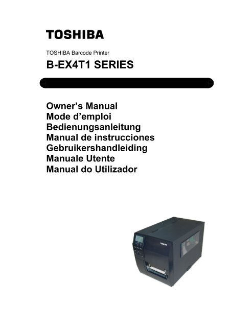
TOSHIBA <strong>Barcode</strong> PrinterB-<strong>EX4T1</strong> SERIESOwner's <strong>Manual</strong>
Waste Recycling information for users:Following information is only for EU-member states:<strong>The</strong> use of the crossed-out wheeled bin symbol indicates that this productmay not be treated as general household waste.By ensuring this product is disposed of correctly you will help preventpotential negative consequences for the environment and human health, which couldotherwise be caused by inappropriate waste handling of this product. For more detailedinformation about the take-back and recycling of this product, please contact your supplierwhere you purchased the product.
1. PRODUCT OVERVIEW ENGLISH VERSION EO1-330891.1 Introduction1. PRODUCT OVERVIEW1.1 IntroductionThank you for choosing the TOSHIBA B-<strong>EX4T1</strong> series bar code printer.This Owner’s <strong>Manual</strong> contains from general set-up through how toconfirm the printer operation using a test print, and should be readcarefully to help gain maximum performance and life from your printer.For most queries please refer to this manual and keep it safe for futurereference. Please contact your TOSHIBA TEC representative for furtherinformation concerning this manual.1.2 FeaturesThis printer has the following features:• <strong>The</strong> print head block can be opened providing smooth loading ofmedia and ribbon.• Various kinds of media can be used as the media sensors can bemoved from the centre to the left edge of the media.• Web functions such as remote maintenance and other advancednetwork features are available.• Superior hardware, including the specially developed 8 dots/mm (203dots/inch) or 12 dots/mm (305 dots/inch) thermal print head whichwill allow very clear print at a printing speed of 3 inches/sec., 6inches/sec., 10 inches/sec., 12 inches/sec. or 14 inches/sec. with 8dots/mm thermal head or 3 inches/sec., 5 inches/sec., 8 inches/sec., 10inches/sec., 12 inches/sec. or 14 inches/sec. with 12 dots/mm thermalhead.• Besides the optional Cutter Module, there is also an optional Peel offModule, Ribbon Saving Module, RS-232C I/F card, Centronics I/Fcard, Expansion I/O Card, Wireless LAN I/F card, the RTC/USB hostI/F card, RFID module, and Narrow width platen kit.1.3 UnpackingUnpack the printer as per the Unpacking Instructions supplied with theprinter.NOTES:1. Check for damage orscratches on the printer.However, please note thatTOSHIBA TEC shall have noliability for any damage ofany kind sustained duringtransportation of the product.2. Keep the cartons and padsfor future transportation ofthe printer.E1- 1
1. PRODUCT OVERVIEW ENGLISH VERSION EO1-330891.4 Accessories1.4 Accessories When unpacking the printer, please make sure all the followingaccessories are supplied with the printer. Power cord Safety precautions Quick installation manualE1- 2
1. PRODUCT OVERVIEW ENGLISH VERSION EO1-330891.5 Appearance1.5 Appearance1.5.1 Dimensions<strong>The</strong> names of the parts or units introduced in this section are used in thefollowing chapters.278 (10.9) 460 (18.1)310(12.2)Dimensions in mm (inches)1.5.2 Front ViewTop CoverLCD Message DisplaySupply WindowOperation PanelMedia Outlet1.5.3 Rear ViewReserved for Parallel InterfaceReserved for Serial orWLAN InterfaceUSB InterfaceReserved for USB HostInterfaceReserved for Expansion I/OinterfaceLAN InterfacePower SwitchAC Power InletE1- 3
1. PRODUCT OVERVIEW ENGLISH VERSION EO1-330891.6 Options1.6 OptionsOption Name Type DescriptionDisc cutter module B-EX204-QM-R Disc cutterEach time media is cut, the media feed is stopped.Rotary cutter module B-EX204-R-QM-R Rotary cutterOn-the-fly (non-stop) cut operation is enabled.Strip module B-EX904-H-QM-R This allows use of on-demand (peel-off) operation orto take-up labels and backing paper together whenusing the rewind guide plate. To purchase the stripmodule, please inquire at your local distributor.Ribbon saving module B-EX904-R-QM-R This module moves the print head up and down byusing a solenoid to minimize ribbon usage as far aspossible.Narrow width platen B-EX904-PK-QM-R This platen kit is for using narrow and thin paper.RFID module mountkitB-EX700-RFID-H1-QM-R This kit is to mount Tagsys HF RFID module andantenna.RFID moduleB-EX700-RFID-U2-EU-RB-EX700-RFID-U2-US-RB-EX700-RFID-U2-CN-RInstalling this module enables read and write ofUHF RFID tags.EU for EuropeUS for USA/CanadaCN for China203-dpi print head B-EX704-TPHE2-QM-R This print head enables a conversion of a 305dpiprint head of the B-<strong>EX4T1</strong>-TS12 model into 203dpiprint head.305-dpi print head B-EX704-TPHE3-QM-R This print head enables a conversion of a 203dpiprint head of the B-<strong>EX4T1</strong>-GS12 model into 305dpiprint head.RTC & USB hostinterface cardB-EX700-RTC-QM-RThis card holds the current time: year, month, day,hour, minute, second and provides a USB hostinterface.Installing this card in the printer allows connectionto an external device with the exclusive interface.Expansion I/O interface B-EX700-IO-QM-RcardParallel interface card B-EX700-CEN-QM-R Installing this card provides a Centronics interfaceport.Serial interface card B-EX700-RS-QM-R Installing this card provides an RS-232C interfaceport.Wireless LAN interfacecardB-EX700-WLAN-QM-RInstalling this card allows a communication bywireless LAN.NOTE:To purchase the optional kits, please contact the nearest authorised TOSHIBA TEC representative orTOSHIBA TEC Head Quarters.E1- 5
2. PRINTER SETUP ENGLISH VERSION EO1-330892. PRINTER SETUP2. PRINTER SETUPThis section outlines the procedures to setup your printer prior to its operation. <strong>The</strong> section includes precautions,loading media and ribbon, connecting cables, setting the operating environment of the printer, and performing anonline print test.Setup FlowInstallationConnecting the power cordProcedureAfter referring to the Safety Precautions in thismanual, install the printer on a safe and stablelocation.Connect a power cord to the power inlet of theprinter, then, to an AC outlet.Reference2.1 Installation2.2 Connecting the PowerCordLoading the mediaLoad a label stock or tag stock.2.3 Loading the MediaMedia sensor positionalignmentAdjust the position of feed gap sensor or blackmark sensor according to the media to be used.2.3.1 Loading the MediaLoading the ribbonIn case of thermal transfer printing, load theribbon.2.3.2 Loading the RibbonConnecting to a host computerConnect the printer to a host computer or anetwork.2.4 Connecting the Cables toYour PrinterTurning the power ONTurn on the printer power.2.5 Turning the PrinterON/OFFPrinter settingSet the printer parameters in the system mode.2.6 Printer SettingInstalling the printer driverPrint testIf necessary, install the printer driver in yourhost computer.Make a print test in your operatingenvironment and check the print result.2.7 Installing the PrinterDrivers2.8 Print TestPosition and Print Tone FineadjustmentAutomatic threshold setting<strong>Manual</strong> threshold settingIf necessary, fine adjust the print start position,cut/strip position, print tone, etc.If the print start position cannot be detectedproperly when pre-printed label is used, set thethreshold automatically.If the print start position cannot be detectedproperly even an automatic threshold setting isperformed, manually set the threshold.2.9 Position and Print ToneFine Adjustment2.10 Threshold Setting2.10 Threshold SettingE2- 1
2. PRINTER SETUP ENGLISH VERSION EO1-330892.1 Installation2.1 Installation To insure the best operating environment, and to assure the safety of theoperator and the equipment, please observe the following precautions.• Operate the printer on a stable, level, operating surface in a locationfree from excessive humidity, high temperature, dust, vibration ordirect sunlight.• Keep your work environment static free. Static discharge can causedamage to delicate internal components.• Make sure that the printer is connected to a clean source of ACPower and that no other high voltage devices that may cause linenoise interference are connected to the same mains.• Assure that the printer is connected to the AC mains with a threeprongpower cable that has the proper ground (earth) connection.• Do not operate the printer with the cover open. Be careful not toallow fingers or articles of clothing to get caught into any of themoving parts of the printer especially the optional cutter mechanism.• Make sure to turn off the printer power and to remove the power cordfrom the printer whenever working on the inside of the printer suchas changing the ribbon or loading the media, or when cleaning theprinter.• For best results, and longer printer life, use only TOSHIBA TECrecommended media and ribbons.• Store the media and ribbons in accordance with their specifications.• This printer mechanism contains high voltage components; thereforeyou should never remove any of the covers of the machine as youmay receive an electrical shock. Additionally, the printer containsmany delicate components that may be damaged if accessed byunauthorised personnel.• Clean the outside of the printer with a clean dry cloth or a clean clothslightly dampened with a mild detergent solution.• Use caution when cleaning the thermal print head as it may becomevery hot while printing. Wait until it has had time to cool beforecleaning. Use only the TOSHIBA TEC recommended print headcleaner to clean the print head.• Do not turn off the printer power or remove the power plug while theprinter is printing or while the ON LINE lamp is blinking.E2- 2
2. PRINTER SETUP ENGLISH VERSION EO1-330892.2 Connecting the Power Cord2.2 Connecting thePower CordCAUTION!1. Make sure that the printerPower Switch is turned tothe OFF position (◦)before connecting thePower Cord to preventpossible electric shock ordamage to the printer.2. Connect the Power Cordto a supply outlet with aproperly grounded(earthed) connection.1. Make sure that the printer Power Switch is in the OFF (◦) position.Connect the Power Cord to the printer as shown in the figure below.Power SwitchPower Cord2. Plug the other end of the Power Cord into a grounded outlet as shownin the figure below.Power CordPower Cord[Example of US Type][Example of EU Type]E2- 3
2. PRINTER SETUP ENGLISH VERSION EO1-330892.3 Loading Supplies2.3 Loading SuppliesWARNING!1. Do not touch any moving parts. To reduce the risk of fingers, jewellery, clothing, etc., beingdrawn into the moving parts, be sure to load the media once the printer has stopped movingcompletely.2. <strong>The</strong> Print Head becomes hot immediately after printing. Allow it to cool before loading the media.3. To avoid injury, be careful not to trap your fingers while opening or closing the cover.CAUTION!1. Be careful not to touch the Print Head Element when raising the Print Head Block. Failure to dothis may cause missing dots by static electricity or other print quality problems.2. When loading or replacing the media or a ribbon, be careful not to damage the print head with ahard object like a watch or a ring.Care must be taken not to allowthe metal or glass part of a watchto touch the print head edge.Care must be taken not to allowa metal object like a ring to touchthe print head edge.Since the print head element can be easily damaged by shock, please treat it carefully by nothitting a hard object against it.E2- 4
2. PRINTER SETUP ENGLISH VERSION EO1-330892.3 Loading Supplies2.3.1 Loading the Media <strong>The</strong> following procedure shows the steps to properly load the media intothe printer so that it feeds straight and true through the printer.NOTES:1. When the Head Lever isturned to FREE position, thePrint Head is raised.2. To enable printing the HeadLever must be set to theLABEL / TAG position.(This ensures that the PrintHead is closed.)<strong>The</strong>re are two head pressurelevels in the LABEL / TAGposition. Set the Head Leverdepending on the media type:Position LABEL: LabelsPosition TAG : TagsHowever, proper positionmay differ depending onmedia. For details, refer toyour TOSHIBA TECauthorised servicerepresentative.3. Do not turn the Locking Ringcounter-clockwise too far or itmay come off the SupplyHolder.<strong>The</strong> printer prints both labels and tags.1. Turn off the power and open the Top Cover.2. Turn the Head Lever to FREE position, then release the Ribbon ShaftHolder Plate.3. Open the Print Head Block.Print Head BlockFREELABELTAGHeadLeverTop CoverRibbon Shaft Holder Plate4. Turn the Locking Ring counterclockwise and remove the SupplyHolder from the Supply Shaft.Locking RingSupply ShaftSupply Holder5. Put the media on the Supply Shaft.6. Pass the media around the Guide Shaft, then pull the media towardsthe front of the printer.E2- 5
2. PRINTER SETUP ENGLISH VERSION EO1-330892.3 Loading Supplies2.3.1 Loading the Media(Cont.)NOTE:Do not over-tighten the LockingRing of the Supply Holder.7. Align the projection of the Supply Holder with the groove of theSupply Shaft, and push the Supply Holder against the media until themedia is held firmly in place. This will centre the mediaautomatically.<strong>The</strong>n turn the Locking Ring clockwise to secure the Supply Holder.Supply HolderGuide ShaftProjectionSupply ShaftLocking RingGrooveIn the case of a label rolled withthe print side facing inside.In the case of a label rolled withthe print side facing outside.MediaGuide Shaft8. Place the media between the Media Guides, adjust the Media Guidesto the media width, and tighten the Locking Screw.9. Check that the media path through the printer is straight. <strong>The</strong> mediashould be centred under the Print Head.Media GuidePrint HeadSupply HolderLocking ScrewMediaMedia GuideE2- 6
2. PRINTER SETUP ENGLISH VERSION EO1-330892.3 Loading Supplies2.3.1 Loading the Media(Cont.)10. Lower the Print Head Block until it stops.11. After loading the media, it may be necessary to set the MediaSensors used to detect the print start position for label or tag printing.Setting the Feed Gap Sensor position(1) <strong>Manual</strong>ly move the Media Sensor so that the Feed Gap Sensor ispositioned at the centre of the labels. (• indicates the position of theFeed Gap Sensor).GapLabel Media Sensor Feed Gap Sensor (•)NOTE:Be sure to set the black marksensor to detect the centre of theblack mark, otherwise a paperjam or no paper error may occur.Setting the Black Mark Sensor position(1) Pull about 500 mm of media out of the front of the printer, turn themedia back on itself and feed it under the Print Head past the sensorso that the black mark can be seen from above.(2) <strong>Manual</strong>ly move the Media Sensor so that the Black Mark Sensor isin line with the centre of the black mark on the media. (• indicatesthe position of the Black Mark Sensor).Black MarkMediaMedia SensorBlack Mark Sensor (•)E2- 7
2. PRINTER SETUP ENGLISH VERSION EO1-330892.3 Loading Supplies2.3.1 Loading the Media(Cont.)12. Batch modeIn the batch mode, the media is continuously printed and fed untilthe number of labels/tags specified in the issue command have beenprinted.13. Loading with peel off moduleWhen the optional Strip Module is fitted, the backing paper isautomatically removed from the label at the Strip Plate as each labelis printed.NOTES:1. Be sure to set the SelectionSwitch to STANDARD/PEEL OFF position.2. <strong>The</strong> backing paper is easierto feed back to the Take-UpSpool if the Front Plate isremoved.3. Fit the Take-Up Clip so thatthe longer side of the clip isfitted into the shallow groovein the Take-Up Spool.4. <strong>The</strong> backing paper can bewound directly onto theTake-up Spool or a papercore.(1) Remove enough labels from the leading edge of the media to leave500mm of backing paper free.(2) Insert the backing paper under the Strip Plate.(3) Wind the backing paper onto the Take-up Spool and fix it in positionwith the Take-up Clip. (Wind the paper counterclockwise aroundthe spool as this is the direction it rotates.)(4) Rotate the Take-up Spool counter-clockwise a few times to removeany slack in the backing paper.(5) Set the Selection Switch mounted on the Rewinder Assembly toSTANDARD/PEEL OFF position.Take-up SpoolStrip PlateBacking PaperTake-up ClipE2- 8
2. PRINTER SETUP ENGLISH VERSION EO1-330892.3 Loading Supplies2.3.1 Loading the Media(Cont.)WARNING!<strong>The</strong> cutter is sharp, so caremust be taken not to injureyourself when handling thecutter.14. Loading with cutterWhen the optional Cutter Module is fitted, the media isautomatically cut. A disc cutter and a rotary cutter are available asan option, but they are used in the same way.Insert the leading edge of the media into the cutter until it comes outthe Media Outlet of the Cutter Module.CAUTION!1. Be sure to cut the backingpaper of the label. Cuttinglabels will cause the glue tostick to the cutter whichmay affect the cutter qualityand shorten the cutter life.2. Use of tag paper when thethickness exceeds thespecified value may affectthe cutter life.Cutter ModuleMediaMedia OutletNOTE:When using the Rotary Cutter, besure to install the Ribbon SavingModule (B-EX904-R-QM-R).Failure to do this may cause apaper jam or ribbon error.E2- 9
2. PRINTER SETUP ENGLISH VERSION EO1-330892.3 Loading Supplies2.3.2 Loading the Ribbon <strong>The</strong>re are two types of media available for printing on: these are thermaltransfer media and direct thermal media (a chemically treated surface).DO NOT LOAD a ribbon when using a direct thermal media.NOTES:1. When attaching the ribbonstoppers, make sure that thepinchers face into the printer2. Be sure to remove any slack inthe ribbon when printing.Printing with a wrinkledribbon will lower the printquality.3. <strong>The</strong> Ribbon Sensor is mountedon the rear of the Print HeadBlock to detect a ribbon end.When a ribbon end isdetected, “NO RIBBON”message will appear on thedisplay and the ERROR LEDwill illuminate.1. Grasp the tabs on the top and bottom of the Ribbon Stoppers andmove the Ribbon Stoppers back to the end of the Ribbon Shaft.Ribbon StopperRibbon Shaft2. Leaving plenty of slack between the ribbon spools, place the ribbononto the Ribbon Shafts as shown below.Ribbon ShaftPrint Head BlockRibbon Take-up RollRibbon pathE2-10
2. PRINTER SETUP ENGLISH VERSION EO1-330892.3 Loading Supplies2.3.2 Loading the Ribbon(Cont.)3. Slide the Ribbon Stoppers along the Ribbon Shafts to a position wherethe ribbon is centred when fitted.4. Lower the Print Head Block and set the Ribbon Shaft Holder Platealigning its holes with the Ribbon Shafts.5. Take up any slack in the ribbon. Wind the leading tape onto theribbon take-up roll until the ink ribbon can be seen from the front ofthe printer.Ribbon ShaftHolder Plate6. Turn the Head Lever to Lock position to close the Print Head.7. Close the Top Cover.• Auto Ribbon Saving ModeWhen the optional Ribbon Saving Module (B-EX904-R-QM-R) isinstalled, it is possible to reduce ribbon loss by stopping the ribbon feedfor non-print areas. To activate the ribbon save, at least the followingnon-print area is required:203 dpi mode(mm)Print speed 3 ips 6 ips 10 ips 12 ips 14 ipsMin. non-print area 20 20 35 60 75305 dpi model(mm)Print speed 3 ips 5 ips 8 ips 10 ips 12 ips 14 ipsMin. non-print area 20 20 25 35 60 75E2-11
2. PRINTER SETUP ENGLISH VERSION EO1-330892.4 Connecting the Cables to Your Printer2.4 Connecting theCables to YourPrinter<strong>The</strong> following paragraphs outline how to connect the cables from theprinter to your host computer, and will also show how to make cableconnections to other devices. Depending on the application softwareyou use to print labels, there are 5 possibilities for connecting theprinter to your host computer. <strong>The</strong>se are:• An Ethernet connection using the printer’s standard LANconnector.• A USB cable connection between the printer’s standard USBconnector and your host computer’s USB port. (Conforming toUSB 2.0)• A serial cable connection between the printer’s optional RS-232serial connector and one of your host computer’s COM ports.• A parallel cable connection between the printer’s optional parallelconnector and your host computer’s parallel port (LPT).• Wireless LAN using an optional Wireless LAN board.For details, refer to APPENDIX 2.Reserved forParallel InterfaceReserved for Serial orWLAN InterfaceUSB InterfaceReserved for USB HostinterfaceReserved forExpansion I/O InterfaceLAN InterfacePower SwitchAC Power InletE2-12
2. PRINTER SETUP ENGLISH VERSION EO1-330892.5 Turning the Printer ON/OFF2.5 Turning the PrinterON/OFFWhen the printer is connected to your host computer it is good practice toturn the printer ON before turning on your host computer and turn OFFyour host computer before turning off the printer.2.5.1 Turning ON the PrinterCAUTION!Use the power switch to turnthe printer On/Off. Pluggingor unplugging the Power Cordto turn the printer On/Off maycause fire, an electric shock,or damage to the printer.1. To turn ON the printer power, press the Power Switch as shown in thediagram below. Note that ( | ) is the power ON side of the switch.Power SwitchNOTE:If a message other than ONLINE appears on the display orthe ERROR LED lamp isilluminated, refer to Section 5.1,Error Messages.2. Check that the ON LINE message appears in the LCD MessageDisplay and that the ON LINE and POWER LED lights areilluminated.2.5.2 Turning OFF the PrinterCAUTION!1. Do not turn off the printerpower while the media isbeing printed, as this maycause a paper jam ordamage to the printer.2. Do not turn off the printerpower while the ON LINElamp is blinking as thismay cause damage toyour computer.1. Before turning off the printer Power Switch verify that the ON LINEmessage appears in the LCD Message Display and that the ON LINELED light is on and is not flashing.2. To turn OFF the printer power press the Power Switch as shown in thediagram below. Note that (◦) is the power OFF side of the switch.Power SwitchE2-13
2. PRINTER SETUP ENGLISH VERSION EO1-330892.6 Printer Setting2.6 Printer Setting Depending on the settings of your host computer or an interface to beused, it may be necessary to change the printer parameter settings.Follow the procedures described below to change the printer parametersettings to correspond to your environment.NOTE:Incorrect settings can cause the printer to function erroneously. If you haveany problems with the parameter settings, please contact your nearestTOSHIBA TEC service representative.For the settings this manual does not cover, please contact your nearestTOSHIBA TEC service representative, or refer to the B-EX4T Series KeyOperation Specification.Power OFFPower ONONLINE Mode[PAUSE]PAUSE stateHold down [RESTART]Hold down [MODE]User System ModeTurn on the power while holdingdown [FEED] & [PAUSE] or[MODE].System Mode• Reset• Parameter setting (⇒Section 2.6.2)• Fine adjustment (⇒Section 2.9)• LAN/WLAN (⇒Section 2.6.3)• BASIC (⇒Section 2.6.4)• Z-MODE (⇒Section 2.6.5)• Auto calibration (⇒Section 2.6.6)• Dump mode (⇒Section 2.6.7)• Log (⇒Section 2.6.8)• Self diagnosis• Parameter setting• Fine adjustment• Test print (⇒Section 2.8)• Sensor adjustment• RAM clear• Interface setting (⇒Section 2.6.10)• BASIC mode• RFID setting• Real Time Clock (⇒Section 2.6.11)• Z-MODE• USB memory• ResetE2-14
2. PRINTER SETUP ENGLISH VERSION EO1-330892.6 Printer Setting2.6 Printer Setting(Cont.)FEEDMODELEFTCANCELDOWNPAUSERESTARTUPRIGHTENTER• Key functions in the system modeKeyFunction[MODE]Returns to the mode menu screen.[CANCEL] or Returns to the upper hierarchy.[FEED]+[RESTAR][ENTER] or [PAUSE] Displays a next screen.Saves the setting and returns to the upperhierarchy.[UP] or [RESTART](Note 1)Moves the cursor upward.(Note 2)Increases a value.[DOWN] or [FEED](Note 1)Moves the cursor downward.(Note 3)Decreases a value.[LEFT](Note 3)Moves the cursor to the left.[RIGHT](Note 3)Moves the cursor to the right.NOTES:1. <strong>The</strong> cursor does not move any further when the selected option is listedat the top or bottom.2. <strong>The</strong> value does not increase or decrease any further when the selectedvalue is the upper or lower limit.3. <strong>The</strong> cursor does not move any further when it is at the left-most orright-most position.4. Be careful the selected value does not become effective if the printer isturned off without pressing the [ENTER] key.2.6.1 User System ModeHow to enter the User System ModeONLINE[PAUSE]Hold down [MODE]Hold down [RESTART]User System Mode<strong>The</strong> User System Mode consists of the following menus.RESETUsed to reset the printer.PARAMETER SET (⇒ Section 2.6.2)Used to set the printer parameters.ADJUST SET (⇒ Section 2.9)Used to fine adjust the print start position, cut position, etc.LAN/WLAN (⇒ Section 2.6.3)Used to enable or disable the LAN communication and SNMP.BASIC (⇒ Section 2.6.4)Used to set the function of basic program when it is loaded to theprinter.Z-MODE (⇒ Section 2.6.5)Same as BASICAUTO CALIB (⇒ Section 2.6.6)Used to enable or disable the automatic calibration function.DUMP MODE (⇒ Section 2.6.6)Used to print the data in the receive buffer for debug.LOG (⇒ Section 2.6.7)Used to save print logs in a USB memory.E2-15
2. PRINTER SETUP ENGLISH VERSION EO1-330892.6 Printer Setting2.6.2 Parameter Setting <strong>The</strong> Parameter Set menu allows configuring printer parameter settings.<strong>The</strong> following table shows the contents of the Parameter Set menu.USER SYSTEM MODERESETPARAMETER SETADJUST SETLAN/WLANContents of the Parameter Set MenuMenu Sub menu ParameterParameter Printer Set MEDIA LOADset (Section 2.6.2.1) FORWARD WAITFW/BK ACTHU CUT/RWDRBN SAVEPRE PEEL OFFBACK SPEEDSoftware Set FONT CODE(Section 2.6.2.2) ZERO FONTCODEPEEL OFF STATUSUSB I/F STATUSFEED KEYKANJI CODEEURO CODEAUTO HD CHKWEB PRINTERRBN NEAR ENDEX I/OLBL/RBN ENDMAX CODEXMLTHRESHOLD SELECTENERGY TYPEPW SAVE TIMEPanelLCD LANGUAGE(Section 2.6.2.3) DISPLAYCONTRASTPassword PASSWORD(Section 2.6.2.4)E2-16
2. PRINTER SETUP ENGLISH VERSION EO1-330892.6 Printer Setting2.6.2 Parameter Setting(Cont.)2.6.2.1 Printer Set(1) MEDIA LOADThis parameter is to choose how the printer behaves to detect thehome position.• OFF• STD• ECO• ECO+BfeedMedia loading function is disabled (Same as a feedby [FEED] key)When the printer is tuned on, reset in batch, or printhead is closed, the printer detects a gap/black markand feeds the paper from the sensor to the print startposition.When the printer is tuned on, reset in batch, or printhead is closed, the printer detects a gap/black markand feeds the paper to the print start position basedon the label pitch.Economy + backfeed(2) FORWARD WAITThis parameter is to choose whether or not to activate the auto forwardwait function. This function, used in the cut mode, automaticallyfeeds the media forward if there is more than 1-second idle time afterprinting, to prevent the top edge of the media from curling.• OFF• ONDisables the auto forward feed waitEnables the auto forward feed wait(3) FORWARD WAIT POS.When the auto forward feed wait parameter is set to ON, the feedamount can be fine adjusted.+5.0mm+4.9mm-4.9mm-5.0mm(4) FW/BK ACT..• MODE1• MODE2<strong>The</strong> printer waits for next issue with 13.7-mm mediaforwarded.When the thermal transfer method, Transmissivesensor, and cut issue are selected, the printer feeds 6-mm media backward, then waits for next issue with3-mm media forwarded.E2-17
2. PRINTER SETUP ENGLISH VERSION EO1-330892.6 Printer Setting2.6.2 Parameter Setting(Cont.)NOTE:<strong>The</strong> print head may not be raiseddepending on the rise of thesolenoid’s temperature.(5) HU CUT/RWD.This parameter is to choose whether or not to activate the head upaction in the cut issue or to use the Rewinder in the batch or strip issue.This function prevents ribbon smudges by raising the print headduring a reverse feed to the print start position.• OFF• ONHead up cut is not performed or the Rewinder is notused.Head up cut is performed or the Rewinder is used.NOTE:1. Do not enable the ribbon savingfunction when the ribbon savingmodule is not installed. Doing socauses ribbon slack and printfailure.2. <strong>The</strong> ribbon saving option must beselected according to the headlever position. Incorrect settingmay disable the proper ribbonsaving function.NOTE:Pre-strip function is automaticallyenabled when the print speed is set to10 ips.(6) RBN SAVEThis parameter is to choose whether or not to activate the ribbonsaving function. This function enables reducing the ribbon losscaused by taking up unused ribbon during non-print areas.• TAG• LABEL• OFFEnabled (When the head lever is set to TAGposition.)Enabled (When the head lever is set to Labelposition)Disabled.(7) PRE PEEL OFFThis parameter is to choose whether to activate the pre-strip function.When this parameter is set to ON, the top edge of a label is separated(pre-stripped) from the backing paper before the label is printed. Thisfunction is intended to make the strip issue easier in the case the labelsare hard to strip due to the label intensity, adhesive power, or theprinting speed.• OFF• ONDisables pre peel offEnables pre peel off(8) BACK SPEEDThis parameter is to choose a back feed speed.In the strip issue, the back feed sped of 3 ips may cause a shortage offeed amount due to a lack of torque, slippery media surface, etc. Insuch case, reduce the back feed speed to 2 ips to secure the feedamount.• STD• LOW3ips2ipsE2-18
2. PRINTER SETUP ENGLISH VERSION EO1-330892.6 Printer Setting2.6.2 Parameter Setting(Cont.)2.6.2.2 Software Set(1) FONT CODEThis parameter is to choose a character code used for printing. Printedcharacters differ depending on the chosen character code and font.• PC-850• PC-852• PC-857• PC-8• PC-851• PC-855• PC-1250• PC-1251• PC-1252• PC-1253• PC-1254• PC-1257• LATIN9• Arabic• PC-866• UTF-8NOTE:<strong>The</strong> following fonts do not support azero with a slash.<strong>The</strong>refore, even if a zero with a slash isspecified, a zero without a slash isused.[Bit map fonts]OCR-A, OCR-B, GOTHIC725 Black,Kanji, Chinese character[Outline fonts]Price fonts 1, 2, and 3, DUTCH801Bold, BRUSH738 Regular,GOTHIC725 Black, TrueType font(2) ZERO FONTThis parameter is to choose the way to indicate zero between “0” and“Ø”.• 0• ØNo slash usedSlash used(3) CODEThis parameter is to choose a command control code.• AUTO Automatically selected.• {,|,}• ESC, LF, NUL• MANUAL Control code is specified by a user.(4) MANUALWhen MANUAL is selected for the CODE parameter, you need tospecify each of the control codes 1 to 3 with hex. code.FFFECODE1 CODE2 CODE30100E2-19
2. PRINTER SETUP ENGLISH VERSION EO1-330892.6 Printer Setting2.6.2 Parameter Setting(Cont.)(5) PEEL OFF STATUSThis parameter is to choose whether the printer sends a strip waitstatus to the host in response to a status request command.• OFF• ON(6) USB I/F STATUSThis parameter is to choose whether or not to return a response to thehost via USB.• OFF• ONDisables sending a response via USBEnables sending a response via USB(7) FEED KEYThis parameter is to choose the function of the FEED key.• FEED• PRINTFeeds one label.Prints data in the image buffer (<strong>The</strong> last printed data)(8) KANJI CODEThis parameter is to choose a KANJI code.• TYPE1• TYPE2Windows codeOriginal codeAfter selecting a Kanji code, press [ENTER] key(9) EURO CODEThis parameter is to choose a Euro code (€).“20” to “FF” (Specify the hex code in 2 bytes of ASCII code)FFFE2120(10) AUTO HD CHKThis parameter is to choose whether to perform the auto print headcheck at a power on time.• OFF• ONAuto print head check is not performed.Auto print head check is performed.E2-20
2. PRINTER SETUP ENGLISH VERSION EO1-330892.6 Printer Setting2.6.2 Parameter Setting(Cont.)(11) WEB PRINTERThis parameter is to choose whether to use the printer as a web printer.When the web printer is enabled, the status of the printer connected toa network can be monitored through the web browser.• OFF• ON INTERNAL• ON EXTERNALDisables web printer functionEnables web printer function (using an internalmemory)Enables web printer function (using an externalmemory)NOTE:Since a detected remainingribbon length has some margin oferror, use the specified length asa guide.(12) RBN NEAR ENDThis parameter is to choose the remaining ribbon length where theribbon near end is detected.• OFF• 30m• 70mRibbon near end is not detected.Ribbon near end is detected when the remainingribbon is 30-m long. (Equivalent to ribbon diameterof 38 mm)Ribbon near end is detected when the remainingribbon is 70-m long. (Equivalent to ribbon diameterof 43 mm)(13) EX.I/OThis parameter is to choose a type of the expansion I/O interfaceoperating mode. This parameter needs to be set depending on theexpansion I/O control specification of the device to be connected viathe expansion I/O interface.• TYPE1• TYPE2Standard modeIn-line mode(14) LBL/RBN ENDThis parameter is to choose a printer processing when a label end orribbon end is detected.NOTE:<strong>The</strong> type specified by thecommand may differ from theactual mode, depending on thestatus of this parameter. Also,the data transmission methoddiffers partly.For details, refer to the ExternalEquipment InterfaceSpecification.• TYPE1• TYPE2When a label/ribbon end is detected in the middle ofprinting, the printer immediately stops printing.Selectable only when the ribbon saving function isnot activated.When a label/ribbon end is detected in the middle ofprinting, the printer prints the half-finished label asfar as possible, and stops when the next label is at thehome position.(15) MAXI CODEThis parameter is to choose a Maxicode specification.• TYPE1• TYPE2Compatible with the current versionSpecial specificationE2-21
2. PRINTER SETUP ENGLISH VERSION EO1-330892.6 Printer Setting2.6.2 Parameter Setting(Cont.)(16) XMLThis parameter is to choose a type of XML data to be printed.• OFF Disables XML data printing.• STD Standard specification• ORACLE Oracle• SAP SAP• STD EXT Standard specification (External memory)• ORACLE EXT Oracle using an external memory• SAP EXT SAP using an external memory(17) THRESHOLD SELECTThis parameter is to choose which threshold value for the mediasensor to validate.• REFLECT• TRANS.Reflective sensorTransmissive sensor<strong>The</strong>n, choose which value to use.• MANUAL SET Threshold set in the Threshold mode takeseffect.• COMMAND SET Threshold set by command takes effect.(18) ENERGY TYPEThis parameter is to choose an energy level applied to the print head.• TRANSFER• DIRECT<strong>The</strong>rmal transfer print method → <strong>The</strong>rmal direct print method → When TRANSFER is selected for the Energy type parameter,choose a ribbon type.• Semi resin1 Semi-resin 1• Semi resin2 Semi-resin 2• Resin1 Resin 1• Resin2 Resin 2• Reserve1 to Reserve6 Reserved When DIRECT is selected for the Energy type parameter• StandardStandard• Reserve1 to Reserve9 Reserved(19) PW SAVE TIMEThis parameter is to set the length of time until the printer enters thesleep mode. (Unit: minute)240 min.239 min.2 min.1 min.E2-22
2. PRINTER SETUP ENGLISH VERSION EO1-330892.6 Printer Setting2.6.2 Parameter Setting(Cont.)NOTE:<strong>The</strong> language displayed onpanel is Japanese whenJapanese is selected, andEnglish when English, German,French, Dutch, Spanish, Italian;or Portuguese is selected.2.6.2.3 PANEL(1) LCD LANGUAGEThis parameter is to choose a language in which the LCD message isdisplayed.• ENGLISH• GERMAN• FRANCH• DUTCH• SPANISH• JAPANESE• ITALIAN• PORTUGUESE(2) MACHINE NAMEThis parameter is to choose whether to display the model name.• OFF• ONHiddenDisplayed(3) PRINT PAGEThis parameter is to choose whether to display the number of labelsprinted.• OFF• ONHiddenDisplayed(4) IP ADDRESSThis parameter is to choose whether to display the IP address.• OFF• ONHiddenDisplayed(5) CONTRASTThis parameter is to adjust the contrast of the LCD.50High482624LowE2-23
2. PRINTER SETUP ENGLISH VERSION EO1-330892.6 Printer Setting2.6.2 Parameter Setting(Cont.)2.6.2.4 PASSWORD(1) PASSWORDThis parameter is for system administrator only. Please do not changethe setting for this parameter.2.6.3 Enabling LAN/WLANUSER SYSTEM MODERESETPARAMETER SETADJUST SETLAN/WLAN<strong>The</strong> LAN/WLAN menu allows selecting whether or not to enable theLAN communication and SNMP.(1) LAN/WLAN• OFF• ON (AUTO)• ON (LAN)• ON (WLAN)LAN and Wireless LAN are disabled.Automatically selected.LAN is enabled.Wireless LAN is enabled.(2) SNMP• OFF• ONSNMP is disabled.SNMP is enabled.2.6.4 Basic Program SettingUSER SYSTEM MODEPARAMETER SETADJUST SETLAN/WLANBASIC<strong>The</strong> following table shows the contents of the Basic program settingmenu.Contents of the Basic Program Setting MenuMenuBASICSub menuBASICFILE MAINTENANCETRACEEXPAND MODE(1) BASICThis parameter is to choose whether to enable the BASIC program.• OFF• ONDisables BASIC program.Enables BASIC program.(2) FILE MAINTENANCE<strong>The</strong> block number and BASIC program file name (up to 12 characters)stored in the BASIC program storage area are displayed. If file nameexceeds 12 characters, the overflowing characters are not displayed.When no file is stored, a hyphen (“-“) is displayed in place of the filename.E2-24
2. PRINTER SETUP ENGLISH VERSION EO1-330892.6 Printer Setting2.6.4 Basic Program Setting(Cont.)(3) TRACEThis parameter is to choose whether to enable tracing the BASICprogram.• OFF• ONDisables tracing the BASIC program.Enables tracing the BASIC program.(4) EXPAND MODE<strong>The</strong> printer switches the mode to execute the BASIC program.2.6.5 Enabling Z-Mode<strong>The</strong> Z-Mode menu allows selecting whether or not to enable the Z-Mode(Zebra converter).USER SYSTEM MODEADJUST SETLAN/WLANBASICZ-MODE(1) Z-MODE• OFF• ON SETTING OFF• ON SETTING ONZ-Mode is disabled.Z-Mode is enabled. BASIC system modeprogram is not started immediately.Z-Mode is enabled. BASIC system modeprogram is started immediately.E2-25
2. PRINTER SETUP ENGLISH VERSION EO1-330892.6 Printer Setting2.6.6 Automatic Calibration <strong>The</strong> Auto Calibration menu allows selecting whether or not to enable theautomatic calibration at a power on time. When the automatic calibrationUSER SYSTEM MODELAN/WLANBASICZ-MODEAUTO CALIBis activate, the printer feeds the media for about 160 mm each time thepower is turned on or the top cover is opened, to detect a print startposition.(1) AUTO CALIB• OFF• ON TRANS.• ON REFLECT• ON ALL• ON TRANS.+Bfeed• ON REFLECT+Bfeed• ON ALL+BfeedDisabled.Enabled. (Transmissive sensor)Enabled. (Reflective sensor)Enabled. (Transmissive & Reflectivesensors)Auto calibration + back feed(Transmissive sensor)Auto calibration + back feed(Reflective sensor)Auto calibration + back feed(Transmissive & Reflective sensors)NOTES:1. When AUTO CALIB is enabled, an automatic calibration is performed atan open/close of the print head and at a power on time.2. When AUTO CALIB is enabled, the media length, effective print length,sensor type, and whether to use ribbon or not specified by commands areignored.3. This function is available only when the media pitch is 10.0 mm to 150.0mm.4. When the printer cannot detect the second black mark/gap, it willcontinue to feed the media for up to 500.0mm. If this does not work, theprinter will stop, resulting in a paper jam.5. During an automatic calibration, the printer also feeds the ribbon. Evenif the ribbon is not loaded, no error results. However, the print conditionwill be automatically changed to “No ribbon” after the calibration ends.6. When the cutter is installed and a previous issue was performed in cutissue mode, the media is cut and ejected after an automatic calibrationcompletes.7. When a label end or a head open occurs during an automatic calibration,the printer stops, resulting in an error. Loading new media and closingthe print head can clear the error and resume the automatic calibration.8. <strong>The</strong> media is fed backward after an auto calibration is performed if thereverse feed is enabled.E2-26
2. PRINTER SETUP ENGLISH VERSION EO1-330892.6 Printer Setting2.6.7 Dump Mode Setting In the Dump Mode, data in the receive buffer are printed. Data areexpressed in hexadecimal values. This operation allows verification ofthe programming commands or debug of the program.USER SYSTEM MODEBASICZ-MODEAUTO CALIBDUMP MODE(1) BUFFERThis parameter is to choose the receive buffer to dump.• RS-232C• CENTRONICS• LAN• BASIC1• BASIC2• USB• RFIDRS-232C receive bufferCentronics receive bufferNetwork I/F receive bufferBASIC Interpreter:I/F → Interpreter bufferBASIC Interpreter:Interpreter buffer → I/FUSB receive bufferRFID receive buffer(2) DUMP LISTThis parameter is to choose the output destination.• USB MEMORY• PRINTSaves in the USB memory. → Prints out → NOTE:If a file with the same namealready exists in the USBmemory, it will be overwritten. When USB MEMORY is selected:A file is automatically created in the USB memory and named in thefollowing format based on the printer model and saved date./ATA0/DUMP/B-<strong>EX4T1</strong>_DUMP_1007291030.BIN(e.g. B-EX4T Type1, 10:30, July 29, 2010) When PRINT is selected:Choose a printing method.• ON DEMAND Prints 166 lines of data (approx. 50 cm), thenstops. Subsequent data is printed when the[ENTER] key is pressed.• ALLPrints all data in the receive buffer.E2-27
2. PRINTER SETUP ENGLISH VERSION EO1-330892.6 Printer Setting2.6.7 Dump Mode Setting(Cont.)Print Conditions• Printing width: 3.9 inches(Approx. 100 mm)• Sensor selection: None• Print speed: 6”/sec. (203 dpi)5”/sec. (305 dpi)• Printing mode: Depends on theselection in use.• 16 bytes/line• Data is printed in the order fromthe new one to the old one.• Data specified by the receivebuffer write pointer will beprinted in boldface.<strong>The</strong> data in the receive buffer is printed as follows.:::00 00 00 00 00 00 00 00 00 00 00 00 00 00 00 00 ................00 00 00 00 00 00 00 00 00 00 00 00 00 00 00 00 ................00 00 00 00 00 00 00 00 00 00 00 00 00 00 00 00 ................00 00 00 00 00 00 00 00 00 00 00 00 00 00 00 00 ................7B 41 58 3B 2B 30 30 30 2C 2B 30 30 30 2C 2B 30 {AX;+000,+000,+030 7C 7D 7B 44 30 37 37 30 2C 31 31 30 30 2C 30 0|}{D0760,1100,037 34 30 7C 7D 7B 43 7C 7D 7B 4C 43 3B 30 30 33 740|}{C|}{LC;00330 2C 30 30 32 30 2C 30 30 33 30 2C 30 36 36 30 0,0020,0030,06602C 30 2C 32 7C 7D 7B 4C 43 3B 30 30 37 30 2C 30 0,2|}{LC;0070,030 32 30 2C 30 30 37 30 2C 30 36 36 30 2C 30 2C 020,0070,0660,0,39 7C 7D 7B 4C 43 3B 30 30 35 30 2C 30 30 32 30 9|}{LC;0050,0020:::44 45 46 47 48 49 4A 7C 7D 7B 50 43 31 30 3B 30 DEFGHIJ|}{PC10;033 35 30 2C 30 34 30 30 2C 31 2C 31 2C 4B 2C 30 350,0400,1,1,K,030 2C 42 3D 41 42 43 44 65 66 67 68 69 6A 6B 6C 0,B=ABCDefghijkl6D 6E 6F 70 7C 7D 7B 50 56 30 32 3B 30 33 33 30 mnop|}{PV02;03302C 30 36 36 30 2C 30 32 37 30 2C 30 32 35 30 2C 0660,0270,0250,41 2C 30 30 2C 42 3D 42 7C 7D 7B 50 56 30 33 3B A,00,B=B|}{PV03;:::3B 30 39 30 30 2C 30 31 38 30 2C 54 2C 48 2C 30 ;0900,0180,T,H,035 2C 41 2C 30 3D 31 32 33 34 35 36 37 38 39 30 5,A,0=123456789041 42 43 44 45 7C 7D 00 00 00 00 00 00 00 00 00 ABCDE|}.........:::NOTE:If an error occurs while printing,the printer stops printing andshows an error message.After clearing the error, theprinter does not resume printingautomatically.Receive Buffer SizeInterface 203 dpi 305 dpiRS-232C 6MB (393216 lines) 6MB (393216 lines)Centronics 6MB (393216 lines) 6MB (393216 lines)LAN 6MB (393216 lines) 6MB (393216 lines)BASIC 1 8KB (512 lines) 8KB (512 lines)BASIC 2 8KB (512 lines) 8KB (512 lines)USB 6MB (393216 lines) 6MB (393216 lines)RFID 8KB (512 lines) 8KB (512 lines)Required Media LengthInterface 203 dpi 305 dpiRS-232C 1189.2 m 1189.2 mCentronics 1189.2 m 1189.2 mLAN 1189.2 m 1189.2 mBASIC 1 2 m 2 mBASIC 2 2 m 2 mUSB 1189.2 m 1189.2 mRFID 2 m 2 m*: Media length required for printing all data in the receive buffer.E2-28
2. PRINTER SETUP ENGLISH VERSION EO1-330892.6 Printer Setting2.6.8 Logging <strong>The</strong> Log menu allows saving print logs in a USB memory.USER SYSTEM MODEZ-MODEAUTO CALIBDUMP MODELOGNOTE:If a file with the same namealready exists in the USBmemory, it will be overwritten.(1) LOG• PRINTER TO USBSaves print logs in the USB memory.A file is automatically created in the USB memory and named in thefollowing format based on the printer model and saved date./ATA0/LOG/B-<strong>EX4T1</strong>_LOG_1007291030.TXT(e.g. B-EX4T Type1, 10:30, July 29, 2010)E2-29
2. PRINTER SETUP ENGLISH VERSION EO1-330892.6 Printer Setting2.6.9 System Mode How to enter the System ModePower ON while holding down[FEED]&[PAUSE]Power OFFPower ON while holding down[MODE]System Mode<strong>The</strong> System Mode consists of the following menus.DIAG.Used to check and print the printer system information andmaintenance counter status.PARAMETER SET (⇒ Section 2.6.2)Used to set the parameters for each printer function.ADJUST SET (⇒ Section 2.9)Used to fine adjust the print position, cut position, print tone, etc.TEST PRINT (⇒ Section 2.8)Used to perform print tests.SENSOR ADJUSTUsed to check the sensor statuses and set each sensor.RAM CLEARUsed to perform a RAM clear. DO NOT USE this menu.INTERFACE (⇒ Section 2.6.10)Used to set the interface parameters.BASIC (⇒ Section 2.6.4)Used to set the function of basic program when it is loaded to theprinter.FOR FACTORYUsed for an in-process inspection. DO NOT USE this menu.RFIDUsed to set RFID related parameters.RTC (⇒ Section 2.6.11)Used to set the date and time of the real time clock, enable or disablethe low battery check, and choose a real time renewal timing.Z-MODE (⇒ Section 2.6.5)Same as BASICUSB MEMORY (⇒ Section 2.6.12)Used to copy data to/from USB memory.RESETUsed to reset the printer.E2-30
2. PRINTER SETUP ENGLISH VERSION EO1-330892.6 Printer Setting2.6.10 Interface Setting <strong>The</strong> Interface menu allows configuring printer interface parameters.<strong>The</strong> following table shows the contents of the Interface menu.SYSTEM MODETEST PRINTSENSOR ADJUSTRAM CLEARINTERFACEContents of the Interface MenuMenu Sub menu ParameterInterface NETWORK LAN/WLANUSBRS-232CCENTRO.SNMPSETTINGBASIC INFORMATIONIP ADDRESSGATEWAY ADDRESSSUBNET MASKSOCKET PORTPORT NUMBERDHCPDHCP CLIENT IDDHCP HOST NAMEWLAN STANDARDWLAN MODEDEFAULT KEY802.11B CHANNEL802.11B BAUD802.11G CHANNEL802.11G BAUDWLAN POWER SAVEWINSWINS ADDRESSLPRSPEEDDATA LENGTHSTOP BITPARITYCONTROLACK/BUSYINPU PRIMEPLUG & PLAYE2-31
2. PRINTER SETUP ENGLISH VERSION EO1-330892.6 Printer Setting2.6.10 Interface Setting(Cont.)2.6.10.1 Network Setting(1) LAN/WLAN• OFF• ON (AUTO)• ON (LAN)• ON (WLAN)LAN and Wireless LAN are disabled.Automatically selected.LAN is enabled.Wireless LAN is enabled.(2) SNMP• OFF• ONSNMP is disabled.SNMP is enabled.(3) BASIC INFORMATION<strong>The</strong> following information is displayed.IP AddressGateway addressSubnet maskSocket port statusSocket port number(4) IP ADDRESS192 168 020 010(5) GATEWAY ADDRESS192 168 020 010(6) SUBNET MASK255 255 255 000(7) SOCKET PORT• OFF• ONSocket port is disabled.Socket port is enabled.E2-32
2. PRINTER SETUP ENGLISH VERSION EO1-330892.6 Printer Setting2.6.10 Interface Setting(Cont.)(8) PORT NUMBER65535655340000100000(9) DHCP• OFF• ONDHCP is disabled.DHCP is enabled.(10) DHCP CLIENT ID• ASCII• HEXDHCP client ID is entered with ASCII code. → DHCP client ID is entered with Hex. code. → When ASCII is selected:Enter 64 characters with ASCII code. When HEX is selected:Enter 64 characters with Hex. code.(11) DHCP HOST NAMEEnter 32 characters with ASCII code.(12) WLAN STANDARD• 11b/g• 11b• 11gE2-33
2. PRINTER SETUP ENGLISH VERSION EO1-330892.6 Printer Setting2.6.10 Interface Setting(Cont.)(13) WLAN MODEThis parameter is to choose the connection mode and authentication.ADHOC OPEN OFFWEP40WEP104SHARED Not used WEP40WEP104INFRA OPEN OFFWEP40WEP104SHARED WEP40WEP104802.1x OPEN TLS WEP40WEP104TTLS WEP40WEP104LEAP WEP40WEP104PEAP WEP40WEP104MD5 WEP40WEP104EAP-FAST WEP40WEP104SHARED KEY EAP-MD5 WEP40WEP104NETWORK EAPWEP40WEP104WPA OPEN TLSTTLSLEAPPEAPEAP-FASTNETWORK EAPWPA-PSKWPA2 OPEN TLSTTLSLEAPPEAPEAP-FASTNETWORK EAPWPA2-PSKE2-34
2. PRINTER SETUP ENGLISH VERSION EO1-330892.6 Printer Setting2.6.10 Interface Setting(Cont.)(14) DEFAULT KEYThis parameter is to choose a WEP key.41(15) 802.11b CHANNELThis parameter is to choose a channel for 802.11b WLAN.141(16) 802.11b BAUDThis parameter is to choose a baud rate for 802.11b WLAN.• 11M• 5.5M• 2M• 1M(17) 802.11g CHANNELThis parameter is to choose a channel for 802.11g. WLAN.141(18) 802.11g BAUDThis parameter is to choose a baud rate for 802.11g WLAN.• 54M• 48M• 36M• 24M• 18M• 12M• 9M• 6M• 11M• 5.5M• 2M• 1ME2-35
2. PRINTER SETUP ENGLISH VERSION EO1-330892.6 Printer Setting2.6.10 Interface Setting(Cont.)(19) WLAN POWER SAVEThis parameter is to choose whether to enable the power save functionwhile WLAN communication.• OFF• ONPower save function is disabled.Power save function is enabled.(20) WINS• OFF• ON (MANUAL)• ON (DHCP)WINS is disabled.WINS is enabled. (<strong>Manual</strong>)WINS is enabled. (DHCP)(21) WINS ADDRESS<strong>The</strong> WINS address is displayed.(22) LPR• OFF• ONLPR is disabled.LPR is enabled.2.6.10.2 USB(1) USB SERIAL ID• OFF• ONUSB serial ID is disabled.USB serial ID is enabled.2.6.10.3 RS-232C(1) SPEED• 2400 bps• 4800 bps• 9600 bps• 19200 bps• 38400 bps• 115200 bpsE2-36
2. PRINTER SETUP ENGLISH VERSION EO1-330892.6 Printer Setting2.6.10 Interface Setting(Cont.)(2) DATA LENGTH• 8 bits• 7 bits(3) STOP BIT• 1 bit• 2 bits(4) PARITY• NONE• EVEN• ODD(5) CONTROL• XON+READY AUTO• XON+XOFF AUTO• READY/BUSY RTS• XON+XOFF• READY/BUSYXON/XOFF modeXON/XOFF+READY/BUSY modeRTS modeXON/XOFF modeREADY/BUSY mode2.6.10.4 CENTRO.(1) ACK/BUSYThis parameter is to choose an ACK/BUSY timing.• TYPE1• TYPE2A rise of ACK signal and a release of BUSY occur at thesame time.A fall of ACK signal and a release of BUSY occur at thesame time.(2) INPUT PRIMEThis parameter is to choose whether to enable a rest operation whenINIT signal is ON.• OFF• ON(3) PLUG & PLAY• OFF• ONE2-37
2. PRINTER SETUP ENGLISH VERSION EO1-330892.6 Printer Setting2.6.11 Real Time Clock (RTC) <strong>The</strong> RTC menu allows setting the date and time, enabling the batterycheck function, and selecting the RTC data renewal timing while printing.SYSTEM MODEBASICFOR FACTORYRFIDRTC<strong>The</strong> Real Time Clock Setting is effective only when an optional RTC &USB Host Interface Card, B-EX700-RTC-QM-R, is installed.(1) DATE TIMEThis parameter is to set date and time.YY/MM/DD00 00 00 [RIGHT]Hh:mm:ss00 0000(2) BATTERY CHECKThis parameter is to choose whether or not to enable the low batterycheck function.• OFF• ON(3) RENEWALThis parameter is to choose when date and time are updated whileprinting.• BATCH• PAGEAs the real time clock data is read only for thefirst media in a batch the same time is printed onthe all media.As the real time clock data is read at the start ofprinting each media, a real time can be printed oneach media.E2-38
2. PRINTER SETUP ENGLISH VERSION EO1-330892.6 Printer Setting2.6.12 Copying Data to/fromUSB MemorySYSTEM MODERFIDRTCZ-MODEUSB MEMORY<strong>The</strong> USB Memory menu allows copying data from a USB memory to theprinter and saving data from the printer to a USB memory.USB memory can be used only when an optional RTC & USB HostInterface Card, B-EX700-RTC-QM-R, is installed.(1) USB TO PRINTERThis parameter is to copy data from a USB memory to the printer.• COPIED DATA• CONFIG FILEData including firmware (BOOT/MAIN/CG/KANJI/HTML), storage area information,and parameter settingsFile containing firmware (BOOT/MAIN/CG/KANJI/HTML)1. When the file selection screen is displayed, choose a file to be copied.2. <strong>The</strong> confirmation message is displayed.3. <strong>The</strong> data is read from the USB memory. It takes 3 to 5 minutes toread all information.(2) PRINTER TO USBThis parameter is to save the firmware (BOOT/MAIN/CG/KANJI/HTML), storage area information, and parameter settings to aUSB memory.• ALL1. <strong>The</strong> confirmation message is displayed.2. <strong>The</strong> data is copied to the USB memory. It takes approx. 40 seconds tosave all information.NOTE:If a file with the same namealready exists in the USBmemory, it will be overwritten.A file is automatically created in the USB memory and named in thefollowing format based on the printer model and saved date./ATA0/SYSTEM/B-<strong>EX4T1</strong>-T1105.DAT(e.g. B-EX4T Type1, 305 dpi model, November 5)E2-39
2. PRINTER SETUP ENGLISH VERSION EO1-330892.7 Installing the Printer Drivers2.7 Installing the Printer Drivers2.7.1 IntroductionThis chapter describes how to install the TOSHIBA printer driver for the TOSHIBA bar code printer on yourWindows host computer; install and delete the printer driver, the procedure for adding the LAN port, cautionsand limitations.2.7.2 General Description(1) FeaturesOnce you install the TOSHIBA printer driver on your Windows host computer, you can use the TOSHIBAbar code printer, as well as the easy-to-use general printers.You can use this printer by connecting a USB cable, or a LAN cable to your host computer.(2) System RequirementsTo install the TOSHIBA printer driver on your host computer, the following system and environment arerequired:• Operating system: Windows 2000, Windows XP, Windows Server 2003, Windows Vista, WindowsServer 2008, Windows 7 or Windows Server 2008 R2• Hardware: A DOS-/V (IBM PC/AT compatible) machine running an above operating system.• Interface: • USB interface• LAN interface2.7.3 Installing the Printer Driver<strong>The</strong> installation procedure of this printer driver differs depending on the printer models and the connectionmethods. Follow the procedure for the appropriate condition to install the printer driver.If the older version of this printer driver has been already installed, be sure to uninstall it first, restart the printer,and install the latest printer driver. See Section 2.7.10 Uninstalling the Printer Driver.• Installation method for each operating systemConnection methodOSPlug and Play is not used.Plug and Play is used.LANUSBWindows 2000 Section 2.7.5 Installation underWindows 2000/XP/Server2003Section 2.7.7 Installation under Windows 2000(USB interface with plug and play enabled)Windows XPWindows Server2003Section 2.7.8 Installation under WindowsXP/Server2003 (USB interface with plug and playenabled.)Windows VistaSection 2.7.6 Installation underWindows Vista/Server2008/7Section 2.7.9 Installation under WindowsVista/Server2008/7 (USB connection with plug andplay enabled)E2-40
2. PRINTER SETUP ENGLISH VERSION EO1-330892.7 Installing the Printer Drivers2.7.4 Preparation for Installation(1) Access <strong>Toshiba</strong> TEC web site at the following address and download the printer driver install file“TPCL72M2E.exe” to the local disc.http://www.toshibatec-ris.com/products/barcode/download/driver_agreement.htmlNote: If you do not agree with the Software License Agreement, you cannot download the file.(2) Double-click the downloaded “TPCL72M2E.exe”,and the “TPCL PRINTER DRIVER – InstallshieldWizard” is displayed. Click the [Next] button.Note: Log on as the user with administrativeprivilege.When the User Account Control screen isdisplayed under WindowsVista/Server2008/7/Server2008R2, click onthe “Allow”.E2-41
2. PRINTER SETUP ENGLISH VERSION EO1-330892.7 Installing the Printer Drivers(3) <strong>The</strong> “Software License Agreement” is displayed.Select “I accept the terms of the licenseagreement” and click the [Next] button.Note: If you do not agree with the SoftwareLicense Agreement, you cannot downloadthe file.(4) When you click the [Install] button, the printerdriver install file is created in “C:\TEC_DRV”.Note: <strong>The</strong> folder name cannot be changed from“C:\TEC_DRV”.(5) When the installation is completed, click the[Finish] button.Note: In the case of Windows Vista/Server2008/7/Server2008R2, the screen on the right willappear. Click the “Install this driversoftware anyway”.E2-42
2. PRINTER SETUP ENGLISH VERSION EO1-330892.7 Installing the Printer Drivers2.7.5 Installation under Windows 2000/XP/Server2003(1) Turn on the PC.Note: Log on as the user with administrative privilege.(2) Select the “Start”, “Printer and FAX” to show the printer folder.Supplement: In the case of Windows 2000, select “Start”, “Setting”, and “Printer”. If the “Printer andFAX” folder is not found, click the “Control Panel” and select the “Printer and FAX”.In the case of the category view, click the “Printer and Other Hardware” and select the“Printer and FAX”.(3) Select the “Add printer” from the File menu. <strong>The</strong> “Add Printer Wizard” is displayed.(4) Click the [Next] button in the “Add PrinterWizard”.E2-43
2. PRINTER SETUP ENGLISH VERSION EO1-330892.7 Installing the Printer Drivers(5) Select the “Local printer attached to thiscomputer” and click the [Next] button.Note: Do not check the “Automatically detect andinstall my Plug and Play printer” checkbox.Even in the case of specifying the network printeror a printer connected to other PC, be sure tochoose the local printer in this step. This setting ischanged after the installation is completed.(6) Specify a printer port and click the [Next] button.(7) When the “Install Printer Software” screenappears, click the [Have Disk] button.E2-44
2. PRINTER SETUP ENGLISH VERSION EO1-330892.7 Installing the Printer Drivers(8) Specify the printer driver install folder(C:/TEC_DRV) created in Section 2.7.4Preparation for Installation, and click the [Open]button. Select the “TEC.inf” and click the [OK]button.(9) <strong>The</strong> list of the installable printer is displayed.(10) Select the model to be installed, and click the [Next] button.(Example: B-SA4T)(11) Select the “Replace existing driver”, and click the[Next] button.Supplement:This step will be omitted when theprinter driver is installed for thefirst time.E2-45
2. PRINTER SETUP ENGLISH VERSION EO1-330892.7 Installing the Printer Drivers(12) Select whether or not to use the printer as a defaultprinter, then click the [Next] button.(13) Select whether or not to share the printer withother users on the network, then click the [Next]button.(14) Select whether or not to perform a print test, thenclick the [Next] button.E2-46
2. PRINTER SETUP ENGLISH VERSION EO1-330892.7 Installing the Printer Drivers(15) When the “Completing the Add Printer Wizard” isdisplayed, click the [Finish] button.(16) When the screen on the right appears, click the[Continue Anyway] button.Note: “Digital Signature Not Found” messagemay be displayed. In that case, click the[Yes] button.(17) Installation of the printer driver starts.(18) When the installation is completed, a new printer icon will be added to the “Printer” folder.E2-47
2. PRINTER SETUP ENGLISH VERSION EO1-330892.7 Installing the Printer Drivers2.7.6 Installation under Windows Vista/Server2008/7/Server2008R2(1) Turn on the PC.Note: Log on as the user with administrative privilege.(2) Select “Start”, “Control Panel”, “Hardware and Sound”, and “Printer” to open the printer folder.Supplement: Entering “Printer” in the Search box of the Start menu causes the “Printer” to be shown inthe Program.(3) Click the “Install a Printer” to start adding a printer.(4) Select the “Add a local printer”.(5) Select a printer port, and click the [Next] button.E2-48
2. PRINTER SETUP ENGLISH VERSION EO1-330892.7 Installing the Printer Drivers(6) When the screen on the right appears, select“TEC” from the Manufacturer list.(7) <strong>The</strong> list of the installable printer models aredisplayed.(8) Select a model to be installed, then click the [Next] button.(9) Select the “Replace the current driver”, and clickthe [Next] button.Supplement: This step will be omitted when theprinter driver is installed for the firsttime.E2-49
2. PRINTER SETUP ENGLISH VERSION EO1-330892.7 Installing the Printer Drivers(10) Select whether or not to use the printer as a defaultprinter, then click the [Next] button.(11) Installation starts.(12) When the installation is completed, the “AddPrinter” screen is displayed. At this time, a newprinter icon is added to the “Printer” folder. Clickthe [Finish] button.If you want to perform a print test, click the [Printa test page] button.E2-50
2. PRINTER SETUP ENGLISH VERSION EO1-330892.7 Installing the Printer Drivers2.7.7 Installation under Windows 2000 (USB with Plug & Play Enabled)(1) Turn on the PC.Note: Log on as the user with administrative privilege.(2) Turn on the printer and connect it to the PC with a USB cable.(3) “USB DEVICE” is detected and “USB Print support” is automatically installed.(4) After a while, the “Found New Hardware Wizard”is displayed. Click the [Next] button.(5) Select the “Search for a suitable driver for mydevice (recommended)”, and click the [Next]button.(6) Check the “Specify a location” checkbox, thenclick the [Next] button.E2-51
2. PRINTER SETUP ENGLISH VERSION EO1-330892.7 Installing the Printer Drivers(7) Click the [Browse] button. Specify the folder(C:\TEC_DRV) created in Section 2.7.4, and clickthe [Next] button.(8) Make sure the driver of this device has beendetected, then click the [Next] button.(9) When the screen on the right is displayed, click the[Yes] button.(10) When the “Completing the Found NewHardware Wizard” is displayed, click the[Finish] button.(11) When the installation is completed, a new printer icon is added to the Printer folder.E2-52
2. PRINTER SETUP ENGLISH VERSION EO1-330892.7 Installing the Printer Drivers2.7.8 Installation under Windows XP/Server2003 (USB with Plug & Play enabled)(1) Turn on the PC.Note: Log on as the user with administrative privilege.(2) Turn on the printer, and connect it to the PC with a USB cable.(3) “USB DEVICE” is detected, and the “USB Print Support” is automatically installed.(4) After a while, new devices are detected.(5) When the “Found New Hardware Wizard” isdisplayed, select “Install from a list or specificlocation [Advanced]” and click the [Next] button.(6) Select the “Search for the best driver in theselocations”, check the “Include this location in thesearch” checkbox, and click the [Browse] button.Specify the folder (C:\TEC_DRV) created inSection 2.7.4, and click the [Next] button.(7) When the screen on the right appears, click the[Continue Anyway] button.E2-53
2. PRINTER SETUP ENGLISH VERSION EO1-330892.7 Installing the Printer Drivers(8) When the “Completing the Found New HardwareWizard” is displayed, click the [Finish] button.(9) When the installation is completed, a new printer icon is added to the Printer folder.2.7.9 Installation under Windows Vista/Server 2008/7/Server2008R2 (USB with Plug &Play Enabled)(1) Turn on the PC.Note: Log on as the user with administrative privilege.(2) Turn on the printer and connect it to the PC with a USB cable.(3) Installation of the device driver software is automatically started.(4) After a while, the printer driver installation is completed.(5) When the installation is completed, a new printer icon is added to the Printer folder.E2-54
2. PRINTER SETUP ENGLISH VERSION EO1-330892.7 Installing the Printer Drivers2.7.10 Uninstalling the Printer Driver1) To delete the printer drivers except for V6.5 Build75 and V6.5 Build77In the following cases, be sure to uninstall the printer driver using the procedure below.• When the same version is installed again.• When an older version has been already installed.• When the installation is canceled on the way or when the [No] is selected at a confirmation of the digitalsignature.• When the printer driver cannot be installed for some reason.Notes: 1. When installing the printer driver with Plug & Play enabled, turn OFF the printer first.2 When the printer driver is deleted, the information of the registered stocks and bar codes are alsodeleted. This information can be saved in a file beforehand by using the export function, andrestored by using the import function after re-installation of the printer driver.• Deleting the printer drivers except for V7.2 M-2Before deleting the printer driver except for V7.2 M-2, follow the procedure described in Section 2.7.4Preparation for Installation. Doing this causes the previously installed printer driver to be updated andcreates the shortcut of the Driver Wizard in the TPCL Printer Driver of TOSHIBA TEC folder.However, it is not possible to update the printer driver which is older than V6.9.3 M-0. For such versions,first delete “C:\TEC_DRV” folder, then conduct the Preparation for Installation. When the preparation iscompleted, the shortcut of the “Driver Wizard” is created in the TPCL Printer Driver folder.• How to uninstall the printer driver(1) Select the “Start”, “All programs”, “TOSHIBATEC”, “TPCL Printer Driver”, and “DriverWizard”.Note: Log on as the user with administrativeprivilege.Exit the all Windows applications beforeperforming the above operation. Confirmthat there is no print job in the spooler, thenclose the spooler and the printer folder.In the case of Windows Vista/Server2008/7/Server2008R2, the User Account Controlscreen may appear. In that case, click the [Allow].(2) Select the “Remove printer drivers”, and clickthe [Next] button.E2-55
2. PRINTER SETUP ENGLISH VERSION EO1-330892.7 Installing the Printer Drivers(3) Select the “Automatically remove all TECPrinter Drivers”, and click the [Next] button.(4) Click the [Finish] button to start to delete theprinter drivers.(5) When the “Restart System” screen is displayed,click the [Restart] button.(6) When the printer driver is deleted successfully, thescreen on the right is displayed.Note: If the deletion of the printer driver failed,retry from Steps 1 to 5 until the deletionsucceeds.Note: In the case a network printer has been installed in multiple user accounts under WindowsE2-56
2. PRINTER SETUP ENGLISH VERSION EO1-330892.7 Installing the Printer DriversVista/server 2008/7/Server2008R2, it is not possible to delete the printer driver. First, delete theprinter icon from each user account, then delete the printer driver.• Deleting the setup information configured during the preparation(1) Select the “Start”, “Control Panel”, and “Add/Remove Programs”.Note: Log on as the user with administrative privilege.(2) Select the “TPCL Printer Driver Vx.x (version)” or “TEC Printer Driver Install file” from the list, thenclick the [Delete] button.(3) When the confirmation message is displayed, click the [Yes] button.(4) When the “Uninstall completed” screen appears, click the [Finish] button.2) To delete the V6.5 Build75 or V6.5 Build77(1) Select the “Start”, “Control Panel”, and “Add/Remove Programs”.Note: Log on as the user with administrative privilege.(2) Select the “TEC **** printer” from the “Edit/Remove Programs”, and click the [Add and delete].(**** indicates a printer model name. For example, B-SA4T, etc.)(3) Confirm that the selected file in the “File Delete confirmation” window is correct, then click the [Yes]button.(4) When “Uninstall completed” is displayed, click the [OK] button.Note: If you deleted the printer icon without performing Steps 1 to 4 above, delete the setup informationthrough the “Add/Remove Programs” after re-installing the printer driver.(5) When the deletion is completed, reboot the PC.E2-57
2. PRINTER SETUP ENGLISH VERSION EO1-330892.8 Print Test2.8 Print Test After your operating environment has been set, perform a print test.1. Perform a print test by using the Printer Driver or an Issue Command.<strong>The</strong> printer driver’s Properties screen allows you to set thecommunication conditions, media size, and other printing conditionsin accordance with your operating environment. For details, refer tothe Help for the Windows Printer Drivers screen.Example: Stock tab display of the Printer Driver’s Properties ScreenPrint MethodSensorLabel GapIssue ModePost-print Action(Cut)Print SpeedFine AdjustmentPrint Method:Sensor:Issue Mode:Post-print Action:Fine Adjustment:Direct thermal or thermal transfer is selectable.Media sensor type is selectable.Batch, strip or cut is selectable.Whether to use the cutter or not is selectable.Adjustment values for the feed amount, cut/stripposition, etc. can be set.2. Confirm the print test result.• When a print start position, cut/strip position, or print tone needs tobe adjusted: ⇒ Section 2.9 Position and Print Tone FineAdjustment• When pre-printed media is used, and if a print start position is notproperly detected: ⇒ Section 2.10 Threshold SettingE2-58
2. PRINTER SETUP ENGLISH VERSION EO1-330892.8 Print Test2.8 Print Test (Cont.) • When using a Strip Module or an optional Cutter ModuleIt is necessary to set the issue mode, cut/strip position, etc. on the PrinterDriver or with TPCL (TEC Printer Command Language) in accordancewith your printing condition.For details of the TPCL, refer to the B-EX4T/EX6T Series ExternalEquipment Interface Specification.Regarding how to use the Printer Driver, refer to the Help for theWindows Printer Drivers screen.To gain maximum performance and life from the Cutter Module or StripModule, periodic cleaning is required.Before starting a cleaning, be sure to TURN OFF the printer to avoid riskof injury.For details of cleaning, refer to Section 4.1.3 Optional Cutter Module.E2-59
2. PRINTER SETUP ENGLISH VERSION EO1-330892.9 Position and Print Tone Fine Adjustment2.9 Position and PrintTone FineAdjustmentThis section describes how to fine adjust a print start position, cut/stripposition, reverse feed amount, print tone, and ribbon motor torque.When a fine adjustment is required, follow the procedure below.Power OFFPower ONONLINE Mode[PAUSE]PAUSE stateHold down [RESTART]Hold down [MODE]User System Mode• Reset• Parameter setting (⇒Section 2.6.2)• Fine adjustment (⇒Section 2.9)• LAN/WLAN (⇒Section 2.6.3)• BASIC (⇒Section 2.6.4)• Z-MODE (⇒Section 2.6.5)• AUTO calibration (⇒Section 2.6.6)• Dump mode (⇒Section 2.6.7)• Log (⇒Section 2.6.8)2.9.1 Fine AdjustmentUSER SYSTEM MODERESETPARAMETER SETADJUST SETLAN/WLANContents of the Fine Adjustment MenuMenuAdjust setParameterFEED ADJ.CUT ADJ.BACK ADJ.X ADJUSTTONE ADJ. (TRANS.)TONE ADJ. (DIRECT)RBN ADJ. RBN ADJ. THRESHOLD THRESHOLD Adjusts the feed amount to theprint start positionAdjusts the cut or strip position.Adjusts the reverse feed amount.Adjusts the print position in Xcoordinate (horizontal direction)Adjusts the print tone for thermaltransfer printing.Adjusts the print tone for directthermal printing.Adjusts the ribbon take-up motordrive voltage.Adjusts the ribbon feed motordrive voltage.Sets a fine adjustment value for thethreshold for the reflective sensor.Sets a fine adjustment value for thethreshold for the transmissivesensor.NOTE:<strong>The</strong> printer driver’s properties screen also has Parameter Fine Adjustmentmenu.E2-60
2. PRINTER SETUP ENGLISH VERSION EO1-330892.9 Position and Print Tone Fine Adjustment2.9.1 Fine Adjustment(Cont.)(1) FEED ADJ.Print start position is shifted by fine adjusting the feed amount.50.0mm49.9mm-49.9mm-50.0mm• Example of Print Start Position Fine AdjustmentWhen setting +3.0 mmCompared with “+0.0mm” position, the print startposition is shifted forward.Feed Direction3mmOne labelPrint Start PositionWhen setting +0.0 mmWhen setting –3.0 mmCompared with “+0.0mm” position, the print startposition is shifted backward.Feed Direction3mmOne labelPrint Start PositionFeed DirectionOne labelPrint Start PositionE2-61
2. PRINTER SETUP ENGLISH VERSION EO1-330892.9 Position and Print Tone Fine Adjustment2.9.1 Fine Adjustment(Cont.) (2) CUT ADJ.Cut position or peel-off position is shifted by fine adjusting the feedamount.50.0mm49.9mm• Example of Cut Position Fine Adjustment-49.9mm-50.0mmWhen setting +3.0 mmCompared with “+0.0mm” position, the cut positionis shifted forward.Feed Direction3mmCut PositionWhen setting +0.0 mmWhen setting –3.0 mmCompared with “+0.0mm” position, the cut positionis shifted backward.Feed Direction3mmCut PositionFeed DirectionCut Position• Example of Peel-off Position Fine AdjustmentWhen setting +3.0 mmCompared with “+0.0mm” position, the peel-offposition is shifted forward.Print HeadPlatenStrip PlateBacking PaperLabelWhen setting +0.0 mmWhen setting –3.0 mmCompared with “+0.0mm” position, the peel-offposition is shifted backward.Feed DirectionE2-62
2. PRINTER SETUP ENGLISH VERSION EO1-330892.9 Position and Print Tone Fine Adjustment2.9.1 Fine Adjustment(Cont.) (3) BACK ADJ.Reverse feed amount to the next print start position is fine adjusted.9.9mm9.8mm-9.8mm-9.9mm• Example of Reverse Feed Amount Fine AdjustmentWhen setting +3.0 mmCompared with “+0.0mm” position, the print start positionafter a reverse feed is shifted forward.Feed Direction3mmPrint Start Position after areverse feedWhen setting +0.0 mmFeed DirectionWhen setting –3.0 mmCompared with “+0.0mm” position, the print start positionafter a reverse feed is shifted backward.Feed Direction3mmPrint Start Position after areverse feedPrint Start Position after areverse feedNOTE:Depending on the print conditions, a label may not return to the homeposition with a reverse feed, even if a reverse feed amount is specified tothe same length as the forward feed.On the following conditions, the media may not return to the homeposition, resulting in an error.• <strong>The</strong> media sensor is used.• <strong>The</strong> media pitch is almost the same as the distance between the printhead and the media sensors (75.5 mm.)• A printer action includes a reverse feed (such as cut issues, strip issues,and automatic forward feed standby.)To prevent an error from occurring, the reverse feed amount needs to beincreased by performing the back feed fine adjustment in the positive (+)direction.E2-63
2. PRINTER SETUP ENGLISH VERSION EO1-330892.9 Position and Print Tone Fine Adjustment2.9.1 Fine Adjustment(Cont.) (4) X ADJUSTPrint position in X-coordinate (horizontal direction) is fine adjusted.99.5mm99.4mm-99.4mm-99.5mm• Example of X Coordinate Fine AdjustmentWhen setting –50.0 mmCompared with “+0.0mm” position, the print positionis shifted to the left.Top Down PrintingYXABCYWhen setting +0.0 mm50.0mmXBottom First PrintingABCWhen setting +50.0 mmCompared with “+0.0mm” position, the print positionis shifted to the right.50.0mmABCE2-64
2. PRINTER SETUP ENGLISH VERSION EO1-330892.9 Position and Print Tone Fine Adjustment2.9.1 Fine Adjustment(Cont.) (5) TONE ADJ.(TRANS.)Print tone for the thermal transfer printing is fine adjusted.+10Darker+9+0 Standard-19-20Lighter(6) TONE ADJ.(DIRECT.)Print tone for the direct thermal printing is fine adjusted.+10Darker+9+0 Standard-19-20Lighter(7) RBN ADJ.When the ribbon is slack or wrinkled and printing is affected, fineadjust the ribbon motor torque.+10High+9-14Motor torque-15LowE2-65
2. PRINTER SETUP ENGLISH VERSION EO1-330892.9 Position and Print Tone Fine Adjustment2.9.1 Fine Adjustment (Cont.) (8) RBN ADJ.When the ribbon is slack or wrinkled and printing is affected, fineadjust the ribbon motor torque.+10High+9-14Motor torque-15LowNOTE:When “0.0 V” is se for thisparameter, it is automaticallycorrected to 1.0V (default)after the power is turned OFFthen ON.(9) THRESHOLD When you perform a threshold setting for the reflective sensor and foundthe threshold needs to be adjusted, set a fine adjustment value.This menu is accessible directly from the Threshold Setting Mode so thatthe threshold can be manually set right away.<strong>Manual</strong>ly set threshold = Peak voltage – <strong>The</strong> value set hereFor details, refer to Section 2.10.4.0V3.9V0.1V0.0VNOTE:When “0.0 V” is se for thisparameter, it is automaticallycorrected to 1.4V (default)after the power is turned OFFthen ON.(10) THRESHOLD When you perform a threshold setting for the Transmissive sensor andfound the threshold needs to be adjusted, set a fine adjustment value.This menu is accessible directly from the Threshold Setting Mode so thatthe threshold can be manually set right away. .<strong>Manual</strong>ly set threshold = Peak voltage – <strong>The</strong> value set hereFor details, refer to Section 2.10.4.0V3.9V0.1V0.0VE2-66
2.PRINTER SETUPENGLISH VERSION EO1-330892.10 Threshold Setting2.10 Threshold SettingTo maintain a constant print position the printer uses the media sensor todetect a print start position according to the difference of voltage betweena print area and a gap or black mark. When the media is pre-printed, thedarker (or more dense) inks can interfere with this process causing paperjam errors.To get around this problem, first, try an automatic threshold setting.If the problem still occurs, then, the threshold voltage needs to be fineadjusted.Threshold is a voltage level by which the printer determines whether aprint area or a gap/a black mark is being detected by the media sensor.<strong>The</strong> threshold is a boundary between a print area and a gap/black mark,and should be a midpoint of their voltage levels.Power OFFPower ONONLINE Mode[PAUSE]PAUSE stateHold down [PAUSE]Threshold Setting Mode• Reflective sensor• Transmissive sensor(1) Load the media to be used.(2) Choose 1) or 2) depending on the sensor type to be used, then pressthe [ENTER].NOTES:1. Failure to feed more than 1.5labels may result in anincorrect threshold setting.2. A paper end or ribbon enderror cannot be detectedduring paper feed.(3) Hold down the [PAUSE] until more than 1.5 labels (tags) have beenfed.<strong>The</strong> media will continue to be fed until the [PAUSE] is released. (Anautomatic threshold setting for the selected sensor is completed bythis operation.)(4) <strong>The</strong> result of the threshold setting is displayed.(e.g.: Succeeded)(e.g: Failed)Sensor typeResult (Text)Result (Graph)Key operation guideE2-67
2.PRINTER SETUPENGLISH VERSION EO1-330892.10 Threshold Setting2.10 Threshold Setting(Cont.)NOTE:To make a threshold value setin this section effective, selectthe Transmissive Sensor (whenusing pre-printed media) orReflective Sensor (when usingmanual threshold value) inIssue Command or the printerdriver.Display example Explanation1 Result: OK (Mid.)Threshold is at the midpoint between thepeak and the baseline.2 Result: OK (High)Threshold is near the peak voltage.Adjusting the threshold to the midpointbetween the peak and the baseline enablesmore accurate detection.3 Result: OK (Low)Threshold is near the baseline voltage.Adjusting the threshold to the midpointbetween the peak and the baseline enablesmore accurate detection.4 Failed (1)<strong>The</strong> media sensor cannot detect a gap/blackmark. Sensor adjustment is required.(⇒Section 2.11)5 Failed (1)<strong>The</strong> media sensor cannot detect a gap/blackmark. (Threshold ≤ Baseline) Sensoradjustment is required. (⇒Section 2.11)6 Failed (2)Detection by the media sensor is disabled.Sensor adjustment is required. (⇒Section2.11)(5) Press the [RIGHT] to see the details.NOTE:<strong>The</strong> threshold can be manuallyset as follows:<strong>Manual</strong>ly set threshold =Peak voltage – Threshold fineadjustment valuee.g.) When Peak=3.5V andFine adjustment value=1.0V,the threshold will be set to2.5V.(e.g: Succeeded)(e.g.: Failed)Sensor typePeak voltageThreshold voltageBaseline voltageKey operation guide(6) To return to the previous display, press the [LEFT].To adjust the threshold, press the [RIGHT]. <strong>The</strong> threshold fineadjustment screen in ADJUST SET menu appears.Set a value and press the [ENTER].(7) <strong>The</strong> result after manually setting the threshold is displayed.E2-68
2.PRINTER SETUPENGLISH VERSION EO1-330892.11 Sensor Setting2.11 Sensor Setting If a paper jam error still occurs even after a threshold setting has beenperformed, register the voltage level of media to the media sensor.Power OFFTurn on the power while holding down[FEED] & [PAUSE] or [MODE].System Mode• Self diagnosis• Parameter setting• Fine adjustment• Test print• Sensor adjustment• RAM clear• Interface setting• BASIC mode• RFID setting• Real Time Clock• Z-MODE• USB memory• ResetSYSTEM MODEPARAMETER SETADJUST SETTEST PRINTSENSOR ADJUSTContents of the Sensor Adjust MenuMenuSensorAdjustParameterTEMPERATUREREFLECTTRANS.PE REFL./TRANS.RIBBONDisplays the ambient temperature andprint head temperature.Registers the voltage level of tag paper’sprint area to the reflective sensor.Registers the voltage level of label gap tothe transmissive sensor.Registers the voltage level of no paper tothe reflective/transmissive sensor.Registers the voltage level of ribbon to theribbon end sensor.E2-69
2.PRINTER SETUPENGLISH VERSION EO1-330892.11 Sensor Setting2.11 Sensor Setting(Cont.)(1) REFLECT1. Select “REFLECT” from the Sensor Adjust menu.2. Place the tag paper to be used on the reflective sensor so that thesensor can detect a print area.3. Hold down the [ENTER] for 3 seconds or more.4. When registration of the “print area level” is completed, “AdjustComplete” is displayed and an asterisk is shown on the right sideof the voltage.(2) TRANS.1. Select “TRANS.” from the Sensor Adjust menu.2. Remove some labels and place the backing paper so that theTransmissive sensor can detect it.3. Hold down the [ENTER] for 3 seconds or more.4. When registration of the “label gap level” is completed, “AdjustComplete” is displayed and an asterisk is shown on the right sideof the voltage.(3) PE REFL./TRANS.1. Select “PE REFL./TRANS.” from the Sensor Adjust menu.2. Remove any media from the media sensor.3. Hold down the [ENTER] for 3 seconds or more.4. When registration of the “no media level” is completed, “AdjustComplete” is displayed and an asterisk is shown on the right sideof the voltage.E2-70
3. ON LINE MODE ENGLISH VERSION EO1-330893.1 Key Functions3. ON LINE MODEThis chapter describes usage of the keys on the Operation Panel in OnLine mode.When the printer is in On Line mode and connected to a host computer,the normal operation of printing images on labels or tags can beaccomplished.3.1 Key Functions• Key functions in the online modeFEEDMODELEFTCANCELDOWNPAUSERESTARTUPRIGHTENTERKey[FEED][RESTART][PAUSE][MODE][CANCEL][ENTER][UP][DOWN][LEFT][RIGHT]Function(1) Feeds one piece of paper.(2) Prints the data in the image buffer on one labelaccording to the system mode setting.(3) Closes the help message.(1) Resumes printing after a temporary stop of labelprinting or after an error.(2) Places the printer in the usual initial state whichis obtained when the power is turned on.(3) Places the printer in the user system mode.(4) Closes the help message.(1) Stops label printing temporarily.(2) Programs the threshold values.(3) Closes the help message.(1) Places the printer in the user system mode.(2) Closes the help message.(1) Clears the job.(2) Displays previous help message page.(1) Displays next help message page.(2) Closes the help message.(1) Scrolls up(1) Scrolls down(1) Displays previous help message page.(1) Displays next help message page.E3- 1
3. ON LINE MODE ENGLISH VERSION EO1-330893.2 LCD3.2 LCD Online state(1)(2)(3)(4)(5) (6) (7) (8) (9)Error state(10)(11)(12)No.Description(1) Model name and firmware version(2) Message(3) <strong>The</strong> number of labels printed(4) IP address (only when LAN/WLAN is enabled.)(5) Radio intensity (only when WLAN is enabled.)Indicates the radio intensity in 4 levels.(6) WLAN connection (only when WLAN is enabled.)▪ Lights up when connecting to an access point.▪ Flashes while roaming.▪ Goes off when disconnected.(7) Data transmissionAppears while receiving data from the host.(8) RFID (only when RFID module is installed.)▪ Appears when a communication between the printer and theRFID module is enabled.▪ Flashes while communicating with the RFID module.(9) Ribbon near endFlashes when a ribbon near end state is detected.(10) <strong>The</strong> number of remaining labels to print(11) Error description and solution(12) Help guideAppears when a help guide message is provided. Press the[RIGHT] key to see the help guide message.E3- 2
3. ON LINE MODE ENGLISH VERSION EO1-330893.3 Operation Example3.3 Operation Example• Online ModeIdling or normal issuingWhen [PAUSE] key ispressed while printing:When [RESTART] key is pressed,the printer resumes printing if thereis remaining data.Printing is stopped.If the print head isopened during idling:Close the print head.Help guide is displayed.Press [RIGHT] keyHelp guide message for head openIf an error occurswhile printing:Load media.When [RESTART] key is pressed, theprinter resumes printing if there isremaining data.Printing is stopped andHelp guide is displayed.Press [RIGHT] keyHelp guide message for no paperE3- 3
3. ON LINE MODE ENGLISH VERSION EO1-330893.3 Operation Example3.3 Operation Example (Cont.)• Help Guide MessageIdling or normal issuingIf an error occurswhile printing:Load media.When [RESTART] key is pressed, theprinter resumes printing if there isremaining data.Printing is stopped andHelp guide is displayed.[RIGHT] or [ENTER][LEFT] or[CANCEL]Cause of the error[RIGHT] or[ENTER][LEFT] or[CANCEL]Troubleshooting[RIGHT] or[ENTER]How to restore to online[RIGHT] or[ENTER]E3- 4
3. ON LINE MODE ENGLISH VERSION EO1-330893.3 Operation Example3.3 Operation Example (Cont.)• Cancellation of Print JobWhile [CANCEL] is held down, the received data is discarded.(Quick reset)Idling or normal issuingWhen [PAUSE] key ispressed while printing:Hold down [CANCEL] for 3 sec. or more.If an error occurs whileprinting:Hold down [CANCEL] for 3 sec. or more.E3- 5
4. MAINTENANCE ENGLISH VERSION EO1-330894.1 Cleaning4. MAINTENANCEWARNING!1. Be sure to disconnect thepower cord beforeperforming maintenance.Failure to do this maycause an electric shock.2. To avoid injury, be carefulnot to pinch your fingerswhile opening or closingthe cover and print headblock.3. <strong>The</strong> print head becomeshot immediately afterprinting. Allow it to coolbefore performing anymaintenance.4. Do not pour water directlyonto the printer.This chapter describes how to perform routine maintenance.To ensure the continuous high quality operation of the printer, you shouldperform a regular maintenance routine. For high throughput it should bedone on a daily basis. For low throughput it should be done on a weeklybasis.4.1 CleaningTo maintain the printer performance and print quality, please clean theprinter regularly, or whenever the media or ribbon is replaced.4.1.1 Print Head/Platen/SensorsCAUTION!1. Do not use any volatilesolvent including thinnerand benzene, as this maycause discoloration to thecover, print failure, orbreakdown of the printer.2. Do not touch the PrintHead Element with barehands, as static maydamage the Print Head.1. Turn off the power and unplug the printer.2. Open the Top Cover.3. Turn the Head Lever to Free position, then release the Ribbon ShaftHolder Plate.4. Open the Print Head Block.5. Remove the ribbon and media.CAUTION!When cleaning the print head, be careful not to damage the print headwith a hard object like a watch or a ring.Care must be taken not to allowthe metal or glass part of a watchto touch the print head edge.Care must be taken not to allow ametal object like a ring to touchthe print head edge.Since the print head element can be easily damaged by shock, pleasetreat it carefully by not hitting a hard object against it.E4- 1
4. MAINTENANCE ENGLISH VERSION EO1-330894.1 Cleaning4.1.1 Print Head/Platen/Sensors (Cont.)6. Clean the Print Head Element with a Print Head Cleaner or a cottonswab or soft cloth slightly moistened with alcohol.NOTE:Please purchase the Print HeadCleaner from your authorisedTOSHIBA TEC servicerepresentative.Print HeadPrint HeadElementPinch RollerFeed RollerPlatenBlack Mark Sensor/Feed Gap Sensor7. Wipe the Platen, Feed Roller, and Pinch Roller with a soft clothslightly moistened with alcohol. Remove dust or foreign substancesfrom the internal part of the printer.8. Wipe the Feed Gap Sensor and Black Mark Sensor with a dry softcloth.4.1.2 Covers and PanelsCAUTION!1. DO NOT POUR WATERdirectly onto the printer.2. DO NOT APPLY cleaneror detergent directly ontoany cover or panel.3. NEVER USE THINNEROR OTHER VOLATILESOLVENT on the plasticcovers.4. DO NOT clean the panel,covers, or the supplywindow with alcohol as itmay cause them todiscolour, loose theirshape or developstructural weakness.Wipe the covers and panels with a dry soft cloth or a cloth slightlymoistened with mild detergent solution.E4- 2
4. MAINTENANCE ENGLISH VERSION EO1-330894.1 Cleaning4.1.3 Optional Cutter Module <strong>The</strong> disc cutter and rotary cutter are available as an option. <strong>The</strong>y are bothcleaned in the same way. When removing the Cutter Cover of the rotaryWARNING!cutter unit, remove the screws from the bottom of the cover.1. Be sure to turn the poweroff before cleaning theCutter Module.2. As the cutter blade issharp, care should betaken not to injure yourselfwhile cleaning.1. Loosen the two Plastic Head Screws to remove the Cutter Cover.2. Remove the jammed paper.3. Clean the Cutter with a soft cloth slightly moistened with alcohol.4. Attach the Cutter Cover.Plastic Head ScrewCutter UnitE4- 3
5. TROUBLESHOOTING ENGLISH VERSION EO1-330895.1 Error Messages5. TROUBLESHOOTINGThis chapter lists the error messages, possible problems, and their solutions.WARNING!If a problem cannot be solved by taking the actions described in this chapter, do not attempt to repair theprinter. Turn off and unplug the printer, then contact an authorised TOSHIBA TEC service representativefor assistance.5.1 Error MessagesNOTES:• If an error is not cleared by pressing the [RESTART] key, turn the printer off and then on.• After the printer is turned off, all print data in the printer is cleared.• “****” indicates the number of unprinted media. Up to 9999 (in pieces).Error Messages Problems/Causes SolutionsHEAD OPEN<strong>The</strong> Print Head Block is opened in Close the Print Head Block.Online mode.HEAD OPEN **** Feeding or printing has been attemptedwith the Print Head Block open.Close the Print Head Block. <strong>The</strong>n pressthe [RESTART] key.COMMS ERROR A communication error has occurred. Make sure the interface cable is correctlyconnected to the printer and the host, andthe host is turned on.PAPER JAM ****1. <strong>The</strong> media is jammed in the mediapath. <strong>The</strong> media is not fed smoothly.1. Remove the jammed media, and cleanthe Platen. <strong>The</strong>n reload the mediacorrectly. Finally press the[RESTART] key.⇒ Section 5.3.2. <strong>The</strong> media is not loaded properly. 2. Reload the media correctly. <strong>The</strong>npress the [RESTART] key.⇒ Section 2.3.3. Wrong Media Sensor is selected forthe media being used.4. <strong>The</strong> Black Mark Sensor is notcorrectly aligned with the BlackMark on the media.5. Size of the loaded media is differentfrom the programmed size.6. Media sensor has not been properlycalibrated for the media being used.3. Turn the printer off and then on. <strong>The</strong>nselect the Media Sensor for the mediabeing used. Finally resend the printjob.4. Adjust the sensor position. <strong>The</strong>n pressthe [RESTART] key.⇒ Section 2.3.1.5. Replace the loaded media with onethat matches the programmed sizethen press the [RESTART] key, orturn the printer off and then on, selecta programmed size that matches theloaded media. Finally resend the printjob.6. Refer to Section 2.10 to set thethreshold. If this does not solve theproblem, turn off the printer, and call aTOSHIBA TEC authorised servicerepresentative.E5- 1
5. TROUBLESHOOTING ENGLISH VERSION EO1-330895.1 Error Messages5.1 Error Messages (Cont.)Error Messages Problems/Cause SolutionsCUTTER ERROR ****(Only when the cuttermodule is installed onthe printer.)1. <strong>The</strong> media is jammed in the cutter. 1. Remove the jammed media. <strong>The</strong>npress the [RESTART] key. If thisdoes not solve the problem, turn offthe printer, and call a TOSHIBA TECauthorised service representative.⇒ Section 4.1.3.2. <strong>The</strong> Cutter Cover is not attachedproperly.2. Attach the Cutter Cover properly.NO PAPER **** 1. <strong>The</strong> media has run out. 1. Load new media. <strong>The</strong>n press the[RESTART] key.⇒ Section 2.3.1.2. <strong>The</strong> media is not loaded properly. 2. Reload the media correctly. <strong>The</strong>npress the [RESTART] key.⇒ Section 2.3.1.RIBBON ERROR ****3. <strong>The</strong> media sensor position has notbeen adjusted properly.4. Media sensor has not been properlycalibrated for the media being used.3. Adjust the sensor position. <strong>The</strong>n pressthe [RESTART] key.⇒ Section 2.3.1.4. Refer to Section 2.10 to set thethreshold. If this does not solve theproblem, turn off the printer, and call aTOSHIBA TEC authorised servicerepresentative.5. <strong>The</strong> media is slack. 5. Take up any slack in the media.1. <strong>The</strong> ribbon is not fed properly. 1. Remove the ribbon, and check thestatus of the ribbon. Replace theribbon, if necessary. If the problem isnot solved, turn off the printer, andcall a TOSHIBA TEC authorisedservice representative.2. <strong>The</strong> ribbon is not loaded. 2. Load a ribbon.⇒ Section 2.3.23. <strong>The</strong> ribbon sensor has a problem. 3. Turn off the printer and call aTOSHIBA TEC authorised servicerepresentative.NO RIBBON **** <strong>The</strong> ribbon has run out. Load a new ribbon. <strong>The</strong>n press the[RESTART] key.⇒ Section 2.3.2.REWIND FULL **** <strong>The</strong> Built-in Rewinder Unit is full. Remove the backing paper from the Built-In Rewinder Unit. <strong>The</strong>n press the[RESTART] key.EXCESS HEAD TEMP <strong>The</strong> Print Head has overheated. Turn off the printer, and allow it to cooldown (about 3 minutes). If this does notsolve the problem, call a TOSHIBA TECauthorised service representative.HEAD ERROR <strong>The</strong>re is a problem with the Print Head. Replace the Print Head.POWER FAILUREA momentary power failure hasoccurred.Check the power source which suppliespower to the printer. If the rating is notcorrect, or if the printer shares the samepower outlet with other electricalappliances that consume large amounts ofpower, change the outlet.E5- 2
5. TROUBLESHOOTING ENGLISH VERSION EO1-330895.1 Error Messages5.1 Error Messages (Cont.)Error Messages Problems/Cause SolutionsSYSTEM ERROR 1. <strong>The</strong> printer is used in a locationwhere it is subject to noise. Or, there1. Keep the printer and the interfacecables away from the source of noiseare power cords of other electricalappliances near the printer orinterface cable.2. <strong>The</strong> Power Cord of the printer is not 2. Ground the Power Cord.MEMORY WRITE ERR.FORMAT ERRORMEMORY FULLEEPROM ERRORRFID WRITE ERRORRFID ERRORLOW BATTERYSYNTAX ERRORPASSWORD INVALIDPlease Power OFFOther error messagesgrounded.3. <strong>The</strong> printer shares the same powersource with any other electricalappliances.4. An application software used onyour host computer has an error ormalfunction.An error has occurred in writing to theflash ROM/USB memory.An error has occurred in formatting theflash ROM/USB memory.Saving failed because of an insufficientcapacity of the flash ROM/USBmemory.Data cannot be read from/written to abackup EEPROM properly.<strong>The</strong> printer did not succeed in writingdata onto an RFID tag after havingretried for a specified times.<strong>The</strong> printer cannot communicate withthe RFID module.<strong>The</strong> voltage of the Real Time ClockBattery is low level.While the printer is in the Downloadmode for upgrading the firmware, itreceives an improper command, forexample, a Issue Command.A wrong password was enteredconsecutively for three times.A hardware or software problem mayhave occurred.3. Provide an exclusive power source forthe printer.4. Confirm the host computer operatesproperly.Turn the printer off, and then on again.Turn the printer off, and then on again.Turn the printer off, and then on again.Turn the printer off, and then on again.Press the [RESTART] key.Turn the printer off, and then on again.If you would like to keep using the samebattery even after “LOW BATTERY”error occurs, turn off the printer and startit in the system mode. Set the date andtime for the RTC again. Reset the printer,then place it in online. As long as thepower is on, this date and time will beeffective.Call a TOSHIBA TEC authorised servicerepresentative for replacement of thebattery.Turn the printer off, and then on again.Please inquire of the system administrator.Turn the printer off and then on. If thisdoes not solve the problem, turn off theprinter again, and call a TOSHIBA TECauthorised service representative.E5- 3
5. TROUBLESHOOTING ENGLISH VERSION EO1-330895.2 Possible Problems5.2 Possible ProblemsThis section describes problems that may occur when using the printer, and their causes and solutions.Possible Problems Causes Solutions<strong>The</strong> printer will not 1. <strong>The</strong> Power Cord is disconnected. 1. Plug in the Power Cord.turn on.2. <strong>The</strong> AC outlet is not functioningcorrectly.2. Test with a power cord from anotherelectric appliance.3. <strong>The</strong> fuse has blown, or the circuit 3. Check the fuse or breaker.breaker has tripped.<strong>The</strong> media is not fed. 1. <strong>The</strong> media is not loaded properly. 1. Load the media properly.⇒ Section 2.3.1.2. <strong>The</strong> printer is in an error condition. 2. Solve the error in the message display.(See Section 5.1 for more detail.)Pressing the [FEED]key in the initial stateresults in an error.Nothing is printed onthe media.<strong>The</strong> printed image isblurred.<strong>The</strong> cutter does notcut.<strong>The</strong> Strip Module doesnot remove labels fromthe backing paper.A feed or an issue was attempted not onthe following default conditions.Sensor type: Feed gap sensorPrinting method: <strong>The</strong>rmal transferMedia pitch: 76.2 mmChange the print condition by using theprinter driver or a print command so thatit corresponds to your printing conditions.<strong>The</strong>n, clear the error state by pressing the[RESTART] key.1. <strong>The</strong> media is not loaded properly. 1. Load the media properly.⇒ Section 2.3.1.2. <strong>The</strong> ribbon is not loaded properly. 2. Load the ribbon properly.⇒ Section 2.3.2.3. <strong>The</strong> print head is not installedproperly.3. Install the print head properly. Closethe Print Head Block.4. <strong>The</strong> combination of the ribbon and 4. Select an appropriate ribbon for themedia is not proper.media type being used.1. <strong>The</strong> combination of the ribbon and 1. Select an appropriate ribbon for themedia is not proper.media type being used.2. <strong>The</strong> Print Head is not clean. 2. Clean the print head using the PrintHead Cleaner or a cotton swab slightlymoistened with ethyl alcohol.1. <strong>The</strong> Cutter Cover is not attached 1. Attach the Cutter Cover properly.properly.2. <strong>The</strong> media is jammed in the Cutter. 2. Remove the jammed paper.⇒ Section 4.1.3.3. <strong>The</strong> cutter blade is dirty. 3. Clean the cutter blade.⇒ Section 4.1.3.Label stock is too thin or the glue is too 1. Refer to Section 7.1 Media andsticky.change the label.2. Set the Pre-strip function to ON.⇒Section 2.6.2.E5- 4
5. TROUBLESHOOTING ENGLISH VERSION EO1-330895.3 Removing Jammed Media5.3 Removing JammedMediaThis section describes in detail how to remove jammed media from theprinter.CAUTION!Do not use any tool that maydamage the Print Head.1. Turn off and unplug the printer.2. Open the Top Cover.3. Turn the Head Lever to Free position, then open the Ribbon ShaftHolder Plate.4. Open the Print Head Block.5. Remove the ribbon and media.Print Head BlockRibbon Shaft Holder PlateNOTE:If you get frequent jams in thecutter, contact a TOSHIBA TECauthorised servicerepresentative.6. Remove the jammed media from the printer. DO NOT USE any sharpimplements or tools as these could damage the printer.7. Clean the Print Head and Platen, then remove any further dust orforeign substances.8. Paper jams in the Cutter Unit can be caused by wear or residual gluefrom label stock on the cutter. Do not use non-specified media in thecutter.CAUTION!When removing the jammed media, be careful not to damage theprint head with a hard object like a watch or a ring.Care must be taken not to allowthe metal or glass part of a watchto touch the print head edge.Care must be taken not to allow ametal object like a ring to touchthe print head edge.Since the print head element can be easily damaged by shock, pleasetreat it carefully by not hitting a hard object against it.E5- 5
6. PRINTER SPECIFICATIONS ENGLISH VERSION EO1-330896. PRINTER SPECIFICATIONS6. PRINTER SPECIFICATIONSThis section describes the printer specifications.ModelItemB-EX4T-GS12-QM-R/CN-R B-EX4T-TS12-QM-R/CN-RDimension (W x D x H) 278 mm x 460 mm x 310 mm (10.9” x 18.1” x 12.2”)Weight (kg)17 kgOperating temperature range 5 degC to 40 degC (40 degF to 104 degF)Relative humidity25% to 85% RH (no condensation)Power supply Universal switching power source AC 100 V to 240 V, 50/50 Hz +/- 10%Input voltage AC100 V to 240 V, 50/60 Hz +/- 10%Power During a print job* 116W 0.59AConsumption During stand-by 15W or lessDuring sleep mode 5.7W 0.09AResolution 8 dots/mm (203 dpi) 12 dots/mm (305 dpi)Printing method<strong>The</strong>rmal transfer or <strong>The</strong>rmal directPrinting speed76.2 mm/sec. (3 inches/sec.)152.4 mm/sec. (6 inches/sec.)254.0 mm/sec. (10 inches/sec.)304.8 mm/sec. (12 inches/sec.)355.6 mm/sec. (14 inches/sec.)76.2 mm/sec. (3 inches/sec.)127.0 mm/sec. (5 inches/sec.)203.8 mm/sec. (8 inches/sec.)254.0 mm/sec. (10 inches/sec.)304.8 mm/sec. (12 inches/sec.)355.6 mm/sec. (14 inches/sec.)Available media width (including 25.0 mm to 120 mm (0.98 inches to 4.72 inches)backing paper)Effective print width (max.) 104.0 mm (4.1 inches)Issue modeBatchStrip (Strip mode is enabled only when the optional Strip Module isinstalled.)Cut (Cut mode is enabled only when the optional Cutter Module isinstalled.)LCD Message displayGraphic type 128 x 64 dots*: While 20% slant lines are printed in the specified format.E6- 1
6. PRINTER SPECIFICATIONS ENGLISH VERSION EO1-330896. PRINTER SPECIFICATIONSItemBar code typesTwo-dimensional codeFontRotationsStandard interfaceOptional interfaceModelB-EX4T-GS12-QM-R/CN-R B-EX4T-TS12-QM-R/CN-RJAN8, JAN13, EAN8, EAN8+2 digits, EAN8+5 digits, EAN13, EAN13+2digits, EAN13+5 digits, UPC-E, UPC-E+2 digits, UPC-E+5 digits, UPC-A,UPC-A+2 digits, UPC-A+5 digits, MSI, ITF, NW-7, CODE39, CODE93,CODE128, EAN128, Industrial 2 to 5, Customer Bar Code, POSTNET, KIXCODE, RM4SCC (ROYAL MAIL 4 STATE CUSTOMER CODE), GS1DataBarData Matrix, PDF417, QR code, Maxi Code, Micro PDF417, CP CodeTimes Roman (6 sizes), Helvetica (6 sizes), Presentation (1 size), LetterGothic (1 size), Prestige Elite (2 sizes), Courier (2 sizes), OCR (2 types),Gothic (1 size), Outline font (4 types), Price font (3 types)24 x 24 Simp-Chinese font (only CN model)0, 90, 180, 270 degUSB interfaceLAN interfaceSerial interface (B-EX700-RS-QM-R)Parallel interface (B-EX700-CEN-QM-R)Expansion I/O interface (B-EX700-IO-QM-R)RTC & USB Host interface (B-EX700-RTC-QM-R)Wireless LAN interface (B-EX700-WLAN-QM-R)NOTES:• Data Matrix TM is a trademark of International Data Matrix Inc., U.S.• PDF417 TM is a trademark of Symbol Technologies Inc., US.• QR Code is a trademark of DENSO CORPORATION.• Maxi Code is a trademark of United Parcel Service of America, Inc., U.S.E6- 2
7. SUPPLY SPECIFICATIONS ENGLISH VERSION EO1-330897.1 Media7. SUPPLY SPECIFICATIONS7.1 MediaPlease make sure that the media being used is approved by TOSHIBA TEC. <strong>The</strong> warranty does not apply when aproblem is caused by using media that is not approved by TOSHIBA TEC.For information regarding TOSHIBA TEC approved media, please contact a TOSHIBA TEC authorised servicerepresentative.7.1.1 Media TypeTwo types of media can be loaded for this thermal transfer and direct thermal printer: label or tag. <strong>The</strong> tablebelow shows size and shape of the media available for this printer.StoppositionCut positionLabelBlack Mark(on reverse side) StoppositionCut positionTag paperBlack Mark(on reverse side)B-EX4T-GS12-QM-R[Unit: mm]Cut modeLabel dispensing modeBatch mode Strip modeRotary cutterItemDisc cutterHead-up disabled Head-up enabled3”/s.: 87.0 - 1500.0Label 10.0 – 1500.0 25.4 – 256.0 Media pitch6”/s.: 99.0 – 1500.038.0 – 1500.0 25.4 – 1500.0Tag 10.0 – 1500.0 ---- 30.0 – 1500.0 25.4 – 1500.0 Label length 8.0 – 1498.0 23.4 – 1498.03”/s.: 81.0 – 1494.06”/s.: 93.0 – 1494.025.0 – 1494.0 23.4 – 1494.0 Tag/Backing paper width 30.0 – 120.0 50.0 – 120.0 30.0 – 120.0 Label width 27.0 – 117.0 Gap length 2.0 – 20.0 6.0 – 20.0 Black mark length (Tag paper) 2.0 – 10.0 Max. effective print width 104.0 ±0.23”/s.:79.0 - 1492.0Label 6.0 – 1496.0 21.4 – 252.023.0 – 1492.06”/s.: 91.0 – 1492.021.4 – 1492.0 Effective print lengthTag 8.0 – 1498.0 ---- 28.0 – 1498.0 21.40 – 1498.0 Print speed up/slow down areaThickness1.0 (Slow down shall be 1.5 when the print speed is 14 ips.)Label 0.08 – 0.17Tag0.08 – 0.263 (30 to 50 mm width)Maximum effective length for on the fly issue 749.0Maximum outer roll diameterRoll directionInner core diameterFeed DirectionØ200 (Ø180 when using the built-in Rewinder)Inside (standard)Ø76.2±0.3E7- 1
7. SUPPLY SPECIFICATIONS ENGLISH VERSION EO1-330897.1 MediaB-EX4T-TS12-QM-RItem Media pitchLabel dispensing modeBatch modeStrip modeLabel 10.0 – 1500.0 25.4 – 256.0Tag 10.0 – 1500.0 ---- Label length 6.0 – 1498.0 23.4 – 1498.0Cut mode[Unit: mm]Rotary cutterDisc cutterHead-up disabled Head-up enabled3”/s.: 94.0 - 1500.05”/s.: 102.0 – 1500.0 38.0 – 1500.0 25.4 – 1500.08”/s.: 113.0 – 1500.03”/s., 5”/s.: 30.0 – 1500.08”/s.: 38.0 – 1494.025.4 – 1500.03”/s.: 81.0 – 1494.05”/s.: 89.0 – 1494.0 25.0 – 1494.0 23.4 – 1494.08”/s.: 100.0 – 1494.0 Tag/Backing paper width 30.0 – 120.0 50.0 – 120.0 30.0 – 120.0 Label width 27.0 – 117.0 Gap length 2.0 – 20.0 6.0 – 20.0 Black mark length (Tag paper) 2.0 – 10.0 Max. effective print width 104.0 ±0.2Label 6.0 – 1496.0 21.4 – 252.03”/s.:79.0 - 1492.05”/s.: 87.0 – 1492.0 23.0 – 1492.0 21.4 – 1492.0 Effective print length8”/s.: 98.0 – 1492.0Tag 8.0 – 1498.0 ----3”/s., 5”/s.: 28.0 – 1498.08”/s.: 36.0 – 1498.021.40 – 1498.0 Print speed up/slow down areaThickness1.0 (Slow down shall be 1.5 when the print speed is 14 ips.)Label 0.08 – 0.17Tag0.08 – 0.263 (30 to 50 mm width)Maximum effective length for on the fly issue 749.0Maximum outer roll diameterRoll directionInner core diameterØ200 (Ø180 when using the built-in Rewinder)Inside (standard)Ø76.2±0.3NOTES:1. To ensure print quality and print head life use only TOSHIBA TEC specified media.2. When the Rotary Cutter is used, the minimum label length differs depending on the print speed.* When issuing a label at 3”/sec., label length shall be 91.0 mm – (Gap length/2) or longer.* When issuing a label at 5”/sec., label length shall be 99.0 mm – (Gap length/2) or longer.* When issuing a label at 6”/sec., label length shall be 103.0 mm – (Gap length/2) or longer.* When issuing a label at 8”/sec., label length shall be 110.0 mm – (Gap length/2) or longer.3. When the Disc cutter is used, the minimum label length shall be 18.0 mm – (Gap length/2) or longer.4: When using the Rotary Cutter, be sure to install the Ribbon Saving Module (B-EX904-R-QM-R) to perform headupand cut. Failure to do this may cause a paper jam or ribbon error.5: <strong>The</strong> Rotary Cutter and the Strip Module do not support the print speed of 10”/sec. or faster.6. When you use tag paper which is narrower than 50 mm, turn the Head Lever to LABEL position.7. <strong>The</strong> ratio of a label length to a gap length must be a minimum of 3 to 1 (3:1).8. When using a label stock in cut mode, be sure to cut the gaps. Cutting labels will cause the glue to stick to thecutter, which may affect the cutter performance and shorten the cutter life.E7- 2
7. SUPPLY SPECIFICATIONS ENGLISH VERSION EO1-330897.1 Media7.1.2 Detection Area of the Transmissive Sensor<strong>The</strong> Transmissive Sensor is movable from the centre to the left edge of media.<strong>The</strong> Transmissive Sensor detects a gap between labels, as illustrated below.Min. 2.0 mm(Min. 6.0 mm when usingthe cutter module.)Sensor position Area to be detected. Centre of mediaLabelGapLabelPrint sideMin. 12 mmMedia feed directionSensor is movablewithin this range.Sensor positionMin. 2.0 mmCentre of mediaPrint sideSquare holes(Round holes are not acceptable.)Min. 12 mmMedia feed directionSensor is movablewithin this range.NOTE:Round holes are not acceptable.E7- 3
7. SUPPLY SPECIFICATIONS ENGLISH VERSION EO1-330897.1 Media7.1.3 Detection Area of the Reflective Sensor<strong>The</strong> Reflective Sensor is movable from the centre to the left edge of media.<strong>The</strong> reflection factor of the Black Mark must be 10% or lower with a waveform length of 950 nm.<strong>The</strong> Reflective Sensor should be aligned with the centre of the Black Mark.Rectangular holes can substitute the black marks, on the condition that nothing is printed on the back side.Sensor should be positioned atthe centre of the black mark.Centre of mediaMin. 2.0 mmDetecting the blackmarks on the back.Min. 12 mmMedia feed directionSensor is movablewithin this range.7.1.4 Effective Print Area<strong>The</strong> figure below illustrates the relation between the head effective print width and media width.Out of print rangeOut of print range4 mm104 mm±0.2(Head Effective Print Range)120 mm (Max. media width)4 mm<strong>The</strong> figure below shows the effective print area on the media.Area to be detected.Start line1.5 mm from theleft edge of media1mmGuaranteed print areaMedia height10 – 1500 mm1.5 mm from theright edge of media1mmMedia feed directionArea to be detected.Media width(backing paper width is not included.)NOTES:1. Be sure not to print on the 1.5-mm wide area from the media edges (shaded area in the above figure).Printing on this area may cause ribbon wrinkles, resulting in a poor print quality of the guaranteed printarea.2. <strong>The</strong> centre of media is positioned at the centre of the Print Head.3. Print quality in the 3-mm area from the print head stop position (including 1.5-mm non-printable area forprint speed slow down) is not guaranteed.E7- 4
7. SUPPLY SPECIFICATIONS ENGLISH VERSION EO1-330897.1 Media7.1.5 RFID TagsAvailable RFID tag types are different depending on the RFID modules, as follows:• B-EX700-RFID-U2-US-R and B-EX700-RFID-U2-EU-R• EPC UHF Gen2• ISO-18000-6C• B-EX700-RFID-H1-QM-R• TAGSYS C210• TAGSYS C220• TAGSYS C240• TAGSYS C320 (Only when the TAGSYS S003 module is used.)• I-Code• Tag-it• ISO15693Cautions for using RFID Tags(1) Lift-up of Print HeadAn RFID tag chip or the print head may be damaged when the print head passes over the chip.This can be prevented by using the ribbon saving module (optional for the B-EX4T). <strong>The</strong> print head is lifted bythe ribbon saving module when it passes over the chip to prevent it from touching the chip.<strong>The</strong> print head is lifted by approximately 1 mm from the platen.(2) Storage of RFID SuppliesDo not store RFID tags close to printers, or their communication performance may not be as specified when theyare used.(3) Roll-type RFID SuppliesWhen RFID supplies are to be rolled, roll hardness must be concerned.Although it depends on the type of glue, tag, and backing paper, RFID-tag embedded labels tend to stay rolled.Especially, when they are wound outside, a paper jam error may occur. Unless otherwise specified, it isrecommended that the RFID-tag embedded labels be wound inside.(4) SensorWhen the transmissive sensor or reflective sensor is enabled, transmittance or reflectivity of a label or tag mayvary at an RFID-tag embedded area depending on the pattern of an antenna or other factors. In such cases, amanual threshold setting is required. For details, refer to Section 2.10 Threshold Setting.(5) CutterWhen an RFID label or tag is used in cut issue mode, care must be taken not to cut an antenna of the RFID tag oran IC chip in order not to damage the cutter.(6) Static ElectricityWhen printing is performed in a place where humidity is low or under some specific conditions, writing data onan RFID tag may fail due to static electricity generated by a label or a ribbon.E7- 5
7. SUPPLY SPECIFICATIONS ENGLISH VERSION EO1-330897.1 Media(7) Printing on Bump (Chip/Antenna) AreaEmbedding an RFID tag in labels creates bumps on the label surface, causing incomplete printing.Uneven printing or incomplete printing can occur easily, especially within 5 mm back and forth, and right andleft sides of the RFID-tag embedded area, as shown in the figure below.NOTE: <strong>The</strong> degree of poor printing quality differs depending on height of a chip/antenna used.5 mmMedia feeddirectionRFID-tagEmbeddedareaPoor printing may occur inthis area due to a bump.5 mmPoor printing may occur inthis area due to a bump.(8) Ambient TemperatureAs low temperature deteriorates wireless performance, writing data on an RFID tag may fail under suchconditions.(9) Head-up Reverse FeedWhen an RFID label is used, a reverse feed may be required before an issue depending on the location of anRFID tag in the label.A printer without the ribbon saving module may not be able to perform a reverse feed properly because the printhead may be caught by an edge of the label. For this reason, the ribbon saving module must be installed in theprinter when media, which requires a reverse feed before an issue, is used.(10) Strip IssueStripping performance in strip issue mode depends on the type of glue, tag, and backing paper. For some RFIDsupplies used, a strip issue may not be performed properly.(11) Caution for Minimum Label Pitch LengthWhen media, of which label pitch length is short, is used, data may be written on an RFID tag next to the targetRFID tag.As the location, where data is to be written, differs among RFID tag types, a check must be performed to makesure that the data is written on the target RFID tags. <strong>The</strong> B-EX RFID Analyze Tool can be used for this purpose.For details, please contact the nearest TOSHIBA TEC support representative.(12) Defective RFID SupplyRFID supplies may include defective RFID tags at the time of shipment from the maker. <strong>The</strong> defect rate differsdepending on tag types, method of converting to supplies, etc.<strong>The</strong> RFID supply manufacturer should provide a way to identify defective tags by printing a mark on them or anyother methods.Or, defective tags should be rejected in the production process.<strong>The</strong> end users must be notified on how to identify a defective tag from a good one.E7- 6
7. SUPPLY SPECIFICATIONS ENGLISH VERSION EO1-330897.2 Ribbon7.2 RibbonPlease make sure that the ribbon being used is approved by TOSHIBA TEC. <strong>The</strong> warranty does not apply to anyproblem caused by using non-approved ribbons.For information regarding TOSHIBA TEC approved ribbon, please contact a TOSHIBA TEC servicerepresentative.TypeWidthLengthOutside DiameterSpool type41 – 112 mmRecommended width is 41, 50, 68, 84, and 112 mm.600 mφ90 mm (max.)<strong>The</strong> table below shows the correlation between ribbon width and media width (backing paper is not included.)Ribbon width Media width Ribbon width Media width41 mm 30 – 36 mm 84 mm 63 – 79 mm50 mm 36 – 45 mm 112 mm 79 – 120 mm68 mm 45 – 63 mmNOTES:1. To ensure print quality and print head life use only TOSHIBA TEC specified ribbons.2. To avoid ribbon wrinkles use a ribbon that is wider than the media by 5 mm or more. However, too muchdifference in width between the two may cause wrinkles.3. When using a 120 mm wide media, be sure to use a 112 mm wide ribbon. Use of other ribbons may causeribbon wrinkles.7.3 Recommended Media and Ribbon TypesMedia typeVellum paper and labelsCoated paperPlastic filmsDescriptionGeneral use for low cost applications.Matt coated paperGeneral use including applications that require small letters and/or symbols.Glossy coated paperUsed where a high-grade finish is requiredSynthetic film (Polypropylene, etc.)This water-proof and solvent-resistant material has high physical strengthand low-temperature resistance, but poor heat resistance (dependant uponmaterial). This material can be used for labels stuck to recyclablecontainers, so it can be recycled in the same process.PET filmThis water-proof and solvent-resistant material has high physical strength,and low-temperature resistance as well as heat resistance. This material isused for many applications, especially where high durability is required.Mode/serial plate labels, caution labels, etc.PolyimideThis material gives the best performance on heat resistance (greater thanPET film). It is often used for PCB labels as it can withstand passagethrough a solder bath.E7- 7
7. SUPPLY SPECIFICATIONS ENGLISH VERSION EO1-330897.4 Care/Handling of Media and Ribbon7.3 Recommended Media and Ribbon Types (Cont.)Ribbon typeSmear-less ribbon (Wax resin ribbon)Scratch and solvent resistance ribbonDescriptionGood match for coated paper. <strong>The</strong> printed image will resist water andlight rubbing.Very good match for plastic films (synthetic paper, PET, polyimide,etc.)Scratch and solvent resistanceHeat resistance with PET and polyimide.Combination of Media and RibbonMedia typeRibbon typeVellum paper and label Coated paper Plastic filmsSmear-less ribbon (waxresinribbon)◦Scratch/solventresistance ribbon◦◦: Good match7.4 Care/Handling of Media and RibbonCAUTION!Be sure to carefully review and understand the Supply <strong>Manual</strong>. Use only media and ribbons that meetspecified requirements. Use of non-specified media and ribbons may shorten the head life and resultin problems with bar code readability or print quality. All media and ribbons should be handled withcare to avoid any damage to the media, ribbons or printer. Read the guidelines in this sectioncarefully.• Do not store the media or ribbon for longer than the manufacturer’s recommended shelf life.• Store media rolls on the flat end. Do not store them on the curved sides as this might flatten that sidecausing erratic media advance and poor print quality.• Store the media in plastic bags and always reseal after opening. Unprotected media can get dirty and theextra abrasion from the dust and dirt particles will shorten the print head life.• Store the media and ribbon in a cool, dry place. Avoid areas where they would be exposed to direct sunlight,high temperature, high humidity, dust or gas.• <strong>The</strong> thermal paper used for direct thermal printing must not have specifications which exceed Na + 800 ppm,K + 250 ppm and Cl - 500 ppm.• Some ink used on pre-printed media may contain ingredients which shorten the print head’s product life. Donot use labels pre-printed with ink which contain hard substances such as carbonic calcium (CaCO 3 ) andkaolin (Al 2 O 3 , 2SiO 2 , 2H 2 O).For further information, please contact your local distributor or your media and ribbon manufacturers.E7- 8
APPENDIX 1 MESSAGES AND LEDSENGLISH VERSION EO1-33089APPENDIX 1 MESSAGES AND LEDSAPPENDIX 1 MESSAGES AND LEDSAppendix 1 describes the LCD messages displayed on the operation panel.Symbols in the message1: : <strong>The</strong> LED is illuminated. : <strong>The</strong> LED is flashing. •: <strong>The</strong> LED is unlit.2: ****: the number of unprinted media. Up to 9999 (in pieces)3: %%,%%%,%%%: Remaining memory size of the external memory: 0 to 09,999,999 (in K bytes)4: ####: Remaining memory size for PC commands storage area in the internal memory: 0 to 3072 (in K bytes)5: &&&&: Remaining memory size for writable characters storage area: 0 to 3147 (in K bytes)No.LCD MessageLED IndicationEA1- 1Printer StatusRestoration byRESTART keyAcceptance ofStatus Request/Reset CommandONLINE ERROR Yes/No Yes/NoON LINE • In online mode ----- Yes1 In online mode (<strong>The</strong> printer in----- YesON LINE •communication)2 HEAD OPEN • •<strong>The</strong> print head block is opened in ----- Yesonline mode.3 PAUSE • • <strong>The</strong> printer is paused. Yes YesA parity, overrun, or framing error has Yes Yes4 COMMS ERROR • occurred during communicationthrough the RS-232C.5 PAPER JAM • <strong>The</strong> media is jammed during paper Yes Yesfeed.6 CUTTER ERROR • A problem has occurred with the cutter Yes Yesmodule.7 NO PAPER • <strong>The</strong> media has run out, or the media is Yes Yesnot loaded properly.8 NO RIBBON • <strong>The</strong> ribbon has run out. Yes Yes9 HEAD OPEN • Feed or printing was attempted with Yes Yesthe print head block open.10 HEAD ERROR • <strong>The</strong>re is a problem with the print head. Yes Yes11 EXCESS HEAD TEMP • <strong>The</strong> print head is overheated. No Yes<strong>The</strong> ribbon has been torn. A problem Yes Yes12 RIBBON ERROR • has occurred with the sensor thatdetermines the torque for the ribbonmotor.13 REWIND FULL • An overflow error has occurred in the Yes Yesrewinder unit.SAVING####KB/&&&&KBWritable character or PC command ----- Yes14 orSAVING%,%%%.%%%KB • save modeFORMAT####KB/&&&&KB<strong>The</strong> storage area is being initialised. ----- Yes15 orFORMAT%,%%%.%%%KB •16 NOW LOADING… •TrueType font or BASIC program is ----- Yesbeing downloaded.17 MEMORY WRITE ERR. • An error has occurred while writing to No Yesflash memory or USB memory.An erase error has occurred while No Yes18 FORMAT ERROR • formatting the flash memory or USBmemory.19 MEMORY FULL • Data cannot be stored because the flash No Yesmemory or USB memory is full.Display of error messageA command error has occurred while Yes Yes20 • (See Notes.)analyzing the command.
APPENDIX 1 MESSAGES AND LEDSENGLISH VERSION EO1-33089APPENDIX 1 MESSAGES AND LEDSNo.LCD MessageLED IndicationPrinter StatusRestoration byRESTART keyAcceptance ofStatus Request/Reset CommandONLINE ERROR Yes/No Yes/No21 POWER FAILURE • A power failure has occurred. No No22 EEPROM ERROR • Data cannot be read from/written to a No Nobackup EEPROM properlyWhen the following abnormalNo Nooperations are performed, a systemerror occurs:(a) Command fetch from an oddaddress(b) Access to word data at an oddaddress(c) Access to long-word data at anodd address23 SYSTEM ERROR • (d) Access to the area of 80000000Hto FFFFFFFFH in the logic spacein user mode.(e) An undefined instruction in anarea other than a delay slot wasdecoded.(f) An undefined instruction in adelay slot was decoded.(g) An instruction to rewrite a delayslot was decoded.DHCP CLIENTDHCP Client is being initialised. (Only ----- -----24 • •INITIALIZING…when the DHCP is enabled.)<strong>The</strong> printer did not succeed in writing Yes Yes25 RFID WRITE ERROR • data onto an RFID tag after havingretried for a specified times.26 RFID ERROR • <strong>The</strong> printer cannot communicate with Yes Yesthe RFID module27 LOW BATTERY • <strong>The</strong> voltage of the Real Time Clock No YesBattery is low level.28 INPUT PASSWORD • •<strong>The</strong> printer is waiting for a password to No Nobe entered.PASSWORD INVALIDA wrong password was enteredNo No29 • •Please Power OFFconsecutively for three times.NOTE: When an error message listed above appears on the LCD message display, please refer to Section 5TROUBLESHOOTING for solution.EA1- 2
APPENDIX 1 MESSAGES AND LEDSENGLISH VERSION EO1-33089APPENDIX 1 MESSAGES AND LEDSNOTES:• If a command error is found in the command received, up to 42 bytes of the erroneous command, starting from thecommand code, will be displayed. (However, [LF] and [NUL] will not be displayed.)Example 1[ESC]PC001;0A00,0300,2,2,A,00,B[LF][NUL]Command error<strong>The</strong> following message appears.SYNTAX ERRORPC001;0A00,0300,2,2,A,00,BExample 2[ESC]T20G30[LF] [NUL]Command error<strong>The</strong> following message appears.SYNTAX ERRORT20G30Example 3[ESC]PC002;0100,0300,15,15,A,00,00,J0101,+000000000A,Z10,P1[LF] [NUL]Command error<strong>The</strong> following message appears.SYNTAX ERRORPC002;0100,0300,15,15,A,00,00,J0101,+00000• When the error command is shown, “? (3FH)” appears for codes other than codes 20H to 7FH and A0H to DFH.• <strong>The</strong> battery level is not checked when the printer is reset or real time clock is not installed.• For details, please refer to the B-EX4T/EX6T Series External Equipment Interface Specification.EA1- 3
APPENDIX 2 INTERFACEENGLISH VERSION EO1-33089APPENDIX 2 INTERFACEAPPENDIX 2 INTERFACENOTE:To prevent radiation and reception of electrical noise, the interface cables must meet the following requirements:• In case of a parallel interface cable or serial interface cable, fully shielded and fitted with metal or metallisedconnector housings.• Keep as short as possible.• Should not be bundled tightly with power cords.• Should not be tied to power line conduits.• A parallel interface cable to be used should conform to IEEE1284.• USB interface (Standard)Physical Layer: Conforming to V2.0 Full speedTransfer type: Control transfer, Bulk transferTransfer rate: Full speed (12M bps)Class:Printer classNumber of ports: 1Power source: Self powerConnector:Type BPin No. Signal1 VCC2 D-3 D+4 GNDSeries B Plug• LAN (Standard)Physical Layer: IEEE802.3 10BASE-T/100BASE-TXNumber of ports: 1Connector: RJ-45LED status: Link LED, Activity LEDLED LED Status LAN statusLink ON 10Mbps link or 100Mbps link is detected.Link LED (Green)OFF No link is detected.* Communication cannot be made while theLink LED is off.Activity LED (Orange)Activity ON CommunicatingOFF IdleLAN cable: 10BASE-T: UTP category 3 or category 5100BASE-TX: UTP category 5Cable length: Segment length Max. 100 mNOTE:When a generally-used twisted pair Ethernet (TPE) or UTP cable is used, a communication error may occurdepending on your operating environment. In such case, you may be requested to use a shielded twisted paircable.EA2- 1
APPENDIX 2 INTERFACEENGLISH VERSION EO1-33089APPENDIX 2 INTERFACE• Serial interface (Option: B-EX700-RS-QM-R)Type:RS-232CCommunication mode: Full duplexTransmission speed: 2400 bps, 4800 bps, 9600 bps, 19200 bps, 38400 bps, 115200 bpsSynchronization: Start-stop synchronizationStart bit:1 bitStop bit1 bit, 2 bitData length: 7 bit, 8 bitParity:None, EVEN, ODDError detection: Parity error, Framing error, Overrun errorProtocol:Unprocedure communicationData input code: ASCII code, European character 8 bit code, graphic 8 bit code, JIS8 code, Shift JISKanji code, JIS Kanji codeReceive buffer: 1M byteConnector:Pin No.Signal1 N.C2 TXD (Transmit Data)3 RXD (Received Data)5 14 DSR (Data Set Ready)5 SG (Signal Ground)6 DTR (Data Terminal Ready)7 CTS (Clear to Send)9 68 RTS (Request to Send)9 N.C• Parallel interface (Centronics) (Option: B-EX700-CEN-QM-R)Mode:Conforming to IEEE1284Compatible mode (SPP mode), Nibble modeData input method: 8 bit parallelControl signal:Data input code:Receive buffer:SPP Mode Nibble Mode ECP ModenStrobe HostClk HostClknAck PtrClk PeriphClkBusy PtrBusy PeriphAckPerror AckDataReq NAckReverseSelect Xflag XflagnAutoFd HostBusy HostAcknInit nInit nReverseRequestnFault nDataAvail nPeriphRequestnSelectIn IEEE1284Active IEEE1284ActiveASCII codeEuropean 8 bit codeGraphic 8 bit codeJIS8 codeShift JIS Kanji codeJIS Kanji code6M byteEA2- 2
APPENDIX 2 INTERFACEENGLISH VERSION EO1-33089APPENDIX 2 INTERFACEConnector:PINSignalNo. SPP Mode Nibble Mode ECP Mode1 nStrobe HostClk HostClk2 Data 1 Data 1 Data 13 Data 2 Data 2 Data 24 Data 3 Data 3 Data 35 Data 4 Data 4 Data 46 Data 5 Data 5 Data 57 Data 6 Data 6 Data 68 Data 7 Data 7 Data 79 Data 8 Data 8 Data 810 nAck PtrClk PeriphClk11 Busy PtrBusy PeriphAck12 PError AckDataReq nAckReverse13 Select Xflag XFlag14 nAutoFd HostBusy HstAck15 NC NC NC16 0V 0V 0V17 CHASSIS GND CHASSIS GND CHASSIS GND18 +5V (For detection) +5V (For detection) +5V (For detection)19 TWISTED PAIR GND(PIN1) TWISTED PAIR GND(PIN1) TWISTED PAIR GND(PIN1)20 TWISTED PAIR GND(PIN2) TWISTED PAIR GND(PIN2) TWISTED PAIR GND(PIN2)21 TWISTED PAIR GND(PIN3) TWISTED PAIR GND(PIN3) TWISTED PAIR GND(PIN3)22 TWISTED PAIR GND(PIN4) TWISTED PAIR GND(PIN4) TWISTED PAIR GND(PIN4)23 TWISTED PAIR GND(PIN5) TWISTED PAIR GND(PIN5) TWISTED PAIR GND(PIN5)24 TWISTED PAIR GND(PIN6) TWISTED PAIR GND(PIN6) TWISTED PAIR GND(PIN6)25 TWISTED PAIR GND(PIN7) TWISTED PAIR GND(PIN7) TWISTED PAIR GND(PIN7)26 TWISTED PAIR GND(PIN8) TWISTED PAIR GND(PIN8) TWISTED PAIR GND(PIN8)27 TWISTED PAIR GND(PIN9) TWISTED PAIR GND(PIN9) TWISTED PAIR GND(PIN9)28 TWISTED PAIR GND(PIN10) TWISTED PAIR GND(PIN10) TWISTED PAIR GND(PIN10)29 TWISTED PAIR GND(PIN11) TWISTED PAIR GND(PIN11) TWISTED PAIR GND(PIN11)30 TWISTED PAIR GND(PIN31) TWISTED PAIR GND(PIN31) TWISTED PAIR GND(PIN31)31 nInit nInit nReverseRequest32 nFault NDataAvail nPeriphRequest33 0V 0V 0V34 NC NC NC35 NC NC NC36 nSelectIn IEEE1284Active IEEE1284ActiveIEEE1284-B ConnectorEA2- 3
APPENDIX 2 INTERFACEENGLISH VERSION EO1-33089APPENDIX 2 INTERFACE• Wireless LAN (Option: B-EX700-WLAN-QM-R)Standard:Conforming to IEEE802.11b, and IEEE802.11gClient protocol: TCP/IP, Socket, LPD (LLPR), DHCP/WINS, HTTPD (SNMP)Print protocol: Socket communication/LPRSecurity protocol: WEP (64 bits/128 bits) or AES, TKIP (only when using WPA, WPA-PSK)Shared key (for WEP), PSK, PEAP, TLS, TTLS, MD5, LEAP, EAP-FASTAntenna:Built-inParameter setting: via USB, LAN, WLAN, RS-232C, ParallelDefault IP address: 192.168.10.21Default subnet mask: 255.255.255.0Certification: Wi-Fi, CCX V3, V4NOTE:MAC address of the Wireless LAN module will be necessary when setting the MAC address filtering function of anaccess point. Please ask a service person of your nearest TOSHIBA TEC service representative.• USB Host interface (Option: B-EX700-RTC-QM-R)Physical Layer: Conforming to V2.0 Full speedTransfer type: Control transfer, Bulk transferTransfer rate: Full speed (12M bps)Number of ports: 1Power supply: 50mA outputConnector:Type AEA2- 4
APPENDIX 2 INTERFACEENGLISH VERSION EO1-33089APPENDIX 2 INTERFACE• Expansion I/O Interface (Option: B-EX700-IO-QM-R)Input SignalIN0 to IN5Output Signal OUT0 to OUT6ConnectorFCN-781P024-G/P or equivalent(External Device Side)ConnectorFCN-685J0024 or equivalent(Printer Side)Pin Signal I/O Function Pin Signal I/O Function1 IN0 Input FEED 13 OUT6 Output2 IN1 Input PRINT 14 N.C. -----3 IN2 Input PAUSE 15 COM1 Common (Power)4 IN3 Input 16 N.C. -----5 IN4 Input 17 N.C. -----6 IN5 Input 18 N.C. -----7 OUT0 Output FEED 19 N.C. -----8 OUT1 Output PRINT 20 N.C. -----9 OUT2 Output PAUSE 21 COM2 Common (Ground)10 OUT3 Output ERROR 22 N.C. -----11 OUT4 Output 23 N.C. -----12 OUT5 Output POWER ON 24 N.C. -----N.C.: No ConnectionInput CircuitOutput CircuitOperating environment Temperature: 0 to 40 °CHumidity: 20 to 90% (No Condensation)EA2- 5
APPENDIX 2 INTERFACEENGLISH VERSION EO1-33089APPENDIX 2 INTERFACE• RFID (Option)• B-EX700-RFID-U2-US-RModule:Frequency:Output:Available RFID tag:TOSHIBATEC TEC TRW-USM-01US settings: 902.75-927.25MHz (UHF US)AU settings: 918.25-925.75MHz (UHF Australia)TW settings: 922.25-927.25MHz (UHF Taiwan)KR settings: 910.4-913.6MHz (UHF Korea)10 to 100 mWEPC C1 Gen2, IOS-18000-6C• B-EX700-RFID-U2-EU-RModule:TOSHIBATEC TEC TRW-EUM-01Frequency:869.85 MHz (UHF Europe)865.2-866.8MHz (UHF India)Output:10 to 100 mWAvailable RFID tag: EPC C1 Gen2, ISO-18000-6C• B-EX700-RFID-H1-QM-RModule:TagSysm MEDIO S002 (Not included in this optional kit.)Frequency:13.56MHzOutput:200 mWAvailable RFID tag: TagSys C210, C220, C240, I-Code, Tag-it, ISO15693EA2- 6
APPENDIX 3 PRINT SAMPLESENGLISH VERSION EO1-33089APPENDIX 3 PRINT SAMPLESAPPENDIX 3 PRINT SAMPLES• FontEA3- 1
APPENDIX 3 PRINT SAMPLESENGLISH VERSION EO1-33089APPENDIX 3 PRINT SAMPLESAPPENDIX 3 PRINT SAMPLES (Cont.)• Bar codesJAN8, EAN8MSIInterleaved 2 of 5CODE39 (Standard)NW7JAN13, EAN13UPC-EEAN13+2 digitsEAN13+5 digitsCODE128CODE39 (Full ASCII)CODE93UPC-E+2 digitsUPC-E+5 digitsEAN8+2 digitsEAN8+5 digitsUPC-AUPC-A+2 digitsEA3- 2
APPENDIX 3 PRINT SAMPLESENGLISH VERSION EO1-33089APPENDIX 3 PRINT SAMPLESUPC-A+5 digitsUCC/EAN128Industrial 2 of 5POSTNETCustomer bar codeCustomer bar code of high priorityKIX CodeRM4SCCData MatrixMicroQRQR codeMicro PDF417MaxiCodeCP CodePDF417EA3- 3
APPENDIX 3 PRINT SAMPLESENGLISH VERSION EO1-33089APPENDIX 3 PRINT SAMPLES● GS1 DataBar family (with no compound composite printed)GS1 DataBar (Truncated)GS1 DataBar StackedGS1 DataBar Stacked OmnidirectionalGS1 DataBar LimitedGS1 DataBar ExpandedGS1 DataBar Expanded StackedUPC-AUPC-EEAN-13EAN-8UCC/EAN-28 with CC-A, CC-B, or CC-CEA3- 4
APPENDIX 3 PRINT SAMPLESENGLISH VERSION EO1-33089APPENDIX 3 PRINT SAMPLES● GS1 DataBar family (with compound composite printed)GS1 DataBar (Truncated)GS1 DataBar StackedGS1 DataBar Stacked OmnidirectionalGS1 DataBar LimitedGS1 DataBar Expanded StackedGS1 DataBar ExpandedUPC-A UPC-E EAN-8EAN-13UCC/EAN-128 with CC-A or CC-BUCC/EAN-128 with CC-CEA3- 5
APPENDIX 4 GLOSSARIESENGLISH VERSION EO1-33089APPENDIX 4 GLOSSARIESAPPENDIX 4 GLOSSARIESBar codeA code which represents alphanumeric charactersby using a series of black and white stripes indifferent widths. Bar codes are used in variousindustrial fields: Manufacturing, Hospitals,Libraries, Retail, Transportation, Warehousing, etc.Reading bar codes is a fast and accurate means ofcapturing data while keyboard entry tends to beslow and inaccurate.Batch modeIssue mode that continuously prints media until thespecified number of media has been printed.Black markA mark printed on the media so that the printer canmaintain a constant print position by detecting thismark.Black mark sensorA reflective sensor which detects the difference ofpotential between the black mark and print area tofind the print start position.Built-in rewinder modePrinter mode of operation where a strip module isinstalled to take up printed media onto the build-inrewinder.Cut modePrinter mode of operation where an optional cuttermodule is installed to automatically cut media fromthe supply roll after they are printed. <strong>The</strong> printcommand can specify to cut every media or to cutafter a set number of media have been printed.Cutter moduleA device used to cut the media.DHCPDynamic Host Configuration ProtocolA communications protocol which lets a networkadministrator temporarily assign an IP address to acomputer plugged into a different place in thenetwork.DPIDot Per Inch<strong>The</strong> unit used to express print density.Expansion I/O interfaceAn interface circuit that may be installed intoprinter to allow the printer to be connected to anexternal device such as a wrapping machine and toreceive feed, print start, and pause signals from theexternal device and to send back print, pause, anderror status signals to the external device.Feed gap sensorA transmissive sensor which detects the differenceof potential between the gap between labels andthe label to find the print position of the label.FontA complete set of alphanumeric characters in onestyle of type. E.g. Helvetica, Courier, TimesGapClearance between labelsIPSInch per second<strong>The</strong> unit used to express print speed.LabelA type of media with adhesive backing.LCDLiquid Crystal DisplayInstalled on the operation panel and displaysoperation modes, error message and so on.MediaMaterial on which data is printed by the printer.Label, tag paper, fanfold paper, perforated paper,etc.Plug and PlayWhen Plug and Play is enabled, the PC willautomatically identify the printer (if the PCsupports Plug & Play), optimize the systemresource (IRQ and DMA), and display a messageprompting a printer driver installation.Pre-printed mediaA type of media on which characters, logos, andother designs have been already printed.EA4- 1
APPENDIX 4 GLOSSARIESENGLISH VERSION EO1-33089APPENDIX 4 GLOSSARIESPrinter IP addressA 32-bit address of a printer connected to TCP/IPnetwork, which identifies the network printer. AnIP address is written as 4 sets of numbers,separated by periods.Print head element<strong>The</strong> thermal print head consists of a single line oftiny resistive elements and when current is allowedto flow through each element it heats up causing asmall dot to be burned onto thermal paper or asmall dot of ink to be transferred from a thermalribbon to ordinary paper.Print speed<strong>The</strong> speed at which printing occurs. This speed isexpressed in units of ips (inches per second).Reflective sensorSee Black mark sensor.Resolution<strong>The</strong> degree of detail to which an image can beduplicated. <strong>The</strong> minimum unit of divided image iscalled a pixel. As the resolution becomes higher,the number of pixels increased, resulting in moredetailed imageRFID (Radio Frequency Identification)A method of automatically identifying people orobjects using radio waves. In case of the B-SXseries, the RFID module writes digital informationto an RFID tag mounted inside labels or tag paperwhile the printer is printing data on them. <strong>The</strong>RFID tag is a microchip attached to an antenna.<strong>The</strong> microchip holds data and the antenna enablesthe tag to send and receive data.RibbonAn inked film used to transfer an image onto themedia. In the thermal transfer printing, it is heatedby the thermal print head, causing an image to betransferred onto the media.TagA type of media with no adhesive. Usually tagsare made of cardboard or other durable material.<strong>The</strong>rmal direct printingA printing method using no ribbon, but thermalmedia which reacts to heat. <strong>The</strong> thermal print headheats the thermal media directly, causing printimage to be printed on the media.<strong>The</strong>rmal print headA print head using thermal transfer or thermaldirect printing method.<strong>The</strong>rmal transfer printingA printing method that the thermal print head heatsan ink or resin coating on the ribbon against themedia, causing the ink/resin to transfer onto themedia.Threshold settingA sensor setting operation to have the printermaintain a constant print position of pre-printedmedia.Transmissive sensorSee Feed gap sensor.USB (Universal Serial Bus)An interface that is used to connect peripherals,such as a printer, keyboard, mouse. <strong>The</strong> USBallows disconnection of a USB device withoutturning off the power.Web printer<strong>The</strong> web printer function allows you to browse theprinter status on the PC, issue media, check orchange the settings, or download the firmware tothe printer. For details, refer to the NetworkSpecification.Strip modeA device used to remove labels from the backingpaper.SupplyMedia and ribbonEA4- 2
M EO1-33089