itsce-604050012 - SACESales.com
itsce-604050012 - SACESales.com
itsce-604050012 - SACESales.com

Create successful ePaper yourself
Turn your PDF publications into a flip-book with our unique Google optimized e-Paper software.
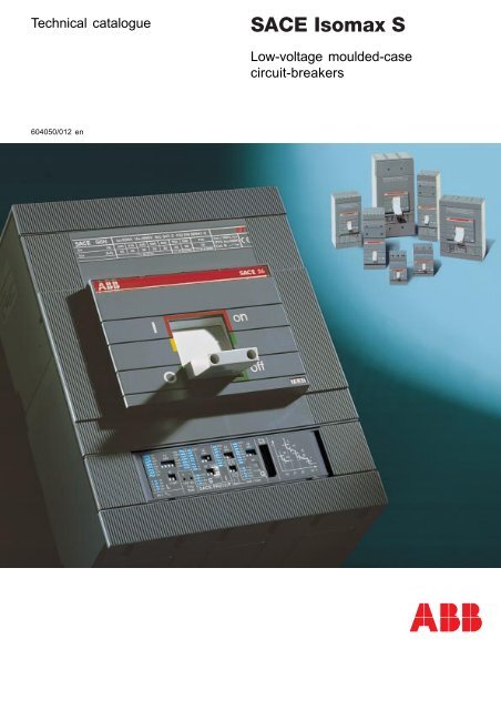
Technical catalogue<br />
Low-voltage moulded-case<br />
circuit-breakers<br />
604050/012 en
Contents<br />
Presentation<br />
1<br />
Main features<br />
2<br />
Ranges<br />
3<br />
Accessories<br />
4<br />
Characteristic curves and<br />
technical information<br />
5<br />
Dimensions and circuit diagrams<br />
6<br />
Order codes<br />
7<br />
ABB SACE<br />
1/1
SACE Isomax S.<br />
The greatest project for moulded-case circuit-breakers<br />
A single series for all applications<br />
1<br />
SACE Isomax S is a project which evolves continually and is today the largest and<br />
most <strong>com</strong>plete family of low voltage moulded-case circuit-breakers on the market,<br />
able to fulfil all installation requirements, from the small user up to large industrial<br />
electrical power distribution plants.<br />
Innovation, Technology and Quality have always been the main guides for ABB<br />
SACE in developing products and are at their peak in the SACE Isomax S series –<br />
the moulded-case circuit-breakers characterised by high quality, reliability, and<br />
performance under all conditions, simplicity of installation and safety of operation.<br />
The continual and constant evolution of the series has led to further extending the<br />
range of products, thereby making the SACE Isomax S offer increasingly <strong>com</strong>plete<br />
over time.<br />
The series, which is divided rationally into eight basic sizes from S1 to S8, does, in<br />
fact, consist of different ranges destined to fulfil any installation need in a specific<br />
and optimal way.<br />
The <strong>com</strong>pleteness of the series can also<br />
be noted in better rationalisation of use:<br />
the overall dimensions, methods of<br />
installation and possibility of applying<br />
accessories are all the same, regardless<br />
of the type of range the circuit-breaker is<br />
placed in.<br />
Great importance is also put on the<br />
microprocessor-based electronic<br />
releases (mounted on the circuitbreakers<br />
starting from 160A): SACE<br />
PR211/P, PR212/P and SACE PR212/MP<br />
(International ABB SACE Patent),<br />
specifically designed to actuate dedicated<br />
functions for motor starting and<br />
protection.<br />
Thanks to innovative and state-of-the-art<br />
protection functions, they ensure<br />
reliability and precision and are unaffected<br />
by electromagnetic interference.<br />
A basic characteristic of these types of<br />
releases is their ability to <strong>com</strong>municate<br />
and dialogue with the SACE SD-View 810<br />
self-configuring software, thereby<br />
allowing full integration of the circuitbreakers<br />
in the management logics<br />
relative to electric network supervision<br />
and control systems.<br />
1/2 ABB SACE
The new series has<br />
been studied<br />
respecting the most<br />
modern ergonomic<br />
criteria. Witness to<br />
this is the prize<br />
awarded with the IF<br />
seal to the circuitbreakers<br />
at the<br />
Design Forum in<br />
Hannover.<br />
1<br />
GSIS9071<br />
ABB SACE<br />
1/3
A world of solutions for installation design<br />
engineering.<br />
An answer to all requirements.<br />
1<br />
The SACE Isomax S family is divided into eight basic sizes, S1,<br />
S2, S3, S4, S5, S6, S7 and S8 with rated uninterrupted currents<br />
from 125 to 3200A.<br />
The types of devices consist of: fixed, plug-in and withdrawable<br />
circuit-breakers with seven ultimate rated breaking capacity<br />
levels - from 16 to 200kA (380-415V) - identified by the<br />
letters:<br />
B, N, S, H, L, V, X.<br />
From this family, which is considered<br />
the <strong>com</strong>mon “nucleus”,<br />
a series of dedicated<br />
ranges are configured, which<br />
keep the same installation<br />
characteristics and accessory<br />
application possibilities.<br />
Within the series there are<br />
therefore circuit-breakers<br />
available for alternating and<br />
direct current distribution, current-limiting<br />
circuit-breakers,<br />
circuit-breakers for motor protection,<br />
switch-disconnectors,<br />
circuit-breakers for applications<br />
with voltages up to 1000V,<br />
and residual current circuitbreakers,<br />
as well as specific<br />
ranges (for motor protection<br />
and switch-disconnectors)<br />
<strong>com</strong>plying with the North<br />
American UL489 and CSA<br />
C22.2 Standards.<br />
This means wider application<br />
possibilities both in industrial<br />
and civil sectors.<br />
They can therefore be mounted<br />
in primary (Power Center) and<br />
secondary (Panel Board) distribution<br />
switchboards, for motor<br />
protection and control (Motor<br />
Control Center), in generators<br />
and for end users. Their<br />
performances are, however, of<br />
particular interest where critical<br />
situations arise (very high<br />
rated and fault currents), or<br />
where <strong>com</strong>plex plant engineering<br />
solutions are needed<br />
(special coordination requirements<br />
and plant automation).<br />
They also guarantee total selectivity<br />
of the protections up<br />
to full breaking capacity of the<br />
circuit-breaker installed on the<br />
load side.<br />
Centralised supervision<br />
and control<br />
systems<br />
The reliability,<br />
efficiency and<br />
quality of a LV<br />
electrical power<br />
distribution service<br />
is considerably increased<br />
by constant<br />
supervision of users<br />
and all the parameters of the installation<br />
itself. The information regarding<br />
the installations is collected using microprocessor-based<br />
field <strong>com</strong>ponents<br />
which can be mounted directly on board<br />
the apparatus, such as the SACE<br />
PR212/P release, or using the devices<br />
in the SACE SD family. Moreover, the<br />
use of the SACE SD-View 810 software<br />
allows a simple personal <strong>com</strong>puter to<br />
be converted into a work station for<br />
supervising and controlling electrical<br />
power distribution plants.<br />
GSIS9072<br />
Alternating current<br />
GSIS9073<br />
GSIS9074<br />
V~<br />
Circuit-breakers with thermomagnetic<br />
releases and circuit-breakers fitted with<br />
microprocessor-based SACE PR211/P,<br />
PR212/P releases are available for protection<br />
of alternating current networks.<br />
These feature an application field from<br />
10 to 3200A and a rated voltage of 690V.<br />
Apart from the more generic applications,<br />
they are particularly suited to protection<br />
of generators, capacitors, transformers<br />
and machine tools.<br />
Thanks to its special construction characteristics,<br />
this range of circuit-breakers<br />
<strong>com</strong>bines normal Isomax safety<br />
characteristics with very high performances.<br />
The breaking technique used<br />
(double interruption per pole) and the<br />
special shape of the breaking parts,<br />
allow very high value short-circuit currents<br />
(200kA) to be tripped extremely<br />
rapidly, making these circuit-breakers<br />
ideal wherever protection close to the<br />
power supply source is needed.<br />
Direct current<br />
V–<br />
Pole connection in series allows applications<br />
in the most severe operating<br />
conditions and in any type of network<br />
(insulated, with earthed polarity, and with<br />
median point of the power supply<br />
earthed). The circuit-breakers for direct<br />
current with thermomagnetic releases<br />
are available for operating currents between<br />
10A and 800 A, with rated<br />
voltages up to 750 V, with 3 poles in<br />
series, and 250 and 500V, with two poles<br />
in series.<br />
The range for applications at 1000V in<br />
alternating current and direct current<br />
extends the use of the moulded-case<br />
circuit-breakers even further and is a<br />
good example of the continual evolution<br />
of the SACE Isomax S series. They<br />
are particularly suitable for installation<br />
in special ambients, such as mines,<br />
petrochemical plants and for electric<br />
traction.<br />
ABB SACE proposes various solutions,<br />
which allow type 2 coordinations to be<br />
made for switching and protecting motors,<br />
from 0.37kW to 355kW.<br />
It is possible to select either circuitbreakers<br />
suited just to protection<br />
against short-circuit, or circuit-breakers<br />
fitted with the new SACE PR212/MP<br />
electronic release, which is technologically<br />
advanced and has been specifically<br />
studied for motor protection. The<br />
latter integrates protection functions on<br />
1/4 ABB SACE
SACE Isomax S<br />
current-limiting<br />
circuit-breakers<br />
GSIS9091<br />
The switch-disconnectors are derived from<br />
the corresponding circuit-breakers, keeping<br />
the overall dimensions, versions and<br />
accessories unchanged. They guarantee<br />
operation and isolation in maximum safety<br />
and their release device can be activated<br />
either by the undervoltage release or by<br />
the shunt opening release. They can also<br />
be fitted with residual current releases,<br />
thereby constructing “pure” residualcurrent<br />
circuit-breakers.<br />
SACE Isomax S<br />
switch-disconnectors<br />
1<br />
SACE Isomax S<br />
Power distribution<br />
GSIS9075<br />
SACE Isomax S<br />
for applications<br />
up to 1000V<br />
board the circuit-breaker which are normally<br />
carried out by other devices,<br />
thereby ensuring numerous installation<br />
and service advantages.<br />
GSIS9093<br />
SACE Isomax S<br />
according to UL/CSA<br />
Standards<br />
Thanks to a specific range of SACE Isomax S circuit-breakers <strong>com</strong>plying<br />
with the UL489 and CSA22.2 Standards, there are also greater possibilities<br />
for those customers operating on markets subject to the specifications<br />
defined in the North American standards. The range consists of<br />
seven sizes with rated uninterrupted current from 100A to 2500A and<br />
breaking capacities, at 480 V AC, which can reach 100kA.<br />
Within the basic series, there are circuit-breakers with magnetic only<br />
releases (MCP - Motor Control Protection) for motor protection, and<br />
switches (Moulded-Case Switch - MCS) for use as isolators or switching<br />
devices for lines, busbars or plant parts.<br />
SACE Isomax S<br />
for motor protection<br />
classical and advanced<br />
ABB SACE<br />
1/5
A world of success<br />
The SACE Isomax S offer has been constantly renewed according to market<br />
requirements – and often even anticipating these – and is always to the fore from<br />
the technological viewpoint. Meanwhile, the quality and reliability have always<br />
remained at the maximum levels expected and the market has shown its appreciation<br />
of this.<br />
1<br />
Behind every reference lies a requirement<br />
fulfilled. It is facts which speak for<br />
SACE Isomax S. SACE Isomax S is a<br />
highly successful product of recognised<br />
quality, with many fields of<br />
application and it involves different<br />
sectors all over the world, with either<br />
standard or highly personalised<br />
products. There is nowhere electrical<br />
power is used where SACE Isomax S is<br />
not to be found: manufacturing industries,<br />
steelworks, refineries and<br />
chemical plants, drilling rigs, gas<br />
pipelines, water pipelines, hospitals,<br />
airports, trains, railway and underground<br />
railway stations, calculation<br />
centres, offices, congress centres,<br />
theatres, and skyscrapers, as well as<br />
the most prestigious buildings worldwide.<br />
ABB SACE has, moreover, acquired<br />
knowledge which is practically<br />
unsurpassed in application areas<br />
where the highest degree of safety is<br />
required, and this has qualified it as<br />
the world leader in various sectors.<br />
Thousands of ships of all types –<br />
cruise ships, container ships, bulk<br />
carriers, tankers, etc. – and flying the<br />
flags of all nations – are equipped with<br />
ABB SACE products, which are also<br />
widely used in railway traction and are<br />
the favourite product in the depths of<br />
mines.<br />
ABB SACE apparatus is also responsible<br />
for protection (sometimes also<br />
integrated with control functions) of<br />
plants of considerable economic and<br />
technological importance, constructed<br />
within the sphere of large infrastructure<br />
projects. Orders are processed<br />
which stand out both for their size<br />
(such as the pumping stations of gas<br />
pipelines thousands of kilometres<br />
long) and for their advanced context<br />
(astronomical observatories and<br />
international research centres).<br />
SACE Isomax S imposes itself on the<br />
markets worldwide. For example,<br />
apparatus has been supplied to some<br />
of the most important European and<br />
Middle Eastern electricity boards as<br />
well as to North American and Asian<br />
electrified transport <strong>com</strong>panies.<br />
Particularly severe<br />
environmental conditions<br />
such as mines and steelworks<br />
Protection and control<br />
in installations for electric<br />
traction<br />
Refineries and chemical plants<br />
as well as<br />
gas pipelines, water pipelines …<br />
Installation on board ships<br />
1/6 ABB SACE
1<br />
Offices, theatres,<br />
shopping malls and residential<br />
<strong>com</strong>plexes<br />
GSIS9076<br />
Underground railway<br />
stations<br />
Off-shore drilling rigs<br />
Protection and control<br />
of motors, generators…<br />
ABB SACE<br />
1/7
Selection and design engineering tools,<br />
management flexibility, services and consultancy:<br />
an all-round offer<br />
1<br />
With the aim of guiding and facilitating selection of its products, ABB SACE<br />
ensures 360° support, both before and after the sale. For this purpose, to design<br />
and size electrical installations, it makes various work tools available, which<br />
facilitate calculations, ensure <strong>com</strong>pliance of the installation with the Standards<br />
and reduce the risks of any errors.<br />
These are basically divided into calculation, design and estimate software, and<br />
manual tools.<br />
– D.O.C. (Design Optimization<br />
& Computation) is a system<br />
which allows correct sizing of<br />
industrial low voltage electrical<br />
installations, able to propose<br />
the most suitable design<br />
selections regarding cables,<br />
busbars and protection devices.<br />
It allows the design engineer<br />
to develop clear and<br />
<strong>com</strong>plete design documentation<br />
rapidly, based on the calculation<br />
models provided by<br />
the most recent standards.<br />
– C.A.T. (Computer Aided<br />
Technical Selection) is both<br />
an electronic catalogue and<br />
a technical aid tool for selecting<br />
and applying accessories<br />
to each individual circuitbreaker.<br />
By means of a guided pathway,<br />
it is possible to select,<br />
configure and order the most<br />
suitable apparatus for your<br />
own installation requirements.<br />
The calculation methods and<br />
data indicated on the slide<br />
rules are taken from the CEI,<br />
IEC and NFC Standards in<br />
force and from installation<br />
practice.<br />
The Guide to low<br />
voltage installations<br />
is a brief<br />
collection of legal<br />
and technical<br />
regulations<br />
based on the<br />
current standards,<br />
regarding<br />
design, sizing<br />
and installation<br />
of an electrical<br />
plant.<br />
The guide takes into<br />
consideration the user<br />
plant from the electric<br />
power delivery point (MV/LV<br />
substation) in 1 st category<br />
systems.<br />
Four Slide rules of different<br />
colours, which make up the<br />
ABB Kits, allow rapid sizing<br />
calculations of the electrical<br />
installation. The following can<br />
be carried out:<br />
- Cable sizing and calculation<br />
of the short-circuit currents<br />
(yellow slide rule)<br />
- Checking the protections<br />
against direct contact and<br />
short-circuit of the cables<br />
(orange slide rule)<br />
- Selective and back-up coordination<br />
(green slide rule)<br />
- Sizing of motor lines and<br />
transformer outgoing feeders<br />
(blue slide rule)<br />
Immediate ordering<br />
and management flexibility<br />
Rapid ordering procedures<br />
have been provided for circuit-breakers<br />
in the SACE<br />
Isomax S series, and the configuration<br />
logic of the series<br />
enables efficient and flexible<br />
warehouse management.<br />
An order file can be generated<br />
<strong>com</strong>patible with the EDIFACT<br />
(Metel or ABB) standard, ready<br />
to be converted into EDI format<br />
and transmitted electronically.<br />
1/8 ABB SACE
Using EDI (Electronic Data Interchange)<br />
to send orders rationalises<br />
the logistics chain,<br />
thereby reducing transit times<br />
and the risk of errors. EDI<br />
transmission allows the order<br />
to be loaded automatically at<br />
ABB SACE so that the request<br />
is immediately sent to production,<br />
together with the<br />
order acknowledgement<br />
to the customer.<br />
The availability of<br />
standardised accessories<br />
for<br />
groups of circuit-breakers<br />
makes it possible<br />
to reduce<br />
the<br />
number kept<br />
in the warehouse<br />
and<br />
very short<br />
procurement<br />
times allow<br />
limited stocks<br />
to be kept as<br />
these can be<br />
rapidly replenished.<br />
Training:<br />
an indispensable tool<br />
for professionals<br />
By means of its technical training<br />
courses, ABB SACE is<br />
<strong>com</strong>mitted to putting its wealth<br />
of experience gained in over<br />
more than 60 years of operation<br />
at disposal. The courses<br />
are an opportunity for all operators<br />
in the sector to update<br />
their knowledge and <strong>com</strong>pare<br />
notes, under the guidance of<br />
experts. Information and training<br />
have always been success<br />
factors for professional<br />
growth and development.<br />
Professional refresher training<br />
on both technical aspects and<br />
product developments, as well<br />
as on the standards and legislation,<br />
is essential, considering<br />
that these have such important<br />
implications for the<br />
safety of people and plants.<br />
The primary aim is to meet the<br />
information needs of professionals,<br />
especially by converting<br />
the technical-standard<br />
and legislative concepts into<br />
practical terms which can be<br />
applied directly to the various<br />
products and installations.<br />
“ABB SACE Service”<br />
Training courses are also provided<br />
for operators and maintenance<br />
personnel who work<br />
on ABB SACE apparatus and<br />
systems. For this purpose and<br />
to meet the need for evaluation<br />
and maintenance of existing<br />
electrical installations,<br />
the <strong>com</strong>pany has set up the<br />
“Service Division” within its<br />
own structure, which acts as<br />
a qualified interlocutor working<br />
in close collaboration with<br />
the managers/users of the<br />
plants, to carry out maintenance,<br />
repair and overhauling<br />
activities at ABB SACE and on<br />
the user’s premises. The division<br />
also offers a spare parts,<br />
assembly and <strong>com</strong>missioning<br />
service for its own switchboards.<br />
1<br />
ABB SACE<br />
1/9
Just one product for everyone<br />
SACE Isomax S is a product which has been thought up and<br />
constructed for all types of customers: the user, the design<br />
engineer, the switchboard builder, the installer, the maintenance<br />
technician and the wholesaler.<br />
1<br />
ABB SACE proposes technical<br />
solutions to the user<br />
which fulfil all requirements<br />
and are always up to date<br />
with technological innovations<br />
in the field of electrical<br />
power distribution. It offers<br />
high quality products,<br />
reliability and precision,<br />
which guarantee high<br />
performances under any<br />
conditions, safe products<br />
during service and, when<br />
necessary, simple replacement<br />
of any faulty parts.<br />
GSIS9092<br />
GSIS9090<br />
The design engineer has<br />
simple installation inside the<br />
products available which<br />
switchboard. The whole<br />
<strong>com</strong>ply perfectly with the<br />
range of products is divided<br />
international technical<br />
into eight sizes and con-<br />
standards and which are<br />
structed in only three depths,<br />
able to do the job simply,<br />
thereby allowing standardi-<br />
safely and reliably at the<br />
sation of the supporting<br />
highest levels of perform-<br />
structures and of the switch-<br />
ance. SACE Isomax S circuit-<br />
boards and installation in<br />
breakers offer the design<br />
prefabricated structures.<br />
engineer solutions for sizing,<br />
The dimensional uniformity<br />
coordination and flexibility of<br />
and the possibilities of<br />
application which allow him<br />
connection, thanks to the<br />
to draw up a state-of-the-art<br />
variety of terminal available,<br />
project, selecting from<br />
considerably facilitates<br />
among well-known ranges<br />
connections by means of<br />
and circuit diagrams to be<br />
integrated in a <strong>com</strong>plete<br />
busbars or cables.<br />
GSIS9079<br />
system, and satisfying all<br />
installation requirements and<br />
performances according to<br />
the standards.<br />
The requirements of a<br />
switchboard builder are fully<br />
satisfied thanks to careful<br />
design of the product. The<br />
limited volumes of the pieces<br />
of apparatus allow the<br />
switchboard dimensions to<br />
be kept to a minimum and<br />
the modularity and <strong>com</strong>pactness<br />
the ranges of products<br />
are conceived with allow<br />
ABB SACE provides the<br />
installer with products for<br />
any type of plant, which are<br />
practical to install, simple to<br />
use, assemble and connect<br />
and easy to check, thanks<br />
also to the quality of the<br />
accessories supplied with<br />
the apparatus and the<br />
technical support documentation<br />
provided.<br />
SACE Isomax S circuitbreakers<br />
allow easy and safe<br />
maintenance to be carried<br />
out, enabling the accessories<br />
to be inserted conveniently<br />
on the front of the circuitbreaker.<br />
Construction rationality as<br />
well as modularity of the<br />
structure, allow the maintenance<br />
technician to carry out<br />
replacements without the<br />
need for any special adaptation,<br />
even when changing<br />
from one type of circuitbreaker<br />
to another (for<br />
to a current-limiting circuitbreaker).<br />
Standardisation of Isomax S<br />
circuit-breakers and their<br />
accessories means simple<br />
and economical management<br />
of the spare parts<br />
warehouse for the wholesaler.<br />
Furthermore, the clarity of<br />
product coding considerably<br />
helps product ordering,<br />
reduces procurement times<br />
and allows limited stocks to<br />
be kept in the warehouse<br />
since the products can be<br />
example from an automatic<br />
replenished rapidly.<br />
1/10 ABB SACE
Main characteristics<br />
Index<br />
Panorama of the SACE Isomax S family<br />
A single series for all applications ...................................................................................... 2/2<br />
Construction characteristics<br />
2<br />
Distinctive features of the series ........................................................................................ 2/4<br />
Conditions of use ................................................................................................................ 2/8<br />
Modularity of the series SACE Isomax S ........................................................................... 2/10<br />
Compliance with the Standards<br />
Standards, Approvals, Certifications and <strong>com</strong>pany quality system ................................. 2/12<br />
ABB SACE<br />
2/1
Panorama of the SACE Isomax S family<br />
A single series for all applications<br />
SACE Isomax S1<br />
SACE Isomax S2<br />
CIRCUIT-BREAKERS FOR AC / DC DISTRIBUTION S1 S2<br />
Poles [nr.] 3 - 4 3 - 4<br />
Iu [A] 125 160<br />
Ue (AC) [V~] 500 690<br />
Icu (380/415V AC)<br />
[kA]<br />
B 16 16<br />
N 25 35<br />
S 50<br />
H<br />
L<br />
V<br />
Ue (DC) [V–] 250 500<br />
2<br />
CURRENT-LIMITING CIRCUIT-BREAKERS S2X 100<br />
Poles [nr.] 3<br />
Iu [A] 100<br />
Ue [V~] 690<br />
Icu (380/415V) [kA] 70<br />
Icu (690V) [kA] 10<br />
CIRCUIT-BREAKERS FOR MOTOR PROTECTION S2X 80<br />
Poles [nr.] 3<br />
Iu [A] 80<br />
In [A] 1…80<br />
Ue [V~] 690<br />
Magnetic only release IEC 60947-2<br />
Electronic release PR211/P (I), IEC 60947-2 -<br />
Electronic release PR212/MP, IEC 60947-4-1 -<br />
CIRCUIT-BREAKERS FOR APPLICATIONS AT 1000 V AC<br />
Poles<br />
Iu<br />
Icu (1000V AC)<br />
[nr.]<br />
[A]<br />
[kA]<br />
CIRCUIT-BREAKERS FOR APPLICATIONS AT 1000 V AC<br />
Poles<br />
Iu<br />
Icu (1000V DC), 4 poles in series<br />
[nr.]<br />
[A]<br />
[kA]<br />
SWITCH-DISCONNECTORS according to IEC 60947-3 Standard<br />
S2D<br />
Poles [nr.] 3 - 4<br />
Ith [A] 125 - 160<br />
Ue [V~] 690<br />
Icm [kA] 3,1<br />
Icw [kA] 2,2<br />
Circuit-breakers according to UL 489 and CSA 22.2 Standards<br />
S1N<br />
Poles [no.] 3<br />
Maximum continuous current (40 °C) [A] 100<br />
Maximum Ampere Breaking Capacity (480 V) [kA] 20<br />
Thermal-magnetic trip unit<br />
Microprocessor based trip unit -<br />
MCP -<br />
MCS -<br />
2/2 ABB SACE
SACE Isomax S3 SACE Isomax S4 SACE Isomax S5 SACE Isomax S6 SACE Isomax S7 SACE Isomax S8<br />
S3 S4 S5 S6 S7 S8<br />
3 - 4 3 - 4 3 - 4 3 - 4 3 - 4 3 - 4<br />
160-250 160-250 400-630 630-800 1250-1600 2000-2500-3200<br />
690 690 690 690 690 690<br />
35 35 35 35<br />
50 50<br />
65 65 65 65 65 85<br />
85 100 100 100 100<br />
120<br />
750 - 750 750 - -<br />
S3X S4X S6X<br />
3 - 4 3 - 4 3 - 4<br />
125-200 250 400-630<br />
690 690 690<br />
200 200 200<br />
75 75 75<br />
2<br />
S3 / S3X S4 / S4X S5 S6 / S6X S7<br />
3 3 3 3 3<br />
160-250 / 125-200 160-250 / 250 400-630 630-800 / 400-630 1250-1600<br />
25…200 100…250 320…630 320..800 1000…1600<br />
690 690 690 690 690<br />
- - - -<br />
-<br />
-<br />
S3L / S3X S4L / S4X S5L S6L / S6X<br />
3 3 3 3<br />
160 / 125 160-250 / 250 400 630-800 / 630<br />
6 / 30 8 / 30 8 12 / 30<br />
S3L S5L S6L<br />
4 4 4<br />
160-250 400 630 / 800<br />
40 40 40 / 50<br />
S3D S6D S7D S8D<br />
3 - 4 3 - 4 3 - 4 3 - 4<br />
100 - 160 - 250 - 320 400 - 630 - 800 1000 - 1250 - 1600 2000-2500-3200<br />
690 690 690 690<br />
10 30 52,5 85<br />
6,5 15 25 40<br />
S3 B/N/H/L S4 N/H/L S5 N/H/L S6 N/H/L S7H S8V<br />
2 - 3 2 - 3 2 - 3 2 - 3 2 - 3 3<br />
150 - 225 250 400 800 1200 1600-2000-2500<br />
85 100 100 100 65 100<br />
- - -<br />
-<br />
S3L S4 N/H/L S5 N/H/L S6 N/H/L S7H S8V<br />
S3 H-D 150/225 S4 H-D S5 H-D S6 H-D S7 H-D S8 V-D<br />
ABB SACE<br />
2/3
Construction characteristics<br />
Distinctive features of the series<br />
Terminals<br />
2<br />
Identification<br />
nameplate<br />
Fixed<br />
contacts<br />
Arcing<br />
chamber<br />
Moving<br />
contacts<br />
Operating lever<br />
Microprocessor-based<br />
electronic release<br />
GSIS9069<br />
2/4 ABB SACE
GSIS9048<br />
GSIS9051<br />
Double insulation<br />
The double insulation technique consists of total separation<br />
between the power circuits and the auxiliary circuits and is a<br />
characteristic of all SACE Isomax S apparatus from size S3 up.<br />
The housing of each electrical accessory is <strong>com</strong>pletely segregated<br />
from the power circuit, thus avoiding all risk of contact<br />
with live parts, thereby increasing operator safety conditions<br />
during management and inspection of the installations.<br />
Moreover, the circuit-breaker has redundant insulation between<br />
the internal live parts, both regarding thickness of materials<br />
and the distances, which are greater than those required<br />
by the IEC Standards and are in accordance with American<br />
usage.<br />
Positive operation<br />
The operating lever always indicates the exact position of the<br />
circuit-breaker moving contacts, thereby guaranteeing safe and<br />
reliable indications (I = Closed; O = Open; yellow-green line =<br />
Open due to release trip). The circuit-breaker operating mechanism<br />
has free release, regardless of the pressure on the lever<br />
or the speed of operation. Release tripping automatically opens<br />
the moving contacts: to close them again, it is necessary to<br />
reset the operating mechanism by pushing the operating lever<br />
from the intermediate position to the lower limit of the open<br />
position.<br />
For plug-in or withdrawable circuit-breakers, the moving part<br />
can only be detached from the fixed part with the circuit-breaker<br />
open (moving contacts separate from the relative fixed contacts).<br />
2<br />
GSIS0074<br />
GSIS9050<br />
Selectivity<br />
The <strong>com</strong>plete range of releases means that the protection functions<br />
of the apparatus can be coordinated according to current-type,<br />
time-type, energy-type or residual-current selectivity<br />
chains. It is therefore possible to isolate only the areas affected<br />
by the fault, ensuring maximum service continuity. Circuit-breakers<br />
in category B are available from 400 A up.<br />
Possibility of inspection<br />
With the circuit-breaker out of service, it is possible to check<br />
the state of the internal parts and live <strong>com</strong>ponents of the circuit-breaker<br />
directly. The arcing chambers and the fixed and<br />
moving contacts are accessible simply by removing the circuit-breaker<br />
cover. The operation, facilitated by the limited<br />
number of <strong>com</strong>ponents, reduces maintenance times and ensures<br />
a higher degree of safety.<br />
ABB SACE<br />
2/5
Construction characteristics<br />
Distinctive features of the series<br />
GSIS9125<br />
GSIS9126<br />
2<br />
Isolation behaviour<br />
In the open position, the circuit-breaker guarantees isolation of<br />
the circuit in <strong>com</strong>pliance with the IEC 60947-2 Standard. For<br />
plug-in or withdrawable version circuit-breakers, in the rackedout<br />
or withdrawn position, the power and auxiliary circuits are<br />
isolated, ensuring that no parts are live. Under these conditions<br />
and by means of special connectors, it is possible to<br />
carry out blank tests, operating the circuit-breaker in <strong>com</strong>plete<br />
safety. The redundant insulation distances guarantee the absence<br />
of leakage currents and dielectric strength in the event<br />
of any overvoltages between the input and output.<br />
Racking-out with the door closed<br />
This system, starting from 160 A, allows the circuit-breaker to<br />
be racked in and out with the <strong>com</strong>partment door closed, increasing<br />
operator safety and allowing construction of internal<br />
arc proof low voltage switchboards. Racking out can only take<br />
place with the circuit-breaker open, using a special rackingout<br />
crank handle supplied with the withdrawable version circuit-breaker.<br />
GSIS9127<br />
GSIS9129<br />
Electromagnetic <strong>com</strong>patibility<br />
By using SACE PR211/P, PR212/P, PR212/MP microprocessorbased<br />
overcurrent releases and SACE RC210, RC211, RC212<br />
electronic residual-current releases, the absence of unwarranted<br />
trips is guaranteed even in the presence of interference<br />
caused by electronic equipment, atmospheric disturbance or<br />
discharges of electrical type. Furthermore, the apparatus does<br />
not generate interference with other electronic equipment in<br />
the vicinity of the installation. This is in <strong>com</strong>pliance with the IEC<br />
60947-2 Appendix F, IEC 1000-4, EN 61000-4, EN 50081-1, EN<br />
50081-2, EN 50082-1, EN 50082-2 European Directive No. 89/<br />
336 specifications regarding electromagnetic <strong>com</strong>patibility<br />
EMC.<br />
Tropicalisation<br />
The SACE Isomax S series of circuit-breakers and accessories<br />
<strong>com</strong>ply with the strictest regulations for use in hot-humid-saline<br />
climates (in <strong>com</strong>pliance with climatograph 8 of the IEC<br />
721-2-1 Standards), thanks to:<br />
– insulating cases made of fibreglass-reinforced synthetic resins;<br />
– anti-corrosion treatment on all main metal parts (C UNI 3564-<br />
65 environment);<br />
– Fe/Zn 12 galvanisation (UNI ISO 2081), protected by a conversion<br />
layer consisting mainly of chromates (UNI ISO 4520).<br />
2/6 ABB SACE
Installation positions<br />
The circuit-breaker can be installed in any position without any<br />
effect on its rated characteristics. In <strong>com</strong>pliance with the IEC<br />
60947-2 Standards, SACE Isomax S circuit-breakers can be<br />
supplied through either top or bottom terminals, without jeopardising<br />
operation of the apparatus.<br />
They can be installed in switchboards, mounted directly on the<br />
base plate or on Din rails up to size S5.<br />
GSIS9131 GSIS9128<br />
Mounting on DIN rail up to 630 A<br />
The brackets for fixing onto standardised DIN EN 50022 rails<br />
for S1, S2 and DIN EN 50023 rails for S3, S4, S5 simplify assembly<br />
of the circuit-breakers up to 630 A in standard switchboards.<br />
This allows standardised supporting structures to be used and<br />
facilitates the stage for designing and constructing the switchboard<br />
metalwork structure.<br />
GSIS9130 GSIS9062<br />
2<br />
Resistance to vibration<br />
Degrees of protection<br />
The circuit-breakers are unaffected by vibrations generated<br />
mechanically or due to electromagnetic effects, in <strong>com</strong>pliance<br />
with the IEC 68-2-6 Standards and the strictest regulations of<br />
the major classification organisations:<br />
– RINA<br />
– DET Norske Veritas<br />
– Lloyd’s Register of Shipping<br />
– Germanischer Lloyd<br />
– Bureau Veritas.<br />
Different measures have been taken in SACE Isomax S circuitbreakers<br />
to achieve IP20 degree of protection for the fixed,<br />
plug-in and withdrawable version circuit-breaker, excluding<br />
the terminals, and IP30 for the front parts of the circuit-breakers<br />
installed in switchboards.<br />
The fixed parts are always provided with IP20 degree of protection.<br />
It is possible to achieve IP54 degree of protection in accordance<br />
with the IEC 60529 Standard with the circuit-breaker<br />
installed in a switchboard fitted with rotary handle operating<br />
mechanism transmission on the <strong>com</strong>partment door and the<br />
special insulation gaskets which can be ordered separately.<br />
ABB SACE<br />
2/7
Construction characteristics<br />
Conditions of use<br />
Degrees of protection (according to CEI EN 60529 Standard file 519)<br />
Circuit-breaker<br />
IP20<br />
Circuit-breaker in switchboard<br />
IP30<br />
IP30<br />
2<br />
GSIS9080<br />
Direct operating mechanism<br />
GSIS9081<br />
without terminal covers<br />
IP30<br />
with terminal covers<br />
GSIS9083<br />
Front for lever operating mechanism<br />
IP40 (1)<br />
Direct rotary handle<br />
Rotary handle transmission<br />
GSIS9084<br />
IP50<br />
GSIS9085 GSIS9082<br />
IP40<br />
IP54<br />
IP30 (2)<br />
GSIS9086<br />
Special IP54 protection<br />
GSIS9087<br />
with terminal covers<br />
and direct rotary handle<br />
Motor operator<br />
GSIS9088<br />
( 1 ) IP30 for withdrawable circuit-breakers ( 2 ) IP40 for S1-S2 and S6-S7 circuit-breakers<br />
2/8 ABB SACE
Operating temperature<br />
SACE Isomax S circuit-breakers can be used in ambient conditions<br />
where the temperature in the surrounding atmosphere<br />
varies between -25 °C and +70 °C and stored in ambients with<br />
temperatures between -40 °C and +70 °C.<br />
The circuit-breakers fitted with thermomagnetic overcurrent<br />
release have their thermal element set for a reference temperature<br />
of +40 °C.<br />
For temperatures between +40 °C and +70 °C, with the same<br />
setting, there is lowering of the thermal trip threshold due to<br />
the temperature-related behaviour of the bimetallic strip of the<br />
release itself.<br />
For temperatures lower than +40 °C, on the other hand, there<br />
is an increase in the thermal trip threshold as indicated in the<br />
table on page 5/39.<br />
The electronic microprocessor-based overcurrent releases<br />
do not undergo any variations in performance with changes in<br />
temperature but, in the case of temperatures higher than 40<br />
°C, the maximum setting of the protection against overloads<br />
(function L) must be reduced to take into consideration inertial<br />
phenomena that occur in the copper parts of the circuitbreaker<br />
through which the phase current passes (moving and<br />
fixed contacts, and connection terminals) which cause a decrease<br />
in the rated uninterrupted current as indicated in the<br />
table on page 5/34.<br />
The performances of the circuit-breaker cannot be guaranteed<br />
for temperatures above +70 °C.<br />
To ensure service continuity of the installations, careful thought<br />
must be given as to how to keep the temperature within acceptable<br />
levels for operation of all the various devices and not<br />
only the circuit-breakers. For example, forced ventilation in<br />
the switchboards and in the areas where they are installed<br />
may be necessary.<br />
2<br />
Altitude<br />
Up to an altitude of 2000 m SACE Isomax S circuit-breaker<br />
rated performances are unaffected.<br />
As the altitude increases, the atmospheric properties change<br />
in terms of <strong>com</strong>position, dielectric strength, cooling capacity<br />
and pressure.<br />
The circuit-breakers therefore undergo derating, which can<br />
basically be measured through the change in significant parameters<br />
such as the rated maximum operating voltage and<br />
the rated uninterrupted current.<br />
Altitude [m] 2000 3000 4000<br />
Rated service voltage, Ue [V~] 690 600 500<br />
Rated uninterrupted current, Iu %Iu 100% 95% 90%<br />
ABB SACE<br />
2/9
Construction characteristics<br />
Modularity of the series SACE Isomax S<br />
2<br />
Starting from the fixed version circuit-breaker and by means of<br />
mounting the conversion kit, all the other versions which are<br />
used for the various requirements are obtained.<br />
The following are available:<br />
– kit for conversion from fixed circuit-breaker to moving part of<br />
a plug-in or withdrawable circuit-breaker<br />
– conversion kit for the connection terminals which make it<br />
possible to obtain front and rear terminals for Copper or<br />
Aluminium cables, and front and rear terminals for flat bar<br />
terminals.<br />
Various accessories are also available:<br />
– shunt opening releases<br />
– undervoltage releases<br />
– auxiliary contacts<br />
– position contacts<br />
– the bracket for rear fixing onto DIN EN 50022 rail for S1-S2<br />
circuit-breakers, DIN EN 50023 rail for S3-S4-S5 circuit-breakers<br />
– direct action motor operator, with stored energy and with<br />
solenoid.<br />
– rotary handle operating mechanisms directly on the circuitbreaker<br />
and with transmission on the <strong>com</strong>partment door<br />
– residual-current releases<br />
– accessories for microprocessor-based overcurrent releases<br />
such as the signalling, dialogue and actuation unit and external<br />
CTs.<br />
– the fixed parts for plug-in or withdrawable circuit-breakers<br />
with front terminals for cables or for flat bars and rear terminals<br />
for flat bars.<br />
2/10 ABB SACE
2<br />
GSIS0159<br />
ABB SACE<br />
2/11
Compliance with the Standards<br />
Standards, Approvals, Certifications and <strong>com</strong>pany quality<br />
system<br />
SACE Isomax S circuit-breakers and their<br />
The attention paid to protecting the en-<br />
accessories <strong>com</strong>ply with the IEC 60947-<br />
vironment is another important priority<br />
2, EN 60947-2 (unified in 17 countries<br />
for ABB SACE, and as confirmation of<br />
of CENELEC), CEI EN 60947 and IEC<br />
this, the environmental management<br />
61000 international Standards and con-<br />
system has been certified by RINA.<br />
form with the EC directive:<br />
– “Low Voltage Directives” (LVD)<br />
no. 73/23 EEC<br />
– “Electromagnetic Compatibility Directive”<br />
(EMC) no. 89/336 EEC.<br />
Certification of <strong>com</strong>pliance with the<br />
2<br />
GSIS9118 GSIS9119<br />
above-mentioned product Standards, is<br />
carried out, in respect of the European<br />
EN 45011 Standard, by the<br />
Italian certification organisation,<br />
ACAE (Association for<br />
Certification of Electrical Apparatus),-<br />
member of the European<br />
organisation LOVAG<br />
(Low Voltage Agreement<br />
Group).<br />
ISO 9001<br />
The ABB SACE Quality System <strong>com</strong>plies<br />
with the International ISO 9001 Standard<br />
(model for assuring quality in design,<br />
development, construction, installation<br />
and assistance) and to the equivalent<br />
European EN ISO 9001 and Italian UNI<br />
EN ISO 9001 Standards.<br />
The certification Organisation is RINA-<br />
QUACER.<br />
ABB SACE obtained its first certification<br />
in 1990.<br />
The ABB SACE Test Room is accredited<br />
by SINAL. The apparatus <strong>com</strong>plies with<br />
the prescriptions for on-board installations<br />
and is approved by major Shipping<br />
Registers, such as: LLOYD’S REGISTER<br />
OF SHIPPING, GERMANlSCHER LLOYD,<br />
BUREAU VERITAS, RINA, DET NORSKE<br />
VERITAS, POLSKI REIESTR STATKOW<br />
and the AMERICAN BUREAU OF SHIP-<br />
PING.<br />
GSIS9119<br />
ABB SACE was the first industrial <strong>com</strong>pany<br />
in the electro-mechanical sector<br />
in Italy to obtain this recognition, and,<br />
thanks to a revision of its production<br />
process with an eye to ecology, has<br />
managed to reduce consumption of raw<br />
materials, processing waste and the risk<br />
of accidents by 20%.<br />
The attention paid to protecting the environment<br />
and to the safety of workers is<br />
a priority <strong>com</strong>mitment of ABB SACE and<br />
as confirmation of this, the <strong>com</strong>pany developed<br />
the Environmental Management<br />
System in <strong>com</strong>pliance with the International<br />
ISO 14001 Standard, certified in<br />
1997, integrating this in 1999 with the<br />
Health and Safety in the Workplace Management<br />
System in accordance with BS<br />
8800 (British Standards).<br />
The prizes obtained by ABB SACE at the<br />
Forum Design in Hannover and at<br />
Electro in Paris bear witness to the consideration<br />
given to man and the respect<br />
for ergonomic criteria.<br />
Please contact ABB SACE for information<br />
regarding the types of circuit-breakers approved,<br />
the performances approved and<br />
their relative validity.<br />
GSIS9132<br />
2/12 ABB SACE
The ranges<br />
Index<br />
SACE Isomax S circuit-breakers for power distribution ........................................... 3/3<br />
Electrical characteristics IEC 60947-2 .............................................................................. 3/4<br />
General characteristics ..................................................................................................... 3/6<br />
Thermomagnetic releases ................................................................................................. 3/8<br />
Electronic releases ............................................................................................................ 3/10<br />
SACE Isomax S current-limiting circuit-breakers ...................................................... 3/15<br />
Electrical characteristics IEC 60947-2 .............................................................................. 3/16<br />
General characteristics ..................................................................................................... 3/18<br />
3<br />
SACE Isomax S circuit-breakers for motor protection<br />
(protection against short-circuit) .................................................................................. 3/23<br />
Electrical characteristics IEC 60947-4 .............................................................................. 3/24<br />
General characteristics ..................................................................................................... 3/26<br />
SACE Isomax S circuit-breakers for motor protection<br />
(integrated protection) .................................................................................................... 3/28<br />
Electrical characteristics IEC 60947-2 and IEC 60947-4 ................................................. 3/28<br />
General characteristics ..................................................................................................... 3/30<br />
SACE Isomax S circuit-breakers for applications up to 1000V ................................ 3/35<br />
Electrical and general characteristics IEC 60947-2 ......................................................... 3/36<br />
SACE Isomax S switch-disconnectors ........................................................................ 3/39<br />
Electrical and general characteristics IEC 60947-3 ......................................................... 3/40<br />
SACE Isomax S circuit-breakers in accordance with UL489 and CSA C22.2<br />
Standards .......................................................................................................................... 3/43<br />
Electrical and general characteristics ............................................................................... 3/44<br />
ABB SACE<br />
3/1
Circuit-breakers for power<br />
distribution<br />
Eight sizes to optimise use for all plant and<br />
installation requirements<br />
690V • 125-3200 A • 16-120 kA (380/415 V)<br />
3<br />
GSIS9063<br />
3/3
SACE Isomax S circuit-breakers<br />
for power distribution<br />
Electrical characteristics IEC 60947-2<br />
GSIS9133<br />
GSIS9134<br />
GSIS9135<br />
SACE Isomax S1<br />
SACE Isomax S2<br />
SACE Isomax S3<br />
Rated uninterrupted current, Iu<br />
Poles<br />
[A]<br />
Nr.<br />
125<br />
3-4<br />
160<br />
3-4<br />
160 - 250<br />
3-4<br />
Rated service voltage, Ue (AC) 50-60Hz [V]<br />
(DC)<br />
[V]<br />
500<br />
250<br />
690<br />
500<br />
690<br />
750<br />
Rated impulse withstand voltage, Uimp<br />
Rated insulation voltage, Ui<br />
[kV]<br />
[V]<br />
6<br />
500<br />
6<br />
690<br />
8<br />
800<br />
Test voltage at industrial frequency for 1 min.<br />
Rated ultimate short-circuit breaking capacity, Icu<br />
[V]<br />
B<br />
3000<br />
N<br />
3000<br />
B N S<br />
3000<br />
N H L<br />
(AC) 50-60 Hz 220/230 V<br />
(AC) 50-60 Hz 380/415 V[kA]<br />
[kA]<br />
25 40<br />
16 25<br />
25 50 65<br />
16 35 (1) 50<br />
65 100 170<br />
35 (1) 65 85<br />
3<br />
(AC) 50-60 Hz 440 V<br />
(AC) 50-60 Hz 500 V<br />
(AC) 50-60 Hz 690 V<br />
(DC) 250 V - 2 poles in series<br />
(DC) 500 V - 2 poles in series<br />
(DC) 500 V - 3 poles in series<br />
[kA]<br />
[kA]<br />
[kA]<br />
[kA]<br />
[kA]<br />
[kA]<br />
10 16<br />
8 12<br />
- -<br />
16 25<br />
- -<br />
- -<br />
10 20 25<br />
8 12 15<br />
6 8 10<br />
16 35 50<br />
- - -<br />
16 35 50<br />
30 50 65<br />
25 40 50<br />
14 18 20 (5)<br />
35 65 85<br />
35 50 65<br />
- - -<br />
(DC) 750 V - 3 poles in series<br />
Rated short-circuit service breaking capacity, Ics (2)<br />
[kA]<br />
[%Icu]<br />
- -<br />
50% 50%<br />
- - -<br />
100% 75% 75%<br />
20 35 50<br />
100% 75% 75%<br />
Rated short-circuit making capacity (415 V)<br />
Opening time (415V at Icu)<br />
[kA]<br />
[ms]<br />
32 52,5<br />
8 6<br />
32 74 105<br />
8 7 6<br />
74 143 187<br />
8 7 6<br />
Rated short-time withstand current for 1 s, Icw<br />
Utilisation category (EN 60947-2)<br />
[kA]<br />
A<br />
A<br />
A<br />
Isolation behaviour<br />
IEC 60947-2, EN 60947-2<br />
Releases: thermomagnetic<br />
T fixed, M fixed 5 Ith<br />
T fixed, M fixed 10 Ith<br />
T adjustable, M fixed 3 Ith<br />
T adjustable, M fixed 5 Ith<br />
T adjustable, M fixed 10 Ith<br />
T adjustable, M adjustable<br />
magnetic only<br />
with microprocessor<br />
M fixed<br />
PR211/P (I-LI)<br />
PR212/P (LSI-LSIG)<br />
Interchangeability<br />
Versions<br />
Terminals<br />
fixed<br />
F - P<br />
FC-R<br />
F - P<br />
EF - FC - FC CuAl - R<br />
F - P - W<br />
F- EF - ES - FC<br />
FC CuAl - RC - R<br />
plug-in<br />
FC-R<br />
FC - R<br />
EF - FC - R<br />
withdrawable (3)<br />
-<br />
-<br />
EF - FC - R<br />
Fixing on DIN rail<br />
Mechanical life<br />
[No. operations / hourly operations]<br />
DIN EN 50022<br />
25000/240<br />
DIN EN 50022<br />
25000/240<br />
DIN EN 50023<br />
25000/120<br />
Electrical life (at 415 V) [No. operations / hourly operations]<br />
Basic dimensions, fixed 3/4 poles L [mm]<br />
8000/120<br />
78/103<br />
8000/120<br />
90/120<br />
10000(160A)-8000(250A)/120<br />
105/140<br />
D [mm]<br />
H [mm]<br />
70<br />
120<br />
70<br />
120<br />
103,5<br />
170<br />
Weights fixed 3/4 poles [kg]<br />
plug-in 3/4 poles [kg]<br />
0,9 /1,2<br />
1 / 1,4<br />
1,1/1,5<br />
1,3/1,7<br />
2,6 / 3,5<br />
3,1 / 4,1<br />
withdrawable 3/4 poles [kg]<br />
-<br />
-<br />
3,5 / 4,5<br />
(1) All the versions with Icu=35kA are certified at 36kA<br />
(2) For S3 N/H/L, S4 N/H/L, S5 N/H, and S6 N/S/H circuitbreakers<br />
the performance percentage of Ics at 690V is<br />
reduced by 25%.<br />
(3) The withdrawable version circuit-breakers must be fitted<br />
with the front flange for the lever operating mechanism or<br />
with its alternative accessories, such as the rotary handle<br />
or the motor operator<br />
(4) For the S5 circuit-breaker, the plug-in version is only<br />
available for the version with 400 A rated current<br />
(5) The SACE S3 circuit-breaker with breaking capacity L at<br />
690 V can only be supplied from above<br />
3/4 ABB SACE
GSIS9095<br />
GSIS9096<br />
GSIS9097<br />
GSIS9098<br />
GSIS9136<br />
SACE Isomax S4<br />
SACE Isomax S5<br />
SACE Isomax S6<br />
SACE Isomax S7<br />
SACE Isomax S8<br />
160 - 250<br />
3-4<br />
400 - 630<br />
3-4<br />
630 - 800<br />
3-4<br />
1250 - 1600<br />
3-4<br />
2000 - 2500 - 3200<br />
3-4<br />
690<br />
-<br />
690<br />
750<br />
690<br />
750<br />
690<br />
-<br />
690<br />
-<br />
8<br />
800<br />
8<br />
800<br />
8<br />
800<br />
8<br />
800<br />
8<br />
690<br />
3000<br />
N H L<br />
3000<br />
N H L<br />
3000<br />
N S H L<br />
3000<br />
S H L<br />
H<br />
2500<br />
V<br />
65 100 200<br />
35 (1) 65 100<br />
65 100 200<br />
35 (1) 65 100<br />
65 85 100 200<br />
35 (1) 50 65 100<br />
85 100 200<br />
50 65 100<br />
85 120<br />
85 120<br />
30 50 80<br />
25 40 65<br />
18 22 30<br />
- - -<br />
- - -<br />
- - -<br />
30 50 80<br />
25 40 65<br />
20 25 30<br />
35 65 100<br />
35 50 65<br />
- - -<br />
30 45 50 80<br />
25 35 40 65<br />
20 22 25 30<br />
35 50 65 100<br />
20 35 50 65<br />
- - - -<br />
40 55 80<br />
35 45 70<br />
20 25 35<br />
- - -<br />
- - -<br />
- - -<br />
70 100<br />
50 70<br />
40 50<br />
- -<br />
- -<br />
- -<br />
3<br />
- - -<br />
100% 100% 75%<br />
20 35 50<br />
100% 100% 75%<br />
16 20 35 50<br />
100% 100% 100% 75%<br />
- - -<br />
100% 75% 50%<br />
- -<br />
50% 50%<br />
74 143 220<br />
8 7 6<br />
74 143 220<br />
8 7 6<br />
74 105 143 220<br />
10 9 8 7<br />
105 143 220<br />
22 22 22<br />
187 264<br />
20 20<br />
A<br />
5 (400A)<br />
B (400A) - A (630A)<br />
7,6 (630A) - 10 (800A)<br />
B<br />
15 (1250A) - 20 (1600A)<br />
B<br />
35<br />
B<br />
F - P - W<br />
F - EF - ES - FC<br />
F - P (400) - W<br />
F - EF(400A) - ES - FC<br />
F - W<br />
F - EF - ES - FC CuAl<br />
F - W<br />
F - EF - ES - FC CuAl (1250A)<br />
F<br />
F (2000-2500A) - VR<br />
FC CuAl - RC - R<br />
EF - FC - R<br />
FC CuAl (400A)-RC (400A)-R<br />
EF - FC - R<br />
RC - R<br />
-<br />
HR - VR<br />
-<br />
-<br />
EF - FC - R<br />
EF(400A) - ES - FC (400A)<br />
R - VR (630A)<br />
EF - HR - VR<br />
EF - HR - VR<br />
-<br />
DIN EN 50023<br />
20000/120<br />
DIN EN 50023<br />
20000/120<br />
-<br />
20000/120<br />
-<br />
10000/120<br />
-<br />
10000/20<br />
10000(160A)-8000(250A)/120<br />
105/140<br />
7000(400A)-5000(630A)/60<br />
140/184<br />
7000(630A)-5000(800A)/60<br />
210/280<br />
7000(1250A)-5000(1600A)/20<br />
210/280<br />
2500(2500A)/20-1500(3200A)/10<br />
406/556<br />
103,5<br />
254<br />
103,5<br />
254<br />
103,5<br />
268<br />
138,5<br />
406<br />
242<br />
400<br />
4 / 5,3<br />
4,5 / 5,9<br />
5 / 7<br />
6,1 / 8,4<br />
9,5 / 12<br />
-<br />
17 / 22<br />
-<br />
57/76<br />
-<br />
4,9 / 6,3<br />
6,4 / 8,7<br />
12,1 / 15,1<br />
21,8 / 29,2<br />
-<br />
KEY TO VERSIONS<br />
F = Fixed<br />
P = Plug-in<br />
W = Withdrawable<br />
KEY TO TERMINALS<br />
F = Front<br />
EF = Extended front<br />
ES = Extended spreaded front<br />
FC = Front for copper cables<br />
FC CuAl = Front for copper or aluminium cables<br />
R = Rear threaded<br />
RC = Rear for copper or aluminium cables<br />
HR = Rear horizontal flat bar<br />
VR = Rear vertical flat bar<br />
ABB SACE<br />
3/5
SACE Isomax S circuit-breakers<br />
for power distribution<br />
General characteristics<br />
The SACE Isomax S series of moulded-case circuit-breakers conforming to the IEC<br />
60947-2 Standard, is divided into eight basic sizes, with rated uninterrupted currents<br />
from 125 to 3200 A and breaking capacities from 16 to 120 kA (380/415 V).<br />
Selection of the size allows the basic electrical characteristics to be identified simply<br />
and immediately, whereas selection of the overcurrent release depends on the<br />
type of application required.<br />
Range of application of the alternating current circuit-breakers<br />
3<br />
GSIS0078<br />
For protection of alternating current networks,<br />
SACE S1, S2, and S3 circuit-breakers<br />
fitted with thermomagnetic releases<br />
and SACE S4, S5, S6, S7, and S8 circuitbreakers<br />
fitted with SACE PR211/P or<br />
PR212/P electronic releases are available.<br />
These are characterised by an application<br />
range from 10 to 3200 A and by<br />
a rated voltage of 690 V.<br />
KEY<br />
TM = Thermomagnetic<br />
M = Magnetic only<br />
PR211-PR212 = Electronic releases<br />
3/6 ABB SACE
Range of application of the direct current circuit-breakers<br />
3<br />
GSIS0079<br />
SACE S1, S2, S3, S5, and S6 circuitbreakers<br />
fitted with thermomagnetic releases<br />
are used in protection of direct<br />
current networks, with an application<br />
range from 10 to 800 A and a minimum<br />
operating voltage of 24 V DC.<br />
With 2 poles in series, SACE Isomax S<br />
circuit-breakers can be used with rated<br />
voltage of 250 and 500 V and breaking<br />
capacities up to 100 kA (250 V DC) and<br />
65 kA (500 V DC); whereas the SACE<br />
S3, S5, and S6 circuit-breakers with 3<br />
poles in series can reach 750 V and<br />
breaking capacities up to 50 kA.<br />
The various possible wiring diagrams<br />
and the trip threshold correction factors<br />
are indicated on page 5/47.<br />
KEY<br />
TM = Thermomagnetic<br />
M = Magnetic only<br />
ABB SACE<br />
3/7
SACE Isomax S circuit-breakers<br />
for power distribution<br />
Thermomagnetic releases<br />
SACE Isomax S1, S2, S3, S5, and S6 circuit-breakers can be<br />
fitted with thermomagnetic releases and are used for protection<br />
of alternating current networks with the S1, S2, and S3<br />
circuit-breakers (for applications from 10A to 250A) and in<br />
direct current with the S1, S2, S3, S5, and S6 circuit-breakers<br />
(from 10A to 800A). They allow protection against overloads<br />
using a thermal device (with fixed threshold for S1 and adjustable<br />
threshold for S2, S3, S5, and S6) carried out using the<br />
bimetallic strip technique, and protection against short-circuit<br />
using a magnetic device (with fixed threshold for S1, S2, and<br />
S3 and adjustable threshold for S5 and S6).<br />
The four-pole circuit-breakers are always fitted with the neutral<br />
protected by the release.<br />
GSIS9058<br />
3<br />
Thermomagnetic releases<br />
L1 - L2 - L3 R10 R12,5 R16 R20 R25 R32 R32 R40 R50 R50 R63 R80 R100 R125 R125<br />
neutral<br />
R10 R12.5 R16 R20 R25 R32 R32 R40 R50 R50 R63 R80 R100 R125 R80<br />
S1 125<br />
S2 160<br />
S3 160<br />
S3 250<br />
S5 400<br />
S5 630<br />
S6 630<br />
S6 800<br />
10 x Ith L1-L2-L3 500 500 500 500 500 500 500 500 500 500 630 800 1000 1250 1250<br />
neutral 500 500 500 500 500 500 500 500 500 500 630 800 1000 1250 800<br />
5 x Ith L1-L2-L3 160 160 160 200 200 200 300 200 250 300 320 400 500 630 630<br />
neutral 160 160 160 200 200 200 300 200 250 300 320 400 500 630 400<br />
3 x Ith L1-L2-L3 300 375<br />
neutral 300 240<br />
TM adjustable<br />
L1-L2-L3<br />
neutral<br />
3/8 ABB SACE
Magnetic only releases<br />
L1 - L2 - L3 R16 R40 R50 R50 R63 R80 R100 R125 R125 R125 R160 R200 R250<br />
neutral<br />
R16 R40 R50 R50 R63 R80 R100 R125 R80 R80 R100 R125 R160<br />
S1 125<br />
S2 160<br />
S3 160<br />
S3 250<br />
10 x Ith L1-L2-L3 500 500 630 800 1000 1250 1250 1250 1600 2000 2500<br />
neutral<br />
500 500 630 800 1000 1250 800 800 1000 1250 1600<br />
5 x Ith L1-L2-L3 160 200 250 300 320 400 630<br />
neutral<br />
160 200 250 300 320 400 400<br />
The magnetic only releases which equip the SACE<br />
S1, S2, and S3 circuit-breakers have a fixed trip<br />
threshold as indicated in the table. For S1, the magnetic<br />
only release is available in the version with<br />
breaking capacity N = 25 kA; for S2, breaking capacities<br />
N = 36 kA and S = 50 kA are available. The<br />
latter version is only available in the 10 x Ith version.<br />
GSIS0068<br />
3<br />
R160 R200 R250 R320 R400 R500 R630 R800<br />
R100 R125 R160 R200 R250 R320 R400 R500<br />
The letter “R” identifies the setting current for phase (L1-L2-L3) and neutral protection<br />
(second line). The ones indicated are the <strong>com</strong>binations provided as standard.<br />
On request, circuit-breakers with neutral at 100% of the phase setting can be supplied.<br />
The thermomagnetic releases which equip the SACE<br />
S2 and S3 circuit-breakers have the thermal element<br />
with threshold adjustable from 0.7 ÷ 1 x In. The regulated<br />
current value which is obtained by using the<br />
appropriate selector must be intended as the rated<br />
value at 40 °C. The magnetic element has fixed trip<br />
threshold, with trip values which vary according to<br />
the phase setting.<br />
The S2 circuit-breaker with breaking capacity S = 50 kA<br />
is only available in the 10 x Ith version.<br />
GSIS0069<br />
The thermomagnetic releases which equip SACE S5<br />
and S6 circuit-breakers have the thermal element with<br />
threshold adjustable from 0.7 ÷ 1 x In. The regulated<br />
current value which is obtained by using the appropriate<br />
selector must be intended as the rated value at<br />
40 °C. The magnetic element can be adjusted from<br />
5 ÷ 10 x In. The table gives the maximum magnetic<br />
trip values (10 x In) for protection of the phases (L1<br />
- L2 - L3) and of the neutral.<br />
GSIS0070<br />
1600 2000 2500<br />
1000 1250 1600<br />
800 1000 1250<br />
500 625 800<br />
480 600 750<br />
300 375 480<br />
The trip thresholds of the magnetic protection are a function of the setting used both<br />
for protection of the phases (L1 - L2 - L3) and of the neutral. The releases denominated<br />
10 x Ith are indicated for all distribution applications, whereas the releases denominated<br />
5 x Ith and 3 x Ith are used where a low magnetic trip threshold is required. With<br />
regard to this, the 3 x Ith are particularly suitable for protection of generators.<br />
3200 4000 5000 6300 8000<br />
2000 2500 3200 4000 5000<br />
ABB SACE<br />
3/9
SACE Isomax S circuit-breakers for power<br />
distribution<br />
Electronic releases<br />
The SACE Isomax S4, S5, S6, S7 and S8 circuit-breakers for protection in alternating<br />
current can be fitted with SACE PR211/P or SACE PR212/P overcurrent releases,<br />
constructed using electronic microprocessor-based technology. This allows protection<br />
functions to be obtained which guarantee a high level of reliability and tripping<br />
precision and which are unaffected by the external ambient. The power supply<br />
needed for correct operation is supplied directly by the release current transformers,<br />
in the presence of a phase current higher than or equal to 18% of their rated current,<br />
even with a single phase supplied with voltage. There is only one adjustment for all<br />
the phases and the neutral and the release is simultaneous for all the circuit-breaker<br />
poles, with trip characteristics which are unaffected by the external ambient. The<br />
functions and settings of the release protections can be verified by means of the<br />
SACE TT1 and SACE PR010/T Test units.<br />
GSIS9060<br />
SACE PR211/P<br />
SACE PR212/P<br />
3<br />
The SACE PR211/P release (available<br />
from S4 to S7) provides protection functions<br />
against overload L and instantaneous<br />
short-circuit I, and is available in<br />
the versions with functions I and LI.<br />
The wide range of adjustments make this<br />
release particularly suitable in all distribution<br />
where tripping reliability and precision<br />
is required and where magnetic<br />
only protection is needed (from 1.5 to<br />
12 x In), using the SACE PR211/P version<br />
I release.<br />
The SACE PR212/P release (available<br />
from S4 to S8) provides protection functions<br />
against overload L, delayed shortcircuit<br />
S and instantaneous short-circuit<br />
I, and against earth fault G. It is available<br />
in the versions PR212/P with functions<br />
LSI and LSIG; both allow use of the<br />
PR010/K signalling unit, the PR212/D<br />
dialogue unit and the PR212/T actuator<br />
unit, which can be used either simultaneously<br />
or individually, except for the<br />
PR212/T actuator unit which is always<br />
supplied when the dialogue unit is required.<br />
It is particularly suitable in applications<br />
with selective coordination requirements,<br />
for earthing protection against the<br />
risk of fire and evolutionary faults, and<br />
for remote control and parametrisation,<br />
network supervision and centralised<br />
load management.<br />
In 100 A 160 A 250 A 320 A<br />
S4 160<br />
S4 250<br />
S5 400<br />
S5 630<br />
S6 630<br />
S6 800<br />
S7 1250<br />
S7 1600<br />
S8 2000<br />
S8 2500<br />
S8 3200<br />
L 40÷100 64÷160 100÷250 128÷320<br />
S 100÷1000 160÷1600 250÷2500 320÷3200<br />
I 150÷1200 240÷1920 375÷3000 480÷3840<br />
G 20÷100 32÷160 50÷250 64÷320<br />
neutral (50%)<br />
neutral (100%)<br />
20÷50 32÷80 50÷125 64÷160<br />
40÷100 64÷160 100÷250 128÷320<br />
3/10 ABB SACE
For four-pole circuit-breakers fitted with<br />
SACE PR212/P release (LSI-LSIG), protection<br />
of the neutral can be set to 50%<br />
or 100% of the phase protection setting<br />
(by means of dip-switches on the front<br />
of the release).<br />
For those with SACE PR211/P release (I-<br />
LI), protection of the neutral at 100% can<br />
be ordered by means of an additional<br />
code 1SDA037505R1.<br />
With three-pole and distributed neutral<br />
circuit-breakers, external toroids can be<br />
used by connecting these directly either<br />
to the SACE PR211/P release, or to the<br />
SACE PR212/P release. On request, it is<br />
possible to obtain full protection of the<br />
neutral with setting equal to 100% of the<br />
protection.<br />
The SACE PR211/P and SACE PR212/P<br />
microprocessor-based releases are<br />
self-supplied and ensure correct operation<br />
of the protection functions, even with<br />
only a single phase supplied with voltage,<br />
in the presence of a current higher<br />
than or equal to 18% of the rated phase<br />
value.<br />
The protection release consists of current<br />
transformers (three or four according<br />
to the circuit-breaker polarity), the<br />
SACE PR211/P or SACE PR212/P protection<br />
unit and an OS demagnetising<br />
opening solenoid which acts directly on<br />
the circuit-breaker operating mechanism<br />
group.<br />
The current transformers are housed<br />
inside the release box and supply the<br />
energy needed for correct operation of<br />
the protection and the signal required to<br />
determine the current. They are available<br />
with primary rated current as indicated<br />
in the table below.<br />
When the protection intervenes, the circuit-breaker<br />
opens by means of the<br />
opening solenoid (OS), which changes<br />
over a contact for signalling release<br />
tripped. Resetting the signal is of mechanical<br />
type and takes place with resetting<br />
of the circuit-breaker operating<br />
lever.<br />
It is possible to test the opening solenoid<br />
(OS) by means of the SACE TT1<br />
test device. A positive result of the test<br />
coincides with circuit-breaker opening.<br />
All the protection functions with relative<br />
trip times can be verified and tested using<br />
the SACE PR010/T accessory unit<br />
(only for PR212/P).<br />
In the versions with SACE PR212/P - LSI/<br />
LSIG release, it is possible to set the<br />
adjustment parameters of the protection<br />
functions directly from the front (dipswitch<br />
positioned on MAN), or to set the<br />
parameters remotely (dip-switch positioned<br />
on ELT) thanks to the use of the<br />
SACE PR212/D dialogue units.<br />
In case of any anomalies in remote<br />
parametrisation, the protection automatically<br />
uses the set of parameters set<br />
manually on the front of the circuitbreaker.<br />
The PR010/K signalling or PR212/D dialogue<br />
units supply the PR212/P (24 VDC<br />
±20%) protection release continuously<br />
and this allows the adjustment parameters<br />
to be set even with the circuitbreaker<br />
open.<br />
3<br />
400 A 630 A 800 A 1000 A 1250 A 1600 A 2000 A 2500 A 3200 A<br />
160÷400 252÷630 320÷800 400÷1000 500÷1250 640÷1600 800÷2000 1000÷2500 1280÷3200<br />
400÷4000 630÷6300 800÷8000 1000÷10000 1250÷12500 1600÷16000 2000÷20000 2500÷25000 3220÷32000<br />
600÷4800 945÷7560 1200÷9600 1500÷12000 1875÷15000 2400÷19200 3000÷24000 3750÷30000 4800÷38400<br />
80÷400 126÷630 160÷800 200÷1000 250÷1250 320÷1600 400÷2000 500÷2500 640÷3200<br />
80÷200 126÷315 160÷400 200÷500 250÷625 320÷800 400÷1000 500÷1250 640÷1600<br />
160÷400 252÷630 320÷800 400÷1000 500÷1250 640÷1600 – – –<br />
ABB SACE<br />
3/11
SACE Isomax S circuit-breakers<br />
for power distribution<br />
Electronic releases<br />
Protection functions and parametrisation of the SACE PR211/P, PR212/P releases<br />
Protection function<br />
Trip threshold<br />
CANNOT<br />
BE EXCLUDED<br />
Against overload with inverse long time<br />
delay and trip characteristic according to<br />
a time dependent curve (I 2 t = constant)<br />
I1 = 0,4 - 0,5 - 0,6 - 0,7 - 0,8 - 0,95 - 1 x In PR211/P (I - LI)<br />
I1 = 0,4 - 0,5 - 0,55 - 0,6 - 0,65 - 0,7 - 0,75 - 0,8 - 0,85 - 0,875 -<br />
0,9 - 0,925 - 0,95 - 0,975 - 1 x In PR212/P (LSI - LSIG)<br />
Release between 1,05 ... 1,30 x I1 (IEC 60947-2)<br />
CAN<br />
BE EXCLUDED<br />
Against short-circuit with inverse short<br />
time delay and trip characteristic with<br />
dependent time (I 2 t = constant) or<br />
independent time<br />
I 2 t=cost<br />
ON<br />
I 2 t=cost<br />
OFF<br />
I2 = 1 - 2 - 3 - 4 - 6 - 8 - 10 x In<br />
Tolerance + 10%<br />
I2 = 1 - 2 - 3 - 4 - 6 - 8 - 10 x In<br />
Tolerance + 10%<br />
CAN<br />
BE EXCLUDED<br />
Against short-circuit with adjustable<br />
instantaneous trip<br />
I3 = 1,5 - 2 - 4 - 6 - 8 - 10 - 12 x In (*)<br />
Tolerance + 20%<br />
(*) For S5 630, I3 max = 8 x In<br />
3<br />
CAN<br />
BE EXCLUDED<br />
Against earth fault with short inverse<br />
time delay and trip characteristic<br />
according to a dependent time curve<br />
(I 2 t = constant)<br />
I4 = 0,2 - 0,3 -0,4 - 0,6 - 0,8 - 0,9 - 1xIn<br />
Tolerance + 20%<br />
SACE PR211/P electronic release, functions I or LI<br />
Protection L<br />
Against overload<br />
Protection I<br />
Against short-circuit with<br />
instantaneous trip<br />
Socket for Test<br />
SACE TT1 Test unit<br />
GSIS9054<br />
3/12 ABB SACE
Trip curves<br />
A B C D<br />
at 6 x I1 at 6 x I1 at 6 x I1 at 6 x I1<br />
t1 = 3s t1 = 6s t1 = 12s t1 = 18s<br />
(tolerance: + 10% up to 2 x In; + 20% above 2 x In)<br />
at 8 x In at 8 x In at 8 x In at 8 x In<br />
t2 = 0,05s t2 = 0,1s t2 = 0,25s t2 = 0,5s<br />
(tolerance: + 20% )<br />
t2 = 0,05s t2 = 0,1s t2 = 0,25s t2 = 0,5s<br />
(tolerance: + 20% )<br />
Characteristics of SACE PR211/P,<br />
SACE PR212/P electronic releases<br />
Operating temperature –25 °C ÷ +70 °C<br />
Relative humidity 90%<br />
Service frequency<br />
45 ... 66 Hz<br />
able to measure<br />
harmonics<br />
up to 550 Hz<br />
Electromagnetic <strong>com</strong>patibility (LF and HF) IEC 60947-2 Annex F<br />
Electrostatic discharges IEC 61000-4-2<br />
Radiated electromagnetic field IEC 61000-4-3<br />
Short-time transients IEC 61000-4-4<br />
Mean time between failure (MTBF)<br />
15 years (at 45 °C)<br />
Characteristics of the signalling contact<br />
Maximum interrupted current<br />
0,5 A<br />
Maximum interrupted voltage<br />
24 VDC/AC<br />
up to 3,25 x I4 up to 2,25 x I4 up to 1,6 x I4 up to 1,25 x I4<br />
t4 = 100ms t4 = 200ms t4 = 400ms t4 = 800ms<br />
(tolerance: + 20% )<br />
Breaking capacity<br />
Contact/contact insulation<br />
Contact/coil insulation<br />
3 W/VA<br />
500 VAC<br />
1000 VAC<br />
3<br />
SACE PR212/P electronic release, functions LSI or LSIG<br />
Protection L<br />
Against overload<br />
Protection S<br />
Against short-circuit<br />
with delayed trip<br />
Protection I<br />
Against short-circuit<br />
with instantaneous trip<br />
Protection G<br />
Against earth fault<br />
Socket for Test<br />
SACE TT1 Test unit<br />
selection for electronic<br />
or manual setting<br />
dip-switch for<br />
setting the neutral<br />
Socket for connection of<br />
SACE PR010/T Test unit<br />
GSIS9056<br />
ABB SACE<br />
3/13
SACE Isomax S current-limiting<br />
circuit-breakers<br />
To interrupt and “limit” even<br />
the worst faults<br />
690V • 100-630A • 70-200kA (380/415 V)<br />
3<br />
GSIS9064<br />
3/15
SACE Isomax S current-limiting<br />
circuit-breakers<br />
Electrical characteristics IEC 60947-2<br />
GSIS9137<br />
3<br />
Rated uninterrupted current, Iu<br />
[A]<br />
Poles<br />
No.<br />
Rated service voltage, Ue (AC) 50-60Hz<br />
[V]<br />
Rated impulse withstand voltage, Uimp [kV]<br />
Rated insulation voltage, Ui [V]<br />
Test voltage at industrial frequency for 1 min.<br />
Rated ultimate short-circuit breaking capacity, Icu<br />
(AC) 50-60 Hz 220/230 V<br />
[kA]<br />
(AC) 50-60 Hz 380/415 V<br />
[kA]<br />
(AC) 50-60 Hz 440 V<br />
[kA]<br />
(AC) 50-60 Hz 500 V<br />
[kA]<br />
(AC) 50-60 Hz 690 V<br />
[kA]<br />
Rated service short-circuit breaking capacity, Ics (1)<br />
[%Icu]<br />
Rated short-circuit making capacity (415 V)<br />
[kA]<br />
Opening time (415V at Icu)<br />
[ms]<br />
Utilisation category (EN 60947-2)<br />
Isolation behaviour<br />
IEC 60947-2, EN 60947-2<br />
Releases: thermomagnetic - T adjustable, M fixed 10 Ith<br />
with microprocessor PR211/P (I-LI)<br />
with microprocessor PR212/P (LSI-LSIG)<br />
Interchangeability<br />
Versions<br />
Terminals<br />
fixed<br />
plug-in<br />
withdrawable<br />
Fixing on DIN rail<br />
Mechanical life<br />
[No. operations / hourly operations]<br />
Electrical life (at 415 V)<br />
[No. operations / hourly operations]<br />
Basic dimensions, fixed L (3/4 poles) [mm]<br />
D<br />
[mm]<br />
H<br />
[mm]<br />
Weights, 3/4 poles fixed [kg]<br />
plug-in<br />
[kg]<br />
withdrawable<br />
[kg]<br />
(1) The value of Ics at 500V and 690V for S3X, S4X and S6X is reduced by 25%<br />
(2) For S3X with R32 setting: Icu (690V) = 50 kA and Ics = 100% Icu<br />
Icu (500V) = 75 kA and Ics = 100% Icu<br />
(3) S3X at 690V can only be supplied from above<br />
SACE Isomax S2X 100<br />
100<br />
3<br />
690<br />
6<br />
690<br />
3000<br />
X<br />
100<br />
70<br />
70<br />
50<br />
10<br />
75%<br />
154<br />
3,5<br />
A<br />
F-P<br />
EF - FC - FC CuAl - R<br />
FC-R<br />
-<br />
DIN EN 50022<br />
25000/240<br />
8000/120<br />
90/120<br />
70<br />
120<br />
1,1/1,5<br />
1,3/1,7<br />
-<br />
KEY TO VERSIONS<br />
F = Fixed<br />
P = Plug-in<br />
W = Withdrawable<br />
3/16 ABB SACE
GSIS9138<br />
GSIS9099<br />
GSIS9100<br />
SACE Isomax S3X<br />
SACE Isomax S4X<br />
SACE Isomax S6X<br />
125-200<br />
3-4<br />
250<br />
3-4<br />
400-630<br />
3-4<br />
690<br />
8<br />
690<br />
8<br />
690<br />
8<br />
800<br />
3000<br />
800<br />
3000<br />
800<br />
3000<br />
X<br />
300<br />
X<br />
300<br />
X<br />
300<br />
200<br />
180<br />
200<br />
180<br />
200<br />
180<br />
150<br />
75 (2)(3)<br />
100%<br />
440<br />
3,5<br />
A<br />
150<br />
75<br />
100%<br />
440<br />
3,5<br />
A<br />
150<br />
75<br />
100%<br />
440<br />
3,5<br />
A<br />
3<br />
F-P-W<br />
F - EF - ES - FC - FC CuAl - RC - R<br />
F-P-W<br />
F - EF - ES - FC - FC CuAl - RC - R<br />
F-W<br />
F - EF - ES - FC CuAl - RC - R<br />
EF - R<br />
EF - R<br />
EF - R<br />
EF - R<br />
-<br />
EF - HR - VR<br />
DIN EN 50023<br />
25000/120<br />
DIN EN 50023<br />
20000/120<br />
-<br />
20000/120<br />
10000(125A)-8000(200A) / 120<br />
105/140<br />
800 / 120<br />
105/140<br />
7000(630A)-5000(800A)/60<br />
210/280<br />
103,5<br />
255<br />
103,5<br />
339<br />
103,5<br />
268<br />
3,6 / 4,8<br />
6,3 / 8,7<br />
5 / 7<br />
8,2 / 10,7<br />
9,5 / 12<br />
-<br />
7,1 / 9,5<br />
9 / 11,5<br />
12,1 / 15,1<br />
KEY TO TERMINALS<br />
F = Front<br />
EF = Extended front<br />
ES = Extended spreaded front<br />
FC = Front for copper cables<br />
FC CuAl = Front for copper or aluminium<br />
cables<br />
R = Rear threaded<br />
RC = Rear for copper or aluminium cables<br />
HR = Rear horizontal flat bar<br />
VR = Rear vertical flat bar<br />
ABB SACE<br />
3/17
SACE Isomax S current-limiting<br />
circuit-breakers<br />
General characteristics<br />
SACE Isomax S2X 100 - S3X - S4X - S6X current-limiting<br />
circuit-breakers<br />
These pieces of apparatus are characterised by a rated voltage Ue of 690 V AC, by<br />
rated uninterrupted currents from 100 A to 630 A, by service currents from 1 to 630 A<br />
and by an ultimate short-circuit breaking capacity up to 200 kA at 380/415 V AC and<br />
75 kA at 690 V AC.<br />
The circuit-breakers, which <strong>com</strong>ply with IEC 60947-2 Standards, are available in the<br />
three- and four-pole type (only three-pole for S2X 100) in the fixed, plug-in and<br />
withdrawable versions.<br />
The function carried out by the current-limiting circuit-breakers is to “limit” the specific<br />
let-through energy to a maximum in the case of short-circuit, safeguarding the<br />
integrity of the circuits and of the apparatus located on the load side.<br />
The breaking system used, which foresees double interruption per pole, allows very<br />
high value short-circuits to be interrupted extremely rapidly.<br />
Moreover, the special shape of the interruptive parts allows the peak values of fault<br />
currents to be limited to figures considerably lower than those of the short-circuit<br />
current present at the point of installation.<br />
For the circuit-breakers on the load side, the rapidity of opening notably reduces<br />
exposure to the electrodynamic stresses which occur in the case of a fault.<br />
GSIS9028<br />
3<br />
Integration with the SACE Isomax S family<br />
The range of current-limiting circuitbreakers<br />
has been conceived as a prod-<br />
low voltage application requirements to<br />
application flexibility which allows all<br />
uct aimed at particularly severe requirements,<br />
but <strong>com</strong>es within the sphere of In the SACE Isomax S series, the cur-<br />
be covered.<br />
the general SACE Isomax S project in rent-limiting circuit-breakers offer the<br />
any case.<br />
same benefits of modular construction.<br />
The user gains considerable advantages<br />
because it means being able to the “basic” version of the current-limit-<br />
All the other versions can be made from<br />
optimise stocks, standardise support ing circuit-breaker by means of special<br />
and installation structures and rationalise<br />
circuit-breaker selection thanks<br />
conversion kits.<br />
to<br />
For S3X, S4X and S6X, conversion from<br />
the fixed circuit-breaker into the moving<br />
part of plug-in or withdrawable circuit-breaker<br />
is carried out by means of<br />
special kits listed under the chapter entitled<br />
“Ordering codes” (for S2X 100, the<br />
kit is the same as the corresponding<br />
S2 B/N/S one).<br />
The fixed parts of current-limiting plugin<br />
or withdrawable version circuit-breakers<br />
can, on the other hand, be used either<br />
for the current-limiting circuit-breakers<br />
themselves or for the corresponding<br />
SACE S2 - S3 - S4 and S6 automatic circuit-breakers.<br />
GSIS9114<br />
GSIS9029<br />
With regard to accessories, too, the S2X<br />
100, S3X, S4X and S6X current-limiting<br />
circuit-breakers use the same accessories<br />
provided for the corresponding automatic<br />
circuit-breakers and also keep<br />
the same electrical characteristics.<br />
SACE Limitor<br />
SACE Isomax S<br />
LN A 32-63-100 S2X 100<br />
LN 100 / LN 125 S3X 125<br />
LN 160 / LN 200 S3X 200<br />
LN 320 (setting 250 A) S4X 250<br />
LN 320 S6X 400<br />
LN 500 / LN 630 S6X 630<br />
The electrical characteristics of<br />
the SACE Isomax S currentlimiting<br />
circuit-breakers allow a<br />
<strong>com</strong>parison with the circuitbreakers<br />
in the previous SACE<br />
Limitor series to be established,<br />
to determine any replacements in<br />
the case of installation upgrading.<br />
3/18 ABB SACE
Only the following are an exception:<br />
– the mechanical interlocking plate for<br />
two superimposed circuit-breakers<br />
– the bracket for fixing onto DIN rail (for<br />
S3X and S4X)<br />
The wiring diagrams are those of the<br />
corresponding SACE S2, S3, S4 and S6<br />
circuit-breakers.<br />
Apart from S2X 100 which are identical<br />
to the corresponding S2 B/N/S, of the<br />
circuit-breakers, the S3X, S4X and S6X<br />
current-limiting circuit-breakers keep<br />
the standardised depth of 103.5 mm,<br />
standardised widths of 105 mm (S3X-<br />
S4X) / 210mm (S6X) for the three-pole<br />
versions and 140 mm (S3X-S4X) /<br />
280mm (S6X) for the four-pole versions,<br />
identical drilled fixing holes for the plugin<br />
and withdrawable versions and identical<br />
drilled holes for the <strong>com</strong>partment<br />
door in all the versions and for all the<br />
accessories.<br />
Applications<br />
The current-limiting circuit-breakers are<br />
suitable for installation in all types of<br />
civil, industrial and service sector<br />
plants, as well as in electrical installations<br />
on board ships, in mines, on offshore<br />
oil rigs and, generally, wherever<br />
very high short-circuit currents can occur<br />
due to the high powers of the generators<br />
and transformers – up to 200 kA<br />
at 380/415 V AC, 180 kA at 440 V AC<br />
and 75kA at 690 V AC.<br />
The circuit-breakers can be placed<br />
near the power supply source both for<br />
general protection (plants, user groups<br />
and electrical lines) and for protection<br />
of electric machines (motors, generators,<br />
transformers, capacitor banks).<br />
They can also be inserted in plants<br />
where back-up protection is foreseen,<br />
which allows use on the load side of circuit-breakers<br />
with breaking capacity<br />
lower than the prospective short-circuit<br />
current at the point of installation.<br />
The breaking capacities of the SACE<br />
Isomax S current-limiting circuit-breakers<br />
have exceeded the best performances<br />
achieved by other apparatus of<br />
this type.<br />
3<br />
Limited<br />
let-through current<br />
Prospective<br />
short-circuit<br />
current<br />
GSIS0084<br />
The increased contact opening<br />
speed, the dynamic blast action<br />
produced by the magnetic field<br />
and the structure of the arcing<br />
chamber contribute to extinguishing<br />
the arc in the shortest<br />
possible time, limiting the specific<br />
let-through energy value I 2 t and<br />
the peak current.<br />
ABB SACE<br />
3/19
Thermomagnetic overcurrent releases<br />
SACE Isomax S current-limiting<br />
circuit-breakers<br />
General characteristics<br />
The table below summarises the size values for the different types of releases:<br />
Ith - rated current of the thermomagnetic release, referred to an ambient temperature of 40 °C<br />
Im - magnetic trip current<br />
In - rated current of the electronic release<br />
Thermomagnetic overcurrent releases<br />
3<br />
Circuit-breaker L1 - L2 - L3 phases Neutral<br />
S2X 100 S3X 125 S3X 200 Setting Thermal adjustment [A] Magnetic trip [A] Setting<br />
[A] 0.7 ... 1 x Ith Im = 10 x Ith [A]<br />
R 1 0.7 ... 1 10 –<br />
R 1,6 1.1 ... 1.6 16 –<br />
R 2.5 1.75 ... 2.5 25 –<br />
R 4 2.8 ... 4 40 –<br />
R 6.3 4.4 ... 6.3 63 –<br />
R 10 7 ... 10 100 –<br />
R 12.5 8.7 ... 12.5 125 –<br />
R 16 11 ... 16 160 –<br />
R 20 14 ... 20 200 –<br />
R 25 17.5 ... 25 250 –<br />
R 32 22.5 ... 32 320 (S2X 100) - 500 (S3X) R 32 (S3X)<br />
R 40 28 ... 40 400 –<br />
R 50 35 ... 50 500 R 100 (S3X)<br />
R 63 44 ... 63 630 –<br />
R 80 56 ... 80 800 R 80 (S3X)<br />
R 100 70 ... 100 1000 R 100 (S3X)<br />
R 125 87.5 ... 125 1250 R 80<br />
R 160 112 ... 160 1600 R 100<br />
R 200 140 ... 200 2000 R 125<br />
GSIS9057<br />
SACE S2X 100 and S3X circuit-breakers, with<br />
thermomagnetic overcurrent releases<br />
3/20 ABB SACE
Electronic overcurrent releases<br />
SACE PR211/P - PR212/P electronic overcurrent releases<br />
Circuit-breaker Release L1 - L2 - L3 phases Neutral Neutral ( 1 )<br />
S4X 250 S6X 400 S6X 630 current L S I G (50% Ith) (100% Ith)<br />
In [A] I1 [A] I2 [A] I3 [A] I4 [A] [A] [A]<br />
100 40 ... 100 100 ... 1000 150 ... 1200 20 ... 100 20 ... 50 40 ... 100<br />
160 64 ... 160 160 ... 1600 240 ... 1920 32 ... 160 32 ... 80 64 ... 160<br />
250 100 ... 250 250 ... 2500 375 ... 3000 50 ... 250 50 ... 125 100 ... 250<br />
320 128 ... 320 320 ... 3200 480 ... 3840 64 ... 320 64 ... 160 128 ... 320<br />
400 160 ... 400 400 ... 4000 600 ... 4800 80 ... 400 80 ... 200 160 ... 400<br />
630 252 ... 630 630 ... 6300 945 ... 7560 126 ... 630 126 ... 315 252 ... 630<br />
L = Protection function against overload<br />
S = Protection function against short-circuit with delayed trip<br />
I = Protection function against short-circuit with instantaneous trip<br />
G = Protection function against earth fault with delayed trip<br />
( 1 ) Only for PR212/P. Available on request for PR211/P, with additional ordering code 1SDA037505R1.<br />
N.B. For more detailed information about the protection functions, please see page 3/12.<br />
3<br />
GSIS9115<br />
SACE S4X, S6X circuit-breakers, with microprocessorbased<br />
overcurrent releases<br />
ABB SACE<br />
3/21
3/22 ABB SACE
SACE Isomax S circuit-breakers<br />
for motor protection<br />
Protection against short-circuit<br />
Magnetic only and electronic circuit-breakers for<br />
classical switching coordinations and<br />
motor protection of any power<br />
690V • 80-1600 A • 70-200 kA (380/415 V)<br />
3<br />
Integrated protection<br />
The evolution of motor protection:<br />
intelligence on board the circuit-breaker to “design”<br />
protection around the motor, optimising space and time<br />
690V • 160-1250 A • 35-200 kA (380/415 V)<br />
GSIS9065<br />
3/23
SACE Isomax S circuit-breakers for<br />
motor protection (protection against short-circuit)<br />
Electrical characteristics IEC 60947-2 and IEC 60947-4-1<br />
GSIS9139<br />
GSIS9135<br />
GSIS9138<br />
S2X 80<br />
S3<br />
S3X<br />
Rated uninterrupted current, Iu<br />
[A]<br />
80<br />
160 / 250<br />
125 / 200<br />
Rated service current, In<br />
Poles<br />
[A]<br />
Nr.<br />
1…80<br />
3<br />
3…160 / 160…200<br />
3<br />
3… 125 / 125…200<br />
3<br />
Rated service voltage, Ue (AC) 50-60Hz<br />
Rated impulse withstand voltage, Uimp<br />
[V]<br />
[kV]<br />
690<br />
6<br />
690<br />
8<br />
690<br />
8<br />
Rated insulation voltage, Ui<br />
Test voltage at industrial frequency for 1 min.<br />
[V]<br />
[V]<br />
690<br />
3000<br />
800<br />
3000<br />
800<br />
3000<br />
Rated ultimate short-circuit breaking capacity, Icu<br />
(AC) 50-60 Hz 220/230 V<br />
[kA]<br />
X<br />
100<br />
N H L<br />
65 100 170<br />
X<br />
300<br />
(AC) 50-60 Hz 380/415 V<br />
(AC) 50-60 Hz 440 V<br />
[kA]<br />
[kA]<br />
70<br />
70<br />
35 (1) 65 85<br />
30 50 65<br />
200<br />
180<br />
3<br />
(AC) 50-60 Hz 500 V<br />
(AC) 50-60 Hz 690 V<br />
Rated service short-circuit breaking capacity, Ics (2)<br />
Rated short-circuit making capacity (415 V)<br />
[kA]<br />
[kA]<br />
[%Icu]<br />
[kA]<br />
50<br />
10<br />
75%<br />
154<br />
25 40 50<br />
14 18 20<br />
100% 75% 75%<br />
74 143 187<br />
150<br />
75 (3)<br />
100%<br />
440<br />
Opening time (415V at Icu)<br />
Utilisation category (EN 60947-2)<br />
[ms]<br />
3,5<br />
A<br />
8 7 6<br />
A<br />
3,5<br />
A<br />
Isolation behaviour<br />
IEC 60947-2, EN 60947-2<br />
Releases:<br />
magnetic only, fixed 13xIn<br />
magnetic only, adjustable 4…12xIn<br />
-<br />
-<br />
-<br />
microprocessor-based, PR211/P (I)<br />
Interchangeability<br />
-<br />
-<br />
-<br />
-<br />
-<br />
-<br />
Versions<br />
Terminals<br />
fixed<br />
F - P<br />
EF - FC<br />
F - P - W<br />
F - EF - ES - FC<br />
F - P - W<br />
F - EF - ES - FC<br />
plug-in<br />
FC CuAl - R<br />
FC - R<br />
FC CuAl - RC - R<br />
EF - FC - R<br />
FC CuAl - R - RC<br />
EF - R<br />
withdrawable<br />
Fixing on DIN rail<br />
-<br />
DIN EN 50022<br />
EF - FC - R<br />
DIN EN 50023<br />
EF - R<br />
DIN EN 50023<br />
Mechanical life<br />
Basic dimensions fixed, 3 poles<br />
[No. operations / hourly operations]<br />
L [mm]<br />
25000/240<br />
90<br />
25000/120<br />
105<br />
25000/120<br />
105<br />
D [mm]<br />
H [mm]<br />
70<br />
120<br />
103,5<br />
170<br />
103,5<br />
255<br />
Weights fixed, 3 poles [kg]<br />
plug-in, 3 poles<br />
[kg]<br />
1,1<br />
1,3<br />
2,6<br />
3,1<br />
3,6<br />
6,3<br />
withdrawable, 3 poles<br />
[kg]<br />
-<br />
3,5<br />
7,1<br />
(1) All the versions with Icu=35kA are certified at 36kA<br />
(2) For S3N/H/L, S4N/H/L, S5N/H, and S6N/H circuit-breakers, the percentage performance of Ics at 690V is reduced by 25%<br />
(3) S3X at 690V can only be supplied from above<br />
KEY TO VERSIONS<br />
F = Fixed<br />
P = Plug-in<br />
W = Withdrawable<br />
3/24 ABB SACE
GSIS9101<br />
GSIS9102<br />
GSIS9103<br />
GSIS9104<br />
GSIS9105<br />
GSIS9106<br />
S4<br />
S4X<br />
S5<br />
S6<br />
S6X<br />
S7<br />
160 / 250<br />
250<br />
400 / 630<br />
630 / 800<br />
400 / 630<br />
1250 / 1600<br />
100, 160 / 250<br />
3<br />
100, 160, 250<br />
3<br />
320, 400 / 630<br />
3<br />
630 / 800<br />
3<br />
320, 400 / 630<br />
3<br />
1000, 1250 / 1600<br />
3<br />
690<br />
8<br />
690<br />
8<br />
690<br />
8<br />
690<br />
8<br />
690<br />
8<br />
690<br />
8<br />
800<br />
3000<br />
800<br />
3000<br />
800<br />
3000<br />
800<br />
3000<br />
800<br />
3000<br />
800<br />
3000<br />
N H L<br />
65 100 200<br />
X<br />
300<br />
N H L<br />
65 100 200<br />
N S H L<br />
65 85 100 200<br />
X<br />
300<br />
S H L<br />
85 100 200<br />
35 (1) 65 100<br />
30 50 80<br />
200<br />
180<br />
35 (1) 65 100<br />
30 50 80<br />
35 (1) 50 65 100<br />
30 45 50 80<br />
200<br />
180<br />
50 65 100<br />
40 55 80<br />
25 40 65<br />
18 22 30<br />
100% 100% 75%<br />
74 143 220<br />
150<br />
75<br />
100%<br />
440<br />
25 40 65<br />
20 25 30<br />
100% 100% 75%<br />
74 143 220<br />
25 35 40 65<br />
20 22 25 30<br />
100% 100% 100% 75%<br />
74 105 143 220<br />
150<br />
75<br />
100%<br />
440<br />
35 45 70<br />
20 25 35<br />
100% 75% 50%<br />
105 143 220<br />
3<br />
8 7 6<br />
A<br />
3,5<br />
A<br />
8 7 6<br />
B(400A) / A(630A)<br />
10 9 8 7<br />
B<br />
3,5<br />
A<br />
22 22 22<br />
B<br />
-<br />
-<br />
-<br />
-<br />
-<br />
-<br />
-<br />
-<br />
-<br />
-<br />
-<br />
-<br />
F - P - W<br />
F - EF - ES - FC<br />
F -P - W<br />
F - EF - ES - FC<br />
F - P(400A) - W<br />
F - EF - ES - FC<br />
F - W<br />
F - EF - ES<br />
F - W<br />
F - EF - ES<br />
F - W<br />
F - EF - ES -<br />
FC CuAl - R - RC<br />
EF - FC - R<br />
FC CuAl - R - RC<br />
EF - R<br />
FC CuAl - R - RC(400A)<br />
EF - FC - R<br />
FC CuAl - R - RC<br />
-<br />
FC CuAl - R - RC<br />
-<br />
FC CuAl (1250A) - HR - VR<br />
-<br />
EF - FC - R<br />
DIN EN 50023<br />
EF - R<br />
DIN EN 50023<br />
EF - FC - R - VR (630A)<br />
DIN EN 50023<br />
EF - HR - VR<br />
-<br />
EF - VR - HR<br />
-<br />
EF - VR - HR<br />
-<br />
20000/120<br />
105<br />
20000/120<br />
105<br />
20000/120<br />
140<br />
20000/120<br />
210<br />
20000/120<br />
210<br />
10000/120<br />
210<br />
103,5<br />
254<br />
103,5<br />
339<br />
103,5<br />
254<br />
103,5<br />
268<br />
103,5<br />
406<br />
138,5<br />
406<br />
4<br />
4,5<br />
5<br />
8,2<br />
5<br />
6,1<br />
9,5<br />
-<br />
15<br />
-<br />
17<br />
-<br />
4,9<br />
9<br />
6,4<br />
12,1<br />
25,4<br />
21,8<br />
KEY TO TERMINALS<br />
F = Front<br />
EF = Extended front<br />
ES = Extended spreaded front<br />
FC = Front for copper cables<br />
FC CuAl = Front for copper or aluminium cables<br />
R = Rear threaded<br />
RC = Rear for copper or aluminium cables<br />
HR = Rear horizontal flat bar<br />
VR = Rear vertical flat bar<br />
ABB SACE<br />
3/25
Magnetic and electronic overcurrent releases<br />
SACE Isomax S circuit-breakers for<br />
motor protection (protection against short-circuit)<br />
General characteristics IEC 60947-2 and IEC 60947-4-1<br />
Three-phase asynchronous motor starting, switching and protection<br />
are essential operations for its correct use. The traditional<br />
system used for this purpose has three different devices:<br />
a circuit-breaker for protection against short-circuit, a thermal<br />
relay for protection against overload and lack of or unbalanced<br />
phase, and a counter for the motor operations. Everything<br />
must necessarily take into account the problems which<br />
arise on start-up.<br />
In particular, different factors must be taken into account when<br />
selecting these devices, such as:<br />
- the motor power<br />
- the starting diagram<br />
- the type of motor: with cage rotor or with wound rotor<br />
- the fault current at the point of motor installation in the network.<br />
ABB SACE proposes a wide range of circuit-breakers, which<br />
by implementing the protection against short-circuit exclusively,<br />
are suitable for use inside protected starters of traditional type.<br />
The new SACE S2X 80, with fixed magnetic protection at 13<br />
times the rated service current, is an extremely <strong>com</strong>pact circuit-breaker,<br />
which stands out for its exceptional performances<br />
in terms of breaking capacity and limitation of the specific letthrough<br />
energy.<br />
Extremely simple and rapid to install, it has the same possibility<br />
of mounting accessories and personalisation as the S2B/N/S<br />
circuit-breakers. It can be used in a vast range of start-ups,<br />
from 0.37kW to 37kW and from 400V-50kA up to 690V-50kA.<br />
SACE S3 N/H/L 160/250 circuit-breakers and the S3X 125/200<br />
current-limiting circuit-breaker are fitted with a magnetic only<br />
release adjustable from 4 to 12 times the rated service current.<br />
They cover coordinations from 37 to 132kW and allow<br />
optimal motor protection thanks to their great flexibility due to<br />
the wide setting range of the magnetic threshold.<br />
Finally, SACE S4 160/250, S5 400/630, S6 630/800, and S7<br />
1250/1600, with different N-S-H-L breaking capacity levels,<br />
like the current-limiting S4X and S6X, can be fitted with the<br />
3<br />
Magnetic only fixed overcurrent releases<br />
SACE Isomax S2X 80<br />
Phases L1 - L2 - L3<br />
Setting<br />
Magnetic trip<br />
[A]<br />
Im = 13 x In [A]<br />
R1 13<br />
R1.6 21<br />
R2 26<br />
R2.5 32<br />
R3.2 42<br />
R4 52<br />
Circuit-breaker<br />
with magnetic<br />
release<br />
Contactor<br />
Thermal relay<br />
R5 65<br />
R6.5 84<br />
R8.8 110<br />
R11 145<br />
Motor<br />
R12.5 163<br />
R16 210<br />
R20 260<br />
R25 325<br />
GSIS9116<br />
R32 415<br />
R42 545<br />
R52 680<br />
R63 820<br />
R80 1040<br />
3/26 ABB SACE
PR211/P (I) electronic microprocessor-based release. Above<br />
all, they are used for protection of high power motors and, thanks<br />
to adjustment of the protection against short-circuit from 1.5 to<br />
12 times, allow the optimum trip value to be selected for any<br />
type of motor.<br />
GSIS9141<br />
Magnetic only adjustable overcurrent releases<br />
Circuit-breaker<br />
Phases L1 - L2 - L3<br />
S3N 160 S3H 160 S3N 250 S3X 125 S3X 200<br />
Setting<br />
Magnetic adjustment [A]<br />
S3L 160 S3H 250<br />
S3L 250 [A] Im = 4 ... 12 x Ith<br />
R 3 12 ... 36<br />
R 5 20 ... 60<br />
R 10 40 ... 120<br />
(*) R 25 100 ... 300<br />
R 50 200 ... 600<br />
3<br />
R 100 400 ... 1200<br />
R 125 500 ... 1500<br />
R 160<br />
640 ... 1600 (10 x Ith)<br />
R 160 640 ... 1920<br />
R 200 800 ... 2400<br />
(*) Only to be used in coordination with contactors<br />
SACE PR211/P (I) electronic microprocessor-based overcurrent releases for motor protection<br />
Circuit-breaker<br />
Phases L1 - L2 - L3<br />
S4N 160 S4N 250 S5N 400 S6N 630 S6N 800 S7S 1250 S7S 1600 S4X 250 S6X 400 S6X 630 Rated current<br />
I (*)<br />
S4H 160 S4H 250 S5H 400 S6H 630 S6H 800 S7H 1250 S7H 1600<br />
of release<br />
S4L 160 S4L 250 S5L 400 S6L 630 S6L 800 S7L 1250 S7L 1600 In [A] I3 [A]<br />
100 150 ... 1200<br />
160 240 ... 1920<br />
250 375 ... 3000<br />
320 480 ... 3840<br />
400 600 ... 4800<br />
630 945 ... 7560<br />
800 1200 ... 9600<br />
1000 1500 ... 12000<br />
1250 1875 ... 15000<br />
1600 2400 ... 19200<br />
(*) I = Protection function against short-circuit<br />
ABB SACE<br />
3/27
SACE Isomax S circuit-breakers for motor<br />
protection (integrated protection)<br />
Electrical characteristics IEC 60947-2 and IEC 60947-4<br />
GSIS9107<br />
S4<br />
3<br />
Rated uninterrupted current, Iu<br />
[A]<br />
Rated service current, In<br />
[A]<br />
Poles<br />
Nr.<br />
Rated service voltage, Ue (AC) 50-60Hz<br />
[V]<br />
Rated impulse withstand voltage, Uimp<br />
[kV]<br />
Rated insulation voltage, Ui<br />
[V]<br />
Test voltage at industrial frequency for 1 min.<br />
[V]<br />
Rated ultimate short-circuit breaking capacity, Icu<br />
(AC) 50-60 Hz 220/230 V<br />
[kA]<br />
(AC) 50-60 Hz 380/415 V<br />
[kA]<br />
(AC) 50-60 Hz 440 V<br />
[kA]<br />
(AC) 50-60 Hz 500 V<br />
[kA]<br />
(AC) 50-60 Hz 690 V<br />
[kA]<br />
Rated service short-circuit breaking capacity, Ics (2)<br />
[%Icu]<br />
Rated short-circuit making capacity (415 V)<br />
[kA]<br />
Opening time (415V at Icu)<br />
[ms]<br />
Utilisation category (EN 60947-2)<br />
Isolation behaviour<br />
IEC 60947-2, EN 60947-2, IEC 60947-4-1, EN 60947-4-1<br />
PR212/MP (LRIU) microprocessor-based releases<br />
Interchangeability<br />
Versions<br />
Terminals fixed<br />
plug-in<br />
withdrawable<br />
Fixing on DIN rail DIN EN 50023<br />
Mechanical life<br />
[No. operations / hourly operations]<br />
Basic dimensions, fixed 3 poles<br />
L [mm]<br />
D [mm]<br />
H [mm]<br />
Weights fixed, 3 poles [kg]<br />
plug-in, 3 poles<br />
[kg]<br />
withdrawable, 3 poles<br />
[kg]<br />
160 / 250<br />
100, 160 / 200<br />
3<br />
690<br />
8<br />
800<br />
3000<br />
N H L<br />
65 100 200<br />
35 (1) 65 100<br />
30 50 80<br />
25 40 65<br />
18 22 30<br />
100% 100% 75%<br />
74 143 220<br />
8 7 6<br />
A<br />
F - P - W<br />
F - EF - ES - FC<br />
FC CuAl - R - RC<br />
EF - FC - R<br />
EF - FC - R<br />
20000/120<br />
105<br />
103,5<br />
254<br />
4<br />
4,5<br />
4,9<br />
(1) All the versions with Icu=35kA are certified at 36kA<br />
(2) For S4N/H/L, S5N/H, and S6N/H circuit-breakers the percentage performance of<br />
Ics at 500V and 690V is reduced by 25%<br />
KEY TO VERSIONS<br />
F = Fixed<br />
P = Plug-in<br />
W = Withdrawable<br />
3/28 ABB SACE
GSIS9108<br />
GSIS9109<br />
GSIS9110<br />
GSIS9111<br />
GSIS9112<br />
S4X<br />
S5<br />
S6<br />
S6X<br />
S7<br />
250<br />
400<br />
630<br />
400 / 630<br />
1250<br />
100, 160, 200<br />
3<br />
690<br />
8<br />
800<br />
3000<br />
X<br />
300<br />
200<br />
180<br />
150<br />
75<br />
100%<br />
440<br />
3,5<br />
A<br />
320<br />
3<br />
690<br />
8<br />
800<br />
3000<br />
N H L<br />
65 100 200<br />
35(1) 65 100<br />
30 50 80<br />
25 40 65<br />
20 25 30<br />
100% 100% 75%<br />
74 143 220<br />
8 7 6<br />
B<br />
630<br />
3<br />
690<br />
8<br />
800<br />
3000<br />
N H L<br />
65 100 200<br />
35(1) 65 100<br />
30 50 80<br />
25 40 65<br />
20 25 30<br />
100% 100% 75%<br />
74 143 220<br />
9 8 7<br />
B<br />
320, 400 / 630<br />
3<br />
690<br />
8<br />
800<br />
3000<br />
X<br />
300<br />
200<br />
180<br />
150<br />
75<br />
100%<br />
440<br />
3,5<br />
A<br />
1000<br />
3<br />
690<br />
8<br />
800<br />
3000<br />
S<br />
H<br />
85 100<br />
50 65<br />
40 55<br />
35 45<br />
20 25<br />
100% 75%<br />
105 143<br />
22 22<br />
B<br />
3<br />
F - P - W<br />
F - EF - ES - FC FC CuAl - R -<br />
RC<br />
EF - R<br />
EF - R<br />
F - P - W<br />
F - EF - ES - FC<br />
FC CuAl - R - RC<br />
EF - FC - R<br />
EF - FC - R<br />
F - W<br />
F - EF - ES<br />
FC CuAl - R - RC<br />
-<br />
EF - HR - VR<br />
-<br />
F - W<br />
F - EF<br />
FC CuAl - R - RC<br />
-<br />
EF - VR - HR<br />
-<br />
F - W<br />
F - EF - ES<br />
FC CuAl - HR - V<br />
-<br />
EF - VR - HR<br />
-<br />
20000/120<br />
105<br />
103,5<br />
339<br />
5<br />
8,2<br />
9<br />
20000/120<br />
140<br />
103,5<br />
254<br />
5<br />
6,1<br />
6,4<br />
20000/120<br />
210<br />
103,5<br />
268<br />
9,5<br />
-<br />
12,1<br />
20000/120<br />
210<br />
103,5<br />
406<br />
15<br />
-<br />
25,4<br />
10000/120<br />
210<br />
138,5<br />
406<br />
17<br />
-<br />
21,8<br />
KEY TO TERMINALS<br />
F = Front<br />
EF = Extended front<br />
ES = Extended spreaded front<br />
FC = Front for copper cables<br />
FC CuAl = Front for copper or aluminium cables<br />
R = Rear threaded<br />
RC = Rear for copper or aluminium cables<br />
HR = Rear horizontal flat bar<br />
VR = Rear vertical flat bar<br />
ABB SACE<br />
3/29
SACE Isomax S circuit-breakers for motor<br />
protection (integrated protection)<br />
General characteristics<br />
SACE PR212/MP electronic microprocessor-based releases<br />
3<br />
SACE Isomax S4N-H-L 160/250, S5N-H-L 400, S6N-H-L 800,<br />
S7S-H 1250 and S4X 250, S6X 400/630 circuit-breakers are<br />
fitted with SACE PR212/MP electronic releases constructed<br />
using microprocessor-based electronic technology. This allows<br />
functions to be obtained which guarantee high trip precision,<br />
utmost reliability and insensitivity to variations in the external<br />
temperature. The SACE PR212/MP electronic release<br />
guarantees <strong>com</strong>plete motor protection as is fully integrated on<br />
board the circuit-breaker; moreover, it is able to control contactor<br />
opening in the case of a fault (except for short-circuit),<br />
by means of the SACE PR212/CI contactor accessory operating<br />
mechanism unit. Furthermore, the PR010/T unit for testing<br />
the release and checking the protection functions, the PR010/K<br />
signalling unit and the PR212/D dialogue unit are available.<br />
The electronic microprocessor-based releases are self-supplied<br />
and consist of three current transformers, the SACE<br />
PR212/MP protection unit and an opening solenoid which acts<br />
directly on the circuit-breaker operating mechanism unit. The<br />
current transformers – housed inside the release box, supply<br />
the energy and the signal required for correct operation of the<br />
protection.<br />
The release is temperature-<strong>com</strong>pensated and sensitive to lack<br />
of phase according to Table IV of the 60947-4-1 7.2.1.5.2 Standard.<br />
Circuit-breaker with<br />
SACE PR212/MP<br />
electronic<br />
microprocessor-based<br />
release<br />
Contactor<br />
Motor<br />
SACE PR212/MP electronic microprocessor-based releases for motor protection<br />
Circuit-breaker<br />
Phases L1 - L2 - L3<br />
S4N 160 S4N 250 S5N 400 S6N 800 S7S 1250 S4X 250 S6X 400 S6X 630 Release rated L R I U<br />
S4H 160 S4H 250 S5H 400 S6H 800 S7H 1250<br />
current<br />
S4L 160 S4L 250 S5L 400 S6L 800 In [A] I1 [A] I5 [A] I3 [A] Iu [A]<br />
100 40 ... 100 600 ... 1300<br />
160 64 ... 160 960 ... 2080<br />
200 80 ... 200 1200 ... 2600<br />
3 ... 10 x I1<br />
320 128 ... 320 1920 ... 4160<br />
400 160 ... 400 2400 ... 5200<br />
0,4 x I1<br />
630 252 ... 630 3780 ... 8190<br />
1000 400 ... 1000 6000 ... 13000<br />
L = Protection function against overload with relative setting current (I1 = 0.4 ... 1 x In, with 0.01 steps - Class = 10A, 10, 20, 30)<br />
R = Protection function against rotor block with relative setting current and time (I5 = 3-4-5-6-7-8-10 x I1 - t5 = 1-4-7-10 s)<br />
I = Protection function against short-circuit with relative setting current (I3 = 6-7-8-9-10-11-12-13 x In)<br />
U = Protection function against lack of or unbalance of phase with relative setting current and time (Iu = 0.4 x I1 - t = 4 s)<br />
3/30 ABB SACE
The SACE Isomax S range of mouldedcase<br />
circuit-breakers for motor protection<br />
is perfectly coordinated with the new<br />
ABB line of contactors. The latter, defined<br />
as A-Line, together with the line of<br />
overload thermal relays and SACE<br />
Isomax S moulded-case circuit-breakers,<br />
is the basis for the new generation<br />
of apparatus specially designed to guarantee<br />
a system of products which can<br />
be integrated according to the applications<br />
required. All this is done with the<br />
aim of not only continuously improving<br />
the products, but above all to provide<br />
designers, installers and end users with<br />
the best solutions in terms of performance<br />
and reliability, <strong>com</strong>bined with simplicity<br />
of the system.<br />
In particular, SACE Isomax S circuitbreakers<br />
and the “A” series of contactors<br />
are an extraordinary solution in terms<br />
of <strong>com</strong>pactness, since they share the<br />
same width and design characteristics,<br />
thereby saving space, assembly material,<br />
installation time and relative cabling<br />
operations.<br />
The circuit-breaker-contactor group enhances<br />
this characteristic even further<br />
with the SACE PR212/MP electronic<br />
overcurrent release, which allows construction<br />
of an extremely <strong>com</strong>pact protected<br />
starter, implementing protection<br />
against overload in accordance with the<br />
IEC 60947-4-1 Standard.<br />
SACE Isomax S moulded-case circuit-breakers<br />
and the new A series<br />
contactors share the same<br />
width and depth and have been<br />
designed to construct a single<br />
<strong>com</strong>pact unit<br />
3<br />
Typical operating characteristic of an asynchronous motor<br />
GSIS9061<br />
l1 = trip current function L<br />
l3 = trip current function I<br />
I5 = trip current function R<br />
t5 = trip time function R<br />
I6 = trip current function U<br />
t6 = trip time function U<br />
le = rated service current of the motor<br />
la = starting current of the motor<br />
Ip = peak value of the subtransient starting<br />
current<br />
ta = motor starting time<br />
tp = duration of the starting subtransient phase<br />
m = typical motor starting curve<br />
c = example of trip curve of a motor<br />
protection circuit-breaker with electronic<br />
release<br />
GSIS0082<br />
The different curves of the functions, with numerous<br />
threshold and time settings, allow an overall<br />
trip curve to be drawn which is really close to the<br />
motor starting curve, thereby optimising its protection<br />
ABB SACE<br />
3/31
SACE Isomax S circuit-breakers<br />
for motor protection (integrated protection)<br />
General characteristics<br />
Protection functions and parametrisation of the SACE PR212/MP release<br />
Function L<br />
Protection against overload<br />
Function L protects the motor against undesired overloads according<br />
to the indications and classes defined in the IEC 60947-4-1 Standards.<br />
Protection is based on a pre-established thermal model (ABB SACE<br />
International Patent) which, by simulating the copper and iron<br />
overtemperatures inside the motor, allows precise safeguarding of<br />
the machine. The protection intervenes when the preset<br />
overtemperature is reached. The trip time is fixed by selecting the trip<br />
class defined in the above-mentioned Standards.<br />
The function is temperature-<strong>com</strong>pensated and sensitive to phase<br />
missing/unbalance in accordance with the IEC 60947-4-1 Standard.<br />
In the case of auxiliary power supply, the thermal memory function is<br />
guaranteed, which allows the release to continue calculating the motor<br />
temperature even after an opening operation.<br />
Parametrisation of protection L<br />
l1 = 0,4 ... 1 x In with 0.01 x In steps<br />
where l1 is the rated service current of the circuit-breaker, which<br />
must be the same or higher than that of the motor to be protected (I1<br />
> Ie), and In is the rated current of the current transformers.<br />
t1 = 4 - 8 - 16 - 24 s<br />
where t1 is the trip at 7.2 x I1 cold,<br />
depending on the class selected<br />
Class 10A - 10 - 20 - 30<br />
are the motor starting classes which determine the trip times for<br />
overload according to the IEC 60947-4-1 4.7.3 Table II Standards.<br />
Release of the contactor: in normal operating mode<br />
Tolerances: in accordance with the IEC 60947-4-1 Standard.<br />
3<br />
Function R<br />
Protection against rotor block<br />
Function R protects the motor against any rotor block during operation.<br />
This protection is automatically disabled for the whole of the motor<br />
starting phase and is then re-activated.<br />
The protection already provides its function from low current increases<br />
(from 3 times the l1 service current of the circuit-breaker) and can<br />
also be disabled.<br />
Both the current level to be tripped and the trip time delay can be<br />
selected.<br />
The protection intervenes when at least one of the phase currents<br />
exceeds the preset value and remains above that threshold for the<br />
set t5 time.<br />
Function I<br />
Protection against short-circuit<br />
This protection function intervenes in the case of a short-circuit between<br />
phases. It is sufficient for a single phase to exceed the set<br />
threshold to cause immediate opening of the circuit-breaker (the protection<br />
cannot be excluded).<br />
The trip current can be adjusted up to 13 times the rated current of the<br />
release, whereas the time is fixed.<br />
To prevent unwarranted trips during starting, the protection recognises<br />
whether the motor to be protected is in the starting phase or<br />
whether there is a short-circuit. This is to allow starting under <strong>com</strong>pletely<br />
safe conditions.<br />
Function U<br />
Protection against lack of and/or unbalance of a<br />
phase<br />
Function U can be used in those cases where particularly precise<br />
control is needed regarding lack of and/or unbalance of phase currents.<br />
This function can be excluded and intervenes if the effective<br />
value of one or two currents drops below the level of 0.4 of the l1<br />
current set with function L and remains there for more than 4 seconds.<br />
Parametrisation of protection R<br />
l5 = OFF - 3 - 4 - 5 - 6 - 7- 8 - 10 x l1<br />
where l5 is the current at which the rotor is considered to be blocked<br />
and l1 is the rated service current of the circuit-breaker selected for<br />
function L.<br />
t5 = 1 - 4 - 7 - 10 s<br />
where t5 is the preset time threshold above which the release trips.<br />
Release of the contactor: in normal operating mode<br />
Tolerances: ± 10% of the trip thresholds<br />
± 20% of the trip times<br />
Parametrisation of protection I<br />
l3 = 6 - 7 - 8 - 9 - 10 - 11 - 12 - 13 x In<br />
where I3 is the instantaneous trip current for short-circuit and In is<br />
the rated current of the current transformers.<br />
To prevent unwarranted trips during the inrush phase of the motor,<br />
instantaneous tripping of protection I takes place at 1.5 x I3 (for I3 <<br />
9 x In), whereas for higher values (I3 > 9 x In) tripping takes place<br />
at 13.5 x In.<br />
Tolerances: ± 20% of the trip thresholds<br />
± 20% of the trip times<br />
Parametrisation of protection U<br />
On, (with I6 = 0.4 x l1 and t6 = 4 s).<br />
Off, in the Off position, the release remains sensitive to the lack of<br />
phase according to the IEC 60947-4-1 Standard, modifying the trip<br />
curves for protection L.<br />
Release of the contactor: in normal operating mode<br />
Tolerances: ± 20% of the trip thresholds<br />
± 20% of the trip times<br />
3/32 ABB SACE
Parametrisation of the release<br />
By means of the microswitch located on the<br />
front, the release can be fitted for<br />
parametrisation:<br />
Man. (manual), thresholds and times are adjusted<br />
by using the microswitches on the front<br />
of the relay<br />
Elt. (electronic), thresholds and times are adjusted<br />
remotely by means of the SACE<br />
PR212/D dialogue unit.<br />
Operating methods<br />
Normal mode: in the case of a fault detected<br />
by functions L-R-U, contactor opening can be<br />
controlled by means of the accessory SACE<br />
PR212/CI module or directly, without the need<br />
for external modules, with an ABB contactor<br />
fitted with an electronic interface with the circuit-breaker.<br />
Heavy duty mode: the circuit-breaker opens<br />
for any type of L-R-I-U fault.<br />
Back-up protection<br />
The electronic release verifies whether the<br />
circuit-breaker or the contactor is effectively<br />
in the open or relay tripped position following<br />
an opening <strong>com</strong>mand. If this is not so, after a<br />
delay set to long or short time, the <strong>com</strong>mand<br />
for circuit-breaker opening is given again.<br />
Protection L<br />
against motor<br />
overload<br />
luminous signalling of<br />
overload:<br />
fixed for I > 0.9 x I1;<br />
flashing for I > 1.05 x I1<br />
Protection R<br />
against blocked<br />
rotor<br />
Protection I<br />
against<br />
instantaneous<br />
short-circuit<br />
Protection U<br />
against the lack<br />
and/or unbalance<br />
of a phase<br />
Man. / Elt.<br />
release<br />
parametrisation<br />
methods<br />
socket for connection<br />
of SACE PR010/T Test<br />
unit<br />
3<br />
Class<br />
class of<br />
motor starting<br />
according to the IEC<br />
60947-4-1 Standards<br />
socket for<br />
SACE TT1<br />
Test unit<br />
selection between:<br />
- PTC (*) temperature<br />
sensor input<br />
- 0/1 generic input<br />
setting the<br />
back-up time<br />
setting the Reset<br />
following a trip:<br />
- manual<br />
- automatic<br />
setting<br />
the work<br />
methods<br />
GSIS9053<br />
(*) A special input is available to connect a PTC temperature probe, inserted in the motor to be protected<br />
Characteristics of the SACE PR212/MP electronic microprocessor-based release<br />
Overloading capacity 2 x In continuously, 7.2 x In for 35 s at 45 °C<br />
Operating temperature – 25 °C ... + 70 °C<br />
Maximum relative humidity percentage<br />
90% without condensation<br />
Rated service frequency<br />
45 - 66 Hz, able to measure harmonics up to 550 Hz<br />
Current measurement methods r.m.s. up to 3 x In (functions L, R, U)<br />
peak value for values over 3 x In (functions L, R, U)<br />
peak value for function I<br />
Electromagnetic <strong>com</strong>patibility<br />
According to: IEC 60947-2 Standard Annex F<br />
Electrostatic discharges<br />
According to: IEC 61000-4-2 Standard<br />
Radiated electromagnetic field<br />
According to: IEC 61000-4-3 Standard<br />
Short-time transients<br />
According to: IEC 61000-4-4 Standard<br />
Mean time between failure (MTBF)<br />
15 years (at 45 °C)<br />
ABB SACE<br />
3/33
3/34 ABB SACE
SACE Isomax S circuit-breakers<br />
for applications up to 1000V<br />
Taking the SACE Isomax S limits higher and higher<br />
1000 V • 160-800 A • 6-50 kA<br />
3<br />
GSIS9066<br />
3/35
3<br />
Within the panorama of Isomax proposals,<br />
there is also the range of circuitbreakers<br />
and switch-disconnectors for<br />
direct current and alternating current<br />
applications up to 1000V.<br />
The typical application sectors are installations<br />
in mines, road or railway tunnels,<br />
traction and industrial applications<br />
in general.<br />
The circuit-breakers for direct current<br />
(connection diagrams on page 5/47) are<br />
available in the four-pole version,<br />
whereas those for alternating current are<br />
available in the three-pole version, with<br />
adjustable or electronic thermomagnetic<br />
releases and have the same dimensions<br />
as the standard versions.<br />
They can also be <strong>com</strong>bined with all the<br />
accessories available for the Isomax<br />
series.<br />
SACE Isomax S circuit-breakers<br />
for applications up to 1000V<br />
Electrical and general characteristics IEC 60947-2<br />
Range at 1000 V in a.c.<br />
V~<br />
Rated uninterrupted current, Iu<br />
[A]<br />
Poles<br />
Nr.<br />
Rated service voltage, Ue (AC) 50-60Hz<br />
[V]<br />
Rated impulse withstand voltage, Uimp<br />
[kV]<br />
Rated insulation voltage, Ui<br />
[V]<br />
Test voltage at industrial frequency for 1 min.<br />
Rated ultimate short-circuit breaking capacity,<br />
Icu (AC) 50-60 Hz 1000 V<br />
[kA]<br />
Rated short-circuit making capacity<br />
[kA]<br />
Opening time<br />
[ms]<br />
Rated short-time withstand current for 1 s, Icw<br />
[kA]<br />
Utilisation category (EN 60947-2)<br />
Isolation behaviour<br />
IEC 60947-2, EN 60947-2<br />
Thermomagnetic releases T adjustable, M fixed 10 Ith<br />
PR211/P (LI only) microprocessor-based releases<br />
PR212/P (LSI-LSIG) microprocessor-based releases<br />
Versions<br />
Terminals<br />
Fixing on DIN rail<br />
Mechanical life<br />
[No. operations / hourly operations]<br />
Dimensions<br />
L [mm]<br />
D [mm]<br />
H [mm]<br />
Weights<br />
[kg]<br />
S3<br />
160<br />
3<br />
1000<br />
8<br />
1000<br />
3000<br />
L<br />
6<br />
9,2<br />
20<br />
A<br />
F<br />
F<br />
DIN EN 50023<br />
25000/120<br />
105<br />
103,5<br />
170<br />
2,6<br />
Range at 1000 V in d.c.<br />
S3<br />
S5<br />
S6<br />
S6<br />
Rated uninterrupted current, Iu<br />
Poles<br />
V–<br />
[A]<br />
Nr.<br />
Rated service voltage, Ue [V –]<br />
Rated impulse withstand voltage, Uimp<br />
[kV]<br />
Rated insulation voltage, Ui<br />
[V]<br />
Test voltage at industrial frequency for 1 min.<br />
Ultimate rated short-circuit breaking capacity, Icu<br />
(4 poles in series) [kA]<br />
Rated short-circuit making capacity<br />
[kA]<br />
Opening time<br />
[ms]<br />
Rated short-time withstand current for 1 s, Icw<br />
[kA]<br />
Utilisation category (EN 60947-2)<br />
Isolation behaviour<br />
IEC 60947-2, EN 60947-2<br />
Thermomagnetic releases, T adjustable - M fixed 10 Ith<br />
Thermomagnetic releases, T adjustable - M adjustable<br />
Versions<br />
Terminals<br />
Fixing on DIN rail<br />
Mechanical life<br />
[No. operations / hourly operations]<br />
Basic dimensions, fixed<br />
L [mm]<br />
D [mm]<br />
H [mm]<br />
Weights, fixed<br />
[kg]<br />
160-250<br />
4<br />
1000<br />
8<br />
1000<br />
3000<br />
L<br />
40<br />
40<br />
25<br />
–<br />
A<br />
–<br />
F<br />
F<br />
DIN EN 50023<br />
25000/120<br />
140<br />
103,5<br />
170<br />
3,5<br />
400<br />
4<br />
1000<br />
8<br />
1000<br />
3000<br />
L<br />
40<br />
40<br />
35<br />
5<br />
B<br />
–<br />
F<br />
F<br />
DIN EN 50023<br />
20000/120<br />
184<br />
103,5<br />
254<br />
7<br />
630<br />
4<br />
1000<br />
8<br />
1000<br />
3000<br />
L<br />
40<br />
40<br />
45<br />
7,6<br />
B<br />
–<br />
F<br />
F<br />
–<br />
20000/120<br />
280<br />
103,5<br />
268<br />
12<br />
800<br />
4<br />
1000<br />
8<br />
1000<br />
3000<br />
L<br />
50<br />
50<br />
50<br />
10<br />
B<br />
–<br />
F<br />
F<br />
–<br />
20000/120<br />
280<br />
103,5<br />
268<br />
12<br />
3/36 ABB SACE
S3X<br />
S4<br />
S4X<br />
S5<br />
S6<br />
S6X<br />
125<br />
3<br />
1000<br />
8<br />
1000<br />
3000<br />
X<br />
30<br />
63<br />
10<br />
A<br />
160-250<br />
3<br />
1000<br />
8<br />
1000<br />
3000<br />
L<br />
8<br />
13,6<br />
30<br />
A<br />
250<br />
3<br />
1000<br />
8<br />
1000<br />
3000<br />
X<br />
30<br />
63<br />
20<br />
A<br />
400<br />
3<br />
1000<br />
8<br />
1000<br />
3000<br />
L<br />
8<br />
13,6<br />
30<br />
5<br />
B<br />
630-800<br />
3<br />
1000<br />
8<br />
1000<br />
3000<br />
L<br />
12<br />
24<br />
30<br />
7,6 (630A)-10 (800A)<br />
B<br />
630<br />
3<br />
1000<br />
8<br />
1000<br />
3000<br />
X<br />
30<br />
63<br />
25<br />
A<br />
F<br />
F<br />
DIN EN 50023<br />
25000/120<br />
105<br />
103,5<br />
255<br />
3,6<br />
F<br />
F<br />
DIN EN 50023<br />
20000/120<br />
105<br />
103,5<br />
254<br />
4<br />
F<br />
F<br />
DIN EN 50023<br />
20000/120<br />
105<br />
103,5<br />
254<br />
4<br />
F<br />
F<br />
DIN EN 50023<br />
20000/120<br />
140<br />
103,5<br />
254<br />
5<br />
F<br />
F<br />
–<br />
20000/120<br />
210<br />
103,5<br />
268<br />
9,5<br />
F<br />
F<br />
–<br />
20000/120<br />
210<br />
103,5<br />
406<br />
15<br />
3<br />
Circuit-breakers with electronic release for alternating current<br />
In100 In250 In400 In630 In800<br />
S4L 160 – – – –<br />
S4L 250 – – – –<br />
S4X 250 – – – –<br />
S5L 400 – – – –<br />
S6L 630 – – – –<br />
S6X 630 – – – –<br />
S6L 800 – – – –<br />
Im = 1,5 …12 x In [A] 150…1200 375…3000 600 ... 4800 945…7560 1200…9600<br />
Circuit-breakers with thermomagnetic release for alternating current<br />
(thermal threshold adjustable from 0.7 to 1 x In; fixed magnetic threshold)<br />
R32 R50 R80 R100 R125 R160 R200 R250<br />
S3L 160 – –<br />
S3X 125 – – –<br />
Im AC (10xIn) [A]<br />
500 500 800 1000 1250 1600 2000 2500<br />
Circuit-breakers with thermomagnetic release for direct current<br />
R32 (1) R50 (1) R80 (1) R100 (1) R125 (1) R160 (1) R200 (1) R250 (1) R400 (2) R630 (2) R800 (2)<br />
S3L 160 – – – – –<br />
S3L 250 – – – – – – – – –<br />
S5L 400 – – – – – – – – – –<br />
S6L 630 – – – – – – – – – –<br />
S6L 800 – – – – – – – – – –<br />
Im DC (10xIn) [A] 500 500 800 1000 1250 1600 2000 2500 – – –<br />
Im DC (5-10xIn) [A]<br />
2000-4000 3150-6300 4000-8000<br />
(1) Thermal threshold adjustable from 0.7 and 1 x In; fixed magnetic threshold<br />
(2) Thermal threshold adjustable from 0.7 and 1 x In; magnetic threshold adjustable between 5 and 10 x In.<br />
ABB SACE<br />
3/37
3/38 ABB SACE
SACE Isomax S<br />
switch-disconnectors<br />
Close, carry and isolate.<br />
The certainty of operating in <strong>com</strong>plete safety.<br />
690 V • 125-3200 A • 3,1-85 KA (Icm) • 2,2-40 kA (Icw)<br />
3<br />
GSIS9067<br />
3/39
SACE Isomax S switch-disconnectors<br />
Electrical and general characteristics IEC 60947-3<br />
GSIS9142<br />
GSIS9143<br />
S2D<br />
S3D<br />
Conventional thermal current at 60 °C, Ith<br />
Number of poles<br />
[A]<br />
Nr.<br />
125 / 160<br />
3/4<br />
100 / 160 / 250 / 320<br />
3/4<br />
Rated service voltage, Ue (AC) 50-60Hz [V~]<br />
(DC)<br />
[V–]<br />
690<br />
500<br />
690<br />
750<br />
Rated current, Iu<br />
Rated impulse withstand voltage, Uimp<br />
[A]<br />
[kV]<br />
125-160<br />
6<br />
100-160-250-320<br />
8<br />
Rated insulation voltage, Ui<br />
Test voltage at industrial frequency for 1 min.<br />
[V]<br />
[V]<br />
690<br />
3000<br />
800<br />
3000<br />
Rated short-circuit making capacity (415 V~), Icm<br />
Rated short-time withstand current for 1 s, Icw<br />
[kA]<br />
[kA]<br />
3,1<br />
2,2<br />
10<br />
6,5<br />
Isolation behaviour<br />
3<br />
IEC 60947-3<br />
Versions<br />
Terminals<br />
fixed<br />
plug-in<br />
F - P<br />
EF - FC - FC CuAl<br />
R - RC<br />
FC - R<br />
F - P - W<br />
F - EF - FC<br />
FC CuAl - R - RC<br />
F - FC - R<br />
Mechanical life<br />
withdrawable<br />
[No. of operations / hourly operations]<br />
-<br />
25000/240<br />
F - FC - R<br />
25000/120<br />
Basic dimensions, fixed L (3/4 poles) [mm]<br />
D<br />
[mm]<br />
90/120<br />
70<br />
105/140<br />
103,5<br />
H<br />
[mm]<br />
Weights, fixed 3/4 poles [kg]<br />
120<br />
1,1/1,5<br />
170<br />
2,6/3,5<br />
Coordination with the circuit-breakers (kA at 380-415 V AC)<br />
LOAD SIDE<br />
<br />
S2D 125 S2D 160 S3D 100 S3D 160 S3D 250 S3D 320 S6D 400 S6D 630 S6D 800 S7D 1000<br />
S1B 16 16<br />
S1N 25 25<br />
S2B 16 16 16 16<br />
S2N 35 35 35 35<br />
S2S 50 50 50 50<br />
S3N 35 35 35 35<br />
SUPPLY SIDE<br />
S3H 65 65 65 65<br />
S5N 35 35 35<br />
S5H 35 35 35<br />
S6N 35 35 35<br />
S6S 50 50 50<br />
S6H 65 65 65<br />
S7S 50<br />
S7H 65<br />
S8H<br />
S8V<br />
3/40 ABB SACE
GSIS9144<br />
GSIS9145<br />
GSIS9146<br />
S6D<br />
S7D<br />
S8D<br />
400 / 630 / 800<br />
3/4<br />
690<br />
750<br />
400-630-800<br />
8<br />
800<br />
3000<br />
30<br />
15<br />
1000 / 1250 / 1600<br />
3/4<br />
690<br />
750<br />
1000-1250-1600<br />
8<br />
800<br />
3000<br />
52,5<br />
25<br />
2000 / 2500 / 3200<br />
3/4<br />
690<br />
750<br />
2000-2500-3200<br />
8<br />
800<br />
3000<br />
85<br />
40<br />
The switch-disconnectors derive from the corresponding circuit-breakers,<br />
of which they keep the same overall dimensions,<br />
versions, fixing systems and possibility of mounting accessories.<br />
They are characterised by a rated voltage of 690 V in alternating<br />
current and 750 V in direct current.<br />
Applications<br />
F - W<br />
F - EF - FC CuAl<br />
R - RC<br />
-<br />
F - HR - VR<br />
20000/120<br />
210/280<br />
103,5<br />
268<br />
9,5/12<br />
F - W<br />
F - EF - FC CuAl (1250A)<br />
HR - VR<br />
-<br />
F - HR - VR<br />
10000/120<br />
210/280<br />
138,5<br />
406<br />
17/22<br />
F<br />
EF (2500A)-R<br />
-<br />
-<br />
10000/20<br />
406/556<br />
242<br />
400<br />
57/76<br />
They can be used as general circuit-breakers in sub-switchboards,<br />
as switching and isolating parts for lines, busbars or<br />
groups of apparatus, or as bus-ties. They can be part of general<br />
isolation devices of groups of machines or units for motor<br />
switching and protection.<br />
Isolation<br />
The main function carried out by these circuit-breakers consists<br />
of isolating the circuit they are inserted in.<br />
Once open, the contacts are at a sufficient distance to prevent<br />
an arc striking, in accordance with the standard prescriptions<br />
relative to isolation behaviour. The position of the operating<br />
lever corresponds with certainty to that of the contacts (positive<br />
operation).<br />
3<br />
S7D 1250 S7D 1600 S8D 2000 S8D 2500 S8D 3200<br />
Protection<br />
Each switch-disconnector must be protected on the supply<br />
side by a coordinated device which safeguards it against shortcircuits.<br />
The coordination table at the side shows the SACE<br />
Isomax S circuit-breaker which can carry out the protection<br />
function for each switch-disconnector. These are always pieces<br />
of apparatus of a size corresponding to or lower than that of<br />
the switch-disconnector.<br />
Making capacity<br />
The making capacity, Icm, is of considerable importance, since<br />
a switch-disconnector must be able to withstand the dynamic,<br />
thermal and current stresses that can occur during closing<br />
without being destroyed, up to and including closing under<br />
short-circuit conditions.<br />
50 50<br />
65 65<br />
85 85 85<br />
120 120 120<br />
Endurance in the closed position<br />
This identifies the capacity for maintaining the closed position<br />
for short-time overcurrents. It is an important parameter which<br />
qualifies the performances of these pieces of apparatus.<br />
ABB SACE<br />
3/41
3/42 ABB SACE
SACE Isomax S circuit-breakers<br />
according to UL489 and<br />
CSA C22.2 Standards<br />
SACE Isomax S quality to conquer “New worlds”<br />
480/600 V • 100-2500 A • 25-100 kA (480V)<br />
3<br />
GSIS9068<br />
3/43
SACE Isomax S circuit-breakers according to<br />
UL489 and CSA C22.2 Standards<br />
Electrical and general characteristics<br />
Circuit-breaker type S1 S3 150 S3 225<br />
Maximum frame continuous current 40 °C [A] 100 150 225<br />
Number of poles Nr. 3 2 - 3 2 - 3<br />
Rated operational voltage (AC) 50-60 Hz [V] 277/480 600 240 (B); 480 (N/H/L)<br />
(DC) [V] 600 500<br />
Test voltage (1min.) 50-60 Hz [V] 3000 3000 3000<br />
UL/CSA short-circuit interrupting capacity [kA rms] N N H L B N H L<br />
240 V AC [kA rms] 50 65 100 150 150 65 100 150<br />
480 V AC [kA rms] 14 (R15) 65 (R15, R30)<br />
20 (R20-R100) 25 50 85 - 25 50 65<br />
600 V AC [kA rms] - 14 14 25 - - - -<br />
500 V DC (2 poles in series)[kA rms] - 35 50 65 50 20 35 50<br />
600 V DC (3 poles in series) [kA rms] - 20 35 50 - - - -<br />
Overcurrent trip relays<br />
Thermal-magnetic<br />
Microprocessor based - - -<br />
Interchangeability - - -<br />
Dimensions H [in/mm] 4,72 / 120 6,70 / 170 6,70 / 170<br />
fixed version W [in/mm] 3,07 / 78 4,13 / 105 4,13 / 105<br />
D [in/mm] 2,75 / 70 4,07 / 103,5 4,07 / 103,5<br />
Mechanical duration [op./ frequency] 25000 / 240 25000 / 120 25000 /120<br />
Weights (fixed - 3P) [lbs.] 2,42 6,75 6,75<br />
3<br />
In the field of moulded-case circuit-breakers, <strong>com</strong>plying with<br />
the UL489 and CSA22.2 standards, the SACE Isomax S offer is<br />
enriched by the following ranges:<br />
– circuit-breakers for power distribution (fitted with<br />
thermomagnetic or electronic releases)<br />
– circuit-breakers with magnetic only releases for motor protection<br />
(Motor Control Protection – MCP)<br />
– switch-disconnectors for use as isolators or switching devices<br />
for lines, busbars or parts of a plant circuit-breakers<br />
(Moulded Case Switch – MCS).<br />
The SACE Isomax S offer in <strong>com</strong>pliance with UL/CSA Standards<br />
is <strong>com</strong>pleted with the introduction of three new sizes. There<br />
are therefore increasing possibilities for those customers who<br />
also operate on markets subject to the standards defined in the<br />
UL/CSA Standards, with a whole range of moulded-case circuit-breakers<br />
available, with rated currents which go from 100A<br />
to 2500A and breaking capacities, at 480 V AC, which can<br />
reach 100kA.<br />
Apart from lowering the range of rated currents, introduction of<br />
the S1 size allows all those applications typical of power subdistribution<br />
where a circuit-breaker characterised by limited<br />
dimensions, but guaranteeing great versatility of application of<br />
accessories and installation, is particularly convenient.<br />
They further increase the possibility of selection, thanks to the<br />
introduction of the new rating for S3, Iu=225A, with three levels<br />
of breaking capacity (N/H/L), up to service voltage values of<br />
Ue=480V AC and 500 V DC.<br />
Finally, the S8 circuit-breaker according to the UL/CSA Standard<br />
also allows <strong>com</strong>pletion towards higher rated currents.<br />
Isomax S8V 1600, 2000 and 2500 are suited to installation<br />
immediately to the load side of power supply sources of low<br />
voltage systems and can operate safely under the most severe<br />
service conditions required by modern installations. Their high<br />
performances, great flexibility in mounting accessories, simple<br />
coordination with the devices on the load side and the possibility<br />
of limiting the depth of the switchboards thanks to their <strong>com</strong>pact<br />
overall dimensions, make Isomax S8 a particularly advantageous<br />
choice.<br />
3/44 ABB SACE
S4 S5 S6 S7 S8<br />
250 400 800 1200 1600-2000-2500<br />
2 - 3 2 - 3 2 - 3 2 - 3 3<br />
600 600 600 600 600<br />
- 600 600 - -<br />
3000 3000 3000 3000 3000<br />
N H L N H L N H L H V<br />
65 150 200 65 150 200 65 150 200 100 120<br />
25 65 100 35 65 100 50 65 100 65 100<br />
18 22 35 22 22 35 25 35 42 50 85<br />
- - - 35 50 65 35 50 65 - -<br />
- - - 20 35 50 20 35 50 - -<br />
- - -<br />
10,00 / 254 10,00 / 254 (300A); 13,62 / 346 (400A) 14,25 / 268 16 / 406 15,75 / 400<br />
4,13 / 105 5,51 / 140 8,27 / 210 8,27 / 210 15,98 / 406<br />
4,07 / 103,5 4,07 / 103,5 4,07 / 103,5 5,45 / 138.5 9,25 / 235<br />
20000 / 120 20000 / 120 20000 / 120 10000 / 120 10000 / 20<br />
8,8 11 22 37,5 135<br />
Motor Control protection - MCP<br />
Type S3L S4 N/H/L S5 N/H/L S6 N/H/L S7H S8V<br />
3<br />
Poles 3 3 3 3 3 3<br />
Trip Unit<br />
Adjustable magnetic only<br />
(4...12xIn)<br />
PR211/P - I<br />
Rating [A] 3…25 50…150 100-250 400 400 400 600-800 600-800 600-800 1000-1200 1600-2000-2500<br />
Interrupting capacity L L N H L N H L N H L H V<br />
240 V AC 50 150 65 150 200 65 150 200 65 150 200 100 120<br />
480 V AC 25 85 25 65 100 35 65 100 50 65 100 65 100<br />
600 V AC 10 25 18 22 35 22 22 35 25 35 42 50 85<br />
500 V DC 65 (1) 65 - - - - - - - - - - -<br />
600 V DC 50 (1) 50 - - - - - - - - - - -<br />
(1)<br />
Performance available only for the 25 A rating version<br />
Moulded Case Switches - MCS<br />
Type S3 H-D 150 S3 H-D 225 S4 H-D S5 H-D S6 H-D S7 H-D S8 V-D<br />
Rating [A] 150 225 250 400 800 1200 2500<br />
Poles 3 3 3 3 3 3 3<br />
Magnetic trip [A] 1500 2250 3000 5000 10000 20000 35000<br />
Rated voltage<br />
(AC) 50-60 Hz [V~] 600 480 600 600 600 600 600<br />
(DC) 3 poles in series [V–] 600 500 600 600 600 600 600<br />
ABB SACE<br />
3/45
3/46 ABB SACE
Accessories<br />
Index<br />
Versions ............................................................................................................................. 4/3<br />
Connection terminals ..................................................................................................... 4/6<br />
Service releases ............................................................................................................... 4/10<br />
Electric signals ................................................................................................................. 4/14<br />
Remote controls .............................................................................................................. 4/17<br />
Operating mechanisms and locks ................................................................................ 4/22<br />
Residual current releases ............................................................................................... 4/26<br />
Accessories for electronic releases .............................................................................. 4/30<br />
Installation accessories and spare parts ..................................................................... 4/35<br />
4<br />
ABB SACE<br />
4/1
4<br />
GSIS9070<br />
4/2 ABB SACE
Accessories<br />
Versions<br />
SACE Isomax S circuit-breakers are available in the FIXED, PLUG-IN or WITHDRAWABLE, three-pole or four-pole versions.<br />
GSIS9120<br />
GSIS9121<br />
GSIS9122<br />
F P W<br />
FIXED<br />
PLUG-IN<br />
WITHDRAWABLE<br />
The FIXED version circuit-breaker with The PLUG-IN version circuit-breaker consists<br />
three or four-poles has:<br />
of:<br />
– the same upper and lower terminals – fixed part to be installed directly on the<br />
– lever operating mechanism<br />
base plate of the cubicle<br />
– thermomagnetic or electronic release – moving part obtained from the fixed<br />
– flange for the front door of the switchboard<br />
circuit-breaker with the addition of the<br />
isolating contacts in correspondence<br />
– possibility of assembly on base plate with the connection terminals, of the<br />
or on DIN rail (up to 630A)<br />
rear frame for fixing to the fixed part<br />
– circuit-breakers featuring only four and of the terminal covers.<br />
depths (70mm for S1-S2, 103.5 for Circuit-breaker racking out is carried out<br />
S3...S6, 138.5 for S7 and 242 for S8) by unscrewing the top and bottom fixing<br />
– standardised front for groups of circuitbreakers<br />
screws. A special lock prevents the cir-<br />
(45mm for S1...S5, 105mm for cuit-breaker from being racked in and out<br />
S3...S7).<br />
with the contacts in the closed position.<br />
F P W<br />
Fixed Plug-in Withdrawable<br />
S1 125 –<br />
S2 160 –<br />
S3 160<br />
S3 250<br />
S4 160<br />
S4 250<br />
S5 400<br />
S5 630 –<br />
S6 630 –<br />
S6 800 –<br />
S7 1250 –<br />
S7 1600 –<br />
S8 2000 – –<br />
S8 2500 – –<br />
S8 3200 – –<br />
The WITHDRAWABLE version circuitbreaker<br />
is made up of:<br />
– fixed part, to be installed directly on<br />
the base plate of the cubicle with the<br />
side group mounted on the fixed part<br />
to allow the racking-out/racking-in<br />
movement<br />
– moving part obtained from the fixed<br />
circuit-breaker with the addition of the<br />
isolating contacts in correspondence<br />
with the connection terminals, of the<br />
rear frame (which is coupled with the<br />
side piece provided on the fixed part<br />
for sliding) for fixing to the fixed part,<br />
and of the terminal covers.<br />
– accessory to be applied on the front of<br />
the circuit-breaker with selection between<br />
front for lever operating mechanism,<br />
motor operator and rotary handle<br />
operating mechanism; application<br />
of one of these accessories allows the<br />
circuit-breaker lock to be made in the<br />
withdrawn position.<br />
Racking-in/out of the moving part is carried<br />
out by means of the special operating<br />
lever supplied with the circuit-breaker<br />
in the moving part for withdrawable version<br />
or with the conversion kit of the fixed<br />
circuit-breaker into moving part of withdrawable<br />
circuit-breaker. The special<br />
mechanism allows the circuit-breaker to<br />
be put into the isolated position (with<br />
power and auxiliary circuits disconnected)<br />
with the <strong>com</strong>partment door<br />
closed, providing increased operator<br />
safety. The lever can only be inserted with<br />
the circuit-breaker open.<br />
Once racked out or withdrawn, the circuit-breaker<br />
can be operated in the open/<br />
closed position and, by means of the<br />
special connection extensions, blank<br />
operating tests of the auxiliary control<br />
circuits can be carried out.<br />
4<br />
ABB SACE<br />
4/3
Accessories<br />
Versions<br />
Starting from the fixed version with front terminals, SACE Isomax S circuit-breakers can be converted into the various versions<br />
using the Conversion kits. This makes management of the product, its versions and stocks as a whole highly flexible. It is, in any<br />
case, always possible to ask for the circuit-breaker in the required version fully prepared in the factory.<br />
Conversion kit into moving part for plug-in circuit-breaker<br />
This allows the fixed circuit-breaker with<br />
front terminals to be converted into the<br />
moving part of a plug-in circuit-breaker.<br />
The kit consists of:<br />
– tulip isolating contacts<br />
– frame<br />
– assembly screws and nuts.<br />
The fixed part is needed to <strong>com</strong>plete the<br />
circuit-breaker.<br />
S1-S2<br />
S3-S4<br />
GSIS9036<br />
GSIS0101<br />
GSIS0102<br />
4<br />
Fixed part<br />
The fixed part allows the circuit-breaker<br />
to be constructed in the plug-in or<br />
withdrawable version. It can also be<br />
provided in the switchboard as a reserve<br />
power supply to be <strong>com</strong>pleted with a<br />
circuit-breaker at the appropriate time.<br />
For plug-in or withdrawable version<br />
circuit-breakers, different circuit-breaker<br />
positions are possible:<br />
– Plug-in: racked-in – racked-out<br />
– Withdrawable: racked-in – racked-out<br />
- withdrawn.<br />
The fixed part for withdrawable version<br />
circuit-breaker is fitted with a guide for<br />
supporting the moving part during the<br />
isolation or withdrawal operations of the<br />
moving part. For SACE S6-S7 circuitbreakers,<br />
there are two guides.<br />
GSIS9123<br />
GSIS9124<br />
4/4 ABB SACE
Conversion kit into moving part for withdrawable circuit-breaker<br />
This allows the fixed circuit-breaker with<br />
front terminals to be converted into the<br />
moving part of a withdrawable circuitbreaker.<br />
The kit consists of isolating contacts,<br />
frame, assembly screws and nuts.<br />
The circuit-breakers in the withdrawable<br />
version must always be <strong>com</strong>pleted, alternatively,<br />
with one of the following accessories:<br />
– front for lever operating mechanism<br />
– rotary handle operating mechanism<br />
– motor operator,<br />
in order to make the racking-out lock if<br />
necessary.<br />
The fixed part is needed to <strong>com</strong>plete the<br />
circuit-breaker.<br />
GSIS9037<br />
4<br />
Conversion kit for fixed part of plug-in into fixed part of withdrawable<br />
A guide for converting the fixed part of a<br />
plug-in version circuit-breaker into the<br />
fixed part of a withdrawable version circuit-breaker<br />
is available for SACE S3-S4-<br />
S5 circuit-breakers.<br />
GSIS9047<br />
Racking-out handle<br />
This allows racking-out and racking-in –<br />
even with the door closed – of the circuit-breaker<br />
in the fixed part.<br />
The handle is the same for the whole<br />
range of circuit-breakers and is supplied<br />
as standard with the Conversion kit or<br />
with the circuit-breakers supplied in the<br />
withdrawable version.<br />
GSIS9012<br />
ABB SACE<br />
4/5
Accessories<br />
Connection terminals<br />
The basic version of the circuit-breaker is supplied with:<br />
– front terminals for SACE S3, S4, S5, S6, S7, and S8 circuitbreakers<br />
– front terminals for copper cables for SACE S1, and S2 circuit-breakers.<br />
Different types of terminals are available, which can be <strong>com</strong>bined<br />
in different ways (upper of one type, lower of another<br />
type), allows the circuit-breaker to be connected to the plant<br />
in the most suitable way for installation requirements.<br />
The following distinctions can be made between:<br />
– front terminals which allow connection of cables or busbars<br />
by acting directly from the front of the circuit-breaker.<br />
– rear terminals which allow installation of the circuit-breakers<br />
in switchboards with rear access to both cable and<br />
busbar connections.<br />
Terminals for connection of busbars or cables terminated with<br />
cable terminals and terminals for direct connection of bare<br />
cable are available.<br />
The information needed to make the connections is summarised<br />
for each type of terminal on pages 4/8-9. Flat bars of<br />
different dimensions and <strong>com</strong>position are re<strong>com</strong>mended for<br />
connection with busbars. Furthermore, the minimum depth<br />
the flat bar to be connected must have is also indicated, if it is<br />
of a different <strong>com</strong>position to the one re<strong>com</strong>mended. The minimum<br />
and maximum cross-section of the cables which can be<br />
tightened in the terminals and the diameter of the terminal are<br />
indicated for connection with bare cables<br />
The torque values to be applied to the tightening screws of the<br />
terminals for cable and to the screws used for connecting the<br />
busbars to the flat bar terminals are given.<br />
The circuit-breakers can be ordered <strong>com</strong>plete with the terminals<br />
required, mounted directly in the factory, or the terminals<br />
can be ordered individually in packs of 3 - 4 - 6 - 8 pieces.<br />
Codes for ordering circuit-breakers directly in the configuration<br />
with upper / lower terminals of the same type are available.<br />
<br />
4<br />
GSIS0086<br />
GSIS0087<br />
GSIS0088<br />
GSIS0089<br />
Front Front extended Front extended Front terminals<br />
terminals terminals spreaded terminals for copper cables<br />
S1 125<br />
S2 160<br />
S2X 80, S2X 100<br />
S3 160 / 250<br />
S3X 125 / 200<br />
S4 160 / 250<br />
S4X 250<br />
S5 400 / 630<br />
S6 630 / 800<br />
S6X 400 / 630<br />
S7 1250 / 1600<br />
S8 2000 / 2500 / 3200<br />
— — — F - P<br />
— F — F - P<br />
— F — F - P<br />
F F - P - W F F - P - W<br />
F F - P - W F F - P - W<br />
F F - P - W F F - P - W<br />
F F - P - W F F - P - W<br />
F F(400A)-P(400A)-W(400A) F - W(630A) F - P(400A) - W(400A)<br />
F F - W F —<br />
F F - W (only at the bottom) F —<br />
F F - W F —<br />
F (2000A / 2500A) — — —<br />
F = Fixed P = Plug-in W = Withdrawable<br />
4/6 ABB SACE
Insulating terminal covers<br />
The terminal covers are applied to the terminals of the circuitbreaker<br />
to prevent accidental contacts with live parts and<br />
thereby guarantee protection against indirect contacts. The<br />
following are available:<br />
– lower terminal covers, which guarantee IP40 degree of<br />
protection for fixed circuit-breakers with rear terminals and<br />
for moving parts of plug-in or withdrawable circuit-breakers.<br />
– upper terminal covers for fixed circuit-breakers with front<br />
terminals, front terminals for cables and rear terminals, which<br />
guarantee IP40 degree of protection.<br />
– terminal covers for fixed parts of plug-in or withdrawable<br />
circuit-breakers, guarantee IP40 degree of protection on the<br />
front with moving part connected. They are available in a<br />
single version.<br />
The degrees of protection indicated are valid for circuit-breakers<br />
installed in switchboards.<br />
Screws for sealing the terminal covers<br />
These are applied to the terminal covers of fixed circuit-breakers<br />
or to the moving parts of plug-in or withdrawable circuitbreakers.<br />
They prevent removal of the upper or lower terminal<br />
covers, and can be locked with wire and a lead seal.<br />
GSIS9052<br />
<br />
4<br />
GSIS0190<br />
GSIS0191<br />
GSIS0192<br />
GSIS0193<br />
GSIS0194<br />
Front terminals Rear threaded Rear terminals Rear terminals Rear terminals<br />
for Cu/Al cables terminals for Cu/Al cables in horizontal flat bar in vertical flat bar<br />
— F - P — — —<br />
F F - P — — —<br />
F F - P — — —<br />
F F - P - W F — —<br />
F F - P - W F — —<br />
F F - P - W F — —<br />
F F - P - W F — —<br />
F(400A) F - P(400A) - W F(400A) — W(630A)<br />
— F F W W<br />
F F F W W<br />
F(1250A) — — F - W F - W<br />
— — — — F<br />
ABB SACE<br />
4/7
Accessories<br />
Connection terminals<br />
S3-S4-S5 S6<br />
S7<br />
S2 S3-S4-S5 S6 630<br />
Front terminals<br />
These allow busbars or cables terminated with a cable terminal to be connected<br />
Type version pieces busbars [mm] tightening terminal covers<br />
L H P hole B [Nm] upper lower fixed part<br />
S3 160, S3X 125 F 1 20 10 4 9 9 R R<br />
S3 250, S3X 200 F 1 20 10 6 9 9 R R<br />
S4 160 F 1 20 10 4 9 9 R R<br />
S4 250, S4X 250 F 1 20 10 6 9 9 R R<br />
S5 400 F 2 25 12 5 11 18 R R<br />
S5 630 F 2 25 12 8 11 18 R R<br />
S6 630,<br />
S6X 400-630 F 2 40 12 5 2 x 7 9 R R<br />
S6 800 F 2 50 12 5 2 x 7 9 R R<br />
S7 1250 F 2 50 20 8 2 x 11 18 R<br />
S7 1600 F 2 50 20 10 2 x 11 18 R<br />
S8 2000 F 3 100 5 4 x 15 70 (2) R<br />
S8 2500 F 4 100 5 4 x 15 70 (2)<br />
4<br />
S6 800<br />
PF S3-S4-S5<br />
PF S7<br />
S3-S4-S5<br />
S6<br />
S7<br />
PF S6<br />
PF S5 630<br />
S7<br />
Front extended terminals<br />
These allow busbars or cables terminated with a cable terminal to be connected<br />
Type version pieces busbars [mm] cable term. [mm] tightening [Nm] terminal covers<br />
L P hole L hole A B upper lower fixed p.<br />
S2 160 F 1 20 4 8 20 8 5 9 R R<br />
S3 160, S3X 125 F-P-W 1 20 4 8.5 20 8.5 9 9 R R R<br />
S3 250, S3X 200 F-P-W 1 20 6 8.5 20 8.5 9 9 R R R<br />
S4 160 F-P-W 1 20 4 8.5 20 8.5 9 9 R R R<br />
S4 250, S4X 250 F-P-W 1 20 6 8.5 20 8.5 9 9 R R R<br />
S5 400 F-P-W 2 25 5 11 25 11 18 18 R R R<br />
S6 630,<br />
S6X 400-630 F-W 2 40 5 11 40 11 9 18 R<br />
S6 800 F-W 2 50 5 14 50 14 9 30 R<br />
S7 1250 F-W 2 50 8 4x11 (4) 45 18 R<br />
S7 1600 F-W 2 50 10 4x11 (4) 45 18 R<br />
Front extended spreaded terminals<br />
These allow busbars or cables terminated with a cable terminal to be connected<br />
Type version pieces busbars [mm] cable term. [mm] tightening [Nm] terminal covers<br />
L P hole L hole A B upper lower fixed p.<br />
S3 F 1 30 4 8.5 30 8.5 9 9 S<br />
S4 F 1 30 4 8.5 30 8.5 9 9 S<br />
S5 400 F 2 40 5 11 40 11 18 18 S<br />
S5 630 F-W 2 40 5 11 40 11 18 18 S<br />
S6 F 2 50 5 3 x 13 4 x 45 13 9 30<br />
S7 1600 F 2 50 10 3 x 13 4 x 45 13 45 20<br />
Front terminals for copper cables<br />
These allow bare copper cables to be connected directly to the circuit-breaker. They are not<br />
suitable for tube cable terminals<br />
Type version pieces cable busbars cable term. tightening Ø clamps terminal covers<br />
[mm 2 ] L [mm] L [mm] B [Nm] [mm] upper lower fixed p.<br />
S1 125 F-P 1 1.5...50 max.10 max.10 2.5-5 (1) 11 R R<br />
S2 160 F-P 1 1.5...70 max.12 max.12 2.5-5 (1) 12.5 R R<br />
S3 160, S3X 125 F-P-W 1 6...185 16 18 R R S<br />
S3 250, S3X 200 F-P-W 1 6...185 16 18 R R S<br />
S4 160 F-P-W 1 6...185 16 18 R R S<br />
S4 250, S4X 250 F-P-W 1 6...185 16 18 R R S<br />
S5 400 F-P-W 1 16...240 25 24 R R S<br />
S5 630 F-W 2 50...185 31 20 S<br />
S1-S2<br />
S3-S4-S5<br />
GSIS0095<br />
Key<br />
(1) Tightening torque of 2.5 Nm for < 10 mm 2<br />
cable cross-section<br />
(2) M12 class 8.8 screws<br />
(3) M16 class 8.8 screws<br />
(4) Only use two holes diagonally<br />
A = Tightening of the terminal onto the circuit-breaker<br />
B = Tightening the cable/busbar or cable terminal onto<br />
the terminal<br />
R = On request<br />
S = Standard<br />
4/8 ABB SACE
Front terminals for copper or aluminium cables<br />
These allow copper or aluminium cables to be connected directly to the circuit-breaker (it is not possible to<br />
use solid aluminium cables). For the SACE S2 circuit-breaker, these terminals must be connected to the<br />
front extended terminals, which are supplied if the circuit-breaker is ordered fitted directly in the factory,<br />
whereas the front extended terminal kit must be specified if they are ordered as loose parts..<br />
S2-S3-S4-S5<br />
S5<br />
Type version pieces cable tightening Ø clamps terminal covers<br />
[mm 2 ] A [Nm] B [Nm] [mm] upper lower fixed p.<br />
S2 160 F 1 2.5...50 9 5.6 9.5 S<br />
F 1 35...95 9 13.5 13.5 S<br />
S3 160 (R100A) F 1 2.5...50 9 5.6 10 R<br />
S3 160, S3X 125 F 1 35...95 9 13.5 14.2 R<br />
S3 250, S3X 200 F 1 25...150 9 31 17 R<br />
S4 160 F 1 35...95 9 13.5 14.2 R<br />
S4 250, S4X 250 F 1 25...150 9 31 17 R<br />
S5 400 F 2 95...120 18 31 15.5 S<br />
F 1 120...240 18 43 21.5 R<br />
S6 630, S6X400-630 F 2 120...240 5 31 21.5 R<br />
S6 800 F 3 70...185 9 43 19 S<br />
S7 1250 F 4 95...240 37 43 21.5 S<br />
Rear terminals for copper or aluminium cables<br />
These allow copper or aluminium cables to be connected directly to the circuit-breaker.<br />
Type version pieces tightening Ø clamps terminal covers<br />
A [Nm] B [Nm] [mm] upper lower fixed p.<br />
S3 160, S3X 125 F 1 9 31 16 S<br />
S3 250, S3X 200 F 1 9 31 16 S<br />
S4 160 F 1 9 31 16 S<br />
S4 250, S4X 250 F 1 9 31 16 S<br />
S5 400 F 1 18 43 21 S<br />
S6 630, S6X400-630 F 2 9 43 21 S<br />
S6 800 F 3 9 31 17.5 S<br />
Rear threaded terminals<br />
These allow rear connection of busbars.<br />
Type version pieces busbars [mm] cable term. [mm] tightening terminal covers<br />
L P hole L hole A B upper lower fixed p.<br />
S1 125 F 1 16 3 5 8 S<br />
P 1 16 3 8<br />
S2 160 F 1 18 4 5 8 S<br />
P 1 18 4 8<br />
S3 160, S3X 125 F 1 20 4 12.5 20 12.5 10 20 S<br />
P-W 1 20 4 12.5 20 12.5 10 20<br />
S3 250, S3X 200 F 1 20 6 12.5 20 12.5 10 20 S<br />
P-W 1 20 6 12.5 20 12.5 10 20<br />
S4 160 F 1 20 4 12.5 20 12.5 10 20 S<br />
P-W 1 20 4 12.5 20 12.5 10 20<br />
S4 250, S4X 250 F 1 20 6 12.5 20 12.5 10 20 S<br />
P-W 1 20 6 12.5 20 12.5 10 20<br />
S5 400 F 2 25 5 16.5 25 16.5 18 40 S<br />
P-W 2 25 5 16.5 25 16.5 18 40<br />
S5 630 F 2 40 5 25 40 25 18 100 S<br />
P-W 2 40 5 25 40 25 18 100<br />
S6 630, S6X 400-630 F 2 40 5 25 40 25 18 100 S<br />
S6 800 F 2 50 5 25 50 25 18 100 S<br />
S6 630 S6 800<br />
S7<br />
S3-S4-S5 S6 630<br />
S6 800<br />
S1-S2<br />
S3-S4-S5-S6<br />
PF S3-S4-S5-S5 630<br />
S7<br />
PF S6 630<br />
4<br />
Rear terminals in horizontal and vertical flat bar<br />
These allow rear connection of busbars.<br />
Type version pieces busbars [mm] cable term. [mm] tightening terminal covers<br />
L P hole L hole B [Nm] upper lower fixed p.<br />
S5 630 W 2 40 5 11 40 11 20<br />
S6 630, S6X 400-630 W 2 40 5 14 40 14 30<br />
S6 800 W 2 50 5 14 50 14 30<br />
S7 1250 F-W 2 50 8 4x11 (4) 20 S<br />
S7 1600 F-W 2 50 10 4x11 (4) 20 S<br />
S8 2000 F 3 100 5 4x15 70 (2)<br />
S8 2500 F 4 100 5 4x15 70 (2)<br />
S8 3200 F 6 100 5 4x18 100 (3)<br />
PF S6<br />
PF S7<br />
GSIS0096<br />
ABB SACE<br />
4/9
Accessories<br />
Service releases<br />
The service releases, shunt opening and undervoltage releases, housed and fixed in a slot in the left part of the circuit-break er<br />
are always alternative to each other. The power supply is made by means of special connectors for sizes S3 to S7, whereas for<br />
S1-S2, it is made by means of free wires 0.6 m long or with plug-socket connectors which can be supplied on request.<br />
Assembly is carried out by pressure into the appropriate housing in the left part of the circuit-breaker.<br />
Shunt opening release<br />
This allows circuit-breaker opening by<br />
means of an electric <strong>com</strong>mand. Release<br />
operation is guaranteed for a voltage<br />
between 70% and 110% of the rated<br />
power supply voltage Un, both in AC and<br />
in DC. It is always fitted with an auxiliary<br />
limit contact.<br />
S1-S2<br />
GSIS0107<br />
S3-S4-S5<br />
(*)<br />
GSIS0108<br />
S6-S7<br />
S8<br />
GSIS9001<br />
4<br />
(*) For the SACE S1-S2 circuit-breakers , the service releases are fixed to the circuit-breaker cover<br />
GSIS0109<br />
GSIS0110<br />
Power supply voltages<br />
S1 - S2 S3 -S4 - S5 S6 - S7 S8<br />
50-60 Hz DC 50-60 Hz DC 50-60 Hz DC 50-60 Hz DC<br />
[V~] [V–] [V~] [V–] [V~] [V–] [V~] [V–]<br />
24 … 30 12 12 24<br />
48 60 24 24 24 24 24 30<br />
100 … 130 48 48 48 48 48 48<br />
220 … 250 60 60 ... 72 60 60 60<br />
380 … 440 110 … 120 110 … 125 110 … 120 110 … 125 100 ... 127 100 ... 27<br />
24 220 … 240 220 … 250 220 … 240 220 … 250 127 ... 150<br />
48 380 … 400 380 … 400 150 ... 180 160<br />
110 480 480 200 ... 255 200 ... 250<br />
220 380 ... 500<br />
250<br />
Powers absorbed<br />
on inrush<br />
S1...S5 S6...S7 S8<br />
Circuit-breaker<br />
opening times<br />
S3 S4...S7 S8<br />
Number of<br />
operations<br />
S3-S4 S5 S6-S7<br />
AC DC AC DC AC DC<br />
[VA] [W] [VA] [W] [VA] [W]<br />
100 120 150 150 200 150<br />
[ms] [ms] [ms]<br />
[nr.] [nr.] [nr.]<br />
< 15 < 15 < 20 10000 7500 2500<br />
4/10 ABB SACE
Undervoltage release<br />
This opens the circuit-breaker due to a<br />
power supply failure to the release, or<br />
voltage drops to minimum values of 0.7<br />
x Un with a trip range from 0.7 to 0.35 x<br />
Un.<br />
After tripping, the circuit-breaker can be<br />
closed again, starting with a voltage<br />
higher than 0.85 x Un. With the undervoltage<br />
release de-energised, neither<br />
circuit-breaker nor main contact closure<br />
is possible.<br />
S1-S2<br />
(*)<br />
GSIS0111<br />
S3-S4-S5<br />
GSIS0108<br />
S6-S7<br />
S8<br />
GSIS0109<br />
GSIS0112<br />
GSIS9002<br />
Power supply voltages<br />
(*) For the SACE S1-S2 circuit-breakers , the service releases are fixed to the cover of the circuit-breaker<br />
S1 - S2 S3 -S4 - S5 S6 - S7 S8<br />
50 Hz 60 Hz DC 50-60 Hz DC 50-60 Hz DC 50 Hz 60 Hz DC<br />
[V~] [V~] [V–] [V~] [V–] [V~] [V–] [V~] [V~] [V–]<br />
24 24 24 24<br />
48 48 48 48 24<br />
110 60 60 30<br />
110 110 … 127 110 … 127 30<br />
220 220 … 250 220 … 250 48<br />
380 380 … 440 380 … 440 380 … 440 48<br />
480 480 60<br />
24 24 24 60<br />
48 48 48 100 110...115<br />
60 60 60 110...115 125 .. 127<br />
110 110 … 125 110 … 125 110...125<br />
120<br />
220 220 … 250 220 … 250 127...130<br />
208...220<br />
220...250<br />
220<br />
230...240 277<br />
240<br />
310<br />
380<br />
380...400 440<br />
415...440 480<br />
500<br />
4<br />
Powers absorbed<br />
during continuous service<br />
S1...S5 S6 - S7 S8<br />
AC DC AC DC AC DC<br />
[VA] [W] [VA] [W] [VA] [W]<br />
6 3 10 4 30 15<br />
Circuit-breaker<br />
opening times<br />
S1...S2 S3 S4...S7 S8<br />
[ms] [ms] [ms] [ms]<br />
< 15 < 18 < 25 < 25<br />
Number<br />
of operations<br />
S3-S4 S5 S6-S7<br />
[nr.] [nr.] [nr.]<br />
10000 7500 2500<br />
ABB SACE<br />
4/11
Accessories<br />
Service releases<br />
Time-delayed undervoltage release<br />
The undervoltage release can be <strong>com</strong>bined<br />
with an external electronic power<br />
supply time-delay device, which allows<br />
circuit-breaker opening to be delayed in<br />
the case of a power cut to the release<br />
itself, according to fixed time-delays of<br />
0.5-1-2-3 [s], so as to avoid unwarranted<br />
trips caused by temporary malfunctions.<br />
It is available for the SACE S3, S4, S5,<br />
S6, and S7 circuit-breakers with power<br />
supply voltages at 110-220 V (50-60 Hz)<br />
only coupled with an undervoltage release<br />
at 310 V DC. Different power supply<br />
voltages are possible for S8.<br />
GSIS9042<br />
Shunt closing release<br />
This allows circuit-breaker closure by<br />
means of an electric <strong>com</strong>mand. Operation<br />
of the release is guaranteed for a<br />
voltage between 80% and 110% of the<br />
rated power supply voltage Un, both in<br />
AC and in DC.<br />
S8<br />
Power supply voltages<br />
S8<br />
50 Hz 60 Hz DC<br />
[V~] [V~] [V–]<br />
24<br />
24<br />
24<br />
30<br />
4<br />
GSIS0112<br />
30<br />
48<br />
48<br />
60<br />
60<br />
100 110...115<br />
110...125<br />
110...115 125...127<br />
GSIS9003<br />
127...130<br />
120<br />
220<br />
208...220<br />
220...250<br />
230...240 277<br />
240<br />
310<br />
380...400 440<br />
380<br />
415 ... 440 480<br />
500<br />
Powers absorbed<br />
on inrush<br />
S8<br />
AC<br />
DC<br />
[VA]<br />
[W]<br />
200 220<br />
Circuit-breaker<br />
closing times<br />
S8<br />
[ms]<br />
< 55<br />
4/12 ABB SACE
Connectors for service releases<br />
These allow the shunt opening release<br />
or the undervoltage release to be connected<br />
to the power supply circuit. They<br />
are available in the following versions:<br />
– plug-socket for S1-S2 circuit-breakers<br />
(free cables always supplied)<br />
– for fixed S3 ... S7 circuit-breakers<br />
– for plug-in/withdrawable S3 ... S7<br />
circuit-breakers.<br />
Assembly is by means of pressure into<br />
special slots in the left side of the circuitbreaker.<br />
Cables of different lengths are available.<br />
S1 - S2<br />
S3 ... S7<br />
GSIS0115 GSIS0113<br />
GSIS0114<br />
GSIS9013<br />
GSIS0116<br />
4<br />
Extension for testing service releases<br />
Available for SACE S3, S4, S5, S6, and<br />
S7 circuit-breakers, this allows supply to<br />
the service releases with the circuitbreaker<br />
in the racked-out position. It is<br />
therefore possible to carry out blank operating<br />
tests of the circuit-breaker with<br />
the circuit-breaker in safe conditions, i.e.<br />
isolated in relation to the power circuits.<br />
GSIS9017<br />
ABB SACE<br />
4/13
Accessories<br />
Electric signals<br />
These allow information relative to the circuit-breaker state of operation to be taken outside the circuit-breaker.<br />
Installation of these accessories is carried out directly from the front of the circuit-breaker in special slots, <strong>com</strong>pletely se gregated<br />
from the live parts, with increased operator safety.<br />
Auxiliary contacts<br />
4<br />
These carry out electrical signalling of the<br />
operating state of the circuit-breaker:<br />
– Open/closed: indicates the position of<br />
the circuit-breaker contacts.<br />
– Release trip: signals circuit-breaker<br />
opening because the overcurrent release<br />
has tripped (for an overload or<br />
short-circuit), the residual current,<br />
shunt opening or undervoltage release<br />
has tripped, or the emergency opening<br />
pushbutton of the motor operator<br />
or the test pushbutton has been<br />
pressed. Signalling is reset when the<br />
circuit-breaker is reset (recovery).<br />
For SACE S3, S4, S5, S6, and S7 circuitbreakers<br />
the auxiliary contacts of the circuit-breaker<br />
are also available in the<br />
gold-plated version for digital signals,<br />
also suitable for use with voltages Un <<br />
24 V with the same type of signalling and<br />
versions.<br />
The signals indicated in the table are<br />
available:<br />
S1-S2<br />
S3-S4-S5<br />
S6-S7<br />
(*)<br />
GSIS0119<br />
GSIS0117<br />
(*) For SACE S1-S2 circuit-breakers the auxiliary contacts are fixed to the cover of the circuit-breaker<br />
GSIS0118<br />
GSIS9004<br />
Signals<br />
2 contacts during open/closed changeover<br />
1 contact during open/closed changeover +<br />
1 contact during release tripped changeover<br />
1 circuit-breaker open signal + 1 circuit-breaker<br />
closed signal + 1 release tripped signal<br />
S1...S2 S3 S4...S7 S8<br />
–<br />
–<br />
– – –<br />
3 NO or NC contacts<br />
release tripped signal<br />
microswitch for signalling closing springs<br />
charged<br />
– – –<br />
– – –<br />
– – –<br />
S1-S2 S3-S4-S5-S6-S7 S8<br />
Rated voltage Un ohmic load<br />
V ~ (50-60 Hz) V – In [A] inductive In [A]<br />
– 30 4 –<br />
127 – 4 2A (cos = 0,3)<br />
220 – 4 2A (cos= 0,3)<br />
Rated voltage Un ohmic load<br />
V ~ (50-60 Hz) V – In [A]<br />
– 125 0,3<br />
– 250 0,15<br />
250 6<br />
400 3<br />
Rated voltage Un<br />
ohmic load<br />
V ~ (50-60 Hz) V – In [A]<br />
– 220 1<br />
380 6<br />
500 3<br />
4/14 ABB SACE
Connectors for auxiliary contacts<br />
These allow the auxiliary contacts to be<br />
connected to the relative power supply<br />
circuit. For S1, S2 circuit-breakers, the<br />
power supply is made by means of free<br />
wires or with mobile plug-socket connectors.<br />
For SACE S3, S4, S5, S6, and S7<br />
circuit-breakers, the auxiliary contacts<br />
(fitted with plug connector) can only be<br />
supplied by means of the specific connection<br />
connectors to be ordered specifying<br />
the size and version of the circuitbreaker<br />
(fixed or plug-in/withdrawable).<br />
Assembly is carried out by pressure into<br />
special slots in the right side of the circuit-breaker.<br />
S1 - S2<br />
S3 ... S7<br />
GSIS0113<br />
GSIS0114<br />
GSIS0120<br />
GSIS0121<br />
(*)<br />
GSIS9015<br />
(*) Connectors for auxiliary contacts, for fixed, plug-in or withdrawable circuit-breakers<br />
Extension for testing auxiliary contacts<br />
Available for SACE S3, S4, S5, S6, and<br />
S7 circuit-breakers, this allows the auxiliary<br />
contacts to be connected to the relative<br />
power supply circuit with the circuitbreaker<br />
in the racked-out position. With<br />
the circuit-breaker in safe conditions, i.e.<br />
isolated in relation to the power circuits,<br />
blank tests of circuit-breaker operation<br />
can be carried out.<br />
GSIS9089<br />
4<br />
ABB SACE<br />
4/15
Accessories<br />
Electric signals<br />
Early auxiliary contact for undervoltage release<br />
The early auxiliary contact for the undervoltage<br />
release, interlocked with the rotary<br />
handle operating mechanism, keeps<br />
the release de-energised with the circuitbreaker<br />
open.<br />
It is supplied <strong>com</strong>plete with socket connector<br />
of the type with double slide for<br />
simultaneous connection of the undervoltage<br />
release and the accept contact.<br />
S3 ... S7<br />
GSIS9038<br />
GSIS0122<br />
GSIS0123<br />
4<br />
Circuit-breaker position contacts<br />
For the fixed part of the SACE S2, S3, S4,<br />
S5, S6, and S7 circuit-breakers, these<br />
S3 ... S7<br />
carry out electrical position signalling of<br />
the circuit-breaker in relation to the fixed<br />
part: racked-in, racked-out. They can<br />
only be connected by means of free wires<br />
and are available in the following versions:<br />
– Contacts for signalling circuit-breaker<br />
racked in<br />
– Contacts for signalling circuit-breaker<br />
racked out.<br />
A maximum of three contacts for S2, two<br />
contacts for S3, three contacts for S4-S5<br />
and five contacts for S6-S7 can be installed<br />
on the fixed part, in any <strong>com</strong>bination.<br />
S2<br />
The circuit-breaker position contacts are Rated voltage Un<br />
ohmic load<br />
also available in the gold-plated version<br />
for digital signals also suitable for use<br />
with voltages Un < 24 V with the same<br />
type of signals and <strong>com</strong>binations.<br />
V ~ (50-60 Hz)<br />
–<br />
127<br />
220<br />
V –<br />
30<br />
–<br />
–<br />
In [A]<br />
4<br />
4<br />
4<br />
inductive In [A]<br />
–<br />
2A (cos = 0,3)<br />
2A (cos= 0,3)<br />
GSIS0160<br />
S3-S4-S5-S6-S7<br />
Rated voltage Un<br />
ohmic load<br />
V ~ (50-60 Hz) V – In [A]<br />
– 125 0,3<br />
– 250 0,15<br />
250 6<br />
400 3<br />
GSIS9006<br />
4/16 ABB SACE
Accessories<br />
Remote controls<br />
These allow remote control of circuit-breaker opening and closing and are particularly suitable for use in electrical network<br />
supervision and control systems. They are <strong>com</strong>plete with manual operating lever and emergency opening pushbutton (starting<br />
from S3). A selector allows changeover from automatic to manual operation. They are always fitted with a padlock and, on<br />
request, can be fitted with a key lock in the open position.<br />
Solenoid operating mechanism for SACE S1-S2<br />
circuit-breakers<br />
S1-S2<br />
This operates both opening and closing<br />
of the circuit-breaker, acting directly on<br />
its lever.<br />
There are two versions available, one<br />
placed “beside” the circuit-breaker (for<br />
installation on a panel or DIN EN 50022<br />
rail), the other on the “front”, suitable for<br />
being installed directly on the front of the<br />
circuit-breaker.<br />
Both versions can be used either for S1<br />
or for S2 and in the three- and four-pole<br />
version.<br />
GSIS0124<br />
GSIS0125<br />
Rated voltage, Un AC DC<br />
[V] – 48<br />
[V] 110 60<br />
GSIS9022<br />
GSIS9023<br />
[V] 220 ... 230 110<br />
[V] – 220<br />
Operating voltage 85 ... 110% Un 85 ... 110% Un<br />
Inrush power absorption, Ps 2300-2500 [VA] 700-900 [W]<br />
Duration opening [s] < 0.1<br />
closing [s] < 0.1<br />
Mechanical life [no. operations] 25000<br />
Degree of protection, on the front IP 30<br />
Minimum duration of the opening<br />
and closing <strong>com</strong>mand impulse [ms] > 100<br />
4<br />
ABB SACE<br />
4/17
Accessories<br />
Remote controls<br />
Direct action motor operator for SACE S3-S4 and S5 circuit-breakers<br />
Both the opening and closing <strong>com</strong>mand<br />
is controlled by the motor, which acts directly<br />
on the circuit-breaker lever. The<br />
table shows the power supply voltage<br />
values Un [V].<br />
S3-S4-S5<br />
GSIS9021<br />
GSIS0126<br />
GSIS0127<br />
4<br />
Rated voltage, Un AC DC<br />
[V] – 24<br />
[V] – 48-60<br />
[V] 110-127 110-125<br />
[V] 220-240 220-250<br />
[V] 380 –<br />
[V] 440 –<br />
Operating voltage 85 ... 110% Un 85 ... 110% Un<br />
Inrush power absorption, Ps 500 [VA] 500 [W]<br />
Service power absorption, Pc 350 [VA] 350 [W]<br />
Operating frequency [Hz] 50-60<br />
Time constant [ms] 18<br />
Duration opening [s] 0.1<br />
closing [s] 0.1<br />
Mechanical life [no. operations] 15000 (S3-S4) / 10000 (S5)<br />
Degree of protection, on the front IP 30<br />
Minimum duration of the opening<br />
and closing <strong>com</strong>mand impulse [ms] > 150<br />
4/18 ABB SACE
Stored energy motor operator for SACE S6-S7 circuit-breakers<br />
With the stored energy operating mechanism,<br />
during circuit-breaker opening the<br />
release mechanism automatically precharges<br />
a system of springs: the stored<br />
energy is exploited for closing the circuitbreaker.<br />
It is supplied <strong>com</strong>plete with<br />
shunt closing release (Ps=100VA~/<br />
100W–) and flange for the <strong>com</strong>partment<br />
door. The table shows the power supply<br />
voltage values Un [V].<br />
In the case of interlocked circuit-breakers,<br />
the key lock against manual operation<br />
is necessary.<br />
S6-S7<br />
GSIS0128<br />
GSIS0129<br />
GSIS9020<br />
Rated voltage, Un AC DC<br />
[V] – 24<br />
[V] – 48<br />
[V] – 60<br />
[V] 110 110<br />
[V] 120-127 120-127<br />
[V] 220-250 220-250<br />
[V] 380 –<br />
[V] – –<br />
Operating voltage 85 ... 110% Un 85 ... 110% Un<br />
Inrush power absorption, Ps 660 [VA] 600 [W]<br />
Service power absorption, Pc 180 [VA] 180 [W]<br />
Operating frequency [Hz] 50-60<br />
Time constant [ms] 22<br />
Duration closing 0.09<br />
opening 1.2<br />
resetting 2<br />
Mechanical life [no. operations] 10000 (S6) / 5000 (S7)<br />
Degree of protection, on the front IP 30<br />
Minimum duration of the opening<br />
and closing <strong>com</strong>mand impulse [ms] > 100<br />
4<br />
ABB SACE<br />
4/19
Accessories<br />
Remote controls<br />
Geared motor for SACE S8 circuit-breaker<br />
This allows the springs of the circuitbreaker<br />
closing mechanism to be<br />
charged automatically, immediately following<br />
an closing operation. It includes<br />
a limit microswitch for electrical signalling<br />
of closing springs charged.<br />
Rated voltage, Un AC DC<br />
[V] – 24-30<br />
[V] – 48-60<br />
[V] 100-130 100-130<br />
[V] 220-250 220-250<br />
Inrush power absorption, Ps 1000 [VA] 1000 [W]<br />
Service power absorption, Pc 230 [VA] 230 [W]<br />
Charging time [s] 7 ... 10<br />
Mechanical life [no. operations] 5000<br />
GSIS9007<br />
Connectors for motor operators<br />
The motor operators, from S3 to S7, can<br />
only be supplied by means of the spe-<br />
S3 ... S7<br />
cific connection connectors. They are of<br />
the slide type and allow simultaneous<br />
connection of both the motor operator<br />
and the auxiliary contacts to the relative<br />
power supply circuit. They are an alternative<br />
to the corresponding connectors<br />
4<br />
for the auxiliary contacts only since they<br />
are housed in the same seat. They must<br />
be ordered specifying the size and version<br />
of the circuit-breaker (fixed or plug-<br />
GSIS0130<br />
GSIS9014<br />
in/withdrawable).<br />
Extension for testing motor operators<br />
For the SACE S3, S4, S5, S6, and S7 circuit-breakers,<br />
this allows both motor operators<br />
and the auxiliary contacts to be<br />
connected to the relative power supply<br />
circuit with the circuit-breaker in the<br />
racked-out position. With the circuitbreaker<br />
in safe conditions, i.e. isolated<br />
in relation to the power circuits, blank<br />
operating tests of the circuit-breaker can<br />
be carried out. It must be ordered specifying<br />
the size and version of the circuitbreaker<br />
(fixed or plug-in/withdrawable)<br />
and automatically excludes the corresponding<br />
extension for testing the auxiliary<br />
contacts<br />
S3 ... S7<br />
GSIS9016<br />
4/20 ABB SACE
Rotary handle operating mechanism<br />
The rotary handle operating mechanism<br />
facilitates operation thanks to its ergonomic<br />
handle. It is always fitted with a<br />
padlock in the open position, which prevents<br />
the circuit-breaker being closed.<br />
The lock slot can take up to 3 padlocks –<br />
stem Ø 6 mm (not supplied). On request<br />
it can be fitted with a <strong>com</strong>partment door<br />
lock or a key lock in the open position.<br />
For SACE S2, S3, S4, S5, S6, and S7 circuit-breakers,<br />
application of the rotary<br />
handle operating mechanism is an alternative<br />
to the front flange for the lever operating<br />
mechanism and for the motor<br />
operator. Different types of rotary handle<br />
operating mechanism are available.<br />
The position of the rotary handle indicates<br />
with certainty the position of the contacts:<br />
open, closed, relay tripped. The release<br />
settings and the nameplate data remain<br />
accessible to the user. For the SACE S6,<br />
S7 circuit-breakers, the direct rotary handle<br />
operating mechanism on the circuitbreaker<br />
is always supplied <strong>com</strong>plete with<br />
flange for the <strong>com</strong>partment door.<br />
The rotary handle operating mechanism<br />
in the emergency version, <strong>com</strong>plete with<br />
red-yellow handle and yellow plate, suitable<br />
for machine tool control, is also available<br />
for all the circuit-breakers.<br />
S1-S2<br />
S3-S4-S5<br />
GSIS0123<br />
GSIS0131<br />
S6-S7<br />
GSIS0132<br />
4<br />
S1-S2 S3-S4-S5 S6-S7<br />
GSIS9025<br />
GSIS9024<br />
F / P F / P W F W<br />
Direct –<br />
Direct emergency – – –<br />
Transmitted with fixed distance 119,5 mm – – – –<br />
Transmitted with fixed emergency distance 119,5 mm – – – –<br />
Transmitted with adjustable distance – 300 mm 300 mm 500 mm 500 mm<br />
Transmitted with adjustable emergency distance – 300 mm – 500 mm –<br />
Extension for transmitted handle 180/500 mm 500 mm – – –<br />
ABB SACE<br />
4/21
Accessories<br />
Operating mechanisms and locks<br />
Front flange for lever operating mechanism<br />
This can be installed on SACE S3, S4,<br />
S5, S6, and S7 fixed, plug-in or withdrawable<br />
circuit-breakers. In the case of withdrawable<br />
circuit-breakers installed in<br />
<strong>com</strong>partments, it allows the IP40 degree<br />
of protection to be kept for the whole isolation<br />
run of the circuit-breaker. It is always<br />
fitted with a padlock in the open<br />
position (stem Ø 6 mm - up to three padlocks<br />
- not supplied) which prevents closing<br />
of the circuit-breaker. On request, it<br />
can be fitted with a key lock in the open<br />
position for one or more circuit-breakers<br />
and with the <strong>com</strong>partment door lock.<br />
It is available in the following versions:<br />
– for fixed or plug-in circuit-breaker.<br />
– for withdrawable circuit-breaker.<br />
For the SACE S6, S7 circuit-breakers, it<br />
is always supplied <strong>com</strong>plete with flange<br />
for the <strong>com</strong>partment door, whereas for<br />
the SACE S3, S4, and S5 circuit-breakers<br />
the flange supplied with the circuit-<br />
S3-S4-S5<br />
S6-S7<br />
4<br />
GSIS0133<br />
GSIS9008<br />
GSIS9026<br />
GSIS0134<br />
breaker can be used.<br />
Key lock in open position<br />
This allows the mechanical closing operation<br />
of the circuit-breaker to be locked.<br />
S3 ... S7<br />
The following versions are available:<br />
– lock with different key for each circuitbreaker<br />
– lock with the same key for groups of<br />
circuit-breakers.<br />
Different locks are supplied for direct<br />
action motor operator, for stored energy<br />
motor operator, and for rotary handle or<br />
front flange for lever operating mecha-<br />
GSIS0135<br />
GSIS0136<br />
nism. The circuit-breaker lock in the open<br />
position ensures circuit isolation in <strong>com</strong>pliance<br />
with the IEC 947-2 Standard.<br />
4/22 ABB SACE
Compartment door lock<br />
This prevents the <strong>com</strong>partment door being<br />
opened with the circuit-breaker<br />
closed. It can be used with the SACE S3,<br />
S4, S5, S6, and S7 circuit-breakers in the<br />
fixed, plug-in or withdrawable version<br />
and fitted with rotary handle operating<br />
mechanism or front flange for lever operating<br />
mechanism. It consists of two elements:<br />
one applied to the rotary handle<br />
operating mechanism or to the front<br />
flange for the lever operating mechanism,<br />
the other, consisting of a metal striker, to<br />
be applied onto the <strong>com</strong>partment door.<br />
For the SACE S1-S2 circuit-breakers it is<br />
an integral part of the rotary handle operating<br />
mechanism.<br />
S3...S7<br />
GSIS0137<br />
GSIS9010<br />
Lock for fixed part of withdrawable circuit-breaker<br />
Key locks or padlocks are available to<br />
be applied to the guide of the fixed part<br />
of a withdrawable circuit-breaker to prevent<br />
the moving part from being rackedin.<br />
The following different versions are<br />
available:<br />
– Padlock, which can take up to three<br />
padlocks with stem Ø 6 mm (not supplied).<br />
– Key lock in the open position with different<br />
key for each circuit-breaker<br />
– Key lock in the open position between<br />
two or more circuit-breakers with the<br />
same key for groups of circuit-breakers<br />
– Key lock of Ronis type (without key).<br />
S3...S7<br />
GSIS0138<br />
4<br />
GSIS9009<br />
GSIS0140<br />
GSIS0139<br />
ABB SACE<br />
4/23
Accessories<br />
Operating mechanisms and locks<br />
Padlock for operating lever<br />
This is applied on the cover of the SACE<br />
S1-S2 circuit-breakers to prevent the<br />
operating lever movement. If activated,<br />
the circuit-breaker remains locked in the<br />
open position, guaranteeing circuit isolation<br />
in <strong>com</strong>pliance with the IEC 947-2<br />
Standard.<br />
S1-S2<br />
GSIS9035<br />
4<br />
S2-S3<br />
GSIS0144<br />
GSIS9049<br />
GSIS0142<br />
GSIS0143<br />
GSIS0141<br />
Anti-tampering lock<br />
This is applied on the cover of the SACE<br />
S2, S3 circuit-breakers in correspondence<br />
with the regulator of the thermal element<br />
of the thermomagnetic release<br />
and prevents it being tampered with.<br />
4/24 ABB SACE
Mechanical interlock between two circuit-breakers<br />
This allows installation of two circuitbreakers<br />
on a single support and, by<br />
means of special lever mechanism,<br />
makes them mechanically inter-dependent.<br />
It prevents operation in parallel of two<br />
power supply sources (e.g.: normal -<br />
emergency). It consists of a kit with levers<br />
and assembly accessories and a<br />
metallic support.<br />
The circuit-breakers and any operating<br />
mechanism accessories must be ordered<br />
separately. The mechanical interlock is<br />
available for SACE S3, S4, S5, S6, and<br />
S7 circuit-breakers in side by side and<br />
superimposed versions.<br />
To be able to take the circuit-breakers<br />
mounted directly on the interlocking<br />
plate, the code “1SDA050093R1” must<br />
be specified as an accessory of the second<br />
circuit-breaker (or fixed part) which<br />
is to be interlocked.<br />
N.B. for the S3X, S4X , S6X circuit-breakers,<br />
only the version side by side can be used.<br />
S3 ... S7<br />
GSIS0145<br />
GSIS0146<br />
4<br />
ABB SACE<br />
4/25
Accessories<br />
Residual current releases<br />
All the circuit-breakers in the SACE Isomax S series are preset for <strong>com</strong>bined assembly with residual current releases. In partic ular,<br />
the SACE S1, S2, and S3 circuit-breakers can be <strong>com</strong>bined with residual current releases in the SACE RC210, RC211 or RC212<br />
series, in the version side by side or underneath the circuit-breaker.<br />
Apart from the protection against overloads and short-circuits typical of circuit-breakers, the residual current circuit-breake rs<br />
which are derived from them also guarantee protection against earth fault currents, thereby ensuring protection against the ris k<br />
of fire. The residual current releases can also be mounted on the SACE S2D and S3D switch-disconnectors. In that case, the<br />
derived apparatus is a “pure” residual-current circuit-breaker, which therefore guarantees only residual current protection an d<br />
not the protections typical of circuit-breakers. The “pure” residual-current circuit-breakers are only sensitive to the earth f ault<br />
current and are generally applied as main isolators in small distribution switchboards towards end users.<br />
The use of “pure” and “non-pure” residual-current circuit-breakers allows continuous monitoring of the state of insulation of t he<br />
installation, ensuring effective protection against the risk of fire and explosion and, in the case of devices with I n<br />
30mA, they<br />
guarantee protection of people against indirect and direct contacts to integrate the <strong>com</strong>pulsory measures foreseen by the<br />
standards and by the accident prevention regulations.<br />
The residual-current releases are constructed in <strong>com</strong>pliance with the following standards:<br />
– IEC 947-2 appendix B<br />
– IEC 255-3 and IEC 1000: for protection against unwarranted trips.<br />
SACE RC210 polarised residual-current release<br />
4<br />
The SACE RC210/1 polarised residualcurrent<br />
release is available for four-pole<br />
SACE Isomax S1 circuit-breakers for assembly<br />
side by side on DIN 50022 rail.<br />
The release is constructed using polarised<br />
type technology and acts directly<br />
on the release operating mechanism of<br />
the circuit-breaker, by means of a small<br />
piston which passes through a pre-cut<br />
window on the side of the circuit-breaker.<br />
It is fitted with a test button for periodically<br />
checking the circuit-breaker.<br />
S1<br />
GSIS0147<br />
GSIS9027<br />
SACE RC211, RC212 electronic residual current releases<br />
The SACE RC211 and RC212 residual<br />
current releases can be installed both<br />
on the SACE S1, S2 and S3 circuit-breakers<br />
and on the SACE S2D and S3D<br />
switch-disconnectors, in the fixed fourpole<br />
version, and can be supplied in two<br />
versions as follows:<br />
– for assembly in position beside the<br />
circuit-breaker<br />
– for assembly in position under the circuit-breaker.<br />
The following releases are available:<br />
– SACE RC211/1, RC212/1 for S1 circuitbreakers<br />
– SACE RC211/2, RC212/2 for S2 circuitbreakers<br />
– SACE RC211/3, RC212/3 for S3 circuitbreakers.<br />
They are constructed using analogue<br />
technology and act directly on the circuit-breaker<br />
by means of an opening<br />
solenoid, supplied with the release, to<br />
be housed in the special slot made in<br />
the area of the third pole.<br />
They do not require an auxiliary power<br />
supply since they are supplied directly<br />
from the network and their operation is<br />
guaranteed even with only a single<br />
phase supplied with voltage and in the<br />
presence of one-direction pulsating currents<br />
with continuous <strong>com</strong>ponents.<br />
The operating conditions of the apparatus<br />
can be controlled constantly by<br />
means of the test pushbutton of the electronic<br />
circuit and the residual current trip<br />
magnetic indicator.<br />
The circuit-breaker <strong>com</strong>plete with residual<br />
current release can be fitted with<br />
the electrical accessories normally available<br />
for the circuit-breaker. The opening<br />
and undervoltage releases are housed<br />
in the special slot made in the fourth pole.<br />
4/26 ABB SACE
Residual current release beside the four-pole version circuit-breaker<br />
This is supplied <strong>com</strong>plete with:<br />
– power cables for connection to the<br />
lower terminals of the circuit-breaker<br />
(respecting correspondence with the<br />
neutral and phases)<br />
– an opening solenoid to be housed in<br />
the area of the third pole, <strong>com</strong>plete with<br />
plug-socket connector for connection<br />
to the residual current release<br />
– 2 brackets for fixing on DIN rail (one<br />
for the circuit-breaker and one for the<br />
residual current release)<br />
– plug connector to make the connection<br />
of the remote opening pushbutton<br />
(to be provided by the customer).<br />
For SACE S1-S2 circuit-breakers the residual<br />
current release is fitted with front<br />
terminals for cables.<br />
For the SACE S3 circuit-breaker, the residual<br />
current release is fitted with front<br />
terminals and is also supplied with a front<br />
flange H= 45 mm for the circuit-breaker.<br />
S1-S2-S3<br />
beside<br />
On request, the front terminals for cables<br />
can be mounted, using the standard<br />
circuit-breaker kit.<br />
GSIS0148<br />
Residual current release under the four-pole version circuit-breaker<br />
This is supplied <strong>com</strong>plete with:<br />
– an opening solenoid to be housed in<br />
the area of the third pole, <strong>com</strong>plete with<br />
plug-socket connector for connection<br />
to the residual current release<br />
– plug connector to make the connection<br />
of the remote opening pushbutton<br />
(to be provided by the customer) with<br />
the SACE RC212 residual current release<br />
– flange for <strong>com</strong>partment door (one for<br />
SACE S1, S2; two for SACE S3)<br />
– protection for assembly in the area<br />
between the circuit-breaker and residual<br />
current release.<br />
For SACE S1, S2 circuit-breakers, the residual<br />
current release is supplied with<br />
front terminals for cables On request, the<br />
rear threaded terminals can be mounted,<br />
using standard kit of the circuit-breaker.<br />
For SACE S3 circuit-breakers, the residual<br />
current release is supplied with<br />
front terminals (together with a front flange<br />
H= 45mm for circuit-breaker). On request,<br />
using the standard kit of the circuit-breaker,<br />
front terminals for cables,<br />
extended front terminals, or rear termi-<br />
S1-S2-S3<br />
under<br />
nals for cables can be mounted or the<br />
rear terminals using the kit with 4 pieces<br />
for the circuit-breaker can be mounted<br />
(code 1SDA023365R1) and the kit for<br />
residual current release (code<br />
1SDA025543R1).<br />
GSIS0149<br />
4<br />
ABB SACE<br />
4/27
Accessories<br />
Residual current releases<br />
Technical characteristics<br />
Residual current releases<br />
SACE RC210 SACE RC211 SACE RC212<br />
Technology polarised type electronic electronic<br />
Action direct with solenoid with solenoid<br />
Primary operating voltage [V] up to 500 220 ... 500 50 ... 500<br />
Operation frequency [Hz] 50 ÷ 60 Hz ± 10% 50 ÷ 60 Hz ± 10% 50 ÷ 60 Hz ± 10%<br />
Range of test operation [V] 230 ... 500 220 ... 500 50 ... 500<br />
Rated service current [A] up to 125 up to 250 up to 250<br />
Trip thresholds In [A] 0,3 - 0,5 0,03 - 0,1 - 0,3 0,03 - 0,1 - 0,3 - 0,5 - 3<br />
Tolerance for In [%] +0, -25 +0, -20<br />
Trip times [s] instantaneous instantaneous 0 - 0,1 - 0,25 - 0,5 - 1 - 1,5<br />
Tolerance over trip times [%] ± 20<br />
Trip signalling<br />
Self-supply<br />
Input for remote opening<br />
Indication of pre-alarm at 50%<br />
AC type only for alternating current<br />
Type A for alternating current, pushbutton<br />
Low sensitivity<br />
High sensitivity<br />
Mounting under the circuit-breaker<br />
Mounting beside the circuit-breaker<br />
Dimensions (L x H x P) [mm] 103 x 120 x 70 120 x 120 x 70 140 x 170 x 108<br />
Connection to the residual current circuit-breaker network<br />
4<br />
Network connection diagrams for which the protection<br />
is active even with only one phase supplied with voltage<br />
Network connection diagrams for which the protection<br />
is active with at least two phases supplied with voltage<br />
GSIS0077<br />
(1) Terminal to be connected to the neutral or to the earthing conductor.<br />
4/28 ABB SACE
SACE RCQ switchboard residual-current relays<br />
The SACE Isomax S4, S5, S6, and S7 circuit-breakers<br />
can be <strong>com</strong>bined with the<br />
SACE RCQ switchboard residual-current<br />
relay with separate toroid (to be installed<br />
externally on the line conductors) and<br />
satisfies requirements with trip thresholds<br />
up to 30 A and times up to 5 s or where<br />
the installation conditions are particularly<br />
restrictive, such as circuit-breakers<br />
already installed, limited space in the circuit-breaker<br />
<strong>com</strong>partment.<br />
Thanks to its wide setting range, the<br />
SACE RCQ switchboard residual-current<br />
relay is suitable for applications where a<br />
coordinated residual current protection<br />
system is to be constructed at the various<br />
distribution levels, from the main<br />
switchboard to the end user. It is particularly<br />
suitable where low sensitivity residual<br />
current protection is required, for<br />
example in partial (current-type) or total<br />
(time-type) selective chains, and for high<br />
sensitivity applications (with physiological<br />
sensitivity) to realise protection of<br />
people against direct contacts<br />
On a drop in the auxiliary power supply<br />
voltage, the opening <strong>com</strong>mand intervenes<br />
after a minimum time of 100 ms<br />
and after the time set plus 100 ms.<br />
The SACE RCQ relay is suitable for use<br />
in the presence of earth currents of alternating<br />
type only (AC Type), for alternating<br />
current and/or pushbutton with continuous<br />
<strong>com</strong>ponents (Type A) and is suitable<br />
for carrying out residual current selectivity<br />
.<br />
The SACE RCQ relay is of the type with<br />
indirect action and acts on the release<br />
mechanism of the circuit-breaker by<br />
means of the circuit-breaker shunt opening<br />
release (to be ordered by the user)<br />
to be housed in the special slot made on<br />
the third pole of the circuit-breaker.<br />
GSIS9046<br />
Residual-current relay<br />
SACE RCQ<br />
Power supply voltage AC [V] 80 ... 500<br />
DC [V] 48 ... 125<br />
Operation frequency [Hz] 50 ÷ 60 Hz ± 10%<br />
Trip threshold adjustment In<br />
- 1 a range of adjustments [A] 0,03 - 0,05 - 0,1 - 0,3 - 0,5<br />
- 2 a range of adjustments [A] 1 - 3 - 5 - 10 - 30<br />
Trip time adjustment [s] 0 - 0,1 - 0,2 - 0,3 - 0,5 - 0,7 - 1 - 2 - 3 - 5<br />
Pre-alarm threshold adjustment [%] x In 25 ... 75% x In<br />
Range of use of the closed transformers In<br />
- Toroidal transformer Ø 60 [mm] [A] 0,03 ... 30<br />
- Toroidal transformer Ø 110 [mm] [A] 0,03 ... 30<br />
- Toroidal transformer Ø 185 [mm] [A] 0,1 ... 30<br />
Range of use of the transformers which can be opened<br />
In<br />
- Toroidal transformer Ø 110 [mm] [A] 0,3 ... 30<br />
- Toroidal transformer Ø 180 [mm] [A] 0,3 ... 30<br />
- Toroidal transformer Ø 230 [mm] [A] 1 ... 30<br />
Alarm pre-threshold signalling<br />
Yellow flashing LED<br />
1 N.O. changeover contact<br />
6 A - 250 V AC 50/60 Hz<br />
Residual-current relay trip signalling<br />
Yellow flashing LED<br />
2 changeover contacts (N.O. N.C.; N.O.)<br />
6 A - 250 VAC 50/60 Hz<br />
Remote opening <strong>com</strong>mand<br />
N.O. Contact<br />
Trip time 15 ms<br />
Connection to the toroidal transformer<br />
By means of 4 twisted conductors<br />
Maximum length 5 m<br />
Dimensions L x H x D [mm] 96 x 96 x 131,5<br />
Drilling for assembly on door [mm] 92 x 92<br />
4<br />
ABB SACE<br />
4/29
Accessories<br />
Accessories for electronic releases<br />
SACE PR212/D-M Modbus and SACE PR212/D-L Lon dialogue unit<br />
4<br />
The dialogue unit is a device which allows<br />
two-way <strong>com</strong>munication from the<br />
circuit-breaker to the outside and vice<br />
versa. ABB SACE has built two distinct<br />
dialogue units able to support two different<br />
standard market protocols: SACE<br />
PR212/D-M (Modbus RTU protocol) and<br />
SACE PR212/D-L (LonTalk protocol by<br />
Echelon). Both units are housed in external<br />
modules, which can be installed on<br />
DIN rails, and can be used with the S4,<br />
S5, S6, and S7 circuit-breakers fitted with<br />
SACE PR212/P electronic release, both<br />
in the LSI and LSIG versions, or SACE<br />
PR212/MP release. They must be supplied<br />
with a stabilised voltage of 24 VDC<br />
(±20% with maximum ripple ±5%) and<br />
be earthed. Communication towards the<br />
outside is generally addressed to a supervision<br />
and control unit, which has the<br />
task of collecting and storing the information<br />
regarding the part of the plant<br />
controlled.<br />
In the case of an error in the serial <strong>com</strong>munication<br />
due to a fault in the dialogue<br />
unit or lack of auxiliary power supply, the<br />
SACE PR212/P protection unit works according<br />
to the last parameters set and,<br />
in any case, in accordance with what<br />
has been set manually. The SACE PR212/<br />
D-M and SACE PR212/D-L dialogue units<br />
are always fitted in <strong>com</strong>bination with the<br />
SACE PR212/T actuator unit, which allows<br />
remote closing or opening operation<br />
of the circuit-breaker (Remote Control)<br />
by means of two digital outputs which<br />
can be disabled thanks to the dip-switch<br />
(LOC/REM) positioned on LOC.<br />
Information available<br />
– State of the circuit-breaker: open;<br />
closed; tripped<br />
– Installation alarms: pre-alarm L; tripped<br />
L-S-I-G-R-V-PTC<br />
– Measurements: currents; N° operations;<br />
N° trips<br />
– Reading and writing curves and trip<br />
thresholds: only manual reading<br />
(MAN), electronic reading and writing<br />
(ELT)<br />
– Circuit-breaker <strong>com</strong>mands: opening;<br />
closing; reset.<br />
PR212/DM PR212/D-M PR212/D-L<br />
Protocol Modbus RTU LonTalk<br />
Physical means of transmission EIA RS485 TP (Twisted Pair)<br />
Speed 9600 – 19200 bit/s 78Kbit/s<br />
Architecture bus bus<br />
4/30 ABB SACE
SACE PR212/T actuator unit<br />
The SACE PR212/T actuator unit allows<br />
circuit-breaker opening and closing by<br />
means of the motor operator mounted on<br />
the circuit-breaker. It is always supplied<br />
in <strong>com</strong>bination with the SACE PR212/D<br />
dialogue unit. An auxiliary power supply<br />
with a stabilised voltage of 24 VDC<br />
(±20%, with maximum ripple - ±5%) and<br />
earthed is required for operation of the<br />
unit.<br />
The PR212/D dialogue unit sends the<br />
digital opening and closing <strong>com</strong>mands,<br />
received from the supervision and control<br />
system, to the inputs of the SACE<br />
PR212/T actuator unit, which carries out<br />
circuit-breaker closing and opening by<br />
means of a power relay. The motor operator<br />
of the circuit-breaker (use the<br />
versions with power supply voltage at<br />
110 V AC/DC or 220 V AC) must be<br />
connected to these relays.<br />
GSIS9043<br />
SACE TT1 Test unit<br />
This allows control of tripping of the SACE<br />
PR211/P, SACE PR212/P, and SACE<br />
PR212/MP electronic releases and the<br />
trip test of the opening solenoid OS. The<br />
device is supplied by means of a 12 V<br />
replaceable battery and is fitted with a<br />
two-pole polarised connector-tracer point<br />
housed on the bottom of the box, which<br />
allows connection of the device to the test<br />
input bushings located on the front of the<br />
SACE PR211/P, SACE PR212/P, or SACE<br />
PR212/MP releases.<br />
The limited dimensions of the accessory<br />
make it practically pocket-type. The trip<br />
test device can be used on the SACE<br />
Isomax S4, S5, S6, S7, and S8 circuitbreakers.<br />
GSIS9031<br />
4<br />
SACE PR212/K signalling unit<br />
The SACE PR212/K signalling unit, only<br />
available for S8, is able to convert the<br />
digital signals supplied by the SACE<br />
PR212/P - (LSIG) protection unit into electric<br />
signals by means of normally open<br />
electrical contacts. An auxiliary power<br />
supply is needed to operate the unit. It is<br />
connected to the internal bus of the protection<br />
unit by means of a dedicated serial<br />
line over which the information regarding<br />
the state of activation of the protection<br />
functions passes, on the basis of<br />
which the relative power contacts are<br />
closed to signal:<br />
– pre-alarm for protection function L<br />
(I>0.9 x I1)<br />
– protection function L, S, I, G trip<br />
– release trip<br />
– <strong>com</strong>munication error with protection<br />
unit.<br />
GSIS9041<br />
PR212/K<br />
Auxiliary power supply 24 V DC ±20%<br />
maximum ripple 5%<br />
Maximum current interrupted<br />
5 A<br />
Maximum voltage interrupted<br />
250 V AC / 130 V DC<br />
Breaking capacity – resistive load<br />
50 W / 800 VA (48 V DC and 220 V AC)<br />
Breaking capacity - inductive load<br />
25 W / 500 VA (48 V DC and 220 V AC)<br />
Contact/contact insulation<br />
1000 Veff<br />
Contact/coil insulation<br />
2000 Veff<br />
ABB SACE<br />
4/31
Accessories<br />
Accessories for electronic releases<br />
SACE PR010/K signalling unit<br />
The SACE PR010/K signalling unit can<br />
convert the signals received via the bus<br />
from the SACE PR212/P (LSI or LSIG) and<br />
SACE PR212/MP (LRIU) protection units<br />
into electric signals by means of normally<br />
open electrical power contacts.<br />
An auxiliary power supply with a voltage<br />
stabilised at 24V DC (±20% with maximum<br />
ripple - ±5%) and earthed is<br />
needed to operate the unit.<br />
It is connected to the Internal Bus of the<br />
protection unit by means of a dedicated<br />
serial line over which the information regarding<br />
the state of activation of the protection<br />
functions passes, on the basis of<br />
which the relative power contacts are<br />
closed.<br />
In particular, the following signals are<br />
available:<br />
Alarm signalling remains active for the<br />
whole duration of the overload up to any<br />
release trip.<br />
The protection trip signals remain active<br />
during the timing phase and remain<br />
that way even after release trip.<br />
A Reset pushbutton on the front of the<br />
unit allows the state of all signals to be<br />
reset.<br />
There are also two LEDs available on the<br />
unit for visually signalling the following<br />
information:<br />
– “Power ON”: auxiliary power supply<br />
present<br />
– “TX (Int Bus)”: flashing synchronised<br />
with the <strong>com</strong>munication activity with<br />
the Internal Bus<br />
The table below shows the characteristics<br />
of the signalling relays available in<br />
the SACE PR010/K unit.<br />
GSIS9147<br />
4<br />
K51<br />
PR212/P (LSI-LSIG)<br />
1 Protection L alarm<br />
2 Protection S alarm<br />
3 Protection I alarm<br />
4 Protection G alarm<br />
5 Bus K.O.<br />
7 Release trip<br />
8 Protection L pre-alarm<br />
PR010/K<br />
Auxiliary power supply 24 V DC ±20%<br />
maximum ripple 5%<br />
Maximum current interrupted<br />
5 A<br />
Maximum voltage interrupted<br />
250 V AC / 130 V DC<br />
Breaking capacity – resistive load<br />
50 W / 800 VA (48 V DC and 220 V AC)<br />
Breaking capacity – inductive load<br />
25 W / 500 VA (48 V DC and 220 V AC)<br />
Contact/contact insulation<br />
1000 Veff<br />
Contact/coil insulation<br />
2000 Veff<br />
K51<br />
PR212/MP (LRIU)<br />
1 Protection L alarm<br />
2 Protection R alarm<br />
3 Protection I alarm<br />
4 Protection U alarm<br />
Welded contactor alarm contacts<br />
5 Bus K.O.<br />
6 PTC alarm<br />
(temperature sensor on motor) (*)<br />
Generic input 0/1<br />
7 Release trip<br />
8 Protection L pre-alarm<br />
Back-up protection alarm<br />
(*) alternatively by means of dip-switch<br />
4/32 ABB SACE
SACE PR010/T Test and Configuration Unit<br />
The SACE PR010/T unit is an instrument<br />
able to carry out the Test, programming<br />
and parameter readout functions for the<br />
protection units which equip the SACE<br />
Isomax S moulded-case circuit-breakers<br />
and the SACE Emax air circuit-breakers.<br />
In particular, for circuit-breakers fitted<br />
with SACE PR212/P or SACE PR212/MP<br />
releases, the test, programming and<br />
readout parameter functions are available.<br />
All the functions mentioned can be carried<br />
out ON BOARD by connection of the<br />
SACE PR010/T unit to the multipin front<br />
flange connector on the protection unit;<br />
connection is guaranteed by means of<br />
special interfacing cables supplied as<br />
standard with the unit.<br />
The man-machine interface is guaranteed<br />
by using a membrane keyboard and<br />
a multi-line alphanumerical display.<br />
There are also two LEDs on the unit which<br />
signal the following respectively:<br />
– POWER-ON and STAND BY situation<br />
– situation of the battery charging state.<br />
Two different types of Test are provided:<br />
automatic and manual.<br />
By means of connection to the PC (with<br />
software provided by ABB SACE), it is<br />
possible to upgrade the SW of the SACE<br />
PR010/T unit to allow adaptation of the<br />
Test unit to evolution of new products.<br />
The results of most importance regarding<br />
the test can also be stored in the unit<br />
itself and sent to the Personal Computer<br />
on explicit request for “issue of report”.<br />
Both in automatic and manual mode, the<br />
SACE PR010/T unit is able to test the following:<br />
– protection functions L, S, I, G;<br />
– protection functions LRIU for SACE<br />
PR212/MP;<br />
– monitoring of correct operation of the<br />
microprocessor.<br />
The SACE PR010/T unit is of the portable<br />
type and operates with rechargeable batteries<br />
and/or with an external power supply.<br />
In its standard supply, the unit includes:<br />
– SACE PR010/T Test unit <strong>com</strong>plete with<br />
rechargeable batteries<br />
– SACE TT1 Test unit<br />
– 100...240 V AC/12 V DC external<br />
power supply<br />
– connection cables between the unit<br />
and the multipin connector present on<br />
the ranges of releases which equip the<br />
SACE Isomax S and the SACE Emax<br />
series<br />
– connection cable between the unit and<br />
the PC (serial RS232)<br />
– power supply cable<br />
– instruction manual and diskette with<br />
application SW<br />
– plastic container.<br />
GSIS9045<br />
4<br />
SACE PR212/CI contactor control unit<br />
The SACE PR212/CI accessory unit can<br />
be associated with all the circuit-breakers<br />
fitted with SACE PR212/MP electronic<br />
release for motor protection. When the<br />
appropriate dip-switch on the front of the<br />
release is positioned on the “Normal<br />
mode”, it allows the contactor to be<br />
opened in the case of fault for overload<br />
L, blocked rotor R or phase missing/<br />
unbalance U.<br />
The SACE PR212/CI unit can always be<br />
installed both on a DIN rail and on the<br />
rear of the door.<br />
GSIS9040<br />
ABB SACE<br />
4/33
Accessories<br />
Accessories for electronic releases<br />
CT for external neutral<br />
This is applied to the neutral conductor<br />
and allows protection against earth faults<br />
with three-pole circuit-breakers to be realised.<br />
The circuit-breaker must be fitted<br />
with SACE PR212/P – LSIG release. The<br />
transformer must be connected to the<br />
release by means of the specific X3-X4<br />
connectors, selected according to the<br />
version of the circuit-breaker and the type<br />
of protection release used.<br />
S4 S5 S6 S7 S8<br />
[A] [A] [A] [A] [A]<br />
100 320 630 1000 1600<br />
160 400 800 1250 2000<br />
250 630 1600 2500<br />
3200<br />
GSIS9005<br />
Connectors<br />
These allow connection of the microprocessor-based<br />
release to units or <strong>com</strong>po-<br />
4<br />
nents of external plants. They are, in fact,<br />
used to make the relay tripped signal<br />
available outside and to connect the protection<br />
transformer of the neutral conductor<br />
outside the circuit-breaker or to the<br />
actuator, dialogue and signalling units, if<br />
these are provided.<br />
– Connector X3 for circuit-breaker fixed<br />
fitted with releases SACE PR211/P<br />
– Connector X3 for plug-in/withdrawable<br />
circuit-breaker (to be applied in the<br />
fixed part) fitted with SACE PR211/P<br />
release<br />
– Connectors X3-X4 for fixed circuitbreaker<br />
fitted with SACE PR212/P release<br />
– Connectors X3-X4 for plug-in/withdrawable<br />
circuit-breaker fitted with<br />
SACE PR212/P release<br />
Connectors X3<br />
GSIS0150<br />
Connectors X4<br />
GSIS9030<br />
GSIS0151<br />
4/34 ABB SACE
Accessories<br />
Installation accessories and spare parts<br />
Bracket for fixing on DIN rail<br />
This is applied to the fixed circuit-breaker<br />
and allows installation on standardised<br />
DIN rails. It simplifies assembly of circuitbreakers<br />
up to 630 A in standard switchboards.<br />
S1-S2<br />
S3-S4-S5<br />
– Bracket for fixing on DIN EN 50022 rail<br />
for SACE S1-S2 circuit-breakers.<br />
– Bracket for fixing on DIN EN 50023 rail<br />
for SACE S3-S4-S5 circuit-breakers.<br />
The fixing bracket kit for SACE S3-S4-S5<br />
circuit-breakers also includes the front<br />
flange H = 45mm.<br />
GSIS9011<br />
GSIS0152<br />
GSIS0153<br />
Flange for <strong>com</strong>partment door<br />
This is always supplied with the circuitbreaker<br />
and can also be used with the<br />
rotary handle operating mechanism for<br />
the SACE S3, S4, S5, S6, and S7 circuitbreakers,<br />
the front flange for lever operating<br />
mechanism and the motor operator.<br />
In case of use of these accessories<br />
with SACE S6, S7 circuit-breakers, a<br />
flange is supplied to be used instead of<br />
the one supplied with the circuit-breaker.<br />
It is not supplied for SACE S1, S2, and<br />
S3 circuit-breakers which are <strong>com</strong>plete<br />
with SACE RC210, RC211, RC212 residual<br />
current releases in the version<br />
beside the circuit-breaker.<br />
GSIS9018<br />
S1-S2<br />
S3 ... S7 withdrawable<br />
GSIS0154<br />
GSIS0156<br />
S3 ... S7 fixed<br />
S8<br />
GSIS0157 GSIS0155<br />
4<br />
ABB SACE<br />
4/35
Accessories<br />
Installation accessories and spare parts<br />
IP54 protection for rotary handle<br />
This allows IP54 degree of protection to<br />
be attained. It is available in the following<br />
versions:<br />
– for rotary handle operating mechanism<br />
on <strong>com</strong>partment door with fixed distance<br />
for SACE S1-S2 circuit-breakers<br />
– for rotary handle operating mechanism<br />
on <strong>com</strong>partment door with adjustable<br />
distance for circuit-breakers SACE S3-<br />
S4-S5-S6 and S7 circuit-breakers.<br />
S1-S2<br />
GSIS0158<br />
GSIS9034<br />
Spare parts<br />
The following spare parts are available:<br />
– operating lever<br />
– cover group<br />
– arcing chambers<br />
– isolating contacts<br />
– opening solenoid for the SACE<br />
RC211and RC212 residual current releases<br />
– kit with washers, screws and dowels<br />
for assembly of the connection terminals.<br />
For further details, please ask the Service<br />
Division of ABB SACE for the spare<br />
parts catalogue.<br />
4<br />
4/36 ABB SACE
Characteristic curves and<br />
technical information<br />
Index<br />
Characteristic curves<br />
Trip curves for distribution<br />
Circuit-breakers with thermomagnetic releases ................................................................ 5/2<br />
Circuit-breakers with SACE PR211/P, SACE PR212/P electronic releases ..................... 5/7<br />
Trip curves for motor protection<br />
Circuit-breakers with magnetic only releases ................................................................... 5/9<br />
Use of the trip curves of circuit-breakers with SACE PR212/MP electronic release ...... 5/10<br />
Circuit-breakers with electronic release SACE PR212/MP ............................................... 5/12<br />
Limitation curves<br />
230 V .................................................................................................................................... 5/14<br />
400-440 V ............................................................................................................................ 5/17<br />
500 V .................................................................................................................................... 5/20<br />
690 V .................................................................................................................................... 5/21<br />
Specific let-through energy curves<br />
230 V .................................................................................................................................... 5/24<br />
400-440 V ............................................................................................................................ 5/27<br />
500 V .................................................................................................................................... 5/30<br />
690 V .................................................................................................................................... 5/31<br />
5<br />
Technical information<br />
Temperature performance<br />
Circuit-breakers with electronic releases .......................................................................... 5/34<br />
Circuit-breakers with thermomagnetic releases ................................................................ 5/39<br />
Power loss values ............................................................................................................. 5/40<br />
Operation and protection of the low-voltage side of three-phase transformers .. 5/42<br />
Operation and protection of three-phase AC capacitors .......................................... 5/44<br />
Protection of three-phase AC generators .................................................................... 5/46<br />
Applications in direct current ......................................................................................... 5/47<br />
Backup protection (backup table) ................................................................................. 5/50<br />
ABB SACE<br />
5/1
Trip curves for distribution<br />
Circuit-breakers with thermomagnetic releases<br />
SACE<br />
S1 125 - S2 160<br />
t [s]<br />
10 3<br />
10 2<br />
10<br />
1<br />
10 4 R32<br />
Magnetic tripping threshold<br />
Im = 10 x Ith<br />
S1<br />
R50…125<br />
10 -1<br />
S2<br />
R50…160<br />
R40<br />
R20 R12,5<br />
R25 R16 R10<br />
10 -2 1,05<br />
10 -1 1<br />
10<br />
10 2<br />
x Ith<br />
GSIS0201<br />
SACE<br />
S1 125 - S2 160<br />
t [s]<br />
10 3<br />
5<br />
10 2<br />
10<br />
1<br />
10 4 R25<br />
Magnetic tripping threshold<br />
Im = 5 x Ith<br />
S1<br />
R40…125<br />
10 -1<br />
S2<br />
R40…160<br />
R32<br />
R16<br />
R20<br />
R12,5<br />
R10<br />
10 -2 1,05<br />
10 -1 1<br />
10<br />
10 2<br />
x Ith<br />
GSIS0202<br />
5/2 ABB SACE
SACE S2X 100<br />
t [s]<br />
10 4<br />
Magnetic tripping threshold<br />
Im = 10 x Ith<br />
10 3<br />
10 2<br />
10<br />
1<br />
10 -1<br />
10 -2 1,05<br />
10 -1 1<br />
10<br />
10 2<br />
x Ith<br />
GSIS0203<br />
SACE S3 160<br />
=<br />
Y<br />
650<br />
=<br />
Y<br />
Magnetic tripping threshold<br />
Im = 10 x Ith<br />
X<br />
=<br />
273<br />
=<br />
70 70 70 120 70 70 70 =<br />
13.5<br />
=<br />
375<br />
=<br />
350<br />
46<br />
284<br />
R30<br />
101 =<br />
A 331<br />
X<br />
=<br />
=<br />
=<br />
ø9<br />
=<br />
101<br />
65<br />
103.5<br />
5<br />
288<br />
1<br />
10.5<br />
4<br />
= =<br />
525<br />
2 Y 3<br />
5<br />
27.5<br />
Y<br />
Y<br />
70 70 70<br />
51.5 48.5<br />
Y<br />
5<br />
293<br />
= =<br />
273<br />
26<br />
R20<br />
109<br />
X<br />
820<br />
=<br />
175<br />
=<br />
1<br />
=<br />
525<br />
=<br />
280<br />
129<br />
=<br />
109<br />
101 779<br />
109<br />
X<br />
ø9<br />
129<br />
=<br />
273<br />
26<br />
109<br />
2<br />
Y<br />
3<br />
=<br />
310<br />
Y<br />
=<br />
17<br />
4<br />
65<br />
288<br />
27.5<br />
GSIS0024<br />
GSIS0204<br />
ABB SACE<br />
5/3
Trip curves for distribution<br />
Circuit-breakers with thermomagnetic releases<br />
SACE<br />
S3 160 - S3 250<br />
t [s]<br />
10 4 R80…R160<br />
Magnetic tripping threshold<br />
Im = 10 x Ith<br />
10 3<br />
10 2<br />
10<br />
1<br />
10 -1<br />
S3 160<br />
S3 250 R200, R250<br />
10 -2 1,05<br />
10 -1 1<br />
10<br />
10 2<br />
x Ith<br />
GSIS0205<br />
SACE S3 160<br />
t [s]<br />
10 4 R32<br />
Magnetic tripping threshold<br />
Im = 5 x Ith<br />
10 3<br />
5<br />
10 2<br />
10<br />
1<br />
10 -1<br />
R50<br />
10 -2 1,05<br />
10 -1 1<br />
10<br />
10 2<br />
x Ith<br />
GSIS0206<br />
5/4 ABB SACE
SACE<br />
S3 160 - S3 250<br />
t [s]<br />
10 4 R80…R160<br />
Magnetic tripping threshold<br />
Im = 3 x Ith<br />
Magnetic tripping threshold<br />
Im = 5 x Ith<br />
10 3<br />
10 2<br />
10<br />
1<br />
10 -1<br />
S3 160<br />
S3 250 R200, R250<br />
10 -2 1,05<br />
10 -1 1<br />
10<br />
10 2<br />
x Ith<br />
GSIS0207<br />
SACE S5 400<br />
(R320-400)<br />
SACE S5 630<br />
(R500)<br />
t [s]<br />
10 4<br />
10 3<br />
Thermal tripping threshold<br />
In = 0,7÷1 x Ith<br />
Magnetic tripping threshold<br />
Im = 5÷10 x Ith<br />
10 2<br />
5<br />
10<br />
1<br />
10 -1<br />
10 -2 1,05<br />
10 -1 1<br />
10<br />
10 2<br />
x Ith<br />
GSIS0208<br />
ABB SACE<br />
5/5
Trip curves for distribution<br />
Circuit-breakers with thermomagnetic releases<br />
SACE S6 630 (R630)<br />
Thermal tripping threshold<br />
In = 0,7÷1 x Ith<br />
Magnetic tripping threshold<br />
Im = 5÷10 x Ith<br />
t [s]<br />
10 4<br />
10 3<br />
10 2<br />
10<br />
1<br />
10 -1<br />
10 -2 1,05<br />
10 -1 1<br />
10<br />
10 2<br />
x Ith<br />
GSIS0209<br />
SACE S6 800 (R800)<br />
Thermal tripping threshold<br />
In = 0,7÷1 x Ith<br />
Magnetic tripping threshold<br />
Im = 5÷10 x Ith<br />
t [s]<br />
10 4<br />
10 3<br />
5<br />
10 2<br />
10<br />
1<br />
10 -1<br />
10 -2 1,05<br />
10 -1 1<br />
10<br />
10 2<br />
x Ith<br />
GSIS0210<br />
5/6 ABB SACE
Trip curves for distribution<br />
Circuit-breakers with electronic releases<br />
SACE S4-S5-S6-S7<br />
t [s]<br />
SACE PR211/P<br />
Functions LI - I<br />
10 3<br />
0,5 0,7 0,95<br />
0,4 0,6 0,8<br />
0,9<br />
1<br />
N.B. For S5 630<br />
The maximum threshold that<br />
can be set for the I function is<br />
8 x I n<br />
10 2<br />
10 4 D<br />
D<br />
C<br />
B<br />
1,5<br />
2<br />
4<br />
A<br />
6<br />
8<br />
10<br />
C<br />
B<br />
10<br />
12<br />
A<br />
1<br />
10 -1<br />
10 -2 1,05<br />
10 -1 1<br />
10<br />
10 2<br />
x I n<br />
GSIS0211<br />
SACE<br />
S4-S5-S6-S7-S8<br />
t [s]<br />
0,4-0,5-0,55-0,6-0,65-0,7-0,75-0,8-<br />
0,85-0,875-0,9-0,925-0,95-0,975-1<br />
SACE PR212/P<br />
Function LSI,<br />
S inverse short delay<br />
(I 2 t = constant ON)<br />
N.B. For S5 630<br />
The maximum threshold that<br />
can be set for the I function is<br />
8 x I n<br />
10 3<br />
10 2<br />
10<br />
1<br />
10 4 I 2 t ON<br />
0,4 1<br />
D<br />
C<br />
B<br />
A<br />
1<br />
D<br />
C<br />
B<br />
A<br />
1,5<br />
2<br />
2<br />
3<br />
4<br />
4<br />
6<br />
8<br />
D<br />
C<br />
B<br />
A<br />
6<br />
8<br />
10<br />
12<br />
5<br />
10<br />
10 -1<br />
10 -2 1,05<br />
10 -1 1<br />
10<br />
10 2<br />
x I n<br />
GSIS0212<br />
ABB SACE<br />
5/7
Trip curves for distribution<br />
Circuit-breakers with electronic releases<br />
SACE<br />
S4-S5-S6-S7-S8<br />
t [s]<br />
0,4-0,5-0,55-0,6-0,65-0,7-0,75-0,8-<br />
0,85-0,875-0,9-0,925-0,95-0,975-1<br />
SACE PR212/P<br />
Function LSI,<br />
S definite short delay<br />
(I 2 t = constant OFF)<br />
N.B. For S5 630<br />
The maximum threshold that<br />
can be set for the I function is<br />
8 x I n<br />
10 4 0,4<br />
10 3<br />
10 2<br />
10<br />
D<br />
C<br />
B<br />
A<br />
1<br />
1<br />
1,5<br />
2<br />
2<br />
3<br />
4<br />
4<br />
6<br />
8<br />
D<br />
C<br />
B<br />
A<br />
10<br />
12<br />
1<br />
6 8 10<br />
10 -1<br />
D<br />
C<br />
B<br />
A<br />
I 2 t OFF<br />
10 -2 1,05<br />
10 -1 1<br />
10<br />
10 2<br />
x I n<br />
GSIS0213<br />
SACE<br />
S4-S5-S6-S7-S8<br />
SACE PR212/P<br />
Function G<br />
t [s]<br />
10 4 0,2 0,3 0,4 0,6 0,8<br />
0,9<br />
1<br />
10 3<br />
5<br />
10 2<br />
10<br />
1<br />
10 -1<br />
D<br />
C<br />
B<br />
A<br />
10 -2 1,05<br />
10 -1 1<br />
10<br />
10 2<br />
x I n<br />
GSIS0214<br />
5/8 ABB SACE
Trip curves for motor protection<br />
Circuit-breakers with magnetic only releases<br />
SACE S2X 80<br />
t [s]<br />
10 4 13<br />
Fixed magnetic tripping<br />
threshold<br />
Im = 13 x Ith<br />
10 3<br />
4 12<br />
SACE S3<br />
10 2<br />
S3<br />
S3<br />
S2X80<br />
Adjustable magnetic<br />
tripping threshold<br />
Im = 4÷12 x Ith<br />
10<br />
1<br />
10 -1<br />
10 -2 1,05<br />
10 -1 1<br />
10<br />
10 2<br />
x I n<br />
GSIS0215<br />
5<br />
ABB SACE<br />
5/9
Trip curves for motor protection<br />
Use of the trip curves of circuit-breakers with<br />
SACE PR212/MP electronic release<br />
For correct parameter setting of the SACE PR212/MP electronic release, it may be useful to <strong>com</strong>pare the overall circuit-breaker<br />
curve with the motor starting curve.<br />
For this purpose, with the protection function graphics shown on the following pages, it is possible to draw the overall curve<br />
required for the circuit-breaker fitted with SACE PR212/MP release simply and immediately.<br />
N.B. For function L, as for all the other functions, make sure you place a glossy tracing sheet over the curve so that the time s on<br />
the axis of the co-ordinates coincide.<br />
5<br />
• Function L (cannot be excluded) -<br />
Protection against overload<br />
To protect the motor against any overloads, as a first step it<br />
is necessary to adjust function L to a current I1 higher than<br />
or equal to the rated current of the motor Ie: I1 > Ie.<br />
For example, if Ie = 135 A, an S4H160 circuit-breaker can<br />
be selected with In = 160 A and the following adjustment<br />
carried out: I1 = 0.85 x In = 136 A.<br />
The second step is to select the trip class according to the<br />
motor starting time ta. For a motor with a start-up overload<br />
of 6 seconds, class 10 can be selected, with a trip time of 8s<br />
at 7.2 x I1.<br />
To trace the curve correctly on the glossy sheet, according<br />
to I/In, simply place the glossy sheet over the graph of<br />
function L so that I/In = 0.85 (on the glossy sheet) corresponds<br />
to I/I1 = 1 (on the graph) and draw the curve relative<br />
to class 10.<br />
• Function R (can be excluded) -<br />
Protection against rotor blockage<br />
Protection against rotor blockage can be set both with regard<br />
to the trip current I5 = 3 ... 10xI1 (in this case I5 = 3 ...<br />
10 x 0.85 x 160), and with regard to the trip time t5.<br />
To trace the curve correctly on the glossy sheet, simply<br />
place the glossy sheet over the graph of function R so that<br />
I/In = I1/In (on the glossy sheet) corresponds to I/I1 = 1 (on<br />
the graph). In this case I/In = I1/In = 0.85, and draw the<br />
desired curve.<br />
• Function I (cannot be excluded) -<br />
Protection against short-circuit<br />
This protection function against short-circuit recognises<br />
whether the motor is in the starting phase, thereby avoiding<br />
unwarranted trips; the trip threshold can be set from 6 x In to<br />
13 x In.<br />
To trace the curve correctly on the glossy sheet, simply<br />
place the glossy sheet over the graph of function I so that<br />
I/In = 1 (on the glossy sheet) corresponds to I/In = 1 (on the<br />
graph) and draw the desired curve.<br />
• Function U (can be excluded) -<br />
Protection against loss and/or unbalance<br />
of a phase<br />
Protection against loss or unbalance of a phase, if set to<br />
ON, intervenes when one or two phases have a current<br />
lower than 0.4xI1 (0.4 x 0.85 x In = 0.4 x 0.85 x 160 A =<br />
54.4A in this case).<br />
To trace the curve correctly on the glossy sheet, simply<br />
place the glossy sheet over the graph of function U so that<br />
I/In = I1/In (on the glossy sheet) corresponds to I/I1 = 1 (on<br />
the graph). In this case I/In = I1/In = 0.85, and draw the<br />
desired curve.<br />
5/10 ABB SACE
Typical operating characteristic of an asynchronous motor<br />
l1<br />
l3<br />
I5<br />
t5<br />
I6<br />
t6<br />
le<br />
la<br />
Ip<br />
ta<br />
tp<br />
m<br />
c<br />
= function L trip current<br />
= function I trip current<br />
= function R trip current<br />
= function R trip time<br />
= function U trip current<br />
= function U trip time<br />
= rated service current of the motor<br />
= motor starting current<br />
= peak value of the sub-transient starting<br />
current<br />
= motor starting time<br />
= duration of the sub-transient starting phase<br />
= typical motor starting curve<br />
= example of trip curve of a motor protection<br />
circuit-breaker with electronic release<br />
5<br />
GSIS0082<br />
ABB SACE<br />
5/11
Trip curves for motor protection<br />
Circuit-breakers with electronic releases SACE PR212/MP<br />
SACE S4-S5-S6-S7<br />
t [s]<br />
10 5 30<br />
SACE PR212/MP<br />
Function L (hot and cold<br />
trip)<br />
10 4<br />
hot<br />
cold<br />
10 3<br />
10 2<br />
10<br />
1<br />
20<br />
10<br />
10A<br />
30<br />
20<br />
10<br />
10A<br />
10 -1 1,05<br />
10 -1 1<br />
10<br />
10 2<br />
I / I 1<br />
GSIS0216<br />
SACE S4-S5-S6-S7<br />
t [s]<br />
10 5 30<br />
SACE PR212/MP<br />
Function L (hot trip with 1<br />
or 2 phases supplied)<br />
10 4<br />
hot<br />
5<br />
10 3 1<br />
10 2<br />
10<br />
20<br />
10<br />
10A<br />
10 -1 1,05<br />
10 -1 1<br />
10<br />
10 2<br />
I / I 1<br />
GSIS0217<br />
5/12 ABB SACE
SACE S4-S5-S6-S7<br />
t [s]<br />
10 4<br />
10 3<br />
10 2<br />
10 5 10<br />
SACE PR212/MP<br />
Function R - U<br />
Function U<br />
Function R<br />
3<br />
4<br />
5<br />
6<br />
7<br />
8<br />
10<br />
10<br />
7<br />
4<br />
1<br />
1<br />
10 -1 1,05<br />
10 -1 1<br />
10<br />
10 2<br />
I / I 1<br />
GSIS0218<br />
SACE S4-S5-S6-S7<br />
t [s]<br />
10 3 13<br />
SACE PR212/MP<br />
Function I<br />
10 2<br />
10<br />
11<br />
12<br />
9<br />
8<br />
10<br />
6<br />
7<br />
5<br />
1<br />
10 -1 1,05<br />
10 -2<br />
10 -3<br />
10 -1 1<br />
10<br />
10 2<br />
x I n<br />
GSIS0219<br />
ABB SACE<br />
5/13
Limitation curves<br />
230 V<br />
SACE S1<br />
Ip [kA]<br />
100<br />
50<br />
20<br />
10<br />
5<br />
2<br />
1<br />
125<br />
100<br />
80<br />
63<br />
50<br />
40<br />
32<br />
25<br />
20<br />
16<br />
12,5<br />
10<br />
1<br />
1<br />
2 5 10 20 50 100 200 500 1000<br />
Is [kA]<br />
GSIS0220<br />
SACE S2<br />
Ip [kA]<br />
100<br />
50<br />
5<br />
20<br />
10<br />
5<br />
2<br />
160<br />
125<br />
100<br />
80<br />
63<br />
50<br />
40<br />
32<br />
25<br />
20<br />
16<br />
12,5<br />
1<br />
1<br />
2 5 10 20 50 100 200 500 1000<br />
Is [kA]<br />
GSIS0221<br />
5/14 ABB SACE
SACE S3 160,<br />
S3 250<br />
Ip [kA]<br />
100<br />
50<br />
20<br />
10<br />
250<br />
200<br />
160<br />
125<br />
100<br />
80<br />
50<br />
32<br />
5<br />
2<br />
1<br />
1<br />
2 5 10 20 50 100 200 500 1000<br />
Is [kA]<br />
GSIS0222<br />
SACE S4 160,<br />
S4 250, S5, S6 630,<br />
S6 800, S7, S8<br />
Ip [kA]<br />
300<br />
200<br />
S7<br />
S8<br />
100<br />
50<br />
S6 800<br />
S6 630<br />
S5<br />
S4 250<br />
S4 160<br />
5<br />
20<br />
10<br />
5<br />
3<br />
1<br />
2 5 10 20 50 100 200 500 1000<br />
Is [kA]<br />
GSIS0223<br />
ABB SACE<br />
5/15
Limitation curves<br />
230 V<br />
SACE S2X 80,<br />
S2X 100<br />
Ip [kA] 100<br />
10<br />
1<br />
0,1<br />
42-52-63-<br />
80-100<br />
25-32<br />
20<br />
16<br />
12,5<br />
11<br />
8,5<br />
6,5<br />
5<br />
4<br />
3,2<br />
2,5<br />
2<br />
1,6<br />
1<br />
0,01<br />
0,01 0,1<br />
1<br />
10<br />
100<br />
1000<br />
Is [kA]<br />
GSIS0224<br />
SACE S3X 125,<br />
S3X 200, S4X, S6X<br />
Ip [kA]<br />
100<br />
50<br />
S6X<br />
5<br />
20<br />
10<br />
5<br />
S4X<br />
S3X 200<br />
In200<br />
S3X 200<br />
In160<br />
S3X 200<br />
In125<br />
S3X 125<br />
In125<br />
S3X 125<br />
In100<br />
S3X 125<br />
In80<br />
S3X 125<br />
In50<br />
S3X 125<br />
In32<br />
2<br />
1<br />
1<br />
2 5 10 20 50 100 200 500 1000<br />
Is [kA]<br />
GSIS0225<br />
5/16 ABB SACE
Limitation curves<br />
400-440 V<br />
SACE S1<br />
Ip [kA] 100<br />
50<br />
20<br />
125<br />
100<br />
10<br />
80<br />
63<br />
50<br />
40<br />
5<br />
32<br />
25<br />
20<br />
16<br />
12,5<br />
2<br />
10<br />
1<br />
1<br />
2 5 10 20 50 100 200 500 1000<br />
Is [kA]<br />
GSIS0226<br />
SACE S2<br />
Ip [kA] 100<br />
50<br />
20<br />
10<br />
5<br />
160<br />
125<br />
100<br />
80<br />
63<br />
50<br />
40<br />
32<br />
25<br />
20<br />
16<br />
12,5<br />
5<br />
2<br />
1<br />
1<br />
2 5 10 20 50 100 200 500 1000<br />
Is [kA]<br />
GSIS0227<br />
ABB SACE<br />
5/17
Limitation curves<br />
400-440 V<br />
SACE S3 160,<br />
S3 250<br />
Ip [kA] 100<br />
50<br />
250<br />
200<br />
20<br />
10<br />
160<br />
125<br />
100<br />
80<br />
50<br />
32<br />
5<br />
2<br />
1<br />
1<br />
2 5 10 20 50 100 200 500 1000<br />
Is [kA]<br />
GSIS0228<br />
SACE<br />
S4 160, S4 250,<br />
S5, S6 630, S6 800,<br />
S7, S8<br />
Ip [kA] 300<br />
200<br />
S8<br />
S7<br />
100<br />
5<br />
50<br />
S6 800<br />
S6 630<br />
S5<br />
S4 250<br />
S4 160<br />
20<br />
10<br />
5<br />
3<br />
1<br />
2 5 10 20 50 100 200 500 1000<br />
Is [kA]<br />
GSIS0229<br />
5/18 ABB SACE
SACE S2X 80,<br />
S2X 100<br />
Ip [kA] 100<br />
10<br />
42-52-63-<br />
80-100<br />
25-32<br />
20<br />
16<br />
12,5<br />
11<br />
8,5<br />
1<br />
6,5<br />
5<br />
4<br />
3,2<br />
2,5<br />
2<br />
0,1<br />
1,6<br />
1<br />
0,01<br />
0,01<br />
0,1<br />
1<br />
10 100<br />
1000<br />
Is [kA]<br />
GSIS0230<br />
SACE S3X 125,<br />
S3X 200, S4X, S6X<br />
Ip [kA]<br />
100<br />
S6X<br />
50<br />
20<br />
10<br />
5<br />
S4X<br />
S3X 200<br />
In 200<br />
S3X 200<br />
In 160<br />
S3X 200<br />
In 125<br />
S3X 125<br />
In 125<br />
S3X 125<br />
In 100<br />
S3X 125<br />
In 80<br />
S3X 125<br />
In 50<br />
S3X 125<br />
In 32<br />
5<br />
2<br />
1<br />
1<br />
2 5 10 20 50 100 200 500 1000<br />
Is [kA]<br />
GSIS0231<br />
ABB SACE<br />
5/19
Limitation curves<br />
500 V<br />
SACE S1<br />
Ip [kA] 100<br />
50<br />
20<br />
125<br />
10<br />
100<br />
80<br />
63<br />
50<br />
5<br />
40<br />
32<br />
25<br />
20<br />
16<br />
2<br />
12,5<br />
10<br />
1<br />
1<br />
2 5 10 20 50 100 200 500 1000<br />
Is [kA]<br />
GSIS0232<br />
5<br />
5/20 ABB SACE
Limitation curves<br />
690 V<br />
SACE S2<br />
Ip [kA] 100<br />
50<br />
20<br />
10<br />
160<br />
125<br />
100<br />
5<br />
80<br />
63<br />
50<br />
40<br />
32<br />
25<br />
2<br />
20<br />
16<br />
12,5<br />
1<br />
1<br />
2 5 10 20 50 100 200 500 1000<br />
Is [kA]<br />
GSIS0233<br />
SACE S3 160,<br />
S3 250<br />
Ip [kA] 100<br />
50<br />
20<br />
10<br />
5<br />
250<br />
200<br />
160<br />
125<br />
100<br />
80<br />
50<br />
32<br />
5<br />
2<br />
1<br />
1<br />
2 5 10 20 50 100 200 500 1000<br />
Is [kA]<br />
GSIS0234<br />
ABB SACE<br />
5/21
Limitation curves<br />
690 V<br />
SACE<br />
S4 160, S4 250, S5,<br />
S6 630, S6 800, S7,<br />
S8<br />
Ip [kA]<br />
300<br />
200<br />
100<br />
S8<br />
S7<br />
50<br />
20<br />
S6 800<br />
S6 630<br />
S5<br />
S4 250<br />
S4 160<br />
10<br />
5<br />
1<br />
2 5 10 20 50 100 200 500 1000<br />
Is [kA]<br />
GSIS0235<br />
SACE S2X 80,<br />
S2X 100<br />
Ip [kA]<br />
100<br />
5<br />
10<br />
1<br />
42-52-63-<br />
80-100<br />
25-32<br />
20<br />
16<br />
12,5<br />
11<br />
8,5<br />
6,5<br />
5<br />
4<br />
3,2<br />
0,1<br />
2,5<br />
2<br />
1,6<br />
1<br />
0,01<br />
0,01<br />
0,1<br />
1 10 100<br />
1000<br />
Is [kA]<br />
GSIS0236<br />
5/22 ABB SACE
SACE S3X 125,<br />
S3X 200, S4X, S6X<br />
Ip [kA] 100<br />
50<br />
20<br />
10<br />
5<br />
S6X<br />
S4X<br />
S3X 200<br />
In 200<br />
S3X 200<br />
In 160<br />
S3X 200<br />
In 125<br />
S3X 125<br />
In 125<br />
S3X 125<br />
In 100<br />
S3X 125<br />
In 80<br />
S3X 125<br />
In 50<br />
S3X 125<br />
In 32<br />
2<br />
1<br />
1<br />
2 5 10 20 50 100 200 500 1000<br />
Is [kA]<br />
GSIS0237<br />
5<br />
ABB SACE<br />
5/23
Specific let-through energy curves<br />
230 V<br />
SACE S1<br />
I 2 t [A 2 s]<br />
10 5<br />
10 4<br />
10 8 Is [kA]<br />
10 7 12,5<br />
10 6<br />
125<br />
100<br />
80<br />
63<br />
50<br />
40<br />
32<br />
25<br />
20<br />
16<br />
10<br />
1<br />
2 5 10 20 50 100 200 500 1000<br />
GSIS0238<br />
SACE S2<br />
I 2 t [A 2 s]<br />
10 7 12,5<br />
5<br />
10 6<br />
10 5<br />
10 4<br />
1<br />
10 8 Is [kA]<br />
160<br />
125<br />
100<br />
80<br />
63<br />
50<br />
40<br />
32<br />
25<br />
20<br />
16<br />
2 5 10 20 50 100 200 500 1000<br />
GSIS0239<br />
5/24 ABB SACE
SACE S3 160,<br />
S3 250<br />
I 2 t [A 2 s]<br />
10 5<br />
10 4<br />
10 8 Is [kA]<br />
10 7 250<br />
10 6<br />
200<br />
160<br />
125<br />
100<br />
80<br />
50<br />
32<br />
1<br />
2 5 10 20 50 100 200 500 1000<br />
GSIS0240<br />
SACE S4 160,<br />
S4 250, S5, S6 630,<br />
S6 800, S7, S8<br />
I 2 t [A 2 s]<br />
10 9<br />
S8<br />
S7<br />
5<br />
10 7<br />
S6 800<br />
S6 630<br />
S5<br />
S4 250<br />
S4 160<br />
10 6<br />
10 5<br />
1<br />
10 8 2 5 10 20 50 100 200 500 1000<br />
Is [kA]<br />
GSIS0241<br />
ABB SACE<br />
5/25
Specific let-through energy curves<br />
230 V<br />
SACE S2X 80,<br />
S2X 100<br />
I 2 t [A 2 s]<br />
10 6 Is [kA]<br />
10 5<br />
10 4<br />
10 3<br />
42-52-63-<br />
80-100<br />
25-32<br />
20<br />
16<br />
12,5<br />
11<br />
8,5<br />
6,5<br />
5<br />
4<br />
3,2<br />
2,5<br />
2<br />
10 2 1<br />
1,6<br />
10<br />
0,01<br />
0,1 1 10 100<br />
1000<br />
GSIS0242<br />
SACE S3X 125,<br />
S3X 200, S4X, S6X<br />
I 2 t [A 2 s]<br />
10 8<br />
5<br />
10 6<br />
S3X 200<br />
In 200<br />
S3X 200<br />
In 160<br />
S3X 200<br />
In 125<br />
S3X 125<br />
In 125<br />
10 5<br />
S3X 125<br />
In 100<br />
S3X 125<br />
In 80<br />
S3X 125<br />
In 50<br />
S3X 125<br />
In 32<br />
10 4<br />
1<br />
10 7 Is [kA]<br />
S6X<br />
S4X<br />
2 5 10 20 50 100 200 500 1000<br />
GSIS0243<br />
5/26 ABB SACE
Specific let-through energy curves<br />
400-440 V<br />
SACE S1<br />
I 2 t [A 2 s]<br />
10 8<br />
10 5<br />
10 4<br />
10 7 Is [kA]<br />
125<br />
100<br />
80<br />
10 6<br />
63<br />
50<br />
40<br />
32<br />
25<br />
20<br />
16<br />
12,5<br />
10<br />
1<br />
2 5 10 20 50 100 200 500 1000<br />
GSIS0244<br />
SACE S2<br />
I 2 t [A 2 s]<br />
10 8<br />
10 6<br />
5<br />
10 5<br />
10 4<br />
1<br />
10 7 Is [kA]<br />
160<br />
125<br />
100<br />
80<br />
63<br />
50<br />
40<br />
32<br />
25<br />
20<br />
16<br />
12,5<br />
2 5 10 20 50 100 200 500 1000<br />
GSIS0245<br />
ABB SACE<br />
5/27
Specific let-through energy curves<br />
400-440 V<br />
SACE S3 160,<br />
S3 250<br />
I 2 t [A 2 s]<br />
10 8<br />
10 6<br />
10 5<br />
10 4<br />
10 7 Is [kA]<br />
250<br />
200<br />
160<br />
125<br />
100<br />
80<br />
50<br />
32<br />
1<br />
2 5 10 20 50 100 200 500 1000<br />
GSIS0246<br />
SACE S4 160,<br />
S4 250, S5, S6 630,<br />
S6 800, S7, S8<br />
I 2 t [A 2 s] 10 9<br />
S8<br />
S7<br />
5<br />
10 7<br />
10 6<br />
10 5<br />
1<br />
10 8 Is [kA]<br />
S6 800<br />
S6 630<br />
S5<br />
S4 250<br />
S4 160<br />
2 5 10 20 50 100 200 500 1000<br />
GSIS0247<br />
5/28 ABB SACE
SACE S2X 80,<br />
S2X 100<br />
I 2 t [A 2 s] 10 6<br />
10 3<br />
42-52-63-<br />
80-100<br />
25-32<br />
20<br />
16<br />
12,5<br />
11<br />
8,5<br />
6,5<br />
5<br />
4<br />
3,2<br />
2,5<br />
2<br />
10 5 1<br />
10 4 Is [kA]<br />
1,6<br />
10 2<br />
10<br />
0,01<br />
0,1 1 10 100<br />
1000<br />
GSIS0248<br />
SACE S3X 125,<br />
S3X 200, S4X, S6X<br />
I 2 t [A 2 s]<br />
10 8<br />
S6X<br />
10 6<br />
10 5<br />
S4X<br />
S3X 200<br />
In 200<br />
S3X 200<br />
In 160<br />
S3X 200<br />
In 125<br />
S3X 125<br />
In 125<br />
S3X 125<br />
In 100<br />
S3X 125<br />
In 80<br />
S3X 125<br />
In 50<br />
S3X 125<br />
In 32<br />
5<br />
10 4<br />
1<br />
10 7 2 5 10 20 50 100 200 500 1000<br />
Is [kA]<br />
GSIS0249<br />
ABB SACE<br />
5/29
Specific let-through energy curves<br />
500 V<br />
SACE S1<br />
I 2 t [A 2 s]<br />
10 8<br />
10 6<br />
125<br />
100<br />
80<br />
63<br />
50<br />
40<br />
10 5<br />
32<br />
25<br />
20<br />
16<br />
12,5<br />
10<br />
10 4<br />
1<br />
10 7 Is [kA]<br />
2 5 10 20 50 100 200 500 1000<br />
GSIS0250<br />
5<br />
5/30 ABB SACE
Specific let-through energy curves<br />
690 V<br />
SACE S2<br />
I 2 t [A 2 s]<br />
10 8<br />
10 6<br />
160<br />
125<br />
100<br />
80<br />
63<br />
50<br />
40<br />
10 5<br />
32<br />
25<br />
20<br />
16<br />
12,5<br />
10 4<br />
1<br />
10 7 Is [kA]<br />
2 5 10 20 50 100 200 500 1000<br />
GSIS0251<br />
SACE S3 160,<br />
S3 250<br />
I 2 t [A 2 s]<br />
10 8<br />
10 7 100<br />
10 6<br />
250<br />
200<br />
160<br />
125<br />
5<br />
80<br />
50<br />
32<br />
10 5<br />
10 4<br />
1<br />
2 5 10 20 50 100 200 500 1000<br />
Is [kA]<br />
GSIS0252<br />
ABB SACE<br />
5/31
Specific let-through energy curves<br />
690 V<br />
SACE S4 160,<br />
S4 250, S5, S6 630,<br />
S6 800, S7, S8<br />
I 2 t [A 2 s]<br />
10 9<br />
S7<br />
S6 800<br />
10 7<br />
S6 630<br />
S5<br />
S4 250<br />
S4 160<br />
10 6<br />
10 5<br />
1<br />
10 8 Is [kA]<br />
S8<br />
2 5 10 20 50 100 200 500 1000<br />
GSIS0253<br />
SACE S2X 80,<br />
S2X 100<br />
I 2 t [A 2 s] 10 6 12,5<br />
5<br />
10 5<br />
10 4<br />
42-52-63-<br />
80-100<br />
25-32<br />
20<br />
16<br />
11<br />
8,5<br />
6,5<br />
5<br />
4<br />
3,2<br />
2,5<br />
2<br />
1,6<br />
1<br />
10 3 1<br />
10 2<br />
10<br />
0,01<br />
0,1<br />
10<br />
100<br />
Is [kA]<br />
GSIS0254<br />
5/32 ABB SACE
SACE S3X 125,<br />
S3X 200, S4X, S6X<br />
I 2 t [A 2 s]<br />
10 8<br />
S6X<br />
10 7 S3X 200<br />
S4X<br />
In 200<br />
S3X 200<br />
In 160<br />
10 6<br />
10 5<br />
S3X 200<br />
In 125<br />
S3X 125<br />
In 125<br />
S3X 125<br />
In 100<br />
S3X 125<br />
In 80<br />
S3X 125<br />
In 50<br />
S3X 125<br />
In 32<br />
10 4<br />
1<br />
2 5 10 20 50 100 200 500 1000<br />
Is [kA]<br />
GSIS0255<br />
5<br />
ABB SACE<br />
5/33
Temperature performance<br />
Circuit-breakers with electronic releases<br />
SACE S4 160<br />
Fixed<br />
up to 40 °C 50 °C 60 °C 70 °C<br />
Imax [A] I1 Imax [A] I1 Imax [A] I1 Imax [A] I1<br />
Front flat bar 160 1 160 1 160 1 160 1<br />
Front for cables 160 1 160 1 160 1 160 1<br />
Rear for cables 160 1 160 1 160 1 152 0.95<br />
Rear threaded 160 1 160 1 160 1 152 0.95<br />
Plug-in - Withdrawable<br />
up to 40 °C 50 °C 60 °C 70 °C<br />
Imax [A] I1 Imax [A] I1 Imax [A] I1 Imax [A] I1<br />
Front flat bar 160 1 160 1 160 1 152 0.95<br />
Front for cables 160 1 160 1 160 1 152 0.95<br />
Rear for cables 160 1 160 1 160 1 144 0.9<br />
Rear threaded 160 1 160 1 160 1 144 0.9<br />
Front flat bar<br />
Front for cables<br />
Front flat bar<br />
Front for cables<br />
Rear for cables<br />
Rear threaded<br />
Rear for cables<br />
Rear threaded<br />
GSIS0256<br />
5<br />
SACE S4 250<br />
Fixed<br />
up to 40 °C 50 °C 60 °C 70 °C<br />
Imax [A] I 1 Imax [A] I 1 Imax [A] I 1 Imax [A] I 1<br />
Front flat bar 250 1 250 1 250 1 237.5 0.95<br />
Front for cables 250 1 250 1 250 1 237.5 0.95<br />
Rear for cables 250 1 250 1 250 1 225 0.9<br />
Rear threaded 250 1 250 1 250 1 225 0.9<br />
Front flat bar<br />
Front for cables<br />
Plug-in - Withdrawable<br />
up to 40 °C 50 °C 60 °C 70 °C<br />
Imax [A] I 1 Imax [A] I 1 Imax [A] I 1 Imax [A] I 1<br />
Front flat bar 250 1 250 1 250 1 225 0.9<br />
Front for cables 250 1 250 1 250 1 225 0.9<br />
Rear for cables 250 1 250 1 250 1 200 0.8<br />
Rear threaded 250 1 250 1 250 1 200 0.8<br />
Front flat bar<br />
Front for cables<br />
Rear for cables<br />
Rear threaded<br />
Rear for cables<br />
Rear threaded<br />
GSIS0257<br />
5/34 ABB SACE
SACE S5 400<br />
Fixed<br />
up to 40 °C 50 °C 60 °C 70 °C<br />
Imax [A] I1 Imax [A] I1 Imax [A] I1 Imax [A] I1<br />
Front flat bar 400 1 400 1 400 1 380 0.95<br />
Front for cables 400 1 400 1 400 1 380 0.9<br />
Rear for cables 400 1 400 1 400 1 360 0.9<br />
Rear threaded 400 1 400 1 400 1 320 0.8<br />
Plug-in - Withdrawable<br />
up to 40 °C 50 °C 60 °C 70 °C<br />
Imax [A] I1 Imax [A] I1 Imax [A] I1 Imax [A] I1<br />
Front flat bar 400 1 400 1 400 1 380 0.95<br />
Front for cables 400 1 400 1 380 0.95 360 0.9<br />
Rear for cables 400 1 400 1 380 0.95 360 0.9<br />
Rear threaded 400 1 380 0.95 360 0.9 320 0.8<br />
Front flat bar<br />
Front flat bar<br />
Front for cables<br />
Rear for cables<br />
Rear threaded<br />
Front for cables<br />
Rear for cables<br />
Rear threaded<br />
GSIS0258<br />
SACE S5 630<br />
Fixed<br />
up to 40 °C 50 °C 60 °C 70 °C<br />
Imax [A] I 1 Imax [A] I 1 Imax [A] I 1 Imax [A] I 1<br />
Front flat bar 630 1 598.5 0.95 567 0.9 504 0.8<br />
Front for cables 630 1 567 0.9 504 0.8 441 0.7<br />
Rear threaded 630 1 504 0.8 441 0.7 378 0.6<br />
Withdrawable<br />
up to 40 °C 50 °C 60 °C 70 °C<br />
Imax [A] I 1 Imax [A] I 1 Imax [A] I 1 Imax [A] I 1<br />
Front flat bar 630 1 504 0.8 441 0.7 378 0.6<br />
Rear flat bar 630 1 567 0.9 504 0.8 441 0.7<br />
Rear threaded 630 1 441 0.7 378 0.6 315 0.5<br />
5<br />
Front flat bar<br />
Rear flat bar<br />
Front for cables<br />
Rear threaded<br />
Front flat bar<br />
Rear threaded<br />
GSIS0259<br />
ABB SACE<br />
5/35
Temperature performance<br />
Circuit-breakers with electronic releases<br />
SACE S6 630<br />
Fixed<br />
up to 40 °C 50 °C 60 °C 70 °C<br />
Imax [A] I1 Imax [A] I1 Imax [A] I1 Imax [A] I1<br />
Front flat bar 630 1 630 1 630 1 598.5 0.95<br />
Front for cables 630 1 630 1 598.5 0.95 567 0.9<br />
Rear for cables 630 1 630 1 598.5 0.95 567 0.9<br />
Rear threaded 630 1 630 1 567 0.9 504 0.8<br />
Withdrawable<br />
up to 40 °C 50 °C 60 °C 70 °C<br />
Imax [A] I1 Imax [A] I1 Imax [A] I1 Imax [A] I1<br />
Front flat bar 630 1 630 1 598.5 0.95 567 0.9<br />
Rear vertical flat bar 630 1 630 1 598.5 0.95 567 0.9<br />
Rear horizontal flat bar 630 1 598.5 0.95 567 0.9 504 0.8<br />
Front flat bar<br />
Front flat bar<br />
Rear vertical flat bar<br />
Rear horizontal flat bar<br />
Front for cables<br />
Rear threaded<br />
GSIS0260<br />
5<br />
SACE S6 800<br />
Fixed<br />
up to 40 °C 50 °C 60 °C 70 °C<br />
Imax [A] I 1 Imax [A] I 1 Imax [A] I 1 Imax [A] I 1<br />
Front flat bar 800 1 800 1 800 1 760 0.95<br />
Front for cables 800 1 800 1 760 0.95 720 0.9<br />
Rear for cables 800 1 800 1 760 0.95 720 0.9<br />
Rear threaded 800 1 800 1 720 0.9 640 0.8<br />
Front flat bar<br />
Plug-in - Withdrawable<br />
up to 40 °C 50 °C 60 °C 70 °C<br />
Imax [A] I 1 Imax [A] I 1 Imax [A] I 1 Imax [A] I 1<br />
Front flat bar 800 1 800 1 760 0.95 720 0.9<br />
Rear vertical flat bar 800 1 800 1 760 0.95 720 0.9<br />
Rear horizontal flat bar 800 1 760 0.95 720 0.9 640 0.8<br />
Front flat bar<br />
Rear vertical flat bar<br />
Rear horizontal flat bar<br />
Front for cables<br />
Rear for cables<br />
Rear threaded<br />
GSIS0261<br />
5/36 ABB SACE
SACE S7 1250<br />
Fixed<br />
up to 40 °C 50 °C 60 °C 70 °C<br />
Imax [A] I1 Imax [A] I1 Imax [A] I1 Imax [A] I1<br />
Front flat bar 1250 1 1250 1 1250 1 1187.5 0.95<br />
Rear vertical flat bar 1250 1 1250 1 1250 1 1187.5 0.95<br />
Front for cables 1250 1 1250 1 1187.5 0.95 1125 0.9<br />
Rear horizontal flat bar 1250 1 1250 1 1250 1 1125 0.9<br />
Withdrawable<br />
up to 40 °C 50 °C 60 °C 70 °C<br />
Imax [A] I1 Imax [A] I1 Imax [A] I1 Imax [A] I1<br />
Front flat bar 1250 1 1250 1 1187.5 0.95 1125 0.9<br />
Rear vertical flat bar 1250 1 1250 1 1187.5 0.95 1125 0.9<br />
Rear horizontal flat bar 1250 1 1250 1 1125 0.9 1000 0.8<br />
Front flat bar<br />
Rear vertical flat bar<br />
Front flat bar<br />
Rear vertical flat bar<br />
Rear horizontal flat bar<br />
Front for cables<br />
Rear horizontal<br />
flat bar<br />
GSIS0262<br />
SACE S7 1600<br />
Fixed<br />
up to 40 °C 50 °C 60 °C 70 °C<br />
Imax [A] I 1 Imax [A] I 1 Imax [A] I 1 Imax [A] I 1<br />
Front flat bar 1600 1 1520 0.95 1440 0.9 1280 0.8<br />
Rear vertical flat bar 1600 1 1520 0.95 1440 0.9 1280 0.8<br />
Rear horizontal flat bar 1600 1 1440 0.9 1280 0.8 1120 0.7<br />
Front flat bar<br />
Rear vertical flat bar<br />
Withdrawable<br />
up to 40 °C 50 °C 60 °C 70 °C<br />
Imax [A] I 1 Imax [A] I 1 Imax [A] I 1 Imax [A] I 1<br />
Front flat bar 1600 1 1440 0.9 1280 0.8 1120 0.7<br />
Rear vertical flat bar 1600 1 1440 0.9 1280 0.8 1120 0.7<br />
Rear horizontal flat bar 1600 1 1280 0.8 1120 0.7 906 0.6<br />
Front flat bar<br />
Rear vertical flat bar<br />
5<br />
Rear horizontal<br />
flat bar<br />
Rear horizontal<br />
flat bar<br />
GSIS0263<br />
ABB SACE<br />
5/37
Temperature performance<br />
Circuit-breakers with electronic releases<br />
SACE S8 2000 SACE S8 2500<br />
Fixed<br />
up to 40 °C 50 °C 60 °C 70 °C<br />
Imax [A] I1 Imax [A] I1 Imax [A] I1 Imax [A] I1<br />
Front flat bar 2000 1 2000 1 1900 0,95 1715 0,85<br />
Rear vertical flat bar 2000 1 2000 1 2000 1 1785 0,9<br />
Fixed<br />
up to 40 °C 50 °C 60 °C 70 °C<br />
Imax [A] I1 Imax [A] I1 Imax [A] I1 Imax [A] I1<br />
Front flat bar 2500 1 2500 1 2270 0,9 2040 0,8<br />
Rear vertical flat bar 2500 1 2500 1 2375 0,95 2130 0,85<br />
2050<br />
2550<br />
2000<br />
Rear vertical flat bar<br />
2500<br />
Rear vertical flat bar<br />
2450<br />
1950<br />
2400<br />
1900<br />
2350<br />
2300<br />
1850<br />
2250<br />
1800<br />
Front flat bar<br />
2200<br />
Front flat bar<br />
1750<br />
2150<br />
2100<br />
1700<br />
2050<br />
1650<br />
30 35 40 45 50 55 60 65<br />
70<br />
2000<br />
30 35 40 45 50 55 60 65 70<br />
GSIS0264<br />
SACE S8 3200<br />
Fixed<br />
up to 45 °C 50 °C 60 °C 70 °C<br />
Imax [A] I1 Imax [A] I1 Imax [A] I1 Imax [A] I1<br />
Rear vertical flat bar 3200 1 3060 0,95 2780 0,85 2510 0,8<br />
5<br />
3300<br />
3200<br />
3100<br />
3000<br />
2900<br />
2800<br />
2700<br />
Rear vertical flat bar<br />
2600<br />
2500<br />
30 35 40 45 50 55 60 65<br />
70<br />
GSIS0265<br />
5/38 ABB SACE
Temperature performance<br />
Circuit-breakers with thermomagnetic releases<br />
SACE S1<br />
10 °C 20 °C 30 °C 40 °C 50 °C 60 °C 70 °C<br />
R 10 13 12 11 10 9 8 7<br />
R 12,5 13 12 11 10 9 8 7<br />
R 16 20 18,5 17 16 15 14 13<br />
R 20 24 22,5 21 20 19 18 17<br />
R 25 30 28 26,5 25 23 21 19<br />
R 32 38 36 34 32 30 28 26<br />
R 40 49 45 43 40 37 35 34<br />
R 50 60 56 53 50 47 44 41<br />
R 63 75 71 67 63 59 55 51<br />
R 80 96 91 86 80 74 68 62<br />
R 100 120 114 108 100 94 88 82<br />
R 125 145 138 132 125 120 112 104<br />
SACE S2<br />
R 12,5 11...15,5 10...14,5 9,5...13 9...12,5 8...11,5 7,5...10,5 6,5...9,5<br />
R 16 14...19 13...18 11,5...17 11...16 10,5...15 9,5...14 8,5...13<br />
R 20 18...24,5 16,5...23 15...21,5 14...20 13...18 12...17 11...16<br />
R 25 21...30 19,5...28 18,5...26,5 17,5...25 16,5...23 15...21 13...19<br />
R 32 28...38 25,5...36 24...34 22,5...32 20,5...29 19...27 17...25<br />
R 40 33...47 32...45 30...42 28...40 26...37 24...34 21...31<br />
R 50 44...58 39...56 38...53 35...50 33...47 30...43 27...40<br />
R 63 53...74 50...70 47...66 44...63 42...60 38...56 34...52<br />
R 80 66...94 63...90 59...85 56...80 52...75 49...70 44...65<br />
R 100 84...118 80...112 76...106 70...100 65...94 59...85 49...75<br />
R 125 102...145 100...140 93...133 88...125 81...116 75...108 58...101<br />
R 160 130...184 125...176 120...168 112...160 106...150 100...140 90...130<br />
SACE S3<br />
R 32 26...43 24...39 22...36 19...32 16...27 14...24 11...21<br />
R 50 37...62 35...58 33...54 30...50 27...46 25...42 22...39<br />
R 80 59...98 55...92 52...86 48...80 44...74 40...66 32...58<br />
R 100 83...118 80...113 74...106 70...100 66...95 59...85 49...75<br />
R 125 103...145 100...140 94...134 88...125 80...115 73...105 63...95<br />
R 160 130...185 124...176 118...168 112...160 106...150 100...104 90...130<br />
R 200 162...230 155...220 147...210 140...200 133...190 122...175 107...160<br />
R 250 200...285 193...275 183...262 175...250 168...240 160...230 150...220<br />
5<br />
SACE S5 400/630<br />
R 320 260...368 245...350 234...335 224...320 212...305 200...285 182...263<br />
R 400 325...465 310...442 295...420 280...400 265...380 250...355 230...325<br />
R 500 435...620 405...580 380...540 350...500 315...450 280...400 240...345<br />
SACE S6 630/800<br />
R 630 520...740 493...705 462...660 441...630 405...580 380...540 350...500<br />
R 800 685...965 640...905 605...855 560...800 520...740 470...670 420...610<br />
ABB SACE<br />
5/39
Power loss values<br />
Power [W]<br />
S1 S2 S3 S4 S5 S6 S7 S8<br />
5<br />
Setting Iu [A] F P F P F P-W F P-W F P-W F W F W F<br />
R 10 10 4 4,5<br />
R 12,5 12,5 6 6,5 6 6,5<br />
R 16 16 8 8,5 7,5 8,5<br />
R 20 20 8 8,5 8 9<br />
R 25 25 9 9,5 10 11<br />
R 32 32 13 14 14 15 12 13<br />
R 40 40 11 12 10 11<br />
R 50 50 13 14 13 14 16 18<br />
R 63 63 15 16 16 17<br />
R 80 80 19 20 21 23 18 21<br />
R 100 100 16 17 18 20 21 25<br />
R 125 125 20 22 24 26 20 26<br />
R 160 160 30 35 30 40<br />
R 200 200 36 46<br />
R 250 250 50 65<br />
R 320 320 60 90<br />
R 400 400 65 96<br />
R 500 500 – –<br />
R 630 630 92 117<br />
R 800 800 93 119<br />
In= 100 100 5 8<br />
In= 160 160 15 22<br />
In= 250 250 40 55<br />
In= 320 320 45 65<br />
In= 400 400 60 90<br />
In= 630 630 170 200 90 115<br />
In= 800 800 96 125<br />
In= 1000 1000 102 140<br />
In= 1250 1250 160 220<br />
In= 1600 1600 260 360<br />
In= 2000 2000 200<br />
In= 2500 2500 315<br />
In= 3200 3200 500<br />
The values indicated in the table refer to balanced loads, with a current flow equal to the Iu and to both three-pole and four-pole fixed version<br />
apparatus. For the latter, the current of the neutral is nil by definition.<br />
5/40 ABB SACE
Power [W]<br />
S2X 80 S2X 100 S3X S4X S6X<br />
Setting Iu [A] F P F P F P-W F P-W F W<br />
R 1 1 8 8,2 8 8,2<br />
R 1,6 1,6 8 8,2 8 8,2<br />
R 2,5 2,5 11 11,2 11 11,2<br />
R 4,3 4,3 11 11,2 11 11,2<br />
R 6,3 6,3 11 11,2 11 11,2<br />
R 10 10 16 16,3 16 16,3<br />
R 12,5 12,5 20 20,3 20 20,3<br />
R 16 16 10 10,6 10 10,6<br />
R 20 20 13 13,6 13 13,6<br />
R 25 25 13 13,7 13 13,7<br />
R 32 32 26 26,6 26 26,6<br />
R 40 40 26 26,9 26 26,9<br />
R 50 50 22 23,3 22 23,3<br />
R 63 63 22 24,1 22 24,1<br />
R 80 80 26 29,1 26 29,1<br />
R 100 100 30 34,4<br />
R 125 125 30,8 37,8<br />
R 200 200 48 58<br />
In= 250 250 60 75<br />
In= 400 400 80,4 101<br />
In= 630 630 126,6 151,6<br />
The values indicated in the table refer to balanced loads, with a current flow equal to the Iu and to both three-pole and four-pole fixed version<br />
apparatus. For the latter, the current of the neutral is nil by definition.<br />
Shock resistance<br />
Tests according to IEC 60068-2-27<br />
Shock value [g]<br />
S1 ** 12<br />
S2 ** 12<br />
S3-S3X * 12<br />
S4X-S4X * 12<br />
S5 * 12<br />
S6-S6X * 12<br />
S7 * 12<br />
5<br />
* for fixed/plug-in/withdrawable circuitbrakekers<br />
with motor operator, undervoltage<br />
release and auxiliary contacts<br />
** for fixed/plug-in circuit-brakekers with<br />
undervoltage release and auxiliary contacts<br />
ABB SACE<br />
5/41
Operation and protection of the low-voltage side<br />
of three-phase transformers<br />
In order to choose the SACE Isomax S circuit-breakers to install<br />
both on the transformer risers and on the lines branching<br />
downstream of them, reference can be made to the following<br />
table dealing with transformers with no-load voltage on the<br />
secondary equal to 400 V which is the most <strong>com</strong>mon condition<br />
of use. The table has been drawn up considering infinite power<br />
upstream and the most unfavourable case has been assumed,<br />
that is, that the short circuit occurs on the transformer clamps.<br />
As regards users, the short circuit is considered downstream<br />
of the user circuit-breaker clamps.<br />
5<br />
Power supply transformers<br />
P U cc<br />
I b<br />
riser I b<br />
total<br />
[kVA] % [A] [A]<br />
1 x 63 4 91 91<br />
2 x 63 91 182<br />
1 x 100 4 144 144<br />
2 x 100 144 288<br />
1 x 125 4 180 180<br />
2 x 125 180 360<br />
1 x 160 4 231 231<br />
2 x 160 231 462<br />
1 x 200 4 289 289<br />
2 x 200 289 578<br />
1 x 250 4 361 361<br />
2 x 250 361 722<br />
1 x 315 4 455 455<br />
2 x 315 455 910<br />
1 x 400 4 577 577<br />
2 x 400 577 1154<br />
1 x 500 4 722 722<br />
2 x 500 722 1444<br />
1 x 630 4 909 909<br />
2 x 630 909 1818<br />
3 x 630 909 2727<br />
1 x 800 5 1155 1155<br />
2 x 800 1155 2310<br />
3 x 800 1155 3465<br />
1 x 1000 5 1443 1443<br />
2 x 1000 1443 2886<br />
3 x 1000 1443 4329<br />
1 x 1250 5 1804 1804<br />
2 x 1250 1804 3608<br />
3 x 1250 1804 5412<br />
1 x 1600 6,25 2309 2309<br />
2 x 1600 2309 4618<br />
3 x 1600 2309 6927<br />
1 x 2000 6,25 2887 2887<br />
2 x 2000 2887 5774<br />
3 x 2000 2887 8661<br />
Circuit-breaker "A"(secondary of transformer)<br />
I cc<br />
riser SACE Isomax S Release TM / PR211-212<br />
[kA] type type settings<br />
2,2 S1B125 R100 0,95<br />
2,2 S1B125 R100 0,95<br />
3,6 S2B160 R160 0,95<br />
3,6 S2B160 R160 0,95<br />
4,5 S3N/S4N250 R200/I n<br />
= 250 A 0,95/0,8<br />
4,5 S3N/S4N250 R200/I n<br />
= 250 A 0,95/0,8<br />
5,8 S3N/S4N250 R250/I n<br />
= 250 A 0,95/0,95<br />
5,8 S3N/S4N250 R250/I n<br />
= 250 A 0,95/0,95<br />
7,2 S5N400 I n<br />
= 320 A 0,95<br />
7,2 S5N400 I n<br />
= 320 A 0,95<br />
9 S5N400 I n<br />
= 400 A 0,95<br />
9 S5N400 I n<br />
= 400 A 0,95<br />
11,3 S6N630 I n<br />
= 630 A 0,8<br />
11,3 S6N630 I n<br />
= 630 A 0,8<br />
14,4 S6N630/S6N800 I n<br />
= 630/800 A 0,95/0,8<br />
14,4 S6N630/S6N800 I n<br />
= 630/800 A 0,95/0,8<br />
18 S6N800/S7S1250 I n<br />
= 800/1000 A 0,95/0,8<br />
18 S6N800/S7S1250 I n<br />
= 800/1000 A 0,95/0,8<br />
23 S7S1250 I n<br />
= 1000 A 0,95<br />
23 S7S1250 I n<br />
= 1000 A 0,95<br />
46 S7S1250 I n<br />
= 1000 A 0,95<br />
23 S7S1250/S7S1600 I n<br />
= 1250/1600 A 0,95/0,8<br />
23 S7S1250/S7S1600 I n<br />
= 1250/1600 A 0,95/0,8<br />
46 S7S1250/S7S1600 I n<br />
= 1250/1600 A 0,95/0,8<br />
29 S7S1600 I n<br />
= 1600 A 0,95<br />
29 S7S1600 I n<br />
= 1600 A 0,95<br />
58 S7H1600 I n<br />
= 1600 A 0,95<br />
36 S8H2000 I n<br />
= 2000 A 0,95<br />
36 S8H2000 I n<br />
= 2000 A 0,95<br />
72 S8H2000 I n<br />
= 2000 A 0,95<br />
37 S8H2500 I n<br />
= 2500 A 0,95<br />
37 S8H2500 I n<br />
= 2500 A 0,95<br />
74 S8H2500 I n<br />
= 2500 A 0,95<br />
46 S8H3200 I n<br />
= 3200 A 0,95<br />
46 S8H3200 I n<br />
= 3200 A 0,95<br />
92 S8V3200 I n<br />
= 3200 A 0,95<br />
5/42 ABB SACE
GSIS0272<br />
Circuit-breaker "B" (user outgoing)<br />
I cu<br />
user<br />
User rated current and type of circuit-breaker<br />
[kA] 32 A 63 A 125 A 160 A 250 A 400 A 630 A 800 A 1250 A 1600 A<br />
2,2 S250 S250<br />
4,4 S250 S250 S1B125<br />
3,6 S250 S250 S1B125<br />
7,2 S250 S250 S1B125<br />
4,5 S250 S250 S1B125 S2B160<br />
9 S250 S250 S1B125 S2B160<br />
5,8 S250 S250 S1B125 S2B160<br />
11,6 S1B125 S1B125 S1B125 S2B160 S3N250<br />
7,2 S250 S250 S1B125 S2B160 S3N250<br />
14,4 S1B125 S1B125 S1B125 S2B160 S3N250 S5N400<br />
9 S250 S250 S1B125 S2B160 S3N250 –<br />
18 S1N125 S1N125 S1N125 S2N160 S3N250 S5N400<br />
11,3 S1B125 S1B125 S1B125 S2B160 S3N250 S5N400<br />
22,6 S1N125 S1N125 S1N125 S2N160 S3N250 S5N400 S5N / S6N630<br />
14,4 S1B125 S1B125 S1B125 S2B160 S3N250 S5N400 –<br />
28,8 S2N160 S2N160 S2N160 S2N160 S3N250 S5N400 S5N / S6N630<br />
18 S1N125 S1N125 S1N125 S2N160 S3N250 S5N400 S5N / S6N630<br />
36 S2N160 S2N160 S2N160 S2N160 S3N250 S5N400 S5N / S6N630 S6N800<br />
23 S1N125 S1N125 S1N125 S2N160 S3N250 S5N400 S5N / S6N630 S6N800<br />
46 S2S160 S2S160 S2S160 S2S160 S3H250 S5H400 S5H / S6S630 S6S800 S7S1250<br />
69 S2X100 S2X100 S3L160 S3L160 S3L250 S5L400 S5L / S6L630 S6L800 S7L1250<br />
23 S1N125 S1N125 S1N125 S2N160 S3N250 S5N400 S5N / S6N630 S6N800 –<br />
46 S2S160 S2S160 S2S160 S2S160 S3H250 S5H400 S5H / S6S630 S6S800 S7S1250<br />
69 S2X100 S2X100 S3L160 S3L160 S3L250 S5L400 S5L / S6L630 S6L800 S7L1250<br />
29 S2N160 S2N160 S2N160 S2N160 S3N250 S5N400 S5N / S6N630 S6N800 S7S1250<br />
58 S2X100 S2X100 S3H160 S3H160 S3H250 S5H400 S5H / S6H630 S6H800 S7H1250 S7H1250<br />
87 S4L160 S4L160 S4L160 S4L160 S4L250 S5L400 S5L/S6L630 S6L800 S7L1250 S7L1250<br />
36 S2N160 S2N160 S2N160 S2N160 S3N250 S5N400 S5N/S6N630 S6N800 S7S1250 S7S1600<br />
72 S3L160 S4L160 S3L160 S3L160 S3L250 S5L400 S5L/S6L630 S6L800 S7L1250 S7L1250<br />
108 S3X125 S3X125(R80) S3X125 S3X200 S4X250 S6X400 S6X630 S8V2000 S8V2000 S8V2000<br />
37 S2S160 S2S160 S2S160 S2S160 S3H250 S5H400 S5H/S6S630 S6S800 S7S1250 S7S1600<br />
74 S3L160 S3L160(R80) S3L160 S3L160 S3L250 S5L400 S5L/S6L630 S6L800 S7L1250 S7L1600<br />
111 S3X125 S3X125(R80) S3X125 S3X200 S4X250 S6X400 S6X630 S8V2000 S8V2000 S8V2000<br />
46 S2S160 S2S160 S2S160 S2S160 S3H250 S5H400 S5H/S6S630 S6S800 S7S1250 S7S1600<br />
92 S4L160 S4L160 S4L160 S4L160 S4L250 S5L400 S5L/S6L630 S6L800 S7L1250 S7L1600<br />
138 S3X125 S3X125(R80) S3X125 S3X200 S4X250 S6X400 S6X630 – – –<br />
5<br />
ABB SACE<br />
5/43
Operation and protection of three-phase<br />
AC capacitors<br />
Table for choosing SACE Isomax S circuit-breakers in relation<br />
to the rated current of the bank and the power of the transformer<br />
installed.<br />
Circuit-breaker Icu Rated Rated Max Maximum rating Mechanical Electrical<br />
380/415 V current of current of electronic/ of capacitor bank endurance endurance<br />
release capacitor magnetic in kVAR-50 Hz<br />
release setting<br />
400 440 500 690<br />
Type [kA] [A] [A] PR... / TM [V] [V] [V] [V] man man/h man man/h<br />
S1 B/N 125 16 / 25 125 83 - / Im=10 In 58 64 72 100 25000 240 8000 120<br />
S2 B/N/S 160 16 / 35 / 50 160 107 - / Im=10 In 74 81 92 127 25000 240 8000 120<br />
S3 N/H/L 160 35 / 65 / 85 160 107 - / Im=10 In 74 81 92 127 25000 120 10000 120<br />
S3 N/H/L 250 35 / 65 / 85 250 167 - / Im=10 In 115 127 144 199 25000 120 8000 120<br />
S4 N/H/L 160 35 / 65 / 100 160 107 I 3<br />
=OFF / - 74 81 92 127 20000 120 10000 120<br />
S4 N/H/L 250 35 / 65 / 100 250 167 I 3<br />
=OFF / - 115 127 144 199 20000 120 8000 120<br />
S5 N/H/L 400 35 / 65 / 100 400 267 I 3<br />
=OFF / Im=10 In 185 203 231 319 20000 120 7000 60<br />
S5 N/H/L 630 35 / 65 / 100 500/630 333 I 3<br />
=OFF / Im=10 In 231 254 288 398 20000 120 5000 60<br />
S6 N/S/H/L 630 35/50/65/100 630 420 I 3<br />
=OFF / Im=10 In 291 320 364 502 20000 120 7000 60<br />
S6 N/S/H/L 800 35/50/65/100 800 533 I 3<br />
=OFF / Im=10 In 369 406 462 637 20000 120 5000 60<br />
S7 S/H/L 1250 50 / 65 / 100 1250 833 I 3<br />
=OFF / - 577 635 722 996 10000 120 7000 20<br />
S7 S/H/L 1600 50 / 65 / 100 1600 1067 I 3<br />
=OFF / - 739 813 924 1275 10000 120 5000 20<br />
S8 H/V 2000 85 / 120 2000 1333 I 3<br />
=OFF / - 924 1016 1155 1593 10000 120 3000 20<br />
S8 H/V 2500 85 / 120 2500 1667 I 3<br />
=OFF / - 1155 1270 1443 1992 10000 120 2500 20<br />
S8 H/V 3200 85 / 120 3200 2133 I 3<br />
=OFF / - 1478 1626 1847 2550 10000 120 1500 10<br />
5<br />
5/44 ABB SACE
Coefficient for calculating capacitor bank power in kVAR/kW<br />
to increase the cos value.<br />
Cos to be obtained<br />
Initial Cos<br />
0,81 0,85 0,9 0,91 0,92 0,93 0,94 0,95 0,96 0,97 0,98 0,99 1<br />
0,60 0,584 0,714 0,849 0,878 0,905 0,939 0,971 1,005 1,043 1,083 1,131 1,192 1,334<br />
0,61 0,549 0,679 0,815 0,843 0,870 0,904 0,936 0,970 1,008 1,048 1,096 1,157 1,299<br />
0,62 0,515 0,645 0,781 0,809 0,836 0,870 0,902 09,36 0,974 1,014 1,062 1,123 1,265<br />
0,63 0,483 0,613 0,749 0,777 0,804 0,838 0,870 0,904 0,942 0,982 1,030 1,091 10233<br />
0,64 0,450 0,580 0,716 0,744 0,771 0,805 0,837 0,871 0,909 0,949 0,997 1,058 1,200<br />
0,65 0,419 0,549 0,685 0,713 0,740 0,774 0,806 0,840 0,878 0,918 0,966 1,007 1,169<br />
0,66 0,388 0,518 0,654 0,682 0,709 0,743 0,775 0,809 0,847 0,887 0,935 0,996 1,138<br />
0,67 0,358 0,488 0,624 0,652 0,679 0,713 0,745 0,779 0,817 0,857 0,905 0,966 1,108<br />
0,68 0,329 0,459 0,595 0,623 0,650 0,984 0,716 0,750 0,788 0,828 0,876 0,937 1,079<br />
0,69 0,299 0,429 0,565 0,593 0,620 0,654 0,686 0,720 0,758 0,798 0,840 0,907 1,049<br />
0,70 0,270 0,400 0,536 0,564 0,591 0,625 0,657 0,691 0,729 0,769 0,811 0,878 1,020<br />
0,71 0,242 0,372 0,508 0,536 0,563 0,597 0,629 0,663 0,701 0,741 0,783 0,850 0,992<br />
0,72 0,213 0,343 0,479 0,507 0,534 0,568 0,600 0,634 0,672 0,712 0,754 0,821 0,963<br />
0,73 0,186 0,316 0,452 0,400 0,507 0,541 0,573 0,607 0,645 0,685 0,727 0,794 0,936<br />
0,74 0,159 0,289 0,425 0,453 0,480 0,514 0,546 0,580 0,618 0,658 0,700 0,767 0,909<br />
0,75 0,132 0,262 0,398 0,426 0,453 0,487 0,519 0,553 0,591 0,631 0,673 0,740 0,882<br />
0,76 0,105 0,235 0,371 0,399 0,426 0,460 0,492 0,526 0,564 0,604 0,652 0,713 0,855<br />
0,77 0,079 0,209 0,345 0,373 0,400 0,434 0,466 0,500 0,538 0,578 0,620 0,687 0,829<br />
0,78 0,053 0,182 0,319 0,347 0,374 0,408 0,440 0,474 0,512 0,552 0,594 0,661 0,803<br />
0,79 0,026 0,156 0,292 0,320 0,347 0,381 0,413 0,447 0,485 0,525 0,567 0,634 0,776<br />
0,80 0,130 0,266 0,294 0,321 0,355 0,387 0,421 0,459 0,499 0,541 0,608 0,750<br />
0,81 0,104 0,240 0,268 0,295 0,329 0,361 0,395 0,433 0,473 0,515 0,582 0,724<br />
5<br />
0,82 0,078 0,214 0,242 0,269 0,303 0,335 0,369 0,407 0,447 0,489 0,556 0,698<br />
0,83 0,052 0,188 0,216 0,243 0,277 0,309 0,343 0,381 0,421 0,462 0,530 0,672<br />
0,84 0,026 0,162 0,190 0,217 0,251 0,283 0,317 0355 0,395 0,437 0,504 0,645<br />
0,85 0,136 0,164 0,191 0,225 0,257 0,291 0,329 0,369 0,417 0,478 0,620<br />
0,86 0,109 0,140 0,167 0,198 0,230 0,264 0,301 0,343 0,390 0,450 0,593<br />
0,87 0,083 0,114 0,141 0,172 0,204 0,238 0,275 0,317 0,364 0,424 0,567<br />
0,88 0,054 0,085 0,112 0,143 0,175 0,209 0,246 0,288 0,335 0,395 0,538<br />
0,89 0,028 0,059 0,086 0,117 0,149 0,183 0,230 0262 0,309 0,369 0,512<br />
0,90 0,031 0,058 0,089 0,121 0,155 0,192 0,234 0,281 0,341 0,484<br />
ABB SACE<br />
5/45
Protection of three-phase AC generators<br />
(Ue = 400 V)<br />
Power<br />
generator<br />
In S1 S2 S3 S3 S4 S4 S5 S5 S6 S6 S7 S7 S8 S8 S8<br />
125 160 160 250 160 250 400 630 630 800 1250 1600 2000 2500 3200<br />
[kVA] [A] R R R R In [A] In [A] In [A] In [A] In [A] In [A] In [A] In [A] In [A] In [A] In [A]<br />
40 100<br />
50 100<br />
63 91 100 100 100 100<br />
100 144,5 160 160 200 160 250 320<br />
160 231,2 250 250 320<br />
200 289 320 630 630<br />
250 361 400 630 630 800<br />
315 455 630 630 800 1000<br />
400 578 630 630 800 1000<br />
500 723 800 1000 1600<br />
630 910 1000 1600<br />
800 1156 1250 1600<br />
1000 1445 1600<br />
1120 1617 1600<br />
1250 1804 2000<br />
1400 2021 2500<br />
1600 2309 2500<br />
2000 2887 3200<br />
5<br />
5/46 ABB SACE
Applications in direct current<br />
Connection diagrams<br />
Suitable connection arrangements must be adopted to obtain<br />
the number of poles in series necessary to guarantee the<br />
breaking capacity required at the various operating voltages.<br />
Circuit protection and isolation with three-pole circuit-breakers<br />
Diagram A:breaking with 1 pole per polarity<br />
Diagram B:breaking with 2 poles in series<br />
per polarity and 1 pole for the<br />
other polarity<br />
Diagram C:breaking with 3 poles in series<br />
per polarity<br />
Load<br />
Load<br />
Load<br />
Poles in parallel<br />
Diagram D:breaking with 2 poles in parallel<br />
per polarity<br />
Diagram E:breaking with series of 2 poles in<br />
parallel per polarity<br />
Load<br />
Load<br />
Use at 1000 V DC with four-pole circuit-breakers<br />
Diagram F: breaking with 4 poles in series<br />
for one polarity<br />
Diagram G:3+1 poles in series<br />
Diagram H:2+2 poles in series<br />
Load<br />
Load<br />
Load<br />
GSIS0271<br />
5<br />
The following table shows which connection arrangement to<br />
adopt according to the number of poles to connected in series<br />
to obtain the required breaking capacity for the type of<br />
distribution network.<br />
Rated<br />
voltage<br />
< 250<br />
< 500<br />
< 750<br />
< 1000<br />
Protection<br />
Function<br />
Isolation<br />
Distribution network<br />
isolated with one with median<br />
from earth polarity* to earth point to earth<br />
A, D A, D A, D<br />
- E -<br />
A, D B A, D<br />
- C, E -<br />
B G H<br />
- C -<br />
G, H - H<br />
- F -<br />
* The negative pole is assumed<br />
to be earthed.<br />
Notes<br />
1) The risk of a double fault to<br />
earth being sufficient for the fault<br />
current to affect only one side of<br />
the circuit breaking poles is<br />
considered negligible.<br />
2) For rated voltages greater<br />
than 750V the 1000 VDC range<br />
is required.<br />
3) Diagram D and diagram E<br />
only for S6.<br />
ABB SACE<br />
5/47
Applications in direct current<br />
Connection diagrams<br />
Example of tripping threshold adjustment in DC - diagram A<br />
Setting<br />
S1 125 S2 160 S3 160 S3 250<br />
I th<br />
I m<br />
=10 Ith<br />
I m<br />
=5 Ith<br />
I th<br />
I m<br />
=10 Ith<br />
I m<br />
=5 Ith<br />
I th<br />
I m<br />
=10 Ith<br />
I m<br />
=5 Ith<br />
I th<br />
I m<br />
=10 Ith<br />
I m<br />
=5 Ith<br />
R 10 10 208<br />
R 12.5 12,5 208 9÷12,5 208<br />
R 16 16 208 11,2÷16 208<br />
R 20 20 650 260 14÷20 650 260<br />
R 25 25 650 260 17,5÷25 650 260<br />
R 32 32 650 260 22,5÷32 650 260 19÷32 650 390<br />
R 40 40 650 260 28÷40 650 260<br />
R 50 50 650 325 35÷50 650 325 30÷50 650 390<br />
R 63 63 819 416 44÷63 819 416<br />
R 80 80 1040 520 56÷80 1040 520 48÷80 1040 520<br />
R 100 100 1300 650 70÷100 1300 650 70÷100 1300 650<br />
R 125 125 1625 819 87,5÷125 1625 819 87,5÷125 1625 819<br />
R 160 112÷160 2080 1040 112÷160 2080 1040<br />
R 200 140÷200 2600 1300<br />
R 250 175÷250 3250 1625<br />
N.B. For the lower settings R10, R12.5, R16 only the version I m<br />
= 5 Ith<br />
can be used<br />
The correction value to adopt for the protection thresholds of<br />
each circuit-breaker is shown in the following table.<br />
Circuit-breaker<br />
Diagram A Diagram B Diagram C Diagram F Diagram G Diagram H<br />
5<br />
S1<br />
S2<br />
S3<br />
k m<br />
= 1<br />
k m<br />
= 1<br />
k m<br />
= 1<br />
k m<br />
= 1<br />
k m<br />
= 1<br />
k m<br />
= 1,15<br />
k m<br />
= 1<br />
k m<br />
= 1<br />
k m<br />
= 1,15<br />
–<br />
–<br />
k m<br />
= 1<br />
–<br />
–<br />
k m<br />
= 1<br />
–<br />
–<br />
k m<br />
= 1<br />
S5<br />
k m<br />
= 1,1<br />
k m<br />
= 1<br />
k m<br />
= 1<br />
k m<br />
= 1,1<br />
k m<br />
= 1,1<br />
k m<br />
= 1,1<br />
S6<br />
k m<br />
= 1,1<br />
k m<br />
= 1<br />
k m<br />
= 1<br />
k m<br />
= 0,9<br />
k m<br />
= 0,9<br />
k m<br />
= 0,9<br />
5/48 ABB SACE
Setting<br />
S5 400 S5 630 S6 630 S6 800<br />
I th<br />
=0,7÷1xI n<br />
I m<br />
=5÷10xI n<br />
I th<br />
=0,7÷1xI n<br />
I m<br />
=5÷10xI n<br />
I th<br />
=0,7÷1xI n<br />
I m<br />
=5÷10xI n<br />
I th<br />
=0,7÷1xI n<br />
I m<br />
= 5÷10xI n<br />
R 320 225÷320 1760÷3520<br />
R 400 280÷400 2200÷4400<br />
R 500 350÷500 2750÷5500<br />
R 630 440÷630 3065÷6930<br />
R 800 560÷800 4400÷8800<br />
Using these the correction factors means that the tripping current<br />
values will be higher for the same tripping threshold, or,<br />
vice versa, that having identified the tripping value one needs<br />
to set the tripping threshold following the reclassified scale<br />
range.<br />
Example<br />
– Operating current: Ib = 600 A<br />
– Magnetic protection required: Im = 5000 A<br />
– Magnetic protection required<br />
to set:<br />
therefore in this specific case, having chosen circuit-breaker<br />
S6 R630 (ln = 630 A), the magnetic threshold setting value will<br />
be:<br />
5000<br />
set = 7<br />
1,1 x 630<br />
set =<br />
I m<br />
k m<br />
x I n<br />
5<br />
ABB SACE<br />
5/49
Backup protection<br />
(backup table with Ue = 400 V~)<br />
The table below shows the backup protection available, with<br />
the related breaking capacities for the rated voltage<br />
Ue=400V~, between ABB moulded-case and air low voltage<br />
circuit-breakers (SACE Isomax S, SACE Limitor LNA and SACE<br />
Emax) and pro M system modular circuit-breakers.<br />
CIRCUIT-BREAKER UPSTREAM<br />
S270 S280/20 S280/20 S290 S500 S1B S2B S1N S2N S3N S4N S5N S6N S2S S6S S7S<br />
In [A] < 125 160 125 160 250 250 630 800 160 800 1600<br />
Icu [kA] 15 20 25 15 50 16 16 25 35 35 35 35 35 50 50 50<br />
CIRCUIT-BREAKER DOWNSTREAM<br />
10 S240 S240 S240 S240 S240<br />
15<br />
S240<br />
S240<br />
S250<br />
S250<br />
16 S250 S250 S250 S250<br />
S240 S250 S250 S270 S1B S1B S250 S1B<br />
20 S250 S2B S2B S2B<br />
S270<br />
S240 S270 S270 S270 S280/20 S270<br />
25<br />
S250 S280/20 S280/20 S1B<br />
S270 S280/25 S2B<br />
S1B<br />
30<br />
S240 S280/20 S280/25 S280/25 S280/20<br />
S280/25 S1B S1N S1N S1N S280/25<br />
35<br />
S1B S1N<br />
S1N S2B<br />
S2B<br />
S250 S1N S3N<br />
40<br />
S4N<br />
S5N<br />
S6N<br />
S270 S1B S2N<br />
S280/20 S1N S3N<br />
50 S280/25 S2B S4N<br />
S1B S2N S5N<br />
S1N<br />
65<br />
5<br />
85<br />
100<br />
130<br />
150<br />
170<br />
200<br />
5/50 ABB SACE
In the interest of facilitating clear representation, the latter must<br />
be read using the follow key:<br />
S250: S250, S260, S270K<br />
S270: S270 (B-C-D), S280 (In = 3 ... 8 A),<br />
S280 (In = 50 ... 63 A), S290<br />
S280/20: S280 (In = 32 ... 40 A)<br />
S280/25: S280 (In = 10... 25 A)<br />
S3H S4H S5H S6H S7H S2X S3L S4L S5L S6L S7L S3X S3X S4X S6X E2L E3L<br />
250 250 630 800 1600 100 250 250 630 800 1600 125 200 250 630 1600 2500<br />
65 65 65 65 65 70 85 100 100 100 100 200 200 200 200 130 130<br />
S240<br />
S250 S250 S250 S250<br />
S270 S1B S1B S240 S270 S1B S1B S250 S250 S250 S1B<br />
S2B S2B S2B S2B S2B<br />
S270 S280/20 S250 S270 S280/20 S270 S270 S270<br />
S280/20 S280/20 S280/20 S280/20<br />
S280/25 S280/25 S240 S280/25 S280/25 S280/20 S280/25<br />
S1B<br />
S2B S280/25 S280/25<br />
S1B S1N S1N S3N S270 S1B S1N S1N S3N S5N S6N<br />
S2B S4N S2B S4N<br />
S5N<br />
S5N<br />
S6N<br />
S1N S2B S6N S1N S6N<br />
S280/20 S1B<br />
S280/25<br />
S1B<br />
S1N<br />
S1N S2N S2N S2N S2N S2N S1B S6S<br />
S2N S2S S2S S2S S3N S3N S2B<br />
S2S S3N S3N S3N S4N S4N<br />
S3N S4N S4N<br />
S5N<br />
S1N S1N S5N S5H S1B<br />
S2N<br />
S6S<br />
S2S<br />
S6H<br />
S3N<br />
S3H<br />
S2N S2S S2S S2B S2N S5H S6H<br />
S2S S3H S3H S3N S6S S7S<br />
S3N S3L S3L S4N S6H S7H<br />
S3H S4H S4H S7S<br />
S3L S5H S7H<br />
S1B S1N S2S S5L S6L<br />
S2B S6L S7L<br />
S7L<br />
S1N<br />
S1N<br />
S5N<br />
S500 S500 LNA S3H<br />
LNA LNA S2N S3L<br />
S2N S2N S2S S4H<br />
S2S S2S S3N S4L<br />
S3N S3H S5H<br />
S3H S3L S5L<br />
S3L<br />
S6S<br />
S6H<br />
S6L<br />
5<br />
ABB SACE<br />
5/51
5<br />
5/52 ABB SACE
Overall dimensions and<br />
circuit diagrams<br />
Index<br />
Overall dimensions<br />
SACE Isomax S1-S2<br />
Fixed circuit-breaker ............................................................................................................ 6/2<br />
Plug-in circuit-breaker .......................................................................................................... 6/3<br />
Circuit-breaker with SACE RC210-RC211-RC212 residual current releases ..................... 6/4<br />
Accessories .......................................................................................................................... 6/5<br />
SACE Isomax S3-S4-S5-S3X-S4X<br />
Fixed circuit-breaker ............................................................................................................ 6/7<br />
Mounting parts for fixed circuit-breaker ............................................................................... 6/9<br />
Plug-in circuit-breaker - withdrawable circuit-breaker ......................................................... 6/10<br />
Mounting parts for plug-in circuit-breaker - withdrawable circuit-breaker ........................... 6/11<br />
SACE S3 circuit-breaker with SACE RC211/3 - RC212/3 residual current releases ......... 6/12<br />
Accessories .......................................................................................................................... 6/14<br />
SACE Isomax S6-S6X<br />
Fixed circuit-breaker ............................................................................................................ 6/18<br />
Mounting parts for fixed circuit-breaker ............................................................................... 6/20<br />
Withdrawable circuit-breaker ............................................................................................... 6/22<br />
Mounting parts for withdrawable circuit-breaker ................................................................. 6/23<br />
Accessories .......................................................................................................................... 6/24<br />
SACE Isomax S7<br />
Fixed circuit-breaker ............................................................................................................ 6/28<br />
Mounting parts for fixed circuit-breaker ............................................................................... 6/29<br />
Withdrawable circuit-breaker ............................................................................................... 6/30<br />
Mounting parts for withdrawable circuit-breaker ................................................................. 6/31<br />
Accessories .......................................................................................................................... 6/32<br />
SACE Isomax S8<br />
Fixed circuit-breaker ............................................................................................................ 6/36<br />
Mounting parts for fixed circuit-breaker ............................................................................... 6/37<br />
Distances to be respected .............................................................................................. 6/38<br />
Minimum distance between centres ............................................................................. 6/39<br />
6<br />
Circuit diagrams<br />
Index................................................................................................................................... 6/41<br />
ABB SACE<br />
6/1
Overall dimensions<br />
SACE S1-S2<br />
Fixed circuit-breaker<br />
Mounting on<br />
sheet metal<br />
Mounting on<br />
DIN EN 50022 channel<br />
Terminal covers<br />
(to order when not included in supply)<br />
(*) 75 with sealable screws<br />
E<br />
Y<br />
B<br />
A<br />
E E<br />
(4 POL)<br />
(3 POL)<br />
3<br />
1<br />
G<br />
71 1.5÷2<br />
3<br />
2<br />
4<br />
4<br />
40<br />
71(*)<br />
1<br />
4<br />
120<br />
X<br />
48<br />
96<br />
X<br />
=<br />
=<br />
45 X 45 X X<br />
=<br />
=<br />
Low<br />
High<br />
D<br />
F<br />
Y<br />
C<br />
(3 POL)<br />
(4 POL)<br />
75<br />
2<br />
Terminals<br />
Front for Cu cables or flat<br />
bars<br />
(with separator plates between the<br />
phases)<br />
24.5<br />
3<br />
3<br />
Front for Cu cables or<br />
flat bars<br />
(with high or low terminal<br />
covers)<br />
Extended front for S2<br />
(*) high terminal covers included in<br />
supply<br />
15<br />
23.5<br />
5<br />
(*)<br />
17.5<br />
ø 8.5<br />
Threaded rear<br />
(**) low terminal covers included in supply (protection class IP20)<br />
View A<br />
42<br />
L<br />
A<br />
(**)<br />
E M8 ø 11 75<br />
X<br />
H<br />
I<br />
H<br />
I<br />
27.5<br />
X<br />
E<br />
E<br />
102<br />
X<br />
39<br />
X<br />
M<br />
Template for drilling sheet metal support<br />
(minimum thickness of sheet metal: 3 mm)<br />
For front terminals<br />
For threaded rear terminals<br />
Template for drilling <strong>com</strong>partment door and fitting flange<br />
(thickness of sheet metal: 1.5 - 2 mm)<br />
Y<br />
6<br />
100<br />
62<br />
Y<br />
(3-4 POL)<br />
E<br />
= =<br />
X<br />
M4/ø4.5<br />
102 100<br />
4 POL<br />
3 POL<br />
E E E<br />
ø18<br />
62 63<br />
M4/ø4.5<br />
= =<br />
E<br />
X<br />
64<br />
R 1.5<br />
ø4<br />
Y<br />
O<br />
N<br />
Y<br />
Q<br />
P<br />
53<br />
X<br />
Key<br />
1<br />
2<br />
3<br />
4<br />
Flange for <strong>com</strong>partment door<br />
Bracket for fitting circuit-breaker<br />
on DIN channel (to order)<br />
Separator plate<br />
Sealable screws<br />
GSIS0001<br />
A<br />
B<br />
C<br />
D<br />
E<br />
F<br />
G<br />
H<br />
I<br />
L<br />
M<br />
N<br />
3 POL 4 POL<br />
O<br />
3 POL 4 POL<br />
P<br />
Q<br />
...<br />
...<br />
...<br />
S1<br />
78<br />
103<br />
39<br />
91<br />
25<br />
116<br />
91<br />
25.5<br />
10.5 x 11<br />
29<br />
62<br />
83.5 108.5<br />
86 111<br />
42<br />
43<br />
...<br />
...<br />
...<br />
S2<br />
90<br />
120<br />
45<br />
103<br />
30<br />
133<br />
93<br />
27.5<br />
12.5 x 12.5<br />
27<br />
60<br />
95.5 125.5<br />
98 128<br />
48<br />
49<br />
...<br />
...<br />
...<br />
6/2 ABB SACE
Plug-in circuit-breaker<br />
Fixed parts mounted on sheet metal or channel<br />
(terminal covers for mobile part with IP20 always included in supply)<br />
X<br />
70<br />
Y<br />
B<br />
A<br />
= =<br />
E E E<br />
I<br />
O<br />
D<br />
F<br />
SAC<br />
o<br />
off<br />
C<br />
(4 POL)<br />
(3 POL)<br />
1<br />
96 163<br />
(3 POL)<br />
(4 POL)<br />
³ 2.5<br />
10<br />
3<br />
42<br />
52<br />
123(*)<br />
4<br />
75<br />
G<br />
(*)127 mm with sealable screws<br />
1.5÷2 mm<br />
2<br />
1<br />
= 124<br />
45 X<br />
=<br />
50<br />
Key<br />
1<br />
2<br />
3<br />
4<br />
Flange for <strong>com</strong>partment door<br />
Sealable screws<br />
Fixed part<br />
Moving part <strong>com</strong>plete with terminal<br />
covers<br />
Terminals<br />
Front<br />
2.5<br />
H<br />
I<br />
Threaded rear<br />
2.5<br />
10<br />
A<br />
View A<br />
M8<br />
76<br />
40<br />
26<br />
E<br />
X<br />
X<br />
102<br />
X<br />
X<br />
E<br />
39<br />
E<br />
65.5<br />
Drilling template for support (5) or channel (6)<br />
(minimum thickness of sheet metal: 2.5 mm)<br />
144<br />
X<br />
For front terminals<br />
84<br />
60<br />
MAX<br />
35<br />
Y<br />
L<br />
M<br />
M4 ø4.5<br />
(4 POL)<br />
(3 POL)<br />
5<br />
5.5<br />
6<br />
For threaded rear terminals<br />
144<br />
60<br />
MAX<br />
102<br />
R<br />
35<br />
Y<br />
L<br />
M<br />
5.5<br />
(4 POL)<br />
(3 POL)<br />
R<br />
5<br />
6<br />
R 13<br />
63<br />
84<br />
Template for drilling<br />
<strong>com</strong>partment door and fitting<br />
flange<br />
(thickness of sheet metal: 1.5 - 2 mm)<br />
64<br />
R 1.5<br />
Y<br />
O<br />
Q<br />
53<br />
X<br />
6<br />
A<br />
B<br />
R<br />
E<br />
M<br />
Y<br />
C<br />
R<br />
(3 POL)<br />
(4 POL)<br />
D<br />
E<br />
F<br />
G<br />
H<br />
I<br />
E<br />
M<br />
Y<br />
L<br />
(3 POL)<br />
(4 POL)<br />
M4 ø4.5<br />
M<br />
N<br />
3 POL 4 POL<br />
O<br />
3 POL 4 POL<br />
ø4<br />
P<br />
N<br />
Y<br />
Q<br />
P<br />
R<br />
...<br />
...<br />
GSIS0002<br />
S1<br />
78<br />
103<br />
39<br />
91<br />
25<br />
116<br />
91<br />
28<br />
10.5 x 11<br />
75<br />
50<br />
83.5 108.5<br />
86 111<br />
42<br />
43<br />
12.5<br />
...<br />
...<br />
S2<br />
90<br />
120<br />
45<br />
103<br />
30<br />
133<br />
93<br />
28<br />
12.5 x 12.5<br />
90<br />
60<br />
95.5 125.5<br />
98 128<br />
48<br />
49<br />
15<br />
...<br />
...<br />
ABB SACE<br />
6/3
Overall dimensions<br />
SACE S1-S2<br />
Circuit-breaker with SACE RC210-RC211-RC212 residual current release<br />
Vertical installation RC211-RC212 (mounting on sheet metal)<br />
(*) Without terminal covers<br />
(**) With low terminal covers<br />
(***) With high terminal covers<br />
Y<br />
C<br />
A<br />
B<br />
Front terminals for Cu<br />
cables or flat bars<br />
(high terminal covers to order)<br />
24.5<br />
71<br />
4<br />
Threaded rear terminals<br />
(low terminal covers included in supply)<br />
71(•)<br />
1.5÷2 mm<br />
Version with high terminal covers:<br />
front or rear output cables<br />
71(•)<br />
1.5÷2 mm<br />
3<br />
3<br />
X1<br />
45<br />
=<br />
=<br />
I<br />
O<br />
o<br />
off<br />
SAC<br />
96<br />
X1<br />
3<br />
245<br />
(*)<br />
80<br />
=<br />
X2 45<br />
=<br />
48<br />
SAC<br />
96<br />
249<br />
(**)<br />
325<br />
(***)<br />
X2<br />
245<br />
3<br />
249<br />
227<br />
3<br />
325<br />
3<br />
Y<br />
Template for drilling sheet metal support<br />
(minimum thickness of sheet metal: 3 mm)<br />
D<br />
4 POL<br />
3 POL<br />
= =<br />
D<br />
D<br />
ø20<br />
ø18<br />
75<br />
G<br />
H<br />
75<br />
(•) 75 with sealable screws<br />
Template for drilling <strong>com</strong>partment door and fitting<br />
flange (thickness of sheet metal: 1.5 - 2 mm)<br />
75<br />
X1 38<br />
293<br />
X2<br />
24.5<br />
96.5<br />
63 62 100<br />
39<br />
71.5<br />
38<br />
25<br />
100<br />
=<br />
= D D D<br />
I<br />
=<br />
= =<br />
D<br />
=<br />
M4 - Ø4,5<br />
125<br />
ø18<br />
ø20<br />
X1<br />
X2<br />
Holes for rear<br />
terminals only<br />
Holes for cables<br />
with rear outlet only<br />
Horizontal installation SACE RC210-RC211-RC212<br />
70<br />
1<br />
125<br />
E<br />
X1 53 64<br />
ø4 F<br />
G<br />
X2 53 64<br />
R1.5<br />
Y<br />
Key<br />
1 Front terminals for cables and flat bars<br />
6<br />
X<br />
48<br />
120<br />
X<br />
2<br />
~70<br />
=<br />
=<br />
3<br />
75<br />
=<br />
45<br />
=<br />
X<br />
2<br />
3<br />
4<br />
Bracket for mounting on DIN EN 50022 channel<br />
Flange for <strong>com</strong>partment door<br />
Separator plate<br />
Note<br />
See the various different versions for the dimensions<br />
of the terminals<br />
GSIS0003<br />
A<br />
B<br />
C<br />
D<br />
E<br />
F<br />
G<br />
H<br />
I<br />
S1 - RC210<br />
–<br />
–<br />
–<br />
25<br />
–<br />
–<br />
–<br />
–<br />
206<br />
S1 - RC211/RC212<br />
103<br />
39<br />
116<br />
25<br />
43<br />
41.7<br />
111<br />
108.5<br />
206<br />
S2 - RC211/RC212<br />
120<br />
45<br />
133<br />
30<br />
49<br />
47.7<br />
128<br />
125.5<br />
240<br />
6/4 ABB SACE
Accessories<br />
Solenoid operator at the side of the circuit-breaker<br />
24.5<br />
A<br />
Y<br />
B<br />
4<br />
3<br />
92<br />
70.2<br />
6.7<br />
E<br />
Y<br />
F<br />
66<br />
–<br />
+ 0.15<br />
1<br />
Key<br />
1<br />
Drilling for fixing the circuitbreaker<br />
and solenoid<br />
operator assembly onto<br />
sheet<br />
120<br />
X<br />
48<br />
SACE S<br />
124<br />
= =<br />
45 X<br />
=<br />
=<br />
50<br />
2<br />
62<br />
100–<br />
+ 0.15<br />
X X<br />
Y<br />
80–<br />
+ 0.15<br />
52<br />
X<br />
2<br />
3<br />
Plate for fixing circuitbreaker<br />
onto DIN EN 50022<br />
rail (a richiesta)<br />
Separator plates between<br />
the phases<br />
C<br />
Y<br />
D<br />
3<br />
4<br />
Spacer<br />
(for SACE S1 only)<br />
A 3 POL<br />
B 3 POL<br />
C 4 POL<br />
D 4 POL<br />
E<br />
F<br />
S1<br />
78<br />
162<br />
64<br />
187<br />
25 ± 0.15<br />
38.5 ± 0.2<br />
S2<br />
90<br />
168<br />
75<br />
198<br />
30 ± 0.1<br />
36 ± 0.2<br />
Solenoid operator on the front of the circuit-breaker<br />
B<br />
150<br />
A<br />
147<br />
3<br />
78<br />
24.5<br />
Y<br />
1.5-2<br />
1<br />
=<br />
124<br />
=<br />
SACE S<br />
X X 96 X<br />
X 45<br />
=<br />
50 =<br />
=<br />
Y<br />
=<br />
91<br />
140.5 23<br />
64–<br />
+ 0.15<br />
X<br />
–<br />
83.5<br />
R1.5<br />
85<br />
+ 0.15<br />
2<br />
X 53<br />
GSIS0004<br />
Key<br />
1<br />
2<br />
3<br />
S1<br />
S2<br />
Flange for <strong>com</strong>partment<br />
door<br />
Template for drilling<br />
<strong>com</strong>partment door and<br />
fitting flange<br />
Separator plates between<br />
the phases<br />
A 3 POL<br />
78<br />
90<br />
B 4 POL<br />
103<br />
120<br />
Interlock across two horizontally-installed circuit-breakers<br />
X<br />
1<br />
Y<br />
120 (S2÷S2)<br />
Y1 Y<br />
117.5 (S1÷S2)<br />
115 (S1÷S1)<br />
62<br />
30<br />
100<br />
X<br />
90<br />
SACE<br />
X<br />
2<br />
X<br />
25<br />
S2÷S2<br />
4.5-M4<br />
90<br />
S1÷S2<br />
30<br />
30<br />
X<br />
X<br />
Key<br />
1<br />
Interlock device<br />
6<br />
Y<br />
Note<br />
See the various different versions for the dimensions of the circuit-breakers<br />
3<br />
Y1<br />
X<br />
25<br />
Y<br />
90<br />
S1÷S1<br />
30<br />
X<br />
GSIS0005<br />
2<br />
3<br />
Template for drilling sheet<br />
metal support<br />
Tightening torque 1,1 Nm<br />
Remove the screws for<br />
stirruping the cover and<br />
replace them with the ones<br />
in the KIT.<br />
ABB SACE<br />
6/5
Overall dimensions<br />
SACE S1-S2<br />
Accessories<br />
Compartment door-mounted rotary handle operating mechanism for fixed or plug-in circuit-breakers<br />
Fixed depth<br />
Adjustable depth (max 300 mm)<br />
119.5<br />
68 51.5<br />
49.5 (*)<br />
18<br />
20 (*)<br />
47<br />
23 max<br />
68<br />
A =168 min. 300 max (298*)<br />
47<br />
137.5<br />
Shaft lenght= A+B-137.5<br />
23 max<br />
3<br />
B = 18 (20*)<br />
3<br />
X<br />
45<br />
= =<br />
X<br />
45<br />
= =<br />
X<br />
7<br />
8<br />
(*) If protection class IP54 required<br />
5<br />
2<br />
≤2.5<br />
1<br />
(*) If protection class IP54 required<br />
5<br />
2<br />
A = 298<br />
B = 20<br />
≤2.5<br />
1<br />
Y<br />
Adjustable depth (max 621,5 mm)<br />
68<br />
C = 340 min. 621.5 max (619.5*)<br />
47<br />
137.5<br />
Shaft lenght= C+B-137.5<br />
23 max<br />
X<br />
ø65<br />
6.8<br />
X<br />
9<br />
B = 18 (20*)<br />
3<br />
45<br />
= =<br />
X<br />
6<br />
2.5<br />
42<br />
45°<br />
R min. 200<br />
4<br />
(*) If protection class IP54 required<br />
5<br />
2<br />
7<br />
8<br />
C max = 619.5<br />
B = 20<br />
≤2.5<br />
1<br />
GSIS0006<br />
6<br />
X<br />
53<br />
Y<br />
ø5<br />
³ø33<br />
6.8<br />
X<br />
Key<br />
1<br />
2<br />
3<br />
Padlock device for open position (max 3 padlocks with ø 6 to be<br />
provided by customer)<br />
Transmission assembly<br />
Rotary handle assembly<br />
Note<br />
See the various different versions for the circuitbreaker<br />
mounting holes<br />
4<br />
5<br />
6<br />
7<br />
8<br />
9<br />
Minimum radius of rotation for fulcrum of <strong>com</strong>partment door<br />
Circuit-breaker operating lever<br />
Drilling of <strong>com</strong>partment door<br />
Joint<br />
Shaft<br />
Support<br />
6/6 ABB SACE
Overall dimensions<br />
SACE S3-S4-S5-S3X-S4X<br />
Fixed circuit-breaker<br />
Y<br />
Mounting on sheet metal<br />
Mounting on DIN EN<br />
50023 channel<br />
Terminal covers<br />
(to order when not included in supply)<br />
117<br />
B<br />
= A =<br />
(4 POL)<br />
(3 POL)<br />
Z<br />
V<br />
4<br />
3<br />
25<br />
135<br />
101.5<br />
H<br />
108 4.5<br />
2.5<br />
46<br />
D<br />
F<br />
1<br />
X<br />
C<br />
I<br />
O<br />
o<br />
off<br />
161<br />
G<br />
=<br />
=<br />
105<br />
10.25<br />
X 1<br />
22.5<br />
45<br />
I<br />
O<br />
o<br />
off<br />
I<br />
O<br />
o<br />
off<br />
X<br />
1<br />
H<br />
2 3<br />
Low<br />
High<br />
4<br />
E<br />
E E<br />
105<br />
Y<br />
5<br />
103.5<br />
107 2<br />
Terminals<br />
Front for flat bars<br />
Front for cables<br />
57 (S5 630)<br />
53.8 (S5 400)<br />
31.8 ø15.5 (S5 400)<br />
ø20 (S5 630)<br />
10 (S3-S3X)<br />
15 (S4-S5)<br />
3 (*)<br />
M8 (S3/S3X-S4/S4X)<br />
M10 (S5)<br />
L 31.2 ø21<br />
(**)<br />
(**) high terminal covers<br />
included in the supply<br />
I<br />
5<br />
I<br />
X<br />
20<br />
X<br />
GSIS0007<br />
(*) 3 mm = minimum admissible<br />
thickness for S5 400<br />
For SACE S3 - S4<br />
S5 400 - S3X - S4X only<br />
1 x 240 mm 2 (S5 400) 2 x 120 mm 2<br />
For SACE S5 400 - S5 630 only<br />
Key<br />
1<br />
2<br />
3<br />
4<br />
Flange for <strong>com</strong>partment door<br />
Bracket for mounting on DIN EN 50023<br />
channel<br />
45 mm front flange<br />
Tightening torque 2 Nm<br />
6<br />
A<br />
B<br />
C<br />
D<br />
E<br />
F<br />
G<br />
H<br />
I<br />
L<br />
V<br />
Z<br />
S3<br />
105<br />
140<br />
170<br />
87.25<br />
35<br />
Ø 8<br />
143<br />
10<br />
73.75<br />
18x18<br />
24<br />
17.5<br />
S4<br />
105<br />
140<br />
254<br />
125.25<br />
35<br />
Ø 8<br />
218<br />
11<br />
107.25<br />
18x18<br />
24<br />
17.5<br />
S5 400<br />
140<br />
183.75<br />
254<br />
125.25<br />
43.75<br />
Ø 10<br />
218<br />
12<br />
107.25<br />
24x24<br />
31<br />
19.5<br />
S5 630<br />
140<br />
183.75<br />
254<br />
125.25<br />
43.75<br />
Ø 10<br />
218<br />
12<br />
107.25<br />
–<br />
31<br />
19.5<br />
S3X<br />
100<br />
140<br />
255<br />
175.25<br />
35<br />
Ø 8<br />
228<br />
10<br />
158.75<br />
18x18<br />
24<br />
17.5<br />
S4X<br />
105<br />
140<br />
359<br />
210.25<br />
35<br />
Ø 8<br />
307.5<br />
11<br />
196.75<br />
18x18<br />
24<br />
17.5<br />
ABB SACE<br />
6/7
Overall dimensions<br />
SACE S3-S4-S5-S3X-S4X<br />
Fixed circuit-breaker<br />
Terminals<br />
For rear Cu/Al cables<br />
Extended front<br />
25<br />
13.5 (S3/S3X-S4/S4X)<br />
16.5 (S5)<br />
(**)<br />
L<br />
O<br />
Y<br />
(***)<br />
P<br />
6<br />
12.5<br />
46<br />
33.5<br />
I<br />
D<br />
N<br />
I<br />
X<br />
I<br />
o<br />
X<br />
O<br />
off<br />
(**) high terminal covers included in supply<br />
(***) Separator plates between the phases to order<br />
Extended front spreaded<br />
A1<br />
B1<br />
101<br />
G1<br />
F1<br />
E1<br />
C1<br />
C1<br />
G1<br />
F1<br />
D1 D1 D1<br />
E1<br />
I1 5<br />
L1<br />
H1<br />
H1<br />
60<br />
2.5<br />
2.5<br />
X<br />
I<br />
o<br />
I<br />
o<br />
X<br />
O off<br />
O off<br />
3 POL 4 POL<br />
Threaded rear<br />
Q<br />
R<br />
25<br />
A<br />
(**)<br />
View A<br />
S<br />
U<br />
I<br />
6<br />
X<br />
(**) low terminal covers included in supply<br />
X<br />
T<br />
GSIS0008<br />
D<br />
I<br />
L<br />
N<br />
O<br />
P<br />
Q<br />
R<br />
S<br />
T<br />
U<br />
A1<br />
B1<br />
C1<br />
D1<br />
E1<br />
F1<br />
G1<br />
H1<br />
I1<br />
L1<br />
S3<br />
87.25<br />
73.75<br />
Ø 16<br />
20<br />
Ø 8.5<br />
100<br />
81.5<br />
36.5<br />
55<br />
100<br />
M 12<br />
130<br />
165<br />
50<br />
45<br />
30<br />
155<br />
...<br />
Ø 8.5<br />
12.5<br />
45<br />
S4<br />
125.25<br />
107.25<br />
Ø 16<br />
20<br />
Ø 8.5<br />
100<br />
81.5<br />
36.5<br />
55<br />
100<br />
M 12<br />
130<br />
165<br />
50<br />
45<br />
30<br />
155<br />
...<br />
Ø 8.5<br />
12.5<br />
45<br />
S5 400<br />
125.25<br />
107.25<br />
Ø 21<br />
25<br />
Ø 11<br />
100<br />
86.5<br />
39.5<br />
62<br />
108<br />
M 16<br />
...<br />
...<br />
...<br />
...<br />
...<br />
...<br />
...<br />
...<br />
...<br />
...<br />
S5 630<br />
125.25<br />
107.25<br />
–<br />
–<br />
–<br />
–<br />
106<br />
41<br />
70<br />
135<br />
M 24<br />
158<br />
202<br />
59<br />
54<br />
40<br />
189 max<br />
...<br />
Ø 11<br />
15<br />
49<br />
S3X<br />
175.25<br />
158.75<br />
Ø 16<br />
20<br />
Ø 8.5<br />
100<br />
81.5<br />
36.5<br />
55<br />
100<br />
M 12<br />
130<br />
165<br />
50<br />
45<br />
30<br />
155<br />
...<br />
Ø 8.5<br />
12.5<br />
45<br />
S4X<br />
210.25<br />
196.75<br />
Ø 16<br />
20<br />
Ø 8.5<br />
100<br />
81.5<br />
36.5<br />
55<br />
100<br />
M 12<br />
130<br />
165<br />
50<br />
45<br />
30<br />
155<br />
...<br />
Ø 8.5<br />
12.5<br />
45<br />
6/8 ABB SACE
Mounting parts for fixed circuit-breaker<br />
Template for drilling sheet metal support<br />
(minimum thickness of sheet metal: 3 mm)<br />
For terminals:<br />
Front for flat bars<br />
Extended front<br />
Front for cables<br />
Y<br />
A<br />
B<br />
(3 POL)<br />
(4 POL)<br />
For terminals for rear<br />
Cu/Al cables<br />
Y<br />
A<br />
B<br />
(3 POL)<br />
(4 POL)<br />
E<br />
For threaded rear terminals<br />
Y<br />
A A<br />
M<br />
M<br />
Y<br />
A A A<br />
M5/ø5.5<br />
D<br />
D<br />
F<br />
L<br />
D<br />
L<br />
D<br />
X<br />
C<br />
X<br />
X<br />
C<br />
G<br />
X<br />
X<br />
N<br />
C<br />
X<br />
X<br />
N<br />
C<br />
X<br />
A<br />
E<br />
M5/ø5.5<br />
H<br />
Y<br />
E<br />
A<br />
B<br />
I<br />
Y<br />
(3 POL)<br />
(4 POL)<br />
(3 POL) M5/ø5.5<br />
(4 POL)<br />
B<br />
Y<br />
Y<br />
For SACE S3 - S4 - S5 400 -S3X - S4X only<br />
For threaded rear<br />
terminals<br />
Y<br />
43.75 43.75<br />
Y<br />
43.75 43.75 43.75<br />
Template for drilling <strong>com</strong>partment door<br />
and fitting flange<br />
(thickness of sheet metal: 2 mm)<br />
ø32<br />
ø32<br />
M5/ø5.5<br />
Y<br />
112<br />
= =<br />
80<br />
= =<br />
105.25<br />
107.25<br />
105.25<br />
87.5<br />
=<br />
=<br />
X<br />
214<br />
43.75<br />
218<br />
X<br />
X<br />
214<br />
22<br />
X<br />
X<br />
112 142<br />
=<br />
=<br />
X<br />
8<br />
8<br />
ø7<br />
Y<br />
(3 POL) M5/ø5.5<br />
(4 POL)<br />
Y<br />
For SACE S5 630 only<br />
Y<br />
GSIS0009<br />
6<br />
A<br />
B<br />
C<br />
D<br />
E<br />
F<br />
G<br />
H<br />
I<br />
L<br />
M<br />
N<br />
S3<br />
35<br />
70<br />
139<br />
71.75<br />
17.5<br />
94.75<br />
185<br />
R15<br />
105<br />
73.75<br />
Ø 24<br />
143<br />
S4<br />
35<br />
70<br />
214<br />
105.25<br />
17.5<br />
128.25<br />
260<br />
R15<br />
105<br />
107.25<br />
Ø 24<br />
218<br />
S5<br />
43.75<br />
87.5<br />
214<br />
105.25<br />
22<br />
134.25<br />
272<br />
R20<br />
131.25<br />
107.25<br />
Ø 30<br />
218<br />
S3X<br />
35<br />
70<br />
224<br />
156.75<br />
17.5<br />
179.75<br />
270<br />
R15<br />
105<br />
158.5<br />
Ø 24<br />
228<br />
S4X<br />
35<br />
70<br />
303.5<br />
194.75<br />
17.5<br />
218<br />
350<br />
R15<br />
105<br />
196.75<br />
Ø 24<br />
307.5<br />
ABB SACE<br />
6/9
Overall dimensions<br />
SACE S3-S4-S5-S3X-S4X<br />
Plug-in circuit-breaker - withdrawable circuit-breaker<br />
Plug-in SACE S3-S4-S5 400-S3X-S4X<br />
Witdrawable SACE S3-S4-S5 400-S3X-S4X<br />
X<br />
C<br />
D<br />
Y<br />
117<br />
B<br />
A<br />
= =<br />
I o<br />
O off<br />
(4 POL)<br />
3<br />
(3 POL)<br />
1<br />
3 2<br />
3<br />
T<br />
= 5<br />
=<br />
161 G<br />
105<br />
=<br />
= 5<br />
X<br />
X<br />
27.5<br />
=<br />
105<br />
=<br />
isolating travel<br />
4 2<br />
ø5.5 1.75<br />
3<br />
1<br />
5<br />
T<br />
G<br />
C<br />
D<br />
Y<br />
B<br />
A<br />
= =<br />
(4 POL)<br />
(3 POL)<br />
3<br />
161 X<br />
5<br />
Key<br />
I<br />
M<br />
E<br />
E<br />
F<br />
105<br />
Y<br />
E<br />
17,5<br />
(S3X-S4X)<br />
153<br />
156.5<br />
184.5<br />
1 Fixed part<br />
2 Moving part <strong>com</strong>plete with IP20 protection class terminal<br />
covers<br />
3 Flange for <strong>com</strong>partment door (included in supply)<br />
4 Lock for <strong>com</strong>partment door (to order)<br />
5 Tightening torque 1,1 Nm (S3-S4-S3X-S4X) - 2 Nm (S5)<br />
Note<br />
The withdrawable circuit-breaker must be <strong>com</strong>pleted with<br />
one of the following accessories:<br />
– front flange for operating lever mechanism<br />
– rotary handle operating mechanism<br />
– motor operator<br />
Terminals<br />
Front for flat bars (up to 400 A and S5 630-400A)<br />
2<br />
P<br />
X<br />
=<br />
105<br />
=<br />
2<br />
27.5 isolating travel<br />
2<br />
ø5.5<br />
167<br />
190<br />
195.5<br />
1.75<br />
167<br />
190<br />
195.5<br />
Front for cables (up to 400 A)<br />
Witdrawable SACE S5 630<br />
4<br />
2<br />
Q<br />
R<br />
3<br />
1<br />
5<br />
1<br />
5<br />
1<br />
C<br />
D<br />
E E E<br />
F<br />
105<br />
74<br />
Y<br />
Y<br />
B<br />
A<br />
= =<br />
A<br />
H<br />
96<br />
E E E<br />
F<br />
H<br />
78,5<br />
Y<br />
96<br />
Threaded rear<br />
(4 POL)<br />
(3 POL)<br />
3<br />
133.25<br />
161 G 270 X<br />
L<br />
L<br />
L<br />
N<br />
S<br />
Front spreaded for SACE S5 630 Vertical flat bar rear terminals for SACE S5 630<br />
158<br />
201,7<br />
8<br />
184<br />
15 ø11 59<br />
54<br />
59.5<br />
5,5<br />
V<br />
View A<br />
U<br />
31 (S3-S4-S3X-S4X)<br />
34 (S5 400)<br />
54,5 (S5 630)<br />
6<br />
35<br />
40<br />
5,5<br />
40<br />
43.75<br />
ø11<br />
59,5<br />
108<br />
83 (S3-S4-S3X-S4X)<br />
84 (S5 400)<br />
118 (S5 630)<br />
Z<br />
GSIS0010<br />
A<br />
B<br />
C<br />
D<br />
E<br />
F<br />
G<br />
H<br />
I<br />
L<br />
M<br />
N<br />
O<br />
P<br />
Q<br />
R<br />
S<br />
T<br />
U<br />
V<br />
Z<br />
S3<br />
105<br />
140<br />
175<br />
89.75<br />
35<br />
52.5<br />
143<br />
84<br />
10<br />
33.5<br />
Ø 8.2<br />
20<br />
5<br />
37.5<br />
79.5<br />
36<br />
18x18<br />
73.75<br />
48<br />
M12<br />
100<br />
S4<br />
105<br />
140<br />
259<br />
127.75<br />
35<br />
52.5<br />
218<br />
84<br />
10<br />
33.5<br />
Ø 8.2<br />
20<br />
5<br />
37.5<br />
79.5<br />
36<br />
18x18<br />
107.25<br />
48<br />
M12<br />
100<br />
S5 400<br />
140<br />
183.75<br />
259<br />
127.75<br />
43.75<br />
70<br />
218<br />
101.5<br />
14<br />
43.5<br />
Ø 10.2<br />
25<br />
6<br />
47.5<br />
91.5<br />
37<br />
24x24<br />
107.25<br />
58<br />
M16<br />
108<br />
S5 630<br />
140<br />
183.75<br />
259<br />
127.75<br />
43.75<br />
70<br />
218<br />
101.5<br />
14<br />
49<br />
Ø 10.2<br />
25<br />
6<br />
55.75<br />
91.5<br />
37<br />
24x24<br />
109.25<br />
80<br />
M24x2<br />
143<br />
S3X<br />
105<br />
140<br />
260<br />
174.5<br />
35<br />
52.5<br />
143<br />
84<br />
10<br />
33.5<br />
Ø 8.2<br />
20<br />
5<br />
–<br />
–<br />
–<br />
–<br />
73.75<br />
48<br />
M12<br />
100<br />
S4X<br />
105<br />
140<br />
344<br />
212.75<br />
35<br />
52.5<br />
218<br />
84<br />
10<br />
33.5<br />
Ø 8.2<br />
20<br />
5<br />
–<br />
–<br />
–<br />
–<br />
107.25<br />
48<br />
M12<br />
100<br />
6/10 ABB SACE
Mounting parts for plug-in circuit-breaker - withdrawable circuit-breaker<br />
Template for drilling sheet metal support<br />
(minimum thickness of sheet metal: 3 mm)<br />
SACE S3-S4-S5 400-S3X-S4X SACE S5 630<br />
For terminals:<br />
Front for flat bars<br />
Front for cables<br />
A<br />
Y<br />
(3 POL)<br />
For terminals<br />
Threaded rear<br />
Y<br />
A<br />
B<br />
(3 POL)<br />
(4 POL)<br />
For terminals:<br />
Vertical flat bar rear terminals<br />
Threaded rear<br />
115 (3 POL)<br />
160 (4 POL)<br />
Y<br />
For terminals:<br />
Front<br />
Front for Cu cables<br />
Front spreaded<br />
115 (3 POL)<br />
160 (4 POL)<br />
Y<br />
B<br />
(4 POL)<br />
F<br />
ø6 (M5)<br />
52<br />
ø6 (M5)<br />
65<br />
D<br />
D<br />
G<br />
65.75<br />
83.25<br />
65.75<br />
83.25<br />
X<br />
C<br />
C<br />
H<br />
X<br />
X<br />
135<br />
135<br />
F<br />
E<br />
57.5<br />
86.75<br />
57.5<br />
86.75<br />
E<br />
N<br />
I<br />
52<br />
R4<br />
72<br />
65<br />
Y<br />
L<br />
M<br />
Y<br />
(3 POL)<br />
(4 POL)<br />
132,5 (3 POL)<br />
177,5 (4 POL)<br />
Y<br />
144 (3 POL)<br />
188 (4 POL)<br />
Y<br />
Template for drilling <strong>com</strong>partment door and fitting flange<br />
(thickness of sheet metal: 2 mm)<br />
ø4<br />
80°<br />
Y<br />
112<br />
= =<br />
80<br />
= =<br />
Y<br />
135<br />
63<br />
45<br />
Nr. 3 ø8<br />
X<br />
=<br />
=<br />
112 142<br />
=<br />
=<br />
X<br />
72.5 =<br />
X 126<br />
=<br />
16<br />
94<br />
=<br />
142<br />
27.5<br />
=<br />
X<br />
ø7<br />
Y<br />
For plug in circuit-breaker<br />
ø7 81<br />
125<br />
R min. 200<br />
Y<br />
For withdrawable circuit-breaker<br />
GSIS0011<br />
6<br />
A<br />
B<br />
C<br />
D<br />
E<br />
F<br />
G<br />
H<br />
I<br />
L<br />
M<br />
N<br />
S3 - S3X<br />
70<br />
105<br />
100<br />
52.25<br />
25<br />
M4-Ø5<br />
73.75<br />
143<br />
35<br />
70<br />
105<br />
R14<br />
S4 - S4X<br />
82<br />
117<br />
135<br />
65.75<br />
41<br />
M4-Ø5<br />
107.25<br />
218<br />
35<br />
70<br />
105<br />
R14<br />
S5<br />
115<br />
160<br />
135<br />
65.75<br />
58<br />
M5-Ø6<br />
107.25<br />
218<br />
43.75<br />
87.5<br />
131.25<br />
R18<br />
ABB SACE<br />
6/11
Overall dimensions<br />
SACE S3-S4-S5-S3X-S4X<br />
SACE S3 circuit-braker with SACE RC211/3 - RC212/3 residual current release<br />
Vertical installation (mounting on sheet metal)<br />
(*) Without terminal covers<br />
(**) with low terminal covers<br />
(***) with high terminal covers<br />
Front terminals for cables<br />
(terminal covers to order)<br />
Rear terminals<br />
(low terminal covers included in supply)<br />
Y<br />
153<br />
140<br />
1<br />
25<br />
109<br />
1.5÷2<br />
109<br />
1.5÷2<br />
2 2<br />
81,5<br />
36,5<br />
97.5<br />
X1<br />
45 = =<br />
96<br />
X1<br />
X1<br />
X1<br />
X1<br />
X1<br />
35<br />
ø 12<br />
305<br />
(*)<br />
90.5<br />
310 397<br />
(**) (***)<br />
305 280<br />
279<br />
310<br />
35<br />
35<br />
X2<br />
45 = =<br />
96<br />
X2<br />
X2<br />
X2<br />
X2<br />
X2<br />
55<br />
100<br />
Y<br />
52.5<br />
3<br />
50<br />
³3<br />
Version with extended front<br />
terminals<br />
Y<br />
153 109<br />
140<br />
31<br />
35 35 35<br />
1<br />
12.5<br />
1.5÷2<br />
Terminals for rear Cu/Al cables<br />
(high terminal covers included in supply)<br />
3<br />
109<br />
1.5÷2<br />
Key<br />
97.5<br />
X1 96<br />
45 = =<br />
X1<br />
X1<br />
2<br />
X1<br />
X1<br />
2<br />
X1<br />
1<br />
2<br />
Tightening torque 2 Nm<br />
Flange for <strong>com</strong>partment door<br />
90.5<br />
346 305<br />
279<br />
305 279<br />
397<br />
X2<br />
45 = =<br />
96<br />
X2<br />
X2<br />
X2<br />
X2<br />
X2<br />
Note<br />
See the various different versions<br />
for the dimensions of the terminals<br />
ø 8.5<br />
Y<br />
3<br />
45<br />
6<br />
1<br />
Template for drilling sheet metal support<br />
(minimum thickness of sheet metal: 3 mm)<br />
Y<br />
Template for drilling <strong>com</strong>partment door<br />
and fitting flange<br />
(thickness of sheet metal: 1.5 - 2 mm)<br />
6<br />
X1<br />
321<br />
105.5<br />
274<br />
±0.15<br />
82<br />
70<br />
±0.1<br />
17.5<br />
R1<br />
ø5.5 - M5<br />
84<br />
ø24<br />
279<br />
X1<br />
Holes for threaded Holes for rear<br />
rear terminals only terminals for<br />
cables only<br />
X1<br />
X2<br />
Y<br />
145.5<br />
±0.1<br />
55.25<br />
64<br />
±0.1 53<br />
64<br />
±0.1 53<br />
ø 4<br />
135.5<br />
X1<br />
X2<br />
35 35 35<br />
Y<br />
148<br />
Y<br />
56.5<br />
GSIS0012<br />
6/12 ABB SACE
TEST<br />
SACE S3 circuit-braker with SACE RC211/3 - RC212/3 residual current release<br />
Horizontal installation<br />
140<br />
Y<br />
35 35 35<br />
140<br />
25<br />
1<br />
97.5<br />
2<br />
X 1<br />
170<br />
SACE S3<br />
=<br />
I o<br />
=<br />
X 45<br />
O off<br />
1<br />
X 1<br />
X<br />
= 1<br />
=<br />
Y<br />
3.5<br />
50<br />
108<br />
GSIS0013<br />
Key<br />
1<br />
2<br />
Front terminals for cables<br />
Bracket for mounting on DIN EN 50023<br />
channel<br />
6<br />
ABB SACE<br />
6/13
Overall dimensions<br />
SACE S3-S4-S5-S3X-S4X<br />
Accessories<br />
Motor operator for fixed circuit-breaker<br />
X<br />
2<br />
220<br />
=<br />
161<br />
=<br />
Y<br />
A<br />
=<br />
B<br />
=<br />
C<br />
(4 POL)<br />
(3 POL)<br />
1<br />
2<br />
Y<br />
112<br />
= =<br />
80<br />
= =<br />
3<br />
=<br />
=<br />
112 142<br />
=<br />
=<br />
X<br />
Key<br />
1<br />
2<br />
3<br />
Flange for <strong>com</strong>partment door<br />
(included in supply)<br />
Dimensions with connectors<br />
Drilling of <strong>com</strong>partment door<br />
Note<br />
See the various different versions for<br />
the circuit-breaker mounting holes<br />
A<br />
B<br />
C<br />
225.5<br />
105<br />
=<br />
117<br />
=<br />
ø7<br />
Y<br />
S3-S4<br />
S3X-S4X<br />
S5<br />
140<br />
183.75<br />
105<br />
140<br />
58<br />
75.5<br />
Y<br />
Motor operator for plug in circuit-breakers<br />
Key<br />
27.5<br />
=<br />
2<br />
isolating travel<br />
269.5<br />
=<br />
A<br />
Y<br />
=<br />
B<br />
=<br />
C<br />
(4 POL)<br />
(3 POL)<br />
1<br />
2<br />
Y<br />
112<br />
= =<br />
80<br />
= =<br />
3<br />
=<br />
=<br />
1<br />
2<br />
3<br />
Flange for <strong>com</strong>partment door<br />
(included in supply)<br />
Dimensions with connectors<br />
Drilling of <strong>com</strong>partment door<br />
Note<br />
See the various different versions for<br />
the circuit-breaker mounting holes<br />
X<br />
105<br />
=<br />
161<br />
=<br />
= =<br />
117<br />
ø7<br />
Y<br />
112 142<br />
=<br />
=<br />
X<br />
S3-S4<br />
S3X-S4X<br />
S5<br />
A<br />
140<br />
183.75<br />
B<br />
105<br />
140<br />
C<br />
58<br />
75.5<br />
Y<br />
Motor operator for withdrawable circuit-breaker<br />
Key<br />
6<br />
27.5<br />
isolating travel<br />
2 269.5<br />
78.5<br />
A<br />
Y<br />
B = =<br />
96<br />
(4 POL)<br />
(3 POL)<br />
C<br />
1<br />
ø7<br />
Y<br />
135<br />
63<br />
Nr. 3 ø8<br />
1<br />
2<br />
Flange for <strong>com</strong>partment<br />
door (included in supply)<br />
Drilling of <strong>com</strong>partment door<br />
Note<br />
See the various different versions for<br />
the circuit-breaker mounting holes<br />
X<br />
=<br />
105<br />
=<br />
1.75<br />
ø5.5<br />
=<br />
161<br />
=<br />
126<br />
=<br />
=<br />
94<br />
16<br />
=<br />
142<br />
27.25<br />
=<br />
X<br />
167<br />
Y<br />
2<br />
81 ø7<br />
125<br />
R min. 200<br />
Y<br />
GSIS0014<br />
S3-S4<br />
S3X-S4X<br />
A<br />
140<br />
B<br />
105<br />
C<br />
58<br />
S5<br />
183.75<br />
140<br />
101.5<br />
6/14 ABB SACE
Accessories<br />
Interlock across two horizontally-installed circuit-breakers<br />
1<br />
(S5)<br />
Y<br />
X<br />
Y<br />
=<br />
A<br />
=<br />
B B B C B B B<br />
= =<br />
E<br />
F<br />
D 105 G<br />
H<br />
5 1 (S3-S4) 4<br />
65<br />
103.5<br />
X<br />
I<br />
L<br />
=<br />
Y<br />
M<br />
=<br />
P<br />
N<br />
N<br />
O<br />
2<br />
Y<br />
3<br />
=<br />
R<br />
Q<br />
R<br />
=<br />
ø7<br />
X<br />
Key<br />
1 Interlock device<br />
Template for drilling<br />
2 mounting holes in sheet<br />
metal<br />
Drilling template for all<br />
3<br />
versions with rear terminals<br />
4<br />
5<br />
Dimensions with four-pole<br />
withdrawable version<br />
mounted on right<br />
Tightening torque 3,7 Nm<br />
Y<br />
275<br />
27.5<br />
Y<br />
Note<br />
See the various different versions<br />
for the dimensions of the circuitbreakers<br />
A<br />
B<br />
C<br />
D<br />
E<br />
F<br />
G<br />
H<br />
I<br />
L<br />
M<br />
N<br />
O<br />
P<br />
Q<br />
R<br />
S3<br />
350<br />
35<br />
66<br />
265<br />
134.5<br />
87.2<br />
170<br />
12<br />
227.5<br />
116<br />
324<br />
155<br />
R15<br />
16<br />
68<br />
75<br />
S4<br />
S5<br />
S3X<br />
S4X<br />
350<br />
500<br />
350<br />
350<br />
35<br />
43.75<br />
35<br />
35<br />
66<br />
119<br />
66<br />
66<br />
350<br />
350<br />
265<br />
350<br />
173.5<br />
173.3<br />
135<br />
173.3<br />
125.3<br />
125.3<br />
172<br />
210<br />
254<br />
254<br />
255<br />
339<br />
12<br />
16<br />
12<br />
12<br />
315<br />
315<br />
227.5<br />
315<br />
156<br />
156<br />
116<br />
156<br />
324<br />
472<br />
324<br />
324<br />
155<br />
202<br />
155<br />
155<br />
R15<br />
R15<br />
R15<br />
R15<br />
16<br />
48<br />
16<br />
16<br />
143<br />
114<br />
68*, 153**<br />
143*, 232.5**<br />
75<br />
117<br />
75<br />
75<br />
* Per interruttore estraibile<br />
con terminals posteriori<br />
** Per interruttore fisso con<br />
terminals posteriori (uscita<br />
posteriore)<br />
Interlock across two vertically-installed circuit-breakers (S3-S4-S5)<br />
Y<br />
Y<br />
A<br />
= H =<br />
103.5 65<br />
N<br />
= =<br />
2 Q 3<br />
5<br />
M<br />
P<br />
F<br />
=<br />
105 G N<br />
=<br />
=<br />
C<br />
M<br />
1<br />
X<br />
E<br />
O<br />
I<br />
X<br />
Key<br />
1 Interlock device<br />
Drilling template for<br />
2 mounting circuit-breakers on<br />
sheet metal<br />
3<br />
Drilling template for all<br />
versions with rear terminals<br />
4<br />
Dimensions with four-pole<br />
withdrawable version<br />
105 =<br />
=<br />
D<br />
F<br />
G<br />
M<br />
N<br />
=<br />
5<br />
Tightening torque 3,7 Nm<br />
6<br />
isolating travel<br />
27.5<br />
275<br />
B B B<br />
Y<br />
11.5<br />
4<br />
M<br />
R<br />
Y<br />
P<br />
Nr. 8 ø7<br />
GSIS0015<br />
Note<br />
See the various different versions<br />
for the dimensions of the circuitbreakers<br />
A<br />
B<br />
C<br />
D<br />
E<br />
F<br />
G<br />
H<br />
I<br />
L<br />
M<br />
N<br />
O<br />
P<br />
Q<br />
R<br />
S3<br />
180<br />
35<br />
152.5<br />
157.5<br />
578<br />
87.5<br />
170<br />
157.5<br />
350<br />
155<br />
75<br />
68<br />
92<br />
14<br />
77.5<br />
R15<br />
S4<br />
180<br />
35<br />
198.5<br />
195.5<br />
750<br />
125.3<br />
254<br />
157.5<br />
490<br />
155<br />
75<br />
143<br />
101<br />
23.5<br />
77.5<br />
R15<br />
S5<br />
220<br />
43.75<br />
198.5<br />
195.5<br />
750<br />
125.3<br />
254<br />
201<br />
490<br />
202<br />
107<br />
114<br />
66<br />
9<br />
98.5<br />
R15<br />
ABB SACE<br />
6/15
Overall dimensions<br />
SACE S3-S4-S5-S3X-S4X<br />
Accessories<br />
Rotary handle operating mechanism on fixed or plug in circuit-breaker<br />
=<br />
X 105<br />
=<br />
Y<br />
105<br />
= =<br />
= =<br />
117<br />
A<br />
Note<br />
See the various different versions<br />
for the circuit-breaker mounting<br />
holes<br />
Y<br />
Y<br />
105<br />
5<br />
161<br />
X<br />
2<br />
1<br />
X<br />
= =<br />
72.5<br />
142 112 X<br />
= =<br />
ø7<br />
ø4<br />
Y<br />
45<br />
==<br />
80<br />
= =<br />
112 3<br />
= =<br />
R min 200<br />
Y<br />
80°<br />
S3-S4<br />
S3X-S4X<br />
S3-S4<br />
S3X-S4X<br />
S5<br />
S5<br />
Compartment door-mounted rotary handle operating mechanism with adjustable depth for fixed or<br />
plug in circuit-breaker<br />
7<br />
9<br />
Key<br />
1<br />
2<br />
3<br />
4<br />
5<br />
Rotary handle operating<br />
mechanism<br />
Lock for <strong>com</strong>partment door<br />
(to order)<br />
Drilling of <strong>com</strong>partment door<br />
Dimensions for connector<br />
for early contact for<br />
undervoltage release<br />
Flange for <strong>com</strong>partment<br />
door (included in supply)<br />
III<br />
IV<br />
III<br />
IV<br />
A<br />
58<br />
93<br />
75.5<br />
119.25<br />
4<br />
2<br />
11.5<br />
1<br />
1<br />
X<br />
52.5<br />
90°<br />
105<br />
X<br />
X<br />
8<br />
3<br />
6<br />
10<br />
3<br />
26<br />
46.5<br />
59<br />
Y<br />
26<br />
5<br />
6<br />
R min 200<br />
Note<br />
See the various different versions for<br />
the circuit-breaker mounting holes<br />
Y<br />
4<br />
X<br />
=<br />
=<br />
5<br />
11.5<br />
33<br />
27<br />
54<br />
R min 200<br />
Y<br />
46<br />
X<br />
GSIS0016<br />
Key<br />
1 Transmission assembly<br />
2 Rotary handle assembly with<br />
door lock device<br />
3<br />
Padlock device for open<br />
position (maximum 3<br />
padlocks with max ø6mm to<br />
be provided by customer)<br />
4 Minimum radius of rotation<br />
for fulcrum of door<br />
5 Drilling of door<br />
6 Support for depths of up to<br />
500 mm<br />
7 66 ... 300 mm<br />
(with IP54 protection min. 90)<br />
8 Distance 7 + 2 mm<br />
(shaft length)<br />
9 301...500 mm<br />
(with IP54 protection min.325)<br />
10 Distance 9 + 2 mm<br />
(Shaft length)<br />
6/16 ABB SACE
Accessories<br />
Rotary handle operating mechanism on withdrawable circuit-breaker<br />
=<br />
X 105<br />
=<br />
Y<br />
170<br />
105<br />
= =<br />
161<br />
X<br />
35 35<br />
37<br />
Y<br />
2 38.5 22<br />
2<br />
42.5<br />
1<br />
ø4<br />
72.5 =<br />
X 126<br />
=<br />
3<br />
Y<br />
135<br />
63<br />
45<br />
Y<br />
16<br />
80°<br />
94<br />
81<br />
125<br />
Nr. 5 ø7<br />
27.25 =<br />
142<br />
=<br />
R min. 200<br />
X<br />
Key<br />
1<br />
2<br />
3<br />
Rotary handle<br />
operating mechanism<br />
Lock for <strong>com</strong>partment<br />
door (to order)<br />
Padlock device for<br />
open position<br />
(maximum 3 padlocks<br />
max. ø 6 mm to be<br />
provided by user)<br />
Note<br />
See the various different<br />
versions for the circuitbreaker<br />
mounting holes<br />
Front flange for operating lever mechanism<br />
Y<br />
=<br />
105<br />
=<br />
4<br />
37 2<br />
2<br />
ø4<br />
80°<br />
Key<br />
1 Front flange for lever<br />
operating mechanism<br />
X<br />
=<br />
105 161<br />
=<br />
=<br />
=<br />
X<br />
X<br />
1<br />
=<br />
=<br />
142 112<br />
= =<br />
ø7<br />
Y<br />
45<br />
==<br />
80<br />
= =<br />
112<br />
= =<br />
72.5<br />
X<br />
3<br />
2<br />
3<br />
4<br />
Lock for <strong>com</strong>partment<br />
door (to order)<br />
Drilling of <strong>com</strong>partment<br />
door<br />
Flange for<br />
<strong>com</strong>partment door<br />
(included in supply)<br />
=<br />
117<br />
=<br />
Y<br />
42.5<br />
Y<br />
Note<br />
See the various different<br />
versions for the circuitbreaker<br />
mounting holes<br />
External neutral for SACE S4-S5 circuit-breakers<br />
50<br />
76.5<br />
=<br />
=<br />
25<br />
=<br />
36.25<br />
4<br />
6<br />
120 66 40<br />
=<br />
In 5 6 Line<br />
100<br />
160<br />
200<br />
250<br />
320<br />
400<br />
Load<br />
95<br />
=<br />
=<br />
11<br />
1 4 5 6<br />
X3<br />
GSIS0017<br />
ABB SACE<br />
6/17
Overall dimensions<br />
SACE S6 - S6X<br />
Fixed circuit-breaker (S6)<br />
1<br />
=<br />
Y<br />
104.75<br />
279.5<br />
210<br />
140<br />
=<br />
(4 POL)<br />
(3 POL)<br />
2<br />
³3<br />
107<br />
101.5<br />
2<br />
12<br />
Terminal covers<br />
(to order when not included in the supply)<br />
low<br />
high<br />
X<br />
268<br />
125.25<br />
161<br />
241<br />
111.75<br />
=<br />
105<br />
=<br />
X<br />
2.5<br />
47<br />
16.5<br />
=<br />
152<br />
Y<br />
=<br />
Mounting on sheet metal<br />
14<br />
9<br />
103.5<br />
159<br />
Key<br />
1<br />
Flange for <strong>com</strong>partment door<br />
(included in supply)<br />
Terminals<br />
2<br />
Tightening torque 2 Nm<br />
Front extended<br />
Front<br />
40<br />
70 70 70<br />
ø11<br />
48.5<br />
62<br />
41.5<br />
5 15<br />
47<br />
ø6.5<br />
40<br />
22.5 ±0.1<br />
12<br />
23<br />
5 min.<br />
S6 630<br />
S6 630 - S6 800<br />
50<br />
ø14<br />
53.5<br />
67<br />
41.5<br />
8 20<br />
47<br />
Threaded rear<br />
(low terminal covers included in supply)<br />
70 70 70 2.5<br />
73<br />
44<br />
M24x2<br />
S6 800<br />
S6 630 - S6 800<br />
Front extended spreaded<br />
45<br />
116<br />
Y<br />
116<br />
116<br />
45<br />
22.5 22.5<br />
90 23<br />
ø13 49.5 8<br />
20<br />
116.5<br />
Front for Cu/Al cables<br />
(IP20 high terminal covers included in<br />
the supply for S6 800)<br />
ø21.5<br />
47<br />
32<br />
For rear Cu/Al cables<br />
(IP20 high terminal covers included in<br />
the supply)<br />
19.5<br />
ø21<br />
12<br />
6<br />
S6 630 - S6 800<br />
S6 630<br />
59<br />
ø20<br />
42<br />
25<br />
16.75<br />
S6 630<br />
ø17.5<br />
12<br />
S6 800<br />
S6 800<br />
GSIS0018<br />
6/18 ABB SACE
Fixed circuit-breaker (S6X)<br />
1<br />
=<br />
Y<br />
280<br />
210<br />
140<br />
=<br />
105<br />
(4 POL)<br />
(3 POL)<br />
2<br />
-3<br />
107<br />
101.5<br />
2<br />
12<br />
Terminal covers<br />
(to order when not included in the supply)<br />
263.25<br />
249.75<br />
low<br />
high<br />
X<br />
406<br />
161<br />
379<br />
=<br />
105<br />
=<br />
X<br />
2.5<br />
47<br />
16.5<br />
Key<br />
=<br />
152<br />
Y<br />
=<br />
Mounting on sheet<br />
metal<br />
14<br />
9<br />
103.5<br />
115<br />
159<br />
1<br />
2<br />
Flange for <strong>com</strong>partment door (included in<br />
supply)<br />
Tightening torque 2 Nm<br />
Terminals<br />
Extended front<br />
Front for Cu/Al cables<br />
40<br />
70 70 70<br />
ø11<br />
41.5<br />
5 15<br />
ø21.5<br />
47<br />
32<br />
48.5<br />
62<br />
47<br />
For rear Cu/Al cables<br />
(IP54 high terminal covers included in the supply)<br />
Front<br />
ø6.5<br />
40<br />
22.5 ±0.1<br />
23<br />
5 min.<br />
19.5<br />
ø21<br />
12<br />
12<br />
14 9<br />
Threaded rear<br />
(low terminal covers included in supply)<br />
70 70 70<br />
2.5<br />
73<br />
44<br />
6<br />
M24x2<br />
23<br />
GSIS0019<br />
ABB SACE<br />
6/19
Overall dimensions<br />
SACE S6 - S6X<br />
Mounting parts for fixed circuit-breaker<br />
(S6)<br />
Template for drilling sheet metal support<br />
(minimum thickness of sheet metal: 3 mm)<br />
For terminals:<br />
Front for flat bars<br />
Front extended<br />
Front for cables<br />
Y<br />
70<br />
140<br />
(3 POL)<br />
(4 POL)<br />
For terminals for rear Cu/Al cables<br />
SACE S6 630 SACE S6 800<br />
Y<br />
Y<br />
70<br />
(3 POL)<br />
70<br />
140<br />
(4 POL)<br />
140<br />
35<br />
35<br />
(3 POL)<br />
(4 POL)<br />
109.75<br />
141.75<br />
109.75 109.75<br />
141.75<br />
X<br />
237<br />
X<br />
X<br />
237<br />
301<br />
237<br />
301<br />
X<br />
M5/ø5.5<br />
M5/ø5.5<br />
M5/ø5.5<br />
R18<br />
R21.5<br />
35<br />
84<br />
85.75<br />
Y<br />
168<br />
238<br />
(3 POL)<br />
(4 POL)<br />
171.5<br />
241.5<br />
(3 POL)<br />
(4 POL)<br />
Y<br />
Y<br />
For terminals threaded rear<br />
3 POL Y<br />
4 POL<br />
Y<br />
70 70 70<br />
Template for drilling<br />
<strong>com</strong>partment door and<br />
fitting flange<br />
(thickness of sheet metal: 2 mm)<br />
Y<br />
147<br />
= =<br />
115<br />
= =<br />
X 237<br />
109.75<br />
8<br />
70<br />
70 70<br />
111.75<br />
241<br />
237<br />
109.75<br />
8<br />
105 35<br />
111.75<br />
241<br />
X<br />
X<br />
=<br />
=<br />
112 142<br />
=<br />
=<br />
X<br />
M5/ø5.5<br />
ø35<br />
M5/ø5.5<br />
ø35<br />
6<br />
Y<br />
Y<br />
ø7<br />
Y<br />
GSIS0021<br />
6/20 ABB SACE
Mounting parts for fixed circuit-breaker (S6X)<br />
Template for drilling sheet metal support<br />
(minimum thickness of sheet metal: 3 mm)<br />
For terminals:<br />
Front for flat bars<br />
Front extended<br />
Front for cables<br />
Y<br />
70<br />
140<br />
(3 POL)<br />
(4 POL)<br />
For terminals for rear Cu/Al cables<br />
Y<br />
70<br />
(3 POL)<br />
140<br />
(4 POL)<br />
35<br />
247.75<br />
247.75<br />
279.75<br />
X<br />
375<br />
109.75<br />
X<br />
X<br />
375<br />
109.75<br />
M5/ø5.5<br />
439<br />
X<br />
M5/ø5.5<br />
R18<br />
35<br />
84<br />
Y<br />
168<br />
238<br />
(3 POL)<br />
(4 POL)<br />
Y<br />
For terminals threaded rear<br />
Template for drilling<br />
<strong>com</strong>partment door and<br />
fitting flange<br />
3 POL<br />
Y<br />
4 POL<br />
Y<br />
70 70 70<br />
(thickness of sheet metal: 2 mm)<br />
Y<br />
247.75<br />
249.75<br />
247.75<br />
105 35<br />
249.75<br />
147<br />
= =<br />
115<br />
= =<br />
X 375<br />
8<br />
M5/ø5.5<br />
70<br />
70 70<br />
Y<br />
109.75 379<br />
ø35<br />
375<br />
8<br />
M5/ø5.5<br />
Y<br />
109.75<br />
ø35<br />
379<br />
X<br />
X<br />
ø7<br />
Y<br />
=<br />
=<br />
112 142 X<br />
=<br />
=<br />
GSIS0020<br />
6<br />
ABB SACE<br />
6/21
Overall dimensions<br />
SACE S6 - S6X<br />
Withdrawable circuit-breaker<br />
Y<br />
Key<br />
27.5 isolating travel<br />
4 2<br />
1<br />
280<br />
210<br />
70 70 70<br />
(4 POL)<br />
(3 POL)<br />
3<br />
1<br />
2<br />
3<br />
Fixed part<br />
Moving part<br />
Flange for <strong>com</strong>partment<br />
door (included in supply)<br />
X<br />
140<br />
=<br />
=<br />
ø5.5<br />
14.5<br />
133<br />
89.5<br />
58<br />
208<br />
145 295<br />
5<br />
A<br />
196<br />
X<br />
4<br />
5<br />
Lock for <strong>com</strong>partment door<br />
(to order)<br />
Tightening torque 9 Nm<br />
152<br />
A<br />
2<br />
167<br />
190<br />
195.5<br />
96 131<br />
123.5 136.5<br />
193.5<br />
S6<br />
S6X<br />
273<br />
411<br />
Y<br />
Terminals<br />
Front for SACE S6 630, S6 800<br />
10<br />
31<br />
3<br />
70<br />
70 70<br />
ø14 40<br />
20<br />
158<br />
X X X<br />
X<br />
Horizontal or vertical rear flat bar for SACE S6 630, S6 800<br />
3<br />
80.5<br />
20<br />
ø14<br />
6<br />
40<br />
X<br />
X<br />
X<br />
X<br />
10<br />
GSIS0022<br />
6/22 ABB SACE
Mounting parts for withdrawable circuit-breaker<br />
Template for drilling sheet metal support<br />
(minimum thickness of sheet metal: 3 mm)<br />
Y<br />
140<br />
210<br />
70<br />
(3 POL)<br />
(4 POL<br />
(4 POL)<br />
77.5<br />
R2<br />
X<br />
57.5<br />
86.5<br />
ø8.5 (M8)<br />
45.5<br />
120<br />
X<br />
77.5<br />
214<br />
284<br />
Y<br />
107<br />
(4 POL)<br />
(3 POL)<br />
(4 POL)<br />
Template for drilling <strong>com</strong>partment door and fitting flange<br />
(thickness of sheet metal: 2 mm)<br />
ø4<br />
80°<br />
ø7<br />
Y<br />
170<br />
80.5<br />
45<br />
==<br />
Nr. 5 ø8<br />
X<br />
90<br />
161<br />
=<br />
9<br />
177<br />
39<br />
=<br />
X<br />
19.75<br />
ø7<br />
101<br />
16<br />
162.5<br />
121<br />
R min 200<br />
Y<br />
GSIS0023<br />
6<br />
ABB SACE<br />
6/23
Overall dimensions<br />
SACE S6 - S6X<br />
Accessories<br />
Interlock across two horizontally-installed circuit-breakers<br />
X<br />
=<br />
273<br />
=<br />
Y<br />
=<br />
650<br />
=<br />
70 70 70 120 70 70 70 =<br />
13.5<br />
=<br />
375<br />
=<br />
350<br />
Y<br />
46<br />
284<br />
R30<br />
101<br />
A<br />
=<br />
331<br />
X<br />
Key<br />
1 Interlock device<br />
Drilling template for<br />
2<br />
mounting circuit-breaker on<br />
sheet metal<br />
3 Drilling template for all<br />
versions with rear terminals<br />
65<br />
103.5<br />
=<br />
5<br />
288<br />
1<br />
=<br />
10.5<br />
4<br />
=<br />
= =<br />
525<br />
2 Y 3<br />
ø9<br />
101<br />
=<br />
4<br />
5<br />
Dimensions with<br />
withdrawable version<br />
mounted on right<br />
Tightening torque 9 Nm<br />
Note<br />
See the various different<br />
versions for the dimensions of<br />
the circuit-breakers<br />
isolating travel<br />
27.5<br />
A mm<br />
Y<br />
Interlock across two vertically-installed circuit-breakers (for S6 only)<br />
S6<br />
S6X<br />
129 (fixed, withdrawable)<br />
267 (fixed)<br />
129 (withdrawable)<br />
Y<br />
51.5 70 70 70 48.5<br />
Key<br />
Y<br />
1<br />
Interlock device<br />
X<br />
820<br />
273<br />
=<br />
175<br />
=<br />
5<br />
1<br />
26<br />
=<br />
525<br />
=<br />
293<br />
= =<br />
280<br />
R20<br />
ø9<br />
109<br />
129<br />
=<br />
109<br />
101 779<br />
109<br />
129<br />
=<br />
X<br />
2<br />
3<br />
4<br />
5<br />
Drilling template for<br />
mounting circuit-breaker on<br />
sheet metal<br />
Drilling template for all<br />
versions with rear terminals<br />
Dimensions with<br />
withdrawable version<br />
mounted underneath<br />
Tightening torque 9 Nm<br />
6<br />
=<br />
310<br />
Y<br />
=<br />
17<br />
273<br />
4<br />
65<br />
288<br />
27.5<br />
26<br />
2<br />
isolating travel<br />
Y<br />
109<br />
3<br />
GSIS0024<br />
Note<br />
See the various different versions<br />
for the dimensions of the circuitbreakers<br />
6/24 ABB SACE
Accessories<br />
Motor operator for fixed circuit-breaker<br />
91.5<br />
Y<br />
222.5 1<br />
198.5<br />
2<br />
23.5<br />
Y<br />
81.25±0.1 81.25±0.1<br />
19.75<br />
ø8 (7 fori)<br />
X<br />
270<br />
192.25<br />
111.75<br />
338<br />
125.25<br />
102.25<br />
304<br />
94.75<br />
R8<br />
72.25<br />
159.5<br />
22.75<br />
319<br />
X<br />
=<br />
140<br />
=<br />
215.5<br />
285.5<br />
3<br />
67<br />
96.5<br />
174<br />
122±0.1<br />
R. min.200<br />
Y<br />
Key<br />
2<br />
Y<br />
Note<br />
See the various different<br />
versions for the circuit-breaker<br />
mounting holes<br />
1<br />
2<br />
3<br />
Flange for <strong>com</strong>partment<br />
door (included in supply)<br />
Template for drilling<br />
<strong>com</strong>partment door<br />
Dimensions with connectors<br />
Motor operator for withdrawable circuit-breakers<br />
Y<br />
27.5<br />
isolating travel<br />
91.5<br />
222.5<br />
1<br />
Y<br />
81.25±0.1 81.25±0.1<br />
19.75<br />
ø8 (7 fori)<br />
X<br />
270<br />
186.5<br />
117.5<br />
338<br />
A<br />
304<br />
B<br />
R<br />
319<br />
72.25<br />
159.5<br />
22.75<br />
X<br />
23.5<br />
2<br />
247.5<br />
= =<br />
140<br />
Y<br />
174<br />
122±0.1<br />
R. min.200<br />
Y<br />
2<br />
GSIS0025<br />
6<br />
Key<br />
S6<br />
S6X<br />
A<br />
108<br />
102.25<br />
B<br />
100.5<br />
94.75<br />
Note<br />
See the various different<br />
versions for the circuit-breaker<br />
mounting holes<br />
1<br />
2<br />
Flange for <strong>com</strong>partment door<br />
(included in supply)<br />
Template for drilling<br />
<strong>com</strong>partment door<br />
ABB SACE<br />
6/25
Overall dimensions<br />
SACE S6 - S6X<br />
Accessories<br />
Rotary handle operating mechanism on fixed circuit-breaker<br />
Y<br />
104.75<br />
152<br />
= 140 =<br />
4<br />
5<br />
103.5<br />
2 44.5 22<br />
37<br />
2<br />
ø4<br />
80°<br />
Key<br />
1 Rotary handle operating<br />
mechanism on circuitbreaker<br />
=<br />
Y 45<br />
2.75<br />
90<br />
2<br />
Lock for <strong>com</strong>partment door<br />
(to order)<br />
X<br />
=<br />
140<br />
=<br />
196<br />
=<br />
1<br />
42.5<br />
= =<br />
177 147<br />
=<br />
=<br />
ø7<br />
115<br />
= = 3<br />
147<br />
= =<br />
R min 200<br />
Y<br />
X<br />
3<br />
4<br />
5<br />
Drilling of <strong>com</strong>partment door<br />
Flange for <strong>com</strong>partment<br />
door (included in supply)<br />
Tightening torque 2 Nm<br />
X<br />
3 POL<br />
237 (S6)<br />
375 (S6X)<br />
Drilling only required for version with rear terminals<br />
70<br />
106 (S6)<br />
244 (S6X)<br />
4 POL<br />
237 (S6)<br />
375 (S6X)<br />
104<br />
241 (S6)<br />
379 (S6X)<br />
70 70<br />
133 133<br />
8<br />
8<br />
104<br />
Y<br />
70 70 70<br />
105 35<br />
106 (S6)<br />
244 (S6X)<br />
241 (S6)<br />
379 (S6X)<br />
X<br />
Note<br />
See the various different versions<br />
for the circuit-breaker mounting<br />
holes<br />
M5/ø5.5<br />
Y<br />
ø35<br />
M5/ø5.5<br />
Y<br />
ø35<br />
6<br />
Compartment door-mounted rotary handle mechanism with adjustable depth for fixed circuit-breaker<br />
28<br />
X 105<br />
X<br />
36<br />
2<br />
3 POL<br />
237 (S6)<br />
375 (S6X)<br />
M5/ø5.5<br />
Y<br />
105<br />
41.5 31<br />
70<br />
Y<br />
R min 200<br />
ø35<br />
4<br />
103.5<br />
168<br />
Drilling only required for version with rear terminals<br />
106 (S6)<br />
244 (S6X)<br />
4 POL<br />
237 (S6)<br />
375 (S6X)<br />
104<br />
241 (S6)<br />
379 (S6X)<br />
70 70<br />
133 133<br />
8<br />
8<br />
104<br />
M5/ø5.5<br />
23<br />
6<br />
1<br />
2<br />
7<br />
19<br />
63 22<br />
Y<br />
70 70 70<br />
105 35<br />
Y<br />
3<br />
28<br />
5<br />
27<br />
ø35<br />
33<br />
106 (S6)<br />
244 (S6X)<br />
41.5<br />
5<br />
Y<br />
54<br />
R min 200<br />
Y<br />
241 (S6)<br />
379 (S6X)<br />
X<br />
=<br />
46<br />
=<br />
GSIS0026<br />
X<br />
Key<br />
1<br />
2<br />
3<br />
4<br />
5<br />
6<br />
Transmission assembly<br />
Rotary handle assembly<br />
with door lock device<br />
Padlock device (maximum 3<br />
padlocks max ø 6 mm to be<br />
provided by customer only<br />
for circuit-breaker open<br />
position)<br />
Minimum radius of rotation<br />
for fulcrum of door<br />
Drilling template for<br />
mounting circuit-breaker on<br />
sheet metal<br />
72...506 mm (with IP54<br />
protection min. 96)<br />
7 Distance 6 -4 mm<br />
(shaft length)<br />
Note<br />
See the various different versions<br />
for the circuit-breaker mounting<br />
holes<br />
6/26 ABB SACE
Accessories<br />
Rotary handle operating mechanism on withdrawable circuit-breaker<br />
Key<br />
151<br />
Y<br />
210<br />
222.5<br />
91.5 131<br />
123.5<br />
Y<br />
136.5<br />
196<br />
X<br />
2<br />
ø4<br />
2 44.5 22<br />
90<br />
X 161<br />
3<br />
1<br />
37<br />
42.5<br />
Y<br />
170<br />
80.5<br />
45<br />
= =<br />
Y<br />
9<br />
39<br />
80°<br />
16<br />
19.75<br />
101<br />
162.5<br />
121<br />
R min 200<br />
Nr. 5 ø8<br />
=<br />
177<br />
=<br />
X<br />
1<br />
2<br />
3<br />
Rotary handle on<br />
circuit-breaker<br />
Lock for <strong>com</strong>partment<br />
door (to order)<br />
Padlock device for<br />
open position<br />
(maximum 3 padlocks<br />
max. ø 6 mm to be<br />
provided by user)<br />
Note<br />
See the various different versions<br />
for the circuit-breaker mounting<br />
holes<br />
Front flange for operating lever mechanism<br />
X<br />
=<br />
140<br />
=<br />
Y<br />
104.75<br />
152<br />
= 140 =<br />
4<br />
=<br />
196<br />
=<br />
5 103.5 37 2<br />
2<br />
1<br />
= =<br />
177 147<br />
= =<br />
ø7<br />
ø4<br />
Y<br />
45<br />
2.75<br />
115<br />
= =<br />
147<br />
= =<br />
Y<br />
80°<br />
90<br />
X<br />
3<br />
Key<br />
1<br />
2<br />
3<br />
4<br />
5<br />
Front flange for operating<br />
lever mechanism<br />
Lock for <strong>com</strong>partment door<br />
(to order)<br />
Drilling of <strong>com</strong>partment door<br />
Flange for <strong>com</strong>partment<br />
door (included in supply)<br />
Tightening torque 2 Nm<br />
Y<br />
42.5<br />
X<br />
3 POL<br />
237 (S6)<br />
375 (S6X)<br />
104<br />
133<br />
8<br />
M5/ø5.5<br />
70<br />
70 70<br />
106 (S6)<br />
244 (S6X)<br />
ø35<br />
241 (S6)<br />
379 (S6X)<br />
X<br />
Drilling only required for<br />
version with rear terminals<br />
External neutral<br />
=<br />
75<br />
40<br />
=<br />
25<br />
Note<br />
See the various different versions<br />
for the circuit-breaker mounting<br />
holes<br />
52.5<br />
115<br />
10<br />
6<br />
4 POL<br />
Y<br />
70 70 70<br />
=<br />
237 (S6)<br />
375 (S6X)<br />
X<br />
104<br />
133<br />
8<br />
M5/ø5.5<br />
105 35<br />
Y<br />
106 (S6)<br />
244 (S6X)<br />
ø35<br />
241 (S6)<br />
379 (S6X)<br />
X<br />
185<br />
77 49<br />
=<br />
=<br />
5 6 Line<br />
In<br />
11<br />
100 A<br />
160 A<br />
200 A<br />
250 A<br />
320 A<br />
400 A<br />
Load<br />
1 4 5 6<br />
X<br />
115<br />
25<br />
=<br />
GSIS0027<br />
ABB SACE<br />
6/27
Overall dimensions<br />
SACE S7<br />
Fixed circuit-breaker<br />
7<br />
217<br />
70<br />
Y<br />
280<br />
=<br />
210<br />
=<br />
152<br />
70 70<br />
(4 POL)<br />
(3 POL)<br />
1<br />
177<br />
2<br />
37<br />
30.5<br />
Terminal covers<br />
low<br />
7<br />
X<br />
406<br />
=<br />
161<br />
X<br />
326<br />
=<br />
105<br />
X<br />
=<br />
=<br />
37<br />
Key<br />
7<br />
Terminals<br />
140<br />
Y<br />
3<br />
138.5<br />
140.5<br />
146.5<br />
2<br />
214.5<br />
1<br />
2<br />
Flange for <strong>com</strong>partment door<br />
(included in supply)<br />
Tightening torque 2 Nm<br />
Front<br />
Y<br />
140<br />
50<br />
22<br />
ø11<br />
22<br />
22<br />
10<br />
10<br />
10<br />
33.5<br />
Front extended<br />
Y<br />
70 70 70<br />
22 50 ø11<br />
39 15<br />
22<br />
107<br />
71<br />
Front for Cu/Al cables for S7 1250<br />
Y<br />
70 70 70<br />
97 ø21.4<br />
78<br />
57<br />
38<br />
37<br />
30.5<br />
Horizontal or vertical flat bar rear terminals<br />
Y<br />
70 70 70<br />
85<br />
6<br />
Front extended spreaded<br />
Y<br />
45 116 116 116<br />
22.5 22.5<br />
90 23<br />
45<br />
ø13<br />
50 15<br />
X<br />
16<br />
171.5<br />
315<br />
A<br />
X<br />
107<br />
B<br />
50 22<br />
ø11<br />
14 22<br />
GSIS0028<br />
A = horizontal installation<br />
B = vertical installation<br />
6/28 ABB SACE
Mounting parts for fixed circuit-breaker<br />
Template for drilling sheet metal support<br />
(Minimum thickness of sheet metal:3 mm)<br />
For terminals:<br />
Front<br />
Front extended<br />
Front for Cu/Al cables<br />
Y<br />
70<br />
140<br />
(3 POL)<br />
(4 POL)<br />
For flat bar rear terminals<br />
3 POL 4 POL<br />
Y<br />
Y<br />
220<br />
ø 3.6 H12<br />
290<br />
ø 3.6 H12<br />
203<br />
50 80<br />
50 80<br />
X<br />
378<br />
X<br />
X<br />
203 171.5<br />
378 315<br />
R40<br />
70<br />
= =<br />
70 70<br />
203 171.5<br />
140<br />
378 315<br />
X<br />
R40 70 70 70<br />
M5/ø5.5<br />
35<br />
ø5.5 - M5<br />
Y<br />
ø5.5 - M5<br />
Y<br />
35<br />
Y<br />
Template for drilling <strong>com</strong>partment door<br />
and fitting flange<br />
(thickness of sheet metal: 2 mm)<br />
Y<br />
147<br />
= =<br />
115<br />
= =<br />
X<br />
=<br />
=<br />
112 142<br />
=<br />
=<br />
X<br />
ø7<br />
Y<br />
GSIS0029<br />
6<br />
ABB SACE<br />
6/29
Overall dimensions<br />
SACE S7<br />
Withdrawable circuit-breaker<br />
Y<br />
Key<br />
2<br />
241.5<br />
3<br />
280<br />
210<br />
140<br />
(4 POL)<br />
(3 POL)<br />
1<br />
2<br />
Fixed part<br />
Moving part<br />
X 140<br />
=<br />
=<br />
4<br />
2<br />
8.25<br />
1<br />
160<br />
max<br />
143.25<br />
270<br />
406<br />
211.25<br />
3<br />
196<br />
X<br />
3<br />
4<br />
5<br />
Flange for <strong>com</strong>partment<br />
door (included in supply)<br />
Lock for <strong>com</strong>partment door<br />
(to order)<br />
Tightening torque 9 Nm<br />
5<br />
ø5.5<br />
218.5<br />
247<br />
96<br />
131<br />
123.5 136.5<br />
193.5<br />
27.5 isolating travel<br />
Y<br />
Terminals<br />
Front<br />
16<br />
31<br />
3<br />
ø11<br />
Y<br />
70 70 70<br />
50<br />
22<br />
14<br />
67<br />
22<br />
X<br />
X<br />
Horizontal or vertical flat bar rear terminals<br />
108<br />
3<br />
Y<br />
ø11<br />
6<br />
22<br />
22 50<br />
14<br />
143.25<br />
X<br />
X<br />
16<br />
70 70 70<br />
GSIS0030<br />
6/30 ABB SACE
Mounting parts for withdrawable circuit-breaker<br />
Template for drilling sheet metal support or channel<br />
(Minimum thickness of sheet metal: 3 mm)<br />
Y<br />
140<br />
210<br />
70<br />
(3 POL)<br />
(4 POL)<br />
120.5<br />
X<br />
92.5<br />
76<br />
ø8.5 (M8)<br />
68.25<br />
120<br />
X<br />
120.5<br />
214<br />
284<br />
Y<br />
107<br />
(3 POL)<br />
(4 POL)<br />
Template for drilling <strong>com</strong>partment door and fitting flange<br />
(thickness of sheet metal: 2 mm)<br />
ø4<br />
80°<br />
ø7<br />
Y<br />
170<br />
80.5<br />
45<br />
==<br />
Nr. 5 ø8<br />
X<br />
90<br />
161<br />
=<br />
9<br />
177<br />
39<br />
=<br />
X<br />
ø7<br />
19.75 16<br />
101<br />
162.5<br />
121<br />
R min 200<br />
Y<br />
GSIS0031<br />
6<br />
ABB SACE<br />
6/31
Overall dimensions<br />
SACE S7<br />
Accessories<br />
Interlock across two horizontally-installed circuit-breakers<br />
X<br />
=<br />
Y<br />
660<br />
70 70 70 120 70 70 70 =<br />
7<br />
=<br />
406 450<br />
=<br />
420<br />
300<br />
Y<br />
30<br />
300<br />
R20<br />
6.5<br />
115 =<br />
117 407<br />
X<br />
Key<br />
1 Interlock device<br />
2 Drilling template for<br />
mounting circuit-breaker on<br />
sheet metal<br />
3<br />
Drilling template for all<br />
versions with rear terminals<br />
5 1<br />
=<br />
7<br />
5.5<br />
4<br />
=<br />
40<br />
ø9<br />
= =<br />
550<br />
=<br />
115<br />
6.5<br />
40<br />
4<br />
5<br />
Dimensions with<br />
withdrawable version<br />
mounted on right<br />
Tightening torque 9 Nm<br />
65<br />
Y 2 3<br />
140.5<br />
336<br />
isolating travel 27.5<br />
Y<br />
Note<br />
See the various different versions<br />
for the dimensions of the circuitbreakers<br />
Interlock across two vertically-installed circuit-breakers<br />
Key<br />
Y<br />
7<br />
1<br />
2<br />
Interlock device<br />
Drilling template for<br />
mounting circuit-breaker on<br />
sheet metal<br />
=<br />
406<br />
=<br />
1<br />
Y<br />
315<br />
= =<br />
115<br />
3<br />
4<br />
Drilling template for all<br />
versions with rear terminals<br />
Tightening torque 9 Nm<br />
6<br />
X<br />
1100<br />
7<br />
=<br />
166<br />
=<br />
7<br />
=<br />
875<br />
=<br />
=<br />
290<br />
= =<br />
R30<br />
=<br />
=<br />
408 994<br />
=<br />
=<br />
ø9<br />
X<br />
=<br />
=<br />
406<br />
4<br />
2<br />
Y<br />
3<br />
7<br />
= 70 70 70 =<br />
340<br />
Y<br />
65<br />
336<br />
27.5<br />
isolating travel<br />
GSIS0032<br />
Note<br />
See the various different versions<br />
for the dimensions of the circuitbreakers<br />
6/32 ABB SACE
Accessories<br />
Motor operator for fixed circuit-breaker<br />
Y<br />
222.5<br />
91.5<br />
140<br />
= =<br />
1<br />
7<br />
231.5<br />
2<br />
23.5<br />
Nr. 7 ø8<br />
Y<br />
81.25±0.1 81.25±0.1<br />
19.75<br />
195.75<br />
217<br />
270<br />
X<br />
108.25<br />
338<br />
98.75<br />
304<br />
91.25<br />
R8<br />
319<br />
72.25<br />
159.5<br />
22.75<br />
X<br />
174<br />
122±0.1<br />
R. min.200<br />
2<br />
285.5<br />
215.5<br />
Y<br />
3<br />
91<br />
Note<br />
See the various different<br />
versions for the circuit-breaker<br />
mounting holes<br />
Y<br />
Key<br />
1<br />
2<br />
3<br />
Flange for <strong>com</strong>partment<br />
door (included in supply)<br />
Template for drilling<br />
<strong>com</strong>partment door<br />
Dimensions with connectors<br />
Motor operator for withdrawable circuit-breaker<br />
27.5 isolating travel<br />
7<br />
Y<br />
222.5<br />
91.5<br />
140<br />
= =<br />
1<br />
Nr. 7 ø8<br />
Y<br />
81.25±0.1 81.25±0.1<br />
19.75<br />
X<br />
211.25<br />
270<br />
190<br />
114<br />
338<br />
104.5<br />
304<br />
97<br />
R8<br />
319<br />
72.25<br />
159.5<br />
22.75<br />
X<br />
23.5<br />
2<br />
295.5<br />
Y<br />
174<br />
122±0.1<br />
R. min.200<br />
Y<br />
2<br />
GSIS0033<br />
6<br />
Key<br />
Note<br />
See the various different<br />
versions for the circuit-breaker<br />
mounting holes<br />
1<br />
2<br />
Flange for <strong>com</strong>partment door<br />
(included in supply)<br />
Template for drilling<br />
<strong>com</strong>partment door<br />
ABB SACE<br />
6/33
Overall dimensions<br />
SACE S7<br />
Accessories<br />
Rotary handle operating mechanism on fixed circuit-breaker<br />
X<br />
196 140<br />
Y<br />
105<br />
140<br />
= =<br />
152<br />
5<br />
=<br />
211.25<br />
=<br />
406<br />
6<br />
140.5<br />
44.5<br />
2<br />
37<br />
42.5<br />
22<br />
2<br />
1<br />
= =<br />
177 147<br />
= =<br />
ø7<br />
ø4<br />
2.75<br />
Y<br />
45<br />
115<br />
= = 3<br />
147<br />
= =<br />
R min 200<br />
Y<br />
80°<br />
90<br />
X<br />
Key<br />
Rotary handle operating<br />
1<br />
mechanism on circuitbreaker<br />
2 Lock for <strong>com</strong>partment door<br />
(to order)<br />
3 Drilling of <strong>com</strong>partment door<br />
Drilling template for<br />
4<br />
mounting circuit-breaker on<br />
sheet metal<br />
5 Flange for <strong>com</strong>partment<br />
door (included in supply)<br />
Drilling only required for version with rear terminals 6<br />
Tightening torque 2 Nm<br />
3 POL Y<br />
4 POL<br />
4<br />
Y<br />
X<br />
378<br />
197.25 165.75<br />
315<br />
70<br />
70 70<br />
50<br />
ø5.5- M5<br />
378<br />
197.25 165.75<br />
315<br />
70<br />
35<br />
70 70<br />
140<br />
50<br />
X<br />
ø5.5- M5<br />
Note<br />
See the various different versions<br />
for the dimensions of the circuitbreakers<br />
R 40 R 40<br />
Compartment door-mounted rotary handle operating mechanism for fixed circuit-breaker<br />
6<br />
X<br />
211.25<br />
105<br />
X<br />
378<br />
105<br />
41.5<br />
Y<br />
28<br />
36 90°<br />
105<br />
31<br />
4<br />
406<br />
205<br />
R min 200<br />
Drilling only required for version with rear terminals<br />
Y<br />
3 POL 6 4 POL<br />
197.25 165.75<br />
315<br />
R 40<br />
70<br />
70 70<br />
220<br />
Y<br />
2<br />
50<br />
ø5.5- M5<br />
ø3.6 H12<br />
80<br />
378<br />
1<br />
23<br />
197.25 165.75<br />
315<br />
R 40<br />
7<br />
19<br />
2<br />
8<br />
63 22<br />
3<br />
Y<br />
35<br />
70 70 70<br />
140<br />
290<br />
Y<br />
28<br />
5<br />
50<br />
27<br />
33<br />
ø5.5- M5<br />
41.5<br />
5<br />
Y<br />
54<br />
R min 200<br />
X<br />
ø3.6 H12<br />
80<br />
Y<br />
=<br />
46<br />
=<br />
X<br />
GSIS0034<br />
Key<br />
1 Transmission assembly<br />
2<br />
Rotary handle assembly<br />
with door lock device<br />
3<br />
Padlock device (maximum 3<br />
padlocks max ø 6 mm to be<br />
provided by customer only<br />
for circuit-breaker open<br />
position)<br />
4 Minimum radius of rotation<br />
for fulcrum of door<br />
5 Template for drilling<br />
<strong>com</strong>partment door<br />
6<br />
Drilling template for<br />
mounting circuit-breaker on<br />
sheet metal<br />
7 72 ... 506 mm (with IP54<br />
protection min. 96)<br />
8 Distance 7 - 4 mm (shaft<br />
lenght)<br />
Note<br />
See the various different versions<br />
for the dimensions of the circuitbreakers<br />
6/34 ABB SACE
Accessories<br />
Rotary handle operating mechanism on withdrawable circuit-breaker<br />
211.25<br />
=<br />
=<br />
Y<br />
210<br />
X 196<br />
X X<br />
406<br />
=<br />
3<br />
Y<br />
=<br />
222.5<br />
91.5 131<br />
123.5 136.5<br />
Front flange for operating lever mechanism<br />
2<br />
2 44.5 22<br />
37<br />
42,5<br />
1<br />
90<br />
161<br />
ø4<br />
Y<br />
170<br />
80.5<br />
45<br />
= =<br />
Y<br />
9<br />
39<br />
80°<br />
16<br />
19.75<br />
101<br />
162.5<br />
121<br />
R min 200<br />
Nr. 7 ø7<br />
=<br />
=<br />
177<br />
X<br />
Key<br />
1<br />
2<br />
3<br />
Rotary handle operating<br />
mechanism on circuitbreaker<br />
Lock for <strong>com</strong>partment door<br />
(to order)<br />
Padlock device for open<br />
position (maximum 3<br />
padlocks max. ø 6 mm to be<br />
provided by user)<br />
Note<br />
See the various different versions<br />
for the circuit-breaker mounting<br />
holes<br />
X<br />
196 140<br />
Y<br />
105<br />
140<br />
= =<br />
152<br />
5<br />
=<br />
211.25<br />
=<br />
406<br />
6<br />
2<br />
140.5 37<br />
42.5<br />
2<br />
1<br />
=<br />
=<br />
177 147<br />
= =<br />
ø7<br />
ø4<br />
Y<br />
45<br />
2.75<br />
115<br />
= =<br />
147<br />
= =<br />
Y<br />
80°<br />
90<br />
X<br />
3<br />
Key<br />
1<br />
2<br />
3<br />
4<br />
5<br />
Front flange for lever<br />
operating mechanism<br />
Lock for <strong>com</strong>partment door<br />
(to order)<br />
Drilling of <strong>com</strong>partment door<br />
Drilling template for<br />
mounting circuit-breaker on<br />
sheet metal<br />
Flange for <strong>com</strong>partment<br />
door (included in supply)<br />
6<br />
Tightening torque 2 Nm<br />
3 POL<br />
197.25 165.75<br />
X 378 315<br />
R 40<br />
4 POL<br />
Y<br />
70<br />
70 70<br />
Y<br />
50<br />
4<br />
X<br />
ø5.5- M5<br />
Drilling only required for<br />
version with rear terminals<br />
External neutral<br />
=<br />
=<br />
75<br />
40<br />
=<br />
25<br />
Note<br />
See the various different versions<br />
for the circuit-breaker mounting<br />
holes<br />
52.5<br />
115<br />
10<br />
6<br />
X<br />
197.25 165.75<br />
378 315<br />
R 40<br />
70<br />
35<br />
70 70<br />
140<br />
Y<br />
50<br />
4<br />
X<br />
ø5.5- M5<br />
185<br />
77 49<br />
=<br />
=<br />
5 6 Line<br />
In<br />
11<br />
100 A<br />
160 A<br />
200 A<br />
250 A<br />
320 A<br />
400 A<br />
Load<br />
1 4 5 6<br />
X<br />
115<br />
25<br />
=<br />
GSIS0035<br />
ABB SACE<br />
6/35
Overall dimensions<br />
SACE S8<br />
Fixed circuit-breaker<br />
=<br />
380<br />
Y<br />
=<br />
556<br />
242<br />
2 2<br />
2.5<br />
Y<br />
1<br />
3<br />
ø9<br />
20<br />
20<br />
400<br />
313<br />
X<br />
X<br />
280<br />
X<br />
X<br />
280 400<br />
X<br />
X<br />
15<br />
120<br />
120<br />
20<br />
150<br />
120<br />
120<br />
203<br />
20<br />
236,5<br />
406<br />
=<br />
530<br />
=<br />
286,5<br />
Terminals<br />
Y<br />
3 POL 4 POL<br />
Y<br />
Front (S8 2000-2500)<br />
Rear (S8 2000-2500)<br />
Y<br />
Y<br />
324<br />
65<br />
324<br />
80 40 80<br />
40<br />
Ø15<br />
= = 20<br />
= =<br />
20 20<br />
=<br />
120<br />
115<br />
85<br />
65<br />
80 40<br />
40 40<br />
=<br />
20<br />
Ø15<br />
40<br />
15<br />
20<br />
150 120 120 150 120 120<br />
Y<br />
Y<br />
20<br />
Rear (S8 3200)<br />
100<br />
95<br />
50 17,5<br />
324<br />
Y<br />
20<br />
85<br />
100<br />
40<br />
20<br />
20<br />
40<br />
3<br />
X<br />
X<br />
580<br />
520 X<br />
X<br />
X<br />
X<br />
6<br />
25<br />
50<br />
20<br />
15<br />
65 65<br />
25<br />
Ø18<br />
Ø15<br />
150<br />
40 = =<br />
120<br />
120<br />
80<br />
Ø15<br />
Y<br />
20<br />
Key<br />
1<br />
2<br />
Flange for <strong>com</strong>partment door<br />
Circuit-breaker mounting holes<br />
5<br />
5<br />
GSIS0036<br />
3<br />
Internal side of <strong>com</strong>partment door<br />
6/36 ABB SACE
Mounting parts for fixed circuit-breaker<br />
Template for drilling sheet metal support<br />
(Minimum thickness of sheet metal: 3mm)<br />
Template for drilling <strong>com</strong>partment door<br />
and fitting flange<br />
(Minimum thickness of sheet metal: < 2,5mm)<br />
N. 8 Ø 9<br />
N. 8 Ø 9<br />
3 POL 4 POL<br />
Key<br />
1 Hole for rear terminals only<br />
2 Minimum radius of rotation of <strong>com</strong>partment door<br />
Accessories<br />
External neutral<br />
6<br />
ABB SACE<br />
6/37
Overall dimensions<br />
Distances to be respected<br />
Insulation distances for installation in metal <strong>com</strong>partment with wall<br />
to chassis ground or wall to chassis ground protected with insulating plate<br />
Wall to chassis ground [mm]<br />
B<br />
A<br />
(U b 415V)<br />
A(*)<br />
(U b 440V)<br />
B<br />
C<br />
S1<br />
S2<br />
25<br />
25<br />
50<br />
50<br />
20<br />
20<br />
20<br />
20<br />
A<br />
S3<br />
35<br />
100<br />
25<br />
20<br />
S4<br />
35<br />
100<br />
25<br />
20<br />
S5<br />
35<br />
100<br />
25<br />
20<br />
S6<br />
35<br />
100<br />
25<br />
20<br />
I<br />
o<br />
S7<br />
50<br />
100<br />
30<br />
20<br />
O<br />
off<br />
S8<br />
200<br />
200<br />
30<br />
120<br />
(*) these distances are valid for operating voltages of > 440 V and for<br />
circuit-breakers with breaking capacity level L.<br />
A<br />
B<br />
C<br />
D<br />
E<br />
3 POL 3 POL<br />
F<br />
C<br />
GSIS0038<br />
S2X100<br />
25<br />
20<br />
20<br />
169<br />
135 –<br />
73<br />
S3X<br />
50<br />
25.5<br />
30<br />
340<br />
161 196<br />
112<br />
S4X<br />
S6X<br />
60<br />
60<br />
25.5<br />
30.5<br />
30<br />
30<br />
430<br />
500<br />
161 196<br />
275 345<br />
112<br />
152<br />
B<br />
E<br />
B<br />
F<br />
A - B - C = Distances inside <strong>com</strong>partment walls<br />
D - E - F = Distances outside <strong>com</strong>partment<br />
A<br />
Insulation distances for installation in insulated<br />
<strong>com</strong>partment<br />
Insulated wall [mm]<br />
A<br />
B<br />
C<br />
D<br />
6<br />
S1<br />
S2<br />
25<br />
25<br />
0<br />
0<br />
20<br />
20<br />
I<br />
O<br />
o<br />
off<br />
S3<br />
35<br />
0<br />
20<br />
S4<br />
S5<br />
35<br />
35<br />
0<br />
0<br />
20<br />
20<br />
C<br />
GSIS0071<br />
S6<br />
S7<br />
S8<br />
35<br />
50<br />
120<br />
10<br />
10<br />
15<br />
20<br />
20<br />
120<br />
The dimensions shown apply for operating voltages Ub of up<br />
to 690 V.<br />
The dimensions to be respected must be added to the<br />
maximum dimensions of the various different versions of the<br />
circuit-breakers, including the terminals.<br />
6/38 ABB SACE
Minimum distance between centres for two horizontally<br />
or vertically-installed circuit-breakers<br />
For horizontal or vertical installation, make sure that the connection busbars or cables don’t reduce the air insulation distan ces.<br />
Minimum distance between centres for horizontallyinstalled<br />
circuit-breakers<br />
Circuit-breaker<br />
width [mm]<br />
3 POL 4 POL<br />
3 POL<br />
I<br />
[mm]<br />
4 POL<br />
Y<br />
Y<br />
S1<br />
78<br />
103<br />
78/93 (*)<br />
103/118 (*)<br />
S2<br />
S3<br />
90<br />
105<br />
120<br />
140<br />
90/105 (*)<br />
105/119 (*)<br />
120/135 (*)<br />
140<br />
on<br />
off<br />
on<br />
off<br />
S4<br />
105<br />
140<br />
105/119 (*)<br />
140<br />
S5<br />
S6<br />
140<br />
210<br />
184<br />
280<br />
140<br />
210<br />
185<br />
280<br />
Y<br />
l<br />
Y<br />
S7<br />
210<br />
280<br />
210<br />
280<br />
S8<br />
435<br />
585<br />
435<br />
585<br />
(*) these are the distances to be respected for circuit-breakers fitted<br />
with a flange for the <strong>com</strong>partment door or side conductor outlets.<br />
The distances between centres are for the installation of fixed<br />
and plug in circuit-breakers. When installing withdrawable<br />
SACE S3, S4, S5, S6, S7 circuit-breakers you should also take<br />
into account the dimensions of the metal supporting channel<br />
that needs to be fitted between the guides of the fixed parts of<br />
two adjacent circuit-breakers.<br />
Minimum distance between centres for verticallyinstalled<br />
circuit-breakers<br />
H [mm]<br />
S1<br />
60<br />
S2<br />
S3<br />
S4<br />
90<br />
140<br />
140<br />
H<br />
1<br />
3<br />
H<br />
2<br />
H<br />
6<br />
S5<br />
140<br />
S6<br />
S7<br />
180<br />
180<br />
GSIS0040<br />
S8<br />
300<br />
1 Connection not insulated<br />
2 Insulated cable<br />
3 Cable terminals<br />
ABB SACE<br />
6/39
6/40 ABB SACE
Circuit-diagrams<br />
Index<br />
Operating status shown ................................................................................................. 6/42<br />
Duty releases ..................................................................................................................... 6/44<br />
Auxiliary contacts ............................................................................................................. 6/46<br />
Position contacts ............................................................................................................. 6/48<br />
Auxiliary circuits of electronic releases ........................................................................ 6/50<br />
Motor operators ................................................................................................................ 6/53<br />
Graphic symbols for circuit-diagrams (IEC 617 and CEI 3-14 … 3-26) ..................... 6/54<br />
Key and reference notes ................................................................................................. 6/55<br />
6<br />
ABB SACE<br />
6/41
Circuit diagrams<br />
Operating status shown<br />
The circuit is shown in the following conditions:<br />
- fixed, plug in or withdrawable circuit-breaker (depending<br />
on type of circuit-breaker), open and racked in<br />
- circuits de-energised<br />
- releases not tripped<br />
- motor operator with springs loaded (for S6-S7 circuit-breakers)<br />
The circuit-breaker is only fitted with those accessories specified<br />
in the ABB SACE confirmation of order. Consult this catalogue<br />
for information on how to make out an order.<br />
SACE S1-S2-S3-S5-S6<br />
Three-pole or four-pole circuit-breaker<br />
with thermomagnetic release<br />
SACE S3D-S6D-S7D-S8D<br />
Three-pole or four-pole<br />
switch-disconnector<br />
GSIS0045<br />
GSIS0046<br />
SACE S1-S2-S3<br />
Four-pole fixed circuit-breaker<br />
with vertically-installed residual-current release<br />
SACE RC211 o RC212<br />
Four-pole fixed circuit-breaker with<br />
horizontally-installed residual-current release<br />
SACE RC210, RC211 o RC212<br />
6<br />
RC211<br />
RC212<br />
GSIS0047<br />
RC210<br />
RC211<br />
RC212<br />
GSIS0048<br />
6/42 ABB SACE
SACE S4-S5-S6-S7<br />
Three-pole or four-pole circuit-breaker<br />
with SACE PR211/P<br />
microprocessor-based release<br />
Three-pole or four-pole circuit-breaker<br />
with SACE PR212/P<br />
microprocessor-based release<br />
Three-pole circuit-breaker<br />
with SACE PR212/MP<br />
microprocessor-based release<br />
GSIS0049<br />
GSIS0050<br />
GSIS0051<br />
SACE S4-S5-S6-S7<br />
Three-pole fixed circuit-breaker<br />
with current transformer on neutral<br />
conductor outside circuit-breaker<br />
Three-pole plug-in or withdrawable<br />
circuit-breaker with current transformer on<br />
neutral conductor outside circuit-breaker<br />
Circuit of current<br />
transformer on neutral<br />
conductor outside circuitbreaker<br />
(for withdrawable<br />
circuit-breaker)<br />
External<br />
circuit<br />
Term.X5<br />
GSIS0052<br />
Internal<br />
circuit<br />
6<br />
N.B. If using a fixed circuit-breaker with a current transformer<br />
on the neutral conductor outside the circuitbreaker,<br />
you must short-circuit the terminals of the TI/N<br />
transformer when you want to remove the circuitbreaker.<br />
Term.X5<br />
External<br />
circuit<br />
GSIS0053<br />
ABB SACE<br />
6/43
Circuit diagrams<br />
Duty releases<br />
SACE S1-S2<br />
Opening<br />
release<br />
Opening<br />
solenoid of<br />
SACE RC211<br />
residualcurrent<br />
release<br />
Opening solenoid<br />
of SACE RC212<br />
residual-current<br />
release<br />
Instantaneous<br />
undervoltage<br />
release<br />
GSIS0054<br />
SACE S3<br />
6<br />
GSIS0055<br />
External<br />
circuit<br />
Internal<br />
circuit<br />
External<br />
circuit<br />
Conn. X1<br />
Conn. X1<br />
Opening<br />
release<br />
Opening<br />
solenoid of<br />
SACE RC211<br />
residualcurrent<br />
release<br />
Opening solenoid<br />
of SACE RC212<br />
residual-current<br />
release<br />
Instantaneous<br />
undervoltage<br />
release<br />
Version of instantaneous<br />
undervoltage release for<br />
machine tools<br />
Undervoltage release with<br />
electronic time-lag device<br />
outside the circuit-breaker<br />
External<br />
circuit<br />
Internal<br />
circuit<br />
External<br />
circuit<br />
Term. XV<br />
Term. XV<br />
6/44 ABB SACE
SACE S4-S5<br />
Opening<br />
release<br />
Instantaneous<br />
undervoltage<br />
release<br />
Version of instantaneous<br />
undervoltage release for<br />
machine tools<br />
Undervoltage release with<br />
electronic time-lag device<br />
outside the circuit-breaker<br />
In<strong>com</strong>patibility<br />
The circuits indicated in the following<br />
figures cannot be powered<br />
simultaneously on the same circuit-breaker<br />
1 - 4 - 5 - 6 2 - 3<br />
External<br />
circuit<br />
Availability<br />
Connectors X1 and X2 are only<br />
supplied to order for circuit-breakers<br />
S1 - S2.<br />
Conn. X1<br />
Term. XV<br />
Internal<br />
circuit<br />
Term. XV<br />
Conn. X1<br />
External<br />
circuit<br />
GSIS0056<br />
Notes<br />
(*A) The undervoltage release is<br />
powered from upstream of the circuit-breaker<br />
or by an independent<br />
power supply: closing of the circuit-breaker<br />
is only allowed when<br />
the release is energised (the closing<br />
lock is implemented mechanically).<br />
(*B) Contact S4 shown in Fig. 5<br />
opens the circuit when the circuitbreaker<br />
is open and closes it again<br />
upon a manual closing <strong>com</strong>mand<br />
from the rotary handle, in conformity<br />
with the Standards governing<br />
machine tools (the circuitbreaker<br />
will not close, however, if<br />
the undervoltage release is not<br />
powered).<br />
SACE S6-S7<br />
Opening<br />
release<br />
Instantaneous<br />
undervoltage<br />
release<br />
Undervoltage release with<br />
electronic time-lag device<br />
outside the circuit-breaker<br />
Term. XV<br />
6<br />
External<br />
circuit<br />
GSIS0057<br />
Internal<br />
circuit<br />
External<br />
circuit<br />
Conn. X1<br />
Term. XV<br />
Conn. X1<br />
ABB SACE<br />
6/45
Circuit diagrams<br />
Auxiliary contacts<br />
SACE S1-S2<br />
Two change-over<br />
contacts for electrical<br />
signalling of circuitbreaker<br />
open/closed<br />
One change-over contact for electrical signalling<br />
of circuit-breaker open or closed and one changeover<br />
contact for electrical signalling of circuitbreaker<br />
open due to tripping of thermomagnetic<br />
releases YO, YO1, YU (tripped position)<br />
Internal<br />
circuit<br />
External<br />
circuit<br />
Conn. X2<br />
Conn. X2<br />
6<br />
External<br />
circuit<br />
SACE S3-S4-S5-S6-S7<br />
External<br />
circuit<br />
Conn. X2<br />
Term. XV<br />
Internal<br />
circuit<br />
Term. XV<br />
Conn. X2<br />
External<br />
circuit<br />
Two change-over<br />
contacts for electrical<br />
signalling of circuitbreaker<br />
open/closed<br />
One change-over contact for electrical signalling<br />
of circuit-breaker open or closed and one changeover<br />
contact for electrical signalling of circuitbreaker<br />
open due to tripping of thermomagnetic<br />
releases YO, YO1, YU (tripped position)<br />
GSIS0059 GSIS0058<br />
6/46 ABB SACE
SACE S6-S7<br />
External<br />
circuit<br />
Conn. X2<br />
Term. XV<br />
Internal<br />
circuit<br />
One contact for electrical signalling of circuit-breaker open, one change-over<br />
contact for electrical signalling of circuit-breaker closed and one contact for<br />
electrical signalling of circuit-breaker not open due to tripping of thermomagnetic<br />
releases YO1, YO1, YU (not tripped/tripped position) to be used, for<br />
example,<br />
for the enabling shown in Fig.8<br />
In<strong>com</strong>patibility<br />
The circuits indicated in the following<br />
figures cannot be powered<br />
simultaneously on the same<br />
circuit-breaker:<br />
11-12-13-14<br />
Availability<br />
Connectors X1 and X2 are only<br />
supplied to order for circuit-breakers<br />
S1 - S2.<br />
Notes<br />
(*C) The electrical signalling contact<br />
for the microprocessor-based<br />
overcurrent release, shown in Fig.<br />
41, has the following electrical<br />
characteristics:<br />
– rated voltage = 125V AC /<br />
30V DC<br />
– breaking capacity (resistive<br />
load = 3 W/VA)<br />
– maximum interrupted current =<br />
0.5 A<br />
Term. XV<br />
Conn. X2<br />
GSIS0080<br />
SACE S4-S5-S6-S7<br />
Contact for<br />
signalling release<br />
Y01 tripped<br />
6<br />
GSIS0060<br />
External<br />
circuit<br />
Term. X6<br />
Term. X5<br />
External<br />
circuit<br />
Internal<br />
circuit<br />
External<br />
circuit<br />
Term. X5<br />
Term. X6<br />
ABB SACE<br />
6/47
Circuit diagrams<br />
Position contacts<br />
SACE S2<br />
First circuitbreaker<br />
position<br />
contact, for<br />
electrical<br />
signalling of<br />
inserted<br />
Second circuitbreaker<br />
position<br />
contact, for<br />
electrical signalling<br />
of inserted<br />
Third circuitbreaker<br />
position<br />
contact, for<br />
electrical<br />
signalling of<br />
inserted<br />
Term. XV<br />
GSIS0061<br />
SACE S3<br />
First circuitbreaker<br />
position<br />
contact, for<br />
electrical<br />
signalling of<br />
inserted<br />
Second circuitbreaker<br />
position<br />
contact, for<br />
electrical signalling<br />
of inserted<br />
First circuit-breaker<br />
position contact, for<br />
electrical signalling of<br />
racked out or removed<br />
6<br />
GSIS0062<br />
External<br />
circuit<br />
Internal<br />
circuit<br />
External<br />
circuit<br />
Term. XV<br />
Term. XV<br />
External<br />
circuit<br />
Internal<br />
circuit<br />
External<br />
circuit<br />
Term. XV<br />
6/48 ABB SACE
SACE S4-S5<br />
First circuitbreaker<br />
position<br />
contact, for<br />
electrical<br />
signalling of<br />
inserted<br />
Second circuitbreaker<br />
position<br />
contact, for<br />
electrical<br />
signalling of<br />
inserted<br />
Third circuitbreaker<br />
position<br />
contact, for<br />
electrical<br />
signalling of<br />
inserted<br />
First circuit-breaker<br />
position contact, for<br />
electrical signalling of<br />
racked out or<br />
removed<br />
Second circuitbreaker<br />
position<br />
contact, for electrical<br />
signalling of racked<br />
out or removed<br />
Third circuit-breaker<br />
position contact, for<br />
electrical signalling of<br />
racked out or<br />
removed<br />
Term. XV<br />
GSIS0063<br />
Internal<br />
circuit<br />
External<br />
circuit<br />
Term. XV<br />
External<br />
circuit<br />
SACE S6-S7<br />
Term. XV<br />
Internal<br />
circuit<br />
First circuit-breaker position<br />
contact, for electrical signalling of<br />
inserted<br />
Second circuit-breaker position<br />
contact, for electrical signalling of<br />
inserted<br />
Third circuit-breaker position<br />
contact, for electrical signalling of<br />
inserted<br />
Fourth circuit-breaker position<br />
contact, for electrical signalling of<br />
inserted<br />
Fifth circuit-breaker position<br />
contact, for electrical signalling of<br />
inserted<br />
First circuit-breaker position<br />
contact, for electrical signalling of<br />
racked out<br />
Second circuit-breaker position<br />
contact, for electrical signalling of<br />
racked out<br />
Third circuit-breaker position<br />
contact, for electrical signalling of<br />
racked out<br />
Fourth circuit-breaker position<br />
contact, for electrical signalling of<br />
racked out<br />
Fifth circuit-breaker position<br />
contact, for electrical signalling of<br />
racked out<br />
In<strong>com</strong>patibility<br />
The circuits<br />
indicated in the<br />
following figures<br />
cannot be powered<br />
simultaneously on<br />
the same circuitbreaker:<br />
20 - 21 - 31<br />
22 - 32 23 - 33<br />
24 - 34 25 - 35<br />
Notes<br />
(*D) The circuitbreaker<br />
can be<br />
fitted with position<br />
contacts S75I and<br />
S75S in any<br />
<strong>com</strong>bination up to a<br />
maximum of<br />
– total of 2 contacts<br />
for S3<br />
– total of 3 contacts<br />
for S4, S5<br />
– total of 5 contacts<br />
for S6, S7<br />
6<br />
Term. XV<br />
GSIS0064<br />
ABB SACE<br />
6/49
Circuit diagrams<br />
Auxiliary circuits of SACE PR212/P electronic releases<br />
SACE S4-S5-S6-S7<br />
SACE PR212/P release connected to the dialogue unit SACE PR212/D and actuator unit SACE PR212/T<br />
GSIS0161<br />
SACE S4-S5-S6-S7<br />
SACE PR212/P release connected to the dialogue unit SACE PR212/D, signalling unit SACE PR010/K<br />
and actuator unit SACE PR212/T<br />
6<br />
GSIS0162<br />
6/50 ABB SACE
Circuit diagrams<br />
Auxiliary circuits of SACE PR212/MP electronic releases<br />
for motor protection<br />
SACE S4-S5-S6-S7<br />
SACE PR212/MP release connected to the dialogue unit SACE PR212/D-L and actuator unit<br />
SACE PR212/T<br />
SACE S4-S5-S6-S7<br />
SACE PR212/MP release connected to the dialogue unit SACE PR212/D-L, actuator unit<br />
SACE PR212/T and contactor operator unit SACE PR212/CI<br />
GSIS0163 GSIS0164<br />
6<br />
ABB SACE<br />
6/51
Circuit diagrams<br />
Auxiliary circuits of SACE PR212/MP electronic releases<br />
for motor protection<br />
SACE S4-S5-S6-S7<br />
SACE PR212/MP release connected to the signalling unit SACE PR010/K and contactor operator unit<br />
SACE PR212/CI<br />
GSSC0318<br />
SACE S4-S5-S6-S7<br />
6<br />
GSSC0319<br />
GSIS0166<br />
GSIS0165<br />
SACE PR212/MP release connected to the dialogue unit SACE PR212/D-L, actuator unit<br />
SACE PR212/T, signalling unit SACE PR010/K and contactor operator unit SACE PR212/CI<br />
6/52 ABB SACE
SACE S4-S5-S6-S7<br />
SACE PR212/MP release connected to the dialogue unit SACE PR212/D-L and actuator unit<br />
SACE PR212/T<br />
GSIS0167<br />
6<br />
ABB SACE<br />
6/53
Circuit diagrams<br />
Motor operators<br />
SACE S1-S2<br />
Solenoid operator<br />
SACE S3-S4-S5<br />
Direct action motor operator<br />
Conn. X2<br />
Term. XV<br />
Conn. X2<br />
GSIS0081<br />
GSIS0065<br />
SACE S6-S7<br />
Stored-energy motor operator<br />
6<br />
GSIS0066<br />
External<br />
circuit<br />
Internal<br />
circuit<br />
Term. XV<br />
Term. XV<br />
Internal<br />
circuit<br />
External<br />
circuit<br />
Conn. X2<br />
Term. XV<br />
Conn. X2<br />
External<br />
circuit<br />
External<br />
circuit<br />
Conn. X2<br />
External<br />
circuit<br />
Internal<br />
circuit<br />
External<br />
circuit<br />
Conn. X2<br />
6/54 ABB SACE
Circuit diagrams<br />
Graphic symbols for circuit diagrams<br />
(Standards IEC 617 and CEI 3-14...3-26)<br />
Thermal effect<br />
Terminal or clamp<br />
Make contact with<br />
held position<br />
Electromagnetic effect<br />
Socket (female) or pole of a<br />
socket<br />
Make position contact<br />
(limit contact)<br />
Time delay<br />
Socket and plug (female and<br />
male)<br />
Opening position contact (limit<br />
contact)<br />
Mechanical<br />
connection<br />
Temperature dependent<br />
resistor<br />
Change-over position contact<br />
with temporary interruption (limit<br />
contact)<br />
Manual mechanical control<br />
(general case)<br />
Resistor (general symbol)<br />
Switch-disconnector<br />
Pushbutton actuator<br />
Induction motor, threephase,<br />
squirrel cage<br />
Contactor (closing contact)<br />
Key control<br />
Motor (general symbol)<br />
Circuit-breaker with automatic<br />
release<br />
Cam control<br />
Brush<br />
Control coil (general symbol)<br />
Earth (general symbol)<br />
Motor energised<br />
in series<br />
Instantaneous overcurrent<br />
relay<br />
Equipotentiality<br />
Current transformer with primary<br />
formed by 4 through conductors<br />
and wound secondary, with<br />
socket<br />
Overcurrent relay with<br />
adjustable short time-delay trip<br />
Galvanically separated<br />
converter<br />
Current transformer<br />
Overcurrent relay with short<br />
inverse time-delay trip<br />
Shielded cable conductors<br />
(example: two conductors)<br />
Make contact<br />
Overcurrent relay with inverse<br />
long time delay<br />
6<br />
Conductors or stranded cables<br />
(example: two conductors)<br />
Break contact<br />
Earth fault overcurrent relay with<br />
inverse short time-delay trip<br />
Connection of conductors<br />
Change-over contact with<br />
temporary interruption<br />
Residual current relay<br />
ABB SACE<br />
6/55
Circuit diagrams<br />
Key and notes<br />
6<br />
= Figure number of diagram<br />
* = See the note indicated by the letter<br />
A1 = Applications of the circuit-breaker<br />
A2 = Applications of the motor operators<br />
A4 = Example switchgear and connections for control and<br />
signalling, outside the circuit-breaker<br />
A11 = PR212/D-L dialogue unit, for connection to a centralised<br />
control system<br />
A12 = PR212/T actuator unit, with auxiliary relays for executing<br />
<strong>com</strong>mands from the dialogue unit<br />
A12/KC = Actuator unit closing control<br />
A12/KO = Actuator unit opening control<br />
A13 = PR010/K signalling unit with auxiliary relays for electrical<br />
signalling of the protection functions of the microprocessor-based<br />
overcurrent release<br />
A14 = Interface unit with SACE PR212/CI operator unit<br />
D = Electronic time-lag device of undervoltage release (outside<br />
the circuit-breaker)<br />
K51 = PR211, PR212/P or PR212/MP microprocessor-based<br />
overcurrent release with the following protection functions:<br />
- L overload protection with inverse long time-delay trip<br />
- S short-circuit protection with inverse or definite short<br />
time-delay trip (only available with PR212/P release)<br />
- I short-circuit protection with instantaneous trip<br />
- G earth fault protection with inverse short time-delay<br />
trip (only available with PR212/P release)<br />
K51/X = Electrical signalling of alarm for internal <strong>com</strong>munication<br />
fault<br />
K51/X = Electrical signalling of alarm for protection function G in<br />
tripping zone<br />
K51/X = Electrical signalling of alarm for protection function I in<br />
tripping zone<br />
K51/X = Electrical signalling of alarm for protection function L in<br />
tripping zone<br />
K51/X = Electrical signalling for protection function L in pre-alarm<br />
zone<br />
K51/X = Electrical signalling of alarm for protection function S in<br />
tripping zone<br />
K51/X = Electrical signalling of alarm for release YO1 tripped<br />
due to overcurrent or ‘trip test’ (Fig. 41)<br />
K87 = RC211-RC212 residual-current release (for circuitbreakers<br />
S1-S2-S3) or RC210 (for circuit-breaker S1)<br />
KO = For S3 - S4 - S5: auxiliary opening relay.<br />
For S6 - S7: opening and spring-loading relay with heldposition<br />
make contact, released by a cam of the motor<br />
operator when the circuit-breaker reaches its open position<br />
and the closing springs have been loaded<br />
M = For S3 - S4 - S5: motor with energising in series for<br />
opening and closing of the circuit-breaker. For S6 - S7:<br />
motor for opening the circuit-breaker and loading the<br />
closing springs of the circuit-breaker<br />
M1 = Three-phase asinchronous motor<br />
Q<br />
= Main switch<br />
Q/0 ... 2 = Auxiliary contacts of the circuit-breaker<br />
R<br />
S1<br />
S2<br />
S3<br />
S4<br />
S75I/1...5 =<br />
= Resistor outside the circuit-breaker, supplied for motor<br />
power supply voltages of more than 220 V<br />
= For S3 - S4 - S5: position contact operated by a circuitbreaker<br />
cam For S6 - S7: contact controlled by the<br />
motor operator cam: closes when the circuit-breaker<br />
reaches its closed position and opens when the circuitbreaker<br />
reaches its open position (doesn’t switch when<br />
the circuit-breaker goes into its tripped position)<br />
= For S3 - S4 - S5: safety contact operated by:<br />
- key lock (if fitted)<br />
- padlock device<br />
- manual control selector.<br />
For S6 - S7: contact controlled by the motor operator<br />
cam: opens when the circuit-breaker reaches its closed<br />
position and closes when the circuit-breaker reaches<br />
its open position (doesn’t switch when the circuit-breaker<br />
goes into its tripped position).The contact is also operated<br />
by the key lock device (if present)<br />
= Contact controlled by the motor operator cam: opens<br />
after contact KO has closed and closes when the circuit-breaker<br />
reaches its open position (doesn’t switch<br />
when the circuit-breaker goes into its tripped position)<br />
= Contact operated by the circuit-breaker rotary handle<br />
Contacts for electrical signalling of circuit-breaker in<br />
inserted position (only for plug in or withdrawable circuit-breakers)<br />
S75S/1...5 = Contacts for electrical signalling of circuit-breaker in<br />
SC<br />
SO<br />
removed or racked-out position (only for plug in or withdrawable<br />
circuit-breakers)<br />
= Pushbutton or contact for closing the circuit-breaker or<br />
for motor start. For circuit-breakers S3 - S4 - S5, the<br />
operating mechanism must have a time of not less than<br />
100ms<br />
= Pushbutton or contact for opening the circuit-breaker<br />
or for motor stop<br />
SO1, S02 = Pushbuttons or contacts for opening the circuit-breaker.<br />
For circuit-breakers S3 - S4 - S5, the operating mechanism<br />
must have a time of not less than 100 ms (see<br />
“Instructions for resetting the circuit-breaker after the<br />
releases have tripped”)<br />
SY = Contact for electrical signalling of circuit-breaker open<br />
due to tripping of thermomagnetic releases, YO, YO1,<br />
YU (tripped position)<br />
TI = Toroidal current transformer<br />
TI/L1 = Current transformer located on phase L1<br />
TI/L2 = Current transformer located on phase L2<br />
TI/L3 = Current transformer located on phase L3<br />
TI/N = Current transformer located on neutral<br />
6/56 ABB SACE
Circuit diagrams<br />
Graphic symbols for circuit diagrams<br />
(Standards IEC 617 and CEI 3-14...3-26)<br />
W1 = Serial interface with monitoring system (EIA RS485 interface)<br />
X1, X2 = Connectors for the auxiliary circuits of the circuit-breaker.<br />
For circuit-breakers S1 - S2 supplied to order only.<br />
X3, X4 = Connectors for the circuits of the microprocessor-based<br />
overcurrent release (with plug in or withdrawable circuit-breakers,<br />
the connectors are pulled out at the same<br />
time as the circuit-breaker)<br />
X5, X6 = Terminal delivery block for microprocessor-based<br />
overcurrent release circuits<br />
XO = Connector for the opening solenoid YO1<br />
XV = Terminal blocks for accessories<br />
YC = Closing release<br />
YO = Opening release<br />
YO1 = Opening solenoid of the RC211 or RC212 residual current<br />
release (for S1 - S2 - S3) and of the overcurrent<br />
release (for S4 ... S8)<br />
YU = Undervoltage release<br />
3) Electrical resetting always enabled<br />
The electrical opening control (contact SO2) is connected in series<br />
directly to relay KO for S3 - S4 - S5 or connected directly to<br />
pole A3 of connector X2 (for S6 - S7) and is therefore always<br />
enabled.<br />
Example of use: automatic resetting of the circuit-breaker immediately<br />
after the releases have been tripped<br />
N.B. If an overcurrent release is fitted, it will be necessary to<br />
identify the causes that brought it to its tripped position in order<br />
to prevent it from closing again in short-circuit conditions.<br />
Manual resetting is always allowed in each of these examples.<br />
Instructions for resetting the circuit-breaker after the releases<br />
have tripped<br />
The circuit-breaker can open both through the action of the motor<br />
operator and due to the following releases tripping:<br />
– overcurrent<br />
– undervoltage<br />
– opening<br />
with consequent opening of contact SY (if fitted) in series with relay<br />
KO.<br />
A reset operation involving manual or electric opening will have to be<br />
carried out in order to close the circuit-breaker again after tripping.<br />
Contact SY closes again at the end of the operation. The type of<br />
resetting should be chosen to suit the design requirements and duty<br />
conditions. A number of possible solutions are suggested below:<br />
External<br />
circuit<br />
Conn.X1<br />
Term.XV<br />
Internal<br />
circuit<br />
1) Manual resetting only<br />
The electrical opening control (contact SO1) must be connected<br />
in series with contact SY. Opening (for S3 - S4 - S5 using the<br />
auxiliary relay KO) is therefore prevented until the circuit-breaker<br />
is in its tripped position. To reset the circuit-breaker one needs to<br />
operate the related lever until the circuit-breaker is in its open<br />
position and the closing springs are fully loaded.<br />
2) Electrical resetting, responsibility of the operator<br />
The normal electric opening control (contact SO1) must be connected<br />
in series with contact SY.<br />
Another opening control is provided (contact SO2), connected<br />
in series directly to relay KO for S3 - S4 - S5 or connected directly<br />
to pole A3 of connector X2 for S6 - S7.<br />
This control must be protected by, for example, a pushbutton<br />
keyswitch. It should only be used if the information relayed to the<br />
control station manager allows one to rule out the possibility of the<br />
tripping having been caused by a short circuit, or if the causes of<br />
the short circuit have been removed.<br />
Term.XV<br />
Conn.X1<br />
External<br />
circuit<br />
GSIS0067<br />
6<br />
ABB SACE<br />
6/57
6/58 ABB SACE
Order codes<br />
Index<br />
General information .......................................................................................................... 7/2<br />
Circuit-breakers for power distribution<br />
SACE Isomax S1 ................................................................................................... 7/3<br />
SACE Isomax S2 ................................................................................................... 7/6<br />
SACE Isomax S3 ................................................................................................... 7/13<br />
SACE Isomax S4 ................................................................................................... 7/26<br />
SACE Isomax S5 ................................................................................................... 7/32<br />
SACE Isomax S6 ................................................................................................... 7/41<br />
SACE Isomax S7 ................................................................................................... 7/47<br />
SACE Isomax S8 ................................................................................................... 7/51<br />
Current-limiting circuit-breakers<br />
SACE Isomax S2X 100 ......................................................................................... 7/52<br />
SACE Isomax S3X ................................................................................................. 7/53<br />
SACE Isomax S4X ................................................................................................. 7/56<br />
SACE Isomax S6X ................................................................................................. 7/58<br />
Circuit-breakers for motor protection<br />
SACE Isomax S2X 80 ........................................................................................... 7/60<br />
SACE Isomax S3 ................................................................................................... 7/61<br />
SACE Isomax S4 ................................................................................................... 7/62<br />
SACE Isomax S5 ................................................................................................... 7/63<br />
SACE Isomax S6 ................................................................................................... 7/63<br />
SACE Isomax S7 ................................................................................................... 7/63<br />
SACE Isomax S3X-S4X-S6X ................................................................................ 7/64<br />
Circuit-breakers for applications up to 1000 V .............................................................. 7/65<br />
Switch-disconnectors<br />
SACE Isomax S2D ................................................................................................ 7/67<br />
SACE Isomax S3D ................................................................................................ 7/68<br />
SACE Isomax S6D ................................................................................................ 7/70<br />
SACE Isomax S7D ................................................................................................ 7/71<br />
SACE Isomax S8D ................................................................................................ 7/72<br />
Accessories ....................................................................................................................... 7/73<br />
7<br />
ABB SACE<br />
7/1
Order codes<br />
General information<br />
Interpretation of abbreviations used for article description<br />
F = Front<br />
terminals<br />
FC Cu = Front<br />
terminals for<br />
copper cables<br />
RC = Rear<br />
terminals for<br />
cables<br />
EF = Extended<br />
front terminals<br />
FC CuAl = Front<br />
terminals for<br />
copper /<br />
aluminium cables<br />
VR = Vertical<br />
flat-bar rear<br />
terminals<br />
ES = Spreaded<br />
extended front<br />
terminals<br />
R = Threaded<br />
rear terminals<br />
HR = Horizontal<br />
flat-bar rear<br />
terminals<br />
Im<br />
Im = 3 Ith<br />
Magnetic<br />
trip current<br />
PR211<br />
P<br />
Microprocessorbased<br />
electronic<br />
release SACE<br />
PR211/P (functions I<br />
- LI)<br />
DC –<br />
Direct current<br />
circuit-breakers for<br />
applications up to<br />
1000V<br />
Im = 5 Ith<br />
Im = 10 Ith<br />
Im = 5...10<br />
Ith<br />
PR212<br />
P<br />
PR212<br />
MP<br />
Microprocessorbased<br />
electronic<br />
release SACE<br />
PR212/P (functions<br />
LSI - LSIG)<br />
Microprocessorbased<br />
electronic<br />
release for motor<br />
protection SACE<br />
PR212/MP<br />
(functions LRIU)<br />
Iu<br />
In<br />
AC ~<br />
Alternate current<br />
circuit-breakers for<br />
applications up to<br />
1000V<br />
Rated uninterrupted<br />
current of the circuitbreaker<br />
Rated current of<br />
electronic release<br />
Ith<br />
Rated current of<br />
thermomagnetic<br />
release<br />
Icw<br />
Rated short-time<br />
withstand current<br />
Icu<br />
Rated ultimate<br />
short-circuit<br />
breaking capacity<br />
7<br />
Icm<br />
Rated duty shortcircuit<br />
making<br />
capacity (peak<br />
value)<br />
7/2<br />
ABB SACE
Order codes<br />
SACE Isomax S1 circuit-breaker<br />
F = FIXED S1B 125 Iu (40 °C) = 125 A Icu (415 V) = 16 kA<br />
PSIS9601<br />
Thermomagnetic Im = 5 Ith code 1SDA0 . . . . . R1 Im = 10 Ith code 1SDA0 . . . . . R1<br />
release 3 poles 4 poles 3 poles 4 poles<br />
FC Cu = Front terminals<br />
for copper cables<br />
S1B 125 F FC Cu R 10 160A 23645 24245 500A 00002 00052<br />
S1B 125 F FC Cu R 12.5 160A 23647 24247 500A 00004 00054<br />
S1B 125 F FC Cu R 16 160A 23649 24249 500A 00006 00056<br />
S1B 125 F FC Cu R 20 200A 23651 24251 500A 00008 00058<br />
S1B 125 F FC Cu R 25 200A 23653 24253 500A 00010 00060<br />
S1B 125 F FC Cu R 32 200A 23655 24255 500A 00012 00062<br />
S1B 125 F FC Cu R 40 200A 23657 24257 500A 00014 00064<br />
S1B 125 F FC Cu R 50 250A 23659 24259 500A 00016 00066<br />
S1B 125 F FC Cu R 63 320A 23661 24261 630A 00018 00068<br />
S1B 125 F FC Cu R 80 400A 23663 24263 800A 00020 00070<br />
S1B 125 F FC Cu R 100 500A 23665 24265 1000A 00022 00072<br />
S1B 125 F FC Cu R 125 630A 23667 24267 1250A 00024 00074<br />
R = Terminali posteriori filettati<br />
S1B 125 F R R 10 160A 23765 23885 500A 00027 00077<br />
S1B 125 F R R 12.5 160A 23767 23887 500A 00029 00079<br />
S1B 125 F R R 16 160A 23769 23889 500A 00031 00081<br />
S1B 125 F R R 20 200A 23771 23891 500A 00033 00083<br />
S1B 125 F R R 25 200A 23773 23893 500A 00035 00085<br />
S1B 125 F R R 32 200A 23775 23895 500A 00037 00087<br />
S1B 125 F R R 40 200A 23777 23897 500A 00039 00089<br />
S1B 125 F R R 50 250A 23779 23899 500A 00041 00091<br />
S1B 125 F R R 63 320A 23781 23901 630A 00043 00093<br />
S1B 125 F R R 80 400A 23783 23903 800A 00045 00095<br />
S1B 125 F R R 100 500A 23785 23905 1000A 00047 00097<br />
S1B 125 F R R 125 630A 23787 23907 1250A 00049 00099<br />
7<br />
ABB SACE<br />
7/3
Order codes<br />
SACE Isomax S1 circuit-breaker<br />
F = FIXED<br />
PSIS9601<br />
S1N 125 Iu (40 °C) = 125 A Icu (415 V) = 25 kA<br />
Thermomagnetic Im = 5 Ith code 1SDA0 . . . . . R1 Im = 10 Ith code 1SDA0 . . . . . R1<br />
release 3 poles 4 poles 3 poles 4 poles<br />
FC Cu = Front terminals<br />
for copper cables<br />
S1N 125 F FC Cu R 10 160A 23669 24269 500A 00152 00202<br />
S1N 125 F FC Cu R 12.5 160A 23671 24271 500A 00154 00204<br />
S1N 125 F FC Cu R 16 160A 23673 24273 500A 00156 00206<br />
S1N 125 F FC Cu R 20 200A 23675 24275 500A 00158 00208<br />
S1N 125 F FC Cu R 25 200A 23677 24277 500A 00160 00210<br />
S1N 125 F FC Cu R 32 200A 23679 24279 500A 00162 00212<br />
S1N 125 F FC Cu R 40 200A 23681 24281 500A 00164 00214<br />
S1N 125 F FC Cu R 50 250A 23683 24283 500A 00166 00216<br />
S1N 125 F FC Cu R 63 320A 23685 24285 630A 00168 00218<br />
S1N 125 F FC Cu R 80 400A 23687 24287 800A 00170 00220<br />
S1N 125 F FC Cu R 100 500A 23689 24289 1000A 00172 00222<br />
S1N 125 F FC Cu R 125 630A 23691 24291 1250A 00174 00224<br />
R = Threaded rear terminals<br />
S1N 125 F R R 10 160A 23789 23909 500A 00177 00227<br />
S1N 125 F R R 12.5 160A 23791 23911 500A 00179 00229<br />
S1N 125 F R R 16 160A 23793 23913 500A 00181 00231<br />
S1N 125 F R R 20 200A 23795 23915 500A 00183 00233<br />
S1N 125 F R R 25 200A 23797 23917 500A 00185 00235<br />
S1N 125 F R R 32 200A 23799 23919 500A 00187 00237<br />
S1N 125 F R R 40 200A 23801 23921 500A 00189 00239<br />
S1N 125 F R R 50 250A 23803 23923 500A 00191 00241<br />
S1N 125 F R R 63 320A 23805 23925 630A 00193 00243<br />
S1N 125 F R R 80 400A 23807 23927 800A 00195 00245<br />
S1N 125 F R R 100 500A 23809 23929 1000A 00197 00247<br />
S1N 125 F R R 125 630A 23811 23931 1250A 00199 00249<br />
Magnetic Im = 5 Ith code 1SDA0 . . . . . R1 Im = 10 Ith code 1SDA0 . . . . . R1<br />
release 3 poles 4 poles 3 poles 4 poles<br />
FC Cu = Front terminals<br />
for copper cables<br />
S1N 125 F FC Cu In 16A 160A 33676 33772<br />
S1N 125 F FC Cu In 40A 200A 33684 33780<br />
S1N 125 F FC Cu In 50A 250A 33686 33782 500A 33662 33758<br />
S1N 125 F FC Cu In 63A 320A 33688 33784 630A 33664 33760<br />
S1N 125 F FC Cu In 80A 400A 33690 33786 800A 33666 33762<br />
S1N 125 F FC Cu In 100A 1000A 33668 33764<br />
S1N 125 F FC Cu In 125A 1250A 33670 33766<br />
R = Threaded rear terminals<br />
S1N 125 F R In 16A 160A 33724 33820<br />
S1N 125 F R In 40A 200A 33732 33828<br />
S1N 125 F R In 50A 250A 33734 33830 500A 33710 33806<br />
S1N 125 F R In 63A 320A 33736 33832 630A 33712 33808<br />
S1N 125 F R In 80A 400A 33738 33834 800A 33714 33810<br />
S1N 125 F R In 100A 1000A 33716 33812<br />
S1N 125 F R In 125A 1250A 33718 33814<br />
7<br />
S1N 125 Curva D Iu (40 °C) = 125 A Icu (415 V) = 25 kA<br />
Thermomagnetic<br />
release<br />
Im = 10 Ith code 1SDA0 . . . . . R1<br />
4 poles<br />
FC Cu = Front terminals<br />
for copper cables<br />
S1N 125 F FC Cu R 63A 1250A 45084<br />
S1N 125 F FC Cu R 80A 1250A 45087<br />
S1N 125 F FC Cu R 100A 1400A 45089<br />
S1N 125 F FC Cu R 125A 1500A 45091<br />
R = Threaded rear terminals<br />
S1N 125 F R R 63A 1250A 45093<br />
S1N 125 F R R 80A 1250A 45095<br />
S1N 125 F R R 100A 1400A 45097<br />
S1N 125 F R R 125A 1500A 45099<br />
7/4<br />
ABB SACE
Order codes<br />
SACE Isomax S1 circuit-breaker<br />
P = PLUG-IN<br />
PSIS9601<br />
Moving part<br />
S1B 125 Iu (40 °C) = 125 A Icu (415 V) = 16 kA<br />
Thermomagnetic Im = 5 Ith code 1SDA0 . . . . . R1 Im = 10 Ith code 1SDA0 . . . . . R1<br />
release 3 poles 4 poles 3 poles 4 poles<br />
S1B 125 P MP R 10 160A 24005 24125 500A 00102 00127<br />
S1B 125 P MP R 12.5 160A 24007 24127 500A 00104 00129<br />
S1B 125 P MP R 16 160A 24009 24129 500A 00106 00131<br />
S1B 125 P MP R 20 200A 24011 24131 500A 00108 00133<br />
S1B 125 P MP R 25 200A 24013 24133 500A 00110 00135<br />
S1B 125 P MP R 32 200A 24015 24135 500A 00112 00137<br />
S1B 125 P MP R 40 200A 24017 24137 500A 00114 00139<br />
S1B 125 P MP R 50 250A 24019 24139 500A 00116 00141<br />
S1B 125 P MP R 63 320A 24021 24141 630A 00118 00143<br />
S1B 125 P MP R 80 400A 24023 24143 800A 00120 00145<br />
S1B 125 P MP R 100 500A 24025 24145 1000A 00122 00147<br />
S1B 125 P MP R 125 630A 24027 24147 1250A 00124 00149<br />
S1N 125 Iu (40 °C) = 125 A Icu (415 V) = 25 kA<br />
Thermomagnetic Im = 5 Ith code 1SDA0 . . . . . R1 Im = 10 Ith code 1SDA0 . . . . . R1<br />
release 3 poles 4 poles 3 poles 4 poles<br />
S1N 125 P MP R 10 160A 24029 24149 500A 00252 00277<br />
S1N 125 P MP R 12.5 160A 24031 24151 500A 00254 00279<br />
S1N 125 P MP R 16 160A 24033 24153 500A 00256 00281<br />
S1N 125 P MP R 20 200A 24035 24155 500A 00258 00283<br />
S1N 125 P MP R 25 200A 24037 24157 500A 00260 00285<br />
S1N 125 P MP R 32 200A 24039 24159 500A 00262 00287<br />
S1N 125 P MP R 40 200A 24041 24161 500A 00264 00289<br />
S1N 125 P MP R 50 250A 24043 24163 500A 00266 00291<br />
S1N 125 P MP R 63 320A 24045 24165 630A 00268 00293<br />
S1N 125 P MP R 80 400A 24047 24167 800A 00270 00295<br />
S1N 125 P MP R 100 500A 24049 24169 1000A 00272 00297<br />
S1N 125 P MP R 125 630A 24051 24171 1250A 00274 00299<br />
Magnetic Im = 5 Ith code 1SDA0 . . . . . R1 Im = 10 Ith code 1SDA0 . . . . . R1<br />
release 3 poles 4 poles 3 poles 4 poles<br />
S1N 125 P MP In 16A 160A 33964 34012<br />
S1N 125 P MP In 40A 200A 33972 34020<br />
S1N 125 P MP In 50A 250A 33974 34022 500A 33950 33998<br />
S1N 125 P MP In 63A 320A 33976 34024 630A 33952 34000<br />
S1N 125 P MP In 80A 400A 33978 34026 800A 33954 34002<br />
S1N 125 P MP In 100A 1000A 33956 34004<br />
S1N 125 P MP In 125A 1250A 33958 34006<br />
S1N 125 Curva D Iu (40 °C) = 125 A Icu (415 V) = 25 kA<br />
Thermomagnetic<br />
release<br />
Im = 10 Ith code 1SDA0 . . . . . R1<br />
4 poles<br />
FC Cu = Front terminals<br />
for copper cables<br />
S1N 125 P MP R 63A 1250A 45101<br />
S1N 125 P MP R 80A 1250A 45103<br />
S1N 125 P MP R 100A 1400A 45105<br />
S1N 125 P MP R 125A 1500A 45107<br />
7<br />
ABB SACE<br />
7/5
Order codes<br />
SACE Isomax S2 circuit-breaker<br />
F = FIXED<br />
S2B 160 Iu (40 °C) = 160 A Icu (415 V) = 16 kA<br />
7<br />
7/6<br />
PSIS9604<br />
Thermomagnetic code 1SDA0 . . . . . R1 code 1SDA0 . . . . . R1<br />
release 3 poles 4 poles 3 poles 4 poles<br />
EF = Extended front<br />
terminals<br />
S2B 160 F EF R 12.5 160A 34056 34440 500A 34032 34416<br />
S2B 160 F EF R 16 160A 34058 34442 500A 34034 34418<br />
S2B 160 F EF R 20 200A 34060 34444 500A 34036 34420<br />
S2B 160 F EF R 25 200A 34062 34446 500A 34038 34422<br />
S2B 160 F EF R 32 200A 34064 34448 500A 34040 34424<br />
S2B 160 F EF R 40 200A 34066 34450 500A 34042 34426<br />
S2B 160 F EF R 50 250A 34068 34452 500A 34044 34428<br />
S2B 160 F EF R 63 320A 34070 34454 630A 34046 34430<br />
S2B 160 F EF R 80 400A 34072 34456 800A 34048 34432<br />
S2B 160 F EF R 100 500A 34074 34458 1000A 34050 34434<br />
S2B 160 F EF R 125 630A 34076 34460 1250A 34052 34436<br />
S2B 160 F EF R 160 800A 34078 34462 1600A 34054 34438<br />
FC Cu = Front terminals<br />
for copper cables<br />
S2B 160 F FC Cu R 12.5 160A 23693 24293 500A 00302 00352<br />
S2B 160 F FC Cu R 16 160A 23695 24295 500A 00304 00354<br />
S2B 160 F FC Cu R 20 200A 23697 24297 500A 00306 00356<br />
S2B 160 F FC Cu R 25 200A 23699 24299 500A 00308 00358<br />
S2B 160 F FC Cu R 32 200A 23701 24301 500A 00310 00360<br />
S2B 160 F FC Cu R 40 200A 23703 24303 500A 00312 00362<br />
S2B 160 F FC Cu R 50 250A 23705 24305 500A 00314 00364<br />
S2B 160 F FC Cu R 63 320A 23707 24307 630A 00316 00366<br />
S2B 160 F FC Cu R 80 400A 23709 24309 800A 00318 00368<br />
S2B 160 F FC Cu R 100 500A 23711 24311 1000A 00320 00370<br />
S2B 160 F FC Cu R 125 630A 23713 24313 1250A 00322 00372<br />
S2B 160 F FC Cu R 160 800A 23715 24315 1600A 00324 00374<br />
FC CuAl = Front terminals<br />
for copper/aluminium cables<br />
S2B 160 F FC CuAl* R 12.5 160A 34200 34584 500A 34176 34560<br />
S2B 160 F FC CuAl* R 16 160A 34202 34586 500A 34178 34562<br />
S2B 160 F FC CuAl* R 20 200A 34204 34588 500A 34180 34564<br />
S2B 160 F FC CuAl* R 25 200A 34206 34590 500A 34182 34566<br />
S2B 160 F FC CuAl* R 32 200A 34208 34592 500A 34184 34568<br />
S2B 160 F FC CuAl* R 40 200A 34210 34594 500A 34186 34570<br />
S2B 160 F FC CuAl* R 50 250A 34212 34596 500A 34188 34572<br />
S2B 160 F FC CuAl* R 63 320A 34214 34598 630A 34190 34574<br />
S2B 160 F FC CuAl* R 80 400A 34216 34600 800A 34192 34576<br />
S2B 160 F FC CuAl* R 100 500A 34218 34602 1000A 34194 34578<br />
S2B 160 F FC CuAl* R 125 630A 34220 34604 1250A 34196 34580<br />
S2B 160 F FC CuAl* R 160 800A 34222 34606 1600A 34198 34582<br />
S2B 160 F FC CuAl** R 12.5 160A 34296 34680 500A 34272 34656<br />
S2B 160 F FC CuAl** R 16 160A 34298 34682 500A 34274 34658<br />
S2B 160 F FC CuAl** R 20 200A 34300 34684 500A 34276 34660<br />
S2B 160 F FC CuAl** R 25 200A 34302 34686 500A 34278 34662<br />
S2B 160 F FC CuAl** R 32 200A 34304 34688 500A 34280 34664<br />
S2B 160 F FC CuAl** R 40 200A 34306 34690 500A 34282 34666<br />
S2B 160 F FC CuAl** R 50 250A 34308 34692 500A 34284 34668<br />
S2B 160 F FC CuAl** R 63 320A 34310 34694 630A 34286 34670<br />
S2B 160 F FC CuAl** R 80 400A 34312 34696 800A 34288 34672<br />
S2B 160 F FC CuAl** R 100 500A 34314 34698 1000A 34290 34674<br />
S2B 160 F FC CuAl** R 125 630A 34316 34700 1250A 34292 34676<br />
S2B 160 F FC CuAl** R 160 800A 34318 34702 1600A 34294 34678<br />
R = Threaded rear terminals<br />
S2B 160 F R R 12.5 160A 23813 23933 500A 00327 00377<br />
S2B 160 F R R 16 160A 23815 23935 500A 00329 00379<br />
S2B 160 F R R 20 200A 23817 23937 500A 00331 00381<br />
S2B 160 F R R 25 200A 23819 23939 500A 00333 00383<br />
S2B 160 F R R 32 200A 23821 23941 500A 00335 00385<br />
S2B 160 F R R 40 200A 23823 23943 500A 00337 00387<br />
S2B 160 F R R 50 250A 23825 23945 500A 00339 00389<br />
S2B 160 F R R 63 320A 23827 23947 630A 00341 00391<br />
S2B 160 F R R 80 400A 23829 23949 800A 00343 00393<br />
S2B 160 F R R 100 500A 23831 23951 1000A 00345 00395<br />
S2B 160 F R R 125 630A 23833 23953 1250A 00347 00397<br />
S2B 160 F R R 160 800A 23835 23955 1600A 00349 00399<br />
Im = 5 Ith Im = 10 Ith<br />
* Cable section = 1 x 2.5...50 mm 2<br />
** Cable section = 1 x 35...95 mm 2<br />
ABB SACE
Order codes<br />
SACE Isomax S2 circuit-breaker<br />
F = FIXED<br />
S2N 160 Iu (40 °C) = 160 A Icu (415 V) = 35 kA<br />
ABB SACE<br />
PSIS9604<br />
Thermomagnetic code 1SDA0 . . . . . R1 code 1SDA0 . . . . . R1<br />
release 3 poles 4 poles 3 poles 4 poles<br />
EF = Extended front<br />
terminals<br />
S2N 160 F EF R 12.5 160A 34826 35210 500A 34802 35186<br />
S2N 160 F EF R 16 160A 34828 35212 500A 34804 35188<br />
S2N 160 F EF R 20 200A 34830 35214 500A 34806 35190<br />
S2N 160 F EF R 25 200A 34832 35216 500A 34808 35192<br />
S2N 160 F EF R 32 200A 34834 35218 500A 34810 35194<br />
S2N 160 F EF R 40 200A 34836 35220 500A 34812 35196<br />
S2N 160 F EF R 50 250A 34838 35222 500A 34814 35198<br />
S2N 160 F EF R 63 320A 34840 35224 630A 34816 35200<br />
S2N 160 F EF R 80 400A 34842 35226 800A 34818 35202<br />
S2N 160 F EF R 100 500A 34844 35228 1000A 34820 35204<br />
S2N 160 F EF R 125 630A 34846 35230 1250A 34822 35206<br />
S2N 160 F EF R 160 800A 34848 35232 1600A 34824 35208<br />
FC Cu = Front terminals<br />
for copper cables<br />
S2N 160 F FC Cu R 12.5 160A 23717 24317 500A 00452 00502<br />
S2N 160 F FC Cu R 16 160A 23719 24319 500A 00454 00504<br />
S2N 160 F FC Cu R 20 200A 23721 24321 500A 00456 00506<br />
S2N 160 F FC Cu R 25 200A 23723 24323 500A 00458 00508<br />
S2N 160 F FC Cu R 32 200A 23725 24325 500A 00460 00510<br />
S2N 160 F FC Cu R 40 200A 23727 24327 500A 00462 00512<br />
S2N 160 F FC Cu R 50 250A 23729 24329 500A 00464 00514<br />
S2N 160 F FC Cu R 63 320A 23731 24331 630A 00466 00516<br />
S2N 160 F FC Cu R 80 400A 23733 24333 800A 00468 00518<br />
S2N 160 F FC Cu R 100 500A 23735 24335 1000A 00470 00520<br />
S2N 160 F FC Cu R 125 630A 23737 24337 1250A 00472 00522<br />
S2N 160 F FC Cu R 160 800A 23739 24339 1600A 00474 00524<br />
FC CuAl = Front terminals<br />
for copper/aluminium cables<br />
S2N 160 F FC CuAl* R 12.5 160A 34970 35354 500A 34946 35330<br />
S2N 160 F FC CuAl* R 16 160A 34972 35356 500A 34948 35332<br />
S2N 160 F FC CuAl* R 20 200A 34974 35358 500A 34950 35334<br />
S2N 160 F FC CuAl* R 25 200A 34976 35360 500A 34952 35336<br />
S2N 160 F FC CuAl* R 32 200A 34978 35362 500A 34954 35338<br />
S2N 160 F FC CuAl* R 40 200A 34980 35364 500A 34956 35340<br />
S2N 160 F FC CuAl* R 50 250A 34982 35366 500A 34958 35342<br />
S2N 160 F FC CuAl* R 63 320A 34984 35368 630A 34960 35344<br />
S2N 160 F FC CuAl* R 80 400A 34986 35370 800A 34962 35346<br />
S2N 160 F FC CuAl* R 100 500A 34988 35372 1000A 34964 35348<br />
S2N 160 F FC CuAl* R 125 630A 34990 35374 1250A 34966 35350<br />
S2N 160 F FC CuAl* R 160 800A 34992 35376 1600A 34968 35352<br />
S2N 160 F FC CuAl** R 12.5 160A 35066 35450 500A 35042 35426<br />
S2N 160 F FC CuAl** R 16 160A 35068 35452 500A 35044 35428<br />
S2N 160 F FC CuAl** R 20 200A 35070 35454 500A 35046 35430<br />
S2N 160 F FC CuAl** R 25 200A 35072 35456 500A 35048 35432<br />
S2N 160 F FC CuAl** R 32 200A 35074 35458 500A 35050 35434<br />
S2N 160 F FC CuAl** R 40 200A 35076 35460 500A 35052 35436<br />
S2N 160 F FC CuAl** R 50 250A 35078 35462 500A 35054 35438<br />
S2N 160 F FC CuAl** R 63 320A 35080 35464 630A 35056 35440<br />
S2N 160 F FC CuAl** R 80 400A 35082 35466 800A 35058 35442<br />
S2N 160 F FC CuAl** R 100 500A 35084 35468 1000A 35060 35444<br />
S2N 160 F FC CuAl** R 125 630A 35086 35470 1250A 35062 35446<br />
S2N 160 F FC CuAl** R 160 800A 35088 35472 1600A 35064 35448<br />
R = Threaded rear terminals<br />
S2N 160 F R R 12.5 160A 23837 23957 500A 00477 00527<br />
S2N 160 F R R 16 160A 23839 23959 500A 00479 00529<br />
S2N 160 F R R 20 200A 23841 23961 500A 00481 00531<br />
S2N 160 F R R 25 200A 23843 23963 500A 00483 00533<br />
S2N 160 F R R 32 200A 23845 23965 500A 00485 00535<br />
S2N 160 F R R 40 200A 23847 23967 500A 00487 00537<br />
S2N 160 F R R 50 250A 23849 23969 500A 00489 00539<br />
S2N 160 F R R 63 320A 23851 23971 630A 00491 00541<br />
S2N 160 F R R 80 400A 23853 23973 800A 00493 00543<br />
S2N 160 F R R 100 500A 23855 23975 1000A 00495 00545<br />
S2N 160 F R R 125 630A 23857 23977 1250A 00497 00547<br />
S2N 160 F R R 160 800A 23859 23979 1600A 00499 00549<br />
Im = 5 Ith Im = 10 Ith<br />
* Cable section = 1 x 2.5...50 mm 2<br />
** Cable section = 1 x 35...95 mm 2<br />
7/7<br />
7
Order codes<br />
SACE Isomax S2 circuit-breaker<br />
F = FIXED<br />
PSIS9604<br />
Thermomagnetic code 1SDA0 . . . . . R1 code 1SDA0 . . . . . R1<br />
release 3 poles 4 poles 3 poles 4 poles<br />
EF = Extended front<br />
terminals<br />
S2N 160 F EF In 16A 160A 34876 35260<br />
S2N 160 F EF In 40A 200A 34884 35268<br />
S2N 160 F EF In 50A 250A 34886 35270 500A 34862 35246<br />
S2N 160 F EF In 63A 320A 34888 35272 630A 34864 35248<br />
S2N 160 F EF In 80A 400A 34890 35274 800A 34866 35250<br />
S2N 160 F EF In 100A 1000A 34868 35252<br />
S2N 160 F EF In 125A 1250A 34870 35254<br />
S2N 160 F EF In 160A 1600A 34872 35256<br />
FC Cu = Front terminals<br />
for copper cables<br />
S2N 160 F FC Cu In 16A 160A 34924 35308<br />
S2N 160 F FC Cu In 40A 200A 34932 35316<br />
S2N 160 F FC Cu In 50A 250A 34934 35318 500A 34910 35294<br />
S2N 160 F FC Cu In 63A 320A 34936 35320 630A 34912 35296<br />
S2N 160 F FC Cu In 80A 400A 34938 35322 800A 34914 35298<br />
S2N 160 F FC Cu In 100A 1000A 34916 35300<br />
S2N 160 F FC Cu In 125A 1250A 34918 35302<br />
S2N 160 F FC Cu In 160A 1600A 34920 35304<br />
FC CuAl = Front terminals<br />
for copper/aluminium cables<br />
S2N 160 F FC CuAl* In 16A 160A 35020 35404<br />
S2N 160 F FC CuAl* In 40A 200A 35028 35412<br />
S2N 160 F FC CuAl* In 50A 250A 35030 35414 500A 35006 35390<br />
S2N 160 F FC CuAl* In 63A 320A 35032 35416 630A 35008 35392<br />
S2N 160 F FC CuAl* In 80A 400A 35034 35418 800A 35010 35394<br />
S2N 160 F FC CuAl* In 100A 1000A 35012 35396<br />
S2N 160 F FC CuAl* In 125A 1250A 35014 35398<br />
S2N 160 F FC CuAl* In 160A 1600A 35016 35400<br />
S2N 160 F FC CuAl** In 16A 160A 35116 35500<br />
S2N 160 F FC CuAl** In 40A 200A 35124 35508<br />
S2N 160 F FC CuAl** In 50A 250A 35126 35510 500A 35102 35486<br />
S2N 160 F FC CuAl** In 63A 320A 35128 35512 630A 35104 35488<br />
S2N 160 F FC CuAl** In 80A 400A 35130 35514 800A 35106 35490<br />
S2N 160 F FC CuAl** In 100A 1000A 35108 35492<br />
S2N 160 F FC CuAl** In 125A 1250A 35110 35494<br />
S2N 160 F FC CuAl** In 160A 1600A 35112 35496<br />
R = Threaded rear terminals<br />
S2N 160 F R In 16A 160A 35164 35548<br />
S2N 160 F R In 40A 200A 35172 35556<br />
S2N 160 F R In 50A 250A 35174 35558 500A 35150 35534<br />
S2N 160 F R In 63A 320A 35176 35560 630A 35152 35536<br />
S2N 160 F R In 80A 400A 35178 35562 800A 35154 35538<br />
S2N 160 F R In 100A 1000A 35156 35540<br />
S2N 160 F R In 125A 1250A 35158 35542<br />
S2N 160 F R In 160A 1600A 35160 35544<br />
Im = 5 Ith Im = 10 Ith<br />
* Cable section = 1 x 2.5...50 mm 2<br />
** Cable section = 1 x 35...95 mm 2<br />
7<br />
7/8<br />
ABB SACE
Order codes<br />
SACE Isomax S2 circuit-breaker<br />
F = FIXED<br />
S2S 160 Iu (40 °C) = 160 A Icu (415 V) = 50 kA<br />
ABB SACE<br />
PSIS9604<br />
Im = 10 Ith<br />
Thermomagnetic<br />
code 1SDA0 . . . . . R1<br />
** Cable section = 1 x 35...95 mm 2<br />
release 3 poles 4 poles<br />
EF = Extended front<br />
terminals<br />
S2S 160 F EF R 12.5 500A 35570 35762<br />
S2S 160 F EF R 16 500A 35572 35764<br />
S2S 160 F EF R 20 500A 35574 35766<br />
S2S 160 F EF R 25 500A 35576 35768<br />
S2S 160 F EF R 32 500A 35578 35770<br />
S2S 160 F EF R 40 500A 35580 35772<br />
S2S 160 F EF R 50 500A 35582 35774<br />
S2S 160 F EF R 63 630A 35584 35776<br />
S2S 160 F EF R 80 800A 35586 35778<br />
S2S 160 F EF R 100 1000A 35588 35780<br />
S2S 160 F EF R 125 1250A 35590 35782<br />
S2S 160 F EF R 160 1600A 35592 35784<br />
FC Cu = Front terminals<br />
for copper cables<br />
S2S 160 F FC Cu R 12.5 500A 00602 00652<br />
S2S 160 F FC Cu R 16 500A 00604 00654<br />
S2S 160 F FC Cu R 20 500A 00606 00656<br />
S2S 160 F FC Cu R 25 500A 00608 00658<br />
S2S 160 F FC Cu R 32 500A 00610 00660<br />
S2S 160 F FC Cu R 40 500A 00612 00662<br />
S2S 160 F FC Cu R 50 500A 00614 00664<br />
S2S 160 F FC Cu R 63 630A 00616 00666<br />
S2S 160 F FC Cu R 80 800A 00618 00668<br />
S2S 160 F FC Cu R 100 1000A 00620 00670<br />
S2S 160 F FC Cu R 125 1250A 00622 00672<br />
S2S 160 F FC Cu R 160 1600A 00624 00674<br />
FC CuAl = Front terminals<br />
for copper/aluminium cables<br />
S2S 160 F FC CuAl* R 12.5 500A 36197 35834<br />
S2S 160 F FC CuAl* R 16 500A 36199 35836<br />
S2S 160 F FC CuAl* R 20 500A 36201 35838<br />
S2S 160 F FC CuAl* R 25 500A 36203 35840<br />
S2S 160 F FC CuAl* R 32 500A 36205 35842<br />
S2S 160 F FC CuAl* R 40 500A 36207 35844<br />
S2S 160 F FC CuAl* R 50 500A 36209 35846<br />
S2S 160 F FC CuAl* R 63 630A 36211 35848<br />
S2S 160 F FC CuAl* R 80 800A 36213 35850<br />
S2S 160 F FC CuAl* R 100 1000A 36215 35852<br />
S2S 160 F FC CuAl* R 125 1250A 36217 35854<br />
S2S 160 F FC CuAl* R 160 1600A 36219 35856<br />
S2S 160 F FC CuAl** R 12.5 500A 36221 35882<br />
S2S 160 F FC CuAl** R 16 500A 36223 35884<br />
S2S 160 F FC CuAl** R 20 500A 36225 35886<br />
S2S 160 F FC CuAl** R 25 500A 36227 35888<br />
S2S 160 F FC CuAl** R 32 500A 36229 35890<br />
S2S 160 F FC CuAl** R 40 500A 36231 35892<br />
S2S 160 F FC CuAl** R 50 500A 36233 35894<br />
S2S 160 F FC CuAl** R 63 630A 36235 35896<br />
S2S 160 F FC CuAl** R 80 800A 36237 35898<br />
S2S 160 F FC CuAl** R 100 1000A 36239 35900<br />
S2S 160 F FC CuAl** R 125 1250A 36241 35902<br />
S2S 160 F FC CuAl** R 160 1600A 36243 35904<br />
R = Threaded rear terminals<br />
S2S 160 F R R 12.5 500A 00627 00677<br />
S2S 160 F R R 16 500A 00629 00679<br />
S2S 160 F R R 20 500A 00631 00681<br />
S2S 160 F R R 25 500A 00633 00683<br />
S2S 160 F R R 32 500A 00635 00685<br />
S2S 160 F R R 40 500A 00637 00687<br />
S2S 160 F R R 50 500A 00639 00689<br />
S2S 160 F R R 63 630A 00641 00691<br />
S2S 160 F R R 80 800A 00643 00693<br />
S2S 160 F R R 100 1000A 00645 00695<br />
S2S 160 F R R 125 1250A 00647 00697<br />
S2S 160 F R R 160 1600A 00649 00699<br />
* Cable section = 1 x 2.5...50 mm 2<br />
7/9<br />
7
Order codes<br />
SACE Isomax S2 circuit-breaker<br />
F = FIXED<br />
PSIS9604<br />
Im = 10 Ith<br />
Magnetic<br />
code 1SDA0 . . . . . R1<br />
** Cable section = 1 x 35...95 mm 2<br />
release 3 poles 4 poles<br />
EF = Extended front<br />
terminals<br />
S2S 160 F EF In 50A 500A 35631 35798<br />
S2S 160 F EF In 63A 630A 35633 35800<br />
S2S 160 F EF In 80A 800A 35635 35802<br />
S2S 160 F EF In 100A 1000A 35636 35804<br />
S2S 160 F EF In 125A 1250A 35638 35806<br />
S2S 160 F EF In 160A 1600A 35640 35808<br />
FC Cu = Front terminals<br />
for copper cables<br />
S2S 160 F FC Cu In 50A 500A 35678 35822<br />
S2S 160 F FC Cu In 63A 630A 35680 35824<br />
S2S 160 F FC Cu In 80A 800A 35682 35826<br />
S2S 160 F FC Cu In 100A 1000A 35684 35828<br />
S2S 160 F FC Cu In 125A 1250A 35686 35830<br />
S2S 160 F FC Cu In 160A 1600A 35688 35832<br />
FC CuAl = Front terminals<br />
for copper/aluminium cables<br />
S2S 160 F FC CuAl* In 50A 500A 35702 35870<br />
S2S 160 F FC CuAl* In 63A 630A 35704 35872<br />
S2S 160 F FC CuAl* In 80A 800A 35706 35874<br />
S2S 160 F FC CuAl* In 100A 1000A 35708 35876<br />
S2S 160 F FC CuAl* In 125A 1250A 35710 35878<br />
S2S 160 F FC CuAl* In 160A 1600A 35712 35880<br />
S2S 160 F FC CuAl** In 50A 500A 35726 35918<br />
S2S 160 F FC CuAl** In 63A 630A 35728 35920<br />
S2S 160 F FC CuAl** In 80A 800A 35730 35922<br />
S2S 160 F FC CuAl** In 100A 1000A 35732 35924<br />
S2S 160 F FC CuAl** In 125A 1250A 35734 35926<br />
S2S 160 F FC CuAl** In 160A 1600A 35736 35928<br />
R = Threaded rear terminals<br />
S2S 160 F R In 50A 500A 35750 35942<br />
S2S 160 F R In 63A 630A 35752 35944<br />
S2S 160 F R In 80A 800A 35754 35946<br />
S2S 160 F R In 100A 1000A 35756 35948<br />
S2S 160 F R In 125A 1250A 35758 35950<br />
S2S 160 F R In 160A 1600A 35760 35952<br />
* Cable section = 1 x 2.5...50 mm 2<br />
7<br />
7/10<br />
ABB SACE
Order codes<br />
SACE Isomax S2 circuit-breaker<br />
P = PLUG-IN<br />
PSIS9604<br />
Moving part<br />
S2B 160 Iu (40 °C) = 160 A Icu (415 V) = 16 kA<br />
Thermomagnetic Im = 5 Ith code 1SDA0 . . . . . R1 Im = 10 Ith code 1SDA0 . . . . . R1<br />
release 3 poles 4 poles 3 poles 4 poles<br />
S2B 160 P MP R 12.5 160A 24053 24173 500A 00402 00427<br />
S2B 160 P MP R 16 160A 24055 24175 500A 00404 00429<br />
S2B 160 P MP R 20 200A 24057 24177 500A 00406 00431<br />
S2B 160 P MP R 25 200A 24059 24179 500A 00408 00433<br />
S2B 160 P MP R 32 200A 24061 24181 500A 00410 00435<br />
S2B 160 P MP R 40 200A 24063 24183 500A 00412 00437<br />
S2B 160 P MP R 50 250A 24065 24185 500A 00414 00439<br />
S2B 160 P MP R 63 320A 24067 24187 630A 00416 00441<br />
S2B 160 P MP R 80 400A 24069 24189 800A 00418 00443<br />
S2B 160 P MP R 100 500A 24071 24191 1000A 00420 00445<br />
S2B 160 P MP R 125 630A 24073 24193 1250A 00422 00447<br />
S2B 160 P MP R 160 8000A 24075 24195 1600A 00424 00449<br />
S2N 160 Iu (40 °C) = 160 A Icu (415 V) = 35 kA<br />
Thermomagnetic Im = 5 Ith code 1SDA0 . . . . . R1 Im = 10 Ith code 1SDA0 . . . . . R1<br />
release 3 poles 4 poles 3 poles 4 poles<br />
S2N 160 P MP R 12.5 160A 24077 24197 500A 00552 00577<br />
S2N 160 P MP R 16 160A 24079 24199 500A 00554 00579<br />
S2N 160 P MP R 20 200A 24081 24201 500A 00556 00581<br />
S2N 160 P MP R 25 200A 24083 24203 500A 00558 00583<br />
S2N 160 P MP R 32 200A 24085 24205 500A 00560 00585<br />
S2N 160 P MP R 40 200A 24087 24207 500A 00562 00587<br />
S2N 160 P MP R 50 250A 24089 24209 500A 00564 00589<br />
S2N 160 P MP R 63 320A 24091 24211 630A 00566 00591<br />
S2N 160 P MP R 80 400A 24093 24213 800A 00568 00593<br />
S2N 160 P MP R 100 500A 24095 24215 1000A 00570 00595<br />
S2N 160 P MP R 125 630A 24097 24217 1250A 00572 00597<br />
S2N 160 P MP R 160 800A 24099 24219 1600A 00574 00599<br />
Magnetic Im = 5 Ith code 1SDA0 . . . . . R1 Im = 10 Ith code 1SDA0 . . . . . R1<br />
release 3 poles 4 poles 3 poles 4 poles<br />
S2N 160 P MP In 16A 160A 36076 36124<br />
S2N 160 P MP In 40A 200A 36084 36132<br />
S2N 160 P MP In 50A 250A 36086 36134 500A 36062 36110<br />
S2N 160 P MP In 63A 320A 36088 36136 630A 36064 36112<br />
S2N 160 P MP In 80A 400A 36090 36138 800A 36066 36114<br />
S2N 160 P MP In 100A 1000A 36068 36116<br />
S2N 160 P MP In 125A 1250A 36070 36118<br />
S2N 160 P MP In 150A 1600A 36072 36120<br />
7<br />
ABB SACE<br />
7/11
Order codes<br />
SACE Isomax S2 circuit-breaker<br />
P = PLUG-IN<br />
PSIS9604<br />
Moving part<br />
S2S 160 Iu (40 °C) = 160 A Icu (415 V) = 50 kA<br />
Thermomagnetic<br />
I m = 5 I th<br />
Im = 10 Ith code 1SDA0 . . . . . R1<br />
release 3 poles 4 poles<br />
S2S 160 P MP R 12.5 500A 00702 00727<br />
S2S 160 P MP R 16 500A 00704 00729<br />
S2S 160 P MP R 20 500A 00706 00731<br />
S2S 160 P MP R 25 500A 00708 00733<br />
S2S 160 P MP R 32 500A 00710 00735<br />
S2S 160 P MP R 40 500A 00712 00737<br />
S2S 160 P MP R 50 500A 00714 00739<br />
S2S 160 P MP R 63 630A 00716 00741<br />
S2S 160 P MP R 80 800A 00718 00743<br />
S2S 160 P MP R 100 1000A 00720 00745<br />
S2S 160 P MP R 125 1250A 00722 00747<br />
S2S 160 P MP R 160 1600A 00724 00749<br />
Magnetic<br />
code 1SDA0 . . . . . R1<br />
release 3 poles 4 poles<br />
S2S 160 P MP In 50A 500A 36158 36182<br />
S2S 160 P MP In 63A 630A 36160 36184<br />
S2S 160 P MP In 80A 800A 36162 36186<br />
S2S 160 P MP In 100A 1000A 36164 36188<br />
S2S 160 P MP In 125A 1250A 36166 36190<br />
S2S 160 P MP In 150A 1600A 36168 36192<br />
7<br />
7/12<br />
ABB SACE
Order codes<br />
SACE Isomax S2 circuit-breaker<br />
F = FIXED<br />
PSIS9607<br />
S3N 160 Iu (40 °C) = 160 A Icu (415 V) = 35 kA<br />
Thermomagnetic<br />
Im = 3 Ith code 1SDA0 . . . . . R1<br />
release 3 poles 4 poles<br />
F = Front terminals<br />
S3N 160 F F R 100 300A 48539 48549<br />
S3N 160 F F R 125 375A 48540 48550<br />
S3N 160 F F R 160 I480A 48541 48551<br />
S3N 160 F F (N50%) R 160 I480A 48559<br />
Thermomagnetic Im = 5 Ith code 1SDA0 . . . . . R1 Im = 10 Ith code 1SDA0 . . . . . R1<br />
release 3 poles 4 poles 3 poles 4 poles<br />
F = Front terminals<br />
S3N 160 F F R 32 250A 13359 13383 500A 13346 13371<br />
S3N 160 F F R 50 250A 13361 13385 500A 13348 13373<br />
S3N 160 F F R 80 400A 13363 13387 800A 13350 13375<br />
S3N 160 F F R 100 500A 13365 13389 1000A 13352 13377<br />
S3N 160 F F R 125 625A 13367 13391 1250A 13354 13379<br />
S3N 160 F F R 160 800A 13369 13393 1600A 13356 13381<br />
EF = Extended front<br />
terminals<br />
S3N 160 F EF R 32 250A 00764 01389 500A 00752 01377<br />
S3N 160 F EF R 50 250A 00766 01391 500A 00754 01379<br />
S3N 160 F EF R 80 400A 00768 01393 800A 00756 01381<br />
S3N 160 F EF R 100 500A 00770 01395 1000A 00758 01383<br />
S3N 160 F EF R 125 625A 00772 01397 1250A 00760 01385<br />
S3N 160 F EF R 160 800A 00774 01399 1600A 00762 01387<br />
FC Cu = Front terminals<br />
for copper cables<br />
S3N 160 F FC Cu R 32 250A 00914 01539 500A 00902 01527<br />
S3N 160 F FC Cu R 50 250A 00916 01541 500A 00904 01529<br />
S3N 160 F FC Cu R 80 400A 00918 01543 800A 00906 01531<br />
S3N 160 F FC Cu R 100 500A 00920 01545 1000A 00908 01533<br />
S3N 160 F FC Cu R 125 625A 00922 01547 1250A 00910 01535<br />
S3N 160 F FC Cu R 160 800A 00924 01549 1600A 00912 01537<br />
FC CuAl = Front terminals<br />
for copper/aluminium cables<br />
S3N 160 F FC CuAl R 32 250A 01064 01689 500A 01052 01677<br />
S3N 160 F FC CuAl R 50 250A 01066 01691 500A 01054 01679<br />
S3N 160 F FC CuAl R 80 400A 01068 01693 800A 01056 01681<br />
S3N 160 F FC CuAl R 100 500A 01070 01695 1000A 01058 01683<br />
S3N 160 F FC CuAl R 125 625A 01072 01697 1250A 01060 01685<br />
S3N 160 F FC CuAl R 160 800A 01074 01699 1600A 01062 01687<br />
R = Threaded rear terminals<br />
S3N 160 F R R 32 250A 01364 14243 500A 01352 14231<br />
S3N 160 F R R 50 250A 01366 14245 500A 01354 14233<br />
S3N 160 F R R 80 400A 01368 14247 800A 01356 14235<br />
S3N 160 F R R 100 500A 01370 14249 1000A 01358 14237<br />
S3N 160 F R R 125 625A 01372 14251 1250A 01360 14239<br />
S3N 160 F R R 160 800A 01374 14253 1600A 01362 14241<br />
RC = Rear terminals<br />
for cables<br />
S3N 160 F RC R 32 250A 01214 01839 500A 01202 01827<br />
S3N 160 F RC R 50 250A 01216 01841 500A 01204 01829<br />
S3N 160 F RC R 80 400A 01218 01843 800A 01206 01831<br />
S3N 160 F RC R 100 500A 01220 01845 1000A 01208 01833<br />
S3N 160 F RC R 125 625A 01222 01847 1250A 01210 01835<br />
S3N 160 F RC R 160 800A 01224 01849 1600A 01212 01837<br />
R Res. Cur = Threaded rear terminals +<br />
kit of threaded rear terminals<br />
for residual-current release<br />
installed below the circuit-breaker<br />
S3N 160 F R Res. Cur R 32 250A 25459 500A 25447<br />
S3N 160 F R Res. Cur R 50 250A 25461 500A 25449<br />
S3N 160 F R Res. Cur R 80 400A 25463 800A 25451<br />
S3N 160 F R Res. Cur R 100 500A 25465 1000A 25454<br />
S3N 160 F R Res. Cur R 125 625A 25467 1250A 25455<br />
S3N 160 F R Res. Cur R 160 800A 25469 1600A 25457<br />
7<br />
ABB SACE<br />
7/13
Order codes<br />
SACE Isomax S2 circuit-breaker<br />
F = FIXED<br />
Im = 5 Ith Im = 10 Ith<br />
PSIS9607<br />
Magnetic code 1SDA0 . . . . . R1 code 1SDA0 . . . . . R1<br />
release 3 poles 4 poles 3 poles 4 poles<br />
F = Front terminals<br />
S3N 160 F F In 50A 250A 25817 25889 500A 25804 25877<br />
S3N 160 F F In 80A 400A 25819 25891 800A 25807 25879<br />
S3N 160 F F In 100A 1000A 25809 25881<br />
S3N 160 F F In 125A 625A 25823 25895 1250A 25811 25883<br />
S3N 160 F F In 160A 1600A 25813 25885<br />
EF = Extended front<br />
terminals<br />
S3N 160 F EF In 50A 250A 27930 29706 500A 27918 29694<br />
S3N 160 F EF In 80A 400A 27932 29708 800A 27920 29696<br />
S3N 160 F EF In 100A 1000A 27922 29698<br />
S3N 160 F EF In 125A 625A 27936 29712 1250A 27924 29700<br />
S3N 160 F EF In 160A 1600A 27926 29702<br />
FC Cu = Front terminals<br />
for copper cables<br />
S3N 160 F FC Cu In 50A 250A 28074 29850 500A 28062 29838<br />
S3N 160 F FC Cu In 80A 400A 28076 29852 800A 28064 29840<br />
S3N 160 F FC Cu In 100A 1000A 28066 29842<br />
S3N 160 F FC Cu In 125A 625A 28080 29856 1250A 28068 29844<br />
S3N 160 F FC Cu In 160A 1600A 28070 29846<br />
FC CuAl = Front terminals<br />
for copper/aluminium cables<br />
S3N 160 F FC CuAl In 50A 250A 28218 29994 500A 28206 29982<br />
S3N 160 F FC CuAl In 80A 400A 28220 29996 800A 28208 29984<br />
S3N 160 F FC CuAl In 100A 1000A 28210 29986<br />
S3N 160 F FC CuAl In 125A 625A 28224 30000 1250A 28212 29988<br />
S3N 160 F FC CuAl In 160A 1600A 28214 29990<br />
R = Threaded rear terminals<br />
S3N 160 F R In 50A 250A 28506 30282 500A 28494 30270<br />
S3N 160 F R In 80A 400A 28508 30284 800A 28496 30272<br />
S3N 160 F R In 100A 1000A 28498 30274<br />
S3N 160 F R In 125A 625A 28512 30288 1250A 28500 30276<br />
S3N 160 F R In 160A 1600A 28502 30278<br />
RC = Rear terminals<br />
for cables<br />
S3N 160 F RC In 50A 250A 28362 30138 500A 28350 30126<br />
S3N 160 F RC In 80A 400A 28364 30140 800A 28352 30128<br />
S3N 160 F RC In 100A 1000A 28354 30130<br />
S3N 160 F RC In 125A 625A 28368 30144 1250A 28356 30132<br />
S3N 160 F RC In 160A 1600A 28358 30134<br />
7<br />
7/14<br />
ABB SACE
Order codes<br />
SACE Isomax S3 circuit-breaker<br />
F = FIXED<br />
PSIS9607<br />
S3H 160 Iu (40 °C) = 160 A Icu (415 V) = 65 kA<br />
Thermomagnetic<br />
Im = 3 Ith code 1SDA0 . . . . . R1<br />
release 3 poles 4 poles<br />
F = Front terminals<br />
S3H 160 F F R 100 300A 48542 48552<br />
S3H 160 F F R 125 375A 48543 48553<br />
S3H 160 F F R 160 480A 48544 48554<br />
S3H 160 F F (N50%) R 160 480A 48560<br />
Thermomagnetic Im = 5 Ith code 1SDA0 . . . . . R1 Im = 10 Ith code 1SDA0 . . . . . R1<br />
release 3 poles 4 poles 3 poles 4 poles<br />
F = Front terminals<br />
S3H 160 F F R 32 250A 13407 13431 500A 13395 13419<br />
S3H 160 F F R 50 250A 13409 13433 500A 13397 13421<br />
S3H 160 F F R 80 400A 13411 13435 800A 13399 13423<br />
S3H 160 F F R 100 500A 13413 13437 1000A 13401 13425<br />
S3H 160 F F R 125 625A 13415 13439 1250A 13403 13427<br />
S3H 160 F F R 160 800A 13417 13441 1600A 13405 13429<br />
EF = Extended front<br />
terminals<br />
S3H 160 F EF R 32 250A 02089 02689 500A 02077 02677<br />
S3H 160 F EF R 50 250A 02091 02691 500A 02079 02679<br />
S3H 160 F EF R 80 400A 02093 02693 800A 02081 02681<br />
S3H 160 F EF R 100 500A 02095 02695 1000A 02083 02683<br />
S3H 160 F EF R 125 625A 02097 02697 1250A 02085 02685<br />
S3H 160 F EF R 160 800A 02099 02699 1600A 02087 02687<br />
FC Cu = Front terminals<br />
for copper cables<br />
S3H 160 F FC Cu R 32 250A 02239 14268 500A 02227 14256<br />
S3H 160 F FC Cu R 50 250A 02241 14270 500A 02229 14258<br />
S3H 160 F FC Cu R 80 400A 02243 14272 800A 02231 14260<br />
S3H 160 F FC Cu R 100 500A 02245 14274 1000A 02233 14262<br />
S3H 160 F FC Cu R 125 625A 02247 14276 1250A 02235 14264<br />
S3H 160 F FC Cu R 160 800A 02249 14278 1600A 02237 14266<br />
FC CuAl = Front terminals<br />
for copper/aluminium cables<br />
S3H 160 F FC CuAl R 32 250A 02364 14343 500A 02352 14331<br />
S3H 160 F FC CuAl R 50 250A 02366 14345 500A 02354 14333<br />
S3H 160 F FC CuAl R 80 400A 02368 14347 800A 02356 14335<br />
S3H 160 F FC CuAl R 100 500A 02370 14349 1000A 02358 14337<br />
S3H 160 F FC CuAl R 125 625A 02372 14351 1250A 02360 14339<br />
S3H 160 F FC CuAl R 160 800A 02374 14353 1600A 02362 14341<br />
R = Threaded rear terminals<br />
S3H 160 F R R 32 250A 02664 03139 500A 02652 03127<br />
S3H 160 F R R 50 250A 02666 03141 500A 02654 03129<br />
S3H 160 F R R 80 400A 02668 03143 800A 02656 03131<br />
S3H 160 F R R 100 500A 02670 03145 1000A 02658 03133<br />
S3H 160 F R R 125 625A 02672 03147 1250A 02660 03135<br />
S3H 160 F R R 160 800A 02674 03149 1600A 02662 03137<br />
RC = Rear terminals<br />
for cables<br />
S3H 160 F RC R 32 250A 02514 02989 500A 02502 02977<br />
S3H 160 F RC R 50 250A 02516 02991 500A 02504 02979<br />
S3H 160 F RC R 80 400A 02518 02993 800A 02506 02981<br />
S3H 160 F RC R 100 500A 02520 02995 1000A 02508 02983<br />
S3H 160 F RC R 125 625A 02522 02997 1250A 02510 02985<br />
S3H 160 F RC R 160 800A 02524 02999 1600A 02512 02987<br />
R Res. Cur = Threaded rear terminals +<br />
kit of threaded rear terminals<br />
for residual-current release<br />
installed below the circuit-breaker<br />
S3H 160 F R Res. Cur R 32 250A 25483 500A 25471<br />
S3H 160 F R Res. Cur R 50 250A 25485 500A 25473<br />
S3H 160 F R Res. Cur R 80 400A 25487 800A 25475<br />
S3H 160 F R Res. Cur R 100 500A 25489 1000A 25477<br />
S3H 160 F R Res. Cur R 125 625A 25491 1250A 25479<br />
S3H 160 F R Res. Cur R 160 800A 25493 1600A 25481<br />
7<br />
ABB SACE<br />
7/15
Order codes<br />
SACE Isomax S3 circuit-breaker<br />
F = FIXED<br />
Im = 5 Ith Im = 10 Ith<br />
PSIS9607<br />
Magnetic code 1SDA0 . . . . . R1 code 1SDA0 . . . . . R1<br />
release 3 poles 4 poles 3 poles 4 poles<br />
F = Front terminals<br />
S3H 160 F F In 50A 250A 25841 25913 500A 25829 25901<br />
S3H 160 F F In 80A 400A 25843 25915 800A 25831 25903<br />
S3H 160 F F In 100A 1000A 25833 25905<br />
S3H 160 F F In 125A 625A 25847 25919 1250A 25835 25907<br />
S3H 160 F F In 160A 1600A 25837 25909<br />
EF = Extended front<br />
terminals<br />
S3H 160 F EF In 50A 250A 28530 30306 500A 28518 30294<br />
S3H 160 F EF In 80A 400A 28532 30308 800A 28520 30296<br />
S3H 160 F EF In 100A 1000A 28522 30298<br />
S3H 160 F EF In 125A 625A 28536 30312 1250A 28524 30300<br />
S3H 160 F EF In 160A 1600A 28526 30302<br />
FC Cu = Front terminals<br />
for copper cables<br />
S3H 160 F FC Cu In 50A 250A 28674 30450 500A 28662 30438<br />
S3H 160 F FC Cu In 80A 400A 28676 30452 800A 28664 30440<br />
S3H 160 F FC Cu In 100A 1000A 28666 30442<br />
S3H 160 F FC Cu In 125A 625A 28680 30456 1250A 28668 30444<br />
S3H 160 F FC Cu In 160A 1600A 28670 30446<br />
FC CuAl = Front terminals<br />
for copper/aluminium cables<br />
S3H 160 F FC CuAl In 50A 250A 28818 30594 500A 28806 30582<br />
S3H 160 F FC CuAl In 80A 400A 28820 30596 800A 28808 30584<br />
S3H 160 F FC CuAl In 100A 1000A 28810 30586<br />
S3H 160 F FC CuAl In 125A 625A 28824 30600 1250A 28812 30588<br />
S3H 160 F FC CuAl In 160A 1600A 28814 30590<br />
R = Threaded rear terminals<br />
S3H 160 F R In 50A 250A 29106 30882 500A 29094 30870<br />
S3H 160 F R In 80A 400A 29108 30884 800A 29096 30872<br />
S3H 160 F R In 100A 1000A 29098 30874<br />
S3H 160 F R In 125A 625A 29112 30888 1250A 29100 30876<br />
S3H 160 F R In 160A 1600A 29102 30878<br />
RC = Rear terminals<br />
for cables<br />
S3H 160 F RC In 50A 250A 28962 30738 500A 28950 30726<br />
S3H 160 F RC In 80A 400A 28964 30740 800A 28952 30728<br />
S3H 160 F RC In 100A 1000A 28954 30730<br />
S3H 160 F RC In 125A 625A 28968 30744 1250A 28956 30732<br />
S3H 160 F RC In 160A 1600A 28958 30734<br />
7<br />
7/16<br />
ABB SACE
Order codes<br />
SACE Isomax S3 circuit-breaker<br />
F = FIXED<br />
PSIS9607<br />
S3L 160 Iu (40 °C) = 160 A Icu (415 V) = 85 kA<br />
Thermomagnetic Im = 5 Ith code 1SDA0 . . . . . R1 Im = 10 Ith code 1SDA0 . . . . . R1<br />
release 3 poles 4 poles 3 poles 4 poles<br />
F = Front terminals<br />
S3L 160 F F R 32 250A 13455 13479 500A 13443 13467<br />
S3L 160 F F R 50 250A 13457 13481 500A 13445 13469<br />
S3L 160 F F R 80 400A 13459 13483 800A 13447 13471<br />
S3L 160 F F R 100 500A 13461 13485 1000A 13449 13473<br />
S3L 160 F F R 125 625A 13463 13487 1250A 13451 13475<br />
S3L 160 F F R 160 800A 13465 13489 1600A 13453 13477<br />
EF = Extended front<br />
terminals<br />
S3L 160 F EF R 32 250A 03264 03864 500A 03252 03852<br />
S3L 160 F EF R 50 250A 03266 03866 500A 03254 03854<br />
S3L 160 F EF R 80 400A 14486 14511 800A 03256 03856<br />
S3L 160 F EF R 100 500A 03269 03869 1000A 03258 03858<br />
S3L 160 F EF R 125 625A 03271 03871 1250A 03260 03860<br />
S3L 160 F EF R 160 800A 03273 03873 1600A 03262 03862<br />
FC Cu = Front terminals<br />
for copper cables<br />
S3L 160 F FC Cu R 32 250A 03408 04008 500A 03396 03996<br />
S3L 160 F FC Cu R 50 250A 03410 04010 500A 03398 03998<br />
S3L 160 F FC Cu R 80 400A 14492 14517 800A 03400 04000<br />
S3L 160 F FC Cu R 100 500A 03413 04013 1000A 03402 04002<br />
S3L 160 F FC Cu R 125 625A 03415 04015 1250A 03404 04004<br />
S3L 160 F FC Cu R 160 800A 03417 04017 1600A 03406 04006<br />
FC CuAl = Front terminals<br />
for copper/aluminium cables<br />
S3L 160 F FC CuAl R 32 250A 03552 04152 500A 03540 04140<br />
S3L 160 F FC CuAl R 50 250A 03554 04154 500A 03542 04142<br />
S3L 160 F FC CuAl R 80 400A 14498 14523 800A 03544 04144<br />
S3L 160 F FC CuAl R 100 500A 03557 04157 1000A 03546 04146<br />
S3L 160 F FC CuAl R 125 625A 03559 04159 1250A 03548 04148<br />
S3L 160 F FC CuAl R 160 800A 03561 04161 1600A 03550 04150<br />
R = Threaded rear terminals<br />
S3L 160 F R R 32 250A 03840 04440 500A 03828 04428<br />
S3L 160 F R R 50 250A 03842 04442 500A 03830 04430<br />
S3L 160 F R R 80 400A 14510 14535 800A 03832 04432<br />
S3L 160 F R R 100 500A 03845 04445 1000A 03834 04434<br />
S3L 160 F R R 125 625A 03847 04447 1250A 03836 04436<br />
S3L 160 F R R 160 800A 03849 04449 1600A 03838 04438<br />
RC = Rear terminals<br />
for cables<br />
S3L 160 F RC R 32 250A 03696 04296 500A 03684 04284<br />
S3L 160 F RC R 50 250A 03698 04298 500A 03686 04286<br />
S3L 160 F RC R 80 400A 14504 14529 800A 03688 04288<br />
S3L 160 F RC R 100 500A 03701 04301 1000A 03690 04290<br />
S3L 160 F RC R 125 625A 03703 04303 1250A 03692 04292<br />
S3L 160 F RC R 160 800A 03705 04305 1600A 03694 04294<br />
R Res. Cur = Threaded rear terminals +<br />
kit of threaded rear terminals<br />
for residual-current release<br />
installed below the circuit-breaker<br />
S3L 160 F R Res. Cur R 32 250A 25507 500A 25495<br />
S3L 160 F R Res. Cur R 50 250A 25509 500A 25497<br />
S3L 160 F R Res. Cur R 80 400A 25511 800A 25499<br />
S3L 160 F R Res. Cur R 100 500A 25513 1000A 25501<br />
S3L 160 F R Res. Cur R 125 625A 25515 1250A 25503<br />
S3L 160 F R Res. Cur R 160 800A 25517 1600A 25505<br />
7<br />
ABB SACE<br />
7/17
Order codes<br />
SACE Isomax S3 circuit-breaker<br />
F = FIXED<br />
Im = 5 Ith Im = 10 Ith<br />
PSIS9607<br />
Magnetic code 1SDA0 . . . . . R1 code 1SDA0 . . . . . R1<br />
release 3 poles 4 poles 3 poles 4 poles<br />
F = Front terminals<br />
S3L 160 F F In 50A 250A 25865 25937 500A 25853 25925<br />
S3L 160 F F In 80A 400A 25867 25939 800A 25855 25927<br />
S3L 160 F F In 100A 1000A 25857 25929<br />
S3L 160 F F In 125A 625A 25871 25943 1250A 25859 25931<br />
S3L 160 F F In 160A 1600A 25861 25933<br />
EF = Extended front<br />
terminals<br />
S3L 160 F EF In 50A 250A 29130 30906 500A 29118 30894<br />
S3L 160 F EF In 80A 400A 29132 30908 800A 29120 30896<br />
S3L 160 F EF In 100A 1000A 29122 30898<br />
S3L 160 F EF In 125A 625A 29136 30912 1250A 29124 30900<br />
S3L 160 F EF In 160A 1600A 29126 30902<br />
FC Cu = Front terminals<br />
for copper cables<br />
S3L 160 F FC Cu In 50A 250A 29274 31050 500A 29262 31038<br />
S3L 160 F FC Cu In 80A 400A 29276 31052 800A 29264 31040<br />
S3L 160 F FC Cu In 100A 1000A 29266 31042<br />
S3L 160 F FC Cu In 125A 625A 29280 31056 1250A 29268 31044<br />
S3L 160 F FC Cu In 160A 1600A 29270 31046<br />
FC CuAl = Front terminals<br />
for copper/aluminium cables<br />
S3L 160 F FC CuAl In 50A 250A 29418 31170 500A 29406 31158<br />
S3L 160 F FC CuAl In 80A 400A 29420 31172 800A 29408 31160<br />
S3L 160 F FC CuAl In 100A 1000A 29410 31162<br />
S3L 160 F FC CuAl In 125A 625A 29424 31176 1250A 29412 31164<br />
S3L 160 F FC CuAl In 160A 1600A 29414 31166<br />
R = Threaded rear terminals<br />
S3L 160 F R In 50A 250A 44388 31458 500A 44376 31446<br />
S3L 160 F R In 80A 400A 44390 31460 800A 44378 31448<br />
S3L 160 F R In 100A 1000A 44380 31450<br />
S3L 160 F R In 125A 625A 44394 31464 1250A 44382 31452<br />
S3L 160 F R In 160A 1600A 44384 31454<br />
RC = Rear terminals<br />
for cables<br />
S3L 160 F RC In 50A 250A 29562 31314 500A 29550 31302<br />
S3L 160 F RC In 80A 400A 29564 31316 800A 29552 31304<br />
S3L 160 F RC In 100A 1000A 29554 31306<br />
S3L 160 F RC In 125A 625A 29568 31320 1250A 29556 31308<br />
S3L 160 F RC In 160A 1600A 29558 31310<br />
7<br />
7/18<br />
ABB SACE
Order codes<br />
SACE Isomax S3 circuit-breaker<br />
P = PLUG-IN<br />
PSIS9607<br />
Moving part<br />
S3N 160 Iu (40 °C) = 160 A Icu (415 V) = 35 kA<br />
Thermomagnetic Im = 5 Ith code 1SDA0 . . . . . R1 Im = 10 Ith code 1SDA0 . . . . . R1<br />
release 3 poles 4 poles 3 poles 4 poles<br />
S3N 160 P MP R 32 250A 01989 02039 500A 01977 02027<br />
S3N 160 P MP R 50 250A 01991 02041 500A 01979 02029<br />
S3N 160 P MP R 80 400A 01993 02043 800A 01981 02031<br />
S3N 160 P MP R 100 500A 01995 02045 1000A 01983 02033<br />
S3N 160 P MP R 125 625A 01997 02047 1250A 01985 02035<br />
S3N 160 P MP R 160 800A 01999 02049 1600A 01987 02037<br />
Magnetic Im = 5 Ith code 1SDA0 . . . . . R1 Im = 10 Ith code 1SDA0 . . . . . R1<br />
release 3 poles 4 poles 3 poles 4 poles<br />
S3N 160 P MP In 50A 250A 31482 31530 500A 31470 31518<br />
S3N 160 P MP In 80A 400A 31484 31532 800A 31472 31520<br />
S3N 160 P MP In 100A 1000A 31474 31522<br />
S3N 160 P MP In 125A 625A 31488 31536 1250A 31476 31524<br />
S3N 160 P MP In 160A 1600A 31478 31526<br />
S3H 160 Iu (40 °C) = 160 A Icu (415 V) = 65 kA<br />
Thermomagnetic Im = 5 Ith code 1SDA0 . . . . . R1 Im = 10 Ith code 1SDA0 . . . . . R1<br />
release 3 poles 4 poles 3 poles 4 poles<br />
S3H 160 P MP R 32 250A 03164 03214 500A 03152 03202<br />
S3H 160 P MP R 50 250A 03166 03216 500A 03154 03204<br />
S3H 160 P MP R 80 400A 03168 03218 800A 03156 03206<br />
S3H 160 P MP R 100 500A 03170 03220 1000A 03158 03208<br />
S3H 160 P MP R 125 625A 03172 03222 1250A 03160 03210<br />
S3H 160 P MP R 160 800A 03174 03224 1600A 03162 03212<br />
Magnetic Im = 5 Ith code 1SDA0 . . . . . R1 Im = 10 Ith code 1SDA0 . . . . . R1<br />
release 3 poles 4 poles 3 poles 4 poles<br />
S3H 160 P MP In 50A 250A 31578 31626 500A 31566 31614<br />
S3H 160 P MP In 80A 400A 31580 31628 800A 31568 31616<br />
S3H 160 P MP In 100A 1000A 31570 31618<br />
S3H 160 P MP In 125A 625A 31584 31632 1250A 31572 31620<br />
S3H 160 P MP In 160A 1600A 31574 31622<br />
S3L 160 Iu (40 °C) = 160 A Icu (415 V) = 85 kA<br />
Thermomagnetic Im = 5 Ith code 1SDA0 . . . . . R1 Im = 10 Ith code 1SDA0 . . . . . R1<br />
release 3 poles 4 poles 3 poles 4 poles<br />
S3L 160 P MP R 32 250A 04464 04512 500A 04452 04500<br />
S3L 160 P MP R 50 250A 04466 04514 500A 04454 04502<br />
S3L 160 P MP R 80 400A 14536 14538 800A 04456 04504<br />
S3L 160 P MP R 100 500A 04469 04517 1000A 04458 04506<br />
S3L 160 P MP R 125 625A 04471 04519 1250A 04460 04508<br />
S3L 160 P MP R 160 800A 04473 04521 1600A 04462 04510<br />
Magnetic Im = 5 Ith code 1SDA0 . . . . . R1 Im = 10 Ith code 1SDA0 . . . . . R1<br />
release 3 poles 4 poles 3 poles 4 poles<br />
S3L 160 P MP In 50A 250A 31674 31722 500A 31662 31710<br />
S3L 160 P MP In 80A 400A 31676 31724 800A 31664 31712<br />
S3L 160 P MP In 100A 1000A 31666 31714<br />
S3L 160 P MP In 125A 625A 31680 31728 1250A 31668 31716<br />
S3L 160 P MP In 160A 1600A 31670 31718<br />
7<br />
ABB SACE<br />
7/19
Order codes<br />
SACE Isomax S3 circuit-breaker<br />
W = WITHDRAWABLE<br />
PSIS9607<br />
Moving part<br />
S3N 160 Iu (40 °C) = 160 A Icu (415 V) = 35 kA<br />
Thermomagnetic Im = 5 Ith code 1SDA0 . . . . . R1 Im = 10 Ith code 1SDA0 . . . . . R1<br />
release 3 poles 4 poles 3 poles 4 poles<br />
S3N 160 W MP R 32 250A 02014 02064 500A 02002 02052<br />
S3N 160 W MP R 50 250A 02016 02066 500A 02004 02054<br />
S3N 160 W MP R 80 400A 02018 02068 800A 02006 02056<br />
S3N 160 W MP R 100 500A 02020 02070 1000A 02008 02058<br />
S3N 160 W MP R 125 625A 02022 02072 1250A 02010 02060<br />
S3N 160 W MP R 160 800A 02024 02074 1600A 02012 02062<br />
Magnetic Im = 5 Ith code 1SDA0 . . . . . R1 Im = 10 Ith code 1SDA0 . . . . . R1<br />
release 3 poles 4 poles 3 poles 4 poles<br />
S3N 160 W MP In 50A 250A 31506 31554 500A 31494 31542<br />
S3N 160 W MP In 80A 400A 31508 31556 800A 31496 31544<br />
S3N 160 W MP In 100A 1000A 31498 31546<br />
S3N 160 W MP In 125A 625A 31512 31560 1250A 31500 31548<br />
S3N 160 W MP In 160A 1600A 31502 31550<br />
S3H 160 Iu (40 °C) = 160 A Icu (415 V) = 65 kA<br />
Thermomagnetic Im = 5 Ith code 1SDA0 . . . . . R1 Im = 10 Ith code 1SDA0 . . . . . R1<br />
release 3 poles 4 poles 3 poles 4 poles<br />
S3H 160 W MP R 32 250A 03189 03239 500A 03177 03227<br />
S3H 160 W MP R 50 250A 03191 03241 500A 03179 03229<br />
S3H 160 W MP R 80 400A 03193 03243 800A 03181 03231<br />
S3H 160 W MP R 100 500A 03195 03245 1000A 03183 03233<br />
S3H 160 W MP R 125 625A 03197 03247 1250A 03185 03235<br />
S3H 160 W MP R 160 800A 03199 03249 1600A 03187 03237<br />
Magnetic Im = 5 Ith code 1SDA0 . . . . . R1 Im = 10 Ith code 1SDA0 . . . . . R1<br />
release 3 poles 4 poles 3 poles 4 poles<br />
S3H 160 W MP In 50A 250A 31602 31650 500A 31590 31638<br />
S3H 160 W MP In 80A 400A 31604 31652 800A 31592 31640<br />
S3H 160 W MP In 100A 1000A 31594 31642<br />
S3H 160 W MP In 125A 625A 31608 31656 1250A 31596 31644<br />
S3H 160 W MP In 160A 1600A 31598 31646<br />
S3L 160 Iu (40 °C) = 160 A Icu (415 V) = 85 kA<br />
Thermomagnetic Im = 5 Ith code 1SDA0 . . . . . R1 Im = 10 Ith code 1SDA0 . . . . . R1<br />
release 3 poles 4 poles 3 poles 4 poles<br />
S3L 160 W MP R 32 250A 04488 04536 500A 04476 04524<br />
S3L 160 W MP R 50 250A 04490 04538 500A 04478 04526<br />
S3L 160 W MP R 80 400A 14537 14539 800A 04480 04528<br />
S3L 160 W MP R 100 500A 04493 04541 1000A 04482 04530<br />
S3L 160 W MP R 125 625A 04495 04543 1250A 04484 04532<br />
S3L 160 W MP R 160 800A 04497 04545 1600A 04486 04534<br />
Magnetic Im = 5 Ith code 1SDA0 . . . . . R1 Im = 10 Ith code 1SDA0 . . . . . R1<br />
release 3 poles 4 poles 3 poles 4 poles<br />
S3L 160 W MP In 50A 250A 31698 31746 500A 31686 31734<br />
S3L 160 W MP In 80A 400A 31700 31748 800A 31688 31736<br />
S3L 160 W MP In 100A 1000A 31690 31738<br />
S3L 160 W MP In 125A 625A 31704 31752 1250A 31692 31740<br />
S3L 160 W MP In 160A 1600A 31694 31742<br />
7<br />
7/20<br />
ABB SACE
Order codes<br />
SACE Isomax S3 circuit-breaker<br />
F = FIXED<br />
PSIS9607<br />
S3N 250 Iu (40 °C) = 250 A Icu (415 V) = 35 kA<br />
Thermomagnetic<br />
Im = 3 Ith code 1SDA0 . . . . . R1<br />
release 3 poles 4 poles<br />
F = Front terminals<br />
S3N 250 F F R 200 600A 48545 48555<br />
S3N 250 F F R 250 750A 48546 48556<br />
S3N 250 F F (N50%) R 200 600A 48561<br />
S3N 250 F F (N50%) R 250 750A 48562<br />
Thermomagnetic Im = 5 Ith code 1SDA0 . . . . . R1 Im = 10 Ith code 1SDA0 . . . . . R1<br />
release 3 poles 4 poles 3 poles 4 poles<br />
F = Front terminals<br />
S3N 250 F F R 200 1000A 13495 13503 2000A 13491 13499<br />
S3N 250 F F R 250 1250A 13497 13505 2500A 13493 13501<br />
EF = Extended front<br />
terminals<br />
S3N 250 F EF R 200 1000A 04552 04777 2000A 04548 04773<br />
S3N 250 F EF R 250 1250A 04554 04779 2500A 04550 04775<br />
FC Cu = Front terminals<br />
for copper cables<br />
S3N 250 F FC Cu R 200 1000A 04606 14419 2000A 04602 14415<br />
S3N 250 F FC Cu R 250 1250A 04608 14421 2500A 04604 14417<br />
FC CuAl = Front terminals<br />
for copper/aluminium cables<br />
S3N 250 F FC CuAl R 200 1000A 04660 14455 2000A 04656 14451<br />
S3N 250 F FC CuAl R 250 1250A 04662 14457 2500A 04658 14453<br />
R = Threaded rear terminals<br />
S3N 250 F R R 200 1000A 04768 04912 2000A 04764 04908<br />
S3N 250 F R R 250 1250A 04770 04914 2500A 04766 04910<br />
RC = Rear terminals<br />
for cables<br />
S3N 250 F RC R 200 1000A 04714 04858 2000A 04710 04854<br />
S3N 250 F RC R 250 1250A 04716 04860 2500A 04712 04856<br />
R Res. Cur = Threaded rear terminals +<br />
kit of threaded rear terminals<br />
for residual-current release<br />
installed below the circuit-breaker<br />
S3N 250 F R Res. Cur R 200 1000A 25523 2000A 25519<br />
S3N 250 F R Res. Cur R 250 1250A 25525 2500A 25521<br />
Magnetic<br />
Im = 10 Ith code 1SDA0 . . . . . R1<br />
release 3 poles 4 poles<br />
F = Front terminals<br />
S3N 250 F F In 200A 2000A 27388 27476<br />
S3N 250 F F In 250A 2500A 27390 27478<br />
EF = Extended front<br />
terminals<br />
S3N 250 F EF In 200A 2000A 31756 32337<br />
S3N 250 F EF In 250A 2500A 31758 32339<br />
FC Cu = Front terminals<br />
for copper cables<br />
S3N 250 F FC Cu In 200A 2000A 31804 32385<br />
S3N 250 F FC Cu In 250A 2500A 31806 32387<br />
FC CuAl = Front terminals<br />
for copper/aluminium cables<br />
S3N 250 F FC CuAl In 200A 2000A 31844 32433<br />
S3N 250 F FC CuAl In 250A 2500A 31846 32435<br />
R = Threaded rear terminals<br />
S3N 250 F R In 200A 2000A 31940 32529<br />
S3N 250 F R In 250A 2500A 31942 32531<br />
RC = Rear terminals<br />
for cables<br />
S3N 250 F RC In 200A 2000A 31892 32481<br />
S3N 250 F RC In 250A 2500A 31894 32483<br />
7<br />
ABB SACE<br />
7/21
Order codes<br />
SACE Isomax S3 circuit-breaker<br />
F = FIXED<br />
PSIS9607<br />
S3H 250 Iu (40 °C) = 250 A Icu (415 V) = 65 kA<br />
Thermomagnetic<br />
Im = 3 Ith code 1SDA0 . . . . . R1<br />
release 3 poles 4 poles<br />
F = Front terminals<br />
S3H 250 F F R 200 600A 48547 48557<br />
S3H 250 F F R 250 750A 48548 48558<br />
S3H 250 F F (N50%) R 200 600A 48563<br />
S3H 250 F F (N50%) R 250 750A 48564<br />
Thermomagnetic Im = 5 Ith code 1SDA0 . . . . . R1 Im = 10 Ith code 1SDA0 . . . . . R1<br />
release 3 poles 4 poles 3 poles 4 poles<br />
F = Front terminals<br />
S3H 250 F F R 200 1000A 13511 13519 2000A 13507 13515<br />
S3H 250 F F R 250 1250A 13513 13521 2500A 13509 13517<br />
EF = Extended front<br />
terminals<br />
S3H 250 F EF R 200 1000A 04957 05182 2000A 04953 05178<br />
S3H 250 F EF R 250 1250A 04959 05184 2500A 04955 05180<br />
FC Cu = Front terminals<br />
for copper cables<br />
S3H 250 F FC Cu R 200 1000A 05011 05236 2000A 05007 05232<br />
S3H 250 F FC Cu R 250 1250A 05013 05238 2500A 05009 05234<br />
FC CuAl = Front terminals<br />
for copper/aluminium cables<br />
S3H 250 F FC CuAl R 200 1000A 05065 05290 2000A 05061 05286<br />
S3H 250 F FC CuAl R 250 1250A 05067 05292 2500A 05063 05288<br />
R = Threaded rear terminals<br />
S3H 250 F R R 200 1000A 05173 05398 2000A 05169 05394<br />
S3H 250 F R R 250 1250A 05175 05400 2500A 05171 05396<br />
RC = Rear terminals<br />
for cables<br />
S3H 250 F RC R 200 1000A 05119 05344 2000A 05115 05340<br />
S3H 250 F RC R 250 1250A 05121 05346 2500A 05117 05342<br />
R Res. Cur = Threaded rear terminals +<br />
kit of threaded rear terminals<br />
for residual-current release<br />
installed below the circuit-breaker<br />
S3H 250 F R Res. Cur R 200 1000A 25531 2000A 25527<br />
S3H 250 F R Res. Cur R 250 1250A 25533 2500A 25529<br />
7<br />
Magnetic<br />
Im = 10 Ith code 1SDA0 . . . . . R1<br />
release 3 poles 4 poles<br />
F = Front terminals<br />
S3H 250 F F In 200A 2000A 27564 27652<br />
S3H 250 F F In 250A 2500A 27566 27654<br />
EF = Extended front<br />
terminals<br />
S3H 250 F EF In 200A 2000A 31948 32537<br />
S3H 250 F EF In 250A 2500A 31950 32539<br />
FC Cu = Front terminals<br />
for copper cables<br />
S3H 250 F FC Cu In 200A 2000A 31996 32585<br />
S3H 250 F FC Cu In 250A 2500A 31998 32587<br />
FC CuAl = Front terminals<br />
for copper/aluminium cables<br />
S3H 250 F FC CuAl In 200A 2000A 32044 32633<br />
S3H 250 F FC CuAl In 250A 2500A 32046 32635<br />
R = Threaded rear terminals<br />
S3H 250 F R In 200A 2000A 32097 32729<br />
S3H 250 F R In 250A 2500A 32099 32732<br />
RC = Rear terminals<br />
for cables<br />
S3H 250 F RC In 200A 2000A 32089 32681<br />
S3H 250 F RC In 250A 2500A 32091 32683<br />
7/22<br />
ABB SACE
Order codes<br />
SACE Isomax S3 circuit-breaker<br />
F = FIXED<br />
PSIS9607<br />
S3L 250 Iu (40 °C) = 250 A Icu (415 V) = 85 kA<br />
Thermomagnetic Im = 5 Ith code 1SDA0 . . . . . R1 Im = 10 Ith code 1SDA0 . . . . . R1<br />
release 3 poles 4 poles 3 poles 4 poles<br />
F = Front terminals<br />
S3L 250 F F R 200 1000A 13527 13535 2000A 13523 13531<br />
S3L 250 F F R 250 1250A 13529 13537 2500A 13525 13533<br />
EF = Extended front<br />
terminals<br />
S3L 250 F EF R 200 1000A 05443 05668 2000A 05439 05664<br />
S3L 250 F EF R 250 1250A 05445 05670 2500A 05441 05666<br />
FC Cu = Front terminals<br />
for copper cables<br />
S3L 250 F FC Cu R 200 1000A 05497 05722 2000A 05493 05718<br />
S3L 250 F FC Cu R 250 1250A 05499 05724 2500A 05495 05720<br />
FC CuAl = Front terminals<br />
for copper/aluminium cables<br />
S3L 250 F FC CuAl R 200 1000A 05551 05776 2000A 05547 05772<br />
S3L 250 F FC CuAl R 250 1250A 05553 05778 2500A 05549 05774<br />
R = Threaded rear terminals<br />
S3L 250 F R R 200 1000A 05659 05884 2000A 05655 05880<br />
S3L 250 F R R 250 1250A 05661 05886 2500A 05657 05882<br />
RC = Rear terminals<br />
for cables<br />
S3L 250 F RC R 200 1000A 05605 05830 2000A 05601 05826<br />
S3L 250 F RC R 250 1250A 05607 05832 2500A 05603 05828<br />
R Res. Cur = Threaded rear terminals +<br />
kit of threaded rear terminals<br />
for residual-current release<br />
installed below the circuit-breaker<br />
S3L 250 F R Res. Cur R 200 1000A 25539 2000A 25535<br />
S3L 250 F R Res. Cur R 250 1250A 25541 2500A 25537<br />
Magnetic<br />
Im = 10 Ith code 1SDA0 . . . . . R1<br />
release 3 poles 4 poles<br />
F = Front terminals<br />
S3L 250 F F In 200A 2000A 27748 27828<br />
S3L 250 F F In 250A 2500A 27750 27830<br />
EF = Extended front<br />
terminals<br />
S3L 250 F EF In 200A 2000A 32137 32737<br />
S3L 250 F EF In 250A 2500A 32139 32739<br />
FC Cu = Front terminals<br />
for copper cables<br />
S3L 250 F FC Cu In 200A 2000A 32185 32785<br />
S3L 250 F FC Cu In 250A 2500A 32187 32787<br />
FC CuAl = Front terminals<br />
for copper/aluminium cables<br />
S3L 250 F FC CuAl In 200A 2000A 32233 32833<br />
S3L 250 F FC CuAl In 250A 2500A 32235 32835<br />
R = Threaded rear terminals<br />
S3L 250 F R In 200A 2000A 32329 32921<br />
S3L 250 F R In 250A 2500A 32331 32923<br />
RC = Rear terminals<br />
for cables<br />
S3L 250 F RC In 200A 2000A 32281 32761<br />
S3L 250 F RC In 250A 2500A 32283 32763<br />
7<br />
ABB SACE<br />
7/23
Order codes<br />
SACE Isomax S3 circuit-breaker<br />
P = PLUG-IN<br />
PSIS9607<br />
Moving part<br />
S3N 250 Iu (40 °C) = 250 A Icu (415 V) = 35 kA<br />
Thermomagnetic Im = 5 Ith code 1SDA0 . . . . . R1 Im = 10 Ith code 1SDA0 . . . . . R1<br />
release 3 poles 4 poles 3 poles 4 poles<br />
S3N 250 P MP R 200 1000A 04921 04939 2000A 04917 04935<br />
S3N 250 P MP R 250 1250A 04923 04941 2500A 04919 04937<br />
Magnetic<br />
Im = 10 Ith code 1SDA0 . . . . . R1<br />
release 3 poles 4 poles<br />
S3N 250 P MP In 200A 2000A 32929 32945<br />
S3N 250 P MP In 250A 2500A 32931 32947<br />
S3H 250 Iu (40 °C) = 250 A Icu (415 V) = 65 kA<br />
Thermomagnetic Im = 5 Ith code 1SDA0 . . . . . R1 Im = 10 Ith code 1SDA0 . . . . . R1<br />
release 3 poles 4 poles 3 poles 4 poles<br />
S3H 250 P MP R 200 1000A 05407 05425 2000A 05403 05421<br />
S3H 250 P MP R 250 1250A 05409 05427 2500A 05405 05423<br />
Magnetic<br />
Im = 10 Ith code 1SDA0 . . . . . R1<br />
release 3 poles 4 poles<br />
S3H 250 P MP In 200A 2000A 32961 32977<br />
S3H 250 P MP In 250A 2500A 32963 32979<br />
S3L 250 Iu (40 °C) = 250 A Icu (415 V) = 85 kA<br />
Thermomagnetic Im = 5 Ith code 1SDA0 . . . . . R1 Im = 10 Ith code 1SDA0 . . . . . R1<br />
release 3 poles 4 poles 3 poles 4 poles<br />
S3L 250 P MP R 200 1000A 05893 05911 2000A 05889 05907<br />
S3L 250 P MP R 250 1250A 05895 05913 2500A 05891 05909<br />
Magnetic<br />
Im = 10 Ith code 1SDA0 . . . . . R1<br />
release 3 poles 4 poles<br />
S3L 250 P MP In 200A 2000A 32993 33009<br />
S3L 250 P MP In 250A 2500A 32995 33011<br />
7<br />
7/24<br />
ABB SACE
Order codes<br />
SACE Isomax S3 circuit-breaker<br />
W = WITHDRAWABLE<br />
PSIS9607<br />
Moving part<br />
S3N 250 Iu (40 °C) = 250 A Icu (415 V) = 35 kA<br />
Thermomagnetic Im = 5 Ith code 1SDA0 . . . . . R1 Im = 10 Ith code 1SDA0 . . . . . R1<br />
release 3 poles 4 poles 3 poles 4 poles<br />
S3N 250 W MP R 200 1000A 04930 04948 2000A 04926 04944<br />
S3N 250 W MP R 250 1250A 04932 04950 2500A 04928 04946<br />
Magnetic<br />
Im = 10 Ith code 1SDA0 . . . . . R1<br />
release 3 poles 4 poles<br />
S3N 250 W MP In 200A 2000A 32937 32953<br />
S3N 250 W MP In 250A 2500A 32939 32955<br />
S3H 250 Iu (40 °C) = 250 A Icu (415 V) = 65 kA<br />
Thermomagnetic Im = 5 Ith code 1SDA0 . . . . . R1 Im = 10 Ith code 1SDA0 . . . . . R1<br />
release 3 poles 4 poles 3 poles 4 poles<br />
S3H 250 W MP R 200 1000A 05416 05434 2000A 05412 05430<br />
S3H 250 W MP R 250 1250A 05418 05436 2500A 05414 05432<br />
Magnetic<br />
Im = 10 Ith code 1SDA0 . . . . . R1<br />
release 3 poles 4 poles<br />
S3H 250 W MP In 200A 2000A 32969 32985<br />
S3H 250 W MP In 250A 2500A 32971 32987<br />
S3L 250 Iu (40 °C) = 250 A Icu (415 V) = 85 kA<br />
Thermomagnetic Im = 5 Ith code 1SDA0 . . . . . R1 Im = 10 Ith code 1SDA0 . . . . . R1<br />
release 3 poles 4 poles 3 poles 4 poles<br />
S3L 250 W MP R 200 1000A 05902 05920 2000A 05898 05916<br />
S3L 250 W MP R 250 1250A 05904 05922 2500A 05900 05918<br />
Magnetic<br />
Im = 10 Ith code 1SDA0 . . . . . R1<br />
release 3 poles 4 poles<br />
S3L 250 W MP In 200A 2000A 33001 33017<br />
S3L 250 W MP In 250A 2500A 33003 33019<br />
7<br />
ABB SACE<br />
7/25
Order codes<br />
SACE Isomax S4 circuit-breaker<br />
F = FIXED<br />
PSIS9610<br />
S4N 160 Iu (40 °C) = 160 A Icu (415 V) = 35 kA<br />
Microprocessor-based PR211 code 1SDA0 . . . . . R1 PR212 code 1SDA0 . . . . . R1<br />
release P 3 poles 4 poles P 3 poles 4 poles<br />
F = Front terminals<br />
S4N 160 F F In 100 A I 15548 15836 LSI 15553 15841<br />
LI 15550 15838 LSIG 15558 15846<br />
S4N 160 F F In 160 A I 15549 15837 LSI 15554 15842<br />
LI 15551 15839 LSIG 15559 15847<br />
EF = Extended front<br />
terminals<br />
S4N 160 F EF In 100 A I 15632 15920 LSI 15635 15923<br />
LI 15633 15921 LSIG 15637 15925<br />
S4N 160 F EF In 160 A I 05924 06080 LSI 05926 06082<br />
LI 05925 06081 LSIG 05929 06085<br />
FC Cu = Front terminals<br />
for copper cables<br />
S4N 160 F FC Cu In 100 A I 15680 15968 LSI 15683 15971<br />
LI 15681 15969 LSIG 15685 15973<br />
S4N 160 F FC Cu In 160 A I 05960 06116 LSI 05962 06118<br />
LI 05961 06117 LSIG 05965 06121<br />
FC CuAl = Front terminals<br />
for copper/aluminium cables<br />
S4N 160 F FC CuAl In 100 A I 15728 16016 LSI 15731 16019<br />
LI 15729 16017 LSIG 15733 16021<br />
S4N 160 F FC CuAl In 160 A I 05996 06152 LSI 05998 06154<br />
LI 05997 06153 LSIG 06001 06157<br />
R = Threaded rear terminals<br />
S4N 160 F R In 100 A I 15830 16112 LSI 15833 16115<br />
LI 15831 16113 LSIG 15835 16117<br />
S4N 160 F R In 160 A I 06074 06224 LSI 06076 06226<br />
LI 06075 06225 LSIG 06079 06229<br />
RC = Rear terminals<br />
for cables<br />
S4N 160 F RC In 100 A I 15782 16064 LSI 15785 16067<br />
LI 15783 16065 LSIG 15787 16069<br />
S4N 160 F RC In 160 A I 06038 06188 LSI 06040 06190<br />
LI 06039 06189 LSIG 06043 06193<br />
7<br />
S4H 160 Iu (40 °C) = 160 A Icu (415 V) = 65 kA<br />
Microprocessor-based PR211 code 1SDA0 . . . . . R1 PR212 code 1SDA0 . . . . . R1<br />
release P 3 poles 4 poles P 3 poles 4 poles<br />
F = Front terminals<br />
S4H 160 F F In 100 A I 16142 16424 LSI 16146 16428<br />
LI 16144 16426 LSIG 16152 16434<br />
S4H 160 F F In 160 A I 16143 16425 LSI 16147 16429<br />
LI 16145 16427 LSIG 16153 16435<br />
EF = Extended front<br />
terminals<br />
S4H 160 F EF In 100 A I 16226 16508 LSI 16228 16510<br />
LI 16227 16509 LSIG 16231 16513<br />
S4H 160 F EF In 160 A I 06254 06404 LSI 06256 06406<br />
LI 06255 06405 LSIG 06259 06409<br />
FC Cu = Front terminals<br />
for copper cables<br />
S4H 160 F FC Cu In 100 A I 16274 16556 LSI 16276 16558<br />
LI 16275 16557 LSIG 16279 16561<br />
S4H 160 F FC Cu In 160 A I 06290 06440 LSI 06292 06442<br />
LI 06291 06441 LSIG 06295 06445<br />
FC CuAl = Front terminals<br />
for copper/aluminium cables<br />
S4H 160 F FC CuAl In 100 A I 16322 16604 LSI 16324 16606<br />
LI 16323 16605 LSIG 16327 16609<br />
S4H 160 F FC CuAl In 160 A I 06326 06476 LSI 06328 06478<br />
LI 06327 06477 LSIG 06331 06481<br />
7/26<br />
ABB SACE
Order codes<br />
SACE Isomax S4 circuit-breaker<br />
F = FIXED<br />
PSIS9610<br />
Microprocessor-based PR211 code 1SDA0 . . . . . R1 PR212 code 1SDA0 . . . . . R1<br />
release<br />
P<br />
3 poles 4 poles<br />
P<br />
3 poles 4 poles<br />
R = Threaded rear terminals<br />
S4H 160 F R In 100 A I 16418 16700 LSI 16420 16702<br />
LI 16419 16701 LSIG 16423 16705<br />
S4H 160 F R In 160 A I 06398 06548 LSI 06400 06550<br />
LI 06399 06549 LSIG 06403 06553<br />
RC = Rear terminals<br />
for cables<br />
S4H 160 F RC In 100 A I 16370 16652 LSI 16372 16654<br />
LI 16371 16653 LSIG 16375 16657<br />
S4H 160 F RC In 160 A I 06362 06512 LSI 06364 06514<br />
LI 06363 06513 LSIG 06367 06517<br />
S4L 160 Iu (40 °C) = 160 A Icu (415 V) = 100 kA<br />
Microprocessor-based PR211 code 1SDA0 . . . . . R1 PR212 code 1SDA0 . . . . . R1<br />
release P 3 poles 4 poles P 3 poles 4 poles<br />
F = Front terminals<br />
S4L 160 F F In 100 A I 16730 17012 LSI 16734 17016<br />
LI 16732 17014 LSIG 16740 17022<br />
S4L 160 F F In 160 A I 16731 17013 LSI 16735 17017<br />
LI 16733 17015 LSIG 16741 17023<br />
EF = Extended front<br />
terminals<br />
S4L 160 F EF In 100 A I 16814 17096 LSI 16816 17098<br />
LI 16815 17097 LSIG 16819 17101<br />
S4L 160 F EF In 160 A I 06578 06728 LSI 06580 06730<br />
LI 06579 06729 LSIG 06583 06733<br />
FC Cu = Front terminals<br />
for copper cables<br />
S4L 160 F FC Cu In 100 A I 16862 17144 LSI 16864 17146<br />
LI 16863 17145 LSIG 16867 17149<br />
S4L 160 F FC Cu In 160 A I 06614 06764 LSI 06616 06766<br />
LI 06615 06765 LSIG 06619 06769<br />
FC CuAl = Front terminals<br />
for copper/aluminium cables<br />
S4L 160 F FC CuAl In 100 A I 16910 17192 LSI 16912 17194<br />
LI 16911 17193 LSIG 16915 17197<br />
S4L 160 F FC CuAl In 160 A I 06650 06800 LSI 06652 06802<br />
LI 06651 06801 LSIG 06655 06805<br />
R = Threaded rear terminals<br />
S4L 160 F R In 100 A I 17006 17288 LSI 17008 17290<br />
LI 17007 17289 LSIG 17011 17293<br />
S4L 160 F R In 160 A I 06722 06872 LSI 06724 06874<br />
LI 06723 06873 LSIG 06727 06877<br />
RC = Rear terminals<br />
for cables<br />
S4L 160 F RC In 100 A I 16958 17240 LSI 16960 17242<br />
LI 16959 17241 LSIG 16963 17245<br />
S4L 160 F RC In 160 A I 06686 06836 LSI 06688 06838<br />
LI 06687 06837 LSIG 06691 06841<br />
7<br />
ABB SACE<br />
7/27
Order codes<br />
SACE Isomax S4 circuit-breaker<br />
P = PLUG-IN<br />
PSIS9610<br />
Moving part<br />
S4N 160 Iu (40 °C) = 160 A Icu (415 V) = 35 kA<br />
Microprocessor-based PR211 code 1SDA0 . . . . . R1 PR212 code 1SDA0 . . . . . R1<br />
P<br />
P<br />
release 3 poles 4 poles 3 poles 4 poles<br />
S4N 160 P MP In 100 A I 16118 16130 LSI 16121 16133<br />
LI 16119 16131 LSIG 16123 16135<br />
S4N 160 P MP In 160 A I 06230 06242 LSI 06232 06244<br />
LI 06231 06243 LSIG 06235 06247<br />
S4H 160 Iu (40 °C) = 160 A Icu (415 V) = 65 kA<br />
Microprocessor-based PR211 code 1SDA0 . . . . . R1 PR212 code 1SDA0 . . . . . R1<br />
release<br />
P<br />
3 poles 4 poles<br />
P<br />
3 poles 4 poles<br />
S4H 160 P MP In 100 A I 16706 16718 LSI 16708 16720<br />
LI 16707 16719 LSIG 16711 16723<br />
S4H 160 P MP In 160 A I 06554 06566 LSI 06556 06568<br />
LI 06555 06567 LSIG 06559 06571<br />
S4L 160 Iu (40 °C) = 160 A Icu (415 V) = 100 kA<br />
Microprocessor-based PR211 code 1SDA0 . . . . . R1 PR212 code 1SDA0 . . . . . R1<br />
release<br />
P<br />
3 poles 4 poles<br />
P<br />
3 poles 4 poles<br />
S4L 160 P MP In 100 A I 17294 17306 LSI 17296 17308<br />
LI 17295 17307 LSIG 17299 17311<br />
S4L 160 P MP In 160 A I 06878 06890 LSI 06880 06892<br />
LI 06879 06891 LSIG 06883 06895<br />
W = WITHDRAWABLE<br />
PSIS9610<br />
Moving part<br />
S4N 160 Iu (40 °C) = 160 A Icu (415 V) = 35 kA<br />
Microprocessor-based PR211 code 1SDA0 . . . . . R1 PR212 code 1SDA0 . . . . . R1<br />
P<br />
P<br />
release 3 poles 4 poles 3 poles 4 poles<br />
S4N 160 W MP In 100 A I 16124 16136 LSI 16127 16139<br />
LI 16125 16137 LSIG 16129 16141<br />
S4N 160 W MP In 160 A I 06236 06248 LSI 06238 06250<br />
LI 06237 06249 LSIG 06241 06253<br />
S4H 160 Iu (40 °C) = 160 A Icu (415 V) = 65 kA<br />
Microprocessor-based PR211 code 1SDA0 . . . . . R1 PR212 code 1SDA0 . . . . . R1<br />
P<br />
P<br />
release 3 poles 4 poles 3 poles 4 poles<br />
S4H 160 W MP In 100 A I 16712 16724 LSI 16714 16726<br />
LI 16713 16725 LSIG 16717 16729<br />
S4H 160 W MP In 160 A I 06560 06572 LSI 06562 06574<br />
LI 06561 06573 LSIG 06565 06577<br />
7<br />
S4L 160 Iu (40 °C) = 160 A Icu (415 V) = 100 kA<br />
Microprocessor-based PR211 code 1SDA0 . . . . . R1 PR212 code 1SDA0 . . . . . R1<br />
release P 3 poles 4 poles P 3 poles 4 poles<br />
S4L 160 W MP In 100 A I 17300 17312 LSI 17302 17314<br />
LI 17301 17313 LSIG 17305 17317<br />
S4L 160 W MP In 160 A I 06884 06896 LSI 06886 06898<br />
LI 06885 06897 LSIG 06889 06901<br />
7/28<br />
ABB SACE
Order codes<br />
SACE Isomax S4 circuit-breaker<br />
F = FIXED<br />
PSIS9610<br />
S4N 250 Iu (40 °C) = 250 A Icu (415 V) = 35 kA<br />
Microprocessor-based PR211 code 1SDA0 . . . . . R1 PR212 code 1SDA0 . . . . . R1<br />
release P 3 poles 4 poles P 3 poles 4 poles<br />
F = Front terminals<br />
S4N 250 F F In 250 A I 17318 17384 LSI 17320 17386<br />
LI 17319 17385 LSIG 17323 17389<br />
EF = Extended front terminals<br />
S4N 250 F EF In 250 A I 06902 07052 LSI 06904 07054<br />
LI 06903 07053 LSIG 06907 07057<br />
FC Cu = Front terminals<br />
for copper cables<br />
S4N 250 F FC Cu In 250 A I 06938 07088 LSI 06940 07090<br />
LI 06939 07089 LSIG 06943 07093<br />
FC CuAl = Front terminals<br />
for copper/aluminium cables<br />
S4N 250 F FC CuAl In 250 A I 06974 07124 LSI 06976 07126<br />
LI 06975 07125 LSIG 06979 07129<br />
R = Threaded rear terminals<br />
S4N 250 F R In 250 A I 07046 07196 LSI 07048 07198<br />
LI 07047 07197 LSIG 07051 07201<br />
RC = Rear terminals for cables<br />
S4N 250 F RC In 250 A I 07010 07160 LSI 07012 07162<br />
LI 07011 07161 LSIG 07015 07165<br />
S4H 250 Iu (40 °C) = 250 A Icu (415 V) = 65 kA<br />
Microprocessor-based PR211 code 1SDA0 . . . . . R1 PR212 code 1SDA0 . . . . . R1<br />
release P 3 poles 4 poles P 3 poles 4 poles<br />
F = Front terminals<br />
S4H 250 F F In 250 A I 17450 17516 LSI 17452 17518<br />
LI 17451 17517 LSIG 17455 17521<br />
EF = Extended front terminals<br />
S4H 250 F EF In 250 A I 07226 07376 LSI 07228 07378<br />
LI 07227 07377 LSIG 07231 07381<br />
FC Cu = Front terminals<br />
for copper cables<br />
S4H 250 F FC Cu In 250 A I 07262 07412 LSI 07264 07414<br />
LI 07263 07413 LSIG 07267 07417<br />
FC CuAl = Front terminals<br />
for copper/aluminium cables<br />
S4H 250 F FC CuAl In 250 A I 07298 07448 LSI 07300 07450<br />
LI 07299 07449 LSIG 07303 07453<br />
R = Threaded rear terminals<br />
S4H 250 F R In 250 A I 07370 07520 LSI 07372 07522<br />
LI 07371 07521 LSIG 07375 07525<br />
RC = Rear terminals for cables<br />
S4H 250 F RC In 250 A I 07334 07484 LSI 07336 07486<br />
LI 07335 07485 LSIG 07339 07489<br />
7<br />
ABB SACE<br />
7/29
Order codes<br />
SACE Isomax S4 circuit-breaker<br />
F = FIXED<br />
PSIS9610<br />
S4L 250 Iu (40 °C) = 250 A Icu (415 V) = 100 kA<br />
Microprocessor-based PR211 code 1SDA0 . . . . . R1 PR212 code 1SDA0 . . . . . R1<br />
release<br />
P<br />
3 poles 4 poles<br />
P<br />
3 poles 4 poles<br />
F = Front terminals<br />
S4L 250 F F In 250 A I 17582 17648 LSI 17584 17650<br />
LI 17583 17649 LSIG 17587 17653<br />
EF = Extended front terminals<br />
S4L 250 F EF In 250 A I 07550 07700 LSI 07552 07702<br />
LI 07551 07701 LSIG 07555 07705<br />
FC Cu = Front terminals<br />
for copper cables<br />
S4L 250 F FC Cu In 250 A I 07586 07736 LSI 07588 07738<br />
LI 07587 07737 LSIG 07591 07741<br />
FC CuAl = Front terminals<br />
for copper/aluminium cables<br />
S4L 250 F FC CuAl In 250 A I 07622 07772 LSI 07624 07774<br />
LI 07623 07773 LSIG 07627 07777<br />
R = Threaded rear terminals<br />
S4L 250 F R In 250 A I 07694 07844 LSI 07696 07846<br />
LI 07695 07845 LSIG 07699 07849<br />
RC = Rear terminals for cables<br />
S4L 250 F RC In 250 A I 07658 07808 LSI 07660 07810<br />
LI 07659 07809 LSIG 07663 07813<br />
7<br />
7/30<br />
ABB SACE
Order codes<br />
SACE Isomax S4 circuit-breaker<br />
P = PLUG-IN<br />
Moving part<br />
S4N 250 Iu (40 °C) = 250 A Icu (415 V) = 35 kA<br />
Microprocessor-based PR211 code 1SDA0 . . . . . R1 PR212 code 1SDA0 . . . . . R1<br />
P<br />
P<br />
release 3 poles 4 poles 3 poles 4 poles<br />
S4N 250 P MP In 250 A I 07202 07214 LSI 07204 07216<br />
LI 07203 07215 LSIG 07207 07219<br />
PSIS9610<br />
S4H 250 Iu (40 °C) = 250 A Icu (415 V) = 65 kA<br />
Microprocessor-based PR211 code 1SDA0 . . . . . R1 PR212 code 1SDA0 . . . . . R1<br />
P<br />
P<br />
release 3 poles 4 poles 3 poles 4 poles<br />
S4H 250 P MP In 250 A I 07526 07538 LSI 07528 07540<br />
LI 07527 07539 LSIG 07531 07543<br />
S4L 250 Iu (40 °C) = 250 A Icu (415 V) = 100 kA<br />
Microprocessor-based PR211 code 1SDA0 . . . . . R1 PR212 code 1SDA0 . . . . . R1<br />
P<br />
P<br />
release 3 poles 4 poles 3 poles 4 poles<br />
S4L 250 P MP In 250 A I 07850 07862 LSI 07852 07864<br />
LI 07851 07863 LSIG 07855 07867<br />
W = WITHDRAWABLE<br />
Moving part<br />
S4N 250 Iu (40 °C) = 250 A Icu (415 V) = 35 kA<br />
Microprocessor-based PR211 code 1SDA0 . . . . . R1 PR212 code 1SDA0 . . . . . R1<br />
release P 3 poles 4 poles P 3 poles 4 poles<br />
S4N 250 W MP In 250 A I 07208 07220 LSI 07210 07222<br />
LI 07209 07221 LSIG 07213 07225<br />
PSIS9610<br />
S4H 250 Iu (40 °C) = 250 A Icu (415 V) = 65 kA<br />
Microprocessor-based PR211 code 1SDA0 . . . . . R1 PR212 code 1SDA0 . . . . . R1<br />
release P 3 poles 4 poles P 3 poles 4 poles<br />
S4H 250 W MP In 250 A I 07532 07544 LSI 07534 07546<br />
LI 07533 07545 LSIG 07537 07549<br />
S4L 250 Iu (40 °C) = 250 A Icu (415 V) = 100 kA<br />
Microprocessor-based PR211 code 1SDA0 . . . . . R1 PR212 code 1SDA0 . . . . . R1<br />
release<br />
P<br />
3 poles 4 poles<br />
P<br />
3 poles 4 poles<br />
S4L 250 W MP In 250 A I 07856 07868 LSI 07858 07870<br />
LI 07857 07869 LSIG 07861 07873<br />
7<br />
ABB SACE<br />
7/31
Order codes<br />
SACE Isomax S5 circuit-breaker<br />
F = FIXED<br />
PSIS9613<br />
S5N 400 Iu (40 °C) = 400 A Icu (415 V) = 35 kA<br />
Thermomagnetic<br />
Im = 5...10 code 1SDA0 . . . . . R1<br />
release Ith 3 poles 4 poles<br />
F = Front terminals<br />
S5N 400 F F R 320 3200A 38438 38440<br />
S5N 400 F F R 400 4000A 38439 38441<br />
EF = Extended front<br />
terminals<br />
S5N 400 F EF R 320 3200A 38442 38444<br />
S5N 400 F EF R 400 4000A 38443 38445<br />
FC Cu = Front terminals<br />
for copper cables<br />
S5N 400 F FC Cu R 320 3200A 38446 38448<br />
S5N 400 F FC Cu R 400 4000A 38447 38449<br />
FC CuAl = Front terminals<br />
for copper/aluminium cables<br />
S5N 400 F FC CuAl* R 320 3200A 38450 38452<br />
S5N 400 F FC CuAl* R 400 4000A 38451 38453<br />
S5N 400 F FC CuAl** R 320 3200A 38466 38480<br />
S5N 400 F FC CuAl** R 400 4000A 38467 38481<br />
R = Threaded rear terminals<br />
S5N 400 F R R 320 3200A 38486 38488<br />
S5N 400 F R R 400 4000A 38487 38489<br />
RC = Rear terminals<br />
for cables<br />
S5N 400 F RC R 320 3200A 38482 38484<br />
S5N 400 F RC R 400 4000A 38483 38485<br />
7<br />
Microprocessor-based PR211 code 1SDA0 . . . . . R1 PR212 code 1SDA0 . . . . . R1<br />
release P 3 poles 4 poles P 3 poles 4 poles<br />
F = Front terminals<br />
S5N 400 F F In 320 A I 17714 17846 LSI 17718 17850<br />
LI 17716 17848 LSIG 17724 17856<br />
S5N 400 F F In 400 A I 17715 17847 LSI 17719 17851<br />
LI 17717 17849 LSIG 17725 17857<br />
EF = Extended front<br />
terminals<br />
S5N 400 F EF In 320 A I 07874 08174 LSI 07878 08178<br />
LI 07876 08176 LSIG 07884 08184<br />
S5N 400 F EF In 400 A I 07875 08175 LSI 07879 08179<br />
LI 07877 08177 LSIG 07885 08185<br />
FC Cu = Front terminals<br />
for copper cables<br />
S5N 400 F FC Cu In 320 A I 07946 08246 LSI 07950 08250<br />
LI 07948 08248 LSIG 07956 08256<br />
S5N 400 F FC Cu In 400 A I 07947 08247 LSI 07951 08251<br />
LI 07949 08249 LSIG 07957 08257<br />
FC CuAl = Front terminals<br />
for copper/aluminium cables<br />
S5N 400 F FC CuAl* In 320 A I 08018 08318 LSI 08022 08322<br />
LI 08020 08320 LSIG 08028 08328<br />
S5N 400 F FC CuAl* In 400 A I 08019 08319 LSI 08023 08323<br />
LI 08021 08321 LSIG 08029 08329<br />
S5N 400 F FC CuAl** In 320 A I 38454 38468 LSI 38458 38472<br />
LI 38456 38470 LSIG 38464 38478<br />
S5N 400 F FC CuAl** In 400 A I 38455 38469 LSI 38459 38473<br />
LI 38457 38471 LSIG 38465 38479<br />
R = Threaded rear terminals<br />
S5N 400 F R In 320 A I 08162 08450 LSI 08166 08454<br />
LI 08164 08452 LSIG 08172 08460<br />
S5N 400 F R In 400 A I 08163 08451 LSI 08167 08455<br />
LI 08165 08453 LSIG 08173 08461<br />
RC = Rear terminals<br />
for cables<br />
S5N 400 F RC In 320 A I 08090 08390 LSI 08094 08394<br />
LI 08092 08392 LSIG 08100 08400<br />
S5N 400 F RC In 400 A I 08091 08391 LSI 08095 08395<br />
LI 08093 08393 LSIG 08101 08401<br />
* Cable section = 1 x 240 mm 2<br />
** Cable section = 2 x 120 mm 2<br />
7/32<br />
ABB SACE
Order codes<br />
SACE Isomax S5 circuit-breaker<br />
F = FIXED<br />
PSIS9613<br />
S5H 400 Iu (40 °C) = 400 A Icu (415 V) = 65 kA<br />
Im = 5...10<br />
Thermomagnetic<br />
code 1SDA0 . . . . . R1<br />
** Cable section = 2 x 120 mm 2<br />
release Ith 3 poles 4 poles<br />
F = Front terminals<br />
S5H 400 F F R 320 3200A 38522 38524<br />
S5H 400 F F R 400 4000A 38523 38525<br />
EF = Extended front terminals<br />
S5H 400 F EF R 320 3200A 38526 38528<br />
S5H 400 F EF R 400 4000A 38527 38529<br />
FC Cu = Front terminals<br />
for copper cables<br />
S5H 400 F FC Cu R 320 3200A 38530 38532<br />
S5H 400 F FC Cu R 400 4000A 38531 38533<br />
FC CuAl = Front terminals<br />
for copper/aluminium cables<br />
S5H 400 F FC CuAl* R 320 3200A 38534 38536<br />
S5H 400 F FC CuAl* R 400 4000A 38535 38537<br />
S5H 400 F FC CuAl** R 320 3200A 38550 38564<br />
S5H 400 F FC CuAl** R 400 4000A 38551 38565<br />
R = Threaded rear terminals<br />
S5H 400 F R R 320 3200A 38570 38572<br />
S5H 400 F R R 400 4000A 38571 38573<br />
RC = Rear terminals for cables<br />
S5H 400 F RC R 320 3200A 38566 38568<br />
S5H 400 F RC R 400 4000A 38567 38569<br />
Microprocessor-based PR211 code 1SDA0 . . . . . R1 PR212 code 1SDA0 . . . . . R1<br />
release<br />
P<br />
3 poles 4 poles<br />
P<br />
3 poles 4 poles<br />
F = Front terminals<br />
S5H 400 F F In 320 A I 17990 18122 LSI 17994 18126<br />
LI 17992 18124 LSIG 18000 18132<br />
S5H 400 F F In 400 A I 17991 18123 LSI 17995 18127<br />
LI 17993 18125 LSIG 18001 18133<br />
EF = Extended front terminals<br />
S5H 400 F EF In 320 A I 08510 08810 LSI 08514 08814<br />
LI 08512 08812 LSIG 08520 08820<br />
S5H 400 F EF In 400 A I 08511 08811 LSI 08515 08815<br />
LI 08513 08813 LSIG 08521 08821<br />
FC Cu = Front terminals<br />
for copper cables<br />
S5H 400 F FC Cu In 320 A I 08582 08882 LSI 08586 08886<br />
LI 08584 08884 LSIG 08592 08892<br />
S5H 400 F FC Cu In 400 A I 08583 08883 LSI 08587 08887<br />
LI 08585 08885 LSIG 08593 08893<br />
FC CuAl = Front terminals<br />
for copper/aluminium cables<br />
S5H 400 F FC CuAl* In 320 A I 08654 08954 LSI 08658 08958<br />
LI 08656 08956 LSIG 08664 08964<br />
S5H 400 F FC CuAl* In 400 A I 08655 08955 LSI 08659 08959<br />
LI 08657 08957 LSIG 08665 08965<br />
S5H 400 F FC CuAl** In 320 A I 38538 38552 LSI 38542 38556<br />
LI 38540 38554 LSIG 38548 38563<br />
S5H 400 F FC CuAl** In 400 A I 38539 38553 LSI 38543 38557<br />
LI 38541 38555 LSIG 38549 38562<br />
R = Threaded rear terminals<br />
S5H 400 F R In 320 A I 08798 09098 LSI 08802 09102<br />
LI 08800 09100 LSIG 08808 09108<br />
S5H 400 F R In 400 A I 08799 09099 LSI 08803 09103<br />
LI 08801 09101 LSIG 08809 09109<br />
RC = Rear terminals for cables<br />
S5H 400 F RC In 320 A I 08726 09026 LSI 08730 09030<br />
LI 08728 09028 LSIG 08736 09036<br />
S5H 400 F RC In 400 A I 08727 09027 LSI 08731 09031<br />
LI 08729 09029 LSIG 08737 09037<br />
* Cable section = 1 x 240 mm 2<br />
7<br />
ABB SACE<br />
7/33
Order codes<br />
SACE Isomax S5 circuit-breaker<br />
7<br />
F = FIXED<br />
PSIS9613<br />
S5L 400 Iu (40 °C) = 400 A Icu (415 V) = 100 kA<br />
Im = 5...10<br />
Thermomagnetic<br />
code 1SDA0 . . . . . R1<br />
** Cable section = 2 x 120 mm 2<br />
release Ith 3 poles 4 poles<br />
F = Front terminals<br />
S5L 400 F F R 320 3200A 38606 38608<br />
S5L 400 F F R 400 4000A 38607 38609<br />
EF = Extended front terminals<br />
S5L 400 F EF R 320 3200A 38610 38612<br />
S5L 400 F EF R 400 4000A 38611 38613<br />
FC Cu = Front terminals<br />
for copper cables<br />
S5L 400 F FC Cu R 320 3200A 38614 38616<br />
S5L 400 F FC Cu R 400 4000A 38615 38617<br />
FC CuAl = Front terminals<br />
for copper/aluminium cables<br />
S5L 400 F FC CuAl* R 320 3200A 38618 38620<br />
S5L 400 F FC CuAl* R 400 4000A 38619 38621<br />
S5L 400 F FC CuAl** R 320 3200A 38634 38648<br />
S5L 400 F FC CuAl** R 400 4000A 38635 38649<br />
R = Threaded rear terminals<br />
S5L 400 F R R 320 3200A 38654 38656<br />
S5L 400 F R R 400 4000A 38655 38657<br />
RC = Rear terminals for cables<br />
S5L 400 F RC R 320 3200A 38650 38652<br />
S5L 400 F RC R 400 4000A 38651 38653<br />
Microprocessor-based PR211 code 1SDA0 . . . . . R1 PR212 code 1SDA0 . . . . . R1<br />
release<br />
P<br />
3 poles 4 poles<br />
P<br />
3 poles 4 poles<br />
F = Front terminals<br />
S5L 400 F F In 320 A I 18254 18386 LSI 18258 18390<br />
LI 18256 18388 LSIG 18264 18396<br />
S5L 400 F F In 400 A I 18255 18387 LSI 18259 18391<br />
LI 18257 18389 LSIG 18265 18397<br />
EF = Extended front terminals<br />
S5L 400 F EF In 320 A I 09158 09458 LSI 09162 09462<br />
LI 09160 09460 LSIG 09168 09468<br />
S5L 400 F EF In 400 A I 09159 09459 LSI 09163 09463<br />
LI 09161 09461 LSIG 09169 09469<br />
FC Cu = Front terminals<br />
for copper cables<br />
S5L 400 F FC Cu In 320 A I 09230 09530 LSI 09234 09534<br />
LI 09232 09532 LSIG 09240 09540<br />
S5L 400 F FC Cu In 400 A I 09231 09531 LSI 09235 09535<br />
LI 09233 09533 LSIG 09241 09541<br />
FC CuAl = Front terminals<br />
for copper/aluminium cables<br />
S5L 400 F FC CuAl* In 320 A I 09302 09602 LSI 09306 09606<br />
LI 09304 09604 LSIG 09312 09612<br />
S5L 400 F FC CuAl* In 400 A I 09303 09603 LSI 09307 09607<br />
LI 09305 09605 LSIG 09313 09613<br />
S5L 400 F FC CuAl** In 320 A I 38622 38636 LSI 38626 38640<br />
LI 38624 38638 LSIG 38628 38646<br />
S5L 400 F FC CuAl** In 400 A I 38623 38637 LSI 38627 38641<br />
LI 38625 38639 LSIG 38629 38647<br />
R = Threaded rear terminals<br />
S5L 400 F R In 320 A I 09446 09746 LSI 09450 09750<br />
LI 09448 09748 LSIG 09456 09756<br />
S5L 400 F R In 400 A I 09447 09747 LSI 09451 09751<br />
LI 09449 09749 LSIG 09457 09757<br />
RC = Rear terminals for cables<br />
S5L 400 F RC In 320 A I 09374 09674 LSI 09378 09678<br />
LI 09376 09676 LSIG 09384 09684<br />
S5L 400 F RC In 400 A I 09375 09675 LSI 09379 09679<br />
LI 09377 09677 LSIG 09385 09685<br />
* Cable section = 1 x 240 mm 2<br />
7/34<br />
ABB SACE
Order codes<br />
SACE Isomax S5 circuit-breaker<br />
P = PLUG-IN<br />
Moving part<br />
S5N 400 Iu (40 °C) = 400 A Icu (415 V) = 35 kA<br />
Thermomagnetic<br />
Im = 5...10 code 1SDA0 . . . . . R1<br />
Ith<br />
release 3 poles 4 poles<br />
S5N 400 P MP R 320 3200A 43896 43902<br />
S5N 400 P MP R 400 4000A 43897 43903<br />
PSIS9613<br />
Microprocessor-based PR211 code 1SDA0 . . . . . R1 PR212 code 1SDA0 . . . . . R1<br />
P<br />
P<br />
release 3 poles 4 poles 3 poles 4 poles<br />
S5N 400 P MP In 320 A I 08462 08486 LSI 08466 08490<br />
LI 08464 08488 LSIG 08472 08496<br />
S5N 400 P MP In 400 A I 08463 08487 LSI 08467 08491<br />
LI 08465 08489 LSIG 08473 08497<br />
S5H 400 Iu (40 °C) = 400 A Icu (415 V) = 65 kA<br />
Im = 5...10<br />
Thermomagnetic<br />
code 1SDA0 . . . . . R1<br />
Ith<br />
release 3 poles 4 poles<br />
S5H 400 P MP R 320 3200A 43898 43904<br />
S5H 400 P MP R 400 4000A 43899 43905<br />
Microprocessor-based PR211 code 1SDA0 . . . . . R1 PR212 code 1SDA0 . . . . . R1<br />
P<br />
P<br />
release 3 poles 4 poles 3 poles 4 poles<br />
S5H 400 P MP In 320 A I 09110 09134 LSI 09114 09138<br />
LI 09112 09136 LSIG 09120 09144<br />
S5H 400 P MP In 400 A I 09111 09135 LSI 09115 09139<br />
LI 09113 09137 LSIG 09121 09145<br />
S5L 400 Iu (40 °C) = 400 A Icu (415 V) = 100 kA<br />
Thermomagnetic<br />
Im = 5...10 code 1SDA0 . . . . . R1<br />
Ith<br />
release 3 poles 4 poles<br />
S5L 400 P MP R 320 3200A 43900 43906<br />
S5L 400 P MP R 400 4000A 43901 43907<br />
Microprocessor-based PR211 code 1SDA0 . . . . . R1 PR212 code 1SDA0 . . . . . R1<br />
P<br />
P<br />
release 3 poles 4 poles 3 poles 4 poles<br />
S5L 400 P MP In 320 A I 09758 09782 LSI 09762 09786<br />
LI 09760 09784 LSIG 09768 09792<br />
S5L 400 P MP In 400 A I 09759 09783 LSI 09763 09787<br />
LI 09761 09785 LSIG 09769 09793<br />
7<br />
ABB SACE<br />
7/35
Order codes<br />
SACE Isomax S5 circuit-breaker<br />
W = WITHDRAWABLE<br />
Moving part<br />
S5N 400 Iu (40 °C) = 400 A<br />
Icu (415 V) = 35 kA<br />
Thermomagnetic<br />
Im = 5...10 code 1SDA0 . . . . . R1<br />
Ith<br />
release 3 poles 4 poles<br />
S5N 400 W MP R 320 3200A 38414 38416<br />
S5N 400 W MP R 400 4000A 38415 38417<br />
PSIS9613<br />
Microprocessor-based PR211 code 1SDA0 . . . . . R1 PR212 code 1SDA0 . . . . . R1<br />
P<br />
P<br />
release 3 poles 4 poles 3 poles 4 poles<br />
S5N 400 W MP In 320 A I 08474 08498 LSI 08478 08502<br />
LI 08476 08500 LSIG 08484 08508<br />
S5N 400 W MP In 400 A I 08475 08499 LSI 08479 08503<br />
LI 08477 08501 LSIG 08485 08509<br />
S5H 400 Iu (40 °C) = 400 A Icu (415 V) = 65 kA<br />
Thermomagnetic<br />
Im = 5...10 code 1SDA0 . . . . . R1<br />
Ith<br />
release 3 poles 4 poles<br />
S5H 400 W MP R 320 3200A 38490 38492<br />
S5H 400 W MP R 400 4000A 38491 38493<br />
Microprocessor-based PR211 code 1SDA0 . . . . . R1 PR212 code 1SDA0 . . . . . R1<br />
release<br />
P<br />
3 poles 4 poles<br />
P<br />
3 poles 4 poles<br />
S5H 400 W MP In 320 A I 09122 09146 LSI 09126 09150<br />
LI 09124 09148 LSIG 09132 09156<br />
S5H 400 W MP In 400 A I 09123 09147 LSI 09127 09151<br />
LI 09125 09149 LSIG 09133 09157<br />
S5L 400 Iu (40 °C) = 400 A Icu (415 V) = 100 kA<br />
Im = 5...10<br />
Thermomagnetic<br />
code 1SDA0 . . . . . R1<br />
Ith<br />
release 3 poles 4 poles<br />
S5L 400 W MP R 320 3200A 38574 38576<br />
S5L 400 W MP R 400 4000A 38575 38577<br />
Microprocessor-based PR211 code 1SDA0 . . . . . R1 PR212 code 1SDA0 . . . . . R1<br />
P<br />
P<br />
release 3 poles 4 poles 3 poles 4 poles<br />
S5L 400 W MP In 320 A I 09770 09794 LSI 09774 09798<br />
LI 09772 09796 LSIG 09780 09804<br />
S5L 400 W MP In 400 A I 09771 09795 LSI 09775 09799<br />
LI 09773 09797 LSIG 09781 09805<br />
7<br />
7/36<br />
ABB SACE
Order codes<br />
SACE Isomax S5 circuit-breaker<br />
W = WITHDRAWABLE<br />
Moving part (1)<br />
S5N 400 Iu (40 °C) = 400 A Icu (415 V) = 35 kA<br />
Im = 5...10<br />
Thermomagnetic<br />
code 1SDA0 . . . . . R1<br />
Ith<br />
release 3 poles 4 poles<br />
S5N 400 W MP R 320 3200A 38426 38436<br />
S5N 400 W MP R 400 4000A 38427 38437<br />
PSIS9613<br />
Microprocessor-based PR211 code 1SDA0 . . . . . R1 PR212 code 1SDA0 . . . . . R1<br />
release<br />
P<br />
3 poles 4 poles<br />
P<br />
3 poles 4 poles<br />
S5N 400 W MP In 320 A I 38418 38428 LSI 38422 38432<br />
LI 38420 38430 LSIG 38424 38434<br />
S5N 400 W MP In 400 A I 38419 51608 LSI 38423 38433<br />
LI 38421 38431 LSIG 38425 38435<br />
S5H 400 Iu (40 °C) = 400 A Icu (415 V) = 65 kA<br />
Im = 5...10<br />
Thermomagnetic<br />
code 1SDA0 . . . . . R1<br />
Ith<br />
release 3 poles 4 poles<br />
S5H 400 W MP R 320 3200A 38506 38520<br />
S5H 400 W MP R 400 4000A 38507 38521<br />
Microprocessor-based PR211 code 1SDA0 . . . . . R1 PR212 code 1SDA0 . . . . . R1<br />
P<br />
P<br />
release 3 poles 4 poles 3 poles 4 poles<br />
S5H 400 W MP In 320 A I 38494 38508 LSI 38498 38512<br />
LI 38496 38510 LSIG 38504 38518<br />
S5H 400 W MP In 400 A I 38495 38509 LSI 38499 38513<br />
LI 38497 38511 LSIG 38505 38519<br />
S5L 400 Iu (40 °C) = 400 A Icu (415 V) = 100 kA<br />
Im = 5...10<br />
Thermomagnetic<br />
code 1SDA0 . . . . . R1<br />
Ith<br />
release 3 poles 4 poles<br />
S5L 400 W MP R 320 3200A 38590 38604<br />
S5L 400 W MP R 400 4000A 38591 38605<br />
Microprocessor-based PR211 code 1SDA0 . . . . . R1 PR212 code 1SDA0 . . . . . R1<br />
release<br />
P<br />
3 poles 4 poles<br />
P<br />
3 poles 4 poles<br />
S5L 400 W MP In 320 A I 38578 38592 LSI 38582 38596<br />
LI 38580 38594 LSIG 38588 38602<br />
S5L 400 W MP In 400 A I 38579 38593 LSI 38583 38597<br />
LI 38581 38595 LSIG 38589 38603<br />
(1) The S5 400 mobile parts indicated on this page can be used in conjunction with S5 630 W FP fixed parts.<br />
Two different fixed parts are available for circuit-breakers S5 400 and S5 630.<br />
Fixed circuit-breaker S5 400:<br />
– converted into the mobile part of a withdrawable circuit-breaker using kit 1SDA0 13718 R1 (three-pole), 1SDA0 13719 R1<br />
(four-pole) can be used in conjunction with the fixed part for S5 400 (see codes on pages 7/81).<br />
– converted into the mobile part of a withdrawable circuit-breaker using kit 1SDA0 38778 R1 (three-pole), 1SDA0 38779 R1<br />
(four-pole) can be used in conjunction with the fixed part for S5 630. This page shows the codes for the mobile parts of<br />
withdrawable circuit-breakers which have already been converted and can be used in conjunction with the fixed parts for<br />
S5 630.<br />
Circuit-breaker S5 630 can be converted into the mobile part of a withdrawable circuit-breaker using kit 1SDA0 38778 R1<br />
(three-pole), 1SDA0 38779 R1 (four-pole) and used in conjunction exclusively with the fixed parts for S5 630 (see codes on<br />
page 7/81).<br />
7<br />
ABB SACE<br />
7/37
Order codes<br />
SACE Isomax S5 circuit-breaker<br />
F = FIXED<br />
PSIS9613<br />
S5N 630 Iu (40 °C) = 630 A Icu (415 V) = 35 kA<br />
Thermomagnetic<br />
Im = 5...10 code 1SDA0 . . . . . R1<br />
Ith<br />
release 3 poles 4 poles<br />
F = Front terminals<br />
S5N 630 F F R 500 5000A 38678 38683<br />
ES = Spreaded extended<br />
front terminals<br />
S5N 630 F ES R 500 5000A 38684 38685<br />
FC Cu = Front terminals<br />
for copper cables<br />
S5N 630 F FC Cu R 500 5000A 38686 38687<br />
R = Threaded rear terminals<br />
S5N 630 F R R 500 5000A 38690 38691<br />
Microprocessor-based PR211 code 1SDA0 . . . . . R1 PR212 code 1SDA0 . . . . . R1<br />
release<br />
P<br />
3 poles 4 poles<br />
P<br />
3 poles 4 poles<br />
F = Front terminals<br />
S5N 630 F F In 630 A I 38674 38679 LSI 38676 38681<br />
LI 38675 38680 LSIG 38677 38682<br />
ES = Spreaded extended<br />
front terminals<br />
S5N 630 F ES In 630 A I 14575 14725 LSI 14577 14727<br />
LI 14576 14726 LSIG 14580 14730<br />
FC Cu = Front terminals<br />
for copper cables<br />
S5N 630 F FC Cu In 630 A I 14611 14761 LSI 14613 14763<br />
LI 14612 14762 LSIG 14616 14766<br />
R = Threaded rear terminals<br />
S5N 630 F R In 630 A I 14719 14869 LSI 14721 14871<br />
LI 14720 14870 LSIG 14724 14874<br />
S5H 630 Iu (40 °C) = 630 A Icu (415 V) = 65 kA<br />
Im = 5...10<br />
Thermomagnetic<br />
code 1SDA0 . . . . . R1<br />
Ith<br />
release 3 poles 4 poles<br />
F = Front terminals<br />
S5H 630 F F R 500 5000A 38708 38713<br />
ES = Spreaded extended<br />
front terminals<br />
S5H 630 F ES R 500 5000A 38714 38715<br />
FC Cu = Front terminals<br />
for copper cables<br />
S5H 630 F FC Cu R 500 5000A 38716 38717<br />
R = Threaded rear terminals<br />
S5H 630 F R R 500 5000A 38720 38721<br />
7<br />
Microprocessor-based<br />
PR211<br />
code 1SDA0 . . . . . R1<br />
PR212<br />
code 1SDA0 . . . . . R1<br />
P<br />
P<br />
release 3 poles 4 poles 3 poles 4 poles<br />
F = Front terminals<br />
S5H 630 F F In 630 A I 38704 38709 LSI 38706 38711<br />
LI 38705 38710 LSIG 38707 38712<br />
ES = Spreaded extended<br />
front terminals<br />
S5H 630 F ES In 630 A I 14899 15049 LSI 14901 15051<br />
LI 14900 15050 LSIG 14904 15054<br />
FC Cu = Front terminals<br />
for copper cables<br />
S5H 630 F FC Cu In 630 A I 14935 15085 LSI 14937 15087<br />
LI 14936 15086 LSIG 14940 15090<br />
R = Threaded rear terminals<br />
S5H 630 F R In 630 A I 15043 15193 LSI 15045 15195<br />
LI 15044 15194 LSIG 15048 15198<br />
7/38<br />
ABB SACE
Order codes<br />
SACE Isomax S5 circuit-breaker<br />
F = FIXED<br />
PSIS9613<br />
S5L 630 Iu (40 °C) = 630 A Icu (415 V) = 100 kA<br />
Thermomagnetic<br />
Im = 5...10 code 1SDA0 . . . . . R1<br />
Ith<br />
release 3 poles 4 poles<br />
F = Front terminals<br />
S5L 630 F F R 500 5000A 38740 38745<br />
ES = Spreaded extended<br />
front terminals<br />
S5L 630 F ES R 500 5000A 38746 38747<br />
FC Cu = Front terminals<br />
for copper cables<br />
S5L 630 F FC Cu R 500 5000A 38748 38749<br />
R = Threaded rear terminals<br />
S5L 630 F R R 500 5000A 38752 38753<br />
Microprocessor-based PR211 code 1SDA0 . . . . . R1 PR212 code 1SDA0 . . . . . R1<br />
release<br />
P<br />
3 poles 4 poles<br />
P<br />
3 poles 4 poles<br />
F = Front terminals<br />
S5L 630 F F In 630 A I 38736 38741 LSI 38738 38743<br />
LI 38737 38742 LSIG 38739 38744<br />
ES = Spreaded extended<br />
front terminals<br />
S5L 630 F ES In 630 A I 15223 15373 LSI 47991 43801<br />
LI 15224 15374 LSIG 15228 15378<br />
FC Cu = Front terminals<br />
for copper cables<br />
S5L 630 F FC Cu In 630 A I 15259 15409 LSI 43748 43815<br />
LI 15260 15410 LSIG 15264 15414<br />
R = Threaded rear terminals<br />
S5L 630 F R In 630 A I 15367 15517 LSI 43775 43843<br />
LI 15368 15518 LSIG 15372 15522<br />
7<br />
ABB SACE<br />
7/39
Order codes<br />
SACE Isomax S5 circuit-breaker<br />
W = WITHDRAWABLE<br />
Moving part<br />
S5N 630 Iu (40 °C) = 630 A Icu (415 V) = 35 kA<br />
Thermomagnetic<br />
Im = 5...10 code 1SDA0 . . . . . R1<br />
Ith<br />
release 3 poles 4 poles<br />
S5N 630 W MP R 500 5000A 38666 38673<br />
PSIS9613<br />
Microprocessor-based PR211 code 1SDA0 . . . . . R1 PR212 code 1SDA0 . . . . . R1<br />
P<br />
P<br />
release 3 poles 4 poles 3 poles 4 poles<br />
S5N 630 W MP In 630 A I 38660 38667 LSI 38662 38669<br />
LI 38661 38668 LSIG 38665 38672<br />
S5H 630 Iu (40 °C) = 630 A Icu (415 V) = 65 kA<br />
Thermomagnetic<br />
Im = 5...10 code 1SDA0 . . . . . R1<br />
Ith<br />
release 3 poles 4 poles<br />
S5H 630 W MP R 500 5000A 38697 38703<br />
Microprocessor-based PR211 code 1SDA0 . . . . . R1 PR212 code 1SDA0 . . . . . R1<br />
P<br />
P<br />
release 3 poles 4 poles 3 poles 4 poles<br />
S5H 630 W MP In 630 A I 38693 38699 LSI 38695 38701<br />
LI 38694 38700 LSIG 38696 38702<br />
S5L 630 Iu (40 °C) = 630 A Icu (415 V) = 100 kA<br />
Thermomagnetic<br />
Im = 5...10 code 1SDA0 . . . . . R1<br />
Ith<br />
release 3 poles 4 poles<br />
S5L 630 W MP R 500 5000A 38729 38754<br />
Microprocessor-based PR211 code 1SDA0 . . . . . R1 PR212 code 1SDA0 . . . . . R1<br />
P<br />
P<br />
release 3 poles 4 poles 3 poles 4 poles<br />
S5L 630 W MP In 630 A I 38723 38730 LSI 38725 38732<br />
LI 38724 38731 LSIG 38728 38734<br />
7<br />
7/40<br />
ABB SACE
Order codes<br />
SACE Isomax S6 circuit-breaker<br />
F = FIXED<br />
ABB SACE<br />
PSIS9616<br />
S6N 630 Iu (40 °C) = 630 A Icu (415 V) = 35 kA<br />
Thermomagnetic<br />
Im = 5...10 code 1SDA0 . . . . . R1<br />
Ith<br />
release 3 poles 4 poles<br />
* Cable section = 1 x 240 mm 2<br />
F = Front terminals<br />
S6N 630 F F R 630 6300A 38787 38788<br />
EF = Extended front terminals<br />
S6N 630 F EF R 630 6300A 38789 38790<br />
FC CuAl = Front terminals<br />
for copper/aluminium cables<br />
S6N 630 F FC CuAl* R 630 6300A 38791 38792<br />
R = Threaded rear terminals<br />
S6N 630 F R R 630 6300A 38795 38796<br />
RC = Rear terminals for cables<br />
S6N 630 F RC R 630 6300A 38793 38794<br />
Microprocessor-based PR211 code 1SDA0 . . . . . R1 PR212 code 1SDA0 . . . . . R1<br />
P<br />
P<br />
release 3 poles 4 poles 3 poles 4 poles<br />
F = Front terminals<br />
S6N 630 F F In 630 A I 18518 18572 LSI 18520 18574<br />
LI 18519 18573 LSIG 18523 18577<br />
EF = Extended front terminals<br />
S6N 630 F EF In 630 A I 09806 09902 LSI 09808 09904<br />
LI 09807 09903 LSIG 09811 09907<br />
FC CuAl = Front terminals<br />
for copper/aluminium cables<br />
S6N 630 F FC CuAl* In 630 A I 09836 09932 LSI 09838 09934<br />
LI 09837 09933 LSIG 09841 09937<br />
R = Threaded rear terminals<br />
S6N 630 F R In 630 A I 09896 09992 LSI 09898 09994<br />
LI 09897 09993 LSIG 09901 09997<br />
RC = Rear terminals for cables<br />
S6N 630 F RC In 630 A I 09866 09962 LSI 09868 09964<br />
LI 09867 09963 LSIG 09871 09967<br />
S6S 630 Iu (40 °C) = 630 A Icu (415 V) = 50 kA<br />
Im = 5...10<br />
Thermomagnetic<br />
code 1SDA0 . . . . . R1<br />
Ith<br />
release 3 poles 4 poles<br />
F = Front terminals<br />
S6S 630 F F R 630 6300A 38799 38800<br />
EF = Extended front terminals<br />
S6S 630 F EF R 630 6300A 38801 38802<br />
FC CuAl = Front terminals<br />
for copper/aluminium cables<br />
S6S 630 F FC CuAl* R 630 6300A 38817 38818<br />
R = Threaded rear terminals<br />
S6S 630 F R R 630 6300A 38957 38959<br />
RC = Rear terminals for cables<br />
S6S 630 F RC R 630 6300A 38819 38820<br />
Microprocessor-based PR211 code 1SDA0 . . . . . R1 PR212 code 1SDA0 . . . . . R1<br />
P<br />
P<br />
release 3 poles 4 poles 3 poles 4 poles<br />
F = Front terminals<br />
S6S 630 F F In 630 A I 18626 18680 LSI 18628 18682<br />
LI 18627 18681 LSIG 18631 18685<br />
EF = Extended front terminals<br />
S6S 630 F EF In 630 A I 10010 10106 LSI 10012 10108<br />
LI 10011 10107 LSIG 10015 10111<br />
FC CuAl = Front terminals<br />
for copper/aluminium cables<br />
S6S 630 F FC CuAl* In 630 A I 10040 10136 LSI 10042 10138<br />
LI 10041 10137 LSIG 10045 10141<br />
R = Threaded rear terminals<br />
S6S 630 F R In 630 A I 10100 10196 LSI 10102 10198<br />
LI 10101 10197 LSIG 10105 10201<br />
RC = Rear terminals for cables<br />
S6S 630 F RC In 630 A I 10070 10166 LSI 10072 10168<br />
LI 10071 10167 LSIG 10075 10171<br />
7/41<br />
7
Order codes<br />
SACE Isomax S6 circuit-breaker<br />
F = FIXED<br />
PSIS9616<br />
S6H 630 Iu (40 °C) = 630 A Icu (415 V) = 65 kA<br />
Thermomagnetic<br />
Im = 5...10 code 1SDA0 . . . . . R1<br />
Ith<br />
release 3 poles 4 poles<br />
F = Front terminals<br />
S6H 630 F F R 630 6300A 38823 38824<br />
EF = Extended front terminals<br />
S6H 630 F EF R 630 6300A 38825 38826<br />
FC CuAl = Front terminals<br />
for copper/aluminium cables<br />
S6H 630 F FC CuAl* R 630 6300A 38827 38835<br />
R = Threaded rear terminals<br />
S6H 630 F R R 630 6300A 38958 38960<br />
RC = Rear terminals for cables<br />
S6H 630 F RC R 630 6300A 38843 38844<br />
Microprocessor-based PR211 code 1SDA0 . . . . . R1 PR212 code 1SDA0 . . . . . R1<br />
P<br />
P<br />
release 3 poles 4 poles 3 poles 4 poles<br />
F = Front terminals<br />
S6H 630 F F In 630 A I 18734 18788 LSI 18736 18790<br />
LI 18735 18789 LSIG 18739 18793<br />
EF = Extended front terminals<br />
S6H 630 F EF In 630 A I 10214 10310 LSI 10216 10312<br />
LI 10215 10311 LSIG 10219 10315<br />
FC CuAl = Front terminals<br />
for copper/aluminium cables<br />
S6H 630 F FC CuAl* In 630 A I 10244 10340 LSI 10246 10342<br />
LI 10245 10341 LSIG 10249 10345<br />
R = Threaded rear terminals<br />
S6H 630 F R In 630 A I 10304 10400 LSI 10306 10402<br />
LI 10305 10401 LSIG 10309 10405<br />
RC = Rear terminals for cables<br />
S6H 630 F RC In 630 A I 10274 10370 LSI 10276 10372<br />
LI 10275 10371 LSIG 10279 10375<br />
S6L 630 Iu (40 °C) = 630 A Icu (415 V) = 100 kA<br />
Thermomagnetic<br />
Im = 5...10 code 1SDA0 . . . . . R1<br />
Ith<br />
release 3 poles 4 poles<br />
F = Front terminals<br />
S6L 630 F F R 630 6300A 38847 38848<br />
EF = Extended front terminals<br />
S6L 630 F EF R 630 6300A 38849 38850<br />
FC CuAl = Front terminals<br />
for copper/aluminium cables<br />
S6L 630 F FC CuAl* R 630 6300A 38851 38859<br />
R = Threaded rear terminals<br />
S6L 630 F R R 630 6300A 38961 38962<br />
RC = Rear terminals for cables<br />
S6L 630 F RC R 630 6300A 38867 38868<br />
7<br />
Microprocessor-based PR211 code 1SDA0 . . . . . R1 PR212 code 1SDA0 . . . . . R1<br />
P<br />
P<br />
release 3 poles 4 poles 3 poles 4 poles<br />
F = Front terminals<br />
S6L 630 F F In 630 A I 18842 18896 LSI 18844 18898<br />
LI 18843 18897 LSIG 18847 18901<br />
EF = Extended front terminals<br />
S6L 630 F EF In 630 A I 10418 10514 LSI 10420 10516<br />
LI 10419 10515 LSIG 10423 10519<br />
FC CuAl = Front terminals<br />
for copper/aluminium cables<br />
S6L 630 F FC CuAl* In 630 A I 10448 10544 LSI 10450 10546<br />
LI 10449 10545 LSIG 10453 10549<br />
R = Threaded rear terminals<br />
S6L 630 F R In 630 A I 10508 10604 LSI 10510 10606<br />
LI 10509 10605 LSIG 10513 10609<br />
RC = Rear terminals for cables<br />
S6L 630 F RC In 630 A I 10478 10574 LSI 10480 10576<br />
LI 10479 10575 LSIG 10483 10579<br />
* Cable section = 2 x 240 mm 2<br />
7/42<br />
ABB SACE
Order codes<br />
SACE Isomax S6 circuit-breaker<br />
W = WITHDRAWABLE<br />
Moving part<br />
S6N 630 Iu (40 °C) = 630 A Icu (415 V) = 35 kA<br />
Im = 5...10<br />
Thermomagnetic<br />
code 1SDA0 . . . . . R1<br />
Ith<br />
release 3 poles 4 poles<br />
S6N 630 W MP R 630 6300A 38785 38786<br />
PSIS9616<br />
Microprocessor-based PR211 code 1SDA0 . . . . . R1 PR212 code 1SDA0 . . . . . R1<br />
release<br />
P<br />
3 poles 4 poles<br />
P<br />
3 poles 4 poles<br />
S6N 630 W MP In 630 A I 09998 10004 LSI 10000 10006<br />
LI 09999 10005 LSIG 10003 10009<br />
S6S 630 Iu (40 °C) = 630 A Icu (415 V) = 50 kA<br />
Im = 5...10<br />
Thermomagnetic<br />
code 1SDA0 . . . . . R1<br />
Ith<br />
release 3 poles 4 poles<br />
S6S 630 W MP R 630 6300A 38797 38798<br />
Microprocessor-based PR211 code 1SDA0 . . . . . R1 PR212 code 1SDA0 . . . . . R1<br />
release<br />
P<br />
3 poles 4 poles<br />
P<br />
3 poles 4 poles<br />
S6S 630 W MP In 630 A I 10202 10208 LSI 10204 10210<br />
LI 10203 10209 LSIG 10207 10213<br />
S6H 630 Iu (40 °C) = 630 A Icu (415 V) = 65 kA<br />
Im = 5...10<br />
Thermomagnetic<br />
code 1SDA0 . . . . . R1<br />
Ith<br />
release 3 poles 4 poles<br />
S6H 630 W MP R 630 6300A 38821 38822<br />
Microprocessor-based PR211 code 1SDA0 . . . . . R1 PR212 code 1SDA0 . . . . . R1<br />
release<br />
P<br />
3 poles 4 poles<br />
P<br />
3 poles 4 poles<br />
S6H 630 W MP In 630 A I 10406 10412 LSI 10408 10414<br />
LI 10407 10413 LSIG 10411 10417<br />
S6L 630 Iu (40 °C) = 630 A Icu (415 V) = 100 kA<br />
Im = 5...10<br />
Thermomagnetic<br />
code 1SDA0 . . . . . R1<br />
Ith<br />
release 3 poles 4 poles<br />
S6L 630 W MP R 630 6300A 38845 38846<br />
Microprocessor-based PR211 code 1SDA0 . . . . . R1 PR212 code 1SDA0 . . . . . R1<br />
P<br />
P<br />
release 3 poles 4 poles 3 poles 4 poles<br />
S6L 630 W MP In 630 A I 10610 10616 LSI 10612 10618<br />
LI 10611 10617 LSIG 10615 10621<br />
7<br />
ABB SACE<br />
7/43
Order codes<br />
SACE Isomax S6 circuit-breaker<br />
F = FIXED<br />
PSIS9616<br />
S6N 800 Iu (40 °C) = 800 A Icu (415 V) = 35 kA<br />
Thermomagnetic<br />
Im = 5...10 code 1SDA0 . . . . . R1<br />
Ith<br />
release 3 poles 4 poles<br />
F = Front terminals<br />
S6N 800 F F R 800 8000A 38871 38872<br />
EF = Extended front terminals<br />
S6N 800 F EF R 800 8000A 38873 38874<br />
FC CuAl = Front terminals<br />
for copper/aluminium cables<br />
S6N 800 F FC CuAl* R 800 8000A 38875 38876<br />
R = Threaded rear terminals<br />
S6N 800 F R R 800 8000A 38879 38880<br />
RC = Rear terminals for cables<br />
S6N 630 F RC R 800 8000A 38877 38878<br />
Microprocessor-based PR211 code 1SDA0 . . . . . R1 PR212 code 1SDA0 . . . . . R1<br />
release<br />
P<br />
3 poles 4 poles<br />
P<br />
3 poles 4 poles<br />
F = Front terminals<br />
S6N 800 F F In 800 A I 18950 19004 LSI 18952 19006<br />
LI 18951 19005 LSIG 18955 19009<br />
EF = Extended front terminals<br />
S6N 800 F EF In 800 A I 10622 10718 LSI 10624 10720<br />
LI 10623 10719 LSIG 10627 10723<br />
FC CuAl = Front terminals<br />
for copper/aluminium cables<br />
S6N 800 F FC CuAl* In 800 A I 10652 10748 LSI 10654 10750<br />
LI 10653 10749 LSIG 10657 10753<br />
R = Threaded rear terminals<br />
S6N 800 F R In 800 A I 10712 10808 LSI 10714 10810<br />
LI 10713 10809 LSIG 10717 10813<br />
RC = Rear terminals for cables<br />
S6N 800 F RC In 800 A I 10682 10778 LSI 10684 10780<br />
LI 10683 10779 LSIG 10687 10783<br />
S6S 800 Iu (40 °C) = 800 A Icu (415 V) = 50 kA<br />
Thermomagnetic<br />
Im = 5...10 code 1SDA0 . . . . . R1<br />
Ith<br />
release 3 poles 4 poles<br />
F = Front terminals<br />
S6S 800 F F R 800 8000A 38883 38884<br />
EF = Extended front terminals<br />
S6S 800 F EF R 800 8000A 38885 38886<br />
FC CuAl = Front terminals<br />
for copper/aluminium cables<br />
S6S 800 F FC CuAl* R 800 8000A 38887 38895<br />
R = Threaded rear terminals<br />
S6S 800 F R R 800 8000A 38963 38964<br />
RC = Rear terminals for cables<br />
S6S 800 F RC R 800 8000A 38903 38904<br />
7<br />
Microprocessor-based PR211 code 1SDA0 . . . . . R1 PR212 code 1SDA0 . . . . . R1<br />
P<br />
P<br />
release 3 poles 4 poles 3 poles 4 poles<br />
F = Front terminals<br />
S6S 800 F F In 800 A I 19058 19112 LSI 19060 19114<br />
LI 19059 19113 LSIG 19063 19117<br />
EF = Extended front terminals<br />
S6S 800 F EF In 800 A I 10826 10922 LSI 10828 10924<br />
LI 10827 10923 LSIG 10831 10927<br />
FC CuAl = Front terminals<br />
for copper/aluminium cables<br />
S6S 800 F FC CuAl* In 800 A I 10856 10952 LSI 10858 10954<br />
LI 10857 10953 LSIG 10861 10957<br />
R = Threaded rear terminals<br />
S6S 800 F R In 800 A I 10916 11006 LSI 10918 11008<br />
LI 10917 11007 LSIG 10921 11011<br />
RC = Rear terminals for cables<br />
S6S 800 F RC In 800 A I 10886 10976 LSI 10888 10978<br />
LI 10887 10977 LSIG 10891 10981<br />
7/44<br />
* Cable section = 3 x 185 mm 2<br />
ABB SACE
Order codes<br />
SACE Isomax S6 circuit-breaker<br />
F = FIXED<br />
ABB SACE<br />
PSIS9616<br />
S6H 800 Iu (40 °C) = 800 A Icu (415 V) = 65 kA<br />
Thermomagnetic<br />
Im = 5...10 code 1SDA0 . . . . . R1<br />
Ith<br />
release 3 poles 4 poles<br />
* Cable section = 3 x 185 mm 2<br />
F = Front terminals<br />
S6H 800 F F R 800 8000A 38907 38908<br />
EF = Extended front terminals<br />
S6H 800 F EF R 800 8000A 38909 38910<br />
FC CuAl = Front terminals<br />
for copper/aluminium cables<br />
S6H 800 F FC CuAl* R 800 8000A 38911 38919<br />
R = Threaded rear terminals<br />
S6H 800 F R R 800 8000A 38965 38966<br />
RC = Rear terminals for cables<br />
S6H 800 F RC R 800 8000A 38927 38928<br />
Microprocessor-based PR211 code 1SDA0 . . . . . R1 PR212 code 1SDA0 . . . . . R1<br />
P<br />
P<br />
release 3 poles 4 poles 3 poles 4 poles<br />
F = Front terminals<br />
S6H 800 F F In 800 A I 19166 19220 LSI 19168 19222<br />
LI 19167 19221 LSIG 19171 19225<br />
EF = Extended front terminals<br />
S6H 800 F EF In 800 A I 11024 11120 LSI 11026 11122<br />
LI 11025 11121 LSIG 11029 11125<br />
FC CuAl = Front terminals<br />
for copper/aluminium cables<br />
S6H 800 F FC CuAl* In 800 A I 11054 11150 LSIG 11056 11152<br />
LI 11055 11151 LSIG 11059 11155<br />
R = Threaded rear terminals<br />
S6H 800 F R In 800 A I 11114 11210 LSIG 11116 11212<br />
LI 11115 11211 LSIG 11119 11215<br />
RC = Rear terminals for cables<br />
S6H 800 F RC In 800 A I 11084 11180 LSI 11086 11182<br />
LI 11085 11181 LSIG 11089 11185<br />
S6L 800 Iu (40 °C) = 800 A Icu (415 V) = 100 kA<br />
Thermomagnetic<br />
Im = 5...10 code 1SDA0 . . . . . R1<br />
Ith<br />
release 3 poles 4 poles<br />
F = Front terminals<br />
S6L 800 F F R 800 8000A 38931 38932<br />
EF = Extended front terminals<br />
S6L 800 F EF R 800 8000A 38933 38934<br />
FC CuAl = Front terminals<br />
for copper/aluminium cables<br />
S6L 800 F FC CuAl* R 800 8000A 38935 38943<br />
R = Threaded rear terminals<br />
S6L 800 F R R 800 8000A 38973 38974<br />
RC = Rear terminals for cables<br />
S6L 800 F RC R 800 8000A 38951 38952<br />
Microprocessor-based PR211 code 1SDA0 . . . . . R1 PR212 code 1SDA0 . . . . . R1<br />
P<br />
P<br />
release 3 poles 4 poles 3 poles 4 poles<br />
F = Front terminals<br />
S6L 800 F F In 800 A I 19274 19328 LSI 19276 19330<br />
LI 19275 19329 LSIG 19279 19333<br />
EF = Extended front terminals<br />
S6L 800 F EF In 800 A I 11228 11324 LSI 11230 11326<br />
LI 11229 11325 LSIG 11233 11329<br />
FC CuAl = Front terminals<br />
for copper/aluminium cables<br />
S6L 800 F FC CuAl* In 800 A I 11258 11354 LSI 11260 11356<br />
LI 11259 11355 LSIG 11263 11359<br />
R = Threaded rear terminals<br />
S6L 800 F R In 800 A I 11318 11414 LSI 11320 11416<br />
LI 11319 11415 LSIG 11323 11419<br />
RC = Rear terminals for cables<br />
S6L 800 F RC In 800 A I 11288 11384 LSI 11290 11386<br />
LI 11289 11385 LSIG 11293 11389<br />
7/45<br />
7
Order codes<br />
SACE Isomax S6 circuit-breaker<br />
W = WITHDRAWABLE<br />
Moving part<br />
S6N 800 Iu (40 °C) = 800 A Icu (415 V) = 35 kA<br />
Thermomagnetic<br />
Im = 5...10 code 1SDA0 . . . . . R1<br />
Ith<br />
release 3 poles 4 poles<br />
S6N 800 W MP R 800 8000A 38869 38870<br />
PSIS9616<br />
Microprocessor-based PR211 code 1SDA0 . . . . . R1 PR212 code 1SDA0 . . . . . R1<br />
P<br />
P<br />
release 3 poles 4 poles 3 poles 4 poles<br />
S6N 800 W MP In 800 A I 10814 10820 LSI 10816 10822<br />
LI 10815 10821 LSIG 10819 10825<br />
S6S 800 Iu (40 °C) = 800 A Icu (415 V) = 50 kA<br />
Thermomagnetic<br />
Im = 5...10 code 1SDA0 . . . . . R1<br />
Ith<br />
release 3 poles 4 poles<br />
S6S 800 W MP R 800 8000A 38881 38882<br />
Microprocessor-based PR211 code 1SDA0 . . . . . R1 PR212 code 1SDA0 . . . . . R1<br />
P<br />
P<br />
release 3 poles 4 poles 3 poles 4 poles<br />
S6S 800 W MP In 800 A I 11012 11018 LSI 11014 11020<br />
LI 11013 11019 LSIG 11017 11023<br />
S6H 800 Iu (40 °C) = 800 A Icu (415 V) = 65 kA<br />
Thermomagnetic<br />
Im = 5...10 code 1SDA0 . . . . . R1<br />
Ith<br />
release 3 poles 4 poles<br />
S6H 800 W MP R 800 8000A 38905 38906<br />
Microprocessor-based PR211 code 1SDA0 . . . . . R1 PR212 code 1SDA0 . . . . . R1<br />
P<br />
P<br />
release 3 poles 4 poles 3 poles 4 poles<br />
S6H 800 W MP In 800 A I 11216 11222 LSI 11218 11224<br />
LI 11217 11223 LSIG 11221 11227<br />
S6L 800 Iu (40 °C) = 800 A Icu (415 V) = 100 kA<br />
Im = 5...10<br />
Thermomagnetic<br />
code 1SDA0 . . . . . R1<br />
Ith<br />
release 3 poles 4 poles<br />
S6L 800 W MP R 800 8000A 38929 38930<br />
Microprocessor-based PR211 code 1SDA0 . . . . . R1 PR212 code 1SDA0 . . . . . R1<br />
P<br />
P<br />
release 3 poles 4 poles 3 poles 4 poles<br />
S6L 800 W MP In 800 A I 11420 11682 LSI 11422 11684<br />
LI 11421 11683 LSIG 11425 11687<br />
7<br />
7/46<br />
ABB SACE
Order codes<br />
SACE Isomax S7 circuit-breaker<br />
F = FIXED<br />
PSIS9620<br />
S7S 1250 Iu (40 °C) = 1250 A Icu (415 V) = 50 kA<br />
Microprocessor-based PR211 code 1SDA0 . . . . . R1 PR212 code 1SDA0 . . . . . R1<br />
P<br />
P<br />
release 3 poles 4 poles 3 poles 4 poles<br />
F = Front terminals<br />
S7S 1250 F F In 1000 A I 19382 19490 LSI 19386 19494<br />
LI 19384 19492 LSIG 19392 19500<br />
S7S 1250 F F In 1250 A I 19383 19491 LSI 19387 19495<br />
LI 19385 19493 LSIG 19393 19501<br />
EF = Extended front terminals<br />
S7S 1250 F EF In 1000 A I 11432 11624 LSI 11436 11628<br />
LI 11434 11626 LSIG 11442 11634<br />
S7S 1250 F EF In 1250 A I 11433 11625 LSI 11437 11629<br />
LI 11435 11627 LSIG 11443 11635<br />
FC CuAl = Front terminals<br />
for copper/aluminium cables<br />
S7S 1250 F FC CuAl In 1000 A I 11492 11428 LSI 11496 11688<br />
LI 11494 11430 LSIG 11502 11694<br />
S7S 1250 F FC CuAl In 1250 A I 11493 11429 LSI 11497 11689<br />
LI 11495 11431 LSIG 11503 11695<br />
VR = Vertical flat-bar<br />
rear terminals<br />
S7S 1250 F VR In 1000 A I 11612 11804 LSI 11616 11808<br />
LI 11614 11806 LSIG 11622 11814<br />
S7S 1250 F VR In 1250 A I 11613 11805 LSI 11617 11809<br />
LI 11615 11807 LSIG 11623 11815<br />
HR = Horizontal flat-bar<br />
rear terminals<br />
S7S 1250 F HR In 1000 A I 11552 11744 LSI 11556 11748<br />
LI 11554 11746 LSIG 11562 11754<br />
S7S 1250 F HR In 1250 A I 11553 11745 LSI 11557 11749<br />
LI 11555 11747 LSIG 11563 11755<br />
S7H 1250 Iu (40 °C) = 1250 A Icu (415 V) = 65 kA<br />
Microprocessor-based PR211 code 1SDA0 . . . . . R1 PR212 code 1SDA0 . . . . . R1<br />
P<br />
P<br />
release 3 poles 4 poles 3 poles 4 poles<br />
F = Front terminals<br />
S7H 1250 F F In 1000 A I 19598 19706 LSI 19602 19710<br />
LI 19600 19708 LSIG 19608 19716<br />
S7H 1250 F F In 1250 A I 19599 19707 LSI 19603 19711<br />
LI 19601 19709 LSIG 19609 19717<br />
EF = Extended front terminals<br />
S7H 1250 F EF In 1000 A I 11840 12032 LSI 11844 12036<br />
LI 11842 12034 LSIG 11850 12042<br />
S7H 1250 F EF In 1250 A I 11841 12033 LSI 11845 12037<br />
LI 11843 12035 LSIG 11851 12043<br />
FC CuAl = Front terminals<br />
for copper/aluminium cables<br />
S7H 1250 F FC CuAl In 1000 A I 11900 12092 LSI 11904 12096<br />
LI 11902 12094 LSIG 11910 12102<br />
S7H 1250 F FC CuAl In 1250 A I 11901 12093 LSI 11905 12097<br />
LI 11903 12095 LSIG 11911 12103<br />
VR = Vertical flat-bar<br />
rear terminals<br />
S7H 1250 F VR In 1000 A I 12020 12212 LSI 12024 12216<br />
LI 12022 12214 LSIG 12030 12222<br />
S7H 1250 F VR In 1250 A I 12021 12213 LSI 12025 12217<br />
LI 12023 12215 LSIG 12031 12223<br />
HR = Horizontal flat-bar<br />
rear terminals<br />
S7H 1250 F HR In 1000 A I 11960 12152 LSI 11964 12156<br />
LI 11962 12154 LSIG 11970 12162<br />
S7H 1250 F HR In 1250 A I 11961 12153 LSI 11965 12157<br />
LI 11963 12155 LSIG 11971 12163<br />
7<br />
ABB SACE<br />
7/47
Order codes<br />
SACE Isomax S7 circuit-breaker<br />
F = FIXED<br />
PSIS9620<br />
S7L 1250 Iu (40 °C) = 1250 A Icu (415 V) = 100 kA<br />
Microprocessor-based PR211 code 1SDA0 . . . . . R1 PR212 code 1SDA0 . . . . . R1<br />
release<br />
P<br />
3 poles 4 poles<br />
P<br />
3 poles 4 poles<br />
F = Front terminals<br />
S7L 1250 F F In 1000 A I 19814 19922 LSI 19818 19926<br />
LI 19816 19924 LSIG 19824 19932<br />
S7L 1250 F F In 1250 A I 19815 19923 LSI 19819 19927<br />
LI 19817 19925 LSIG 19825 19933<br />
EF = Extended front terminals<br />
S7L 1250 F EF In 1000 A I 12248 12440 LSI 12252 12444<br />
LI 12250 12442 LSIG 12258 12450<br />
S7L 1250 F EF In 1250 A I 12249 12441 LSI 12253 12445<br />
LI 12251 12443 LSIG 12259 12451<br />
FC CuAl = Front terminals<br />
for copper/aluminium cables<br />
S7L 1250 F FC CuAl In 1000 A I 12308 12500 LSI 12312 12504<br />
LI 12310 12502 LSIG 12318 12510<br />
S7L 1250 F FC CuAl In 1250 A I 12309 12501 LSI 12313 12505<br />
LI 12311 12503 LSIG 12319 12511<br />
VR = Vertical flat-bar<br />
rear terminals<br />
S7L 1250 F VR In 1000 A I 12428 12620 LSI 12432 12624<br />
LI 12430 12622 LSIG 12438 12630<br />
S7L 1250 F VR In 1250 A I 12429 12621 LSI 12433 12625<br />
LI 12431 12623 LSIG 12439 12631<br />
HR = Horizontal flat-bar<br />
rear terminals<br />
S7L 1250 F HR In 1000 A I 12368 12560 LSI 12372 12564<br />
LI 12370 12562 LSIG 12378 12570<br />
S7L 1250 F HR In 1250 A I 12369 12561 LSI 12373 12565<br />
LI 12371 12563 LSIG 12379 12571<br />
W = WITHDRAWABLE<br />
Moving part<br />
S7S 1250 Iu (40 °C) = 1250 A Icu (415 V) = 50 kA<br />
Microprocessor-based PR211 code 1SDA0 . . . . . R1 PR212 code 1SDA0 . . . . . R1<br />
P<br />
P<br />
release 3 poles 4 poles 3 poles 4 poles<br />
S7S 1250 W MP In 1000 A I 11816 11828 LSI 11820 11832<br />
LI 11818 11830 LSIG 11826 11838<br />
S7S 1250 W MP In 1250 A I 11817 11829 LSI 11821 11833<br />
LI 11819 11831 LSIG 11827 11839<br />
PSIS9620<br />
S7H 1250 Iu (40 °C) = 1250 A Icu (415 V) = 65 kA<br />
Microprocessor-based PR211 code 1SDA0 . . . . . R1 PR212 code 1SDA0 . . . . . R1<br />
release<br />
P<br />
3 poles 4 poles<br />
P<br />
3 poles 4 poles<br />
S7H 1250 W MP In 1000 A I 12224 12236 LSI 12228 12240<br />
LI 12226 12238 LSIG 12234 12246<br />
S7H 1250 W MP In 1250 A I 12225 12237 LSI 12229 12241<br />
LI 12227 12239 LSIG 12235 12247<br />
7<br />
S7L 1250 Iu (40 °C) = 1250 A Icu (415 V) = 100 kA<br />
Microprocessor-based PR211 code 1SDA0 . . . . . R1 PR212 code 1SDA0 . . . . . R1<br />
release<br />
P<br />
3 poles 4 poles<br />
P<br />
3 poles 4 poles<br />
S7L 1250 W MP In 1000 A I 12632 12644 LSI 12636 12648<br />
LI 12634 12646 LSIG 12642 12654<br />
S7L 1250 W MP In 1250 A I 12633 12645 LSI 12637 12649<br />
LI 12635 12647 LSIG 12643 12655<br />
7/48<br />
ABB SACE
Order codes<br />
SACE Isomax S7 circuit-breaker<br />
F = FIXED<br />
PSIS9620<br />
S7S 1600 Iu (40 °C) = 1600 A Icu (415 V) = 50 kA<br />
Microprocessor-based PR211 code 1SDA0 . . . . . R1 PR212 code 1SDA0 . . . . . R1<br />
release P 3 poles 4 poles P 3 poles 4 poles<br />
F = Front terminals<br />
S7S 1600 F F In 1600 A I 20030 20072 LSI 20032 20074<br />
LI 20031 20073 LSIG 20035 20077<br />
EF = Extended front terminals<br />
S7S 1600 F EF In 1600 A I 12656 12710 LSI 12658 12712<br />
LI 12657 12711 LSIG 12661 12715<br />
VR = Vertical flat-bar<br />
rear terminals<br />
S7S 1600 F VR In 1600 A I 12704 12758 LSI 12706 12760<br />
LI 12705 12759 LSIG 12709 12763<br />
HR = Horizontal flat-bar<br />
rear terminals<br />
S7S 1600 F HR In 1600 A I 12680 12734 LSI 12682 12736<br />
LI 12681 12735 LSIG 12685 12739<br />
S7H 1600 Iu (40 °C) = 1600 A Icu (415 V) = 65 kA<br />
Microprocessor-based PR211 code 1SDA0 . . . . . R1 PR212 code 1SDA0 . . . . . R1<br />
release P 3 poles 4 poles P 3 poles 4 poles<br />
F = Front terminals<br />
S7H 1600 F F In 1600 A I 20114 20156 LSI 20116 20158<br />
LI 20115 20157 LSIG 20119 20161<br />
EF = Extended front terminals<br />
S7H 1600 F EF In 1600 A I 12776 12830 LSI 12778 12832<br />
LI 12777 12831 LSIG 12781 12835<br />
VR = Vertical flat-bar<br />
rear terminals<br />
S7H 1600 F VR In 1600 A I 12824 12878 LSI 12826 12880<br />
LI 12825 12879 LSIG 12829 12883<br />
HR = Horizontal flat-bar<br />
rear terminals<br />
S7H 1600 F HR In 1600 A I 12800 12854 LSI 12802 12856<br />
LI 12801 12855 LSIG 12805 12859<br />
S7L 1600 Iu (40 °C) = 1600 A Icu (415 V) = 100 kA<br />
Microprocessor-based PR211 code 1SDA0 . . . . . R1 PR212 code 1SDA0 . . . . . R1<br />
release P 3 poles 4 poles P 3 poles 4 poles<br />
F = Front terminals<br />
S7L 1600 F F In 1600 A I 20198 20240 LSI 20200 20242<br />
LI 20199 20241 LSIG 20203 20245<br />
EF = Extended front terminals<br />
S7L 1600 F EF In 1600 A I 12896 12962 LSI 12898 12964<br />
LI 12897 12963 LSIG 12901 12967<br />
VR = Vertical flat-bar<br />
rear terminals<br />
S7L 1600 F VR In 1600 A I 12956 13010 LSI 12958 13012<br />
LI 12957 13011 LSIG 12961 13015<br />
HR = Horizontal flat-bar<br />
rear terminals<br />
S7L 1600 F HR In 1600 A I 12932 12986 LSI 12934 12988<br />
LI 12933 12987 LSIG 12937 12991<br />
7<br />
ABB SACE<br />
7/49
Order codes<br />
SACE Isomax S7 circuit-breaker<br />
W = WITHDRAWABLE<br />
Moving part<br />
S7S 1600 Iu (40 °C) = 1600 A Icu (415 V) = 50 kA<br />
Microprocessor-based PR211 code 1SDA0 . . . . . R1 PR212 code 1SDA0 . . . . . R1<br />
release P 3 poles 4 poles P 3 poles 4 poles<br />
S7S 1600 W MP In 1600 A I 12764 12770 LSI 12766 12772<br />
LI 12765 12771 LSIG 12769 12775<br />
PSIS9620<br />
S7H 1600 Iu (40 °C) = 1600 A Icu (415 V) = 65 kA<br />
Microprocessor-based PR211 code 1SDA0 . . . . . R1 PR212 code 1SDA0 . . . . . R1<br />
release P 3 poles 4 poles P 3 poles 4 poles<br />
S7H 1600 W MP In 1600 A I 12884 12890 LSI 12886 12892<br />
LI 12885 12891 LSIG 12889 12895<br />
S7L 1600 Iu (40 °C) = 1600 A Icu (415 V) = 100 kA<br />
Microprocessor-based PR211 code 1SDA0 . . . . . R1 PR212 code 1SDA0 . . . . . R1<br />
release<br />
P<br />
3 poles 4 poles<br />
P<br />
3 poles 4 poles<br />
S7L 1600 W MP In 1600 A I 13016 13022 LSI 13018 13024<br />
LI 13017 13023 LSIG 13021 13027<br />
7<br />
7/50<br />
ABB SACE
Order codes<br />
SACE Isomax S8 circuit-breaker<br />
F = FIXED<br />
GSIS9018<br />
S8H 2000 Iu (40 °C) = 2000 A Icu (415 V) = 85 kA<br />
Microprocessor-based<br />
PR212 code 1SDA0 . . . . . R1<br />
release<br />
P<br />
3 poles 4 poles<br />
F = Front terminals<br />
S8H 2000 F F In 1600 A LSI 44861 44877<br />
LSIG 44863 44879<br />
S8H 2000 F F In 2000 A LSI 44862 44878<br />
LSIG 44864 44880<br />
VR = Vertical flat-bar rear terminals<br />
S8H 2000 F VR In 1600 A LSI 44869 44885<br />
LSIG 44871 44887<br />
S8H 2000 F VR In 2000 A LSI 44870 44886<br />
LSIG 44872 44888<br />
S8V 2000 Iu (40 °C) = 2000 A Icu (415 V) = 120 kA<br />
Microprocessor-based<br />
PR212 code 1SDA0 . . . . . R1<br />
release P 3 poles 4 poles<br />
F = Front terminals<br />
S8V 2000 F F In 1600 A LSI 44918 44934<br />
LSIG 44920 44936<br />
S8V 2000 F F In 2000 A LSI 44919 44935<br />
LSIG 44921 44937<br />
VR = Vertical flat-bar rear terminals<br />
S8V 2000 F VR In 1600 A LSI 44926 44942<br />
LSIG 44928 44944<br />
S8V 2000 F VR In 2000 A LSI 44927 44943<br />
LSIG 44929 44945<br />
S8H 2500 Iu (40 °C) = 2500 A Icu (415 V) = 85 kA<br />
Microprocessor-based<br />
PR212 code 1SDA0 . . . . . R1<br />
release P 3 poles 4 poles<br />
F = Front terminals<br />
S8H 2500 F F In 2500 A LSI 44891 44899<br />
LSIG 44892 44900<br />
VR = Vertical flat-bar rear terminals<br />
S8H 2500 F VR In 2500 A LSI 44895 44903<br />
LSIG 44896 44904<br />
S8V 2500 Iu (40 °C) = 2500 A Icu (415 V) = 120 kA<br />
Microprocessor-based<br />
PR212 code 1SDA0 . . . . . R1<br />
release P 3 poles 4 poles<br />
F = Front terminals<br />
S8V 2500 F F In 2500 A LSI 44948 44956<br />
LSIG 44949 44957<br />
VR = Vertical flat-bar rear terminals<br />
S8V 2500 F VR In 2500 A LSI 44952 44960<br />
LSIG 44953 44961<br />
S8H 3200 Iu (40 °C) = 3200 A Icu (415 V) = 85 kA<br />
Microprocessor-based<br />
PR212 code 1SDA0 . . . . . R1<br />
release P 3 poles 4 poles<br />
VR = Vertical flat-bar rear terminals<br />
S8H 3200 F VR In 3200 A LSI 44908 44912<br />
LSIG 44909 44913<br />
S8V 3200 Iu (40 °C) = 3200 A Icu (415 V) = 120 kA<br />
Microprocessor-based<br />
PR212 code 1SDA0 . . . . . R1<br />
release<br />
P<br />
3 poles 4 poles<br />
VR = Vertical flat-bar rear terminals<br />
S8V 3200 F VR In 3200 A LSI 44964 44968<br />
LSIG 44965 44969<br />
7<br />
ABB SACE<br />
7/51
Order codes<br />
SACE Isomax S2X 100 current-limiting circuit-breaker<br />
F = FIXED<br />
GSIS9150<br />
S2X 100 Iu (40 °C) = 100 A Icu (415 V) = 70 kA<br />
Thermomagnetic<br />
release<br />
FC Cu = Front terminals<br />
for copper cables<br />
S2X 100 F FC Cu R 1 10A 50307<br />
S2X 100 F FC Cu R 1.6 16A 50308<br />
S2X 100 F FC Cu R 2.5 25A 50309<br />
S2X 100 F FC Cu R 4 40A 50310<br />
S2X 100 F FC Cu R 6.3 63A 50311<br />
S2X 100 F FC Cu R 10 100A 50312<br />
S2X 100 F FC Cu R 12.5 125A 50313<br />
S2X 100 F FC Cu R 16 160A 50314<br />
S2X 100 F FC Cu R 20 200A 50315<br />
S2X 100 F FC Cu R 25 250A 50316<br />
S2X 100 F FC Cu R 32 320A 50317<br />
S2X 100 F FC Cu R 40 400A 50318<br />
S2X 100 F FC Cu R 50 500A 50319<br />
S2X 100 F FC Cu R 63 630A 50320<br />
S2X 100 F FC Cu R 80 800A 50321<br />
S2X 100 F FC Cu R 100 1000A 50322<br />
R = Threaded rear<br />
terminals<br />
S2X 100 F R R 1 10A 50339<br />
S2X 100 F R R 1.6 16A 50340<br />
S2X 100 F R R 2.5 25A 50341<br />
S2X 100 F R R 4 40A 50342<br />
S2X 100 F R R 6.3 63A 50343<br />
S2X 100 F R R 10 100A 50344<br />
S2X 100 F R R 12.5 125A 50345<br />
S2X 100 F R R 16 160A 50346<br />
S2X 100 F R R 20 200A 50347<br />
S2X 100 F R R 25 250A 50348<br />
S2X 100 F R R 32 320A 50349<br />
S2X 100 F R R 40 400A 50350<br />
S2X 100 F R R 50 500A 50351<br />
S2X 100 F R R 63 630A 50352<br />
S2X 100 F R R 80 800A 50353<br />
S2X 100 F R R 100 1000A 50354<br />
I m<br />
code 1SDA0 . . . . . R1<br />
3 poles<br />
7<br />
P = PLUG-IN<br />
GSIS9150<br />
Moving part<br />
S2X 100 Iu (40 °C) = 100 A Icu (415 V) = 70 kA<br />
Thermomagnetic<br />
release<br />
S2X 100 P MP R 1 10A 50371<br />
S2X 100 P MP R 1.6 16A 50372<br />
S2X 100 P MP R 2.5 25A 50373<br />
S2X 100 P MP R 4 40A 50374<br />
S2X 100 P MP R 6.3 63A 50375<br />
S2X 100 P MP R 10 100A 50376<br />
S2X 100 P MP R 12.5 125A 50377<br />
S2X 100 P MP R 16 160A 50378<br />
S2X 100 P MP R 20 200A 50379<br />
S2X 100 P MP R 25 250A 50380<br />
S2X 100 P MP R 32 320A 50381<br />
S2X 100 P MP R 40 400A 50382<br />
S2X 100 P MP R 50 500A 50383<br />
S2X 100 P MP R 63 630A 50384<br />
S2X 100 P MP R 80 800A 50385<br />
S2X 100 P MP R 100 1000A 50386<br />
I m<br />
code 1SDA0 . . . . . R1<br />
3 poles<br />
7/52<br />
ABB SACE
Order codes<br />
SACE Isomax S3X current-limiting circuit-breaker<br />
F = FIXED<br />
GSIS9151<br />
S3X 125 Iu (40 °C) = 125 A Icu (415 V) = 200 kA<br />
Thermomagnetic<br />
I m code 1SDA0 . . . . . R1<br />
release 3 poles 4 poles<br />
F = Front terminals<br />
S3X 125 F F R 32 500A 45197 45207<br />
S3X 125 F F R 50 500A 45199 45209<br />
S3X 125 F F R 80 800A 45201 45211<br />
S3X 125 F F R 100 1000A 45203 45213<br />
S3X 125 F F R 125 1250A 45205 45215<br />
EF = Extended front<br />
terminals<br />
S3X 125 F EF R 32 500A 45217 45267<br />
S3X 125 F EF R 50 500A 45219 45269<br />
S3X 125 F EF R 80 800A 45221 45271<br />
S3X 125 F EF R 100 1000A 45223 45273<br />
S3X 125 F EF R 125 1250A 45225 45275<br />
FC Cu = Front terminals<br />
for copper cables<br />
S3X 125 F FC Cu R 32 500A 45227 45277<br />
S3X 125 F FC Cu R 50 500A 45229 45279<br />
S3X 125 F FC Cu R 80 800A 45231 45281<br />
S3X 125 F FC Cu R 100 1000A 45233 45283<br />
S3X 125 F FC Cu R 125 1250A 45235 45285<br />
FC CuAl = Front terminals<br />
for copper/aluminium cables<br />
S3X 125 F FC CuAl R 32 500A 45237 45287<br />
S3X 125 F FC CuAl R 50 500A 45239 45289<br />
S3X 125 F FC CuAl R 80 800A 45241 45291<br />
S3X 125 F FC CuAl R 100 1000A 45243 45293<br />
S3X 125 F FC CuAl R 125 1250A 45245 45295<br />
R = Threaded rear<br />
terminals<br />
S3X 125 F R R 32 500A 45257 45307<br />
S3X 125 F R R 50 500A 45259 45309<br />
S3X 125 F R R 80 800A 45261 45311<br />
S3X 125 F R R 100 1000A 45263 45313<br />
S3X 125 F R R 125 1250A 45265 45315<br />
RC = Rear terminals<br />
for cables<br />
S3X 125 F RC R 32 500A 45247 45297<br />
S3X 125 F RC R 50 500A 45249 45299<br />
S3X 125 F RC R 80 800A 45251 45301<br />
S3X 125 F RC R 100 1000A 45253 45303<br />
S3X 125 F RC R 125 1250A 45255 45305<br />
7<br />
ABB SACE<br />
7/53
Order codes<br />
SACE Isomax S3X current-limiting circuit-breaker<br />
F = FIXED<br />
GSIS9151<br />
S3X 200 Iu (40 °C) = 200 A Icu (415 V) = 200 kA<br />
Thermomagnetic<br />
Im code 1SDA0 . . . . . R1<br />
release 3 poles 4 poles<br />
F = Front terminals<br />
S3X 200 F F R 125 1250A 46039 46045<br />
S3X 200 F F R 160 1600A 46041 46047<br />
S3X 200 F F R 200 2000A 46043 46049<br />
EF = Extended front<br />
terminals<br />
S3X 200 F EF R 125 1250A 46051 46081<br />
S3X 200 F EF R 160 1600A 46053 46083<br />
S3X 200 F EF R 200 2000A 46055 46085<br />
FC Cu = Front terminals<br />
for copper cables<br />
S3X 200 F FC Cu R 125 1250A 46057 46087<br />
S3X 200 F FC Cu R 160 1600A 46059 46089<br />
S3X 200 F FC Cu R 200 2000A 46061 46091<br />
FC CuAl = Front terminals<br />
for copper/aluminium cables<br />
S3X 200 F FC CuAl R 125 1250A 46063 46093<br />
S3X 200 F FC CuAl R 160 1600A 46065 46095<br />
S3X 200 F FC CuAl R 200 2000A 46067 46097<br />
R = Threaded rear<br />
terminals<br />
S3X 200 F R R 125 1250A 46075 46105<br />
S3X 200 F R R 160 1600A 46077 46107<br />
S3X 200 F R R 200 2000A 46079 46109<br />
RC = Rear terminals<br />
for cables<br />
S3X 200 F RC R 125 1250A 46069 46099<br />
S3X 200 F RC R 160 1600A 46071 46101<br />
S3X 200 F RC R 200 2000A 46073 46103<br />
P = PLUG-IN<br />
GSIS9151<br />
Moving part<br />
S3X 125 Iu (40 °C) = 125 A Icu (415 V) = 200 kA<br />
Thermomagnetic<br />
code 1SDA0 . . . . . R1<br />
release 3 poles 4 poles<br />
S3X 125 P MP R 32 500A 45317 45327<br />
S3X 125 P MP R 50 500A 45319 45329<br />
S3X 125 P MP R 80 800A 45321 45331<br />
S3X 125 P MP R 100 1000A 45323 45333<br />
S3X 125 P MP R 125 1250A 45325 45335<br />
S3X 200 Iu (40 °C) = 200 A Icu (415 V) = 200 kA<br />
Thermomagnetic<br />
code 1SDA0 . . . . . R1<br />
release 3 poles 4 poles<br />
S3X 200 P MP R 125 1250A 46111 46117<br />
S3X 200 P MP R 160 1600A 46113 46119<br />
S3X 200 P MP R 200 2000A 46115 46121<br />
I m<br />
I m<br />
7<br />
7/54<br />
ABB SACE
Order codes<br />
SACE Isomax S3X current-limiting circuit-breaker<br />
W = WITHDRAWABLE<br />
GSIS9151<br />
Moving part<br />
S3X 125 Iu (40 °C) = 125 A Icu (415 V) = 200 kA<br />
Thermomagnetic<br />
Im code 1SDA0 . . . . . R1<br />
release 3 poles 4 poles<br />
S3X 125 W MP R 32 500A 45337 45347<br />
S3X 125 W MP R 50 500A 45339 45349<br />
S3X 125 W MP R8 0 800A 45341 45351<br />
S3X 125 W MP R 100 1000A 45343 45353<br />
S3X 125 W MP R 125 1250A 45345 45355<br />
S3X 200 Iu (40 °C) = 200 A Icu (415 V) = 200 kA<br />
Thermomagnetic<br />
code 1SDA0 . . . . . R1<br />
release 3 poles 4 poles<br />
S3X 200 W MP R 125 1250A 46123 46129<br />
S3X 200 W MP R 160 1600A 46125 46131<br />
S3X 200 W MP R 200 2000A 46127 46133<br />
I m<br />
7<br />
ABB SACE<br />
7/55
Order codes<br />
SACE Isomax S4X current-limiting circuit-breaker<br />
F = FIXED<br />
GSIS9152<br />
S4X 250 Iu (40 °C) = 250 A Icu (415 V) = 200 kA<br />
Microprocessor-based PR211 code 1SDA0 . . . . . R1 PR212 code 1SDA0 . . . . . R1<br />
release<br />
P<br />
3 poles 4 poles<br />
P<br />
3 poles 4 poles<br />
F = Front terminals<br />
S4X 250 F F In=100 I 46582 46592 LSI 46586 46596<br />
LI 46584 46594 LSIG 46588 46598<br />
S4X 250 F F In=160 I 46583 46593 LSI 46587 46597<br />
LI 46585 46595 LSIG 46589 46599<br />
S4X 250 F F In=250 I 46524 46528 LSI 46526 46530<br />
LI 46525 46529 LSIG 46527 46531<br />
EF = Extended front<br />
terminals<br />
S4X 250 F EF In=100 I 46657 46707 LSI 46663 46713<br />
LI 46660 46710 LSIG 46668 46716<br />
S4X 250 F EF In=160 I 46658 46708 LSI 46664 46714<br />
LI 46661 46711 LSIG 46669 46717<br />
S4X 250 F EF In=250 I 46659 46709 LSI 46665 46715<br />
LI 46662 46712 LSIG 46670 46718<br />
FC Cu = Front terminals<br />
for copper cables<br />
S4X 250 F FC Cu In=100 I 46671 46719 LSI 46677 46725<br />
LI 46674 46722 LSIG 46680 46728<br />
S4X 250 F FC Cu In=160 I 46672 46720 LSI 46678 46726<br />
LI 46675 46723 LSIG 46681 46729<br />
S4X 250 F FC Cu In=250 I 46673 46721 LSI 46679 46727<br />
LI 46676 46724 LSIG 46682 46730<br />
FC CuAl = Front terminals<br />
for copper/aluminium cables<br />
S4X 250 F FC CuAl In=100 I 46830 46842 LSI 46836 46848<br />
LI 46833 46845 LSIG 46839 46851<br />
S4X 250 F FC CuAl In=160 I 46831 46843 LSI 46837 46849<br />
LI 46834 46846 LSIG 46840 46852<br />
S4X 250 F FC CuAl In=250 I 46832 46844 LSI 46838 46850<br />
LI 46835 46847 LSIG 46841 46853<br />
R = Threaded rear<br />
terminals<br />
S4X 250 F R In=100 I 46695 46743 LSI 46701 46749<br />
LI 46698 46746 LSIG 46704 46752<br />
S4X 250 F R In=160 I 46696 46744 LSI 46702 46750<br />
LI 46699 46747 LSIG 46705 46753<br />
S4X 250 F R In=250 I 46697 46745 LSI 46703 46751<br />
LI 46700 46748 LSIG 46706 46754<br />
RC = Rear terminals<br />
for cables<br />
S4X 250 F RC In=100 I 46683 46731 LSI 46689 46737<br />
LI 46686 46734 LSIG 46692 46740<br />
S4X 250 F RC In=160 I 46684 46732 LSI 46690 46738<br />
LI 46687 46735 LSIG 46693 46741<br />
S4X 250 F RC In=250 I 46685 46733 LSI 46691 46739<br />
LI 46688 46736 LSIG 46694 46742<br />
7<br />
7/56<br />
ABB SACE
Order codes<br />
SACE Isomax S4X current-limiting circuit-breaker<br />
P = PLUG-IN<br />
Moving part<br />
S4X 250 Iu (40 °C) = 250 A Icu (415 V) = 200 kA<br />
Microprocessor-based PR211 code 1SDA0 . . . . . R1 PR212 code 1SDA0 . . . . . R1<br />
release<br />
P<br />
3 poles 4 poles<br />
P<br />
3 poles 4 poles<br />
S4X 250 P MP In=100 I 46755 46767 LSI 46761 46773<br />
LI 46758 46770 LSIG 46764 46776<br />
S4X 250 P MP In=160 I 46756 46768 LSI 46762 46774<br />
LI 46759 46771 LSIG 46765 46777<br />
S4X 250 P MP In=250 I 46757 46769 LSI 46763 46775<br />
LI 46760 46772 LSIG 46766 46778<br />
GSIS9152<br />
GSIS9152<br />
W = WITHDRAWABLE<br />
Moving part<br />
S4X 250 Iu (40 °C) = 250 A Icu (415 V) = 200 kA<br />
Microprocessor-based PR211 code 1SDA0 . . . . . R1 PR212 code 1SDA0 . . . . . R1<br />
release<br />
P<br />
3 poles 4 poles<br />
P<br />
3 poles 4 poles<br />
S4X 250 W MP In=100 I 46779 46791 LSI 46785 46797<br />
LI 46782 46794 LSIG 46788 46800<br />
S4X 250 W MP In=160 I 46780 46792 LSI 46786 46798<br />
LI 46783 46795 LSIG 46789 46801<br />
S4X 250 W MP In=250 I 46781 46793 LSI 46787 46799<br />
LI 46784 46796 LSIG 46790 46802<br />
7<br />
ABB SACE<br />
7/57
Order codes<br />
SACE Isomax S6X current-limiting circuit-breaker<br />
F = FIXED<br />
GSIS9153<br />
S6X 400 Iu (40 °C) = 400 A Icu (415 V) = 200 kA<br />
Microprocessor-based PR211 code 1SDA0 . . . . . R1 PR212 code 1SDA0 . . . . . R1<br />
release<br />
P<br />
3 poles 4 poles<br />
P<br />
3 poles 4 poles<br />
F = Front terminals<br />
S6X 400 F F In=320 I 47595 47601 LSI 47597 47603<br />
LI 47596 47602 LSIG 47598 47604<br />
S6X 400 F F In=400 I 46534 46538 LSI 46536 46540<br />
LI 46535 46539 LSIG 46537 46541<br />
EF = Extended front<br />
terminals<br />
S6X 400 F EF In=320 I 47661 47693 LSI 47665 47697<br />
LI 47663 47695 LSIG 47667 47699<br />
S6X 400 F EF In=400 I 47660 47692 LSI 47664 47696<br />
LI 47662 47694 LSIG 47666 47698<br />
FC CuAl = Front terminals<br />
for copper/aluminium cables<br />
S6X 400 F FC CuAl In=320 I 47669 47701 LSI 47673 47704<br />
LI 47671 47703 LSIG 47675 47707<br />
S6X 400 F FC CuAl In=400 I 47668 47700 LSI 47672 47705<br />
LI 47670 47702 LSIG 47674 47706<br />
R = Threaded rear<br />
terminals<br />
S6X 400 F R In=320 I 47685 47717 LSI 47689 47721<br />
LI 47687 47719 LSIG 47691 47723<br />
S6X 400 F R In=400 I 47684 47716 LSI 47688 47720<br />
LI 47686 47718 LSIG 47690 47722<br />
RC = Rear terminals<br />
for cables<br />
S6X 400 F RC In=320 I 47677 47709 LSI 47681 47713<br />
LI 47679 47711 LSIG 47683 47715<br />
S6X 400 F RC In=400 I 47676 47708 LSI 47680 47712<br />
LI 47678 47710 LSIG 47682 47714<br />
S6X 630 Iu (40 °C) = 630 A Icu (415 V) = 200 kA<br />
Microprocessor-based PR211 code 1SDA0 . . . . . R1 PR212 code 1SDA0 . . . . . R1<br />
P<br />
P<br />
release 3 poles 4 poles 3 poles 4 poles<br />
F = Front terminals<br />
S6X 630 F F In=630 I 46560 46564 LSI 46562 46566<br />
LI 46561 46565 LSIG 46563 46567<br />
EF = Extended front<br />
terminals<br />
S6X 630 F EF In=630 I 47724 47744 LSI 47726 47746<br />
LI 47725 47745 LSIG 47727 47747<br />
FC CuAl = Front terminals<br />
for copper/aluminium cables<br />
S6X 630 F FC CuAl In=630 I 47729 47749 LSI 47731 47751<br />
LI 47730 47750 LSIG 47732 47752<br />
R = Threaded rear<br />
terminals<br />
S6X 630 F R In=630 I 47739 47759 LSI 47741 47761<br />
LI 47740 47760 LSIG 47742 47762<br />
RC = Rear terminals<br />
for cables<br />
S6X 630 F RC In=630 I 47734 47754 LSI 47736 47756<br />
LI 47735 47755 LSIG 47737 47757<br />
7<br />
7/58<br />
ABB SACE
Order codes<br />
SACE Isomax S6X current-limiting circuit-breaker<br />
W = WITHDRAWABLE<br />
Moving part<br />
S6X 400 Iu (40 °C) = 400 A Icu (415 V) = 200 kA<br />
Microprocessor-based PR211 code 1SDA0 . . . . . R1 PR212 code 1SDA0 . . . . . R1<br />
P<br />
P<br />
release 3 poles 4 poles 3 poles 4 poles<br />
S6X 400 W MP In=320 I 47633 47643 LSI 47637 47647<br />
LI 47635 47645 LSIG 47641 47649<br />
S6X 400 W MP In=400 I 47632 47642 LSI 47636 47646<br />
LI 47634 47644 LSIG 47640 47648<br />
GSIS9153<br />
S6X 630 Iu (40 °C) = 630 A Icu (415 V) = 200 kA<br />
Microprocessor-based PR211 code 1SDA0 . . . . . R1 PR212 code 1SDA0 . . . . . R1<br />
P<br />
P<br />
release 3 poles 4 poles 3 poles 4 poles<br />
S6X 630 W MP In=630 I 47650 47655 LSI 47652 47657<br />
LI 47651 47656 LSIG 47653 47658<br />
7<br />
ABB SACE<br />
7/59
Order codes<br />
SACE Isomax S2X 80 circuit-breaker for motor protection<br />
F = FIXED<br />
GSIS9154<br />
S2X 80 Iu (40 °C) = 80 A Icu (415 V) = 70 kA<br />
Magnetic only<br />
release<br />
FC Cu = Front terminals for copper cables<br />
S2X 80 F FC Cu R 1 13A 50231<br />
S2X 80 F FC Cu R 1.6 21A 50232<br />
S2X 80 F FC Cu R 2 26A 50233<br />
S2X 80 F FC Cu R 2.5 32A 50234<br />
S2X 80 F FC Cu R 3.2 42A 50235<br />
S2X 80 F FC Cu R 4 52A 50236<br />
S2X 80 F FC Cu R 5 65A 50237<br />
S2X 80 F FC Cu R 6.5 84A 50238<br />
S2X 80 F FC Cu R 8.5 110A 50239<br />
S2X 80 F FC Cu R 11 145A 50240<br />
S2X 80 F FC Cu R 12.5 163A 50241<br />
S2X 80 F FC Cu R 16 210A 50242<br />
S2X 80 F FC Cu R 20 260A 50243<br />
S2X 80 F FC Cu R 25 325A 50244<br />
S2X 80 F FC Cu R 32 415A 50245<br />
S2X 80 F FC Cu R 42 545A 50246<br />
S2X 80 F FC Cu R 52 680A 50247<br />
S2X 80 F FC Cu R 63 820A 50248<br />
S2X 80 F FC Cu R 80 1040A 50249<br />
R = Threaded rear terminals<br />
S2X 80 F R R 1 13A 50250<br />
S2X 80 F R R 1.6 21A 50251<br />
S2X 80 F R R 2 26A 50252<br />
S2X 80 F R R 2.5 32A 50253<br />
S2X 80 F R R 3.2 42A 50254<br />
S2X 80 F R R 4 52A 50255<br />
S2X 80 F R R 5 65A 50256<br />
S2X 80 F R R 6.5 84A 50257<br />
S2X 80 F R R 8.5 110A 50258<br />
S2X 80 F R R 11 145A 50259<br />
S2X 80 F R R 12.5 163A 50260<br />
S2X 80 F R R 16 210A 50261<br />
S2X 80 F R R 20 260A 50262<br />
S2X 80 F R R 25 325A 50263<br />
S2X 80 F R R 32 415A 50264<br />
S2X 80 F R R 42 545A 50265<br />
S2X 80 F R R 52 680A 50266<br />
S2X 80 F R R 63 820A 50267<br />
S2X 80 F R R 80 1040A 50268<br />
Im<br />
code 1SDA0 . . . . . R1<br />
3 poles<br />
7<br />
P = PLUG-IN<br />
GSIS9154<br />
Moving part<br />
S2X 80 Iu (40 °C) = 80 A Icu (415 V) = 70 kA<br />
Magnetic only<br />
release<br />
S2X 80 P MP R 1 13A 50269<br />
S2X 80 P MP R 1.6 21A 50270<br />
S2X 80 P MP R 2 26A 50271<br />
S2X 80 P MP R 2.5 32A 50272<br />
S2X 80 P MP R 3.2 41A 50273<br />
S2X 80 P MP R 4 52A 50274<br />
S2X 80 P MP R 5 65A 50275<br />
S2X 80 P MP R 6.5 84A 50276<br />
S2X 80 P MP R 8.5 110A 50277<br />
S2X 80 P MP R 11 145A 50278<br />
S2X 80 P MP R 12.5 163A 50279<br />
S2X 80 P MP R 16 210A 50280<br />
S2X 80 P MP R 20 260A 50281<br />
S2X 80 P MP R 25 325A 50282<br />
S2X 80 P MP R 32 415A 50283<br />
S2X 80 P MP R 42 545A 50284<br />
S2X 80 P MP R 52 680A 50285<br />
S2X 80 P MP R 63 820A 50286<br />
S2X 80 P MP R 80 1040A 50287<br />
I m<br />
code 1SDA0 . . . . . R1<br />
3 poles<br />
7/60<br />
ABB SACE
Order codes<br />
SACE Isomax S3 circuit-breaker for motor protection<br />
F = FIXED<br />
PSIS9607<br />
S3N 160 Iu (40 °C) = 160 A Icu (415 V) = 35 kA<br />
Magnetic only<br />
release<br />
code 1SDA0 . . . . . R1<br />
3 poles<br />
F = Front terminals<br />
S3N 160 F F R 3 12 ... 36A 47782<br />
S3N 160 F F R 5 20 ... 60A 47783<br />
S3N 160 F F R 10 40 ... 120A 47784<br />
S3N 160 F F R 25 100 ... 300A 47785<br />
S3N 160 F F R 50 200 ... 600A 47786<br />
S3N 160 F F R 100 400 ... 1200A 47787<br />
S3N 160 F F R 125 500 ... 1500A 47788<br />
S3N 160 F F R 160 640 ... 1600A 47789<br />
Im<br />
S3H 160 Iu (40 °C) = 160 A Icu (415 V) = 65 kA<br />
Magnetic only<br />
release<br />
code 1SDA0 . . . . . R1<br />
3 poles<br />
F = Front terminals<br />
S3H 160 F F R 50 200 ... 600A 45185<br />
S3H 160 F F R 100 400 ... 1200A 45186<br />
S3H 160 F F R 125 500 ... 1500A 45187<br />
S3H 160 F F R 160 640 ... 1600A 45188<br />
S3L 160 Iu (40 °C) = 160 A Icu (415 V) = 85 kA<br />
Magnetic only<br />
release<br />
code 1SDA0 . . . . . R1<br />
3 poles<br />
F = Front terminals<br />
S3L 160 F F R 50 200 ... 600A 50544<br />
S3L 160 F F R 100 400 ... 1200A 50545<br />
S3L 160 F F R 125 500 ... 1500A 50546<br />
S3L 160 F F R 160 640 ... 1600A 50547<br />
S3N 250 Iu (40 °C) = 250 A Icu (415 V) = 35 kA<br />
Magnetic only<br />
release<br />
code 1SDA0 . . . . . R1<br />
3 poles<br />
F = Front terminals<br />
S3N 250 F F R 160 640 ... 1920A 48651<br />
S3N 250 F F R 200 800 ... 2400A 48654<br />
S3H 250 Iu (40 °C) = 250 A Icu (415 V) = 65 kA<br />
Magnetic only<br />
release<br />
code 1SDA0 . . . . . R1<br />
3 poles<br />
F = Front terminals<br />
S3H 250 F F R 160 640 ... 1920A 48657<br />
S3H 250 F F R 200 800 ... 2400A 48658<br />
I m<br />
Im<br />
Im<br />
I m<br />
S3L 250 Iu (40 °C) = 250 A Icu (415 V) = 85 kA<br />
Magnetic only<br />
release<br />
code 1SDA0 . . . . . R1<br />
3 poles<br />
F = Front terminals<br />
S3L 250 F F R 160 640 ... 1920A 50548<br />
S3L 250 F F R 200 800 ... 2400A 50549<br />
I m<br />
7<br />
Note<br />
Plug-in and withdrawable version are taken from the corresponding fixed version by means of the conversion<br />
kits indicated on page 80.<br />
ABB SACE<br />
7/61
Order codes<br />
SACE Isomax S4 circuit-breaker for motor protection<br />
F = FIXED<br />
S4N 160 Iu (40 °C) = 160 A Icu (415 V) = 35 kA<br />
Microprocessor-based<br />
release<br />
PR212<br />
MP<br />
F = Front terminals<br />
S4N 160 F F In = 100A LRIU 50139<br />
S4N 160 F F In = 160A LRIU 50140<br />
code 1SDA0 . . . . . R1<br />
3 poles<br />
PSIS9610<br />
S4H 160 Iu (40 °C) = 160 A Icu (415 V) = 65 kA<br />
Microprocessor-based<br />
release<br />
PR212<br />
MP<br />
F = Front terminals<br />
S4H 160 F F In = 100A LRIU 45049<br />
S4H 160 F F In = 160A LRIU 45050<br />
code 1SDA0 . . . . . R1<br />
3 poles<br />
S4L 160 Iu (40 °C) = 160 A Icu (415 V) = 100 kA<br />
Microprocessor-based<br />
release<br />
F = Front terminals<br />
S4L 160 F F In = 100A LRIU 50550<br />
S4L 160 F F In = 160A LRIU 50551<br />
S4N 250 Iu (40 °C) = 250 A Icu (415 V) = 35 kA<br />
Microprocessor-based<br />
release<br />
F = Front terminals<br />
S4N 250 F F In = 200A LRIU 50141<br />
S4H 250 Iu (40 °C) = 250 A Icu (415 V) = 65 kA<br />
Microprocessor-based<br />
release<br />
F = Front terminals<br />
S4H 250 F F In = 200A LRIU 48662<br />
S4L 250 Iu (40 °C) = 250 A Icu (415 V) = 100 kA<br />
Microprocessor-based<br />
release<br />
PR212<br />
MP<br />
PR212<br />
MP<br />
PR212<br />
MP<br />
PR212<br />
MP<br />
F = Front terminals<br />
S4L 250 F F In = 200A LRIU 50552<br />
code 1SDA0 . . . . . R1<br />
3 poles<br />
code 1SDA0 . . . . . R1<br />
3 poles<br />
code 1SDA0 . . . . . R1<br />
3 poles<br />
code 1SDA0 . . . . . R1<br />
3 poles<br />
7<br />
Note<br />
Plug-in and withdrawable version are taken from the corresponding fixed version by means of the conversion<br />
kits indicated on page 80.<br />
7/62<br />
ABB SACE
Order codes<br />
SACE Isomax S5-S6-S7 circuit-breakers for motor protection<br />
F = FIXED<br />
S5N 400 Iu (40 °C) = 400 A Icu (415 V) = 35 kA<br />
Microprocessor-based<br />
release<br />
PR212<br />
MP<br />
F = Front terminals<br />
S5N 400 F F In = 320A LRIU 50142<br />
code 1SDA0 . . . . . R1<br />
3 poles<br />
PSIS9613<br />
S5H 400 Iu (40 °C) = 400 A Icu (415 V) = 65 kA<br />
Microprocessor-based<br />
release<br />
PR212<br />
MP<br />
F = Front terminals<br />
S5H 400 F F In = 320A LRIU 45051<br />
code 1SDA0 . . . . . R1<br />
3 poles<br />
S5L 400 Iu (40 °C) = 400 A Icu (415 V) = 100 kA<br />
Microprocessor-based<br />
release<br />
F = Front terminals<br />
S5L 400 F F In = 320A LRIU 50553<br />
S6N 800 Iu (40 °C) = 800 A Icu (415 V) = 35 kA<br />
Microprocessor-based<br />
release<br />
PR212<br />
MP<br />
PR212<br />
MP<br />
F = Front terminals<br />
S6N 800 F F In = 630A LRIU 50143<br />
code 1SDA0 . . . . . R1<br />
3 poles<br />
code 1SDA0 . . . . . R1<br />
3 poles<br />
PSIS9616<br />
S6H 800 Iu (40 °C) = 800 A Icu (415 V) = 65 kA<br />
Microprocessor-based<br />
release<br />
PR212<br />
MP<br />
F = Front terminals<br />
S6H 800 F F In = 630A LRIU 45052<br />
code 1SDA0 . . . . . R1<br />
3 poles<br />
S6L 800 Iu (40 °C) = 800 A Icu (415 V) = 100 kA<br />
Microprocessor-based<br />
release<br />
F = Front terminals<br />
S6L 800 F F In = 630A LRIU 50554<br />
S7S 1250 Iu (40 °C) = 1250 A Icu (415 V) = 50 kA<br />
Microprocessor-based<br />
release<br />
PR212<br />
MP<br />
PR212<br />
MP<br />
F = Front terminals<br />
S7S 1250 F F In = 1000A LRIU 50144<br />
code 1SDA0 . . . . . R1<br />
3 poles<br />
code 1SDA0 . . . . . R1<br />
3 poles<br />
S7H 1250 Iu (40 °C) = 1250 A Icu (415 V) = 65 kA<br />
Microprocessor-based<br />
release<br />
PR212<br />
MP<br />
F = Front terminals<br />
S7H 1250 F F In = 1000A LRIU 45053<br />
code 1SDA0 . . . . . R1<br />
3 poles<br />
7<br />
PSIS9620<br />
Note<br />
Withdrawable version are taken from the corresponding fixed version by means of the conversion kits<br />
indicated on page 80.<br />
ABB SACE<br />
7/63
Order codes<br />
SACE Isomax S3X-S4X-S6X current-limiting<br />
circuit-breakers for motor protection<br />
F = FIXED<br />
S3X 125 Iu (40 °C) = 125 A Icu (415 V) = 200 kA<br />
Magnetic only<br />
release<br />
code 1SDA0 . . . . . R1<br />
3 poles<br />
F = Front terminals<br />
S3X 125 F F R 25 100 ... 300A 45387<br />
S3X 125 F F R 50 200 ... 600A 45388<br />
S3X 125 F F R 100 400 ... 1200A 45389<br />
S3X 125 F F R 125 500 ... 1500A 45390<br />
Im<br />
GSIS9151<br />
S3X 200 Iu (40 °C) = 200 A Icu (415 V) = 200 kA<br />
Magnetic only<br />
release<br />
code 1SDA0 . . . . . R1<br />
3 poles<br />
F = Front terminals<br />
S3X 200 F F R 125 500 ... 1500A 46135<br />
S3X 200 F F R 160 640 ... 1920A 48659<br />
S3X 200 F F R 200 800 ... 2400A 48660<br />
I m<br />
S4X 250 Iu (40 °C) = 250 A Icu (415 V) = 200 kA<br />
Microprocessor-based<br />
release<br />
PR212<br />
MP<br />
code 1SDA0 . . . . . R1<br />
3 poles<br />
F = Front terminals<br />
S4X 250 F F In = 100A LRIU 46590<br />
S4X 250 F F In = 160A LRIU 46591<br />
S4X 250 F F In = 200A LRIU 48661<br />
GSIS9152<br />
S6X 400 Iu (40 °C) = 400 A Icu (415 V) = 200 kA<br />
Microprocessor-based<br />
release<br />
code 1SDA0 . . . . . R1<br />
3 poles<br />
F = Front terminals<br />
S6X 400 F F In = 320A LRIU 47780<br />
S6X 630 Iu (40 °C) = 630 A Icu (415 V) = 200 kA<br />
Microprocessor-based<br />
release<br />
PR212<br />
MP<br />
PR212<br />
MP<br />
code 1SDA0 . . . . . R1<br />
3 poles<br />
F = Front terminals<br />
S6X 630 F F In = 400A LRIU 47781<br />
S6X 630 F F In = 630A LRIU 48663<br />
GSIS9153<br />
7<br />
Note<br />
Plug-in and withdrawable version are taken from the corresponding fixed version by means of the conversion<br />
kits indicated on page 80.<br />
7/64<br />
ABB SACE
Order codes<br />
SACE Isomax S circuit-breakers for applications<br />
up to 1000V<br />
F = FIXED<br />
PSIS9607<br />
S3L 160 Iu (40 °C) = 160 A Icu (1000 V) = 6 kA<br />
Thermomagnetic<br />
release<br />
AC ~<br />
F = Front terminals<br />
S3L 160 F F R 32 Im 500A 50436<br />
S3L 160 F F R 50 Im 500A 50437<br />
S3L 160 F F R 80 Im 800A 50438<br />
S3L 160 F F R 100 Im 1000A 50439<br />
S3L 160 F F R 125 Im 1250A 50441<br />
S3L 160 F F R 160 Im 1600A 50442<br />
code 1SDA0 . . . . . R1<br />
3 poles<br />
S3L 160 Iu (40 °C) = 160 A Icu (1000 V) = 40 kA<br />
Thermomagnetic<br />
release<br />
code 1SDA0 . . . . . R1<br />
4 poles<br />
F = Front terminals<br />
S3L 160 F F (N100%) R 32 Im 500A 50443<br />
S3L 160 F F (N100%) R 50 Im 500A 50444<br />
S3L 160 F F (N100%) R 80 Im 800A 50445<br />
S3L 160 F F (N100%) R 100 Im 1000A 50446<br />
S3L 160 F F (N100%) R 125 Im 1250A 50447<br />
S3L 160 F F (N100%) R 160 Im 1600A 50448<br />
S3L 250 Iu (40 °C) = 250 A Icu (1000 V) = 40 kA<br />
Thermomagnetic<br />
release<br />
code 1SDA0 . . . . . R1<br />
4 poles<br />
F = Front terminals<br />
S3L 250 F F (N100%) R 200 Im 2000A 50449<br />
S3L 250 F F (N100%) R 250 Im 2500A 50450<br />
S3X 125 Iu (40 °C) = 125 A Icu (1000 V)= 30 kA<br />
Thermomagnetic<br />
release<br />
F = Front terminals<br />
S3X 125 F F R 32 Im 500A 50451<br />
S3X 160 F F R 50 Im 500A 50452<br />
S3X 160 F F R 80 Im 800A 50453<br />
S3X 160 F F R 100 Im 1000A 50454<br />
S3X 160 F F R 125 Im 1250A 50455<br />
S4L 160 Iu (40 °C) = 160 A Icu (1000 V) = 8 kA<br />
code 1SDA0 . . . . . R1<br />
3 poles<br />
Microprocessor-based PR211 code 1SDA0 . . . . . R1 PR212 code 1SDA0 . . . . . R1<br />
release P 3 poles P 3 poles<br />
DC –<br />
DC –<br />
AC ~<br />
F = Front terminals<br />
S4L 160 F F In 100 A LI 50547 LSI 50458<br />
LSIG 50459<br />
PSIS9610<br />
S4L 250 Iu (40 °C) = 250 A Icu (1000 V) = 8 kA<br />
Microprocessor-based PR211 code 1SDA0 . . . . . R1 PR212 code 1SDA0 . . . . . R1<br />
release P 3 poles P 3 poles<br />
F = Front terminals<br />
S4L 250 F F In 250 A LI 50460 LSI 50461<br />
LSIG 50462<br />
S4X 250 Iu (40 °C) = 250 A Icu (1000 V) = 30 kA<br />
Microprocessor-based PR211 code 1SDA0 . . . . . R1 PR212 code 1SDA0 . . . . . R1<br />
release P 3 poles P 3 poles<br />
F = Front terminals<br />
S4X 250 F F In 250 A LI 50463 LSI 50464<br />
LSIG 50465<br />
7<br />
ABB SACE<br />
7/65
Order codes<br />
SACE Isomax S circuit-breakers for applications<br />
up to 1000V<br />
F = FIXED<br />
S5L 400 Iu (40 °C) = 400 A Icu (1000 V) = 40 kA<br />
Thermomagnetic<br />
release<br />
code 1SDA0 . . . . . R1<br />
4 poles<br />
F = Front terminals<br />
S5L 400 F F (N100%) R 400 Im 4000A 50466<br />
DC –<br />
PSIS9613<br />
S6L 630 Iu (40 °C) = 630 A Icu (1000 V) = 40 kA<br />
Thermomagnetic<br />
release<br />
code 1SDA0 . . . . . R1<br />
4 poles<br />
F = Front terminals<br />
S6L 630 F F (N100%) R 630 Im 6300A 50467<br />
DC –<br />
S6L 800 Iu (40 °C) = 800 A Icu (1000 V) = 50 kA<br />
Thermomagnetic<br />
release<br />
code 1SDA0 . . . . . R1<br />
4 poles<br />
F = Front terminals<br />
S6L 800 F F (N100%) R 800 Im 8000A 50468<br />
DC –<br />
PSIS9616<br />
S5L 400 Iu (40 °C) = 400 A Icu (1000 V) = 8 kA<br />
Microprocessor-based PR211 code 1SDA0 . . . . . R1 PR212 code 1SDA0 . . . . . R1<br />
release<br />
P<br />
3 poles<br />
P<br />
3 poles<br />
S5L 400 F F In 400 A LI 50582 LSI 50583<br />
LSIG 50584<br />
7<br />
PSIS9155 GSIS9153<br />
S6L 630 Iu (40 °C) = 630 A Icu (1000 V) = 12 kA<br />
Microprocessor-based PR211 code 1SDA0 . . . . . R1 PR212 code 1SDA0 . . . . . R1<br />
release<br />
P<br />
3 poles<br />
P<br />
3 poles<br />
S6L 630 F F In 630 A LI 50469 LSI 50470<br />
LSIG 50471<br />
S6L 800 Iu (40 °C) = 800 A Icu (1000 V) = 12 kA<br />
Microprocessor-based PR211 code 1SDA0 . . . . . R1 PR212 code 1SDA0 . . . . . R1<br />
release P 3 poles P 3 poles<br />
F = Front terminals<br />
S6L 800 F F In 800 A LI 50534 LSI 50535<br />
LSIG 50536<br />
S6X 630 Iu (40 °C) = 630 A Icu (1000 V) = 30 kA<br />
Microprocessor-based PR211 code 1SDA0 . . . . . R1 PR212 code 1SDA0 . . . . . R1<br />
P<br />
P<br />
release 3 poles 3 poles<br />
F = Front terminals<br />
S4X 630 F F In 630 A LI 50472 LSI 50473<br />
LSIG 50474<br />
S3D/S6D/S7D Iu (40 °C) = 320/800/1600 A<br />
Switch-disconnector<br />
F = Front terminals<br />
S3D 320 F F 50446<br />
S6D 800 F F 50475<br />
S7D 1600 F F 50479<br />
code 1SDA0 . . . . . R1<br />
3 poles<br />
7/66<br />
ABB SACE
Order codes<br />
SACE Isomax S2D switch-disconnectors<br />
F = FIXED<br />
S2D 125 Iu (40 °C) = 125 A Icw (1s) = 2.2 kA Icm (415 V) = 3.1 kA<br />
PSIS9604<br />
Switch-disconnector<br />
code 1SDA0 . . . . . R1<br />
3 poles 4 poles<br />
FC Cu = Front terminals<br />
for copper cables<br />
S2D 125 F FC Cu 45057 45063<br />
FC CuAl = Front terminals<br />
for copper/aluminium cables<br />
S2D 125 F FC CuAl* 45058 45064<br />
S2D 125 F FC CuAl** 45059 45065<br />
EF = Extended front terminals<br />
S2D 125 F EF 45056 45062<br />
R = Threaded rear terminals<br />
S2D 125 F R 45060 45066<br />
S2D 160 Iu (40 °C) = 160 A Icw (1s) = 2.2 kA Icm (415 V) = 3.1 kA<br />
Switch-disconnector<br />
code 1SDA0 . . . . . R1<br />
3 poles 4 poles<br />
FC Cu = Front terminals<br />
for copper cables<br />
S2D 160 F FC Cu 20632 45071<br />
FC CuAl = Front terminals<br />
for copper/aluminium cables<br />
S2D 160 F FC CuAl* 45068 45072<br />
S2D 160 F FC CuAl** 20633 45074<br />
EF = Extended front terminals<br />
S2D 160 F EF 20630 45070<br />
R = Threaded rear terminals<br />
S2D 160 F R 20634 45073<br />
P = PLUG-IN<br />
Moving part<br />
S2D 125 Iu (40 °C) = 125 A Icw (1s) = 2.2 kA Icm (415 V) = 3.1 kA<br />
PSIS9604<br />
Switch-disconnector<br />
code 1SDA0 . . . . . R1<br />
3 poles 4 poles<br />
S2D 125 P MP 45061 45067<br />
S2D 160 Iu (40 °C) = 160 A Icw (1s) = 2.2 kA Icm (415 V) = 3.1 kA<br />
Switch-disconnector<br />
code 1SDA0 . . . . . R1<br />
3 poles 4 poles<br />
S2D 160 P MP 45069 45075<br />
* Cable section = 1 x 2.5...50 mm 2<br />
** Cable section = 1 x 35...95 mm 2<br />
7<br />
ABB SACE<br />
7/67
Order codes<br />
SACE Isomax S3D switch-disconnectors<br />
F = FIXED<br />
S3D 100 Iu (40 °C) = 100 A Icw (1s) = 6.5 kA Icm (415 V) = 10 kA<br />
PSIS9607<br />
Switch-disconnector<br />
code 1SDA0 . . . . . R1<br />
3 poles 4 poles<br />
F = Front terminals<br />
S3D 100 F F 20906 20907<br />
EF = Extended front terminals<br />
S3D 100 F EF 20329 20354<br />
FC Cu = Front terminals<br />
for copper cables<br />
S3D 100 F FC Cu 20335 20360<br />
FC CuAl = Front terminals<br />
for copper/aluminium cables<br />
S3D 100 F FC CuAl 20341 20366<br />
R = Threaded rear terminals<br />
S3D 100 F R 20353 20378<br />
RC = Rear terminals for cables<br />
S3D 100 F RC 20347 20372<br />
S3D 160 Iu (40 °C) = 160 A Icw (1s) = 6.5 kA Icm (415 V) = 10 kA<br />
Switch-disconnector<br />
code 1SDA0 . . . . . R1<br />
3 poles 4 poles<br />
F = Front terminals<br />
S3D 160 F F 20908 20909<br />
EF = Extended front terminals<br />
S3D 160 F EF 20383 20408<br />
FC Cu = Front terminals<br />
for copper cables<br />
S3D 160 F FC Cu 20389 20414<br />
FC CuAl = Front terminals<br />
for copper/aluminium cables<br />
S3D 160 F FC CuAl 20395 20420<br />
R = Threaded rear terminals<br />
S3D 160 F R 20407 20432<br />
RC = Rear terminals for cables<br />
S3D 160 F RC 20401 20426<br />
P = PLUG-IN<br />
S3D 100 Iu (40 °C) = 100 A Icw (1s) = 6.5 kA Icm (415 V) = 10 kA<br />
Switch-disconnector<br />
code 1SDA0 . . . . . R1<br />
3 poles 4 poles<br />
S3D 100 P MP 20379 20381<br />
PSIS9607<br />
S3D 160 Iu (40 °C) = 160 A Icw (1s) = 6.5 kA Icm (415 V) = 10 kA<br />
Switch-disconnector<br />
code 1SDA0 . . . . . R1<br />
3 poles 4 poles<br />
S3D 160 P MP 20433 20435<br />
W = WITHDRAWABLE<br />
S3D 100 Iu (40 °C) = 100 A Icw (1s) = 6.5 kA Icm (415 V) = 10 kA<br />
Switch-disconnector<br />
code 1SDA0 . . . . . R1<br />
3 poles 4 poles<br />
S3D 100 W MP 20380 20382<br />
7<br />
PSIS9607<br />
S3D 160 Iu (40 °C) = 160 A Icw (1s) = 6.5 kA Icm (415 V) = 10 kA<br />
Switch-disconnector<br />
code 1SDA0 . . . . . R1<br />
3 poles 4 poles<br />
S3D 160 W MP 20434 20436<br />
7/68<br />
ABB SACE
Order codes<br />
SACE Isomax S3D switch-disconnectors<br />
F = FIXED<br />
S3D 250 Iu (40 °C) = 250 A Icw (1s) = 6.5 kA Icm (415 V) = 10 kA<br />
PSIS9607<br />
Switch-disconnector<br />
code 1SDA0 . . . . . R1<br />
3 poles 4 poles<br />
F = Front terminals<br />
S3D 250 F F 20910 20911<br />
EF = Extended front terminals<br />
S3D 250 F EF 20437 20462<br />
FC Cu = Front terminals<br />
for copper cables<br />
S3D 250 F FC Cu 20443 20468<br />
FC CuAl = Front terminals<br />
for copper/aluminium cables<br />
S3D 250 F FC CuAl 20449 20474<br />
R = Threaded rear terminals<br />
S3D 250 F R 20461 20486<br />
RC = Rear terminals for cables<br />
S3D 250 F RC 20455 20480<br />
S3D 320 Iu (40 °C) = 320 A Icw (1s) = 6.5 kA Icm (415 V) = 10 kA<br />
Switch-disconnector<br />
code 1SDA0 . . . . . R1<br />
3 poles 4 poles<br />
F = Front terminals<br />
S3D 320 F F 20912 20913<br />
EF = Extended front terminals<br />
S3D 320 F EF 20491 20516<br />
FC Cu = Front terminals<br />
for copper cables<br />
S3D 320 F FC Cu 20497 20522<br />
FC CuAl = Front terminals<br />
for copper/aluminium cables<br />
S3D 320 F FC CuAl 20503 20528<br />
R = Threaded rear terminals<br />
S3D 320 F R 20515 20540<br />
RC = Rear terminals for cables<br />
S3D 320 F RC 20509 20534<br />
P = PLUG-IN<br />
S3D 250 Iu (40 °C) = 250 A Icw (1s) = 6.5 kA Icm (415 V) = 10 kA<br />
Switch-disconnector<br />
code 1SDA0 . . . . . R1<br />
3 poles 4 poles<br />
S3D 250 P MP 20487 20489<br />
PSIS9607<br />
S3D 320 Iu (40 °C) = 320 A Icw (1s) = 6.5 kA Icm (415 V) = 10 kA<br />
Switch-disconnector<br />
code 1SDA0 . . . . . R1<br />
3 poles 4 poles<br />
S3D 320 P MP 20541 20543<br />
W = WITHDRAWABLE<br />
S3D 250 Iu (40 °C) = 250 A Icw (1s) = 6.5 kA Icm (415 V) = 10 kA<br />
Switch-disconnector<br />
code 1SDA0 . . . . . R1<br />
3 poles 4 poles<br />
S3D 250 W MP 20488 20490<br />
PSIS9607<br />
S3D 320 Iu (40 °C) = 320 A Icw (1s) = 6.5 kA Icm (415 V) = 10 kA<br />
Switch-disconnector<br />
code 1SDA0 . . . . . R1<br />
3 poles 4 poles<br />
S3D 320 W MP 20542 20544<br />
7<br />
ABB SACE<br />
7/69
Order codes<br />
SACE Isomax S6D switch-disconnectors<br />
F = FIXED<br />
S6D 400 Iu (40 °C) = 400 A Icw (1s) = 15 kA Icm (415 V) = 30 kA<br />
GSIS9156<br />
Switch-disconnector<br />
code 1SDA0 . . . . . R1<br />
3 poles 4 poles<br />
F = Front terminals<br />
S6D 400 F F 20545 20581<br />
EF = Extended front terminals<br />
S6D 400 F EF 20552 20588<br />
FC CuAl = Front terminals<br />
for copper/aluminium cables<br />
S6D 400 F FC CuAl 20566 20601<br />
R = Threaded rear terminals<br />
S6D 400 F R 20573 20608<br />
RC = Rear terminals for cables<br />
S6D 400 F RC 23326 23327<br />
S6D 630 Iu (40 °C) = 630 A Icw (1s) = 15 kA Icm (415 V) = 30 kA<br />
Switch-disconnector<br />
code 1SDA0 . . . . . R1<br />
3 poles 4 poles<br />
F = Front terminals<br />
S6D 630 F F 20674 20699<br />
EF = Extended front terminals<br />
S6D 630 F EF 20680 20705<br />
FC CuAl = Front terminals<br />
for copper/aluminium cables<br />
S6D 630 F FC CuAl 20686 20711<br />
R = Threaded rear terminals<br />
S6D 630 F R 20698 20723<br />
RC = Rear terminals for cables<br />
S6D 630 F RC 20692 20717<br />
S6D 800 Iu (40 °C) = 800 A Icw (1s) = 15 kA Icm (415 V) = 30 kA<br />
Switch-disconnector<br />
code 1SDA0 . . . . . R1<br />
3 poles 4 poles<br />
F = Front terminals<br />
S6D 800 F F 20724 20749<br />
EF = Extended front terminals<br />
S6D 800 F EF 20730 20755<br />
FC CuAl = Front terminals<br />
for copper/aluminium cables<br />
S6D 800 F FC CuAl 20736 20761<br />
R = Threaded rear terminals<br />
S6D 800 F R 20748 20773<br />
RC = Rear terminals for cables<br />
S6D 800 F RC 20742 20767<br />
W = WITHDRAWABLE<br />
S6D 400 Iu (40 °C) = 400 A Icw (1s) = 15 kA Icm (415 V) = 30 kA<br />
Switch-disconnector<br />
code 1SDA0 . . . . . R1<br />
3 poles 4 poles<br />
S6D 400 W MP 20617 20619<br />
7<br />
GSIS9156<br />
S6D 630 Iu (40 °C) = 630 A Icw (1s) = 15 kA Icm (415 V) = 30 kA<br />
Switch-disconnector<br />
code 1SDA0 . . . . . R1<br />
3 poles 4 poles<br />
S6D 630 W MP 20918 20919<br />
S6D 800 Iu (40 °C) = 800 A Icw (1s) = 15 kA Icm (415 V) = 30 kA<br />
Switch-disconnector<br />
code 1SDA0 . . . . . R1<br />
3 poles 4 poles<br />
S6D 800 W MP 20920 20921<br />
7/70<br />
ABB SACE
Order codes<br />
SACE Isomax S7D switch-disconnectors<br />
F = FIXED<br />
S7D 1000 Iu (40 °C) = 1000 A Icw (1s) = 25 kA Icm (415 V) = 52.5 kA<br />
Switch-disconnector<br />
code 1SDA0 . . . . . R1<br />
3 poles 4 poles<br />
F = Front terminals<br />
S7D 1000 F F 20774 20799<br />
EF = Extended front terminals<br />
S7D 1000 F EF 20780 20805<br />
FC CuAl = Front terminals<br />
for copper/aluminium cables<br />
S7D 1000 F FC CuAl 20786 20811<br />
VR = Vertical flat-bar rear terminals<br />
S7D 1000 F VR 20798 20823<br />
HR = Horizontal flat-bar rear terminals<br />
S7D 1000 F HR 20792 20817<br />
PSIS9625<br />
S7D 1250 Iu (40 °C) = 1250 A Icw (1s) = 25 kA Icm (415 V) = 52.5 kA<br />
Switch-disconnector<br />
code 1SDA0 . . . . . R1<br />
3 poles 4 poles<br />
F = Front terminals<br />
S7D 1250 F F 20824 20849<br />
EF = Extended front terminals<br />
S7D 1250 F EF 20830 20855<br />
FC CuAl = Front terminals<br />
for copper/aluminium cables<br />
S7D 1250 F FC CuAl 20836 20861<br />
VR = Vertical flat-bar rear terminals<br />
S7D 1250 F VR 20848 20873<br />
HR = Horizontal flat-bar rear terminals<br />
S7D 1250 F HR 20842 20867<br />
S7D 1600 Iu (40 °C) = 1600 A Icw (1s) = 25 kA Icm (415 V) = 52.5 kA<br />
Switch-disconnector<br />
code 1SDA0 . . . . . R1<br />
3 poles 4 poles<br />
F = Front terminals<br />
S7D 1600 F F 20874 20890<br />
EF = Extended front terminals<br />
S7D 1600 F EF 20879 20895<br />
VR = Vertical flat-bar rear terminals<br />
S7D 1600 F VR 20889<br />
HR = Horizontal flat-bar rear terminals<br />
S7D 1600 F HR 20884 20900<br />
W = WITHDRAWABLE<br />
S7D 1000 Iu (40 °C) = 1000 A Icw (1s) = 25 kA Icm (415 V) = 52.5 kA<br />
Switch-disconnector<br />
code 1SDA0 . . . . . R1<br />
3 poles 4 poles<br />
S7D 1000 W MP 20922 20923<br />
PSIS9625<br />
S7D 1250 Iu (40 °C) = 1250 A Icw (1s) = 25 kA Icm (415 V) = 52.5 kA<br />
Switch-disconnector<br />
code 1SDA0 . . . . . R1<br />
3 poles 4 poles<br />
S7D 630 W MP 20924 20925<br />
S7D 1600 Iu (40 °C) = 1600 A Icw (1s) = 25 kA Icm (415 V) = 52.5 kA<br />
Switch-disconnector<br />
code 1SDA0 . . . . . R1<br />
3 poles 4 poles<br />
S7D 1600 W MP 20926 20927<br />
7<br />
ABB SACE<br />
7/71
Order codes<br />
SACE Isomax S8D switch-disconnectors<br />
F = FIXED<br />
S8D 2000 Iu (40 °C) = 2000 A Icw (1s) = 40 kA Icm (415 V) = 85 kA<br />
Switch-disconnector<br />
code 1SDA0 . . . . . R1<br />
3 poles 4 poles<br />
F = Front terminals<br />
S8D 2000 F F 45158 45159<br />
VR = Vertical flat-bar rear terminals<br />
S8D 2000 F VR 45160 45161<br />
S8D 2500 Iu (40 °C) = 2500 A Icw (1s) = 40 kA Icm (415 V) = 85 kA<br />
GSIS9149<br />
Switch-disconnector<br />
code 1SDA0 . . . . . R1<br />
3 poles 4 poles<br />
F = Front terminals<br />
S8D 2500 F F 45162 45163<br />
VR = Vertical flat-bar rear terminals<br />
S8D 2500 F VR 45164 45165<br />
S8D 3200 Iu (40 °C) = 3200 A Icw (1s) = 40 kA Icm (415 V) = 85 kA<br />
Switch-disconnector<br />
code 1SDA0 . . . . . R1<br />
3 poles 4 poles<br />
VR = Vertical flat-bar rear terminals<br />
S8D 3200 F VR 45167 45166<br />
7<br />
7/72<br />
ABB SACE
Order codes<br />
SACE Isomax S accessories<br />
Duty releases<br />
GSIS9001<br />
Shunt opening releases<br />
Type<br />
code 1SDA0 . . . . . R1<br />
S1-S2 S3-S4-S5 S6-S7 S8<br />
24...30 V AC 13311<br />
48 V AC - 60 V DC 13306<br />
110...130 V AC 13312<br />
220...250 V AC 13313<br />
380...400 V AC 13314<br />
12 V DC 50581<br />
24 V DC 13304<br />
48 V DC 13305<br />
110 V DC 13307<br />
220 V DC 13309<br />
250 V DC 13310<br />
12 V DC 23403 23404<br />
24 V AC / DC 13781 14136<br />
48 V AC / DC 13782 14137<br />
60 V AC / DC 23406<br />
60 V AC / 60 ... 72 V DC 23405<br />
110...120 V AC - 110...125 V DC 13783 14138<br />
220...240 V AC - 220...250 V DC 13785 14140<br />
380...400 V AC 13786 14141<br />
480 V AC 37512 37514<br />
24 V DC 50685<br />
30 V DC - 24 V AC 46602<br />
48 V AC / DC 46600<br />
60 V DC 46603<br />
100...127 V DC / AC 47564<br />
127...150 V AC 46605<br />
160 V DC / 150...180 V AC 47565<br />
200...250 V DC / 200...255 V AC 46607<br />
380...500 V AC 46608<br />
GSIS9003<br />
Shunt closing releases<br />
Type<br />
code 1SDA0 . . . . . R1<br />
S8<br />
24 V AC 50 Hz 46636<br />
30 V AC 50 Hz 46643<br />
48 V AC 50 Hz 46637<br />
60 V AC 50 Hz 46638<br />
127 ...130 V AC 50 Hz 46646<br />
220 V AC 50 Hz 46633<br />
500 V AC 50 Hz 46644<br />
24 V AC 60 Hz 46649<br />
120 V AC 60 Hz 46647<br />
208 ...220 V AC 60 Hz 46641<br />
240 V AC 60 Hz 46648<br />
380 V AC 60 Hz 46645<br />
100 V AC 50 Hz - 110 ...115 V AC 60 Hz 46639<br />
110 ...115 V AC 50 Hz - 125 ...127 V AC 60 Hz 46634<br />
230 ...240 V AC 50 Hz - 277 V AC 60 Hz 46640<br />
380 ...400 V AC 50 Hz - 440 V AC 60 Hz 46635<br />
415 ...440 V AC 50 Hz - 480 V AC 60 Hz 46642<br />
24 V DC 46650<br />
30 V DC 46655<br />
48 V DC 46651<br />
60 V DC 46656<br />
110...125 V DC 46652<br />
220...250 V DC 46653<br />
310 V DC 46654<br />
7<br />
ABB SACE<br />
7/73
Order codes<br />
SACE Isomax S accessories<br />
Undervoltage releases<br />
GSIS9002<br />
Type<br />
code 1SDA0 . . . . . R1<br />
S1-S2 S3-S4-S5 S6-S7 S8<br />
24 V AC 50 Hz 23401 46613<br />
30 V AC 50 Hz 46620<br />
48 V AC 50 Hz 23402 46614<br />
60 V AC 50 Hz 46615<br />
110 V AC 50 Hz 13319<br />
127 ...130 V AC 50 Hz 46623<br />
220 V AC 50 Hz 13320 46609<br />
500 V AC 50 Hz 46621<br />
100 V AC 50 Hz - 110 ...115 V AC 60 Hz 46616<br />
110 ...115 V AC 50 Hz - 125 ...127 V AC 60 Hz 46611<br />
230 ...240 V AC 50 Hz - 277 V AC 60 Hz 46617<br />
380 V AC 50 Hz - 380 ...440 V AC 60 Hz 13321<br />
380 ...400 V AC 50 Hz - 440 V AC 60 Hz 46612<br />
415 ...440 V AC 50 Hz - 480 V AC 60 Hz 46619<br />
24 V AC 13842 14188<br />
48 V AC 13843 14189<br />
60 V AC 23346 23347<br />
110 V AC 60 Hz 45046<br />
110 ...127 V AC 13844 14190<br />
120 V AC 60 Hz 46624<br />
208 ...220 V AC 60 Hz 46618<br />
220 ...250 V AC 13846 14192<br />
240 V AC 60 Hz 46625<br />
380 V AC 60 Hz 46622<br />
380 ...440 V AC 13847 14193<br />
480 V AC 37513 37515<br />
24 V DC 13315 13833 14179 46626<br />
30 V DC 46631<br />
48 V DC 13316 13835 14181 46627<br />
60 V DC 45045 13836 14182 46632<br />
110 V DC 13317<br />
110...125 V DC 13838 14184 46628<br />
220 V DC 13318<br />
220...250 V DC 13839 14185 46629<br />
Undervoltage releases + time-lag device<br />
GSIS9042<br />
Type<br />
code 1SDA0 . . . . . R1<br />
S3-S4-S5 S6-S7 S8<br />
110 - 220 V AC 13840 14186<br />
24 V AC/DC 50737<br />
30 V AC/DC 50738<br />
48 V AC/DC 50739<br />
60 V AC/DC 50740<br />
110/125 V AC/DC 50741<br />
220/250 V AC/DC 50742<br />
7<br />
GSIS9013<br />
Connectors for duty releases<br />
Type<br />
code 1SDA0 . . . . . R1<br />
S1-S2 S3-S4-S5-S6 S7<br />
for fixed circuit-breakers - L=1m 13865<br />
for fixed circuit-breakers - L=2m 37523<br />
for fixed circuit-breakers - L=1m 14209<br />
for fixed circuit-breakers - L=2m 44752<br />
for plug-in or withdrawable circuit-breakers - L=1m 13866<br />
for withdrawable circuit-breakers - L=1m 14210<br />
for withdrawable circuit-breakers - L=2m 48949<br />
flying 9-pole socket-plug - L=0,6m 13333<br />
extension for testing auxiliary circuits<br />
with the circuit-breaker racked out 25552 25552<br />
7/74<br />
ABB SACE
Order codes<br />
SACE Isomax S accessories<br />
Electrical signalling<br />
GSIS9004<br />
Auxiliary contacts<br />
Type<br />
code 1SDA0 . . . . . R1<br />
S1-S2 S3-S4-S5 S6-S7 S8<br />
2 open/closed change-over contacts 13328 13856 23366<br />
1 open/closed change-over contacts<br />
and 1 release tripped signal 13327 13575 23332<br />
1 NO, 1 NC and 1 release not tripped signal 25773<br />
1 NO, 1 NC and 1 release tripped signal 48956<br />
3 open/closed change-over contacts 47563<br />
Auxiliary contacts for digital signals<br />
Type<br />
code 1SDA0 . . . . . R1<br />
S1-S2 S3-S4-S5 S6-S7 S8<br />
2 open/closed change-over contacts 25544 25774<br />
1 open/closed change-over contacts<br />
and 1 release tripped signal 25545 25775<br />
1 NO, 1 NC and 1 release not tripped signal 25776<br />
Early making contacts and connectors<br />
Type<br />
code 1SDA0 . . . . . R1<br />
S1-S2 S3-S4-S5-S6 S7 S8<br />
early making contact and connector<br />
for undervoltage release 25551 48106<br />
GSIS9015<br />
Connectors for auxiliary contacts<br />
Type<br />
code 1SDA0 . . . . . R1<br />
S1-S2 S3-S4-S5-S6 S7 S8<br />
for fixed circuit-breakers - L=1m 13863<br />
for fixed circuit-breakers - L=2m 37522<br />
for fixed circuit-breakers - L=1m 14207<br />
for fixed circuit-breakers - L=2m 44751<br />
for plug-in or withdrawable circuit-breakers - L=1m 13864<br />
for withdrawable circuit-breakers - L=1m 14208<br />
for withdrawable circuit-breakers - L=2m 48947<br />
flying 9-pole socket-plug - L=0,6m 13329<br />
extension for testing auxiliary circuits with the<br />
circuit-breaker racked out 25553 25553<br />
Signally contacts<br />
Type<br />
code 1SDA0 . . . . . R1<br />
S8<br />
contact for signalling closing springs charged 47562<br />
7<br />
ABB SACE<br />
7/75
Order codes<br />
SACE Isomax S accessories<br />
Motor operating mechanisms<br />
GSIS9023<br />
GSIS9022<br />
Solenoid operator<br />
Type<br />
code 1SDA0 . . . . . R1<br />
S1-S2<br />
at the side of the circuit-breaker<br />
48 V DC 48025<br />
60 V DC - 110 V AC 48026<br />
110 V DC - 220...230 V AC 48027<br />
220 V DC 48028<br />
on the front of the circuit-breaker<br />
48 V DC 48015<br />
60 V DC - 110 V AC 48016<br />
110 V DC - 220...230 V AC 48017<br />
220 V DC 48018<br />
GSIS9021<br />
Direct action motor operating mechanism<br />
Type<br />
code 1SDA0 . . . . . R1<br />
S3-S4-S5<br />
24 V DC 13873<br />
48...60 V DC 13874<br />
100...127 V AC - 100...125 V DC 13875<br />
220...240 V AC - 220...250 V DC 13876<br />
380 V AC 13877<br />
440 V AC 14545<br />
GSIS9020<br />
Stored energy motor operating mechanism<br />
Type<br />
code 1SDA0 . . . . . R1<br />
S6<br />
S7<br />
24 V DC 14029 14214<br />
48 V DC 14030 14215<br />
60 V DC 23348 23350<br />
110 V AC / DC 23349 23351<br />
120...127 V AC / DC 14031 14216<br />
220...250 V AC / DC 14032 14217<br />
380 V AC 14033 14218<br />
GSIS9007<br />
Geared motor for automatic charging of closing springs<br />
Type<br />
code 1SDA0 . . . . . R1<br />
S8<br />
24/30 V DC 47558<br />
48/60 V DC 47559<br />
100...130 V DC 47560<br />
220...250 V DC 47561<br />
7<br />
GSIS9014<br />
Connectors for motor operating mechanism and auxiliary<br />
contacts<br />
Type<br />
code 1SDA0 . . . . . R1<br />
S1-S2 S3-S4-S5-S6 S7<br />
for fixed circuit-breakers - L=1m 13857<br />
for fixed circuit-breakers - L=2m 37524<br />
for fixed circuit-breakers - L=1m 14203<br />
for fixed circuit-breakers - L=2m 44850<br />
for plug-in or withdrawable circuit-breakers - L=1m 13858<br />
for withdrawable circuit-breakers - L=1m 14204<br />
for withdrawable circuit-breakers - L=2m 48950<br />
flying 9-pole socket-plug - L=0,6m 13329<br />
extension for testing auxiliary circuits with the<br />
circuit-breaker racked out 25554 25554<br />
7/76<br />
ABB SACE
Order codes<br />
SACE Isomax S accessories<br />
Operating mechanism and locks<br />
Direct-mounted rotary handle operating mechanism<br />
GSIS9025<br />
Type<br />
code 1SDA0 . . . . . R1<br />
S1-S2 S3-S4-S5 S6 S7<br />
for fixed/plug-in circuit breakers 13867 14026 14211<br />
for withdrawable circuit breakers 13868 14027 14212<br />
emergency for fixed or plug-in circuit-breakers 13870 46568 46570<br />
Rotary handle operating mechanism with transmission rod<br />
GSIS9024<br />
Type<br />
code 1SDA0 . . . . . R1<br />
S1-S2 S3-S4-S5 S6 S7<br />
<strong>com</strong>partment door, fixed depth for fixed<br />
or plug-in circuit-breakers (L= 119,5 mm) 13326<br />
<strong>com</strong>partment door, adjustable depth<br />
(Lmax=300 mm) for fixed or plug-in 13869<br />
<strong>com</strong>partment door, adjustable depth<br />
(Lmax=300 mm) for withdrawable 50714<br />
<strong>com</strong>partment door, adjustable depth<br />
(Lmax=500 mm) for fixed 14028 14213<br />
<strong>com</strong>partment door, adjustable depth<br />
(Lmax=500 mm) for withdrawable 50715 50716<br />
<strong>com</strong>partment door, emergency, fixed depth<br />
for fixed or plug-in circuit-breakers (Lmax= 119.5 mm) 45054<br />
<strong>com</strong>partment door, emergency, adjustable depth<br />
for fixed or plug-in circuit-breakers (Lmax= 300 mm) 13871<br />
<strong>com</strong>partment door, emergency, adjustable depth<br />
for fixed circuit-breakers (Lmax= 500 mm) 46569 46572<br />
remote transmission rod with adj. depth (Lmax= 180 mm) 25436<br />
remote transmission rod with adj. depth (Lmax= 500 mm) 45055 25427<br />
Front flange<br />
GSIS9026<br />
Type<br />
code 1SDA0 . . . . . R1<br />
S3...S5 S6 S7 S8<br />
front flange for operating lever mechanism for fixed or plug-in 13889 14035 14227<br />
front flange for operating lever mechanism for withdrawable 13890 14036 14228<br />
flange for <strong>com</strong>partment door 45023<br />
Key lock for open position<br />
GSIS9008<br />
Type<br />
code 1SDA0 . . . . . R1<br />
S3...S5 S6-S7 S8<br />
for motor operating mechanism - a different key for each cb. 13883 13885<br />
for motor operating mechanism - the same key for sets of cbs 13884 13886<br />
for motor operating mechanism against manual operation -<br />
the same key for each circuit-breaker 36245<br />
for front flange / rotary handle -<br />
a different key for each circuit-breaker 13881 13881<br />
for front flange / rotary handle -<br />
the same key for sets of circuit-breakers 13882 13882<br />
for front flange 45024<br />
key lock type RONIS 43514 43514<br />
GSIS9010<br />
GSIS9035<br />
Locks<br />
Type Size code 1SDA0 . . . . . R1<br />
<strong>com</strong>partment door lock for front flange<br />
for locks /crank handle operating mechanism S3-S4-S5-S6-S7 13880<br />
padlock device for operating lever S1-S2 13332<br />
padlock device on the front of the circuit-breaker S8 45025<br />
tamper-proof lock for thermal release S2 36196<br />
tamper-proof lock for thermal release S3 25548<br />
7<br />
ABB SACE<br />
7/77
Order codes<br />
SACE Isomax S accessories<br />
Mechanical interlock across two circuit-breakers<br />
PSIS9640<br />
Type<br />
code 1SDA0 . . . . . R1<br />
horizontal<br />
vertical<br />
S3 23330 23331<br />
S3X 50524<br />
S4 13690 13691<br />
S4X 50525<br />
S5400/630 43453 43454<br />
S6 14024 14025<br />
S7 14205 14206<br />
S3-S4-S5-S6-S7 (circuit-breaker/fixed part for interlocking) 50093 50093<br />
Connection terminals<br />
Type<br />
code 1SDA0 . . . . . R1<br />
3 pieces 4 pieces 6 pieces 8 pieces<br />
7<br />
PSIS9663<br />
PSIS9641<br />
PSIS9642<br />
PSIS9643<br />
EF=Extended front terminals<br />
S2 25797 25798<br />
S3-S4 23353 23359 13596 13597<br />
S5 400 23367 23373 13706 13707<br />
S6 630 23379 23389 13920 13921<br />
S6 800 23383 23393 13954 13955<br />
S7 23399 23396 14079 14080<br />
ES=Spreaded extended front terminals<br />
S3-S4 46517 46518 46515 46516<br />
S5 47551 47552 47549 47550<br />
S6 (1/2 upper kit) 50692 – – –<br />
S6 (1/2 lower kit) 50704 – – –<br />
S6 – 50693 50688 50689<br />
S7 (1/2 upper kit) 50694 – – –<br />
S7 (1/2 lowerkit) 50705 – – –<br />
S7 – 50695 50690 50691<br />
FC Cu=Front terminals for copper cables<br />
S3-S4 23354 23360 13598 13599<br />
S5 400 23368 23374 13708 13709<br />
S5 630 38769 38770 38767 38768<br />
FC CuAl=Front terminals for copper/aluminium cables<br />
S2 (2,5-50 mm 2 ) (*) 50526 50528 36194 36195<br />
S2 (35-95 mm 2 ) (*) 50527 50530 25801 25802<br />
S3D 100 23355 23361 13600 13601<br />
S3 160 - S4 160 (1x95 mm 2 ) 23356 23362 13602 13603<br />
S3 250 - S4 250 (1x150 mm 2 ) 23357 23363 20293 20294<br />
S5 400 (2x120 mm 2 ) 25766 25765 23295 23296<br />
S5 400 (1x240 mm 2 ) 23370 23376 13710 13711<br />
S6 630 (2x240 mm 2 ) 23380 23390 13922 13923<br />
S6 800 (3x185 mm 2 ) 23384 23394 13956 13957<br />
S7 1250 (4x240 mm 2 ) 23387 23397 14081 14082<br />
R=Threaded rear terminals<br />
S1 13268 13269<br />
S2 13294 13295<br />
S3-S4 23352 23365 13606 13607<br />
S5 400 23372 23378 13714 13715<br />
S5 630 38776 38777 38968 38775<br />
S6 23382 23392 13960 13961<br />
R Res.Cur.=Threaded rear terminals<br />
for reasidual current-release mounted below<br />
S3 25543<br />
HR/VR=Horizontal or vertical flat-bar rear terminals<br />
S7 23400 23398 14083 14084<br />
S8 46578 46579<br />
RC = Rear terminals for copper/aluminium cables<br />
S3-S4 (1x120 mm 2 ) 23358 23364 13604 13605<br />
S5 400 (1x240 mm 2 ) 23371 23377 13712 13713<br />
S6 630 (2x150 mm 2 ) 23381 23391 13924 13925<br />
S6 800 (3x240 mm 2 ) 23385 23395 13958 13959<br />
(*) Order also the relevant EF extended front terminals<br />
7/78<br />
ABB SACE
Order codes<br />
SACE Isomax S accessories<br />
Insulating terminal covers<br />
PSIS9644<br />
PSIS9638<br />
Type<br />
code 1SDA0 . . . . . R1<br />
3 poles 4 poles<br />
high for fixed<br />
S1 13290 13291<br />
S2 13340 13341<br />
S3-S4 13695 13696<br />
S5 13897 13898<br />
S6 14040 14041<br />
low for fixed and for moving part of plug-in or withdrawable circuit-breakers<br />
S1 13292 13293<br />
S2 13342 13343<br />
S3-S4 13693 13694<br />
S5 13895 13896<br />
S6 14038 14039<br />
S7 23324 23325<br />
Screws for sealing terminal covers<br />
Type<br />
code 1SDA0 . . . . . R1<br />
S1-S2 13344<br />
S3-S4-S5-S6-S7 13699<br />
Accessories for electronic releases<br />
GSIS9041<br />
GSIS9043<br />
GSIS9031<br />
GSIS9045<br />
GSIS9005<br />
Type Model code<br />
1SDA0 . . . . . R1<br />
Signalling unit SACE PR010/K S4-S5-S6-S7 48965<br />
Signalling unit SACE PR212/K S8 45021<br />
Dialogue unit SACE PR212/D-M Modbus + actuator unit SACE PR212/T<br />
for SACE PR212/P (LSI - LSIG) S4-S5-S6-S7 50718<br />
Dialogue unit SACE PR212/D-M Modbus + actuator unit SACE PR212/T<br />
for SACE PR212/MP (LRIU) S4-S5-S6-S7 50719<br />
Dialogue unit SACE PR212/D-L Lon + actuator unit SACE PR212/T<br />
for SACE PR212/P (LSI - LSIG) S4-S5-S6-S7 50720<br />
Dialogue unit SACE PR212/D-L Lon + actuator unit SACE PR212/T<br />
for SACE PR212/MP (LRIU) S4-S5-S6-S7 50721<br />
Dialogue unit SACE PR212/D + Actuator unit SACE PR212/T S8 45020<br />
Test unit SACE TT1 S4-S5-S6-S7 37121<br />
Test and configuration unit SACE PR010/T S4-S5-S6-S7 48964<br />
SACE PR212/CI contactor operating unit (with PR212/MP) S4-S5-S6-S7 50708<br />
Current transformer for neutral conductor outside circuit-breaker S4 100 37114<br />
Current transformer for neutral conductor outside circuit-breaker S4 160 37115<br />
Current transformer for neutral conductor outside circuit-breaker S4 250 37117<br />
Current transformer for neutral conductor outside circuit-breaker S5 320 37118<br />
Current transformer for neutral conductor outside circuit-breaker S5 400 37119<br />
Current transformer for neutral conductor outside circuit-breaker S5 630 37120<br />
Current transformer for neutral conductor outside circuit-breaker S6 630 25777<br />
Current transformer for neutral conductor outside circuit-breaker S6 800 25778<br />
Current transformer for neutral conductor outside circuit-breaker S7 1000 25779<br />
Current transformer for neutral conductor outside circuit-breaker S7 1250 25780<br />
Current transformer for neutral conductor outside circuit-breaker S7 1600 25781<br />
Current transformer for neutral conductor outside circuit-breaker S8 1600 45015<br />
Current transformer for neutral conductor outside circuit-breaker S8 2000 45016<br />
Current transformer for neutral conductor outside circuit-breaker S8 2500 45017<br />
Current transformer for neutral conductor outside circuit-breaker S8 3200 45018<br />
X3 connector for relay tripped signal and neutral protection<br />
for fixed circuit-breaker with PR211/P, PR212/P - LSI S4-S5-S6-S7 13702<br />
X3, X4 connectors for relay tripped signal and neutral protection<br />
for fixed circuit-breaker with PR212/P - LSIG S4-S5-S6-S7 13704<br />
X3 connector for relay tripped signal and neutral protection<br />
for plug-in or withdrawable circuit-breaker with PR211/P, PR212/P - LSI S4-S5-S6-S7 13703<br />
X3, X4 connectors for relay tripped signal and neutral protection<br />
for plug-in or withdrawable circuit-breaker with PR212/P - LSIG S4-S5-S6-S7 13705<br />
electrical/mechanical signalling and lock for PR212/P tripped S8 46581<br />
7<br />
ABB SACE<br />
7/79
Order codes<br />
SACE Isomax S accessories<br />
Conversion kits<br />
from fixed circuit-breaker to moving part of plug-in circuit-breaker<br />
GSIS9036<br />
Type<br />
code 1SDA0 . . . . . R1<br />
3 poles 4 poles<br />
S1 13270 13271<br />
S2 13296 13297<br />
S3-S4 13608 13609<br />
S3X 46519 46520<br />
S4X 46511 46512<br />
S5 400 13716 13717<br />
from fixed circuit-breaker to moving part of withdrawable circuitbreaker<br />
GSIS9037<br />
Type<br />
code 1SDA0 . . . . . R1<br />
3 poles 4 poles<br />
S3-S4 13610 13611<br />
S3X 46521 46522<br />
S4X 46514 46513<br />
S5 400 13718 13719<br />
S5 630 38778 38779<br />
S6 630 / 800 13962 13963<br />
S6X 47619 47620<br />
S7 23299 14087<br />
from plug-in circuit-breaker to withdrawable circuit-breaker<br />
Type Size code<br />
1SDA0 . . . . . R1<br />
Guide for preparing the fixed part of a plug-in circuit-breaker for use<br />
as the fixed part of a withdrawable circuit-breaker S3-S4 13692<br />
Guide for preparing the fixed part of a plug-in circuit-breaker for use<br />
as the fixed part of a withdrawable circuit-breaker S5 13892<br />
GSIS9047<br />
7<br />
7/80<br />
ABB SACE
Order codes<br />
SACE Isomax S accessories<br />
Fixed parts<br />
GSIS9123<br />
Plug-in circuit-breaker<br />
Type<br />
code 1SDA0 . . . . . R1<br />
3 poles 4 poles<br />
EF = Extended front terminals<br />
S3 P FP EF 13539 13548<br />
S4 P FP EF 13612 13621<br />
S5 400 P FP EF 13720 13729<br />
FC = Front terminals for copper cables<br />
S1 P FP FC 13272 13274<br />
S2 P FP FC 13298 13300<br />
S3 P FP FC 13543 13550<br />
S4 P FP FC 13616 13625<br />
S5 400 P FP FC 13724 13733<br />
R = Threaded rear terminals<br />
S1 P FP R 13273 13275<br />
S2 P FP R 13299 13540<br />
S3 P FP R 13547 13554<br />
S4 P FP R 13620 13629<br />
S5 400 P FP R 13728 13737<br />
Withdrawable circuit-breaker<br />
GSIS9124<br />
Type<br />
code 1SDA0 . . . . . R1<br />
3 poles 4 poles<br />
EF = Extended front terminals<br />
S3 W FP EF 13555 13564<br />
S4 W FP EF 13630 13639<br />
S5 400 W FP EF 13738 13747<br />
S6 W FP EF 13964 13973<br />
S7 W FP EF 48951 14097<br />
ES = Spreaded extended front terminals<br />
S5 630 W FP ES 38761 38762<br />
FC = Front terminals for copper cables<br />
S3 W FP FC 13559 13568<br />
S4 W FP FC 13634 13643<br />
S5 400 W FP FC 13742 13751<br />
R = Threaded rear terminals<br />
S3 W FP R 13563 13572<br />
S4 W FP R 13638 13647<br />
S5 400 W FP R 13746 13755<br />
S5 630 W FP R 38763 38970<br />
VR = Vertical flat-bar rear terminals<br />
S5 630 W FP VR 38971 38972<br />
S6 W FP VR 13972 13981<br />
S7 W FP VR 14096 14105<br />
HR = Horizontal flat-bar rear terminals<br />
S6 W FP HR 13968 13977<br />
S7 W FP HR 14092 14101<br />
7<br />
ABB SACE<br />
7/81
Order codes<br />
SACE Isomax S accessories<br />
Accessories for fixed part of plug-in or withdrawable<br />
circuit-breakers<br />
Terminals for the fixed parts of plug-in or withdrawable<br />
circuit-breakers<br />
PSIS9653<br />
PSIS9655 PSIS9654<br />
Type<br />
code 1SDA0 . . . . . R1<br />
3 poles 4 poles<br />
EF = Extended front terminals<br />
S3-S4 13650 13651<br />
S5 400 13759 13760<br />
S5 630 38780 38781<br />
S6 (with terminals mounted below for S6X) 13984 13985<br />
S7 14108 14109<br />
FC Cu/Al = Front terminals for copper / aluminium cables<br />
S3-S4 13652 13653<br />
S5 400 13761 13762<br />
R = Threaded rear terminals<br />
S3-S4 13654 13655<br />
S5 400 13763 13764<br />
S5 630 38969 38782<br />
HR = Horizontal flat-bar rear terminals<br />
S6 13986 13987<br />
S7 14110 14111<br />
VR = Vertical flat-bar rear terminals<br />
S5 630 38763 38784<br />
S6 13988 13989<br />
S7 14112 14113<br />
PSIS9646<br />
Insulating covers for fixed parts<br />
Type<br />
code 1SDA0 . . . . . R1<br />
3 poles 4 poles<br />
S3-S4 13697 13698<br />
S5 400 13899 13900<br />
Position contacts<br />
GSIS9006<br />
Type Model code<br />
1SDA0 . . . . . R1<br />
contacts for signalling circuit-breaker racked out S3-S4-S5-S6-S7 13859<br />
contacts for signalling circuit-breaker racked out for digital signals S3-S4-S5-S6-S7 25546<br />
contacts for signalling circuit-breaker racked in S3-S4-S5-S6-S7 13860<br />
contacts for signalling circuit-breaker racked in for digital signals S3-S4-S5-S6-S7 25547<br />
Lock for fixed part of withdrawable circuit-breakers<br />
GSIS9009<br />
Type Model code<br />
1SDA0 . . . . . R1<br />
key lock for locking in racked in / out position - different key for each cb. S3-S4-S5-S6-S7 25434<br />
key lock for locking in racked in / out position - same key for sets of cb. S3-S4-S5-S6-S7 25435<br />
padlock device S3-S4-S5-S6-S7 13872<br />
7<br />
7/82<br />
ABB SACE
Order codes<br />
SACE Isomax S accessories<br />
Installation accessories<br />
Bracket for mounting on DIN rail<br />
Type Model code<br />
1SDA0 . . . . . R1<br />
GSIS9011<br />
DIN EN 50022 S1 23328<br />
DIN EN 50022 S2 23329<br />
DIN EN 50022 (for solenoid operator) S1 48523<br />
DIN EN 50022 (for solenoid operator) S2 48524<br />
DIN EN 50023 (<strong>com</strong>plete with DIN front flange H=45 mm) S3 - 3 poles 13576<br />
DIN EN 50023 (<strong>com</strong>plete with DIN front flange H=45 mm) S3 - 4 poles 13577<br />
DIN EN 50023 (<strong>com</strong>plete with DIN front flange H=45 mm) S4 - 3 poles 13700<br />
DIN EN 50023 (<strong>com</strong>plete with DIN front flange H=45 mm) S4 - 4 poles 13701<br />
DIN EN 50023 (<strong>com</strong>plete with DIN front flange H=45 mm) S5 - 3 poles 13901<br />
DIN EN 50023 (<strong>com</strong>plete with DIN front flange H=45 mm) S5 - 4 poles 13902<br />
IP54 protection<br />
Type Model code<br />
1SDA0 . . . . . R1<br />
PSIS9657<br />
for fixed-depth rotary handle operating mechanism on door S1-S2 13339<br />
for adjustable-depth rotary handle operating mechanism on door S3-S4-S5-S6-S7 13891<br />
Residual-current releases<br />
SACE RC210, RC211, SACE RC212<br />
GSIS9027<br />
Type<br />
code 1SDA0 . . . . . R1<br />
side by side below<br />
RC210/1 for S1 (In=63 A - In=0,3 A) 45076<br />
RC210/1 for S1 (In=63 A - In=0,5 A) 45077<br />
RC210/1 for S1 (In=63 A - In=0,3 A) 45079<br />
RC210/1 for S1 (In=63 A - In=0,5 A) 45080<br />
RC211/1 for S1 13282 13283<br />
RC211/2 for S2 13222 13323<br />
RC211/3 for S3 20288 20289<br />
RC212/1 for S1 13284 13285<br />
RC212/2 for S2 13324 13325<br />
RC212/3 for S3 20290 20291<br />
PSIS9665<br />
SACE RCQ<br />
Type<br />
code 1SDA0 . . . . . R1<br />
GSIS9046<br />
release and closed toroid - diameter 60 mm 37388<br />
release and closed toroid - diameter 110 mm 37389<br />
release and closed toroid - diameter 185 mm 50542<br />
release and opening toroid - diameter 110 mm 37390<br />
release and opening toroid - diameter 180 mm 37391<br />
release and opening toroid - diameter 230 mm 37392<br />
release only 37393<br />
closed toroid only - diameter 60 mm 37394<br />
closed toroid only - diameter 110 mm 37395<br />
closed toroid only - diameter 185 mm 50543<br />
opening toroid only - diameter 110 mm 37396<br />
opening toroid only - diameter 180 mm 37397<br />
opening toroid only - diameter 230 mm 37398<br />
7<br />
ABB SACE<br />
7/83
Due to possible developments of standards as well as of materials,<br />
the characteristics and dimensions specified in the present catalogue<br />
may only be considered binding after confirmation by ABB SACE.<br />
604050/012 en<br />
Printed in Italy<br />
Tipografia<br />
Distributed by:<br />
Gross Automation<br />
1725 South Johnson Road<br />
New Berlin, WI 53146<br />
262-446-0000, FAX 262-446-0300