Siemeca AMR ⢠Network Node WTT16/WTX16 M-Bus ... - Armatec AB
Siemeca AMR ⢠Network Node WTT16/WTX16 M-Bus ... - Armatec AB
Siemeca AMR ⢠Network Node WTT16/WTX16 M-Bus ... - Armatec AB
Create successful ePaper yourself
Turn your PDF publications into a flip-book with our unique Google optimized e-Paper software.
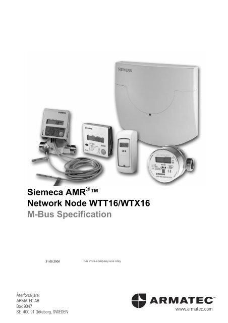
<strong>Siemeca</strong> <strong>AMR</strong> ® <br />
<strong>Network</strong> <strong>Node</strong> <strong>WTT16</strong>/<strong>WTX16</strong><br />
M-<strong>Bus</strong> Specification<br />
31.08.2006 For intra-company use only<br />
Återförsäljare:<br />
ARMATEC <strong>AB</strong><br />
Box 9047<br />
SE_400 91 Göteborg, SWEDEN
Abstract:<br />
This document describes how to communicate on the M-bus with a network node (up to<br />
V2.1) made by Siemens Building Technologies electronic. The document has been created<br />
to support customer-specific applications.<br />
This document must not be copied and/or shared with or distributed to third parties without<br />
approval from Siemens Building Technologies electronic GmbH.<br />
Siemens<br />
Building Technologies electronic GmbH<br />
HVP-IP<br />
Sondershäuser Landstr. 27<br />
99974 Mühlhausen/Thüringen<br />
Tel: +49 (3601) 46 83-0<br />
Fax: +49 (3601) 46 83-34<br />
www.siemens.com/siemeca<br />
©2006 Siemens Building Technologies AG<br />
Subject to change<br />
2/56 For intra-company use only<br />
Siemens<br />
Netzwerkknoten <strong>WTT16</strong>/<strong>WTX16</strong><br />
Building Technologies Contents 09.03.2007
Contents<br />
1 General Remarks about the M-<strong>Bus</strong> ........................... 5<br />
2 References................................................................. 10<br />
3 The <strong>Network</strong> <strong>Node</strong>..................................................... 11<br />
3.1 Physical Layer............................................................. 12<br />
3.2 Data Link Layer ........................................................... 14<br />
3.3 Application Layer......................................................... 21<br />
3.4 Special <strong>Network</strong> <strong>Node</strong> Commands ............................. 34<br />
4 Meters......................................................................... 41<br />
4.1 Current Data (Memory Block #0) ................................ 42<br />
4.2 Cutoff Date Data (Memory Block #1) .......................... 44<br />
4.3 Statistical Data (Memory Block ≥ #8) ......................... 45<br />
4.4 Overview of Data Points for <strong>Siemeca</strong> Meter Statistics 46<br />
5 Annex ......................................................................... 47<br />
5.1 M-<strong>Bus</strong> Ranges............................................................. 47<br />
5.2 Types of M-<strong>Bus</strong> Telegrams ......................................... 48<br />
5.3 Meter Readout from <strong>Network</strong> <strong>Node</strong> ............................ 50<br />
For intra-company use only 3/56<br />
Siemens<br />
Netzwerkknoten <strong>WTT16</strong>/<strong>WTX16</strong><br />
Building Technologies Contents 09.03.2007
4/56 For intra-company use only<br />
Siemens<br />
Netzwerkknoten <strong>WTT16</strong>/<strong>WTX16</strong><br />
Building Technologies Contents 09.03.2007
1 General Remarks about<br />
the M-<strong>Bus</strong><br />
M-<strong>Bus</strong><br />
Architecture<br />
Feeding of M-<strong>Bus</strong><br />
The M-bus is a pure master / slave bus, i.e., the master determines<br />
when communication takes place and which data are transmitted. An<br />
M-bus slave is not capable, for example, of transmitting a message<br />
on its own to the master in the event of an error. The M-bus design<br />
allows the production of low-cost and, most of all, energy-saving<br />
slaves, i.e., meters. This is of crucial importance for ensuring that<br />
meters will be operational for a period of many years.<br />
The M-bus – slave interface is fed by the bus and has a defined<br />
current consumption of 1.5 mA. This current consumption is called<br />
one M-bus load. In order to feed the actual meter, more power can<br />
be drawn from the M-bus, so that current consumption may exceed<br />
1.5 mA. Consequently, the meter will operate with more than one M-<br />
bus load. This fact is important for dimensioning the M-bus system.<br />
A repeater or an M-bus master is able to drive a certain number of<br />
M-bus devices (with one M-bus load). Whenever a meter draws<br />
several M-bus loads, the number of devices to be connected must<br />
be reduced accordingly or a repeater must be employed. The M-bus<br />
standard allows a device to draw up to four M-bus loads. The<br />
number of M-bus loads should be looked up in the operating<br />
instructions for the devices concerned.<br />
The bus is protected against polarity reversal for easy installation. In<br />
other words, thanks to the voltage-modulated signal that the master<br />
uses to the slaves, the polarity of the two leads does not matter<br />
when the device is connected. The slaves, for their part, respond<br />
with a current-modulated signal. There is a significant disadvantage<br />
to it, too. Communication is possible only between the master and<br />
the slave. A slave can never receive the current-modulated signals<br />
of another slave.<br />
For intra-company use only 5/56<br />
Siemens<br />
Netzwerkknoten <strong>WTT16</strong>/<strong>WTX16</strong><br />
Building Technologies General Remarks about the M-<strong>Bus</strong> 09.03.2007
M-<strong>Bus</strong> Topology<br />
The topology of an M-bus connection can be flexibly adjusted to the<br />
conditions in the field. For this reason, both pure lines or bus<br />
structures and a star topology can be used. No form of ring topology<br />
is permitted, however.<br />
M-<strong>Bus</strong> Range<br />
The M-bus is a long-range bus capable of linking meters to the M-<br />
bus master via a two-wire connection that extends over several<br />
kilometers. The range of the M-bus line is mainly determined by the<br />
capacity of the cable and the diameter. The greater the cable<br />
capacity per 100 meters of cable and the smaller the cross-section<br />
of the line used, the shorter the range will be. Accordingly, a parallel<br />
connection of several M-bus lines (star topology) will equally reduce<br />
the maximum range. If the range within an existing cable network<br />
needs to be increased, it helps to operate the meters at a<br />
transmission rate of 300 bauds instead of the preset 2,400 bauds.<br />
(See also Annex.) Another way to extend the range is to use an M-<br />
bus repeater. Such a device receives the signals from the M-<strong>Bus</strong><br />
master in the first M-bus segment and transmits them in the second<br />
M-bus segment to the slaves in an amplified manner (and vice<br />
versa). Additionally, it assures the feeding of the second M-bus<br />
segment, with the number of loads that can be connected depending<br />
both on that segment and on transmission loss. Maximum M-bus<br />
ranges are listed in the Annex. If the loads available are not<br />
sufficient, additional repeaters may be connected in series or in<br />
parallel.<br />
6/56 For intra-company use only<br />
Siemens<br />
M-<strong>Bus</strong> Spezifikation<br />
Building Technologies General Remarks about the M-<strong>Bus</strong> 09.03.2007
M-<strong>Bus</strong> Data<br />
Transmission<br />
Format<br />
Example:<br />
M-<strong>Bus</strong> Addressing<br />
Primary Address<br />
Under the Intel format (little endian), data points greater than one<br />
byte are transmitted with the least significant byte first. Within a byte,<br />
however, bits are transmitted with the most significant bit first (bit 7).<br />
A consumption value 123456 (BCD-coded) would be transmitted on<br />
the M-bus in the following sequence: 56 34 12. Therefore, binary<br />
transmission would be “01010110 00110100 00010010” (without<br />
showing any start, stop and parity bits).<br />
An M-bus device (slave) may have two addresses:<br />
• Primary address<br />
• Secondary address<br />
The primary address is determined with the aid of the service tool<br />
when the devices are installed. Numbers from 0 to 250 may be<br />
assigned to a primary address. Thus, a maximum of 251 devices<br />
can be addressed on a primary address M-bus. Primary address "0“<br />
is preset by the manufacturer. It should always be changed during<br />
installations, so that a device you may have forgotten will still be<br />
found in a search run.<br />
Primary address "253" indicates that the secondary address is used<br />
for identifying the M-bus device. The secondary address is<br />
transmitted in the application layer.<br />
Address "254" is used as a test address. This means that every M-<br />
bus device will always respond to this address, irrespective of its<br />
own primary address. For this reason, the test address may only be<br />
used when exactly one M-bus slave is connected to the bus.<br />
Otherwise, collisions will occur when device responses are sent<br />
back.<br />
Address "255" is used as broadcast address. This means that all the<br />
M-bus devices connected to the bus receive and process the<br />
command from the master. However, no receipt confirmation will be<br />
sent back to the master in that case. For this reason, the broadcast<br />
address should not be employed to parameterize important settings.<br />
There are devices where the primary address cannot be changed.<br />
Such devices can only be addressed through an M-bus master<br />
which supports secondary addresses.<br />
For intra-company use only 7/56<br />
Siemens<br />
Netzwerkknoten <strong>WTT16</strong>/<strong>WTX16</strong><br />
Building Technologies General Remarks about the M-<strong>Bus</strong> 09.03.2007
Secondary Address<br />
The secondary address is a globally unambiguous number assigned<br />
by the manufacturer.<br />
The secondary address in the M-bus consists of four parts:<br />
• Device identification (device ID = consecutive number, e.g.,<br />
12345678)<br />
• Manufacturer's ID (unambiguous code identifying the<br />
manufacturer, e.g., 12901 = "LSE")<br />
• Version (software version of the device)<br />
• Medium (physical measurand of the device, e.g., 6 = "hot water")<br />
In the secondary address, the maximum number of devices is limited<br />
only by the characteristics of the cable and the storage capacity of<br />
the M-bus master. M-bus systems administered through the<br />
secondary address may comprise several thousand devices. A<br />
detailed description of the secondary address is provided on<br />
Page 18.<br />
8/56 For intra-company use only<br />
Siemens<br />
M-<strong>Bus</strong> Spezifikation<br />
Building Technologies General Remarks about the M-<strong>Bus</strong> 09.03.2007
M-<strong>Bus</strong> Standard<br />
The OSI<br />
Reference Model<br />
The M-bus was first standardized with the heat meter in EN1434-3<br />
[5]. Since 2005, the M-bus has been standardized in EN13757,<br />
together with the COSEM Protocol, as a standard in its own right.<br />
The M-bus itself is governed by EN13757-2 [2] and EN13757-3 [3].<br />
In the last few years, a specific model has gained general<br />
acceptance for the description of communication between two<br />
machines.<br />
Its underlying idea is to<br />
separate the various functions<br />
or layers of communication<br />
and to assign them to<br />
different functional blocks.<br />
However, not all of those<br />
seven layers are really<br />
needed or implemented in<br />
every communication link.<br />
The M-bus standard only<br />
provides for the following<br />
layers:<br />
• Application layer [3]<br />
• Data link layer [2], [4]<br />
• Physical layer [2], [4]<br />
The description of the data link layer relates almost entirely to [1] in<br />
this context.<br />
This document is structured according to the three OSI layers<br />
supported. For an understanding of the M-bus protocol, knowledge<br />
of the application layer of the M-bus is indispensable. If the creation<br />
of a separate M-bus master is intended, purchase of the European<br />
standard EN13757 listed in the next section is recommended. (The<br />
requirements to be met by the hardware are described in [2], while<br />
the protocol is set out in [3].<br />
For intra-company use only 9/56<br />
Siemens<br />
Netzwerkknoten <strong>WTT16</strong>/<strong>WTX16</strong><br />
Building Technologies General Remarks about the M-<strong>Bus</strong> 09.03.2007
2 References<br />
[1] EN60870-5-2 Telecontrol equipment and systems – Part 5:<br />
Transmission protocols, Main Section 2: Link<br />
transmission procedures<br />
[2] EN13757 – 2 Communication systems for remote reading<br />
of meters – Part 2: Physical and link layers<br />
[3] EN13757 – 3 Communication systems for remote reading<br />
of meters – Part 3: Dedicated application<br />
layer<br />
[4] EN13757 – 4 Communication systems for remote reading<br />
of meters – Part 4: Wireless meter readout<br />
(radio meter reading for operation in the<br />
868 MHz to 870 MHz SDR band)<br />
[5] EN1434 – 3 Heat meters – Part 3: Data exchange and<br />
interfaces<br />
[6] Data Sheet „<strong>Siemeca</strong> <strong>AMR</strong> Remote Meter Readout<br />
System – Data Points of Meters“<br />
Internet download:<br />
An older version of [2] is available at:<br />
http://www.m-bus.com/files/W4A21021.pdf,<br />
while an older version of [3] can be downloaded from:<br />
http://www.m-bus.com/files/W4B21021.pdf.<br />
10/56 For intra-company use only<br />
Siemens<br />
M-<strong>Bus</strong> Spezifikation<br />
Building Technologies References 09.03.2007
3 The <strong>Network</strong> <strong>Node</strong><br />
Radio and M-<strong>Bus</strong><br />
Devices<br />
The network node (without<br />
gateway) is a system device<br />
whose job it is to receive and<br />
store the data from radioing<br />
meters and to make them<br />
available for the readout<br />
process.<br />
M-<strong>Bus</strong><br />
virtual M-BUS<br />
Since the M-bus is a pure<br />
master-slave bus, which does<br />
not allow messages from the<br />
slave to the master to be sent<br />
spontaneously, the data<br />
received via radio are stored.<br />
The M-bus master is in a<br />
position at any time to call up<br />
a copy of the data.<br />
As a general principle, an M-<br />
bus master cannot access the<br />
radio channel directly. In<br />
order to make the stored radio<br />
device accessible to the M-bus master, the network node simulates<br />
the existence on the bus of each radioing meter received as a "real"<br />
M-bus device. Consequently, the M-bus master addresses the meter<br />
directly and also gives the appearance of receiving a response<br />
directly from the meter. In other words, the master is not "aware"<br />
that, in reality, it is communicating with an entirely different device.<br />
As a result, a network node represents the following devices on the<br />
M-bus:<br />
• The network node directly connected to the bus (i.e., itself)<br />
• All the network nodes existing within the radio network<br />
• All the radioing meters existing within the radio network<br />
The number of devices that a network node represents on the M-bus<br />
can be determined on the basis of the information shown on the LCD<br />
display (sum of B and C levels). Since most radioing meters only<br />
possess transmitters but no receivers and since the travel time in the<br />
radio channel is much greater than the M-bus standard would<br />
permit, many commands that access the devices are only partly<br />
executed or are refused (e.g., "Change Cutoff Date").<br />
For intra-company use only 11/56<br />
Siemens<br />
Netzwerkknoten <strong>WTT16</strong>/<strong>WTX16</strong><br />
Building Technologies The <strong>Network</strong> <strong>Node</strong> 09.03.2007
3.1 Physical Layer<br />
Interfaces<br />
Data can be read out through the following interfaces:<br />
• Radio<br />
• M-bus<br />
• RS232 (<strong>WTT16</strong>.232 or <strong>WTX16</strong>.232 only)<br />
• IrDA (network node firmware version 2.2 and higher)<br />
The Radio<br />
Interface<br />
M-<strong>Bus</strong> Interface<br />
In order for the radio interface to be used, a PC equipped with a PC<br />
radio module (WTZ.RM) and the ACT26 service tool are required.<br />
This interface is not suited for accessing user-specific readout<br />
programs and will not be dealt with further in the present material.<br />
The M-bus interface of the<br />
<strong>WTT16</strong> / <strong>WTX16</strong> is an M-bus<br />
fixed M-<strong>Bus</strong> connection,<br />
max. 5 standard load<br />
slave which conforms to the<br />
standard, and it features one<br />
M-bus load. The M-bus<br />
interface is accessible either<br />
temporary<br />
M-<strong>Bus</strong> connection<br />
through a temporary plug-in<br />
MODE<br />
RESET<br />
connection or through a<br />
screwed connection for<br />
permanent assembly. This interface can only be addressed through<br />
an M-bus master module. For this, the proper M-bus master, such as<br />
that of the <strong>WTX16</strong>.GSM or <strong>WTX16</strong>.IP, is needed.<br />
Alternatively, the M-bus interface of the <strong>WTT16</strong> / <strong>WTX16</strong> can be<br />
addressed with a PC and a special PC – M-bus adapter, such as the<br />
WHZ3.USB or WFZ.MBM, and corresponding M-bus master<br />
software. The M-bus interface of the <strong>WTT16</strong> / <strong>WTX16</strong> may be<br />
addressed with 2,400 bauds or 300 bauds. Other baud rates will not<br />
be accepted. The master recognizes the baud rate automatically. No<br />
parameterization is required.<br />
Data are transmitted asynchronously byte by byte. A byte is sent<br />
with one start bit, eight data bits, one even parity bit and one stop bit.<br />
There must not be any gap between individual bytes. This means<br />
that the next start bit has to follow after one or two stop bits. The M-<br />
bus standard prescribes minimum and maximum response times for<br />
the M-bus slave.<br />
12/56 For intra-company use only<br />
Siemens<br />
Netzwerkknoten <strong>WTT16</strong>/<strong>WTX16</strong><br />
Building Technologies The <strong>Network</strong> <strong>Node</strong> 09.03.2007
This time interval starts after the telegram has been sent by the<br />
master. The slave has to sent a reply back to the master within this<br />
time interval.<br />
Minimum response delay:<br />
Maximum response delay:<br />
11 bit times<br />
330 bit times + 50 ms<br />
Reading device data consumes additional current. Therefore, the<br />
operational life of the battery-powered <strong>WTT16</strong> network node is<br />
shorter than that of other network nodes within the network. For this<br />
reason, it is recommended that the network node readout through<br />
the M-bus be limited to one readout per day. If 500 meters are<br />
stored, this would correspond to an additional battery consumption<br />
of some 3 %.<br />
The RS-232 Serial<br />
Interface<br />
The RS-232 interface is only<br />
available in the special<br />
<strong>WTT16</strong>.232 and <strong>WTX16</strong>.232<br />
models. This interface is<br />
intended for connecting the<br />
network node directly to a PC.<br />
M-bus master software like<br />
ACT26 may be used for the<br />
communication with the network node. The data rate is freely<br />
selectable from 300 bauds to 9,600 bauds and can be set with the<br />
ACT26 service tool.<br />
GND<br />
n.c.<br />
RTS<br />
CTS<br />
Rx<br />
Tx<br />
Data are transmitted asynchronously byte by byte. A byte is sent<br />
with one start bit, eight data bits, one even parity bit and one stop bit.<br />
There should not be any gaps between individual bytes. Gaps of up<br />
to 8 milliseconds will be accepted, however. The response times of<br />
the RS-232 interface are identical to those of the M-bus interface.<br />
Reading device data consumes additional current. For this reason,<br />
the operational life of the battery-powered <strong>WTT16</strong>.RS232 network<br />
node is shorter than that of other network nodes within the network.<br />
Therefore, it is recommended that the network node readout through<br />
the RS-232 interface be limited to one readout per day. If 500 meters<br />
are stored, this would correspond to an additional battery<br />
consumption of about 5 %.<br />
For intra-company use only 13/56<br />
Siemens<br />
Netzwerkknoten <strong>WTT16</strong>/<strong>WTX16</strong><br />
Building Technologies The <strong>Network</strong> <strong>Node</strong> 09.03.2007
3.2 Data Link Layer<br />
Telegram Format<br />
The M-bus standard supports several telegram formats in<br />
accordance with [1], Format FT1.2:<br />
Single<br />
Character<br />
Short Frame<br />
Control<br />
Frame<br />
Long<br />
Frame<br />
E5h/A2h start 10h start 68h start 68h<br />
C field L field = 3 L field<br />
A field L field = 3 L field<br />
check sum start 68h start 68h<br />
stop 16h C field C field<br />
A field<br />
CI field<br />
check sum<br />
stop 16h<br />
A field<br />
CI field<br />
user data<br />
(0-252 byte)<br />
check sum<br />
stop 16h<br />
Single Character<br />
Start and Stop<br />
Symbols<br />
L Field<br />
C Field<br />
A Field<br />
This format contains one E5h (229d) character and serves to<br />
acknowledge (CONFIRM) the last successful transmission. Should<br />
the node detect that more than one of the stored devices are<br />
addressed, it will send the A2h (162d) character as a negative<br />
acknowledgement (COLLISION) to signal an apparent collision.<br />
Through these symbols, the link layer is in a position to recognize<br />
the beginning and end of a telegram unambiguously.<br />
The L field describes the length of a telegram. The length<br />
information takes into consideration all the characters of a telegram,<br />
excluding start and stop symbols, the check sum and the L field<br />
itself. The two fields should be identical. Otherwise, the telegram is<br />
to be discarded.<br />
The C field (control field) controls the link layer functions of the<br />
telegram. The C field is based on standard [1].<br />
The address field indicates the primary address of the slave that the<br />
master is communicating with.<br />
14/56 For intra-company use only<br />
Siemens<br />
Netzwerkknoten <strong>WTT16</strong>/<strong>WTX16</strong><br />
Building Technologies The <strong>Network</strong> <strong>Node</strong> 09.03.2007
CI Field<br />
Check Sum<br />
Types of M-<strong>Bus</strong><br />
Telegrams<br />
The CI field (control information field) controls the functions of the<br />
application layer. Through them, this layer determines the structure<br />
and significance of the data relayed in the telegram.<br />
User Data<br />
The data points relayed in a data structure, together with such<br />
information as length and type data. This data structure is described<br />
in greater detail in [3] and consists of a DIB (data information block),<br />
VIB (value information block) and DATA (value / user data).<br />
The check sum constitutes the sum (without carry flag) of all the<br />
bytes transmitted. It is sent for checking the consistency of<br />
telegrams.<br />
The table below shows the types of M-bus telegrams (C fields)<br />
supported by the network node. Any use of C fields not indicated in<br />
the table will lead to an application error. (See "Application Error.")<br />
The Annex lists the telegram types as examples.<br />
Name C Field Binary C Field<br />
Hex.<br />
Telegram<br />
Format<br />
Description<br />
SND_NKE 0100 0000 40 Short frame Initialization of slave<br />
SND_UD 01F1 0011 53/73 Long / control<br />
frame<br />
Send user data to slave<br />
REQ_UD2 01F1 1011 5B/7B Short frame Request for class 2 data<br />
RSP_UD 0000 1000 08 Long / control<br />
frame<br />
Data transfer from slave<br />
to master after request<br />
Table 1: Telegram Types (C Fields) Supported by <strong>Network</strong> <strong>Node</strong> (F: FCB Bit )<br />
Follow-up<br />
Telegrams (FCB)<br />
Normalize / Confirm<br />
Under the M-bus standard [3], large amounts of data can be<br />
transmitted by means of follow-up telegrams. Follow-up telegrams<br />
are not supported at the network node. If the Frame Count Valid bit<br />
(FCV, C Field Bit 4) is set, the Frame Count Bit (FCB, C Field Bit 5)<br />
will be ignored.<br />
In the event of primary address and test address agreement or in the<br />
event of a secondary address, a Normalize telegram (SND_NKE)<br />
will be acknowledged on a selected device through the E5h<br />
(CONFIRM) single handshake signal. Whenever a selected device<br />
receives a Normalize telegram addressed to another device, the<br />
selection will be cancelled.<br />
For intra-company use only 15/56<br />
Siemens<br />
Netzwerkknoten <strong>WTT16</strong>/<strong>WTX16</strong><br />
Building Technologies The <strong>Network</strong> <strong>Node</strong> 09.03.2007
Send Data /<br />
Confirm<br />
Request Data /<br />
Respond Data<br />
Commands are transmitted from the master to the slave by means of<br />
a Send User Data telegram (SND_UD). Every Send User Data<br />
telegram with a correct primary address, correct secondary address<br />
or test address will be confirmed through the E5h (CONFIRM) single<br />
handshake signal. Such confirmation will take place if the telegram is<br />
received correctly, irrespective of whether the meter knows the data<br />
or is able to store them (link layer confirmation). Whenever Send<br />
Data are transmitted with the broadcast address (broadcast; primary<br />
address = 255), no confirmation will take place. If a response to a<br />
command is expected, the master needs to perform a request<br />
(REQ_UD2).<br />
To receive data from an M-bus slave, the master must retrieve the<br />
data after a command through a special request. Only then will the<br />
actual response be transmitted from the slave to the master.<br />
Of the request telegrams defined in the M-bus standard [3], only<br />
request user data 2 (REQ_UD2) will be supported by the network<br />
node. The retrieval of all the information will thus be effected through<br />
the master. The reply is sent back in the Respond User Data<br />
telegram (RSP_UD). Request User Data 1 (REQ_UD1) will not be<br />
processed. However, a CONFIRM will be sent back in response to a<br />
valid REQ_UD1.<br />
16/56 For intra-company use only<br />
Siemens<br />
Netzwerkknoten <strong>WTT16</strong>/<strong>WTX16</strong><br />
Building Technologies The <strong>Network</strong> <strong>Node</strong> 09.03.2007
M-<strong>Bus</strong> Protocol<br />
In reply to a request user data (REQ_UD2), the M-bus slave will<br />
send a response data telegram (RSP_UD) of the type shown below.<br />
start character 1 $ 68 not changeable<br />
telegram length 2 $ 6F length = 111 bytes<br />
telegram length 3 $ 6F<br />
start character 4 $ 68 not changeable<br />
c-field 5 $ 08 respond with data<br />
address field 6 $ AA primary device address (e.g. =170)<br />
ci-field 7 $ 72 variable structure response<br />
device<br />
identification<br />
8 $ 78 device identification<br />
device<br />
identification<br />
device<br />
identification<br />
device<br />
identification<br />
9 $ 56 (e.g. 12345678)<br />
10 $ 34<br />
11 $ 12<br />
manufacturer id 12 $ 65 manufacturer (e.g. = 3265h = lse)<br />
manufacturer id 13 $ 32<br />
version 14 $ 03 software version (e.g =03)<br />
medium 15 $ 08 heat cost allocator<br />
access number 16 $ 1B number of interrogations (e.g. = 27)<br />
status 17 $ 00 error status (e.g. no error)<br />
signature byte 1 18 $ 00 no encryption<br />
signature byte 2 19 $ 00 no encryption<br />
variable data<br />
checksum … $ xx to check bit errors during<br />
transmission<br />
stop character … $ 16 not changeable<br />
Actual data are transmitted with one or several variable length data<br />
points (in the 'variable data' part). Those data points can be<br />
transmitted in an arbitrary order, which may change even from one<br />
transmission to the next.<br />
Each data point starts with control fields (DIF, DIFE, VIF, VIFE),<br />
which describe the decryption (length, format, unit, etc.) of the data<br />
value. A detailed description of these control fields is provided in [3].<br />
For intra-company use only 17/56<br />
Siemens<br />
Netzwerkknoten <strong>WTT16</strong>/<strong>WTX16</strong><br />
Building Technologies The <strong>Network</strong> <strong>Node</strong> 09.03.2007
Addressing<br />
Primary Addressing<br />
Secondary<br />
Addressing<br />
The network node supports primary and secondary addressing.<br />
Primary addresses 0...250 can be assigned to the network node.<br />
Primary address "0“ is preset by the manufacturer. In addition to the<br />
assigned primary address, the network node also responds to test<br />
address 254 and broadcast address 255. The primary address<br />
always serves to address the M-bus connected network node itself.<br />
The (virtual) devices stored in it can only be addressed through<br />
secondary addressing. (See also Page 8.)<br />
If the master sets the primary address to 253, the slaves will be<br />
identified through the secondary address. The slave, for its part, will<br />
respond with the correct primary address (provided that it has a<br />
primary address). The devices stored in the network node do not<br />
have any primary address and will equally respond on the M-bus<br />
with primary address 253.<br />
The secondary address succeeds the CI field (CI = 72) and is<br />
always structured as follows:<br />
Name Format Example<br />
Device<br />
4 bytes (BCD) 01234567<br />
Identification<br />
Manufacturer 2 bytes (binary) 3265h (12901dez.) = "LSE"<br />
Code<br />
Version 1 byte (binary) 01h<br />
Medium 1 byte (binary) 0Eh<br />
Table 2: Secondary Address on the M-bus<br />
The example shown in Table 2 is transmitted on the M-bus in the<br />
following order:<br />
67 45 23 01 65 32 01 0E<br />
Device<br />
Identification<br />
The device identification is always given as an 8-digit figure shown in<br />
binary-coded decimal numbers (BCD).<br />
18/56 For intra-company use only<br />
Siemens<br />
Netzwerkknoten <strong>WTT16</strong>/<strong>WTX16</strong><br />
Building Technologies The <strong>Network</strong> <strong>Node</strong> 09.03.2007
Manufacturer ID<br />
The manufacturer ID shows the manufacturer's globally unique<br />
code. The manufacturer ID may be computed from the three letters<br />
of the manufacturer identifier. The following formula is used for this<br />
purpose:<br />
Manufacturer ID = [ASCII(1st letter) – 64] x 32 x 32<br />
+ [ASCII(2nd letter) – 64] x 32<br />
+ [ASCII(3rd letter) – 64]<br />
Siemens Building Technologies electronic (formerly known as Landis<br />
und Staefa electronic) with the "LSE" identifier thus carries the<br />
manufacturer ID "12901."<br />
Version<br />
Medium<br />
The version provides the current software version of the device.<br />
Since the software version is part of the address, a network node will<br />
change its address following a software update. In other words,<br />
should a node be given a software update after it had been<br />
connected to an M-bus master, a new search run needs to be<br />
performed, so that the master can address this network node again.<br />
The medium indicates the physical measurand of the device.<br />
Medium 14 has been set aside for the network node which is not a<br />
meter.<br />
Medium<br />
(decimal)<br />
Medium<br />
(hex) Meaning<br />
00 00 Other<br />
01 01 Oil<br />
02 02 Electricity<br />
03 03 Gas<br />
04 04 Heat (volume measurement in return pipe )<br />
05 05 Steam<br />
06 06 Hot water (30°C to 90°C)<br />
07 07 Cold water<br />
08 08 Heat cost allocator<br />
09 09 Compressed air<br />
10 0A Cold (volume measurement in return pipe)<br />
11 0B Cold (volume measurement in flow pipe)<br />
12 0C Heat (volume measurement in flow pipe)<br />
13 0D Heat / cold<br />
14 0E <strong>Network</strong> node / system device<br />
15 0F Unknown<br />
Table 3: List Showing all the Media Supported in Accordance with [3]<br />
For intra-company use only 19/56<br />
Siemens<br />
Netzwerkknoten <strong>WTT16</strong>/<strong>WTX16</strong><br />
Building Technologies The <strong>Network</strong> <strong>Node</strong> 09.03.2007
Extended<br />
Secondary<br />
Addressing<br />
If the device identification is subsequently changed (e.g., when a<br />
radio pulse adaptor for water meters is retrofitted), <strong>Siemeca</strong> devices<br />
will automatically and additionally broadcast a fabrication number.<br />
The fabrication number is a copy of the original device ID. It prevents<br />
any address conflict from occurring on the M-bus (and on the radio<br />
channel), even if the same device ID has inadvertently been<br />
programmed in two different devices. The master has to use<br />
extended selection for that purpose.<br />
However, if a meter is simultaneously registered in two networks or<br />
two network nodes from one network are connected to the M-bus,<br />
there will still be a collision, even if extended selection (without wild<br />
cards) is used. The reason for such a collision is that the meter is<br />
simulated on the M-bus by two network nodes. Thus, the same<br />
device address does, indeed, exist twice on the M-bus.<br />
20/56 For intra-company use only<br />
Siemens<br />
Netzwerkknoten <strong>WTT16</strong>/<strong>WTX16</strong><br />
Building Technologies The <strong>Network</strong> <strong>Node</strong> 09.03.2007
3.3 Application Layer<br />
Master to Slave<br />
CI Field (Master)<br />
Note :<br />
The following table lists the CI fields which the network node accepts<br />
from the master. Any CI field other than those given will result in an<br />
application error. (See Application Error.)<br />
SND_UD:<br />
master->slave<br />
CI Field<br />
Frame<br />
Format<br />
Remark<br />
application reset 50h control frame<br />
application select 50h long frame Additional sub code is used for<br />
selection.<br />
send data 1) 51h long frame<br />
selection of slaves 52h long frame<br />
deselection of<br />
slaves<br />
56h long frame<br />
set baud rate 2) B8h...BDh control frame Not for M-<strong>Bus</strong>! RS-232 only!<br />
Table 4: CI Fields Accepted by <strong>Network</strong> <strong>Node</strong><br />
An acknowledgment (CONFIRM / COLLISION) is sent in response<br />
to an SND_DU, even if the CI field is not recognized or the<br />
command is not executed. The acknowledgment applies to<br />
successful transmission on the link layer only. Any application error<br />
that may have occurred can be queried through an REQ_UD2.<br />
The Set Baud Rate command can only be applied to the RS-232.<br />
The baud rate is automatically switched (300 bauds / 2,400 bauds)<br />
at the M-bus interface. The command will be ignored.<br />
For intra-company use only 21/56<br />
Siemens<br />
Netzwerkknoten <strong>WTT16</strong>/<strong>WTX16</strong><br />
Building Technologies The <strong>Network</strong> <strong>Node</strong> 09.03.2007
Application Reset /<br />
Select<br />
With the aid of Application Reset, the response of the network node<br />
can be configured for the meters stored. To this end, three groups of<br />
data may be selected:<br />
Selected<br />
Data<br />
Standard<br />
Data<br />
Statistical<br />
Data<br />
Tariff<br />
Data<br />
Meaning<br />
Contains current values, cutoff date values and error<br />
information.<br />
Contains the consumption of the first measurand at the<br />
end of each month concerned.<br />
Contains the consumption of the second measurand at<br />
the end of each month concerned (water meters only).<br />
Table 5: Data Groups that May Be Selected at the <strong>Network</strong> <strong>Node</strong> for Each Meter Stored<br />
Whenever an application reset is performed on a meter stored in the<br />
network node, the standard and statistical data will be configured as<br />
a standard response. An application reset can also be used to delete<br />
an application error.<br />
Application Reset<br />
(Hex)<br />
Code<br />
CI field 1 50<br />
Application Select<br />
(Hex)<br />
Code<br />
CI Field 1 50<br />
Sub code for<br />
application select<br />
2 30 Example: standard +<br />
statistical data<br />
22/56 For intra-company use only<br />
Siemens<br />
Netzwerkknoten <strong>WTT16</strong>/<strong>WTX16</strong><br />
Building Technologies The <strong>Network</strong> <strong>Node</strong> 09.03.2007
The following combinations are possible:<br />
Application Selected Data for Response<br />
Select<br />
10 Standard data only<br />
20 Standard data only<br />
30 Standard and statistical data<br />
40 Standard and tariff data<br />
Other No impact. Application select will be ignored (no<br />
application error).<br />
Table 6: Coding for Application Select<br />
Application Select is stored permanently and preserved until the next<br />
Application Select or Application Reset is effected. Application<br />
Select can only be executed on meters. The network node will<br />
ignore any form of Application Select.<br />
Send Data<br />
Send Data is used for transmitting commands to the network node or<br />
to the devices stored in it.<br />
Send Data<br />
(Hex)<br />
Code<br />
CI Field 1 51<br />
DIF 2 01 Example:<br />
VIF 3 7A<br />
Value 4 01<br />
Set primary address to "1."<br />
Select / Deselect<br />
The Select command serves to select a specific device on the M-bus<br />
for communication. "Select" is required only if the slave is to be<br />
operated through a secondary address. Only one device may be<br />
selected on the bus at any given time. Otherwise, collisions may be<br />
caused by slaves responding simultaneously. In such a case, not<br />
only invalid responses, but also telegrams with a seemingly correct<br />
content may reach the master, so that deselection will be<br />
compulsory. Nor may any wildcards be used in the selection<br />
process, as they are bound to result in multiple selection.<br />
For intra-company use only 23/56<br />
Siemens<br />
Netzwerkknoten <strong>WTT16</strong>/<strong>WTX16</strong><br />
Building Technologies The <strong>Network</strong> <strong>Node</strong> 09.03.2007
Select<br />
(Hex)<br />
Code<br />
CI Field 1 52<br />
Device ID (4th byte) 2 78 Device ID = 12345678<br />
Device ID (3rd byte) 3 56<br />
Device ID (2nd<br />
byte)<br />
4 34<br />
Device ID (1st byte) 5 12<br />
Manufacturer (2nd<br />
byte)<br />
Manufacturer (1st<br />
byte)<br />
6 65 Manufacturer ID "LSE" = 12901<br />
(decimal)<br />
7 32<br />
Version 8 01 Software version = 01<br />
Medium 9 08 Heat cost allocator<br />
When the communication is finished, the device needs to be<br />
deselected. Deselection should always take place at the end of any<br />
given communication and not just when the next communication with<br />
another device starts.<br />
There are several ways to deselect a device in the network node:<br />
• "Deselect" command on the device selected<br />
• "Select" command on another device<br />
• SND_NKE on the selected device or another device<br />
• Change of data rate<br />
Deselect<br />
(Hex)<br />
Code<br />
CI Field 1 56<br />
Device ID (4th byte) 2 78 Device ID = 12345678<br />
Device ID (3rd byte) 3 56<br />
Device ID (2nd byte) 4 34<br />
Device ID (1st byte) 5 12<br />
Manufacturer (2nd<br />
byte)<br />
Manufacturer (1st<br />
byte)<br />
6 65 Manufacturer ID "LSE" =<br />
12901 (decimal)<br />
7 32<br />
Version 8 01 Software version = 01<br />
Medium 9 08 Heat cost allocator<br />
24/56 For intra-company use only<br />
Siemens<br />
Netzwerkknoten <strong>WTT16</strong>/<strong>WTX16</strong><br />
Building Technologies The <strong>Network</strong> <strong>Node</strong> 09.03.2007
Extended Select /<br />
Deselect<br />
If the network node identifies a COLLISION following selection<br />
(without wildcards), a conflict of address may exist. This means that<br />
the same device ID is used in two meters. In a case of this kind,<br />
extended selection, which takes the fabrication number into account,<br />
would be helpful. (See also Page 20.)<br />
(Hex)<br />
Extended Select<br />
Code<br />
CI Field 1 52<br />
Device ID (4th byte) 2 78 Device ID = 12345678<br />
Device ID (3rd byte) 3 56<br />
Device ID (2nd byte) 4 34<br />
Device ID (1st byte) 5 12<br />
Manufacturer (2nd<br />
byte)<br />
Manufacturer (1st<br />
byte)<br />
6 65 Manufacturer ID "LSE" =<br />
12901 (decimal)<br />
7 32<br />
Version 8 01 Software version = 01<br />
Medium 9 08 Heat cost allocator<br />
DIF 10 0C<br />
VIF 11 78<br />
Device ID (4th byte) 12 32 Fabrication number=<br />
98765432<br />
Device ID (3rd byte) 13 54<br />
Fabrication<br />
number(2nd byte)<br />
14 76<br />
Fabrication<br />
number(1st byte)<br />
15 98<br />
Set Baud Rate<br />
Using the CI fields listed in the table, the baud rate can be set at the<br />
RS-232 interface. Owing to the fact that the baud rate is<br />
automatically recognized and set, any baud rate setting through the<br />
M-bus will be ignored.<br />
CI Field (Hex) B8 B9 BA BB BC BD<br />
Baud rate 300 600 1200 2400 4800 9600<br />
Table: Baud Rates Which May Be Set at the RS-232 Interface of the <strong>Network</strong> <strong>Node</strong><br />
For intra-company use only 25/56<br />
Siemens<br />
Netzwerkknoten <strong>WTT16</strong>/<strong>WTX16</strong><br />
Building Technologies The <strong>Network</strong> <strong>Node</strong> 09.03.2007
Slave to Master<br />
CI Field (Slave)<br />
If the network node has received an REQ_UD2, it will respond with<br />
an RSP_UD. The table below shows the various responses possible.<br />
RSP_UD: slave -><br />
master<br />
Report of<br />
application error<br />
Respond variable<br />
data<br />
CI Field<br />
70h<br />
72h<br />
Frame<br />
Format<br />
Long<br />
frame<br />
Long<br />
frame<br />
Remarks<br />
Used in case of<br />
application error<br />
Standard or command<br />
response<br />
Application Error<br />
If an M-bus master triggers an invalid command on the network<br />
node, the successful transmission of the command will be<br />
acknowledged (CONFIRM "E5h"). Together with the next request<br />
(REQ_UD2), an application error (report of application error) will<br />
then be sent instead of a normal response (RSP_UD).<br />
Application Error<br />
(Hex)<br />
Code<br />
CI Field 1 70<br />
Application error<br />
code<br />
2 10 Example<br />
26/56 For intra-company use only<br />
Siemens<br />
Netzwerkknoten <strong>WTT16</strong>/<strong>WTX16</strong><br />
Building Technologies The <strong>Network</strong> <strong>Node</strong> 09.03.2007
The following<br />
application errors<br />
may occur:<br />
(Decimal)<br />
Application<br />
Error Code<br />
(Hex)<br />
Application<br />
Error Code<br />
Meaning<br />
00 00h Non-specified error<br />
01 01h CI field not supported.<br />
02 02h Telegram does not fit into input buffer.<br />
04 04h Premature end of telegram<br />
05 05h More than 10 DIFEs in a single data point<br />
06 06h More than 10 VIFEs in a single data point<br />
08 08h The application is very busy and cannot<br />
respond at present.<br />
16 10h Access refused. (User, password or<br />
authorization invalid.)<br />
17 11h Command not recognized or supported.<br />
18 12h Parameter missing or wrong.<br />
19 13h Unknown receiver address<br />
Table 7: Application Errors of <strong>Network</strong> <strong>Node</strong> The application errors contained in the lines<br />
highlighted in gray are not listed in [3].<br />
The application error may be queried as often as required. However,<br />
it will be deleted automatically after about four minutes. Also, it will<br />
be reset by every new command. This way, the standard response<br />
of the network node can be obtained by an Application Reset prior to<br />
the Request.<br />
Standard<br />
Response of the<br />
<strong>Network</strong> <strong>Node</strong><br />
If the network node is sent a Request (REQ_UD2), with no<br />
command preceding it, the network node will always send back the<br />
standard response as its response (RSP_UD).<br />
The standard response to a Request will also be given following a<br />
command for which no response is generated, but was executed<br />
without any application error occurring (positive feedback).<br />
A command, in respect to which a response is expected, will<br />
produce the command response (RSP_UD) after the Request<br />
(REQ_UD2) or an application error if the command could not be<br />
executed successfully. In order to force the standard response of the<br />
network node, an Application Reset can be requested.<br />
For intra-company use only 27/56<br />
Siemens<br />
Netzwerkknoten <strong>WTT16</strong>/<strong>WTX16</strong><br />
Building Technologies The <strong>Network</strong> <strong>Node</strong> 09.03.2007
The response telegram of the network node is always composed of<br />
an invariable and a variable part and is structured in the following<br />
manner: (This table shows the application layer only.)<br />
Standard Response<br />
(Hex)<br />
Code<br />
CI Field 1 72<br />
Device ID (4th byte) 2 78 Device ID = 12345678<br />
Device ID (3rd byte) 3 56<br />
Device ID (2nd byte) 4 34<br />
Device ID (1st byte) 5 12<br />
Manufacturer (2nd<br />
byte)<br />
Manufacturer (1st<br />
byte)<br />
6 65<br />
7 32<br />
Version 8 22<br />
Medium 9 14<br />
Access number 10 03<br />
Manufacturer ID "LSE" =<br />
12901 (decimal)<br />
Software version = 22<br />
(equivalent to V2.2)<br />
<strong>Network</strong> node / system<br />
device<br />
Example: Consecutive<br />
telegram number = 3<br />
Status 11 04<br />
Example: Weak battery<br />
indication<br />
Signature (2nd byte) 12 00 Encryption always 00 00.<br />
Signature (1st byte) 13 00<br />
Variable data.. ... xx Start of variable data<br />
….<br />
xx<br />
The CI field is followed by an 8-byte secondary address, as<br />
described in the Secondary Addressing section.<br />
The Invariable<br />
Part of the<br />
Response<br />
Telegram<br />
Access Number<br />
The access number is a consecutive number, which is increased<br />
with every Request (REQ_UD2). If the value 255 is surpassed,<br />
numbering will restart at 0. This field ensures that telegrams and<br />
check sums always change, even if the current meter reading<br />
remains unchanged.<br />
28/56 For intra-company use only<br />
Siemens<br />
Netzwerkknoten <strong>WTT16</strong>/<strong>WTX16</strong><br />
Building Technologies The <strong>Network</strong> <strong>Node</strong> 09.03.2007
Status / Error<br />
Codes<br />
The status represents the error status of the network node or the<br />
error status of the device stored in it. The status is coded in a bit-bybit<br />
manner.<br />
Error<br />
Bit<br />
0<br />
1<br />
(Hex.)<br />
Value in<br />
the Event<br />
of a<br />
Single<br />
Error<br />
00h<br />
01h<br />
02h<br />
03h<br />
(Decimal)<br />
Value in<br />
the Event<br />
of a<br />
Single<br />
Error<br />
00h<br />
01h<br />
02h<br />
03h<br />
Meaning<br />
No error<br />
Reserved<br />
Application alert (atypical<br />
consumption)<br />
Reserved<br />
2 04h 04h Weak battery<br />
3 - - Permanent error (in combination)<br />
4 - - Minor error (temporary error (in<br />
5 28h<br />
combination))<br />
Serious device error (permanent<br />
error)<br />
6 50h Values measured outside of<br />
permissible range (temporary error)<br />
7 88h<br />
90h<br />
Communication permanently<br />
interrupted (permanent error)<br />
Communication temporarily<br />
interrupted (temporary error)<br />
Table 8: Error Codes in Status Field. The lines highlighted in gray are defined by the<br />
manufacturer (by SBTE in this case).<br />
Status bits 5, 6 and 7 are always set together with bit 3 or 4. Status<br />
bit 7 is set by the network node if the connection to the device is<br />
interrupted. Any attempt by the network node to reestablish the<br />
connection will be marked as temporary interruption of<br />
communication. If such attempts remain unsuccessful, the status will<br />
be converted to permanent interruption of communication.<br />
Communication errors are displayed with an error date.<br />
Status bits 5 and 6 are taken over from the device received. Bit 6<br />
shows a temporary device error, which may correct itself (e.g.,<br />
temperature in flow pipe too high). Bit 5 indicates a permanent<br />
device error (serious error), which requires servicing in any case<br />
whatsoever. The exact cause of the error in the malfunctioning<br />
device can be determined directly on the device by means of a<br />
For intra-company use only 29/56<br />
Siemens<br />
Netzwerkknoten <strong>WTT16</strong>/<strong>WTX16</strong><br />
Building Technologies The <strong>Network</strong> <strong>Node</strong> 09.03.2007
service tool. Permanent device errors are transmitted with an error<br />
date.<br />
There may even be several errors occurring together.<br />
30/56 For intra-company use only<br />
Siemens<br />
Netzwerkknoten <strong>WTT16</strong>/<strong>WTX16</strong><br />
Building Technologies The <strong>Network</strong> <strong>Node</strong> 09.03.2007
Example:<br />
1. Error code 168 (A8h) indicates a permanent device error and<br />
permanent interruption of communication at the same time.<br />
2. Error code 188 (BCh) shows a discharged battery, a permanent<br />
device error and temporary interruption of communication at the<br />
same time.<br />
Signature<br />
The Variable Part<br />
of the Response<br />
Telegram<br />
Operating Hours<br />
Example:<br />
Current Date &<br />
Time<br />
Example:<br />
Albatross ID<br />
Example:<br />
In accordance with [3], the signature shows whether and how the<br />
telegram is encrypted. The encryption on the M-bus is not supported<br />
in the network node. It is always 00 00.<br />
The variable data points start after the signature. These may vary as<br />
a function of the commands given by the M-bus master or as a<br />
function of the device configuration or the software version. Each<br />
data point starts with a DIF field. From the DIF or the DIFEs that may<br />
exist, the lengths of the data point and, with it, the beginning of the<br />
next data point can be determined. The use of DIF and DIFE control<br />
fields is explained in the M-bus standard [3].<br />
This value shows the number of hours elapsed since the network<br />
node was started up.<br />
0C 22 34 12 00 00<br />
indicates 1,234 operating hours, hence 51 days.<br />
This data point shows the date and time of the network node. Being<br />
a type F data point, this data point is encrypted in accordance with<br />
[3].<br />
04h 6Dh 1B 06 CE 06<br />
corresponds to June 5, 2006, 5:27 a.m. (Standard Winter Time).<br />
This value provides an unambiguous device type identifier. This<br />
value is used to ensure the exact identification of devices for service<br />
tools and does not have to be stored or transmitted for billing<br />
purposes.<br />
06 FD 0C 14 00 0E 00 22 03<br />
is an Albatross ID of the <strong>WTT16</strong>.<br />
For intra-company use only 31/56<br />
Siemens<br />
Netzwerkknoten <strong>WTT16</strong>/<strong>WTX16</strong><br />
Building Technologies The <strong>Network</strong> <strong>Node</strong> 09.03.2007
Device Type (ASN)<br />
Example:<br />
Status / Error Date<br />
Example:<br />
<strong>Network</strong> Index<br />
Example:<br />
This data point shows the device type. For the network node, the<br />
device type is either <strong>WTT16</strong> or <strong>WTX16</strong>. Device types are presented<br />
as a 5-character ASCII string in inverse order.<br />
0D FD 0B 05 36 31 54 54 57<br />
shows a <strong>WTT16</strong>.<br />
The error date contains a valid value if the meter status indicates a<br />
permanent device error or temporary or permanent interruption of<br />
communication. (See also Page 29.) An invalid date is shown with<br />
FFh FFh.<br />
32 6C FF FF<br />
This is not a valid error date.<br />
For servicing purposes, it is often useful to establish exactly in which<br />
radio network the network node is located. This data point furnishes<br />
such information.<br />
02 FA 3D nn kk<br />
nn<br />
kk<br />
M-bus primary address of the network node through<br />
which the radioing devices are presented on the M-bus –<br />
8-bit binary coded<br />
is the primary radio broadcast address of the node itself.<br />
The primary radio broadcast address of a network node<br />
is shown on display level A - 8-bit binary coded.<br />
Example:<br />
Main Battery Power<br />
Consumption<br />
02 FA 3D 02 0A<br />
shows network node 10. It forms part of the network that is reached<br />
through the network node with M-bus primary address 02 on the M-<br />
bus.<br />
This data point shows the remaining capacity of the exchangeable<br />
main battery in percent. Since this consumption cannot be presented<br />
as a normal M-bus data point, the unit of this value is shown with a<br />
variable VIF. The unit is ASCII-coded and rendered in inverse order<br />
according to the M-bus. It shows "% Batt." A 255 consumption value<br />
signals that the network node concerned is fed externally and not fed<br />
through a battery. There is no data point for the capacity of the<br />
backup battery.<br />
32/56 For intra-company use only<br />
Siemens<br />
Netzwerkknoten <strong>WTT16</strong>/<strong>WTX16</strong><br />
Building Technologies The <strong>Network</strong> <strong>Node</strong> 09.03.2007
Example:<br />
01 7C 06 54 54 41 42 20 25 64<br />
indicates a remaining capacity of 100 percent.<br />
Since no binding device replacement interval has been set for the<br />
network node (calibration validity) – as is the case for water meters,<br />
for instance – the node may be operated up to the end of the battery<br />
life.<br />
For intra-company use only 33/56<br />
Siemens<br />
Netzwerkknoten <strong>WTT16</strong>/<strong>WTX16</strong><br />
Building Technologies The <strong>Network</strong> <strong>Node</strong> 09.03.2007
3.4 Special <strong>Network</strong> <strong>Node</strong><br />
Commands<br />
Selection of a<br />
Device in the<br />
Memory<br />
In order to be able to read the addresses of the stored devices, the<br />
master needs to select the correct position in the memory. The<br />
memory block and the memory location are required for that. There<br />
are two memory blocks:<br />
Memory<br />
Block<br />
Memory<br />
Location<br />
Explanation<br />
#1 1..500 Contains the addresses of all the<br />
meters stored.<br />
#2 1..12 Contains the addresses of all the<br />
network nodes stored.<br />
Table 9: The memory block is selected through special DIFs and DIFEs [3].<br />
Memory block #1 (meters): DIF = 42h<br />
A DIFE is required for memory block #2.<br />
Memory block #2 (network nodes): DIF=82h DIFE=01h<br />
The individual device is selected within the memory block through<br />
the memory location number.<br />
"Last Memory<br />
Location"<br />
Command<br />
In order for all the devices to be read out efficiently, the occupied<br />
memory area must be known. Typically, memory occupancy starts<br />
with memory location 1. This command allows the last memory<br />
location number used to be read. Various memory locations may not<br />
be occupied (e.g., when the device has been deleted). For this<br />
reason, an unused memory location does not signal the end of the<br />
occupied memory. The command may be applied to memory blocks<br />
#1 and #2.<br />
SND_UD #1: 48 FD 22<br />
SND_UD #2: 88 01 FD 22<br />
The response to an REQ_UD2 refers to the largest memory location<br />
used, either for the meter memory (#1) or the network node memory<br />
(#2).<br />
RSP_UD #1:<br />
RSP_UD #2:<br />
42 FD 22 mp mp<br />
82 01 FD 22 mp mp<br />
mp mp<br />
the largest memory location number used (memory<br />
position) – (16-bit binary value (unsigned integer))<br />
34/56 For intra-company use only<br />
Siemens<br />
Netzwerkknoten <strong>WTT16</strong>/<strong>WTX16</strong><br />
Building Technologies The <strong>Network</strong> <strong>Node</strong> 09.03.2007
"Read Secondary<br />
Address"<br />
Command<br />
Many devices are stored at one single memory location in the<br />
network node. This command furnishes the complete secondary<br />
address for the memory location selected in the event that the<br />
memory location is used.<br />
SND_UD #1:<br />
42 7A mp mp 08 79<br />
SND_UD #2:<br />
82 01 7A mp mp 08 79<br />
The mp mp value constitutes a 16-bit binary value (integer) for the<br />
identification of the memory location selected. The lowest-value byte<br />
is transmitted first (LSB first).<br />
Example:<br />
42 7A 23 01 08 79<br />
selects memory location 291 (=123h).<br />
Depending on the memory block selected, the command provides<br />
the following responses after an REQ_UD2:<br />
RSP_UD #1:<br />
42 7A mp mp 07 79 id id id id ma ma vv mm<br />
RSP_UD #2:<br />
82 01 7A mp mp 07 79 id id id id ma ma vv mm<br />
If there is a secondary address at this memory location, whose<br />
device ID is different from the fabrication number, the following<br />
response will appear:<br />
RSP_UD #1:<br />
42 7A mp mp 07 79 id id id id ma ma vv mm 0C 78 fn fn fn fn<br />
RSP_UD #2:<br />
82 01 7A mp mp 07 79 id id id id ma ma vv mm 0C 78 fn fn fn fn<br />
mp mp queried memory location number (memory position) –<br />
(16-bit binary value (unsigned integer))<br />
id id id id Device ID – 32-bit (8-digit) BCD-coded<br />
ma ma Manufacturer code – 16-bit binary value (unsigned<br />
integer)<br />
vv Version – 8-bit binary value (unsigned integer)<br />
mm Medium – 8-bit binary value (unsigned integer)<br />
For intra-company use only 35/56<br />
Siemens<br />
Netzwerkknoten <strong>WTT16</strong>/<strong>WTX16</strong><br />
Building Technologies The <strong>Network</strong> <strong>Node</strong> 09.03.2007
Example:<br />
RSP_UD: 42 7A 23 01 07 79 78 56 34 12 65 32 14 0E 0C 78 32 54<br />
76 98<br />
Memory block #1 (DIF = 42)<br />
Memory position<br />
291 (123h)<br />
Device ID 12345678<br />
Manufacturer ID<br />
LSE (3265h)<br />
Version<br />
20 (14h)<br />
Medium<br />
14 (0Eh)<br />
In the response, too, the lowest-value byte is transmitted first (LSB<br />
first).<br />
If the memory location is not used or if the memory location number<br />
selected is invalid, only a shortened response will come up:<br />
RSP_UD #1:<br />
42 7A mp mp<br />
RSP_UD #2:<br />
82 01 7A mp mp<br />
mp mp queried memory location number (memory position) –<br />
(16-bit binary value (unsigned integer))<br />
Search Run und<br />
Readout of an M-<br />
bus with <strong>Network</strong><br />
<strong>Node</strong><br />
Search Run of<br />
Primary-address<br />
Devices<br />
In order for an M-bus master to communicate with an M-bus slave,<br />
the master must know the address of the device. To this end, it must<br />
learn in all the available devices on the M-bus when it is first started.<br />
The master uses different approaches for primary-address and<br />
secondary-address devices.<br />
A total 251 M-bus slaves may be connected to an M-bus line.<br />
1. Accessing test address 254 with SND_NKE<br />
a. If no response has been received within the<br />
maximum response delay, there are no devices on<br />
the M-bus. (The master should repeat the test.)<br />
b. If exactly one CONFIRM has been received within<br />
the maximum response delay, there is only one<br />
device on the M-bus. The master sends an<br />
REQ_UD2 to read out the device data.<br />
36/56 For intra-company use only<br />
Siemens<br />
Netzwerkknoten <strong>WTT16</strong>/<strong>WTX16</strong><br />
Building Technologies The <strong>Network</strong> <strong>Node</strong> 09.03.2007
c. If more than one CONFIRM or something else has<br />
been received as CONFIRM, there is more than one<br />
user on the M-bus. The primary search run is started.<br />
2. Commencing with address 0, an SND_NKE is sent to each<br />
primary address. The next address will not be called up until<br />
the maximum response delay has elapsed.<br />
a. If a CONFIRM is received, the master will send an<br />
REQ_UD2 to the valid primary address to read out<br />
the device data.<br />
b. If several CONFIRMs or something else are received,<br />
the test at this address should be repeated. If the<br />
result proves to be the same, two devices have been<br />
programmed with the same primary address. An alert<br />
or an error message should be issued. After that, the<br />
search run is to be continued.<br />
The primary search run may be shortened by the user predefining<br />
the maximum number of M-bus devices.<br />
Search Run of<br />
Secondary-address<br />
Devices (Wildcard<br />
Search)<br />
The devices stored in the network node cannot be accessed by<br />
primary addressing. If this is the case, the master will resort to the<br />
wildcard search described in [3]. Under this method, the master will<br />
use wildcards for parts of the address which are accepted by every<br />
M-bus slave. Depending on the result – i.e., whether none, one or<br />
several devices respond – the address will be broken down further.<br />
As wildcard symbol, "F" is used in BCD-coded parts of the address,<br />
while "FFh" is used in binary-coded parts of the address.<br />
Example:<br />
The following network nodes are connected on an M-bus. But only<br />
the network nodes "selected" respond to a "Select" sent to address<br />
FF 0F 00 10 65 32 FF 0E (LSB first).<br />
Device ID<br />
Manufactur<br />
er ID<br />
Version Medium Response<br />
to a Select<br />
10000001 LSE 20d 14d Yes<br />
10000987 LSE 20d 14d Yes<br />
10001001 LSE 20d 14d No<br />
10000001 LSE 21d 14d Yes<br />
10000001 LSE 20d 15d No<br />
For intra-company use only 37/56<br />
Siemens<br />
Netzwerkknoten <strong>WTT16</strong>/<strong>WTX16</strong><br />
Building Technologies The <strong>Network</strong> <strong>Node</strong> 09.03.2007
Readout of Device<br />
List from <strong>Network</strong><br />
<strong>Node</strong><br />
The wildcard search will take the longer, the more users there are on<br />
the M-bus. Since a network node may represent up to 500 devices<br />
and 12 network nodes on the M-bus and several network nodes<br />
(from different networks) may be connected to the M-bus, a wildcard<br />
search would possibly take many hours to complete. For this reason,<br />
another method for learning in devices has been implemented in<br />
version 1.4 and higher.<br />
1. A primary search run is carried out. In this run, all the devices<br />
with unambiguous primary addresses will be found.<br />
2. The M-bus devices recognized must be identified as network<br />
nodes. For this purpose, the secondary address of each M-bus<br />
device found is checked. Each of the following conditions have<br />
to be met:<br />
a. Manufacturer must be LSE (3265h or 12901).<br />
b. Version must be higher or equal to 0Eh (or 14d).<br />
c. Medium must be equal to 0EH (or 14d).<br />
3. The following procedure is applied to each network node<br />
identified:<br />
a. Select network node.<br />
b. Send Last Memory Location command (memory<br />
block #1) to the primary address of the network node<br />
and wait for CONFIRM.<br />
c. Send REQ_UD2. The response will contain the last<br />
valid memory location.<br />
d. Send Read Secondary Address command to memory<br />
location 1 and wait for CONFIRM.<br />
e. Send REQ_UD2. The response contains the<br />
secondary address of the device at memory<br />
location 1. This address will be stored in the device<br />
list of the master.<br />
f. Using a memory location number increased by 1 in<br />
each case, repeat steps d. and e. until the last valid<br />
memory location has been read out.<br />
g. If network node information is to be read out as well,<br />
steps b. through f. also need to be repeated for<br />
memory block #2.<br />
38/56 For intra-company use only<br />
Siemens<br />
Netzwerkknoten <strong>WTT16</strong>/<strong>WTX16</strong><br />
Building Technologies The <strong>Network</strong> <strong>Node</strong> 09.03.2007
h. Now, the master possesses a complete list of all the<br />
devices of this network node. The network node is to<br />
be deselected.<br />
4. Once the secondary addresses of all the stored devices have<br />
been read out and stored in the device list, the M-bus master<br />
will start the read-out process.<br />
a. To this end, every device registered in the device list<br />
is to be selected.<br />
b. Using an REQ_UD2, the current data of the devices<br />
are queried.<br />
c. The device is to be deselected thereafter. (This may<br />
also be done by selecting the next device.)<br />
5. Now, the data of the devices not recognized as network nodes<br />
under step 2. should be read out as well.<br />
6. In conclusion, the bus is to be reset by an SND_NKE sent to<br />
the primary address of a network node.<br />
The disadvantage of the procedure described above is that only<br />
primary-address M-bus devices and the radioing meters stored will<br />
be found. Correct M-bus devices, which do not support primary<br />
addressing, will only be found through a wildcard search. The same<br />
applies to situations in which more than one M-bus device is<br />
employed and where the primary address is permanently<br />
programmed to 0 and cannot be changed. Collisions on primary<br />
address 0 can only be prevented by using the secondary address or<br />
by switching off competing devices.<br />
For intra-company use only 39/56<br />
Siemens<br />
Netzwerkknoten <strong>WTT16</strong>/<strong>WTX16</strong><br />
Building Technologies The <strong>Network</strong> <strong>Node</strong> 09.03.2007
4 Meters<br />
Memory Block<br />
(storage number)<br />
Not only does each meter transmit the current consumption reading,<br />
it also relays the consumption at predefined times. As a<br />
consequence, there are several dates and numerous consumption<br />
values. In order for them to be presented in the right context, the<br />
data points belonging together use the same memory block number<br />
(storage number.<br />
Memory Meaning<br />
Block<br />
#0 Current consumption<br />
#0 Current status and device information<br />
#1 Consumption at cutoff date<br />
#8..#25 Statistics (consumption at end of month)<br />
Table 10: Use of Memory Blocks in Meters<br />
It should be noted that meters do not switch from Standard Summer<br />
Time to Standard Winter Time and back. Therefore, a one-hour<br />
difference to real time may occur even in new devices.<br />
For intra-company use only 41/56<br />
Siemens<br />
Netzwerkknoten <strong>WTT16</strong>/<strong>WTX16</strong><br />
Building Technologies Meters 09.03.2007
4.1 Current Data (Memory Block #0)<br />
The Annex lists an example of communication between the meter<br />
and the M-bus master for all the data points presented.<br />
Albatross ID<br />
Example:<br />
<strong>Network</strong> Index<br />
This value provides an unambiguous device type identifier. This<br />
value is used by service tools and need not be stored or transmitted<br />
for billing purposes.<br />
06 FD 0C 2B 00 07 00 5D 02 is the Albatros ID of the WFM36.<br />
For servicing purposes, it will be helpful to find out in which radio<br />
network the meter is received. This data point furnishes such<br />
information.<br />
02 FA 3D nn kk<br />
nn<br />
kk<br />
M-bus primary address of the network node through<br />
which the meter is represented on the M-bus – 8-bit<br />
binary coded<br />
is the primary radio broadcast address of the node that<br />
receives the meter directly and transmits its data. The<br />
primary radio broadcast address of a network node is<br />
shown on display level A - 8-bit binary coded.<br />
Example:<br />
02 FA 3D 02 0A<br />
shows that the meter is received by network node 10 and distributed<br />
in the network. The network node carrying M-bus primary address<br />
02 presents the meter on the M-bus.<br />
Current Date &<br />
Time<br />
Example:<br />
Current<br />
Consumption<br />
This data point shows the time when the consumption data are<br />
generated in the meter and sent off. As running time in the radio<br />
network may stretch over several days (or be considerably longer in<br />
the event of an error), the current date and time of the meter are<br />
perceptibly different from the actual readout time. Being a type F<br />
data point, this data point is encrypted in accordance with [3].<br />
04 h6 Dh 1B 06 CE 06<br />
corresponds to June 5, 2006, 5:27 a.m. (Standard Winter Time).<br />
This value shows the current consumption at the current date.<br />
42/56 For intra-company use only<br />
Siemens<br />
Netzwerkknoten <strong>WTT16</strong>/<strong>WTX16</strong><br />
Building Technologies Meters 09.03.2007
Example:<br />
Leakage Duration<br />
Example:<br />
Status / Error Date<br />
Example:<br />
0C 13 35 00 00 00<br />
shows a current consumption of 35 liters.<br />
In selected volume meters, such as WFx36 water meters, leakage<br />
duration is transmitted as well. This current value is given in hours<br />
and describes the period since when water has been consumed<br />
without any interruption (e.g., in the event of a defective toilet<br />
flushing mechanism). When leakage duration exceeds a predefined<br />
limit, an additional application alert will be transmitted in the status<br />
message. (See Page 29.)<br />
02 BB 56 05 00<br />
shows that consumption has been uninterrupted for five hours.<br />
The error date contains a valid value when the meter status<br />
indicates a permanent device error or temporary or permanent<br />
interruption of communication. (See also "Status / Error Codes" on<br />
Page 29.) An invalid date is presented with FFh FFh.<br />
32 6C FF FF This is no valid error date.<br />
For intra-company use only 43/56<br />
Siemens<br />
Netzwerkknoten <strong>WTT16</strong>/<strong>WTX16</strong><br />
Building Technologies Meters 09.03.2007
4.2 Cutoff Date Data (Memory<br />
Block #1)<br />
Cutoff Date<br />
Example:<br />
The cutoff date shows the end of a billing period and is usually set to<br />
December 31 of each year. It can be changed directly on the meter<br />
by means of service tools. The cutoff date is presented with memory<br />
block #1. If no cutoff date has been reached yet, either<br />
FF FF ("x x x") or FF FC ("31.12.--") will be transmitted.<br />
42 6C DE 04<br />
shows the most recent cutoff date in relation to April 30, 2006.<br />
42 6C FF FC<br />
shows that the next cutoff date has been preprogrammed for<br />
December 31. But no cutoff date has been exceeded yet. (Cutoff<br />
date is still invalid.)<br />
Consumption at<br />
Cutoff Date<br />
This value shows the consumption of the meter at the end of a given<br />
cutoff date. If no cutoff date has been exceeded yet, "0"<br />
consumption will be transmitted. There are two consumption values<br />
at the cutoff date for heat meters or heat / cold meters.<br />
Heat Meters (Medium 04d)<br />
• Heat energy consumption marked as tariff 0<br />
• Volume consumed marked as tariff 0<br />
Example:<br />
4C 04 34 12 00 00<br />
shows a consumption of 12.34 kWh, while<br />
4C 13 23 01 00 00<br />
shows a consumption of 123 liters.<br />
Heat / Cold Meters (Medium 13d)<br />
• Heat energy consumption marked as tariff 0<br />
• Cold energy consumption marked as tariff 1<br />
Example:<br />
4C 04 34 12 00 00<br />
shows a (heat) consumption of 12.34 kWh, while<br />
CC 10 04 23 01 00 00<br />
shows a (cold) consumption of 1.23 kWh.<br />
44/56 For intra-company use only<br />
Siemens<br />
Netzwerkknoten <strong>WTT16</strong>/<strong>WTX16</strong><br />
Building Technologies Meters 09.03.2007
4.3 Statistical Data<br />
(Memory Block ≥ #8)<br />
Statistics<br />
At the beginning of the subsequent month, the network node will<br />
receive the consumption of the meter at the last day of the preceding<br />
month (end-of-month value). This value is stored in the network<br />
node. The network node is capable of storing 13 end-of-month<br />
values (up to version 1.4) or 18 end-of-month values (version 2.0<br />
and higher). End-of-month values are stored as statistical values.<br />
Statistics always start on memory block #8. It is there that the oldest<br />
value is stored. The statistical value stored most recently is found at<br />
the highest memory location number. When all the memory locations<br />
are occupied, the oldest value is discarded. The second oldest value<br />
is stored in memory block #8, with the third oldest kept in memory<br />
block #9 and so on. The most recent statistical value is stored in the<br />
highest memory block (#25 in version 2.0 and higher and #20 up to<br />
version 1.4). In the event that a statistical value could not be<br />
transmitted due to radio interference, a gap will be left when the next<br />
statistical value is transmitted. The value that could not be<br />
transmitted will be filled with FF.<br />
Example:<br />
Description<br />
DIF/DIFE<br />
(Hex)<br />
VIF/VIFE<br />
(Hex)<br />
(Hex) Value<br />
(Example)<br />
Number of memory<br />
blocks transmitted<br />
89 04 FD 22 03<br />
Date of most recent<br />
memory block<br />
82 05<br />
(memory<br />
block #10)<br />
6C DF 05<br />
Time gap between<br />
memory blocks<br />
(always one month)<br />
89 04 FD 28 01<br />
Memory block #10 8C 05 13 23 01 00 00<br />
Memory block #9<br />
(transmission error)<br />
CC 04 13 FF FF FF FF<br />
Memory block #8 8C 04 13 95 00 00 00<br />
For intra-company use only 45/56<br />
Siemens<br />
Netzwerkknoten <strong>WTT16</strong>/<strong>WTX16</strong><br />
Building Technologies Meters 09.03.2007
The example shows the statistical values of a water meter, which<br />
was read out from the network node three months after its<br />
installation.<br />
The following consumption values can be obtained from the<br />
statistical data points of the above example:<br />
Date<br />
Last end-of-month value May 31,<br />
2006<br />
Value<br />
123 liters (10 -3 m 3 )<br />
Second (penultimate) endof-month<br />
value<br />
April 30,<br />
2006<br />
x x x (invalid)<br />
First end-of-month value March 31,<br />
2006<br />
95 liters (10 -3 m 3 )<br />
4.4 Overview of Data Points for<br />
<strong>Siemeca</strong> Meter Statistics<br />
A broadsheet (see [6]) provides an overview of the data points<br />
supported by <strong>Siemeca</strong> devices.<br />
46/56 For intra-company use only<br />
Siemens<br />
Netzwerkknoten <strong>WTT16</strong>/<strong>WTX16</strong><br />
Building Technologies Meters 09.03.2007
5 Annex<br />
5.1 M-<strong>Bus</strong> Ranges<br />
The table below serves as a general guideline for the ranges achievable with the M-bus. However, the properties of the specif<br />
especially those of the M-bus master, need to be considered as well. The following calculation example is based on an M-bus<br />
with an WZC.P250 level converter. If WZC.P250s are connected in series, the maximum cable length will increase accordingl<br />
Type of System<br />
Small Residential<br />
Buildings<br />
Larger Residential<br />
Buildings<br />
Smaller<br />
Neighborhoods<br />
Larger<br />
Neighborhoods<br />
Maximum<br />
Distance<br />
Cumulative Cable<br />
Length<br />
Diameter or Cross-section of<br />
Cable<br />
Number of M-<strong>Bus</strong><br />
Devices (Slaves)<br />
350 m 1,000 m 0.8 mm 250 9,6<br />
350 m 4,000 m 0.8 mm<br />
250 2,4<br />
64 9,6<br />
1,000 m 4,000 m 0.8 mm 64 2,4<br />
3,000 m 5,000 m 1.5 mm 64 2,4<br />
Ma<br />
Tra
5.2 Types of M-<strong>Bus</strong> Telegrams<br />
Note: $00 means a hexadecimal number.<br />
req_ud2<br />
Cod<br />
e<br />
start character 1 $ 10<br />
c-field 2 $ 5b request for data<br />
with fcb=0 (or $7b with<br />
fcb=1)<br />
address field 3 $ aa device address = 170<br />
checksum 4 $ 05<br />
stop character 5 $ 16<br />
RSP_UD<br />
start character 1 $ 68 not changeable<br />
telegram length 2 $ 6f length = 111 bytes<br />
telegram length 3 $ 6f<br />
start character 4 $ 68 not changeable<br />
c-field 5 $ 08 respond with data<br />
address field 6 $ aa primary device address (e.g.<br />
=170)<br />
ci-field 7 $ 72 variable structure response<br />
device identification 8 $ 78 device identification<br />
device identification 9 $ 56 (e.g. 12345678)<br />
device identification 10 $ 34<br />
device identification 11 $ 12<br />
manufacturer id 12 $ 65 manufacturer (e.g. = 3265h =<br />
lse)<br />
manufacturer id 13 $ 32<br />
version 14 $ 03 software version (e.g =03)<br />
medium 15 $ 08 heat cost allocator<br />
access number 16 $ 1b number of interrogations (e.g.<br />
= 27)<br />
status 17 $ 00 error status (e.g., no error)<br />
signature byte 1 18 $ 00 no encryption<br />
signature byte 2 19 $ 00 no encryption<br />
variable data<br />
checksum … $ xx to check bit errors during<br />
transmission<br />
stop character … $ 16 not changeable<br />
48/56 For intra-company use only<br />
Siemens<br />
Netzwerkknoten <strong>WTT16</strong>/<strong>WTX16</strong><br />
Building Technologies Annex 09.03.2007
SND_UD<br />
start character 1 $<br />
68<br />
telegram length 2 $<br />
08<br />
telegram length 3 $<br />
08<br />
start character 4 $<br />
68<br />
c-field 5 $<br />
53<br />
address field 6 $<br />
aa<br />
ci-field 7 $<br />
51<br />
variable data … x x<br />
... x x<br />
checksum<br />
x x<br />
stop character last $<br />
16<br />
confirm<br />
acknowledgement byte<br />
length<br />
send user data; fcb=0 (7 3<br />
fcb = 1)<br />
device address = e.g., 170<br />
data send<br />
$ e5<br />
For intra-company use only 49/56<br />
Siemens<br />
Netzwerkknoten <strong>WTT16</strong>/<strong>WTX16</strong><br />
Building Technologies Annex 09.03.2007
5.3 Meter Readout from <strong>Network</strong><br />
<strong>Node</strong><br />
The following is an example of communication between the 5750010<br />
water meter and the M-bus master.<br />
Master: SELECT 68 0B 0B 68 73 FD 52 10 00<br />
75 05 65 32 2B 07 15 16<br />
Slave: CONFIRM E5<br />
Master: REQ_UD2 10 7B FD 78 16<br />
Slave:<br />
RSP_UD2<br />
DLL header 68 5B 5B 68 08 FD<br />
APL header 72 10 00 75 05 65 32 2B 07<br />
04 00 00 00<br />
Albatros ID 06 FD 0C 2B 00 07 00 5D 02<br />
<strong>Network</strong> index 02 FA 3D 02 0A<br />
Current date 04 6D 1B 06 CE 06<br />
Current<br />
0C 13 35 00 00 00<br />
consumption<br />
Cutoff date<br />
42 6C FF FC<br />
Consumption at 4C 13 00 00 00 00<br />
cutoff date<br />
Error date<br />
32 6C FF FF<br />
Statistical length 89 04 FD 22 03<br />
Statistical date 82 05 6C DF 05<br />
(#10)<br />
Statistical interval 89 04 FD 28 01<br />
Memory block 8C 05 13 23 01 00 00<br />
#10<br />
Memory block #9 CC 04 13 FF FF FF FF<br />
Memory block #8 8C 04 13 95 00 00 00<br />
Check sum + D3 16<br />
postamble<br />
Master: SND_NKE 10 40 FD 3D 16<br />
Slave: CONFIRM E5<br />
50/56 For intra-company use only<br />
Siemens<br />
Netzwerkknoten <strong>WTT16</strong>/<strong>WTX16</strong><br />
Building Technologies Annex 09.03.2007
For intra-company use only 51/56<br />
Siemens<br />
Netzwerkknoten <strong>WTT16</strong>/<strong>WTX16</strong><br />
Building Technologies Annex 09.03.2007
Keyword Index<br />
A<br />
A Field..............................................................................................17<br />
Addressing...........................................................................20, 23, 32<br />
Albatross ID ...............................................................................36, 48<br />
Application Error ............................................................17, 24, 30, 31<br />
Application layer ................................................................................9<br />
Application Layer<br />
Standardantwort vom Netzwerkknoten........................................34<br />
Application Layer .........................................................................3, 24<br />
Application Reset / Select................................................................25<br />
C<br />
C Field .......................................................................................16, 17<br />
Check Sum ......................................................................................17<br />
CI Field ..................................................17, 24, 25, 26, 27, 29, 30, 32<br />
Current Consumption.......................................................................49<br />
Current Date & Time..................................................................36, 48<br />
Cutoff Date.............................................................................3, 12, 51<br />
D<br />
Data link layer ....................................................................................9<br />
Data Link Layer............................................................................3, 16<br />
Device Identification.........................................................................20<br />
Device Type.....................................................................................37<br />
F<br />
Follow-up Telegrams .......................................................................17<br />
Follow-up Telegrams (FCB).............................................................17<br />
I<br />
Invariable Part of the Response Telegram ......................................33<br />
L<br />
L Field ..............................................................................................16<br />
Last Memory Location ...............................................................39, 45<br />
Leakage Duration ............................................................................50<br />
M<br />
Main Battery Power Consumption ...................................................37<br />
Manufacturer ID ...........................................21, 27, 28, 29, 32, 43, 44<br />
M-<strong>Bus</strong> Addressing .............................................................................7<br />
M-<strong>Bus</strong> Data Transmission Format.....................................................7<br />
52/56 For intra-company use only<br />
Siemens<br />
Netzwerkknoten <strong>WTT16</strong>/<strong>WTX16</strong><br />
Building Technologies Keyword Index 09.03.2007
M-<strong>Bus</strong> Interface ...............................................................................13<br />
M-<strong>Bus</strong> Protocol ................................................................................19<br />
M-<strong>Bus</strong> Range.....................................................................................6<br />
M-<strong>Bus</strong> Standard.................................................................................9<br />
M-<strong>Bus</strong> Topology.................................................................................6<br />
Medium ............................8, 20, 21, 27, 28, 29, 32, 42, 43, 44, 45, 51<br />
Memory Block......................................................3, 39, 47, 48, 51, 52<br />
N<br />
<strong>Network</strong> Index............................................................................37, 48<br />
<strong>Network</strong> <strong>Node</strong> ..................................................................................11<br />
<strong>Network</strong> <strong>Node</strong> Commands...........................................................3, 39<br />
Normalize / Confirm .........................................................................17<br />
O<br />
Operating Hours ..............................................................................36<br />
OSI Reference Model ........................................................................9<br />
P<br />
Physical layer.....................................................................................9<br />
Physical Layer .............................................................................3, 13<br />
Primary Address ................................................................................7<br />
R<br />
Radio Interface ................................................................................13<br />
Read Secondary Address..........................................................41, 45<br />
Readout of Device List from <strong>Network</strong> <strong>Node</strong> ....................................45<br />
Request Data / Respond Data.........................................................18<br />
RS-232 Serial Interface ...................................................................15<br />
S<br />
Search Run of Primary-address Devices ........................................43<br />
Search Run of Secondary-address Devices (Wildcard Search)......44<br />
Secondary Address ...........................................................................8<br />
Select / Deselect........................................................................26, 29<br />
Selection of a Device in the Memory ...............................................39<br />
Send Data..................................................................................18, 26<br />
Send Data / Confirm ........................................................................18<br />
Set Baud Rate ...........................................................................24, 29<br />
Signature ...................................................................................32, 36<br />
Single Character ..............................................................................16<br />
Standard Response...................................................................31, 32<br />
Start and Stop Symbols...................................................................16<br />
Statistics ..........................................................................3, 47, 52, 53<br />
Status / Error Date.....................................................................37, 50<br />
For intra-company use only 53/56<br />
Siemens<br />
Netzwerkknoten <strong>WTT16</strong>/<strong>WTX16</strong><br />
Building Technologies Keyword Index 09.03.2007
T<br />
Telegram Format .......................................................................16, 17<br />
Types of M-<strong>Bus</strong> Telegrams....................................................3, 17, 56<br />
V<br />
Variable Part of the Response Telegram ........................................36<br />
Version...................................8, 20, 21, 27, 28, 29, 32, 41, 43, 44, 45<br />
54/56 For intra-company use only<br />
Siemens<br />
Netzwerkknoten <strong>WTT16</strong>/<strong>WTX16</strong><br />
Building Technologies Keyword Index 09.03.2007
For intra-company use only 55/56<br />
Siemens<br />
Netzwerkknoten <strong>WTT16</strong>/<strong>WTX16</strong><br />
Building Technologies Keyword Index 09.03.2007
This documentation only provides general descriptions and/or performance characteristics, which,<br />
in a given case, may not always apply in the manner presented or may change as products evolve.<br />
Desired performance characteristics shall only be binding if expressly agreed in the relevant<br />
contract signed.<br />
Siemens<br />
Building Technologies electronic GmbH<br />
HVP-IP<br />
Sondershäuser Landstr. 27<br />
99974 Mühlhausen/Thüringen<br />
Germany<br />
Tel: +49 (3601) 46 83-0<br />
Fax: +49 (3601) 46 83-34<br />
www.siemens.com/siemeca<br />
2006 Siemens Building Technologies AG<br />
Subject to change<br />
56/56 For intra-company use only<br />
Siemens<br />
Building Technologies<br />
Netzwerkknoten <strong>WTT16</strong>/<strong>WTX16</strong><br />
Keyword Index<br />
09.03.2007<br />
Återförsäljare:<br />
ARMATEC <strong>AB</strong><br />
Box 9047<br />
SE_400 91 Göteborg, SWEDEN


