Elk M1XSLZW M1 to Leviton Z-Wave Interface Installation Manual
Elk M1XSLZW M1 to Leviton Z-Wave Interface Installation Manual
Elk M1XSLZW M1 to Leviton Z-Wave Interface Installation Manual

Create successful ePaper yourself
Turn your PDF publications into a flip-book with our unique Google optimized e-Paper software.
ELK-<strong><strong>M1</strong>XSLZW</strong><br />
<strong>M1</strong> <strong>to</strong> Levi<strong>to</strong>n Z-<strong>Wave</strong> <strong>Interface</strong><br />
INSTRUCTIONS<br />
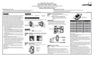
APPLICATION & OVERVIEW:<br />
The <strong><strong>M1</strong>XSLZW</strong> is a specialized <strong>Elk</strong>-<strong>M1</strong> serial expander for<br />
connecting <strong>M1</strong> Controls <strong>to</strong> Z-<strong>Wave</strong> enabled devices through a<br />
Levi<strong>to</strong>n VRC0P+3 Z-<strong>Wave</strong> Serial <strong>Interface</strong>. Z-<strong>Wave</strong> is a<br />
wireless, low power, "mesh" network technology widely used<br />
for au<strong>to</strong>mating devices such as: Lights, Thermostats,<br />
Electronic Locks, etc. Z-<strong>Wave</strong> empowers devices <strong>to</strong> be remotely<br />
controlled from across the room or across the world with<br />
benefits such as energy savings, convenience, and comfort.<br />
The VRC0P+3 is known as a Z-<strong>Wave</strong> Secondary Controller. It<br />
is required as a permanent member of the Z-<strong>Wave</strong> network <strong>to</strong><br />
maintain contact with all Z-<strong>Wave</strong> devices and communicate via<br />
RS232 <strong>to</strong> the <strong><strong>M1</strong>XSLZW</strong>. The <strong><strong>M1</strong>XSLZW</strong> translates the pro<strong>to</strong>col<br />
in<strong>to</strong> the <strong>M1</strong> control and allows commands <strong>to</strong> be sent and<br />
received on the Z-<strong>Wave</strong> network.<br />
Functionally the <strong><strong>M1</strong>XSLZW</strong> is a serial expander (RS485 <strong>to</strong><br />
RS232) and shares the same TYPE 5 databus ID as <strong>M1</strong>XSP<br />
serial expanders. A maximum of seven (7) TYPE 5 serial<br />
expanders may be connected <strong>to</strong> an <strong>M1</strong>.<br />
A key benefit of combining the <strong><strong>M1</strong>XSLZW</strong> and VRC0P+3 is the<br />
ability <strong>to</strong> interface with new generation Z-<strong>Wave</strong> devices such<br />
as the electronic deadbolts and locksets from Kwikset, Yale,<br />
and Schlage. Locks require a special Security Encrypted (SE)<br />
pro<strong>to</strong>col and a process called "Beaming". Both the <strong><strong>M1</strong>XSLZW</strong><br />
and the VRC0P+3 support these new requirements.<br />
In general, any Z-<strong>Wave</strong> device that is compatible with the<br />
Levi<strong>to</strong>n VRC0P+3 should also be compatible with the <strong>M1</strong>.<br />
However some devices may have limited functionality due <strong>to</strong><br />
design or feature differences.<br />
NOTE: The Levi<strong>to</strong>n VRC0P+3 is not included with the<br />
<strong><strong>M1</strong>XSLZW</strong>. It must be purchased separately.<br />
Specify Levi<strong>to</strong>n Part Number: VRC0P-1LW<br />
SPECIFICATIONS:<br />
• Activity/Status LED (Orange)<br />
• Au<strong>to</strong>-Reset Hardware Watchdog Circuit<br />
• Addressable (1-7) TYPE 5 Databus ID<br />
• Operating Voltage: 12 Volts D.C.<br />
• Current Draw: 31mA<br />
• Housing: 4.25" x 6.375" x 2.125"<br />
• Circuit Board: 2.25" x 3.95"<br />
• Connection <strong>to</strong> VRC0P+3: DB9M 9 Pin Port<br />
• Connection <strong>to</strong> <strong>M1</strong>: Eleva<strong>to</strong>r Screw Terminals (4)<br />
Specifications are Subject <strong>to</strong> Change without notice.<br />
NOTICE: Drawings, illustrations, diagrams, part numbers, etc. are<br />
provided as reference only and are based on equipment available at<br />
the time the information was created. All information contained in this<br />
document are subject <strong>to</strong> change without notice.<br />
The extent of integration between <strong>Elk</strong> Products and Partner Mfgs<br />
varies, and there may be situations or limitations beyond <strong>Elk</strong>'s control<br />
that make certain desirable features unavailable or unusable. Partner<br />
products and/or pro<strong>to</strong>cols, including <strong>Elk</strong>'s may not contain the<br />
capabilities or data definitions <strong>to</strong> permit additional integration beyond<br />
what is currently available. Partners may also, at their option, add,<br />
modify, or discontinue features or support without notification.<br />
® 2011 <strong>Elk</strong> Products Inc. All rights reserved.<br />
Levi<strong>to</strong>n and ViziaRF+ are registered trademarks of<br />
Levi<strong>to</strong>n Manufacturing Co. Inc.<br />
L638 Rev. 1 12/5/2011<br />
For reasons stated herein, <strong>Elk</strong> Products makes no warranty that it will<br />
be able <strong>to</strong> integrate all available features or operations, nor does it<br />
make any express or implied warranties of fitness for a particular<br />
purpose or of merchantability. Refer <strong>to</strong> <strong>Elk</strong>'s Limited Warranty.<br />
Printed in USA
STEP 1 - READ THIS FIRST!<br />
DO NOT attempt installation of the <strong><strong>M1</strong>XSLZW</strong> until the entire Z-<strong>Wave</strong> network is setup wth all devices and controllers<br />
Associated and Updated. A Levi<strong>to</strong>n VRC0P+3 Serial <strong>Interface</strong> (p/n VRC0P-1LW) is required. Installers NOT experienced<br />
with setting up a Z-<strong>Wave</strong> network are encouraged <strong>to</strong> obtain Z-<strong>Wave</strong> training before proceeding. Once the Z-<strong>Wave</strong><br />
network and the VRCOP+3 are setup and working the <strong><strong>M1</strong>XSLZW</strong> is relatively easy <strong>to</strong> install. Attempting <strong>to</strong> take shortcuts<br />
generally results in wasted time and troubleshooting.<br />
To integrate an <strong>Elk</strong>-<strong>M1</strong> Control <strong>to</strong> a Z-<strong>Wave</strong> network the following components will be required:<br />
QTY Part Number & Description<br />
1 ELK-<strong>M1</strong>G or <strong>M1</strong>EZ8 Control<br />
1 ELK-<strong><strong>M1</strong>XSLZW</strong> <strong>M1</strong> <strong>to</strong> Levi<strong>to</strong>n Serial <strong>Interface</strong><br />
1 <strong>Elk</strong>RP Remote Programming Software<br />
1 LEVITON VRC0P+3 (VRC0P-1LW) Serial <strong>Interface</strong> (Secondary Controller) & cable. It must be labeled with<br />
a +3 (VRC0P+3). Older units are NOT COMPATIBLE and are not upgradeable! The VRC0P+3 MUST have<br />
firmware version V2.33S / Z-<strong>Wave</strong> 3.11 or greater. A way <strong>to</strong> confirm is <strong>to</strong> connect it <strong>to</strong> a PC serial port and use<br />
a serial comm. program like Hyperterminal. Connect at 9,600 Baud, 8, N, 1. On power up the VRC0P+3 will<br />
transmit its name and firmware ID <strong>to</strong> the Hyperterminal display screen.<br />
1 Levi<strong>to</strong>n VRUSB-1US USB Z-<strong>Wave</strong> Stick [RECOMMENDED] Primary Controller.<br />
1 Levi<strong>to</strong>n PC Installer Software [RECOMMENDED]<br />
Z-<strong>Wave</strong> devices (lights, thermostats, locks, etc.) Levi<strong>to</strong>n ViziaRF+ [RECOMMENDED] **<br />
** Levi<strong>to</strong>n ViziaRF+ brand Z-<strong>Wave</strong> devices offer unique features, one of which is the ability <strong>to</strong> report back their status <strong>to</strong> all<br />
other ViziaRF+ controllers (I.E. VRC0P+3). Unfortunately, most other brands of Z-<strong>Wave</strong> devices only report their status back <strong>to</strong><br />
the single controller that commanded the change. Thus other controllers will be out-of-sync thinking a device is On when it is<br />
Off, or Off when it is On. Devices may be polled <strong>to</strong> determine their status, but this is NOT practical or efficient since polling<br />
consumes extensive bandwidth/time which can delay or disrupt communications. Polling is definitely NOT an option that<br />
should be performed on a regular basis. Levi<strong>to</strong>n Vizia RF+ devices do NOT require polling!<br />
Information in this manual about Z-<strong>Wave</strong> is NOT a substitute for actual Z-<strong>Wave</strong> training. Additional Z-<strong>Wave</strong><br />
information, particularly the Levi<strong>to</strong>n ViziaRF+ brand of Z-<strong>Wave</strong> can be found on the Levi<strong>to</strong>n web site links:<br />
http://www.levi<strong>to</strong>n.com/OA_HTML/ibeCCtpSctDspRte.jspsection=25545&minisite=10024<br />
http://communities.levi<strong>to</strong>n.com/docs/DOC-2389<br />
http://communities.levi<strong>to</strong>n.com/community/knowledgebaseforums/home_au<strong>to</strong>mation<br />
Z-<strong>Wave</strong> Network: Z-<strong>Wave</strong> is a wireless (RF) 'Mesh' Network that utilizes a proprietary pro<strong>to</strong>col. The network can be as simple<br />
as two devices, or dozens of devices if the installation is large. Typical Z-<strong>Wave</strong> devices are: Controllers, Light Switches, Lamp<br />
Modules, Appliance Modules, Locks, Thermostats, etc.<br />
Network Routing: Routing is used by a 'Mesh' network <strong>to</strong> provide primary and alternate communications paths. Z-<strong>Wave</strong><br />
devices have relatively short transmission range ~30 ft. or so. For extended distances messages must be routed (repeated)<br />
across the mesh through other 'routable' devices. A message may route through a single neighbor device or multiple devices<br />
before reaching its destination. It is very important for Z-<strong>Wave</strong> devices <strong>to</strong> be installed in their permanent location PRIOR TO<br />
INCLUSION in the network. This way each knows what neighbors are close by. Routing is also called repeating or hopping.<br />
A Z-<strong>Wave</strong> network allows for a maximum of 4 repeats or hops. In other words, messages can be routed through a maximum<br />
of 4 devices <strong>to</strong> reach a destination.<br />
Non-Routable devices - Devices that operate from Battery Only such as motion sensors, handheld remotes, and Locks do<br />
not route or repeat Z-<strong>Wave</strong> communications. This is because they are generally in a state of sleep <strong>to</strong> preserve and extend<br />
their battery life. They must be awakened by <strong>to</strong>uch, movement, or 'beaming' before they can communicate. They are often<br />
called 'End Node Devices' since they cannot be used <strong>to</strong> route communications and are therefore at the end of the path.<br />
Z-<strong>Wave</strong> NODE IDs: Each device in a Z-<strong>Wave</strong> Network must have a unique ID called a Node ID from a pool of 128 Nodes<br />
allowed. Duplicate Node IDs are not permitted, and a Z-<strong>Wave</strong> device can only be a member of one network at a time. Setting<br />
up Z-<strong>Wave</strong> devices and assigning Node IDs requires a Z-<strong>Wave</strong> Primary Controller.<br />
Z-<strong>Wave</strong> Primary Controller: A Primary Controller is required <strong>to</strong> setup a network and assign Node IDs. The Levi<strong>to</strong>n Vizia rf+<br />
VRUSB-1US USB stick Primary Controller and Installer Tool PC Software is recommend. There are other Z-<strong>Wave</strong> Primary<br />
Controllers, but ONLY THE Levi<strong>to</strong>n VRUSB-1US supports the enrollment of Locks. Other advantages of the USB Stick and PC<br />
software is that a permanent copy of the network settings may be saved on the PC hard drive for future service.<br />
* All setup and programming references in this manual utilized the Levi<strong>to</strong>n VRUSB-1US and Installer Tool. *<br />
Page 2<br />
<strong><strong>M1</strong>XSLZW</strong> Instruction <strong>Manual</strong>
Z-<strong>Wave</strong> Secondary Controller: A Secondary Controller (e.g. VRC0P+3) is able <strong>to</strong> communicate with and control devices<br />
but it cannot be used <strong>to</strong> setup or configure devices. A Secondary Controller must receive a copy of the network configuration<br />
from the Primary Controller in a step called Update Controller. I.E. The VRCOP+3 Controller must be Updated.<br />
A VRC0P+3 MUST BE enrolled as a permanent Secondary Controller. It communicates with all Z-<strong>Wave</strong> devices and the<br />
<strong><strong>M1</strong>XSLZW</strong>, which then translates the pro<strong>to</strong>col in<strong>to</strong> the <strong>M1</strong> and processes all transmitted or received commands.<br />
Node Inclusion: Inclusion is the process used by a Primary Controller <strong>to</strong> add a Z-<strong>Wave</strong> device <strong>to</strong> a Network and assign it a<br />
Node ID. Devices retain their Node ID until such time as they are Excluded (removed) from a network or fac<strong>to</strong>ry defaulted. A<br />
device must be excluded from its previous network before it may be Included with a new network. A new Node ID will be<br />
assigned by the new network. There is no known method for moving a device <strong>to</strong> a new network and having it retain its<br />
previous Node ID. And there is no known method for forcing a specific Node ID <strong>to</strong> a specific device. The Primary Controller<br />
picks the next available Node ID (never used in the network) and assigns it <strong>to</strong> the device. The Primary Controller (Levi<strong>to</strong>n<br />
VRUSB-1US Stick and PC) must be held close <strong>to</strong> the Device (1-2ft) when Including.<br />
Node Exclusion: Exclusion is the process used by a Primary Controller <strong>to</strong> remove a Z-<strong>Wave</strong> device from a network when no<br />
longer needed. Exclusion removes the device as a member of the network and resets it <strong>to</strong> fac<strong>to</strong>ry defaults. It DOES NOT<br />
clear routes and associations from other network controllers or devices, and that can cause sluggish communications<br />
when devices attempt <strong>to</strong> route through devices that are no longer present. Processes such as Network ReDiscovery and<br />
Update Controllers should be performed after devices are Excluded or Included. This helps refresh routings and improve<br />
network performance. If a device s<strong>to</strong>ps working or is removed from the premises the network can also be sluggish. Dead<br />
or removed devices MUST be Excluded as soon as possible. The process for removing a dead or removed device may<br />
differ from regular Exclusion. For more information see the Primary Controller Instructions or seek help from a Z-<strong>Wave</strong><br />
device manufacturer or training event. <strong>Elk</strong> does not produce any Z-<strong>Wave</strong> devices and cannot address Z-<strong>Wave</strong> questions.<br />
The Primary Controller (Levi<strong>to</strong>n VRUSB-1US Stick and PC) must be held close <strong>to</strong> the Device (1-2ft) when Excluding.<br />
Association: Association is used by a Primary Controller <strong>to</strong> define Areas and/or relationships between Z-<strong>Wave</strong> devices<br />
(controllers, switches, dimmers, thermostats, locks, etc.) E.G. Take an area or room with a multi-but<strong>to</strong>n Scene/Zone<br />
Controller Keypad and several Dimmers. The but<strong>to</strong>ns MUST be associated with the Dimmers <strong>to</strong> be controlled. The<br />
Dimmers will not react <strong>to</strong> a but<strong>to</strong>n press if not associated. NOTE: Not all Z-<strong>Wave</strong> devices support full association.<br />
Update Controller: Updating transfers existing Node ID information, associations, routings, etc. from the Primary Controller<br />
<strong>to</strong> other Secondary Controllers. This is a VERY IMPORTANT step when setting up or making changes <strong>to</strong> a Z-<strong>Wave</strong> network.<br />
The Primary Controller (Levi<strong>to</strong>n VRUSB-1US Stick and PC) must be held close <strong>to</strong> the Device (1-2ft) when Updating.<br />
Occasionally the VRC0P+3 Secondary Controller may fail <strong>to</strong> update "Error=Could not update VRC0P". In this situation the<br />
only solution may be <strong>to</strong> Default it and repeat the Inclusion process followed by the Update and Associate processes.<br />
VERY IMPORTANT! Updating Controllers should be done ANY TIME changes are made <strong>to</strong> that network. This populates<br />
information about new devices and cleans up (removes) remnants of devices that have been removed or excluded.<br />
Summarized steps for setting up a Z-<strong>Wave</strong> Network using the Levi<strong>to</strong>n VRUSB-1US and Installer Tool Software.<br />
Perform these steps PRIOR <strong>to</strong> connecting <strong>to</strong> the ELK-<strong><strong>M1</strong>XSLZW</strong> and after any changes.<br />
1. Permanently install all Z-<strong>Wave</strong> Devices in their intended location, including the Levi<strong>to</strong>n VRC0P+3 (VRC0P-1LW).<br />
2. Use a portable Computer, the Levi<strong>to</strong>n VRUSB-1US Primary Controller, and Installer Software <strong>to</strong> setup devices.<br />
a. On the software title bar click Network > Self-Installer Checklist.<br />
b. Click box 1 Dimmers and Switches and click Another Dimmer/Switch <strong>to</strong> add dimmers,switches,locks, Tstats, etc.<br />
c. Click box 2 Controllers and click Another Controller <strong>to</strong> add each Controller. VRC0P+3 is a Controller.<br />
d. Click box 3 Update Controllers and follow directions <strong>to</strong> update each Controllers, including the VRC0P+3.<br />
e. Click box 4 Create Areas and click Another Area. An areas can be a rooms, floors, departments, etc.<br />
f. Click box 5 Associations and follow directions. Click Another Association if applicable.<br />
g. Click box 6 Deploy System followed by Save and Deploy System.<br />
h. Click Exit Checklist when finished.<br />
3. On the software title bar click Diagnostics > RS232 Setup. Select the VRC0P+3 Node as the RS232 Module, then<br />
place a check in the box for each device, then click Set Association. THIS IS A VERY IMPORTANT STEP!<br />
4. Click on the + box <strong>to</strong> expand the All Devices folder showing all devices in the Z-<strong>Wave</strong> network. On this listing you may<br />
right click on the RS232 Module (VRC0P+3 Node Icon) <strong>to</strong> Update Controller or do the RS232 Setup. This is handy and<br />
MAY BE NECESSARY <strong>to</strong> quickly refresh the VRC0P+3 after any changes.<br />
Having each Z-<strong>Wave</strong> Device installed in its permanent location and INCLUDED by use of a portable Computer and VRUSB-1US USB<br />
Primary Controller helps makes sure that neighbor devices are detected and network routing information is fully established.<br />
<strong><strong>M1</strong>XSLZW</strong> Instruction <strong>Manual</strong> Page 3
STEP 2 - Setting up the <strong><strong>M1</strong>XSLZW</strong><br />
Mounting - Connections - Setting the Data Bus Address - Enrolling the Data Bus Device<br />
1. Turn off the <strong>M1</strong> Master Power Switch and unplug the Levi<strong>to</strong>n VRC0P+3 before making any wiring connections.<br />
2. Mount the <strong><strong>M1</strong>XSLZW</strong> as close as possible <strong>to</strong> the Levi<strong>to</strong>n VRC0P+3. The RS232 Serial cord supplied with the VRC0P+3 is<br />
approximately 8 ft. DO NOT use an extension or attempt <strong>to</strong> make this cord any longer!<br />
3. Follow the wiring recommendations in the <strong>M1</strong> <strong>Installation</strong> <strong>Manual</strong> <strong>to</strong> connect the data bus terminals +12V, A, B, and Neg<br />
from the <strong>M1</strong> Control <strong>to</strong> the terminals on the <strong><strong>M1</strong>XSLZW</strong>. It may be necessary <strong>to</strong> install an <strong>M1</strong>DBH or <strong>M1</strong>DBHR Data Bus Hub<br />
if more than 2 homerun data bus cables are coming in<strong>to</strong> the <strong>M1</strong> Control.<br />
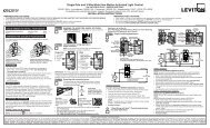
4. Set the data bus address switches on the <strong><strong>M1</strong>XSLZW</strong> <strong>to</strong> a value between 1 and 7 following the diagram below. Make sure<br />
the address you select is NOT being used by any other data bus Type 5 (serial expander) device. Each switch has an<br />
OFF and On position (binary value 0 or 1). The combination of these switches represents a decimal value of between 0<br />
(all Off) and 15 (all On).<br />
Address 1<br />
ON<br />
TABLE 1: Data Bus Address Switch Settings<br />
Address 2 Address 3 Address 4 Address 5 Address 6 Address 7 LEGEND<br />
ON<br />
ON<br />
ON<br />
ON<br />
ON<br />
ON<br />
ON<br />
1 2 3 4<br />
1 2 3 4<br />
1 2 3 4<br />
1 2 3 4<br />
1 2 3 4<br />
1 2 3 4<br />
1 2 3 4<br />
OFF<br />
For Data Bus Type 5 Devices (Serial Expanders) the only valid Addresses are 1 thru 7 and therefore the maximum number of Type 5 Devices is 7.<br />
Data Bus Terminating Jumper JP1 – This is engages a 120 Ohm resis<strong>to</strong>r for terminating the <strong>M1</strong> RS-485 Data Bus. See Data bus wiring instructions before use.<br />
5. Connect the Levi<strong>to</strong>n VRC0P+3 Serial <strong>Interface</strong> <strong>to</strong> the <strong><strong>M1</strong>XSLZW</strong> using the modular RS232 serial cable supplied with the<br />
VRC0P+3. DO NOT use an extension or attempt <strong>to</strong> make this cord any longer!<br />
6. Once all wire connections are complete plug the Levi<strong>to</strong>n VRC0P+3 in<strong>to</strong> a convenient AC Output that is NOT controlled by a<br />
switch (Always On 24hours). Next, turn on the <strong>M1</strong> Master Power Switch which will then supply power <strong>to</strong> the <strong><strong>M1</strong>XSLZW</strong>.<br />
7. Enroll the <strong><strong>M1</strong>XSLZW</strong> <strong>to</strong> the <strong>M1</strong> Control. REQUIRED! This is done either via a Keypad or <strong>Elk</strong>RP Software. From a Keypad<br />
access the Installer level programming and select Menu 01-Bus Module Enrollment. Press the right arrow key <strong>to</strong> start the<br />
enrollment. When complete press the right arrow (edit) key <strong>to</strong> view the results. The <strong><strong>M1</strong>XSLZW</strong> shares the same bus type<br />
as other serial expanders and will display as a "SerialPExpdr T5" followed by a specific address (Addr) number. Verify<br />
that the address displayed matches the address selected in step 4 above.<br />
Should it become necessary <strong>to</strong> replace a <strong><strong>M1</strong>XSLZW</strong> then set the replacement unit <strong>to</strong> the same address as the old unit<br />
and perform the enrollment process. To permanently remove any data bus device perform the enrollment process<br />
AFTER disconnecting the device. This will help avoid a "missing device" trouble condition.<br />
TABLE 2: Diagnostic LED Indica<strong>to</strong>r<br />
Slow blink (1/2 sec.) = Normal communication with <strong>M1</strong>.<br />
Rapid flicker = The <strong><strong>M1</strong>XSLZW</strong> is synchronizing with the VRC0P+3 <strong>to</strong> collect all current data.<br />
This is au<strong>to</strong>matically performed upon reboot or power up.<br />
No blink = No communication with <strong>M1</strong>. Check the wiring with the <strong>M1</strong> and that the device has power.<br />
LIMITATIONS:<br />
1) <strong>Elk</strong> does not recommend mixing (combining) Z-<strong>Wave</strong> devices with other lighting technologies (e.g. Insteon, UPB, Zigbee,<br />
Lutron, etc.) on any installation. Potential interference, device ID overlap, and other issues can lead <strong>to</strong> unreliable operation. If<br />
mixing of technologies cannot be avoided, the Installer must assume all risk and liability. <strong>Elk</strong> does not endorse or support the<br />
mixing of Z-<strong>Wave</strong> and other lighting technologies.<br />
2) Z-<strong>Wave</strong> Thermostats CANNOT BE MIXED (combined) with other Thermostat technologies or brands. I.E. Do not mix<br />
hardwired Thermostats such as RCS RS485, HAI RS232, or Aprilaire RS485 on the same <strong>M1</strong> panel with Z-<strong>Wave</strong> Thermostats. If<br />
this advice is not followed AND Z-<strong>Wave</strong> Thermostats become mixed with hardwired Thermostats on the same installation NO<br />
DATA will be displayed for the Z-<strong>Wave</strong> Thermostat(s).<br />
Page 4<br />
<strong><strong>M1</strong>XSLZW</strong> Instruction <strong>Manual</strong>
STEP 3 - Adding Z-<strong>Wave</strong> Lights <strong>to</strong> <strong>M1</strong><br />
Skip <strong>to</strong> Step 5 if not<br />
adding Lights<br />
Each Z-<strong>Wave</strong> Light in a network must have a unique Node ID from a pool of 128 Nodes allowed. Adding a Z-<strong>Wave</strong> light <strong>to</strong> <strong>M1</strong><br />
involves mapping (assigning) its Node ID <strong>to</strong> a corresponding <strong>M1</strong> Light Device number location. See Table 3. NOTE: Leave<br />
BLANK any <strong>M1</strong> Light Device location that corresponds <strong>to</strong> a Z-<strong>Wave</strong> Node ID that is NOT a light. Below are instructions for<br />
programming <strong>M1</strong> Lighting using <strong>Elk</strong>RP > Au<strong>to</strong>mation > Lighting.<br />
3.1 Setup the Z-<strong>Wave</strong> network FIRST. [Page 3] All Z-<strong>Wave</strong> devices and controllers MUST be Associated and Updated.<br />
3.2 Make a list of each Z-<strong>Wave</strong> device, its Node ID, location, and type (light, thermostat, lock, controller, etc.)<br />
3.3 Verify that the <strong><strong>M1</strong>XSLZW</strong> is connected <strong>to</strong> the VRC0P+3.<br />
3.4 Select the first Z-<strong>Wave</strong> Light Node ID and corresponding <strong>M1</strong> Light Device number location. See Table 3.<br />
NOTE: All Z-<strong>Wave</strong> devices are<br />
assigned Node IDs, but ONLY<br />
those that are lighting types<br />
should be entered in the <strong>M1</strong> Light<br />
Device locations. Leave empty<br />
(blank) any location that<br />
corresponds <strong>to</strong> a Node ID that is<br />
NOT a light device.<br />
3.5 Program a Name (up <strong>to</strong> 15 characters) describing the location or name of the light.<br />
3.6 Set the Format <strong>to</strong> "Serial Expander". This will be the same for all Z-<strong>Wave</strong> Lights.<br />
3.7 Set the Type according <strong>to</strong> the Z-<strong>Wave</strong> device. (On/Off Switch, Dimmer, or Appliance)<br />
3.8 DO NOT put a check mark in the Opt. location.<br />
3.9 Put a check mark in the Show box IF the light needs <strong>to</strong> be displayed on <strong>to</strong>uchscreens or keypads.<br />
3.10 Voice Description is optional. Up <strong>to</strong> 6 words may be used <strong>to</strong> provide a spoken description for each light.<br />
Controlling Z-<strong>Wave</strong> Lights using <strong>Elk</strong>RP Rules<br />
3.11 Select <strong>Elk</strong>RP > Au<strong>to</strong>mation > Rules.<br />
3.12 Click New <strong>to</strong> start a new Rule. E.G. Turn OFF several Z-<strong>Wave</strong> Lights when the System is Armed Away.<br />
3.13 Click WHENEVER > Security/Alarms > Is Armed > Armed Away. A pop-up box appears <strong>to</strong> pick the Area (partition).<br />
Use the drop down <strong>to</strong> pick the area or Click OK <strong>to</strong> accept "Area 1".<br />
3.14 Click THEN > Control Lighting > Individual. A new box will appear.<br />
3.15 In the Select lighting device box scroll and select one of the Lights. E.G. Foyer [2 (A2)].<br />
3.16 Click Turn Off followed by OK. The screen should resemble the first two lines in the illustration below.<br />
3.17 Repeat for additional lights and then click DONE <strong>to</strong> complete the Rule.<br />
3.18 Make sure that <strong>Elk</strong>RP is connected and on-line with the <strong>M1</strong> Control, then click Send <strong>to</strong> Control.<br />
The Rule shown controls 2 lights<br />
when the System is Armed Away.<br />
Then Operands - Lights may be<br />
Turned Off, Turned On, or Toggled<br />
(flip/flop). The "Set <strong>to</strong> Level" only<br />
appears on lights that are type=<br />
dimmer. Range is 1 <strong>to</strong> 99%.<br />
Fade (ramp) Rate - Range is 0 <strong>to</strong> 7<br />
with the following fade rate times in<br />
seconds: 0=immediate, 1=2, 2=4,<br />
3=8, 4=16, 5=32, 6=46, and 7=60.<br />
Not all Lights support fade rate.<br />
For - Checking this box allows a time<br />
delay for On or Off. Duration is: Days,<br />
Hrs, Min, Sec, or may be a Cus<strong>to</strong>m<br />
Setting selection.<br />
In this rule the Foyer is turned Off.<br />
The Flood light is turned On for 30<br />
seconds meaning it will turn off<br />
au<strong>to</strong>matically 30 seconds after<br />
arming and leaving the home.<br />
<strong><strong>M1</strong>XSLZW</strong> Instruction <strong>Manual</strong> Page 5
Z-<strong>Wave</strong><br />
Node ID<br />
1<br />
2<br />
3<br />
4<br />
5<br />
6<br />
7<br />
8<br />
9<br />
10<br />
11<br />
12<br />
13<br />
14<br />
15<br />
16<br />
17<br />
18<br />
19<br />
20<br />
21<br />
22<br />
23<br />
24<br />
25<br />
26<br />
ELK Lighting<br />
Device<br />
1 (A1)<br />
2 (A2)<br />
3 (A3)<br />
4 (A4)<br />
5 (A5)<br />
6 (A6)<br />
7 (A7)<br />
8 (A8)<br />
9 (A9)<br />
10 (A10)<br />
11 (A11)<br />
12 (A12)<br />
13 (A13)<br />
14 (A14)<br />
15 (A15)<br />
16 (A16)<br />
17 (B1)<br />
18 (B2)<br />
19 (B3)<br />
20 (B4)<br />
21 (B5)<br />
22 (B6)<br />
23 (B7)<br />
24 (B8)<br />
25 (B9)<br />
26 (B10)<br />
TABLE 3: Z-<strong>Wave</strong> Lighting <strong>to</strong> <strong>M1</strong> Lighting Device Mapping<br />
Z-<strong>Wave</strong><br />
Node ID<br />
27<br />
28<br />
29<br />
30<br />
31<br />
32<br />
33<br />
34<br />
35<br />
36<br />
37<br />
38<br />
39<br />
40<br />
41<br />
42<br />
43<br />
44<br />
45<br />
46<br />
47<br />
48<br />
49<br />
50<br />
51<br />
52<br />
ELK Lighting<br />
Device<br />
27 (B11)<br />
28 (B12)<br />
29 (B13)<br />
30 (B14)<br />
31 (B15)<br />
32 (B16)<br />
33 (C1)<br />
34 (C2)<br />
35 (C3)<br />
36 (C4)<br />
37 (C5)<br />
38 (C6)<br />
39 (C7)<br />
40 (C8)<br />
41 (C9)<br />
42 (C10)<br />
43 (C11)<br />
44 (C12)<br />
45 (C13)<br />
46 (C14)<br />
47 (C15)<br />
48 (C16)<br />
49 (D1)<br />
50 (D2)<br />
51 (D3)<br />
52 (D4)<br />
Z-<strong>Wave</strong><br />
Node ID<br />
53<br />
54<br />
55<br />
56<br />
57<br />
58<br />
59<br />
60<br />
61<br />
62<br />
63<br />
64<br />
65<br />
66<br />
67<br />
68<br />
69<br />
70<br />
71<br />
72<br />
73<br />
74<br />
75<br />
76<br />
77<br />
78<br />
ELK Lighting<br />
Device<br />
53 (D5)<br />
54 (D6)<br />
55 (D7)<br />
56 (D8)<br />
57 (D9)<br />
58 (D10)<br />
59 (D11)<br />
60 (D12)<br />
61 (D13)<br />
62 (D14)<br />
63 (D15)<br />
64 (D16)<br />
65 (E1)<br />
66 (E2)<br />
67 (E3)<br />
68 (E4)<br />
69 (E5)<br />
70 (E6)<br />
71 (E7)<br />
72 (E8)<br />
73 (E9)<br />
74 (E10)<br />
75 (E11)<br />
76 (E12)<br />
77 (E13)<br />
78 (E14)<br />
Z-<strong>Wave</strong><br />
Node ID<br />
79<br />
80<br />
81<br />
82<br />
83<br />
84<br />
85<br />
86<br />
87<br />
88<br />
89<br />
90<br />
91<br />
92<br />
93<br />
94<br />
95<br />
96<br />
97<br />
98<br />
99<br />
100<br />
101<br />
102<br />
103<br />
104<br />
ELK Lighting<br />
Device<br />
79 (E15)<br />
80 (E16)<br />
81 (F1)<br />
82 (F2)<br />
83 (F3)<br />
84 (F4)<br />
85 (F5)<br />
86 (F6)<br />
87 (F7)<br />
88 (F8)<br />
89 (F9)<br />
90 (F10)<br />
91 (F11)<br />
92 (F12)<br />
93 (F13)<br />
94 (F14)<br />
95 (F15)<br />
96 (F16)<br />
97 (G1)<br />
98 (G2)<br />
99 (G3)<br />
100 (G4)<br />
101 (G5)<br />
102 (G6)<br />
103 (G7)<br />
104 (G8)<br />
Z-<strong>Wave</strong><br />
Node ID<br />
105<br />
106<br />
107<br />
108<br />
109<br />
110<br />
111<br />
112<br />
113<br />
114<br />
115<br />
116<br />
117<br />
118<br />
119<br />
120<br />
121<br />
122<br />
123<br />
124<br />
125<br />
126<br />
127<br />
128<br />
ELK Lighting<br />
Device<br />
105 (G9)<br />
106 (G10)<br />
107 (G11)<br />
108 (G12)<br />
109 (G13)<br />
110 (G14)<br />
111 (G15)<br />
112 (G16)<br />
113 (H1)<br />
114 (H2)<br />
115 (H3)<br />
116 (H4)<br />
117 (H5)<br />
118 (H6)<br />
119 (H7)<br />
120 (H8)<br />
121 (H9)<br />
122 (H10)<br />
123 (H11)<br />
124 (H12)<br />
125 (H13)<br />
126 (H14)<br />
127 (H15)<br />
128 (H16)<br />
LIMITATIONS: 1) <strong>Elk</strong> does not recommend mixing (combining) Z-<strong>Wave</strong> devices with other lighting technologies<br />
(e.g. Insteon, UPB, Zigbee, Lutron, etc.) on any installation. Potential interference, device ID overlap, and other<br />
issues can lead <strong>to</strong> unreliable operation. If mixing of technologies cannot be avoided, the Installer must assume<br />
all risk and liability. <strong>Elk</strong> does not endorse or support the mixing of Z-<strong>Wave</strong> and other lighting technologies.<br />
Node IDs are assigned <strong>to</strong> all Z-<strong>Wave</strong> devices, but ONLY lighting devices should be entered in the Light Device table. Leave<br />
BLANK any Light Device location that corresponds <strong>to</strong> a Node ID that is NOT a light device.<br />
Z-<strong>Wave</strong><br />
Group #<br />
1<br />
2<br />
3<br />
4<br />
5<br />
6<br />
7<br />
8<br />
9<br />
10<br />
11<br />
12<br />
13<br />
14<br />
15<br />
16<br />
17<br />
18<br />
19<br />
20<br />
21<br />
22<br />
23<br />
24<br />
25<br />
26<br />
Page 6<br />
ELK Lighting<br />
Device<br />
129 (I1)<br />
130 (I2)<br />
131 (I3)<br />
132 (I4)<br />
133 (I5)<br />
134 (I6)<br />
135 (I7)<br />
136 (I8)<br />
137 (I9)<br />
138 (I10)<br />
139 (I11)<br />
140 (I12)<br />
141 (I13)<br />
142 (I14)<br />
143 (I15)<br />
144 (I16)<br />
145 (J1)<br />
146 (J2)<br />
147 (J3)<br />
148 (J4)<br />
149 (J5)<br />
150 (J6)<br />
151 (J7)<br />
152 (J8)<br />
153 (J9)<br />
154 (J10)<br />
TABLE 4: Z-<strong>Wave</strong> Light Group <strong>to</strong> <strong>M1</strong> Lighting Device Mapping<br />
Z-<strong>Wave</strong><br />
Group #<br />
27<br />
28<br />
29<br />
30<br />
31<br />
32<br />
33<br />
34<br />
35<br />
36<br />
37<br />
38<br />
39<br />
40<br />
41<br />
42<br />
43<br />
44<br />
45<br />
46<br />
47<br />
48<br />
49<br />
50<br />
51<br />
52<br />
ELK Lighting<br />
Device<br />
155 (J11)<br />
156 (J12)<br />
157 (J13)<br />
158 (J14)<br />
159 (J15)<br />
160 (J16)<br />
161 (K1)<br />
162 (K2)<br />
163 (K3)<br />
164 (K4)<br />
165 (K5)<br />
166 (K6)<br />
167 (K7)<br />
168 (K8)<br />
169 (K9)<br />
170 (K10)<br />
171 (K11)<br />
172 (K12)<br />
173 (K13)<br />
174 (K14)<br />
175 (K15)<br />
176 (K16)<br />
177 (L1)<br />
178 (L2)<br />
179 (L3)<br />
180 (L4)<br />
Z-<strong>Wave</strong><br />
Group #<br />
53<br />
54<br />
55<br />
56<br />
57<br />
58<br />
59<br />
60<br />
61<br />
62<br />
63<br />
64<br />
65<br />
66<br />
67<br />
68<br />
69<br />
70<br />
71<br />
72<br />
73<br />
74<br />
75<br />
76<br />
77<br />
78<br />
ELK Lighting<br />
Device<br />
181 (L5)<br />
182 (L6)<br />
183 (L7)<br />
184 (L8)<br />
185 (L9)<br />
186 (L10)<br />
187 (L11)<br />
188 (L12)<br />
189 (L13)<br />
190 (L14)<br />
191 (L15)<br />
192 (L16)<br />
193 (<strong>M1</strong>)<br />
194 (M2)<br />
195 (M3)<br />
196 (M4)<br />
197 (M5)<br />
198 (M6)<br />
199 (M7)<br />
200 (M8)<br />
201 (M9)<br />
202 (<strong>M1</strong>0)<br />
203 (<strong>M1</strong>1)<br />
204 (<strong>M1</strong>2)<br />
205 (<strong>M1</strong>3)<br />
206 (<strong>M1</strong>4)<br />
Z-<strong>Wave</strong><br />
Group #<br />
79<br />
80<br />
81<br />
82<br />
83<br />
84<br />
85<br />
86<br />
87<br />
88<br />
89<br />
90<br />
91<br />
92<br />
93<br />
94<br />
95<br />
96<br />
97<br />
98<br />
99<br />
100<br />
101<br />
102<br />
103<br />
104<br />
ELK Lighting<br />
Device<br />
207 (<strong>M1</strong>5)<br />
208 (<strong>M1</strong>6)<br />
209 (N1)<br />
210 (N2)<br />
211 (N3)<br />
212 (N4)<br />
213 (N5)<br />
214 (N6)<br />
215 (N7)<br />
216 (N8)<br />
217 (N9)<br />
218 (N10)<br />
219 (N11)<br />
220 (N12)<br />
221 (N13)<br />
222 (N14)<br />
223 (N15)<br />
224 (N16)<br />
225 (O1)<br />
226 (O2)<br />
227 (O3)<br />
228 (O4)<br />
229 (O5)<br />
230 (O6)<br />
231 (O7)<br />
232 (O8)<br />
Z-<strong>Wave</strong><br />
Group #<br />
105<br />
106<br />
107<br />
108<br />
109<br />
110<br />
111<br />
112<br />
113<br />
114<br />
115<br />
116<br />
117<br />
118<br />
119<br />
120<br />
121<br />
122<br />
123<br />
124<br />
125<br />
126<br />
127<br />
128<br />
ELK Lighting<br />
Device<br />
233 (O9)<br />
234 (O10)<br />
235 (O11)<br />
236 (O12)<br />
237 (O13)<br />
238 (O14)<br />
239 (O15)<br />
240 (O16)<br />
241 (P1)<br />
242 (P2)<br />
243 (P3)<br />
244 (P4)<br />
245 (P5)<br />
246 (P6)<br />
247 (P7)<br />
248 (P8)<br />
249 (P9)<br />
250 (P10)<br />
251 (P11)<br />
252 (P12)<br />
253 (P13)<br />
254 (P14)<br />
255 (P15)<br />
256 (P16)<br />
<strong><strong>M1</strong>XSLZW</strong> Instruction <strong>Manual</strong>
STEP 4 - Adding Z-<strong>Wave</strong> Light Groups <strong>to</strong> <strong>M1</strong><br />
Z-<strong>Wave</strong> Lights may be assigned in<strong>to</strong> Groups (areas) <strong>to</strong> permit single command of all devices in the group. <strong>M1</strong> supports 128<br />
Z-<strong>Wave</strong> Groups. Setup requires mapping a group <strong>to</strong> a <strong>M1</strong> Light Device number location 129-256. See Table 4. Group<br />
commands are: On, Off, or Set <strong>to</strong> Level (1 <strong>to</strong> 5). Set <strong>to</strong> Level allows up <strong>to</strong> 5 Group Scenes <strong>to</strong> be triggered. Below are steps for<br />
programming Light Groups using <strong>Elk</strong>RP > Au<strong>to</strong>mation > Lighting.<br />
4.1 Setup the Z-<strong>Wave</strong> network FIRST. (Page 3) All Z-<strong>Wave</strong> devices and controllers MUST be Associated and Updated.<br />
4.2 Make a list of all the programmed Z-<strong>Wave</strong> Groups by number.<br />
4.3 Verify that the <strong><strong>M1</strong>XSLZW</strong> is connected <strong>to</strong> the VRC0P+3.<br />
4.4 Select the first Group <strong>to</strong> be programmed and match it <strong>to</strong> the <strong>M1</strong> Light Device Number location. See Table 4.<br />
4.5 Program the Name (up <strong>to</strong> 15 characters) describing the Group or Area. (E.G.location, room name, etc.)<br />
4.6 Set the Format <strong>to</strong> "Serial Expander". This will be the same for all Z-<strong>Wave</strong> Groups.<br />
4.7 Set the Type as On/Off or Dimmer. Dimmer adds the advantage of Set <strong>to</strong> Level and Pre-Set Scenes.<br />
4.8 DO NOT put a check mark in the Opt. location.<br />
4.9 Put a check mark in the Show box IF the Group will need <strong>to</strong> be displayed on <strong>to</strong>uchscreens or keypads.<br />
4.10 Voice Description is optional. Up <strong>to</strong> 6 words may be used <strong>to</strong> provide a spoken description for each Group.<br />
Controlling Z-<strong>Wave</strong> Light Groups using Rules<br />
4.11 Select <strong>Elk</strong>RP > Au<strong>to</strong>mation > Rules.<br />
4.12 Click New <strong>to</strong> start a new Rule. E.G. Turning On 2 Z-<strong>Wave</strong> Groups when the System is Disarmed.<br />
4.13 Click WHENEVER > Security/Alarms > Is Disarmed. A pop-up box appears <strong>to</strong> pick the Area (partition). Use the drop<br />
down <strong>to</strong> pick the area or Click OK <strong>to</strong> accept "Area 1".<br />
4.14 Click THEN > Control Lighting > Individual. A new box will appear.<br />
4.15 In the Select lighting device box scroll and select one of the Group numbers: E.G. Grp1 [129 (I1)].<br />
4.16 Click Turn On followed by OK. The screen should resemble the first two lines in the illustration below.<br />
4.17 Repeat for additional light groups and then click DONE <strong>to</strong> complete the Rule.<br />
4.18 Make sure that <strong>Elk</strong>RP is connected and on-line with the <strong>M1</strong> Control, then click Send <strong>to</strong> Control.<br />
This Rule controls 2 groups of<br />
lights when System is Disarmed.<br />
Then Operands - In addition <strong>to</strong><br />
Turn On, Turn Off, or Toggle it is<br />
also possible <strong>to</strong> have lights in the<br />
Group respond <strong>to</strong> 1 or 5 pre-set<br />
SCENES. This is accomplished by<br />
selecting Set <strong>to</strong> Level and using a<br />
value of 1 <strong>to</strong> 5.<br />
Fade (ramp) Rate - Range is 0 <strong>to</strong> 7<br />
with the following fade rate times in<br />
seconds: 0=immediate, 1=2, 2=4,<br />
3=8, 4=16, 5=32, 6=46, and 7=60.<br />
Not all Lights support fade rate.<br />
For - Checking this box allows a<br />
time delay for On or Off. Duration<br />
is: Days, Hrs, Min, Sec, or a<br />
Cus<strong>to</strong>m Setting selection.<br />
In this rule Group 1 is turned On. Group 2 is Set <strong>to</strong> Level 3 which will activate Scene #3 in lights belonging <strong>to</strong> Group 2.<br />
<strong><strong>M1</strong>XSLZW</strong> Instruction <strong>Manual</strong> Page 7
STEP 5 - Adding Z-<strong>Wave</strong> Thermostats <strong>to</strong> <strong>M1</strong><br />
Each Z-<strong>Wave</strong> Thermostat in a network must have a unique Node ID from a pool of 128 Nodes allowed. Adding the<br />
Thermostat <strong>to</strong> <strong>M1</strong> involves mapping its Node ID <strong>to</strong> one of 16 Thermostat locations in <strong>Elk</strong>RP (Thermostats 1-16).<br />
Skip <strong>to</strong> Step 6 if not<br />
adding Thermostats<br />
Thermostat mapping is done au<strong>to</strong>matically by the <strong><strong>M1</strong>XSLZW</strong> upon power-up. This is called "Discovery Mode" and it starts<br />
from the lowest Z-<strong>Wave</strong> Node ID and searches UP until it finds a Thermostat. It then maps this <strong>to</strong> <strong>Elk</strong>RP Thermostat #1. If<br />
other Z-<strong>Wave</strong> Thermostats are found, the next higher Node ID will be mapped <strong>to</strong> Thermostat #2, and so on. This means that<br />
ALL Z-<strong>Wave</strong> devices (especially Thermostats) must already be setup, Associated, and Updated. Below are instructions for<br />
programming Thermostats using <strong>Elk</strong>RP > Au<strong>to</strong>mation > Thermostats.<br />
5.1 Setup the Z-<strong>Wave</strong> network FIRST. (Page 3) All Z-<strong>Wave</strong> devices and controllers MUST be Associated and Updated.<br />
At least 1 Thermostat and the VRC0P+3 must be installed.<br />
5.2 Make a list of every Z-<strong>Wave</strong> device, its Node ID, location, and type (light, thermostat, controller, etc.)<br />
5.3 Verify that the <strong><strong>M1</strong>XSLZW</strong> is connected <strong>to</strong> the VRC0P+3.<br />
5.4 Power-up the <strong><strong>M1</strong>XSLZW</strong> <strong>to</strong> start the Discovery Mode. This requires several minutes during which the status LED will<br />
flash rapidly. DO NOT TOUCH anything until the rapid flashing changes <strong>to</strong> a slow 1 sec. flash. As the <strong><strong>M1</strong>XSLZW</strong><br />
discovers a Thermostat it will map it <strong>to</strong> an <strong>Elk</strong>-RP Thermostat number starting with the lowest Node ID and working up.<br />
5.5 From the list of Z-<strong>Wave</strong> devices pick Thermostat 1 (the Thermostat with the lowest Node ID) and program a name (up <strong>to</strong><br />
15 characters) in the <strong>Elk</strong>RP Thermostat 1 location. Repeat for additional Thermostats starting up through the Node IDs.<br />
The name should describe the location of the Z-<strong>Wave</strong> Thermostat (i.e. Hallway, 1st Floor, etc.). A NAME IS MANDATORY.<br />
<strong>M1</strong> will ignore (not display) a Themostat that doesn't have a name.<br />
TIP! If the cus<strong>to</strong>mer wants the Thermostats <strong>to</strong> appear in a desired order then it will be necessary <strong>to</strong> perform the Z-<strong>Wave</strong><br />
Inclusion in exactly that desired order. That's because the order of mapping in <strong>M1</strong> is based solely on the Z-<strong>Wave</strong> Node ID<br />
numbering starting at the lowest and working up. Remember that <strong>M1</strong> rules reference the Thermostat Name, making it VERY<br />
important for each name <strong>to</strong> describe and/or match the correct location.<br />
LIMITATIONS: Z-<strong>Wave</strong> Thermostats CANNOT BE MIXED (combined) with other Thermostat technologies or<br />
brands. I.E. Do not mix hardwired Thermostats such as RCS RS485, HAI RS232, or Aprilaire RS485 on the same<br />
<strong>M1</strong> panel with Z-<strong>Wave</strong> Thermostats. If this advice is not followed AND Z-<strong>Wave</strong> Thermostats become mixed with<br />
hardwired Thermostats on the same installation NO DATA will be displayed for the Z-<strong>Wave</strong> Thermostat(s).<br />
Q - Will the Thermostat Mapping be affected if a Z-<strong>Wave</strong> Thermostat is replaced<br />
A - It certainly may but it all depends on the ability <strong>to</strong> retain (keep) the old Node ID and re-use it in the replacement<br />
Thermostat. By carefully following the "Replace Node/Device" procedure in the Primary Controller it is possible <strong>to</strong> swap a<br />
Thermostat and retain the previous Node ID, but this MUST be followed meticulously! If the Replace Node/Device<br />
procedure is not followed OR fails <strong>to</strong> work as intended, the Primary Controller will assign a new Node ID <strong>to</strong> the<br />
replacement device. When the Discovery Mode is activated the new Node ID will most likely cause a re-arrangement of<br />
the mapping. IF the old Node ID cannot be transferred <strong>to</strong> the new device then a complete reprogramming starting at<br />
step 5.1 will be required.<br />
IMPORTANT! TEST each Thermostat Lock after any changes are made <strong>to</strong> the Z-<strong>Wave</strong> network. Verify that each is<br />
communicating and responding properly. Test all <strong>Elk</strong>RP Rules that involve a Thermostat. Verify that all keypads,<br />
<strong>to</strong>uchscreens, or software interfaces are properly displaying the: 1)Mode i.e. Au<strong>to</strong>, Heat, Cool, or Aux., 2) Current<br />
Temperature, 3) Heat Setpoint, 4) Cool Setpoint, 5)Fan Mode<br />
Page 8<br />
<strong><strong>M1</strong>XSLZW</strong> Instruction <strong>Manual</strong>
Controlling Z-<strong>Wave</strong> Thermostat using Rules<br />
5.6 Select <strong>Elk</strong>RP > Au<strong>to</strong>mation > Rules.<br />
5.7 Click New <strong>to</strong> start a new Rule. Example: Lower the Heat and Raise the Cool Setpoints when Armed.<br />
5.8 Click WHENEVER > Security/Alarms > Is Armed > Armed Away. A pop-up box appears <strong>to</strong> pick the Area (partition).<br />
Use the drop down <strong>to</strong> pick the area or Click OK <strong>to</strong> accept "Area 1".<br />
5.9 Click THEN > Thermostat. A new box will appear.<br />
5.10 In the Select Thermostat box scroll and select one of the Thermostats. E.G. Main Hallway [Tstat 1].<br />
5.11 Click Set heating desired temperature <strong>to</strong>.<br />
5.11 In the value box scroll <strong>to</strong> set the temperature value. Set the F or C box <strong>to</strong> your preference. Then click OK. The screen<br />
should resemble the first two lines in the illustration below.<br />
5.12 To set the Cooling setpoint click THEN > Thermostat.<br />
5.13 Select the same Thermostats. E.G. Main Hallway [Tstat 1] as before.<br />
5.14 Click Set cooling desired temperature <strong>to</strong>.<br />
5.15 In the value box scroll <strong>to</strong> set the temperature value. Set the F or C box <strong>to</strong> your preference. Then click OK. The screen<br />
should resemble the first three lines in the illustration below.<br />
5.16 Click DONE <strong>to</strong> complete this Rule.<br />
5.17 Make sure that <strong>Elk</strong>RP is connected and on-line with the <strong>M1</strong> Control, then click Send <strong>to</strong> Control.<br />
NOTE: Some makes and models of Z-<strong>Wave</strong> Thermostats do not broadcast or voluntarily send their data <strong>to</strong><br />
the VRC0P+3. The result will be that <strong>M1</strong> will display "Not Enabled" since it doesn't have any information<br />
from the Thermostat <strong>to</strong> display. The only solution for this is <strong>to</strong> POLL the Thermostat(s) <strong>to</strong> obtain their<br />
status and information. See Step 7 and Table 7 concerning Advanced or Optional TEXT Strings<br />
available with the <strong><strong>M1</strong>XSLZW</strong>.<br />
<strong><strong>M1</strong>XSLZW</strong> Instruction <strong>Manual</strong> Page 9
STEP 6 - Adding Z-<strong>Wave</strong> Locks <strong>to</strong> <strong>M1</strong><br />
Each Z-<strong>Wave</strong> Lock in a network must have a unique Node ID from a pool of 128 Node IDs allowed. Up <strong>to</strong> ten (10) Z-<strong>Wave</strong><br />
Locks may be controlled by an <strong>M1</strong>. Special procedures and steps are required, including: 1) Mapping the Node ID of each<br />
Lock <strong>to</strong> one of ten (10) Virtual lock numbers (LOCK1-LOCK10). 2) Creating <strong>M1</strong> Text Strings as Z-<strong>Wave</strong> Lock commands <strong>to</strong> the<br />
<strong><strong>M1</strong>XSLZW</strong>. 3) Creating a "THEN Send Text <strong>to</strong> Port X" command in an <strong>Elk</strong>RP Rule. The Text will be your command and the<br />
Port X will be the Data Bus Address of the <strong><strong>M1</strong>XSLZW</strong>.<br />
Mapping of the locks is done by the <strong><strong>M1</strong>XSLZW</strong> on power-up using "Discovery Mode". This starts with the lowest Z-<strong>Wave</strong> Node<br />
ID and searches UP until a lock is found. The first Lock found is mapped as LOCK1. If other Locks are found then the next<br />
higher Node ID will be mapped <strong>to</strong> LOCK2, and so on. Discovery can only work after ALL Z-<strong>Wave</strong> devices (especially Locks)<br />
have been setup, Associated, and Updated. See <strong>Elk</strong>RP instructions below:<br />
6.1 Setup the Z-<strong>Wave</strong> network FIRST. (Page 3) All Z-<strong>Wave</strong> devices and controllers MUST be Associated and Updated.<br />
At least 1 Lock and the VRC0P+3 must be installed.<br />
6.2 Make a list of each Z-<strong>Wave</strong> device, its Node ID, location, and type (light, lock, thermostat, controller, etc.)<br />
6.3 Verify that the <strong><strong>M1</strong>XSLZW</strong> is connected <strong>to</strong> the VRC0P+3.<br />
6.4 Power-up the <strong><strong>M1</strong>XSLZW</strong> <strong>to</strong> start the Discovery Mode. This requires several minutes during which the status LED will<br />
flash rapidly. DO NOT TOUCH anything until the rapid flashing changes <strong>to</strong> a slow 1 sec. flash. As the <strong><strong>M1</strong>XSLZW</strong><br />
discovers a Lock it will map it <strong>to</strong> one of ten (10) Virtual Lock numbers (LOCK1-LOCK10) and s<strong>to</strong>re them in memory,<br />
starting with the lowest Node ID and working up.<br />
6.5 Use the list of Z-<strong>Wave</strong> devices and select the first Lock (the Lock with the lowest Node ID).<br />
6.6 Select <strong>Elk</strong>RP > Au<strong>to</strong>mation > Texts and then Click on New <strong>to</strong> add a new Text String.<br />
6.7 In the Text String field enter:
Controlling a Z-<strong>Wave</strong> Lock using Rules<br />
6.9 Select <strong>Elk</strong>RP > Au<strong>to</strong>mation > Rules.<br />
6.10 Click New <strong>to</strong> start a new Rule. E.G. Lock door when Exit Delay expires and System is Armed.<br />
6.11 Click WHENEVER > Security/Alarms > Exit Delay > Expires. A pop-up box appears <strong>to</strong> pick the Area (partition). Click<br />
OK <strong>to</strong> accept Any Area OR pick a specific area and then click OK.<br />
6.12 Click AND > Security/Alarms > Is Armed > Armed <strong>to</strong> Any Mode. A pop-up box appears <strong>to</strong> pick the Area (partition).<br />
Click OK <strong>to</strong> accept Any Area OR pick a specific area and then click OK.<br />
6.13 Click THEN > Send Text Out Port. A new box will appear <strong>to</strong> pick the Text. Use the drop down <strong>to</strong> pick the
STEP 7 - Rule Examples and Advanced <strong><strong>M1</strong>XSLZW</strong> Options<br />
Below are <strong>Elk</strong>-RP Rule examples being used <strong>to</strong> control Lights, Thermostats, and Locks.<br />
Rule 1 - Activates Save Energy<br />
Task* when Armed Away.<br />
Rule 2 - Task* "Save Energy"<br />
turns off lights and sets back<br />
HVAC (Thermostat) <strong>to</strong> save $$.<br />
Rule 3 - Activates Welcome<br />
Home Task* when Disarmed.<br />
Rule 4 - Task* "Welcome<br />
Home" turns on some lights<br />
and sets HVAC <strong>to</strong> 69 & 72 deg.<br />
Rule 5 - Task* "At Home"<br />
adjusts lights in Groups.<br />
Rule 6 - Locks door #1 as soon<br />
as exit delay expires following<br />
System Arming.<br />
Rule 7 - Locks door #1 just as<br />
soon as Front Door closes<br />
following System Arming. The<br />
door will get locked no matter<br />
whether Rule 6 or 7 fires first.<br />
Rule 8 - Turns on Foyer Lights<br />
when entry delay begins AND it<br />
is dark outside.<br />
Rule 9 - Turns on Hallway<br />
lighting Group when hallway<br />
motion is detected.<br />
Rule 10 - Au<strong>to</strong>matically turns<br />
some lights Off at 11:00PM.<br />
Rule 11 - Turns Out15 ON<br />
when text string
Additional Notes and Rule Examples for Z-<strong>Wave</strong> Electronic Deadbolt Locks<br />
DELAYING LOCK COMMANDS - A great use for <strong>M1</strong> Rules and Z-<strong>Wave</strong> Locks is the ability <strong>to</strong> au<strong>to</strong>matically lock exterior<br />
doors when the Alarm is Armed. But while immediate locking may be OK for Stay Mode arming, it may be better <strong>to</strong> have a<br />
short delay or secondary trigger for Away Mode arming. This is <strong>to</strong> allow a User time <strong>to</strong> arm from a Keypad and still leave<br />
prior <strong>to</strong> the door locking. Shown below is a CORRECT and a INCORRECT way <strong>to</strong> construct such a delay.<br />
CORRECT<br />
X INCORRECT X<br />
This Rule triggers only WHEN the Front Door Becomes Secure<br />
(CLOSES). It then tests <strong>to</strong> see if the System is Armed Away. If both<br />
conditions are true THEN the Text String command "
Z-<strong>Wave</strong><br />
Node ID<br />
1<br />
2<br />
3<br />
4<br />
5<br />
6<br />
7<br />
8<br />
9<br />
10<br />
11<br />
12<br />
13<br />
14<br />
15<br />
16<br />
17<br />
18<br />
19<br />
20<br />
21<br />
22<br />
23<br />
24<br />
25<br />
26<br />
27<br />
28<br />
29<br />
30<br />
31<br />
32<br />
33<br />
34<br />
35<br />
36<br />
37<br />
38<br />
39<br />
40<br />
41<br />
42<br />
43<br />
44<br />
45<br />
46<br />
47<br />
48<br />
49<br />
50<br />
51<br />
52<br />
53<br />
54<br />
55<br />
56<br />
57<br />
58<br />
59<br />
60<br />
61<br />
62<br />
63<br />
64<br />
This page is provided for listing all the Z-<strong>Wave</strong> Devices, their names, and device types<br />
Name or Description of Device<br />
Device Type<br />
Z-<strong>Wave</strong><br />
Node ID<br />
65<br />
66<br />
67<br />
68<br />
69<br />
70<br />
71<br />
72<br />
73<br />
74<br />
75<br />
76<br />
77<br />
78<br />
79<br />
80<br />
81<br />
82<br />
83<br />
84<br />
85<br />
86<br />
87<br />
88<br />
89<br />
90<br />
91<br />
92<br />
93<br />
94<br />
95<br />
96<br />
97<br />
98<br />
99<br />
100<br />
101<br />
102<br />
103<br />
104<br />
105<br />
106<br />
107<br />
108<br />
109<br />
110<br />
111<br />
112<br />
113<br />
114<br />
115<br />
116<br />
117<br />
118<br />
119<br />
120<br />
121<br />
122<br />
123<br />
124<br />
125<br />
126<br />
127<br />
128<br />
Name or Description of Device<br />
Device Type<br />
Page 14<br />
PO Box 100 3266 US Hwy 70 West, Hildebran, NC 28637 - Ph 828-397-4200 Fax 828-397-4415 - http://www.elkproducts.com<br />
<strong><strong>M1</strong>XSLZW</strong> Instruction <strong>Manual</strong>