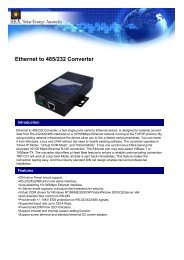
Compact Manual 0303 - Solar Energy Australia
Compact Manual 0303 - Solar Energy Australia
Compact Manual 0303 - Solar Energy Australia

Create successful ePaper yourself
Turn your PDF publications into a flip-book with our unique Google optimized e-Paper software.
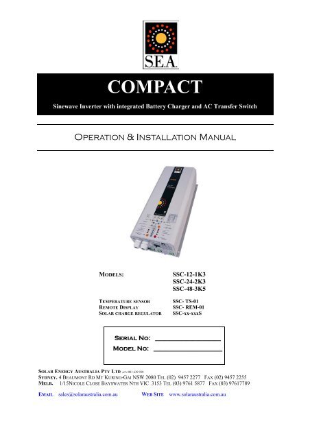
COMPACT<br />
Sinewave Inverter with integrated Battery Charger and AC Transfer Switch<br />
OPERATION & INSTALLATION MANUAL<br />
MODELS:<br />
TEMPERATURE SENSOR<br />
REMOTE DISPLAY<br />
SOLAR CHARGE REGULATOR<br />
SSC-12-1K3<br />
SSC-24-2K3<br />
SSC-48-3K5<br />
SSC- TS-01<br />
SSC- REM-01<br />
SSC-xx-xxxS<br />
Serial No: _____________________<br />
Model No: ______________________<br />
SOLAR ENERGY AUSTRALIA PTY LTD ACN 081 639 938<br />
SYDNEY. 4 BEAUMONT RD MT KURING-GAI NSW 2080 TEL (02) 9457 2277 FAX (02) 9457 2255<br />
MELB. 1/15NICOLE CLOSE BAYSWATER NTH VIC 3153 TEL (03) 9761 5877 FAX (03) 97617789<br />
EMAIL sales@solaraustralia.com.au WEB SITE www.solaraustralia.com.au
<strong>Solar</strong> <strong>Energy</strong> <strong>Australia</strong><br />
<strong>Compact</strong><br />
CONTENTS<br />
GENERAL INFORMATION 3<br />
WARRANTY 4<br />
INTRODUCTION<br />
Basic Schematic<br />
Main Functions<br />
Battery Connections<br />
INSTALLATION 7<br />
OPERATION 9<br />
CHARGER INFORMATION 12<br />
POWER SHARING 13<br />
STATE OF CHARGE MONITOR 14<br />
MULTIFUNCTION CONTACT 14<br />
REMOTE DISPLAY 14<br />
PROGRAMMING CHARGING VOLTAGES 15<br />
PROGRAMMING AUX CONTACTS 19<br />
DISABLING FUNCTIONS 20<br />
MAINTENANCE 20<br />
SPECIFICATIONS 21<br />
5<br />
6<br />
6<br />
TRUE SINEWAVE OUTPUT<br />
VERY LOW TOTAL HARMONIC DISTORTION (THD)<br />
EXTREMELY HIGH EFFICIENCY<br />
BATTERY SAVING STANDBY CIRCUIT<br />
BUILT IN HIGH CAPACITY BATTERY CHARGER<br />
FAST ACTING AC SYNCHRONISED TRANSFER SWITCH<br />
OVERLOAD PROTECTED<br />
POWER FACTOR CORRECTION<br />
User <strong>Manual</strong> COMPACT Rev 0803<br />
SSC-1601A<br />
Page 2
<strong>Solar</strong> <strong>Energy</strong> <strong>Australia</strong><br />
<strong>Compact</strong><br />
Operating instructions<br />
GENERAL INFORMATION<br />
This manual is a part of the delivery package of every COMPACT inverter-charger. It serves as guidelines for safe and<br />
efficient operation of COMPACT. The instructions are only valid for use with the following models and accessories.<br />
• COMPACT SSC-12-1K3<br />
• COMPACT SSC-24-2K3<br />
• COMPACT SSC-48-3K5<br />
• COMPACT SSC-XX-XXX-S<br />
• Temperature sensor SSC-TS-01<br />
• Remote Display SSC-REM-01<br />
Any personnel who installs a COMPACT and/or works with it must be fully familiar with the contents of this manual and<br />
must follow exactly all the warnings and safety instructions. Installation of, or any work on the COMPACT must be carried<br />
out by a qualified and trained personnel. Installation and application must comply with the respective local installations<br />
codes and safety regulations.<br />
Quality and Warranty<br />
During production and assembling, all COMPACT Inverter/Chargers go through many testing procedures. Every COM-<br />
PACT has its own serial number, which helps to refer back to its original data in the event of controls or repairs. That is<br />
why you should never remove the identification plate showing the serial number and must ensure you return your warranty<br />
card as soon as possible.<br />
The warranty period for your COMPACT is 2 Years.<br />
User <strong>Manual</strong> COMPACT Rev 0803<br />
SSC-1601A<br />
Page 3
<strong>Solar</strong> <strong>Energy</strong> <strong>Australia</strong><br />
<strong>Compact</strong><br />
IMPORTANT: YOU MUST REGISTER YOUR WARRANTY<br />
SOLAR ENERGY AUSTRALIA WARRANTY Terms and Conditions<br />
<strong>Solar</strong> <strong>Energy</strong> <strong>Australia</strong> considers reliability of your power system/inverter as absolutely critical. We would rather avoid<br />
any potential inconvenience by being proactive. Many external influences can effect the reliability of an inverter, none of<br />
which are under the control of <strong>Solar</strong> <strong>Energy</strong> <strong>Australia</strong>. For these reasons we request that you register your warranty within<br />
60 days of purchase. Warranties which are not registered receive a 6 month warranty.<br />
These terms and conditions do not exclude your rights under the statutory or implied warranty within your state or<br />
territory.<br />
<strong>Solar</strong> <strong>Energy</strong> <strong>Australia</strong> warrant this product against defects in material or workmanship, to the original purchaser only for<br />
an initial period of 6 months from date of purchase, when in normal use and service. The warranty period will be extended<br />
to a total of two (2) years when you register your warranty within 60 days of purchase (max. 3 years after date of<br />
manufacture). No warranty will be provided on units which have not been paid for in full.<br />
This warranty does not extend to products which have been opened, altered or repaired by persons other than authorised<br />
by <strong>Solar</strong> <strong>Energy</strong> <strong>Australia</strong> or to products which become defective due to acts of God, fire, sabotage, vandalism,<br />
contaminated fluids, negligence or failure to operate, house and maintain the product in accordance with instructions<br />
provided in this manual.<br />
It is extremely important that all installation and operating instructions contained within this manual are strictly<br />
adhered to. Failure to do so will void your warranty. Units which are to be installed/used within 1km of the coast<br />
must have the marine version of our product. Corrosion caused by failure to purchase the appropriate marine model will<br />
void warranty.<br />
<strong>Solar</strong> <strong>Energy</strong> <strong>Australia</strong> will use the information you supply to carry out a system check, to attempt to avoid any problems<br />
before they occur. <strong>Solar</strong> <strong>Energy</strong> <strong>Australia</strong> will repair or replace the defective product in accordance with its best<br />
judgement. For service under warranty, the buyer or installer must contact <strong>Solar</strong> <strong>Energy</strong> <strong>Australia</strong> to obtain appropriate<br />
paper work and shipping instructions before returning the unit. To make a warranty claim you must produce proof of<br />
purchase when returning the unit. Units returned without prior authorisation or warranty registration will be delayed. The<br />
buyer will pay all charges incurred in returning the product to the factory including, installers time. <strong>Solar</strong> <strong>Energy</strong> <strong>Australia</strong><br />
will pay return freight charges, if the product is found to be defective, within the terms of the warranty. Repair or<br />
replacement of any unit does not extend the original warranty terms in any way.<br />
This warranty does not cover repairs made necessary due to the product coming in contact with dirt, abrasives, moisture,<br />
rust, corrosion, varnish or other similar, insufficient system maintenance, failure due to poor quality or poor condition<br />
batteries, failure to use the appropriate AC transfer switch or wiring carried out by inappropriately qualified personnel.<br />
<strong>Solar</strong> <strong>Energy</strong> <strong>Australia</strong> will in no way be held responsible for any losses incurred due to the malfunctioning or failure of a<br />
product.<br />
Suitably qualified personnel must carry out all AC & DC permanent wiring . Failure to do so will void warranty.<br />
To register your warranty you must do the following:<br />
<br />
<br />
<br />
Return your completed warranty registration card within 60 days of purchase.<br />
Fixed installations must provide a picture of the installation from a distance of 1 metre, household installations<br />
must supply a second picture showing the structure housing the inverter.<br />
Circuit diagram of installation. This can be obtained from your installer.<br />
If the above items are not received, they may be requested before work can commence on any faulty units. <strong>Solar</strong> <strong>Energy</strong><br />
<strong>Australia</strong> is here to help.<br />
These measures are put in place to ensure you have years of trouble free service from your <strong>Solar</strong> <strong>Energy</strong> <strong>Australia</strong><br />
inverter. If you have any questions about this warranty please do not hesitate to contact us.<br />
PLEASE COMPLETE AND RETURN YOUR WARRANTY CARD<br />
User <strong>Manual</strong> COMPACT Rev 0803<br />
SSC-1601A<br />
Page 4
RCC-01<br />
AC IN<br />
CHARGER<br />
SOLAR CHARGE<br />
EQUA LIZE<br />
Program<br />
Contact active<br />
Contact manual<br />
INVERTER - CHARGER<br />
TRANSFER<br />
(Select)<br />
OFF<br />
AC OUT<br />
INVERTER<br />
RESET<br />
ALARM<br />
Over Te mp .<br />
Overlo ad<br />
Ba tte ry<br />
Low/High<br />
AUXILIARY (Program) CONTACT (Change ON/ OFF status)<br />
A %<br />
160<br />
70<br />
60<br />
50<br />
40<br />
30<br />
20<br />
130<br />
100<br />
80<br />
60<br />
40<br />
20<br />
10<br />
10 5<br />
Ch Inv<br />
arg ert<br />
er er<br />
<strong>Solar</strong> <strong>Energy</strong> <strong>Australia</strong><br />
<strong>Compact</strong><br />
Caution: Even when a COMPACT has been completely disconnected, there can still be deadly voltages present at<br />
the OUTPUT. To remove these voltages you must switch the COMPACT ON with the ON/OFF switch. After one<br />
minute the electronics are discharged and any work can now be safely carried out.<br />
Caution: In normal use lead-acid and lead-gel batteries give out explosive gases. Never smoke or allow a spark or<br />
flame in the vicinity of batteries. The batteries must always be stored or placed in a well ventilated area, they should<br />
be placed in such a way that there is no danger of short circuiting through carelessness. Never charge frozen batteries.<br />
The COMPACT is not to be used or sold for life support equipment or applications.<br />
Special Precautions<br />
• While working on batteries there should always be a second person close to you or within your voice range, in case<br />
help is needed.<br />
• Plenty of fresh water and soap must be ready at hand so that in case of acid coming in contact with skin , eyes and<br />
clothes, the areas in question can be thoroughly washed.<br />
• If acid enters the eyes, you must thoroughly wash the eyes with cold running water for at least 15 minutes. It is recommended<br />
that you immediately consult a medical doctor.<br />
• Baking powder neutralizes battery acid electrolyte. Always keep some at hand.<br />
• Special care must be taken when working with metal tools near or on the batteries. With tools such as screwdrivers,<br />
spanners etc. short-circuits can result. Sparks produced by the short-circuit can cause an explosion.<br />
• When working on batteries all personal metal items such as rings, necklaces and bracelets must be removed. Batteries<br />
are so powerful that short-circuit with these items can melt them and thus cause severe burns. Always follow the<br />
battery manufacturers instructions.<br />
• Under certain conditions your COMPACT or a connected generator can start automatically. While working on an<br />
electrical installation you must ensure that these appliances are disconnected before commencing any work.<br />
INTRODUCTION<br />
The COMPACT is a sine wave inverter with integrated battery charger and AC transfer switch.<br />
with many additional functions.<br />
Basic schematic<br />
AC IN<br />
L<br />
Input PE<br />
230Vac<br />
N<br />
100nF<br />
1uF<br />
10nF<br />
10nF<br />
AC OUT<br />
L<br />
PE<br />
N<br />
Output<br />
230Vac<br />
Battery<br />
BATTERY<br />
150A<br />
4x2,7M Ω<br />
Filter<br />
Inverter<br />
Charger<br />
AUX. CONT.<br />
CT35<br />
Temp. Sensor<br />
1uF<br />
1uF<br />
<strong>Solar</strong>module<br />
SOLAR<br />
Max. 6m<br />
6p Temp.<br />
RJ11<br />
Microprocessor,<br />
Control, Adjustment<br />
Display<br />
8p<br />
Remote control<br />
Max. 40m<br />
Remote control<br />
Remote control<br />
COMPACT<br />
User <strong>Manual</strong> COMPACT Rev 0803<br />
SSC-1601A<br />
Page 5
<strong>Solar</strong> <strong>Energy</strong> <strong>Australia</strong><br />
<strong>Compact</strong><br />
Description of main functions<br />
1. The Inverter<br />
The sinewave-inverter section of your COMPACT generates a sinewave AC voltage with an exceptionally precise voltage<br />
and stabilized frequency. In order to start large electric motors , the user has the possibility to employ a short-start-power<br />
which is 3-times the nominal power of the COMPACT.<br />
The inverter is protected against overload and short-circuit. A power-stage with the latest MOS-FET power transistors, a<br />
toroidal transformer, and a fast regulating system make-up a robust and reliable inverter with very high efficiency. A 1-20<br />
Watt adjustable load detection system serves to provide the smallest energy consumption and ensures a long life for the<br />
battery.<br />
2. The Transfer system<br />
COMPACT can be connected to an AC input source. For example a stand-by motor generator or the AC grid, such as shore<br />
power or a caravan park. With the transfer system, on one side you have AC voltage which is used to run the load, on the<br />
other side the batteries are being charged. The distribution of energy between the AC loads and battery charger is automatic.<br />
3. The Battery charger<br />
The built-in battery charger is capable of charging the batteries quickly and completely. A microprocessor controlled, 3 to<br />
4 Step charging process ensures the optimum charging of the batteries. The desired charging current can be set continuously<br />
from 0 – 55A (SSC-48-3K5 0 - 50A). The battery charger can be used for lead-acid or gel batteries. Thanks to the floating<br />
charge ability of your <strong>Compact</strong>, the batteries can remain continuously connected.<br />
4. The solar charge regulator (SSC-xx-xxx-s models only)<br />
With the built-in solar regulator, the COMPACT is a complete solar-power-center. In a solar installation this regulator ensures<br />
that the batteries are charged correctly. With the COMPACT, batteries can be charged with a generator and with the<br />
solar modules at the same time. The charging of batteries with both energy sources is carried out fully automatically.<br />
5. Remote control (optional)<br />
A remote display can be connected to your COMPACT. All operating elements and displays with the exception of the load<br />
detection level adjustment are available on the remote control. The remote control is supplied with a 20m long cable. This<br />
cable can be up to 40m long. On the remote control output power and charging current are also shown.<br />
Battery connections<br />
Lead-acid batteries are normally available in blocks of 2V, 6V or 12V . In most cases, to generate the necessary operating<br />
voltage and the capacity of the batteries for the COMPACT many batteries have to be connected together in parallel and or<br />
in series. Following three examples are shown:<br />
1. Parallel Connection: Maximum 2 batteries in parallel.<br />
12V<br />
12V<br />
12V<br />
2. Series Connection<br />
2V 2V 2V 2V 2V 2V<br />
12V<br />
2V 2V 2V 2V 2V 2V<br />
24V<br />
2V 2V 2V 2V 2V 2V<br />
12V 12V 12V 12V<br />
48V<br />
User <strong>Manual</strong> COMPACT Rev 0803<br />
SSC-1601A<br />
Page 6
<strong>Solar</strong> <strong>Energy</strong> <strong>Australia</strong><br />
<strong>Compact</strong><br />
3. Parallel- Series Connection:<br />
12V 12V 12V 12V 24V<br />
Location<br />
INSTALLATION<br />
The location of the COMPACT must be chosen by the following criteria:<br />
• Protection from unauthorized handling.<br />
• Dry dust free room, no condensation, no rodents.<br />
• Never install directly over the battery and never in a cabinet together with the batteries.<br />
• Keep ventilation holes free. The ventilation of the COMPACT is designed in such a way that it will work most efficiently<br />
when mounted vertically.<br />
• In mobile installation it is important to keep vibrations to a minimum.<br />
Mounting<br />
1. <strong>Compact</strong><br />
The COMPACT can be installed in any desired location. It is preferred that the appliance be wall mounted with battery cables<br />
downwards. The COMPACT is fixed on the wall with four screws through the four holes (dia. 5.5mm) which are accessible<br />
from the outside. In motor vehicles, the COMPACT must be fixed on vibration reducing mounts. The COMPACT<br />
must not be fixed on a combustible wall, as the back of the casing can get hot and reach up to 80 degree Celsius.<br />
2. Protection cover IP23<br />
To reduce the chance of foreign objects entering the <strong>Compact</strong> or condensation<br />
from a steel roof, you should use the IP23 cover (Part No SSC-IP23-01)<br />
this is easily installed after fixing the COMPACT to the wall. To do this,<br />
release slightly the mounting screws of the <strong>Compact</strong>, it’s then possible to<br />
pass the IP 23 cover between the COMPACT and the wall. The cover must<br />
touch the top screws. Retighten the 4 screws. It’s ready.<br />
Connection<br />
1. General instructions on connecting<br />
The cable connection on the terminals AC INPUT / AC OUTPUT / 15A<br />
230VAC are carried out with a No 1 screwdriver, the connection on the SO-<br />
LAR terminal with a No 2 screwdriver.<br />
The conductor cross section on the terminals AC INPUT / AC OUTPUT / 15A<br />
230VAC of the connecting cable must be minimum. 2.5mm 2 .<br />
All connecting cables and also the mounted battery cables , must be fixed with strain relief clamps.<br />
The COMPACT is delivered with battery cables already connected.<br />
The battery cables must never be extended. If the extension is unavoidable then the conductor cross section must be increased,<br />
contact your installer for this calculation.<br />
To protect the battery cable, a fuse corresponding to the conductor cross section must be fixed directly on to the battery.<br />
All cables must be tightly screwed in place. For safety, a yearly maintenance program is recommended. In mobile installations,<br />
maintenance must be carried out more often.<br />
Connections must be done by qualified personnel. Material such as cable, connectors and distribution boxes, fuses<br />
etc. used in the installation must comply with the respective valid low-voltage installation rules and regulations<br />
Applicable Standards.<br />
AS4509. Remote Home Power systems<br />
AS4086. Secondary batteries for use with Stand Alone Power systems<br />
AS 3010.1 Generators<br />
User <strong>Manual</strong> COMPACT Rev 0803<br />
SSC-1601A<br />
Page 7
<strong>Solar</strong> <strong>Energy</strong> <strong>Australia</strong><br />
<strong>Compact</strong><br />
2. Protection cover for the terminals connections (supplied<br />
standard)<br />
It is possible to provide gland protection for AC terminations by using<br />
the cover supplied. This allows AC cabling to pass through a cable<br />
gland before connecting to the <strong>Compact</strong>, this cover is supplied with<br />
cable glands. (see picture)<br />
Connections<br />
M A L<br />
N<br />
Do not open before<br />
disconnectin<br />
battery<br />
BATTERY<br />
Caution<br />
Check battery polarity (+/-) before connecting!<br />
A wrong connection could damage the system.<br />
15<br />
SOLAR<br />
Remote<br />
control<br />
sfe<br />
elay<br />
Eq<br />
ua<br />
liz<br />
e<br />
Temp.<br />
Auxiliary Contact<br />
15A-250Vac<br />
AC Input<br />
PE<br />
N L<br />
Typ:<br />
N°:<br />
ssc-xx-x<br />
Vbat: 22-32 Vdc<br />
Pnom: 2000 VA<br />
Uin: 150 - 250 Vac<br />
Uout: 230 V/50 Hz<br />
I <strong>Solar</strong>: 30A max.<br />
I Charge: 70A<br />
AC Output<br />
PE<br />
N L<br />
B C D E F G H J K<br />
Connections / Front Side<br />
A Battery +/- Battery cables<br />
B SOLAR +/- Connections for <strong>Solar</strong> modules<br />
C Remote control Connecting terminal for Remote Control SSC-REM-01<br />
D Equalize Slide switch for equalization of the Battery<br />
E Transfer delay Slide switch for Transfer Delay<br />
F Temp. Connecting terminal for Temperature sensor SSC-TS-01<br />
G Aux. Contact Connecting terminal for Auxiliary Contact<br />
H AC Input Connecting terminal for AC-input. Located directly above<br />
this terminal is the automatic safety cut-out for this terminal<br />
J ID Plate Identification plate with Technical data and Serial number<br />
K AC Output Connecting terminal for AC-output<br />
L Caution Caution: Check Polarity (+/-) before connecting to battery.<br />
Polarity reversal can damage the COMPACT.<br />
M Don’t … Do not open without disconnecting all terminals<br />
N 15A Protection 15A Protection switch for the Transfer system<br />
User <strong>Manual</strong> COMPACT Rev 0803<br />
SSC-1601A<br />
Page 8
<strong>Solar</strong> <strong>Energy</strong> <strong>Australia</strong><br />
<strong>Compact</strong><br />
Cabling/wiring<br />
When making connections to the <strong>Compact</strong> you must ensure that all connections are carried out in a clean and correct manner and under no<br />
circumstances that a cable is connected to a wrong terminal.<br />
Connecting the COMPACT must be carried out in the following order.<br />
(a) Pre-installation settings<br />
Before you start with the wiring of the COMPACT you must set the type of battery. If sealed-gel batteries are used then you must set the<br />
small slide-switch ”Equalize“ which is on the front with the connecting terminals, to OFF position. In case of normal lead-acid batteries,<br />
these can handle a higher equalizing charge, the same slide switch can be set to the ON position. If in doubt leave the setting in the OFF<br />
position.<br />
(b) Connection to battery<br />
Prepare the batteries for connection. Prepare battery cables, if necessary press on cable tabs/shoes. Connect the red cable to the Battery<br />
positive fuse/circuit breaker and the black cable to battery Minus(-) Take care when connecting the second cable to the battery, as a spark<br />
is produced, this is caused for a short time due to high current flowing in the COMPACT to charge the capacitors. This is another reason to<br />
install a battery fuse/circuit breaker. For this reason follow strictly the safety measures described in this manual.<br />
DO NOT INSERT THE BATTERY FUSE AT THIS STAGE.<br />
(c) Connection to the AC OUTPUT<br />
The AC output must be connected to the screw terminal AC OUTPUT. For this, use a 3-core cable with a conductor cross section of<br />
2,5mm 2 . Connections are marked as follows “N“= Neutral, “PE“= Earth, “L“= Live or Active.<br />
Caution: High voltage can be at the AC output, ensure the <strong>Compact</strong> is not connected when making AC connections<br />
(d) Connection to the AC INPUT<br />
The AC input supply from the electricity grid or from a generator must be connected to the screw terminals marked AC INPUT. For this<br />
use a 3-core cable with a conductor cross section of 2,5mm 2 . Connections are marked as follows “N“ =Neutral, “PE“= Earth, “L“ = Live/<br />
Active.<br />
(e) Connect the <strong>Solar</strong>modules: SOLAR +/- (Only for solar option)<br />
<strong>Solar</strong> modules are connected on these terminals. Under no circumstances should any other energy source i.e. wind generator be connected<br />
to these terminals. Depending on the power of the modules, the cable cross section should be 2.5 up to 6mm 2 . Before connecting it is<br />
necessary to check with a Voltmeter that the voltage of the Module meets the following values:<br />
SSC-12-1K3S 17-25V /30A,<br />
SSC-24-2K3S 34-45V /30A,<br />
SSC-48-3K5S 68-90V /20A.<br />
(f) Connection to Auxiliary Contact<br />
On these three terminals is a potential free change-over contact capable of switching a maximum current and voltage of 16A/250Vac. The<br />
“Contact active” LED shows the status of these contacts, when the LED is ON, the contacts are active. The schematic view of the connections<br />
on the front of the <strong>Compact</strong>, shows the contacts in the non active state.<br />
(g) Connection to Remote display<br />
The Remote Display SSC-REM-01 is connected in the terminal marked “Remote control“ with a RJ11/8 connector. The Remote Control<br />
can be plugged IN at any time. Push in the connector, without forcing it, until you hear the „click“, now the connector is locked in place.<br />
The same applies to the plug at the Remote Display end. The length of the cable for the Remote Display should not exceed 40m, is comes<br />
standard with 20m cable.<br />
(h) Connection to Temperature Sensor (Optional.)<br />
The Temperature sensor SSC-TS-01 is connected to the terminal marked “Temp“ with a RJ11/6 connector. The Temperature Sensor can<br />
be plugged IN at any time. Push in the connector without forcing it, until you hear a click, now the connector is locked in place. The Temperature<br />
Sensor should be glued or taped to the wall of the battery or near it. The Temperature Sensor cable must not be tied together with<br />
the battery cables or laid in a cable bundle.<br />
OPERATING<br />
You can now apply power to your compact by inserting the battery fuse:<br />
Caution: this will generate a spark.<br />
Check if the “OFF” LED is lit. If it is not lit, press quickly the “ON/OFF” switch, now “OFF” should be lit.<br />
On connecting the battery the COMPACT needs 1 – 2 Minutes to calculate the actual State of Charge of the battery. During this time the<br />
battery State of Charge is shown as 100% charged. (LED 14,15,16 &17 lit).<br />
If the LED marked “Battery Low/High” is lit, the battery charge is too low. If the LED marked “Battery Low/High” is blinking, the battery<br />
charge is too high.<br />
Caution: With a wrong battery voltage the COMPACT can be destroyed. ( For example: connecting a SSC-12-1K3 to a 48V Battery).<br />
If the COMPACT has been connected with reverse battery polarity, it must be returned to <strong>Solar</strong> <strong>Energy</strong> <strong>Australia</strong> for repair.<br />
User <strong>Manual</strong> COMPACT Rev 0803<br />
SSC-1601A<br />
Page 9
<strong>Solar</strong> <strong>Energy</strong> <strong>Australia</strong><br />
<strong>Compact</strong><br />
Display and operating control elements<br />
INPUT LIMIT<br />
CHARGER TRANSFER STANDBY<br />
16A<br />
70A<br />
230V<br />
20w<br />
0<br />
0<br />
150V<br />
OFF<br />
AC IN<br />
AC OUT<br />
CHARGER<br />
SOLAR CHARGE<br />
EQUALIZE<br />
14<br />
INVERTER<br />
RESET ALARM<br />
Lock (select)<br />
Over Temp<br />
Program<br />
Contact Active<br />
Contact <strong>Manual</strong><br />
AUX. CONTACT<br />
(Program)<br />
15<br />
16<br />
17<br />
18<br />
Overload<br />
Batt Low / High<br />
OFF<br />
ON / OFF<br />
(Change status)<br />
(a)<br />
Light Emitting Diodes: (LED’s)<br />
LED Marking LED ON LED blinks<br />
AC IN<br />
Incoming AC voltage is within the required parameters Incoming AC voltage is NOT within the required parameters..<br />
and is present at the AC IN input.<br />
CHARGER Battery Charger is working The input voltage is out value (voltage or frequency)<br />
SOLAR CHARGE Optional <strong>Solar</strong> modules are delivering energy<br />
Program You have enetered the Program mode for the Aux.<br />
Contact<br />
Contact active Auxiliary Contact is activated<br />
Contact manual Aux. Cont. manually activated<br />
Transfer system is active. In- coming voltage is being<br />
sent directly to AC OUT outlet<br />
AC OUT There is voltage at the AC OUT outlet The Inverter is in Standby-Mode<br />
INVERTER Inverter is working Forced -Inverter Mode<br />
Over Temp. The COMPACT has shutdown because of overheating.<br />
<strong>Compact</strong> will automatically restart.<br />
Overload The COMPACT has shutdown because of overload or<br />
short-circuit. <strong>Compact</strong> may automatically restart.<br />
Batt. Low/High Battery voltage is too low Battery voltage is too high<br />
OFF<br />
COMPACT is turned off. It can only be turned back<br />
on manually.<br />
COMPACT is for the time being turned off. Turning it<br />
back on will follow automatically!<br />
14 Battery Charger and or <strong>Solar</strong> Charge Regulator are<br />
doing an equalization cycle<br />
15–18 Approx state of charge of Battery LED 15 – Absorption time is running<br />
CURRENT<br />
MONITOR<br />
Displays the value of the output power in % of max<br />
continuous power (in Inverter Mode) and the charge<br />
current in Amps. (in Charger Mode) In this mode the<br />
200% LED indicate that power sharing is in use.<br />
User <strong>Manual</strong> COMPACT Rev 0803<br />
SSC-1601A<br />
Page 10
<strong>Solar</strong> <strong>Energy</strong> <strong>Australia</strong><br />
<strong>Compact</strong><br />
(b)<br />
Push buttons<br />
ON/OFF<br />
RESET<br />
Aux. Contact<br />
Turning the COMPACT on and off (Help Button for Programming)<br />
Press to turn OFF Alarm Signal. (Help Button for Programming)<br />
<strong>Manual</strong>ly activates the Auxiliary contact. (Help Button for Programming)<br />
(c)<br />
Turning Knobs<br />
CHARGER<br />
TRANSFER<br />
STANDBY<br />
INPUT LIMIT<br />
Adjustment for max. Charging Current (Not for <strong>Solar</strong> charge regulator)<br />
Adjustment for Transfer Voltage Threshold(TRANSFER – INVERTER)<br />
Adjustment for “Standby“ system<br />
Must be adjusted to the maximal available current of your AC INPUT supply (see separate<br />
chapter for further information)<br />
The Inverter<br />
The Inverter section of the COMPACT produces a high quality Sinewave output, the quality of this output is compatible<br />
with any appliance. Thanks to the generous dimensioning of the COMPACT, you can operate appliances requiring higher<br />
power than the nominal power of the COMPACT for a short time. The COMPACT provide up to 3-times the nominal<br />
power to start motors etc.<br />
The Inverter mode is displayed through LED marked “Inverter” If the Inverter Mode is disabled (see elsewhere in this manual)<br />
this LED will blink. If the LED is lit, the Inverter is in operation and you have 230Vac at output AC OUT. The actual<br />
power consumption of the AC load is displayed on the power monitor and on the remote display.<br />
(a) Load detection system “Standby“<br />
In order to avoid unnecessary discharge of the battery, the inverter switches OFF automatically if no AC power is being<br />
used. The <strong>Compact</strong> switches ON automatically again if an AC load is switched ON. The AC Out LED blinks if the inverter<br />
is in Standby-Mode. The switching-ON threshold can be adjusted with the “STANDBY” adjustment dial. Adjusting the<br />
switching-on level is done using a small screwdriver as follows: Switch off all AC loads; turn the “Standby” dial to the right<br />
until the AC Out is blinking, switch on the smallest AC load (i.e. Mobile phone charger); turn the “Standby” dial slowly to<br />
the left until the AC Out LED is lit.<br />
If the Standby- Mode is not wanted, turn the “Standby” dial to the left, to the OFF position, this will keep the <strong>Compact</strong><br />
running continuously, but will also discharge your batteries quicker.<br />
(b) Overload<br />
If the <strong>Compact</strong> is overloaded for too long or too heavily, it switches off. The “Overload“ LED is lit and the “OFF“ LED<br />
will blink. After approximately 10 seconds the Inverter switches on automatically. If the Inverter is overloaded four times in<br />
quick succession, then it no longer switches back on automatically, if this occurs contact your <strong>Solar</strong> <strong>Energy</strong> <strong>Australia</strong> representative<br />
immediately. The OFF LED remains lit. Press the “ON/OFF“ push button in order to switch the Inverter back<br />
ON.<br />
(c) Overheating(Over Temp)<br />
If the Inverter has been overloaded for a long time or it has been working in a high ambient temperature, it will switch OFF.<br />
The “Over Temp“ LED is lit and the “OFF“ LED blinks. After cooling down, the inverter switches back on automatically.<br />
One minute before the inverter switches off due to high temperature a buzzer will be heard. If the Auxiliary Contact has<br />
been programmed for “Over Temp” then the contact will be active when the buzzer sounds. This could be used for example<br />
to start an emergency back up generator, creating a no break energy supply.<br />
(d) Battery Condition<br />
Deep discharging of batteries leads to high losses in capacity and early aging. That is why the <strong>Compact</strong> will constantly<br />
monitor the battery condition. When battery voltage gets too low the <strong>Compact</strong> switches OFF. The “Batt Low/High” LED<br />
is lit and the “OFF“ LED blinks. When the battery voltage returns to 12.1V / 24.2V / 48.4V, the Inverter switches ON automatically.<br />
One minute before the Inverter switches OFF due to low voltage, a buzzer will be heard<br />
If the Auxiliary Contact has been programmed for “Low Battery” then the contact will be active when the buzzer sounds.<br />
This could be used for example to start a warning system, to shut down critical equipment such as computers.<br />
The low voltage is set to 11.8V / 23.6V / 47.2V. These settings are standard for most batteries. The voltage levels are maintained<br />
by the built-in Battery-Management-System of the COMPACT which looks at the load and battery condition and<br />
adjusts to suit.<br />
This setting is comparable with the levels of 10.8V/ 21.6V / 43.2, which are given for most batteries on nominal load.<br />
All voltage levels can be adjusted to suit your system. To adjust these levels see the instructions under the section on Programming.<br />
Check your battery supplier or system installer for the suggested values for your batteries.<br />
User <strong>Manual</strong> COMPACT Rev 0803<br />
SSC-1601A<br />
Page 11
<strong>Solar</strong> <strong>Energy</strong> <strong>Australia</strong><br />
<strong>Compact</strong><br />
[V/cell]<br />
[A]<br />
2.50<br />
2.33<br />
70<br />
60<br />
Equalization<br />
Absorption<br />
Float charge<br />
Charging current<br />
2.17<br />
40<br />
A<br />
B<br />
C<br />
Charg. Phase / adjust. current<br />
Equalization time<br />
Absorption time<br />
2.00<br />
20<br />
D<br />
Float charging phase<br />
A<br />
B<br />
C<br />
D<br />
t<br />
The Battery charger<br />
(a) Charging Cycle<br />
The fully automatic COMPACT Battery Charger is adjusted at the factory so that most lead-acid and lead-gel batteries can<br />
be charged to the maximum. As soon as the minimum AC voltage (as set with the “Transfer” adjustment dial) is available<br />
at the AC input (“AC IN” LED is lit), the Battery Charger is switched on automatically (“CHARGER” LED is lit). The battery<br />
is automatically charged to match the pre adjusted voltage levels and charge current. Thanks to the <strong>Compact</strong>s sophisticated<br />
and intelligent Floating Charge System, the batteries can be left in charge mode for unlimited time.<br />
During the charging cycle, the AC loads are continually supplied with power from the incoming AC voltage source. ( “AC<br />
OUT” LED is lit).<br />
The charger functions are shown in the following diagram:<br />
(b) Equalization charging:<br />
Equalization charge is a higher voltage applied to the batteries for a specified period of time.<br />
Equalization mode should never be used when using Gel-Batteries<br />
Before you program the COMPACT for Equalization-charge you must confirm with your supplier that the batteries are suitable<br />
for this process.<br />
Equalization is recommended for lead-acid batteries in order to mix the electrolyte fluid and to clean the lead plates of the<br />
batteries.<br />
If the COMPACT is operating with a lead-acid battery which is suitable for equalization, the slide switch “Equalize“ which<br />
is on the cable connection side, must be placed in the ON position. In this setting, at every 25 charge cycles an equalization<br />
cycle will be carried out for 2 hours (factory setting). During such a charge cycle the “Equalize” LED is lit. During a<br />
Charge cycle, equalization can be started independent of the actual programming. For this the slide switch must be slid from<br />
“OFF” to the “ON” position. The Equalize LED will light up. If the periodic equalization is not required, slide switch must<br />
be slid back to the „OFF“ position after the completion of the manual cycle.<br />
(c ) Absorption Charge<br />
Your <strong>Compact</strong> will provide a constant charge current until the absorption voltage is reached, note that this is the peak voltage<br />
and may not read accurately with a meter due to the ripple current. LED 15 will flash to indicate the absorption phase<br />
is running. As the battery state of charge increases, the charge current will be reduced and the battery voltage will continue<br />
to rise.<br />
CAUTION: During the equalization process, the batteries will produce a lot more gas.<br />
DANGER OF AN EXPLOSION !!<br />
User <strong>Manual</strong> COMPACT Rev 0803<br />
SSC-1601A<br />
Page 12
<strong>Solar</strong> <strong>Energy</strong> <strong>Australia</strong><br />
<strong>Compact</strong><br />
Input current repartition (Power sharing)<br />
To manage the power available on the AC INPUT the COMPACT is<br />
equipped with a system usually called “Power sharing” or INPUT power distribution.<br />
With this feature it is possible to limit the AC INPUT current assigned<br />
to the charger. The more current used by the AC load, the less power<br />
is given to the charger. Priority for the AC Loads. When power sharing is<br />
used the red 200% LED on the power monitor is lit to show that the battery<br />
charging is being limited<br />
Generator<br />
Power<br />
Current<br />
(230V)<br />
500W 2A<br />
900W 4A<br />
1500W 6,5A<br />
2000W 8,5A<br />
3000W 13A<br />
Set the INPUT LIMIT<br />
The current available to the COMPACT depends on the source of the AC input supply, i.e. motor generator, limited grid<br />
supply in a caravan park or shore power. The value of the “INPUT LIMIT” adjustment dial must be lower or equal to the<br />
current available from the AC Input source.<br />
For example if you have a generator of 2kW you must adjust the “Input Limit” to approximately 8.5A. To calculate this,<br />
divide the nominal power of the AC input source (2000W) by the voltage (230V). If the circuit breaker before the COM-<br />
PACT is lower than this value, then you must set the “Input Limit” to the value of the circuit breaker.<br />
Charging current<br />
The maximum charging current for the battery can be adjusted using the “CHARGER” adjustment dial. The charging current<br />
should be set to approximately 10% of the battery capacity (at C10). This means that the charging current for a battery<br />
with 300Ah should be approx 30A.<br />
The charging current is displayed on the “CURRENT MONITOR” on the front panel and on the Remote Display.<br />
Battery condition<br />
The built in microprocessor features a specially developed algorithm<br />
(formulae) which calculates the actual state of charge ( SOC) of the<br />
battery and displays it on LED 15-18. The Equalize LED is lit when<br />
the system is performing an equalization charge.<br />
The SOC displayed should be used as a guide only, for batteries<br />
which are not sealed, use a hydrometer to determine the exact SOC.<br />
For Safety reasons, you must get the recommended charge voltage<br />
and charge current from your battery supplier. The voltage levels<br />
and charge characteristics can be changed through “Programming”.<br />
The correct charging levels are critical for safe functioning and long<br />
life of the battery.<br />
14<br />
15<br />
16<br />
17<br />
18<br />
Equalization cycle<br />
Battery 75 – 100%<br />
Battery 50 – 75%<br />
Battery 25 – 50%<br />
Battery 0 – 25%<br />
The Transfer system<br />
When an AC voltage is present at the AC IN of the COMPACT, the “AC IN” LED is lit. When this voltage matches the<br />
lowest adjusted value set by the “TRANSFER” dial, and the frequency is between 44Hz and 65Hz, then this power is<br />
transferred directly to the AC load and the battery charger section of the <strong>Compact</strong>. The “TRANSFER” LED is lit to indicate<br />
this has happened. The inverter is then switched off and the battery charger switched on. This process is automatic<br />
and should not be noticed by the load, at worst a slight flicker may be seen in lights.<br />
The maximum current of the Transfer switch is 15A. That means through this system, AC loads of up to a maximum 3500<br />
Watts can be operated. When the Battery Charger is working, part of this power is used for the charging according to the<br />
power sharing settings.<br />
The Transfer system is protected against overload with an automatic safety fuse on the AC Input side of the COMPACT.<br />
If the system has been overloaded the button/pin of the fuse will pop-out. To put the automatic safety system back in to<br />
operating you must push this pin back in.<br />
User <strong>Manual</strong> COMPACT Rev 0803<br />
SSC-1601A<br />
Page 13
<strong>Solar</strong> <strong>Energy</strong> <strong>Australia</strong><br />
<strong>Compact</strong><br />
Note: In the Inverter operation, the COMPACT generates a True Sineusoidal and quartz stabilized output voltage.<br />
However, when the COMPACT is transferring power supplied from the a grid or a generator the voltage and quality of the<br />
power running the AC load will be the same as that coming from the grid or generator. The <strong>Compact</strong> cannot modify the<br />
incoming voltage.<br />
Setting the transfer voltage threshold<br />
The voltage threshold of the transfer can be adjusted between 150 to 230V with the “Transfer” adjustment dial . This value<br />
is set at the factory with a value of 200V. The majority of appliances can work on this voltage. When the Input voltages<br />
reaches the selected value on the adjustment dial, and the frequency is between 44Hz and 65Hz,. then the inverter switches<br />
off and the AC INPUT goes directly ton the AC OUTPUT. When the voltage INPUT is 20V less than the value set, the<br />
transfer of power is stopped and the OUTPUT is switched back to the inverter.<br />
Do not use the adjustment dial “TRANSFER” to adjust the AC OUTPOUT voltage!<br />
This is only a voltage threshold level to enable or disable the transfer.<br />
FAST (UPS)- MODE for the Transfer Switch<br />
The quick and almost break free Transfer mode is programmed with a slide switch „“Transfer Delay“ OFF”, which is on the<br />
front side with the( cable connections side) of the <strong>Compact</strong>.<br />
The aim of the COMPACT is to supply the AC loads with almost break-free AC power. When the incoming voltage “AC<br />
IN“ no longer matches values which have been set with the “Transfer” adjustment dial, the <strong>Compact</strong> switches back to<br />
Inverter. The transfer is carried out in around 0.02 seconds. This quick transfer ensures that the a break-free function for<br />
most AC loads is achieved. If AC voltage is restored at the AC Input which is within the set parameters, the transfer of<br />
power will resume, the inverter is stopped and battery charging will recommence.<br />
Delayed mode of the Transfer System<br />
The delayed mode of the transfer system Transfer Delay ON is programmed with the slide switch on front with the cable<br />
connections. The COMPACT provides an almost break-free alternating voltage for the AC loads. A quick transfer switch is<br />
not always sensible nor is it always desired. For example, when the AC load is being operated by a small standby back-up<br />
generator. An overload of a short duration on such a generator, i.e. start of a vacuum cleaner etc., has the effect of<br />
decreasing the voltage for a short time. As in such cases the transfer to the Inverter is not desirable, the transfer system can<br />
be programmed with a delay. When the slide switch (Transfer delay) is in the „On“ position, the transfer to the inverter<br />
takes place with a delay of 5 seconds. If the voltage falls below 100Vac, the transfer takes place without delay! The transfer<br />
switching to the Inverter takes place without any break.<br />
The <strong>Solar</strong> charge regulator (option)<br />
A COMPACT model is available with an inbuilt <strong>Solar</strong> Charge Regulator. To charge the batteries, <strong>Solar</strong> modules can be<br />
connected to the screw terminal SOLAR +/-. The in-built regulator is a Shunt regulator with a maximum input current of<br />
30A for SSC-12-1k3 and SSC-24-2K3, 20A for SSC-48-3K5. The operating voltage of <strong>Solar</strong> modules to be connected<br />
must match the actual operating voltage of the COMPACT and never exceed the max. rated value.<br />
Under no circumstances should any other charging sources such as a wind-generator be connected at the input of<br />
the <strong>Solar</strong> Charge Regulator.<br />
The <strong>Solar</strong> Charge Regulator works automatically and is always in operation. As soon as the energy is delivered from the<br />
<strong>Solar</strong> Charge Regulator, the “SOLAR CHARGE” LED is lit and the batteries are being charged. The <strong>Solar</strong> Charge<br />
Regulator works even when the Battery Charger is functioning. The method of operation is a 3 or 4 step charging process,<br />
the same as the battery charger. The function is described in the section on “Battery Charging”. The programming and the<br />
adjustments are carried out in accordance with the same conditions. Check with your battery supplier which adjustments<br />
must be carried out for your battery.<br />
User <strong>Manual</strong> COMPACT Rev 0803<br />
SSC-1601A<br />
Page 14
<strong>Solar</strong> <strong>Energy</strong> <strong>Australia</strong><br />
<strong>Compact</strong><br />
The Multifunctional Contact<br />
In the COMPACT there is a built-in programmable power relay. The potential-free change-over contact (n/o – n/c) of this<br />
power relay is connected to the screw terminals “ AUX CONTACT”.<br />
Maximum Contact load:<br />
-230Vac /16Amp-30Vdc/1A<br />
With the Push Button “AUXILIARY CONTACT“ the contact can be manually switched on or off independent of programming<br />
and the operating situation. The “Contact active” LED shows the status of the contact. The drawing on the screw terminal<br />
“AUX CONTACT” shows the inactive position, “Contact active” LED off.<br />
The switching on and off of this contact can be freely programmed for each operating situation of the COMPACT that is<br />
indicated with a LED. There is no limitation to its applications. An example and the setting of this contact are explained<br />
elsewhere in this manual.<br />
In the factory we program this output to be active when one of these situations are detected:<br />
* Over temperature LED lit<br />
* Overload LED lit<br />
* Over or under voltage of batteries LED lit or blinks<br />
* <strong>Compact</strong> is turned OFF manually or with a fault (OFF LED lit)<br />
* If the COMPACT is turned off manually or has turned OFF due to a fault, the “OFF” LED will be lit.<br />
THE REMOTE DISPLAY<br />
As an option, a Remote Display can be connected to the COMPACT. All operating controls and displays except for level<br />
adjustments are available on the Remote Display. The Remote Control is supplied with a 20m long cable. It can be lengthened<br />
up to a maximum of 40m. The Remote Display is suitable for surface mounting on the wall or on to a switch board. It<br />
is fixed with 4 screws. The COMPACT can also be programmed with the Remote Control. The Programming is described<br />
in the section “Programming“.<br />
User <strong>Manual</strong> COMPACT Rev 0803<br />
SSC-1601A<br />
Page 15
<strong>Solar</strong> <strong>Energy</strong> <strong>Australia</strong><br />
<strong>Compact</strong><br />
The output power and the charging currents are displayed on the Remote Control.<br />
COMPACT<br />
Remote display<br />
ON/OFF<br />
! -batt !<br />
Dry contact<br />
only<br />
1 2 3 4<br />
Remote control<br />
60V/0,5A<br />
max.<br />
The Control Input is connected in parallel to the ON/OFF- push button. The COMPACT can be switched on or off through<br />
this input with an impulse button or an impulse contact.<br />
Order Number for Remote Control: SSC- REM-01<br />
Dimensions: H x W x D / 111.5 x 136.5 x 25mm<br />
Caution: No external voltage should be connected to this Input Control.<br />
The Temperature sensor (Optional)<br />
Charging voltages of lead-acid batteries can change depending on temperature. To correct the operating voltages according<br />
to the actual temperatures, a temperature sensor can be connected to the COMPACT.<br />
The compensation through the sensor is –3mV/°C/Cell.<br />
Order Number: SSC-TS-01<br />
Dimensions: H x W x D / 58 x 51.5 x 22mm<br />
PROGRAMMING<br />
Factory settings<br />
The COMPACT is delivered with the following default settings:<br />
(a) Battery voltages<br />
Low voltage 11.6V / 23.2V / 46.4V<br />
Float Charge 13.5V / 27.0V / 54.0V<br />
Absorption Voltage ( at completion) 14.4V / 28.8V / 57.6V<br />
Equalization 15.3V / 30.6V / 61.2V<br />
Absorption Time:<br />
2 Hours<br />
(b) Auxiliary contact<br />
Active in case of fault or manual turn off with the ”OverTemp”, “Overload”, “Batt Low/High” and “OFF” LED<br />
Resetting Factory Settings<br />
When the COMPACT is to be connected to a battery or after an interruption (RESET), it will default back to the factory<br />
settings..<br />
In order to get to these settings during operation you must press the three Push Buttons “On/Off”,<br />
“Reset Alarm” & “Aux Contact” simultaneously for a minimum of 2 seconds<br />
Charging Voltages and absorption time<br />
The voltage levels (low voltage, float charge, end of charge (absorption) and equalization ) and the duration of the absorption<br />
charge can all be adjusted.<br />
The range of these settings are shown in the table below: The bold print shows the factory settings.<br />
User <strong>Manual</strong> COMPACT Rev 0803<br />
SSC-1601A<br />
Page 16
<strong>Solar</strong> <strong>Energy</strong> <strong>Australia</strong><br />
<strong>Compact</strong><br />
Low voltage<br />
“On/Off” LED<br />
Float Charge<br />
“Batt Low / High<br />
LED<br />
Absorption<br />
“Overload” LED<br />
Equalization<br />
“Overtemp” LED<br />
LED 12V 24V 48V 12V 24V 48V 12V 24V 48V 12V 24V 48V<br />
Absorption<br />
Time<br />
All LED’s<br />
14 12.0 24.0 48.0 13.7 27.4 54.8 16.2 32.4 64.8 16.2 32.4 64.8 4 h<br />
15 11.8 23.6 47.2 13.6 27.2 54.4 15.6 31.2 62.4 15.9 31.8 63.6 3 h<br />
16 11.6 23.2 46.4 13.5 27.0 54.0 15.0 30.0 60.0 15.6 31.2 62.4 2 h<br />
17 11.4 22.8 45.6 13.4 26.8 53.6 14.4 28.8 57.6 15.3 30.6 61.2 1 h<br />
18 11.2 22.4 44.8 13.3 26.6 53.2 14.2 28.4 56.8 15.0 30.0 60.0 0 – 1Min.<br />
Programming Voltages and timing threshold.<br />
When programming your <strong>Compact</strong>, switches and LED’s perform different functions as they do when in the normal mode,<br />
the diagrams below shows the function of each when in the programming mode, the normal meanings are in brackets. Programming<br />
can be done at any time and will not interfere with the <strong>Compact</strong>s operation. All voltages mentioned should be<br />
halved for 12v systems and doubled for 48v systems.<br />
All voltage and Timing programming is done in the following manner:<br />
Press “Program” & “Change Status” buttons simultaneously to enter programming mode<br />
Press the “Select” button to choose the parameter you want to change<br />
Press “Change Status” button to change the values.<br />
If no buttons are pressed for 10 seconds whilst in the programming mode, the display will revert back to normal operation.<br />
The voltage levels and times changed through programming will be active with the next charge cycle!<br />
CAUTION Voltage levels which are not suitable can greatly reduce the battery life or could even destroy it ! Check<br />
with your battery supplier if unsure.<br />
To Programm Low Voltage Cut Out<br />
AC IN<br />
AC OUT<br />
CHARGER<br />
SOLAR CHARGE<br />
INVERTER<br />
SELECT<br />
(Reset Alarm)<br />
Program<br />
Contact Active<br />
Contact <strong>Manual</strong><br />
PROGRAM<br />
(Aux Contact)<br />
24.0v<br />
23.6v<br />
23.2v<br />
22.8v<br />
22.4v<br />
Set Equalisation<br />
Voltage (Over Temp)<br />
Set Absorption<br />
Voltage (Overload)<br />
Set Float Voltage (Batt High/Low)<br />
Set Low Voltage (OFF)<br />
CHANGE STATUS<br />
(ON/OFF)<br />
Absorption<br />
Time<br />
* To enter the programming mode hold down, the “Program” button and the “Change status” as shown above, for<br />
minimum 2 seconds simultaneously. ( You will see the LED’s change)<br />
* Press the “Select” button until the Red LED next to “Set Low Voltage” is lit, then use the “Change Status” button to<br />
select the value you require as indicated on the 5 centre LED’s.<br />
User <strong>Manual</strong> COMPACT Rev 0803<br />
SSC-1601A<br />
Page 17
<strong>Solar</strong> <strong>Energy</strong> <strong>Australia</strong><br />
<strong>Compact</strong><br />
To Program Absorption Voltage<br />
AC IN<br />
AC OUT<br />
CHARGER<br />
SOLAR CHARGE<br />
INVERTER<br />
SELECT<br />
(Reset Alarm)<br />
Program<br />
Contact Active<br />
Contact <strong>Manual</strong><br />
PROGRAM<br />
(Aux Contact)<br />
32.4v 30.0v<br />
31.2v 29.6v<br />
30.0v 29.2v<br />
28.8v<br />
28.4v<br />
Set Equalisation<br />
Voltage (Over Temp)<br />
Set Absorption<br />
Voltage (Overload)<br />
Set Float Voltage (Batt High/Low)<br />
Set Low Voltage (OFF)<br />
CHANGE STATUS<br />
(ON/OFF)<br />
Absorption<br />
Time<br />
* To enter the programming mode hold down, the “Program” button and the “Change status” as shown<br />
above, for minimum 2 seconds simultaneously.<br />
* Press the “Select” button until the Red LED next to “Set Absorption Voltage” is lit, then use the<br />
“Change Status” button to select the value you require as indicated on the 5 centre LED’s..<br />
To Program Absorption Time<br />
AC IN<br />
AC OUT<br />
CHARGER<br />
SOLAR CHARGE<br />
Program<br />
Contact Active<br />
Contact <strong>Manual</strong><br />
PROGRAM<br />
(Aux Contact)<br />
4hrs<br />
3hrs<br />
2hrs<br />
1hr<br />
0-1min<br />
INVERTER<br />
SELECT<br />
(Reset Alarm)<br />
Set Equalisation<br />
Voltage (Over Temp)<br />
Set Absorption<br />
Voltage (Overload)<br />
Set Float Voltage (Batt High/Low)<br />
Set Low Voltage (OFF)<br />
CHANGE STATUS<br />
(ON/OFF)<br />
Absorption<br />
Time<br />
* To enter the programming mode hold down, the “Program” button and the “Change status” as shown<br />
above, for minimum 2 seconds simultaneously.<br />
* Press the “Select” button until the all 4 Red LED’s are lit, then use the “Change Status” button to select<br />
the value you require as indicated on the 5 centre LED’s.<br />
User <strong>Manual</strong> COMPACT Rev 0803<br />
SSC-1601A<br />
Page 18
<strong>Solar</strong> <strong>Energy</strong> <strong>Australia</strong><br />
<strong>Compact</strong><br />
To Program Float Voltage<br />
AC IN<br />
AC OUT<br />
CHARGER<br />
SOLAR CHARGE<br />
Program<br />
Contact Active<br />
Contact <strong>Manual</strong><br />
PROGRAM<br />
(Aux Contact)<br />
27.4v<br />
27.2v<br />
27.0v<br />
26.8v<br />
26.6v<br />
INVERTER<br />
SELECT<br />
(Reset Alarm)<br />
Set Equalisation<br />
Voltage (Over Temp)<br />
Set Absorption<br />
Voltage (Overload)<br />
Set Float Voltage (Batt High/Low)<br />
Set Low Voltage (OFF)<br />
CHANGE STATUS<br />
(ON/OFF)<br />
Absorption<br />
Time<br />
* To enter the programming mode hold down, the “Program” button and the “Change status” as shown<br />
above, for minimum 2 seconds simultaneously.<br />
* Press the “Select” button until the Red LED next to “Set Float Voltage” is lit, then use the “Change<br />
Status” button to select the value you require as indicated on the 5 centre LED’s.<br />
To Program Equalisation Voltage<br />
AC IN<br />
AC OUT<br />
CHARGER<br />
SOLAR CHARGE<br />
Program<br />
Contact Active<br />
Contact <strong>Manual</strong><br />
PROGRAM<br />
(Aux Contact)<br />
32.4v 31.0v<br />
31.8v 30.8v<br />
31.2v 30.6v<br />
30.6v 30.4v<br />
30.0v 30.2v<br />
INVERTER<br />
SELECT<br />
(Reset Alarm)<br />
Set Equalisation<br />
Voltage (Over Temp)<br />
Set Absorption<br />
Voltage (Overload)<br />
Set Float Voltage (Batt High/Low)<br />
Set Low Voltage (OFF)<br />
CHANGE STATUS<br />
(ON/OFF)<br />
Absorption<br />
Time<br />
* To enter the programming mode hold down, the “Program” button and the “Change status” as shown<br />
above, for minimum 2 seconds simultaneously.<br />
* Press the “Select” button until the Red LED next to “Set Equalisation Voltage” is lit, then use the<br />
“Change Status” button to select the value you require as indicated on the 5 centre LED’s.<br />
User <strong>Manual</strong> COMPACT Rev 0803<br />
SSC-1601A<br />
Page 19
<strong>Solar</strong> <strong>Energy</strong> <strong>Australia</strong><br />
<strong>Compact</strong><br />
PROGRAMMING THE AUXILLIARY CONTACT<br />
(a) Principle<br />
The Auxiliary Contact can be basically programmed for any operating situation of the COMPACT which is indicated with a<br />
LED. The programming is possible for one or more operating situations. If the contact is programmed for many situations,<br />
it is activated as soon as the COMPACT finds itself in any one of the programmed situations..<br />
(b) The programming of the Auxiliary Contact is carried out in the following Steps:<br />
Press down the “Program” button for min. 2 seconds. The “Program” LED is lit to show the COMPACT is in program<br />
mode.<br />
A flashing LED indicates that condition has been programmed to activate the auxiliary contact. The <strong>Compact</strong> is factory<br />
programmed with “Over Temp”, “Overload”, “Battery Low High” and “Off” as the conditions which will activate the auxiliary<br />
contact. These will flash when you first enter the programming mode.<br />
Once in the programming mode use the “Select” button as per diagram below to choose the desired condition in which the<br />
contact should be activated, if the yellow “Contact Active” LED is flashing then this condition is already selected to activate<br />
the auxiliary contact. Pressing the “Change status” button will activate or deactivate this setting.<br />
If desired , push the “Select” button to choose another condition in which the contact should be activated.<br />
With the “Change status” button confirm or change the status for this condition.<br />
If during 10 seconds no buttons are pushed, then the chosen values are automatically stored and the COMPACT switches<br />
back to normal operating condition<br />
INPUT LIMIT<br />
CHARGER TRANSFER STANDBY<br />
16A<br />
70A<br />
230V<br />
20w<br />
0<br />
0<br />
150V<br />
OFF<br />
AC IN<br />
AC OUT<br />
CHARGER<br />
SOLAR CHARGE<br />
INVERTER<br />
SELECT<br />
EQUALIZE<br />
14<br />
Over Temp<br />
Program<br />
Contact Active<br />
Contact <strong>Manual</strong><br />
15<br />
16<br />
17<br />
Overload<br />
Batt Low / High<br />
OFF<br />
(Program)<br />
18<br />
(Change status)<br />
(c) Example<br />
Auxiliary Contact as generator starter<br />
When in the programming of the Auxiliary Contact, the State of Charge (SOC)LED’s (LED 15-18) can be used as a condition,<br />
but you must take note of the following requirements.<br />
If you have to start an emergency back-up supply with a battery having a certain SOC, then two SOC levels must be programmed.<br />
The first (i.e. Battery 25% LED 17) for the starting or activating the Auxiliary Contact and the second (i.e. Battery<br />
100% LED15) for stopping or deactivating the Auxiliary Contact. By programming in this way the Auxiliary Contact<br />
starts with the lowest set condition and stops when it has reached the highest programmed condition through charging. For<br />
example if LEDs 15& 17 are programmed to activate the contact, the contact will become activate when only LED 18 is lit.<br />
The contact will remain activated until LED 15 is lit (after absorption time)<br />
User <strong>Manual</strong> COMPACT Rev 0803<br />
SSC-1601A<br />
Page 20
<strong>Solar</strong> <strong>Energy</strong> <strong>Australia</strong><br />
<strong>Compact</strong><br />
Auxiliary Contact as Twilight Switch (With solar charger option)<br />
The Auxiliary Contact of the COMPACT can also be used as a twilight switch , i.e. for automatically operating<br />
exterior lighting. <strong>Solar</strong> modules connected to the <strong>Compact</strong> will measure the light intensity. If the COMPACT is<br />
operating without solar modules and a twilight-switching function is desired, you can connect small solar cells<br />
with the nominal voltage of the COMPACT to the SOLAR terminals for the purpose of measuring the light<br />
intensity. To function as a twilight-switch the Auxiliary Contact must be programmed so that the condition<br />
“SOLAR CHARGE” LED is active. Programming must be carried out in steps and in accordance with the description<br />
for the programming of the Auxiliary Contact<br />
<strong>Manual</strong> operating of Auxiliary Contact:<br />
The Auxiliary Contact can be operated manually at any time by pressing the “AUX. CONTACT” button. The “Contact<br />
manual“ LED lights up to indicate that the Contact is manually operated, and the “Contact active“ LED lights up when the<br />
Contact is active. By pushing the “ AUX CONTACT” button again, the Contact is deactivated. By pushing it a third time,<br />
automatic functions are restored.<br />
DISABLING SOME OF THE COMPACT FUNCTIONS<br />
Each different function, charger, inverter and transfer can be disabled. This is useful for specific applications which are required<br />
to disable some of these three functions.<br />
If you press the “Reset Alarm” button for more than 2 seconds you can have access to the different possibilities shown in<br />
the following diagram.<br />
In programming mode the display only shows the different types of program with the “Charger”, “Transfer” and “Inverter’<br />
functions. To change the type of programming press the “Reset Alarm” button until the LED corresponding to the desired<br />
function is lit, in to the table below. After 10 seconds the COMPACT will exit the programming mode and function with<br />
the new programming. In normal user mode, the disabled functions are displayed by a blinking LED<br />
Diagram of the different mode<br />
9<br />
Indicates an off LED<br />
Indicates a blinking LED<br />
Indicates a lit LED<br />
AC IN 1<br />
CHARGER 2<br />
7<br />
8<br />
9<br />
AC OUT<br />
INVERTER<br />
All the functions are enabled. This is the factory<br />
setting.<br />
AC IN 1<br />
CHARGER 2<br />
7<br />
8<br />
9<br />
AC OUT<br />
INVERTER<br />
The inverter is disabled. Only the transfer switch and<br />
the charger will work normally.<br />
AC IN 1<br />
CHARGER 2<br />
7<br />
8<br />
9<br />
AC OUT<br />
INVERTER<br />
Charger and transfer switch are disabled. the inverter<br />
will work continuously even if there is a correct AC<br />
voltage at the input<br />
AC IN 1<br />
CHARGER 2<br />
7<br />
8<br />
9<br />
AC OUT<br />
INVERTER<br />
Inverter and charger are both disabled.<br />
Only the transfer switch function is enabled in input<br />
voltage and frequency is OK.<br />
MAINTENANCE : A regular maintenance check is important for the and reliable operation of your inverter. Your<br />
qualified installer should ensure that all connection are tight and clean. This should be done monthly in mobile applications.<br />
Also check that no debris is blocking any of the ventilation holes on the inverter.<br />
User <strong>Manual</strong> COMPACT Rev 0803<br />
SSC-1601A<br />
Page 21
<strong>Solar</strong> <strong>Energy</strong> <strong>Australia</strong><br />
<strong>Compact</strong><br />
Technical specifications<br />
SSC-12-1K3 SSC-24-2K3 SSC-48-3K5<br />
Inverter Section<br />
Nominal battery voltage 12V 24V 48V<br />
Input voltage range 9.5 – 16.5V 19 – 33V 38 – 66V<br />
Nominal power (W) 1300VA 2300VA 3500VA<br />
Maximum power 30 min 1600VA 2500VA 4000VA<br />
Maximum power 3min 2000VA 3000VA 4800VA<br />
Maximum power 5 sec 3500VA 6000VA 9000VA<br />
Maximum load<br />
Asymmetrical load max.<br />
Standby adjustable<br />
Up to short circuit<br />
Up to nominal output power<br />
1 – 25W<br />
Power factor range 0.1 – 1<br />
Maximum efficiency 94% 95% 95%<br />
DC Current draw, OFF/Standby/On with NO load 41mA/ 50mA/ 0.5A 33mA/ 38mA/ 0.37A 25mA/ 30mA/ .25A<br />
Output voltage<br />
230Vac<br />
Output frequency crystal controlled 50 Hz± 0.05 %<br />
Total Harmonic Distortion < 2%<br />
Dynamic behavior 0 → 100 %<br />
Overload and short circuit protection<br />
Overheating temperature protection<br />
0.5ms<br />
Automatic disconnection with 5 time restart attempt<br />
Acoustic warning before shut-off. Automatic restart<br />
Battery Charger Section<br />
Charging current adjustable 0-55A 0-55A 0-50A<br />
Setting of AC INPUT current POWER SHARING<br />
Maximum input voltage<br />
Minimum input voltage<br />
Input Frequency range<br />
0 to 15A<br />
265 Vac , 350 V peak<br />
Adjustable 150 – 230Vac<br />
44 – 65Hz<br />
Power factor correction (PFC) EN 61000-3-2 EN 61000-3-2<br />
<strong>Solar</strong> Charge Regulator-Floating (S models only)<br />
Maximum Poen Circuit Voltage 25V 45V 90V<br />
Maximum charging current 30A 30A 20A<br />
Controller Method Shunt regulator I / V / Vo / equalize<br />
Battery Monitoring (25°C) in accordance with<br />
TLBM® (True Level Battery Management)<br />
*Absorption charge time<br />
*End of charge cycle voltage 14.4V 28.8V 57.6V<br />
*Floating voltage 13.6V 27.2V 54.4V<br />
*Equalization voltage every 25 cycles 15.3V 31.6V 63.2V<br />
*Low battery disconnection voltage 10.8V 21.6V 43.2V<br />
Temperature compensation (Option)<br />
General data<br />
Potential free Multifunction contact<br />
Max Current at Transfer relay<br />
AC transfer time (UPS-Mode)<br />
0 – 4h<br />
3mV / °C / cell<br />
16A - 250Vac / 3A – 60V dc<br />
15A AC/3.5KVA<br />
20 ms max<br />
Dimension H * W * L (mm) 124 / 215 / 480 124 / 215 / 480 124 / 215 / 670<br />
Protection index IP<br />
Compliance EN50081 I/II, EN 55014 – EN 55022, EN 61000-3-2<br />
IEC 801 I/II/III/IV, CEI 555, IEC 1000-3-2, LVD 73/23/EEC, C-Tick<br />
Operating temperature<br />
-20°C to +55°C<br />
Fan forced Ventilation from 45°C<br />
Weight 16.0kg 17.1kg 29.4kg<br />
Noise level without/with fan operating (dB)<br />
< 10 / < 35 / dB<br />
IP22<br />
Options<br />
Remote Display (111.5 x 136.5 x 25mm / with 20m Cable)<br />
Temperature sensor (58 x 51.5x 22mm / 3m Cable)<br />
IP 23 Protection cover for COMPACT<br />
SSC-REM-01<br />
SSC-TS-01<br />
SSC-IP23-01<br />
User <strong>Manual</strong> COMPACT Rev 0803<br />
SSC-1601A<br />
Page 22