DCS-7513 Manual - CCTV Cameras
DCS-7513 Manual - CCTV Cameras
DCS-7513 Manual - CCTV Cameras

You also want an ePaper? Increase the reach of your titles
YUMPU automatically turns print PDFs into web optimized ePapers that Google loves.
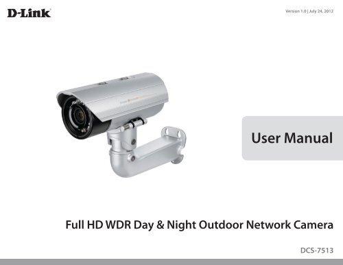
Version 1.0 | July 24, 2012<br />
User <strong>Manual</strong><br />
Full HD WDR Day & Night Outdoor Network Camera<br />
<strong>DCS</strong>-<strong>7513</strong>
D-Link reserves the right to revise this publication and to make changes in the content hereof without obligation to notify any person or organization<br />
of such revisions or changes. Information in this document may become obsolete as our services and websites develop and change.<br />
<strong>Manual</strong> Revisions<br />
Revision Date Description<br />
1.0 July 24, 2012 <strong>DCS</strong>‐<strong>7513</strong> Revision A1 with firmware version 1.00<br />
Trademarks<br />
D-Link and the D-Link logo are trademarks or registered trademarks of D-Link Corporation or its subsidiaries in the United States or other countries.<br />
All other company or product names mentioned herein are trademarks or registered trademarks of their respective companies.<br />
Copyright © 2012 D-Link Corporation.<br />
Preface<br />
All rights reserved. This publication may not be reproduced, in whole or in part, without prior expressed written permission from D-Link Corporation.<br />
D-Link <strong>DCS</strong>-<strong>7513</strong> User <strong>Manual</strong><br />
2
Table of Contents<br />
Product Overview.............................................................. 5<br />
Package Contents......................................................................... 5<br />
Introduction.................................................................................... 6<br />
System Requirements.................................................................. 6<br />
Features............................................................................................ 7<br />
Hardware Overview..................................................................... 8<br />
Front........................................................................................... 8<br />
Sides........................................................................................... 9<br />
Cable Harness.......................................................................10<br />
Internal....................................................................................11<br />
Assembly and Installation...............................................12<br />
Installing an SD Card..................................................................12<br />
Mounting the Camera...............................................................14<br />
Attach Camera to the Cable Management Bracket.....15<br />
Orienting the Camera........................................................17<br />
Deploying the Camera......................................................18<br />
Camera Installation Wizard......................................................20<br />
General Connection Using 12V DC Power Adapter.....20<br />
General Connection Using 24 V AC Power Wiring........21<br />
Connection Using Power over Ethernet.....................22<br />
Software Installation..........................................................23<br />
D-ViewCam Setup Wizard................................................26<br />
Configuration...................................................................28<br />
Using the Configuration Interface........................................28<br />
Live Video.......................................................................................29<br />
D-Link <strong>DCS</strong>-<strong>7513</strong> User <strong>Manual</strong><br />
Setup...............................................................................................31<br />
Setup Wizard.........................................................................31<br />
Internet Connection Setup Wizard...........................32<br />
Motion Detection Setup Wizard................................35<br />
Network Setup.....................................................................37<br />
Dynamic DNS........................................................................40<br />
Image Setup..........................................................................41<br />
Audio and Video..................................................................43<br />
Lens Control..........................................................................45<br />
Preset.......................................................................................46<br />
Motion Detection................................................................48<br />
Time and Date......................................................................49<br />
Event Setup...........................................................................50<br />
Add Server.........................................................................52<br />
Add Media..........................................................................53<br />
Add Event...........................................................................55<br />
Add Recording..................................................................56<br />
SD Card...................................................................................58<br />
Advanced.......................................................................................59<br />
Digital Input/Output..........................................................59<br />
ICR and IR...............................................................................60<br />
HTTPS......................................................................................61<br />
Access List..............................................................................62<br />
Maintenance.................................................................................63<br />
Device Management..........................................................63<br />
System.....................................................................................64<br />
3
Firmware Upgrade..............................................................65<br />
Status...............................................................................................66<br />
Device Info.............................................................................66<br />
Logs..........................................................................................67<br />
Help..........................................................................................68<br />
DI/DO Specifications........................................................69<br />
Technical Specifications...................................................70<br />
Warranty...........................................................................74<br />
Registration......................................................................80<br />
D-Link <strong>DCS</strong>-<strong>7513</strong> User <strong>Manual</strong><br />
4
Section 1: Product Overview<br />
Product Overview<br />
Package Contents<br />
<strong>DCS</strong>‐<strong>7513</strong> Full HD WDR Day & Night Outdoor Network Camera<br />
Cable Management Bracket and Mounting Shoe<br />
CAT5 Ethernet cable<br />
Power adapter<br />
CD-ROM with User <strong>Manual</strong> and software<br />
Mounting Plate<br />
Alignment Sticker and Hardware Kit<br />
Quick Installation Guide<br />
If any of the above items are missing, please contact your reseller.<br />
Note: Using a power supply with a different voltage than the one included with your<br />
product will cause damage and void the warranty for this product.<br />
D-Link <strong>DCS</strong>-<strong>7513</strong> User <strong>Manual</strong><br />
5
Section 1: Product Overview<br />
Introduction<br />
The <strong>DCS</strong>‐<strong>7513</strong> Full HD WDR Day & Night Outdoor Network Camera is a professional surveillance and security solution for small,<br />
medium, and large enterprises alike. The <strong>DCS</strong>-<strong>7513</strong> uses a 2 megapixel progressive scan CMOS sensor; the professional sensor<br />
results in low noise and high sensitivity capabilities ideal for surveillance applications.<br />
The <strong>DCS</strong>-<strong>7513</strong> is equipped with a P-iris lens that controls the iris with extreme precision. It's built-in stepping motor maintains<br />
the iris opening at an optimal level at all times, resulting in superior image clarity and depth of field as well as image quality.<br />
Together with WDR enhancement, users can identify image details in extremely bright as well as dark environments.<br />
The <strong>DCS</strong>‐<strong>7513</strong> has an IP66 certified weatherproof housing designed for both indoor and outdoor applications. The built-in<br />
removable IR-cut filter and IR LEDs give the <strong>DCS</strong>-<strong>7513</strong> the capability to view up to 30M at night. The <strong>DCS</strong>-<strong>7513</strong> also incorporates<br />
Power over Ethernet (PoE), allowing it to be easily installed in a variety of locations without the need for supplemental power<br />
cabling. The combination of IP66 housing, IR-Cut Filter, IR LEDs and PoE make the <strong>DCS</strong>-<strong>7513</strong> an ideal solution for a high<br />
performance, reliable and cost-effective 24 hour megapixel surveillance solution with an easy clutter-free installation.<br />
System Requirements<br />
• Computer with Microsoft Windows® 7, Vista®, or XP (for CD-ROM Setup Wizard)<br />
• PC with 1.3GHz or above; at least 128MB RAM<br />
• Internet Explorer 7 or above , Firefox 3.5 or above, Safari 4 and Chrome 8.0 or above<br />
• Existing 10/100 Ethernet-based network<br />
• An SD memory card (optional) is required for recording to onboard storage. SDHC Class 6 or above is recommended.<br />
• Broadband Internet connection<br />
D-Link <strong>DCS</strong>-<strong>7513</strong> User <strong>Manual</strong><br />
6
Section 1: Product Overview<br />
Features<br />
P-iris<br />
The P-iris lens in the <strong>DCS</strong>‐<strong>7513</strong> solves the long-standing problem of capturing sharp images in varying light conditions. The the <strong>DCS</strong>‐<strong>7513</strong> optimizes<br />
the iris opening under all lighting conditions and the result is images with better contrast, clarity, resolution and depth of field with improved image<br />
sharpness and increased image usability for network video surveillance.<br />
Remote Zoom & Focus<br />
The remote focus function eliminates the need for manual focusing at the camera position and allowing the user to make key adjustments from<br />
any computer. The remote zoom functionality allows the user to make final adjustments to the zoom from the computer. It provides a convenient<br />
way to ensure that the viewing angle is optimized for the scene and required need for resolution.<br />
Wide Dynamic Range<br />
Wide Dynamic Range technology neutralizes imperfect lighting, providing clear images with the right amount of contrast even when a subject is<br />
backlit<br />
Automatic Thermostat Temperature Regulation<br />
The <strong>DCS</strong>-<strong>7513</strong> monitors and automatically regulates its temperature to ensure it can perform at its optimal ability. It balances fan use against a built<br />
in heater based on a range of preset thermostatic settings. This gives the <strong>DCS</strong>-<strong>7513</strong> the ability to perform in the most demanding of environments.<br />
Remote Monitoring Utility<br />
The D-ViewCam application adds enhanced features and functionality for the Network Camera and allows administrators to configure and access<br />
the Network Camera from a remote site via Intranet or Internet. Other features include image monitoring, recording images to a hard drive, viewing<br />
up to 32 cameras on one screen, and taking snapshots.<br />
IR LED for Day and Night Functionality<br />
The built-in infrared LEDs enables night time viewing of up to 30 meters (98 feet).<br />
IP66 Weatherproof Housing<br />
The <strong>DCS</strong>‐<strong>7513</strong> uses an IP66 weatherproof housing, allowing you to rest assured that in the toughest of conditions, it will continue to provide roundthe-clock<br />
surveillance.<br />
PoE (Power over Ethernet) for Flexible Installation<br />
The <strong>DCS</strong>‐<strong>7513</strong> can draw all the power it needs from a PoE switch or PoE injector for a simple and clutter-free installation.<br />
D-Link <strong>DCS</strong>-<strong>7513</strong> User <strong>Manual</strong><br />
7
Section 1: Product Overview<br />
Hardware Overview<br />
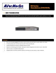
Front<br />
3<br />
4<br />
1<br />
2<br />
5<br />
1 Camera Lens Vari-focal lens to record video of the surrounding area<br />
2 Light Sensor<br />
The light sensor measures the lighting conditions and switches between color<br />
and infrared accordingly<br />
3 IR LEDs Infrared LEDs illuminate the camera's field of view at night<br />
4 Power/Status LED Indicates the camera's current status<br />
5 Weatherproof Casing<br />
The camera is housed in an IP66 certified weatherproof casing, which protects<br />
it against rain and dust.<br />
D-Link <strong>DCS</strong>-<strong>7513</strong> User <strong>Manual</strong><br />
8
Section 1: Product Overview<br />
2<br />
1<br />
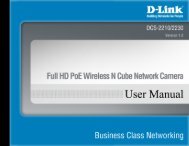
Sides<br />
3<br />
4<br />
6<br />
5<br />
1 Adjustable Top Shield Shields the camera sensor from direct sunlight.<br />
2 Adjustment Screw Allows positioning of top shield.<br />
3 Camera Shoe Adjustable mounting seat.<br />
4 Wire in Bracket Tightly assembles and protects the cables from outdoor wear and tear.<br />
5 Cable Channel Channel for cable placement.<br />
6 Quick Release Rod Allows the camera to be swiveled into position for easy maintenance.<br />
D-Link <strong>DCS</strong>-<strong>7513</strong> User <strong>Manual</strong><br />
9
Section 1: Product Overview<br />
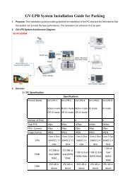
Cable Harness<br />
8<br />
7<br />
6 5 4 3 2<br />
1<br />
1 Power Connector Power connector for the provided 12V DC power adapter.<br />
2 Audio In (Red) Connects to a microphone.<br />
3 Audio Out (Green) Connects to a speaker.<br />
4 BNC Connector<br />
The BNC connector is recommended for use with handheld monitors to check<br />
the Field of View during installation.<br />
5 Reset Button Press and hold the recessed button for 10 seconds to reset the camera.<br />
6 24 V Power Connector Connects to 24V AC power supply.<br />
7 DI/DO Connector I/O connectors for external devices. 12V DC output.<br />
8 Ethernet Jack<br />
Connects to an RJ45 Ethernet port. Can be used with PoE to provide power<br />
to the camera.<br />
D-Link <strong>DCS</strong>-<strong>7513</strong> User <strong>Manual</strong><br />
10
Section 1: Product Overview<br />
Internal<br />
1<br />
1 SD Card Slot Insert an SD card for Local storage for storing recorded image and video<br />
Note: For step-by-step instruction on how to insert an SD card please skip to "Installing an SD Card" on page 12.<br />
D-Link <strong>DCS</strong>-<strong>7513</strong> User <strong>Manual</strong><br />
11
Section 2: Assembly and Installation<br />
Step 1<br />
Place the camera face down on a non-slip flat surface.<br />
Assembly and Installation<br />
Installing an SD Card<br />
Step 2<br />
Remove the adjustable top shield by removing the two retaining screws.<br />
2<br />
Step 3<br />
Remove the base of the camera by holding the camera firmly and rotating the base in a counter<br />
clockwise direction.<br />
3<br />
D-Link <strong>DCS</strong>-<strong>7513</strong> User <strong>Manual</strong><br />
12
Section 2: Assembly and Installation<br />
Step 4<br />
Insert your SD memory card into the slot with the notch oriented to the front of the camera.<br />
4<br />
Step 5<br />
Replace the base of the camera by holding the camera firmly and rotating the base in a clockwise<br />
direction ensuring a tight fit.<br />
Note: Users are advised to ensure that the weatherproof seals are secured firmly in place.<br />
5<br />
D-Link <strong>DCS</strong>-<strong>7513</strong> User <strong>Manual</strong><br />
13
Section 2: Assembly and Installation<br />
Mounting the Camera<br />
The <strong>DCS</strong>-<strong>7513</strong> is suitable for mounting to a wall using the camera shoe and cable management bracket provided.<br />
Step 1<br />
Straighten the two sets of cables from the camera side by side.<br />
Step 2<br />
Pass individual cables into the cable management bracket ensuring the head<br />
of each has fully passed through the bend.<br />
Step 3<br />
Once all the cables are in the cable management bracket push the cable until<br />
you are able to pull them through the base of the bracket.<br />
Step 4<br />
Attach the camera bracket to the cable management bracket following the<br />
steps outlined in "Attach Camera to the Cable Management Bracket" on page 15.<br />
1<br />
2<br />
3<br />
D-Link <strong>DCS</strong>-<strong>7513</strong> User <strong>Manual</strong><br />
14
Section 2: Assembly and Installation<br />
Attach Camera to the Cable Management Bracket<br />
Note:<br />
Before attaching the camera to the cable management bracket, ensure the<br />
camera shoe is oriented correctly for its final position. For instructions on how<br />
to orient the camera shoe skip to "Orienting the Camera" on page 17.<br />
Step 1<br />
Using the two screws provided attach the quick release retention clip to<br />
the bottom of the camera.<br />
D-Link <strong>DCS</strong>-<strong>7513</strong> User <strong>Manual</strong><br />
15
Section 2: Assembly and Installation<br />
Step 2<br />
Push the quick release rod to reveal the attachment notches.<br />
Step 3<br />
Slot the quick release retention clip over the quick release rod.<br />
Step 4<br />
Allow the quick release rod to return.<br />
2<br />
3<br />
Step 5<br />
Using the provided Allen Wrench, tighten the two remaining bolts.<br />
5<br />
D-Link <strong>DCS</strong>-<strong>7513</strong> User <strong>Manual</strong><br />
16
Section 2: Assembly and Installation<br />
Orienting the Camera<br />
The <strong>DCS</strong>-<strong>7513</strong> can be adjusted to ensure an optimal viewing position when mounted to a wall by following the steps outlined.<br />
Step 1<br />
Using the Allen Wrench provided, loosen the adjusting bolts on both sides of<br />
the camera shoe. This will allow you to adjust the vertical orientation of the<br />
camera.<br />
Step 2<br />
Firmly tighten the adjustment bolts on both sides of the camera shoe.<br />
1<br />
Step 3<br />
Using the Allen Wrench provided, loosen the adjusting bolts on both sides of<br />
the cable management bracket. This will allow you to adjust the horizontal<br />
orientation of the camera.<br />
3<br />
Step 4<br />
Firmly tighten the adjustment bolts on both sides of the cable management<br />
bracket.<br />
D-Link <strong>DCS</strong>-<strong>7513</strong> User <strong>Manual</strong><br />
17
Section 2: Assembly and Installation<br />
Deploying the Camera<br />
Note: Before deploying the camera to a fixed location, it is recommended that you take a photo from the desired location to<br />
ensure an adequate field-of-view.<br />
Step 1<br />
Position the Alignment Sticker in the desired location making sure the Camera<br />
and cable management bracket have sufficient space. Use the dimension<br />
diagrams in "Dimensions" on page 72 for additional reference.<br />
Step 2<br />
Use a 6mm drill bit to make required holes approximately 30mm deep.<br />
1<br />
Step 3<br />
Remove the Alignment Sticker.<br />
Step 4<br />
Insert wall anchors and affix the mounting plate using the screws provided.<br />
4<br />
D-Link <strong>DCS</strong>-<strong>7513</strong> User <strong>Manual</strong><br />
18
Section 2: Assembly and Installation<br />
Step 5<br />
Suspend the camera and cable management bracket from the two lugs on the<br />
mounting plate.<br />
5<br />
Step 6<br />
Fasten the camera firmly to the mounting plate using the screw provided ensuring<br />
clear passage for the cables through the cable channel or via the mounting plate<br />
cut-out.<br />
5<br />
6<br />
6<br />
D-Link <strong>DCS</strong>-<strong>7513</strong> User <strong>Manual</strong><br />
19
Section 2: Assembly and Installation<br />
Camera Installation Wizard<br />
General Connection Using 12V DC Power Adapter<br />
Step 1<br />
Connect the network camera to a switch or router via an Ethernet cable.<br />
Step 2<br />
Connect the supplied power cable from the camera to a power outlet.<br />
2<br />
1<br />
D-Link <strong>DCS</strong>-<strong>7513</strong> User <strong>Manual</strong><br />
20
Section 2: Assembly and Installation<br />
General Connection Using 24 V AC Power Wiring<br />
Step 1<br />
Connect the network camera to a switch or router via an Ethernet cable.<br />
Step 2<br />
Connect the supplied power cable from the camera to a 24V AC power source.<br />
2<br />
1<br />
D-Link <strong>DCS</strong>-<strong>7513</strong> User <strong>Manual</strong><br />
21
Section 2: Assembly and Installation<br />
Connection Using Power over Ethernet<br />
Step 1<br />
If you are using a PoE switch, connect the IP camera to the switch via an Ethernet cable, which will provide transmission of<br />
both power and data.<br />
1<br />
D-Link <strong>DCS</strong>-<strong>7513</strong> User <strong>Manual</strong><br />
22
Section 2: Assembly and Installation<br />
Software Installation<br />
Step 1<br />
Insert the Installation CD-ROM into your computer’s optical drive to start the<br />
autorun program.<br />
The CD-ROM will open the Camera Installation Wizard. The Setup Wizard will<br />
guide you through the installation process through to configuring your camera.<br />
Note:<br />
If the autorun program does not automatically start on your computer, go to<br />
Windows, click Start > Run. In the Run command box type D:\<strong>DCS</strong><strong>7513</strong>.exe,<br />
where D: represents your CD-ROM drive.<br />
Step 2<br />
Accept the End User Licence Agreement and follow the on-screen prompts to<br />
install the Camera Installation Wizard.<br />
Step 3<br />
Select your camera from the list, then click Wizard. If you have multiple cameras,<br />
you can identify them by the MAC ID printed on the label on the back of your<br />
camera.<br />
D-Link <strong>DCS</strong>-<strong>7513</strong> User <strong>Manual</strong><br />
23
Section 2: Assembly and Installation<br />
Step 4<br />
By default the Admin ID is "admin" and the password is blank.<br />
It is recommended that you create and confirm a password for your device.<br />
Click Next to continue.<br />
Step 5<br />
Select Static IP if your Internet Service Provider has provided you with connection<br />
settings, or if you wish to set a static address within your home network. Enter<br />
the correct configuration information and click Next to continue.<br />
Note: Select DHCP if you are unsure of which settings to choose.<br />
Click Next to continue.<br />
D-Link <strong>DCS</strong>-<strong>7513</strong> User <strong>Manual</strong><br />
24
Section 2: Assembly and Installation<br />
Step 6<br />
Confirm your camera login details and IP address details and click Restart.<br />
The LED on the front of the <strong>DCS</strong>‐<strong>7513</strong> will blink, then turn solid green once it<br />
successfully connects to your network..<br />
Step 7<br />
Your <strong>DCS</strong>‐<strong>7513</strong> camera is now set up, Click Exit to exit the wizard and can skip to<br />
"Configuration" on page 28 for advanced configuration of your camera.<br />
D-Link <strong>DCS</strong>-<strong>7513</strong> User <strong>Manual</strong><br />
25
Section 2: Assembly and Installation<br />
D-ViewCam Setup Wizard<br />
D-ViewCam software is included for the administrator to manage multiple D-Link IP cameras remotely. You may use the<br />
software to configure all the advanced settings for your cameras. D-ViewCam is a comprehensive management tool for IP<br />
surveillance.<br />
Step 1<br />
Insert the CD-ROM into the CD-ROM drive. Click Install D-ViewCam Software<br />
from menu, and select D-ViewCam to install the VMS software.<br />
Step 2<br />
Follow the Installation Wizard to install D-ViewCam.<br />
D-Link <strong>DCS</strong>-<strong>7513</strong> User <strong>Manual</strong><br />
26
Section 2: Assembly and Installation<br />
Step 3<br />
Click Finish to complete the installation.<br />
Step 4<br />
To start D-ViewCam, select Start > All Programs > D-Link D-ViewCam ><br />
Main Console.<br />
Step 5<br />
For more detail operation of using D-ViewCam software, please refer to<br />
D-ViewCam <strong>Manual</strong>.<br />
D-Link <strong>DCS</strong>-<strong>7513</strong> User <strong>Manual</strong><br />
27
Section 3: Configuration<br />
Configuration<br />
Using the Configuration Interface<br />
After completing the Camera Installation Wizard, you are ready to use your camera. The camera’s built-in Web configuration<br />
utility is designed to allow you to easily access and configure your <strong>DCS</strong>‐<strong>7513</strong>. At the end of the wizard, click Link, or enter the IP<br />
address of your camera into a web browser, such as Firefox. To log in, use the User name admin and the password you created<br />
in the Installation Wizard. If you did not create a password, the default password is blank. After entering your password, click OK.<br />
Step 1<br />
Click the Link button on the Wizard.<br />
The Setup Wizard will automatically open your web browser to the IP address of<br />
the camera.<br />
Step 2<br />
Enter your credentials to access the configuration interface.<br />
2<br />
D-Link <strong>DCS</strong>-<strong>7513</strong> User <strong>Manual</strong><br />
28
Section 3: Configuration<br />
Live Video<br />
This section shows your camera’s live video. You may select any of the available icons listed below to operate the camera. You may also select your<br />
language using the drop-down menu on the left side of the screen.<br />
You can zoom in and out on the live video image using your mouse. Right-click to zoom out or left-click to zoom in on the image.<br />
SD Status:<br />
IO Status:<br />
This option displays the status of the SD card. If no SD card has been<br />
inserted, this screen will display the message "Card Invalid."<br />
This option displays the status of your I/O device if a device has been<br />
connected.<br />
Digital Input<br />
Indicator<br />
Motion Trigger<br />
Indicator<br />
Recording<br />
Indicator<br />
Control Pad<br />
Auto Pan<br />
Stop<br />
Preset Path<br />
This indicator will change color when a digital input signal is<br />
detected.<br />
This indicator will change color when a trigger event occurs.<br />
Note: The video motion feature for your camera must be<br />
enabled.<br />
When a recording is in progress, this indicator will change<br />
color.<br />
This control pad can be used to electronically pan, tilt, and<br />
zoom (ePTZ) within the camera's predefined view area, if one<br />
has been defined.<br />
Starts the automatic panning function. The ROI will pan from<br />
back and forth within the FOV<br />
Stops the camera ePTZ motion<br />
Starts the camera's motion along the predefined path<br />
ePTZ Speed:<br />
You may select a value between 0 and 10. 0 is the slowest and 10 is the<br />
fastest.<br />
D-Link <strong>DCS</strong>-<strong>7513</strong> User <strong>Manual</strong><br />
29
Section 3: Configuration<br />
Global View:<br />
This window indicates the total field of view (FOV) of the camera. The<br />
red box indicates the visible region of interest (ROI).<br />
Language: You may select the interface language using this menu.<br />
Video Profile 1<br />
Video Profile 2<br />
Video Profile 3<br />
Full screen mode<br />
Taking a Snapshot<br />
Record a Video Clip<br />
Set a Storage Folder<br />
Listen/Stop Audio In (from microphone)<br />
Start/Stop Audio Out (to speaker)<br />
Start/Stop Digital Output<br />
Go To:<br />
(Preset List)<br />
If any presets have been defined, selecting a preset from this list will<br />
display it.<br />
D-Link <strong>DCS</strong>-<strong>7513</strong> User <strong>Manual</strong><br />
30
Section 3: Configuration<br />
Setup<br />
Setup Wizard<br />
To configure your Network Camera, click Internet Connection Setup Wizard. Alternatively,<br />
you may click <strong>Manual</strong> Internet Connection Setup to manually configure your Network<br />
Camera and skip to "Network Setup" on page 37.<br />
To quickly configure your Network Camera’s motion detection settings, click Motion<br />
Detection Setup Wizard. If you want to enter your settings without running the wizard, click<br />
<strong>Manual</strong> Motion Detection Setup and skip to"Motion Detection" on page 48.<br />
D-Link <strong>DCS</strong>-<strong>7513</strong> User <strong>Manual</strong><br />
31
Section 3: Configuration<br />
Internet Connection Setup Wizard<br />
This wizard will guide you through a step-by-step process to configure your new D-Link<br />
Camera and connect the camera to the internet. Click Next to continue.<br />
Note: Select DHCP if you are unsure of which settings to choose.<br />
Click Next to continue.<br />
D-Link <strong>DCS</strong>-<strong>7513</strong> User <strong>Manual</strong><br />
32
Section 3: Configuration<br />
Select Static IP if your Internet Service Provider has provided you with connection settings, or<br />
if you wish to set a static address within your home network. Enter the correct configuration<br />
information and click Next to continue.<br />
If you are using PPPoE, select Enable PPPoE and enter your user name and password,<br />
otherwise click Next to continue.<br />
If you have a Dynamic DNS account and would like the camera to update your IP address<br />
automatically, Select Enable DDNS and enter your host information. Click Next to continue.<br />
Enter a name for your camera and click Next to continue.<br />
D-Link <strong>DCS</strong>-<strong>7513</strong> User <strong>Manual</strong><br />
33
Section 3: Configuration<br />
Configure the correct time to ensure that all events will be triggered as scheduled. Click Next<br />
to continue.<br />
Confirm the settings are correct and click Apply to save them.<br />
The settings will be saved to the <strong>DCS</strong>-<strong>7513</strong> and the camera will restart.<br />
D-Link <strong>DCS</strong>-<strong>7513</strong> User <strong>Manual</strong><br />
34
Section 3: Configuration<br />
This wizard will guide you through a step-by-step process to configure your camera's<br />
motion detection functions.<br />
Click Next to continue.<br />
Motion Detection Setup Wizard<br />
Step 1<br />
This step will allow you to enable or disable motion detection, specify the detection sensitivity,<br />
and adjust the camera’s ability to detect movement.<br />
You may specify whether the camera should capture a snapshot or a video clip when motion<br />
is detected.<br />
Please see the Motion Detection section on "Motion Detection" on page 48 for information<br />
about how to configure motion detection.<br />
Step 2<br />
This step allows you to enable motion detection based on a customized schedule. Specify the<br />
day and hours. You may also choose to always record whenever motion is detected.<br />
D-Link <strong>DCS</strong>-<strong>7513</strong> User <strong>Manual</strong><br />
35
Section 3: Configuration<br />
Step 3<br />
This step allows you to specify how you will receive event notifications from your camera. You<br />
may choose not to receive notifications, or to receive notifications via e-mail or FTP.<br />
Please enter the relevant information for your e-mail or FTP account.<br />
Click Next to continue.<br />
Step 4<br />
You have completed the Motion Detection Wizard.<br />
Please verify your settings and click Apply to save them.<br />
Please wait a few moments while the camera saves your settings and restarts.<br />
D-Link <strong>DCS</strong>-<strong>7513</strong> User <strong>Manual</strong><br />
36
Section 3: Configuration<br />
Network Setup<br />
Use this section to configure the network connections for your camera. All relevant information must be entered accurately. After making any<br />
changes, click the Save Settings button to save your changes.<br />
LAN Settings:<br />
This section lets you configure settings for your local area network.<br />
DHCP:<br />
Static IP Client:<br />
Select this connection if you have a DHCP server running on<br />
your network and would like your camera to obtain an IP address<br />
automatically.<br />
If you choose DHCP, you do not need to fill out the IP address settings.<br />
You may obtain a static or fixed IP address and other network<br />
information from your network administrator for your camera. A<br />
static IP address may simplify access to your camera in the future.<br />
IP Address:<br />
Enter the fixed IP address in this field.<br />
Subnet Mask:<br />
Default Gateway:<br />
This number is used to determine if the destination is in the same<br />
subnet. The default value is 255.255.255.0.<br />
The gateway used to forward frames to destinations in a different<br />
subnet. Invalid gateway settings may cause the failure of<br />
transmissions to a different subnet.<br />
Primary DNS:<br />
Secondary DNS:<br />
The primary domain name server translates names to IP addresses.<br />
The secondary DNS acts as a backup to the primary DNS.<br />
Enable UPnP Presentation:<br />
able UPnP Port Forwarding:<br />
Enabling this setting allows your camera to be configured as a UPnP<br />
device on your network.<br />
Enabling this setting allows the camera to add port forwarding<br />
entries into the router automatically on a UPnP capable network.<br />
D-Link <strong>DCS</strong>-<strong>7513</strong> User <strong>Manual</strong><br />
37
Section 3: Configuration<br />
Enable PPPoE:<br />
Enable this setting if your network uses PPPoE.<br />
User Name / Password:<br />
Enter the username and password for your PPPoE<br />
account. Re-enter your password in the Confirm<br />
Password field. You may obtain this information from<br />
your ISP.<br />
HTTP Port:<br />
The default port number is 80.<br />
Access Name for Stream 1~3:<br />
HTTPS Port:<br />
Authentication:<br />
RTSP Port:<br />
Enable CoS:<br />
Enable QoS:<br />
The default name is video#.mjpg, where # is the number<br />
of the stream.<br />
You may use a PC with a secure browser to connect to<br />
the HTTPS port of the camera. The default port number<br />
is 443.<br />
Choose to enable or disable RTSP digest encryption.<br />
Digest encryption uses MD5 hashes.<br />
The port number that you use for RTSP streaming to<br />
mobile devices, such as mobile phones or PDAs. The<br />
default port number is 554. You may specify the address<br />
of a particular stream. For instance, live1.sdp can be<br />
accessed at rtsp://x.x.x.x/video1.sdp where the x.x.x.x<br />
represents the ip address of your camera.<br />
Enabling the Class of Service setting implements a<br />
best-effort policy without making any bandwidth<br />
reservations.<br />
Enabling QoS allows you to specify a traffic priority<br />
policy to ensure a consistent Quality of Service during<br />
busy periods. If the Network Camera is connected to a<br />
router that itself implements QoS, the router's settings<br />
will override the QoS settings of the camera.<br />
D-Link <strong>DCS</strong>-<strong>7513</strong> User <strong>Manual</strong><br />
38
Section 3: Configuration<br />
Enable IPv6:<br />
Enable Multicast for stream:<br />
Enable the IPv6 setting to use the IPv6 protocol. Enabling<br />
the option allows you to manually set up the address,<br />
specify an optional IP address, specify an optional router<br />
and an optional primary DNS.<br />
The <strong>DCS</strong>‐<strong>7513</strong> allows you to multicast each of the<br />
available streams via group address and specify the TTL<br />
value for each stream. Enter the port and TTL settings<br />
you wish to use if you do not want to use the defaults.<br />
D-Link <strong>DCS</strong>-<strong>7513</strong> User <strong>Manual</strong><br />
39
Section 3: Configuration<br />
Dynamic DNS<br />
DDNS (Dynamic Domain Name Server) will hold a DNS host name and synchronize the public IP address of the modem when it has been modified.<br />
A user name and password are required when using the DDNS service. After making any changes, click the Save Settings button to save your<br />
changes.<br />
Enable DDNS:<br />
Select this checkbox to enable the DDNS function.<br />
Server Address:<br />
Select your Dynamic DNS provider from the drop-down<br />
menu or enter the server address manually.<br />
Host Name:<br />
Enter the host name of the DDNS server.<br />
User Name:<br />
Password:<br />
Enter the user name or e-mail used to connect to your<br />
DDNS account.<br />
Enter the password used to connect to your DDNS<br />
server account.<br />
Timeout:<br />
Enter the DNS timeout values you wish to use.<br />
Status:<br />
Indicates the connection status, which is automatically<br />
determined by the system.<br />
D-Link <strong>DCS</strong>-<strong>7513</strong> User <strong>Manual</strong><br />
40
Section 3: Configuration<br />
Image Setup<br />
In this section, you may configure the video image settings for your camera. A preview of the image will be shown in Live Video.<br />
Enable Privacy Mask:<br />
The Privacy Mask setting allows you to specify up to 3 rectangular<br />
areas on the camera's image to be blocked/excluded from<br />
recordings and snapshots.<br />
You may click and drag the mouse cursor over the camera image<br />
to draw a mask area. Right-clicking on the camera image brings<br />
up the following menu options:<br />
Disable All: Disables all mask areas<br />
Enable All: Enables all mask areas<br />
Reset All: Clears all mask areas.<br />
Mirror:<br />
This will mirror the image horizontally.<br />
Flip:<br />
Power Line:<br />
White Balance:<br />
Exposure Mode:<br />
This will flip the image vertically. When turning Flip on, you may<br />
want to consider turning Mirror on as well.<br />
Select the frequency used by your power lines to avoid<br />
interference or distortion.<br />
Use the drop-down box to change white balance settings to help<br />
balance colors for different environments. You can choose from<br />
Auto, Outdoor, Indoor, Fluorescent, and Push Hold.<br />
Changes the exposure mode. Use the drop-down box to set the<br />
camera for Indoor, Outdoor, or Night environments, or to Moving<br />
to capture moving objects. The Low Noise option will focus on<br />
creating a high-quality picture without noise. You can also create<br />
3 different custom exposure modes. The Max Gain setting will<br />
allow you to control the maximum amount of gain to apply to<br />
brighten the picture.<br />
D-Link <strong>DCS</strong>-<strong>7513</strong> User <strong>Manual</strong><br />
41
Section 3: Configuration<br />
Enable Automatic Iris Adjustment:<br />
Iris Adjustment:<br />
Iris Speed:<br />
Denoise:<br />
Selecting this option will allow the camera to<br />
automatically determine the optimal iris adjustment.<br />
To counteract difficult lighting scenarios you can<br />
manually adjust the camera's iris.<br />
This allows you to select the speed at which iris<br />
adjustments take place.<br />
This setting controls the amount of noise reduction that<br />
will be applied to the picture.<br />
Brightness:<br />
Contrast:<br />
Adjust this setting to compensate for backlit subjects.<br />
Adjust this setting to alter the color intensity/strength.<br />
Saturation:<br />
Sharpness:<br />
WDR Level:<br />
Reset Default:<br />
This setting controls the amount of coloration, from<br />
grayscale to fully saturated.<br />
Specify a value from 0 to 128 to specify how much<br />
sharpening to apply to the image.<br />
Specify a value from 0 to 10 to specify how much WDR to<br />
apply to the image, or select None.<br />
Click this button to reset the image to factory default<br />
settings.<br />
D-Link <strong>DCS</strong>-<strong>7513</strong> User <strong>Manual</strong><br />
42
Section 3: Configuration<br />
Audio and Video<br />
You may configure up to 3 video profiles with different settings for your camera. Hence, you may set up different profiles for your computer and<br />
mobile display. In addition, you may also configure the two-way audio settings for your camera. After making any changes, click the Save Settings<br />
button to save your changes.<br />
Aspect ratio:<br />
Mode:<br />
Frame size / View window area:<br />
Maximum frame rate:<br />
Set the aspect ratio of the video to 4:3 standard or 16:9<br />
widescreen.<br />
Set the video codec to be used to JPEG, MPEG-4, or<br />
H.264.<br />
Frame size determines the total capture resolution, and<br />
View window area determines the Live Video viewing<br />
window size. If the Frame size is larger than the Live<br />
Video size, you can use the ePTZ controls to look around.<br />
16:9 1920 x 1080, 1280 x 720, 800 x 450, 640 x<br />
360, 480 x 270, 320 x 176, 176 x 144 up to 30<br />
fps<br />
4:3 1440 x 1080, 1280 x 960, 1024 x 768, 800 x<br />
600, 640 x 480, 320 x 240, 176 x 144 up to 30<br />
fps<br />
Note: If your View window area is the same as your Frame<br />
size, you will not be able to use the ePTZ function.<br />
A higher frame rate provides smoother motion for<br />
videos, and requires more bandwidth. Lower frame<br />
rates will result in stuttering motion, and requires less<br />
bandwidth.<br />
D-Link <strong>DCS</strong>-<strong>7513</strong> User <strong>Manual</strong><br />
43
Section 3: Configuration<br />
Video Quality:<br />
Constant bit rate:<br />
Fixed quality:<br />
This limits the maximum frame rate, which can be combined<br />
with the "Fixed quality" option to optimize the bandwidth<br />
utilization and video quality. If fixed bandwidth utilization is<br />
desired regardless of the video quality, choose "Constant bit<br />
rate" and select the desired bandwidth.<br />
The bps will affect the bit rate of the video recorded by the<br />
camera. Higher bit rates result in higher video quality.<br />
Select the image quality level for the camera to try to<br />
maintain. High quality levels will result in increased bit rates.<br />
Audio in off:<br />
Selecting this checkbox will mute incoming audio.<br />
Audio in gain level:<br />
This setting controls the amount of gain applied to incoming<br />
audio to increase its volume.<br />
Audio out off:<br />
Selecting this checkbox will mute outgoing audio.<br />
Audio out volume level:<br />
This setting controls the amount of gain applied to outgoing<br />
audio to increase its volume.<br />
D-Link <strong>DCS</strong>-<strong>7513</strong> User <strong>Manual</strong><br />
44
Section 3: Configuration<br />
Lens Control<br />
The settings on this page allow you to remotely fine tune the zoom and focus to achieve optimal performance.<br />
Focus Mode: Select an option from the drop-down menu.<br />
Auto Allow the camera to automatically adjust<br />
<strong>Manual</strong> Show the Focus Slider control to allow<br />
manual adjustment.<br />
Zoom Control<br />
Focus Control<br />
Use the slider control to fine tune the camera zoom.<br />
Use the slider control to fine tune the camera focus.<br />
Fine Tune Focus automatically: Allow the camera to adjust the focus automatically.<br />
D-Link <strong>DCS</strong>-<strong>7513</strong> User <strong>Manual</strong><br />
45
Section 3: Configuration<br />
Preset<br />
This screen allows you to set preset points for the ePTZ function of the camera, which allows you to look around the camera's viewable area by<br />
using a zoomed view. Presets allow you to quickly go to and view a specific part of the area your camera is covering, and you can create preset<br />
sequences, which will automatically change the camera's view between the different presets according to a defined order and timing you can set.<br />
Note: If your View window area is the same as your Frame size, you will not be able to use the ePTZ function.<br />
Video Profile:<br />
This selects which video profile to use.<br />
ePTZ Speed:<br />
Arrow Buttons and Home Button:<br />
Input Preset Name:<br />
Preset List:<br />
Preset Sequence:<br />
You may select a value between 0 and 10. 0 is the slowest<br />
and 10 is the fastest.<br />
Use these buttons to move to a specific part of the<br />
viewing area, which you can then set as a preset. Click<br />
the Home button to return to the center of the viewing<br />
area.<br />
Enter the name of the preset you want to create, then<br />
click the Add button to make a new preset. If an existing<br />
preset has been selected from the Preset List, you can<br />
change its name by typing in a new name, then clicking<br />
the Rename button.<br />
Click this drop-down box to see a list of all the presets<br />
that have been created. You can select one, then click<br />
the GoTo button to change the displayed camera view<br />
to the preset. Clicking the Remove button will delete<br />
the currently selected preset.<br />
This section allows you to create a preset sequence,<br />
which automatically moves the camera's view between<br />
a set of preset views.<br />
D-Link <strong>DCS</strong>-<strong>7513</strong> User <strong>Manual</strong><br />
46
Section 3: Configuration<br />
Preset List: To add a preset to the sequence, select it from the drop-down box at the<br />
bottom of this window, set the Dwell Time to determine how long the<br />
camera view will stay at that preset, then click the Add button. The preset<br />
name will appear in the list, followed by the dwell time to view that preset<br />
for.<br />
You can rearrange your presets in the sequence by selecting a preset in the<br />
sequence, then clicking the arrow buttons to move it higher or lower in the<br />
current sequence.<br />
Clicking the trash can button will remove the currently selected preset from<br />
the sequence.<br />
If you want to change the dwell time for a preset, select it from the list, enter<br />
a new dwell time, then click the Update button.<br />
D-Link <strong>DCS</strong>-<strong>7513</strong> User <strong>Manual</strong><br />
47
Section 3: Configuration<br />
Motion Detection<br />
Enabling Video Motion will allow your camera to use the motion detection feature. You may draw a finite motion area that will be used for<br />
monitoring. After making any changes, click the Save Settings button to save your changes.<br />
Enable Video Motion:<br />
Sensitivity:<br />
Percentage:<br />
Draw Motion Area:<br />
Erase Motion Area:<br />
Select this box to enable the motion detection feature<br />
of your camera.<br />
Specifies the measurable difference between two<br />
sequential images that would indicate motion. Please<br />
enter a value between 0 and 100.<br />
Specifies the amount of motion in the window being<br />
monitored that is required to initiate an alert. If this is set<br />
to 100%, motion is detected within the whole window<br />
will trigger a snapshot.<br />
Draw the motion detection area by dragging your mouse<br />
in the window (indicated by the red square).<br />
To erase a motion detection area, simply click on the red<br />
square that you wish to remove.<br />
Right-clicking on the camera image brings up the<br />
following menu options:<br />
Select All: Draws a motion detection area over the<br />
entire screen.<br />
Clear All: Clears any motion detection areas that have<br />
been drawn.<br />
Restore: Restores the previously specified motion<br />
detection areas.<br />
D-Link <strong>DCS</strong>-<strong>7513</strong> User <strong>Manual</strong><br />
48
Section 3: Configuration<br />
Time and Date<br />
This section allows you to automatically or manually configure, update, and maintain the internal system clock for your camera. After making any<br />
changes, click the Save Settings button to save your changes.<br />
Time Zone:<br />
Enable Daylight Saving:<br />
Select your time zone from the drop-down menu.<br />
Select this to enable Daylight Saving Time.<br />
Auto Daylight Saving:<br />
Set Date and Time <strong>Manual</strong>ly:<br />
Offset:<br />
Synchronize with NTP Server:<br />
NTP Server:<br />
Select this option to allow your camera to configure the<br />
Daylight Saving settings automatically.<br />
Selecting this option allows you to configure the Daylight<br />
Saving date and time manually.<br />
Sets the amount of time to be added or removed when<br />
Daylight Saving is enabled.<br />
Enable this feature to obtain time automatically from an<br />
NTP server.<br />
Network Time Protocol (NTP) synchronizes the <strong>DCS</strong>‐<strong>7513</strong><br />
with an Internet time server. Choose the one that is<br />
closest to your location.<br />
Set the Date and Time <strong>Manual</strong>ly:<br />
This option allows you to set the time and date manually.<br />
Copy Your Computer's Time<br />
Settings:<br />
This will synchronize the time information from your PC.<br />
D-Link <strong>DCS</strong>-<strong>7513</strong> User <strong>Manual</strong><br />
49
Section 3: Configuration<br />
Event Setup<br />
In a typical application, when motion is detected, the <strong>DCS</strong>‐<strong>7513</strong> sends images to a FTP server or via e-mail as notifications. As shown in the<br />
illustration below, an event can be triggered by many sources, such as motion detection. When an event is triggered, a specified action will be<br />
performed. You can configure the Network Camera to send snapshots or videos to your e-mail address or FTP site.<br />
Event Condition<br />
Action<br />
ex.<br />
Motion detection,<br />
Periodically, Digital input,<br />
System reboot<br />
Media<br />
(what to send)<br />
ex.<br />
Snapshot, Video Clips<br />
Server<br />
(where to send)<br />
ex.<br />
Email, FTP<br />
To start plotting an event, it is suggested to configure server and media columns first so that the Network Camera will know what action shall be<br />
performed when a trigger is activated.<br />
D-Link <strong>DCS</strong>-<strong>7513</strong> User <strong>Manual</strong><br />
50
Section 3: Configuration<br />
The Event Setup page includes 4 different sections.<br />
• Event<br />
• Server<br />
• Media<br />
• Recording<br />
1. To add a new item - "event, server or media," click Add. A screen will appear and allow you<br />
to update the fields accordingly.<br />
2. To delete the selected item from the drop-down menu of event, server or media, click Delete.<br />
3. Click on the item name to pop-up a window for modifying.<br />
D-Link <strong>DCS</strong>-<strong>7513</strong> User <strong>Manual</strong><br />
51
Section 3: Configuration<br />
Add Server<br />
You can configure up to 5 servers to save snapshots and/or video to. After making any<br />
changes, click the Save Settings button to save your changes.<br />
Server Name:<br />
E-mail:<br />
FTP:<br />
Network Storage:<br />
SD Card:<br />
Enter the unique name of your server.<br />
Enter the configuration for the target e-mail server<br />
account.<br />
Enter the configuration for the target FTP server account.<br />
Specify a network storage device. Only one network<br />
storage device is supported.<br />
Use the camera's onboard SD card storage.<br />
D-Link <strong>DCS</strong>-<strong>7513</strong> User <strong>Manual</strong><br />
52
Section 3: Configuration<br />
Add Media<br />
There are three types of media, Snapshot, Video Clip, and System Log. After making any<br />
changes, click the Save Settings button to save your changes.<br />
Media Name:<br />
Snapshot:<br />
Enter a unique name for media type you want to create.<br />
Select this option to set the media type to snapshots.<br />
Source:<br />
Send pre-event image(s) [0~4]:<br />
Send post-event image(s) [0~7]:<br />
Set the video profile to use as the media source. Refer<br />
to Audio and Video on "Audio and Video" on page 43 for<br />
more information on video profiles.<br />
Set the number of pre-event images to take. Pre-event<br />
images are images taken before the main event snapshot<br />
is taken.<br />
Set the number of post-event images to take. Post-event<br />
images are images taken after the main event snapshot<br />
is taken. You can set up to 7 post-event images to be<br />
taken.<br />
For example:<br />
If both the Send pre-event images and Send<br />
post-event images are set to four, a total of 9<br />
images are generated after a trigger is activated.<br />
1 pic. 2 pic. 3 pic. 4 pic. 5 pic. 6 pic. 7 pic. 8 pic. 9 pic.<br />
The moment the<br />
trigger is activated.<br />
D-Link <strong>DCS</strong>-<strong>7513</strong> User <strong>Manual</strong><br />
53
Section 3: Configuration<br />
File name prefix:<br />
The prefix name will be added on the file name.<br />
SNAPSHOTS20080104_100341<br />
File name prefix<br />
Date and time suffix<br />
The format is: YYYYMMDD_HHMMSS<br />
Add date and time suffix to file<br />
name:<br />
Check this to add timing information as file name suffix.<br />
Video clip:<br />
Select this option to set the media type to video clips.<br />
Source:<br />
Pre-event recording:<br />
Maximum duration:<br />
Set the video profile to use as the media source. Refer<br />
to "Audio and Video" on page 43 for more information on<br />
video profiles.<br />
This sets how many seconds to record before the main<br />
event video clip starts. You can record up to 4 seconds of<br />
pre-event video.<br />
Set the maximum length of video to record for your<br />
video clips.<br />
Maximum file size:<br />
Set the maximum file size to record for your video clips.<br />
System log:<br />
Select this option to set the media type to system logs.<br />
This will save the event to the camera system log, but<br />
will not record any snapshots or video.<br />
D-Link <strong>DCS</strong>-<strong>7513</strong> User <strong>Manual</strong><br />
54
Section 3: Configuration<br />
Add Event<br />
Create and schedule up to 3 events with their own settings here. After making any changes,<br />
click the Save Settings button to save your changes.<br />
Event name:<br />
Enable this event:<br />
Enter a name for the event.<br />
Select this box to activate this event.<br />
Priority:<br />
Delay:<br />
Set the priority for this event. The event with higher<br />
priority will be executed first.<br />
Select the delay time before checking the next event. It<br />
is being used for both events of motion detection and<br />
digital input trigger.<br />
Trigger:<br />
Specify the input type that triggers the event.<br />
Video Motion Detection:<br />
Periodic:<br />
Motion is detected during live video monitoring. Select<br />
the windows that need to be monitored.<br />
The event is triggered in specified intervals. The trigger<br />
interval unit is in minutes.<br />
Digital Input:<br />
System Boot:<br />
Network Lost:<br />
Time:<br />
The external trigger input to the camera.<br />
Triggers an event when the system boots up.<br />
Triggers an event when the network connection is lost.<br />
Select Always or enter the time interval.<br />
Server:<br />
Specify the location where the event information should<br />
be saved to.<br />
D-Link <strong>DCS</strong>-<strong>7513</strong> User <strong>Manual</strong><br />
55
Section 3: Configuration<br />
Add Recording<br />
Here you can configure and schedule the recording settings. After making any changes, click the Save Settings button to save your changes.<br />
Recording entry name:<br />
Enable this recording:<br />
The unique name of the entry.<br />
Select this to enable the recording function.<br />
Priority:<br />
Set the priority for this entry. The entry with a higher<br />
priority value will be executed first.<br />
Source:<br />
Recording schedule:<br />
Recording settings:<br />
Destination:<br />
The source of the stream.<br />
Scheduling the recording entry.<br />
Configuring the setting for the recording.<br />
Select the folder where the recording file will be stored.<br />
Total cycling recording size:<br />
Please input a HDD volume between 1MB and 2TB for<br />
recording space. The recording data will replace the<br />
oldest record when the total recording size exceeds this<br />
value. For example, if each recording file is 6MB, and the<br />
total cyclical recording size is 600MB, then the camera<br />
will record 100 files in the specified location (folder) and<br />
then will delete the oldest file and create new file for<br />
cyclical recording.<br />
Please note that if the free HDD space is not enough, the<br />
recording will stop. Before you set up this option please<br />
make sure your HDD has enough space, and it is better to<br />
not save other files in the same folder as recording files.<br />
D-Link <strong>DCS</strong>-<strong>7513</strong> User <strong>Manual</strong><br />
56
Section 3: Configuration<br />
Size of each file for recording:<br />
Time of each file for recording:<br />
File Name Prefix:<br />
If this is selected, files will be separated based on the file<br />
size you specify.<br />
If this is selected, files will be separated based on the<br />
maximum length you specify.<br />
The prefix name will be added on the file name of the<br />
recording file(s).<br />
D-Link <strong>DCS</strong>-<strong>7513</strong> User <strong>Manual</strong><br />
57
Section 3: Configuration<br />
SD Card<br />
Here you may browse and manage the recorded files which are stored on the SD card.<br />
Format SD Card:<br />
View Recorded Picture:<br />
Playback Recorded Video:<br />
Click this icon to automatically format the SD card and create<br />
"picture" & "video" folders.<br />
If the picture files are stored on the SD card, click on the picture<br />
folder and choose the picture file you would like to view.<br />
If video files are stored on the SD card, click on the video folder<br />
and choose the video file you would like to view.<br />
Refresh:<br />
Reloads the file and folder information from the SD card.<br />
D-Link <strong>DCS</strong>-<strong>7513</strong> User <strong>Manual</strong><br />
58
Section 3: Configuration<br />
Advanced<br />
Digital Input/Output<br />
This screen allows you to control the behavior of digital input and digital output devices. The I/O connector provides the physical interface for<br />
digital output (DO) and digital input (DI) that is used for connecting a variety of external alarm devices such as IR-Sensors and alarm relays. The<br />
digital input is used for connecting external alarm devices and once triggered images will be taken and e-mailed. After making any changes, click<br />
the Save Settings button to save your changes.<br />
Select D/I or D/O Mode:<br />
LED:<br />
The camera will send a signal when an event is triggered,<br />
depending upon the type of device connected to the DI<br />
circuit.<br />
N.C. stands for Normally Closed. This means that the<br />
normal state of the circuit is closed. Therefore events are<br />
triggered when the device status changes to "Open."<br />
N.O. stands for Normally Open. This means that the<br />
normal state of the circuit is open. Therefore events are<br />
triggered when the device status changes to "Closed."<br />
You may specify whether or not to illuminate the status<br />
LED on the camera.<br />
Video Output: Enable/ disable the BNC terminal TV output signal.<br />
D-Link <strong>DCS</strong>-<strong>7513</strong> User <strong>Manual</strong><br />
59
Section 3: Configuration<br />
Here you can configure the ICR and IR settings. An IR(Infrared) Cut-Removable(ICR) filter can be disengaged for increased sensitivity in low light<br />
environments.<br />
Automatic:<br />
ICR and IR<br />
The Day/Night mode is set automatically. Generally, the<br />
camera uses Day mode and switches to Night mode<br />
when needed.<br />
Day Mode:<br />
Night Mode:<br />
Day mode enables the IR Cut Filter.<br />
Night mode disables the IR Cut Filter.<br />
Schedule Mode:<br />
IR Light Control:<br />
Set up the Day/Night mode using a schedule. The camera<br />
will enter Day mode at the starting time and return to<br />
Night mode at the ending time.<br />
The camera can enable or disable the IR (infrared) light<br />
according to your preferences. This setting provides<br />
additional controls depending on your specific application.<br />
Off:<br />
On:<br />
Sync:<br />
The IR light will always be off.<br />
The IR light will always be on.<br />
The IR light will turn on when the ICR sensor is on.<br />
Schedule:<br />
The IR light will turn on or off according to the schedule<br />
that you specify below.<br />
D-Link <strong>DCS</strong>-<strong>7513</strong> User <strong>Manual</strong><br />
60
Section 3: Configuration<br />
HTTPS<br />
This page allows you to install and activate an HTTPS certificate for secure access to your camera. After making any changes, click the Save Settings<br />
button to save your changes.<br />
Enable HTTPS Secure Connection:<br />
Enable the HTTPS service.<br />
Create Certificate Method:<br />
Choose the way the certificate should be created. Three<br />
options are available:<br />
Create a self-signed certificate automatically<br />
Create a self-signed certificate manually<br />
Create a certificate request and install<br />
Status:<br />
Displays the status of the certificate.<br />
Note:<br />
The certificate cannot be removed while the HTTPS is<br />
still enabled. To remove the certificate, you must first<br />
uncheck Enable HTTPS secure connection.<br />
D-Link <strong>DCS</strong>-<strong>7513</strong> User <strong>Manual</strong><br />
61
Section 3: Configuration<br />
Here you can set access permissions for users to view your <strong>DCS</strong>‐<strong>7513</strong>.<br />
Allow list:<br />
Start IP address:<br />
End IP address:<br />
Access List<br />
The list of IP addresses that have the access right to the<br />
camera.<br />
The starting IP Address of the devices (such as a computer)<br />
that have permission to access the video of the camera.<br />
Click Add to save the changes made.<br />
Note: A total of seven lists can be configured for both<br />
columns.<br />
The ending IP Address of the devices (such as a computer)<br />
that have permission to access the video of the camera.<br />
Delete allow list:<br />
Remove the customized setting from the Allow List.<br />
Deny list:<br />
The list of IP addresses that have no access rights to the<br />
camera.<br />
Delete deny list:<br />
Remove the customized setting from the Delete List.<br />
For example:<br />
When the range of the Allowed List is set from 1.1.1.0<br />
to 192.255.255.255 and the range of the Denied List is<br />
set from 1.1.1.0 to 170.255.255.255. Only users with IPs<br />
located between 171.0.0.0 and 192.255.255.255 can<br />
access the Network Camera.<br />
Alowed<br />
List<br />
Denied<br />
List<br />
D-Link <strong>DCS</strong>-<strong>7513</strong> User <strong>Manual</strong><br />
62
Section 3: Configuration<br />
Maintenance<br />
Device Management<br />
You may modify the name and administrator’s password of your camera, as well as add and manage the user accounts for accessing the camera.<br />
You may also use this section to create a unique name and configure the OSD settings for your camera.<br />
Admin Password Setting:<br />
Add User Account:<br />
User Name:<br />
Password:<br />
Set a new password for the administrator’s account.<br />
Add new user account.<br />
The user name for the new account.<br />
The password for the new account.<br />
User List:<br />
Camera Name:<br />
Enable OSD:<br />
Label:<br />
Show Time:<br />
All the existing user accounts will be displayed here. You<br />
may delete accounts included in the list, but you may<br />
want to reserve at least one as a guest account.<br />
Create a unique name for your camera that will be added<br />
to the file name prefix when creating a snapshot or a<br />
video clip.<br />
Select this option to enable the On-Screen Display<br />
feature for your camera.<br />
Enter a label for the camera, which will be shown on the<br />
OSD when it is enabled.<br />
Select this option to enable the time-stamp display on<br />
the video screen.<br />
D-Link <strong>DCS</strong>-<strong>7513</strong> User <strong>Manual</strong><br />
63
Section 3: Configuration<br />
System<br />
In this section, you may backup, restore and reset the camera configuration, or reboot the camera.<br />
Save To Local Hard Drive:<br />
Load From Local Hard Drive:<br />
Restore to Factory Default:<br />
You may save your current camera configuration as a file<br />
on your computer.<br />
Locate a pre-saved configuration by clicking Browse and<br />
then restore the pre-defined settings to your camera by<br />
clicking Load Configuration.<br />
You may reset your camera and restore the factory<br />
settings by clicking Restore Factory Defaults.<br />
Reboot Device: This will restart your camera.<br />
D-Link <strong>DCS</strong>-<strong>7513</strong> User <strong>Manual</strong><br />
64
Section 3: Configuration<br />
Firmware Upgrade<br />
The camera's current firmware version will be displayed on this screen. You may visit the D-Link Support Website to check for the latest available<br />
firmware version.<br />
To upgrade the firmware on your <strong>DCS</strong>‐<strong>7513</strong>, please download and save the latest firmware version from the D-Link Support Page to your local<br />
hard drive. Locate the file on your local hard drive by clicking the Browse button. Select the file and click the Upload button to start upgrading the<br />
firmware.<br />
Current Firmware Version:<br />
Current Product Name:<br />
Displays the detected firmware version.<br />
Displays the camera model name.<br />
File Path:<br />
Locate the file (upgraded firmware) on your hard drive<br />
by clicking Browse.<br />
Upload: Uploads the new firmware to your camera.<br />
D-Link <strong>DCS</strong>-<strong>7513</strong> User <strong>Manual</strong><br />
65
Section 3: Configuration<br />
Status<br />
Device Info<br />
This page displays detailed information about your device and network connection.<br />
D-Link <strong>DCS</strong>-<strong>7513</strong> User <strong>Manual</strong><br />
66
Section 3: Configuration<br />
Logs<br />
This page displays the log information of your camera. You may download the information by clicking Download. You may also click Clear to delete<br />
the saved log information.<br />
D-Link <strong>DCS</strong>-<strong>7513</strong> User <strong>Manual</strong><br />
67
Section 3: Configuration<br />
This page provides helpful information regarding camera operation.<br />
Help<br />
D-Link <strong>DCS</strong>-<strong>7513</strong> User <strong>Manual</strong><br />
68
Appendix A: DI/DO Specifications<br />
DI/DO Specifications<br />
D-Link <strong>DCS</strong>-<strong>7513</strong> User <strong>Manual</strong><br />
69
Appendix A: Technical Specifications<br />
Technical Specifications<br />
Camera<br />
Camera Hardware<br />
Profile<br />
• 1/2.8” 2 Megapixel progressive CMOS sensor<br />
• 30 meter IR illumination distance<br />
• Minimum illumination 0.2 (color)/0.05 (b/w) Lux with IR LED on<br />
• Built-in Infrared-Cut<br />
• Removable (ICR) Filter module<br />
• 3~9mm vari focal lens<br />
• Aperture F1.2<br />
• Angle of view (16:9)<br />
• -(H) 121.2° ~ 38.1°<br />
• -(V) 62.1° ~ 21.3°<br />
• -(D) 148.4° ~ 43.8°<br />
Camera Housing IP-66 compliant weatherproof housing Cable management bracket<br />
Image Features<br />
Video Compression<br />
• Configurable image size, quality, frame rate, and bit rate<br />
• Time stamp and text overlays<br />
• Configurable motion detection windows<br />
• Simultaneous H.264/MPEG-4/MJPEG format compression<br />
• H.264/MPEG-4 multicast streaming<br />
Video Resolution 16:9 - 1920 x 1080,1280 x 720, 800 x 450, 640 x 360, 480 x 270,<br />
320 x 176, 176 x 144 up to 30 fps<br />
Audio Support G.726 G.711<br />
External Device<br />
Interface<br />
• 10/100 BASE-TX Ethernet port with PoE<br />
• 1 DI / 1 DO<br />
• DC12 V, 100 mA Output<br />
Network Network Protocols • IPv6<br />
• IPv4<br />
• TCP/IP<br />
• UDP<br />
• ICMP<br />
• DHCP client<br />
• NTP client (D-Link)<br />
• DNS client<br />
• DDNS client (D-Link)<br />
• SMTP client<br />
• FTP client<br />
Security<br />
Administrator and user group protection<br />
Password authentication<br />
• Configurable privacy mask zones<br />
• Configurable shutter speed, brightness, saturation, contrast,<br />
contrast, sharpness, zoom, focus, and aperture.<br />
• JPEG for still images<br />
4:3 - 1440 x 1080, 1280 x 960, 1024 x 768, 800 x 600, 640 x 480,<br />
320 x 240, 176 x 144 up to 30 fps<br />
• SD/SDHC card Slot<br />
• Audio input / output<br />
• HTTP / HTTPS<br />
• Samba client<br />
• PPPoE<br />
• UPnP port forwarding<br />
• RTP / RTSP/ RTCP<br />
• IP filtering<br />
• QoS<br />
• CoS<br />
• Multicast<br />
• IGMP<br />
• ONVIF compliant<br />
HTTP and RTSP digest encryption<br />
D-Link <strong>DCS</strong>-<strong>7513</strong> User <strong>Manual</strong><br />
70
Appendix A: Technical Specifications<br />
System<br />
Management<br />
General<br />
System<br />
Requirements for<br />
Web Interface<br />
Event Management<br />
Remote<br />
Management<br />
OS Support<br />
D-ViewCam System<br />
Requirements<br />
D-ViewCam<br />
Software Functions<br />
Weight<br />
External Power<br />
Adapter<br />
Power Consumption<br />
• Browser: Internet Explorer, Firefox, Chrome, Safari<br />
• Motion detection<br />
• Event notification and uploading of snapshots/video clips via<br />
e-mail or FTP<br />
• Take snapshots/video clips and save to local hard drive or NAS<br />
via web browser<br />
Windows 2000/XP/Vista/Windows 7/iPhone/iPad/Android<br />
• Operating System: Microsoft Windows 7/Vista/XP<br />
• Web Browser: Internet Explorer 7 or higher<br />
• Remote management/control of up to 32 cameras<br />
• Viewing of up to 32 cameras on one screen<br />
2050g (with bracket and sunshield)<br />
Input: 100 to 240 V AC, 50/60 Hz<br />
11.02 +-5% Watt<br />
• Supports multiple SMTP and FTP servers<br />
• Multiple event notifications<br />
• Multiple recording methods for easy backup<br />
• Configuration interface accessible via web browser<br />
• Protocol: Standard TCP/IP<br />
• Supports all management functions provided in web interface<br />
• Scheduled motion triggered, or manual recording options<br />
Output: 12 V DC 1.25 A<br />
Temperature<br />
Operating: -40 to 50 °C (-40 to 122 °F) Storage: -20° to 70° C (-4° to 158° F)<br />
Humidity Operating: 20% to 80% non-condensing Storage: 5% to 95% non-condensing<br />
Certifications<br />
CE<br />
CE LVD<br />
FCC<br />
C-Tick<br />
D-Link <strong>DCS</strong>-<strong>7513</strong> User <strong>Manual</strong><br />
71
Appendix A: Technical Specifications<br />
Dimensions 316.5<br />
97.5<br />
223.5<br />
120<br />
249.1<br />
90.7<br />
100 216.7<br />
D-Link <strong>DCS</strong>-<strong>7513</strong> User <strong>Manual</strong><br />
72
Appendix B: Contact Technical Support<br />
Contacting Technical Support<br />
U.S. and Canadian customers can contact D-Link technical support through our web site or by phone.<br />
Before you contact technical support, please have the following ready:<br />
• Model number of the product (e.g. <strong>DCS</strong>-<strong>7513</strong>)<br />
• Hardware Revision (located on the label on the bottom of the device (e.g. rev A1))<br />
• Serial Number (s/n number located on the label on the bottom of the router).<br />
You can find software updates and user documentation on the D-Link website as well as frequently asked questions and<br />
answers to technical issues.<br />
For customers within the United States:<br />
Phone Support:<br />
(877) 354-6555<br />
Internet Support:<br />
http://support.dlink.com<br />
For customers within Canada:<br />
Phone Support:<br />
(877) 354-6560<br />
Internet Support:<br />
http://support.dlink.ca<br />
D-Link <strong>DCS</strong>-<strong>7513</strong> User <strong>Manual</strong><br />
73
Appendix C: Warranty<br />
Warranty<br />
Subject to the terms and conditions set forth herein, D-Link Systems, Inc. (“D-Link”) provides this Limited Warranty:<br />
• Only to the person or entity that originally purchased the product from D-Link or its authorized reseller or distributor, and<br />
• Only for products purchased and delivered within the fifty states of the United States, the District of Columbia, U.S. Possessions<br />
or Protectorates, U.S. Military Installations, or addresses with an APO or FPO.<br />
Limited Warranty:<br />
D-Link warrants that the hardware portion of the D-Link product described below (“Hardware”) will be free from material defects in workmanship<br />
and materials under normal use from the date of original retail purchase of the product, for the period set forth below (“Warranty Period”), except<br />
as otherwise stated herein.<br />
• Hardware (excluding power supplies and fans): Five (5) years<br />
• Power supplies and fans: One (1) year<br />
• Spare parts and spare kits: Ninety (90) days<br />
The customer’s sole and exclusive remedy and the entire liability of D-Link and its suppliers under this Limited Warranty will be, at<br />
D-Link’s option, to repair or replace the defective Hardware during the Warranty Period at no charge to the original owner or to refund the actual<br />
purchase price paid. Any repair or replacement will be rendered by D-Link at an Authorized D-Link Service Office. The replacement hardware<br />
need not be new or have an identical make, model or part. D-Link may, at its option, replace the defective Hardware or any part thereof with any<br />
reconditioned product that D-Link reasonably determines is substantially equivalent (or superior) in all material respects to the defective Hardware.<br />
Repaired or replacement hardware will be warranted for the remainder of the original Warranty Period or ninety (90) days, whichever is longer,<br />
and is subject to the same limitations and exclusions. If a material defect is incapable of correction, or if D-Link determines that it is not practical<br />
to repair or replace the defective Hardware, the actual price paid by the original purchaser for the defective Hardware will be refunded by D-Link<br />
upon return to D-Link of the defective Hardware. All Hardware or part thereof that is replaced by D-Link, or for which the purchase price is refunded,<br />
shall become the property of D-Link upon replacement or refund.<br />
D-Link <strong>DCS</strong>-<strong>7513</strong> User <strong>Manual</strong><br />
74
Appendix C: Warranty<br />
Limited Software Warranty:<br />
D-Link warrants that the software portion of the product (“Software”) will substantially conform to D-Link’s then current functional specifications<br />
for the Software, as set forth in the applicable documentation, from the date of original retail purchase of the Software for a period of ninety (90)<br />
days (“Software Warranty Period”), provided that the Software is properly installed on approved hardware and operated as contemplated in its<br />
documentation. D-Link further warrants that, during the Software Warranty Period, the magnetic media on which D-Link delivers the Software will be<br />
free of physical defects. The customer’s sole and exclusive remedy and the entire liability of D-Link and its suppliers under this Limited Warranty will<br />
be, at D-Link’s option, to replace the non-conforming Software (or defective media) with software that substantially conforms to D-Link’s functional<br />
specifications for the Software or to refund the portion of the actual purchase price paid that is attributable to the Software. Except as otherwise<br />
agreed by D-Link in writing, the replacement Software is provided only to the original licensee, and is subject to the terms and conditions of the<br />
license granted by D-Link for the Software. Replacement Software will be warranted for the remainder of the original Warranty Period and is subject<br />
to the same limitations and exclusions. If a material non-conformance is incapable of correction, or if D-Link determines in its sole discretion that it<br />
is not practical to replace the non-conforming Software, the price paid by the original licensee for the non-conforming Software will be refunded by<br />
D-Link; provided that the non-conforming Software (and all copies thereof) is first returned to D-Link. The license granted respecting any Software<br />
for which a refund is given automatically terminates.<br />
Non-Applicability of Warranty:<br />
The Limited Warranty provided hereunder for Hardware and Software portions of D-Link’s products will not be applied to and does not cover any<br />
refurbished product and any product purchased through the inventory clearance or liquidation sale or other sales in which D-Link, the sellers, or<br />
the liquidators expressly disclaim their warranty obligation pertaining to the product and in that case, the product is being sold “As-Is” without any<br />
warranty whatsoever including, without limitation, the Limited Warranty as described herein, notwithstanding anything stated herein to the contrary.<br />
Submitting A Claim (USA):<br />
The customer shall return the product to the original purchase point based on its return policy. In case the return policy period has expired and<br />
the product is within warranty, the customer shall submit a claim to D-Link as outlined below:<br />
• The customer must submit with the product as part of the claim a written description of the Hardware defect or Software<br />
nonconformance in sufficient detail to allow D-Link to confirm the same, along with proof of purchase of the product (such as a<br />
copy of the dated purchase invoice for the product) if the product is not registered.<br />
• The customer must obtain a Case ID Number from D-Link Technical Support at 1-877-354-6555, who will attempt to assist the<br />
customer in resolving any suspected defects with the product. If the product is considered defective, the customer must obtain<br />
a Return Material Authorization (“RMA”) number by completing the RMA form and entering the assigned Case ID Number at<br />
https://rma.dlink.com/.<br />
D-Link <strong>DCS</strong>-<strong>7513</strong> User <strong>Manual</strong><br />
75
Appendix C: Warranty<br />
• After an RMA number is issued, the defective product must be packaged securely in the original or other suitable shipping package<br />
to ensure that it will not be damaged in transit, and the RMA number must be prominently marked on the outside of the package.<br />
Do not include any manuals or accessories in the shipping package. D-Link will only replace the defective portion of the product<br />
and will not ship back any accessories.<br />
• The customer is responsible for all in-bound shipping charges to D-Link. No Cash on Delivery (“COD”) is allowed. Products sent COD<br />
will either be rejected by D-Link or become the property of D-Link. Products shall be fully insured by the customer and shipped<br />
to D-Link Systems, Inc., 17595 Mt. Herrmann, Fountain Valley, CA 92708. D-Link will not be held responsible for any packages that<br />
are lost in transit to D-Link. The repaired or replaced packages will be shipped to the customer via UPS Ground or any common<br />
carrier selected by D-Link. Return shipping charges shall be prepaid by D-Link if you use an address in the United States, otherwise<br />
we will ship the product to you freight collect. Expedited shipping is available upon request and provided shipping charges are<br />
prepaid by the customer. D-Link may reject or return any product that is not packaged and shipped in strict compliance with the<br />
foregoing requirements, or for which an RMA number is not visible from the outside of the package. The product owner agrees to<br />
pay D-Link’s reasonable handling and return shipping charges for any product that is not packaged and shipped in accordance<br />
with the foregoing requirements, or that is determined by D-Link not to be defective or non-conforming.<br />
Submitting A Claim (Canada):<br />
The customer shall return the product to the original purchase point based on its return policy. In case the return policy period has expired and<br />
the product is within warranty, the customer shall submit a claim to D-Link as outlined below:<br />
• Customers need to provide their receipt (proof of purchase) even if the product is registered. Without a receipt, no warranty service will<br />
be done. The registration is not considered a proof of purchase.<br />
• The customer must submit with the product as part of the claim a written description of the Hardware defect or Software nonconformance<br />
in sufficient detail to allow D-Link to confirm the same, along with proof of purchase of the product (such as a copy of the dated purchase<br />
invoice for the product) if the product is not registered.<br />
• The customer must obtain a Case ID Number from D-Link Technical Support at 1-877-354-6560, who will attempt to assist the customer<br />
in resolving any suspected defects with the product. If the product is considered defective, the customer must obtain a Return Material<br />
Authorization (“RMA”) number by completing the RMA form and entering the assigned Case ID Number at https://rma.dlink.ca/.<br />
• After an RMA number is issued, the defective product must be packaged securely in the original or other suitable shipping package to<br />
ensure that it will not be damaged in transit, and the RMA number must be prominently marked on the outside of the package. Do not<br />
include any manuals or accessories in the shipping package. D-Link will only replace the defective portion of the product and will not ship<br />
back any accessories.<br />
D-Link <strong>DCS</strong>-<strong>7513</strong> User <strong>Manual</strong><br />
76
Appendix C: Warranty<br />
• The customer is responsible for all in-bound shipping charges to D-Link. No Cash on Delivery (“COD”) is allowed. Products sent COD will<br />
be rejected by D-Link. Products shall be fully insured by the customer and shipped to D-Link Networks, Inc., 2525 Meadowvale Boulevard<br />
Mississauga, Ontario, L5N 5S2 Canada. D-Link will not be held responsible for any packages that are lost in transit to D-Link. The repaired<br />
or replaced packages will be shipped to the customer via Purolator Canada or any common carrier selected by D-Link. Return shipping<br />
charges shall be prepaid by D-Link if you use an address in Canada, otherwise we will ship the product to you freight collect. Expedited<br />
shipping is available upon request and provided shipping charges are prepaid by the customer. D-Link may reject or return any product<br />
that is not packaged and shipped in strict compliance with the foregoing requirements, or for which an RMA number is not visible from<br />
the outside of the package. The product owner agrees to pay D-Link’s reasonable handling and return shipping charges for any product<br />
that is not packaged and shipped in accordance with the foregoing requirements, or that is determined by D-Link not to be defective or<br />
non-conforming.<br />
• RMA phone number: 1-800-361-5265 Hours of Operation: Monday-Friday, 9:00AM – 9:00PM EST<br />
What Is Not Covered:<br />
The Limited Warranty provided herein by D-Link does not cover:<br />
Products that, in D-Link’s judgment, have been subjected to abuse, accident, alteration, modification, tampering, negligence, misuse, faulty installation,<br />
lack of reasonable care, repair or service in any way that is not contemplated in the documentation for the product, or if the model or serial number<br />
has been altered, tampered with, defaced or removed; Initial installation, installation and removal of the product for repair, and shipping costs;<br />
Operational adjustments covered in the operating manual for the product, and normal maintenance; Damage that occurs in shipment, due to act<br />
of God, failures due to power surge, and cosmetic damage; Any hardware, software, firmware or other products or services provided by anyone<br />
other than D-Link; and Products that have been purchased from inventory clearance or liquidation sales or other sales in which D-Link, the sellers,<br />
or the liquidators expressly disclaim their warranty obligation pertaining to the product.<br />
While necessary maintenance or repairs on your Product can be performed by any company, we recommend that you use only an Authorized D-Link<br />
Service Office. Improper or incorrectly performed maintenance or repair voids this Limited Warranty.<br />
Disclaimer of Other Warranties:<br />
EXCEPT FOR THE LIMITED WARRANTY SPECIFIED HEREIN, THE PRODUCT IS PROVIDED “AS-IS” WITHOUT ANY WARRANTY OF ANY KIND WHATSOEVER<br />
INCLUDING, WITHOUT LIMITATION, ANY WARRANTY OF MERCHANTABILITY, FITNESS FOR A PARTICULAR PURPOSE AND NONINFRINGEMENT.<br />
IF ANY IMPLIED WARRANTY CANNOT BE DISCLAIMED IN ANY TERRITORY WHERE A PRODUCT IS SOLD, THE DURATION OF SUCH IMPLIED WARRANTY<br />
SHALL BE LIMITED TO THE DURATION OF THE APPLICABLE WARRANTY PERIOD SET FORTH ABOVE. EXCEPT AS EXPRESSLY COVERED UNDER THE<br />
LIMITED WARRANTY PROVIDED HEREIN, THE ENTIRE RISK AS TO THE QUALITY, SELECTION AND PERFORMANCE OF THE PRODUCT IS WITH THE<br />
PURCHASER OF THE PRODUCT.<br />
D-Link <strong>DCS</strong>-<strong>7513</strong> User <strong>Manual</strong><br />
77
Appendix C: Warranty<br />
Limitation of Liability:<br />
TO THE MAXIMUM EXTENT PERMITTED BY LAW, D-LINK IS NOT LIABLE UNDER ANY CONTRACT, NEGLIGENCE, STRICT LIABILITY OR OTHER LEGAL<br />
OR EQUITABLE THEORY FOR ANY LOSS OF USE OF THE PRODUCT, INCONVENIENCE OR DAMAGES OF ANY CHARACTER, WHETHER DIRECT, SPECIAL,<br />
INCIDENTAL OR CONSEQUENTIAL (INCLUDING, BUT NOT LIMITED TO, DAMAGES FOR LOSS OF GOODWILL, LOSS OF REVENUE OR PROFIT, WORK<br />
STOPPAGE, COMPUTER FAILURE OR MALFUNCTION, FAILURE OF OTHER EQUIPMENT OR COMPUTER PROGRAMS TO WHICH D-LINK’S PRODUCT<br />
IS CONNECTED WITH, LOSS OF INFORMATION OR DATA CONTAINED IN, STORED ON, OR INTEGRATED WITH ANY PRODUCT RETURNED TO D-LINK<br />
FOR WARRANTY SERVICE) RESULTING FROM THE USE OF THE PRODUCT, RELATING TO WARRANTY SERVICE, OR ARISING OUT OF ANY BREACH OF<br />
THIS LIMITED WARRANTY, EVEN IF D-LINK HAS BEEN ADVISED OF THE POSSIBILITY OF SUCH DAMAGES. THE SOLE REMEDY FOR A BREACH OF<br />
THE FOREGOING LIMITED WARRANTY IS REPAIR, REPLACEMENT OR REFUND OF THE DEFECTIVE OR NONCONFORMING PRODUCT. THE MAXIMUM<br />
LIABILITY OF D-LINK UNDER THIS WARRANTY IS LIMITED TO THE PURCHASE PRICE OF THE PRODUCT COVERED BY THE WARRANTY. THE FOREGOING<br />
EXPRESS WRITTEN WARRANTIES AND REMEDIES ARE EXCLUSIVE AND ARE IN LIEU OF ANY OTHER WARRANTIES OR REMEDIES, EXPRESS, IMPLIED<br />
OR STATUTORY.<br />
Governing Law:<br />
This Limited Warranty shall be governed by the laws of the State of California. Some states do not allow exclusion or limitation of incidental or<br />
consequential damages, or limitations on how long an implied warranty lasts, so the foregoing limitations and exclusions may not apply. This<br />
Limited Warranty provides specific legal rights and you may also have other rights which vary from state to state.<br />
Trademarks:<br />
D-Link is a registered trademark of D-Link Corporation/D-Link Systems, Inc. Other trademarks or registered trademarks are the property of their<br />
respective owners.<br />
Copyright Statement:<br />
No part of this publication or documentation accompanying this product may be reproduced in any form or by any means or used to make any<br />
derivative such as translation, transformation, or adaptation without permission from D-Link Corporation/D-Link Systems, Inc., as stipulated by the<br />
United States Copyright Act of 1976 and any amendments thereto. Contents are subject to change without prior notice.<br />
Copyright ©2012 by D-Link Corporation/D-Link Systems, Inc. All rights reserved.<br />
CE Mark Warning:<br />
This is a Class A product. In a domestic environment, this product may cause radio interference, in which case the user may be required to take<br />
adequate measures.<br />
D-Link <strong>DCS</strong>-<strong>7513</strong> User <strong>Manual</strong><br />
78
Appendix C: Warranty<br />
FCC Statement:<br />
This equipment has been tested and found to comply with the limits for a Class A digital device, pursuant to Part 15 of the FCC Rules. These limits are<br />
designed to provide reasonable protection against harmful interference in a residential installation. This equipment generates, uses and can radiate<br />
radio frequency energy and, if not installed and used in accordance with the instructions, may cause harmful interference to radio communications.<br />
However, there is no guarantee that interference will not occur in a particular installation. If this equipment does cause harmful interference to radio<br />
or television reception, which can be determined by turning the equipment off and on, the user is encouraged to try to correct the interference by<br />
one of the following measures:<br />
• Reorient or relocate the receiving antenna.<br />
• Increase the separation between the equipment and receiver.<br />
• Connect the equipment into an outlet on a circuit different from that to which the receiver is connected.<br />
• Consult the dealer or an experienced radio/TV technician for help.<br />
This device complies with Part 15 of the FCC Rules. Operation is subject to the following two conditions: (1) This device may not cause harmful<br />
interference, and (2) this device must accept any interference received, including interference that may cause undesired operation.<br />
FCC Caution:<br />
Any changes or modifications not expressly approved by the party responsible for compliance could void the user’s authority to operate this<br />
equipment.<br />
IMPORTANT NOTICE:<br />
FCC Radiation Exposure Statement:<br />
This equipment complies with FCC radiation exposure limits set forth for an uncontrolled environment. This equipment should be installed and<br />
operated with minimum distance 20cm between the radiator & your body. To maintain compliance with FCC RF exposure compliance requirements,<br />
please avoid direct contact to the transmitting antenna during transmitting.<br />
The availability of some specific channels and/or operational frequency bands are country dependent and are firmware programmed at the factory<br />
to match the intended destination. The firmware setting is not accessible by the end user.<br />
D-Link <strong>DCS</strong>-<strong>7513</strong> User <strong>Manual</strong><br />
79
Appendix D: Registration<br />
Registration<br />
Product registration is entirely voluntary and failure to complete or return this form will not diminish your warranty rights.<br />
Version 1.0<br />
July 24, 2012<br />
D-Link <strong>DCS</strong>-<strong>7513</strong> User <strong>Manual</strong><br />
80