IntelR 80960 RN I/O Processor Datasheet
IntelR 80960 RN I/O Processor Datasheet
IntelR 80960 RN I/O Processor Datasheet

You also want an ePaper? Increase the reach of your titles
YUMPU automatically turns print PDFs into web optimized ePapers that Google loves.
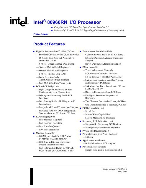
Intel ® <strong>80960</strong><strong>RN</strong> I/O <strong>Processor</strong><br />
Data Sheet<br />
Product Features<br />
■ Complies with PCI Local Bus Specification, Revision 2.2<br />
■ Universal (5 V and 3.3 V) PCI Signalling Environment (C-stepping only)<br />
■<br />
■<br />
■<br />
■<br />
High Performance Intel ® <strong>80960</strong>JT Core<br />
—Sustained One Instruction/Clock Execution<br />
—16 Kbyte, Two-Way Set-Associative<br />
Instruction Cache<br />
—4 Kbyte, Direct-Mapped Data Cache<br />
—Sixteen 32-Bit Global Registers<br />
—Sixteen 32-Bit Local Registers<br />
—1 Kbyte, Internal Data RAM<br />
—Local Register Cache<br />
(Eight Available Stack Frames)<br />
—Two 32-Bit On-Chip Timer Units<br />
PCI-to-PCI Bridge Unit<br />
—Eight Delayed Read/Write Buffers<br />
HoldinguptoeightTransactions<br />
—Primary and Secondary 64-bit PCI<br />
Interfaces<br />
—TwoPostingBuffersHoldingupto12<br />
Transactions<br />
—Delayed and Posted Transaction Support<br />
—Forwards Memory, I/O, Configuration<br />
Commands from PCI Bus to PCI Bus<br />
I 2 O Messaging Unit<br />
—Four Message Registers<br />
— Two Doorbell Registers<br />
—Four Circular Queues<br />
—1004 Index Registers<br />
Memory Controller<br />
—128 Mbytes of 64-Bit SDRAM or<br />
64 Mbytes of 32-Bit SDRAM<br />
—ECC Single-Bit error correction,<br />
Double-Bit error detection<br />
—Two Independent Banks for SRAM /<br />
ROM/Flash(8Mbyte/Bank;8-Bit)<br />
■<br />
■<br />
■<br />
■<br />
■<br />
■<br />
■<br />
■<br />
Two Address Translation Units<br />
— Connects Internal Bus to 64-bit PCI Buses<br />
—Inbound/Outbound Address Translation<br />
Support<br />
—Direct Outbound Addressing Support<br />
DMA Controller<br />
—Three Independent Channels<br />
—PCI Memory Controller Interface<br />
—64-Bit Internal + PCI Bus Addressing<br />
—Independent Interface to 64-bit Primary<br />
and Secondary PCI Buses<br />
—264 Mbyte/sec Burst Transfers to PCI and<br />
SDRAM Memory<br />
—Direct Addressing to/from PCI Buses<br />
—Unaligned Transfers Supported in<br />
Hardware<br />
— Two Channels Dedicated to Primary PCI Bus<br />
—One Channel Dedicated to Secondary PCI Bus<br />
I 2 C Bus Interface Unit<br />
—Serial Bus<br />
—Master/Slave Capabilities<br />
—System Management Functions<br />
Secondary PCI Arbitration Unit<br />
—Supports Six Secondary PCI Devices<br />
—Multi-priority Arbitration Algorithm<br />
Private PCI Device Support<br />
Perimeter Land Grid Array Package<br />
—540-pin<br />
Application Accelerator<br />
—Built-in hardware XOR engine<br />
Performance Monitoring<br />
—Ninety-eight events monitored on-chip<br />
Order Number: 273157-010<br />
June, 2002
Intel ® <strong>80960</strong><strong>RN</strong> I/O <strong>Processor</strong><br />
Information in this document is provided in connection with Intel products. No license, express or implied, by estoppel or otherwise, to any intellectual<br />
property rights is granted by this document. Except as provided in Intel's Terms and Conditions of Sale for such products, Intel assumes no liability<br />
whatsoever, and Intel disclaims any express or implied warranty, relating to sale and/or use of Intel products including liability or warranties relating to<br />
fitness for a particular purpose, merchantability, or infringement of any patent, copyright or other intellectual property right. Intel products are not<br />
intended for use in medical, life saving, or life sustaining applications.<br />
Intel may make changes to specifications and product descriptions at any time, without notice.<br />
Designers must not rely on the absence or characteristics of any features or instructions marked "reserved" or "undefined." Intel reserves these for<br />
future definition and shall have no responsibility whatsoever for conflicts or incompatibilities arising from future changes to them.<br />
The Intel ® <strong>80960</strong><strong>RN</strong> I/O <strong>Processor</strong> may contain design defects or errors known as errata which may cause the product to deviate from published<br />
specifications. Current characterized errata are available on request.<br />
Contact your local Intel sales office or your distributor to obtain the latest specifications and before placing your product order.<br />
Copies of documents which have an ordering number and are referenced in this document, or other Intel literature may be obtained by calling<br />
1-800-548-4725 or by visiting Intel's website at http://www.intel.com.<br />
Copyright © Intel Corporation, 2002<br />
Intel, Intel Solutions960 and Intel i960 are registered trademarks of Intel Corporation or its subsidiaries in the United States and other countries.<br />
*Other names and brands may be claimed as the property of others.<br />
Data Sheet
Intel ® <strong>80960</strong><strong>RN</strong> I/O <strong>Processor</strong><br />
Contents<br />
1.0 About this Document................................................................................................7<br />
1.1 Intel ® Solutions960 ® Program ...............................................................................7<br />
1.2 Terminology...........................................................................................................7<br />
1.3 Additional Information Sources .............................................................................7<br />
2.0 Functional Overview .................................................................................................8<br />
2.1 Key Functional Units .............................................................................................9<br />
2.1.1 PCI-to-PCI Bridge Unit .............................................................................9<br />
2.1.2 Private PCI Device Support......................................................................9<br />
2.1.3 DMA Controller.........................................................................................9<br />
2.1.4 Address Translation Unit ..........................................................................9<br />
2.1.5 Messaging Unit.........................................................................................9<br />
2.1.6 Memory Controller Unit ..........................................................................10<br />
2.1.7 I2C Bus Interface Unit ............................................................................10<br />
2.1.8 Secondary PCI Arbitration Unit ..............................................................10<br />
2.1.9 Application Accelerator Unit ...................................................................10<br />
2.1.10 Performance Monitor Unit ......................................................................10<br />
2.1.11 Bus Interface Unit...................................................................................10<br />
2.2 Intel ® i960 ® Core Features (Intel ® <strong>80960</strong>JT).......................................................11<br />
2.2.1 Burst Bus................................................................................................12<br />
2.2.2 Timer Unit...............................................................................................12<br />
2.2.3 Priority Interrupt Controller .....................................................................12<br />
2.2.4 Faults and Debugging ............................................................................12<br />
2.2.5 On-Chip Cache and Data RAM ..............................................................12<br />
2.2.6 Local Register Cache .............................................................................13<br />
2.2.7 Test Features .........................................................................................13<br />
2.2.8 Memory-Mapped Control Registers .......................................................13<br />
2.2.9 Instructions, Data Types and Memory Addressing Modes.....................13<br />
3.0 Package Information...............................................................................................15<br />
3.1 Package Introduction...........................................................................................15<br />
3.1.1 Functional Signal Definitions ..................................................................15<br />
3.1.1.1 Signal Pin Descriptions .............................................................16<br />
3.1.2 540-Lead H-PBGA Package ..................................................................26<br />
3.2 Package Thermal Specifications .........................................................................38<br />
3.2.1 Thermal Specifications ...........................................................................38<br />
3.2.1.1 Ambient Temperature................................................................38<br />
3.2.1.2 Case Temperature ....................................................................38<br />
3.2.1.3 Thermal Resistance ..................................................................39<br />
3.2.2 Thermal Analysis....................................................................................39<br />
3.3 Heat Sink Information..........................................................................................40<br />
3.4 Vendor Information..............................................................................................40<br />
3.4.1 Socket-Header Vendor...........................................................................40<br />
3.4.2 Burn-in Socket Vendor ...........................................................................40<br />
3.4.3 Shipping Tray Vendor.............................................................................41<br />
3.4.4 Logic Analyzer Interposer Vendor ..........................................................41<br />
3.4.5 JTAG Emulator Vendor ..........................................................................41<br />
3.5 ............................................................................................................................41<br />
Data Sheet 3
Intel ® <strong>80960</strong><strong>RN</strong> I/O <strong>Processor</strong><br />
4.0 Electrical Specifications........................................................................................42<br />
4.1 Absolute Maximum Ratings ................................................................................42<br />
4.2 V CC5REF Pin Requirements (V DIFF ).....................................................................43<br />
4.3 V CCPLL Pin Requirements ...................................................................................43<br />
4.4 Targeted DC Specifications ................................................................................44<br />
4.5 Targeted AC Specifications.................................................................................46<br />
4.5.1 Clock Signal Timings..............................................................................46<br />
4.5.2 PCI Interface Signal Timings..................................................................47<br />
4.5.3 Intel ® <strong>80960</strong>JN Core Interface Timings.................................................. 48<br />
4.5.4 SDRAM/Flash Interface Signal Timings .................................................48<br />
4.5.5 Boundary Scan Test Signal Timings ...................................................... 49<br />
4.5.6 I2C Interface Signal Timings .................................................................. 50<br />
4.6 AC Timing Waveforms ........................................................................................51<br />
4.7 AC Test Conditions ............................................................................................. 53<br />
5.0 Device Identification on Reset............................................................................54<br />
4 Data Sheet
Intel ® <strong>80960</strong><strong>RN</strong> I/O <strong>Processor</strong><br />
Figures<br />
Tables<br />
1 Intel ® <strong>80960</strong><strong>RN</strong> Functional Block Diagram ..................................................... 8<br />
2 Intel ® <strong>80960</strong>JT Core Block Diagram ............................................................. 11<br />
3 540L H-PBGA Package Diagram (Top and Side View) ................................ 26<br />
4 540L H-PBGA Package Diagram (Bottom View) .......................................... 27<br />
5 Thermocouple Attachment - A) No Heatsink / B) With Heatsink ................... 38<br />
6 V CC5REF Current-Limiting Resistor................................................................ 43<br />
7 V CCPLL Lowpass Filter .................................................................................. 43<br />
8 P_CLK, TCK, DCLKIN, DCLKOUT Waveform............................................. 51<br />
9 T OV Output Delay Waveform......................................................................... 51<br />
10 T OF Output Float Waveform .......................................................................... 52<br />
11 T IS and T IH Input Setup and Hold Waveform ................................................ 52<br />
12 I 2 C Interface Signal Timings.......................................................................... 52<br />
13 AC Test Load (all signals except SDRAM and Flash signals)....................... 53<br />
1 Related Documentation................................................................................... 7<br />
2 Instruction Set .............................................................................................. 14<br />
3 Pin Description Nomenclature....................................................................... 16<br />
4 Memory Controller Signals ............................................................................ 17<br />
5 Primary PCI Bus Signals ............................................................................... 20<br />
6 Secondary PCI Arbiter Signals...................................................................... 21<br />
7 Secondary PCI Bus Signals .......................................................................... 22<br />
8 Intel ® <strong>80960</strong>Jx Core Signals and Configuration Straps................................. 24<br />
9 I 2 C, JTAG, Core Signals ............................................................................... 25<br />
10 540-Lead H-PBGA Package — Signal Name Order ..................................... 28<br />
11 540-Lead H-PBGA Pinout — Ballpad Number Order.................................... 33<br />
12 540-Lead H-PBGA Package Thermal Characteristics .................................. 39<br />
13 Heat Sink Vendors and Contacts .................................................................. 40<br />
14 Socket-Header Vendor.................................................................................. 40<br />
15 Burn-in Socket Vendor .................................................................................. 40<br />
16 Shipping Tray Vendor.................................................................................... 41<br />
17 Logic Analyzer Interposer Vendor ................................................................. 41<br />
18 JTAG Emulator Vendor ................................................................................. 41<br />
19 Operating Conditions..................................................................................... 42<br />
20 V DIFF Specification for Dual Power Supply Requirements (3.3 V, 5 V)......... 43<br />
21 DC Characteristics ........................................................................................ 44<br />
22 I CC Characteristics ........................................................................................ 45<br />
23 Input Clock Timings....................................................................................... 46<br />
24 SDRAM Output Clock Timings ...................................................................... 46<br />
25 PCI Signal Timings....................................................................................... 47<br />
26 Intel ® <strong>80960</strong>JN Core Signal Timings............................................................. 48<br />
27 SDRAM / Flash Signal Timings..................................................................... 48<br />
28 Boundary Scan Test Signal Timings ............................................................. 49<br />
29 I2C Interface Signal Timings ......................................................................... 50<br />
30 Device ID Registers...................................................................................... 54<br />
Data Sheet 5
Intel ® <strong>80960</strong><strong>RN</strong> I/O <strong>Processor</strong><br />
This Page Intentionally Left Blank<br />
6 Data Sheet
Intel ® <strong>80960</strong><strong>RN</strong> I/O <strong>Processor</strong><br />
1.0 About this Document<br />
This is the data sheet for the Intel ® <strong>80960</strong><strong>RN</strong> processor. This data sheet contains a functional<br />
overview, mechanical data (package signal locations and simulated thermal characteristics),<br />
targeted electrical specifications (simulated), and bus functional waveforms. Detailed functional<br />
descriptions other than parametric performance is published in the i960 ® RM/<strong>RN</strong> I/O <strong>Processor</strong><br />
Developer’s Manual.<br />
1.1 Intel ® Solutions960 ® Program<br />
The Intel ® Solutions960 ® program features a wide variety of development tools which support the<br />
i960 ® processor family. Many of these tools are developed by partner companies; some are<br />
developed by Intel, such as profile-driven optimizing compilers. For more information on these<br />
products, contact your local Intel representative.<br />
1.2 Terminology<br />
In this document, the following terms are used:<br />
• Primary and Secondary PCI buses are the <strong>80960</strong><strong>RN</strong> processor’s external PCI buses which<br />
conform to PCI SIG specifications.<br />
• Intel ® <strong>80960</strong> core refers to the Intel ® <strong>80960</strong>JT processor which is integrated into the <strong>80960</strong><strong>RN</strong><br />
processor.<br />
1.3 Additional Information Sources<br />
Intel documentation is available from your local Intel Sales Representative or Intel Literature Sales.<br />
Intel Corporation<br />
Literature Sales<br />
P.O. Box 5937<br />
Denver, CO 80217-9808<br />
1-800-548-4725<br />
Table 1.<br />
Related Documentation<br />
Document Title<br />
Order / Contact<br />
i960 ® RM/<strong>RN</strong> I/O <strong>Processor</strong> Developer’s Manual Intel Order # 273158<br />
i960 ® Jx Microprocessor User’s Guide Intel Order # 272483<br />
i960 ® RM/<strong>RN</strong>/RS I/O <strong>Processor</strong> Specification Update Intel Order # 273164<br />
PCI Local Bus Specification, Revision 2.2 PCI Special Interest Group 1-800-433-5177<br />
PCI-to-PCI Bridge Architecture Specification, Revision 1.1 PCI Special Interest Group 1-800-433-5177<br />
I 2 C Peripherals for Microcontrollers<br />
Philips Semiconductor<br />
Data Sheet 7
Intel ® <strong>80960</strong><strong>RN</strong> I/O <strong>Processor</strong><br />
2.0 Functional Overview<br />
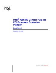
As indicated in Figure 1, the <strong>80960</strong><strong>RN</strong> processor combines many features with the <strong>80960</strong>JT to create<br />
an intelligent I/O processor. Subsections following the figure briefly describe the main features; for<br />
detailed functional descriptions, refer to the i960 ® RM/<strong>RN</strong> I/O <strong>Processor</strong> Developer’s Manual.<br />
The PCI bus is an industry standard, high performance, low latency system bus that operates up to<br />
264 Mbyte/s. The <strong>80960</strong><strong>RN</strong> processor, a multi-function PCI device, is fully compliant with the<br />
PCI Local Bus Specification, Revision 2.2. Function 0 is the PCI-to-PCI bridge unit; Function 1 is<br />
the address translation unit.<br />
The PCI-to-PCI bridge unit is the path between two independent 64-bit PCI buses and provides the<br />
ability to overcome PCI electrical load limits. The addition of the Intel ® i960 ® core processor<br />
brings intelligence to the bridge.<br />
The <strong>80960</strong><strong>RN</strong> processor, object code compatible with the i960 core processor, is capable of<br />
sustained execution at the rate of one instruction per clock.<br />
The internal bus, a 64-bit PCI-like bus, is a high-speed interface to local memory and I/O. Physical<br />
and logical memory attributes are programmed via memory-mapped control registers (MMRs); an<br />
extension not found on the Intel ® i960Kx,SxorCxprocessors.<br />
Figure 1.<br />
Intel ® <strong>80960</strong><strong>RN</strong> Functional Block Diagram<br />
Local Memory<br />
(SDRAM, Flash)<br />
I 2 C Serial Bus<br />
<strong>80960</strong><strong>RN</strong> <strong>Processor</strong><br />
<strong>80960</strong> Core<br />
Memory<br />
Controller<br />
Bus<br />
Interface<br />
I 2 CBus<br />
Interface<br />
Application<br />
Accelerator<br />
Internal<br />
Arbitration<br />
64-bit Internal Bus<br />
Messaging<br />
Unit<br />
Two DMA<br />
Channels<br />
Address<br />
Translation<br />
One DMA<br />
Channel<br />
Address<br />
Translation<br />
64-bit/32-bit Primary PCI Bus<br />
PCI to PCI<br />
Bridge<br />
64-bit/32-bit Secondary PCI Bus<br />
Performance<br />
Monitoring<br />
Unit<br />
Secondary<br />
PCI Arbitration<br />
Unit<br />
8 Data Sheet
Intel ® <strong>80960</strong><strong>RN</strong> I/O <strong>Processor</strong><br />
2.1 Key Functional Units<br />
2.1.1 PCI-to-PCI Bridge Unit<br />
The PCI-to-PCI bridge unit (referred to as “bridge”) connects two independent PCI buses. Each<br />
PCI bus may be 32 or 64 bits wide. The bridge is fully compliant with the PCI-to-PCI Bridge<br />
Architecture Specification, Revision 1.1 published by the PCI Special Interest Group. The bridge<br />
forwards bus transactions on one PCI bus to the other PCI bus. Dedicated data queues support high<br />
performance bandwidth on the PCI buses. The <strong>80960</strong><strong>RN</strong> supports PCI 64-bit Dual Address Cycle<br />
(DAC) addressing.<br />
The bridge has dedicated PCI configuration space accessible through the primary PCI bus.<br />
2.1.2 Private PCI Device Support<br />
The <strong>80960</strong><strong>RN</strong> processor explicitly supports private PCI devices on the secondary PCI bus. The<br />
bridge and Address Translation Unit work together to hide private PCI devices from PCI<br />
configuration cycles and allow these hidden devices to use a private PCI address space. The<br />
Address Translation Unit issues PCI configuration cycles to configure hidden devices.<br />
2.1.3 DMA Controller<br />
The DMA Controller supports low-latency, high-throughput data transfers between PCI bus agents<br />
and local memory. Three separate DMA channels accommodate data transfers: two for primary<br />
PCI bus, one for the secondary PCI bus. The DMA Controller supports chaining and unaligned<br />
data transfers. The DMA Controller is programmable only through the i960 core processor.<br />
2.1.4 Address Translation Unit<br />
The Address Translation Unit (ATU) allows PCI transactions direct access to local memory. The<br />
<strong>80960</strong><strong>RN</strong> processor has direct access to both PCI buses. The ATU supports transactions between<br />
PCI address space and <strong>80960</strong><strong>RN</strong> processor address space.<br />
Address translation is controlled through programmable registers accessible from both the primary<br />
PCI interface and the <strong>80960</strong> core. Dual access to registers allows flexibility in mapping the two<br />
address spaces.<br />
2.1.5 Messaging Unit<br />
The Messaging Unit (MU) provides data transfer between the PCI system and the <strong>80960</strong><strong>RN</strong><br />
processor. The Messaging Unit uses interrupts to notify the PCI system or the <strong>80960</strong><strong>RN</strong> processor<br />
when new data arrives. The MU has four messaging mechanisms: Message Registers, Doorbell<br />
Registers, Circular Queues, and Index Registers. Each mechanism allows a host processor or<br />
external PCI device and the <strong>80960</strong><strong>RN</strong> processor to communicate through message passing and<br />
interrupt generation.<br />
Data Sheet 9
Intel ® <strong>80960</strong><strong>RN</strong> I/O <strong>Processor</strong><br />
2.1.6 Memory Controller Unit<br />
The Memory Controller Unit (MCU) allows direct control of a local SDRAM and Flash subsystem.<br />
The MCU features programmable chip selects, a wait state generator and Error Correction and<br />
Detection. With the ATU configuration registers, local memory can be configured as PCI<br />
addressable memory or private processor memory.<br />
2.1.7 I 2 C Bus Interface Unit<br />
The I 2 C (Inter-Integrated Circuit) Bus Interface Unit allows the <strong>80960</strong> core to serve as a master and<br />
slave device residing on the I 2 C bus. The I 2 C bus is a serial bus developed by Philips<br />
Semiconductor comprising a two pin interface. The bus allows the <strong>80960</strong><strong>RN</strong> processor to interface<br />
to other I 2 C peripherals and microcontrollers for system management functions. It requires a<br />
minimum of hardware for an economical system to relay status and reliability information on the<br />
I/O subsystem to an external device. For more information, see I 2 C Peripherals for<br />
Microcontrollers (Philips Semiconductor).<br />
2.1.8 Secondary PCI Arbitration Unit<br />
The Secondary PCI Arbitration Unit provides PCI arbitration for the secondary PCI bus. The<br />
arbitration includes a fairness algorithm with programmable priorities and six external PCI Request<br />
and Grant signal pairs.<br />
2.1.9 Application Accelerator Unit<br />
The Application Accelerator Unit (AAU) provides hardware acceleration of XOR functions<br />
commonly used in RAID algorithms. Additionally, the AAU provides block moves within local<br />
memory. The Application Accelerator interfaces the internal bus and operates on data within local<br />
memory. The AAU is programmable through the i960 core processor and supports chaining and<br />
unaligned data transfers.<br />
2.1.10 Performance Monitor Unit<br />
The Performance Monitor Unit (PMU) allows software to monitor the performance of the different<br />
buses: Primary PCI, Secondary PCI, and Internal. Multiple performance characteristics are<br />
captured with 14 mode registers and a global time stamp register.<br />
2.1.11 Bus Interface Unit<br />
The Bus Interface Unit (BIU) provides an interface between the 100 MHz <strong>80960</strong>JT core and the<br />
66 MHz internal bus. To optimize performance, the BIU implements prefetching and write merging.<br />
10 Data Sheet
Intel ® <strong>80960</strong><strong>RN</strong> I/O <strong>Processor</strong><br />
2.2 Intel ® i960 ® Core Features (Intel ® <strong>80960</strong>JT)<br />
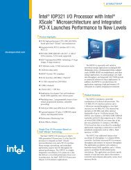
The processing power of the <strong>80960</strong><strong>RN</strong> processor comes from the 100 MHz <strong>80960</strong>JT processor<br />
core. The <strong>80960</strong>JT is a scalar implementation of the <strong>80960</strong> Core Architecture. Figure 2 shows a<br />
block diagram of the <strong>80960</strong>JT Core processor.<br />
Factors that contribute to the <strong>80960</strong>JT core’s performance include:<br />
• 100 MHz Single-clock execution of most instructions<br />
• Independent Multiply/Divide Unit<br />
• Efficient instruction pipeline minimizes pipeline break latency<br />
• Register and resource scoreboarding allow overlapped instruction execution<br />
• 128-bit register bus speeds local register caching<br />
• 16 Kbyte two-way set-associative, integrated instruction cache<br />
• 4 Kbyte direct-mapped, integrated data cache<br />
• 1 Kbyte integrated data RAM delivers zero wait state program data<br />
Figure 2.<br />
The <strong>80960</strong> core operates out of its own 32-bit address space, which is independent of the PCI<br />
address space. Local memory can be:<br />
• Made visible to the PCI address space<br />
• Kept private to the <strong>80960</strong>JT core<br />
• Allocated as a combination of the two<br />
Intel ® <strong>80960</strong>JT Core Block Diagram<br />
P_CLK<br />
TAP<br />
5<br />
PLL, Clocks,<br />
Power Mgmt<br />
Boundary Scan<br />
Controller<br />
8-Set<br />
Local Register<br />
Cache<br />
128<br />
Global / Local<br />
Register File<br />
SRC1 SRC2 DST<br />
Multiply<br />
Divide<br />
Unit<br />
SRC1<br />
SRC2<br />
DST<br />
Instruction Cache<br />
16 Kbyte Two-Way Set<br />
Associative<br />
Instruction Sequencer<br />
Constants<br />
Execution<br />
and<br />
Address<br />
Generation<br />
Unit<br />
Effective<br />
Address<br />
SRC1<br />
SRC2<br />
DST<br />
Control<br />
3 Independent 32-Bit SRC1, SRC2, and DST Buses<br />
Memory<br />
Interface<br />
Unit<br />
32-bit Addr<br />
32-bit Data<br />
SRC1<br />
DST<br />
32-bit buses<br />
address / data<br />
Physical Region<br />
Configuration<br />
Bus<br />
Control Unit<br />
Bus Request<br />
Queues<br />
Two 32-Bit<br />
Timers<br />
Control<br />
Address/<br />
Data Bus<br />
Interrupt<br />
Programmable<br />
Port<br />
Interrupt Controller 9<br />
Memory-Mapped<br />
Register Interface<br />
1Kbyte<br />
Data RAM<br />
4Kbyte<br />
Direct Mapped<br />
Data Cache<br />
32<br />
Data Sheet 11
Intel ® <strong>80960</strong><strong>RN</strong> I/O <strong>Processor</strong><br />
2.2.1 Burst Bus<br />
2.2.2 Timer Unit<br />
A 32-bit high-performance bus controller interfaces the <strong>80960</strong><strong>RN</strong> processor to the Bus Interface<br />
Unit. The Bus Control Unit fetches instructions and transfers data on the internal bus at the rate of<br />
up to four 32-bit words per six clock cycles. The external address/data bus is multiplexed.<br />
Data caching is programmed through a group of logical memory templates and a defaults register.<br />
The Bus Control Unit’s features include:<br />
• Multiplexed external bus minimizes pin count<br />
• External ready control for address-to-data, data-to-data and data-to-next-address wait state types<br />
• Little endian byte ordering<br />
• Unaligned bus accesses performed transparently<br />
• Three-deep load/store queue decouples the bus from the <strong>80960</strong> core<br />
Upon reset, the <strong>80960</strong>JT conducts an internal self test. Before executing its first instruction, it<br />
performs an external bus confidence test by performing a checksum on the first words of the<br />
Initialization Boot Record.<br />
The timer unit (TU) contains two independent 32-bit timers that are capable of counting at several<br />
clock rates and generating interrupts. Each is programmed through the Timer Unit registers. These<br />
memory-mapped registers are addressable on 32-bit boundaries. Timers have a single-shot mode<br />
and auto-reload capabilities for continuous operation. Each timer has an independent interrupt<br />
request to the <strong>80960</strong>JT’s interrupt controller. The TU can generate a fault when unauthorized writes<br />
from user mode are detected.<br />
2.2.3 Priority Interrupt Controller<br />
Low interrupt latency is critical to many embedded applications. As part of its highly flexible<br />
interrupt mechanism, the <strong>80960</strong>JT exploits several techniques to minimize latency:<br />
• Interrupt vectors and interrupt handler routines can be reserved on-chip<br />
• Register frames for high-priority interrupt handlers can be cached on-chip<br />
• The interrupt stack can be placed in cacheable memory space<br />
2.2.4 Faults and Debugging<br />
The <strong>80960</strong>JT employs a comprehensive fault model. The processor responds to faults by making<br />
implicit calls to a fault handling routine. Specific information collected for each fault allows the<br />
fault handler to diagnose exceptions and recover appropriately.<br />
The processor also has built-in debug capabilities. With software, the <strong>80960</strong>JT may be configured<br />
to detect as many as seven different trace event types. Alternatively, mark and fmark instructions<br />
can generate trace events explicitly in the instruction stream. Hardware breakpoint registers are<br />
also available to trap on execution and data addresses.<br />
2.2.5 On-Chip Cache and Data RAM<br />
Memory subsystems often impose substantial wait state penalties. The <strong>80960</strong>JT integrates<br />
considerable storage resources on-chip to decouple CPU execution from the external bus. The<br />
<strong>80960</strong>JT includes a 16 Kbyte instruction cache, a 4 Kbyte data cache and 1 Kbyte data RAM.<br />
12 Data Sheet
Intel ® <strong>80960</strong><strong>RN</strong> I/O <strong>Processor</strong><br />
2.2.6 Local Register Cache<br />
The <strong>80960</strong>JT rapidly allocates and deallocates local register sets during context switches. The processor<br />
needs to flush a register set to the stack only when it saves more than seven sets to its local register cache.<br />
2.2.7 Test Features<br />
The <strong>80960</strong><strong>RN</strong> processor incorporates numerous features that enhance the user’s ability to test both<br />
the processor and the system to which it is attached. These features include ONCE (On-Circuit<br />
Emulation) mode and Boundary Scan (JTAG).<br />
The <strong>80960</strong>JT provides testability features compatible with IEEE Standard Test Access Port and<br />
Boundary Scan Architecture (IEEE Std. 1149.1).<br />
One of the boundary scan instructions, HIGHZ, forces the processor to float all its output pins (ONCE<br />
mode). ONCE mode can also be initiated at reset without using the boundary scan mechanism.<br />
ONCE mode is useful for board-level testing. This feature allows a mounted <strong>80960</strong><strong>RN</strong> processor to<br />
electrically “remove” itself from a circuit board allowing system-level testing where a remote<br />
tester can exercise the processor system.<br />
The test logic does not interfere with component or system behavior and ensures that components<br />
function correctly and the connections between various components are correct.<br />
The JTAG Boundary Scan feature is an alternative to conventional “bed-of-nails” testing.<br />
Boundary Scan can examine connections that might otherwise be inaccessible to a test system.<br />
2.2.8 Memory-Mapped Control Registers<br />
The <strong>80960</strong>JT is compliant with <strong>80960</strong> family architecture. Each memory-mapped, 32-bit register is<br />
accessed via memory-format instructions. The processor ensures that these accesses do not<br />
generate external bus cycles.<br />
2.2.9 Instructions, Data Types and Memory Addressing Modes<br />
As with all <strong>80960</strong> family processors, the instruction set supports several different data types and formats:<br />
• Bit<br />
• Bit fields<br />
• Integer (8-, 16-, 32-, 64-bit)<br />
• Ordinal (8-, 16-, 32-, 64-bit unsigned integers)<br />
• Triple word (96 bits)<br />
• Quad word (128 bits)<br />
The <strong>80960</strong>JT provides a full set of addressing modes for C and assembly:<br />
• Two Absolute modes<br />
• Five Register Indirect modes<br />
• Index with displacement mode<br />
• IP with displacement mode<br />
Data Sheet 13
Intel ® <strong>80960</strong><strong>RN</strong> I/O <strong>Processor</strong><br />
Table 2 shows the available <strong>80960</strong>JT instructions.<br />
Table 2.<br />
Instruction Set<br />
Data Movement Arithmetic Logical Bit, Bit Field and Byte<br />
Add<br />
Subtract<br />
Load<br />
Store<br />
Move<br />
Conditional Select<br />
Load Address<br />
Multiply<br />
Divide<br />
Remainder<br />
Modulo<br />
Shift<br />
Extended Shift<br />
Extended Multiply<br />
Extended Divide<br />
Add with Carry<br />
Subtract with Carry<br />
Conditional Add<br />
Conditional Subtract<br />
Rotate<br />
And<br />
Not And<br />
And Not<br />
Or<br />
Exclusive Or<br />
Not Or<br />
Or Not<br />
Nor<br />
Exclusive Nor<br />
Not<br />
Nand<br />
Set Bit<br />
Clear Bit<br />
Not Bit<br />
Alter Bit<br />
Scan For Bit<br />
Span Over Bit<br />
Extract<br />
Modify<br />
Scan Byte for Equal<br />
Byte Swap<br />
Comparison Branch Call/Return Fault<br />
Compare<br />
Conditional Compare<br />
Compare and Increment<br />
Compare and<br />
Decrement<br />
Test Condition Code<br />
Check Bit<br />
Unconditional Branch<br />
Conditional Branch<br />
Compare and Branch<br />
Call<br />
Call Extended<br />
Call System<br />
Return<br />
Branch and Link<br />
Conditional Fault<br />
Synchronize Faults<br />
Debug<br />
<strong>Processor</strong><br />
Management<br />
Atomic<br />
Flush Local Registers<br />
Modify Trace Controls<br />
Mark<br />
Force Mark<br />
Modify Arithmetic<br />
Controls<br />
Modify Process Controls<br />
Halt<br />
System Control<br />
Cache Control<br />
Interrupt Control<br />
Atomic Add<br />
Atomic Modify<br />
14 Data Sheet
Intel ® <strong>80960</strong><strong>RN</strong> I/O <strong>Processor</strong><br />
3.0 Package Information<br />
3.1 Package Introduction<br />
The <strong>80960</strong><strong>RN</strong> processor is offered in a Perimeter Land Grid Array (PBGA) package. This is a<br />
perimeter array package with five rows of ball connections in the outer area of the package. See<br />
Figure 4 “540L H-PBGA Package Diagram (Bottom View)” on page 27.<br />
3.1.1 Functional Signal Definitions<br />
This section defines the pins and signals in the following tables:<br />
• Table 3 “Pin Description Nomenclature” on page 16<br />
• Table 4 “Memory Controller Signals” on page 17<br />
• Table 5 “Primary PCI Bus Signals” on page 20<br />
• Table 6 “Secondary PCI Arbiter Signals” on page 21<br />
• Table 8 “Intel ® <strong>80960</strong>Jx Core Signals and Configuration Straps” on page 24<br />
• Table 9 “I 2 C, JTAG, Core Signals” on page 25<br />
Data Sheet 15
Intel ® <strong>80960</strong><strong>RN</strong> I/O <strong>Processor</strong><br />
3.1.1.1 Signal Pin Descriptions<br />
Table 3.<br />
Pin Description Nomenclature<br />
Symbol<br />
Description<br />
I<br />
O<br />
I/O<br />
Input pin only<br />
Output pin only<br />
Pin can be either an input or output<br />
OD Open Drain pin<br />
- Pin must be connected as described<br />
N/C<br />
5V<br />
Sync(...)<br />
Async<br />
Prst(...)<br />
Srst(...)<br />
Irst(...)<br />
P32(...)<br />
S32(...)<br />
NO CONNECT. Do not make electrical connections to these balls.<br />
Input pin is 5 volt tolerant<br />
Synchronous. Inputs meet setup and hold times relative to an input clock.<br />
Sync(P) Synchronous to P_CLK<br />
Sync(D) Synchronous to DCLKIN<br />
Sync(T) Synchronous to TCK<br />
Asynchronous. Inputs may be asynchronous relative to P_CLK, DCLKIN, orTCK. All<br />
asynchronous signals are level-sensitive.<br />
While the P_RST# pin is asserted, the pin:<br />
Prst(1) Is driven to Vcc<br />
Prst(0) Is driven to Vss<br />
Prst(X) Is driven to unknown state<br />
Prst(H)IspulleduptoVcc<br />
Prst(L)IspulleddowntoVss<br />
Prst(Z) Floats<br />
Prst(Q) Is a valid output<br />
Since P_RST# is asynchronous, these are asynchronous events.<br />
While the S_RST# pin is asserted, the pin:<br />
Srst(1) Is driven to Vcc<br />
Srst(0) Is driven to Vss<br />
Srst(X) Is driven to unknown state<br />
Srst(H)IspulleduptoVcc<br />
Srst(L)IspulleddowntoVss<br />
Srst(Z) Floats<br />
Srst(Q) Is a valid output<br />
Note that S_RST# is asserted when P_RST# is asserted or BCR[6] is set with software.<br />
While the I_RST# pin is asserted, the pin:<br />
Irst(1) Is driven to Vcc<br />
Irst(0) Is driven to Vss<br />
Irst(X) Is driven to unknown state<br />
Irst(H)IspulleduptoVcc<br />
Irst(L)IspulleddowntoVss<br />
Irst(Z) Floats<br />
Irst(Q) Is a valid output<br />
Note that I_RST# is asserted when P_RST# is asserted or EBCR[5] is set with software.<br />
While the Primary PCI Bus is configured as a 32-bit PCI bus by the Primary central resource:<br />
P32(H) is pulled up internally to Vcc<br />
P32(L) is pulled down internally to Vss<br />
While the Secondary PCI Bus is configured as a 32-bit PCI bus with 32BITPCI_EN#:<br />
S32(H) is pulled up internally to Vcc<br />
S32(L) is pulled down internally to Vss<br />
16 Data Sheet
Intel ® <strong>80960</strong><strong>RN</strong> I/O <strong>Processor</strong><br />
Table 4. Memory Controller Signals (Sheet 1 of 3)<br />
Name Count Type Description<br />
DCLKOUT<br />
1 O<br />
Irst(Q)<br />
SDRAM OUTPUT CLOCK dedicated for SDRAM memory<br />
subsystem.<br />
DCLKIN<br />
1 I SDRAM INPUT CLOCK dedicated for SDRAM memory<br />
subsystem. Used to skew DCLKOUT appropriately to<br />
accommodate flight time and clock buffer delays.<br />
SA[11:0]<br />
SBA[1:0]<br />
SRAS#<br />
SCAS#<br />
SDQM[7:0]<br />
SWE#<br />
SCE[1:0]#<br />
SCKE[1:0]<br />
DQ[63:0]<br />
SCB[7:0]<br />
ROE#<br />
RWE#<br />
RCE[1:0]#<br />
RALE<br />
12 O<br />
Irst(Q)<br />
2 O<br />
Irst(Q)<br />
1 O<br />
Irst(1)<br />
1 O<br />
Irst(1)<br />
8 O<br />
Irst(1)<br />
1 O<br />
Irst(1)<br />
2 O<br />
Irst(1)<br />
2 O<br />
Irst(Q)<br />
64 I/O<br />
Irst(1)<br />
Sync(D)<br />
8 I/O<br />
Irst(1)<br />
Sync(D)<br />
1 O<br />
Irst(1)<br />
1 O<br />
Irst(1)<br />
2 O<br />
Irst(1)<br />
1 O<br />
Irst(0)<br />
SDRAM MULTIPLEXED ADDRESS BUS carries the multiplexed<br />
row and column addresses to the SDRAM memory banks. For<br />
SA[10], see note 1.<br />
SDRAM INTE<strong>RN</strong>AL BANK SELECT indicates which of the SDRAM<br />
internal banks are read or written during the current transaction.<br />
SDRAM ROW ADDRESS STROBE indicates the presence of a valid<br />
row address on the Multiplexed Address Bus SA[11:0]. See note 1.<br />
SDRAM COLUMN ADDRESS STROBE indicates the presence of<br />
a valid column address on the Multiplexed Address Bus SA[11:0].<br />
Seenote1.<br />
SDRAM DATA MASK controls which of the eight bytes on the data<br />
bus should be written or read. When SDQM[7:0] asserted, the<br />
SDRAM devices do not accept/drive valid data from/to the byte<br />
lanes. When SDQM[7:0] deasserted, the SDRAM devices<br />
accept/drivevaliddatafrom/tothebytelanes.<br />
By convention, SDQM[1] masks two x8 SDRAM devices.<br />
Functionally, all SDQM[7:0] signals are equivalent.<br />
SDRAM WRITE ENABLE indicates that the current memory<br />
transaction is a write operation. See note 1.<br />
SDRAM CHIP ENABLE enables the SDRAM devices for a<br />
memory access (1 per bank supported). See note 1.<br />
SCKE[1:0] are the clock enables for the SDRAM memory.<br />
Deasserting will place the SDRAM in self-refresh mode. See note 1.<br />
DATA BUS carries 64-bit data to and from memory. During a data<br />
(T d ) cycle, read or write data is present on one or more contiguous<br />
bytes, comprising DQ[63:56], DQ[55:48], DQ[47:40], DQ[39:32],<br />
DQ[31:24], DQ[23:16], DQ[15:8] and DQ[7:0]. During write<br />
operations, unused pins are driven to determinate values.<br />
ERROR CORRECTION CODE carries the 8-bit ECC code to and<br />
from memory during data cycles.<br />
ROM OUTPUT ENABLE specifies, during a T a cycle, whether the<br />
operation is a write (1) or read (0) to the ROM interface. It remains<br />
valid during T d cycles. When ROE# is asserted, the data is<br />
transferred from the memory on RAD[16:9].<br />
ROM WRITE ENABLE indicates the direction data is to be<br />
transferred to/from ROM and controls the WE input on the ROM<br />
device. When RWE# is asserted, the data is transferred to the<br />
memory on DQ[7:0].<br />
FLASH CHIP ENABLE enables Flash devices for a memory access.<br />
ROM ADDRESS LATCH ENABLE indicates the cycle in which the<br />
address on RAD[16:3] should be externally latched for the Flash<br />
subsystem.<br />
Data Sheet 17
Intel ® <strong>80960</strong><strong>RN</strong> I/O <strong>Processor</strong><br />
Table 4. Memory Controller Signals (Sheet 2 of 3)<br />
Name Count Type Description<br />
RAD[16:9]<br />
RAD[8]<br />
RAD[7]<br />
RAD[6]/<br />
RST_MODE#<br />
(Config. Pin)<br />
RAD[5]<br />
RAD[4]/<br />
STEST<br />
(Config. Pin)<br />
RAD[3]/<br />
RETRY<br />
(Config. Pin)<br />
8 I/O<br />
5V<br />
Irst(X)<br />
Sync(D)<br />
1 O<br />
Prst(H)<br />
1 O<br />
Prst(H)<br />
1 I/O<br />
5V<br />
Prst(H)<br />
1 O<br />
Prst(H)<br />
1 I/O<br />
5V<br />
Prst(H)<br />
1 I/O<br />
5V<br />
Prst(H)<br />
FLASH ADDRESS/DATA BUS: Duringanaddress(T a ) cycle, bits<br />
16:9 contain a physical word address. During a data cycle (Td), bits<br />
16:9 carry data bits 16:9 of the Flash data byte.<br />
FLASH ADDRESS BUS: During an address (T a ) cycle, bit 8 contain<br />
a physical word address. RAD[8]. multiplexes physical address bits<br />
[22] with [8]. Refer to the MCU chapter of the i960 ® RM/<strong>RN</strong> I/O<br />
<strong>Processor</strong> Developer’s Manual for details.<br />
FLASH ADDRESS BUS: During an address (T a ) cycle, bit 7 contain<br />
a physical word address. RAD[7]. multiplexes physical address bits<br />
[21] with [7]. Refer to the MCU chapter of the i960 ® RM/<strong>RN</strong> I/O<br />
<strong>Processor</strong> Developer’s Manual for details.<br />
FLASH ADDRESS BUS: During an address (T a ) cycle, bit 6 contain<br />
a physical word address. RAD[6]. multiplexes physical address bits<br />
[20] with [6]. Within four clocks after the deassertion of P_RST#,<br />
this pin is an output only. Refer to the MCU chapter of the i960 ®<br />
RM/<strong>RN</strong> I/O <strong>Processor</strong> Developer’s Manual for details.<br />
RESET MODE is sampled at Primary PCI bus reset to determine if<br />
the <strong>80960</strong><strong>RN</strong> processor is to be held in reset. If asserted, the<br />
<strong>80960</strong><strong>RN</strong> processor will be held in reset until the <strong>80960</strong> <strong>Processor</strong><br />
Reset bit is cleared in the Extended Bridge Control Register.<br />
FLASH ADDRESS BUS: During an address (T a ) cycle, bit 5 contain<br />
a physical word address. RAD[5]. multiplexes physical address bits<br />
[19] with [5]. Within four clocks after the deassertion of P_RST#,<br />
this pin is an output only. Refer to the MCU chapter of the i960 ®<br />
RM/<strong>RN</strong> I/O <strong>Processor</strong> Developer’s Manual for details.<br />
FLASH ADDRESS BUS: During an address (T a ) cycle, bit 4 contain<br />
a physical word address. RAD[4]. multiplexes physical address bits<br />
[18] with [4]. Within four clocks after the deassertion of P_RST#,<br />
this pin is an output only. Refer to the MCU chapter of the i960 ®<br />
RM/<strong>RN</strong> I/O <strong>Processor</strong> Developer’s Manual for details.<br />
SELF TEST enables or disables the processor’s internal self-test<br />
feature at initialization. STEST is examined at the end of P_RST#.<br />
When STEST is asserted, the processor performs its internal<br />
self-test and the external bus confidence test. When STEST is<br />
deasserted, the processor performs only the external bus<br />
confidence test.<br />
0 = Self Test Disabled<br />
1 = Self Test Enabled<br />
FLASH ADDRESS BUS: During an address (T a ) cycle, bit 3 contain<br />
a physical word address. RAD[3]. multiplexes physical address bits<br />
[17] with [3]. Within four clocks after the deassertion of P_RST#,<br />
this pin is an output only. Refer to the MCU chapter of the i960 ®<br />
RM/<strong>RN</strong> I/O <strong>Processor</strong> Developer’s Manual for details.<br />
RETRY is sampled at Primary PCI bus reset to determine if the<br />
Primary PCI interface will be disabled. If high, the Primary PCI<br />
interface will disable PCI configuration cycles by signaling a Retry<br />
until the Configuration Cycle Retry bit is cleared in the Extended<br />
Bridge Control Register. If low, the Primary PCI interface allow<br />
configuration cycles to occur.<br />
18 Data Sheet
Intel ® <strong>80960</strong><strong>RN</strong> I/O <strong>Processor</strong><br />
Table 4. Memory Controller Signals (Sheet 3 of 3)<br />
Name Count Type Description<br />
RAD[2]/<br />
32BITMEM_EN#<br />
(Config. Pin)<br />
RAD[1]/<br />
32BITPCI_EN#<br />
(Config. Pin)<br />
RAD[0]<br />
1 I/O<br />
5V<br />
Prst(H)<br />
1 I/O<br />
5V<br />
Prst(H)<br />
1 O<br />
Prst(H)<br />
FLASH ADDRESS BUS: During an address (T a ) cycle, bit 2<br />
contains a physical word address. Within four clocks after the<br />
deassertion of P_RST#, this pin is an output only. Refer to the MCU<br />
chapter of the i960 ® RM/<strong>RN</strong> I/O <strong>Processor</strong> Developer’s Manual for<br />
details.<br />
32-BIT Memory Enable The 32BITMEM_EN# signal is sampled at<br />
Primary PCI Reset to notify the memory controller if 32-bit wide<br />
SDRAM memories are connected to the memory controller.<br />
If 32BITMEM_EN# is high, the memory controller supports the<br />
64-bit SDRAM protocol for accesses to SDRAM memories.<br />
If 32BITMEM_EN# is low, the memory controller supports the<br />
32-bit SDRAM protocol for accesses to SDRAM memories.<br />
FLASH ADDRESS BUS: During an address (T a ) cycle, bit 1<br />
contains a physical word address. Within four clocks after the<br />
deassertion of P_RST#, this pin is an output only. Refer to the MCU<br />
chapter of the i960 ® RM/<strong>RN</strong> I/O <strong>Processor</strong> Developer’s Manual for<br />
details.<br />
32-BIT Secondary PCI Enable The 32BITPCI_EN# signal is<br />
sampled at Primary PCI Reset to notify the secondary PCI arbiter<br />
NOT to generate the 64-bit protocol of the rising edge of the<br />
secondary reset for the secondary PCI bus.<br />
If 32BITPCI_EN# is high, the secondary PCI arbiter asserts<br />
S_REQ64# during S_RST#, indicating the secondary PCI bus is a<br />
64-bit bus.<br />
If 32BITPCI_EN# is low, the secondary PCI arbiter does not assert<br />
S_REQ64# during S_RST#, indicating the secondary PCI bus is<br />
NOT a 64-bit bus.<br />
FLASH ADDRESS BUS: During an address (T a ) cycle, bit 0<br />
contains a physical word address. Refer to the MCU chapter of the<br />
i960 ® RM/<strong>RN</strong> I/O <strong>Processor</strong> Developer’s Manual for details.<br />
NOTE:<br />
1. These pins remain functional for 20 DCLKIN periods after I_RST# is asserted for a warm boot. The<br />
designated Irst() state applies after 20 DCLKIN periods after I_RST# is asserted. For more details, refer to<br />
the MCU Chapter of the i960 ® RM/<strong>RN</strong> I/O <strong>Processor</strong> Developer’s Manual.<br />
Data Sheet 19
Intel ® <strong>80960</strong><strong>RN</strong> I/O <strong>Processor</strong><br />
Table 5. Primary PCI Bus Signals (Sheet 1 of 2)<br />
Name Count Type Description<br />
P_AD[31:0] 32<br />
P_AD[63:32] 32<br />
P_PAR 1<br />
P_PAR64 1<br />
P_C/BE[3:0]# 4<br />
P_C/BE[7:4]# 4<br />
P_REQ# 1<br />
P_REQ64# 1<br />
P_GNT# 1<br />
P_ACK64# 1<br />
P_FRAME# 1<br />
P_IRDY# 1<br />
P_TRDY# 1<br />
I/O<br />
5V<br />
Sync(P)<br />
Prst(Z)<br />
I/O<br />
5V<br />
Sync(P)<br />
Prst(Z)<br />
P32(H)<br />
I/O<br />
5V<br />
Sync(P)<br />
Prst(Z)<br />
I/O<br />
5V<br />
Sync(P)<br />
Prst(Z)<br />
P32(H)<br />
I/O<br />
5V<br />
Sync(P)<br />
Prst(Z)<br />
I/O<br />
5V<br />
Sync(P)<br />
Prst(Z)<br />
P32(H)<br />
O<br />
Prst(Z)<br />
I/O<br />
5V<br />
Sync(P)<br />
Prst(Z)<br />
P32(Z)<br />
I<br />
5V<br />
Sync(P)<br />
Prst(Z)<br />
I/O<br />
5V<br />
Sync(P)<br />
Prst(Z)<br />
P32(Z)<br />
I/O<br />
5V<br />
Sync(P)<br />
Prst(Z)<br />
I/O<br />
5V<br />
Sync(P)<br />
Prst(Z)<br />
I/O<br />
5V<br />
Sync(P)<br />
Prst(Z)<br />
PRIMARY PCI ADDRESS/DATA is the multiplexed PCI address<br />
and bottom 32 bits of the data bus.<br />
PRIMARY PCI DATA is the upper 32 bits of the primary PCI data<br />
bus driven during the data phase.<br />
PRIMARY PCI BUS PARITY is even parity across P_AD[31:0] and<br />
P_C/BE[3:0]#.<br />
PRIMARY PCI BUS UPPER DWORD PARITY is even parity<br />
across P_AD[63:32] and P_C/BE[7:4]#.<br />
PRIMARY PCI BUS COMMAND and BYTE ENABLES are<br />
multiplexed on the same PCI pins. During the address phase, they<br />
define the bus command. During the data phase, they are used as<br />
byte enables for P_AD[31:0].<br />
PRIMARY PCI BUS BYTE ENABLES are as byte enables for<br />
P_AD[63:32] during the data phase.<br />
PRIMARY PCI BUS REQUEST indicates to the primary PCI bus<br />
arbiter that the <strong>80960</strong><strong>RN</strong> processor desires use of the PCI bus.<br />
PRIMARY PCI BUS REQUEST 64-BIT TRANSFER indicates the<br />
attempt of a 64-bit transaction on the primary PCI bus. If the target<br />
is 64-bit capable, the target acknowledges the attempt with the<br />
assertion of P_ACK64#.<br />
PRIMARY PCI BUS GRANT indicates that access to the primary<br />
PCI bus has been granted.<br />
PRIMARY PCI BUS ACKNOWLEDGE 64-BIT TRANSFER<br />
indicates that the device has positively decoded its address as the<br />
target of the current access and the target is willing to transfer data<br />
using the full 64-bit data bus.<br />
PRIMARY PCI BUS CYCLE FRAME is asserted to indicate the<br />
beginning and duration of an access.<br />
PRIMARY PCI BUS INITIATOR READY indicates the initiating<br />
agent’s ability to complete the current data phase of the<br />
transaction. During a write, it indicates that valid data is present on<br />
the Address/Data bus. During a read, it indicates the processor is<br />
ready to accept the data.<br />
PRIMARY PCI BUS TARGET READY indicates the target agent’s<br />
ability to complete the current data phase of the transaction. During a<br />
read, it indicates that valid data is present on the Address/Data bus.<br />
During a write, it indicates the target is ready to accept the data.<br />
20 Data Sheet
Intel ® <strong>80960</strong><strong>RN</strong> I/O <strong>Processor</strong><br />
Table 5. Primary PCI Bus Signals (Sheet 2 of 2)<br />
Name Count Type Description<br />
P_STOP# 1<br />
P_DEVSEL# 1<br />
P_SERR# 1<br />
P_CLK 1<br />
P_RST# 1<br />
P_PERR# 1<br />
P_LOCK# 1<br />
P_IDSEL 1<br />
P_INT[A:D]# 4<br />
I/O<br />
5V<br />
Sync(P)<br />
Prst(Z)<br />
I/O<br />
5V<br />
Sync(P)<br />
Prst(Z)<br />
I/O<br />
5V<br />
OD<br />
Sync(P)<br />
Prst(Z)<br />
I<br />
5V<br />
I<br />
5V<br />
Async<br />
I/O<br />
5V<br />
Sync(P)<br />
Prst(Z)<br />
I<br />
5V<br />
Sync(P)<br />
I<br />
5V<br />
Sync(P)<br />
O<br />
OD<br />
Prst(Z)<br />
PRIMARY PCI BUS STOP indicates a request to stop the current<br />
transaction on the primary PCI bus.<br />
PRIMARY PCI BUS DEVICE SELECT is driven by a target agent<br />
that has successfully decoded the address. As an input, it indicates<br />
whether or not an agent has been selected.<br />
PRIMARY PCI BUS SYSTEM ERROR is driven for address parity<br />
errors on the primary PCI bus.<br />
PRIMARY PCI BUS INPUT CLOCK provides the timing for all<br />
primary PCI transactions and is the clock source for all internal<br />
<strong>80960</strong><strong>RN</strong> units.<br />
PRIMARY RESET brings PCI-specific registers, sequencers, and<br />
signals to a consistent state. When P_RST# is asserted:<br />
PCI output signals are driven to a known consistent state.<br />
PCI bus interface output signals are three-stated.<br />
open drain signals such as P_SERR# are floated.<br />
P_RST# may be asynchronous to P_CLK when asserted or<br />
deasserted. Although asynchronous, deassertion must be<br />
guaranteed to be a clean, bounce-free edge.<br />
PRIMARY PCI BUS PARITY ERROR is asserted when a data<br />
parity error occurs during a primary PCI bus transaction.<br />
PRIMARY PCI BUS LOCK indicates the need to perform an atomic<br />
operation on the primary PCI bus.<br />
PRIMARY PCI BUS INITIALIZATION DEVICE SELECT is used to<br />
select the <strong>80960</strong><strong>RN</strong> during a Configuration Read or Write<br />
command on the primary PCI bus.<br />
PRIMARY PCI BUS INTERRUPT requests an interrupt. The<br />
assertion and deassertion of P_INT[A:D]# is asynchronous to<br />
P_CLK. A device asserts its P_INT[A:D]# line when requesting<br />
attention from its device driver. Once the P_INT[A:D]# signal is<br />
asserted, it remains asserted until the device driver clears the<br />
pending request. P_INT[A:D]# Interrupts are level sensitive.<br />
Table6.<br />
SecondaryPCIArbiterSignals<br />
Name Count Type Description<br />
S_REQ[5:0]#<br />
S_GNT[5:0]#<br />
6 I<br />
5V<br />
Sync(P)<br />
6 O<br />
Srst(Z)<br />
SECONDARY PCI BUS REQUESTS are the request signals from<br />
devices 0 through 5 on the secondary PCI bus.<br />
SECONDARY PCI BUS GRANT are grant signals sent to devices<br />
5-0 on the secondary PCI bus<br />
Data Sheet 21
Intel ® <strong>80960</strong><strong>RN</strong> I/O <strong>Processor</strong><br />
Table 7. Secondary PCI Bus Signals (Sheet 1 of 2)<br />
Name Count Type Description<br />
S_AD[31:0] 32<br />
S_AD[63:32] 32<br />
S_PAR 1<br />
S_PAR64 1<br />
S_C/BE[3:0]# 4<br />
S_C/BE[7:4]# 4<br />
S_REQ64# 1<br />
S_ACK64# 1<br />
S_FRAME# 1<br />
S_IRDY# 1<br />
S_TRDY# 1<br />
S_STOP# 1<br />
I/O<br />
5V<br />
Sync(P)<br />
Srst(0)<br />
I/O<br />
5V<br />
Sync(P)<br />
Srst(Z)<br />
S32(H)<br />
I/O<br />
Sync(P)<br />
Srst(0)<br />
I/O<br />
5V<br />
Sync(P)<br />
Srst(Z)<br />
S32(H)<br />
I/O<br />
5V<br />
Sync(P)<br />
Srst(0)<br />
I/O<br />
5V<br />
Sync(P)<br />
Srst(Z)<br />
S32(H)<br />
I/O<br />
5V<br />
Sync(P)<br />
Srst(Q)<br />
S32(Z)<br />
I/O<br />
5V<br />
Sync(P)<br />
Srst(Z)<br />
S32(Z)<br />
I/O<br />
5V<br />
Sync(P)<br />
Srst(Z)<br />
I/O<br />
5V<br />
Sync(P)<br />
Srst(Z)<br />
I/O<br />
5V<br />
Sync(P)<br />
Srst(Z)<br />
I/O<br />
5V<br />
Sync(P)<br />
Srst(Z)<br />
SECONDARY PCI ADDRESS/DATA is the multiplexed secondary<br />
PCI address and lower 32 bits of the data bus.<br />
SECONDARY PCI DATA is the upper 32 bits of the secondary PCI<br />
data bus.<br />
SECONDARY PCI BUS PARITY is even parity across S_AD[31:0]<br />
and S_C/BE[3:0]#.<br />
SECONDARY PCI BUS UPPER DWORD PARITY is even parity<br />
across S_AD[63:32] and S_C/BE[7:4]#.<br />
SECONDARY PCI BUS COMMAND and BYTE ENABLES are<br />
multiplexed on the same PCI pins. During the address phase, they<br />
define the bus command. During the data phase, they are used as<br />
the byte enables for S_AD[31:0].<br />
SECONDARY PCI BYTE ENABLES are used as byte enables for<br />
S_AD[63:32] during secondary PCI data phases.<br />
SECONDARY PCI BUS REQUEST 64-BIT TRANSFER indicates<br />
the attempt of a 64-bit transaction on the secondary PCI bus. If the<br />
target is 64-bit capable, the target acknowledges the attempt with<br />
the assertion of S_ACK64#.<br />
SECONDARY PCI BUS ACKNOWLEDGE 64-BIT TRANSFER<br />
indicates that the device has positively decoded its address as the<br />
target of the current access, indicates the target is willing to transfer<br />
data using 64 bits.<br />
SECONDARY PCI BUS CYCLE FRAME is asserted to indicate the<br />
beginning and duration of an access.<br />
SECONDARY PCI BUS INITIATOR READY indicates the initiating<br />
agent’s ability to complete the current data phase of the<br />
transaction. During a write, it indicates that valid data is present on<br />
the secondary Address/Data bus. During a read, it indicates the<br />
processor is ready to accept the data.<br />
SECONDARY PCI BUS TARGET READY indicates the target<br />
agent’s ability to complete the current data phase of the<br />
transaction. During a read, it indicates that valid data is present on<br />
the secondary Address/Data bus. During a write, it indicates the<br />
target is ready to accept the data.<br />
SECONDARY PCI BUS STOP indicates a request to stop the<br />
current transaction on the secondary PCI bus.<br />
22 Data Sheet
Intel ® <strong>80960</strong><strong>RN</strong> I/O <strong>Processor</strong><br />
Table 7. Secondary PCI Bus Signals (Sheet 2 of 2)<br />
Name Count Type Description<br />
S_DEVSEL# 1<br />
S_SERR# 1<br />
S_RST# 1<br />
S_PERR# 1<br />
S_LOCK# 1<br />
I/O<br />
5V<br />
Sync(P)<br />
Srst(Z)<br />
I/O<br />
5V<br />
OD<br />
Sync(P)<br />
Srst(Z)<br />
O<br />
Async<br />
I/O<br />
5V<br />
Sync(P)<br />
Srst(Z)<br />
I/O<br />
5V<br />
Sync(P)<br />
Srst(Z)<br />
SECONDARY PCI BUS DEVICE SELECT is driven by a target<br />
agent that has successfully decoded the address. As an input, it<br />
indicates whether or not an agent has been selected.<br />
SECONDARY PCI BUS SYSTEM ERROR is driven for address<br />
parity errors on the secondary PCI bus.<br />
SECONDARY PCI BUS RESET is an output based on P_RST#. It<br />
brings PCI-specific registers, sequencers, and signals to a<br />
consistent state. When P_RST# is asserted or BCR[6] is set, it<br />
causes S_RST# to assert and:<br />
• PCI output signals are driven to a known consistent state.<br />
• PCI bus interface output signals are three-stated.<br />
• open drain signals such as S_SERR# are floated<br />
S_RST# may be asynchronous to S_CLKIN when asserted or<br />
deasserted. Although asynchronous, deassertion must be<br />
guaranteed to be a clean, bounce-free edge.<br />
SECONDARY PCI BUS PARITY ERROR is asserted when a data<br />
parity error during a secondary PCI bus transaction.<br />
SECONDARY PCI BUS LOCK indicates the need to perform an<br />
atomic operation on the secondary PCI bus.<br />
Data Sheet 23
Intel ® <strong>80960</strong><strong>RN</strong> I/O <strong>Processor</strong><br />
Table 8.<br />
Intel ® <strong>80960</strong>Jx Core Signals and Configuration Straps<br />
Name Count Type Description<br />
SECONDARY PCI BUS INTERRUPT REQUESTS. S_INT[D:A]#<br />
assertion and deassertion is asynchronous to P_CLK. Asdevice<br />
asserts S_INT[D:A]# when requesting attention from it device<br />
driver. When S_INT[D:A]# is asserted, it remains asserted until the<br />
device driver clears the pending request. S_INT[D:A]# interrupts<br />
are level low sensitive.<br />
XINT[3:0]#/<br />
S_INT[D:A]#<br />
4<br />
I<br />
5V<br />
Async<br />
EXTE<strong>RN</strong>AL INTERRUPT. External devices use this signal to<br />
request an interrupt service. These signals operate in dedicated<br />
mode, where each signal is assigned a dedicated interrupt level.<br />
The S_INT[D:A]#/XINT[3:0]# signals can be directed as follows:<br />
Sec. PCIPrimary PCIi960 core processor<br />
S_INTA#⇒P_INTA# or XINT0#<br />
S_INTB#⇒P_INTB# or XINT1#<br />
S_INTC#⇒P_INTC# or XINT2#<br />
S_INTD#⇒P_INTD# or XINT3#<br />
XINT[5:4]# 2<br />
NMI# 1<br />
I<br />
5V<br />
Async<br />
I<br />
5V<br />
Async<br />
EXTE<strong>RN</strong>AL INTERRUPT pins are used to request <strong>80960</strong><strong>RN</strong><br />
interrupt service.<br />
NON-MASKABLE INTERRUPT causes an i960 core processor<br />
non-maskable interrupt event to occur. NMI# is the highest priority<br />
interrupt source.<br />
V CC5REF 1 -<br />
V CCPLL 3 -<br />
INPUT REFERENCE VOLTAGE is strapped to 5 V. This reference<br />
voltage allows the <strong>80960</strong><strong>RN</strong> input pins to be 5 V tolerant.<br />
PLL POWER is a separate V CC supply pin for the phase lock loop<br />
clock generator. It is intended for external connection to the V CC<br />
board plane. In noisy environments, add a simple bypass filter<br />
circuit to reduce noise-induced clock jitter and its effects on timing<br />
relationships.<br />
FAIL# 1<br />
O<br />
Irst(0)<br />
FAIL indicates a failure of the processor’s built-in self-test<br />
performed during initialization. FAIL# is asserted immediately upon<br />
reset and toggles during self-test to indicate the status of individual<br />
tests:<br />
When self-test passes, the processor deasserts FAIL# and<br />
commences operation from user code.<br />
When self-test fails, the processor asserts FAIL# and then stops<br />
executing. Self-test failing does not cause the bridge to stop<br />
execution.<br />
0 = Self Test Failed<br />
1 = Self Test Passed<br />
24 Data Sheet
Intel ® <strong>80960</strong><strong>RN</strong> I/O <strong>Processor</strong><br />
Table 9.<br />
I 2 C, JTAG, Core Signals<br />
Name Count Type Description<br />
TCK 1<br />
I<br />
5V<br />
TEST CLOCK is an input which provides the clocking function for<br />
the IEEE 1149.1 Boundary Scan Testing (JTAG). State information<br />
and data are clocked into the component on the rising edge and<br />
data is clocked out of the component on the falling edge.<br />
TDI 1<br />
I<br />
5V<br />
Sync(T)<br />
TDO 1 O<br />
TEST DATA INPUT is the serial input pin for the JTAG feature. TDI<br />
is sampled on the rising edge of TCK, during the SHIFT-IR and<br />
SHIFT-DR states of the Test Access Port. This signal has a weak<br />
internal pull-up to ensure proper operation when this signal is<br />
unconnected.<br />
TEST DATA OUTPUT is the serial output pin for the JTAG feature.<br />
TDO is driven on the falling edge of TCK during the SHIFT-IR and<br />
SHIFT-DR states of the Test Access Port. At other times, TDO floats.<br />
TRST# 1<br />
TMS 1<br />
SDA 1<br />
SCL 1<br />
LCDINIT# 1<br />
I_RST# 1<br />
ONCE#<br />
(Config. Pin)<br />
1<br />
I<br />
5V<br />
Async<br />
I<br />
5V<br />
Sync(T)<br />
I/O<br />
5V<br />
OD<br />
Irst(Z)<br />
I/O<br />
5V<br />
OD<br />
Irst(Z)<br />
I<br />
Sync(I)<br />
O<br />
Async<br />
I<br />
5V<br />
TEST RESET asynchronously resets the Test Access Port (TAP)<br />
controller function of IEEE 1149.1 Boundary Scan Testing (JTAG).<br />
This signal has a weak internal pull-up to ensure proper operation<br />
when this signal is unconnected.<br />
TEST MODE SELECT is sampled at the rising edge of TCK to<br />
select the operation of the test logic for IEEE 1149.1 Boundary<br />
Scan testing. This signal has a weak internal pull-up to ensure<br />
proper operation when this signal is unconnected.<br />
I 2 CDATAis used for data transfer and arbitration on the I 2 Cbus.<br />
I 2 CCLOCKprovides synchronous operation of the I 2 Cbus.<br />
LCD INITIALIZATION is a static signal used to initialize the internal<br />
logic for the LCD960 debugger. This signal has an internal pull-up<br />
for normal operation.<br />
INTE<strong>RN</strong>AL BUS RESET indicates when the internal bus has been<br />
reset with P_RST# or a software reset.<br />
ONCE MODE: The processor samples this pin during reset. If it is<br />
asserted LOW at the end of reset, the processor enters ONCE<br />
Mode. In ONCE Mode, the processor stops all clocks and floats all<br />
output pins except the TDO and RAD[8:0] pins. The pin has a weak<br />
internal pull-up which is active during reset to ensure normal<br />
operation if the pin is left unconnected.<br />
Data Sheet 25
Intel ® <strong>80960</strong><strong>RN</strong> I/O <strong>Processor</strong><br />
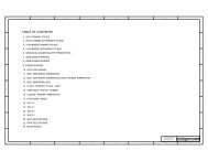
3.1.2 540-Lead H-PBGA Package<br />
Figure 3.<br />
540L H-PBGA Package Diagram (Top and Side View)<br />
Pin#1Corner<br />
42.500 ± 0.200<br />
GC<strong>80960</strong><strong>RN</strong>100<br />
SSSSSS<br />
MALAY<br />
FFFFFFFF-[{SN}]<br />
M<br />
INTEL © ‘98<br />
27.700<br />
27.700<br />
42.500 ± 0.200<br />
0.55 ± 0.15<br />
Slug<br />
1.56 REF<br />
Seating Plane<br />
1.025 ± 0.075<br />
3.845 ± 0.255<br />
Ball spacing is 1.270<br />
Ball width is 0.750 ± 0.150<br />
2.150 ± 0.150<br />
NOTES:<br />
1. All dimensions and tolerances conform to ANSI Y14.5M 1982.<br />
2. Dimensions are measured at the maximum solder ball diameter parallel to primary datum.<br />
3. Primary datum and seating plane are defined by the spherical crowns of the solder balls.<br />
4. All dimensions are in millimeters.<br />
5. S spec numbers are only printed on the C-X steppings.<br />
26 Data Sheet
Intel ® <strong>80960</strong><strong>RN</strong> I/O <strong>Processor</strong><br />
Figure 4.<br />
540L H-PBGA Package Diagram (Bottom View)<br />
1 2 3 4 5 6 7 8 9 10 11 12 13 14 15 16 17 18 19 20 21 22 23 24 25 26 27 28 29 30 31 32<br />
AM<br />
AL<br />
AK<br />
AJ<br />
AH<br />
AG<br />
AF<br />
AE<br />
AD<br />
AC<br />
AB<br />
AA<br />
Y<br />
W<br />
V<br />
U<br />
T<br />
R<br />
P<br />
N<br />
M<br />
L<br />
K<br />
J<br />
H<br />
G<br />
F<br />
E<br />
D<br />
C<br />
B<br />
A<br />
AM<br />
AL<br />
AK<br />
AJ<br />
AH<br />
AG<br />
AF<br />
AE<br />
AD<br />
AC<br />
AB<br />
AA<br />
Y<br />
W<br />
V<br />
U<br />
T<br />
R<br />
P<br />
N<br />
M<br />
L<br />
K<br />
J<br />
H<br />
G<br />
F<br />
E<br />
D<br />
C<br />
B<br />
A<br />
1 2 3 4 5 6 7 8 9 10 11 12 13 14 15 16 17 18 19 20 21 22 23 24 25 26 27 28 29 30 31 32<br />
Data Sheet 27
Intel ® <strong>80960</strong><strong>RN</strong> I/O <strong>Processor</strong><br />
Table 10. 540-Lead H-PBGA Package — Signal Name Order (Sheet 1 of 5)<br />
Signal Ball # Signal Ball # Signal Ball #<br />
DCLKIN E21 DQ35 C24 N/C AG1<br />
DCLKOUT A22 DQ36 E24 N/C AL16<br />
DQ00 D22 DQ37 B25 P_ACK64# V5<br />
DQ01 A23 DQ38 E25 P_AD00 U1<br />
DQ02 C23 DQ39 C26 P_AD01 U2<br />
DQ03 A24 DQ40 A27 P_AD02 U3<br />
DQ04 D24 DQ41 C27 P_AD03 T1<br />
DQ05 A25 DQ42 A28 P_AD04 T3<br />
DQ06 C25 DQ43 G32 P_AD05 T4<br />
DQ07 A26 DQ44 H31 P_AD06 T5<br />
DQ08 E26 DQ45 H28 P_AD07 R1<br />
DQ09 B27 DQ46 J30 P_AD08 R3<br />
DQ10 E27 DQ47 J28 P_AD09 R5<br />
DQ11 C28 DQ48 W28 P_AD10 P1<br />
DQ12 H32 DQ49 Y31 P_AD11 P3<br />
DQ13 H30 DQ50 Y28 P_AD12 P4<br />
DQ14 J32 DQ51 AA30 P_AD13 P5<br />
DQ15 J29 DQ52 AA28 P_AD14 N1<br />
DQ16 W29 DQ53 AB31 P_AD15 N2<br />
DQ17 Y32 DQ54 AB28 P_AD16 K3<br />
DQ18 Y30 DQ55 AC30 P_AD17 K4<br />
DQ19 AA32 DQ56 AC28 P_AD18 K5<br />
DQ20 AA29 DQ57 AD31 P_AD19 J1<br />
DQ21 AB32 DQ58 AD28 P_AD20 J2<br />
DQ22 AB30 DQ59 AE30 P_AD21 J3<br />
DQ23 AC32 DQ60 AE28 P_AD22 J5<br />
DQ24 AC29 DQ61 AF31 P_AD23 H1<br />
DQ25 AD32 DQ62 AF28 P_AD24 H5<br />
DQ26 AD30 DQ63 AH32 P_AD25 G1<br />
DQ27 AE32 FAIL# E12 P_AD26 G2<br />
DQ28 AE29 LCDINIT# A21 P_AD27 G3<br />
DQ29 AF32 I_RST# A11 P_AD28 E5<br />
DQ30 AF30 ONCE# C21 P_AD29 A6<br />
DQ31 AG32 NMI# A9 P_AD30 C6<br />
DQ32 E22 N/C A16 P_AD31 D6<br />
DQ33 B23 N/C G5 P_AD32 AG2<br />
DQ34 E23 N/C V28 P_AD33 AG3<br />
28 Data Sheet
Intel ® <strong>80960</strong><strong>RN</strong> I/O <strong>Processor</strong><br />
Table 10. 540-Lead H-PBGA Package — Signal Name Order (Sheet 2 of 5)<br />
Signal Ball # Signal Ball # Signal Ball #<br />
P_AD34 AF1 P_C/BE6# V3 RALE B19<br />
P_AD35 AF3 P_C/BE7# V4 RCE0# C19<br />
P_AD36 AF4 P_FRAME# L5 RCE1# E19<br />
P_AD37 AF5 P_DEVSEL# L1 P_IDSEL H3<br />
P_AD38 AE1 P_GNT# A7 ROE# D20<br />
P_AD39 AE2 P_INTA# E8 RWE# A20<br />
P_AD40 AE3 P_INTB# D8 SA00 N30<br />
P_AD41 AE5 P_INTC# E7 SA01 N29<br />
P_AD42 AD1 P_INTD# C7 SA02 N28<br />
P_AD43 AD3 P_IRDY# L3 SA03 P32<br />
P_AD44 AD4 P_LOCK# M4 SA04 P31<br />
P_AD45 AD5 P_PAR N3 SA05 P30<br />
P_AD46 AC1 P_PAR64 W3 SA06 P28<br />
P_AD47 AC2 P_PERR# M3 SA07 R32<br />
P_AD48 AC3 P_SERR# M1 SA08 R30<br />
P_AD49 AC5 P_STOP# M5 SA09 R29<br />
P_AD50 AB1 P_REQ# E6 SA10 R28<br />
P_AD51 AB3 P_REQ64# U5 SA11 T32<br />
P_AD52 AB4 P_RST# B7 SBA0 T31<br />
P_AD53 AB5 P_TRDY# L2 SBA1 T30<br />
P_AD54 AA1 RAD00 A13 SCAS# L30<br />
P_AD55 AA2 RAD01 B13 SCB0 K32<br />
P_AD56 AA3 RAD02 C13 SCB1 K30<br />
P_AD57 AA5 RAD03 E13 SCB2 V31<br />
P_AD58 Y1 RAD04 A14 SCB3 W32<br />
P_AD59 Y3 RAD05 C14 SCB4 K31<br />
P_AD60 Y4 RAD06 D14 SCB5 K28<br />
P_AD61 Y5 RAD07 E14 SCB6 V30<br />
P_AD62 W1 RAD08 A15 SCB7 W30<br />
P_AD63 W2 RAD09 C15 SCE0# M30<br />
P_CLK C20 RAD10 E15 SCE1# M28<br />
P_C/BE0# R2 RAD11 E17 SCKE0 T28<br />
P_C/BE1# N5 RAD12 A18 SCKE1 U32<br />
P_C/BE2# K1 RAD13 C18 SCL A8<br />
P_C/BE3# H4 RAD14 D18 SDA C8<br />
P_C/BE4# W5 RAD15 E18 SDQM0 L29<br />
P_C/BE5# V1 RAD16 A19 SDQM1 M32<br />
Data Sheet 29
Intel ® <strong>80960</strong><strong>RN</strong> I/O <strong>Processor</strong><br />
Table 10. 540-Lead H-PBGA Package — Signal Name Order (Sheet 3 of 5)<br />
Signal Ball # Signal Ball # Signal Ball #<br />
SDQM2 U30 S_AD28 AJ25 S_C/BE1# AJ19<br />
SDQM3 U28 S_AD29 AK25 S_C/BE2# AM21<br />
SDQM4 L28 S_AD30 AM25 S_C/BE3# AH24<br />
SDQM5 M31 S_AD31 AH26 S_C/BE4# AL12<br />
SDQM6 U29 S_AD32 AH1 S_C/BE5# AM12<br />
SDQM7 V32 S_AD33 AH3 S_C/BE6# AH13<br />
SRAS# N32 S_AD34 AH4 S_C/BE7# AJ13<br />
SWE# L32 S_AD35 AJ2 S_DEVSEL# AM20<br />
S_ACK64# AM13 S_AD36 AJ5 S_FRAME# AK21<br />
S_AD00 AH14 S_AD37 AK5 S_GNT0# AM26<br />
S_AD01 AK14 S_AD38 AM5 S_GNT1# AJ27<br />
S_AD02 AL14 S_AD39 AH6 S_GNT2# AM27<br />
S_AD03 AM14 S_AD40 AK6 S_GNT3# AK28<br />
S_AD04 AH15 S_AD41 AL6 S_GNT4# AM28<br />
S_AD05 AJ15 S_AD42 AM6 S_GNT5# AK29<br />
S_AD06 AK15 S_AD43 AH7 S_IRDY# AJ21<br />
S_AD07 AM15 S_AD44 AJ7 S_LOCK# AK20<br />
S_AD08 AJ17 S_AD45 AK7 S_PAR AK19<br />
S_AD09 AK17 S_AD46 AM7 S_PAR64 AK12<br />
S_AD10 AM17 S_AD47 AH8 S_PERR# AH20<br />
S_AD11 AH18 S_AD48 AK8 S_REQ0# AL26<br />
S_AD12 AK18 S_AD49 AL8 S_REQ1# AH27<br />
S_AD13 AL18 S_AD50 AM8 S_REQ2# AK27<br />
S_AD14 AM18 S_AD51 AH9 S_REQ3# AH28<br />
S_AD15 AH19 S_AD52 AJ9 S_REQ4# AL28<br />
S_AD16 AH22 S_AD53 AK9 S_REQ5# AJ29<br />
S_AD17 AK22 S_AD54 AM9 S_REQ64# AK13<br />
S_AD18 AL22 S_AD55 AH10 S_RST# AK26<br />
S_AD19 AM22 S_AD56 AK10 S_SERR# AM19<br />
S_AD20 AH23 S_AD57 AL10 S_STOP# AL20<br />
S_AD21 AJ23 S_AD58 AM10 S_TRDY# AH21<br />
S_AD22 AK23 S_AD59 AH11 TCK C12<br />
S_AD23 AM23 S_AD60 AJ11 TDI A12<br />
S_AD24 AK24 S_AD61 AK11 TDO E11<br />
S_AD25 AL24 S_AD62 AM11 TMS B11<br />
S_AD26 AM24 S_AD63 AH12 TRST# C11<br />
S_AD27 AH25 S_C/BE0# AH17 V CC A17<br />
30 Data Sheet
Intel ® <strong>80960</strong><strong>RN</strong> I/O <strong>Processor</strong><br />
Table 10. 540-Lead H-PBGA Package — Signal Name Order (Sheet 4 of 5)<br />
Signal Ball # Signal Ball # Signal Ball #<br />
V CC A29 V CC F2 V CC AL3<br />
V CC B2 V CC F3 V CC AL4<br />
V CC B3 V CC F4 V CC AL5<br />
V CC B4 V CC G30 V CC AL7<br />
V CC B5 V CC G31 V CC AL9<br />
V CC B6 V CC H2 V CC AL11<br />
V CC B8 V CC J31 V CC AL13<br />
V CC B10 V CC K2 V CC AL15<br />
V CC B12 V CC L31 V CC AL17<br />
V CC B14 V CC M2 V CC AL19<br />
V CC B16 V CC N31 V CC AL21<br />
V CC B17 V CC P2 V CC AL23<br />
V CC B18 V CC R31 V CC AL25<br />
V CC B20 V CC T2 V CC AL27<br />
V CC B22 V CC U31 V CC AL29<br />
V CC B24 V CC V2 V CC AL30<br />
V CC B26 V CC W31 V CC AL31<br />
V CC B28 V CC Y2 V CC AM4<br />
V CC B29 V CC AA31 V CC AM16<br />
V CC B30 V CC AB2 V CC5REF E20<br />
V CC B31 V CC AC31 V CCPLL1 C22<br />
V CC C2 V CC AD2 V CCPLL2 B15<br />
V CC C3 V CC AE31 V CCPLL3 D26<br />
V CC C5 V CC AF2 V SS A1<br />
V CC C16 V CC AG30 V SS A2<br />
V CC C29 V CC AG31 V SS A3<br />
V CC C30 V CC AH2 V SS A4<br />
V CC C31 V CC AH30 V SS A5<br />
V CC D2 V CC AH31 V SS A30<br />
V CC D12 V CC AJ1 V SS A31<br />
V CC D30 V CC AJ30 V SS A32<br />
V CC D31 V CC AJ31 V SS B1<br />
V CC D32 V CC AK2 V SS B21<br />
V CC E2 V CC AK3 V SS B32<br />
V CC E3 V CC AK30 V SS C1<br />
V CC E10 V CC AK31 V SS C4<br />
V CC E31 V CC AL2 V SS C17<br />
Data Sheet 31
Intel ® <strong>80960</strong><strong>RN</strong> I/O <strong>Processor</strong><br />
Table 10. 540-Lead H-PBGA Package — Signal Name Order (Sheet 5 of 5)<br />
Signal Ball # Signal Ball # Signal Ball #<br />
V SS C32 V SS F32 V SS AJ6<br />
V SS D1 V SS G4 V SS AJ8<br />
V SS D3 V SS G28 V SS AJ10<br />
V SS D4 V SS G29 V SS AJ12<br />
V SS D5 V SS H29 V SS AJ14<br />
V SS D7 V SS J4 V SS AJ16<br />
V SS D9 V SS K29 V SS AJ18<br />
V SS D11 V SS L4 V SS AJ20<br />
V SS D13 V SS M29 V SS AJ22<br />
V SS D15 V SS N4 V SS AJ24<br />
V SS D16 V SS P29 V SS AJ26<br />
V SS D17 V SS R4 V SS AJ28<br />
V SS D19 V SS T29 V SS AJ32<br />
V SS D21 V SS U4 V SS AK1<br />
V SS D23 V SS V29 V SS AK4<br />
V SS D25 V SS W4 V SS AK16<br />
V SS D27 V SS Y29 V SS AK32<br />
V SS D28 V SS AA4 V SS AL1<br />
V SS D29 V SS AB29 V SS AL32<br />
V SS E1 V SS AC4 V SS AM1<br />
V SS E4 V SS AD29 V SS AM2<br />
V SS E16 V SS AE4 V SS AM3<br />
V SS E28 V SS AF29 V SS AM29<br />
V SS E29 V SS AG4 V SS AM30<br />
V SS E30 V SS AG5 V SS AM31<br />
V SS E32 V SS AG28 V SS AM32<br />
V SS F1 V SS AG29 XINT0# B9<br />
V SS F5 V SS AH5 XINT1# C9<br />
V SS F28 V SS AH16 XINT2# E9<br />
V SS F29 V SS AH29 XINT3# A10<br />
V SS F30 V SS AJ3 XINT4# C10<br />
V SS F31 V SS AJ4 XINT5# D10<br />
32 Data Sheet
Intel ® <strong>80960</strong><strong>RN</strong> I/O <strong>Processor</strong><br />
Table 11. 540-Lead H-PBGA Pinout — Ballpad Number Order (Sheet 1 of 5)<br />
Ball # Signal Ball # Signal Ball # Signal<br />
A1 V SS B6 V CC C11 TRST#<br />
A2 V SS B7 P_RST# C12 TCK<br />
A3 V SS B8 V CC C13 RAD02<br />
A4 V SS B9 XINT0# C14 RAD05<br />
A5 V SS B10 V CC C15 RAD09<br />
A6 P_AD29 B11 TMS C16 V CC<br />
A7 P_GNT# B12 V CC C17 V SS<br />
A8 SCL B13 RAD01 C18 RAD13<br />
A9 NMI# B14 V CC C19 RCE0#<br />
A10 XINT3# B15 V CCPLL2 C20 P_CLK<br />
A11 I_RST# B16 V CC C21 ONCE#<br />
A12 TDI B17 V CC C22 V CCPLL1<br />
A13 RAD00 B18 V CC C23 DQ02<br />
A14 RAD04 B19 RALE C24 DQ35<br />
A15 RAD08 B20 V CC C25 DQ06<br />
A16 N/C B21 V SS C26 DQ39<br />
A17 V CC B22 V CC C27 DQ41<br />
A18 RAD12 B23 DQ33 C28 DQ11<br />
A19 RAD16 B24 V CC C29 V CC<br />
A20 RWE# B25 DQ37 C30 V CC<br />
A21 LCDINIT# B26 V CC C31 V CC<br />
A22 DCLKOUT B27 DQ09 C32 V SS<br />
A23 DQ01 B28 V CC D1 V SS<br />
A24 DQ03 B29 V CC D2 V CC<br />
A25 DQ05 B30 V CC D3 V SS<br />
A26 DQ07 B31 V CC D4 V SS<br />
A27 DQ40 B32 V SS D5 V SS<br />
A28 DQ42 C1 V SS D6 P_AD31<br />
A29 V CC C2 V CC D7 V SS<br />
A30 V SS C3 V CC D8 P_INTB#<br />
A31 V SS C4 V SS D9 V SS<br />
A32 V SS C5 V CC D10 XINT5#<br />
B1 V SS C6 P_AD30 D11 V SS<br />
B2 V CC C7 P_INTD# D12 V CC<br />
B3 V CC C8 SDA D13 V SS<br />
B4 V CC C9 XINT1# D14 RAD06<br />
B5 V CC C10 XINT4# D15 V SS<br />
Data Sheet 33
Intel ® <strong>80960</strong><strong>RN</strong> I/O <strong>Processor</strong><br />
Table 11. 540-Lead H-PBGA Pinout — Ballpad Number Order (Sheet 2 of 5)<br />
Ball # Signal Ball # Signal Ball # Signal<br />
D16 V SS E21 DCLKIN H28 DQ45<br />
D17 V SS E22 DQ32 H29 V SS<br />
D18 RAD14 E23 DQ34 H30 DQ13<br />
D19 V SS E24 DQ36 H31 DQ44<br />
D20 ROE# E25 DQ38 H32 DQ12<br />
D21 V SS E26 DQ08 J1 P_AD19<br />
D22 DQ00 E27 DQ10 J2 P_AD20<br />
D23 V SS E28 V SS J3 P_AD21<br />
D24 DQ04 E29 V SS J4 V SS<br />
D25 V SS E30 V SS J5 P_AD22<br />
D26 V CCPLL3 E31 V CC J28 DQ47<br />
D27 V SS E32 V SS J29 DQ15<br />
D28 V SS F1 V SS J30 DQ46<br />
D29 V SS F2 V CC J31 V CC<br />
D30 V CC F3 V CC J32 DQ14<br />
D31 V CC F4 V CC K1 P_C/BE2#<br />
D32 V CC F5 V SS K2 V CC<br />
E1 V SS F28 V SS K3 P_AD16<br />
E2 V CC F29 V SS K4 P_AD17<br />
E3 V CC F30 V SS K5 P_AD18<br />
E4 V SS F31 V SS K28 SCB5<br />
E5 P_AD28 F32 V SS K29 V SS<br />
E6 P_REQ# G1 P_AD25 K30 SCB1<br />
E7 P_INTC# G2 P_AD26 K31 SCB4<br />
E8 P_INTA# G3 P_AD27 K32 SCB0<br />
E9 XINT2# G4 V SS L1 P_DEVSEL#<br />
E10 V CC G5 N/C L2 P_TRDY#<br />
E11 TDO G28 V SS L3 P_IRDY#<br />
E12 FAIL# G29 V SS L4 V SS<br />
E13 RAD03 G30 V CC L5 P_FRAME#<br />
E14 RAD07 G31 V CC L28 SDQM4<br />
E15 RAD10 G32 DQ43 L29 SDQM0<br />
E16 V SS H1 P_AD23 L30 SCAS#<br />
E17 RAD11 H2 V CC L31 V CC<br />
E18 RAD15 H3 P_IDSEL L32 SWE#<br />
E19 RCE1# H4 P_C/BE3# M1 P_SERR#<br />
E20 V CC5REF H5 P_AD24 M2 V CC<br />
34 Data Sheet
Intel ® <strong>80960</strong><strong>RN</strong> I/O <strong>Processor</strong><br />
Table 11. 540-Lead H-PBGA Pinout — Ballpad Number Order (Sheet 3 of 5)<br />
Ball # Signal Ball # Signal Ball # Signal<br />
M3 P_PERR# R32 SA07 W29 DQ16<br />
M4 P_LOCK# T1 P_AD03 W30 SCB7<br />
M5 P_STOP# T2 V CC W31 V CC<br />
M28 SCE1# T3 P_AD04 W32 SCB3<br />
M29 V SS T4 P_AD05 Y1 P_AD58<br />
M30 SCE0# T5 P_AD06 Y2 V CC<br />
M31 SDQM5 T28 SCKE0 Y3 P_AD59<br />
M32 SDQM1 T29 V SS Y4 P_AD60<br />
N1 P_AD14 T30 SBA1 Y5 P_AD61<br />
N2 P_AD15 T31 SBA0 Y28 DQ50<br />
N3 P_PAR T32 SA11 Y29 V SS<br />
N4 V SS U1 P_AD00 Y30 DQ18<br />
N5 P_C/BE1# U2 P_AD01 Y31 DQ49<br />
N28 SA02 U3 P_AD02 Y32 DQ17<br />
N29 SA01 U4 V SS AA1 P_AD54<br />
N30 SA00 U5 P_REQ64# AA2 P_AD55<br />
N31 V CC U28 SDQM3 AA3 P_AD56<br />
N32 SRAS# U29 SDQM6 AA4 V SS<br />
P1 P_AD10 U30 SDQM2 AA5 P_AD57<br />
P2 V CC U31 V CC AA28 DQ52<br />
P3 P_AD11 U32 SCKE1 AA29 DQ20<br />
P4 P_AD12 V1 P_C/BE5# AA30 DQ51<br />
P5 P_AD13 V2 V CC AA31 V CC<br />
P28 SA06 V3 P_C/BE6# AA32 DQ19<br />
P29 V SS V4 P_C/BE7# AB1 P_AD50<br />
P30 SA05 V5 P_ACK64# AB2 V CC<br />
P31 SA04 V28 N/C AB3 P_AD51<br />
P32 SA03 V29 V SS AB4 P_AD52<br />
R1 P_AD07 V30 SCB6 AB5 P_AD53<br />
R2 P_C/BE0# V31 SCB2 AB28 DQ54<br />
R3 P_AD08 V32 SDQM7 AB29 V SS<br />
R4 V SS W1 P_AD62 AB30 DQ22<br />
R5 P_AD09 W2 P_AD63 AB31 DQ53<br />
R28 SA10 W3 P_PAR64 AB32 DQ21<br />
R29 SA09 W4 V SS AC1 P_AD46<br />
R30 SA08 W5 P_C/BE4# AC2 P_AD47<br />
R31 V CC W28 DQ48 AC3 P_AD48<br />
Data Sheet 35
Intel ® <strong>80960</strong><strong>RN</strong> I/O <strong>Processor</strong><br />
Table 11. 540-Lead H-PBGA Pinout — Ballpad Number Order (Sheet 4 of 5)<br />
Ball # Signal Ball # Signal Ball # Signal<br />
AC4 V SS AG1 N/C AH28 S_REQ3#<br />
AC5 P_AD49 AG2 P_AD32 AH29 V SS<br />
AC28 DQ56 AG3 P_AD33 AH30 V CC<br />
AC29 DQ24 AG4 V SS AH31 V CC<br />
AC30 DQ55 AG5 V SS AH32 DQ63<br />
AC31 V CC AG28 V SS AJ1 V CC<br />
AC32 DQ23 AG29 V SS AJ2 S_AD35<br />
AD1 P_AD42 AG30 V CC AJ3 V SS<br />
AD2 V CC AG31 V CC AJ4 V SS<br />
AD3 P_AD43 AG32 DQ31 AJ5 S_AD36<br />
AD4 P_AD44 AH1 S_AD32 AJ6 V SS<br />
AD5 P_AD45 AH2 V CC AJ7 S_AD44<br />
AD28 DQ58 AH3 S_AD33 AJ8 V SS<br />
AD29 V SS AH4 S_AD34 AJ9 S_AD52<br />
AD30 DQ26 AH5 V SS AJ10 V SS<br />
AD31 DQ57 AH6 S_AD39 AJ11 S_AD60<br />
AD32 DQ25 AH7 S_AD43 AJ12 V SS<br />
AE1 P_AD38 AH8 S_AD47 AJ13 S_C/BE7#<br />
AE2 P_AD39 AH9 S_AD51 AJ14 V SS<br />
AE3 P_AD40 AH10 S_AD55 AJ15 S_AD05<br />
AE4 V SS AH11 S_AD59 AJ16 V SS<br />
AE5 P_AD41 AH12 S_AD63 AJ17 S_AD08<br />
AE28 DQ60 AH13 S_C/BE6# AJ18 V SS<br />
AE29 DQ28 AH14 S_AD00 AJ19 S_C/BE1#<br />
AE30 DQ59 AH15 S_AD04 AJ20 V SS<br />
AE31 V CC AH16 V SS AJ21 S_IRDY#<br />
AE32 DQ27 AH17 S_C/BE0# AJ22 V SS<br />
AF1 P_AD34 AH18 S_AD11 AJ23 S_AD21<br />
AF2 V CC AH19 S_AD15 AJ24 V SS<br />
AF3 P_AD35 AH20 S_PERR# AJ25 S_AD28<br />
AF4 P_AD36 AH21 S_TRDY# AJ26 V SS<br />
AF5 P_AD37 AH22 S_AD16 AJ27 S_GNT1#<br />
AF28 DQ62 AH23 S_AD20 AJ28 V SS<br />
AF29 V SS AH24 S_C/BE3# AJ29 S_REQ5#<br />
AF30 DQ30 AH25 S_AD27 AJ30 V CC<br />
AF31 DQ61 AH26 S_AD31 AJ31 V CC<br />
AF32 DQ29 AH27 S_REQ1# AJ32 V SS<br />
36 Data Sheet
Intel ® <strong>80960</strong><strong>RN</strong> I/O <strong>Processor</strong><br />
Table 11. 540-Lead H-PBGA Pinout — Ballpad Number Order (Sheet 5 of 5)<br />
Ball # Signal Ball # Signal Ball # Signal<br />
AK1 V SS AL1 V SS AM1 V SS<br />
AK2 V CC AL2 V CC AM2 V SS<br />
AK3 V CC AL3 V CC AM3 V SS<br />
AK4 V SS AL4 V CC AM4 V CC<br />
AK5 S_AD37 AL5 V CC AM5 S_AD38<br />
AK6 S_AD40 AL6 S_AD41 AM6 S_AD42<br />
AK7 S_AD45 AL7 V CC AM7 S_AD46<br />
AK8 S_AD48 AL8 S_AD49 AM8 S_AD50<br />
AK9 S_AD53 AL9 V CC AM9 S_AD54<br />
AK10 S_AD56 AL10 S_AD57 AM10 S_AD58<br />
AK11 S_AD61 AL11 V CC AM11 S_AD62<br />
AK12 S_PAR64 AL12 S_C/BE4# AM12 S_C/BE5#<br />
AK13 S_REQ64# AL13 V CC AM13 S_ACK64#<br />
AK14 S_AD01 AL14 S_AD02 AM14 S_AD03<br />
AK15 S_AD06 AL15 V CC AM15 S_AD07<br />
AK16 V SS AL16 N/C AM16 V CC<br />
AK17 S_AD09 AL17 V CC AM17 S_AD10<br />
AK18 S_AD12 AL18 S_AD13 AM18 S_AD14<br />
AK19 S_PAR AL19 V CC AM19 S_SERR#<br />
AK20 S_LOCK# AL20 S_STOP# AM20 S_DEVSEL#<br />
AK21 S_FRAME# AL21 V CC AM21 S_C/BE2#<br />
AK22 S_AD17 AL22 S_AD18 AM22 S_AD19<br />
AK23 S_AD22 AL23 V CC AM23 S_AD23<br />
AK24 S_AD24 AL24 S_AD25 AM24 S_AD26<br />
AK25 S_AD29 AL25 V CC AM25 S_AD30<br />
AK26 S_RST# AL26 S_REQ0# AM26 S_GNT0#<br />
AK27 S_REQ2# AL27 V CC AM27 S_GNT2#<br />
AK28 S_GNT3# AL28 S_REQ4# AM28 S_GNT4#<br />
AK29 S_GNT5# AL29 V CC AM29 V SS<br />
AK30 V CC AL30 V CC AM30 V SS<br />
AK31 V CC AL31 V CC AM31 V SS<br />
AK32 V SS AL32 V SS AM32 V SS<br />
Data Sheet 37
Intel ® <strong>80960</strong><strong>RN</strong> I/O <strong>Processor</strong><br />
3.2 Package Thermal Specifications<br />
The device is specified for operation when T C (case temperature) is within the range of 0°C to<br />
85°C, depending on operating conditions. Refer to the “Thermal Data for the 540-lead PBGA<br />
package” application note for more information regarding maximum case temperatures on the<br />
540-lead PBGA package. Case temperature may be measured in any environment to determine<br />
whether the processor is within specified operating range. Measure the case temperature at the<br />
center of the top surface, opposite the ballpad.<br />
3.2.1 Thermal Specifications<br />
This section defines the terms used for thermal analysis.<br />
3.2.1.1 Ambient Temperature<br />
Ambient temperature, T A , is the temperature of the ambient air surrounding the package. In a<br />
system environment, ambient temperature is the temperature of the air upstream from the package.<br />
3.2.1.2 Case Temperature<br />
To ensure functionality and reliability, the device is specified for proper operation when the case<br />
temperature, T C , is within the specified range as indicated in Table 12 “540-Lead H-PBGA<br />
Package Thermal Characteristics” on page 39.<br />
When measuring case temperature, attention to detail is required to ensure accuracy. If a<br />
thermocouple is used, calibrate it before taking measurements. Errors may result when the<br />
measured surface temperature is affected by the surrounding ambient air temperature. Such errors<br />
may be due to a poor thermal contact between thermocouple junction and the surface, heat loss by<br />
radiation, or conduction through thermocouple leads.<br />
To minimize measurement errors:<br />
• Use a 35 gauge K-type thermocouple or equivalent.<br />
• Attach the thermocouple bead or junction to the package top surface at a location<br />
corresponding to the center of the die (Figure 5A). The center of the die gives a more accurate<br />
measurement and less variation as the boundary condition changes.<br />
• Attach the thermocouple bead at a 0° angle with respect to the package as shown in Figure 5A,<br />
when no heatsink is attached.<br />
• When a passive heat sink is attached, a groove is made on the bottom surface of the heatsink<br />
and the thermocouple is attached at a 0° angle, as shown in Figure 5B.<br />
Figure 5.<br />
Thermocouple Attachment - A) No Heatsink / B) With Heatsink<br />
<strong>80960</strong><strong>RN</strong><br />
Bottom of<br />
<strong>Processor</strong><br />
Thermocouple<br />
Heatsink<br />
Groove for<br />
thermocouple<br />
A) No Heatsink B) With Heatsink<br />
38 Data Sheet
Intel ® <strong>80960</strong><strong>RN</strong> I/O <strong>Processor</strong><br />
3.2.1.3 Thermal Resistance<br />
The thermal resistance value for the case-to-ambient, θ CA , is used as a measure of the cooling<br />
solution’s thermal performance.<br />
3.2.2 Thermal Analysis<br />
Table 12 lists the case-to-ambient thermal resistances of the <strong>80960</strong><strong>RN</strong> for different air flow rates<br />
with and without a heat sink.<br />
To calculate T A , the maximum ambient temperature to conform to a particular case temperature:<br />
T A =T C -P(θ CA )<br />
Compute P by multiplying I CC and V CC .Valuesforθ JC and θ CA are given in Table 12.<br />
Junction temperature (T J ) is commonly used in reliability calculations. T J can be calculated from<br />
θ JC (thermal resistance from junction to case) using the following equation:<br />
T J =T C +P(θ JC )<br />
Similarly, when T A is known, the corresponding case temperature (T C ) can be calculated as<br />
follows:<br />
T C =T A +P(θ CA )<br />
The θ JA (Junction to Ambient) for this package is currently estimated at 13.10° C/Watt with no<br />
airflow and no heatsink. The θ JA (Junction to Ambient) for this package is currently estimated at<br />
8.30° C/Watt with no airflow and a passive heatsink:<br />
θ JA = θ JC + θ CA<br />
Table 12.<br />
540-Lead H-PBGA Package Thermal Characteristics<br />
Thermal Resistance — °C/Watt<br />
Airflow — ft./min (m/sec)<br />
Parameter<br />
0<br />
(0)<br />
50<br />
(0.25)<br />
100<br />
(0.50)<br />
200<br />
(1.01)<br />
300<br />
(1.52)<br />
400<br />
(2.03)<br />
600<br />
(3.04)<br />
800<br />
(4.06)<br />
θ JC (Junction-to-Case) 0.44 0.44 0.44 0.44 0.44 0.44 0.44 0.44<br />
θ CA (Case-to-Ambient)<br />
Without Heatsink<br />
12.66 11.61 10.66 9.26 8.26 7.61 6.57 5.78<br />
θ CA (Case-to-Ambient)<br />
With Passive 0.25 in. 9.0 8.2 7.5 6.1 5.1 4.7 3.8 3.2<br />
Heatsink 2,3<br />
θ CA (Case-to-Ambient)<br />
With Passive 0.35 in. 7.86 6.96 6.06 4.56 3.66 3.16 2.56 2.16<br />
Heatsink 2<br />
θ JA<br />
θ JC<br />
θ CA<br />
Data Sheet 39
Intel ® <strong>80960</strong><strong>RN</strong> I/O <strong>Processor</strong><br />
3.3 Heat Sink Information<br />
Under normal circumstances, a heat sink is not required for the <strong>80960</strong><strong>RN</strong>.<br />
Table 13 provides a list of suggested sources for heat sinks. This is neither an endorsement nor a<br />
warranty of the performance of any of the listed products and/or companies.<br />
Table 13.<br />
Heat Sink Vendors and Contacts<br />
Company<br />
Factory<br />
Representative<br />
Phone # Fax #<br />
Heatsink Part #<br />
Passive<br />
AAVID Thermalloy, Inc<br />
80 Commercial Street<br />
Concord, NH 03301 USA<br />
info@aavid.com<br />
http://www.aavidthermalloy.com/atp/atp.html<br />
Attention: Sales (603) 224-9988 (603) 223-1790 21933B withoou thermal<br />
grease (uses pins)<br />
21935B withoou thermal<br />
grease (uses pins)<br />
3.4 Vendor Information<br />
Table 14 through Table 18 provide vendor details for socket-headers, burn-in sockets, shipping<br />
trays, logic analyzer interposers and JTAG emulators for the Intel ® <strong>80960</strong><strong>RN</strong>. This is neither an<br />
endorsement nor a warranty of the performance of any of the listed products and/or companies.<br />
3.4.1 Socket-Header Vendor<br />
Table 14.<br />
Socket-Header Vendor<br />
Company<br />
Adapter Technologies, Inc.<br />
214-218 South 4th St.<br />
Perkasie, PA 18944<br />
Factory<br />
Representative<br />
Phone/Fax #<br />
John Miller 215-258-5750/<br />
215-258-5760<br />
Part #<br />
BGA 540 Pin Header BGA 540 Pin Socket Carrier<br />
BGAH-540-0-01-3201-0277-1 BGA-540-0-02-3201-0275P-130<br />
3.4.2 Burn-in Socket Vendor<br />
Table 15.<br />
Burn-in Socket Vendor<br />
Company Factory Representative Phone # Burn-in Socket Part #<br />
Texas Instruments<br />
111 Forbes Blvd.<br />
Mansfield, MA 02048<br />
W. Ray Johnson 508-236-5375 ULGA540-005<br />
40 Data Sheet
Intel ® <strong>80960</strong><strong>RN</strong> I/O <strong>Processor</strong><br />
3.4.3 Shipping Tray Vendor<br />
Table 16.<br />
Shipping Tray Vendor<br />
Company Factory Representative Phone # Shipping Tray Part #<br />
3M Ron Goth 602-465-5381 7-0000-21001-184-167<br />
3.4.4 Logic Analyzer Interposer Vendor<br />
Table 17.<br />
Logic Analyzer Interposer Vendor<br />
Company Factory Representative Phone/Fax # Part #<br />
Packard-Hughes Interconnect<br />
17150 Von Karman Ave<br />
Irvine, CA 92614-0968<br />
Karen May 949-660-5773<br />
949-660-5825<br />
1126898<br />
3.4.5 JTAG Emulator Vendor<br />
3.5<br />
Table 18.<br />
JTAG Emulator Vendor<br />
Company<br />
Factory Representative<br />
Phone/<br />
Fax #<br />
Part #<br />
Spectrum Digital, Inc.<br />
Jeff Bond<br />
281-494-4500/<br />
281-494-5310<br />
701500<br />
Data Sheet 41
Intel ® <strong>80960</strong><strong>RN</strong> I/O <strong>Processor</strong><br />
4.0 Electrical Specifications<br />
4.1 Absolute Maximum Ratings<br />
Parameter<br />
Storage Temperature<br />
Case Temperature Under Bias<br />
Supply Voltage wrt. V SS<br />
Supply Voltage wrt. V SS on V CC5<br />
VoltageonAnyBallwrt.V SS<br />
Maximum Rating<br />
–55°C to+125°C<br />
0°C to+85°C<br />
–0.5 V to + 4.6 V<br />
–0.5 V to + 6.5 V<br />
–0.5 V to V CC +0.5V<br />
NOTICE: This data sheet contains information on<br />
products in the design phase of development. Do<br />
not finalize a design with this information. Revised<br />
information will be published when the product<br />
becomes available. The specifications are subject<br />
to change without notice. Contact your local Intel<br />
representative before finalizing a design.<br />
†WA<strong>RN</strong>ING: Stressing the device beyond the<br />
“Absolute Maximum Ratings” may cause<br />
permanent damage. These are stress ratings only.<br />
Operation beyond the “Operating Conditions” is<br />
not recommended and extended exposure beyond<br />
the “Operating Conditions” may affect device<br />
reliability.<br />
Table 19.<br />
Operating Conditions<br />
Symbol Parameter Min Max Units Notes<br />
V CC Supply Voltage 3.0 3.6 V<br />
V CC5 Input Protection Bias V CC V CC +2.5 V<br />
F P_CLK Input Clock Frequency 16 33.33 MHz<br />
T C<br />
Case Temperature Under Bias<br />
GC (540L PBGA) 0 85 °C<br />
42 Data Sheet
Intel ® <strong>80960</strong><strong>RN</strong> I/O <strong>Processor</strong><br />
4.2 V CC5REF Pin Requirements (V DIFF )<br />
In mixed voltage systems that drive <strong>80960</strong><strong>RN</strong> processor inputs in excess of 3.3 V, the V CC5REF pin<br />
must be connected to the system’s 5 V supply. To limit current flow into the V CC5REF pin, there is<br />
a limit to the voltage differential between the V CC5REF pin and the other V CC pins. The voltage<br />
differential between the V CC5REF pin and its 3.3 V V CC pins should never exceed 2.25 V. This<br />
limit applies to power-up, power-down, and steady-state operation. Table 20 outlines this<br />
requirement.<br />
If the voltage difference requirements cannot be met due to system design limitations, an alternate<br />
solution may be employed. As shown in Figure 6, a minimum of 100 Ω series resistor may be used<br />
to limit the current into the V CC5REF pin. This resistor ensures that current drawn by the V CC5REF<br />
pin does not exceed the maximum rating for this pin.<br />
Figure 6.<br />
V CC5REF Current-Limiting Resistor<br />
+5 V (±0.25 V) VCC5REF Pin<br />
100 Ω<br />
(±5%, 0.5 W)<br />
This resistor is not necessary in systems that can guarantee the V DIFF specification.<br />
In 3.3 V-only systems (only applies to <strong>80960</strong><strong>RN</strong> C-x steppings) and systems that drive pins from<br />
3.3 V logic, connect the V CC5REF pindirectlytothe3.3VV CC plane.<br />
Table 20. V DIFF Specification for Dual Power Supply Requirements (3.3 V, 5 V)<br />
Symbol Parameter Min Max Units Notes<br />
V DIFF V CC5 -V CC Difference 2.25 V (1)<br />
NOTE:<br />
1. V CC5REF input should not exceed V CC by more than 2.25 V during power-up and power-down, or during<br />
steady-state operation.<br />
4.3 V CCPLL Pin Requirements<br />
To reduce clock skew on the i960 Jx processor, the V CCPLL pin for the Phase Lock Loop (PLL)<br />
circuit is isolated on the pinout. The lowpass filter, as shown in Figure 7, reduces noise induced<br />
clock jitter and its effects on timing relationships in system designs. The trace lengths between the<br />
4.7 µF capacitor, the 0.01 µF capacitor, and V CCPLL must be as short as possible.<br />
Figure 7.<br />
V CCPLL Lowpass Filter<br />
10Ω, 5%, 1/8W<br />
V CC<br />
(Board Plane)<br />
+<br />
4.7µF<br />
0.01µF<br />
V CCPLL<br />
(On i960 ® Jx processors)<br />
Data Sheet 43
Intel ® <strong>80960</strong><strong>RN</strong> I/O <strong>Processor</strong><br />
4.4 Targeted DC Specifications<br />
Table 21.<br />
DC Characteristics<br />
Symbol Parameter Min Max Units Notes<br />
V IL5 Input Low Voltage 5 Volt PCI -0.5 0.8 V (1,4)<br />
V IH5 Input High Voltage 5 Volt PCI 2 V CC +0.5 V (1,4)<br />
V IL3.3 Input Low Voltage 3.3 Volt PCI -0.5 0.3V CC V (1,4,5)<br />
V IH3.3 Input High Voltage 3.3 Volt PCI 0.5V CC V CC + 0.5 V (1,4,5)<br />
V OL1 Output Low Voltage <strong>Processor</strong> signals 0.4 V I OL =6mA(3)<br />
V OH1<br />
Output High Voltage <strong>Processor</strong> signals<br />
2.4<br />
V CC -0.5<br />
V<br />
I OH =-2mA(3)<br />
I OH =-200µA (3, 6)<br />
V OL2<br />
Output Low Voltage 5 V PCI / Flash<br />
signals<br />
0.4 V I OL =6mA(1)<br />
V OH2<br />
Output High Voltage 5 V PCI / Flash<br />
signals<br />
2.4 V I OH =-2mA(1)<br />
V OL3 Output Low Voltage SDRAM signals -2.0 0.4 V I OL =3mA(4)<br />
V OH3 Output High Voltage SDRAM signals 2.4 V CC +2.0 V I OH =-2mA(4)<br />
V OL4 Output Low Voltage 3.3 V PCI signals 0.1V CC V I OL =1500µA (1,5)<br />
V OH4 Output Low Voltage 3.3 V PCI signals 0.9V CC V I OH =-500µA (1,5)<br />
C IN Input Capacitance - PBGA 10 pF F S_CLK =T F Min (1, 2)<br />
C OUT I/O or Output Capacitance - PBGA 10 pF F S_CLK =T F Min (1, 2)<br />
C CLK S_CLK Capacitance - PBGA 5 10 pF F S_CLK =T F Min (1, 2)<br />
C IDSEL IDSEL Ball Capacitance 8 pF (1,2)<br />
L PIN Ball Inductance 25 nH (1,2)<br />
NOTES:<br />
1. As required by the PCI Local Bus Specification, Revision 2.2.<br />
2. Not tested.<br />
3. <strong>Processor</strong> signals include RALE, RCE[1:0]#, ROE#, RWE#, XINT[5:4]#, NMI#, FAIL#, TDI, TDO, TMS,<br />
TRST#, SDA, andSCL.<br />
4. SDRAM signals include SA[11:0], SBA[1:0], SCAS#, SCE[1:0]#, SCKE[1:0], SDQM[7:0], SRAS#,<br />
SWE#, DCLKIN, DCLKOUT, DQ[63:0], andSCB[7:0].<br />
5. 3.3 V PCI signalling only supported on C-x steppings on the <strong>80960</strong><strong>RN</strong> processor<br />
6. Guaranteed by characterization<br />
44 Data Sheet
Intel ® <strong>80960</strong><strong>RN</strong> I/O <strong>Processor</strong><br />
Table 22.<br />
I CC Characteristics<br />
Symbol Parameter Typ Max Units Notes<br />
I LI1<br />
I LI2<br />
Input Leakage Current for each signal except<br />
TMS, TRST#, TDI, ONCE#, RAD[8:0] and<br />
LCDINIT#.<br />
Input Leakage Current for TMS, TRST#, TDI,<br />
ONCE#, RAD[8:0] and LCDINIT#.<br />
±5 µA 0 ≤ V IN ≤ V CC<br />
-140 -250 µA V IN =0.45V(1)<br />
I LO Output Leakage Current ± 5 µA 0.4 ≤ V OUT ≤ V CC<br />
I CC Active<br />
(Power<br />
Supply)<br />
I CC Active<br />
(Thermal)<br />
Power Supply Current 1.65 A (1,2)<br />
Thermal Current 1.2 A (1,3)<br />
I CC Active<br />
(Power<br />
Modes)<br />
Reset Mode<br />
ONCE Mode<br />
0.95<br />
0.02<br />
A<br />
(4)<br />
(4)<br />
NOTES:<br />
1. Measured with device operating and outputs loaded to the test condition in Figure 13.<br />
2. I CC Active (Power Supply) value is provided for selecting your system’s power supply. It is measured using<br />
one of the worst case instruction mixes with V CC = 3.6 V and ambient temperature = 55°C.<br />
3. I CC Active (Thermal) value is provided for your system’s thermal management. Typical I CC is measured<br />
with V CC = 3.3 V and ambient temperature = 55°C.<br />
4. I CC Test (Power modes) refers to the I CC values that are tested when the device is in Reset mode or ONCE<br />
mode with V CC = 3.6 V and ambient temperature = 55°C.<br />
Data Sheet 45
Intel ® <strong>80960</strong><strong>RN</strong> I/O <strong>Processor</strong><br />
4.5 Targeted AC Specifications<br />
4.5.1 Clock Signal Timings<br />
Table 23.<br />
Input Clock Timings<br />
Symbol Parameter Min Max Units Notes<br />
T F P_CLK Frequency 16 33.33 MHz<br />
T C P_CLK Period 30 62.5 ns (1)<br />
T CS P_CLK Period Stability ±250 ps Adjacent Clocks (2)<br />
TCH P_CLK High Time 12 ns Measured at 1.5 V (2)<br />
T CL P_CLK Low Time 12 ns Measured at 1.5 V (2)<br />
T CR P_CLK Rise Time 1 4 V/ns 0.4 V to 2.4 V (2)<br />
T CF P_CLK Fall Time 1 4 V/ns 2.4 V to 0.4 V (2)<br />
T DICS DCLKIN Period Stability ±250 ps Adjacent Clocks (2)<br />
T DICH DCLKIN High Time 5 ns Measured at 1.5 V (2)<br />
T DICL DCLKIN Low Time 5 ns Measured at 1.5 V (2)<br />
NOTES:<br />
1. See Figure 8 “P_CLK, TCK, DCLKIN, DCLKOUT Waveform” on page 51.<br />
2. Not tested.<br />
Table 24.<br />
SDRAM Output Clock Timings<br />
Symbol Parameter Min Max Units Notes<br />
T DOF DCLKOUT Frequency 2T F MHz<br />
T DOC DCLKOUT Period T C /2 ns (1)<br />
T DOCS DCLKOUT Period Stability ±250 ps Adjacent Clocks<br />
TDOCH DCLKOUT High Time 5 ns Measured at 1.5 V<br />
T DOCL DCLKOUT Low Time 5 ns Measured at 1.5 V<br />
NOTE:<br />
1. See Figure 8 “P_CLK, TCK, DCLKIN, DCLKOUT Waveform” on page 51.<br />
46 Data Sheet
Intel ® <strong>80960</strong><strong>RN</strong> I/O <strong>Processor</strong><br />
4.5.2 PCI Interface Signal Timings<br />
Table 25.<br />
PCI Signal Timings<br />
Symbol Parameter Min Max Units Notes<br />
T OV1<br />
Output Valid Delay from P_CLK - PCI Signals Except 2 11 ns<br />
P_REQ#, P_INT[A:D]#, andS_GNT[5:0]#<br />
(1,2)<br />
T OV2 Output Valid Delay from P_CLK - P_INT[A:D]# 0 25 ns (1,2,6)<br />
T OV3 Output Valid Delay from P_CLK - S_REQ64# 0 ns (1,2,8)<br />
T OV4<br />
Output Valid Delay from P_CLK - P_REQ# and<br />
2 12 ns<br />
S_GNT[5:0]#<br />
(1,2)<br />
T OF Output Float Delay from P_CLK 28 ns (1,4,5,6)<br />
T IS1<br />
Input Setup to P_CLK - PCI Signals Except P_GNT# and 7 ns<br />
S_REQ[5:0]#<br />
(1,3)<br />
T IS2 Input Setup to P_CLK - P_GNT# 10 ns (1,3)<br />
T IS3 Input Setup to P_CLK - S_REQ[5:0]# 12 ns (1,3)<br />
T IH1 Input Hold from P_CLK - PCI Signals 0 ns (1,3)<br />
T IS4 Input Setup to P_CLK - S_INT[A:D]# 25 ns (1,3,7,9)<br />
T IH2 Input Hold to P_CLK - S_INT[A:D]# 2 ns (1,3,7,9)<br />
T IS5 Input Setup to P_CLK - P_RST# 6 ns (1,3,7)<br />
T IH3 Input Hold to P_CLK - P_RST# 2 ns (1,3,7)<br />
T IS6 Input Setup to P_RST# - P_REQ64# 10T c ns (1,3)<br />
T IH4 Input Hold to P_RST# - P_REQ64# 0 50 ns (1,3)<br />
NOTES:<br />
1. The PCI Local Bus Specification, Revision 2.2 requires that all of the PCI signal AC timings use 0 pF for<br />
minimum timings and 50 pF for maximum timings.<br />
2. See Figure 9 “T OV Output Delay Waveform” on page 51.<br />
3. See Figure 11 “T IS and T IH Input Setup and Hold Waveform” on page 52.<br />
4. A float condition occurs when the output current becomes less than I LO . Float delay is not tested. See<br />
Figure 10 “T OF Output Float Waveform” on page 52.<br />
5. See Figure 10 “T OF Output Float Waveform” on page 52.<br />
6. Outputs precharged to V CC5 .<br />
7. P_RST#, S_INT[A:D]# may be synchronous or asynchronous. Meeting setup and hold time guarantees<br />
recognition at a particular clock edge.<br />
8. S_REQ64# is asserted asynchronously with respect to P_RST#. S_REQ64# is deasserted one P_CLK<br />
after the deassertion of S_RST#.<br />
9. S_INT[A:D]# must be asserted for a minimum of two P_CLK periods to guarantee recognition.<br />
Data Sheet 47
Intel ® <strong>80960</strong><strong>RN</strong> I/O <strong>Processor</strong><br />
4.5.3 Intel ® <strong>80960</strong>JN Core Interface Timings<br />
Table 26.<br />
Intel ® <strong>80960</strong>JN Core Signal Timings<br />
Symbol Parameter Min Max Units Notes<br />
T OV5 Output Valid Delay from P_CLK - FAIL# 2 TBD ns (1,5)<br />
T IS7 Input Setup to P_CLK - NMI#, XINT[5:4]# 25 ns (2,3)<br />
T IH5 Input Hold from P_CLK - NMI#, XINT[5:4]# 2 ns (2,3)<br />
NOTES:<br />
1. See Figure 9 “T OV Output Delay Waveform” on page 51.<br />
2. See Figure 11 “T IS and T IH Input Setup and Hold Waveform” on page 52.<br />
3. Setup and hold times must be met for proper processor operation. NMI# and XINT[5:4]# may be<br />
synchronous or asynchronous. Meeting setup and hold time guarantees recognition at a particular clock<br />
edge. For asynchronous operation, NMI# and XINT[5:4]# must be asserted for a minimum of two P_CLK<br />
periods to guarantee recognition.<br />
4. Core signals include: XINT[5:4]#, NMI#, FAIL# .<br />
5. The processor asserts FAIL# during built-in self-test. If self-test passes, FAIL# is deasserted. The<br />
processor asserts FAIL# during the bus confidence test. If the test passes, FAIL# is deasserted and user<br />
program execution begins.<br />
4.5.4 SDRAM/Flash Interface Signal Timings<br />
Table 27.<br />
SDRAM / Flash Signal Timings<br />
Sym Parameter Min Max Units Notes<br />
T OV6<br />
Output Valid Delay from DCLKIN - SA[11:0], SBA[1:0], SCAS#, 1.62 6.60 ns<br />
SRAS#, and SWE#.<br />
(1,5)<br />
T OV7 Output Valid Delay from DCLKIN - DQ[63:0], andSCB[7:0]. 2.03 7.14 ns (1,5)<br />
T OV8 Output Valid Delay from DCLKIN - SDQM[7:0] 2.57 6.85 ns (1,5)<br />
T OV9 Output Valid Delay from DCLKIN - SCKE[1:0] 1.74 5.50 ns (1,5)<br />
T OV10 Output Valid Delay from DCLKIN - SCE[1:0]# 1.65 5.25 ns (1,5)<br />
T IS8 Input Setup to DCLKIN - DQ[63:0], andSCB[7:0] 3.00 ns (2)<br />
T IH6 Input Hold from DCLKIN - DQ[63:0], and SCB[7:0] 1.5 ns (2)<br />
T OV11<br />
Output Valid Delay from DCLKIN - RAD[16:0], RALE, RCE[1:0]#, 1.4 11.0 ns<br />
ROE#, andRWE#.<br />
(1,5)<br />
T IS9 Input Setup to DCLKIN -RAD[16:0] 5 ns (2)<br />
T IH7 Input Hold from DCLKIN - RAD[16:0] 1.4 ns (2)<br />
NOTES:<br />
1. See Figure 9 “T OV Output Delay Waveform” on page 51.<br />
2. See Figure 11 “T IS and T IH Input Setup and Hold Waveform” on page 52.<br />
3. SDRAM signals include SA[11:0], SBA[1:0], SCAS#, SCE[1:0]#, SCKE[1:0], SDQM[7:0], SRAS#,<br />
SWE#, DQ[63:0], andSCB[7:0]. Timings are for 3.3 V signalling environment.<br />
4. Flash signals include RAD[16:0], RALE, RCE[1:0]#, ROE#, andRWE#. Timings are for 5V signalling<br />
environment.<br />
5.Theseoutputvalidtimesarespecifiedwitha0pFloading.<br />
48 Data Sheet
Intel ® <strong>80960</strong><strong>RN</strong> I/O <strong>Processor</strong><br />
4.5.5 Boundary Scan Test Signal Timings<br />
Table 28.<br />
Boundary Scan Test Signal Timings<br />
Symbol Parameter Min Max Units Notes<br />
T BSF TCK Frequency 0 0.5T F MHz<br />
T BSCH TCK High Time 15 ns Measured at 1.5 V (1)<br />
T BSCL TCK Low Time 15 ns Measured at 1.5 V (1)<br />
T BSCR TCK Rise Time 5 ns 0.8 V to 2.0 V (1)<br />
T BSCF TCK Fall Time 5 ns 2.0 V to 0.8 V (1)<br />
T BSIS1 Input Setup to TCK — TDI, TMS 4 ns (4)<br />
T BSIH1<br />
Input Hold from TCK — TDI,<br />
TMS<br />
6 ns (4)<br />
T BSIS2 Input Setup to TCK — TRST# 25 ns (4)<br />
T BSIH2 Input Hold from TCK — TRST# 3 ns (4)<br />
T BSOV1 TDO Valid Delay 3 30 ns Relative to falling edge of TCK (2,3)<br />
T OF1 TDO Float Delay 3 30 ns Relative to falling edge of TCK (2,5)<br />
T OV12<br />
All Outputs (Non-Test) Valid<br />
Delay<br />
3 30 ns Relative to falling edge of TCK (2,3)<br />
T OF2<br />
T IS10<br />
T IH8<br />
All Outputs (Non-Test) Float<br />
Delay<br />
Input Setup to TCK — All Inputs<br />
(Non-Test)<br />
Input Hold from TCK — All Inputs<br />
(Non-Test)<br />
3 30 ns Relative to falling edge of TCK (2,5)<br />
4 ns (4)<br />
6 ns (4)<br />
NOTES:<br />
1. Not tested.<br />
2. Outputs precharged to V CC5 .<br />
3. See Figure9“T OV Output Delay Waveform” on page 51.<br />
4. See Figure 11 “T IS and T IH Input Setup and Hold Waveform” on page 52.<br />
5. A float condition occurs when the output current becomes less than I LO . Float delay is not tested. See<br />
Figure 10 “T OF Output Float Waveform” on page 52.<br />
Data Sheet 49
Intel ® <strong>80960</strong><strong>RN</strong> I/O <strong>Processor</strong><br />
4.5.6 I 2 C Interface Signal Timings<br />
Table 29.<br />
I 2 C Interface Signal Timings<br />
Symbol<br />
Parameter<br />
Std. Mode<br />
Fast Mode<br />
Min Max Min Max<br />
Units<br />
Notes<br />
F SCL SCL Clock Frequency 0 100 0 400 KHz<br />
T BUF<br />
BusFreeTimeBetweenSTOPandSTART<br />
Condition<br />
4.7 1.3 µs (1)<br />
T HDSTA Hold Time (repeated) START Condition 4 0.6 µs (1,3)<br />
T LOW SCL Clock Low Time 4.7 1.3 µs (1,2)<br />
T HIGH SCL Clock High Time 4 0.6 µs (1,2)<br />
T SUSTA SetupTimeforaRepeatedSTARTCondition 4.7 0.6 µs (1)<br />
T HDDAT Data Hold Time 0 0 0.9 µs (1)<br />
T SUDAT Data Setup Time 250 100 ns (1)<br />
T SR SCL and SDA Rise Time 1000 20+0.1C b 300 ns (1,4)<br />
T SF SCL and SDA Fall Time 300 20+0.1C b 300 ns (1,4)<br />
T SUSTO Setup Time for STOP Condition 4 0.6 µs (1)<br />
NOTES:<br />
1. See Figure 12 “I 2 C Interface Signal Timings” on page 52.<br />
2. Not tested.<br />
3. After this period, the first clock pulse is generated.<br />
4. C b = the total capacitance of one bus line, in pF.<br />
50 Data Sheet
Intel ® <strong>80960</strong><strong>RN</strong> I/O <strong>Processor</strong><br />
4.6 AC Timing Waveforms<br />
Figure 8.<br />
P_CLK, TCK, DCLKIN, DCLKOUT Waveform<br />
T CR<br />
T CF<br />
2.0V<br />
1.5V<br />
0.8V<br />
T CH<br />
T CL<br />
T C<br />
Figure 9.<br />
T OV Output Delay Waveform<br />
P_CLK / DCLKIN 1.5V<br />
1.5V<br />
T OVX Max<br />
T OVX Min<br />
1.5V Valid<br />
1.5V<br />
Data Sheet 51
Intel ® <strong>80960</strong><strong>RN</strong> I/O <strong>Processor</strong><br />
Figure 10.<br />
T OF Output Float Waveform<br />
P_CLK / DCLKIN<br />
1.5V<br />
1.5V<br />
T OF<br />
Figure 11.<br />
T IS and T IH Input Setup and Hold Waveform<br />
P_CLK / DCLKIN<br />
1.5V<br />
1.5V<br />
1.5V<br />
T IHX<br />
T ISX<br />
1.5V<br />
Valid<br />
Figure 12.<br />
I 2 C Interface Signal Timings<br />
SDA<br />
T BUF<br />
T LOW<br />
T SR<br />
T SF<br />
T HDSTA<br />
T SUSTO<br />
T HDSTA T SP<br />
Stop<br />
T HDDAT<br />
T HIGH<br />
T SUDAT T SUSTA<br />
Repeated<br />
Stop<br />
Start<br />
Start<br />
SCL<br />
52 Data Sheet
Intel ® <strong>80960</strong><strong>RN</strong> I/O <strong>Processor</strong><br />
4.7 AC Test Conditions<br />
The AC specifications in Section 4.5, “Targeted AC Specifications” on page 46 are tested with a<br />
50 pF load indicated in Figure 13.<br />
Figure 13.<br />
AC Test Load (all signals except SDRAM and Flash signals)<br />
Output Ball<br />
C L<br />
C L =50pF<br />
The PCI maximum AC specifications are tested with the 50 pF load indicated in Figure 13. The<br />
PCI minimum AC specifications are tested with a 0 pF load. All of the SDRAM and Flash timings<br />
are specified for a 0 pF load.<br />
Data Sheet 53
Intel ® <strong>80960</strong><strong>RN</strong> I/O <strong>Processor</strong><br />
5.0 Device Identification on Reset<br />
During the manufacturing process, values characterizing the i960 RM/<strong>RN</strong> I/O processor type and<br />
stepping are programmed into memory-mapped registers. The i960 RM/<strong>RN</strong> I/O processor contains<br />
two, read-only device ID MMRs. One holds the <strong>Processor</strong> Device ID (PDIDR MMR Location -<br />
0000 1710H) and the other holds the i960 Core <strong>Processor</strong> Device ID (DEVICEID MMR Location -<br />
FF00 8710H). During initialization, the DEVICEID is placed in g0.<br />
The device identification values are compliant with the IEEE 1149.1 specification and Intel<br />
standards. Table 30 describes the fields of the two Device IDs.<br />
Table 30.<br />
Note:<br />
The value programmed into these registers varies with stepping. Refer to the Specification Update<br />
for the correct value.<br />
Device ID Registers<br />
IB<br />
ro<br />
31<br />
ro<br />
ro<br />
28 24 20 16 12 8 4 0<br />
ro ro ro ro ro ro ro ro ro ro ro ro ro ro ro ro ro ro ro ro ro ro ro ro ro ro ro ro ro<br />
PCI<br />
na na na na na na na na na na na na na na na na na na na na na na na na na na na na na na na na<br />
IB:<br />
PCI:<br />
0000 1710H<br />
FF00 8710H<br />
NA<br />
Legend:NA = Not AccessibleRO = Read Only<br />
RV = ReservedPR = PreservedRW = Read/Write<br />
RS = Read/SetRC = Read Clear<br />
IB = Internal Bus AddressPCI = PCI Configuration Address Offset<br />
Bit Default Description<br />
31:28 X Version - Indicates stepping changes.<br />
27 X<br />
V CC - Indicates device voltage type.<br />
0=5.0V<br />
1=3.3V<br />
26:21 X Product Type - Indicates the generation or “family member”.<br />
20:17 X Generation Type - Indicates the generation of the device.<br />
16:12 X Model Type - Indicates member within a series and specific model information.<br />
11:01 X<br />
Manufacturer ID - Indicates manufacturer ID assigned by IEEE.<br />
0000 0001 001 = Intel Corporation<br />
0 1 Constant<br />
54 Data Sheet