RT120Q Operator's Manual - Ditch Witch
RT120Q Operator's Manual - Ditch Witch
RT120Q Operator's Manual - Ditch Witch

You also want an ePaper? Increase the reach of your titles
YUMPU automatically turns print PDFs into web optimized ePapers that Google loves.
<strong>RT120Q</strong><br />
Operator’s<br />
<strong>Manual</strong><br />
Issue 1.1<br />
Original Translation<br />
CMW ® 053-2634
<strong>RT120Q</strong> Operator’s <strong>Manual</strong> Overview - 1<br />
Chapter Contents<br />
Serial Number Location . . . . . . . . . . . . . . . . . . . . . . 2<br />
Intended Use . . . . . . . . . . . . . . . . . . . . . . . . . . . . . . . 3<br />
Equipment Modification . . . . . . . . . . . . . . . . . . . . . . 3<br />
Unit Components . . . . . . . . . . . . . . . . . . . . . . . . . . . 4<br />
Operator Orientation. . . . . . . . . . . . . . . . . . . . . . . . . 5<br />
About This <strong>Manual</strong> . . . . . . . . . . . . . . . . . . . . . . . . . . 5<br />
• Bulleted Lists. . . . . . . . . . . . . . . . . . . . . . . . . . . . . . . . . . . . . . . . . . . . . . 5<br />
• Numbered Lists. . . . . . . . . . . . . . . . . . . . . . . . . . . . . . . . . . . . . . . . . . . . 5<br />
Overview<br />
CMW
Overview - 2<br />
Serial Number Location<br />
<strong>RT120Q</strong> Operator’s <strong>Manual</strong><br />
Serial Number Location<br />
Record serial numbers and date of purchase in spaces provided. <strong>RT120Q</strong> (1) and engine serial numbers<br />
(2) are located as shown.<br />
1 2<br />
t37om002w.eps<br />
Date of manufacture<br />
Date of purchase<br />
<strong>RT120Q</strong> serial number<br />
Front attachment serial number<br />
Rear attachment serial number<br />
Trailer serial number<br />
Engine serial number<br />
CMW
<strong>RT120Q</strong> Operator’s <strong>Manual</strong> Overview - 3<br />
Intended Use<br />
Intended Use<br />
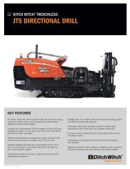
The <strong>RT120Q</strong> is a riding trencher designed to install buried service lines of various sizes using a variety of<br />
<strong>Ditch</strong> <strong>Witch</strong> attachments.<br />
Attachment Max. width/diameter Max. depth<br />
H910 trencher 24” (610 mm) 96” (2.4 m)<br />
H911 trencher 24” (610 mm) 92” (2.3 m)<br />
H1032 plow 3” (80 mm) 42” (1.07 m)<br />
H1052 combo n/a 70” (1.78 m)<br />
H1140 saw 103” (1.03 m) 40.5” (1.03 m)<br />
RC120 reel carrier 84” (2.13 m) reel dia n/a<br />
A920 backhoe 24” (610 mm) 105” (2.7 m)<br />
This unit is designed for operation in temperatures typically experienced in earth moving and construction<br />
work environments. Provisions may be required to operate in extreme temperatures. Contact your <strong>Ditch</strong><br />
<strong>Witch</strong> dealer. Use in any other way is considered contrary to the intended use.<br />
The <strong>RT120Q</strong> should be used with genuine <strong>Ditch</strong> <strong>Witch</strong> chain, teeth, and sprockets. It should be operated,<br />
serviced, and repaired only by persons familiar with their particular characteristics and acquainted with the<br />
relevant safety procedures.<br />
Equipment Modification<br />
This equipment was designed and built in accordance with applicable standards and regulations.<br />
Modification of equipment could mean that it will no longer meet regulations and may not function properly<br />
or in accordance with the operating instructions. Modification of equipment should only be made by<br />
competent personnel possessing knowledge of applicable standards, regulations, equipment design<br />
functionality/requirements and any required specialized testing.<br />
The protection offered by the Rollover Protective System (ROPS) will be impaired if it has been subjected<br />
to any modification, structural damage, or has been involved in an overturn accident. The ROPS must be<br />
replaced after a roll-over.<br />
CMW
Overview - 4<br />
Unit Components<br />
<strong>RT120Q</strong> Operator’s <strong>Manual</strong><br />
Unit Components<br />
2 3 4<br />
1<br />
5<br />
t37om003w.eps<br />
1. Rollover Protective Structure (ROPS)<br />
2. Operator station<br />
3. Control console<br />
4. Engine compartment<br />
5. Backfill blade (optional)<br />
WARNING: The protection offered by the Rollover Protective System (ROPS) will be impaired if it has<br />
been subjected to any modification, structural damage, or has been involved in an overturn accident.<br />
The ROPS must be replaced after a roll-over.<br />
CMW
<strong>RT120Q</strong> Operator’s <strong>Manual</strong> Overview - 5<br />
Operator Orientation<br />
Operator Orientation<br />
1<br />
1. Front of unit<br />
2. Right of unit<br />
3. Rear of unit<br />
4. Left of unit<br />
Right and left sides of machine are determined by<br />
facing front of unit while seated at the controls.<br />
4<br />
2<br />
3<br />
t37om004w.eps<br />
About This <strong>Manual</strong><br />
This manual contains information for the proper use of this machine. See Operation Overview for basic<br />
operating procedures. Cross references such as “See page 50” will direct you to detailed procedures.<br />
Bulleted Lists<br />
Bulleted lists provide helpful or important information or contain procedures that do not have to be<br />
performed in a specific order.<br />
Numbered Lists<br />
Numbered lists contain illustration callouts or list steps that must be performed in order.<br />
CMW
Overview - 6<br />
<strong>RT120Q</strong> Operator’s <strong>Manual</strong><br />
About This <strong>Manual</strong><br />
CMW
<strong>RT120Q</strong> Operator’s <strong>Manual</strong> Foreword - 7<br />
Foreword<br />
This manual is an important part of your equipment. It provides safety information and operation<br />
instructions to help you use and maintain your <strong>Ditch</strong> <strong>Witch</strong> equipment.<br />
Read this manual before using your equipment. Keep it with the equipment at all times for future reference.<br />
If you sell your equipment, be sure to give this manual to the new owner.<br />
If you need a replacement copy, contact your <strong>Ditch</strong> <strong>Witch</strong> dealer. If you need assistance in locating a<br />
dealer, visit our website at www.ditchwitch.com or write to the following address:<br />
The Charles Machine Works, Inc.<br />
Attn: Marketing Department<br />
PO Box 66<br />
Perry, OK 73077-0066<br />
USA<br />
The descriptions and specifications in this manual are subject to change without notice. The Charles<br />
Machine Works, Inc. reserves the right to improve equipment. Some product improvements may have<br />
taken place after this manual was published. For the latest information on <strong>Ditch</strong> <strong>Witch</strong> equipment, see your<br />
<strong>Ditch</strong> <strong>Witch</strong> dealer.<br />
Thank you for buying and using <strong>Ditch</strong> <strong>Witch</strong> equipment.<br />
CMW
Foreword - 8<br />
<strong>RT120Q</strong> Operator’s <strong>Manual</strong><br />
RT120 T4i<br />
Operator’s <strong>Manual</strong><br />
Issue number 1.0/OM-05/13<br />
Part number 053-2634<br />
Copyright 2013<br />
by The Charles Machine Works, Inc.<br />
Machine Works, Inc.<br />
, <strong>Ditch</strong> <strong>Witch</strong>, CMW, and Roto <strong>Witch</strong> are registered trademarks of The Charles<br />
CMW
<strong>RT120Q</strong> Operator’s <strong>Manual</strong> Contents - 9<br />
Contents<br />
Overview<br />
machine serial number, information about the type of work this machine is designed<br />
to perform, basic machine components, and how to use this manual<br />
Foreword<br />
part number, revision level, and publication date of this manual, and factory contact<br />
information<br />
Safety<br />
machine safety alerts and emergency procedures<br />
Controls<br />
machine controls, gauges, and indicators and how to use them<br />
1<br />
7<br />
11<br />
21<br />
Operation Overview<br />
an overview for completing a job with this machine: planning, setting up, installing<br />
product, and restoring the jobsite; with cross references to detailed procedures<br />
Prepare<br />
procedures for inspecting and classifying the jobsite, planning the installation path,<br />
and preparing the jobsite for work<br />
Drive<br />
procedures for startup, cold start, driving, and shutdown<br />
Transport<br />
procedures for lifting, hauling, and towing<br />
65<br />
69<br />
75<br />
81<br />
Trench<br />
procedures for trenching<br />
93<br />
Plow<br />
procedures for plowing<br />
101<br />
Reel Carrier<br />
procedures for using reel carrier<br />
111<br />
Backhoe<br />
procedures for digging with backhoe<br />
115<br />
CMW
Contents - 10<br />
<strong>RT120Q</strong> Operator’s <strong>Manual</strong><br />
Drill<br />
procedures for drilling<br />
121<br />
Saw<br />
procedures for sawing<br />
Systems and Equipment<br />
chain, teeth, sprockets, and optional equipment<br />
129<br />
137<br />
Complete the Job<br />
procedures for backfilling and restoring the jobsite and rinsing and storing<br />
equipment<br />
Service<br />
service intervals and instructions for this machine including lubrication, replacement<br />
of wear items, and basic maintenance<br />
Specifications<br />
machine specifications including weights, measurements, power ratings, and fluid<br />
capacities<br />
Support<br />
the warranty policy for this machine, and procedures for obtaining warranty<br />
consideration and training<br />
Service Record<br />
a record of major service performed on the machine<br />
143<br />
145<br />
187<br />
205<br />
209<br />
CMW
<strong>RT120Q</strong> Operator’s <strong>Manual</strong> Safety - 11<br />
Chapter Contents<br />
Guidelines . . . . . . . . . . . . . . . . . . . . . . . . . . . . . . . . 12<br />
Safety Alert Classifications . . . . . . . . . . . . . . . . . . 13<br />
Safety Alerts . . . . . . . . . . . . . . . . . . . . . . . . . . . . . . 14<br />
Emergency Procedures . . . . . . . . . . . . . . . . . . . . . 17<br />
• Electric Strike Description . . . . . . . . . . . . . . . . . . . . . . . . . . . . . . . . . . . 17<br />
• If an Electric Line is Damaged . . . . . . . . . . . . . . . . . . . . . . . . . . . . . . . 18<br />
• If a Gas Line is Damaged . . . . . . . . . . . . . . . . . . . . . . . . . . . . . . . . . . . 19<br />
• If a Fiber Optic Cable is Damaged . . . . . . . . . . . . . . . . . . . . . . . . . . . . 20<br />
• If Machine Catches on Fire . . . . . . . . . . . . . . . . . . . . . . . . . . . . . . . . . . 20<br />
Safety<br />
CMW®
Safety - 12<br />
<strong>RT120Q</strong> Operator’s <strong>Manual</strong><br />
Guidelines<br />
Guidelines<br />
Follow these guidelines before operating any jobsite equipment:<br />
• Complete proper training and read operator’s manual before using equipment.<br />
• Contact your local One-Call (811 in USA) or the One-Call referral number (888-258-0808 in USA and<br />
Canada) to have underground utilities located before digging. Also contact any utilities that do not<br />
participate in the One-Call service. Mark proposed path with white paint prior to contacting One-Call or<br />
utilities.<br />
• Classify jobsite based on its hazards and use correct tools and machinery, safety equipment, and work<br />
methods for jobsite.<br />
• Mark jobsite clearly and keep spectators away.<br />
• Wear personal protective equipment.<br />
• Review jobsite hazards, safety and emergency procedures, and individual responsibilities with all<br />
personnel before work begins. Safety videos are available from your <strong>Ditch</strong> <strong>Witch</strong> ® dealer.<br />
• Replace missing or damaged safety shields and safety signs.<br />
• Use equipment carefully. Stop operation and investigate anything that does not look or feel right.<br />
• Do not operate unit where flammable gas may be present.<br />
• Contact your <strong>Ditch</strong> <strong>Witch</strong> dealer if you have any question about operation, maintenance, or equipment<br />
use.<br />
• Complete the equipment checklist located at www.ditchwitch.com/resources/safety.<br />
CMW®
<strong>RT120Q</strong> Operator’s <strong>Manual</strong> Safety - 13<br />
Safety Alert Classifications<br />
Safety Alert Classifications<br />
These classifications and the icons defined on the following pages work together to alert you to situations<br />
which could be harmful to you, jobsite bystanders or your equipment. When you see these words and<br />
icons in the book or on the machine, carefully read and follow all instructions. YOUR SAFETY IS AT<br />
STAKE.<br />
Watch for the three safety alert levels: DANGER, WARNING and CAUTION. Learn what each level<br />
means.<br />
indicates a hazardous situation that, if not avoided, will result in death or serious injury.<br />
This signal word is to be limited to the most extreme situations.<br />
indicates a hazardous situation that, if not avoided, could result in death or serious injury.<br />
injury.<br />
indicates a hazardous situation that, if not avoided, could result in minor or moderate<br />
Watch for two other words: NOTICE and IMPORTANT.<br />
NOTICE indicates information considered important, but not hazard-related (e.g., messages relating to<br />
property damage).<br />
IMPORTANT can help you do a better job or make your job easier in some way.<br />
CMW®
Safety - 14<br />
Safety Alerts<br />
<strong>RT120Q</strong> Operator’s <strong>Manual</strong><br />
Safety Alerts<br />
Moving digging teeth will cause death or<br />
serious injury. Trench cave-in can cause you to fall. Stay<br />
away.<br />
Turning shaft will kill you or crush arm or leg. Stay away.<br />
Electric shock. Contacting electric lines will cause death or serious injury.<br />
Know location of lines and stay away.<br />
Jobsite hazards could cause death or serious injury. Use<br />
correct equipment and work methods. Use and maintain proper safety<br />
equipment.<br />
Crushing weight could cause death or serious injury. Use<br />
proper procedures and equipment or stay away.<br />
Moving parts could cut off hand or foot. Stay away.<br />
Explosion possible. Serious injury or equipment damage could occur.<br />
Follow directions carefully.<br />
Incorrect procedures could result in death, injury, or property damage.<br />
Learn to use equipment correctly.<br />
CMW®
<strong>RT120Q</strong> Operator’s <strong>Manual</strong> Safety - 15<br />
Safety Alerts<br />
Fall possible. Riders can fall from machine and be injured or killed. Only<br />
operator is allowed on machine.<br />
Rollover possible. If machine rolls over, you could be thrown from seat and<br />
killed or crushed. Wear seat belt.<br />
Improper control function could cause death or serious injury. If control does<br />
not work as described in instructions, stop machine and have it serviced.<br />
Looking into fiber optic cable could result in permanent vision damage. Do<br />
not look into ends of fiber optic or unidentified cable.<br />
Pressurized fluid or air could pierce skin and cause injury or<br />
death. Stay away.<br />
Runaway possible. Machine could run over you or others. Learn how to use<br />
all controls. Start and operate only from operator’s position.<br />
Fire or explosion possible. Fumes could ignite and cause burns. No<br />
smoking, no flame, no spark.<br />
Avoid static electricity when fueling. Ultra Low Sulfur Diesel (ULSD) poses a<br />
greater static ignition hazard than earlier diesel formulations. Avoid death or serious injury<br />
from fire or explosion. Consult with your fuel system supplier to ensure the delivery system<br />
is in compliance with fueling standards for proper grounding and bonding practices.<br />
CMW®
Safety - 16<br />
<strong>RT120Q</strong> Operator’s <strong>Manual</strong><br />
Safety Alerts<br />
Moving traffic - hazardous situation. Death or serious injury could result.<br />
Avoid moving vehicles, wear high visibility clothing, post appropriate warning signs.<br />
Hot pressurized cooling system fluid could cause serious burns. Allow to<br />
cool before servicing.<br />
Flying objects may cause injury. Wear hard hat and safety glasses.<br />
Hot parts may cause burns. Do not touch until cool.<br />
protection.<br />
Exposure to high noise levels may cause hearing loss. Wear hearing<br />
Fall possible. Slips or trips may result in injury. Keep area clean.<br />
Battery acid may cause burns. Avoid contact.<br />
Improper handling or use of chemicals may result in illness, injury, or<br />
equipment damage. Follow instructions on labels and in material safety data sheets<br />
(MSDS).<br />
Breathing crystalline silica dust may cause lung disease. Cutting, drilling, or<br />
working materials such as concrete, sand, or rock containing quartz may result in exposure<br />
to silica dust. Use dust control methods or appropriate breathing protection when exposed<br />
to silica dust.<br />
CMW®
<strong>RT120Q</strong> Operator’s <strong>Manual</strong> Safety - 17<br />
Emergency Procedures<br />
Emergency Procedures<br />
Jobsite hazards could cause death or serious injury. Use<br />
correct equipment and work methods. Use and maintain proper safety<br />
equipment.<br />
Before operating any equipment, review emergency procedures and check that all safety precautions have<br />
been taken.<br />
EMERGENCY SHUTDOWN - Turn ignition switch to stop position or push remote engine stop button (if<br />
equipped).<br />
Electric Strike Description<br />
Electric shock. Contacting electric lines will cause death or serious injury.<br />
Know location of lines and stay away.<br />
When working near electric cables, remember the following:<br />
• Electricity follows all paths to ground, not just path of least resistance.<br />
• Pipes, hoses, and cables will conduct electricity back to all equipment.<br />
• Low voltage current can injure or kill. Many work-related electrocutions result from contact with less<br />
than 440 volts.<br />
Most electric strikes are not noticeable, but indications of a strike include:<br />
• power outage<br />
• smoke<br />
• explosion<br />
• popping noises<br />
• arcing electricity<br />
If any of these occur, assume an electric strike has occurred.<br />
CMW®
Safety - 18<br />
If an Electric Line is Damaged<br />
<strong>RT120Q</strong> Operator’s <strong>Manual</strong><br />
Emergency Procedures<br />
If you suspect an electric line has been damaged and you are on tractor, DO NOT MOVE. Remain on<br />
tractor and take the following actions. The order and degree of action will depend upon the situation.<br />
• Warn people nearby that an electric strike has occurred. Instruct them to leave the area and contact<br />
utility.<br />
• Raise attachments and drive from immediate area.<br />
• Contact utility company to shut off power.<br />
• Do not return to jobsite or allow anyone into area until given permission by utility company.<br />
If you suspect an electric line has been damaged and you are off tractor, DO NOT TOUCH TRACTOR.<br />
Take the following actions. The order and degree of action will depend upon the situation.<br />
• LEAVE AREA. The ground surface may be electrified, so take small steps with feet close together to<br />
reduce the hazard of being shocked from one foot to the other. For more information, contact your<br />
<strong>Ditch</strong> <strong>Witch</strong> dealer.<br />
• Contact utility company to shut off power.<br />
• Do not return to jobsite or allow anyone into area until given permission by utility company.<br />
CMW®
<strong>RT120Q</strong> Operator’s <strong>Manual</strong> Safety - 19<br />
Emergency Procedures<br />
If a Gas Line is Damaged<br />
Fire or explosion possible. Fumes could ignite and cause burns. No<br />
smoking, no flame, no spark.<br />
Explosion possible. Serious injury or equipment damage could occur.<br />
Follow directions carefully.<br />
If you suspect a gas line has been damaged, take the following actions. The order and degree of action will<br />
depend on the situation.<br />
• Immediately shut off engine(s), if this can be done safely and quickly.<br />
• Remove any ignition source(s), if this can be done safely and quickly.<br />
• Warn others that a gas line has been cut and that they should leave the area.<br />
• Leave jobsite as quickly as possible.<br />
• Immediately call your local emergency phone number and utility company.<br />
• If jobsite is along street, stop traffic from driving near jobsite.<br />
• Do not return to jobsite until given permission by emergency personnel and utility company.<br />
CMW®
Safety - 20<br />
If a Fiber Optic Cable is Damaged<br />
<strong>RT120Q</strong> Operator’s <strong>Manual</strong><br />
Emergency Procedures<br />
Do not look into cut ends of fiber optic or unidentified cable. Vision damage can occur.<br />
If Machine Catches on Fire<br />
Perform emergency shutdown procedure and then take the following actions. The order and degree of<br />
action will depend on the situation.<br />
• Immediately move battery disconnect switch (if equipped and accessible) to disconnect position.<br />
• If fire is small and fire extinguisher is available, attempt to extinguish fire.<br />
• If fire cannot be extinguished, leave area as quickly as possible and contact emergency personnel.<br />
CMW®
<strong>RT120Q</strong> Operator’s <strong>Manual</strong> Controls - 21<br />
Chapter Contents<br />
Center Console . . . . . . . . . . . . . . . . . . . . . . . . . . . . 22<br />
Graphic Display. . . . . . . . . . . . . . . . . . . . . . . . . . . . 26<br />
Right Console . . . . . . . . . . . . . . . . . . . . . . . . . . . . . 39<br />
Left Console . . . . . . . . . . . . . . . . . . . . . . . . . . . . . . 42<br />
Seat Console . . . . . . . . . . . . . . . . . . . . . . . . . . . . . . 45<br />
Seat Deck. . . . . . . . . . . . . . . . . . . . . . . . . . . . . . . . . 47<br />
Trencher Controls. . . . . . . . . . . . . . . . . . . . . . . . . . 49<br />
Plow Controls . . . . . . . . . . . . . . . . . . . . . . . . . . . . . 51<br />
Combo Controls . . . . . . . . . . . . . . . . . . . . . . . . . . . 53<br />
Backhoe Console . . . . . . . . . . . . . . . . . . . . . . . . . . 56<br />
Saw Controls . . . . . . . . . . . . . . . . . . . . . . . . . . . . . . 60<br />
Drill Controls . . . . . . . . . . . . . . . . . . . . . . . . . . . . . . 61<br />
Battery Disconnect . . . . . . . . . . . . . . . . . . . . . . . . . 63<br />
Controls<br />
CMW
Controls - 22<br />
Center Console<br />
<strong>RT120Q</strong> Operator’s <strong>Manual</strong><br />
Center Console<br />
4 5 6 7<br />
3<br />
8<br />
2<br />
9<br />
1<br />
10<br />
11<br />
t37om001w.eps<br />
1. Auxiliary power outlet<br />
2. Horn switch<br />
3. Engine override switch<br />
4. Axle lock switch<br />
5. Graphic display<br />
6. Ground drive speed switch<br />
7. Reel carrier switch*<br />
8. Reel winder mode selector switch*<br />
9. Ignition key switch<br />
10. Ground drive foot control<br />
11. Steering column tilt control<br />
* option<br />
CMW
<strong>RT120Q</strong> Operator’s <strong>Manual</strong> Controls - 23<br />
Center Console<br />
Item Description Notes<br />
1. Auxiliary outlet Provides power for other<br />
equipment.<br />
Power output is 12V, 10A.<br />
c00ic179h.eps<br />
2. Horn To sound horn, press.<br />
c00ic044h.eps<br />
3. Engine override switch For engine override, press.<br />
c00ic024w.eps<br />
4. Axle lock switch To lock rear axle, press top.<br />
To unlock rear axle, press<br />
bottom.<br />
NOTICE: To prevent mechanical<br />
damage, stop tractor before operating<br />
axle lock switch.<br />
IMPORTANT: After pressing switch to<br />
unlock axle, it may be necessary to<br />
move tractor 6’ (2 m) in reverse to<br />
fully unlock.<br />
CMW
Controls - 24<br />
<strong>RT120Q</strong> Operator’s <strong>Manual</strong><br />
Center Console<br />
Item Description Notes<br />
5. Graphic display Graphic symbols are<br />
displayed for indicators and<br />
conditions previously shown<br />
with gauges.<br />
See more information in “Graphic<br />
Display” on page 26.<br />
!<br />
c00ic604w.eps<br />
6. Ground drive speed<br />
switch<br />
c00ic602w.eps<br />
3<br />
2<br />
1<br />
To select High (3), Medium<br />
(2) or Low (1), press<br />
appropriate switch position.<br />
Screen icon displays High, Medium or<br />
Low selection.<br />
7. Reel carrier switch To raise, press top.<br />
Optional.<br />
To lower, press bottom.<br />
c00ic205h.eps<br />
8. Reel winder selector<br />
switch<br />
To change backfill blade<br />
joystick to reel winder control<br />
mode, press top.<br />
To return to backfill blade<br />
mode, press bottom.<br />
Optional.<br />
c00ic642w.eps<br />
CMW
<strong>RT120Q</strong> Operator’s <strong>Manual</strong> Controls - 25<br />
Center Console<br />
Item Description Notes<br />
9. Ignition switch To start engine, insert key and<br />
turn clockwise.<br />
To stop engine, turn<br />
counterclockwise.<br />
IMPORTANT: If engine does not start<br />
on first attempt, check that all<br />
interlock requirements have been<br />
met, return switch to STOP, and try<br />
again.<br />
c00ic027w.eps<br />
10. Ground drive foot<br />
control<br />
c00ic072c.eps<br />
11. Steering column tilt<br />
control<br />
To move tractor forward, push<br />
top of pedal.<br />
To move tractor backward,<br />
push bottom of pedal.<br />
To increase speed in either<br />
direction, push pedal farther<br />
from center.<br />
To reduce speed in either<br />
direction, release pedal.<br />
To adjust tilt, pull.<br />
To secure steering column in<br />
position, release.<br />
Pedal should automatically return to<br />
neutral when released.<br />
c00ic037w.eps<br />
CMW
Controls - 26<br />
Graphic Display<br />
<strong>RT120Q</strong> Operator’s <strong>Manual</strong><br />
Graphic Display<br />
0%<br />
0% 3 0%<br />
0 RPM<br />
0 : 00 : 00 AM/PM<br />
15<br />
10 20<br />
RPM<br />
5 25<br />
x100<br />
0 30<br />
0<br />
0.0 v 0 PSI<br />
0 F<br />
0.0 H<br />
t37om048w.eps<br />
The graphic display module shows engine RPM and has icons for other functions. Soft keys allow the<br />
operator to toggle between various screens and functions.<br />
Item Description Notes<br />
Attachment speed<br />
Displays precentage of<br />
attachment speed, and plow<br />
or trencher/saw mode.<br />
Note: Screen icons change according<br />
to attachment being operated.<br />
c00ic028w.eps<br />
CMW
<strong>RT120Q</strong> Operator’s <strong>Manual</strong> Controls - 27<br />
Graphic Display<br />
Item Description Notes<br />
Operator presence<br />
Idicates operator presence<br />
and start interlock condition.<br />
c00ic001w.eps<br />
Fuel level<br />
Displays fuel level and<br />
percentage.<br />
c00ic003w.eps<br />
Batery voltage<br />
Displays battery voltage.<br />
c00ic008w.eps<br />
Day/Night mode<br />
Indicates selected mode.<br />
c00ic010w.eps<br />
CMW
Controls - 28<br />
<strong>RT120Q</strong> Operator’s <strong>Manual</strong><br />
Graphic Display<br />
Item Description Notes<br />
Engine hours<br />
Displays engine hours.<br />
0.0 H<br />
c00ic020w.eps<br />
Engine oil pressure<br />
Displays engine oil pressure.<br />
c00ic005w.eps<br />
Engine coolant temperature<br />
Displays coolant temperature.<br />
c00ic004w.eps<br />
Axle lock<br />
Displays status of axle<br />
differential lock.<br />
c00ic002w.eps<br />
CMW
<strong>RT120Q</strong> Operator’s <strong>Manual</strong> Controls - 29<br />
Graphic Display<br />
Item Description Notes<br />
Ground drive speed/<br />
direction<br />
Displays ground drive<br />
direction of travel, and speed<br />
as a percentage.<br />
c00ic006w.eps<br />
Ground drive gear indicator<br />
Displays selected gear in<br />
center of icon.<br />
c00ic009w.eps<br />
Cruise control indicator<br />
Displays cruise mode status.<br />
c00ic032w.eps<br />
Parking brake indicator<br />
Displays parking brake<br />
status.<br />
c00ic055t.eps<br />
CMW
Controls - 30<br />
<strong>RT120Q</strong> Operator’s <strong>Manual</strong><br />
Graphic Display<br />
Item Description Notes<br />
Hydraulic filter restriction<br />
indicator<br />
Displays restriction status.<br />
Hydraulic fluid high<br />
temperature indicator<br />
Displays hot fluid status.<br />
c00ic037t.eps<br />
Menu indicator<br />
Displays menu icon over key<br />
3.<br />
c00ic031w.eps<br />
CMW
<strong>RT120Q</strong> Operator’s <strong>Manual</strong> Controls - 31<br />
Graphic Display<br />
Main Menu<br />
SYSTEM<br />
SETTINGS<br />
USER<br />
SETTINGS<br />
GAUGE<br />
DISPLAY<br />
DIGNOSTICS<br />
t33om093w.eps<br />
Press the center soft key to display the main menu screen, which has icons for other functions. Soft keys<br />
below on screen icons allow the operator to toggle between various screens and functions.<br />
Item Description Notes<br />
System Settings<br />
This is an information display.<br />
c00ic015w.eps<br />
CMW
Controls - 32<br />
<strong>RT120Q</strong> Operator’s <strong>Manual</strong><br />
Graphic Display<br />
Item Description Notes<br />
User Settings<br />
Allows operator to customize<br />
settings.<br />
c00ic016w.eps<br />
Gauge Display<br />
Press the soft key below this<br />
on screen icon to select.<br />
c00ic017w.eps<br />
Diagnostics<br />
Displays interlock icons and<br />
diagnostic codes, if any.<br />
Press soft key below on<br />
screen icons to return to main<br />
menu or gauge display.<br />
Note: If diagnostic codes are<br />
displayed, contact your <strong>Ditch</strong> <strong>Witch</strong><br />
dealer.<br />
c00ic018w.eps<br />
CMW
<strong>RT120Q</strong> Operator’s <strong>Manual</strong> Controls - 33<br />
Graphic Display<br />
System Settings<br />
SYSTEM SETTINGS<br />
Component<br />
VERSION<br />
Part No.<br />
Application<br />
OS<br />
Bootloader<br />
Configuration<br />
2<br />
2<br />
2<br />
3 10155<br />
3 10081<br />
3 10146<br />
Release<br />
Release<br />
Release<br />
78333159<br />
78333166<br />
78333156<br />
1 0 1 Beta<br />
0<br />
<strong>RT120Q</strong>T4i<br />
Back<br />
Copyright<br />
2012 The Charles Machine Works<br />
t37om043w.eps<br />
Item Description Notes<br />
Back<br />
Press soft key below this icon<br />
to return to previous screen.<br />
Press center soft key to display gauge<br />
screen.<br />
c00ic011w.eps<br />
CMW
Controls - 34<br />
<strong>RT120Q</strong> Operator’s <strong>Manual</strong><br />
Graphic Display<br />
User Settings<br />
1<br />
USER<br />
Ambient Light<br />
SETTINGS<br />
Day<br />
3<br />
Brightness<br />
100%<br />
Units<br />
USA Standard<br />
2<br />
Language<br />
English<br />
4<br />
Back Save Reset<br />
t33om092w.eps<br />
Item Description Notes<br />
Back<br />
Press soft key below this icon<br />
to return to previous screen.<br />
Press center soft key to display gauge<br />
screen.<br />
Down<br />
c00ic011w.eps<br />
Press soft key below this icon<br />
to toggle through selections<br />
1-4.<br />
Press center soft key to display gauge<br />
screen.<br />
c00ic012w.eps<br />
CMW
<strong>RT120Q</strong> Operator’s <strong>Manual</strong> Controls - 35<br />
Graphic Display<br />
Item Description Notes<br />
Save<br />
Press soft key below this icon<br />
to save settings.<br />
c00ic013w.eps<br />
Reset<br />
Press soft key below this icon<br />
to return to default settings.<br />
c00ic014w.eps<br />
Day/Night<br />
Press soft key below this icon<br />
to select day or night mode.<br />
c00ic010w.eps<br />
CMW
Controls - 36<br />
Diagnostics<br />
<strong>RT120Q</strong> Operator’s <strong>Manual</strong><br />
Graphic Display<br />
N<br />
N<br />
MAIN<br />
MENU<br />
GAUGE<br />
DISPLAY<br />
t37om044w.eps<br />
Note: If diagnostic codes are displayed, contact your <strong>Ditch</strong> <strong>Witch</strong> dealer.<br />
Item Description Notes<br />
Attachment Neutral<br />
Indicates attachment controls<br />
in neutral position.<br />
N<br />
c00ic021w.eps<br />
CMW
<strong>RT120Q</strong> Operator’s <strong>Manual</strong> Controls - 37<br />
Graphic Display<br />
Item Description Notes<br />
Operator Presence<br />
Indicates operator presence<br />
for start interlock status.<br />
c00ic001w.eps<br />
Ground Drive Neutral<br />
N<br />
Indicates ground drive<br />
controls in neutral position.<br />
c00ic022w.eps<br />
Main Menu<br />
Press soft key below this icon<br />
to return to previous screen.<br />
Press center soft key to display gauge<br />
screen.<br />
c00ic019w.eps<br />
Gauge Display<br />
Press the soft key below this<br />
on screen icon to select.<br />
c00ic017w.eps<br />
CMW
Controls - 38<br />
<strong>RT120Q</strong> Operator’s <strong>Manual</strong><br />
Graphic Display<br />
Item Description Notes<br />
Engine stop<br />
Press to stop engine from<br />
backhoe operator’s station.<br />
Switch must be raised (reset) to allow<br />
engine starting.<br />
c00ic649w.eps<br />
CMW
<strong>RT120Q</strong> Operator’s <strong>Manual</strong> Controls - 39<br />
Right Console<br />
Right Console<br />
1 2 3 4 5<br />
t37om005w.eps<br />
1. Backfill blade lift/tilt or reel winder control<br />
2. Rear steer control*<br />
3. Rear steer manual/auto control*<br />
4. Frame tilt control<br />
5. Throttle<br />
*option<br />
CMW
Controls - 40<br />
<strong>RT120Q</strong> Operator’s <strong>Manual</strong><br />
Right Console<br />
Item Description Notes<br />
1. Backfill blade lift/tilt<br />
function control<br />
c00ic625w.eps<br />
Reel winder function<br />
control<br />
Backfill blade mode:<br />
• To lower, move forward.<br />
• To float, move forward to<br />
end.<br />
• To raise, move backward.<br />
• To tilt right side down,<br />
move right.<br />
• To tilt left side down,<br />
move left.<br />
Reel winder mode:<br />
• To unwind, move forward.<br />
• To wind, move backward.<br />
• To lower reel winder arm,<br />
move right.<br />
• To raise reel winder arm,<br />
move left.<br />
Reel winder mode selector switch on<br />
center console changes function to<br />
control reel winder arm lift and winder<br />
direction.<br />
c00ic207h.eps<br />
2. Rear steer switch To move rear tracks left,<br />
press left.<br />
To move rear tracks right,<br />
press right.<br />
NOTICE:<br />
• Tracks move when you press the<br />
switch. To stop movement,<br />
release switch.<br />
• Visually verify track position<br />
3. Rear steer manual/auto<br />
switch<br />
To center tracks, press right.<br />
To manually steer rear tracks,<br />
press left.<br />
Use manual mode and the manual<br />
rear steer switch to bypass auto<br />
mode.<br />
CMW
<strong>RT120Q</strong> Operator’s <strong>Manual</strong> Controls - 41<br />
Item Description Notes<br />
4. Frame tilt control To tilt left, press left.<br />
To tilt right, press right.<br />
c00ic626w.eps<br />
5. Throttle To increase speed, move<br />
forward.<br />
To decrease speed, move<br />
rearward.<br />
CMW
Controls - 42<br />
Left Console<br />
<strong>RT120Q</strong> Operator’s <strong>Manual</strong><br />
Left Console<br />
1<br />
t37om006w.eps<br />
1. Parking brake control<br />
1. Parking brake control To set brake, pull handle up.<br />
To release brake, push<br />
handle down.<br />
Engaged parking brake disables<br />
ground drive.<br />
CMW
<strong>RT120Q</strong> Operator’s <strong>Manual</strong> Controls - 43<br />
Rear Console<br />
Rear Console<br />
1 2<br />
t37om007w.eps<br />
1. Cruise control selector switch 2. Cruise control rpm dial control<br />
1. Cruise control selector To turn on, press top. Switch<br />
indicator and display should<br />
indicate that cruise mode is<br />
activated.<br />
c00ic630w.eps<br />
To turn off, press top again.<br />
Switch indicator and display<br />
should indicate that cruise<br />
mode is deactivated.<br />
Turn on cruise control only when:<br />
• ground drive motor control is in<br />
low<br />
• ground drive is in neutral<br />
Hand and foot controls must be in<br />
neutral or cruise control switch input<br />
will be ignored.<br />
CMW
Controls - 44<br />
<strong>RT120Q</strong> Operator’s <strong>Manual</strong><br />
2. Cruise control rpm dial<br />
control<br />
RPM<br />
<br />
To decrease engine load<br />
while using cruise control,<br />
turn clockwise.<br />
To increase engine load while<br />
using cruise control, turn<br />
counterclockwise.<br />
This typically decreases engine load<br />
temporarily.<br />
This typically increases engine load<br />
temporarily.<br />
c00ic629w.eps<br />
CMW
<strong>RT120Q</strong> Operator’s <strong>Manual</strong> Controls - 45<br />
Seat Console<br />
Seat Console<br />
2<br />
1<br />
t33om002w.eps<br />
1. Ground drive speed control 2. Attachment speed/direction control<br />
Item Description Notes<br />
1. Ground drive speed<br />
control<br />
To go faster in either<br />
direction, move farther from<br />
neutral.<br />
To stop, return to center.<br />
NOTICE: Control does not<br />
automatically return to neutral.<br />
IMPORTANT: This control is disabled<br />
in high gear.<br />
c00ic631w.eps<br />
CMW
Controls - 46<br />
<strong>RT120Q</strong> Operator’s <strong>Manual</strong><br />
Seat Console<br />
Item Description Notes<br />
2. Attachment speed/<br />
direction control<br />
To go faster in either<br />
direction, move farther from<br />
neutral.<br />
To stop, return to center.<br />
NOTICE: Control does not<br />
automatically return to neutral.<br />
c00ic632w.eps<br />
CMW
<strong>RT120Q</strong> Operator’s <strong>Manual</strong> Controls - 47<br />
Seat Deck<br />
Seat Deck<br />
1<br />
2<br />
1<br />
2<br />
3<br />
3 4<br />
4<br />
5<br />
t33om003w.eps<br />
1. Seat belt<br />
2. Armrest adjustment control<br />
3. Seat slide control<br />
4. Seat height adjustment lock<br />
5. Seat pivot control<br />
Item Description Notes<br />
1. Seat belt To fasten, insert latch into<br />
buckle. Adjust until seat belt<br />
is low and tight.<br />
To release, lift top of buckle.<br />
2. Armrest adjustment<br />
control<br />
To raise or lower armrests:<br />
• Remove knob.<br />
• Adjust armrest to desired<br />
position.<br />
• Replace knob.<br />
CMW
Controls - 48<br />
<strong>RT120Q</strong> Operator’s <strong>Manual</strong><br />
Seat Deck<br />
Item Description Notes<br />
3. Seat slide control To slide seat forward or<br />
backward, pull, then adjust<br />
seat.<br />
To lock seat in place, release.<br />
4. Seat height adjustment<br />
lock<br />
To lock seat height, turn<br />
clockwise.<br />
To unlock seat height, turn<br />
counterclockwise.<br />
5. Seat pivot control To pivot seat to the right, pull.<br />
To lock seat in position,<br />
release.<br />
To return seat to front-facing<br />
position, swing seat left.<br />
Seat pivots only to the right and can<br />
be locked in any position from 0-90°.<br />
IMPORTANT: Drive tractor with<br />
operator’s seat facing front. If desired,<br />
operate rear attachments with seat<br />
pivoted.<br />
CMW
<strong>RT120Q</strong> Operator’s <strong>Manual</strong> Controls - 49<br />
Trencher Controls<br />
Trencher Controls<br />
1 2 3<br />
t37om008w.eps<br />
1. Trencher slide control*<br />
2. Trench cleaner lift control*<br />
3. Boom lift control<br />
*optional<br />
Item Description Notes<br />
1. Trencher slide control<br />
(H911 only)<br />
To slide trencher right, push.<br />
To slide trencher left, pull.<br />
c00ic198h.eps<br />
CMW
Controls - 50<br />
<strong>RT120Q</strong> Operator’s <strong>Manual</strong><br />
Trencher Controls<br />
Item Description Notes<br />
2. Trench cleaner lift<br />
control<br />
To lower, push.<br />
To raise, pull.<br />
3. Boom lift control To lower, push.<br />
To raise, pull.<br />
CMW
<strong>RT120Q</strong> Operator’s <strong>Manual</strong> Controls - 51<br />
Plow Controls<br />
Plow Controls<br />
1 2 3 4<br />
t37om009w.eps<br />
1. Plow swing control<br />
2. Blade steer control<br />
3. Plow lift control<br />
4. Stow lock control<br />
Item Description Notes<br />
1. Plow swing control To swing left, pull.<br />
NOTICE:<br />
c00ic202h.eps<br />
To swing right, push.<br />
To float, push to end.<br />
• If soil conditions allow, operate in<br />
float position.<br />
• Lower plow into ground before<br />
moving control to float position.<br />
• Do not raise plow with control in<br />
float position.<br />
CMW
Controls - 52<br />
<strong>RT120Q</strong> Operator’s <strong>Manual</strong><br />
Plow Controls<br />
Item Description Notes<br />
2. Blade steer control To steer right, push.<br />
To steer left, pull.<br />
c00ic203h.eps<br />
3. Plow lift control To raise, pull.<br />
To lower, push.<br />
To float, push to end.<br />
NOTICE:<br />
• If soil conditions allow, operate in<br />
float position.<br />
• Lower plow into ground before<br />
moving control to float position.<br />
c00ic204h.eps<br />
4. Stow lock control To lock:<br />
• Raise plow fully.<br />
• Pull stow lock handle.<br />
• Lower plow slightly to<br />
engage lock.<br />
Use this control to lock plow in the up<br />
position.<br />
c00ic643w.eps<br />
To unlock:<br />
• Raise plow slightly.<br />
• Push stow lock handle to<br />
release lock.<br />
CMW
<strong>RT120Q</strong> Operator’s <strong>Manual</strong> Controls - 53<br />
Combo Controls<br />
Combo Controls<br />
1 2 3 4 5 6<br />
t37om010w.eps<br />
1. Plow swing control<br />
2. Blade steer control<br />
3. Plow lift control<br />
4. Boom lift control<br />
5. Plow stow lock control<br />
6. Trench / Plow switch<br />
Item Description Notes<br />
1. Plow swing control To swing left, pull.<br />
NOTICE:<br />
c00ic202h.eps<br />
To swing right, push.<br />
To float, push to end.<br />
• If soil conditions allow, operate in<br />
float position.<br />
• Lower plow into ground before<br />
moving control to float position.<br />
• Do not raise plow with control in<br />
float position.<br />
CMW
Controls - 54<br />
<strong>RT120Q</strong> Operator’s <strong>Manual</strong><br />
Combo Controls<br />
2. Blade steer control To steer right, push.<br />
To steer left, pull.<br />
c00ic203h.eps<br />
3. Plow lift control To raise, pull.<br />
To lower, push.<br />
To float, push to end.<br />
NOTICE:<br />
• If soil conditions allow, operate in<br />
float position.<br />
• Lower plow into ground before<br />
moving control to float position.<br />
c00ic204h.eps<br />
4. Boom lift control To lower, push.<br />
To raise, pull.<br />
5. Plow stow lock control To lock:<br />
• Raise plow fully.<br />
• Pull stow lock handle.<br />
• Lower plow slightly to<br />
engage lock.<br />
Use this control to lock plow in the up<br />
position.<br />
c00ic643w.eps<br />
To unlock:<br />
• Raise plow slightly.<br />
• Push stow lock handle to<br />
release lock.<br />
CMW
<strong>RT120Q</strong> Operator’s <strong>Manual</strong> Controls - 55<br />
Combo Controls<br />
6. Trench / Plow switch To trench, set switch to trench<br />
position.<br />
To plow, set switch to plow<br />
position.<br />
CMW
Controls - 56<br />
Backhoe Console<br />
<strong>RT120Q</strong> Operator’s <strong>Manual</strong><br />
Backhoe Console<br />
t37om046w.eps<br />
1. Remote backfill blade control*<br />
2. Left stabilizer control<br />
3. Boom/Swing control<br />
4. Remote throttle control switch<br />
5. Remote throttle enable switch<br />
6. Work light switch*<br />
7. Swing lock pin<br />
8. Ground drive switch<br />
9. Remote engine stop switch<br />
10. Bucket/Dipper control<br />
11. Stow lock control<br />
12. Right stabilizer control<br />
*optional<br />
CMW
<strong>RT120Q</strong> Operator’s <strong>Manual</strong> Controls - 57<br />
Backhoe Console<br />
Item Description Notes<br />
1. Remote backfill blade<br />
control<br />
To lower, push.<br />
To raise, pull.<br />
2. Left stabilizer control To lower, push out.<br />
To raise, pull in.<br />
3. Boom/Swing control To swing boom left, move left.<br />
To swing boom right, move<br />
right.<br />
To raise boom, pull.<br />
To lower boom, push.<br />
Control can perform more than one<br />
action at a time. By “feathering” the<br />
control, operator can combine<br />
backhoe operations.<br />
NOTICE: Do not operate with<br />
backhoe in the stowed (upright)<br />
position.<br />
4. Remote throttle To increase engine speed,<br />
press top.<br />
To decrease engine speed,<br />
press bottom.<br />
c00ic029w.eps<br />
CMW
Controls - 58<br />
<strong>RT120Q</strong> Operator’s <strong>Manual</strong><br />
Backhoe Console<br />
Item Description Notes<br />
5. Remote throttle enable To enable remote throttle<br />
control, press top.<br />
To disable remote throttle<br />
control, press bottom.<br />
Note: This switch must be returned to<br />
the OFF position for normal throttle<br />
control at tractor.<br />
c00ic030w.eps<br />
6. Work light switch To turn on, press right.<br />
To turn off, press left.<br />
7. Swing lock pin To lock:<br />
• Engage stow lock.<br />
• Insert swing lock pin into<br />
hole (1).<br />
To release:<br />
• Remove pin and store in<br />
hole (2).<br />
• Release stow lock.<br />
This pin locks boom from swinging<br />
during transport.<br />
NOTICE: Do not store pin in holes<br />
marked with an “X.” Backhoe could<br />
swing and destroy pin.<br />
8. Remote ground drive<br />
control<br />
c00ic216h.eps<br />
To move tractor forward,<br />
push.<br />
To move tractor backward,<br />
pull.<br />
NOTICE:<br />
• This control is disabled if tractor<br />
seat is occupied.<br />
• Tractor must be in low speed for<br />
remote ground drive to function.<br />
• Ensure that backfill blade, if<br />
equipped, and stabilizers are<br />
raised before operating this<br />
control.<br />
• Do not move more than 30’ (10<br />
m) at a time.<br />
CMW
<strong>RT120Q</strong> Operator’s <strong>Manual</strong> Controls - 59<br />
Backhoe Console<br />
Item Description Notes<br />
9. Remote engine stop<br />
switch<br />
Press to stop engine<br />
immediately.<br />
For normal engine shutdown, use<br />
ignition switch.<br />
Note: This switch must be returned to<br />
the UP position to allow engine<br />
restarting.<br />
10. Bucket/Dipper control To open bucket, move right.<br />
To close bucket, move left.<br />
To move dipper in, pull.<br />
Control can perform more than one<br />
action at a time. By “feathering” the<br />
control, operator can combine<br />
backhoe operations.<br />
To move dipper out, push.<br />
11. Stow lock control To lock:<br />
• Raise boom fully.<br />
• Pull stow lock handle.<br />
• Lower boom slightly to<br />
engage lock.<br />
• Insert swing lock pin.<br />
To unlock:<br />
• Remove swing lock pin.<br />
• Raise boom slightly.<br />
• Push stow lock handle to<br />
release lock.<br />
Use this control to lock boom in the up<br />
position.<br />
NOTICE: Always use stow lock and<br />
install swing lock pin during transport.<br />
When unlocked, store swing lock pin<br />
in holder located on left stabilizer<br />
support.<br />
12. Right stabilizer control To lower, push out.<br />
To raise, pull in.<br />
CMW
Controls - 60<br />
Saw Controls<br />
<strong>RT120Q</strong> Operator’s <strong>Manual</strong><br />
Saw Controls<br />
1 2<br />
t37om045w.eps<br />
1. Saw slide control 2. Saw lift control<br />
Item Description Notes<br />
1. Saw slide control To slide saw right, push.<br />
To slide saw to center, pull.<br />
CMW
<strong>RT120Q</strong> Operator’s <strong>Manual</strong> Controls - 61<br />
Item Description Notes<br />
2. Saw lift control To lower, push.<br />
To raise, pull.<br />
c00ic209h.eps<br />
CMW
Controls - 62<br />
Drill Controls<br />
<strong>RT120Q</strong> Operator’s <strong>Manual</strong><br />
Drill Controls<br />
1<br />
2<br />
t33om063w.eps<br />
1. Drilling attachment control 2. Drilling attachment<br />
Item Description Notes<br />
1. Drilling attachment<br />
control<br />
c00ic655w.eps<br />
To rotate clockwise, press<br />
bore.<br />
To rotate counterclockwise,<br />
press reverse.<br />
IMPORTANT: Always rotate<br />
clockwise during drilling and<br />
backreaming. Rotate<br />
counterclockwise only to dislodge a<br />
dry bore bit or reamer that has seized<br />
in the bore hole.<br />
Switch should return to neutral<br />
position when released.<br />
CMW
<strong>RT120Q</strong> Operator’s <strong>Manual</strong> Controls - 63<br />
Battery Disconnect<br />
Battery Disconnect<br />
1<br />
t37om011w.eps<br />
1. Battery disconnect switch<br />
Item Description Notes<br />
1. Battery disconnect<br />
switch<br />
To connect, move left.<br />
To disconnect, move right.<br />
NOTICE: Do not operate battery<br />
switch with engine running.<br />
c00ic654w.eps<br />
CMW
Controls - 64<br />
<strong>RT120Q</strong> Operator’s <strong>Manual</strong><br />
CMW
<strong>RT120Q</strong> Operator’s <strong>Manual</strong> Operation Overview - 65<br />
Chapter Contents<br />
Planning. . . . . . . . . . . . . . . . . . . . . . . . . . . . . . . . . . 66<br />
Trenching. . . . . . . . . . . . . . . . . . . . . . . . . . . . . . . . . 66<br />
Plowing . . . . . . . . . . . . . . . . . . . . . . . . . . . . . . . . . . 66<br />
Drilling . . . . . . . . . . . . . . . . . . . . . . . . . . . . . . . . . . . 66<br />
Digging with Backhoe . . . . . . . . . . . . . . . . . . . . . . 67<br />
Sawing . . . . . . . . . . . . . . . . . . . . . . . . . . . . . . . . . . . 67<br />
Leaving Jobsite. . . . . . . . . . . . . . . . . . . . . . . . . . . . 67<br />
Operation Overview<br />
CMW
Operation Overview - 66<br />
Planning<br />
<strong>RT120Q</strong> Operator’s <strong>Manual</strong><br />
Planning<br />
1. Gather information about jobsite. See page 70.<br />
2. Inspect jobsite. See page 71.<br />
3. Classify jobsite. See page 72.<br />
4. Select chain and teeth to match your soil type, if necessary. See page 140<br />
5. Check supplies and prepare equipment. See page 74.<br />
6. Haul equipment to jobsite. See page 88.<br />
Trenching<br />
1. Start unit. See page 76.<br />
2. Position tractor and controls. See page 94.<br />
3. Begin trenching. See page 96.<br />
4. Engage cruise control if desired. See page 138.<br />
5. Complete the installation. See page 99.<br />
6. Shut down tractor. See page 80.<br />
Plowing<br />
1. Start unit. See page 76.<br />
2. Position tractor and controls. See page 102.<br />
• offset plowing - page 109<br />
• coordinated plowing - page 109<br />
• crabbing - page 109<br />
3. Attach product. See page 103.<br />
4. Begin plowing. See page 105.<br />
5. Engage cruise control if desired. See page 138.<br />
6. Complete the installation. See page 108.<br />
7. Shut down tractor. See page 80.<br />
Drilling<br />
1. Start unit. See page 76.<br />
2. Dig approach trench and target trench. See page 123.<br />
3. Assemble drill string and position tractor. See page 124.<br />
CMW
<strong>RT120Q</strong> Operator’s <strong>Manual</strong> Operation Overview - 67<br />
Digging with Backhoe<br />
4. Begin drilling. See page 125.<br />
5. Use drill string guide as needed. See page 126.<br />
6. Add rod. See page 127.<br />
7. Backream. See page 127.<br />
8. Shut down tractor. See page 80.<br />
9. Disassemble joints. See page 128.<br />
Digging with Backhoe<br />
1. Start unit. See page 76.<br />
2. Set stabilizers and unstow backhoe. See page 116.<br />
3. Excavate. See page 117.<br />
4. Stow backhoe properly. See page 118.<br />
5. Shut down tractor. See page 80.<br />
Sawing<br />
1. Start unit. See page 76.<br />
2. Position tractor and controls. See page 130.<br />
3. Begin sawing. See page 132.<br />
4. Complete the installation. See page 134.<br />
5. Backfill the trench. See page 144.<br />
6. Shut down tractor. See page 80.<br />
Leaving Jobsite<br />
1. Backfill if necessary. See page 144.<br />
2. Rinse equipment. See page 144.<br />
3. Stow tools. See page 144.<br />
4. Haul equipment from jobsite. See page 88.<br />
CMW
Operation Overview - 68<br />
<strong>RT120Q</strong> Operator’s <strong>Manual</strong><br />
Leaving Jobsite<br />
CMW
<strong>RT120Q</strong> Operator’s <strong>Manual</strong> Prepare - 69<br />
Chapter Contents<br />
Gather Information . . . . . . . . . . . . . . . . . . . . . . . . . 70<br />
• Review Job Plan . . . . . . . . . . . . . . . . . . . . . . . . . . . . . . . . . . . . . . . . . . 70<br />
• Notify One-Call Services. . . . . . . . . . . . . . . . . . . . . . . . . . . . . . . . . . . . 70<br />
• Arrange for Traffic Control. . . . . . . . . . . . . . . . . . . . . . . . . . . . . . . . . . . 70<br />
• Plan for Emergency Services . . . . . . . . . . . . . . . . . . . . . . . . . . . . . . . . 70<br />
Inspect Site . . . . . . . . . . . . . . . . . . . . . . . . . . . . . . . 71<br />
• Identify Hazards . . . . . . . . . . . . . . . . . . . . . . . . . . . . . . . . . . . . . . . . . . 71<br />
Classify Jobsite. . . . . . . . . . . . . . . . . . . . . . . . . . . . 72<br />
• Inspect Jobsite . . . . . . . . . . . . . . . . . . . . . . . . . . . . . . . . . . . . . . . . . . . 72<br />
• Select a Classification. . . . . . . . . . . . . . . . . . . . . . . . . . . . . . . . . . . . . . 72<br />
• Apply Precautions . . . . . . . . . . . . . . . . . . . . . . . . . . . . . . . . . . . . . . . . . 73<br />
Check Supplies and Prepare Equipment . . . . . . . 74<br />
• Supplies . . . . . . . . . . . . . . . . . . . . . . . . . . . . . . . . . . . . . . . . . . . . . . . . 74<br />
• Fluid Levels. . . . . . . . . . . . . . . . . . . . . . . . . . . . . . . . . . . . . . . . . . . . . . 74<br />
• Condition and Function . . . . . . . . . . . . . . . . . . . . . . . . . . . . . . . . . . . . . 74<br />
• Accessories. . . . . . . . . . . . . . . . . . . . . . . . . . . . . . . . . . . . . . . . . . . . . . 74<br />
Prepare<br />
CMW
Prepare - 70<br />
Gather Information<br />
<strong>RT120Q</strong> Operator’s <strong>Manual</strong><br />
Gather Information<br />
A successful job begins before you dig. The first step in planning is reviewing information already available<br />
about the job and jobsite.<br />
Review Job Plan<br />
Review blueprints or other plans. Check for information about existing or planned structures, elevations, or<br />
proposed work that may be taking place at the same time.<br />
Notify One-Call Services<br />
Contact your local One-Call (811 in USA) or the One-Call referral number (888-258-0808 in USA and<br />
Canada) to have underground utilities located before digging. Also contact any utilities that do not<br />
participate in the One-Call service.<br />
Arrange for Traffic Control<br />
If working near a road or other traffic area, contact local authorities about safety procedures and<br />
regulations.<br />
Plan for Emergency Services<br />
Have the telephone numbers for local emergency and medical facilities on hand. Check that you will have<br />
access to a telephone.<br />
CMW
<strong>RT120Q</strong> Operator’s <strong>Manual</strong> Prepare - 71<br />
Inspect Site<br />
Inspect Site<br />
Inspect jobsite before transporting equipment. Check for the following:<br />
• changes in elevation such as hills or other open trenches<br />
• obstacles such as buildings, railroad crossings, or streams<br />
• signs of utilities<br />
• traffic<br />
• access<br />
• soil type and condition<br />
Identify Hazards<br />
Identify safety hazards and classify jobsite. See “Classify Jobsite” on page 72.<br />
Jobsite hazards could cause death or serious injury. Use<br />
correct equipment and work methods. Use and maintain proper safety<br />
equipment.<br />
To Help Avoid Injury:<br />
• Wear personal protective equipment including hard hat, safety eye wear, and hearing protection.<br />
• Do not wear jewelry or loose clothing.<br />
• Notify One-Call and companies which do not subscribe to One-Call.<br />
• Comply with all utility notification regulations before digging or drilling.<br />
• Verify location of previously marked underground hazards.<br />
• Mark jobsite clearly and keep spectators away.<br />
Remember, jobsite is classified by hazards in place -- not by line being installed.<br />
CMW
Prepare - 72<br />
Classify Jobsite<br />
<strong>RT120Q</strong> Operator’s <strong>Manual</strong><br />
Classify Jobsite<br />
Inspect Jobsite<br />
• Follow U.S. Department of Labor regulations on excavating and trenching (Part 1926, Subpart P) and<br />
other similar regulations.<br />
• Contact your local One-Call (811 in USA) or the One-Call referral number (888-258-0808 in USA and<br />
Canada) to have underground utilities located before digging. Also contact any utilities that do not<br />
participate in the One-Call service.<br />
• Inspect jobsite and perimeter for evidence of underground hazards, such as:<br />
– “buried utility” notices<br />
– utility facilities without overhead lines<br />
– gas or water meters<br />
– junction boxes<br />
– drop boxes<br />
– light poles<br />
– manhole covers<br />
– sunken ground<br />
• Have an experienced locating equipment operator sweep area within 20’ (6 m) to each side of trench<br />
path. Verify previously marked line and cable locations.<br />
• Mark location of all buried utilities and obstructions.<br />
• Classify jobsite.<br />
Select a Classification<br />
Jobsites are classified according to underground hazards present.<br />
If working . . . then classify jobsite as . . .<br />
within 10’ (3 m) of a buried electric line<br />
within 10’ (3 m) of a natural gas line<br />
in sand, granite, or concrete which is capable of producing<br />
crystalline silica (quartz) dust<br />
within 10’ (3 m) of any other hazard<br />
electric<br />
natural gas<br />
crystalline silica (quartz) dust<br />
other<br />
NOTICE: If you have any doubt about jobsite classification, or if jobsite might contain unmarked<br />
hazards, take steps outlined previously to identify hazards and classify jobsite before working.<br />
CMW
<strong>RT120Q</strong> Operator’s <strong>Manual</strong> Prepare - 73<br />
Classify Jobsite<br />
Apply Precautions<br />
Once classified, precautions appropriate for jobsite must be taken.<br />
Electric Jobsite Precautions<br />
Use one or both of these methods.<br />
• Expose line by careful hand digging or soft excavation.<br />
• Have service shut down while work is in progress. Have electric company test lines before returning<br />
them to service.<br />
Natural Gas Jobsite Precautions<br />
In addition to positioning equipment upwind from gas lines, use one or both of these methods.<br />
• Expose lines by careful hand digging or soft excavation.<br />
• Have gas shut off while work is in progress. Have gas company test lines before returning them to<br />
service.<br />
Crystalline Silica (Quartz) Dust Precautions<br />
Crystalline silica dust is a naturally occurring substance found in soil, sand, concrete, granite, and quartz.<br />
Breathing silica dust particles while cutting, drilling, or working materials may cause lung disease or<br />
cancer. To reduce exposure:<br />
• Use water spray or other means to control dust.<br />
• Refer to U.S. Department of Labor Occupational Safety and Health Administration guidelines to learn<br />
more about appropriate breathing protection and permissible exposure limits.<br />
Other Jobsite Precautions<br />
You may need to use different methods to safely avoid other underground hazards. Talk with those<br />
knowledgeable about hazards present at each site to determine which precautions should be taken or if<br />
job should be attempted.<br />
CMW
Prepare - 74<br />
Check Supplies and Prepare Equipment<br />
Supplies<br />
• fuel<br />
• keys<br />
• personal protective equipment, such as hard hat and safety glasses<br />
Fluid Levels<br />
• fuel<br />
• hydraulic fluid<br />
• battery charge<br />
• engine oil<br />
Condition and Function<br />
• digging chain and teeth<br />
• brake pads and disc<br />
• fan belts<br />
• light bulbs<br />
• filters (air, oil, hydraulic)<br />
• tracks<br />
• pumps and motors<br />
• hoses and valves<br />
• signs, guards, and shields<br />
Accessories<br />
Fire Extinguisher<br />
<strong>RT120Q</strong> Operator’s <strong>Manual</strong><br />
Check Supplies and Prepare Equipment<br />
If required, mount a fire extinguisher near the power unit but away from possible points of ignition. The fire<br />
extinguisher should always be classified for both oil and electric fires. It should meet legal and regulatory<br />
requirements.<br />
CMW
<strong>RT120Q</strong> Operator’s <strong>Manual</strong> Drive - 75<br />
Chapter Contents<br />
Start Unit . . . . . . . . . . . . . . . . . . . . . . . . . . . . . . . . . 76<br />
Drive . . . . . . . . . . . . . . . . . . . . . . . . . . . . . . . . . . . . . 78<br />
Safe Slope Operation . . . . . . . . . . . . . . . . . . . . . . . 79<br />
Shut Down . . . . . . . . . . . . . . . . . . . . . . . . . . . . . . . . 80<br />
Drive<br />
CMW
Drive - 76<br />
Start Unit<br />
<strong>RT120Q</strong> Operator’s <strong>Manual</strong><br />
Start Unit<br />
Before operating tractor, read engine manufacturer’s starting and operating instructions. Follow<br />
instructions for new engine break-in.<br />
Incorrect procedures could result in death, injury, or property damage.<br />
Learn to use equipment correctly.<br />
To help avoid injury:<br />
• Read operator’s manual before operating equipment. Follow instructions carefully. Contact <strong>Ditch</strong><br />
<strong>Witch</strong> dealership for operation information or demonstration.<br />
• Wear hard hat, safety glasses, and other protective equipment required by job. Do not wear jewelry<br />
or loose clothing that can catch on controls.<br />
Runaway possible. Machine could run over you or others. Learn how to<br />
use all controls. Start and operate only from operator’s position.<br />
Rollover possible. If machine rolls over, you could be thrown from seat<br />
and killed or crushed. Wear seat belt.<br />
CMW
<strong>RT120Q</strong> Operator’s <strong>Manual</strong> Drive - 77<br />
Start Unit<br />
1. Fasten and adjust seat belt.<br />
2. Check that ground drive control and attachment speed/direction control are in neutral.<br />
3. Move throttle to idle.<br />
4. Verify that parking brake is engaged.<br />
5. Turn ignition switch to the run position (key on, engine off). Cold start wait indicator will light (if<br />
equipped).<br />
Explosion possible. Serious injury or equipment damage could<br />
occur. Follow directions carefully.<br />
To help avoid injury: Do not use ether or any other type of aerosol starting fluid when unit is<br />
equipped with cold start option.<br />
6. When cold start wait indicator goes off, turn ignition switch all the way clockwise to start tractor.<br />
Warning alarm will sound. Indicators will light.<br />
• If engine does not crank, check start interlock display.<br />
• If engine turns but does not start within 10 seconds, allow starter to cool before trying to start<br />
again.<br />
Improper control function could cause death or serious injury.<br />
To help avoid injury: Stop machine and have it serviced if control does not work<br />
as described in instructions.<br />
IMPORTANT: Machine will not start if start interlock requirements are not met. See page 26 for<br />
start interlock information.<br />
7. Run engine at half-throttle or less for five minutes before operating tractor. During warmup, check that<br />
all controls work properly.<br />
CMW
Drive - 78<br />
Drive<br />
<strong>RT120Q</strong> Operator’s <strong>Manual</strong><br />
Drive<br />
General Operation<br />
Moving traffic – hazardous situation. Death or serious injury could result.<br />
Avoid moving vehicles, wear high visibility clothing, post appropriate warning signs.<br />
To help avoid injury:<br />
• Drive carefully in congested areas. Know machine’s clearance and turning radius.<br />
• Keep attachments low when operating on slope. Drive slowly and cautiously.<br />
EMERGENCY SHUTDOWN: Turn ignition switch to STOP.<br />
1. Turn on lights as needed.<br />
2. Raise backfill blade and all attachments.<br />
3. Release parking brake.<br />
4. Adjust throttle.<br />
5. When operating in low or medium:<br />
• if using the hand control, the foot control will only increase speed.<br />
• any opposing signal from controls causes ground drive to stop.<br />
6. When operating in high, ground drive stops if hand control is moved out of neutral position.<br />
CMW
<strong>RT120Q</strong> Operator’s <strong>Manual</strong> Drive - 79<br />
Drive<br />
Safe Slope Operation<br />
Tipover possible. Machine can tip over and crush you.<br />
To help avoid injury:<br />
• Always operate with heavy end uphill.<br />
• Drive cautiously at all times.<br />
• Never jerk control levers. Use a steady even motion.<br />
• Do not park unit on slope without lowering digging attachment to the ground, returning all controls<br />
to neutral position, shutting down unit, and applying parking brake.<br />
Operating safely on a slope depends upon many factors including:<br />
• Distribution of machine weight, including front loading and absence of load<br />
• Height of load<br />
• Even or rough ground conditions<br />
• Potential for ground giving way causing unplanned tilt forward, reverse or sideways<br />
• Nearness of ditches, ruts, stumps or other obstructions and sudden changes in slope<br />
• Speed<br />
• Turning<br />
• Braking performance<br />
• Operator skill<br />
These varying factors make it impractical to specify a maximum safe operating angle in this manual. It is<br />
therefore important for the operator to be aware of these conditions and adjust operation accordingly.<br />
Maximum engine angle and braking performance are two absolute limits which must never be exceeded.<br />
These maximums are stated below since they are design limits. These design limits usually exceed the<br />
operating limits and must never be used alone to establish safe operating angle for variable conditions.<br />
Maximum engine lubrication angle – 30°<br />
Maximum service brake retarding force – equal to traction of both tracks.<br />
Maximum secondary brake retarding force – equal to traction of one track.<br />
Maximum park brake holding force – equal to traction of both tracks.<br />
CMW
Drive - 80<br />
Shut Down<br />
<strong>RT120Q</strong> Operator’s <strong>Manual</strong><br />
Shut Down<br />
1. When job is complete, move ground drive control to neutral.<br />
2. Engage parking brake and verify parking brake indicator is on.<br />
3. Lower all attachments to ground and let machine idle for three minutes to cool.<br />
4. Turn ignition switch to STOP. If leaving machine unattended, remove key.<br />
5. For maintenance or long-term storage, turn battery disconnect switch to disconnect position.<br />
CMW
<strong>RT120Q</strong> Operator’s <strong>Manual</strong> Transport - 81<br />
Chapter Contents<br />
Lift . . . . . . . . . . . . . . . . . . . . . . . . . . . . . . . . . . . . . . 82<br />
• Points . . . . . . . . . . . . . . . . . . . . . . . . . . . . . . . . . . . . . . . . . . . . . . . . . . 82<br />
• Procedure . . . . . . . . . . . . . . . . . . . . . . . . . . . . . . . . . . . . . . . . . . . . . . . 82<br />
Tie Down . . . . . . . . . . . . . . . . . . . . . . . . . . . . . . . . . 85<br />
• Points . . . . . . . . . . . . . . . . . . . . . . . . . . . . . . . . . . . . . . . . . . . . . . . . . . 85<br />
• Procedure . . . . . . . . . . . . . . . . . . . . . . . . . . . . . . . . . . . . . . . . . . . . . . . 85<br />
Haul . . . . . . . . . . . . . . . . . . . . . . . . . . . . . . . . . . . . . 88<br />
• Procedure . . . . . . . . . . . . . . . . . . . . . . . . . . . . . . . . . . . . . . . . . . . . . . . 88<br />
Tow . . . . . . . . . . . . . . . . . . . . . . . . . . . . . . . . . . . . . 91<br />
• Procedure . . . . . . . . . . . . . . . . . . . . . . . . . . . . . . . . . . . . . . . . . . . . . . . 91<br />
Transport<br />
CMW
Transport - 82<br />
Lift<br />
<strong>RT120Q</strong> Operator’s <strong>Manual</strong><br />
Lift<br />
Crushing weight. If load falls or moves it could kill or crush you. Use<br />
proper procedures and equipment or stay away.<br />
Incorrect procedures could result in death, injury, or property damage.<br />
Learn to use equipment correctly.<br />
Points<br />
Lifting points are identified by lifting decals. Lifting at other points is unsafe<br />
and can damage machinery.<br />
Procedure<br />
Tractor<br />
This machine is not configured for lifting. If the machine must be lifted, load machine into a container or<br />
onto a platform appropriate for lifting. See “Specifications” on page 187 for size and weight of machine.<br />
CMW
<strong>RT120Q</strong> Operator’s <strong>Manual</strong> Transport - 83<br />
Lift<br />
Centerline Trencher<br />
Use crane capable of supporting the<br />
equipment's size and weight. See<br />
“Specifications” on page 187 or measure and<br />
weigh equipment before lifting.<br />
Traversing Trencher<br />
Use crane capable of supporting the<br />
equipment's size and weight. See<br />
“Specifications” on page 187 or measure and<br />
weigh equipment before lifting.<br />
Combo<br />
Use crane capable of supporting the equipment’s<br />
size and weight. See “Specifications” on<br />
page 187 or measure and weigh equipment<br />
before lifting.<br />
CMW
Transport - 84<br />
<strong>RT120Q</strong> Operator’s <strong>Manual</strong><br />
Lift<br />
Plow<br />
Use crane capable of supporting the<br />
equipment's size and weight. See<br />
“Specifications” on page 187 or measure and<br />
weigh equipment before lifting.<br />
Reel Carrier<br />
Use crane capable of supporting the<br />
equipment's size and weight. See page 187 or<br />
measure and weigh equipment before lifting.<br />
CMW
<strong>RT120Q</strong> Operator’s <strong>Manual</strong> Transport - 85<br />
Tie Down<br />
Tie Down<br />
Incorrect procedures could result in death, injury, or property damage.<br />
Learn to use equipment correctly.<br />
Points<br />
Tiedown points are identified by tiedown decals. Securing to trailer at other<br />
points is unsafe and can damage machinery.<br />
Procedure<br />
Tractor<br />
Attach chains at front and rear tiedown points.<br />
Make sure chains are tight before transporting<br />
unit.<br />
t37om012w.eps<br />
Centerline Trencher<br />
Lower trencher to trailer deck and chain at<br />
attachment frame and through boom. Make<br />
sure chains are tight before transporting.<br />
IMPORTANT: If trencher is equipped with<br />
a trench cleaner, ensure that trench<br />
cleaner shoe is fully up and extra bolt<br />
(found in operator’s manual compartment)<br />
is installed in appropriate hole for<br />
additional support.<br />
CMW
Transport - 86<br />
<strong>RT120Q</strong> Operator’s <strong>Manual</strong><br />
Tie Down<br />
Traversing Trencher<br />
Lower trencher to trailer deck and chain at<br />
attachment frame and through boom. Make<br />
sure chains are tight before transporting.<br />
IMPORTANT: If trencher is equipped with<br />
a trench cleaner, ensure that trench<br />
cleaner shoe is fully up and extra bolt<br />
(found in operator’s manual compartment)<br />
is installed in appropriate hole for<br />
additional support.<br />
Combo<br />
Lower attachment to trailer deck and chain at<br />
attachment frame and vibrator box. Make sure<br />
chains are tight before transporting.<br />
NOTICE:<br />
• Engage attachment stow lock and swing<br />
lock devices in addition to securing at<br />
tiedowns.<br />
• Unsecured plow can swing outside the<br />
trailer and become a traffic hazard. Lower<br />
plow and chain to trailer deck before<br />
hauling.<br />
• If trencher is equipped with a trench<br />
cleaner, ensure that trench cleaner shoe<br />
is fully up and extra bolt (found in<br />
operator’s manual compartment) is<br />
installed in appropriate hole for additional<br />
support.<br />
CMW
<strong>RT120Q</strong> Operator’s <strong>Manual</strong> Transport - 87<br />
Tie Down<br />
Plow<br />
Lower plow to trailer deck and chain at<br />
attachment frame and vibrator box. Make sure<br />
chains are tight before transporting.<br />
NOTICE:<br />
• Engage attachment stow lock and<br />
swing lock devices in addition to<br />
securing at tiedowns.<br />
• Unsecured plow can swing outside<br />
the trailer and become a traffic<br />
hazard. Lower plow and chain to<br />
trailer deck before hauling.<br />
Reel Carrier<br />
Lower reel carrier to lowest position and tie down<br />
at attachment arms. Make sure chains are tight<br />
before transporting.<br />
CMW
Transport - 88<br />
Haul<br />
<strong>RT120Q</strong> Operator’s <strong>Manual</strong><br />
Haul<br />
Incorrect procedures could result in death, injury, or property damage.<br />
Learn to use equipment correctly.<br />
To help avoid injury:<br />
• Read trailer operator’s manual before loading or transporting your machine. Incorrectly loaded<br />
machine can slip or cause trailer sway.<br />
• Ensure that tow vehicle has proper tow capacity rating.<br />
• Attach trailer to tow vehicle before loading or unloading.<br />
• Park, load, and unload trailer on level ground.<br />
• Check that unit and trailer do not exceed size or weight regulations.<br />
• Load trailer correctly to avoid trailer sway. Ten to fifteen percent of total vehicle weight (equipment<br />
plus trailer) must be on tongue to help prevent trailer sway.<br />
• Connect safety chains to tow vehicle. Attach left chain to right side of tow vehicle and vice versa to<br />
cradle hitch. Do not connect to pintle hook or hitch ball.<br />
• Connect breakaway switch cable to tow vehicle. Do not connect to pintle hook or hitch ball.<br />
Procedure<br />
Inspect Trailer<br />
1. Check hitch for wear and cracks. Lubricate if needed.<br />
2. Check battery for 12V charge.<br />
3. Inspect lights for cleanliness and correct operation. Inspect reflectors and replace if needed.<br />
4. Check trailer tire pressure. Check lug nut torque with a torque wrench. Adjust if needed.<br />
5. Ensure trailer brakes are adjusted to come on in synchronization with tow vehicle brakes.<br />
6. Check ramps and trailer bed for cracks.<br />
CMW
<strong>RT120Q</strong> Operator’s <strong>Manual</strong> Transport - 89<br />
Haul<br />
Load<br />
Crushing weight. If load falls or moves it could kill or crush you. Use<br />
proper procedures and equipment or stay away.<br />
To help avoid injury:<br />
• Attach trailer to tow vehicle before loading or unloading.<br />
• Load and unload trailer on level ground.<br />
• Block trailer wheels.<br />
• Put ground drive control into neutral. Turn off ignition. Set parking brake.<br />
Rollover possible. If machine rolls over, you could be thrown from seat<br />
and killed or crushed. Wear seat belt.<br />
1. Fasten and adjust seat belt.<br />
2. Tilt steering column down.<br />
3. Start tractor. See page 76 for proper start-up procedures.<br />
4. Raise attachments, but keep them low and centered. Check that they are not in float.<br />
5. Release parking brake and verify that parking brake indicator is off.<br />
6. Move ground drive switch to low.<br />
7. Slow engine to low throttle and slowly drive tractor onto trailer.<br />
8. Position tractor on trailer deck for proper weight distribution.<br />
9. Engage parking brake and verify that parking brake indicator is on.<br />
10. Lower attachments to trailer bed and turn tractor off. See page 80 for proper shutdown procedures.<br />
11. Attach chains to tractor and attachments where tiedown decals are located. See page 85.<br />
CMW
Transport - 90<br />
<strong>RT120Q</strong> Operator’s <strong>Manual</strong><br />
Haul<br />
Unload<br />
Crushing weight. If load falls or moves it could kill or crush you. Use<br />
proper procedures and equipment or stay away.<br />
NOTICE:<br />
• Attach trailer to tow vehicle before loading or unloading.<br />
• Load and unload trailer on level ground.<br />
• Block trailer wheels.<br />
Rollover possible. If machine rolls over, you could be thrown from seat<br />
and killed or crushed. Wear seat belt.<br />
1. Lower trailer or ramps.<br />
2. Check that parking brake is engaged and verify that parking brake indicator is on.<br />
3. Check that ground drive controls are in neutral.<br />
4. Remove chains from tiedowns.<br />
5. Fasten and adjust seat belt.<br />
6. Tilt steering column down.<br />
7. Start tractor. See page 76 for proper start-up procedures.<br />
8. Raise attachments, but keep them low and centered. Check that they are not in float.<br />
9. Release parking brake and verify that parking brake indicator is off.<br />
10. Slow engine to low throttle and slowly back unit down trailer or ramps.<br />
CMW
<strong>RT120Q</strong> Operator’s <strong>Manual</strong> Transport - 91<br />
Tow<br />
Tow<br />
Incorrect procedures could result in death, injury, or property damage.<br />
Learn to use equipment correctly.<br />
Under normal conditions, tractor should not be towed. If tractor becomes disabled and towing is<br />
necessary:<br />
• Do not tow for more than 200 yd (180 m).<br />
• Tow at less than 1 mph (1.6 km/h).<br />
• Steering will be very difficult.<br />
Procedure<br />
1. Engage parking brake.<br />
2. Block front and rear tracks to prevent unit<br />
from rolling.<br />
3. Attach tow line to all available tie-down<br />
points facing towing vehicle.<br />
4. Activate the tow valve (shown).<br />
• Remove floor plate.<br />
• Locate two hex-shaped relief valves.<br />
• Turn each valve (whole hex)<br />
counterclockwise three complete<br />
revolutions.<br />
t37om013w.eps<br />
NOTICE: Do not turn tow valve<br />
more than three revolutions.<br />
• Replace floor plate.<br />
5. Remove blocks.<br />
6. Fasten seat belt and adjust seat belt.<br />
7. Disengage parking brake.<br />
Warning: While towing, unit will not have brakes.<br />
8. After towing, turn tow valve clockwise three complete revolutions.<br />
CMW
Transport - 92<br />
<strong>RT120Q</strong> Operator’s <strong>Manual</strong><br />
Tow<br />
CMW
<strong>RT120Q</strong> Operator’s <strong>Manual</strong> Trench - 93<br />
Chapter Contents<br />
Setup . . . . . . . . . . . . . . . . . . . . . . . . . . . . . . . . . . . . 94<br />
Operation . . . . . . . . . . . . . . . . . . . . . . . . . . . . . . . . . 96<br />
Trench<br />
CMW
Trench - 94<br />
Setup<br />
<strong>RT120Q</strong> Operator’s <strong>Manual</strong><br />
Setup<br />
EMERGENCY SHUTDOWN - Turn ignition switch to STOP.<br />
Crushing weight could cause death or serious injury. Use proper<br />
procedures and equipment or stay away.<br />
To help avoid injury: Use attachments or counterweights to make front and rear loads balance when all<br />
attachments are raised. Contact your <strong>Ditch</strong> <strong>Witch</strong> dealer about counterweighting for your equipment.<br />
Jobsite hazards could cause death or serious injury. Use<br />
correct equipment and work methods. Use and maintain proper safety<br />
equipment.<br />
To help avoid injury: Comply with all utility notification regulations before digging or drilling.<br />
Incorrect procedures can result in death, injury, or property damage.<br />
Learn to use equipment correctly.<br />
NOTICE: The <strong>RT120Q</strong> is programmed to operate with the original attachment (trencher or plow)<br />
configuration. If you change attachments, contact your <strong>Ditch</strong> <strong>Witch</strong> dealer to make sure the electronic<br />
programming is updated. If you change attachments without updating the electronic programming, your<br />
attachment may not function correctly.<br />
CMW
<strong>RT120Q</strong> Operator’s <strong>Manual</strong> Trench - 95<br />
Setup<br />
1. If using optional trench cleaner, remove bolt installed for transport.<br />
2. Fasten and adjust seat belt.<br />
3. Start tractor. See page 76 for start-up procedures.<br />
4. Drive to starting point. Move in line with planned trench. See page 78 for driving procedures.<br />
5. Engage parking brake and verify parking brake indicator is on.<br />
6. Move ground drive switch to low.<br />
7. Turn seat to the desired position.<br />
8. Engage axle lock.<br />
9. Lower boom to just above ground.<br />
10. Check that attachment speed/direction control is in neutral.<br />
11. Check that boom is in line with planned trench.<br />
CMW
Trench - 96<br />
Operation<br />
<strong>RT120Q</strong> Operator’s <strong>Manual</strong><br />
Operation<br />
Incorrect procedures could result in death, injury, or property damage.<br />
Learn to use equipment correctly.<br />
To help avoid injury:<br />
• Comply with all utility notification regulations before digging or drilling.<br />
• Notify companies that do not subscribe to One-Call.<br />
Breathing crystalline silica dust may cause lung disease. Cutting, drilling,<br />
or working materials such as concrete, sand, or rock containing quarts may result in<br />
exposure to silica dust. Use dust control methods or appropriate breathing protection<br />
when exposed to silica dust.<br />
Electrical shock. Contacting electrical lines will cause death or serious<br />
injury. Know location of lines and stay away.<br />
To help avoid injury: Expose lines by hand before digging. Cutting high voltage cable can<br />
cause electrocution.<br />
Flying objects thrown by machine may strike people. Wear hard hat and<br />
safety glasses.<br />
CMW
<strong>RT120Q</strong> Operator’s <strong>Manual</strong> Trench - 97<br />
Operation<br />
Start Trench<br />
1. Lower backfill blade, if equipped, to reduce shock when trenching begins.<br />
2. If equipped with combo, set trench/plow switch to the trench position.<br />
3. Move attachment speed/direction control to desired speed. DIGGING CHAIN WILL MOVE.<br />
Moving digging teeth will cause death or serious injury. Stay away.<br />
To help avoid injury:<br />
• Machine might jerk when digging starts. Allow 3’ (1 m) between digging teeth and obstacle.<br />
• Keep everyone at least 6’ (2 m) from machine, attachments, and their range of movement.<br />
4. Set throttle to full engine speed.<br />
5. Lift trench cleaner, if equipped.<br />
6. Slowly lower digging boom to desired trench depth.<br />
CMW
Trench - 98<br />
<strong>RT120Q</strong> Operator’s <strong>Manual</strong><br />
Operation<br />
Move Forward<br />
1. Raise backfill blade, if equipped.<br />
2. Release parking brake, if set, and verify parking brake indicator is off.<br />
3. If using trench cleaner:<br />
• Use ground drive foot control to move forward about 1 foot (30 cm), or until there is enough room<br />
for trench cleaner to enter trench.<br />
• Return ground drive control to neutral to stop forward movement.<br />
• Raise boom slightly, then fully lower trench cleaner to lock it in place.<br />
• Lower boom to desired trench depth.<br />
NOTICE:<br />
• Do not have trench cleaner in working position when starting a trench.<br />
• Do not back up with trench cleaner in working position.<br />
• Do not use trench cleaner in working position in conditions where large rocks can get<br />
between chain and cleaner.<br />
4. Move ground drive hand control to desired speed. Always start trenching with ground drive speed set<br />
at low. Increase ground drive speed only as soil conditions permit.<br />
IMPORTANT:<br />
• Ground drive speed/direction can be controlled with foot pedal or hand lever. When<br />
trenching, set ground drive speed with hand lever. Use foot pedal to temporarily adjust<br />
speed if digging conditions change for a short distance.<br />
• For cruise control operation, see page 138.<br />
5. Operate engine at full throttle when working.<br />
NOTICE:<br />
• Do not make sharp turns. Lower boom to full depth when turning.<br />
• If an object becomes lodged in chain, move attachment speed/direction control to neutral<br />
and raise boom slightly. Reverse chain direction. If object must be removed manually, turn<br />
engine off and engage parking brake.<br />
CMW
<strong>RT120Q</strong> Operator’s <strong>Manual</strong> Trench - 99<br />
Operation<br />
Finish Trenching<br />
1. When trench is complete, move ground drive hand control to neutral.<br />
2. Adjust throttle to low idle.<br />
3. Raise boom.<br />
4. As boom clears top of trench, move attachment speed/direction control to neutral.<br />
5. Raise trench cleaner.<br />
6. Swivel seat to the drive position.<br />
7. Disengage axle lock.<br />
IMPORTANT: Drive tractor in reverse 6’ (2 m) while turning steering wheel left to right to fully<br />
disengage axle lock.<br />
8. Drive a short distance away from work site. See page 78 for driving procedures.<br />
9. Shut down tractor. See page 80 for proper shutdown procedures.<br />
10. Stow trench cleaner.<br />
CMW
Trench - 100<br />
<strong>RT120Q</strong> Operator’s <strong>Manual</strong><br />
Operation<br />
CMW
<strong>RT120Q</strong> Operator’s <strong>Manual</strong> Plow - 101<br />
Chapter Contents<br />
Setup . . . . . . . . . . . . . . . . . . . . . . . . . . . . . . . . . . . 102<br />
• Position Tractor. . . . . . . . . . . . . . . . . . . . . . . . . . . . . . . . . . . . . . . . . . 103<br />
• Attach Product. . . . . . . . . . . . . . . . . . . . . . . . . . . . . . . . . . . . . . . . . . . 103<br />
Operation . . . . . . . . . . . . . . . . . . . . . . . . . . . . . . . . 105<br />
• Special Plowing. . . . . . . . . . . . . . . . . . . . . . . . . . . . . . . . . . . . . . . . . . 109<br />
Plow<br />
CMW
Plow - 102<br />
Setup<br />
<strong>RT120Q</strong> Operator’s <strong>Manual</strong><br />
Setup<br />
EMERGENCY SHUTDOWN - Turn ignition switch to STOP.<br />
Crushing weight could cause death or serious injury. Use proper<br />
procedures and equipment or stay away.<br />
To help avoid injury: Keep everyone at least 6’ (2 m) from machine, attachments, and their range of<br />
movement.<br />
Jobsite hazards could cause death or serious injury. Use<br />
correct equipment and work methods. Use and maintain proper safety<br />
equipment.<br />
To help avoid injury: Comply with all utility notification regulations before digging or drilling.<br />
Incorrect procedures can result in death, injury, or property damage.<br />
Learn to use equipment correctly.<br />
To help avoid injury: Use attachments or counterweights to make front and rear loads balance when all<br />
attachments are raised. Contact your <strong>Ditch</strong> <strong>Witch</strong> dealer about counterweighting for your equipment.<br />
NOTICE:<br />
• Do not operate vibrator unless plow is in the ground.<br />
• The <strong>RT120Q</strong> is programmed to operate with the original attachment (trencher or plow)<br />
configuration. If you change attachments, contact your <strong>Ditch</strong> <strong>Witch</strong> dealer to make sure the<br />
electronic programming is updated. If you change attachments without updating the electronic<br />
programming, your attachment may not function correctly.<br />
CMW
<strong>RT120Q</strong> Operator’s <strong>Manual</strong> Plow - 103<br />
Setup<br />
Position Tractor<br />
IMPORTANT: If material must be at a constant depth, dig starting and target trenches.<br />
1. Fasten and adjust seat belt.<br />
2. Start tractor. See page 76 for start-up procedures.<br />
3. Drive to starting point. Move in line with planned trench.<br />
4. Engage parking brake and verify parking brake indicator is on.<br />
5. Lower backfill blade, if equipped.<br />
6. If equipped with combo, set trench/plow switch to the plow position.<br />
7. Lower plow to starting point of trench.<br />
8. Turn ignition switch to STOP.<br />
Attach Product<br />
To Pull Product<br />
1. Insert material into pulling grip.<br />
2. Tape grip with duct tape.<br />
CMW
Plow - 104<br />
<strong>RT120Q</strong> Operator’s <strong>Manual</strong><br />
Setup<br />
To Feed Product<br />
IMPORTANT: ROPS-attached cable guide<br />
should be a genuine <strong>Ditch</strong> <strong>Witch</strong> cable guide<br />
manufactured for this purpose.<br />
1. Remove cable guide.<br />
2. Feed cable through tube from top to<br />
bottom.<br />
3. Replace cable guide and tighten<br />
fasteners.<br />
4. Secure cable.<br />
CAUTION: Keep everyone away<br />
from material being installed.<br />
CMW
<strong>RT120Q</strong> Operator’s <strong>Manual</strong> Plow - 105<br />
Operation<br />
Operation<br />
Incorrect procedures could result in death, injury, or property damage.<br />
Learn to use equipment correctly.<br />
To help avoid injury:<br />
• Comply with all utility notification regulations before digging or drilling.<br />
• Notify companies that do not subscribe to One-Call.<br />
Breathing crystalline silica dust may cause lung disease. Cutting, drilling,<br />
or working materials such as concrete, sand, or rock containing quarts may result in<br />
exposure to silica dust. Use dust control methods or appropriate breathing protection<br />
when exposed to silica dust.<br />
Electrical shock. Contacting electrical lines will cause death or serious<br />
injury. Know location of lines and stay away.<br />
To help avoid injury: Expose lines by hand before digging. Cutting high voltage cable can<br />
cause electrocution.<br />
Crushing weight could cause death or serious injury. Use proper<br />
procedures and equipment or stay away.<br />
NOTICE: Do not drive backward with plow in the ground.<br />
CMW
Plow - 106<br />
Prepare<br />
<strong>RT120Q</strong> Operator’s <strong>Manual</strong><br />
Operation<br />
1. Fasten and adjust seat belt.<br />
2. Start tractor.<br />
3. Adjust throttle to low idle.<br />
4. Check that ground drive hand and foot controls are in neutral.<br />
5. Release parking brake and verify parking brake indicator is off.<br />
6. Move ground drive switch to low.<br />
7. Lower reel carrier to lowest position possible, if equipped.<br />
NOTICE: Use extreme caution when operating reel carrier on sloped surfaces.<br />
8. Raise backfill blade, if equipped.<br />
9. Swivel seat to the desired position.<br />
10. Engage axle lock.<br />
CMW
<strong>RT120Q</strong> Operator’s <strong>Manual</strong> Plow - 107<br />
Operation<br />
Lower Plow<br />
1. If equipped with combo, ensure that the trench/plow switch is in the plow position.<br />
2. Move ground drive hand control forward to plowing speed and lower plow blade into ground.<br />
NOTICE:<br />
• Lower plow into ground before moving plow lift control or plow swing control to float.<br />
• Do NOT move ground drive to reverse with plow blade in the ground.<br />
3. Move plow lift control to float.<br />
4. Move plow swing control to float.<br />
5. Increase engine speed to full throttle.<br />
IMPORTANT: Keep sod cutter edge sharp when plowing in areas with heavy grass cover or<br />
surface clutter.<br />
6. Move attachment speed/direction control forward to start plow vibration. PLOW WILL VIBRATE.<br />
7. Reduce attachment speed to a point with the least tractor vibration and the highest ground drive speed<br />
possible without track slippage. Adjust vibrator speed if ROPS vibrates excessively.<br />
Note: In some soil conditions, changing vibrator weights can improve plow performance.<br />
Contact your <strong>Ditch</strong> <strong>Witch</strong> dealer for details.<br />
8. Check cable for damage during plowing. Run continuity checks on electric cable and check pipe<br />
pressure. Damage can result from improper operation, incorrect blade choice, striking underground<br />
obstructions, or other conditions.<br />
CMW
Plow - 108<br />
Finish Plowing<br />
<strong>RT120Q</strong> Operator’s <strong>Manual</strong><br />
Operation<br />
1. When installation is complete, move plow swing out of float.<br />
2. With vibrator running, raise plow to ground level.<br />
NOTICE: Do not operate vibrator when plow is out of the ground. This will cause excessive<br />
vibration resulting in rapid wear, and possible damage to the unit and product being installed.<br />
3. Move attachment speed/direction control to neutral.<br />
4. Swivel seat to the drive position.<br />
5. Engage parking brake and verify parking brake indicator is on.<br />
6. Lower backfill blade, if equipped.<br />
7. Turn ignition switch to STOP and remove product from plow.<br />
8. Swing plow to center position and engage swing lock and stow lock.<br />
9. Raise backfill blade, if equipped.<br />
10. Disengage axle lock.<br />
IMPORTANT: Drive tractor in reverse 6’ (2 m) while turning steering wheel left to right to fully<br />
disengage axle lock.<br />
11. Drive a short distance away from work site.<br />
12. Shut down tractor. See page 80 for proper shutdown procedures.<br />
CMW
<strong>RT120Q</strong> Operator’s <strong>Manual</strong> Plow - 109<br />
Operation<br />
Special Plowing<br />
Your <strong>Ditch</strong> <strong>Witch</strong> equipment allows you to<br />
plow four ways: normal plowing, offset plowing<br />
(1), coordinated plowing (2), and crabbing (3).<br />
NOTICE: Oversteering blade may damage<br />
blade or cable.<br />
Offset Plow<br />
Offset plowing can be used to plow next to a<br />
road while keeping tracks on a more stable surface or in similar conditions.<br />
1. Use plow swing to move plow to planned trench line.<br />
2. Use blade steer to position blade parallel to direction of tractor frame.<br />
Coordinated Plow<br />
Coordinated plowing can be used to turn a tight circle around a jobsite obstacle or in similar conditions.<br />
1. Move rear steer/center switch to the rear steer position.<br />
2. Use the rear steer switch to position the tracks as shown above (2).<br />
3. Slowly move tractor forward.<br />
4. Plow as normal.<br />
IMPORTANT: When coordinated plowing, keep plow blade straight or in the same angle position as rear<br />
tracks.<br />
Crab Plow<br />
Crab can be used to plow along edge of jobsite or in similar conditions.<br />
1. Move rear steer/center switch to the rear steer position.<br />
2. Use the rear steer switch to position the tracks as shown above (3).<br />
3. Slowly move tractor forward.<br />
4. Plow as normal.<br />
CMW
Plow - 110<br />
<strong>RT120Q</strong> Operator’s <strong>Manual</strong><br />
Operation<br />
CMW
<strong>RT120Q</strong> Operator’s <strong>Manual</strong> Reel Carrier - 111<br />
Chapter Contents<br />
Setup . . . . . . . . . . . . . . . . . . . . . . . . . . . . . . . . . . . 112<br />
• Adjust Reel Winder . . . . . . . . . . . . . . . . . . . . . . . . . . . . . . . . . . . . . . . 112<br />
Operation . . . . . . . . . . . . . . . . . . . . . . . . . . . . . . . . 113<br />
Reel Carrier<br />
CMW
Reel Carrier - 112<br />
Setup<br />
<strong>RT120Q</strong> Operator’s <strong>Manual</strong><br />
Setup<br />
Incorrect procedures can result in death, injury, or property damage.<br />
Learn to use equipment correctly.<br />
Adjust Reel Winder<br />
1. Lower reel carrier.<br />
2. Turn ignition switch to STOP.<br />
3. Remove reel.<br />
Crushing weight could cause death or serious<br />
injury. Use proper procedures and equipment or stay away.<br />
4. While supporting lever arm (3), remove<br />
bolt (1) that attaches hydraulic lift cylinder<br />
to lever arm.<br />
5. Attach cylinder rod to the correct mounting<br />
hole for your diameter reel:<br />
• For 2-5’ (61-152 cm) diameter reels,<br />
attach to bottom mounting hole (1).<br />
• For 5-7’ (152-213 cm) diameter reels,<br />
attach to top mounting hole (2).<br />
CMW
<strong>RT120Q</strong> Operator’s <strong>Manual</strong> Reel Carrier - 113<br />
Operation<br />
Operation<br />
1. Fasten and adjust seat belt.<br />
1. Drive to beginning of planned plow path.<br />
2. Engage parking brake.<br />
3. Lower backfill blade, if equipped.<br />
4. Lower plow attachment.<br />
5. Adjust throttle.<br />
6. Attach service line to reel.<br />
away.<br />
Moving parts could cut off hand or foot. Stay<br />
7. Move reel winder selector switch to activate reel winder control functions.<br />
8. Lower reel winder arm until track meets reel flange.<br />
9. Wind service line.<br />
10. When finished winding, raise reel winder arm.<br />
11. Adjust throttle.<br />
12. Move reel winder selector switch to activate backfill blade controls.<br />
13. Raise backfill blade, if equipped.<br />
14. Release parking brake.<br />
15. Follow directions in “Plow” on page 101 to begin plowing.<br />
CMW
Reel Carrier - 114<br />
<strong>RT120Q</strong> Operator’s <strong>Manual</strong><br />
Operation<br />
CMW
<strong>RT120Q</strong> Operator’s <strong>Manual</strong> Backhoe - 115<br />
Chapter Contents<br />
Setup . . . . . . . . . . . . . . . . . . . . . . . . . . . . . . . . . . . 116<br />
Operation . . . . . . . . . . . . . . . . . . . . . . . . . . . . . . . . 117<br />
Stowing . . . . . . . . . . . . . . . . . . . . . . . . . . . . . . . . . 118<br />
Backhoe<br />
CMW
Backhoe - 116<br />
Setup<br />
<strong>RT120Q</strong> Operator’s <strong>Manual</strong><br />
Setup<br />
1. Move attachment speed/direction control to neutral position.<br />
2. Move ground drive control to neutral position.<br />
3. Set ground drive motor speed to low.<br />
4. Lower rear attachment to 6” (150 mm) above ground.<br />
5. Check that backfill blade, if equipped is straight and lower it to ground.<br />
6. Decrease engine speed to low throttle.<br />
7. Move to backhoe operator’s station.<br />
8. Lower stabilizers enough to lift front tracks.<br />
IMPORTANT: For more information about stabilizer controls, see 56.<br />
9. Remove swing lock pin from hole (1) and<br />
store in hole (2).<br />
10. Raise boom to release tension on stow<br />
lock.<br />
11. Release stow lock by pushing handle<br />
forward.<br />
IMPORTANT: For more information<br />
about stow lock, see page 51.<br />
12. Adjust engine speed to 1/2 to 3/4 throttle<br />
for digging.<br />
NOTICE: Engine speed affects<br />
speed of backhoe operation.<br />
CMW
<strong>RT120Q</strong> Operator’s <strong>Manual</strong> Backhoe - 117<br />
Operation<br />
Operation<br />
Dig<br />
Use boom/swing control and bucket/dipper control to dig hole or trench.<br />
IMPORTANT: For more information about backhoe controls, see page 48.<br />
• Keep dipper and boom at right angles as<br />
much as possible for maximum power.<br />
• Keep bucket in line with dipper as much<br />
as possible.<br />
• Position bucket so teeth cut soil. As soil is<br />
cut, curl bucket under dipper.<br />
• Move dipper and bucket together.<br />
Increasing engine speed will not increase<br />
backhoe force.<br />
Move Unit<br />
NOTICE: Only use this method to move unit less than 30’ (10 m) at one time.<br />
1. Raise stabilizers.<br />
2. Release parking brake.<br />
3. Use remote ground drive switch to move unit.<br />
4. Lower stabilizers.<br />
5. Set parking brake.<br />
CMW
Backhoe - 118<br />
Stow<br />
<strong>RT120Q</strong> Operator’s <strong>Manual</strong><br />
Operation<br />
NOTICE: Before returning to tractor operator station, raise stabilizers, return remote throttle to low idle,<br />
and stow and lock boom.<br />
1. When hole or trench is complete, lift boom<br />
while keeping dipper pointed at ground.<br />
2. Curl bucket closed and move dipper fully<br />
toward boom.<br />
3. Lift boom to highest position and latch<br />
stow lock.<br />
4. Lower boom slightly to engage lock.<br />
5. Engage swing lock. See page 56.<br />
CMW
<strong>RT120Q</strong> Operator’s <strong>Manual</strong> Backhoe - 119<br />
Operation<br />
6. Raise stabilizers.<br />
7. Return remote throttle to low idle.<br />
NOTICE: Before returning to tractor<br />
operator station, raise stabilizers, return<br />
remote throttle to low idle, and stow and<br />
lock boom.<br />
8. Rotate seat into stowed position and<br />
engage seat lock (shown).<br />
CMW
Backhoe - 120<br />
<strong>RT120Q</strong> Operator’s <strong>Manual</strong><br />
Operation<br />
CMW
<strong>RT120Q</strong> Operator’s <strong>Manual</strong> Drill - 121<br />
Chapter Contents<br />
Drilling Attachment. . . . . . . . . . . . . . . . . . . . . . . . 122<br />
Prepare Jobsite and Equipment . . . . . . . . . . . . . 123<br />
• Approach Trench. . . . . . . . . . . . . . . . . . . . . . . . . . . . . . . . . . . . . . . . . 123<br />
• Target Trench . . . . . . . . . . . . . . . . . . . . . . . . . . . . . . . . . . . . . . . . . . . 123<br />
• Drill Rod and Equipment . . . . . . . . . . . . . . . . . . . . . . . . . . . . . . . . . . . 124<br />
Drill . . . . . . . . . . . . . . . . . . . . . . . . . . . . . . . . . . . . . 125<br />
• Using Drill String Guide. . . . . . . . . . . . . . . . . . . . . . . . . . . . . . . . . . . . 126<br />
Add Rod . . . . . . . . . . . . . . . . . . . . . . . . . . . . . . . . . 127<br />
Backream. . . . . . . . . . . . . . . . . . . . . . . . . . . . . . . . 127<br />
Disassemble Joints . . . . . . . . . . . . . . . . . . . . . . . 128<br />
Drill<br />
CMW
Drill - 122<br />
Drilling Attachment<br />
<strong>RT120Q</strong> Operator’s <strong>Manual</strong><br />
Drilling Attachment<br />
Turning shaft will kill you or crush arm or leg. Stay away.<br />
To help avoid injury:<br />
• Do not straddle trench or drill pipe while drilling. Keep everybody at least 10’ (3 m) away from drill<br />
pipe during operation.<br />
• Keep all persons away from material being installed. If swivel malfunctions, material being installed<br />
can rotate.<br />
• Use a guide to align drill rod when starting a bore. Guides are available from your <strong>Ditch</strong> <strong>Witch</strong><br />
dealership.<br />
Jobsite hazards could cause death or serious injury. Use<br />
correct equipment and work methods. Use and maintain proper safety<br />
equipment.<br />
To help avoid injury: Set up warning barriers and keep people away from equipment and jobsite while<br />
drilling.<br />
Incorrect procedures could result in death, injury, or property damage.<br />
Learn to use equipment correctly.<br />
Improper control function could cause death or serious injury. If control<br />
does not work as described in instructions, stop machine and have it serviced.<br />
To help avoid injury:<br />
• Do not alter controls. Improper control function can cause serious injury.<br />
• Do not tape or tie down switch or lever.<br />
• Stop drilling and turn off power supply if releasing control does not stop turning shaft. Have unit<br />
repaired.<br />
CMW
<strong>RT120Q</strong> Operator’s <strong>Manual</strong> Drill - 123<br />
Prepare Jobsite and Equipment<br />
Prepare Jobsite and Equipment<br />
Approach Trench (1)<br />
1. Mark path where you intend to drill.<br />
2. Dig an approach trench (1) along the<br />
intended bore path.<br />
IMPORTANT: The approach trench should<br />
be at least:<br />
• deep enough for pipe to lay flat and<br />
enter soil at correct angle<br />
• 20’ (6 m) long<br />
• 4” (100 mm) wide<br />
Target Trench (2)<br />
1. Select a completion point for the drilling<br />
project.<br />
2. Dig a target trench (2) across the<br />
anticipated completion point.<br />
IMPORTANT:<br />
• The actual length of the target trench depends on soil conditions and length of pipe sections. Make<br />
it deep enough for drill bit to enter slightly above the trench floor.<br />
• An alternative to digging a target trench is to use an electronic tracker to locate the bit, then dig<br />
down with posthole diggers. This method may be desirable to minimize surface soil disturbance.<br />
CMW
Drill - 124<br />
Drill Rod and Equipment<br />
<strong>RT120Q</strong> Operator’s <strong>Manual</strong><br />
Prepare Jobsite and Equipment<br />
1. Assemble at least 20’ (6 m), but not more than 30’ (9 m), of drill rod.<br />
NOTICE: More than 10-15’ (3-4.5 m) of drill rod out of the trench increases the tendency of drill<br />
rod to bend.<br />
2. Install drill bit to the cutting end of the drill string.<br />
3. Put drill string in approach trench.<br />
4. Move tractor to the approach trench and align the drilling attachment with the intended bore path.<br />
5. Turn off engine.<br />
6. Attach drill string to drilling attachment.<br />
CMW
<strong>RT120Q</strong> Operator’s <strong>Manual</strong> Drill - 125<br />
Drill<br />
Drill<br />
EMERGENCY SHUTDOWN: Release drilling control and turn ignition switch to STOP.<br />
1. Start tractor’s engine and begin clockwise (forward) rotation.<br />
2. Slowly advance tractor while maintaining clockwise rotation.<br />
NOTICE:<br />
• Drilling too quickly causes bit to drift off course and may bend drill rod. After bore path is<br />
established, speed may be slightly increased.<br />
• If drill rod starts to bend, stop forward movement of unit and back the unit slightly until rod<br />
straightens. Do not drill with bent rod.<br />
• If drill rod hits an obstruction, rotate drill string counterclockwise to back up slightly.<br />
CMW
Drill - 126<br />
Using Drill String Guide<br />
<strong>RT120Q</strong> Operator’s <strong>Manual</strong><br />
Drill<br />
Turning shaft will kill you or crush arm or leg. Stay away.<br />
To help avoid injury:<br />
• Do not straddle trench or drill rod while drilling. Keep everybody at least 10’ (3 m) away from drill rod<br />
during operation.<br />
• Use a drill string guide to align drill rod when starting a bore. Guides are available from your <strong>Ditch</strong><br />
<strong>Witch</strong> dealership.<br />
Use drill string guide to align drill string as it<br />
enters the soil. When using drill string guide,<br />
follow these guidelines:<br />
• Use only approved <strong>Ditch</strong> <strong>Witch</strong> drill string<br />
guide (p/n 179-737).<br />
• Stand only on the left side of the approach<br />
trench.<br />
• Keep drill string guide at least 3’ (1 m)<br />
behind bit.<br />
• Use drill string guide to control only the first<br />
5’ (1.5 m) of the bore path.<br />
• After drilling 5’ (1.5 m), stop unit and<br />
remove drill string guide.<br />
• Do not use drill string guide during<br />
backreaming or any time the drill string is<br />
being pulled back.<br />
CMW
<strong>RT120Q</strong> Operator’s <strong>Manual</strong> Drill - 127<br />
Add Rod<br />
Add Rod<br />
IMPORTANT: It is recommended that a helper be used to add drill rod.<br />
1. Use control to stop drilling attachment.<br />
2. Use ground drive controls to back up unit 6” (150 mm) to loosen drill rod in ground.<br />
3. Disconnect drill rod from drilling attachment.<br />
4. Use ground drive controls to move unit away from bore.<br />
5. Add one drill rod to continue bore.<br />
• Have a helper direct unit operator to align drilling attachment with new rod and stop when drilling<br />
attachment and rod are 1” (25 mm) apart.<br />
• Have a helper lightly hold rod and direct unit operator to move unit forward slowly.<br />
• As soon as rod begins to engage drilling attachment, have helper release rod and move hands<br />
and arms clear of drilling attachment.<br />
Backream<br />
After drill bit enters target trench, the bore hole may be enlarged by changing the drill bit to a backreamer<br />
and drawing it back through the initial bore.<br />
1. Turn tractor ignition switch to STOP.<br />
2. Replace drill bit with backreamer.<br />
3. Start tractor engine and begin clockwise rotation.<br />
NOTICE: Always rotate clockwise during backreaming. Rotate counterclockwise only to<br />
dislodge a dry bore bit or reamer that has seized in the bore hole.<br />
4. Slowly back up tractor while maintaining rotation.<br />
5. When backreamer exits the bore hole, stop rotation immediately.<br />
NOTICE:<br />
• Do not try to increase hole size too much in one pass. Several passes using successively<br />
larger reamers will save wear on machine.<br />
• During backreaming, keep drill string straight. Sharp bends in the drill rod at the motor<br />
coupling can cause rod failure.<br />
CMW
Drill - 128<br />
Disassemble Joints<br />
<strong>RT120Q</strong> Operator’s <strong>Manual</strong><br />
Disassemble Joints<br />
1. Press tab through hole in female side of<br />
joint (1) using special tool or screwdriver.<br />
2. Pull rods apart (2).<br />
CMW
<strong>RT120Q</strong> Operator’s <strong>Manual</strong> Saw - 129<br />
Chapter Contents<br />
Setup . . . . . . . . . . . . . . . . . . . . . . . . . . . . . . . . . . . 130<br />
• Before First Use . . . . . . . . . . . . . . . . . . . . . . . . . . . . . . . . . . . . . . . . . 130<br />
Operation . . . . . . . . . . . . . . . . . . . . . . . . . . . . . . . . 132<br />
• Normal Use . . . . . . . . . . . . . . . . . . . . . . . . . . . . . . . . . . . . . . . . . . . . . 133<br />
Saw<br />
CMW
Saw - 130<br />
Setup<br />
<strong>RT120Q</strong> Operator’s <strong>Manual</strong><br />
Setup<br />
EMERGENCY SHUTDOWN - Turn ignition switch to STOP.<br />
Crushing weight could cause death or serious injury. Use proper<br />
procedures and equipment or stay away.<br />
To help avoid injury: Use attachments or counterweights to make front and rear loads balance when all<br />
attachments are raised. Contact your <strong>Ditch</strong> <strong>Witch</strong> dealer about counterweighting for your equipment.<br />
Jobsite hazards could cause death or serious injury. Use<br />
correct equipment and work methods. Use and maintain proper safety<br />
equipment.<br />
To help avoid injury: Comply with all utility notification regulations before digging or drilling.<br />
Incorrect procedures can result in death, injury, or property damage.<br />
Learn to use equipment correctly.<br />
Before First Use and After Replacing Bits<br />
NOTICE: Unless otherwise instructed, all service should be performed with tractor off.<br />
Check Bit Clearance<br />
1. Check that all bits are properly secured.<br />
2. Check that all bit retaining rings are secure.<br />
3. Spin wheel by hand and listen for bits hitting diverters.<br />
4. If bits hit diverters, repeat steps 1-3 to make sure bits are in the proper location and secured at proper<br />
depth.<br />
5. If bits do not hit diverters:<br />
• Set parking brake.<br />
CMW
<strong>RT120Q</strong> Operator’s <strong>Manual</strong> Saw - 131<br />
Setup<br />
• Fasten and adjust seat belt.<br />
• Start tractor and adjust throttle.<br />
• Raise saw slightly.<br />
• Use attachment speed/direction control to rotate saw slowly. As it rotates, listen for clicking<br />
sounds. If clicking is present, repeat steps 1-4.<br />
CMW
Saw - 132<br />
Operation<br />
<strong>RT120Q</strong> Operator’s <strong>Manual</strong><br />
Operation<br />
Breathing crystalline silica dust may cause lung disease. Cutting, drilling,<br />
or working materials such as concrete, sand, or rock containing quartz may result in<br />
exposure to silica dust. Use dust control methods or appropriate breathing protection<br />
when exposed to silica dust.<br />
Electrical shock. Contacting electrical lines will cause death or serious<br />
injury. Know location of lines and stay away.<br />
To help avoid injury: Expose lines by hand before digging. Cutting high voltage cable can<br />
cause electrocution.<br />
Incorrect procedures could result in death, injury, or property damage.<br />
Learn to use equipment correctly.<br />
safety glasses.<br />
Flying objects thrown by machine may strike people. Wear hard hat and<br />
Moving digging teeth will kill you or cut off arm or leg. Stay away.<br />
To help avoid injury:<br />
• Allow 3’ (1 m) between digging teeth and obstacle. Machine might jerk when digging starts.<br />
• Keep everyone at least 6’ (2 m) from machine, attachments, and their range of movement.<br />
CMW
<strong>RT120Q</strong> Operator’s <strong>Manual</strong> Saw - 133<br />
Normal Use<br />
IMPORTANT:<br />
• Saw use is not recommended for soft, wet, or sticky soil conditions.<br />
• Before operating saw, check bits for free rotation. Tap bits lightly with a hammer and turn<br />
by hand. If bits are stuck, remove and clean packed soil from bit block.<br />
• For best results, use retaining clip loading and removing tool and a knock-out bar included<br />
with saw to remove and reinsert bits.<br />
• Carbide bits are recommended for cutting abrasive material, such as sandstone or frozen<br />
sands or gravels.<br />
1. Fasten and adjust seat belt.<br />
2. Start tractor. See page 76 for start-up procedures.<br />
3. Drive to starting point. Move in line with planned trench. See page 78 for correct operating procedures.<br />
4. Engage parking brake and verify parking brake indicator is on.<br />
5. Move gearbox control to 1 (low).<br />
6. Tilt steering wheel column up.<br />
7. Swivel seat to the desired position.<br />
8. Engage axle lock.<br />
9. Lower saw to just above ground.<br />
10. Lower stabilizer until distance from bottom of skid shoe to bottom of saw bits equals desired trench<br />
depth.<br />
11. Ensure that saw is aligned with planned trench and that tracks are pointing straight ahead. Work slowly<br />
and carefully.<br />
CMW
Saw - 134<br />
<strong>RT120Q</strong> Operator’s <strong>Manual</strong><br />
1. Adjust throttle to low idle.<br />
2. Move attachment speed/direction control to desired speed. SAW WILL TURN.<br />
away.<br />
Moving digging teeth will kill you or cut off arm or leg. Stay<br />
To help avoid injury:<br />
• Machine might jerk when digging starts. Allow 3’ (1 m) between digging teeth and<br />
obstacle.<br />
• Keep everyone at least 6’ (2 m) from machine, attachments, and their range of movement.<br />
3. Slowly lower saw to trench depth.<br />
Incorrect procedures could result in death, injury, or property<br />
damage. Learn to use equipment correctly.<br />
To help avoid injury: Ensure that stabilizers are in contact with the ground while sawing.<br />
Failure to use stabilizers correctly will damage equipment.<br />
4. Release parking brake and verify parking brake indicator is off.<br />
5. Increase engine speed to full throttle.<br />
6. Push ground drive control forward to trenching speed.<br />
IMPORTANT:<br />
• Lower saw into softer material then move into harder or abrasive material. For example,<br />
lower saw into dirt at shoulder before cutting across road.<br />
• For cruise control operation, see page 43.<br />
7. If a curved trench must be cut, make a series of straight cuts.<br />
8. When trench is complete, adjust throttle to low idle.<br />
9. Raise saw and stabilizers.<br />
10. As saw clears top of trench, move attachment speed/direction control to neutral.<br />
11. Swivel seat to the drive position.<br />
12. Tilt steering wheel column down.<br />
13. Drive a short distance away from work site.<br />
CMW
<strong>RT120Q</strong> Operator’s <strong>Manual</strong> Saw - 135<br />
14. Disengage axle lock.<br />
IMPORTANT: Drive tractor in reverse 6’ (2 m) while turning steering wheel left to right to fully<br />
disengage axle lock.<br />
15. Shut down tractor. See “Shut Down” on page 80 for correct shutdown procedures.<br />
16. Wash bits and mounting blocks with high pressure water before parking unit overnight.<br />
CMW
Saw - 136<br />
<strong>RT120Q</strong> Operator’s <strong>Manual</strong><br />
CMW
<strong>RT120Q</strong> Operator’s <strong>Manual</strong> Systems and Equipment - 137<br />
Chapter Contents<br />
Systems and Equipment<br />
Cruise Control . . . . . . . . . . . . . . . . . . . . . . . . . . . . 138<br />
• Operate Cruise Control . . . . . . . . . . . . . . . . . . . . . . . . . . . . . . . . . . . . 138<br />
Chain, Teeth, and Sprockets . . . . . . . . . . . . . . . . 140<br />
• Chain and Tooth Maintenance . . . . . . . . . . . . . . . . . . . . . . . . . . . . . . 140<br />
• Chain Types . . . . . . . . . . . . . . . . . . . . . . . . . . . . . . . . . . . . . . . . . . . . 140<br />
• Chain Selection. . . . . . . . . . . . . . . . . . . . . . . . . . . . . . . . . . . . . . . . . . 140<br />
Optional Equipment . . . . . . . . . . . . . . . . . . . . . . . 142<br />
• <strong>RT120Q</strong> Tractor . . . . . . . . . . . . . . . . . . . . . . . . . . . . . . . . . . . . . . . . . 142<br />
• H910/H911 Trencher. . . . . . . . . . . . . . . . . . . . . . . . . . . . . . . . . . . . . . 142<br />
• H1032 Plow. . . . . . . . . . . . . . . . . . . . . . . . . . . . . . . . . . . . . . . . . . . . . 142<br />
• H1140 Saw . . . . . . . . . . . . . . . . . . . . . . . . . . . . . . . . . . . . . . . . . . . . . 142<br />
• A920 Backhoe. . . . . . . . . . . . . . . . . . . . . . . . . . . . . . . . . . . . . . . . . . . 142
Systems and Equipment - 138<br />
Cruise Control<br />
<strong>RT120Q</strong> Operator’s <strong>Manual</strong><br />
Cruise Control<br />
Cruise control is a standard feature that allows the unit to automatically adjust ground drive speed<br />
according to digging conditions. In easier soil conditions, the ground drive speed will increase. When the<br />
unit encounters difficult soil conditions, the ground drive speed will decrease. The unit does this by<br />
adjusting ground drive pump output to maintain a preset engine speed.<br />
Operate Cruise Control<br />
EMERGENCY SHUTDOWN - Turn ignition switch to STOP.<br />
Plowing<br />
1. First set the following controls:<br />
• ground drive controls to neutral<br />
• ground drive switch to low<br />
• ensure cruise control is off<br />
• all other controls set as desired<br />
2. Set ground drive hand control to maximum speed suitable for digging conditions.<br />
3. Press cruise control switch once and ensure that cruise control indicator lights.<br />
4. Use RPM control to select optimum engine speed for digging conditions.<br />
5. When finished plowing, move ground drive control to neutral and press cruise control switch again to<br />
turn off cruise control.
<strong>RT120Q</strong> Operator’s <strong>Manual</strong> Systems and Equipment - 139<br />
Cruise Control<br />
Trenching<br />
1. First set the following controls:<br />
• ground drive controls to neutral<br />
• ground drive switch to low<br />
• ensure cruise control is off<br />
• all other controls set as desired<br />
2. Move cruise control RPM control to arrow at center.<br />
3. Press cruise control switch once and ensure that cruise control indicator lights.<br />
4. Following procedures on page 96, begin trenching to desired depth.<br />
5. When desired depth is reached, ensure throttle is fully open.<br />
6. Slowly move ground drive control forward.<br />
7. Slowly adjust cruise control RPM control to match digging conditions.<br />
IMPORTANT:<br />
• In harder digging conditions, higher cruise control rpm setting may improve digging<br />
performance.<br />
• In easier digging conditions, lower cruise control rpm setting may increase ground drive<br />
speed.<br />
8. When finished trenching, move ground drive control to neutral and press cruise control switch again to<br />
turn off cruise control.<br />
9. Allow chain to dig itself free before stopping attachment.
Systems and Equipment - 140<br />
Chain, Teeth, and Sprockets<br />
<strong>RT120Q</strong> Operator’s <strong>Manual</strong><br />
Chain, Teeth, and Sprockets<br />
Chain and Tooth Maintenance<br />
• Always replace sprockets at the same time you replace the digging chain. Sprockets and chain are<br />
designed to work together. Replacing one without the other will cause premature wear of the new part.<br />
• Keep digging teeth sharp. Using dull, worn teeth will decrease production and increase shock load to<br />
other trencher components. It can also cause chain stretch, which leads to premature chain wear and<br />
failure.<br />
• Maintain the proper amount of tension on the digging chain. Overtightening will cause chain stretch<br />
and loss of machine performance. For correct tightening procedure, see page 162.<br />
• Use the tooth pattern most appropriate for your digging conditions. If you move to a different soil type,<br />
contact your <strong>Ditch</strong> <strong>Witch</strong> dealer for information about the most effective chain type and tooth pattern.<br />
Chain Types<br />
Chain type<br />
4-pitch<br />
2-pitch<br />
alternating side bar<br />
bolt-on adapters<br />
Shark Chain II<br />
combination<br />
Features<br />
standard chain<br />
more teeth for smoother cutting<br />
prevents spoil compaction on chain<br />
allow easy configuration changes<br />
versatile, virtually maintenance-free<br />
provides pick and shovel effect<br />
Chain Selection<br />
These charts are meant as a guideline only. No one chain type works well in all conditions. See your <strong>Ditch</strong><br />
<strong>Witch</strong> dealer for soil conditions and chain recommendations for your area. Ask for the latest Chain, Teeth,<br />
and Sprockets Parts Catalog.<br />
• 1 = best<br />
• 2 = better<br />
• 3 = good<br />
• 4 = not recommended<br />
Chain<br />
Sandy<br />
Soil<br />
Soft Soil<br />
Medium<br />
Soil<br />
Hard Soil<br />
Rocky<br />
Soil<br />
Sticky<br />
Soil<br />
4-pitch cup tooth 3 1 2 3 4 1<br />
2-pitch cup tooth 2 3 1 1 3 4<br />
bolt-on adaptor, 2-pitch 4 4 3 2 1 4
<strong>RT120Q</strong> Operator’s <strong>Manual</strong> Systems and Equipment - 141<br />
Chain, Teeth, and Sprockets<br />
Chain<br />
Sandy<br />
Soil<br />
Soft Soil<br />
Medium<br />
Soil<br />
Hard Soil<br />
Rocky<br />
Soil<br />
Sticky<br />
Soil<br />
bolt-on adaptor/cup tooth<br />
combo<br />
4 3 2 1 2 4<br />
Shark Chain II 4 3 2 1 1 4<br />
alternating side bar 4 4 4 4 4 1<br />
Soil<br />
sandy soil<br />
soft soil<br />
medium soil<br />
hard soil<br />
rocky soil<br />
sticky soil<br />
Description<br />
sugar sand, blow sand, or other soils where sand is the predominant component<br />
sandy loam<br />
loams, loamy clays<br />
packed clays, gumbo, all compacted soils<br />
chunk rock, glacial till, cobble, rip rap, gravel<br />
gumbo, sticky clays
Systems and Equipment - 142<br />
Optional Equipment<br />
<strong>RT120Q</strong> Operator’s <strong>Manual</strong><br />
Optional Equipment<br />
See your <strong>Ditch</strong> <strong>Witch</strong> dealer for more information about the following optional equipment.<br />
<strong>RT120Q</strong> Tractor<br />
Equipment<br />
backup alarm<br />
light kit<br />
Description<br />
alarm sounds when tractor is in reverse<br />
mounts to ROPS and includes work lights and hazard light<br />
H910/H911 Trencher<br />
Equipment<br />
booms<br />
hydraulic trench cleaner<br />
long auger extensions<br />
Description<br />
several boom length options are available<br />
removes spoils from the trench floor<br />
for conditions that require spoils to be moved farther from the trench<br />
H1032 Plow<br />
Equipment<br />
blades<br />
toes<br />
bullets<br />
RC120Q reel carrier<br />
Description<br />
several blade options are available<br />
stabilize the plow for more constant depth<br />
allow a larger cavity for the material being installed<br />
designed to fit your <strong>Ditch</strong> <strong>Witch</strong> equipment and speed cable installation<br />
H1140 Saw<br />
Equipment<br />
cutting bit types<br />
Description<br />
rotating, self-sharpening conical bit with spring retainer, or carbide cap or<br />
carbide insert available.<br />
A920 Backhoe<br />
Equipment<br />
bucket width<br />
Description<br />
12-24” (305-610 mm) buckets available
<strong>RT120Q</strong> Operator’s <strong>Manual</strong> Complete the Job - 143<br />
Chapter Contents<br />
Restore Jobsite . . . . . . . . . . . . . . . . . . . . . . . . . . . 144<br />
• Backfilling . . . . . . . . . . . . . . . . . . . . . . . . . . . . . . . . . . . . . . . . . . . . . . 144<br />
Rinse Equipment . . . . . . . . . . . . . . . . . . . . . . . . . 144<br />
Stow Tools . . . . . . . . . . . . . . . . . . . . . . . . . . . . . . 144<br />
Complete the Job<br />
CMW
Complete the Job - 144<br />
Restore Jobsite<br />
<strong>RT120Q</strong> Operator’s <strong>Manual</strong><br />
Restore Jobsite<br />
After product is installed, return spoils to the<br />
trench with optional backfill blade.<br />
Backfilling<br />
1. Position unit at end of trench, several feet<br />
from spoils. Aim tractor at outer edge of<br />
spoils.<br />
2. Adjust backfill blade to fit land contour.<br />
3. Move outer edge of spoils toward trench.<br />
Take two or more passes at spoils rather<br />
than moving all spoils at once.<br />
4. Repeat on other side of trench, if necessary.<br />
5. Engage float and make final pass over<br />
trench.<br />
Rinse Equipment<br />
Spray water onto equipment to remove dirt and mud.<br />
NOTICE: Do not spray water onto operator’s console. Electrical components could be damaged. Wipe<br />
down instead.<br />
Stow Tools<br />
Make sure all tools and accessories are loaded and properly secured on trailer.<br />
CMW
<strong>RT120Q</strong> Operator’s <strong>Manual</strong> Service - 145<br />
Chapter Contents<br />
Service Precautions . . . . . . . . . . . . . . . . . . . . . . . 146<br />
Lubrication Overview . . . . . . . . . . . . . . . . . . . . . . 147<br />
Tier 4i Engine . . . . . . . . . . . . . . . . . . . . . . . . . . . . 148<br />
Recommended Lubricants/Service Key . . . . . . 149<br />
• Approved Fuel. . . . . . . . . . . . . . . . . . . . . . . . . . . . . . . . . . . . . . . . . . . 151<br />
• Approved Coolant . . . . . . . . . . . . . . . . . . . . . . . . . . . . . . . . . . . . . . . . 152<br />
• Engine Oil Temperature Chart . . . . . . . . . . . . . . . . . . . . . . . . . . . . . . 152<br />
10 Hour . . . . . . . . . . . . . . . . . . . . . . . . . . . . . . . . . 153<br />
50 Hour . . . . . . . . . . . . . . . . . . . . . . . . . . . . . . . . . 165<br />
100 Hour. . . . . . . . . . . . . . . . . . . . . . . . . . . . . . . . . 167<br />
250 Hour . . . . . . . . . . . . . . . . . . . . . . . . . . . . . . . . 170<br />
500 Hour . . . . . . . . . . . . . . . . . . . . . . . . . . . . . . . . 173<br />
1000 Hour . . . . . . . . . . . . . . . . . . . . . . . . . . . . . . . 176<br />
2000 Hour. . . . . . . . . . . . . . . . . . . . . . . . . . . . . . . . 178<br />
As Needed . . . . . . . . . . . . . . . . . . . . . . . . . . . . . . 180<br />
Service
Service - 146<br />
Service Precautions<br />
<strong>RT120Q</strong> Operator’s <strong>Manual</strong><br />
Service Precautions<br />
Incorrect procedures could result in death, injury, or property damage.<br />
Learn to use equipment correctly.<br />
To help avoid injury:<br />
• Perform all service with the engine off unless otherwise instructed.<br />
• Refer to engine manufacturer’s manual for engine maintenance instructions.<br />
• Lower unstowed attachments to ground, before servicing equipment,<br />
Welding<br />
NOTICE: Welding can damage electronics.<br />
• Disconnect battery at battery disconnect switch, if equipped, or disconnect battery cables before<br />
welding to prevent damage to battery. Do not turn off battery disconnect switch with engine running<br />
or alternator and other electronic devices may be damaged.<br />
• Connect welder ground clamp close to welding point and make sure no electronic components are in<br />
the ground path.<br />
• Always disconnect the ECU ground connection from the frame, harness connections to the ECU,<br />
and other electronic components prior to welding on machine or attachments.<br />
Cleaning<br />
NOTICE: When cleaning equipment, do not spray electrical components with water.<br />
Changing Attachments<br />
The <strong>RT120Q</strong> T4i is programmed to operate with the original attachment configuration. If you change<br />
attachments, contact your <strong>Ditch</strong> <strong>Witch</strong> dealer to make sure the electronic programming is updated. If you<br />
change attachments without updating the electronic programming, your attachment may not function<br />
correctly.
<strong>RT120Q</strong> Operator’s <strong>Manual</strong> Service - 147<br />
Lubrication Overview<br />
Lubrication Overview<br />
1000 h<br />
500 h<br />
250 h<br />
100 h<br />
50 h<br />
10 h<br />
t37om041w.eps
Service - 148<br />
Tier 4i Engine<br />
<strong>RT120Q</strong> Operator’s <strong>Manual</strong><br />
Tier 4i Engine<br />
The Deutz Tier 4i TCD 3.6 L4 engine uses a computer-controlled fuel management system, turbocharger<br />
with charge air cooling, and exhaust after treatment system (EAT). The engine and the corresponding EAT<br />
system are adapted to each other and linked by an appropriate electronic controller.<br />
The diesel oxidation catalytic converter behind the cylinder head at the rear of the engine is a very<br />
recognizable feature. A crankcase breather is located on top of the left side of engine.<br />
Diagnostic and maintenance work may only be carried out by authorized personnel using equipment<br />
approved by Deutz.<br />
Deutz control units are equipped with self-diagnostics. Active and passive error codes are saved in the<br />
error memory. Active errors are displayed on the electronic display panel or error lamp (flash code) CAN<br />
bus. If error codes are recorded, call Product Support.<br />
NOTICE: Diesel engines that are equipped with an exhaust after treatment system (EAT) may only be<br />
operated with an ultra low sulfur diesel fuel. See “Approved Fuel” on page 151.
<strong>RT120Q</strong> Operator’s <strong>Manual</strong> Service - 149<br />
Recommended Lubricants/Service Key<br />
Recommended Lubricants/Service Key<br />
Item<br />
Description<br />
Tier 4i<br />
DEO<br />
Diesel engine oil meeting or exceeding Deutz specification DQC III- LA.<br />
NOTICE: Shipped from factory with API CJ-4 DEO meeting Deutz specification DQC II-<br />
LA. Change oil initially at 250 hours.<br />
• Engine must use low sulfated ash, phosphorous, and sulfur (low SAPS) oil.<br />
• See viscosity chart.<br />
• If oils meeting only API CJ-4 or ACEA E6/E9 are used, service interval is reduced<br />
to 250 hours.<br />
Tier 3<br />
DEO<br />
MPG<br />
EPG<br />
Diesel engine oil meeting or exceeding Deutz specification DQC III.<br />
NOTICE: Shipped from factory with API CJ-4 DEO meeting Deutz specification DQC II-<br />
LA. Change oil initially at 100 hours if fuel sulphur content exceeds 500 ppm (500 mg/<br />
kg). Otherwise, initial oil change should be at 250 hours.<br />
• See viscosity chart.<br />
• If oils meeting only API CJ-4 or ACEA E7 are used, service interval is reduced to<br />
250 hours.<br />
Multipurpose grease. Use polyurea based NLGI GC-LB Grade 1.5 or lithium based NLGI<br />
GC-LB Grade 2.<br />
Extreme pressure grease. Use polyurea based NLGI GC-LB Grade 1.5 or lithium based<br />
NLGI GC-LB Grade 2, with extreme pressure additives.<br />
MPL Multipurpose gear oil meeting API service classification GL-5 (SAE 80W90)<br />
THF<br />
Tractor hydraulic fluid, similar to Phillips 66 HG, Mobilfluid 423, Chevron Tractor<br />
Hydraulic Fluid, Texaco TDH Oil, or equivalent<br />
DEAC Low silicate, fully formulated diesel engine antifreeze/coolant meeting ASTM D6210.<br />
Check level of fluid or lubricant<br />
Check condition<br />
Filter<br />
Change, replace.<br />
Adjust, service, or test
Service - 150<br />
<strong>RT120Q</strong> Operator’s <strong>Manual</strong><br />
Recommended Lubricants/Service Key<br />
Proper lubrication and maintenance protects <strong>Ditch</strong> <strong>Witch</strong> equipment from damage and failure. Service<br />
intervals listed are for minimum requirements. In extreme conditions, service machine more frequently.<br />
Use only recommended lubricants. Fill to capacities listed in “Fluid Capacities” on page 190.<br />
For more information on engine lubrication and maintenance, see your Deutz engine manual.<br />
NOTICE:<br />
• Use only genuine <strong>Ditch</strong> <strong>Witch</strong> parts, filters, approved lubricants, TJC, and approved coolants to<br />
maintain warranty.<br />
• Use the “Service Record” on page 209 to record all required service to your machine.
<strong>RT120Q</strong> Operator’s <strong>Manual</strong> Service - 151<br />
Recommended Lubricants/Service Key<br />
Approved Fuel<br />
Tier 4i Engine (U.S., Canada, EU, and Japan)<br />
Avoid static electricity when fueling. Ultra Low Sulfur Diesel (ULSD)<br />
poses a greater static ignition hazard than earlier diesel formulations. Avoid death or<br />
serious injury from fire or explosion. Consult with your fuel system supplier to ensure the<br />
delivery system is in compliance with fueling standards for proper grounding and bonding<br />
practices.<br />
This engine is designed to run on diesel fuel. Use only high quality fuel meeting ASTM D975 No. 2D,<br />
EN590, or equivalent. At temperatures below 32°F (0°C) winter fuel blends are acceptable. See the engine<br />
operation manual for more information.<br />
NOTICE: Use only Ultra Low Sulfur Diesel (less than 15 ppm (15 mg/kg) sulfur content) in this unit.<br />
Operating with higher sulfur content will damage the engine and aftertreatment device.<br />
Biodiesel blends up to 5% (B5) are approved for use in this unit. The fuel used must meet the<br />
specifications for diesel fuel shown above. In certain markets, higher blends may be used if certain steps<br />
are taken. Extra attention is needed when using biodiesel, especially when operating in cold weather or<br />
storing fuel. Contact your <strong>Ditch</strong> <strong>Witch</strong> dealer or the engine manufacturer for more information.<br />
Tier 3 Engine (Rest of World)<br />
This engine is designed to run on diesel fuel. Use only high quality fuel meeting ASTM D975 No. 2D,<br />
EN590, or equivalent. At temperatures below 32°F (0°C) winter fuel blends are acceptable. See the engine<br />
operation manual for more information.<br />
IMPORTANT: Worldwide, fuel sulfur regulations vary widely. Fuel used should always comply with local<br />
regulations. Prior to shipping, Tier 3 units were filled with API CJ-4 DEO. If operating fuel with sulfur<br />
content above 500 ppm (500 mg/kg), change oil initially at 100 hours.<br />
Biodiesel blends up to 5% (B5) are approved for use in this unit. The fuel used must meet the<br />
specifications for diesel fuel shown above. In certain markets, higher blends may be used if certain steps<br />
are taken. Extra attention is needed when using biodiesel, especially when operating in cold weather or<br />
storing fuel. Contact your <strong>Ditch</strong> <strong>Witch</strong> dealer or the engine manufacturer for more information.
Service - 152<br />
Approved Coolant<br />
<strong>RT120Q</strong> Operator’s <strong>Manual</strong><br />
Recommended Lubricants/Service Key<br />
This unit was filled with John Deere Cool-Gard II coolant before shipment from factory. Add only John<br />
Deere Cool-Gard II (p/n 255-006) or any fully formulated, ethylene glycol based, low-silicate, heavy-duty<br />
diesel engine coolant meeting ASTM specification D6210.<br />
NOTICE:<br />
• Use only pre-diluted coolant or concentrated coolant mixed with distilled water. Do not use tap<br />
water.<br />
• Do not use water or high-silicate automotive-type coolant. This will lead to engine damage or<br />
premature engine failure.<br />
• Do not mix heavy-duty diesel engine coolant and automotive-type coolant. This will lead to coolant<br />
breakdown and engine damage.<br />
Engine Oil Temperature Chart<br />
SAE 0W-30<br />
SAE 0W-40<br />
SAE 5W-30<br />
SAE 5W-40<br />
SAE 10W-30<br />
SAE 10W-40<br />
SAE 15W-40<br />
SAE 20W-50<br />
t37om047w.eps<br />
Temperature range anticipated before next oil change
<strong>RT120Q</strong> Operator’s <strong>Manual</strong> Service - 153<br />
10 Hour<br />
10 Hour<br />
Location Task Notes<br />
TRACTOR Check engine oil level DEO<br />
Check air filter indicator and clean dust trap<br />
Check hydraulic fluid level<br />
THF<br />
Check hydraulic hoses<br />
Check coolant level<br />
DEAC<br />
Check radiator fins<br />
TRENCHER Lube trencher tail roller EPG<br />
Lube trencher pivot<br />
Lube trencher auger bearings<br />
Lube trencher auger shaft<br />
EPG<br />
EPG<br />
EPG<br />
Check trencher auger bolts<br />
Check digging chain teeth and bits<br />
Check boom mounting bolts<br />
Check attachment mounting bolts<br />
250 ft•lb (339 N•m)<br />
200 ft•lb (271 N•m)<br />
Check restraint bar position<br />
Check trench cleaner position (if equipped)<br />
Check personnel restraint bar/trench cleaner bolts<br />
350 ft•lb (475 N•m)<br />
Check digging chain tension<br />
PLOW Lube plow pivots EPG<br />
Check plow vibrator oil level<br />
MPL<br />
Check plow arm pins and bushings<br />
Check plow connector pivots<br />
Check attachment mounting bolts<br />
200 ft•lb (271 N•m)
Service - 154<br />
Tractor<br />
<strong>RT120Q</strong> Operator’s <strong>Manual</strong><br />
10 Hour<br />
Check Engine Oil Level<br />
Check engine oil at dipstick (1) before operation<br />
and every 10 hours thereafter. Add DEO at fill (2)<br />
as necessary to keep oil level at highest line on<br />
dipstick.<br />
1 2<br />
Check Air Filter Indicator and Clean<br />
Dust Trap<br />
t37om014w.eps<br />
Check air filter indicator (1) and clean dust trap<br />
every 10 hours. Red band indicates filter must be<br />
changed. Push button (2) to re-set indicator.<br />
2<br />
NOTICE: Only open the air filter canister when<br />
air restriction is indicated. Change the elements,<br />
do not attempt to clean them.<br />
1<br />
• Compressed air or water may damage filter<br />
elements.<br />
• Tapping filter elements to loosen dirt may<br />
damage the elements.<br />
t37om015w.eps<br />
Wipe dust from trap every 10 hours.<br />
t37om016w.eps
<strong>RT120Q</strong> Operator’s <strong>Manual</strong> Service - 155<br />
10 Hour<br />
Check Hydraulic Fluid Level<br />
With frame level, check fluid at sight glass every<br />
10 hours. Add THF at fill as necessary.<br />
Clean dust from cap by blowing with low-pressure<br />
air.<br />
IMPORTANT:<br />
• Open cap slowly, tank may be under<br />
pressure.<br />
• Do not open unless adding hydraulic fluid.<br />
t37om018w.eps
Service - 156<br />
<strong>RT120Q</strong> Operator’s <strong>Manual</strong><br />
10 Hour<br />
Check Hydraulic Hoses<br />
away.<br />
Fluid or air pressure could pierce skin and cause injury or death. Stay<br />
To help avoid injury:<br />
• Before disconnecting a hydraulic line, turn engine off and operate all controls to relieve pressure.<br />
Lower, block, or support any raised component with a hoist. Cover connection with heavy cloth and<br />
loosen connector nut slightly to relieve residual pressure. Catch all fluid in a container.<br />
• Before using system, check that all connections are tight and all lines are undamaged.<br />
• Use a piece of cardboard or wood, rather than hands, to search for leaks.<br />
• Wear protective clothing, including gloves and eye protection.<br />
If you are injured, seek immediate medical attention from a doctor familiar with this type of injury.<br />
Check all hydraulic hoses every 10 hours.
<strong>RT120Q</strong> Operator’s <strong>Manual</strong> Service - 157<br />
10 Hour<br />
Check Coolant Level<br />
With engine cool, check coolant level in<br />
expansion tank sight glass every 10 hours.<br />
Maintain level so that coolant is visible in sight<br />
glass and no higher than bottom of fill neck. If<br />
low, add approved coolant. Do not overfill. Add<br />
pre-dilluted coolant to maintain proper freeze<br />
protection.<br />
IMPORTANT: See page 152 for information<br />
on approved coolants.<br />
t37om019w.eps<br />
Check Radiator Fins<br />
Check radiator for dirt, grass, and other foreign<br />
matter every 10 hours. Clean out with<br />
compressed air or spray wash if required. Be<br />
careful not to damage fins with high pressure air<br />
or water. Check more often if operating in dusty<br />
or grassy conditions.<br />
t37om020w.eps
Service - 158<br />
Trencher<br />
<strong>RT120Q</strong> Operator’s <strong>Manual</strong><br />
10 Hour<br />
Lube Trencher Tail Roller<br />
Wipe zerks clean and lube every 10 hours with<br />
EPG. Lube roller zerks on both sides of boom.<br />
Lube Trencher Pivot<br />
Wipe five zerks located on right of trencher pivot<br />
clean and lube every 10 hours with EPG.<br />
Wipe four zerks located on left of trencher pivot<br />
clean and lube every 10 hours with EPG.
<strong>RT120Q</strong> Operator’s <strong>Manual</strong> Service - 159<br />
10 Hour<br />
Lube Trencher Auger Bearings<br />
Lube two auger bearing zerks (one on each side)<br />
every 10 hours with EPG.<br />
Lube Trencher Auger Shaft<br />
Lube four auger shaft zerks (two on each side)<br />
every 10 hours with EPG.<br />
Check Trencher Auger Bolts<br />
Check trencher auger bolts every 10 hours. For<br />
optimal spoils delivery, adjust augers to match<br />
terrain and digging depth.
Service - 160<br />
<strong>RT120Q</strong> Operator’s <strong>Manual</strong><br />
10 Hour<br />
Check Digging Chain Teeth and Bits<br />
Check teeth (1) for wear every 10 hours. Replace<br />
worn teeth, using <strong>Ditch</strong> <strong>Witch</strong> replacement parts<br />
and maintaining original tooth pattern.<br />
For more efficient digging, contact your <strong>Ditch</strong><br />
<strong>Witch</strong> dealer for information about the tooth<br />
pattern best suited to your jobsite.<br />
If using rock chain bits, check that bits rotate<br />
freely. Clean chain and check bits after each use.<br />
Replace bit when carbide cap or insert is worn or<br />
adapter can be damaged.<br />
Check chain every 10 hours. Replace worn or<br />
broken chains. If sidebars (2) are bent or loose<br />
on chain pins (3), chain spacers should be used<br />
to join sidebars.<br />
Check Boom Mounting Bolts<br />
Check 14 bolts (7 on each side) every 10 hours<br />
and tighten as necessary to keep bolts and other<br />
fasteners tight. Check for looseness or wear.<br />
Check that bolts are tightened to 250 ft•lb (28<br />
N•m).
<strong>RT120Q</strong> Operator’s <strong>Manual</strong> Service - 161<br />
10 Hour<br />
Check Attachment Mounting Bolts<br />
Check bolts every 10 hours and tighten as<br />
necessary to keep bolts and other fasteners tight.<br />
Check for looseness or wear. Apply Loctite 271 ®<br />
adhesive. Check that bolts are tightened to 200<br />
ft•lb (271 N•m).<br />
Check Restraint Bar Position<br />
Check restraint bar position every 10 hours, or<br />
anytime the digging chain is adjusted or<br />
replaced. The restraint bar is properly positioned<br />
when the end of bar extends between the center<br />
of the tail roller/sprocket and the end of the<br />
digging chain. Check for looseness or wear.<br />
Tighten bolts as necessary to keep them tight.<br />
Bolts mounting arm to boom should be tightened<br />
to 400 ft•lb (542 N•m). Apply Loctite 271 ®<br />
adhesive.<br />
t33om89w.eps<br />
Check Trench Cleaner Position<br />
Check trench cleaner position (if equipped) every<br />
10 hours, or anytime the digging chain is adjusted<br />
or replaced. The trench cleaner is properly<br />
positioned when there is 3-4 in (76-102 mm)<br />
between the digging teeth and the inside of the<br />
trench cleaner shoe (A).<br />
Check that bolts holding personnel restraint bar/<br />
trench cleaner to arm are tightened to 350 ft•lb<br />
(475 N•m). Apply Loctite 271 ® adhesive.<br />
A<br />
t33om90w.eps
Service - 162<br />
<strong>RT120Q</strong> Operator’s <strong>Manual</strong><br />
10 Hour<br />
Check Personnel Restraint Bar/<br />
Trench Cleaner Bolts<br />
Check all bolts that mount restraint bar/trench<br />
cleaner to arm every 10 hours and tighten as<br />
necessary to keep bolts tight. Check for<br />
looseness or wear. Apply Loctite 271 ® adhesive.<br />
Check that bolts holding personnel restraint bar/<br />
trench cleaner to arm are tightened to 350 ft•lb<br />
(475 N•m). Bolts mounting arm to boom should<br />
be tightened to 400 ft•lb (542 N•m).<br />
Check Digging Chain Tension.<br />
Fluid pressure could pierce skin and cause injury or death. Stay away.<br />
To help avoid injury: Service digging boom grease cylinder only while standing on opposite side of<br />
boom. Wear gloves and safety glasses, and cover fitting with cloth when relieving pressure in cylinder.<br />
Check digging chain tension every 10 hours.<br />
With boom horizontal, measure distance from<br />
bottom of boom to chain. When properly<br />
adjusted, distance should be 4.5 - 5.5” (114 - 140<br />
mm).<br />
To tighten chain, loosen six bolts on trencher<br />
boom and pump EPG into cylinder. To relieve<br />
chain tension, loosen plug on grease cylinder.
<strong>RT120Q</strong> Operator’s <strong>Manual</strong> Service - 163<br />
10 Hour<br />
Plow<br />
Lube Plow Pivots<br />
Lube pivots every 10 hours with EPG.<br />
Check Plow Vibrator Oil Level<br />
Hot parts may<br />
cause burns. Do not touch until<br />
cool.<br />
Check plow vibrator oil on each side of vibrator<br />
every 10 hours. With vibrator horizontal, oil<br />
should be halfway up sight glass (2). Add MPL as<br />
needed at fill (1).
Service - 164<br />
<strong>RT120Q</strong> Operator’s <strong>Manual</strong><br />
10 Hour<br />
Check Plow Arm Pins and Bushings<br />
Check plow arm pins and bushings every 10<br />
hours. Tighten as needed.<br />
Check Plow Connector Pivots<br />
Visually check pivots every 10 hours for wear or<br />
damage.<br />
Check Attachment Mounting Bolts<br />
Check mounting bolts every 10 hours and tighten<br />
as necessary to keep bolts and other fasteners<br />
tight. Check for looseness or wear. Apply Loctite<br />
271 ® adhesive. Check that bolts are tightened to<br />
200 ft•lb (271 N•m).
<strong>RT120Q</strong> Operator’s <strong>Manual</strong> Service - 165<br />
50 Hour<br />
50 Hour<br />
Location Task Notes<br />
TRACTOR<br />
Check drive belt<br />
Lube track pivot bearings<br />
MPG<br />
TRENCHER Check trencher gearbox oil level MPL<br />
PLOW Change plow vibrator oil (initial) MPL<br />
Tractor<br />
Check Drive Belt<br />
Check belt every 50 hours for damage or wear.<br />
Replace worn belt. To tension belt, loosen bolt (1)<br />
and adjust tensioner. See Deutz engine manual<br />
for more information.<br />
1<br />
t37om021w.eps<br />
Lube Track Pivot Bearings<br />
Lube track pivot bearings at zerk (shown) every 50<br />
hours. Use MPG.<br />
t37om022w.eps
Service - 166<br />
Trencher<br />
<strong>RT120Q</strong> Operator’s <strong>Manual</strong><br />
50 Hour<br />
Check Trencher Gearbox Oil Level<br />
Check oil at sight tube every 50 hours. Keep oil<br />
level at horizontal line on housing. If necessary,<br />
add MPL at fill plug.<br />
Plow<br />
Change Plow Vibrator Oil<br />
Hot parts may<br />
cause burns. Do not touch until<br />
cool.<br />
Change plow vibrator oil after first 50 hours of<br />
operation. Drain oil at drain plug (2). Replace<br />
plug and move plow vibrator to horizontal<br />
position. Add MPL at fill (1) until oil is halfway up<br />
sight glass (2). Refill capacity is 4 qt (3.8 L).
<strong>RT120Q</strong> Operator’s <strong>Manual</strong> Service - 167<br />
100 HOUR<br />
100 HOUR<br />
Location Task Notes<br />
TRACTOR Change engine oil (Tier 3) Initial; if using fuel with sulfur<br />
content above 500 ppm (500<br />
mg/kg)<br />
Check track tension<br />
Inspect track rollers and sprocket<br />
PLOW<br />
Check plow shear mounts<br />
Test plow connector pivots<br />
Tractor<br />
Change Engine Oil and Filter (Initial)<br />
Change engine oil and filter at 100 hours if fuel<br />
sulfur content is above 500 ppm (500 mg/kg).<br />
See page 149 for more information about DEO<br />
specifications.<br />
2<br />
To change:<br />
1. While oil is warm, remove drain plug (3).<br />
Drain oil and replace plug.<br />
2. Remove filter (1) and replace with new filter<br />
each time oil is changed. Add DEO at fill<br />
neck (2).<br />
1<br />
t37om039w.eps<br />
3
Service - 168<br />
Check Track Tension<br />
Check track tension every 100 hours.<br />
<strong>RT120Q</strong> Operator’s <strong>Manual</strong><br />
100 HOUR<br />
1<br />
To check:<br />
1. Elevate unit on jackstands, or lifting devices<br />
capable of holding the weight of the tractor.<br />
2. Measure tension using one of the methods<br />
below. Track is tensioned correctly when:<br />
• the track just comes into contact with the<br />
middle rollers,<br />
• when there is a 1/4” gap between the<br />
tracks and the middle rollers,<br />
• or when grease pressure is 1400-1600<br />
psi.<br />
To adjust:<br />
t37om023w.eps<br />
2<br />
1. Loosen bolts on each cylinder end (2).<br />
2. Pump MPG into zerk (1) until track is correctly tensioned.<br />
3. Tighten bolts on cylinder end (2).<br />
Inspect Track Rollers and Sprocket<br />
Inspect track rollers and sprocket for wear every<br />
100 hours. Replace as needed.<br />
t37om024w.eps
<strong>RT120Q</strong> Operator’s <strong>Manual</strong> Service - 169<br />
100 HOUR<br />
Plow<br />
Check Shear Mounts<br />
Check shear mounts for wear every 100 hours.<br />
Replace as needed.<br />
IMPORTANT: When replacing shear mounts,<br />
it is important to compress the shear mounts<br />
with the washers to prevent the shear mount<br />
from tearing.<br />
Test Plow Connector Pivots<br />
Test upper and lower connector pivots every 100<br />
hours.<br />
To test upper pivot:<br />
1. Lower plow to ground.<br />
2. Use plow lift control to put hydraulic load on<br />
pivot joints. Do not raise plow.<br />
3. As hydraulic load is applied and released,<br />
visually check joints for motion. If motion is<br />
observed, contact your <strong>Ditch</strong> <strong>Witch</strong> dealer.<br />
To test lower pivot:<br />
1. Lower plow to ground.<br />
2. Use hydraulic jack to place load on lower arm.<br />
3. As hydraulic load is applied and released, visually check joints for motion. If motion is observed,<br />
contact your <strong>Ditch</strong> <strong>Witch</strong> dealer.<br />
IMPORTANT: Lower plow blade to ground and visually inspect bushings and joints. Replace bushings if<br />
there is excessive motion.
Service - 170<br />
250 Hour<br />
<strong>RT120Q</strong> Operator’s <strong>Manual</strong><br />
250 Hour<br />
Location Task Notes<br />
TRACTOR Engine oil and filter change DEO<br />
Lube driveshaft U-joints<br />
Lube axle spindle pins<br />
Check ground drive gearbox oil level<br />
Check differential oil level<br />
Lube planetary wheel ends<br />
EPG<br />
EPG<br />
MPL<br />
MPL<br />
MPL<br />
Tractor<br />
Engine Oil and Filter Change (Tier 3)<br />
Change engine oil and filter every 250 hours<br />
when using motor oils meeting only API CJ-4 or<br />
ACEA E7. See page 149 for more information<br />
about DEO specifications.<br />
2<br />
To change:<br />
1. While oil is warm, remove drain plug (3).<br />
Drain oil and replace plug.<br />
2. Remove filter (1) and replace with new filter<br />
each time oil is changed. Add DEO at fill<br />
neck (2).<br />
1<br />
t37om039w.eps<br />
3<br />
Engine Oil and Filter Change (Tier 4i)<br />
Change engine oil and filter every 250 hours<br />
when using motor oils meeting only API CJ-4 or<br />
ACEA E6/E9. See page 149 for more information<br />
about DEO specifications.<br />
2<br />
To change:<br />
1. While oil is warm, remove drain plug (3).<br />
Drain oil and replace plug.<br />
2. Remove filter (1) and replace with new filter<br />
each time oil is changed. Add DEO at fill<br />
neck (2).<br />
1<br />
t37om039w.eps<br />
3
<strong>RT120Q</strong> Operator’s <strong>Manual</strong> Service - 171<br />
250 Hour<br />
Lube Driveshaft U-joints<br />
Lube driveshaft U-joints every 250 hours with 3-4<br />
shots of EPG.<br />
t37om025w.eps<br />
Lube Axle Spindle Pins<br />
Lube axle spindle pins every 250 hours with 3-4<br />
shots of EPG.<br />
Check Ground Drive Gearbox Oil<br />
Level<br />
Check oil level at fill (shown) every 250 hours.<br />
Keep level at raised horizontal line on gearbox.<br />
Add MPL as needed.<br />
t37om026w.eps<br />
t37om027w.eps
Service - 172<br />
<strong>RT120Q</strong> Operator’s <strong>Manual</strong><br />
250 Hour<br />
Check Differential Oil Level<br />
Check oil level at fill (shown) every 250 hours.<br />
Add MPL as needed.<br />
t37om028w.eps<br />
Check Planetary Wheel End Oil Level<br />
Remove track to check oil level in planetary<br />
wheel ends every 250 hours. Add MPL as<br />
needed.<br />
t37om029w.eps
<strong>RT120Q</strong> Operator’s <strong>Manual</strong> Service - 173<br />
500 Hour<br />
500 Hour<br />
Location Task Notes<br />
TRACTOR Change engine oil and filter ONLY if using motor oil<br />
meeting Deutz specifications<br />
DQCIII-LA (Tier 4i) or DQCIII<br />
(Tier 3).<br />
Change fuel filters<br />
Change hydraulic fluid and filter<br />
THF<br />
Test coolant freeze protection level<br />
PLOW Change plow vibrator oil MPL<br />
TRENCHER<br />
Adjust headshaft bearings<br />
Tractor<br />
Change Engine Oil and Filter<br />
Change engine oil and filter every 500 hours<br />
ONLY if using motor oil meeting Deutz<br />
specifications DQCIII-LA. See page 149 for more<br />
information about DEO specifications.<br />
2<br />
To change:<br />
1. While oil is warm, remove drain plug (3).<br />
Drain oil and replace plug.<br />
2. Remove filter (1) and replace with new filter<br />
each time oil is changed. Add DEO at fill<br />
neck (2).<br />
1<br />
t37om039w.eps<br />
3
Service - 174<br />
<strong>RT120Q</strong> Operator’s <strong>Manual</strong><br />
500 Hour<br />
Change Fuel Filters<br />
Change fuel filters (shown) every 500 hours.<br />
Change Hydraulic Fluid and Filter<br />
Change hydraulic fluid and filter every 500 hours.<br />
Change hydraulic fluid and filter every 250 hours<br />
if jobsite temperature exceeds 100°F (38°C)<br />
more than 50% of the time.<br />
t37om030w.eps<br />
2<br />
To change:<br />
3<br />
1. Remove drain plug (1).<br />
2. Drain fluid and replace plug.<br />
3. Change filter (2).<br />
4. Add THF at fill (3).<br />
t37om031w.eps<br />
1<br />
Test Coolant Freeze Protection Level<br />
With engine cool, test coolant freeze protection<br />
level using a hydrometer or refractometer.<br />
Recommended freeze protection level is -34°F<br />
(-37°C). Adjust as needed.<br />
If colder temperatures are expected, consult your<br />
<strong>Ditch</strong> witch dealer or coolant supplier.<br />
IMPORTANT: See page 152 for information<br />
on approved coolants.<br />
Use pre-dilluted coolant to maintain proper freeze<br />
protection.<br />
t37om019w.eps
<strong>RT120Q</strong> Operator’s <strong>Manual</strong> Service - 175<br />
500 Hour<br />
Plow<br />
Change Plow Vibrator Oil<br />
Hot parts may<br />
cause burns. Do not touch until<br />
cool.<br />
Change plow vibrator oil every 500 hours. If<br />
normal operating temperature exceeds 100°F<br />
(38°C), change plow vibrator oil every 250 hours.<br />
Drain oil at drain plug (2). Replace plug and<br />
move plow vibrator to horizontal position. Add<br />
MPL at fill until oil is halfway up sight glass (1).<br />
Refill capacity is 4 qts (3.8 L).<br />
Trencher<br />
Adjust Headshaft Bearing<br />
Adjust headshaft bearing every 500 hours.<br />
To adjust:<br />
1. Remove cover. Remove bolts attaching<br />
trenching attachment motor to gearbox.<br />
2. Remove bolt and washers in left end of<br />
headshaft.<br />
3. Support gearbox with hoist and slide it off<br />
headshaft.<br />
4. Install spacer (p/n 184-044) in place of<br />
gearbox while checking bearings.<br />
5. Replace bolt on end of headshaft.<br />
6. Remove chain from headshaft sprocket.<br />
7. Turn chain sprocket until headshaft sprocket turns. When properly adjusted, it will take two hands and<br />
some effort. If it turns easily, remove a shim.
Service - 176<br />
1000 Hour<br />
<strong>RT120Q</strong> Operator’s <strong>Manual</strong><br />
1000 Hour<br />
Location Task Notes<br />
TRACTOR Change differential oil MPL<br />
Change ground drive gearbox oil<br />
Change planetary wheel end oil<br />
MPL<br />
MPL<br />
TRENCHER Change trencher gearbox oil MPL<br />
Tractor<br />
Change Differential Oil<br />
Change differential oil every 1000 hours.<br />
To change:<br />
1. Remove drain plug (2).<br />
2. Drain fluid and replace plug.<br />
3. Add MPL at fill (1).<br />
t37om033w.eps<br />
Change Ground Drive Gearbox Oil<br />
Change ground drive gearbox oil every 1000<br />
hours.<br />
To change:<br />
1. Remove drain plug (2).<br />
2. Drain oil and replace plug.<br />
3. Fill gearbox with MPL at fill (1).<br />
t37om034w.eps
<strong>RT120Q</strong> Operator’s <strong>Manual</strong> Service - 177<br />
1000 Hour<br />
Change Planetary Wheel End Oil<br />
Change wheel end oil every 1000 hours.<br />
To change:<br />
1. Position wheel with plug at bottom.<br />
2. Remove plug.<br />
3. Drain oil.<br />
4. Reposition wheel with plug at midway<br />
position.<br />
5. Fill with MPL to plug opening.<br />
6. Replace plug.<br />
t37om035w.eps<br />
Trencher<br />
Change Trencher Gearbox Oil<br />
Change trencher gearbox oil every 1000 hours.<br />
Drain at plug. Replace drain plug and fill with<br />
MPL to lowest line on sight tube.
Service - 178<br />
2000 Hour<br />
<strong>RT120Q</strong> Operator’s <strong>Manual</strong><br />
2000 Hour<br />
Location Task Notes<br />
TRACTOR Change engine coolant DEAC<br />
Check seatbelt and seatbelt<br />
mounting hardware<br />
Tractor<br />
Change Engine Coolant<br />
NOTICE:<br />
• The use of non-approved coolant may lead to engine damage or premature engine failure and will<br />
void engine warranty.<br />
• See “Approved Coolant” on page 152 for list of approved coolants.<br />
Drain cooling system at drain (2) every two years<br />
or 2000 hours. Add approved coolant at fill (1).<br />
1<br />
2<br />
t37om042w.eps
<strong>RT120Q</strong> Operator’s <strong>Manual</strong> Service - 179<br />
2000 Hour<br />
Inspect Seat Belt<br />
Check seat belt and mounting hardware as<br />
needed. Inspect the webbing, buckle and latch,<br />
retractor, and mounting hardware.<br />
Buckle and Latch<br />
2<br />
1 3<br />
1<br />
Check that the buckle and latch (1) are not broken<br />
or corroded. When inserting the latch into the<br />
buckle, the latch should insert smoothly until an<br />
audible click is heard. Latch should not release<br />
when the seat belt is tugged.<br />
Webbing<br />
Inspect seat belt webbing (2) to ensure that it is not cut, frayed or showing signs of extreme or unusual<br />
wear. Check the area near the buckle and latch and anywhere the seat belt has contact with equipment or<br />
seat.<br />
Retractor<br />
Check that the retractor (3) operates smoothly when the belt is pulled and released. Retractor should spool<br />
belt without locking.<br />
Mounting Hardware<br />
Inspect the seat belt mounting bolts (4) on both sides of the seat to ensure they are tight. Replace missing,<br />
damaged, or corroded bolts.<br />
4<br />
SeatBelt.eps
Service - 180<br />
As Needed<br />
<strong>RT120Q</strong> Operator’s <strong>Manual</strong><br />
As Needed<br />
Location Task Notes<br />
TRACTOR<br />
Adjust parking brake<br />
Clean radiator fins<br />
Drain water separators and fuel filter<br />
As indicated on dash display<br />
TRENCHER<br />
PLOW<br />
Replace digging chain<br />
Clean feed tube<br />
Replace sod cutter and blade<br />
Check plow blade bolts<br />
210 ft•lb (285 N•m)<br />
BACKHOE<br />
Replace pins and bushings
<strong>RT120Q</strong> Operator’s <strong>Manual</strong> Service - 181<br />
As Needed<br />
Tractor<br />
Adjust Parking Brake<br />
Adjust parking brake as needed.<br />
To adjust:<br />
1. Release parking brake.<br />
2. Remove orange sleeve.<br />
3. Twist lever clockwise to tighten.<br />
4. Engage parking brake to test tension. If<br />
tension is too tight, the brake lever will not<br />
engage fully. Repeat steps 1-3 as necessary.<br />
5. Replace orange sleeve.<br />
t37om036w.eps<br />
Clean Radiator Fins<br />
Clean out radiator fins with compressed air or<br />
spray wash if required. Be careful not to damage<br />
fins with high-pressure air or water. Check more<br />
often if operating in dusty or grassy conditions.<br />
Drain Water Separators and Fuel Filter<br />
t37om037w.eps<br />
Drain water separators and fuel filter as needed.<br />
WIF (water in fuel) indicator will indicate need.<br />
Drain at plug as needed until water is removed<br />
and fuel runs from drain.<br />
t37om017w.eps
Service - 182<br />
Trencher<br />
<strong>RT120Q</strong> Operator’s <strong>Manual</strong><br />
As Needed<br />
Replace Digging Chain<br />
Visually check digging chains for wear on teeth<br />
(1), rollers, and sidebars (2). Check pins (3) and<br />
bushing wear by measuring distance between<br />
chain pins and comparing it with a new chain.<br />
IMPORTANT: Replace sprockets when a new<br />
chain is installed.<br />
To remove chain:<br />
1. Fasten and adjust seat belt.<br />
2. Start tractor. See page 76 for proper start-up<br />
procedures.<br />
3. Move attachment direction/speed control<br />
until digging chain connector pin is on top of boom.<br />
4. Lower boom to ground.<br />
5. Engage parking brake and verify parking brake indicator is on.<br />
6. Turn ignition switch to STOP.<br />
7. Secure chain by clamping links on either side<br />
of connector pin with chain jaws. Squeeze<br />
jaws to reduce pressure on connector pin.
<strong>RT120Q</strong> Operator’s <strong>Manual</strong> Service - 183<br />
As Needed<br />
8. Loop cable through links nearest connector<br />
pin.<br />
away.<br />
Fluid pressure could pierce skin and cause injury or death. Stay<br />
To help avoid injury: Service digging boom grease cylinder only while standing on opposite<br />
side of boom. Wear gloves and safety glasses, and cover fitting with cloth when relieving<br />
pressure in cylinder.<br />
9. Loosen plug on grease cylinder to relieve chain tension.<br />
10. Stand clear of chain and remove lock key from connector pin. Drive connector pin out of link.<br />
Crushing weight could cause death or serious<br />
injury. Use proper procedures and equipment or stay away.<br />
11. Unclamp links. Slowly release cable and lower chain to ground.<br />
12. Lay chain on ground with teeth down.
Service - 184<br />
<strong>RT120Q</strong> Operator’s <strong>Manual</strong><br />
As Needed<br />
To install chain:<br />
1. Lay chain on ground with teeth down and pointed toward unit.<br />
2. Fasten and adjust seat belt.<br />
3. Start tractor. See page 76 for start-up procedures.<br />
4. Disengage parking brake and verify parking brake indicator is off.<br />
5. Move ground drive control to reverse.<br />
6. Back unit up until chain extends past head shaft about 1’ (305 mm).<br />
7. Move ground drive control to neutral.<br />
8. Lower backfill blade, if equipped, to ground.<br />
9. Lower boom to horizontal position.<br />
10. Engage parking brake and verify parking brake indicator is on.<br />
11. Turn ignition switch to STOP.<br />
12. Pull rear end of chain over and about 10" (260 mm) past tail roller.<br />
13. Use hoist to pull front end of chain over head shaft sprocket.<br />
14. Move chain down boom until chain connector pin and lock key can be installed. Install connector pin<br />
and lock key.<br />
15. Tighten chain by pumping EPG into grease cylinder.<br />
Time Augers<br />
Ensure that augers are balanced, as shown. If<br />
auger timing is off, unit will bounce from side to<br />
side even in normal digging conditions.<br />
To adjust timing:<br />
1. Remove bolts holding augers to auger shaft<br />
and rotate either auger as needed until<br />
augers are balanced.<br />
2. Reinstall bolts and tighten securely.
<strong>RT120Q</strong> Operator’s <strong>Manual</strong> Service - 185<br />
As Needed<br />
Plow<br />
Clean Feed Tube<br />
Clean feed tube as needed.<br />
Replace Sod Cutter and Blade<br />
Replace worn sod cutter and plow blade as<br />
needed.
Service - 186<br />
<strong>RT120Q</strong> Operator’s <strong>Manual</strong><br />
As Needed<br />
Check Plow Blade Bolts<br />
Check plow blade bolts as needed. If loose, use<br />
Loctite® 242 (blue) and tighten bolts to 210 ft•lb<br />
(285 N•m).<br />
Backhoe<br />
Replace Pins and Bushings<br />
Replace pins (1) and bushings (2) when worn or<br />
damaged.
<strong>RT120Q</strong> Operator’s <strong>Manual</strong> Specifications - 187<br />
<strong>RT120Q</strong> Tractor<br />
Specifications<br />
<strong>RT120Q</strong> Tractor<br />
L2<br />
W2<br />
L1<br />
H1<br />
A2<br />
L4<br />
W4<br />
t37om038w.eps<br />
Dimensions U.S. Metric<br />
A2 Angle of approach 34° 34°<br />
H1 Height 117 in 2.97 m<br />
L1 Nose to rear mount length 125 in 3.18 m<br />
L2 Length - transport 166 in 4.22 m<br />
L4 Wheelbase 79 in 2.01 m<br />
W2 Width 89 in 2.26 m<br />
W4 Tread 71 in 1.80 m<br />
General<br />
<strong>Ditch</strong> <strong>Witch</strong> model <strong>RT120Q</strong> tractor, 4-wheel drive, rigid frame, hydrostatic ground drive through rubber<br />
tracks, 4-wheel steering, hydrostatic attachment drive, riding unit.
Specifications - 188<br />
<strong>RT120Q</strong> Operator’s <strong>Manual</strong><br />
<strong>RT120Q</strong> Tractor<br />
Operation U.S. Metric<br />
Forward speeds<br />
Low 2.0 mph 3.2 km/h<br />
Medium 4.4 mph 7.1 km/h<br />
High 7.2 mph 11.6 km/h<br />
Reverse speeds<br />
Low 2.0 mph 3.2 km/h<br />
Medium 4.4 mph 7.1 km/h<br />
High 4.7 mph 7.5 km/h<br />
Vehicle clearance circle (SAE) wall to wall with optional backfill blade<br />
Front steer only 39.5 ft 12 m<br />
Coordinated steer 27 ft 8.2 m<br />
Ground clearance 15.5 in 394 mm<br />
Basic unit weight 13,600 lb 6169 kg<br />
Maximum allowable tractor weight 26,200 lb 11,884 kg<br />
Front counterweight 1300 lb 590 kg<br />
Side counterweight (each) 250 lb 114 kg<br />
Backfill Blade (optional) U.S. Metric<br />
Blade width 80 in 2.03 m<br />
Blade height 17 in 430 mm<br />
Lift height above ground 26 in 660 mm<br />
Blade drop below ground 10 in 254 mm<br />
Maximum swing angle (left/right) 30° 30°<br />
Tilt angle (up/down) 24° 24°
<strong>RT120Q</strong> Operator’s <strong>Manual</strong> Specifications - 189<br />
<strong>RT120Q</strong> Tractor<br />
Power Plant U.S. Metric<br />
Engine: Deutz Tier 3 or Tier 4i TCD 3.6 L4 diesel, liquid cooled, 4 cyl, common rail direct injection,<br />
turbocharged with charge air cooling, and Tier 4i with exhaust after treatment system (EAT).<br />
Displacement 221 in 3 3.6 L<br />
Bore 3.86 in 98 mm<br />
Stroke 4.72 in 120 mm<br />
Engine manufacturer’s gross power rating per SAE J1349 121 hp 90 kW<br />
Estimated net power per SAE J1349 113 hp 84 kW<br />
Rated speed 2300 rpm 2300 rpm<br />
Maximum engine tilt angles*<br />
Longitudinal 30° 30°<br />
Lateral 30° 30°<br />
*Exceeding these operating angles will cause engine damage. This DOES NOT IMPLY machine is<br />
stable to maximum angle of safe engine operation.<br />
Power Train<br />
Ground drive: hydrostatic<br />
Differentials: planetary front and rear with rear steering<br />
Service brake: hydrostatic<br />
Parking brake: disc, hand operated<br />
Tracks: 450x86x42 rubber track, chevron pattern<br />
Attachment drive: hydrostatic, electronically-operated speed infinitely variable from zero to maximum<br />
Hydraulic System U.S. Metric<br />
Ground drive pump capacity at 2300 rpm 47.4 gpm 179 L/min<br />
Ground drive pump relief pressure at 2300 rpm 6200 psi 427.5 bar<br />
Attachment pump capacity at 2300 rpm 47.4 gpm 179 L/min<br />
Attachment pump relief pressure at 2300 rpm 6200 psi 427.5 bar<br />
Auxiliary pump capacity at 2300 rpm 13.8 gpm 52 L/min<br />
Auxiliary pump relief pressure at 2300 rpm 3300 psi 227.5 bar
Specifications - 190<br />
<strong>RT120Q</strong> Operator’s <strong>Manual</strong><br />
<strong>RT120Q</strong> Tractor<br />
Fluid Capacities U.S. Metric<br />
Fuel tank 38 gal 144 L<br />
Engine oil 8.4 qt 8 L<br />
Hydraulic reservoir 20 gal 76 L<br />
Hydraulic system 25 gal 95 L<br />
Cooling system 12.3 qt 11.6 L<br />
Battery (2 used)<br />
Group 65, SAE res. cap 165 min., SAE cold crank @ 0° F (-18° C), 875 amp<br />
Auxiliary power outlet - 12 volt, 10 amp<br />
Vibration Level<br />
Average vibration transmitted to the operator’s hand and whole body while plowing is 8.12 and 1.44 m/<br />
sec 2 respectively.<br />
Operator seat complies with ISO 7096.<br />
Noise Levels<br />
Operator ear sound pressure level is 92 dBa per ISO 6394.<br />
Exterior sound power level is 109 dBa per ISO 6393.<br />
Unless otherwise specified, all figures are for standard equipment only.<br />
Specifications are called out according to SAE recommended procedures. Specifications are general and subject to change without<br />
notice. If exact measurements are required, equipment should be weighed and measured. Due to selected options, delivered<br />
equipment may not necessarily match that described.
<strong>RT120Q</strong> Operator’s <strong>Manual</strong> Specifications - 191<br />
H910 Trencher<br />
H910 Trencher<br />
Dimensions U.S. Metric<br />
A 3 Angle of departure 30° 30°<br />
A Trench depth, maximum 93 in 2.36 m<br />
B Trench width, maximum 24 in 610 mm<br />
C Boom travel down 65° 65°<br />
C 1 Boom travel up 50° 50°<br />
E 1 Centerline of trench to outside edge, left 45.5 in 1.12 m<br />
E 2 Centerline of trench to outside edge, right 36.5 in 927 mm<br />
F Headshaft height, digging chain 36 in 914 mm<br />
H 1 Transport height 128 in 3.25 m<br />
L 2 Transport length 120 in 3.05 m<br />
L Headshaft overhang 48.5 in 1.2 m<br />
N Soil discharge reach 33 in 843 mm<br />
Attachment weight 1750 lb 794 kg
Specifications - 192<br />
<strong>RT120Q</strong> Operator’s <strong>Manual</strong><br />
H910 Trencher<br />
Operation U.S. Metric<br />
Headshaft speeds with <strong>RT120Q</strong> at 2300 engine rpm<br />
Ratio low 152 rpm 152 rpm<br />
Ratio standard 203 rpm 203 rpm<br />
Ratio high (not recommended) 247 rpm 247 rpm<br />
Digging chain speeds with <strong>RT120Q</strong><br />
Ratio low 428 ft/min 130 m/min<br />
Ratio standard 572 ft/min 174 m/min<br />
Ratio high (not recommended) 694 ft/min 212 m/min
<strong>RT120Q</strong> Operator’s <strong>Manual</strong> Specifications - 193<br />
H911 Trencher<br />
H911 Trencher<br />
Dimensions U.S. Metric<br />
A3 Angle of departure 27° 27°<br />
A Trench depth, maximum 90 in 2.29 m<br />
B Trench width, maximum 24 in 610 mm<br />
C Boom travel down 65° 65°<br />
C1 Boom travel up 50° 50°<br />
E1 Centerline of trench to outside edge, left 30.5 in 775 mm<br />
E2 Centerline of trench to outside edge, right 19 in 483 mm<br />
F Headshaft height, digging chain 39 in 991 mm<br />
H1 Transport height 130 in 3.30 m<br />
L2 Transport length 134.5 in 3.42 m<br />
L Headshaft overhang 62.5 in 1.59 m<br />
N Soil discharge reach 33 in 838 mm<br />
Attachment weight 2350 lb 1066 kg
Specifications - 194<br />
<strong>RT120Q</strong> Operator’s <strong>Manual</strong><br />
H911 Trencher<br />
Operation U.S. Metric<br />
Headshaft speeds with <strong>RT120Q</strong> at 2300 engine rpm<br />
Ratio low 152 rpm 152 rpm<br />
Ratio standard 203 rpm 203 rpm<br />
Ratio high (not recommended) 247 rpm 247 rpm<br />
Digging chain speeds with <strong>RT120Q</strong><br />
Ratio low 428 ft/min 130 m/min<br />
Ratio standard 572 ft/min 174 m/min<br />
Ratio high (not recommended) 694 ft/min 212 m/min
<strong>RT120Q</strong> Operator’s <strong>Manual</strong> Specifications - 195<br />
H1032 Plow<br />
H1032 Plow<br />
Dimensions U.S. Metric<br />
A Cover depth* 36 in 915 mm<br />
A’ Penetration* 40 in 1.02 m<br />
A3’ Angle of departure, transport, no blade 47.5° 47.5°<br />
A3 Angle of departure, transport, 24” (610-mm) blade 30° 30°<br />
Angle of departure, transport, 30” (760-mm) blade 24° 24°<br />
H Angle of depression, plow max. 25° 25°<br />
H2 Height transport 93 in 2.36 m<br />
J Blade ground clearance, 30” (760-mm) blade 24 in 610 mm<br />
L2 Attachment length, fully lowered, no blade 97 in 2.46 m<br />
L2’ Attachment length, fully raised, no blade 78 in 1.98 m<br />
Plow swing angle 43° 43°<br />
Inclusive blade steer angle 89° 89°<br />
Center of plow to outside edge of machine, left 43.5 in 1.11 m
Specifications - 196<br />
<strong>RT120Q</strong> Operator’s <strong>Manual</strong><br />
H1032 Plow<br />
Center of plow to outside edge of machine, right 45.5 in 1.16 m<br />
*Suggested maximum. Plow blade used will be determined by job requirements and soil conditions<br />
Operation U.S. Metric<br />
Plow vibrator force @ 1800 rpm 35,215 lb 157 kN<br />
Maximum material diameter<br />
Pulled 3 in 80 mm<br />
Fed 2 in 50 mm<br />
General U.S. Metric<br />
Attachment weight, without plow blade 2600 lb 1180 kg<br />
Counterweight required. Contact your local <strong>Ditch</strong> <strong>Witch</strong> dealer for counterweight requirements.
<strong>RT120Q</strong> Operator’s <strong>Manual</strong> Specifications - 197<br />
H1052 Combo<br />
H1052 Combo<br />
Trencher<br />
Dimensions U.S. Metric<br />
A Trench depth, maximum 70 in 1.78 m<br />
A3 Angle of departure 26° 26°<br />
B Trench width 6-12 in 150-300 mm<br />
C1 Boom travel up 44° 44°<br />
C Boom travel down 60° 60°<br />
F Headshaft height, digging chain 31 in 790 mm<br />
L 2 Transport length (48” boom) 111 in 2.19 m<br />
D Transport height (48” boom) 96 in 2.44 m<br />
E1 Center of trench to outside edge, left* 13 in 330 mm<br />
E2 Center of trench to outside edge, right 76 in 1.93 m<br />
N Spoil discharge reach, minimum 19 in 480 mm
Specifications - 198<br />
<strong>RT120Q</strong> Operator’s <strong>Manual</strong><br />
H1052 Combo<br />
L Headshaft overhang 48 in 1.22 m<br />
*Left edge of machine is defined as outside of digging chain guard<br />
Operation U.S. Metric<br />
Maximum headshaft speed at 2300 engine rpm<br />
Ratio low 229 rpm 229 rpm<br />
Ratio standard 280 rpm 280 rpm<br />
Ratio high (not recommended) 377 rpm 377 rpm<br />
Maximum digging chain speed<br />
Ratio low 644 ft/min 196 m/min<br />
Ratio standard 787 ft/min 240 m/min<br />
Ratio high 1059 ft/min 323 m/min
<strong>RT120Q</strong> Operator’s <strong>Manual</strong> Specifications - 199<br />
H1052 Combo<br />
Plow<br />
Dimensions U.S. Metric<br />
A Cover depth* 36 in 915 mm<br />
A’ Penetration* 40 in 1.02 m<br />
A3 Angle of departure, transport, 24” (610-mm) blade 30° 30°<br />
Angle of departure, transport, 30” (760-mm) blade 24° 24°<br />
A3’ Angle of departure, transport, no blade 47.5° 47.5°<br />
H Angle of depression, plow max. 25° 25°<br />
H2 Height, transport 93 in 2.36 m<br />
J Blade ground clearance, 30” (760-mm) blade 24 in 610 mm<br />
L2 Attachment length, fully lowered, no blade 97 in 2.46 m<br />
L2’ Attachment length, fully raised, no blade 78 in 1.98 m<br />
Plow swing angle, left 0° 0°<br />
Plow swing angle, right 43° 43°<br />
Inclusive blade steer angle 89° 89°<br />
Center of plow to outside edge of machine, left 41 in 1.04 m
Specifications - 200<br />
<strong>RT120Q</strong> Operator’s <strong>Manual</strong><br />
H1052 Combo<br />
Center of plow to outside edge of machine, right 48 in 1.22 mm<br />
* Suggested maximum. Plow blade used will be determined by job requirements and soil conditions.<br />
Operational U.S. Metric<br />
Plow vibrator force @ 1800 rpm 35,215 lb 156 644 kN<br />
Maximum material diameter<br />
Pulled 3 in 76 mm<br />
Fed 2 in 51 mm<br />
General U.S. Metric<br />
Attachment weight without boom, chain, or plow blade 3465 lb 1567 kg<br />
Counterweight required. Contact your local <strong>Ditch</strong> <strong>Witch</strong> dealer for counterweight requirements.
<strong>RT120Q</strong> Operator’s <strong>Manual</strong> Specifications - 201<br />
A920 Backhoe<br />
A920 Backhoe<br />
Dimensions U.S. Metric<br />
A Transport height 122 in 3.10 m<br />
C Ground clearance 33 in 838 mm<br />
D Backhoe length, stowed 117 in 2.97 m<br />
F Digging depth, max. 108 in 2.74 m<br />
G Digging depth, 2” (0.6 m) flat bottom 105 in 2.67 m<br />
J Operating height, fully raised 160 in 4.06 m<br />
K Loading height 108 in 2.74 m<br />
L Loading reach 78 in 1.98 m<br />
M Reach from swing pivot 158 in 4.01 m<br />
N Swing pivot to centerline axle 57 in 1.45 m<br />
P Bucket rotation 170° 170°<br />
B Stabilizer spread, transport 86 in 2.18 m
Specifications - 202<br />
<strong>RT120Q</strong> Operator’s <strong>Manual</strong><br />
A920 Backhoe<br />
E Backhoe or basic unit width 82 in 2.08 m<br />
R Stabilizer spread, operating 121 in 3.07 m<br />
U Leveling angle 10° 10°<br />
General U.S. Metric<br />
Bucket<br />
Width 12-24 in 305-610<br />
mm<br />
Capacity 1.7-3.5 ft 3 0.05-.1 m 3<br />
Backhoe weight with 18” (686 mm) bucket 3300 lb 1497 kg<br />
Lift capacity, boom over end and swing arc, SAE*<br />
@ 48” (1.2 m) 1170 lb 530 kg<br />
@ ground level 1250 lb 567 kg<br />
@ 72” (1.8 m) 1184 lb 537 kg<br />
Lift capacity, dipperstick over end and swing arc, SAE*<br />
@ 52” (1.3 m) 3184 lb 1444 kg<br />
@ 96” (2.4 m) 2242 lb 1017 kg<br />
Swing arc 180° 180°<br />
Digging force<br />
Using bucket cylinder 6600 lb 2994 kg<br />
Using dipperstick cylinder 4475 lb 2030 kg<br />
*Lift capacities are for a stationary machine supported by stabilizers.
<strong>RT120Q</strong> Operator’s <strong>Manual</strong> Specifications - 203<br />
RC120 Reel Carrier<br />
RC120 Reel Carrier<br />
N<br />
L5<br />
t37om040w.eps<br />
Dimensions U.S. Metric<br />
L5 Distance from backfill blade to outside edge of reel carrier with 74 in 1.88 m<br />
maximum diameter reel<br />
N Maximum reel diameter 84 in 2.13 m<br />
Internal width 54 in 1.37 m<br />
Capacity 2500 lb 1134 kg<br />
Attachment weight with six 90-lb (41-kg) counterweights 1600 lb 726 kg
Specifications - 204<br />
H1140 Saw<br />
<strong>RT120Q</strong> Operator’s <strong>Manual</strong><br />
H1140 Saw<br />
L2<br />
D<br />
J<br />
A<br />
A3<br />
t37om049w.eps<br />
Dimensions U.S. Metric<br />
A Trench depth 40.5 in 1.03 m<br />
Trench width 4.5, 6, 8 in 115,150,<br />
203 mm<br />
D Transport height - attachment 130 in 3.3.m<br />
Height - wheel on ground 102 in 2.6 m<br />
L2’ Overall length - wheel on ground 122.5 in 3.1 m<br />
J Ground clearance at wheel 27 in 700 mm<br />
A3 Angle of departure 24° 24°<br />
Attachment weight 5900 lb 2675 kg
<strong>RT120Q</strong> Operator’s <strong>Manual</strong> Support - 205<br />
Procedure<br />
Support<br />
Procedure<br />
Notify your dealer immediately of any malfunction or failure of <strong>Ditch</strong> <strong>Witch</strong> ® equipment.<br />
Always give model, serial number, and approximate date of your equipment purchase. This information<br />
should be recorded and placed on file by the owner at the time of purchase.<br />
Return damaged parts to dealer for inspection and warranty consideration if in warranty time frame.<br />
Order genuine <strong>Ditch</strong> <strong>Witch</strong> replacement or repair parts from your authorized <strong>Ditch</strong> <strong>Witch</strong> dealer. Use of<br />
another manufacturer's parts may void warranty consideration.<br />
Resources<br />
Publications<br />
Contact your <strong>Ditch</strong> <strong>Witch</strong> dealer for publications and videos covering safety, operation, service, and repair<br />
of your equipment.<br />
<strong>Ditch</strong> <strong>Witch</strong> Training<br />
For information about on-site, individualized training, contact your <strong>Ditch</strong> <strong>Witch</strong> dealer.<br />
CMW ®
Warranty - 206<br />
<strong>RT120Q</strong> Operator’s <strong>Manual</strong><br />
Warranty<br />
<strong>Ditch</strong> <strong>Witch</strong> ® Equipment and Replacement Parts<br />
Limited Warranty Policy<br />
Subject to the limitation and exclusions herein, free replacement parts will be provided at any authorized <strong>Ditch</strong> <strong>Witch</strong> dealership for<br />
any <strong>Ditch</strong> <strong>Witch</strong> equipment or parts manufactured by The Charles Machine Works, Inc. (CMW) that fail due to a defect in material or<br />
workmanship within one (1) year of first commercial use. Free labor will be provided at any authorized <strong>Ditch</strong> <strong>Witch</strong> dealership for<br />
installation of parts under this warranty during the first year following “initial commercial” use of the serial-numbered <strong>Ditch</strong> <strong>Witch</strong><br />
equipment on which it is installed. The customer is responsible for transporting their equipment to an authorized <strong>Ditch</strong> <strong>Witch</strong><br />
dealership for all warranty work.<br />
Exclusions from Product Warranty<br />
• All incidental or consequential damages.<br />
• All defects, damages, or injuries caused by misuse, abuse, improper installation, alteration, neglect, or uses other than those for<br />
which products were intended.<br />
• All defects, damages, or injuries caused by improper training, operation, or servicing of products in a manner inconsistent with<br />
manufacturer’s recommendations.<br />
• All engines and engine accessories (these are covered by original manufacturer’s warranty).<br />
• Tires, belts, and other parts which may be subject to another manufacturer’s warranty (such warranty will be available to<br />
purchaser).<br />
• ALL IMPLIED WARRANTIES NOT EXPRESSLY STATED HEREIN, INCLUDING ANY WARRANTY OF FITNESS FOR A<br />
PARTICULAR PURPOSE AND MERCHANTABILITY.<br />
IF THE PRODUCTS ARE PURCHASED FOR COMMERCIAL PURPOSES, AS DEFINED BY THE UNIFORM COMMERCIAL<br />
CODE, THEN THERE ARE NO WARRANTIES WHICH EXTEND BEYOND THE FACE HEREOF AND THERE ARE NO IMPLIED<br />
WARRANTIES OF ANY KIND WHICH EXTEND TO A COMMERCIAL BUYER. ALL OTHER PROVISIONS OF THIS LIMITED<br />
WARRANTY APPLY INCLUDING THE DUTIES IMPOSED.<br />
<strong>Ditch</strong> <strong>Witch</strong> products have been tested to deliver acceptable performance in most conditions. This does not imply they will deliver<br />
acceptable performance in all conditions. Therefore, to assure suitability, products should be operated under anticipated working<br />
conditions prior to purchase.<br />
Defects will be determined by an inspection within thirty (30) days of the date of failure of the product or part by CMW or its authorized<br />
dealer. CMW will provide the location of its inspection facilities or its nearest authorized dealer upon inquiry. CMW reserves the right<br />
to supply remanufactured replacements parts under this warranty as it deems appropriate.<br />
Extended warranties are available upon request from your local <strong>Ditch</strong> <strong>Witch</strong> dealer or CMW.<br />
Some states do not allow exclusion or limitation of incidental or consequential damages, so above limitation of exclusion may not<br />
apply. Further, some states do not allow exclusion of or limitation of how long an implied warranty lasts, so the above limitation may<br />
not apply. This limited warranty gives product owner specific legal rights and the product owner may also have other rights which vary<br />
from state to state.<br />
For information regarding this limited warranty, contact CMW’s Product Support department, P.O. Box 66, Perry, OK 73077-0066, or<br />
contact your local <strong>Ditch</strong> <strong>Witch</strong> dealer.<br />
First version: 1/91; Latest version: 11/11<br />
CMW ®
<strong>RT120Q</strong> Operator’s <strong>Manual</strong> Service Record - 209<br />
Service Record<br />
Service Performed Date Hours<br />
CMW ®
Service Record - 210<br />
<strong>RT120Q</strong> Operator’s <strong>Manual</strong><br />
Service Performed Date Hours<br />
CMW ®