Tecknit EMI - Astat
Tecknit EMI - Astat
Tecknit EMI - Astat

Create successful ePaper yourself
Turn your PDF publications into a flip-book with our unique Google optimized e-Paper software.
TECKNIT EM! SHIELDING PRODUCTS<br />
After World War II, the increased use of high frequencies<br />
in communications and electronic<br />
equipment created the crippling problem of<br />
Electromagnetic Interference (<strong>EMI</strong>). <strong>Tecknit</strong> was<br />
one of the pioneering leaders in the search for<br />
<strong>EMI</strong> shielding methods.<br />
Founded in 1958, <strong>Tecknit</strong> at first specialized in<br />
the manufacture of wire based shielding products<br />
designed for military use. Since then, <strong>Tecknit</strong> has<br />
matched continuing advances in electronic technology<br />
by expanding its line of shielding products<br />
to include metal impregnated silicone elastomers,<br />
air vent panels, shielding windows, beryllium copper<br />
finger stock, coatings and a host of hybrid<br />
shielding products.<br />
Today, <strong>Tecknit</strong> supplies shielding solutions to an<br />
ever widening range of technology companies,<br />
including telecommunications, aerospace, data<br />
communications, medical diagnostic equipment,<br />
test instrumentation, automotive, military, and<br />
information technology.<br />
MANUFACTURING / ENGINEERING<br />
<strong>Tecknit</strong> <strong>EMI</strong> Shielding Products maintains a staff<br />
of experienced engineers—expert in every phase<br />
of shielding technology. The <strong>Tecknit</strong> Global<br />
Manufacturing Facilities have an ever widening<br />
range of precision disciplines including: injection<br />
molding, precision computer controlled milling,<br />
silicone extrusion and stamping, wire spinning,<br />
precision wire forming and clean room assembly.<br />
In addition, <strong>Tecknit</strong> maintains <strong>EMI</strong> shielding test<br />
laboratories in order to help insure quality standards<br />
and a reliable flow of world class products.<br />
RECOGNIZED FOR QUALITY<br />
<strong>Tecknit</strong> <strong>EMI</strong> Shielding Products has been awarded<br />
ISO 9001:2000 certification and distributes<br />
products into every important technology center<br />
around the world, where <strong>Tecknit</strong> shielding products<br />
enjoy a reputation for technical excellence<br />
and high reliability.<br />
QUALITY POLICY<br />
<strong>Tecknit</strong> strives to expand its market share and to<br />
maintain its presence as a world class manufacturer<br />
through it s ongoing commitment to continuous<br />
quality improvement and customer satisfaction.<br />
<strong>Tecknit</strong> is dedicated to exceeding customer<br />
expectations and needs by delivering high quality<br />
products and maintaining an exceptional on time<br />
delivery performance.<br />
Wire knitting<br />
Precision metal stamping<br />
Heat Treating<br />
Computer controlled milling<br />
Form-In-Place production in England<br />
Mexico: 528-18-369-8610 • China: 86-10-67884650 • www.tecknit.com
Contents<br />
Page<br />
Product<br />
Number Code<br />
U.S. Customary<br />
[SI Metric]<br />
2<br />
INTRODUCTION ..............................................................................................................1 - 4<br />
<strong>EMI</strong> Shielding Design Guide<br />
SECTION 1..................................................................................................................5 - 22<br />
ELECTROMAGNETIC COMPATIBILITY OVERVIEW ..................................................................5<br />
ELECTROMAGNETIC SHIELDING OVERVIEW....................................................................6 - 7<br />
ELECTROMAGNETIC COMPATIBILITY DESIGN ..............................................................8 - 14<br />
PCB Design ..................................................................................................................8 - 9<br />
Internal Cable Design ..........................................................................................................9<br />
Enclosure Shielding Design..........................................................................................9 - 12<br />
Filters ........................................................................................................................12 - 13<br />
Bonding and Grounding ..........................................................................................13 - 14<br />
SECTION 2<br />
SPECIAL APPLICATIONS ..............................................................................................15 - 22<br />
Military Equipment EMC Design ........................................................................................15<br />
Modeling and Analysis ..............................................................................................15 - 16<br />
Special Design Considerations ....................................................................................17 -22<br />
Architectural Shielding Design ..........................................................................................22<br />
A - Wire Mesh<br />
TECKNIT STRIPS (Knitted Wire Mesh Material) ............................................................A1 - A2 20<br />
CUSTOM STRIPS (Wire Mesh Knitted over Elastomer Core) ..........................................A3 - A4 21<br />
EMC SHIELDING TAPE (Thin Strip of Knitted Wire Mesh) ............................................A5 - A6 23<br />
TECKMESH TAPE (Shield and Seal Wire Mesh) ............................................................A7 - A8 23<br />
SEAMLESS KNITTED WIRE (Die-Compressed Mesh Gaskets) ....................................A9 - A10 30<br />
CUSTOM KNITTED WIRE (Custom Mesh Gaskets)....................................................A11 - A12 31<br />
DUOSTRIPSTM AND DUOGASKETS (Knitted Wire Mesh with Elastomer Seal) ......A13 - A16 43<br />
TECKSTRIP ® (Knitted Wire Mesh with Extruded Aluminum Strips or Frames) ............A17 - A18 51<br />
DUOSIL ® (Extruded Strip of Wire Mesh and Silicone) ................................................A19 - A20 80<br />
B - Metal Fibers And Screens<br />
DUOLASTIC(Woven Wire Impregnated with Elastomer) ............................................B1 - B2 42<br />
TECKFELT (Thin Gasket Sheets of Sintered Metal Fiber) ..........................................B3 - B4 45<br />
TECKSPAN (Expanded Metal with Optional Elastomer Filler) ....................................B5 - B6 48<br />
C - Oriented Wire<br />
ELASTOMET ® (Oriented Array of Wires in Silicone Rubber) ..........................................C1 - C5 82<br />
ELASTOFOAM (Oriented Array of Wires in Silicone Sponge) ........................................C6 - C8 88<br />
D - Conductive Elastomers<br />
ELASTOMER SHIELDING DESIGN GUIDE ..................................................................D1 -D11<br />
CONSIL SILICONE ELASTOMER PRODUCT CHART ..................................................D13 -D14<br />
CONDUCTIVE ELASTOMER TOLERANCES (Sheets, Rule Die Cut and Molded Gaskets) ....D15 68<br />
CONDUCTIVE ADHESIVE TRANSFER TAPE ......................................................................D16 03<br />
VULCON (Molded-In Place Conductive Elastomers) ..............................................D17 - D20 67<br />
TECKFIP ® GASKETING ( Formed-In Place Conductive Elastomers) ..........................D21 - D24<br />
U.S.A.: 908-272-5500 • U.K.: 44-1476-590600 • Spain: 34-91-4810178
Page<br />
Number<br />
Product<br />
Code<br />
CONSIL ® - E (Extruded Silver-Filled Silicone Elastomer) ............................................D25 - D26 81<br />
CONSIL ® - II (Conductive Silver/Silicone Elastomers) ................................................D27 - D28 84<br />
CONSIL ® - R (Pure Silver-Filled Silicone Elastomer) ..................................................D29 - D30 85<br />
SC-CONSIL ® (Carbon-Filled Silicone Elastomer) ........................................................D31 - D32 86<br />
CONSIL ® - C (Silver-Copper Filled Silicone Elastomer) ..............................................D33 - D34 87<br />
CONSIL ® - N (Silver-Nickel Filled Silicone Elastomer)................................................D35 - D36 83<br />
CONSIL ® - A (Silver-Aluminum Filled Silicone Elastomer) ..........................................D37 - D38 89<br />
CONSIL ® - V (Extruded Silver-Filled Silicone Elastomer) ............................................D39 - D40 75<br />
NC-CONSIL ® (Nickel Coated Graphite-Filled Silicone Elastomer) ..............................D41 - D42 79<br />
E - Windows<br />
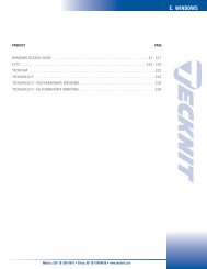
WINDOWS DESIGN GUIDE ........................................................................................E1 - E17<br />
ECTC ........................................................................................................................E19 - E20 70<br />
TECKFILM..........................................................................................................................E21 70<br />
TECKSHIELD F ..................................................................................................................E22 71<br />
TECKSHIELD F: POLYCARBONATE WINDOWS ..................................................................E23<br />
TECKSHIELD F: ALLYCARBONATE WINDOWS....................................................................E24<br />
F - Air Vent Panels<br />
TECKCELL - A AND PARACELL (Aluminum Honeycomb Vent Panels) ..................F1 - F4 60<br />
TECKCELL- SIB (Steel and Brass Honeycomb Vent Panels) ...................................... F5 - F6 62<br />
TECKCELL-A (LP) (Low Profile, Aluminum, Shielding Air Vent Panels) ......................F7 - F8 60<br />
TECKSCREEN (Dust Arresting <strong>EMI</strong> Shielding Air Vent Panels)..................................F9 - F10 63<br />
TECKAIRE (Low Profile Dust and <strong>EMI</strong> Filtering Air Vent Panels) ............................F11 - F12 64<br />
G - Conductive Systems<br />
CONDUCTIVE ADHESIVES (One Part Silver-Filled RTV) ..............................................G1 - G2 72<br />
CONDUCTIVE ADHESIVES (Silver and Nickel Filled RTV) ............................................G3 - G4 72<br />
TECKBOND- C (Silver Plated Copper-Filled Silicone Adhesive) ........................................ G5 72<br />
TECKBOND- A (Silver Plated Aluminum-Filled Silicone Adhesive).................................... G6 72<br />
TECKBOND NC (Nickel Coated Graphite-Filled Silicone Adhesive) ..................................G7 72<br />
CONDUCTIVE CAULKING (Silver-Filled Flexible Resin Caulking Systems) ..................G9 - G10 72<br />
CONDUCTIVE EPOXY (Silver-Filled Systems for Joining, Bonding and Sealing) ........G11 - G12 72<br />
CONDUCTIVE GREASE (Electrically Conductive Silver-Filled Grease) ........................G13 - G14 72<br />
CONDUCTIVE COATINGS (Electrically Conductive Paints) ........................................G15 - G16 73<br />
H Shielding Components<br />
DIE COMPRESSED MESH CONTACTS (Wire Mesh Resilient Contact Element) ..............H1 -H2 32<br />
<strong>EMI</strong> CONNECTOR GASKETS (<strong>EMI</strong> Flange Seals for Electrical Connectors)....................H3 - H7 XX<br />
CONDUCTIVE O-SEALS (Conductive Elastomer Gaskets)............................................H9 - H10 XX<br />
WAVEGUIDE GASKETS (Silicone Elastomer Gaskets) ................................................H11 - H13 87<br />
EMC FOIL TAPE (Conductive Foil Tape with Conductive Adhesive ......................................H14 23<br />
TECKMASK (<strong>EMI</strong> Foil Tape with Easy Peel Mask) ................................................H15 - H16 23<br />
I - Beryllium Copper Gaskets<br />
BERYLLIUM COPPER (Copper <strong>EMI</strong> Shielding Gaskets)....................................................I1 - I8 55-56<br />
J - Fabric-over-Foam Gaskets<br />
TECKSOF 2000 (Conductive Fabric over Foam Gaskets) ............................................J1 - J9 27<br />
K - Glossary and Appendix A....................................................................K1 -K6<br />
Mexico: 528-18-369-8610 • China: 86-10-67884650 • www.tecknit.com<br />
3
<strong>Tecknit</strong> World-Wide<br />
Grantham, England<br />
Apodaca, Mexico<br />
Cranford, NJ<br />
Madrid, Spain<br />
Beijing, China<br />
TECKNIT INC.<br />
Founded in 1958, <strong>Tecknit</strong> has grown into a<br />
multimillion dollar international group of companies<br />
offering a broad range of <strong>EMI</strong> shielding products<br />
and services. In order to better serve customers,<br />
<strong>Tecknit</strong> maintains manufacturing facilities in the<br />
United States, England, Spain, Mexico and China.<br />
Each facility is equipped to efficiently and<br />
economically supply <strong>EMI</strong> shielding products to<br />
regional customers as well as making available cost<br />
savings to customers world-wide. Our <strong>Tecknit</strong>-USA<br />
facility, located in Cranford, New Jersey, is an ISO<br />
9001:2000 certified company.<br />
TECKNIT EUROPE<br />
<strong>Tecknit</strong> Europe is headquartered in Grantham,<br />
England, it supplies the European automotive,<br />
telecommunication, aircraft and commercial<br />
electronics manufacturers. <strong>Tecknit</strong> Europe consists<br />
of manufacturing facilities in Grantham, England<br />
and Madrid, Spain. These facilities enable <strong>Tecknit</strong><br />
Europe to pursue specialized engineering projects<br />
tailored to fit your requirements in the European<br />
market. <strong>Tecknit</strong> Europe is a BS-EN-ISO 9002<br />
certified company.<br />
TECKNIT DE MEXICO<br />
<strong>Tecknit</strong> de Mexico offers both Latin American and<br />
North American customers design and engineering<br />
support from its large facility conveniently located<br />
near the U.S. border in Apodaca, Mexico. Here,<br />
Central, South and North American customers<br />
benefit from the unique manufacturing advantages<br />
found in Mexico, plus the pooled world-wide<br />
engineering resources of <strong>Tecknit</strong> <strong>EMI</strong> Shielding<br />
Products. <strong>Tecknit</strong> de Mexico is an ISO 9001:2000<br />
certified company.<br />
TECKNIT CHINA<br />
China is a major participant in the world economy.<br />
In order to serve China and the growing Asian<br />
market <strong>Tecknit</strong> has established manufacturing<br />
facilities in the heart of Beijing’s Economic And<br />
Industrial Development Area as well as in Shenzhen<br />
and Shanghai, China. Here large varieties of<br />
shielding materials are fabricated to suit customer’s<br />
needs. <strong>Tecknit</strong> China manufactures berylliumcopper<br />
fingerstock, ventilation panels, knitted mesh<br />
products, Form-In-Place gaskets and other <strong>EMI</strong><br />
shielding products. <strong>Tecknit</strong> (Beijing) Electronics<br />
Technologies Co. is an ISO 9001:2000 certified<br />
company.<br />
U.S.A.: 908-272-5500 • U.K.: 44-1476-590600 • Spain: 34-91-4810178
INTRODUCTION<br />
Introduction<br />
U.S. Customary<br />
[SI Metric]<br />
1<br />
U.S.A.: 908-272-5500 • U.K.: 44-1476-590600 • Spain: 34-91-4810178
INTRODUCTION<br />
STANDARD PRODUCTS AND SPECIALS<br />
This catalog presents a technical review of the<br />
TECKNIT <strong>EMI</strong> Shielding Product Line. It is intended<br />
to serve as a guide to the selection, engineering,<br />
and specification of materials and components<br />
for <strong>EMI</strong> or EMP shielding, grounding, and<br />
static discharge. While the standard products illustrated<br />
in this catalog cover a broad range of materials<br />
and applications, TECKNIT has consistently<br />
provided successful solutions to an even broader<br />
range of special problems. We invite inquiries<br />
about our capabilities and recommendations for<br />
any shielding, grounding, or static discharge<br />
application.<br />
BASIC DESIGN CONSIDERATIONS<br />
The following will serve to introduce basic<br />
mechanical and electrical packaging design<br />
considerations for effectively achieving<br />
Electromagnetic Compatibility through the use of<br />
TECKNIT <strong>EMI</strong> Shielding products described in this<br />
catalog. Terminology used, in some cases, is<br />
somewhat unique to the subject, and is described<br />
in the Glossary of Terms included in a separate<br />
section of this catalog.<br />
Electronic equipment/systems, which operate<br />
effectively within design parameters without<br />
causing or suffering unacceptable performance<br />
degradation due to electromagnetic radiation<br />
or response, are described as having<br />
Electromagnetic Compatibility (EMC). A review of<br />
the following electromagnetic spectrum describes<br />
the area in which TECKNIT products can provide<br />
the designer with the required shielding levels of<br />
Electromagnetic Interference (<strong>EMI</strong>) protection for<br />
electronic equipment and systems.<br />
Both mechanical and electrical design aspects<br />
should be carefully considered in the selection of<br />
<strong>EMI</strong> Shielding products. Mechanical considerations<br />
are significant because of physical dimensions<br />
and tolerances involved in construction of<br />
electronic equipment and systems. These factors<br />
may seriously impact on the electrical performance<br />
characteristics of <strong>EMI</strong> shielding products. It<br />
is thus essential that the designer adequately consider<br />
the origin and methods of suppression of<br />
<strong>EMI</strong>.<br />
The <strong>EMI</strong> Shielding Design Guide section of this<br />
catalog contains valuable theoretical and practical<br />
information on “how to select” TECKNIT <strong>EMI</strong>/FFI<br />
shielding materials. In addition, the <strong>EMI</strong> Shielding<br />
Design Guide provides specific information on <strong>EMI</strong><br />
shielding requirements for electronic circuits<br />
which either radiate electromagnetic energy or<br />
are susceptible to electromagnetic interference.<br />
TYPES OF INTERFERENCE<br />
RFI - Radio Frequency<br />
Interference: unwanted radiated<br />
electronic noise (broadcast)<br />
10 kHz to 1000 MHz<br />
EMP - ElectroMagnetic Pulse:<br />
broadband, high intensity<br />
transient phenomena, such as<br />
lightning or nuclear explosion<br />
<strong>EMI</strong> - ElectroMagnetic<br />
Interference: dc to 300 GHz<br />
ESD - ElectroStatic Discharge:<br />
A Transient Phenomena<br />
Involving Static Electricity-<br />
Friction<br />
Mexico: 528-18-369-8610 • China: 86-10-67884650 • www.tecknit.com<br />
2
INTRODUCTION<br />
Introduction, Continued<br />
By using the information provided, the design or<br />
packaging engineermay develop an <strong>EMI</strong> shielding<br />
profile by comparing the required shielding levels<br />
of specific TECKNIT <strong>EMI</strong> shielding materials.<br />
Total shielding is accomplished through the use of<br />
line filters, and <strong>EMI</strong> shielding materials. These <strong>EMI</strong><br />
shielding materials consist of gasket and barrier<br />
materials which provide custom designed products<br />
for specific applications.<br />
<strong>EMI</strong> shielding materials may be generally classified<br />
into three categories:<br />
• Gasketing Materials<br />
• Barrier Materials<br />
• Shielding Components<br />
As shown in the Table of Contents, the products in<br />
these categories may then be arranged to form<br />
eight subsections (A through H) based upon<br />
shielding materials (e.g., knitted wire mesh) or<br />
product type (e.g., windows, vent panels, etc.)<br />
GASKETING MATERIALS:<br />
• Knitted Wire Mesh (Section A)<br />
• Metal Fibers & Screen Gaskets (Section B)<br />
• Oriented Wire Gaskets (Section C)<br />
• Conductive Elastomers (Section D)<br />
• Beryllium Copper Gaskets (Section I)<br />
• Fabric-over-Foam (Section J)<br />
BARRIER MATERIALS:<br />
• Viewing Windows (Section E)<br />
• Air Vent Panels (Section F)<br />
• Conductive Coatings (Section G)<br />
SHIELDING COMPONENTS:<br />
• Toggle boots and shaft seals, foil tape, FUZZ<br />
BUTTON contact elements, connector gaskets,<br />
O-Seals (Section H).<br />
There are seven basic steps involved in the selection<br />
and specification of <strong>EMI</strong> shielding materials.<br />
1. IDENTIFY - susceptible devices and major emissions<br />
sources. Example: Home computer power<br />
supply, aircraft navigation equipment, etc. (generally<br />
specified).<br />
2. <strong>EMI</strong> SHIELDING DESIGN SPECIFICATIONS -<br />
Example: Military, FCC, VDE, Tempest, etc.<br />
(Specified)<br />
3. PERFORM SHIELDING ANALYSIS - Reference<br />
TECKNIT Design Guide to determine shielding<br />
profile by comparing "required shielding" with<br />
shielding obtained for various gaskets and<br />
materials.<br />
4. IDENTIFY MECHANICAL RESTRAINTS - Example:<br />
Openings and discontinuities for viewing, servicing,<br />
air flow, moisture seals, temperature<br />
extremes, etc.<br />
5. TEST-VERIFICATION - To FCC, VDE, MIL-STD<br />
specification. Examine new methods employing<br />
Transfer Impedance or TEM cell.<br />
6. GENERATE SHIELDING SPECIFICATION - For gasket,<br />
barrier, gasket and/or shielding components.<br />
Reference TECKNIT <strong>EMI</strong> Shielding<br />
Products Catalog data sheets for specific material<br />
specifications. Contact TECKNIT<br />
Representative or TECKNIT Factory locations for<br />
design assistance if required and for assigning<br />
of TECKNIT part numbers.<br />
MECHANICAL ASPECTS OF THE SELECTION OF<br />
GASKETING MATERIALS<br />
In developing <strong>EMI</strong> Shielding, many mechanical<br />
and electrical design considerations are interdependent.<br />
One of the more important is joint<br />
unevenness. Joint unevenness refers to the degree<br />
of mismatch between mating seam surfaces. It<br />
results when the mating surfaces make contact at<br />
irregular intervals due to surface roughness or to<br />
bowing of cover plates which may be the result of:<br />
Improper Material Selection, Thickness of Cover<br />
Plate, Too Few Fasteners, Excessive and/or<br />
Uneven Bolt Alignment, Improper Gasket Size<br />
Selection. Ideally, gaskets should make even, con-<br />
3<br />
U.S.A.: 908-272-5500 • U.K.: 44-1476-590600 • Spain: 34-91-4810178
INTRODUCTION<br />
tinuous and uniform contact with seam surfaces.<br />
Seam surfaces should be free of contaminates and<br />
insulating materials such as paints or other decorative<br />
finishes. Joint uneveness and surface conditions<br />
are excellent examples of mechanical<br />
restraints which can have adverse effects on the<br />
electrical performance of a gasket. The ideal gasket<br />
material will bridge irregularities without losing<br />
its properties of resiliency, stability or conductivity.<br />
The primary function of an <strong>EMI</strong> seam gasket is to<br />
minimize the coupling efficiency of a seam. To<br />
provide effective <strong>EMI</strong> Shielding, the seam design<br />
should incorporate the following features:<br />
• Mating surface should be as flat as economically<br />
possible.<br />
• Flange width should be at least (5) times the<br />
maximum expected joint unevenness.<br />
• Mating surfaces requiring dissimilar materials<br />
should be selected from the groupings of metals<br />
shown in the electrochemical compatibility chart<br />
in the TECKNIT Shielding Design Guide.<br />
Materials at opposite ends of the table should be<br />
avoided.<br />
• Mating surfaces should be cleaned to re-move<br />
all dirt and oxide films just prior to assembly of<br />
the enclosure parts.<br />
• Dielectric protective/decorative coatings should<br />
be removed in the mating surface area. These<br />
faces should be treated with chromate conversion<br />
coating for aluminum, and plated with tin,<br />
nickel, or zinc for steel.<br />
• Fasteners should be tightened from the middle<br />
of the longest seam toward the ends to minimize<br />
buckling and warping. In most cases, there will<br />
be several gasket and barrier shielding materials<br />
which can be utilized. A final selection is made<br />
through the consideration of application requirements,<br />
as well as, mechanical design restraints,<br />
economics and other factors which might be<br />
imposed.<br />
ADMINISTRATION AND MANUFACTURING<br />
From its origin in 1958 as Technical Wire<br />
Products, Inc., TECKNIT has become a world<br />
leader in the design and production of <strong>EMI</strong>/EMP<br />
shielding, grounding, and static discharge products.<br />
Today TECKNIT occupies administrative and<br />
manufacturing facilities in the United States,<br />
Mexico, China, Spain and the UK.<br />
SALES AND APPLICATIONS ASSISTANCE<br />
TECKNIT sales representatives and distributors<br />
located throughout the World are available to provide<br />
sales and product application assistance.<br />
PRICE AND AVAILABILITY<br />
Price and delivery quotations on catalog items<br />
are available from your nearest TECKNIT<br />
representative or directly from TECKNIT Sales<br />
Administration Offices Worldwide.<br />
STATEMENT IN LIEU OF WARRANTY<br />
All technical information and data in this document<br />
is based on tests and is believed accurate<br />
and reliable. Nevertheless, since the products<br />
described herein are not provided to conform with<br />
mutually accepted specifications and the use<br />
thereof is unknown, the manufacturer and seller of<br />
the products do not guarantee results, freedom<br />
from patent infringement or suitability of the products<br />
for any application thereof. The manufacturer<br />
and seller of the products described in this document<br />
will provide all possible technical assistance<br />
and will replace any products proven defective. No<br />
statement or recommendation made by the manufacturer<br />
or seller not contained herein shall have<br />
any force or effect unless in conformity with an<br />
agreement signed by an officer of the seller or<br />
manufacturer.<br />
Mexico: 528-18-369-8610 • China: 86-10-67884650 • www.tecknit.com<br />
4
<strong>EMI</strong> SHIELDING DESIGN GUIDE<br />
Section 1:<br />
Electromagnetic Compatibility Overview<br />
U.S. Customary<br />
[SI Metric]<br />
Electromagnetic compatibility (EMC) is the ability<br />
of an electronic system or subsystem to reliably<br />
operate in its intended electromagnetic environment<br />
without either responding to electrical<br />
noise or generating unwanted electrical noise.<br />
Electromagnetic interference (<strong>EMI</strong>) is the impairment<br />
of the performance of an electronic system<br />
or subsystem by an unwanted electromagnetic<br />
disturbance.<br />
Electromagnetic compatibility is achieved by<br />
reducing the interference below the level that disrupts<br />
the proper operation of the electronic system<br />
or subsystem. This compatibility is generally<br />
accomplished by means of electronic filters, and<br />
component or equipment shielding. An example<br />
of an <strong>EMI</strong> emitter/ susceptor system is shown in<br />
Figure 1.<br />
The emitter represents a system or subsystem<br />
that generates noise and the susceptor represents<br />
a system or subsystem that is susceptible to<br />
noise. In the real world, a system or subsystem<br />
can be simultaneously an emitter and a susceptor.<br />
The dotted lines show examples of radiated<br />
interference phenomena and the solid lines show<br />
examples of conducted interference phenomena.<br />
The arrows indicate the direction of noise transmission<br />
and coupling. Line A depicts interference<br />
coupled directly from the emitter to the susceptor<br />
through radiation paths. Line B shows that interconnect<br />
cables can also act as emitters of radiated<br />
noise. Line C shows that interconnect cables<br />
can act as susceptors and respond to noise that<br />
originated as radiated emissions. Thus, noise that<br />
originally began as radiated emission can show<br />
up in the susceptor system as conducted susceptibility.<br />
Line D represents the crosstalk problem<br />
found in interconnect cables where noise in one<br />
cable can be capacitively and inductively coupled<br />
to another cable.<br />
FIGURE 1<br />
INTERFERENCE COUPLING PATHS<br />
5<br />
U.S.A.: 908-272-5500 • U.K.: 44-1476-590600 • Spain: 34-91-4810178
Section 1:<br />
Electromagnetic Shielding Overview<br />
<strong>EMI</strong> SHIELDING DESIGN GUIDE<br />
Electromagnetic waves consist of two oscillating<br />
fields at right angles (Figure 2). One of these<br />
fields is the electric field (E-Field) while the other<br />
is the magnetic field (H-Field). The electromagnetic<br />
wave impedance (Z w ) in ohms is defined as the<br />
ratio of E-Field intensity expressed in volts per<br />
meter (V/m) to the H-Field intensity expressed in<br />
amperes per meter (A/m). E-Fields are generated<br />
by and most easily interact with high impedance<br />
voltage driven circuitry, such as a straight wire or<br />
dipole. H-Fields are generated by and most readily<br />
interact with low impedance current driven circuitry<br />
such as wire loops.<br />
interaction with conductive materials were developed<br />
well over a hundred years ago by J.C.<br />
Maxwell. The solutions of these differential equations<br />
are generally complex, even for simple models.<br />
This has discouraged their use in shielding<br />
analysis.<br />
FIGURE 3<br />
LOSSES DUE TO A SOLID CONDUCTIVE BARRIER<br />
FIGURE 2<br />
ELECTROMAGNETIC PLANE POLARIZED WAVEFORM<br />
Any barrier placed between an emitter and a susceptor<br />
that diminishes the strength of the interference<br />
can be thought of as an <strong>EMI</strong> shield. How<br />
well the shield attenuates an electromagnetic field<br />
is referred to as its shielding effectiveness (SE).<br />
Therefore, shielding effectiveness is a measure of<br />
the ability of that material to control radiated electromagnetic<br />
energy. The standard unit of measurement<br />
for shielding effectiveness is the decibel<br />
(dB). The decibel is expressed as the ratio of two<br />
values of electromagnetic field strength where the<br />
field strengths are compared before and after the<br />
shield is in place. It is defined as:<br />
E-Field, SE dB = 20 log 10 (E 1 \ E 2 )<br />
H-Field, SE dB = 20 log 10 (H 1 \ H 2 )<br />
The losses in field strength from a shielding barrier<br />
are a function of the barrier material (permeability,<br />
conductivity and thickness), frequency and<br />
distance from the <strong>EMI</strong> source to the shield.<br />
The basic differential equations that express classical<br />
electromagnetic field phenomena and its<br />
A simpler method for studying the effects of electromagnetic<br />
wave interaction with conductive barriers<br />
was developed by S.A. Schelkunoff in the<br />
1930’s. Using this technique, total shielding<br />
effectiveness (SE dB ) of a solid conductive barrier<br />
can be expressed as the sum of the reflection,<br />
(R dB ), absorption, (A dB ) and re-reflection (B dB )<br />
losses (refer to Figure 3). The reflection loss is<br />
proportional to the electromagnetic wave impedance<br />
(Z W ) and inversely proportional to the barrier<br />
intrinsic impedance (Z B ). The absorption loss is<br />
proportional to the barrier thickness (t) and<br />
absorption coefficient of the barrier (α ). The<br />
inverse of the absorption coefficient is called the<br />
‘skin depth’ (δ ). Skin depth is a magnetic property<br />
that tends to confine the current flow to the<br />
surface of a conductor. The skin depth becomes<br />
shallower as frequency, conductivity or permeability<br />
increases. Electromagnetic fields become<br />
attenuated by 1/e (natural logarithm) for every<br />
skin depth of penetration into the barrier as<br />
shown in Figure 4. The greater the number of<br />
skin depths that exist within a given thickness of<br />
metal, the greater the absorption loss. Since the<br />
skin depth becomes shallower as frequency<br />
increases, absorption loss becomes the dominant<br />
term at high frequencies. The re-reflection loss is<br />
Mexico: 528-18-369-8610 • China: 86-10-67884650 • www.tecknit.com<br />
6
<strong>EMI</strong> SHIELDING DESIGN GUIDE<br />
Section 1:<br />
Electromagnetic Shielding Overview, cont<br />
U.S. Customary<br />
[SI Metric]<br />
strongly dependent upon the absorption loss. Just<br />
as a reflection occurs at the air to metal entrance<br />
boundary of the barrier, a similar reflection occurs<br />
at the metal to air exit boundary . For an absorption<br />
loss of greater than 10 dB, the reflection term<br />
can be ignored.<br />
FIGURE 4<br />
ABSORPTIVE LOSSES AS A FUNCTION OF SKIN DEPTH (δ)<br />
The barrier intrinsic impedance is a function of<br />
the barrier relative permeability (µ r ), relative conductivity<br />
(σ r ), and frequency (f). The wave impedance<br />
is a function of the absolute permeability<br />
(µ o ) and absolute permittivity (ε o ). Two other<br />
important factors in the shielding equation are the<br />
distance (r) from the source of electromagnetic<br />
energy to the barrier, and wavelength (λ).<br />
Wavelength is related to the propagation velocity<br />
(C = 3 x 10 8 m/sec) and the frequency (f) as follows:<br />
λ = c/f. When the source to barrier distance<br />
is less than about one sixth of the wavelength of<br />
the frequency of the electromagnetic energy<br />
(λ/2π), the field is called the ‘near field’. When<br />
the source to barrier distance is greater than<br />
λ/2π, the field is called the ‘far field’.<br />
The distance between the source and barrier is<br />
important in determining the reflectivity factors in<br />
the near field for E-Fields and H-Fields. For E-<br />
Fields the reflection loss in the near field increases<br />
as the separation between the source and<br />
shielding barrier decreases and as frequency<br />
decreases. For H-Fields, on the other hand, the<br />
reflection loss in the near field increases as the<br />
separation between the source and shielding barrier<br />
increases and as the frequency increases. For<br />
absorption, the losses are independent of the<br />
near field/far field condition and are the same<br />
whether the wave is predominantly an E-Field,<br />
HField or a plane wave, which is an electromagnetic<br />
wave in which all points normal to the direction<br />
of propagation are in phase or parallel to one<br />
another or going in the same direction.<br />
Summarizing:<br />
• Absorption: Absorption increases with increase<br />
in frequency of the electromagnetic wave,<br />
barrier thickness, barrier permeability, and<br />
conductivity.<br />
• Reflection: As a general rule, above 10 kHz,<br />
reflection increases with an increase in conductivity<br />
and a decrease in permeability.<br />
• Reflection - E-Field: Increases with a decrease<br />
in frequency and a decrease in distance<br />
between the source and shielding barrier.<br />
• Reflection - H-Field: Increases with an increase<br />
in frequency and an increase in distance<br />
between the source and shielding barrier.<br />
• Reflection - Plane Wave: Increases with a<br />
decrease in frequency.<br />
The solution of shielding effectiveness equations<br />
for solid conductive barriers, which considers the<br />
barrier as an infinite plane of finite thickness,<br />
usually results in shielding levels much greater<br />
than practically achieved with an actual shielded<br />
enclosure. This is due to barrier finite dimensions<br />
and discontinuities, which are a necessary part of<br />
a conductive cabinet design (e.g., seams, cable<br />
penetrations and air vents). Barrier thickness<br />
required to meet mechanical strength requirements<br />
generally provides adequate shielding<br />
effectiveness. The barrier material and shielding<br />
treatments of seams, penetrations and apertures<br />
are the more important design considerations. In<br />
Appendix A is a ranking of materials with respect<br />
to relative conductivity, relative permeability,<br />
absorption loss, and, reflection loss. Shielding<br />
treatments, including those manufactured by<br />
<strong>Tecknit</strong>, are discussed in the following sections of<br />
this Design Guide.<br />
7<br />
U.S.A.: 908-272-5500 • U.K.: 44-1476-590600 • Spain: 34-91-4810178
Section 1:<br />
Electromagnetic Compatibility Design<br />
<strong>EMI</strong> SHIELDING DESIGN GUIDE<br />
EMC design should be an integral part of any<br />
electronic device or system. This is far more cost<br />
effective than the alternative, that is, attempting to<br />
achieve EMC on a finished product. The primary<br />
EMC design techniques include electromagnetic<br />
shielding, circuit filtering, and good ground<br />
design including special attenuation to the bonding<br />
of grounding elements.<br />
Figure 5 presents a recommended methodology<br />
to good EMC design of a device or system. A hierarchy<br />
is presented in the form of a pyramid. First,<br />
the foundation of a good EMC design is simply<br />
the application of good electrical and mechanical<br />
design principles. This includes reliability considerations<br />
like meeting design specifications within<br />
acceptable tolerances, good packaging and comprehensive<br />
development testing.<br />
Next, internal cables are generally used to connect<br />
PCBs or other internal subassemblies. The<br />
internal cable EMC design, including routing and<br />
shielding, is very important to the overall EMC of<br />
any given device.<br />
After the EMC design of the PCB and internal<br />
cables are complete, special attention must be<br />
given to the enclosure shielding design and the<br />
treatment of all apertures, penetrations and cable<br />
interfaces. Finally, consideration must be given to<br />
filtering of input and output power and other<br />
cables.<br />
The following sections look at each of these<br />
important areas and provide practical EMC design<br />
guidelines.<br />
PCB DESIGN<br />
When designing a PCB, the design goal is to control<br />
the following:<br />
1. emissions from the PCB circuitry,<br />
2. susceptibility of the PCB circuits to external<br />
interference,<br />
3. coupling between PCB circuits and other nearby<br />
circuits in the device, and<br />
4. coupling between circuits on the PCB.<br />
This is accomplished primarily by paying special<br />
attention to the board layout and design, minimizing<br />
impedance discontinuities, and, when possible,<br />
by using low amplitude signals.<br />
FIGURE 5<br />
EMC DESIGN PYRAMID<br />
Generally, the engine that drives today’s electronic<br />
equipment is located on a printed circuit board<br />
(PCB). This engine is comprised of potential interference<br />
sources, as well as components and circuits<br />
sensitive to electromagnetic energy.<br />
Therefore, the PCB EMC design is the next most<br />
important consideration in EMC design. The location<br />
of active components, the routing of traces,<br />
impedance matching, grounding design, and circuit<br />
filtering are driven, in part, by EMC considerations.<br />
Certain PCB components may also require<br />
shielding.<br />
If clock frequencies above 10 MHz are used, in<br />
most cases it will be necessary to use multilayer<br />
design with an embedded ground layer. If this is<br />
cost prohibitive for your product, use guardbanding,<br />
that is, grounds on each side of signal traces.<br />
Components should be located such that noisy<br />
and sensitive circuits can be isolated. Keep clock<br />
traces, buses and chip enables separate from I/O<br />
lines and connectors. Clock runs should be minimized<br />
and oriented perpendicular to signal<br />
traces. If the clocks go off the board, then they<br />
should be located close to the connector.<br />
Otherwise, clocks should be centrally located to<br />
help minimize onboard distribution traces.<br />
Input/output chips should be located near the<br />
associated connectors. Output circuits should be<br />
damped with a resistor, inductor or ferrite bead<br />
Mexico: 528-18-369-8610 • China: 86-10-67884650 • www.tecknit.com<br />
8
<strong>EMI</strong> SHIELDING DESIGN GUIDE<br />
Section 1:<br />
Electromagnetic Compatibility Design, cont<br />
U.S. Customary<br />
[SI Metric]<br />
mounted close to the driver. Circuit types (i.e.,<br />
digital, analog, power) should be separated, as<br />
well as their grounds. <strong>Tecknit</strong> offers a variety of<br />
shielding components especially suited for PCB<br />
shielding applications including a comprehensive<br />
line of conductive elastomers. See Section D of<br />
the <strong>Tecknit</strong> Shielding Products Catalog.<br />
For high frequency design, the layout should be<br />
treated as a signal transmission environment,<br />
necessitating that impedance discontinuities be<br />
minimized.<br />
Good decoupling practices should be used<br />
throughout the PCB; use bypasses liberally.<br />
Typically, this will be a 0.1 to 1.0 microfarad<br />
ceramic capacitor. Bypass capacitors should be<br />
mounted close to the IC.<br />
Minimize power bus loop areas by routing the<br />
power bus as close as possible to its return.<br />
Power lines should be filtered at the PCB interface.<br />
INTERNAL CABLE DESIGN<br />
Internal cabling should be minimized as much as<br />
possible. When cables are required to connect<br />
assemblies and PCBs, the lengths should be minimized.<br />
Long service loops can be disastrous. If<br />
PCBs are properly designed, the requirement for<br />
shielding of internal cabling will be minimized.<br />
However, if it is found that cable shielding is<br />
required, the technique used to ground the shield<br />
is critical to the attenuation afforded by the<br />
shield. Cable shields should not be used as signal<br />
returns. For certain unbalanced circuits, coaxial<br />
cables are often used. In this case the ‘shield’ of<br />
the coaxial cable is intentionally used for signal<br />
return. In this application, the shield is not<br />
intended for attenuation of electromagnetic energy<br />
emanating from the center conductor. If the<br />
circuits at each end of a coaxial cable are<br />
designed properly, the coaxial cable should not<br />
radiate. However, if circuit impedances are not<br />
properly matched and the coaxial cable does<br />
radiate, another shield must be added to the<br />
cable (triaxial). This outer ground would be then<br />
bonded to the chassis ground.<br />
ENCLOSURE SHIELDING DESIGN<br />
The enclosure must be designed with shielding in<br />
mind. If PCBs and internal cabling are properly<br />
designed, the need for enclosure shielding will be<br />
minimized. However, if it is found that enclosure<br />
shielding is required, designing the enclosure to<br />
permit the application of shielding treatments will<br />
minimize the level of the shielding design and<br />
associated cost.<br />
A shielded enclosure should be fabricated from<br />
materials that possess the desired physical and<br />
electrical characteristics, including resistance to<br />
adverse environmental conditions. Discontinuities<br />
degrade the shielding and their design is critical<br />
in maintaining the desired levels of shielding<br />
effectiveness, providing the possibility of electromagnetic<br />
coupling through the openings and<br />
seams. The efficiency of the coupling depends<br />
upon the size of the hole or seam in relation to<br />
the wavelength of the interference. Any openings<br />
in an enclosure can provide a highly efficient coupling<br />
path at some frequency. As the aperture<br />
increases in size, its coupling efficiency increases.<br />
A good rule of thumb to follow in general design<br />
practice is to avoid openings larger than l/20 for<br />
standard commercial products and l/50 for products<br />
operating in the microwave range. Since<br />
most <strong>EMI</strong> coupling problems are broadband in<br />
nature, the frequency of concern would be the<br />
highest threat frequency within the bandwidth<br />
envelope. Figure 6 shows l/20 and l/50 aperture<br />
sizes over the frequency range 100 kilohertz<br />
(kHz) to 10 gigahertz (GHz).<br />
9<br />
In the <strong>Tecknit</strong> <strong>EMI</strong> Shielding Products Catalog,<br />
knitted wire mesh and metal foil tapes can be<br />
found which are specifically designed for harness<br />
and cable shielding, as well as grounding<br />
applications.<br />
FIGURE 6<br />
MAXIMUM SIZE OPENING AGAINST THREAT FREQUENCY<br />
U.S.A.: 908-272-5500 • U.K.: 44-1476-590600 • Spain: 34-91-4810178
<strong>EMI</strong> SHIELDING DESIGN GUIDE<br />
When it is necessary to specify an opening larger<br />
than λ/20 or λ/50, protective measures, such as<br />
the products manufactured by <strong>Tecknit</strong>, may be<br />
required to reduce the coupling which the aperture<br />
introduces. See Section 4 for application<br />
solutions.<br />
Electromagnetic energy leakage through an aperture<br />
is dependent upon two factors:<br />
1. the longest dimension, (d), of the aperture<br />
2. the wavelength of the radiating field.<br />
For wavelengths less than two times the longest<br />
aperture dimension, the electromagnetic energy<br />
will pass freely through the opening without being<br />
attenuated. For wavelengths equal to twice the<br />
opening, the shielding is zero. The frequency at<br />
which this occurs is called the cutoff frequency<br />
(f c ).<br />
f c = C/2d, where C is the propagation velocity of<br />
electromagnetic waves<br />
For wavelengths greater than two times the maximum<br />
dimension, the attenuation is expressed as :<br />
frequency is reduced proportionally to the ratio of<br />
the distance from the aperture:<br />
f c = (C/2d) (r/d) and<br />
R dB = (20 log l/2d) (r/d), where λ/2 > d<br />
The presence of more than one aperture of the<br />
same size in a solid metal barrier has the effect of<br />
reducing the total effective shielding. The amount<br />
of shielding reduction is dependent on the spacing<br />
between any two adjacent apertures, the<br />
wavelength of the interference and the total number<br />
of apertures. If the adjacent apertures have<br />
the same maximum dimension and are spaced at<br />
least a half wavelength apart, the shielding reduction<br />
is minimal and can be considered zero for<br />
practical purposes.<br />
As the apertures are brought closer together (s d > t<br />
(t = material thickness)<br />
Apertures affect both the reflection and absorption<br />
terms. The reflection term is lowered as a<br />
result of an increase in the barrier impedance relative<br />
to the wave impedance. This increase in<br />
barrier impedance is caused by leakage inductance,<br />
which is related to the dimensions of the<br />
aperture and the spacing of the radiating circuits<br />
from the aperture. A good approximation of the<br />
net shielding is to assume 0 dB shielding at the<br />
cutoff frequency and a linear increase of 20 dB<br />
per decade in shielding as the frequency<br />
decreases. The maximum possible shielding<br />
effectiveness, of course, is equal to that calculated<br />
for a solid barrier without an aperture.<br />
However, this does not consider the effects of the<br />
noise source in close proximity to the aperture. As<br />
long as the potential <strong>EMI</strong> source is spaced at<br />
least as far away as the largest dimension of the<br />
aperture, this approximation will hold true.<br />
When a noise source is closer than the largest<br />
dimension of the aperture, a reduction in shielding<br />
can be expected. Deriving the shielding<br />
requirement in this situation can be very complicated.<br />
As an approximation, the effective cutoff<br />
where n = number of apertures<br />
s < λ/2 > d > t<br />
s = edge to edge hole spacing<br />
These relationships apply to knitted or woven wire<br />
screen material if the wires make good contact at<br />
each crossover or intersection.<br />
Nonmetallic Enclosures<br />
Many commercial electronic devices are packaged<br />
in enclosures of plastic or other nonconductive<br />
materials. If the devices must rely on enclosure<br />
shielding for EMC compliance, these enclosures<br />
must be treated with a conductive material<br />
to provide shielding. Metallizing techniques for<br />
this application include vacuum deposition, electroless<br />
plating, arc spray, and conductive spray<br />
‘paint’. The latter is the most frequently used<br />
technique which is really a paint-like slurry of<br />
metal particles in a carrier. These conformal coatings<br />
are loaded with very fine particles of a conductive<br />
material such as silver, nickel, copper and<br />
carbon. For example, <strong>Tecknit</strong> manufactures a<br />
highly conductive acrylic and polyurethane paints<br />
filled with silver particles. Surface resistivities as<br />
low as 50 milliohms per square are attainable for<br />
a one mil coating thickness. The lower the sur-<br />
Mexico: 528-18-369-8610 • China: 86-10-67884650 • www.tecknit.com<br />
10
<strong>EMI</strong> SHIELDING DESIGN GUIDE<br />
Section 1:<br />
Electromagnetic Compatibility Design, cont<br />
U.S. Customary<br />
[SI Metric]<br />
11<br />
face resistivity of the conductive coating, the<br />
greater the shielding effectiveness. Shielding<br />
effectiveness levels of 60 dB to 100 dB can be<br />
achieved.<br />
Windows<br />
Often, large-area openings are required for viewing<br />
displays, status lamps and device operating<br />
status. When shielding of these large areas is<br />
required for EMC purposes, several options are<br />
available: (a) laminating a conductive screen<br />
between optically clear plastic or glass sheets; (b)<br />
casting a mesh within a plastic sheet; and (c)<br />
applying an optically clear conductive layer to a<br />
transparent substrate.<br />
Refer to Section E of the <strong>Tecknit</strong> <strong>EMI</strong> Shielding<br />
Products Catalog for application and performance<br />
data on <strong>EMI</strong> shielding windows.<br />
Seams<br />
In the design of seams, the goal should be to<br />
achieve complete conductive contact along the<br />
entire length of the seam. In cases where this is<br />
not practical, special attention must be given to:<br />
1. Seam Overlap: The two surfaces of the seam<br />
form a capacitor. Since capacitance is a function<br />
of area, seam overlap should be made as large as<br />
practical to provide sufficient capacitive coupling<br />
for the seam to function as an electrical short at<br />
high frequencies. As a good rule to follow, the<br />
minimum seam overlap to spacing-between-surfaces<br />
ratio should be 5 to 1.<br />
FIGURE 7<br />
SEAM OVERLAP AND SPACING<br />
2. Seam Contact Points: Along the entire length of<br />
every seam there should be firm electrical contact<br />
at intervals no greater than λ/20 for most commercial<br />
devices and λ/50 for microwave devices.<br />
This contact can be obtained by using pressure<br />
devices such as screws or fasteners, grounding<br />
pads, contact straps across the seam, or conductive<br />
gaskets. <strong>Tecknit</strong> manufactures foil tapes,<br />
thin elastomer gaskets, conductive caulks and<br />
various other products which can be used in this<br />
application.<br />
If the seam surfaces are conductive and mate<br />
tightly, an electrical short is provided. To ensure<br />
a tight seam design, conductive gasketing along<br />
the entire length of the seam may be used.<br />
Conductive gasketing should be considered in the<br />
following cases:<br />
1. Total enclosure shielding requirements exceed<br />
40dB.<br />
2. Enclosures with seam openings greater than<br />
λ/20.<br />
3. Threat/emission frequencies exceed 100 MHz.<br />
4. Machined mating surfaces are impractical.<br />
5. Dissimilar materials are used on the mating<br />
surfaces of the seam and the device is<br />
designed to operate in severe environments.<br />
6. Environmental (e.g., dust, vapor) seals are<br />
necessary.<br />
<strong>Tecknit</strong> manufactures a wide variety of conductive<br />
gaskets for a broad range of applications, see the<br />
<strong>Tecknit</strong> Catalog.<br />
When using gasketing materials to attain a satisfactory<br />
<strong>EMI</strong> shield, as well as proper environmental<br />
seal, be aware that gaskets are subject to both<br />
minimum and maximum pressure limits to<br />
achieve a proper electromagnetic seal. The<br />
greater the pressure applied to the gasketed joint,<br />
the better the apparent environmental and <strong>EMI</strong><br />
seal. However, should the pressure exceed the<br />
maximum pressure limit of the gasket, permanent<br />
damage to the gasket can occur. This damage<br />
may decrease pressure across the seam and<br />
degrade both the environmental and <strong>EMI</strong> shielding<br />
characteristics. Wherever possible, use gasket<br />
compression stops or grooves to limit compression<br />
to the maximum recommended values.<br />
Penetrations<br />
Enclosure penetrations may be categorized as (a)<br />
those through which a conductor is passed, and<br />
(b) those through which a conductor does not<br />
pass. An example of the former is a cable interface<br />
port, and examples of the latter are air vents<br />
and holes for dielectric shafts.<br />
Generally, to maintain the shielding integrity of the<br />
enclosure at cable penetrations, electronic filters<br />
or shielded cables must be used. <strong>Tecknit</strong> manufactures<br />
wire mesh and foil tapes which can be<br />
used for cable shielding purposes. See Section A<br />
in the <strong>Tecknit</strong> Catalog.<br />
U.S.A.: 908-272-5500 • U.K.: 44-1476-590600 • Spain: 34-91-4810178
<strong>EMI</strong> SHIELDING DESIGN GUIDE<br />
To maintain the shielding integrity of an enclosure<br />
with feedthroughs for non-conductive shafts or air<br />
vents, waveguide theory may be applied. A metal<br />
tube may be used for non-conductive shafts as<br />
shown in Figure 8. This tube may be treated as a<br />
waveguide to determine its ‘shielding’ characteristics.<br />
The attenuation (A) characteristics of an individual<br />
waveguide below the cutoff frequency (fc)<br />
is a function of the depth to width ratio (d/w). As<br />
the depth to width ratio increases, so does the<br />
shielding.<br />
For circular waveguides, the following relationships<br />
apply:<br />
f c = 1.76 x 10¹⁰/w cm = 6.92 x 10⁹/w in<br />
A dB = 32 d/w<br />
For rectangular waveguides, the following relationships<br />
apply:<br />
f c = 1.5 x 10¹⁰/w cm = 5.9 x 10⁹/w in<br />
A dB = 27.3 d/w<br />
As discussed above, air vents that attenuate electromagnetic<br />
energy can generally be designed<br />
using multiple small holes in a metallic enclosure.<br />
However, in some cases where adequate attenuation<br />
can not be achieved in this manner, for<br />
example, when the noise source is close to the air<br />
vent, a honeycomb waveguide design may be<br />
used as shown in Figure 8. These waveguide air<br />
vent panels are available from <strong>Tecknit</strong>. See<br />
Section F in the <strong>Tecknit</strong> Catalog.<br />
FILTERS<br />
Generally, to suppress power line and signal line<br />
emission, some form of filtering is required. Filter<br />
attenuation is highly dependent upon source and<br />
load impedances. Manufacturers’ data is generally<br />
published for 50 ohm source and load impedances<br />
while actual impedances are generally<br />
reactive and vary considerably over the frequency<br />
range of interest. While there are methods for<br />
determining the actual impedances, these values<br />
are usually unknown. Hence, the selection of filters<br />
through mathematical computation is usually<br />
impractical.<br />
An alternative approach is that of impedance mismatch.<br />
That is, if a filter mismatches its source<br />
and load impedances, minimum transfer of signal<br />
(<strong>EMI</strong>) power will occur. If the source impedance<br />
is high, the filter input impedance should be low,<br />
or shunt capacitive. If the source impedance is<br />
low, the filter input impedance should be high, or<br />
series reactive. The same mismatch should exist<br />
between the load impedance and the filter’s output<br />
impedance.<br />
Another consideration is whether the <strong>EMI</strong> is common<br />
mode or differential mode, where common<br />
mode refers to noise voltages on two conductors<br />
referenced to ground, and differential mode refers<br />
to a voltage present on one conductor referenced<br />
to the other. In many cases both types of <strong>EMI</strong><br />
must be attenuated.<br />
Virtually all off-the-shelf power line filters are<br />
designed to handle common mode noise, and<br />
many provide both common and differential<br />
mode filtering. Without conducted emission test<br />
data, it is generally difficult to determine the interference<br />
mode of the equipment and thus the type<br />
of filter required.<br />
FIGURE 8<br />
WAVEGUIDES BEYOND CUTPFF<br />
FIGURE 9<br />
EXAMPLE OF FILTER TYPES<br />
Mexico: 528-18-369-8610 • China: 86-10-67884650 • www.tecknit.com<br />
12
<strong>EMI</strong> SHIELDING DESIGN GUIDE<br />
Section 1:<br />
Electromagnetic Compatibility Design, cont<br />
U.S. Customary<br />
[SI Metric]<br />
Some knowledge of basic filter design is helpful in<br />
selecting which filter type to try first. Where common<br />
mode filtering is required, line-to-ground<br />
capacitors and common core inductors should<br />
be used.<br />
Where differential mode filtering is required, lineto-<br />
line capacitors and discrete series inductors<br />
should be used. Figure 9 illustrates examples of<br />
both filter types. Most filter manufacturers, given<br />
some knowledge of a particular device and the<br />
<strong>EMI</strong> problem, can assist in selecting a suitable filter.<br />
The only way to be sure that a filter will<br />
reduce <strong>EMI</strong> to compliant levels is to test the<br />
equipment for conducted emissions, and be prepared<br />
to try several different filters. This trial-anderror<br />
approach may be unscientific, but in most<br />
cases proves to be the fastest, most cost effective,<br />
and minimum risk approach.<br />
The installation of a filter is extremely critical.<br />
Filter case-to-frame ground connections must<br />
have low impedance over the frequency range of<br />
the filter, input- to-output leads must have maximum<br />
physical isolation, and, in the case of power<br />
line and I/O line filters, the filtered lines must be<br />
as close as possible to the enclosure entry point<br />
(see Figure 10).<br />
FIGURE 10<br />
FILTER INSTALLATION<br />
Connector pin filters and ferrite beads are also<br />
very effective, especially on I/O line and for high<br />
frequency (>100 MHz) attenuation. One must be<br />
cautious that the capacitor and ferrite impedances<br />
do not affect intended signal characteristics.<br />
BONDING AND GROUNDING<br />
In the preceding sections, references were made<br />
to the importance of good low impedance ground<br />
connections for shielding and filtering. Grounding<br />
is probably the most important, yet least understood,<br />
aspect of <strong>EMI</strong> control. Often, ‘ground’ connections<br />
are made without appropriate attention<br />
to the ground conductor impedance at the frequencies<br />
of interest. As a result, the performance<br />
of enclosure shielding, cable shielding or filtering<br />
may be degraded, and the erroneous conclusion<br />
made that the ‘shield’ or ‘filter’ design is incorrect.<br />
When we use the word "ground", we are generally<br />
speaking about a reference point. In most cases,<br />
the best place to begin is with the green safety<br />
wire of the AC power cable, assuming the device<br />
is not battery powered of course. Since safety<br />
organizations require that the safety ground be<br />
connected to the chassis, the green wire is generally<br />
attached to the chassis immediately upon<br />
entering the enclosure. This is good practice for<br />
<strong>EMI</strong> control as well since this ‘safety ground point’<br />
will also serve as the primary point of reference<br />
for all other ground connections. The goal is to<br />
maintain a very low impedance path between this<br />
point and any other ground connection point in<br />
the device.<br />
Thus, ‘bonding’, or maintaining a low impedance<br />
connection between mating conductive parts, is<br />
an important part of a good ground scheme. This<br />
requires that mating parts of enclosures not be<br />
painted, the ground straps not be attached to<br />
painted surfaces, and, perhaps, in corrosive environments,<br />
special attention be given to the use of<br />
dissimilar metals to preclude the effects of galvanic<br />
action. The goal is to maintain, as close<br />
as practical, a single potential ‘safety ground’<br />
system.<br />
Signal returns should generally be attached to<br />
safety ground at one point (single-point ground<br />
concept) to avoid ground loops. The term generally<br />
is important to note here since, in some<br />
cases, it might be found that a multi-point ground<br />
approach yields better results. Trial-and-error may<br />
be required. Printed circuit board design should<br />
also employ a singlepoint ground approach to<br />
13<br />
U.S.A.: 908-272-5500 • U.K.: 44-1476-590600 • Spain: 34-91-4810178
<strong>EMI</strong> SHIELDING DESIGN GUIDE<br />
maintain isolation of different circuit types as previously<br />
discussed. The best approach is to develop<br />
a ground diagram showing all ground connections,<br />
using different symbols for ‘safety’, ‘analog’,<br />
‘digital’, and ‘rf’ grounds. This will help to highlight<br />
potential problems such as ground loops and<br />
common ground paths for different circuit types.<br />
Figure 11 illustrates the concept described above.<br />
This is an ideal condition. However, in many<br />
cases it is necessary to connect returns from one<br />
PCB to another or one circuit type to another.<br />
This results in ground loops. To minimize the<br />
potential <strong>EMI</strong> threat, the following approaches<br />
can be taken:<br />
1. use balanced differential circuits when possible,<br />
2. minimized loop areas, and<br />
3. run hot and return leads next to each other.<br />
FIGURE 11<br />
EXAMPLE OF DEVICE GROUND DIAGRAM<br />
Mexico: 528-18-369-8610 • China: 86-10-67884650 • www.tecknit.com<br />
14
<strong>EMI</strong> SHIELDING DESIGN GUIDE<br />
Section 2:<br />
Special Applications<br />
U.S. Customary<br />
[SI Metric]<br />
15<br />
MILITARY EQUIPMENT EMC DESIGN<br />
Since about 1990, there has been a trend in the<br />
military to accept commercial-off-the-shelf (COTS)<br />
equipment, especially in ‘noncritical’ equipment.<br />
In many military contracts, EMC requirements referencing<br />
FCC and IEC standards can be found.<br />
There are several reasons for this including cost<br />
reduction.<br />
However, where more stringent requirements are<br />
deemed necessary the most commonly used military<br />
standards for both emissions and immunity<br />
(more commonly referred to as susceptibility in<br />
the military) are MIL-STD-461D, Requirements for<br />
the Control of Electromagnetic Interference<br />
Emissions and Susceptibility and MIL-STD-462D,<br />
Measurement of Electromagnetic Interference<br />
Characteristics. As the titles indicate, one document<br />
sets forth emission limits and susceptibility<br />
criteria while the other defines the test methodology.<br />
As one might expect, the military emission limits<br />
are much lower and the susceptibility criteria<br />
more severe than those found in most commercial<br />
standards. Also, the frequency ranges are<br />
broader as referenced in the MIL-STD- 461D<br />
requirements.<br />
The basic EMC design principles set forth in this<br />
Design Guide for commercial products applies as<br />
well to military products. The primary areas that<br />
differ are generally in the design of the enclosures<br />
and line filters. Also, especially in large complex<br />
systems, EMC design analyses are required in the<br />
schematic design phase to guide the electrical<br />
and mechanical engineers.<br />
MODELING AND ANALYSIS<br />
In many cases a circuit or module will emit or be<br />
susceptible to <strong>EMI</strong> only on certain frequencies.<br />
For example: a radio transmitter operating at 10<br />
MHz might interfere with the normal operation of<br />
a digital electronic circuit located nearby, whereas,<br />
with a difference of as little as one percent in<br />
the transmission frequency, the problem might<br />
not exist. On the other hand, a particularly ‘noisy’<br />
signal source might have several discrete emission<br />
frequencies, all within the response bandwidth<br />
of the susceptible circuit.<br />
To comprehend the multifrequency problem associated<br />
with electromagnetic emissions, it is helpful<br />
to understand frequency relationships associated<br />
with fundamental waveforms, such as the<br />
square wave. An ideal square wave consists of a<br />
signal switching two distinct voltage levels with<br />
FIGURE 12<br />
IDEALIZED SQUARE WAVE WITH ITS FOURIER COMPONENTS<br />
instantaneous transitions between levels. Figure<br />
12 illustrates an ideal square wave along with its<br />
frequency spectrum. Fourier theory states that a<br />
square wave spectrum can be expressed as an<br />
infinite sum of simple sine waves of decreasing<br />
amplitude whose frequency decreases as the odd<br />
multiple of the basic frequency of the square<br />
wave itself. This figure illustrates that there is a<br />
significant amount of energy still contained in the<br />
higher order harmonics when compared to the<br />
energy contained in the fundamental frequency.<br />
Figure 13 shows the same ideal square wave<br />
spectrum with amplitude converted to decibels<br />
and frequency on a logarithmic scale. This is<br />
commonly done to permit comparison with applicable<br />
limits which are formatted in this manner.<br />
The vertical lines represent the signal amplitude<br />
as a function of frequency and the curve drawn<br />
through the points of maximum amplitude represents<br />
the worst case limits. It is standard practice<br />
to ignore the discrete nature of emissions and<br />
deal exclusively with the curve shown connecting<br />
the points of maximum amplitude since it is difficult<br />
and time consuming to predict emissions one<br />
frequency at a time. Figure 13 shows that the<br />
emissions profile of an ideal square wave<br />
decreases at the rate of 20 dB per frequency<br />
decade. Actual square waves do not have instantaneous<br />
transitions to perfectly flat voltage levels<br />
as shown in the idealized case. They are more<br />
accurately modeled by a trapezoidal waveform.<br />
U.S.A.: 908-272-5500 • U.K.: 44-1476-590600 • Spain: 34-91-4810178
<strong>EMI</strong> SHIELDING DESIGN GUIDE<br />
FIGURE 13<br />
AMPLITUDE OF IDEALIZED SQUARE WAVE IN dB REFERENCE TO A<br />
Figure 14 shows a trapezoidal wave with a finite<br />
rise time together with a frequency versus amplitude<br />
plot. The slope of the emissions shifts from<br />
20 dB per decade to 40 dB per decade as a<br />
function of the rise time/fall time of the waveform<br />
(1/+tr). As the rise time (tr) increases, the frequency<br />
at which the slope changes from 20 dB to<br />
40 dB per decade decreases. In addition, the<br />
emissions profiles are functions of the duty cycle<br />
of the signal. If the signal is symmetrical (50%<br />
duty cycle) the worst case emissions profile<br />
results. As the duty cycle decreases, the amplitude<br />
of the low frequency emissions also decreases.<br />
the amplitude of the low frequency emissions<br />
also decreases. Figure 14 shows the amplitude<br />
verses frequency plot for 50% and 20% duty<br />
cycle trapezoidal waveforms.<br />
After the major emission sources and the most<br />
susceptible devices in system have been identified<br />
and characterized, the entire EMC problem<br />
must be integrated into the total system EMC<br />
design plan. The noise acceptable from individual<br />
units or subsystems must be allocated on the<br />
basis of the total acceptable system noise. Each<br />
emitter circuit adds its noise to the system in a<br />
root mean square (rms) fashion. If all the noise<br />
emitters are of approximately equal strength, the<br />
total noise is equal to the average noise of the<br />
emitters times the square root of the number of<br />
emitters. If one emitter dominates the others, total<br />
noise would be approximately equal to the noise<br />
of the dominant emitter. Usually there are two<br />
or three dominant emitters of comparable<br />
magnitude.<br />
FIGURE 14<br />
TRAPEZOIDAL WAVEFORM AMPLITUDE VERSUS FREQUENCY<br />
Both the emitter noise level as well as the susceptor’s<br />
noise threshold must be considered. If the<br />
susceptor’s lowest signal threshold level can be<br />
made greater by at least two times the highest<br />
emitter (noise) level (for a 6dB safety margin),<br />
then the emitter and susceptor are considered to<br />
be compatible with each other.<br />
In addition to the interaction of the system with<br />
the external environment, interaction inside the<br />
system must also be considered, i.e., crosstalk<br />
must be controlled. In other cases, it may be necessary<br />
to characterize electromagnetic fields from<br />
high power antennas on ships and aircraft platforms,<br />
and how these fields affect on-board<br />
equipment. The more complex analytic problems<br />
require computer aided techniques. Many EMC<br />
analysis software packages are available for modeling<br />
these complex scenarios. Whether simple<br />
manual models or the more complex computer<br />
aided models are used, the characteristics of any<br />
<strong>EMI</strong> control devices or techniques must be<br />
included in the final analysis. For example,<br />
shielding attenuation levels and filter insertion<br />
loss levels.<br />
Mexico: 528-18-369-8610 • China: 86-10-67884650 • www.tecknit.com<br />
16
<strong>EMI</strong> SHIELDING DESIGN GUIDE<br />
Section 2:<br />
Special Applications, cont<br />
U.S. Customary<br />
[SI Metric]<br />
SPECIAL DESIGN CONSIDERATIONS<br />
When military equipment must operate in severe<br />
electromagnetic environments or mission critical<br />
scenarios, the EMC design moves to a much<br />
higher level. As mentioned above, the basic EMC<br />
design principles and approach for non-military<br />
equipment and illustrated in Figure 5 still apply,<br />
however, the level of design changes significantly.<br />
Let’s look at each design phase shown on Figure<br />
5 and the briefly review the ways the design<br />
might change for a severe military environment or<br />
mission critical application.<br />
Good Electrical and Mechanical Design<br />
The major impact on the basic design of the<br />
equipment is generally due to reliability, maintainability,<br />
and atmospheric and mechanical environmental<br />
constraints. Thus, ‘MIL’ parts, those meeting<br />
military standards are used PCB Design.<br />
Again PCB material, design and layout will be<br />
affected primarily by reliability, maintainability,<br />
and atmospheric and mechanical environmental<br />
constraints. However, when devices must operate<br />
in extremely high frequency regions, impedance<br />
discontinuities become particularly critical. For<br />
mission critical equipment, all aspects of good<br />
PCB EMC design become critical including the<br />
control of circuit emission, circuit susceptibility to<br />
external interference, coupling between circuits<br />
on the board, as well as circuits on the board and<br />
other nearby circuits.<br />
<strong>Tecknit</strong> offers a variety of shielding components<br />
especially suited for PCB shielding applications.<br />
These are very effective in minimizing chip and<br />
circuit radiation. For example, <strong>Tecknit</strong> Shielding<br />
Laminates are available in a variety of foil and<br />
substrate combinations, from simple die cut<br />
shapes to formed complex assemblies with folds,<br />
scores, and cooling holes.<br />
Internal Cable EMC Design<br />
shielding is often required, or as a minimum, the<br />
cables must be routed close to the metal enclosure<br />
surface. The latter enhances harness emission<br />
decoupling to ground. <strong>Tecknit</strong> EMC Shielding<br />
Tape is specially designed for harness shielding<br />
providing 60 dB of shielding at 10 MHz and 30<br />
dB of shielding at 10 GHz.<br />
Enclosure Shielding Design<br />
The area where EMC design criteria varies most<br />
between non-military and military equipment is in<br />
the enclosure shielding design. Therefore, this<br />
topic requires special attention. The reason for<br />
this is simply that the enclosure is the last line of<br />
defense for controlling radiated <strong>EMI</strong>, often the difference<br />
between meeting specification requirements<br />
and not meeting the requirements. Minor<br />
miscalculations in gasket pressure, aperture<br />
dimensions, and seam design, for example, may<br />
result in major EMC problems. Also, atmospheric<br />
and mechanical environmental factors must be<br />
integrated into the shielding design as discussed<br />
below.<br />
a. Environmental Seals The <strong>EMI</strong> gasket is often<br />
called upon to function as an environmental seal<br />
to provide protection from dust, moisture and<br />
vapors. Therefore, selection of the sealing elastomer<br />
is as important as the <strong>EMI</strong> gasket. To seal<br />
against dust and moisture, flat or strip <strong>EMI</strong> gaskets<br />
joined to a sponge or solid elastomer are<br />
adequate. Sponge elastomers, characterized by<br />
compressibility, are ideally suited for use in sheet<br />
metal enclosures having uneven joints. Required<br />
closure pressures are generally low, between 5<br />
and 15 psi. To avoid overcompressing sponge<br />
elastomers, compression stops are recommended.<br />
These stops can be designed into the enclosure<br />
or embedded in the elastomer. Both techniques<br />
are illustrated in Figure 15. <strong>Tecknit</strong> offers<br />
a wide variety of sponge elastomer gaskets, as<br />
well as other types of low closure force gaskets.<br />
17<br />
Internal cable design and layout is a real challenge<br />
in military equipment. For equipment<br />
designed to operate at millimeter wave and<br />
microwave frequencies, extremely high quality,<br />
rigid coaxial transmission lines must be used. In<br />
complex equipment in mission critical systems,<br />
containing large multi-wire cable harnesses, different<br />
circuit types ( i.e., rf, data, DC power, AC<br />
power) must be separated and the cable routing<br />
controlled to prevent interference coupling. To<br />
prevent or minimize radiation from harnesses,<br />
FIGURE 15<br />
GASKET COMPRESSION STOPS<br />
U.S.A.: 908-272-5500 • U.K.: 44-1476-590600 • Spain: 34-91-4810178
<strong>EMI</strong> SHIELDING DESIGN GUIDE<br />
The listing below presents the most important<br />
characteristics of the more common elastomers.<br />
Neoprene This elastomer is used commonly in<br />
<strong>EMI</strong> gaskets and will withstand temperatures<br />
ranging from -54°C to +100°C for sponge<br />
(closed cell) elastomers. Neoprene is lightly resistant<br />
to normal environmental conditions, moisture<br />
and to some hydrocarbons. It is the least expensive<br />
of the synthetic rubber materials and is best<br />
suited from a cost standpoint for commercial<br />
applications.<br />
Silicone This material has outstanding physical<br />
characteristics and will operate continuously at<br />
temperatures ranging from -62°C to +260°C for<br />
solid and - 75°C to +205°C for closed cell sponge<br />
elastomers. Even under the severest temperature<br />
extremes these materials remain flexible and are<br />
highly resistant to water and to swelling in the<br />
presence of hydrocarbons.<br />
Buna-n Butadiene-Acrylonitrile resists swelling in<br />
the presence of most oils, has moderate strength<br />
and heat resistance although it is not generally<br />
suited for low temperature applications.<br />
Natural Rubber This material has good resistance<br />
to acids and alkalies (when specially treated) and<br />
can be used to 160°C, is resilient and impervious<br />
to water. Rubber will crack in a highly oxidizing<br />
(ozone) atmosphere and tends to swell in the<br />
presence of oils.<br />
Fluorosilicone Has the same characteristics of silicone<br />
with improved resistance to petroleum oils,<br />
fuels and silicone oils. Since most seals used with<br />
<strong>EMI</strong> gaskets have elastomeric properties of<br />
stretch and compressibility, some guidelines are<br />
needed when specifying the dimensional tolerance<br />
of these materials. Figure 16 shows some of<br />
the common errors encountered in gasket design.<br />
FIGURE 16<br />
GASKET DESIGN ERRORS<br />
a.) Minimum gasket width should not be less than one half of the thickness (height).<br />
b.) Minimum distance from bolt hole (or compression stop) to nearest edge of sealing gasket should not<br />
be less than the thickness of the gasket material. When bolt holes must be closer, use U-shaped slots.<br />
c.) Minimum hole diameter not less than gasket thickness.<br />
d.) Tolerances should be conservative whenever possible. Refer to <strong>Tecknit</strong> Shielding Products Catalog for<br />
tolerances on rule die-cut gaskets and elastomer strips.<br />
Mexico: 528-18-369-8610 • China: 86-10-67884650 • www.tecknit.com<br />
18
<strong>EMI</strong> SHIELDING DESIGN GUIDE<br />
Section 2:<br />
Special Applications, cont<br />
U.S. Customary<br />
[SI Metric]<br />
Sealing against differential pressure between the<br />
enclosure interior and exterior is best accomplished<br />
using a gasket which is contained within<br />
a groove in the enclosure. This is also true for<br />
shielding extremely high frequencies. For these<br />
applications, the best known seal is the "O" ring.<br />
<strong>Tecknit</strong> offers seals of this type in either solid or<br />
hollow cross sections, and in various shapes.<br />
Unlike sponge elastomers, solid elastomers do<br />
not compress, they deflect. Since solid elastomers<br />
do not change volume under pressure, groove<br />
design must take into consideration seal deflection.<br />
As a rule of thumb, the groove should have<br />
a minimum cross sectional area at least equal to<br />
125% of that of the seal to accommodate deflection<br />
under worst case tolerance conditions of<br />
elastomer and groove.<br />
Normal deflection for solid rectangular seals<br />
ranges from 5 to 15%. The pressure required to<br />
deflect solid elastomer seals is a function of the<br />
elastomer hardness and the cross section shape.<br />
Typical pressures are as low as 20 psi for low<br />
compression, low durometer material to 150 psi<br />
for high compression, high durometer material.<br />
minimize the effects of minor pressure difference.<br />
The maximum recommended closure force (P max )<br />
is based on two criteria:<br />
1. maximum compression set of 10% and/or<br />
2. avoidance of possible irreversible damage to<br />
the gasket material when pressure exceeds the<br />
recommended maximum.<br />
Higher closure pressures may be applied to most<br />
knitted wire mesh gaskets when used in Type 1<br />
joints, but the gaskets should be replaced when<br />
cover plates are removed, i.e., whenever the<br />
seam is opened.<br />
FIGURE 18<br />
COMPRESSION SET<br />
19<br />
FIGURE 17<br />
SHIELDING EFFECTIVENESS VERSES CLOSURE FORCE<br />
(TYPICAL CHARACTERISTICS AT A GIVEN FREQUENCY)<br />
b. Closure Pressure Shielding effectiveness and<br />
closure pressure have a general relationship as<br />
shown in Figure 17. The minimum closure force<br />
(P min ) is the recommended applied force to establish<br />
good shielding effectiveness and to<br />
c. Compression Set Selection of a gasketing material<br />
for a seam which must be opened and closed<br />
is to a large extent determined by the compression<br />
set characteristics of the gasket material.<br />
Most resilient gasket materials will recover most of<br />
their original height after a sufficient length of<br />
time when subjected to moderate closing forces.<br />
The difference between the original height and<br />
the height after the compression force is removed<br />
is compression set. As the deflection pressure is<br />
increased, the compression set increases. See<br />
Figure 18.<br />
Another consideration for pressure seals is the<br />
chemical permeability of the elastomer compound.<br />
This is defined as the volume (cm3) of<br />
gas that will permeate in one second through a<br />
specimen of one cubic centimeter.<br />
U.S.A.: 908-272-5500 • U.K.: 44-1476-590600 • Spain: 34-91-4810178
<strong>EMI</strong> SHIELDING DESIGN GUIDE<br />
Finally, leakage can be reduced by using conductive<br />
grease. Compatibility of the grease with the<br />
seal elastomer and the application should be<br />
checked. <strong>Tecknit</strong> manufactures a wide variety of<br />
“O” ring gaskets and conductive grease for a<br />
broad range of applications.<br />
d. Corrosion It is necessary to select shielding<br />
materials and finishes which inhibit corrosion, are<br />
compatible with the enclosure materials and are<br />
highly conductive. Corrosion occurs between dissimilar<br />
metals in the presence of an electrolyte.<br />
The rate of corrosion depends on the electrochemical<br />
potential between two metals and the<br />
conditions under which contact is made.<br />
Materials must be used which provide the least<br />
corrosion due to galvanic action when materials<br />
are in contact for an extended period of time with<br />
appropriate protective finish. Maximum galvanic<br />
activity occurs when dissimilar metals are<br />
exposed to salt atmosphere, fuels, chemicals and<br />
other liquids which may act as electrolytes. To<br />
minimize corrosion, all surfaces should be free of<br />
moisture.<br />
Therefore, <strong>EMI</strong> gasket material making contact<br />
with the enclosure material in a corrosive atmosphere<br />
must be selected or treated to ensure that<br />
materials in contact are compatible. Table 1 separates<br />
metals by electrochemical compatibility. The<br />
design goal should be to use metals in the same<br />
group. When this is not feasible, a protective finish<br />
must be used to retard corrosion.<br />
Table 1<br />
GROUPING OF METALS BY ELECTROCH<strong>EMI</strong>CAL COMPATIBILITY<br />
GROUP I GROUP II GROUP III GROUP IV<br />
Magnesium Aluminum Cadmium Plating Brass<br />
Magnesium Alloys Aluminum Alloys Carbon Steel Stainless Steel<br />
Aluminum Beryllium Iron Copper & Copper Alloys<br />
Aluminum Alloys Zinc & Zinc Plating Nickel & Nickel Plating Nickel/Copper Alloys<br />
Beryllium Chromium Plating Tin & Tin Plating Monel<br />
Zinc & Zinc Plating Cadmium Plating Tin/Lead Solder Silver<br />
Chromium Plating Carbon Steel Lead Graphite<br />
Iron Brass Rhodium<br />
Nickel & Nickel Plating Stainless Steel Palladium<br />
Tin & Tin Plating Copper & Copper Alloys Titanium<br />
Tin/Lead Solder Nickel/Copper Alloys Platinum<br />
Lead Monel Gold<br />
When it is necessary for dissimilar metals to be<br />
used, the following practices should be applied to<br />
insure compatibility:<br />
1. Use a tin or cadmium plated washer between a<br />
steel screw in contact with aluminum.<br />
2. Use selective plating where it is essential to<br />
have reliable electrical contact.<br />
3. Design to ensure that the area of the cathodic<br />
metal (lower position in a group) is smaller<br />
than the area of the anodic metal (higher position<br />
in a group).<br />
e. Seam Design Generally, higher enclosure<br />
shielding effectiveness levels will be required for<br />
military equipment operating in severe electromagnetic<br />
environments or mission critical scenarios.<br />
Therefore, special attention must be given to<br />
seam design. A few special seam shielding features<br />
for achieving higher levels of shielding effectiveness<br />
are as follows:<br />
Mexico: 528-18-369-8610 • China: 86-10-67884650 • www.tecknit.com<br />
20
<strong>EMI</strong> SHIELDING DESIGN GUIDE<br />
Section 2:<br />
Special Applications, cont<br />
U.S. Customary<br />
[SI Metric]<br />
Grooves For Retaining Gaskets: A groove for retaining<br />
a gasket assembly provides several advantages:<br />
1. Can act as a compression stop.<br />
2. Prevents overcompression.<br />
3. Provides a fairly constant closure force under<br />
repeated opening and closing of the seam.<br />
4. Provides a moisture and pressure seal when<br />
properly designed.<br />
5. Cost effective in lowering assembly time and<br />
cost of gasketing material.<br />
6. Best overall sealing performance.<br />
for calculating fastener spacing (Refer to Figure<br />
20):<br />
C = [480 (a/b) E t 3 DH / 13 P min + 2P max ]1/4<br />
where<br />
a = width of cover plate flange at seam<br />
b = width of gasket<br />
C = fastener spacing<br />
E = modulus of elasticity of cover plate<br />
∆H = H1 - H2<br />
H1 = minimum gasket deflection<br />
H2 = maximum gasket deflection<br />
H = gasket height<br />
P min / P max = minimum/maximum<br />
gasket pressure<br />
t = thickness of cover plate<br />
FIGURE 19<br />
GROOVE DESIGN CONSIDERATIONS<br />
21<br />
Solid elastomers are not compressible. They are<br />
easily deformed but do not change in volume as<br />
do sponge elastomers. Therefore, allowance for<br />
material flow must be considered in the groove<br />
design. If the groove cross section (volume),<br />
when the cover flange is fully closed, is insufficient<br />
to contain the fully deflected material, proper<br />
closure of the flange may be difficult. In addition,<br />
overstressing of the material may degrade<br />
electrical and physical properties of the shielding<br />
material. Figure 19 depicts the various conditions<br />
of groove design.<br />
Closely Spaced Fasteners: Fastener spacing<br />
design is a function of cover plate thickness, minimum-<br />
maximum pressures, gasket compressibility<br />
and material characteristics, and flange dimensions.<br />
This is reflected in the following equation<br />
FIGURE 20<br />
COVER PLATE AND GASKET DIMENSION<br />
Input/Output Filters<br />
Just as the enclosure shielding design is the last<br />
line of defense for radiated <strong>EMI</strong> control, I/O filtering<br />
is the last line of defense for controlling conducted<br />
<strong>EMI</strong>. Generally, higher filter insertion loss<br />
levels will be required for military equipment<br />
operating in severe electromagnetic environments<br />
or mission critical scenarios. This generally results<br />
in physically larger filters, which could conflict<br />
with size and weight constraints. To accommodate<br />
large filters it is often necessary to design the<br />
filter enclosure around other subassemblies within<br />
the equipment, resulting in filters with complex<br />
U.S.A.: 908-272-5500 • U.K.: 44-1476-590600 • Spain: 34-91-4810178
<strong>EMI</strong> SHIELDING DESIGN GUIDE<br />
shapes. Interface connectors are often unique.<br />
Therefore, all things considered, filters for military<br />
equipment will most likely be a custom design.<br />
To minimize cost and schedule impacts, the filter<br />
should be designed early in the equipment development<br />
cycle, as part of the EMC analysis and<br />
modeling effort.<br />
ARCHITECTURAL SHIELDING DESIGN<br />
Certain buildings, and large areas within buildings,<br />
must be designed to provide electromagnetic wave<br />
shielding. The purpose of this requirement is<br />
either:<br />
1. to protect sensitive electronic equipment operating<br />
inside the building (generally computer<br />
based equipment) from high level rf or radar<br />
signals outside the building, or<br />
2. to protect confidential or proprietary information<br />
being processed on computer equipment inside<br />
the building from interception by unauthorized<br />
persons outside the building through the detection<br />
and analysis of the electromagnetic waves<br />
emanating from the computer equipment.<br />
A few examples of the first condition are as follows:<br />
1. airline reservation centers located near airports,<br />
2. computer facilities located near military installations,<br />
and<br />
3. Magnetic Resonance Imaging (MRI) facilities<br />
located near a commercial radio broadcast station.<br />
The second scenario is generally associated<br />
with the following:<br />
1. government embassies,<br />
2. secure government computer facilities,<br />
3. stock and other financial organizations, and<br />
4. industrial computer facilities involved in classified<br />
government contracts.<br />
In both cases some level of electromagnetic shielding<br />
is required over a specified frequency spectrum.<br />
The owner, or user, of the building determines<br />
this shielding requirement based on an<br />
analysis of the potential problem. This analysis<br />
might include a site or computer equipment survey.<br />
When associated with a government installation,<br />
certain regulations and guidelines must<br />
also be followed to determine the shielding<br />
requirements.<br />
Once these requirements have been established,<br />
they are passed on to the architects and engineers<br />
who generally work with an engineering firm that<br />
specializes in shielding design, so that the proper<br />
shielding design approach is employed in the<br />
building plans and specifications. <strong>Tecknit</strong> can<br />
direct you to the appropriate design firms.<br />
Where unfinished material is appropriate, tin coated<br />
steel, galvanized steel, aluminum and copper<br />
are most frequently used. Basically, the entire<br />
building, or area in the building to be shielded, is<br />
“covered” with this metallic material; that is, the<br />
roof (or ceiling), walls and floor. In some cases, it<br />
is possible to make use of earth for completing a<br />
building shielding system. When shielding an<br />
entire building the shielding may be installed: a)<br />
outside the structural steel, b) as an integral part<br />
of the structure, or, c) inside, depending on the<br />
building design, materials selected, shielding<br />
requirements and cost. When shielding is required<br />
as part of the renovation of an existing building,<br />
shielding options are more limited. In the latter<br />
case, it is generally easier to apply to shielding on<br />
the exterior of the building.<br />
In general, the shielding material is covered with<br />
standard exterior or interior building finishes such<br />
as architectural panels, sheet rock, brick, and so<br />
forth. Finished exterior metal architectural panels<br />
may be used to achieve shielding where low leve<br />
requirements exit (< 30 dB). The obvious advantage<br />
is economic where the finish and shield material<br />
are the same. This applies as well to metal<br />
roofing.<br />
The shielding envelope must be continuous, free<br />
of openings which might allow a leak. This requirement<br />
poses some unique problems in the treatment<br />
of windows, doors, air vents, plumbing, electrical<br />
connections and other penetrations which<br />
are essential for the operation of the building.<br />
An important consideration is the method used in<br />
joining the metallic shielding panels. The seams<br />
must be tight, metal-to-metal connections, free of<br />
paint, dirt, rust or any other insulating material.<br />
The various techniques used for joining shielding<br />
panels include welding, soldering, mechanical fasteners<br />
with pressure plates, and conductive tape.<br />
<strong>Tecknit</strong> has many products in its Shielding<br />
Products Catalog that can be used in these, architectural<br />
shielding applications, including gaskets,<br />
windows, vents, conductive coatings and tapes,<br />
etc..<br />
Mexico: 528-18-369-8610 • China: 86-10-67884650 • www.tecknit.com<br />
22
A. WIRE MESH<br />
U.S. Customary<br />
[SI Metric]<br />
Section A:<br />
Knitted Wire Mesh<br />
U.S.A.: 908-272-5500 • U.K.: 44-1476-590600 • Spain: 34-91-4810178
A. WIRE MESH<br />
PRODUCT<br />
PAGE<br />
TECKNIT STRIPS (Knitted Wire Mesh Material) . . . . . . . . . . . . . . . . . . . . . . . . . . . . . . . . . . . . .A1 - A2<br />
CUSTOM STRIPS (Wire Mesh Knitted over Elastic Core) . . . . . . . . . . . . . . . . . . . . . . . . . . . . . .A3 - A4<br />
EMC SHIELDING TAPE (Thin Strip of Knitted Wire Mesh) . . . . . . . . . . . . . . . . . . . . . . . . . . . . .A5 - A6<br />
TECKMESH TAPE (Shield and Seal Wire Mesh) . . . . . . . . . . . . . . . . . . . . . . . . . . . . . . . . . . . . .A7 - A8<br />
SEAMLESS KNITTED WIRE (Die-Compressed Mesh Gaskets) . . . . . . . . . . . . . . . . . . . . . . . . .A9 - A10<br />
CUSTOM KNITTED WIRE (Custom Mesh Gaskets) . . . . . . . . . . . . . . . . . . . . . . . . . . . . . . . . .A11 - A12<br />
DUOSTRIPS AND DUOGASKETS (Knitted Wire Mesh with Elastomer Seal) . . . . . . . . . . .A13 - A16<br />
TECKSTRIP ® (Knitted Wire Mesh with Extruded Aluminum Strips or Frames) . . . . . . . . . . . . .A17 - A18<br />
DUOSIL ® (Extruded Strip of Wire Mesh and Silicone) . . . . . . . . . . . . . . . . . . . . . . . . . . . . . . .A19 - A20<br />
Mexico: 528-18-369-8610 • China: 86-10-67884650 • www.tecknit.com
A. WIRE MESH<br />
<strong>Tecknit</strong> Strips<br />
WIRE MESH GASKET MATERIAL<br />
U.S. Customary<br />
[SI Metric]<br />
GENERAL DESCRIPTION<br />
TECKNIT STRIPS are resilient, conductive, knitted<br />
wire mesh strips used as gasket material to<br />
provide effective <strong>EMI</strong> shielding at the joints and<br />
seams of electronic enclosures. Any metal that<br />
can be produced in the form of wire can be fabricated<br />
by TECKNIT into one of the <strong>EMI</strong> shielding<br />
strips. TECKNIT STRIPS are produced in one of<br />
four basic cross sections: rectangular, round,<br />
round with fin and double core. The standard<br />
materials used are: Tin-Plated Phosphor Bronze<br />
(Sn/Ph/Bz), Tin-Coated Copper-Clad Steel<br />
(Sn/Cu/Fe), Silver-Plated Brass (Ag/Brass), Monel<br />
(a Nickel-Copper alloy) and Aluminum (Al).<br />
APPLICATION INFORMATION<br />
TECKNIT STRIPS are used to provide <strong>EMI</strong> shielding<br />
for electronic enclosures. Generally the rectangular<br />
strips are used on cast or machined<br />
enclosures while the round and fin types are used<br />
on sheet metal enclosures. TECKNIT STRIPS<br />
can be attached using TECKNIT conductive<br />
adhesives. (Refer to Conductive Adhesives ) They<br />
can also be riveted or spot-welded. Mesh strip<br />
does not provide a pressure or weather seal and<br />
should not be used in salt spray environments. To<br />
shield effectively, the mesh should be deflected<br />
15% (min.) to 30% of its height.<br />
<strong>EMI</strong> SHIELDING PERFORMANCE*<br />
TECKNIT STRIPS Shielding Effectiveness has<br />
been tested in accordance with TECKNIT Test<br />
Method TSETS-01 and based upon modified<br />
MIL-STD-285. Typical values are:<br />
H-FIELD E-FIELD PLANE WAVE<br />
MATERIALS 100 kHz 10 MHz 1 GHz 10 GHz<br />
dB dB dB dB<br />
Ag/Br 80+ 135+ 105 95<br />
Sn/Cu/Fe 80+ 130+ 105 95<br />
Sn/Ph/Bz 80+ 130+ 110 100<br />
Aluminum 60 130 90 80<br />
Monel 60+ 130 90 80<br />
*Based on 127 mm x 127 mm Aperture<br />
SPECIFICATIONS<br />
Wire Mesh Material Description<br />
- Phosphor Bronze: .0045 in. [0.114 mm] diameter,<br />
per ASTM B-105, Alloy 30 (CDA C50700),<br />
tin-plated per ASTM B-33.<br />
(Code: 20-6XXXX).<br />
- Sn/Cu/Fe: .0045 in. [0.114 mm] diameter, per<br />
ASTM B-520. (Code: 20-4XXXX).<br />
- Ag/Brass: .005 in. [0.114 mm] diameter, per<br />
QQ-W-321, (ASTM-B-134) silver-plated (3% silver<br />
by weight). (Code: 20-3XXXX).<br />
- Monel: .0045 in. [0.114 mm] diameter, per<br />
QQ-N-281, or AMS-4730. (Code: 20-1XXXX).<br />
- Aluminum Alloy: .005 in. [0.127 mm] diameter,<br />
per SAE-AMS-4182 (except max. tensile<br />
strength is 75,000 psi). (Code: 20-2XXXX).<br />
ORDERING INFORMATION<br />
After selecting the TECKNIT standard material<br />
and the strip cross section desired, substitute the<br />
TECKNIT wire code number in place of the “X” to<br />
complete the Part Number as indicated on the<br />
following page.<br />
Example: The part number signifying a round with<br />
fin strip made of Sn/Cu/Fe wire (.063 in. dia. x<br />
.750 in. overall width) would be 20 - 4 2114.<br />
Wire Code<br />
Dimensions<br />
Reference<br />
A-1<br />
U.S.A.: 908-272-5500 • U.K.: 44-1476-590600 • Spain: 34-91-4810178
A. WIRE MESH<br />
ROUND CROSS SECTION<br />
ROUND WITH FIN<br />
DIAMETER PART DIAMETER PART<br />
in. [mm] NUMBER in. [mm] NUMBER<br />
.063 [1.60] 20-X1110t .250 [6.35] 20-X1103<br />
.094 [2.39] 20-X1111t .313 [7.95] 20-X1113<br />
.125 [3.18] 20-X1101 .375 [9.53] 20-X1114<br />
.156 [3.96] 20-X1112 .438 [11.13] 20-X1115<br />
t Tolerance is +.015-0.<br />
RECTANGULAR CROSS SECTION<br />
WIDTH HEIGHT PART WIDTH HEIGHT PART<br />
in. [mm] in. [mm] NUMBER in. [mm] in. [mm] NUMBER<br />
.063 [1.60] .063 [1.60] 20-X0105 .250 [6.35] .188 [4.78] 20-X0118<br />
.094 [2.39] .094 [2.39] 20-X0107 .250 [6.35] .250 [6.35] 20-X0119<br />
.125 [3.18] .063 [1.60] 20-X0104 .313 [7.95] .063 [1.60] 20-X0120<br />
.125 [3.18] .094 [2.39] 20-X0110 .313 [7.95] .094 [2.39] 20-X0121<br />
.125 [3.18] .125 [3.18] 20-X0101 .313 [7.95] .125 [3.18] 20-X0122<br />
.125 [3.18] .156 [3.96] 20-X0102 .313 [7.95] .188 [4.78] 20-X0123<br />
.188 [4.78] .063 [1.60] 20-X0111 .313 [7.95] .250 [6.35] 20-X0124<br />
.188 [4.78] .094 [2.39] 20-X0112 .313 [7.95] .313 [7.95] 20-X0125<br />
.188 [4.78] .125 [3.18] 20-X0113 .375 [9.53] .063 [1.60] 20-X0126<br />
.188 [4.78] .188 [4.78] 20-X0114 .375 [9.53] .094 [2.39] 20-X0127<br />
.250 [6.35] .094 [2.39] 20-X0116 .375 [9.53] .188 [4.78] 20-X0129<br />
.250 [6.35] .125 [3.18] 20-X0117 .375 [9.53] .250 [6.35] 20-X0130<br />
.375 [9.53] .375 [9.53] 20-X0131<br />
DIA. O/A PART DIA. O/A PART<br />
in. [mm] in. [mm] NUMBER in. [mm] in. [mm] NUMBER<br />
.063 [1.60] .375 [9.53] 20-X2111 .188 [4.78] .875 [22.23] 20-X2128<br />
.063 [1.60] .500 [12.70] 20-X2112 .250 [6.35] .500 [12.70] 20-X2129<br />
.063 [1.60] .625 [15.88] 20-X2113 .250 [6.35] .625 [15.88] 20-X2104<br />
.063 [1.60] .750 [19.05] 20-X2114 .250 [6.35] .750 [19.05] 20-X2105<br />
.094 [2.39] .375 [9.53] 20-X2115 .250 [6.35] .875 [22.23] 20-X2130<br />
.094 [2.39] .500 [12.70] 20-X2116 .250 [6.35] 1.000 [25.40] 20-X2131<br />
.094 [2.39] .750 [19.05] 20-X2117 .313 [7.95] .625 [15.88] 20-X2132<br />
.125 [3.18] .375 [9.53] 20-X2101 .313 [7.95] .750 [19.05] 20-X2133<br />
.125 [3.18] .438 [11.13] 20-X2118 .313 [7.95] .875 [22.23] 20-X2134<br />
.125 [3.18] .500 [12.70] 20-X2119 .375 [9.53] .625 [15.88] 20-X2135<br />
.125 {3.18] .563 [14.30] 20-X2120 .375 [9.53] .750 [19.05] 20-X2136<br />
.125 [3.18] .625 [15.88] 20-X2102 .375 [9.53] .875 [22.23] 20-X2137<br />
.125 [3.18] .750 [19.05] 20-X2121 .375 [9.53] 1.000 [25.40] 20-X2138<br />
.156 [3.96] .500 [12.70] 20-X2122 .438 [11.13] .750 [19.05] 20-X2139<br />
.156 [3.96] .625 [15.88] 20-X2123 .438 [11.13] .875 [22.23] 20-X2140<br />
.156 [3.96] .750 [19.05] 20-X2124 .438 [11.13] 1.000 [25.40] 20-X2141<br />
.188 [4.78] .438 [11.13] 20-X2125 .500 [12.70] .750 [19.05] 20-X2142<br />
.188 [4.78] .500 [12.70] 20-X2126 .500 [12.70] .875 [22.23] 20-X2143<br />
.188 [4.78] .625 [15.88] 20-X2103 .500 [12.70] 1.000 [25.40] 20-X2144<br />
.188 [4.78] .750 [19.05] 20-X2127<br />
DOUBLE CORE<br />
DIA. O/A PART DIA. O/A PART<br />
in. [mm] in. [mm] NUMBER in. [mm] in. [mm] NUMBER<br />
.063 [1.60] .500 [12.70] 20-X5103 .188 [4.78] .625 [15.88] 20-X5112<br />
.063 [1.60] .625 [15.88] 20-X5104 .188 [4.78] .750 [19.05] 20-X5113<br />
.063 [1.60] .750 [19.05] 20-X5106 .188 [4.78] .875 [22.23] 20-X5114<br />
.063 [1.60] .875 [22.23] 20-X5107 .188 [4.78] 1.000 [25.40] 20-X5115<br />
.125 [3.18] .500 [12.70] 20-X5108 .250 [6.35] .750 [19.05] 20-X5116<br />
.125 [3.18] .625 [15.88] 20-X5101 .250 [6.35] .875 [22.23] 20-X5117<br />
.125 [3.18] .750 [19.05] 20-X5109 .250 [6.35] 1.000 [25.40] 20-X5118<br />
.125 [3.18] .875 [22.02] 20-X5115 .375 [9.53] 1.000 [25.40] 20-X519<br />
.125 [3.18] 1.000 [25.40] 20-X5111 .375 [9.53] 1.250 [31.75] 20-X5120<br />
Mexico: 528-18-369-8610 • China: 86-10-67884650 • www.tecknit.com<br />
A-2
A. WIRE MESH<br />
Custom Strips<br />
WIRE MESH OVER ELASTOMER CORE<br />
U.S. Customary<br />
[SI Metric]<br />
GENERAL DESCRIPTION<br />
TECKNIT Custom Strip combines the resiliency<br />
and conductivity of knitted wire mesh with excellent<br />
compression and deflection characteristics of<br />
sponge elastomer. TECKNIT Custom Strip consists<br />
of two covers of knitted wire mesh over an<br />
elatomer (core). Core materials can be either<br />
neoprene, silicone closed cell sponge or TECKNIT<br />
low-closure force elastomer tubing. The knitted<br />
wire mesh can be either Tin Plate Phosphor<br />
Bronze, Tin Coated Copper Clad Steel (Sn/Cu/Fe),<br />
or Monel.<br />
APPLICATION INFORMATION<br />
TECKNIT Custom Strip is intended for use in<br />
electronic enclosures exhibiting a wide range of<br />
seam unevenness. It is especially useful as an<br />
<strong>EMI</strong> shieldseal for doors and other access openings<br />
where lowclosure force and compression set<br />
are primary considerations. TECKNIT Custom<br />
Strip is also ideal for <strong>EMI</strong> shielding applications<br />
that demand frequent assembly and disassembly<br />
and whose environmental requirements are not<br />
critical factors. For more critical environmental<br />
sealing, refer to TECKNIT DUOSTRIP , DUOSIL ® ,<br />
ELASTOMET ® , ELASTOFOAM , or CONSIL ®<br />
materials.<br />
<strong>EMI</strong> SHIELDING PERFORMANCE*<br />
Optimum <strong>EMI</strong> shielding is obtained with two (2)<br />
knitted covers deflected to 75% of original gasket<br />
height. The use of only one (1) knitted cover<br />
decreases shielding effectiveness 5-10 dB. More<br />
than two (2) covers do not improve shielding<br />
effectiveness significantly. See total shielding<br />
effectiveness data given below.<br />
TECKNIT CUSTOM STRIPS Shielding Effectiveness<br />
has been tested in accordance with TECKNIT<br />
Test Method TSETS-01 and based upon modified<br />
MIL-STD-285. Typical values are given below.<br />
H-FIELD E-FIELD PLANE WAVE<br />
MATERIALS 100 kHz 10 MHz 1 GHz 10 GHz<br />
dB dB dB dB<br />
Sn/Ph/Bz 80 130 110 95<br />
Monel 60 125 90 80<br />
Sn/Cu/Fe 80 130 105 95<br />
*Based on 127 mm x 127 mm Aperture<br />
SPECIFICATIONS<br />
MATERIAL DESCRIPTION<br />
Wire Mesh:<br />
- Phosphor Bronze: .0045 in. [0.114 mm] diameter,<br />
per ASTM B-105, Alloy 30 (CDA C50700),<br />
tin-plated per ASTM B-33.<br />
- Sn/Cu/Fe: .0045 in. [0.114 mm] diameter, per<br />
ASTM B-520.<br />
- Monel: .0045 in. [0.114 mm] diameter per<br />
QQ-N-281 or AMS-4730.<br />
Elastomer Core:<br />
- Neoprene sponge: per MIL-R-6130, Type II,<br />
Grade A, Condition medium (ASTM-D-6576).<br />
- Silicone sponge: per SAE-AMS-3195.<br />
- Silicone solid: per ZZ-R-765, Class 2,<br />
Grade 40 (Standard), Grade 50 (Hollow Cores)<br />
(AA-59588).<br />
PERFORMANCE CHARACTERISTICS<br />
Temperature Range:<br />
- 24°F to 212°F [-30°C to 100°C] for Neoprene<br />
sponge.<br />
- 103°F to 401°F [-75°C to 205°C] for Silicone<br />
sponge.<br />
- 75°F to 500°F [-60°C to 260°C] for Silicone<br />
solid.<br />
A-3<br />
U.S.A.: 908-272-5500 • U.K.: 44-1476-590600 • Spain: 34-91-4810178
A. WIRE MESH<br />
TABLE 1-STANDARD FORMS AVAILABLE<br />
RECTANGULAR<br />
DOUBLE KNITTED COVER<br />
OVER SPONGE<br />
ELASTOMER DIMENSIONS NEOPRENE SPONGE CORE SILICONE SPONGE CORE<br />
MIN. [MM] L X W Sn/Ph/Bz Sn/Cu/Fe Monel Sn/Ph/Bz Sn/Cu/Fe Monel<br />
.125 X 188 [3.18 X4.78] 21-63915 21-43915 21-13915 21-63948 21-43948 21-13948<br />
.125 X250 [3.18 X6.35] 21-63916 21-43916 21-13916 21-63949 21-43949 21-13949<br />
.125 X.375 [3.18 X 9.53] 21-63917 21-43917 21-13917 21-63950 21-43950 21-13950<br />
.188 X .188 [4.78 X 4.78] 21-63918 21-43918 21-13918 21-63951 21-43951 21-13951<br />
.188 X .375 [4.78 X 9.53] 21-63920 21-43920 21-13920 21-63953 21-43953 21-13953<br />
ROUND DOUBLE KNITTED<br />
COVER OVER SPONGE<br />
ELASTOMER DIMENSIONS NEOPRENE SPONGE CORE SILICONE SPONGE CORE<br />
Sn/Ph/Bz Sn/Cu/Fe Monel Sn/Ph/Bz Sn/Cu/Fe Monel<br />
.063 [1.60] - - - - 21-00076 -<br />
.125 [3.18] 21-63900 21-43900 21-13900 21-63933 21-43933 21-13933<br />
.188 [4.78] 21-63901 21-43901 21-13901 21-63934 21-43934 21-13934<br />
.250 [6.35] 21-63902 21-43902 21-13902 21-63935 21-43935 21-13935<br />
SINGLE FIN<br />
DOUBLE KNITTED COVER<br />
OVER SPONGE<br />
ELASTOMER NEOPRENE SPONGE CORE SILICONE SPONGE CORE<br />
DIA. O.A. Sn/Ph/Bz Sn/Cu/Fe Monel Sn/Ph/Bz Sn/Cu/Fe Monel<br />
.125 [3.18] .500 [12.70] 21-63907 21-43907 21-13907 21-63940 21-43940 21-13940<br />
.125 [3.18] .625 [15.88] 21-63908 21-43908 21-13908 21-63941 21-43941 21-13941<br />
.125 [3.18] .750 [19.05] 21-63909 21-43909 21-13909 21-63942 21-43942 21-13942<br />
.188 [4.78] .500 [12.70] 21-63910 21-43910 21-13910 21-63943 21-43943 21-13943<br />
.188 [4.78] .625 [15.88] 21-63911 21-43911 21-13911 21-63944 21-43944 21-13944<br />
.188 [4.78] .750 [19.05] 21-63912 21-43912 21-13912 21-63945 21-43945 21-13945<br />
.250 [6.35] .750 [19.05 ] 21-63913 21-43913 21-13913 21-63946 21-43946 21-13946<br />
.250 [6.35] 1.000 [25.40] 21-63914 21-43914 21-13914 21-63947 21-43947 21-13947<br />
ROUND DOUBLE KNITTED<br />
COVER OVER HOLLOW CORE<br />
.062 [1.58]<br />
CORE WALL<br />
THICKNESS<br />
"D" DOUBLE KNITTED COVER<br />
OVER HOLLOW CORE<br />
.093 [2.36]<br />
CORE WALL<br />
THICKNESS<br />
ELASTOMER DIAMETER<br />
SILICONE HOLLOW CORE<br />
DIA. O.A. Sn/Ph/Bz Sn/Cu/Fe Monel<br />
.500 [12.70] .375 [9.53] - 21-00070 21-00072<br />
.375 [9.53] .250 [6.35] - 21-00071 21-00073<br />
ELASTOMER DIAMETER<br />
SILICONE SOLID HOLLOW CORE<br />
W H Sn/Ph/Bz Sn/Cu/Fe Monel<br />
.500 [12.70] .500 [12.70] - 21-00074 21-00075<br />
ELASTOMER TOLERANCES: ±.031 in. [0.79 mm]<br />
For TECKNIT OVERALL DIMENSIONS, add .031<br />
in. [0.79 mm] to Elastomer Dimension. Resulting<br />
dimensions are applicable to parts under a 4 oz.<br />
[113 g.] load using .75 in. [19.05 mm] anvils.<br />
ORDERING INFORMATION<br />
To order available TECKNIT Custom Strip, specify<br />
TECKNIT Part Number and quantity required. For<br />
other types of custom strips or for those utilizing<br />
fiberglass, high-temperature ceramic fibers, elastomer<br />
tubing, or other specialized materials, contact<br />
your nearest TECKNIT area representative or<br />
factory.<br />
Mexico: 528-18-369-8610 • China: 86-10-67884650 • www.tecknit.com<br />
A-4
A. WIRE MESH<br />
<strong>EMI</strong> Shielding Tape<br />
THIN STRIP OF WIRE MESH<br />
U.S. Customary<br />
[SI Metric]<br />
GENERAL DESCRIPTION<br />
EMC SHIELDING TAPE is a double layered strip<br />
of knitted wire mesh providing effective <strong>EMI</strong><br />
shielding for electrical and electronic cable<br />
assemblies. The knitted construction of <strong>EMI</strong><br />
SHIELDING TAPE maximizes conformability and<br />
flexibility while minimizing bulk and weight.<br />
Standard EMC SHIELDING TAPE uses Sn/Cu/Fe<br />
knitted wire to provide greater physical strength<br />
and shielding effectiveness than may be achieved<br />
with other tape materials.<br />
TIN COATING 3% by weight offering<br />
low impedance contact and maximum<br />
corrosion resistance.<br />
COPPER CLADDING 40%<br />
by weight offering maximum<br />
conductivity.<br />
STEEL CORE 57% by weight offing<br />
maximum strength and permeability.<br />
Figure 1. Cross section of Sn/Cu/Fe wire.<br />
APPLICATION INFORMATION<br />
TECKNIT EMC SHIELDING TAPE is recommended<br />
for <strong>EMI</strong> shielding, grounding, and static discharge<br />
applications. It is particularly effective as a<br />
primary or supplementary shield for electronic<br />
cables and cable assemblies. The flexibility of<br />
EMC SHIELDING TAPE permits it to conform to<br />
irregular surfaces. EMC SHIELDING TAPE is useful<br />
in a broad range of temperatures and environments.<br />
<strong>EMI</strong> SHIELDING PERFORMANCE<br />
TECKNIT EMC SHIELDING TAPE Shielding<br />
Effectiveness has been tested in accordance with<br />
TECKNIT Test Method TSETS-01 and based upon<br />
modified MIL-STD-285. Typical values are given<br />
below.<br />
H-FIELD E-FIELD PLANE WAVE<br />
MATERIALS 100 kHz 10 MHz 1 GHz 10 GHz<br />
dB dB dB dB<br />
Sn/Cu/Fe 45 60 40 30<br />
SPECIFICATIONS<br />
MATERIAL DESCRIPTION<br />
Wire Mesh*: Sn/Cu/Fe, (tin coated copper clad<br />
steel see Figure 1) .0045 ± .0005 in. [0.114 ±<br />
0.012mm] diameter in accordance with ASTM<br />
B-520.<br />
Width: 1.00 in. [25.4 mm] nominal.<br />
Thickness: .02in. [0.45 mm] nominal.<br />
Weight: 8.0 oz. per 100 feet [745 grams per<br />
100 meters].<br />
PERFORMANCE CHARACTERISTICS<br />
Corrosion Resistance: Excellent.<br />
Solderability: Excellent.<br />
*Special orders available in different widths and in such materials<br />
as Monel, Aluminum, Silver Plated Brass, Tin-Plated<br />
Phosphor Bronze.<br />
A-5<br />
U.S.A.: 908-272-5500 • U.K.: 44-1476-590600 • Spain: 34-91-4810178
A. WIRE MESH<br />
TAPE LENGTH VS. CABLE SIZE<br />
TECKNIT<br />
LENGTH OF<br />
PART NUMBERS<br />
EMC TAPE<br />
23-50225 25 ft. [7.6 m] per roll<br />
23-50200 100 ft. [30.5 m] per roll<br />
23-50233 1000 ft. [305 m] per spool<br />
23-50231 1500 ft. [457 m] per spool<br />
23-50228 2000 ft. [610 m] per spool<br />
23-50229 2500 ft. [762 m] per spool<br />
Note: For each termination and/or branch connection add 30<br />
in. [76 cm] of EMC tape to anticipated usage.<br />
Figure 2<br />
SHIELDING TAPE TERMINATION<br />
TECKNIT Two Part, Silver-filled, Conductive Epoxy<br />
(Part No. 72-08116), is recommended for cable<br />
shielding tape termination. The epoxy is rigid with<br />
a volume resistivity of 0.001 ohm-cm. EMC<br />
SHIELDING TAPE may also be terminated by<br />
means of soldering or clamping.<br />
METHODS OF APPLYING EMC SHIELDING TAPE<br />
TECKNIT EMC SHIELDING TAPE<br />
should be wrapped around the cable assembly.<br />
Wrap the main cable and terminate the tape<br />
before beginning to wrap the cable branch. Start<br />
and end all helical wrapping with a minimum of<br />
two overlapping circumferential wraps. At branch<br />
connections, start at least 4 in. [100 mm] before<br />
and after branch to assure adequate EMC<br />
SHIELDING TAPE coverage at the “V” section.<br />
Branch connections should not be designed to<br />
occur within 4 in. [100 mm] or each other.<br />
Recommended lead for most applications is 0.50<br />
in. [13 mm], although some additional shielding<br />
will be achieved when utilizing a 0.25 in. [6 mm]<br />
lead. The length of EMC SHIELDING TAPE<br />
required for each cable using these two types<br />
of lead wraps can be obtained by referring to<br />
Figure 2.<br />
WIRE TYPE / WIRE DIAMETER<br />
TECKNIT mesh stockings are available in any of<br />
our standard wires:<br />
WIRE TYPE<br />
WIRE DIAMETER<br />
Sn/Cu/Fe .0045"<br />
Monel .0045"<br />
Aluminum .005"<br />
Sn/Phosphor Bronze .0045"<br />
Ag/Brass .005"<br />
Stockings are available in widths from .250" to 10.0"<br />
Contact TECKNIT for price and availability.<br />
ORDERING INFORMATION<br />
For 25 and 100 ft. [7.6 and 30.5 m] lengths,<br />
EMC SHIELDING TAPE is supplied in individual<br />
packages. Longer continuous lengths are supplied<br />
on spools. To order standard parts, specify<br />
the TECKNIT Part Number and the quantity or<br />
rolls or feet. For non-standard items contact your<br />
nearest TECKNIT area representative or factory<br />
location.<br />
Mexico: 528-18-369-8610 • China: 86-10-67884650 • www.tecknit.com<br />
A-6
A. WIRE MESH<br />
Teckmesh Tape<br />
SHIELD & SEAL WIRE MESH<br />
U.S. Customary<br />
[SI Metric]<br />
A-7<br />
GENERAL DESCRIPTION<br />
TECKMESH is a flexible EMC tape for shielding<br />
and sealing cables and harnesses. Constructed of<br />
knitted wire mesh for shielding and silicone elastomer<br />
for sealing, it is self-sealing and inseparable<br />
after 24 hours at room temperature.<br />
The shield is a double layer of knitted wire mesh.<br />
Standard wire material is tin coated copper clad<br />
steel (Sn/Cu/Fe) for optimum magnetic and electric<br />
field shielding. Minimum shielding in the 100<br />
kHz to 1 GHz spectrum is 40 dB. Other materials<br />
are available such as tin plated phosphor bronze<br />
for increased shielding in the 10 MHz to 10 GHz<br />
region.<br />
The seal is a silicone elastomer that fuses on contact<br />
with itself. No adhesives, clamps or special<br />
tools are required for cable or harness wrapping<br />
or curing.<br />
The combination of shielding and sealing materials<br />
provides uniform tension on the shielding<br />
mesh to ensure tight <strong>EMI</strong> control even under<br />
adverse conditions of cable twisting and bending.<br />
The tape seals against moisture, corrosive electrolytes,<br />
and noxious gases permitting extended<br />
life. It readily conforms to cable or harness surface<br />
permitting branching, extensions, repairs<br />
and the mounting of grounding tabs. It is<br />
extremely easy to use.<br />
APPLICATION INFORMATION<br />
TECKMESH is recommended for shielding,<br />
grounding, and static discharge applications. It is<br />
effective for most commercial applications for<br />
supplemental shielding of electrical and electronic<br />
cables and harnesses against radiating emissions<br />
under FCC or VDE regulations. As a primary<br />
shield, it provides more than an adequate shield<br />
when properly assembled for personal computers,<br />
communication devices and equipment controllers.<br />
SPECIFICATIONS<br />
MATERIAL DESCRIPTION<br />
Shield:<br />
- Phosphor Bronze: .0045 in. [0.114 mm] diameter,<br />
per ASTM B-105, Alloy 30 (CDA C50700), tinplated<br />
per ASTM B-33.<br />
- Knitted wire mesh: 1.0 in. [25.4 mm] wide.<br />
- Standard (P/N 23-50300): Sn/Cu/Fe (tin coated<br />
copper clad steel), .0045 in. [0.114 mm] dia. per<br />
ASTM B-520.<br />
- Option (P/N 23-50303): Tin plated phosphor<br />
bronze, .0045 in. [0.114 mm] per ASTM B-105,<br />
alloy 30 (CDA C50700), plated per ASTM B-33.<br />
Seal: Silicone, 1.0 in. [25.4 mm] wide.<br />
- Width (overall): 1.50 in. [38.1 mm] nominal.<br />
- Length (of roll): 36 ft. [10.97 meters] nominal.<br />
- Thickness: Tape, .04 in. [1.0 mm] nominal. 50%<br />
overlap, .09 in. [2.2 mm] nominal.<br />
- Weight: 24.6 oz. per 100 ft. [2.3 kg per 100<br />
meters].<br />
PERFORMANCE CHARACTERISTICS<br />
Shield:<br />
- Pull Strength: 50 lbs. [222 N].<br />
- Elongation (max.): 100%.<br />
- Solderability: Excellent.<br />
Seal:<br />
- Hardness, Shore A Durometer: 50 (ASTM D-2240).<br />
- Room Temp. Cure: 24 hours.<br />
- Tensile Strength (min.) (ASTM D-412): 700 psi<br />
[4.8 MPa].<br />
- Tear Strength (min.) (ASTM D-624): 85 lbf/in.<br />
[148 N/m].<br />
- Bond Strength (min.) 24 hours at room temp.:<br />
2 lbs. [8.5 N].<br />
- Dielectric Strength (min.): 400V/mil [15.7 kv/mm].<br />
- Volume Resistivity (min.): 10 14 ohms/cm.<br />
- Temperature Range: -67°F to 390°F [-55°C to<br />
200°C]<br />
U.S.A.: 908-272-5500 • U.K.: 44-1476-590600 • Spain: 34-91-4810178
A. WIRE MESH<br />
<strong>EMI</strong> SHIELDING PERFORMANCE<br />
TECKMESH Shielding Tape has been tested for<br />
shielding effectiveness (SE) in accordance with<br />
TECKNIT Test Method TSET-01 based on a modified<br />
MIL-STD-285 test. The tests were performed<br />
using a 50% overlap which produces a 4 layer<br />
shield. Typical values are given below.<br />
H-FIELD E-FIELD PLANE WAVE<br />
MATERIALS 100 kHz 10 MHz 1 GHz 10 GHz<br />
dB dB dB dB<br />
Sn/Cu/Fe 45 60 40 30<br />
Sn/Ph/Bz -- 70 50 35<br />
ORDERING INFORMATION<br />
To order, specify the TECKNIT part number and<br />
the quantity or rolls or feet. For assistance contact<br />
your nearest TECKNIT area representative or factory<br />
location.<br />
TECKNIT<br />
LENGTH<br />
PART NUMBERS<br />
23-50300 36 ft. roll<br />
23-50303 36 ft. roll<br />
METHOD OF APPLICATION<br />
The overall width of the shielding tape is 1.5 inches;<br />
one inch for the shield and one inch for the<br />
elastomer. The two sections of the tape are overlapped<br />
by .5 inch and bonded together:<br />
Figure 1. Cross Section<br />
Wrap tape around the cable starting at one end.<br />
Wrap the main cable before wrapping the branches.<br />
Secure the beginning wrap by using the sealing<br />
tape. Remove about 4 inches of the shielding<br />
mesh by clipping the tie points holding the mesh<br />
to the elastomer seal. The 4 inch long tab of<br />
mesh can be used as a grounding point or<br />
removed if the opposite end is to be grounded.<br />
The mesh shield can be soldered to a convenient<br />
ground or a spade lug attached to the mesh for<br />
grounding to a mounting screw. The free end of<br />
the sealing tape should be used to seal off the<br />
end of the shield to exclude moisture.<br />
Mexico: 528-18-369-8610 • China: 86-10-67884650 • www.tecknit.com<br />
A-8
A. WIRE MESH<br />
Seamless Knitted Wire<br />
DIE-COMPRESSED MESH GASKETS<br />
U.S. Customary<br />
[SI Metric]<br />
GENERAL DESCRIPTION<br />
SEAMLESS KNITTED WIRE gaskets are utilized<br />
forhigh volume, custom engineered applications.<br />
Although most applications involve rings, gaskets<br />
can be produced in rectangular and special<br />
shapes, with holes or mounting recesses, corner<br />
radii and other special features. TECKNIT gaskets<br />
are formed by die-compressing a controlled<br />
amount of knitted wire mesh that contains no<br />
joints or splices. SEAMLESS KNITTED WIRE<br />
MESH gaskets offer excellent <strong>EMI</strong> shielding characteristics,<br />
controlled density, good resiliency, low<br />
cost, and easy installation. They can be manufactured<br />
as small as 0.125 in. [3.18 mm] I.D. and<br />
0.250 in. [6.35 mm] O.D. Wall thickness and<br />
height are generally limited to 0.063 in. [1.59<br />
mm] minimum and 0.250 in. [6.35 mm] maximum.<br />
APPLICATION INFORMATION<br />
Unique SEAMLESS KNITTED WIRE MESH gaskets<br />
are used in <strong>EMI</strong> shielding applications that<br />
include cable TV, microwave ovens, waveguide<br />
flanges, connector and filter mountings. They<br />
have also been used for shaft seals, heat sinks,<br />
shock absorbers, and filters, and can be manufactured<br />
by hand-forming and joining for prototype<br />
requirements. (For applications requiring<br />
both <strong>EMI</strong> shielding and moisture sealing, see<br />
TECKNIT DUOGASKET.)<br />
MATERIAL RECOMMENDATIONS<br />
The four standard wire materials used to manufacture<br />
SEAMLESS KNITTED WIRE gaskets are<br />
listed under TECKNIT specifications. For availability<br />
of SEAMLESS KNITTED WIRE MESH gaskets<br />
in other wire materials, contact TECKNIT.<br />
SPECIFICATIONS<br />
MATERIAL DESCRIPTION<br />
Wire Mesh*:<br />
- Phosphor Bronze: .0045 in. [0.114 mm]<br />
diameter, per ASTM B-105, Alloy 30 (CDA<br />
C50700), tin-plated per ASTM B-33.<br />
- Sn/Cu/Fe: .0045 in. [0.114 mm] diameter, per<br />
ASTM B-520.<br />
- Ag/Brass: .005 in. [0.127 mm] diameter, per<br />
QQW-321 (ASTM B-520), silver-plated (3%<br />
silver by weight).<br />
- Monel: .0045 in. [0.114 mm] diameter, per<br />
QQN-281 or AMS-4730.<br />
* NOTE: Recommended volume density of wire is 14 to 20<br />
percent.<br />
<strong>EMI</strong> SHIELDING PERFORMANCE<br />
TECKNIT SEAMLESS KNITTED WIRE Shielding<br />
Effectiveness has been tested in accordance with<br />
TECKNIT Test Method TSETS-01 and based upon<br />
modified MIL-STD-285. Typical values are given<br />
below.<br />
H-FIELD E-FIELD PLANE WAVE<br />
MATERIALS 100 kHz 10 MHz 1 GHz 10 GHz<br />
dB dB dB dB<br />
Ag/Br 80 135 105 95<br />
Sn/Cu/Fe 80 130 105 95<br />
Sn/Ph/Bz 80 130 110 100<br />
Monel 60 130 90 80<br />
A-9<br />
U.S.A.: 908-272-5500 • U.K.: 44-1476-590600 • Spain: 34-91-4810178
A. WIRE MESH<br />
SEAMLESS KNITTED WIRE MESH gaskets may<br />
also be made from wire of nonstandard materials<br />
and diameters. Maximum gasket size is limited to<br />
approximately 4 in. [102 mm] diameter. Contact<br />
your nearest TECKNIT representative or factory<br />
for design assistance.<br />
STANDARD TOLERANCES<br />
DIMENSIONS<br />
TOLERANCES<br />
in. [mm]<br />
in. [mm]<br />
I.D. 0.125-3.875 +0, -0.020 in.<br />
[3.175-98.4] [+0, -0.50 mm]<br />
O.D. 0.250-4.0 +0.020, -0 in.<br />
[6.35-101.6 ] [+0.50, -0 mm]<br />
HEIGHT* .063-.250 +0.020, -0 in.<br />
[1.6-6.35] [+0.50, -0 mm]<br />
*Dimensions applicable to parts under a 4 oz. [113g] load using .75 in<br />
[19.1 mm] anvils.<br />
ORDERING INFORMATION<br />
When ordering round SEAMLESS KNITTED WIRE<br />
MESH gaskets, specify the I.D., O.D. and height.<br />
For gaskets of other shapes, provide a drawing<br />
specifying all critical dimensions (i.e., corner<br />
radii, hole dimensions, location of holes and<br />
density/weight requirement.) Before finalizing<br />
design, contact TECKNIT to determine whether<br />
existing tooling is available for your application.<br />
Mexico: 528-18-369-8610 • China: 86-10-67884650 • www.tecknit.com<br />
A-10
A. WIRE MESH<br />
Custom Knitted Wire<br />
CUSTOM MESH GASKETS<br />
U.S. Customary<br />
[SI Metric]<br />
GENERAL DESCRIPTION<br />
TECKNIT CUSTOM KNITTED WIRE MESH gaskets<br />
and assemblies are produced from many<br />
standard forms of knitted wire materials. These<br />
include TECKNIT STRIPS (rectangular, round,<br />
double core and round with fin) and TECKNIT<br />
CUSTOM STRIPS (double knit over sponge and<br />
hollow cross section elastomer core constructions).<br />
For standard materials and cross sections<br />
used in the manufacture of TECKNIT CUSTOM<br />
KNITTED WIRE gasket and assemblies, refer to<br />
pages listing TECKNIT STRIPS and TECKNIT<br />
CUSTOM STRIPS.<br />
APPLICATION INFORMATION<br />
TECKNIT CUSTOM KNITTED WIRE MESH gaskets<br />
and assemblies are effective in a variety of<br />
<strong>EMI</strong> shielding applications. They install easily and<br />
offer the design engineer many methods of<br />
attachment, such as rivets, clips, retaining strips,<br />
spot welds, side wall friction, and adhesives (see<br />
TECKNIT CONDUCTIVE systems).<br />
<strong>EMI</strong> SHIELDING PERFORMANCE*<br />
TECKNIT CUSTOM KNITTED WIRE Shielding<br />
Effectiveness has been tested in accordance with<br />
TECKNIT Test Method TSETS-01 and based upon<br />
modified MIL-STD-285. Typical values are given<br />
below.<br />
H-FIELD E-FIELD PLANE WAVE<br />
MATERIALS 100 kHz 10 MHz 1 GHz 10 GHz<br />
dB dB dB dB<br />
Ag/Br 80+ 135+ 105 95<br />
Sn/Cu/Fe 80+ 130+ 105 95<br />
Sn/Ph/Bz 80+ 130+ 110 100<br />
Aluminum 60 130 90 80<br />
Monel 60+ 130 90 80<br />
*Based on 127 mm x 127 mm Aperture<br />
SPECIFICATIONS<br />
MATERIAL DESCRIPTION<br />
Wire Mesh*:<br />
- Phosphor Bronze: .0045 in. [0.114 mm] diameter,<br />
per ASTM B-105, Alloy 30 (CDA C50700),<br />
tin plated per ASTM B-33.<br />
- Sn/Cu/Fe: .0045 in. [0.114 mm] diameter, per<br />
ASTM B-520.<br />
- Ag/Brass: .005 in. [0.127 mm] diameter, per<br />
QQW-321 (ASTM-B-134), silver plated (3%<br />
silver by weight).<br />
- Monel: .0045 in. [0.114 mm] diameter, per<br />
QQN-281, or AMS-4730.<br />
- Aluminum Alloy 5056: .005 in. [0.127 mm]<br />
diameter, per SAE AMS-4182 (except max.<br />
tensile strength is 75,000 psi).<br />
Elastomer<br />
- Neoprene sponge (closed cell): MIL-R-6130,<br />
Type II, Grade A, Condition medium.<br />
- Neoprene solid: MIL-R-6855, Class 2, Grade 40.<br />
- Silicone sponge (closed cell): AMS-3195.<br />
- Silicone solid: ZZ-R-765, Class 2, Grade 40<br />
(Standard), Grade 50 (For Hollow Cores).<br />
PERFORMANCE CHARACTERISTICS<br />
Temperature Range<br />
- Neoprene sponge: -24°F to 212°F [-30°C<br />
to 100°C]<br />
- Neoprene solid: -65°F to 212°F [-54°C<br />
to 100°C]<br />
- Silicone sponge: -103°F to 401°F [-75°C<br />
to 205°C]<br />
- Silicone solid: -75°F to 500°F [-60°C to 260°C]<br />
A-11<br />
U.S.A.: 908-272-5500 • U.K.: 44-1476-590600 • Spain: 34-91-4810178
A. WIRE MESH<br />
INSPECTION METHODS<br />
TECKNIT CUSTOM KNITTED WIRE MESH gaskets<br />
and assemblies conform to flange or groove<br />
mountings. Dimensional tolerances for gaskets<br />
and assemblies are usually greater than the tolerances<br />
of flanges and grooves. The inherent<br />
resiliency and conformability of the gaskets allow<br />
them to easily adapt to enclosure dimensions.<br />
Recommended inspection methods for knitted<br />
wire mesh gaskets employ the use of templates or<br />
samples of the flange or groove into which the<br />
gasket will be installed.<br />
ORDERING INFORMATION<br />
It is recommended that TECKNIT CUSTOM KNIT-<br />
TED WIRE MESH gaskets and assemblies be<br />
designed using standard TECKNIT STRIP and<br />
CUSTOM STRIP cross sections listed on their<br />
respective pages in this catalog. Specify TECKNIT<br />
Part Number for cross section and material.<br />
Supply the remaining specifications for finished<br />
parts: overall dimensions, hole locations, mounting<br />
methods, and any other mechanical requirements.<br />
Holes and ends of knitted wire mesh may<br />
be finished to minimize fraying. This can be<br />
accomplished by utilizing finishing methods such<br />
as sewing, spot welding, grommetting, or similar<br />
methods. For assistance with your custom application,<br />
contact your nearest TECKNIT area representative<br />
or factory location.<br />
TOLERANCES<br />
CROSS SECTION DIMENSIONS<br />
Width and Height*<br />
.06 to .38 in. [1.6 to 9.5mm] ............ ±.031 in. [0.79mm]<br />
.38 in. [9.5mm] to .500 in. [12.7] ±.063 in. [1.60 mm]<br />
OVERALL DIMENSIONS<br />
Length and Width<br />
Up to 12 in. [305mm].....................±.063 in. [1.60mm]<br />
For additional<br />
6 in. [152.4 mm] ............................±.031 in. [0.79mm]<br />
Holes and Slots ..............................±.031 in. [0.79mm]<br />
*NOTE: Dimensions are measured with parts under 4 oz. [113g] load<br />
using .75 in. [19.1 mm] anvils.<br />
Mexico: 528-18-369-8610 • China: 86-10-67884650 • www.tecknit.com<br />
A-12
A. WIRE MESH<br />
Duostrips and Duogaskets <br />
WIRE MESH WITH ELASTOMER SEAL<br />
U.S. Customary<br />
[SI Metric]<br />
A-13<br />
GENERAL DESCRIPTIONS<br />
TECKNIT DUOSTRIPS and DUOGASKETS consist<br />
of knitted wire mesh strips combined with an<br />
elastomer. This combination provides electromagnetic<br />
shielding plus an environmental seal. The<br />
<strong>EMI</strong> shielding knitted wire mesh should be selected<br />
to provide optimum shielding effectiveness<br />
while assuring compatibility with the metals of the<br />
surface being gasketed. Most commonly<br />
employed metals are Tin-Plated Phosphor Bronze,<br />
Tin-Coated Copper-Clad Steel (Sn/ Cu/Fe) and<br />
Monel. Environmental sealing is achieved by<br />
using elastomers with solid or closed cell sponge<br />
neoprene or silicone. Optional elastomers include<br />
fluorosilicone, buna and butyl rubber.<br />
APPLICATION INFORMATION<br />
TECKNIT DUOSTRIPS and DUOGASKETS are<br />
used in applications requiring <strong>EMI</strong> shielding and<br />
environmental sealing. Optional pressure sensitive<br />
adhesive backing provides a convenient and<br />
effective means of mounting the gasket.<br />
DUOSTRIPS and DUOGASKETS are used to seal<br />
enclosure doors and lids, removable cover plates,<br />
and as interface gaskets for mounting shielding<br />
windows and air vent panels.<br />
<strong>EMI</strong> SHIELDING PERFORMANCE*<br />
TECKNIT TWIN DUOSTRIP Shielding<br />
Effectiveness has been tested in accordance with<br />
TECKNIT Test Method TSETS-01 and based upon<br />
modified MIL-STD-285. Typical values are given<br />
below.<br />
H-FIELD E-FIELD PLANE WAVE<br />
MATERIALS 100 kHz 10 MHz 1 GHz 10 GHz<br />
dB dB dB dB<br />
Monel 65 135 100 90<br />
*Based on 127 mm x 127 mm Aperture<br />
CLOSURE PRESSURES RECOMMENDED<br />
The many parameters in shielding/sealing gasket<br />
design, such as width, thickness and durometer,<br />
make it difficult to specify exact closing pressure<br />
criteria. A general rule, for both solid and sponge<br />
elastomers, closing pressures should be 69 kPa<br />
[10 psi] min.<br />
SPECIFICATIONS<br />
MATERIAL DESCRIPTION<br />
Wire Mesh:<br />
- Phosphor Bronze: .0045 in. [0.114 mm] diameter,<br />
per ASTM B-105, Alloy 30 (CDA C50700),<br />
tin-plated per ASTM B-33.<br />
- Sn/Cu/Fe: .0045 in. [0.114 mm] diameter, per<br />
ASTM B-520.<br />
- Ag/Brass: .005 in. [0.127 mm] diameter, per<br />
QQ-W-321, (ASTM-B-134) silver-plated (3%<br />
silver by weight).<br />
- Monel: .0045 in. [0.114 mm] diameter, per<br />
QQ-N-281, or AMS-4730.<br />
- Aluminum Alloy 5056: .005 in. [0.127 mm]<br />
diameter, per SAE AMS-4182 (except max.<br />
tensile strength is 75,000 psi).<br />
Elastomer:<br />
- Neoprene sponge: (closed cell), MIL-R-6130,<br />
Type II, Grade A, Condition medium.<br />
(ASTM-D-6576)<br />
- Neoprene solid: MIL-R-6855, Class 2, Grade 40.<br />
- Silicone sponge (closed cell): SAE AMS-3195.<br />
- Silicone solid: ZZ-R-765, Class 2, Grade 40<br />
(Standard), Grade 50 (Hollow Cores).<br />
(AA-59588)<br />
PERFORMANCE CHARACTERISTICS<br />
Temperature Range:<br />
- Neoprene sponge: -24°F to 212°F [-31°C<br />
to 100°C]<br />
- Neoprene solid: -65°F to 212°F [-54°C to 100°C]<br />
- Silicone sponge: -103°F to 401°F [-75°C<br />
to 205°C]<br />
- Silicone solid: -75°F to 500°F [-60°C to 260°C]<br />
U.S.A.: 908-272-5500 • U.K.: 44-1476-590600 • Spain: 34-91-4810178
A. WIRE MESH<br />
DUOSTRIPS<br />
Figure 1.<br />
CROSS SECTION NEOPRENE SPONGE SILICONE SPONGE<br />
DIMENSIONS in. [mm] PLAIN TECKSTIK ADH. PLAIN TECKSTIK-SIL. ADH.<br />
A B C D MONEL SN/CU/FE MONEL SN/CU/FE MONEL SN/CU/FE MONEL SN/CU/FE<br />
.062 [1.57] .250 [6.35] .062 [1.57] .125 [3.18] 43-13511 43-00213 43-16792 43-00252 43-13802 43-00120 43-00144 43-00165<br />
.062 [1.57] .375 [9.53] .062 [1.57] .125 [3.18] 43-13446 43-00214 43-00003 43-00253 43-00063 43-00121 43-16796 43-00166<br />
.062 [1.57] .500 [12.70] .062 [1.57] .125 [3.18] 43-00030 43-00215 43-16795 43-00000 43-13546 43-00122 43-00145 43-00167<br />
.062 [1.57] .625 [15.88] .062 [1.57] .125 [3.18] 43-00200 43-00216 43-00237 43-00254 43-13841 43-00123 43-00041 43-46711<br />
.093 [2.36] .250 [6.35] .093 [2.36] .125 [3.18] 43-13634 43-00217 43-16764 43-00255 43-00100 43-00124 43-00146 43-00168<br />
.093 [2.36] .375 [9.53] .093 [2.36] .125 [3.18] 43-00201 43-00218 43-00238 43-46456 43-00101 43-00125 43-00147 43-00169<br />
.093 [2.36] .500 [12.70] .093 [2.36] .125 [3.18] 43-13613 43-00219 43-16797 43-46458 43-00102 43-00126 43-16799 43-00170<br />
.093 [2.36] .750 [19.05] .093 [2.36] .125 [3.18] 43-13245 43-00220 43-00239 43-00256 43-00103 43-00127 43-00148 43-00171<br />
.125 [3.18] .187 [4.75] .125 [3.18] .187 [4.75] 43-13268 43-00221 43-00240 43-00258 43-00104 43-00128 43-00150 43-00173<br />
.125 [3.18] .250 [6.35] .125 [3.18] .125 [3.18] 43-13334 43-00222 43-00241 43-46136 43-00105 43-00129 43-00021 43-00174<br />
.125 [3.18] .250 [6.35] .125 [3.18] .250 [6.35] 43-13261 43-00223 43-16136 43-00259 43-13635 43-00130 43-00151 43-00175<br />
.125 [3.18] .375 [9.53] .125 [3.18] .125 [3.18] 43-13971 43-43971 43-16106 43-46102 43-13980 43-43980 43-16404 43-46406<br />
.125 [3.18] .500 [12.70] .125 [3.18] .125 [3.18] 43-13746 43-00224 43-16108 43-46100 43-13842 43-00131 43-16408 43-46408<br />
.125 [3.18] .500 [12.70] .125 [3.18] .250 [6.35] 43-13262 43-00225 43-00242 43-00260 43-13794 43-00132 43-16431 43-46710<br />
.125 [3.18] .625 [15.88] .125 [3.18] .125 [3.18] 43-13972 43-43972 43-16110 43-46101 43-13981 43-43981 43-16410 43-46410<br />
.125 [3.18] .750 [19.05] .125 [3.18] .125 [3.18] 43-00202 43-43175 43-16112 43-00262 43-00107 43-43178 43-00040 43-00177<br />
.125 [3.18] .750 [19.05] .125 [3.18] .250 [6.35] 43-00203 43-43162 43-00244 43-00263 43-00108 43-00134 43-00153 43-00178<br />
.187 [4.75] .250 [6.35] .187 [4.75] .125 [3.18] 43-00204 43-00227 43-00246 43-00265 43-00109 43-43161 43-00155 43-00180<br />
.187 [4.75] .375 [9.53] .187 [4.75] .125 [3.18] 43-13974 43-43974 43-16206 43-46206 43-13983 43-43983 43-16506 43-46506<br />
.187 [4.75] .500 [12.70] .187 [4.75] .125 [3.18] 43-13115 43-00228 43-16208 43-46208 43-00110 43-00135 43-16508 43-46508<br />
.187 [4.75] .625 [15.88] .187 [4.75] .125 [3.18] 43-13975 43-43975 43-16210 43-46210 43-13984 43-43984 43-16510 43-46510<br />
.187 [4.75] .625 [15.88] .187 [4.75] .250 [6.35] 43-00205 43-00229 43-00247 43-00266 43-00111 43-00136 43-00156 43-00181<br />
.187 [4.75] .750 [19.05] .187 [4.75] .250 [6.35] 43-00206 43-00230 43-00248 43-00267 43-00112 43-00137 43-00157 43-00182<br />
.250 [6.35] .250 [6.35] .250 [6.35] .125 [3.18] 43-00207 43-00231 43-16304 43-00020 43-00113 43-43142 43-00159 43-00184<br />
.250 [6.35] .375 [9.53] .250 [6.35] .125 [3.18] 43-13977 43-43977 43-16306 43-46306 43-13986 43-43986 43-16606 43-46606<br />
.250 [6.35] .500 [12.70] .250 [6.35] .125 [3.18] 43-00208 43-00232 43-16308 43-46308 43-00114 43-00138 43-16608 43-46608<br />
.250 [6.35] .625 [15.88] .250 [6.35] .125 [3.18] 43-13978 43-43978 43-16310 43-46310 43-13987 43-43987 43-16610 43-46610<br />
TWIN MESH DUOSTRIP<br />
Figure 2.<br />
DIMENSIONS in. [mm] PLAIN TECKSTIK ADH. PLAIN TECKSTIK-SIL. ADH.<br />
A B C D MONEL SN/CU/FE MONEL SN/CU/FE MONEL SN/CU/FE MONEL SN/CU/FE<br />
.125 [3.18] .250 [6.35] .125 [3.18] .125 [3.18] 43-13335 43-43123 43-16718 43-46131 43-00324 43-00331 43-00042 43-00344<br />
.125 [3.18] .375 [9.53] .125 [3.18] .125 [3.18] 43-13141 43-00306 43-16726 43-46137 43-00325 43-00332 43-00339 43-46138<br />
.125 [3.18] .500 [12.70] .125 [3.18] .250 [6.35] 43-00302 43-00309 43-00315 43-00320 43-00328 43-00335 43-00341 43-00347<br />
.187 [4.75] .250 [6.35] .187 [4.75] .125 [3.18] 43-00303 43-00310 43-00316 43-00321 43-13707 43-00336 43-00342 43-00348<br />
Mexico: 528-18-369-8610 • China: 86-10-67884650 • www.tecknit.com<br />
A-14
A. WIRE MESH<br />
Duostrips, Duogaskets Cont.<br />
U.S. Customary<br />
[SI Metric]<br />
OPTIONAL CONSTRUCTIONS DUOSTRIP AND DUOGASKET TOLERANCES<br />
Figure 3. Twin Elastomer Duostrip<br />
Figure 4. Solid Elastomer Duostrip<br />
DUOGASKET DRAWING STANDARDS<br />
Figure 5.<br />
NOTES:<br />
1. Minimum sealing gasket with (B) is .125 in.<br />
[3.18 mm] but not less than gasket thickness (A).<br />
2. Minimum distance from bolt hole or compression<br />
stop to edge of sealing gasket is not less<br />
than thickness of gasket material nor less than<br />
.062 in. [1.57 mm].<br />
3. If bolt holes must be closer than shown in<br />
Note 2, use U-shaped slots (S).<br />
4. Minimum hole diameter not less than gasket<br />
thickness nor less than .094 in. [2.39 mm]<br />
ELASTOMER CROSS SECTION TOLERANCES<br />
Dimensions Sponge Rubber Solid Rubber<br />
under .100 in. ± .016 in. ± .016 in.<br />
[2.54 mm] [.40 mm] [.40 mm]<br />
A . 100 in. to .200 in. ± .031 in. ± .016 in.<br />
[2.54 to 5.08 mm] [.79 mm] [.40 mm]<br />
.200 to .500 in. ± .047 in. ± .031 in.<br />
[5.08 to 12.7 mm] [1.19 mm] [.79 mm]<br />
under 1.00 in. ± .031 in. ± .031 in.<br />
[25.4 mm] [.79 mm] [.79 mm]<br />
B 1.00 to 2.00 in. ± .063 in. ± .063 in.<br />
[25.4 to 50.8 mm] [1.59 mm] [1.59 mm]<br />
WIRE MESH CROSS SECTION TOLERANCES<br />
Dimensions Gasket Height & Width Tolerance<br />
.062 to .187 in. + .016, - 0 in.<br />
[1.57 to 4.75 mm] [+ 0.41, - 0 mm]<br />
C,D<br />
.188 to .500 in. + .031, - 0 in.<br />
[4.78 to 9.53 mm] [+ 0.79, - 0 mm]<br />
E,F,G,H<br />
K,L,M,N<br />
DUOGASKET TOLERANCES<br />
Dimensions Sponge Rubber Solid Rubber<br />
under 6 in. ± .031 in. ± .016 in.<br />
[152.4 mm] [.79 mm] [.40 mm]<br />
each additional ± .005 in. ± .003 in.<br />
1 in. [25.4 mm] [.13 mm] [.08 mm]<br />
under 6 in. ± .016 in. ± .016 in.<br />
[152.4 mm] [.40 mm] [.40 mm]<br />
each additional ± .003 in. ± .003 in.<br />
1 in. [25.4 mm] [.08 mm] [.08 mm]<br />
P,S - ± .016 in. ± .016 in.<br />
[.40 mm] [.40 mm]<br />
NOTE: All tolerances are based on gasket thicknesses of .125" or less. For<br />
gaskets thicker than .125", contact factory for applicable tolerances. All<br />
parts available with tin-plated phosphor bronze mesh.<br />
DESIGN AND THICKNESS CONSIDERATIONS<br />
Most DUOSTRIP and DUOGASKET applications<br />
use sponge materials, however; any of the standard<br />
cross sections shown in Figures 1-3 are<br />
available using solid elastomers. For DUOSTRIPS<br />
and DUOGASKETS designed with solid elastomers,<br />
the thickness of the knitted wire mesh<br />
<strong>EMI</strong> gasket is always 0.031 in. [0.79 mm] thicker<br />
than the elastomer for optimum shielding and<br />
sealing (see Figure 5). With a sponge-elastomer,<br />
A-15<br />
U.S.A.: 908-272-5500 • U.K.: 44-1476-590600 • Spain: 34-91-4810178
A. WIRE MESH<br />
the knitted wire mesh <strong>EMI</strong> gasket thickness is<br />
generally the same as that of the elastomer (see<br />
Figure 1).<br />
The most common thickness specified for the<br />
elastomer portion of DUOSTRIPS and DUOGAS-<br />
KETS is 0.125 in. [3.18 mm] and should be<br />
specified whenever possible. Also available are<br />
0.062 in. [1.57 mm], 0.093 in. [2.36 mm], 0.187<br />
in. [4.75 mm] and 0.250 in. [6.35 mm] thick<br />
elastomer.<br />
COMPRESSION STOPS<br />
TECKNIT can provide disc or washer-type compression<br />
stops on sponge or solid elastomer<br />
DUOSTRIP and DUOGASKETS to minimize overcompressing<br />
and bowing of flanges between bolt<br />
locations. TECKNIT stops are fabricated from<br />
standard tubing materials in either aluminum or<br />
stainless steel.<br />
Figure 6. Compression Stop Design<br />
ADHESIVE BACK GASKETS AND STRIPS<br />
DUOSTRIPS and DUOGASKETS are available with<br />
TECKSTIK, a pressure-sensitive adhesive backing<br />
on the elastomer portion of the gaskets, which<br />
holds them in place temporarily for installation.<br />
TECKSTIK shelf life is one year when stored at or<br />
below 73°F [23°C].<br />
DUOSTRIPS - SPECIAL LENGTHS AND<br />
FINISHED ENDS<br />
Standard DUOSTRIPS are supplied in 25 ft. ± 1<br />
in. [7.60 ± 0.03 m] rolls. DUOSTRIPS can also<br />
be cut to specific lengths with square or miter-cut<br />
ends, or strips with finished <strong>EMI</strong> gasket ends.<br />
DUOGASKETS-SIZES AVAILABLE<br />
The sealing portion of the DUOGASKETS is diecut<br />
from sheet elastomer. One-piece, jointless sealing<br />
gaskets are available up to 36 in. x 36 in. [914<br />
mm x 914 mm]. Larger gaskets are normally<br />
spliced using one of the splicing methods shown<br />
in Figure 7. These techniques should be considered<br />
if a jointless design results in a large waste<br />
of elastomer. In preparing drawings, indicate<br />
whether or not elastomer splices are permitted.<br />
Molded sealing gaskets are also available to suit<br />
special flange configurations. The elastomer portion<br />
of the gasket may be molded for high volume,<br />
custom applications.<br />
STANDARD ±.005 in. [± 0.13 mm]<br />
O.D. .062 .093 .125 .188 .250 .375<br />
[1.57] [2.36] [3.18] [4.78] [6.35] [9.53]<br />
I.D. - - - .93 .125 .250<br />
- - - [2.36] [3.18] [6.35]<br />
MATERIAL T DIMENSION in.[mm] TOLERANCES in.[mm]<br />
.040 - .090 ±.006<br />
Aluminum [1.02 - 2.29] [0.15]<br />
.090 - .130 ±.008<br />
[2.29 - 3.30] [0.20]<br />
Stainless Steel .130 - .190 ±.010<br />
[3.30 - 4.83] [0.25]<br />
Selected from std. gauge sheets, rod and tubing materials only.<br />
Figure 7. Four basic splicing techniques.<br />
ORDERING INFORMATION<br />
To order a standard 25 ft. ± 1 in. [7.60 m ± 0.03<br />
m] roll of DUOSTRIP, specify dimensions and part<br />
number. For any DUOSTRIP variation, supply a<br />
sketch and indicate special elastomer requirements<br />
and <strong>EMI</strong> gasketing. For design assistance,<br />
contact your nearest TECKNIT area representative<br />
or factory location.<br />
Mexico: 528-18-369-8610 • China: 86-10-67884650 • www.tecknit.com<br />
A-16
A. WIRE MESH<br />
Teckstrip®<br />
WIRE MESH WITH ALUMINUM STRIP<br />
U.S. Customary<br />
[SI Metric]<br />
GENERAL DESCRIPTION<br />
TECKSTRIP is a combination of resilient <strong>EMI</strong><br />
shielding mesh crimped in a solid aluminum<br />
mounting strip. A jaw-type construction of the aluminum<br />
extrusion ensures secure fastening of <strong>EMI</strong><br />
shielding mesh. In addition, the aluminum extrusion<br />
provides a positive compression stop, minimizing<br />
compression set of the <strong>EMI</strong> shielding<br />
mesh. TECKSTRIP can be supplied as ready-tomount<br />
frames or in custom or bulk lengths.<br />
APPLICATION INFORMATION<br />
TECKSTRIP greatly simplifies shielding gasket<br />
installation. TECKSTRIP can be attached directly<br />
to the enclosure to be shielded by spot welding,<br />
bolting, riveting, or similar fastening techniques.<br />
The aluminum frame permits accurate positioning,<br />
is easy and economical to install, and when<br />
attached to sheet metal enclosures, provides<br />
rigidity and enhances structural strength.<br />
<strong>EMI</strong> SHIELDING PERFORMANCE*<br />
H-FIELD E-FIELD PLANE WAVE<br />
MATERIALS 100 kHz 10 MHz 1 GHz 10 GHz<br />
dB dB dB dB<br />
Sn/Ph/Bz 80 130 100 100<br />
Monel 60 130 90 80<br />
Sn/Cu/Fe 80 130 105 95<br />
*Based on 127 mm x 127 mm aperature.<br />
FABRICATED STRIPS AND FRAMES<br />
TECKSTRIP may be supplied as a finished frame<br />
assembly manufactured to custom specifications.<br />
Individual prefabricated strips may also be utilized<br />
to construct a custom, TECKSTRIP frame.<br />
These prefabricated sections may be supplied<br />
with holes, slots, and countersinks. Custom frame<br />
constructions are also available to meet customer<br />
requirements. See Figures 1 and 2 for frame and<br />
strip dimensioning and the table following Figure<br />
2 for standard tolerances.<br />
SPECIFICATIONS<br />
MATERIAL DESCRIPTION<br />
TECKSTRIP Extrusion: Aluminum alloy 6063-T6 per<br />
QQ-A-200/9 (ASTM-B-221) (Chromate conversion<br />
coating per MIL-C-5541 Class 1A optional).<br />
Wire Mesh:<br />
- Phosphor Bronze: .0045 in. [0.114 mm] diameter<br />
per ASTM B-105, Alloy 30 (CDA C50700), tinplated<br />
per ASTM B-33.<br />
- Sn/Cu/Fe (Tin Coated, Copper Clad Steel): .0045<br />
in. [0.114 mm], diameter per ASTM B-520.<br />
- Monel: .0045 in. [0.114 mm] diameter per QQN-<br />
281 or AMS-4730.<br />
Elastomer Core (when specified): Neoprene sponge<br />
per MIL-R-6130, Type II, Grade A, Condition<br />
Medium (ASTM-D-6576).<br />
Silicone sponge per SAE-AMS-3195.<br />
PERFORMANCE CHARACTERISTICS<br />
Temperature Range:<br />
-24°F to 212°F [-30°C to 100°C] for Neoprene<br />
sponge.<br />
-103°F to 401°F [-75°C to 205°C] for Silicone<br />
sponge.<br />
A-17<br />
U.S.A.: 908-272-5500 • U.K.: 44-1476-590600 • Spain: 34-91-4810178
A. WIRE MESH<br />
EXTRUSION STYLE<br />
Table 1.<br />
EXTRUSION SELECTION in. [mm]<br />
Extrusion Bulk Strip<br />
W T Style Code (A)<br />
.375 in. [9.53 mm] .093 in. [2.36 mm] 165 0<br />
.375 in. [9.53 mm] .125 in. [3.18 mm] 153 1<br />
.437 in. [11.10 mm] .093 in. [2.36 mm] 169 2<br />
.437 in. [11.10 mm] .125 in. [3.18 mm] 178 3<br />
.500 in. [12.70 mm] .125 in. [31.8 mm] 160 4<br />
.625 in. [15.88 mm] .125 in. [3.18 mm] 174 5<br />
.750 in. [19.05 mm] .125 in. [3.18 mm] 150 6<br />
1,000 in. [25.40 mm]* .125 in. [3.18 mm] 155 7<br />
251 8<br />
EXTRUSION STYLE 251<br />
384 9<br />
Figure 1. Frame dimensions (Mesh not shown)<br />
BULK AND FINISHED LENGTHS<br />
TECKSTRIP can be supplied in standard bulk<br />
lengths of 5 ft. [1.5 m], 7.5 ft. [2.25 m], or 15 ft.<br />
[4.5 m]. Ends are rough cut to a tolerance of<br />
±1.0 in. [2.5 cm] in bulk lengths. Finished mesh<br />
ends can be supplied to any desired length up to<br />
15 ft. [4.5 m] at nominal additional cost.<br />
EXTRUSION STYLE 384<br />
<strong>EMI</strong> GASKETING MATERIAL Table 2.<br />
<strong>EMI</strong> GASKET <strong>EMI</strong> GASKET MESH STRIP MESH STRIP GASKET SHAPE WIRE TYPE<br />
DIM. in. [mm] DESCRIPTION MATERIAL NUMBER CODE B CODE C<br />
.188+.031-0<br />
[4.78+0.79-0]<br />
Rubber<br />
Dimensions*<br />
.188±.031<br />
[4.78±0.79]<br />
Rubber<br />
Dimensions*<br />
.188±.031<br />
[4.78±0.79]<br />
Solid Monel 12150 0<br />
TECKNIT Strip Sn/Cu/Fe 42250 1 1<br />
Sn/Ph/Bz 62250 2<br />
Strip with Monel 12152 0<br />
Neoprene Sn/Cu/Fe 42252 2 1<br />
Sponge Core Sn/Ph/Bz 62252 2<br />
Custom Strip Monel 13452 0<br />
with Silicone Sn/Cu/Fe 43252 3 1<br />
Sponge Core Sn/Ph/Bz 63252 2<br />
Figure 2. Finished strip dimensions<br />
FINISHED STRIP AND FRAME TOLERANCES in. [mm]<br />
0-12 12-24 24-36 36-48<br />
DIM [0-305] [305-610] [610-915] [915-1220]<br />
A,B,G ±.015[±0.38] ±.031[±0.79] ±.047[±1.19] ±.060[±1.52]<br />
C,D,E,F ±.015[±0.38] ±.020[±0.51] ±.031[±0.79]<br />
G<br />
Over 48 in. [1220 mm], check with TECKNIT Engineers.<br />
ORDERING INFORMATION<br />
Select TECKSTRIP by extrusion style and <strong>EMI</strong><br />
gasketing material by mesh strip number. Provide<br />
a sketch of all fabrication details. Part numbers<br />
will be assigned by TECKNIT when the part<br />
description is complete. For bulk material, order<br />
by part number. Part numbers are constructed<br />
as follows.<br />
BULK STRIP DESIGNATION<br />
*Overall dimensions: Add .031 in. [0.79 mm] to rubber dimension. Resulting dimensions are applicable<br />
to parts under a 4 oz. [113g] load using .750 in. [19.05 mm] anvils.<br />
Table 3.<br />
BULK STRIP LENGTH FINISH LENGTH CODE (D)<br />
5 Feet No Finish 0<br />
Chromate 1<br />
7.5 Feet No Finish 2<br />
Chromate 3<br />
15 Feet No Finish 4<br />
Chromate 5<br />
For assistance and for other selected extrusion<br />
crosssections and <strong>EMI</strong> gasket materials contact<br />
your nearest TECKNIT area representative or<br />
factory location.<br />
Mexico: 528-18-369-8610 • China: 86-10-67884650 • www.tecknit.com<br />
A-18
A. WIRE MESH<br />
Duosil®<br />
COMPOSITE WIRE MESH AND SILICONE OR FLUOROSILICONE RUBBER STRIP<br />
U.S. Customary<br />
[SI Metric]<br />
GENERAL DESCRIPTION<br />
DUOSIL is a composite material which provides<br />
an effective <strong>EMI</strong> shield and an optimum environmental<br />
seal. It is produced by employing a<br />
patented process and state-of-the-art elastomer<br />
extrusion technology. This process accomplishes<br />
the fusion of specially shaped silicone or fluorosilicone<br />
rubber to a knitted wire mesh shielding<br />
strip. During manufacture, a controlled amount of<br />
elastomer is permitted to penetrate the porous<br />
boundary face of the shielding strip. Following<br />
curing, the result is an inseparable composite<br />
combining the high reliability of both materials<br />
into a single rugged structure.<br />
APPLICATION INFORMATION<br />
DUOSIL was initially developed as a radiation and<br />
environmental seal for outdoor, all-weather commercial<br />
electronic VHF and UHF equipment.<br />
Proven to be an ideal shield and seal in these<br />
severe commercial environments, DUOSIL has<br />
also been used with great effectiveness in<br />
demanding military applications. DUOSIL <strong>EMI</strong><br />
shielding gasket material is ideally suited for<br />
installation into the narrow grooves in cast enclosures.<br />
Its small cross section composite saves<br />
space and weight without sacrificing shielding or<br />
sealing effectiveness.<br />
<strong>EMI</strong> SHIELDING PERFORMANCE*<br />
TECKNIT DUOSIL Shielding Effectiveness has<br />
been tested in accordance with TECKNIT Test<br />
Method TSETS-01, based upon modified MIL-<br />
STD-285. Typical values are given below.<br />
H-FIELD E-FIELD PLANE WAVE<br />
MATERIALS 100 kHz 10 MHz 1 GHz 10 GHz<br />
dB dB dB dB<br />
Monel 60 130 90 80<br />
Sn/Ph/Bz 90 135 105 95<br />
*Based on 127 mm x 127 mm aperature.<br />
SPECIFICATIONS<br />
MATERIAL DESCRIPTION<br />
Shielding Wire Mesh<br />
- Monel: per QQ-N-281, .0045 in. [0.114 mm]<br />
diameter or AMS 4730<br />
- Phosphor Bronze: .0045 in. [0.114 mm] diameter,<br />
per ASTM B-105, Alloy 30 (CDA C50700), tinplated<br />
per ASTM B-33.<br />
Sealing Elastomer<br />
- Silicone rubber: per ZZ - R - 765 Class 2,<br />
Grade 50 (AA-59588).<br />
- Fluorosilicone rubber: ref MIL-R-25988B, Class I,<br />
Grade 40, Type II (SAE-AMS-R-25988).<br />
PERFORMANCE CHARACTERISTICS<br />
Silicone Fluorosilicone<br />
Hardness, Shore<br />
A Durometer 50 ± 7 40 ± 5<br />
ASTM D-2240<br />
Temperature -80°F to 500°F -67°F to 257°F<br />
Range [-62°C to 260°C] [-55°C to 125°C]<br />
Brittle Point<br />
ASTM D-746 -100°F [-73°C] -81°F [-63°C]<br />
Composite Peel<br />
Strength (min.) 3 lbf/in. [525 N/m] 3 lbf/in. [525 N/m]<br />
Color Gray Blue<br />
A-19<br />
U.S.A.: 908-272-5500 • U.K.: 44-1476-590600 • Spain: 34-91-4810178
A. WIRE MESH<br />
DUOSIL DESIGN CONSIDERATIONS<br />
Standard cross-sections are listed below. In addition,<br />
DUOSIL can be manufactured for custom<br />
designed cross-sections. Custom designed crosssections<br />
become cost effective as the result of the<br />
elimination of costly conventional mesh to elastomer<br />
bonding techniques.<br />
Contact TECKNIT factory personnel for custom<br />
design assistance and/or application information<br />
concerning DUOSIL.<br />
STANDARD DUOSIL - CROSS SECTIONS AND<br />
GROOVE DESIGN DATA<br />
Figure 2. Compression Deflection data.<br />
ORDERING INFORMATION<br />
When ordering DUOSIL, specify reuqired length<br />
and TECKNIT Part Number. For assistance, contact<br />
your nearest TECKNIT area representative or<br />
factory location.<br />
STANDARD SILICONE ELASTOMER<br />
DUOSIL DIMENSIONS<br />
Part Gasket Dimensions Groove Dimensions<br />
Number inches [mm] inches [mm]<br />
A B C D E F<br />
80-10008 .070 .098 .035 .035 .088 .088<br />
[1.77] [2.48] [0.88] [0.88] [2.23] [2.23]<br />
80-09863 .093 .125 .046 .046 .113 .110<br />
[2.36] [3.18] [1.17] [1.17] [2.87] [2.79]<br />
80-00013 .125 .062 .062 .062 .056 .163<br />
[3.18] [1.57] [1.57] [1.57] [1.42]* [4.14]<br />
80-00007 .125 .175 .062 .062 .158 .135<br />
[3.18] [4.45] [1.57] [1.57] [4.01] [3.43]<br />
80-09864 .156 .156 .062 .093 .141 .174<br />
[3.96] [3.96] [1.57] [2.36] [3.58] [4.42]<br />
80-00250 .180 .165 .090 .090 .150 .185<br />
[4.57] [4.19] [2.28] [2.28] [3.80] [4.69]<br />
80-09869 .188 .188 .093 .093 .169 .192<br />
[4.78] [4.78] [2.36] [2.36] [4.29] [488]<br />
*Groove (E) tolerance + 0 - .002 [0.05]<br />
Mexico: 528-18-369-8610 • China: 86-10-67884650 • www.tecknit.com<br />
A-20
B. METAL FIBERS AND SCREENS<br />
U.S. Customary<br />
[SI Metric]<br />
Section B:<br />
Metal Fibers and Screens<br />
U.S.A.: 908-272-5500 • U.K.: 44-1476-590600 • Spain: 34-91-4810178
B. METAL FIBERS AND SCREENS<br />
PRODUCT<br />
PAGE<br />
DUOLASTIC (Woven Wire Impregnated with Elastomer) . . . . . . . . . . . . . . . . . . . . . . . . . . . . .B1 - B2<br />
TECKFELT (Thin Gasket Sheets of Sintered Metal Fiber) . . . . . . . . . . . . . . . . . . . . . . . . . . . .B3 - B4<br />
TECKSPAN (Expanded Metal with Optional Elastomer Filler) . . . . . . . . . . . . . . . . . . . . . . . . .B5 - B6<br />
Mexico: 528-18-369-8610 • China: 86-10-67884650 • www.tecknit.com
B. METAL FIBERS AND SCREENS<br />
Duolastic<br />
WIRE MESH GASKET MATERIAL<br />
U.S. Customary<br />
[SI Metric]<br />
GENERAL DESCRIPTION<br />
TECKNIT DUOLASTIC* material consists of a<br />
woven aluminum wire screen impregnated with<br />
neoprene or silicone elastomer. DUOLASTIC provides<br />
both <strong>EMI</strong> shielding and environmental sealing.<br />
The aluminum wire screen provides electrical<br />
contact between mating surfaces, while the elastomer<br />
material fills the gaps between the individual<br />
wires of the screen to ensure a fluid tight seal.<br />
APPLICATION INFORMATION<br />
TECKNIT DUOLASTIC is the thinnest TECKNIT<br />
gasket material available. Parts are manufactured<br />
from sheets 0.016 or 0.020 in. [0.41 or 0.51<br />
mm] thick. The physical properties of DUOLAS-<br />
TIC allow gaskets of intricate shapes to be manufactured.<br />
DUOLASTIC should be used in applications<br />
where space limitations require a gasket of<br />
minimum thickness.<br />
<strong>EMI</strong> SHIELDING PERFORMANCE<br />
When properly installed, DUOLASTIC will provide<br />
a total E-Field shielding effectiveness of 75 to 100<br />
dB, out to 1 GHz.<br />
SPECIFICATIONS<br />
MATERIAL DESCRIPTION<br />
- Wire Screen: Aluminum alloy 5056 per<br />
SAE-AMS-4182.<br />
- Sealing Elastomer: Neoprene per<br />
SAE-AMS-3222 or Silicone per AMS 3302D.<br />
PERFORMANCE CHARACTERISTICS<br />
Temperature Range:<br />
-40°F to 212°F [-40°C to 100°C] for Neoprene.<br />
-75°F to 500°F [-60°C to 260°C] for Silicone.<br />
Recommended Closing Force: 100 psi [690 kPa].<br />
CABLE CONNECTOR GASKET<br />
(Mounting Flange Type)<br />
TECKNIT offers many <strong>EMI</strong> materials which can be<br />
formed into cable Connector Gaskets. DUOLAS-<br />
TIC is the thinnest gasket material available for<br />
applications where space limitations require a<br />
gasket of minimum thickness and has proven to<br />
be a very reliable <strong>EMI</strong> material in such applications.<br />
Refer to TECKNIT Standard Cable<br />
Connector Gaskets.<br />
B-1<br />
U.S.A.: 908-272-5500 • U.K.: 44-1476-590600 • Spain: 34-91-4810178
B. METAL FIBERS AND SCREENS<br />
HOLES VS. SLOTS<br />
PARTS NUMBERS<br />
MATERIAL THICKNESS SEALING<br />
NUMBER in. [mm] MATERIAL<br />
42-80000 .020 ± .004 [0.51 ± 0.10] Neoprene<br />
42-60000 .020 ± .004 [0.51 ± 0.10] Silicone<br />
42-80500 .016 ± .004 [0.41 ± 0.10] Neoprene<br />
42-60500 .016 ± .004 [0.41 ± 0.10] Silicone<br />
TOLERANCES<br />
DUOLASTIC gaskets less than 10 in. can be cut<br />
to ± .015 in.; greater than 10 in. but less than<br />
20 in.: ± .030 in.; for gaskets 20 in. and greater:<br />
± .040 in.<br />
ORDERING INFORMATION<br />
DUOLASTIC gaskets can be fabricated in virtually<br />
any shape or size. Wall thickness should be not<br />
less than .075 in. [1.91 mm] to avoid breakout.<br />
DUOLASTIC materials are also available in bulk<br />
form 8 in. [203 mm] wide and up to 50 ft. [15.24<br />
m] in length. When ordering DUOLASTIC, specify<br />
all gasket dimensions and TECKNIT part number.<br />
For assistance, contact the TECKNIT area representative<br />
or factory nearest you.<br />
“D” Subminiature Connector Gaskets<br />
ALUMINUM WOVEN WIRE SCREEN IMPREGNATED WITH ELASTOMER<br />
DUOLASTIC is also used to manufacture “D”<br />
subminiature connector gaskets. The woven<br />
aluminum wire screen is provided with either<br />
neoprene or silicone elastomer to meet individual<br />
design requirements where effective electrical<br />
contact between mating surfaces is essential. In<br />
addition, the elastomer material fills in between<br />
the individual wires of the screen affording environmental<br />
protection.<br />
* See section H: <strong>EMI</strong> Connector Gaskets for additional information<br />
GASKET DIMENSIONS<br />
PART MOUNTING NUMBER OF A B C D E F<br />
NUMBER METHOD CONNECTOR PINS ± .020 ± .005 ± .010 ± .010 ± .020 ± .005<br />
42-X1700 Front Mounting 9 1.313 .984 .782 .450 .750 .140<br />
42-X1701 Rear Mounting 1.313 .984 .665 .370 .750 .140<br />
42-X1702 Front Mounting 15 1.641 1.312 1.110 .450 .750 .140<br />
42-X1703 Rear Mounting 1.641 1.312 .993 .370 .750 .140<br />
42-X1704 Front Mounting 25 2.188 1.852 1.650 .450 .750 .140<br />
42-X1705 Rear Mounting 2.188 1.852 1.533 .370 .750 .140<br />
42-X1706 Front Mounting 37 2.829 2.500 2.298 .450 .750 .140<br />
42-X1707 Rear Mounting 2.829 2.500 2.181 .370 .750 .140<br />
42-X1708 Front Mounting 50 2.740 2.406 2.200 .562 .860 .140<br />
42-X1709 Rear Mounting 2.740 2.406 2.087 .480 .860 .140<br />
NOTE: When ordering .020 Silicone Filled Duolastic, replace the “X” in the Part Number with a “6”.<br />
When ordering .020 Neoprene Filled Duolastic, replace the “X” in the Part Number with an “8”.<br />
Mexico: 528-18-369-8610 • China: 86-10-67884650 • www.tecknit.com<br />
B-2
B. METAL FIBERS AND SCREENS<br />
Teckfelt<br />
SINTERED METAL FIBER GASKET MATERIAL<br />
U.S. Customary<br />
[SI Metric]<br />
GENERAL DESCRIPTION<br />
TECKFELT is a sintered metal fiber felt structure<br />
produced in sheet form. It can be filled with<br />
silicone elastomer for applications requiring an<br />
environmental or fluid seal. TECKFELT can<br />
also be supplied unfilled when <strong>EMI</strong> is the sole<br />
consideration.<br />
APPLICATION INFORMATION<br />
The randomly arranged compacted metal fibers<br />
characteristic of TECKFELT provide a highly conductive<br />
path between mating surfaces. This<br />
makes TECKFELT an ideal material for <strong>EMI</strong> or<br />
EMP shielding, grounding, and static discharge<br />
applications, especially in corrosive environments.<br />
SEALING PROPERTIES<br />
TECKFELT elastomer impregnated gaskets have<br />
been compared to other types of thin, dual-purpose<br />
gaskets and are proven to have the lowest<br />
air leak rate and best sealing properties of all thin<br />
<strong>EMI</strong> gasket materials.<br />
<strong>EMI</strong> SHIELDING PERFORMANCE*<br />
TECKNIT TECKFELT Shielding Effectiveness has<br />
been tested in accordance with TECKNIT Test<br />
Method TSETS-01 and based upon modified<br />
MIL-STD-285. Typical values are given below.<br />
SPECIFICATIONS<br />
MATERIAL DESCRIPTION<br />
Metals: Corrosion resistant steel.<br />
- Fiber Diameter: 0.0004 to 0.004 in. [0.01 to<br />
0.1 mm] mean diameter range.<br />
- Density: 1.5 g/cm3 (unfilled).<br />
Filler (when specified): Commercial Grade<br />
Silicone elastomer<br />
Temperature Range (with filler): -75°F to 392°F<br />
[-60°C to 200°C].<br />
H-FIELD E-FIELD PLANE WAVE<br />
MATERIALS 100 kHz 10 MHz 1 GHz 10 GHz<br />
dB dB dB dB<br />
Teckfelt 70 130 85 70<br />
*Based on 127 mm x 127 mm Aperture<br />
B-3<br />
U.S.A.: 908-272-5500 • U.K.: 44-1476-590600 • Spain: 34-91-4810178
B. METAL FIBERS AND SCREENS<br />
TECKFELT SHEETS<br />
Standard sheet size is 12 in.x 15 in. [305x380mm].<br />
MATERIAL TYPE SHEET THICKNESS* PART NUMBER<br />
Unfilled .031 in. [0.79 mm] 45-09810<br />
.063 in. [1.59 mm] 45-09812<br />
Filled .031 in. [0.79 mm] 45-09811<br />
.063 in. [1.59 mm] 45-09813<br />
ORDERING INFORMATION<br />
When ordering TECKFELT Gaskets, specify gasket<br />
dimensions and TECKNIT part number. To order<br />
CUSTOM TECKFELT or for other assistance, contact<br />
your nearest TECKNIT area representative or<br />
factory location.<br />
*Sheet thickness tolerance ±.005 in. [0.13 mm]<br />
CUSTOM TECKFELT GASKETS<br />
TECKFELT gaskets can be manufactured in a<br />
wide range of shapes and sizes.<br />
When designing custom TECKFELT gaskets, it is<br />
important to maintain a minimum wall thickness<br />
of 0.090 in. [2.29 mm] between the outside edge<br />
of the gasket and the edge of any internal opening,<br />
such as at mounting holes, to avoid break out<br />
of thin gasket sections. For standard TECKFELT<br />
connector flange gaskets, see <strong>EMI</strong> Connector<br />
information.<br />
HOLES VS. SLOTS<br />
TOLERANCES<br />
TECKFELT gaskets less than 10 inches can be<br />
cut to ± .015 inches. For each additional 5 inches<br />
add an additional ± .015 inches to tolerance.<br />
CUSTOM TECKFELT SHEETS<br />
Sheets thicker than standard sheet size can be<br />
manufactured by bonding two or more standard<br />
TECKFELT sheets using a silicone adhesive.<br />
Mexico: 528-18-369-8610 • China: 86-10-67884650 • www.tecknit.com<br />
B-4
B. METAL FIBERS AND SCREENS<br />
Teckspan<br />
EXPANDED METAL GASKETS<br />
U.S. Customary<br />
[SI Metric]<br />
GENERAL DESCRIPTION<br />
TECKSPAN materials are manufactured from<br />
sheets of aluminum or monel expanded metal to<br />
produce a conductive material with over 200 contact<br />
points per square inch of gasket surface. The<br />
small openings of the expanded metal can be<br />
filled with a silicone elastomer which effectively<br />
provides an environmental seal in addition to an<br />
<strong>EMI</strong> shield. Where <strong>EMI</strong> shielding only is required,<br />
metal gaskets may be easily stamped from the<br />
unfilled sheets of TECKSPAN.<br />
APPLICATION INFORMATION<br />
TECKSPAN is one of the TECKNIT family of thin<br />
<strong>EMI</strong> shielding materials. TECKSPAN can be used<br />
in shielding electronic enclosures where size limitations<br />
necessitate the use of thin gasket materials<br />
and where closure pressures are 50 psi or<br />
greater. When filled with a silicone elastomer,<br />
TECKSPAN provides good fluid sealing properties<br />
at moderate flange pressures. The many expanded<br />
metal contact points of both filled and unfilled<br />
TECKSPAN also provide a low impedance contact<br />
surface.<br />
<strong>EMI</strong> SHIELDING PERFORMANCE<br />
TECKNIT TECKSPAN Shielding Effectiveness has<br />
been tested in accordance with TECKNIT Test<br />
Methods TSETS-01 and based upon modified<br />
MIL-STD- 285. Typical values for a 5" square size<br />
are given below.<br />
H-FIELD E-FIELD PLANE WAVE<br />
MATERIALS 100 kHz 10 MHz 1 GHz 10 GHz<br />
dB dB dB dB<br />
Monel 60 125 85 50<br />
Aluminum 50 85 70 40<br />
SPECIFICATIONS<br />
MATERIAL DESCRIPTION<br />
Expanded Metal<br />
- Monel: per QQ-N-281.<br />
- Aluminum alloy: QQ-A-250/2 (ASTM-B-209).<br />
- Openings: Diamond shaped, .100 in. x .100 in.<br />
[2.54 mm x 2.54 mm] approximately.<br />
- Contact Points: 200-250 per in.2 [31-39<br />
per cm2].<br />
Sealing Elastomer<br />
- Silicone rubber: per ZZ-R-765 (AA-59588),<br />
Class 2b, Grade 50, Color gray.<br />
- Fluorosilicone Rubber: per MIL-R-25988B<br />
Class 1 Grade 40. (SAE-AMS-25988)<br />
PERFORMANCE CHARACTERISTICS<br />
Temperature: -75°F to 500°F [-60°C to 260°C]<br />
Recommended Closing Force: 50 psi [345 kPa]<br />
minimum.<br />
B-5<br />
U.S.A.: 908-272-5500 • U.K.: 44-1476-590600 • Spain: 34-91-4810178
B. METAL FIBERS AND SCREENS<br />
CABLE CONNECTOR GASKETS<br />
(Mounting Flange Type)<br />
TECKNIT has many <strong>EMI</strong> shielding materials that<br />
can be used for manufacturing cable connector<br />
gaskets. TECKSPAN has proven to be a very reliable<br />
<strong>EMI</strong> material for such applications. Refer to<br />
TECKNIT Standard <strong>EMI</strong> Connector Gaskets data.<br />
STANDARD BULK SHEET<br />
THICKNESS METAL ELASTOMER PART<br />
±.004 in. [±.10mm] <strong>EMI</strong> SHIELD SEAL NUMBER<br />
.020 [0.51] Monel Silicone 48-09862*<br />
.020 [0.51] Aluminum Silicone 48-09863*<br />
.020 [0.51] Monel Fluorosilicone 48-01094**<br />
.032 [0.81] Monel None 48-00476<br />
.032 [0.81] Aluminum None 48-00481<br />
.032 [0.81] Monel Silicone 48-09860<br />
.032 [0.81] Aluminum Silicone 48-09866<br />
TOLERANCES<br />
TECKSPAN gaskets less than 10 inches can be<br />
cut to ± .015 inches. For each additional 5 inches<br />
add an additional ± .015 inches to tolerance.<br />
ORDERING INFORMATION<br />
TECKSPAN gaskets are available in many shapes<br />
and sizes. TECKSPAN gaskets can be fabricated<br />
to minimum tolerances of .015 in. [± 0.38 mm].<br />
Wall thickness should not be less than .125 in.<br />
[3.18 mm] to avoid “breakout”. All materials,<br />
except where noted, are available in bulk form-<br />
7.50 in. [190 mm] maximum width and from 10<br />
ft. [3.05 m] to 50 ft. [15.25 m] maximum lengths.<br />
Use TECKNIT Part Numbers for specifying materials.<br />
For specification assistance, contact your<br />
nearest TECKNIT area representative or factory<br />
location.<br />
*Not stocked<br />
**Standard Width 11.50 in.<br />
NOTE: Except where noted, all materials are available 7.50" wide.<br />
HOLES VS. SLOTS<br />
Mexico: 528-18-369-8610 • China: 86-10-67884650 • www.tecknit.com<br />
B-6
C. ORIENTED WIRES<br />
U.S. Customary<br />
[SI Metric]<br />
Section C:<br />
Oriented Wires<br />
U.S.A.: 908-272-5500 • U.K.: 44-1476-590600 • Spain: 34-91-4810178
C. ORIENTED WIRES<br />
PRODUCT<br />
PAGE<br />
ELASTOMET ® (Oriented Array of Wires in Silicone Rubber) . . . . . . . . . . . . . . . . . . . . . . . . . . . .C1 - C5<br />
ELASTOFOAM ® (Oriented Array of Wires in Silicone Sponge) . . . . . . . . . . . . . . . . . . . . . . . . . . .C6 - C8<br />
Mexico: 528-18-369-8610 • China: 86-10-67884650 • www.tecknit.com
C. ORIENTED WIRES<br />
Elastomet®<br />
ORIENTED WIRES IN SOLID SILICONE RUBBER<br />
U.S. Customary<br />
[SI Metric]<br />
GENERAL DESCRIPTION<br />
TECKNIT ELASTOMET is a patented composite<br />
gasket material consisting of scores of individual<br />
fine wires embedded and bonded in a solid silicone<br />
or fluorosilicone elastomer.<br />
FEATURES<br />
- Effective broadband shielding and environmental<br />
sealing at moderate closure forces.<br />
- Low contact resistance.<br />
- Electrochemically compatible with most metals<br />
and alloys.<br />
- Wide operating temperature range.<br />
- Available in sheets, strips, and stamped gaskets.<br />
- All wires oriented perpendicular to mating<br />
surfaces.<br />
- Convoluted wires acting like individual springs<br />
permit superior gasket rebound.<br />
- Superior moisture resistance: absence of<br />
connections between wires prevents moisture<br />
channeling or “wicking.”<br />
- In accordance with DESC drawing No. 90046.<br />
- Meets salt spray test per ASTM B117-03.<br />
APPLICATION INFORMATION<br />
ELASTOMET is recommended for use in military,<br />
industrial, and commercial applications requiring<br />
<strong>EMI</strong> suppression, grounding, or static discharge<br />
in conjunction with the following design criteria;<br />
environmental sealing, medium to high closure<br />
forces, and absence of loose wire fragments<br />
which could cause electrical or mechanical damage<br />
to equipment. For applications with severe<br />
joint uneveness, low closure forces, and where<br />
greater compressibility is required, use ELASTO-<br />
FOAM ® shielding material. Refer to ELASTOFOAM<br />
page for information.<br />
COMPRESSION/DEFLECTION CURVE<br />
H-FIELD E-FIELD PLANE WAVE<br />
MATERIALS 100 kHz 10 MHz 1 GHz 10 GHz<br />
dB dB dB dB<br />
Monel 75 130+ 110 100<br />
Phosphor Bronze 80 130+ 115 100<br />
SPECIFICATIONS<br />
MATERIAL DESCRIPTION<br />
Wire<br />
- Standard: Monel, .0045 in. [0.114 mm] dia.,<br />
per QQ-N-281.<br />
- Special: Aluminum Alloy 5056, .005 in. [0.127<br />
mm] dia., per SAE-AMS-4182 (except max.<br />
tensile strength is 75,000 psi).<br />
Phosphor Bronze, .0045 in. [0.114 mm] dia.<br />
per ASTM B 105, Alloy 30 (CDA C50700).<br />
Elastomer<br />
- Standard: Solid Silicone Rubber per ZZ-R-765,<br />
Class 3A, Grade 30. (30 + 5, - 10 Shore A<br />
Durometer) (AA-59588).<br />
- Color: Gray.<br />
- Special: Fluorosilicone* per MIL-R-25988B<br />
Class 1 Grade 40, Type II (SAE-AMS-R-25988).<br />
- Color: Light Blue.<br />
Wire Population: 960/1in. 2 [150 cm 2 ] ±15%.**<br />
C-1<br />
<strong>EMI</strong> SHIELDING PERFORMANCE*<br />
TECKNIT ELASTOMET Shielding Effectiveness<br />
has been tested in accordance with TECKNIT<br />
Test Method TSETS-01, based upon modified<br />
MIL-STD- 285. Typical values are given below.<br />
PERFORMANCE CHARACTERISTICS<br />
Temperature Range:<br />
-65°F to 392°F [-55°C to 200°C].<br />
Recommended Closure Force: 50 psi to 100 psi.<br />
Recommended Compression: 5% min.<br />
*Fluorosilicone available only with phosphor bronze wire.<br />
** Minimum of 4 wires required in cross-section for effective shielding.<br />
U.S.A.: 908-272-5500 • U.K.: 44-1476-590600 • Spain: 34-91-4810178
C. ORIENTED WIRES<br />
STANDARD SHEETS (Table 1.)<br />
Standard ELASTOMET sheets are Monel wire in<br />
solid silicone, 3 in. [76 mm], 6 in. [152 mm],<br />
and 9 in. [229 mm] wide by 3 ft. [0.9 m] long.<br />
Custom widths will be formed by bonding<br />
together sheets.<br />
Table 1. Standard Sheets<br />
Height Width Part No. Height Width Part No.<br />
in. [mm] in. [mm] Monel in. [mm] in. [mm] Monel<br />
3 [76] 82-55312<br />
** 3 [76] 82-55303 .125[3.18] 6 [152] 82-55612<br />
.030[0.76] 6 [152] 82-55603 9 [229] 82-55912<br />
3 [76] 82-55304 3 [76] 82-55315<br />
.045[1.14] 6 [152] 82-55604 .156 [3.96] 6 [152] 82-55615<br />
** 9 [229] 82-55904 9 [229] 82-55915<br />
3 [76] 82-55306 3 [76] 82-55318<br />
.062[1.57] 6 [152] 82-55606 .187 [4.75] 6 [152] 82-55618<br />
9 [229] 82-55906 9 [229] 82-55918<br />
3 [76] 82-55309 3 [76] 82-55325<br />
.093[2.36] 6 [152] 82-55609 .250 [6.35] 6 [152] 82-55625<br />
9 [229] 82-55909 9 [229] 82-55925<br />
Change third digit of part number from -5 to -4 to specify “custom<br />
ALUMINUM ELASTOMET”.<br />
Change the third digit of part number -5 to -B to specify “custom<br />
PHOSPHOR BRONZE ELASTOMET”.<br />
Change third digit of part number -5 to -F to specify “custom PHOSPHOR<br />
BRONZE FLUOROSILICONE ELASTOMET”.<br />
Change fourth digit from -5 to -6 to specify “PRESSURE SENSITIVE<br />
ADHESIVE BACKING“.<br />
** Not available with Phosphor Bronze Wire or Fluorosilicone Elastomer.<br />
STANDARD ELASTOMET STRIPS (Table 2.)<br />
Standard strips are nominally 11 ft. [3.4 m] in<br />
length. Bonded continuous lengths are available<br />
on special orders. Custom strips are available with<br />
aluminum and with Phosphor Bronze wires.<br />
Pressure sensitive adhesive backing is available<br />
for Monel, aluminum, and phosphor bronze<br />
strips. Contact TECKNIT for thicknesses greater<br />
than .500 in. [12.70 mm].<br />
Table: 2 - Standard Elastomer Strips<br />
Width Height Part No. Width Height Part No.<br />
in. [mm] in. [mm] Monel in. [mm] in. [mm] Monel<br />
.093 [2.36] **.030 [.076] 82-12651 .500 [12.70] **.030 [0.76] 82-12665<br />
.093 [2.36] .062 [1.57] 82-12628 .500 [12.70] .062 [1.57] 82-12281<br />
.093 [2.36] .093 [2.36] 82-12021 .500 [12.70] .093 [2.36] 82-12286<br />
.093 [2.36] .125 [3.18] 82-12026 .500 [12.70] .125 [3.18] 82-12291<br />
.093 [2.36] .156 [3.96] 82-12629 .500 [12.70] .156 [3.96] 82-12296<br />
- - - .500 [12.70] .187 [4.75] 82-12301<br />
.125 [3.18] **.030 [0.76] 82-12655 .500 [12.70] .250 [6.35] 82-12306<br />
.125 [3.18] .062 [1.57] 82-12041 - - -<br />
.125 [3.18] .093 [2.36] 82-12046 - - -<br />
.125 [3.18] .125 [3.18] 82-12051 - - -<br />
.125 [3.18] .156 [3.96] 82-12056 .625 [15.88] **.030 [0.76] 82-12667<br />
.125 [3.18] .187 [4.75] 82-12061 .625 [15.88] .062 [1.57] 82-12336<br />
- - - .625 [15.88] .093 [2.36] 82-12341<br />
.187 [4.75] **.030 [0.76] 82-12657 .625 [15.88] .125 [3.18] 82-12346<br />
.187 [4.75] .062 [1.57] 82-12086 .625 [15.88] .156 [3.96] 82-12351<br />
.187 [4.75] .093 [2.36] 82-12091 .625 [15.88] .187 [4.75] 82-12356<br />
.187 [4.75] .125 [3.18] 82-12096 .625 [15.88] .250 [6.35] 82-12361<br />
.187 [4.75] .156 [3.96] 82-12101 .625 [15.88] .375 [9.53] 82-12371<br />
.187 [4.75] .187 [4.75] 82-12106 - - -<br />
- - - - - -<br />
- - - - - -<br />
- - - - - -<br />
.250 [6.35] **.030 [0.76] 82-12659 .750 [19.05] **.030 [0.76] 82-12669<br />
.250 [6.35] .062 [1.57] 82-12126 .750 [19.05] .062 [1.57] 82-12391<br />
.250 [6.35] .093 [2.36] 82-12131 .750 [19.05] .093 [2.36] 82-12396<br />
.250 [6.35] .125 [3.18] 82-12136 .750 [19.05] .125 [3.18] 82-12401<br />
.250 [6.35] .156 [3.96] 82-12141 .750 [19.05] .156 [3.96] 82-12406<br />
.250 [6.35] .187 [4.75] 82-12146 .750 [19.05] .187 [4.75] 82-12411<br />
.250 [6.35] .250 [6.35] 82-12151 .750 [19.05] .250 [6.35] 82-12416<br />
- - - .750 [19.05] .375 [9.53] 82-12426<br />
- - - .750 [19.05] .500 [12.70] 82-12431<br />
- - - - - -<br />
.375 [9.53] **.030 [0.76] 82-12663 1.000 [25.40] **.030[0.76] 82-12671<br />
.375 [9.53] .062 [1.57] 82-12226 1.000 [25.40] .062 [1.57] 82-12446<br />
.375 [9.53] .093 [2.36] 82-12231 1.000 [25.40] .093 [2.36] 82-12451<br />
.375 [9.53] .125 [3.18] 82-12236 1.000 [25.40] .125 [3.18] 82-12456<br />
.375 [9.53] .156 [3.96] 82-12241 1.000 [25.40] .156 [3.96] 82-12461<br />
.375 [9.53] .187 [4.75] 82-12246 1.000 [25.40] .187 [4.75] 82-12466<br />
.375 [9.53] .250 [6.35] 82-12251 1.000 [25.40] .250 [6.35] 82-12471<br />
.375 [9.53] .375 [9.53] 82-12261 1.000 [25.40] .375 [9.53] 82-12481<br />
- - - 1.000 [25.40] .500 [12.70] 82-12486<br />
Change third digit of part number from -1 to -2 to specify “custom ALUMINUM ELASTOMET”.<br />
Change the third digit of part number -1 to -B to specify “custom PHOSPHOR BRONZE<br />
ELASTOMET”.<br />
Change third digit of part number -1 to -F to specify “custom PHOSPHOR BRONZE<br />
FLUOROSILICONE ELASTOMET”.<br />
Change fourth digit from -2 to -3 to specify “PRESSURE SENSITIVE ADHESIVE BACKING”.<br />
Use of the pressure-sensitive adhesive is restricted to strips and gaskets having a<br />
minimum cross-section width of .250 in. [6.35 mm].<br />
** Not available with Phosphor Bronze Wire or Fluorosilicone Elastomer.<br />
Figure 1.<br />
Mexico: 528-18-369-8610 • China: 86-10-67884650 • www.tecknit.com<br />
C-2
C. ORIENTED WIRES<br />
Elastomet, Cont.<br />
U.S. Customary<br />
[SI Metric]<br />
TWIN ELASTOMET STRIPS (Table 3.)<br />
TWIN ELASTOMET is a variation of the standard<br />
ELASTOMET strip in that the oriented wires<br />
occupy only a portion of the total strip width.<br />
See Figure below.<br />
TWIN ELASTOMET STRIPS are available standard<br />
with Monel or custom with phosphor bronze or<br />
aluminum wires. Minimum custom width (W) is<br />
.375 in. [9.5 mm]. Width and height tolerances<br />
are the same as those specified for ELASTOMET<br />
strips. Contact TECKNIT offices for minimum<br />
order requirements for TWIN ELASTOMET.<br />
Figure 2.<br />
Table 4.<br />
SHEET & STRIP CROSS-SECTION TOLERANCES<br />
Dimension Height Width<br />
in. [mm] in. [mm] in. [mm]<br />
.030 to .092 + .010 - .005 N/A<br />
[.76 to 2.36] [+ .25 - .13] -<br />
.093 to .250 ± .010 ± .016<br />
[2.36 to 6.36] [± .25] [± .40]<br />
.251 to .750 ± .010 ± .031<br />
[6.37 to 19.05] [± .25] [± .79]<br />
over .750 [over 19.05] ± .015 [± .38] ± .047 [± 1.19]<br />
3 [76] N/A ± .13 [± 3.2]<br />
6 [152] N/A ± .25 [± 6.4]<br />
9 [229] N/A ± .38 [± 9.7]<br />
36 [91.4] N/A ± 1.00 [± 2.54]<br />
SPECIFYING DIE-CUT GASKETS<br />
Table 3.<br />
STANDARD TWIN ELASTOMET STRIPS<br />
W in. [mm] H in. [mm] Part Number *<br />
.625 [15.88] .062 [1.57] 82-12972<br />
.625 [15.88] .125 [3.18] 82-12911<br />
.625 [15.88] .187 [4.75] 82-12936<br />
.625 [15.88] .250 [6.35] 82-12956<br />
.750 [19.05] .062 [1.57] 82-12973<br />
.750 [19.05] .125 [3.18] 82-12916<br />
.750 [19.05] .187 [4.75] 82-12941<br />
.750 [19.05] .250 [6.35] 82-12961<br />
1.000 [25.40] .062 [1.57] 82-12974<br />
1.000 [25.40] .125 [3.18] 82-12921<br />
1.000 [25.40] .187 [4.75] 82-12946<br />
1.000 [25.40] .250 [6.35] 82-12966<br />
* Change fourth digit from 2 to 3 to specify pressure sensitive adhesive<br />
backing.<br />
PRESSURE-SENSITIVE ADHESIVE<br />
ELASTOMET can be furnished with an acrylic<br />
pressure-sensitive adhesive applied to the mounting<br />
surface. Use of the pressure-sensitive adhesive<br />
is restricted to strips and gaskets having a<br />
minimum cross-section width of .250 in. [6.35<br />
mm]. Shelf life is one year from date of receipt<br />
when stored at or below room temperature<br />
(23°C).<br />
FABRICATED GASKETS TOLERANCES<br />
The following tolerances and notes refer to the<br />
dimensions illustrated in Figure 3.<br />
Figure 3.<br />
CUSTOM FABRICATED GASKET TOLERANCES<br />
Symbol Dimension Tolerances<br />
in. [mm]<br />
in. [mm]<br />
up to 6 [152] ± .016 [± .40]<br />
A Each Additional ± .003 [± .08]<br />
1 in. [25.4]<br />
1 in. [up to 25.4] ± .016 [± .40]<br />
B 1 in. [over 25.4] ± .031 [± .79]<br />
W, H See Tolerance For Strips<br />
C-3<br />
U.S.A.: 908-272-5500 • U.K.: 44-1476-590600 • Spain: 34-91-4810178
C. ORIENTED WIRES<br />
ORDERING INFORMATION<br />
For standard sheets and strips, specify TECKNIT<br />
Part Number and quantity required. For nonstandard<br />
items contact your TECKNIT area representative<br />
or factory location.<br />
NOTES:<br />
1. Bolt holes closer to the gasket edge than the gasket thickness must be<br />
u-shaped slots, or see note 3.<br />
2. Distance from compression stop to edge of sealing gasket must not be<br />
less than gasket thickness.<br />
3. Bolt holes closer to gasket edge than gasket thickness can be with<br />
edge protrusion.<br />
4. Hole diameter must not be less than gasket thickness, nor less than<br />
.093 inches diameter.<br />
Elasto-Bond ® Adhesive<br />
GENERAL DESCRIPTION<br />
ELASTO-BOND is a ready to use one component<br />
non-conductive silicone rubber based adhesive<br />
sealant. The adhesive system is an RTV that<br />
cures by reacting with moisture in the air. The<br />
compound is ready to use and does not require<br />
additional preparation or mixing.<br />
APPLICATION INFORMATION<br />
ELASTO-BOND adhesive sealant is recommended<br />
wherever a flexible bond is required between a<br />
metal surface and an ELASTOMET ® or ELASTO-<br />
FOAM ® gasket. To ensure optimum performance<br />
the bond thickness should not exceed .005 to<br />
.010 in. Depending on the degree of adhesion<br />
required, gaskets can be spot bonded or continuously<br />
bonded.<br />
SPECIFICATIONS<br />
MATERIAL DESCRIPTION<br />
Part Number: 72-00177<br />
Resin: Silicone RTV<br />
Uncured Consistency: Nonslumping Paste<br />
Cured Condition: Flexible<br />
PERFORMANCE CHARACTERISTICS<br />
Temperature Range: -76°F to 399°F<br />
[-60°C to 204°C]<br />
Peel Strength (min.): ASTM D-1002 60 psi<br />
[.414 MPa]<br />
Color: Grey<br />
Shelf Life (unopened container): 6 mos. min.<br />
(when stored at 21°C)<br />
Recommended Cure: 72 hours at room<br />
temperature and 50% RH<br />
Full Cure: 7 Days<br />
Clean Up Solvent: Denatured Alcohol<br />
Packaging**: Tube 1.5 oz. [43 g]<br />
**Primer supplied in separate vial.<br />
SURFACE PREPARATION<br />
Metal surfaces should be lightly abraded with<br />
Scotch Brite or an equivalent, degreased with<br />
1,1,1 trichloroethane and then wiped with acetone<br />
or MEK before applying primer. Gaskets<br />
should be cleaned with isopropanol before applying<br />
adhesive.<br />
Mexico: 528-18-369-8610 • China: 86-10-67884650 • www.tecknit.com<br />
C-4
C. ORIENTED WIRES<br />
Elastomet, Cont.<br />
U.S. Customary<br />
[SI Metric]<br />
TECKNIT ELASTOMET ®<br />
<strong>Tecknit</strong> Elastomer is a patented composite gasket material consisting of scores of individual fine wires<br />
embedded in and bonded in a solid silicone elastomer.<br />
TECKNIT ELASTOMET SAMPLE<br />
<strong>Tecknit</strong> Elastomet’s patented chemical bonding<br />
wire loss.<br />
COMPETITVE SAMPLE<br />
C-5<br />
U.S.A.: 908-272-5500 • U.K.: 44-1476-590600 • Spain: 34-91-4810178
C. ORIENTED WIRES<br />
Elastofoam®<br />
ORIENTED WIRES IN SOFT SILICONE SPONGE<br />
GENERAL DESCRIPTION<br />
ELASTOFOAM is a patented, composite <strong>EMI</strong><br />
shielding and environmental sealing gasket material<br />
consisting of scores of individual fine wires<br />
embedded and bonded in a soft closed cell silicone<br />
sponge elastomer. The material is characterized<br />
by outstanding compressibility, recovery and<br />
wire retention.<br />
FEATURES<br />
- All wires oriented perpendicular to mating<br />
surfaces.<br />
- Effective broadband shielding and<br />
environmental sealing at low closure forces.<br />
- Convoluted wires acting like individual springs<br />
permit superior gasket rebound.<br />
- Wires chemically bonded to elastomer-will not<br />
fall out.<br />
- Low compression set.<br />
- Accommodates a broad range of surface<br />
irregularities.<br />
- Good moisture resistance: closed cell sponge<br />
plus absence of connections between wires pre<br />
vents moisture channeling or “wicking.”<br />
- Compatible with most metals and alloys.<br />
- Wide operating temperature range.<br />
- Meets salt spray test per ASTM B117-03.<br />
- In Accordance with DESC drawing No. 90046.<br />
APPLICATION INFORMATION<br />
ELASTOFOAM is recommended for use in military,<br />
industrial, and commercial application<br />
requiring <strong>EMI</strong> suppression, grounding, or static<br />
discharge in conjunction with the following design<br />
criteria: low closure forces, severe joint uneveness,<br />
environmental sealing, repeated opening<br />
and closing of access doors and panels, and<br />
absence of wire fragments which could cause<br />
electrical or mechanical damage to equipment.<br />
For applications requiring medium to high<br />
closure forces, use ELASTOMET. Refer to the<br />
ELASTOMET page.<br />
COMPRESSION/DEFECTION CURVE<br />
SPECIFICATION<br />
MATERIAL DESCRIPTION<br />
Wire<br />
- Standard:<br />
- Monel, .0020 in. [0.05 mm] dia. per QQ-N-281.<br />
- Special:<br />
- Aluminum alloy, 5056, .0050 in. [0.127mm] per<br />
SAE-AMS-4182 (except max. tensile strength is<br />
75,000 psi).<br />
- Phosphor Bronze, .0020 in. [0.05 mm] dia. per<br />
ASTM B-105, Alloy 30 (C50700)<br />
Wire Population<br />
650/in. 2 [100/cm2] ± 15%<br />
Elastomer<br />
- Closed cell silicone sponge: per SAE-AMS-3195,<br />
except density is .028 lb./in.3 [0.78 g/cm3]<br />
- Color: Gray<br />
PERFORMANCE CHARACTERISTICS<br />
Temperature Range: -65°F to 338°F [-55°C to<br />
170°C].<br />
Recommended Closure Force: 10 PSI to 40 PSI<br />
Recommended Compression: 10% min.<br />
Mexico: 528-18-369-8610 • China: 86-10-67884650 • www.tecknit.com<br />
C-6
C. ORIENTED WIRES<br />
Elastofoam, Cont.<br />
U.S. Customary<br />
[SI Metric]<br />
C-7<br />
STANDARD STRIPS<br />
Strips are available in standard widths from .125<br />
to 1.000 in. [3.18 to 25.40 mm]. Standard strip<br />
length is 11 ft. [3.4 m]. Bonded continuous<br />
lengths are available on special order.<br />
TWIN ELASTOFOAM (Monel Wire Only)<br />
TWIN ELASTOFOAM is a variation of the standard<br />
ELASTOFOAM Strip in that the oriented wires<br />
occupy only a portion of the total strip width. See<br />
Figure 1.<br />
STANDARD STRIPS<br />
Figure 1.<br />
W in. [mm] H in. [mm] Rec. Groove TECKNIT<br />
Depth Part No.**<br />
.125 [3.18] .062 [1.57] 1 88-12653<br />
.125 [3.18] .093 [2.36] 2 88-12047<br />
.125 [3.18] .125 [3.18] 3 88-12052<br />
.125 [3.18] .156 [3.96] 4 88-12057<br />
.125 [3.18] .187 [4.75] 5 88-12062<br />
.187 [4.75] .062 [1.57] 1 88-12087<br />
.187 [4.75] .093 [2.36] 2 88-12092<br />
.187 [4.75] .125 [3.18] 3 88-12097<br />
.187 [4.75] .156 [3.96] 4 88-12102<br />
.187 [4.75] .187 [4.75] 5 88-12107<br />
.187 [4.75] .250 [6.35] 6 88-12112<br />
.250 [6.35] .062 [1.57] 1 88-12127<br />
.250 [6.35] .093 [2.36] 2 88-12132<br />
.250 [6.35] .125 [3.18] 3 88-12137<br />
.250 [6.35] .156 [3.96] 4 88-12142<br />
.250 [6.35] .187 [4.75] 5 88-12147<br />
.250 [6.35] .250 [6.35] 6 88-12152<br />
.375 [9.52] .062 [1.57] 1 88-12227<br />
.375 [9.52] .093 [2.36] 2 88-12232<br />
.375 [9.52] .125 [3.18] 3 88-12237<br />
.375 [9.52] .156 [3.96] 4 88-12242<br />
.375 [9.52] .187 [4.75] 5 88-12247<br />
.375 [9.52] .250 [6.35] 6 88-12252<br />
.375 [9.52] .375 [9.52] 7 88-12262<br />
.500 [12.70] .062 [1.57] 1 88-12282<br />
.500 [12.70] .093 [2.36] 2 88-12287<br />
.500 [12.70] .125 [3.18] 3 88-12292<br />
.500 [12.70] .156 [3.96] 4 88-12297<br />
RECOMMENDED GROOVE DEPTH in. [mm]<br />
1 .047 [1.19] + 0 - .003 [+ 0 - 0.08]<br />
2 .075 [1.91] + 0 - .003 [+ 0 - 0.08]<br />
3 .099 [2.51] ± .004 [± 0.10]<br />
4 .125 [3.18] ± .005 [± 0.13]<br />
5 .150 [3.81] ± .006 [± 0.15]<br />
6 .200 [5.08] ± .006 [± 0.15]<br />
7 .300 [7.62] ± .006 [± 0.15]<br />
8 .400 [10.16] ± .006 [± 0.15]<br />
<strong>EMI</strong> SHIELDING PERFORMANCE<br />
TECKNIT ELASTOFOAM Shielding Effectiveness<br />
has been tested in accordance with TECKNIT<br />
Test Method TSETS-01 and based upon modified<br />
MIL-STD-285. Typical values are given below.<br />
H-FIELD E-FIELD PLANE WAVE<br />
MATERIALS 100 kHz 10 MHz 1 GHz 10 GHz<br />
dB dB dB dB<br />
Monel 60 130 105 95<br />
STRIP CROSS-SECTIONAL TOLERANCES<br />
DIMENSION HEIGHT (H) WIDTH (W)<br />
in. [mm ] in. [mm] in. [mm]<br />
.062 to .092 [1.57 to 2.34] +.010 [.25], -.005 [.13] ±.015 [.38]<br />
.093 to .125 [3.26 to 3.18] ±.010 [.25] ±.015 [.38]<br />
.126 to .250 [3.2 to 6.35] ±.010 [.25] ±.031 [.787]<br />
.251 to .750 [6.37 to 19.05] ±.010 [.25] ±.047 [1.19]<br />
.751 to 1.00 [19.08 to 25.4] ±.015 [.381] ±.062 [1.57]<br />
W in. [mm] H in. [mm] Rec. Groove TECKNIT<br />
Depth Part No.**<br />
.500 [12.70] .187 [4.75] 5 88-12302<br />
.500 [12.70] .250 [6.35] 6 88-12307<br />
.500 [12.70] .375 [9.52] 7 88-12317<br />
.500 [12.70] .500 [12.70] 8 88-12322<br />
.625 [15.88] .062 [1.57] 1 88-12337<br />
.625 [15.88] .093 [2.36] 2 88-12342<br />
.625 [15.88] .125 [3.18] 3 88-12347<br />
.625 [15.88] .156 [3.96] 4 88-12352<br />
.625 [15.88] .187 [4.75] 5 88-12357<br />
.625 [15.88] .250 [6.35] 6 88-12362<br />
.625 [15.88] .375 [9.52] 7 88-12372<br />
.750 [19.05] .062 [1.57] 1 88-12392<br />
.750 [19.05] .093 [2.36] 2 88-12397<br />
.750 [19.05] .125 [3.18] 3 88-12402<br />
.750 [19.05] .156 [3.96] 4 88-12407<br />
.750 [19.05] .187 [4.75] 5 88-12412<br />
.750 [19.05] .250 [6.35] 6 88-12417<br />
.750 [19.05] .375 [9.52] 7 88-12427<br />
.750 [19.05] .500 [12.70] 8 88-12432<br />
1.000 [25.40] .062 [1.57] 1 88-12447<br />
1.000 [25.40] .093 [2.36] 2 88-12452<br />
1.000 [25.40] .125 [3.18] 3 88-12457<br />
1.000 [25.40] .156 [3.96] 4 88-12462<br />
1.000 [25.40] .187 [4.75] 5 88-12467<br />
1.000 [25.40] .250 [6.35] 6 88-12472<br />
1.000 [25.40] .375 [9.52] 7 88-12482<br />
1.000 [25.40] .500 [12.70] 8 88-12487<br />
NOTES: ** 1. To specify ALUMINUM ELASTOFOAM STRIP, change the third digit of the part number from -1 to -2. Contact factory for availability.<br />
2. To specify TWIN ELASTOFOAM STRIP, change the THIRD digit of the part number from -1 to -3. Minimum available width is .375 in. [9.53 mm]<br />
3. To specify PHOSPHOR BRONZE ELASTOFOAM STRIP, change the THIRD digit of the part number from -1 to -7. Contact factory for availability.<br />
4. To specify PRESSURE SENSITIVE ADHESIVE BACKING, change the FOURTH digit from -2 to -3. Use of the pressure-sensitive adhesive is restricted to<br />
strips and gaskets having minimum cross-section width of .250 in. [6.35 mm].<br />
U.S.A.: 908-272-5500 • U.K.: 44-1476-590600 • Spain: 34-91-4810178
C. ORIENTED WIRES<br />
STANDARD DIE-CUT GASKETS<br />
FABRICATED GASKET TOLERANCES<br />
The following tolerances and notes refer to the<br />
dimensions illustrated in Figure 2.<br />
CUSTOM FABRICATED GASKET TOLERANCES<br />
SYMBOL DIMENSION TOLERANCES<br />
in. [mm]<br />
in.[mm]<br />
0 - 6 in. [0 - 152] ± .020 [.508]<br />
A Each additional 1 in. [25.4] ± .007 [.178]<br />
0 - .250 in. [0 - 6.3] ± .020 [.508]<br />
B .251 - 6 in. [6.4 - 152] ± .031 [.787]<br />
Each additional 1 in. [25.4] ± .005 [.127]<br />
H,W<br />
See tolerances<br />
for strips<br />
Notes:<br />
1. Bolt holes closer to gasket edge than gasket thickness must be<br />
u-shaped slots, or see note 3.<br />
2. Distance from compression stop to edge of sealing gasket must not be<br />
less than gasket thickness.<br />
3. Bolt holes closer to gasket edge than gasket thickness can be with<br />
edge protrusion.<br />
4. Hole diameter must not be less than gasket thickness, not less than<br />
.125 in diameter.<br />
PRESSURE-SENSITIVE ADHESIVE<br />
ELASTOFOAM can be furnished with an acrylic<br />
pressure-sensitive adhesive applied to the mounting<br />
surface. Use of the pressure-sensitive adhesive<br />
is restricted to strips and gaskets having minimum<br />
cross-section width of .250 in. [6.35 mm].<br />
Shelf life is one year from date of receipt when<br />
stored at or below room temperature (23°C).<br />
ORDERING INFORMATION<br />
To order standard parts specify the TECKNIT Part<br />
Number and the quantity in feet. For assistance<br />
with nonstandard strips or assembled gaskets,<br />
contact your nearest TECKNIT area representative<br />
or factory location.<br />
Mexico: 528-18-369-8610 • China: 86-10-67884650 • www.tecknit.com<br />
C-8
D. CONDUCTIVE ELASTOMER<br />
U.S. Customary<br />
[SI Metric]<br />
Section D:<br />
Conductive Elastomer<br />
U.S.A.: 908-272-5500 • U.K.: 44-1476-590600 • Spain: 34-91-4810178
D. CONDUCTIVE ELASTOMER<br />
PRODUCT<br />
PAGE<br />
ELASTOMER SHIELDING DESIGN GUIDE . . . . . . . . . . . . . . . . . . . . . . . . . . . . . . . . . . . . . . . .D1 -D11<br />
CONSIL SILICONE ELASTOMER PRODUCT CHART . . . . . . . . . . . . . . . . . . . . . . . . . . . . . . . .D13 -D14<br />
CONDUCTIVE ELASTOMER TOLERANCES (Sheets, Rule Die Cut and Molded Gaskets) . . . . . . . . .D15<br />
CONDUCTIVE ADHESIVE TRANSFER TAPE . . . . . . . . . . . . . . . . . . . . . . . . . . . . . . . . . . . . . . . . . .D16<br />
VULCON (Molded-In Place Conductive Elastomers) . . . . . . . . . . . . . . . . . . . . . . . . . . . . . .D17 - D20<br />
TECKFIP ® GASKETING ( Formed-In Place Conductive Elastomers) . . . . . . . . . . . . . . . . . . . .D21 - D24<br />
CONSIL ® - E (Extruded Silver-Filled Silicone Elastomer) . . . . . . . . . . . . . . . . . . . . . . . . . . . . .D25 - D26<br />
CONSIL ® - II (Conductive Silver/Silicone Elastomers) . . . . . . . . . . . . . . . . . . . . . . . . . . . . . . .D27 - D28<br />
CONSIL ® - R (Pure Silver-Filled Silicone Elastomer) . . . . . . . . . . . . . . . . . . . . . . . . . . . . . . . .D29 - D30<br />
SC-CONSIL ® (Carbon-Filled Silicone Elastomer) . . . . . . . . . . . . . . . . . . . . . . . . . . . . . . . . . . .D31 - D32<br />
CONSIL ® - C (Silver-Copper Filled Silicone Elastomer) . . . . . . . . . . . . . . . . . . . . . . . . . . . . . .D33 - D34<br />
CONSIL ® - N (Silver-Nickel Filled Silicone Elastomer) . . . . . . . . . . . . . . . . . . . . . . . . . . . . . . .D35 - D36<br />
CONSIL ® - A (Silver-Aluminum Filled Silicone Elastomer) . . . . . . . . . . . . . . . . . . . . . . . . . . . .D37 - D38<br />
CONSIL ® - V (Extruded Silver-Filled Silicone Elastomer) . . . . . . . . . . . . . . . . . . . . . . . . . . . . .D39 - D40<br />
NC-CONSIL ® (Nickel Coated Graphite-Filled Silicone Elastomer) . . . . . . . . . . . . . . . . . . . . . .D41 - D42<br />
Mexico: 528-18-369-8610 • China: 86-10-67884650 • www.tecknit.com
D. CONDUCTIVE ELASTOMER<br />
U.S. Customary<br />
[SI Metric]<br />
D-1<br />
Elastomer Shielding Design Guide<br />
This Elastomer Shielding Design Guide describes<br />
design techniques by which the gasket can be incorporated<br />
into an enclosure. These techniques cover:<br />
a. Seam Design<br />
b. Gasket Design<br />
c. Groove Design<br />
d. Fastener Spacing<br />
Seam Design<br />
The primary function of an <strong>EMI</strong> seam gasket is to minimize<br />
the coupling efficiency of a seam. The reflection<br />
and absorption functions of the <strong>EMI</strong> gasket are to a<br />
large extent masked by metal cover plates and fasteners<br />
which provide the major contribution towards the<br />
restoration of the enclosure integrity. This fact does not<br />
diminish the important role of the <strong>EMI</strong> gasket in the<br />
enclosure design nor the adequate design of the enclosure<br />
to minimize enclosure discontinuities.<br />
In the design of a shielding enclosure, the impedance<br />
between the mating seam surfaces should be as nearly<br />
equal to the enclosure material as possible to permit<br />
uniform current flow throughout the enclosure. Any significant<br />
difference in seam impedance, including that<br />
introduced by the gasket materials, can produce<br />
nonuniform current flow resulting in the generation of<br />
<strong>EMI</strong> voltages. These voltages can then be sources of<br />
radiated energy both into or out of the enclosure. To<br />
provide effective shielding, the seam design should<br />
incorporate the following features:<br />
a. Mating surfaces should be as flat as economically<br />
possible.<br />
b. Flange width should be at least five (5) times the<br />
maximum expected separation between mating surfaces.<br />
c. Mating surfaces requiring dissimilar materials should<br />
be selected from one of the electrochemical groups<br />
shown in Table 6-3.<br />
d. Mating surfaces should be cleaned to remove all dirt<br />
and oxide films just prior to assembly of the enclosure<br />
parts.<br />
e. Protective coatings having conductivity much less<br />
than half that of the mating surfaces should be avoided<br />
or the coating removed in the area of mating surfaces.<br />
f. Surfaces requiring a protective coating should be plated<br />
with tin, nickel, zinc or cadmium.<br />
g. Fasteners should be tightened from the middle of the<br />
longest seam toward the ends to minimize buckling.<br />
h. Bonded surfaces should be held under pressure during<br />
adhesive curing to minimize surface oxidation.<br />
i. Edges of exposed seams should be sealed with a<br />
suitable protective compound (caulk) and preferably<br />
one which is conductive to prevent the intrusion of<br />
moisture. Even with these precautions in the manufacturing,<br />
preparation and assembly of enclosure<br />
parts, mating surfaces are seldom perfect.<br />
Gasket Design<br />
In <strong>EMI</strong> shielding, many mechanical and electrical<br />
design considerations are interdependent. One of the<br />
more important ones is joint uneveness. Joint uneveness<br />
refers to the degree of mismatch between mating<br />
seam surfaces. It results when the mating surfaces<br />
make contact at irregular intervals due to surface<br />
roughness or to bowing of cover plates because of<br />
improper material selection, thinness of the cover plate,<br />
too few fasteners, excessive bolt tightening, or improper<br />
gasket selection. Ideally, gaskets should make firm,<br />
continuous and uniform contact with seam surfaces.<br />
Performance of any shielding product can be degraded<br />
by improper application. Joint uneveness is an excellent<br />
example of a mechanical restraint which can have<br />
an adverse effect on the electrical performance of a<br />
gasket.<br />
Figure 7-1 depicts an enlarged cross sectional view of<br />
an enclosure seam. Figure 7-la shows the seam without<br />
gasketing material joining only at the irregular high<br />
spots between the surfaces. In fact, if the cover plate<br />
were weightless and zero pressure applied between<br />
parts by fasteners, the enclosure and cover plate would<br />
only make contact at the three highest points. As pressure<br />
is applied, the irregular high spots become flattened<br />
resulting in more surface area and more points<br />
coming in contact to support the plate. Basically it is<br />
the function of a resilient gasket which bridges these<br />
gaps but at a much lower closing pressure. The ideal<br />
gasket will bridge irregularities within its compressiondeflection<br />
capabilities without losing its properties of<br />
resiliency, stability or conductivity.<br />
Figure 7-1, Seam Joint Uneveness<br />
The maximum joint uneveness is the dimension of the<br />
maximum separation between the flanges of the seam<br />
when the two surfaces are just touching. This separation<br />
is designated as h as shown in Figure 7-1a.<br />
U.S.A.: 908-272-5500 • U.K.: 44-1476-590600 • Spain: 34-91-4810178
D. CONDUCTIVE ELASTOMER<br />
With a gasket in place, the maximum spacing (h1)<br />
between mating surfaces occurs at the minimum gasket<br />
compression. Conversely, the minimum spacing<br />
(h2) occurs at the maximum gasket compression. The<br />
difference between the maximum (h1) and the minimum<br />
(h2) spacing is h. The gasket under these<br />
extreme conditions undergoes its severest mechanical<br />
test at the maximum deflection and severest electrical<br />
test at the minimum deflection.<br />
There are, therefore, four important properties of an<br />
<strong>EMI</strong> gasket which must be considered before it is<br />
incorporated into an enclosure. These properties are<br />
compression (or deflection), compression set, shielding<br />
effectiveness and environmental seal. Compression, the<br />
reduction in volume of a gasket under pressure, is usually<br />
applied to sponge materials or products that are<br />
formed with hollow cores. Deflection, the reduction of a<br />
dimension due to pressure without necessarily resulting<br />
in a change in volume, is applicable to all materials<br />
including solid elastomers. Since these terms have<br />
been used interchangeably, the term compression is<br />
used here. Compression set is the permanent loss of<br />
the original height of a gasket after being compressed.<br />
It is important therefore to understand the various types<br />
of joints in order to determine which gasket properties<br />
are most important to a particular design.<br />
Types of Joints: There are traditionally three types of<br />
joints classified by usage:<br />
Type I Permanently mounted cover plates or assemblies.<br />
Generally compression set is not of concern in<br />
these applications even though high pressures may be<br />
encountered. For applications requiring an environmental<br />
seal in addition to an <strong>EMI</strong> seal under high closing<br />
forces, an elastomerfilled flat gaskets such as<br />
TECKNIT Duolastic Teckfelt or Teckspan are most<br />
applicable.<br />
Type II Access cover plate with high joint uneveness<br />
which is opened frequently but always closes on the<br />
same portion of the gasket. A hinged door is an example<br />
of a Type II joint. Most of the elastomeric gaskets<br />
are suitable for this type of application where the closure<br />
pressures are under 100 psi. In the lowest closure<br />
pressures, the hollow-shaped elastomers are most suitable.<br />
TECKNIT extruded conductive elastomer materials<br />
would meet these requirements for low closure<br />
force with low compression set. These gaskets need<br />
only be replaced as the result of wear and aging or<br />
whenever the gaskets are removed.<br />
Type III Removable cover plate with a symmetrical<br />
mounting pattern which is replaceable but not necessarily<br />
in the original orientation. Gaskets for this type of<br />
application are removable and reusable. Gasket materials<br />
which exhibit low closure force and low compression<br />
set would be suitable in most applications.<br />
Environmental Seals<br />
In many applications, it is desirable to incorporate an<br />
environmental seal (fluid or gas) such as neoprene or<br />
silicone solid or closed cell sponge elastomer. As a general<br />
rule, the degree of seal effectiveness is a function<br />
of the gasket deformation or percent compression.<br />
These seals must:<br />
a. Be impervious to the fluid(s) or gas(es) being<br />
excluded.<br />
b. Be compatible with the environment (including pressure,<br />
temperature and vibration) while retaining the<br />
original characteristics of resiliency, cohesion and<br />
softness (compressibility).<br />
c. Conform uniformly to mating surface irregularities.<br />
There are elastomeric materials besides neoprene and<br />
silicone which are suitable environmental seals. The<br />
listing below presents the most important characteristics<br />
of the more common elastomers.<br />
a. Neoprene This elastomer is used commonly in <strong>EMI</strong><br />
gaskets and will withstand temperatures ranging<br />
from<br />
—54°C to +100°C for solid and —32°C to +100°C<br />
for sponge (closed cell) elastomers. Neoprene is<br />
lightly resistant to normal environmental conditions,<br />
moisture and to some hydrocarbons. It is the least<br />
expensive of the synthetic rubber materials, and is<br />
best suited from a cost standpoint for commercial<br />
applications.<br />
b. Silicone This material has outstanding physical characteristics<br />
and will operate continuously at temperatures<br />
ranging from —62°C to +260°C for solid and<br />
—75°C to +205°C for closed cell sponge elastomers.<br />
Even under the severest temperature extremes these<br />
materials remain flexible and are highly resistant to<br />
water and to swelling in the presence of hydrocarbons.<br />
c. Buna-n Butadiene-Acrylonitrile resists swelling in the<br />
presence of most oils, has moderate strength and<br />
heat resistance although it is not generally suited for<br />
low temperature applications.<br />
d. Natural Rubber This material has good resistance to<br />
acids and alkalies (when specially treated) and can<br />
be used to 160°C, is resilient and impervious to<br />
water. Rubber will crack in a highly oxidizing (ozone)<br />
atmosphere and tends to swell in the presence of<br />
oils.<br />
Since most seals used with <strong>EMI</strong> gaskets have elastomeric<br />
properties of stretch and compressibility, some<br />
guidelines are needed when specifying the dimensional<br />
tolerance of these materials: Figure 7-2 shows some of<br />
the common errors encountered in gasket design.<br />
Mexico: 528-18-369-8610 • China: 86-10-67884650 • www.tecknit.com<br />
D-2
D. CONDUCTIVE ELASTOMER<br />
Elastomer Shielding Design Guide<br />
COMMON ERRORS IN GASKET DESIGN<br />
U.S. Customary<br />
[SI Metric]<br />
Detail Why faulty Suggested remedy<br />
Projection or ear”<br />
Bolt holes close to edge<br />
Causes breakage in stripping and assembling<br />
Notch instead of hole<br />
Metalworking tolerances applied to gasket<br />
thickness, diameters, length, width, etc.<br />
Transference of fillets, radii, etc., from<br />
mating metal parts to gasket<br />
Results in perfectly usable parts being rejected<br />
at incoming inspection. Requires time and limits.<br />
Increases cost of parts and tooling. Delays<br />
deliveries.<br />
Unless part is molded, such features mean<br />
extra operations and higher cost.<br />
Most gasket materials are compressible. Many<br />
are affected by humidity changes. Try standard<br />
or commercial tolerances before concluding<br />
that special accuracy is required.<br />
Most gasket stocks will conform to mating<br />
parts without preshaping. Be sure radii,<br />
chamfers, etc., are functional, not merely<br />
copied from metal members<br />
Thin walls, delicate cross section in relation<br />
to overall size.<br />
High scrap loss; stretching or distortion in<br />
shipment or use. Restricts choice to high<br />
tensile strength materials.<br />
Have the gasket in mind during early design<br />
stages.<br />
Large gaskets made in sections with beveled<br />
joints<br />
Extra operations to skive. Extra operations to<br />
glue. Difficult to obtain smooth, even joints<br />
without steps or transverse grooves.<br />
Die-cut dovetail joint<br />
D-3<br />
a. Minimum gasket width should not be less than<br />
one half of the thickness (height).<br />
b. Minimum distance from bolt hole (or compression<br />
stop) to nearest edge of sealing gasket<br />
should not be less than the thickness of the<br />
gasket material. When bolt holes must be closer,<br />
use U-shaped slots.<br />
c. Minimum hole diameter not less than gasket<br />
thickness.<br />
d. Tolerances should be conservative whenever<br />
possible. Standard tolerances for die-rule cut<br />
gaskets (Table 7-1) should not be closer than:<br />
Figure 7-1, Gasket Tolerances<br />
SolId elastomer:<br />
Tolerances<br />
Up to 150mm (6.0”): ± 0.4mm (0.016”)<br />
Over 150mm (6.0”): ± 0.8mm (0.032”)<br />
Holes: ± 0.4mm (0.016)<br />
Sponge elastomer:<br />
Tolerances<br />
Up to 100mm (4.0”): ± 0.8mm (0.032”)<br />
Over 100mm (4.0”): ± 1.6mm (0.063”)<br />
Holes: ± 0.8mm (0.032’)<br />
Figure 7-2, Gasket Design Errors<br />
e. Cross section tolerances (Table 7-2) of elastomer<br />
strips should be:<br />
(1) WIdth Dimensions Tolerance<br />
Solid<br />
Sponge<br />
Up to 3.2mm (0.125”) ± 0.4mm (0.016”) ± 0.4mm (0.016”)<br />
32 to 6.4mm (0.125”-0.250”) ± 0.4mm (0.016”) ± 0.8mm (0.032”)<br />
6.4 to 19mm (0.250”-0.750”) ± 0.8mm (0.032”) ±1.2mm (0.047”)<br />
Over 19mm (0.7509) ± 1.2 mm (0.047”) ± 1.6mm(0.063”)<br />
(2) Height Dimensions Tolerance<br />
Solid<br />
Sponge<br />
Up to 19mm (0.750”): ± 0.25mm (0.010”) ± 025mm (0.010”)<br />
Note: Check specific product data sheet specification for tolerance<br />
limitations.<br />
U.S.A.: 908-272-5500 • U.K.: 44-1476-590600 • Spain: 34-91-4810178
D. CONDUCTIVE ELASTOMER<br />
Closure Pressure<br />
Shielding effectiveness and closure pressure have<br />
a general relationship as shown in Figure 7-3.<br />
The minimum closure force (Pmin) is the recommended<br />
applied force to establish good shielding<br />
effectiveness and to minimize the effects of minor<br />
pressure difference. The maximum recommended<br />
closure force (Pmx) is based on two criteria:<br />
(1) maximum compression set of 10% and/or (2)<br />
avoidance of possible irreversible damage to the<br />
gasket material when pressure exceeds the recommended<br />
maximum. Higher closure pressures<br />
may be applied to most knitted wire mesh gaskets<br />
when used in Type I joints, but the gaskets should<br />
be replaced when cover plates are removed, i.e.,<br />
whenever the seam is opened.<br />
Figure 7-4, Compression Set<br />
General Compression/Deflection Curves<br />
Compression/deflection curves can be used to<br />
determine the following gasket characteristics:<br />
1. Gasket height needed to compensate for joint<br />
uneveness.<br />
2. Gasket closing pressure needed to assure good<br />
shielding.<br />
3. Gasket compression set as a function of<br />
applied pressure.<br />
Figure 7-3, Shielding Effectiveness Versus Closure Force<br />
(Typical characteristics at a given frequency)<br />
Compression Set<br />
Selection of a gasketing material for a seam which<br />
must be opened and closed is to a large extent<br />
determined by the compression set characteristics<br />
of the gasket material. Most resilient gasket<br />
materials will recover most of their original height<br />
after a sufficient length of time when subjected to<br />
moderate closing forces. The difference between<br />
the original height and the height after the compression<br />
force is removed is compression set. As<br />
the deflection pressure is increased, the compression<br />
set increases (See Figure 7-4).<br />
The data presented is representative of the general<br />
characteristics of the materials depicted.<br />
Variation in the values presented can be expected<br />
as a result of manufacturing tolerances, density of<br />
material, variation in hardness (durometer) and<br />
variations in cross sections. Figures 7-5 through<br />
Figure 7-8 cover knitted wire mesh, oriented<br />
wires in solid elastomer, oriented wires in a<br />
sponge elastomer and a medium durometer (45)<br />
elastomer Minimum gasket height can be calculated<br />
from the data presented for rectangular<br />
cross sections.<br />
Example, Figure 7-5 knitted wire mesh gasket<br />
shows a minimum recommended closing pressure<br />
of 138 kPa (20 psi) and a maximum recommended<br />
closing pressure of 414 kPa (60 psi).<br />
Below 138 kPa (20 psi), a significant falloff in<br />
shielding effectiveness can be expected while<br />
above 414 kPa (60 psi) high compression iet may<br />
result. Using these minimum (Pmjn) and maximum<br />
(Pmax) pressure values and extending them<br />
to the compression/deflection curve, minimum<br />
and maximum compression values (percentage of<br />
original gasket height H) can be determined. In<br />
the case of the knitted wire mesh, the minimum<br />
recommended deflection is 80% of the original<br />
Mexico: 528-18-369-8610 • China: 86-10-67884650 • www.tecknit.com<br />
D-4
D. CONDUCTIVE ELASTOMER<br />
U.S. Customary<br />
[SI Metric]<br />
Elastomer Shielding Design Guide<br />
height (or 0.8H), and the maximum recommended<br />
deflection is 60% (or 0.6H). The difference in<br />
gasket height then is:<br />
h = 0.8H - 0.6H = 0.2H<br />
Using this value with the known or anticipated<br />
joint un- eveness, the minimum gasket height can<br />
be calculated. For purposes of this example,<br />
assume joint uneveness (h) is 0.06”.<br />
h = h 1 — h 2 = 0.06”<br />
For minimum gasket height, the maximum compression<br />
difference (h) must equal the maximum<br />
joint uneveness (h), H = h. Substituting<br />
for H (0.2H) and for h (006”)<br />
0.2H = 0.06”<br />
H min = 0.06 = 0.30”<br />
0.2<br />
This value is the minimum gasket height which<br />
will accommodate the required pressure range,<br />
shielding effectiveness, compression set and joint<br />
uneveness when using a knitted wire mesh gasket.<br />
Any gasket with a height greater than 0.30”<br />
should be suitable for the depicted example.<br />
Figure 7-5, KnItted Wire Mesh Gasket<br />
Figure 7-6, OrIented Wires in Solid Elastomer<br />
Figure 7-7, Oriented Wires in Sponge Elastomer<br />
D-5<br />
U.S.A.: 908-272-5500 • U.K.: 44-1476-590600 • Spain: 34-91-4810178
D. CONDUCTIVE ELASTOMER<br />
Figure 7-9, Compression Stops<br />
Figure 7-8, Conductive Solid Elastomer (CONSIL)<br />
Compression Stops<br />
In order to avoid damage to the gasket or excessive<br />
bowing of the cover plate from gasket overcompression,<br />
discs or washer type compression<br />
stops can be provided as an integral part of the<br />
gasket assembly. Compression stops are stamped<br />
out from standard gauge sheet or Cut to thickness<br />
from rod or tubing. Materials commonly<br />
used are aluminum and stainless steel. For<br />
sponge elastomers, such as DUOSTRIPS/DUO-<br />
GASKETS or ELASTOFOAM, compression stops<br />
should be cut to a maximum of 80% of the elastomer<br />
thickness and a minimum of 65%. For<br />
solid elastomers, such as ELASTOMET or CONSIL<br />
materials the compression stops should be 90%<br />
to 95% of the gasket height.<br />
Some typical compression stop assemblies are<br />
shown in Figure 7-9. Another form of compression<br />
stop is to confine the gasket by means of a<br />
groove such that the cover plate flange mates<br />
with enclosure flange, thereby effecting a compression<br />
stop.<br />
Groove Design<br />
A groove for retaining a gasket assembly provides<br />
several advantages:<br />
1. Can act as a compression stop.<br />
2. Prevents overcompression.<br />
3. Provides a fairly constant closure force under<br />
repeated opening and closing of the seam.<br />
4. Provides a moisture and pressure seal when<br />
properly designed.<br />
5. Cost effective in lowering assembly time and<br />
cost of gasketing material.<br />
6. Best overall <strong>EMI</strong> sealing performance.<br />
Solid elastomers are not compressible. They are<br />
easily deformed but do not change in volume as<br />
do sponge elastomers. Therefore, allowance for<br />
material flow must be considered in the groove<br />
design. If the groove cross section (volume),<br />
when the cover flange is fully closed, is insufficient<br />
to contain the fully deflected material, proper<br />
closure of the flange may be difficult. In addition,<br />
over- stressing of the material may degrade<br />
electrical and physical properties of the shielding<br />
material. Figure 7-10 depicts the various conditions<br />
of groove design.<br />
Mexico: 528-18-369-8610 • China: 86-10-67884650 • www.tecknit.com<br />
D-6
D. CONDUCTIVE ELASTOMER<br />
U.S. Customary<br />
[SI Metric]<br />
Elastomer Shielding Design Guide<br />
The design of the rectangular groove is relatively<br />
simple. The critical dimension is dimension “C”,<br />
the depth of the groove as shown in Figure 7-11.<br />
Groove design must also take into account the<br />
dimensional tolerances of the groove and the<br />
elastomer gasket. For small gasket cross sections<br />
up to 2.5 mm (0.10”), the best tolerances are<br />
obtained from extruded materials. Table 7-2 lists<br />
typical standard tolerances for strip and molded<br />
products and Table 7-3 (below) lists typical tolerances<br />
for extruded products such as CONSIL-E<br />
and SC-CONSIL.<br />
GROOVE DESIGNS<br />
Figure 7-10, Groove Design Considerations<br />
Figure 7-11 shows the design for two different<br />
grooves. Figure 7-11a depicts a typical rectangular<br />
groove, while Figure 7-11b shows a design<br />
which can mechanically retain circular cross<br />
section (cords) gaskets by side friction.<br />
UNRETAINED-<br />
GASKET GROOVE<br />
(MOST CROSS SECTIONS)<br />
Figure 7-11, Groove Designs<br />
RETAINED-<br />
GASKET GROOVE<br />
Table 7-3, Extruded Product Tolerances<br />
DIMENSIONS<br />
TOLERANCES<br />
Under 2.5 mm (0.10”): ± 0.13 mm (0.005”)<br />
2.5 to 5.1 mm (0.10” to 0.20”): ± 0.25 mm (0.010”)<br />
5.1 to 7.6 mm (0.20” to 0.30”): ± 0.38 mm (0.015”)<br />
Over 7.6 mm (0.30”): ± 0.51 mm (0.020”)<br />
Use the following steps to calculate the “C” and<br />
“D” groove dimensions:<br />
1. Determine the maximum useful compression<br />
as a percentage of the original gasket height.<br />
This value should be the maximum compression<br />
which will not result in permanent damage<br />
to the gasket shielding or sealing properties<br />
(refer to Figures 7-5 through 7-8 for typical<br />
properties and to specific data sheets where<br />
applicable).<br />
2. Determine the minimum useful compression<br />
value from Figures 7-5 through 7-8.<br />
3. Calculate the maximum cross section of the<br />
gasket by adding the plus tolerance to the<br />
nominal value. Table 7-4 provides form-factors<br />
for three common cross sections.<br />
Table 7-4 Gasket Configuration<br />
Maximum Minimum Maximum Cross<br />
Height Height Form Section Area<br />
Shape (H max) (H mm) Factor (S max)<br />
Rectangular<br />
(H x W) (H + toI)* (H - tol) 1 (H + tol)(W + tol)<br />
Round (dia) (dia + tol) (dia - tol) 0.785 0.785 (dia + tol) 2<br />
“D” Shape<br />
(A) (A + tol) (A - tol) 0.893 0.893 (A + tol)2<br />
tol = tolerance = one half of the total allowable tolerance around the<br />
nominal value.<br />
D-7<br />
After determining the maximum and minimum<br />
gasket height and the maximum cross section area<br />
of the gasket (see Table 7-4), the C-dimension can<br />
be calculated from<br />
U.S.A.: 908-272-5500 • U.K.: 44-1476-590600 • Spain: 34-91-4810178
D. CONDUCTIVE ELASTOMER<br />
the following relationships:<br />
C min = minimun groove depth<br />
C max = maximum groove depth<br />
C nom = nominal groove depth (average)<br />
C 01 = maximum compression as a fraction of<br />
original height<br />
C 02 = minimum compression as a fraction of<br />
original height and<br />
C min = (C 01 ) (H max ),<br />
where H max = nominal height (H o ) of gasket<br />
before compression plus the upper tolerance (H o<br />
+ tol).<br />
C max = (C 02 ) (H min ),<br />
where H min = nominal height (H o ) of gasket<br />
before compression minus the lower tolerance<br />
(H o - tol).<br />
C nom = C min + C max<br />
2<br />
The D-dimension (groove width) can be calculated<br />
from:<br />
D min = S max ,<br />
C’ min<br />
where S max , maximum cross sectional area of<br />
gasket (reference Table 7-4, and:<br />
C’ min = C nom — lower tolerance<br />
D nom = D min + lower tol + allowance<br />
D max = D nom + upper tol,<br />
where the upper tolerance is the value of the<br />
positive tolerance, and:<br />
D nom = nominal value of the groove width<br />
D max = maximum value of the groove width<br />
Allowance = an added value to account for the<br />
use of adhesives and for groove<br />
design features such as inside radii.<br />
EXAMPLE, calculate the groove dimensions for a<br />
0.125” diameter round cross section solid elastomer<br />
gasket with a diameter tolerance of plus<br />
and minus 0.010”. Determine first C min and<br />
C max from a 70% maximum compression (C 01 )<br />
and a 90% minimum compression (C 02 ):<br />
C min = (C 01 ) (H max )=(0.7) (0.125+0.010)=0.0945”<br />
C max = (C 02 ) (H min )=(0.9) (0.125-0.010)=0.1035”<br />
C nom = 0.0945+0.1035=0.099±0.0045<br />
2<br />
The tolerance on the C-dimension is critical in<br />
maintaining the compression range within the<br />
limits specified, especially for the smaller cross<br />
sections. A maximum tolerance for the C-dimension<br />
for this size gasket should be limited to ±<br />
0.0045.<br />
It is sometimes desirable to specify a unilateral<br />
(one directional) tolerance which is permitted to<br />
vary in only one direction from the nominal or<br />
design size. Unilateral tolerances should be used<br />
in the design of the groove depth where it is<br />
important to ensure that the design favors either<br />
the high compression or low compression forces.<br />
A negative (minus) unilateral tolerance tends to<br />
favor slightly higher compression forces while a<br />
positive (plus) unilateral tolerance tends to favor<br />
slightly lower compression forces.<br />
In the groove example, since the tolerance is<br />
tight, it is desirable to use a unilateral tolerance<br />
for the depth dimension to ensure that the gasket<br />
is not overcompressed. Using a unilaterial tolerance<br />
of + 0.006”, which should favor the lower<br />
compression forces, the C-dimension would be<br />
expressed as 0.096,” + 0.006/—0.000 and the<br />
C min would equal 0.096”, the C max would equal<br />
0.102, well within the mm/max dimensions<br />
calculated.<br />
The groove width (D) can now be calculated<br />
using the groove width equations above and Table<br />
7-4. For the above example:<br />
D min =S max =(.785) (.125 + .010) 2 = 0.149”<br />
C’ min (0.096 - 0.000)<br />
D min =D min + lower tolerance+ allowance<br />
=0.149 .006+.010=0.165”<br />
where tolerance for the width dimension is<br />
±0.006”, see Table 7-6.<br />
Tables 7-5 (rectangular strips), Table 7-6 (round<br />
strips) and Table 7-7 (“0” shape strips) provide<br />
suggested values for “C” and “D” groove dimensions<br />
with suggested tolerances which will maintain<br />
the gasket within the suggested compression<br />
range of 70% to 90% of original height.<br />
Table 7-5, Groove Dimensions<br />
Rectangular Gasket<br />
C 01 = .7 (max compresson)<br />
C 02 = .9 (min compression)<br />
Strip<br />
Groove Dimension (Inch)<br />
H (inches) W (inchs) C ± tol D ± 006”<br />
.030 ± .005 .125 ± .010<br />
± .002<br />
.022 - .000 .231<br />
.060 ± .005 .125 ± .010<br />
+ .004<br />
.045<br />
- .000<br />
.211<br />
.093 ± .005 .188 ± .010 .071 + .006<br />
- .000<br />
.289<br />
.125 ± 010 .250 ± 015 .096 + .006<br />
- .000<br />
.389<br />
.188 ± .010<br />
.250 ± 015<br />
.375 ± .020<br />
.500 ± .020<br />
.150 ± .006<br />
.199 ± .006<br />
.559<br />
.730<br />
Relerence TECKNIT Data Sheet D-810<br />
Mexico: 528-18-369-8610 • China: 86-10-67884650 • www.tecknit.com<br />
D-8
D. CONDUCTIVE ELASTOMER<br />
U.S. Customary<br />
[SI Metric]<br />
Elastomer Shielding Design Guide<br />
Table 7-6, Groove Dimensions<br />
Round Gasket<br />
C 01 = .7 (max compresson)<br />
C 02 = .9 (min compression)<br />
Groove Dimensions (inch)<br />
Diameter Depth Width<br />
(inch) C ± tol D ± .006<br />
.062 ± .005 .046<br />
+ .006<br />
- .000<br />
.093<br />
+ .006<br />
.093 ± .005 .071 - .000<br />
.122<br />
.103 ± .005 .087<br />
+ .006<br />
.135<br />
.125 ± .010 .096 - .000<br />
.165<br />
.188 ± .010 .150 ± .006<br />
.230<br />
.250 ± .015 .199 ± .006<br />
.302<br />
.375 ± .020 .298 ± .006<br />
.436<br />
Relerence TECKNIT Data Sheet D-810<br />
Figure 7-12, Bowed Cover Plate<br />
D-9<br />
Table 7-7, Groove Dimensions<br />
“D” SHAPE Gasket<br />
C 01 = .7 (max compresson)<br />
C 02 = .9 (min compression)<br />
Groove Dimensions (inch)<br />
A Depth Width<br />
(inch) C ± tol D ± .006<br />
.062 ± .005 .046<br />
+ .006<br />
- .000<br />
.103<br />
.093 ± .005 .071<br />
+ .006<br />
- .000<br />
.137<br />
.125 ± .010 .096<br />
+ .006<br />
- .000<br />
.186<br />
.188 ± .010 .146<br />
+ .006<br />
- .000<br />
.256<br />
.250 ± .015 .199<br />
+ .006<br />
- .000<br />
.336<br />
.375 ± .020 .295<br />
+ .006<br />
- .000<br />
.488<br />
Relerence TECKNIT Data Sheet D-810<br />
Fastener Spacing<br />
Fasteners are normally required between cover<br />
plate and enclosure to provide enough closing<br />
force along the seam length to insure adequate<br />
contact pressure and to compensate for joint<br />
uneveness. Fastener spacing, cover plate thickness,<br />
minimum-maximum pressures, gasket compressibility<br />
and material characteristics are important<br />
parameters in the cover plate design.<br />
Maximum gasket deflection occurs at the fastener<br />
locations where the maximum compressive force<br />
is applied. Frequently the closure forces required<br />
to compress a resilient gasket is sufficient to<br />
cause bowing of the cover plate. The amount of<br />
bowing depends on several interrelated factors.<br />
Figure 7-12 shows the result of high fastener<br />
pressure on cover plate bowing. The bowing can<br />
be severe enough that insufficient pressure is<br />
applied at the mid section of the gasket resulting<br />
in little or no shielding or even the development of<br />
a slit gap. These effects can be minimized by<br />
proper spacing, proper cover plate thickness and<br />
proper selection of gasket materials. The basic<br />
equation for bolt spacing (reference Figure 7-13)<br />
is given as:<br />
C =<br />
480 (a/b) E t 3 H<br />
13P min + 2P max<br />
1/4<br />
Figure 7-13, Cover Plate arid Gasket Dimension<br />
where a=width of cover plate flange at seam<br />
b=width of gasket<br />
C=bolt spacing<br />
E=modulus of elasticity of cover plate<br />
H=H 1 -H 2<br />
H 1 =minimum gasket deflection<br />
H 2 = maximum gasket deflection<br />
H=gasket height<br />
P min /P max = minimum/maximum gasket pressure<br />
t=thickness of cover plate<br />
The equation can be tremendously simplified by<br />
making two assumptions which can be shown to<br />
have only slight affect on the result or which can<br />
be used to provide a close approximation for bolt<br />
spacing. These assumptions are:<br />
1. Width of gasket equals width of cover plate<br />
flange (a=b). This condition is the limiting condition<br />
since the cover plate flange dimension<br />
(a) is always equal to or greater than the gasket<br />
width (b). For a gasket width equal to one<br />
half of the flange width, the bolt spacing correction<br />
is less than 1.19 times the value<br />
obtained for a=b or (a/b=1). The actual correction<br />
factor is the fourth root of the a/b ratio or<br />
(a/b)1/4. Using (a=b) actually provides a safety<br />
factor over any other relationship between (a)<br />
and (b).<br />
2. Maximum pressure (P max) equals three times the<br />
minImum pressure (P min ) For almost all resilient<br />
U.S.A.: 908-272-5500 • U.K.: 44-1476-590600 • Spain: 34-91-4810178
D. CONDUCTIVE ELASTOMER<br />
gaskets, P max is usually greater than twice P min<br />
Using the ratio P max /P min = 3, bolt spacing is<br />
reduced by less than 7% for P max to P min ratio<br />
of 6. Actual correction factors for other values of<br />
P max to P min ratios and P min are given in Table<br />
7-8.<br />
Table 7-8<br />
Correction Factors For Bolt Spacing<br />
(Reference FIgures 7-14 and 7-15)<br />
P max /P min Correction<br />
P max /P min<br />
Correction Factor<br />
2 1.02<br />
3 1.00<br />
4 .98<br />
5 .95<br />
6 .94<br />
Figure 7-14, Bolt Spacing - Aluminum Cover Plate<br />
P min Correction<br />
P min<br />
Correction Factor<br />
10 1.19<br />
20 1.00<br />
30 .90<br />
40 .84<br />
50 .80<br />
Incorporating these two assumptions into the<br />
basic equation, the bolt spacing is:<br />
1/4 where a/b = 1<br />
Et 3 H<br />
C = 2.242<br />
P<br />
P max /P min = 3<br />
min<br />
and for P min = 20 psi, typical of elastomeric gaskets,<br />
C = 59.62 t 3 H<br />
C = 78.46 t 3 H<br />
1/4<br />
1/4<br />
, aluminum plate (E = 10 7 psi)<br />
, steel plate (E = 3 x 10 7 psi)<br />
Figures 7-14 and 7-15 show sets of curves representing<br />
deflection as a percentage of gasket<br />
height (H) for aluminum and steel plates<br />
respectively. The H value is the difference<br />
between the maximum and the minimum gasket<br />
height under compression (reference Figures 7-5<br />
through 7-8). Knowing the cover plate thickness<br />
and the gasket differential (H), the bolt spacing<br />
can be easily determined. Since the P min for<br />
both figures has been selected as 20 psi, a correction<br />
factor is provided for P min values from 10<br />
through 50 psi (see Table 7-8).<br />
FIgure 7-15, Bolt Spacing - Steel Cover Plate<br />
EXAMPLE, assume a design which uses a steel<br />
cover plate thickness of .125” with an anticipated<br />
gasket variation of .010” (H) under a minimum<br />
pressure (P min ) of 20 psi and a maximum pressure<br />
(P max ) of 60 psi. Figure 7-15 shows a bolt<br />
spacing for steel at the stated pressure range of<br />
20 to 60 psi to be 5.2 inches. For the same conditions<br />
using an aluminum plate, the bolt spacing<br />
is 4.0 inches (see Figure 7-14). The charts can<br />
also be used in reverse. For example, when it is<br />
desired to limit the number of fasteners for easier<br />
disassembly or removal of a cover plate. Select<br />
the desired bolt spacing and gasket differential<br />
(H) to determine the required cover plate flange<br />
thickness.<br />
Mexico: 528-18-369-8610 • China: 86-10-67884650 • www.tecknit.com<br />
D-10
D. CONDUCTIVE ELASTOMER<br />
U.S. Customary<br />
[SI Metric]<br />
Elastomer Shielding Design Guide<br />
EXAMPLE, assume a 10 inch bolt spacing is desirable<br />
and a maximum gasket differential (H) of<br />
0.03” is anticipated. The questions which need to<br />
be answered are (1) what is the necessary thickness<br />
of the cover plate flange and (2) what gasket<br />
materials are most suited for that application.<br />
Referring to Figure 7-14 (aluminum), draw an<br />
imaginery line from the point at the bottom of the<br />
chart which represents a 10 inch bolt spacing to<br />
the point representing H0.03” at the intersect of<br />
the 10 inch bolt spacing line and H=.03”, draw<br />
an imaginery horizontal line to the left scal (coordinate)<br />
to find the minimum thickness of the<br />
cover plate flange (t). In this case, t=.3 inch. The<br />
larger the H values for the specific compression<br />
conditions established by the pressure range of<br />
20 to 60 psi, the softer and more resilient are the<br />
gaskets needed to satisfy the large variations in<br />
joint uneveness caused by flange bowing.<br />
D-11<br />
U.S.A.: 908-272-5500 • U.K.: 44-1476-590600 • Spain: 34-91-4810178
D. CONDUCTIVE ELASTOMER<br />
Mexico: 528-18-369-8610 • China: 86-10-67884650 • www.tecknit.com<br />
D-12
D. CONDUCTIVE ELASTOMER<br />
CONSIL SILICONE ELASTOMER PRODUCT CHART<br />
Material Grade<br />
Elastomer<br />
Filler<br />
Temperature<br />
Specific Gravity<br />
ASTM-D-297<br />
Hardness Shore A ASTM-D-2240<br />
Tensile Strength, Min.<br />
ASTM-D-412<br />
Elongation, Min.-ASTM-D-412<br />
Tear Strength, Min.<br />
ASTM-D-624<br />
Forms<br />
1- extruded, 2- molded, 3- injection molded<br />
Volume Resistivity- ohm-cm max.<br />
Shielding Effectiveness<br />
1GHz (E-field) dB<br />
Flammability Rating<br />
Recommended Adhesive<br />
<strong>Tecknit</strong> Consil Silicone Elastomer Product Chart<br />
SC Consil<br />
FR861/<br />
FR862<br />
SC Consil<br />
860/861<br />
862/864<br />
Consil A<br />
895<br />
Consil A<br />
897<br />
Consil NC<br />
750/751<br />
770<br />
Consil NC<br />
FR750/<br />
FR751<br />
Consil E<br />
811/815<br />
Consil II<br />
841/842<br />
Consil R<br />
855<br />
Consil R<br />
856/857<br />
Consil N<br />
891<br />
Consil C<br />
871/874<br />
Consil C<br />
873<br />
Consil C<br />
875<br />
Commercial MIL-G-83528 MIL-G-83528 Commercial MIL-G-83528 Commercial MIL-G-83528<br />
Type B / Type D / Type A Type C<br />
Comm. Comm.<br />
Silicone Fluoro- Silicone Fluorosilicone<br />
silicone<br />
Carbon Silver plated Aluminum Nickel coated Graphite Silver plated Glass Pure Silver Silver plated Silver plated Copper particles<br />
particles particles Nickel<br />
particles<br />
-60ºF to -60ºF to -67ºF to -67ºF to -67ºF to -67ºF to -60ºF to -60ºF to -67ºF to -60ºF to -67ºF to -67ºF to -49ºF to -67ºF to<br />
351ºF 351ºF 350ºF 350ºF 350ºF 350ºF 351ºF 351ºF 392ºF 351ºF 257ºF 257ºF 257ºF 257ºF<br />
[-51ºC to [-51ºC to [-55ºC to [-55ºC to [-55ºC [-55ºC [-51ºC to [-51ºC to [-55ºC to [-51ºC to [-55ºC to [-55ºC to [-45ºC to [-55ºC to<br />
177ºC] 177ºC] 177ºC] 177ºC] 160ºC] 160ºC] 177ºC] 177ºC] 200ºC] 177ºC] 125ºC] 125ºC] / 125ºC] 125ºC]<br />
-55ºF to<br />
125ºF<br />
[-48ºC to<br />
52ºC]<br />
1.16 ±0.03 1.28 ±0.03 / 2.0 ±13% 2.0 ±13% 2.0 ±13% 2.1 / 2.0 1.86 ±0.25 1.80 ±0.25 / 3.5 ±13% 1.7 / 2.5 4.0 ±13% 3.5 / 3.7 3.5 ±13% 4.0 ±13%<br />
1.2 ±0.03 ±13% 1.86 ±0.25 ±0.25 ±13%<br />
+10 / -5 70 ±5 65 ±7 70 ±7 55 ±7/70 ±7 60 ±10 60 ±5 47 ±7/70 ±7 65 ±5 40 ±5/50 ±5 75 ±7 65 ±7 85 ±7 75 ±7<br />
650 psi 500 psi / 200 psi 180 psi 150 psi 150 psi 50 psi 100 psi / 300 psi 100 psi 200 psi 200 psi 400 psi 180 psi<br />
650 psi 120 psi<br />
100 % 100 % 100% 60% 100% 100% 50% 120% 200% 100% 100% 100% 100% 100%<br />
50 ppi 50 ppi / 30 ppi 35 ppi 50 ppi / 50 ppi 35 ppi / 45 ppi 40 ppi 25 ppi / 30 ppi 25 ppi 40 ppi 35 ppi<br />
60 ppi 40 ppi 20 ppi 44 ppi<br />
2/1 1/2/1/3 1 & 2 2/1/1 2/1 1 2 & 3 2 1 & 2 2 1 & 2<br />
15/24 3-24 0.008 0.012 0.1 0.1 0.03 0.01 0.002 0.015/0.006 0.005 0.004 0.005 0.01<br />
55 65 110 100 100 90 100 100 120 100 110 115 115<br />
UL94 V0 NONE UL94 V0 NONE<br />
Teckbond NC Teckbond A Teckbond NC CON/RTV-II Cond. Adhesive 72-00002 CON/RTV-Ni Teckbond C<br />
or CON/RTV-II<br />
D-13<br />
U.S.A.: 908-272-5500 • U.K.: 44-1476-590600 • Spain: 34-91-4810178
D. CONDUCTIVE ELASTOMER<br />
ENGINEER’S ELASTOMER<br />
DESIGN REFERENCE CHART<br />
Suggested Remedies in Gasket Design<br />
Fault Why Faulty Suggested Remedy<br />
Causes breakage in<br />
stripping and assembly.<br />
Bolt holes close to edge.<br />
Use ‘ear’ or ‘notch’.<br />
Metalworking tolerances applied to gasket.<br />
Results in rejection of perfectly<br />
good parts. Requires time and<br />
correspondence to reach acceptable<br />
level. Costly and slow.<br />
Most gasket materials are<br />
compressible and affected<br />
by humidity. Use commercial tolerances<br />
in preference to special tolerances.<br />
Transference of fillets and radii<br />
from metal parts to gasket.<br />
Unless molded part, this<br />
results in unnecessary costs.<br />
Most gasket stock will conform<br />
without shaping. Ensure features<br />
are functional, not copied<br />
from metalwork.<br />
Thin walls in relation to size. High scrap, distortion during ship or Have gasket in mind early<br />
in use. High tensile materials only.<br />
in design process.<br />
Large gaskets with bevel joints. Extra ops. Smooth joint difficult. Die-cut dovetails.<br />
Recommended Deflection<br />
of Silver Filled Elastomers<br />
The deflection of conductive<br />
elastomer gaskets should never<br />
exceed the maximum<br />
7-10% of thickness<br />
}<br />
18-20% of diameter<br />
12-15% of height<br />
Approx. 50% but not<br />
more than 100% of<br />
void width<br />
Mexico: 528-18-369-8610 • China: 86-10-67884650 • www.tecknit.com<br />
D-14
D. CONDUCTIVE ELASTOMER<br />
CONDUCTIVE ELASTOMER TOLERANCES<br />
SHEETS, RULE DIE CUT AND MOLDED GASKETS<br />
U.S. Customary<br />
[SI Metric]<br />
RULE DIE CUT AND MOLDED GASKETS<br />
The following tolerances refer to the dimensions<br />
illustrated in Figure 1.<br />
CUSTOM FABRICATED CONDUCTIVE<br />
ELASTOMER TOLERANCES<br />
SYMBOL DIMENSION TOLERANCE<br />
A, B, V, W up to 6 in. [152] ± .016 [.40]<br />
H each additional ± .003 [.08]<br />
1 in. [25.4]<br />
E, R up to 1 in. [25.4] ± .016 [.40]<br />
over 1 in. [25.4] ± .031 [.79]<br />
T<br />
See Tolerance<br />
For Sheets<br />
CONDUCTIVE ELASTOMER SHEET TOLERANCES<br />
THICKNESS<br />
TOLERANCE<br />
.020 to .032 [.51 to .81] ± .005 [.13]<br />
.033 to .045 [.84 to .14] ± .007 [.18]<br />
.046 to .062 [1.17 to 1.57] ± .008 [.20]<br />
.063 to .090 [1.60 to 2.39] ± .010 [.25]<br />
.091 to .125 [2.41 to 3.17] ± .012[.30]<br />
over .126 [3.17] ± .015 [.38]<br />
LENGTH & WIDTH TOLERANCE<br />
up to 12 x 18 [305 x 457] ± .125 [3.18]<br />
NOTE: The above tolerances are based on gasket thickness of .125 or<br />
less. For gaskets thicker than .125, contact factory for applicable<br />
tolerances.<br />
TOLERANCES<br />
MOLDED X-SECTIONS<br />
SYMBOL DIMENSION TOLERANCE<br />
T, W, D, A under .101 [2.56] ± .005 [0.127]<br />
OD, ID, L .101 - .250 [2.56 - 6.35] ± .010 [2.56 ]<br />
.251 - .499 [6.37 - 12.67] ± .015 [.381]<br />
.500 - .999 [12.7 - 25.37] ± .020 [.508]<br />
1.0 [25.4] and over ± .031 [0.787]<br />
OVERALL DIMENSION-MOLDED PARTS<br />
SIZE (INCHES)<br />
FIXED<br />
Above<br />
Incl.<br />
0 - .40 (0 - 10) ± .006<br />
.40 - .63 (102 - 16) ± .008<br />
.63 - 1.00 (16 - 25) ± .010<br />
1.00 - 1.60 (25 - 40) ± .013<br />
1.60 - 2.50 (40 - 63) ± .016<br />
2.50 - 4.00 (63 - 100) ± .020<br />
4.00 - 6.30 (100 - 160) ± .025<br />
6.30 & over multiply by .004<br />
EXTRUDED X-SECTIONS<br />
SYMBOL DIMENSION TOLERANCE<br />
T, W, D, A under .201 [5.10] ± .005 [0.127]<br />
OD, ID, L .201 - .350 [5.10 - 8.89] ± .008 [0.203]<br />
.351 - .499 [8.915 - 12.674] ± .010 [0.254]<br />
.500 [12.7] and over ± .015 [0.381]<br />
NOTES:<br />
1. Bolt holes closer to gasket edge than gasket thickness must be<br />
Ushaped slots, or see note 3.<br />
2. Distance from compression stop to edge of sealing gasket must not be<br />
less than gasket thickness.<br />
3. Bolt holes closer to gasket edge than gasket thickness can be with<br />
edge protrusion.<br />
4. Holes diameter must not be less than gasket thickness, nor less than<br />
.125" in diameter.<br />
D-15<br />
U.S.A.: 908-272-5500 • U.K.: 44-1476-590600 • Spain: 34-91-4810178
D. CONDUCTIVE ELASTOMER<br />
CONDUCTIVE ADHESIVE TRANSFER TAPE<br />
ACRYLIC PRESSURE SENSITIVE ADHESIVE<br />
GENERAL DESCRIPTION<br />
<strong>Tecknit</strong> conductive adhesive transfer tape is an<br />
economical and convenient product for use with<br />
<strong>Tecknit</strong> CONSIL conductive elastomers.<br />
FEATURES<br />
- Eliminates messy solvents.<br />
- Easy to apply.<br />
- No mixing or clean up.<br />
- Instant tack for immediate bonding.<br />
- No cure time.<br />
STANDARD PART NUMBER DESIGNATION<br />
WIDTH<br />
PART NUMBER<br />
0.187 inch 03-00000<br />
0.250 inch 03-00001<br />
0.500 inch 03-00002<br />
1.000 inch 03-00003<br />
SURFACE PREPARATION<br />
To ensure the maximum adhesive bond strength<br />
and best electrical conductivity, surfaces to be<br />
bonded should be free of grease, oils, and dirt.<br />
Recommended surface cleaning solvents are<br />
denatured alcohol and water. Allow to dry before<br />
applying tape.<br />
SPECIFICATIONS<br />
MATERIAL DESCRIPTION<br />
Adhesive<br />
Liner<br />
0.002 inch acrylic adhesive<br />
transfer tap with<br />
silver-plated conductive particles<br />
0.0035 inch silicone treated<br />
low release paper liner<br />
PERFORMANCE CHARACTERISTICS<br />
Release Value<br />
Adhesion<br />
Resistance<br />
15 gram/inch width<br />
40 ounce/inch width<br />
to stainless steel after<br />
1 hour at room temperature<br />
0.01 ohm/square inch, maximum<br />
Relative High Temperature Operation Range<br />
Long Term 158°F<br />
(Days, Weeks)<br />
[70°C]<br />
Short Term 248°F<br />
(Minutes, Hours)<br />
[120°C]<br />
Temperature Resistance -30°F to 225°F<br />
[-1°C to 107°C]<br />
Shelf Life<br />
12 months at room temperature<br />
and 50% relative humidity<br />
ORDERING INFORMATION<br />
<strong>Tecknit</strong> conductive adhesive transfer tape is available<br />
in standard widths of .187", .250", .500" and<br />
1.0" in 10 yard long rolls. Widths up to 27" and<br />
different lengths are available by special order.<br />
For assistance, contact your nearest <strong>Tecknit</strong><br />
representative.<br />
Mexico: 528-18-369-8610 • China: 86-10-67884650 • www.tecknit.com<br />
D-16
D. CONDUCTIVE ELASTOMER<br />
Vulcon<br />
MOLDED-IN PLACE CONDUCTIVE ELASTOMERS<br />
U.S. Customary<br />
[SI Metric]<br />
CORROSION<br />
Corrosion can threaten the long-term performance<br />
of even the best <strong>EMI</strong> gaskets. In salt spray<br />
environments, the “quick-fix” has been to coat<br />
the outer flange area with an inert grease or RTV<br />
to provide an environmental seal. Both grease<br />
and RTV are messy and must be re-applied<br />
whenever the seal is broken. VULCON is the solution<br />
to these shortcomings. Figure 1 shows how<br />
VULCON uses the same concept of preventing<br />
exposure of the <strong>EMI</strong> gasket, but does so by being<br />
molded in place around the entire periphery of<br />
the enclosure cover, totally surrounding bolt<br />
holes. Alongside the nonconductive seal (towards<br />
the inside of enclosure), is the <strong>EMI</strong> seal. Each<br />
time the enclosure is resealed after servicing, the<br />
<strong>EMI</strong> seal is automatically protected without<br />
depending on the re-application of a protective<br />
lubricant or RTV. MIL-G- 83528 references this<br />
type of twin seal as the best method for prevention<br />
of <strong>EMI</strong> gasket corrosion. Silicone or fluorosilicone<br />
both provide excellent environmental seals<br />
and can be vulcanized directly to the enclosure<br />
cover.<br />
OLD SOLUTION Figure 1a.<br />
Grease or RTV (1) applied around flange perimeter<br />
to protect <strong>EMI</strong> gasket (2).<br />
VULCON "TWIN SEAL" Figure 1b.<br />
TOP VIEW OF VULCON "TWIN SEAL".<br />
TOLERANCE BUILDUP<br />
Figure 1c.<br />
As with any gasketing material, proper compression<br />
of an elastomer is crucial to its performance.<br />
Factors affecting the percent compression are:<br />
- Tolerance of gasket thickness.<br />
- Tolerance of flange surfaces.<br />
- Fastener spacing.<br />
- Deflection characteristics of flange materials.<br />
In Figure 2, the critical dimension is the height of<br />
the gasket above the flange surface (A). If the<br />
gasket is too high, excessive closure force will<br />
be required. If the gasket is too low an effective<br />
environmental/ <strong>EMI</strong> seal will not be achieved.<br />
Differences between standard tolerances vs.<br />
VULCON tolerances are shown in Figure 2a<br />
and 2b.<br />
Grease or RTV (1) applied around flange perimeter<br />
to protect <strong>EMI</strong> gasket (2).<br />
D-17<br />
U.S.A.: 908-272-5500 • U.K.: 44-1476-590600 • Spain: 34-91-4810178
D. CONDUCTIVE ELASTOMER<br />
VULCON is the solution when proper gasket compression<br />
must be guaranteed:<br />
- VULCON reduces standard gasket cross section<br />
tolerances to precision machined tolerances<br />
(±.003).<br />
- VULCON precisely positions the top surface of<br />
the gasket to the flange surface (Figure 2b).<br />
- VULCON controls the exact position of the<br />
gasket along the flange surface. By doing so,<br />
repeated closures can be made without the<br />
possibility of gasket being pinched by fastener.<br />
TECKNIT can vulcanize to a customer supplied<br />
frame, flange, or enclosure cover. TECKNIT also<br />
has in-house CNC capabilities to provide both the<br />
vulcanized elastomer and metalwork as one finished<br />
part.<br />
STANDARD GASKET IN GROOVE<br />
Figure 2a.<br />
Groove Depth .100" ± .005"<br />
Elastomer Height .125" ± .008"<br />
“A” Dimension .025" ± .013"<br />
Gasket Compression 10% to 29%<br />
INSTALLATION/GASKET POSITIONING<br />
Conductive elastomer <strong>EMI</strong> gaskets are predominantly<br />
used in defense related electronic systems.<br />
Field servicing of these systems must be considered<br />
throughout the design cycle, taking into<br />
account “real world” considerations:<br />
- Equipment must be capable of being dismantled<br />
and re-assembled in the field quickly, with a<br />
minimum of spare parts and under adverse<br />
conditions.<br />
- Electronic “boxes” have to be serviced without<br />
their removal from the overall system (jet aircraft,<br />
shipboard control room etc.). Situations<br />
where the gasket has to be reinstalled in the<br />
vertical position can easily occur.<br />
- <strong>EMI</strong> gasket must be in place for the equipment<br />
to function properly in an environment potentially<br />
saturated with electronic noise (radars, communications<br />
systems, jamming). Any opportunity<br />
for error in the installation of the <strong>EMI</strong> gasket<br />
(overstretching, replacing with nonconductive<br />
material, or omitting a gasket altogether) must<br />
be eliminated.<br />
VULCON is the solution for the fastest, easiest<br />
and most reliable way to establish a guaranteed<br />
seal after field service, VULCON requires no<br />
adhesives, no tricky positioning or alignment of<br />
gasket, no special tools, and no messy tubes of<br />
grease or RTV. VULCON eliminates the chance of<br />
an environmental and/or <strong>EMI</strong> seal not being in<br />
place whenever the enclosure cover is installed.<br />
VULCON SOLUTION<br />
Figure 2b.<br />
“A” Dimension .013" ± .003"<br />
Gasket Compression 10% to 17%<br />
(.096" gasket height)<br />
Mexico: 528-18-369-8610 • China: 86-10-67884650 • www.tecknit.com<br />
D-18
D. CONDUCTIVE ELASTOMER<br />
Vulcon cont.<br />
U.S. Customary<br />
[SI Metric]<br />
CUSTOM REQUIREMENTS<br />
VULCON is inherently a custom process. No standard,<br />
“off the shelf” products exist for VULCON -<br />
each part is optimized to meet the specific<br />
requirements of the application.<br />
A variety of elastomers are offered, providing a<br />
broad range of physical and electrical properties.<br />
Table 1 lists the more common ones used. (For<br />
other elastomers, contact your nearest TECKNIT<br />
representative or call TECKNIT directly.<br />
Cross sections are also custom designed for each<br />
application. Textured surfaces such as ribs aid in<br />
reducing closure pressure and improve sealing.<br />
Some of the more popular cross sections are<br />
shown in Figures 3a-e.<br />
RIBBED Figure 3a. D-SHAPED Figure 3b.<br />
MOST COMMON ELASTOMERS FOR VULCON<br />
MIL-G-83528<br />
TYPE<br />
Silicone Nonconductive -<br />
Fluorosilicone Nonconductive -<br />
CONSIL-C* Conductive A<br />
(Silicone) (Silver-Copper)<br />
CONSIL-CF* Conductive C<br />
(Fluoro) (Silver-Copper)<br />
CONSIL-A* Conductive B<br />
(Silicone) (Silver-Aluminum)<br />
CONSIL-RHT Conductive,high temp -<br />
(Silicone) (Pure Silver)<br />
* Commercial type materials also available.<br />
RECTANGLE Figure 3c. TRIANGLE Figure 3d.<br />
TRIANGLE WITH DIFFERENT DUROMETER Figure 3e.<br />
ON TOP AND BOTTOM<br />
ORDERING INFORMATION<br />
Contact your factory to discuss your application.<br />
D-19<br />
U.S.A.: 908-272-5500 • U.K.: 44-1476-590600 • Spain: 34-91-4810178
D. CONDUCTIVE ELASTOMER<br />
VULCON patterns on an enclosure cover can<br />
have many variations. Figures 4a - d show just<br />
some of TECKNIT’s capabilities.<br />
VULCON is the most versatile and adaptable<br />
gasketing concept available today.<br />
VULCON SINGLE GASKET VULCANIZED<br />
TO PLATE Figure 4a.<br />
VULCON "TWIN SEAL" IN GROOVE Figure 4c.<br />
Makes excellent environmental and <strong>EMI</strong> Seal for<br />
harsh environment.<br />
VULCON SINGLE GASKET IN GROOVE<br />
Allows for metal flanges to meet. Figure 4b.<br />
VULCON "TWIN SEAL" WITH<br />
COMPRESSION STOPS Figure 4d.<br />
Mexico: 528-18-369-8610 • China: 86-10-67884650 • www.tecknit.com<br />
D-20
D. CONDUCTIVE ELASTOMER<br />
Teckfip Gaskets<br />
FORMED-IN-PLACE CONDUCTIVE ELASTOMER<br />
U.S. Customary<br />
[SI Metric]<br />
D-21<br />
GENERAL DESCRIPTION<br />
TECKFIP (FORM-IN-PLACE) gasketing is a custom<br />
process where a highly conductive silicone based<br />
gasket is dispensed on a part where an <strong>EMI</strong> shield<br />
is required. The materials range from a pure silver<br />
filled resin to silver/copper, silver/aluminum, silver/glass<br />
and our new tungsten/carbide filled<br />
resins that all cure to form a flexible <strong>EMI</strong> shields<br />
and environmental seals. They are precisely<br />
applied in a programmed pattern and are ideal<br />
solutions meeting the requirements and cost<br />
demands of commercial applications.<br />
TECKFIP compounds are ideal for applications<br />
requiring a quick full cure gasket that meets wide<br />
temperature range demands. Most TECKFIP compounds<br />
adhere best to Aluminum (with chromate<br />
conversion per MIL-C-5441 Class 1A or 3A) or<br />
Zinc.<br />
TECKFIP compounds have a Shore A hardness<br />
ranging from a soft 50 durometer to a firmer 70<br />
durometer. Our soft 50 Shore A durometer material<br />
is ideal for lightweight fragile plastic or metal<br />
parts. It cures at room temperature as required by<br />
plastic applications and its low compression set<br />
helps the gasket withstand repeated assembly and<br />
compression. In addition, TECKFIP low durometer<br />
compounds adhere to most materials and are<br />
compatible with conductively coated plastics such<br />
as ABS, PVC, etc. The compounds can also be<br />
applied to bare metals sufaces such as aluminum,<br />
magnesium, steel,nickel, copper, silver chromated<br />
and nickel and other plated surfaces. Fast curing<br />
allows faster handling and shipping of finished<br />
parts.<br />
TECKFIP FEATURES AND BENEFITS<br />
• Excellent <strong>EMI</strong> shielding performance.<br />
• Direct application of gasket to component part<br />
reduces assembly and handling.<br />
• Able to be applied to enclosure walls and partitions<br />
in widths as small as .020 inches.<br />
• Low compression set.<br />
• Eliminates costly tooling resulting in faster turnaround<br />
and design changes.<br />
• Minimizes material cost in comparison to die cut<br />
or molded gasket equivalency.<br />
• Room temperature curing (ideal for shielded<br />
plastic components).<br />
• Soft and compressible.<br />
• Gaskets can be handled quickly after applying.<br />
SPECIFICATIONS<br />
MATERIAL DESCRIPTION<br />
FIP-C: Ag/Cu<br />
This compound is an all round high performance<br />
compound, and is very similar to a Consil C molded<br />
or extruded elastomer. It has been traditionally<br />
used for telecommunications base station shielding.<br />
This material has excellent adhesive strength,<br />
and the electrical conductivity remains stable<br />
even under long term mechanical loads such as<br />
vibration or periodic loading and temperature<br />
fluctuations.<br />
This compound has long been established as the<br />
market leader in conductive Form-in-Place applications<br />
with the reliability and durability needed in<br />
the telecommunications marketplace. It is available<br />
in two forms, moisture cure (FIP-C) and heat<br />
cure (HC FIP-C).<br />
FIP-C SP: Ag/Cu - small particle<br />
This is the small particle version of the FIP-C compound.<br />
It was specifically designed for mobile cell<br />
phone applications, which require a high degree of<br />
<strong>EMI</strong> shielding. While the compound has been optimized<br />
for its overall shielding effectiveness, high<br />
cycling applications are not recommended for this<br />
material. This compound is ideally designed for<br />
projects that will not get opened and closed frequently,<br />
such as mobile phones.<br />
FIP-E: Ag/glass<br />
This is <strong>Tecknit</strong>’s commercial grade FIP compound<br />
designed for moderate shielding performance. The<br />
Ag/glass particles are very smooth which leads to<br />
very low compression set value. The material<br />
is also available as a heat cured compound (HC<br />
FIP-E).<br />
FIP-E SP: Ag/glass – small particle<br />
U.S.A.: 908-272-5500 • U.K.: 44-1476-590600 • Spain: 34-91-4810178
D. CONDUCTIVE ELASTOMER<br />
FIP Comparison Reference<br />
FIP-X FIP-R FIP-N/FIP-N (LD) FIP-E FIP-E (SP) FIP-C FIP-C (SP) FIP-A HC FIP-C HC FIP-E<br />
Specifications:<br />
Metal Filler: tungsten carbide pure silver silver/nickel silver/glass silver/glass silver/copper silver/copper Silver Aluminium silver/copper silver/glass<br />
Small Particle Small Particle Heat Cure Heat Cure<br />
Color: dark gray pale yellow pale yellow ivory ivory beige beige silver/tan grey ivory<br />
Shore A hardness: 65 +/- 8 50 +/-7 60 +/-7/48+/-7 55 +/- 2 70+/-10 50 +/- 5 55 +/-5 60 +/-7 50 +/- 5 70+/-10<br />
Specific Gravity +/- 15% : 1.74 2.7 3.5 1.8 1.8 2.5 2.11 3.5 2.6 1.8<br />
Temp Range: -55 to +125C -55 to +125C -55 to +125C -55 to +125C -55 to +125C -55 to +125C -55 to +125C -55 to +125C -55 to +125C -55 to +125C<br />
Tack Free Time:
D. CONDUCTIVE ELASTOMER<br />
Teckfip Gaskets cont.<br />
U.S. Customary<br />
[SI Metric]<br />
This is the small particle version of the Ag/glass<br />
(FIP E) compound that was specifically designed<br />
for the mobile cell phone applications. It should be<br />
noted that this compound offers the lowest compression<br />
set value of all the compounds, making it<br />
ideally suited to applications where by the gasket<br />
is frequently compressed and uncompressed.<br />
FIP-X: Al/WC<br />
FIP-X is <strong>Tecknit</strong>’s newest compound and features<br />
a conductive powder that is a unique particle combining<br />
tungsten carbide and aluminum. The premium<br />
advantage of this compound is its ability to<br />
be non-corrosive even in the most hostile of external<br />
environments. The compound has been<br />
exhaustively tested for hostile environments and<br />
easily exceeds the requirements of the ASTM<br />
B117 test specification. <strong>Tecknit</strong> also offers a<br />
flame-retardant version of this compound which<br />
has achieved the UL94-V0 rating.<br />
FIP-A: Al/Cu<br />
This compound is ideally suited to corrosion-concerned<br />
applications where the gasket is applied to<br />
an aluminum casting. The corrosion resistance is<br />
enhanced due to the galvanic compatibility<br />
between the casting and the conductive<br />
Aluminum/Copper particle used. The compression<br />
set performance is good and this compound offers<br />
a very stable <strong>EMI</strong> shielding performance even<br />
under large mechanical stress. The electrical conductivity<br />
performance and <strong>EMI</strong> shielding is very<br />
similar to the high performing FIP-C elastomer<br />
gasket.<br />
FIP-N: Al/Ni<br />
This compound is similar in performance to FIP-A<br />
elastomer and hence offers a good non-corrosive<br />
<strong>EMI</strong> shield in harsh conditions. This material is<br />
one of our more cost effective FIP compounds<br />
FIP-R: Ag<br />
This compound is based on a very rugged pure<br />
silver particle. By using silver as the conductive<br />
medium, this compound offers great performance<br />
in terms of heat aged electrical conductive stability<br />
and prolonged mechanical vibration. In addition to<br />
this, the electrical conductivity performance is the<br />
highest of all <strong>Tecknit</strong> FIP compounds.<br />
"A" Dimension Height: .020" [.51] - .125" [3.18]<br />
"B" Dimension Width: "A" +10% (Ref.)<br />
Profile Tolerance : ±10%<br />
Minimum Flange Width: .030" [.762]<br />
Outside Radius:<br />
1/2 "B" Width Dimension<br />
Inside Radius:<br />
Sharp<br />
Maximum Overall Size: 28" x 19" x 4"<br />
[711.2] x [482.6] x [101.6]<br />
Recommended Compression: 25% of Gasket Height "A"<br />
Gasket Path:<br />
Can be comprised of any<br />
geometric shape connected<br />
together (ie. line, arc,<br />
circle, ellipse).<br />
ORDERING INFORMATION<br />
1.Teckfip can be applied to your part at any of<br />
our growing number of global application sites.<br />
<strong>Tecknit</strong> currently has sites in the US, UK,<br />
Spain, Mexico and China. Contact a <strong>Tecknit</strong><br />
representative or our application support group<br />
to discuss your application.<br />
2.Teckfip compound can be applied in easy to<br />
use containers for gasket application at a customers<br />
site. The compounds are compatible<br />
with several application machines. Contact our<br />
application support group to confirm application<br />
machine compatibly.<br />
TECKFIP DESIGN GUIDELINES<br />
D-23<br />
U.S.A.: 908-272-5500 • U.K.: 44-1476-590600 • Spain: 34-91-4810178
D. CONDUCTIVE ELASTOMER<br />
TECKFIP FORCE/DEFLECTION<br />
Mexico: 528-18-369-8610 • China: 86-10-67884650 • www.tecknit.com<br />
D-24
D. CONDUCTIVE ELASTOMER<br />
Consil®-E<br />
EXTRUDED SILVER-FILLED SILICONE ELASTOMER<br />
U.S. Customary<br />
[SI Metric]<br />
GENERAL DESCRIPTION<br />
CONSIL-E is a continuously extruded silicone<br />
elastomer filled with silver-plated inert particles.<br />
It is a medium hardness material providing high<br />
electrical conductivity and moisture sealing.<br />
CONSIL-E is available in a variety of standard<br />
cross-sections: rectangular, round, “D” shape,<br />
“U” channels, “P” shapes and various thin wall<br />
constructions. Custom crosssections are available<br />
per customer specifications. CONSIL-E is<br />
designed to provide reliable cost effective shielding<br />
and is especially ideal for a wide range<br />
of commercial and telecommunications <strong>EMI</strong><br />
applications.<br />
APPLICATION INFORMATION<br />
CONSIL-E is intended primarily for groove and<br />
flange mounting applications. In order to assure<br />
electrical conductivity and sealing reliability, recommended<br />
design compression is 7%-15% of<br />
original height for rectangular strips, 12%-30%<br />
for solid round and “D” shapes, and 20%-60%<br />
for tubing and “P” shapes. For small cross sections<br />
refer to the force vs. deflection graph on<br />
page D-10. The hollow shapes are designed for<br />
low closure pressure applications. Excessive<br />
deflection is not recommended since it can result<br />
in permanent compression set and degradation of<br />
electrical conductivity.<br />
BONDING AND SPLICING<br />
TECKNIT two part RTV Conductive Silicone<br />
Adhesive (Part Number 72-00036) is recommended<br />
for splicing, joining, and bonding<br />
CONSIL-E gaskets to enclosures. The material<br />
provides a flexible bond and resilient seal.<br />
<strong>EMI</strong> SHIELDING PERFORMANCE<br />
TECKNIT CONSIL-E Shielding Effectiveness has<br />
been tested in accordance with TECKNIT Test<br />
Method TSETS-01 and based upon modified MIL-<br />
STD-285. Typical values are based on a 5" x 5"<br />
Aperture.<br />
SPECIFICATIONS<br />
MATERIAL DESCRIPTION<br />
Consil-E Compound No. 811 815<br />
Elastomer Binder Silicone Silicone<br />
Conductive Filler Type Silver-plated glass particles<br />
Color Tan Tan<br />
Form Available<br />
Extruded X-Sections<br />
PERFORMANCE CHARACTERISTICS<br />
Specific Gravity 1.86 ± .25 2.10 ± .25<br />
ASTM D-792<br />
Volume Res. 0.03 ohm-cm 0.03 ohm-cm<br />
(Max.)<br />
Hardness (Shore A) 70 ± 15 60 ± 7<br />
ASTM D-2240<br />
Tensile Strength 50 psi 50 psi<br />
(Min.) ASTM D-412 [345 kPa] [345 kPa]<br />
Elongation to break 50% 50%<br />
(Min.) ASTM D-412<br />
Tear Strength (Min.) 35 ppi 20 ppi<br />
ASTM D-624<br />
Temperature Range -60°F to +350°F -60°F to +350°F<br />
[-55°C to +177°C] [-55°C to +177°C]<br />
ORDERING INFORMATION<br />
Extruded materials are available in continuous<br />
lengths. For cross sections not listed above or<br />
custom specification requirements, contact your<br />
nearest TECKNIT area representative or factory<br />
location.<br />
H-FIELD E-FIELD PLANE WAVE<br />
MATERIALS 100 kHz 10 MHz 1 GHz 10 GHz<br />
dB dB dB dB<br />
811 65 130+ 100+ 90+<br />
815 65 130+ 100+ 90+<br />
D-25<br />
U.S.A.: 908-272-5500 • U.K.: 44-1476-590600 • Spain: 34-91-4810178
D. CONDUCTIVE ELASTOMER<br />
PART NUMBERS AND CROSS SECTIONS<br />
HOLLOW SQUARE<br />
Thickness Diameter Compound Part<br />
& Width<br />
Number<br />
.133 [3.37] .078 [1.98] 815 81-50010<br />
STANDARD TUBING<br />
OD ID Compound Part Number<br />
.250 [6.35] .125 [3.18] 811 81-20009<br />
.375 [9.53] .250 [6.35] 811 81-20010<br />
.040 [1.01] .020 [.050] 815 81-50000<br />
.060 [1.52] 040 [1.01] 815 81-50001<br />
STANDARD RECTANGULAR<br />
Width - W<br />
Thickness Com- .125 .188 .250 .375 .500<br />
T pound [3.18] [4.78] [6.35] [9.53] [12.70]<br />
.032 [0.76] 811 81-20023 81-20024 81-20025 81-20026 81-20027<br />
.062 [1.57] 811 81-20028 81-20029 81-20030 81-20031 81-20032<br />
.093 [2.35] 811 81-20033 81-20034 81-20035 81-20036 81-20037<br />
.125 [3.18] 811 81-20038 81-20039 81-20040 81-20041 81-20042<br />
.188 [4.78] 811 - 81-20044 81-20045 81-20046 81-20047<br />
.250 [6.35] 811 - - 81-20050 81-20051 81-20052<br />
STANDARD “U” SHAPES<br />
STANDARD ROUND<br />
Diameter Compound Part Diameter Compound Part<br />
Number<br />
Number<br />
.062 [1.57] 811 81-20000 .188 [4.78] 811 81-20006<br />
.070 [1.78] 811 81-20001 .250 [6.53] 811 81-20007<br />
.093 [2.36] 811 81-20002 .375 [9.53] 811 81-20008<br />
.103 [2.62] 811 81-20003 - - -<br />
.125 [3.18] 811 81-20004 .040 [1.01] 815 81-50005<br />
.139 [3.53] 811 81-20005 - - -<br />
A B C D Com- Part<br />
pound Number<br />
.062 [1.57] .125 [3.18] .188 [4.78] .188 [4.78] 811 81-20012<br />
.125 [3.18] .188 [4.78] .250 [6.35] .250 [6.35] 811 81-20013<br />
HOLLOW "D" SHAPE<br />
COMPRESSION AND DEFLECTION DATA<br />
COMPRESSION/DEFLECTION CURVE, CONSIL-E 811<br />
OH IH OW IW Compound Part<br />
Number<br />
.120 [3.04] .080 [2.03] .150 [3.81] .110 [2.79] 815 81-50015<br />
STANDARD “D” SHAPE<br />
FORCE vs. DEFLECTION<br />
Groove Dimensions<br />
A Compound Part C D<br />
Number +.006 in. +.006 in.<br />
[0.15 mm] -0 [0.15 mm]<br />
.062 [1.59] 811 81-20014 .046 [1.17] .103 [2.65]<br />
.093 [2.36] 811 81-20015 .071 [1.80] .137 [3.50]<br />
.125 [3.18] 811 81-20016 .096 [2.44] .188 [4.75]<br />
.188 [4.78] 811 81-20017 .146 [3.71] .256 [6.50]<br />
.250 [6.35] 811 81-20018 .199 [5.05] .336 [8.55]<br />
.375 [9.35] 811 81-20019 .295 [7.49] .488 [12.40]<br />
STANDARD “P” SHAPES<br />
D ID L T Com- Part<br />
pound Number<br />
.188 [4.78] .125 [3.18] .500 [12.70] .062 [1.57] 811 81-20020<br />
.250 [6.35] .188 [4.78] .750 [19.05] .062 [1.57] 811 81-20021<br />
.375 [9.53] .250 [6.35] 1.00 [25.40] .075 [1.91] 811 81-20022<br />
Mexico: 528-18-369-8610 • China: 86-10-67884650 • www.tecknit.com<br />
D-26
D. CONDUCTIVE ELASTOMER<br />
Consil®-II<br />
MOLDED SILVER-FILLED SILICONE ELASTOMER<br />
U.S. Customary<br />
[SI Metric]<br />
GENERAL DESCRIPTION<br />
CONSIL-II is a molded silicone elastomer filled<br />
with silver-coated inert particles. It provides high<br />
electrical conductivity, broadband shielding and<br />
moisture sealing.<br />
CONSIL-II is designed to provide reliable cost<br />
effective shielding for a wide range of <strong>EMI</strong><br />
applications.<br />
CONSIL-II is manufactured in sheets, molded<br />
parts, strips, and die cut flat gaskets.<br />
APPLICATION INFORMATION<br />
CONSIL-II should be used where there is a need<br />
for high broadband shielding combined with<br />
excellent moisture sealing properties.<br />
In order to assure electrical conductivity and sealing<br />
reliability, recommended design compression<br />
is 7%- 15% of original height for sheets and rectangular<br />
strips, and 12%-30% for “O” and “D”<br />
shapes.<br />
ADHERING AND JOINING<br />
TECKNIT CON/RTV-II (Part Number 72-00036) is<br />
a two component, electrically conductive, silver<br />
silicone adhesive sealant of medium viscosity. It is<br />
recommended for splicing, joining, and bonding<br />
CONSIL- II gaskets to enclosures. The material<br />
provides a flexible bond and resilient seal.<br />
<strong>EMI</strong> SHIELDING PERFORMANCE<br />
TECKNIT CONSIL-II Shielding Effectiveness has<br />
been tested in accordance with TECKNIT Test<br />
Method<br />
TSETS-01 and based upon modified MIL-STD-<br />
285. Typical shielding effectiveness values are<br />
based on a 5" square aperture.<br />
SPECIFICATIONS<br />
MATERIAL DESCRIPTION<br />
Consil-II - Compound No. 841 842<br />
Elastomer Binder Silicone Silicone<br />
Conductive Filler<br />
Silver Plated Glass Particles<br />
Color Tan Tan<br />
Form Available Molded Sheets Molded Sheets<br />
& Strips & Strips<br />
PERFORMANCE CHARACTERISTICS<br />
Specific Gravity 1.80 1.86<br />
ASTM D-792 ± .25 ± .25<br />
Volume Resistivity 0.01 0.01<br />
(Max.) ohm-cm ohm-cm<br />
Hardness (Shore A) 47 70<br />
ASTM D-2240 ± 10 ± 10<br />
Tensile Strength (Min.) 100 psi 120 psi<br />
ASTM D-412 [690 kPa] [830 kPa]<br />
Elongation to break (Min.) 120% 120%<br />
ASTM D-412<br />
Tear Strength (Min.) 35 ppi 45 ppi<br />
ASTM D-624 [7.88 kN/m] [7.88 kN/m]<br />
Temperature Range -60°F to 351°F -60°F to 351°F<br />
[-51°C to 177°C] [-51°C to 177°C]<br />
TECKNIT CONSIL-II Shielding Effectiveness has<br />
been tested in accordance with the test method<br />
described in paragraph 4.6.12 of MIL-G-83528.<br />
Typical values are shown.<br />
H-FIELD E-FIELD PLANE WAVE<br />
MATERIALS 100 kHz 10 MHz 1 GHz 10 GHz<br />
dB dB dB dB<br />
841 75 130 100+ 90<br />
842 75 130 100+ 90<br />
D-27<br />
U.S.A.: 908-272-5500 • U.K.: 44-1476-590600 • Spain: 34-91-4810178
D. CONDUCTIVE ELASTOMER<br />
STANDARD SHEETS<br />
Length x Width<br />
Thickness Compound 12 x 12 12 x 18<br />
[305 x 305] [305 x 457]<br />
.020 [0.51] 841 84-30140 -<br />
842 84-30150 -<br />
.032 [0.76] 841 84-30170 84-30180<br />
842 84-30175 84-30185<br />
.040 [1.02] 841 84-30171 84-30181<br />
842 84-30176 84-30186<br />
.062 [1.52] 841 84-30172 84-30182<br />
842 84-30177 84-30187<br />
.093 [2.36] 841 84-30178 84-30183<br />
842 84-30178 84-30188<br />
.125 [3.18] 841 84-30174 84-30184<br />
842 84-30179 84-30189<br />
STANDARD RECTANGULAR<br />
STANDARD LENGTH=18 in. [457 mm]<br />
Width W<br />
Thickness Com- .125 .188 .250 .375 .500<br />
T pound [3.18] [4.78] [6.35] [9.53] [12.70]<br />
.032 841 84-70100 84-70101 84-70102 84-70103 84-70104<br />
[0.76] 842 84-70105 84-70106 84-70107 84-70108 84-70109<br />
.062 841 84-70110 84-70111 84-70112 84-70113 84-70114<br />
[1.52] 842 84-70115 84-70116 84-70117 84-70118 84-70119<br />
.093 841 84-70120 84-70121 84-70122 84-70123 84-70124<br />
[2.36] 842 84-70125 84-70126 84-70127 84-70128 84-70129<br />
.125 841 84-70130 84-70131 84-70132 84-70133 84-70134<br />
[3.18] 842 84-70135 84-70136 84-70137 84-70138 84-70139<br />
.188 841 - 84-70141 84-70142 84-70143 84-70144<br />
[4.78] 842 - 84-70146 84-70147 84-70148 84-70149<br />
.250 841 - - 84-70152 84-70153 84-70154<br />
[6.35] 842 - - 84-70157 84-70158 84-70159<br />
COMPRESSION AND DEFLECTION DATA<br />
STANDARD ROUND<br />
STANDARD LENGTH = 24 in. [610 mm]<br />
Diameter Com- Part Diameter Com- Part<br />
pound Number pound Number<br />
.062 841 84-70020 .125 841 84-70022<br />
[1.57] 842 84-70000 [3.18] 842 84-70002<br />
.070 841 84-70021 .139 841 84-70025<br />
[1.78] 842 84-70001 [3.53] 842 84-70005<br />
093 841 84-70023 .188 841 84-70026<br />
[2.36] 842 84-70003 [4.78] 842 84-70006<br />
.103 841 84-70024 .250 841 84-70027<br />
[2.62] 842 84-70004 [6.35] 842 84-70007<br />
STANDARD “D” SHAPES<br />
STANDARD LENGTH = 24 in. [610 mm]<br />
Groove Dimensions<br />
A Com- Part C D<br />
pound Number +.006 -0 [0.15] ±.066 [0.15]<br />
.062 841 84-70070 .046 .103<br />
[1.59] 842 84-70071 [1.17] [2.65]<br />
.093 841 84-70072 .071 .137<br />
[2.38] 842 84-70073 [1.80] [3.50]<br />
.125 841 84-70074 .096 .188<br />
[3.18] 842 84-70075 [2.44] [4.75]<br />
.188 841 84-70076 .146 .256<br />
[4.78] 842 84-70077 [3.17] [6.50]<br />
.250 841 84-70078 .199 .336<br />
[6.35] 842 84-70079 [5.05] [8.55]<br />
SPECIAL “U” SHAPES<br />
STANDARD LENGTH = 24 in. [610 mm]<br />
A B C D Com- Part<br />
pound Number<br />
.062 .188 .250 .250 841 84-70010<br />
[1.57] [4.78] [6.35] [6.35] 842 84-70011<br />
.125 .375 .312 .500 841 84-70012<br />
[3.18] [9.53] [7.92] [12.70] 842 84-70013<br />
.188 .375 .375 .500 841 84-70014<br />
[4.78] [9.53] [9.53] [12.70] 842 84-70015<br />
.093 .312 .218 .421 841 84-70016*<br />
[2.63] [7.92] [5.54] [10.69] 842 84-70017*<br />
ORDERING INFORMATION<br />
For cross-sections not listed above and custom design<br />
applications and molded parts, contact your<br />
nearest TECKNIT area representative or factory location.<br />
Mexico: 528-18-369-8610 • China: 86-10-67884650 • www.tecknit.com<br />
D-28
D. CONDUCTIVE ELASTOMER<br />
Consil®-R<br />
PURE SILVER-FILLED SILICONE ELASTOMER<br />
U.S. Customary<br />
[SI Metric]<br />
GENERAL DESCRIPTION<br />
CONSIL-R is a pure silver filled elastomer available<br />
in a variety of durometers and compounds.<br />
CONSIL-RHT 855 is a pure silver-filled silicone<br />
elastomer ideal for applications where high temperature<br />
is a concern.<br />
CONSIL-R 856 offers the lowest durometer available<br />
for pure silver-filled elastomers. CONSIL-R<br />
857 provides similar properties as 856, with a<br />
high durometer.<br />
APPLICATION INFORMATION<br />
To assure electrical conductivity and sealing reliability,<br />
the recommended design compression for<br />
sheets and rectangular strips is 7%-15% of original<br />
height and 12%-30% for round and “D”<br />
shapes.<br />
CONSIL-R is designed for use in low to moderate<br />
pressure applications. For compression and<br />
deflection data, see Figure 1. CONSIL-R is fungus<br />
inert thereby making it suitable for applications<br />
where micro-organism growth is a consideration.<br />
CONSIL-RHT 855 silicone is used throughout<br />
industry for seals, gaskets, electrical connectors,<br />
electromagnetic shields and other applications<br />
subjected to severe operating conditions.<br />
<strong>EMI</strong> SHIELDING PERFORMANCE<br />
TECKNIT CONSIL-R shielding effectiveness has<br />
been tested in accordance with the test method<br />
described in paragraph 4.6.12 of MIL-G-83528.<br />
Typical values are shown.<br />
H-FIELD E-FIELD PLANE WAVE<br />
COMPOUND 100 kHz 10 MHz 1 GHz 10 GHz<br />
dB dB dB dB<br />
856, 857 70+ 130+ 100+ 90<br />
855 70 120+ 120 100<br />
SPECIFICATIONS<br />
MATERIAL DESCRIPTION<br />
CONSIL-R Compound No. 855 856 857<br />
Elastomer Binder Silicone Silicone Silicone<br />
Conductive Filler<br />
Pure Silver<br />
Color Red- Silver- Silver-<br />
Brown Tan Tan<br />
Form Available<br />
Molded, Sheets & Strips<br />
PERFORMANCE CHARACTERISTICS<br />
Specific Gravity 3.5 1.7 2.5<br />
ASTM D-792 ±13% ±.25% ±.25%<br />
Volume Resistivity 0.002 0.015 0.006<br />
(Max.) ohm-cm ohm-cm ohm-cm<br />
Hardness (Shore A) 65 ± 5 40 ± 5 50 ± 5<br />
ASTM D-2240<br />
Tensil Strength 300 psi 100 psi 100 psi<br />
(Min.) ASTM D-412 [2.07 kPa] [690 kPa] [690 kPa]<br />
Elongation to Break 200% 100% 100%<br />
(Min) ASTM D-412<br />
Tear Strength 40 ppi 25 ppi 35 ppi<br />
(Min.) ASTM D-412 [7 kN/m] [4.38 kN/m] [7.7 kN/m]<br />
Temperature Range -67°F to -60°F to -60°F to<br />
392°F 351°F 351°F<br />
[-55°C to [-51°C to [-51°C to<br />
200°C] 177°C] 177°C]<br />
D-29<br />
U.S.A.: 908-272-5500 • U.K.: 44-1476-590600 • Spain: 34-91-4810178
D. CONDUCTIVE ELASTOMER<br />
To order catalog parts made from Compound 855;<br />
use the same Part No. as Compound 856 except<br />
the third digit changes from “1” to “A”. Example:<br />
Compound 856 standard “D” Part No. 85-10512<br />
changes to No. 85-A0512 for Compound 855.<br />
STANDARD SHEETS<br />
Length x Width<br />
Thickness Compound 12 x 12 12 x 18<br />
[305 x 305] [305 x 457]<br />
.032 [0.76] 856 85-10130 85-10030<br />
857 85-10131 85-10031<br />
.040 [1.02] 856 85-10140 85-10040<br />
857 85-10141 85-10041<br />
.062 [1.52] 856 85-10160 85-10060<br />
857 85-10161 85-10061<br />
.093 [2.36] 856 85-10190 85-10090<br />
857 85-10191 85-10091<br />
.125 [3.18] 856 85-10110 85-10010<br />
857 85-10111 85-10011<br />
STANDARD STRIPS RECTANGULAR<br />
STANDARD LENGTH=18 in. [457 mm]<br />
Width W<br />
Thickness Com- .125 .188 .250 .375 .500<br />
T pound [3.18] [4.78] [6.35] [9.53] [12.70]<br />
032 856 85-10400 85-10401 85-10402 85-10403 85-10404<br />
[0.76] 857 85-10405 85-10406 85-10407 85-10408 85-10409<br />
.062 856 85-10415 85-10416 85-10417 85-10418 85-10419<br />
[1.52] 857 85-10420 85-10421 85-10422 85-10423 85-10424<br />
.093 856 85-10430 85-10431 85-10432 85-10433 85-10434<br />
[2.36] 857 85-10435 85-10436 85-10437 85-10438 85-10439<br />
.125 856 85-10445 85-10446 85-10447 85-10448 85-10449<br />
[3.18] 857 85-10450 85-10451 85-10452 85-10453 85-10454<br />
.188 856 - 85-10461 85-10462 85-10463 85-10464<br />
[4.78] 857 - 85-10466 85-10467 85-10468 85-10469<br />
.250 856 - - 85-10477 85-10478 85-10479<br />
[6.35] 857 - - 85-10482 85-10483 85-10484<br />
COMPRESSION AND DEFLECTION DATA<br />
STANDARD ROUND<br />
STANDARD LENGTH = 24 in. [610 mm]<br />
Dia. Com- Part Dia. Com- Part<br />
in. (mm) pound Number in. (mm) pound Number<br />
.062 856 85-10550 .125 856 85-10553<br />
[1.57] 857 85-10551 [3.18] 857 85-10554<br />
.070 856 85-10563 .139 856 85-10572<br />
[1.78] 857 85-10564 [3.53] 857 85-10573<br />
.093 856 85-10566 .188 856 85-10590<br />
[2.36] 857 85-10567 [4.78] 857 85-10591<br />
.103 856 85-10569 .250 856 85-10593<br />
[2.62] 857 85-10570 [6.35] 857 85-10594<br />
STANDARD “D” SHAPES<br />
STANDARD LENGTH = 24 in. [610 mm]<br />
Groove Dimensions<br />
A Com- Part C D<br />
pound Number +.006 [0.15]-0 ±.006 [0.15]<br />
.062 856 85-10500 .046 .103<br />
[1.57] 857 85-10501 [1.17] [2.65]<br />
.093 856 85-10503 .071 .137<br />
[2.36] 857 85-10504 [1.80] [3.50]<br />
.125 856 85-10506 .096 .186<br />
[3.18] 857 85-10507 [2.44] [4.75]<br />
.188 856 85-10509 .146 .256<br />
[4.78] 857 85-10510 [3.71] [6.60]<br />
.250 856 85-10512 .199 .336<br />
[6.35] 857 85-10513 [5.05] [8.55]<br />
ORDERING INFORMATION<br />
For standard sheets and strips, specify TECKNIT<br />
Part Number and quantity required. For cross<br />
sections not listed above and custom design<br />
applications, contact your nearest TECKNIT area<br />
representative or factory location.<br />
Mexico: 528-18-369-8610 • China: 86-10-67884650 • www.tecknit.com<br />
D-30
D. CONDUCTIVE ELASTOMER<br />
SC-Consil®<br />
CARBON-FILLED SILICONE ELASTOMER UL94 V-0 RATING AVAILABLE<br />
U.S. Customary<br />
[SI Metric]<br />
GENERAL DESCRIPTION<br />
SC-CONSIL is a silicone elastomer filled with carbon<br />
particles. It provides superior shielding and a<br />
reliable environmental seal. The combination of<br />
carbon particles and silicone allows SC-CONSIL to<br />
maintain its physical and electrical properties over<br />
an extremely wide temperature range. SC-CONSIL<br />
is manufactured in sheets, molded and continuously<br />
extruded strips, and in die-cut gaskets.<br />
There is a range of SC-CONSIL compounds available.<br />
Standard SC-CONSIL material has a volume<br />
resistivity of 8 ohm-cm for compression and injection<br />
molded parts and 24 ohm-cm for extruded<br />
parts. A special low volume resistivity compound<br />
is available for extruded parts at 3 ohm-cm.<br />
Flame Retardent UL94 V-O compounds for both<br />
extruded and molded parts are available.<br />
APPLICATION INFORMATION<br />
SC-CONSIL provides excellent voltage handling<br />
capabilities for grounding, lower current densities,<br />
and is ideal for static discharge and corona applications.<br />
Various extruded shapes designed for<br />
groove and flange mounting, such as tubes and<br />
P-shapes, provide maximum deflection at low to<br />
medium closure pressures. SC-CONSIL also provides<br />
a good environmental seal under moderate<br />
closing forces.<br />
Recommended design compression is 5%-10%<br />
of original height for sheets and rectangular<br />
strips, 15%-20% for solid “O” and “D” shapes,<br />
and 20%-30% for thin tubing.<br />
<strong>EMI</strong> SHIELDING PERFORMANCE<br />
<strong>Tecknit</strong> Consil shielding effectiveness has been<br />
tested in accordance with the test method<br />
described in paragraph 4.6.12 of MIL-G-83528.<br />
Typical values are shown.<br />
H-FIELD E-FIELD PLANE WAVE<br />
COMPOUND 100 kHz 10 MHz 1 GHz 10 GHz<br />
dB dB dB dB<br />
860 93 77 68 88<br />
861 94 73 59 85<br />
862 91 76 65 83<br />
864 91 76 67 89<br />
FR861 93 72 56 88<br />
FR862 93 72 56 88<br />
SPECIFICATIONS<br />
MATERIAL DESCRIPTION<br />
Compound 860 861 862 864 FR861 FR862<br />
Binder Silicone Silicone Silicone Silicone Silicone Silicone<br />
Filler<br />
Carbon Carbon Carbon Carbon Carbon Carbon<br />
Color Black Black Black Black Black Black<br />
Form* (1) (2) (1) (3) (2) (1)<br />
Flammability - - - - UL94 VO**<br />
Form Available - - - - UL Yellow Card<br />
No. E-48923S<br />
PERFORMANCE CHARACTERISTICS<br />
Specific Gravity 1.28 1.20 1.27 1.20 1.25 1.25<br />
ASTM D-792 ± .03 ± .03 ± .25 ± .25 ± .03 ± .03<br />
Volume Res. 3 ohm 8 ohm 24 ohm 8 ohm 15 ohm 24 ohm<br />
(Max.) -cm -cm -cm -cm -cm -cm<br />
Hardness 70 ±5 70 ±5 70 ±5 70 ±5 65±10/5 65±10/5<br />
(Shore A) ASTM D-2240<br />
Tensile Strength 500 psi 650 psi 500 psi 500 psi 650 psi 650 psi<br />
(Min.) ASTM D-624<br />
Elongation To<br />
Break (Min.) 75% 100% 100% 100% 100% 100%<br />
ASTM D-412<br />
Tear Strength<br />
(Min.) 50 ppi 50 ppi 60 ppi 60 ppi 50 ppi 50 ppi<br />
ASTM D-624<br />
Temp. Range<br />
-60°F to 351°F[-51°C to 177°C]<br />
*(1) Extruded Strips, (2) Molded Sheets & Strips, (3) Injected Molded Parts.<br />
**UL Yellow Card No. E48923S<br />
D-31<br />
U.S.A.: 908-272-5500 • U.K.: 44-1476-590600 • Spain: 34-91-4810178
D. CONDUCTIVE ELASTOMER<br />
STANDARD SHEETS<br />
Length x Width<br />
Thickness Compound 12 x 12 12 x 18<br />
[305 x 305] [305 x 457]<br />
.020 [0.51] 861 86-10198 -<br />
.032 [0.76] 861 86-10015 86-10016<br />
.047 [1.19] 861 86-10011 86-10012<br />
.062 [1.57] 861 86-10021 86-10022<br />
.093 [2.36] 861 86-10031 86-10032<br />
.125 [3.18] 861 86-10041 86-10042<br />
.188 [4.78] 861 86-10061 86-10062<br />
.250 [6.35] 861 86-10068 86-10069<br />
STANDARD ROUND<br />
Dia. Com- Part Dia. Com- Part<br />
in. (mm) pound Number in. (mm) pound Number<br />
.047 [1.19] 862 86-10000 .125 [3.18] 862 86-10003<br />
.062 [1.52] 862 86-10001 .139 [3.53] 862 86-10008<br />
.070 [1.78] 862 86-10006 .188 [4.78] 862 86-10004<br />
.093 [2.36] 862 86-10002 .250 [6.35] 862 86-10005<br />
.103 [2.62] 862 86-10007 - - -<br />
STANDARD TUBING<br />
STANDARD ENCLOSURE DOOR GASKETS<br />
STANDARD “D” SHAPES<br />
Groove Dimensions<br />
A Com- Part C D<br />
pound Number +.006 [0.15]-0 ±.006 [0.15]<br />
.062 [1.59] 862 86-10090 .046 [1.17] .103 [2.65]<br />
.093 [2.38] 862 86-10091 .071 [1.80] .137 [3.50]<br />
.125 [3.18] 862 86-10092 .096 [2.44] .188 [4.75]<br />
.188 [4.78] 862 86-10093 .146 [3.71] .256 [6.50]<br />
.250 [6.35] 862 86-10094 .199 [5.05] .336 [8.55]<br />
STANDARD “U” SHAPES<br />
OD ID Compound Part Number<br />
.250 [6.35] .125 [3.18] 862 86-10080<br />
.375 [9.53] .250 [6.35] 862 86-10082<br />
.500 [12.70] .375 [9.53] 862 86-10134<br />
STANDARD THIN WALL TUBING<br />
OD ID Compound Part Number<br />
.062 [1.52] .032 [0.76] 862 86-10135<br />
.075 [1.91] .040 [1.02] 862 86-10136<br />
.093 [2.29] .062 [1.52] 862 86-10137<br />
.125 [3.18] .093 [2.29] 862 86-10138<br />
.188 [4.78] .125 [3.18] 862 86-10139<br />
.250 [6.35] .188 [4.78] 862 86-10140<br />
HOLLOW "D" SHAPE<br />
OH IH OW IW Compound Part<br />
Number<br />
0.187 [4.75] 0.087 [2.21] 0.187 [4.75] 0.087 [2.21] 862 86-10684<br />
A B C D Com- Part<br />
pound Number<br />
.032 [0.76] .125 [3.18] .156 [3.96] .156 [3.96] 862 86-10142<br />
.062 [1.57] .125 [3.18] .188 [4.78] .188 [4.78] 862 86-10143<br />
.062 [1.57] .188 [4.78] .250 [6.35] .250 [6.35] 862 86-10075<br />
.093 [2.36] .156 [3.96] .128 [3.25] .250 [6.35] 862 86-10144<br />
.093 [2.36] .312 [7.92] .218 [5.54] .421 [10.69] 862 86-10418<br />
.125 [3.18] .375 [9.53] .312 [7.92] .500 [12.70] 862 86-10076<br />
.188 [4.78] .375 [9.53] .375 [9.53] .500 [12.70] 862 86-10077<br />
STANDARD “P” SHAPES<br />
D ID L T Com- Part<br />
pound Number<br />
.188 [4.78] .125 [3.18] .500 [12.70] .062 [1.57] 862 86-10192<br />
.250 [6.35] .188 [4.78] .750 [19.05] .062 [1.57] 862 86-10193<br />
.375 [9.53] .250 [6.35] 1.00 [25.40] .075 [1.91] 862 86-10194<br />
COMPRESSION AND DEFLECTION DATA<br />
ORDERING INFORMATION<br />
All sheeting thicknesses are available in continuous<br />
strip form up to 3 in. [76 mm] wide. SC-<br />
CONSIL extruded materials are available in continuous<br />
length from 25 ft. [7.62 m] min. to 50 ft.<br />
[15 m] max. For cross sections not lised above<br />
and custom design applications, contact your<br />
nearest TECKNIT area representative or factory<br />
location. To order parts made from compound<br />
860, please contact TECKNIT. To order catalog<br />
parts made from FR 861 or FR 862, change the<br />
third digit of the part number to the letter "F".<br />
Mexico: 528-18-369-8610 • China: 86-10-67884650 • www.tecknit.com<br />
D-32
D. CONDUCTIVE ELASTOMER<br />
Consil®-C<br />
SILVER-COPPER FILLED SILICONE ELASTOMER<br />
U.S. Customary<br />
[SI Metric]<br />
GENERAL DESCRIPTION<br />
CONSIL-C is a silicone or fluorosilicone elastomer<br />
filled with silver-plated copper particles designed<br />
to achieve maximum electrical conductivity. CON-<br />
SIL-C provides one of the highest shielding effectiveness<br />
of any conductive elastomer material, in<br />
addition to offering excellent moisture sealing for<br />
all enclosure joints and seams. CONSIL-C is available<br />
in sheets and die-cut or molded gaskets. It<br />
can also be extruded into standard rectangular,<br />
round and “D”-shaped cross sections. Extruded<br />
hollow strip forms are available on special order.<br />
APPLICATION INFORMATION<br />
The MIL-DTL-83528 certified compounds meet<br />
the demanding requirements of many military<br />
and aerospace systems, and as gaskets for waveguides<br />
and connectors. In addition, CONSIL-C<br />
can also be used for EMP and TEMPEST applications.<br />
Recommended design compression is 6%<br />
at 100 psi closure force for rectangular cross sections.<br />
Closure forces will be lower for custom<br />
tubes or Pshaped extrusions. Aerospace applications<br />
demand fluorosilicone because of its inherent<br />
resistance to jet fuels and its ability to perform<br />
under extreme conditions.<br />
BONDING AND SPLICING<br />
When required, TECKNIT conductive adhesives<br />
are available to bond CONSIL-C to metal enclosure<br />
surfaces or for splicing strips together. For<br />
flexible bonds and joint splices, use TECKNIT<br />
one-part RTV conductive silicone adhesivesealant<br />
paste with silver plated copper filler (part<br />
number 72-00192).<br />
<strong>EMI</strong> SHIELDING PERFORMANCE<br />
TECKNIT CONSIL-C Shielding Effectiveness has<br />
been tested in accordance with the test method<br />
described in paragraph 4.6.12 of MIL-DTL-83528.<br />
Typical values are shown.<br />
SPECIFICATIONS<br />
MATERIAL DESCRIPTION<br />
Consil-C<br />
Compound No. 871 873 875<br />
Conductive Filler<br />
Silver Plated Copper Particles<br />
Elastomer Binder Silicone Silicone Fluorosilicone<br />
Type A Commercial C<br />
(MIL-DTL 83528) (MIL-DTL 83528)<br />
Color Gray Gray Blue-Gray<br />
Form Available Molded Molded Molded<br />
& Extruded<br />
& Extruded<br />
PERFORMANCE CHARACTERISTICS<br />
Specific Gravity 3.5 3.5 4.0<br />
±13% ±13% ±13%<br />
Volume Res. .004 .005 .01<br />
ohm-cm ohm-cm ohm-cm<br />
Hardness (Shore A) 65 85 75<br />
ASTM D-2240 ±7 ±7 ±7<br />
Tensile Strength 200 psi 400 psi 180 psi<br />
(Min.) ASTM D-624<br />
Elongation to 100%/ 100%/ 100%/<br />
Break (Min/Max) 300% 300% 300%<br />
Tear Strength 25 ppi 40 ppi 35 ppi<br />
(Min.) [4.38 [7 [6.13<br />
ASTM D-624 kN/m] kN/m] kN/m]<br />
Operating 67°F to -49°F to 67°F to<br />
Temperature 257°F 257°F 257°F<br />
Range [-55°C to [-45°C to [-55°C to<br />
125°C] 125°C] 125°C]<br />
H-FIELD E-FIELD PLANE WAVE<br />
COMPOUND 100 kHz 10 MHz 1 GHz 10 GHz<br />
dB dB dB dB<br />
871 75 120+ 115 110<br />
873 75 120+ 115 110<br />
875 75 120+ 115 110<br />
D-33<br />
U.S.A.: 908-272-5500 • U.K.: 44-1476-590600 • Spain: 34-91-4810178
D. CONDUCTIVE ELASTOMER<br />
STANDARD SHEETS<br />
Length x Width<br />
Thickness Compound 12 x 12 12 x 18<br />
[305 x 305] [305 x 457]<br />
.020 [0.51] 871 87-10001 87-10006<br />
873 87-10041 87-10046<br />
.032 [0.81] 871 87-10002 87-10007<br />
873 87-10042 87-10047<br />
875 87-50002 -<br />
.062 [1.57] 871 87-10003 87-10008<br />
873 87-10043 87-10048<br />
875 87-50003 -<br />
.093 [2.36] 871 87-10004 87-10009<br />
873 87-10044 87-10049<br />
875 87-50004 -<br />
.125 [3.18] 871 87-10005 87-10010<br />
873 87-10045 87-10050<br />
875 87-50005 -<br />
STANDARD ROUND<br />
Dia. Com- Part Dia. Com- Part<br />
pound Number pound Number<br />
.062 871 87-10511 .125 871 87-10515<br />
[1.57] 875 87-50511 [3.18] 875 87-50515<br />
.070 871 87-10512 .139 871 87-10516<br />
[1.78] 875 87-50512 [3.53] 875 87-50516<br />
.093 871 87-10513 .188 871 87-10517<br />
[2.36] 875 87-50513 [4.78] 875 87-50517<br />
.103 871 87-10514 .250 871 87-10518<br />
[2.62] 875 87-50514 [6.35] 875 87-50518<br />
STANDARD TUBING<br />
STANDARD STRIPS RECTANGULAR<br />
Width W<br />
Thickness Com- .125 .188 .250 .375 .500<br />
T pound [3.18] [4.78] [6.35] [9.53] [12.70]<br />
.032 871 87-20031 87-20037 87-20043 87-20049 87-20055<br />
[0.76] 875 87-50031 87-50037 87-50043 87-50049 87-50055<br />
.062 871 87-20032 87-20038 87-20044 87-20050 87-20056<br />
[1.52] 875 87-50032 87-50038 87-50044 87-50050 87-50056<br />
.093 871 87-20033 87-20039 87-20045 87-20051 87-20057<br />
[2.36] 875 87-50033 87-50039 87-50045 87-50051 87-50057<br />
.125 871 87-20034 87-20040 87-20046 87-20052 87-20058<br />
[3.18] 875 87-50034 87-50040 87-50046 87-50052 87-50058<br />
.188 871 - 87-20041 87-20047 87-20053 87-20059<br />
[4.78] 875 - 87-50041 87-50047 87-50053 87-50059<br />
.250 871 - - 87-20048 87-20054 87-20060<br />
[6.35] 875 - - 87-50048 87-50054 87-50060<br />
STANDARD<br />
“D” SHAPES<br />
Groove Dimensions<br />
A Com- Part C D<br />
pound Number +.006 [0.15]-0 ±.006 [0.15]<br />
.062 871 87-10606 .046 .103<br />
[1.59] 875 87-50606 [1.17] [2.65]<br />
.093 871 87-10607 .071 .137<br />
[2.38] 875 87-50607 [1.80] [3.50]<br />
.125 871 87-10608 .096 .188<br />
[3.18] 875 87-50608 [2.44] [4.75]<br />
.188 871 87-10609 .146 .256<br />
[4.78] 875 87-50609 [3.71] [6.50]<br />
.250 871 87-10610 .199 .336<br />
[6.35] 875 87-50610 [5.05] [8.55]<br />
STANDARD “U” SHAPES<br />
OD ID Compound Part Number<br />
0.103 [2.62] 0.040 [1.02] 871 87-12259<br />
0.125 [3.18] 0.045 [1.14] 871 87-12260<br />
0.156 [3.96] 0.102 [2.59] 871 87-12261<br />
0.250 [6.35] 0.125[3.18] 871 87-12263<br />
0.250 [6.35] 0.160 [4.06] 871 87-12262<br />
0.375 [9.53] 0.250 [6.35] 871 87-12258<br />
HOLLOW "D" SHAPE<br />
A B C D Com- Part<br />
pound Number<br />
0.047 [1.19] 0.081 [2.06] 0.175 [4.45] 0.156 [3.96] 871 87-12269<br />
0.062 [1.57] 0.109 [2.77] 0.156 [3.96] 0.156 [3.96] 871 87-12270<br />
0.090 [2.29] 0.310 [7.87] 0.220 [5.59] 0.420 [10.7] 871 87-12268<br />
0.145 [3.68] 0.190 [4.83] 0.265 [6.73] 0.250 [6.35] 871 87-12271<br />
STANDARD “P” SHAPES<br />
OH IH OW IW Compound Part<br />
Number<br />
0.187 [4.75] 0.087 [2.21] 0.187 [4.75] 0.087 [2.21] 871 87-12267<br />
0.312 [7.92] 0.188 [4.78] 0.312 [7.92] 0.188 [4.78] 871 87-0110A<br />
COMPRESSION AND DEFLECTION DATA<br />
D ID L T Com- Part<br />
pound Number<br />
0.200 [5.08] 0.080 [2.03] 0.625 [15.9] 0.062 [1.57] 871 87-12272<br />
0.250 [6.35] 0.125 [3.18] 0.500 [12.7] 0.062 [1.57] 871 87-12273<br />
0.250 [6.35] 0.125 [3.18] 0.625 [15.9] 0.062 [1.57] 871 87-12274<br />
0.250 [6.35] 0.188 [4.78] 0.750 [19.1] 0.062 [1.57] 871 87-12275<br />
ORDERING INFORMATION<br />
Extruded strips are available in continuous lengths up<br />
to 50 ft. [15m] maximum, 25 ft. [7.5m] minimum<br />
lengths. Strips can also be molded in lengths of 24 in.<br />
[610 mm] using CONSIL-C compounds C871, C873,<br />
C875. For standard sheets and strips, specify TECKNIT<br />
part number and quantity required. For cross section<br />
not listed and custom specification requirements,<br />
contact your nearest TECKNIT area representative or<br />
factory location.<br />
Mexico: 528-18-369-8610 • China: 86-10-67884650 • www.tecknit.com<br />
D-34
D. CONDUCTIVE ELASTOMER<br />
Consil®-N<br />
SILVER-NICKEL FILLED SILICONE ELASTOMER<br />
U.S. Customary<br />
[SI Metric]<br />
GENERAL DESCRIPTION<br />
CONSIL-N is a silicone elastomer filled with silverplated<br />
nickel particles and designed to provide<br />
high shielding effectiveness and corrosion resistance.<br />
CONSIL-N is available in sheets and die-cut<br />
or molded gaskets. Special cross sections for custom<br />
applications are available.<br />
APPLICATION INFORMATION<br />
CONSIL-N is an excellent conductive elastomer<br />
for use in applications requiring <strong>EMI</strong>/EMP shielding<br />
and environmental sealing. Recommended<br />
design compression is 7%-15% of original height<br />
for rectangular cross sections and 12%-30% for<br />
solid round and solid “D” shapes. Over compression<br />
may lead to compression set and degradation<br />
of electrical conductivity.<br />
TECKNIT CON/RTV-Ni (Part Number 72-00035)<br />
is a two component, electrically conductive, nickel<br />
silicone adhesive sealant of medium viscosity. It<br />
is recommended for splicing, joining, and bonding<br />
CONSIL-N gaskets to enclosures. The material<br />
provides a flexible bond and resilient seal.<br />
<strong>EMI</strong> SHIELDING PERFORMANCE<br />
TECKNIT CONSIL-N Shielding Effectiveness has<br />
been tested in accordance with TECKNIT Test<br />
Method MIL-G-83528, Paragraph 4.6.12. Typical<br />
values are shown.<br />
H-FIELD E-FIELD PLANE WAVE<br />
COMPOUND 100 kHz 10 MHz 1 GHz 10 GHz<br />
dB dB dB dB<br />
891 75 120 110 100<br />
SPECIFICATIONS<br />
MATERIAL DESCRIPTION<br />
Consil-N Compound No. 831<br />
Elastomer binder<br />
Conductive Filler<br />
Color<br />
Form available<br />
PERFORMANCE CHARACTERISTICS<br />
Silicone<br />
Silver plated nickel particles<br />
Gray<br />
Molded Sheets & Strips<br />
Specific Gravity 4.0<br />
ASTM D-792 ± 13%<br />
Volume Res. (Max.)<br />
0.005 ohm-cm<br />
Hardness (Shore A) 75<br />
ASTM D-2240 ± 7<br />
Tensile Strength (Min.)<br />
ASTM D-412<br />
200 psi<br />
[1.35 MPa]<br />
Elongation To Break 100% to 300%<br />
(Min./Max.) ASTM D-624<br />
Tear Strength (Min.)<br />
30 ppi<br />
ASTM D-624<br />
[5.25 kN/m]<br />
Temperature Range -67°F to 257°F<br />
[-55°C to 125°C]<br />
D-35<br />
U.S.A.: 908-272-5500 • U.K.: 44-1476-590600 • Spain: 34-91-4810178
D. CONDUCTIVE ELASTOMER<br />
STANDARD SHEETS<br />
Length x Width<br />
Thickness Compound 12 x 12 12 x 18<br />
[305 x 305] [305 x 457]<br />
.020 [0.51] 831 83-30190 -<br />
.032 [0.76] 831 83-30170 83-30180<br />
.040 [1.02] 831 83-30171 83-30181<br />
.062 [1.52] 831 83-30172 83-30182<br />
.093 [2.36] 831 83-30173 83-30183<br />
.125 [3.18] 831 83-30174 83-30184<br />
STANDARD RECTANGULAR<br />
STANDARD ROUND<br />
STANDARD LENGTH = 24 in. [610 mm]<br />
Dia. Com- Part Dia. Com- Part<br />
pound Number pound Number<br />
.062 [1.57] 831 83-30020 .125 [3.18] 831 83-30022<br />
.070 [1.78] 831 83-30021 .139 [3.53] 831 83-30025<br />
.093 [2.36] 831 83-30023 .188 [4.78] 831 83-30026<br />
.103 [2.62] 831 83-30024 .250 [6.35] 831 83-30027<br />
STANDARD “D” SHAPES<br />
STANDARD LENGTH = 24 in. [610 mm]<br />
Width W<br />
Thickness Com- .125 .188 .250 .375 .500<br />
T pound [3.18] [4.78] [6.35] [9.53] [12.70]<br />
.032 [0.76] 831 83-30100 83-30101 83-30102 83-30103 83-30104<br />
.062 [1.52] 831 83-30110 83-30111 83-30112 83-30113 83-30114<br />
.093 [2.36] 831 83-30120 83-30121 83-30122 83-30123 83-30124<br />
.125 [3.18] 831 83-30130 83-30131 83-30132 83-30133 83-30134<br />
.188 [4.78] 831 - 83-30141 83-30142 83-30143 83-30144<br />
.250 [6.35] 831 - - 83-30152 83-30153 83-30154<br />
COMPRESSION AND DEFLECTION DATA<br />
Groove Dimensions<br />
A Com- Part C D<br />
pound Number +.006 [0.15]-0 ±.006 [0.15]<br />
.062 [1.59] 831 83-30070 .046 [1.17] .103 [2.65]<br />
.093 [2.38] 831 83-30072 .071 [1.80] 1.37 [3.50]<br />
.125 [3.18] 831 83-30074 .096 [2.44] .188 [4.75]<br />
.188 [4.78] 831 83-30076 .146 [3.71] .256 [6.50]<br />
.250 [6.35] 831 83-30078 .199 [5.05] .336 [8.55]<br />
STANDARD “U” SHAPES<br />
STANDARD LENGTH = 24 in. [610 mm]<br />
A B C D Com- Part<br />
pound Number<br />
.062 [1.57] .188 [4.78] . 250 [6.35] .250 [6.35] 831 83-30010<br />
.125 [3.18] .375 [9.53] .312 [7.92] .500 [12.70] 831 83-30012<br />
.188 [4.78] .375 [9.53] .312 [7.92] .500 [12.70] 831 83-30014<br />
.093 [2.63] .312 [7.92] .218 [5.54] .421 [10.69] 831 83-30016*<br />
ORDERING INFORMATION<br />
For cross-sections not listed above, custom<br />
design applications, and molded parts, contact<br />
your nearest TECKNIT area representative or<br />
factory location.<br />
Mexico: 528-18-369-8610 • China: 86-10-67884650 • www.tecknit.com<br />
D-36
D. CONDUCTIVE ELASTOMER<br />
Consil®-A<br />
SILVER-ALUMINUM FILLED SILICONE ELASTOMER<br />
U.S. Customary<br />
[SI Metric]<br />
GENERAL DESCRIPTION<br />
CONSIL-A is a silicone or fluorosilicone elastomer<br />
filled with silver-plated aluminum particles<br />
designed to achieve maximum electrical conductivity.<br />
CONSIL-A provides high shielding effectiveness<br />
with minimal galvanic corrosion. Lighter in<br />
weight than other high performance conductive<br />
elastomers,<br />
CONSIL-A provides an excellent moisture seal for<br />
enclosure joints and seams. CONSIL-A is available<br />
in sheets, die-cut or molded gaskets, and<br />
continuously extruded strips.<br />
APPLICATION INFORMATION<br />
The MILG-83528 certified compounds meet the<br />
demanding requirements of many military and<br />
aerospace systems, high frequency microwave<br />
environments and wave guide connector gaskets.<br />
EMP and TEMPEST requirements are ideal applications<br />
for CONSIL-A.<br />
Recommended compression of CONSIL-A is 100<br />
psi with deflection of 6% of original gasket height.<br />
<strong>Tecknit</strong> Teckbond-A is a two part silicone adhesive<br />
recommended for splicing, joining and bonding<br />
of Consil-A gaskets to enclosures. The adhesive<br />
provides a flexible bond and resilient seal.<br />
See 72-00236.<br />
<strong>EMI</strong> SHIELDING PERFORMANCE<br />
TECKNIT CONSIL-A Shielding Effectiveness has<br />
been tested in accordance with MIL-G-83528,<br />
Paragraph 4.6.12. Typical values are shown.<br />
H-FIELD E-FIELD PLANE WAVE<br />
COMPOUND 100 kHz 10 MHz 1 GHz 10 GHz<br />
dB dB dB dB<br />
895 75 120+ 110 100<br />
897 55 110 100 90<br />
SPECIFICATIONS<br />
MATERIAL DESCRIPTION<br />
Consil-A Compound 895 897<br />
Elastomer Binder Silicone Fluorosilicone<br />
Conductive Filler<br />
Silver Plated Aluminum Particles<br />
Type B D<br />
(MIL-DTL-83528)<br />
Color Blue Blue<br />
Form Available<br />
PERFORMANCE CHARACTERISTICS<br />
Molded & Extruded<br />
Specific Gravity 2.0 2.0<br />
± 13% ± 13%<br />
Volume 0.008 0.012<br />
Resistivity ohm-cm ohm-cm<br />
Hardness (Shore A) 65 70<br />
ASTM D-2240 ± 7 ± 7<br />
Tensile Strength<br />
Min.) 200 psi 180 psi<br />
ASTM D-412<br />
Elongation to Break 100%/ 60%<br />
(Min./Max.) 300% 260%<br />
Tear Strength 30 ppi 35 ppi<br />
(Min.) [5.25 [6.13<br />
ASTM D-624 kN/m] kN/m]<br />
Operating -67°F to -67°F to<br />
Temperature 350°F 350°F<br />
Range [-55°C to [-55°C to<br />
160°C] 160°C]<br />
D-37<br />
U.S.A.: 908-272-5500 • U.K.: 44-1476-590600 • Spain: 34-91-4810178
STANDARD SHEETS<br />
Length x Width<br />
Thickness Compound 12 x 12 12 x 18<br />
[305 x 305] [305 x 457]<br />
.020 895 89-50190 89-50179<br />
[0.51] 897 - -<br />
.032 895 89-50170 89-50180<br />
[0.76] 897 - -<br />
.040 895 89-50171 89-50181<br />
[1.02] 897 89-70171 89-70181<br />
.062 895 89-50172 89-50182<br />
[1.52] 897 89-70172 89-70182<br />
.093 895 89-50173 89-50183<br />
[2.36] 897 89-70173 89-70183<br />
.125 895 89-50174 89-50184<br />
[3.18] 897 89-70174 89-70184<br />
STANDARD ROUND<br />
STANDARD LENGTH = 24 in. [610 mm]<br />
Dia. Com- Part Dia. Com- Part<br />
pound Number pound Number<br />
.062 895 89-50020 .125 895 89-50022<br />
[1.57] 897 89-70020 [3.18] 897 89-70022<br />
.070 895 89-50021 .139 895 89-50025<br />
[1.78] 897 89-70021 [3.53] 897 89-70025<br />
.093 895 89-50023 .188 895 89-50026<br />
[2.36] 897 89-70023 [4.78] 897 89-70026<br />
.103 895 89-50024 .250 895 89-50027<br />
[2.62] 897 89-70024 [6.35] 897 89-70027<br />
STANDARD TUBING<br />
OD ID Compound Part Number<br />
0.103 [2.62] 0.040 [1.02] 895 89-0180B<br />
0.125 [3.18] 0.045 [1.14] 895 89-0141B<br />
0.156 [3.96] 0.050 [1.27] 895 89-0142B<br />
0.250 [6.35] 0.125 [3.18] 895 89-0143B<br />
STANDARD RECTANGULAR<br />
Width W<br />
Thickness Com- .125 .188 .250 .375 .500<br />
T pound [3.18] [4.78] [6.35] [9.53] [12.70]<br />
.032 [0.76] 895 89-50100 89-50101 89-50102 89-50103 89-50104<br />
897 89-70100 89-70101 89-70102 89-70103 89-70104<br />
.062 [1.52] 895 89-50110 89-50111 89-50112 89-50113 89-50114<br />
897 89-70110 89-70111 89-70112 89-70113 89-70114<br />
.093 [2.36] 895 89-50120 89-50121 89-50122 89-50123 89-50124<br />
897 89-70120 89-70121 89-70122 89-70123 89-70124<br />
.125 [3.18] 895 89-50130 89-50131 89-50132 89-50133 89-50134<br />
897 89-70130 89-70131 89-70132 89-70133 89-70134<br />
.188 [4.78] 895 - 89-50141 89-50142 89-50143 89-50144<br />
897 - 89-70141 89-70142 89-70143 89-70144<br />
.250 [6.35] 895 - - 89-50152 89-50153 89-50154<br />
897 - - 89-70152 89-70153 89-70154<br />
STANDARD<br />
“D” SHAPES<br />
Groove Dimensions<br />
A Com- Part C D<br />
pound Number +.006 [0.15]-0 ±.006 [0.15]<br />
0.62 895 89-50070 .046 .103<br />
[1.57] 897 89-70070 [1.17] [2.65]<br />
.093 895 89-50072 .071 .137<br />
[2.36] 897 89-70072 [1.80] [3.50]<br />
.125 895 89-50074 .096 .186<br />
[3.18] 897 89-70074 [2.44] [4.75]<br />
.188 895 89-50076 .146 .256<br />
[4.78] 897 89-70076 [3.71] [6.50]<br />
.250 895 89-50078 .199 .336<br />
[6.35] 897 89-70078 [5.05] [8.55]<br />
STANDARD “U” SHAPES<br />
D. CONDUCTIVE ELASTOMER<br />
HOLLOW "D" SHAPE<br />
OH IH OW IW Compound Part<br />
Number<br />
0.187 [4.75] 0.087 [2.21] 0.187 [4.75] 0.087 [2.21] 895 89-50370<br />
0.312 [7.92] 0.188 [4.78] 0.312 [7.92] 0.188 [4.78] 895 89-0111B<br />
COMPRESSION AND DEFLECTION DATA<br />
A B C D Com- Part<br />
pound Number<br />
.062 .188 .250 . 250 895 89-50010<br />
[1.57] [4.78] [6.35] [6.35] 897 89-70010<br />
.125 .375 .312 .500 895 89-50012<br />
[3.18] [9.53] [7.92] [ 12.70] 897 89-70012<br />
.188 .375 .375 .500 895 89-50014<br />
[4.78] [9.53] [9.53] [12.70] 897 89-70014<br />
.093 .312 .218 .421 895 89-50016*<br />
[2.63] [7.92] [5.54] [10.69] 897 89-70016*<br />
STANDARD “P” SHAPES<br />
D ID L T Com- Part<br />
pound Number<br />
0.200 [5.08] 0.080 [2.03] 0.437 [11.1] 0.062 [1.57] 895 89-01053<br />
0.200 [5.08] 0.080 [2.03] 0.475 [12.1] 0.062 [1.57] 895 89-0120B<br />
0.250 [6.35] 0.150 [3.81] 0.625[1.59] 0.062 [1.57] 895 89-01054<br />
ORDERING INFORMATION<br />
For cross-sections not listed above, custom<br />
design applications, and molded parts, contact<br />
your nearest TECKNIT area representative or<br />
factory location.<br />
Mexico: 528-18-369-8610 • China: 86-10-67884650 • www.tecknit.com<br />
D-38
D. CONDUCTIVE ELASTOMER<br />
Consil®-V<br />
EXTRUDED SILVER-FILLED SILICONE ELASTOMER<br />
U.S. Customary<br />
[SI Metric]<br />
GENERAL DESCRIPTION<br />
Consil-V is an extruded silicone elastomer filled<br />
with silver-plated inert particles. The V-shape<br />
cross section is ideally suited for applications<br />
requiring low closure force gasketing.<br />
FEATURES<br />
• Ideally suited for Telecom & Medical<br />
applications.<br />
• Provides environmental sealing.<br />
• Offers low closure force.<br />
• Low compression set.<br />
• Available with pressure sensitive adhesive or<br />
push rivets or both.<br />
<strong>EMI</strong> SHIELDING PERFORMANCE<br />
TECKNIT CONSIL-V shielding effectiveness has<br />
been tested in accordance with TECKNIT test<br />
method TSETS-01, based upon modified MIL-<br />
STD-285. Typical values are given below.<br />
H-FIELD E-FIELD PLANE WAVE<br />
COMPOUND 100 kHz 10 MHz 1 GHz<br />
751 80 dB 75 dB 70 dB<br />
COMPRESSION AND DEFLECTION DATA<br />
SPECIFICATIONS<br />
MATERIAL DESCRIPTION<br />
Consil-V Compound No. 751<br />
Elastomer Binder<br />
Conductive Filler<br />
Color<br />
Form Available<br />
PERFORMANCE CHARACTERISTICS<br />
Modified Silicone<br />
Silver-plated glass<br />
Tan<br />
Extruded Strips<br />
Specific Gravity 1.7 ±13%<br />
ASTM D-792<br />
Volume Res. Max.<br />
.05 ohm-cm<br />
Hardness (Shore A) 50 ±10<br />
ASTM D-2240<br />
Tensile Strength<br />
100 psi<br />
(Min.) ASTM D-412<br />
[690 kPa]<br />
Elongation to Break 100%<br />
(Min.) ASTM D-624<br />
Temperature Range -60°F to 350°F<br />
[-51°C to 160°C]<br />
D-39<br />
U.S.A.: 908-272-5500 • U.K.: 44-1476-590600 • Spain: 34-91-4810178
D. CONDUCTIVE ELASTOMER<br />
METHODS OF ATTACHMENT<br />
CONSIL-V is attached via three different methods:<br />
pressure sensitive adhesive, push rivets, or a<br />
combination of both. Rivets will be spaced on<br />
1 inch centers or in increments of 1 inch.<br />
PART NUMBER<br />
75-00000 plain<br />
75-00001 pressure sensitive adhesive<br />
75-00002 push rivets<br />
75-00003 pressure sensitive adhesive<br />
and push rivets<br />
Tolerance on width/height: ± .015" [.38]<br />
ORDERING INFORMATION<br />
CONSIL-V is available in continuous lengths up to<br />
25 ft. [7.5m] long or in shorter custom lengths.<br />
Contact your nearest TECKNIT area representative<br />
or factory location.<br />
Figure 1. V-Shape Cross Section<br />
Figure 2. Canoe Clip<br />
NOTE: Requires 0.125" [3.18] hole diameter for installation.<br />
Mexico: 528-18-369-8610 • China: 86-10-67884650 • www.tecknit.com<br />
D-40
D. CONDUCTIVE ELASTOMER<br />
NC-Consil®<br />
NICKEL COATED GRAPHITE FILLED SILICONE ELASTOMER<br />
U.S. Customary<br />
[SI Metric]<br />
GENERAL DESCRIPTION<br />
NC-Consil is a silicone elastomer filled with Nickel<br />
coated graphite carbon particles. It provides high<br />
electrical conductivity, broadband shielding and<br />
environmental sealing. NC-Consil is designed to<br />
provide reliable cost effective shielding for a wide<br />
range of <strong>EMI</strong> applications ideal for the commercial<br />
market. NC-Consil is manufactured in sheets,<br />
molded shapes, extruded profiles and die-cut<br />
gaskets. Flame retardant UL94 V-0 rated compouds<br />
for both extruded and molded parts are<br />
available.<br />
APPLICATION INFORMATION<br />
NC-Consil should be used where there is a need<br />
for high broadband shielding combined with<br />
excellent environmental sealing properties. To<br />
assure electrical conductivity and sealing reliability,<br />
the recommended design compression for<br />
sheets and rectangular strips is 7% - 15% of original<br />
height. 12% - 30% for round and "D" shapes<br />
and 20% - 60% for tubing and "P" shapes. The<br />
hollow shapes are designed for low closure force<br />
applications. Over compression is not recommended<br />
since it can result in compression set<br />
and degradation of electrical conductivity.<br />
BONDING AND SPLICING<br />
<strong>Tecknit</strong> Teckbond-NC is a one part RTV conductive<br />
silicone adhesive with nickel coated graphite<br />
filler recommended for splicing, joining and bonding<br />
of NC-Consil gaskets to enclosures. The adhesive<br />
provides a flexible bond and resilient seal.<br />
See 72-00350.<br />
<strong>EMI</strong> SHIELDING PERFORMANCE<br />
<strong>Tecknit</strong> NC-Consil shielding effectiveness has<br />
been tested in accordance with the test method<br />
described in paragraph 4.6.12 of MIL-G-83528.<br />
Typical values are shown.<br />
H-FIELD E-FIELD PLANE WAVE<br />
COMPOUND 100 kHz 10 MHz 1 GHz 10 GHz<br />
dB dB dB dB<br />
750 100 100 100 85<br />
751 100 100 100 85<br />
770 100 100 100 85<br />
FR750 100 100 90 89<br />
FR751 100 100 93 90<br />
SPECIFICATIONS<br />
MATERIAL DESCRIPTION<br />
NC-Consil 750 751 770 FR750 FR751<br />
Compound No.<br />
Elastomer Binder - Silicone -<br />
Conductive Filler - Nickel Coated Graphite -<br />
Color - Dark Gray -<br />
Form Available Molded Extruded Extruded Molded Extruded<br />
Sheets Strips<br />
& Strips<br />
PERFORMANCE CHARACTERISTICS<br />
Flamability:<br />
Rating -- -- -- UL 94V-0**<br />
Specific Gravity 2.0 2.0 2.0 2.1 2.0<br />
ASTM D-792 ± 13% ± 13% ± 13% ± 13% ± 13%<br />
Volume Res. (Max.)<br />
0.1 ohm-cm<br />
Hardness 55 55 70 60 60<br />
(Shore A) ± 10 ±10 ±10 ± 10 ± 10<br />
ASTM D-2240<br />
Tensile<br />
150 psi<br />
Strength(Min)<br />
[1.02 MPa]<br />
ASTM D-624<br />
Elongation To<br />
Break (Min/Max) 100%<br />
ASTM D-412<br />
Tear 50 ppi 40 ppi 50 ppi 50 ppi 50 ppi<br />
Strength (Min) [8.76 [7 kN/m] [7 kN/m] [8.76 [8.76<br />
ASTM D-624 kN/m] kN/m] kN/m] kN/m]<br />
Temperature<br />
-67°F to 350°F [-55°C to 160°C]<br />
Range<br />
** UL Yellow Card No. E191466<br />
To order catalog parts made from UL Rated compounds<br />
FR750 or FR753, change the 3rd digit of<br />
the part number to -5. eg: 79-10511 changes to<br />
79-50511.<br />
To order extruded catalog parts made form compound<br />
770, change the 3rd digit of the part number<br />
to a 7. eg: 79-<br />
D-41<br />
U.S.A.: 908-272-5500 • U.K.: 44-1476-590600 • Spain: 34-91-4810178
D. CONDUCTIVE ELASTOMER<br />
STANDARD SHEETS<br />
Length x Width<br />
Thickness Compound 12 x 12 12 x 18<br />
[305 x 305] [305 x 457]<br />
.020 [0.51] 750 79-10001 -<br />
.032 [0.76] 750 79-10002 79-10008<br />
.047 [1.19] 750 79-10003 79-10009<br />
.062 [1.57] 750 79-10004 79-10010<br />
.093 [2.36] 750 79-10005 79-10011<br />
.125 [3.18] 750 79-10006 79-10012<br />
STANDARD ROUND<br />
Dia. Com- Part Dia. Com- Part<br />
pound Number pound Number<br />
.047 [1.19] 751 79-10510 .125 [3.18] 751 79-10515<br />
.062 [1.52] 751 79-10511 .139 [3.53] 751 79-10516<br />
.070 [1.78] 751 79-10512 .188 [4.78] 751 79-10517<br />
.093 [2.36] 751 79-10513 .250 [6.35] 751 79-10518<br />
.103 [2.62] 751 79-10514 - - -<br />
STANDARD TUBING<br />
OD ID Com- Part # Com- Part #<br />
pound<br />
pound<br />
.250 [6.35] .125 [3.18] 751 79-10080 770 79-70080<br />
.375 [9.53] .250 [6.35] 751 79-10081 770 79-70081<br />
.500 [12.70] .375 [9.53] 751 79-10082 770 79-70082<br />
STANDARD THIN WALL TUBING<br />
OD ID Compound Part Number<br />
.062 [1.52] .020 [0.51] 751 79-10135<br />
.075 [1.91] .030 [0.76] 751 79-10136<br />
.093 [2.29] .040 [1.02] 751 79-10137<br />
.125 [3.18] .060 [1.52] 751 79-10138<br />
.188 [4.78] .125 [3.18] 751 79-10139<br />
.250 [6.35] .188 [4.78] 751 79-10140<br />
COMPRESSION AND DEFLECTION DATA<br />
STANDARD RECTANGULAR<br />
Width W<br />
Thickness Com- .125 .188 .250 .375 .500<br />
T pound [3.18] [4.78] [6.35] [9.53] [12.70]<br />
.032 [0.76] 750 79-10200* 79-10201* 79-10202* 79-10203* 79-10204*<br />
.062 [1.52] 751 79-10205 79-10206 79-10207 79-10208 79-10209<br />
.093 [2.36] 751 79-10210 79-10211 79-10212 79-10213 79-10214<br />
.125 [3.18] 751 79-10215 79-10216 79-10217 79-10218 79-10219<br />
.188 [4.78] 751 79-10216 79-10220 79-10221 79-10222 79-10223<br />
.250 [6.35] 751 79-10217 79-10221 79-10224 79-10225 79-10226<br />
STANDARD LENGTH = 18 in. [457 mm]<br />
STANDARD<br />
“D” SHAPES<br />
Groove Dimensions<br />
A Com- Part C D<br />
pound Number +.006 [0.15]-0 ±.006 [0.15]<br />
.062 [1.59] 751 79-10090 .046 [1.17] .103 [2.65]<br />
.093 [2.38] 751 79-10091 .071 [1.80] .137 [3.50]<br />
.125 [3.18] 751 79-10092 .096 [2.44] .188 [4.75]<br />
.188 [4.78] 751 79-10093 .146 [3.71] .256 [6.50]<br />
.250 [6.35] 751 79-10094 .199 [5.05] .336 [8.55]<br />
STANDARD “U” SHAPES<br />
A B C D Com- Part<br />
pound Number<br />
.032 [0.76] .125 [3.18] .156 [3.96] .156 [3.96] 751 79-10142<br />
.062 [1.57] .125 [3.18] .188 [4.78] .188 [4.78] 751 79-10143<br />
.062 [1.57] .188 [4.78] .250 [6.35] .250 [6.35] 751 79-10144<br />
.093 [2.36] .312 [7.92] .218 [5.54] .421 [10.69] 751 79-10146<br />
.125 [3.18] .375 [9.53] .312 [7.92] .500 [12.70] 751 79-10147<br />
.188 [4.78] .375 [9.53] .375 [9.53] .500 [12.70] 751 79-10148<br />
STANDARD “P” SHAPES<br />
D ID L T Com- Part<br />
pound Number<br />
.188 [4.78] .125 [3.18] .500 [12.70] .062 [1.57] 751 79-10192<br />
.250 [6.35] .188 [4.78] .750 [19.05] .062 [1.57] 751 79-10193<br />
.375 [9.53] .250 [6.35] 1.00 [25.40] .075 [1.91] 751 79-10194<br />
Note: Change third digit of part number from 1 to 7 to specify 770 compound.<br />
ORDERING INFORMATION<br />
All sheet thicknesses are available in continuous<br />
strip form up to 3 in. [76 mm] wide. NC-CONSIL<br />
extruded materials are available in continuous<br />
lengths. For cross sections not listed above or<br />
custom specification requirements, contact your<br />
nearest TECKNIT area representative or factory<br />
location. To order catalog parts made from compounds<br />
FR750, FR751 or FR752, change the<br />
third digit of the part number to -5.<br />
Mexico: 528-18-369-8610 • China: 86-10-67884650 • www.tecknit.com<br />
D-42
E. WINDOWS<br />
U.S. Customary<br />
[SI Metric]<br />
Section E:<br />
Windows<br />
U.S.A.: 908-272-5500 • U.K.: 44-1476-590600 • Spain: 34-91-4810178
E. WINDOWS<br />
PRODUCT<br />
PAGE<br />
WINDOWS DESIGN GUIDE . . . . . . . . . . . . . . . . . . . . . . . . . . . . . . . . . . . . . . . . . . . . . . . . . . .E1 - E17<br />
ECTC . . . . . . . . . . . . . . . . . . . . . . . . . . . . . . . . . . . . . . . . . . . . . . . . . . . . . . . . . . . . . . . . . . .E19 - E20<br />
TECKFILM . . . . . . . . . . . . . . . . . . . . . . . . . . . . . . . . . . . . . . . . . . . . . . . . . . . . . . . . . . . . . . . . . . . .E21<br />
TECKSHIELD F . . . . . . . . . . . . . . . . . . . . . . . . . . . . . . . . . . . . . . . . . . . . . . . . . . . . . . . . . . . . . . . .E22<br />
TECKSHIELD F: POLYCARBONATE WINDOWS . . . . . . . . . . . . . . . . . . . . . . . . . . . . . . . . . . . . . . . .E23<br />
TECKSHIELD F: ALLYCARBONATE WINDOWS . . . . . . . . . . . . . . . . . . . . . . . . . . . . . . . . . . . . . . . . .E24<br />
Mexico: 528-18-369-8610 • China: 86-10-67884650 • www.tecknit.com
E. WINDOWS<br />
U.S. Customary<br />
[SI Metric]<br />
Design Guidelines to<br />
<strong>EMI</strong> Shielding Windows<br />
INTRODUCTION<br />
The DESIGN GUIDELINES TO SHIELDING WIN-<br />
DOWS is intended to aid designers in understanding<br />
the trade-offs associated with the selection<br />
of specific materials against anticipated<br />
performance.<br />
One of the many requirements, which compromise<br />
the shielding integrity of equipment enclosures,<br />
is the need for large-area openings for<br />
access to electronics, ventilation, and displays.<br />
The displays may be panel meters, digital displays,<br />
oscilloscopes, status monitors, mechanical<br />
indicators or other read-outs. The most critical<br />
displays to shield against electronic noise are the<br />
large area, high resolution monitors (CRT).<br />
Shielding of these large apertures is generally<br />
more difficult than those encountered for cover<br />
plates, doors, ventilation panels and small apertures,<br />
such as connectors, switches and other<br />
controls in which the majority of the opening is<br />
covered by a continuous homogeneous conductive<br />
(metal) plate. Therefore, when working with<br />
window designs, which do not have a continuous<br />
conductive cover, consideration must be given to<br />
shielding as related to relative apertures and<br />
screens and supporting substrates. These two<br />
factors are inter-related and need to be treated as<br />
a combined problem.<br />
Shielding windows are presently manufactured in<br />
one of three ways: (1) laminating a conductive<br />
screen between optically clear plastic and glass<br />
sheets; (2) Casting a screen within a plastic<br />
sheet; (3) applying an optically clear conductive<br />
layer to a transparent substrate. Until recently,<br />
the typical conductive screen was a knitted wire<br />
mesh made from Monel, tin-plated copper-clad<br />
iron core (Sn/Cu/Fe or Monel wire).<br />
Knitted densities range from 30 openings per<br />
inch for the 0.001-inch diameter tungsten wire<br />
(94% open area) to 10 openings per inch for the<br />
0.0045-inch diameter wire (90% open area).<br />
These high open area meshes provide high optical<br />
transmission with average shielding effectiveness<br />
(greater than 60 dB) below 10 MHz when<br />
wire crossovers are adequately bonded.<br />
Optically clear conductive coatings are produced<br />
by depositing an electrically conductive transparent<br />
coating (ECTC) directly onto the surface of<br />
various optical substrates. Typically, these coatings<br />
can provide better than 50 dB shielding<br />
effectiveness below 100 MHz with an optical<br />
transmission of better than 70% over the visible<br />
light spectrum. Increased shielding effectiveness<br />
may be achieved by increasing the thickness of<br />
the deposited coating material (decreasing resistance)<br />
at the expense of loss in optical transmission<br />
and increase in optical reflection.<br />
High-density woven wire screens have been<br />
employed which have extended the useful highfrequency<br />
response beyond 10GHz. These<br />
screens have made use of silver-plated, stainless<br />
steel wires; copper-plated, stainless steel wires;<br />
and copper wires. In all cases these screens<br />
make direct contact to a peripheral wire mesh<br />
gasket, window frame or enclosure structure.<br />
Woven meshes have ranged from 80 mesh (wires<br />
to the inch) to 150 mesh and wire diameters from<br />
0.001 inch diameter to 0.0045 inch diameter.<br />
Typical performance for a 100 mesh screen will<br />
provide almost 60% open area with shielding<br />
effectiveness of up to 60 dB beyond 1 GHz.<br />
Higher mesh densities and large wire diameters<br />
usually result in higher shielding effectiveness<br />
with lower optical performance.<br />
In the following sections, various aspects of<br />
shielding window design will be reviewed as related<br />
to shielding performance, optical performance,<br />
optical designs and methods for mounting windows<br />
to enclosures.<br />
E-1<br />
U.S.A.: 908-272-5500 • U.K.: 44-1476-590600 • Spain: 34-91-4810178
E. WINDOWS<br />
SHIELDING PERFORMANCE<br />
A great deal of information has been written and<br />
published on total shielding effectiveness (SE) as<br />
an aid in reducing electromagnetic interference<br />
(electrical noise). Electromagnetic compatibility<br />
(EMC) may be achieved by reducing the electromagnetic<br />
interference (<strong>EMI</strong>) below the threshold<br />
level that disrupts the normal operation of an<br />
electronic system. An electronic system can be<br />
both an emitter and a susceptor. An <strong>EMI</strong> emitter<br />
generates unwanted noise; a susceptor responds<br />
to unwanted noise. Military and governmental<br />
specifications stipulate the allowable levels of<br />
radiated and conducted emissions and the necessary<br />
circuit immunity to these emissions to<br />
achieve electromagnetic compatibility (EMC).<br />
Shielding requirements for shielding windows can<br />
vary from moderate to severe. Any barrier placed<br />
between an emitter and a susceptor that diminishes<br />
the field strength of the interference is an<br />
<strong>EMI</strong> shield. The attenuation of the electromagnetic<br />
field is referred to as its shielding effective<br />
(SE). The standard unit of measurement for<br />
shielding effectiveness is the decibel (dB). The<br />
decibel is expressed as the ratio of electromagnetic<br />
field strength on one side of a shielding barrier<br />
to the field strength on the opposite side.<br />
emitter to the shield. Figure 2-1 depicts the relationship<br />
between decibels, attenuation ratio, and<br />
percent attenuation.<br />
In most shielding applications, shielding effectiveness<br />
below 20 dB (10:1 reduction in <strong>EMI</strong>) is considered<br />
marginal due to long-term environmental<br />
effects on the mating surfaces of enclosures and<br />
shielding gaskets and barriers. Normally, acceptable<br />
shielding performance covers the range from<br />
30 dB to 80 dB. Above average shielding ranges<br />
from 80d dB to 120 dB. Above 120 dB, shielding<br />
effectiveness is difficult to achieve and difficult<br />
to confirm by measurement.<br />
Figure 2-2 shows the range of shielding effectiveness<br />
for the three primary barrier materials used<br />
in shielding window: knitted wire mesh screens<br />
(Band I), transparent conductive coatings (Band<br />
II), and woven mesh screens (Band III).<br />
Shielding performance is the primary consideration<br />
in the design process and is, therefore, considered<br />
first.<br />
The losses in field strength (absorption and<br />
reflection) from a shield are functions of the barrier<br />
material properties: permeability, conductivity,<br />
and thickness, as well as the distance from the<br />
Figure 2. Shielding Effectiveness as a Function of Attenuation.<br />
Figure 2-2. Barrier Shielding Performance for Shielding<br />
Windows.<br />
Mexico: 528-18-369-8610 • China: 86-10-67884650 • www.tecknit.com<br />
E-2
E. WINDOWS<br />
Design Guidelines to<br />
<strong>EMI</strong> Shielding Windows cont.<br />
U.S. Customary<br />
[SI Metric]<br />
The shielding values presented in Figure 2-2 are<br />
considered to be conservative based on measurements<br />
in shielded room tests, which generally<br />
show from 10 dB to 20 dB higher shielding effectiveness.<br />
The origin of the data is based on the<br />
theoretical relationship given by:<br />
SE dB = 195-20 log 10 (df)<br />
Where d is the mesh wire spacing in inches and f<br />
is the threat frequency in Hertz.<br />
Since most <strong>EMI</strong> problems are broadband (cover a<br />
broad frequency range), the frequency of most<br />
concern is generally the highest frequency within<br />
that bandwidth envelope to which the equipment<br />
is responsive and which may be a threat to electromagnetic<br />
compatibility. Therefore, the highest<br />
threat frequency and the shielding requirements<br />
at that frequency are both needed to determine<br />
the type or types of windows, which are suitable<br />
for that application.<br />
For example, assume the highest threat frequency<br />
is 10 MHz with a maximum required shielding<br />
of 60 dB at that frequency. Figure 2-2 shows that<br />
any of the three families of shielding materials<br />
would be suitable to provide of shielding materials<br />
would be suitable to provide adequate shielding.<br />
On the other hand, changing the maximum threat<br />
frequency from 10 MHz to 100 MHz would<br />
eliminate the knitted wire mesh screens and the<br />
transparent conductive coatings, leaving only the<br />
high-performance woven screens as a suitable<br />
solution.<br />
Knowing which types of windows are available,<br />
the next selection should be made on the basis of<br />
the optical transmission that is attainable from the<br />
screen materials or conductive coatings, plus the<br />
optical substrate. Standard optical substrates<br />
should cause only a minor reduction in optical<br />
transmission should be less than 1% to up to<br />
10%, depending upon the reflection and absorption<br />
from coated and uncoated surfaces of the<br />
substrates. The following section will deal with<br />
the evaluation of the windows from an optical<br />
aspect of the specific materials to be referred to<br />
as percent open area. This characteristic is<br />
important in determining optical contrast which<br />
can affect operator fatigue in using devices such<br />
as video display monitors.<br />
Table 2-1 summarizes the general shielding effectiveness<br />
ranges at specific frequencies for the<br />
three shielding materials shown in Figure 2-2.<br />
The three frequencies are 1 MHz (magnetic<br />
field), 10MHz (electric field), and 1 GHz (plane<br />
wave).<br />
SUMMARY<br />
Figure 2-1. Shielding Performance<br />
Shielding Screen Material<br />
Shielding Range (dB)<br />
Magnetic Electric Plane<br />
1 MHz 10MHz 1GHz<br />
I Knitted Wire Mesh 30-40 60-70 20-25<br />
(Monel-Cross over Bond)<br />
10-30 CPI<br />
II Transparent Conductive 40-50 70-80 30-40<br />
Coating<br />
8 to 24 OHM/Square<br />
III Woven WireMesh 65-75 95-110 60-70<br />
(Copper Wire)<br />
80-200 mesh<br />
E-3<br />
U.S.A.: 908-272-5500 • U.K.: 44-1476-590600 • Spain: 34-91-4810178
E. WINDOWS<br />
OPTICAL PERFORMANCE<br />
To deal with the material selection process an<br />
understanding of optical properties of shielding<br />
windows is imperative. These properties concern<br />
the optical transmission of the finished window,<br />
including optical substrate, shielding screen, laminating<br />
material, coatings, and characteristics of<br />
transmission color filters. This section discusses<br />
the optical performance of the shielding screens.<br />
Knitted mesh screens are produced on industrial<br />
knitting machines that were originally developed<br />
for the commercial, knitted fabric materials industry.<br />
The machines have been adapted to handle<br />
wire instead of yarn. In this process they produce<br />
a continuous tube of material called a “stocking.”<br />
The diameter of the stockings varies from 3/8<br />
inch to 30 inches. Various sizes are used to<br />
make electrically conductive metal gaskets and<br />
the conductive mesh screens for shielding windows.<br />
The irregular shapes formed in the knitting<br />
process (see Figure 3-1) aid in minimizing any<br />
obscuration of regular shapes as might be formed<br />
in typed or printed information. The density of<br />
the mesh is determined by the courses per inch<br />
along the length of the stocking, the wire material<br />
and the wire diameter. To maintain a square pattern<br />
of openings in both directions, it is necessary<br />
to call out the number of openings per inch<br />
around the stocking as well. This effectively<br />
determines the complete description of the knitted<br />
mesh screen. Knitted screens are generally<br />
limited to about 30 openings per inch when used<br />
as a screen for shielding windows.<br />
wires per inch). Typical wire diameters vary from<br />
0.001 inch to 0.0025 inch depending upon plating<br />
and blackening. Blackening of the screen<br />
reduces reflections and improves image contrast.<br />
Figure 3-2. Woven Mesh Screens.<br />
A third shielding material is the transparent conductive<br />
coating. This material exhibits good shielding<br />
properties at moderate optical transparency (reference<br />
Table 2-1 on shielding performance for knitted,<br />
woven and transparent conductive coatings). Since<br />
the shielding effectiveness is a function of the resistivity<br />
of the transparent coating which, in turn, is a<br />
function of the optical transmission, there are tradeoffs<br />
in performance (see Figure 3-3 and Table 3-1).<br />
An optimum relationship for this type of coating<br />
occurs at approximately 10 to 14 ohms per surface<br />
resistivity to obtain approximately 70% transmission<br />
and greater than 50 dB shielding at 100 MHz.<br />
Figure 3. Knitted Mesh Screens.<br />
Woven mesh using fine wires, generally much<br />
smaller than 0.005 inch diameter, provide a significant<br />
improvement in shielding effectiveness<br />
over other shielding widow materials, even at<br />
higher frequencies. These woven screens have<br />
80 or more wires to the inch in both directions<br />
(Figure 3-2). Typical mesh density is 100 mesh<br />
(100 by 100 wires per inch), 120 mesh (120 by<br />
120 wires per inch) and 150 mesh (150 by 150<br />
Figure 3-3. Light Transmission-Resistivity Relationship (Thin<br />
Gold Coating).<br />
Mexico: 528-18-369-8610 • China: 86-10-67884650 • www.tecknit.com<br />
E-4
E. WINDOWS<br />
U.S. Customary<br />
[SI Metric]<br />
E-5<br />
Design Guidelines to<br />
<strong>EMI</strong> Shielding Windows cont.<br />
Figure 3-4 provides a ready reference for the optical<br />
Transmission (percent open area) of the three types<br />
of shielding materials for windows covering the most<br />
commonly used knitted mesh screens, woven mesh<br />
screens and transparent conductive coatings. The<br />
commonly used materials are annotated by circle (O)<br />
on the figure.<br />
Figure 3-4. Percent Open Area of Mesh Screen.<br />
Section A of Figure 3-4 encompasses the useful<br />
range of knitted materials. Wire diameters from<br />
0.001 inch to 0.0045 inch bound the upper and<br />
lower limits while 10 to 25 CPI provide the limits of<br />
mesh densities. These boundaries provide the highest<br />
optical open area ranging from about 80% to<br />
greater than 95%. Bonding of wire crossovers has<br />
been assumed in all performance data shown in this<br />
guideline.<br />
Section B of Figure 3-4 depicts the useful range of<br />
woven screen materials ranging from wire diameters<br />
of 0.001 inch to 0.0045 inch and mesh densities<br />
Figure 3-1.<br />
from 80 to 200 mesh. The circles indicate commonly<br />
used mesh materials that are generally readily<br />
available. Performance for 100 mesh screen with<br />
0.0045 inch diameter copper wire provides approximately<br />
30% optical transparency and 70 dB shielding,<br />
while 100 mesh with 0.002 inch Diameter copper<br />
wire provides about twice the open area (64%)<br />
while reducing the shielding effectiveness by only 10<br />
to 12 dB.<br />
Section C of Figure 3-4 (vertical coordinate) shows<br />
the normal range of transparency for the transparent<br />
conductive coating. These electrically conductive<br />
transparent coatings (ECTC) have a distinct advantage<br />
over screen materials when used with three<br />
color CRT’s employing a color mask on the faceplate.<br />
The color mask is used to delineate the specific<br />
phosphor color to be displayed. The masks have a<br />
color repetition pattern or pitch that varies from an<br />
equivalent mesh density of about 60 mesh for broadcast<br />
monitors to 130 mesh for the very high-resolution<br />
monitors. Whenever a repetitive pattern, such<br />
as a shielding mesh screen, is placed in front of a<br />
color CRT, patterns of dark and light bars are known<br />
as moiré patterns. They occur as a result of the<br />
mesh screen having nearly the same pitch as the<br />
pattern of the CRT color mask. Rotating the mesh<br />
will vary the number of bars. Changing the number<br />
of wires per inch (mesh density) will also alter the<br />
number of bars. Often there is an optimum mesh<br />
density, wire size and angular relationship to the<br />
fixed CRT color mask pattern that will minimize or<br />
even eliminate the interference pattern.<br />
These light and dark bars are the result of the patterns<br />
of two objects, either aligning up exactly with<br />
each other to produce light areas or misaligning<br />
completely and blocking all transmitted light to produce<br />
dark bars. Sometimes, it is difficult to attain a<br />
perfect match between the CRT mask and the<br />
screen mesh. ECTC windows on the other hand do<br />
not have a repetitive structure similar to the shielding<br />
mesh screens. They are, therefore, ideal in some<br />
applications as an <strong>EMI</strong> shield for color monitors.<br />
The main limitations with the ECTC windows are high<br />
Shielding Screen Material Shielding Range (dB) Optical Open Area (%)<br />
Magnetic Electric Plane<br />
1 MHz 10MHz 1GHz 0.001” DIA. 0.002’ DIA. 0.0045” DIA.<br />
I Knitted Wire Mesh 30-40 60-70 20-25 95-98% 90-96% 79-91%<br />
(Monel-Cross over Bond)<br />
10-30 CPI<br />
II Transparent Conductive 40-50 70-80 30-40 60-80% NA NA<br />
Coating (Molecular<br />
8 to 24 OHM/Square Structure)<br />
III Woven WireMesh 65-75 95-110 60-70 64-86% 36-70% 30-41%<br />
(Copper Wire) 80-200 mesh<br />
U.S.A.: 908-272-5500 • U.K.: 44-1476-590600 • Spain: 34-91-4810178
E. WINDOWS<br />
cost, their tendency to be easily scratched, a noticeable<br />
color tint for some coatings and a lower shielding<br />
effectiveness than the woven mesh screens.<br />
The TECKNIT <strong>EMI</strong> Shielding Design Guide is an<br />
excellent reference in determining the required<br />
shielding for specific specifications (MIL-STD-461,<br />
FCC, VDE and others) against equipment circuits<br />
and <strong>EMI</strong> generators. Tables 3-1 summarize the performance<br />
capabilities of shielding windows from both<br />
shielding and optical aspects.<br />
OPTICALLY CLEAR WINDOW SUBSTRATES<br />
Glass and clear plastic optical substrate materials are<br />
the most common for covering large area apertures<br />
for viewing windows. This section discusses the<br />
basic properties of these materials for shielding<br />
applications requiring both flat and curved windows.<br />
GLASS SUBSTRATES<br />
Glass substrate materials provide the hardest surface<br />
for resistance to scratches and marring. Once fully<br />
laminated, these windows closely match the properties<br />
of safety glass, with the added protection of an<br />
embedded screen mesh.<br />
Properties of the glass conform to ASTM-C-1036 and<br />
mirror to mirror select quality. Edges are cut and<br />
trimmed to remove any sharp surfaces. Edges may<br />
be ground, ground and polished, beveled, or mitered<br />
on special order as specified by customer drawings<br />
or specifications. Standard glass window thickness<br />
is 0.205 inch with a tolerance of plus or minus 0.020<br />
inch. Other thickness may be furnished in the<br />
ranges and tolerances shown in Table 4-1.<br />
Maximum outside dimensions (length by width) are<br />
18 inches by 14 inches with a standard tolerance of<br />
plus or minus 0.031 inch. Major defects such as<br />
gaseous inclusions, which are permitted by Federal<br />
Specifications, are culled before laminating. Glass,<br />
in effect, when specified for shielding windows will<br />
exceed the requirements as stipulated in federal<br />
Specifications. Plate glass is specified to assure virtually<br />
parallel and flat surfaces. See TECKSHIELD-F<br />
Data Sheet for laminated glass windows.<br />
PLASTIC SUBSTRATES<br />
Not all-clear plastics are of use in the manufacture of<br />
shielding windows. Plastics are divided into two general<br />
classes: thermoplastic and thermosetting resins.<br />
A thermoplastic material softens when heated and<br />
hardens on cooling. Since this action is reversible it<br />
is possible for the material to be molded and remolded<br />
without appreciable change in the material properties.<br />
The significant difference in thermosetting<br />
materials is the irreversible heating action. These<br />
latter materials, once softened by heating, remain in<br />
the shape formed during the original heating cycle.<br />
Hence, the desired or final shape of the windows to<br />
be made must be incorporated into the mold of the<br />
part. Furthermore, with thermosetting plastics, the<br />
desired color) other than clear) depends on the thorough<br />
blending of the proper mixture of the coloring<br />
agent with the plastic material before molding.<br />
THERMOPLASTICS-Cellulose Derivatives: The principal<br />
cellulose derivatives are the nitrate, acetate,<br />
acetate butyrate, and ethyl cellulose. The cellulose<br />
plastics have a comparatively poor surface hardness<br />
and poor abrasive resistance. They are readily<br />
hygroscopic (absorb water) with a resultant change<br />
in dimensions. Most do not possess the high optical<br />
qualities of glass or some of the other plastic substrate<br />
materials. Softening occurs at about 60*C for<br />
these thermoplastic materials and, therefore must be<br />
used in applications which will not exceed their softening<br />
temperature. Cellulose acetate butyrate (CAB)<br />
is probably the best of the cellulose family of plastics.<br />
It is especially suited to molding and possesses<br />
lower water absorption than other cellulose derivates<br />
and therefore, betters dimensional stability than cellulose<br />
acetate.<br />
THERMOPLASTICS-Synthetic Resins: The principal<br />
thermoplastic resin materials consist of polycarbonates,<br />
polystyrenes and methyl methacrylates<br />
(acrylic). In general these resins are characterized<br />
by higher resistance to chemicals and lower water<br />
absorption than the cellulose derivatives. They generally<br />
have optical characteristics very close to glass<br />
with a much lower tendency toward scratching, but<br />
are still very much softer than glass. Polycarbonate<br />
is about 10 times easier to scratch or mar than the<br />
methyl methacrylates (acrylic).<br />
Polycarbonate material is virtually unbreakable and<br />
can withstand impacts greater than 200 ft.-lbs. for a<br />
one eighth inch thick sheet. Softening temperature<br />
is about 125*C. The poorer than desirable scratch<br />
performance makes polycarbonate a poor candidate<br />
for viewing windows that require periodic cleaning,<br />
such as may be needed with cathode ray tubes<br />
(CRT). Some aromatic solvents (hydrocarbon) cause<br />
surface stress cracking in this material.<br />
Polystyrene material is relatively hard and rigid, naturally<br />
colorless and quite transparent. The softening<br />
range is about 20*C higher than the cellulose plastics,<br />
but lower than that for acrylic resins. Most<br />
other properties for this material are excellent except<br />
for poor resistance to most organic solvents.<br />
Methyl methacrylate (acrylic) material has high luster,<br />
high transparency, and good surface hardness, is<br />
comparatively inert chemically and is not toxic.<br />
Essentially, acrylic possesses almost all the desirable<br />
qualities of glass except for scratch resistance. Com<br />
pared to other plastics, methyl methacrylate is harder<br />
than most but still readily scratched by dust particles.<br />
Methyl methacrylate is a very stable compound and<br />
retains to a high degree its mechanical properties<br />
under adverse environmental conditions. Impact<br />
resistance when compared to some plastics is<br />
poor, although when compared to glass it is much<br />
superior.<br />
Mexico: 528-18-369-8610 • China: 86-10-67884650 • www.tecknit.com<br />
E-6
E. WINDOWS<br />
Design Guidelines to<br />
<strong>EMI</strong> Shielding Windows cont.<br />
U.S. Customary<br />
[SI Metric]<br />
THERMOSETTING RESINS – ACP, CR-39 (PPG industries):<br />
ACP (Allyl Cast Plastic) is known as Columbia<br />
Resin (CR-39). It is a transparent solid, cured from<br />
the clear, colorless, water-insoluble liquid monomer<br />
through the aid of a catalyst. It is strong, relatively<br />
insoluble and inert. It is normally free of internal<br />
haze, has a low water absorption and moderate coefficient<br />
of thermal conductivity. Refractive index is<br />
almost identical to that of crown glass, and yet, the<br />
density is about one-half. The resin material is<br />
Superior to acrylic and other plastics with respect to<br />
softening under heat, crazing, resistance to abrasion<br />
and attach by chemicals. The continuous use temperature<br />
is 100*C.<br />
In summary, the three most likely candidates for<br />
optical substrate materials in shielding window application<br />
are glass, acrylic and CR-39, in that order.<br />
Table 4-2 summarizes the performance characteristics<br />
of these materials.<br />
TABLE 4-1<br />
STANDARD SIZES AND TOLERANCES<br />
MATERIAL MAXIMUM SIZE TOLERANCE THICKNESS (Overall) REMARKS<br />
Plate Glass Standard ±0.031” Standard (1) Glass per ASTM-C-1036<br />
(woven mesh) 32” x 56” 0.270 ± 0.020 inch<br />
32” x 32” 0.205 ± 0.020 inch<br />
Special<br />
Special<br />
14” x 14” 0.145 ± 0.020 inch<br />
Plastic Standard ±0.031” Standard (acrylic) Acrylic per L-P-391<br />
(woven mesh) 24” x 24” 0.145 ± 0.020 inch<br />
Special<br />
Special (acrylic)<br />
32” x 32” 0.205 ± 0.020 inch<br />
32” x 56” 0.270 ± 0.020 inch<br />
Plastic 18” x 22” ±0.031” Standard (cast) (2) Smooth or matte finish,<br />
(knitted mesh 0.125±0.010 inch Polycarbonate CR-39,<br />
& ECTC) (4) Standard (edge laminated) (3) Acrylics<br />
0.135±0.015 inch<br />
Special (Cast)<br />
0.060±0.010 inch<br />
(1)<br />
TECKSHIELD-F Specification Reference, Appendix A-1<br />
(2)<br />
EMC-CAST Specification Reference, Appendix A-2<br />
(3)<br />
EMC-LAMlNATED Specification Reference, Appendix A-3<br />
(4)<br />
EMC-ECTC Specification Reference, Appendix A-4<br />
(5)<br />
Contact factory for larger edge bonded windows.<br />
E-7<br />
TABLE 4-2<br />
PROPERTIES OF WINDOW SUBSTRATES (TYPICAL VALUES FOR CLEAR COLORLESS MATERIAL)<br />
METHYL<br />
PLATE METHACRYLATE POLYCARBONATE (1) CR-39<br />
PROPERTY UNITS GLASS (ACRYLIC) (1)<br />
OPTICAL<br />
Index of refraction – 1.529 1.48-1.51 1.59 1.50-1.57<br />
Transmission % 90 21-23 85-89 89-91<br />
Haze % 0.9 0.6 0.5-2.0 0.4<br />
MECHANICAL<br />
Flexure Strength psi 12-14,000 12-13,000 5,000<br />
Impact Strength (Izod Notch) ft-lb./in. 0.4 12-16 0.2-0.4<br />
Hardness Rockwell M80-M90 M68-M74 M95-M100<br />
Specific Gravity – 2.52 1.20 1.20 1.32<br />
ELECTRICAL<br />
Dielectric Strength volt/mil 450-530 380-425 290<br />
Dielectric Constnat @1MHz 2.7-3.2 3.0-3.1 3.5-3.8<br />
Volume Resistivity ohm-cm 10 15 8x10 16 4x10 14<br />
THERMAL<br />
Coeff. Therm. Expan. in/in/ºF 4.7X10 -6 45x10 -6 37.5x10 -6 60x10 -6<br />
Continuous Use Temp. ºC/F 110/230 80/175 100/212 100/212<br />
Thermal Conductivity<br />
Specific Heat<br />
Btu-in/hr•ft 2 •ºF<br />
Btu/lbºF<br />
1.44<br />
0.35<br />
1.35-1.41<br />
0.3<br />
1.45<br />
0.3<br />
CH<strong>EMI</strong>CAL/PHYSICAL<br />
Water Absorbtion % (24hrs.) — 0.3-0.4 0.15 0.2<br />
Abrasion Resistance ASTM 1044 0 14 100 —<br />
(1)<br />
Connectors & Interconnections Handbook Volume 4, Materials, 1983.<br />
U.S.A.: 908-272-5500 • U.K.: 44-1476-590600 • Spain: 34-91-4810178
E. WINDOWS<br />
CONTRAST ENHANCEMENT<br />
The optical performance of substrate materials may<br />
be substantially improved by increasing the optical<br />
contrast of the displayed image through glare reduction<br />
and optical filtering. Additionally, special surface<br />
treatments for some plastics may increase the<br />
scratch and mar resistance of surfaces subject to<br />
frequent cleaning. Here special coatings can significantly<br />
reduce the harsh effects of dust and dirt<br />
scratches from cleaning materials, which cause<br />
unwanted light scattering and image distortion or<br />
obscuration.<br />
Wherever high ambient lighting conditions are present,<br />
loss in display contrast may occur from window<br />
reflections unless these reflections are controlled by<br />
means of antireflection coatings, matte finishes, optical<br />
color transmission filters, or special laminates<br />
such as polarizers.<br />
Antiglare or glare reduction techniques consist of<br />
either an antireflection coating for glass windows or a<br />
matte finish for glass or plastic windows.<br />
Antireflection coatings utilize optical interference filters,<br />
while matte finishes are imprinted into the surface<br />
of the substrate and scatter incident light to<br />
reduce specular reflection (See Figure 5-1).<br />
Color transmission filters transmit only specific color<br />
hues within a comparatively narrow spectral band<br />
reducing the amount of optical energy, which does<br />
not contribute to the display image. Polarizers selectively<br />
block the passage of unwanted wide band<br />
spectral energy such as is reflected from the internal<br />
surface of a display.<br />
ANTIREFLECTION COATINGS<br />
Antireflection interference coatings are applied to<br />
optical elements of shielding windows to reduce<br />
reflections. These coatings are applied by several<br />
deposition methods, such as high vacuum evaporation,<br />
sputtering thin film coating techniques. The<br />
techniques to reduce surface reflection from glass<br />
optical elements have been well known in the optical<br />
industry for many years. Virtually all lenses in modern<br />
cameras have a single or multilayer antireflection<br />
coating. The amount and the rate of material<br />
applied to the surface are controlled to obtain the<br />
required film thickness. These specialized coatings<br />
consist of several thin film layers of different materials<br />
to obtain a particular optical effect.<br />
The basic laws of optics determine the reflection that<br />
occurs at a boundary between two transparent<br />
media of different index of refraction (n). The index<br />
of refraction is a measure of the speed of light in a<br />
medium. For vacuum, the index is 1.00 and for all<br />
practical purposes, it is 1.00 for air. Higher indices<br />
indicate a slower propagation speed for light in that<br />
media. The index for plate glass, such as used in<br />
shielding windows, is 1.525. This higher index<br />
means that the speed of light in plate glass is<br />
approximately two-thirds the speed of light in air.<br />
These indices are used to determine the percentage<br />
Figure 5-1. Glare Reduction Techniques.<br />
of incident light, which will be reflected at the<br />
boundary.<br />
The reflection (R) occurs at the boundary of interface<br />
between two different indices and can be calculated<br />
from the equation:<br />
(n g – n a ) 2<br />
R=<br />
(n g – n a ) 2<br />
For ng: the index for glass is 1.52<br />
For na: the index for air, 1.00<br />
For the indices given above, the ratio of reflected to<br />
incident light is 0.04 or 4%. A similar reflection will<br />
occur wherever a boundary between two different<br />
indices exists, such as the boundary between glass<br />
and air at the second surface. The front and back<br />
surface reflections then may amount to a total of 8%<br />
Mexico: 528-18-369-8610 • China: 86-10-67884650 • www.tecknit.com<br />
E-8
E. WINDOWS<br />
U.S. Customary<br />
[SI Metric]<br />
Design Guidelines to<br />
<strong>EMI</strong> Shielding Windows cont.<br />
of the incident light being reflected back to the viewer<br />
for plate glass with an index of 1.52. Figure 5-2<br />
shows the relationship of reflection to indices from<br />
1.0 to 2.0.<br />
Figure 5-3. Air-Antireflection Coating-Glass interface<br />
E-9<br />
Figure 5-2. Percent Reflection Against Index of Refraction.<br />
Figure 5-3 represents schematically an air/antireflection-coating<br />
glass interface. The light wavefront<br />
represented by two electromagnetic rays (A<br />
& B) impinge onto the front surface of the antireflection<br />
coating. Small portions (4%) of rays A &<br />
B are reflected while the larger portion of each<br />
enters the coating. Ray A reflects another small<br />
portion (4%) at the boundary between the antireflection<br />
coating and the glass substrate. The<br />
thickness of the coating is exactly ? of the wavelength<br />
of the reflected light to be absorbed. The<br />
reflected Ray A at the boundary between the<br />
antireflection coating at Point 2 arrives at Point 3<br />
exactly out of phase with Ray B (out of phase<br />
occurs where Ray A is positive, Ray B is negative<br />
and of equal amplitude). At point 3 the out of<br />
phase condition results in destructive interference<br />
between rays A & B with a complete cancellation<br />
of the reflected wave fronts. The same cancellation<br />
occurs at the back surface when it is also<br />
subjected to the antireflection coating.<br />
In reality, the number of materials that are available<br />
for antireflection coating are fairly limited,<br />
requiring a high index of refraction for the lass<br />
substrate and a low index for the coating. Under<br />
exact conditions, it was shown in the paragraph<br />
that the air-to-coating boundary reflection may<br />
result in complete cancellation of the reflection<br />
from the coating-to-glass boundary, thus producing<br />
a near zero reflection value at some selected<br />
optical wave length. Unfortunately, in most applications,<br />
exact matching of indices and layer<br />
thickness seldom occurs. Even for only slightly<br />
mismatched conditions, the human eye is<br />
extremely sensitive to low light levels. To the<br />
untrained observer, a 1% to 2% reflectivity is still<br />
very apparent and often difficult to distinguish<br />
from an uncoated glass surface. To be effective<br />
for glare reduction application, the coating must<br />
reduce a single surface reflection significantly<br />
below 0.5% The transmission of TECKNIT highefficiency<br />
optical coating is greater than 99%<br />
which is more than 7% higher than that for<br />
uncoated plate glass. Uncoated plate glass transmits<br />
approximately 90% of the incident light.<br />
Surface reflections account for 8% and absorption<br />
accounts for approximately 2%. To avoid the<br />
reflection of the second (back) glass-to-air boundary,<br />
the back surface must be coated with a similar<br />
coating.<br />
The eight percent (8%) reflection of incident light<br />
from the glass surface may be frequently as<br />
intense as the optical energy generated by many<br />
displays. Cathode ray tubes (CRT) monitors,<br />
radar scopes for traffic controllers, digital LED and<br />
LCD and electroluminescence are examples of<br />
fairly low brightness displays. In some applications<br />
where the ambient light is very high (outdoors),<br />
the intensity of the reflected light may<br />
exceed the light energy from most data displays.<br />
U.S.A.: 908-272-5500 • U.K.: 44-1476-590600 • Spain: 34-91-4810178
E. WINDOWS<br />
Under these conditions, it is often easier to see<br />
the reflected image of the scene behind the viewer<br />
than the display itself that has been completely<br />
of almost completely washed-out (zero contrast)<br />
by ambient light. In these cases, the use of light<br />
dispersion (scattering surfaces as are provided by<br />
matte finishes. Circular polarizers are useful for<br />
eliminating reflections internal within the display<br />
that can be reflected back toward the viewer<br />
reducing image contrast.<br />
MATTE FINISH<br />
Matte finishes are used as an antireflection surface<br />
treatment to effect a dispersion of specular<br />
reflectance. These finishes for either glass (an<br />
etch finish) or plastic (mold or cast finish) are<br />
available as an alternate to thee antireflection<br />
coating (HEOC for glass). Matte front surface finishes<br />
are used in applications where the shielding<br />
windows may be used in close proximity to the<br />
display, such as flat (or nearly flat) CRT, plasma<br />
display, LED, LCD, and electroluminescent and<br />
monochrome or multicolor displays.<br />
At or near normal incidence where ambient light<br />
strikes the window straight on, light reflected is a<br />
function of the indices as discussed earlier. As<br />
the angle of incidence increases s measured from<br />
the normal (perpendicular) to the window surface,<br />
an abrupt increase in reflection occurs bout<br />
45∞ incident angle. These near grazing angles<br />
are often coincident with the positioning of overhead<br />
lighting. Reflections under these conditions<br />
are best treated with a shading hood or by using<br />
matte finish which dispense the reflected energy<br />
(reference Figure 5-1).<br />
POLARIZERS<br />
Polarizers provide a third method of discrimination<br />
between optical signals and optical noise.<br />
There are two basic types of polarizers, linear and<br />
circular.<br />
Electromagnetic radiation is generally conceived<br />
of on the basis of field theory. An electric and<br />
magnetic field are said to exist at right angles to<br />
each other. In any random waveform, the orientation<br />
of either field would be random in relation<br />
to some fixed axis. Therefore, in a bundle of optical<br />
waveforms or rays, there would be (statistically)<br />
a complete random orientation of the fields<br />
(the electric field, for example) as shown in<br />
Figure 5-4b. These waveforms would be unpolarized;<br />
that is, there would be no preferential orientation<br />
of either field. A polarized wave, then, is<br />
one in which the fields are specially oriented in<br />
one direction, Figure 5-4A.<br />
Figure 5-4. Polarized and Unpolarized Waveforms<br />
A linear polarizer selectively transmits an unpolarized<br />
waveform by resolving the field components<br />
that are aligned with the polarizing axis of the<br />
polarizer. In this manner, the polarized waveform<br />
consists of a single orientation of the electric field.<br />
When viewed through another linear polarizer<br />
(called an analyzer) with its polarization axis at<br />
right angles (90º) to the polarized waveform, the<br />
light will be completely blocked. When the axis is<br />
aligned at other than a right angle to the polarized<br />
waveform, the wave is transmitted as a function<br />
of the angle (COSINE 2 0) between the axes of the<br />
polarizer and the analyzer. For example, where<br />
the axes are aligned at 45º, about 50% of the<br />
polarized light will pass through the analyzer.<br />
Linear polarizers are used to control light output.<br />
These polarizers attenuate reflected light glare<br />
form smooth objects where the reflected light has<br />
been polarized in a known plane, such as horizontally.<br />
To minimize the reflected light, the linear<br />
polarizer acting as an analyzer is oriented with<br />
its polarizing axis perpendicular to the reflecting<br />
surface.<br />
Circular polarizers provide an important additional<br />
advantage. When viewing objects through a window,<br />
the objects on the inside of the enclosure<br />
are generally oriented at various angles to the<br />
window surface, such that the light that reflects<br />
from those objects may be polarized in several<br />
different planes.<br />
Mexico: 528-18-369-8610 • China: 86-10-67884650 • www.tecknit.com<br />
E-10
E. WINDOWS<br />
U.S. Customary<br />
[SI Metric]<br />
Design Guidelines to<br />
<strong>EMI</strong> Shielding Windows cont.<br />
The problem then becomes one of discriminating<br />
between light which enters the display from the<br />
window side and light generated within the display.<br />
Generally, the acceptance angle of the light<br />
entering the display will be fairly narrow (Figure<br />
5-5). The farther away the display is located in<br />
relation to the window, the narrower the acceptance<br />
angle of the interfering light and, therefore,<br />
less chance that light will be retro-reflected back<br />
to the viewer. Light, which originates outside the<br />
acceptance angle will not contribute to the loss in<br />
contrast with the image being emitted at the display<br />
(CRT, LED, annunciators - those displays that<br />
generate their own illumination). Additionally, orientation<br />
of the reflecting object within the display<br />
plays an important part in determining what light<br />
from the window will be reflected back out the<br />
window toward the viewer.<br />
Figure 5-6. Circular Polarizer.<br />
E-11<br />
Figure 5-5. Glare Acceptance Angle.<br />
CIRCULAR POLARIZER – HOW IT WORKS<br />
A circular polarizer consists of linear polarizer in<br />
series with a 1/4 wave-retarding element. It is<br />
important that the linear polarizer precedes and is<br />
oriented (aligned) correctly to the ? wave-retarding<br />
element.<br />
With reference to Figure 5-6, light passing<br />
through the linear polarizer is polarized along its<br />
polarizing axis and enters the 1/4 wave retarder.<br />
The 1/4 wave retarder separates the polarized<br />
rays into two equal rays that pass through the<br />
retarder at different speeds (by virtue of two different<br />
indices of refraction). The thickness of the<br />
retarder determines the phase relationship of the<br />
two light rays and is selected to produce a 90º<br />
phase shift (1/4 wavelength). After passing<br />
through the 1/4 wavelength retarder, the phase<br />
relationship of the rays remains constant. Upon<br />
striking a highly reflective surface (specular), the<br />
phase orientation of the two rays reverses with the<br />
phase lagging ray preceding the previously phase<br />
leading ray by 1/4 wavelength.<br />
On reentry through the 1/4 wave element, the<br />
retarder phase aligns the two rays and orients the<br />
resultant wave at right angles to its original polarization.<br />
The 90º rotated polarized wave emerging<br />
from the 1/4 wave retarder is then completely<br />
blocked by the linear polarizer (the first element<br />
of the circular polarizer).<br />
Circular polarizers can not be used with LCD display.<br />
LCD displays use linear polarizers in their<br />
normal operation to effect selective filtering of the<br />
external illumination. This type of display would<br />
partially or completely block the incident light<br />
from the circular polarizer, effectively defeating<br />
the purpose of the various elements of the LCD.<br />
OPTICAL COLOR TRANSMISSION FILTERS<br />
Optical filters generally are classified according to<br />
their spectral properties such as short wave cutoff,<br />
long wave cut-off, bandpass, rejection, or<br />
neutral density.<br />
Short wave cut-off filters are used to block the<br />
ultraviolet while long wave cut-off filters may be<br />
used to eliminate infrared heating. Bandpass filters<br />
are principally used to increase the signal-tonoise<br />
ratio (contrast) of displays (or detectors).<br />
Rejection filters are usually employed to eliminate<br />
specific spectral wavelength(s) or to minimize<br />
their intensity, which might be harmful to the<br />
operation of equipment, such as laser beam.<br />
Neutral density filters reduce the average illumination<br />
across the visual spectrum.<br />
U.S.A.: 908-272-5500 • U.K.: 44-1476-590600 • Spain: 34-91-4810178
E. WINDOWS<br />
In shielding window applications, transmission filters<br />
are used to provide various hue and shades<br />
of transmitted light. To assist the designer in<br />
selecting the proper filter for specific applications,<br />
it becomes important to be able to calculate the<br />
effect of material thickness and combinations of<br />
elements that tend to alter the transmitted light<br />
and the overall density of the filter.<br />
Light transmitted through the filter material experiences<br />
a first surface reflection, absorption within<br />
the bulk of the material and losses due to the<br />
second surface reflection. The transmitted light<br />
(T) is a fraction of the incident light and the optical<br />
density of the filter is given by:<br />
1<br />
D = log 10<br />
T<br />
Where there are several transmission factors<br />
involved (multiple values of T), thee factors<br />
should be included and multiplied together. For<br />
example, if the transmission factor for a color filter<br />
at the peak wavelength is Tp and the optical<br />
substrate transmission factor is Ts, the density<br />
expression would be:<br />
D T = log 10<br />
1<br />
T P T S<br />
Standard colors are available for plastics which<br />
broadly cover four hue classes (red, yellow, green,<br />
blue) and neutral gray. Table 5-1 tabulates suggested<br />
filters, which most nearly match the spectral<br />
band for each of the emitters.<br />
Figure 5-7 provides spectral transmission curves<br />
for the more commonly used filters.<br />
ABRASION RESISTANT COATINGS<br />
The surfaces of most plastics are relatively soft in<br />
comparison to glass. As a result, the front surface<br />
of shielding windows are subjected to possible<br />
scratching and marring when periodically<br />
cleaned to remove dust, dirt and grease in normal<br />
handling during operation of the equipment.<br />
These soft surfaces can be treated with specially<br />
formulated coatings for use on thermoplastic and<br />
thermosetting plastics.<br />
Abrasion resistant coating not only provides<br />
scratch and mar resistance, but is also resistant<br />
to moisture and cleaning solvents. The coatings<br />
re clear and non-yellowing and are resistant to<br />
ultraviolet light. They can be applied to methyl<br />
methacrylate (acrylic), polycarbonate or CR-39.<br />
Polycarbonates are not recommended for normal<br />
shielding window applications unless protected<br />
with an abrasion resistant coating.<br />
Figure 5-7. Standard Spectral Transmision Filters.<br />
TABLE 5-1<br />
RECOMMENDED TRANSMITTING FILTERS FOR TYPICAL LED <strong>EMI</strong>TTERS<br />
<strong>EMI</strong>TTER FILTER PEAK PERCENT PERCENT<br />
NUMBER WAVELINGTH TRANSMISSION TOTAL LUMINOUS<br />
(p in nm) at p TRANSMISSION<br />
LED<br />
Red 2423 650 80 10<br />
Yellow 2422 580 82 60<br />
Green 2092 530 53 21<br />
Mexico: 528-18-369-8610 • China: 86-10-67884650 • www.tecknit.com<br />
E-12
E. WINDOWS<br />
Design Guidelines to<br />
<strong>EMI</strong> Shielding Windows cont.<br />
U.S. Customary<br />
[SI Metric]<br />
ASSEMBLY AND MOUNTING<br />
The edge of shielding windows is prepared for<br />
mounting to the enclosure by applying an interface<br />
gasket, which conducts induced currents<br />
from the shielding mesh or conductive surfaces to<br />
the ground plane of the system.<br />
There are essentially two basic barrier terminations<br />
for shielding windows: (1) conductive busbar;<br />
(2) conductive gasketing. The conductive<br />
busbar I used to contact the shielding screen or<br />
conductive coating. The busbar terminates the<br />
edge of the window opening by contacting the<br />
screen mesh while providing a flat surface on one<br />
or both sides of the window (Figure 6-1) to make<br />
electrical contact to the enclosure bezel.<br />
Conductive gasketing is often used in combination<br />
with conductive busbars to provide a resilient<br />
interface for aid in absorbing hock and vibration.<br />
Figure 6-1. Busbar Termination.<br />
CONDUCTIVE BUSBAR<br />
A conductive busbar is an electrical conductor<br />
that can be used as a common electrical connection<br />
around the perimeter of the shielding window<br />
to the conductive shielding barrier of knitted wire<br />
mesh screen, transparent conductive coating<br />
(ECTC) or woven mesh screen.<br />
Generally, the more economical way to manufacture<br />
small shielding windows is to either laminate<br />
or cast knitted wire mesh screen or woven mesh<br />
screen into large area sheets and/or to dissect the<br />
sheets into several smaller area windows. The<br />
windows that are cut to size from the larger<br />
sheets have the mesh screen emerging at the<br />
four edges of the window as shown in Figure 6-1.<br />
Contact is made to the screen by means of a conductive<br />
busbar of either a highly conductive coating<br />
such as an organic-type paint which is highly<br />
filled with conductive silver particles or a deposited<br />
metal film.<br />
Silver is the preferred filler for paint to attain maximum<br />
conductivity. The liquid carrier for the paint<br />
is an acrylic base, which produces a hard, firm<br />
busbar and is compatible with most optical substrate<br />
materials. The busbar then provides a comparatively<br />
large contact area to which an electrochemically<br />
compatible, conductive, resilient<br />
gasket may be attached for shock mount and<br />
moisture barrier.<br />
An alternate mounting method for these types of<br />
windows, employing a peripheral busbar, is to<br />
bond the window directly to the enclosure using a<br />
conductive RTV (room temperature vulcanization)<br />
adhesive or a conductive epoxy. This latter<br />
mounting technique provides a comparatively<br />
rigid mounting and should be backed up by several<br />
mounting clips or fasteners to ensure proper<br />
bonding and to reduce possible seam flexure.<br />
CONDUCTIVE GASKETING<br />
The termination of the shielding mesh screen to<br />
attain maximum performance from the shielding<br />
window is as important in the material and methods<br />
selection as in the shielding screen itself.<br />
Improper screen termination may severely reduce<br />
the shielding effectiveness of a high performance<br />
shielding window as may be required for performance<br />
shielding window as may be required for<br />
NASCIM 5100A (Tempest) applications. There<br />
are three recommended edge terminations for<br />
woven mesh screens in applications requiring the<br />
maximum performance over any extended period.<br />
The three methods are listed in order of performance.<br />
1. Bond, Direct Contact, Self Gasketing: Shielding<br />
effectiveness tests have shown that the most<br />
consistent results and highest performance are<br />
Figure 6-2. Bond Direct Contact.<br />
E-13<br />
U.S.A.: 908-272-5500 • U.K.: 44-1476-590600 • Spain: 34-91-4810178
E. WINDOWS<br />
attained when the shielding screen is bonded<br />
permanently to the enclosure by spot welding,<br />
brazing or soldering, depending upon the<br />
material used for the screen. Generally, this<br />
method is not cost effective. A nearly identical<br />
assembly may be attained by a mechanical<br />
clamping of the screen as shown in Figure 6-2.<br />
For both glass and plastic windows, the use of<br />
elastomer gaskets (neoprene or silicone) as<br />
moisture barriers and for shock mounting is<br />
recommended.<br />
2. Wrap-Around, Direct Contact, Self Gasketing:<br />
The mesh screen is wrapped over a sponge or<br />
hollow core elastomer gasket and secured to<br />
the underside of the window (Figure 6-3). The<br />
use of elastomer moisture barrier and shock<br />
mounts to protect the window and screen from<br />
possible adverse environment is recommended.<br />
Figure 6-3. Wrap Around Screen, Direct Contact (Most<br />
Commonoly Used Configuration).<br />
Figure 6-4. Interfacial Gasket, Indirect Contact with Mesh<br />
Screens (Most Economical)<br />
3. Interfacial Gasket, Indirect Contact, Conductive<br />
Gasketing: the mesh screen is extended along<br />
the flat of the step formed in the lamination<br />
process and secured to the underside of the<br />
window (Figure 6-4). A conductive metallic or<br />
elastomer gasket I mounted and bonded to the<br />
surface of the step. The gasket should be<br />
resilient and compatible with the screen and<br />
enclosure materials. Contact resistance must<br />
be kept low by means of a low impedance<br />
bond, such as a conductive RTV or conductive<br />
epoxy. A recommended gasket for this type of<br />
application, providing both EMC and moisture<br />
barrier, is a knitted mesh bonded to a silicone<br />
sponge (see <strong>Tecknit</strong> DUOGASKET). The knitted<br />
mesh strip should utilize tin-plated phosphor<br />
bronze (TPPB). TPPB provides highest<br />
shielding and environmental compatibility<br />
between the shielding screen and the enclosure<br />
surface.<br />
Many combinations of gaskets are possible. The<br />
three methods described have been successful in<br />
specific applications. The greatest number of<br />
interfacing surfaces which must make low impedance<br />
contact between each interface, the greater<br />
will be induced electromagnetic noise current and<br />
the lower the shielding effectiveness of the system.<br />
As a rule of thumb, provide a 10:1 signal to<br />
noise ratio margin (about 20 dB more shielding)<br />
than may be actually required when all the mating<br />
surfaces are freshly cleaned and properly protected.<br />
SURFACE PREPARATION<br />
The primary function of an EMC gasket is to provide<br />
impedance that matches or exceeds the conductivity<br />
the enclosure and minimizes the coupling<br />
efficiency of the seam itself from becoming<br />
a re-radiator. Normally, the reflection and absorption<br />
functions of a conductive shielding gasket are<br />
to a large extent masked by metal cover has been<br />
replaced by a quasi-continuous open mesh which<br />
at best is equivalent to a very thin barrier. At high<br />
frequencies (about 100MHz) the screen does not<br />
respond as a solid barrier. Special attention must<br />
be paid to the method by which the induced <strong>EMI</strong><br />
currents in the mesh screen are returned to the<br />
system ground. Any significant difference in<br />
seam impedance, including that introduced by<br />
the gasket materials, may produce nonuniform<br />
current flow resulting in the generation of <strong>EMI</strong><br />
voltages. Such induced voltages can then<br />
become sources of <strong>EMI</strong> radiated energy. To minimize<br />
these effects, the seam design and preparation<br />
is important and the following features should<br />
be incorporated into any new design:<br />
1. Mating surfaces should be as flat and parallel<br />
as practically possible.<br />
2. Mating surfaces must be conductive and protected<br />
from oxidation by plating with a hard<br />
conductive finish that is galvanically compatible<br />
with each other and with interfacial gaskets<br />
(tin, nickel, cadmium).<br />
3. Protective coatings having less than half the<br />
conductivity of the mating surfaces should be<br />
avoided.<br />
Mexico: 528-18-369-8610 • China: 86-10-67884650 • www.tecknit.com<br />
E-14
E. WINDOWS<br />
Design Guidesline to<br />
<strong>EMI</strong> Shielding Windows cont.<br />
U.S. Customary<br />
[SI Metric]<br />
4. Flange width should allow at least five times<br />
the maximum expected separation between<br />
mating conductive surfaces.<br />
5. Mating surfaces should be cleaned to remove<br />
dirt and oxide films just prior to assembly of<br />
the shielding window to the enclosure and<br />
bezel.<br />
6. Bonded surfaces should be held under pressure<br />
during adhesive curing to minimize surface<br />
oxidation and to maximize conductivity<br />
after cure.<br />
CORROSION<br />
Corrosion is one of the major factors, which influences<br />
specific design considerations. Generally,<br />
the lightweight structural materials, aluminum<br />
and magnesium, are most highly active electrochemically<br />
when in contact with the more conductive<br />
materials used for shielding. Selecting<br />
suitable shielding materials and finishes, which<br />
inhibit oxidation and corrosion and are compatible<br />
with enclosure materials, becomes a major<br />
tradeoff in the designing of shielding windows.<br />
Corrosion occurs between dissimilar metals in the<br />
presence of an electrolyte. Dissimilar metals in<br />
contact in the presence of an electrolyte cause<br />
galvanic corrosion. A single metal under stress in<br />
the presence of an electrolyte may result in stress<br />
corrosion due to impurities embedded within the<br />
conductor. Table 6-1, electrochemical compatibility<br />
grouping, lists groups of common materials<br />
used as structural, barrier and gasketing materials.<br />
The rate of corrosion (erosion of the less<br />
noble metal, anodic) depends upon the electrochemical<br />
potential difference between the dissimilar<br />
metals and the strength of the electrolyte.<br />
Table 6-1. Grouping of Metals by Electrochemical<br />
Compatibility.<br />
(ANODIC)<br />
Group I Group II Group III Group IV<br />
Magnesium Aluminum Cadmium Plating Brass<br />
Magnesium Aluminum Alloys Carbon Steel Stainless Steel<br />
Alloys Beryllium Iron Copper & Copper<br />
Aluminum Zinc & Zinc Plsling Nickel & Nickel Plating Alloys<br />
Aluminum Chromium Plating Tin & Tin Plating Nickel / Copper<br />
Alloys Cadmium Plating Tin / Lead Solder Alloys<br />
Beryllium Carbon Steel Lead Monel<br />
Zinc & Zinc Iron Brass Silver<br />
Plating Nickel & Nickel Plating Stainless Steel Graphite<br />
Chromium Tin & Tin Plating Copper & Copper Alloys Rhodium<br />
Plating Tin / Lead Solder Nickel/Copper Alloys Palladium<br />
Lead Monel Titanium<br />
Platinum<br />
Gold<br />
(CATHODIC)<br />
Selection of materials from a common group provides<br />
the least chance for corrosion due to galvanic<br />
action when materials are in contact for<br />
extended periods of time in a normal office environment.<br />
The materials are arranged in their<br />
decreasing order of galvanic activity within each<br />
group and from left to right. Materials at the top<br />
of a group or in groups to the left erode under<br />
galvanic action. Dissimilar metals, which are in<br />
different groups, may be accommodated by plating<br />
one or both with a material that is common to<br />
both the enclosure and the mating surface. For<br />
example, aluminum and copper are not compatible<br />
in most environmental situations since they<br />
are not contained within one single group (aluminum<br />
is in groups I and II, while copper is in<br />
groups III and IV. To make these materials compatible,<br />
either one or both, preferable the latter,<br />
would have to be tin plated.<br />
MOUNTING WINDOWS<br />
Twist drills that are commonly used for metals<br />
may normally be used on most plastics. Since,<br />
when machining plastics, a scraping action produces<br />
better results than a cutting action; drills<br />
may be repointed to provide zero rake angle.<br />
Moderate speed and light pressures produce<br />
best results and minimize temperature changes<br />
at the cutting edge, which may result in galling or<br />
seizing.<br />
Plastic windows may be provided with holes,<br />
which are often used for mounting and access<br />
holes for screwdriver adjustments for “zeroing” or<br />
“scaling” digital readouts. These holes should be<br />
drilled prior to the application of surface coating<br />
or finishes whenever possible to prevent scratching<br />
or marring the surfaces of the window.<br />
Holes or notches are not recommended for glass<br />
windows.<br />
Common mounting methods include pressureclips<br />
to secure windows under pressure during<br />
curing and clamping bars for larger plastic or<br />
glass windows. Bolt spacing © for windows,<br />
especially those with resilient gasketing, should<br />
follow the basic equation as given by:<br />
C =<br />
480 (a/b) E t3 ∆H<br />
13 P min + 2 P max<br />
1/4<br />
inches<br />
E-15<br />
U.S.A.: 908-272-5500 • U.K.: 44-1476-590600 • Spain: 34-91-4810178
E. WINDOWS<br />
Where: a=width of clamping bar<br />
b=width of resilent gasket<br />
E=modulus of elasticity of cover plate<br />
t=thickness of clamping bar<br />
∆H=H1–H2 (difference between max/min<br />
gasket deflection)<br />
P min=minimum pressure (at minimum<br />
deflection)<br />
P max=maximum pressure (at maximum<br />
deflection)<br />
The bolt spacing equation can be simplified by<br />
making some assumptions:<br />
1. The bar width (a) will always be equal or<br />
greater than the gasket width (b); therefore,<br />
the ratio a/b will usually be greater than one<br />
(1). The worst case, which requires the minimum<br />
bolt spacing (C), occurs when a/b equals<br />
one. Should the bar be twice the width of the<br />
gasket, the bolt spacing could be increased by<br />
about 20%.<br />
2. The maximum closing pressure, as a rule of<br />
thumb, should not exceed the minimum pressure<br />
by more than a 3:1 ratio.<br />
3. The minimum closing pressure with a solid<br />
elastomer moisture seal should not be less<br />
than 50 PSI (P min.).<br />
4. Modulus of elasticity for most metals (clamping<br />
bar) is greater than 10 PSI.<br />
5. Assume a maximum deflection of 0.010 inch<br />
(∆H).<br />
Then, maximum bolt spacing, C, becomes:<br />
Example: Aluminum clamping bar 1/8 inch thick<br />
(t) would require a center-to-center bolt spacing<br />
of 3-1/8 or less.<br />
SPECIFYING SHIELDING WINDOWS<br />
Sections 1 through 6 have provided methods by<br />
which the designer can establish minimum system<br />
need from shielding and optical clarity<br />
requirements.<br />
Table 3-1 summarizes the shielding range in dB<br />
and open area in percent (%) of three types of<br />
shielding screen materials.<br />
Table 4-1 tabulates maximum sizes, thickness<br />
and tolerances for standard glass and plastic optical<br />
substrates.<br />
Table 4-2 tabulates optical, mechanical, electrical,<br />
thermal and chemical/physical properties of standard<br />
optical substrate materials: plate glass,<br />
methyl methacrylate (acrylic), polycarbonate, and<br />
CR-39.<br />
Table 5-1 tabulates standard color transmission<br />
filters for plastic substrates.<br />
Table 7-1 summarizes standard features of the<br />
TECKNIT TECKSHIELD-F, and EMC-ECTC windows.<br />
Table 7-1 provides a suggested work sheet, which<br />
will aid TECKNIT Application Engineers in handling<br />
request for designing or ordering flat shielding<br />
windows. For curved shielding windows fully laminated<br />
or edges bonded, contact factory. Usually<br />
by consulting with the factory before the design<br />
stage can result in cost savings and performance<br />
enhancement for curved shielding windows.<br />
C = 15(t) 3/4<br />
Table 7-1<br />
TECKSHIELD-F<br />
(Fully Laminated)<br />
EMC-ECTC<br />
Maximum Size 32” x 54”<br />
(813mm x 1372mm)<br />
Shielding Material Woven Mesh or Transparent<br />
Knitted Mesh<br />
Conductive Coating<br />
Shielding Effectiveness (1GHz) >60 dB >30 dB<br />
Anti-Glare Finish (On Request) Yes Yes<br />
Anti-Reflection Coating (On Request) Yes Yes<br />
(HEOC)<br />
(One Side Only)<br />
(HEOC)<br />
Color Transmission Yes Yes<br />
Filters (On Request) (Ref. Table 5-1) (Ref. Table 5-1)<br />
Abrasive Resistant Yes Yes<br />
Coating<br />
(On Acrylic and Polycarbonate)<br />
Circular Polarizers Yes Yes<br />
(Fully Laminated)<br />
(Edge Bond)<br />
Mexico: 528-18-369-8610 • China: 86-10-67884650 • www.tecknit.com<br />
E-16
E. WINDOWS<br />
Design Guidelines to<br />
<strong>EMI</strong> Shielding Windows cont.<br />
U.S. Customary<br />
[SI Metric]<br />
ENGINEERING SPECIFICATIONS ES-71-01,<br />
TECKSHIELD WINDOWS – FLAT GLASS<br />
I OPTICAL QUALITY<br />
The finished window will meet the optical quality<br />
criteria with respect to any imperfections and<br />
defects as detailed below:<br />
A. Minor Imperfections<br />
1. Definition – Any one of the following conditions,<br />
exceeding 0.0001 square inches but<br />
not exceeding 0.0025 square inch area<br />
per defect and not exceeding 0.2 inch in<br />
its longest dimension, in the viewing area:<br />
a. embedded Particles<br />
b. air bubbles<br />
c. scratches<br />
d. wire screen defects<br />
2. Accept/Reject Criteria<br />
The window shall not have more than one<br />
such “imperfection” per 40 sq. in. of viewing<br />
area.<br />
B. Major Defects<br />
3. Definition – Any condition as described in<br />
Section A, but exceeding 0.0025 square<br />
inch in area or exceeding 0.2 inch in its<br />
longest dimension per defect in the viewing<br />
area.<br />
4. Accept/Reject Criteria<br />
Any “Major Defect” shall be cause for<br />
rejection.<br />
B. Specular Reflectance: When applied to substrate<br />
materials having indices of refraction of<br />
1.5 ± 0.04, the specular reflectance from a<br />
coated surface shall average less than 0.85%<br />
for an angle of incidence of 10º over the wavelength<br />
range of 450 to 650 nanometers.<br />
C. Coating Quality: The coating shall be uniform<br />
in quality and condition, clean, smooth, and<br />
free from foreign materials, and from physical<br />
imperfections and optical imperfections as<br />
follows:<br />
1. The coating shall show no evidence of flaking,<br />
peeling or blistering.<br />
2. The coating shall not contain blemishes,<br />
such as discoloration, stains, smears and<br />
streaks or show evidence of a cloudy or<br />
hazy appearance.<br />
3. The coating shall show no evidence of<br />
scratches, digs, or pinholes within a central<br />
area, which covers 60% of the overall<br />
viewing area.<br />
D. Abrasion Resistance: There shall be no visible<br />
damage to the coated surface when rubbed 15<br />
times with a standard rubber-pumice eraser<br />
under a force of 2 to 2-1/2 pounds.<br />
E. Humidity: Continuous exposure to 100% relative<br />
humidity at a temperature of 80º C.<br />
F. Operating and Storage Temperature Range: -55º<br />
to + 80ºC continuous.<br />
II ANTI REFLECTION COATING (HEOC)<br />
The multi-layer low-reflection coating will meet<br />
the minimum acceptable requirements for optical<br />
contrast enhancement when used for TECKNIT<br />
<strong>EMI</strong> shielding windows.<br />
A. Coated Area: Unless otherwise specified, glass<br />
elements shall be coated over their entire<br />
effective aperture, except for an allowable<br />
uncoated area with a maximum width of 0.060<br />
inch around edges.<br />
E-17<br />
U.S.A.: 908-272-5500 • U.K.: 44-1476-590600 • Spain: 34-91-4810178
E. WINDOWS<br />
Mexico: 528-18-369-8610 • China: 86-10-67884650 • www.tecknit.com<br />
E-18
E. WINDOWS<br />
ECTC <br />
Windows<br />
U.S. Customary<br />
[SI Metric]<br />
ELECTRICALLY CONDUCTIVE TRANSPARENT COATING<br />
GENERAL DESCRIPTION<br />
ECTC WINDOWS are custom designed optical<br />
display panels produced by depositing a very thin<br />
electrically conductive transparent coating directly<br />
onto the surface of various optical substrate materials<br />
to provide high <strong>EMI</strong> shielding performance<br />
coupled with good light transmission properties.<br />
APPLICATION INFORMATION<br />
Applications of ECTC WINDOWS are found in<br />
equipment requiring visual displays where the<br />
viewing panel must also serve to reduce the radiated<br />
electromagnetic energy entering or leaving<br />
the device.<br />
SUBSTRATE MATERIALS<br />
Most transparent plastic and glass sheet material<br />
are suitable for ECTC coating. However, even<br />
those optical substrate materials with high quality<br />
surfaces, have minute surface imperfections<br />
which become more apparent after coating. In<br />
most applications these blemishes will not<br />
degrade the appearance of the finished window<br />
or the shielding performance.<br />
CONDUCTIVE COATING<br />
Standard ECTC coating has a nominal resistivity<br />
of 14.0 ohms per square and a light transmission<br />
of about 70 percent in the visible spectrum.<br />
Applying ECTC coatings to both surfaces of the<br />
optical substrate, increases shielding effectiveness<br />
by 6 to 10 dB, while reducing the optical<br />
transmission from 70 percent to about 50 percent.<br />
ECTC coatings are easily damaged by abrasion<br />
since “finger printing” from oils present in normal<br />
skin moisture are difficult to remove. In normal<br />
usage, the coating is applied to the inner surface<br />
of the window substrate which permits cleaning of<br />
the front surface with a commercial window<br />
cleaner. NOTE: Inspection, handling and installation<br />
personnel should use clean, lint-free cotton<br />
gloves when handling ECTC Windows.<br />
SPECIFICATIONS<br />
MATERIAL DESCRIPTION<br />
• Optical Substrate<br />
Acrylic: Acrylic sheet per Federal Specification<br />
L-P-391, Type 1, Grade C, clear (ASTM-D-4802).<br />
Glass: Glass sheet per Specification<br />
ASTM-C-1036, clear.<br />
Commercial Grade Polycarbonate<br />
• Conductive Coating:<br />
TECKNIT ECTC vacuum deposited thin metal film.<br />
Indium Tin Oxide coatings available upon request.<br />
• Busbar Termination: TECKNIT Silver Acrylic conductive<br />
coating.<br />
• Mounting Frame (when specified): Aluminum alloy<br />
PERFORMANCE CHARACTERISTICS<br />
• Coating<br />
Surface Resistivity: 14 ohms/square nominal<br />
(±4 ohms/square).<br />
• Temperature Range<br />
Acrylic: -67°F to 150°F [-55°C to 65°C].<br />
Glass: -67°F to 167°F [-55°C to 85°C].<br />
MATERIAL H-FIELD E-FIELD PLANE WAVE<br />
ECTC 100 kHz 10 MHz 1 GHz<br />
20 dB 90 dB 30 dB<br />
Tested in accordance with TECKNIT Test Method<br />
TSETS-01, which is based upon modified MIL-<br />
STD- 285. Typical values are based on a 5"<br />
square window.<br />
E-19<br />
U.S.A.: 908-272-5500 • U.K.: 44-1476-590600 • Spain: 34-91-4810178
E. WINDOWS<br />
BUSBAR TERMINATION AND<br />
INTERFACE GASKETING<br />
The edges of ECTC WINDOWS are terminated<br />
with a border of highly conductive, silver busbar<br />
material. This conductive band serves two purposes:<br />
1. Provides a uniform current distribution. The<br />
busbar material has a very low surface resistivity<br />
when compared to the ECTC coating.<br />
2. Provides a more durable low impedance bearing<br />
surface than the ECTC coating alone. An<br />
interface gasket joins the ECTC window coating to<br />
the enclosure panel.<br />
The most widely used interface gasket is TECK-<br />
NIT CONSIL, silver-filled silicone rubber gaskets.<br />
These gaskets provide both environmental and<br />
electromagnetic sealing without damage to the<br />
busbar or coating.<br />
FRAMING AND MOUNTING<br />
Standard ECTC Windows can be mounted directly<br />
to the equipment panel or enclosure without an<br />
interface gasket using TECKNIT conductive<br />
epoxy. When using standard interface gasketing,<br />
TECKNIT standard framing is available.<br />
STANDARD OPTICAL SUBSTRATE MATERIAL<br />
Table 1. STANDARD THICKNESS (T)<br />
MATERIALS THICKNESS (T) TOLERANCE<br />
in. [mm] in. [mm]<br />
Acrylic .062 [1.52] ±.016 [0.41]<br />
.125 [3.18] ±.020 [0.51]<br />
Glass .090 [2.29] ±.020 [0.51]<br />
.125 [3.18] ±.020 [0.51]<br />
STANDARD WINDOW CONFIGURATION<br />
Figure 1. Window Dimensioning.<br />
*Continuous Busbar around periphery<br />
(TECKNIT Silver Acrylic Conductive Coating).<br />
STANDARD FRAME STYLES<br />
Figure 2. Frame Cross Section<br />
STANDARD FRAME DIMENSIONING<br />
Figure 3. Overall Frame Style<br />
STANDARD TOLERANCES<br />
Table 2.<br />
WINDOW<br />
SYMBOL DIMENSION TOLERANCE<br />
A,B 18 in. [up to 457 mm] ±.031 [0.79]<br />
FRAME<br />
C,D,E,F,G 12 in. [up to 305 mm] ±.015 [0.38]<br />
12-18 in. [305 to 457 mm] ±.020 [0.50]<br />
K,L 12 in. [up to 102 mm] ±.015 [0.38]<br />
4-24 in. [102.1 to 610 mm] ±.031 [0.79]<br />
FRAME CROSS SECTION<br />
W,X 0-.750 in. [up to 19 mm] ±.010 [0.25]<br />
.750 -1.250 in. [19.1 to 31.8 mm] ±.012 [0.30]<br />
S,T .750 in. [up to 19 mm] ±.006 [0.15]<br />
ORDERING INFORMATION<br />
ECTC Windows are custom designed to customer<br />
specifications and drawings. Customer drawings<br />
should provide dimensional data as suggested in<br />
Figure 3 such as overall size, viewing area, window<br />
size and thickness (dimensions AxB), type of<br />
edge termination and interface gasket, type frame<br />
by style number and special options. For assistance,<br />
contact your TECKNIT representative or<br />
factory engineer.<br />
Mexico: 528-18-369-8610 • China: 86-10-67884650 • www.tecknit.com<br />
E-20
E. WINDOWS<br />
Teckfilm <br />
TRANSPARENT CONDUCTIVE COATING ON POLYESTER FILM<br />
U.S. Customary<br />
[SI Metric]<br />
GENERAL DESCRIPTION<br />
TECKFILM is a highly conductive coating deposited<br />
on a transparent polyester film. It is available<br />
in rolls 30" wide. Usable width is 28". The conductive<br />
coating is overcoated with a ceramic type<br />
film which serves to increase visible light transmission<br />
and to provide a protective barrier that<br />
exhibits electrical conductivity through the layer.<br />
CONSIL ® -II silver filled silicone elastomer material<br />
is recommended between the TECKFILM and<br />
conductive mating surface as an interface gasket<br />
and an environmental seal between the enclosure<br />
and TECKFILM window panel assembly.<br />
APPLICATION INFORMATION<br />
TECKFILM is designed for electric and planewave<br />
shielding, grounding and static discharge applications.<br />
TECKFILM is used as a transparent, shielding<br />
panel for visual displays in instrumentation<br />
equipment, control panels, computer processing,<br />
printers, peripheral equipment and large electrode<br />
displays as a grounding shield.<br />
MOUNTING TECHNIQUES<br />
Various methods of mounting are as follows:<br />
1. Affixed to conductive mating surface with<br />
clamps or bonded with TECKNIT Two-Part RTV<br />
Silver Silicone Adhesive Sealant (Part No. 72-<br />
00036).<br />
2. Mounted between a substrate and conductive<br />
mounting surface with or without the aid of edge<br />
bonding to the substrate.<br />
NOTE: TECKFILM conductive surface can be<br />
marred if handled excessively.<br />
<strong>EMI</strong> SHIELDING PERFORMANCE<br />
TECKNIT TECKFILM Shielding Effectiveness has<br />
been tested in accordane with TECKNIT Test<br />
Method TSETS-01 which is based upon modified<br />
MIL-STD- 285. Typical shielding effectiveness values<br />
are based on a 5" square window.<br />
SPECIFICATIONS<br />
MATERIAL DESCRIPTION<br />
• Substrate: Polyester film .005 in. [0.13mm] thick, clear and colorless.<br />
• Conductive Coating: Vacuum deposited thin metal film with<br />
protective ceramic coating.<br />
• Standard Bulk Material<br />
Part Number: 70-00117<br />
PERFORMANCE CHARACTERISTICS<br />
• Substrate and Coating<br />
Surface Resistivity: 14 ohms/square (nominal)<br />
(±4 ohms/square).<br />
Visible Light Transmission: 70 to 80%.<br />
Temperature Range: -76°F to 300°F [-60°C to 150°C].<br />
ORDERING INFORMATION<br />
Fabricated and rule die cut window shapes up<br />
to 28" wide can be supplied. Contact your<br />
TECKNIT area representative or factory engineer<br />
for assistance.<br />
MATERIAL H-FIELD E-FIELD PLANE WAVE<br />
100 kHz 10 MHz 1 GHz<br />
TECKFILM 20 dB 90 dB 30 dB<br />
E-21<br />
U.S.A.: 908-272-5500 • U.K.: 44-1476-590600 • Spain: 34-91-4810178
E. WINDOWS<br />
Teckshield ® -F<br />
HIGH PERFORMANCE EMC WINDOWS<br />
GENERAL DESCRIPTION<br />
TECKSHIELD-F high-performance fully laminated<br />
flat windows are specially designed to provide<br />
optimum optical transmission and <strong>EMI</strong> shielding<br />
in severe interference environments. TECK-<br />
SHIELD-F windows have proven to be effective in<br />
TEMPEST qualified Visual Display Units, as well<br />
as in printers and enclosures requiring large viewing<br />
apertures. A special low-resistance mesh is<br />
laminated between two layers of glass or acrylic.<br />
The edge termination between the window mesh<br />
and the enclosure is designed to provide uniform<br />
mesh-to-enclosure continuity around the entire<br />
perimeter of the shielding aperture.<br />
FEATURES<br />
• Full lamination provides rugged construction,<br />
prevents moisture intrusion or entrapment<br />
between optical layers, enhances optical contrast<br />
by elimination of two optical media-to- air<br />
interfaces.<br />
• High shielding performance of large viewing<br />
apertures at a broad range of frequencies.<br />
• Minimum optical distortion of viewed display.<br />
• Design options include color filters and polarizers<br />
for contrast enhancement, which permit<br />
flexibility in matching optical and shielding<br />
requirements to specific applications.<br />
APPLICATION INFORMATION<br />
TECKSHIELD-F high-performance flat windows<br />
are designed for enclosures requiring superior<br />
shielding against <strong>EMI</strong> radiation or susceptibility.<br />
They provide maximum <strong>EMI</strong> protection and high<br />
optical clarity for teleprinters, digital, graphic, and<br />
other flat displays. TECKSHIELD-F windows can<br />
also be economically matched to most visual display<br />
units to minimize image distortion and to<br />
maximize shielding effectiveness.<br />
<strong>EMI</strong> SHIELDING PERFORMANCE<br />
MESH H-FIELD E-FIELD PLANE WAVE<br />
SCREEN 100 KHZ 10 MHZ 1 GHZ 10 GHZ<br />
100 OPI 55 dB 120 dB 60 dB 40 dB<br />
145 OPI 55 dB 120 dB 80 dB 45 dB<br />
SPECIFICATIONS<br />
MATERIAL DESCRIPTION<br />
• Standard Optical Media<br />
Glass: Per Specification ASTM-C-1036, Type 1, Class 1.<br />
Acrylic: Per Federal Specification L-P-391, Type 1, Grade C<br />
(ASTM-D-4802).<br />
• Optical Media Options<br />
Acrylic Colors: See Table 2.<br />
Anti-Reflection Coatings:<br />
Non-Glare Coating (Matte Finish).<br />
High Efficiency Anti-Reflection Coating<br />
(Less than 0.6% Reflection).<br />
• Mesh Screen<br />
100 OPI: Blackened Copper Mesh 0.0022" Wire Diameter,<br />
60% Open Area.<br />
145 OPI: Blackened Copper Mesh 0.0022" Wire Diameter,<br />
45% Open Area.<br />
Interface Gasket: Copper Mesh Wrap-Around Termination.<br />
See Figure 2.<br />
Duogasket: See Figure 3.<br />
Busbar Termination: <strong>Tecknit</strong> Silver Acrylic Conductive<br />
Coating (Fig. 5)<br />
PERFORMANCE CHARACTERISTICS<br />
• Operating & Storage Temperature<br />
Glass: -67°F to 176°F [-55°C to 80°C]<br />
Acrylic: -67°F to 140°F [-55°C to 60°C]<br />
Tested in accordance with TECKNIT Test Method<br />
TSETS-01, which is based upon modified MIL-<br />
STD-285. Typical Shielding Effectiveness values<br />
are based on a 5" square window.<br />
Mexico: 528-18-369-8610 • China: 86-10-67884650 • www.tecknit.com<br />
E-22
E. WINDOWS<br />
U.S. Customary<br />
[SI Metric]<br />
STANDARD WINDOW CONSTRUCTION<br />
Standard TECKSHIELD-F fully laminated window<br />
construction consists of: (a) Standard mesh<br />
screen, blackened and laminated between (b)<br />
two layers of standard optical medium (clear and<br />
colorless see Fig. 1), and with (c) an interfacial<br />
gasket (copper mesh wrap around or Duogasket)<br />
to provide electrical continuity between the window<br />
mesh and equipment enclosure. The<br />
Duogasket consists of an environmental seal<br />
and an <strong>EMI</strong> gasket seal.<br />
Standard window thicknesses are 0.205 in.<br />
[5.2 mm] for glass substrates and 0.145 in.<br />
[3.68 mm] for acrylic substrates.<br />
using TECKNIT conductive epoxy to establish<br />
an electrical bond to the enclosure. Additional<br />
mechanical clips may be required to locate and<br />
mechanically secure the window to the enclosure.<br />
STANDARD TOLERANCES Table 1.<br />
WINDOW<br />
SYMBOL DIMENSION TOLERANCE<br />
A,B 18 in. [up to 457 mm] ±0.031 [0.79]<br />
FRAME DIMENSION<br />
C,D,E,F,G up to 12 in. [305 mm]<br />
12 to 18 in. [305-457 mm]<br />
±0.015 [0.38]<br />
±0.020 [0.50]<br />
K,L up to 4 in. [102 mm]<br />
4 to 24 in. [102.1-610 mm]<br />
±0.015 [0.38]<br />
±0.031 [0.79]<br />
FRAME CROSS SECTION<br />
W,X up to 0 - .750 in. [19 mm]<br />
.750 to1.250 in. [19.1-31.8 mm]<br />
±0.010 [0.25]<br />
±0.012 [0.30]<br />
S,T up to 0.750 in. [19 mm] ±0.006 [0.15]<br />
E-23<br />
FRAMING AND MOUNTING<br />
Standard TECKSHIELD-F windows may be<br />
mounted directly to the equipment enclosure utilizing<br />
the recommended interface gasket termination<br />
shown in Figs. 2, 3, 4 and 5. When specifying<br />
a finished mounting frame for the standard<br />
window thickness shown in Fig. 1, provide a<br />
drawing of the frame as shown in Fig. 6 using the<br />
TECKNIT styles shown in Fig. 2-5.<br />
In some instances, standard TECKSHIELD-F windows<br />
may be mounted directly to the equipment<br />
enclosure without an interface Duogasket by<br />
ACRYLIC COLOR TRANSMISSION FILTERS<br />
Table 2.<br />
Red Amber Yellow Green Blue Gray<br />
2423 2422 2208 2092 2069 2514<br />
ORDERING INFORMATION<br />
TECKSHIELD-F high-performance windows are<br />
custom designed to customer specifications.<br />
Drawings should be provided that show dimensional<br />
data such as overall dimensions, mounting<br />
hole dimensions, desired viewing area, window<br />
and frame thickness (when required), type of<br />
edge terminations and interface gasket, type of<br />
frame or bezel and special options. For assistance<br />
contact your nearest TECKNIT area representative<br />
or factory location.<br />
Teckshield ® -F Polycarbonate Windows<br />
FEATURES<br />
• 80% open area-best light transmission of all<br />
<strong>Tecknit</strong> woven window meshes.<br />
• Available as thin as .053" [1.35].<br />
• -60°F to 158°F [-55°C to 70°C] operating<br />
temperature.<br />
• All standard <strong>Tecknit</strong> <strong>EMI</strong> terminations available.<br />
<strong>EMI</strong> SHIELDING PERFORMANCE<br />
H-FIELD E-FIELD PLANE WAVE<br />
100 kHz 10 MHz 1 GHz 10 GHz<br />
80 OPI SS 35 dB 85dB 42 dB 30 dB<br />
100 OPI SS 40 dB 105 dB 52 dB 35 dB<br />
SPECIFICATIONS<br />
MATERIAL DESCRIPTION<br />
• Mesh Screen: Blackened 304 stainless steel, .001" dia.,<br />
80 or 100 openings per inch.<br />
• Standard Substrate: Polycarbonate, clear & colorless.<br />
• Available Upon Request<br />
UL-94VO-rated polycarbonate<br />
Abrasion resistant & anti-glare coatings<br />
U.S.A.: 908-272-5500 • U.K.: 44-1476-590600 • Spain: 34-91-4810178
E. WINDOWS<br />
Teckshield® -F<br />
Allycarbonate Windows<br />
ALLYCARBONATE <strong>EMI</strong> SHIELDED WINDOWS<br />
PHYSICAL & OPTICAL PROPERTIES OF<br />
MONOMER CASTING MEDIUM<br />
Temperature Range:<br />
-60ºCto 100ºC<br />
-60ºC to 130ºC (1 Hour Duration)<br />
Rockwell Hardness (M):<br />
97 ASTM Test Method (D 785)<br />
Visible Transmission %:<br />
93.3 ASTM Test Method (D1003)<br />
<strong>Tecknit</strong> Allylcarbonate shielded windows are manufactured<br />
by casting a woven <strong>EMI</strong> shield mesh<br />
into a material that has optical properties similar<br />
to that of glass. The window offers a lightweight,<br />
cost effective alternative to traditional glass laminated<br />
shielded windows and is a more flexible<br />
material to machine, making it more suited to<br />
meet the changing design demands that are part<br />
of modern electronics.<br />
Available Standard Shielding Mesh Types<br />
50 OPI - Blackened stainless steel woven screen 0.001<br />
inch diameter wire<br />
100 OPI - Blackened stainless steel woven screen 0.001<br />
inch diameter wire<br />
100 OPI - Blackened copper woven screen 0.002 inch<br />
diameter wire<br />
Shielding Performance of Mesh Screens<br />
H-FIELD E-FIELD PLANE WAVE<br />
100 kHz 10 MHz 1 GHz 10 GHz<br />
50 OPI 16db 45db 56db 36db<br />
100 OPI 40db 105db 52db 35db<br />
100 OPI 55db 120db 60db 40db<br />
Note: (OPI Number of openings per inch of woven screen)<br />
Some examples of shielding screens also available as a non-standard are,<br />
80 OPI and 150 OPI woven materials, however lead times for these products<br />
may vary. Please contact our Sales Office.<br />
Allylcarbonace windows are ideally suited to<br />
applications where there is a requirement to<br />
shield displays or visual apertures. Windows are<br />
machined using computerised programming<br />
technology This offers a facility to accurately<br />
engrave data or drill mounting holes into the window<br />
itself.<br />
The windows operate in a very broad temperature<br />
range and have a high resistance to abrasion and<br />
most acids and solvents. The window product is<br />
ideally suited to many applications and is now<br />
supplied throughout a broad range of companies<br />
in military and Commercial Industries.<br />
FEATURES<br />
• 80% open area-best light transmission of all<br />
<strong>Tecknit</strong> woven window meshes.<br />
• Available as thin as .053" [1.35].<br />
• -60°F to 158°F [-55°C to 70°C] operating<br />
temperature.<br />
• All standard <strong>Tecknit</strong> <strong>EMI</strong> terminations available.<br />
• Cast Material Supplied as a Standard<br />
.079” [2mm] to .236” [6mm] thick<br />
Clear or medium-grade matte finish<br />
Mexico: 528-18-369-8610 • China: 86-10-67884650 • www.tecknit.com<br />
E-24
F. AIR VENT PANELS<br />
U.S. Customary<br />
[SI Metric]<br />
Section F:<br />
Air Vent Panels<br />
U.S.A.: 908-272-5500 • U.K.: 44-1476-590600 • Spain: 34-91-4810178
F. AIR VENT PANELS<br />
PRODUCT<br />
PAGE<br />
TECKCELL - A AND PARACELL (Aluminum Honeycomb Vent Panels) . . . . . . . . . . . . . . . . .F1 - F4<br />
TECKCELL - S/B (Steel and Brass Honeycomb Vent Panels) . . . . . . . . . . . . . . . . . . . . . . . . . .F5 - F6<br />
TECKSCELL - A (LP) (Low Profile, Aluminum, Shielding Air Vent Panels) . . . . . . . . . . . . . . . .F7 - F8<br />
TECKSCREEN - A (Dust Arresting <strong>EMI</strong> Shielding Air Vent Panels) . . . . . . . . . . . . . . . . . . . . .F9 - F10<br />
TECKAIRE ® (Low Profile Dust and <strong>EMI</strong> Filtering Air Vent Panels) . . . . . . . . . . . . . . . . . . . . . .F11 - F12<br />
Mexico: 528-18-369-8610 • China: 86-10-67884650 • www.tecknit.com
F. AIR VENT PANELS<br />
Teckcell -A & Paracell<br />
ALUMINUM HONEYCOMB AIR VENT PANELS<br />
U.S. Customary<br />
[SI Metric]<br />
GENERAL DESCRIPTION<br />
Standard TECKCELL air vent panels are constructed<br />
of aluminum honeycomb installed in an<br />
extruded aluminum frame. The “waveguide” style<br />
construction of the honeycomb provides high <strong>EMI</strong><br />
shielding effectiveness combined with the highest<br />
airflow of any vent medium. Standard honeycomb<br />
cell size is 0.125 in.[3.2mm] wide by 0.50 in.<br />
[12.7mm] deep. Tin or electroless nickel plating<br />
may be used to improve shielding and environmental<br />
effectiveness.<br />
PARACELL shielding air vent panels are constructed<br />
of two parallel aluminum honeycomb<br />
medium layers installed in an extruded aluminum<br />
frame. Each layer of honeycomb is oriented 90°<br />
to each other (Fig. 1). This eliminates the polarization<br />
characteristics of straight honeycomb by<br />
greatly improving shielding effectiveness (with<br />
some compromise in air flow). Standard honeycomb<br />
cell size for each layer is .125 in. [3.2 mm]<br />
wide by .25 in. [6.4 mm] deep, yielding a total<br />
thickness of .500 in. [12.7 mm]. The panels may<br />
be plated with a chromate conversion coating for<br />
environmental protection. The PARACELL construction<br />
does not require tin or nickel plating for<br />
improved shielding effectiveness.<br />
APPLICATION INFORMATION<br />
TECKCELL-A and PARACELL air vent panels are<br />
furnished ready to install with standard framing<br />
and <strong>EMI</strong> shielding gaskets. For surface mounted<br />
applications use frame style 21 (Fig. 4) with a<br />
DUOGASKET. For recessed applications use<br />
frame style 23 (Fig. 5) with a TECKNIT STRIP<br />
GASKET. The DUOGASKET is made of neoprene<br />
sponge and knitted copper clad steel. The STRIP<br />
GASKET consists of knitted copper clad steel<br />
mesh. Panels with a length or width exceeding<br />
24in. [610mm] need cross braces.<br />
For special applications round TECKCELL-A vent<br />
panels are available (Fig. 6). The frames are<br />
made of spun aluminum. Where the construction<br />
must be drip proof, aluminum honeycomb is<br />
available slanted downward at 30°, 45° and 60°<br />
(Figs. 7, 8).<br />
Flexible .125 in. [3.2 mm] thick polyurethane filter<br />
foam is available for TECKCELL-A and PARA-<br />
CELL panels to filter out dust particles (frame<br />
style 21 only). Based on specifications from the<br />
Air Filter Institute filter foam provides an average<br />
arrestance of 50%. In designs requiring special<br />
framing, supply a sketch and/or contact your representative<br />
or the factory.<br />
If greater structural support is required or severe<br />
environmental conditions exist, steel honeycomb<br />
or brass honeycomb is recommeded.<br />
SPECIFICATIONS<br />
MATERIAL DESCRIPTION<br />
• Frame<br />
Aluminum alloy: 6063-T1 per QQ-A-200/9<br />
(ASTM-B-221).<br />
• Honeycomb<br />
Aluminum alloy: 5052 Grade B, per MIL-C-7438.<br />
• <strong>EMI</strong> Gasket (1)<br />
Wire Mesh: Sn/Cu/Fe/ (tin coated, copper-clad steel)<br />
wire per ASTM B-520.<br />
Elastomer: Neoprene sponge per MIL-R-6130, Type II,<br />
Grade A, Condition Medium (ASTM-D-6576)<br />
• Threaded Inserts (2)<br />
Steel alloy, cadmium plated, 6-32 UNC-2B or 8-32<br />
UNC-2B<br />
FINISH DESCRIPTION<br />
• Chromate: Trivalent Chromium Coating in compliance<br />
with the EU RoHS Directive 2002/95/EC.<br />
• Options<br />
Tin (3) : Tin plate per MIL-T-10727, Type 1 (ASTM-D-545).<br />
Nickel: Electroless Nickel plate per MIL-C-26074A,<br />
Class 1, Grade B (SAE-AMS-C-26074).<br />
Chromate: Chromate conversion coating per<br />
MIL-C-5541, Class 1 A or 3A.<br />
(1) Reference DUOGASKET Data or <strong>Tecknit</strong> Strips Data. (2) Threaded<br />
inserts available on request. (3) Frame requires drain holes for plating.<br />
F-1<br />
U.S.A.: 908-272-5500 • U.K.: 44-1476-590600 • Spain: 34-91-4810178
<strong>EMI</strong> SHIELDING PERFORMANCE<br />
TECKNIT TECKCELL-A and PARACELL shielding<br />
effectiveness has been tested in accordance with<br />
<strong>Tecknit</strong> Test Method TSETS-01 and is based on<br />
modified MIL-STD-285. Typical values for a 5 in.<br />
square panel are given below.<br />
H-FIELD E-FIELD PLANE WAVE<br />
MATERIALS 100 kHz 10 MHz 1 GHz 10 GHz<br />
dB dB dB dB<br />
PLATING dB dB dB dB<br />
Chromate 40 80 60 40<br />
Tin 70 125 105 85<br />
Nickel 80 135 115 95<br />
H-FIELD E-FIELD PLANE WAVE<br />
PARACELL 100 kHz 10 MHz 1 GHz 10 GHz<br />
PLATING dB dB dB dB<br />
Chromate 65 110 95 85<br />
DIMENSIONAL TOLERANCES FOR TECKCELL-A<br />
AND PARACELL PANELS<br />
Ref. Figures 1 and 2<br />
FRAME<br />
FEATURE DIMENSION TOLERANCE<br />
0-8 in. [0-200mm] ±.015 in. [±0.38mm]<br />
LW 8-24 in. [201-610mm] ±.031 in. [±0.76mm]<br />
>24 in. [Over 610mm] ±.062 in. [±1.57mm]<br />
Hole/Fastener<br />
Locations C,D,E,F ±.015 in. [± 0.38 mm]<br />
Hole Diameter All ±.005 in. [± 0.13 mm]<br />
Frame<br />
Cross Section All ±.010 in. [± 0.25 mm]<br />
<strong>EMI</strong> GASKET*<br />
Mesh:<br />
Height & up to 187 in. [4.75 mm] + .016, - 0 in.<br />
Width<br />
[+ 0.41, - 0 mm]<br />
Elastomer:<br />
Height up to .100 in. [2.54 mm] ±.016 in. [0.41 mm]<br />
Width up to .500 in. [12.7 mm] ± .031 in. [0.79mm<br />
Figure 1. 90º Oriented Paracell Panel Figure 2. Vent Panel Frame Dimensions (Ref.Table 1.)<br />
F. AIR VENT PANELS<br />
TECKCELL-A PANEL FRAME STYLE 21 DIMENSIONS<br />
Table I. (Ref. Figure 2)<br />
NUMBER OF<br />
TECKNIT**<br />
OPENING AREA FRAME DIMENSION FASTENERS PART NO.<br />
in.2 [cm2] AxB (Ref) WxL C D E F W L Std. 8.32 Std. .204 No Holes<br />
(Ref) in. [mm] in. [mm] in. [mm] in. [mm] in. [mm] in. [mm] Side Side Fasteners Dia. Holes or Fasteners<br />
4 [25.81] 2x2 [50.8x50.8] 3x3 [76.2x76.2] 1.250 [31.75] 1.250 [31.75] - - 1 1 60-70929 60-02052 60-02002<br />
9 [58.06] 3x3 [76.2x76.2] 4x4 [101.6x101.6] 1.750 [44.45] 1.750 [44.45] - - 1 1 60-70200 60-02053 60-02003<br />
15 [96.77] 3x5 [76.2x127.0] 4x6 [101.6x152.4] 1.750 [44.45] 1.000 [25.40] 3.500 [88.90] - 1 2 60-70201 60-02054 60-02004<br />
16 [103.23] 4x4 [101.6x101.6] 5x5 [127.0x127.0] 2.250 [57.15] .750 [19.05] 3.000 [76.20] - 1 2 60-70204 60-02055 60-02005<br />
21 [135.48] 3x7 [76.2x177.8] 4x8 [101.6x203.2 1.750 [44.45] .750 [19.05] 3.000 [76.20] - 1 3 60-70202 60-02056 60-02006<br />
24 [154.84] 4x6 [101.6x152.4] 5x7 [127.0x177.8] 2.250 [57.15] 1.500 [38.10] 3.500 [88.90] - 1 2 60-70205 60-02057 60-02007<br />
25 [161.29] 5x5 [127.0x127.0] 6x6 [152.4x152.4] 1.000 [25.40] 1.000 [25.40] 3.500 [88.90] 3.500 [88.90] 2 2 60-70207 60-02058 60-02008<br />
33 [212.91] 3x11 [76.2x279.4] 4x12 [101.6x304.8] 1.750 [44.45] 1.250 [31.75] 3.000 [76.20] - 1 4 60-70203 60-02059 60-02009<br />
35 [225.81] 5x7 [127.0x177.8] 6x8 [152.4x203.2] 1.250 [31.75] .750 [19.05] 3.000 [76.20] 3.000 [76.20] 2 3 60-70208 60-02060 60-02010<br />
36 [232.26] 6x6 [152.4x152.4] 7x7 [177.8x177.8] 1.500 [38.10] 1.500 [38.10] 3.500 [88.90] 3.500 [88.90] 2 2 60-70211 60-02061 60-02011<br />
36 [232.26] 4x9 [101.6x228.6] 5x10 [127.0x254.0] 2.250 [57.15] 1.250 [31.75] 3.500 [88.90] - 1 3 60-70206 60-02062 60-02012<br />
42 [270.97] 3x14 [76.2x355.6] 4x15 [101.6x381.0 1.750 [44.45] 1.250 [31.75] 3.000 [76.20] - 1 5 60-71042 60-02063 60-02013<br />
48 [309.68] 3x16 [76.2x406.4] 4x17 [101.6x431.8] 1.750 [44.45] 1.250 [31.75] 3.500 [88.90] - 1 5 60-71043 60-02064 60-02014<br />
49 [316.13] 7x7 [177.8x177.8] 8x8 [203.2x203.2] 2.000 [50.80] .750 [19.05] 3.000 [76.20] 3.500 [88.90] 2 3 60-70214 60-02065 60-02015<br />
54 [348.39] 6x9 [152.4x228.6] 7x10 [177.8x254.0] 1.500 [38.10] 1.250 [31.75] 3.500 [88.90] 3.500 [88.90] 2 3 60-70212 60-02066 60-02016<br />
55 [354.84] 5x11 [127.0x279.4] 6x12 [152.4x304.8] 1.000 [25.40] 1.250 [31.75] 3.000 [76.20] 3.500 [88.90] 2 4 60-70209 60-02067 60-02017<br />
63 [406.45] 7x9 [177.8x225.6] 8x10 [203.2x254.0] 2.000 [50.80] 1.250 [31.75] 3.500 [88.90] 3.500 [88.90] 2 3 60-71044 60-02068 60-02018<br />
70 [451.61] 5x14 [127.0x355.6] 6x15 [152.4x381.0] 1.000 [25.40] 1.250 [31.75] 3.000 [76.20] 3.500 [88.90] 2 5 60-71045 60-02069 60-02019<br />
77 [496.77] 7x11 [177.8x279.4] 8x12 [203.2x304.8] .750 [19.05] 1.250 [31.75] 3.000 [76.20] 3.000 [76.20] 3 4 60-70215 60-02070 60-02020<br />
78 [503.22] 6x13 [152.4x330.0] 7x14 [177.8x355.6] 1.500 [38.10] 1.500 [38.01] 3.500 [88.90] 3.500 [88.90] 2 4 60-70213 60-02071 60-02021<br />
81 [522.58] 9x9 [228.6x228.6] 10x10 [254.0x254.0] 1.250 [31.75] 1.250 [31.75] 3.500 [88.90] 3.500 [88.90] 3 3 60-70217 60-02072 60-02022<br />
85 [548.39] 5x17 [127.0x431.8] 6x18 [152.4x457.2] 1.000 [25.40] 1.250 [31.75] 3.750 [95.25] 3.500 [88.90] 2 5 60-70210 60-02073 60-02023<br />
91 [587.10] 7x13 [177.8x330.2] 8x14 [203.2x355.6] .750 [19.05] 1.500 [38.10] 3.500 [88.90] 3.000 [76.20] 3 4 60-71046 60-02074 60-02024<br />
105 [677.42] 7x15 [177.8x381.0] 8x16 [203.2x406.4] .750 [19.05] 1.250 [31.75] 3.250 [82.55] 3.000 [76.20] 3 5 60-70216 60-02075 60-02025<br />
117 [754.84] 9x13 [228.6x330.2] 10x14 [254.0x355.6] 1.250 [31.75] 1.500 [38.10] 3.500 [88.90] 3.500 [88.90] 3 4 60-70218 60-02076 60-02026<br />
121 [780.64] 11x11 [274.4x279.4] 12x12 [304.8x304.8] 1.250 [31.75] 1.250 [31.75] 3.000 [76.20] 3.000 [76.20] 4 4 60-70220 60-02077 60-02027<br />
153 [987.09] 9x17 [228.6x431.8] 10x18 [254.0x457.2] 1.250 [31.75] 1.250 [31.75] 3.750 [95.25] 3.500 [88.90] 3 5 60-70219 60-02078 60-02028<br />
165 [1,064.51] 11x15 [279.4x381.0] 12x16 [304.8x406.4] 1.250 [31.75] 1.250 [31.75] 3.250 [82.55] 3.000 [76.20] 4 5 60-70221 60-02079 60-02029<br />
196 [1.264.51] 14x14 [355.6x355.6] 15x15 [381.0x381.0] 1.250 [31.75] 1.250 [31.75] 3.000 [76.20] 3.000 [76.20] 5 5 60-71047 60-02080 60-02030<br />
209 [1,348.38] 11x19 [279.4x482.6] 12x20 [304.8x508.0] 1.250 [31.75] 1.000 [25.40] 3.500 [88.90] 3.000 [76.20] 4 6 60-70222 60-02081 60-02031<br />
253 [1,632.25] 11x23 [279.4x584.2] 12x24 [304.8x609.6] 1.250 [31.75] 1.250 [31.75] 3.500 [88.90] 3.000 [76.20] 4 7 60-70223 60-02082 60-02032<br />
324 [2,090.32] 18x18 [457.2x457.2] 19x19 [482.6x482.6] 1.750 [44.45] 1.750 [44.45] 3.000 [76.20] 3.000 [76.20] 6 6 60-71048 60-02083 60-02033<br />
**To order standard TECKCELL-A Panels with Filter Foam, change third digit to a 3 (60-3XXXX)<br />
Mexico: 528-18-369-8610 • China: 86-10-67884650 • www.tecknit.com<br />
F-2
F. AIR VENT PANELS<br />
Teckcell -A & Paracell cont.<br />
U.S. Customary<br />
[SI Metric]<br />
FRAME STYLE 21<br />
Figure 4. CIRCULAR PANELS<br />
Figure 6.<br />
FRAME STYLE 23<br />
Figure 5.<br />
FRAME STYLE 23: For T=.500in., V=10.03 [.395], R=18.54 [.73]<br />
For T=.750in. and 1.00in., V=9.53 [.375], R=19.05 [.75]<br />
TECKCELL-A RAINSHIELD<br />
PARACELL RAINSHIELD<br />
Figure 7. Figure 8.<br />
F-3<br />
U.S.A.: 908-272-5500 • U.K.: 44-1476-590600 • Spain: 34-91-4810178
F. AIR VENT PANELS<br />
HONEYCOMB CORE SELECTOR<br />
TECKCELL-A AND PARACELL<br />
AIR FLOW CHARACTERISTICS<br />
Figure 9.<br />
Table 2.<br />
Code Cell Width Cell Depth Foil Thickness<br />
No. (W) in. [mm] (T) in.[mm] (tf)<br />
CS 1 .125 [3.18] .500 [12.70] .0015 [0.04]<br />
CS 2 .125 [3.18] .750 [19.05] .0015 [0.04]<br />
CS 3 .125 [3.18] 1.000 [25.40] .0015 [0.04]<br />
CS 8 .250 [6.35] 1.000 [25.40] .003 [0.08]<br />
CS 9 .125 [3.18] *.500 [12.70] .0015 [0.04]<br />
30° slant<br />
CS 10 .125 [3.18] *.500 [12.70] .0015 [0.04]<br />
45° slant<br />
CS 11 .125 [3.18] *.500 [12.70] .0015 [0.04]<br />
60° slant<br />
*Cell depth is variable depending on angle. Honeycomb thickness<br />
is .500 in. [12.7 mm]<br />
For filter foam use suffix “F” at the end of the honeycomb core<br />
selector code number (see Table 2). Standard foam color is charcoal<br />
gray. (Example call-out: CS1F)<br />
FINISH SELECTOR<br />
Table 3.<br />
Code No.<br />
FS1<br />
FS2<br />
FS5<br />
FS6<br />
Finish<br />
No Finish<br />
Chromate Conversion Coating<br />
Tin Plate<br />
Electroless Nickel Plate<br />
NOTE: To determine AIR FLOW, divide total air flow (CMF) delivered by the<br />
number of square inches (AxB) of the vent panel to find CFM/ sq. in. From<br />
this value, determine the static pressure drop across the vent panel. The<br />
reverse operation can be used to limit the static pressure drop to a given<br />
value by selecting the proper size vent panel (dimensions A & B) and limiting<br />
the CFM/sq. in.<br />
ORDERING INFORMATION<br />
To order <strong>Tecknit</strong> aluminum honeycomb air vent<br />
panels, the following information should be provided:<br />
Teckcell-A or Paracell type panels, overall<br />
dimensions, frame style, honeycomb core, finish<br />
and mounting provisions (see Tables 2, 3, 4).<br />
PANEL HOLE OR FASTENER SELECTOR<br />
Table 4.<br />
Code No.<br />
HF1<br />
HF2<br />
HF3<br />
HF4<br />
Hole and Fastener Information<br />
No holes or fasteners in frame<br />
Panel with .204 in. [5.18 mm] dia. through holes.<br />
Panel with 8-32 blind fasteners<br />
Panel with 6-32 blind fasteners<br />
Mexico: 528-18-369-8610 • China: 86-10-67884650 • www.tecknit.com<br />
F-4
F. AIR VENT PANELS<br />
Teckcell -S/B<br />
STEEL AND BRASS HONEYCOMB AIR VENT PANELS HIGH PERFORMANCE VENT PANELS<br />
U.S. Customary<br />
[SI Metric]<br />
GENERAL DESCRIPTION<br />
TECKCELL-S/B high-performance vent panels are<br />
made of a framed honeycomb medium to ensure<br />
optimum shielding and ventilation. The panels are<br />
framed and gasketed to provide ready-to-install<br />
honeycomb panel assemblies. TECKCELL-S/B<br />
panels are available in two honeycomb media,<br />
steel or brass, and two standard framing styles.<br />
Standard honeycomb cell size is 0.125 in. [3.2<br />
mm] wide by 0.500 in. [12.7 mm] deep. The<br />
panels can be plated with tin, cadmium or nickel<br />
for environmental protection. Optional framing<br />
styles and media sizes are available on special<br />
order.<br />
APPLICATION INFORMATION<br />
TECKCELL-S/B steel and brass panels are used<br />
on electronic equipment enclosures that require<br />
highest <strong>EMI</strong> shielding effectiveness for the most<br />
demanding requirements. These panels are used<br />
in military shelters and equipment where EMP<br />
shielding or TEMPEST requirements are specified.<br />
For extreme environmental conditions such<br />
as harsh fumes and salt spray, use brass honeycomb<br />
air vent panels.<br />
<strong>EMI</strong> SHIELDING PERFORMANCE<br />
TECKNIT TECKCELL-S/B PANELS Shielding<br />
Effectiveness has been tested in accordance with<br />
TECKNIT Test Method TSETS-01 and based upon<br />
modified MIL-STD-285. Typical values for a 5"<br />
square panel are given below.<br />
H-FIELD E-FIELD PLANE WAVE<br />
TECKCELL S/B 100 kHz 10 MHz 1 GHz 10 GHz<br />
PLATING dB dB dB dB<br />
Tin 85 135+ 115 110<br />
SPECIFICATIONS<br />
MATERIAL DESCRIPTION<br />
• Frame<br />
Teckcell-Steel: SAE 1010<br />
Teckcell-Brass: Alloy 260<br />
• Honeycomb<br />
Teckcell-Steel: Per QQ-S-698, Alloy C-1010<br />
Teckcell-Brass: Per QQ-B-613 (ASTM-B-36),<br />
Alloy 260<br />
• <strong>EMI</strong> Gasket (1)<br />
Wire Mesh: Sn/Cu/Fe (tin coated, copper-clad<br />
steel) wire per ASTM B-520.<br />
Elastomer: Neoprene sponge per<br />
MIL-R-6130, Type II, Grade A, Cond. Med.<br />
FINISH DESCRIPTION<br />
Tin (2) : Tin plate per MIL-T-10727, Type 1.<br />
(ASTM-B-545)<br />
Nickel: Electroless Nickel plate per<br />
MIL-C-26074A, Class 1, Grade B.<br />
(SAE-AMS-C-26074)<br />
PERFORMANCE<br />
• Temperature Range:<br />
Teckcell-Steel: -80°F to 400°F [-63°C to 204°C]<br />
Teckcell-Brass: -80°F to 400°F [-63°C to<br />
204°C]<br />
(1) Reference Duogasket Data Sheet. Optional mesh material available.<br />
(2) Requires drain holes for plating.<br />
F-5<br />
U.S.A.: 908-272-5500 • U.K.: 44-1476-590600 • Spain: 34-91-4810178
F. AIR VENT PANELS<br />
STANDARD FRAMES-STEEL (Style 41, 43)<br />
STANDARD FRAMES-BRASS (Style 51, 53)<br />
Figure 1. Frame Dimensions.<br />
Note (1): Duogaskets have U slots at fastener or hole locations.<br />
Note (2): Drain holes are standard on plated panels.<br />
TECKCELL-S/B AIR FLOW CHARACTERISTICS<br />
DIMENSIONAL TOLERANCES FOR<br />
TECKCELL-S/B PANELS<br />
FRAME<br />
FEATURE DIMENSION TOLERANCE<br />
0-8 in.[0-203 mm] ±.015 in.[0.38 mm]<br />
A 8-24 in.[203-610 mm] ±.032 in.[0.76 mm]<br />
>24 in.[over 610 mm] ±.062 in.[1.57 mm]<br />
Hole/Fastener<br />
Locations B ±.015 in.[0.38 mm]<br />
Hole Diameter All ±.005 in.[0.13 mm]<br />
Frame All ±.010 in.[0.25 mm]<br />
Cross Section<br />
<strong>EMI</strong> GASKET*<br />
FEATURE DIMENSION TOLERANCE<br />
Mesh Height up to .188 in. +.016, -0 in.<br />
& Width [4.78 mm] [+0.41, -0 mm]<br />
CUSTOM OPTIONS<br />
Framing - For panels requiring alternate frame<br />
designs supply a drawing for part number assignment.<br />
Honeycomb Media - Standard cell size is 0.125" x<br />
0.500" [3.17 mm wide by 12.7 mm deep]. Cell<br />
sizes other than standard, such as 0.250 in.<br />
[6.34 mm] wide by 1.00 in. [25.4 mm] deep, are<br />
also available to provide improved shielding<br />
and/or air flow.<br />
Mounting holes - Panels can be provided with<br />
hole patterns to customer specifications.<br />
Note: To determine AIR FLOW divide total air flow (CFM) delivered by the<br />
number of square inches (AxB) of the vent panel to find CFM/ sq. in. From<br />
this value, determine the static pressure drop across the vent panel. The<br />
reverse operation can be used to limit the static pressure drop to a given<br />
value by selecting the proper size vent panel (dimensions A & B) and limiting<br />
the CFM/sq. in.<br />
ORDERING INFORMATION<br />
TECKCELL-S/B air vent panels specifications<br />
should include: frame style and dimensions, core<br />
material, frame and core finish, and mounting<br />
provisions. Customer panels using materials and<br />
finishes, other than those called out on this data<br />
sheet, should include appropriate material specifications<br />
and detailed dimensional data. For assistance<br />
contact your nearest TECKNIT representative<br />
or factory location.<br />
Mexico: 528-18-369-8610 • China: 86-10-67884650 • www.tecknit.com<br />
F-6
F. AIR VENT PANELS<br />
Teckcell -A (LP)<br />
LOW PROFILE, ALUMINUM, SHIELDING AIR VENT PANELS<br />
U.S. Customary<br />
[SI Metric]<br />
GENERAL DESCRIPTION<br />
TECKCELL-A (LP) panels have been developed by<br />
<strong>Tecknit</strong> to satisfy the need for a thin, low cost,<br />
<strong>EMI</strong> shielding vent panel that does not compromise<br />
shielding performance.<br />
These new vents utilize .250" [6.35 mm] thick<br />
honeycomb (.125" [3.2 mm] cell width) and dispel<br />
the belief that honeycomb shielding panels<br />
are an expensive solution, limited to military grade<br />
shielding problems. They provide excellent air<br />
flow and <strong>EMI</strong> shielding performance for commercial<br />
and low profile applications. These cost effective<br />
panels are available with the following gasket<br />
materials.<br />
• Beryllium copper fingers for <strong>EMI</strong> protection.<br />
• Oriented wires in silicone for <strong>EMI</strong> protection and<br />
environmental sealing.<br />
<strong>EMI</strong> SHIELDING PERFORMANCE<br />
Shielding effectiveness has been tested in accordance<br />
with TECKNIT test method TSETS-01,<br />
based upon modified MIL-STD-285. Typical values<br />
are given below.<br />
E-FIELD PLANE WAVE<br />
TECKCELL A 10 MHz 1 GHz 10 GHz<br />
dB dB dB<br />
Be/Cu Gasket 70 50 30<br />
Elastomet 60 40 25<br />
SPECIFICATIONS<br />
MATERIAL DESCRIPTION<br />
• Frame: Aluminum alloy 6063-T1 per QQ-A-200/9<br />
(ASTM-B-221).<br />
• Honeycomb: Aluminum alloy 5052 Grade B, Class 2<br />
per MIL-C-7438.<br />
• <strong>EMI</strong> Gaskets<br />
Beryllium Copper Fingerstock: 55-45000<br />
Elastomet: Monel wires in solid silicone rubber.<br />
FINISH DESCRIPTION<br />
• Standard: Trivalent Chromium Coating in compliance<br />
with the EU RoHS Directive 2002/95/EC.<br />
• Optional: Tin plate per MIL-T-10727 Type 1 (ASTM)-B-<br />
545). Electroless nickel-plate per MIL-C-26074A, Class 1,<br />
Grade B (SAE-AMS-C-26074).<br />
Chromate conversion coating per MIL-C-5541, Class 1A<br />
or 3A.<br />
F-7<br />
U.S.A.: 908-272-5500 • U.K.: 44-1476-590600 • Spain: 34-91-4810178
F. AIR VENT PANELS<br />
DIMENSIONS FOR LOW PROFILE TECKCELL-A VENT PANELS<br />
PART NUMBERS<br />
DIMENSIONS<br />
GASKETING<br />
L C Be/Cu Elastomet<br />
± .015" [0.38 mm] ± .010" [0.25 mm]<br />
2.36 [59.94] 1.97 [50.03] 60-40001 60-40011<br />
3.14 [79.75] 2.81 [71.37] 60-40002 60-40012<br />
3.62 [91.94] 3.25 [82.55] 60-40003 60-40013<br />
4.69 [119.12] 4.13 [104.90] 60-40004 60-40014<br />
ORDERING INFORMATION<br />
To order TECKCELL-A (LP) air vent panels, simply<br />
specify the standard items by the part numbers<br />
listed on this page. For custom sizes or any<br />
special air vent requirements, please contact the<br />
factory.<br />
Mexico: 528-18-369-8610 • China: 86-10-67884650 • www.tecknit.com<br />
F-8
F. AIR VENT PANELS<br />
Teckscreen <br />
DUST ARRESTING <strong>EMI</strong> SHIELDING AIR VENT PANELS<br />
U.S. Customary<br />
[SI Metric]<br />
GENERAL DESCRIPTION<br />
TECKSCREEN Panels consist of three layers of<br />
aluminum wire screen sandwiched between rigid<br />
expanded metal and installed within a frame.<br />
Standard TECKSCREEN panels are available with<br />
an <strong>EMI</strong> gasket on the panel frame to provide a<br />
superior shielding interface. TECKSCREEN Panels<br />
are an alternative to panels with honeycomb constructions.<br />
APPLICATION INFORMATION<br />
TECKSCREEN Panels are used in applications<br />
requiring both <strong>EMI</strong> shielding and an air filter<br />
medium for ventilation or inlet cooling. Typical<br />
applications include electronic equipment enclosures,<br />
mobile military control stations, and shielding<br />
rooms. Most standard air fans or blower packages<br />
can be mounted behind TECKSCREEN<br />
Panels. TECKSCREEN Panels have been evaluated<br />
for their air flow characteristics. Results of<br />
these tests for a filter face area of 1.0 ft.2 [0.09<br />
m2] are shown below in Figure 1.<br />
Figure 1. Air Filtration<br />
SPECIFICATIONS<br />
MATERIAL DESCRIPTION<br />
• Frame: Aluminum alloy 6063-T1 per QQ-A-200/9<br />
(ASTM-B-221).<br />
• Expanded Metal Screen: Aluminum alloy<br />
3003-H14 per ASTM B-209<br />
• Wire Screen: Aluminum 5154 alloy wire fabric.<br />
• <strong>EMI</strong> Gasket (1)<br />
Wire Mesh: Sn/Cu/Fe (tin coated, copper clad steel)<br />
wire per ASTM B-520.<br />
Elastomer: Neoprene sponge per MIL-R-6130, Type II,<br />
Grade A, Condition Medium. (ASTM-D-6576)<br />
• Blind Fastener (2) : Steel alloy, cadmium plated<br />
6-32 UNC-2B or 8-32 UNC-2B<br />
FINISH DESCRIPTION<br />
• Chromate (3) : Trivalent Chromium conversion coating in<br />
compliance with EU RoHS Directive 2002/95/EC.<br />
(1) Reference Duogasket or <strong>Tecknit</strong> Strip Data Sheet<br />
(2) Threaded inserts are available on request<br />
(3) For other finishes contact <strong>Tecknit</strong>.<br />
Note: Rated Capacity, 320 ft.3/min. [9m3/min.]. Dust holding capacity 12.1<br />
grams. Average Arrestance 20.2%.<br />
F-9<br />
U.S.A.: 908-272-5500 • U.K.: 44-1476-590600 • Spain: 34-91-4810178
F. AIR VENT PANELS<br />
STANDARD FRAMING AND MOUNTING DESIGNS<br />
Specially designed aluminum extrusions can be<br />
manufactured into frames to provide convenient<br />
mounting assemblies. TECKSCREEN panels may<br />
be mounted over or through openings in equipment<br />
enclosures. Panels with standard extrusions<br />
are supplied with a TECKNIT <strong>EMI</strong> gasket already<br />
installed. Requirements for holes, studs or<br />
threaded inserts should be included when specifying<br />
panels.<br />
FRAME STYLE 93<br />
Figure 2.<br />
FRAME STYLE 104<br />
Figure 3.<br />
<strong>EMI</strong> SHIELDING PERFORMANCE<br />
TECKNIT TECKSCREEN Shielding Effectiveness<br />
has been tested in accordance with TECKNIT<br />
Test Method TSETS-01 and based upon modified<br />
MILSTD-285. Typical values for a 5" square panel<br />
are given below.<br />
H-FIELD E-FIELD PLANE WAVE<br />
TECKSCREEN 100 kHz 10 MHz 1 GHz 10 GHz<br />
PLATING dB dB dB dB<br />
Chromate 70 120 80 60<br />
TECKSCREEN PANELS<br />
DIMENSIONAL TOLERANCE<br />
FRAME<br />
FEATURE DIMENSION TOLERANCE<br />
Length up to 8 in. [203 mm] ±.015 in. [0.4 mm]<br />
& Width 8-24 in. [203-610 mm] ±.031 in. [0.8 mm]<br />
Over 24 in. [ 611 mm] ±.060 in. [1.6 mm]<br />
Hole<br />
Locations ALL ±.015 in.[0.4 mm]<br />
Hole<br />
Diameters ALL ±.005 in. [0.13 mm]<br />
Frame<br />
Cross Sections ALL ±.010 in. [0.25 mm]<br />
<strong>EMI</strong> GASKETS<br />
FEATURE DIMENSION TOLERANCE<br />
Mesh:<br />
Height Up to .125 in. + .016, - 0 in.<br />
& Width [3.18 mm] [0.41, 0 mm]<br />
Elastomer:<br />
Height Up to .100 in. [2.54 mm] ±.016 in. [0.41 mm]<br />
Width Up to .500 in. [12.7 mm] ±.031 in. [0.79 mm]<br />
ORDERING INFORMATION<br />
When ordering TECKSCREEN Air Vent Panels,<br />
specifications should include: frame style number,<br />
overall frame and opening dimensions, air<br />
flow direction, hole locations and fastener requirements.<br />
For specifications assistance, contact your<br />
nearest TECKNIT area representative or factory<br />
location.<br />
Mexico: 528-18-369-8610 • China: 86-10-67884650 • www.tecknit.com<br />
F-10
F. AIR VENT PANELS<br />
Teckaire ®<br />
LOW PROFILE DUST AND <strong>EMI</strong> FILTERING AIR VENT PANELS<br />
U.S. Customary<br />
[SI Metric]<br />
GENERAL DESCRIPTION<br />
TECKAIRE panels are made of a viscous impingement<br />
filter medium framed within an aluminum<br />
extrusion. They are extremely low profile vents<br />
and require only .2 in. [5 mm] of inside enclosure<br />
depth. TECKAIRE panels combine excellent dust<br />
arrestance and shielding properties with minimal<br />
restriction of air flow. They are available with an<br />
<strong>EMI</strong> gasket on the panel frame to provide a superior<br />
shielding interface. Maximum overall size of<br />
TECKAIRE panels is 12x25 in. [305x610 mm]<br />
requiring cross braces to reinforce the frame.<br />
APPLICATION INFORMATION<br />
TECKAIRE panels are used on electronic equipment<br />
enclosures and shielded rooms. They are<br />
especially suited for applications requiring a<br />
shielding vent panel of minimum depth. TECK-<br />
AIRE panels will perform under harsh environmental<br />
conditions and meet MIL-E-5272C,<br />
Section 4.6, salt spray test.<br />
AIR FLOW CHARACTERISTICS<br />
(WITH VISCOUS FILTER COATING)<br />
At the rated air velocity of 355 feet per minute,<br />
the pressure drop through TECKAIRE with viscous<br />
filter coating is less than .22 in W.G. [55<br />
Pascals]. At this velocity, average dust arrestance<br />
is 45% with about 12 grams of dust retained for<br />
each 1 ft.2[0.093 m2] of filter area. Standard<br />
TECKAIRE Filters are supplied without a viscous<br />
impingement coating. When specified, TECKAIRE<br />
TECKAIRE AIRFLOW AND<br />
FILTRATION CHARACTERISTICS<br />
Figure 1.<br />
Filters will be furnished with a viscous impingement<br />
coating consisting of a water soluble film of<br />
hydrocarbon oil. Dust saturated filters may be<br />
washed in water, recoated, and returned to<br />
service.<br />
SPECIFICATIONS<br />
MATERIAL DESCRIPTION<br />
• Frame: Aluminum alloy 6063-T1 per QQ-A-200/9<br />
(ASTM-B-221).<br />
• Filter Medium: Aluminum alloy 1145-H-19,<br />
with interlayer polyethylene binder.<br />
• <strong>EMI</strong> Gasket<br />
Wire mesh: Sn/Cu/Fe (tin coated, copper clad steel)<br />
wire per ASTM B-520.<br />
Viscous Filter Coating (1) : Water soluable hydrocarbon<br />
oil film.<br />
FINISH DESCRIPTION<br />
• Chromate: Trivalent Chromium conversion coating in<br />
compliance with Eu RoHS Directive 2002/95/EC.<br />
(1) Upon request the panels are coated with a viscous<br />
impingement coating.<br />
F-11<br />
U.S.A.: 908-272-5500 • U.K.: 44-1476-590600 • Spain: 34-91-4810178
F. AIR VENT PANELS<br />
VENT PANEL FRAME DIMENSIONING<br />
Figure 2.<br />
FRAME STYLE 131<br />
Figure 3.<br />
FRAME STYLE 133A<br />
Figure 4.<br />
FRAME<br />
FEATURE DIMENSION TOLERANCE<br />
Length up to 8 in. [203 mm] ±.015 in. [0.4 mm]<br />
& Width 8-24 in. [204-610 mm] ±.031 in. [0.8 mm]<br />
> 24 in. [ 610 mm] ±.062 in. [1.6 mm]<br />
Hole<br />
Locations C,D,E,F ±.015 in.[0.38 mm]<br />
Hole<br />
Diameters ALL ±.005 in. [0.13 mm]<br />
Frame<br />
Cross Sections ALL ±.010 in. [0.25 mm]<br />
<strong>EMI</strong> SHIELDING PERFORMANCE<br />
TECKNIT TECKAIRE Shielding Effectiveness has<br />
been tested in accordance with TECKNIT Test<br />
Method TSETS-01 and based upon modified MIL-<br />
STD- 285. Typical Shielding Effectiveness values<br />
are based on a 5" square panel.<br />
ORDERING INFORMATION<br />
When ordering TECKAIRE Air Vent Panels, specifications<br />
should include: extrusion style number,<br />
overall frame and opening dimensions, and hole<br />
locations. For specification assistance, contact<br />
your nearest TECKNIT area representative or factory<br />
location.<br />
H-FIELD E-FIELD PLANE WAVE<br />
TECKAIRE 100 kHz 10 MHz 1 GHz 10 GHz<br />
PLATING dB dB dB dB<br />
Chromate 60 125 75 55<br />
Mexico: 528-18-369-8610 • China: 86-10-67884650 • www.tecknit.com<br />
F-12
G. CONDUCTIVE SYSTEMS<br />
U.S. Customary<br />
[SI Metric]<br />
Section G:<br />
Conductive Systems<br />
U.S.A.: 908-272-5500 • U.K.: 44-1476-590600 • Spain: 34-91-4810178
G. CONDUCTIVE SYSTEMS<br />
PRODUCT<br />
PAGE<br />
CONDUCTIVE ADHESIVES (One Part Silver-Filled RTV) . . . . . . . . . . . . . . . . . . . . . . . . . . . . . . .G1 - G2<br />
CONDUCTIVE ADHESIVES (Silver and Nickel Filled RTV) . . . . . . . . . . . . . . . . . . . . . . . . . . . . .G3 - G4<br />
TECKBOND -C (Silver Plated Copper-Filled Silicone Adhesive) . . . . . . . . . . . . . . . . . . . . . . . . . . . . .G5<br />
TECKBOND -A (Silver Plated Aluminum-Filled Silicone Adhesive) . . . . . . . . . . . . . . . . . . . . . . . . . . .G6<br />
TECKBOND -NC (Nickel Coated Graphite-Filled Silicone Adhesive) . . . . . . . . . . . . . . . . . . . . . . . . . .G7<br />
CONDUCTIVE CAULKING (Silver-Filled Flexible resin Caulking Systems) . . . . . . . . . . . . . . . . .G9 - G10<br />
CONDUCTIVE EPOXY (Silver-Filled Systems for Joining, Bonding and Sealing) . . . . . . . . . . .G11 - G12<br />
CONDUCTIVE GREASE (Electically Conductive Silver-Filled Grease) . . . . . . . . . . . . . . . . . . . .G13 - G14<br />
CONDUCTIVE COATINGS ( Electically Conductive Paints) . . . . . . . . . . . . . . . . . . . . . . . . . . .G15 - G16<br />
Mexico: 528-18-369-8610 • China: 86-10-67884650 • www.tecknit.com
G. CONDUCTIVE SYSTEMS<br />
Conductive Adhesives<br />
ONE PART: SILVER-FILLED SILICONE RTV<br />
U.S. Customary<br />
[SI Metric]<br />
GENERAL DESCRIPTION<br />
TECKNIT CON/RTV-I system is a pure silver<br />
loaded, one component RTV silicone adhesivesealant.<br />
It is ready to use without mixing and<br />
cures quickly at room temperature on exposure to<br />
moisture in the air to form a flexible, resilient,<br />
conductive bond or seal.<br />
APPLICATION INFORMATION<br />
TECKNIT CON/RTV-I can be used in the following<br />
applications:<br />
1. Bonding or installing various conductive silicone<br />
elastomer <strong>EMI</strong> gaskets. These include silver<br />
filled silicone (CONSIL ® ), silicone filled with stainless<br />
steel fiber. (TECKFELT), silicone impregnated<br />
woven (DUOLASTIC), expanded<br />
(TECKSPAN), metal aluminum wire or silicone<br />
filled oriented wire (ELASTOMET ® ). It can also be<br />
used for attaching porous or wire mesh materials.<br />
2. For joining strips of conductive elastomers to<br />
form continuous shield/seal rings or gaskets.<br />
3. To form-in-place conductive gasketing to attach<br />
shielding windows to frames or bezels, and in<br />
turn, installing the framed window on a shielding<br />
enclosure; for in place <strong>EMI</strong> gasketing of shield<br />
penetrating components such as connectors or<br />
switches: conductively attaching small screens,<br />
honeycomb or metal shielding vents to enclosures.<br />
4. For flow-in-place <strong>EMI</strong> gasketing for grooves in<br />
cast boxes or covers or as a conductive seam<br />
sealant. Generally, these are field repair or “fix”<br />
applications.<br />
CURING CHARACTERISTICS<br />
CON/RTV-I cures on exposure to moisture in the<br />
air. A skin forms on the surface of a .250 in.[6.35<br />
mm] diameter bead in 3-4 minutes at standard<br />
room temperature conditions 72°F[23°C] and<br />
50% RH. Lower temperature and humidity slow<br />
the cure, while higher temperature and humidity<br />
accelerate it. In all adhering and joining operations<br />
the adhesive must be spread and parts<br />
assembled before the adhesive becomes “tack<br />
free.” Thin films (less than .005 in. [0.13 mm] )<br />
should be avoided as cure is rapid. Early in the<br />
cure stage an odor caused by acetic acid will be<br />
evident and will disappear after complete cure.<br />
SPECIFICATIONS<br />
MATERIAL DESCRIPTION<br />
• Number of Components: One<br />
• Resin: Silicone<br />
• Filler: Ag<br />
AS SUPPLIED<br />
• Color: Silver-Tan<br />
• Consistency: Thick paste<br />
• Final Condition: Flexible<br />
• Volume: 1.1 in. 3<br />
• Weight: 2 oz.<br />
• Pot Life @ 77°F [25°C]: 5 minutes<br />
• Shelf Life, unopened container: 5-1/2 months<br />
• Recommended Cure: 24 hours @ 77°F [25°C] x 50%<br />
RH [for 1/8” dia bead]<br />
• Full Cure: 72 hours @ 77°F [25°C] x 50% RH<br />
CURED*<br />
• Volume Resistivity<br />
(QA-1038), max.: 0.01 ohm-cm<br />
• Shear Strength, min. (ASTM D-1002): 150 psi<br />
• Peel Strength, min. (ASTM D-1876)<br />
(silicone aluminum): 2 ppi<br />
• Temperature Range: -75°F to 400°F [-59°C to 204°C]<br />
PART NUMBER<br />
• 72-00002<br />
• Transportation Class: Combustable<br />
*72 hours @ 25°C x 50% RH<br />
G-1<br />
U.S.A.: 908-272-5500 • U.K.: 44-1476-590600 • Spain: 34-91-4810178
G. CONDUCTIVE SYSTEMS<br />
A preliminary check of the affect of acetic acid on<br />
surfaces to be bonded is recommended. Cure is<br />
optimum in 24 hours in most cases. Parts may be<br />
handled 2 hours after assembly.<br />
SURFACE PREPARATION AND BONDING<br />
TECHNIQUES<br />
1. Roughen both surfaces to be bonded with<br />
Scotchbrite ® or equivalent.<br />
2. Degrease both surfaces with VM&P Naptha or<br />
an equivalent and then solvent wipe with acetone<br />
or methyl ethyl keytone. Allow to dry before applying<br />
adhesive.<br />
3. Apply adhesive from tube directly to bond area<br />
in spots or as a bead. CAP TUBE TO KEEP OUT<br />
MOISTURE.<br />
4. Spread adhesive to approximately twice the<br />
desired final film thickness. Work quickly.<br />
Remember assembly must be complete within 3-<br />
4 minutes! Large areas must be bonded in<br />
stages.<br />
5. Place conductive gasket in position on top of<br />
adhesive and work into place with slight circular<br />
motion.<br />
6. A hand roller is useful to evenly distribute<br />
adhesive if film is not spread to uniform thickness.<br />
This technique removes “lumps.”<br />
7. Handle only after 2 hours. 24 hours will provide<br />
cure. Remember impermeable materials<br />
slow the moisture penetration necessary to obtain<br />
full cure.<br />
8. Though not required, slight pressure applied<br />
during cure will increase bond strength.<br />
9. Vertical bonds must be made with gasket<br />
materials held in place during cure.<br />
®<br />
Scotchbright is a registered trademark of 3M Co.<br />
GASKET PREPARATION AND JOINING<br />
TECHNIQUES<br />
1. Wipe cut ends of elastomer to be joined with<br />
clean isopropanol alcohol moistened cloth.<br />
2. Apply adhesive to both faces to be joined.<br />
3. Join ends together and hold in position with<br />
pins or other holding devices until cure is completed.<br />
TECKNIT P/N<br />
UNIT DESCRIPTION<br />
72-00002 2.0 oz.[56 g] CON/RTV-I packaged in<br />
collapsible aluminum tube, spreading<br />
tool, instructions.<br />
ORDERING INFORMATION<br />
When ordering TECKNIT CON/RTV-I, specify<br />
number of units and TECKNIT Part Number 72-<br />
00002. For assistance, contact your nearest<br />
TECKNIT area representative or factory location.<br />
Mexico: 528-18-369-8610 • China: 86-10-67884650 • www.tecknit.com<br />
G-2
G. CONDUCTIVE SYSTEMS<br />
Conductive Adhesives<br />
SILVER AND NICKEL FILLED RTV'S<br />
U.S. Customary<br />
[SI Metric]<br />
GENERAL DESCRIPTION<br />
Two RTV silicone adhesive-sealants comprise<br />
TECKNIT electrically conductive, medium viscosity<br />
adhesive- sealant systems. They are CON/RTV-<br />
II (silver- filled) and CON/RTV-Ni (nickel-filled).<br />
Each is formulated with a special conductive<br />
material producing its own unique advantages.<br />
Each system with its conductive material and volume<br />
resistivity is shown in Table 2. After full cure,<br />
the resultant bond or seal of each system is flexible,<br />
resilient and conductive.<br />
APPLICATION INFORMATION<br />
TECKNIT Conductive Adhesive-Sealants are recommended<br />
wherever an electrically conductive<br />
flexible bond and seal is required. The main consideration<br />
for selecting the correct adhesive<br />
should be based on the galvanic coupling of<br />
metallic (or conductive) materials. Excellent practices<br />
and recommendations can be obtained by<br />
reviewing MIL-STD- 1250. The Adhesive-Sealants<br />
are also used to join and install a variety of conductive<br />
elastomers and porous or open wire mesh<br />
gaskets. Recommended applications and material<br />
combinations are given in Table 3.<br />
PREPARATION OF TWO PART CONDUCTIVE<br />
SILICONE ADHESIVES<br />
Mix Part 1 of the adhesive by stirring to disperse<br />
any material that has settled out. Stir in Part 2<br />
(catalyst) and thoroughly mix with Part 1 to insure<br />
uniform dispersion. The Part 2 supplied is the<br />
correct amount to properly catalyze the entire<br />
content of the Part 1 container. It is recommended<br />
that the full amount of Part 1 be catalyzed.<br />
This avoids errors in mixing. However if less is<br />
required, use portions as recommended in Table<br />
1, “Small Quantity Mixing Proportions.”<br />
SURFACE PREPARATION<br />
To insure the best adhesive bond and electrical<br />
conductivity the following procedure should be<br />
used. Remove all grease, oil and dirt. Roughen all<br />
surfaces to be bonded with an abrasive material.<br />
After surface has been roughened, degrease with<br />
VM&P Naptha, then solvent wipe with acetone or<br />
methyl ethyl keytone. Allow to dry before applying<br />
adhesive.<br />
SMALL QUANTITY MIXING PROPORTIONS<br />
PART 1<br />
PART 2 (Catalyst) oz. [grams]<br />
oz. [g] Net Wt. Nickel Silver<br />
.5 [14] .01 [.29] .01 [.29]<br />
1.0 [28] .02 [.57] .02 [.57]<br />
2.0 [57] .04 [1.16] .05 [1.16]<br />
4.0 [113] .10 [2.86] .10 [2.86]<br />
CURING CHARACTERISTICS<br />
Curing two part conductive adhesives begins with<br />
the addition of the catalyst. 70% of maximum<br />
peel strength is reached in about 24 hours at<br />
room temperature, with maximum strength<br />
achieved after 7 days. The cure time can be<br />
shortened by exposing the applied adhesive to<br />
elevated temperatures in a circulating air oven.<br />
Four hours at 50°C will yield approximately 50%<br />
of full cure strength.<br />
SAFETY AND USAGE CAUTIONS<br />
Conductive Adhesives contain a flammable solvent<br />
and should be used in well ventilated areas.<br />
Avoid direct skin contact and inhalation of vapors.<br />
Prevent contact with eyes. Do not use near open<br />
flame. Industrial use only. Some individuals may<br />
observe skin irritation-wash with mild soap and<br />
rinse with clean water. Contact physician should<br />
irritation occur.<br />
G-3<br />
U.S.A.: 908-272-5500 • U.K.: 44-1476-590600 • Spain: 34-91-4810178
G. CONDUCTIVE SYSTEMS<br />
SPECIFICATIONS Table 2.<br />
MATERIAL DESCRIPTION CON/RTV-II 2 Part CON/RTV-Ni 2 Part<br />
• Number of Components: Two Two<br />
• Resin: Silicone Silicone<br />
• Filler: Ag/Glass Ni<br />
AS SUPPLIED<br />
• Color: Beige Dark gray<br />
• Consistency: Paste Thin paste<br />
• Final Condition: Flexible Flexible<br />
• Mix Ratio: 49:1 49:1<br />
• Volume: 13.6 in. 3 7.0 in. 3<br />
• Weight: 16 oz. 16 oz.<br />
• Pot Life @ 25°C: 4 hours 4 hours<br />
• Shelf Life, unopened container: 9 months 9 months<br />
• Recommended Cure/Full Cure: 168 hours 168 hours<br />
CURED*<br />
• Volume Resistivity, QAP-1017, max. 0.01 ohm-cm 0.1 ohm-cm<br />
• Shear Strength, min. (ASTM D-1002): 60 psi 50 psi<br />
• Peel Strength, min. (ASTM D-1876) (silicone aluminum): 3 ppi 3 ppi<br />
• Shrinkage, max.: 31% 44%<br />
• Temperature Range: -67°F to 302°F -67° to 302°F<br />
[-55°C to 150°C]<br />
[-55°C to 150°C]<br />
PART NUMBER 72-00036 72-00035<br />
• Transportation Class: Part I: Flammable liquid Part I: Flammable liquid<br />
Part II: Non Flammable Part II: Non Flammable<br />
*24 hrs. @ RT followed by 24 hrs @ 212°F [100°C]<br />
BONDING:<br />
1. Keep adhesive covered to minimize solvent<br />
evaporation and extend pot life.<br />
2. Apply a uniform film .010 to .015 in. [0.25 to<br />
0.38 mm] thick on both surfaces to be bonded.<br />
3. Press surfaces firmly together avoiding formation<br />
of air bubbles in the bond area. For optimum<br />
bond strength pressure should be maintained<br />
during cure.<br />
4. Allow to cure. Sufficient bond strength for normal<br />
handling develops in 24 hours.<br />
5. Because curing relies on evaporation of solvent,<br />
surface area to be bonded is a determining<br />
factor in actual cure time. Solvent entrapment<br />
inhibits curing.<br />
6. For non-permeable adherents, [rubber to rubber<br />
(solid) or metal to rubber (solid)], allow for<br />
some solvent evaporation before joining surfaces.<br />
RECOMMENDED APPLICATIONS<br />
Table 3:<br />
CONDUCTIVE CONDUCTIVE OTHER METALLIC<br />
ADHESIVE-SEALANTS ELASTOMERS MATERIALS<br />
CON/RTV-II (Silver) Consil-E, -II, -R Silver, Gold<br />
CON/RTV-Ni (Nickel) SC-Consil Nickel, Monel,<br />
Aluminum, Tin,<br />
Copper<br />
CLEAN UP:<br />
Excessive adhesive may be removed by wiping<br />
with a clean cloth dampened in a solvent VM&P<br />
Naptha. This should be done immediately after<br />
bonding and before the adhesive cures.<br />
ORDERING INFORMATION<br />
When ordering TECKNIT 2-part adhesives, specify<br />
quantity and part number. For assistance contact<br />
your nearest TECKNIT representative or factory.<br />
Mexico: 528-18-369-8610 • China: 86-10-67884650 • www.tecknit.com<br />
G-4
G. CONDUCTIVE SYSTEMS<br />
TeckBond -C<br />
SILVER-PLATED COPPER-FILLED ADHESIVE<br />
U.S. Customary<br />
[SI Metric]<br />
GENERAL DESCRIPTION<br />
TECKBOND-C is a silicone rubber base filled with<br />
silver-plated copper particles to produce a highly<br />
conductive one-component adhesive sealant. The<br />
system is an RTV moisture-cured compound<br />
which is ready to use without additional preparation<br />
or mixing. The compound cures at room temperature<br />
to form a flexible resilient conductive<br />
bond or sealant.<br />
APPLICATION INFORMATION<br />
TECKBOND conductive adhesive-sealants are<br />
recommended wherever a flexible bond is<br />
required in a metal-to-silicone gasket application,<br />
such as TECKNIT CONSIL ® -C. These adhesives<br />
are recommended in applications where the bond<br />
thickness is less than 0.016 in. [0.4 mm]. To<br />
ensure optimum bond performance, the surface<br />
of the metal may require priming.<br />
CURING CHARACTERISTICS<br />
TECKBOND one-part RTV cures on exposure to<br />
moisture in the air. The adhesive is tack free in<br />
30 minutes. Parts can be handled after 2 hours<br />
and used after 72 hrs. Lower humidity will slow<br />
curing while higher humidity accelerates curing.<br />
Full cure is achieved in approximately 7 days.<br />
SURFACE PREPARATION<br />
To ensure maximum adhesive bond strength and<br />
electrical conductivity, surfaces should be free of<br />
grease, oil and dirt. Gaskets should be cleaned<br />
using denatured alcohol just prior to bonding and<br />
should be held in position under slight pressure<br />
to ensure continuous contact with the adhesive.<br />
Use of the one-part adhesive on metal surfaces<br />
requires the use of a primer supplied with the<br />
adhesive. Allow the primer to air dry 1 to 2 hours<br />
under normal room temperatures and humidity<br />
conditions. Low humidity will require a longer drying<br />
time. Surfaces to be bonded should be roughened<br />
with Scotchbrite, degreased withVM&P<br />
Naptha and wiped with acetone or methyl ethyl<br />
keytone. Allow to dry and then apply a thin, even<br />
layer of primer by wiping or brushing.<br />
PART NUMBER WEIGHT VOLUME<br />
72-00192 3.5 oz 1.6 cu in<br />
72-00193 14 oz 6.4 cu in<br />
SPECIFICATIONS<br />
MATERIAL DESCRIPTION<br />
• Number of Components: One + primer<br />
• Resin: Silicone<br />
• Filler: Ag/Cu<br />
AS SUPPLIED<br />
• Color: Gray<br />
• Consistency: Thick paste<br />
• Final Condition: Flexible<br />
• Mix Ratio: N/A<br />
• Pot Life @ 77°F [25°C]: N/A<br />
• Shelf Life, unopened container: 9 months<br />
• Recommended Cure: 72 hrs. @ 77°F [25°C] x 50% RH<br />
(1/8” dia. bead)<br />
• Full Cure: 168 hours @ 77°F [25°C] x 50% RH<br />
CURED*<br />
• Volume Resistivity, 77°F [25°C] & 50% RH<br />
(QA-1038), max.: .04 ohm-cm<br />
• Shear Strength, min. (ASTM D-1002),: 200 psi<br />
• Peel Strength, min. (ASTM D-1876)<br />
(silicone-aluminum): 2.5 ppi<br />
• Shrinkage, max.: 1.0%<br />
• Temperature Range: -85°F to 360°F [-65°C to 182°C]<br />
• Transportation Class: Adhesive - Non Flammable<br />
Primer - Flammable<br />
*168 hrs. @ 25°C x 50% RH<br />
ORDERING INFORMATION<br />
When ordering TECKBOND adhesives specify<br />
quantity and part number. For assistance contact<br />
your nearest TECKNIT area representative or factory<br />
location.<br />
G-5<br />
U.S.A.: 908-272-5500 • U.K.: 44-1476-590600 • Spain: 34-91-4810178
G. CONDUCTIVE SYSTEMS<br />
TeckBond -A<br />
SILVER-PLATED ALUMINUM-FILLED ADHESIVE<br />
GENERAL DESCRIPTION<br />
TECKBOND-A conductive system is a silicone<br />
based, two-component RTV, filled with silver-plated<br />
aluminum particles. After cure, the resultant<br />
bond or seal is flexible, resilient, and conductive.<br />
APPLICATION INFORMATION<br />
TECKBOND-A conductive adhesive is recommended<br />
wherever a flexible bond is required in a<br />
metal to silicone gasket application, such as<br />
TECKNIT ® CONSIL ® -A. (Reference TECKNIT Data<br />
Sheet D-895.)<br />
CURING CHARACTERISTICS<br />
TECKBOND two-part RTV is a two-component<br />
adhesive which begins to cure immediately upon<br />
addition of the catalyst which is supplied as a<br />
separate vial. Full cure at room temperature is<br />
achieved after 7 days.<br />
SURFACE PREPARATION<br />
To ensure maximum adhesive bond strength and<br />
electrical conductivity, surfaces should be free of<br />
grease, oil and dirt. Gaskets should be cleaned<br />
using denatured alcohol just prior to bonding and<br />
should be held in position under slight pressure<br />
to ensure continuous contact with the adhesive.<br />
Metal surfaces should be roughened with<br />
Scotchbrite, degreased with toluene and then<br />
wiped with acetone prior to applying adhesive.<br />
MIXING INSTRUCTIONS<br />
Mix Part 1 of the adhesive by stirring to disperse<br />
any filler which has settled out. Stir in Part 2 (catalyst)<br />
and thoroughly mix with Part 1 until completely<br />
dispersed. The amount of Part 2 supplied<br />
is the correct amount to properly catalyze the<br />
entire contents of Part 1. The full amount should<br />
be catalyzed. This avoids errors in mixing.<br />
However, if less is required, a mix ratio by weight<br />
of 49:1 should be used.<br />
SPECIFICATIONS<br />
MATERIAL DESCRIPTION<br />
• Number of Components: Two<br />
• Resin: Silicone<br />
• Filler: Ag/Al<br />
AS SUPPLIED<br />
• Color: Beige<br />
• Consistency: Thick paste<br />
• Final Condition: Flexible<br />
• Mix Ratio: 49:1<br />
• Volume: 14 in. 3<br />
• Weight: 16 oz.<br />
• Pot Life @ 77°F [25°C]: N/A<br />
• Shelf Life, unopened container: 9 months<br />
• Recomended Cure: 24 hrs. @ RT followed by<br />
24hrs. @ 212°F [100°C]<br />
CURED*<br />
• Volume Resistivity (QAP-1017), max.: 0.01 ohm cm<br />
• Shear Strength, min. (ASTM D-1002),: 100 psi<br />
• Peel Strength, min. (ASTM D-1876)<br />
(silicone-aluminum): 2 ppi<br />
• Shrinkage, max.: 40%<br />
• Temperature Range: -67°F to 150°F [-55°C to 302°C]<br />
• Transportation Class: Part I - Flammable<br />
Part II - Non Flammable<br />
*24 hrs. @ 77°F [25°C] followed by 24hrs. @ 212°F [100°C]<br />
PART NUMBER<br />
• 72-00236<br />
ORDERING INFORMATION<br />
When ordering TECKBOND adhesives specify<br />
quantity and part number. For assistance contact<br />
your nearest TECKNIT area representative or<br />
factory location.<br />
Mexico: 528-18-369-8610 • China: 86-10-67884650 • www.tecknit.com<br />
G-6
G. CONDUCTIVE SYSTEMS<br />
TeckBond -NC<br />
NICKEL COATED GRAPHITE-FILLED ADHESIVE<br />
U.S. Customary<br />
[SI Metric]<br />
GENERAL DESCRIPTION<br />
TECKBOND-NC is a silicone rubber base filled<br />
with nickel coated graphite particles to produce a<br />
highly conductive one-component adhesive<br />
sealant. The system is an RTV moisture-cured<br />
compound which is ready to use without additional<br />
preparation or mixing. The compound cures at<br />
room temperature to form a flexible resilient conductive<br />
bond or sealant.<br />
APPLICATION INFORMATION<br />
TECKBOND conductive adhesive-sealants are<br />
recommended wherever a flexible bond is<br />
required in a metal-to-silicone gasket application,<br />
such as TECKNIT NC-CONSIL ® .<br />
These adhesives are recommended in applications<br />
where the bond thickness is less than 0.016 in.<br />
[0.4 mm]. To ensure optimum bond performance,<br />
the surface of the metal may require priming.<br />
CURING CHARACTERISTICS<br />
TECKBOND one-part RTV cures on exposure to<br />
moisture in the air. The adhesive is tack free in<br />
30 minutes. Parts can be handled after 2 hours<br />
and used after 72 hrs. Lower humidity will slow<br />
curing while higher humidity accelerates curing.<br />
Full cure is achieved in approximately 7 days.<br />
SURFACE PREPARATION<br />
To ensure maximum adhesive bond strength and<br />
electrical conductivity, surfaces should be free of<br />
grease, oil and dirt. Gaskets should be cleaned<br />
using denatured alcohol just prior to bonding and<br />
should be held in position under slight pressure<br />
to ensure continuous contact with the adhesive.<br />
Use of the one-part adhesive on metal surfaces<br />
requires the use of a primer supplied with the<br />
adhesive. Allow the primer to air dry 1 to 2 hours<br />
under normal room temperatures and humidity<br />
conditions. Low humidity will require a longer drying<br />
time. Surfaces to be bonded should be roughened<br />
with Scotchbrite, degreased with VM&P<br />
Naptha and wiped with acetone or methyl ethyl<br />
keytone. Allow to dry and then apply a thin, even<br />
layer of primer by wiping or brushing.<br />
PART NUMBER WEIGHT VOLUME<br />
72-00350 2.5 oz tube 1.7 in 3<br />
72-00355 10 oz cartridge 6.7 in 3<br />
• Transportation Class: Adhesive - Combustable<br />
Primer - Flammable<br />
SPECIFICATIONS<br />
MATERIAL DESCRIPTION<br />
• Number of Components: One<br />
• Resin: Silicone<br />
• Filler: Nickel coated graphite<br />
AS SUPPLIED<br />
• Color: Dark gray<br />
• Consistency: Thick paste<br />
• Final Condition: Flexible<br />
• Pot Life @ 25°C: N/A<br />
• Shelf Life, unopened container: 9 months<br />
• Tack Free: 1.5 hours<br />
• Recommended Cure: 72 hrs. @ 77°F [25°C] x 50% RH<br />
(1/8 dia. bead)<br />
• Full Cure: 168 hours @ 77°F [25°C] x 50% RH<br />
CURED*<br />
• Volume Resistivity, (QA-1038), max.: 0.5 ohm-cm<br />
• Shear Strength, min. (ASTM D-1002),: 100 psi<br />
• Peel Strength, min. (ASTM D-1876)<br />
(silicone-aluminum): 3 ppi<br />
• Shrinkage, max.: 1.0%<br />
• Temperature Range: -67°F to 392°F [-55°C to 200°C]<br />
ORDERING INFORMATION<br />
When ordering TECKBOND adhesives specify<br />
quantity and part number. For assistance contact<br />
your nearest TECKNIT area representative or<br />
factory location.<br />
G-7<br />
U.S.A.: 908-272-5500 • U.K.: 44-1476-590600 • Spain: 34-91-4810178
G. CONDUCTIVE SYSTEMS<br />
Mexico: 528-18-369-8610 • China: 86-10-67884650 • www.tecknit.com<br />
G-8
G. CONDUCTIVE SYSTEMS<br />
Conductive Caulking<br />
SILVER-FILLED FLEXIBLE RESIN CAULKING SYSTEM<br />
U.S. Customary<br />
[SI Metric]<br />
GENERAL DESCRIPTION<br />
TECKNIT standard electrically conductive caulks<br />
consist of four one-component resin systems<br />
filled with silver plated glass or copper particles.<br />
These systems are formulated to provide over 100<br />
dB total shielding effectiveness across the RF<br />
spectrum. They may be used to improve joint or<br />
seam integrity for all types of electronic enclosures.<br />
An outstanding feature of these one-component<br />
systems is the ease with which they may be<br />
applied with conventional caulking guns and dispensing<br />
equipment, such as small bead orifice<br />
syringes. Hand application with spatula or putty<br />
knife is also simple.<br />
High yield per pound is another advantage<br />
offered in these conductive caulks. Proprietary<br />
formulation techniques result in lower density<br />
than most current state-of-the-art caulking<br />
compounds.<br />
The systems are safe to handle, very easily<br />
applied and free of any corrosive binders. They<br />
contain silver plated glass or copper particles for<br />
electrical conductivity, assuring stable operation<br />
over wide temperature ranges not generally possible<br />
with carbon- black filled systems.<br />
APPLICATION INFORMATION<br />
72-00005 CAULKING, CONDUCTIVE. THERMOPLAS-<br />
TIC, FLEXIBLE — This thixotropic cream system,<br />
which remains permanently flexible after curing,<br />
is easy to apply with standard caulking equipment.<br />
It is a thermoplastic + solvent type, which<br />
dries quickly to a highly conductive seal. Small<br />
beads are easily drawn. It is safe to handle, nonexothermic<br />
and has excellent adhesion to metal.<br />
The system is watertight, ozone resistant, and<br />
non-corrosive to applied surfaces. Among the<br />
chief uses are caulking <strong>EMI</strong> tight cabinets and<br />
enclosures, fasteners, panels and handles. The<br />
system is extremely vibration and thermal shock<br />
resistant.<br />
72-00014 CAULKING, CONDUCTIVE, SILICONE,<br />
FAST CURING, FLEXIBLE — This system is a conductive,<br />
fast room temperature curing silicone-silver<br />
caulking compound. Ease of application and<br />
high electrical conductivity are outstanding features<br />
of this flexible system. It is used to fill gaps<br />
in shielded room joints, repair damaged conductive<br />
gaskets and shield/seal permanently mounted<br />
panels, components and hardware. This system<br />
will withstand shock vibration, seam warping and<br />
compensate for thermal expansion.<br />
72-00151 CAULKING, CONDUCTIVE, RTV SILICONE<br />
FLEXIBLE — This silver plated, highly conductive,<br />
moisture curing RTV silicone caulking compound<br />
has excellent adhesion to metals and is ideal for<br />
permanent <strong>EMI</strong> shielding and fluid sealing.<br />
Primer is supplied in a separate vial. Allow the<br />
primer to dry 1 to 2 hours under normal room<br />
temperature and humidity conditions. This material<br />
is well suited for aerospace and military applications<br />
and is an ideal material where good conductivity,<br />
flexible and long life expectancy are<br />
required.<br />
PREPARATION AND APPLICATION<br />
To ensure the best electrical and mechanical reliability,<br />
it is highly recommended that the surfaces<br />
to be caulked be thoroughly cleaned of grease,<br />
oils, dirt and oxide coatings. Preparation should<br />
be in accordance with standard practice for<br />
preparing surfaces for adhesive bonding.<br />
G-9<br />
U.S.A.: 908-272-5500 • U.K.: 44-1476-590600 • Spain: 34-91-4810178
G. CONDUCTIVE SYSTEMS<br />
APPLICATION OF CAULKING SYSTEMS<br />
72-00005 — Stir well in original container to<br />
assure uniformity before using. Apply to surface<br />
with caulking or dispensing equipment, putty<br />
knife or spatula. Cover unused contents to prevent<br />
solvent evaporation.<br />
72-00014 — This caulk is solvent evaporating,<br />
air curing and is supplied in a standard 1 lb. can.<br />
Thoroughly stir contents of original container<br />
before application or loading into dispensing<br />
equipment.<br />
72-00151, 72-00152 — 2 oz. tube and 1 lb. tube<br />
respectively. No mixing required.<br />
ORDERING INFORMATION<br />
When ordering CONDUCTIVE CAULKING SYS-<br />
TEMS, specify quantity and TECKNIT Part<br />
Number. Special packaging in 5 lb. [2.25 kg]<br />
cans is also available for 72-00005 and 72-<br />
00014. For assistance, contact your nearest<br />
TECKNIT area representative or factory location.<br />
SPECIFICATIONS<br />
MATERIAL DESCRIPTION<br />
• Number of Components: One One One<br />
• Resin: Polyolefin Silicone Silicone<br />
• Filler: Ag/Glass Ag/Glass Ag/Copper<br />
AS SUPPLIED<br />
• Color: Tan Tan Gray<br />
• Consistency: Liquid Self-Leveling Paste<br />
• Final Condition: Flexible Flexible Flexible<br />
• Mix Ratio: N/A N/A N/A<br />
• Volume: 16.0 in. 3 13.8 in. 3 1.0 in. 3 / 7.7 in. 3<br />
• Weight: 16 oz. 16 oz. 2 oz. / 16 oz.<br />
• Pot Life @ 25°C: N/A N/A N/A<br />
• Shelf Life, unopened container: 9 months 9 months 9 months<br />
• Recommended Cure: 72 hours @ 25°C 24 hours @ 25°C 72 hours @ 25°C<br />
x 50% RH<br />
• Full Cure: 72 hours @ 25°C 24 hours @ 25°C 168 hours @ 25°C<br />
x 50% RH<br />
CURED QAP-1017 QAP-1017 QAP-1038<br />
• Volume Resistivity, max.*: .005 .01 .01<br />
• Shear Strength, min.: 4 psi 25 psi 150 psi<br />
(ASTM D-1002), silicone-aluminum<br />
• Peel Strength, min.(ASTM D-1876): N/A N/A 3.0 ppi<br />
• Shrinkage, max.: 46% 26% 1%<br />
• Temperature Range: -65°F to + 200°F -80°F to + 400°F -67° to + 257°F<br />
[-54°C to + 94°C] [-63°C to + 204°C] [-55°C to + 125°C]<br />
PART NUMBERS 72-00005 72-00014 72-00151<br />
72-00152<br />
• Transportation Class: Nonflammable Flammable Flammable<br />
(Adhesive & Primer)<br />
Mexico: 528-18-369-8610 • China: 86-10-67884650 • www.tecknit.com<br />
G-10
G. CONDUCTIVE SYSTEMS<br />
Conductive Epoxy<br />
SILVER-FILLED EPOXY SYSTEMS<br />
U.S. Customary<br />
[SI Metric]<br />
GENERAL DESCRIPTION<br />
72-00008 - EPOXY ADHESIVE, CONDUCTIVE<br />
TWOCOMPONENT - This commercial grade, conductive<br />
epoxy is designed for use in bonding<br />
applications where good conductivity is required.<br />
When mixed in a ratio of 1:1.4 by volume or<br />
weight, the two components produce a light colored<br />
creamy paste which can be easily applied.<br />
72-08116 - EPOXY SOLDER, CONDUCTIVE, HIGH<br />
SILVER CONTENT, TWO-COMPONENT - This is a silver<br />
filled epoxy system designed for maximum<br />
performance and lowest volume resistivity. It is<br />
easily mixed 1:1 by volume or weight, from the<br />
two one-ounce jars. Its consistency is that of a<br />
thick paste, making it easy to dispense and apply.<br />
PREPARATION AND CLEANING<br />
To ensure the best electrical and mechanical reliability,<br />
it is highly recommended that the surfaces<br />
to be bonded are thoroughly cleaned of grease,<br />
oils, dirt and oxide coatings. Preparation should<br />
be in accordance with standard practice for<br />
preparing surfaces for adhesive bonding.<br />
APPLICATION OF EPOXY SYSTEMS<br />
72-00008 - Epoxy Adhesive, Conductive, Two-<br />
Component.<br />
Stir parts 1 and 2 thoroughly, then mix together<br />
one unit of part 1 and 1.4 units of part 2. They<br />
may be mixed either by volume or weight. Apply<br />
with dispensing equipment, syringe or spatula.<br />
May be cured at room temperature or elevated<br />
temperature. See Table for cure time and temperature.<br />
CAUTIONS<br />
The conductive systems are safe, non-volatile and<br />
non-toxic; however, the following precautions<br />
must be observed:<br />
Avoid direct skin contact, as the systems may<br />
cause irritation to some individuals. If this should<br />
occur, wash with mild soap and rinse with clean<br />
water. Contact physician should irritation occur ...<br />
Avoid inhalation of vapors by working in ventilated<br />
area ... Prevent contact with the eyes ... Do not<br />
use near open flame ... This material is for industrial<br />
use only.<br />
ORDERING INFORMATION<br />
When ordering CONDUCTIVE EPOXY, specify<br />
number of kits and TECKNIT Part Number. For<br />
assistance, contact your nearest TECKNIT area<br />
representative or factory location.<br />
72-08116 - Epoxy Solder, Conductive, High Silver<br />
Content, Two Component.<br />
Stir Part 1 and Part 2 thoroughly, then mix together<br />
one unit of Part 1 and one unit of Part 2. They<br />
may be mixed either by volume or weight. Since<br />
each jar is half filled, there is sufficient room to<br />
mix Part 1 and Part 2 together in either jar. May<br />
be cured at room temperature or elevated temperature.<br />
For solvent cleaning of surface or material<br />
cleaning use Xylene.<br />
G-11<br />
U.S.A.: 908-272-5500 • U.K.: 44-1476-590600 • Spain: 34-91-4810178
G. CONDUCTIVE SYSTEMS<br />
SPECIFICATIONS<br />
MATERIAL DESCRIPTION<br />
• Number of Components: Two Two<br />
• Resin: Epoxy Epoxy<br />
• Filler: Ag/Glass Ag<br />
AS SUPPLIED<br />
• Color: Silver gray Bright silver<br />
• Consistency: Thick paste Thick paste<br />
• Final Condition: Rigid Rigid<br />
• Mix Ratio: 1:1.4 1:1<br />
• Volume: 14.7 in. 3 1.5 in. 3<br />
• Weight: 16 oz. 2 oz.<br />
• Pot Life @ 25°C: 45 minutes 45 minutes<br />
• Shelf Life, unopened container: 15 months 15 months<br />
• Recommended Cure: 30 minutes 30 minutes<br />
@ 212°F [100°C]<br />
@ 212°F [100°C]<br />
CURED*<br />
• Volume Resistivity, QAP-1017 max.: 0.02 ohm-cm .001 ohm-cm<br />
• Shear Strength, min. (ASTM D-1002): 1000 psi 1400 psi<br />
• Shrinkage, max.: 1% 1%<br />
• Temperature Range: -80° to 300°F -80° to 300°F<br />
[-62°C to 149°C]<br />
[-62°C to 149°C]<br />
PART NUMBER 72-00008 72-08116<br />
• Transportation Class: Part I-Nonflammable Combustable<br />
Part II-Nonflammable<br />
Combustable<br />
*30 mins. @ 212°F [100°C] followed by 24 hrs @ RT<br />
Mexico: 528-18-369-8610 • China: 86-10-67884650 • www.tecknit.com<br />
G-12
G. CONDUCTIVE SYSTEMS<br />
Conductive Grease<br />
CONDUCTIVE SILVER-FILLED SILICONE GREASE<br />
U.S. Customary<br />
[SI Metric]<br />
GENERAL DESCRIPTION<br />
TECKNIT CONDUCTIVE GREASE is a highly conductive<br />
silver-filled silicone grease which contains<br />
no carbon or graphite. The material will maintain<br />
its electrical and lubricating properties over a<br />
broad environmental range. These conditions and<br />
properties include high and low temperatures,<br />
excellent resistance to moisture and humidity,<br />
inertness to many chemicals, ozone and radiation.<br />
TECKNIT CONDUCTIVE GREASE is a viscous<br />
paste which can be applied to vertical or<br />
overhead surfaces without dripping or running at<br />
elevated operating temperatures.<br />
APPLICATIONS INFORMATION<br />
TECKNIT CONDUCTIVE GREASE is used on<br />
power substation switches and in suspension<br />
insulators to reduce <strong>EMI</strong> noise. It also reduces<br />
make-break arcing and pitting of the sliding metal<br />
contact surfaces of switches and fills in existing<br />
pitted areas with silver/ silicone. In addition, normally<br />
closed switches are prevented from sticking<br />
due to corrosion or icing. The grease is effective<br />
in maintaining a continuous electrical path<br />
between contact surfaces which connections of<br />
power insulators, which if allowed to arc, can give<br />
rise to <strong>EMI</strong> noise. TECKNIT CONDUCTIVE<br />
GREASE is designed to maintain low resistance<br />
electrical contact and thereby maintain equipment<br />
operation over extended harsh environmental<br />
conditions, helping to deliver continuous electrical<br />
service.<br />
OTHER APPLICATIONS<br />
TECKNIT CONDUCTIVE GREASE is used on the<br />
contacting surfaces of circuit breakers and knife<br />
blade switches. It reduces localized overheating<br />
or “hot spots” in turn maintaining the blade<br />
spring properties and current rating of the switch<br />
or breaker at original equipment level. Lubricating<br />
conductively prevents “freeze up” in operating<br />
equipment and permits restoration of marginal or<br />
discarded breakers to rated capacity.<br />
METHODS OF APPLICATION<br />
Apply TECKNIT CONDUCTIVE GREASE to both<br />
contact surfaces of the switch. To ensure complete<br />
coating, apply the grease to the pivoting<br />
blade and operate the switch several times. These<br />
switch surfaces may be wiped smooth with your<br />
finger to achieve a thin layer. Do not wipe off the<br />
grease with a rag. With ball and socket insulators<br />
a sufficient quantity of grease must be applied to<br />
fill the clearance gap between the ball and socket<br />
contact surfaces. TECKNIT CONDUCTIVE<br />
GREASE is reapplied as required during scheduled<br />
maintenance either by wiping or brushing<br />
with stiff-bristled brush.<br />
Before applying to contact surfaces, it is recommended<br />
that the desired quantity of grease be<br />
kneaded to guarantee proper dispersion of silver.<br />
For solvent cleaning, use Toluene.<br />
ORDERING INFORMATION<br />
TECKNIT CONDUCTIVE GREASE is available in<br />
standard packages of 1 lb. [0.45 kg] jars (Part<br />
Number 72-00015) and 2 oz.[0.06 kg] jars (Part<br />
Number 72-00016) and should be ordered by<br />
specifying the part number and the total quantity<br />
required. Custom packaging and other size containers<br />
are available on request by contacting<br />
your nearest TECKNIT Area Representative or<br />
factory location.<br />
G-13<br />
U.S.A.: 908-272-5500 • U.K.: 44-1476-590600 • Spain: 34-91-4810178
G. CONDUCTIVE SYSTEMS<br />
SPECIFICATIONS<br />
MATERIAL DESCRIPTION<br />
• Number of Components: One<br />
• Resin: Silicone<br />
• Filler: Ag/Glass<br />
AS SUPPLIED<br />
• Color: Silver Gray<br />
• Consistency: Light Paste<br />
• Final Condition: Non-Setting<br />
• Pot Life @ 25°C: Indefinite<br />
• Shelf Life, unopened container: Indefinite<br />
• Volume Resistivity, (QAP-1017), max.: .20 ohm-cm<br />
• Temperature Range: -67°F to +400°F<br />
[-55°C to +190°C]<br />
PART NUMBER<br />
• 72-00015: 1lb. Jar - Volume 10.7 cm in<br />
72-00016: 2 oz. Jar - Volume 1.4 cm in<br />
• Transportation Class: Nonflammable<br />
Mexico: 528-18-369-8610 • China: 86-10-67884650 • www.tecknit.com<br />
G-14
G. CONDUCTIVE SYSTEMS<br />
Conductive Coatings<br />
ELECTRICALLY CONDUCTIVE ACRYLIC AND POLYURETHANE PAINTS<br />
U.S. Customary<br />
[SI Metric]<br />
GENERAL DESCRIPTION<br />
TECKNIT manufactures a highly conductive<br />
acrylic and polyurethane paints filled with silver.<br />
These coatings provide a cost effective method<br />
for shielding and grounding plastic enclosures,<br />
which are susceptible to <strong>EMI</strong>, and other applications<br />
requiring a flexible protective shield.<br />
SHELF LIFE AND STORAGE<br />
RECOMMENDATIONS<br />
It is recommended the ACRYLIC-1 paint be used<br />
within six months of the manufactured date and<br />
the POLYURETHANE paints be used within nine<br />
months of the manufactured date. All conductive<br />
coating containers should be stored in the<br />
“upside-down” position and at a temperature<br />
between 50°F and 86°F [10°C and 30°C]. DO<br />
NOT FREEZE CONDUCTIVE COATINGS.<br />
PAINT PREPARATION<br />
Before and during use, CONDUCTIVE COATINGS<br />
should be thoroughly stirred. Each component of<br />
the two and three part polyurethane coatings<br />
should be stirred prior to combining. The components<br />
of the two and three part systems are supplied<br />
as a premeasured kit.<br />
SAFETY AND USAGE CAUTIONS<br />
TECKNIT CONDUCTIVE ACRYLIC AND<br />
POLYURETHANE PAINTS contain a flammable<br />
solvent and should be used in a well ventilated<br />
area. Avoid direct skin contact and inhalation of<br />
vapors. Prevent contact with eyes. Do not use<br />
near open flame. Industrial use only. Some individuals<br />
may experience skin irritation - wash with<br />
mild soap and rinse with clear water. Contact<br />
physician should irritation occur.<br />
SURFACE PREPARATION<br />
To ensure the best electrical and mechanical reliability,<br />
remove all grease, oils, dirt, mold releases<br />
and foreign matter. Preparation should be in<br />
accordance with standard practice for onecoat<br />
painting. Recommended cleaning agent<br />
is alcohol.<br />
RECOMMENDED THINNING<br />
THINNING IS REQUIRED FOR THE ACRYLIC-1<br />
PAINT to achieve the proper consistency when<br />
using spray equipment. Thinning increases drying<br />
time by two or three fold but assures “wetting<br />
out” of the ACRYLIC-1 paint offering optimum<br />
electrical properties. Thinner should never exceed<br />
25% by volume. The POLYURETHANE coatings<br />
can be used with spray equipment as supplied. It<br />
is not recommended to thin the POLYURETHANE<br />
COATINGS. Toluene can be used for solvent<br />
cleaning the ACRYLIC-1.<br />
ORDERING INFORMATION<br />
Small quantities can be shipped within one week<br />
after receipt of order. To order TECKNIT conductive<br />
paint, specify quantity and part number. For<br />
additional assistance, or for scheduling large<br />
quantity shipments, contact your nearest TECK-<br />
NIT area representative or factory location.<br />
G-15<br />
U.S.A.: 908-272-5500 • U.K.: 44-1476-590600 • Spain: 34-91-4810178
G. CONDUCTIVE SYSTEMS<br />
SPECIFICATIONS<br />
MATERIAL DESCRIPTION<br />
• Number of Components One Two<br />
• Resin Acrylic Polyurethane<br />
• Filler Ag/Glass Ag<br />
AS SUPPLIED<br />
• Color Silver Gray Metalic Gray<br />
• Consistency Thin Paint Thin Paint<br />
• Final Condition Durable Film Flexible Film<br />
• Mix Ratio N/A 75.5 : 24.5<br />
• Volume 16.4 in. 3 /115 in. 3 11.4 in. 3<br />
• Weight 16 oz./128 oz. (1 gallon) 12 oz.<br />
• Pot Life @ 25°C 30 minutes 30 minutes<br />
• Shelf Life, unopened container 6 months 9 months<br />
• Full Cure 168 hours @ RT 7-21 days @ RT<br />
CURED*<br />
• Surface Resistivity, (QA-1074), max. OMS 1.0 per square .06 per square<br />
• Coverage (Approx.) at Recommended 0.002" thick 56 sq. ft./400 sq. ft. 39 sq. ft.<br />
• Temperature Range -65°F to +298°F -67°F to +347°F<br />
[-54°C to +134°C] [-55°C to +161°C]<br />
PART NUMBERS 73-00025/73-00081 73-00008<br />
• Transportation Class Flammable Flammable<br />
* 7 days @ 25°C<br />
Mexico: 528-18-369-8610 • China: 86-10-67884650 • www.tecknit.com<br />
G-16
H. SHIELDING COMPONENTS<br />
U.S. Customary<br />
[SI Metric]<br />
Section H:<br />
Shielding Components<br />
U.S.A.: 908-272-5500 • U.K.: 44-1476-590600 • Spain: 34-91-4810178
H. SHIELDING COMPONENTS<br />
PRODUCT<br />
PAGE<br />
DIE COMPRESSED MESH CONTACTS (Wire Mesh Resilient Contact Element) . . . . . . . . . . . . . .H1 -H2<br />
<strong>EMI</strong> CONNECTOR GASKETS (<strong>EMI</strong> Flange Seals for Electrical Connectors) . . . . . . . . . . . . . . . . .H3 - H7<br />
CONDUCTIVE O-SEALS (Conductive Elastomer Gaskets) . . . . . . . . . . . . . . . . . . . . . . . . . . . . .H9 - H10<br />
WAVEGUIDE GASKETS (Silicone Elastomer Gaskets) . . . . . . . . . . . . . . . . . . . . . . . . . . . . . . .H11 - H13<br />
EMC FOIL TAPE (Conductive Foil Tape with Conductive Adhesive . . . . . . . . . . . . . . . . . . . . . . . . . .H14<br />
TECKMASK (<strong>EMI</strong> Foil Tape with Easy Peel Mask) . . . . . . . . . . . . . . . . . . . . . . . . . . . . . . .H15 - H16<br />
Mexico: 528-18-369-8610 • China: 86-10-67884650 • www.tecknit.com
H. SHIELDING COMPONENTS<br />
Die Compressed Mesh Contacts<br />
WIRE MESH RESILIENT CONTACT ELEMENT<br />
U.S. Customary<br />
[SI Metric]<br />
GENERAL DESCRIPTION<br />
DIE COMPRESSED MESH CONTACTS are<br />
resilient, low-impedance, multi-path shielding and<br />
grounding elements. Each unit is formed by die<br />
compressing a charge of cohesive, fine knitted<br />
wire mesh to a desired shape and density, providing<br />
low resistance, redundancy of contact and<br />
mechanical compliance.<br />
FEATURES INCLUDE:<br />
• Resiliency-high compressibility and recovery<br />
characteristic of wire mesh.<br />
• Low Impedance-typically less than 15<br />
milliohms, even at low closure force.<br />
• Durability-conforms to contact surface, remains<br />
conductive and resilient even after thousands of<br />
cycles.<br />
• Low Cost, Fast Delivery-MESH CONTACTS can<br />
be produced in large or small quantities quickly<br />
and economically.<br />
APPLICATION INFORMATION<br />
FUZZ BUTTON ELEMENTS are versatile resilient<br />
electrically conductive pads with many applications<br />
in <strong>EMI</strong> grounding, and static discharge, as<br />
well as heat transfer and vibration or shock<br />
dampening. They are particularly useful for low<br />
closure force <strong>EMI</strong>shielding and static discharge in<br />
computer enclosures.<br />
DIE COMPRESSED MESH CONTACTS may be<br />
retained in metal cup-type inserts or attached to<br />
threaded studs for mounting.<br />
SPECIFICATIONS<br />
MATERIAL DESCRIPTION<br />
• Wire Mesh<br />
Standard: Phosphor Bronze: .0045 in. [0.114 mm]<br />
diameter, per ASTM B-105, Alloy 30 (CDA C 50700),<br />
tin-plated per ASTM B-33.<br />
Optional:<br />
Monel: .0045 in. [0.114 mm] diameter, per QQN-281 or<br />
AMS-4730.<br />
Ag/Brass: .003 in. [0.076 mm] diameter, per<br />
QQW-321 (ASTM-B-134), Silver-plated (3% Silver by<br />
weight).<br />
H-1<br />
U.S.A.: 908-272-5500 • U.K.: 44-1476-590600 • Spain: 34-91-4810178
H. SHIELDING COMPONENTS<br />
Figure 1.<br />
Figure 2. Resistance/Percent Deflection versus Load for a typical<br />
.120 inch Diameter Tin Plated Phospher Bronze part (i.e. 30-01751).<br />
STANDARD DIE COMPRESSED MESH CONTACTS (1) Table 1.<br />
DIAMETER (2) HEIGHT (3)<br />
.125 .250 .375 .500<br />
.125 32-01761 32-01762 32-01763 32-01764<br />
.156 32-01765 32-01766 32-01767 32-01768<br />
.188 32-01769 32-01770 32-01771 32-01772<br />
.246 32-01753 32-01754 32-01755 32-01756<br />
.375 32-01773 32-01774 32-01775 32-01776<br />
.484 32-01757 32-01758 32-01759 32-01760<br />
(1) Standard material is Tin-plated Phosphor Bronze.<br />
(2) Other sizes and materials available, please contact factory.<br />
(3) All dimensions given are in a free state under no load.<br />
(4) Height to diameter ratio not recommended above 4:1.<br />
TOLERANCES Table 2.<br />
Dimensional up to over<br />
.125 [3.18] .125 [3.18]<br />
Diameter ± .010 [0.25] + .015 [0.38]<br />
- .005 [0.13]<br />
Height + .010 [0.25] + .015 [0.38]<br />
- .005 [0.13] - .005 [0.13]<br />
ORDERING INFORMATION<br />
To order DIE COMPRESSED MESH CONTACTS<br />
specify the TECKNIT Part Number and the quantity<br />
desired. Contact your nearest TECKNIT area<br />
representative or factory location for assistance on<br />
designs and mounting techniques.<br />
Mexico: 528-18-369-8610 • China: 86-10-67884650 • www.tecknit.com<br />
H-2
H. SHIELDING COMPONENTS<br />
<strong>EMI</strong> Connector Gaskets<br />
<strong>EMI</strong> FLANGE SEALS FOR ELECTRICAL CONNECTORS<br />
U.S. Customary<br />
[SI Metric]<br />
GENERAL DESCRIPTION<br />
A variety of TECKNIT <strong>EMI</strong> shielding materials can<br />
be manufactured into connector gaskets for military<br />
and commercial applications. These materials<br />
include TECKNIT CONSIL ® materials,<br />
TECKFELT, DUOLASTIC, TECKSPAN, and<br />
ELASTOMET ® . Each TECKNIT material has its<br />
own advantages and characteristics. The gaskets<br />
can be manufactured to provide shielding only or<br />
a combination of shielding and environmental<br />
sealing. Tests have shown total shielding effectiveness<br />
of 100 dB or greater can be achieved with<br />
these TECKNIT materials.<br />
STANDARD FOR DIMENSIONING<br />
CONNECTOR GASKETS<br />
Figure 2. MIL-C-38999 Series III only.<br />
ORDERING INFORMATION<br />
Figure 1.<br />
To order TECKNIT connector gaskets, first select<br />
the Material Part Number Prefix. Second, locate<br />
the required gasket dimension from Table II or III<br />
and record the TECKNIT Order Number or Suffix.<br />
Third, combine the Material Prefix Number with<br />
the Order Number to obtain the complete TECK-<br />
NIT Part Number which can be used to order<br />
gaskets. For assistance, or to determine the availability<br />
of connector gaskets not listed here, contact<br />
your nearest TECKNIT representative or factory<br />
location.<br />
SPECIFICATIONS<br />
STANDARD<br />
THK.<br />
MATERIALS* <strong>EMI</strong> SEALING (see Fig. 1)<br />
(part # prefix) SEAL ELASTOMER in. [mm]<br />
DUOLASTIC<br />
(42-6xxxx) Aluminum Silicone .020 [0.51]<br />
(42-8xxxx) Aluminum Neoprene .020 [0.51]<br />
TECKFELT<br />
(45-6xxxx) Stainless Steel Silicone .030 [0.76]<br />
TECKSPAN<br />
(48-6xxxx) Monel Silicone .030 [0.76]<br />
(48-8xxxx) Aluminum Silicone .030 [0.76]<br />
ELASTOMET<br />
(82-6xxxx) Monel Silicone .030 [0.76]<br />
(82-7xxxx) Phosphor, Bronze Silicone .030 [0.76]<br />
(82-8xxxx) Aluminum Silicone .030 [0.76]<br />
CONSIL-II (842)<br />
(84-6xxxx) Silver-plated Silicone .030 [0.76]<br />
inert particles<br />
CONSIL-C (873)<br />
(87-7xxxx) Silver-plated Silicone .030 [0.76]<br />
copper particles<br />
CONSIL-C (875)<br />
(87-5xxxx) Silver-plated Fluoro- .030 [0.76]<br />
copper particles silicone<br />
CONSIL-A (895)<br />
(89-5xxxx) Silver-plated Silicone .030 [0.76]<br />
aluminum particles<br />
CONSIL-A (897)<br />
(89-7xxxx) Silver-plated Fluoro- .030 [0.76]<br />
aluminum particles silicone<br />
*For material specifications and thickness tolerances see applicable<br />
material data sheet.<br />
H-3<br />
U.S.A.: 908-272-5500 • U.K.: 44-1476-590600 • Spain: 34-91-4810178
H. SHIELDING COMPONENTS<br />
STANDARD CONNECTOR GASKETS Table 1.<br />
FLANGE, CONNECTOR SHELL SIZE<br />
GASKET DIMENSIONS<br />
JT,PT & PC<br />
AN,HT MIL-C-26482<br />
& QWL MS-3110<br />
MIL-C-5015 MS-3112 A B C D R *TECKNIT<br />
MS-3100 MS-3119 ± .015 ± .015 ± .015 ± .015 ± .015 ORDER<br />
MS-3102 SP MS-3120 [0.38] [0.38] [0.38] [0.38] [0.38] NUMBER<br />
#6 0.688 [17.48] 0.375 [9.53] 0.469 [11.91] .156 [3.96] .109 [2.77] XX-X1650<br />
#8 0.812 [20.62] 0.500 [12.70] 0.594 [15.09] .156 [3.96] .109 [2.77] XX-X1651<br />
#8 0.875 [22.23] 0.500 [12.70] 0.594 [15.09] .172 [4.37] .125 [3.18] XX-X1408<br />
#10 0.938 [23.83] 0.625 [15.88] 0.719 [18.26] .156 [3.96] .109 [2.77] XX-X1652<br />
#6 0.953 [24.21] 0.375 [9.53] 0.641 [16.28] .172 [4.37] .156 [3.96] XX-X1653<br />
#10 1.000 [25.40] 0.625 [15.88] 0.719 [18.26] .172 [4.37] .125 [3.18] XX-X1411<br />
#12 1.031 [26.19] 0.750 [19.05] 0.813 [20.65] .156 [3.96] .109 [2.77] XX-X1654<br />
#8 1.047 [26.59] 0.500 [12.70] 0.734 [18.64] .172 [4.37] .156 [3.96] XX-X1655<br />
#12 1.094 [27.79] 0.750 [19.05] 0.813 [20.65] .172 [4.37] .125 [3.18] XX-X1415<br />
#14 1.125 [28.58] 0.875 [22.23] 0.906 [23.01] .156 [3.96] .109 [2.77] XX-X1656<br />
#10 1.125 [28.58] 0.687 [17.45] 0.812 [20.62] .172 [4.37] .063 X 45° XX-X1418<br />
[1.60 X 45°]<br />
#14 1.188 [30.18] 0.875 [22.23] 0.906 [23.01] .172 [4.37] .125 [3.18] XX-X1423<br />
#16 1.219 [30.96] 1.000 [25.40] 0.969 [24.61] .156 [3.96] .125 [3.18] XX-X1657<br />
#12 1.250 [31.75] 0.781 [19.84] 0.938 [23.83] .172 [4.37] .156 [3.96] XX-X1658<br />
#16 1.281 [32.54] 1.000 [25.40] 0.969 [24.61] .172 [4.37] .125 [3.18] XX-X1434<br />
#18 1.312 [33.32] 1.125 [28.58] 1.063 [27.00] .156 [3.96] .125 [3.18] XX-X1659<br />
#14 1.344 [34.14] 0.875 [22.23] 1.031 [26.19] .172 [4.37] .156 [3.96] XX-X1660<br />
#18 1.375 [34.93] 1.125 [28.58] 1.063 [27.00] .203 [5.16] .125 [3.18] XX-X1439<br />
#20 1.469 [37.31] 1.281 [32.54] 1.156 [29.36] .156 [3.96] .125 [3.18] XX-X1448<br />
#16 1.438 [36.53] 1.000 [25.40] 1.125 [28.58] .172 [4.37] .156 [3.96] XX-X1661<br />
#20 1.500 [38.10] 1.250 [31.75] 1.156 [29.36] .203 [5.16] .125 [3.18] XX-X1455<br />
#18 1.516 [38.51] 1.125 [28.58] 1.203 [30.56] .172 [4.37] .156 [3.96] XX-X1662<br />
#22 1.563 [39.70] 1.375 [34.93] 1.250 [31.75] .130 [3.30] .156 [3.96] XX-X1461<br />
#22 1.625 [41.28] 1.375 [34.93] 1.250 [31.75] .203 [5.16] .125 [3.18] XX-X1465<br />
#20 1.672 [42.47] 1.250 [31.75] 1.297 [32.94] .172 [4.37] .187 [4.75] XX-X1663<br />
#24 1.688 [42.88] 1.500 [38.10] 1.375 [34.93] .156 [3.96] .156 [3.96] XX-X1664<br />
#24 1.750 [44.45] 1.500 [38.10] 1.375 [34.93] .203 [5.16] .125 [3.18] XX-X1480<br />
#22 1.750 [44.45] 1.375 [34.93] 1.375 [34.93] .172 [4.37] .187 [4.75] XX-X1478<br />
#24 1.875 [47.63] 1.500 [38.10] 1.500 [38.10] .172 [4.37] .187 [4.75] XX-X1665<br />
#28 2.000 [50.80] 1.750 [44.45] 1.563 [39.70] .203 [5.16] .125 [3.18] XX-X1491<br />
#32 2.250 [57.15] 2.000 [50.80] 1.750 [44.45] .219 [5.56] - XX-X1496<br />
#36 2.500 [63.50] 2.188 [55.58] 1.938 [49.23] .219 [5.56] .125 [3.18] XX-X1505<br />
#40 2.750 [69.85] 2.438 [61.93] 2.188 [55.58] .219 [5.56] .125 [3.18] XX-X1509<br />
#44 3.000 [76.20] 2.781 [70.64] 2.375 [60.33] .219 [5.56] .125 [3.18] XX-X1144<br />
#48 3.250 [82.55] 3.031 [76.99] 2.625 [66.68] .219 [5.56] .109 [2.77] XX-X1148<br />
RF CONNECTORS<br />
BN & BNC 0.687 [17.45] 0.437 [11.10] 0.500 [12.70] .100 [2.54] .093 [2.36] XX-X1402<br />
C & N 1.000 [25.40] 0.625 [15.88] 0.719 [18.26] .172 [4.37] .125 [3.18] XX-X1411<br />
HN 1.188 [30.18] 0.750 [19.05] 0.906 [23.01] .156 [3.96] .140 [3.56] XX-X1422<br />
UHF 1.281 [32.54] 1.000 [25.40] 0.969 [24.61] .172 [4.37] .125 [3.18] XX-X1434<br />
LC 2.000 [50.50] 1.250 [31.75] 1.437 [36.50] .265 [6.73] .281 [7.14] XX-X1666<br />
*To form, a complete TECKNIT part no., substitute the appropriate material prefix from the Specifications<br />
Table for the “XX-X” in the above TECKNIT order number.<br />
Mexico: 528-18-369-8610 • China: 86-10-67884650 • www.tecknit.com<br />
H-4
H. SHIELDING COMPONENTS<br />
<strong>EMI</strong> Connector Gaskets, continued<br />
U.S. Customary<br />
[SI Metric]<br />
COMMONLY USED CONNECTOR SIZES AND PART NUMBERS Table 1.<br />
.687 [17.45]<br />
.687 [17.45]<br />
.687 [17.45]<br />
.750 [19.05]<br />
.750 [19.05]<br />
.800 [20.32]<br />
.812 [20.62]<br />
.875 [22.23]<br />
.953 [24.21]<br />
.348 [8.84]<br />
.348 [8.84]<br />
.437 [11.10]<br />
.375 [9.53]<br />
.500 [12.70]<br />
.440 [11.18]<br />
.385 [9.53]<br />
.531 [13.49]<br />
.609 [15.47]<br />
GASKET DIMENSIONS<br />
A B C D R *TECKNIT<br />
±.015 ±.015 ±.015 ±.015 ±015 ORDER<br />
0.38 0.38 0.38 0.38 0.38 NUMBER<br />
.500 [12.70]<br />
.500 [12.70]<br />
.500 [12.70]<br />
-<br />
-<br />
.500 [12.70]<br />
.500 [12.70]<br />
.594 [15.09]<br />
.719 [18.26]<br />
1.000 [25.40]<br />
1.000 [25.40]<br />
1.031 [26.19]<br />
1.094 [27.79]<br />
1.094 [27.79]<br />
1.094 [27.79]<br />
1.125 [28.58]<br />
1.160 [29.46]<br />
1.188 [30.18]<br />
1.188 [30.18]<br />
1.188 [30.18]<br />
1.188 [30.18]<br />
.656 [16.66]<br />
.703 [17.86]<br />
.719 [18.26]<br />
.750 [19.05]<br />
.781 [19.84]<br />
.875 [22.23]<br />
.750 [19.05]<br />
.925 [23.50]<br />
.984 [25.00]<br />
.906 [23.01]<br />
.938 [23.83]<br />
.950 [24.13]<br />
.719 [18.26]<br />
.719 [18.26]<br />
.719 [18.26]<br />
.812 [20.62]<br />
.812 [20.62]<br />
.812 [20.62]<br />
.812 [20.62]<br />
.906 [23.01]<br />
.812 [20.62]<br />
.906 [23.01]<br />
.906 [23.01]<br />
.906 [23.01]<br />
1.188 [30.18] 1.000 [25.40] .969 [24.61]<br />
1.203 [30.58] .875 [22.23] .906 [23.01]<br />
1.250 [31.75]<br />
1.265 [32.13]<br />
1.265 [32.13]<br />
1.266 [32.16]<br />
1.281 [32.54]<br />
1.281 [32.54]<br />
.875 [22.23]<br />
.875 [22.23]<br />
.937 [23.80]<br />
.781 [19.84]<br />
.875 [22.23]<br />
.875 [22.23]<br />
.938 [23.83]<br />
-<br />
.906 [23.01]<br />
.938 [23.83]<br />
.969 [24.61]<br />
.969 [24.61]<br />
1.281 [32.54] 1.031 [26.19]<br />
1.281 [32.54] 1.063 [27.00]<br />
.969 [24.61]<br />
969 [24.61]<br />
1.344 [34.14] 1.000 [25.40] 1.031 [26.19]<br />
1.360 [34.54] .870 [22.10] 1.030 [26.16]<br />
1.375 [34.93] 1.000 [25.40] 1.063 [27.00]<br />
1.375 [34.93] 1.156 [29.36] 1.063 [27.00]<br />
1.375 [34.93] 1.188 [30.18] 1.063 [27.00]<br />
1.375 [34.93] 1.000 [25.40] 1.062 [26.97]<br />
1.375 [34.93] 1.000 [25.40] -<br />
1.406 [35.71] 1.000 [25.40] 1.000 [25.40]<br />
1.406 [35.71] 1.125 [28.58] 1.062 [26.97]<br />
1.437 [36.49] 1.062 [26.97] 1.125 [28.58]<br />
1.437 [36.49] 1.125 [28.58] 1.125 [28.58]<br />
1.437 [36.49] 1.250 [31.75] 1.188 [30.18]<br />
1.469 [36.49] 1.312 [33.32] 1.188 [30.18]<br />
1.500 [38.10] .875 [22.23] 1.062 [26.97]<br />
1.500 [38.10] 1.000 [25.40] 1.125 [28.58]<br />
1.500 [38.10] 1.031 [26.19] 1.125 [28.58]<br />
1.500 [38.10] 1.140 [28.96] 1.156 [29.36]<br />
.100 [2.54]<br />
.109 [2.77]<br />
.109 [2.77]<br />
-<br />
-<br />
.120 [3.05]<br />
.128 [3.25]<br />
.120 [3.05]<br />
.120 [3.05]<br />
.120 [3.05]<br />
.156 [3.96]<br />
.130 [3.30]<br />
.150 [3.81]<br />
.120 [3.05]<br />
.143 [3.63]<br />
.156 [3.96]<br />
.125 [3.18]<br />
.156 [3.96]<br />
.120 [3.05]<br />
.120 [3.05]<br />
.120 [3.05]<br />
.065 [1.65]<br />
.125 [3.18]<br />
.156 [3.96]<br />
-<br />
.140 [3.56]<br />
.125 [3.18]<br />
.150 [3.81]<br />
.146 [3.71]<br />
.120 [3.05]<br />
.120 [3.05]<br />
.156 [3.96]<br />
.120 [3.05]<br />
.128 [3.25]<br />
.120 [3.05]<br />
.120 [3.05]<br />
.166 [4.22]<br />
-<br />
.177 [4.50]<br />
.149 [3.78]<br />
.156 [3.96]<br />
.156 [3.96]<br />
.125 [3.18]<br />
.125 [3.18]<br />
.177 [4.50]<br />
.188 [4.78]<br />
.173 [4.39]<br />
.120 [3.05]<br />
.093 [2.36]<br />
.093 [2.36]<br />
-<br />
.062 [1.57]<br />
-<br />
.150 [3.81]<br />
-<br />
.062 [1.57]<br />
.125X45°<br />
[3.18X45°]<br />
.125 [3.18]<br />
-<br />
.156 [3.96]<br />
.140 [3.56]<br />
.125 [3.18]<br />
-<br />
.125 [3.18]<br />
-<br />
.125 [3.18]<br />
.140 [3.56]<br />
.141 [3.58]<br />
.125 [3.18]<br />
-<br />
.063X45°<br />
[1.60X45°]<br />
.125 [3.18]<br />
-<br />
-<br />
-<br />
.160 [4.06]<br />
.188 [4.78]<br />
.125 [3.18]<br />
.156 [3.96]<br />
.125 [3.18]<br />
.120 [3.05]<br />
.156 [3.96]<br />
.188 [4.76]<br />
.156 [3.96]<br />
.166 [4.22]<br />
-<br />
.201 [5.11]<br />
.125 [3.18]<br />
.156 [3.96]<br />
.125 [3.18]<br />
.125 [3.18]<br />
.156 [3.96]<br />
-<br />
-<br />
.188 [4.78]<br />
.171 [4.34]<br />
XX-X1400<br />
XX-X1401<br />
XX-X1403<br />
XX-X1404<br />
XX-X1405<br />
XX-X1406<br />
XX-X1407<br />
XX-X1409<br />
XX-X1410<br />
XX-X1110<br />
XX-X1412<br />
XX-X1413<br />
XX-X1414<br />
XX-X1416<br />
XX-X1417<br />
XX-X1419<br />
XX-X1420<br />
XX-X1421<br />
XX-X1114<br />
XX-X1424<br />
XX-X1425<br />
XX-X1426<br />
XX-X1427<br />
XX-X1428<br />
XX-X1429<br />
XX-X1430<br />
XX-X1431<br />
XX-X1432<br />
XX-X1433<br />
XX-X1116<br />
XX-X1435<br />
XX-X1436<br />
XX-X1437<br />
XX-X1438<br />
XX-X1118<br />
XX-X1440<br />
XX-X1441<br />
XX-X1442<br />
XX-X1443<br />
XX-X1444<br />
XX-X1445<br />
XX-X1446<br />
XX-X1447<br />
XX-X1449<br />
XX-X1450<br />
XX-X1451<br />
XX-X1452<br />
XX-X1453<br />
GASKET DIMENSIONS<br />
A B C D R *TECKNIT<br />
±.015 ±.015 ±.015 ±.015 ±015 ORDER<br />
0.38 0.38 0.38 0.38 0.38 NUMBER<br />
1.500 [38.10] 1.219 [30.96] 1.156 [29.36]<br />
1.500 [38.10] 1.281 [32.54] 1.156 [29.36]<br />
1.500 [38.10] 1.240 [31.50] 1.160 [29.46]<br />
1.500 [38.10] 1.344 [34.14]* 1.188 [30.18]<br />
1.516 [38.51] 1.250 [31.75] 1.203 [30.56]<br />
1.516 [38.51] 1.125 [28.58] -<br />
1.531 [38.89] 1.156 [29.36] 1.203 [30.56]<br />
1.594 [40.49] 1.312 [33.32] 1.250 [31.75]<br />
1.594 [40.49] 1.406 [35.71] 1.250 [31.75]<br />
1.625 [41.28] 1.375 [34.93] 1.250 [31.75]<br />
1.625 [41.28] 1.406 [35.71] 1.250 [31.75]<br />
1.625 [41.28] 1.437 [36.50] 1.250 [31.75]<br />
1.640 [41.66] 1.250 [31.75] -<br />
1.672 [42.47] 1.375 [34.93] 1.297 [32.94]<br />
1.688 [42.88] 1.385 [35.18] 1.297 [32.94]<br />
1.688 [42.88] 1.375 [34.93] 1.297 [32.94]<br />
1.687 [42.85] 1.312 [33.32] 1.312 [33.32]<br />
1.735 [44.09] 1.560 [39.62] 1.312 [33.32]<br />
1.470 [44.20] 1.439 [36.55] 1.312 [33.32]<br />
1.750 [44.45] 1.281 [32.54] 1.297 [32.94]<br />
1.750 [44.45] 1.562 [39.67] 1.312 [33.32]<br />
1.750 [44.45] 1.500 [38.10] 1.312 [33.32]<br />
1.750 [44.45] 1.500 [38.10] 1.375 [34.92]<br />
1.750 [44.45] 1.531 [38.89] 1.375 [34.92]<br />
1.750 [44.45] 1.500 [38.10] 1.375 [34.92]<br />
1.781 [45.24] 1.594 [40.49] 1.438 [36.53]<br />
1.800 [45.72] 1.440 [36.58] 1.380 [35.05]<br />
1.812 [46.02] 1.560 [39.62] 1.312 [33.32]<br />
1.812 [46.02] 1.375 [34.93] -<br />
1.875 [47.63] 1.625 [41.28] 1.500 [38.10]<br />
1.875 [47.63] 1.531 [38.89] 1.375 [34.92]<br />
1.950 [49.53] 1.500 [38.10] -<br />
2.000 [50.80] 1.437 [36.50] 1.437 [36.50]<br />
2.000 [50.80] 39.80 [1.567] 1.437 [38.50]<br />
2.000 [50.80] 1.781 [45.24] 1.563 [39.70]<br />
2.000 [50.80] 1.781 [45.24] 1.563 [39.70]<br />
2.070 [52.58] 1.625 [41.28] -<br />
2.125 [53.98] 1.688 [42.88] 1.688 [42.88]<br />
2.250 [57.15] 1.843 [46.81] 1.750 [44.45]<br />
2.250 [57.15] 2.000 [50.80] 1.750 [44.45]<br />
2.250 [57.15] 2.031 [51.59] 1.750 [44.45]<br />
2.250 [57.15] 2.031 [51.59] 1.750 [44.45]<br />
2.281 [57.94] 2.015 [51.18] 1.688 [42.88]<br />
2.375 [60.33] 2.032 [51.61] 1.688 [42.88]<br />
2.500 [63.50] 1.250 [31.75] 1.750 [44.45]<br />
2.500 [63.50] 1.625 [41.28] 1.750 [44.45]<br />
2.500 [63.50] 2.250 [57.15] 1.852 [47.04]<br />
2.500 [63.50] 2.281 [57.94] 1.983 [49.23]<br />
.156 [3.96]<br />
.120 [3.05]<br />
.156 [3.96]<br />
.171 [4.34]<br />
.156 [3.96]<br />
-<br />
.125 [3.18]<br />
.173 [4.39]<br />
.141 [3.58]<br />
.171 [4.34]<br />
.120 [3.05]<br />
.120 [3.05]<br />
-<br />
.125 [3.18]<br />
.150 [3.81]<br />
.150 [3.81]<br />
.156 [3.96]<br />
.125 [3.18]<br />
.136 [3.45]<br />
.173 [4.39]<br />
.140 [3.56]<br />
.125 [3.18]<br />
.125 [3.18]<br />
.147 [3.73]<br />
.109 [2.77]<br />
.136 [3.45]<br />
.204 [5.18]<br />
.125 [3.18]<br />
-<br />
.156 [3.96]<br />
.109 [2.77]<br />
-<br />
.257 [6.53]<br />
.257 [6.53]<br />
.147 [3.73]<br />
.188 [4.76]<br />
-<br />
.195 [4.95]<br />
.219 [5.56]<br />
.219 [5.56]<br />
.173 [4.39]<br />
.219 [5.56]<br />
.219 [5.56]<br />
.125 [3.18]<br />
.312 [7.92]<br />
.312 [7.92]<br />
.177 [4.50]<br />
.173 [4.39]<br />
.171 [4.34]<br />
.187 [4.75]<br />
.160 [4.06]<br />
.187 [4.75]<br />
.125 [3.18]<br />
-<br />
-<br />
-<br />
.125 [3.18]<br />
.188 [4.78]<br />
.125 [3.18]<br />
.187 [4.75]<br />
.35 X 45°<br />
[8.89 X 45°]<br />
.125 [3.18]<br />
-<br />
.181 [4.60]<br />
.156 [3.96]<br />
.200 [5.59]<br />
-<br />
.226 [5.74]<br />
.125 [3.18]<br />
.156 [3.96]<br />
.125 [3.18]<br />
.125 [3.18]<br />
.188 [4.78]<br />
.062 [1.57]<br />
.093 [2.36]<br />
.250 [6.35]<br />
-<br />
.125 [3.18]<br />
.250 [6.35]<br />
-<br />
.125 [3.18]<br />
.125 [3.18]<br />
.218 [5.54]<br />
.125 [3.18]<br />
-<br />
.218 [5.54]<br />
-<br />
.125 [3.18]<br />
.125 [3.18]<br />
.125 [3.18]<br />
.125 [3.18]<br />
.250 [6.35]<br />
-<br />
-<br />
.312 [7.92]<br />
.093 [2.36]<br />
XX-X1454<br />
XX-X1120<br />
XX-X1456<br />
XX-X1457<br />
XX-X1458<br />
XX-X1459<br />
XX-X1460<br />
XX-X1462<br />
XX-X1463<br />
XX-X1464<br />
XX-X1466<br />
XX-X1467<br />
XX-X1468<br />
XX-X1469<br />
XX-X1470<br />
XX-X1471<br />
XX-X1472<br />
XX-X1473<br />
XX-X1474<br />
XX-X1475<br />
XX-X1476<br />
XX-X1477<br />
XX-X1479<br />
XX-X1124<br />
XX-X1481<br />
XX-X1482<br />
XX-X1483<br />
XX-X1484<br />
XX-X1485<br />
XX-X1486<br />
XX-X1487<br />
XX-X1488<br />
XX-X1489<br />
XX-X1490<br />
XX-X1128<br />
XX-X1492<br />
XX-X1493<br />
XX-X1494<br />
XX-X1495<br />
XX-X1497<br />
XX-X1498<br />
XX-X1499<br />
XX-X1500<br />
XX-X1501<br />
XX-X1502<br />
XX-X1503<br />
XX-X1504<br />
XX-X1136<br />
H-5<br />
U.S.A.: 908-272-5500 • U.K.: 44-1476-590600 • Spain: 34-91-4810178
H. SHIELDING COMPONENTS<br />
COMMONLY USED CONNECTOR SIZES AND PART NUMBERS, CONT. Table 2.<br />
GASKET DIMENSIONS<br />
A B C D R *TECKNIT<br />
±.015 ±.015 ±.015 ±.015 ±015 ORDER<br />
0.38 0.38 0.38 0.38 0.38 NUMBER<br />
2.500 [63.50]<br />
2.625 [66.68]<br />
2.281 [57.94]<br />
2.188 [55.58]<br />
1.983 [49.23]<br />
2.093 [53.16]<br />
2.690 [68.33] 2.250 [57.15] 2.250 [57.15]<br />
2.750 [69.85] 2.531 [64.29] 2.188 [55.58]<br />
2.750 [69.85] 2.531 [64.29] 2.234 [56.74]<br />
2.765 [70.23] 2.515 [63.88] 2.085 [52.96]<br />
2.781 [70.64]<br />
2.875 [73.03]<br />
2.500 [63.50]<br />
2.531 [64.29]<br />
2.234 [56.74]<br />
2.094 [53.19]<br />
2.875 [73.03] 2.500 [63.50] 2.500 [63.50]<br />
.281 [7.14]<br />
.221 [5.61]<br />
.201 [5.11]<br />
.173 [4.39]<br />
.173 [4.39]<br />
.236 [5.99]<br />
.166 [4.22]<br />
.138 [3.51]<br />
.154 [3.91]<br />
.093 [2.36]<br />
.266 [6.76]<br />
.125 X 45°<br />
[3.18 X 45°]<br />
.125 [3.18]<br />
.26 X 45°<br />
[6.60 X 45°]<br />
.250 [6.60]<br />
FULL<br />
.250 [6.60]<br />
.188 [4.78]<br />
XX-X1506<br />
XX-X1507<br />
XX-X1508<br />
XX-X1140<br />
XX-X1510<br />
XX-X1511<br />
XX-X1512<br />
XX-X1513<br />
XX-X1514<br />
GASKET DIMENSIONS<br />
A B C D R *TECKNIT<br />
±.015 ±.015 ±.015 ±.015 ±015 ORDER<br />
0.38 0.38 0.38 0.38 0.38 NUMBER<br />
3.265 [82.93]<br />
3.281 [83.34]<br />
3.375 [85.73]<br />
3.812 [96.82]<br />
4.000 [101.60]<br />
4.000 [101.60]<br />
3.035 [77.09]<br />
3.015 [76.58]<br />
2.138 [79.71]<br />
3.125 [79.38]<br />
2.000 [50.80]<br />
2.938 [74.63]<br />
2.531 [64.29]<br />
2.531 [64.29]<br />
2.475 [62.87]<br />
3.250 [82.55]<br />
3.000 [72.20]<br />
3.375 [85.73]<br />
4.500 [114.30] 3.000 [76.20] 3.800 [96.52]<br />
4.500 [114.30] 4.000 [101.60] 3.875 [98.43]<br />
4.625 [117.48] 3.888 [98.76] -<br />
.296 [7.52]<br />
.281 [7.14]<br />
.166 [4.22]<br />
.312 [7.92]<br />
.281 [7.14]<br />
.180 [4.57]<br />
.250 [6.35]<br />
.281 [7.14]<br />
-<br />
.312 [7.92]<br />
.125 [3.18]<br />
1.000 [25.40]<br />
-<br />
-<br />
.312 [7.92]<br />
.35 X 45°<br />
[8.89 X 45°]<br />
.312 [7.92]<br />
-<br />
XX-X1515<br />
XX-X1516<br />
XX-X1517<br />
XX-X1518<br />
XX-X1519<br />
XX-X1520<br />
XX-X1521<br />
XX-X1522<br />
XX-X1523<br />
*To form a complete TECKNIT part no., substitute the appropriate material prefix from Specifications Table for the “XX-X” in the above TECKNIT order<br />
number.<br />
STANDARD CONNECTOR GASKETS Table 3.<br />
CONNECTOR<br />
SHELL SIZE<br />
GASKET DIMENSIONS<br />
MIL-C-38999 A B C D R E** TECKNIT*<br />
± .015 +.020 ± .015 ± .015 ± .015 ± .015 ORDER<br />
NUMBER SERIES [0.38] -.000 [0.38] [0.38] [0.38] [0.38] NUMBER<br />
[+ 0.51,-000 ]<br />
8 II .840 [21.34] .630 [16.00] .594 [15.09] .135 [3.43] .125 [3.18] XX-X1616<br />
9 I .965 [24.51] .750 [19.05] .719 [18.26] .135 [3.43] .125 [3.18] XX-X1617<br />
9A III .965 [24.51] .750 [19.05] .719 [18.26] .135 [3.43] .125 [3.18] .222[5.64] XX-X1640<br />
10 II .965 [24.51] .750 [19.05] .719 [18.26] .135 [3.43] .125 [3.18] XX-X1617<br />
11 I & 1V 1.060 [26.92] .875 [22.23] .812 [20.62] .141 [3.58] .125 [3.18] XX-X1618<br />
11B III 1.060 [26.92] .875 [22.23] .812 [20.62] .141 [3.58] .125 [3.18] .206 [5.23] XX-X1641<br />
12 II 1.060 [26.92] .875 [22.23] .812 [20.62] .141 [3.58] .125 [3.18] XX-X1618<br />
13 I & IV 1.153 [29.29] 1.005 [25.53] .906 [23.01] .135 [3.43] .125 [3.18] XX-X1619<br />
13C III 1.153 [29.29] 1.005 [25.53] .906 [23.01] .135 [3.43] .125 [3.18] .206 [5.23] XX-X1642<br />
14 II 1.153 [29.29] 1.005 [25.53] .906 [23.01] .135 [3.43] .125 [3.18] XX-X1619<br />
15 I & IV 1.258 [31.95] 1.135 [28.83] .969 [24.61] .156 [3.96] .141 [3.58] XX-X1620<br />
15D III 1.258 [31.95] 1.135 [28.83] .969 [24.61] .156 [3.96] .141 [3.58] .206 [5.23] XX-X1643<br />
16 II 1.258 [31.95] 1.135 [28.83] .969 [24.61] .156 [3.96] .141 [3.58] XX-X1620<br />
17 I & IV 1.351 [34.32] 1.260 [32.00] 1.062 [26.97] .156 [3.96] .141 [3.58] XX-X1621<br />
17E III 1.351 [34.32] 1.260 [32.00] 1.062 [26.97] .156 [3.96] .141 [3.58] .222 [5.64] XX-X1644<br />
18 II 1.351 [34.32] 1.260 [32.00] 1.062 [26.97] .156 [3.96] .141 [3.58] XX-X1621<br />
19 I & IV 1.500 [38.10] 1.375 [34.93] 1.156 [29.36] .141 [3.58] .172 [437] XX-X1622<br />
19F III 1.500 [38.10] 1.375 [34.93] 1.156 [29.36] .141 [3.58] .172 [437] .206 [5.23] XX-X1645<br />
20 II 1.500 [38.10] 1.375 [34.93] 1.156 [29.36] .141 [3.58] .172 [437] XX-X1622<br />
21 I & IV 1.625 [41.28] 1.500 [38.10] 1.250 [31.75] .141 [3.58] .188 [4.78] XX-X1623<br />
21G III 1.625 [41.28] 1.500 [38.10] 1.250 [31.75] .141 [3.58] .188 [4.78] .206 [5.23] XX-X1646<br />
22 II 1.625 [41.28] 1.500 [38.10] 1.250 [31.75] .141 [3.58] .188 [4.78] XX-X1623<br />
23 I & IV 1.750 [44.45] 1.625 [41.28] 1.375 [34.93] .172 [4.37] .188 [4.78] XX-X1624<br />
23H III 1.750 [44.45] 1.625 [41.28] 1.375 [34.93] .172 [4.37] .188 [4.78] .259 [6.58] XX-X1647<br />
24 II 1.750 [44.45] 1.625 [41.28] 1.375 [34.93] .172 [4.37] .188 [4.78] XX-X1624<br />
25 I & IV 1.875 [47.63] 1.750 [44.45] 1.500 [38.10] .172 [4.37] .188 [4.78] XX-X1625<br />
25J III 1.875 [47.63] 1.750 [44.45] 1.500 [38.10] .172 [4.37] .188 [4.78] .259 [6.58] XX-X1648<br />
* To form a complete TECKNIT part no., substitute the appropriate material suffix from the SPECIFICATIONS TABLE for the “XX-X” in the TECKNIT order<br />
number.<br />
**Required for Series III only. At TECKNIT’s option dimension “E” may be slotted through to Hole “B” (see Figure 2).<br />
Mexico: 528-18-369-8610 • China: 86-10-67884650 • www.tecknit.com<br />
H-6
H. SHIELDING COMPONENTS<br />
<strong>EMI</strong> Connector Gaskets, continued<br />
“D” SUBMINIATURE CONNECTOR GASKETS<br />
U.S. Customary<br />
[SI Metric]<br />
GASKET DIMENSIONS<br />
PART MOUNTING NUMBER OF A B C D E F<br />
NUMBER METHOD CONNECTOR PINS ± .020 ± .005 ± .010 ± .010 ± .020 ± .005<br />
42-X1700 Front Mounting 9 1.313 .984 .782 .450 .750 .140<br />
42-X1701 Rear Mounting 1.313 .984 .665 .370 .750 .140<br />
42-X1702 Front Mounting 15 1.641 1.312 1.110 .450 .750 .140<br />
42-X1703 Rear Mounting 1.641 1.312 .993 .370 .750 .140<br />
42-X1704 Front Mounting 25 2.188 1.852 1.650 .450 .750 .140<br />
42-X1705 Rear Mounting 2.188 1.852 1.533 .370 .750 .140<br />
42-X1706 Front Mounting 37 2.829 2.500 2.298 .450 .750 .140<br />
42-X1707 Rear Mounting 2.829 2.500 2.181 .370 .750 .140<br />
42-X1708 Front Mounting 50 2.740 2.406 2.200 .562 .860 .140<br />
42-X1709 Rear Mounting 2.740 2.406 2.087 .480 .860 .140<br />
NOTE: “D” Subminature Connector Gaskets can be fabricated from any of <strong>Tecknit</strong>’s sheet stock materials. Contact your nearest <strong>Tecknit</strong> representative or<br />
factory location for part numbers and design assitance.<br />
H-7<br />
U.S.A.: 908-272-5500 • U.K.: 44-1476-590600 • Spain: 34-91-4810178
H. SHIELDING COMPONENTS<br />
Mexico: 528-18-369-8610 • China: 86-10-67884650 • www.tecknit.com<br />
H-8
H. SHIELDING COMPONENTS<br />
Conductive O-Seals<br />
CONDUCTIVE ELASTOMER RING SEALS<br />
U.S. Customary<br />
[SI Metric]<br />
GENERAL DESCRIPTION<br />
O-SEALS are resilient O-rings of electrically conductive<br />
silicone elastomer. They can be manufactured<br />
from a variety of TECKNIT CONSIL ® materials,<br />
and are available in round or rectangular<br />
cross-sections and provide high electrical conductivity,<br />
shielding effectiveness, and moisture or<br />
pressure sealing. They are designed for static<br />
applications in which the sealed surfaces do not<br />
move relative to each other.<br />
APPLICATION INFORMATION<br />
Typical applications for O-SEALS include connector,<br />
jam-nut and interfacial seals, waveguide<br />
flange seals, cap seals, and conductive moisture<br />
seals for sealing screws. Typical groove dimensions<br />
for round cross-section O-SEALS are listed<br />
in Table 1 below.<br />
Table 1. Groove Dimensions for Round Cross-Section O-SEALS<br />
O-SEAL Groove Groove<br />
Cross-Section Depth Width<br />
Diameter ±.003 in. [0.07 mm] ±.005 in. [0.12 mm]<br />
.070 in. [1.78 mm] .055 in. [1.40 mm] .080 in. [2.03 mm]<br />
.103 in. [2.62 mm] .082 in. [2.06 mm] .1127 in. [2.97 mm]<br />
SPECIFICATIONS<br />
STANDARD CONDUCTIVE ELASTOMER VOL.<br />
MATERIALS* FILLER RES.(max.)<br />
Consil-II 842 Silver plated Silicone .01<br />
inert particles<br />
ohm-cm<br />
Consil-C 871 Silver plated Silicone .004<br />
copper particles<br />
ohm-cm<br />
Consil-C 873 Silver plated Silicone .005<br />
copper particles<br />
ohm-cm<br />
Consil-A 895 Silver plated Silicone .008<br />
aluminum particles<br />
ohm-cm<br />
*For detailed material specifications see applicable data sheets.<br />
Figure 1. Groove Design<br />
ORDERING INFORMATION<br />
To order O-SEALS specify the TECKNIT Part<br />
Numbers shown in Tables II and III and the<br />
quantity required. For part not listed in Tables II<br />
and III, or for part numbers of other CONSIL<br />
materials, contact your nearest TECKNIT area<br />
representative or factory location to determine<br />
availability of the required tooling.<br />
H-9<br />
U.S.A.: 908-272-5500 • U.K.: 44-1476-590600 • Spain: 34-91-4810178
H. SHIELDING COMPONENTS<br />
INTERFACIAL SEALS Table 2.<br />
CONNECTOR<br />
SHELL<br />
DIMENSIONS<br />
MIL-C- MIL-C- I.D. O.D. T<br />
26482 5015 ± .010 in. ± .010 ± .005 in. Consil II Consil-C Consil-A<br />
[0.25mm] [0.25 mm] [0.13] 842 871 895<br />
#8 .319 [8.10] .422 [10.72] .075 [1.91] 84-30220 87-30220 89-50220<br />
#8 .328 [8.33] .391 [9.93] .030 [0.76] 84-30221 87-30221 89-50221<br />
#10 .447 [11.35] .550 [13.97] .075 [1.91] 84-30222 87-30222 89-50222<br />
#10 .406 [10.31] .469 [11.91] .030 [0.76] 84-30223 87-30223 89-50223<br />
#12 .547 [13.89] .703 [17.86] .075 [1.91] 84-30224 87-30224 89-50224<br />
#12 .531 [13.49] .594 [15.09] .030 [0.76] 84-30225 87-30225 89-50225<br />
#14 .671 [17.04] .828 [21.03] .075 [1.91] 84-30226 87-30226 89-50226<br />
#14 .641 [16.28] .700 [17.78] .030 [0.76] 84-30227 87-30227 89-50227<br />
#16 .797 [20.24] .953 [24.21] .075 [1.91] 84-30228 87-30228 89-50228<br />
#16 .781 [19.84] .844 [21.44] .030 [0.76] 84-30229 87-30229 89-50229<br />
#18 .891 [22.63] 1.047 [26.59] .075 [1.91] 84-30230 87-30230 89-50230<br />
#18 .891 [22.63] .953 [24.21] .030 [0.76] 84-30231 87-30231 89-50231<br />
#20 1.039 [26.39] 1.172 [29.77] .075 [1.91] 84-30232 87-30232 89-50232<br />
#20 .984 [24.99] 1.047 [26.59] .030 [0.76] 84-30233 87-30233 89-50233<br />
#22 1.141 [28.98] 1.297 [32.94] .075 [1.91] 84-30234 87-30234 89-50234<br />
#22 1.109 [28.17] 1.172 [29.77] .030 [0.76] 84-30235 87-30235 89-50235<br />
#24 1.266 [32.16] 1.322 [36.12] .075 [1.91] 84-30236 87-30236 89-50236<br />
#24 1.219 [30.96] 1.281 [32.54] .030 [0.76] 84-30237 87-30237 89-50237<br />
#28 1.455 [36.96] 1.547 [39.29] .040 [1.02] 84-30238 87-30238 89-50238<br />
#32 1.672 [42.47] 1.766 [14.86] .040 [1.02] 84-30239 87-30239 89-50239<br />
#36 1.891 [48.03] 1.984 [50.39] .040 [1.02] 84-30240 87-30240 89-50240<br />
JAM NUT AND O-RING SEAL Table 3.<br />
CONNECTOR<br />
SHELL REFERENCE DIMENSIONS<br />
MIL-C-<br />
Substitute for<br />
26482 MIL-C- MS-29513 I.D. Section Dia.<br />
81511 Size Reference ± 0.010 in. ± .005 in. Consil-II Consil-C Consil-A<br />
MIL-C- Dash Number [0.25 mm] [0.13 mm] 842 871 895<br />
38999<br />
-11 .301 [7.65] .070 [1.78] 84-30200 87-30200 89-50200<br />
-13 .426 [10.82] .070 [1.78] 84-30201 87-30201 89-50201<br />
-14 .489 [12.42] .070 [1.78] 84-30202 87-30202 89-50202<br />
#6 -15 .551 [14.00] .070 [1.78] 84-30203 87-30203 89-50203<br />
#8 -17 .676 [17.17] .070 [1.78] 84-30204 87-30204 89-50204<br />
#8 -18 .739 [18.77] .070 [1.78] 84-30205 87-30205 89-50205<br />
#9, 10 -19 .801 [20.35] .070 [1.78] 84-30206 87-30206 89-50206<br />
#10 -20 .864 [21.95] .070 [1.78] 84-30207 87-30207 89-50207<br />
#11, 12 -22 .989 [25.12] .070 [1.78] 84-30208 87-30208 89-50208<br />
#13, 14 #14 -24 1.114 [28.30] .070 [1.78] 84-30209 87-30209 89-50209<br />
#15, 16 #16 -26 1.239 [31.47] .070 [1.78] 84-30210 87-30210 89-50210<br />
#17, 18 #18 -28 1.364 [34.65] .070 [1.78] 84-30211 87-30211 89-50211<br />
#19, 20 1.487 [37.77] .103 [2.62] 84-30212 87-30212 89-50212<br />
#21, 22 1.612 [40.94] .103 [2.62] 84-30213 87-30213 89-50213<br />
#23, 24 1.737 [44.12] .103 [2.62] 84-30214 87-30214 89-50214<br />
#25 1.862 [47.30] .103 [2.62] 84-30215 87-30215 89-50215<br />
Mexico: 528-18-369-8610 • China: 86-10-67884650 • www.tecknit.com<br />
H-10
H. SHIELDING COMPONENTS<br />
Waveguide Gaskets<br />
CONDUCTIVE SILICONE ELASTOMER GASKETS<br />
U.S. Customary<br />
[SI Metric]<br />
GENERAL DESCRIPTION<br />
TECKNIT ® WAVEGUIDE GASKETS are made from<br />
a silicone elastomer filled with silver-plated particles<br />
designed to achieve maximum electrical conductivity.<br />
Gaskets for choke or grooved contact<br />
flanges are molded from TECKNIT CONSIL ® - C<br />
(Compound 873) elastomer in solid round or solid<br />
“D” shaped cross sections. Flat contact flange<br />
gaskets are die cut from .027 in. [0.69 mm] thick<br />
TECKNIT CONSIL-C (Compound 877) elastomer.<br />
CONSIL-C (Compound 877) contains an expanded<br />
copper metal reinforcement to eliminate cold<br />
flow. All gaskets are reusable and have no metal<br />
surfaces to mar flanges.<br />
APPLICATION INFORMATION<br />
TECKNIT WAVEGUIDE GASKETS offer the circuit<br />
designer a wide variety of RF and pressure tight<br />
seals for any waveguide system. They can be<br />
used for EMP and TEMPEST applications, and<br />
are widely used by the military and aerospace<br />
communities in sophisticated electronic countermeasure,<br />
communication, and guidance systems.<br />
Recommended design compression is 7 to 10%<br />
of thickness for rectangular cross sections, 18 to<br />
20% of diameter for round cross sections and 12<br />
to 15% of height for “D” shaped cross sections.<br />
All at 50 to 200 PSI closure force.<br />
<strong>EMI</strong> SHIELDING PERFORMANCE*<br />
TECKNIT CONSIL-C Shielding Effectiveness has<br />
been tested in accordance with TECKNIT test<br />
method TSETS-01 and based upon MODIFIED<br />
MIL-STD- 285. Typical values are given below.<br />
H-FIELD E-FIELD PLANE WAVE<br />
MATERIALS 100 kHz 10 MHz 1 GHz 10 GHz<br />
dB dB dB dB<br />
873 75 130+ 115 110<br />
877 75 130+ 115 110<br />
(*Based on 127 mm x 127 mm Aperture)<br />
SPECIFICATIONS<br />
MATERIAL DESCRIPTION<br />
Consil-C<br />
Compound No. 873 877<br />
Elastomer Silicone Silicone<br />
Filler Silver Plated Silver Plated<br />
Copper Particles Copper Particles<br />
& Expanded Copper<br />
Reinforcement<br />
Color Gray Red<br />
Texture Smooth Smooth<br />
PERFORMANCE CHARACTERISTICS<br />
Hardness Shore A 85 80<br />
Durometer, ASTM D-2240 ±7 ±7<br />
Volume Res. .005 .007<br />
(max.) QA-1039 ohm-cm ohm-cm<br />
Specific Gravity 3.5 4.75<br />
ASTM D-792 ±13% ±.75<br />
Tensile Strength 400 psi 600 psi<br />
(Min.) ASTM D-412<br />
[4.05 MPa]<br />
Tear Strength 40 ppi 70 ppi<br />
(Min.) ASTM D-624 [7 kN/m] [12.25 kN/m]<br />
Elongation to (Min/Max) 100%/ NA (1)<br />
ASTM D-412 300%<br />
Temperature Range -49°F to 257°F -49°F to 257°F<br />
[-45°C to 125°C] [-45°C to 125°C]<br />
Form Available: Molded Die Cut<br />
& Extruded<br />
(1)<br />
NA = Not Applicable<br />
H-11<br />
U.S.A.: 908-272-5500 • U.K.: 44-1476-590600 • Spain: 34-91-4810178
H. SHIELDING COMPONENTS<br />
TECKNIT WAVEGUIDE GASKET SELECTION CHART<br />
Wave- Frequency Flange Flange Gasket Gasket Part<br />
guide Band Range Description Type Type (1) Material Number<br />
Size<br />
GHz<br />
WR28 K a 26.5 UG-599/U Cover 1 877 87-87000<br />
WR42 K 18.0<br />
UG-595/U<br />
UG-597/U<br />
Cover 1 877 87-87001<br />
WR62 K u 12.4 UG-419/U Cover 1 877 87-87002<br />
WR90 X<br />
UG-39/U<br />
Cover 1 877 87-87003<br />
8.2 UG-135U<br />
12.4 UG-1736/U Flat<br />
1 877 87-87004<br />
UG-1737/U Contact<br />
WR112 X 1<br />
UG-51/U<br />
Cover 1 877 87-87005<br />
7.05 UG-138/U<br />
10.00 UG-1734/U Flat<br />
1 877 87-87006<br />
UG-1735/U Contact<br />
WR137 X b<br />
UG-344/U<br />
Cover 2 877 87-87007<br />
5.85 UG-441/U<br />
8.20 UG-1732/U Flat<br />
1 877 87-87008<br />
UG-1733/U Contact<br />
WR159<br />
4.90 UG-1730/U Flat<br />
7.05 UG-1731/U Contact 1 877 87-87009<br />
WR187 C<br />
UG-149A/U<br />
Cover 2 877 87-87010<br />
3.95 UG-407/U<br />
5.85 UG-1728/U Flat<br />
1 877 87-87011<br />
UG-1729/U Contact<br />
WR284<br />
UG-53U<br />
Cover 2 877 87-87012<br />
2.60 UG-584/U<br />
3.95 UG-1724/U Flat<br />
1 877 87-87013<br />
UG-1725/U Contact<br />
GASKET TYPE<br />
1 Die Cut Rectangular<br />
2 Die Cut Circular<br />
Mexico: 528-18-369-8610 • China: 86-10-67884650 • www.tecknit.com<br />
H-12
H. SHIELDING COMPONENTS<br />
Waveguide Gaskets, continued<br />
U.S. Customary<br />
[SI Metric]<br />
TYPE 1 GASKET DIMENSIONS Table 3.<br />
A B C D H T PART<br />
± .015 [0.38] ± .015 [0.38] +.015 [0.38] +.015 [0.38] ±.010 [0.25] ±.005 [0.13] NUMBER<br />
-0 -0<br />
.750 [19.05] .750 [19.05] .145 [3.68] .285 [7.24] .116 [2.95] .027 [0.69] 87-87000<br />
.875 [22.23] .875 [22.23] .175 [4.45] .425 [10.80] .116 [2.95] .027 [0.69] 87-87001<br />
1.313 [33.35] 1.313 [33.35] .630 [16.00] .320 [8.13] .140 [3.56] .027 [0.69] 87-87002<br />
1.625 [41.28] 1.625 [41.28] .905 [22.99] .405 [10.29] .169 [4.29] .027 [0.69] 87-87003<br />
1.594 [40.49] 2.094 [53.19] .405 [10.29] .905 [22.99] .169 [4.29] .027 [0.69] 87-87004<br />
1.875 [47.63] 1.875 [47.63] 1.130 [28.70] .505 [12.83] .180 [4.57] .027 [0.69] 87-87005<br />
1.750 [44.45] 2.500 [63.50] .505 [12.83] 1.130 [28.70] .171 [4.34] .027 [0.69] 87-87006<br />
1.937 [49.20] 2.687 [68.25] .633 [16.08] 1.380 [35.05] .206 [5.23] .027 [0.69] 87-87008<br />
2.438 [61.93] 3.188 [80.98] .805 [20.45] 1.600 [40.64] .257 [6.53] .027 [0.69] 87-87009<br />
3.500 [88.90] 2.500 [63.50] 1.880 [47.75] .880 [22.35] .266 [6.76] .027 [0.69] 87-87011<br />
4.500 [114.30] 3.000 [76.20] 2.850 [72.39] 1.350 [34.29] .266 [6.76] .027 [0.69] 87-87013<br />
TYPE 2 GASKET DIMENSIONS Table 4.<br />
A B C H T PART<br />
±.015 [0.38] +.015 [0.38] +.015 [0.38] ±.010 [0.38] ±.005 [0.13] NUMBER<br />
-0 -0<br />
3.125 [79.38] .632 [16.05] 1.382 [35.10] .234 [5.94] .027 [0.69] 87-87007<br />
3.625 [92.08] .882 [22.40] 1.882 [47.80] .234 [5.94] .027 [0.69] 87-87010<br />
5.312 [134.93] 1.350[34.29] 2.850 [72.39] 2.90 [7.37] .027 [0.69] 87-87012<br />
H-13<br />
U.S.A.: 908-272-5500 • U.K.: 44-1476-590600 • Spain: 34-91-4810178
H. SHIELDING COMPONENTS<br />
EMC Foil Tape<br />
CONDUCTIVE FOIL TAPE WITH CONDUCTIVE ADHESIVE<br />
GENERAL DESCRIPTION<br />
TECKNIT ® EMC FOIL TAPE consists of copper or<br />
aluminum foil backed with conductive acrylic<br />
adhesive on one side. The adhesive is a pressuresensitive<br />
type consisting of a uniform dispersion<br />
of conductive particles.<br />
APPLICATION INFORMATION<br />
• Sealing of seams on <strong>EMI</strong> shielding rooms,<br />
enclosures and electronic equipment.<br />
• Shielding of cables by wrapping.<br />
• Provides a reliable ground surface.<br />
• Static discharge drain.<br />
• Practical multi-purpose repair material.<br />
STANDARD PART NUMBER DESIGNATION<br />
PART<br />
WIDTH NUMBER<br />
Copper 0.5 Inch 23-60005<br />
1.0 Inch 23-60010<br />
2.0 Inch 23-60020<br />
4.0 Inch 23-60040<br />
Aluminum 0.5 Inch 23-70005<br />
1.0 Inch 23-70010<br />
2.0 Inch 23-70020<br />
4.0 Inch 23-70040<br />
ORDERING INFORMATION<br />
TECKNIT EMC FOIL TAPE is available in standard<br />
widths of .5", 1.0", 2.0" and 4.0" in standard 36<br />
yard lengths. Widths up to 24", different lengths<br />
are available on special order.<br />
SPECIFICATIONS<br />
MATERIAL DESCRIPTION<br />
• Foil<br />
Copper* .0014 inch. (1 oz.)<br />
Aluminum .002 inch.<br />
• Thickness<br />
Copper .0029 inch ±10%.<br />
Aluminum .0035 inch ±10%.<br />
• Interliner: Polyethylene Coated Paper.<br />
• Adhesive<br />
Conductive Acrylic .0015 inch ±10%.<br />
PERFORMANCE CHARACTERISTICS<br />
• Peel Strength (ASTM D-1000)<br />
Copper 40 oz./inch of width.<br />
Aluminum 35 oz./inch of width.<br />
• Tensile Strength (ASTM D-1000)<br />
Copper 35 lb./inch of width.<br />
Aluminum 20 lb./inch of width.<br />
• Conductivity through Adhesive<br />
Copper 0.010 ohms/in.2<br />
Aluminum 0.010 ohms/in.2<br />
• Shielding Effectiveness: 10MHz to 1GHz<br />
Copper 60 dB<br />
Aluminum 55 dB<br />
• Temperature Range<br />
-131°F to +311°F [-55°C to + 155°C]<br />
*Available Tinned<br />
Mexico: 528-18-369-8610 • China: 86-10-67884650 • www.tecknit.com<br />
H-14
H. SHIELDING COMPONENTS<br />
TeckMask <br />
<strong>EMI</strong> FOIL TAPE WITH EASY PEEL MASK<br />
U.S. Customary<br />
[SI Metric]<br />
GENERAL DESCRIPTION<br />
<strong>Tecknit</strong>’s TECKMASK tape has been designed to<br />
withstand the rigorous powder painting processes<br />
currently used in sheet metal cabinet manufacturing.<br />
TECKMASK tape also provides a conductive,<br />
non- corroding surface, thus eliminating<br />
expensive plating, hand masking and chromate<br />
conversion coating of enclosure flanges prior to<br />
painting. After painting and baking, the high temperature<br />
recessed paint mask is removed, leaving<br />
a clean conductive surface with a smooth paint<br />
edge.<br />
SPECIFICATIONS<br />
MATERIAL DESCRIPTION<br />
APPLICATION INFORMATION<br />
TECKMASK tape is recommended for use in<br />
areas where a conductive path is required, typically,<br />
the interface between the cabinet frame and<br />
an <strong>EMI</strong> gasket.<br />
TECKMASK consists of an easily removable 2-mil<br />
nylon protective film mask over 2 oz. tin-plated<br />
copper foil and backed with an aggressive conductive<br />
pressure sensitive adhesive. The foil tape<br />
is a special electrolytic grade of premium, dead<br />
soft, zero temper, high tensile copper that is tin<br />
clad on both sides. The high temperature nylon<br />
film mask is backed with a thin film of removable<br />
adhesive which has been formulated to leave no<br />
trace of adhesive or residue upon removal of the<br />
film from the foil tape.<br />
<strong>EMI</strong> SHIELDING PERFORMANCE<br />
TECKMASK tape shielding effectiveness has been<br />
tested in accordance with MIL-STD-285. Typical<br />
values are given below.<br />
• Foil:<br />
Tinned Copper<br />
Thickness .0028"<br />
Tin plating per MIL-T-10727<br />
• Mask:<br />
Nylon<br />
Thickness: .002"<br />
Color: Light green<br />
• Total Thickness: .0077"<br />
• Temperature Range: -10°F to 400°F<br />
[-23°C to 204°]<br />
• Adhesion:<br />
Film to Foil: 20 oz/in.<br />
Foil to Substrate: 70 oz/inch width<br />
• Shear: 2.2 psi (PSTC #7)<br />
• Electrical Resistance: .002 ohm/sq. inch<br />
• Surface Resistivity: .010 ohm<br />
• Release Liner: 65# Kraft.<br />
• Standard Widths: .430" to 1.5"<br />
• Standard Lengths: 18 yards<br />
• Custom lengths and widths: consult factory<br />
H-FIELD E-FIELD PLANE WAVE<br />
100 kHZ 10 MHz 1 GHz<br />
dB dB dB<br />
141 114.5 116<br />
H-15<br />
U.S.A.: 908-272-5500 • U.K.: 44-1476-590600 • Spain: 34-91-4810178
H. SHIELDING COMPONENTS<br />
APPLICATION GUIDELINES<br />
A. SURFACE PREPARATION:<br />
Teckmask tape should be applied to a clean dry<br />
Surface (Figure 1). If the surface is contaminated,<br />
clean with a rag dipped in methylethyl ketone.<br />
Use a rubber roller or rubber squeegee and moderate<br />
pressure (4-10 lbs) to ensure proper adhesion<br />
of Teckmask tape to cabinet. After applying,<br />
allow Teckmask Tape to stand one hour at room<br />
temperature to develop adhesion sufficient to<br />
withstand normal processing and handling. Full<br />
adhesion is developed after 24 hours.<br />
Figure 1.<br />
B. APPLICATION INSTRUCTIONS:<br />
1. Paint the cabinet using conventional methods<br />
(Figure 2).<br />
2. BAKE. Recommended baking schedule for<br />
optimum performance of Teckmask Tape is 5 to<br />
60 minutes at 225° to 350°F (Figure 3).<br />
Figure 3.<br />
3. Allow painted area to cool to ambient temperature<br />
before removing mask portion of tape (Figure<br />
4). Mask should be removed immediately after<br />
cooling as it will reestablish adhesion within 24 to<br />
48 hours. If the mask does regain adhesion it can<br />
be removed by reheating to the recommended<br />
bake schedule listed above.<br />
4. To minimize the chance of lifting the metal<br />
tape, the mask should be peeled back at an<br />
angle as close to 180° as possible. If the tape<br />
shows signs of lifting during mask removal, it can<br />
be rolled back down, using moderate pressure,<br />
with a rubber roller or squeegee.<br />
Figure 2.<br />
Figure 4.<br />
ORDERING INFORMATION<br />
Standard TECKMASK Tape is available in 18 yard<br />
length rolls. Consult factory for custom length,<br />
and/or width requirements. TECKMASK tape is<br />
available with a non-recessed mask.<br />
PART NUMBERS<br />
PART NUMBER<br />
WIDTH<br />
23-61004 .43" [10.92]<br />
23-61005 .50" [12.70]<br />
23-61006 .625" [15.88]<br />
23-61007 .75" [19.05]<br />
23-61010 1.0" [25.40]<br />
23-61015 1.5" [38.10]<br />
Mexico: 528-18-369-8610 • China: 86-10-67884650 • www.tecknit.com<br />
H-16
I. LOW CLOSURE FORCE GASKETS<br />
U.S. Customary<br />
[SI Metric]<br />
Section I:<br />
Beryllium Copper Gaskets<br />
U.S.A.: 908-272-5500 • U.K.: 44-1476-590600 • Spain: 34-91-4810178
I. LOW CLOSURE FORCE GASKETS<br />
PRODUCT<br />
PAGE<br />
BERYLLIUM COPPER (Copper <strong>EMI</strong> Shielding Gaskets) . . . . . . . . . . . . . . . . . . . . . . . . . . . . . . . . .I1 - I8<br />
Mexico: 528-18-369-8610 • China: 86-10-67884650 • www.tecknit.com
I. LOW CLOSURE FORCE GASKETS<br />
Beryllium Copper<br />
<strong>EMI</strong> SHIELDING FINGERSTOCK GASKETS<br />
U.S. Customary<br />
[SI Metric]<br />
GENERAL DESCRIPTION<br />
<strong>Tecknit</strong> Beryllium Copper <strong>EMI</strong> Shielding<br />
Fingerstock Gaskets are durable metal strips used<br />
as gasket material to provide high shielding effectiveness<br />
in closure applications where low closure<br />
forces are required. Where extremely low closure<br />
force is required, Softstock gaskets are available<br />
in all standard cross sections. The following graph<br />
compares the force / deflection of Softstock to<br />
standard Beryllium Copper gasketing.<br />
Both Softstock and standard Beryllium Copper<br />
gaskets are ideal for applications where closure<br />
force is applied parallel to the mating surface and<br />
the gasket is “wiped” rather than perpendicularly<br />
compressed. Beryllium copper gaskets retain a<br />
high resistance to relaxation - virtually eliminating<br />
compression set.<br />
Note: For detailed technical data, please<br />
contact our Customer Service Department at<br />
(908) 272-5500 for information on the following:<br />
• Force/deflection on specific part numbers<br />
• Shielding effectiveness on specific part<br />
numbers<br />
• Physical properties of Beryllium Copper Alloy<br />
• Pressure sensitive adhesive tape specifications<br />
• Product tolerances and detailed drawings<br />
• Plating specifications<br />
<strong>Tecknit</strong> offers a wide choice of Beryllium Copper<br />
gaskets specially designed for both large and<br />
small enclosures. They can be installed by a variety<br />
of methods, including adhesive strips, clip-on,<br />
and rivet mount designs.<br />
APPLICATION INFORMATION<br />
<strong>Tecknit</strong> Beryllium Copper <strong>EMI</strong> Shielding Gaskets<br />
can be used in a broad range of electronic equipment<br />
where <strong>EMI</strong>/RFI or ESD problems exist.<br />
Beryllium Copper Gaskets perform flawlessly in a<br />
variety of environments. They can be plated with<br />
a large choice of metal finishes to ensure their<br />
compatibility with any mating surface. They will<br />
not burn nor are they affected by radiation, or<br />
ultraviolet. For these reasons, top designers use<br />
Beryllium Copper <strong>EMI</strong> Shielding in everything<br />
from computers and radios to military guidance<br />
systems and consumer electronics.<br />
SPECIFICATIONS<br />
MATERIAL DESCRIPTION<br />
• Metal: Beryllium Copper Alloy C17200 (ASTM B194)<br />
• Heat Treated: 353-435 DPH/Vickers<br />
PERFORMANCE CHARACTERISTICS<br />
TYPICAL SHIELDING EFFECTIVENESS<br />
25% deflection in accordance with MIL-STD-285 test procedure.<br />
H-FIELD E-FIELD PLANE WAVE<br />
Standard 100 kHz 10 MHz 1 GHz<br />
Finger Stock 110 dB 100 dB 90 dB<br />
Softstock 95dB 85dB 75dB<br />
I-1<br />
U.S.A.: 908-272-5500 • U.K.: 44-1476-590600 • Spain: 34-91-4810178
I. LOW CLOSURE FORCE GASKETS<br />
PRODUCT DESCRIPTIONS<br />
OPEN END - Low compression force strips with adhesive backing. Allpurpose<br />
contact strip offers superior performance under minimum<br />
compression. Ideally suited for applications requiring a range of compression<br />
due to variations in mounting surface.<br />
Product A B C D E F Approx.<br />
Number Ref. Length<br />
5X-50000 .580[14.73] .235[5.96] .770[19.55] .060[1.52] .375[9.52] .032[0.81] 24"<br />
5X-52000 .380[9.65] .150[3.81] .500[12.7] .060[1.52] .250[6.35] .022[0.55] 16"<br />
5X-54000 .280[7.11] .120[3.04] .370[9.39] .040[1.01] .188[4.77] .018[0.45] 16"<br />
5X-53800 .780[19.81] .270[6.85] .940[23.87] .060[1.52] .375[9.52] .040[1.01] 24<br />
Contact <strong>Tecknit</strong> for availability of 25ft. coils<br />
FOLD-OVER - Same characteristics as the open end series. However, this<br />
design incorporates a “fold over” design which encaptures each finger protecting<br />
them from damage.<br />
Product A B C D E F Approx.<br />
Number Ref. Length<br />
5X-51500 .580[14.73] .223[5.84] .760[19.30] .060[1.52] .375[9.52] .032[0.81] 24"<br />
5X-52100 .400[10.16] .150[3.81] .510[12.95] .060[1.52] .250[6.35] .022[0.55] 16"<br />
5X-54100 .280[7.11] .120[3.04] .380[9.65] .050[1.27] .188[4.77] .018[0.45] 16"<br />
5X-54200 .173[4.39] .080[2.32] .250[6.35] .050[1.27] .187[4.76] .018[0.45] 16"<br />
Contact <strong>Tecknit</strong> for availability of 25ft. coils<br />
RIGHT ANGLE - For applications where a minimal amount of material thickness<br />
is desired. This series provides optimum shielding with minimal closure<br />
force.<br />
Product A B C D E F G Approx.<br />
Number Ref. Ref. Length<br />
5X-50400 .580[14.73] .735[18.66] .770[19.55] .060[1.52] .375[9.52] .032[.812] .50[12.7] 24"<br />
5X-52400 .380[9.65] .450[11.43] .500[12.7] .060[1.52] .250[6.35] .022[.558] .30[7.62] 16"<br />
5X-54400 .280[7.11] .354[8.99] .370[9.39] .040[1.01] .188[4.77] .018[.457] .23[5.84] 16"<br />
5X-53400 .780[19.81] .810[20.57] .940[23.87] .060[1.52] .375[9.52] .040[1.016] .54[13.71] 24"<br />
LARGE ENCLOSURE - A design uniquely suited to applications such as<br />
shielded room doors or large electronic enclosures. May be used in wiping<br />
or compression applications.<br />
Product A B C D E F Approx.<br />
Number Ref. Length<br />
5X-63900 1.500[38.1] .225[5.71] 1.760[44.70] .060[1.524] .375[9.52] .040[1.016] 24"<br />
5X-63800 1.090[27.68] .225[5.71] 1.350[34.29] .060[1.524] .375[9.52] .040[1.016] 24"<br />
Contact <strong>Tecknit</strong> for availability of 25ft. coils.<br />
Mexico: 528-18-369-8610 • China: 86-10-67884650 • www.tecknit.com<br />
I-2
I. LOW CLOSURE FORCE GASKETS<br />
Beryllium Copper, continued<br />
U.S. Customary<br />
[SI Metric]<br />
TWIST - Designed for compression applications with minimum flange<br />
widths. Available in single sided and double sided versions.<br />
Product A B C D Approx.<br />
Number<br />
Length<br />
5X-45000 .230[5.84] .030[0.762] .095[2.41] .015[0.381] 24"<br />
5X-45500 .340[8.64] .070[1.77] .165[4.19] .015[0.381] 24"<br />
5X-46000 .500[12.7] .070[1.77] .165[4.19] .015[0.381] 24"<br />
Contact <strong>Tecknit</strong> for availability of 25ft. coils<br />
RIGHT ANGLE TWIST- For compression applications where side mounting<br />
is desired.<br />
Product A B C D E F Approx.<br />
Number Ref. Length<br />
5X-65100 .080[2.03] .190[4.82] .095[2.41] .015[0.381] .160[4.064] .03[.762} 24"<br />
5X-65500 .160[4.06] .260[6.60] .165[4.19] .015[0.381] .190[4.830] .07[1.778] 24"<br />
CLIP-ON - For applications where adhesive mounting is not possible.<br />
Product A B C D E Approx.<br />
Number<br />
Length<br />
*5X-61000 .300[7.62] .092[2.33] .078[1.98] .188[4.77] .047[1.19] 16"<br />
*5X-62000 .440[11.17] .078[1.98] .078[1.98] .188[4.77] .047[1.19] 16"<br />
*5X-63000 .600[15.24] .205[5.20] .078[1.98] .188[4.77] .047[1.19] 16"<br />
*5X-64000 1.090[27.68] .255[6.47] .081[2.05] .375[9.52] .040[1.016] 16"<br />
MODIFIED CLIP-ON - For applications where adhesive mounting is not possible<br />
and where space limitations exist.<br />
Product A B C D E Approx.<br />
Number<br />
Length<br />
5X-66600 .600[15.23] .165[4.14] .097[2.46] .188[4.77] .047[1.19] 16"<br />
5X-66700 .272[6.90] .200[5.08] .070[1.78] .190[4.82] .030[.762] 18"<br />
CLIP-ON TWIST - For compression applications where non-adhesive<br />
mounting is desired.<br />
Product A B C D Approx.<br />
Number<br />
Length<br />
5X-65200 .150[3.81] .100[2.54] .095[2.41] .015[0.381] 24"<br />
*5X-66500 .270[6.85] .110[2.79] .165[4.19] .015[0.381] 24"<br />
REVERSE CLIP-ON - For applications where closure force is applied from<br />
the same side as the flange form.<br />
Product A B C D E F G Approx. Lance<br />
Number<br />
Length<br />
5X-65000 .380 .200 .070 .040 .250 .250 .500 16" T<br />
[9.65] [5.08] [1.77] [1.016] [6.35] [6.35] [12.70]<br />
5x-66000 .380 .200 .070 .040 .250 .250 .500 16" D<br />
[9.65] [5.08] [1.77] [1.016 [6.35] [6.35] {12.70]<br />
* "D" and "T" Lances available in 1/2" and 1" spacing. Contact the factory.<br />
NOTE: Clip dimension alternatives available. Contact TECKNIT factory.<br />
I-3<br />
U.S.A.: 908-272-5500 • U.K.: 44-1476-590600 • Spain: 34-91-4810178
I. LOW CLOSURE FORCE GASKETS<br />
CONTACT STRIPS - For a variety of design applications. Contact strips offer<br />
near continuous contact from each finger.<br />
Product A B C D Approx.<br />
Number<br />
Length<br />
5X-60900 .520[13.20] .100[2.54] .188[4.77] .047[1.19] 16"<br />
5X-61900 .670[17.01] .080[2.03] .188[4.77] .047[1.19] 16"<br />
5X-62900 .860[21.84] .205[5.20] .188[4.77] .047[1.19] 16"<br />
Contact <strong>Tecknit</strong> for availability of 25ft. coils.<br />
RIGHT ANGLE CONTACT STRIP - Same performance characteristics of the<br />
contact strip, but designed for side mounting applications.<br />
Product A B C D E Approx.<br />
Number<br />
Length<br />
5X-61500 .300[7.62] .357[9.06] .188[4.77] .047[1.19] .257[6.52] 16"<br />
5X-62500 .440[11.17] .360[9.14] .188[4.77] .047[1.19] .280[7.112] 16"<br />
5X-63500 .600[15.24] .500[12.11] .188[4.77] .047[1.19] .290[7.36] 16"<br />
5X-64500 1.090[27.68] .650[14.09] .375[9.52] .040[1.016] .395[10.03] 16"<br />
SYMMETRICAL SLOT MOUNT SERIES - Fingers are designed to snap into<br />
parallel slots and can be compressed to stock thickness.<br />
Product A B C1 C2 D E F Ref.<br />
Number Min. Ref. Length<br />
5X-71000 .320[8.13] .110[2.79] .085[2.16] - .040[1.01] .187[4.74] .169[4.29] 16"<br />
5X-71100 .320[8.13] .110[2.79] .085[2.16] - .040[1.01] .187[4.74] .169[4.29] .187" (1 finger)<br />
5X-71200 .320[8.13] .110[2.79] .085[2.16] - .040[1.01] .187[4.74] .169[4.29] .375" (2 finger)<br />
5X-71300 .320[8.13] .110[2.79] .085[2.16] - .040[1.01] .187[4.74] .169[4.29] .563" (3 finger)<br />
5X-72000 .600[15.23] .220[5.58] .140[3.56] - .070[1.77] .282[7.16] .25[6.35] 15.75"<br />
5X-72100 .600[15.23] .220[5.58] .140[3.56] - .070[1.77] .282[7.16 .250[6.35] .282" (1 finger)<br />
5X-72200 .600[15.23] .220[5.58] .140[3.56] - .070[1.77] .282[7.16] .250[6.35] .563" (2 finger)<br />
5X-72300 .600[15.23] .220[5.58] .140[3.56] - .070[1.77] .282[7.16] .250[6.35] .845" (3 finger)<br />
55-73000 .358[9.09] .128[3.25] .110[2.79] .098[2.29] .050[1.27] .202[5.13] .184[5.67] .389" (2 fingers)<br />
SYMMETRICAL STAGGERED SLOT MOUNT - Designed to ease longer strip<br />
mount installations.<br />
Product A B C D E F<br />
Number Min. Length<br />
56-74016 .320[8.13] .110[2.79] .085[2.16] .040[1.02] .187[4.75] .169[4.29] .92" (5 fingers)<br />
56-74000 .320[8.13] .110[2.79] .085[2.16] .040[1.02] .187[4.75] .169[4.29] 16.3"<br />
56-75016 .560[14.22] .240[6.09] .128[3.25] .040[1.02] .281[7.15] .250[6.35] 4.187[106.3] (15 fingers)<br />
*Availble in soft stock only.<br />
SOFT FINGERS - Superior elastic performance in applications where<br />
extremely low closure forces are required. Softstock version only.<br />
Product A B C D E F Max. Thickness<br />
Number Min. Length<br />
56-70000 .370[9.398] .13[3.30] - - .250[6.35] .225[5.71] 16" .0020[.0508]<br />
*Availble in soft stock only.<br />
Mexico: 528-18-369-8610 • China: 86-10-67884650 • www.tecknit.com<br />
I-4
I. LOW CLOSURE FORCE GASKETS<br />
Beryllium Copper, continued<br />
U.S. Customary<br />
[SI Metric]<br />
SOFT MINI CLIP-ON - Designed for use on connectors and other small<br />
applications. Softstock version only.<br />
Product A B C D E Length Thickness<br />
Number<br />
Min.<br />
56-68000* .025[0.64] .042[1.07] .025[0.64] .049[1.25] .020[0.51 .784[19.92] .002<br />
± .020[.50] [.0508]<br />
*Available in Softstock only.<br />
SYMMETRICAL - A symmetrical strip suited for use applications with<br />
bi-directional closure force designs.<br />
Product A B C D E F Approx.<br />
Number Min. Length<br />
5X-55700 .350[8.89] .110[2.79] .380[9.65] .070[1.77] .187[4.74] .018[0.45] 15"<br />
5X-3000 .450[11.43] .080[203] .510[12.95] .040[1.016 .125[3.175] .05[.635] 24"<br />
5X-55400 .450[11.43] .140[3.55] .510[12.95] .080[2.03] .250[6.35] .022[0.55] 15"<br />
*Available in Softstock only.<br />
SYMMETRICAL WITH SPINE - All the advantages of standard symmetrical<br />
with the added feature of a spine running lengthwise to allow for parallel<br />
sliding. Symmetrical strips are suited for use with bi-directional closure<br />
force designs.<br />
Product A B C D E F Approx.<br />
Number Min. Length<br />
5X-55300 .350[8.89] .110[2.79] .380[9.65] .070[1.77] .187[4.74] .018[0.45] 15"<br />
SYMMETRICAL WITH RIVET MOUNT - For bi-directional closure force<br />
designs that require the highest reliability mounting methods.<br />
Product A B C D E F G H Approx. Rivet<br />
Number Min. Length Type<br />
5X-55800 .350[8.89] .110[2.79] .380[9.65] .070[1.77] .187[4.74] .018[0.45] .66 .84 15" Clip<br />
5X-55500 .450[11.43] .140[3.55] .510[12.95] .080[2.03] .250[6.35] .022[0.55] .63 .88 15" Clip<br />
5X-55900 .350[8.89] .110[2.79] .380[9.65] .070[1.77] .187[4.74] .018[0.45] .66 .84 15" Push<br />
5X-55600 .450[11.43] .140[3.55] .510[12.95] .080[2.03] .250[6.35] .022[0.55] .63 .88 15" Push<br />
SYMMETRICAL RIVET MOUNT WITH SPINE - Standard symmetrical advantages<br />
with added feature of a spine running lengthwise to allow parallel<br />
sliding.<br />
Product A B C D E F G H Approx. Rivet<br />
Number Min. Length Type<br />
5X-55100 .350[8.89] .110[2.79] .380[9.65] .070[1.77] .187[4.74] .018[0.45] .66 .84 15" Clip<br />
5X-55200 .350[8.89] .110[2.79] .380[9.65] .070[1.77] .187[4.74] .018[0.45] .66 .84 15" Push<br />
LONGITUDINAL GROUNDING STRIP - Designed for sliding contact applications,<br />
such as rack-mounted equipment equipment and sliding drawer or<br />
cover applications.<br />
I-5<br />
Product A B C D E Approx.<br />
Number Min. Length<br />
55-00101 .250[6.35] .177[4.49] – .070[1.77] .102[2.59] 6.38"<br />
U.S.A.: 908-272-5500 • U.K.: 44-1476-590600 • Spain: 34-91-4810178
I. LOW CLOSURE FORCE GASKETS<br />
T-LANCE - Clip-on Gaskets with the “T” lance<br />
assure extra grip and electrical conductivity. “T”<br />
lance is the perfect solution for mounting gaskets<br />
on aluminum and other softer metals. All “T”<br />
lance gaskets are available in standard finishes.<br />
T-LANCE AND D-LANCE - Items requiring a "T" or<br />
"D" lance, add a "T" or "D" on the end ot the part<br />
number. Also add the spacing dimension: .500"<br />
or 1000"<br />
Example: 55-63000T500<br />
"T" lance with .500" spacing<br />
Example: 55-62000D100<br />
"D" lance with 1.000" spacing<br />
D-LANCE - “D” lances snap into mounting<br />
surface holes for enhanced gripping power and<br />
conductivity.<br />
Standard lance locations are on .50” centers.<br />
Other locations are available. Please contact<br />
factory.<br />
MOUNTING METHODS<br />
TECKNIT supplies gaskets adaptable to six<br />
attachment methods: clip-on, pressure sensitive<br />
adhesive, solder, weld, slot, and rivet mounting.<br />
Please note that the clip dimensions depicted in<br />
this catalog can be modified to accommodate a<br />
variety of mounting surface material thicknesses.<br />
In addition, various rivet styles are available for<br />
the symmetrical rivet series.<br />
COILS - When ordering Be/Cu coils, simply add<br />
the code letter "C" to the part number.<br />
Example: 55-51500C<br />
When ordering Beryllium Copper Gaskets with<br />
plating, refer to the <strong>Tecknit</strong> Plating Code Chart<br />
below. Simply substitute the last two digits of the<br />
part number with the appropriate code number of<br />
the plating to specified.<br />
Example: 55 - 520 00 = 55-520 06 (Satin Tin Finish)<br />
PLATING CODE CHART<br />
Standard plating thickness: 0001" min. (Gold is:<br />
00005" min.)<br />
Finish Identification Finish Identification<br />
Bright Finish 00 Electroless Nickel 09<br />
Gold 01 Bright Nickel 10<br />
Silver 02 Tin/Nickel 11<br />
Tin Lead 05 Zinc 12<br />
Satin Tin 06 Zinc Chromate<br />
Bright Tin 07 (Yellow) 13<br />
Dull Nickel 08 Zinc Chromate<br />
(Clear) 40<br />
PLATING FOR GALVANIC COMPATABILITY<br />
Often plating is advisable to prevent inter action<br />
with Beryllium Copper and the metal it contacts.<br />
The figure below shows groups of compatible<br />
metals. Each group of metals overlap with those<br />
next in the group. It is safe to use metals from<br />
adjacent groups. For example, Beryllium Copper<br />
is found in Group lll, makining it safe to use with<br />
metals and platings from groups ll, lll or lV.<br />
ORDERING INFORMATION<br />
When ordering standard Beryllium Copper<br />
Gaskets replace the second digit of the part number<br />
(X) with a 5. To order the low compression<br />
Softstock version, change the “X” to a 6.<br />
Example: 5X - 71000 =<br />
55 - 71000 (Standard)<br />
56 - 71000 (Softstock)<br />
Mexico: 528-18-369-8610 • China: 86-10-67884650 • www.tecknit.com<br />
I-6
I. LOW CLOSURE FORCE GASKETS<br />
Beryllium Copper, continued<br />
U.S. Customary<br />
[SI Metric]<br />
GROUPING OF METALS BY ELECTROCH<strong>EMI</strong>CAL COMPATIBILITY<br />
ANODE<br />
Group l Group ll Group lll Group lV<br />
Magnesium Aluminum Cadmium Plating Brass<br />
Magnesium Alloys Aluminum Alloys Carbon Steel Stainless Steel<br />
Aluminum Zinc & Zinc Plating Iron Beryllium Copper<br />
Aluminum Alloys Chromium Plating Nickel & Nickel Plating Copper / Copper Alloys<br />
Zinc / Zinc Plating Cadmium Plating Tin & Tin Plating Nickel / Copper Alloys<br />
Chromium Plating Carbon Steel Tin / Lead Solder Monel<br />
Iron Lead Silver<br />
Nickel & Nickel Plating Brass Graphite<br />
Tin & Tin Plating Stainless Steel Rhodium<br />
Tin / Lead Solder Beryllium Copper Titanium<br />
CATHODE<br />
Copper / Copper Alloys<br />
Nickel / Copper Alloys<br />
Platinum<br />
Gold<br />
I-7<br />
U.S.A.: 908-272-5500 • U.K.: 44-1476-590600 • Spain: 34-91-4810178
I. LOW CLOSURE FORCE GASKETS<br />
Mexico: 528-18-369-8610 • China: 86-10-67884650 • www.tecknit.com<br />
I-8
J. FABRIC OVER FOAM<br />
U.S. Customary<br />
[SI Metric]<br />
Section J:<br />
Tecksof 2000<br />
U.S.A.: 908-272-5500 • U.K.: 44-1476-590600 • Spain: 34-91-4810178
J. FABRIC OVER FOAM<br />
PRODUCT<br />
PAGE<br />
TECKSOF 2000 (Conductive Fabric over Foam Gaskets) . . . . . . . . . . . . . . . . . . . . . . . . . . . . . .J1 - J9<br />
Mexico: 528-18-369-8610 • China: 86-10-67884650 • www.tecknit.com
J. FABRIC OVER FOAM<br />
TECKSOF 2000 <br />
CONDUCTIVE FABRIC OVER FOAM GASKETS -- UL 94-VO RATED<br />
U.S. Customary<br />
[SI Metric]<br />
GENERAL DESCRIPTION<br />
The <strong>Tecknit</strong> TECKSOF 2000 Series gasket consists<br />
of conductive fabric over foam and has been<br />
designed to meet today’s commercial <strong>EMI</strong> shielding<br />
application demands where wide tolerance<br />
gaps exist. The foam core is flexible and conformable,<br />
making it ideal for applications requiring low<br />
closure force and minimal compression set.<br />
<strong>Tecknit</strong> TECKSOF 2000 Series gaskets are ideally<br />
suited for commercial electronic enclosures. They<br />
provide shielding effectiveness in excess of 100<br />
dB.<br />
APPLICATION INFORMATION<br />
Conductive soft gaskets are an ideal low cost<br />
solution for placement in enclosures where weight<br />
and space are limited. TECKSOF 2000 is an<br />
excellent choice where conformability as well as<br />
high shielding requirements are specified.<br />
Applications recommended include electronic<br />
cabinets/enclosures, laptop computers, cellular<br />
devices and portable electronic devices such as<br />
PDA's.<br />
FEATURES<br />
• Low compression force requirements: Typicaly<br />
less than 2lbs./1 inch<br />
• Shielding effectiveness of over 100 dB<br />
• Highly flexible and conformable<br />
• Thin light weight design<br />
• Corrosion resistant nickel coating for excellent<br />
galvanic compatibility<br />
• Low surface contact resistance<br />
• Continuous intimate contact between mating<br />
surfaces<br />
• Pressure sensitive adhesive as well as rigid<br />
mounting mechanisms<br />
• Easy cut to length installation<br />
• Wide variety of profile options<br />
• General Duty and Flame resistant, UL 94-VO<br />
Rated. Foam cores available<br />
SPECIFICATIONS<br />
MATERIAL DESCRIPTION<br />
Foam Core:<br />
• Urethane<br />
Conductive Fabric:<br />
• Nickel Copper metallized fabric<br />
• Others available<br />
GENERAL PERFORMANCE CHARACTERISTICS<br />
• Shielding Effectiveness:<br />
• Surface Resistivity:<br />
.250”x.375” profile:<br />
>100 dB<br />
(20 MHz to 10 GHz,<br />
MIL-G-83528B)<br />
< 0.07 ohm/sq.<br />
(Typically 500,000 Cycles<br />
(ASTM D3886 )<br />
Galvanic Compatibility<br />
With Aluminum,<br />
Galvanized Steel,<br />
Electrogalvanized Steel<br />
And Other Materials.<br />
UL94V-0 or UL94V-1<br />
depending on profile<br />
10%-Profile Dependent<br />
• Typical compression 30-40%<br />
• Maximum compression<br />
80%-Profile Dependent<br />
• Expected minimum IP rating 54<br />
J-1<br />
U.S.A.: 908-272-5500 • U.K.: 44-1476-590600 • Spain: 34-91-4810178
J. FABRIC OVER FOAM<br />
TECKSOF 2000 Structure<br />
1= Conductive Fabric<br />
2= Foam core<br />
3= PSA tape<br />
4= Paper liner<br />
SPECIFICATIONS – CONDUCTIVE FABRICS<br />
There are main four types of conductive fabric for T2000 fabric-over-foam:<br />
CONDUCTIVE FABRIC – RIPSTOP, WOVEN<br />
(NO.SR-W23B)<br />
Applications<br />
For extra abrasion resistance, Conductive Polyester<br />
Flammability<br />
UL94V-1: 0.8MM to 1.0mm.UL94V-0: >1.0mm<br />
Plating type<br />
Nickel + Copper + Nickel<br />
Tensile strength<br />
CD60/MD65 (LB/INCH)<br />
Max. short duration temp 210°C<br />
Surface Resistance<br />
0.04 to 0.08 ohms per square<br />
CONDUCTIVE FABRIC – TAFFETA, WOVEN<br />
(NO.ST-W29B)<br />
Applications<br />
standard material, Conductive polyester<br />
Flammability<br />
UL94V-0: >0.8mm<br />
Plating type<br />
Nickel + Copper + Nickel<br />
Tensile strength<br />
CD60/MD65 (LB/INCH)<br />
Max. short duration temp 200°C<br />
Surface Resistance<br />
0.04 to 0.07 ohms per square<br />
CONDUCTIVE FABRIC – NON WOVEN (NO.SN-W05B)<br />
- Limited availability; contact <strong>Tecknit</strong> Sales for assistance<br />
Applications<br />
Die cut gaskets. Non UL94 rated.<br />
Material<br />
Conductive non woven Polyester<br />
Plating type<br />
Nickel + Copper + Nickel<br />
Tensile strength<br />
CD6.30/MD15.20<br />
Max. short duration temp: 210°C<br />
Surface Resistance<br />
0.04 to 0.07 ohms per square<br />
CONDUCTIVE WRAP – USING CONDUCTIVE RUBBER (NO.SN-RUB)<br />
- Limited availability; contact <strong>Tecknit</strong> Sales for assistance<br />
Applications<br />
Provides an environmental seal, as well as <strong>EMI</strong> shield<br />
Material<br />
Urethane rubber, coated with silver powder.<br />
Plating type<br />
Silver<br />
Surface resistance:<br />
Calculated to 0.016 ohm - square<br />
Tensile strength<br />
15kgf/cm2 to ASTM D638<br />
Ozone resistance:<br />
250 ppm for 96 hours, no cracking to KSM6518<br />
Elongation<br />
120% to ASTM D638<br />
TYPICAL RESISTANCE VS COMPRESSION GRAPH<br />
Mexico: 528-18-369-8610 • China: 86-10-67884650 • www.tecknit.com<br />
J-2
J. FABRIC OVER FOAM<br />
TECKSOF 2000, continued<br />
U.S. Customary<br />
[SI Metric]<br />
COMPRESSION/DEFLECTION DATA<br />
SAMPLE<br />
SIZE<br />
GENERAL DUTY<br />
UL94<br />
3x3mm<br />
lbs/in<br />
lbs/in<br />
Deflection %<br />
Deflection %<br />
4x4mm<br />
lbs/in<br />
lbs/in<br />
Deflection %<br />
Deflection %<br />
5x5mm<br />
lbs/in<br />
lbs/in<br />
Deflection %<br />
Deflection %<br />
J-3<br />
U.S.A.: 908-272-5500 • U.K.: 44-1476-590600 • Spain: 34-91-4810178
J. FABRIC OVER FOAM<br />
TECKSOF 2000 Profile Descriptions<br />
TECKSOF 2000 PART No. PROFILE WIDTH HEIGHT WIDTH HEIGHT UL Rating Notes:<br />
Product Code: mm mm in in<br />
27- 406 C-FOLD 6.4 6.4 0.250 0.250 V-0<br />
410 C-FOLD W/ INSERT 9.8 10.9 0.386 0.430 V-0<br />
407 C-FOLD 10.7 9.8 0.420 0.385 V-0<br />
402 C-FOLD 10.9 10.0 0.430 0.395 V-0<br />
409 C-FOLD 10.9 10.0 0.430 0.395 V-0<br />
403 C-FOLD 12.4 11.9 0.487 0.470 V-0<br />
405 C-FOLD 14.7 17.1 0.580 0.675 V-0<br />
401 C-FOLD 15.0 17.1 0.590 0.675 V-0<br />
404 C-FOLD 15.2 17.1 0.600 0.675 V-0<br />
412 C-FOLD 19.0 23.0 0.748 0.906 V-0<br />
27- 408 DOUBLE D 2.8 9.7 0.110 0.380 V-0<br />
411 DOUBLE D 15.0 3.8 0.591 0.150 V-0<br />
27- 206 D-SHAPE 2.3 2.3 0.090 0.090 V-0<br />
209 D-SHAPE 2.3 3.2 0.090 0.125 V-0<br />
201 D-SHAPE 3.8 1.5 0.150 0.060 V-0<br />
205 D-SHAPE 3.8 2.3 0.150 0.090 V-0<br />
203 D-SHAPE 3.8 3.0 0.150 0.120 V-0<br />
210 D-SHAPE 3.8 3.8 0.150 0.150 V-0<br />
218 D-SHAPE 4.0 3.0 0.157 0.118 V-0<br />
215 D-SHAPE 4.8 5.1 0.190 0.200 V-0<br />
217 D-SHAPE 4.8 7.6 0.189 0.300 V-0<br />
219 D-SHAPE 5.0 3.0 0.197 0.118 V-0<br />
220 D-SHAPE 5.4 3.6 0.213 0.142 V-0<br />
222 D-SHAPE 6.0 8.0 0.236 0.315 V-0<br />
221 D-SHAPE 6.4 2.0 0.252 0.079 V-0<br />
207 D-SHAPE 6.4 3.0 0.250 0.120 V-0<br />
216 D-SHAPE 6.4 3.2 0.250 0.125 V-0<br />
202 D-SHAPE 6.4 3.6 0.250 0.140 V-0<br />
211 D-SHAPE 6.4 6.4 0.250 0.250 V-0<br />
223 D-SHAPE 7.6 4.8 0.299 0.189 V-0<br />
214 D-SHAPE 8.0 5.0 0.315 0.196 V-0<br />
224 D-SHAPE 8.0 8.5 0.315 0.335 V-0<br />
225 D-SHAPE 9.0 4.0 0.354 0.157 V-0<br />
208 D-SHAPE 9.1 3.0 0.360 0.120 V-0<br />
204 D-SHAPE 9.5 6.4 0.375 0.250 V-0<br />
226 D-SHAPE 9.7 3.3 0.382 0.130 V-0<br />
227 D-SHAPE 10.0 2.5 0.394 0.098 V-0<br />
228 D-SHAPE 10.0 4.6 0.394 0.181 V-0<br />
229 D-SHAPE 10.0 5.0 0.394 0.197 V-0<br />
230 D-SHAPE 10.0 10.0 0.394 0.394 V-0<br />
231 D-SHAPE 10.0 11.0 0.394 0.433 V-0<br />
232 D-SHAPE 12.0 10.0 0.472 0.394 V-0<br />
233 D-SHAPE 12.2 5.1 0.480 0.201 V-0<br />
234 D-SHAPE 12.7 9.5 0.500 0.374 V-0<br />
212 D-SHAPE 12.7 12.7 0.500 0.500 V-0<br />
213 D-SHAPE 12.7 17.8 0.500 0.700 V-0<br />
235 D-SHAPE 13.0 4.8 0.512 0.189 V-0<br />
236 D-SHAPE 18.0 10.0 0.709 0.394 V-0<br />
237 D-SHAPE 18.0 14.3 0.709 0.563 V-0<br />
238 D-SHAPE 20.0 5.0 0.787 0.197 V-0<br />
239 D-SHAPE 20.0 7.0 0.787 0.276 V-0<br />
240 D-SHAPE 49.0 7.0 1.929 0.276 V-0<br />
Mexico: 528-18-369-8610 • China: 86-10-67884650 • www.tecknit.com<br />
J-4
J. FABRIC OVER FOAM<br />
TECKSOF 2000, continued<br />
TECKSOF 2000 Profile Descriptions<br />
TECKSOF 2000 PART No. PROFILE WIDTH HEIGHT WIDTH HEIGHT UL Rating Notes:<br />
Product Code: mm mm in in<br />
27- 302 I/O 19.1 1.5 0.750 0.060 V-0<br />
313 I/O 21.0 1.7 0.827 0.067 V-0<br />
307 I/O 21.1 2.0 0.830 0.080 V-0<br />
303 I/O 22.0 1.5 0.866 0.060 V-0<br />
304 I/O 22.9 1.5 0.900 0.060 V-0<br />
312 I/O 24.0 2.5 0.945 0.098 V-0<br />
314 I/O 24.0 1.0 0.945 0.039 V-0<br />
311 I/O 24.8 2.0 0.976 0.079 V-0<br />
315 I/O 25.0 1.0 0.984 0.039 V-0<br />
300 I/O 25.4 1.5 1.000 0.060 V-0<br />
316 I/O 25.5 1.9 1.004 0.075 V-0<br />
317 I/O 29.0 1.0 1.142 0.039 V-0<br />
318 I/O 31.0 1.0 1.220 0.039 V-0<br />
319 I/O 33.0 1.0 1.299 0.039 V-0<br />
305 I/O 33.8 1.5 1.330 0.060 V-0<br />
320 I/O 35.0 1.0 1.378 0.039 V-0<br />
321 I/O 35.0 2.0 1.378 0.079 V-0<br />
310 I/O 38.1 1.5 1.500 0.060 V-0<br />
322 I/O 39.4 3.2 1.550 0.125 V-0<br />
323 I/O 40.0 1.5 1.575 0.059 V-0<br />
324 I/O 40.0 2.0 1.575 0.079 V-0<br />
327 I/O 40.0 3.0 1.575 0.118 V-0<br />
326 I/O 40.5 2.0 1.594 0.079 V-0<br />
325 I/O 40.9 3.1 1.610 0.120 V-0<br />
306 I/O 41.0 1.5 1.615 0.060 V-0<br />
308 I/O 41.0 3.2 1.615 0.125 V-0<br />
328 I/O 42.0 2.0 1.654 0.079 V-0<br />
329 I/O 43.0 2.5 1.693 0.098 V-0<br />
330 I/O 45.0 1.0 1.772 0.039 V-0<br />
331 I/O 45.0 1.5 1.772 0.059 V-0<br />
332 I/O 45.0 2.0 1.772 0.079 V-0<br />
301 I/O 50.8 1.6 2.000 0.062 V-0<br />
309 I/O 65.0 1.8 2.560 0.070 V-0<br />
333 I/O 68.9 2.0 2.713 0.079 V-0<br />
334 I/O 74.9 2.0 2.949 0.079 V-0<br />
335 I/O 84.0 1.5 3.307 0.059 V-0<br />
27- 502 KNIFE 6.0 2.0 0.236 0.079 V-0<br />
501 KNIFE 11.3 2.7 0.445 0.106 V-0<br />
500 KNIFE 19.1 6.4 0.750 0.250 V-0<br />
27- 801 P-SHAPE 10.0 2.6 0.394 0.102 V-0<br />
802 P-SHAPE 12.0 3.7 0.472 0.146 V-0<br />
803 P-SHAPE 13.2 3.3 0.520 0.130 V-0<br />
800 P-SHAPE 13.2 4.0 0.520 0.157 V-0<br />
805 T-SHAPE 14.7 17.0 0.579 0.669 V-0<br />
* Part has rigid insert in 804 P-SHAPE 17.0 10.0 0.669 0.394 V-0<br />
base leg<br />
27- 806 ROUND 3.0 DIA 0.118 DIA V-0<br />
807 ROUND 8.0 DIA 0.315 DIA V-0<br />
J-5<br />
U.S.A.: 908-272-5500 • U.K.: 44-1476-590600 • Spain: 34-91-4810178
J. FABRIC OVER FOAM<br />
TECKSOF 2000 Profile Descriptions<br />
TECKSOF 2000 PART No. PROFILE WIDTH HEIGHT WIDTH HEIGHT UL Rating Notes:<br />
Product Code: mm mm in in<br />
27- 107 SQUARE 2.0 2.0 0.079 0.079 V-0<br />
108 SQUARE 2.3 2.3 0.091 0.091 V-0<br />
100 SQUARE 3.0 3.0 0.118 0.118 V-0<br />
109 SQUARE 4.0 4.0 0.157 0.157 V-0<br />
103 SQUARE 5.0 5.0 0.195 0.195 V-0<br />
110 SQUARE 6.0 6.0 0.236 0.236 V-0<br />
101 SQUARE 6.4 6.4 0.250 0.250 V-0<br />
111 SQUARE 8.0 8.0 0.315 0.315 V-0<br />
112 SQUARE 9.0 9.0 0.354 0.354 V-0<br />
104 SQUARE 9.5 9.5 0.376 0.375 V-0<br />
105 SQUARE 10.0 10.0 0.395 0.395 V-0<br />
113 SQUARE 12.0 12.0 0.472 0.472 V-0<br />
102 SQUARE 12.7 12.7 0.500 0.500 V-0<br />
114 SQUARE 13.0 13.0 0.512 0.512 V-0<br />
115 SQUARE 15.0 15.0 0.591 0.591 V-0<br />
106 SQUARE 17.0 17.0 0.670 0.670 V-0<br />
116 SQUARE 17.0 17.0 0.669 0.669 V-0<br />
117 SQUARE 30.0 30.0 1.181 1.181 V-0<br />
118 SQUARE 35.0 35.0 1.378 1.378 V-0<br />
27- 630 RECTANGLE 2.0 1.0 0.079 0.039 V-0<br />
631 RECTANGLE 3.0 0.5 0.118 0.020 V-0<br />
709 RECTANGLE 3.0 1.0 0.120 0.040 V-0 V-1 w/Ripstop<br />
632 RECTANGLE 3.0 1.5 0.118 0.059 V-0<br />
737 RECTANGLE 3.0 2.0 0.118 0.079 V-0<br />
738 RECTANGLE 3.0 2.5 0.118 0.098 V-0<br />
739 RECTANGLE 3.5 2.5 0.138 0.098 V-0<br />
740 RECTANGLE 3.5 4.5 0.138 0.177 V-0<br />
720 RECTANGLE 3.9 2.5 0.155 0.100 V-0<br />
710 RECTANGLE 4.0 1.0 0.157 0.040 V-0 V-1 w/Ripstop<br />
741 RECTANGLE 4.0 3.0 0.157 0.118 V-0<br />
715 RECTANGLE 4.1 2.0 0.160 0.080 V-0<br />
634 RECTANGLE 4.5 1.0 0.177 0.039 V-0<br />
633 RECTANGLE 4.5 1.5 0.177 0.059 V-0<br />
723 RECTANGLE 4.8 3.3 0.190 0.130 V-0<br />
635 RECTANGLE 5.0 0.5 0.197 0.020 V-0<br />
742 RECTANGLE 5.0 2.0 0.197 0.079 V-0<br />
743 RECTANGLE 5.0 3.0 0.197 0.118 V-0<br />
744 RECTANGLE 5.0 3.5 0.197 0.138 V-0<br />
745 RECTANGLE 5.0 5.5 0.197 0.217 V-0<br />
701 RECTANGLE 5.1 1.0 0.200 0.040 V-0<br />
708 RECTANGLE 5.1 1.6 0.200 0.062 V-0 V-1 w/Ripstop<br />
728 RECTANGLE 5.1 4.1 0.200 0.160 V-0<br />
636 RECTANGLE 6.0 1.0 0.236 0.039 V-0<br />
746 RECTANGLE 6.0 2.0 0.236 0.079 V-0<br />
747 RECTANGLE 6.0 3.0 0.236 0.118 V-0<br />
749 RECTANGLE 6.0 4.0 0.236 0.157 V-0<br />
750 RECTANGLE 6.0 5.0 0.236 0.197 V-0<br />
751 RECTANGLE 6.0 6.5 0.236 0.256 V-0<br />
721 RECTANGLE 6.4 3.2 0.250 0.125 V-0<br />
748 RECTANGLE 6.4 3.2 0.252 0.126 V-0<br />
718 RECTANGLE 6.7 2.5 0.265 0.100 V-0<br />
637 RECTANGLE 7.0 0.5 0.276 0.020 V-0<br />
711 RECTANGLE 7.0 1.0 0.275 0.040 V-0 V-1 w/Ripstop<br />
Mexico: 528-18-369-8610 • China: 86-10-67884650 • www.tecknit.com<br />
J-6
J. FABRIC OVER FOAM<br />
TECKSOF 2000, continued<br />
TECKSOF 2000 Profile Descriptions<br />
TECKSOF 2000 PART No. PROFILE WIDTH HEIGHT WIDTH HEIGHT UL Rating Notes:<br />
Product Code: mm mm in in<br />
27- 638 RECTANGLE 7.0 1.5 0.276 0.059 V-0<br />
716 RECTANGLE 7.0 2.0 0.275 0.080 V-0<br />
752 RECTANGLE 7.0 4.0 0.276 0.157 V-0<br />
753 RECTANGLE 7.0 5.0 0.276 0.197 V-0<br />
754 RECTANGLE 7.0 6.0 0.276 0.236 V-0<br />
639 RECTANGLE 7.5 1.5 0.295 0.059 V-0<br />
640 RECTANGLE 7.6 0.5 0.299 0.020 V-0<br />
714 RECTANGLE 7.6 1.6 0.300 0.062 V-0<br />
661 RECTANGLE 8.0 0.8 0.315 0.031 V-0<br />
662 RECTANGLE 8.0 1.0 0.315 0.039 V-0<br />
663 RECTANGLE 8.0 1.2 0.315 0.047 V-0<br />
641 RECTANGLE 8.0 1.5 0.315 0.059 V-0<br />
755 RECTANGLE 8.0 2.0 0.315 0.079 V-0<br />
756 RECTANGLE 8.0 3.0 0.315 0.118 V-0<br />
726 RECTANGLE 8.0 4.0 0.315 0.157 V-0<br />
707 RECTANGLE 8.0 5.0 0.315 0.196 V-0<br />
757 RECTANGLE 8.0 6.0 0.315 0.236 V-0<br />
758 RECTANGLE 8.0 7.0 0.315 0.276 V-0<br />
642 RECTANGLE 9.0 0.5 0.354 0.020 V-0<br />
643 RECTANGLE 9.0 1.0 0.354 0.039 V-0<br />
644 RECTANGLE 9.0 1.3 0.354 0.051 V-0<br />
759 RECTANGLE 9.0 2.0 0.354 0.079 V-0<br />
760 RECTANGLE 9.0 3.0 0.354 0.118 V-0<br />
761 RECTANGLE 9.0 4.0 0.354 0.157 V-0<br />
762 RECTANGLE 9.0 5.0 0.354 0.197 V-0<br />
763 RECTANGLE 9.0 8.0 0.354 0.315 V-0<br />
764 RECTANGLE 9.4 6.4 0.370 0.252 V-0<br />
719 RECTANGLE 9.5 2.5 0.375 0.100 V-0<br />
664 RECTANGLE 9.5 3.2 0.375 0.125 V0<br />
722 RECTANGLE 9.5 4.0 0.375 0.156 V-0<br />
706 RECTANGLE 9.5 6.4 0.375 0.250 V-0<br />
724 RECTANGLE 9.7 3.3 0.380 0.130 V-0<br />
645 RECTANGLE 10.0 0.8 0.394 0.031 V-0<br />
712 RECTANGLE 10.0 1.0 0.395 0.040 V-0 V-1 w/Ripstop<br />
646 RECTANGLE 10.0 1.5 0.394 0.059 V-0<br />
765 RECTANGLE 10.0 3.0 0.394 0.118 V-0<br />
767 RECTANGLE 10.0 4.0 0.394 0.157 V-0<br />
729 RECTANGLE 10.0 5.0 0.395 0.195 V-0<br />
768 RECTANGLE 10.0 6.0 0.394 0.236 V-0<br />
769 RECTANGLE 10.0 7.0 0.394 0.276 V-0<br />
770 RECTANGLE 10.0 8.0 0.394 0.315 V-0<br />
771 RECTANGLE 10.0 9.0 0.394 0.354 V-0<br />
772 RECTANGLE 10.0 11.0 0.394 0.433 V-0<br />
717 RECTANGLE 10.2 2.0 0.400 0.080 V-0<br />
731 RECTANGLE 11.0 7.0 0.433 0.276 V-0<br />
647 RECTANGLE 12.0 1.0 0.472 0.039 V-0<br />
773 RECTANGLE 12.0 2.5 0.472 0.098 V-0<br />
774 RECTANGLE 12.0 3.5 0.472 0.138 V-0<br />
775 RECTANGLE 12.0 5.0 0.472 0.197 V-0<br />
776 RECTANGLE 12.0 6.0 0.472 0.236 V-0<br />
777 RECTANGLE 12.0 7.0 0.472 0.276 V-0<br />
778 RECTANGLE 12.0 8.0 0.472 0.315 V-0<br />
779 RECTANGLE 12.0 9.0 0.472 0.354 V-0<br />
J-7<br />
U.S.A.: 908-272-5500 • U.K.: 44-1476-590600 • Spain: 34-91-4810178
J. FABRIC OVER FOAM<br />
TECKSOF 2000 Profile Descriptions<br />
TECKSOF 2000 PART No. PROFILE WIDTH HEIGHT WIDTH HEIGHT UL Rating Notes:<br />
Product Code: mm mm in in<br />
27- 780 RECTANGLE 12.0 10.0 0.472 0.394 V-0<br />
656 RECTANGLE 12.7 0.8 0.500 0.031 V-0 V-1 w/Ripstop<br />
700 RECTANGLE 12.7 1.6 0.500 0.062 V-0 V-1 w/Ripstop<br />
705 RECTANGLE 12.7 3.2 0.500 0.125 V-0<br />
725 RECTANGLE 12.7 3.8 0.500 0.150 V-0<br />
730 RECTANGLE 12.7 6.4 0.500 0.250 V-0<br />
733 RECTANGLE 12.7 9.5 0.500 0.374 V-0<br />
713 RECTANGLE 13.0 1.0 0.510 0.040 V-0 V-1 w/Ripstop<br />
648 RECTANGLE 13.0 1.5 0.512 0.059 V-0<br />
781 RECTANGLE 13.0 2.0 0.512 0.079 V-0<br />
782 RECTANGLE 13.0 3.5 0.512 0.138 V-0<br />
783 RECTANGLE 13.0 4.0 0.512 0.157 V-0<br />
784 RECTANGLE 13.0 5.0 0.512 0.197 V-0<br />
785 RECTANGLE 13.0 6.0 0.512 0.236 V-0<br />
786 RECTANGLE 13.0 7.0 0.512 0.276 V-0<br />
787 RECTANGLE 13.0 8.0 0.512 0.315 V-0<br />
788 RECTANGLE 13.0 10.0 0.512 0.394 V-0<br />
789 RECTANGLE 13.0 15.0 0.512 0.591 V-0<br />
649 RECTANGLE 14.0 1.5 0.551 0.059 V-0<br />
790 RECTANGLE 14.0 6.0 0.551 0.236 V-0<br />
650 RECTANGLE 15.0 1.0 0.591 0.039 V-0<br />
791 RECTANGLE 15.0 2.0 0.591 0.079 V-0<br />
792 RECTANGLE 15.0 3.0 0.591 0.118 V-0<br />
727 RECTANGLE 15.0 4.0 0.591 0.157 V-0<br />
793 RECTANGLE 15.0 5.0 0.591 0.197 V-0<br />
794 RECTANGLE 15.0 6.0 0.591 0.236 V-0<br />
732 RECTANGLE 15.0 7.5 0.591 0.295 V-0<br />
795 RECTANGLE 15.0 8.0 0.591 0.315 V-0<br />
796 RECTANGLE 15.0 10.0 0.591 0.394 V-0<br />
797 RECTANGLE 15.0 11.0 0.591 0.433 V-0<br />
798 RECTANGLE 15.0 12.0 0.591 0.472 V-0<br />
799 RECTANGLE 15.0 17.0 0.591 0.669 V-0<br />
600 RECTANGLE 16.0 7.0 0.630 0.276 V-0<br />
601 RECTANGLE 17.0 7.0 0.669 0.276 V-0<br />
602 RECTANGLE 17.5 5.0 0.689 0.197 V-0<br />
704 RECTANGLE 17.8 3.2 0.700 0.125 V-0<br />
651 RECTANGLE 18.0 1.6 0.709 0.063 V-0<br />
603 RECTANGLE 18.0 10.0 0.709 0.394 V-0<br />
652 RECTANGLE 19.0 1.0 0.748 0.039 V-0<br />
653 RECTANGLE 19.0 1.5 0.748 0.059 V-0<br />
605 RECTANGLE 19.0 2.0 0.748 0.079 V-0<br />
604 RECTANGLE 19.0 18.5 0.748 0.728 V-0<br />
702 RECTANGLE 19.1 6.4 0.750 0.250 V-0<br />
654 RECTANGLE 20.0 1.0 0.787 0.039 V-0<br />
655 RECTANGLE 20.0 1.6 0.787 0.063 V-0<br />
606 RECTANGLE 20.0 3.0 0.787 0.118 V-0<br />
607 RECTANGLE 20.0 5.0 0.787 0.197 V-0<br />
608 RECTANGLE 20.0 6.0 0.787 0.236 V-0<br />
609 RECTANGLE 20.0 7.0 0.787 0.276 V-0<br />
610 RECTANGLE 20.0 8.0 0.787 0.315 V-0<br />
611 RECTANGLE 20.0 9.0 0.787 0.354 V-0<br />
612 RECTANGLE 20.0 10.0 0.787 0.394 V-0<br />
613 RECTANGLE 20.0 12.0 0.787 0.472 V-0<br />
614 RECTANGLE 20.0 13.0 0.787 0.512 V-0<br />
615 RECTANGLE 20.0 15.0 0.787 0.591 V-0<br />
735 RECTANGLE 21.0 1.7 0.827 0.067 V-0<br />
616 RECTANGLE 21.0 2.0 0.827 0.079 V-0<br />
618 RECTANGLE 21.0 4.0 0.827 0.157 V-0<br />
703 RECTANGLE 21.0 18.0 0.827 0.710 V-0<br />
617 RECTANGLE 21.1 2.0 0.830 0.080 V-0<br />
Mexico: 528-18-369-8610 • China: 86-10-67884650 • www.tecknit.com<br />
J-8
J. FABRIC OVER FOAM<br />
TECKSOF 2000, continued<br />
TECKSOF 2000 Profile Descriptions<br />
TECKSOF 2000 PART No. PROFILE WIDTH HEIGHT WIDTH HEIGHT UL Rating Notes:<br />
Product Code: mm mm in in<br />
27- 619 RECTANGLE 24.0 3.5 0.945 0.138 V-0<br />
620 RECTANGLE 25.0 5.0 0.984 0.197 V-0<br />
657 RECTANGLE 25.4 1.6 1.000 0.063 V-0<br />
621 RECTANGLE 25.4 3.2 1.000 0.125 V-0<br />
622 RECTANGLE 25.4 6.5 1.000 0.256 V-0<br />
623 RECTANGLE 29.0 3.0 1.142 0.118 V-0<br />
624 RECTANGLE 30.0 10.0 1.181 0.394 V-0<br />
625 RECTANGLE 30.0 12.0 1.181 0.472 V-0<br />
736 RECTANGLE 34.0 4.0 1.340 0.157 V-0<br />
626 RECTANGLE 43.0 20.0 1.693 0.787 V-0<br />
627 RECTANGLE 45.0 20.0 1.772 0.787 V-0<br />
628 RECTANGLE 50.0 25.0 1.969 0.984 V-0<br />
629 RECTANGLE 60.0 10.0 2.362 0.394 V-0<br />
ENGINEERING TOLERANCES (TYPICAL VALUES)<br />
CUT TO LENGTH<br />
ENGLISH UNITS (Inches)METRIC UNITS (mm)<br />
DIMENSIONS TOLERANCE DIMENSIONS TOLERANCE<br />
1 - 6 ±.030 25 - 152 ±0.8<br />
6 - 11 ±.050 152 - 280 ±1.3<br />
11 - 48 ±.100 280 - 1,220 ±2.6<br />
48 - 70 ±.187 1,220 - 1,780 ±4.8<br />
70 - 84 ±.250 1,780 - 2,134 ±6.4<br />
CROSS SECTION<br />
ENGLISH UNITS (Inches)METRIC UNITS (mm)<br />
DIMENSIONS TOLERANCE DIMENSIONS TOLERANCE<br />
J. FABRIC OVER FOAM<br />
Mexico: 528-18-369-8610 • China: 86-10-67884650 • www.tecknit.com<br />
J-10
K. GLOSSARY<br />
U.S. Customary<br />
[SI Metric]<br />
Section K:<br />
Glossary and Appendix A<br />
PAGE<br />
GLOSSARY . . . . . . . . . . . . . . . . . . . . . . . . . . . . . . . . . . . . . . . . . . . . . . . . . . . . . . . . . . . . . . . .K1 - K5<br />
APPENDIX A . . . . . . . . . . . . . . . . . . . . . . . . . . . . . . . . . . . . . . . . . . . . . . . . . . . . . . . . . . . . . . . . . . .K6<br />
U.S.A.: 908-272-5500 • U.K.: 44-1476-590600 • Spain: 34-91-4810178
K. GLOSSARY<br />
A<br />
ABSORPTION Dissipation or loss of electromagnetic<br />
energy in the medium through which the energy<br />
passes. Measured is decibels (dB).<br />
ADHESION The attraction of two dissimilar substances.<br />
Compare COHESION.<br />
ADHESIVE-SEALANT A material which can perform<br />
as both an adhesive and environmental sealant.<br />
AG/BR Silver plated brass.<br />
ARRESTANCE The capacity of an air filter to capture<br />
and hold particulate material or dust.<br />
ATTENUATION A loss of energy. Generally<br />
expressed in decibels.<br />
B<br />
BLEED To exude a liquid or gaseous material.<br />
BOND, mechanical Joining of objects by means of<br />
adhesion.<br />
BUNA-N A synthetic rubber compound useful in<br />
applications involving exposure to jet fuels, e.g..<br />
JP- 1 through JP-6.<br />
BUS A metallic electrical conductor used to make<br />
a common electrical connection.<br />
BUTYL A synthetic rubber made by polymerization<br />
of butylene and isoprene or butadiene. Useful in<br />
applications involving exposure to phosphate type<br />
hydraulic fluids.<br />
C<br />
CHOKE FLANGE A waveguide flange having a mating<br />
surface designed with a slot to restrict leakage<br />
of electromagnetic energy.<br />
CHROMATE CONVERSION COATING A surface protection<br />
treatment frequently used in shielding<br />
applications. Although non-conductive itself, the<br />
chromate conversion coating is easily penetrated<br />
by <strong>EMI</strong> gasket materials when pressure is<br />
applied. This low cost finish is usually applied in<br />
accordance with MIL-C-5541.<br />
cm Centimeter.<br />
COHESION The mutual attraction by which the elements<br />
of a material cling to each other. Compare<br />
ADHESION in which the elements of a material<br />
cling to the elements of a different material.<br />
COLD FLOW See CREEP.<br />
COMPATIBILITY The ability of two materials to form<br />
a chemically stable system. Two or more metals<br />
which display no appreciable corrosion when in<br />
contact with each other are said to display compatibility.<br />
COMPRESSION The application of pressure to a<br />
material as opposed to the application of tension.<br />
In the case of cellular or sponge elastomers, compression<br />
will result in a decrease in cross-section<br />
area. Compression of solid elastomers produces a<br />
change in the shape of a cross-section with no<br />
change in its area (compare DEFLECTION).<br />
COMPRESSION SET The percent of permanent<br />
height reduction in a material caused by compression<br />
under specific conditions of load, temperature,<br />
and time.<br />
COMPRESSION STOP A material which acts to limit<br />
further compression of a gasket material. Used<br />
when a specified gap is required to avoid damage<br />
to gasket materials due to overcompression.<br />
CONDUCTANCE A measure of the ability of a material<br />
to conduct electric current. The reciprocal of<br />
the resistance of the material expressed in ohms.<br />
CONDUCTIVITY Conductance of a unit cube of any<br />
material. Reciprocal of the volume resistivity,<br />
expressed in ohms per centimeter.<br />
CONTACT RESISTANCE The resistance in ohms<br />
between two metal objects in contact with each<br />
other.<br />
CREEP The diameter change in time of a material<br />
under load.<br />
CURE To change the physical properties of a<br />
material by chemical reaction through the action<br />
of heat or catalysts or a combination of the two.<br />
Mexico: 528-18-369-8610 • China: 86-10-67884650 • www.tecknit.com<br />
K-1
K. GLOSSARY<br />
Glossary, Continued<br />
U.S. Customary<br />
[SI Metric]<br />
dB See DECIBEL.<br />
D<br />
DECIBEL (dB) A dimensionless unit for expressing<br />
the ratio of two values of power (10 log P1 /P2 )<br />
voltage (20 log E1 /E2 ).<br />
DEFLECTION The amount of movement of a material<br />
as a result of stress. Deflection of elastomers<br />
occurs with the application of compression force.<br />
DIELECTRIC STRENGTH The maximum potential<br />
gradient an insulating (dielectric) material can<br />
withstand before it breaks down, (volts per mil).<br />
DRY BACK Solvent activated dry adhesive for permanent<br />
mounting of <strong>EMI</strong> gaskets which use solid<br />
or sponge neoprene rubber.<br />
DYNAMIC RANGE The ratio of the specified maximum<br />
signal level capability of a system to its<br />
noise level. Usually expressed in decibels.<br />
E<br />
E-FIELD See ELECTRIC FIELD.<br />
ELASTOMER Any of various polymers having elastic<br />
properties similar to natural rubber.<br />
ELECTRIC OR E-FIELD The high impedance, or<br />
electric, component of an electromagnetic wave.<br />
An E-Field induces a charge of a shield. Compare<br />
MAGNETIC or H-FIELD.<br />
ELECTROLYTIC CORROSION Corrosion which occurs<br />
when a DC current flows between two metals in<br />
the presence of a conducting fluid, electrolyte.<br />
The rate of corrosion does not depend on the<br />
metals (they may be the same) but upon the<br />
amount of current and the nature of the corrosive<br />
fluid. Compare GALVANIC CORROSION.<br />
ELECTROMAGNETIC COMPATIBILITY (EMC) The<br />
ability of electronic equipment or systems to operate<br />
in their intended operational environments<br />
without causing or suffering unacceptable degradation<br />
because of unintentional electromagnetic<br />
radiation or response.<br />
ELECTROMAGNETIC INTERFERENCE (<strong>EMI</strong>) Any electromagnetic<br />
interference, periodic or random,<br />
which may have a disturbing influence on devices<br />
exposed to it.<br />
ELECTROMAGNETIC PULSE (EMP) Broadband,<br />
high-intensity, transient electromagnetic fields<br />
such as those produced by lightning and nuclear<br />
explosions.<br />
ELECTROSTATIC CHARGE An electric charge accumulated<br />
on an object, usually by friction.<br />
ELONGATION The fractional increase in length of a<br />
material stressed in tension.<br />
EMULSION A suspension of one fluid in another.<br />
EXPANDED METAL A technique whereby metal foil<br />
or sheet material is pierced with a pattern of small<br />
slits and stretched, or expanded, to yield a screen<br />
consisting of one unbroken piece of metal.<br />
F<br />
FILLER Generally, material added to another material<br />
in order to improve its existing properties or<br />
add new ones. In the case of conductive elastomers<br />
(e.g.,<br />
TECKNIT Consil materials) silver or carbon is introduced<br />
to add electrical conductivity.<br />
FLASH The excess material on a rubber part<br />
resulting from rubber being forced out of the<br />
mold cavity during the molding operation.<br />
FLUOROSILICONE A synthetic rubber useful in<br />
applications involving petroleum oils and fuels<br />
and silicone oils.<br />
FULL INTEGRITY Said of an enclosure when all<br />
seams, joints, and apertures are completely<br />
sealed or covered so as to provide no degradation<br />
in electromagnetic shielding performance.<br />
FUNGUS Mold, yeast, mildew, and other microorganisms.<br />
FUNGUS INERT Neither destroying nor supporting<br />
fungi.<br />
FUNGUS RESISTANT Unaffected by fungi when<br />
tested in accordance with MIL-STD-810, Method<br />
508.<br />
K-2<br />
U.S.A.: 908-272-5500 • U.K.: 44-1476-590600 • Spain: 34-91-4810178
K. GLOSSARY<br />
G<br />
G Giga (a multiplier, 109). g Gram (metric unit of<br />
mass). g/cm3 Gram per cubic centimeter. Metric<br />
expression for density (mass per unit volume).<br />
GALVANIC CORROSION Corrosion which occurs<br />
between two dissimilar metals in the presence of<br />
moisture or some other electrolyte. Under these<br />
conditions an electrochemical cell is formed and<br />
current will flow from one metal to the other carrying<br />
ions of the metal with it. Compare ELEC-<br />
TROLYTIC CORROSION. GASKET, <strong>EMI</strong> A material,<br />
or combination of materials, which conducts electricity<br />
and which is used to ensure a continuous<br />
low-impedance contact between two surfaces<br />
which conduct electromagnetic energy.<br />
GO/NO-GO A test technique in which the object<br />
tested is required to perform in a specified manner.<br />
If it performs, it passes (GO); if it does not<br />
perform, it fails (NO-GO). (e.g., a tapped hole<br />
which will (GO) or will not (NO-GO) accept a particular<br />
screwthread gauge).<br />
GROUND A reference potential to which all signal<br />
and power voltages are established.<br />
GROUNDING The establishment of an electrically<br />
conductive path between two points, with one<br />
point generally being a reference point.<br />
GROUNDPLANE A conductive surface or plate used<br />
as a common reference point for circuit returns<br />
and electrical or signal potentials.<br />
H<br />
HARDNESS Resistance of material to plastic deformation<br />
usually by indentation.<br />
HERTZ (Hz) A unit of frequency which is equivalent<br />
to one cycle per second (1/s).<br />
H-FIELD See MAGNETIC FIELD.<br />
HONEYCOMB A low air resistance core material<br />
used in <strong>EMI</strong> shielding air vent panels. Generally<br />
made of aluminum, brass, or steel, the material<br />
consists of multiple hexagonal cells operating as<br />
wave guides below cut-off. The material offers<br />
extremely low resistance to air flow and high<br />
shielding effectiveness.<br />
HYDROSCOPIC Tending to absorb moisture.<br />
Hz See HERTZ (Hz).<br />
I<br />
IMPEDANCE (Z) The total opposition offered by a<br />
compound or circuit to the flow of an alternating<br />
or varying current. Impedance Z is expressed in<br />
ohms and is a combination of resistance R and<br />
reactance X, computed as Z =ÖR2 + X2.<br />
Impedance is also computed as Z = E/I, where E<br />
is applied a-c voltage and I is the resulting current.<br />
In computations, impedance is handled as a<br />
complex ratio of voltage to current. IMPINGE-<br />
MENT FILTER An air filter coated with a viscous<br />
fluid to improve its dust attestance and holding<br />
capacity.<br />
INSERTION LOSS The loss in power due to the<br />
insertion of a gasket, window, or vent panel in a<br />
seam, joint, or aperture. Generally expressed as<br />
the ratio in decibels of the power received before<br />
insertion to the power received after insertion.<br />
IRIDITE See CHROMATE CONVERSION COATING.<br />
k Kilo (multiplier, 103).<br />
K<br />
K kelvin (a unit of temperature).<br />
M<br />
m Milli (a multiplier, 10-3).<br />
M Mega (a multiplier, 106).<br />
MAGNETIC or H-FIELD The low impedance, or<br />
magnetic component of an electromagnetic wave.<br />
A magnetic field induces current in a shield.<br />
Compare ELECTRIC or E-FIELD.<br />
MIL 0.001 inch.<br />
MONEL An alloy of nickel and copper.<br />
Mexico: 528-18-369-8610 • China: 86-10-67884650 • www.tecknit.com<br />
K-3
K. GLOSSARY<br />
Glossary, Continued<br />
U.S. Customary<br />
[SI Metric]<br />
N<br />
NECKING The localized reduction in cross-section<br />
that may occur in a material under tensile stress.<br />
NEOPRENE Polychloroprene Rubber. A general<br />
purpose polymer with many desirable characteristics,<br />
including high resilience with low compression<br />
set and flame resistance. Attacked by ozone<br />
and various hydrocarbon fluids including jet fuels.<br />
NOMINAL A stated value as opposed to an actual<br />
one. Values expressed as nominals may actually<br />
express a mid point between two limits, or an<br />
average, normal, or typical value.<br />
NONSETTING Nonhardening.<br />
O<br />
OHM (W) A unit of electrical resistance.<br />
OHM-cm A unit of material volume resistivity.<br />
OVERCOMPRESSION Compression which causes<br />
irreparable damage to a material or component.<br />
P<br />
PARAMETER A quantity to which arbitrary values<br />
may be assigned.<br />
PASCAL (Pa) The metric unit of pressure or stress<br />
equal to one n/m2, or 0.000145 psi.<br />
PERMEABILITY (µ) A relative measure of the ability<br />
of a material to serve as a path for magnetic lines<br />
of force based on air = 1. Permeability is the<br />
magnetic induction B in gauss divided by the<br />
magnetizing force H in oersteds.<br />
PLANE WAVE A simple wave in which all points<br />
normal to the direction of propagation are in<br />
phase.<br />
PRESSURE-SENSITIVE ADHESIVE An adhesive<br />
which, under normal conditions of temperature<br />
and humidity, remains tacky. Used on gasket<br />
materials as a positioning aid during equipment<br />
assembly. It is not intended to be used for permanent<br />
mounting. See DRY BACK.<br />
POT LIFE The period of time during which a reacting<br />
plastic or rubber compound remains suitable<br />
for application after a reaction with an initiating<br />
agent or hardener.<br />
R<br />
RADIATION Electromagnetic energy, such as light<br />
waves, sound waves, radio waves, x-rays, infrared<br />
and thermal waves traveling through a medium<br />
or through space.<br />
RADIO WAVES (or Hertzian Waves)<br />
Electromagnetic waves in the frequency range of<br />
3 kHz to 300 GHz propagated in space without<br />
artificial guide.<br />
REF. Reference information. Not a requirement.<br />
REFLECTION The loss of electromagnetic energy<br />
due to reflection at the air-metal boundary of a<br />
shield. The efficiency of the reflecting shield is a<br />
complex function of the wave and shield impedance.<br />
Compare ABSORPTION.<br />
RELATIVE CONDUCTIVITY A comparative measure<br />
of electrical conductivity based on copper = 1.<br />
RESILIENCY The ratio of energy input is a rapid<br />
instantaneous full recovery of a deformed specimen.<br />
RFI Radio Frequency Interference.<br />
Electromagnetic interference (<strong>EMI</strong>) within the frequency<br />
range 3 kHz to 300 GHz.<br />
RH Relative humidity.<br />
RTV (Room Temperature Vulcanizing) An elastomeric<br />
adhesive which cures at room temperature,<br />
about 23°C.<br />
S<br />
SHELF LIFE Length of time under specified conditions<br />
that a material retains its usability and specified<br />
properties.<br />
SHIELD Electrically conductive materials placed<br />
around a circuit, component, or cable to suppress<br />
the effect of an electromagnetic field within or<br />
beyond definite regions.<br />
K-4<br />
U.S.A.: 908-272-5500 • U.K.: 44-1476-590600 • Spain: 34-91-4810178
K. GLOSSARY<br />
SHIELDING EFFECTIVENESS The effectiveness of a<br />
given material as a shield under a specific set of<br />
conditions, measured in decibels (dB).<br />
SHIELD-SEAL A material which provides both <strong>EMI</strong><br />
and environmental sealing.<br />
SHORE A A scale used for the measurement of<br />
hardness with a durometer.<br />
SILICONES Polymeric materials in which the<br />
recurring chemical group contains silicon and<br />
oxygen atoms as links in the main chain.<br />
SINTERED Metal particles fused together under<br />
pressure at a temperature below their melting<br />
points.<br />
Sn/Cu/Fe <strong>Tecknit</strong> designation for a tin coated, copper-<br />
clad steel wire used to make <strong>EMI</strong> gasket<br />
materials.<br />
STRESS RELAXATION The decrease in stress after<br />
a given time at constant strain.<br />
STRIPLINE A type of transmission line which consists<br />
of a single narrow conductor parallel and<br />
equidistant to one or two wide ground planes.<br />
THIXOTROPIC Describes materials that are gellike<br />
at rest but fluid when agitated.<br />
V<br />
VISCOSITY The resistance of a material to flow<br />
under stress.<br />
VOLUME RESISTIVITY The electrical resistance<br />
between opposite faces of a centimeter cube of<br />
material, commonly expressed in ohm-centimeters<br />
(ohm-cm).<br />
W.G. Water gauge.<br />
W<br />
WICKING Capillary absorption of liquid (including<br />
water) along fibers or holes in a base material.<br />
W/m-K Watt per meter-kelvin (metric unit of thermal<br />
conductivity).<br />
SURFACE RESISTIVITY The resistance of a material<br />
between two opposite sides of a unit square of its<br />
surface.<br />
T<br />
TEAR STRENGTH The maximum force required to<br />
tear a specified specimen the force acting substantially<br />
parallel to the major axis of the test<br />
specimen.<br />
TENSILE STRENGTH The maximum tensile stress<br />
applied during stretching a specimen to rupture.<br />
THERMOPLASTIC A term used to describe those<br />
materials which can be repeatedly made to flow<br />
under the application of heat.<br />
THERMOSETTING A term used to describe plastic<br />
materials that are capable of being changed into<br />
substantially infusible or insoluble products when<br />
cured by application of heat or by chemical<br />
means. Once cured, the plastic cannot be made<br />
to flow.<br />
Mexico: 528-18-369-8610 • China: 86-10-67884650 • www.tecknit.com<br />
K-5
K. GLOSSARY<br />
Appendix A<br />
U.S. Customary<br />
[SI Metric]<br />
K-6<br />
Materials normally encountered in enclosure and<br />
shielding design are presented in Table A-1. The<br />
materials are listed in two groups. The first grouping<br />
ranks the relative conductivity of nonmagnetic<br />
materials from silver (most conductive) through<br />
titanium (least conductive). The second group<br />
ranks the materials by relative permeability for<br />
steel (lowest permeability) through supermalloy<br />
(highest permeability). Relative permeability for<br />
the first group is effectively independent of frequency,<br />
whereas the materials in the second<br />
group are highly dependent upon frequency and<br />
magnetic induction or flux density (gauss).<br />
The relative permeability values for the magnetic<br />
materials (relative permeability greater than 1, µ r<br />
> 1) are provided for frequencies of 1 kHz, 10<br />
kHz and 100 kHz. Above 1 megahertz, the relative<br />
permeability approaches 1 and approximates<br />
the permeability of the nonmagnetic material of<br />
the first group.<br />
The effect of frequency dependent permeability<br />
on the absorption loss term (A dB ) is shown for the<br />
magnetic materials at the discrete frequencies<br />
from 1kHz to 1 MHz. For example, the absorption<br />
loss for Mu- Metal peaks at about 9 kHz whereas<br />
supermalloy peaks at about 20 kHz with a constant<br />
magnetic induction (B) of 20 gauss.<br />
The last columns, relative reflection loss, depict<br />
the effects of loss in the reflection term (R dB )<br />
due to the high values of permeability at low<br />
frequencies.<br />
Table A-1<br />
SHIELDING MATERIAL CHARACTERISTICS<br />
Relative Relative Permeability µ r Absorption Loss (dB) Relative Reflection Loss<br />
Conductivity B (Magnetic Ind) = 20 Gauss Per MIL Barrier Thickness (dB)<br />
A dB = 3.334 (t in ) (µ r σ r f) 1/2 = ∆R dB = 10 log 10 (σ r /µ r )<br />
σ r f= f= *f= f= f= f= f= f= f= f=<br />
Material (Cu=1) 1 kHz 10 kHz 100 kHz 1 kHz 10 kHz 100 kHz 1 MHz 10 kHz 100 kHz 1 MHz<br />
Group 1<br />
Silver (Pure) 1.08 1 1 1 0.11 0.35 1.10 3.46 + 0.3 + 0.3 + 0.3<br />
Copper (Annealed) 1.00 1 1 1 0.11 0.33 1.05 3.33 0.0 0.0 0.0<br />
Gold 0.70 1 1 1 0.09 0.28 0.88 2.79 - 1.6 - 1.6 - 1.6<br />
Chromium 0.66 1 1 1 0.09 0.27 0.86 2.71 - 1.8 - 1.8 - 1.8<br />
Aluminum 0.61 1 1 1 0.08 0.26 0.82 2.60 - 2.2 - 2.2 - 2.2<br />
Brass (91% Cu 9% Zn) 0.47 1 1 1 0.07 0.23 0.72 2.29 - 3.3 - 3.3 - 3.3<br />
Magnesium 0.37 1 1 1 0.06 0.20 0.64 2.03 - 4.3 - 4.3 - 4.3<br />
Tungsten 0.31 1 1 1 0.06 0.19 0.59 1.86 - 5.1 - 5.1 - 5.1<br />
Zinc 0.30 1 1 1 0.06 0.18 0.58 1.83 - 5.2 - 5.2 - 5.2<br />
Cadmium 0.23 1 1 1 0.05 0.16 0.51 1.60 - 6.4 - 6.4 - 6.4<br />
Nickel 0.22 1 1 1 0.05 0.16 0.49 1.56 - 6.6 - 6.6 - 6.6<br />
Phosphor-Bronze 0.22 1 1 1 0.05 0.16 0.49 1.56 - 6.6 - 6.6 - 6.6<br />
Tin 0.15 1 1 1 0.04 0.13 0.41 1.29 - 8.2 - 8.2 - 8.2<br />
Beryllium 0.10 1 1 1 0.03 0.11 0.33 1.05 - 10.0 - 10.0 - 10.0<br />
Lead 0.08 1 1 1 0.03 0.09 0.30 0.94 - 11.0 - 11.0 - 11.0<br />
Monel 0.041 1 1 1 0.02 0.07 0.21 0.68 - 13.9 - 13.9 - 13.9<br />
Manganese 0.040 1 1 1 0.02 0.07 0.21 0.67 - 14.0 - 14.0 - 14.0<br />
Titanium 0.039 1 1 1 0.02 0.07 0.21 0.66 - 14.1 - 14.1 - 14.1<br />
Group II<br />
Steel 0.10 180 60 5 0.45 0.82 0.75 1.05 -27.8 - 17.0 - 10.0<br />
Iron 0.17 200 100 10 0.61 1.37 1.37 1.37 -27.7 -17.7 - 7.7<br />
4% Silicon Iron 0.23 500 150 10 1.13 1.96 1.60 1.60 -28.1 -16.4 - 6.4<br />
Permalloy 0.21 2,500 800 50 2.42 4.32 3.42 1.53 -35.8 -23.8 - 6.8<br />
Hypernik 0.21 4,500 1,400 95 3.24 5.72 4.71 1.53 -38.2 -26.6 - 6.8<br />
Iron (Purified) 0.17 5,000 1,500 100 3.07 5.32 4.35 1.37 -39.5 -27.7 - 7.7<br />
Mu-Metal 0.20 20,000 6,000 400 6.67 11.55 9.43 1.49 -44.8 -33.0 - 7.0<br />
Supermalloy 0.20 100,000 30,000 2,000 14.91 25.83 21.09 1.49 -51.8 -40.0 - 7.0<br />
U.S.A.: 908-272-5500 • U.K.: 44-1476-590600 • Spain: 34-91-4810178
K. GLOSSARY<br />
Mexico: 528-18-369-8610 • China: 86-10-67884650 • www.tecknit.com<br />
K-7
C<br />
USA<br />
<strong>Tecknit</strong> - Corporate Headquarter<br />
505 W. 3rd Ave.<br />
Denver, CO 80223<br />
e-mail: tecknit@tecknit.com<br />
www.tecknit.com<br />
<strong>Tecknit</strong><br />
135 Bryant Avenue<br />
Cranford, NJ 07016<br />
Tel: 908-272-5500<br />
Fax: 908-272-2741<br />
e-mail: tecknit@tecknit.com<br />
www.tecknit.com<br />
UK<br />
<strong>Tecknit</strong> Europe<br />
Swingbridge Road,<br />
Grantham, England NG31 7XT<br />
Tel: 44 1476.590600<br />
Fax: 44 1476.591600<br />
e-mail: tecknit@twp-europe.co.uk<br />
www.emcshielding.co.uk<br />
SPAIN<br />
<strong>Tecknit</strong> Europe Espana S L<br />
C/Juan De La Cierna No 4<br />
Pol.Ind.Ntra.Stra De Butarque<br />
28914 Leganes<br />
Madrid, Spain<br />
Tel: 00 34 91 4810178<br />
Fax: 00 34 91 4810056<br />
e-mail: tecknit@twp-europe.co.uk<br />
MEXICO<br />
<strong>Tecknit</strong> de Mexico S.A. de C.V.<br />
Boulevard Milenium 209<br />
Parque Industrial Milenium<br />
Apodaca, N.L. 66600, Mexico<br />
Tel: 011 528-369-8610<br />
Fax: 011 528-369-8611<br />
e-mail: tecknit.@tecknit.com<br />
www.tecknit.com<br />
CHINA<br />
<strong>Tecknit</strong> (Beijing) Electronics Technologies Co. Ltd.<br />
902 Zhong He Industrial Park.<br />
No. 16 Zhong He Road<br />
Beijing Economic & Technological Development Zone<br />
Beijing 100176, China<br />
Tel: (8610) 6788-4650<br />
Fax (8610) 6788-4649<br />
e-mail: tecknit@tecknit.com.cn<br />
www.tecknit.com.cn<br />
<strong>Tecknit</strong> (Beijing) Electronics Technologies Co. Ltd.<br />
Shenzhen Branch.<br />
3/F Bldg 2 CATIC Shahe North Industrial District<br />
Overseas Chinese Town<br />
Shenzhen, China<br />
Tel: 86-755-2692-9460<br />
Fax: 86-755-2692-9461<br />
e-mail: tecknit@tecknit.com.cn<br />
www.tecknit.com.cn<br />
<strong>Tecknit</strong> (Beijing) Electronics Technologies Co. Ltd.<br />
Shanghai Branch<br />
70 Cao Bao Road<br />
Bldg. C, Suite 3003<br />
Shanghai, China<br />
Tel: 86 021-6432-6760<br />
Fax: 86 021-6432-6762<br />
e-mail: tecknit@tecknit.com.cn<br />
www.tecknit.com.cn<br />
ISO<br />
E<br />
Q U A<br />
R<br />
T<br />
L<br />
I<br />
I<br />
F<br />
T Y<br />
I<br />
D<br />
E<br />
©Copyright 2005 <strong>Tecknit</strong>-Printed in USA<br />
Rev. 06.1