NEMA Contactors and Starters - Tri-State Electrical Supply
NEMA Contactors and Starters - Tri-State Electrical Supply
NEMA Contactors and Starters - Tri-State Electrical Supply

You also want an ePaper? Increase the reach of your titles
YUMPU automatically turns print PDFs into web optimized ePapers that Google loves.
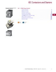
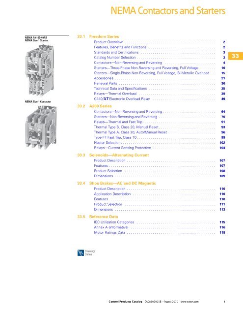
<strong>NEMA</strong> <strong>Contactors</strong> <strong>and</strong> <strong>Starters</strong><br />
<strong>NEMA</strong> AN16DN0AB<br />
<strong>NEMA</strong> Size 1 Starter<br />
<strong>NEMA</strong> Size 1 Contactor<br />
33.1 Freedom Series<br />
Product Overview . . . . . . . . . . . . . . . . . . . . . . . . . . . . . . . . . . . . . . . . . . . . . . 2<br />
Features, Benefits <strong>and</strong> Functions . . . . . . . . . . . . . . . . . . . . . . . . . . . . . . . . . . 2<br />
St<strong>and</strong>ards <strong>and</strong> Certifications . . . . . . . . . . . . . . . . . . . . . . . . . . . . . . . . . . . . . . 3<br />
Catalog Number Selection . . . . . . . . . . . . . . . . . . . . . . . . . . . . . . . . . . . . . . . . 3<br />
<strong>Contactors</strong>—Non-Reversing <strong>and</strong> Reversing . . . . . . . . . . . . . . . . . . . . . . . . . . 4<br />
<strong>Starters</strong>—Three-Phase Non-Reversing <strong>and</strong> Reversing, Full Voltage . . . . . . . . 10<br />
<strong>Starters</strong>—Single-Phase Non-Reversing, Full Voltage, Bi-Metallic Overload . . . 15<br />
Accessories . . . . . . . . . . . . . . . . . . . . . . . . . . . . . . . . . . . . . . . . . . . . . . . . . . . 21<br />
Renewal Parts . . . . . . . . . . . . . . . . . . . . . . . . . . . . . . . . . . . . . . . . . . . . . . . . . 30<br />
Technical Data <strong>and</strong> Specifications . . . . . . . . . . . . . . . . . . . . . . . . . . . . . . . . . . 35<br />
Relays—Thermal Overload . . . . . . . . . . . . . . . . . . . . . . . . . . . . . . . . . . . . . . . 39<br />
C440/XT Electronic Overload Relay . . . . . . . . . . . . . . . . . . . . . . . . . . . . . . . . 49<br />
33.2 A200 Series<br />
<strong>Contactors</strong>—Non-Reversing <strong>and</strong> Reversing . . . . . . . . . . . . . . . . . . . . . . . . . . . 64<br />
<strong>Starters</strong>—Non-Reversing <strong>and</strong> Reversing . . . . . . . . . . . . . . . . . . . . . . . . . . . . . 70<br />
Relays—Thermal <strong>and</strong> Fast <strong>Tri</strong>p . . . . . . . . . . . . . . . . . . . . . . . . . . . . . . . . . . . . . 91<br />
Thermal Type B, Class 20, Manual Reset. . . . . . . . . . . . . . . . . . . . . . . . . . . . . 93<br />
Thermal Type A, Class 20, Auto/Manual Reset . . . . . . . . . . . . . . . . . . . . . . . . 96<br />
Type FT Fast <strong>Tri</strong>p, Class 10. . . . . . . . . . . . . . . . . . . . . . . . . . . . . . . . . . . . . . . . 99<br />
Heater Selection . . . . . . . . . . . . . . . . . . . . . . . . . . . . . . . . . . . . . . . . . . . . . . . . 102<br />
Relays—Current Sensing Protective . . . . . . . . . . . . . . . . . . . . . . . . . . . . . . . . 104<br />
33.3 Solenoids—Alternating Current<br />
Product Description . . . . . . . . . . . . . . . . . . . . . . . . . . . . . . . . . . . . . . . . . . . . . 107<br />
Features . . . . . . . . . . . . . . . . . . . . . . . . . . . . . . . . . . . . . . . . . . . . . . . . . . . . . . 107<br />
Product Selection . . . . . . . . . . . . . . . . . . . . . . . . . . . . . . . . . . . . . . . . . . . . . . 108<br />
Dimensions . . . . . . . . . . . . . . . . . . . . . . . . . . . . . . . . . . . . . . . . . . . . . . . . . . . 109<br />
33.4 Shoe Brakes—AC <strong>and</strong> DC Magnetic<br />
Product Description . . . . . . . . . . . . . . . . . . . . . . . . . . . . . . . . . . . . . . . . . . . . . 110<br />
Application Description . . . . . . . . . . . . . . . . . . . . . . . . . . . . . . . . . . . . . . . . . . 110<br />
Features . . . . . . . . . . . . . . . . . . . . . . . . . . . . . . . . . . . . . . . . . . . . . . . . . . . . . . 110<br />
Product Selection . . . . . . . . . . . . . . . . . . . . . . . . . . . . . . . . . . . . . . . . . . . . . . 111<br />
Dimensions . . . . . . . . . . . . . . . . . . . . . . . . . . . . . . . . . . . . . . . . . . . . . . . . . . . 113<br />
33.5 Reference Data<br />
Drawings<br />
Online<br />
IEC Utilization Categories . . . . . . . . . . . . . . . . . . . . . . . . . . . . . . . . . . . . . . . . 115<br />
Annex A (informative) . . . . . . . . . . . . . . . . . . . . . . . . . . . . . . . . . . . . . . . . . . . 116<br />
Motor Ratings Data . . . . . . . . . . . . . . . . . . . . . . . . . . . . . . . . . . . . . . . . . . . . . 118<br />
33<br />
33<br />
33<br />
33<br />
33<br />
33<br />
33<br />
33<br />
33<br />
33<br />
33<br />
33<br />
33<br />
33<br />
33<br />
33<br />
33<br />
33<br />
33<br />
33<br />
33<br />
33<br />
33<br />
33<br />
33<br />
33<br />
33<br />
33<br />
33<br />
33<br />
Control Products Catalog CA08102001E—August 2010 www.eaton.com 1
33.1<br />
<strong>NEMA</strong> <strong>Contactors</strong> <strong>and</strong> <strong>Starters</strong><br />
Freedom Series<br />
33<br />
33<br />
33<br />
33<br />
33<br />
33<br />
33<br />
33<br />
33<br />
33<br />
33<br />
33<br />
33<br />
33<br />
33<br />
33<br />
33<br />
33<br />
33<br />
33<br />
33<br />
33<br />
33<br />
33<br />
33<br />
33<br />
33<br />
33<br />
33<br />
33<br />
Freedom Series<br />
Product Overview<br />
Freedom Series starters <strong>and</strong><br />
contactors feature a compact,<br />
space-saving design, using<br />
state-of-the-art technology<br />
<strong>and</strong> the latest in high<br />
strength, impact <strong>and</strong><br />
temperature resistant<br />
insulating materials.<br />
Features, Benefits <strong>and</strong> Functions<br />
Freedom <strong>NEMA</strong><br />
●<br />
●<br />
●<br />
●<br />
●<br />
●<br />
Adjustable bimetallic<br />
ambient compensated<br />
overload relays with<br />
interchangeable heater<br />
packs—available in three<br />
basic sizes, covering<br />
applications up to<br />
900 hp—reducing the<br />
number of different<br />
contactor/overload relay<br />
combinations that have to<br />
be stocked. Fixed heater<br />
overloads are optional<br />
Electronic overload relay<br />
(C440) available as a st<strong>and</strong>alone<br />
unit <strong>and</strong> assembled<br />
with Freedom Contactor<br />
A full line of snap-on<br />
accessories— top <strong>and</strong><br />
side mounted auxiliary<br />
contacts, solid-state <strong>and</strong><br />
pneumatic timers, etc.<br />
Straight-through wiring—<br />
line lugs at top, load lugs<br />
at bottom<br />
Horizontal or vertical<br />
mounting on upright panel<br />
for application freedom<br />
Screw type power<br />
terminals have captive,<br />
backed-out self-lifting<br />
pressure plates with<br />
± screws—reduced<br />
wiring time<br />
Contents<br />
Description<br />
Page<br />
Technical Data <strong>and</strong> Specifications<br />
St<strong>and</strong>ards <strong>and</strong> Certifications . . . . . . . . . . . . . . . . . . . . . . 3<br />
Catalog Number Selection . . . . . . . . . . . . . . . . . . . . . . . 3<br />
<strong>Contactors</strong>—Non-Reversing <strong>and</strong> Reversing . . . . . . . . . . 4<br />
<strong>Starters</strong>—Three-Phase Non-Reversing <strong>and</strong><br />
Reversing, Full Voltage . . . . . . . . . . . . . . . . . . . . . . . . . 10<br />
<strong>Starters</strong>—Single-Phase Non-Reversing,<br />
Full Voltage, Bi-Metallic Overload . . . . . . . . . . . . . . . . . 15<br />
Accessories. . . . . . . . . . . . . . . . . . . . . . . . . . . . . . . . . . . 21<br />
Renewal Parts. . . . . . . . . . . . . . . . . . . . . . . . . . . . . . . . . 30<br />
Technical Data <strong>and</strong> Specifications . . . . . . . . . . . . . . . . . . 35<br />
Relays—Thermal Overload . . . . . . . . . . . . . . . . . . . . . . . 39<br />
C440/XT Electronic Overload Relay . . . . . . . . . . . . . . . . 49<br />
●<br />
●<br />
●<br />
●<br />
●<br />
●<br />
●<br />
Accessible terminals for<br />
easy wiring. Optional<br />
fingerproof shields<br />
available to prevent<br />
electrical shock<br />
Top located coil terminals<br />
convenient <strong>and</strong> readily<br />
accessible. 45 mm<br />
contactor magnet coils<br />
have three terminals,<br />
permitting either top or<br />
diagonal wiring—easy to<br />
replace European or U.S.<br />
style starters or contactors<br />
without changing wiring<br />
layout<br />
Designed to meet or<br />
exceed <strong>NEMA</strong>, UL, CSA,<br />
VDE, BS <strong>and</strong> other<br />
international st<strong>and</strong>ards<br />
<strong>and</strong> listings<br />
American engineering—<br />
built by Eaton, using the<br />
latest in statistical process<br />
control methods to<br />
produce high quality,<br />
reliable products<br />
Sized based on st<strong>and</strong>ard<br />
<strong>NEMA</strong> classifications<br />
Easy coil change <strong>and</strong><br />
inspectable/replaceable<br />
contacts<br />
Available in open <strong>and</strong><br />
<strong>NEMA</strong> Type 1, 3R, 4/4X<br />
<strong>and</strong> 12 enclosures<br />
2 Control Products Catalog CA08102001E—August 2010 www.eaton.com
<strong>NEMA</strong> <strong>Contactors</strong> <strong>and</strong> <strong>Starters</strong><br />
Freedom Series<br />
33.1<br />
St<strong>and</strong>ards <strong>and</strong> Certifications<br />
●<br />
●<br />
●<br />
St<strong>and</strong>ard: designed to<br />
meet or exceed UL,<br />
<strong>NEMA</strong>, IEC, CSA, VDE<br />
<strong>and</strong> BS<br />
UL listed: UL File #E1491,<br />
Guide #NLDX—Open <strong>and</strong><br />
<strong>NEMA</strong> 1, 4, 12 Enclosed<br />
CSA Certified: CSA File<br />
#LR353, Class #321104<br />
Open <strong>and</strong> <strong>NEMA</strong> 1<br />
Enclosed<br />
Catalog Number Selection<br />
Freedom Series<br />
Device Type<br />
A = Starter<br />
C = Contactor<br />
Device Assembly<br />
Configuration<br />
70 = Multi-speed<br />
1 = Non-reversing<br />
5 = Reversing<br />
Contactor Frame Size <br />
A =<br />
B =<br />
D =<br />
G =<br />
K =<br />
N =<br />
S =<br />
T =<br />
U =<br />
V =<br />
<strong>NEMA</strong><br />
Size<br />
00<br />
0<br />
1<br />
2<br />
3<br />
4<br />
5<br />
6<br />
7<br />
8<br />
St<strong>and</strong>ard<br />
E = IEC<br />
N = <strong>NEMA</strong><br />
Continuous<br />
Amperes<br />
9<br />
18<br />
27<br />
45<br />
90<br />
135<br />
270<br />
540<br />
810<br />
1215<br />
ISO 9000 Certification<br />
When you turn to Eaton’s<br />
products, you turn to quality.<br />
The International St<strong>and</strong>ards<br />
Organization (ISO) has<br />
established a series of<br />
st<strong>and</strong>ards acknowledged<br />
by 91 industrialized nations<br />
to bring harmony to the<br />
international quest for quality.<br />
The ISO certification process<br />
covers 20 quality system<br />
elements in design,<br />
production <strong>and</strong> installation<br />
that must conform to<br />
achieve registration. This<br />
commitment to quality will<br />
result in increased product<br />
reliability <strong>and</strong> total customer<br />
satisfaction.<br />
<strong>NEMA</strong> Enclosure<br />
N = Open<br />
Notes<br />
<br />
For contactor only orders, add B to end of catalog number if <strong>NEMA</strong> Size 00–2, 6.<br />
<br />
<strong>NEMA</strong> Sizes 00 <strong>and</strong> 0 only.<br />
<br />
<strong>NEMA</strong> Sizes 00 <strong>and</strong> 0 only. Sizes 1–8 are 24/60 only.<br />
<br />
<strong>NEMA</strong> Sizes 4 <strong>and</strong> 5 require the use of CTs with 1-5A OL relay. Size 4 starters are not shipped as assembled units.<br />
Order CN15NN01 contactor <strong>and</strong> 1–5A OL (C440A1A005SAX or C440A2A005SAX) with 60–300A CTs (ZEB-XCT300).<br />
Short Circuit Protection<br />
Fuses <strong>and</strong> Inverse-Time<br />
Circuit Breakers may be<br />
selected per Article 430,<br />
Part D of the National<br />
<strong>Electrical</strong> Code to protect<br />
motor branch circuits from<br />
fault conditions. If higher<br />
ratings or settings are required<br />
to start the motor, do not<br />
exceed the maximum as<br />
listed in Exception No. 2,<br />
Article 430-52.<br />
A N 1 9 A N 0 A 5E 005<br />
OLR Type<br />
5 = Contactor only—no overload relay<br />
6 = Starter w/C306 bi-metal OLR<br />
9 = Starter w/C440 electronic overload<br />
For <strong>Starters</strong><br />
Starter<br />
Mounting Option<br />
0<br />
V<br />
= Horizontal<br />
= Vertical<br />
For <strong>Contactors</strong> Only<br />
2<br />
3<br />
4<br />
5<br />
= Two-pole<br />
= Three-pole<br />
= Four-pole<br />
= Five-pole<br />
Suffix<br />
A<br />
B<br />
C<br />
D<br />
E<br />
H<br />
J<br />
K<br />
L<br />
N<br />
T<br />
U<br />
V<br />
W<br />
Y<br />
C440 OLR Designation<br />
(FVNR <strong>and</strong> FVR only)<br />
5E = St<strong>and</strong>ard feature set<br />
SEL Reset, SEL Class (10A, 10, 20, 30)<br />
5G = Ground fault feature set<br />
SEL Reset, SEL Class (10, 20)<br />
AC Coil Suffix<br />
Coil Volts <strong>and</strong> Hertz<br />
= 120/60 or 110/50<br />
= 240/60 or 220/50<br />
= 480/60 or 440/50<br />
= 600/60 or 550/50<br />
= 208/60<br />
= 277/60<br />
= 208 – 240/60 <br />
= 240/50<br />
= 380 – 415/50<br />
= 550/50<br />
= 24/60, 24/50 <br />
= 24/50<br />
= 32/50<br />
= 48/60<br />
= 48/50<br />
C440 FLA Range<br />
(FVNR <strong>and</strong> FVR only)<br />
<strong>NEMA</strong> Size 00<br />
1P6 = 0.33–1.65A<br />
005 = 1–5A<br />
020 = 4–20A<br />
<strong>NEMA</strong> Size 0<br />
1P6 = 0.33–1.65A<br />
005 = 1–5A<br />
020 = 4–20A<br />
<strong>NEMA</strong> Size 1<br />
1P6 = 0.33–1.65A<br />
005 = 1–5A<br />
020 = 4–20A<br />
045 = 9–45A<br />
<strong>NEMA</strong> Size 2<br />
005 = 1–5A<br />
020 = 4–20A<br />
045 = 9–45A<br />
<strong>NEMA</strong> Size 3<br />
100 = 20–100A <br />
<strong>NEMA</strong> Size 4 <br />
300 = 60–300A <br />
<strong>NEMA</strong> Size 5 <br />
300 = 60–300A<br />
33<br />
33<br />
33<br />
33<br />
33<br />
33<br />
33<br />
33<br />
33<br />
33<br />
33<br />
33<br />
33<br />
33<br />
33<br />
33<br />
33<br />
33<br />
33<br />
33<br />
33<br />
33<br />
33<br />
33<br />
33<br />
33<br />
33<br />
33<br />
33<br />
33<br />
Control Products Catalog CA08102001E—August 2010 www.eaton.com 3
33.1<br />
<strong>NEMA</strong> <strong>Contactors</strong> <strong>and</strong> <strong>Starters</strong><br />
Freedom Series<br />
33<br />
33<br />
33<br />
33<br />
33<br />
33<br />
33<br />
33<br />
33<br />
33<br />
33<br />
33<br />
33<br />
33<br />
33<br />
33<br />
33<br />
33<br />
33<br />
33<br />
33<br />
33<br />
33<br />
33<br />
33<br />
33<br />
33<br />
33<br />
33<br />
33<br />
Non-Reversing <strong>and</strong> Reversing <strong>Contactors</strong><br />
<strong>Contactors</strong>—Non-Reversing <strong>and</strong> Reversing<br />
Product Description<br />
Non-Reversing<br />
<strong>Contactors</strong> are most<br />
commonly used to switch<br />
motor loads in applications<br />
where running overcurrent<br />
protection is either not<br />
required or is provided<br />
separately. <strong>Contactors</strong> consist<br />
of a magnetically actuated<br />
switch which can be remotely<br />
operated by a pushbutton<br />
station or pilot device such<br />
as a proximity switch, limit<br />
switch, float switch, auxiliary<br />
contacts, etc.<br />
Reversing<br />
Reversing contactors are<br />
used primarily for reversing<br />
single- or three-phase motors<br />
in applications where running<br />
overcurrent protection is<br />
either not required or is<br />
provided separately. They<br />
consist of two contactors<br />
mechanically <strong>and</strong> electrically<br />
interlocked to prevent line<br />
shorts <strong>and</strong> energization of<br />
both contactors<br />
simultaneously.<br />
Contents<br />
Description<br />
Page<br />
<strong>Contactors</strong>—Non-Reversing <strong>and</strong> Reversing<br />
Product Selection . . . . . . . . . . . . . . . . . . . . . . . . . . . . . . 5<br />
Kits <strong>and</strong> Accessories . . . . . . . . . . . . . . . . . . . . . . . . . . . . 6<br />
Renewal Parts Publication Numbers. . . . . . . . . . . . . . . . 6<br />
Technical Data <strong>and</strong> Specifications . . . . . . . . . . . . . . . . . . 7<br />
Dimensions . . . . . . . . . . . . . . . . . . . . . . . . . . . . . . . . . . . 8<br />
<strong>Starters</strong>—Three-Phase Non-Reversing <strong>and</strong><br />
Reversing, Full Voltage . . . . . . . . . . . . . . . . . . . . . . . . . . . 10<br />
<strong>Starters</strong>—Single-Phase Non-Reversing,<br />
Full Voltage, Bi-Metallic Overload . . . . . . . . . . . . . . . . . . . 15<br />
Accessories . . . . . . . . . . . . . . . . . . . . . . . . . . . . . . . . . . . . . 21<br />
Renewal Parts . . . . . . . . . . . . . . . . . . . . . . . . . . . . . . . . . . . 30<br />
Technical Data <strong>and</strong> Specifications . . . . . . . . . . . . . . . . . . . . 35<br />
Relays—Thermal Overload. . . . . . . . . . . . . . . . . . . . . . . . . . 39<br />
Features, Benefits <strong>and</strong> Functions<br />
● Designed specifically for Non-Reversing<br />
●<br />
use in applications<br />
● Holding circuit contact(s)<br />
requiring <strong>NEMA</strong> ratings. supplied as st<strong>and</strong>ard:<br />
<strong>Contactors</strong> meet or<br />
● Sizes 00–3 have NO<br />
exceed <strong>NEMA</strong> st<strong>and</strong>ards<br />
auxiliary contact block<br />
ICS 2-1993<br />
mounted on right h<strong>and</strong><br />
Long life twin break,<br />
side (on Size 00, contact<br />
silver cadmium oxide<br />
occupies 4th power pole<br />
contacts—provide<br />
position—no increase<br />
excellent conductivity <strong>and</strong> in width)<br />
superior resistance to<br />
● Sizes 4–5 have a<br />
welding <strong>and</strong> arc erosion<br />
NO contact block<br />
● Designed to 3,000,000<br />
mounted on left side<br />
electrical operations at<br />
● Sizes 6–7 have a<br />
maximum hp ratings up<br />
2NO/2NC contact<br />
through 25 hp at 600V<br />
block on top left<br />
● Steel mounting plate<br />
● Size 8 has a NO/NC<br />
st<strong>and</strong>ard on all open<br />
contact block on top left<br />
type contactors<br />
back <strong>and</strong> a NO contact<br />
block on top right back<br />
Reversing<br />
● One NO-NC side mounted<br />
interlock supplied as<br />
st<strong>and</strong>ard on each<br />
contactor for Sizes 00–8<br />
4 Control Products Catalog CA08102001E—August 2010 www.eaton.com
<strong>NEMA</strong> <strong>Contactors</strong> <strong>and</strong> <strong>Starters</strong><br />
Freedom Series<br />
33.1<br />
Product Selection<br />
Three-Pole <strong>Contactors</strong><br />
<strong>NEMA</strong> Size 00<br />
CN55AN3AB<br />
<strong>NEMA</strong> Size 0<br />
CN15BN3AB<br />
<strong>NEMA</strong> Size 3<br />
CN15KN3A<br />
Magnet Coils—AC <strong>and</strong> DC<br />
Contactor coils listed in this<br />
section also have a 50 Hz<br />
rating as shown in the<br />
adjacent table. Select<br />
required contactor by<br />
catalog number <strong>and</strong> replace<br />
the magnet coil alpha<br />
Type CN15/CN55 <strong>NEMA</strong> <strong>Contactors</strong>—Non-Reversing <strong>and</strong> Reversing<br />
designation in the catalog<br />
number (_) with the proper<br />
code suffix from the table.<br />
For Sizes 00–2, the magnet<br />
coil alpha designation will be<br />
the next to the last digit of<br />
the listed catalog number.<br />
EXAMPLE: For a 380V, 50 Hz<br />
coil, change CN15AN3_B<br />
to CN15AN3LB. For all<br />
other sizes, the magnet<br />
coil alpha designation will<br />
be the last digit of the listed<br />
catalog number.<br />
AC Suffix<br />
Coil Volts <strong>and</strong> Hertz Code Suffix Coil Volts <strong>and</strong> Hertz Code Suffix<br />
120/60 or 110/50 A 380–415/50 L<br />
240/60 or 220/50 B 550/50 N<br />
480/60 or 440/50 C 24/60, 24/50 T<br />
600/60 or 550/50 D 24/50 U<br />
208/60 E 32/50 V<br />
277/60 H 48/60 W<br />
208–240/60 J 48/50 Y<br />
240/50 K<br />
Notes<br />
<br />
Maximum horsepower rating of starters for 380V 50 Hz applications:<br />
<strong>NEMA</strong> Size 00 0 1 2 3 4 5 6 7 8<br />
Horsepower 1-1/2 5 10 25 50 75 150 300 600 900<br />
<br />
<br />
<br />
<strong>NEMA</strong><br />
Size<br />
Continuous<br />
Ampere Rating<br />
Common control. For separate 120V control, insert letter D in 7th position of listed catalog number.<br />
Example: CN15VND3C.<br />
<strong>NEMA</strong> Sizes 00 <strong>and</strong> 0 only.<br />
<strong>NEMA</strong> Sizes 00 <strong>and</strong> 0 only. Sizes 1–8 are 24/60 only.<br />
Maximum UL Horsepower <br />
Single-Phase<br />
Three-Phase<br />
Non-Reversing Reversing<br />
115V 230V 208V 240V 480V 600V Catalog Number Catalog Number<br />
00 9 1/3 1 1-1/2 1-1/2 2 2 CN15AN3_B CN55AN3_B<br />
0 18 1 2 3 3 5 5 CN15BN3_B CN55BN3_B<br />
1 27 2 3 7-1/2 7-1/2 10 10 CN15DN3_B CN55DN3_B<br />
2 45 3 7-1/2 10 15 25 25 CN15GN3_B CN55GN3_B<br />
3 90 25 30 50 50 CN15KN3_ CN55KN3_<br />
4 135 40 50 100 100 CN15NN3_ CN55NN3_<br />
5 270 75 100 200 200 CN15SN3_ CN55SN3_<br />
6 540 150 200 400 400 CN15TN3_B CN55TN3_B<br />
7 810 200 300 600 600 CN15UN3_ CN55UN3_<br />
8 1215 400 450 900 900 CN15VN3_ CN55VN3_<br />
For DC Magnet Coils,<br />
see Accessories, Pages 28<br />
<strong>and</strong> 29.<br />
33<br />
33<br />
33<br />
33<br />
33<br />
33<br />
33<br />
33<br />
33<br />
33<br />
33<br />
33<br />
33<br />
33<br />
33<br />
33<br />
33<br />
33<br />
33<br />
33<br />
33<br />
33<br />
33<br />
33<br />
33<br />
33<br />
33<br />
33<br />
33<br />
33<br />
Control Products Catalog CA08102001E—August 2010 www.eaton.com 5
33.1<br />
<strong>NEMA</strong> <strong>Contactors</strong> <strong>and</strong> <strong>Starters</strong><br />
Freedom Series<br />
33<br />
33<br />
33<br />
33<br />
33<br />
33<br />
33<br />
33<br />
33<br />
33<br />
33<br />
33<br />
33<br />
33<br />
33<br />
33<br />
33<br />
33<br />
33<br />
33<br />
33<br />
33<br />
33<br />
33<br />
33<br />
33<br />
33<br />
33<br />
33<br />
33<br />
Two-, Four- <strong>and</strong> Five-Pole <strong>Contactors</strong><br />
<strong>NEMA</strong> Size 2<br />
Five-Pole Contactor<br />
CN15GN5AB<br />
Magnet Coils—AC <strong>and</strong> DC<br />
Select required starter by<br />
catalog number <strong>and</strong> replace<br />
the magnet coil alpha<br />
designation in the catalog<br />
number (_) with the proper<br />
code suffix from the table.<br />
AC Suffix<br />
Kits <strong>and</strong> Accessories<br />
● Auxiliary contacts,<br />
contactor mounted—<br />
Pages 25—27<br />
●<br />
Transient suppressor, for<br />
magnet coil—Page 24<br />
●<br />
Timers—solid-state <strong>and</strong><br />
pneumatic, mount on<br />
contactor—Page 22<br />
Renewal Parts<br />
Publication Numbers<br />
● See Page 30<br />
Type CN15 <strong>NEMA</strong> <strong>Contactors</strong>—Non-Reversing<br />
Two-Pole<br />
Maximum UL Horsepower<br />
Non-Reversing<br />
Continuous<br />
<strong>NEMA</strong> Ampere Single-Phase (Two-Pole) Three-Phase Catalog<br />
Size Rating 115V 230V 208V 240V 480V 600V Number<br />
Notes<br />
<strong>NEMA</strong> Sizes 00 <strong>and</strong> 0 only.<br />
<strong>NEMA</strong> Sizes 00 <strong>and</strong> 0 only. Sizes 1–8 are 24/60 only.<br />
For Sizes 00–2, the magnet<br />
coil alpha designation will be<br />
the next to the last digit of<br />
the listed catalog number.<br />
EXAMPLE: For a 380V, 50 Hz<br />
coil, change CN15BN3_B<br />
to CN15BN3LB. For all<br />
other sizes, the magnet<br />
coil alpha designation will<br />
be the last digit of the listed<br />
catalog number.<br />
Four-Pole<br />
Non-Reversing<br />
Catalog<br />
Number<br />
Five-Pole<br />
Non-Reversing<br />
Catalog<br />
Number<br />
00 9 1/3 1 1-1/2 1-1/2 2 2 CN15AN2_B CN15AN4_B —<br />
0 18 1 2 2 3 5 5 CN15BN2_B — —<br />
1 27 2 3 7-1/2 7-1/2 10 10 CN15DN2_B CN15DN4_B CN15DN5_B<br />
2 45 3 7-1/2 10 15 25 25 CN15GN2_B CN15GN4_B CN15GN5_B<br />
3 90 25 30 50 50 CN15KN2_ — —<br />
4 135 40 50 100 100 CN15NN2_ — —<br />
5 270 75 100 200 200 CN15SN2_ — —<br />
6 540 150 200 400 400 CN15TN2_B — —<br />
Coil Volts <strong>and</strong> Hertz Code Suffix Coil Volts <strong>and</strong> Hertz Code Suffix<br />
120/60 or 110/50 A 380–415/50 L<br />
240/60 or 220/50 B 550/50 N<br />
480/60 or 440/50 C 24/60, 24/50 T<br />
600/60 or 550/50 D 24/50 U<br />
208/60 E 32/50 V<br />
277/60 H 48/60 W<br />
208–240/60 J 48/50 Y<br />
240/50 K<br />
For DC Magnet Coils,<br />
see Accessories, Pages 28<br />
<strong>and</strong> 29.<br />
6 Control Products Catalog CA08102001E—August 2010 www.eaton.com
<strong>NEMA</strong> <strong>Contactors</strong> <strong>and</strong> <strong>Starters</strong><br />
Freedom Series<br />
33.1<br />
Technical Data <strong>and</strong> Specifications<br />
Wire (75°C) Sizes—AWG or kcmil—Open <strong>and</strong> Enclosed<br />
<strong>NEMA</strong> Size Power Terminals Line or Load Control Terminals Cu Only<br />
00 12–16 str<strong>and</strong>ed; 12–14 solid Cu 12–16 str<strong>and</strong>ed<br />
0 8–16 str<strong>and</strong>ed; 10–14 solid Cu<br />
12–14 solid<br />
1 8–14 str<strong>and</strong>ed or solid Cu<br />
2 3–14 (upper) <strong>and</strong>/or 6–14 (lower) str<strong>and</strong>ed or solid Cu<br />
3 1/0–14 Cu/Al<br />
4 250 mcm–6<br />
5 750 kcmil–2, or (2) 250 kcmil–3/0 Cu/Al<br />
6 (2) 750 kcmil–3/0 Cu/Al<br />
7 (3) 750 kcmil–3/0 Cu/Al<br />
8 (4) 750 kcmil–4/0 Cu/Al<br />
Plugging <strong>and</strong> Jogging Service Horsepower Ratings <br />
<strong>NEMA</strong> Size 200V 230V 460V 575V<br />
00 — 1/2 1/2 1/2<br />
0 1-1/2 1-1/2 2 2<br />
1 3 3 5 5<br />
2 7-1/2 10 15 15<br />
3 15 20 30 30<br />
4 25 30 60 60<br />
5 60 75 150 150<br />
6 125 150 300 300<br />
Notes<br />
<br />
Two compartment box lug.<br />
<br />
Maximum horsepower where operation is interrupted more than 5 times per minute or more than 10 times in a 10 minute period.<br />
<strong>NEMA</strong> st<strong>and</strong>ard ICS 2-1993 table 2-4-3.<br />
33<br />
33<br />
33<br />
33<br />
33<br />
33<br />
33<br />
33<br />
33<br />
33<br />
33<br />
33<br />
33<br />
33<br />
33<br />
33<br />
33<br />
33<br />
33<br />
33<br />
33<br />
33<br />
33<br />
33<br />
33<br />
33<br />
33<br />
33<br />
33<br />
33<br />
Control Products Catalog CA08102001E—August 2010 www.eaton.com 7
33.1<br />
<strong>NEMA</strong> <strong>Contactors</strong> <strong>and</strong> <strong>Starters</strong><br />
Freedom Series<br />
33<br />
33<br />
33<br />
33<br />
33<br />
33<br />
33<br />
33<br />
33<br />
33<br />
33<br />
33<br />
33<br />
33<br />
33<br />
33<br />
33<br />
33<br />
33<br />
33<br />
33<br />
33<br />
33<br />
33<br />
33<br />
33<br />
33<br />
33<br />
33<br />
33<br />
Dimensions<br />
Approximate Dimensions in Inches (mm)<br />
Non-Reversing <strong>Contactors</strong>—Open Type<br />
G<br />
A<br />
U<br />
X<br />
G<br />
A<br />
U<br />
X<br />
Dimensions <strong>and</strong> Shipping Weights<br />
<strong>NEMA</strong><br />
Size<br />
A<br />
Top<br />
Mtd.<br />
Aux.<br />
G<br />
A<br />
U<br />
E<br />
X<br />
Auxiliary<br />
D<br />
Contacts<br />
Mtg. Holes for<br />
#10-32 Screws<br />
Sizes 00, Two- to Four-Pole<br />
A<br />
Top<br />
Mtd.<br />
Aux.<br />
D<br />
Number<br />
of Poles<br />
Top<br />
Mtd.<br />
Aux.<br />
G<br />
A<br />
U<br />
E<br />
X<br />
Wide<br />
A<br />
F<br />
C<br />
Side<br />
Mtd.<br />
Aux.<br />
Top<br />
Mtd.<br />
Aux.<br />
Auxiliary<br />
Contacts<br />
Mtg. Holes for<br />
#10-32 Screws<br />
Sizes 1–2, Five-Pole<br />
F<br />
C<br />
Side<br />
Mtd.<br />
Aux.<br />
High<br />
B<br />
Deep<br />
C<br />
Note<br />
Center mounting slot at bottom supplied only on Size 00 <strong>and</strong> 0 contactors.<br />
B<br />
B<br />
G<br />
A<br />
U<br />
X<br />
A<br />
Top<br />
Mtd.<br />
Aux.<br />
Mtg. Holes for (2)<br />
5/16-18 Screws<br />
G<br />
A<br />
U<br />
E<br />
X<br />
Top<br />
Mtd.<br />
Aux.<br />
Auxiliary<br />
D Contacts<br />
Mtg. Holes for<br />
#10-32 Screws<br />
Sizes 0–2, Two- <strong>and</strong> Three-Pole<br />
D<br />
Mounting<br />
D<br />
Mounting<br />
E F G<br />
Shipping Weight<br />
Lbs (kg)<br />
00 2–4 1.75 (44.5) 3.88 (98.6) 3.49 (88.6) 1.50 (38.1) 3.38 (85.9) 4.62 (117.3) 0.54 (13.7) 1.7 (0.7)<br />
0 2–3 1.75 (44.5) 3.88 (98.6) 3.49 (88.6) 1.50 (38.1) 3.38 (85.9) 4.62 (117.3) 0.54 (13.7) 1.8 (0.8)<br />
1–2 2–3 2.56 (65.0) 5.05 (128.3) 4.44 (112.8) 2.00 (50.8) 4.50 (114.3) 5.80 (147.3) 0.54 (13.7) 3.1 (1.4)<br />
1–2 4 3.44 (87.4) 5.05 (128.3) 4.44 (112.8) 2.00 (50.8) 4.50 (114.3) 5.80 (147.3) 0.54 (13.7) 3.6 (1.6)<br />
1–2 5 4.32 (109.7) 5.05 (128.3) 4.44 (112.8) 2.00 (50.8) 4.50 (114.3) 5.80 (147.3) 0.54 (13.7) 4.0 (1.8)<br />
3 2–3 4.08 (103.6) 7.17 (182.1) 5.94 (150.9) 3.00 (76.2) 6.63 (168.4) — — 8.5 (3.9)<br />
4 2–3 7.05 (179.1) 9.11 (231.4) 7.25 (184.2) 6.00 (152.4) 8.50 (215.9) — — 20.0 (9.1)<br />
5 2–3 7.05 (179.1) 13.12 (333.2) 7.78 (197.6) 6.00 (152.4) 12.50 (317.5) — — 23.0 (10.4)<br />
6 3 8.63 (219.2) 13.54 (343.9) 8.88 (225.6) 4.33 (110.0) 8.63 (219.2) — — 35.0 (15.9)<br />
7 3 11.02 (279.9) 19.30 (490.2) 11.46 (291.1) 6.89 (175.0) 11.02 (279.9) — — 100.0 (45.4)<br />
8 3 13.00 (330.2) 24.50 (622.3) 13.63 (346.2) 4.22 (107.2) 14.86 (377.4) — — 160.0 (72.6)<br />
F<br />
C<br />
Side<br />
Mtd.<br />
Aux.<br />
B<br />
Side<br />
Mtd.<br />
Aux.<br />
Mtg. Holes for (3)<br />
1/4-20 Screws<br />
Size 3<br />
G<br />
A<br />
U<br />
X<br />
A<br />
Top<br />
Mtd.<br />
Aux.<br />
G<br />
A<br />
UX<br />
E<br />
Top<br />
Mtd.<br />
Aux.<br />
F<br />
C<br />
Side<br />
Mtd.<br />
Aux.<br />
Auxiliary<br />
D Contacts<br />
Mtg. Holes for<br />
#10-32 Screws<br />
Sizes 0–2, Two- <strong>and</strong> Three-Pole<br />
A C A C<br />
A<br />
D<br />
E<br />
Size 6<br />
E<br />
C<br />
Mtg. Slots for (2)<br />
5/16-18 Screws<br />
B<br />
B<br />
D<br />
E<br />
Mtg. Holes for<br />
(3) Screws<br />
Sizes 4–5<br />
B<br />
B<br />
8 Control Products Catalog CA08102001E—August 2010 www.eaton.com
<strong>NEMA</strong> <strong>Contactors</strong> <strong>and</strong> <strong>Starters</strong><br />
Freedom Series<br />
33.1<br />
Approximate Dimensions in Inches (mm)<br />
Reversing <strong>Contactors</strong>—Open Type<br />
G<br />
A<br />
U<br />
X<br />
Dimensions <strong>and</strong> Shipping Weights<br />
<strong>NEMA</strong><br />
Size<br />
Top<br />
Mtd.<br />
Aux.<br />
Wide<br />
A<br />
A<br />
D<br />
A<br />
D<br />
Note<br />
<br />
Includes cross wiring.<br />
Top<br />
Mtd.<br />
Aux.<br />
G<br />
A<br />
U<br />
X<br />
E<br />
Auxiliary<br />
Contacts<br />
Mtg. Holes for (3)<br />
#10-32 Screws<br />
High<br />
B<br />
Top<br />
Mtd.<br />
Aux.<br />
F<br />
C<br />
Side<br />
Mtd.<br />
Aux.<br />
Deep<br />
C<br />
B<br />
Sizes 00–2 Size 3<br />
Sizes 4–5<br />
E<br />
C<br />
Mtg. for (4)<br />
1/4-20 Screws<br />
B<br />
A<br />
D<br />
Size 6<br />
Mounting<br />
D<br />
Mounting<br />
E F G<br />
Shipping Weight<br />
Lbs (kg)<br />
00–0 4.20 (106.7) 4.35 (110.5) 3.52 (89.4) 3.50 (88.9) 3.86 (98.0) 4.90 (124.5) 0.54 (13.7) 3.3 (1.5)<br />
1–2 5.71 (145.0) 5.05 (128.3) 4.44 (112.8) 5.25 (133.4) 3.63 (92.2) 5.80 (147.3) 0.54 (13.7) 7.8 (3.5)<br />
3 8.70 (221.0) 7.17 (182.1) 5.94 (150.9) 7.00 (177.8) 6.63 (168.4) — — 17.0 (7.7)<br />
4 14.68 (372.9) 9.11 (231.4) 7.25 (184.2) 13.50 (342.9) 8.50 (215.9) — — 47.0 (21.3)<br />
5 14.50 (368.3) 12.25 (311.2) 7.78 (197.6) 13.50 (342.9) 11.50 (292.1) — — 63.0 (28.6)<br />
6 19.77 (502.2) 16.61 (421.9) 9.90 (251.5) 18.00 (457.2) 12.00 (304.8) — — 80.0 (36.3)<br />
7 28.00 (711.2) 26.75 (679.5) 12.75 (323.9) 12.75 (323.9) 11.00 (279.4) — — 260.0 (118.0)<br />
8 30.13 (765.3) 39.00 (990.6) 14.69 (373.1) 14.13 (358.9) 15.00 (381.0) — — 350.0 (158.9)<br />
E<br />
C<br />
A<br />
D<br />
D<br />
Mtg. Holes for (4)<br />
3/8-16 Screws<br />
A<br />
E<br />
C<br />
Mtg. Holes for (3)<br />
1/4-20 Screws<br />
D<br />
Mtg. Holes for (6)<br />
1/2-13 Screws<br />
Open Type—Sizes 7–8 Horizontal<br />
B<br />
E<br />
C<br />
B<br />
B<br />
33<br />
33<br />
33<br />
33<br />
33<br />
33<br />
33<br />
33<br />
33<br />
33<br />
33<br />
33<br />
33<br />
33<br />
33<br />
33<br />
33<br />
33<br />
33<br />
33<br />
33<br />
33<br />
33<br />
33<br />
33<br />
33<br />
33<br />
33<br />
33<br />
33<br />
Control Products Catalog CA08102001E—August 2010 www.eaton.com 9
33.1<br />
<strong>NEMA</strong> <strong>Contactors</strong> <strong>and</strong> <strong>Starters</strong><br />
Freedom Series<br />
33<br />
33<br />
33<br />
33<br />
33<br />
33<br />
33<br />
33<br />
33<br />
33<br />
33<br />
33<br />
33<br />
33<br />
33<br />
33<br />
33<br />
33<br />
33<br />
33<br />
33<br />
33<br />
33<br />
33<br />
33<br />
33<br />
33<br />
33<br />
33<br />
33<br />
Three-Phase Non-Reversing <strong>and</strong> Reversing, Full Voltage <strong>Starters</strong><br />
Contents<br />
<strong>Starters</strong>—Three-Phase Non-Reversing <strong>and</strong> Reversing, Full Voltage<br />
Product Description<br />
Features, Benefits <strong>and</strong><br />
Functions<br />
Non-Reversing<br />
Three-phase, full voltage<br />
magnetic starters are most<br />
commonly used to switch AC<br />
motor loads. <strong>Starters</strong> consist<br />
of a magnetically actuated<br />
switch (contactor) <strong>and</strong> an<br />
overload relay assembled<br />
together.<br />
Reversing<br />
Three-phase, full voltage<br />
magnetic starters are used<br />
primarily for reversing of<br />
three-phase squirrel cage<br />
motors. They consist of two<br />
contactors <strong>and</strong> a single<br />
overload relay assembled<br />
together. The contactors are<br />
mechanically <strong>and</strong> electrically<br />
interlocked to prevent line<br />
shorts <strong>and</strong> energization of<br />
both contactors<br />
simultaneously.<br />
●<br />
Bimetallic ambient<br />
compensated overload<br />
relays—available in three<br />
basic sizes covering<br />
applications up to 900 hp—<br />
reducing number of<br />
different contactor/overload<br />
relay combinations that<br />
have to be stocked<br />
These overload relays<br />
feature:<br />
● Selectable manual<br />
or automatic reset<br />
operation<br />
● Interchangeable heater<br />
packs adjustable ±24%<br />
to match motor FLA <strong>and</strong><br />
calibrated for 1.0 <strong>and</strong><br />
1.15 service factors.<br />
Heater packs for smaller<br />
overload relay will<br />
mount in larger overload<br />
relay—useful in derating<br />
applications such as<br />
jogging<br />
● Load lugs built into<br />
relay base<br />
● Single-phase protection,<br />
Class 20 or Class 10<br />
trip time<br />
● Overload trip indication<br />
●<br />
<strong>Electrical</strong>ly isolated<br />
NO-NC contacts (pull<br />
RESET button to test)<br />
Description<br />
Page<br />
<strong>Contactors</strong>—Non-Reversing <strong>and</strong> Reversing. . . . . . . . . . . . . 4<br />
<strong>Starters</strong>—Three-Phase Non-Reversing <strong>and</strong><br />
Reversing, Full Voltage<br />
Product Selection . . . . . . . . . . . . . . . . . . . . . . . . . . . . . . 11<br />
Kits <strong>and</strong> Accessories . . . . . . . . . . . . . . . . . . . . . . . . . . . . 13<br />
Renewal Parts Publication Numbers. . . . . . . . . . . . . . . . 13<br />
Technical Data <strong>and</strong> Specifications . . . . . . . . . . . . . . . . . . 13<br />
Wiring Diagrams . . . . . . . . . . . . . . . . . . . . . . . . . . . . . . . 14<br />
<strong>Starters</strong>—Single-Phase Non-Reversing,<br />
Full Voltage, Bi-Metallic Overload . . . . . . . . . . . . . . . . . . . 15<br />
Accessories . . . . . . . . . . . . . . . . . . . . . . . . . . . . . . . . . . . . . 21<br />
Renewal Parts . . . . . . . . . . . . . . . . . . . . . . . . . . . . . . . . . . . 30<br />
Technical Data <strong>and</strong> Specifications . . . . . . . . . . . . . . . . . . . . 35<br />
Relays—Thermal Overload. . . . . . . . . . . . . . . . . . . . . . . . . . 39<br />
C440/XT Electronic Overload Relay . . . . . . . . . . . . . . . . . . . 49<br />
● The C440 is a selfpowered,<br />
robust<br />
electronic overload<br />
designed for integrated<br />
use with Freedom<br />
<strong>NEMA</strong> contactors<br />
● Tiered feature set to<br />
provide coverage<br />
specific to your<br />
application<br />
● Broad 5:1 FLA range<br />
for maximum flexibility<br />
● Coverage from<br />
0.05–1500A to meet<br />
all your needs<br />
● Long life twin break,<br />
silver cadmium oxide<br />
contacts—provide<br />
excellent conductivity<br />
<strong>and</strong> superior resistance<br />
to welding <strong>and</strong> arc erosion.<br />
Generously sized for low<br />
resistance <strong>and</strong> cool<br />
operation<br />
● Designed to 3,000,000<br />
electrical operations at<br />
maximum hp ratings up<br />
through 25 hp at 600V<br />
●<br />
Steel mounting plate<br />
st<strong>and</strong>ard on all open<br />
type starters<br />
●<br />
Wired for separate or<br />
common control<br />
Non-Reversing<br />
● Holding circuit contact(s)<br />
supplied as st<strong>and</strong>ard:<br />
● Sizes 00–3 have a NO<br />
auxiliary contact block<br />
mounted on right-h<strong>and</strong><br />
side (on Size 00, contact<br />
occupies 4th power pole<br />
position—no increase<br />
in width)<br />
● Sizes 4–5 have a<br />
NO contact block<br />
mounted on left side<br />
● Sizes 6–7 have a<br />
2NO/2NC contact<br />
block on top left<br />
● Size 8 has a NO/NC<br />
contact block on top<br />
left back <strong>and</strong> a NO on<br />
top right back<br />
Reversing<br />
● Each contactor (Size 00–8)<br />
supplied with one NO-NC<br />
side mounted contact<br />
block as st<strong>and</strong>ard. NC<br />
contacts are wired as<br />
electrical interlocks<br />
10 Control Products Catalog CA08102001E—August 2010 www.eaton.com
<strong>NEMA</strong> <strong>Contactors</strong> <strong>and</strong> <strong>Starters</strong><br />
Freedom Series<br />
33.1<br />
Product Selection<br />
When Ordering <strong>Supply</strong><br />
●<br />
Catalog number<br />
●<br />
Heater pack number (see selection table, Pages 41–43) or full load current<br />
Size 0<br />
Non-Reversing Starter<br />
Size 1<br />
Reversing Starter<br />
Magnet Coils—AC or DC<br />
Starter coils listed in this<br />
section also have a 50 Hz<br />
rating as shown in the<br />
adjacent table. Select<br />
required starter by catalog<br />
number <strong>and</strong> replace the<br />
magnet coil alpha designation<br />
Type AN16/AN56 <strong>NEMA</strong>—Manual or Automatic Reset Overload Relay—Non-Reversing <strong>and</strong> Reversing <br />
in the catalog number (_) with<br />
the proper code suffix from<br />
the table.<br />
For Sizes 00–2 <strong>and</strong> 5–8, the<br />
magnet coil alpha designation<br />
will be the next to last digit<br />
of the listed catalog number.<br />
EXAMPLE: For a 380V, 50 Hz<br />
coil, change AN16BN0_C<br />
to AN16BN0LC. For all<br />
other sizes, the magnet<br />
coil alpha designation will<br />
be the last digit of the listed<br />
catalog number.<br />
AC Suffix<br />
Coil Volts <strong>and</strong> Hertz Code Suffix Coil Volts <strong>and</strong> Hertz Code Suffix<br />
120/60 or 110/50 A 380–415/50 L<br />
240/60 or 220/50 B 550/50 N<br />
480/60 or 440/50 C 24/60, 24/50 T<br />
600/60 or 550/50 D 24/50 U<br />
208/60 E 32/50 V<br />
277/60 H 48/60 W<br />
208–240/60 J 48/50 Y<br />
240/50 K 48/50 Y<br />
Notes<br />
<br />
Starter catalog numbers do not include heater packs. Select one carton of three heater packs. Heater pack selection, Pages 41–43.<br />
<br />
Maximum horsepower rating of starters for 380V 50 Hz applications:<br />
<strong>NEMA</strong> Size 00 0 1 2 3 4 5 6 7 8<br />
Horsepower 1-1/2 5 10 25 50 75 150 300 600 900<br />
<br />
<br />
<br />
<br />
<br />
<strong>NEMA</strong><br />
Size<br />
Continuous<br />
Ampere<br />
Rating<br />
(Amperes) 115V 230V 208V 240V 480V 600V Number<br />
Service-Limit<br />
Current Rating<br />
Maximum UL<br />
Single-Phase<br />
Horsepower <br />
Three-Phase<br />
Three-Pole<br />
Non-Reversing <br />
Catalog<br />
For DC Magnet Coils,<br />
see Accessories, Pages 28<br />
<strong>and</strong> 29.<br />
Underscore (_) indicates coil suffix required, see AC Suffix table.<br />
The service-limit current ratings represent the maximum rms current, in amperes, which the controller shall be permitted to carry for protracted periods in normal service. At service-limit current<br />
ratings, temperature rises shall be permitted to exceed those obtained by testing the controller at its continuous current rating. The current rating of overload relays or trip current of other motor<br />
protective devices used shall not exceed the service-limit current rating of the controller.<br />
Common control. For separate 120V control, insert letter D in 7th position of listed catalog number. Example: AN56VND0CB.<br />
<strong>NEMA</strong> Sizes 00 <strong>and</strong> 0 only.<br />
<strong>NEMA</strong> Sizes 00 <strong>and</strong> 0 only. Sizes 1–8 are 24/60 only.<br />
Three-Pole<br />
Reversing <br />
Catalog<br />
Number<br />
Vertical<br />
Reversing <br />
Catalog<br />
Number<br />
00 9 11 1/3 1 1-1/2 1-1/2 2 2 AN16AN0_C AN56AN0_C —<br />
0 18 21 1 2 3 3 5 5 AN16BN0_C AN56BN0_C AN56BNV0_<br />
1 27 32 2 3 7-1/2 7-1/2 10 10 AN16DN0_B AN56DN0_B AN56DNV0_<br />
2 45 52 3 7-1/2 10 15 25 25 AN16GN0_B AN56GN0_B AN56GNV0_<br />
3 90 104 — — 25 30 50 50 AN16KN0_ AN56KN0_ AN56KNV0_<br />
4 135 156 — — 40 50 100 100 AN16NN0_ AN56NN0_ AN56NNV0_<br />
5 270 311 — — 75 100 200 200 AN16SN0_B AN56SN0_B —<br />
6 540 621 — — 150 200 400 400 AN16TN0_C AN56TN0_C —<br />
7 810 932 — — 200 300 600 600 AN16UN0_B AN56UN0_B —<br />
8 1215 1400 — — 400 450 900 900 AN16VN0_B AN56VN0_B —<br />
33<br />
33<br />
33<br />
33<br />
33<br />
33<br />
33<br />
33<br />
33<br />
33<br />
33<br />
33<br />
33<br />
33<br />
33<br />
33<br />
33<br />
33<br />
33<br />
33<br />
33<br />
33<br />
33<br />
33<br />
33<br />
33<br />
33<br />
33<br />
33<br />
33<br />
Control Products Catalog CA08102001E—August 2010 www.eaton.com 11
33.1<br />
<strong>NEMA</strong> <strong>Contactors</strong> <strong>and</strong> <strong>Starters</strong><br />
Freedom Series<br />
33<br />
33<br />
33<br />
33<br />
33<br />
33<br />
33<br />
33<br />
33<br />
33<br />
33<br />
33<br />
33<br />
33<br />
33<br />
33<br />
33<br />
33<br />
33<br />
33<br />
33<br />
33<br />
33<br />
33<br />
33<br />
33<br />
33<br />
33<br />
33<br />
33<br />
Two-Speed Selective Control<br />
When Ordering <strong>Supply</strong><br />
●<br />
Catalog number plus<br />
magnet coil code suffix.<br />
Example: Size 0—<br />
AN700BN022B<br />
●<br />
Heater pack number or full<br />
load current for each speed<br />
Two-Winding<br />
AN700DN022<br />
One-Winding<br />
AN700BN0218<br />
One-Winding<br />
AN700DN0218<br />
For two-speed other than<br />
selective control:<br />
●<br />
●<br />
Catalog number plus<br />
magnet coil code suffix<br />
<strong>and</strong> option required.<br />
Example: AN700BN022B<br />
except compelling<br />
Heater pack number or full<br />
load current for each speed<br />
Note: Two-speed starters<br />
are designed for starting <strong>and</strong><br />
controlling both separate<br />
(two-winding) <strong>and</strong> reconnectable<br />
(one-winding) motors. Separate<br />
winding, WYE-WYE motors<br />
have a separate winding for<br />
each speed. Reconnectable,<br />
consequent pole motors use the<br />
same winding for both speeds.<br />
All st<strong>and</strong>ard starters are wired<br />
for selective control.<br />
Separate Winding <br />
Maximum Horsepower—60/50 Hertz<br />
Constant or Variable Torque<br />
Constant Horsepower<br />
<strong>NEMA</strong> Open Type<br />
115V 200V 230V 460V/575V 115V 200V 230V 460/575V Size Catalog Number<br />
1-1/2 3 3 5 1 2 2 3 0 AN700BN022_<br />
3 7-1/2 7-1/2 10 2 5 5 7-1/2 1 AN700DN022_<br />
— 10 15 25 — 7-1/2 10 20 2 AN700GN022_<br />
— 25 30 50 — 20 25 40 3 AN700KN022_<br />
— 40 50 100 — 30 40 75 4 AN700NN022_<br />
— 75 100 200 — 60 75 150 5 AN700SN022_<br />
Prices of starters do not include heater packs. Select two packs (two overload relays, one for each speed). Heater pack selection, Pages 41–43.<br />
Reconnectable Winding <br />
Maximum Horsepower—60/50 Hertz<br />
Open Type<br />
Constant or Constant<br />
Constant or Variable Torque<br />
Constant Horsepower<br />
<strong>NEMA</strong> Variable Torque Horsepower<br />
115V 200V 230V 460V/575V 115V 200V 230V 460/575V Size Catalog Number Catalog Number<br />
1-1/2 3 3 5 1 2 2 3 0 AN700BN0218_ AN700BN0219_<br />
3 7-1/2 7-1/2 10 2 5 5 7-1/2 1 AN700DN0218_ AN700DN0219_<br />
— 10 15 25 — 7-1/2 10 20 2 AN700GN0218_ AN700GN0219_<br />
— 25 30 50 — 20 25 40 3 AN700KN0218_ AN700KN0219_<br />
— 40 50 100 — 30 40 75 4 AN700NN0218_ AN700NN0219_<br />
Prices of starters do not include heater packs. Select two packs (two overload relays, one for each speed). Heater pack selection, Pages 41–43.<br />
Magnetic Coils—AC or DC<br />
Coil Voltage <strong>and</strong> Hz Code Suffix Coil Voltage <strong>and</strong> Hz Code Suffix Coil Voltage <strong>and</strong> Hz Code Suffix<br />
120/60 or 110/50 A 277/60 H 24/60, 24/50 T<br />
240/60 or 220/50 B 208–240/60 J 24/50 U<br />
480/60 or 440/50 C 240/50 K 32/50 V<br />
600/60 or 550/50 D 380–415/50 L 48/60 W<br />
208/60 E 550/50 N 48/50 Y<br />
Notes<br />
<br />
If branch circuit protective device is 45A or greater, C320FBR1 fuse kit(s) may be required for circuit protection per NEC 530-072.<br />
<br />
<strong>NEMA</strong> Sizes 00 <strong>and</strong> 0 only. Sizes 1–5 are 24/60 only.<br />
12 Control Products Catalog CA08102001E—August 2010 www.eaton.com
<strong>NEMA</strong> <strong>Contactors</strong> <strong>and</strong> <strong>Starters</strong><br />
Freedom Series<br />
33.1<br />
Kits <strong>and</strong> Accessories<br />
●<br />
Auxiliary contacts,<br />
contactor mounted—<br />
Pages 25–27<br />
●<br />
Transient suppressor, for<br />
magnet coil—Page 24<br />
●<br />
Timers—solid-state <strong>and</strong><br />
pneumatic, mount on<br />
contactor—Page 22<br />
Technical Data <strong>and</strong> Specifications<br />
Renewal Parts<br />
Publication Numbers<br />
●<br />
See Page 30<br />
Wire (75°C) Sizes—AWG or kcmil—<strong>NEMA</strong> Sizes 00–2—Open <strong>and</strong> Enclosed<br />
<strong>NEMA</strong> Size<br />
Wire Size Cu Only<br />
Power Terminals—Line<br />
00 12–16 AWG str<strong>and</strong>ed, 12–14 AWG solid<br />
0 8–16 AWG str<strong>and</strong>ed, 10–14 AWG solid<br />
1 8–14 AWG str<strong>and</strong>ed or solid<br />
2 3–14 AWG (upper) <strong>and</strong>/or 6–14 AWG (lower) str<strong>and</strong>ed or solid <br />
Power Terminals—Load—Cu Only (str<strong>and</strong>ed or solid)<br />
00–0 14–6 AWG str<strong>and</strong>ed or solid<br />
1–2 14–2 AWG str<strong>and</strong>ed or solid<br />
Control Terminals—Cu Only<br />
12–16 AWG str<strong>and</strong>ed, 12–14 AWG solid<br />
Wire (75°C) Sizes—AWG or kcmil—<strong>NEMA</strong> Sizes 3–8—Open <strong>and</strong> Enclosed<br />
<strong>NEMA</strong> Size<br />
Wire Size <br />
Power Terminals—Line <strong>and</strong> Load<br />
3 1/0–14 AWG Cu/Al<br />
4 Open—3/0–8 AWG Cu; Enclosed—250 kcmil—6 AWG Cu/Al<br />
5 750 kcmil—2 AWG; or (2) 250 kcmil—3/0 AWG Cu/Al<br />
6 (2) 750 kcmil—3/0 AWG Cu/Al<br />
7 (3) 750 kcmil—3/0 AWG Cu/Al<br />
8 (4) 750 kcmil—1/0 AWG Cu/Al<br />
Control Terminals—Cu Only<br />
12–16 AWG str<strong>and</strong>ed, 12–14 AWG solid<br />
Plugging <strong>and</strong> Jogging Service Horsepower Ratings <br />
<strong>NEMA</strong> Size 200V 230V 460V 575V<br />
00 — 1/2 1/2 1/2<br />
0 1-1/2 1-1/2 2 2<br />
1 3 3 5 5<br />
2 7-1/2 10 15 15<br />
3 15 20 30 30<br />
4 25 30 60 60<br />
5 60 75 150 150<br />
6 125 150 300 300<br />
Notes<br />
<br />
Minimum per NEC. Maximum wire size: Sizes 00 <strong>and</strong> 0 to 8 AWG <strong>and</strong> Sizes 1–2 to 2 AWG.<br />
<br />
Two compartment box lug.<br />
<br />
Maximum horsepower where operation is interrupted more than 5 times per minute, or more than 10 times in a 10 minute period.<br />
<strong>NEMA</strong> St<strong>and</strong>ard ICS2-1993 table 2-4-3.<br />
33<br />
33<br />
33<br />
33<br />
33<br />
33<br />
33<br />
33<br />
33<br />
33<br />
33<br />
33<br />
33<br />
33<br />
33<br />
33<br />
33<br />
33<br />
33<br />
33<br />
33<br />
33<br />
33<br />
33<br />
33<br />
33<br />
33<br />
33<br />
33<br />
33<br />
Control Products Catalog CA08102001E—August 2010 www.eaton.com 13
33.1<br />
<strong>NEMA</strong> <strong>Contactors</strong> <strong>and</strong> <strong>Starters</strong><br />
Freedom Series<br />
33<br />
33<br />
33<br />
33<br />
33<br />
33<br />
33<br />
33<br />
33<br />
33<br />
33<br />
33<br />
33<br />
33<br />
33<br />
33<br />
33<br />
33<br />
33<br />
33<br />
33<br />
33<br />
33<br />
33<br />
33<br />
33<br />
33<br />
33<br />
33<br />
33<br />
Wiring Diagrams<br />
Three-Phase <strong>and</strong> Single-Phase Applications<br />
L1 L2<br />
L3<br />
A2<br />
Separate Control<br />
Remove Wire “c”<br />
when it is supplied. “c”<br />
Connect separate<br />
control lines to the<br />
No. 1 Terminal on T1 T2 T3<br />
the remote pilot T1 T2 T3<br />
device <strong>and</strong> Terminal<br />
96 on the overload<br />
relay.<br />
Motor<br />
1<br />
A1 A2<br />
L1 L2 L3<br />
1<br />
A1 A2<br />
Separate Control<br />
Remove Wire “c”<br />
when it is supplied.<br />
Connect separate<br />
control lines to the<br />
No. 1 Terminal on T1 T2 T3<br />
the remote pilot T1 T2 T3<br />
device <strong>and</strong> Terminal<br />
96 on the overload<br />
relay.<br />
Motor<br />
“c”<br />
98<br />
97<br />
96<br />
95<br />
2<br />
3<br />
98<br />
97<br />
96<br />
95<br />
2<br />
3<br />
Remote Pilot Devices<br />
Two-Wire<br />
Control 1 3<br />
Not for Use with<br />
Auto Reset OL Relays<br />
Three-Wire Start<br />
Control<br />
3<br />
2<br />
Stop<br />
1<br />
When more than<br />
one pushbutton<br />
station is used,<br />
omit Connector<br />
“A” <strong>and</strong> connect<br />
per sketch.<br />
<strong>NEMA</strong> Size 00<br />
Start<br />
Stop<br />
“A”<br />
Remote Pilot Devices<br />
Two-Wire<br />
Control 1 3<br />
Not for Use with<br />
Auto Reset OL Relays<br />
Three-Wire Start<br />
Control<br />
3<br />
2<br />
Stop<br />
1<br />
When more than<br />
one pushbutton<br />
station is used,<br />
omit Connector<br />
“A” <strong>and</strong> connect<br />
per sketch.<br />
<strong>NEMA</strong> Sizes 0, 1 <strong>and</strong> 2<br />
Start<br />
Stop<br />
“A”<br />
Start<br />
Stop<br />
Start<br />
Stop<br />
3<br />
2<br />
1<br />
3<br />
2<br />
1<br />
L1<br />
T1<br />
L2<br />
T2<br />
Field Conversion<br />
to Single-Phase, Add<br />
Dotted Connections<br />
L1<br />
T1<br />
T1<br />
T2<br />
Motor<br />
T2<br />
Field Conversion<br />
to Single-Phase, Add<br />
Dotted Connections<br />
T1<br />
L2<br />
T2<br />
Motor<br />
14 Control Products Catalog CA08102001E—August 2010 www.eaton.com
<strong>NEMA</strong> <strong>Contactors</strong> <strong>and</strong> <strong>Starters</strong><br />
Freedom Series<br />
33.1<br />
<strong>NEMA</strong> Size 1—BN15DN0AB<br />
Contents<br />
<strong>Starters</strong>—Single-Phase Non-Reversing, Full Voltage, Bi-Metallic Overload<br />
Product Description<br />
Single-phase, full voltage<br />
magnetic starters connect<br />
the motor directly across the<br />
line, allowing it to draw full<br />
inrush current during start-up.<br />
These starters are most<br />
commonly used for control of<br />
self-starting single-phase<br />
motors up to 15 hp at 230V.<br />
They consist of a two-pole<br />
electromagnetic contactor to<br />
make <strong>and</strong> break the motor<br />
power circuit <strong>and</strong> an overload<br />
relay to provide running<br />
overload protection. <strong>Starters</strong><br />
listed in the table include:<br />
●<br />
Two-pole Freedom Series<br />
contactor with long life<br />
twin break, silver cadmium<br />
oxide contacts. Generously<br />
sized for low resistance<br />
<strong>and</strong> cool operation.<br />
Designed to 3 million<br />
electrical operations<br />
at maximum hp <strong>and</strong><br />
30 million mechanical<br />
operations to Size 0,<br />
10 million operations<br />
to Size 2 <strong>and</strong> 6 million<br />
operations to Size 3<br />
●<br />
●<br />
●<br />
Three-pole Freedom Series<br />
overload with poles two<br />
<strong>and</strong> three wired in series<br />
for motor overload<br />
protection. This overload<br />
is ambient compensated,<br />
selectable manual or<br />
automatic reset,<br />
interchangeable Class 10<br />
or 20 heater packs, 1.0<br />
or 1.15 service factor<br />
selectability, overload trip<br />
indication <strong>and</strong> electrically<br />
isolated NO-NC contacts<br />
(pull RESET button to test)<br />
Holding circuit NO auxiliary<br />
contact supplied as<br />
st<strong>and</strong>ard. On Size 00, the<br />
contact occupies the 4th<br />
power pole position. Sizes<br />
0–3 have the NO auxiliary<br />
mounted on the right side<br />
of the contactor<br />
Steel mounting plate as<br />
st<strong>and</strong>ard on all open type<br />
starters. Wired for separate<br />
or common control<br />
Description<br />
Page<br />
<strong>Contactors</strong>—Non-Reversing <strong>and</strong> Reversing . . . . . . . . . . . . . 4<br />
<strong>Starters</strong>—Three-Phase Non-Reversing <strong>and</strong><br />
Reversing, Full Voltage. . . . . . . . . . . . . . . . . . . . . . . . . . . . 10<br />
<strong>Starters</strong>—Single-Phase Non-Reversing,<br />
Full Voltage, Bi-Metallic Overload<br />
Product Selection . . . . . . . . . . . . . . . . . . . . . . . . . . . . . . 16<br />
Wiring Diagrams . . . . . . . . . . . . . . . . . . . . . . . . . . . . . . . 16<br />
Dimensions . . . . . . . . . . . . . . . . . . . . . . . . . . . . . . . . . . . 17<br />
Accessories . . . . . . . . . . . . . . . . . . . . . . . . . . . . . . . . . . . . . 21<br />
Renewal Parts . . . . . . . . . . . . . . . . . . . . . . . . . . . . . . . . . . . 30<br />
Technical Data <strong>and</strong> Specifications . . . . . . . . . . . . . . . . . . . . 35<br />
Relays—Thermal Overload . . . . . . . . . . . . . . . . . . . . . . . . . . 39<br />
C440/XT Electronic Overload Relay . . . . . . . . . . . . . . . . . . . 49<br />
33<br />
33<br />
33<br />
33<br />
33<br />
33<br />
33<br />
33<br />
33<br />
33<br />
33<br />
33<br />
33<br />
33<br />
33<br />
33<br />
33<br />
33<br />
33<br />
33<br />
33<br />
33<br />
33<br />
33<br />
33<br />
33<br />
33<br />
33<br />
33<br />
33<br />
Control Products Catalog CA08102001E—August 2010 www.eaton.com 15
33.1<br />
<strong>NEMA</strong> <strong>Contactors</strong> <strong>and</strong> <strong>Starters</strong><br />
Freedom Series<br />
33<br />
33<br />
33<br />
33<br />
33<br />
33<br />
33<br />
33<br />
33<br />
33<br />
33<br />
33<br />
33<br />
33<br />
33<br />
33<br />
33<br />
33<br />
33<br />
33<br />
33<br />
33<br />
33<br />
33<br />
33<br />
33<br />
33<br />
33<br />
33<br />
33<br />
Product Selection<br />
When Ordering Specify<br />
●<br />
Catalog number<br />
●<br />
Heater pack number (see selection table, Pages 41–43) or full load current<br />
BN16DM0AB<br />
Wiring Diagrams<br />
Type BN16 <strong>NEMA</strong>—Manual or Automatic Reset Overload Relay<br />
<strong>NEMA</strong> Maximum Horsepower<br />
Magnet Coil Voltage<br />
Open Type Two-Pole<br />
Size<br />
Motor Voltage Single-Phase (60 Hz)<br />
Catalog Number<br />
00 115 1/3 120 BN16AN0AC<br />
230 1 240 BN16AN0BC<br />
0 115 1 120 BN16BN0AC<br />
230 2 240 BN16BN0BC<br />
1 115 2 120 BN16DN0AB<br />
230 3 240 BN16DN0BB<br />
1P 115 3 120 BN16PN0AB<br />
230 5 240 BN16PN0BB<br />
2 115 3 120 BN16GN0AB<br />
230 7-1/2 240 BN16GN0BB<br />
3 115 7-1/2 120 BN16KN0A<br />
230 15 240 BN16KN0B<br />
Starter catalog numbers do not include heater packs. Select one carton of three heater packs. Heater pack selection, Pages 41–43.<br />
Notes<br />
<br />
For separate 120V control circuit. For maximum hp at listed motor voltages, use the rating of other starters of same size.<br />
Single-Phase Applications (Factory Wired)<br />
1<br />
L1<br />
AC Lines<br />
3<br />
L2<br />
Front View of Panel<br />
“C”<br />
T1 T2<br />
1<br />
A1 A2<br />
2/13<br />
M<br />
Single-Phase Motor<br />
3/14<br />
98<br />
3/14<br />
START<br />
1 3/14<br />
97<br />
2/13<br />
OL<br />
96<br />
Not for Use with<br />
STOP<br />
Auto Reset OL Relays<br />
1<br />
Reset<br />
2/T1 4/T2 6/T3 95<br />
Two-Wire Control Three-Wire Control<br />
T1 T2<br />
2 4 When more than<br />
one pushbutton START “A” START<br />
Separate Control<br />
station is used,<br />
3/14<br />
Remove Wire “C” if supplied <strong>and</strong> connect separate control omit Connector “A”<br />
2/13<br />
lines to the Number 1 Terminal on the remote pilot device<br />
<strong>and</strong> connect per STOP STOP<br />
<strong>and</strong> to the Number 96 Terminal on the overload relay.<br />
sketch at right.<br />
1<br />
16 Control Products Catalog CA08102001E—August 2010 www.eaton.com
<strong>NEMA</strong> <strong>Contactors</strong> <strong>and</strong> <strong>Starters</strong><br />
Freedom Series<br />
33.1<br />
Dimensions<br />
Approximate Dimensions in Inches (mm)<br />
Non-Reversing <strong>Starters</strong>, Bi-Metallic Overload—Open Type<br />
G<br />
Dimensions <strong>and</strong> Shipping Weights<br />
<strong>NEMA</strong><br />
Size<br />
E<br />
Aux.<br />
Wide<br />
A<br />
G<br />
A<br />
U<br />
X<br />
A<br />
Top<br />
Mtd.<br />
Aux.<br />
G<br />
D<br />
A Mtg. Holes for (3)<br />
1/4-20 Screws<br />
Size 3<br />
Top<br />
Mtd.<br />
Aux.<br />
High<br />
B<br />
Deep<br />
C<br />
Mounting<br />
D<br />
Note<br />
<br />
Holding circuit contact for Size 00 occupies 4th power pole position—no increase in width.<br />
F<br />
C<br />
A<br />
Side<br />
U Mtd.<br />
X Aux.<br />
B<br />
E<br />
C L Auxiliary<br />
Contacts<br />
Mtg. Holes for #10-32 Screws<br />
C A C<br />
Aux.<br />
Cont.<br />
E<br />
B<br />
A<br />
E<br />
D Mtg. Holes for (4)<br />
3/8-16 Screws<br />
Size 6<br />
C<br />
D<br />
B<br />
Size 4<br />
Mounting<br />
E F G<br />
Shipping Weight<br />
Lbs (kg)<br />
00–0 1.80 (45.7) 6.60 (167.6) 3.52 (89.4) — 6.07 (154.2) 4.90 (124.5) 0.54 (13.7) 2.2 (1.0)<br />
1–1P 2.56 (65.0) 7.08 (179.8) 4.44 (112.8) 2.00 (50.8) 6.63 (168.4) 5.80 (147.3) 0.54 (13.7) 4.5 (2.0)<br />
2 2.56 (65.0) 8.08 (205.2) 4.44 (112.8) 2.00 (50.8) 7.63 (193.8) 5.80 (147.3) 0.54 (13.7) 4.7 (2.1)<br />
3 4.08 (103.6) 11.35 (288.3) 5.94 (150.9) 3.00 (76.2) 10.81 (274.6) — — 11.0 (5.0)<br />
4 7.05 (179.1) 12.06 (306.3) 7.25 (184.2) 6.00 (152.4) 8.50 (215.9) — — 23.0 (10.4)<br />
5 7.00 (177.8) 17.77 (451.4) 7.76 (197.1) 6.00 (152.4) 16.00 (406.4) — — 36.0 (16.3)<br />
6 9.47 (240.5) 21.69 (550.9) 9.90 (251.5) 3.10 (78.7) 18.00 (457.2) — — 75.0 (34.1)<br />
7 15.13 (384.3) 29.13 (739.9) 12.64 (321.1) 13.25 (336.6) 21.25 (539.8) — — 120.0 (54.5)<br />
8 15.13 (384.3) 34.50 (876.3) 15.00 (381.0) 13.25 (336.6) 16.75 (425.5) — — 210.0 (95.3)<br />
G<br />
A<br />
U<br />
X<br />
0.13<br />
(3.3)<br />
A<br />
Top<br />
Mtd.<br />
Aux.<br />
C L<br />
D<br />
Mtg. Holes for<br />
1/4-20 Screws<br />
A<br />
D<br />
B<br />
G<br />
A<br />
U<br />
X<br />
E<br />
Top<br />
Mtd.<br />
Aux.<br />
Auxiliary<br />
Contacts<br />
Mtg. Holes for<br />
#10-32 Screws<br />
Sizes 1–2<br />
E<br />
A<br />
D<br />
C<br />
Mtg. Holes for<br />
1/2-13 Screws<br />
Sizes 7–8<br />
F<br />
C<br />
Side<br />
Mtd.<br />
Aux.<br />
E<br />
C<br />
Mtg. Holes for<br />
1/4-20 Screws<br />
Size 5<br />
B<br />
B<br />
B<br />
33<br />
33<br />
33<br />
33<br />
33<br />
33<br />
33<br />
33<br />
33<br />
33<br />
33<br />
33<br />
33<br />
33<br />
33<br />
33<br />
33<br />
33<br />
33<br />
33<br />
33<br />
33<br />
33<br />
33<br />
33<br />
33<br />
33<br />
33<br />
33<br />
33<br />
Control Products Catalog CA08102001E—August 2010 www.eaton.com 17
33.1<br />
<strong>NEMA</strong> <strong>Contactors</strong> <strong>and</strong> <strong>Starters</strong><br />
Freedom Series<br />
33<br />
33<br />
33<br />
33<br />
33<br />
33<br />
33<br />
33<br />
33<br />
33<br />
33<br />
33<br />
33<br />
33<br />
33<br />
33<br />
33<br />
33<br />
33<br />
33<br />
33<br />
33<br />
33<br />
33<br />
33<br />
33<br />
33<br />
33<br />
33<br />
33<br />
Approximate Dimensions in Inches (mm)<br />
Reversing <strong>Starters</strong>, Bi-Metallic Overload—Open Type<br />
A<br />
U<br />
X<br />
.13<br />
(3.3)<br />
D1<br />
G<br />
Dimensions <strong>and</strong> Shipping Weights<br />
<strong>NEMA</strong><br />
Size<br />
Top<br />
Mtd.<br />
Aux.<br />
Wide<br />
A<br />
C L<br />
D<br />
A<br />
D<br />
A<br />
Top<br />
Mtd.<br />
Aux.<br />
High<br />
B<br />
G<br />
A<br />
U<br />
X<br />
E<br />
Mtg. Holes for (6)<br />
3/8-16 Screws<br />
Size 6<br />
Top<br />
Mtd.<br />
Aux.<br />
Auxiliary<br />
Contacts<br />
<br />
Deep<br />
C<br />
F<br />
C<br />
Side<br />
Mtd.<br />
Aux.<br />
Mtg. Holes for (3)<br />
#10-32 Screws<br />
Sizes 00 – 2<br />
E<br />
E1<br />
Mounting<br />
D<br />
Notes<br />
<br />
Includes cross wiring overhang.<br />
<br />
See catalog listings for type <strong>and</strong> location of auxiliary contacts supplied with a particular starter.<br />
C<br />
B<br />
B<br />
D Mtg. Holes for (3)<br />
1/4-20 Screws<br />
Size 3<br />
Mounting<br />
E D1 E1 F G<br />
Shipping Weight<br />
Lbs (kg)<br />
00–0 4.20 (106.7) 7.38 (187.5) 3.52 (89.4) 3.50 (88.9) 6.87 (174.5) — — 4.90 (124.5) 0.54 (13.7 3.6 (1.6)<br />
1 5.71 (145.0) 7.08 (179.8) 4.44 (112.8) 5.25 (133.4) 5.75 (146.1) — — 5.80 (147.3) 0.54 (13.7) 8.3 (3.8)<br />
2 5.71 (145.0) 8.08 (205.2) 4.44 (112.8) 5.25 (133.4 6.75 (171.5) — — 5.80 (147.3) 0.54 (13.7) 8.5 (3.9)<br />
3 8.70 (221.0) 11.35 (288.3) 5.94 (150.9) 7.00 (177.8) 10.81 (274.6) — — — — 20.0 (9.1)<br />
4 14.68 (372.9) 12.06 (306.3) 7.25 (184.2) 13.50 (342.9) 8.50 (215.9) — — — — 49.0 (22.2)<br />
5 14.50 (368.3) 17.77 (451.4) 7.76 (197.1) 13.50 (342.9) 16.00 (406.4) — — — — 68.0 (30.9)<br />
6 19.77 (502.2) 22.63 (574.8) 9.90 (251.5) 18.00 (457.2) 12.00 (304.8) 3.10 (78.7) 18.00 (457.2) — — 90.0 (40.9)<br />
7 28.06 (712.7) 32.13 (816.1) 12.70 (322.6) 12.75 (323.9) 21.25 (539.8) — — — — 175.0 (79.5)<br />
8 30.38 (771.7) 41.50 (1054.1) 14.70 (373.4) 14.13 (358.9) 16.75 (425.5) — — — — 430.0 (195.2)<br />
A<br />
C L<br />
A<br />
E<br />
E<br />
D Mtg. Holes for (4)<br />
1/4-20 Screws<br />
Sizes 4 – 5<br />
A<br />
D D<br />
Mtg. Holes for (6)<br />
1/2-13 Screws<br />
Open Type — Sizes 7 – 8 Horizontal<br />
E<br />
C<br />
C<br />
C<br />
B<br />
B<br />
B<br />
18 Control Products Catalog CA08102001E—August 2010 www.eaton.com
<strong>NEMA</strong> <strong>Contactors</strong> <strong>and</strong> <strong>Starters</strong><br />
Freedom Series<br />
33.1<br />
Approximate Dimensions in Inches (mm)<br />
Reversing <strong>Starters</strong>—Vertical Construction, Bi-Metallic Overload—AN56V Open Vertical Starter<br />
F<br />
Dimensions <strong>and</strong> Shipping Weights<br />
<strong>NEMA</strong><br />
Size<br />
A<br />
D<br />
A<br />
D<br />
Wide<br />
A<br />
High<br />
B<br />
Note<br />
Wire overhang 1.00 mm left, 50 mm right.<br />
E<br />
Mtg. Holes for (3)<br />
#10-32 Screws<br />
<strong>NEMA</strong> Size 0<br />
E<br />
F<br />
Mtg. Holes for (3)<br />
1/4-20 Screws<br />
<strong>NEMA</strong> Size 3<br />
C<br />
C<br />
B<br />
Deep<br />
C<br />
B<br />
Mounting<br />
Wide<br />
D<br />
Mtg. Holes for (3)<br />
#10-32 Screws<br />
<strong>NEMA</strong> Sizes 1 – 2<br />
Mounting<br />
HIgh<br />
E<br />
Wire Zone<br />
Shipping Weight<br />
Lbs (kg)<br />
0 4.25 (108.0) 12.05 (306.1) 3.84 (97.5) 2.00 (50.8) 11.50 (292.1) — 4.0 (1.8)<br />
1 4.25 (108.0) 12.05 (306.1) 3.86 (98.0) 2.00 (50.8) 11.50 (292.1) 1.00 (25.4) 9.0 (4.1)<br />
2 4.25 (108.0) 12.05 (306.1) 3.86 (98.0) 2.00 (50.8) 11.50 (292.1) 1.00 (25.4) 9.5 (4.3)<br />
3 9.25 (235.0) 16.75 (425.5) 5.18 (131.6) 7.15 (181.6) 16.07 (408.2)<br />
21.0 (9.5)<br />
4 9.08 (230.6) 19.84 (503.9) 5.18 (131.6) 8.00 (203.2) 18.51 (470.2) 1.50 (38.1) 50.0 (22.7)<br />
F<br />
F<br />
D<br />
A<br />
A<br />
D<br />
F<br />
F<br />
E<br />
E<br />
Mtg. Holes for (4)<br />
1/4-20 Screws<br />
<strong>NEMA</strong> Size 4<br />
C<br />
C<br />
B<br />
B<br />
33<br />
33<br />
33<br />
33<br />
33<br />
33<br />
33<br />
33<br />
33<br />
33<br />
33<br />
33<br />
33<br />
33<br />
33<br />
33<br />
33<br />
33<br />
33<br />
33<br />
33<br />
33<br />
33<br />
33<br />
33<br />
33<br />
33<br />
33<br />
33<br />
33<br />
Control Products Catalog CA08102001E—August 2010 www.eaton.com 19
33.1<br />
<strong>NEMA</strong> <strong>Contactors</strong> <strong>and</strong> <strong>Starters</strong><br />
Freedom Series<br />
33<br />
33<br />
33<br />
33<br />
33<br />
33<br />
33<br />
33<br />
33<br />
33<br />
33<br />
33<br />
33<br />
33<br />
33<br />
33<br />
33<br />
33<br />
33<br />
33<br />
33<br />
33<br />
33<br />
33<br />
33<br />
33<br />
33<br />
33<br />
33<br />
33<br />
Approximate Dimensions in Inches (mm)<br />
Multispeed <strong>Starters</strong>, Bi-Metallic Overload—AN700 Open Vertical Starter<br />
F<br />
<br />
<br />
F<br />
Dimensions <strong>and</strong> Shipping Weights<br />
<strong>NEMA</strong><br />
Size<br />
A<br />
D<br />
E<br />
Wide<br />
A<br />
Notes<br />
<br />
Mounting holes for (3) #10 screws.<br />
<br />
Mounting holes for (3) 1/4-20 screws.<br />
C<br />
Size“0” Multispeed Starter<br />
2-Speed, 2-Winding<br />
F<br />
<br />
<br />
F<br />
A<br />
D<br />
Size“4” Multispeed Starter<br />
2-Speed, 2-Winding<br />
A<br />
D<br />
E<br />
C<br />
B<br />
Size“0” Multispeed Starter<br />
2-Speed, 1-Winding<br />
A<br />
D<br />
Size“3” Multispeed Starter<br />
2-Speed, 1-Winding<br />
E<br />
B<br />
E<br />
C<br />
C<br />
F<br />
<br />
F<br />
<br />
High<br />
B<br />
<br />
<br />
A<br />
D<br />
Size“1 – 2” Multispeed Starter<br />
2-Speed, 2-Winding<br />
B<br />
A<br />
D<br />
E<br />
<br />
F<br />
E<br />
Deep<br />
C<br />
Mounting holes for (4) 1/4-20 screws.<br />
Mounting holes for (4) 5/16 screws.<br />
C<br />
A<br />
D<br />
B<br />
E<br />
Mounting<br />
Wide<br />
D<br />
<br />
Mounting<br />
High<br />
E<br />
Mounting holes for (4) 3/8 screws.<br />
Wire<br />
Zone F<br />
Shipping Weight<br />
Lbs (kg)<br />
Two-Speed—Selective Control—Separate Winding<br />
0 5.19 (132) 7.38 (188) 3.52 (89) 3.50 (89) 6.87 (175) 0.89 (23) 4.5 (2.0)<br />
1 5.66 (144) 7.08 (180) 4.42 (112) 5.25 (133) 5.75 (146) 1.23 (31) 9.0 (4.1)<br />
2 5.66 (144) 8.08 (205) 4.42 (112) 5.25 (133) 6.75 (165) 1.63 (41) 10.0 (4.5)<br />
3 8.72 (221) 11.35 (288) 5.89 (150) 7.00 (178) 10.81 (275) 1.77 (45) 24.0 (10.9)<br />
4 14.68 (373) 12.06 (306) 7.25 (184) 13.50 (343) 8.50 (216) 1.95 (50) 53.0 (24.1)<br />
5 14.50 (368) 17.82 (453) 7.76 (197) 13.50 (343) 16.00 (406) 4.56 (116) 73.0 (33.1)<br />
Two-Speed—Selective Control—Reconnectable Winding<br />
0 8.62 (219) 7.06 (179) 3.82 (81) 6.62 (168) 6.50 (165) 0.50 (13) 6.0 (2.7)<br />
1 8.97 (228) 7.12 (181) 4.72 (120) 6.62 (168) 6.50 (165) 1.04 (26) 10.0 (4.5)<br />
2 8.90 (226) 8.62 (219) 4.75 (121) 8.40 (213) 8.12 (206) 1.03 (26) 11.0 (5.0)<br />
3 16.00 (406) 13.46 (342) 6.38 (162) 15.00 (381) 12.25 (311) 1.24 (31) 31.0 (14.1)<br />
4 15.46 (393) 31.00 (787) 7.74 (197) 13.50 (343) 30.00 (762) 1.84 (47) 72.0 (32.7)<br />
F<br />
<br />
C<br />
Size“5” Multispeed Starter<br />
2-Speed, 2-Winding<br />
C<br />
Size“1” Multispeed Starter<br />
2-Speed, 1-Winding<br />
B<br />
F<br />
B<br />
A<br />
D<br />
<br />
F<br />
E<br />
<br />
A<br />
D<br />
Size“3” Multispeed Starter<br />
2-Speed, 2-Winding<br />
B<br />
Size“4” Multispeed Starter<br />
2-Speed, 1-Winding<br />
A<br />
D<br />
Size“2” Multispeed Starter<br />
2-Speed, 1-Winding<br />
C<br />
B<br />
E<br />
E<br />
C<br />
C<br />
B<br />
B<br />
20 Control Products Catalog CA08102001E—August 2010 www.eaton.com
<strong>NEMA</strong> <strong>Contactors</strong> <strong>and</strong> <strong>Starters</strong><br />
Freedom Series<br />
33.1<br />
Accessories<br />
Three-Pole Top Mounted Fuse Block Kit<br />
IEC Sizes A–K, <strong>NEMA</strong> Sizes 00–2<br />
Field mount to Freedom<br />
Series starters <strong>and</strong> contactors.<br />
Designed to save space <strong>and</strong><br />
Mounted Fuse<br />
Block Kit<br />
Fuse Block Kits<br />
Fuse Type<br />
Class H—30A 250V<br />
Class R—30A 250V<br />
Class G—15A 300V<br />
Class G—20A 300V<br />
Class G—30A 300V<br />
Class G— 60A 300V<br />
Class T— 30A 300V<br />
Class T— 60A 300V<br />
Class J—30A 600V<br />
Class J—60A 600V<br />
Type M—30A 600V <br />
Class CC—30A 600V<br />
Class T—30A 600V<br />
Class T—60A 600V<br />
Three-Pole Top Mounted Fuse Block Kit<br />
D<br />
A<br />
Mounting<br />
Plate<br />
reduce installation costs. They<br />
provide short circuit protection<br />
for branch circuits.<br />
Catalog Number<br />
C350KH21<br />
C350KR21<br />
C350KG37<br />
C350KG38<br />
C350KG31<br />
C350KG32<br />
C350KT31<br />
C350KT32<br />
C350KJ61<br />
C350KJ62<br />
C350KM61<br />
C350KC63<br />
C350KT61<br />
C350KT62<br />
Fuse Block<br />
Approximate Dimensions in Inches (mm)<br />
Class Amperes Volts Wide A High B Deep C D<br />
G 15, 20, 30 300 2.40 (61.0) 3.00 (76.2) 2.04 (51.8) —<br />
60<br />
300 2.62 (66.5) 4.25 (108.0) 2.08 (52.8) —<br />
H 30 250 3.00 (76.2) 3.10 (78.7) 2.23 (56.6) 3.62 (91.9)<br />
J 30, 60 600 4.81 (122.2) 4.12 (104.6) 2.82 (71.6) —<br />
M, CC 30 600 2.40 (61.0) 3.00 (76.2) 2.04 (51.8) —<br />
R 30 250 3.00 (76.2) 3.10 (78.7) 2.23 (56.6) 3.62 (91.9)<br />
T 30, 60 300 3.44 (87.4) 3.00 (76.2) 2.33 (59.2) —<br />
30 600 3.75 (95.3) 3.31 (84.1) 2.26 (57.4) —<br />
60 600 4.87 (123.7) 3.00 (76.2) 2.58 (65.5) —<br />
C<br />
B<br />
Mechanical Interlock <strong>and</strong> Reversing Kits<br />
Mechanical interlocks <strong>and</strong> interlock, stabilizer bar <strong>and</strong><br />
reversing kits are designed a pre-cut, trimmed <strong>and</strong><br />
for field assembly of<br />
formed wire set. Auxiliary<br />
reversing contactors or<br />
contacts, if required, must<br />
starters from Freedom Series be ordered separately. See<br />
components. The reversing Pages 25 <strong>and</strong> 26.<br />
kits include a mechanical<br />
C321KM60B<br />
Part No. 23-7165<br />
Wire Set<br />
Mechanical Interlock Only <br />
Application<br />
<strong>NEMA</strong><br />
Size<br />
IEC Size<br />
Reversing Kits (Horizontal Contactor<br />
Mounting Only)<br />
Application<br />
Notes<br />
<br />
Type M fuse block not approved for branch circuit protection.<br />
<br />
Without cross-wiring.<br />
<br />
For use with latest series product.<br />
<br />
Kit includes (2) NC auxiliary contacts.<br />
Contactor<br />
Mounting<br />
Catalog<br />
Number<br />
00–2 A–K Horizontal C321KM60B<br />
3 L–N Horizontal C321KM30<br />
3 to 4 N to P Horizontal C321KM43<br />
4 P–S Horizontal C321KM40<br />
4 to 5 — Horizontal C321KM45<br />
4 to 6 S to T/U Horizontal C321KM80<br />
5 — Horizontal C321KM50<br />
5 to 6 — Horizontal C321KM56<br />
6 T <strong>and</strong> U Horizontal C321KM70<br />
6 to 7 T/U to V–X Horizontal C321KM90<br />
7 V, W <strong>and</strong> X Horizontal C321KM34<br />
4 or 5 to 5 P–S to 5 Vertical C321KM55<br />
5 to 6 — Vertical C321KM65<br />
6 T <strong>and</strong> U Vertical C321KM66<br />
6 to 7 T/U to V–X Vertical C321KM67<br />
<strong>NEMA</strong><br />
Size<br />
Catalog<br />
Number<br />
IEC Size<br />
00 A–C C321KM60K14B<br />
0 D–F C321KM60K13B<br />
1 — C321KM60K15B<br />
2 G–K C321KM60K16B<br />
3 — C321KM60K17 <br />
— L <strong>and</strong> M C321KM60K21 <br />
— N C321KM60K18 <br />
4 — C321KM60K19 <br />
5 — C321KM60K20 <br />
— P–S C321KM60K44 <br />
33<br />
33<br />
33<br />
33<br />
33<br />
33<br />
33<br />
33<br />
33<br />
33<br />
33<br />
33<br />
33<br />
33<br />
33<br />
33<br />
33<br />
33<br />
33<br />
33<br />
33<br />
33<br />
33<br />
33<br />
33<br />
33<br />
33<br />
33<br />
33<br />
33<br />
Control Products Catalog CA08102001E—August 2010 www.eaton.com 21
33.1<br />
<strong>NEMA</strong> <strong>Contactors</strong> <strong>and</strong> <strong>Starters</strong><br />
Freedom Series<br />
33<br />
33<br />
33<br />
33<br />
33<br />
33<br />
33<br />
33<br />
33<br />
33<br />
33<br />
33<br />
33<br />
33<br />
33<br />
33<br />
33<br />
33<br />
33<br />
33<br />
33<br />
33<br />
33<br />
33<br />
33<br />
33<br />
33<br />
33<br />
33<br />
33<br />
Solid-<strong>State</strong> Timers<br />
Solid-<strong>State</strong> ON DELAY Timer—Side Mounted on Freedom Series<br />
<strong>NEMA</strong> 00–2, IEC A–K <strong>and</strong> C25D, C25E <strong>and</strong> C25F Frame<br />
This timer is designed to be ON DELAY timing function<br />
wired in series with the starts. At the completion of<br />
load (typically a coil). When the set timing period, timer<br />
the START button is pushed <strong>and</strong> series wired load will<br />
(power applied to timer), the both be energized.<br />
Solid-<strong>State</strong> Timer<br />
Shorting Bar Kits<br />
These kits provide phase-tophase<br />
power connections of<br />
contactors for field assembly.<br />
The kits include bus<br />
Mounted Timer Product Selection<br />
Catalog<br />
Timing Range<br />
Number <br />
0.1–1.0 seconds C320TDN1_<br />
1–30 seconds C320TDN30_<br />
30–300 seconds C320TDN300_<br />
5–30 minutes C320TDN3000_<br />
Shorting Bar Kits<br />
Description<br />
<strong>NEMA</strong> Size 3, IEC Sizes L–N<br />
<strong>NEMA</strong> Size 4, IEC Sizes A–S<br />
<strong>NEMA</strong> Size 6, IEC Sizes T <strong>and</strong> U<br />
connections <strong>and</strong> mounting<br />
hardware. The shorting bars<br />
connect all three phases of a<br />
single contactor.<br />
Catalog<br />
Number<br />
C321SB18<br />
C321SB19<br />
C321SB22<br />
Pneumatic Timers—Top Mounted<br />
Attachment mounts on top of unit has 1NO-1NC isolated<br />
any <strong>NEMA</strong> Size 00–2 or IEC timed contacts—circuits in<br />
Size A–K Freedom Series each pole must be the same<br />
starter or contactor (top polarity. Units are convertible<br />
mounted auxiliary contacts from OFF to ON DELAY or<br />
cannot be installed on device vice-versa.<br />
when timer is used). Timer<br />
Pneumatic Timers<br />
Pneumatic Timers<br />
Timing Range<br />
Maximum Ampere Ratings<br />
Vac<br />
Description<br />
120 240 480 600<br />
Locking Cover for Overload Relay—C306 Only<br />
Snap-on transparent or<br />
dial—helps prevent<br />
opaque plastic panel for accidental or unauthorized<br />
covering access port to the changes to trip <strong>and</strong> reset<br />
overload relay trip setting setting.<br />
Locking Cover for Overlay Relay<br />
Min. Ordering<br />
Description<br />
Quantity (Std. Pkg.)<br />
Notes<br />
<br />
Add operating voltage suffix to catalog number.<br />
A = 120V, B = 240V, E = 208V<br />
Rated 0.5 ampere pilot duty—not to be used on larger contactors.<br />
Terminal connections are quick connects only. Two per side.<br />
Catalog<br />
Number<br />
0.1 to 30 seconds C320TP1<br />
10 to 180 seconds C320TP2<br />
Make 30 15 7.5 6<br />
Break 3 1.5 0.75 0.6<br />
Locking Cover for<br />
Overlay Relay<br />
Catalog<br />
Number<br />
Clear cover, no<br />
50 C320PC3<br />
accessibility<br />
Gray cover, no<br />
50 C320PC4<br />
accessibility, with<br />
Auto only nib<br />
Gray cover, no<br />
50 C320PC5<br />
accessibility, with<br />
Manual only nib<br />
Gray cover with FLA dial 50 C320PC6<br />
accessibility, A, B, C, D<br />
positions <strong>and</strong> Auto only nib<br />
Gray cover with FLA dial<br />
accessibility, A, B, C, D<br />
positions <strong>and</strong> Manual<br />
only nib<br />
50 C320PC7<br />
22 Control Products Catalog CA08102001E—August 2010 www.eaton.com
<strong>NEMA</strong> <strong>Contactors</strong> <strong>and</strong> <strong>Starters</strong><br />
Freedom Series<br />
33.1<br />
Identification Markers<br />
IEC Sizes A–K, <strong>NEMA</strong> Sizes 00–2<br />
Designed to snap on the face<br />
of contactor for easy,<br />
personalized identification of<br />
Control Circuit Fuse Block<br />
These panel mounted<br />
fuse holders, designed for<br />
control circuit protection or<br />
other similar low current<br />
requirements, have extractor<br />
type fuse caps. The Class CC<br />
rejection type fuses (KTK-R)<br />
used in these holders are<br />
intended for use with<br />
Control Circuit<br />
Fuse Block<br />
Identification Markers<br />
Description<br />
Identification marker<br />
individual devices. Includes<br />
holder <strong>and</strong> labels.<br />
equipment designated as<br />
being suitable for use on<br />
systems having high available<br />
fault currents. If branch<br />
circuit protective device is<br />
45A or greater, C320FBR<br />
fuse kit may be required for<br />
control circuit protection per<br />
NEC 430-72.<br />
Control Circuit Fuse Block<br />
Type Max. Amperes Catalog Number<br />
Dimensions<br />
Approximate Dimensions in Inches (mm)<br />
Fuse<br />
1.88 (47.8)<br />
1.25 (31.8)<br />
0.97<br />
(24.6)<br />
Catalog Number<br />
C320DL2<br />
Fuse holder only 15 C320FB <br />
0.88 1.19<br />
(22.4) (30.2)<br />
2.06<br />
(52.3)<br />
30 C320FBR <br />
DIN Rail Mounting Channel—35 mm<br />
Designed for DIN rail<br />
mounting of IEC style<br />
contactors <strong>and</strong> starters.<br />
DIN Rail<br />
Finger Protection Shields<br />
Snap-on shields for both<br />
contactors <strong>and</strong> starters<br />
provide IEC Type IP20 finger<br />
Adapter to DIN Rail Mount<br />
<strong>NEMA</strong> 1–2 <strong>and</strong> IEC G–K <strong>Contactors</strong><br />
Designed to allow DIN rail<br />
mounting of <strong>NEMA</strong> 1–2 <strong>and</strong><br />
IEC G–K contactors. Includes<br />
all hardware required to<br />
DIN Rail<br />
Description<br />
Catalog Number<br />
1 meter length MC382MA1<br />
protection. Prevents<br />
accidental contact with<br />
line/load terminals.<br />
Finger Protection Shields<br />
Application<br />
<strong>NEMA</strong> Size 00, IEC Sizes A–C<br />
<strong>NEMA</strong> Size 0, IEC Sizes D–F<br />
<strong>NEMA</strong> Sizes 1–2, IEC Sizes G–K<br />
<strong>Contactors</strong><br />
Reversing contactors<br />
<strong>NEMA</strong> Size 1<br />
<strong>Starters</strong><br />
Reversing starters<br />
<strong>NEMA</strong> Size 2, IEC Sizes G–K<br />
<strong>Starters</strong><br />
Reversing starters<br />
Adapter to DIN Rail Mount<br />
Catalog Number<br />
C320DN65<br />
convert contactors from<br />
panel mounting to 35 mm<br />
DIN rail mounting.<br />
Notes<br />
<br />
A fuse is not supplied, but holder will accept a Bussman Type KTK or KTK-R<br />
(13/32 in x 1-1/2 in) fuse, 600V maximum.<br />
Includes a 5A, 600V KTK-R fuse.<br />
Catalog Number<br />
C320LS1<br />
C320LS2<br />
C320LS3<br />
C320LS4<br />
C320LS5<br />
C320LS6<br />
C320LS7<br />
C320LS8<br />
33<br />
33<br />
33<br />
33<br />
33<br />
33<br />
33<br />
33<br />
33<br />
33<br />
33<br />
33<br />
33<br />
33<br />
33<br />
33<br />
33<br />
33<br />
33<br />
33<br />
33<br />
33<br />
33<br />
33<br />
33<br />
33<br />
33<br />
33<br />
33<br />
33<br />
Control Products Catalog CA08102001E—August 2010 www.eaton.com 23
33.1<br />
<strong>NEMA</strong> <strong>Contactors</strong> <strong>and</strong> <strong>Starters</strong><br />
Freedom Series<br />
33<br />
33<br />
33<br />
33<br />
33<br />
33<br />
33<br />
33<br />
33<br />
33<br />
33<br />
33<br />
33<br />
33<br />
33<br />
33<br />
33<br />
33<br />
33<br />
33<br />
33<br />
33<br />
33<br />
33<br />
33<br />
33<br />
33<br />
33<br />
33<br />
33<br />
Transient Suppressor Kits<br />
<strong>NEMA</strong> Sizes 00–2, IEC Sizes A–K<br />
These kits limit high voltage<br />
transients produced in the<br />
control circuit when power is<br />
removed from the contactor<br />
or starter coil. There are three<br />
separate suppressors for use<br />
on 24–120V, 208–240V or<br />
277–480V coils respectively.<br />
C320TS2<br />
<strong>NEMA</strong> Sizes 3–5, IEC Sizes L–S<br />
This device mounts on top<br />
of any side mounted auxiliary<br />
contact on Freedom Series<br />
<strong>NEMA</strong> Sizes 3–5, IEC Sizes<br />
L–S <strong>and</strong> lighting contactors<br />
100–300A. It connects across<br />
coil terminals on any 120V<br />
contactor or starter magnet<br />
C320AS1<br />
Add-On Power Pole Kit<br />
<strong>NEMA</strong> Sizes 00–2, IEC A–K<br />
This device mounts on the<br />
side of Freedom <strong>NEMA</strong> Size<br />
00–2 <strong>and</strong> IEC Size A–K<br />
contactors. One unit can be<br />
mounted on each side <strong>and</strong><br />
These devices mount directly<br />
to the coil terminals of<br />
Freedom Series contactors<br />
or starters <strong>NEMA</strong> Sizes 00–2,<br />
IEC Sizes A–K <strong>and</strong> lighting<br />
contactors 10–60A.<br />
Reversing devices will<br />
require two.<br />
<strong>NEMA</strong> Sizes 00–2, IEC Sizes A–K<br />
Description<br />
Coil<br />
Voltage <br />
coil (reversing starters or<br />
contactors require 2).<br />
Limits high voltage<br />
transients produced in<br />
the circuit when power is<br />
removed from the coil.<br />
<strong>NEMA</strong> Sizes 3–5, IEC Sizes L–S<br />
Catalog<br />
Number<br />
Transient suppressor 24/120V C320TS1<br />
208/240V C320TS2<br />
277/480V C320TS3<br />
Description<br />
Coil<br />
Voltage<br />
Catalog<br />
Number<br />
Transient suppressor 120V C320AS1<br />
carries UL, cUL <strong>and</strong> IEC<br />
ratings. The device is rated<br />
for resistive, inductive <strong>and</strong><br />
lighting applications.<br />
<strong>NEMA</strong> Sizes 00–2, IEC A–K<br />
UL Ampere Rating<br />
Horsepower Single-Phase<br />
Inductive Resistive<br />
600V 600V 115V<br />
230V<br />
Note<br />
<br />
Suppressor is compatible with coil voltages/ranges as shown, both 50 <strong>and</strong> 60 Hz.<br />
Locked<br />
Rotor<br />
240V<br />
Adhesive Dust Cover<br />
<strong>NEMA</strong> Sizes 00–2, IEC Sizes A–K<br />
These adhesive stickers<br />
come 25 to a package <strong>and</strong><br />
provide extra protection from<br />
contaminants when applied<br />
to the sides of Freedom<br />
<strong>NEMA</strong> Sizes 00–2 <strong>and</strong> IEC<br />
Lighting Ballast<br />
Tungsten<br />
480V<br />
IEC 947 Ampere Rating<br />
AC-1<br />
600V<br />
AC-3<br />
600V<br />
Sizes A–K. Adhesive covers<br />
are easily applied to side<br />
opening where auxiliaries<br />
are not installed <strong>and</strong> provide<br />
extra protection from metal<br />
filings <strong>and</strong> other debris.<br />
<strong>NEMA</strong> Sizes 00–2, IEC Sizes A–K<br />
Description<br />
Catalog Number<br />
25 to a package C320DSTCVR<br />
AC-5a<br />
AC-5b<br />
480V<br />
1NO Power Pole<br />
Catalog<br />
Number<br />
15 20 1/2 2 96 20 20 12 18 C320PPD10<br />
24 Control Products Catalog CA08102001E—August 2010 www.eaton.com
<strong>NEMA</strong> <strong>Contactors</strong> <strong>and</strong> <strong>Starters</strong><br />
Freedom Series<br />
33.1<br />
Auxiliary Contacts<br />
Contact Configuration Code<br />
This two-digit code is found<br />
on the auxiliary contact to<br />
assist in identifying the<br />
specific contact<br />
configuration. The first digit<br />
indicates the quantity of<br />
NO contacts <strong>and</strong> the second<br />
indicates the quantity of<br />
NC contacts.<br />
Side Mounted<br />
Top Mounted<br />
<strong>NEMA</strong> Sizes 00–2—IEC Sizes A–K<br />
The auxiliary contacts listed<br />
on this page are designed<br />
for installation on Freedom<br />
Series starters <strong>and</strong><br />
contactors. Snap-on<br />
design facilitates quick,<br />
easy installation.<br />
<strong>NEMA</strong> Sizes 00–2—IEC Sizes A–K <br />
Description<br />
Contact<br />
Configuration Code <br />
These bifurcated design<br />
contact blocks, featuring<br />
silver cadmium alloy<br />
contacts, are well suited<br />
for use in very low energy<br />
(logic level) circuits.<br />
Catalog Number<br />
Side Mounted<br />
1NO 10 C320KGS1<br />
1NC 01 C320KGS2<br />
1NO-1NC 11 C320KGS3<br />
2NO 20 C320KGS4<br />
2NC 02 C320KGS5<br />
1NO-1NCI N/A C320KGS6<br />
1NO (EC)-1NC (LO) N/A C320KGS7<br />
1NCI N/A C320KGS8<br />
Top Mounted<br />
1NO 10 C320KGT1<br />
1NC 01 C320KGT2<br />
1NO-1NC 11 C320KGT3<br />
2NO 20 C320KGT4<br />
2NC 02 C320KGT5<br />
1NO-1NCI N/A C320KGT6<br />
1NO (EC)-1NC (LO) N/A C320KGT7<br />
1NCI N/A C320KGT8<br />
3NO 30 C320KGT9<br />
2NO-1NC 21 C320KGT10<br />
1NO-2NC 12 C320KGT11<br />
3NC 03 C320KGT12<br />
4NO 40 C320KGT13<br />
3NO-1NC 31 C320KGT14<br />
2NO-2NC 22 C320KGT15<br />
1NO-3NC 13 C320KGT16<br />
4NC 04 C320KGT17<br />
3NO-1NCI N/A C320KGT18<br />
2NO-1NCI-1NC N/A C320KGT19<br />
2NO-1NO (EC)-1NC (LO) N/A C320KGT20<br />
1NO-1NC-1NO (EC)-1NC (LO) N/A C320KGT21<br />
Notes<br />
<br />
NCI = Normally Closed early opening designed for use in reversing applications. EC = Early Closing. LO = Late Opening.<br />
<br />
For reference only—not part of catalog number.<br />
33<br />
33<br />
33<br />
33<br />
33<br />
33<br />
33<br />
33<br />
33<br />
33<br />
33<br />
33<br />
33<br />
33<br />
33<br />
33<br />
33<br />
33<br />
33<br />
33<br />
33<br />
33<br />
33<br />
33<br />
33<br />
33<br />
33<br />
33<br />
33<br />
33<br />
Control Products Catalog CA08102001E—August 2010 www.eaton.com 25
33.1<br />
<strong>NEMA</strong> <strong>Contactors</strong> <strong>and</strong> <strong>Starters</strong><br />
Freedom Series<br />
33<br />
33<br />
33<br />
33<br />
33<br />
33<br />
33<br />
33<br />
33<br />
33<br />
33<br />
33<br />
33<br />
33<br />
33<br />
33<br />
33<br />
33<br />
33<br />
33<br />
33<br />
33<br />
33<br />
33<br />
33<br />
33<br />
33<br />
33<br />
33<br />
33<br />
<strong>NEMA</strong> Sizes 3–8—IEC Sizes L–Z<br />
C320KGS42<br />
C320KGS22<br />
Base Auxiliary Contacts—<br />
<strong>NEMA</strong> Sizes 3–5, IEC Sizes L–S<br />
Circuit<br />
<strong>NEMA</strong> Size 3<br />
Contact IEC Sizes L –N<br />
Configuration Catalog<br />
Code Number<br />
<strong>NEMA</strong> Sizes 4–5<br />
IEC Sizes P–S<br />
Catalog<br />
Number<br />
NO 10 C320KGS31 C320KGS41<br />
NO-NC 11 C320KGS32 C320KGS42<br />
Auxiliary Contacts—<strong>NEMA</strong> Sizes 3–5,<br />
IEC Sizes L–S<br />
Circuit<br />
Contact<br />
Configuration Code <br />
Catalog<br />
Number<br />
NO 10 C320KGS20<br />
NC 01 C320KGS21<br />
NO-NC 11 C320KGS22<br />
Sealed Logic Level<br />
NO 10 C320KGS20L<br />
NC 01 C320KGS21L<br />
NO-NC 11 C320KGS22L<br />
Auxiliary Contacts—<strong>NEMA</strong> Sizes 6–8,<br />
IEC Sizes T–Z<br />
Circuit<br />
Contact<br />
Configuration<br />
Code <br />
Size<br />
Catalog<br />
Number<br />
NO-NC 11 <strong>NEMA</strong> 8, IEC Z C320KA5<br />
2NO-2NC 22 <strong>NEMA</strong> 6–7 C320KA6<br />
2NO-2NC 22 IEC T–X C320KA8<br />
Auxiliary Contact Ratings (Amperes)<br />
Ratings—<strong>NEMA</strong> A600<br />
AC Volts<br />
Current<br />
120V 240V 480V 600V<br />
Make <strong>and</strong> interrupting 60 30 15 12<br />
Break 6 3 1.5 1<br />
Continuous 10 10 10 10<br />
Ratings—<strong>NEMA</strong> P300<br />
Continuous Thermal Rating: 5A<br />
DC Volts<br />
Make/Break Amperes<br />
125 1.10<br />
250 0.55<br />
Ratings—Logic Level<br />
Minimum Ratings for Logic Level <strong>and</strong> Hostile Atmosphere Application<br />
Minimum Amperes<br />
20 mA<br />
Minimum Volts<br />
24 Vac/Vdc<br />
Ratings C320KGS20L, C320KGS21L, C320KGS22L<br />
DC-12<br />
AC-12<br />
U e I e U e I e<br />
80 0.1 250 0.1<br />
Notes<br />
<br />
For reference only—not part of catalog number.<br />
<br />
NO-NC occupies two position—L2 <strong>and</strong> L3, or R2 <strong>and</strong> R3. See figure on Page 27.<br />
<br />
Form C contacts.<br />
26 Control Products Catalog CA08102001E—August 2010 www.eaton.com
<strong>NEMA</strong> <strong>Contactors</strong> <strong>and</strong> <strong>Starters</strong><br />
Freedom Series<br />
33.1<br />
Auxiliary Contact Location<br />
<strong>NEMA</strong> Sizes 00–2, IEC Sizes A–K<br />
The sketches below illustrate<br />
the maximum number of<br />
auxiliary contacts that can be<br />
Auxiliary Contacts<br />
Size<br />
Poles<br />
Auxiliary Contact Location<br />
Available Mounting Positions <br />
Open Type<br />
Enclosed<br />
assembled to a contactor or<br />
starter <strong>and</strong> their locations.<br />
Catalog<br />
Number<br />
A–K 3 T1, L1 L1 AE16<br />
00 3 T1, L1, R1 L1 AN16<br />
0–2 3 T1, L1 L1<br />
A–K 3 L1, R1 L1, R1 AE56<br />
00–2 3 T1, T2 — AN56<br />
A–C 2–4 T1, L1, R1 L1, R1 CE15<br />
D–K 3 T1, L1 L1<br />
G–J 4 T1, R1 —<br />
G–J 5 T1 —<br />
00 2–4 T1, L1, R1 L1 CN15<br />
0–2 2–3 T1, L1 L1<br />
1, 2 4 T1, L1 —<br />
1, 2 5 T1, L1 —<br />
10A 2–4 T1, L1, R1 L1 CN35<br />
20–60A 2–3 T1, L1 L1<br />
60A 4 T1, L1 —<br />
60A 5 T1, L1 —<br />
A–K 3 L1, R1 L1, R1 CE55<br />
00–2 3 T1, T2 — CN55<br />
L1<br />
T1<br />
Top View<br />
L1 T1 R1<br />
Front View<br />
R1<br />
Non-Reversing<br />
<strong>Contactors</strong> <strong>and</strong> <strong>Starters</strong><br />
L1<br />
T1<br />
Top View<br />
T2<br />
R1<br />
L1 T1 T2 R1<br />
Front View<br />
Reversing<br />
<strong>Contactors</strong> <strong>and</strong> <strong>Starters</strong><br />
<strong>NEMA</strong> Sizes 3–8, IEC Sizes L–Z<br />
The sketches below illustrate<br />
the maximum number of<br />
auxiliary contacts that can be<br />
assembled to a contactor <strong>and</strong><br />
their locations.<br />
Mounting Positions<br />
Size<br />
<strong>NEMA</strong> Size 3, IEC Sizes L–N<br />
<strong>NEMA</strong> Sizes 4–5, IEC Sizes P–S<br />
<strong>NEMA</strong> Sizes 6–7, IEC Sizes T–X<br />
<strong>NEMA</strong> Size 8, IEC Size Z<br />
Auxiliary Contact Location<br />
Rear<br />
L1<br />
Base<br />
Aux.<br />
Cont.<br />
L2<br />
Aux.<br />
Cont.<br />
Left Side<br />
of Contactor<br />
L3<br />
Aux.<br />
Cont.<br />
<strong>NEMA</strong> Sizes 3–5<br />
IEC Sizes L–S<br />
L1<br />
Note: A base auxiliary contact<br />
must be added in position R1<br />
before additional auxiliary<br />
contacts can be mounted on<br />
<strong>NEMA</strong> Size 3 <strong>and</strong> IEC Sizes L–N,<br />
or in L1 on <strong>NEMA</strong> Sizes 4–5 <strong>and</strong><br />
IEC Sizes P–S.<br />
Available Mounting Positions <br />
R2, R3, L1, L2, L3<br />
L2, L3, R1, R2, R3<br />
R1<br />
L2, R2<br />
<strong>NEMA</strong> Sizes 6–7<br />
IEC Sizes T, U, V, W <strong>and</strong> X<br />
L1<br />
L2<br />
Front<br />
of Contactor<br />
<strong>NEMA</strong> Size 8<br />
IEC Size Z<br />
Notes<br />
Available positions on contactors or starters other than what is factory installed.<br />
When a pneumatic timer is mounted on contactor, only side mounted auxiliary contact<br />
positions are available. The solid-state timer, when added, takes up side mounted auxiliary<br />
contact position.<br />
R1<br />
R3<br />
Aux.<br />
Cont.<br />
R1<br />
R2<br />
R2<br />
Aux.<br />
Cont.<br />
R1<br />
Base<br />
Aux.<br />
Cont.<br />
Right Side<br />
of Contactor<br />
Rear<br />
33<br />
33<br />
33<br />
33<br />
33<br />
33<br />
33<br />
33<br />
33<br />
33<br />
33<br />
33<br />
33<br />
33<br />
33<br />
33<br />
33<br />
33<br />
33<br />
33<br />
33<br />
33<br />
33<br />
33<br />
33<br />
33<br />
33<br />
33<br />
33<br />
33<br />
Control Products Catalog CA08102001E—August 2010 www.eaton.com 27
33.1<br />
<strong>NEMA</strong> <strong>Contactors</strong> <strong>and</strong> <strong>Starters</strong><br />
Freedom Series<br />
33<br />
33<br />
33<br />
33<br />
33<br />
33<br />
33<br />
33<br />
33<br />
33<br />
33<br />
33<br />
33<br />
33<br />
33<br />
33<br />
33<br />
33<br />
33<br />
33<br />
33<br />
33<br />
33<br />
33<br />
33<br />
33<br />
33<br />
33<br />
33<br />
33<br />
DC Magnet Coils<br />
When Ordering Specify<br />
Conversion Kit for<br />
Field Assembly<br />
●<br />
Catalog number<br />
Factory Installed DC Coil<br />
●<br />
For factory installed DC<br />
magnet coil on AC<br />
contactors or noncombination<br />
starters (open<br />
type only), substitute the<br />
code suffix from the table<br />
on this page for the<br />
magnet coil identifier in<br />
the device catalog number.<br />
EXAMPLE: For Size 0 AC<br />
contactor with a 24 Vdc<br />
coil, change AN16BN0AC<br />
to AN16BN0T1C<br />
Application<br />
● Connect for separate<br />
control<br />
● Not for use with cover<br />
control switch operators<br />
● Use twin break, heavyduty<br />
pilot devices<br />
● Designed for +10%, –20%<br />
rated voltage, continuous<br />
duty operation<br />
Non-Reversing Kit Consists of:<br />
● One encapsulated DC<br />
magnet coil<br />
● One NCI or NO/NCI side<br />
mounted auxiliary contact<br />
Note: These kits are supplied<br />
with a NO/NCI side mounted<br />
auxiliary contact in place of the<br />
NCI contact.<br />
●<br />
●<br />
Two blue colored<br />
connection wires<br />
One instruction publication<br />
Operation<br />
See next page for operation<br />
details.<br />
DC Magnet Coils<br />
Contactor or<br />
Conversion Data<br />
Starter Size<br />
Magnet Coil<br />
Coil<br />
<strong>NEMA</strong> IEC Volts Number<br />
Amps<br />
P.U./Seal<br />
Watts<br />
P.U./Seal<br />
NCI<br />
Interlock<br />
Complete Conversion Kit<br />
Catalog<br />
Number<br />
Ship Wt.<br />
Lbs (kg)<br />
Factory<br />
Installed<br />
Code<br />
Suffix<br />
Non-Reversing—Kit Includes NCI Side Mounted Auxiliary Contact<br />
00 <strong>and</strong> 0 A–F 12 9-2988-11 6.4/0.28 76.8/3.36 C320KGD1 C335KD3R1 1.0 (0.5) R1<br />
CN35–A, B, D<br />
D15 Relays<br />
24 9-2988-12 3.2/0.14 76.8/3.36 C320KGD1 C335KD3T1 T1<br />
48 9-2988-13 1.6/0.07 76.8/3.36 C320KGD1 C335KD3W1 W1<br />
120 9-2988-14 0.64/0.028 76.8/3.36 C320KGD1 C335KD3A1 A1<br />
<br />
A–F 12 9-2988-11 6.4/0.28 76.8/3.36 C320KGD2 C335KD3R4 1.0 (0.5) R4<br />
00 <strong>and</strong> 0<br />
CN35–A, B, D<br />
24 9-2988-12 3.2/0.14 76.8/3.36 C320KGD2 C335KD3T4 T4<br />
D15 Relays<br />
48 9-2988-13 1.6/0.07 76.8/3.36 C320KGD2 C335KD3W4 W4<br />
120 9-2988-14 0.64/0.028 76.8/3.36 C320KGD2 C335KD3A4 A4<br />
1 <strong>and</strong> 2 G–K 12 9-2990-1 15.4/0.42 185/4.98 C320KGD5 C335KD4R4 1.0 (0.5) R4<br />
CN35–G<br />
24 9-2990-2 7.7/0.021 185/4.96 C320KGD5 C335KD4T4 T4<br />
48 9-2990-3 3.9/0.11 185/5.04 C320KGD5 C335KD4W4 W4<br />
120 9-2990-4 1.5/0.041 185/4.87 C320KGD5 C335KD4A4 A4<br />
3<br />
L–N 12 9-3002-1 24/0.40 293/4.84 C320KGD3 C335KD5R1 2.0 (0.9) R1<br />
CN35–K<br />
24 9-3002-2 12/0.20 288/4.75 C320KGD3 C335KD5T1 T1<br />
48 9-3002-3 6.1/0.097 295/4.67 C320KGD3 C335KD5W1 W1<br />
120 9-3002-4 2.5/0.038 298/4.57 C320KGD3 C335KD5A1 A1<br />
4 <strong>and</strong> 5 P–S 24 9-2026-4 18/0.22 400/5.3 C320KGD3 C335KA3T1 2.5 (1.1) T1B<br />
CN35–N, S<br />
48 9-2026-3 9/0.11 400/5.2 C320KGD3 C335KA3W1 W1B<br />
120 9-2026-2 3.3/0.05 450/5.4 C320KGD3 C335KA3A1 A1B<br />
240 9-2026-1 1.7/0.02 440/4.9 C320KGD3 C335KA3B1 B1B<br />
Reversing<br />
00 <strong>and</strong> 0 A–F 12 (2) 9-2988-1 6.4/0.28 76.8/3.36 (2) C320KGD1 C335RD3R1 1.0 (0.5) R1 <br />
CN35–A, B, D<br />
D15 relays<br />
24 (2) 9-2988-2 3.2/0.14 76.8/3.36 (2) C320KGD1 C335RD3T1 T1 <br />
48 (2) 9-2988-3 1.6/0.07 76.8/3.36 (2) C320KGD1 C335RD3W1 W1 <br />
1 <strong>and</strong> 2<br />
CN35–G<br />
120 (2) 9-2988-4 0.64/0.028 76.8/3.36 (2) C320KGD1 C335RD3A1 A1 <br />
G–K 12 (2) 9-2990-1 15.4/0.42 185/4.98 (2) C320KGD3<br />
<br />
— R1 <br />
24 (2) 9-2990-2 7.7/0.21 185/4.96 (2) C320KGD3<br />
<br />
T1 <br />
48 (2) 9-2990-3 3.9/0.11 185/5.04 (2) C320KGD3<br />
<br />
W1 <br />
120 (2) 9-2990-4 1.5/0.041 185/4.87 (2) C320KGD3<br />
<br />
A1 <br />
Notes<br />
These kits are supplied with a NO/NCI side mounted auxiliary contact in place of the NCI contact.<br />
Kit does not include mechanical interlock or crossover wiring. Two NO/NCI top mounted auxiliary contacts are supplied for electrical interlocking.<br />
Factory installed DC coils on <strong>NEMA</strong> contactors <strong>and</strong> starters include a NO/NC top mounted auxiliary contact on each contactor for electrical<br />
interlocking. On IEC contactors <strong>and</strong> starters, a NC top mounted auxiliary contact is supplied on each contactor for electrical interlocking.<br />
Available factory assembled only.<br />
28 Control Products Catalog CA08102001E—August 2010 www.eaton.com
<strong>NEMA</strong> <strong>Contactors</strong> <strong>and</strong> <strong>Starters</strong><br />
Freedom Series<br />
33.1<br />
Operation<br />
These DC coil kits have<br />
separate pick-up <strong>and</strong> seal<br />
windings. A special (side<br />
mounted) early-break NCI<br />
auxiliary contact is used to<br />
either disconnect the pick-up<br />
winding or insert the seal<br />
winding in series with the<br />
pick-up winding, depending<br />
on the frame size of the<br />
contactor. DC coil kits come<br />
in two styles, a suffix 1 <strong>and</strong> a<br />
suffix 4. Suffix 1 contains only<br />
the special (side mounted)<br />
early break NCI auxiliary<br />
contact. Suffix 4 contains<br />
a NO contact in the same<br />
package as the special<br />
(side mounted) early-break<br />
NCI auxiliary contact.<br />
Note: For <strong>NEMA</strong> Sizes 00 <strong>and</strong> 0<br />
<strong>and</strong> IEC Sizes A–F, contactors<br />
Elementary Diagrams<br />
A1<br />
2<br />
NCI<br />
NO<br />
A2<br />
Important<br />
Incoming DC must be connected<br />
between A1 <strong>and</strong> Top A2 Terminal.<br />
A1<br />
A2 Top<br />
Hold<br />
Hold<br />
Pick-Up<br />
3<br />
3<br />
<br />
NO<br />
<br />
Pick-Up<br />
DC Coil Elementary Diagram<br />
for <strong>NEMA</strong> Sizes 1–3 <strong>and</strong> IEC Sizes G–N<br />
<strong>Contactors</strong> <strong>and</strong> <strong>Starters</strong><br />
2<br />
3<br />
A2 Bottom<br />
NCI<br />
DC Coil Elementary Diagram<br />
for <strong>NEMA</strong> Sizes 00, 0, 4 <strong>and</strong> 5<br />
<strong>and</strong> IEC Sizes A–F <strong>and</strong> P–S<br />
<strong>Contactors</strong> <strong>and</strong> <strong>Starters</strong><br />
may utilize either suffix 1 or 4 DC<br />
coil kits; starters may utilize suffix<br />
4 DC coil kits only. For <strong>NEMA</strong><br />
Sizes 1 <strong>and</strong> 2 <strong>and</strong> IEC Sizes G–K,<br />
both contactors <strong>and</strong> starters may<br />
utilize a suffix 4 DC coil kit only.<br />
On the above sizes only,<br />
when the special auxiliary<br />
package is mounted on the<br />
side of a contactor or starter,<br />
no st<strong>and</strong>ard auxiliary contact<br />
may be mounted on the<br />
same side.<br />
Note: For <strong>NEMA</strong> Sizes 3–5 <strong>and</strong><br />
IEC Sizes L–S, special coil NCI<br />
clearing contact is an add-on<br />
auxiliary (must mount on a base<br />
mount auxiliary contact; normally<br />
a 1NO). This arrangement will<br />
normally account for two of the<br />
three contact positions on the<br />
side of each contactor or starter.<br />
Auxiliary<br />
Contact<br />
Competitive Mounting Plates<br />
The C321 adapter plates<br />
permit direct replacement of<br />
competitive starters with<br />
Freedom Series starters<br />
without drilling <strong>and</strong> tapping<br />
new mounting holes. Allen-<br />
Bradley 509, Eaton’s A10<br />
C321CMP1<br />
(adapter plate not required for<br />
replacing A10 Starter Sizes 1,<br />
4 <strong>and</strong> 5), Furnas 14, ESP100,<br />
General Electric CR206,<br />
CR306, Siemens SXL,<br />
Square D 8536,<br />
Westinghouse A200, B200.<br />
Competitive Mounting Plates<br />
Freedom<br />
Index Number <br />
<strong>NEMA</strong> Size<br />
Catalog Number<br />
00, 0 C321CMP0<br />
1 C321CMP1<br />
2 C321CMP2<br />
3 C321CMP3<br />
4 C321CMP4<br />
5 C321CMP5<br />
Note<br />
<br />
1NO available in Suffix 4 kits only.<br />
<br />
H<strong>and</strong>ling number only—does not appear on product. The h<strong>and</strong>ling number is stamped<br />
on the carton label only.<br />
33<br />
33<br />
33<br />
33<br />
33<br />
33<br />
33<br />
33<br />
33<br />
33<br />
33<br />
33<br />
33<br />
33<br />
33<br />
33<br />
33<br />
33<br />
33<br />
33<br />
33<br />
33<br />
33<br />
33<br />
33<br />
33<br />
33<br />
33<br />
33<br />
33<br />
Control Products Catalog CA08102001E—August 2010 www.eaton.com 29
33.1<br />
<strong>NEMA</strong> <strong>Contactors</strong> <strong>and</strong> <strong>Starters</strong><br />
Freedom Series<br />
33<br />
33<br />
33<br />
33<br />
33<br />
33<br />
33<br />
33<br />
33<br />
33<br />
33<br />
33<br />
33<br />
33<br />
33<br />
33<br />
33<br />
33<br />
33<br />
33<br />
33<br />
33<br />
33<br />
33<br />
33<br />
33<br />
33<br />
33<br />
33<br />
33<br />
Special Modifications<br />
For Catalog Numbers AN16, AN56, CE15, CN15, CN35, CN55<br />
Starter Size —<strong>NEMA</strong><br />
Addition or Special Feature<br />
00 0 1/— 2 3 4 5 6 7 8<br />
Control Circuit<br />
Extra auxiliary circuit, factory installed NO or NC—each contact <br />
Consult sales office for pricing adders.<br />
Transient suppressor <br />
Consult sales office for pricing adders.<br />
Power Circuit<br />
Contactor/starter for ring lug capability—add Mod Code T16 to catalog number Consult sales office for pricing adders.<br />
(Power terminals only, control terminals as st<strong>and</strong>ard)<br />
St<strong>and</strong>alone overload relays can not accept ring lugs on line side<br />
Factory Installed Dust Covers<br />
Factory installed C320DSTCVR—add Mod Code -53 to catalog number NA NA NA NA NA NA<br />
Renewal Parts<br />
For a complete listing of parts, refer to the Renewal Parts Publication Number referenced below.<br />
For Catalog Numbers AN16, AN30, AN40, AN56, AN70, AN80, AN800, CN15,<br />
CN35 <strong>and</strong> CN55 <strong>Contactors</strong> <strong>and</strong> <strong>Starters</strong> (Size 00, 0)<br />
<strong>NEMA</strong> Size 00 <strong>NEMA</strong> Size 0<br />
Series B1 Series C1 Series B1 Series C1<br />
Description<br />
Part No. Part No. Part No. Part No.<br />
Renewal Parts Publication Number 22177 22177 22177 22177<br />
Contact Kits<br />
Two-pole <br />
Three-pole<br />
<br />
Four-pole<br />
<br />
Five-pole<br />
<br />
Magnet Coils<br />
Coil Suffix<br />
120V 60 Hz or 110V 50 Hz A 9-2875-1 9-2875-1 9-2876-1 9-2876-1<br />
240V 60 Hz or 220V 50 Hz B 9-2875-2 9-2875-2 9-2876-2 9-2876-2<br />
480V 60 Hz or 440V 50 Hz C 9-2875-3 9-2875-3 9-2876-3 9-2876-3<br />
600V 60 Hz or 550V 50 Hz D 9-2875-4 9-2875-4 9-2876-4 9-2876-4<br />
208V 60 Hz E 9-2875-5 9-2875-5 9-2876-5 9-2876-5<br />
277V 60 Hz H 9-2875-12 9-2875-12 9-2876-12 9-2876-12<br />
208/240V 60 Hz J 9-2875-37 9-2875-37 9-2876-17 9-2876-17<br />
240V 50 Hz K 9-2875-11 9-2875-11 9-2876-11 9-2876-11<br />
380–415V 50 Hz L 9-2875-6 9-2875-6 9-2876-6 9-2876-6<br />
380V 50 Hz L — — — —<br />
415V 50 Hz M — — — —<br />
550V 50 Hz N — — — —<br />
24V 60 Hz–24V 50 Hz T 9-2875-36 9-2875-36 9-2876-36 9-2876-36<br />
24V 60 Hz T — — — —<br />
24V 50 Hz U 9-2875-36 9-2875-36 9-2876-36 9-2876-36<br />
32V 50 Hz V 9-2875-16 9-2875-16 9-2876-16 9-2876-16<br />
48V 60 Hz W 9-2875-8 9-2875-8 9-2876-8 9-2876-8<br />
48V 50 Hz Y 9-2875-9 9-2875-9 9-2876-9 9-2876-9<br />
Magnet Frame Armature<br />
Lower magnet frame <br />
Upper magnet frame<br />
<br />
Notes<br />
<br />
These modifications are generally available in kit form at lower cost. See specific product sections for kit listings.<br />
<br />
CN35A = Size 00, CN35B <strong>and</strong> CN35D = Size 0, CN35G = Size 2, CN35K = Size 3, CN35N = Size 4, <strong>and</strong> CN35S = Size 5.<br />
<br />
Replace with complete contactor.<br />
30 Control Products Catalog CA08102001E—August 2010 www.eaton.com
<strong>NEMA</strong> <strong>Contactors</strong> <strong>and</strong> <strong>Starters</strong><br />
Freedom Series<br />
33.1<br />
For Catalog Numbers AN16, AN30, AN40, AN56, AN70, AN80, AN800, CN15, CN35 <br />
<strong>and</strong> CN55 <strong>Contactors</strong> <strong>and</strong> <strong>Starters</strong> (Size 1, 2)<br />
<strong>NEMA</strong> Size 1 <strong>NEMA</strong> Size 2<br />
Series A1 Series B1 Series A1 Series B1 <strong>NEMA</strong> Size 3<br />
Description<br />
Part No. Part No. Part No. Part No. Part No.<br />
Renewal Parts Publication Number 20861 22177 20861 22177 20426<br />
Contact Kits<br />
Two-pole 6-65 6-65 6-65-7 6-65-7 6-43-5<br />
Three-pole 6-65-2 6-65-2 6-65-8 6-65-8 6-43-6<br />
Four-pole 6-65-9 6-65-9 6-65-15 6-65-15 —<br />
Five-pole 6-65-10 6-65-10 6-65-16 6-65-16 —<br />
Magnet Coils<br />
Coil Suffix<br />
120V 60 Hz or 110V 50 Hz A 9-3285-1 9-3285-1 9-3285-1 9-3285-1 9-2756-1 KIT<br />
240V 60 Hz or 220V 50 Hz B 9-3285-2 9-3285-2 9-3285-2 9-3285-2 9-2756-2 KIT<br />
480V 60 Hz or 440V 50 Hz C 9-3285-3 9-3285-3 9-3285-3 9-3285-3 9-2756-3 KIT<br />
600V 60 Hz or 550V 50 Hz D 9-3285-4 9-3285-4 9-3285-4 9-3285-4 9-2756-4 KIT<br />
208V 60 Hz E 9-3285-9 9-3285-9 9-3285-9 9-3285-9 9-2756-5 KIT<br />
277V 60 Hz H 9-3285-7 9-3285-7 9-3285-7 9-3285-7 9-2756-9 KIT<br />
208/240V 60 Hz J — — — — —<br />
240V 50 Hz K 9-3285-14 9-3285-14 9-3285-14 9-3285-14 9-2756-13 KIT<br />
380–415V 50 Hz L 9-3285-8 9-3285-8 9-3285-8 9-3285-8 —<br />
380V 50 Hz L — — — — 9-2756-12 KIT<br />
415V 50 Hz M — — — — 9-2756-8 KIT<br />
550V 50 Hz N — — — — 9-2756-14 KIT<br />
24V 60 Hz–24V 50 Hz T — — — — —<br />
24V 60 Hz T 9-3285-6 9-3285-6 9-3285-6 9-3285-6 9-2756-6 KIT<br />
24V 50 Hz U 9-3285-12 9-3285-12 9-3285-12 9-3285-12 9-2756-11 KIT<br />
32V 50 Hz V 9-3285-10 9-3285-10 9-3285-10 9-3285-10 9-2756-10 KIT<br />
48V 60 Hz W 9-3285-11 9-3285-11 9-3285-11 9-3285-11 9-2756-15 KIT<br />
48V 50 Hz Y 9-3285-13 9-3285-13 9-3285-13 9-3285-13 9-2756-7 KIT<br />
Magnet Frame Armature<br />
Lower magnet frame 17-18200 17-18200 17-18200 17-18200 17-8955-2 KIT<br />
Upper magnet frame 48-1936 48-1936 48-1936 48-1936 48-1902 KIT<br />
Note<br />
<br />
CN35A = Size 00, CN35B <strong>and</strong> CN35D = Size 0, CN35G = Size 2, CN35K = Size 3, CN35N = Size 4, <strong>and</strong> CN35S = Size 5.<br />
33<br />
33<br />
33<br />
33<br />
33<br />
33<br />
33<br />
33<br />
33<br />
33<br />
33<br />
33<br />
33<br />
33<br />
33<br />
33<br />
33<br />
33<br />
33<br />
33<br />
33<br />
33<br />
33<br />
33<br />
33<br />
33<br />
33<br />
33<br />
33<br />
33<br />
Control Products Catalog CA08102001E—August 2010 www.eaton.com 31
33.1<br />
<strong>NEMA</strong> <strong>Contactors</strong> <strong>and</strong> <strong>Starters</strong><br />
Freedom Series<br />
33<br />
33<br />
33<br />
33<br />
33<br />
33<br />
33<br />
33<br />
33<br />
33<br />
33<br />
33<br />
33<br />
33<br />
33<br />
33<br />
33<br />
33<br />
33<br />
33<br />
33<br />
33<br />
33<br />
33<br />
33<br />
33<br />
33<br />
33<br />
33<br />
33<br />
For a complete listing of parts, refer to the Renewal Parts Publication Number referenced below.<br />
For Catalog Numbers AN16, AN30, AN40, AN56, AN70, AN80, AN800, CN15, CN35 <strong>and</strong> CN55<br />
<strong>Contactors</strong> <strong>and</strong> <strong>Starters</strong> (Size 4, 5, 6)<br />
<strong>NEMA</strong> Size 4 <strong>NEMA</strong> Size 5 <strong>NEMA</strong> Size 6<br />
Contactor <strong>and</strong> Starter Contactor <strong>and</strong> Starter<br />
Series A1 Series B1 Series A1 Series B1 Series A1, Starter Series B1 Series B1, Starter Series C1<br />
Description<br />
Part No. Part No. Part No. Part No. Part No. Part No.<br />
Renewal Parts Publication Number 20428 20428 20429 20429 20146 23349<br />
Contact Kits<br />
Two-pole 6-44 6-26 6-45 6-45 6-601-2 —<br />
Three-pole 6-44-2 6-26-2 6-45-2 6-45-2 6-601 6-648<br />
Magnet Coils<br />
Coil Suffix<br />
120V 60 Hz or 110V 50 Hz A 9-1891-1 KIT 9-1891-1 KIT 9-1891-1 KIT 9-1891-1 KIT 9-2698 9-3006<br />
240V 60 Hz or 220V 50 Hz B 9-1891-2 KIT 9-1891-2 KIT 9-1891-2 KIT 9-1891-2 KIT 9-2698-2 9-3006-2<br />
480V 60 Hz or 440V 50 Hz C 9-1891-3 KIT 9-1891-3 KIT 9-1891-3 KIT 9-1891-3 KIT 9-2698-3 9-3006-3<br />
600V 60 Hz or 550V 50 Hz D 9-1891-4 KIT 9-1891-4 KIT 9-1891-4 KIT 9-1891-4 KIT 9-2698-4 9-3006-4<br />
208V 60 Hz E 9-1891-13 KIT 9-1891-13 KIT 9-1891-13 KIT 9-1891-13 KIT 9-2698-5 —<br />
277V 60 Hz H 9-1891-26 KIT 9-1891-26 KIT 9-1891-26 KIT 9-1891-26 KIT — —<br />
208/240V 60 Hz J — — — — — —<br />
240V 50 Hz K 9-1891-20 KIT 9-1891-20 KIT 9-1891-20 KIT 9-1891-20 KIT — —<br />
380–415V 50 Hz L — — — — 9-2698-6 9-3006-7<br />
380V 50 Hz L 9-1891-14 KIT 9-1891-14 KIT 9-1891-14 KIT 9-1891-14 KIT — —<br />
415V 50 Hz M 9-1891-21 KIT 9-1891-21 KIT 9-1891-21 KIT 9-1891-21 KIT — —<br />
550V 50 Hz N 9-1891-8 KIT 9-1891-8 KIT 9-1891-8 KIT 9-1891-8 KIT — —<br />
24V 60 Hz–24V 50 Hz T — — — — — 9-3006-8<br />
24V 60 Hz T 9-1891-15 KIT 9-1891-15 KIT 9-1891-15 KIT 9-1891-15 KIT — —<br />
24V 50 Hz U 9-1891-16 KIT 9-1891-16 KIT 9-1891-16 KIT 9-1891-16 KIT — —<br />
48V 60 Hz W — — — — 9-2698-8 9-3006-9<br />
48V 50 Hz Y 9-1891-18 KIT 9-1891-18 KIT 9-1891-18 KIT 9-1891-18 KIT — —<br />
Overload Relays<br />
For replacement on existing starters three-pole— 10-6530-4 10-6530-4 C306DN3B C306DN3B C306DN3B C306DN3B<br />
ambient compensated bimetallic<br />
Current Transformer — — 42-3564 42-3564 42-3598 42-3598<br />
Magnet Frame Armature <br />
Lower Magnet Frame 48-1030-2 48-1030-2 48-1030-2 48-1030-2 — —<br />
Upper Magnet Frame 48-1029-4 48-1029-4 48-1029-4 48-1029-4 — —<br />
Feeder Group Renewal <br />
Volts<br />
Hertz<br />
<strong>NEMA</strong> Size 4 <strong>NEMA</strong> Size 5 <strong>NEMA</strong> Size 6<br />
Contactor <strong>and</strong> Starter<br />
Series A1 Series B1 Series A1 Series B1 Series A1, Starter Series B1<br />
110–120 50/60 — — — — 9-2705 9-3007<br />
220–240 50/60 — — — — 9-2705-2 9-3007-2<br />
440–480 50/60 — — — — 9-2705-3 9-3007-3<br />
550–600 50/60 — — — — 9-2705-4 9-3007-4<br />
208 50/60 — — — — 9-2705-5 9-3007-5<br />
380–415 50/60 — — — — 9-2705-6 9-3007-8<br />
48–52 50/60 — — — — 9-2705-8 9-3007-6<br />
Notes<br />
<br />
CN35A = Size 00, CN35B <strong>and</strong> CN35D = Size 0, CN35G = Size 2, CN35K = Size 3, CN35N = Size 4, <strong>and</strong> CN35S = Size 5.<br />
<br />
Consult factory.<br />
<br />
Voltage ratings of the main coils must match those of the feeder group for proper operation of the starter/contactor.<br />
Contactor <strong>and</strong> Starter<br />
Series B1, Starter Series C1<br />
32 Control Products Catalog CA08102001E—August 2010 www.eaton.com
<strong>NEMA</strong> <strong>Contactors</strong> <strong>and</strong> <strong>Starters</strong><br />
Freedom Series<br />
33.1<br />
For a complete listing of parts, refer to the Renewal Parts Publication Number referenced below.<br />
For Catalog Numbers AN16, AN30, AN40, AN56, AN70, AN80, AN800, CN15, CN35 <br />
<strong>and</strong> CN55 <strong>Contactors</strong> <strong>and</strong> <strong>Starters</strong> (Size 7, 8)<br />
<strong>NEMA</strong> Size 7 <strong>NEMA</strong> Size 8<br />
Series A1 Series B1 Series A1 Series B1<br />
Description<br />
Part No. Part No. Part No. Part No.<br />
Renewal Parts Publication Number 20848 20848 20849 20849<br />
Contact Kits<br />
Two-pole — — — —<br />
Three-pole 6-613 6-613 6-571 6-571<br />
Magnet Coils<br />
Coil Suffix<br />
120V 60 Hz or 110V 50 Hz A 9-2698 9-2698 9-2654 9-2654<br />
240V 60 Hz or 220V 50 Hz B 9-2698-2 9-2698-2 9-2654-2 9-2654-2<br />
480V 60 Hz or 440V 50 Hz C 9-2698-3 9-2698-3 9-2654-3 9-2654-3<br />
600V 60 Hz or 550V 50 Hz D 9-2698-4 9-2698-4 9-2654-4 9-2654-4<br />
208V 60 Hz E 9-2698-5 9-2698-5 9-2654-6 9-2654-6<br />
277V 60 Hz H — — — —<br />
208/240V 60 Hz J — — — —<br />
240V 50 Hz K — — — —<br />
380–415V 50 Hz L — — — —<br />
380V 50 Hz L 9-2698-6 9-2698-6 9-2654-5 9-2654-5<br />
415V 50 Hz M — — — —<br />
550V 50 Hz N — — — —<br />
24V 60 Hz–24V 50 Hz T — — — —<br />
24V 60 Hz T — — — —<br />
24V 50 Hz U — — — —<br />
32V 50 Hz V — — — —<br />
48V 60 Hz W — — — —<br />
48V 50 Hz Y — — — —<br />
Overload Relays<br />
For replacement on existing starters three-pole—ambient compensated bimetallic C306DN3B C306DN3B C306DN3B C306DN3B<br />
Current Transformer 42-3598-2 42-3598-2 42-3598-3 42-3598-3<br />
Magnet Frame Armature <br />
Lower magnet frame — — — —<br />
Upper magnet frame — — — —<br />
Notes<br />
<br />
CN35A = Size 00, CN35B <strong>and</strong> CN35D = Size 0, CN35G = Size 2, CN35K = Size 3, CN35N = Size 4, <strong>and</strong> CN35S = Size 5.<br />
<br />
Consult factory.<br />
33<br />
33<br />
33<br />
33<br />
33<br />
33<br />
33<br />
33<br />
33<br />
33<br />
33<br />
33<br />
33<br />
33<br />
33<br />
33<br />
33<br />
33<br />
33<br />
33<br />
33<br />
33<br />
33<br />
33<br />
33<br />
33<br />
33<br />
33<br />
33<br />
33<br />
Control Products Catalog CA08102001E—August 2010 www.eaton.com 33
33.1<br />
<strong>NEMA</strong> <strong>Contactors</strong> <strong>and</strong> <strong>Starters</strong><br />
Freedom Series<br />
33<br />
33<br />
33<br />
33<br />
33<br />
33<br />
33<br />
33<br />
33<br />
33<br />
33<br />
33<br />
33<br />
33<br />
33<br />
33<br />
33<br />
33<br />
33<br />
33<br />
33<br />
33<br />
33<br />
33<br />
33<br />
33<br />
33<br />
33<br />
33<br />
33<br />
Feeder Group Renewal <br />
<strong>NEMA</strong> Size 7 <strong>NEMA</strong> Size 8<br />
Volts<br />
Hertz<br />
Series A1 Series B1 Series A1 Series B1<br />
110–120 50/60 9-2705 9-2705 — —<br />
220–240 50/60 9-2705-2 9-2705-2 — —<br />
440–480 50/60 9-2705-3 9-2705-3 — —<br />
550–600 50/60 9-2705-4 9-2705-4 — —<br />
208 50/60 9-2705-5 9-2705-5 — —<br />
380–415 50/60 9-2705-6 9-2705-6 — —<br />
48–52 50/60 9-2705-8 9-2705-8 — —<br />
120 50/60 — — 9-2664 9-2664<br />
240 50/60 — — 9-2664-2 9-2664-2<br />
480 50/60 — — 9-2664-3 9-2664-3<br />
600 50/60 — — 9-2664-4 9-2664-4<br />
380 50/60 — — 9-2664-5 9-2664-5<br />
208 50/60 — — 9-2664-6 9-2664-6<br />
415 50/60 — — 9-2664-7 9-2664-7<br />
110 50/60 — — 9-2664-8 9-2664-8<br />
220 50/60 — — 9-2664-9 9-2664-9<br />
550 50/60 — — 9-2664-10 9-2664-10<br />
440 50/60 — — 9-2664-11 9-2664-11<br />
Note<br />
<br />
Voltage ratings of the main coils must match those of the feeder group for proper operation of the starter/contactor.<br />
34 Control Products Catalog CA08102001E—August 2010 www.eaton.com
<strong>NEMA</strong> <strong>Contactors</strong> <strong>and</strong> <strong>Starters</strong><br />
Freedom Series<br />
33.1<br />
Technical Data <strong>and</strong> Specifications<br />
All data is based on a st<strong>and</strong>ard<br />
contactor with no auxiliary<br />
devices <strong>and</strong> a 120 Vac or<br />
24 Vdc magnet coil. Coil data<br />
has a ±5% range depending<br />
on the application, therefore<br />
specific data may vary.<br />
Coil Data Notes<br />
P.U. Pick-up time is the average time taken from closing of the coil circuit<br />
to main contact touch<br />
D.O. Drop-out time is the average time taken from opening of the coil circuit<br />
to main contact separation<br />
Cold Coil data with a cold coil<br />
Hot Coil data with a hot coil<br />
33<br />
33<br />
33<br />
33<br />
33<br />
33<br />
33<br />
33<br />
33<br />
33<br />
33<br />
33<br />
33<br />
33<br />
33<br />
33<br />
33<br />
33<br />
33<br />
33<br />
33<br />
33<br />
33<br />
33<br />
33<br />
33<br />
33<br />
33<br />
33<br />
33<br />
Control Products Catalog CA08102001E—August 2010 www.eaton.com 35
33.1<br />
<strong>NEMA</strong> <strong>Contactors</strong> <strong>and</strong> <strong>Starters</strong><br />
Freedom Series<br />
33<br />
33<br />
33<br />
33<br />
33<br />
33<br />
33<br />
33<br />
33<br />
33<br />
33<br />
33<br />
33<br />
33<br />
33<br />
33<br />
33<br />
33<br />
33<br />
33<br />
33<br />
33<br />
33<br />
33<br />
33<br />
33<br />
33<br />
33<br />
33<br />
33<br />
Specifications—Sizes 00–3<br />
Description<br />
Contactor Catalog Number/Size<br />
CN15A<br />
<strong>NEMA</strong> Size 00<br />
CN15B<br />
<strong>NEMA</strong> Size 0<br />
CN15D<br />
<strong>NEMA</strong> Size 1<br />
CN15G<br />
<strong>NEMA</strong> Size 2<br />
CN15K<br />
<strong>NEMA</strong> Size 3<br />
Configuration<br />
Number of poles 2, 3, 4 2, 3 2, 3, 4, 5 2, 3, 4, 5 2, 3<br />
Auxiliary contacts, st<strong>and</strong>ard 4th pole NO (1) Side NO (1) Side NO (1) Side NO (1) Side NO (1)<br />
Add-on auxiliary contacts Top (4) or side (4) Top (4) or side (3) Top (4) or side (3) Top (4) or side (3) Left side (4) or right side (3)<br />
Frame size 45 mm 45 mm 65 mm 65 mm 90 mm<br />
Maximum voltage rating 600 Vac 600 Vac 600 Vac 600 Vac 600 Vac<br />
Continuous ampere ratings (I) 9A 18A 27A 45A 90A<br />
Maximum Horsepower (hp)<br />
Single-phase<br />
115V 1/3 1 2 3 7-1/2<br />
230V 1 2 3 7-1/2 15<br />
Three-phase<br />
200V 1-1/2 3 7-1/2 10 25<br />
230V 1-1/2 3 7-1/2 15 30<br />
460V 2 5 10 25 50<br />
575V 2 5 10 25 50<br />
AC Magnet Coil Data<br />
Pick-up volts—cold 74% 74% 74% 74% 72%<br />
Pick-up volts—hot 78% 78% 78% 78% 76%<br />
Pick-up voltamperes 80 100 230 230 390<br />
Pick-up watts 49 65 95 95 112<br />
Sealed voltamperes 7.5 10 28 28 49.8<br />
Sealed watts 2.4 3.1 7.8 7.8 13<br />
Drop-out volts—cold 75% 75% 75% 75% 75%<br />
Drop-out volts—hot 75% 75% 75% 75% 75%<br />
Maximum operation rate—ops/hour 12,000 12,000 12,000 12,000 7,200<br />
Pick-up time (ms) 12 12 20 20 14<br />
Drop-out time (ms) 12 12 14 14 11<br />
Coil operating range % of rated voltage –15% to +10% –15% to +10% –15% to +10% –15% to +10% –15% to +10%<br />
DC magnet coil data<br />
For DC magnet coils (<strong>and</strong><br />
coil data), see Accessories,<br />
Pages 28 <strong>and</strong> 29.<br />
For DC magnet coils (<strong>and</strong><br />
coil data), see Accessories,<br />
Pages 28 <strong>and</strong> 29.<br />
For DC magnet coils (<strong>and</strong><br />
coil data), see Accessories,<br />
Pages 28 <strong>and</strong> 29.<br />
For DC magnet coils (<strong>and</strong><br />
coil data), see Accessories,<br />
Pages 28 <strong>and</strong> 29.<br />
For DC magnet coils (<strong>and</strong><br />
coil data), see Accessories,<br />
Pages 28 <strong>and</strong> 29.<br />
Operating temperature –20° to 65°C –20° to 65°C –20° to 65°C –20° to 65°C –20° to 65°C<br />
Maximum operating altitude (ft) 6000 6000 6000 6000 6000<br />
Mechanical life 20,000,000 20,000,000 10,000,000 10,000,000 6,000,000<br />
<strong>Electrical</strong> Life (480V/60 Hz)<br />
AC-3 4,000,000 3,000,000 5,000,000 3,500,000 1,700,000<br />
AC-4 90,000 85,000 200,000 62,000 80,000<br />
Wire Range<br />
Power terminals<br />
Control terminals<br />
12–16 str<strong>and</strong>ed,<br />
12–14 solid Cu<br />
12–16 str<strong>and</strong>ed,<br />
12–14 solid Cu<br />
8–16 str<strong>and</strong>ed,<br />
10–14 solid Cu<br />
12–16 str<strong>and</strong>ed,<br />
12–14 solid Cu<br />
8–14 str<strong>and</strong>ed or<br />
solid Cu<br />
12–16 str<strong>and</strong>ed,<br />
12–14 solid Cu<br />
2–14 (upper) <strong>and</strong>/or<br />
6–14 (lower) str<strong>and</strong>ed<br />
or solid Cu<br />
12–16 str<strong>and</strong>ed,<br />
12–14 solid Cu<br />
1/0–14 Cu<br />
12–16 str<strong>and</strong>ed,<br />
12–14 solid Cu<br />
Power terminal torque<br />
7 15 20 40 (14–8 AWG) 35 (14–10 AWG)<br />
Line <strong>and</strong> load—lb-in<br />
45 (6–4 AWG) 40 (8 AWG)<br />
50 (3 AWG) 45 (6–4 AWG)<br />
50 (3–1/0 AWG)<br />
Auxiliary contact rating A600, P300 A600, P300 A600, P300 A600, P300 A600, P300<br />
36 Control Products Catalog CA08102001E—August 2010 www.eaton.com
<strong>NEMA</strong> <strong>Contactors</strong> <strong>and</strong> <strong>Starters</strong><br />
Freedom Series<br />
33.1<br />
Specifications—Sizes 4–8<br />
Description<br />
Note<br />
<br />
20–30% of rated coil voltage.<br />
Contactor Catalog Number/Size<br />
CN15N<br />
<strong>NEMA</strong> Size 4<br />
CN15S<br />
<strong>NEMA</strong> Size 5<br />
CN15T<br />
<strong>NEMA</strong> Size 6<br />
CN15U<br />
<strong>NEMA</strong> Size 7<br />
CN15V<br />
<strong>NEMA</strong> Size 8<br />
Configuration<br />
Number of poles 2, 3 2, 3 3 3 3<br />
Auxiliary contacts, st<strong>and</strong>ard Side NO (1) Side NO (1) Top left 2NO/2NC (1) Top left 2NO/2NC (1) Side 2NO/NC (1)<br />
Add-on auxiliary contacts Left side (3) or right side (4) Left side (3) or right side (4) Top right 2NO/2NC (1) Top right 2NO/2NC (1) NO/NC (2)<br />
Frame size 180 mm 180 mm 280 mm 280 mm 334 mm<br />
Maximum voltage rating 600 Vac 600 Vac 600 Vac 600 Vac 600 Vac<br />
Continuous ampere ratings (I) 135A 270A 540A 810A 1215A<br />
Maximum Horsepower (hp)<br />
Single-phase<br />
115V — — — — —<br />
230V — — — — —<br />
Three-phase<br />
200V 40 75 150 200 400<br />
230V 50 100 200 300 450<br />
460V 100 200 400 600 900<br />
575V 100 200 400 600 900<br />
AC Magnet Coil Data<br />
Pick-up volts—cold 72.5% 75% 75% 75% 75%<br />
Pick-up volts—hot 76% 77% 75% 75% 75%<br />
Pick-up voltamperes 1158 1158 1600 1600 2450<br />
Pick-up watts 240 240 1345 1345 2060<br />
Sealed voltamperes 100 100 25 25 75<br />
Sealed watts 27.2 27.2 22 22 60<br />
Drop-out volts—cold 75% 75%<br />
<br />
Drop-out volts—hot 75% 75%<br />
<br />
Maximum operation rate—ops/hour 2400 2400 N/A N/A N/A<br />
Pick-up time (ms) 28 25 105 105 70<br />
Drop-out time (ms) 14 13 200 200 50<br />
Coil operating range % of rated voltage –15% to +10% –15% to +10% –15% to +10% –15% to +10% –15% to +10%<br />
DC magnet coil data<br />
For DC magnet coils (<strong>and</strong><br />
coil data), see Accessories,<br />
Pages 28 <strong>and</strong> 29.<br />
For DC magnet coils (<strong>and</strong><br />
coil data), see Accessories,<br />
Pages 28 <strong>and</strong> 29.<br />
For DC magnet coils (<strong>and</strong><br />
coil data), see Accessories,<br />
Pages 28 <strong>and</strong> 29.<br />
For DC magnet coils (<strong>and</strong><br />
coil data), see Accessories,<br />
Pages 28 <strong>and</strong> 29.<br />
For DC magnet coils (<strong>and</strong><br />
coil data), see Accessories,<br />
Pages 28 <strong>and</strong> 29.<br />
Operating temperature –20° to 65°C –20° to 65°C –20° to 65°C –20° to 65°C –20° to 65°C<br />
Maximum operating altitude (ft) 6000 6000 6000 6,00 6000<br />
Mechanical life 5,000,000 5,000,000 5,000,000 5,000,000 5,000,000<br />
<strong>Electrical</strong> Life (480V/60 Hz)<br />
AC-3 800,000 500,000 590,000 450,000 420,000<br />
AC-4 70,000 34,000 7400 5000 4200<br />
Wire Range<br />
Power terminals<br />
Control Terminals<br />
Open—3/0–8 Cu;<br />
Enclosed—250 kcmil–<br />
6 Cu/Al<br />
12–16 str<strong>and</strong>ed,<br />
12–14 solid Cu<br />
750 kcmil—2 or<br />
(2) 250 kcmil–3/0 Cu/Al<br />
12–16 str<strong>and</strong>ed,<br />
12–14 solid Cu<br />
(2) 750 kcmil–3/0 Cu/Al (3) 750 kcmil–3/0 Cu/Al (4) 750 kcmil–1/0 Cu/Al<br />
12–16 str<strong>and</strong>ed,<br />
12–14 solid Cu<br />
12–16 str<strong>and</strong>ed,<br />
12–14 solid Cu<br />
12–16 str<strong>and</strong>ed,<br />
12–14 solid Cu<br />
Power terminal torque line <strong>and</strong> load—lb-in 200 550 550 550 500<br />
Auxiliary contact rating A600, P300 A600, P300 A600, P300 A600, P300 A600, P300<br />
33<br />
33<br />
33<br />
33<br />
33<br />
33<br />
33<br />
33<br />
33<br />
33<br />
33<br />
33<br />
33<br />
33<br />
33<br />
33<br />
33<br />
33<br />
33<br />
33<br />
33<br />
33<br />
33<br />
33<br />
33<br />
33<br />
33<br />
33<br />
33<br />
33<br />
Control Products Catalog CA08102001E—August 2010 www.eaton.com 37
33.1<br />
<strong>NEMA</strong> <strong>Contactors</strong> <strong>and</strong> <strong>Starters</strong><br />
Freedom Series<br />
33<br />
33<br />
33<br />
33<br />
33<br />
33<br />
33<br />
33<br />
33<br />
33<br />
33<br />
33<br />
33<br />
33<br />
33<br />
33<br />
33<br />
33<br />
33<br />
33<br />
33<br />
33<br />
33<br />
33<br />
33<br />
33<br />
33<br />
33<br />
33<br />
33<br />
<strong>Electrical</strong> Life—AC-3 <strong>and</strong> AC-4 Utilization Categories<br />
Life Load Curves<br />
Eaton’s Freedom Series<br />
<strong>NEMA</strong> contactors have been<br />
designed <strong>and</strong> manufactured<br />
for superior life performance<br />
in any worldwide application.<br />
All testing has been based on<br />
requirements as found in<br />
<strong>NEMA</strong> <strong>and</strong> UL st<strong>and</strong>ards <strong>and</strong><br />
conducted by Eaton. Actual<br />
application life may vary<br />
depending on environmental<br />
conditions <strong>and</strong> application<br />
duty cycle.<br />
AC-3 <strong>and</strong> AC-4 Utilization Categories<br />
Operations Operations<br />
100,000,000<br />
10,000,000<br />
1,000,000<br />
100,000<br />
100,000,000<br />
10,000,000<br />
1,000,000<br />
100,000<br />
9<br />
1 10<br />
Utilization Categories<br />
The International<br />
Electrotechnical Commission<br />
(IEC) has developed utilization<br />
categories for contactors <strong>and</strong><br />
auxiliary contacts. The IEC<br />
utilization categories are used<br />
to define the type of electrical<br />
load for estimating electrical<br />
life, <strong>and</strong> do not imply the<br />
devices are IEC rated.<br />
AC-1—Non-inductive or<br />
slightly inductive loads,<br />
such as resistance furnaces<br />
<strong>and</strong> heating.<br />
Size 00<br />
Size 0<br />
Size 1<br />
Size 2<br />
Size 3<br />
Break Amperes<br />
<strong>NEMA</strong> AC-3 Load Life, Sizes 00–5, 480V 60 Hz<br />
Size 4<br />
AC-2—Starting of slip-ring<br />
motors.<br />
AC-3—Squirrel cage motors;<br />
starting, switching off motors<br />
during running.<br />
AC-4—Squirrel cage motors;<br />
starting, plugging, inching<br />
or jogging.<br />
Note: AC-3 tests are conducted<br />
at rated device currents <strong>and</strong> AC-4<br />
tests are conducted at six times<br />
rated device currents. All tests<br />
have been run at 460V, 60 Hz.<br />
Size 5<br />
18 27 45 90 135 270<br />
100 1000<br />
Size 00<br />
Size 0<br />
Size 1<br />
10,000<br />
54 108 153 270 540 822 1620<br />
1 10<br />
100 1000 10,000<br />
Break Amperes<br />
<strong>NEMA</strong> AC-4 Load Life, Sizes 00–5, 480V 60 Hz<br />
Size 2<br />
Size 3<br />
Size 4<br />
Size 5<br />
Contactor Choice<br />
●<br />
Decide what utilization<br />
category your application<br />
is <strong>and</strong> choose the<br />
appropriate curve<br />
●<br />
Locate the intersection of<br />
the life-load curve of the<br />
appropriate contactor with<br />
the applications operational<br />
current (I e ), as found on<br />
the horizontal axis<br />
● Read the estimated<br />
contact life along the<br />
vertical axis in number<br />
of operational cycles<br />
38 Control Products Catalog CA08102001E—August 2010 www.eaton.com
<strong>NEMA</strong> <strong>Contactors</strong> <strong>and</strong> <strong>Starters</strong><br />
Freedom Series<br />
33.1<br />
32A Overload—C306DN3B<br />
Contents<br />
Description<br />
Page<br />
<strong>Contactors</strong>—Non-Reversing <strong>and</strong> Reversing . . . . . . . . . . . . . 4<br />
<strong>Starters</strong>—Three-Phase Non-Reversing <strong>and</strong><br />
Reversing, Full Voltage. . . . . . . . . . . . . . . . . . . . . . . . . . . . 10<br />
<strong>Starters</strong>—Single-Phase Non-Reversing,<br />
Full Voltage, Bi-Metallic Overload . . . . . . . . . . . . . . . . . . . 15<br />
Accessories . . . . . . . . . . . . . . . . . . . . . . . . . . . . . . . . . . . . . 21<br />
Renewal Parts . . . . . . . . . . . . . . . . . . . . . . . . . . . . . . . . . . . 30<br />
Technical Data <strong>and</strong> Specifications . . . . . . . . . . . . . . . . . . . . 35<br />
Relays—Thermal Overload<br />
Product Selection . . . . . . . . . . . . . . . . . . . . . . . . . . . . . . 40<br />
Accessories . . . . . . . . . . . . . . . . . . . . . . . . . . . . . . . . . . . 44<br />
Modifications. . . . . . . . . . . . . . . . . . . . . . . . . . . . . . . . . . 44<br />
Replacement Parts . . . . . . . . . . . . . . . . . . . . . . . . . . . . . 45<br />
Technical Data <strong>and</strong> Specifications . . . . . . . . . . . . . . . . . . 46<br />
Dimensions . . . . . . . . . . . . . . . . . . . . . . . . . . . . . . . . . . . 48<br />
C440/XT Electronic Overload Relay . . . . . . . . . . . . . . . . . . . 49<br />
33<br />
33<br />
33<br />
33<br />
33<br />
33<br />
33<br />
33<br />
33<br />
33<br />
Relays—Thermal Overload<br />
Product Description<br />
C306 Overload Relays are<br />
designed for use with CE<br />
or CN non-reversing <strong>and</strong><br />
reversing contactors. Four<br />
sizes are available for<br />
overload protection up<br />
to 144A.<br />
Features<br />
● Selectable manual or<br />
automatic reset operation<br />
● Interchangeable heater<br />
packs adjustable ±24%<br />
to match motor FLA <strong>and</strong><br />
calibrated for use with<br />
1.0 <strong>and</strong> 1.15 service factor<br />
motors. Heater packs for<br />
32A overload relay will<br />
mount in 75A overload<br />
relay—useful in derating<br />
applications such as<br />
jogging<br />
● Class 10 or 20<br />
heater packs<br />
● Load lugs built into<br />
relay base<br />
● Bimetallic, ambient<br />
compensated operated.<br />
<strong>Tri</strong>p free mechanism<br />
●<br />
<strong>Electrical</strong>ly isolated NO-NC<br />
contacts (pull RESET<br />
button to test). (<strong>Electrical</strong><br />
ratings see table on<br />
Page 47)<br />
●<br />
Overload trip indication<br />
● Shrouded or fingerproof<br />
terminals to reduce<br />
possibility of electrical<br />
shock<br />
St<strong>and</strong>ards <strong>and</strong> Certifications<br />
● Meets UL 508 singlephasing<br />
requirements<br />
● UL listed, CSA certified,<br />
<strong>NEMA</strong> compliance <strong>and</strong><br />
CE mark<br />
33<br />
33<br />
33<br />
33<br />
33<br />
33<br />
33<br />
33<br />
33<br />
33<br />
33<br />
33<br />
33<br />
33<br />
33<br />
33<br />
33<br />
33<br />
33<br />
33<br />
Control Products Catalog CA08102001E—August 2010 www.eaton.com 39
33.1<br />
<strong>NEMA</strong> <strong>Contactors</strong> <strong>and</strong> <strong>Starters</strong><br />
Freedom Series<br />
33<br />
33<br />
33<br />
33<br />
33<br />
33<br />
33<br />
33<br />
33<br />
33<br />
33<br />
33<br />
33<br />
33<br />
33<br />
33<br />
33<br />
33<br />
33<br />
33<br />
33<br />
33<br />
33<br />
33<br />
33<br />
33<br />
33<br />
33<br />
33<br />
33<br />
Product Selection<br />
C306 Thermal Overload Relays<br />
C306DN3B<br />
C306GN3B<br />
C306DT3B<br />
C306GT3B<br />
<strong>Contactors</strong><br />
<strong>NEMA</strong> Size<br />
St<strong>and</strong>alone Applications<br />
Maximum<br />
Ampere Rating<br />
Number<br />
of Poles<br />
Open Type<br />
Catalog Number<br />
<br />
<strong>NEMA</strong> Sizes 5–8 use the 32A overload in conjunction with CTs.<br />
<br />
Series B overload relays have load lugs built into relay base <strong>and</strong> will only accept Series B heater packs. These relays<br />
can be directly attached to contactor or they can be DIN rail or panel mounted using adapter on Page 45.<br />
<br />
These relays can be panel mounted only.<br />
<br />
Overload relay assembled with mounting adapter for DIN rail or panel mount.<br />
<br />
Panel mount only.<br />
<br />
<strong>NEMA</strong> Sizes 5–8 use the 32A overload in conjunction with CTs.<br />
<strong>NEMA</strong> 1 Enclosed<br />
Catalog Number<br />
00, 0 32 3 C306DN3B C306DG3B<br />
1, 2 75 3 C306GN3B C306GG3B<br />
3 105 3 C306KN3 —<br />
4 144 3 C306NN3 —<br />
5–8 — — — —<br />
<strong>NEMA</strong> Size<br />
Maximum<br />
Ampere Rating<br />
Number<br />
of Poles<br />
Open Type<br />
Catalog Number<br />
00, 0, 1 32 3 C306DT3B<br />
1 75 3 C306GT3B<br />
3 105 3 C306KN3<br />
4 144 3 C306NN3<br />
5–8 — — —<br />
40 Control Products Catalog CA08102001E—August 2010 www.eaton.com
<strong>NEMA</strong> <strong>Contactors</strong> <strong>and</strong> <strong>Starters</strong><br />
Freedom Series<br />
33.1<br />
Heater Pack Selection<br />
Heater packs H2001B to<br />
H2017B <strong>and</strong> H2101B to<br />
H2117B are to be used only<br />
with Series B overload relays<br />
Catalog Numbers C306DN3B<br />
(Part No. 10-7016) <strong>and</strong><br />
C306GN3B (Part No.<br />
10-7020). The load lugs are<br />
built into the overload relay<br />
base to allow load wiring prior<br />
to heater pack installation.<br />
The previous heater design<br />
had integral load lugs. The<br />
Series B heater packs are<br />
electrically equivalent to the<br />
previous heater design.<br />
Heaters H2018-3 to H2024-3<br />
have not changed.<br />
<strong>Starters</strong> with Series B Overload Relays <br />
<strong>NEMA</strong>—AN Type<br />
IEC—AE Type<br />
Size Series Size Series<br />
00–0 C A–F C<br />
1–2 B G–K B<br />
5 B G–K B<br />
6 C G–K B<br />
7–8 B G–K B<br />
Heater Pack<br />
H2001B–H2017B<br />
St<strong>and</strong>ard <strong>Tri</strong>p—Class 20 Heater<br />
Motor Full Load Ampere Rating<br />
Dial Position<br />
Overload Relay Size<br />
A B C D<br />
Notes<br />
<br />
The series of a starter is the last digit of the listed catalog number. Example: AN16DN0AB.<br />
<br />
Heater packs are shipped three to a carton. catalog numbers are for three heater packs.<br />
Catalog Number <br />
For Use with <strong>NEMA</strong> Sizes 00–0 Series C, <strong>NEMA</strong> Sizes 1–2 Series B; IEC Sizes A–F Series C, IEC Sizes G–K Series B<br />
32A or 75A 0.254 0.306 0.359 0.411 H2001B-3<br />
0.375 0.452 0.530 0.607 H2002B-3<br />
0.560 0.676 0.791 0.907 H2003B-3<br />
0.814 0.983 1.15 1.32 H2004B-3<br />
1.20 1.45 1.71 1.96 H2005B-3<br />
1.79 2.16 2.53 2.90 H2006B-3<br />
2.15 2.60 3.04 3.49 H2007B-3<br />
3.23 3.90 4.56 5.23 H2008B-3<br />
4.55 5.50 6.45 7.40 H2009B-3<br />
6.75 8.17 9.58 11.0 H2010B-3<br />
9.14 10.8 12.4 14.0 H2011B-3<br />
14.0 16.9 19.9 22.8 H2012B-3<br />
18.7 22.7 26.7 30.7 H2013B-3<br />
23.5 28.5 33.5 38.5 H2014B-3<br />
For Use with <strong>NEMA</strong> Size 2, IEC Sizes G–K Only, Series B<br />
75A 29.0 34.0 39.1 44.1 H2015B-3<br />
39.6 45.5 51.5 57.4 H2016B-3<br />
53.9 60.9 67.9 74.9 H2017B-3<br />
33<br />
33<br />
33<br />
33<br />
33<br />
33<br />
33<br />
33<br />
33<br />
33<br />
33<br />
33<br />
33<br />
33<br />
33<br />
33<br />
33<br />
33<br />
33<br />
33<br />
33<br />
33<br />
33<br />
33<br />
33<br />
33<br />
33<br />
33<br />
33<br />
33<br />
Control Products Catalog CA08102001E—August 2010 www.eaton.com 41
33.1<br />
<strong>NEMA</strong> <strong>Contactors</strong> <strong>and</strong> <strong>Starters</strong><br />
Freedom Series<br />
33<br />
33<br />
33<br />
33<br />
33<br />
33<br />
33<br />
33<br />
33<br />
33<br />
33<br />
33<br />
33<br />
33<br />
33<br />
33<br />
33<br />
33<br />
33<br />
33<br />
33<br />
33<br />
33<br />
33<br />
33<br />
33<br />
33<br />
33<br />
33<br />
33<br />
Heater Pack<br />
H2018–H2024<br />
St<strong>and</strong>ard <strong>Tri</strong>p—Class 20 Heater, continued<br />
Motor Full Load Ampere Rating<br />
Dial Position<br />
Overload Relay Size<br />
A B C D<br />
Notes<br />
Heater packs are shipped three to a carton. catalog numbers are for three heater packs.<br />
Sizes 5–8 <strong>and</strong> IEC P–Z use the 32A overload relay with current transformers.<br />
Catalog Number <br />
For Use with <strong>NEMA</strong> Sizes 3–4, IEC Sizes L–N Only—Series A<br />
105A or 144A 8.0 9.2 10.3 11.5 H2025-3<br />
11.4 12.8 14.3 15.7 H2026-3<br />
14.3 15.7 17.4 19.0 H2027-3<br />
18.0 20.2 22.3 24.5 H2018-3<br />
24.6 27.6 30.5 33.4 H2019-3<br />
33.5 37.5 41.5 45.6 H2020-3<br />
45.7 51.2 56.7 62.1 H2021-3<br />
62.2 69.7 77.1 84.6 H2022-3<br />
84.7 95.0 105.0 115.0 H2023-3<br />
106.0 118.0 131.0 144.0 H2024-3<br />
For Use with Size 5 <strong>Starters</strong>—Series B <strong>and</strong> IEC P, R <strong>and</strong> S with 300/5 CT<br />
32A 49 59 69 79 H2004B-3<br />
72 87 103 118 H2005B-3<br />
107 130 152 174 H2006B-3<br />
129 156 182 209 H2007B-3<br />
194 234 274 — H2008B-3<br />
For Use with Size 6 <strong>Starters</strong> Only—Series B <strong>and</strong> IEC T–V with 600/5 CT<br />
32A 144 174 205 235 H2005B-3<br />
215 259 304 348 H2006B-3<br />
258 312 365 419 H2007B-3<br />
388 468 547 627 H2008B-3<br />
For Use with Size 7 <strong>Starters</strong> Only—Series B <strong>and</strong> IEC W–X with 1000/5 CT<br />
32A 163 197 230 264 H2004B-3<br />
240 290 342 392 H2005B-3<br />
358 432 506 580 H2006B-3<br />
430 520 608 698 H2007B-3<br />
646 780 912 — H2008B-3<br />
For Use Size 8 <strong>Starters</strong> Only—Series B <strong>and</strong> IEC Z with 1500/5 CT<br />
32A 244 295 345 396 H2004B-3<br />
360 435 513 588 H2005B-3<br />
537 648 759 870 H2006B-3<br />
645 780 912 1047 H2007B-3<br />
969 1170 1368 — H2008B-3<br />
42 Control Products Catalog CA08102001E—August 2010 www.eaton.com
<strong>NEMA</strong> <strong>Contactors</strong> <strong>and</strong> <strong>Starters</strong><br />
Freedom Series<br />
33.1<br />
Heater Pack<br />
H2101B–H2117B<br />
Fast <strong>Tri</strong>p—Class 10 Heater<br />
Motor Full Load Ampere Rating<br />
Dial Position<br />
Overload Relay Size<br />
A B C D<br />
Notes<br />
<br />
Heater packs are shipped three to a carton. catalog numbers are for three heater packs.<br />
<br />
Sizes 5–8 <strong>and</strong> IEC P–Z use the 32A overload relay with current transformers.<br />
Catalog Number <br />
For Use with <strong>NEMA</strong> Sizes 00–0 Series C, <strong>NEMA</strong> Sizes 1–2 Series B; IEC Sizes A–F Series C, IEC Sizes G–K Series B<br />
32A or 75A 0.260 0.313 0.367 0.420 H2101B-3<br />
0.384 0.464 0.543 0.623 H2102B-3<br />
0.570 0.688 0.806 0.924 H2103B-3<br />
0.846 1.02 1.20 1.37 H2104B-3<br />
1.28 1.55 1.83 2.10 H2105B-3<br />
1.92 2.33 2.74 3.15 H2106B-3<br />
2.30 2.79 3.28 3.77 H2107B-3<br />
3.38 4.10 4.82 5.54 H2108B-3<br />
4.96 6.03 7.09 8.16 H2109B-3<br />
7.07 8.58 10.1 11.6 H2110B-3<br />
9.60 11.2 12.8 14.4 H2111B-3<br />
14.4 17.5 20.7 23.8 H2112B-3<br />
18.7 21.8 25.0 28.1 H2113B-3<br />
23.5 27.3 31.0 34.8 H2114B-3<br />
For Use with Size 2, IEC Sizes G–K Only—Series B<br />
75A 28.3 32.6 37.0 41.3 H2115B-3<br />
36.6 42.3 48.1 53.8 H2116B-3<br />
53.8 60.8 67.9 74.9 H2117B-3<br />
For Use with Size 5 <strong>Starters</strong> Only—Series B <strong>and</strong> IEC P, R <strong>and</strong> S with 300/5 CT<br />
32A 51 61 72 82 H2104B-3<br />
77 93 110 126 H2105B-3<br />
115 140 164 189 H2106B-3<br />
138 167 197 226 H2107B-3<br />
203 246 289 — H2108B-3<br />
For Use with Size 6 <strong>Starters</strong> Only—Series B <strong>and</strong> IEC T–V with 600/5 CT<br />
32A 154 186 220 252 H2105B-3<br />
230 280 329 378 H2106B-3<br />
276 335 394 452 H2107B-3<br />
406 492 578 — H2108B-3<br />
For Use with Size 7 <strong>Starters</strong> Only—Series B <strong>and</strong> IEC W–X with 1000/5 CT<br />
32A 169 204 240 274 H2104B-3<br />
256 310 366 420 H2105B-3<br />
384 466 543 630 H2106B-3<br />
460 558 656 754 H2107B-3<br />
676 820 — — H2108B-3<br />
For Use with Size 8 <strong>Starters</strong> Only—Series B <strong>and</strong> IEC Z with 1500/5 CT<br />
32A 254 306 360 411 H2104B-3<br />
384 465 549 630 H2105B-3<br />
576 699 822 945 H2106B-3<br />
690 837 984 1131 H2107B-3<br />
1014 1230 — — H2108B-3<br />
33<br />
33<br />
33<br />
33<br />
33<br />
33<br />
33<br />
33<br />
33<br />
33<br />
33<br />
33<br />
33<br />
33<br />
33<br />
33<br />
33<br />
33<br />
33<br />
33<br />
33<br />
33<br />
33<br />
33<br />
33<br />
33<br />
33<br />
33<br />
33<br />
33<br />
Control Products Catalog CA08102001E—August 2010 www.eaton.com 43
33.1<br />
<strong>NEMA</strong> <strong>Contactors</strong> <strong>and</strong> <strong>Starters</strong><br />
Freedom Series<br />
33<br />
33<br />
33<br />
33<br />
33<br />
33<br />
33<br />
33<br />
33<br />
33<br />
33<br />
33<br />
33<br />
33<br />
33<br />
33<br />
33<br />
33<br />
33<br />
33<br />
33<br />
33<br />
33<br />
33<br />
33<br />
33<br />
33<br />
33<br />
33<br />
33<br />
Accessories<br />
DIN Rail <strong>and</strong> Panel Mounting Adapter<br />
These adapters are required adapter includes line<br />
when component overload terminals <strong>and</strong> connects<br />
relays are to be separately with the overload relays<br />
mounted. The terminal base on Page 40.<br />
C306TB1<br />
DIN Rail <strong>and</strong> Panel Mounting Adapter<br />
Description<br />
Catalog Number<br />
For 32A overload relay<br />
C306TB1<br />
For 75A overload relay<br />
C306TB2B <br />
Locking Cover for Overload Relay—C306 Only<br />
Snap-on transparent or<br />
dial—helps prevent accidental<br />
opaque plastic panel for<br />
or unauthorized changes to<br />
covering access port to the trip <strong>and</strong> reset setting.<br />
overload relay trip setting<br />
Overload Relay Cover<br />
Locking Cover for Overload Relay—<br />
C306 Only<br />
Description<br />
Min. Order Qty.<br />
(Std. Pkg.)<br />
Catalog<br />
Number<br />
Clear cover, no accessibility 50 C320PC3<br />
Gray cover, no accessibility with 50 C320PC4<br />
auto only nib<br />
Gray cover, no accessibility with 50 C320PC5<br />
manual only nib<br />
Gray cover with FLA dial 50 C320PC6<br />
accessibility, A, B, C, D positions<br />
<strong>and</strong> auto only nib<br />
Gray cover with FLA dial<br />
accessibility, A, B, C, D positions<br />
<strong>and</strong> manual only nib<br />
50 C320PC7<br />
Notes<br />
<br />
This Series B adapter will accept Series A or B overload relays (C306GN3 or C306GN3B),<br />
C306TB2 can only be used with C306GN3.<br />
Modifications<br />
C306 Thermal Overload Relays with Mounting Adapter<br />
Consists of a thermal<br />
permits fast <strong>and</strong> easy<br />
overload relay mounted to a installation.<br />
terminal base adapter—<br />
C306 Thermal Overload Relays with Mounting Adapter<br />
Description<br />
Catalog Number<br />
C306DN3B + C306TB1<br />
C306GN3B + C306TB2B<br />
C306DT3B<br />
C306GT3B<br />
44 Control Products Catalog CA08102001E—August 2010 www.eaton.com
<strong>NEMA</strong> <strong>Contactors</strong> <strong>and</strong> <strong>Starters</strong><br />
Freedom Series<br />
33.1<br />
Replacement Parts<br />
Heater Pack Replacement<br />
The heater pack series is<br />
determined by the 6th<br />
character of the catalog<br />
number. Series A or prior<br />
heater packs (identified by<br />
either “A” or “-” as the 6th<br />
character) have built-in load<br />
lugs. Series B or later heater<br />
Superseded Series A<br />
Heater Pack<br />
Series B<br />
Heater Pack<br />
packs do not (load lugs are on<br />
overload relay). Replacement<br />
of Series A or earlier heater<br />
packs with Series B or later<br />
heater packs, requires the<br />
one time addition of Lug<br />
Adapter Kit C3606KAL1-3B to<br />
the Series A1 overload relay.<br />
Heater Pack Replacement Requirements<br />
Existing Heater Pack<br />
Catalog Numbers Replacement Product Required<br />
H2001-3–H2013-3<br />
H2001A-3–H2013A-3<br />
H2001B-3–H2013B-3<br />
H2014-3<br />
H2014A-3<br />
H2014B-3<br />
H2015-3–H2017-3<br />
H2015A-3–H2017A-3<br />
H2015B-3–H2017B-3<br />
Lug adapter kit C306KAL1-3B <strong>and</strong><br />
Series B heater pack<br />
Series B heater pack<br />
When inventory is exhausted, replace<br />
with lug adapter kit C3606KAL1-3B<br />
<strong>and</strong> Series B heater pack<br />
Series B heater pack<br />
When inventory is exhausted,<br />
replace with heater pack chosen<br />
from table below<br />
When inventory is exhausted, replace<br />
with lug adapter kit C3606KAL1-3B<br />
<strong>and</strong> Series B heater pack<br />
Series B heater pack<br />
Heater Pack Ratings<br />
Motor Full Load Ampere Rating<br />
Dial Position<br />
Order Heater Pack<br />
A B C D<br />
Catalog Number<br />
29.0 32.5 36.0 39.5 H2015B-3<br />
39.6 44.3 49.1 53.8 H2016B-3<br />
53.9 60.4 66.8 74.9 H2017B-3<br />
Overload Relay Lug Adapter Kit<br />
Superseded 32A Series A<br />
Overload Relay—C306DN3<br />
These kits are used in<br />
conjunction with Catalog<br />
Numbers H2001B–H2014B<br />
or H2101B–H2114B heater<br />
packs as a means of utilizing<br />
these Series B heater packs<br />
in Catalog Numbers<br />
C306DN3 <strong>and</strong> C306GN3<br />
Series Al overload relays. The<br />
kit consists of three lug<br />
C306KAL1<br />
Overload Relay Lug<br />
Description<br />
Overload Relay Replacement—<br />
Series A Only<br />
When replacing a Catalog<br />
Number C306DN3 (Part No.<br />
10-6044) or C306GN3 (10-<br />
6319) Series A overload relay<br />
on a starter, order a Series B<br />
overload relay <strong>and</strong> Series B<br />
heater packs.<br />
Series Al overload relay lug adapter kit<br />
Superseded 75A Series A<br />
Overload Relay—C306GN3<br />
adapters <strong>and</strong> installation<br />
instructions. When installing<br />
Series B heater packs plus<br />
lug adapters in Series A<br />
overload relays, refer to<br />
heater pack FLA adjustment<br />
tables originally supplied with<br />
equipment (also supplied<br />
with kit).<br />
Catalog Number<br />
C306KAL1-3B<br />
33<br />
33<br />
33<br />
33<br />
33<br />
33<br />
33<br />
33<br />
33<br />
33<br />
33<br />
33<br />
33<br />
33<br />
33<br />
33<br />
33<br />
33<br />
33<br />
33<br />
33<br />
33<br />
33<br />
33<br />
33<br />
33<br />
33<br />
33<br />
33<br />
33<br />
Control Products Catalog CA08102001E—August 2010 www.eaton.com 45
33.1<br />
<strong>NEMA</strong> <strong>Contactors</strong> <strong>and</strong> <strong>Starters</strong><br />
Freedom Series<br />
33<br />
33<br />
33<br />
33<br />
33<br />
33<br />
33<br />
33<br />
33<br />
33<br />
33<br />
33<br />
33<br />
33<br />
33<br />
33<br />
33<br />
33<br />
33<br />
33<br />
33<br />
33<br />
33<br />
33<br />
33<br />
33<br />
33<br />
33<br />
33<br />
33<br />
Technical Data <strong>and</strong> Specifications<br />
Operation<br />
C306 Overload Relay Setting<br />
For motors having a 1.15<br />
service factor, rotate the<br />
FLA (Full Load Amperes)<br />
adjustment dial to correspond<br />
to the motor’s FLA rating.<br />
Estimate the dial position<br />
when the motor FLA falls<br />
between two letter values as<br />
shown in the example.<br />
For motors having a 1.0<br />
service factor, rotate the<br />
FLA dial one-half position<br />
counterclockwise (CCW).<br />
FLA Dial Adjustment<br />
1.0<br />
Service<br />
Factor<br />
A<br />
B<br />
1.15<br />
Service<br />
Factor<br />
Example of 12.0 FLA setting<br />
for heater pack number H2011B<br />
showing position for<br />
1.0 or 1.15 service<br />
factor motors.<br />
Class 10 <strong>and</strong> Class 20 <strong>Tri</strong>p Curves<br />
<strong>Tri</strong>p Time<br />
(Seconds)<br />
10,000<br />
5000<br />
4000<br />
3000<br />
2000<br />
1000<br />
500<br />
400<br />
300<br />
200<br />
100<br />
50<br />
40<br />
30<br />
20<br />
10<br />
5<br />
4<br />
3<br />
2<br />
1<br />
0<br />
C<br />
D<br />
The overload relay is factory<br />
set at M for manual reset<br />
operation. For automatic<br />
reset operation, turn the<br />
reset adjustment dial to the<br />
A position as shown in the<br />
illustration.<br />
Automatic reset is not<br />
intended for two-wire<br />
control devices.<br />
Manual/Automatic Reset<br />
M<br />
A<br />
Example of setting for<br />
manual reset.<br />
2 4 6 8 10<br />
Multiples of Current Setting<br />
Class 10 Overload Relay 25°C Open Rating<br />
Test for <strong>Tri</strong>p Indication<br />
To test overload relay for trip<br />
indication when in manual<br />
reset, pull out the blue reset<br />
button. An orange flag will<br />
appear indicating that the<br />
device has tripped. Push<br />
reset button in to reset.<br />
Warning—To provide<br />
continued protection against<br />
fire or shock hazard, the<br />
complete overload relay must<br />
From<br />
Cold Start<br />
From<br />
Hot Start<br />
be replaced if burnout of the<br />
heater element occurs.<br />
General<br />
“Overload relays are provided<br />
to protect motors, motor<br />
control apparatus <strong>and</strong> motorbranch<br />
circuit conductors<br />
against excessive heating<br />
due to motor overloads <strong>and</strong><br />
failure to start. This definition<br />
does not include: 1) motor<br />
circuits over 600V, 2) short<br />
circuits, 3) ground faults<br />
<strong>and</strong> 4) fire pump control.”<br />
(NEC Art. 430-31)<br />
Time Current Characteristics<br />
The time-current<br />
characteristics of an overload<br />
relay is an expression of<br />
performance which defines<br />
its operating time at various<br />
multiples of its current<br />
setting. Tests are run at<br />
Underwriters Laboratories<br />
(UL) in accordance with<br />
<strong>NEMA</strong> St<strong>and</strong>ards <strong>and</strong> the<br />
NEC. UL requires:<br />
● When tested at 100<br />
percent of its current<br />
rating, the overload relay<br />
shall trip ultimately<br />
<strong>Tri</strong>p Time<br />
(Seconds)<br />
10,000<br />
5000<br />
4000<br />
3000<br />
2000<br />
1000<br />
500<br />
400<br />
300<br />
200<br />
100<br />
50<br />
40<br />
30<br />
20<br />
10<br />
5<br />
4<br />
3<br />
2<br />
1<br />
0<br />
2 4 6 8 10<br />
Multiples of Current Setting<br />
Class 20 Overload Relay 25°C Open Rating<br />
●<br />
When tested at 200<br />
percent of its current rating,<br />
the overload relay shall trip<br />
in not more than 8 minutes<br />
●<br />
When tested at 600 percent<br />
of the current rating, the<br />
overload relay shall trip<br />
in not more than 10 or<br />
20 seconds, depending<br />
on the Class of the relay<br />
“Current Rating” is defined<br />
as the minimum current at<br />
which the relay will trip. Per<br />
NEC, an overload must<br />
ultimately trip at 125% of FLA<br />
current (heater) setting for a<br />
1.15 service factor motor <strong>and</strong><br />
115% FLA for a 1.0 service<br />
factor motor.<br />
“Current Setting” is defined<br />
as the FLA of the motor <strong>and</strong><br />
thus the overload heater<br />
pack setting.<br />
Example: 600% of current<br />
rating is defined as 750%<br />
(600 x 1.25) of FLA current<br />
(heater) setting for a 1.15<br />
service factor motor. A 10A<br />
heater setting must trip in 20<br />
seconds or less at 75A motor<br />
current for a Class 20 relay.<br />
From<br />
Cold Start<br />
From<br />
Hot Start<br />
46 Control Products Catalog CA08102001E—August 2010 www.eaton.com
<strong>NEMA</strong> <strong>Contactors</strong> <strong>and</strong> <strong>Starters</strong><br />
Freedom Series<br />
33.1<br />
Wire (75°C) Sizes—AWG or kcmil—<strong>NEMA</strong> Sizes 00–2, IEC A–K—Open<br />
Power Terminals—Line<br />
IEC Size <strong>NEMA</strong> Size Cu Only<br />
A, B, C 00 12–16 str<strong>and</strong>ed, 12–14 solid<br />
D, E, F 0 8 –16 str<strong>and</strong>ed, 10–14 solid<br />
1 8–14 str<strong>and</strong>ed or solid<br />
G, H, J, K 2 3–14 (upper) <strong>and</strong>/or 6–14 (lower) str<strong>and</strong>ed or solid <br />
Power Terminals—Load—Cu Only (Str<strong>and</strong>ed or Solid)<br />
Catalog Number Terminal Wire Size<br />
C306DN3B 32A 14–6 AWG<br />
C306GN3B 75A 14–2 AWG<br />
Control Terminals—Cu Only<br />
12–16 AWG str<strong>and</strong>ed, 12–14 AWG solid<br />
Wire (75°C) Sizes—AWG or kcmil—<strong>NEMA</strong> Sizes 3–8, IEC L–N—Open<br />
Power Terminals—Line <strong>and</strong> Load<br />
IEC Size <strong>NEMA</strong> Size Wire Size<br />
L 3 1/0–14 Cu/Al<br />
M — 1/0–8 Cu/Al<br />
N — 3/0–8 Cu/Al<br />
— 4 Open—3/0–8 Cu<br />
Enclosed—250 kcmil—6 Cu/Al<br />
— 5 750 kcmil—2 or (2) 250 kcmil—3/0 Cu/Al<br />
6–7 (2) 750 kcmil—3/0 Cu/Al<br />
8 (2) 750 kcmil—1/0 Cu/Al<br />
Control Terminals—Cu Only<br />
12–16 AWG str<strong>and</strong>ed, 12–14 AWG solid<br />
Power Terminal Torque Line <strong>and</strong> Load Terminals<br />
Catalog Number Terminal Torque in lb-in<br />
C306DT3B 32A 20<br />
C306GT3B 75A 35 (14–10 AWG)<br />
40 (8 AWG)<br />
45 (6–4 AWG)<br />
50 (3–2 AWG)<br />
C306KN3<br />
(socket head screw)<br />
105A 120 (3/16)<br />
200 (1/4)<br />
250 (5/16)<br />
C306NN3<br />
(socket head screw)<br />
144A 120 (3/16)<br />
200 (1/4)<br />
250 (5/16)<br />
C306NN3<br />
(slotted head screw)<br />
35 (14–10 AWG)<br />
40 (8 AWG)<br />
45 (6–4 AWG)<br />
50 (3–1/0 AWG)<br />
Plugging <strong>and</strong> Jogging Service Horsepower Ratings <br />
<strong>NEMA</strong> Size 200V 230V 460V 575V<br />
00 — 1/2 1/2 1/2<br />
0 1-1/2 1-1/2 2 2<br />
1 3 3 5 5<br />
2 7-1/2 10 15 15<br />
3 15 20 30 30<br />
4 25 30 60 60<br />
5 60 75 150 150<br />
6 125 150 300 300<br />
Overload Relay UL/CSA Contact Ratings Control Circuit <br />
AC Volts 120V 240V 480V 600V<br />
NC Contact B600<br />
Make <strong>and</strong> break amperes 30 15 7.5 6<br />
Break amperes 3 1.5 0.75 0.6<br />
Continuous amperes 5 5 5 5<br />
NO Contact C600<br />
Make <strong>and</strong> break amperes 15 7.5 3.375 3<br />
Break amperes 1.5 0.75 0.375 0.3<br />
Continuous amperes 2.5 2.5 2.5 2.5<br />
Notes<br />
<br />
Two compartment box lug.<br />
<br />
Maximum horsepower where operation is interrupted more than 5 times per minute or more<br />
than 10 times in a 10 minute period. <strong>NEMA</strong> st<strong>and</strong>ard ICS 2-1993 table 2-4-3.<br />
<br />
DC ratings cover Freedom Series coils only.<br />
33<br />
33<br />
33<br />
33<br />
33<br />
33<br />
33<br />
33<br />
33<br />
33<br />
33<br />
33<br />
33<br />
33<br />
33<br />
33<br />
33<br />
33<br />
33<br />
33<br />
33<br />
33<br />
33<br />
33<br />
33<br />
33<br />
33<br />
33<br />
33<br />
33<br />
Control Products Catalog CA08102001E—August 2010 www.eaton.com 47
33.1<br />
<strong>NEMA</strong> <strong>Contactors</strong> <strong>and</strong> <strong>Starters</strong><br />
Freedom Series<br />
33<br />
33<br />
33<br />
33<br />
33<br />
33<br />
33<br />
33<br />
33<br />
33<br />
33<br />
33<br />
33<br />
33<br />
33<br />
33<br />
33<br />
33<br />
33<br />
33<br />
33<br />
33<br />
33<br />
33<br />
33<br />
33<br />
33<br />
33<br />
33<br />
33<br />
Dimensions<br />
Approximate Dimensions in Inches (mm)<br />
St<strong>and</strong>-Alone Overload Relays<br />
32A <strong>and</strong> 75A Sizes—C306DT38 <strong>and</strong> C306GT3B<br />
F<br />
B<br />
D<br />
A<br />
Dimensions <strong>and</strong> Shipping Weights<br />
Ampere<br />
Size<br />
105A <strong>and</strong> 144A Sizes—C306KN38 <strong>and</strong> C306NN3B<br />
G<br />
C<br />
A C<br />
E<br />
Wide<br />
A<br />
High<br />
B<br />
Deep<br />
C<br />
E<br />
B<br />
D<br />
Mtg. Holes for (3)<br />
1/4-20 Screws<br />
Mounting<br />
D E F (Slot) G (Hole)<br />
Shipping Weight<br />
Lbs (kg)<br />
32A 1.77 (45.0) 4.13 (104.9) 3.69 (93.7) 1.36 (34.5) 3.74 (95.0) 0.18 x 0.30 (4.6 x 7.6) 0.18 (4.6) dia. 0.8 (0.4)<br />
75A 2.54 (64.5) 4.69 (119.1) 3.74 (95.0) 2.00 (50.8) 3.45 (87.6) 0.22 x 0.26 (5.6 x 6.6) 0.21 (5.3) dia. 1.4 (0.6)<br />
105 <strong>and</strong> 144A 4.00 (101.6) 7.17 (182.1) 4.91 (124.7) 3.00 (76.2) 6.62 (168.1) — — 4.0 (1.8)<br />
48 Control Products Catalog CA08102001E—August 2010 www.eaton.com
<strong>NEMA</strong> <strong>Contactors</strong> <strong>and</strong> <strong>Starters</strong><br />
Freedom Series<br />
33.1<br />
C440/XT Electronic Overload Relay<br />
C440/XT Electronic Overload Relay<br />
Product Description<br />
Eaton’s new electronic<br />
overload relay (EOL) is<br />
the most compact, highfeatured,<br />
economical product<br />
in its class. Designed on a<br />
global platform, the new<br />
EOL covers the entire power<br />
control spectrum including<br />
<strong>NEMA</strong>, IEC <strong>and</strong><br />
DP contactors. The <strong>NEMA</strong><br />
<strong>and</strong> DP versions are offered<br />
with the C440 designation<br />
while the IEC offering has the<br />
XT designation. The<br />
electronic design provides<br />
reliable, accurate <strong>and</strong> value<br />
driven protection <strong>and</strong><br />
communications capabilities<br />
in a single compact device. It<br />
is the flexible choice for any<br />
application requiring easy-touse,<br />
reliable protection.<br />
Eaton has a long history of<br />
innovations <strong>and</strong> product<br />
development in motor control<br />
<strong>and</strong> protection, including both<br />
traditional <strong>NEMA</strong>, as well as<br />
IEC control. It was from this<br />
experience that the C440<br />
was developed, delivering<br />
new solutions to meet<br />
today’s dem<strong>and</strong>s.<br />
C440 is a self-powered<br />
electronic overload relay<br />
available up to 100A as a<br />
self contained unit. With<br />
external CTs, C440 can<br />
protect motor up to<br />
1500 FLA. Available add-on<br />
accessories include remote<br />
reset capability <strong>and</strong><br />
communication modules<br />
with I/O for DeviceNet,<br />
PROFIBUS, <strong>and</strong> Modbus.<br />
Contents<br />
Description<br />
Page<br />
<strong>Contactors</strong>—Non-Reversing <strong>and</strong> Reversing . . . . . . . . . . . . . 4<br />
<strong>Starters</strong>—Three-Phase Non-Reversing <strong>and</strong><br />
Reversing, Full Voltage. . . . . . . . . . . . . . . . . . . . . . . . . . . . 10<br />
<strong>Starters</strong>—Single-Phase Non-Reversing,<br />
Full Voltage, Bi-Metallic Overload . . . . . . . . . . . . . . . . . . . 15<br />
Accessories . . . . . . . . . . . . . . . . . . . . . . . . . . . . . . . . . . . . . 21<br />
Renewal Parts . . . . . . . . . . . . . . . . . . . . . . . . . . . . . . . . . . . 30<br />
Technical Data <strong>and</strong> Specifications . . . . . . . . . . . . . . . . . . . . 35<br />
Relays—Thermal Overload<br />
C440/XT Electronic Overload Relay<br />
St<strong>and</strong>ards <strong>and</strong> Certifications . . . . . . . . . . . . . . . . . . . . . . 50<br />
Catalog Number Selection . . . . . . . . . . . . . . . . . . . . . . . 51<br />
Product Selection . . . . . . . . . . . . . . . . . . . . . . . . . . . . . . 52<br />
Accessories . . . . . . . . . . . . . . . . . . . . . . . . . . . . . . . . . . 53<br />
Technical Data <strong>and</strong> Specifications . . . . . . . . . . . . . . . . . 56<br />
Dimensions . . . . . . . . . . . . . . . . . . . . . . . . . . . . . . . . . . 62<br />
Features <strong>and</strong> Benefits<br />
Features<br />
● Reliable, accurate, electronic motor protection<br />
● Easy to select, install <strong>and</strong> maintain<br />
● Compact size<br />
● Flexible, intelligent design<br />
● Global product offering—available with <strong>NEMA</strong>, IEC <strong>and</strong> DP<br />
power control<br />
Size/Range<br />
● Broad FLA range<br />
(0.33–1500A)<br />
● Selectable trip class<br />
(10A, 10, 20, 30)<br />
● Direct mounting to <strong>NEMA</strong>,<br />
IEC <strong>and</strong> DP contactors<br />
● Most compact electronic<br />
overload in its class<br />
Motor Control<br />
● Two B600 alarm (NO) <strong>and</strong><br />
fault (NC) contacts<br />
● Test/<strong>Tri</strong>p button<br />
Motor Protection<br />
● Thermal overload<br />
●<br />
Phase loss<br />
● Selectable (ON/OFF)<br />
phase unbalance<br />
● Selectable (ON/OFF)<br />
ground fault<br />
User Interface<br />
● Large FLA selection dial<br />
● <strong>Tri</strong>p status indicator<br />
● Operating mode LED<br />
● DIP switch selectable trip<br />
class, phase unbalance <strong>and</strong><br />
ground fault<br />
● Selectable Auto/Manual<br />
reset<br />
Feature Options<br />
●<br />
Remote reset<br />
● 120 Vac<br />
● 24 Vac<br />
●<br />
24 Vdc<br />
●<br />
●<br />
Tamper-proof cover<br />
Communications modules<br />
● Modbus RTU RS-485<br />
● DeviceNet with I/O<br />
●<br />
PROFIBUS with I/O<br />
● Modbus RTU with I/O<br />
(Q4 2010)<br />
●<br />
Ethernet IP (planned)<br />
●<br />
Smartwire (planned)<br />
33<br />
33<br />
33<br />
33<br />
33<br />
33<br />
33<br />
33<br />
33<br />
33<br />
33<br />
33<br />
33<br />
33<br />
33<br />
33<br />
33<br />
33<br />
33<br />
33<br />
33<br />
33<br />
33<br />
33<br />
33<br />
33<br />
33<br />
33<br />
33<br />
33<br />
Control Products Catalog CA08102001E—August 2010 www.eaton.com 49
33.1<br />
<strong>NEMA</strong> <strong>Contactors</strong> <strong>and</strong> <strong>Starters</strong><br />
Freedom Series<br />
33<br />
33<br />
33<br />
33<br />
33<br />
33<br />
33<br />
33<br />
33<br />
33<br />
33<br />
33<br />
33<br />
33<br />
33<br />
33<br />
33<br />
33<br />
33<br />
33<br />
33<br />
33<br />
33<br />
33<br />
33<br />
33<br />
33<br />
33<br />
33<br />
33<br />
Benefits<br />
Reliability <strong>and</strong> Improved<br />
Uptime<br />
●<br />
C440 provides the users<br />
with peace of mind<br />
knowing that their<br />
assets are protected<br />
with the highest level<br />
of motor protection <strong>and</strong><br />
communication capability<br />
in its class<br />
● Extends the life of plant<br />
assets with selectable<br />
motor protection features<br />
such as trip class, phase<br />
unbalance <strong>and</strong> ground fault<br />
●<br />
Protects against<br />
unnecessary downtime<br />
by discovering changes<br />
in your system (line/load)<br />
with remote monitoring<br />
capabilities<br />
● Status LED provides<br />
added assurance that<br />
valuable assets are<br />
protected by indicating the<br />
overload operational status<br />
Flexibility<br />
●<br />
Available with <strong>NEMA</strong>,<br />
IEC <strong>and</strong> DP contactors<br />
●<br />
Improves return on<br />
investment by reducing<br />
inventory carrying costs<br />
with wide FLA adjustment<br />
(5:1) <strong>and</strong> selectable<br />
trip class<br />
● Patented design<br />
incorporates built-in ground<br />
fault protection thus<br />
eliminating the need for<br />
separate CTs <strong>and</strong> modules<br />
●<br />
Flexible communication<br />
with optional I/O enables<br />
easy integration into plant<br />
management systems for<br />
remote monitoring <strong>and</strong><br />
control<br />
● Available as an open<br />
component <strong>and</strong> in<br />
enclosed control <strong>and</strong><br />
motor control center<br />
assemblies<br />
Monitoring Capabilities<br />
●<br />
Individual phase<br />
currents RMS<br />
●<br />
Average three-phase<br />
current RMS<br />
●<br />
Thermal memory<br />
●<br />
Fault indication (overload,<br />
phase loss, phase<br />
unbalance, ground fault)<br />
Safety<br />
● IP 20 rated terminal blocks<br />
● Available in Eaton’s<br />
industry leading FlashGard<br />
MCCs<br />
●<br />
Tested to the highest<br />
industry st<strong>and</strong>ards such<br />
as UL, CSA, CE <strong>and</strong> IEC<br />
● RoHS compliant<br />
St<strong>and</strong>ards <strong>and</strong> Certifications<br />
●<br />
UL<br />
●<br />
CSA<br />
●<br />
CE<br />
●<br />
<strong>NEMA</strong><br />
●<br />
IEC/EN 60947 VDE 0660<br />
●<br />
ISO 13849-1 (EN954-1)<br />
●<br />
RoHS<br />
●<br />
ATEX directive 94/9/EC<br />
●<br />
Equipment Group 2,<br />
Category 2<br />
Electronic Overload Education<br />
Description Definition Cause Effect if not Protected C440/XT Protection<br />
Motor Protection<br />
Thermal overload<br />
Overload is a condition in which<br />
current draw exceeds 115% of<br />
the full load amperage rating for<br />
an inductive motor.<br />
• An increase in the load or torque that is<br />
being driven by the motor.<br />
• A low voltage supply to the motor<br />
causes the current to go high to<br />
maintain the power needed.<br />
• A poor power factor causing above<br />
normal current draw.<br />
• Increase in current draw leads to heat<br />
<strong>and</strong> insulation breakdown, which can<br />
cause system failure.<br />
• Increase in current can increase<br />
power consumption <strong>and</strong> waste<br />
valuable energy.<br />
Ground fault A line to ground fault. A current leakage path to ground. An undetected ground fault can burn<br />
through multiple insulation windings,<br />
ultimately leading to motor failure, not to<br />
mention risk to equipment or personnel<br />
Unbalanced phases<br />
(voltage <strong>and</strong> current)<br />
Phase loss—current<br />
(single-phasing)<br />
Uneven voltage or current<br />
between phases in a three-phase<br />
system.<br />
One of the three-phase voltages is<br />
not present.<br />
When a three-phase load is powered with<br />
a poor quality line, the voltage per phase<br />
may be unbalanced.<br />
Multiple causes, loose wire, improper<br />
wiring, grounded phase, open fuse, etc.<br />
Unbalanced voltage causes large<br />
unbalanced currents <strong>and</strong> as a result this<br />
can lead to motor stator windings being<br />
overloaded, causing excessive heating,<br />
reduced motor efficiency <strong>and</strong> reduced<br />
insulation life.<br />
Single-phasing can lead to unwanted<br />
motor vibrations in addition to the results<br />
of unbalanced phases as listed above.<br />
• Thermal trip behavior is defined by<br />
UL, CSA <strong>and</strong> IEC st<strong>and</strong>ards.<br />
• <strong>Tri</strong>p class is settable from 10A,<br />
10, 20, 30<br />
Fixed protective setting that takes the<br />
starter offline if ground fault current<br />
exceeds 50% of the FLA dial setting,<br />
i.e., if the FLA dial is set to 12A, the<br />
overload relay will trip if the ground<br />
current exceeds 6A.<br />
Fixed protective setting that takes the<br />
starter offline if a phase drops below<br />
50% of the other two phases.<br />
Fixed protective setting that takes the<br />
starter offline if a phase drops below<br />
50% of the other two phases.<br />
50 Control Products Catalog CA08102001E—August 2010 www.eaton.com
<strong>NEMA</strong> <strong>Contactors</strong> <strong>and</strong> <strong>Starters</strong><br />
Freedom Series<br />
33.1<br />
Catalog Number Selection<br />
Freedom Series <strong>NEMA</strong> <strong>Starters</strong> with C440 Electronic Overload Relays <br />
A =<br />
B =<br />
D =<br />
G =<br />
K =<br />
N =<br />
S =<br />
Device Type<br />
A = Starter<br />
Device Assembly<br />
Configuration<br />
1 = Non-reversing<br />
5 = Reversing<br />
Contactor Frame Size<br />
<strong>NEMA</strong><br />
Size<br />
00<br />
0<br />
1<br />
2<br />
3<br />
4<br />
5<br />
Continuous<br />
Amperes<br />
9<br />
18<br />
27<br />
45<br />
90<br />
135<br />
270<br />
St<strong>and</strong>ard<br />
N = <strong>NEMA</strong><br />
OLR Type<br />
9 = Starter w/C440 EOLR<br />
<strong>NEMA</strong> Enclosure<br />
N = Open<br />
A N 1 9 A N 0 A 5E 005<br />
For <strong>Starters</strong><br />
Starter Mounting Option<br />
0 = Horizontal<br />
AC Coil Suffix<br />
Suffix Volts <strong>and</strong> Hertz<br />
Notes<br />
<br />
See Page 52 for Product Selection.<br />
<br />
<strong>NEMA</strong> Sizes 00 <strong>and</strong> 0 only.<br />
<br />
<strong>NEMA</strong> Sizes 00 <strong>and</strong> 0 only. Sizes 1–3 are 24/60 only.<br />
<br />
Starter not shipped as an assembled unit. Order <strong>NEMA</strong> Size 4 contactor (CN15NN3A) plus current transformers (ZEB-XCT300)<br />
<strong>and</strong> 1–5A C440 overload relay (C440A1A005SELAX or C440A2A005SELAX).<br />
<br />
<strong>NEMA</strong> Size 5 starter available with 60-300A panel mounted CTs. Starter shipped as an assembled unit with<br />
1–5A C440 overload relay (C440A1A005SELAX or C440A2A005SELAX).<br />
C440 OLR Designation<br />
(FVNR <strong>and</strong> FVR only)<br />
5E = St<strong>and</strong>ard feature set<br />
SEL Reset, SEL Class (10A, 10, 20, 30)<br />
5G =Ground fault feature set<br />
SEL Reset, SEL Class (10, 20)<br />
A =<br />
B =<br />
C =<br />
D =<br />
E =<br />
H =<br />
J =<br />
K =<br />
L =<br />
N =<br />
T =<br />
U =<br />
V =<br />
W =<br />
Y =<br />
120/60 or 110/50<br />
240/60 or 220/50<br />
480/60 or 440/50<br />
600/60 or 550/50<br />
208/60<br />
277/60<br />
208–240/60 <br />
240/50<br />
380–415/50<br />
550/50<br />
24/60, 24/50 <br />
24/50<br />
32/50<br />
48/60<br />
48/50<br />
C440 FLA Range<br />
(FVNR <strong>and</strong> FVR only)<br />
<strong>NEMA</strong> Size 00<br />
1P6 = 0.33–1.65A<br />
005 = 1–5A<br />
020 = 4–20A<br />
<strong>NEMA</strong> Size 0<br />
1P6 = 0.33–1.65A<br />
005 = 1–5A<br />
020 = 4–20A<br />
<strong>NEMA</strong> Size 1<br />
1P6 = 0.33–1.65A<br />
005 = 1–5A<br />
020 = 4–20A<br />
045 = 9–45A<br />
<strong>NEMA</strong> Size 2<br />
005 = 1–5A<br />
020 = 4–20A<br />
045 = 9–45A<br />
<strong>NEMA</strong> Size 3<br />
100 = 20–100A<br />
<strong>NEMA</strong> Size 4 <br />
—<br />
<strong>NEMA</strong> Size 5 <br />
300 = 60–300A<br />
33<br />
33<br />
33<br />
33<br />
33<br />
33<br />
33<br />
33<br />
33<br />
33<br />
33<br />
33<br />
33<br />
33<br />
33<br />
33<br />
33<br />
33<br />
33<br />
33<br />
33<br />
33<br />
33<br />
33<br />
33<br />
33<br />
33<br />
33<br />
33<br />
33<br />
Control Products Catalog CA08102001E—August 2010 www.eaton.com 51
33.1<br />
<strong>NEMA</strong> <strong>Contactors</strong> <strong>and</strong> <strong>Starters</strong><br />
Freedom Series<br />
33<br />
33<br />
33<br />
33<br />
33<br />
33<br />
33<br />
33<br />
33<br />
33<br />
33<br />
33<br />
33<br />
33<br />
33<br />
33<br />
33<br />
33<br />
33<br />
33<br />
33<br />
33<br />
33<br />
33<br />
33<br />
33<br />
33<br />
33<br />
33<br />
33<br />
Product Selection<br />
Type AN19/59 Freedom Series <strong>Starters</strong><br />
Type AN19/59 Freedom Series <strong>Starters</strong> with C440 Electronic Overload Relays<br />
<strong>NEMA</strong> Starter<br />
Non-Reversing <strong>and</strong> Reversing<br />
Maximum UL Horsepower<br />
Continuous Service Limit<br />
Three-Pole<br />
Three-Pole<br />
<strong>NEMA</strong> Ampere Current Rating Single-Phase Three-Phase<br />
Non-Reversing Reversing <br />
Size Rating (Amps)<br />
115V 230V 208V 240V 480V 600V Catalog Number Catalog Number<br />
00 9 11 1/3 1 1-1/2 1-1/2 2 2 AN19AN0_ 5E _ AN59AN0_ 5E _<br />
0 18 21 1 2 3 3 5 5 AN19BN0_ 5E _ AN59BN0_ 5E _<br />
1 27 32 2 3 7-1/2 7-1/2 10 10 AN19DN0_ 5E _ AN59DN0_ 5E _<br />
2 45 52 3 7-1/2 10 15 25 25 AN19GN0_ 5E _ AN59GN0_ 5E _<br />
3 90 104 — — 25 30 50 50 AN19KN0_ 5E _ AN59KN0_ 5E _<br />
4 135 156 — — 40 50 100 100 <br />
5 270 311 — — 75 100 200 200 AN19SN0_ 5E _ AN59SN0_ 5E _<br />
Type AN19/59 Freedom Series <strong>Starters</strong> with C440 with Ground Fault Electronic Overload Relays<br />
<strong>NEMA</strong> Starter with<br />
Ground Fault<br />
Non-Reversing <strong>and</strong> Reversing<br />
Maximum UL Horsepower<br />
Continuous Service Limit<br />
Three-Pole<br />
Three-Pole<br />
<strong>NEMA</strong> Ampere Current Rating Single-Phase Three-Phase<br />
Non-Reversing Reversing <br />
Size Rating (Amps)<br />
115V 230V 208V 240V 480V 600V Catalog Number Catalog Number<br />
00 9 11 1/3 1 1-1/2 1-1/2 2 2 AN19AN0_ 5G _ AN59AN0_ 5G _<br />
0 18 21 1 2 3 3 5 5 AN19BN0_ 5G _ AN59BN0_ 5G _<br />
1 27 32 2 3 7-1/2 7-1/2 10 10 AN19DN0_ 5G _ AN59DN0_ 5G _<br />
2 45 52 3 7-1/2 10 15 25 25 AN19GN0_ 5G _ AN59GN0_ 5G _<br />
3 90 104 — — 25 30 50 50 AN19KN0_ 5G _ AN59KN0_ 5G _<br />
4 135 156 — — 40 50 100 100<br />
<br />
5 270 311 — — 75 100 200 200 AN19SN0_ 5G _ AN59SN0_ 5G _<br />
Coil Suffix Codes<br />
Suffix Coil Volts <strong>and</strong> Hertz Suffix Coil Volts <strong>and</strong> Hertz<br />
A 120/60 or 110/50 L 380–415/50<br />
B 240/60 or 220/50 N 550/50<br />
C 480/60 or 440/50 T 24/60, 24/50<br />
D 600/60 or 550/50 U 24/50<br />
E 208/60 V 32/50<br />
H 277/60 W 48/60<br />
J 208–240/60 Y 48/50<br />
K 240/50<br />
Notes<br />
Underscore (_) indicates coils suffix required, see Coil Suffix table above.<br />
<br />
Underscore (_) indicates OLR designation required, see C440 FLA Range table above.<br />
<br />
Starter not shipped as an assembled unit. Order <strong>NEMA</strong> Size 4 contactor (CN15NN3A) plus current transformers (ZEB-XCT300)<br />
<strong>and</strong> 1–5A C440 overload relay (C440A1A005SELAX or C440A2A005SELAX).<br />
<br />
<strong>NEMA</strong> Size 5 starter available with 60-300A panel mounted CTs. Starter shipped as an assembled unit with<br />
1–5A C440 overload relay (C440A1A005SELAX or C440A2A005SELAX).<br />
C440 FLA Range (FVNR <strong>and</strong> FVR <strong>Starters</strong> Only)<br />
<strong>NEMA</strong> Size OLR Code FLA Range OLR Code FLA Rating<br />
00 1P6 0.33–1.65A 020 4.0–20A<br />
005 1.0–5.0A — —<br />
0 1P6 0.33–1.65A 020 4.0–20A<br />
005 1.0–5.0A — —<br />
1 1P6 0.33–1.65A 020 4.0–20A<br />
005 1.0–5.0A 045 9.0–45A<br />
2 005 1.0–5.0A 045 9.0–45A<br />
020 4.0–20A — —<br />
3 100 20–100A — —<br />
4 300 — — 60–300A<br />
5 300 60–300A — —<br />
52 Control Products Catalog CA08102001E—August 2010 www.eaton.com
<strong>NEMA</strong> <strong>Contactors</strong> <strong>and</strong> <strong>Starters</strong><br />
Freedom Series<br />
33.1<br />
Accessories<br />
CT Kits<br />
Safety Cover<br />
Reset Bar<br />
Remote Reset<br />
Accessories<br />
Description<br />
Safety Cover<br />
Clear Lexan cover that mounts on top of the FLA dial <strong>and</strong> DIP switches when closed.<br />
Communication<br />
The C440 is provided with two levels of communication capability.<br />
Basic Communication via<br />
Expansion Module—<br />
Monitoring Only<br />
Basic communication on<br />
the C440 is accomplished<br />
using an expansion module.<br />
The expansion module plugs<br />
into the expansion bay on<br />
the C440 overload relay,<br />
enabling communications<br />
with the overload via their<br />
Modbus RTU (RS-485)<br />
network. No additional parts<br />
are required. See<br />
figure below.<br />
Basic Communication—<br />
Modbus<br />
Reset Bar<br />
Assembles to the top of the overload to provide a larger target area for door<br />
mounted reset operators.<br />
Remote Reset<br />
Remote reset module (24 Vdc) <br />
Remote reset module (120 Vac) <br />
Remote reset module (24 Vac) <br />
Advanced<br />
Communication—<br />
Monitoring <strong>and</strong> Control<br />
C440 also has the ability to<br />
communicate on industrial<br />
protocols such as DeviceNet,<br />
PROFIBUS, Modbus RTU <strong>and</strong><br />
Modbus TCP, <strong>and</strong> Ethernet<br />
(planned) while providing<br />
control capability using I/O.<br />
An expansion module<br />
(mentioned earlier) combined<br />
with a communication<br />
adapter <strong>and</strong> a communication<br />
module allows easy<br />
integration onto the<br />
customer’s network. See<br />
figure below.<br />
Advanced Communication—<br />
Communication Adapter with<br />
Communication Module<br />
Advanced<br />
Communication—<br />
Communication Module<br />
The communication adapter<br />
comes st<strong>and</strong>ard with four<br />
inputs <strong>and</strong> two outputs<br />
(24 Vdc or 120 Vac) while<br />
providing the customer with<br />
flexible mounting options<br />
(DIN rail or panel). See<br />
figure below,<br />
Note<br />
<br />
Customer can wire remote mounted button to reset module (i.e., 22 mm pushbutton, catalog number M22-D-B-GB14-K10).<br />
Catalog Number<br />
ZEB-XSC<br />
ZEB-XRB<br />
C440-XCOM<br />
ZEB-XRR-120<br />
ZEB-XRR-24<br />
33<br />
33<br />
33<br />
33<br />
33<br />
33<br />
33<br />
33<br />
33<br />
33<br />
33<br />
33<br />
33<br />
33<br />
33<br />
33<br />
33<br />
33<br />
33<br />
33<br />
33<br />
33<br />
33<br />
33<br />
33<br />
33<br />
33<br />
33<br />
33<br />
33<br />
Control Products Catalog CA08102001E—August 2010 www.eaton.com 53
33.1<br />
<strong>NEMA</strong> <strong>Contactors</strong> <strong>and</strong> <strong>Starters</strong><br />
Freedom Series<br />
33<br />
33<br />
33<br />
33<br />
33<br />
33<br />
33<br />
33<br />
33<br />
33<br />
33<br />
33<br />
33<br />
33<br />
33<br />
33<br />
33<br />
33<br />
33<br />
33<br />
33<br />
33<br />
33<br />
33<br />
33<br />
33<br />
33<br />
33<br />
33<br />
33<br />
The following information can be viewed using the communication option:<br />
●<br />
Motor status—running,<br />
●<br />
Percent thermal capacity<br />
●<br />
Overload relay settings—<br />
stopped, tripped or<br />
●<br />
Fault codes (only available trip class, DIP switch<br />
resetting<br />
prior to reset)<br />
selections, reset selections<br />
●<br />
Individual rms phase<br />
●<br />
●<br />
Percent phase unbalance Modbus address (can be<br />
currents (A, B, C)<br />
●<br />
Ground fault current <strong>and</strong><br />
set over the network)<br />
●<br />
Average of three-phase<br />
percent<br />
rms current<br />
Expansion Module<br />
Communication<br />
Adapter<br />
Communication Accessories<br />
Description<br />
Expansion module (Remote Reset/Modbus RTU, RS-485 Communication)<br />
Communication adapter kit (DIN C Panel mounted adapter, required for advance communication option)<br />
DeviceNet communication module kit—120V I/O (consists of C440-XCOM + C441K + C440-COM-ADP)<br />
DeviceNet communication module kit—24 Vdc I/O (consists of C440-XCOM + C441L + C440-COM-ADP)<br />
PROFIBUS communication module kit—120V I/O (consists of C440-XCOM + C441S + C440-COM-ADP)<br />
PROFIBUS communication module kit—24V I/O (consists of C440-XCOM + C441Q + C440-COM-ADP)<br />
Modbus communication module kit—120V I/O (consists of C440-XCOM + C441N + C440-COM-ADP)<br />
Modbus communication module kit—24 Vdc I/O (consists of C440-XCOM + C441P + C440-COM-ADP)<br />
Ethernet IP communication module kit—120V I/O (consists of C440-XCOM + C441R + C440-COM-ADP)<br />
Catalog Number<br />
C440-XCOM<br />
C440-COM-ADP<br />
C440-DN-120<br />
C440-DN-24<br />
C440-DP-120<br />
C440-DP-24<br />
C440-MOD-120<br />
C440-MOD-24<br />
C440-EIP-120<br />
54 Control Products Catalog CA08102001E—August 2010 www.eaton.com
<strong>NEMA</strong> <strong>Contactors</strong> <strong>and</strong> <strong>Starters</strong><br />
Freedom Series<br />
33.1<br />
Modbus Communication Module<br />
The Modbus module<br />
combined with an expansion<br />
module <strong>and</strong> a communication<br />
adapter provide Modbus<br />
communication capability to<br />
the C440 electronic overload<br />
relay.<br />
Modbus<br />
Communication Module<br />
DeviceNet Communication Modules<br />
The DeviceNet<br />
Communication Module<br />
provides monitoring <strong>and</strong><br />
control for the C440 overload<br />
relay from a single DeviceNet<br />
node. These modules also<br />
offer convenient I/O in two<br />
voltage options,<br />
24 Vdc <strong>and</strong> 120 Vac.<br />
DeviceNet<br />
Communication Module<br />
PROFIBUS Communication Modules<br />
The PROFIBUS module<br />
combined with an expansion<br />
module <strong>and</strong> a communication<br />
adapter provide Modbus<br />
communication capability to<br />
the C440 electronic overload<br />
relay.<br />
PROFIBUS<br />
Communication Module<br />
Features <strong>and</strong> Benefits<br />
●<br />
The Modbus<br />
communication module is<br />
capable of baud rates<br />
up to 115K<br />
●<br />
The Modbus address <strong>and</strong><br />
baud rate configuration can<br />
be easily changed using<br />
the HMi user interface<br />
●<br />
Modbus address <strong>and</strong> baud<br />
rate are set via convenient<br />
DIP switches; LEDs are<br />
provided to display<br />
Modbus traffic<br />
● Configuration with<br />
common Modbus<br />
configuration tools<br />
Features <strong>and</strong> Benefits<br />
● Communication to<br />
DeviceNet uses only one<br />
DeviceNet MAC ID<br />
● Configuration<br />
● DeviceNet MAC ID <strong>and</strong><br />
Baud rate are set via<br />
convenient DIP<br />
switches with an option<br />
to set from the network<br />
● Advanced configuration<br />
available using common<br />
DeviceNet tools<br />
Features <strong>and</strong> Benefits<br />
●<br />
The PROFIBUS<br />
communication module is<br />
capable of baud rates<br />
up to 12 Mb<br />
● PROFIBUS address is<br />
set via convenient DIP<br />
switches; LEDs are<br />
provided to display<br />
PROFIBUS status<br />
● Intuitive configuration<br />
with common PROFIBUS<br />
configuration tools<br />
●<br />
●<br />
●<br />
●<br />
●<br />
●<br />
Terminals<br />
●<br />
Unique locking<br />
mechanism provides for<br />
easy removal of the<br />
terminal block with the<br />
field wiring installed<br />
●<br />
Each terminal is marked<br />
for ease of wiring <strong>and</strong><br />
troubleshooting<br />
Selectable I/O assemblies<br />
● 4IN/2OUT<br />
● Signal types include<br />
24 Vdc I/O <strong>and</strong><br />
120 Vac I/O<br />
Terminals<br />
● Unique locking<br />
mechanism provides for<br />
easy removal of the<br />
terminal block with the<br />
field wiring installed<br />
● Each terminal is marked<br />
for ease of wiring <strong>and</strong><br />
troubleshooting<br />
Selectable I/O assemblies<br />
● 4IN/2OUT<br />
● Signal types include<br />
24 Vdc I/O <strong>and</strong><br />
120 Vac I/O<br />
●<br />
●<br />
●<br />
●<br />
●<br />
●<br />
●<br />
Each I/O module is<br />
optically isolated<br />
between the field I/O<br />
<strong>and</strong> the network adapter<br />
to protect the I/O <strong>and</strong><br />
communication circuits<br />
from possible damage<br />
due to transients <strong>and</strong><br />
ground loops<br />
Input Module features a<br />
user-definable input<br />
debounce, which limits<br />
the effects of transients<br />
<strong>and</strong> electrical noise<br />
Output Module supports<br />
a user-definable safe<br />
state for loss of<br />
communication; hold<br />
last state, ON or OFF<br />
Combined status LED<br />
●<br />
●<br />
●<br />
Each I/O module is<br />
optically isolated<br />
between the field I/O<br />
<strong>and</strong> the network adapter<br />
to protect the I/O <strong>and</strong><br />
communication circuits<br />
from possible damage<br />
due to transients <strong>and</strong><br />
ground loops<br />
Input Module features a<br />
user-definable input<br />
debounce, which limits<br />
the effects of transients<br />
<strong>and</strong> electrical noise<br />
Output Module supports<br />
a user-definable safe<br />
state for loss of<br />
communication; hold<br />
last state, ON or OFF<br />
33<br />
33<br />
33<br />
33<br />
33<br />
33<br />
33<br />
33<br />
33<br />
33<br />
33<br />
33<br />
33<br />
33<br />
33<br />
33<br />
33<br />
33<br />
33<br />
33<br />
33<br />
33<br />
33<br />
33<br />
33<br />
33<br />
33<br />
33<br />
33<br />
33<br />
Control Products Catalog CA08102001E—August 2010 www.eaton.com 55
33.1<br />
<strong>NEMA</strong> <strong>Contactors</strong> <strong>and</strong> <strong>Starters</strong><br />
Freedom Series<br />
33<br />
33<br />
33<br />
33<br />
33<br />
33<br />
33<br />
33<br />
33<br />
33<br />
33<br />
33<br />
33<br />
33<br />
33<br />
33<br />
33<br />
33<br />
33<br />
33<br />
33<br />
33<br />
33<br />
33<br />
33<br />
33<br />
33<br />
33<br />
33<br />
33<br />
Technical Data <strong>and</strong> Specifications<br />
Electronic Overload Relays up to 1500A<br />
Specification<br />
Description 45 mm 55 mm<br />
<strong>Electrical</strong> Ratings Range Range<br />
Operating voltage (three-phase) <strong>and</strong> frequency 690 Vac (60/50 Hz) 690 Vac (60/50 Hz)<br />
FLA Range<br />
0.33–1.65A<br />
1–5A<br />
4–20A<br />
9–45A 20–100A<br />
Use with <strong>Contactors</strong><br />
XT IEC frames B, C, D F, G<br />
Freedom <strong>NEMA</strong> sizes 00, 0, 1, 2 3<br />
<strong>Tri</strong>p Class<br />
Motor Protection<br />
Thermal overload setting<br />
10A, 10, 20, 30<br />
Selectable<br />
1.05 x FLA: does not trip<br />
1.15 x FLA: overload trip<br />
10A, 10, 20, 30<br />
Selectable<br />
1.05 x FLA: does not trip<br />
1.15 x FLA: overload trip<br />
Feature Range Range<br />
Phase loss Fixed threshold 50% Fixed threshold 50%<br />
Phase unbalance (selectable: enable/disable) Fixed threshold 50% Fixed threshold 50%<br />
Ground fault (selectable: enable/disable)<br />
50% of FLA dial setting<br />
>150% = 2 sec<br />
>250% = 1 sec<br />
50% of FLA dial setting<br />
>150% = 2 sec<br />
>250% = 1 sec<br />
Reset Manual/automatic Manual/automatic<br />
Indicators<br />
<strong>Tri</strong>p status Orange flag Orange flag<br />
Mode LED<br />
One flash: Overload operating properly<br />
Two flashes: Current is above FLA dial setting—pending trip<br />
Options<br />
Remote reset Yes Yes<br />
Reset bar Yes Yes<br />
Communication expansion module Yes Yes<br />
Communication adapter Yes Yes<br />
Capacity<br />
Load terminals<br />
Terminal capacity 12–10 AWG (4–6 mm 2 )<br />
6–1 AWG (16–50 mm 2 )<br />
8–6 AWG (6–16 mm 2 )<br />
Tightening torque<br />
20–25 lb-in (2.3–2.8 Nm)<br />
25–30 lb-in (2.8–3.4 Nm)<br />
25–30 lb-in (2.8–3.4 Nm)<br />
Input, auxiliary contact <strong>and</strong> remote reset terminals<br />
Terminal capacity 2 x (18–12) AWG 2 x (18–12) AWG<br />
Tightening torque 5.3 lb-in (0.8–1.2 Nm) 5.3 lb-in (0.8–1.2 Nm)<br />
Voltages<br />
Insulation voltage U i (three-phase) 690 Vac 690 Vac<br />
Insulation voltage U i (control) 500 Vac 500 Vac<br />
Rated impulse withst<strong>and</strong> voltage 6000 Vac 6000 Vac<br />
Overvoltage category/pollution degree III/3 III/3<br />
One flash: Overload operating properly<br />
Two flashes: Current is above FLA dial setting—pending trip<br />
56 Control Products Catalog CA08102001E—August 2010 www.eaton.com
<strong>NEMA</strong> <strong>Contactors</strong> <strong>and</strong> <strong>Starters</strong><br />
Freedom Series<br />
33.1<br />
Electronic Overload Relays up to 1500A, continued<br />
Specification<br />
Description 45 mm 55 mm<br />
Auxiliary <strong>and</strong> Control Circuit Ratings<br />
Conventional thermal continuous current 5A 5A<br />
Rated operational current—IEC AC-15<br />
Make contact (1800 VA)<br />
120V 15A 15A<br />
240V 15A 15A<br />
415V 0.5A 0.5A<br />
500V 0.5A 0.5A<br />
Break contact (180 VA)<br />
120V 1.5A 1.5A<br />
240V 1.5A 1.5A<br />
415V 0.9A 0.9A<br />
500V 0.8A 0.8A<br />
IEC DC-13 (L/R F 15 ms1)<br />
0–250V 1.0A 1.0A<br />
Rated operational current—UL B600<br />
Make contact (3600 VA)<br />
120V 30A 30A<br />
240V 15A 15A<br />
480V 7.5A 7.5A<br />
600V 6A 6A<br />
Break contact (360 VA)<br />
120V 3A 3A<br />
240V 1.5A 1.5A<br />
480V 0.75A 0.75A<br />
600V 0.6A 0.6A<br />
R300—Vdc ratings (28 VA)<br />
0–120V 0.22A 0.22A<br />
250V 0.11A 0.11A<br />
Short-Circuit Rating without Welding<br />
Maximum fuse 6A gG/gL 6A gG/gL<br />
Environmental Ratings<br />
Ambient temperature (operating) –13°F to 149°F (–25°C to 65°C) –13°F to 149°F (–25°C to 65°C)<br />
Ambient temperature (storage) –40°F to 185°F (–40°C to 85°C) –40°F to 185°F (–40°C to 85°C)<br />
Operating humidity UL 991 (H3) 5% to 95% non-condensing 5% to 95% non-condensing<br />
Altitude (no derating) <strong>NEMA</strong> ICS1 2000m 2000m<br />
Shock (IEC 600068-2-27) 15g any direction 15g any direction<br />
Vibration (IEC 60068-2-6) 3g any direction 3g any direction<br />
Pollution degree per IEC 60947-4-1 3 for product (2 for pcb) 3 for product (2 for pcb)<br />
Ingress protection IP20 IP20<br />
Protection against direct contact when actuated from front (IEC 536) Finger- <strong>and</strong> back-of-h<strong>and</strong> proof Finger- <strong>and</strong> back-of-h<strong>and</strong> proof<br />
Mounting position Any Any<br />
Climatic proofing Damp heat, constant to IEC 60068-2-30 Damp heat, constant to IEC 60068-2-30<br />
33<br />
33<br />
33<br />
33<br />
33<br />
33<br />
33<br />
33<br />
33<br />
33<br />
33<br />
33<br />
33<br />
33<br />
33<br />
33<br />
33<br />
33<br />
33<br />
33<br />
33<br />
33<br />
33<br />
33<br />
33<br />
33<br />
33<br />
33<br />
33<br />
33<br />
Control Products Catalog CA08102001E—August 2010 www.eaton.com 57
33.1<br />
<strong>NEMA</strong> <strong>Contactors</strong> <strong>and</strong> <strong>Starters</strong><br />
Freedom Series<br />
33<br />
33<br />
33<br />
33<br />
33<br />
33<br />
33<br />
33<br />
33<br />
33<br />
33<br />
33<br />
33<br />
33<br />
33<br />
33<br />
33<br />
33<br />
33<br />
33<br />
33<br />
33<br />
33<br />
33<br />
33<br />
33<br />
33<br />
33<br />
33<br />
33<br />
Electronic Overload Relays up to 1500A, continued<br />
Specification<br />
Description 45 mm 55 mm<br />
<strong>Electrical</strong>/EMC<br />
Radiated emissions<br />
30 mHz to 1000 mHz 30 mHz to 1000 mHz<br />
IEC 60947-4-1-Table 15<br />
EN 55011 (CISPIR 11) Group 1, Class A, ISM<br />
Conducted emissions<br />
0.15 mHz to 30 mHz 0.15 mHz to 30 mHz<br />
IEC 60947-4-1-Table 14<br />
EN 55011 (CISPIR 11) Group 1; Class ISM<br />
ESD immunity<br />
IEC 60947-4-1 (Table 13)<br />
±8 kV air, ±6 kV contact ±8 kV air, ±6 kV contact<br />
Radiated immunity<br />
IEC 60947-4-1<br />
IEC 61000-4-3<br />
Conducted immunity<br />
IEC 60947-4-1, IEC 61000-4-6<br />
Fast transient immunity<br />
IEC 60947-4-1 (Table 13)<br />
IEC 61000-4-4<br />
Surge immunity<br />
IEC 60947-4-1 (Table 13)<br />
IEC 61000-4-5 a Class 4<br />
10 V/m 80 mHz–1000 mHz<br />
3 V/m from 1.4 to 2.7 gHz<br />
80% amplitude modulated<br />
1 kHz sine wave<br />
140 dub (10V rms)<br />
150 kHz–100 mHz<br />
±4 kV using direct method<br />
with accessory installed in expansion bay<br />
±2 kV using direct method<br />
Three-phase power inputs:<br />
±4 kV line-to-line (DM)<br />
±4 kV line-to-ground (CM)<br />
With accessory installed in expansion bay:<br />
±2 kV line-to-line (DM) –>1.2/50 us;<br />
2 kV line-to-earth, 1 kV line-to-line<br />
±4 kV line-to-ground (CM)<br />
Power freq. magnetic field immunity<br />
30 A/m, 50 Hz 30 A/m, 50 Hz<br />
IEC 60947-4-1, IEC 61000-4-8<br />
Electromagnetic field<br />
10 V/m 10 V/m<br />
IEC 60947-4-1 Table 13, IEC 61000-4-3<br />
Distortion IEEE 519 5% THD max., 5th harmonic 3% max. 5% THD max., 5th harmonic 3% max.<br />
Electrostatic discharge (ESD)<br />
IEC 61000-4-2, EN 61131-2<br />
<strong>Electrical</strong> fast transient (EFT)<br />
IEC 61000-4-4, EN 61131-2<br />
Surge immunity<br />
IEC 61000-4-5, EN 61131-2<br />
4 kV contact<br />
8 kV air discharge<br />
4 kV contact<br />
8 kV air discharge<br />
±2 kV using direct method ±2 kV using direct method<br />
±2 kV line-to-ground (CM) ±2 kV line-to-ground (CM)<br />
58 Control Products Catalog CA08102001E—August 2010 www.eaton.com
<strong>NEMA</strong> <strong>Contactors</strong> <strong>and</strong> <strong>Starters</strong><br />
Freedom Series<br />
33.1<br />
Communication Modules<br />
Description Modbus DeviceNet PROFIBUS<br />
<strong>Electrical</strong>/EMC<br />
Radiated emissions<br />
30–1000 mHz 30–1000 mHz 30–1000 mHz<br />
IEC 60947-4-1—Table 15, EN 55011<br />
(CISPIR 11) Group 1, Class A<br />
Conducted emissions<br />
0.15–30 mHz 0.15–30 mHz 0.15–30 mHz<br />
IEC 60947-4-1—Table 14, EN 55011<br />
(CISPIR 11) Group 1, Class A<br />
ESD immunity<br />
±8 kV air, ±4 kV contact ±8 kV air, ±4 kV contact ±8 kV air, ±4 kV contact<br />
IEC 60947-4-1 (Table 13)<br />
Radiated immunity<br />
IEC 60947-4-1<br />
Conducted immunity<br />
IEC 60947-4-1<br />
Fast transient immunity<br />
IEC 60947-4-1 (Table 13) IEC 6100-4-4<br />
Surge immunity<br />
IEC 60947-4-1 (Table 13)<br />
IEC 61000-4-5 Class 3<br />
Electromagnetic field <br />
IEC 60947-4-1 (Table 13) IEC 61000-4-3<br />
Environmental Ratings<br />
Note<br />
Relates to C441M only.<br />
10 V/m 80–1000 mHz<br />
80% amplitude modulated 1 kHz sine wave<br />
140 dBuV (10V rms)<br />
150 kHz–80 mHz<br />
10 V/m 80–1000 mHz<br />
80% amplitude modulated 1 kHz sine wave<br />
140 dBuV (10V rms)<br />
150 kHz–80 mHz<br />
10 V/m 80–1000 mHz<br />
80% amplitude modulated 1 kHz sine wave<br />
140 dBuV (10V rms)<br />
150 kHz–80 mHz<br />
±2 kV using direct method ±2 kV supply <strong>and</strong> control, ±1 kV communication ±2 kV supply <strong>and</strong> control, ±1 kV communication<br />
User IO <strong>and</strong> communication lines :<br />
±1 kV line-to-line (DM)<br />
±2 kV line-to-ground (CM)<br />
User IO <strong>and</strong> communication lines:<br />
±0.5 kV line-to-line (DM)<br />
±1 kV line-to-ground (CM)<br />
10 V/m 10 V/m 10 V/m<br />
User IO <strong>and</strong> communication lines:<br />
±0.5 kV line-to-line (DM)<br />
±1 kV line-to-ground (CM)<br />
Ambient temperature (operating) –4°F to 122°F (–20°C to 50°C) –13°F to 122°F (–25°C to 50°C) –13°F to 122°F (–25°C to 50°C)<br />
Ambient temperature (storage) –40°F to 185°F (–40°C to 85°C) –40°F to 185°F (–40°C to 85°C) –40°F to 185°F (–40°C to 85°C)<br />
Operating humidity 5–95% noncondensing 5–95% noncondensing 5–95% noncondensing<br />
Altitude (no derating) 2000m 2000m 2000m<br />
Shock (IEC 600068-2-27) 15G any direction 15G any direction 15G any direction<br />
Vibration (IEC 60068-2-6) 3G any direction 3G any direction 3G any direction<br />
Pollution degree per IEC 60947-1 3 3 3<br />
Degree of protection IP20 IP20 IP20<br />
Overvoltage category per UL 508 III III III<br />
DeviceNet<br />
DeviceNet connections — Group 2, polling, bit strobe, explicit, no UCMM —<br />
DeviceNet baud rate — 125K, 250K, 500K —<br />
PROFIBUS<br />
PROFIBUS connections — — Group 2, polling, bit strobe, explicit, no UCMM<br />
PROFIBUS baud rate — — 9.6K, 19.2K, 45.45K, 93.75K, 187.5K, 500K, 1.5M,<br />
3M, 6M, 12M<br />
C441_ 24 Vdc Input<br />
Nominal input voltage 24 Vdc 24 Vdc 24 Vdc<br />
Operating voltage 18–30 Vdc 18–30 Vdc 18–30 Vdc<br />
Number of inputs 4 4 4<br />
Signal delay 5 ms (programmable to 65 sec) 5 ms (programmable to 65 sec) 5 ms (programmable to 65 sec)<br />
OFF-state voltage 10 Vdc<br />
Nominal input current 5 mA 5 mA 5 mA<br />
Isolation 1500V 1500V 1500V<br />
Terminal screw torque 7–9 in-lb 7–9 in-lb 7–9 in-lb<br />
24V source current 50 mA 50 mA 50 mA<br />
33<br />
33<br />
33<br />
33<br />
33<br />
33<br />
33<br />
33<br />
33<br />
33<br />
33<br />
33<br />
33<br />
33<br />
33<br />
33<br />
33<br />
33<br />
33<br />
33<br />
33<br />
33<br />
33<br />
33<br />
33<br />
33<br />
33<br />
33<br />
33<br />
33<br />
Control Products Catalog CA08102001E—August 2010 www.eaton.com 59
33.1<br />
<strong>NEMA</strong> <strong>Contactors</strong> <strong>and</strong> <strong>Starters</strong><br />
Freedom Series<br />
33<br />
33<br />
33<br />
33<br />
33<br />
33<br />
33<br />
33<br />
33<br />
33<br />
33<br />
33<br />
33<br />
33<br />
33<br />
33<br />
33<br />
33<br />
33<br />
33<br />
33<br />
33<br />
33<br />
33<br />
33<br />
33<br />
33<br />
33<br />
33<br />
33<br />
Communication Modules, continued<br />
Description Modbus DeviceNet PROFIBUS<br />
Operating Voltage Range—DC Input Modules<br />
OFF state 0–6 Vdc 0–6 Vdc 0–6 Vdc<br />
Transition region 6–18 Vdc 6–18 Vdc 6–18 Vdc<br />
ON state 18–30 Vdc 18–30 Vdc 18–30 Vdc<br />
C441_ 120 Vac Input<br />
Nominal input voltage 120 Vac 120 Vac 120 Vac<br />
Operating voltage 80–140 Vac 80–140 Vac 80–140 Vac<br />
Number of inputs 4 4 4<br />
OFF-state voltage 70 Vac<br />
Nominal input current 15 mA 15 mA 15 mA<br />
Signal delay 1/2 cycle 1/2 cycle 1/2 cycle<br />
Isolation 1500V 1500V 1500V<br />
Terminal screw torque 7–9 in-lb 7–9 in-lb 7–9 in-lb<br />
Operating Voltage Range—AC Input Modules<br />
OFF state 0–30 Vac 0–30 Vac 0–30 Vac<br />
Transition region 30–80 Vac 30–80 Vac 30–80 Vac<br />
ON state 80–140 Vac 80–140 Vac 80–140 Vac<br />
Output Modules<br />
Nominal voltage<br />
120 Vac<br />
120 Vac<br />
120 Vac<br />
24 Vdc<br />
24 Vdc<br />
24 Vdc<br />
Number of outputs (2) 1NO Form A<br />
1NO/NC Form C<br />
Note<br />
<br />
Resistive current at 55°C ambient.<br />
(2) 1NO Form A<br />
1NO/NC Form C<br />
(2) 1NO Form A<br />
1NO/NC Form C<br />
Relay OFF time 3 ms 3 ms 3 ms<br />
Relay ON time 7 ms 7 ms 7 ms<br />
Max. current per point 5A (B300 rated) 5A (B300 rated) 5A (B300 rated)<br />
<strong>Electrical</strong> life 100,000 cycles 100,000 cycles 100,000 cycles<br />
Mechanical life 1,000,000 cycles 1,000,000 cycles 1,000,000 cycles<br />
60 Control Products Catalog CA08102001E—August 2010 www.eaton.com
<strong>NEMA</strong> <strong>Contactors</strong> <strong>and</strong> <strong>Starters</strong><br />
Freedom Series<br />
33.1<br />
Short Circuit Ratings (North America CSA, cUL)<br />
Changes to UL 508A <strong>and</strong> NEC in recent years have brought a focus to control panel safety with<br />
regard to short-circuit current ratings (SCCR). Eaton’s C440 electronic overload relays combined<br />
with XT series IEC <strong>and</strong> Freedom Series <strong>NEMA</strong> contactors provide a wide variety of SCCR<br />
solutions needed for a variety of applications. The SCCR data in this document reflects the<br />
latest information as of April 2010.<br />
C440/XT St<strong>and</strong>alone Overload Relays (XT, C440)<br />
St<strong>and</strong>ard-Fault Short Circuit Data<br />
Overload<br />
FLA Range<br />
Maximum<br />
Operating<br />
Voltage<br />
600V (kA)<br />
Maximum<br />
Fuse Size (A)<br />
(RK5)<br />
Maximum<br />
Breaker<br />
Size (A)<br />
High-Fault Short Circuit Data<br />
Fuses (RK5, J, CC)<br />
Thermal-Magnetic Circuit Breakers<br />
Maximum<br />
Maximum<br />
480V (kA) 600V (kA) Fuse Size 480V (kA) 600V (kA) Breaker Size<br />
0.33–1.65A 600 Vac 1 6 15 — — — — — —<br />
1–5A 600 Vac 5 20 20 100 100 30 100 35 20<br />
4–20A 600 Vac 5 80 80 100 100 100 100 35 80<br />
9–45A 600 Vac 5 175 175 100 100 100 100 35 100/175 (480/600)<br />
20–100A 600 Vac 10 400 400 100 100 200 150 35 250/400 (480/600)<br />
<strong>NEMA</strong> Freedom Series <strong>Starters</strong> with C440 Electronic Overload Relays<br />
Maximum High-Fault Short Circuit Data<br />
Thermal-Magnetic Circuit Breakers<br />
<strong>NEMA</strong><br />
Operating Fuses (RK5, J, CC)<br />
Maximum<br />
Maximum<br />
Size<br />
Voltage 480V 600V Fuse Size 480V 600V Breaker Size<br />
00 0.33–1.65A 100 100 30 — — —<br />
1–5A 100 100 30 100 35 35<br />
4–20A 100 100 30 100 35 35<br />
0 0.33–1.65A 100 100 60 — — —<br />
1–5A 100 100 60 100 35 70<br />
4–20A 100 100 60 100 35 70<br />
1 0.33–1.65A 100 100 100 — — —<br />
1–5A 100 100 100 100 35 100<br />
4–20A 100 100 100 100 35 100<br />
9–45A 100 100 100 100 35 100<br />
2 1–5A 100 100 100 100 35 175<br />
4–20A 100 100 100 100 35 175<br />
9–45A 100 100 100 100 35 175<br />
3 20–100A 100 100 200 50 50 250<br />
IEC XT <strong>Starters</strong> with XT Electronic Overload Relays<br />
Maximum High-Fault Short Circuit Data<br />
Contactor Operating Fuses (RK5, J, CC)<br />
Maximum<br />
Frame Size Voltage 480V<br />
600V<br />
Fuse Size 480V 600V<br />
Thermal-Magnetic Circuit Breakers<br />
B 1–5A 100 100 30 — — —<br />
4–20A 100 100 30 — — —<br />
C 1–5A 100 100 60 — — —<br />
4–20A 100 100 60 — — —<br />
9–45A 100 100 60 — — —<br />
D 9–45A 100 100 200 65 35 175<br />
20–100A 100 100 200 65 35 175<br />
F 20–100A 100 100 200 65 65 350<br />
G 20–100A 100 100 200 65 65 350<br />
Maximum<br />
Breaker Size<br />
33<br />
33<br />
33<br />
33<br />
33<br />
33<br />
33<br />
33<br />
33<br />
33<br />
33<br />
33<br />
33<br />
33<br />
33<br />
33<br />
33<br />
33<br />
33<br />
33<br />
33<br />
33<br />
33<br />
33<br />
33<br />
33<br />
33<br />
33<br />
33<br />
33<br />
Control Products Catalog CA08102001E—August 2010 www.eaton.com 61
33.1<br />
<strong>NEMA</strong> <strong>Contactors</strong> <strong>and</strong> <strong>Starters</strong><br />
Freedom Series<br />
33<br />
33<br />
33<br />
33<br />
33<br />
33<br />
33<br />
33<br />
33<br />
33<br />
33<br />
33<br />
33<br />
33<br />
33<br />
33<br />
33<br />
33<br />
33<br />
33<br />
33<br />
33<br />
33<br />
33<br />
33<br />
33<br />
33<br />
33<br />
33<br />
33<br />
Dimensions<br />
Approximate Dimensions in Inches (mm)<br />
<strong>NEMA</strong> <strong>Starters</strong><br />
Full Voltage Non-Reversing <strong>Starters</strong><br />
B<br />
E<br />
A<br />
D<br />
RESET<br />
A<br />
E<br />
B<br />
Sizes 00, 0<br />
Size 3<br />
C<br />
Text<br />
Orientation<br />
C<br />
Text<br />
Orientation<br />
<strong>NEMA</strong> Size A B C D E<br />
00, 0 1.97 (50.0) 6.60 (167.6) 4.90 (124.5) — 6.18 (157.0)<br />
1, 2 2.60 (65.0) 7.10 (180.0) 4.98 (126.5) 2.00 (50.8) 6.50 (165.0)<br />
3 4.09 (103.8) 11.40 (289.6) 5.92 (150.3) 1.77 (44.9) 10.81 (274.6)<br />
5 7.00 (177.8) 17.81 (452.3) 8.08 (205.2) 6.00 (152.4) 16.01 (406.6)<br />
D<br />
A<br />
RESET<br />
A<br />
D<br />
E<br />
B<br />
Sizes 1, 2<br />
E<br />
B<br />
Size 5<br />
C<br />
Text<br />
Orientation<br />
Text<br />
Orientation<br />
C<br />
62 Control Products Catalog CA08102001E—August 2010 www.eaton.com
<strong>NEMA</strong> <strong>Contactors</strong> <strong>and</strong> <strong>Starters</strong><br />
Freedom Series<br />
33.1<br />
Approximate Dimensions in Inches (mm)<br />
Full Voltage Reversing <strong>Starters</strong><br />
A<br />
D<br />
D<br />
A<br />
D<br />
A<br />
B<br />
E<br />
Sizes 00, 0<br />
B<br />
E<br />
Size 2<br />
E<br />
Size 5<br />
C<br />
C<br />
Text<br />
Orientation<br />
Text<br />
Orientation<br />
C<br />
B<br />
<strong>NEMA</strong> Size A B C D E<br />
00, 0 5.20 (132.0) 7.40 (187.0) 4.90 (125.0) 3.50 (89.0) 6.90 (174.0)<br />
1 6.70 (171.0) 7.10 (180.0) 4.98 (126.5) 5.25 (133.0) 5.70 (144.0)<br />
2 6.70 (171.0) 8.10 (205.0) 4.98 (126.5) 5.25 (133.0) 6.70 (170.0)<br />
3 8.08 (205.2) 11.35 (288.3) 6.00 (152.0) 7.00 (177.8) 10.77 (273.6)<br />
5 14.50 (368.3) 17.81 (452.3) 8.06 (204.8) 13.50 (342.9) 16.00 (406.6)<br />
B<br />
E<br />
RESET<br />
D<br />
A<br />
D<br />
A<br />
B<br />
E<br />
Size 1<br />
Size 3<br />
C<br />
Text<br />
Orientation<br />
C<br />
Text<br />
Orientation<br />
33<br />
33<br />
33<br />
33<br />
33<br />
33<br />
33<br />
33<br />
33<br />
33<br />
33<br />
33<br />
33<br />
33<br />
33<br />
33<br />
33<br />
33<br />
33<br />
33<br />
33<br />
33<br />
33<br />
33<br />
33<br />
33<br />
33<br />
33<br />
33<br />
33<br />
Control Products Catalog CA08102001E—August 2010 www.eaton.com 63
33.2<br />
<strong>NEMA</strong> <strong>Contactors</strong> <strong>and</strong> <strong>Starters</strong><br />
A200 Series<br />
33<br />
33<br />
33<br />
33<br />
33<br />
33<br />
33<br />
33<br />
33<br />
33<br />
33<br />
33<br />
33<br />
33<br />
33<br />
33<br />
33<br />
33<br />
33<br />
33<br />
33<br />
33<br />
33<br />
33<br />
33<br />
33<br />
33<br />
33<br />
33<br />
33<br />
<strong>Contactors</strong>—Non-Reversing <strong>and</strong> Reversing<br />
<strong>Contactors</strong>—Non-Reversing <strong>and</strong> Reversing<br />
Product Description<br />
Class A201 <strong>Contactors</strong>,<br />
Sizes 00–4; Three-Phase,<br />
1-1/2–100 hp<br />
A201 Magnetic <strong>Contactors</strong><br />
from Eaton’s electrical sector<br />
are 600V rated devices<br />
available in <strong>NEMA</strong> Sizes 00–<br />
4, 10A through 150A (open<br />
rating). Product features<br />
include:<br />
●<br />
●<br />
●<br />
●<br />
Straight-through wiring<br />
to line <strong>and</strong> load terminals<br />
located up front for ease<br />
of installation<br />
Moving <strong>and</strong> stationary<br />
contacts are front<br />
accessible, simplifying<br />
inspection <strong>and</strong><br />
maintenance<br />
Reliable U-shaped magnet<br />
for reduced power<br />
consumption<br />
Coil design reduces<br />
inventory/maintenance<br />
expenses. For a given<br />
voltage, one size coil fits<br />
all contactors Sizes 00–2,<br />
<strong>and</strong> a second coil fits<br />
three-pole Model J Sizes 3<br />
<strong>and</strong> 4. Model K coils are<br />
different design<br />
A201 contactors have<br />
normally open holding circuit<br />
interlocks which are supplied<br />
as st<strong>and</strong>ard.<br />
Panel layout <strong>and</strong> drilling are<br />
simplified through the use<br />
of common backplates, one<br />
for Sizes 00–2 <strong>and</strong> one for<br />
Sizes 3–4. In addition, panel<br />
space is reduced dramatically<br />
through the use of unique<br />
corner cavities for mounting<br />
the wide variety of<br />
modifications shown on<br />
Page 83.<br />
For reversing applications,<br />
two contactors are supplied<br />
on a common base with<br />
electrical <strong>and</strong> mechanical<br />
interlocks which prevent both<br />
contactors from being closed<br />
at the same time.<br />
Class A201 <strong>Contactors</strong>,<br />
Sizes 5–9; Three-Phase,<br />
Over 100 hp<br />
These AC magnetic<br />
contactors utilize clapper<br />
design <strong>and</strong> feature straightthrough<br />
wiring.<br />
Contacts are silver alloy for<br />
longer life. The contacts close<br />
with optimum wiping action<br />
which serves to keep the<br />
contacting surfaces clean.<br />
De-ion® arc quenchers draw<br />
the arc away from the<br />
contacts at opening, which<br />
reduces burning <strong>and</strong> pitting<br />
<strong>and</strong> increases contact life.<br />
All of the contactors are<br />
complete with one unwired,<br />
normally-open (NO) auxiliary<br />
contact mounted <strong>and</strong> have<br />
Contents<br />
Description<br />
Page<br />
A200 Series<br />
<strong>Contactors</strong>—Non-Reversing <strong>and</strong> Reversing . . . . . . . . . . 64<br />
<strong>Starters</strong>—Non-Reversing <strong>and</strong> Reversing . . . . . . . . . . . . 70<br />
Relays—Thermal <strong>and</strong> Fast <strong>Tri</strong>p . . . . . . . . . . . . . . . . . . . . 91<br />
Thermal Type B, Class 20, Manual Reset . . . . . . . . . . . . 93<br />
Thermal Type A, Class 20, Auto/Manual Reset. . . . . . . . 96<br />
Type FT Fast <strong>Tri</strong>p, Class 10 . . . . . . . . . . . . . . . . . . . . . . . 99<br />
Heater Selection . . . . . . . . . . . . . . . . . . . . . . . . . . . . . . . 102<br />
Relays—Current Sensing Protective . . . . . . . . . . . . . . . . 104<br />
accommodations for<br />
additional auxiliary contacts.<br />
No control circuit wiring or<br />
terminal markings are included.<br />
Size 5, 300A, 600V, Open<br />
Size 6, 600A, 600V, Open<br />
Class A201 Size 5 <strong>and</strong> 6<br />
contactors are front clapper<br />
design, AC operated with the<br />
armature pivoting on dual<br />
needle bearings which assure<br />
accurate contact alignment.<br />
The contactor base is molded<br />
of a high impact, nontracking,<br />
non-hygroscopic<br />
glass polyester material<br />
permitting front mounting<br />
<strong>and</strong> wiring on a steel panel.<br />
Floating magnet assures<br />
quiet operation.<br />
Size 5 <strong>and</strong> 6 contactors must<br />
be mounted with the line<br />
terminals directly above the<br />
load terminals.<br />
Multi-voltage coil ratings<br />
allow selection of the voltage<br />
which closely matches the<br />
actual system voltage to assure<br />
optimum contactor operation.<br />
Each contactor<br />
accommodates two Type J11<br />
auxiliary contacts, providing<br />
up to four auxiliary circuits,<br />
normally-open or normallyclosed<br />
(NO <strong>and</strong> NC).<br />
A201 Size 5 <strong>and</strong> 6<br />
contactors <strong>and</strong> starters are<br />
UL recognized when supplied<br />
without terminals. When<br />
supplied with terminals, the<br />
devices are UL listed.<br />
Two special configurations of<br />
the Class A201 Size 5 <strong>and</strong> 6<br />
contactors are available:<br />
●<br />
●<br />
Latched Design—<br />
This is a mechanically<br />
held, electrically released<br />
device. It is applied where<br />
the contactor must remain<br />
closed during extreme<br />
voltage fluctuations or<br />
power failure. It is also<br />
suitable for applications<br />
requiring quiet operation<br />
since the operating coil is<br />
de-energized when the<br />
contactor is closed. The<br />
latch assembly consists<br />
of a mechanical latch<br />
mechanism, electrically<br />
operated AC trip solenoid<br />
<strong>and</strong> a clearing contact<br />
DC Operated—This device<br />
is DC operated. It is used<br />
where low dropout voltage<br />
or exceptionally quiet<br />
operation is desired. The<br />
DC assembly consists of a<br />
DC operating coil, integrally<br />
mounted rectifier <strong>and</strong><br />
shorting contact<br />
64 Control Products Catalog CA08102001E—August 2010 www.eaton.com
<strong>NEMA</strong> <strong>Contactors</strong> <strong>and</strong> <strong>Starters</strong><br />
A200 Series<br />
33.2<br />
Size 7, 900A, 600V, Open<br />
Size 8, 1350A, 600V, Open<br />
Size 9, 2500A, 600V, Open<br />
Class A201 Size 7 <strong>and</strong> 8<br />
contactors are DC operated<br />
side clapper design with the<br />
shaft mounted on dual needle<br />
bearings to ensure positive<br />
contact alignment <strong>and</strong> long<br />
contact life.<br />
A steel panel base permits<br />
mounting on angle or channel<br />
without additional support,<br />
for versatile low cost<br />
installation.<br />
Each stationary contact<br />
assembly is mounted on an<br />
individual molded insulator.<br />
Each pair of contacts is<br />
surrounded by a De-ion grid<br />
type arc quencher for rapid<br />
<strong>and</strong> confined arc interruption<br />
<strong>and</strong> long contact life.<br />
The shunt for each pole is<br />
made of flexible, braided<br />
copper cable for freedom of<br />
movement <strong>and</strong> long life.<br />
The rugged DC operating<br />
coils are designed to operate<br />
at high temperature <strong>and</strong><br />
insulated to meet Class H<br />
service.<br />
An integrally mounted<br />
avalanche type silicon<br />
rectifier supplies DC coil<br />
voltage from the AC<br />
control circuit.<br />
Sizes 7 <strong>and</strong> 8 accommodate<br />
three Type L-63 auxiliary<br />
contacts which are easily<br />
converted from normallyopen<br />
to normally-closed,<br />
providing auxiliary circuit<br />
flexibility. Size 9 uses L-64<br />
auxiliary contacts with a total<br />
of four circuits.<br />
A201 Size 7, 8 <strong>and</strong> 9<br />
contactors <strong>and</strong> starters are<br />
UL recognized when supplied<br />
without terminals. When<br />
supplied with terminals, the<br />
devices are UL listed.<br />
Application Description<br />
Magnetic contactors are<br />
used to switch transformers<br />
<strong>and</strong> capacitors <strong>and</strong> to control<br />
electrical power circuits<br />
such as heating, lighting<br />
<strong>and</strong> motors that require<br />
no overload protection, or<br />
where overload protection<br />
is separately provided. They<br />
can be operated remotely<br />
by manual or automatic<br />
pilot devices.<br />
St<strong>and</strong>ards <strong>and</strong> Certifications<br />
A201 contactors are UL listed<br />
components <strong>and</strong> also have<br />
CSA certification.<br />
Instructional Leaflets<br />
16960B Sizes 00–1 Magnetic<br />
Contactor,<br />
Non-reversing<br />
or Reversing<br />
16961E Size 2 Magnetic<br />
Contactor,<br />
Non-reversing<br />
or Reversing<br />
13238G Size 3 Magnetic<br />
Contactor,<br />
Non-reversing<br />
or Reversing<br />
17001C Size 4 Magnetic<br />
Contactor,<br />
Non-reversing<br />
or Reversing<br />
17049D Size 5 Magnetic<br />
Contactor,<br />
Non-reversing<br />
or Reversing<br />
17053B Size 6 Magnetic<br />
Contactor,<br />
Non-reversing<br />
or Reversing<br />
17048 Sizes 7–8 Magnetic<br />
Contactor,<br />
Non-reversing<br />
or Reversing<br />
16978 Size 9 Magnetic<br />
Contactor,<br />
Non-reversing<br />
or Reversing<br />
33<br />
33<br />
33<br />
33<br />
33<br />
33<br />
33<br />
33<br />
33<br />
33<br />
33<br />
33<br />
33<br />
33<br />
33<br />
33<br />
33<br />
33<br />
33<br />
33<br />
33<br />
33<br />
33<br />
33<br />
33<br />
33<br />
33<br />
33<br />
33<br />
33<br />
Control Products Catalog CA08102001E—August 2010 www.eaton.com 65
33.2<br />
<strong>NEMA</strong> <strong>Contactors</strong> <strong>and</strong> <strong>Starters</strong><br />
A200 Series<br />
33<br />
33<br />
33<br />
33<br />
33<br />
33<br />
33<br />
33<br />
33<br />
33<br />
33<br />
33<br />
33<br />
33<br />
33<br />
33<br />
33<br />
33<br />
33<br />
33<br />
33<br />
33<br />
33<br />
33<br />
33<br />
33<br />
33<br />
33<br />
33<br />
33<br />
Product Selection<br />
Non-Reversing, Sizes 00–9<br />
When Ordering Specify<br />
Order by catalog number from the table below, plus suffix for<br />
coil voltages, verifying usage of appropriate sizes.<br />
A201 Size 1 Contactor<br />
Front Connected <strong>Contactors</strong><br />
Size<br />
Amps<br />
Max. UL Horsepower Two Poles Open Three Poles Open Four Poles Open Five Poles Open<br />
Single-Phase Three-Phase Catalog Catalog<br />
Catalog<br />
Catalog<br />
115V 230V 208V 240V 480V 600V Number Number<br />
Number<br />
Number<br />
Sizes 00–6<br />
00 9 1/3 1 1-1/2 1-1/2 2 2 A201KAB_ A201KAC_ A201KAD_ A201KAE_<br />
0 18 1 2 3 3 5 5 A201K0B_ A201K0C_ A201K0D_ A201K0E_<br />
1 27 2 3 7-1/2 7-1/2 10 10 A201K1B_ A201K1C_ A201K1D_ A201K1E_<br />
2 45 3 7-1/2 10 15 25 25 A201K2B_ A201K2C_ A201K2D_ A201K2E_<br />
3 90 — — 25 30 50 50 A201K3B_ A201K3C_ A201K3D_ A201K3E_<br />
4 135 — — 40 50 100 100 A201K4B_ A201K4C_ A201K4D_ A201K4E_<br />
5 270 — — 75 100 200 200 A201K5B_ A201K5C_ — —<br />
6 540 — — 150 200 400 400 A201K6B_ A201K6C_ — —<br />
Sizes 7–9<br />
7 810 — — 200 300 600 600 A201K7B_ A201K7C_ — —<br />
8 1215 — — 400 450 900 900 A201K8B_ A201K8C_ — —<br />
9 2250 — — — 800 1600 — A201K9B_ A201K9C_Z1 — —<br />
Rear Connected <strong>Contactors</strong><br />
120V Rectified Coil/Open Only<br />
Size<br />
Catalog Number<br />
7 A201K7CJZ1Z4<br />
8 A201K8CJZ1Z4<br />
9 A201K9CJZ1Z4<br />
Coil Suffix<br />
Coil Volts <strong>and</strong> Hz<br />
Code Suffix<br />
Sizes 00–6<br />
120/60 or 110/50 A<br />
200–208/60 B<br />
240/60 W<br />
Sizes 7, 8 <strong>and</strong> 9 <br />
480/60 X<br />
600/60 E<br />
110–120/50 or 60 J<br />
220–240/50 or 60 K<br />
440–480/50 or 60 U<br />
600/60 E<br />
Notes<br />
<br />
Sizes 7–9 use rectifier with DC coil.<br />
<br />
For Size 9, only available coil voltage is 120V.<br />
<br />
Supplied without terminal lugs.<br />
66 Control Products Catalog CA08102001E—August 2010 www.eaton.com
<strong>NEMA</strong> <strong>Contactors</strong> <strong>and</strong> <strong>Starters</strong><br />
A200 Series<br />
33.2<br />
Reversing, Sizes 00–9<br />
When Ordering Specify<br />
Order by catalog number from the table below, plus suffix for<br />
coil voltages, verifying usage of appropriate sizes.<br />
Size 1 Horizontal<br />
Reversing Contactor<br />
Class A211—Horizontally Mounted <strong>and</strong> Class A251—Vertically Mounted Reversing <strong>Contactors</strong><br />
Size<br />
Coil Suffix<br />
Coil Volts <strong>and</strong> Hz<br />
Code Suffix<br />
Sizes 00–6<br />
120/60 or 110/50 A<br />
200–208/60 B<br />
240/60 W<br />
480/60 X<br />
600/60 E<br />
Sizes 7, 8 <strong>and</strong> 9 <br />
110–120/50 or 60 J<br />
220 –240/50 or 60 K<br />
440–480/50 or 60 U<br />
600/60 E<br />
Notes<br />
Amps<br />
<br />
Sizes 7–9 use rectifier with DC coil.<br />
<br />
For Size 9, only available coil voltage is 120V.<br />
Max. UL Horsepower Horizontal Design Vertical Design<br />
Single-Phase Three-Phase Catalog<br />
Catalog<br />
115V 230V 208V 240V 480V 600V Number<br />
Number<br />
Sizes 0 –6<br />
0 18 1 2 3 3 5 5 A211K0C_ A251K0C_<br />
1 27 2 3 7-1/2 7-1/2 10 10 A211K1C_ A251K1C_<br />
2 45 3 7-1/2 10 15 25 25 A211K2C_ A251K2C_<br />
3 90 — — 25 30 50 50 A211K3C_ A251K3C_<br />
4 135 — — 40 50 100 100 A211K4C_ A251K4C_<br />
5 270 — — 75 100 200 200 A211K5C_ A251K5C_<br />
6 540 — — 150 200 400 400 A211K6C_ A251K6C_<br />
Sizes 7–9<br />
7 810 — — 200 300 600 600 — A251K7C_<br />
8 1215 — — 400 450 900 900 — A251K8C_<br />
9 2250 — — — 800 1600 — — A251K9C_ <br />
33<br />
33<br />
33<br />
33<br />
33<br />
33<br />
33<br />
33<br />
33<br />
33<br />
33<br />
33<br />
33<br />
33<br />
33<br />
33<br />
33<br />
33<br />
33<br />
33<br />
33<br />
33<br />
33<br />
33<br />
33<br />
33<br />
33<br />
33<br />
33<br />
33<br />
Control Products Catalog CA08102001E—August 2010 www.eaton.com 67
33.2<br />
<strong>NEMA</strong> <strong>Contactors</strong> <strong>and</strong> <strong>Starters</strong><br />
A200 Series<br />
33<br />
33<br />
33<br />
33<br />
33<br />
33<br />
33<br />
33<br />
33<br />
33<br />
33<br />
33<br />
33<br />
33<br />
33<br />
33<br />
33<br />
33<br />
33<br />
33<br />
33<br />
33<br />
33<br />
33<br />
33<br />
33<br />
33<br />
33<br />
33<br />
33<br />
Dimensions<br />
Approximate Dimensions in Inches (mm)<br />
Not to be used for construction purposes unless approved.<br />
Non-Reversing Open <strong>Contactors</strong><br />
Figure A—Sizes 00–4 A210<br />
F<br />
A<br />
E<br />
2 G<br />
0.20 (5.1) 4<br />
E Mounting Slots<br />
Figure C—Size 6<br />
0.12<br />
(3.0)<br />
C<br />
0.22 (5.6)<br />
Dia. Hole<br />
D<br />
B<br />
0.38 x 0.5 (9.7 x 12.7)<br />
2 Mounting Slots<br />
E<br />
C<br />
E<br />
2<br />
A<br />
H<br />
G<br />
D<br />
B<br />
Figure B—Size 5<br />
Figure D—Sizes 7–9<br />
Dimensions <strong>and</strong> Shipping Weights<br />
<strong>NEMA</strong> No. of Mounting Screws<br />
Size Poles Fig. No. Size A B C D E F G H<br />
0.12<br />
(3.0)<br />
0.38 x 0.5 (9.7 x 12.7)<br />
2 Mounting Slots<br />
C<br />
0.38 (9.7) Dia. Open End<br />
Mounting Slot<br />
(2 Places)<br />
C<br />
B<br />
E<br />
2<br />
E<br />
A<br />
A<br />
E<br />
H<br />
G<br />
D<br />
4 Holes for 0.38 (9.7) Dia.<br />
Mounting Hardware<br />
B<br />
H<br />
G<br />
D<br />
Weight,<br />
Lbs (kg)<br />
00, 0, 1 2–4 A 3 #10 3.31 (84.1) 4.38 (111.3) 4.61 (117.1) 3.95 (100.3) 1.50 (38.1) 1.66 (42.2) 0.23 (5.8) — 2.6 (1.2)<br />
5 A 3 #10 4.19 (106.4) 4.38 (111.3) 4.61 (117.1) 3.95 (100.3) 1.50 (38.1) 2.09 (53.1) 0.23 (5.8) — 3.2 (1.5)<br />
2 2, 3 A 3 #10 3.31 (84.1) 4.38 (111.3) 4.94 (125.5) 3.95 (100.3) 1.50 (38.1) 1.66 (42.2) 0.23 (5.8) — 3.3 (1.5)<br />
4, 5 A 3 #10 5.06 (128.5) 4.38 (111.3) 4.94 (125.5) 3.95 (100.3) 1.50 (38.1) 2.53 (64.3) 0.23 (5.8) — 4.5 (2.0)<br />
3, 4 2, 3 A 3 1/4 in. 4.63 (117.6) 6.63 (168.4) 6.75 (171.5) 6.00 (152.4) 1.88 (47.8) 2.31 (58.7) 0.38 (9.7) — 9.3 (4.2)<br />
4, 5 A 3 1/4 in. 7.25 (184.2) 6.63 (168.4) 6.75 (171.5) 6.00 (152.4) 1.88 (47.8) 3.63 (92.2) 0.38 (9.7) — 13.0 (5.9)<br />
5 2, 3 B 4 3/8 in. 7.22 (183.4) 12.00 (304.8) 7.75 (196.9) 11.00 (279.4) 2.75 (69.9) — 0.59 (15.0) 2.22 (56.4) 25.0 (11.4)<br />
6 2, 3 C 4 3/8 in. 7.22 (183.4) 13.50 (342.9) 9.50 (251.3) 11.00 (279.4) 2.75 (69.9) — 0.59 (15.0) 2.22 (56.4) 42.0 (19.1)<br />
7 3 D 4 3/8 in. 23.50 (596.9) 18.63 (473.2) 11.00 (279.4) 12.00 (304.8) 22.00 (558.8) — 5.63 (143.0) 0.75 (19.1) 215.0 (97.6)<br />
8 3 D 4 3/8 in. 23.50 (596.9) 19.25 (489.0) 11.00 (279.4) 12.00 (304.8) 22.00 (558.8) — 5.63 (143.0) 0.75 (19.1) 265.0 (120.3)<br />
9 3 D 4 1/2 in. 33.00 (838.2) 29.75 (755.7) 12.94 (328.7) 8.00 (203.2) 30.75 (781.1) — 14.50 (368.3) 1.63 (41.4) 315.0 (143.0)<br />
68 Control Products Catalog CA08102001E—August 2010 www.eaton.com
<strong>NEMA</strong> <strong>Contactors</strong> <strong>and</strong> <strong>Starters</strong><br />
A200 Series<br />
33.2<br />
Approximate Dimensions in Inches (mm)<br />
Not to be used for construction purposes unless approved.<br />
Reversing Open <strong>Contactors</strong><br />
Figure A—Sizes 00–4 Horizontal<br />
F<br />
A<br />
E<br />
Figure C—Sizes 5, 6 Horizontal<br />
Figure B—Sizes 00–4 Vertical Figure D—Sizes 5, 6 Vertical Figure E—Sizes 7–9 Vertical<br />
Dimensions <strong>and</strong> Shipping Weights<br />
<strong>NEMA</strong><br />
Size<br />
H<br />
0.20 (5.1)<br />
Dia.<br />
3 Mtg.<br />
Holes<br />
No. of<br />
Poles<br />
G<br />
D<br />
B<br />
E<br />
2 0.20 (5.1) Dia.<br />
3 Mounting<br />
Slots<br />
A<br />
F<br />
Fig.<br />
G<br />
D B<br />
C<br />
C<br />
C<br />
E<br />
C<br />
E<br />
2<br />
F E H<br />
A<br />
Mounting Screws<br />
No. Size A B C D E F G H<br />
G<br />
D<br />
B<br />
Weight,<br />
Lbs (kg)<br />
00, 0, 1 3 x 3 H. A 3 #10 7.13 (181.1) 4.45 (113.0) 5.05 (128.3) 3.95 (100.3) 5.31 (134.9) 3.56 (90.4) 0.25 (6.4) — 7.8 (3.5)<br />
3 x 3 V. B 3 #10 3.33 (84.6) 9.61 (244.1) 5.05 (128.3) 9.08 (230.6) 2.16 (54.9) 0.75 (19.1) 0.25 (6.4) 4.52 (114.8) 8.9 (4.0)<br />
2 3 x 3 H. A 3 #10 7.13 (181.1) 4.45 (113.0) 5.38 (136.7) 3.95 (100.3) 5.31 (134.9) 3.56 (90.4) 0.25 (6.4) — 9.1 (4.1)<br />
3 x 3 V. B 3 #10 3.33 (84.6) 9.61 (244.1) 5.38 (136.7) 9.08 (230.6) 2.16 (54.9) 0.75 (19.1) 0.25 (6.4) 4.52 (114.8) 10.0 (4.5)<br />
3, 4 3 x 3 H. A 3 1/4 in. 9.75 (247.7) 6.88 (174.8) 7.25 (184.2) 6.00 (152.4) 7.00 (177.8) 4.88 (124.0) 0.44 (11.2) — 24.0 (10.9)<br />
3 x 3 V. B 3 1/4 in. 4.63 (117.6) 16.56 (420.6) 7.25 (184.2) 15.69 (398.5) 2.75 (69.9) 0.94 (23.9) 0.44 (11.2) 7.78 (197.6) 25.0 (11.4)<br />
5 3 x 3 H. C 8 3/8 in. 17.22 (437.4) 12.00 (304.8) 7.75 (196.9) 11.00 (279.4) 2.75 (69.9) 10.00 (254.0 0.59 (15.0) 1.38 (35.1) 55.0 (25.0)<br />
3 x 3 V. D 8 3/8 in. 8.25 (209.6) 30.00 (762.0) 7.75 (196.9) 18.00 (457.8) 2.75 (69.9) — — 1.38 (35.1) 55.0 (25.0)<br />
6 3 x 3 H. C 8 3/8 in. 17.22 (437.4) 13.50 (342.9) 8.75 (222.3) 11.00 (279.4) 2.75 (69.9) 10.00 (254.0) 0.59 (15.0) 1.38 (35.1) 90.0 (40.9)<br />
3 x 3 V. D 8 3/8 in. 8.25 (209.6) 41.50 (1054.1) 8.75 (222.3) 28.00 (711.2) 2.75 (69.9) — — 1.38 (35.1) 90.0 (40.9)<br />
7 3 x 3 V. E 8 3/8 in. 23.50 (596.9) 38.63 (981.2) 11.00 (279.4) 20.00 (508.0) 22.00 (558.8) — 5.63 (143.0) 0.75 (19.1) 450.0 (204.3)<br />
8 3 x 3 V. E 8 3/8 in. 23.50 (596.9) 39.25 (997.0) 11.00 (279.4) 20.00 (508.0) 22.00 (558.8) — 5.63 (143.0) 0.75 (19.1) 550.0 (249.7)<br />
9 3 x 3 V. E 8 1/2 in. 33.00 (838.2) 62.75 (1593.9) 12.94 (328.7) 33.00 (838.2) 30.75 (781.1) — 14.50 (368.3) 1.63 (41.4) 650.0 (295.1)<br />
E<br />
2<br />
A<br />
H<br />
D<br />
B<br />
C<br />
0.53 (13.5) Dia.—3 Holes<br />
A<br />
E<br />
H<br />
G<br />
D<br />
B<br />
33<br />
33<br />
33<br />
33<br />
33<br />
33<br />
33<br />
33<br />
33<br />
33<br />
33<br />
33<br />
33<br />
33<br />
33<br />
33<br />
33<br />
33<br />
33<br />
33<br />
33<br />
33<br />
33<br />
33<br />
33<br />
33<br />
33<br />
33<br />
33<br />
33<br />
Control Products Catalog CA08102001E—August 2010 www.eaton.com 69
33.2<br />
<strong>NEMA</strong> <strong>Contactors</strong> <strong>and</strong> <strong>Starters</strong><br />
A200 Series<br />
33<br />
33<br />
33<br />
33<br />
33<br />
33<br />
33<br />
33<br />
33<br />
33<br />
33<br />
33<br />
33<br />
33<br />
33<br />
33<br />
33<br />
33<br />
33<br />
33<br />
33<br />
33<br />
33<br />
33<br />
33<br />
33<br />
33<br />
33<br />
33<br />
33<br />
<strong>Starters</strong>—Non-Reversing <strong>and</strong> Reversing<br />
<strong>Starters</strong>—Non-Reversing <strong>and</strong> Reversing<br />
Product Description<br />
<strong>NEMA</strong> Sizes 00–4; Three-Phase,<br />
1-1/2–100 hp<br />
These <strong>Starters</strong> from<br />
Eaton’s electrical sector<br />
use Class A201 contactors<br />
as described on Page 64.<br />
Contactor features are<br />
enhanced through the ability<br />
to provide positive motor<br />
protection in the form of<br />
several types of overload<br />
relays. See Pages 91–103.<br />
Type B Overload Relay,<br />
Manual Reset Only<br />
Supplied as st<strong>and</strong>ard on<br />
Class A200 <strong>and</strong> A900 starters<br />
(two-speed). The bi-metallic<br />
overload relay offers ambient<br />
compensation <strong>and</strong> trip-to-test<br />
feature (relay contact status<br />
check) as st<strong>and</strong>ard. In<br />
addition, an isolated normallyopen<br />
contact is available in kit<br />
form for customer mounting.<br />
Type B overload relays are<br />
manual reset only.<br />
Type A Overload Relay,<br />
Manual or Automatic Reset<br />
This is an optional overload<br />
relay, offering the capability<br />
of field conversion to<br />
automatic reset. It is available<br />
as an ambient compensated<br />
or non-compensated type.<br />
Non-Reversing <strong>Starters</strong><br />
Non-reversing starters are<br />
supplied as open devices. All<br />
starters are supplied with a<br />
normally-open holding circuit<br />
interlock.<br />
Reversing <strong>Starters</strong><br />
For reversing applications<br />
(Class A210), a starter <strong>and</strong> a<br />
contactor electrically <strong>and</strong><br />
mechanically interlocked are<br />
supplied on a common<br />
baseplate. Reversing starters<br />
are used to start, stop <strong>and</strong><br />
reverse AC squirrel cage<br />
motors <strong>and</strong> for primary<br />
control of reversing woundrotor<br />
motors.<br />
For plugging or inching, when<br />
operations exceed five times<br />
per minute, decreased<br />
horsepower ratings in<br />
accordance with <strong>NEMA</strong><br />
St<strong>and</strong>ard ICS 2-321 are<br />
recommended.<br />
Two-Speed <strong>Starters</strong>, A900s<br />
For across-the-line starting of<br />
two-speed constant hp,<br />
constant torque <strong>and</strong> variable<br />
Contents<br />
Description<br />
Page<br />
<strong>Contactors</strong>—Non-Reversing <strong>and</strong> Reversing. . . . . . . . . . . . . 64<br />
<strong>Starters</strong>—Non-Reversing <strong>and</strong> Reversing<br />
Application Description . . . . . . . . . . . . . . . . . . . . . . . . . . 71<br />
Features <strong>and</strong> Benefits. . . . . . . . . . . . . . . . . . . . . . . . . . . 71<br />
St<strong>and</strong>ards <strong>and</strong> Certifications . . . . . . . . . . . . . . . . . . . . . . 71<br />
Instructional Leaflets. . . . . . . . . . . . . . . . . . . . . . . . . . . . 71<br />
Product Selection . . . . . . . . . . . . . . . . . . . . . . . . . . . . . . 72<br />
Accessories. . . . . . . . . . . . . . . . . . . . . . . . . . . . . . . . . . . 75<br />
Renewal Parts. . . . . . . . . . . . . . . . . . . . . . . . . . . . . . . . . 78<br />
Accessories <strong>and</strong> Field Modification Kits . . . . . . . . . . . . . 83<br />
Technical Data <strong>and</strong> Specifications . . . . . . . . . . . . . . . . . . 84<br />
Mechanical Characteristics . . . . . . . . . . . . . . . . . . . . . . . 86<br />
Dimensions . . . . . . . . . . . . . . . . . . . . . . . . . . . . . . . . . . . 88<br />
Relays—Thermal <strong>and</strong> Fast <strong>Tri</strong>p. . . . . . . . . . . . . . . . . . . . . . . 91<br />
Thermal Type B, Class 20, Manual Reset . . . . . . . . . . . . . . 93<br />
Thermal Type A, Class 20, Auto/Manual Reset . . . . . . . . . . 96<br />
Type FT Fast <strong>Tri</strong>p, Class 10. . . . . . . . . . . . . . . . . . . . . . . . . . 99<br />
Heater Selection. . . . . . . . . . . . . . . . . . . . . . . . . . . . . . . . . . 102<br />
Relays—Current Sensing Protective . . . . . . . . . . . . . . . . . . 104<br />
torque squirrel cage motors,<br />
two-speed starters (Class<br />
A900) are available. These<br />
starters consist of two<br />
starters, one for each motor<br />
speed, mechanically <strong>and</strong><br />
electrically interlocked <strong>and</strong><br />
wired for manual speed<br />
selection by means of<br />
pushbuttons. Auxiliary relays<br />
may be added to provide<br />
automatic acceleration or<br />
deceleration.<br />
<strong>Starters</strong> for two-speed, two<br />
independent winding motors<br />
consist of two-, three- or fourpole<br />
starters electrically <strong>and</strong><br />
mechanically interlocked.<br />
<strong>Starters</strong> for two-speed, single<br />
reconnectable winding<br />
motors consist of one threepole<br />
<strong>and</strong> one five-pole starter<br />
mechanically <strong>and</strong> electrically<br />
interlocked.<br />
<strong>NEMA</strong> Sizes 5–9; Three-Phase<br />
75 to 1600 hp<br />
Non-reversing (Class A200),<br />
<strong>and</strong> reversing (Classes A210,<br />
A250) full voltage starters<br />
are used for across-the-line<br />
starting of squirrel cage<br />
induction motors. They are<br />
used with motors rated above<br />
50 hp at 230V, <strong>and</strong> above<br />
100 hp at 460 through 600V.<br />
Sizes 5 <strong>and</strong> 6 starters use<br />
Class A201 contactors as<br />
described on Page 64. In<br />
addition to st<strong>and</strong>ard motor<br />
starters, special application<br />
devices are available: Sizes 5<br />
<strong>and</strong> 6 starters with integrally<br />
rectified AC to DC coils for<br />
applications where low<br />
voltage problems are<br />
prevalent are available.<br />
Front Removable Parts—<br />
All operating parts can be<br />
removed quickly <strong>and</strong> easily<br />
from the front. Straightthrough<br />
wiring <strong>and</strong><br />
conveniently located<br />
connection points for external<br />
wires <strong>and</strong> cables minimize<br />
installation time.<br />
Type B Block Type<br />
Thermal Overload Relay—<br />
Dependable overload<br />
protection is assured by<br />
these snap-action, manual<br />
reset relays. Automatic reset<br />
Type A relays are available as<br />
an option.<br />
70 Control Products Catalog CA08102001E—August 2010 www.eaton.com
<strong>NEMA</strong> <strong>Contactors</strong> <strong>and</strong> <strong>Starters</strong><br />
A200 Series<br />
33.2<br />
Types of <strong>Starters</strong><br />
Class A200, Sizes 5 <strong>and</strong> 6—<br />
Non-reversing starters<br />
contain an AC magneticallyoperated<br />
Size 5 or Size 6 line<br />
contactor <strong>and</strong> block Type B<br />
three-pole overload relay,<br />
along with three current<br />
transformers. A control relay<br />
whose contacts h<strong>and</strong>le the<br />
coil current of the starter is<br />
provided with Size 6 starters.<br />
Class A200, Sizes 7, 8<br />
<strong>and</strong> 9—Non-reversing<br />
starters contain a DC<br />
operated line contactor, DC<br />
power supply, block Type B<br />
three-pole overload relay with<br />
three current transformers<br />
<strong>and</strong> a control relay.<br />
Class A960/A970/A980<br />
Multi-Speed <strong>Starters</strong>:<br />
Refer to Page 74.<br />
Application Description<br />
Magnetic starters are used<br />
for full-voltage, across-theline<br />
starting <strong>and</strong> stopping of<br />
squirrel cage motors. They<br />
can be operated locally or<br />
remotely by manual or<br />
automatic pilot devices.<br />
Features <strong>and</strong> Benefits<br />
Sizes 00–4<br />
●<br />
Straight-Through Wiring,<br />
Up-Front, Out-Front<br />
Terminals for ease in<br />
installation<br />
●<br />
Unique Accessory<br />
Mounting Cavities reduce<br />
panel space requirements<br />
●<br />
Snap-in Accessories for<br />
application flexibility<br />
● Vertical <strong>and</strong> Horizontal<br />
Interlocking capability<br />
increases application<br />
flexibility<br />
●<br />
Ambient Compensated<br />
Overload Relays available<br />
as st<strong>and</strong>ard, offering<br />
superior motor protection<br />
in variable motor/controller<br />
environments<br />
● Isolated Normally Open<br />
Relay Contact available in<br />
kit mounting form on Type<br />
B Overload Relay<br />
Sizes 5–9<br />
● Rectified AC/DC Coils<br />
available to reduce<br />
premature drop-out or<br />
“kiss” problems due to<br />
inherent low voltage<br />
conditions<br />
● Clapper Design armature<br />
assembly pivots on needle<br />
bearings resulting in quick,<br />
smooth opening <strong>and</strong><br />
closing of the magnet<br />
● Stainless Steel Kick-Out<br />
Spring assures quick,<br />
positive drop-out time<br />
● Front Removable Parts all<br />
current carrying parts front<br />
removable for easy<br />
inspection <strong>and</strong><br />
maintenance<br />
St<strong>and</strong>ards <strong>and</strong> Certifications<br />
Class A200 starters are UL<br />
listed <strong>and</strong> recognized <strong>and</strong><br />
also carry CSA certification.<br />
Instructional Leaflets<br />
16958 Sizes 00–1, 3-Pole<br />
Motor Controller<br />
16956 Sizes 00–1, 2-Pole,<br />
Single-Phase Motor<br />
Controller<br />
16959 Size 2, 3-Pole<br />
Motor Controller<br />
16957 Size 2, 2-Pole,<br />
Single-Phase<br />
Motor Controller<br />
15465C Sizes 3 <strong>and</strong> 4J<br />
Motor Controller<br />
17000C Size 4, Model K<br />
Motor Controller<br />
17054C Size 5<br />
Motor Controller<br />
17055C Size 6<br />
Motor Controller<br />
33<br />
33<br />
33<br />
33<br />
33<br />
33<br />
33<br />
33<br />
33<br />
33<br />
33<br />
33<br />
33<br />
33<br />
33<br />
33<br />
33<br />
33<br />
33<br />
33<br />
33<br />
33<br />
33<br />
33<br />
33<br />
33<br />
33<br />
33<br />
33<br />
33<br />
Control Products Catalog CA08102001E—August 2010 www.eaton.com 71
33.2<br />
<strong>NEMA</strong> <strong>Contactors</strong> <strong>and</strong> <strong>Starters</strong><br />
A200 Series<br />
33<br />
33<br />
33<br />
33<br />
33<br />
33<br />
33<br />
33<br />
33<br />
33<br />
33<br />
33<br />
33<br />
33<br />
33<br />
33<br />
33<br />
33<br />
33<br />
33<br />
33<br />
33<br />
33<br />
33<br />
33<br />
33<br />
33<br />
33<br />
33<br />
33<br />
Product Selection<br />
Non-Reversing, Sizes 00–9<br />
When Ordering Specify<br />
Order by catalog number<br />
from the tables to the right,<br />
plus suffix for coil voltages,<br />
verifying usage of appropriate<br />
sizes.<br />
Size 3 Starter<br />
Non-Reversing <strong>Starters</strong><br />
Size<br />
Heaters<br />
Enter heaters as separate<br />
item by listing catalog<br />
number from the tables<br />
on Pages 102 <strong>and</strong> 103, as<br />
required per starter.<br />
Coil Suffix<br />
Coil Volts <strong>and</strong> Hz<br />
Code Suffix<br />
Sizes 00–6<br />
120/60 or 110/50 AC<br />
200–208/60 B<br />
240/60 W<br />
480/60 X<br />
600/60 E<br />
Sizes 7, 8 <strong>and</strong> 9 <br />
110–120/50 or 60 J<br />
220–240/50 or 60 W<br />
440–480/50 or 60 X<br />
600/60 E<br />
Notes<br />
Amperes<br />
Max. UL Horsepower<br />
Single-Phase<br />
Three-Phase<br />
115V 230V 208V 240V 480V 600V<br />
<br />
For ambient compensated overload relay with auto-reset, add Suffix D.<br />
<br />
Single-phase with one single-pole overload relay.<br />
<br />
Sizes 7–9 use rectifier with DC coil.<br />
<br />
For Size 9, only available coil voltage is 120V.<br />
Open<br />
Catalog Number <br />
Two-Poles —Sizes 00–2<br />
00 9 1/3 — 1-1/2 1-1/2 2 2 A200MABR<br />
0 18 1 — 3 3 5 5 A200M0BR<br />
1 27 2 — 7-1/2 7-1/2 10 10 A200M1BR<br />
1-1/2 36 3 — — — — — A200MDBR<br />
2 45 7-12 — 10 15 25 25 A200M2BR<br />
Three Poles—Sizes 00–6<br />
00 9 1/3 — 1-1/2 1-1/2 2 2 A200MAC_<br />
0 18 1 — 3 3 5 5 A200M0C_<br />
1 27 2 — 7-1/2 7-1/2 10 10 A200M1C_<br />
2 45 7-12 — 10 15 25 25 A200M2C_<br />
3 90 — — 25 30 50 50 A200M3C_<br />
4 135 — — 40 50 100 100 A200M4C_<br />
5 270 — — 75 100 200 200 A200M5C_<br />
6 540 — — 150 200 400 400 A200M6C_<br />
Three Poles—Sizes 7–9<br />
7 810 — — 200 300 600 600 A200M7C_<br />
8 1215 — — 400 450 900 900 A200M8C_<br />
9 2250 — — — 800 1600 — A200M9C_ <br />
72 Control Products Catalog CA08102001E—August 2010 www.eaton.com
<strong>NEMA</strong> <strong>Contactors</strong> <strong>and</strong> <strong>Starters</strong><br />
A200 Series<br />
33.2<br />
Reversing, Sizes 00–9<br />
When Ordering Specify<br />
Order by catalog number<br />
from table below, plus suffix<br />
for coil voltages, verifying<br />
usage of appropriate sizes.<br />
Size 1 Horizontal<br />
Reversing Starter<br />
Reversing <strong>Starters</strong><br />
Size<br />
Heaters<br />
Enter heaters as separate<br />
item by listing catalog<br />
number from the tables on<br />
Pages 102 <strong>and</strong> 103, as<br />
required per starter.<br />
Coil Suffix<br />
Coil Volts <strong>and</strong> Hz<br />
Code Suffix<br />
Sizes 00–6<br />
120/60 or 110/50 AC<br />
200–208/60 B<br />
240/60 W<br />
480/60 X<br />
600/60 E<br />
Sizes 7, 8 <strong>and</strong> 9 <br />
110–120/50 or 60 J<br />
220–240/50 or 60 W<br />
440–480/50 or 60 X<br />
600/60 E<br />
Notes<br />
Amps<br />
Max. UL Horsepower Horizontal Design Vertical Design<br />
Single-Phase Three-Phase Catalog<br />
Catalog<br />
115V 230V 208V 240V 480V 600V Number <br />
Number <br />
Sizes 00 –6<br />
00 9 1/3 1 1-1/2 1-1/2 2 2 A210MAC_ A250MAC_<br />
0 18 1 2 3 3 5 5 A210M0C_ A250M0C_<br />
1 27 2 3 7-1/2 7-1/2 10 10 A210M1C_ A250M1C_<br />
2 45 3 7-1/2 10 15 25 25 A210M2C_ A250M2C_<br />
3 90 — — 25 30 50 50 A210M3C_ A250M3C_<br />
4 135 — — 40 50 100 100 A210M4C_ A250M4C_<br />
5 270 — — 75 100 200 200 A210M5C_ A250M5C_<br />
6 540 — — 150 200 400 400 A210M6C_ A250M6C_<br />
Sizes 7–9<br />
7 810 — — 200 300 600 600 — A250M7C_<br />
8 1215 — — 400 450 900 900 — A250M8C_<br />
9 2250 — — — 800 1600 — — A250M9C_ <br />
<br />
For ambient compensated overload relay with auto-reset, add Suffix D.<br />
<br />
Sizes 7–9 use rectifier with DC coil.<br />
<br />
For Size 9, only available coil voltage is 120V.<br />
33<br />
33<br />
33<br />
33<br />
33<br />
33<br />
33<br />
33<br />
33<br />
33<br />
33<br />
33<br />
33<br />
33<br />
33<br />
33<br />
33<br />
33<br />
33<br />
33<br />
33<br />
33<br />
33<br />
33<br />
33<br />
33<br />
33<br />
33<br />
33<br />
33<br />
Control Products Catalog CA08102001E—August 2010 www.eaton.com 73
33.2<br />
<strong>NEMA</strong> <strong>Contactors</strong> <strong>and</strong> <strong>Starters</strong><br />
A200 Series<br />
33<br />
33<br />
33<br />
33<br />
33<br />
33<br />
33<br />
33<br />
33<br />
33<br />
33<br />
33<br />
33<br />
33<br />
33<br />
33<br />
33<br />
33<br />
33<br />
33<br />
33<br />
33<br />
33<br />
33<br />
33<br />
33<br />
33<br />
33<br />
33<br />
33<br />
For Separate Two-Winding Motors<br />
Heaters<br />
Enter heaters as separate<br />
item by listing catalog<br />
number from the tables<br />
on Pages 102 <strong>and</strong> 103,<br />
as required per starter.<br />
For Single-Winding Motors<br />
Three-Phase, Non-Reversing, Reversing 60 Hz <strong>Starters</strong>—Heater Selection<br />
<strong>NEMA</strong><br />
Sizes 0–6<br />
Coil Suffix<br />
Coil Volts <strong>and</strong> Hz<br />
Coil Suffix<br />
Sizes 0–6<br />
120/60 or 110/50 AC<br />
200–208/60 B<br />
240/60 W<br />
480/60 X<br />
600/60 E<br />
Note<br />
Amperes<br />
Constant Horsepower Constant or Variable Torque Three Poles Open<br />
208V 240V 480V 600V 208V 240V 480V 600V Catalog Number <br />
Sizes 0–6<br />
0 18 3 3 5 5 2 2 3 3 A960M0C_<br />
1 27 7-1/2 7-1/2 10 10 5 5 7-1/2 7-1/2 A960M1C_<br />
2 45 10 15 25 25 7-1/2 10 20 20 A960M2C_<br />
3 90 25 30 50 50 20 25 40 40 A960M3C_<br />
4 135 40 50 100 100 30 40 75 75 A960M4C_<br />
5 270 75 100 200 200 60 75 150 150 A960M5C_<br />
6 540 150 200 400 400 100 150 300 300 A960M6C_<br />
<strong>NEMA</strong> Amperes 208V 240V 480V 600V<br />
<br />
For ambient compensated overload relay with auto-reset, add Suffix D.<br />
Three Poles Open<br />
Catalog Number <br />
Constant Horsepower<br />
0 18 3 3 5 5 A970M0C_<br />
1 27 7-1/2 7-1/2 10 10 A970M1C_<br />
2 45 10 15 25 25 A970M2C_<br />
3 90 25 30 50 50 A970M3C_<br />
4 135 40 50 100 100 A970M4C_<br />
5 270 75 100 200 200 A970M5C_<br />
6 540 150 200 400 400 A970M6C_<br />
Constant or Variable Torque<br />
0 18 2 2 3 3 A980M0C_<br />
1 27 5 5 7-1/2 7-1/2 A980M1C_<br />
2 45 7-1/2 10 20 20 A980M2C_<br />
3 90 20 25 40 40 A980M3C_<br />
4 135 30 40 75 75 A980M4C_<br />
5 270 60 75 150 150 A980M5C_<br />
6 540 100 150 300 300 A980M6C_<br />
74 Control Products Catalog CA08102001E—August 2010 www.eaton.com
<strong>NEMA</strong> <strong>Contactors</strong> <strong>and</strong> <strong>Starters</strong><br />
A200 Series<br />
33.2<br />
Accessories<br />
SS-56 Surge Suppressor<br />
●<br />
Designed to be used with<br />
magnetic motor controllers<br />
through Size 4 in 120V,<br />
60 Hz control circuit<br />
applications where<br />
electronic equipment<br />
is used<br />
●<br />
Steady state coil volts:<br />
120, 60 Hz, rms<br />
SS-56 Surge<br />
Suppressor<br />
Surge Suppressor <br />
Type Mounting<br />
Starter<br />
Mechanical Interlock<br />
● Prevents closing of one<br />
member of a reversing or<br />
multi-speed contactor until<br />
the opposite member is<br />
completely open<br />
● Lever type mechanism<br />
assures positive action<br />
Mechanical Interlock<br />
Contactor Arrangement<br />
(Number of Poles, Horizontal or Vertical)<br />
●<br />
Peak input volts: 169.6,<br />
60 Hz, max. amplitude<br />
●<br />
Max. ambient<br />
temperature: 65°C<br />
●<br />
Nominal limiting volts:<br />
270 peak<br />
●<br />
Nominal rate of volt rise:<br />
0.5 per ms<br />
●<br />
Kit Catalog Number<br />
SS-56<br />
Can be factory assembled<br />
or field mounted on A200<br />
<strong>and</strong> A900 starters <strong>and</strong><br />
contactors<br />
Continuous<br />
Size<br />
Interlock<br />
Catalog Number<br />
3 x 3 horizontal 0, 1 M-33-1B<br />
4 x 4 horizontal 0, 1 M-33-1B<br />
5 x 3 horizontal 0, 1 M-33-1B<br />
All pole combination, vertical 0, 1 M-34-1A<br />
3 x 3 horizontal reversing 2 M-33-2B<br />
3 x 3 vertical reversing 2 M-34-2A<br />
5 x 3 horizontal 2 M-35-2A<br />
4 x 4 horizontal 2 M-36-2A<br />
All pole combination horizontal 3, 4 M-33-3B<br />
All pole combination vertical 3, 4 M-34-3<br />
F-56 Fuse Block<br />
●<br />
Facilitates installation of<br />
fuses (15A, 600V max.) in<br />
control circuits<br />
●<br />
Utilizes Bussman type KTK<br />
fuses, or equivalent<br />
Fuse Block<br />
Mounting<br />
Starter<br />
Panel<br />
R-56 Interposing Relay<br />
The R-56AA interposing relay<br />
is a low energy solid-state<br />
device with a single NO solidstate<br />
contact. It can be used<br />
as a 120 Vac control relay, <strong>and</strong><br />
will operate on as little as 40<br />
Vac input. Is useful in<br />
Interposing Relay<br />
Type Mounting<br />
Starter or panel<br />
B3NO Bell Alarm Contact<br />
● Isolated normally open bell<br />
alarm contact<br />
Bell Alarm Contact<br />
Kit Catalog Number<br />
B3NO-2<br />
B3NO-4 <br />
Control Contact Ratings (B600)<br />
Maximum Amperes<br />
AC Volts<br />
Make<br />
Overload Relay Reset Extension<br />
● Used to adjust overload<br />
reset rod depth of Class<br />
A200 Model J starters <strong>and</strong><br />
current design overload<br />
relays to same dimensions<br />
as obsolete B200 starters<br />
<strong>and</strong> overloads identified by<br />
suffix B, i.e., BA13B<br />
●<br />
●<br />
●<br />
Mounts in same cavity as<br />
Type J auxiliary contact<br />
No tools or mounting<br />
hardware needed<br />
Fuse not included<br />
applications requiring long<br />
control wiring runs where<br />
excessive voltage drop would<br />
prevent the contactor or relay<br />
from energizing. Will operate a<br />
Size 4 contactor from 10,000<br />
feet using 18 AWG wire.<br />
●<br />
Kit Catalog Number<br />
F56<br />
F56-P<br />
Kit Catalog Number<br />
R56-AA<br />
Mounts in Type B blocktype<br />
overload relay<br />
Break<br />
24–120 30 3.00<br />
121–600 3600 VA 360 VA<br />
Continuous current rating: 5A<br />
When replacing obsolete<br />
B200 device with Class A200<br />
starter <strong>and</strong> Type B overload,<br />
order Style 6710C11H03.<br />
No charge.<br />
When replacing obsolete<br />
B200 device with Class A200<br />
starter <strong>and</strong> Type A overload,<br />
order Style 1490C15H10.<br />
No charge.<br />
Notes<br />
<br />
Can be used on Sizes 5 <strong>and</strong> 6 with 120V coil. Mounting bracket required—order separately.<br />
Mounting bracket 177C043G04.<br />
<br />
For Size 3 <strong>and</strong> 4.<br />
33<br />
33<br />
33<br />
33<br />
33<br />
33<br />
33<br />
33<br />
33<br />
33<br />
33<br />
33<br />
33<br />
33<br />
33<br />
33<br />
33<br />
33<br />
33<br />
33<br />
33<br />
33<br />
33<br />
33<br />
33<br />
33<br />
33<br />
33<br />
33<br />
33<br />
Control Products Catalog CA08102001E—August 2010 www.eaton.com 75
33.2<br />
<strong>NEMA</strong> <strong>Contactors</strong> <strong>and</strong> <strong>Starters</strong><br />
A200 Series<br />
33<br />
33<br />
33<br />
33<br />
33<br />
33<br />
33<br />
33<br />
33<br />
33<br />
33<br />
33<br />
33<br />
33<br />
33<br />
33<br />
33<br />
33<br />
33<br />
33<br />
33<br />
33<br />
33<br />
33<br />
33<br />
33<br />
33<br />
33<br />
33<br />
33<br />
Power Pole Kit<br />
●<br />
Adds 1NO or 1NC power<br />
pole to Size 00–1 A201<br />
Class contactors<br />
●<br />
Factory installed or field<br />
mountable in load side<br />
auxiliary cavities<br />
●<br />
●<br />
600V AC<br />
Continuous current rating<br />
of 18A for Size 0, 27A for<br />
Size 1<br />
Power Pole Kit <br />
Continuous Current Rating Kit Size Kit Catalog Number<br />
Normally Open<br />
18 0 PNO-0<br />
27 1 PNO-1<br />
Normally Closed<br />
18 0 PNC-0<br />
27 1 PNC-1<br />
Replacement Auxiliary Contacts<br />
Contactor<br />
Size<br />
Contact<br />
Arrangement<br />
Extra Auxiliary Contact Kits<br />
All starters include an auxiliary<br />
contact with 1NO <strong>and</strong> 1NC<br />
contact. These kits include an<br />
auxiliary contact with contacts<br />
Auxiliary Elect. Contact<br />
Catalog<br />
Number<br />
Style<br />
Number<br />
5, 6 1NO + 1NC J11 9084A17G01<br />
2NO J20 9084A17G02<br />
2NC J02 9084A17G03<br />
7, 8 1NO — 578D461G01<br />
1NC — 578D461G03<br />
9 1NO + 1NC — 843D943G04<br />
2NO — 843D943G05<br />
2NC — 843D943G06<br />
as shown, plus operating arm<br />
<strong>and</strong> mounting bracket when<br />
required.<br />
Extra Auxiliary Contact Kits<br />
Contactor Size Contact Arrangement Style Number<br />
5, 6 1NO + 1NC 3463D94G18<br />
2NO<br />
3463D94G04<br />
2NC<br />
3463D94G19<br />
7, 8 2NO 818D498G06<br />
1NO<br />
818D498G04<br />
DC Coil Conversion Kits<br />
Kits listed below include all<br />
necessary parts to convert<br />
from AC to DC control<br />
including the DC coil with<br />
DC Coil Conversion Kits<br />
Mechanical Interlocks<br />
Style Numbers<br />
Contactor Sizes<br />
Horizontal<br />
Notes<br />
<br />
Do not use with DC operated contactors.<br />
<br />
Size 7 <strong>and</strong> larger use DC coils as st<strong>and</strong>ard.<br />
built-in diode, rectifier,<br />
auxiliary interlock <strong>and</strong> all<br />
mounting hardware.<br />
Size Voltage Kit Style Number<br />
5 110-120 7864A28G01<br />
220-240 7864A28G02<br />
440-480 7864A28G03<br />
6 110-120 7864A29G01<br />
220-240 7864A29G02<br />
440-480 7864A29G03<br />
Vertical<br />
3, 4 <strong>and</strong> 5 2050A11G75 2050A11G65<br />
5 <strong>and</strong> 5 2050A11G27 2050A11G17<br />
5 <strong>and</strong> 6 2050A11G26 2050A11G16<br />
6 <strong>and</strong> 7, 8 — 2050A11G55<br />
7, 8 <strong>and</strong> 7, 8 No (rear conn.) 567D624G01<br />
7, 8 <strong>and</strong> 9 No (rear conn.) 9944D56G06<br />
9 <strong>and</strong> 9 No (rear conn.) 9944D56G01<br />
76 Control Products Catalog CA08102001E—August 2010 www.eaton.com
<strong>NEMA</strong> <strong>Contactors</strong> <strong>and</strong> <strong>Starters</strong><br />
A200 Series<br />
33.2<br />
Overload Protection<br />
Overload Protection<br />
Size 5 <strong>Starters</strong><br />
Type B overload relay is a<br />
three-pole, block type, thermal<br />
ambient compensated device<br />
with manual reset mounted<br />
integrally. Current<br />
transformers are enclosed in a<br />
protective case <strong>and</strong> integrally<br />
mounted to save panel space.<br />
St<strong>and</strong>ard ratio is 300:5.<br />
Overload Protection<br />
Size 6 <strong>Starters</strong><br />
Overload protection assembly<br />
consists of three current<br />
transformers, Type B threepole<br />
block overload relay <strong>and</strong><br />
an optional interposing relay.<br />
These parts are mounted on a<br />
Overload Relay Kits<br />
Kit Size<br />
Kit Part Number<br />
5 2057A34G01<br />
6 6379D80G10<br />
Replacement Terminal Lugs <br />
Contactor<br />
Size<br />
Cable<br />
Size<br />
Terminals<br />
Quantity<br />
in Kit<br />
Note<br />
<br />
All mounting hardware is included in kit.<br />
panel which connects<br />
directly to the load terminal<br />
of the contactor. Current<br />
transformers are 600:5 ratio<br />
as st<strong>and</strong>ard.<br />
If automatic reset is required,<br />
the Type A, three-pole block,<br />
ambient compensated relay<br />
is available upon request.<br />
Overload Relay Kits<br />
Each kit includes three<br />
current transformers<br />
(st<strong>and</strong>ard ratio) <strong>and</strong> one<br />
Type B, three-pole block<br />
overload relay, ambient<br />
compensated with<br />
manual reset.<br />
Quantity Required<br />
per Pole<br />
Kit Style<br />
Number<br />
5 1-500 MCM 6 2 2119A76G01<br />
6 2-500 MCM 6 2 7858A96G01<br />
7 4-500 MCM 12 4 7858A96G02<br />
8 4-500 MCM 12 4 7858A96G03<br />
33<br />
33<br />
33<br />
33<br />
33<br />
33<br />
33<br />
33<br />
33<br />
33<br />
33<br />
33<br />
33<br />
33<br />
33<br />
33<br />
33<br />
33<br />
33<br />
33<br />
33<br />
33<br />
33<br />
33<br />
33<br />
33<br />
33<br />
33<br />
33<br />
33<br />
Control Products Catalog CA08102001E—August 2010 www.eaton.com 77
33.2<br />
<strong>NEMA</strong> <strong>Contactors</strong> <strong>and</strong> <strong>Starters</strong><br />
A200 Series<br />
33<br />
33<br />
33<br />
33<br />
33<br />
33<br />
33<br />
33<br />
33<br />
33<br />
33<br />
33<br />
33<br />
33<br />
33<br />
33<br />
33<br />
33<br />
33<br />
33<br />
33<br />
33<br />
33<br />
33<br />
33<br />
33<br />
33<br />
33<br />
33<br />
33<br />
Renewal Parts<br />
When Ordering Specify<br />
Use this renewal parts data<br />
to identify device by style<br />
number, catalog number<br />
<strong>and</strong>/or description.<br />
Select style number of<br />
replacement part from the<br />
following pages.<br />
For clarification of ordering<br />
procedure, pricing <strong>and</strong><br />
discounts, contact the<br />
Customer Support Center.<br />
JF Autostarters<br />
JF Autostarter Kits <br />
Frame Size<br />
Solenoid Assembly with Coil (All Sizes) <br />
Volt Hz Style Number <br />
General Information<br />
This renewal parts data<br />
will provide the proper<br />
identification of st<strong>and</strong>ard<br />
parts which may be required<br />
for maintenance of Eaton’s<br />
components.<br />
It is the intent of this catalog<br />
section to make it possible<br />
to quickly select the parts<br />
needed.<br />
An investment in<br />
renewal parts <strong>and</strong> regular<br />
maintenance program will<br />
Notes<br />
<br />
Kits contain a complete set of moving contacts, stationary contacts <strong>and</strong> springs.<br />
<br />
When replacing solenoid assembly series 416C160 use adapter plate style 9917D02H01—<br />
one required.<br />
<br />
These styles replace coil style 296B892G__. When ordering new style as replacement,<br />
customer must order adapter plate 9917D02H01, one required.<br />
protect against downtime<br />
<strong>and</strong> ensure a proper duty<br />
cycle for your equipment.<br />
To maintain maximum<br />
operating efficiency <strong>and</strong><br />
dependability of your<br />
equipment, only genuine<br />
Eaton replacement parts<br />
should be used.<br />
This section identifies the<br />
replacements parts which<br />
are available. Order by style<br />
number.<br />
Start Contacts Run Contacts Grid Stack Kit<br />
Required Style Number Required Style Number Required Style Number<br />
2–3 1 38A7018G12 1 38A7018G13 1 3354D90G10<br />
4–5 5L 1 550D409G18 1 550D409G19 1 3354D90G10<br />
5M–5MM 1 3354D90G08 1 3354D90G09 2 3354D90G10<br />
115 60 5264C05H01<br />
230 60 5264C05H02<br />
460 60 5264C05H03<br />
575 60 5264C05H04<br />
78 Control Products Catalog CA08102001E—August 2010 www.eaton.com
<strong>NEMA</strong> <strong>Contactors</strong> <strong>and</strong> <strong>Starters</strong><br />
A200 Series<br />
33.2<br />
AC <strong>Starters</strong>, <strong>Contactors</strong> A200, A201<br />
AC <strong>Contactors</strong> Model J Sizes 00, 0, 1, 2 Kits <br />
Part<br />
AC Coils<br />
DC Coil <br />
Poles<br />
Notes<br />
<br />
Model C contact tips <strong>and</strong> coils 00-4, two-, three-, four- <strong>and</strong> five-pole contactors are same as<br />
Model J. All other parts are unavailable.<br />
<br />
Mounting hardware included.<br />
<br />
Use one each of 373B331G11 <strong>and</strong> 373B331G12.<br />
<br />
Two-, three-pole.<br />
<br />
Four-, five-pole.<br />
<br />
Dual voltage coils. Use only on contactors or starters originally supplied with a dual<br />
voltage coil.<br />
<br />
Use only on contactors originally supplied with a DC coil.<br />
Size 00 Size 0 Size 1 Size 2<br />
Style Number Style Number Style Number Style Number<br />
Contact kit 2 373B331G17 373B331G02 373B331G07 373B331G11<br />
3 373B331G18 373B331G04 373B331G09 373B331G12<br />
4 373B331G18 373B331G04 373B331G09 373B331G13 <br />
5 373B331G19 373B331G05 373B331G10 —<br />
Arc box 2, 3, 4 6714C74G01 6714C74G02 6714C74G03 6714C74G07 <br />
5 6714C74G04 6714C74G05 6714C74G06 6714C74G08 <br />
Cross bar 2, 3 N/A N/A N/A 672B788G32<br />
4, 5 N/A N/A N/A 672B788G34<br />
Upper base (for single rated coils only) 2, 3 N/A N/A N/A 672B788G33<br />
4, 5 N/A N/A N/A 672B788G35<br />
Lower base 2, 3 N/A N/A N/A 1250C33G09<br />
4, 5 N/A N/A N/A 1250C33G05<br />
KO spring (package of 10) All N/A N/A N/A 503C796G01<br />
Terminal line/load (package of 3) All N/A N/A N/A 371B870G03<br />
Voltage<br />
Hz<br />
Size 00, 0, 1 Size 2<br />
Two-, Three-, Four-Pole Five-Pole Two-, Three-Pole Four-, Five-Pole<br />
Style Number Style Number Style Number Style Number<br />
120/110 60/50 505C806G01 505C808G01 505C806G01 505C818G01<br />
208 60 505C806G02 505C808G02 505C806G02 505C818G02<br />
600/550 60/50 505C806G05 505C808G05 505C806G05 505C818G05<br />
380 50 505C806G07 505C808G07 505C806G07 505C818G07<br />
240/220 60/50 505C806G12 505C808G12 505C806G12 505C818G12<br />
480/440 60/50 505C806G13 505C808G13 505C806G13 505C818G13<br />
24 60 505C806G16 N/A 505C806G16 505C818G15<br />
277 60 505C806G18 505C808G16 505C806G18 505C818G16<br />
240/480 60/60 505C806G03 505C808G03 505C806G03 505C818G03<br />
120/240 60/60 505C806G10 505C808G10 505C806G10 505C818G10<br />
Voltage<br />
Size 0, 1<br />
Single-, Two-, Three-, Four-Pole<br />
Style Number<br />
Size 2<br />
Single-, Two-, Three-Pole<br />
Style Number<br />
12 1268C86G07 1268C86G07<br />
24 1268C86G04 1268C86G04<br />
48 1268C86G05 1268C86G05<br />
125 1268C86G02 1268C86G02<br />
250 1268C86G01 1268C86G01<br />
125/250 1268C86G03 1268C86G03<br />
33<br />
33<br />
33<br />
33<br />
33<br />
33<br />
33<br />
33<br />
33<br />
33<br />
33<br />
33<br />
33<br />
33<br />
33<br />
33<br />
33<br />
33<br />
33<br />
33<br />
33<br />
33<br />
33<br />
33<br />
33<br />
33<br />
33<br />
33<br />
33<br />
33<br />
Control Products Catalog CA08102001E—August 2010 www.eaton.com 79
33.2<br />
<strong>NEMA</strong> <strong>Contactors</strong> <strong>and</strong> <strong>Starters</strong><br />
A200 Series<br />
33<br />
33<br />
33<br />
33<br />
33<br />
33<br />
33<br />
33<br />
33<br />
33<br />
33<br />
33<br />
33<br />
33<br />
33<br />
33<br />
33<br />
33<br />
33<br />
33<br />
33<br />
33<br />
33<br />
33<br />
33<br />
33<br />
33<br />
33<br />
33<br />
33<br />
Accessories for Size 5–9 AC <strong>Contactors</strong><br />
A rectifier circuit converts the AC supply to DC supply. This<br />
conversion provides pick up <strong>and</strong> drop out characteristics. All<br />
necessary parts are included in the kit.<br />
AC-DC Coil Conversion Kits<br />
Size 5 Size 6<br />
Voltage<br />
Style Number<br />
Style Number<br />
120 Vac 7864A28G01 7864A29G01<br />
240 Vac 7864A28G02 7864A29G02<br />
480 Vac 7864A28G03 7864A29G03<br />
Replacement Coils for AC-DC Coil Conversion Kit<br />
Size 5 Size 6<br />
Voltage<br />
Style Number<br />
Style Number<br />
120 Vac 7856A15G05 7856A16G05<br />
240 Vac 7856A15G10 7856A16G10<br />
480 Vac 7856A15G15 7856A16G15<br />
Auxiliary <strong>Electrical</strong> Interlocks Size 7–9 AC <strong>and</strong> All DC Units<br />
Type Circuits Application Style Number<br />
L63 NO Size 7–8 578D461G01<br />
L63 NC Size 7–8 578D461G03<br />
L64 NO-NC Size 9 843D943G04<br />
L64 2NO Size 9 843D943G05<br />
L64 2NC Size 9 843D943G06<br />
Model J–K, Sizes 3 <strong>and</strong> 4<br />
Accessories for Size 00–6 AC <strong>Contactors</strong><br />
Auxiliary <strong>Electrical</strong> Interlocks<br />
Catalog<br />
Number<br />
(Obsolete)<br />
Style<br />
Number<br />
(Obsolete)<br />
Circuits<br />
Catalog<br />
Number<br />
Current<br />
Style<br />
Number<br />
Current<br />
(L-56) (2609D01G01) 1NO <strong>and</strong> 1NC J11 9084A17G01<br />
(L-56D) (2609D01G02) 2NO J20 9084A17G02<br />
(L-56E) (2609D01G03) 1NO <strong>and</strong> 1NC J11 9084A17G01<br />
(L-56B) (2609D01G04) 2NO J20 9084A17G02<br />
(L-56H) (2609D01G05) 2NO J20 9084A17G02<br />
(L-56J) (2609D01G06) 1NO <strong>and</strong>1NC DB J1C 9084A17G04<br />
(L-56A) (2609D01G07) N/A N/A N/A<br />
(L-56B) (2609D01G08) N/A N/A N/A<br />
(L-56F) (2609D01G09) N/A N/A N/A<br />
(L-56G) (2609D01G10) 1NO <strong>and</strong> 1NC DB J1C 9084A17G04<br />
(L-56C) (2609D01G11) 2NC J02 9084A17G03<br />
(L-56M) (2609D01G12) N/A N/A N/A<br />
(L-56P) (2609D01G17) 1NO <strong>and</strong> 1NC J11 9084A17G01<br />
(L-56R) (2609D01G18) 2NC J02 9084A17G03<br />
(L-56S) (2609D01G19) 1NO <strong>and</strong> 1NC J11 9084A17G01<br />
Sizes 3 <strong>and</strong> 4 Kits <br />
Size 3–Model J<br />
Size 4–Model J <br />
Size 4–Model K <br />
Part<br />
Poles<br />
Style Number<br />
Style Number<br />
Style Number<br />
Contact kit 2 626B187G12 626B187G16 5250C81G16<br />
3 626B187G13 626B187G17 5250C81G17<br />
4<br />
<br />
5250C81G18<br />
5<br />
<br />
5250C81G19<br />
Arc box 2, 3 6714C74G09 6714C74G11 6714C74G11<br />
4, 5 6714C74G10 6714C74G12 6714C74G12<br />
Cross bar 2, 3 672B788G36 672B788G36 672B788G40<br />
4, 5 672B788G38 672B788G38 —<br />
Upper base 2, 3 672B788G37 672B788G37 672B788G52<br />
4, 5 672B788G39 672B788G39 —<br />
Lower base 2, 3 1250C33G03 1250C33G03 1250C33G10<br />
4, 5 1250C33G06 1250C33G06 —<br />
KO spring (package of 10) All 503C796G02 503C796G02 672B788G50<br />
Terminal line/load (package of 3) All 372B357G12 372B357G18 372B357G18<br />
Notes<br />
<br />
Model C contact tips <strong>and</strong> coils 00-4, two-, three-, four- <strong>and</strong> five-pole contactors are same as Model J. All other parts are unavailable.<br />
<br />
For 200A A202 magnetically latched lighting contactors order three-pole contact kit style 672B788G07.<br />
<br />
Model K replaces Model J, offering superior design life characteristics. Renewal parts are different. Use parts for proper model only.<br />
<br />
Use quantity two of 626B187G12.<br />
<br />
Use quantity one each of 626B187G12 <strong>and</strong> 626B187G13.<br />
<br />
Use quantity two of 626B187G16.<br />
<br />
Use quantity one each of 626B187G16 <strong>and</strong> 626B187G17.<br />
80 Control Products Catalog CA08102001E—August 2010 www.eaton.com
<strong>NEMA</strong> <strong>Contactors</strong> <strong>and</strong> <strong>Starters</strong><br />
A200 Series<br />
33.2<br />
Accessories for Model J–K, Series 3, 4<br />
DC Coils <br />
Voltage<br />
AC Coils<br />
A201 <strong>Contactors</strong>—Size 5–9<br />
Model J Size 3, 4<br />
Two-, Three-Pole<br />
Style Number<br />
24 1255C68G04<br />
48 1255C68G05<br />
125 1255C68G01<br />
250 1255C68G02<br />
125/250 1255C68G03<br />
Voltage<br />
Hz<br />
GCA 530/630—GPD 7, 8, 9 Kits <br />
Notes<br />
<br />
Use only on units originally supplied with DC coil.<br />
<br />
Dual voltage coils. Use only on contactors or starters originally supplied with dual voltage coil.<br />
<br />
Model K replaces Model J, offering superior design life characteristics. Renewal parts are<br />
different. Use parts for proper model only.<br />
<br />
Catalog Number A201/A200 Series replaces GCA/GPD series. Renewal parts are the same.<br />
<br />
Use 477B477G06 for silver tungsten applications.<br />
R.C.<br />
Model J Size 3, 4<br />
Model K Size 4 <br />
Two-, Three-Pole Four-, Five-Pole Two-, Three-Pole Four-, Five-Pole<br />
Style Number Style Number Style Number Style Number<br />
120/110 60/50 505C633G01 505C635G01 5250C79G01 5250C80G01<br />
208 60 505C633G02 505C635G02 5250C79G02 5250C80G02<br />
600/550 60/50 505C633G05 505C635G05 5250C79G05 5250C80G05<br />
380 50 505C633G07 505C635G07 5250C79G07 5250C80G07<br />
240/220 60/50 505C633G12 505C635G12 5250C79G12 5250C80G12<br />
480/440 60/50 505C633G13 505C635G13 5250C79G13 5250C80G13<br />
24 60 505C633G34 N/A 5250C79G34 N/A<br />
277 60 505C633G14 N/A 5250C79G14 N/A<br />
240/480 60/60 505C633G03 505C635G03 5250C79G03 5250C80G03<br />
120/244 60/60 505C633G10 505C635G10 5250C79G10 5250C80G10<br />
Part<br />
Size 5 Size 6 Size 7 Size 8<br />
Size 9<br />
Style Number Style Number Style Number Style Number Style Number<br />
Contact kit (one per pole) 477B477G05 2066A10G11 461A757G17 646C829G05 5264C42G01 <br />
5264C42G02 <br />
Arc box 2050A15G45 2066A10G45 831D580G01 831D580G01 9917D69G02<br />
Magnet assembly 2050A15G46 2050A15G46 N/A N/A N/A<br />
Mag. spg. kit 2050A15G47 2050A15G47 N/A N/A N/A<br />
Acr cup kit 2050A15G48 N/A N/A N/A N/A<br />
Load conversion kit 2050A15G49 2066A10G49 N/A N/A N/A<br />
Line conversion kit 2050A15G50 2066A10G50 N/A N/A N/A<br />
K.O. spring–6 2050A15G51 2066A10G46 N/A N/A N/A<br />
C.T. 300/5 655C285H03 N/A N/A N/A N/A<br />
C.T. 400/5 655C285H04 N/A N/A N/A N/A<br />
C.T. 600/5 N/A 2066A10G18 N/A N/A N/A<br />
C.T. 800/5 N/A 2066A10G19 N/A N/A N/A<br />
Phase barrier N/A N/A 640C441G01 640C441G01 5264C35G03 <br />
Cross bar 2050A15G12 2066A10G15 N/A N/A N/A<br />
Shunt N/A 2066A10G48 650C129G01 646C831G02 5264C39G02 <br />
<br />
<br />
<br />
<br />
F.C.<br />
C.T. kit which replaces the single molded 1 C.T. assembly used on the old size 6 airbreak. The kit<br />
includes a single molded 3 C.T. assembly, 2 bus bar <strong>and</strong> hardware. This C.T. kit also replaces the<br />
single molded 3 C.T. assembly used on the present size 6 airbreak <strong>and</strong> size vacuum.<br />
Set of three.<br />
Set of four.<br />
33<br />
33<br />
33<br />
33<br />
33<br />
33<br />
33<br />
33<br />
33<br />
33<br />
33<br />
33<br />
33<br />
33<br />
33<br />
33<br />
33<br />
33<br />
33<br />
33<br />
33<br />
33<br />
33<br />
33<br />
33<br />
33<br />
33<br />
33<br />
33<br />
33<br />
Control Products Catalog CA08102001E—August 2010 www.eaton.com 81
33.2<br />
<strong>NEMA</strong> <strong>Contactors</strong> <strong>and</strong> <strong>Starters</strong><br />
A200 Series<br />
33<br />
33<br />
33<br />
33<br />
33<br />
33<br />
33<br />
33<br />
33<br />
33<br />
33<br />
33<br />
33<br />
33<br />
33<br />
33<br />
33<br />
33<br />
33<br />
33<br />
33<br />
33<br />
33<br />
33<br />
33<br />
33<br />
33<br />
33<br />
33<br />
33<br />
Accessories for A201 <strong>Contactors</strong>—Size 5–9<br />
Coils (Sizes 5 <strong>and</strong> 6)<br />
Size 5 Size 6<br />
Voltage<br />
Hz<br />
Style Number Style Number<br />
Sizes 5 <strong>and</strong> 6<br />
110/120 60 2050A14G05 2050A12G05<br />
110/120 50 2050A14G06 2050A12G06<br />
200/208 50 2050A14G07 2050A12G07<br />
220/240 50 2050A14G08 2050A12G08<br />
200/208 60 2050A14G09 2050A12G09<br />
220/240 60 2050A14G10 2050A12G10<br />
277/303 60 2050A14G12 2050A12G12<br />
380/415 50 2050A14G14 2050A12G14<br />
440/480 60 2050A14G15 2050A12G15<br />
440/480 50 2050A14G16 2050A12G16<br />
550/600 60 2050A14G17 2050A12G17<br />
550/600 50 2050A14G18 2050A12G18<br />
380/415 60 2050A14G19 2050A12G19<br />
120/240 60 2050A14G20 2050A12G20<br />
24 DC — 2050A14G21 2050A12G21<br />
48 DC — 2050A14G22 2050A12G22<br />
125 DC — 2050A14G25 2050A12G25<br />
250 DC — 2050A14G27 2050A12G27<br />
Coils (Sizes 7–9)<br />
Line Voltage Style Number Required<br />
Sizes 7 <strong>and</strong> 8<br />
125 Vdc 438C805G04 2<br />
230 Vdc 438C805G02 2<br />
250 Vdc 438C805G03 2<br />
110/120 Vac 438C805G12 2<br />
220/240 Vac 438C805G11 2<br />
380 Vac 438C805G15 2<br />
440/480 Vac 438C805G10 2<br />
550/575 Vac 438C805G13 2<br />
Size 9<br />
110 Vdc 5264C34G01 —<br />
Notes<br />
Rectifier 125V 2018A40G01 (one required).<br />
Rectifier 250V 2018A40G02 (one required).<br />
Rectifier 600V 2018A40G03 (one required).<br />
These coils require an external rectifier. If the rectifier needs replacement, order by the<br />
appropriate style number.<br />
<br />
Contains coil <strong>and</strong> resistor.<br />
82 Control Products Catalog CA08102001E—August 2010 www.eaton.com
<strong>NEMA</strong> <strong>Contactors</strong> <strong>and</strong> <strong>Starters</strong><br />
A200 Series<br />
33.2<br />
Modifications<br />
Factory Modifications<br />
Modification<br />
Control circuit<br />
Overload relays<br />
(substitutions)<br />
Catalog <strong>NEMA</strong> Size<br />
Description<br />
Number<br />
Suffix 00–1 2 3 4 5 6 7 8 9<br />
1 Extra auxiliary contact (1NO-1NC) non-reversing, J1 Consult sales office for pricing adders.<br />
reversing, 2-speed unwired<br />
2 Extra auxiliary contact non-reversing, reversing, J2 Consult sales office for pricing adders.<br />
2-speed unwired<br />
3 Extra auxiliary contact non-reversing, unwired J3 Consult sales office for pricing adders.<br />
4 Extra auxiliary contact non-reversing, unwired J4 Consult sales office for pricing adders.<br />
Wired for separate control (NC) C Consult sales office for pricing adders.<br />
Omit control wiring (NC) X Consult sales office for pricing adders.<br />
Ambient compensated with auto reset (NC) D Consult sales office for pricing adders.<br />
Fast trip—ambient compensated (specify motor FLA) D7 Consult sales office for pricing adders.<br />
Overload relay alarm contact (NO) per overload E Consult sales office for pricing adders.<br />
Accessories <strong>and</strong> Field Modification Kits<br />
Type J Auxiliary Contact<br />
● Capable of being field<br />
mounted in a contactor or<br />
starter (Classes A200,<br />
A900 Sizes 00–6, V200,<br />
V201 vacuum <strong>and</strong> definite<br />
purpose controllers)<br />
● Provides two separate<br />
electrical contact sets<br />
which wire vertically <strong>and</strong><br />
are color coded; black<br />
designates NC <strong>and</strong> silver<br />
designates NO. Please<br />
Auxiliary Contact Ratings<br />
Voltage Make Break<br />
<strong>NEMA</strong> A600<br />
120–600 Vac 7200 VA 720 VA<br />
72–120 Vac 60A 720 VA<br />
28–72 Vac 60 VA 10A<br />
<strong>NEMA</strong> R300<br />
28–300 Vdc 28 VA 28 VA<br />
Auxiliary Contact Types<br />
Contact Type Max. Catalog Number<br />
1NO <strong>and</strong> 1NC 4 J11<br />
2NC 4 J02<br />
2NO 4 J20<br />
1 coil clearing NC <strong>and</strong> 1NO 4 J1C<br />
●<br />
●<br />
note that the vertical wiring<br />
is contrary to the horizontal<br />
wiring of the L-56 auxiliary<br />
contacts<br />
Designed to fit within<br />
dimensions of starter; no<br />
additional panel space is<br />
required<br />
Provides circuit isolation<br />
(no polarity restrictions)<br />
<strong>and</strong> single break bifurcated<br />
contacts<br />
33<br />
33<br />
33<br />
33<br />
33<br />
33<br />
33<br />
33<br />
33<br />
33<br />
33<br />
33<br />
33<br />
33<br />
33<br />
33<br />
33<br />
33<br />
33<br />
33<br />
33<br />
33<br />
33<br />
33<br />
33<br />
33<br />
33<br />
33<br />
33<br />
33<br />
Control Products Catalog CA08102001E—August 2010 www.eaton.com 83
33.2<br />
<strong>NEMA</strong> <strong>Contactors</strong> <strong>and</strong> <strong>Starters</strong><br />
A200 Series<br />
33<br />
33<br />
33<br />
33<br />
33<br />
33<br />
33<br />
33<br />
33<br />
33<br />
33<br />
33<br />
33<br />
33<br />
33<br />
33<br />
33<br />
33<br />
33<br />
33<br />
33<br />
33<br />
33<br />
33<br />
33<br />
33<br />
33<br />
33<br />
33<br />
33<br />
Technical Data <strong>and</strong> Specifications<br />
<strong>Electrical</strong> Characteristics<br />
Sizes 00–4 Sizes 5–9<br />
Size 00 Size 0 Size 1 Size 2 Size 3 Size 4<br />
Size 5 Size 6 Size 7 Size 8 Size 9<br />
Max. voltage rating 600V 600V 600V 600V 600V 600V<br />
Max. voltage rating 600V 600V 600V 600V 600V<br />
Ampere rating<br />
(Open) 10A 20A 30A 50A 100A 150A<br />
Ampere rating<br />
(Open) 300A 600A 900A 1350A 2500A<br />
(Enclosed) 9A 18A 27A 45A 90A 135A<br />
(Enclosed) 270A 540A 810A 1215A 2250A<br />
Squirrel Cage Motor<br />
Maximum horsepower at:<br />
Squirrel Cage Motor<br />
Maximum horsepower at:<br />
200V/60 Hz 1-1/2 hp 3 hp 7-1/2 hp 10 hp 25 hp 40 hp<br />
200V/60 Hz 75 hp 150 hp — — —<br />
230V/ 60 Hz 1-1/2 hp 3 hp 7-1/2 hp 15 hp 30 hp 50 hp<br />
230V/60 Hz 100 hp 200 hp 300 hp 450 hp 800 hp<br />
380V/50 Hz 1-1/2 hp 5 hp 10 hp 25 hp 50 hp 75 hp<br />
380V/50 Hz 150 hp 300 hp — — —<br />
460V–575V/60 Hz 2 hp 5 hp 10 hp 25 hp 50 hp 100 hp<br />
460V–575V/60 Hz 200 hp 400 hp 600 hp 900 hp 1600 hp<br />
Resistive Heating kW <br />
Single-phase, two-pole<br />
Resistive Heating kW <br />
Single-phase, two-pole<br />
120V — — 3 kW 5 kW 10 kW 15 kW<br />
120V 30 kW 60 kW 90 kW<br />
<br />
240V — — 6 kW 10 kW 20 kW 30 kW<br />
240V 60 kW 120 kW 180 kW<br />
<br />
480V — — 12 kW 20 kW 40 kW 60 kW<br />
480V 120 kW 240 kW 360 kW<br />
<br />
600V — — 15 kW 25 kW 50 kW 75 kW<br />
600V 150 kW 300 kW 450 kW<br />
<br />
Three-phase, three-pole<br />
120V — — 5 kW 8.5 kW 17 kW 26 kW<br />
Three-phase, three-pole<br />
120V 52 kW 105 kW 155 kW<br />
<br />
240V — — 10 kW 17 kW 34 kW 68 kW<br />
240V 105 kW 210 kW 315 kW<br />
<br />
480V — — 20 kW 34 kW 68 kW 105 kW<br />
480V 210 kW 415 kW 625 kW<br />
<br />
600V — — 25 kW 43 kW 86 kW 130 kW<br />
600V 260 kW 515 kW 775 kW<br />
<br />
Capacitor Switching kVAR, Three-Phase<br />
Capacitor Switching kVAR, Three-Phase<br />
240V — — — 12 kVAR 27 kVAR 40 kVAR 240V 80 kVAR 160 kVAR 240 kVAR 360 kVAR 665 kVAR<br />
480V — — — 25 kVAR 53 kVAR 80 kVAR 480V 160 kVAR 320 kVAR 480 kVAR 720 kVAR 1325 kVAR<br />
600V — — — 31 kVAR 67 kVAR 100 kVAR 600V 200 kVAR 400 kVAR 600 kVAR 900 kVAR 1670 kVAR<br />
Transformer Switching kVA <br />
Single-phase, two-pole<br />
Transformer Switching kVA <br />
Single-phase, two-pole<br />
120V — 0.6 kVA 1.2 kVA 2.1 kVA 4.1 kVA 6.8 kVA<br />
120V 14 kVA 27 kVA 41 kVA 61 kVA 112 kVA<br />
240V — 1.2 kVA 2.4 kVA 4.1 kVA 8.1 kVA 14 kVA<br />
240V 27 kVA 54 kVA 81 kVA 122 kVA 225 kVA<br />
480V — 2.4 kVA 4.9 kVA 8.3 kVA 16 kVA 27 kVA<br />
480V 54 kVA 108 kVA 162 kVA 244 kVA 450 kVA<br />
600V — 3 kVA 6.2 kVA 10 kVA 20 kVA 34 kVA<br />
600V 68 kVA 135 kVA 203 kVA 304 kVA 562 kVA<br />
Three-phase, three-pole<br />
120V — 1.8 kVA 3.6 kVA 6.3 kVA 12 kVA 20 kVA<br />
Three-phase, three-pole<br />
120V 41 kVA 81 kVA 122 kVA 182 kVA 337 kVA<br />
240V — 2.1 kVA 4.3 kVA 7.2 kVA 14 kVA 23 kVA<br />
240V 47 kVA 94 kVA 140 kVA 210 kVA 342 kVA<br />
480V — 4.2 kVA 8.5 kVA 14 kVA 28 kVA 47 kVA<br />
480V 94 kVA 188 kVA 280 kVA 420 kVA 783 kVA<br />
600V — 5.2 kVA 11 kVA 18 kVA 35 kVA 59 kVA<br />
600V 117 kVA 234 kVA 351 kVA 526 kVA 975 kVA<br />
Notes<br />
Resistive loads having inrush currents not exceeding 1.5 times continuous rating.<br />
These ratings are for transformers having inrush currents not more than 20 times peak of<br />
continuous current ratings. For inrush currents greater than 20 times, refer to factory.<br />
<br />
For ratings refer to factory.<br />
84 Control Products Catalog CA08102001E—August 2010 www.eaton.com
<strong>NEMA</strong> <strong>Contactors</strong> <strong>and</strong> <strong>Starters</strong><br />
A200 Series<br />
33.2<br />
DC Power Pole Ratings<br />
The following represent typical production test values <strong>and</strong> should<br />
not be interpreted as a guarantee of actual performance.<br />
DC Operated 120 <strong>and</strong> 240V Coils<br />
DC Contact Ampere Rating<br />
Two Poles in Series <br />
Contactor Size<br />
120V<br />
240V<br />
0 — —<br />
1 20 10<br />
2 45 30<br />
3 75 40<br />
4 90 70<br />
380V, 50 Hz Starter Maximum Horsepower Ratings<br />
Horsepower Ratings<br />
<strong>NEMA</strong> Size 00 0 1 2 3 4 5 6 7 8<br />
Maximum 1-1/2 5 10 25 50 75 150 300 450 700<br />
horsepower<br />
Operating Coil Characteristics at Rated Coil Volts, Sizes 00–9<br />
The following represent typical production test values <strong>and</strong> should not be interpreted as a guarantee of actual performance.<br />
Operating Coil Characteristics<br />
Sizes 00, 0, 1 Size 2 Size 3 Size 4 Size 5 Size 6 Size 7 Size 8 Size 9<br />
AC Coil<br />
Burden<br />
(Open VA) 160 VA 160 VA 625 VA 700 VA 1700 VA 2900 VA<br />
<br />
(Closed VA) 25 VA 25 VA 50 VA 64 VA 180 VA 220 VA<br />
<br />
(Closed Watts) 7.8 W 7.8 W 18 W 21 W 32 W 42 W — — —<br />
Pick-up volts 85% 85% 85% 85% 78% 70% — — —<br />
Drop-out volts 40–60% 40–60% 40–60% 40–60% 65 to 75% 60 to 70% — — —<br />
Pick-up time Hz 1–1-1/2 1-1/2–2 2–2-1/2 1–1-1/2 1.5 4.0 — — —<br />
Drop-out time Hz 3/4–1 3/4–1 3/4–1 3/4–1 0.75 0.75 — — —<br />
DC Coil<br />
Burden<br />
(Open VA) 17 VA 17 VA 35 VA 35 VA 600 VA 2120 VA 400 VA 400 VA 2100 VA<br />
(Closed VA) 17 VA 17 VA 35 VA 35 VA 22 VA 21 VA 400 VA 400 VA 350 VA<br />
(Closed Watts) 18 W 18 W 35 W 35 W 20 W 20 W 400 W 400 W 350 W<br />
Pick-Up Volts 80% 80% 80% 80% 64% 73% 45%–65% 45%–65% 50%–65% <br />
Drop-Out Volts 5–10% 5–10% 5–10% 5–10% 18% 13% 30%–45% 30%–45% 40%–50% <br />
Pick-Up Time Hz — 25–75 ms 25–75 ms 25–75 ms 2.7 Hz 3 Hz 21–41 Hz 17–29 Hz 16–18 <br />
Drop-Out Time Hz — 16–25 ms 16–25 ms 16–25 ms 9.3 Hz 17.5 Hz 7–12 Hz 7–12 Hz 18–20 Hz <br />
Notes<br />
<br />
Non-inductive load.<br />
<br />
AC coil data pertains to Model K, DC coil data pertains to Model J.<br />
<br />
DC operated only.<br />
<br />
Percent of rated coil voltage.<br />
<br />
At 60 Hz base.<br />
<br />
To contact touch.<br />
<br />
Lower figure when coil is cold. Higher figure when coil is hot.<br />
<br />
Drop-out time to clear arc. Time varies with type of load <strong>and</strong> contact wear.<br />
33<br />
33<br />
33<br />
33<br />
33<br />
33<br />
33<br />
33<br />
33<br />
33<br />
33<br />
33<br />
33<br />
33<br />
33<br />
33<br />
33<br />
33<br />
33<br />
33<br />
33<br />
33<br />
33<br />
33<br />
33<br />
33<br />
33<br />
33<br />
33<br />
33<br />
Control Products Catalog CA08102001E—August 2010 www.eaton.com 85
33.2<br />
<strong>NEMA</strong> <strong>Contactors</strong> <strong>and</strong> <strong>Starters</strong><br />
A200 Series<br />
33<br />
33<br />
33<br />
33<br />
33<br />
33<br />
33<br />
33<br />
33<br />
33<br />
33<br />
33<br />
33<br />
33<br />
33<br />
33<br />
33<br />
33<br />
33<br />
33<br />
33<br />
33<br />
33<br />
33<br />
33<br />
33<br />
33<br />
33<br />
33<br />
33<br />
Mechanical Characteristics<br />
<strong>NEMA</strong> St<strong>and</strong>ard ICS 2-110<br />
Direct-current operated<br />
contactors shall withst<strong>and</strong><br />
110% of their rated voltage<br />
continuously without injury to<br />
the operating coils <strong>and</strong> shall<br />
close successfully at 80% of<br />
their rated voltage.<br />
Alternating-current operated<br />
contactors shall withst<strong>and</strong><br />
110% of their rated voltage<br />
continuously without injury to<br />
the operating coils <strong>and</strong> shall<br />
close successfully at 85% of<br />
their rated voltage.<br />
Mechanical Characteristics, Sizes 00–9<br />
Sizes 00, 0, 1 Size 2 Size 3 Size 4 Size 5 Size 6 Size 7 Size 8 Size 9<br />
Dimensions in inches (mm)<br />
Height 6.45 (163.8) 7.16 (181.9) 9.93 (252.2) 9.93 (252.2) 12.00 (304.8) 13.50 (342.9) 18.62 (472.9) 19.25 (489) 25.00 (635) <br />
Width 3.31 (84.1) 3.31 (84.1) 4.62 (117.3) 4.62 (117.3) 7.00 (177.8) 7.00 (177.8) 23.50 (596.9) 23.50 (596.9) 32.00 (812.8) <br />
Depth 4.61 (117.1) 4.96 (126) 6.75 (171.5) 6.75 (171.5) 7.75 (196.9) 8.75 (222.3) 11.00 (279.4) 11.00 (279.4) 13.00 (330.2) <br />
Panel area—square inches 21.35 23.7 46.0 46.0 84.0 94.5 437.5 452.4 800<br />
Weight—pounds 3.5 3.5 11.5 11.5 25 42 215 265 315<br />
Cable connection — — — — Front Front Front/rear Front/rear Front/rear<br />
Maximum cable size/phase 6 AWG 3 AWG 1/0 4/0 1–500 MCM 2–500 MCM 3–500 MCM 4–500 MCM 8–500 MCM<br />
copper (AWG/MCM)<br />
Auxiliary electrical circuits 8 6 6 6 4 4 3 3 4<br />
available<br />
Latched version available Yes Yes Yes Yes Yes Yes No No No<br />
Mechanical interlock combinations available<br />
Sizes<br />
00, 0, 1, 2, 3, 4 Vert., Horiz. Vert., Horiz. Vert., Horiz. Vert., Horiz. Vert., Horiz. — — — —<br />
5 — — — — Vert., Horiz. Vert., Horiz. — — —<br />
6 — — — — Vert., Horiz. Vert., Horiz. Vertical Vertical —<br />
7, 8 — — — — — Vertical Vertical Vertical Vertical<br />
9 — — — — — — Vertical Vertical Vertical<br />
Data from Tables 430—147 Through 150 of 1996 NEC: Motor Amperes at Full Load , Three-Phase AC<br />
Single-Phase Induction Type Squirrel Cage<br />
Single-Phase Induction Type Squirrel Cage<br />
AC<br />
<strong>and</strong> Wound-Rotor Amperes<br />
DC<br />
AC<br />
<strong>and</strong> Wound-Rotor Amperes<br />
DC<br />
hp 115V 230V 200V 230V 460V 575V 120V 240V hp 115V 230V 200V 230V 460V 575V 120V 240V<br />
1/6 4.4 2.2 — — — — — — 30 — — 92 80 40 32 — 106<br />
1/4 5.8 2.9 — — — — 3.1 1.6 40 — — 120 104 52 41 — 140<br />
1/3 7.2 3.6 — — — — 4.1 2.0 50 — — 150 130 65 52 — 173<br />
1/2 9.8 4.9 2.5 2.2 1.1 0.9 5.4 2.7 60 — — 177 154 77 62 — 206<br />
3/4 13.8 6.9 3.7 3.2 1.6 1.3 7.6 3.8 75 — — 221 192 96 77 — 255<br />
1 16 8 4.8 4.2 2.1 1.7 9.5 4.7 100 — — 285 248 124 99 — 341<br />
1-1/2 20 10 6.9 6.0 3.0 2.4 13.2 6.6 125 — — 359 312 156 125 — 425<br />
2 24 12 7.8 6.8 3.4 2.7 17 8.5 150 — — 414 360 180 144 — 506<br />
3 34 17 11.0 9.6 4.8 3.9 25 12.2 200 — — 552 480 240 192 — 675<br />
5 56 28 17.5 15.2 7.6 6.1 40 20 250 — — — — 302 242 — —<br />
7-1/2 80 40 25.3 22 11 9 58 29 300 — — — — 361 289 — —<br />
10 100 50 32.2 28 14 11 76 38 350 — — — — 414 336 — —<br />
15 — — 48.3 42 21 17 — 55 400 — — — — 477 382 — —<br />
20 — — 62.1 54 27 22 — 72 450 — — — — 515 412 — —<br />
25 — — 78.2 68 34 27 — 89 500 — — — — 590 472 — —<br />
Notes<br />
<br />
For Sizes 5–9 contactors only; for starter Sizes 5–9, refer to factory.<br />
<br />
These current values are for motors running at usual speeds <strong>and</strong> with normal torque characteristics. Motors for special low speed or high torque may require higher current. In all cases, heaters<br />
should be selected on basis of information on motor nameplate or motor card data.<br />
86 Control Products Catalog CA08102001E—August 2010 www.eaton.com
<strong>NEMA</strong> <strong>Contactors</strong> <strong>and</strong> <strong>Starters</strong><br />
A200 Series<br />
33.2<br />
Combination Ratings<br />
Sizes 3 <strong>and</strong> 4<br />
Sizes 00–2<br />
Other Available Coil Voltages—AC <strong>and</strong> DC Coils <br />
Short-Circuit<br />
Max. Circuit Breaker Short-Circuit<br />
Short-Circuit<br />
Max. Circuit Breaker Short-Circuit<br />
Protective Device Rating Interrupting Withst<strong>and</strong> Capability<br />
Protective Device Rating Interrupting Withst<strong>and</strong> Capability<br />
(SCPD)<br />
SCPD Rating<br />
Current Voltage<br />
(SCPD)<br />
SCPD Rating<br />
Current Voltage<br />
Sizes 00, 0, 1<br />
Size 3<br />
Class H fuse 60A — 5000A 600V<br />
Class H fuse 60A — 5000A 600V<br />
Class J fuse 60A — 100,000A 600V<br />
Class J fuse 60A — 100,000A 600V<br />
Class R fuse 60A — 100,000A 600V<br />
Class R fuse 60A — 100,000A 600V<br />
Class T fuse 60A — 100,000A 600V<br />
Class T fuse 60A — 100,000A 600V<br />
Magnetic only 30A Marked HMCP 100,000A 480V<br />
Magnetic only 100A Marked HMCP 100,000A 480V<br />
Type CB 50,000A 600V<br />
Type CB 50,000A 600V<br />
Thermal/magnetic 50A 65,000A 65,000A 480V<br />
Thermal/magnetic 150A 65,000A 65,000A 480V<br />
Type CB 25,000A 25,000A 600V<br />
Type CB 25,000A 25,000A 600V<br />
100,000A 100,000A 480V<br />
100,000A 100,000A 480V<br />
35,000A 35,000A 600V<br />
35,000A 35,000A 600V<br />
Magnetic only<br />
30A HMCP + current 100,000A 600V<br />
Magnetic only<br />
100A HMCP + current 100,000A 600V<br />
Type CB + CL limiter<br />
Type CB + CL limiter<br />
Thermal/magnetic 50A 150,000A 100,000A 480V<br />
Thermal/magnetic 150A 50,000A 100,000A 480V<br />
Type CLB Type CLB <br />
Size 2<br />
Size 4<br />
Class H fuse 100A — 5000A 600V<br />
Class H fuse 400A — 10,000A 600V<br />
Class J fuse 100A — 100,000A 600V<br />
Class J fuse 400A — 100,000A 600V<br />
Class R fuse 100A — 100,000A 600V<br />
Class R fuse 400A — 100,000A 600V<br />
Class T fuse 100A — 100,000A 600V<br />
Class T fuse 400A — 100,000A 600V<br />
Magnetic only 50A Marked HMCP 100,000A 480V<br />
Magnetic only 150A Marked HMCP 100,000A 480V<br />
Type CB 50,000A 600V<br />
Type CB 50,000A 600V<br />
Thermal/magnetic 90A 65,000A 65,000A 480V<br />
Thermal/magnetic 250A 65,000A 65,000A 480V<br />
Type CB 25,000A 25,000A 600V<br />
Type CB 25,000A 25,000A 600V<br />
100,000A 100,000A 480V<br />
100,000A 100,000A 480V<br />
35,000A 35,000A 600V<br />
35,000A 35,000A 600V<br />
Magnetic only<br />
50A HMCP + current 100,000A 600V<br />
Magnetic only<br />
150A HMCP + current 100,000A 600V<br />
Type CB + CL limiter<br />
Type CB + CL limiter<br />
Thermal/magnetic 50A 150,000A 100,000A 480V<br />
Thermal/magnetic 250A 200,000A 100,000A 600V<br />
Type CLB Type CB + CL <br />
Thermal/magnetic 250A 150,000A 100,000A 480V<br />
Type CLB <br />
Coil Suffix<br />
Coils<br />
Catalog<br />
Number<br />
Suffix<br />
Coil Rating<br />
(Volts/Hertz)<br />
Catalog<br />
Number<br />
Suffix<br />
Coil Rating<br />
(Volts/Hertz)<br />
AC A 120/60, 110/50 N 110/50<br />
B 200-208/60 P 48/60<br />
C 240/60 <strong>and</strong> 480/60 R 120/60 <strong>and</strong> 240/60<br />
D 440/50 U 440-480/50 or 60 Rect. to DC<br />
E 600/60 Hz V 110/60<br />
G 220/50 W 240/60<br />
H 380/50 X 480/60<br />
I 24/60 Y 415/50<br />
J 110-120/50 or 60 Rect. to DC Z 277/60<br />
K 220-240/50 or 60 Rect. to DC — —<br />
DC L 24 Vdc S 125 Vdc<br />
M 48 Vdc T 250 Vdc<br />
Notes<br />
<br />
Instantaneous adjustable trip.<br />
<br />
Circuit breaker.<br />
<br />
Inverse time circuit breaker.<br />
<br />
Instantaneous adjustable trip with current limiting attachment.<br />
<br />
Inverse time with built-in current limiting attachment.<br />
<br />
Inverse time current limiting breaker.<br />
<br />
Availability may be limited.<br />
<br />
DC coils for Size 5 <strong>and</strong> 6 contactors <strong>and</strong> starters are intermittent duty rated only.<br />
A mechanical latch is required.<br />
<br />
DC coils. Use only on contactors originally supplied with a DC coil.<br />
33<br />
33<br />
33<br />
33<br />
33<br />
33<br />
33<br />
33<br />
33<br />
33<br />
33<br />
33<br />
33<br />
33<br />
33<br />
33<br />
33<br />
33<br />
33<br />
33<br />
33<br />
33<br />
33<br />
33<br />
33<br />
33<br />
33<br />
33<br />
33<br />
33<br />
Control Products Catalog CA08102001E—August 2010 www.eaton.com 87
33.2<br />
<strong>NEMA</strong> <strong>Contactors</strong> <strong>and</strong> <strong>Starters</strong><br />
A200 Series<br />
33<br />
33<br />
33<br />
33<br />
33<br />
33<br />
33<br />
33<br />
33<br />
33<br />
33<br />
33<br />
33<br />
33<br />
33<br />
33<br />
33<br />
33<br />
33<br />
33<br />
33<br />
33<br />
33<br />
33<br />
33<br />
33<br />
33<br />
33<br />
33<br />
33<br />
Dimensions<br />
Approximate Dimensions in Inches (mm)<br />
Not to be used for construction purposes unless approved.<br />
Open Non-Reversing <strong>Starters</strong><br />
Figure A—Sizes 00–4<br />
A<br />
K<br />
J F M Reset Travel<br />
E<br />
2 L<br />
E<br />
Figure C—Size 6<br />
E<br />
0.38 (9.7) Wide E<br />
4 Mtg. Slots 2 H<br />
C A F<br />
M<br />
Dimensions <strong>and</strong> Shipping Weights<br />
<strong>NEMA</strong><br />
Size<br />
No. of<br />
Poles<br />
Note<br />
<br />
Refer to factory.<br />
G<br />
B<br />
Reset<br />
Rod<br />
L<br />
K<br />
Fig.<br />
00, 0, 1 2, 3 A 3 #10 3.31<br />
(84.1)<br />
2 2, 3 A 3 #10 3.31<br />
(84.1)<br />
3, 4 2, 3 A 3 1/4 in. 4.63<br />
(117.6)<br />
5 3 B 4 3/8 in. 7.59<br />
(192.8)<br />
6 3 C 4 3/8 in. 9.25<br />
(235.0)<br />
7 3<br />
37.88<br />
(962.2)<br />
8 3<br />
<br />
37.88<br />
(962.2)<br />
C<br />
G<br />
D<br />
B<br />
D<br />
Figure B—Size 5<br />
B<br />
Term. Lug<br />
Supplied<br />
When<br />
Ordered<br />
0.38 x .5 (9.7 x 12.7)<br />
(2 Mtg. Slots)<br />
M<br />
L<br />
C<br />
G<br />
D<br />
E<br />
F<br />
Reset Rod<br />
2<br />
C Cont’r Mtg.<br />
E H<br />
L Holes<br />
A K J<br />
C L of Cont’r<br />
Mounting<br />
Screws<br />
No. Size A B C D E F G H J K L M<br />
6.42<br />
(163.1)<br />
7.17<br />
(182.1)<br />
9.94<br />
(252.5)<br />
16.22<br />
(412.0)<br />
23.50<br />
(596.9)<br />
21.50<br />
(546.1)<br />
21.50<br />
(546.1)<br />
4.61<br />
(117.1)<br />
4.94<br />
(125.5)<br />
6.75<br />
(171.5)<br />
7.75<br />
(196.9)<br />
9.50<br />
(241.3)<br />
11.75<br />
(298.5)<br />
11.75<br />
(298.5)<br />
6.00<br />
(152.4)<br />
6.75<br />
(171.5)<br />
9.25<br />
(235.0)<br />
11.00<br />
(279.4)<br />
11.00<br />
(279.4)<br />
1.88<br />
(47.8)<br />
1.88<br />
(47.8)<br />
2.88<br />
(73.2)<br />
2.75<br />
(69.9)<br />
2.75<br />
(69.9)<br />
1.66<br />
(42.2)<br />
1.66<br />
(42.2)<br />
.94<br />
(23.9)<br />
3.81<br />
(96.8)<br />
4.81<br />
(122.2)<br />
0.23<br />
(5.8)<br />
0.23<br />
(5.8)<br />
0.38<br />
(9.7)<br />
2.69<br />
(68.3)<br />
2.75<br />
(69.9)<br />
— 0.39<br />
(9.9)<br />
— 0.41<br />
(10.4)<br />
— 0.55<br />
(14.0)<br />
2.42<br />
(61.5)<br />
3.06<br />
(77.7)<br />
0.33<br />
(8.4)<br />
0.59<br />
(15.0)<br />
0.77<br />
(19.6)<br />
0.80<br />
(20.3)<br />
0.33<br />
(8.4)<br />
— 6.50<br />
(165.1)<br />
4.48<br />
(113.8)<br />
4.53<br />
(115.1)<br />
6.36<br />
(161.5)<br />
7.00<br />
(177.8)<br />
8.44<br />
(214.4)<br />
0.27<br />
(6.9)<br />
0.27<br />
(6.9)<br />
0.27<br />
(6.9)<br />
0.27<br />
(6.9)<br />
0.27<br />
(6.9)<br />
— — — — — — — — — —<br />
— — — — — — — — — —<br />
9 3<br />
<br />
Weight,<br />
Lbs (kg)<br />
35.0<br />
(15.9)<br />
43.0<br />
(19.5)<br />
115.0<br />
(52.2)<br />
29.0<br />
(13.2)<br />
55.0<br />
(25.0)<br />
88 Control Products Catalog CA08102001E—August 2010 www.eaton.com
<strong>NEMA</strong> <strong>Contactors</strong> <strong>and</strong> <strong>Starters</strong><br />
A200 Series<br />
33.2<br />
Approximate Dimensions in Inches (mm)<br />
Not to be used for construction purposes unless approved.<br />
Open Reversing <strong>Starters</strong><br />
Figure A—Sizes 00–4 Horizontal<br />
0.28 (7.1) Dia.<br />
J<br />
M<br />
3 Mtg. Holes Reset<br />
E<br />
Travel L<br />
Dimensions <strong>and</strong> Shipping Weights<br />
<strong>NEMA</strong><br />
Size<br />
Number<br />
of Poles<br />
Note<br />
<br />
Refer to factory.<br />
F<br />
A<br />
Fig.<br />
00, 0, 1 3 x 3 Horiz. A 3 #10 7.13<br />
(181.1)<br />
3 x 3 Vert. B 3 #10 3.33<br />
(84.6)<br />
2 3 x 3 Horiz. A 3 #10 7.13<br />
(181.1)<br />
3 x 3 Vert. B 3 #10 3.33<br />
(84.6)<br />
3, 4 3 x 3 Horiz. A 3 1/4 in. 9.75<br />
(247.7)<br />
3 x 3 Vert. B 3 1/4 in. 4.63<br />
(117.6)<br />
5 3 x 3 Horiz. — 4 3/8 in. 35.25<br />
(895.4)<br />
6 3 x 3 Horiz. — 4 3/8 in. 35.25<br />
(895.4)<br />
G<br />
D<br />
K<br />
C<br />
B<br />
Figure B—Sizes 00–4 Vertical<br />
G<br />
B D<br />
N<br />
J<br />
F<br />
A<br />
E<br />
0.28 (7.1) Dia.<br />
3 Mtg. Holes<br />
K<br />
Reset Travel<br />
Mounting<br />
Screws<br />
No. Size A B C D E F G J K L M N<br />
6.50<br />
(165.1)<br />
11.63<br />
(295.4)<br />
7.25<br />
(184.2)<br />
12.38<br />
(314.5)<br />
10.13<br />
(257.3)<br />
19.81<br />
(503.2)<br />
25.50<br />
(647.7)<br />
25.50<br />
(647.7)<br />
5.05<br />
(128.3)<br />
5.05<br />
(128.3)<br />
5.38<br />
(136.7)<br />
5.38<br />
(136.7)<br />
7.25<br />
(184.2)<br />
7.25<br />
(184.2)<br />
8.75<br />
(222.3)<br />
10.50<br />
(266.7)<br />
6.00<br />
(152.4)<br />
11.13<br />
(282.7)<br />
6.75<br />
(171.5)<br />
11.88<br />
(301.8)<br />
9.25<br />
(235.0)<br />
18.94<br />
(481.1)<br />
5.69<br />
(144.5)<br />
1.88<br />
(47.8)<br />
5.69<br />
(144.5)<br />
1.88<br />
(47.8)<br />
8.00<br />
(203.2)<br />
2.88<br />
(73.2)<br />
3.56<br />
(90.4)<br />
1.66<br />
(42.2)<br />
3.56<br />
(90.4)<br />
1.66<br />
(42.2)<br />
4.88<br />
(124.0)<br />
2.94<br />
(74.7)<br />
0.25<br />
(6.4)<br />
0.25<br />
(6.4)<br />
0.25<br />
(6.4)<br />
0.25<br />
(6.4)<br />
0.44<br />
(11.2)<br />
0.44<br />
(11.2)<br />
2.3<br />
(58.4)<br />
0.39<br />
(9.9)<br />
2.31<br />
(58.7)<br />
0.39<br />
(9.9)<br />
3.11<br />
(79.0)<br />
0.55<br />
(14.0)<br />
0.59<br />
(15.0)<br />
0.59<br />
(15.0)<br />
0.77<br />
(19.6)<br />
0.77<br />
(19.6)<br />
0.80<br />
(20.3)<br />
0.80<br />
(20.3)<br />
4.92<br />
(125.0<br />
4.92<br />
(125.0)<br />
4.97<br />
(126.2)<br />
4.97<br />
(126.2)<br />
6.86<br />
(174.2)<br />
6.86<br />
(174.2)<br />
M<br />
C<br />
L<br />
0.27<br />
(6.9)<br />
0.27<br />
(6.9)<br />
0.27<br />
(6.9)<br />
0.27<br />
(6.9)<br />
0.27<br />
(6.9)<br />
0.27<br />
(6.9)<br />
Weight,<br />
Lbs (kg)<br />
— 9.0<br />
(4.0)<br />
4.52<br />
(114.8)<br />
9.8<br />
(4.4)<br />
— 10.8<br />
4.9)<br />
4.52<br />
(114.8)<br />
12.2<br />
(5.5)<br />
— 26.0<br />
(11.8)<br />
7.91<br />
(200.9)<br />
28.0<br />
(12.7)<br />
— — — — — — — — — 73.0<br />
(33.1)<br />
— — — — — — — — — 127.0<br />
(57.7)<br />
7<br />
<br />
8 <br />
9<br />
<br />
33<br />
33<br />
33<br />
33<br />
33<br />
33<br />
33<br />
33<br />
33<br />
33<br />
33<br />
33<br />
33<br />
33<br />
33<br />
33<br />
33<br />
33<br />
33<br />
33<br />
33<br />
33<br />
33<br />
33<br />
33<br />
33<br />
33<br />
33<br />
33<br />
33<br />
Control Products Catalog CA08102001E—August 2010 www.eaton.com 89
33.2<br />
<strong>NEMA</strong> <strong>Contactors</strong> <strong>and</strong> <strong>Starters</strong><br />
A200 Series<br />
33<br />
33<br />
33<br />
33<br />
33<br />
33<br />
33<br />
33<br />
33<br />
33<br />
33<br />
33<br />
33<br />
33<br />
33<br />
33<br />
33<br />
33<br />
33<br />
33<br />
33<br />
33<br />
33<br />
33<br />
33<br />
33<br />
33<br />
33<br />
33<br />
33<br />
Approximate Dimensions in Inches (mm)<br />
Not to be used for construction purposes unless approved.<br />
Open Multi-Speed <strong>Starters</strong><br />
Figure A—Sizes 00–4<br />
Figure B—Sizes 2<br />
Dimensions <strong>and</strong> Shipping Weights<br />
<strong>NEMA</strong><br />
Size<br />
J<br />
Number<br />
of<br />
Poles<br />
A<br />
N<br />
J<br />
R<br />
E<br />
A<br />
Fig.<br />
Mounting<br />
Screws<br />
00, 0, 1 3 x 3 Horiz. A 3 #10 7.13<br />
(181.1)<br />
5 x 3 Horiz. B 3 #10 8.00<br />
(203.2)<br />
2 3 x 3 Horiz. A 3 #10 7.13<br />
(181.1)<br />
5 x 3 Horiz. B 3 #10 8.88<br />
(225.6)<br />
3, 4 3 x 3 Horiz. A 3 1/4 in. 9.75<br />
(247.7)<br />
5 x 3 Horiz. B 3 1/4 in. 12.38<br />
(314.5)<br />
F<br />
E<br />
No. Size A B C D E F G J K L M N P R<br />
6.50<br />
(165.1)<br />
6.50<br />
(165.1)<br />
7.25<br />
(184.2)<br />
7.25<br />
(184.2)<br />
10.13<br />
(257.3)<br />
5.05<br />
(128.3)<br />
5.05<br />
(128.3)<br />
5.38<br />
(136.7)<br />
5.38<br />
(136.7)<br />
7.25<br />
(184.2)<br />
7.25<br />
(184.2)<br />
Notes<br />
Three-pole x three-pole devices are for Wye-Wye two-winding motors only.<br />
Refer to factory.<br />
G<br />
D<br />
K<br />
0.2 (5.1) Dia.<br />
3 Mounting Slots<br />
G<br />
D<br />
K<br />
10.13<br />
(257.3)<br />
M<br />
0.2 (5.1) Dia.<br />
3 Mounting Slots<br />
M<br />
C<br />
Reset Travel<br />
L<br />
6.00<br />
(152.4)<br />
6.00<br />
(152.4)<br />
6.75<br />
(171.5)<br />
6.75<br />
(171.5)<br />
9.25<br />
(235.0)<br />
9.25<br />
(235.0)<br />
5.69<br />
(144.5)<br />
6.53<br />
(165.9)<br />
5.69<br />
(144.5)<br />
6.56<br />
(166.6)<br />
8.00<br />
(203.2)<br />
9.31<br />
(236.5)<br />
3.56<br />
(90.4)<br />
3.56<br />
(90.4)<br />
3.56<br />
(90.4)<br />
3.56<br />
(90.4)<br />
4.88<br />
(124.0)<br />
4.88<br />
(124.0)<br />
0.25<br />
(6.4)<br />
0.25<br />
(6.4)<br />
0.25<br />
(6.4)<br />
0.25<br />
(6.4)<br />
0.44<br />
(11.2)<br />
0.44<br />
(11.2)<br />
2.30<br />
(58.4)<br />
2.30<br />
(58.4)<br />
2.69<br />
(68.3)<br />
2.69<br />
(68.3)<br />
3.11<br />
(79.0)<br />
3.11<br />
(79.0)<br />
0.33<br />
(8.4)<br />
0.48<br />
(12.2)<br />
0.69<br />
(17.5)<br />
0.69<br />
(17.5)<br />
0.80<br />
(20.3)<br />
0.80<br />
(20.3)<br />
4.92<br />
(125.0)<br />
4.92<br />
(125.0)<br />
4.97<br />
(126.2)<br />
4.97<br />
(126.2)<br />
6.86<br />
(174.2)<br />
6.86<br />
(174.2)<br />
0.27<br />
(6.9)<br />
0.27<br />
(6.9)<br />
0.27<br />
(6.9)<br />
0.27<br />
(6.9)<br />
0.27<br />
(6.9)<br />
0.27<br />
(6.9)<br />
3.81<br />
(96.8)<br />
4.66<br />
(118.4)<br />
3.81<br />
(96.8)<br />
4.66<br />
(118.4)<br />
5.13<br />
(130.3)<br />
6.44<br />
(163.6)<br />
— 2.91<br />
(73.9)<br />
— 2.91<br />
(73.9)<br />
— 2.91<br />
(73.9)<br />
— 2.84<br />
(72.1)<br />
— 4.00<br />
(101.6)<br />
— 4.00<br />
(101.6)<br />
5<br />
<br />
6 <br />
C<br />
Reset Travel<br />
L<br />
B<br />
B<br />
Weight,<br />
Lbs (kg)<br />
10.0<br />
(4.5)<br />
11.0<br />
(5.0)<br />
11.0<br />
(5.0)<br />
13.0<br />
(5.9)<br />
28.0<br />
(12.7)<br />
33.5<br />
(15.2)<br />
90 Control Products Catalog CA08102001E—August 2010 www.eaton.com
<strong>NEMA</strong> <strong>Contactors</strong> <strong>and</strong> <strong>Starters</strong><br />
A200 Series<br />
33.2<br />
Relays—Thermal <strong>and</strong> Fast <strong>Tri</strong>p<br />
Relays—Thermal <strong>and</strong> Fast <strong>Tri</strong>p<br />
Product Overview<br />
Type B <strong>and</strong> Type A, Class 20<br />
Thermal Overload Relays<br />
from Eaton’s electrical sector<br />
will protect the motor against<br />
abnormal overload conditions.<br />
Bimetallic actuated, they are<br />
available as either ambient<br />
compensated or noncompensated<br />
in either singlepole<br />
or block type three-pole<br />
design. Type B use one pole<br />
of the three-pole block for<br />
single-phase.<br />
Single-pole relays are also<br />
available as Fast <strong>Tri</strong>p Class 10<br />
ambient compensated type,<br />
which provides approximately<br />
125% motor protection with<br />
a tripping time of less than<br />
10 seconds, at 600% of<br />
heater current rating.<br />
Fast trip relays can be<br />
identified by the green reset<br />
rods. They are available for<br />
panel or starter mounting.<br />
The three-pole fast trip<br />
design is composed of<br />
three single-pole relays<br />
on a common baseplate,<br />
with a common reset bar.<br />
The bimetal element is<br />
actuated by precisely<br />
calibrated heater elements<br />
which are connected directly<br />
in the circuit to be protected.<br />
Thermal actuation of this<br />
device opens the contacts in<br />
the coil circuit of a contactor<br />
or relay which results in the<br />
disconnection of power to<br />
the overloaded circuit.<br />
Interchangeable thermal<br />
heater elements for singlepole<br />
st<strong>and</strong>ard trip <strong>and</strong> block<br />
type overload relays are<br />
available to cover motor full<br />
load currents from 0.29 to<br />
133A in approximately 10%<br />
steps (see Heater Application<br />
Table). Fast trip overload<br />
relays do not have<br />
interchangeable heater<br />
elements but are available<br />
in a series of ratings to cover<br />
motor full load currents from<br />
1.6 to 150A in approximately<br />
50% steps.<br />
Contents<br />
Description<br />
Page<br />
<strong>Contactors</strong>—Non-Reversing <strong>and</strong> Reversing . . . . . . . . . . . . . 64<br />
<strong>Starters</strong>—Non-Reversing <strong>and</strong> Reversing . . . . . . . . . . . . . . . 70<br />
Relays—Thermal <strong>and</strong> Fast <strong>Tri</strong>p<br />
St<strong>and</strong>ards <strong>and</strong> Certifications . . . . . . . . . . . . . . . . . . . . . . 92<br />
Instruction Leaflets . . . . . . . . . . . . . . . . . . . . . . . . . . . . . 92<br />
Thermal Type B, Class 20, Manual Reset. . . . . . . . . . . . . . . 93<br />
Thermal Type A, Class 20, Auto/Manual Reset . . . . . . . . . . 96<br />
Type FT Fast <strong>Tri</strong>p, Class 10 . . . . . . . . . . . . . . . . . . . . . . . . . . 99<br />
Heater Selection . . . . . . . . . . . . . . . . . . . . . . . . . . . . . . . . . . 102<br />
Relays—Current Sensing Protective . . . . . . . . . . . . . . . . . . 104<br />
Features<br />
Manual or Automatic Reset<br />
Type B is furnished with a<br />
manual reset. Type A is<br />
normally furnished set for<br />
manual reset operation <strong>and</strong><br />
may be quickly adjusted<br />
for automatic reset when<br />
required. Automatic reset<br />
should not be used with<br />
two-wire control or where<br />
automatic restarting would<br />
endanger either personnel<br />
or equipment.<br />
<strong>Tri</strong>p Indication<br />
An immediate visible<br />
indication of trip is provided<br />
on the overload relay. When<br />
an overload occurs, which<br />
causes the relay to operate,<br />
a trip indicator projects out<br />
<strong>and</strong> thus shows positive<br />
visual indication of trip.<br />
Type B has a mechanical<br />
trip bar to manually check<br />
the NC contact operation on<br />
the overload relay.<br />
Adjustable <strong>Tri</strong>p<br />
On Type A, the trip rating of a<br />
specific heater element can<br />
be adjusted over a range of<br />
approximately 85% to 115%<br />
of its respective rating to<br />
permit the desired close<br />
protection.<br />
This is accomplished by<br />
turning the adjusting knob<br />
on the relay to the respective<br />
stop position.<br />
Positive Contact Break<br />
A follow-through contact,<br />
provided on the stationary<br />
terminal of the snap action<br />
control switch, provides<br />
reliable electrical continuity<br />
during toggling, thus<br />
eliminating false trip<br />
sometimes prevalent<br />
with thermally operated<br />
switches. This contact also<br />
allows contact wipe for<br />
further reliability.<br />
33<br />
33<br />
33<br />
33<br />
33<br />
33<br />
33<br />
33<br />
33<br />
33<br />
33<br />
33<br />
33<br />
33<br />
33<br />
33<br />
33<br />
33<br />
33<br />
33<br />
33<br />
33<br />
33<br />
33<br />
33<br />
33<br />
33<br />
33<br />
33<br />
33<br />
Control Products Catalog CA08102001E—August 2010 www.eaton.com 91
33.2<br />
<strong>NEMA</strong> <strong>Contactors</strong> <strong>and</strong> <strong>Starters</strong><br />
A200 Series<br />
33<br />
33<br />
33<br />
33<br />
33<br />
33<br />
33<br />
33<br />
33<br />
33<br />
33<br />
33<br />
33<br />
33<br />
33<br />
Ambient Compensation<br />
Motor overload protection<br />
can be provided with the<br />
same trip characteristics in<br />
ambient temperature from<br />
–40° to 77°C (–40° to 167°F).<br />
A compensating bimetal<br />
maintains a constant “travel<br />
to trip” distance independent<br />
of ambient conditions.<br />
The compensating feature<br />
is fully automatic <strong>and</strong> no<br />
adjustments are required<br />
over wide fluctuations in<br />
ambient temperatures.<br />
Compensated relays are<br />
identified by black reset rods<br />
on Type A <strong>and</strong> light gray reset<br />
rods on Type B, while noncompensated<br />
relays use red<br />
reset rods. AA three-pole<br />
units have gray reset rods.<br />
AA one-pole units have black<br />
reset rods.<br />
Control Contact<br />
Single-pole <strong>and</strong> block<br />
type relays are supplied as<br />
st<strong>and</strong>ard with a SPST NC<br />
control contact. A SPDT<br />
NO-NC with common is<br />
available as a factory<br />
modification on Type A.<br />
An isolated NO contact can<br />
be supplied on Type B as<br />
either a factory modification<br />
or as a field kit.<br />
St<strong>and</strong>ards <strong>and</strong> Certifications<br />
●<br />
UL 508<br />
●<br />
CSA<br />
●<br />
ANSI/<strong>NEMA</strong> ICS 2-222<br />
Instruction Leaflets<br />
14885B Fast <strong>Tri</strong>p A<br />
Sizes 0–4, 3-Pole<br />
OL Relay<br />
14567E Type A Sizes 1–2,<br />
1-Pole OL Relay<br />
Mod A<br />
14568 Type A Sizes 1–2,<br />
3-Pole OL Relay<br />
Mod J<br />
14570D Type A Sizes 3–4,<br />
3-Pole OL Relay<br />
Mod J<br />
14569C Type A Sizes 3–4,<br />
1-Pole OL Relay<br />
Mod A<br />
17093A Type B OLR for<br />
Sizes 7, 8 <strong>and</strong><br />
9 <strong>Contactors</strong><br />
16955A Type B Sizes 1–2,<br />
1-Pole OL Relay<br />
16954A Type B Sizes 1–2,<br />
3-Pole OL Relay<br />
15392B Type B Sizes 3–4,<br />
3-Pole OL Relay<br />
13676F Fast <strong>Tri</strong>p Sizes 0–4,<br />
1-Pole OL Relay<br />
33<br />
33<br />
33<br />
33<br />
33<br />
33<br />
33<br />
33<br />
33<br />
33<br />
33<br />
33<br />
33<br />
33<br />
33<br />
92 Control Products Catalog CA08102001E—August 2010 www.eaton.com
<strong>NEMA</strong> <strong>Contactors</strong> <strong>and</strong> <strong>Starters</strong><br />
A200 Series<br />
33.2<br />
Thermal Type B, Class 20, Manual Reset<br />
Thermal Type B, Class 20, Manual Reset<br />
Application Description<br />
The Type B overload relay is<br />
designed to protect industrial<br />
motors against overload<br />
conditions. Using modern<br />
block type, bimetallic design,<br />
this relay will provide<br />
Class 20 operation in either<br />
single-phase or three-phase<br />
applications.<br />
Operation<br />
The Type B overload relay<br />
is a bimetallic actuated<br />
device. The bimetal elements<br />
are operated by precisely<br />
calibrated heaters. The heater<br />
elements are connected<br />
either directly in the circuit<br />
to be measured, or through<br />
current transformers on<br />
applications <strong>NEMA</strong> Size 5<br />
<strong>and</strong> larger.<br />
As the bimetals are heated<br />
by motor current flow, a<br />
deflection force is produced.<br />
Upon a sustained level of<br />
abnormal current flow, the<br />
deflection becomes great<br />
enough to open the snapaction<br />
output contact.<br />
Contents<br />
Description<br />
Page<br />
<strong>Contactors</strong>—Non-Reversing <strong>and</strong> Reversing . . . . . . . . . . . . . 64<br />
<strong>Starters</strong>—Non-Reversing <strong>and</strong> Reversing . . . . . . . . . . . . . . . 70<br />
Relays—Thermal <strong>and</strong> Fast <strong>Tri</strong>p . . . . . . . . . . . . . . . . . . . . . . . 91<br />
Thermal Type B, Class 20, Manual Reset<br />
Product Selection . . . . . . . . . . . . . . . . . . . . . . . . . . . . . . 94<br />
Accessories . . . . . . . . . . . . . . . . . . . . . . . . . . . . . . . . . . . 94<br />
Technical Data . . . . . . . . . . . . . . . . . . . . . . . . . . . . . . . . . 95<br />
Dimensions . . . . . . . . . . . . . . . . . . . . . . . . . . . . . . . . . . . 95<br />
Thermal Type A, Class 20, Auto/Manual Reset . . . . . . . . . . 96<br />
Type FT Fast <strong>Tri</strong>p, Class 10 . . . . . . . . . . . . . . . . . . . . . . . . . . 99<br />
Heater Selection . . . . . . . . . . . . . . . . . . . . . . . . . . . . . . . . . . 102<br />
Relays—Current Sensing Protective . . . . . . . . . . . . . . . . . . 104<br />
Ambient Compensation<br />
The Type B ambient<br />
compensated design is<br />
supplied as st<strong>and</strong>ard on<br />
all A200 starters. This design<br />
uses a second compensating<br />
bimetal responsive to<br />
ambient air temperature in<br />
the surrounding enclosure.<br />
This feature reduces<br />
nuisance tripping in<br />
applications using compact<br />
control panels <strong>and</strong> motor<br />
control centers where<br />
internal temperature rise<br />
is significant compared to<br />
motor ambient temperature.<br />
The compensating<br />
characteristic is maintained<br />
in ambient temperatures<br />
from 40° to 77°C.<br />
Features<br />
● Ambient compensation<br />
st<strong>and</strong>ard<br />
● Alarm contact field<br />
mountable<br />
● Class 20—600V design<br />
● Inverse time delay trip<br />
● Test trip device for weld<br />
check<br />
● Hi-visibility up-front trip<br />
indication<br />
● <strong>Tri</strong>p-free reset mechanism<br />
33<br />
33<br />
33<br />
33<br />
33<br />
33<br />
33<br />
33<br />
33<br />
33<br />
33<br />
33<br />
33<br />
33<br />
33<br />
33<br />
33<br />
33<br />
33<br />
33<br />
33<br />
33<br />
33<br />
33<br />
33<br />
33<br />
33<br />
33<br />
33<br />
33<br />
Control Products Catalog CA08102001E—August 2010 www.eaton.com 93
33.2<br />
<strong>NEMA</strong> <strong>Contactors</strong> <strong>and</strong> <strong>Starters</strong><br />
A200 Series<br />
33<br />
33<br />
33<br />
33<br />
33<br />
33<br />
33<br />
33<br />
33<br />
33<br />
33<br />
33<br />
33<br />
33<br />
33<br />
33<br />
33<br />
33<br />
33<br />
33<br />
33<br />
33<br />
33<br />
33<br />
33<br />
33<br />
33<br />
33<br />
33<br />
33<br />
Product Selection<br />
Heaters<br />
Enter heaters as separate<br />
item by listing catalog<br />
number from tables,<br />
Pages 102 <strong>and</strong> 103, as<br />
required per starter.<br />
Relays<br />
Type B Overload Relay<br />
Panel Mounting<br />
Accessories<br />
Thermal Type B Overload Relay<br />
Motor Full<br />
Load Amps<br />
Panel Mounted<br />
Ambient Comp.<br />
Catalog Number<br />
Alarm Contact Kit Selection <br />
Type B Overload Relay Size<br />
Catalog Number<br />
1, 2 B3NO-2<br />
3, 4 B3NO-4<br />
Non-Comp.<br />
Catalog Number<br />
Notes<br />
Includes contactor mounting bracket, overload relay <strong>and</strong> connection straps to contactor.<br />
For replacement on B200 size 00, 0, 1 use BA23A instead of BA13A <strong>and</strong> use BN23A instead<br />
of BN13A.<br />
Starter Mounted<br />
Replacement for<br />
Type B Overload Relays<br />
Ambient Comp.<br />
Catalog Number<br />
Non-Comp.<br />
Catalog Number<br />
Replacement for Type A Overload Relays in<br />
Manual Reset Mode (Three-Pole Only) <br />
Ambient Comp.<br />
Catalog Number<br />
Single-Pole (One NC Contact)<br />
0.25–26.2 BA11JP BN11JP BA11A BN11A — —<br />
26.3–45 BA21JP BN21JP BA21A BN21A — —<br />
19–90 Use three-pole<br />
design, wire three<br />
poles in series<br />
19–135 Use three-pole<br />
design, wire three<br />
poles in series<br />
Three-Pole (One NC Contact)<br />
Use three-pole<br />
design, wire three<br />
poles in series<br />
Use three-pole<br />
design, wire three<br />
poles in series<br />
Use three-pole<br />
design, wire three<br />
poles in series<br />
Use three-pole<br />
design, wire three<br />
poles in series<br />
Use three-pole<br />
design, wire three<br />
poles in series<br />
Use three-pole<br />
design, wire three<br />
poles in series<br />
Use three-pole<br />
design, wire three<br />
poles in series<br />
Use three-pole<br />
design, wire three<br />
poles in series<br />
0.25–26.2 BA13JP BN13JP BA13A BN13A BA13J BN13J<br />
26.3–45 BA23JP BN23JP BA23A BN23A BA23J BN23J<br />
19–90 BA33P BN33P BA33A BN33A BA33A BN33A<br />
19–135 BA43P BN43P BA43A BN43A BA43A BN43A<br />
Non-Comp.<br />
Catalog Number<br />
Use three-pole<br />
design, wire three<br />
poles in series<br />
Use three-pole<br />
design, wire three<br />
poles in series<br />
94 Control Products Catalog CA08102001E—August 2010 www.eaton.com
<strong>NEMA</strong> <strong>Contactors</strong> <strong>and</strong> <strong>Starters</strong><br />
A200 Series<br />
33.2<br />
Technical Data<br />
Control Contact Ratings—<strong>NEMA</strong> B600 NO <strong>and</strong><br />
NC Control Contact Rating<br />
AC Volts Make Break<br />
24–120 30A 3A<br />
120–600 3600 VA 360 VA<br />
Dimensions<br />
Approximate Dimensions in Inches (mm)<br />
Not to be used for construction purposes unless approved.<br />
Thermal Type B Overload Relays<br />
Sizes 1 <strong>and</strong> 2—Three-Pole, Panel Mounted<br />
1.98<br />
(50.3)<br />
0.2 (5.1) Dia.<br />
6 Mtg. Slots<br />
3.31<br />
(84.1)<br />
0.8<br />
(20.3)<br />
0.94 (23.9)<br />
.17<br />
(4.3)<br />
2.81 3.14<br />
(71.4) (79.8)<br />
0.41 (10.4) 0.53<br />
(13.5)<br />
4.00<br />
(101.6)<br />
2.22<br />
(56.4)<br />
Dimensions<br />
Relay Size A B C D<br />
3 3.13 (79.5) 4.06 (103.1) 044 (11.2) 0.31 (7.9)<br />
4 3.38 (85.9) 4.38 (111.3) 0.31 (7.9) 0.19 (4.8)<br />
Note<br />
<br />
Alarm contact available as factory modification of field mountable. For factory modification,<br />
add suffix B.<br />
Sizes 3 <strong>and</strong> 4—Three-Pole, Panel Mounted<br />
C<br />
A<br />
D<br />
1.34 (34.0)<br />
B<br />
2.22<br />
(56.4)<br />
0.47<br />
(11.9)<br />
0.28 (7.1) Dia.<br />
3 Mtg. Slots<br />
4.44<br />
(112.8)<br />
0.25<br />
(6.4)<br />
3.38<br />
(85.9)<br />
1.75 (44.5)<br />
1.38 (35.1)<br />
5.28<br />
(134.1)<br />
3.88<br />
(98.6)<br />
0.47 (11.9)<br />
33<br />
33<br />
33<br />
33<br />
33<br />
33<br />
33<br />
33<br />
33<br />
33<br />
33<br />
33<br />
33<br />
33<br />
33<br />
33<br />
33<br />
33<br />
33<br />
33<br />
33<br />
33<br />
33<br />
33<br />
33<br />
33<br />
33<br />
33<br />
33<br />
33<br />
Control Products Catalog CA08102001E—August 2010 www.eaton.com 95
33.2<br />
<strong>NEMA</strong> <strong>Contactors</strong> <strong>and</strong> <strong>Starters</strong><br />
A200 Series<br />
33<br />
33<br />
33<br />
33<br />
33<br />
33<br />
33<br />
33<br />
33<br />
33<br />
33<br />
33<br />
33<br />
33<br />
33<br />
33<br />
33<br />
33<br />
33<br />
33<br />
33<br />
33<br />
33<br />
33<br />
33<br />
33<br />
33<br />
33<br />
33<br />
33<br />
Thermal Type A, Class 20, Auto/Manual Reset<br />
Thermal Type A, Class 20, Auto/Manual Reset<br />
Application Description Features<br />
The Type A overload relay is<br />
●<br />
designed to protect industrial auto reset<br />
motors against overload<br />
●<br />
conditions. Using modern<br />
available<br />
block type, bimetallic design,<br />
●<br />
this relay will provide Class<br />
●<br />
20 operation in either singleor<br />
three-phase applications.<br />
Field selectable manual/<br />
Alarm contract factory<br />
Class 20—600V design<br />
Inverse time delay trip<br />
● Adjustable trip rating ±15%<br />
● Color coded reset rod:<br />
● Compensated (gray)<br />
● Non-compensated (red)<br />
Contents<br />
Description<br />
Page<br />
<strong>Contactors</strong>—Non-Reversing <strong>and</strong> Reversing. . . . . . . . . . . . . 64<br />
<strong>Starters</strong>—Non-Reversing <strong>and</strong> Reversing . . . . . . . . . . . . . . . 70<br />
Relays—Thermal <strong>and</strong> Fast <strong>Tri</strong>p. . . . . . . . . . . . . . . . . . . . . . . 91<br />
Thermal Type B, Class 20, Manual Reset . . . . . . . . . . . . . . 93<br />
Thermal Type A, Class 20, Auto/Manual Reset<br />
Product Selection . . . . . . . . . . . . . . . . . . . . . . . . . . . . . . 97<br />
Technical Data <strong>and</strong> Specifications . . . . . . . . . . . . . . . . . . 97<br />
Dimensions . . . . . . . . . . . . . . . . . . . . . . . . . . . . . . . . . . . 98<br />
Type FT Fast <strong>Tri</strong>p, Class 10. . . . . . . . . . . . . . . . . . . . . . . . . . 99<br />
Heater Selection. . . . . . . . . . . . . . . . . . . . . . . . . . . . . . . . . . 102<br />
Relays—Current Sensing Protective . . . . . . . . . . . . . . . . . . 104<br />
Operation<br />
The Type A overload relay is<br />
a bimetallic actuated device.<br />
The bimetal elements are<br />
operated by precisely<br />
calibrated heaters. The<br />
heater elements are<br />
connected either directly in<br />
the circuit to be measured, or<br />
through current transformers<br />
on applications <strong>NEMA</strong> Size 5<br />
<strong>and</strong> larger.<br />
As the bimetals are heated<br />
by motor current flow, a<br />
deflection force is produced.<br />
Upon a sustained level of<br />
abnormal current flow, the<br />
deflection becomes great<br />
enough to open the snapaction<br />
output contact.<br />
Automatic Reset<br />
The Type A overload relay can<br />
be supplied as an option on<br />
all A200 starters to provide<br />
automatic reset operation.<br />
The overload relay is always<br />
shipped in the non-automatic<br />
mode. To set up auto<br />
operation, reposition the<br />
reset rod by loosening <strong>and</strong> retightening<br />
a hold-down clamp<br />
at the base of overload relay.<br />
96 Control Products Catalog CA08102001E—August 2010 www.eaton.com
<strong>NEMA</strong> <strong>Contactors</strong> <strong>and</strong> <strong>Starters</strong><br />
A200 Series<br />
33.2<br />
Product Selection<br />
Heaters<br />
Enter heaters as separate<br />
item by listing catalog<br />
number from tables,<br />
Pages 102 <strong>and</strong> 103, as<br />
required per starter.<br />
Relays<br />
Type A Overload Relay<br />
Single-Pole Panel<br />
Mounting<br />
Technical Data <strong>and</strong> Specifications<br />
Thermal Type A Overload Relay <br />
Motor Full<br />
Load Amps<br />
Panel Mounted<br />
Starter Replacement<br />
Ambient Comp. Non-Comp. Ambient Comp. Non-Comp.<br />
Catalog Number Catalog Number Catalog Number Catalog Number<br />
Single-Pole (One NC Contact)<br />
0.25–26.2 AA11P AN11P AA11A AN11A<br />
26.3–45 AA21P AN21P AA21A AN21A<br />
19–90 AA31P AN31P AA31A AN31A<br />
19–135 AA41P AN41P AA41A AN41A<br />
Three-Pole (One NC Contact)<br />
0.25–26.2 AA13P AN13P AA13A AN13A <br />
26.3–45 AA23P AN23P AA23A AN23A <br />
19–90 AA33P AN33P AA33A AN33A <br />
19–135 AA43P AN43P AA43A AN43A <br />
Control Contact Ratings<br />
AC<br />
Normally Closed<br />
Normally Open<br />
Volts<br />
Make Break Make Break<br />
Three-Pole Control Contact Ratings<br />
24–120 20A 2A 0.5A 0.5A<br />
120–600 2400 VA 240 VA 600 VA 60 VA<br />
Single-Pole Control Contact Ratings<br />
24–120 30A 3A 10A 1A<br />
120–600 3600 VA 360 VA 1200 VA 120 VA<br />
Notes<br />
<br />
For alarm contact (Form C), add Suffix B. Available only as factory modification on Type A relay.<br />
<br />
Three-pole Type B overload relay is a suitable alternative to a three-pole Type A overload relay in<br />
manual reset mode. For example, BA13JP for AA13P, BN23J for AN23A, etc. (See Page 94.)<br />
33<br />
33<br />
33<br />
33<br />
33<br />
33<br />
33<br />
33<br />
33<br />
33<br />
33<br />
33<br />
33<br />
33<br />
33<br />
33<br />
33<br />
33<br />
33<br />
33<br />
33<br />
33<br />
33<br />
33<br />
33<br />
33<br />
33<br />
33<br />
33<br />
33<br />
Control Products Catalog CA08102001E—August 2010 www.eaton.com 97
33.2<br />
<strong>NEMA</strong> <strong>Contactors</strong> <strong>and</strong> <strong>Starters</strong><br />
A200 Series<br />
33<br />
33<br />
33<br />
33<br />
33<br />
33<br />
33<br />
33<br />
33<br />
33<br />
33<br />
33<br />
33<br />
33<br />
33<br />
33<br />
33<br />
33<br />
33<br />
33<br />
33<br />
33<br />
33<br />
33<br />
33<br />
33<br />
33<br />
33<br />
33<br />
33<br />
Dimensions<br />
Approximate Dimensions in Inches (mm)<br />
Not to be used for construction purposes unless approved.<br />
Type A<br />
Single-Pole (Sizes 4 Shown)<br />
B<br />
G<br />
H<br />
Dimensions<br />
Dimension<br />
T<br />
S<br />
C<br />
Q<br />
F<br />
E<br />
D<br />
K Dia.<br />
2 Mtg.<br />
Holes<br />
Relay Size<br />
1 2 3 4<br />
N<br />
P<br />
M<br />
L<br />
A 2.72 (69.1) 3.48 (88.4) 4.19 (106.4) 4.5 (114.3)<br />
B 0.94 (23.9) 0.67 (17.0) 0.25 (6.4) 0.38 (9.7)<br />
C 2.75 (69.9) 3.5 (88.9) 3.53 (89.7) 3.78 (96.0)<br />
D 3.25 (82.6) 3.25 (82.6) 4.13 (104.9) 4.13 (104.9)<br />
E 2.63 (66.8) 2.63 (66.8) 3.38 (85.9) 3.38 (85.9)<br />
F 1.34 (34.0) 1.34 (34.0) 2.19 (55.6) 2.19 (55.6)<br />
G 0.25 (6.4) 0.25 (6.4) 0.28 (7.1) 0.28 (7.1)<br />
H 0.31 (7.9) 0.31 (7.9) 0.38 (9.7) 0.38 (9.7)<br />
J 0.06 (1.5) 0.06 (1.5) 0.06 (1.5) 0.06 (1.5)<br />
K 0.22 (5.6) 0.22 (5.6) 0.27 (6.8) 0.27 (6.8)<br />
L 1.34 (34.0) 1.34 (34.0) 1.69 (42.9) 1.69 (42.9)<br />
M 0.66 (16.8) 0.66 (16.8) 0.88 (22.4) 0.88 (22.4)<br />
N 0.16 (4.1) 0.16 (4.1) 0.27 (6.8) 0.27 (6.8)<br />
P 0.22 (5.6) 0.22 (5.6) 0.34 (8.6) 0.34 (8.6)<br />
Q 0.06 (1.5) 0.06 (1.5) 0.69 (17.5) 0.69 (17.5)<br />
R 4.00 (101.6) 4.00 (101.6) 5.19 (131.8) 5.19 (131.8)<br />
S 0.47 (11.9) 0.47 (11.9) 0.59 (15.0) 0.59 (15.0)<br />
T 1.11 (28.2) 1.11 (28.2) 0.69 (17.5) 0.69 (17.5)<br />
J<br />
A<br />
<strong>Tri</strong>p<br />
Indicator<br />
Common<br />
Terminal<br />
No Terminal<br />
(When<br />
Supplied)<br />
NC Terminal<br />
R<br />
Three-Pole (Size 4 Shown)<br />
D<br />
E<br />
C<br />
A<br />
G F<br />
R<br />
N<br />
Q P<br />
J Dia.—3 Mtg. Slots<br />
K<br />
H<br />
B<br />
L<br />
M<br />
Dimensions<br />
Relay Size<br />
Dimension 1 2 3 4<br />
A 2.38 (60.5) 2.44 (62.0) 3.13 (79.5) 3.38 (85.9)<br />
B 3.13 (79.5) 3.17 (80.5) 4.06 (103.1) 4.38 (111.3)<br />
C 0.36 (9.1) 0.33 (8.4) 0.44 (11.2) 0.31 (7.9)<br />
D 1.66 (42.2) 1.66 (42.2) 2.22 (56.4) 2.22 (56.4)<br />
E 0.17 (4.3) 0.17 (4.3) 0.25 (6.4) 0.25 (6.4)<br />
F 2.81 (71.4) 2.81 (71.4) 3.38 (85.9) 3.38 (85.9)<br />
G 3.08 (78.2) 3.08 (78.2) 3.88 (98.6) 3.88 (98.6)<br />
H 0.47 (11.9) 0.47 (11.9) 0.47 (11.9) 0.47 (11.9)<br />
J 0.20 (5.1) 0.20 (5.1) 0.28 (7.1) 0.28 (7.1)<br />
K 0.28 (7.1) 0.28 (7.1) 0.47 (11.9) 0.47 (11.9)<br />
L 4.00 (101.6) 4.00 (101.6) 5.28 (134.1) 5.28 (134.1)<br />
M 3.31 (84.1) 3.31 (84.1) 4.44 (112.8) 4.44 (112.8)<br />
N 1.80 (45.7) 1.80 (45.7) 2.77 (70.4) 2.77 (70.4)<br />
P 1.89 (48.0) 1.89 (48.0) 1.75 (44.5) 1.75 (44.5)<br />
Q 1.00 (25.4) 1.00 (25.4) 1.34 (34.0) 1.34 (34.0)<br />
R — — 1.03 (26.2) 1.03 (26.2)<br />
98 Control Products Catalog CA08102001E—August 2010 www.eaton.com
<strong>NEMA</strong> <strong>Contactors</strong> <strong>and</strong> <strong>Starters</strong><br />
A200 Series<br />
33.2<br />
Type FT Fast <strong>Tri</strong>p, Class 10<br />
Contents<br />
Description<br />
Page<br />
<strong>Contactors</strong>—Non-Reversing <strong>and</strong> Reversing . . . . . . . . . . . . . 64<br />
<strong>Starters</strong>—Non-Reversing <strong>and</strong> Reversing . . . . . . . . . . . . . . . 70<br />
Relays—Thermal <strong>and</strong> Fast <strong>Tri</strong>p . . . . . . . . . . . . . . . . . . . . . . . 91<br />
Thermal Type B, Class 20, Manual Reset. . . . . . . . . . . . . . . 93<br />
Thermal Type A, Class 20, Auto/Manual Reset . . . . . . . . . . 96<br />
Type FT Fast <strong>Tri</strong>p, Class 10<br />
Product Selection . . . . . . . . . . . . . . . . . . . . . . . . . . . . . . 100<br />
Technical Data <strong>and</strong> Specifications . . . . . . . . . . . . . . . . . . 100<br />
Dimensions . . . . . . . . . . . . . . . . . . . . . . . . . . . . . . . . . . . 101<br />
Heater Selection . . . . . . . . . . . . . . . . . . . . . . . . . . . . . . . . . . 102<br />
Relays—Current Sensing Protective . . . . . . . . . . . . . . . . . . 104<br />
33<br />
33<br />
33<br />
33<br />
33<br />
33<br />
33<br />
33<br />
33<br />
33<br />
Type FT Fast <strong>Tri</strong>p, Class 10<br />
Application Description<br />
The Type FT overload relay is<br />
designed to protect special<br />
purpose motors having<br />
restricted thermal <strong>and</strong> locked<br />
rotor capabilities. Using<br />
modern block type, bimetallic<br />
design, this relay will provide<br />
Class 10 operation in singleor<br />
three-phase applications.<br />
Operation<br />
The Type FT overload relay is<br />
a bimetallic actuated device.<br />
The bimetal elements are<br />
operated directly from line<br />
current, thus separate<br />
calibrating heater elements<br />
are not utilized. The overload<br />
relay may be wired directly in<br />
the motor circuit, or throughcurrent<br />
transformers on<br />
applications larger than 150A.<br />
As the bimetals are heated by<br />
motor current flow, a<br />
deflection force is produced.<br />
Upon a sustained level of<br />
abnormal current flow, the<br />
deflection becomes great<br />
enough to open the snap<br />
action output contact.<br />
Features<br />
● Class 10—600V design<br />
● Inverse time delay trip<br />
● Color coded reset rod—<br />
green<br />
● Alarm contact factory<br />
available<br />
● Field selectable manual/<br />
auto reset<br />
● Adjustable trip rating<br />
±20%<br />
● Ambient compensation<br />
included<br />
33<br />
33<br />
33<br />
33<br />
33<br />
33<br />
33<br />
33<br />
33<br />
33<br />
33<br />
33<br />
33<br />
33<br />
33<br />
33<br />
33<br />
33<br />
33<br />
33<br />
Control Products Catalog CA08102001E—August 2010 www.eaton.com 99
33.2<br />
<strong>NEMA</strong> <strong>Contactors</strong> <strong>and</strong> <strong>Starters</strong><br />
A200 Series<br />
33<br />
33<br />
33<br />
33<br />
33<br />
33<br />
33<br />
33<br />
33<br />
33<br />
33<br />
33<br />
33<br />
33<br />
33<br />
33<br />
33<br />
33<br />
33<br />
33<br />
33<br />
33<br />
33<br />
33<br />
33<br />
33<br />
33<br />
33<br />
33<br />
33<br />
Product Selection<br />
Type FT Single-Pole<br />
Technical Data <strong>and</strong> Specifications<br />
Type FT Single-Pole (One NC Contact); Three-Phase (Three NC Contacts in Series) <br />
Motor Full Load<br />
Amperes<br />
Panel Mounted<br />
Starter Replacement<br />
Single-Pole<br />
Three-Pole<br />
Single-Pole<br />
Catalog Number Catalog Number <strong>NEMA</strong> Size Catalog Number<br />
0.76–1.1 FT11P-1.1 FT13P-1.1 — FT11A-1.1<br />
1.1–1.6 FT11P-1.6 FT13P-1.6 — FT11A-1.6<br />
1.6–2.4 FT11P-2.4 FT13P-2.4 0, 1 FT11A-2.4<br />
2.4–3.6 FT11P-3.6 FT13P-3.6 0, 1 FT11A-3.6<br />
3.6–5.4 FT11P-5.4 FT13P-5.4 0, 1 FT11A-5.4<br />
5.4–8.0 FT11P-8.0 FT13P-8 0, 1 FT11A-8<br />
8.0–12 FT11P-12 FT13P-12 0, 1 FT11A-12<br />
12–18 FT11P-18 FT13P-18 1 FT11A-18<br />
16–24 — FT13P-24 —<br />
22–32 FT11P-32 FT13P-32 0, 1 FT11A-32<br />
24–36 FT21P-36 FT23P-36 2 FT21A-36<br />
36–54 FT21P-54 FT23P-54 12 FT21A-54<br />
22–32 FT31P-32 FT33P-32 3 FT31A-32<br />
32–48 FT31P-48 FT33P-48 3 FT31A-48<br />
48–72 FT31P-72 FT33P-72 3 FT31A-72<br />
72–110 FT41P-110 FT43P-110 4 FT41A-110<br />
100–150 FT41P-150 FT43P-150 4 FT41A-150<br />
Control Contact Ratings<br />
Normally Closed<br />
Normally Open<br />
AC Volts<br />
Make Break Make Break<br />
24–120 30A 3A 10A 1A<br />
120–600 3600 VA 360 VA 1200 VA 120 VA<br />
Note<br />
<br />
Single-pole (1NO-NC contact): add suffix B. Three-pole (3NO-NC contacts): add suffix B. Example: FT13PB-12.<br />
100 Control Products Catalog CA08102001E—August 2010 www.eaton.com
<strong>NEMA</strong> <strong>Contactors</strong> <strong>and</strong> <strong>Starters</strong><br />
A200 Series<br />
33.2<br />
Dimensions<br />
Approximate Dimensions in Inches (mm)<br />
Not to be used for construction purposes unless approved.<br />
Type FT Overload Relays<br />
Three-Pole, Size 1<br />
3.25<br />
(82.6)<br />
2.81<br />
(71.4)<br />
Three-Pole, Size 2<br />
3.61<br />
(91.7)<br />
0.17<br />
(4.3)<br />
3.25<br />
(82.6) 2.81<br />
(71.4)<br />
Three-Pole, Sizes 3, 4<br />
D<br />
3.88<br />
(98.6) 3.38<br />
(85.9)<br />
0.25<br />
(6.4)<br />
Dimensions<br />
0.19<br />
(4.8)<br />
0.11<br />
(2.8)<br />
1.30<br />
(33.0)<br />
1.64<br />
(41.7)<br />
0.19 0.50<br />
(4.8) (12.7)<br />
1.00 (25.4)<br />
1.30<br />
(33.0)<br />
0.06<br />
(1.5)<br />
0.16 (4.1)<br />
1.75<br />
(44.5)<br />
E<br />
0.69<br />
(17.5)<br />
0.11<br />
(2.8)<br />
0.88 (22.4)<br />
0.50 (12.7)<br />
1.00 (25.4)<br />
3.28 (83.3)<br />
1.64<br />
(41.7)<br />
0.22<br />
(5.6)<br />
3.28 (83.3)<br />
0.17 (4.3)<br />
3 Mtg.<br />
Holes<br />
0.22<br />
(5.6)<br />
4.41 (112)<br />
2.20<br />
0.48<br />
(55.9)<br />
(12.2)<br />
1.42<br />
(36.1)<br />
1.75 (44.5)<br />
0.69<br />
(17.5)<br />
0.69<br />
(17.5)<br />
0.17 (4.3)<br />
3 Mtg.<br />
Holes<br />
0.63<br />
(16.0)<br />
Relay Size A B C D E<br />
3 4.25 (108.0) 0.53 (13.5) 2.91 (73.9) 0.09 (2.3) 0.06 (1.5)<br />
4 4.50 (114.3) 0.59 (15.0) 3.03 (77.0) 0.22 (5.6) 0.19 (4.8)<br />
C<br />
0.28 (7.1)<br />
3 Mtg.<br />
Holes<br />
4.49 (114) H<strong>and</strong> Reset Pos.<br />
4.38 (111.3) Auto Reset Pos.<br />
2.72<br />
(69.1)<br />
0.06<br />
(1.5)<br />
0.38<br />
(9.7)<br />
4.49 (114) H<strong>and</strong> Reset Pos.<br />
4.38 (111.3) Auto Reset Pos.<br />
3.48<br />
(88.4)<br />
0.06<br />
(1.5)<br />
3.28 (83.3)<br />
0.06<br />
(1.5)<br />
0.06<br />
(1.5)<br />
5.63 (143) H<strong>and</strong> Reset Pos.<br />
5.52 (140.2) Auto Reset Pos.<br />
A<br />
3.31 (84.1)<br />
0.06<br />
(1.5)<br />
2.81 (71.4)<br />
0.28 (7.1)<br />
0.06<br />
(1.5)<br />
B 0.74<br />
(18.8)<br />
33<br />
33<br />
33<br />
33<br />
33<br />
33<br />
33<br />
33<br />
33<br />
33<br />
33<br />
33<br />
33<br />
33<br />
33<br />
33<br />
33<br />
33<br />
33<br />
33<br />
33<br />
33<br />
33<br />
33<br />
33<br />
33<br />
33<br />
33<br />
33<br />
33<br />
Control Products Catalog CA08102001E—August 2010 www.eaton.com 101
33.2<br />
<strong>NEMA</strong> <strong>Contactors</strong> <strong>and</strong> <strong>Starters</strong><br />
A200 Series<br />
33<br />
33<br />
33<br />
33<br />
33<br />
33<br />
33<br />
33<br />
33<br />
33<br />
33<br />
33<br />
33<br />
33<br />
33<br />
33<br />
33<br />
33<br />
33<br />
33<br />
33<br />
33<br />
33<br />
33<br />
33<br />
33<br />
33<br />
33<br />
33<br />
33<br />
Heater Selection<br />
General Information on Heater Coil Selection<br />
For maximum motor<br />
protection <strong>and</strong> compliance<br />
with Article 430-32 of the<br />
National <strong>Electrical</strong> Code,<br />
select heater coils from the<br />
tables in this section on the<br />
basis of motor nameplate<br />
full load current.<br />
When the full load current is<br />
unknown, selection may be<br />
made on the basis of average<br />
full load currents as shown on<br />
Pages 118 <strong>and</strong> 119.<br />
Caution—The average<br />
ratings could be high or<br />
low for a specific motor <strong>and</strong><br />
Type A <strong>and</strong> B Overload Relays, Sizes 3 <strong>and</strong> 4<br />
Size<br />
Starter<br />
For Size 4 <strong>Starters</strong><br />
For Size 3 <strong>Starters</strong><br />
Ambient Compensated<br />
Enclosed <strong>Starters</strong><br />
All Applications<br />
therefore selection on this<br />
basis always involves risk.<br />
For fully reliable motor<br />
protection, select heater<br />
coils on the basis of full<br />
load current rating as<br />
shown on the motor<br />
nameplate.<br />
Heater coils are rated to<br />
protect 40°C rise motors, <strong>and</strong><br />
open <strong>and</strong> drip-proof motors<br />
having a service factor of<br />
1.15 where the motor <strong>and</strong><br />
the controller are at the same<br />
ambient temperature.<br />
Non-Compensating<br />
Enclosed <strong>Starters</strong><br />
Full Load Current of Motor Amps<br />
12.8–14.1 11.9–13.0 FH68<br />
14.2–15.5 13.1–14.3 FH69<br />
15.6–17.1 14.4–15.9 FH70<br />
17.2–18.9 16.0–17.4 FH71<br />
19.0–20.8 17.5–19.1 FH72<br />
20.9–22.9 19.2–21.1 FH73<br />
23.0–25.2 21.2–23.2 FH74<br />
25.3–27.8 23.3–25.6 FH75<br />
27.9–30.6 25.7–28.1 FH76<br />
30.7–33.5 28.2–30.8 FH77<br />
33.6–37.5 30.9–34.5 FH78<br />
37.6–41.5 34.6–38.2 FH79<br />
41.6–56.3 38.3–42.6 FH80<br />
46.4–50 42.7–46 FH81<br />
51–55 47–51 FH82<br />
56–61 52–56 FH83<br />
62–66 57–61 FH84<br />
67–73 62–67 FH85<br />
74–78 68–72 FH86<br />
79–84 73–77 FH87<br />
85–92 78–84 FH88<br />
93–101 85–91 FH89<br />
102–110 92–99 FH90<br />
111–122 100–110 FH91<br />
123–129 111–122 FH92<br />
130–133 123–128 FH93<br />
— 129–133 FH94<br />
Heater (One Heater<br />
per Catalog Number)<br />
Catalog Number<br />
For other conditions:<br />
1. For 50°C, 55°C, 75°C rise<br />
motors <strong>and</strong> enclosed<br />
motors having a<br />
service factor of 1.0,<br />
select one<br />
size smaller coil.<br />
2. Ambient temperature of<br />
controller lower than<br />
motor<br />
by 26°C (47°F), use one<br />
size smaller coil.<br />
3. Ambient temperature of<br />
controller higher than<br />
motor by 26°C (47°F),<br />
use one size larger coil.<br />
Ultimate tripping current of<br />
heater coils is approximately<br />
1.25 times the minimum<br />
current rating listed in the<br />
tables.<br />
Type A <strong>and</strong> B Overload Relays, Sizes 5 <strong>and</strong> 6 <br />
Compensated Overload Relay<br />
Heater (One Heater per<br />
Open Starter<br />
Enclosed Starter<br />
Catalog Number)<br />
Full Load Current of Motor (Amps)<br />
Catalog Number<br />
Size 5 (with 300/5 Current Transformers)<br />
— — FH23<br />
118–129 118–129 FH24<br />
130–141 130–141 FH25<br />
142–155 142–155 FH26<br />
156–170 156–170 FH27<br />
171–187 171–187 FH28<br />
188–205 188–205 FH29<br />
206–224 206–224 FH30<br />
225–244 225–244 FH31<br />
245–263 245–263 FH32<br />
264–292 264–292 FH33<br />
293–300 — FH34<br />
Size 6 (with 600/5 Current Transformers)<br />
— — FH23<br />
236–259 236–259 FH24<br />
260–283 260–283 FH25<br />
284–310 284–310 FH26<br />
311–340 311–340 FH27<br />
341–374 341–374 FH28<br />
375–411 375–411 FH29<br />
412–448 412–448 FH30<br />
449–489 449–489 FH31<br />
490–527 490–527 FH32<br />
528–585 528–540 FH33<br />
586–600 — FH34<br />
Note<br />
<br />
Size 7 <strong>and</strong> larger—advise full load current.<br />
102 Control Products Catalog CA08102001E—August 2010 www.eaton.com
<strong>NEMA</strong> <strong>Contactors</strong> <strong>and</strong> <strong>Starters</strong><br />
A200 Series<br />
33.2<br />
Type A <strong>and</strong> B Overload Relays, Sizes 0, 1 <strong>and</strong> 2<br />
Non-Compensated Open <strong>Starters</strong> <strong>and</strong><br />
Ambient Comp. Open <strong>and</strong> Enclosed <strong>Starters</strong><br />
Size<br />
Starter<br />
Block Type Overload<br />
sing Three Heaters<br />
Single-Pole Type<br />
Overload<br />
Heater (One Heater<br />
per Catalog Number)<br />
Catalog Number<br />
Non-Compensating<br />
Enclosed <strong>Starters</strong><br />
Block Type Overload<br />
Using Three Heaters<br />
Single-Pole Type<br />
Overload<br />
Full Load Current of Motor (Amps)<br />
0.25–0.27 0.29–0.31 FH03 0.24–0.25 0.28–0.30 FH03<br />
0.28–0.31 0.32–0.35 FH04 0.26–0.28 0.31–0.34 FH04<br />
0.32–0.34 0.36–0.39 FH05 0.29–0.31 0.35–0.37 FH05<br />
0.35–0.38 0.40–0.43 FH06 0.32–0.35 0.38–0.42 FH06<br />
0.39–0.42 0.44–0.48 FH07 0.36–0.39 0.43–0.47 FH07<br />
0.43–0.46 0.49–.053 FH08 0.40–0.43 0.48–0.52 FH08<br />
0.47–0.50 0.54–0.58 FH09 0.44–0.47 0.53–0.56 FH09<br />
0.51–0.55 0.59–0.64 FH10 0.48–0.51 0.57–0.63 FH10<br />
0.56–0.62 0.65–0.71 FH11 0.52–0.57 0.64–0.70 FH11<br />
0.63–0.68 0.72–0.79 FH12 0.58–0.63 0.71–0.77 FH12<br />
0.69–0.75 0.80–0.87 FH13 0.64–0.70 0.78–0.85 FH13<br />
0.76–0.83 0.88–0.96 FH14 0.71–0.77 0.86–0.94 FH14<br />
0.84–0.91 0.97–1.06 FH15 0.78–0.85 0.95–1.03 FH15<br />
0.92–1.00 1.07–1.16 FH16 0.86–0.93 1.04–1.13 FH16<br />
1.01–1.11 1.17–1.28 FH17 0.94–1.03 1.14–1.25 FH17<br />
1.12–1.22 1.29–1.41 FH18 1.04–1.13 1.26–1.38 FH18<br />
1.23–1.34 1.42–1.55 FH19 1.14–1.25 1.39–1.52 FH19<br />
1.35–1.47 1.56–1.71 FH20 1.26–1.37 1.53–1.67 FH20<br />
1.48–1.62 1.72–1.87 FH21 1.38–1.51 1.68–1.83 FH21<br />
1.63–1.78 1.88–2.06 FH22 1.52–1.65 1.84–2.01 FH22<br />
1.79–1.95 2.07–2.26 FH23 1.66–1.81 2.02–2.21 FH23<br />
1.96–2.15 2.27–2.48 FH24 1.82–1.99 2.22–2.43 FH24<br />
2.16–2.35 2.49–2.72 FH25 2.00–2.19 2.44–2.66 FH25<br />
2.36–2.58 2.73–2.99 FH26 2.20–2.39 2.67–2.92 FH26<br />
2.59–2.83 3.00–3.28 FH27 2.40–2.63 2.93–3.21 FH27<br />
2.84–3.11 3.29–3.60 FH28 2.64–2.89 3.22–3.53 FH28<br />
3.12–3.42 3.61–3.95 FH29 2.90–3.17 3.54–3.87 FH29<br />
3.43–3.73 3.96–4.31 FH30 3.18–3.47 3.88–4.22 FH30<br />
3.74–4.07 4.32–4.71 FH31 3.48–3.79 4.23–4.61 FH31<br />
4.08–4.39 4.72–5.14 FH32 3.80–4.11 4.62–4.9 FH32<br />
4.40–4.87 5.15–5.6 FH33 4.12–4.55 5.0–5.5 FH33<br />
4.88–5.3 5.7–6.2 FH34 4.56–5.0 5.6–6.0 FH34<br />
5.4–5.9 6.3–6.8 FH35 5.1–5.5 6.1–6.6 FH35<br />
6.0–6.4 6.9–7.5 FH36 5.6–5.9 6.7–7.3 FH36<br />
6.5–7.1 7.6–8.2 FH37 6.0–6.6 7.4–8.0 FH37<br />
7.2–.78 8.3–9.0 FH38 6.7–7.2 8.1–8.7 FH38<br />
7.9–8.5 9.1–9.9 FH39 7.3–7.9 8.8–9.7 FH39<br />
8.6–9.4 10.0–10.8 FH40 8.0–8.7 9.8–10.5 FH40<br />
9.5–10.3 10.9–11.9 FH41 8.8–9.5 10.6–11.7 FH41<br />
10.4–11.3 12.0–13.1 FH42 9.6–10.5 11.8–12.7 FH42<br />
11.4–12.4 13.2–14.3 FH43 10.6–11.5 12.8–14.0 FH43<br />
12.5–13.5 14.4–15.7 FH44 11.6–12.6 14.1–15.3 FH44<br />
13.6–14.9 15.8–17.2 FH45 12.7–13.8 15.4–16.6 FH45<br />
15.0–16.3 17.3–18.9 FH46 13.9–15.1 16.7–18.3 FH46<br />
16.4–18.0 19.0–20.8 FH47 15.2–16.7 18.4–20.0 FH47<br />
18.1–19.8 20.9–22.9 FH48 16.8–18.3 20.1–21.9 FH48<br />
19.9–21.7 23.0–25.2 FH49 18.4–20.2 22.0–23.9 FH49<br />
21.8–23.9 25.3–27.6 FH50 20.3–22.2 24.0–26.2 FH50<br />
24.0–26.2 27.7–30.3 FH51 22.3–24.3 26.3–28.8 FH51<br />
26.3–28.7 30.4–33.3 FH52 24.4–26.6 28.9–31.4 FH52<br />
28.8–31.4 33.4–36.4 FH53 26.7–29.1 31.5–34.5 FH53<br />
31.5–34.5 36.5–39.9 FH54 29.2–32.0 34.6–37.9 FH54<br />
34.6–37.9 40.0–43.9 FH55 32.1–35.2 3.80–41.9 FH55<br />
38.0–41.5 FH56 35.3–38.5 42.0–45.0 FH56<br />
41.6–45.0 FH57 38.6–42.3 FH57<br />
For Size 2 <strong>Starters</strong><br />
For Size 1 <strong>Starters</strong><br />
For Size 0 <strong>Starters</strong><br />
Heater<br />
Catalog Number<br />
33<br />
33<br />
33<br />
33<br />
33<br />
33<br />
33<br />
33<br />
33<br />
33<br />
33<br />
33<br />
33<br />
33<br />
33<br />
33<br />
33<br />
33<br />
33<br />
33<br />
33<br />
33<br />
33<br />
33<br />
33<br />
33<br />
33<br />
33<br />
33<br />
33<br />
Control Products Catalog CA08102001E—August 2010 www.eaton.com 103
33.2<br />
<strong>NEMA</strong> <strong>Contactors</strong> <strong>and</strong> <strong>Starters</strong><br />
A200 Series<br />
33<br />
33<br />
33<br />
33<br />
33<br />
33<br />
33<br />
33<br />
33<br />
33<br />
33<br />
33<br />
33<br />
33<br />
33<br />
33<br />
33<br />
33<br />
33<br />
33<br />
33<br />
33<br />
33<br />
33<br />
33<br />
33<br />
33<br />
33<br />
33<br />
33<br />
Relays—Current Sensing Protective<br />
Relays—Current Sensing Protective<br />
Product Description<br />
The IQ500 is a heaterless,<br />
current-sensing, solid-state<br />
motor protective relay with<br />
optional communications<br />
capabilities. Several functions<br />
are incorporated into the base<br />
relay (IQ502/IQ504) as<br />
st<strong>and</strong>ard:<br />
●<br />
●<br />
●<br />
Overload (overcurrent)<br />
protection<br />
Phase unbalance <strong>and</strong><br />
phase loss protection<br />
Ground current protection<br />
(Class II)<br />
The base relay can serve as<br />
the initial building block for a<br />
motor protection system by<br />
adding the IQ500M Special<br />
Function Module. The<br />
module can address<br />
application related motor load<br />
functions with the additional<br />
features:<br />
●<br />
●<br />
●<br />
●<br />
Underload protection<br />
Long acceleration<br />
Jam protection<br />
Load control<br />
The IQ500 can provide a costeffective<br />
alternative to<br />
conventional protective relays<br />
such as current relays,<br />
ground fault relays <strong>and</strong> phase<br />
loss or phase unbalance<br />
relays. Used with the<br />
PowerNet system, a lowcost,<br />
local area<br />
communication network,<br />
information such as current<br />
values, status, setpoint<br />
values <strong>and</strong> cause of trip can<br />
be displayed remotely. The<br />
IQ500 relay is ideal for a<br />
variety of industrial<br />
applications such as mining,<br />
timber, material h<strong>and</strong>ling, air<br />
conditioning compressors,<br />
wastewater treatment plants<br />
<strong>and</strong> petrochemical industries.<br />
Contents<br />
Description<br />
Page<br />
<strong>Contactors</strong>—Non-Reversing <strong>and</strong> Reversing. . . . . . . . . . . . . 64<br />
<strong>Starters</strong>—Non-Reversing <strong>and</strong> Reversing . . . . . . . . . . . . . . . 70<br />
Relays—Thermal <strong>and</strong> Fast <strong>Tri</strong>p. . . . . . . . . . . . . . . . . . . . . . . 91<br />
Thermal Type B, Class 20, Manual Reset . . . . . . . . . . . . . . 93<br />
Thermal Type A, Class 20, Auto/Manual Reset . . . . . . . . . . 96<br />
Type FT Fast <strong>Tri</strong>p, Class 10. . . . . . . . . . . . . . . . . . . . . . . . . . 99<br />
Heater Selection. . . . . . . . . . . . . . . . . . . . . . . . . . . . . . . . . . 102<br />
Relays—Current Sensing Protective<br />
St<strong>and</strong>ards <strong>and</strong> Certifications . . . . . . . . . . . . . . . . . . . . . . 105<br />
Product Selection . . . . . . . . . . . . . . . . . . . . . . . . . . . . . . 105<br />
Dimensions . . . . . . . . . . . . . . . . . . . . . . . . . . . . . . . . . . . 106<br />
104 Control Products Catalog CA08102001E—August 2010 www.eaton.com
<strong>NEMA</strong> <strong>Contactors</strong> <strong>and</strong> <strong>Starters</strong><br />
A200 Series<br />
33.2<br />
Features<br />
●<br />
Overload class is<br />
adjustable using DIP<br />
switches for 5, 10, 20 or 30<br />
seconds, maximum trip<br />
times at six times rated<br />
current<br />
●<br />
Designed for 1000V <strong>and</strong><br />
less distribution systems<br />
●<br />
Form C (NO/NC) contact<br />
on output relay<br />
● Isolated alarm relay output<br />
contact<br />
● Communications capability<br />
using IMPACC network<br />
●<br />
Manual or automatic reset<br />
(either a true manual or<br />
remote electrical reset)—<br />
selectable<br />
● Overload, Class II ground<br />
current, phase unbalance<br />
<strong>and</strong> single-phase<br />
protection are st<strong>and</strong>ard<br />
● LED indication (bicolored—red/green)<br />
for<br />
device status, including<br />
overload, phase unbalance<br />
or ground current trip<br />
● Special Function Module<br />
adds protection for<br />
underload <strong>and</strong> jam<br />
conditions, also provides<br />
for long acceleration<br />
St<strong>and</strong>ards <strong>and</strong> Certifications<br />
● UL File No. E19223<br />
●<br />
●<br />
●<br />
●<br />
●<br />
●<br />
●<br />
●<br />
●<br />
Optional load control<br />
feature available with<br />
special function module<br />
Feed-through current<br />
transformer windows for<br />
contactors, <strong>NEMA</strong> Sizes 1–<br />
4 (for Size 5 <strong>and</strong> larger,<br />
external current<br />
transformers can be used)<br />
Fits mounting footprint of<br />
Eaton’s MORA relay<br />
Panel or starter mountable<br />
Cause of trip is held in<br />
memory through a power<br />
loss<br />
Bell alarm contact available<br />
for remote status<br />
indication<br />
DIP switch provided for<br />
setting operating<br />
frequency—50 or 60 Hz<br />
Plug-in terminal block for<br />
control power, trip relay<br />
<strong>and</strong> bell alarm relay<br />
connections<br />
Operating temperature:<br />
–20° to 60°C (–4° to 140°F)<br />
Benefits<br />
● No external current<br />
transformers are required<br />
since they are internal to<br />
the IQ500<br />
●<br />
●<br />
●<br />
DIP switches used to<br />
select functions <strong>and</strong><br />
settings on base relay are<br />
clearly marked <strong>and</strong><br />
covered with screw-on<br />
plastic covers<br />
On the automatic reset,<br />
the reset times can be<br />
selected for long (90<br />
second) or short (10<br />
second) delay<br />
Device can be set for<br />
different motor full load<br />
currents without additional<br />
parts or modules<br />
Optional Benefits<br />
●<br />
With the addition of the<br />
IQ500M Special Function<br />
Module, the enhanced<br />
protection includes jam<br />
(overtorque) <strong>and</strong> underload<br />
<strong>and</strong> provides long<br />
acceleration time (high<br />
inertia load)<br />
● The underload <strong>and</strong> jam<br />
protection functions each<br />
have independent Form C<br />
output relays as part of the<br />
module. In addition, the<br />
underload <strong>and</strong> jam<br />
functions each have their<br />
own LEDs for status<br />
indication<br />
●<br />
●<br />
●<br />
●<br />
The underload <strong>and</strong> jam<br />
functions also have<br />
separate selectable trip<br />
levels <strong>and</strong> adjustable tripdelay<br />
<strong>and</strong> start-delay<br />
settings<br />
The IQ500M can be used<br />
as a load control module<br />
that allows “shedding <strong>and</strong><br />
restoring” a particular load<br />
that contributes to the load<br />
being monitored<br />
The PONI (Product<br />
Operated Network<br />
Interface) card attaches<br />
directly to the base relay or<br />
special function module for<br />
interfacing with the Eaton’s<br />
PowerNet communications<br />
system<br />
Localized display can be<br />
achieved with the Central<br />
Monitoring Unit<br />
33<br />
33<br />
33<br />
33<br />
33<br />
33<br />
33<br />
33<br />
33<br />
33<br />
33<br />
33<br />
33<br />
33<br />
33<br />
33<br />
33<br />
33<br />
33<br />
33<br />
Product Selection<br />
33<br />
33<br />
IQ502A<br />
Current Sensing Protective Relay<br />
Maximum Horsepower<br />
200V 230V 460–475V<br />
Ampere<br />
Rating<br />
Note<br />
<br />
Can be used with external CTs having 5A secondary.<br />
Control Voltage<br />
110/120V 50/60 Hz<br />
Catalog Number<br />
220/240V 50/60 Hz<br />
Catalog Number<br />
20 25 50 3.4–66A IQ502A IQ502B<br />
60 75 150 10.8–207A IQ504A IQ504B<br />
— — — 0.32–5.4A IQ500LA IQ500LB <br />
Special function module IQ500M IQ500M<br />
33<br />
33<br />
33<br />
33<br />
33<br />
33<br />
33<br />
33<br />
Control Products Catalog CA08102001E—August 2010 www.eaton.com 105
33.2<br />
<strong>NEMA</strong> <strong>Contactors</strong> <strong>and</strong> <strong>Starters</strong><br />
A200 Series<br />
33<br />
33<br />
33<br />
33<br />
33<br />
33<br />
33<br />
33<br />
33<br />
33<br />
33<br />
33<br />
33<br />
33<br />
33<br />
33<br />
33<br />
33<br />
33<br />
33<br />
33<br />
33<br />
33<br />
33<br />
33<br />
33<br />
33<br />
33<br />
33<br />
33<br />
Dimensions<br />
Approximate Dimensions in Inches (mm)<br />
Current Sensing Protective Relays<br />
IQ504<br />
IQ500L <strong>and</strong> IQ502<br />
0.19 (4.8)<br />
Dia.<br />
0.164-32 Tap<br />
2 Holes<br />
0.44 (11.2)<br />
Dia.<br />
2.88<br />
(73.2)<br />
3.59<br />
(91.2)<br />
4.5<br />
(114.3)<br />
0.5<br />
(12.7)<br />
1.88<br />
(47.8)<br />
3.59<br />
(91.2)<br />
0.53<br />
(13.5)<br />
4.88<br />
(124.0)<br />
2.5 3.0<br />
(63.5) (76.2) 3.25<br />
(82.6)<br />
1.19<br />
0.78 (30.2)<br />
(19.8)<br />
2.75<br />
(69.9)<br />
4.13<br />
(104.9)<br />
0.81<br />
(20.6)<br />
Dia.<br />
0.5<br />
(12.7)<br />
Dia.<br />
5.47<br />
(138.9)<br />
4.88<br />
(124.0)<br />
5.47<br />
(138.9)<br />
4.13<br />
(104.9)<br />
106 Control Products Catalog CA08102001E—August 2010 www.eaton.com
<strong>NEMA</strong> <strong>Contactors</strong> <strong>and</strong> <strong>Starters</strong><br />
Solenoids—Alternating Current<br />
33.3<br />
Solenoids—Alternating Current<br />
Product Description<br />
Solenoids from Eaton’s<br />
electrical sector are used for<br />
a wide variety of applications<br />
where straight line motion is<br />
to be obtained automatically<br />
or at a remote point.<br />
Features<br />
●<br />
●<br />
●<br />
●<br />
●<br />
Plunger <strong>and</strong> frame are<br />
machined to ensure<br />
quiet operation<br />
Push- <strong>and</strong> pull-type<br />
operation<br />
With <strong>and</strong> without<br />
terminal box<br />
Plunger provided with<br />
connecting pin<br />
Size C <strong>and</strong> D solenoids<br />
are provided with special<br />
bearing to minimize<br />
wear in clevis under<br />
severe service<br />
Contents<br />
Description<br />
Page<br />
Solenoids—Alternating Current<br />
Product Selection . . . . . . . . . . . . . . . . . . . . . . . . . . . . . . 108<br />
Dimensions . . . . . . . . . . . . . . . . . . . . . . . . . . . . . . . . . . . 109<br />
33<br />
33<br />
33<br />
33<br />
33<br />
33<br />
33<br />
33<br />
33<br />
33<br />
33<br />
33<br />
33<br />
33<br />
33<br />
33<br />
33<br />
33<br />
33<br />
33<br />
33<br />
33<br />
33<br />
33<br />
33<br />
33<br />
33<br />
33<br />
33<br />
33<br />
Control Products Catalog CA08102001E—August 2010 www.eaton.com 107
33.3<br />
<strong>NEMA</strong> <strong>Contactors</strong> <strong>and</strong> <strong>Starters</strong><br />
Solenoids—Alternating Current<br />
33<br />
33<br />
33<br />
33<br />
33<br />
33<br />
33<br />
33<br />
33<br />
33<br />
33<br />
33<br />
33<br />
33<br />
33<br />
33<br />
33<br />
33<br />
33<br />
33<br />
33<br />
33<br />
33<br />
33<br />
33<br />
33<br />
33<br />
33<br />
33<br />
33<br />
Product Selection<br />
When Ordering Specify<br />
●<br />
Catalog number<br />
10370<br />
AC Solenoids—60 Hz, Continuous Duty<br />
Operating Data <br />
Magnetic Force in Lbs<br />
Horizontal Position With Gravity Against Gravity Max.<br />
Current<br />
At 100% At 85% At 100% At 85% At 100% At 85% Stroke in<br />
Size Volt. Voltage Voltage Voltage Voltage Voltage Voltage Inches (mm) Inrush Sealed<br />
Notes<br />
<br />
Mounting of solenoids “with conduit box”—Size A are for wall mounting—Size B, C <strong>and</strong> D are for floor mounting.<br />
<br />
Recommended selection of solenoids on basis of 85% voltage values.<br />
<br />
Part numbers are now obsolete.<br />
Without<br />
Conduit Box<br />
Floor Mtg.<br />
Catalog<br />
Number<br />
Wall Mtg.<br />
Catalog<br />
Number<br />
With<br />
Conduit Box<br />
Mtg. <br />
Catalog<br />
Number<br />
60 Hertz Pull Type<br />
A 110 0.72 0.50 0.90 0.68 0.55 0.33 1 (25.4) 1.83 0.34 — 10370H1 10370H610<br />
220 0.72 0.50 0.90 0.68 0.55 0.33 1 (25.4) 0.92 0.17 — 10370H2 10370H611<br />
440 0.72 0.50 0.90 0.68 0.55 0.33 1 (25.4) 0.45 0.08 — 10370H3 10370H612<br />
B 110 4.2 3 4.5 3.3 3.9 2.7 1 (25.4) 5.4 0.87 10370H57 10370H694 10370H69<br />
220 4.2 3 4.5 3.3 3.9 2.7 1 (25.4) 2.6 0.42 10370H58 10370H696 10370H70<br />
440 4.2 3 4.5 3.3 3.9 2.7 1 (25.4) 1.29 0.20 10370H59 10370H697 10370H71<br />
C 110 7 5.25 8 6.25 6 4.25 1.25 (31.8) 10.4 1.07 10370H244 — 10370H256<br />
220 7 5.25 8 6.25 6 4.25 1.25 (31.8) 5.2 0.52 10370H245 — 10370H257<br />
440 7 5.25 8 6.25 6 4.25 1.25 (31.8) 2.5 0.26 10370H246 — 10370H258<br />
D 110 12.4 10 13.65 11.25 11.15 8.75 1.25 (31.8) 18 1.58 10370H356 10370H814 10370H368<br />
220 12.4 10 13.65 11.25 11.15 8.75 1.25 (31.8) 9.3 0.81 10370H357 10370H816 10370H369<br />
440 12.4 10 13.65 11.25 11.15 8.75 1.25 (31.8) 4.4 0.40 10370H358 10370H817 10370H370<br />
60 Hertz Push Type<br />
A 110 0.72 0.50 0.90 0.68 0.55 0.33 1 (25.4) 1.83 0.34 — 10370H13 10370H25<br />
220 0.72 0.50 0.90 0.68 0.55 0.33 1 (25.4) 0.92 0.17 — 10370H14 10370H26<br />
440 0.72 0.50 0.90 0.68 0.55 0.33 1 (25.4) 0.45 0.08 — 10370H15 10370H27<br />
B 110 4.2 3 4.5 3.3 3.9 2.7 1 (25.4) 5.4 0.87 10370H81 10370H708 10370H93<br />
220 4.2 3 4.5 3.3 3.9 2.7 1 (25.4) 2.6 0.42 10370H82 10370H710 10370H94<br />
440 4.2 3 4.5 3.3 3.9 2.7 1 (25.4) 1.29 0.20 10370H83 10370H711 10370H95<br />
C 110 7 5.25 8 6.25 6 4.25 1.25 (31.8) 10.4 1.07 10370H268 — 10370H280<br />
220 7 5.25 8 6.25 6 4.25 1.25 (31.8) 5.2 0.52 — 10370H774 10370H281<br />
440 7 5.25 8 6.25 6 4.25 1.25 (31.8) 2.5 0.26 — 10370H775 10370H282<br />
D 110 12.4 10 13.65 11.25 11.15 8.75 1.25 (31.8) 18 1.58 10370H380 10370H828 10370H392<br />
220 12.4 10 13.65 11.25 11.15 8.75 1.25 (31.8) 9.3 0.81 10370H381 10370H830 10370H393<br />
440 12.4 10 13.65 11.25 11.15 8.75 1.25 (31.8) 4.4 0.40 10370H382 10370H831 10370H394<br />
108 Control Products Catalog CA08102001E—August 2010 www.eaton.com
<strong>NEMA</strong> <strong>Contactors</strong> <strong>and</strong> <strong>Starters</strong><br />
Solenoids—Alternating Current<br />
33.3<br />
Dimensions<br />
Approximate Dimensions in Inches (mm)<br />
AC Solenoids<br />
Wall Mounted<br />
D<br />
A<br />
E<br />
Dimensions <strong>and</strong> Shipping Weights<br />
Size<br />
Push Type<br />
Wide<br />
A<br />
Note<br />
<br />
In sealed state.<br />
B<br />
High<br />
B <br />
C<br />
Floor Mounted<br />
D<br />
A<br />
Mounting<br />
Deep<br />
C D E<br />
B<br />
E<br />
C<br />
Shipping<br />
Weight<br />
Lbs (kg)<br />
Pull Type<br />
Wide<br />
A<br />
High<br />
B <br />
Mounting<br />
Deep<br />
C D E<br />
Shipping<br />
Weight<br />
Lbs (kg)<br />
Wall Mounted<br />
A 2.38 (60.5) 3.63 (92.2) 2.25 (57.2) 1.13 (28.7) 1.63 (41.4) 2.0 (0.9) 2.38 (60.5) 2.63 (66.8) 2.25 (57.2) 1.13 (28.7) 1.63 (41.4) 2.0 (0.9)<br />
B 2.63 (66.8) 4.88 (124.0) 3.00 (76.2) 2.00 (50.8) 2.13 (54.1) 2.5 (1.1) 2.63 (66.8) 3.63 (92.2) 3.00 (76.2) 2.00 (50.8) 2.13 (54.1) 2.5 (1.1)<br />
C 3.00 (76.2) 6.13 (155.7) 4.13 (104.9) 2.38 (60.5) 3.13 (79.5) 5.0 (2.3) 3.00 (76.2) 4.88 (124.0) 4.13 (104.9) 2.38 (60.5) 3.13 (79.5) 5.0 (2.3)<br />
D 4.00 (101.6) 6.13 (155.7) 4.13 (104.9) 2.75 (69.9) 3.13 (79.5) 7.0 (3.2) 4.00 (101.6) 4.88 (124.0) 4.13 (104.9) 2.75 (69.9) 3.13 (79.5) 7.0 (3.2)<br />
Floor Mounted<br />
B 3.13 (79.5) 4.88 (124.0) 3.00 (76.2) 1.50 (38.1) 2.25 (57.2) 2.5 (1.1) 3.13 (79.5) 3.88 (98.6) 3.00 (76.2) 1.50 (38.1) 2.25 (57.2) 2.5 (1.1)<br />
C 3.50 (88.9) 6.13 (155.7) 3.75 (95.3) 1.75 (44.5) 3.13 (79.5) 5.0 (2.3) 3.50 (88.9) 4.88 (124.0) 3.75 (95.3) 1.75 (44.5) 3.13 (79.5) 5.0 (2.3)<br />
D 3.88 (98.6) 6.13 (155.7) 3.75 (95.3) 2.25 (57.2) 3.13 (79.5) 7.0 (3.2) 3.88 (98.6) 4.88 (124.0) 3.75 (95.3) 2.25 (57.2) 3.13 (79.5) 7.0 (3.2)<br />
33<br />
33<br />
33<br />
33<br />
33<br />
33<br />
33<br />
33<br />
33<br />
33<br />
33<br />
33<br />
33<br />
33<br />
33<br />
33<br />
33<br />
33<br />
33<br />
33<br />
33<br />
33<br />
33<br />
33<br />
33<br />
33<br />
33<br />
33<br />
33<br />
33<br />
Control Products Catalog CA08102001E—August 2010 www.eaton.com 109
33.4<br />
<strong>NEMA</strong> <strong>Contactors</strong> <strong>and</strong> <strong>Starters</strong><br />
Shoe Brakes—AC <strong>and</strong> DC Magnetic<br />
33<br />
33<br />
33<br />
Shoe Brakes—AC <strong>and</strong> DC, 511 Series<br />
Contents<br />
Description<br />
Page<br />
Shoe Brakes—AC <strong>and</strong> DC Magnetic<br />
Product Selection . . . . . . . . . . . . . . . . . . . . . . . . . . . . . . 111<br />
Dimensions . . . . . . . . . . . . . . . . . . . . . . . . . . . . . . . . . . . 113<br />
33<br />
33<br />
33<br />
33<br />
33<br />
33<br />
33<br />
33<br />
33<br />
33<br />
33<br />
33<br />
33<br />
33<br />
33<br />
33<br />
33<br />
Product Description<br />
Type S Brakes from<br />
Eaton’s electrical sector<br />
re electrically released <strong>and</strong><br />
spring applied providing<br />
“fail-safe” operation. The<br />
retarding torque developed<br />
is directly proportional to the<br />
spring pressure.<br />
Application Description<br />
●<br />
●<br />
●<br />
●<br />
●<br />
●<br />
●<br />
●<br />
Conveyors<br />
Machine tools<br />
Printing presses<br />
Small cranes<br />
Overhead doors<br />
Dumb waiters<br />
Vacuum molding machines<br />
Carnival rides<br />
Features<br />
The brake wheel is of<br />
relatively large size in relation<br />
to the torque developed by<br />
the brake. This permits use of<br />
a larger brake shoe lining <strong>and</strong><br />
lower shoe pressures. Low<br />
shoe pressure, equally<br />
distributed over a large lining<br />
area, results in even wear of<br />
the friction surfaces <strong>and</strong> even<br />
braking torque. The oversize<br />
wheel type construction also<br />
permits use of a smaller<br />
operating solenoid that<br />
requires less current for a<br />
given torque rating.<br />
DC Brakes<br />
St<strong>and</strong>ard DC brakes are<br />
equipped with shunt coils.<br />
The magnet coil circuit on<br />
DC brakes consists of two<br />
separate windings <strong>and</strong> a<br />
protective switch.<br />
Mounting<br />
Type S brakes are designed<br />
<strong>and</strong> recommended for use<br />
<strong>and</strong> mounting only in the<br />
horizontal position. Side or<br />
vertical mountings are not<br />
recommended because the<br />
solenoid loading is altered,<br />
resulting in accelerated wear<br />
<strong>and</strong> premature coil failure.<br />
33<br />
33<br />
33<br />
33<br />
33<br />
33<br />
33<br />
33<br />
33<br />
33<br />
110 Control Products Catalog CA08102001E—August 2010 www.eaton.com
<strong>NEMA</strong> <strong>Contactors</strong> <strong>and</strong> <strong>Starters</strong><br />
Shoe Brakes—AC <strong>and</strong> DC Magnetic<br />
33.4<br />
Product Selection<br />
When Ordering Specify<br />
●<br />
Brake<br />
●<br />
Catalog number plus<br />
suffix number for coil<br />
●<br />
Example: 511H1193-41<br />
●<br />
Wheel<br />
●<br />
Catalog number plus<br />
suffix number for<br />
bore size<br />
● Example: 511H1150-3<br />
Size S-4 Brake<br />
<strong>and</strong> Wheel<br />
Type S Brakes—Floor Mounting<br />
Torque—lb-ft<br />
AC<br />
Base<br />
For Type S4, S5-1/2, S7, S10 Base<br />
Brake Catalog<br />
Coil Volts Coil<br />
Catalog<br />
Continuous Intermittent Size Number <strong>and</strong> Hertz Suffix Number <br />
3 3 S-4 511H1194 120V 60 Hz -39<br />
511H955<br />
10 10 S-4 511H1193<br />
208V 60 Hz -45<br />
240V 60 Hz -40<br />
511H956<br />
— 15 S-4 511H1192 480V 60 Hz -41<br />
511H957<br />
25<br />
—<br />
25<br />
35<br />
S-5-1/2<br />
S-5-1/2<br />
511H992<br />
511H993<br />
600V 60 Hz<br />
220V 50 Hz<br />
-58<br />
-6<br />
110V 50 Hz<br />
380V 50 Hz<br />
-5<br />
-7<br />
511H994<br />
511H995<br />
50<br />
—<br />
50<br />
75<br />
S-7<br />
S-7<br />
511H970<br />
511H971<br />
440V 50 Hz<br />
550V 50 Hz<br />
-8<br />
-9<br />
511H975<br />
511H976<br />
85 85 S-7 511H1195 511H1197<br />
— 110 S-7 511H1196 511H1198<br />
Notes<br />
<br />
Intermittent duty indicates that the coil can be placed across the line continuously for one hour maximum without excessive heating. It is equivalent to 1/2 time ON<br />
<strong>and</strong> 1/2 time OFF.<br />
<br />
Add suffix number for coil voltage to base catalog number.<br />
<br />
Does not include wheel.<br />
DC<br />
Coil<br />
Voltage<br />
120 Vdc<br />
240 Vdc<br />
Coil<br />
Suffix <br />
-97<br />
-98<br />
33<br />
33<br />
33<br />
33<br />
33<br />
33<br />
33<br />
33<br />
33<br />
33<br />
33<br />
33<br />
33<br />
33<br />
33<br />
33<br />
33<br />
33<br />
33<br />
33<br />
33<br />
33<br />
33<br />
33<br />
33<br />
33<br />
33<br />
33<br />
33<br />
33<br />
Control Products Catalog CA08102001E—August 2010 www.eaton.com 111
33.4<br />
<strong>NEMA</strong> <strong>Contactors</strong> <strong>and</strong> <strong>Starters</strong><br />
Shoe Brakes—AC <strong>and</strong> DC Magnetic<br />
33<br />
33<br />
33<br />
33<br />
33<br />
33<br />
33<br />
33<br />
33<br />
33<br />
33<br />
33<br />
33<br />
33<br />
33<br />
33<br />
33<br />
33<br />
33<br />
33<br />
33<br />
33<br />
33<br />
33<br />
33<br />
33<br />
33<br />
33<br />
33<br />
33<br />
Brake Selection<br />
The method most generally used to determine required<br />
braking torque is to calculate the full load motor torque by<br />
the following formula:<br />
T = 5252 x hp<br />
rpm<br />
T = Full load motor torque in lb-ft<br />
hp = Motor horsepower<br />
rpm = Speed of shaft on which brake wheel is mounted<br />
The torque rating of the brake selected should be at least equal<br />
to the full load motor torque for the duty considered.<br />
Brake Wheels<br />
Brake Wheel Suffix Numbers<br />
Bore Size Suffix Number—Add to Base Catalog Number<br />
Bore in Inches (mm) Keyway in Inches Suffix Number Bore in Inches (mm) Keyway in Inches (mm) Suffix Number<br />
Wheel<br />
Size in<br />
Inches<br />
Min.<br />
Bore in<br />
Inches (mm)<br />
Notes<br />
<br />
Bore tolerance: +0.000–0.001 in.<br />
Taper is at rate of 1.25 in per ft on diameter. In bore size selection, use diameter of tapered shaft. Bore tolerance: +0.000–0.005 in.<br />
Add suffix number for bore size to base catalog number.<br />
Bore size selected must be between minimum <strong>and</strong> maximum dimensions listed in brake wheel selection table.<br />
Max.<br />
Bore in<br />
Inches (mm)<br />
Pilot<br />
Bore in<br />
Inches (mm) WK 2 Straight<br />
Bore <br />
Base <br />
Catalog<br />
Number<br />
Tapered<br />
Bore <br />
Base <br />
Catalog<br />
Number<br />
4.0 0.50 (12.7) 1.38 (35.1) 0.50 (12.7) 0.06 511H1150 511H1151<br />
5.5 0.75 (19.1) 2.00 (50.8) 0.75 (19.1) 0.26 511H1160 511H1161<br />
7.0 1.00 (25.4) 2.25 (57.2) 0.75 (19.1) 0.77 511H1170 511H1171<br />
St<strong>and</strong>ard Bore Sizes<br />
Pilot bore None -1 1.625 (41.28) 3/38 x 3/16 -9<br />
0.625 (15.88) 3/16 x 3/32 -2 1.875 (47.63) 1/2 x 1/4 -10<br />
0.750 (19.05) 3/16 x 3/32 -3 2.125 (53.98) 1/2 x 1/4 -11<br />
0.875 (22.23) 3/16 x 3/32 -4 2.375 (60.33) 5/8 x 5/16 -12<br />
1.000 (25.40) 1/4 x 1/8 -5 2.500 (63.50) 5/8 x 5/16 -63<br />
1.125 (28.58) 1/4 x 1/8 -6 2.625 (66.68) 5/8 x 5/16 -13<br />
1.250 (31.75) 1/4 x 1/8 -7 2.750 (69.85) 5/8 x 5/16 -18<br />
1.375 (34.93) 5/16 x 5/32 -8 2.875 (73.03) 3/4 x 3/8 -14<br />
Non-St<strong>and</strong>ard Bore Sizes<br />
0.500 (12.70) 1/8 x 1/16 -50 1.687 (42.85) 3/8 x 3/16 -58<br />
0.750 (19.05) 1/4 x 1/8 -51 1.750 (44.45) 3/8 x 3/16 -59<br />
0.875 (22.23) 1/4 x 1/8 -52 1.937 (49.20) 1/2 x 1/4 -60<br />
1.000 (25.40) 5/16 x 5/32 -53 2.000 (50.80) 1/2 x 1/4 -61<br />
1.187 (30.15) 1/4 x 1/8 -54 2.250 (57.15) 1/2 x 1/4 -62<br />
1.375 (34.93) 3/8 x 3/16 -55 — — —<br />
1.437 (36.50) 3/8 x 3/16 -56 — — —<br />
1.500 (38.10) 3/8 x 3/16 -57 — — —<br />
112 Control Products Catalog CA08102001E—August 2010 www.eaton.com
<strong>NEMA</strong> <strong>Contactors</strong> <strong>and</strong> <strong>Starters</strong><br />
Shoe Brakes—AC <strong>and</strong> DC Magnetic<br />
33.4<br />
Dimensions<br />
Approximate Dimensions in Inches (mm)<br />
St<strong>and</strong>ard Brake Wheels<br />
A<br />
X<br />
Y<br />
St<strong>and</strong>ard Brake Wheel Dimensions<br />
A Z W X Y<br />
Approximate Shipping Weights<br />
Weight in Lbs (kg)<br />
Note<br />
Hub lengths other than st<strong>and</strong>ard are not available.<br />
Bore<br />
Max.<br />
4.00 (101.6) 2.75 (69.9) 1.63 (41.4) 1.38 (35.1) 2.50 (63.5) 1.38 (35.1) 0.50 (12.7)<br />
5.50 (139.7) 3.25 (82.6) 2.00 (50.8) 1.63 (41.4) 3.25 (82.6) 2.00 (50.8) 0.75 (19.1)<br />
7.00 (177.8) 4.25 (108.0) 3.00 (76.2) 1.25 (31.8) 4.00 (101.6) 2.25 (57.2) 1.00 (25.4)<br />
Brake Size<br />
Z<br />
W<br />
Torque Rating<br />
ft-lb<br />
Net —<br />
Brake with Wheel<br />
Net —<br />
Wheel Only<br />
Min.<br />
Boxed —<br />
Brake with Wheel<br />
Type “S” AC Shoe Brakes<br />
S-4 3 15.8 (7.2) 3.4 (1.5) 17.0 (7.7)<br />
S-4 10 15.8 (7.2) 3.4 (1.5) 17.0 (7.7)<br />
S-4 15 15.8 (7.2) 3.4 (1.5) 17.0 (7.7)<br />
S-5-1/2 25 33.2 (15.1) 7.5 (3.4) 36.0 (16.3)<br />
S-5-1/2 35 33.2 (15.1) 7.5 (3.4) 36.0 (16.3)<br />
S-7 50 52.1 (23.7) 18.8 (8.5) 55.0 (25.0)<br />
S-7 75 52.1 (23.7) 18.8 (8.5) 55.0 (25.0)<br />
Type “S” DC Shoe Brakes<br />
S-4 3 18.0 (8.2) 3.4 (1.5) 20.0 (9.1)<br />
S-4 10 18.0 (8.2) 3.4 (1.5) 20.0 (9.1)<br />
S-4 15 18.0 (8.2) 3.4 (1.5) 20.0 (9.1)<br />
S-5-1/2 25 35.0 (15.9) 7.5 (3.4) 38.0 (17.3)<br />
S-5-1/2 35 35.0 (15.9) 7.5 (3.4) 38.0 (17.3)<br />
S-7 50 54.0 (24.5) 18.8 (8.5) 58.0 (26.3)<br />
S-7 75 54.0 (24.5) 18.8 (8.5) 58.0 (26.3)<br />
S-7 85 54.0 (24.5) 18.8 (8.5) 58.0 (26.3)<br />
S-7 110 54.0 (24.5) 18.8 (8.5) 58.0 (26.3)<br />
33<br />
33<br />
33<br />
33<br />
33<br />
33<br />
33<br />
33<br />
33<br />
33<br />
33<br />
33<br />
33<br />
33<br />
33<br />
33<br />
33<br />
33<br />
33<br />
33<br />
33<br />
33<br />
33<br />
33<br />
33<br />
33<br />
33<br />
33<br />
33<br />
33<br />
Control Products Catalog CA08102001E—August 2010 www.eaton.com 113
33.4<br />
<strong>NEMA</strong> <strong>Contactors</strong> <strong>and</strong> <strong>Starters</strong><br />
Shoe Brakes—AC <strong>and</strong> DC Magnetic<br />
33<br />
33<br />
33<br />
33<br />
33<br />
33<br />
33<br />
33<br />
33<br />
33<br />
33<br />
33<br />
33<br />
33<br />
33<br />
33<br />
33<br />
33<br />
33<br />
33<br />
33<br />
33<br />
33<br />
33<br />
33<br />
33<br />
33<br />
33<br />
33<br />
33<br />
Approximate Dimensions in Inches (mm)<br />
Type S4, S5-1/2 <strong>and</strong> S7 Solenoid Operated<br />
R<br />
P<br />
Type “S” AC Shoe Brakes<br />
Brake<br />
Size<br />
Torque<br />
Rating<br />
ft-lb A B C D E F G H J K L M N O P Q R<br />
S-4 3 4.00<br />
(101.6)<br />
S-4 10 4.00<br />
(101.6)<br />
S-4 15 4.00<br />
(101.6)<br />
S-5-1/2 25 5.50<br />
(139.7)<br />
S-5-1/2 35 5.50<br />
(139.7)<br />
S-7 50 7.00<br />
(177.8)<br />
S-7 75 7.00<br />
(177.8)<br />
Type “S” DC Shoe Brakes<br />
Brake<br />
Size<br />
S<br />
T<br />
F<br />
Note<br />
Open type brake only.<br />
D<br />
2.88<br />
(73.2)<br />
2.88<br />
(73.2)<br />
2.88<br />
(73.2)<br />
4.00<br />
(101.6)<br />
4.00<br />
(101.6)<br />
5.00<br />
(127.0)<br />
5.00<br />
(127.0)<br />
7.50<br />
(190.5)<br />
7.50<br />
(190.5)<br />
7.50<br />
(190.5)<br />
9.50<br />
(241.3)<br />
9.50<br />
(241.3)<br />
11.50<br />
(292.1)<br />
11.50<br />
(292.1)<br />
2.63<br />
(66.8)<br />
2.63<br />
(66.8)<br />
2.63<br />
(66.8))<br />
3.50<br />
(88.9)<br />
3.50<br />
(88.9)<br />
4.38<br />
(111.3)<br />
4.38<br />
(111.3)<br />
1.25<br />
(31.8)<br />
1.25<br />
(31.8)<br />
1.25<br />
(31.8)<br />
2.00<br />
(50.8)<br />
2.00<br />
(50.8)<br />
2.50<br />
(63.5)<br />
2.50<br />
(63.5)<br />
7.50<br />
(190.5)<br />
7.50<br />
(190.5)<br />
7.50<br />
(190.5)<br />
8.38<br />
(212.9)<br />
8.38<br />
(212.9)<br />
9.50<br />
(241.3)<br />
9.50<br />
(241.3)<br />
3.13<br />
(79.5)<br />
3.13<br />
(79.5)<br />
3.13<br />
(79.5)<br />
4.13<br />
(104.9)<br />
4.13<br />
(104.9)<br />
5.00<br />
(127.0)<br />
5.00<br />
(127.0)<br />
0.38<br />
(9.7)<br />
0.38<br />
(9.7)<br />
0.38<br />
(9.7)<br />
0.44<br />
(11.2)<br />
0.44<br />
(11.2)<br />
0.56<br />
(14.2)<br />
0.56<br />
(14.2)<br />
0.63<br />
(16.0)<br />
0.63<br />
(16.0)<br />
0.63<br />
(16.0)<br />
1.00<br />
(25.4)<br />
1.00<br />
(25.4)<br />
1.00<br />
(25.4)<br />
1.00<br />
(25.4)<br />
2.88<br />
(73.2)<br />
2.88<br />
(73.2)<br />
2.88<br />
(73.2)<br />
4.88<br />
(124.0)<br />
7.88<br />
(200.2)<br />
6.00<br />
(152.4)<br />
6.00<br />
(152.4)<br />
0.25<br />
(6.4)<br />
0.25<br />
(6.4)<br />
0.25<br />
(6.4)<br />
0.38<br />
(9.7)<br />
0.38<br />
(9.7)<br />
2.75<br />
(69.9)<br />
2.75<br />
(69.9)<br />
2.75<br />
(69.9)<br />
3.25<br />
(82.6)<br />
3.25<br />
(82.6)<br />
— 4.25<br />
(108.0)<br />
— 4.25<br />
(108.0)<br />
1.63<br />
(41.4)<br />
1.63<br />
(41.4)<br />
1.63<br />
(41.4)<br />
2.00<br />
(50.8)<br />
2.00<br />
(50.8)<br />
2.13<br />
(54.1)<br />
2.13<br />
(54.1)<br />
1.63<br />
(41.4)<br />
1.63<br />
(41.4)<br />
1.63<br />
(41.4)<br />
2.00<br />
(50.8)<br />
2.00<br />
(50.8)<br />
3.00<br />
(76.2)<br />
3.00<br />
(76.2)<br />
2.88<br />
(73.2)<br />
2.88<br />
(73.2)<br />
2.88<br />
(73.2)<br />
3.13<br />
(79.5)<br />
3.13<br />
(79.5)<br />
3.13<br />
(79.5)<br />
3.13<br />
(79.5)<br />
3.00<br />
(76.2)<br />
3.00<br />
(76.2)<br />
3.00<br />
(76.2)<br />
3.75<br />
(95.3)<br />
3.75<br />
(95.3)<br />
4.75<br />
(120.7)<br />
4.75<br />
(120.7)<br />
Torque<br />
Rating<br />
ft-lb A B C D E F G H J K L M N O P Q R<br />
S-4 3 4.00<br />
(101.6)<br />
S-4 10 4.00<br />
(101.6)<br />
S-4 15 4.00<br />
(101.6)<br />
S-5-1/2 25 5.50<br />
(139.7)<br />
S-5-1/2 35 5.50<br />
(139.7)<br />
S-7 50 7.00<br />
(177.8)<br />
S-7 75 7.00<br />
(177.8)<br />
S-7 85 7.00<br />
(177.8)<br />
S-7 110 7.00<br />
(177.8)<br />
A<br />
K<br />
D<br />
G<br />
3.50<br />
(88.9)<br />
3.50<br />
(88.9)<br />
3.50<br />
(88.9)<br />
4.00<br />
(101.6)<br />
4.00<br />
(101.6)<br />
5.00<br />
(127.0)<br />
5.00<br />
(127.0)<br />
5.00<br />
(127.0)<br />
5.00<br />
(127.0)<br />
U E<br />
J<br />
8.00<br />
(203.2)<br />
8.00<br />
(203.2)<br />
8.00<br />
(203.2)<br />
9.50<br />
(241.3)<br />
9.50<br />
(241.3)<br />
11.50<br />
(292.1)<br />
11.50<br />
(292.1)<br />
11.50<br />
(292.1)<br />
11.50<br />
(292.1)<br />
C<br />
Q<br />
B<br />
2.63<br />
(66.8)<br />
2.63<br />
(66.8)<br />
2.63<br />
(66.8)<br />
3.50<br />
(88.9)<br />
3.50<br />
(88.9)<br />
4.38<br />
(111.3)<br />
4.38<br />
(111.3)<br />
4.38<br />
(111.3)<br />
4.38<br />
(111.3)<br />
M<br />
O<br />
N<br />
(2) “H” Dia. Holes<br />
for Mounting<br />
1.25<br />
(31.8)<br />
1.25<br />
(31.8)<br />
1.25<br />
(31.8)<br />
2.00<br />
(50.8)<br />
2.00<br />
(50.8)<br />
2.50<br />
(63.5)<br />
2.50<br />
(63.5)<br />
2.50<br />
(63.5)<br />
2.50<br />
(63.5)<br />
L<br />
Hub<br />
Length<br />
7.56<br />
(192.0)<br />
7.56<br />
(192.0)<br />
7.56<br />
(192.0)<br />
8.38<br />
(212.9)<br />
8.38<br />
(212.9)<br />
9.50<br />
(241.3)<br />
9.50<br />
(241.3)<br />
9.50<br />
(241.3)<br />
9.50<br />
(241.3)<br />
3.25<br />
(82.6)<br />
3.25<br />
(82.6)<br />
3.25<br />
(82.6))<br />
4.13<br />
(104.9)<br />
4.13<br />
(104.9)<br />
5.00<br />
(127.0)<br />
5.00<br />
(127.0)<br />
5.00<br />
(127.0)<br />
5.00<br />
(127.0)<br />
0.38<br />
(9.7)<br />
0.38<br />
(9.7)<br />
0.38<br />
(9.7)<br />
0.44<br />
(11.2)<br />
0.44<br />
(11.2)<br />
0.56<br />
(14.2)<br />
0.56<br />
(14.2)<br />
0.56<br />
(14.2)<br />
0.56<br />
(14.2)<br />
0.75<br />
(19.1)<br />
0.75<br />
(19.1)<br />
0.75<br />
(19.1)<br />
0.75<br />
(19.1)<br />
0.75<br />
(19.1)<br />
0.75<br />
(19.1)<br />
0.75<br />
(19.1)<br />
0.75<br />
(19.1)<br />
0.75<br />
(19.1)<br />
2.88<br />
(73.2)<br />
2.88<br />
(73.2)<br />
2.88<br />
(73.2)<br />
4.88<br />
(124.0)<br />
4.88<br />
(124.0)<br />
6.00<br />
(152.4)<br />
6.00<br />
(152.4)<br />
6.00<br />
(152.4)<br />
6.00<br />
(152.4)<br />
0.25<br />
(6.4)<br />
0.25<br />
(6.4)<br />
.25<br />
(6.4)<br />
0.38<br />
(9.7)<br />
0.38<br />
(9.7)<br />
2.75<br />
(69.9)<br />
2.75<br />
(69.9)<br />
2.75<br />
(69.9)<br />
3.25<br />
(82.6)<br />
3.25<br />
(82.6)<br />
— 4.25<br />
(108.0)<br />
— 4.25<br />
(108.0)<br />
— 4.25<br />
(108.0)<br />
— 4.25<br />
(108.0)<br />
1.63<br />
(41.4)<br />
1.63<br />
(41.4)<br />
1.63<br />
(41.4)<br />
2.00<br />
(50.8)<br />
2.00<br />
(50.8)<br />
2.13<br />
(54.1)<br />
2.13<br />
(54.1)<br />
2.13<br />
(54.1)<br />
2.13<br />
(54.1)<br />
1.63<br />
(41.4)<br />
1.63<br />
(41.4)<br />
1.63<br />
(41.4)<br />
2.00<br />
(50.8)<br />
2.00<br />
(50.8)<br />
3.00<br />
(76.2)<br />
3.00<br />
(76.2)<br />
3.00<br />
(76.2)<br />
3.00<br />
(76.2)<br />
2.63<br />
(66.8)<br />
2.63<br />
(66.8)<br />
2.63<br />
(66.8)<br />
2.88<br />
(73.2)<br />
2.88<br />
(73.2)<br />
2.88<br />
(73.2)<br />
2.88<br />
(73.2)<br />
2.88<br />
(73.2)<br />
2.88<br />
(73.2)<br />
3.00<br />
(76.2))<br />
3.00<br />
(76.2)<br />
3.00<br />
(76.2)<br />
3.75<br />
(95.3)<br />
3.75<br />
(95.3)<br />
4.88<br />
(124.0)<br />
4.88<br />
(124.0)<br />
4.88<br />
(124.0)<br />
4.88<br />
(124.0)<br />
3.13<br />
(79.5)<br />
3.13<br />
(79.5)<br />
3.13<br />
(79.5))<br />
3.13<br />
(79.5)<br />
3.13<br />
(79.5)<br />
3.13<br />
(79.5)<br />
3.13<br />
(79.5)<br />
4.06<br />
(103.1)<br />
4.06<br />
(103.1))<br />
4.06<br />
(103.1)<br />
4.06<br />
(103.1)<br />
4.06<br />
(103.1)<br />
4.06<br />
(103.1)<br />
4.06<br />
(103.1)<br />
4.06<br />
(103.1)<br />
4.06<br />
(103.1)<br />
114 Control Products Catalog CA08102001E—August 2010 www.eaton.com
<strong>NEMA</strong> <strong>Contactors</strong> <strong>and</strong> <strong>Starters</strong><br />
Reference Data<br />
33.5<br />
Reference Data<br />
IEC Utilization Categories<br />
(See also IEC/EN 60947-1;<br />
2.1.18/IEV 441-17-19)<br />
A combination of specified<br />
requirements relating to the<br />
condition in which the<br />
switching device or fuse<br />
fulfills its purpose <strong>and</strong><br />
selected to represent a<br />
characteristic group of reallife<br />
applications. The<br />
specified requirements may,<br />
for example, relate to the<br />
values of making <strong>and</strong><br />
breaking capacity <strong>and</strong> other<br />
characteristic values, data<br />
concerning associated<br />
circuits <strong>and</strong> the applicable<br />
conditions of use <strong>and</strong><br />
operational behavior.<br />
Used in Technical Data <strong>and</strong> Formulas<br />
Code Descriptions Code Descriptions<br />
DF Duty factory I rmv Response value of short-time delayed short-circuit release<br />
I Dn Response value of earth-fault release I sd Response value of short-time delayed short-circuit release<br />
I cm Rated short-circuit making capacity I T Response value of earth-fault release<br />
I cn Rated short-circuit breaking capacity I g Response value of earth-fault release<br />
I cs Rated service short-circuit breaking capacity I th Conventional free air thermal current<br />
I cu Rated ultimate short-circuit breaking capacity I the Conventional thermal current of enclosed devices<br />
I cw Rated short-time withst<strong>and</strong> current I u Rated uninterrupted current<br />
I e Rated operational current S NT Transformer rating<br />
I k Transformer initial short-circuit AC current t r Time delay of overload release response<br />
I L Load monitoring response value t T Time delay of earth-fault release response<br />
I n Rated current t g Time delay of earth-fault release response<br />
I NT Transformer rated current t v Time delay of short-circuit release response<br />
I PK Rated peak withst<strong>and</strong> current U c Rated actuating voltage<br />
I q Rated conditional short-circuit current U e Rated operational voltage<br />
I r Overcurrent release set value U i Rated insulation voltage<br />
I rm Response value of non-delayed short-circuit release U imp Rated impulse withst<strong>and</strong> voltage<br />
I i Response value of non-delayed short-circuit release U k Transformer short-circuit voltage<br />
I rmf Response value of fixed, non-delayed short-circuit release U s Rated control voltage<br />
33<br />
33<br />
33<br />
33<br />
33<br />
33<br />
33<br />
33<br />
33<br />
33<br />
33<br />
33<br />
33<br />
33<br />
33<br />
33<br />
33<br />
33<br />
33<br />
33<br />
33<br />
33<br />
33<br />
33<br />
33<br />
33<br />
33<br />
33<br />
33<br />
33<br />
Control Products Catalog CA08102001E—August 2010 www.eaton.com 115
33.5<br />
<strong>NEMA</strong> <strong>Contactors</strong> <strong>and</strong> <strong>Starters</strong><br />
Reference Data<br />
33<br />
33<br />
33<br />
33<br />
33<br />
33<br />
33<br />
33<br />
33<br />
33<br />
33<br />
33<br />
33<br />
33<br />
33<br />
33<br />
33<br />
33<br />
33<br />
33<br />
33<br />
33<br />
33<br />
33<br />
33<br />
33<br />
33<br />
33<br />
33<br />
33<br />
Annex A (informative)<br />
Examples of Utilization Categories for Low-Voltage Switchgear <strong>and</strong> Controlgear <br />
Category Typical Applications Relevant IEC Product St<strong>and</strong>ard<br />
Nature of Current—AC<br />
AC-1 Non-inductive or slightly inductive loads, resistance furnaces 60947-4-1<br />
AC-2 Slip-ring motors: starting, switching off 60947-4-1<br />
AC-3 Squirrel-cage motors: starting, switching off motors during running 60947-4-1<br />
AC-4 Squirrel-cage motors: starting, plugging , inching 60947-4-1<br />
AC-5a Switching of electric discharge lamp controls 60947-4-1<br />
AC-5b Switching of inc<strong>and</strong>escent lamps 60947-4-1<br />
AC-6a Switching of transformers 60947-4-1<br />
AC-6b Switching of capacitor banks 60947-4-1<br />
AC-7a Slightly inductive loads for household appliances <strong>and</strong> similar applications 61095<br />
AC-7b Motor-loads for household applications 61095<br />
AC-8a Hermetic refrigerant compressor motor control with manual resetting of overload releases 60947-4-1<br />
AC-8b Hermetic refrigerant compressor motor control with automatic resetting of overload releases 60947-4-1<br />
AC-12 Control of resistive loads <strong>and</strong> solid-state loads with isolation by optocouplers 60947-5-1<br />
AC-12 Control of resistive loads <strong>and</strong> solid-state loads with optical isolation 60947-5-2<br />
AC-13 Control of solid-state loads with transformer isolation 60947-5-1<br />
AC-14 Control of small electromagnetic loads 60947-5-1<br />
AC-15 Control of AC electromagnetic loads 60947-5-1<br />
AC-20 Connecting <strong>and</strong> disconnecting under no-load conditions 60947-3<br />
AC-21 Switching of resistive loads, including moderate overloads 60947-3<br />
AC-22 Switching of mixed resistive <strong>and</strong> inductive loads, including moderate overloads 60947-3<br />
AC-23 Switching of motor loads or other highly inductive loads 60947-3<br />
AC-31 Non inductive or slightly inductive loads 60947-6-1<br />
AC-33 Motor loads or mixed loads including motors, resistive loads <strong>and</strong> up to 30% inc<strong>and</strong>escent lamp loads 60947-6-1<br />
AC-35 Electric discharge lamp loads 60947-6-1<br />
AC-36 Inc<strong>and</strong>escent lamp loads 60947-6-1<br />
AC-40 Distribution circuits comprising mixed resistive <strong>and</strong> reactive loads having a resultant inductive reactance 60947-6-2<br />
AC-41 Non-inductive or slightly inductive loads, resistance furnaces 60947-6-2<br />
AC-42 Slip-ring motors: starting, switching off 60947-6-2<br />
AC-43 Squirrel cage motors: starting, switching off motors during running 60947-6-2<br />
AC-44 Squirrel cage motors: starting, plugging , inching 60947-6-2<br />
AC-45a Switching of electric discharge lamp controls 60947-6-2<br />
AC-45b Switching of inc<strong>and</strong>escent lamps 60947-6-2<br />
AC-51 Non-inductive or slightly inductive loads, resistance furnaces 60947-4-3<br />
AC-52a Control of slip ring motor stators: 8 h duty with on-load currents for start, acceleration, run 60947-4-2<br />
AC-52b Control of slip ring motor stators: intermittent duty 60947-4-2<br />
AC-53a Control of squirrel cage motors: 8 h duty with on-load currents for start, acceleration, run 60947-4-2<br />
AC-53b Control of squirrel cage motors: intermittent duty 60947-4-2<br />
Notes<br />
60947-1 © IEC: 2004.<br />
Plugging is understood to be stopping or reversing the motor rapidly by reversing motor primary connections while the motor is running.<br />
Inching is understood to be energizing a motor once or repeatedly for short periods to obtain small movements of the driven mechanism.<br />
116 Control Products Catalog CA08102001E—August 2010 www.eaton.com
<strong>NEMA</strong> <strong>Contactors</strong> <strong>and</strong> <strong>Starters</strong><br />
Reference Data<br />
33.5<br />
Examples of Utilization Categories for Low-Voltage Switchgear <strong>and</strong> Controlgear, continued <br />
Category Typical Applications Relevant IEC Product St<strong>and</strong>ard<br />
Nature of Current—AC, continued<br />
AC-55a Switching of electric discharge lamp controls 60947-4-3<br />
AC-55b Switching of inc<strong>and</strong>escent lamps 60947-4-3<br />
AC-56a Switching of transformers 60947-4-3<br />
AC-56b Switching of capacitor banks 60947-4-3<br />
AC-58a<br />
Control of hermetic refrigerant compressor motors with automatic resetting of overload releases: 8 h duty<br />
60947-4-2<br />
with on-load currents for start, acceleration, run<br />
AC-58b Control of hermetic refrigerant compressor motors with automatic resetting of overload releases: intermittent duty 60947-4-2<br />
AC-140 Control of small electromagnetic loads with holding (closed) current ≤ 0,2 A, e.g. contactor relays 60947-5-2<br />
Nature of Current—AC <strong>and</strong> DC<br />
A Protection of circuits, with no rated short-time withst<strong>and</strong> current 60947-2<br />
B Protection of circuits, with a rated short-time withst<strong>and</strong> current 60947-2<br />
Nature of Current—DC<br />
DC-1 Non-inductive or slightly inductive loads, resistance furnaces 60947-4-1<br />
DC-3 Shunt-motors: starting, plugging , inching , dynamic breaking of motors 60947-4-1<br />
DC-5 Series-motors: starting, plugging , inching , dynamic breaking of motors 60947-4-1<br />
DC-6 Switching of inc<strong>and</strong>escent lamps 60947-4-1<br />
DC-12 Control of resistive loads <strong>and</strong> solid-state loads with isolation by optocouplers 60947-5-1<br />
DC-12 Control of resistive loads <strong>and</strong> solid-state loads with optical isolation 60947-5-2<br />
DC-13 Control of electromagnets 60947-5-1<br />
DC-13 Control of electromagnets 60947-5-2<br />
DC-14 Control of electromagnetic loads having economy resistors in circuit 60947-5-1<br />
DC-20 Connecting <strong>and</strong> disconnecting under no-load conditions 60947-3<br />
DC-21 Switching of resistive loads, including moderate overloads 60947-3<br />
DC-22 Switching of mixed resistive <strong>and</strong> inductive loads, including moderate overloads (e.g. shunt motors) 60947-3<br />
DC-23 Switching of motor loads or other highly inductive loads (e.g. series motors) 60947-3<br />
DC-31 Resistive loads 60947-6-1<br />
DC-33 Motor loads or mixed loads including motors 60947-6-1<br />
DC-36 Inc<strong>and</strong>escent lamp loads 60947-6-1<br />
DC-40 Distribution circuits comprising mixed resistive <strong>and</strong> reactive loads having a resultant inductive reactance 60947-6-2<br />
DC-41 Non-inductive or slightly inductive loads, resistance furnaces 60947-6-2<br />
DC-43 Shunt-motors: starting, plugging , inching , dynamic breaking of DC 60947-6-2<br />
DC-45 Series-motors: starting, plugging , inching , dynamic breaking of DC 60947-6-2<br />
DC-46 Switching of inc<strong>and</strong>escent lamps 60947-6-2<br />
Notes<br />
<br />
60947-1 © IEC: 2004.<br />
<br />
Plugging is understood to be stopping or reversing the motor rapidly by reversing motor primary connections while the motor is running.<br />
<br />
Inching is understood to be energizing a motor once or repeatedly for short periods to obtain small movements of the driven mechanism.<br />
33<br />
33<br />
33<br />
33<br />
33<br />
33<br />
33<br />
33<br />
33<br />
33<br />
33<br />
33<br />
33<br />
33<br />
33<br />
33<br />
33<br />
33<br />
33<br />
33<br />
33<br />
33<br />
33<br />
33<br />
33<br />
33<br />
33<br />
33<br />
33<br />
33<br />
Control Products Catalog CA08102001E—August 2010 www.eaton.com 117
33.5<br />
<strong>NEMA</strong> <strong>Contactors</strong> <strong>and</strong> <strong>Starters</strong><br />
Reference Data<br />
33<br />
33<br />
33<br />
33<br />
33<br />
33<br />
33<br />
33<br />
33<br />
33<br />
Motor Ratings Data<br />
Ampere Rating of AC <strong>and</strong> DC Motors<br />
Ampere ratings of motors<br />
vary somewhat, depending<br />
upon the type of motor. The<br />
values given below are for<br />
drip-proof, Class B insulated<br />
(T Frame) where available,<br />
1.15 service factor, <strong>NEMA</strong><br />
Design B motors. These<br />
values represent an average<br />
full load motor current which<br />
was calculated from the<br />
motor performance data<br />
published by several motor<br />
manufacturers. In the case<br />
of high torque squirrel cage<br />
motors, the ampere ratings<br />
will be at least 10% greater<br />
than the values given in the<br />
following table.<br />
Caution—These average<br />
ratings could be high or<br />
low for a specific motor<br />
<strong>and</strong> therefore heater coil<br />
selection on this basis<br />
always involves risk.<br />
For fully reliable motor<br />
protection, select heater<br />
coils on the basis of full<br />
load current rating as<br />
shown on the motor<br />
nameplate.<br />
Ampere Ratings of Three-Phase, 60 Hz, AC Induction Motor<br />
Syn. Speed Current in Amperes<br />
hp RPM 200V 230V 380V 460V 575V 2200V<br />
1/4 1800 1.09 .95 0.55 0.48 0.38 —<br />
1200 1.61 1.40 0.81 0.70 0.56 —<br />
900 1.84 1.60 0.93 0.80 0.64 —<br />
1/3 1800 1.37 1.19 0.69 0.60 0.48 —<br />
1200 1.83 1.59 0.92 0.80 0.64 —<br />
900 2.07 1.80 1.04 0.90 0.72 —<br />
1/2 1800 1.98 1.72 0.99 0.86 0.69 —<br />
1200 2.47 2.15 1.24 1.08 0.86 —<br />
900 2.74 2.38 1.38 1.19 0.95 —<br />
3/4 1800 2.83 2.46 1.42 1.23 0.98 —<br />
1200 3.36 2.92 1.69 1.46 1.17 —<br />
900 3.75 3.26 1.88 1.63 1.30 —<br />
1 3600 3.22 2.80 1.70 1.40 1.12 —<br />
1800 4.09 3.56 2.06 1.78 1.42 —<br />
1200 4.32 3.76 2.28 1.88 1.50 —<br />
33<br />
900 4.95 4.30 2.60 2.15 1.72 —<br />
1-1/2 3600 5.01 4.36 2.64 2.18 1.74 —<br />
33<br />
33<br />
33<br />
1800 5.59 4.86 2.94 2.43 1.94 —<br />
1200 6.07 5.28 3.20 2.64 2.11 —<br />
900 6.44 5.60 3.39 2.80 2.24 —<br />
2 3600 6.44 5.60 3.39 2.80 2.24 —<br />
1800 7.36 6.40 3.87 3.20 2.56 —<br />
33<br />
1200 7.87 6.84 4.14 3.42 2.74 —<br />
900 9.09 7.90 4.77 3.95 3.16 —<br />
33<br />
3 3600 9.59 8.34 5.02 4.17 3.34 —<br />
1800 10.8 9.40 5.70 4.70 3.76 —<br />
33<br />
33<br />
33<br />
1200 11.7 10.2 6.20 5.12 4.10 —<br />
900 13.1 11.4 6.90 5.70 4.55 —<br />
5 3600 15.5 13.5 8.20 6.76 5.41 —<br />
1800 16.6 14.4 8.74 7.21 5.78 —<br />
1200 18.2 15.8 9.59 7.91 6.32 —<br />
33<br />
900 18.3 15.9 9.60 7.92 6.33 —<br />
7-1/2 3600 22.4 19.5 11.8 9.79 7.81 —<br />
33<br />
1800 24.7 21.5 13.0 10.7 8.55 —<br />
1200 25.1 21.8 13.2 10.9 8.70 —<br />
33<br />
33<br />
33<br />
900 26.5 23.0 13.9 11.5 9.19 —<br />
10 3600 29.2 25.4 15.4 12.7 10.1 —<br />
1800 30.8 26.8 16.3 13.4 10.7 —<br />
1200 32.2 28.0 16.9 14.0 11.2 —<br />
900 35.1 30.5 18.5 15.2 12.2 —<br />
33<br />
15 3600 41.9 36.4 22.0 18.2 14.5 —<br />
1800 45.1 39.2 23.7 19.6 15.7 —<br />
33<br />
1200 47.6 41.4 25.0 20.7 16.5 —<br />
900 51.2 44.5 26.9 22.2 17.8 —<br />
33<br />
33<br />
33<br />
20 3600 58.0 50.4 30.5 25.2 20.1 —<br />
1800 58.9 51.2 31.0 25.6 20.5 —<br />
1200 60.7 52.8 31.9 26.4 21.1 —<br />
900 63.1 54.9 33.2 27.4 21.9 —<br />
Note<br />
33<br />
<br />
380V 50 Hz.<br />
118 Control Products Catalog CA08102001E—August 2010 www.eaton.com
<strong>NEMA</strong> <strong>Contactors</strong> <strong>and</strong> <strong>Starters</strong><br />
Reference Data<br />
33.5<br />
Ampere Ratings of Three-Phase, 60 Hz, AC Induction Motor,<br />
continued<br />
hp<br />
Syn. Speed<br />
RPM<br />
Current in Amperes<br />
200V 230V 380V 460V 575V 2200V<br />
25 3600 69.9 60.8 36.8 30.4 24.3 —<br />
1800 74.5 64.8 39.2 32.4 25.9 —<br />
1200 75.4 65.6 39.6 32.8 26.2 —<br />
900 77.4 67.3 40.7 33.7 27.0 —<br />
30 3600 84.8 73.7 44.4 36.8 29.4 —<br />
1800 86.9 75.6 45.7 37.8 30.2 —<br />
1200 90.6 78.8 47.6 39.4 31.5 —<br />
900 94.1 81.8 49.5 40.9 32.7 —<br />
40 3600 111 96.4 58.2 48.2 38.5 —<br />
1800 116 101 61.0 50.4 40.3 —<br />
1200 117 102 61.2 50.6 40.4 —<br />
900 121 105 63.2 52.2 41.7 —<br />
50 3600 138 120 72.9 60.1 48.2 —<br />
1800 143 124 75.2 62.2 49.7 —<br />
Single-Phase AC Motors<br />
The following values of fullload<br />
currents are for motors<br />
running at usual speeds <strong>and</strong><br />
motors with normal torque<br />
characteristics. Motors built<br />
for especially low speeds or<br />
high torques may have higher<br />
full-load currents <strong>and</strong><br />
multispeed motors will have<br />
full-load current varying with<br />
speed, in which case the<br />
nameplate current ratings<br />
shall be used.<br />
The voltages listed are rated<br />
motor voltages. The currents<br />
listed shall be permitted for<br />
system voltage ranges of 110<br />
to 120 <strong>and</strong> 220 to 240V.<br />
Table 430.248. Full-Load<br />
Currents in Amperes,<br />
Single-Phase Alternating-<br />
Current Motors<br />
hp 115V 200V 208V 230V<br />
1/6 4.4 2.5 2.4 2.2<br />
1/4 5.8 3.3 3.2 2.9<br />
1/3 7.2 4.1 4.0 3.6<br />
1/2 9.8 5.6 5.4 4.9<br />
3/4 13.8 7.9 7.6 6.9<br />
1 16 9.2 8.8 8<br />
1-1/2 20 11.5 11 10<br />
2 24 13.8 13.2 12<br />
3 34 19.6 18.7 17<br />
5 56 32.2 30.8 28<br />
7-1/2 80 46 44 40<br />
10 100 57.5 55 50<br />
33<br />
33<br />
33<br />
33<br />
33<br />
33<br />
33<br />
33<br />
33<br />
33<br />
1200 145 126 76.2 63.0 50.4 —<br />
900 150 130 78.5 65.0 52.0 —<br />
Note<br />
<br />
380V 50 Hz.<br />
33<br />
60 3600 164 143 86.8 71.7 57.3 —<br />
1800 171 140 90.0 74.5 59.4 —<br />
33<br />
1200 173 150 91.0 75.0 60.0 —<br />
900 177 154 93.1 77.0 61.5 —<br />
75 3600 206 179 108 89.6 71.7 —<br />
1800 210 183 111 91.6 73.2 —<br />
1200 212 184 112 92.0 73.5 —<br />
33<br />
33<br />
33<br />
900 222 193 117 96.5 77.5 —<br />
100 3600 266 231 140 115 92.2 —<br />
33<br />
1800 271 236 144 118 94.8 23.6<br />
1200 275 239 145 120 95.6 24.2<br />
33<br />
900 290 252 153 126 101 24.8<br />
125 3600 — 292 176 146 116 —<br />
1800 — 293 177 147 117 29.2<br />
1200 — 298 180 149 119 29.9<br />
900 — 305 186 153 122 30.9<br />
33<br />
33<br />
33<br />
150 3600 — 343 208 171 137 —<br />
1800 — 348 210 174 139 34.8<br />
33<br />
1200 — 350 210 174 139 35.5<br />
900 — 365 211 183 146 37.0<br />
33<br />
200 3600 — 452 257 226 181 —<br />
1800 — 458 265 229 184 46.7<br />
1200 — 460 266 230 184 47.0<br />
900 — 482 279 241 193 49.4<br />
250 3600 — 559 338 279 223 —<br />
33<br />
33<br />
33<br />
1800 — 568 343 284 227 57.5<br />
1200 — 573 345 287 229 58.5<br />
33<br />
900 — 600 347 300 240 60.5<br />
300 1800 — 678 392 339 271 69.0<br />
33<br />
1200 — 684 395 342 274 70.0<br />
400 1800 — 896 518 448 358 91.8<br />
500 1800 — 1110 642 555 444 116<br />
33<br />
33<br />
33<br />
Control Products Catalog CA08102001E—August 2010 www.eaton.com 119
33.5<br />
<strong>NEMA</strong> <strong>Contactors</strong> <strong>and</strong> <strong>Starters</strong><br />
Reference Data<br />
33<br />
33<br />
33<br />
33<br />
33<br />
33<br />
33<br />
33<br />
33<br />
33<br />
33<br />
33<br />
33<br />
33<br />
33<br />
33<br />
33<br />
33<br />
33<br />
33<br />
33<br />
33<br />
33<br />
33<br />
33<br />
33<br />
33<br />
33<br />
33<br />
33<br />
DC Motors<br />
The following values of fullload<br />
currents are for motors<br />
running at base speed.<br />
These are average directcurrent<br />
quantities.<br />
Table 430.247. Full-Load Current in Amperes,<br />
Direct-Current Motors<br />
hp<br />
Ampere Capacity of Fuses for Motors<br />
Armature Voltage Rating Recommended Values<br />
120V 240V 120V 240V<br />
1/4 3.1 1.6 5 3<br />
1/3 4.1 2.0 5 3<br />
1/2 5.4 2.7 7 3<br />
3/4 7.6 3.8 10 5<br />
1 9.5 4.7 15 7<br />
1-1/2 13.2 6.6 20 10<br />
2 17 8.5 25 12<br />
3 25 12.2 30 15<br />
5 40 20 50 25<br />
7-1/2 58 29 80 40<br />
10 76 38 100 50<br />
15 — 55 — 75<br />
20 — 72 — 100<br />
25 — 89 — 125<br />
30 — 106 — 150<br />
40 — 140 — 200<br />
50 — 173 — 250<br />
60 — 206 — 275<br />
75 — 255 — 350<br />
100 — 341 — 500<br />
125 — 425 — 600<br />
150 — 506 — —<br />
200 — 675 — —<br />
Three-Phase AC Motors<br />
The following values of fullload<br />
currents are typical for<br />
motors running at speeds<br />
usual for belted motors <strong>and</strong><br />
motors with normal torque<br />
characteristics.<br />
Motors built for low speeds<br />
(1,200 RPM or less) or high<br />
torques may require more<br />
running current <strong>and</strong><br />
multispeed motors will have<br />
Table 430.250. Full-Load Current Three-Phase<br />
Alternating-Current Motors<br />
hp<br />
Induction Type Squirrel Cage <strong>and</strong><br />
Wound-Rotor Amperes<br />
full-load current varying with<br />
speed. In these cases the<br />
nameplate current rating shall<br />
be used.<br />
The voltages listed are rated<br />
motor voltages. The currents<br />
listed shall be permitted for<br />
system voltage ranges of 110<br />
to 120, 220 to 240, 440 to<br />
480 <strong>and</strong> 550 to 600V.<br />
Synchronous Type Unity<br />
Power Factor Amperes<br />
115V 200V 208V 230V 460V 575V 2300V 230V 460V 575V 2300V<br />
1/2 4.4 2.5 2.4 2.2 1.1 0.9 — — — — —<br />
3/4 6.4 3.7 3.5 3.2 1.6 1.3 — — — — —<br />
1 8.4 4.8 4.6 4.2 2.1 1.7 — — — — —<br />
1-1/2 12.0 6.9 6.6 6.0 3.0 2.4 — — — — —<br />
2 13.6 7.8 7.5 6.8 3.4 2.7 — — — — —<br />
3 — 11.0 10.6 9.6 4.8 3.9 — — — — —<br />
5 — 17.5 16.7 15.2 7.6 6.1 — — — — —<br />
7-1/2 — 25.3 24.2 22 11 9 — — — — —<br />
10 — 32.2 30.8 28 14 11 — — — — —<br />
15 — 48.3 46.2 42 21 17 — — — — —<br />
20 — 62.1 59.4 54 27 22 — — — — —<br />
25 — 78.2 74.8 68 34 27 — 53 26 21 —<br />
30 — 92 88 80 40 32 — 63 32 26 —<br />
40 — 120 114 104 52 41 — 83 41 33 —<br />
50 — 150 143 130 65 52 — 104 52 42 —<br />
60 — 177 169 154 77 62 16 123 61 49 12<br />
75 — 221 211 192 96 77 20 155 78 62 15<br />
100 — 285 273 248 124 99 26 202 101 81 20<br />
125 — 359 343 312 156 125 31 253 126 101 25<br />
150 — 414 396 360 180 144 37 302 151 121 30<br />
200 — 552 528 480 240 192 49 400 201 161 40<br />
250 — — — — 302 242 60 — — — —<br />
300 — — — — 361 289 72 — — — —<br />
350 — — — — 414 336 83 — — — —<br />
400 — — — — 477 382 95 — — — —<br />
450 — — — — 515 412 103 — — — —<br />
500 — — — — 590 472 118 — — — —<br />
Notes<br />
These are average direct-current quantities.<br />
For 90 <strong>and</strong> 80 percent power factor, the above figures shall be multiplied by 1.1 <strong>and</strong><br />
1.25 respectively.<br />
120 Control Products Catalog CA08102001E—August 2010 www.eaton.com