Modified Stock Gearing - Boston Gear
Modified Stock Gearing - Boston Gear
Modified Stock Gearing - Boston Gear

You also want an ePaper? Increase the reach of your titles
YUMPU automatically turns print PDFs into web optimized ePapers that Google loves.
A L T R A I N D U S T R I A L M O T I O N<br />
Rotary Drive Products<br />
<strong>Gear</strong>s, Bearings, Couplings and Shaft Accessories
Altra<br />
Industrial Motion<br />
<strong>Boston</strong> <strong>Gear</strong><br />
<strong>Boston</strong> <strong>Gear</strong> is a global supplier of quality power<br />
transmission products to most major industrial markets. With<br />
unparalleled delivery programs and superior customer service,<br />
the power transmission consumer, distributor and OEMs who<br />
demand the best, count on <strong>Boston</strong> <strong>Gear</strong>.<br />
<strong>Boston</strong> <strong>Gear</strong> provides an extensive off-the-shelf product<br />
offering of more than 20,000 products combined with the<br />
ability to custom engineer unique solutions when required.<br />
Products are designed to perform in an unlimited array of<br />
industrial applications from unit handling to food processing<br />
and everything in between including solutions for paper<br />
converting, corrugated, mixers, hoists, pumps and steel.<br />
Altra is a leading multinational<br />
designer, producer and marketer<br />
of a wide range of mechanical<br />
power transmission products.<br />
We sell our products in over 70<br />
countries throughout the world.<br />
Our products are frequently used<br />
in critical applications, such as<br />
fail-safe brakes for elevators,<br />
wheelchairs and forklifts as well<br />
as in a wide range of highvolume<br />
manufacturing processes,<br />
where reliability and accuracy are<br />
important for both avoiding costly<br />
downtime and enhancing the<br />
overall efficiency of manufacturing<br />
operations.<br />
Altra products are marketed<br />
under a variety of well recognized<br />
and established manufacturing<br />
brand names including Warner<br />
Electric, <strong>Boston</strong> <strong>Gear</strong>, TB Wood’s,<br />
and Formsprag Clutch.<br />
bostongear.com<br />
Check out BostSpec2, the online product<br />
configurator at bostongear.com. Just input your<br />
application’s requirements using the drop down<br />
menus to identify performance criteria.<br />
The right product will power its way up to the top.<br />
• Download 2D and 3D CAD formats and dimensional line drawings.<br />
• Submit an online RFQ to the local distributor of your choice.
Table Of Contents<br />
<strong>Stock</strong> Altered and Custom Worm and Worm <strong>Gear</strong>s ...............................................................................................3-5<br />
Selection and Reference Guide...............................................................................................................................6-12<br />
Product Descriptions..............................................................................................................................................13-16<br />
A SPUR GEARS<br />
Section Contents ................................................................................................................................................17<br />
Pinions and Spur <strong>Gear</strong>s ....................................................................................................................18-27, 37-46<br />
Change <strong>Gear</strong>s................................................................................................................................................28-32<br />
Stem Pinions .......................................................................................................................................................33<br />
Drawn Pinion Wire ..............................................................................................................................................34<br />
Rack ...............................................................................................................................................................35, 47<br />
Internal <strong>Gear</strong>s................................................................................................................................................36, 48<br />
Selection.........................................................................................................................................................49-62<br />
<strong>Gear</strong> Gauge Sets.................................................................................................................................................62<br />
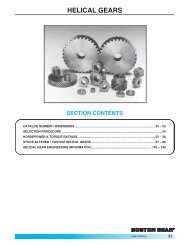
B HELICAL GEARS<br />
Section Contents ................................................................................................................................................63<br />
Helical <strong>Gear</strong>s..................................................................................................................................................64-65<br />
Selection.........................................................................................................................................................66-68<br />
<strong>Stock</strong> Altered and Custom Helical <strong>Gear</strong>s .......................................................................................................3-5<br />
C MITER AND BEVEL GEARS<br />
Section Contents ................................................................................................................................................69<br />
Miter <strong>Gear</strong>s ....................................................................................................................................................70-73<br />
Bevel <strong>Gear</strong>s....................................................................................................................................................74-78<br />
Selection.........................................................................................................................................................79-83<br />
<strong>Stock</strong> Altered and Custom Miter & Bevel <strong>Gear</strong>s............................................................................................3-5<br />
D WORMS AND WORM GEARS<br />
Section Contents ................................................................................................................................................85<br />
Worms and Worm <strong>Gear</strong>s ..............................................................................................................................86-95<br />
Selection.........................................................................................................................................................96-98<br />
E SHAFT ACCESSORIES<br />
Selection Contents .............................................................................................................................................99<br />
Shaft Couplings .........................................................................................................................................100-106<br />
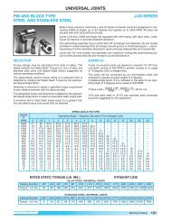
Universal Joints.........................................................................................................................................107-113<br />
Shaft Collars, Set Screw and Clamping Collars ....................................................................................114-117<br />
Washers and Bushings .............................................................................................................................118-119<br />
Pulleys, Round Belt...........................................................................................................................................120<br />
Miniature Timing Belt & Pulley Selection................................................................................................121-134<br />
F BEARINGS<br />
Selection Contents ...........................................................................................................................................135<br />
BOST-BRONZ (Oil-Impregnated Sintered Bronze) .............................................................................136-144<br />
BEAR-N-BRONZ (660 Cast Bronze) .....................................................................................................145-153<br />
Bronze Bearing Emergency Bank ................................................................................................................154<br />
BOStonE F-1 (Glass Filled Teflon) ........................................................................................................155-157<br />
RULON ® 641 Bearings ..........................................................................................................................158-159<br />
BOStonE Molded Plastic .......................................................................................................................160-171<br />
BOStonE Molded Nylon.........................................................................................................................172-173<br />
Sleeve Bearing Engineering ..................................................................................................................174-182<br />
Anti-Friction (Ball Bearings) ..................................................................................................................183-197<br />
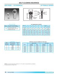
Self-Aligning (Rod End & Spherical Bearings).....................................................................................198-206<br />
Engineering.............................................................................................................................................207-211<br />
Mounted Bearings..................................................................................................................................212-232<br />
Rolling Element Bearing Engineering ..................................................................................................233-239<br />
G CHAINS<br />
Section Contents ...........................................................................................................................................241<br />
Roller Chains .............................................................................................................................................242-252<br />
Block Chains .....................................................................................................................................................253<br />
Continued on next page<br />
P-1930-BG 04/10 <strong>Boston</strong> <strong>Gear</strong> 800-825-6544 1
Table Of Contents Continued<br />
G CHAINS (continued) ......................................................................................................................................................<br />
Leaf (Cable) Chains ..........................................................................................................................................253<br />
Ladder Chains ...................................................................................................................................................254<br />
Miniature Roller Chains....................................................................................................................................255<br />
Chain Pullers/Chain Breaking Tools...............................................................................................................256<br />
H SPROCKETS<br />
Section Contents ...........................................................................................................................................257<br />
Roller Chain Drives ................................................................................................................................258-265<br />
Miniature Chain Sprockets ...........................................................................................................................266<br />
Roller Chain Sprockets..........................................................................................................................267-289<br />
Block Chain Sprockets .................................................................................................................................290<br />
Ladder Chain Sprockets........................................................................................................................291-292<br />
Roller Chain Drive Tensioners ..............................................................................................................293-296<br />
Idler Sprockets ..............................................................................................................................................293<br />
I ENGINEERING INFORMATION<br />
SPUR GEARS<br />
Nomenclature.......................................................................................................................................298-299<br />
Involute Form ...............................................................................................................................................300<br />
Diametral Pitch / Pressure Angle / Tooth Dimensions............................................................................301<br />
Backlash / Undercut / Formulas................................................................................................................302<br />
Lewis Formula..............................................................................................................................................303<br />
HELICAL GEARS<br />
Nomenclature / Helix Angle........................................................................................................................304<br />
Formulas.......................................................................................................................................................305<br />
Thrust Loads................................................................................................................................................306<br />
MITER & BEVEL GEARS<br />
Nomenclature ..............................................................................................................................................307<br />
Mounting Distance ......................................................................................................................................308<br />
Tooth Strength / Thrust ..............................................................................................................................309<br />
WORMS & WORM GEARS<br />
Hand / Efficiency / Thrust Loads ...............................................................................................................310<br />
Formulas / Self-Locking .............................................................................................................................311<br />
COUPLING / UNIVERSAL JOINTS ..................................................................................................................312<br />
GENERAL INFORMATION<br />
How To Figure Horsepower & Torque ......................................................................................................313<br />
Mountings / Alterations / Lubrication .......................................................................................................314<br />
Materials / Styles / Keyways & Setscrews ...............................................................................................315<br />
Sprockets, Sprocket Diameters .........................................................................................................316-318<br />
Horsepower & Torque Capacity Of Shafting ............................................................................................319<br />
Temperature Conversion Table .................................................................................................................320<br />
Equivalent Table ..........................................................................................................................................321<br />
Metric Conversion Chart ............................................................................................................................322<br />
Application Classifications .................................................................................................................323-324<br />
INDEX TO CATALOG NUMBERS .............................................................................................................325-328<br />
2 <strong>Boston</strong> <strong>Gear</strong> 800-825-6544 P-1930-BG 04/10
<strong>Modified</strong> <strong>Stock</strong> <strong><strong>Gear</strong>ing</strong><br />
With thousands of stock gears available, chances<br />
are we’ve got just what you’re looking for. If you<br />
find a stock gear that’s close to what you need,<br />
but not precisely right, that’s not a problem.<br />
We can modify most stock gears to meet your<br />
requirements and ship it within 24 hours.<br />
The full range of modifications we can provide<br />
are shown below.<br />
24 HOUR<br />
MODIFIED STOCK GEARING<br />
Face Width Reduced<br />
Keyway(s) Added<br />
SHIPMENT<br />
Tapped Holes Added<br />
(for set screws)<br />
Hub Projection Reduced<br />
Bore Enlarged<br />
Hub Diameter Reduced<br />
With <strong>Boston</strong> <strong>Gear</strong>, stock<br />
gear modifications are quick<br />
and easy. Give us a call at<br />
800-825-6544.<br />
Keyways and bores<br />
available in common<br />
metric sizes.<br />
Custom <strong><strong>Gear</strong>ing</strong><br />
Not every job is alike and not every job requires the same solution.<br />
That’s why <strong>Boston</strong> <strong>Gear</strong> will configure a custom gear to suit you.<br />
Even though we have built our reputation on supplying a breadth of<br />
standard products for virtually any industry, we have forged a name<br />
for ourselves as makers of quality custom gears. Custom doesn’t<br />
have to mean expensive and it doesn’t have to mean that it requires<br />
long lead times.<br />
Depending on the amount of tooling required and the complexity of<br />
the job, your custom gear solution can be delivered in days, not<br />
weeks. No matter how small or how large your job is, contact our<br />
custom engineering team for a customized quote.<br />
To request a quote for a custom gear solution from <strong>Boston</strong> <strong>Gear</strong>,<br />
simply fill out the “Request For Quotation Form” on page 5, and<br />
FAX to 800-387-0130. Or give us a call at 800-816-5608.<br />
P-1930-BG 4/10 <strong>Boston</strong> <strong>Gear</strong> 800-825-6544 3
Custom <strong><strong>Gear</strong>ing</strong> Capabilities<br />
<strong>Gear</strong> Types<br />
• Spur<br />
• Helical<br />
• Miter & Bevel<br />
• Worm & Worm <strong>Gear</strong><br />
AGMA Classes<br />
AGMA 9<br />
AGMA 8<br />
Non-Heat Treated,<br />
Spur & Helical <strong>Gear</strong>s only<br />
Heat Treated & Non-Heat Treated,<br />
all other gears<br />
Note: Worm & Worm <strong>Gear</strong>s do not have AGMA Class<br />
listings, however <strong>Boston</strong> <strong>Gear</strong> manufacturing<br />
tolerances relate to AGMA 8.<br />
Capacities<br />
<strong>Gear</strong> Diametral Pitch Face<br />
Type Pitch Diameter Max.<br />
Spur 64DP-3DP .250"-36.000" 5.000"<br />
Helical 64DP-3DP .337"-24.000" 5.000"<br />
Internal Spur 64DP-3DP 1.000"-24.000" 5.000"<br />
Bevel & Miter 64DP-3DP .500"-24.000" 3.000"<br />
Worm 48DP-3DP .333"-4.000" 12.000"<br />
Worm <strong>Gear</strong> 48DP-3DP .420"-24.000" 5.000"<br />
Shaved <strong>Gear</strong> 24DP-3DP 1.000"-24.000" 5.000"<br />
Splines<br />
Consult Engineering<br />
Diametral<br />
Circular<br />
Module Pitch Pitch (in.)<br />
.4 63.500 .0495<br />
.5 50.800 .0618<br />
.6 42.333 .0742<br />
.8 31.750 .0989<br />
1 25.400 .1237<br />
1.25 20.320 .1546<br />
1.5 16.933 .1855<br />
2 12.700 .2474<br />
2.5 10.160 .3092<br />
3 8.467 .3711<br />
4 6.350 .4947<br />
5 5.080 .6184<br />
6 4.233 .7422<br />
8 3.175 .9895<br />
Note: Circular Pitch (.0491”-1.0472”) or Module Pitch<br />
(.4mm-8mm) within the Diametral Pitch Limits are<br />
optional (refer to page 302).<br />
Tolerances<br />
Geometric Dimensioning<br />
Backlash<br />
Refer to Engineering Information found on pages 301<br />
and 309.<br />
Refer to engineering for backlash related to helical and<br />
worm gearing.<br />
Lot Sizes<br />
25 pcs Minimum Quantity on 6" OD and less<br />
Finishes<br />
63 RMS Minimum on gear teeth<br />
32 RMS Minimum on Bores, Shaved <strong>Gear</strong> Teeth, Ground<br />
Worms, and Machined Surfaces<br />
Material<br />
≤ 2" ≥ 2"<br />
Features Diameter Diameter<br />
Bore Diameter .0005" .0010"<br />
Ground O.D. .0005" .0010"<br />
Turned O.D. .0020" .0020"<br />
Bore Length .0020" .0020"<br />
Keyway Width .0020" .0020"<br />
Keyway Depth .0100" .0100"<br />
Tapped Holes<br />
2B Thread<br />
≤ 2" ≥ 2"<br />
Features Diameter Diameter<br />
Perpendicularity .0010" .0010"<br />
Parallelism .0010" .0010"<br />
Circular Runout .0010" .0010"<br />
Flatness .0010" .0010"<br />
Concentricity .0005" .0010"<br />
Description<br />
Designation<br />
Low Carbon Steels<br />
11L17, 12L14, 12L15<br />
Medium Carbon Steels 11L41, 1045<br />
Low Carbon Alloy Steels 86(L)20* (*86L20 or 8620)<br />
Medium Carbon Alloy Steels 41(L)30, 41(L)40, 41(L)50<br />
Preheat Treated Steels 4140, 4150<br />
Stainless Steels 17-4PH, 303, 304<br />
Cast Iron Grade 25, Grade 30<br />
Brass<br />
Free Cutting, Half Hard<br />
Bronze<br />
Non-Metallic<br />
Phenolic (NEMA“C”), Delron, Nylon<br />
4 <strong>Boston</strong> <strong>Gear</strong> 800-825-6544 P-1930-BG 4/10
Custom <strong><strong>Gear</strong>ing</strong> “Request For Quotation” Form<br />
Company Name<br />
Address<br />
Date<br />
Ref.<br />
City/State Zip Quantity Req.<br />
Tel. No. Fax No. P.O. No.<br />
Contact Name<br />
email<br />
<strong>Gear</strong> Type<br />
Spur Helical Miter Bevel Worm Worm <strong>Gear</strong><br />
No. of Teeth<br />
Pitch (DP, CP MOD)<br />
Pressure Angle<br />
Helix Angle<br />
Hand (LH, RH)<br />
Material<br />
Face Width<br />
Length Through Bore<br />
Hub Diameter<br />
Hub Projection<br />
Bore Diameter<br />
Keyway<br />
Setscrew(s)<br />
Teeth in Mating <strong>Gear</strong><br />
Center Distance<br />
Mounting Distance<br />
No. of Starts (Thread)<br />
Outside Diameter<br />
Heat Treat — Yes/No<br />
Depth of Hardness<br />
Special Information<br />
FAX to 800-387-0130. Or give us a call at 800-816-5608.<br />
P-1930-BG 4/10 <strong>Boston</strong> <strong>Gear</strong> 800-825-6544 5
<strong>Modified</strong> <strong>Stock</strong> <strong><strong>Gear</strong>ing</strong><br />
With thousands of stock gears available, chances<br />
are we’ve got just what you’re looking for. If you<br />
find a stock gear that’s close to what you need,<br />
but not precisely right, that’s not a problem.<br />
We can modify most stock gears to meet your<br />
requirements and ship it within 24 hours.<br />
The full range of modifications we can provide<br />
are shown below.<br />
24 HOUR<br />
MODIFIED STOCK GEARING<br />
Face Width Reduced<br />
Keyway(s) Added<br />
SHIPMENT<br />
Tapped Holes Added<br />
(for set screws)<br />
Hub Projection Reduced<br />
Bore Enlarged<br />
Hub Diameter Reduced<br />
With <strong>Boston</strong> <strong>Gear</strong>, stock<br />
gear modifications are quick<br />
and easy. Give us a call at<br />
800-825-6544.<br />
Keyways and bores<br />
available in common<br />
metric sizes.<br />
Custom <strong><strong>Gear</strong>ing</strong><br />
Not every job is alike and not every job requires the same solution.<br />
That’s why <strong>Boston</strong> <strong>Gear</strong> will configure a custom gear to suit you.<br />
Even though we have built our reputation on supplying a breadth of<br />
standard products for virtually any industry, we have forged a name<br />
for ourselves as makers of quality custom gears. Custom doesn’t<br />
have to mean expensive and it doesn’t have to mean that it requires<br />
long lead times.<br />
Depending on the amount of tooling required and the complexity of<br />
the job, your custom gear solution can be delivered in days, not<br />
weeks. No matter how small or how large your job is, contact our<br />
custom engineering team for a customized quote.<br />
To request a quote for a custom gear solution from <strong>Boston</strong> <strong>Gear</strong>,<br />
simply fill out the “Request For Quotation Form” on page 5, and<br />
FAX to 800-387-0130. Or give us a call at 800-816-5608.<br />
P-1930-BG 04/10 <strong>Boston</strong> <strong>Gear</strong> 800-825-6544 3
Custom <strong><strong>Gear</strong>ing</strong> Capabilities<br />
<strong>Gear</strong> Types<br />
• Spur<br />
• Helical<br />
• Miter & Bevel<br />
• Worm & Worm <strong>Gear</strong><br />
AGMA Classes<br />
AGMA 9<br />
AGMA 8<br />
Non-Heat Treated,<br />
Spur & Helical <strong>Gear</strong>s only<br />
Heat Treated & Non-Heat Treated,<br />
all other gears<br />
Note: Worm & Worm <strong>Gear</strong>s do not have AGMA Class<br />
listings, however <strong>Boston</strong> <strong>Gear</strong> manufacturing<br />
tolerances relate to AGMA 8.<br />
Capacities<br />
<strong>Gear</strong> Diametral Pitch Face<br />
Type Pitch Diameter Max.<br />
Spur 64DP-3DP .250"-36.000" 5.000"<br />
Helical 64DP-3DP .337"-24.000" 5.000"<br />
Internal Spur 64DP-3DP 1.000"-24.000" 5.000"<br />
Bevel & Miter 64DP-3DP .500"-24.000" 3.000"<br />
Worm 48DP-3DP .333"-4.000" 12.000"<br />
Worm <strong>Gear</strong> 48DP-3DP .420"-24.000" 5.000"<br />
Shaved <strong>Gear</strong> 24DP-3DP 1.000"-24.000" 5.000"<br />
Splines<br />
Consult Engineering<br />
Diametral<br />
Circular<br />
Module Pitch Pitch (in.)<br />
.4 63.500 .0495<br />
.5 50.800 .0618<br />
.6 42.333 .0742<br />
.8 31.750 .0989<br />
1 25.400 .1237<br />
1.25 20.320 .1546<br />
1.5 16.933 .1855<br />
2 12.700 .2474<br />
2.5 10.160 .3092<br />
3 8.467 .3711<br />
4 6.350 .4947<br />
5 5.080 .6184<br />
6 4.233 .7422<br />
8 3.175 .9895<br />
Note: Circular Pitch (.0491”-1.0472”) or Module Pitch<br />
(.4mm-8mm) within the Diametral Pitch Limits are<br />
optional (refer to page 302).<br />
Tolerances<br />
Geometric Dimensioning<br />
Backlash<br />
Refer to Engineering Information found on pages 301<br />
and 309.<br />
Refer to engineering for backlash related to helical and<br />
worm gearing.<br />
Lot Sizes<br />
25 pcs Minimum Quantity on 6" OD and less<br />
Finishes<br />
63 RMS Minimum on gear teeth<br />
32 RMS Minimum on Bores, Shaved <strong>Gear</strong> Teeth, Ground<br />
Worms, and Machined Surfaces<br />
Material<br />
≤ 2" ≥ 2"<br />
Features Diameter Diameter<br />
Bore Diameter .0005" .0010"<br />
Ground O.D. .0005" .0010"<br />
Turned O.D. .0020" .0020"<br />
Bore Length .0020" .0020"<br />
Keyway Width .0020" .0020"<br />
Keyway Depth .0100" .0100"<br />
Tapped Holes<br />
2B Thread<br />
≤ 2" ≥ 2"<br />
Features Diameter Diameter<br />
Perpendicularity .0010" .0010"<br />
Parallelism .0010" .0010"<br />
Circular Runout .0010" .0010"<br />
Flatness .0010" .0010"<br />
Concentricity .0005" .0010"<br />
Description<br />
Designation<br />
Low Carbon Steels<br />
11L17, 12L14, 12L15<br />
Medium Carbon Steels 11L41, 1045<br />
Low Carbon Alloy Steels 86(L)20* (*86L20 or 8620)<br />
Medium Carbon Alloy Steels 41(L)30, 41(L)40, 41(L)50<br />
Preheat Treated Steels 4140, 4150<br />
Stainless Steels 17-4PH, 303, 304<br />
Cast Iron Grade 25, Grade 30<br />
Brass<br />
Free Cutting, Half Hard<br />
Bronze<br />
Non-Metallic<br />
Phenolic (NEMA“C”), Delron, Nylon<br />
4 <strong>Boston</strong> <strong>Gear</strong> 800-825-6544 P-1930-BG 04/10
Custom <strong><strong>Gear</strong>ing</strong> “Request For Quotation” Form<br />
Company Name<br />
Address<br />
Date<br />
Ref.<br />
City/State Zip Quantity Req.<br />
Tel. No. Fax No. P.O. No.<br />
Contact Name<br />
email<br />
<strong>Gear</strong> Type<br />
Spur Helical Miter Bevel Worm Worm <strong>Gear</strong><br />
No. of Teeth<br />
Pitch (DP, CP MOD)<br />
Pressure Angle<br />
Helix Angle<br />
Hand (LH, RH)<br />
Material<br />
Face Width<br />
Length Through Bore<br />
Hub Diameter<br />
Hub Projection<br />
Bore Diameter<br />
Keyway<br />
Setscrew(s)<br />
Teeth in Mating <strong>Gear</strong><br />
Center Distance<br />
Mounting Distance<br />
No. of Starts (Thread)<br />
Outside Diameter<br />
Heat Treat — Yes/No<br />
Depth of Hardness<br />
Special Information<br />
FAX to 800-387-0130. Or give us a call at 800-816-5608.<br />
P-1930-BG 04/10 <strong>Boston</strong> <strong>Gear</strong> 800-825-6544 5
<strong>Gear</strong> Selection<br />
<strong>Stock</strong> <strong>Gear</strong>s<br />
Pressure<br />
Description Application Angle (PA) Material<br />
Pinions<br />
and<br />
<strong>Gear</strong>s<br />
14-1/2° Brass<br />
Parallel 20° Brass<br />
Shafts 14-1/2° Steel<br />
20° Delrin<br />
Pinions<br />
and<br />
<strong>Gear</strong>s<br />
Parallel<br />
Shafts<br />
14-1/2° Non-Metallic<br />
14-1/2° Steel, Iron<br />
20° Steel, Iron<br />
Spur<br />
<strong>Gear</strong>s<br />
Change<br />
<strong>Gear</strong>s<br />
Stem<br />
Pinions<br />
Parallel<br />
Shafts<br />
Parallel<br />
Shafts<br />
14-1/2° Steel, Iron<br />
14-1/2° Steel<br />
Drawn<br />
Pinion<br />
Wire<br />
Parallel<br />
Shafts<br />
Brass<br />
14-1/2° Steel<br />
Rack<br />
Use with<br />
Spur <strong>Gear</strong>s<br />
14-1/2° Nylon<br />
14-1/2° Steel<br />
20° Steel<br />
Internal Parallel 14-1/2° Brass<br />
<strong>Gear</strong>s Shafts 20° Brass<br />
Helical<br />
<strong>Gear</strong>s<br />
Parallel<br />
Helical and 90° Steel<br />
14-1/2°<br />
<strong>Gear</strong>s<br />
Non-Intersecting<br />
Bronze<br />
Shafts<br />
Straight 90°<br />
Miter Intersecting 20°<br />
<strong>Gear</strong>s<br />
Shafts<br />
Nylon<br />
Brass<br />
Steel<br />
Iron<br />
Miter<br />
and<br />
Bevel<br />
<strong>Gear</strong>s<br />
Spiral 90°<br />
Miter Intersecting 20° Steel<br />
<strong>Gear</strong>s<br />
Shafts<br />
Straight 90° Brass<br />
Bevel Intersecting 20° Steel<br />
<strong>Gear</strong>s Shafts Iron<br />
Spiral 90°<br />
Bevel Intersecting 20° Steel<br />
<strong>Gear</strong>s<br />
Shafts<br />
Worms<br />
and<br />
Worm<br />
<strong>Gear</strong>s<br />
Worms/<br />
Worm <strong>Gear</strong>s<br />
Worms/<br />
Worm <strong>Gear</strong>s<br />
Worms/<br />
Worm <strong>Gear</strong>s<br />
90°<br />
Non-Intersecting<br />
Shafts<br />
90°<br />
Non-Intersecting<br />
Shafts<br />
90°<br />
Non-Intersecting<br />
Shafts<br />
(PA)<br />
14-1/2°<br />
14-1/2°<br />
20°<br />
25°<br />
14-1/2°<br />
20°<br />
25°<br />
Thread<br />
Single<br />
Single<br />
Double<br />
Quad<br />
Single<br />
Double<br />
Quad<br />
Worm<br />
Acetal<br />
Nylon<br />
Steel<br />
Steel<br />
<strong>Gear</strong><br />
Acetal<br />
Minlon<br />
Bronze<br />
Bronze<br />
Iron<br />
6 <strong>Boston</strong> <strong>Gear</strong> 800-825-6544 P-1930-BG 04/10
Reference Guide<br />
<strong>Gear</strong> Catalog Reference Pages<br />
Horsepower Catalog<br />
Diametrical Pitch Selection and Torque Number<br />
Pitch Diameter Face Width Procedure Ratings Selection<br />
Tooth Gauge<br />
48DP – 16DP .208" – 5.000" .062" – .313" 49 50 – 52 18 – 21<br />
64DP – 24DP .250" – 6.000" .125" – .250" 49 – 37 – 42<br />
32DP – 24DP .500" – 6.000" .187" – .250" 49 50 19 – 20<br />
48DP – 24DP .375" – 2.500" .125" – .250" 49 – 37 – 42<br />
16DP – 8DP 1.000" – 3.500" .500" – 1.250" 49 52 – 55 22 – 24<br />
20DP – 3DP .750" – 36.000" .500" – 3.000" 49 51 – 57 20 – 27<br />
20DP – 5DP .600" – 36.000" .500" – 2.500" 49 58 – 62 42 – 46<br />
20DP – 8DP 1.000" – 12.500" .375" – 1.250" 49 51 – 55 28 – 32<br />
20DP – 6DP .287" – 1.750" 1.125" – 3.000" 49 51 – 56 33<br />
48DP – 24DP .125" – .667" 48" Lengths 49 50 34<br />
48DP – 24DP .125" – .667" 48" Lengths 49 50 34<br />
48DP – 24DP .104" – .208" .125" – .250" 49 50 35<br />
48DP – 3DP .104" – 1.167" .125" – 3.000" 49 50 – 57 35<br />
20DP – 4DP .450" – 1.750" .500" – 3.500" 49 58 – 62 47<br />
48DP – 16DP 1.000" – 6.000" .125" – .312" 49 50 36<br />
64DP – 24DP 1.000" – 6.000" .125" – .250" 49 – 48<br />
24TDP – 6TDP .333" – 6.000" .250" – 1.250" 66 67 – 68 64 – 65<br />
8TDP – 6TDP 1.000" – 6.000" .750" – 1.250" 66 68 65<br />
48DP – 16DP .312" – 2.000" .070" – .390" 79 80 70 – 71<br />
48DP – 24DP .312" – 1.500" .080" – .230" 79 80 70<br />
48DP – 4DP .375" – 7.000" .080" – 1.430" 79 80 – 81 70 – 72<br />
8DP – 4DP 3.500" – 8.000" .750" – 1.333" 79 80 – 81 72<br />
18DP – 5DP 1.000" – 5.000" .220" – 1.150" 79 83 73<br />
48DP – 24DP .250" – 2.000" .090" – .260" 79 82 74<br />
20DP – 6DP .500" – 6.000" .180" – 1.070" 79 82 74 – 77<br />
16DP – 4DP 1.000" – 9.000" .420" – 1.400" 79 82 75 – 77<br />
30DP – 8DP .430" – 4.250" .140" –.710" 79 83 78<br />
Worm <strong>Gear</strong> Worm <strong>Gear</strong><br />
48DP – 32DP<br />
24DP – 32DP .333" .417" .562" .156"<br />
96 – 86 – 88<br />
48DP – 24DP to to to to<br />
1.500" 4.167" .812" .219"<br />
.333" .417" .562" .156"<br />
48DP – 4DP to to to to<br />
96 97 – 98 86 – 94<br />
3.000" 6.000" 5.250" 1.500"<br />
.625" 1.250" 1.000" .312"<br />
16DP – 3DP<br />
to to to to<br />
96 97 – 98 89 – 95<br />
4.000" 18.000" 5.250" 2.000"<br />
P-1930-BG 04/10 <strong>Boston</strong> <strong>Gear</strong> 800-825-6544 7
Product Selection / Reference Guide<br />
PLAIN CYLINDRICAL FLANGED TYPE THRUST TYPE<br />
BOST-BRONZ ®<br />
OIL<br />
IMPREGNATED<br />
SINTERED<br />
BRONZE<br />
Pages 138–140 Pages 141–142 Page 143<br />
PLATE STOCK CORED BARS SOLID BARS<br />
Page 143 Page 144 Page 144<br />
PLAIN CYLINDRICAL CORED BARS SOLID BARS<br />
BEAR-N-BRONZ ®<br />
660 CAST<br />
BRONZE<br />
Pages 146–150 Pages 151–153 Page 153<br />
BOST-BRONZ & BEAR-N-BRONZ<br />
PLAIN CYLINDRICAL<br />
BRONZE<br />
EMERGENCY<br />
BEARING BANKS<br />
BOStonE ® F-1<br />
GLASS FILLED<br />
TEFLON<br />
BOSTONE ® F-1<br />
GLASS FILLED<br />
TEFLON<br />
Page 154 Page 156<br />
FLANGED THRUST TYPE SOLID BARS<br />
(EXTRUDED)<br />
Page 156 Page 157 Page 157<br />
RULON ® 641 BEARINGS PLAIN CYLINDRICAL FLANGED<br />
Rulon ®<br />
BOSTONE ®<br />
MOLDED<br />
PLASTIC<br />
Pages 158–159 Page 161 Page 161<br />
ROLL END FOR TUBING EXTRA LENGTH BLIND ROLL END ADAPTER GUIDE ROLL<br />
& STANDARD PIPE BORE INSERTS FOR HEX SHAFT<br />
BOStonE ®<br />
MOLDED<br />
PLASTIC<br />
Pages 162–168 Page 169 Page 169 Page 170<br />
ROLLERS SHAFT CLIP STUB SHAFT FOR<br />
ROLLERS<br />
Page 170 Page 171 Page 171<br />
8 <strong>Boston</strong> <strong>Gear</strong> 800-825-6544 P-1930-BG 04/10
Product Selection / Reference Guide<br />
PLAIN CYLINDRICAL FLANGED THRUST TYPE CABLE PULLEYS<br />
BOStonE ®<br />
MOLDED<br />
NYLON<br />
Page 172 Page 172 Page 173 Page 173<br />
1600 SERIES 7500 SERIES 7600 SERIES 6900 SERIES<br />
RADIAL<br />
BALL<br />
BEARINGS<br />
Pages 185–186 Page 187 Page 188 Page 189<br />
3000 SERIES 400F SERIES FLANGED<br />
THRUST<br />
BALL<br />
BEARINGS<br />
BALL<br />
BEARING<br />
SHEAVES<br />
Pages 190–191 Page 192<br />
GROUND, UNBANDED 600 SERIES<br />
Page 193 Page 194<br />
2000 SERIES 2100 SERIES 2200 SERIES<br />
BALL<br />
BEARING<br />
WHEELS<br />
Page 195 Page 196 Page 197<br />
KF FEMALE SERIES HM-C SERIES CMHD MALE SERIES HM MALE SERIES<br />
HF-C FEMALE SERIES CFHD FEMALE SERIES HF FEMALE SERIES<br />
ROD<br />
END<br />
BEARINGS<br />
Page 198 Page 199 Page 200 Page 201<br />
HME MALE SERIES HMX MALE SERIES<br />
HFE FEMALE SERIES HFX FEMALE SERIES<br />
Page 202 Page 203<br />
P-1930-BG 04/10 <strong>Boston</strong> <strong>Gear</strong> 800-825-6544 9
Product Selection / Reference Guide<br />
SPHERICAL<br />
BEARINGS<br />
LHA-LHB-LHSS LHSSE-LHSSVV LS SERIES<br />
SERIES<br />
SERIES<br />
REPLACEMENT<br />
BEARINGS<br />
& LOCKING<br />
COLLAR SERIES<br />
Page 204 Page 205 Page 206<br />
L, H, F, T, A PS/XL-S-MB SERIES<br />
SERIES<br />
Page 213 Page 214<br />
PPB SERIES PS SERIES XL SERIES L-SERIES<br />
H-SERIES<br />
PILLOW<br />
BLOCKS<br />
Page 215 Page 216 Page 217 Pages 218–219<br />
SL/SH SERIES<br />
MB SERIES<br />
Pages 220–221 Page 222<br />
PS2/PS3 SERIES XL2/XL3 SERIES F SERIES SF/ST SERIES<br />
T-SERIES<br />
FLANGED<br />
UNITS<br />
Page 223 Page 224 Pages 225–226 Pages 227–228<br />
MBF SERIES<br />
MBP SERIES<br />
Page 229 Page 230<br />
A SERIES<br />
TU SERIES<br />
SHAFT<br />
SUPPORTS<br />
TAKE-UP<br />
FRAMES<br />
Page 231 Page 232<br />
10 <strong>Boston</strong> <strong>Gear</strong> 800-825-6544 P-1930-BG 04/10
Product Selection / Reference Guide<br />
INSERT (3 JAW) SPIDER RING SHEAR<br />
COUPLINGS<br />
FC Type – Pages 100-101 BF Type – Page 102 BG Type – Page 103<br />
CLAMP MULTI-JAW RIGID SLEEVE<br />
UNIVERSAL<br />
JOINTS<br />
SCC Type – Page 104 FA Type – Page 105 CR Type – Page 105 FCP Type – Page 106<br />
PIN & BLOCK FORGED MOLDED MOLDED WITH<br />
SLIDE EXTENSION<br />
J Type – Pages 107–108 UJN Type – Pages 109–111 JP Type – Page 112 JPE Type – Page 113<br />
SETSCREW CLAMPING–THREADED CLAMPING – 1 PIECE CLAMPING – 2 PIECE<br />
COLLARS<br />
SC Type – Page 114 CSC Type – Page 115 CS Type – Page 116 2CS Type – Page 117<br />
HARDENED STEEL WASHERS<br />
SOFT STEEL BUSHINGS<br />
WASHERS<br />
BUSHINGS<br />
Page 118 Page 119<br />
GROOVED<br />
PULLEYS<br />
MINIATURE<br />
TIMING BELTS<br />
& PULLEYS<br />
Page 120<br />
TIMING BELTS<br />
PULLEYS<br />
Pages 121-124 & 130 Pages 125–129 & 131–134<br />
P-1930-BG 04/10 <strong>Boston</strong> <strong>Gear</strong> 800-825-6544 11
Product Selection / Reference Guide<br />
MULTIPLE WIDTHS TRANSMISSION CONVEYOR SERIES HEAVY SERIES<br />
ANSI STANDARD<br />
SERIES<br />
ROLLER,<br />
BLOCK &<br />
LEAF CHAINS<br />
Page 243–244 Page 245 Page 245 Page 245<br />
ATTACHMENTS HOLLOW PIN BLOCK LEAF (CABLE)<br />
Page 251 Page 252 Page 253 Page 253<br />
LADDER MINIATURE ROLLER CHAIN PULLERS &<br />
CHAIN<br />
CHAIN BREAKING<br />
TOOLS<br />
SPROCKETS<br />
Page 254 Page 255 Page 256<br />
PLASTIC & STAINLESS ROLLER CHAIN BLOCK CHAIN LADDER CHAIN<br />
STEEL<br />
DRIVE<br />
TENSIONERS<br />
Page 266 Pages 267–289 Page 290 Pages 291–292<br />
SCREW/SPRING ADJUSTABLE SHAFT MOUNTED DRIVE TENSIONS<br />
TYPE LG TYPE BG TYPE HG &UG<br />
Page 294 Pages 294-295 Page 296<br />
12 <strong>Boston</strong> <strong>Gear</strong> 800-825-6544 P-1930-BG 04/10
<strong>Boston</strong> <strong>Gear</strong><br />
Spur <strong>Gear</strong>s<br />
■ Parallel Shaft Applications<br />
■ Reliability from Steel, Cast Iron<br />
and Brass<br />
■ More Cost Effective, Quieter Running<br />
and Corrosion-Resistant Operation<br />
from Non-Metallic Options<br />
■ Higher Load Carrying Capacity with<br />
20° PA (Pressure Angle)<br />
■ Higher Contact Ratio for a Smoother,<br />
Quieter Operation with 14-1/2° PA<br />
Selections From <strong>Stock</strong><br />
• Pinions and <strong>Gear</strong>s (Steel, Cast<br />
Iron, Brass, Non-Metallic)<br />
• Change <strong>Gear</strong>s (Steel or Cast<br />
Iron)<br />
• Stem Pinions (Steel)<br />
• Drawn Pinion Wire (Brass,<br />
Steel)<br />
• Rack (Steel, Nylon)<br />
• Internal (Brass)<br />
• Diametral Pitch 64 DP to 3 DP<br />
• Pitch Diameter .208" to<br />
36.000"<br />
• Diametral Pitch System<br />
Standardized on <strong>Stock</strong> <strong>Gear</strong>s<br />
• 14-1/2° and 20° Pressure<br />
Angles<br />
<strong>Boston</strong> spur gears are designed to transmit motion and power between<br />
parallel shafts. Configurations include spur, rack, pinion wire, stem<br />
pinions and internal gears; most with a selection of bores, keyways and<br />
set screws. Fine-pitch gears are available in plastic, brass, stainless steel<br />
and steel. Heavier pitch spurs are available in steel and cast iron. Styles<br />
include plain, web, web with lightening holes or spoked. Change gears<br />
have consecutive numbers of teeth for a variety of ratios.<br />
<strong>Boston</strong> <strong>Gear</strong> manufactures both 14-1/2° and 20°PA, involute, full depth<br />
system gears. While 20°PA is generally recog nized as having higher load<br />
carrying capacity, 14-1/2°PA gears have extensive use. The lower<br />
Pressure Angle results in less change in backlash due to center distance<br />
variation and concentricity errors. It also provides a higher contact ratio<br />
and is consequently a smoother, quieter operation provided that the<br />
undercut of the teeth is not present.<br />
P-1930-BG 04/10 <strong>Boston</strong> <strong>Gear</strong> 800-825-6544 13
<strong>Boston</strong> <strong>Gear</strong><br />
Helical <strong>Gear</strong>s<br />
■ Parallel and 90° Non-Intersecting Shaft<br />
Applications<br />
■ Improved Tooth Strength<br />
■ Greater Load Carrying Capacity<br />
■ Increased Contact Ratio<br />
■ Smoother Operating Characteristics<br />
Selections From <strong>Stock</strong><br />
• Helicals, 45° Helix Angle<br />
• Transverse Diametral Pitch (TDP)<br />
System<br />
• Hardened Steel (24 TDP – 6 TDP)<br />
• Bronze (8 TDP – 6 TDP)<br />
• Pitch Diameter .333" to 6.000"<br />
• 14-1/2° Pressure Angle<br />
<strong>Boston</strong> helical gears are stocked both right and left hand, made with a 45°<br />
helix angle. They are designed to transmit motion and power between<br />
non-intersecting shafts which are positioned either parallel (opposing hand)<br />
or at 90° to each other (same hand). Because these gears are top-hobbed,<br />
there is extremely close concentricity between the pitch diameter and the<br />
outside diameter.<br />
Helical gears offer additional benefits relative to Spur <strong>Gear</strong>s, those being:<br />
– Improved tooth strength due to the elongated helical wrap-around.<br />
– Increased contact ratio due to the axial tooth overlap.<br />
– Helical <strong>Gear</strong>s tend to have greater load carrying capacity than Spur <strong>Gear</strong>s<br />
of similar size.<br />
– Because of the above, smoother operating characteristics are apparent.<br />
All <strong>Boston</strong> Helicals are cut to the Transverse Diametral Pitch System, resulting<br />
in a higher Normal Diametral Pitch Number.<br />
14 <strong>Boston</strong> <strong>Gear</strong> 800-825-6544 P-1930-BG 04/10
<strong>Boston</strong> <strong>Gear</strong><br />
Miter and Bevel <strong>Gear</strong>s<br />
■ 90° Intersecting Shaft Applications<br />
■ Coniflex® Tooth Form for Increased Life and<br />
Smoother, Quieter Operation<br />
■ Spiral Miter and Bevel for Higher Speed, Greater<br />
Torque Load, and Quieter Operating Applications<br />
■ Miter <strong>Gear</strong>s for 1:1 Ratio Applications<br />
■ Bevel <strong>Gear</strong>s for 1.5:1 to 6:1 Ratio Applications<br />
■ Soft Bores for Customized Alterations<br />
Selections from <strong>Stock</strong><br />
• Straight Miter <strong>Gear</strong>s<br />
– Nylon (48 DP – 16 DP)<br />
– Brass (48 DP – 24 DP)<br />
– Steel (48 DP – 4 DP)<br />
– Iron (8 DP – 4 DP)<br />
• Spiral Miter <strong>Gear</strong>s (35° Spiral Angle)<br />
– Steel (18 DP – 5 DP)<br />
• Straight Bevel <strong>Gear</strong>s<br />
– Brass (48 DP – 24 DP)<br />
– Steel (20 DP – 6 DP)<br />
– Iron (16 DP – 4 DP)<br />
• Spiral Bevel <strong>Gear</strong>s (35° Spiral Angle)<br />
– Steel (30 DP – 8 DP)<br />
• Diametral Pitch – 48 DP to 4 DP<br />
• Pitch Diameter – 0.250" to 9.000"<br />
• 20° Pressure Angle<br />
• Hardened or Unhardened Teeth (Steel)<br />
• Made in Accordance with AGMA<br />
Specifications for the Basic Tooth<br />
Form<br />
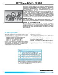
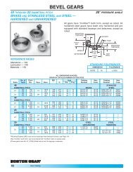
<strong>Boston</strong> miter and bevel gears are designed for transmission of motion and<br />
power between intersecting shafts positioned at a right angle. Straight tooth<br />
miter and bevel gears are cut with a generated tooth form having a localized<br />
lengthwise tooth bearings known as the “Coniflex” ® tooth form. The superiority<br />
of these gears over straight bevels with full length tooth bearing lies in the<br />
control of tooth contact. The localization of contact permits minor adjustment<br />
of the gears in assembly and allows for some displacement due to deflection<br />
under operating loads, without concentration of the load on the end of the<br />
tooth. This results in increased life and quieter operation.<br />
Spiral tooth form miter and bevel gears are suited for higher speed and larger<br />
torque applications.<br />
® Registered trademark of The Gleason Works.<br />
P-1930-BG 04/10 <strong>Boston</strong> <strong>Gear</strong> 800-825-6544 15
<strong>Boston</strong> <strong>Gear</strong><br />
Worms and Worm <strong>Gear</strong>s<br />
■ 90° Non-Intersecting Shaft Applications<br />
■ Smoothest, Quietest Form of <strong><strong>Gear</strong>ing</strong><br />
■ High Ratio Speed Reduction<br />
■ Minimal Space Requirements<br />
■ Resistance to Back Driving with<br />
Some Ratios<br />
■ Increased Efficiency with Lower Ratios<br />
Selections from <strong>Stock</strong><br />
• Worms<br />
– Acetal (48 DP – 24 DP)<br />
– Steel (48 DP – 3 DP)<br />
• Worm <strong>Gear</strong>s<br />
– Acetal (48 DP – 24 DP)<br />
– Bronze (48 DP – 4 DP)<br />
– Cast Iron (16 DP – 3 DP)<br />
• Pressure Angle<br />
– 14-1/2°, 20°, 25°<br />
• Thread<br />
– Single, Double, Quadruple<br />
• Diametral Pitch – 48 DP to 3 DP<br />
• Center Distances – 0.375" to<br />
11.000"<br />
<strong>Boston</strong> <strong>Gear</strong> worms and worm gears provide an effective answer for such<br />
power transmission applications as high-ratio speed reduction, limited space,<br />
right-angle shafts and non-intersecting shafts. When properly applied, they<br />
are the smoothest and quietest form of gearing. Steel worms and cast iron or<br />
bronze worm gears having throated teeth are available in single or multiple<br />
threads, 48 to 3 diametral pitch or up to 85" pitch diameter. Acetal worms<br />
and worm gears are available in 48, 32 and 24 diametral pitches.<br />
The efficiency of a worm gear drive depends on the lead angle and number of<br />
starts on the worm. The angle generally decreases with increasing ratio and<br />
worm pitch diameter. For increased efficiency the ratio should be kept low.<br />
16 <strong>Boston</strong> <strong>Gear</strong> 800-825-6544 P-1930-BG 04/10
Spur <strong>Gear</strong>s<br />
Section Contents<br />
A<br />
14-1/2° PRESSURE ANGLE – CATALOG NUMBER / DIMENSIONS<br />
Spur <strong>Gear</strong>s ................................................................................................................................. 18-27<br />
Change <strong>Gear</strong>s ............................................................................................................................. 28-32<br />
Stem Pinions..................................................................................................................................... 33<br />
Drawn Pinion Wire ........................................................................................................................... 34<br />
Rack .................................................................................................................................................. 35<br />
Internal <strong>Gear</strong>s................................................................................................................................... 36<br />
20° PRESSURE ANGLE – CATALOG NUMBER / DIMENSIONS<br />
Spur <strong>Gear</strong>s .................................................................................................................................. 37-46<br />
Rack .................................................................................................................................................. 47<br />
Internal <strong>Gear</strong>s................................................................................................................................... 48<br />
Selection Procedure................................................................................................................................. 49<br />
Horsepower & Torque Ratings .......................................................................................................... 50-62<br />
<strong>Gear</strong> Gauges ............................................................................................................................................. 62<br />
<strong>Stock</strong> Altered/Custom Spur <strong>Gear</strong>s........................................................................................................ 3-5<br />
Spur <strong>Gear</strong> Engineering Information .............................................................................................. 298-303<br />
P-1930-BG 04/10 <strong>Boston</strong> <strong>Gear</strong> 800-825-6544 17
Spur <strong>Gear</strong>s<br />
48 and 32 Diametral Pitch (Brass)<br />
14-1/2° Pressure Angle (will not operate with 20° spurs)<br />
A<br />
FACE<br />
PITCH<br />
DIA.<br />
STANDARD TOLERANCES<br />
DIMENSION TOLERANCE<br />
BORE All ±.0005<br />
REFERENCE PAGES<br />
Alterations — 314<br />
Lubrication — 314<br />
Materials — 315<br />
HUB<br />
PROJ.<br />
BORE<br />
OVERALL<br />
LENGTH<br />
48 D.P. 32 D.P.<br />
HUB<br />
DIA.<br />
ALL DIMENSIONS IN INCHES<br />
ORDER BY CATALOG NUMBER OR ITEM CODE<br />
Style Without Keyway<br />
No. Hub See or Setscrew<br />
of Pitch Page Catalog Item<br />
Teeth Dia. Bore Dia. Proj. 315 Number Code<br />
48<br />
Face = .125"<br />
Outside Dia. = Pitch Dia. + .042"<br />
DIAMETRAL PITCH<br />
Overall Length = .125" + Hub Proj.<br />
BRASS<br />
10 .208 .0935 – – G127 09322<br />
12 .250 G129 09324<br />
14 .292 G130 09326<br />
15 .312 .125 – – G131 09328<br />
16 .333 G132 09330<br />
18 .375 G133 09332<br />
20 .417 G134 09334<br />
22 .458 G135 09336<br />
24 .500 G136 09338<br />
26 .542 G137 09340<br />
32 .667 .1875 – – A G138 09342<br />
36 .750 G139 09344<br />
40 .833 G140 09346<br />
44 .917 G141 09348<br />
48 1.000 G142 09350<br />
54 1.125 G143 09352<br />
60 1.250 G144 09354<br />
66 1.375 .250 .50 .25 G145 09356<br />
72 1.500 G146 09358<br />
84 1.750 G147 09360<br />
96 2.000 G148 09362<br />
100 2.083 G154 09364<br />
120<br />
144<br />
2.500<br />
3.000<br />
.3125 .62 .31 D<br />
G149<br />
G150<br />
09366<br />
09368<br />
192 4.000 G151 09370<br />
32 Face = .062"<br />
DIAMETRAL PITCH Outside Dia. = Pitch Dia. + .062"<br />
BRASS<br />
10<br />
14<br />
.312<br />
.438<br />
.125 – –<br />
G96<br />
G98<br />
09234<br />
09238<br />
16 .500 G99 09240<br />
20 .625 G101 09244<br />
24 .750 .1875 – – G102 09246<br />
28 .875 G103 09248<br />
32 1.000 A G104 09250<br />
40<br />
48<br />
1.250<br />
1.500<br />
.250 – –<br />
G105<br />
G106<br />
09252<br />
09254<br />
64 2.000 G110 09256<br />
80 2.500 .3125 – – G111 09258<br />
96 3.000 G112 09260<br />
112 3.500 G113 09262<br />
128 4.000 .375 – – G114 09264<br />
Face = .188"<br />
8 .250 G159 09266<br />
10 .312 G161 09268<br />
12 .375 .125 – – G163 09270<br />
14 .438 G165 09272<br />
15 .469 G166 09274<br />
16 .500 G167 09276<br />
18 .562 G168 09278<br />
20 .625 G169 09280<br />
22 .688<br />
.1875 – – A<br />
G170 09282<br />
24 .750 G171 09284<br />
26 .812 G172 09286<br />
28 .875 G173 09288<br />
30 .938 G174 09290<br />
32 1.000 G175 09292<br />
36 1.125 G176 09294<br />
40<br />
44<br />
1.250<br />
1.375<br />
.250 – –<br />
G177<br />
G178<br />
09296<br />
09298<br />
48 1.500 G179 09300<br />
52 1.625 G180 09302<br />
56 1.750 .3125 – – G181 09304<br />
18 <strong>Boston</strong> <strong>Gear</strong> 800-825-6544 P-1930-BG 04/10
Spur <strong>Gear</strong>s<br />
32 and 24 Diametral Pitch (Brass & Steel)<br />
14-1/2° Pressure Angle (will not operate with 20° spurs)<br />
ALL DIMENSIONS IN INCHES<br />
ORDER BY CATALOG NUMBER OR ITEM CODE<br />
Style Without Keyway With<br />
No. Hub See or Setscrew Setscrew<br />
of Pitch Page Catalog Item Catalog Item<br />
Teeth Dia. Bore Dia. Proj. 315 Number Code Number Code<br />
32<br />
Face = .188"<br />
Outside Dia. = Pitch Dia. + .062"<br />
DIAMETRAL PITCH<br />
Overall Length = .187" + Hub Proj.<br />
BRASS<br />
64 2.000 .25 B G182 09306 – –<br />
72 2.250 C G183 09308 – –<br />
80<br />
96<br />
2.500<br />
3.000<br />
.3125<br />
.62<br />
.31 D<br />
G184<br />
G185<br />
09310<br />
09312<br />
–<br />
–<br />
–<br />
–<br />
112 3.500 G186 09314 – –<br />
128 4.000 .75 G187 09316 – –<br />
STEEL<br />
16 .500 .1875 – – S3216 09572 – –<br />
20<br />
22<br />
.625<br />
.688<br />
.250 – –<br />
S3220<br />
S3222<br />
09574<br />
09576<br />
–<br />
–<br />
–<br />
–<br />
24 .750 .3125 – – S3224 09578 – –<br />
28 .875 .375 – – S3228 09580 – –<br />
32 1.000 .3125 S3232 09582 – –<br />
40 1.250 S3240 09584 – –<br />
48 1.500 S3248 09586 – –<br />
56 1.750 .375 – – S3256 09588 – –<br />
64 2.000 S3264 09590 – –<br />
80 2.500 S3280 09592 – –<br />
96 3.000 S3296 09594 – –<br />
16<br />
18<br />
.500<br />
.562<br />
.1875<br />
.39<br />
.45<br />
.31<br />
–<br />
–<br />
–<br />
–<br />
H3216<br />
H3218<br />
09536<br />
09538<br />
20<br />
22<br />
.625<br />
.688<br />
.250<br />
.52<br />
.58<br />
.31<br />
A –<br />
–<br />
–<br />
–<br />
H3220<br />
H3222<br />
09540<br />
09542<br />
24 .750 .64 – – H3224 09544<br />
26 .812 .70 – – H3226 09546<br />
28 .875 .3125 .75 .31 – – H3228 09548<br />
30 .938 .75 – – H3230 09550<br />
32 1.000 .75 .38 – – H3232 09552<br />
40<br />
48<br />
1.250<br />
1.500<br />
.88 .38<br />
–<br />
–<br />
–<br />
–<br />
H3240<br />
H3248<br />
09554<br />
09556<br />
56<br />
64<br />
1.750<br />
2.000<br />
1.00 .38<br />
–<br />
–<br />
–<br />
–<br />
H3256<br />
H3264<br />
09558<br />
09560<br />
80 2.500 .375 1.12 .38 – – H3280 09562<br />
96 3.000 1.25 .50 – – H3296 09564<br />
128 4.000 1.88 .50 – – H32128 09566<br />
160 5.000 2.12 .50 – – H32160 09568<br />
192 6.000 2.12 .50 – – H32192 09570<br />
24<br />
Face = .250"<br />
Outside Dia. = Pitch Dia. + .083"<br />
DIAMETRAL PITCH<br />
Overall Length = .250" + Hub Proj.<br />
BRASS<br />
12 .500 .38 G254 09202 – –<br />
16 .667 .1875 .50 .25 G256 09204 – –<br />
18 .750 .50<br />
A<br />
G257 09206 – –<br />
24 1.000 G258 09208 – –<br />
30 1.250 .250 .62 .25 G259 09210 – –<br />
36 1.500 G261 09212 – –<br />
42 1.750 .62 .25<br />
B<br />
G263 09214 – –<br />
48 2.000 G264 09216 – –<br />
54<br />
60<br />
2.250<br />
2.500<br />
.3125<br />
.69 .31 C<br />
G265<br />
G266<br />
09218<br />
09220<br />
–<br />
–<br />
–<br />
–<br />
66 2.750 G267 09222 – –<br />
72 3.000 .75 .31 G268 09224 – –<br />
84 3.500 .75 .31 G269 09226 – –<br />
96 4.000 .375 .75 .31 D G270 09228 – –<br />
120 5.000 .88 .38 G272 09230 – –<br />
144 6.000 .88 .38 G274 09232 – –<br />
FACE<br />
PITCH<br />
DIA.<br />
HUB<br />
PROJ.<br />
BORE<br />
OVERALL<br />
LENGTH<br />
STANDARD TOLERANCES<br />
DIMENSION TOLERANCE<br />
BORE All ±.0005<br />
32 D.P. 24 D.P.<br />
REFERENCE PAGES<br />
Alterations — 314<br />
Horsepower Ratings — 50<br />
Lubrication — 314<br />
Materials — 315<br />
Selection Procedure — 49<br />
HUB<br />
DIA.<br />
A<br />
P-1930-BG 04/10 <strong>Boston</strong> <strong>Gear</strong> 800-825-6544 19
A<br />
Spur <strong>Gear</strong>s<br />
24 and 20 Diametral Pitch (Steel)<br />
14-1/2° Pressure Angle (will not operate with 20° spurs)<br />
FACE<br />
PITCH<br />
DIA.<br />
STANDARD TOLERANCES<br />
DIMENSION TOLERANCE<br />
BORE All ±.0005<br />
24 D.P.<br />
HUB<br />
PROJ.<br />
KEYWAY<br />
BORE<br />
OVERALL<br />
LENGTH<br />
20 D.P.<br />
REFERENCE PAGES<br />
Alterations — 314<br />
Horsepower Ratings — 50, 51<br />
Lubrication — 314<br />
Materials — 315<br />
Selection Procedure — 49<br />
HUB<br />
DIA.<br />
*Special Pitch Diameter, used for calculating Center<br />
Distance only, not Ratio.<br />
†H2412 & H2414 have #35 (.110) drilled hole through<br />
one wall, no keyway.<br />
‡H2415-H24144 has one setscrew, no keyway.<br />
**NA11B-5/16"-NA14B-5/16 bore has #35 (.110) drilled<br />
hole through one wall, no keyway.<br />
††3/8" & 1/2" bores have one setscrew, no keyway.<br />
NA40-5/8" & NA40-3/4" bores have standard keyway<br />
at 90° to setscrew. See Page 315.<br />
ALL DIMENSIONS IN INCHES<br />
ORDER BY CATALOG NUMBER OR ITEM CODE<br />
Style Without Keyway With Keyway<br />
No. Hub See or Setscrew & Setscrew †<br />
of Pitch Page Catalog Item Catalog Item<br />
Teeth Dia. Bore Dia. Proj. 315 Number Code Number Code<br />
24<br />
Face = .250"<br />
Outside Dia. = Pitch Dia. + .083"<br />
DIAMETRAL PITCH<br />
Overall Length = .250" + Hub Proj.<br />
STEEL<br />
12<br />
15<br />
.500<br />
.625<br />
.250<br />
–<br />
–<br />
–<br />
–<br />
S2412<br />
S2415<br />
09630<br />
09632<br />
–<br />
–<br />
–<br />
–<br />
16<br />
18<br />
.667<br />
.750<br />
.3125<br />
–<br />
–<br />
–<br />
–<br />
S2416<br />
S2418<br />
09634<br />
09636<br />
–<br />
–<br />
–<br />
–<br />
21 .875 .375 – – S2421 09638 – –<br />
24 1.000 S2424 09640 – –<br />
30 1.250 S2430 09642 – –<br />
36 1.500 S2436 09644 – –<br />
42 1.750 .500 – – S2442 09646 – –<br />
48 2.000 S2448 09648 – –<br />
60 2.500 S2460 09650 – –<br />
72 3.000 S2472 09652 – –<br />
12 .500 .36 – – H2412 † 09596<br />
14 .583 .250 .46 .31 A – – H2414 † 09598<br />
15 .625 .50 – – H2415 ‡ 09600<br />
16 .667 .54 – – H2416 09602<br />
18 .750 .3125 .62 .31 – – H2418 09604<br />
20 .833 .70 – – H2420 09606<br />
21 .875 .74 .31 – – H2421 09608<br />
24 1.000 .87 – – H2424 09610<br />
30 1.250 1.00 – – H2430 09612<br />
36<br />
42<br />
1.500<br />
1.750<br />
.375 1.12<br />
1.12<br />
.38<br />
–<br />
–<br />
–<br />
–<br />
H2436<br />
H2442<br />
09614<br />
09616<br />
48 2.000 1.25 – – H2448 09618<br />
60 2.500 1.25 – – H2460 09620<br />
72 3.000 1.38 – – H2472 09622<br />
96<br />
120<br />
4.000<br />
5.000<br />
.500<br />
2.00<br />
2.25<br />
.50<br />
–<br />
–<br />
–<br />
–<br />
H2496<br />
H24120<br />
09624<br />
09626<br />
144 6.000 2.25 – – H24144 09628<br />
20<br />
Face = .375"<br />
Outside Dia. = Pitch Dia. + .100"<br />
DIAMETRAL PITCH<br />
Overall Length = .375" + Hub Proj.<br />
STEEL<br />
11 .600 * .46 NA11B 09662 NA11B-5/16 ** 46000<br />
12<br />
13<br />
.600<br />
.650<br />
.3125<br />
.46<br />
.50<br />
.38<br />
NA12B<br />
NA13B<br />
09664<br />
09666<br />
NA12B-5/16 ** 46001<br />
NA13B-5/16 ** 46002<br />
14 .700 .56 NA14B 09668 NA14B-5/16 ** 46003<br />
15 .750 .60 NA15B 09670 NA15B-3/8 †† 46004<br />
16 .800 .375 .66 .38 NA16B 09672 NA16B-3/8 †† 46005<br />
18 .900 .74 NA18B 09674 NA18B-3/8 †† 46006<br />
20 1.000<br />
.375<br />
.500<br />
.84 .38<br />
NA20B<br />
–<br />
09676<br />
–<br />
NA20B-3/8 †† 46007<br />
NA20B-1/2 †† 46008<br />
22 1.100<br />
.375<br />
.500<br />
.82 .38<br />
NA22B<br />
–<br />
09678<br />
–<br />
NA22B-3/8 †† 46009<br />
NA22B-1/2 †† 46010<br />
24 1.200<br />
.375<br />
.500<br />
.92 .38<br />
NA24<br />
–<br />
09680<br />
–<br />
NA24-3/8 ††<br />
NA24-1/2 †† 46011<br />
46012<br />
25 1.250<br />
.375<br />
.500<br />
.97 .38<br />
NA25B<br />
–<br />
09682<br />
–<br />
NA25B-3/8 †† 46013<br />
NA25B-1/2 †† 46014<br />
28 1.400<br />
.375<br />
.500<br />
1.12 .38<br />
A NA28B<br />
–<br />
09684<br />
–<br />
NA28B-3/8 †† 46015<br />
NA28B-1/2 †† 46016<br />
30 1.500<br />
.375<br />
.500<br />
1.22 .38<br />
NA30B<br />
–<br />
09686<br />
–<br />
NA30B-3/8 †† 46017<br />
NA30B-1/2 †† 46018<br />
32 1.600<br />
.375<br />
.500<br />
1.32 .50<br />
NA32<br />
–<br />
09688<br />
–<br />
NA32-3/8 ††<br />
NA32-1/2 †† 46019<br />
46020<br />
35 1.750<br />
.375<br />
.500<br />
1.47 .50<br />
NA35<br />
–<br />
09690<br />
–<br />
NA35-3/8 ††<br />
NA35-1/2 †† 46021<br />
46022<br />
36 1.800<br />
.375<br />
.500<br />
1.52 .50<br />
NA36<br />
–<br />
09692<br />
–<br />
NA36-3/8 ††<br />
NA36-1/2 †† 46023<br />
46024<br />
.375 NA40 09694 NA40-3/8 †† 46025<br />
40 2.000<br />
.500<br />
.625<br />
1.72 .50<br />
–<br />
–<br />
–<br />
–<br />
NA40-1/2 ††<br />
NA40-5/8<br />
46026<br />
46027<br />
.750 – – NA40-3/4 46028<br />
48 2.400 1.33 NA48A 10208 – –<br />
50<br />
60<br />
2.500<br />
3.000<br />
.375<br />
1.42<br />
1.92<br />
.50<br />
NA50A<br />
NA60A<br />
10210<br />
10212<br />
–<br />
–<br />
–<br />
–<br />
64 3.200 2.12 NA64A 10214 – –<br />
20 <strong>Boston</strong> <strong>Gear</strong> 800-825-6544 P-1930-BG 04/10
Spur <strong>Gear</strong>s<br />
20 and 16 Diametral Pitch (Cast Iron, Brass & Steel)<br />
14-1/2° Pressure Angle (will not operate with 20° spurs)<br />
ALL DIMENSIONS IN INCHES<br />
ORDER BY CATALOG NUMBER OR ITEM CODE<br />
Style Without Keyway With Keyway<br />
No. Hub See or Setscrew and Setscrew †<br />
of Pitch Page Catalog Item Catalog Item<br />
Teeth Dia. Bore Dia. Proj. 315 Number Code Number Code<br />
20<br />
Face = .375”<br />
Outside Dia. = Pitch Dia. + .100”<br />
DIAMETRAL PITCH<br />
Overall Length = .375” + Hub Proj.<br />
CAST IRON<br />
70 3.500<br />
.375 1.25 .50<br />
NA70 10216 – –<br />
72 3.600<br />
B<br />
NA72 10218 – –<br />
80 4.000 NA80 10220 – –<br />
84 4.200 NA84 10222 – –<br />
90<br />
96<br />
4.500<br />
4.800<br />
.500 1.25 .50<br />
C<br />
NA90<br />
NA96<br />
10224<br />
10226<br />
–<br />
–<br />
–<br />
–<br />
100 5.000 NA100 10228 – –<br />
112 5.600 NA112 10230 – –<br />
120 6.000 NA120 10232 – –<br />
140 7.000<br />
.50<br />
1.50<br />
D<br />
NA140 10234 – –<br />
144 7.200 .500 NA144 10236 – –<br />
160 8.000 NA160 10238 – –<br />
180 9.000 .62 NA180 10240 – –<br />
200 10.000 2.25 NA200B 10242 – –<br />
16<br />
Face = .313"<br />
Outside Dia. = Pitch Dia. + .125"<br />
DIAMETRAL PITCH<br />
Overall Length = Face + Hub Proj.<br />
BRASS<br />
8<br />
9<br />
.500<br />
.563<br />
.1875 – –<br />
G226<br />
G227<br />
09168<br />
09170<br />
–<br />
–<br />
–<br />
–<br />
10 .625 G228 09172 – –<br />
12 .750 G229 09174 – –<br />
14<br />
16<br />
.875<br />
1.000<br />
.250 – –<br />
A G230<br />
G231<br />
09176<br />
09178<br />
–<br />
–<br />
–<br />
–<br />
18 1.125 G232 09180 – –<br />
20 1.250 G233 09182 – –<br />
24<br />
28<br />
1.500<br />
1.750<br />
.3125<br />
–<br />
–<br />
–<br />
–<br />
G235<br />
G236<br />
09184<br />
09186<br />
–<br />
–<br />
–<br />
–<br />
32 2.000<br />
B G237 09188 – –<br />
40 2.500 .3125 .75 .31 G238 09190 – –<br />
48 3.000 G239 09192 – –<br />
56 3.500 .88 D G240 09194 – –<br />
64 4.000 .375 1.00 .38 G241 09196 – –<br />
80 5.000 1.00 G242 09198 – –<br />
STEEL Face = .500"<br />
11 .750 * .56 NB11B 09704 NB11B-3/8 † 46029<br />
12<br />
13<br />
.750<br />
.813<br />
.375<br />
.56<br />
.63<br />
.44<br />
NB12B<br />
NB13B<br />
09706<br />
09708<br />
NB12B-3/8 †<br />
NB13B-3/8 † 46030<br />
46031<br />
14 .875 .69 NB14B 09710 NB14B-3/8 † 46032<br />
15 .938 .75 NB15B 09712 NB15B-1/2 † 46033<br />
16 1.000 .500 .81 .44 NB16B 09714 NB16B-1/2 † 46034<br />
18 1.125 .94 NB18B 09716 NB18B-1/2 † 46035<br />
20 1.250<br />
.500<br />
.625<br />
.96 .44<br />
NB20B<br />
–<br />
09718<br />
–<br />
NB20B-1/2 †<br />
NB20B-5/8<br />
46036<br />
46037<br />
22 1.375<br />
.500<br />
.625<br />
1.08 .44<br />
NB22B<br />
–<br />
09720<br />
–<br />
NB22B-1/2 †<br />
NB22B-5/8<br />
46038<br />
46039<br />
.500 NB24B 09722 NB24B-1/2 † 46040<br />
24 1.500 .625 1.20 .44 A – – NB24B-5/8 46041<br />
.750 – – NB24B-3/4 46042<br />
.500 NB26B 09724 NB26B-1/2 † 46043<br />
26 1.625 .625 1.33 .44 – – NB26B-5/8 46044<br />
.750 – – NB26B-3/4 40645<br />
.500 NB28B 09726 NB28B-1/2 † 46046<br />
28<br />
1.750<br />
.625<br />
.750<br />
1.45 .50<br />
–<br />
–<br />
–<br />
–<br />
NB28B-5/8<br />
NB28B-3/4<br />
46047<br />
46048<br />
.875 – – NB28B-7/8 46049<br />
.500 NB30B 09728 NB30B-1/2 † 46050<br />
.625 – – NB30B-5/8 46051<br />
30 1.875 .750 1.58 .50 – – NB30B-3/4 46052<br />
.875 – – NB30B-7/8 46053<br />
1.000 – – NB30B-1 46054<br />
FACE<br />
PITCH<br />
DIA.<br />
HUB<br />
PROJ.<br />
KEYWAY<br />
BORE<br />
OVERALL<br />
LENGTH<br />
STANDARD TOLERANCES<br />
DIMENSION TOLERANCE<br />
BORE All ±.0005<br />
20 D.P. 16 D.P.<br />
REFERENCE PAGES<br />
Alterations — 314<br />
Horsepower Ratings — 51, 52<br />
Lubrication — 314<br />
Materials — 315<br />
Selection Procedure — 49<br />
HUB<br />
DIA.<br />
*Special Pitch Diameter, used for calculating Center<br />
Distance only, not Ratio.<br />
†3/8" and 1/2" bores have one setscrew, no keyway.<br />
5/8" bore and larger have standard keyway at 90° to<br />
setscrew. See Page 315.<br />
A<br />
P-1930-BG 04/10 <strong>Boston</strong> <strong>Gear</strong> 800-825-6544 21
Spur <strong>Gear</strong>s<br />
16 and 12 Diametral Pitch (Steel, Non-Metallic & Cast Iron)<br />
14-1/2° Pressure Angle (will not operate with 20° spurs)<br />
A<br />
FACE<br />
PITCH<br />
DIA.<br />
HUB<br />
PROJ.<br />
BORE<br />
KEYWAY<br />
OVERALL<br />
LENGTH<br />
STANDARD TOLERANCES<br />
DIMENSION TOLERANCE<br />
BORE All ±.0005<br />
16 D.P. 12 D.P.<br />
REFERENCE PAGES<br />
Alterations — 314<br />
Horsepower Ratings — 52, 53<br />
Lubrication — 314<br />
Materials — 315<br />
Selection Procedure — 49<br />
HUB<br />
DIA.<br />
*Special Pitch Diameter, used for calculating Center<br />
Distance only, not Ratio.<br />
†1/2" bore has one setscrew, no keyway.<br />
5/8" bore and larger have standard keyway at 90° to<br />
setscrew. See Page 315.<br />
ALL DIMENSIONS IN INCHES<br />
ORDER BY CATALOG NUMBER OR ITEM CODE<br />
Style Without Keyway With Keyway<br />
No. Hub See or Setscrew and Setscrew †<br />
of Pitch Page Catalog Item Catalog Item<br />
Teeth Dia. Bore Dia. Proj. 315 Number Code Number Code<br />
16<br />
Face = .500"<br />
Outside Dia. = Pitch Dia. + .125"<br />
DIAMETRAL PITCH<br />
Overall Length = .500" + Hub Proj.<br />
STEEL<br />
.500 NB32 09730 NB32-1/2 46055<br />
.625 – – NB32-5/8 46056<br />
32 2.000 .750 1.70 .50 – – NB32-3/4 46057<br />
.875 A – – NB32-7/8 46058<br />
1.000 – – NB32-1 46059<br />
36 2.250 1.95 NB36 09732 – –<br />
40 2.500 .500 1.69 .50 NB40A 10244 – –<br />
48 3.000 2.19 NB48A 10246 – –<br />
NON-METALLIC<br />
16<br />
20<br />
1.000<br />
1.250<br />
.375<br />
.81<br />
1.06<br />
.50<br />
QBH16<br />
QBH20<br />
09014<br />
09018<br />
–<br />
–<br />
–<br />
–<br />
24 1.500 1.31 .50 QBH24 09022 – –<br />
32 2.000 1.81 .50 A QBH32 09024 – –<br />
40 2.500 .500 – – QB40 09000 – –<br />
48 3.000 – – QB48 09002 – –<br />
64 4.000 – – QB64 09006 – –<br />
CAST IRON<br />
54 3.375 1.25 .50 NB54 10248 – –<br />
56 3.500 .500 1.25 .50 B NB56 10250 – –<br />
60 3.750 1.38 .62 NB60 10252 – –<br />
64 4.000 1.38 NB64 10254 – –<br />
72<br />
80<br />
4.500<br />
5.000<br />
1.38<br />
1.50<br />
C<br />
NB72<br />
NB80<br />
10256<br />
10258<br />
–<br />
–<br />
–<br />
–<br />
84 5.250<br />
.625<br />
1.50 .62 NB84 10260 – –<br />
96 6.000 1.50 NB96 10262 – –<br />
112 7.000 1.50 NB112 10264 – –<br />
120 7.500 1.50 NB120 10266 – –<br />
128 8.000 1.50 D NB128 10268 – –<br />
144 9.000 1.75 NB144 10270 – –<br />
160 10.000 .625 1.75 .75 NB160B 10272 – –<br />
192 12.000 2.00 NB192B 10274 – –<br />
12<br />
Face = .750"<br />
Outside Dia. = Pitch Dia. + .167"<br />
DIAMETRAL PITCH<br />
Overall Length = .750" + Hub Proj.<br />
STEEL<br />
11 1.000 * .75 ND11B 09744 ND11B-1/2 † 46060<br />
12 1.000<br />
.500<br />
.75<br />
.50<br />
ND12B 09746 ND12B-1/2 † 46061<br />
13 1.083 .83 ND13B 09748 ND13B-1/2 † 46062<br />
14 1.167 .92 ND14B 09750 ND14B-1/2 † 46063<br />
15 1.250 1.00 ND15B 09752 ND15B-5/8 46064<br />
16 1.333 .625 .99 .50 ND16B 09754 ND16B-5/8 46065<br />
18 1.500 1.15 ND18B 09756 ND18B-5/8 46066<br />
20 1.667<br />
.625<br />
.750<br />
1.32 .50<br />
ND20B<br />
–<br />
09758<br />
–<br />
ND20B-5/8<br />
ND20B-3/4<br />
46067<br />
46068<br />
.625 ND21B 09760 ND21B-5/8 46069<br />
21 1.750 .750 1.40 .50 – – ND21B-3/4 46070<br />
.875 A – – ND21B-7/8 46071<br />
.625 ND22B 09762 ND22B-5/8 46072<br />
22<br />
1.833<br />
.750<br />
.875<br />
1.49 .50<br />
–<br />
–<br />
–<br />
–<br />
ND22B-3/4<br />
ND22B-7/8<br />
46073<br />
46074<br />
1.000 – – ND22B-1 46075<br />
.625 ND24B 09764 ND24B-5/8 46076<br />
24<br />
2.000<br />
.750<br />
1.65 .50<br />
– – ND24B-3/4 46077<br />
.875 – – ND24B-7/8 46078<br />
1.000 – – ND24B-1 46079<br />
30 2.500 2.15 ND30 09766 – –<br />
32 2.667 1.92 ND32A 10276 – –<br />
36 3.000 .625 2.25 .62 ND36A 10278 – –<br />
40 3.333 2.34 ND40A 10280 – –<br />
42 3.500 2.50 ND42A 10282 – –<br />
22 <strong>Boston</strong> <strong>Gear</strong> 800-825-6544 P-1930-BG 04/10
Spur <strong>Gear</strong>s<br />
12 and 10 Diametral Pitch (Steel, Non-Metallic & Cast Iron)<br />
14-1/2° Pressure Angle (will not operate with 20° spurs)<br />
ALL DIMENSIONS IN INCHES<br />
ORDER BY CATALOG NUMBER OR ITEM CODE<br />
Style Without Keyway With Keyway<br />
No. Hub See or Setscrew and Setscrew †<br />
of Pitch Page Catalog Item Catalog Item<br />
Teeth Dia. Bore Dia. Proj. 315 Number Code Number Code<br />
12<br />
Face = .750"<br />
Outside Dia. = Pitch Dia. + .167"<br />
DIAMETRAL PITCH<br />
Overall Length = .750" + Hub Proj.<br />
NON-METALLIC<br />
15 1.250 1.00 QDH15 09038 – –<br />
18 1.500 .500 1.25 .50 QDH18 09042 – –<br />
21 1.750 1.50 QDH21 09046 – –<br />
24 2.000 1.75<br />
A<br />
QDH24 09050 – –<br />
30 2.500<br />
.625<br />
2.25<br />
.50<br />
QDH30 09052 – –<br />
36 3.000 – – QD36 09026 – –<br />
48 4.000 – – QD48 09030 – –<br />
60 5.000 .750 – – QD60 09034 – –<br />
CAST-IRON<br />
48 4.000 ND48 10284 – –<br />
54 4.500 C ND54 10286 – –<br />
60 5.000<br />
.750 1.75 .75<br />
ND60 10288 – –<br />
64 5.333 ND64 10290 – –<br />
72 6.000 ND72 10292 – –<br />
84 7.000 ND84 10294 – –<br />
96 8.000 ND96 10296 – –<br />
108<br />
112<br />
9.000<br />
9.333<br />
.750 2.00<br />
.75<br />
D ND108<br />
ND112<br />
10298<br />
10300<br />
–<br />
–<br />
–<br />
–<br />
120 10.000 ND120 10302 – –<br />
144<br />
168<br />
12.000<br />
14.000<br />
.875 2.00<br />
1.00<br />
ND144<br />
ND168<br />
10304<br />
10306<br />
–<br />
–<br />
–<br />
–<br />
10<br />
Face = 1.000"<br />
Outside Dia. = Pitch Dia. + .200"<br />
DIAMETRAL PITCH<br />
Overall Length = 1.000" + Hub Proj.<br />
STEEL<br />
11 1.200 * .92 NF11B 09778 NF11B-5/8 46080<br />
12 1.200 .625 .92 .62 NF12B 09780 NF12B-5/8 46081<br />
14 1.400 1.02 NF14B 09782 NF14B-5/8 46082<br />
15<br />
16<br />
1.500<br />
1.600<br />
.750<br />
1.12<br />
1.22<br />
.62<br />
NF15B<br />
NF16B<br />
09784<br />
09786<br />
NF15B-3/4<br />
NF16B-3/4<br />
46083<br />
46084<br />
18 1.800<br />
.750<br />
.875<br />
1.42 .62<br />
NF18B<br />
–<br />
09788<br />
–<br />
NF18B-3/4<br />
NF18B-7/8<br />
46085<br />
46086<br />
.750 NF20B 09790 NF20B-3/4 46087<br />
20 2.000 .875 1.62 .62 – – NF20B-7/8 46088<br />
1.000 A – – NF20B-1 46089<br />
.750 NF24B 09792 NF24B-3/4 46090<br />
24 2.400 .875 2.02 .62 – – NF24B-7/8 46091<br />
1.000 – – NF24B-1 46092<br />
25 2.500 .750 2.12 .62 NF25 09794 – –<br />
28 2.800 1.81 NF28A 10310 – –<br />
30 3.000 2.02 NF30A 10312 – –<br />
32 3.200 .750 2.22 .88 NF32A 10314 – –<br />
35 3.500 2.52 NF35A 10316 – –<br />
36 3.600 2.61 NF36A 10318 – –<br />
NON-METALLIC<br />
15<br />
18<br />
1.500<br />
1.800<br />
.625<br />
1.20<br />
1.50<br />
.62<br />
QFH15<br />
QFH18<br />
09062<br />
09066<br />
–<br />
–<br />
–<br />
–<br />
20 2.000 1.70 A QFH20 09068 – –<br />
25 2.500 .750 2.20 .62 QFH25 09070 – –<br />
30 3.000 2.70 QFH30 09072 – –<br />
FACE<br />
PITCH<br />
DIA.<br />
HUB<br />
PROJ.<br />
BORE<br />
OVERALL<br />
LENGTH<br />
12 D.P. 10 D.P.<br />
HUB<br />
DIA.<br />
STANDARD TOLERANCES<br />
DIMENSION TOLERANCE<br />
BORE All ±.0005<br />
REFERENCE PAGES<br />
Alterations — 314<br />
Horsepower Ratings — 53, 54<br />
Lubrication — 314<br />
Materials — 315<br />
Selection Procedure — 49<br />
* Special Pitch Diameter, used for calculating Center<br />
Distance only, not Ratio.<br />
†All gears have standard keyway at 90° to setscrew.<br />
See Page 315.<br />
A<br />
P-1930-BG 04/10 <strong>Boston</strong> <strong>Gear</strong> 800-825-6544 23
Spur <strong>Gear</strong>s<br />
10 and 8 Diametral Pitch (Cast Iron, Steel & Non-Metallic)<br />
14-1/2° Pressure Angle (will not operate with 20° spurs)<br />
A<br />
FACE<br />
PITCH<br />
DIA.<br />
HUB<br />
PROJ.<br />
BORE<br />
KEYWAY<br />
OVERALL<br />
LENGTH<br />
STANDARD TOLERANCES<br />
DIMENSION TOLERANCE<br />
BORE All ±.0005<br />
10 D.P. 8 D.P.<br />
REFERENCE PAGES<br />
Alterations — 314<br />
Horsepower Ratings — 54, 55<br />
Lubrication — 314<br />
Materials — 315<br />
Selection Procedure — 49<br />
HUB<br />
DIA.<br />
* Special Pitch Diameter, used for calculating Center<br />
Distance only, not Ratio.<br />
†All gears have standard keyway, at 90° to setscrew.<br />
See Page 315.<br />
ALL DIMENSIONS IN INCHES<br />
ORDER BY CATALOG NUMBER OR ITEM CODE<br />
Style Without Keyway With Keyway<br />
No. Hub See or Setscrew and Setscrew †<br />
of Pitch Page Catalog Item Catalog Item<br />
Teeth Dia. Bore Dia. Proj. 315 Number Code Number Code<br />
10<br />
Face = 1.000"<br />
Outside Dia. = Pitch Dia. + .200"<br />
DIAMETRAL PITCH<br />
Overall Length = 1.000" + Hub Proj.<br />
CAST IRON<br />
40 4.000 NF40 10320 – –<br />
42 4.200 NF42 10322 – –<br />
45 4.500 B NF45 10324 – –<br />
48 4.800 NF48 10326 – –<br />
50 5.000 NF50 10328 – –<br />
54 5.400 2.12 C NF54 10330 – –<br />
55 5.500 .875 .88 NF55 10332 – –<br />
60 6.000 NF60 10334 – –<br />
64 6.400 NF64 10336 – –<br />
70 7.000 NF70 10338 – –<br />
72 7.200 NF72 10340 – –<br />
80 8.000 NF80 10342 – –<br />
84 8.400 NF84 10344 – –<br />
90 9.000 2.25 D NF90 10346 – –<br />
96 9.600 NF96 10348 – –<br />
100 10.000 2.25 .88 NF100 10350 – –<br />
110 11.000 NF110 10352 – –<br />
120 12.000 NF120 10356 – –<br />
140<br />
144<br />
14.000<br />
14.400<br />
1.00 2.50<br />
1.00<br />
NF140<br />
NF144<br />
10358<br />
10360<br />
–<br />
–<br />
–<br />
–<br />
160 16.000 NF160 10362 – –<br />
180 18.000 2.75 NF180 10364 – –<br />
8<br />
Face = 1.250"<br />
Outside Dia. = Pitch Dia. + .250"<br />
DIAMETRAL PITCH<br />
Overall Length = 1.250" + Hub Proj.<br />
STEEL<br />
11 1.500 * 1.12 NH11B 09806 NH11B-3/4 46093<br />
12 1.500 .750 1.12 .75 NH12B 09808 NH12B-3/4 46094<br />
14 1.750 1.31 NH14B 09810 NH14B-3/4 46095<br />
15 1.875 .875 1.43 .75 NH15B 09812 NH15B-7/8 46096<br />
16 2.000<br />
.875<br />
1.000<br />
1.56 .75<br />
NH16B<br />
–<br />
09814<br />
–<br />
NH16B-7/8<br />
NH16B-1<br />
46097<br />
46098<br />
.875 NH18B 09816 NH18B-7/8 46099<br />
18 2.250 1.000 1.81 .75 – – NH18B-1 46100<br />
1.125 – – NH18B-1-1/8 46101<br />
.875 A NH20B 09818 NH20B-7/8 46102<br />
20 2.500 1.000 2.06 .75 – – NH20B-1 46103<br />
1.125 – – NH20B-1-1/8 46104<br />
.875 NH22B 09820 NH22B-7/8 46105<br />
22 2.750 1.000 2.31 .75 – – NH22B-1 46106<br />
1.125 – – NH22B-1-1/8 46107<br />
24 3.000 2.06 NH24A 10368 – –<br />
28 3.500 .875 2.56 .88 NH28A 10370 – –<br />
30 3.750 2.75 NH30A 10372 – –<br />
32 4.000 1.000 3.00 .88 NH32A 10374 – –<br />
NON-METALLIC<br />
16<br />
18<br />
2.000<br />
2.250<br />
.750<br />
1.62<br />
1.88<br />
.75<br />
QHH16<br />
QHH18<br />
09082<br />
09084<br />
–<br />
–<br />
–<br />
–<br />
20 2.500 2.12 A QHH20 09086 – –<br />
24 3.000 .875 2.62 .75 QHH24 09088 – –<br />
28 3.500 3.12 QHH28 09090 – –<br />
24 <strong>Boston</strong> <strong>Gear</strong> 800-825-6544 P-1930-BG 04/10
Spur <strong>Gear</strong>s<br />
8 and 6 Diametral Pitch (Cast Iron & Steel)<br />
14-1/2° Pressure Angle (will not operate with 20° spurs)<br />
ALL DIMENSIONS IN INCHES<br />
ORDER BY CATALOG NUMBER OR ITEM CODE<br />
Style Without Keyway With Keyway<br />
No. Hub See or Setscrew and Setscrew †<br />
of Pitch Page Catalog Item Catalog Item<br />
Teeth Dia. Bore Dia. Proj. 315 Number Code Number Code<br />
8<br />
Face = 1.250"<br />
Outside Dia. = Pitch Dia. + .250"<br />
DIAMETRAL PITCH<br />
Overall Length = 1.250" + Hub Proj.<br />
CAST IRON<br />
36 4.500 NH36 10376 – –<br />
40 5.000 NH40 10378 – –<br />
42 5.250 B NH42 10380 – –<br />
44 5.500 NH44 10382 – –<br />
48 6.000<br />
1.000 2.50 1.00<br />
NH48 10384 – –<br />
54 6.750 C NH54 10386 – –<br />
56 7.000 NH56 10388 – –<br />
60 7.500 NH60 10390 – –<br />
64 8.000 NH64 10392 – –<br />
72 9.000 NH72 10394 – –<br />
80 10.000 NH80 10396 – –<br />
84 10.500 NH84 10398 – –<br />
88 11.000 D NH88 10400 – –<br />
96<br />
112<br />
12.000<br />
14.000<br />
1.125 3.00 1.12<br />
NH96<br />
NH112<br />
10402<br />
10404<br />
–<br />
–<br />
–<br />
–<br />
120 15.000 NH120 10406 – –<br />
128 16.000 NH128 10408 – –<br />
144 18.000 NH144 10410 – –<br />
160 20.000 1.125 3.25 1.25 NH160B 10412 – –<br />
6<br />
Face = 1.500"<br />
Outside Dia. = Pitch Dia + .333"<br />
DIAMETRAL PITCH<br />
Overall Length = 1.500" + Hub Proj.<br />
STEEL<br />
11<br />
12<br />
2.000 *<br />
2.000<br />
1.000 1.46 .88<br />
NJ11B<br />
NJ12B<br />
09830 NJ11B-1<br />
09832 NJ12B-1<br />
46108<br />
46109<br />
14 2.333<br />
1.000<br />
1.125<br />
1.79 .88<br />
NJ14B<br />
–<br />
09834 NJ14B-1 46110<br />
– NJ14B-1-1/8 46111<br />
1.000 NJ15B 09836 NJ15B-1 46112<br />
15 2.500<br />
1.125<br />
1.1875<br />
1.96 .88<br />
–<br />
–<br />
–<br />
–<br />
NJ15B-1-1/8 46113<br />
NJ15B-1-3/16 46114<br />
1.250 – – NJ15B-1-1/4 46115<br />
1.000 NJ16B 09838 NJ16B-1 46116<br />
16 2.667<br />
1.125<br />
1.1875<br />
2.13 .88<br />
A<br />
–<br />
–<br />
–<br />
–<br />
NJ16B-1-1/8 46117<br />
NJ16B-1-3/16 46118<br />
1.250 – – NJ16B-1-1/4 46119<br />
1.000 NJ18B 09840 NJ18B-1 46120<br />
18 3.000<br />
1.125<br />
1.1875<br />
2.46 .88<br />
–<br />
–<br />
–<br />
–<br />
NJ18B-1-1/8 46121<br />
NJ18B-1-3/16 46122<br />
1.250 – – NJ18B-1-1/4 46123<br />
1.000 NJ20 09842 NJ20-1 46124<br />
20 3.333<br />
1.125<br />
1.1875<br />
2.79 .88<br />
–<br />
–<br />
–<br />
–<br />
NJ20-1-1/8<br />
NJ20-1-3/16<br />
46125<br />
46126<br />
1.250 – – NJ20-1-1/4 46127<br />
21 3.500 1.000 2.96 .88 NJ21B 09844 – –<br />
24 4.000 3.00 NJ24A 10414 – –<br />
27 4.500 1.125 3.50 .88 NJ27A 10416 – –<br />
30 5.000 4.00 NJ30A 10418 – –<br />
FACE<br />
PITCH<br />
DIA.<br />
HUB<br />
PROJ.<br />
BORE<br />
OVERALL<br />
LENGTH<br />
8 D.P. 6 D.P.<br />
HUB<br />
DIA.<br />
STANDARD TOLERANCES<br />
DIMENSION TOLERANCE<br />
BORE All ±.0005<br />
REFERENCE PAGES<br />
Alterations — 314<br />
Horsepower Ratings — 55, 56<br />
Lubrication — 314<br />
Materials — 315<br />
Selection Procedure — 49<br />
* Special Pitch Diameter, used for calculating Center<br />
Distance only, not Ratio.<br />
†All gears have standard keyway, at 90° to setscrew.<br />
See Page 315.<br />
A<br />
P-1930-BG 04/10 <strong>Boston</strong> <strong>Gear</strong> 800-825-6544 25
Spur <strong>Gear</strong>s<br />
6 and 5 Diametral Pitch (Steel & Cast Iron)<br />
14-1/2° Pressure Angle (will not operate with 20° spurs)<br />
A<br />
FACE<br />
PITCH<br />
DIA.<br />
HUB<br />
PROJ.<br />
BORE<br />
OVERALL<br />
LENGTH<br />
STANDARD TOLERANCES<br />
DIMENSION TOLERANCE<br />
BORE All ±.0005<br />
6 D.P. 5 D.P.<br />
HUB<br />
DIA.<br />
ALL DIMENSIONS IN INCHES<br />
ORDER BY CATALOG NUMBER OR ITEM CODE<br />
Style Without Keyway<br />
No. Hub See or Setscrew<br />
of Pitch Page Catalog Item<br />
Teeth Dia. Bore Dia. Proj. 315 Number Code<br />
6<br />
Face = 1.500˝<br />
Outside Dia. = Pitch Dia + .333˝<br />
DIAMETRAL PITCH<br />
Overall Length = 1.500˝ + Hub Proj.<br />
CAST IRON<br />
32 5.333 NJ32 10420<br />
33 5.500 B NJ33 10422<br />
36 6.000 NJ36 10424<br />
40<br />
42<br />
6.667<br />
7.000<br />
1.125 2.50 1.00<br />
C<br />
NJ40<br />
NJ42<br />
10426<br />
10428<br />
48 8.000 NJ48 10430<br />
54 9.000 NJ54 10432<br />
60 10.000 NJ60 10434<br />
64 10.667<br />
3.00<br />
NJ64 10436<br />
66 11.000 NJ66 10438<br />
72 12.000 1.25 D NJ72 10440<br />
84 14.000 1.250 NJ84 10442<br />
96 16.000 3.25 NJ96 10444<br />
108 18.000 NJ108 10446<br />
120 20.000 3.50<br />
1.50<br />
NJ120B 10448<br />
144 24.000 3.75 NJ144B 10452<br />
5<br />
Face = 1.750"<br />
Outside Dia. = Pitch Dia. + .400"<br />
DIAMETRAL PITCH<br />
Overall Length = 1.750" + Hub Proj.<br />
STEEL<br />
11 2.400 * 1.78 NK11B 09846<br />
12 2.400 1.78 NK12B 09848<br />
14 2.800 2.18 NK14B 09850<br />
15 3.000 1.0625 2.38 .88 A NK15B 09852<br />
16 3.200 2.58 NK16B 09854<br />
18 3.600 2.98 NK18B 09856<br />
20 4.000 3.38 NK20B 09858<br />
CAST IRON<br />
24 4.800 A NK24B 10454<br />
25 5.000 1.0625 3.00 1.25 NK25B 10456<br />
30 6.000 NK30B 10458<br />
35 7.000 B NK35B 10460<br />
40 8.000 1.1875 3.00 1.25 NK40B 10462<br />
45 9.000 NK45B 10464<br />
50 10.000 NK50B 10466<br />
55 11.000 NK55B 10468<br />
60<br />
70<br />
12.000<br />
14.000<br />
1.1875 3.50 1.25<br />
D<br />
NK60B<br />
NK70B<br />
10470<br />
10472<br />
80 16.000 NK80B 10474<br />
100 20.000 1.3125 3.75 1.50 NK100B 10478<br />
*Special Pitch Diameter, used for calculating Center Distance only, not Ratio.<br />
REFERENCE PAGES<br />
Alterations — 314<br />
Horsepower Ratings — 56<br />
Lubrication — 314<br />
Materials — 315<br />
Selection Procedure — 49<br />
26 <strong>Boston</strong> <strong>Gear</strong> 800-825-6544 P-1930-BG 04/10
Spur <strong>Gear</strong>s<br />
4 and 3 Diametral Pitch (Steel & Cast Iron)<br />
14-1/2° Pressure Angle (will not operate with 20° spurs)<br />
ALL DIMENSIONS IN INCHES<br />
ORDER BY CATALOG NUMBER OR ITEM CODE<br />
Style Without Keyway<br />
No. Hub See or Setscrew<br />
of Pitch Page Catalog Item<br />
Teeth Dia. Bore Dia. Proj. 315 Number Code<br />
4<br />
Face = 2.000"<br />
Outside Dia. = Pitch Dia. + .500"<br />
DIAMETRAL PITCH<br />
Overall Length = 2.000" + Hub Proj.<br />
STEEL<br />
11 3.000 * 2.27 NL11B 09860<br />
12 3.000 2.27 NL12B 09862<br />
14 3.500 2.77 NL14B 09864<br />
15<br />
16<br />
3.750<br />
4.000<br />
1.125<br />
3.02<br />
3.27<br />
.88 A<br />
NL15B<br />
NL16B<br />
09866<br />
09868<br />
18 4.500 3.77 NL18B 09870<br />
20 5.000 4.27 NL20B 09872<br />
22 5.500 4.77 NL22B 09874<br />
CAST IRON<br />
24 6.000 1.125 A NL24B 10484<br />
28 7.000 NL28B 10486<br />
30<br />
32<br />
7.500<br />
8.000<br />
3.50<br />
B<br />
NL30<br />
NL32B<br />
10488<br />
10490<br />
36 9.000 NL36B 10492<br />
40 10.000 NL40B 10494<br />
42 10.500 C NL42 10496<br />
44 11.000 1.250 1.50 NL44B 10498<br />
48 12.000 NL48B 10500<br />
54 13.500 4.00 NL54 10502<br />
56 14.000 NL56B 10504<br />
60 15.000 NL60 10506<br />
64 16.000 D NL64B 10508<br />
72 18.000 NL72B 10510<br />
80 20.000<br />
1.50<br />
NL80B 10512<br />
84 21.000<br />
1.375 4.50<br />
NL84 10514<br />
88 22.000<br />
1.75<br />
NL88B 10516<br />
96 24.000 NL96B 10518<br />
3<br />
Face = 3.000"†<br />
Outside Dia. = Pitch Dia. + .667"<br />
DIAMETRAL PITCH<br />
Overall Length = Face + Hub Proj.<br />
STEEL<br />
11 4.000 * NO11B † 09876<br />
12 4.000 NO12B † 09878<br />
14 4.667 NO14B 09880<br />
15<br />
16<br />
5.000<br />
5.333<br />
1.3125 – – A<br />
NO15B<br />
NO16B<br />
09882<br />
09884<br />
18 6.000 NO18B 09886<br />
20 6.667 NO20 09888<br />
21 7.000 NO21B 09890<br />
CAST IRON<br />
24 8.000 4.50<br />
1.25<br />
NO24B 10524<br />
30 10.000<br />
1.4375<br />
B NO30B 10526<br />
36 12.000 5.25<br />
1.75<br />
NO36B 10528<br />
42 14.000 C NO42 10530<br />
48 16.000 NO48B 10532<br />
54 18.000 1.5625 5.25 1.75 NO54 10534<br />
60 20.000 NO60B 10536<br />
72 24.000<br />
1.6875<br />
5.50<br />
1.75<br />
D NO72B 10538<br />
84 28.000 5.75 NO84B 10540<br />
96<br />
108<br />
32.000<br />
36.000<br />
1.9375 5.75 1.75<br />
NO96B<br />
NO108B<br />
10542<br />
10544<br />
*Special Pitch Diameter, used for calculating Center Distance only, not Ratio.<br />
†NO11B and NO12B have 4" Face.<br />
FACE<br />
PITCH<br />
DIA.<br />
HUB<br />
PROJ.<br />
BORE<br />
OVERALL<br />
LENGTH<br />
STANDARD TOLERANCES<br />
DIMENSION TOLERANCE<br />
BORE All ±.0005<br />
4 D.P. 3 D.P.<br />
REFERENCE PAGES<br />
Alterations — 314<br />
Horsepower Ratings — 56, 57<br />
Lubrication — 314<br />
Materials — 315<br />
Selection Procedure — 49<br />
HUB<br />
DIA.<br />
A<br />
P-1930-BG 04/10 <strong>Boston</strong> <strong>Gear</strong> 800-825-6544 27
Change <strong>Gear</strong>s<br />
20 Diametral Pitch (Steel & Cast Iron)<br />
14-1/2° Pressure Angle (will not operate with 20° spurs)<br />
A<br />
No.<br />
of Pitch Hub Catalog Item<br />
Teeth Dia. Dia. Number Code<br />
No.<br />
of Pitch Hub Catalog Item<br />
Teeth Dia. Dia. Number Code<br />
20<br />
DIAMETRAL PITCH Outside Dia. = Pitch Dia. +.100"<br />
PITCH<br />
DIA.<br />
.375 FACE<br />
HUB<br />
DIA.<br />
REFERENCE PAGES<br />
Alterations — 314<br />
Horsepower Ratings — 51<br />
Lubrication — 314<br />
Materials — 315<br />
Selection Procedure — 49<br />
1 1<br />
(2) 8 × 16 KEYWAYS<br />
180° APART<br />
.625 BORE<br />
COMPOUND<br />
STEEL BUSHINGS<br />
These steel bushings have 2 keys, 180°<br />
apart and fit bores of GA series change<br />
gears with a slip fit. They are used to<br />
mount two gears on one shaft (or stud)<br />
and drive one from the other.<br />
.737<br />
.733<br />
.125<br />
.625<br />
.4370<br />
.4380<br />
.750<br />
20 D.P.<br />
STEEL<br />
20 1.000 GA20 10038<br />
21 1.050 GA21 10040<br />
22 1.100 GA22 10042<br />
23 1.150 GA23 10044<br />
24 1.200 GA24 10046<br />
25 1.250 GA25 10048<br />
26 1.300 GA26 10050<br />
27 1.350 GA27 10052<br />
28 1.400 GA28 10054<br />
29 1.450 GA29 10056<br />
30 1.500 GA30 10058<br />
31 1.550 GA31 10060<br />
32 1.600 GA32 10062<br />
33 1.650 GA33 10064<br />
34 1.700 – GA34 10066<br />
35 1.750 GA35 10068<br />
36 1.800 GA36 10070<br />
37 1.850 GA37 10072<br />
38 1.900 GA38 10074<br />
39 1.950 GA39 10076<br />
40 2.000 GA40 10078<br />
41 2.050 GA41 10080<br />
42 2.100 GA42 10082<br />
43 2.150 GA43 10084<br />
44 2.200 GA44 10086<br />
45 2.250 GA45 10088<br />
46 2.300 GA46 10090<br />
47 2.350 GA47 10092<br />
48 2.400 GA48 10094<br />
49 2.450 GA49 10096<br />
50 2.500 GA50 10098<br />
CAST IRON<br />
51 2.550 GA51B 10802<br />
52 2.600 GA52B 10804<br />
53 2.650 GA53B 10806<br />
54 2.700 GA54B 10808<br />
55 2.750 GA55B 10810<br />
56 2.800 GA56B 10812<br />
57 2.850 GA57B 10814<br />
58 2.900 1.38 GA58B 10816<br />
59 2.950 GA59B 10818<br />
60 3.000 GA60B 10820<br />
61 3.050 GA61B 10822<br />
62 3.100 GA62B 10824<br />
63 3.150 GA63B 10826<br />
64 3.200 GA64B 10828<br />
65 3.250 GA65B 10830<br />
66 3.300 GA66B 10832<br />
67 3.350 1.56 GA67B 10834<br />
68 3.400 GA68B 10836<br />
69 3.450 GA69B 10838<br />
70 3.500 GA70B 10840<br />
CAST IRON<br />
71 3.550 GA71B 10842<br />
72 3.600 GA72B 10844<br />
73 3.650 GA73B 10846<br />
74 3.700 GA74B 10848<br />
75 3.750 1.56 GA75B 10850<br />
76 3.800 GA76B 10852<br />
77 3.850 GA77B 10854<br />
78 3.900 GA78B 10856<br />
79 3.950 GA79B 10858<br />
80 4.000 GA80B 10860<br />
81 4.050 GA81B 10862<br />
82 4.100 GA82B 10864<br />
83 4.150 GA83B 10866<br />
84 4.200 GA84B 10868<br />
85 4.250 GA85B 10870<br />
86 4.300 GA86B 10872<br />
87 4.350 GA87B 10874<br />
88 4.400 GA88B 10876<br />
89 4.450 GA89B 10878<br />
90 4.500 GA90B 10880<br />
91 4.550 GA91B 10882<br />
92 4.600 GA92B 10884<br />
93 4.650 GA93B 10886<br />
94 4.700 GA94B 10888<br />
95 4.750 GA95B 10890<br />
96 4.800 GA96B 10892<br />
97 4.850 GA97B 10894<br />
98 4.900 1.69 GA98B 10896<br />
99 4.950 GA99B 10898<br />
100 5.000 GA100B 10900<br />
101 5.050 GA101B 10902<br />
102 5.100 GA102B 10904<br />
103 5.150 GA103B 10906<br />
104 5.200 GA104B 10908<br />
105 5.250 GA105B 10910<br />
106 5.300 GA106B 10912<br />
107 5.350 GA107B 10914<br />
108 5.400 GA108B 10916<br />
109 5.450 GA109B 10918<br />
110 5.500 GA110B 10920<br />
111 5.550 GA111B 10922<br />
112 5.600 GA112B 10924<br />
113 5.650 GA113B 10926<br />
114 5.700 GA114B 10928<br />
115 5.750 GA115B 10930<br />
116 5.800 GA116B 10932<br />
117 5.850 GA117B 10934<br />
118 5.900 GA118B 10936<br />
119 5.950 GA119B 10938<br />
120 6.000 GA120B 10940<br />
Style<br />
See<br />
Page<br />
315<br />
20 – 78 Teeth – A<br />
79 – 120 Teeth – C<br />
ORDER BY CATALOG NUMBER<br />
OR ITEM CODE<br />
CATALOG NO. ITEM CODE<br />
GAB20A 18500<br />
28 <strong>Boston</strong> <strong>Gear</strong> 800-825-6544 P-1930-BG 04/10
Change <strong>Gear</strong>s<br />
16 Diametral Pitch (Steel & Cast Iron)<br />
14-1/2° Pressure Angle (will not operate with 20° spurs)<br />
ALL DIMENSIONS IN INCHES<br />
ORDER BY CATALOG NUMBER OR ITEM CODE<br />
No.<br />
of Pitch Hub Catalog Item<br />
Teeth Dia. Dia. Number Code<br />
No.<br />
of Pitch Hub Catalog Item<br />
Teeth Dia. Dia. Number Code<br />
16<br />
DIAMETRAL PITCH Outside Dia. = Pitch Dia. +.125"<br />
A<br />
STEEL<br />
20 1.250 GB20 10100<br />
21 1.313 GB21 10102<br />
22 1.375 GB22 10104<br />
23 1.438 GB23 10106<br />
24 1.500 GB24 10108<br />
25 1.563 GB25 10110<br />
26 1.625 GB26 10112<br />
27 1.688 GB27 10114<br />
28 1.750 GB28 10116<br />
29 1.813 GB29 10118<br />
30 1.875 – GB30 10120<br />
31 1.938 GB31 10122<br />
32 2.000 GB32 10124<br />
33 2.063 GB33 10126<br />
34 2.125 GB34 10128<br />
35 2.188 GB35 10130<br />
36 2.250 GB36 10132<br />
37 2.313 GB37 10134<br />
38 2.375 GB38 10136<br />
39 2.438 GB39 10138<br />
40 2.500 GB40 10140<br />
CAST IRON<br />
41 2.563 GB41B 10942<br />
42 2.625 GB42B 10944<br />
43 2.688 GB43B 10946<br />
44 2.750 GB44B 10948<br />
45 2.913 GB45B 10950<br />
46 2.875 GB46B 10952<br />
47 2.938 1.56 GB47B 10954<br />
48 3.000 GB48B 10956<br />
49 3.063 GB49B 10958<br />
50 3.125 GB50B 10960<br />
51 3.188 GB51B 10962<br />
52 3.250 GB52B 10964<br />
53 3.313 GB53B 10966<br />
54 3.375 GB54B 10968<br />
55 3.438 GB55B 10970<br />
56 3.500 GB56B 10972<br />
57 3.563 GB57B 10974<br />
58 3.625 GB58B 10976<br />
59 3.688 GB59B 10978<br />
60 3.750 GB60B 10980<br />
61 3.813 GB61B 10982<br />
62 3.875 GB62B 10984<br />
63 3.938 GB63B 10986<br />
64 4.000 1.81 GB64B 10988<br />
65 4.063 GB65B 10990<br />
66 4.125 GB66B 10992<br />
67 4.188 GB67B 10994<br />
68 4.250 GB68B 10996<br />
69 4.313 GB69B 10998<br />
70 4.375 GB70B 11000<br />
71 4.438 GB71B 11002<br />
72 4.500 GB72B 11004<br />
73 4.563 GB73B 11006<br />
74 4.625 GB74B 11008<br />
75 4.688 GB75B 11010<br />
CAST IRON<br />
76 4.750 GB76B 11012<br />
77 4.813 GB77B 11014<br />
78 4.875 GB78B 11016<br />
79 4.938 GB79B 11018<br />
80 5.000 GB80B 11020<br />
81 5.063 GB81B 11022<br />
82 5.125 GB82A 11024<br />
83 5.188 GB83A 11026<br />
84 5.250 GB84A 11028<br />
85 5.313 GB85A 11030<br />
86 5.375 GB86A 11032<br />
87 5.438 GB87A 11034<br />
88 5.500 GB88A 11036<br />
89 5.563 GB89A 11038<br />
90 5.625 GB90A 11040<br />
91 5.688 GB91A 11042<br />
92 5.750 GB92A 11044<br />
93 5.813 GB93A 11046<br />
94 5.875 GB94A 11048<br />
95 5.938 GB95A 11050<br />
96 6.000 GB96A 11052<br />
97 6.063 GB97A 11054<br />
98 6.125 GB98A 11056<br />
99 6.188 GB99A 11058<br />
100 6.250 GB100A 11060<br />
101 6.313 1.81 GB101A 11062<br />
102 6.375 GB102A 11064<br />
103 6.438 GB103A 11066<br />
104 6.500 GB104A 11068<br />
105 6.563 GB105A 11070<br />
106 6.625 GB106A 11072<br />
107 6.688 GB107A 11074<br />
108 6.750 GB108A 11076<br />
109 6.913 GB109A 11078<br />
110 6.975 GB110A 11080<br />
111 6.938 GB111A 11082<br />
112 7.000 GB112A 11084<br />
113 7.063 GB113A 11086<br />
114 7.125 GB114A 11088<br />
115 7.188 GB115A 11090<br />
116 7.250 GB116A 11092<br />
117 7.313 GB117A 11094<br />
118 7.375 GB118A 11096<br />
119 7.438 GB119A 11098<br />
120 7.500 GB120A 11100<br />
121 7.563 GB121A 11102<br />
122 7.625 GB122A 11104<br />
123 7.688 GB123A 11106<br />
124 7.750 GB124A 11108<br />
125 7.813 GB125A 11110<br />
126 7.875 GB126A 11112<br />
127 7.938 GB127A 11114<br />
128 8.000 GB128A 11116<br />
Style<br />
See<br />
Page<br />
315<br />
20 – 79 Teeth – A<br />
80 – 128 Teeth – C<br />
PITCH<br />
DIA.<br />
.500 FACE<br />
HUB<br />
DIA.<br />
.750 BORE<br />
REFERENCE PAGES<br />
Alterations — 314<br />
Horsepower Ratings — 52<br />
Lubrication — 314<br />
Materials — 315<br />
Selection Procedure — 49<br />
3<br />
(2) 1 6 × 3<br />
32 KEYWAYS<br />
180° APART<br />
COMPOUND<br />
STEEL BUSHINGS<br />
These steel bushings have 2 keys, 180°<br />
apart and fit bores of GB series change<br />
gears with a slip fit. They are used to<br />
mount two gears on one shaft (or stud)<br />
and drive one from the other.<br />
.914<br />
.910<br />
.188<br />
.750<br />
.4995<br />
.5005<br />
1.000<br />
16 D.P.<br />
ORDER BY CATALOG NUMBER<br />
OR ITEM CODE<br />
CATALOG NO. ITEM CODE<br />
GBB16A 18502<br />
P-1930-BG 04/10 <strong>Boston</strong> <strong>Gear</strong> 800-825-6544 29
Change <strong>Gear</strong>s<br />
12 Diametral Pitch (Steel & Cast Iron)<br />
14-1/2° Pressure Angle (will not operate with 20° spurs)<br />
A<br />
ALL DIMENSIONS IN INCHES<br />
ORDER BY CATALOG NUMBER OR ITEM CODE<br />
No.<br />
of Pitch Hub Catalog Item<br />
Teeth Dia. Dia. Number Code<br />
No.<br />
of Pitch Hub Catalog Item<br />
Teeth Dia. Dia. Number Code<br />
12<br />
DIAMETRAL PITCH Outside Dia. = Pitch Dia. +.167"<br />
PITCH<br />
DIA.<br />
REFERENCE PAGES<br />
Alterations — 314<br />
Horsepower Ratings — 53<br />
Lubrication — 314<br />
Materials — 315<br />
Selection Procedure — 49<br />
Compound<br />
Steel Bushings<br />
These steel bushings have 2 keys, 180°<br />
apart and fit bores of GD series change<br />
gears with a slip fit. They are used to<br />
mount two gears on one shaft (or stud)<br />
and drive one from the other.<br />
.250<br />
1.217<br />
1.213<br />
.750 FACE<br />
HUB<br />
DIA.<br />
1.000<br />
.7495<br />
.7505<br />
(2) 1 – × 1 – KEYWAYS<br />
4 8<br />
180° APART<br />
1.000 BORE<br />
1.50<br />
12 D.P.<br />
STEEL<br />
20 1.667 GD20 10142<br />
21 1.750 GD21 10144<br />
22 1.833 GD22 10146<br />
23 1.917 GD23 10148<br />
24 2.000 GD24 10150<br />
25 2.083 GD25 10152<br />
26 2.167 GD26 10154<br />
27 2.250 GD27 10156<br />
28 2.333 – GD28 10158<br />
29 2.417 GD29 10160<br />
30 2.500 GD30 10162<br />
31 2.583 GD31 10164<br />
32 2.667 GD32 10166<br />
33 2.750 GD33 10168<br />
34 2.833 GD34 10170<br />
35 2.971 GD35 10172<br />
36 3.000 GD36 10174<br />
CAST IRON<br />
37 3.083 GD37A 11118<br />
38 3.167 GD38A 11120<br />
39 3.250 GD39A 11122<br />
40 3.333 GD40A 11124<br />
41 3.417 GD41A 11126<br />
42 3.500 1.76<br />
GD42A 11128<br />
43 3.583 GD43A 11130<br />
44 3.667 GD44A 11132<br />
45 3.750 GD45A 11134<br />
46 3.833 GD46A 11136<br />
47 3.917 GD47A 11138<br />
48 4.000 GD48A 11140<br />
49 4.083 GD49A 11142<br />
50 4.167 GD50A 11144<br />
51 4.250 GD51A 11146<br />
52 4.333 GD52A 11148<br />
53 4.417 GD53A 11150<br />
54 4.500 GD54A 11152<br />
55 4.583 GD55A 11154<br />
56 4.667 GD56A 11156<br />
57 4.750 GD57A 11158<br />
58 4.833 GD58A 11160<br />
59 4.917 GD59A 11162<br />
60 5.000 GD60A 11164<br />
61 5.083 2.19 GD61A 11166<br />
62 5.167 GD62A 11168<br />
63 5.250 GD63A 11170<br />
64 5.333 GD64A 11172<br />
65 5.417 GD65A 11174<br />
66 5.500 GD66A 11176<br />
67 5.583 GD67A 11178<br />
68 5.667 GD68A 11180<br />
69 5.750 GD69A 11182<br />
70 5.833 GD70A 11184<br />
71 5.917 GD71A 11186<br />
72 6.000 GD72A 11188<br />
73 6.083 GD73A 11190<br />
74 6.167 GD74A 11192<br />
CAST IRON<br />
75 6.250 GD75A 11194<br />
76 6.333 GD76A 11196<br />
77 6.417 GD77A 11198<br />
78 6.500 GD78A 11200<br />
79 6.583 2.19 GD79A 11202<br />
80 6.667 GD80A 11204<br />
81 6.750 GD81A 11206<br />
82 6.833 GD82A 11208<br />
83 6.917 GD83A 11210<br />
84 7.000 GD84A 11212<br />
85 7.083 GD85A 11214<br />
86 7.167 GD86A 11216<br />
87 7.250 GD87A 11218<br />
88 7.333 GD88A 11220<br />
89 7.417 GD89A 11222<br />
90 7.500 GD90A 11224<br />
91 7.583 GD91A 11226<br />
92 7.667 GD92A 11228<br />
93 7.750 GD93A 11230<br />
94 7.833 GD94A 11232<br />
95 7.917 GD95A 11234<br />
96 8.000 GD96A 11236<br />
97 8.083 GD97A 11238<br />
98 8.167 GD98A 11240<br />
99 8.250 GD99A 11242<br />
100 8.333 2.44 GD100A 11244<br />
101 8.417 GD101A 11246<br />
102 8.500 GD102A 11248<br />
103 8.583 GD103A 11250<br />
104 8.667 GD104A 11252<br />
105 8.750 GD105A 11254<br />
106 8.833 GD106A 11256<br />
107 8.917 GD107A 11258<br />
108 9.000 GD108A 11260<br />
109 9.083 GD109A 11262<br />
110 9.167 GD110A 11264<br />
111 9.250 GD111A 11266<br />
112 9.333 GD112A 11268<br />
113 9.417 GD113A 11270<br />
114 9.500 GD114A 11272<br />
115 9.583 GD115A 11274<br />
116 9.667 GD116A 11276<br />
117 9.750 GD117A 11278<br />
118 9.833 GD118A 11280<br />
119 9.917 GD119A 11282<br />
120 10.000 GD120A 11284<br />
Style<br />
See<br />
Page<br />
315<br />
20 – 60 Teeth – A<br />
61 – 120 Teeth – C<br />
ORDER BY CATALOG NUMBER<br />
OR ITEM CODE<br />
CATALOG NO. ITEM CODE<br />
GDB12A 18504<br />
30 <strong>Boston</strong> <strong>Gear</strong> 800-825-6544 P-1930-BG 04/10
Change <strong>Gear</strong>s<br />
10 Diametral Pitch (Steel & Cast Iron)<br />
14-1/2° Pressure Angle (will not operate with 20° spurs)<br />
ALL DIMENSIONS IN INCHES<br />
ORDER BY CATALOG NUMBER OR ITEM CODE<br />
No.<br />
of Pitch Hub Catalog Item<br />
Teeth Dia. Dia. Number Code<br />
No.<br />
of Pitch Hub Catalog Item<br />
Teeth Dia. Dia. Number Code<br />
10<br />
DIAMETRAL PITCH Outside Dia. = Pitch Dia. +.200"<br />
A<br />
STEEL<br />
20 2.000 GF20 10176<br />
21 2.100 GF21 10178<br />
22 2.200 GF22 10180<br />
23 2.300 GF23 10182<br />
24 2.400 GF24 10184<br />
25 2.500 – GF25 10186<br />
26 2.600 GF26 10188<br />
27 2.700 GF27 10190<br />
28 2.800 GF28 10192<br />
29 2.900 GF29 10194<br />
30 3.000 GF30 10196<br />
CAST IRON<br />
31 3.100 GF31B 11286<br />
32 3.200 GF32B 11288<br />
33 3.300 GF33B 11290<br />
34 3.400 GF34B 11292<br />
35 3.500 GF35B 11294<br />
36 3.600 1.94 GF36B 11296<br />
37 3.700 GF37B 11298<br />
38 3.800 GF38B 11300<br />
39 3.900 GF39B 11302<br />
40 4.000 GF40B 11304<br />
41 4.100 GF41B 11306<br />
42 4.200 GF42B 11308<br />
43 4.300 GF43B 11310<br />
44 4.400 GF44B 11312<br />
45 4.500 GF45B 11314<br />
46 4.600 GF46B 11316<br />
47 4.700 GF47B 11318<br />
48 4.800 2.68 GF48B 11320<br />
49 4.900 GF49B 11322<br />
50 5.000 GF50B 11324<br />
51 5.100 GF51B 11326<br />
52 5.200 GF52A 11328<br />
53 5.300 GF53A 11330<br />
54 5.400 GF54A 11332<br />
55 5.500 GF55A 11334<br />
56 5.600 GF56A 11336<br />
57<br />
58<br />
5.700<br />
5.800 3.12 GF57A<br />
GF58A<br />
11338<br />
11340<br />
59 5.900 GF59A 11342<br />
60 6.000 GF60A 11344<br />
CAST IRON<br />
61 6.100 GF61A 11346<br />
62 6.200 GF62A 11348<br />
63 6.300 GF63A 11350<br />
64 6.400 GF64A 11352<br />
65 6.500 GF65A 11354<br />
66 6.600 GF66A 11356<br />
67 6.700 GF67A 11358<br />
68 6.800 GF68A 11360<br />
69 6.900 GF69A 11362<br />
70 7.000 GF70A 11364<br />
71 7.100 GF71A 11366<br />
72 7.200 GF72A 11368<br />
73 7.300 GF73A 11370<br />
74 7.400 GF74A 11372<br />
75 7.500 GF75A 11374<br />
76 7.600 GF76A 11376<br />
77 7.700 GF77A 11378<br />
78 7.800 GF78A 11380<br />
79 7.900 GF79A 11382<br />
80 8.000 GF80A 11384<br />
81 8.100 3.12 GF81A 11386<br />
82 8.200 GF82A 11388<br />
83 8.300 GF83A 11390<br />
84 8.400 GF84A 11392<br />
85 8.500 GF85A 11394<br />
86 8.600 GF86A 11396<br />
87 8.700 GF87A 11398<br />
88 8.800 GF88A 11400<br />
89 8.900 GF89A 11402<br />
90 9.000 GF90A 11404<br />
91 9.100 GF91A 11406<br />
92 9.200 GF92A 11408<br />
93 9.300 GF93A 11410<br />
94 9.400 GF94A 11412<br />
95 9.500 GF95A 11414<br />
96 9.600 GF96A 11416<br />
97 9.700 GF97A 11418<br />
98 9.800 GF98A 11420<br />
99 9.900 GF99A 11422<br />
100 10.000 GF100A 11424<br />
Style<br />
See<br />
Page<br />
315<br />
20 – 60 Teeth – A<br />
61 – 66 Teeth – B<br />
67 – 100 Teeth – C<br />
1.000" FACE<br />
PITCH<br />
DIA.<br />
HUB<br />
DIA.<br />
REFERENCE PAGES<br />
Alterations — 314<br />
Horsepower Ratings — 54<br />
Lubrication — 314<br />
Materials — 315<br />
Selection Procedure — 49<br />
5<br />
(2) 1 6 × 5<br />
32 KEYWAYS<br />
180° APART<br />
1.250 BORE<br />
Compound<br />
Steel Bushings<br />
These steel bushings have 2 keys, 180°<br />
apart and fit bores of GF series change<br />
gears with a slip fit. They are used to<br />
mount two gears on one shaft (or stud)<br />
and drive one from the other.<br />
.313<br />
.9995<br />
1.0005<br />
10 D.P.<br />
1.523<br />
1.519<br />
1.250<br />
2.000<br />
ORDER BY CATALOG NUMBER<br />
OR ITEM CODE<br />
CATALOG NO. ITEM CODE<br />
GFB10A 18506<br />
P-1930-BG 04/10 <strong>Boston</strong> <strong>Gear</strong> 800-825-6544 31
Change <strong>Gear</strong>s<br />
8 Diametral Pitch (Steel & Cast Iron)<br />
14-1/2° Pressure Angle (will not operate with 20° spurs)<br />
A<br />
ALL DIMENSIONS IN INCHES<br />
ORDER BY CATALOG NUMBER OR ITEM CODE<br />
No.<br />
of Pitch Hub Catalog Item<br />
Teeth Dia. Dia. Number Code<br />
No.<br />
of Pitch Hub Catalog Item<br />
Teeth Dia. Dia. Number Code<br />
8<br />
DIAMETRAL PITCH Outside Dia. = Pitch Dia. +.250"<br />
1.250 FACE<br />
PITCH<br />
DIA.<br />
HUB<br />
DIA.<br />
REFERENCE PAGES<br />
Alterations — 314<br />
Horsepower Ratings — 55<br />
Lubrication — 314<br />
Materials — 315<br />
Selection Procedure — 49<br />
3 3<br />
(2) 8 × 16 KEYWAYS<br />
180° APART<br />
1.375 BORE<br />
Compound<br />
Steel Bushings<br />
These steel bushings have 2 keys, 180°<br />
apart and fit bores of GH series change<br />
gears with a slip fit. They are used to<br />
mount two gears on one shaft (or stud)<br />
and drive one from the other.<br />
.375<br />
1.1245<br />
1.1255<br />
8 D.P.<br />
STEEL<br />
20 2.500 – GH20 10198<br />
21 2.625 – GH21 10200<br />
22 2.750 – GH22 10202<br />
23 2.875 – GH23 10204<br />
24 3.000 – GH24 10206<br />
CAST IRON<br />
25 3.125 GH25B 11426<br />
26 3.250 GH26B 11428<br />
27 3.375 GH27B 11430<br />
28 3.500 GH28B 11432<br />
29 3.625 GH29B 11434<br />
30 3.750 2.06 GH30B 11436<br />
31 3.875 GH31B 11438<br />
32 4.000 GH32B 11440<br />
33 4.125 GH33B 11442<br />
34 4.250 GH34B 11444<br />
35 4.375 GH35B 11446<br />
36 4.500 GH36B 11448<br />
37 4.625 GH37B 11450<br />
38 4.750 GH38B 11452<br />
39 4.875 GH39B 11454<br />
40 5.000 GH40B 11456<br />
41 5.125 2.69 GH41A 11458<br />
42 5.250 GH42A 11460<br />
43 5.375 GH43A 11462<br />
44 5.500 GH44A 11464<br />
45 5.625 GH45A 11466<br />
46 5.750 GH46A 11468<br />
47 5.875 GH47A 11470<br />
48 6.000 GH48A 11472<br />
49 6.125 GH49A 11474<br />
50 6.250 GH50A 11476<br />
51 6.375 GH51A 11478<br />
52 6.500 3.12 GH52A 11480<br />
53 6.625 GH53A 11482<br />
54 6.750 GH54A 11484<br />
55 6.875 GH55A 11486<br />
56 7.000 GH56A 11488<br />
57 7.125 GH57A 11490<br />
58 7.250 GH58A 11492<br />
59 7.375 3.25 GH59A 11494<br />
60 7.500 GH60A 11496<br />
CAST IRON<br />
61 7.625 GH61A 11498<br />
62 7.750 GH62A 11500<br />
63 7.875 GH63A 11502<br />
64 8.000 GH64A 11504<br />
65 8.125 GH65A 11506<br />
66 8.250 GH66A 11508<br />
67 8.375 GH67A 11510<br />
68 8.500 GH68A 11512<br />
69 8.625 GH69A 11514<br />
70 8.750 3.25 GH70A 11516<br />
71 8.875 GH71A 11518<br />
72 9.000 GH72A 11520<br />
73 9.125 GH73A 11522<br />
74 9.250 GH74A 11524<br />
75 9.375 GH75A 11526<br />
76 9.500 GH76A 11528<br />
77 9.625 GH77A 11530<br />
78 9.750 GH78A 11532<br />
79 9.875 GH79A 11534<br />
80 10.000 GH80A 11536<br />
81 10.125 GH81A 11538<br />
82 10.250 GH82A 11540<br />
83 10.375 GH83A 11542<br />
84 10.500 GH84A 11544<br />
85 10.625 GH85A 11546<br />
86 10.750 GH86A 11548<br />
87 10.875 GH87A 11550<br />
88 11.000 GH88A 11552<br />
89 11.125 3.75 GH89A 11554<br />
90 11.250 GH90A 11556<br />
91 11.375 GH91A 11558<br />
92 11.500 GH92A 11560<br />
93 11.625 GH93A 11562<br />
94 11.750 GH94A 11564<br />
95 11.875 GH95A 11566<br />
96 12.000 GH96A 11568<br />
97 12.125 GH97A 11570<br />
98 12.250 GH98A 11572<br />
99 12.375 GH99A 11574<br />
100 12.500 GH100A 11576<br />
Style 20 – 49 Teeth – A<br />
See 50 – 57 Teeth – B<br />
Page 58 – 68 Teeth – C<br />
315 69 – 100 Teeth – D<br />
1.698<br />
1.694<br />
1.375 2.50<br />
ORDER BY CATALOG NUMBER<br />
OR ITEM CODE<br />
CATALOG NO. ITEM CODE<br />
GHB8A 18508<br />
32 <strong>Boston</strong> <strong>Gear</strong> 800-825-6544 P-1930-BG 04/10
Stem Pinions<br />
20 through 6 Diametral Pitch (Steel)<br />
14-1/2° Pressure Angle (will not operate with 20° spurs)<br />
<strong>Boston</strong> <strong>Gear</strong> Stem Pinions feature small numbers of teeth cut integral on a steel<br />
shaft. Undercutting of the teeth is minimized by the use of special enlarged<br />
Pitch Diameters. When run with standard stock spur gears, they provide high<br />
ratios not normally found in spur gear drives. They are not intended to be operated<br />
with each other, with internal gears or with 11 tooth pinions, but will run<br />
satisfactorily with all other standard 14 1 ⁄2° Pressure Angle spur gears.<br />
A<br />
ALL DIMENSIONS IN INCHES<br />
ORDER BY CATALOG NUMBER OR ITEM CODE<br />
No.<br />
of Pitch Stem Stem Overall Catalog Item<br />
Teeth Dia. * Dia. Length Length Number Code<br />
20<br />
DIAMETRAL PITCH FACE = 1.125"<br />
5 .287 .375 2.875 4.500 NAR5 09654<br />
6 .335 .375 2.875 4.500 NAR6 09656<br />
8 .430 .500 3.375 5.000 NAR8 09658<br />
10 .525 .625 3.375 5.000 NAR10 09660<br />
16<br />
DIAMETRAL PITCH FACE = 1.375"<br />
5 .359 .4375 3.125 5.000 NBR5 09696<br />
6 .419 .500 3.125 5.000 NBR6 09698<br />
8 .537 .625 3.375 5.250 NBR8 09700<br />
10 .656 .750 3.375 5.250 NBR10 09702<br />
12<br />
DIAMETRAL PITCH FACE = 2.000"<br />
5 .479 .625 4.375 7.250 NDR5 09734<br />
6 .558 .625 4.375 7.250 NDR6 09736<br />
7 .637 .750 4.375 7.250 NDR7 09738<br />
8 .716 .875 4.375 7.250 NDR8 09740<br />
10 .875 1.000 4.375 7.250 NDR10 09742<br />
10<br />
DIAMETRAL PITCH FACE = 2.250"<br />
5 .575 .750 4.375 7.500 NFR5 09768<br />
6 .670 .750 4.375 7.500 NFR6 09770<br />
7 .765 .875 4.375 7.500 NFR7 09772<br />
8 .860 1.000 4.375 7.500 NFR8 09774<br />
10 1.050 1.125 4.375 7.500 NFR10 09776<br />
8<br />
DIAMETRAL PITCH FACE = 2.500"<br />
5 .718 .875 4.375 7.750 NHR5 09796<br />
6 .837 1.000 4.375 7.750 NHR6 09798<br />
7 .956 1.125 4.375 7.750 NHR7 09800<br />
8 1.075 1.125 4.375 7.750 NHR8 09802<br />
10 1.312 1.500 4.375 7.750 NHR10 09804<br />
6<br />
DIAMETRAL PITCH FACE = 3.000"<br />
5 .958 1.250 4.375 8.500 NJR5 09822<br />
6 1.116 1.375 4.375 8.500 NJR6 09824<br />
8 1.433 1.625 5.000 9.000 NJR8 09826<br />
10 1.750 2.000 5.375 9.500 NJR10 09828<br />
*Used for calculating Center Distance, not ratio.<br />
PITCH<br />
DIA<br />
(SPL)<br />
FACE<br />
OVERALL LENGTH<br />
STEM LENGTH<br />
STANDARD TOLERANCES<br />
DIMENSION TOLERANCE<br />
STEM DIA. All +.0000 – .0015<br />
STEM<br />
DIA<br />
P-1930-BG 04/10 <strong>Boston</strong> <strong>Gear</strong> 800-825-6544 33
Drawn Pinion Wire<br />
48, 32 and 24 Diametral Pitch (Brass & Steel)<br />
14-1/2° Pressure Angle (will not operate with 20° spurs)<br />
A<br />
Drawn Pinion Wire, teeth not generated.<br />
All Pinion Wire is stocked in 4 foot<br />
pieces. Other lengths can be furnished<br />
on special order. Price on application.<br />
ORDER BY CATALOG NUMBER<br />
OR ITEM CODE<br />
No. of Pitch Catalog Item<br />
Teeth Dia. Number Code<br />
48<br />
DIAMETRAL PITCH<br />
BRASS<br />
6 .125 G24 36900<br />
8 .167 G25 36902<br />
9 .188 G26 36904<br />
10 .208 G27 36906<br />
12 .250 G29 36908<br />
14 .292 G30 36910<br />
15 .312 G31 36912<br />
16 .333 G32 36914<br />
18 .375 G33 36916<br />
STEEL<br />
6 .125 GS24 36954<br />
8 .167 GS25 36956<br />
9 .188 GS26 36958<br />
10 .208 GS27 36960<br />
12 .250 GS29 36962<br />
14 .292 GS30 36964<br />
15 .312 GS31 36966<br />
16 .333 GS32 36968<br />
18 .375 GS33 36970<br />
32<br />
DIAMETRAL PITCH<br />
BRASS<br />
6 .188 G39 36918<br />
8 .250 G40 36920<br />
9 .281 G41 36922<br />
10 .312 G42 36924<br />
11 .344 G43 36926<br />
12 .375 G44 36928<br />
14 .438 G45 36930<br />
15 .469 G46 36932<br />
16 .500 G47 36934<br />
STEEL<br />
6 .188 GS39 36972<br />
8 .250 GS40 36974<br />
9 .281 GS41 36976<br />
10 .312 GS42 36978<br />
11 .344 GS43 36980<br />
12 .375 GS44 36982<br />
14 .438 GS45 36984<br />
15 .469 GS46 36986<br />
16 .500 GS47 36988<br />
24<br />
DIAMETRAL PITCH<br />
BRASS<br />
6 .250 G54 36936<br />
9 .375 G56 36940<br />
10 .417 G57 36942<br />
12 .500 G59 36946<br />
14 .583 G60 36948<br />
15 .625 G61 36950<br />
16 .667 G62 36952<br />
STEEL<br />
6 .250 GS54 36990<br />
8 .333 GS55 36992<br />
9 .375 GS56 36994<br />
10 .417 GS57 36996<br />
11 .458 GS58 36998<br />
12 .500 GS59 37000<br />
14 .583 GS60 37002<br />
15 .625 GS61 37004<br />
16 .667 GS62 37006<br />
34 <strong>Boston</strong> <strong>Gear</strong> 800-825-6544 P-1930-BG 04/10
Rack<br />
48 through 3 Diametral Pitch (Nylon & Steel)<br />
14-1/2° Pressure Angle (will not operate with 20° spurs)<br />
ALL DIMENSIONS IN INCHES<br />
ORDER BY CATALOG NUMBER OR ITEM CODE<br />
Pitch Nom- Mating Nylon Steel<br />
Overall Line inal Spur<br />
Thick- to Back Length <strong>Gear</strong> Catalog Item Catalog Item<br />
ness (B) (Feet) Page # Number Code Number Code<br />
48 DIAMETRAL PITCH FACE WIDTH = .125"<br />
.125 .104<br />
1<br />
GP586-1 53899 – –<br />
18<br />
2 – – L501-2 12726<br />
32 DIAMETRAL PITCH FACE WIDTH = .188"<br />
1 GP583-1 53900 – –<br />
.188 .156 2 18, 19 – – L503-2 12728<br />
4 – – L503-4 12730<br />
24 DIAMETRAL PITCH FACE WIDTH = .250"<br />
1 GP579-1 53901 – –<br />
.250 .208 2 19, 20 – – L505-2 12732<br />
4 – – L505-4 12734<br />
20 DIAMETRAL PITCH FACE WIDTH = .375"<br />
2 – – L509-2 12736<br />
.375 .325 4 20, 21 – – L509-4 12738<br />
6 – – L509-6 12740<br />
16 DIAMETRAL PITCH *FACE WIDTH = .313"<br />
2 – – L510-2 12742<br />
.312 .250<br />
4<br />
– – L510-4 12744<br />
21, 22<br />
4 – – L512-4 12746<br />
.500 .438<br />
6 – – L512-6 12748<br />
12 DIAMETRAL PITCH FACE WIDTH = .750"<br />
4 – – L514-4 12750<br />
.500 .417<br />
6<br />
– – L514-6 12752<br />
22, 23<br />
.750 .667 4 – – L515-4 12754<br />
6 – – L515-6 12756<br />
10 DIAMETRAL PITCH FACE WIDTH = 1.000"<br />
4 – – L516-4 37324<br />
.625 .525<br />
6<br />
– – L516-6 37326<br />
23, 24<br />
4 – – L517-4 37328<br />
1.000 .900<br />
6 – – L517-6 37330<br />
8 DIAMETRAL PITCH FACE WIDTH = 1.250"<br />
4 – – L518-4 37332<br />
.750 .625<br />
6<br />
– – L518-6 37334<br />
24, 25<br />
4 – – L519-4 37336<br />
1.250 1.125<br />
6 – – L519-6 37338<br />
6 DIAMETRAL PITCH FACE WIDTH = 1.500"<br />
4 – – L520-4 37340<br />
1.000 .833<br />
6<br />
– – L520-6 37342<br />
25, 26<br />
4 – – L521-4 37344<br />
1.500 1.333<br />
6 – – L521-6 37346<br />
5 DIAMETRAL PITCH FACE WIDTH = 1.750"<br />
1.250 1.050<br />
4<br />
– – L522-4 37348<br />
26<br />
6 – – L522-6 37350<br />
4 DIAMETRAL PITCH FACE WIDTH = 2.000"<br />
1.500 1.250<br />
4<br />
– – L523-4 37352<br />
27<br />
6 – – L523-6 37354<br />
3 DIAMETRAL PITCH FACE WIDTH = 3.000"<br />
1.500 1.167<br />
*Face Width of L512-4 and L512-6 = 1/2".<br />
4<br />
– – L524-4 37356<br />
27<br />
6 – – L524-6 37358<br />
PITCH LINE<br />
TO BACK<br />
(B)<br />
LENGTH<br />
STANDARD TOLERANCES ‡<br />
DIMENSION TOLERANCE<br />
LENGTH † All + 1.00 – .000<br />
1/8 – 3/4 + .000 – .002<br />
FACE 1 – 1-1/2 + .000 – .003<br />
WIDTH 1-3/4 – 2 + .000 – .004<br />
3 + .000 – .006<br />
†Ends not machined. Tolerance allows for cutting and<br />
matching. Nylon Rack is molded in proper lengths to<br />
permit end to end butting without interruption of tooth<br />
spacing.<br />
‡Steel only.<br />
PITCH DIA<br />
OF GEAR<br />
(D)<br />
GEAR<br />
CENTER LINE<br />
TO BACK OF RA<br />
B + D<br />
2<br />
PITCH LINE<br />
TO BACK<br />
(B)<br />
REFERENCE PAGES<br />
Alterations — 314<br />
Lubrication — 314<br />
Materials — 315<br />
CK<br />
LENGTH<br />
WIDTH<br />
OVERALL<br />
THICKNESS<br />
FACE<br />
WIDTH<br />
OVERALL<br />
THICKNESS<br />
A<br />
P-1930-BG 04/10 <strong>Boston</strong> <strong>Gear</strong> 800-825-6544 35
Internal <strong>Gear</strong>s<br />
48 through 16 Diametral Pitch (Brass)<br />
14-1/2° Pressure Angle (will not operate with 20° spurs)<br />
A<br />
FACE<br />
PITCH<br />
DIA.<br />
INSIDE<br />
DIA.<br />
OUTSIDE<br />
DIA.<br />
STANDARD TOLERANCES<br />
DIMENSION TOLERANCE<br />
48 Pitch All +.004 – .000<br />
I.D. 32 Pitch All +.005 – .000<br />
24 Pitch All +.006 – .000<br />
16 Pitch All +.008 – .000<br />
O.D. All +.001 + .003<br />
ORDER BY CATALOG NUMBER<br />
OR ITEM CODE<br />
No. of Pitch Catalog Item<br />
Teeth Dia. O.D. I.D. Number Code<br />
48<br />
DIAMETRAL PITCH FACE = .125"<br />
48 1.000 1.500 .986 G632 12066<br />
72 1.500 2.000 1.486 G633 12068<br />
96 2.000 2.750 1.986 G635 12070<br />
144 3.000 3.750 2.986 G637 12072<br />
32<br />
DIAMETRAL PITCH FACE = .188"<br />
48 1.500 2.000 1.480 G664 12056<br />
64 2.000 2.750 1.980 G666 12058<br />
96 3.000 3.750 2.980 G668 12060<br />
128 4.000 4.750 3.980 G669 12062<br />
192 6.000 6.750 5.980 G670 12064<br />
24<br />
DIAMETRAL PITCH FACE = .250"<br />
36 1.500 2.250 1.474 G675 12046<br />
48 2.000 2.750 1.974 G677 12048<br />
72 3.000 3.750 2.974 G679 12050<br />
96 4.000 4.750 3.974 G680 12052<br />
144 6.000 6.750 5.974 G681 12054<br />
16<br />
DIAMETRAL PITCH FACE = .313"<br />
32 2.000 2.750 1.962 G689 12038<br />
48 3.000 3.750 2.962 G691 12040<br />
64 4.000 4.750 3.962 G692 12042<br />
96 6.000 6.750 5.962 G693 12044<br />
GEAR<br />
PITCH DIA.<br />
(D)<br />
PINION<br />
PITCH DIA.<br />
(d)<br />
CENTER DISTANCE<br />
CENTER<br />
DISTANCE =<br />
D – d<br />
2<br />
NOTE: The difference in tooth numbers between <strong>Gear</strong> and Pinion<br />
should not be less than 15.<br />
36 <strong>Boston</strong> <strong>Gear</strong> 800-825-6544 P-1930-BG 04/10
Spur <strong>Gear</strong>s<br />
64 and 48 Diametral Pitch (Delrin & Brass)<br />
20° Pressure Angle (will not operate with 14-1⁄2° spurs)<br />
ALL DIMENSIONS IN INCHES<br />
ORDER BY CATALOG NUMBER OR ITEM CODE<br />
Style Without Keyway<br />
No. Hub See or Setscrew<br />
of Pitch Page Catalog Item<br />
Teeth Dia. Bore Dia. Proj. 315 Number Code<br />
64<br />
Face = .125"<br />
Outside Dia. = Pitch Dia. + .033"<br />
DIAMETRAL PITCH<br />
Overall Length = .125" + Hub Proj.<br />
BRASS<br />
16 .250 .19 Y6416 09482<br />
18 .281 .22 Y6418 09484<br />
20 .312 .125 .25 .19 Y6420 09486<br />
24 .375 .28 Y6424 09488<br />
28 .438 .34 Y6428 09490<br />
32 .500 .38 Y6432 09492<br />
36 .562 .44 Y6436 09494<br />
40 .625 .44 Y6440 09496<br />
44 .688 .1875 .50 .25 A Y6444 09498<br />
48 .750 .50 Y6448 09500<br />
52 .812 .56 Y6452 09502<br />
56 .875 .56 Y6456 09504<br />
60 .938 .62 Y6460 09506<br />
64 1.000 .62 Y6464 09508<br />
72 1.125 .69 Y6472 09510<br />
80 1.250 .69 Y6480 09512<br />
88 1.375 .250 .75 .25 Y6488 09514<br />
96 1.500 .75 Y6496 09516<br />
112 1.750 .81 Y64112 09518<br />
128 2.000 .88 Y64128 09520<br />
144 2.250 .75 Y64144 09522<br />
160 2.500 .3125 .75 .31 C Y64160 09524<br />
192 3.000 .88 Y64192 09526<br />
48<br />
Face = .125"<br />
Outside Dia. = Pitch Dia. + .042"<br />
DIAMETRAL PITCH<br />
Overall Length = .125" + Hub Proj.<br />
MOLDED DELRIN<br />
18 .375<br />
YP4818 53902<br />
.31<br />
19 .396 YP4819 53903<br />
20 .417<br />
YP4820 53904<br />
.34<br />
21 .438 YP4821 53905<br />
22 .458<br />
YP4822 53906<br />
.38<br />
23 .479 YP4823 53907<br />
24 .500<br />
YP4824 53908<br />
.1562 .41 .25<br />
25 .521 YP4825 53909<br />
26 .542<br />
YP4826 53910<br />
.45<br />
27 .562 YP4827 53911<br />
28 .583<br />
YP4828 53912<br />
.48<br />
29 .604 YP4829 53913<br />
30 .625 .50 A YP4830 53914<br />
31 .646 YP4831 53915<br />
32 .667 YP4832 53916<br />
33 .688 YP4833 53917<br />
34 .708 YP4834 53918<br />
35 .729 YP4835 53919<br />
36 .750 .1875 .55 .25 YP4836 53920<br />
37 .771 YP4837 53921<br />
38 .792 YP4838 53922<br />
39 .813 YP4839 53923<br />
40 .833 YP4840 53924<br />
42 .875 YP4842 53925<br />
FACE<br />
PITCH<br />
DIA.<br />
STANDARD TOLERANCES<br />
DIMENSION TOLERANCE<br />
BORE All ±.0005<br />
48 D.P. 64 D.P.<br />
REFERENCE PAGES<br />
Alterations — 314<br />
Lubrication — 314<br />
Materials — 315<br />
HUB<br />
PROJ.<br />
BORE<br />
OVERALL<br />
LENGTH<br />
HUB<br />
DIA.<br />
A<br />
P-1930-BG 04/10 <strong>Boston</strong> <strong>Gear</strong> 800-825-6544 37
Spur <strong>Gear</strong>s<br />
48 Diametral Pitch (Delrin)<br />
20° Pressure Angle (will not operate with 14-1⁄2° spurs)<br />
A<br />
FACE<br />
PITCH<br />
DIA.<br />
STANDARD TOLERANCES *<br />
DIMENSION TOLERANCE<br />
BORE All +.001 – .000<br />
*<strong>Gear</strong>s with Brass Inserts only.<br />
48 D.P.<br />
REFERENCE PAGES<br />
Alterations — 314<br />
Materials — 315<br />
HUB<br />
PROJ.<br />
BORE<br />
OVERALL<br />
LENGTH<br />
†All YPB gears have setscrews.<br />
HUB<br />
DIA.<br />
BORE<br />
SETSCREW<br />
1/8 #2-56<br />
3/16 #4-40<br />
1/4 #6-32<br />
ALL DIMENSIONS IN INCHES<br />
ORDER BY CATALOG NUMBER OR ITEM CODE<br />
Style Without Keyway<br />
No. Hub See or Setscrew †<br />
of Pitch Page Catalog Item<br />
Teeth Dia. Bore Dia. Proj. 315 Number Code<br />
48<br />
Face = .125"<br />
Outside Dia. = Pitch Dia. + .042"<br />
DIAMETRAL PITCH<br />
Overall Length = .125" + Hub Proj.<br />
MOLDED DELRIN<br />
44 .917<br />
.188 .55<br />
YP4844 53926<br />
45 .938 YP4845 53927<br />
48 1.000 YP4848 53928<br />
52 1.083 YP4852 53929<br />
54 1.125 YP4854 53930<br />
56 1.168 YP4856 53931<br />
60 1.250 YP4860 53932<br />
64 1.333<br />
.250 .61 .25 B<br />
YP4864 53933<br />
66 1.375 YP4866 53934<br />
72 1.500 YP4872 53935<br />
80 1.667 YP4880 53936<br />
84 1.750 YP4884 53937<br />
96 2.000 YP4896 53938<br />
100 2.083 YP48100 53939<br />
108 2.250 YP48108 53940<br />
120 2.500 YP48120 53941<br />
MOLDED DELRIN WITH BRASS INSERTS<br />
18 .375<br />
.31<br />
YPB4818 53942<br />
19 .396 YPB4819 53943<br />
20 .417<br />
.34<br />
YPB4820 53944<br />
21 .438<br />
.125<br />
YPB4821 53945<br />
22 .458<br />
.38<br />
YPB4822 53946<br />
23 .479 YPB4823 53947<br />
24 .500<br />
.40<br />
YPB4824 53948<br />
25 .521 YPB4825 53949<br />
26 .542<br />
.45<br />
YPB4826 53950<br />
27 .562 YPB4827 53951<br />
28 .583<br />
.48<br />
YPB4828 53952<br />
29 .604 YPB4829 53953<br />
30 .625 .50 A YPB4830 53954<br />
31 .646 YPB4831 53955<br />
32 .667 YPB4832 53956<br />
33 .688 YPB4833 53957<br />
34 .708 .188 YPB4834 53958<br />
35 .729 YPB4835 53959<br />
36 .750 YPB4836 53960<br />
37 .771 .55 .25 YPB4837 53961<br />
38 .792 YPB4838 53962<br />
39 .813 YPB4839 53963<br />
40 .833 YPB4840 53964<br />
42 .875 YPB4842 53965<br />
44 .917 YPB4844 53966<br />
45 .938 YPB4845 53967<br />
48 1.000 YPB4848 53968<br />
52 1.083 YPB4852 53969<br />
54 1.125 YPB4854 53970<br />
56 1.168 YPB4856 53971<br />
60 1.250 YPB4860 53972<br />
64 1.333 YPB4864 53973<br />
66 1.375 .250 .61 B YPB4866 53974<br />
72 1.500 YPB4872 53975<br />
80 1.667 YPB4880 53976<br />
84 1.750 YPB4884 53977<br />
96 2.000 YPB4896 53978<br />
100 2.083 YPB48100 53979<br />
108 2.250 YPB48108 53980<br />
120 2.500 YPB48120 53981<br />
38 <strong>Boston</strong> <strong>Gear</strong> 800-825-6544 P-1930-BG 04/10
Spur <strong>Gear</strong>s<br />
48 and 32 Diametral Pitch (Delrin & Brass)<br />
20° Pressure Angle (will not operate with 14-1⁄2° spurs)<br />
ALL DIMENSIONS IN INCHES<br />
ORDER BY CATALOG NUMBER OR ITEM CODE<br />
Style Without Keyway<br />
No. Hub See or Setscrew<br />
of Pitch Page Catalog Item<br />
Teeth Dia. Bore Dia. Proj. 315 Number Code<br />
48<br />
Face = .125"<br />
Outside Dia. = Pitch Dia. + .042"<br />
DIAMETRAL PITCH<br />
Overall Length = .125" + Hub Proj.<br />
BRASS<br />
12 .250 .18 Y4812 09444<br />
15 .312<br />
.125<br />
.22<br />
.19<br />
Y4815 09446<br />
18 .375 .28 Y4818 09448<br />
21 .438 .35 Y4821 09450<br />
24 .500 .38 Y4824 09452<br />
27 .562 .44 Y4827 09454<br />
30 .625 .1875 .44 .25 Y4830 09456<br />
36 .750 .50 A Y4836 09458<br />
42 .875 .57 Y4842 09460<br />
48 1.000 .63 Y4848 09462<br />
54 1.125 .69 Y4854 09464<br />
60 1.250 .69 Y4860 09466<br />
66 1.375 .250 .75 .25 Y4866 09468<br />
72 1.500 .75 Y4872 09470<br />
84 1.750 .82 Y4884 09472<br />
96 2.000 .88 Y4896 09474<br />
120 2.500 .75 Y48120 09476<br />
144 3.000 .3125 .88 .31 C Y48144 09478<br />
192 4.000 1.00 Y48192 09480<br />
32<br />
Face = .188"<br />
Outside Dia. = Pitch Dia. + .062"<br />
DIAMETRAL PITCH<br />
Overall Length = .188" + Hub Proj.<br />
MOLDED DELRIN<br />
12 .375 .28 YP3212 53982<br />
14 .438 .31 YP3214 53983<br />
15 .469 .1562 .31 .31 YP3215 53984<br />
16 .500<br />
.34<br />
YP3216 53985<br />
18 .562 YP3218 53986<br />
20 .625 .47 A YP3220 53987<br />
22 .688<br />
.50<br />
YP3222 53988<br />
24 .750<br />
.1875 .31<br />
YP3224 53989<br />
26 .812 .56 YP3226 53990<br />
28 .875 .50 YP3228 53991<br />
30 .938 .56 YP3230 53992<br />
32 1.000 .63 YP3232 53993<br />
34 1.062 YP3234 53994<br />
36 1.125 YP3236 53995<br />
38 1.187<br />
.250 .61 .31<br />
YP3238 53996<br />
40 1.250 YP3240 53997<br />
42 1.312 YP3242 53998<br />
44 1.375 YP3244 53999<br />
48 1.500 .63 B YP3248 54000<br />
52 1.625 YP3252 54001<br />
56 1.750 .67 YP3256 54002<br />
64 2.000<br />
.3125 .31<br />
YP3264 54003<br />
72 2.250 YP3272 54004<br />
80 2.500 .81 YP3280 54005<br />
96 3.000 YP3296 54006<br />
FACE<br />
PITCH<br />
DIA.<br />
HUB<br />
PROJ.<br />
BORE<br />
OVERALL<br />
LENGTH<br />
HUB<br />
DIA.<br />
STANDARD TOLERANCES *<br />
DIMENSION TOLERANCE<br />
BORE All ±.0005˜<br />
*Brass only.<br />
48 D.P. 32 D.P.<br />
REFERENCE PAGES<br />
Alterations — 314<br />
Lubrication — 314<br />
Materials — 315<br />
A<br />
P-1930-BG 04/10 <strong>Boston</strong> <strong>Gear</strong> 800-825-6544 39
Spur <strong>Gear</strong>s<br />
32 Diametral Pitch (Delrin & Brass)<br />
20° Pressure Angle (will not operate with 14-1⁄2° spurs)<br />
A<br />
FACE<br />
PITCH<br />
DIA.<br />
STANDARD TOLERANCES<br />
DIMENSION TOLERANCE<br />
Brass<br />
BORE All ± .0005<br />
Delrin with Brass Inserts<br />
BORE All + .001 – .000<br />
32 D.P.<br />
REFERENCE PAGES<br />
Alterations — 314<br />
Lubrication — 314<br />
Materials — 315<br />
HUB<br />
PROJ.<br />
BORE<br />
OVERALL<br />
LENGTH<br />
HUB<br />
DIA.<br />
†All YPB gears have setscrew and spot drill.<br />
ALL DIMENSIONS IN INCHES<br />
ORDER BY CATALOG NUMBER OR ITEM CODE<br />
Style Without Keyway<br />
No. Hub See or Setscrew †<br />
of Pitch Page Catalog Item<br />
Teeth Dia. Bore Dia. Proj. 315 Number Code<br />
32<br />
Face = .188"<br />
Outside Dia. = Pitch Dia. + .062"<br />
DIAMETRAL PITCH<br />
Overall Length = .188" + Hub Proj.<br />
MOLDED DELRIN with BRASS INSERTS<br />
12 .375 .28 YPB3212 54007<br />
14 .438 .31 YPB3214 54008<br />
15 .469 .125 .31 YPB3215 54009<br />
16 .500 .34 YPB3216 54010<br />
18 .562 .34 YPB3218 54011<br />
20 .625 .47 A YPB3220 54012<br />
22 .688 .50 YPB3222 54013<br />
24 .750<br />
.50 YPB3224 54014<br />
.1875<br />
26 .812 .56 YPB3226 54015<br />
28 .875 .50 YPB3228 54016<br />
30 .938 .56 YPB3230 54017<br />
32 1.000 .63 .31 YPB3232 54018<br />
34 1.062 .61 YPB3234 54019<br />
36 1.125 .61 YPB3236 54020<br />
38 1.187<br />
.61 YPB3238 54021<br />
.250<br />
40 1.250 .61 YPB3240 54022<br />
42 1.312 .61 YPB3242 54023<br />
44 1.375 .61 B YPB3244 54024<br />
48 1.500 .63 YPB3248 54025<br />
52 1.625 .67 YPB3252 54026<br />
56 1.750 .67 YPB3256 54027<br />
64 2.000<br />
.67 YPB3264 54028<br />
.3125<br />
72 2.250 .81 YPB3272 54029<br />
80 2.500 .81 YPB3280 54030<br />
96 3.000 .81 YPB3296 54031<br />
BRASS<br />
12 .375<br />
.28<br />
Y3212 09406<br />
.125<br />
.25<br />
14 .438 .34 Y3214 09408<br />
16 .500 .40 Y3216 09410<br />
18 .562 .43 Y3218 09412<br />
20 .625 .1875 .47 .25 Y3220 09414<br />
24 .750 .53 Y3224 09416<br />
28 .875 .59 A Y3228 09418<br />
32 1.000 .66 Y3232 09420<br />
36 1.125<br />
.72<br />
Y3236 09422<br />
.250<br />
.25<br />
40 1.250 .72 Y3240 09424<br />
48 1.500 .78 Y3248 09426<br />
56 1.750 .84<br />
Y3256 09428<br />
.25<br />
64 2.000 .90 Y3264 09430<br />
72 2.250 .88 Y3272 09432<br />
80 2.500<br />
.88 Y3280 09434<br />
.3125<br />
96 3.000 1.00<br />
Y3296 09436<br />
.31 C<br />
112 3.500 1.00 Y32112 09438<br />
128 4.000 1.00 Y32128 09440<br />
160 5.000 1.00 Y32160 09442<br />
BORE<br />
SETSCREW<br />
1/8 #2-56<br />
3/16 #4-40<br />
1/4 #6-32<br />
5/16 #8-32<br />
40 <strong>Boston</strong> <strong>Gear</strong> 800-825-6544 P-1930-BG 04/10
Spur <strong>Gear</strong>s<br />
24 Diametral Pitch (Delrin)<br />
20° Pressure Angle (will not operate with 14-1⁄2° spurs)<br />
ALL DIMENSIONS IN INCHES<br />
ORDER BY CATALOG NUMBER OR ITEM CODE<br />
Style Without Keyway<br />
No. Hub See or Setscrew †<br />
of Pitch Page Catalog Item<br />
Teeth Dia. Bore Dia. Proj. 315 Number Code<br />
24<br />
Face = .250"<br />
Outside Dia. = Pitch Dia. + .083"<br />
DIAMETRAL PITCH<br />
Overall Length = .250" + Hub Proj.<br />
MOLDED DELRIN<br />
12 .500 .38 YP2412 54032<br />
14 .583 .44 YP2414 54033<br />
15 .625<br />
.48<br />
YP2415 54034<br />
16 .667 YP2416 54035<br />
17 .709 YP2417 54036<br />
18 .750 .188 A YP2418 54037<br />
19 .791 YP2419 54038<br />
20 .833 .55 YP2420 54039<br />
21 .875 YP2421 54040<br />
22 .917 YP2422 54041<br />
23 .959 YP2423 54042<br />
24 1.000 .63 YP2424 54043<br />
25 1.041 .61 YP2425 54044<br />
26 1.083 YP2426 54045<br />
27 1.125<br />
.63<br />
YP2427 54046<br />
28 1.167 .250 YP2428 54047<br />
30 1.250 .31 YP2430 54048<br />
32 1.333 YP2432 54049<br />
33 1.375 .61 YP2433 54050<br />
34 1.416 YP2434 54051<br />
36 1.500 .63 YP2436 54052<br />
39 1.625 B YP2439 54053<br />
40 1.666 YP2440 54054<br />
42 1.750 YP2442 54055<br />
44 1.833 YP2444 54056<br />
45 1.875 YP2445 54057<br />
48 2.000 .313 .67 YP2448 54058<br />
50 2.083 YP2450 54059<br />
52 2.166 YP2452 54060<br />
54 2.250 YP2454 54061<br />
56 2.333 YP2456 54062<br />
60 2.500 YP2460 54063<br />
MOLDED DELRIN WITH BRASS INSERTS<br />
12 .500 .38 YPB2412 54064<br />
14 .583 .44 YPB2414 54065<br />
15 .625<br />
.48<br />
YPB2415 54066<br />
16 .667 YPB2416 54067<br />
17 .709 YPB2417 54068<br />
18 .750 .188 A YPB2418 54069<br />
19 .791 YPB2419 54070<br />
20 .833 .55 YPB2420 54071<br />
21 .875 YPB2421 54072<br />
22 .917 YPB2422 54073<br />
23 .959 .31 YPB2423 54074<br />
24 1.000 .63 YPB2424 54075<br />
25 1.041 .61 YPB2425 54076<br />
26 1.083 YPB2426 54077<br />
27 1.125<br />
.63<br />
YPB2427 54078<br />
28 1.167 .250 YPB2428 54079<br />
30 1.250 YPB2430 54080<br />
32 1.333 B YPB2432 54081<br />
33 1.375 .61 YPB2433 54082<br />
34 1.416 YPB2434 54083<br />
36 1.500 .63 YPB2436 54084<br />
39 1.625 YPB2439 54085<br />
40 1.666 .313 .67 YPB2440 54086<br />
42 1.750 YPB2442 54087<br />
FACE<br />
PITCH<br />
DIA.<br />
HUB<br />
PROJ.<br />
BORE<br />
24 D.P.<br />
OVERALL<br />
LENGTH<br />
HUB<br />
DIA.<br />
STANDARD TOLERANCES *<br />
DIMENSION TOLERANCE<br />
BORE All +.001 – .000<br />
*<strong>Gear</strong>s with Brass Inserts only.<br />
REFERENCE PAGES<br />
Alterations — 314<br />
Materials — 315<br />
†All YPB gears have setscrew and spot drill.<br />
BORE<br />
SETSCREW<br />
3/16 #4-40<br />
1/4 #6-32<br />
5/16 #8-32<br />
A<br />
P-1930-BG 04/10 <strong>Boston</strong> <strong>Gear</strong> 800-825-6544 41
Spur <strong>Gear</strong>s<br />
24 and 20 Diametral Pitch (Delrin, Brass, Steel & Cast Iron)<br />
20° Pressure Angle (will not operate with 14-1⁄2° spurs)<br />
A<br />
FACE<br />
PITCH<br />
DIA.<br />
STANDARD TOLERANCES<br />
DIMENSION TOLERANCE<br />
Brass, Steel and Cast Iron<br />
BORE All ± .0005<br />
Delrin with Brass Inserts<br />
BORE All + .001 – .000<br />
REFERENCE PAGES<br />
HUB<br />
PROJ.<br />
BORE<br />
Alterations — 314<br />
Horsepower Ratings — 58<br />
Lubrication — 314<br />
Materials — 315<br />
Selection Procedure — 49<br />
OVERALL<br />
LENGTH<br />
†YPB gears have one setscrew (#8-32), no keyway.<br />
*5/16" bore have #35 (.110) drilled hole<br />
through one wall, no keyway.<br />
‡3/8" bore have one setscrew.<br />
No keyway.<br />
1/2" bore and larger have standard<br />
keyway at 90° to setscrew.<br />
See Page 315.<br />
HUB<br />
DIA.<br />
24 D.P. 20 D.P.<br />
ALL DIMENSIONS IN INCHES<br />
ORDER BY CATALOG NUMBER OR ITEM CODE<br />
Style Without Keyway With Keyway<br />
No. Hub See or Setscrew and Setscrew †<br />
of Pitch Page Catalog Item Catalog Item<br />
Teeth Dia. Bore Dia. Proj. 315 Number Code Number Code<br />
24<br />
Face = .250"<br />
Outside Dia. = Pitch Dia. + .083"<br />
DIAMETRAL PITCH<br />
Overall Length = .250" + Hub Proj.<br />
MOLDED DELRIN WITH BRASS INSERTS<br />
44 1.833 YPB2444 54088 – –<br />
45 1.875 YPB2445 54089 – –<br />
48 2.000 YPB2448 54090 – –<br />
50<br />
52<br />
2.083<br />
2.166<br />
.3125 .67 .31 B<br />
YPB2450 54091<br />
YPB2452 54092<br />
–<br />
–<br />
–<br />
–<br />
54 2.250 YPB2454 54093 – –<br />
56 2.333 YPB2456 54094 – –<br />
60 2.500 YPB2460 54095 – –<br />
BRASS<br />
12 .500 .38 Y2412 09372 – –<br />
15<br />
18<br />
.625<br />
.750<br />
.1875<br />
.50<br />
.54<br />
.25<br />
Y2415<br />
Y2418<br />
09374<br />
09376<br />
–<br />
–<br />
–<br />
–<br />
21 .875 .60<br />
Y2421 09378 – –<br />
24 1.000 .66<br />
A<br />
Y2424 09380 – –<br />
27<br />
30<br />
1.125<br />
1.250<br />
.250<br />
.73<br />
.73<br />
.25<br />
Y2427<br />
Y2430<br />
09382<br />
09384<br />
–<br />
–<br />
–<br />
–<br />
36 1.500 .79 Y2436 09386 – –<br />
42 1.750 .86 .25 Y2442 09388 – –<br />
48<br />
54<br />
2.000<br />
2.250<br />
.3125<br />
.92<br />
.88 .31<br />
Y2448<br />
Y2454<br />
09390<br />
09392<br />
–<br />
–<br />
–<br />
–<br />
60 2.500 .88 Y2460 09394 – –<br />
72 3.000 Y2472 09396 – –<br />
84 3.500 .31 C Y2484 09398 – –<br />
96 4.000 .375 1.00 Y2496 09400 – –<br />
120<br />
144<br />
5.000<br />
6.000<br />
.38<br />
Y24120<br />
Y24144<br />
09402<br />
09404<br />
–<br />
–<br />
–<br />
–<br />
20<br />
Face = .500"<br />
Outside Dia. = Pitch Dia. + .100"<br />
DIAMETRAL PITCH<br />
Overall Length = .500" + Hub Proj.<br />
STEEL<br />
12<br />
14<br />
.600<br />
.700<br />
.3125<br />
.46<br />
.56<br />
.44<br />
YA12<br />
YA14<br />
09892<br />
09894<br />
YA12-5/16 *<br />
YA14-5/16 * 46128<br />
46129<br />
15 .750 .60 YA15 09896 YA15-3/8 ‡ 46130<br />
16 .800 .375 .66 .44 YA16 09898 YA16-3/8 ‡ 46131<br />
18 .900 .74 YA18 09900 YA18-3/8 ‡ 46132<br />
20 1.000 .84 YA20 09902 YA20-1/2 46133<br />
24<br />
25<br />
1.200<br />
1.250 .500<br />
.92<br />
.97<br />
.44<br />
A<br />
YA24<br />
YA25<br />
09914<br />
09904<br />
YA24-1/2<br />
YA25-1/2<br />
46134<br />
46135<br />
30 1.500 1.22 YA30 09906 YA30-1/2 46136<br />
35 1.750 1.47 .50 YA35 09908 YA35-1/2 46137<br />
.500 YA40 09910 YA40-1/2 46138<br />
40 2.000 .625 1.72 .50 – – YA40-5/8 46139<br />
.750 – – YA40-3/4 46140<br />
45 2.250 1.97 YA45 09912 – –<br />
50<br />
60<br />
2.500<br />
3.000<br />
.500<br />
1.62<br />
2.12<br />
.50<br />
YA50A<br />
YA60A<br />
10548<br />
10550<br />
–<br />
–<br />
–<br />
–<br />
70 3.500 2.38 YA70A 10552 – –<br />
CAST IRON<br />
80 4.000 C YA80 10554 – –<br />
84 4.200 .625 1.38 .62 B YA84 10556 – –<br />
90 4.500<br />
YA90 10558 – –<br />
100 5.000<br />
C<br />
YA100 10560 – –<br />
120 6.000<br />
.625 1.50 .62<br />
YA120 10562 – –<br />
140 7.000 YA140 10564 – –<br />
160 8.000 D YA160 10566 – –<br />
180<br />
200<br />
9.000<br />
10.000<br />
.625 1.75 .75<br />
YA180<br />
YA200<br />
10568<br />
10570<br />
–<br />
–<br />
–<br />
–<br />
42 <strong>Boston</strong> <strong>Gear</strong> 800-825-6544 P-1930-BG 04/10
Spur <strong>Gear</strong>s<br />
16 and 12 Diametral Pitch (Steel & Cast Iron)<br />
20° Pressure Angle (will not operate with 14-1⁄2° spurs)<br />
ALL DIMENSIONS IN INCHES<br />
ORDER BY CATALOG NUMBER OR ITEM CODE<br />
Style Without Keyway With Keyway<br />
No. Hub See or Setscrew and Setscrew †<br />
of Pitch Page Catalog Item Catalog Item<br />
Teeth Dia. Bore Dia. Proj. 315 Number Code Number Code<br />
16<br />
Face = .750"<br />
Outside Dia. = Pitch Dia. + .125"<br />
DIAMETRAL PITCH<br />
Overall Length = .750" + Hub Proj.<br />
STEEL<br />
12<br />
14<br />
.750<br />
.875<br />
.375<br />
.56<br />
.69<br />
.50<br />
YB12<br />
YB14<br />
09916<br />
09918<br />
YB12-3/8 †<br />
YB14-3/8 † 46141<br />
46142<br />
15 .938<br />
.375<br />
.500<br />
.75 .50<br />
YB15<br />
–<br />
09920<br />
–<br />
YB15-3/8 †<br />
YB15-1/2<br />
45991<br />
46143<br />
16<br />
18<br />
1.000<br />
1.125<br />
.500<br />
.81<br />
.94<br />
.50<br />
YB16<br />
YB18<br />
09922<br />
09924<br />
YB16-1/2<br />
YB18-1/2<br />
46144<br />
46145<br />
20 1.250 .625 1.05 .50 YB20 09926 YB20-5/8 46146<br />
24 1.500<br />
.625<br />
.750<br />
1.20 .50<br />
YB24<br />
–<br />
09928<br />
–<br />
YB24-5/8<br />
YB24-3/4<br />
46147<br />
46148<br />
28 1.750<br />
.625<br />
.750<br />
1.45 .50<br />
YB28<br />
–<br />
09930<br />
–<br />
YB28-5/8<br />
YB28-3/4<br />
46149<br />
46150<br />
.625 YB30 09932 YB30-5/8 46151<br />
30 1.875 .750 1.58 .50 – – YB30-3/4 46152<br />
.875 A – – YB30-7/8 46153<br />
.625 YB32 09934 YB32-5/8 46154<br />
32 2.000<br />
.750<br />
.875<br />
1.70 .50<br />
–<br />
–<br />
–<br />
–<br />
YB32-3/4<br />
YB32-7/8<br />
46155<br />
46156<br />
1.000 – – YB32-1 46157<br />
36 2.250 1.95 .50 YB36 09936 – –<br />
40 2.500 2.20 YB40 09938 – –<br />
48<br />
56<br />
3.000<br />
3.500<br />
.625 2.00<br />
2.50<br />
.62<br />
YB48A<br />
YB56A<br />
10572<br />
10574<br />
–<br />
–<br />
–<br />
–<br />
60 3.750 2.75 YB60A 10576 – –<br />
64 4.000 2.88 YB64A 10578 – –<br />
72 4.500 .750 3.38 .75 YB72A 10580 – –<br />
80 5.000 3.88 YB80A 10582 – –<br />
CAST IRON<br />
96 6.000 1.75 YB96 10584 – –<br />
128 8.000 .750 2.00 .75 YB128 10588 – –<br />
144 9.000 2.00 D YB144 10590 – –<br />
160<br />
192<br />
10.000<br />
12.000<br />
.875 2.00<br />
.75<br />
1.00<br />
YB160<br />
YB192<br />
10592<br />
10594<br />
–<br />
–<br />
–<br />
–<br />
12<br />
Face = 1.000"<br />
Outside Dia. = Pitch Dia. + .167"<br />
DIAMETRAL PITCH<br />
Overall Length = 1.000" + Hub Proj.<br />
STEEL<br />
12 1.000 .500 .75 .62 YD12 09940 YD12-1/2 * 46158<br />
13 1.083 .83 YD13 09942 YD13-5/8 ‡ 46159<br />
14<br />
15<br />
1.167<br />
1.250<br />
.625<br />
.92<br />
.99<br />
.62<br />
YD14<br />
YD15<br />
09944<br />
09946<br />
YD14-5/8<br />
YD15-5/8<br />
46160<br />
46161<br />
16 1.333 1.07 YD16 09948 YD16-5/8 46162<br />
18<br />
20<br />
1.500<br />
1.667<br />
.750<br />
1.24<br />
1.32<br />
.62<br />
YD18<br />
YD20<br />
09950<br />
09952<br />
YD18-3/4<br />
YD20-3/4<br />
46163<br />
46164<br />
21 1.750<br />
.750<br />
.875<br />
1.40 .62<br />
YD21<br />
–<br />
09954<br />
–<br />
YD21-3/4<br />
YD21-7/8<br />
46165<br />
46166<br />
.750 YD24 09956 YD24-3/4 46167<br />
24 2.000 .875 1.65 .62 A – – YD24-7/8 46168<br />
1.000 – – YD24-1 46169<br />
.750 YD28 09958 YD28-3/4 46170<br />
28 2.333 .875 1.99 .62 – – YD28-7/8 46171<br />
1.000 – – YD28-1 46172<br />
30 2.500 2.15 .62 YD30 09960 – –<br />
36 3.000 .750 1.94<br />
.88<br />
YD36A 10596 – –<br />
42 3.500 2.44 YD42A 10598 – –<br />
48<br />
54<br />
4.000<br />
4.500<br />
.875<br />
2.88<br />
3.38<br />
.88<br />
YD48A<br />
YD54A<br />
10600<br />
10602<br />
–<br />
–<br />
–<br />
–<br />
FACE<br />
PITCH<br />
DIA.<br />
HUB<br />
PROJ.<br />
BORE<br />
OVERALL<br />
LENGTH<br />
HUB<br />
DIA.<br />
STANDARD TOLERANCES<br />
DIMENSION TOLERANCE<br />
BORE All ±.0005<br />
16 D.P. 12 D.P.<br />
REFERENCE PAGES<br />
Alterations — 314<br />
Horsepower Ratings — 58, 59<br />
Lubrication — 314<br />
Materials — 315<br />
Selection Procedure — 49<br />
†3/8" bore have one setscrew.<br />
No keyway.<br />
YB15-1/2 and larger have standard<br />
keyway at 90° to setscrew.<br />
See page 315.<br />
*YD12-1/2 has one setscrew.<br />
No keyway.<br />
‡YD13-5/8 has one setscrew.<br />
No keyway.<br />
YD14-5/8 bore and larger have standard<br />
keyway at 90° to setscrew.<br />
A<br />
P-1930-BG 04/10 <strong>Boston</strong> <strong>Gear</strong> 800-825-6544 43
Spur <strong>Gear</strong>s<br />
12 and 10 Diametral Pitch (Cast Iron & Steel)<br />
20° Pressure Angle (will not operate with 14-1⁄2° spurs)<br />
A<br />
FACE<br />
PITCH<br />
DIA.<br />
HUB<br />
PROJ.<br />
BORE<br />
OVERALL<br />
LENGTH<br />
STANDARD TOLERANCES<br />
DIMENSION TOLERANCE<br />
BORE All ±.0005<br />
12 D.P. 10 D.P.<br />
REFERENCE PAGES<br />
Alterations — 314<br />
Horsepower Ratings — 59, 60<br />
Lubrication — 314<br />
Materials — 315<br />
Selection Procedure — 49<br />
HUB<br />
DIA.<br />
ALL DIMENSIONS IN INCHES<br />
ORDER BY CATALOG NUMBER OR ITEM CODE<br />
Style Without Keyway With Keyway<br />
No. Hub See or Setscrew and Setscrew †<br />
of Pitch Page Catalog Item Catalog Item<br />
Teeth Dia. Bore Dia. Proj. 315 Number Code Number Code<br />
12<br />
Face = 1.000"<br />
Outside Dia. = Pitch Dia. + .166"<br />
DIAMETRAL PITCH<br />
Overall Length = 1.000" + Hub Proj.<br />
CAST IRON<br />
60 5.000 B YD60 10604 – –<br />
66 5.500 YD66 10606 – –<br />
72<br />
84<br />
6.000<br />
7.000<br />
.875<br />
2.12 .88 YD72<br />
YD84<br />
10608<br />
10610<br />
–<br />
–<br />
–<br />
–<br />
96 8.000 YD96 10612 – –<br />
108 9.000 2.25 YD108 10614 – –<br />
120 10.000 2.25 .88 D YD120 10616 – –<br />
132 11.000 YD132 10618 – –<br />
144 12.000<br />
1.000 2.50 1.00<br />
YD144 10620 – –<br />
168 14.000 YD168 10622 – –<br />
192 16.000 YD192 10624 – –<br />
216 18.000 2.75 YD216 10626 – –<br />
10<br />
Face = 1.250"<br />
Outside Dia. = Pitch Dia. + .200"<br />
DIAMETRAL PITCH<br />
Overall Length = 1.250" + Hub Proj.<br />
STEEL<br />
12<br />
14<br />
1.200<br />
1.400<br />
.625<br />
.92<br />
1.12<br />
.62<br />
YF12<br />
YF14<br />
09962<br />
09964<br />
YF12-5/8<br />
YF14-5/8<br />
46173<br />
46174<br />
15<br />
16<br />
1.500<br />
1.600<br />
.750<br />
1.22<br />
1.32<br />
.62<br />
YF15<br />
YF16<br />
09966<br />
09968<br />
YF15-3/4<br />
YF16-3/4<br />
46175<br />
46176<br />
18 1.800<br />
.750<br />
.875<br />
1.42 .62<br />
YF18<br />
–<br />
09970<br />
–<br />
YF18-3/4<br />
YF18-7/8<br />
46177<br />
46178<br />
20 2.000<br />
.875<br />
1.000<br />
1.62 .62<br />
YF20<br />
–<br />
09972<br />
–<br />
YF20-7/8<br />
YF20-1<br />
46179<br />
46180<br />
24 2.400<br />
.875<br />
1.000<br />
2.02 .62<br />
A YF24<br />
–<br />
09974<br />
–<br />
YF24-7/8<br />
YF24-1<br />
46181<br />
46182<br />
25 2.500<br />
.875<br />
1.000<br />
2.12 .62<br />
YF25<br />
–<br />
09976<br />
–<br />
YF25-7/8<br />
YF25-1<br />
46183<br />
46184<br />
28 2.800<br />
.875<br />
1.000<br />
2.42 .62<br />
YF28<br />
–<br />
09978<br />
–<br />
YF28-7/8<br />
YF28-1<br />
46185<br />
46186<br />
30<br />
35<br />
3.000<br />
3.500<br />
.875<br />
2.00<br />
2.50<br />
.88<br />
YF30A<br />
YF35A<br />
10630<br />
10632<br />
–<br />
–<br />
–<br />
–<br />
40 4.000 2.95 YF40A 10634 – –<br />
45<br />
48<br />
4.500<br />
4.800<br />
1.000<br />
3.45<br />
3.75<br />
.88<br />
YF45A<br />
YF48A<br />
10636<br />
10638<br />
–<br />
–<br />
–<br />
–<br />
50 5.000 3.95 YF50A 10640 – –<br />
CAST IRON<br />
55<br />
60<br />
5.500<br />
6.000<br />
B<br />
YF55<br />
YF60<br />
10642<br />
10644<br />
–<br />
–<br />
–<br />
–<br />
70 7.000 1.000 2.50 1.00 YF70 10646 – –<br />
80 8.000 YF80 10648 – –<br />
90 9.000 YF90 10650 – –<br />
100 10.000 D YF100 10652 – –<br />
120<br />
140<br />
12.000<br />
14.000 1.125<br />
3.00 1.12 YF120<br />
YF140<br />
10656<br />
10658<br />
–<br />
–<br />
–<br />
–<br />
160 16.000 YF160 10660 – –<br />
200 20.000 3.25 1.25 YF200B 10664 – –<br />
†All gears have standard keyway at 90° to setscrew. See Page 315.<br />
44 <strong>Boston</strong> <strong>Gear</strong> 800-825-6544 P-1930-BG 04/10
Spur <strong>Gear</strong>s<br />
8 and 6 Diametral Pitch (Steel & Cast Iron)<br />
20° Pressure Angle (will not operate with 14-1⁄2° spurs)<br />
ALL DIMENSIONS IN INCHES<br />
ORDER BY CATALOG NUMBER OR ITEM CODE<br />
Style Without Keyway With Keyway<br />
No. Hub See or Setscrew and Setscrew †<br />
of Pitch Page Catalog Item Catalog Item<br />
Teeth Dia. Bore Dia. Proj. 315 Number Code Number Code<br />
8<br />
Face = 1.500"<br />
Outside Dia. = Pitch Dia. + .250"<br />
DIAMETRAL PITCH<br />
Overall Length = 1.500" + Hub Proj.<br />
STEEL<br />
12<br />
14<br />
1.500<br />
1.750<br />
.750<br />
1.12<br />
1.31<br />
.75<br />
YH12<br />
YH14<br />
09980<br />
09982<br />
YH12-3/4<br />
YH14-3/4<br />
46187<br />
46188<br />
15 1.875<br />
.750<br />
.875<br />
1.43 .75<br />
YH15<br />
–<br />
09984<br />
–<br />
YH15-3/4<br />
YH15-7/8<br />
46189<br />
46190<br />
16 2.000<br />
.875<br />
1.000<br />
1.56 .88<br />
YH16<br />
–<br />
09986<br />
–<br />
YH16-7/8<br />
YH16-1<br />
46191<br />
46192<br />
.875 YH18 09988 YH18-7/8 46193<br />
18 2.250 1.000 1.81 .88 A – – YH18-1 46194<br />
1.125 – – YH18-1-1/8 46195<br />
.875 YH20 09990 YH20-7/8 46196<br />
20 2.500 1.000 2.06 .88 – – YH20-1 46197<br />
1.125 – – YH20-1-1/8 46198<br />
.875 YH22 09992 YH22-7/8 46199<br />
22 2.750 1.000 2.31 .88 – – YH22-1 46200<br />
1.125 – – YH22-1-1/8 46201<br />
.875 YH24 09994 YH24-7/8 46202<br />
24 3.000 1.000 2.56 .88 – – YH24-1 46203<br />
1.125 – – YH24-1-1/8 46204<br />
28 3.500 .875 3.06 .88 YH28 09996 – –<br />
32<br />
36<br />
4.000<br />
4.500<br />
1.000<br />
3.00<br />
3.50<br />
.88<br />
YH32C<br />
YH36C<br />
10666<br />
10668<br />
–<br />
–<br />
–<br />
–<br />
CAST IRON<br />
40 5.000 YH40B 10670 – –<br />
44 5.500 B YH44B 10672 – –<br />
48 6.000 YH48B 10674 – –<br />
56<br />
60<br />
7.000<br />
7.500<br />
1.000 2.50 1.00<br />
C<br />
YH56B<br />
YH60<br />
10676<br />
10678<br />
–<br />
–<br />
–<br />
–<br />
64 8.000 YH64B 10680 – –<br />
72 9.000 YH72B 10682 – –<br />
80 10.000 YH80B 10684 – –<br />
88 11.000 3.00 D YH88B 10686 – –<br />
96<br />
112<br />
12.000<br />
14.000<br />
1.125 1.25<br />
YH96B<br />
YH112B<br />
10688<br />
10690<br />
–<br />
–<br />
–<br />
–<br />
120 15.000 3.25 YH120 10692 – –<br />
128 16.000 YH128B 10694 – –<br />
6<br />
Face = 2.000"<br />
Outside Dia. = Pitch Dia. + .333"<br />
DIAMETRAL PITCH<br />
Overall Length = 2.000" + Hub Proj.<br />
STEEL<br />
12 2.000 1.000 1.46 .88 YJ12 09998 YJ12-1 46205<br />
14 2.333<br />
1.000<br />
1.125<br />
1.79 .88<br />
A<br />
YJ14<br />
–<br />
10000<br />
–<br />
YJ14-1<br />
YJ14-1-1/8<br />
46206<br />
46207<br />
1.000 YJ15 10002 YJ15-1 46208<br />
15 2.500<br />
1.125<br />
1.1875<br />
1.96 .88<br />
–<br />
–<br />
–<br />
–<br />
YJ15-1-1/8 46209<br />
YJ15-1-3/16 46210<br />
1.250 – – YJ15-1-1/4 46211<br />
†All gears have standard keyway at 90° to setscrew. See Page 315.<br />
FACE<br />
PITCH<br />
DIA.<br />
HUB<br />
PROJ.<br />
BORE<br />
OVERALL<br />
LENGTH<br />
HUB<br />
DIA.<br />
STANDARD TOLERANCES<br />
DIMENSION TOLERANCE<br />
BORE All ±.0005<br />
8 D.P. 6 D.P.<br />
REFERENCE PAGES<br />
Alterations — 314<br />
Horsepower Ratings — 60, 61<br />
Lubrication — 314<br />
Materials — 315<br />
Selection Procedure — 49<br />
A<br />
P-1930-BG 04/10 <strong>Boston</strong> <strong>Gear</strong> 800-825-6544 45
Spur <strong>Gear</strong>s<br />
6 and 5 Diametral Pitch (Steel & Cast Iron)<br />
20° Pressure Angle (will not operate with 14-1⁄2° spurs)<br />
A<br />
FACE<br />
PITCH<br />
DIA.<br />
HUB<br />
PROJ.<br />
BORE<br />
OVERALL<br />
LENGTH<br />
STANDARD TOLERANCES<br />
DIMENSION TOLERANCE<br />
BORE All ±.0005<br />
REFERENCE PAGES<br />
Alterations — 314<br />
Horsepower Ratings — 61, 62<br />
Lubrication — 314<br />
Materials — 315<br />
Selection Procedure — 49<br />
HUB<br />
DIA.<br />
6 D.P. 5 D.P.<br />
ALL DIMENSIONS IN INCHES<br />
ORDER BY CATALOG NUMBER OR ITEM CODE<br />
Style Without Keyway With Keyway<br />
No. Hub See or Setscrew and Setscrew †<br />
of Pitch Page Catalog Item Catalog Item<br />
Teeth Dia. Bore Dia. Proj. 315 Number Code Number Code<br />
6<br />
Face = 2.000"<br />
Outside Dia. = Pitch Dia. + .333"<br />
DIAMETRAL PITCH<br />
Overall Length = 2.000" + Hub Proj.<br />
STEEL<br />
1.000 YJ16 10004 YJ16-1 46212<br />
16 2.667<br />
1.125<br />
1.1875<br />
2.13 .88<br />
–<br />
–<br />
–<br />
–<br />
YJ16-1-1/8 46213<br />
YJ16-1-3/16 46214<br />
1.250 – – YJ16-1-1/4 46215<br />
1.000 YJ18 10006 YJ18-1 46216<br />
18 3.000<br />
1.125<br />
1.1875<br />
2.46 .88<br />
–<br />
–<br />
–<br />
–<br />
YJ18-1-1/8 46217<br />
YJ18-1-3/16 46218<br />
1.250 – – YJ18-1-1/4 46219<br />
1.000 A YJ21 10008 YJ21-1 46220<br />
21 3.500<br />
1.125<br />
1.1875<br />
2.96 .88<br />
–<br />
–<br />
–<br />
–<br />
YJ21-1-1/8 46221<br />
YJ21-1-3/16 46222<br />
1.250 – – YJ21-1-1/4 46223<br />
24 4.000 3.00 YJ24A 10704 – –<br />
27 4.500 1.125 3.50 .88 YJ27A 10706 – –<br />
30 5.000 4.00 YJ30C 10708 – –<br />
CAST IRON<br />
33<br />
36<br />
5.500<br />
6.000<br />
1.125<br />
3.00<br />
3.50<br />
1.50<br />
B<br />
A<br />
YJ33B<br />
YJ36B<br />
10710<br />
10712<br />
–<br />
–<br />
–<br />
–<br />
42 7.000 YJ42B 10714 – –<br />
48 8.000 1.250 3.50 1.50 B YJ48B 10716 – –<br />
54 9.000 YJ54B 10718 – –<br />
60<br />
66<br />
10.000<br />
11.000<br />
C<br />
YJ60B<br />
YJ66B<br />
10720<br />
10722<br />
–<br />
–<br />
–<br />
–<br />
72<br />
84<br />
12.000<br />
14.000<br />
1.250 4.00 1.50<br />
YJ72B<br />
YJ84B<br />
10724<br />
10726<br />
–<br />
–<br />
–<br />
–<br />
96 16.000 D YJ96B 10728 – –<br />
108 18.000 YJ108B 10730 – –<br />
120 20.000 1.375 4.50 1.50 YJ120B 10732 – –<br />
5<br />
Face = 2.500"<br />
Outside Dia. = Pitch Dia. + .400"<br />
DIAMETRAL PITCH<br />
Overall Length = 2.500" + Hub Proj.<br />
STEEL<br />
12 2.400 1.78 YK12 10010 – –<br />
14 2.800 2.18 YK14 10012 – –<br />
15<br />
16<br />
3.000<br />
3.200<br />
1.125<br />
2.38<br />
2.58<br />
.88 A<br />
YK15<br />
YK16<br />
10014<br />
10016<br />
–<br />
–<br />
–<br />
–<br />
18 3.600 2.98 YK18 10018 – –<br />
20 4.000 3.38 YK20 10020 – –<br />
CAST IRON<br />
24 4.800 YK24 10738 – –<br />
25<br />
28<br />
5.000<br />
5.600<br />
1.125 3.75 1.25 A<br />
YK25B<br />
YK28<br />
10740<br />
10742<br />
–<br />
–<br />
–<br />
–<br />
30 6.000 YK30B 10744 – –<br />
35 7.000<br />
B<br />
YK35B 10746 – –<br />
40 8.000<br />
1.250<br />
3.75<br />
1.25<br />
YK40B 10748 – –<br />
45 9.000 YK45B 10750 – –<br />
50 10.000 4.00 C YK50 10752 – –<br />
60 12.000 YK60 10754 – –<br />
70 14.000 1.375 4.38 1.50 YK70B 10756 – –<br />
80 16.000 YK80B 10758 – –<br />
100<br />
110<br />
20.000<br />
22.000 1.500<br />
4.75<br />
1.75 D<br />
YK100<br />
YK110<br />
10762<br />
10764<br />
–<br />
–<br />
–<br />
–<br />
120 24.000 5.00 YK120 10766 – –<br />
140 28.000 5.00 YK140B 10768 – –<br />
160 32.000 1.625 5.00 2.00 YK160B 10770 – –<br />
180 36.000 5.50 YK180B 10772 – –<br />
†All gears have standard keyway at 90° to setscrew. See Page 315.<br />
46 <strong>Boston</strong> <strong>Gear</strong> 800-825-6544 P-1930-BG 04/10
Rack<br />
20 through 4 Diametral Pitch (Steel)<br />
20° Pressure Angle (will not operate with 14-1⁄2° spurs)<br />
ALL DIMENSIONS IN INCHES<br />
ORDER BY CATALOG NUMBER OR ITEM CODE<br />
Pitch Line Nominal Mating Steel<br />
Overall to Back Length Spur <strong>Gear</strong> Catalog Item<br />
Thickness (B) (Feet) Page No. Number Code<br />
20<br />
DIAMETRAL PITCH FACE WIDTH - .500”<br />
16<br />
.500 .450<br />
4<br />
42<br />
L2020-4 12758<br />
6 L2020-6 12760<br />
DIAMETRAL PITCHFACE WIDTH - .750”<br />
.750 .688<br />
4<br />
L2016-4 12762<br />
43<br />
6 L2016-6 12764<br />
12<br />
DIAMETRAL PITCH FACE WIDTH - 1.000”<br />
1.000 .917<br />
4<br />
43 – 44<br />
L2012-4 37320<br />
6 L2012-6 37322<br />
10<br />
DIAMETRAL PITCH FACE WIDTH - 1.250”<br />
1.250 1.150<br />
4<br />
44<br />
L2010-4 37316<br />
6 L2010-6 37318<br />
8<br />
DIAMETRAL PITCH FACE WIDTH - 1.500”<br />
1.500 1.375<br />
4<br />
45<br />
L208-4 37312<br />
6 L208-6 37314<br />
6<br />
DIAMETRAL PITCH FACE WIDTH - 2.000”<br />
1.500 1.333<br />
4<br />
45 – 46<br />
L206-4 37308<br />
6 L206-6 37310<br />
5<br />
DIAMETRAL PITCH FACE WIDTH - 2.500”<br />
1.500 1.300<br />
4<br />
46<br />
L205-4 37304<br />
6 L205-6 37306<br />
4<br />
DIAMETRAL PITCH FACE WIDTH - 3.500”<br />
2.000 1.750<br />
4<br />
–<br />
L204-4 37300<br />
6 L204-6 37302<br />
PITCH LINE<br />
TO BACK<br />
(B)<br />
LENGTH<br />
WIDTH<br />
OVERALL<br />
THICKNESS<br />
STANDARD TOLERANCES<br />
DIMENSION TOLERANCE<br />
LENGTH † All +1.000 – .000<br />
1/2 – 3/4 +.000 – .002<br />
FACE 1 – 1-1/2 +.000 – .003<br />
WIDTH 2 – 2-1/2 +.000 – .004<br />
3-1/2 +.000 – .006<br />
†Ends not machined. Tolerance allows for cutting and<br />
matching.<br />
A<br />
PITCH DIA<br />
OF GEAR<br />
(D)<br />
GEAR<br />
CENTER LINE<br />
TO BACK OF RA<br />
B + D<br />
2<br />
CK<br />
FACE<br />
WIDTH<br />
OVERALL<br />
THICKNESS<br />
LENGTH<br />
PITCH LINE<br />
TO BACK<br />
(B)<br />
REFERENCE PAGES<br />
Alterations — 314<br />
Lubrication — 314<br />
Materials — 315<br />
P-1930-BG 04/10 <strong>Boston</strong> <strong>Gear</strong> 800-825-6544 47
Internal <strong>Gear</strong>s<br />
64 through 24 Diametral Pitch (Brass)<br />
20° Pressure Angle (will not operate with 14-1⁄2° spurs)<br />
ALL DIMENSIONS IN INCHES<br />
ORDER BY CATALOG NUMBER OR ITEM CODE<br />
No. of Pitch Catalog Item<br />
Teeth Dia. O.D. I.D. Number Code<br />
64<br />
DIAMETRAL PITCH FACE WIDTH - .125”<br />
64 1.000 1.500 .980 YI6464 12030<br />
96 1.500 2.000 1.480 YI6496 12032<br />
128 2.000 2.750 1.980 YI64128 12034<br />
192 3.000 3.750 2.980 YI64192 12036<br />
48<br />
DIAMETRAL PITCH FACE WIDTH - .125”<br />
48 1.000 1.500 .974 YI4848 12020<br />
72 1.500 2.000 1.474 YI4872 12022<br />
96 2.000 2.750 1.974 YI4896 12024<br />
144 3.000 3.750 2.974 YI48144 12026<br />
192 4.000 4.750 3.974 YI48192 12028<br />
32<br />
DIAMETRAL PITCH FACE WIDTH - .188”<br />
48 1.500 2.000 1.461 YI3248 12010<br />
64 2.000 2.750 1.961 YI3264 12012<br />
96 3.000 3.750 2.961 YI3296 12014<br />
128 4.000 4.750 3.961 YI32128 12016<br />
192 6.000 6.750 5.961 YI32192 12018<br />
24<br />
DIAMETRAL PITCH FACE WIDTH - .250”<br />
36 1.500 2.250 1.450 YI2436 12000<br />
48 2.000 2.750 1.950 YI2448 12002<br />
72 3.000 3.750 2.950 YI2472 12004<br />
96 4.000 4.750 3.950 YI2496 12006<br />
144 6.000 6.750 5.950 YI24144 12008<br />
A<br />
FACE<br />
PITCH<br />
DIA.<br />
INSIDE<br />
DIA.<br />
OUTSIDE<br />
DIA.<br />
STANDARD TOLERANCES<br />
DIMENSION TOLERANCE<br />
64 Pitch All +.004 – .000<br />
I.D. 48 Pitch<br />
32 Pitch<br />
All<br />
All<br />
+.005 – .000<br />
+.006 – .000<br />
24 Pitch All +.008 – .000<br />
O.D. All +.001 + .003<br />
NOTE: The difference in tooth numbers between <strong>Gear</strong> and Pinion should not be less than 12.<br />
PINION<br />
PITCH DIA.<br />
(d)<br />
GEAR<br />
PITCH DIA.<br />
(D)<br />
CENTER DISTANCE<br />
CENTER<br />
DISTANCE =<br />
D – d<br />
2<br />
48 <strong>Boston</strong> <strong>Gear</strong> 800-825-6544 P-1930-BG 04/10
Spur <strong>Gear</strong>s<br />
<strong>Boston</strong> spur gears are designed to transmit motion or power between<br />
parallel shafts. Configurations include spur, rack, pinion wire, stem pinions<br />
and internal gears; most with a selection of bores, keyways and setscrews.<br />
Styles include plain, web, web with lightening holes or spoked. Change<br />
gears have consecutive numbers of teeth for reduction uses.<br />
<strong>Boston</strong> fine-pitch spur gears are available in Delrin and Brass.<br />
Configurations include spur, rack, pinion wire and internal gears; most<br />
with a selection of bores, keyways, and setscrews. Styles include plain,<br />
web with lightening holes or spoked.<br />
A<br />
Selection Procedure<br />
1. Determine service factor.<br />
a. Using application Classification Chart, pages 322-<br />
323, determine service factor or<br />
b. With knowledge of operating conditions and load<br />
classification, select service factor from Table 1<br />
below.<br />
Design HP = Application Load X Service Factor (Table 1)<br />
3. Select spur gear pinion with horsepower capacity equal to<br />
(or greater than) design horsepower determined in Step 2.<br />
14 1 ⁄2° Pressure Angle Spur <strong>Gear</strong>s—Page 50 to Page 57.<br />
20° Pressure Angle Spur <strong>Gear</strong>s— Page 58 to Page 62.<br />
4. Select a driven spur gear with a catalog rating equal to or<br />
greater than the horsepower determined in Step 2. All<br />
ratings are predicated on gears properly lubricated and<br />
maintained.<br />
Selection Hints<br />
A. Select pinion having pitch diameter at least twice the<br />
shaft diameter.<br />
B. Pinion number of teeth should be greater than 16 for<br />
14 1 ⁄2°PA and 13 for 20°PA to avoid excessive under -<br />
cutting.<br />
C. For tooth numbers or RPMs not on Chart, interpolation<br />
of horsepower is adequate.<br />
D.Pitchline velocities above 1000 FPM are not<br />
recommended for metallic spur gears. The Selection<br />
Chart reflects this in the lack of ratings for larger numbers<br />
of teeth at higher RPM’s. Ratings to the right of heavy line<br />
are not recommended, as suggested maximum velocity<br />
is exceeded, and should be used for interpolation<br />
purposes only.<br />
TABLE 1<br />
Service<br />
Factor<br />
Operating Conditions<br />
.8 Uniform — not more than 15 minutes in 2 hours.<br />
1.0<br />
Moderate Shock — not more than 15 minutes in 2 hours.<br />
Uniform — not more than 10 hours per day.<br />
1.25<br />
Moderate Shock — not more than 10 hours per day.<br />
Uniform — more than 10 hours per day.<br />
1.50<br />
Heavy Shock — not more than 15 minutes in 2 hours.<br />
Moderate Shock — more than 10 hours per day.<br />
1.75 Heavy Shock — not more than 10 hours per day.<br />
2.0 Heavy Shock — more than 10 hours per day.<br />
Heavy shock loads and/or severe wear conditions may<br />
require the use of higher service factors. Consultation with<br />
factory is recommended in these applications.<br />
P-1930-BG 04/10 <strong>Boston</strong> <strong>Gear</strong> 800-825-6544 49
Spur <strong>Gear</strong>s<br />
Approximate Horsepower and Torque* Ratings<br />
For Class I Service (Service Factor = 1.0)<br />
A<br />
32 DIAMETRAL PITCH STEEL 14 1 ⁄2° PRESSURE ANGLE 3/16" FACE REFERENCE PAGE 19.<br />
No. 25 RPM 50 RPM 100 RPM 200 RPM 300 RPM 600 RPM 900 RPM 1200 RPM 1800 RPM 3600 RPM<br />
Teeth H.P. Torque H.P. Torque H.P. Torque H.P. Torque H.P. Torque H.P. Torque H.P. Torque H.P. Torque H.P. Torque H.P. Torque<br />
16 .003 7.4 .01 7.3 .01 7.3 .02 7.1 .03 7.0 .06 6.6 .09 6.3 .11 5.9 .15 5.4 .24 4.2<br />
18 .003 8.9 .01 8.8 .01 8.7 .03 8.5 .04 8.3 .07 7.8 .10 7.3 .13 6.9 .18 6.1 .27 4.7<br />
20 .004 10.2 .01 10.2 .02 10.1 .03 9.8 .05 9.6 .08 8.9 .12 8.3 .15 7.8 .20 6.9 .30 5.2<br />
22 .005 11.7 .01 11.6 .02 11.4 .04 11.1 .05 10.8 .09 9.9 .13 9.3 .16 8.7 .22 7.6 .32 5.7<br />
24 .01 13.0 .01 12.9 .02 12.7 .04 12.3 .06 11.9 .10 10.9 .14 10.1 .18 9.4 .24 8.3 .34 6.0<br />
26 .01 14.5 .01 14.4 .02 14.1 .04 13.7 .06 13.3 .12 12.0 .16 11.1 .20 10.2 .26 8.9 .37 6.4<br />
28 .01 15.9 .01 15.1 .02 15.5 .05 14.9 .07 14.5 .12 13.1 .17 12.0 .21 11.0 .27 9.5 .39 6.8<br />
30 .01 17.3 .01 17.0 .03 16.7 .05 16.1 .07 15.5 .13 13.9 .18 12.7 .22 11.7 .29 10.0 .40 7.0<br />
32 .01 18.9 .01 18.7 .03 18.3 .06 17.6 .08 16.9 .14 15.2 .20 13.7 .24 12.6 .31 10.7 .43 7.4<br />
40 .01 24.5 .02 24.2 .04 23.6 .07 22.4 .10 21.3 .18 18.7 .24 16.7 .29 15 .36 12.5 .48 8.4<br />
48 .01 29.9 .02 29.4 .05 28.5 .09 26.8 .12 25.4 .21 21.8 .27 19.1 .32 17 .40 13.9 .52 9.0<br />
56 .01 35.7 .03 35 .05 33.8 .10 31.5 .14 29.6 .24 24.9 .31 21.6 .36 18.9 .44 15.3 .55 9.7<br />
64 .02 41.4 .03 40.6 .06 38.9 .11 36 .16 33.5 .26 27.8 .34 23.7 .39 20.7 .47 16.5 .58 10.2<br />
80 .02 52.4 .04 51 .08 48.5 .14 44.2 .19 40.6 .31 32.5 .39 27.2 .44 23.3 .52 18.2<br />
96 .02 62.6 .05 60.6 .09 57.1 .16 51.2 .22 46.4 .34 36.2 .42 29.6 .48 25.1 .55 19.2<br />
128 .03 83.9 .06 80.6 .12 74.6 .21 64.9 .27 57.5 .41 42.7 .49 34 .54 28.3<br />
160 .04 106 .08 101 .15 92.1 .25 78.2 .32 67.8 .46 48.6 .54 37.9<br />
192 .05 126 .09 119 .17 107 .28 88.4 .36 75.4 .50 52.4 .57 40.1<br />
24 DIAMETRAL PITCH STEEL 14 1 ⁄2° PRESSURE ANGLE 1/4" FACE REFERENCE PAGE 20.<br />
No. 25 RPM 50 RPM 100 RPM 200 RPM 300 RPM 600 RPM 900 RPM 1200 RPM 1800 RPM 3600 RPM<br />
Teeth H.P. Torque H.P. Torque H.P. Torque H.P. Torque H.P. Torque H.P. Torque H.P. Torque H.P. Torque H.P. Torque H.P. Torque<br />
12 .004 10.9 .01 10.8 .02 10.7 .03 10.5 .05 10.3 .09 9.7 .13 9.2 .17 8.7 .22 7.9 .35 6.1<br />
14 .01 14.2 .01 14.1 .02 13.9 .04 13.6 .06 13.3 .12 12.4 .17 11.6 .21 10.9 .28 9.8 .43 7.5<br />
15 .01 15.8 .01 15.7 .02 15.5 .05 15.1 .07 14.7 .13 13.7 .18 12.8 .23 12 .31 10.7 .46 8.0<br />
16 .01 17.5 .01 17.4 .03 17.2 .05 16.7 .08 16.2 .14 15 .20 14 .25 13.1 .33 11.6 .49 8.6<br />
18 .01 20.9 .02 20.7 .03 20.4 .06 19.8 .09 19.2 .17 17.6 .23 16.3 .29 15.1 .38 13.3 .55 9.7<br />
20 .01 24.3 .02 24.1 .04 23.7 .07 22.9 .11 22.1 .19 20.1 .26 18.5 .33 17.1 .42 14.8 .61 10.6<br />
21 .01 26.1 .02 25.8 .04 25.4 .08 24.5 .11 23.6 .20 21.4 .28 19.6 .34 18.1 .45 15.6 .63 11.0<br />
24 .01 30.7 .02 30.4 .05 29.7 .09 28.5 .13 27.5 .23 24.6 .32 22.3 .39 20.4 .50 17.4 .69 12.0<br />
30 .02 40.7 .03 40.2 .06 39.2 .12 37.2 .17 35.5 .30 31.1 .40 27.7 .48 24.9 .60 20.8 .80 13.9<br />
36 .02 51.2 .04 50.4 .08 48.8 .15 46 .21 43.5 .36 37.3 .47 32.7 .55 29.1 .68 23.9 .89 15.5<br />
42 .02 60.7 .05 59.6 .09 59.5 .17 53.6 .24 50.3 .40 42.4 .52 36.6 .61 32.3 .74 26 .94 16.5<br />
48 .03 70.4 .05 68.9 .11 66.2 .19 61.3 .27 57 .45 47.2 .58 40.3 .67 35.1 .80 28 .99 17.4<br />
60 .04 90 .07 87.7 .13 83.3 .24 75.9 .33 69.6 .53 55.9 .67 46.6 .76 40 .89 31.2<br />
72 .04 109 .08 106 .16 99.8 .28 89.5 .39 81 .60 63.2 .74 51.8 .84 43.9 .96 33.6<br />
96 .06 147 .11 141 .21 130 .36 113 .48 100 .71 74.7 .85 59.5 .94 49.5<br />
120 .07 185 .14 175 .25 159 .43 135 .56 118 .80 84.3 .94 65.7 1.07 56.4<br />
144 .09 219 .16 207 .29 185 .49 153 .62 131 .86 90.8 .99 69.6<br />
Ratings are based on strength calculation. Basic static strength rating, or for hand operation of above gears is approximately 3 times the 100 RPM rating.<br />
NOTE: Ratings to right of heavy line are not recommended, as pitch line velocity exceeds 1000 feet per minute.<br />
They should be used for interpolation purposes only.<br />
* Torque Ratings (Lb. Ins.).<br />
Ratings for brass gears are approximately 50% of steel ratings with same face width.<br />
50 <strong>Boston</strong> <strong>Gear</strong> 800-825-6544 P-1930-BG 04/10
Spur <strong>Gear</strong>s<br />
Approximate Horsepower and Torque* Ratings<br />
For Class I Service (Service Factor = 1.0)<br />
20 DIAMETRAL PITCH STEEL 14 1 ⁄2° PRESSURE ANGLE 3/8" FACE REFERENCE PAGE 20.<br />
No. 25 RPM 50 RPM 100 RPM 200 RPM 300 RPM 600 RPM 900 RPM 1200 RPM 1800 RPM 3600 RPM<br />
Teeth H.P. Torque H.P. Torque H.P. Torque H.P. Torque H.P. Torque H.P. Torque H.P. Torque H.P. Torque H.P. Torque H.P. Torque<br />
11 .01 21.6 .02 21.4 .03 21.2 .07 20.7 .10 20.2 .18 18.9 .25 17.8 .32 16.8 .43 15.1 .66 11.6<br />
12 .01 23.5 .02 23.4 .04 23 .07 22.5 .10 21.9 .19 20.5 .27 19.2 .34 18 .46 16.1 .70 12.2<br />
13 .01 26.9 .02 26.8 .04 26.4 .08 25.7 .12 25 .22 23.2 .31 21.6 .39 20.3 .51 17.9 .77 13.4<br />
14 .01 30.7 .02 30.5 .05 30 .09 29.1 .13 28.3 .25 26.1 .35 24.2 .43 22.6 .57 20 .84 14.7<br />
15 .01 34.2 .03 33.9 .05 33.4 .10 32.3 .15 31.4 .27 28.8 .38 26.6 .47 24.7 .62 21.7 .90 15.8<br />
16 .02 37.8 .03 37.5 .06 36.8 .11 35.7 .16 34.5 .30 31.6 .41 29 .51 26.9 .67 23.4 .97 16.9<br />
18 .02 45.1 .04 44.7 .07 43.8 .13 42.3 .19 40.8 .35 36.9 .48 33.7 .59 31 .76 26.7 1.08 18.9<br />
20 .02 52.4 .04 51.9 .08 50.8 .15 48.7 .22 46.9 .40 42 .54 38 .66 34.8 .85 29.7 1.18 20.6<br />
22 .02 59.5 .05 58.8 .09 57.5 .17 54.9 .25 52.7 .45 46.8 .60 42 .73 38.2 .92 32.3 1.26 22.1<br />
24 .03 66.3 .05 65.4 .10 63.8 .19 60.8 .28 58 .49 51.1 .65 45.6 .78 41.2 .99 34.6 1.33 23.3<br />
25 .03 70.5 .06 69.5 .11 67.7 .20 64.4 .29 61.4 .51 53.8 .68 47.9 .82 43.1 1.03 36 1.38 24.0<br />
28 .03 81.2 .06 80 .12 77.7 .23 73.4 .33 69.7 .57 60.3 .76 53.2 .91 47.5 1.12 39.2 1.47 25.7<br />
30 .03 87.8 .07 86.4 .13 83.7 .25 78.9 .36 74.6 .61 64 .80 56.1 .95 50 1.17 40.9 1.52 26.6<br />
32 .04 96.3 .08 94.7 .15 91.6 .27 86 .39 81 .66 69.1 .86 60.2 1.02 53.3 1.24 43.4 1.59 27.8<br />
35 .04 107 .08 105 .16 101 .30 94.7 .42 88.9 .71 74.9 .92 64.7 1.09 57 1.31 46 1.66 29.1<br />
36 .04 110 .09 108 .17 104 .31 97.1 .43 91 .73 76.4 .94 65.8 1.10 57.8 1.33 46.5 1.68 29.3<br />
40 .05 124 .10 122 .19 117 .34 108 .48 101 .79 83.5 1.02 71.2 1.18 62.1 1.41 49.4 1.75 30.7<br />
48 .06 151 .12 148 .22 141 .41 128 .56 118 .91 95.4 1.14 80 1.31 69.8 1.54 53.8<br />
50 .06 158 .12 154 .23 146 .42 133 .58 122 .93 98 1.17 81.7 1.34 70.1 1.56 54.6<br />
60 .08 193 .15 187 .28 176 .50 158 .68 143 1.06 112 1.31 91.6 1.48 77.6 1.70 59.5<br />
64 .08 209 .16 203 .30 190 .54 169 .73 153 1.12 118 1.37 96 1.54 80.9<br />
A<br />
20 DIAMETRAL PITCH CAST IRON 14 1 ⁄2° PRESSURE ANGLE 3/8" FACE REFERENCE PAGE 21.<br />
No. 25 RPM 50 RPM 100 RPM 200 RPM 300 RPM 600 RPM 900 RPM 1200 RPM 1800 RPM 3600 RPM<br />
Teeth H.P. Torque H.P. Torque H.P. Torque H.P. Torque H.P. Torque H.P. Torque H.P. Torque H.P. Torque H.P. Torque H.P. Torque<br />
70 .05 137 .10 132 .20 123 .35 109 .46 97.5 .71 74.2 .86 60 .96 50.2<br />
72 .06 140 .11 136 .20 126 .35 111 .47 99.4 .72 75.3 .87 60.6 .97 50.7<br />
80 .06 158 .12 152 .22 141 .39 123 .52 108 .77 80.7 .92 64.3 1.02 53.4<br />
84 .07 166 .13 159 .23 147 .40 127 .53 112 .79 82.7 .94 65.5 1.03 54.3<br />
90 .07 177 .13 169 .25 155 .42 133 .56 117 .81 85.4 .96 67.2<br />
96 .07 189 .14 180 .26 164 .44 140 .58 122 .84 87.9 .98 68.8<br />
100 .08 196 .15 186 .27 170 .46 144 .59 125 .85 89.5 1.00 69.7<br />
112 .09 222 .17 210 .30 189 .50 158 .65 136 .91 95.5 1.05 73.6<br />
120 .09 237 .18 223 .32 200 .53 166 .67 141 .93 98.1 1.07 75.1<br />
140 .11 273 .20 255 .36 225 .58 183 .73 153 .99 104<br />
144 .11 281 .21 262 .37 230 .59 186 .74 156 1.00 105<br />
160 .13 317 .23 294 .41 256 .64 203 .80 168 1.06 111<br />
180 .14 353 .26 324 .44 278 .69 217 .85 178 1.10 115<br />
200 .15 388 .28 354 .48 300 .73 230 .89 187 1.13 119<br />
Ratings are based on strength calculation. Basic static strength rating, or for hand operation of above gears is approximately 3 times the 100 RPM rating.<br />
NOTE: Ratings to right of heavy line are not recommended, as pitch line velocity exceeds 1000 feet per minute.<br />
They should be used for interpolation purposes only.<br />
*Torque Ratings (Lb. Ins.).<br />
P-1930-BG 04/10 <strong>Boston</strong> <strong>Gear</strong> 800-825-6544 51
Spur <strong>Gear</strong>s<br />
Approximate Horsepower and Torque* Ratings<br />
For Class I Service (Service Factor = 1.0)<br />
A<br />
16 DIAMETRAL PITCH STEEL 14 1 ⁄2° PRESSURE ANGLE 1/2" FACE REFERENCE PAGE 21 & 22.<br />
No. 25 RPM 50 RPM 100 RPM 200 RPM 300 RPM 600 RPM 900 RPM 1200 RPM 1800 RPM 3600 RPM<br />
Teeth H.P. Torque H.P. Torque H.P. Torque H.P. Torque H.P. Torque H.P. Torque H.P. Torque H.P. Torque H.P. Torque H.P. Torque<br />
11 .02 44.9 .04 44.5 .07 43.9 .14 42.7 .20 41.5 .36 38.3 .51 35.6 .63 33.2 .84 29.4 1.24 21.7<br />
12 .02 48.9 .04 48.5 .08 47.8 .15 46.3 .21 44.9 .39 41.2 .54 38.1 .67 35.4 .89 31 1.29 22.6<br />
13 .02 56.1 .04 55.6 .09 54.7 .17 52.9 .24 51.2 .44 46.7 .61 42.9 .76 39.7 .99 34.6 1.42 24.9<br />
14 .03 63.8 .05 63.2 .10 62 .19 59.8 .28 57.8 .50 52.4 .68 47.9 .84 44.2 1.09 38.2 1.55 27.1<br />
15 .03 71.1 .06 70.3 .11 68.9 .21 66.4 .30 63.9 .55 57.6 .75 52.5 .92 48.1 1.18 41.3 1.66 29.0<br />
16 .03 78.7 .06 77.8 .12 76.2 .23 73.1 .33 70.3 .60 63 .82 57.1 .99 52.2 1.27 44.5 1.77 30.9<br />
18 .04 93.8 .07 99.6 .14 90.5 .27 86.5 .39 82.8 .70 73.4 .94 65.9 1.14 59.8 1.44 50.4 1.96 34.3<br />
20 .04 109 .09 107 .17 105 .32 99 .45 94.9 .79 83.2 1.06 74.1 1.27 66.7 1.59 55.7 2.13 37.2<br />
22 .05 124 .10 122 .19 118 .36 112 .51 106 .88 92.3 1.16 81.5 1.39 72.9 1.72 60.3 2.27 39.7<br />
24 .05 138 .11 135 .21 131 .39 124 .56 117 .96 100 1.26 88 1.49 78.3 1.83 64.2 2.38 41.7<br />
26 .06 154 .12 151 .23 146 .43 137 .61 129 1.04 110 1.36 95.4 1.61 84.4 1.96 68.6 2.51 43.9<br />
28 .07 168 .13 165 .25 160 .47 149 .66 140 1.12 118 1.45 102 1.71 89.6 2.06 72.3 2.62 45.8<br />
30 .07 182 .14 179 .27 172 .51 160 .71 149 1.19 125 1.53 107 1.79 93.8 2.15 75.1 2.69 47.1<br />
32 .08 200 .16 196 .30 188 .55 174 .77 162 1.28 134 1.63 114 1.90 99.7 2.27 79.4 2.81 49.3<br />
36 .09 228 .18 223 .34 213 .62 196 .86 181 1.40 147 1.77 124 2.05 107 2.42 84.6<br />
40 .10 258 .20 251 .38 239 .69 217 .95 200 1.52 160 1.91 134 2.18 115 2.55 89.4<br />
48 .12 314 .24 304 .45 286 .81 257 1.11 232 1.73 181 2.12 149 2.40 126 2.76 96.5<br />
16 DIAMETRAL PITCH CAST IRON 14 1 ⁄2° PRESSURE ANGLE 1/2" FACE REFERENCE PAGE 22.<br />
No. 25 RPM 50 RPM 100 RPM 200 RPM 300 RPM 600 RPM 900 RPM 1200 RPM 1800 RPM 3600 RPM<br />
Teeth H.P. Torque H.P. Torque H.P. Torque H.P. Torque H.P. Torque H.P. Torque H.P. Torque H.P. Torque H.P. Torque H.P. Torque<br />
54 .09 217 .17 209 .31 196 .55 173 .74 156 1.13 119 1.38 96.6 1.54 81.1<br />
56 .09 224 .17 216 .32 202 .57 178 .76 160 1.16 121 1.40 98.1 1.57 82.2<br />
60 .10 239 .18 231 .34 214 .60 188 .80 167 1.20 126 1.44 100 1.60 84.2<br />
64 .10 260 .20 249 .37 231 .64 201 .85 178 1.26 132 1.50 105 1.67 87.5<br />
72 .12 290 .22 277 .40 255 .69 219 .91 192 1.33 140 1.57 110<br />
80 .13 327 .25 311 .45 283 .76 240 .99 208 1.42 149 1.66 116<br />
84 .14 342 .26 325 .47 294 .79 248 1.02 214 1.45 152 1.69 118<br />
96 .15 388 .29 365 .52 327 .86 271 1.10 231 1.53 161 1.76 123<br />
112 .18 455 .34 425 .60 376 .97 304 1.22 256 1.65 173<br />
120 .19 486 .36 452 .63 396 1.01 318 1.26 265 1.69 177<br />
128 .20 516 .38 477 .66 415 1.05 330 1.30 274 1.72 181<br />
144 .23 574 .42 527 .72 453 1.12 353 1.38 289 1.79 188<br />
160 .26 648 .47 590 .79 500 1.22 384 1.48 311 1.89 198<br />
192 .307 762 .54 683 .90 566 1.34 421 1.60 335<br />
16 DIAMETRAL PITCH NON-METALLIC 14 1 ⁄2° PRESSURE ANGLE 1/2" FACE REFERENCE PAGE 22.<br />
No. 25 RPM 50 RPM 100 RPM 200 RPM 300 RPM 600 RPM 900 RPM 1200 RPM 1800 RPM 3600 RPM<br />
Teeth H.P. Torque H.P. Torque H.P. Torque H.P. Torque H.P. Torque H.P. Torque H.P. Torque H.P. Torque H.P. Torque H.P. Torque<br />
16 .06 19 .09 19 .15 16 .20 14 .25 13 .32 11 .56 9<br />
20 .09 28 .12 30 .20 21 .26 18 .32 17 .42 15 .69 12<br />
24 .11 34 .15 31 .24 25 .31 22 .38 20 .50 17 .82 14<br />
32 .14 44 .19 40 .31 32 .40 28 .49 26 .65 23 1.12 20<br />
40 .18 57 .24 50 .38 40 .49 34 .62 32 .82 29 1.41 25<br />
48 .21 63 .28 58 .44 46 .60 40 .72 37 .96 33 1.65 29<br />
64 .26 82 .34 71 .54 57 .72 50 .88 46 1.20 42<br />
Ratings are based on strength calculation. Basic static strength rating, or for hand operation of above gears is approximately 3 times the 100 RPM rating.<br />
NOTE: 1. Ratings to right of heavy line are not recommended, as pitch line velocity exceeds 1000 feet per minute.<br />
They should be used for interpolation purposes only.<br />
2. Non-metallic gears are most commonly used for the driving pinion of a pair of gears, with mating gear made of Cast Iron or Steel, where pitch line velocities<br />
exceed 1000 FPM and are not subjected to shock loads.<br />
*Torque Ratings (Lb. Ins.).<br />
52 <strong>Boston</strong> <strong>Gear</strong> 800-825-6544 P-1930-BG 04/10
Spur <strong>Gear</strong>s<br />
Approximate Horsepower and Torque* Ratings<br />
For Class I Service (Service Factor = 1.0)<br />
12 DIAMETRAL PITCH STEEL 14 1 ⁄2° PRESSURE ANGLE 3/4" FACE REFERENCE PAGE 22.<br />
No. 25 RPM 50 RPM 100 RPM 200 RPM 300 RPM 600 RPM 900 RPM 1200 RPM 1800 RPM 3600 RPM<br />
Teeth H.P. Torque H.P. Torque H.P. Torque H.P. Torque H.P. Torque H.P. Torque H.P. Torque H.P. Torque H.P. Torque H.P. Torque<br />
11 .05 119 .09 118 .18 116 .35 112 .51 108 .93 97 1.27 88.6 1.55 81.5 2.00 70 2.82 49.4<br />
12 .05 130 .10 129 .20 126 .38 120 .55 116 .99 104 1.35 94.4 1.64 86.3 2.10 73.6 2.92 51.1<br />
13 .06 149 .12 147 .23 144 .44 138 .63 132 1.12 118 1.51 106 1.83 96.3 2.33 81.6 3.19 55.9<br />
14 .07 169 .13 167 .26 163 .49 156 .71 149 1.25 131 1.68 118 2.03 107 2.56 89.6 3.46 60.6<br />
15 .07 189 .15 186 .29 181 .55 172 .78 164 1.37 144 1.83 128 2.20 116 2.76 96.6 3.69 64.6<br />
16 .08 209 .16 206 .32 200 .60 190 .86 180 1.50 157 1.99 139 2.38 125 2.96 103 3.91 68.5<br />
18 .10 249 .19 245 .38 237 .71 224 1.01 242 1.73 182 2.28 159 2.70 142 3.32 116 4.31 75.4<br />
20 .11 289 .23 284 .44 274 .82 257 1.15 215 1.95 205 2.54 178 2.99 157 3.64 127 4.65 81.4<br />
21 .12 310 .24 304 .47 293 .87 274 1.22 257 2.06 216 2.67 187 3.14 164 3.80 133 4.81 84.3<br />
22 .13 328 .26 322 .49 310 .92 288 1.28 270 2.15 226 2.78 195 3.25 171 3.92 137 4.93 86.2<br />
24 .14 365 .28 357 .54 343 1.01 317 1.41 296 2.33 245 2.98 209 3.47 182 4.14 145 5.14 90.0<br />
30 .19 483 .37 470 .71 447 1.29 407 1.78 373 2.85 299 3.57 250 4.09 215 4.78 167<br />
32 .21 529 .41 514 .77 488 1.40 442 1.92 403 3.05 320 3.80 266 4.32 227 5.02 176<br />
36 .24 605 .46 586 .88 552 1.57 495 2.13 448 3.33 349 4.09 286 4.62 243 5.31 186<br />
40 .27 682 .52 659 .98 617 1.74 547 2.34 492 3.59 377 4.37 306 4.90 257<br />
42 .28 715 .55 689 1.02 644 1.80 568 2.42 509 3.69 387 4.46 312 4.99 262<br />
A<br />
12 DIAMETRAL PITCH CAST IRON 14 1 ⁄2° PRESSURE ANGLE 3/4" FACE REFERENCE PAGE 23.<br />
No. 25 RPM 50 RPM 100 RPM 200 RPM 300 RPM 600 RPM 900 RPM 1200 RPM 1800 RPM 3600 RPM<br />
Teeth H.P. Torque H.P. Torque H.P. Torque H.P. Torque H.P. Torque H.P. Torque H.P. Torque H.P. Torque H.P. Torque H.P. Torque<br />
48 .20 497 .38 477 .70 441 1.22 384 1.62 340 2.41 253 2.88 201 3.19 167<br />
54 .23 571 .43 545 .79 500 1.36 430 1.79 377 2.62 275 3.09 216 3.40 178<br />
60 .25 631 .48 600 .87 546 1.47 463 1.91 402 2.74 288 3.21 224<br />
64 .27 683 .51 647 .93 586 1.56 493 2.02 425 2.87 301 3.33 233<br />
72 .30 762 .57 718 1.02 644 1.69 533 2.17 455 3.01 316 3.46 242<br />
84 .36 896 .66 837 1.17 739 1.90 598 2.40 503 3.24 340<br />
96 .40 1014 .74 938 1.30 817 2.06 649 2.56 538 3.39 356<br />
108 .46 1148 .84 1054 1.44 906 2.24 706 2.76 579 3.58 376<br />
112 .47 1187 .86 1087 1.47 929 2.29 720 2.80 588 3.62 379<br />
120 .50 1264 .91 1150 1.55 975 2.37 748 2.89 607 3.69 387<br />
144 .59 1487 1.06 1333 1.75 1103 2.61 821 3.11 654 3.86 406<br />
168 .69 1745 1.22 1541 1.98 1248 2.87 905 3.38 710<br />
12 DIAMETRAL PITCH NON-METALLIC 14 1 ⁄2° PRESSURE ANGLE 3/4" FACE REFERENCE PAGE 23.<br />
No. 25 RPM 50 RPM 100 RPM 200 RPM 300 RPM 600 RPM 900 RPM 1200 RPM 1800 RPM 3600 RPM<br />
Teeth H.P. Torque H.P. Torque H.P. Torque H.P. Torque H.P. Torque H.P. Torque H.P. Torque H.P. Torque H.P. Torque H.P. Torque<br />
15 .13 41 .20 42 .34 36 .45 31 .56 29 .72 25 1.15 20<br />
18 .19 60 .26 54 .43 45 .56 39 .68 36 .90 31 1.44 25<br />
21 .23 72 .31 65 .50 52 .66 46 .81 42 1.06 37 1.80 31<br />
24 .27 85 .36 76 .58 60 .76 53 .92 48 1.22 42 2.07 36<br />
30 .34 107 .44 92 .73 76 .95 66 1.14 60 1.56 54 2.64 46<br />
36 .40 126 .52 109 .82 86 1.13 79 1.36 71 1.83 64 3.18 56<br />
48 .51 161 .66 138 1.05 110 1.39 97 1.70 89 2.33 81<br />
60 .60 189 .80 168 1.29 135 1.72 120 2.13 112 2.95 103<br />
Ratings are based on strength calculation. Basic static strength rating, or for hand operation of above gears is approximately 3 times the 100 RPM rating.<br />
NOTE: 1. Ratings to right of heavy line are not recommended, as pitch line velocity exceeds 1000 feet per minute.<br />
They should be used for interpolation purposes only.<br />
2. Non-metallic gears are most commonly used for the driving pinion of a pair of gears, with mating gear made of Cast Iron or Steel, where pitch line velocities<br />
exceed 1000 FPM and are not subjected to shock loads.<br />
*Torque Ratings (Lb. Ins.).<br />
P-1930-BG 04/10 <strong>Boston</strong> <strong>Gear</strong> 800-825-6544 53
Spur <strong>Gear</strong>s<br />
Approximate Horsepower and Torque* Ratings<br />
For Class I Service (Service Factor = 1.0)<br />
A<br />
10 DIAMETRAL PITCH STEEL 14 1 ⁄2° PRESSURE ANGLE 1" FACE REFERENCE PAGE 23.<br />
No. 25 RPM 50 RPM 100 RPM 200 RPM 300 RPM 600 RPM 900 RPM 1200 RPM 1800 RPM 3600 RPM<br />
Teeth H.P. Torque H.P. Torque H.P. Torque H.P. Torque H.P. Torque H.P. Torque H.P. Torque H.P. Torque H.P. Torque H.P. Torque<br />
11 .09 229 .18 226 .35 221 .67 211 .96 202 1.71 179 2.31 162 2.80 147 3.55 124 4.85 85<br />
12 .10 249 .20 246 .38 240 .73 229 1.04 218 1.83 192 2.45 172 2.95 155 3.71 130 5.00 88<br />
14 .13 325 .25 320 .49 311 .93 294 1.33 279 2.30 241 3.04 213 3.62 190 4.49 157 5.89 103<br />
15 .14 362 .28 356 .55 345 1.03 325 1.46 307 2.51 264 3.30 231 3.92 206 4.82 169 6.25 109<br />
16 .16 400 .31 393 .60 381 1.13 357 1.60 337 2.73 287 3.57 250 4.22 221 5.15 180 6.62 116<br />
18 .19 447 .37 468 .72 451 1.33 420 1.87 394 3.15 330 4.07 285 4.76 250 5.75 201 7.25 127<br />
20 .22 553 .43 542 .83 520 1.53 481 2.13 448 3.53 371 4.52 317 5.26 276 6.28 220 7.79 136<br />
24 .28 698 .54 681 1.03 648 1.88 592 2.59 545 4.19 440 5.26 369 6.04 317 7.09 248<br />
25 .29 742 .57 722 1.09 687 1.98 625 2.73 574 4.38 460 5.49 384 6.28 330 7.34 257<br />
28 .34 854 .66 829 1.24 784 2.24 707 3.06 644 4.83 507 5.98 419 6.79 357 7.85 275<br />
30 .37 922 .71 893 1.34 842 2.39 754 3.25 683 5.07 533 6.24 437 7.05 370 8.10 283<br />
32 .40 1010 .78 977 1.46 917 2.59 817 3.51 737 5.41 569 6.61 463 7.44 391<br />
35 .45 1123 .86 1083 1.60 1011 2.83 893 3.80 799 5.79 608 7.01 491 7.83 411<br />
36 .46 1153 .88 1111 1.64 1036 2.89 912 3.88 815 5.87 617 7.09 496 7.91 415<br />
10 DIAMETRAL PITCH CAST IRON 14 1 ⁄2° PRESSURE ANGLE 1" FACE REFERENCE PAGE 24.<br />
No. 25 RPM 50 RPM 100 RPM 200 RPM 300 RPM 600 RPM 900 RPM 1200 RPM 1800 RPM 3600 RPM<br />
Teeth H.P. Torque H.P. Torque H.P. Torque H.P. Torque H.P. Torque H.P. Torque H.P. Torque H.P. Torque H.P. Torque H.P. Torque<br />
40 .31 780 .59 749 1.10 693 1.92 603 2.54 534 3.79 398 4.52 317 5.01 263<br />
42 .32 818 .62 783 1.15 722 1.99 626 2.63 552 3.88 407 4.61 323 5.09 267<br />
45 .35 889 .67 850 1.24 780 2.13 670 2.79 587 4.08 428 4.81 337<br />
48 .38 946 .71 901 1.31 823 2.23 701 2.91 611 4.20 441 4.92 345<br />
50 .39 983 .74 935 1.35 851 2.29 722 2.98 626 4.27 449 4.99 350<br />
54 .43 1083 .82 1029 1.48 931 2.48 782 3.21 674 4.53 476 5.26 368<br />
55 .44 1105 .83 1046 1.50 945 2.51 791 3.24 681 4.57 480 5.29 371<br />
60 .48 1199 .90 1130 1.61 1013 2.66 839 3.41 716 4.73 497 5.43 381<br />
64 .51 1297 .97 1217 1.72 1084 2.82 890 3.59 755 4.93 518<br />
70 .56 1410 1.04 1316 1.84 1162 2.99 942 3.77 792 5.10 535<br />
72 .57 1447 1.07 1349 1.88 1187 3.04 958 3.82 803 5.15 541<br />
80 .64 1623 1.19 1502 2.07 1308 3.30 1039 4.10 861 5.43 570<br />
84 .67 1697 1.24 1565 2.15 1355 3.39 1069 4.10 882 5.51 579<br />
90 .72 1807 1.32 1659 2.26 1425 3.53 1111 4.34 911 5.63 591<br />
96 .76 1916 1.39 1750 2.37 1492 3.65 1152 4.46 938 5.73 602<br />
100 .79 1988 1.44 1810 2.44 1535 3.74 1177 4.54 955 5.80 609<br />
110 .87 2203 1.58 1990 2.64 1667 3.99 1258 4.81 1011 6.05 636<br />
120 .94 2380 1.69 2133 2.80 1766 4.17 1314 4.98 1047 6.18 650<br />
140 1.08 2724 1.91 2405 3.09 1949 4.48 1413 5.27 1108<br />
144 1.11 2791 1.95 2457 3.15 1983 4.54 1430 5.33 1119<br />
160 1.24 3132 2.16 2727 3.44 2166 4.87 1535 5.66 1188<br />
180 1.37 3459 2.36 2971 3.68 2318 5.11 1609 5.87 1233<br />
10 DIAMETRAL PITCH NON-METALLIC 14 1 ⁄2° PRESSURE ANGLE 1" FACE REFERENCE PAGE 23.<br />
No. 25 RPM 50 RPM 100 RPM 200 RPM 300 RPM 600 RPM 900 RPM 1200 RPM 1800 RPM 3600 RPM<br />
Teeth H.P. Torque H.P. Torque H.P. Torque H.P. Torque H.P. Torque H.P. Torque H.P. Torque H.P. Torque H.P. Torque H.P. Torque<br />
15 .27 85 .38 80 .63 66 .83 58 1.00 52 1.31 46 2.08 36<br />
18 .33 104 .47 99 .78 82 1.02 71 1.24 65 1.63 57 2.60 45<br />
20 .40 126 .54 113 .88 92 1.15 80 1.39 73 1.85 65 3.12 55<br />
25 .51 161 .67 140 1.09 114 1.42 99 1.73 90 2.32 81 4.00 70<br />
30 .62 195 .81 170 1.29 135 1.69 118 2.07 109 2.80 98 4.89 86<br />
Ratings are based on strength calculation. Basic static strength rating, or for hand operation of above gears is approximately 3 times the 100 RPM rating.<br />
NOTE: 1. Ratings to right of heavy line are not recommended, as pitch line velocity exceeds 1000 feet per minute.<br />
They should be used for interpolation purposes only.<br />
2. Non-metallic gears are most commonly used for the driving pinion of a pair of gears, with mating gear made of Cast Iron or Steel, where pitch line velocities<br />
exceed 1000 FPM and are not subjected to shock loads.<br />
*Torque Ratings (Lb. Ins.).<br />
54 <strong>Boston</strong> <strong>Gear</strong> 800-825-6544 P-1930-BG 04/10
Spur <strong>Gear</strong>s<br />
Approximate Horsepower and Torque* Ratings<br />
For Class I Service (Service Factor = 1.0)<br />
8 DIAMETRAL PITCH STEEL 14 1 ⁄2° PRESSURE ANGLE 1-1/4" FACE REFERENCE PAGE 24.<br />
No. 25 RPM 50 RPM 100 RPM 200 RPM 300 RPM 600 RPM 900 RPM 1200 RPM 1800 RPM 3600 RPM<br />
Teeth H.P. Torque H.P. Torque H.P. Torque H.P. Torque H.P. Torque H.P. Torque H.P. Torque H.P. Torque H.P. Torque H.P. Torque<br />
11 .18 446 .35 439 .68 427 1.28 404 1.82 383 3.16 332 4.19 294 5.00 263 6.21 217 8.17 143<br />
12 .19 485 .38 478 .73 463 1.38 436 1.96 412 3.37 354 4.43 310 5.26 276 6.47 226 8.39 147<br />
14 .25 632 .49 620 .95 599 1.77 559 2.49 524 4.21 442 5.45 382 6.40 336 7.75 271 9.81 172<br />
15 .28 703 .55 690 1.05 664 1.96 617 2.74 576 4.58 481 5.90 413 6.89 362 8.29 290 10.39 182<br />
16 .31 778 .60 762 1.16 731 2.15 677 3.00 630 4.97 522 6.36 445 7.39 388 8.83 309 10.96 192<br />
18 .37 927 .72 905 1.37 865 2.52 794 3.49 734 5.69 598 7.20 504 8.30 436 9.80 343<br />
20 .43 1075 .83 1047 1.58 996 2.88 907 3.96 832 6.35 667 7.96 557 9.10 478 10.64 372<br />
22 .48 1219 .94 1184 1.78 1121 3.21 1012 4.39 923 6.95 730 8.62 603 9.79 514 11.34 397<br />
24 .54 1355 1.04 1313 1.96 1237 3.52 1109 4.78 1004 7.46 783 9.17 642 10.36 544 11.90 417<br />
28 .66 1655 1.27 1596 2.37 1490 4.18 1316 5.61 1178 8.53 896 10.33 723 11.54 606<br />
30 .71 1786 1.36 1718 2.53 1598 4.44 1400 5.93 1247 8.93 938 10.73 752 11.94 627<br />
32 .78 1957 1.49 1878 2.76 1738 4.80 1513 6.38 1340 9.49 997 11.34 794 12.56 660<br />
A<br />
8 DIAMETRAL PITCH CAST IRON 14 1 ⁄2° PRESSURE ANGLE 1-1/4" FACE REFERENCE PAGE 25.<br />
No. 25 RPM 50 RPM 100 RPM 200 RPM 300 RPM 600 RPM 900 RPM 1200 RPM 1800 RPM 3600 RPM<br />
Teeth H.P. Torque H.P. Torque H.P. Torque H.P. Torque H.P. Torque H.P. Torque H.P. Torque H.P. Torque H.P. Torque H.P. Torque<br />
36 .53 1339 1.01 1279 1.86 1174 3.20 1009 4.21 884 6.14 645 7.25 507<br />
40 .60 1508 1.14 1434 2.07 1305 3.51 1107 4.57 961 6.55 688 7.66 536<br />
42 .63 1579 1.19 1498 2.16 1358 3.63 1145 4.71 989 6.69 703 7.78 545<br />
44 .67 1681 1.26 1591 2.28 1437 3.82 1204 4.93 1036 6.95 730 8.05 564<br />
48 .72 1824 1.36 1719 2.44 1540 4.05 1275 5.18 1088 7.19 756 8.27 579<br />
54 .83 2092 1.55 1958 2.75 1735 4.48 1413 5.67 1192 7.72 811<br />
56 .86 2164 1.60 2021 2.83 1784 4.59 1446 5.78 1215 7.83 822<br />
60 .92 2307 1.70 2145 2.98 1880 4.79 1508 5.99 1259 8.01 842<br />
64 .99 2492 1.83 2307 3.19 2008 5.06 1595 6.30 1323 8.33 875<br />
72 1.10 2775 2.02 2548 3.47 2188 5.42 1707 6.66 1399 8.64 908<br />
80 1.23 3107 2.24 2828 3.81 2398 5.84 1839 7.10 1492 9.06 952<br />
84 1.29 3246 2.34 2943 3.94 2481 5.99 1887 7.25 1523 9.18 965<br />
88 1.34 3384 2.42 3056 4.06 2561 6.13 1933 7.39 1553 9.30 976<br />
96 1.45 3656 2.60 3277 4.31 2713 6.41 2019 7.65 1608 9.50 998<br />
112 1.69 4256 2.98 3757 4.83 3045 7.01 2207 8.24 1731<br />
120 1.79 4517 3.14 3960 5.04 3176 7.22 2275 8.44 1773<br />
128 1.89 4773 3.30 4155 5.24 3300 7.42 2339 8.62 1811<br />
144 2.09 5272 3.59 4528 5.60 3532 7.78 2452<br />
160 2.33 5868 3.95 4980 6.07 3828 8.28 2610<br />
8 DIAMETRAL PITCH NON-METALLIC 14 1 ⁄2° PRESSURE ANGLE 1-1/4" FACE REFERENCE PAGE 24.<br />
No. 25 RPM 50 RPM 100 RPM 200 RPM 300 RPM 600 RPM 900 RPM 1200 RPM 1800 RPM 3600 RPM<br />
Teeth H.P. Torque H.P. Torque H.P. Torque H.P. Torque H.P. Torque H.P. Torque H.P. Torque H.P. Torque H.P. Torque H.P. Torque<br />
16 .56 176 .76 160 1.23 129 1.61 112 1.96 103 2.60 91 4.39 77<br />
18 .61 192 .88 185 1.41 148 1.84 129 2.25 118 3.00 105 4.71 82<br />
20 .74 233 .99 208 1.59 167 2.08 146 2.54 133 3.40 119 5.84 102<br />
24 .90 283 1.19 250 1.90 200 2.50 175 3.06 160 4.13 144 7.22 126<br />
28 1.06 334 1.38 290 2.20 231 2.91 204 3.57 187 4.86 170<br />
6 DIAMETRAL PITCH STEEL 14 1 ⁄2° PRESSURE ANGLE 1-1/2" FACE REFERENCE PAGE 25.<br />
No. 25 RPM 50 RPM 100 RPM 200 RPM 300 RPM 600 RPM 900 RPM 1200 RPM 1800 RPM 3600 RPM<br />
Teeth H.P. Torque H.P. Torque H.P. Torque H.P. Torque H.P. Torque H.P. Torque H.P. Torque H.P. Torque H.P. Torque H.P. Torque<br />
11 .38 946 .74 928 1.42 893 2.64 832 3.70 778 6.20 652 8.01 561 9.37 492 11.29 395 14.19 249<br />
12 .41 1030 .80 1008 1.54 968 2.84 896 3.97 834 6.57 691 8.41 589 9.78 514 11.69 409 14.51 254<br />
14 .53 1340 1.04 1308 1.98 1247 3.62 1142 5.01 1053 8.12 853 10.24 717 11.77 618 13.85 485<br />
15 .59 1491 1.15 1452 2.19 1381 3.99 1257 5.49 1154 8.81 925 11.03 773 12.62 663 14.75 517<br />
16 .65 1648 1.27 1603 2.41 1519 4.37 1376 5.98 1257 9.51 999 11.83 828 13.47 708 15.65 548<br />
18 .78 1962 1.51 1902 2.84 1792 5.10 1606 6.92 1455 10.80 1135 13.28 930 15.00 788 17.23 603<br />
20 .90 2273 1.74 2196 3.26 2057 5.79 1825 7.81 1640 11.97 1258 14.57 1020 16.33 858<br />
21 .97 2436 1.86 2349 3.48 2194 6.15 1937 8.25 1734 12.56 1319 15.20 1065 16.99 892<br />
24 1.13 2860 2.18 2745 4.03 2541 7.02 2212 9.32 1958 13.87 1457 16.57 1160 18.35 964<br />
27 1.32 3335 2.53 3186 4.64 2924 7.97 2512 10.48 2201 15.29 1606 18.05 1264<br />
30 1.49 3761 2.84 3576 5.17 3255 8.76 2761 11.41 2396 16.35 1717 19.10 1338<br />
Ratings are based on strength calculation. Basic static strength rating, or for hand operation of above gears is approximately 3 times the 100 RPM rating.<br />
NOTE: Ratings to right of heavy line are not recommended, as pitch line velocity exceeds 1000 feet per minute.<br />
They should be used for interpolation purposes only.<br />
*Torque Ratings (Lb. Ins.).<br />
P-1930-BG 04/10 <strong>Boston</strong> <strong>Gear</strong> 800-825-6544 55
Spur <strong>Gear</strong>s<br />
Approximate Horsepower and Torque* Ratings<br />
For Class I Service (Service Factor = 1.0)<br />
A<br />
6 DIAMETRAL PITCH CAST IRON 14 1 ⁄2° PRESSURE ANGLE 1-1/2" FACE REFERENCE PAGE 26.<br />
No. 25 RPM 50 RPM 100 RPM 200 RPM 300 RPM 600 RPM 900 RPM 1200 RPM 1800 RPM 3600 RPM<br />
Teeth H.P. Torque H.P. Torque H.P. Torque H.P. Torque H.P. Torque H.P. Torque H.P. Torque H.P. Torque H.P. Torque H.P. Torque<br />
32 .98 2470 1.86 2341 3.36 2120 5.66 1783 7.32 1539 10.38 1090 12.06 844<br />
33 1.01 2543 1.91 2406 3.45 2173 5.78 1821 7.46 1567 10.51 1104<br />
36 1.12 2813 2.10 2650 3.77 2375 6.24 1967 7.99 1678 11.09 1165<br />
40 1.25 3163 2.35 2962 4.17 2628 6.80 2144 8.62 1811 11.76 1235<br />
42 1.31 3310 2.45 3090 4.33 2728 7.02 2211 8.85 1858 11.97 1257<br />
48 1.51 3814 2.80 3530 4.88 3073 7.75 2441 9.64 2025 12.75 1339<br />
54 1.73 4364 3.18 4005 5.46 3440 8.52 2683 10.47 2199 13.59 1427<br />
60 1.90 4801 3.47 4371 5.88 3706 9.02 2842 10.97 2305 14.00 1471<br />
64 2.05 5177 3.72 4688 6.26 3944 9.50 2993 11.48 2411 14.50 1523<br />
66 2.11 5322 3.81 4807 6.39 4027 9.65 3040 11.62 2442 14.62 1536<br />
72 2.28 5750 4.09 5153 6.77 4267 10.08 3175 12.03 2528 14.94 1569<br />
84 2.66 6695 4.69 5912 7.60 4790 11.02 3473 12.96 2724<br />
96 2.98 7510 5.19 6538 8.24 5193 11.68 3680 13.56 2849<br />
108 3.35 8436 5.75 7246 8.97 5652 12.45 3924 14.31 3006<br />
120 3.65 9205 6.19 7806 9.50 5987 12.96 4083<br />
144 4.23 10664 7.01 8831 10.43 6571 13.79 4347<br />
5 DIAMETRAL PITCH STEEL 14 1 ⁄2° PRESSURE ANGLE 1-3/4" FACE REFERENCE PAGE 26.<br />
No. 25 RPM 50 RPM 100 RPM 200 RPM 300 RPM 600 RPM 900 RPM 1200 RPM 1800 RPM 3600 RPM<br />
Teeth H.P. Torque H.P. Torque H.P. Torque H.P. Torque H.P. Torque H.P. Torque H.P. Torque H.P. Torque H.P. Torque H.P. Torque<br />
11 .63 1583 1.23 1546 2.35 1479 4.31 1360 5.99 1258 9.79 1028 12.41 869 14.33 753 16.96 594<br />
12 .68 1723 1.33 1680 2.54 1600 4.64 1462 6.40 1345 10.33 1085 12.99 910 14.91 783 17.49 613<br />
14 .89 2241 1.73 2176 3.26 2057 5.89 1855 8.04 1689 12.68 1332 15.70 1099 17.82 936 20.60 721<br />
15 .99 2491 1.92 2415 3.61 2275 6.47 2039 8.79 1847 13.71 1441 16.86 1181 19.05 1000 21.88 766<br />
16 1.09 2754 2.11 2664 3.97 2501 7.07 2227 9.56 2008 14.76 1550 18.03 1262 20.27 1065<br />
18 1.30 3275 2.50 3156 4.67 2942 8.22 2590 11.01 2313 16.68 1752 20.13 1410 22.46 1179<br />
20 1.50 3793 2.89 3640 5.35 3370 9.31 2934 12.36 2597 18.40 1933 21.98 1539 24.34 1279<br />
5 DIAMETRAL PITCH CAST IRON 14 1 ⁄2° PRESSURE ANGLE 1-3/4" FACE REFERENCE PAGE 26.<br />
No. 25 RPM 50 RPM 100 RPM 200 RPM 300 RPM 600 RPM 900 RPM 1200 RPM 1800 RPM 3600 RPM<br />
Teeth H.P. Torque H.P. Torque H.P. Torque H.P. Torque H.P. Torque H.P. Torque H.P. Torque H.P. Torque H.P. Torque H.P. Torque<br />
24 1.13 2859 2.16 2723 3.95 2487 6.73 2120 8.79 1847 12.69 1333 14.88 1042<br />
25 1.20 3034 2.29 2885 4.17 2626 7.07 2227 9.20 1933 13.19 1385 15.41 1079<br />
30 1.49 3752 2.80 3534 5.03 3168 8.32 2623 10.66 2238 14.80 1554 17.00 1191<br />
35 1.80 4548 3.37 4246 5.95 3749 9.64 3038 12.15 2554 16.44 1727<br />
40 2.08 5242 3.85 4852 6.70 4224 10.65 3356 13.25 2783 17.53 1841<br />
45 2.36 5947 4.33 5459 7.44 4689 11.60 3657 14.27 2997 18.52 1945<br />
50 2.60 6543 4.73 5956 8.01 5051 12.29 3874 14.95 3142 19.08 2005<br />
55 2.90 7321 5.25 6612 8.79 5539 13.27 4182 15.99 3359 20.11 2112<br />
60 3.14 7910 5.62 7089 9.31 5870 13.86 4368 16.56 3478 20.55 2159<br />
70 3.65 9213 6.45 8135 10.46 6592 15.16 4779 17.84 3748<br />
80 4.17 10514 7.26 9153 11.54 7270 16.35 5152 18.99 3989<br />
100 5.03 12671 8.52 10745 13.08 8241 17.84 5620<br />
4 DIAMETRAL PITCH STEEL 14 1 ⁄2° PRESSURE ANGLE 2" FACE REFERENCE PAGE 27.<br />
No. 25 RPM 50 RPM 100 RPM 200 RPM 300 RPM 600 RPM 900 RPM 1200 RPM 1800 RPM 3600 RPM<br />
Teeth H.P. Torque H.P. Torque H.P. Torque H.P. Torque H.P. Torque H.P. Torque H.P. Torque H.P. Torque H.P. Torque H.P. Torque<br />
11 1.11 2810 2.17 2730 4.10 2584 7.41 2334 10.13 2128 16.01 1682 19.86 1391 22.57 1185 26.14 915<br />
12 1.21 3057 2.35 2963 4.43 2792 7.94 2502 10.79 2266 16.83 1768 20.69 1449 23.37 1228 26.85 940<br />
14 1.58 3971 3.04 3831 5.67 3577 10.02 3158 13.46 2827 20.48 2151 24.79 1736 27.70 1455<br />
15 1.75 4414 3.37 4247 6.26 3948 10.98 3461 14.67 3081 22.06 2318 26.52 1857 29.50 1550<br />
16 1.93 4876 3.71 4680 6.87 4332 11.97 3772 15.90 3339 23.66 2485 28.26 1979 31.30 1644<br />
18 2.30 5794 4.39 5535 8.06 5080 13.85 4364 18.20 3824 26.56 2790 31.35 2196<br />
20 2.66 6703 5.06 6373 9.21 5802 15.61 4920 20.33 4271 29.13 3060 34.04 2384<br />
22 3.01 7579 5.69 7173 10.28 6478 17.22 5427 22.23 4670 31.33 3291 36.29 2541<br />
Ratings are based on strength calculation. Basic static strength rating, or for hand operation of above gears is approximately 3 times the 100 RPM rating.<br />
NOTE: Ratings to right of heavy line are not recommended, as pitch line velocity exceeds 1000 feet per minute.<br />
They should be used for interpolation purposes only.<br />
*Torque Ratings (Lb. Ins.).<br />
56 <strong>Boston</strong> <strong>Gear</strong> 800-825-6544 P-1930-BG 04/10
Spur <strong>Gear</strong>s<br />
Approximate Horsepower and Torque* Ratings<br />
For Class I Service (Service Factor = 1.0)<br />
4 DIAMETRAL PITCH CAST IRON 14 1 ⁄2° PRESSURE ANGLE 2" FACE REFERENCE PAGE 27.<br />
No. 25 RPM 50 RPM 100 RPM 200 RPM 300 RPM 600 RPM 900 RPM 1200 RPM 1800 RPM 3600 RPM<br />
Teeth H.P. Torque H.P. Torque H.P. Torque H.P. Torque H.P. Torque H.P. Torque H.P. Torque H.P. Torque H.P. Torque H.P. Torque<br />
24 2.00 5042 3.77 4750 6.75 4257 11.19 3525 14.32 3008 19.88 2089 22.84 1600<br />
28 2.43 6129 4.54 5723 8.02 5053 12.99 4094 16.38 3441 22.16 2328<br />
30 2.62 6599 4.87 6135 8.53 5378 13.69 4314 17.14 3601 22.92 2408<br />
32 2.86 7211 5.30 6675 9.22 5811 14.65 4616 18.22 3829 24.11 2534<br />
36 3.25 8187 5.96 7514 10.24 6454 15.98 5034 19.64 4126 25.49 2677<br />
40 3.64 9177 6.63 8354 11.24 7085 17.24 5433 20.97 4406 26.77 2812<br />
42 3.80 9588 6.90 8694 11.63 7328 17.69 5575 21.42 4499 27.12 2849<br />
44 4.04 10181 7.29 9195 12.22 7703 18.46 5816 22.24 4672 27.97 2938<br />
48 4.36 10999 7.82 9858 12.95 8163 19.28 6074 23.02 4837 28.58 3002<br />
54 4.97 12530 8.81 11104 14.35 9045 20.94 6598 24.72 5193<br />
56 5.13 12933 9.06 11419 14.68 9253 21.29 6708 25.04 5261<br />
60 5.44 13727 9.55 12034 15.32 9652 21.94 6915 25.65 5388<br />
64 5.86 14763 10.20 12852 16.20 10209 22.95 7233 26.66 5601<br />
72 6.47 16305 11.11 14005 17.33 10923 24.07 7585 27.65 5810<br />
80 7.18 18101 12.18 15350 18.68 11772 25.48 8029<br />
84 7.47 18838 12.60 15877 19.17 12079 25.93 8170<br />
88 7.76 19561 13.00 16387 19.63 12372 26.35 8304<br />
96 8.32 20970 13.78 17365 20.50 12922 27.13 8548<br />
A<br />
3 DIAMETRAL PITCH STEEL 14 1 ⁄2° PRESSURE ANGLE 3" FACE REFERENCE PAGE 27.<br />
No. 25 RPM 50 RPM 100 RPM 200 RPM 300 RPM 600 RPM 900 RPM 1200 RPM 1800 RPM 3600 RPM<br />
Teeth H.P. Torque H.P. Torque H.P. Torque H.P. Torque H.P. Torque H.P. Torque H.P. Torque H.P. Torque H.P. Torque H.P. Torque<br />
11 2.94 7421 5.67 7146 10.56 6652 18.55 5846 24.82 5213 37.47 3936 45.15 3162 50.30 2642<br />
12 3.20 8067 6.14 7743 11.37 7167 19.80 6239 26.30 5524 39.14 4111 46.74 3273 51.78 2719<br />
14 4.15 10462 7.92 9979 14.49 9134 24.79 7812 32.48 6824 47.09 4947 55.40 3880<br />
15 4.61 11618 8.76 11046 15.96 10056 27.06 8528 35.24 7403 50.49 5304 59.01 4132<br />
16 5.09 12825 9.64 12156 17.47 11008 29.38 9259 38.03 7989 53.89 5661 62.60 4383<br />
18 6.03 15214 11.37 14333 20.38 12845 33.75 10637 43.20 9076 60.00 6303 68.93 4827<br />
20 6.97 17570 13.05 16454 23.16 14599 37.80 11913 47.89 10062 65.33 6863<br />
21 7.46 18795 13.92 17549 24.59 15495 39.84 12556 50.24 10554 67.96 7139<br />
3 DIAMETRAL PITCH CAST IRON 14 1 ⁄2° PRESSURE ANGLE 3" FACE REFERENCE PAGE 27.<br />
No. 25 RPM 50 RPM 100 RPM 200 RPM 300 RPM 600 RPM 900 RPM 1200 RPM 1800 RPM 3600 RPM<br />
Teeth H.P. Torque H.P. Torque H.P. Torque H.P. Torque H.P. Torque H.P. Torque H.P. Torque H.P. Torque H.P. Torque H.P. Torque<br />
24 5.23 13175 9.67 12195 16.84 10617 26.76 8433 33.30 6995 44.05 4627<br />
30 6.81 17164 12.40 15626 21.03 13251 32.25 10162 39.23 8241 50.07 5259<br />
36 8.41 21199 15.07 18998 24.96 15732 37.15 11707 44.37 9322 55.08 5786<br />
42 9.81 24721 17.32 21828 28.06 17687 40.69 12822 47.87 10056<br />
48 11.20 28241 19.50 24586 30.99 19530 43.91 13838 51.00 10715<br />
54 12.71 32043 21.83 27523 34.06 21466 47.30 14906 54.35 11417<br />
60 13.87 34965 23.52 29651 36.08 22740 49.22 15509<br />
72 16.35 41223 27.08 34136 40.30 25402 53.32 16803<br />
84 18.76 47293 30.40 38322 44.08 27782 56.87 17923<br />
96 20.75 52300 32.96 41545 46.71 29437 59.02 18597<br />
108 22.99 57968 35.87 45212 49.81 31395 61.84 19486<br />
Ratings are based on strength calculation. Basic static strength rating, or for hand operation of above gears is approximately 3 times the 100 RPM rating.<br />
NOTE: Ratings to right of heavy line are not recommended, as pitch line velocity exceeds 1000 feet per minute.<br />
They should be used for interpolation purposes only.<br />
*Torque Ratings (Lb. Ins.).<br />
P-1930-BG 04/10 <strong>Boston</strong> <strong>Gear</strong> 800-825-6544 57
Spur <strong>Gear</strong>s<br />
Approximate Horsepower and Torque* Ratings<br />
For Class I Service (Service Factor = 1.0)<br />
A<br />
20 DIAMETRAL PITCH STEEL 20° PRESSURE ANGLE 1/2" FACE REFERENCE PAGE 42.<br />
No. 25 RPM 50 RPM 100 RPM 200 RPM 300 RPM 600 RPM 900 RPM 1200 RPM 1800 RPM 3600 RPM<br />
Teeth H.P. Torque H.P. Torque H.P. Torque H.P. Torque H.P. Torque H.P. Torque H.P. Torque H.P. Torque H.P. Torque H.P. Torque<br />
12 .01 36.5 .03 36.3 .06 35.8 .11 34.9 .16 34.1 .30 31.8 .42 29.7 .53 28.0 .71 25.0 1.08 18.9<br />
14 .02 48.0 .04 47.7 .07 46.9 .14 45.6 .21 44.3 .39 40.9 .54 37.9 .67 35.4 .89 31.2 1.32 23.0<br />
15 .02 53.8 .04 53.3 .08 52.5 .16 50.9 .23 49.3 .43 45.3 .60 41.9 .74 38.9 .97 34.1 1.42 24.9<br />
16 .02 58.6 .05 58.1 .09 57.1 .18 55.2 .25 53.5 .46 48.8 .64 44.9 .79 41.6 1.04 36.3 1.49 26.2<br />
18 .03 68.6 .05 67.9 .11 66.7 .20 64.2 .29 62.0 .53 56.1 .73 51.2 .90 47.1 1.16 40.6 1.64 28.7<br />
20 .03 79.2 .06 78.4 .12 76.8 .23 73.7 .34 70.8 .60 63.5 .82 57.5 1.00 52.6 1.28 44.9 1.78 31.2<br />
24 .04 99.5 .08 98.3 .15 95.8 .29 91.3 .41 87.1 .73 76.7 .98 68.5 1.18 61.9 1.48 51.9 2.00 34.9<br />
25 .04 105 .08 103 .16 101 .30 95.6 .43 91.1 .76 79.9 1.02 71.1 1.22 64.1 1.53 53.5 2.04 35.8<br />
30 .05 132 .10 130 .20 126 .38 119 .53 112 .92 96.4 1.21 84.5 1.43 75.2 1.76 61.6 2.28 40.0<br />
35 .07 165 .13 162 .25 156 .46 145 .65 136 1.09 115 1.42 99.4 1.67 87.5 2.02 70.6 2.55 44.7<br />
40 .08 194 .15 190 .29 182 .53 168 .75 157 1.24 130 1.58 111 1.84 96.6 2.20 77.0 2.73 47.8<br />
45 .09 224 .17 219 .33 209 .61 192 .84 177 1.38 145 1.74 122 2.01 105 2.37 83.0<br />
50 .10 248 .19 242 .37 230 .66 210 .92 192 1.47 154 1.84 129 2.10 111 2.46 86.1<br />
60 .12 306 .24 296 .44 279 .79 250 1.08 227 1.68 177 2.07 145 2.34 123 2.69 94.0<br />
70 .14 365 .28 352 .52 329 .92 291 1.24 260 1.88 198 2.28 160 2.55 134<br />
20 DIAMETRAL PITCH CAST IRON 20° PRESSURE ANGLE 1/2" FACE REFERENCE PAGE 42.<br />
No. 25 RPM 50 RPM 100 RPM 200 RPM 300 RPM 600 RPM 900 RPM 1200 RPM 1800 RPM 3600 RPM<br />
Teeth H.P. Torque H.P. Torque H.P. Torque H.P. Torque H.P. Torque H.P. Torque H.P. Torque H.P. Torque H.P. Torque H.P. Torque<br />
80 .10 256 .20 246 .36 228 .63 198 .84 176 1.24 131 1.49 104 1.65 86.5<br />
84 .11 269 .20 257 .38 237 .65 206 .86 181 1.27 134 1.51 106 1.67 87.8<br />
90 .11 287 .22 274 .40 252 .69 216 .90 189 1.32 138 1.55 109 1.71 89.7<br />
100 .13 317 .24 302 .44 275 .74 233 .96 202 1.38 145 1.61 113 1.76 92.4<br />
120 .15 387 .29 365 .52 327 .86 271 1.10 231 1.53 161 1.76 123<br />
140 .18 447 .33 418 .59 369 .95 299 1.20 251 1.62 170 1.83 128<br />
160 .21 520 .38 481 .66 419 1.06 333 1.31 276 1.74 183<br />
180 .23 579 .42 532 .72 457 1.13 356 1.39 292 1.80 189<br />
200 .25 637 .46 580 .78 492 1.20 377 1.46 306 1.86 195<br />
16 DIAMETRAL PITCH STEEL 20° PRESSURE ANGLE 3/4" FACE REFERENCE PAGE 43.<br />
No. 25 RPM 50 RPM 100 RPM 200 RPM 300 RPM 600 RPM 900 RPM 1200 RPM 1800 RPM 3600 RPM<br />
Teeth H.P. Torque H.P. Torque H.P. Torque H.P. Torque H.P. Torque H.P. Torque H.P. Torque H.P. Torque H.P. Torque H.P. Torque<br />
12 .03 85.5 .07 84.7 .13 83.4 .26 80.9 .37 78.4 .69 72.0 .95 66.5 1.18 61.8 1.55 54.2 2.26 39.5<br />
14 .04 112 .09 111 .17 109 .33 105 .48 102 .88 92.2 1.20 84.4 1.48 77.7 1.92 67.2 2.73 47.7<br />
15 .05 126 .10 124 .19 122 .37 117 .54 113 .97 102 1.33 92.8 1.62 85.2 2.09 73.1 2.93 51.3<br />
16 .05 136 .11 135 .21 133 .40 127 .58 122 1.04 110 1.42 99.4 1.73 90.8 2.21 77.5 3.07 53.8<br />
18 .06 160 .13 158 .25 155 .47 148 .67 142 1.19 125 1.61 113 1.94 102 2.46 86.2 3.35 58.6<br />
20 .07 185 .14 183 .28 178 .54 169 .77 161 1.35 141 1.80 126 2.16 113 2.70 94.7 3.62 63.3<br />
24 .09 233 .18 229 .35 222 .66 209 .94 198 1.62 170 2.12 149 2.52 132 3.10 108 4.02 70.4<br />
28 .11 283 .22 278 .43 268 .79 250 1.12 235 1.88 198 2.44 171 2.87 151 3.47 122 4.40 77.0<br />
30 .12 308 .24 302 .46 291 .86 270 1.20 253 2.01 211 2.59 181 3.02 159 3.63 127 4.55 79.7<br />
32 .13 340 .26 333 .51 320 .94 296 1.31 275 2.17 228 2.78 195 3.23 170 3.86 135 4.79 83.9<br />
36 .16 395 .31 385 .58 368 1.07 338 1.49 312 2.42 254 3.06 215 3.53 186 4.17 146 5.09 89.1<br />
40 .18 452 .35 440 .66 418 1.21 381 1.66 349 2.67 280 3.34 234 3.82 201 4.47 156 5.37 94.1<br />
48 .22 556 .43 539 .81 508 1.44 455 1.96 412 3.06 322 3.76 264 4.25 223 4.88 171<br />
56 .26 665 .51 642 .95 599 1.68 529 2.25 474 3.43 360 4.15 291 4.64 244<br />
60 .28 711 .54 684 1.01 636 1.77 557 2.36 496 3.55 373 4.27 299 4.75 250<br />
64 .31 779 .59 748 1.10 692 1.91 602 2.54 533 3.78 397 4.51 316 5.00 263<br />
72 .35 872 .66 833 1.21 764 2.08 656 2.74 575 4.00 420 4.72 330<br />
80 .39 991 .75 943 1.36 858 2.31 728 3.01 632 4.31 653 5.04 353<br />
Ratings are based on strength calculation. Basic static strength rating, or for hand operation of above gears is approximately 3 times the 100 RPM rating.<br />
NOTE: Ratings to right of heavy line are not recommended, as pitch line velocity exceeds 1000 feet per minute.<br />
They should be used for interpolation purposes only.<br />
*Torque Ratings (Lb. Ins.).<br />
58 <strong>Boston</strong> <strong>Gear</strong> 800-825-6544 P-1930-BG 04/10
Spur <strong>Gear</strong>s<br />
Approximate Horsepower and Torque* Ratings<br />
For Class I Service (Service Factor = 1.0)<br />
16 DIAMETRAL PITCH CAST IRON 20° PRESSURE ANGLE 3/4" FACE REFERENCE PAGE 43.<br />
No. 25 RPM 50 RPM 100 RPM 200 RPM 300 RPM 600 RPM 900 RPM 1200 RPM 1800 RPM 3600 RPM<br />
Teeth H.P. Torque H.P. Torque H.P. Torque H.P. Torque H.P. Torque H.P. Torque H.P. Torque H.P. Torque H.P. Torque H.P. Torque<br />
96 .28 707 .53 666 .95 597 1.57 494 2.01 421 2.79 293 3.20 224<br />
128 .38 949 .70 879 1.21 765 1.93 608 2.40 504 3.17 333 3.56 249<br />
144 .42 1057 .77 970 1.32 833 2.06 650 2.54 533 3.29 346<br />
160 .47 1195 .86 1088 1.46 923 2.25 707 2.73 574 3.49 366<br />
192 .56 1406 1.00 1260 1.66 1044 2.46 777 2.94 618 3.65 384<br />
A<br />
12 DIAMETRAL PITCH STEEL 20° PRESSURE ANGLE 1" FACE REFERENCE PAGE 43.<br />
No. 25 RPM 50 RPM 100 RPM 200 RPM 300 RPM 600 RPM 900 RPM 1200 RPM 1800 RPM 3600 RPM<br />
Teeth H.P. Torque H.P. Torque H.P. Torque H.P. Torque H.P. Torque H.P. Torque H.P. Torque H.P. Torque H.P. Torque H.P. Torque<br />
12 .08 202 .16 200 .31 196 .60 188 .86 181 1.54 162 2.09 147 2.55 134 3.27 114 4.53 79.4<br />
13 .09 233 .18 230 .36 225 .68 215 .98 206 1.75 183 2.36 165 2.86 150 3.63 127 4.97 87.1<br />
14 .11 265 .21 262 .41 256 .77 244 1.11 233 1.96 206 2.63 184 3.18 167 4.00 140 5.42 94.8<br />
15 .12 297 .23 293 .45 285 .86 271 1.23 259 2.16 227 2.88 202 3.46 182 4.34 152 5.80 102.0<br />
16 .13 323 .25 319 .49 310 .93 294 1.33 279 2.31 243 3.07 215 3.68 193 4.58 160 6.05 106.0<br />
18 .15 379 .30 373 .57 361 1.08 340 1.53 322 2.63 276 3.46 242 4.10 215 5.04 177 6.55 115.0<br />
20 .17 437 .34 429 .66 415 1.23 389 1.74 365 2.95 310 3.84 269 4.52 238 5.50 193 7.02 123.0<br />
21 .19 468 .36 459 .70 443 1.31 413 1.84 388 3.11 327 4.03 282 4.73 249 5.73 201 7.26 127.0<br />
24 .22 548 .43 537 .82 515 1.51 477 2.11 444 3.50 368 4.48 314 5.21 274 6.22 218 7.72 135.0<br />
28 .26 667 .52 651 .99 621 1.80 568 2.49 524 4.04 425 5.10 357 5.86 308 6.89 241<br />
30 .29 720 .56 707 1.07 673 1.94 612 2.68 562 4.29 451 5.37 376 6.15 323 7.19 252<br />
36 .37 928 .71 899 1.34 847 2.41 759 3.27 688 5.11 537 6.28 440 7.09 373 8.15 285<br />
42 .44 1112 .85 1073 1.59 1001 2.81 884 3.77 792 5.73 602 6.94 486 7.76 407<br />
48 .52 1304 .99 1252 1.84 1159 3.20 1009 4.25 893 6.33 665 7.56 529 8.37 440<br />
54 .60 1505 1.14 1437 2.09 1319 3.60 1133 4.73 993 6.90 724 8.14 570<br />
12 DIAMETRAL PITCH CAST IRON 20° PRESSURE ANGLE 1" FACE REFERENCE PAGE 44.<br />
No. 25 RPM 50 RPM 100 RPM 200 RPM 300 RPM 600 RPM 900 RPM 1200 RPM 1800 RPM 3600 RPM<br />
Teeth H.P. Torque H.P. Torque H.P. Torque H.P. Torque H.P. Torque H.P. Torque H.P. Torque H.P. Torque H.P. Torque H.P. Torque<br />
60 .40 998 .75 949 1.37 864 2.32 733 3.03 636 4.34 456 5.07 355<br />
66 .45 1125 .84 1064 1.53 961 2.56 805 3.30 693 4.65 488 5.38 377<br />
72 .48 1221 .91 1150 1.64 1031 2.71 853 3.47 728 4.81 506 5.53 387<br />
84 .58 1450 1.07 1354 1.90 1196 3.07 969 3.88 814 5.24 551<br />
96 .65 1641 1.21 1519 2.10 1322 3.33 1050 4.15 871 5.49 576<br />
108 .75 1879 1.37 1725 2.35 1482 3.67 1156 4.51 947 5.85 615<br />
120 .82 2068 1.49 1882 2.53 1596 3.88 1224 4.73 993 6.03 634<br />
132 .89 2252 1.61 2034 2.70 1704 4.08 1287 4.92 1033 6.19 650<br />
144 .97 2433 1.73 2181 2.87 1806 4.26 1344 5.09 1070 6.32 664<br />
168 1.13 2861 2.00 2526 3.25 2047 4.71 1484 5.54 1164<br />
192 1.27 3209 2.22 2794 3.52 2219 4.99 1573 5.80 1218<br />
216 1.41 3545 2.42 3045 3.77 2375 5.23 1649 6.01 1263<br />
Ratings are based on strength calculation. Basic static strength rating, or for hand operation of above gears is approximately 3 times the 100 RPM rating.<br />
NOTE: Ratings to right of heavy line are not recommended, as pitch line velocity exceeds 1000 feet per minute.<br />
They should be used for interpolation purposes only.<br />
*Torque Ratings (Lb. Ins.).<br />
P-1930-BG 04/10 <strong>Boston</strong> <strong>Gear</strong> 800-825-6544 59
Spur <strong>Gear</strong>s<br />
Approximate Horsepower and Torque* Ratings<br />
For Class I Service (Service Factor = 1.0)<br />
A<br />
10 DIAMETRAL PITCH STEEL 20° PRESSURE ANGLE 1-1/4" FACE REFERENCE PAGE 44.<br />
No. 25 RPM 50 RPM 100 RPM 200 RPM 300 RPM 600 RPM 900 RPM 1200 RPM 1800 RPM 3600 RPM<br />
Teeth H.P. Torque H.P. Torque H.P. Torque H.P. Torque H.P. Torque H.P. Torque H.P. Torque H.P. Torque H.P. Torque H.P. Torque<br />
12 .14 363 .28 358 .55 349 1.06 333 1.51 318 2.66 280 3.57 250 4.30 226 5.40 189 7.27 127<br />
14 .19 477 .37 469 .72 456 1.37 431 1.95 409 3.37 354 4.46 312 5.31 279 6.58 230 8.63 151<br />
15 .21 533 .42 525 .81 509 1.52 479 2.16 453 3.70 389 4.87 341 5.78 303 7.10 249 9.22 161<br />
16 .23 580 .45 571 .88 552 1.64 518 2.32 488 3.96 416 5.18 363 6.12 321 7.47 262 9.60 168<br />
18 .27 679 .53 667 1.02 642 1.90 599 2.67 561 4.48 471 5.79 406 6.79 356 8.19 287 10.33 181<br />
20 .31 784 .61 768 1.17 737 2.16 682 3.02 635 5.00 526 6.41 449 7.45 391 8.90 311 11.04 193<br />
24 .39 983 .76 958 1.45 913 2.65 834 3.65 767 5.89 619 7.41 519 8.50 447 9.98 349<br />
25 .41 1032 .80 1005 1.52 956 2.76 870 3.80 799 6.10 641 7.64 535 8.74 459 10.21 358<br />
28 .47 1195 .92 1161 1.74 1097 3.14 990 4.29 901 6.76 710 8.37 586 9.50 499 10.99 385<br />
30 .52 1300 1.00 1260 1.88 1187 3.38 1064 4.59 964 7.16 752 8.80 616 9.94 522 11.42 400<br />
35 .64 1615 1.24 1558 2.31 1454 4.08 1284 5.47 1150 8.33 875 10.08 706 11.27 592<br />
40 .75 1896 1.44 1820 2.67 1685 4.65 1467 6.18 1299 9.20 966 10.99 770 12.17 639<br />
45 .87 2190 1.66 2092 3.05 1920 5.23 1649 6.88 1445 10.04 1054 11.85 830<br />
48 .92 2328 1.76 2218 3.21 2026 5.48 1727 7.16 1504 10.33 1085 12.12 849<br />
50 .96 2420 1.83 2301 3.32 2095 5.64 1777 7.34 1542 10.52 1105 12.29 861<br />
10 DIAMETRAL PITCH CAST IRON 20° PRESSURE ANGLE 1-1/4" FACE REFERENCE PAGE 44.<br />
No. 25 RPM 50 RPM 100 RPM 200 RPM 300 RPM 600 RPM 900 RPM 1200 RPM 1800 RPM 3600 RPM<br />
Teeth H.P. Torque H.P. Torque H.P. Torque H.P. Torque H.P. Torque H.P. Torque H.P. Torque H.P. Torque H.P. Torque H.P. Torque<br />
55 .65 1638 1.23 1550 2.22 1400 3.72 1173 4.80 1009 6.77 711 7.84 549<br />
60 .71 1778 1.33 1675 2.38 1501 3.94 1243 5.05 1061 7.01 737 8.06 564<br />
70 .84 2114 1.57 1974 2.77 1743 4.48 1413 5.65 1187 7.65 803<br />
80 .98 2462 1.81 2279 3.15 1984 5.00 1576 6.22 1307 8.23 865<br />
90 1.09 2742 2.00 2517 3.43 2162 5.35 1686 6.58 1382 8.54 897<br />
100 1.20 3016 2.18 2746 3.70 2329 5.67 1786 6.89 1448 8.80 924<br />
120 1.45 3650 2.59 3271 4.30 2709 6.40 2016 7.64 1605 9.48 996<br />
140 1.66 4177 2.93 3688 4.74 2989 6.88 2167 8.09 1699<br />
160 1.91 4814 3.32 4191 5.28 3329 7.49 2359 8.69 1826<br />
200 2.30 5802 3.90 4920 5.99 3773 8.17 2573<br />
8 DIAMETRAL PITCH STEEL 20° PRESSURE ANGLE 1-1/2" FACE REFERENCE PAGE 45.<br />
No. 25 RPM 50 RPM 100 RPM 200 RPM 300 RPM 600 RPM 900 RPM 1200 RPM 1800 RPM 3600 RPM<br />
Teeth H.P. Torque H.P. Torque H.P. Torque H.P. Torque H.P. Torque H.P. Torque H.P. Torque H.P. Torque H.P. Torque H.P. Torque<br />
12 .27 678 .53 667 1.03 647 1.93 609 2.74 576 4.71 495 6.19 434 7.35 386 9.03 316 11.72 205<br />
14 .35 890 .69 874 1.34 843 2.50 787 3.51 738 5.92 622 7.68 537 9.01 473 10.91 382 13.81 242<br />
15 .39 996 .77 976 1.49 939 2.77 873 3.88 816 6.49 681 8.35 585 9.76 513 11.73 411 14.70 257<br />
16 .43 1084 .84 1061 1.62 1018 2.99 943 4.18 877 6.92 727 8.85 620 10.30 541 12.30 431<br />
18 .50 1268 .98 1238 1.88 1183 3.44 1086 4.77 1003 7.78 817 9.84 689 11.35 596 13.40 469<br />
20 .58 1462 1.13 1424 2.15 1354 3.91 1233 5.39 1131 8.64 908 10.82 758 12.38 650 14.47 507<br />
22 .66 1651 1.27 1604 2.41 1518 4.35 1371 5.95 1250 9.41 989 11.67 817 13.27 698 15.36 538<br />
24 .73 1831 1.41 1775 2.65 1672 4.75 1498 6.46 1357 10.08 1059 12.39 868 14.00 735 16.08 563<br />
28 .88 2224 1.70 2145 3.18 2003 5.61 1768 7.54 1583 11.47 1204 13.88 972 15.51 815<br />
32 1.06 2664 2.03 2557 3.76 2367 6.54 2060 8.68 1824 12.92 1358 15.44 1081 17.10 898<br />
36 1.22 3082 2.34 2944 4.29 2703 7.37 2321 9.68 2034 14.13 1484 16.68 1168<br />
Ratings are based on strength calculation. Basic static strength rating, or for hand operation of above gears is approximately 3 times the 100 RPM rating.<br />
NOTE: Ratings to right of heavy line are not recommended, as pitch line velocity exceeds 1000 feet per minute.<br />
They should be used for interpolation purposes only.<br />
*Torque Ratings (Lb. Ins.).<br />
60 <strong>Boston</strong> <strong>Gear</strong> 800-825-6544 P-1930-BG 04/10
Spur <strong>Gear</strong>s<br />
Approximate Horsepower and Torque* Ratings<br />
For Class I Service (Service Factor = 1.0)<br />
8 DIAMETRAL PITCH CAST IRON 20° PRESSURE ANGLE 1-1/2" FACE REFERENCE PAGE 45.<br />
No. 25 RPM 50 RPM 100 RPM 200 RPM 300 RPM 600 RPM 900 RPM 1200 RPM 1800 RPM 3600 RPM<br />
Teeth H.P. Torque H.P. Torque H.P. Torque H.P. Torque H.P. Torque H.P. Torque H.P. Torque H.P. Torque H.P. Torque H.P. Torque<br />
40 .84 2111 1.59 2007 2.90 1928 4.92 1550 6.40 1345 9.18 964 10.72 751<br />
44 .95 2384 1.79 2256 3.23 2038 5.42 1707 6.99 1469 9.86 1035 11.41 799<br />
48 1.03 2587 1.93 2437 3.47 2184 5.74 1809 7.35 1543 10.20 1072 11.72 821<br />
56 1.22 3080 2.28 2876 4.03 2539 6.53 2057 8.23 1729 11.14 1170<br />
60 1.30 3283 2.42 3052 4.25 2676 6.81 2146 8.53 1792 11.40 1198<br />
64 1.42 3588 2.64 3322 4.59 2892 7.29 2297 9.07 1905 12.00 1260<br />
72 1.59 3997 2.91 3669 5.00 3151 7.80 2458 9.59 2014 12.44 1307<br />
80 1.79 4525 3.27 4119 5.54 3493 8.50 2679 10.34 2173 13.20 1386<br />
88 1.96 4929 3.53 4451 5.92 3729 8.93 2816 10.76 2262 13.54 1422<br />
96 2.11 5325 3.79 4772 6.27 3952 9.33 2941 11.15 2341 13.83 1453<br />
112 2.49 6266 4.39 5533 7.11 4483 10.31 3250 12.13 2549<br />
120 2.64 6651 4.63 5830 7.42 4677 10.63 3351 12.43 2610<br />
128 2.79 7028 4.85 6118 7.71 4860 10.93 3444 12.69 2667<br />
A<br />
6 DIAMETRAL PITCH STEEL 20° PRESSURE ANGLE 2" FACE REFERENCE PAGE 45 & 46.<br />
No. 25 RPM 50 RPM 100 RPM 200 RPM 300 RPM 600 RPM 900 RPM 1200 RPM 1800 RPM 3600 RPM<br />
Teeth H.P. Torque H.P. Torque H.P. Torque H.P. Torque H.P. Torque H.P. Torque H.P. Torque H.P. Torque H.P. Torque H.P. Torque<br />
12 .63 1559 1.24 1565 2.38 1502 4.41 1391 6.16 1294 10.20 1072 13.06 915 15.19 798 18.14 635<br />
14 .83 2097 1.62 2046 3.10 1951 5.67 1786 7.84 1647 12.70 1334 16.02 1122 18.42 967 21.67 759<br />
15 .93 2345 1.81 2284 3.45 2171 6.27 1977 8.64 1814 13.85 1455 17.35 1215 19.85 1043 23.20 812<br />
16 1.01 2551 1.97 2480 3.73 2351 6.76 2129 9.26 1945 14.71 1545 18.30 1282 20.85 1095 24.21 848<br />
18 1.18 2981 2.29 2889 4.32 2722 7.74 2440 10.52 2210 16.41 1724 20.18 1413 22.79 1197 26.18 917<br />
21 1.46 3671 2.81 3541 5.25 3306 9.26 2919 12.44 2613 18.93 1988 22.91 1605 25.61 1345<br />
24 1.70 4294 3.27 4122 6.05 3815 10.54 3322 14.00 2941 20.83 2188 24.88 1743 27.56 1448<br />
27 1.98 4986 3.78 4763 6.94 4372 11.92 3755 15.66 3241 22.85 2400 26.98 1889<br />
30 2.25 5660 4.27 5381 7.77 4899 13.18 4155 17.17 3607 24.60 2584 28.75 2013<br />
6 DIAMETRAL PITCH CAST IRON 20° PRESSURE ANGLE 2" FACE REFERENCE PAGE 46.<br />
No. 25 RPM 50 RPM 100 RPM 200 RPM 300 RPM 600 RPM 900 RPM 1200 RPM 1800 RPM 3600 RPM<br />
Teeth H.P. Torque H.P. Torque H.P. Torque H.P. Torque H.P. Torque H.P. Torque H.P. Torque H.P. Torque H.P. Torque H.P. Torque<br />
33 1.53 3847 2.89 3641 5.22 3288 8.74 2755 11.28 2370 15.90 1670 18.42 1290<br />
36 1.71 4316 3.23 4066 5.78 3644 9.58 3018 12.26 2575 17.02 1788 19.56 1370<br />
42 2.04 5148 3.81 4807 6.73 4244 10.91 3439 13.76 2891 18.62 1955<br />
48 2.38 6009 4.41 5563 7.68 4843 12.21 3847 15.19 3191 20.09 2111<br />
54 2.74 6899 5.02 6333 8.63 5440 13.46 4243 16.55 3477 21.48 2256<br />
60 3.01 7591 5.48 6910 9.30 5860 14.26 4494 17.35 3645 22.14 2326<br />
66 3.38 8515 6.10 7691 10.22 6443 15.44 4864 18.60 3907 23.39 2457<br />
72 3.65 9200 6.54 8245 10.83 6827 16.12 5080 19.26 4045 23.90 2511<br />
84 4.30 10835 7.59 9566 12.30 7752 17.83 5620 20.98 4407<br />
96 4.82 12152 8.39 10579 13.33 8404 18.90 5955 21.95 4611<br />
108 5.47 13800 9.40 11583 14.67 9245 20.37 6420 23.41 4917<br />
120 5.97 15059 10.13 12770 15.54 9793 21.20 6680<br />
Ratings are based on strength calculation. Basic static strength rating, or for hand operation of above gears is approximately 3 times the 100 RPM rating.<br />
NOTE: Ratings to right of heavy line are not recommended, as pitch line velocity exceeds 1000 feet per minute.<br />
They should be used for interpolation purposes only.<br />
*Torque Ratings (Lb. Ins.).<br />
P-1930-BG 04/10 <strong>Boston</strong> <strong>Gear</strong> 800-825-6544 61
Spur <strong>Gear</strong>s<br />
Approximate Horsepower and Torque* Ratings<br />
For Class I Service (Service Factor = 1.0)<br />
A<br />
5 DIAMETRAL PITCH STEEL 20° PRESSURE ANGLE 2-1/2" FACE REFERENCE PAGE 46.<br />
No. 25 RPM 50 RPM 100 RPM 200 RPM 300 RPM 600 RPM 900 RPM 1200 RPM 1800 RPM 3600 RPM<br />
Teeth H.P. Torque H.P. Torque H.P. Torque H.P. Torque H.P. Torque H.P. Torque H.P. Torque H.P. Torque H.P. Torque H.P. Torque<br />
12 1.14 2865 2.22 2794 4.22 2662 7.71 2431 10.65 2237 17.19 1805 21.61 1513 24.80 1302 29.09 1019<br />
14 1.49 3756 2.89 3647 5.47 3449 9.87 3110 13.48 2832 21.25 2233 26.31 1843 29.87 1569 34.53 1209<br />
15 1.67 4198 3.23 4069 6.08 3833 10.90 3435 14.81 3112 23.11 2427 28.41 1990 32.09 1686 36.87 1291<br />
16 1.81 4565 3.50 4416 6.58 4146 11.72 3693 15.85 3329 24.47 2570 29.89 2093 33.61 1765<br />
18 2.12 5332 4.08 5138 7.60 4789 13.38 4216 17.92 3766 27.15 2852 32.77 2295 36.56 1920<br />
20 2.44 6141 4.68 5894 8.66 5456 15.07 4750 20.02 4205 29.79 3129 35.58 2492 39.41 2070<br />
5 DIAMETRAL PITCH CAST IRON 20° PRESSURE ANGLE 2-1/2" FACE REFERENCE PAGE 46.<br />
No. 25 RPM 50 RPM 100 RPM 200 RPM 300 RPM 600 RPM 900 RPM 1200 RPM 1800 RPM 3600 RPM<br />
Teeth H.P. Torque H.P. Torque H.P. Torque H.P. Torque H.P. Torque H.P. Torque H.P. Torque H.P. Torque H.P. Torque H.P. Torque<br />
24 1.82 4599 3.48 4381 6.35 4002 10.82 3411 14.15 2972 20.41 2144 23.95 1677<br />
25 1.91 4826 3.64 4588 6.63 4177 11.24 3542 14.64 3075 20.97 2203 24.51 1716<br />
28 2.21 5571 4.18 5267 7.54 4750 12.60 3970 16.23 3410 22.81 2396 26.37 1847<br />
30 2.40 6050 4.52 5700 8.10 5108 13.42 4230 17.18 3609 23.86 2506 27.41 1920<br />
35 2.97 7477 5.54 6982 9.78 6164 15.85 4995 19.98 4199 27.04 2840<br />
40 3.47 8737 6.42 8087 11.17 7040 17.75 5593 22.08 4639 29.21 3068<br />
45 3.98 10040 7.31 9216 12.56 7916 19.59 6174 24.09 5060 31.26 3284<br />
50 4.38 11046 7.98 10056 13.53 8528 20.75 6540 25.25 5304 32.22 3384<br />
60 5.32 13399 9.53 12008 15.78 9944 23.48 7400 28.05 5892 34.81 3657<br />
70 6.27 15794 11.06 13945 17.93 11300 26.00 8192 30.58 6425<br />
80 7.23 18229 12.59 15869 20.00 12605 28.34 8932 32.92 6916<br />
100 8.71 21969 14.78 18630 22.67 14288 30.92 9745<br />
110 9.68 24409 16.22 20449 24.50 15439 32.88 10362<br />
120 10.38 26168 17.19 21669 25.58 16125 33.85 10666<br />
140 11.70 29508 18.97 23910 27.50 17334 35.49 11182<br />
160 13.30 33526 21.13 26631 29.94 18870 37.83 11921<br />
180 14.49 36534 22.61 28495 31.40 19787 38.97 12281<br />
Ratings are based on strength calculation. Basic static strength rating, or for hand operation of above gears is approximately 3 times the 100 RPM rating.<br />
NOTE: Ratings to right of heavy line are not recommended, as pitch line velocity exceeds 1000 feet per minute.<br />
They should be used for interpolation purposes only.<br />
*Torque Ratings (Lb. Ins.).<br />
<strong>Gear</strong> Gauge Set<br />
14-1/2° and 20° Pressure Angles<br />
This handy, steel gear gauge set consists of 16 leaves — 24 gauges — to<br />
measure both 14-1/2° and 20° Pressure Angle tooth form, in diametral pitch<br />
sizes 64, 48, 32, 24, 20, 16, 12, 10, 8, 6, 5 and 4. Pitch sizes 8, 6, 5 and 4 both<br />
14-1/2° and 20° are cut on individual leaves. Pitch sizes 64 through 10 inclusive,<br />
have both 14-1/2° and 20° Pressure Angles on a single leaf.<br />
SOLD ONLY AS A COMPLETE SET<br />
ORDER BY CATALOG NUMBER OR ITEM CODE<br />
Catalog Number<br />
Item Code<br />
<strong>Gear</strong> Gauge 06000<br />
62 <strong>Boston</strong> <strong>Gear</strong> 800-825-6544 P-1930-BG 04/10
Helical <strong>Gear</strong>s<br />
Section Contents<br />
B<br />
CATALOG NUMBER / DIMENSIONS................................................................................................. 64-65<br />
SELECTION PROCEDURE ....................................................................................................................... 66<br />
HORSEPOWER & TORQUE RATINGS............................................................................................... 67-68<br />
STOCK ALTERED / CUSTOM HELICAL GEARS .................................................................................. 3-5<br />
HELICAL GEAR ENGINEERING INFORMATION .......................................................................... 304-306<br />
P-1930-BG 04/10 <strong>Boston</strong> <strong>Gear</strong> 800-825-6544 63
Helical <strong>Gear</strong>s<br />
24 through 10 Transverse Diametral Pitch (Steel – Hardened)<br />
14-1/2° Normal Pressure Angle – 45° Helix Angle<br />
These gears are hardened all over, except as noted. Teeth on all steel gears are<br />
polished.<br />
ALL DIMENSIONS IN INCHES<br />
ORDER BY CATALOG NUMBER OR ITEM CODE<br />
B<br />
FACE<br />
PITCH<br />
DIA.<br />
STANDARD TOLERANCES<br />
DIMENSION TOLERANCE<br />
BORE All ±.0005<br />
REFERENCE PAGES<br />
Alterations — 314<br />
Horsepower Ratings — 67<br />
Lubrication — 314<br />
Materials — 315<br />
Selection Procedure — 66<br />
BORE<br />
KEYWAY<br />
NOTE: Normal Diametral Pitch is equal to the<br />
Transverse Diametral Pitch divided by the cosine<br />
of the Helix Angle.<br />
No.<br />
Style<br />
See RIGHT HAND LEFT HAND<br />
of Pitch Page Catalog Item Catalog Item<br />
Teeth Dia. Bore Keyway 315 Number Code Number Code<br />
24 Face: 8-15 Teeth = .375"<br />
TRANSVERSE DIAMETRAL PITCH 18-72 Teeth = .250"<br />
8 .333 .1875 * H2408R 18268 H2408L 18270<br />
10<br />
12<br />
.417<br />
.500<br />
.250<br />
**<br />
H2410R<br />
H2412R<br />
18272<br />
18276<br />
H2410L<br />
H2412L<br />
18274<br />
18278<br />
15 .625<br />
.375<br />
H2415R 18280 H2415L 18282<br />
18 .750<br />
A<br />
H2418R 18284 H2418L 18286<br />
20 .833<br />
.500<br />
H2420R 18288 H2420L 18290<br />
24 1.000 H2424R 18292 H2424L 18294<br />
30 1.250 H2430R 18296 H2430L 18298<br />
36 1.500<br />
1/8 x 1/16<br />
H2436R † 18300 H2436L † 18302<br />
48 2.000 .625 H2448R † 18304 H2448L † 18306<br />
60 2.500 H2460R † 18308 H2460L † 18310<br />
72 3.000 H2472R † 18312 H2472L † 18314<br />
20 Face: 8-15 Teeth = .563"<br />
TRANSVERSE DIAMETRAL PITCH 18-72 Teeth = .375"<br />
8 .400 .250 H2008R 18228 H2008L 18230<br />
10 .500 .3125 ** H2010R 18232 H2010L 18234<br />
12 .600 .375 H2012R 18236 H2012L 18238<br />
15 .750 .4375 H2015R 18240 H2015L 18242<br />
20 1.000 .500 1/8 x 1/16 A H2020R 18244 H2020L 18246<br />
25 1.250 .625 H2025R 18248 H2025L 18250<br />
30 1.500 H2030R † 18252 H2030L † 18254<br />
40<br />
50<br />
2.000<br />
2.500<br />
.750 3/16 x 3/32<br />
H2040R †<br />
H2050R † 18256<br />
18260<br />
H2040L †<br />
H2050L † 18258<br />
18262<br />
60 3.000 H2060R † 18264 H2060L † 18266<br />
16 Face = .500"<br />
TRANSVERSE DIAMETRAL PITCH<br />
12 .750 .375 1/16 x 1/32 H1612R 18200 H1612L 18202<br />
16 1.000 H1616R 18204 H1616L 18206<br />
20 1.250 H1620R 18208 H1620L 18210<br />
24<br />
32<br />
1.500<br />
2.000<br />
.500 1/8 x 1/16<br />
A H1624R †<br />
H1632R † 18212<br />
18216<br />
H1624L †<br />
H1632L † 18214<br />
18218<br />
40 2.500 H1640R † 18220 H1640L † 18222<br />
48 3.000 H1648R † 18224 H1648L † 18226<br />
12 Face = .750"<br />
TRANSVERSE DIAMETRAL PITCH<br />
12 1.000 H1212R 18170 H1212L 18168<br />
15 1.250 H1215R 18174 H1215L 18172<br />
18 1.500<br />
.625 1/8 x 1/16 A<br />
H1218R † 18178 H1218L † 18176<br />
24 2.000 H1224R † 18182 H1224L † 18180<br />
30 2.500 H1230R † 18186 H1230L † 18184<br />
36 3.000 H1236R † 18190 H1236L † 18188<br />
10 Face = .875"<br />
TRANSVERSE DIAMETRAL PITCH<br />
8 .800 .375 1/16 x 1/32 H1008R 18130 H1008L 18128<br />
10 1.000 .500<br />
1/8 x 1/16<br />
H1010R 18134 H1010L 18132<br />
12 1.200 .625 H1012R 18138 H1012L 18136<br />
15 1.500 A H1015R † 18142 H1015L † 18140<br />
20 2.000 H1020R † 18146 H1020L † 18144<br />
25 2.500 .750 3/16 x 3/32 H1025R † 18148 H1025L † 18150<br />
30 3.000 H1030R † 18154 H1030L † 18152<br />
40 4.000 H1040R † 18158 H1040L † 18156<br />
*1/16" wide x .04" deep slot cut on end of gear for drive pin, not key.<br />
**3/32" wide x .06" deep slot cut on end of gear for drive pin, not key.<br />
†Teeth only hardened.<br />
64 <strong>Boston</strong> <strong>Gear</strong> 800-825-6544 P-1930-BG 04/10
All gears with hubs have setscrew at 90° to keyway. Steel gears have teeth only<br />
hardened, except as noted. Teeth on all steel gears are polished.<br />
ALL DIMENSIONS IN INCHES<br />
ORDER BY CATALOG NUMBER OR ITEM CODE<br />
Style<br />
No. Hub See RIGHT HAND LEFT HAND<br />
of Pitch Page Catalog Item Catalog Item<br />
Teeth Dia. Bore Dia. Proj. Keyway 315 Number Code Number Code<br />
Helical <strong>Gear</strong>s<br />
8 and 6 Transverse Diametral Pitch (Bronze & Steel – Hardened)<br />
14-1/2° Normal Pressure Angle – 45° Helix Angle<br />
8<br />
Face without Hubs = 1.000"<br />
–with Hubs = .750"<br />
TRANSVERSE DIAMETRAL PITCH<br />
Overall Length = Face + Hub Proj.<br />
STEEL–HARDENED<br />
8 1.000 .500 – –<br />
1/8 x 1/16<br />
H808R * 18066 H808L * 18064<br />
10 1.250 .625 – – H810R * 18070 H810L * 18068<br />
12 1.500 .750 – – H812R 18074 H812L 18072<br />
16 2.000 A H816R 18078 H816L 18076<br />
20 2.500 .875 – – 3/16 x 3/32<br />
H820R 18082 H820L 18080<br />
24 3.000 H824R 18086 H824L 18084<br />
32 4.000 H832R 18090 H832L 18088<br />
8 1.000 .500 .75 .50 1/8 x 1/16 HS808R * 18092 HS808L * 18094<br />
10 1.250 .625 1.00 .50 HS810R * 18096 HS810L * 18098<br />
12 1.500 .750 1.25 .50 3/16 x 3/32 HS812R * 18100 HS812L * 18102<br />
16 2.000 1.62 HS816R 18104 HS816L 18106<br />
20 2.500 A HS820R 18108 HS820L 18110<br />
24 3.000 1.000 2.00 .50 1/4 x 1/8<br />
HS824R 18112 HS824L 18114<br />
32 4.000 HS832R 18116 HS832L 18118<br />
40 5.000 HS840R 18120 HS840L 18122<br />
48 6.000 2.25 HS848R 18124 HS848L 18126<br />
BRONZE<br />
8 1.000 .500 .75 .50<br />
1/8 x 1/16<br />
HB808R 18356 HB808L 18358<br />
10 1.250 .625 1.00 .50 HB810R 18360 HB810L 18362<br />
12 1.500 .750 1.24 .50 3/16 x 3/32<br />
A<br />
HB812R 18364 HB812L 18366<br />
16 2.000 1.62 HB816R 18368 HB816L 18370<br />
20 2.500 HB820R 18372 HB820L 18374<br />
24 3.000 1.000 2.00 .50 1/4 x 1/8<br />
HB824R 18376 HB824L 18378<br />
32 4.000 HB832R 18380 HB832L 18382<br />
40 5.000 B HB840R 18384 HB840L 18386<br />
48 6.000 2.25 HB848R 18388 HB848L 18390<br />
6<br />
Face without Hubs = 1.250"<br />
–with Hubs = 1.000"<br />
TRANSVERSE DIAMETRAL PITCH<br />
Overall Length = Face + Hub Proj.<br />
STEEL–HARDENED<br />
8 1.333 .625 – – 1/8 x 1/16 H608R 18000 H608L 18002<br />
10 1.667 .750 – – 3/16 x 3/32 H610R 18004 H610L 18006<br />
12 2.000 A H612R 18010 H612L 18008<br />
15 2.500 1.000 – – 1/4 x 1/8<br />
H615R 18014 H615L 18012<br />
18 3.000 H618R 18018 H618L 18016<br />
24 4.000 H624R 18022 H624L 18020<br />
8 1.333 .625 1.00 .75 1/8 x 1/16 HS608R 18024 HS608L 18026<br />
9 1.500 .750<br />
1.18 .75 3/16 x 3/32<br />
HS609R 18028 HS609L 18030<br />
10 1.667 1.34 HS610R 18032 HS610L 18034<br />
12 2.000 1.000 1.62 .75 1/4 x 1/8 HS612R 18036 HS612L 18038<br />
15 2.500 2.00 HS615R 18040 HS615L 18042<br />
18 3.000 2.25 A HS618R 18044 HS618L 18046<br />
20 3.333 1.250 .75 5/16 x 5/32<br />
HS620R 18048 HS620L 18050<br />
24 4.000<br />
2.50<br />
HS624R 18052 HS624L 18054<br />
30 5.000 HS630R 18056 HS630L 18058<br />
36 6.000 HS636R 18060 HS636L 18062<br />
BRONZE<br />
12 2.000 1.000 1.62 .75 1/4 x 1/8 HB612R 18328 HB612L 18330<br />
15<br />
18<br />
2.500<br />
3.000<br />
2.00<br />
2.25<br />
A<br />
HB615R<br />
HB618R<br />
18332<br />
18336<br />
HB615L 18334<br />
HB618L 18338<br />
20 3.333 1.250 .75 5/16 x 5/32<br />
HB620R 18340 HB620L 18342<br />
24 4.000<br />
2.50<br />
HB624R 18344 HB624L 18346<br />
30 5.000 B HB630R 18348 HB630L 18350<br />
36 6.000 HB636R 18352 HB636L 18354<br />
*Hardened all over.<br />
PITCH<br />
DIA.<br />
FACE<br />
STANDARD TOLERANCES<br />
DIMENSION TOLERANCE<br />
BORE All ±.0005<br />
REFERENCE PAGES<br />
HUB<br />
PROJ.<br />
BORE<br />
Alterations — 314<br />
Horsepower Ratings — 67, 68<br />
Lubrication — 314<br />
Materials — 315<br />
Selection Procedure — 66<br />
OVERALL<br />
LENGTH<br />
KEYWAY<br />
SETSCREW<br />
HUB<br />
DIA.<br />
NOTE: Normal Diametral Pitch is equal to the<br />
Transverse Diametral Pitch divided by the cosine<br />
of the Helix Angle.<br />
B<br />
P-1930-BG 04/10 <strong>Boston</strong> <strong>Gear</strong> 800-825-6544 65
Helical <strong>Gear</strong>s<br />
<strong>Boston</strong> standard stock helical gears are made with a 45° helix angle to transmit<br />
motion and/or power between non-intersecting shafts that are parallel or at 90°<br />
to each other. They are stocked both right and left-handed. For parallel shaft<br />
operation, helical gears having opposite hand helix angles are required, while for<br />
shafts at 90° the same hand helix must be used.<br />
For parallel shaft applications, helical gears provide overlapping tooth contact.<br />
This results in a smoother, quieter operation and higher horsepower capacity<br />
than afforded by spur gears of comparable size.<br />
For 90° shaft applications, the tooth contact area is very small which<br />
considerably limits the load capacity. Horsepower ratings are not tabulated in this<br />
catalog, for 90° applications.<br />
<strong>Boston</strong> helical gears are top hobbed, resulting in extremely close concentricity<br />
between the pitch diameter and the outside diameter.<br />
B<br />
Selection Procedure<br />
Approximate horsepower and torque ratings for selected<br />
sizes (numbers of teeth) at various operating speeds (RPM)<br />
are given for hardened steel helical gears. The ratings are<br />
based on the beam strength of the gear tooth. These ratings<br />
are for parallel shaft applications under normal operating<br />
conditions, that is: properly mounted and lubricated, carrying<br />
a smooth load for not more than 10 hours per day or a<br />
moderate shock load not more than 15 minutes in two hours<br />
(Service Factor 1.0). Refer to Table 1, below, for other types<br />
of service.<br />
Ratings for gear sizes or speeds not listed may be<br />
interpolated from the values indicated. Pitchline velocities are<br />
limited as reflected by the lack of ratings for larger numbers<br />
of teeth at higher RPM’s in the selection chart. Application in<br />
this area is not recommended.<br />
Ref. Parallel shafts are approximately 98% efficient<br />
90° shafts are approximately 50% efficient<br />
Horsepower ratings for bronze gears are approximately 33%<br />
of these ratings.<br />
1. Determine service factor.<br />
a. Using Application Classification Chart I, pages 323-324<br />
determine service factor or<br />
b. With knowledge of operating conditions and load<br />
classification, select service factor from Table 1.<br />
2. Determine Design Horsepower.<br />
Design HP = Application Load × Service Factor (Table 1)<br />
3. Select pinion with horsepower capacity equal to (or<br />
greater than) design horsepower determined in Step 2.<br />
Reference Rating Pages 67, 68.<br />
4. Select a driven gear with a catalog rating equal to (or<br />
greater than) the horsepower determined in Step 2.<br />
Service<br />
Factor<br />
TABLE 1<br />
Operating Conditions<br />
.8 Uniform – not more than 15 minutes in 2 hours.<br />
1.0<br />
Moderate Shock – not more than 15 minutes in 2 hours.<br />
Uniform – not more than 10 hours per day.<br />
1.25<br />
Moderate Shock – not more than 10 hours per day.<br />
Uniform – more than 10 hours per day.<br />
1.50<br />
Heavy Shock – not more than 15 minutes in 2 hours.<br />
Moderate Shock – more than 10 hours per day.<br />
1.75 Heavy Shock – not more than 10 hours per day.<br />
2.0 Heavy Shock – more than 10 hours per day.<br />
Heavy shock loads and/or severe wear conditions may require the use of<br />
higher service factors. Consultation with factory is recommended in these<br />
applications.<br />
66 <strong>Boston</strong> <strong>Gear</strong> 800-825-6544 P-1930-BG 04/10
Helical <strong>Gear</strong>s<br />
Approximate Horsepower and Torque* Ratings<br />
For Class I Service (Service Factor = 1.0)<br />
No. 25 RPM 50 RPM 100 RPM 200 RPM 300 RPM 600 RPM 900 RPM 1200 RPM 1800 RPM 3600 RPM<br />
Teeth H.P. Torque H.P. Torque H.P. Torque H.P. Torque H.P. Torque H.P. Torque H.P. Torque H.P. Torque H.P. Torque H.P. Torque<br />
24 DIAMETRAL PITCH – 33.94 NORMAL DIAMETRAL PITCH HARDENED STEEL .250-.375" FACE<br />
8 .01 13.5 .01 13.5 .02 13.4 .04 13.2 .06 13.0 .12 12.5 .17 12.0 .22 11.6 .31 10.8 .51 8.9<br />
10 .01 18.0 .01 17.9 .03 17.8 .06 17.4 .08 17.1 .16 16.3 .22 15.5 .28 14.8 .39 13.6 .62 10.9<br />
12 .01 22.5 .02 22.3 .04 22.1 .07 21.6 .10 21.1 .19 20.0 .27 18.9 .34 17.9 .46 16.2 .72 12.6<br />
15 .01 29.1 .02 28.9 .05 28.5 .09 27.8 .13 27.1 .24 25.2 .34 23.5 .42 22.0 .56 19.6 .84 14.8<br />
18 .01 23.6 .02 23.4 .04 23.1 .07 22.4 .10 21.7 .19 19.9 .26 18.4 .33 17.1 .43 15.0 .62 10.9<br />
20 .01 26.8 .02 26.5 .04 26.1 .08 25.2 .12 24.3 .21 22.2 .29 20.4 .36 18.8 .47 16.3 .67 11.7<br />
24 .01 32.6 .03 32.3 .05 31.6 .10 30.3 .14 29.2 .25 26.1 .34 23.7 .41 21.6 .53 18.5 .73 12.8<br />
30 .02 41.3 .03 40.8 .06 39.7 .12 37.8 .17 36.0 .30 31.6 .40 28.1 .48 25.3 .60 21.1 .81 14.1<br />
36 .02 49.9 .04 49.1 .08 47.6 .14 44.9 .20 42.4 .35 36.4 .46 31.9 .54 28.4 .66 23.3 .86 15.1<br />
48 .03 67.0 .05 65.6 .10 63.0 .19 58.3 .26 54.3 .43 45.0 .55 38.4 .64 33.5 .76 26.6 .94 16.5<br />
60 .03 83.8 .06 81.6 .12 77.6 .22 70.7 .31 64.9 .50 52.0 .62 43.4 .71 37.3 .83 29.0 1.00 17.5<br />
72 .04 101 .08 97.7 .15 92.1 .26 82.5 .36 74.8 .56 58.3 .68 47.8 .77 40.5 .89 31.0 1.00 18.2<br />
20 DIAMETRAL PITCH – 28.28 NORMAL DIAMETRAL PITCH HARDENED STEEL .375-.563" FACE<br />
8 .01 29.2 .02 29.1 .05 28.8 .09 28.4 .13 27.9 .25 26.6 .36 25.4 .46 24.3 .64 22.3 1.00 18.0<br />
10 .01 37.7 .03 37.5 .06 37.1 .12 36.3 .17 35.6 .32 33.5 .45 31.7 .57 30.1 .78 27.2 1.20 21.2<br />
12 .02 48.5 .04 48.2 .08 47.5 .15 46.4 .22 45.2 .40 42.2 .56 39.5 .71 37.1 .95 33.2 1.44 25.1<br />
15 .02 62.7 .05 62.2 .10 61.2 .19 59.3 .27 51.6 .50 52.8 .70 48.8 .86 45.4 1.14 39.8 1.66 29.0<br />
20 .02 57.7 .05 57.1 .09 55.9 .17 53.7 .25 51.6 .44 46.2 .60 41.9 .73 38.3 .93 32.7 1.30 22.7<br />
25 .03 73.8 .06 72.8 .11 70.9 .21 67.4 .31 64.3 .54 56.4 .72 50.2 .86 45.2 1.08 37.7 1.44 25.2<br />
30 .04 89.1 .07 87.6 .13 85.0 .25 80.0 .36 75.7 .62 65.0 .81 56.9 .96 50.7 1.19 41.5 1.54 27.0<br />
40 .05 120 .09 118 .18 113 .33 104 .46 97.2 .77 80.5 .98 68.7 1.14 59.9 1.36 47.7 1.69 29.6<br />
50 .06 151 .12 147 .22 139 .40 127 .55 117 .89 93.4 1.11 78.0 1.27 66.9 1.49 52.1 1.79 31.4<br />
60 .07 180 .14 175 .26 165 .47 147 .64 134 .99 104 1.22 85.4 1.38 72.3 1.58 55.4 1.86 32.5<br />
16 DIAMETRAL PITCH – 22.63 NORMAL DIAMETRAL PITCH HARDENED STEEL .500" FACE<br />
12 .03 67.2 .05 66.6 .10 65.6 .20 63.6 .29 61.7 .54 56.6 .75 52.3 .93 48.6 1.20 42.6 1.80 31.1<br />
16 .04 93.4 .07 92.4 .14 90.5 .28 86.9 .40 83.5 .71 74.8 .97 67.8 1.18 62.0 1.51 52.9 2.10 36.7<br />
20 .05 120 .09 118 .18 115 .35 110 .50 104 .87 91.5 1.16 81.5 1.40 73.4 1.75 61.3 2.34 41.0<br />
24 .06 146 .11 144 .22 139 .42 131 .59 124 1.00 107 1.33 93.3 1.58 83.0 1.94 68.1 2.52 44.2<br />
32 .08 197 .15 193 .29 185 .54 172 .76 160 1.26 132 1.61 113 1.87 98.4 2.24 78.4 2.78 48.7<br />
40 .10 249 .19 242 .37 230 .67 210 .92 193 1.47 154 1.84 129 2.11 111 2.46 86.2 3.00 51.8<br />
48 .12 298 .23 289 .43 273 .77 244 1.05 221 1.64 173 2.02 141 2.28 120 2.62 91.8 3.08 53.9<br />
12 DIAMETRAL PITCH – 16.97 NORMAL DIAMETRAL PITCH HARDENED STEEL .750" FACE<br />
12 .07 179 .14 177 .27 173 .53 166 .76 160 1.36 143.2 1.85 130 2.26 119 2.89 101 4.01 70.2<br />
15 .09 231 .18 228 .35 222 .67 211 .96 201 1.68 176 2.24 157 2.69 142 3.37 118 4.51 79.0<br />
18 .11 281 .22 277 .43 268 .80 253 1.14 239 1.95 205 2.57 180 3.05 160 3.75 131 4.86 85.1<br />
24 .15 387 .30 379 .58 364 1.07 337 1.49 313 2.47 260 3.16 222 3.68 193 4.39 154 5.45 95.5<br />
30 .19 489 .38 477 .72 453 1.31 413 1.80 379 2.89 304 3.62 254 4.14 218 4.84 170 5.82 102<br />
36 .23 589 .45 571 .85 538 1.53 482 2.08 437 3.24 341 3.99 279 4.50 237 5.17 181 6.08 106<br />
10 DIAMETRAL PITCH – 14.14 NORMAL DIAMETRAL PITCH HARDENED STEEL .875" FACE<br />
8 .07 181 .14 179 .28 176 .54 171 .79 165 1.44 151 1.78 139 2.45 129 3.20 112 4.62 80.9<br />
10 .10 240 .19 238 .37 233 .71 223 1.02 215 1.83 193 2.49 174 3.03 159 3.88 136 5.39 94.4<br />
12 .12 300 .23 296 .46 288 .87 275 1.25 262 2.20 231 2.95 206 3.55 186 4.46 156 6.01 105<br />
15 .15 387 .30 381 .59 369 1.10 348 1.56 329 2.69 282 3.53 247 4.19 220 5.16 181 6.69 117<br />
20 .21 533 .41 522 .79 501 1.47 464 2.05 432 3.40 357 4.35 305 5.06 266 6.05 212 7.51 131<br />
25 .27 680 .53 662 1.00 630 1.82 573 2.50 526 4.01 422 5.03 352 5.75 302 6.72 235 8.09 142<br />
30 .32 818 .63 793 1.19 747 2.12 669 2.89 606 4.50 473 5.54 388 6.25 328 7.18 252 8.44 148<br />
40 .44 1097 .84 1053 1.55 975 2.69 849 3.58 751 5.32 559 6.36 445 7.04 370 7.89 276 8.97 157<br />
8 DIAMETRAL PITCH – 11.31 NORMAL DIAMETRAL PITCH HARDENED STEEL .750" FACE<br />
8 .10 242 .19 239 .37 234 .71 225 1.03 216 1.85 194 2.51 176 3.06 160 3.91 137 5.43 95<br />
10 .13 321 .25 317 .49 309 .93 293 1.33 280 2.53 245 3.12 218 3.74 197 4.69 164 6.27 110<br />
12 .16 400 .31 394 .61 382 1.14 360 1.62 340 2.78 292 3.65 256 4.34 228 5.33 187 6.92 121<br />
16 .22 555 .43 543 .83 521 1.53 483 2.14 447 3.54 372 4.53 318 5.27 277 6.30 221 7.82 137<br />
20 .28 710 .55 692 1.04 658 1.90 599 2.62 550 4.20 441 5.26 368 6.01 316 7.03 246 8.45 148<br />
24 .34 862 .66 836 1.25 787 2.24 706 3.04 639 4.75 499 5.84 409 6.59 346 7.57 265 8.90 156<br />
32 .46 1160 .88 1113 1.64 1031 2.85 897 3.78 794 5.63 591 6.72 471 7.44 391 8.34 292<br />
40 .58 1454 1.10 1383 2.00 1259 3.39 1068 4.41 927 6.32 664 7.39 517 8.07 424 8.88 311<br />
48 .69 1137 1.30 1636 2.33 1466 3.85 1214 4.93 1036 6.85 719 7.87 551 8.50 447<br />
B<br />
Ratings are based on strength calculation. Basic static strength rating, or for hand operation of above gears is approximately 3 times the 100 RPM rating.<br />
NOTE: Ratings to right of heavy line exceed 1500 Feet per Minute and should be used for interpolation purposes only.<br />
*Torque Rating (Lb. Ins.)<br />
P-1930-BG 04/10 <strong>Boston</strong> <strong>Gear</strong> 800-825-6544 67
Helical <strong>Gear</strong>s<br />
Approximate Horsepower and Torque* Ratings<br />
For Class I Service (Service Factor = 1.0)<br />
No. 25 RPM 50 RPM 100 RPM 200 RPM 300 RPM 600 RPM 900 RPM 1200 RPM 1800 RPM 3600 RPM<br />
Teeth H.P. Torque H.P. Torque H.P. Torque H.P. Torque H.P. Torque H.P. Torque H.P. Torque H.P. Torque H.P. Torque H.P. Torque<br />
B<br />
8 DIAMETRAL PITCH – 11.31 NORMAL DIAMETRAL PITCH HARDENED STEEL 1.000" FACE<br />
8 .13 323 .25 319 .50 313 .95 300 1.4 288 2.5 258 3.3 234 4.1 214 5.2 183 7.2 127<br />
10 .17 428 .34 422 .65 412 1.20 391 1.8 373 3.1 327 4.2 291 5.0 262 6.3 219 8.4 146<br />
12 .21 534 .42 525 .81 509 1.50 480 2.2 453 3.7 389 4.9 341 5.8 304 7.1 249 9.2 162<br />
16 .29 740 .57 725 1.1 696 2.00 644 2.9 599 4.7 496 6.1 423 7.0 370 8.4 294 10.4 182<br />
20 .38 947 .73 923 1.4 877 2.50 799 3.5 733 5.6 588 7.0 491 8.0 421 9.3 328 11.1 197<br />
24 .46 1150 .88 1114 1.7 1050 3.00 941 4.1 852 6.3 665 7.7 545 8.8 462 10.1 352 11.9 208<br />
32 .61 1547 1.20 1485 2.2 1374 3.80 1196 5.0 1059 7.5 788 9.0 628 9.9 521 11.1 389 12.7 221<br />
8 DIAMETRAL PITCH – 11.31 NORMAL DIAMETRAL PITCH BRONZE .750" FACE<br />
8 .04 97 .08 95.8 .15 93.8 .29 90.0 .41 86.5 .74 77.5 1.00 70.2 1.22 64.2 1.56 54.8 2.17 38.0<br />
10 .05 128 .10 127 .20 123 .37 117 .53 112 .93 98.1 1.25 87.3 1.50 78.7 1.88 65.7 2.51 43.9<br />
12 .06 160 .12 158 .24 153 .46 144 .65 136 1.11 117 1.46 102 1.73 91.1 2.13 74.7 2.77 48.4<br />
16 .09 222 .17 217 .33 209 .61 193 .86 180 1.42 149 1.81 127 2.11 111 2.52 88.2 3.13 54.7<br />
20 .11 284 .22 277 .42 263 .76 240 1.05 220 1.68 176 2.10 147 2.41 126 2.81 98.4 3.38 59.2<br />
24 .14 345 .27 334 .50 315 .90 282 1.22 256 1.90 199 2.33 163 2.64 138 3.03 106 3.56 62.3<br />
32 .18 464 .35 445 .65 412 1.14 359 1.51 318 2.75 236 2.69 188 2.98 156 3.34 117<br />
40 .23 582 .44 553 .80 504 1.36 427 1.76 371 2.53 266 2.95 207 3.23 169 3.55 124<br />
48 .28 695 .52 655 .93 587 1.54 486 1.97 414 2.74 288 3.15 220 3.40 179<br />
6 DIAMETRAL PITCH – 8.48 NORMAL DIAMETRAL PITCH HARDENED STEEL 1.000" FACE<br />
8 .01 572 .45 564 .87 548 1.65 520 2.35 494 4.09 430 5.44 381 6.50 342 8.09 283 10.70 187<br />
9 .26 664 .52 653 1.00 633 1.89 597 2.68 564 4.61 484 6.06 424 7.19 378 8.84 310 11.47 201<br />
10 .30 758 .59 745 1.14 720 2.14 674 3.02 634 5.11 537 6.66 466 7.84 412 9.54 334 12.17 213<br />
12 .37 944 .73 924 1.41 887 2.61 821 3.64 764 6.02 633 7.71 540 8.97 471 10.71 375 13.29 233<br />
15 .48 1217 .94 1185 1.79 1127 3.26 1026 4.48 942 7.19 755 9.00 630 10.30 541 12.04 421 14.48 253<br />
18 .59 1478 1.14 1433 2.14 1350 3.84 1210 5.22 1096 8.14 855 10.00 700 11.30 593 12.98 454 15.25 267<br />
20 .66 1670 1.28 1613 2.40 1511 4.25 1340 5.73 1204 8.79 924 10.69 749 11.99 630 13.65 478<br />
24 .80 2024 1.54 1942 2.85 1798 4.97 1565 6.60 1386 9.82 1031 11.72 821 12.98 682 14.55 510<br />
30 1.01 2546 1.92 2420 3.50 2203 5.93 1868 7.72 1622 11.06 1162 12.92 905 14.11 741 15.54 544<br />
36 1.21 3048 2.28 2872 4.08 2573 6.76 2131 8.65 1818 12.02 1262 13.81 967 14.92 783<br />
6 DIAMETRAL PITCH – 8.48 NORMAL DIAMETRAL PITCH HARDENED STEEL 1.250" FACE<br />
8 .28 715 .56 705 1.09 685 2.06 650 2.94 617 5.12 537 6.79 476 8.13 427 10.11 354 13.37 234<br />
10 .38 948 .74 931 1.43 899 2.67 842 3.77 792 6.39 672 8.32 583 9.80 515 11.93 418 15.22 266<br />
12 .47 1180 .92 1155 1.76 1109 3.26 1026 4.55 955 7.53 791 9.64 675 11.21 589 13.38 469 16.61 291<br />
15 .60 1521 1.18 1482 2.24 1409 4.07 1282 5.60 1177 8.99 944 11.25 788 12.87 676 15.04 527 18.10 317<br />
18 .73 1848 1.42 1791 2.68 1687 4.80 1512 6.52 1370 10.17 1068 12.50 876 14.12 742 16.22 568 19.06 334<br />
24 1.00 2529 1.93 2428 3.57 2247 6.21 1956 8.24 1732 12.27 1289 14.65 1026 16.23 852 18.19 637<br />
6 DIAMETRAL PITCH – 8.48 NORMAL DIAMETRAL PITCH BRONZE 1.000" FACE<br />
12 .15 378 .29 370 .56 355 1.04 328 1.46 306 2.41 253 3.08 216 3.59 188 4.28 150 5.32 93.1<br />
15 .19 487 .38 474 .72 451 1.30 410 1.79 377 2.88 302 3.60 252 4.12 216 4.81 169 5.79 101<br />
18 .23 591 .45 513 .86 540 1.54 484 2.09 439 3.25 342 4.00 280 4.52 237 5.19 182 6.10 107<br />
20 .26 668 .51 645 .96 604 1.70 536 2.29 482 3.52 369 4.28 300 4.80 252 5.46 191<br />
24 .32 810 .62 777 1.14 719 1.99 626 2.64 554 3.93 412 4.69 328 5.19 273 5.82 204<br />
30 .40 1018 .77 968 1.40 881 2.37 747 3.09 649 4.42 465 5.17 362 5.65 296 6.22 218<br />
36 .48 1219 .91 1149 1.63 1029 2.70 852 3.46 727 4.81 505 5.52 387 5.97 313<br />
Ratings are based on strength calculation. Basic static strength rating, or for hand operation of above gears is approximately 3 times the 100 RPM rating.<br />
NOTE: Ratings to right of heavy line exceed 1500 Feet per Minute and should be used for interpolation purposes only.<br />
*Torque Rating (Lb. Ins.)<br />
68 <strong>Boston</strong> <strong>Gear</strong> 800-825-6544 P-1930-BG 04/10
Miter & Bevel <strong>Gear</strong>s<br />
Section Contents<br />
CATALOG NUMBER / DIMENSIONS<br />
C<br />
MITER GEARS............................................................................................................................ 70-72<br />
SPIRAL MITER GEARS.................................................................................................................... 73<br />
BEVEL GEARS ............................................................................................................................ 74-77<br />
SPIRAL BEVEL GEARS.................................................................................................................... 78<br />
SELECTION PROCEDURE .......................................................................................................................79<br />
HORSEPOWER AND TORQUE RATINGS<br />
MITER GEARS............................................................................................................................ 80-81<br />
BEVEL GEARS.................................................................................................................................. 82<br />
SPIRAL MITER GEARS.................................................................................................................... 83<br />
SPIRAL BEVEL GEARS.................................................................................................................... 83<br />
STOCK ALTERED / CUSTOM MITER AND BEVEL GEARS................................................................. 3-5<br />
MITER / BEVEL GEAR ENGINEERING INFORMATION ............................................................... 307-309<br />
P-1930-BG 04/10 <strong>Boston</strong> <strong>Gear</strong> 800-825-6544 69
Miter <strong>Gear</strong>s<br />
48 through 20 Diametral Pitch (Nylon, Brass, Stainless Steel & Steel – Unhardened)<br />
1:1 Ratio 20° Pressure Angle<br />
All gears have “Coniflex” ® tooth form, except as noted.<br />
MOUNTING<br />
DISTANCE<br />
PITCH<br />
DIA.<br />
FACE<br />
D<br />
BORE<br />
HUB<br />
DIA.<br />
HUB<br />
PROJ.<br />
REFERENCE PAGES<br />
Alterations — 314<br />
Lubrication — 314<br />
Materials — 315<br />
STANDARD TOLERANCES *<br />
DIMENSION TOLERANCE<br />
BORE All ±.0005<br />
*Brass and Steel only.<br />
C<br />
ALL DIMENSIONS IN INCHES<br />
ORDER BY CATALOG NUMBER OR ITEM CODE<br />
No. of Pitch MD Hub Catalog Item Catalog Item Catalog Item Catalog Item<br />
Teeth Dia. Face Bore * D Dia. Proj. Number Code Number Code Number Code Number Code<br />
48 MOLDED STAINLESS STEEL<br />
DIAMETRAL PITCH NYLON BRASS STEEL UNHARDENED<br />
15 .312 .07 .125 .312 .215 .25 .13 GP4815 †‡ 54096 G460Y † 12126 GSS460Y † 49984 — —<br />
18 .375 .08 .125 .406 .286<br />
.33<br />
.31<br />
.19<br />
.16<br />
GP4818Y †<br />
—<br />
54097<br />
—<br />
—<br />
G461Y † —<br />
12128<br />
—<br />
GSS461Y † —<br />
49985<br />
—<br />
L94Y † —<br />
12140<br />
24 .500 .08 .1875 .531 .375 .38 .25 GP4824Y † 54098 — — — — — —<br />
32<br />
DIAMETRAL PITCH<br />
16 .500 .12 .1875 .500 .349 .41 .19 GP3216Y † 54099 G462Y † 12114 GSS462Y † 49986 L97Y † 12146<br />
24 .750 .14 .1875 .688<br />
.406 .50 .19 GP3224Y † 54100 — — — — — —<br />
.427 .50 .25 — — G463Y † 12116 GSS463Y † 49987 L95Y † 12142<br />
30<br />
DIAMETRAL PITCH<br />
15 .500 .12 .1875 .500 .349 .41 .19 — — — — — — L93Y 12138<br />
24<br />
DIAMETRAL PITCH<br />
24 1.000 .20 .250 .906 .567 .62<br />
.19 GP2424Y † 54101 — — — — — —<br />
.28 — — G464Y 12100 — — L96Y 12144<br />
30 1.250 .23 .250 1.031 .590 .62 .31 GP2430Y † 54102 G465Y 12102 — — — —<br />
36 1.500 .23 .3125 1.188 .620 .69 .31 GP2436Y † 54103 G466Y 12104 — — — —<br />
20<br />
DIAMETRAL PITCH<br />
12 .600 .13 .250 .672 .489 .50 .31 — — — — — — L98Y 12148<br />
*Mounting Distance (MD) must not be made less than dimension shown, see Page 308.<br />
†Not “Coniflex” tooth form. Can be furnished with “Coniflex” tooth on special order.<br />
‡Acetal.<br />
70 <strong>Boston</strong> <strong>Gear</strong> 800-825-6544 P-1930-BG 04/10
Miter <strong>Gear</strong>s<br />
16 through 10 Diametral Pitch (Nylon & Steel – Unhardened & Hardened)<br />
1:1 Ratio 20° Pressure Angle<br />
All gears have “Coniflex” ® tooth form, except as noted.<br />
All hardened steel gears have teeth only hardened, except as noted,<br />
and are equipped with standard keyways and setscrews<br />
PITCH<br />
DIA.<br />
MOUNTING<br />
DISTANCE<br />
KEYWAY<br />
FACE<br />
SETSCREW<br />
BORE<br />
HUB<br />
DIA.<br />
STANDARD TOLERANCES *<br />
DIMENSION TOLERANCE<br />
BORE All ±.0005<br />
*Steel only.<br />
D<br />
HUB<br />
PROJ.<br />
ALL DIMENSIONS IN INCHES<br />
ORDER BY CATALOG NUMBER OR ITEM CODE<br />
REFERENCE PAGES<br />
Alterations — 314<br />
Horsepower Ratings — 80, 81<br />
Lubrication — 314<br />
Materials — 315<br />
Selection Procedure — 79<br />
No. of Pitch MD Hub Catalog Item Catalog Item Catalog Item<br />
Teeth Dia. Face Bore * D Dia. Proj. Number Code Number Code Number Code<br />
16 MOLDED STEEL STEEL<br />
DIAMETRAL PITCH NYLON UNHARDENED HARDENED<br />
12 .750 .16 .3125 .812 .583 .62 .38 — — L99Y 12150 — —<br />
16 1.000 .23 .375 1.062 .755 .75 .44 GP1616Y † 54104 L110Y 12174 HLK110Y ** 12326<br />
20 1.250 .28 .4375 1.250 .849 1.00 .50 — — L111Y 12176 — —<br />
24 1.500 .32 .500 1.375 .880 1.00 .50 — — L112Y 12156 — —<br />
32 2.000 .39 .500 1.562 .875 1.25 .38 GP1632Y †‡ 54105 — — — —<br />
14<br />
DIAMETRAL PITCH<br />
14 1.000 .20<br />
.375<br />
.4375<br />
1.062 .739 .88 .50<br />
—<br />
—<br />
—<br />
—<br />
L124Y<br />
L100Y<br />
12202<br />
12152<br />
—<br />
—<br />
—<br />
—<br />
12<br />
DIAMETRAL PITCH<br />
.375 — — L125Y 12204 — —<br />
15 1.250 .29 .4375 1.250 .864 1.00 .50 — — L126Y 12206 — —<br />
.500 — — L101Y 12154 HLK101Y ** 12328<br />
18 1.500 .33<br />
.500<br />
.625<br />
1.500 1.021 1.25 .63<br />
—<br />
—<br />
—<br />
—<br />
L127Y<br />
L102Y<br />
12208<br />
12158<br />
—<br />
HLK102Y<br />
—<br />
12330<br />
.500 — — L119Y 12190 — —<br />
21 1.750 .40<br />
.5625<br />
.625<br />
1.750 1.192 1.38 .69<br />
—<br />
—<br />
—<br />
—<br />
L120Y<br />
L121Y<br />
12192<br />
12194<br />
—<br />
HLK121Y<br />
—<br />
12334<br />
.750 — — L133Y 12218 — —<br />
24 2.000 .44 .500 1.875 1.224 1.31 .69 — — L113Y 12178 — —<br />
30 2.500 .55 .625 2.312 1.489 1.62 .84 — — L114Y 12180 HLK114Y 12332<br />
10<br />
DIAMETRAL PITCH<br />
.500 — — L128Y 12210 — —<br />
20 2.000 .45 .625 2.000 1.364 1.62 .81 — — L129Y 12212 HLK129Y 12348<br />
.750 — — L103Y 12160 HLK103Y 12344<br />
.750 — — L130Y 12214 HLK130Y 12350<br />
25 2.500 .56 .875 2.438 1.630 2.00 .94 — — L104Y 12162 HLK104Y 12346<br />
1.000 — — L131Y 12216 HLK131Y 12352<br />
C<br />
*Mounting Distance (MD) must not be made less than dimension shown, see Page 308.<br />
†Not “Coniflex” tooth form.<br />
**Hardened all over.<br />
‡Nylon (Mineral Filled).<br />
P-1930-BG 04/10 <strong>Boston</strong> <strong>Gear</strong> 800-825-6544 71
Miter <strong>Gear</strong>s<br />
8 through 4 Diametral Pitch (Steel – Unhardened, Hardened & Cast Iron)<br />
1:1 Ratio 20° Pressure Angle<br />
All gears have “Coniflex” ® tooth form, except as noted.<br />
All hardened steel gears have teeth only hardened, except as<br />
noted, and are equipped with standard keyways and<br />
setscrews. All unhardened steel gears have no keyway and no<br />
setscrew.<br />
PITCH<br />
DIA.<br />
MOUNTING<br />
DISTANCE<br />
KEYWAY<br />
FACE<br />
C<br />
REFERENCE PAGES<br />
Alterations — 314<br />
Horsepower Ratings — 80, 81<br />
Lubrication — 314<br />
Materials — 315<br />
Selection Procedure — 79<br />
STANDARD TOLERANCES<br />
DIMENSION TOLERANCE<br />
BORE All ±.0005<br />
ALL DIMENSIONS IN INCHES<br />
ORDER BY CATALOG NUMBER OR ITEM CODE<br />
No. of Pitch MD Hub Catalog Item Catalog Item Catalog Item<br />
Teeth Dia. Face Bore * D Dia. Proj. Number Code Number Code Number Code<br />
8 STEEL STEEL<br />
DIAMETRAL PITCH UNHARDENED HARDENED CAST IRON<br />
.66 .750 2.562 1.583 1.75 .81 L115Y 12182 HLK115Y 12366 — —<br />
24 3.000 .68 1.000<br />
1.250<br />
2.750 1.786 2.50 1.00<br />
L105Y-A<br />
L116Y<br />
12164<br />
12184<br />
HLK105YA<br />
HLK116Y<br />
12362<br />
12368<br />
—<br />
—<br />
—<br />
—<br />
1.000 L117Y 12186 HLK117Y 12370 — —<br />
28 3.500<br />
.77 1.1875<br />
1.250<br />
3.250 2.099 2.50 1.25 L132Y<br />
L106Y<br />
12196<br />
12166<br />
HLK132Y<br />
HLK106Y<br />
12374<br />
12364<br />
—<br />
—<br />
—<br />
—<br />
.77 .875 2.875 1.724 2.00 .88 — — — — OA828Y-1 12418<br />
32 4.000<br />
6<br />
DIAMETRAL PITCH<br />
SETSCREW<br />
.85 1.000 3.625 2.286 3.00 1.13 L123Y 12200 HLK123Y 12372 — —<br />
.85 .875 3.438 2.098 2.25 1.12 — — — — OA832Y-1 12420<br />
24 4.000 .87<br />
1.250<br />
1.500<br />
3.625 2.317 3.00 1.31<br />
L118Y<br />
L107Y<br />
12188<br />
12168<br />
HLK118Y<br />
HLK107Y<br />
12386<br />
12384<br />
OA624Y †<br />
—<br />
12412<br />
—<br />
27 4.500 .96<br />
1.250<br />
1.500<br />
4.125 2.630 3.25 1.50<br />
L134Y<br />
L135Y<br />
12220<br />
12222<br />
—<br />
—<br />
—<br />
—<br />
—<br />
—<br />
—<br />
—<br />
30 5.000 1.16 1.000 4.250 2.640 2.50 1.38 — — — — OA630Y-1 12414<br />
36 6.000 1.28 1.125 4.625 2.605 2.88 1.19 — — — — OA636Y-1 12416<br />
5<br />
DIAMETRAL PITCH<br />
1.375 L122Y 12198 HLK122Y 12398 — —<br />
25 5.000 1.12 1.500 4.625 3.005 3.50 1.75 L136Y 12224 — — OA525Y 12408<br />
1.750 L108Y 12170 HLK108Y 12396 — —<br />
40 8.000 1.50 1.375 5.500 2.660 3.75 1.00 — — — — OA540Y-1 12410<br />
4<br />
DIAMETRAL PITCH<br />
24 6.000 1.35<br />
1.500<br />
5.500 3.567 4.00 1.94<br />
L137Y 12226 — — — —<br />
1.750 L109Y 12172 HLK109Y 12404 OA424Y ** 12406<br />
28 7.000 1.43 2.000 6.000 3.630 5.00 1.94 L138Y 12228 — — — —<br />
BORE<br />
HUB<br />
DIA.<br />
D<br />
HUB<br />
PROJ.<br />
*Mounting Distance (MD) must not be made less than dimension shown, see Page 308.<br />
†Hub Dia. — 2.750"<br />
**Hub Proj. — 2.000"<br />
72 <strong>Boston</strong> <strong>Gear</strong> 800-825-6544 P-1930-BG 04/10
Spiral Miter <strong>Gear</strong>s<br />
18 through 5 Diametral Pitch (Steel – Unhardened & Hardened)<br />
1:1 Ratio 20° Pressure Angle – 35° Spiral Angle<br />
All hardened steel gears have teeth only hardened, except as<br />
noted, and are equipped with standard keyways and<br />
setscrews<br />
MOUNTING<br />
DISTANCE<br />
PITCH<br />
DIA.<br />
FACE<br />
D<br />
BORE<br />
HUB<br />
DIA.<br />
HUB<br />
PROJ.<br />
STANDARD TOLERANCES<br />
DIMENSION TOLERANCE<br />
BORE All ±.0005<br />
ALL DIMENSIONS IN INCHES<br />
ORDER BY CATALOG NUMBER OR ITEM CODE<br />
No. of Pitch MD Hub Catalog Item Catalog Item<br />
Teeth Dia. Face Bore * D Dia. Proj. Number Code Number Code<br />
18 STEEL STEEL<br />
DIAMETRAL PITCH UNHARDENED HARDENED<br />
18 1.000 .22 .375 1.062 .739 .75 .44<br />
LSA110Y-R<br />
LSA110Y-L<br />
12310<br />
12312<br />
HLSK110Y-R †<br />
HLSK110Y-L † 12322<br />
12324<br />
12<br />
DIAMETRAL PITCH<br />
15 1.250 .30 .500 1.250 .864 1.00 .50<br />
LSA101Y-R 12282 HLSK101Y-R † 12336<br />
18 1.500 .34 .625 1.500 1.021 1.25 .56<br />
10<br />
DIAMETRAL PITCH<br />
20 2.000 .47 .750 2.000 1.364 1.62 .78<br />
25 2.500 .58 .875 2.438 1.630 2.00 .91<br />
8<br />
DIAMETRAL PITCH<br />
28 3.500 .78 1.1875 3.250 2.099 2.50 1.25<br />
7<br />
DIAMETRAL PITCH<br />
21 3.000 .69 1.000 2.750 1.786 2.50 .88<br />
6<br />
DIAMETRAL PITCH<br />
24 4.000 .89<br />
1.250<br />
1.500<br />
3.625 2.317 3.00 1.31<br />
5<br />
DIAMETRAL PITCH<br />
25 5.000 1.15 1.375 4.625 3.005 3.50 1.75<br />
*Mounting Distance (MD) must not be made less than dimension shown, see Page 308.<br />
†Hardened all over.<br />
REFERENCE PAGES<br />
Alterations — 314<br />
Horsepower Ratings — 83<br />
Lubrication — 314<br />
Materials — 315<br />
Selection Procedure — 79<br />
LSA101Y-L 12284 HLSK101Y-L † 12338<br />
LSA102Y-R 12286 HLSK102Y-R 12340<br />
LSA102Y-L 12288 HLSK102Y-L 12342<br />
LSA103Y-R 12290 HLSK103Y-R 12354<br />
LSA103Y-L 12292 HLSK103Y-L 12356<br />
LSA104Y-R 12294 HLSK104Y-R 12358<br />
LSA104Y-L 12296 HLSK104Y-L 12360<br />
LSA106Y-R 12302 HLSK106Y-R 12376<br />
LSA106Y-L 12304 HLSK106Y-L 12378<br />
LSA105YA-R 12298 HLSK105YA-R 12380<br />
LSA105YA-L 12300 HLSK105YA-L 12382<br />
LSA118Y-R 12314 HLSK118Y-R 12392<br />
LSA118Y-L 12316 HLSK118Y-L 12394<br />
LSA107Y-R 12306 HLSK107Y-R 12388<br />
LSA107Y-L 12308 HLSK107Y-L 12390<br />
LSA122Y-R 12318 HLSK122Y-R 12400<br />
LSA122Y-L 12320 HLSK122Y-L 12402<br />
C<br />
P-1930-BG 04/10 <strong>Boston</strong> <strong>Gear</strong> 800-825-6544 73
Bevel <strong>Gear</strong>s<br />
48 through 20 Diametral Pitch (Brass, Stainless Steel & Steel – Hardened & Unhardened)<br />
20° Pressure Angle<br />
REFERENCE PAGES<br />
Alterations — 314<br />
Lubrication — 314<br />
Materials — 315<br />
All gears have “Coniflex” ® tooth form, except as noted. All<br />
hardened steel gears have teeth only hardened and are<br />
equipped with standard keyways and setscrews, except as<br />
noted.<br />
MOUNTING<br />
DISTANCE<br />
PITCH<br />
DIA.<br />
BORE<br />
SETSCREW<br />
D<br />
HUB<br />
DIA.<br />
PITCH<br />
DIA.<br />
KEYWAY<br />
FACE<br />
HUB<br />
PROJ.<br />
STANDARD TOLERANCES<br />
DIMENSION TOLERANCE<br />
BORE All ±.0005<br />
D<br />
MOUNTING<br />
DISTANCE<br />
C<br />
ALL DIMENSIONS IN INCHES<br />
ORDER BY CATALOG NUMBER OR ITEM CODE<br />
No. of Pitch MD Hub Catalog Item Catalog Item<br />
Ratio Teeth Dia. Face Bore * D Dia. Proj. Number Code Number Code<br />
48 STAINLESS<br />
DIAMETRAL PITCH BRASS STEEL<br />
2:1<br />
36<br />
18<br />
.750<br />
.375<br />
.12<br />
.1875<br />
.125<br />
.438<br />
.594<br />
.257<br />
.335<br />
.44<br />
.28<br />
.19<br />
.19<br />
G479Y-G †<br />
G479Y-P † 12136<br />
12134<br />
GSS479Y-G †<br />
GSS479Y-P † 49991<br />
49990<br />
3:1<br />
36<br />
12<br />
.750<br />
.250<br />
.09<br />
.1875<br />
.125<br />
.375<br />
.562<br />
.257<br />
.285<br />
.44<br />
.22<br />
.19<br />
.17<br />
G478Y-G †<br />
G478Y-P † 12132<br />
12130<br />
GSS478Y-G †<br />
GSS478Y-P † 49989<br />
49988<br />
32<br />
DIAMETRAL PITCH<br />
2:1<br />
32 1.000<br />
.14 .1875<br />
.594 .382 .56 .25 G481Y-G † 12120 GSS481Y-G † 49993<br />
16 .500 .719 .365 .38 .17 G481Y-P † 12118 GSS481Y-P † 49992<br />
4:1<br />
64<br />
16<br />
2.000<br />
.500<br />
.24<br />
.3125<br />
.1875<br />
.688<br />
1.250<br />
.445<br />
.500<br />
1.00<br />
.38<br />
.31<br />
.22<br />
G486Y-G †<br />
G486Y-P † 12108<br />
12106<br />
GSS486Y-G †<br />
GSS486Y-P † 49995<br />
49994<br />
24<br />
DIAMETRAL PITCH<br />
2:1<br />
36<br />
18<br />
1.500<br />
.750<br />
.24<br />
.250<br />
.1875<br />
.781<br />
1.062<br />
.460<br />
.540<br />
.88<br />
.56<br />
.31<br />
.25<br />
G485Y-G<br />
G485Y-P<br />
12124<br />
12122<br />
—<br />
—<br />
—<br />
—<br />
48<br />
24<br />
2.000<br />
1.000<br />
.26<br />
.3125<br />
.250<br />
.938<br />
1.375<br />
.507<br />
.630<br />
1.12<br />
.69<br />
.31<br />
.28<br />
G487Y-G<br />
G487Y-P<br />
12112<br />
12110<br />
—<br />
—<br />
—<br />
—<br />
20 STEEL STEEL<br />
DIAMETRAL PITCH UNHARDENED HARDENED<br />
2:1<br />
20<br />
10<br />
1.000<br />
.500<br />
.18<br />
.375<br />
.1875<br />
.688<br />
.750<br />
.460<br />
.425<br />
.75<br />
.41<br />
.31<br />
.25<br />
L147Y-G<br />
L147Y-P<br />
12234<br />
12236<br />
—<br />
—<br />
—<br />
—<br />
20<br />
10<br />
1.000<br />
.500<br />
.18<br />
.375<br />
.1875<br />
.688<br />
.750<br />
.460<br />
.425<br />
.75<br />
.41<br />
.31<br />
.25<br />
—<br />
—<br />
—<br />
—<br />
HL147Y-G ‡<br />
HL147Y-P ‡ 11854<br />
11856<br />
*Mounting Distance (MD) must not be made less than dimension shown, see Page 308.<br />
†Not “Coniflex” tooth form. Can be furnished with “Coniflex” tooth on special order.<br />
‡These gears have No. 47 (.0785) drilled hole in hub. No keyway or setscrew.<br />
74 <strong>Boston</strong> <strong>Gear</strong> 800-825-6544 P-1930-BG 04/10
Bevel <strong>Gear</strong>s<br />
16 through 12 Diametral Pitch (Steel – Unhardened, Hardened & Cast Iron)<br />
20° Pressure Angle<br />
All gears have “Coniflex” ® tooth form.<br />
All Hardened steel gears have teeth only hardened and are<br />
equipped with standard keyways and setscrews.<br />
MOUNTING<br />
DISTANCE<br />
PITCH<br />
DIA.<br />
BORE<br />
STANDARD TOLERANCES<br />
DIMENSION TOLERANCE<br />
BORE All ±.0005<br />
D<br />
HUB<br />
DIA.<br />
PITCH<br />
DIA.<br />
FACE<br />
D<br />
HUB<br />
PROJ.<br />
MOUNTING<br />
DISTANCE<br />
REFERENCE PAGES<br />
Alterations — 314<br />
Horsepower Ratings — 82<br />
Lubrication — 314<br />
Materials — 315<br />
Selection Procedure — 79<br />
ALL DIMENSIONS IN INCHES<br />
ORDER BY CATALOG NUMBER OR ITEM CODE<br />
No. of Pitch MD Hub Catalog Item Catalog Item Catalog Item<br />
Ratio Teeth Dia. Face Bore * D Dia. Proj. Number Code Number Code Number Code<br />
16 STEEL STEEL CAST IRON GEARS<br />
DIAMETRAL PITCH UNHARDENED HARDENED STEEL PINIONS<br />
1-1/2:1<br />
24 1.500<br />
.26<br />
.500 1.188 .760 1.12 .56 L146Y-G 12230 — — — —<br />
16 1.000 .375 1.250 .740 .81 .44 L146Y-P 12232 — — — —<br />
24 1.500<br />
.26<br />
.500 1.188 .750 1.12 .56 — — HL146Y-G 11850 — —<br />
16 1.000 .375 1.250 .740 .81 .44 — — HL146Y-P 11852 — —<br />
24 1.500 .20 .500 1.000 .625 1.00 .44 L148Y-G 12238 HL148Y-G 11858 — —<br />
2:1<br />
12 .750 .19 .375 1.125 .575 .66 .34 L148Y-P 12240 HL148Y-P 11860 — —<br />
32 2.000<br />
.36<br />
.500 1.188 .775 1.12 .50 L149Y-G 12242 HL149Y-G 11862 — —<br />
16 1.000 .375 1.500 .845 .81 .44 L149Y-P 12244 HL149Y-P 11864 — —<br />
3:1<br />
48<br />
16<br />
3.000<br />
1.000<br />
.42<br />
.625<br />
.4375<br />
1.312<br />
2.000<br />
.882<br />
.920<br />
1.50<br />
.88<br />
.56<br />
.47<br />
—<br />
—<br />
—<br />
—<br />
—<br />
—<br />
—<br />
—<br />
PA3316Y-G<br />
PA3316Y-P<br />
12484<br />
12486<br />
4:1<br />
64<br />
16<br />
4.000<br />
1.000<br />
.49<br />
.625<br />
.500<br />
1.375<br />
2.500<br />
.898<br />
.990<br />
2.25<br />
.81<br />
.56<br />
.47<br />
—<br />
—<br />
—<br />
—<br />
—<br />
—<br />
—<br />
—<br />
PA4416Y-G<br />
PA4416Y-P<br />
12492<br />
12494<br />
6:1<br />
96<br />
16<br />
6.000<br />
1.000<br />
.62<br />
.625<br />
.500<br />
1.688<br />
3.750<br />
1.257<br />
1.375<br />
1.75<br />
.94<br />
.88<br />
.72<br />
—<br />
—<br />
—<br />
—<br />
—<br />
—<br />
—<br />
—<br />
PA6616Y-G<br />
PA6616Y-P<br />
12516<br />
12518<br />
14<br />
DIAMETRAL PITCH<br />
28 2.000 .36 .500 1.375 .945 1.62 .66 L150Y-G 12246 HL150Y-G 11866 — —<br />
2:1<br />
14 1.000 .35<br />
.375<br />
.500<br />
1.625 .965 .81 .56<br />
—<br />
L150Y-P<br />
—<br />
12248<br />
HL150Y-P 11868<br />
— —<br />
—<br />
—<br />
—<br />
—<br />
12<br />
DIAMETRAL PITCH<br />
1-1/2:1<br />
27 2.250 .42<br />
.500<br />
.750<br />
1.750 1.135 1.50 .78<br />
L151Y-G 12250<br />
— —<br />
— —<br />
HL151Y-G 11870<br />
—<br />
—<br />
—<br />
—<br />
18 1.500 .41 .500 1.875 1.130 1.25 .66 L151Y-P 12254 HL151Y-P 11872 — —<br />
36 3.000 .54 .625 1.875 1.275 2.12 .88 L152BY-G 12260 — — — —<br />
18 1.500 .54 .500 2.375 1.385 1.31 .81 L152BY-P 12262 — — — —<br />
2:1 36 3.000 .54 1.000 1.875 1.275 2.12 .88 L152Y-G 12256 HL152Y-G 11874 — —<br />
18 1.500 .53<br />
.625<br />
.750<br />
2.375 1.375 1.31 .81<br />
—<br />
L152Y-P<br />
—<br />
12258<br />
HL152Y-P 11876<br />
— —<br />
—<br />
—<br />
—<br />
—<br />
C<br />
*Mounting Distance (MD) must not be made less than dimension shown, see Page 308.<br />
P-1930-BG 04/10 <strong>Boston</strong> <strong>Gear</strong> 800-825-6544 75
Bevel <strong>Gear</strong>s<br />
12 and 10 Diametral Pitch (Steel – Unhardened, Hardened & Cast Iron)<br />
20° Pressure Angle<br />
All gears have “Coniflex” ® tooth form.<br />
All Hardened steel gears have teeth only hardened and are<br />
equipped with standard keyways and setscrews.<br />
C<br />
REFERENCE PAGES<br />
Alterations — 314<br />
Horsepower Ratings — 82<br />
Lubrication — 314<br />
Materials — 315<br />
Selection Procedure — 79<br />
MOUNTING<br />
DISTANCE<br />
STANDARD TOLERANCES<br />
DIMENSION TOLERANCE<br />
BORE All ±.0005<br />
ALL DIMENSIONS IN INCHES<br />
ORDER BY CATALOG NUMBER OR ITEM CODE<br />
No. of Pitch MD Hub Catalog Item Catalog Item Catalog Item<br />
Ratio Teeth Dia. Face Bore * D Dia. Proj. Number Code Number Code Number Code<br />
12 STEEL STEEL CAST IRON GEARS<br />
DIAMETRAL PITCH UNHARDENED HARDENED STEEL PINIONS<br />
2:1<br />
36<br />
18<br />
3.000<br />
1.500<br />
.47<br />
.625<br />
.500<br />
1.500<br />
2.250<br />
.882<br />
1.205<br />
1.44<br />
1.25<br />
.50<br />
.69<br />
—<br />
—<br />
—<br />
—<br />
—<br />
—<br />
—<br />
—<br />
PA3212Y-G<br />
PA3212Y-P<br />
12480<br />
12482<br />
48<br />
24<br />
4.000<br />
2.000<br />
.59<br />
.625<br />
.500<br />
2.000<br />
2.875<br />
1.180<br />
1.440<br />
1.63<br />
1.50<br />
.75<br />
—<br />
—<br />
—<br />
—<br />
—<br />
—<br />
—<br />
—<br />
PA4212Y-G<br />
PA4212Y-P<br />
12488<br />
12490<br />
3:1<br />
54 4.500<br />
.60<br />
.625 1.750 1.063 1.75 .75 — — — — PA45312Y-G 12532<br />
18 1.500 .500 3.000 1.350 1.25 .69 — — — — PA45312Y-P 12534<br />
4:1<br />
72<br />
18<br />
6.000<br />
1.500<br />
.61<br />
.750<br />
.500<br />
2.000<br />
3.750<br />
1.320<br />
1.365<br />
2.00<br />
1.25<br />
.95<br />
.72<br />
—<br />
—<br />
—<br />
—<br />
—<br />
—<br />
—<br />
—<br />
PA6412Y-G<br />
PA6412Y-P<br />
12508<br />
12510<br />
6:1<br />
72 6.000<br />
.74<br />
.750 1.750 1.320 2.00 .95 — — — — PA6612Y-G 12512<br />
12 1.000 .500 3.750 1.495 .94 .72 — — — — PA6612Y-P 12514<br />
10<br />
DIAMETRAL PITCH<br />
30 3.000 .58<br />
.750<br />
2.250 1.445 2.50 1.00<br />
L153Y-G 12264 — — — —<br />
1 1/2:1 1.000 — — HL153Y-G 11878 — —<br />
20 2.000 .58 .750 2.500 1.525 1.75 .91 L153Y-P 12266 HL153Y-P 11880 — —<br />
40 4.000<br />
.72<br />
.875 2.500 1.695 3.00 1.19 L155Y-G 12268 — — — —<br />
20 2.000 .750 3.125 1.805 1.75 1.06 L155Y-P 12270 — — — —<br />
2:1<br />
40 4.000<br />
.72<br />
1.250 2.500 1.695 3.00 1.19 — — HL155Y-G 11882 — —<br />
20 2.000 .875 3.125 1.805 1.75 1.06 — — HL155Y-P 11884 — —<br />
50 5.000<br />
.71 .750<br />
2.625 1.600 2.00 1.00 — — — — PA5210Y-G 12496<br />
25 2.500 3.375 1.555 2.00 .75 — — — — PA5210Y-P 12498<br />
60 6.000<br />
.79<br />
1.000 2.750 1.865 3.00 1.38 L157Y-G 12274 — — — —<br />
3:1<br />
20 2.000 .875 4.375 2.155 1.75 1.31 L157Y-P 12276 — — — —<br />
60 6.000<br />
.79<br />
.875 2.750 1.913 3.00 1.38 — — — — PA6310Y-G 12500<br />
20 2.000 .750 4.375 2.155 1.75 1.31 — — — — PA6310Y-P 12502<br />
4:1<br />
60 6.000<br />
.73<br />
.875 2.250 1.632 2.50 1.13 — — — — PA6410Y-G 12504<br />
15 1.500 .625 3.875 1.610 1.44 .84 — — — — PA6410Y-P 12506<br />
6:1<br />
90 9.000<br />
.86<br />
1.000 2.500 1.820 2.75 1.31 — — — — PA9610Y-G 12524<br />
15 1.500 .625 5.500 1.870 1.44 .97 — — — — PA9610Y-P 12526<br />
PITCH<br />
DIA.<br />
BORE<br />
D<br />
HUB<br />
DIA.<br />
PITCH<br />
DIA.<br />
FACE<br />
D<br />
HUB<br />
PROJ.<br />
MOUNTING<br />
DISTANCE<br />
*Mounting Distance (MD) must not be made less than dimension shown, see Page 308.<br />
76 <strong>Boston</strong> <strong>Gear</strong> 800-825-6544 P-1930-BG 04/10
Bevel <strong>Gear</strong>s<br />
8 through 4 Diametral Pitch (Steel – Unhardened, Hardened & Cast Iron)<br />
20° Pressure Angle<br />
All gears have “Coniflex” ® tooth form.<br />
All Hardened steel gears have teeth only hardened and are<br />
equipped with standard keyways and setscrews.<br />
MOUNTING<br />
DISTANCE<br />
PITCH<br />
DIA.<br />
BORE<br />
SETSCREW<br />
D<br />
HUB<br />
DIA.<br />
PITCH<br />
DIA.<br />
KEYWAY<br />
FACE<br />
D<br />
HUB<br />
PROJ.<br />
MOUNTING<br />
DISTANCE<br />
STANDARD TOLERANCES<br />
DIMENSION TOLERANCE<br />
BORE All ±.0005<br />
ALL DIMENSIONS IN INCHES<br />
ORDER BY CATALOG NUMBER OR ITEM CODE<br />
REFERENCE PAGES<br />
Alterations — 314<br />
Horsepower Ratings — 82<br />
Lubrication — 314<br />
Materials — 315<br />
Selection Procedure — 79<br />
No. of Pitch MD Hub Catalog Item Catalog Item Catalog Item<br />
Ratio Teeth Dia. Face Bore * D Dia. Proj. Number Code Number Code Number Code<br />
8 STEEL STEEL CAST IRON GEARS<br />
DIAMETRAL PITCH UNHARDENED HARDENED STEEL PINIONS<br />
40 5.000 .83<br />
1.000<br />
1.500<br />
2.875 1.850 3.00 1.25<br />
L156Y-G 12252<br />
— —<br />
— —<br />
HL156Y-G 11886<br />
—<br />
—<br />
—<br />
—<br />
2:1 20 2.500 .83 1.000 4.000 2.290 2.12 1.41 L156Y-P 12272 HL156Y-P 11888 — —<br />
40<br />
20<br />
5.000<br />
2.500<br />
.83<br />
1.000<br />
.875<br />
2.875<br />
4.000<br />
1.850<br />
2.290<br />
3.00<br />
2.12<br />
1.25<br />
1.41<br />
—<br />
—<br />
—<br />
—<br />
—<br />
—<br />
—<br />
—<br />
PA528Y-G<br />
PA528Y-P<br />
12424<br />
12426<br />
3:1<br />
48<br />
16<br />
6.000<br />
2.000<br />
.84<br />
.875<br />
.750<br />
2.375<br />
4.250<br />
1.632<br />
2.085<br />
2.75<br />
1.75<br />
1.00<br />
1.19<br />
—<br />
—<br />
—<br />
—<br />
—<br />
—<br />
—<br />
—<br />
PA638Y-G<br />
PA638Y-P<br />
12436<br />
12438<br />
4:1<br />
64<br />
16<br />
8.000<br />
2.000<br />
.85<br />
1.000<br />
.875<br />
2.750<br />
5.250<br />
1.882<br />
2.105<br />
2.75<br />
1.88<br />
1.25<br />
1.22<br />
—<br />
—<br />
—<br />
—<br />
—<br />
—<br />
—<br />
—<br />
PA848Y-G<br />
PA848Y-P<br />
12452<br />
12454<br />
72<br />
18<br />
9.000<br />
2.250<br />
1.23<br />
1.125<br />
.875<br />
3.250<br />
5.750<br />
2.320<br />
2.470<br />
3.00<br />
2.13<br />
1.69<br />
1.22<br />
—<br />
—<br />
—<br />
—<br />
—<br />
—<br />
—<br />
—<br />
PA948Y-G<br />
PA948Y-P<br />
12460<br />
12462<br />
6<br />
DIAMETRAL PITCH<br />
36<br />
18<br />
6.000<br />
3.000<br />
1.07<br />
1.06<br />
1.125<br />
3.500<br />
4.750<br />
2.260<br />
2.765<br />
3.25<br />
2.50<br />
1.50<br />
1.59<br />
L158Y-G 12278<br />
L158Y-P 12280<br />
—<br />
—<br />
—<br />
—<br />
—<br />
—<br />
—<br />
—<br />
36 6.000 1.07 1.750 3.500 2.260 3.25 1.50 — — HL158Y-G 11890 — —<br />
18 3.000 1.06 1.125 4.750 2.765 2.50 1.59 — — HL158Y-P 11892 — —<br />
2:1<br />
36<br />
18<br />
6.000<br />
3.000<br />
1.07<br />
1.125<br />
1.000<br />
3.500<br />
4.750<br />
2.260<br />
2.765<br />
3.25<br />
2.50<br />
1.50<br />
1.59<br />
—<br />
—<br />
—<br />
—<br />
—<br />
—<br />
—<br />
—<br />
PA626Y-G<br />
PA626Y-P<br />
12432<br />
12434<br />
42<br />
21<br />
7.000<br />
3.500<br />
1.06<br />
1.125<br />
1.000<br />
3.750<br />
5.000<br />
2.305<br />
2.515<br />
3.50<br />
2.50<br />
1.50<br />
1.25<br />
—<br />
—<br />
—<br />
—<br />
—<br />
—<br />
—<br />
—<br />
PA726Y-G<br />
PA726Y-P<br />
12440<br />
12442<br />
48<br />
24<br />
8.000<br />
4.000<br />
1.18<br />
1.125<br />
1.000<br />
3.438<br />
5.438<br />
1.898<br />
2.560<br />
3.25<br />
2.62<br />
1.00<br />
1.25<br />
—<br />
—<br />
—<br />
—<br />
—<br />
—<br />
—<br />
—<br />
PA826Y-G<br />
PA826-Y-P<br />
12448<br />
12450<br />
3:1<br />
45<br />
15<br />
7.500<br />
2.500<br />
1.08<br />
1.125<br />
.875<br />
3.000<br />
5.250<br />
2.132<br />
2.575<br />
3.25<br />
2.12<br />
1.25<br />
1.44<br />
—<br />
—<br />
—<br />
—<br />
—<br />
—<br />
—<br />
—<br />
PA7536Y-G 12520<br />
PA7536Y-P 12522<br />
5<br />
DIAMETRAL PITCH<br />
2:1<br />
30<br />
15<br />
6.000<br />
3.000<br />
1.05<br />
1.125<br />
1.000<br />
3.500<br />
4.375<br />
2.257<br />
2.390<br />
3.25<br />
2.62<br />
1.38<br />
1.28<br />
—<br />
—<br />
—<br />
—<br />
—<br />
—<br />
—<br />
—<br />
PA625Y-G<br />
PA625Y-P<br />
12428<br />
12430<br />
3:1<br />
45<br />
15<br />
9.000<br />
3.000<br />
1.32<br />
1.250<br />
1.000<br />
3.750<br />
5.875<br />
2.507<br />
2.685<br />
3.75<br />
2.62<br />
1.69<br />
1.31<br />
—<br />
—<br />
—<br />
—<br />
—<br />
—<br />
—<br />
—<br />
PA935Y-G<br />
PA935Y-P<br />
12456<br />
12458<br />
4<br />
DIAMETRAL PITCH<br />
2:1<br />
32<br />
16<br />
8.000<br />
4.000<br />
1.40<br />
1.125<br />
1.125<br />
4.250<br />
6.000<br />
2.695<br />
3.350<br />
3.75<br />
3.25<br />
1.56<br />
1.81<br />
—<br />
—<br />
—<br />
—<br />
—<br />
—<br />
—<br />
—<br />
PA824Y-G<br />
PA824Y-P<br />
12444<br />
12446<br />
C<br />
*Mounting Distance (MD) must not be made less than dimension shown, see Page 308.<br />
P-1930-BG 04/10 <strong>Boston</strong> <strong>Gear</strong> 800-825-6544 77
Spiral Bevel <strong>Gear</strong>s<br />
30 through 8 Diametral Pitch ( Steel – Unhardened & Hardened)<br />
20° Pressure Angle – 35° Spiral Angle<br />
All Hardened steel gears have teeth only hardened and are<br />
equipped with standard keyways and setscrews, except as<br />
noted. All pinions are left hand.<br />
C<br />
REFERENCE PAGES<br />
Alterations — 314<br />
Horsepower Ratings — 83<br />
Lubrication — 314<br />
Materials — 315<br />
Selection Procedure — 79<br />
MOUNTING<br />
DISTANCE<br />
ALL DIMENSIONS IN INCHES<br />
ORDER BY CATALOG NUMBER OR ITEM CODE<br />
STANDARD TOLERANCES<br />
DIMENSION TOLERANCE<br />
BORE All ±.0005<br />
No. of Pitch MD Hub Catalog Item Catalog Item<br />
Ratio Teeth Dia. Face Bore * D Dia. Proj. Number Code Number Code<br />
30 STEEL STEEL<br />
DIAMETRAL PITCH UNHARDENED HARDENED<br />
2:1<br />
26<br />
13<br />
.87<br />
.43<br />
.14<br />
.250<br />
.1875<br />
.688<br />
.750<br />
.480<br />
.453<br />
.75<br />
.38<br />
.38<br />
.30<br />
SS302-G<br />
SS302-P<br />
11938<br />
11940<br />
—<br />
—<br />
—<br />
—<br />
26 .87<br />
.14<br />
.375 .688 .480 .75 .38 — — SH302-G 11914<br />
13 .43 .1875 .750 .453 .38 .30 — — SH302-P † 11916<br />
19<br />
DIAMETRAL PITCH<br />
26 1.37<br />
.25<br />
.500 1.000 .730 1.12 .42 SS192-G 11934 — —<br />
2:1<br />
13 .68 .3125 1.062 .623 .62 .33 SS192-P 11936 — —<br />
26 1.37<br />
.25<br />
.625 1.000 .730 1.12 .42 — — SH192-G 11910<br />
13 .68 .3125 1.062 .623 .62 .33 — — SH192-P † 11912<br />
14<br />
DIAMETRAL PITCH<br />
26 1.86<br />
.31<br />
.625 1.188 .760 1.38 .50 SS142-G 11926 — —<br />
13 .93 .4375 1.250 .625 .81 .30 SS142-P 11928 — —<br />
26 1.86<br />
.31<br />
.750 1.188 .760 1.38 .50 — — SH142-G 11902<br />
2:1<br />
13 .93 .4375 1.250 .625 .81 .30 — — SH142-P 11904<br />
32 2.29<br />
.38<br />
.750 1.375 .855 1.62 .56 SS142-1G 11930 — —<br />
16 1.14 .500 1.625 .848 1.00 .45 SS142-1P 11932 — —<br />
32 2.29<br />
.38<br />
.875 1.375 .855 1.62 .56 — — SH142-1G 11906<br />
16 1.14 .500 1.625 .848 1.00 .45 — — SH142-1P 11908<br />
10<br />
DIAMETRAL PITCH<br />
34 3.40<br />
.57<br />
1.000 1.875 1.135 2.00 .75 SS102-G 11922 — —<br />
2:1<br />
17 1.70 .625 2.375 1.219 1.50 .63 SS102-P 11924 — —<br />
34 3.40<br />
.57<br />
1.1875 1.875 1.135 2.00 .75 — — SH102-G 11898<br />
17 1.70 .625 2.375 1.219 1.50 .63 — — SH102-P 11900<br />
8<br />
DIAMETRAL PITCH<br />
34 4.250<br />
.71<br />
1.250 2.500 1.575 2.88 1.06 SS82-G 11918 — —<br />
2:1<br />
17 2.125 .750 3.125 1.677 1.88 .94 SS82-P 11920 — —<br />
34 4.250<br />
.71<br />
1.500 2.500 1.575 2.88 1.06 — — SH82-G 11894<br />
17 2.125 .750 3.125 1.677 1.88 .94 — — SH82-P 11896<br />
PITCH<br />
DIA.<br />
BORE<br />
D<br />
HUB<br />
DIA.<br />
PITCH<br />
DIA.<br />
FACE<br />
D<br />
HUB<br />
PROJ.<br />
MOUNTING<br />
DISTANCE<br />
*Mounting Distance (MD) must not be made less than dimension shown, see Page 308.<br />
†No keyway or setscrew.<br />
78 <strong>Boston</strong> <strong>Gear</strong> 800-825-6544 P-1930-BG 04/10
Miter & Bevel <strong>Gear</strong>s<br />
<strong>Boston</strong> stock miter and bevel gears are designed for transmission of power<br />
and/or motion between intersecting shafts at a right angle (90°). Miter gears are<br />
a special type of bevel gear designed to operate as pairs being identical in<br />
number of teeth and pitch (1 to 1 ratio only). Other <strong>Boston</strong> stock bevel gear sets<br />
are available with ratios from 1-1/2:1 to 6:1.<br />
All <strong>Boston</strong> standard stock bevels and miters are manufactured with a 20°<br />
pressure angle. These bevel gears are made in accordance with AGMA<br />
specifications for a long and short addendum system for gears and pinions,<br />
which serves to reduce the amount of pinion tooth undercut and to nearly<br />
equalize the strength and durability of the gear and pinion. <strong>Boston</strong> straight tooth<br />
bevel and miter gears have generated teeth with “Coniflex” ® tooth form, unless<br />
otherwise specified.<br />
INTERCHANGE<br />
<strong>Stock</strong> miter and bevel gears having identical diametral pitch, number of teeth<br />
and mounting distance (and spiral angle for spiral bevels) are interchangeable.<br />
SPIRAL VS. STRAIGHT TOOTH<br />
<strong>Boston</strong> standard stock straight bevel gears can be used for all applications<br />
requiring transmission of power and motion between intersecting shafts. <strong>Boston</strong><br />
standard stock spiral bevel gears have an overlapping tooth action which<br />
results in a smoother gear action, lower noise, and higher load capacity than a<br />
straight bevel of equal size.<br />
®Trademark of the Gleason Works.<br />
Selection Procedure<br />
Approximate horsepower ratings for selected sizes (number<br />
of teeth) at various operating speeds (RPM) are given for<br />
<strong>Boston</strong> standard stock Bevel and Miter gears.<br />
For straight tooth Miter gears, refer to Pages 80, 81.<br />
For straight tooth Bevel gears, refer to Page 82.<br />
For spiral tooth Miter gears, refer to Page 83.<br />
For spiral tooth Bevel gears, refer to Page 83.<br />
All ratings are based on normal operating conditions, that is:<br />
properly mounted and lubricated, carrying a smooth load for<br />
not more than 10 hours (Service Factor = 1.0). Refer to Table 1<br />
for service factors in other service conditions.<br />
1. Determine service factor.<br />
a. Using Application Classification Chart I, pages 323-324<br />
determine service factor or<br />
b. With knowledge of operating conditions and load<br />
classification, select service factor from Table 1.<br />
2. Determine Design Horsepower.<br />
Design HP = Application Load x Service Factor (Table 1)<br />
3. Select a gear set with horsepower capacity equal to (or<br />
greater than) design horsepower determined in Step 2.<br />
C<br />
TABLE 1<br />
Service<br />
Factor<br />
Operating Conditions<br />
.8 Uniform — not more than 15 minutes in 2 hours.<br />
Moderate Shock — not more than 15 minutes in 2 hours.<br />
1.0<br />
Uniform — not more than 10 hours per day.<br />
Moderate Shock — not more than 10 hours per day.<br />
1.25<br />
Uniform — more than 10 hours per day.<br />
Heavy Shock — not more than 15 minutes in 2 hours.<br />
1.50<br />
Moderate Shock — more than 10 hours per day.<br />
1.75 Heavy Shock — not more than 10 hours per day.<br />
2.0 Heavy Shock — more than 10 hours per day.<br />
Heavy shock loads and/or severe wear conditions may<br />
require the use of higher service factors. Consultation with<br />
factory is recommended in these applications.<br />
P-1930-BG 04/10 <strong>Boston</strong> <strong>Gear</strong> 800-825-6544 79
Miter <strong>Gear</strong>s<br />
Steel & Iron – Straight Tooth (1:1 Ratio)<br />
L-Series – Unhardened Steel<br />
HLK Series – Hardened Steel (Teeth only)<br />
OA Series – Cast Iron<br />
APPROXIMATE HP & TORQUE* RATINGS FOR CLASS I SERVICE (Service Factor = 1.0)<br />
C<br />
Catalog 50 RPM 100 RPM 200 RPM 300 RPM 600 RPM 900 RPM 1200 RPM 1800 RPM<br />
Number Pitch HP Torque HP Torque HP Torque HP Torque HP Torque HP Torque HP Torque HP Torque<br />
L110Y<br />
16<br />
.02 24.7 .03 18.5 .06 18.5 .09 18.5 .15 15.4 .21 14.4 .26 13.4 .33 11.3<br />
L111Y .03 37.1 .05 30.9 .10 30.9 .13 26.8 .24 24.7 .32 22.0 .38 19.6 .48 16.5<br />
L101Y<br />
L125Y 12 .03 37.1 .06 37.1 .12 37.1 .17 35.0 .29 29.9 .40 27.5 .47 24.2 .59 20.2<br />
L126Y<br />
HLK110Y<br />
16 .04 49.4<br />
.06 37.1 .12 37.1 .18 37.1 .30 30.9 .42 28.8 .52 26.8 .66 22.6<br />
L112Y .07 43.2 .14 43.2 .20 41.2 .30 30.9 .44 30.2 .52 26.8 .64 22.0<br />
L102Y<br />
L127Y<br />
12 .05 61.8 .09 55.6 .18 55.6 .25 51.5 .42 43.2 .56 38.4 .66 34.0 .81 27.8<br />
L119Y<br />
L120Y<br />
L121Y<br />
12 .07 86.5 .14 86.5 .25 77.2 .35 72.1 .60 61.8 .77 52.8 .90 46.3 1.1 37.7<br />
L133Y<br />
HLK101Y .06 74.1 .12 74.1 .24 74.1 .34 70.0 .58 59.7 .96 65.9 1.1 56.6 1.3 44.6<br />
L113Y 12 .09 111 .17 105 .33 102 .45 92.6 .75 77.2 .96 65.9 1.1 56.6 1.3 44.6<br />
HLK102Y .10 124 .18 111 .36 111 .50 103 .84 86.5 1.1 75.5 1.3 66.9 1.6 54.9<br />
L103Y<br />
L128Y 10 .11 136 .20 124 .37 114 .52 107 .87 89.6 1.1 75.5 1.3 66.9 1.5 51.5<br />
L129Y<br />
L114Y<br />
12<br />
.15 185 .29 179 .52 161 .71 146 1.1 113 1.4 96.1 1.6 82.4 1.9 65.2<br />
HLK121Y .14 173 .28 173 .50 154 .70 144 1.2 124 1.5 103 1.8 92.6 2.2 75.5<br />
L130Y<br />
L104Y 10 .18 222 .33 204 .61 188 .83 171 1.3 134 1.6 110 1.7 87.5 2.2 75.5<br />
L131Y<br />
HLK103Y<br />
HLK129Y<br />
10 .20 247 .40 247 .74 229 1.0 206 1.7 175 2.2 151 2.6 134 3.1 106<br />
OA828Y-1 8 .28 346 .53 327 .93 287 1.2 247 1.9 196 2.3 158 — — — —<br />
L105Y-A<br />
L115Y 8 .30 371 .56 346 1.0 309 1.4 288 2.1 216 2.6 178 3.0 154 3.4 116<br />
L116Y<br />
HLK114Y 12 .29 358 .58 358 1.0 309 1.4 288 2.3 237 2.8 192 3.2 165 3.9 133<br />
OA832Y-1 8 .37 457 .68 420 1.2 371 1.6 329 2.4 247 2.8 192 — — — —<br />
HLK104Y<br />
HLK130Y 10 .33 408 .66 408 1.2 371 1.7 350 2.6 268 3.3 226 3.8 196 4.5 154<br />
HLK131Y<br />
Ratings are based on strength calculation. Basic Static Strength Rating, or for hand operation of above gears is approximately 3 times the 100 RPM rating.<br />
NOTE: Ratings to right of heavy line are not recommended, as pitch line velocity exceeds 1000 feet per minute. Use for interpolation purposes only.<br />
*Torque (Lb. Ins.) Output Rating<br />
HP (Input)<br />
80 <strong>Boston</strong> <strong>Gear</strong> 800-825-6544 P-1930-BG 04/10
Miter <strong>Gear</strong>s<br />
Steel & Iron – Straight Tooth (1:1 Ratio)<br />
L-Series – Unhardened Steel<br />
HLK Series – Hardened Steel (Teeth only)<br />
OA Series – Cast Iron<br />
APPROXIMATE HP & TORQUE* RATINGS FOR CLASS I SERVICE (Service Factor = 1.0)<br />
Catalog 50 RPM 100 RPM 200 RPM 300 RPM 600 RPM 900 RPM 1200 RPM 1800 RPM<br />
Number Pitch HP Torque HP Torque HP Torque HP Torque HP Torque HP Torque HP Torque HP Torque<br />
L106Y<br />
L117Y 8 .42 519 .79 488 1.4 432 1.9 391 2.8 288 3.4 233 3.8 196 — —<br />
L132Y<br />
OA624Y 6 .46 568 .87 537 1.5 463 2.0 412 3.0 309 3.5 240 — — — —<br />
L123Y 8 .55 679 1.0 618 1.8 556 2.4 494 3.5 360 4.2 288 4.6 237 — —<br />
HLK105YA<br />
HLK115Y 8 .55 679 1.1 679 2.0 618 2.7 556 4.3 443 5.3 364 5.9 304 6.9 237<br />
HLK116Y<br />
L107Y<br />
L118Y<br />
6 .69 852 1.3 803 2.2 679 3.0 618 4.5 463 5.3 364 5.8 299 — —<br />
OA630Y-1 6 .82 1013 1.5 926 2.5 772 3.2 659 4.7 484 — — — — — —<br />
OA525Y 5 .90 1112 1.6 988 2.7 834 3.5 721 5.1 525 — — — — — —<br />
L134Y<br />
L135Y<br />
6 .90 1112 1.6 988 2.8 865 3.7 762 5.4 556 6.4 439 7.0 360 — —<br />
HLK106Y<br />
HLK117Y 8 .80 988 1.6 988 2.8 865 3.7 762 5.7 587 6.8 467 7.6 391 — —<br />
HLK132Y<br />
OA636Y-1 6 1.1 1359 1.9 1174 3.2 988 4.1 844 5.8 597 — — — — — —<br />
HLK123Y 8 1.0 1235 2.0 1235 3.6 1112 4.7 968 7.0 721 8.4 576 9.2 474 — —<br />
L108Y<br />
L122Y 5 1.3 1606 2.4 1482 4.1 1266 5.3 1091 7.6 782 9.0 618 — — — —<br />
L136Y<br />
HLK107Y<br />
HLK118Y<br />
6 1.3 1606 2.6 1606 4.5 1390 6.0 1235 8.0 824 11.0 755 12.0 618 — —<br />
OA424Y 4 1.6 1976 2.8 1729 4.6 1421 5.9 1215 8.2 844 — — — — — —<br />
OA540Y-1 5 2.0 2471 3.5 2162 5.6 1729 7.0 1441 — — — — — — — —<br />
L109Y<br />
L137Y<br />
4 2.3 2841 4.2 2594 7.0 2162 8.7 1791 12.4 1276 14.3 981 — — — —<br />
L138Y 4 3.0 3706 5.3 3274 8.6 2656 10.8 2224 14.6 1503 16.6 1139 — — — —<br />
HLK108Y<br />
HLK122Y<br />
5 2.4 2965 4.9 3026 8.2 2532 10.0 2059 15.0 1544 18.0 1235 — — — —<br />
HLK109Y 4 4.2 5188 8.3 5126 14.0 4324 17.0 3500 25.0 2574 28.0 1922 — — — —<br />
C<br />
Ratings are based on strength calculation. Basic Static Strength Rating, or for hand operation of above gears is approximately 3 times the 100 RPM rating.<br />
NOTE: Ratings to right of heavy line are not recommended, as pitch line velocity exceeds 1000 feet per minute. Use for interpolation purposes only.<br />
*Torque (Lb. Ins.) Output Rating<br />
HP (Input)<br />
P-1930-BG 04/10 <strong>Boston</strong> <strong>Gear</strong> 800-825-6544 81
Bevel <strong>Gear</strong>s<br />
Steel & Iron – Straight Tooth<br />
L-Series/PA Series Pinions – Unhardened Steel<br />
PA Series – Cast Iron<br />
HL Series – Hardened Steel (Teeth Only)<br />
APPROXIMATE HP & TORQUE* RATINGS FOR CLASS I SERVICE (Service Factor = 1.0)<br />
C<br />
Catalog 50 RPM † 100 RPM 200 RPM 300 RPM 600 RPM 900 RPM 1200 RPM 1800 RPM<br />
Number Pitch Ratio HP Torque HP Torque HP Torque HP Torque HP Torque HP Torque HP Torque HP Torque<br />
L146Y 16 .03 55.6 .06 55.6 .11 51.0 .16 49.4 .29 44.8 .40 41.2 .48 37.1 .62 31.9<br />
HL146Y 16 .04 74.1 .08 74.1 .16 74.1 .23 71.0 .41 63.3 .55 56.6 .67 51.7 .86 44.3<br />
L151Y 12 1-1/2:1 .10 185 .20 185 .37 171 .53 164 .91 141 1.19 122 1.41 109 1.74 89.6<br />
HL151Y 12 .14 259 .27 250 .52 241 .73 225 1.26 195 1.65 170 1.96 151 2.41 124<br />
L153Y 10 .24 445 .45 417 .84 389 1.17 361 1.93 298 2.47 254 2.88 222 3.44 177<br />
HL153Y 10 .33 611 .63 584 1.16 537 1.62 500 2.68 414 3.44 354 4.00 309 4.77 245<br />
L148Y 16 .02 49.4 .03 37.1 .06 37.1 .09 37.1 .17 35.0 .23 31.6 .28 28.8 .37 25.4<br />
HL148Y 16 .02 49.4 .04 49.4 .09 55.6 .12 49.4 .23 47.4 .32 43.9 .39 40.1 .52 35.7<br />
L149Y 16<br />
2:1<br />
.04 98.8 .09 111 .17 105 .24 98.8 .43 88.5 .58 79.6 .71 73.1 .91 62.5<br />
L150Y 14 .05 124 .09 111 .18 111 .26 107 .47 96.8 .64 87.8 .77 79.3 .99 67.9<br />
HL150Y 14 .07 173 .13 161 .25 154 .36 148 .65 134 .88 121 1.07 110 1.38 94.7<br />
HL149Y 16 .06 148 .12 148 .23 142 .33 136 .60 124 .81 111 .99 102 1.27 87.2<br />
PA3212Y 12 .04 99 .09 111 .16 99 .23 95 .40 82 .52 71 .62 64 .76 52.2<br />
PA4212Y 12 .08 198 .16 198 .29 179 .41 169 .68 140 .87 119 1.00 103 1.20 82.4<br />
L152Y 12<br />
2:1<br />
.14 346 .27 334 .50 309 .72 296 1.23 253 1.62 222 1.92 198 2.36 162<br />
PA5210Y 10 .15 371 .28 346 .51 315 .70 288 1.10 226 1.40 192 1.60 165 — —<br />
HL152Y 12 .19 469 .37 457 .70 432 .99 408 1.71 352 2.24 307 2.66 274 3.27 224<br />
L155Y 10 .30 741 .58 716 1.08 667 1.51 622 2.50 515 3.20 439 3.73 384 4.45 305<br />
PA528Y 8 .20 494 .38 469 .70 432 .96 395 1.50 309 1.90 261 2.20 226 — —<br />
L156Y 8 .54 1334 1.03 1272 1.88 1161 2.59 1066 4.16 856 5.21 715 5.96 614 6.97 478<br />
HL155Y 10<br />
2:1<br />
.42 1038 .81 1001 1.50 926 2.10 865 3.48 716 4.45 611 5.18 533 6.18 424<br />
PA626Y 6 .40 988 .75 926 1.30 803 1.80 741 2.90 597 3.50 480 4.00 412 — —<br />
PA625Y 5 .43 1062 .82 1013 1.50 926 2.00 824 3.10 638 3.80 522 4.30 443 — —<br />
PA726Y 6 .48 1186 .89 1099 1.60 988 2.10 865 3.90 803 — — — — — —<br />
L158Y 6 1.07 2644 2.02 2495 3.62 2236 4.92 2026 7.67 1579 9.43 1294 10.65 1096 12.24 840<br />
PA826Y 6 .63 1556 1.20 1482 2.00 1235 2.70 1112 4.00 824 4.80 659. — — — —<br />
HL156Y 8 2:1 .76 1878 1.44 1779 2.62 1618 3.60 1482 5.78 1190 7.24 994 8.28 852 9.68 664<br />
PA824Y 4 .98 2421 1.80 2224 3.20 1976 4.20 1729 7.30 1503 7.50 1029 — — — —<br />
HL158Y 6 1.49 3681 2.80 3459 5.02 3101 6.83 2812 10.65 2193 13.10 1798 14.79 1522 17.00 1167<br />
PA3316Y 16 .05 185 .11 204 .20 185 .30 185 .53 164 .72 148 .88 136 1.12 115<br />
PA45312Y 12 .16 593 .31 574 .59 547 .84 519 1.44 445 1.89 389 2.24 346 2.75 283<br />
PA6310Y 10 .34 1260 .66 1223 1.21 1121 1.70 1050 2.81 868 3.60 741 4.18 645 5.00 515<br />
PA638Y 8 3:1 .43 1594 .82 1519 1.52 1408 2.12 1309 3.51 1084 4.49 924 5.22 806 6.24 642<br />
L157Y 10 .34 1260 .66 1223 1.21 1121 1.70 1050 2.81 868 3.60 741 4.18 645 5.00 515<br />
PA7536Y 6 .88 3261 1.66 3076 3.03 2807 4.17 2576 6.69 2066 8.38 1725 9.59 1481 11.21 1154<br />
PA935Y 5 1.53 5670 2.88 5336 5.16 4781 7.01 4330 10.93 3375 13.44 2767 15.19 2346 17.45 1796<br />
PA4416Y 16 .06 296 .12 296 .24 296 .34 280 .61 251 .83 228 1.02 210 1.30 4178<br />
PA6412Y 12 .17 840 .32 791 .61 754 .86 708 1.48 609 1.94 533 2.31 476 2.83 388<br />
PA6410Y 10 4:1 .22 1087 .42 1038 .80 988 1.13 931 1.95 803 2.56 703 3.04 626 3.74 513<br />
PA848Y 8 .43 2125 .83 2051 1.54 1902 2.15 1771 3.56 1466 4.56 1252 5.30 1091 6.33 869<br />
PA948Y 8 .75 3706 1.43 3533 2.62 3236 3.64 2998 5.92 2438 7.50 2059 8.65 1781 10.21 1401<br />
PA6616Y 16<br />
6:1<br />
.09 667 .17 630 .33 611 .48 593 .86 531 1.17 482 1.42 439 1.82 375<br />
PA6612Y 12 .12 889 .23 852 .44 815 .63 778 1.13 698 1.54 634 1.88 581 2.40 494<br />
Ratings are based on strength calculation. Basic Static Strength Rating, or for hand operation of above gears is approximately 3 times the 100 RPM rating.<br />
*Torque (Lb. Ins.) Output Rating<br />
HP (Input)<br />
†RPM of Pinion<br />
82 <strong>Boston</strong> <strong>Gear</strong> 800-825-6544 P-1930-BG 04/10
Steel Spiral Miter & Bevel <strong>Gear</strong>s<br />
Steel Spiral Miter <strong>Gear</strong>s (1:1 Ratio)<br />
LSA Series – Unhardened Steel<br />
HLSK Series – Hardened Steel (Teeth Only)<br />
APPROXIMATE HP & TORQUE* RATINGS FOR CLASS I SERVICE (Service Factor = 1.0)<br />
Catalog 50 RPM 100 RPM 200 RPM 300 RPM 600 RPM 900 RPM 1200 RPM 1800 RPM<br />
Number Pitch HP Torque HP Torque HP Torque HP Torque HP Torque HP Torque HP Torque HP Torque<br />
LSA110Y 18 .01 12.4 .02 12.4 .04 12.4 .07 14.4 .14 14.4 .20 13.7 .25 12.9 .35 12.0<br />
LSA101Y 12 .02 24.7 .04 24.7 .08 24.7 .13 26.8 .25 25.7 .35 24.0 .45 23.2 .62 21.3<br />
LSA102Y 12 .03 37.1 .07 43.2 .13 40.1 .20 41.2 .38 39.1 .54 37.1 .63 32.4 .95 32.6<br />
HLSK110Y 18 .03 37.1 .07 43.2 .14 43.2 .21 43.2 .42 43.2 .59 40.5 .76 39.1 1.0 34.3<br />
HLSK101Y 12 .06 74.1 .13 80.3 .26 80.3 .39 80.3 .75 77.2 1.0 68.6 1.3 66.9 1.8 61.8<br />
LSA103Y 10 .07 86.5 .15 92.6 .30 92.6 .44 90.6 .80 82.4 1.1 75.5 1.4 72.1 2.0 68.6<br />
HLSK102Y 12 .10 124. .21 130. .41 127. .61 126 1.0 103 1.6 110 2.0 103 2.8 96.1<br />
LSA104Y 10 .15 185 .30 185. .57 176. .83 171 1.5 154 2.0 137 2.6 134 3.6 124<br />
LSA105YA 7 .22 272. .44 272. .84 259. 1.2 247 2.2 226 3.0 206 3.8 196 5.1 175<br />
HLSK103Y 10 .23 284. .46 284. .89 275. 1.3 268 2.4 247 3.4 233 4.3 221 5.9 202<br />
LSA106Y 8 .34 420 .69 426. 1.3 401. 1.8 371 3.3 340 4.5 309 5.7 293 7.8 268<br />
LSA107Y 6 .46 568. .90 556. 1.7 525. 2.4 494 4.3 443 5.9 405 7.4 381 10.0 343<br />
LSA118Y 6 .46 568 .90 556 1.7 525 2.4 494 4.3 443 5.9 405 7.4 381 10.0 343<br />
HLSK104Y 10 .45 556. .90 556. 1.7 525. 2.5 515 4.5 463 6.1 419 7.9 407 11.1 381<br />
HLSK105YA 7 .67 828. 1.3 803. 2.5 772. 3.6 741 6.5 669 9.0 618 11.0 566 15.0 515<br />
LSA122Y 5 .83 1025. 1.6 988. 3.0 926. 4.3 885 7.5 772 10.0 686 12.0 618 17.0 583<br />
HLSK106Y 8 1.0 1235. 2.0 1235. 3.9 1204. 5.6 1153 10.0 1029 13.0 892 17.0 875 23.0 789<br />
HLSK107Y 6 1.3 1606. 2.7 1668. 5.1 1575. 7.3 1503 13.0 1338 17.0 1167 22.0 1132 33.0 1132<br />
HLSK118Y 6 1.3 1606 2.7 1668 5.1 1575 7.3 1503 13.0 1338 17.0 1167 22.0 1132 33.0 1132<br />
HLSK122Y 5 2.4 2965. 4.9 3026 9.1 2810. 13.1 2697 23.01 2378 30.0 2059 38.0 1956 51.0 1750<br />
C<br />
Steel Spiral Bevel <strong>Gear</strong>s** (2:1 Ratio)<br />
SS-Series – Unhardened Steel<br />
SH Series – Hardened Steel (Teeth Only)<br />
APPROXIMATE HP & TORQUE* RATINGS FOR CLASS I SERVICE (Service Factor = 1.0)<br />
Catalog 50 RPM † 100 RPM † 200 RPM † 300 RPM † 600 RPM † 900 RPM † 1200 RPM † 1800 RPM †<br />
Number Pitch HP Torque HP Torque HP Torque HP Torque HP Torque HP Torque HP Torque HP Torque<br />
SS302 30 .002 4.9 .004 4.9 .008 4.9 .013 5.4 .025 5.1 .037 5.1 .05 5.1 .07 4.8<br />
SH302 30 .005 12.4 .01 12.4 .02 12.4 .03 12.4 .06 12.4 .09 12.4 .12 12.4 .18 12.4<br />
SS192 19 .01 24.7 .02 24.7 .04 24.7 .06 24.7 .12 24.7 .18 24.7 .24 24.7 .35 24.0<br />
SS142 14 .02 49.4 .05 61.8 .09 55.6 .14 57.6 .26 53.5 .39 53.5 .51 52.5 .76 52.2<br />
SH192 19 .03 74.1 .05 61.8 .10 61.8 .16 65.9 .31 63.8 .46 63.1 .60 61.8 .88 60.4<br />
SS142-1 14 .04 98.8 .08 98.8 .16 98.8 .23 94.7 .45 92.6 .67 92.0 .88 90.6 1.3 89.2<br />
SH142 14 .06 148 .12 148 .23 142 .34 140 .66 136 .98 135 1.3 134 1.9 130<br />
SH142-1 14 .10 247 .20 247 .39 241 .58 239 1.1 226 1.7 233 2.2 226 3.2 220<br />
SS102 10 .14 346 .27 334 .52 321 .78 321 1.5 309 2.2 302 2.9 299 4.3 295<br />
SS82 8 .26 642 .50 618 .99 611 1.5 618 2.8 576 4.2 576 5.5 566 8.0 549<br />
SH102 10 .34 840 .67 828 1.3 803 2.0 824 3.8 782 5.6 769 7.3 751 10.7 734<br />
SH82 8 .64 1581 1.3 1606 2.5 1544 3.7 1524 7.1 1462 10.5 1441 13.7 1410 20.0 1373<br />
Ratings are based on strength calculation. Basic Static Strength Rating, or for hand operation of above gears is approximately 3 times the 100 RPM rating.<br />
*Torque (Lb. Ins.) Output Rating<br />
HP (Input)<br />
Note: Ratings to right of heavy line are not recommended, as pitch line velocity exceeds 1000 feet per minute. Use for interpolation purposes only.<br />
**Ratings reflect <strong>Gear</strong> and Pinion sets.<br />
†Pinion RPM<br />
P-1930-BG 04/10 <strong>Boston</strong> <strong>Gear</strong> 800-825-6544 83
Notes<br />
C<br />
84 <strong>Boston</strong> <strong>Gear</strong> 800-825-6544 P-1930-BG 04/10
Worms & Worm <strong>Gear</strong>s<br />
Section Contents<br />
CATALOG NUMBERS / DIMENSIONS .............................................................................................. 86-95<br />
SELECTION PROCEDURE ....................................................................................................................... 96<br />
HORSEPOWER & TORQUE RATINGS............................................................................................... 97-98<br />
CENTER DISTANCES & RATIOS AVAILABLE........................................................................................ 98<br />
STOCK ALTERED / CUSTOM WORM AND WORM GEARS ............................................................... 3-5<br />
WORM/WORM GEAR ENGINEERING INFORMATION................................................................ 310-311<br />
D<br />
P-1930-BG 04/10 <strong>Boston</strong> <strong>Gear</strong> 800-825-6544 85
Worms & Worm <strong>Gear</strong>s<br />
48 Diametral Pitch (Bronze Worm <strong>Gear</strong>s, Steel Worms – Unhardened & Hardened,<br />
Acetal Worm <strong>Gear</strong>s & Worms)<br />
Pressure Angle – Single thread 14-1/2° – Double thread 20° – Quad thread 25°<br />
RATIO = <strong>Gear</strong> Teeth ÷ Worm Threads<br />
All Worms and Worm <strong>Gear</strong>s stocked RIGHT HAND ONLY.<br />
D<br />
FACE<br />
*<br />
STANDARD TOLERANCES<br />
DIMENSION<br />
TOLERANCE<br />
Bronze<br />
and Steel<br />
All ±.0005<br />
BORE Acetal All +.001 –.002<br />
Acetal with<br />
Brass Insert<br />
All +.001 –.000<br />
WORM LEAD and LEAD ANGLE<br />
SINGLE DOUBLE QUAD<br />
LEAD .0654" .1309" .2618"<br />
LEAD<br />
ANGLE<br />
3°35´ 7°7´ 14°2´<br />
PITCH<br />
DIA.<br />
BORE<br />
REFERENCE PAGES<br />
Alterations — 314<br />
Lubrication — 314<br />
Materials — 315<br />
HUB<br />
PROJ.<br />
BORE<br />
FACE<br />
HUB<br />
DIA.<br />
PITCH<br />
DIA.<br />
HUB<br />
PROJ.<br />
HUB<br />
DIA.<br />
ALL DIMENSIONS IN INCHES<br />
ORDER BY CATALOG NUMBER OR ITEM CODE<br />
48<br />
FACE = .156"<br />
WORM *CENTER LINE WORM TO<br />
DIAMETRAL PITCH GEARS FLUSH END = .078"<br />
Style<br />
No. Hub See SINGLE Thread DOUBLE Thread QUAD Thread<br />
of Pitch Page Catalog Item Catalog Item Catalog Item<br />
Teeth Dia. Bore Dia. Proj. 315 Number Code Number Code Number Code<br />
ACETAL**<br />
20 .417 .34 .19 GP1018 54106 – – – –<br />
30 .625 .44<br />
GP1019 54107 – – – –<br />
.187 B<br />
40 .833<br />
.25 GP1020 54108 – – – –<br />
.50<br />
50 1.042 GP1021 54109 – – – –<br />
ACETAL WITH BRASS INSERTS**<br />
20 .417 .125 .34 .19 GP1018-1/8 54118 – – – –<br />
30 .625 .125 GP1019-1/8 54119 – – – –<br />
.44 .25<br />
.188 GP1019-3/16 54120 – – – –<br />
40 .833 .188 B GP1020-3/16 54121 – – – –<br />
.50 .25<br />
.250 GP1020-1/4 54122 – – – –<br />
50 1.042 .188 GP1021-3/16 54123 – – – –<br />
.50 .25<br />
.250 GP1021-1/4 54124 – – – –<br />
BRONZE<br />
20 .417 .34 .19 G1018 13564 D1118 13488 Q1318 13440<br />
30 .625 .44 G1019 13566 D1119 13490 Q1319 13442<br />
40 .833 .1875 .50<br />
G1020 13568 D1120 13492 Q1320 13444<br />
.25 A<br />
50 1.042 .50 G1021 13570 D1121 13494 Q1321 13446<br />
60 1.250 .62 G1024 13572 D1124 13500 Q1324 13452<br />
80 1.667 .62<br />
G1022 13574 D1122 13496 Q1322 13448<br />
.250 .31<br />
100 2.083 .69 B G1023 13576 D1123 13498 Q1323 13450<br />
48 WORMS FOR ABOVE GEARS<br />
DIAMETRAL PITCH<br />
SINGLE Thread DOUBLE Thread QUAD Thread<br />
Hub<br />
Pitch Catalog Item Catalog Item Catalog Item<br />
Dia. Face Bore Dia. Proj. Number Code Number Code Number Code<br />
ACETAL<br />
.333 .562 .187 .26 .19 LSHP 54141 – – – –<br />
UNHARDENED – STEEL<br />
.333 .562 .1875 .26 .19 LSH-1 12920 DSH-1 12928 QSH-1 12934<br />
HARDENED – STEEL<br />
.333 .562 .1875 .26 .19<br />
All Steel worms have .0625 drilled hole in hub.<br />
Hxxx worms have polished threads.<br />
Gxxx worms have ground and polished threads.<br />
HLSH-1 13026 HDSH-1 13052 HQSH-1 13062<br />
GLSH-1 12952 GDSH-1 13036 GQSH-1 13042<br />
86 <strong>Boston</strong> <strong>Gear</strong> 800-825-6544 P-1930-BG 04/10
Worms & Worm <strong>Gear</strong>s<br />
32 Diametral Pitch (Bronze Worm <strong>Gear</strong>s, Steel Worms – Unhardened & Hardened,<br />
Acetal Worm <strong>Gear</strong>s & Worms)<br />
Pressure Angle – Single thread 14-1/2° – Double thread 20° – Quad thread 25°<br />
RATIO = <strong>Gear</strong> Teeth ÷ Worm Threads<br />
All Worms and Worm <strong>Gear</strong>s stocked RIGHT HAND ONLY.<br />
ALL DIMENSIONS IN INCHES<br />
ORDER BY CATALOG NUMBER OR ITEM CODE<br />
32<br />
FACE = .219"<br />
WORM *CENTER LINE WORM TO<br />
DIAMETRAL PITCH GEARS FLUSH END = .109"<br />
Style<br />
No. Hub See SINGLE Thread DOUBLE Thread QUAD Thread<br />
of Pitch Page Catalog Item Catalog Item Catalog Item<br />
Teeth Dia. Bore Dia. Proj. 315 Number Code Number Code Number Code<br />
ACETAL**<br />
20 .625 .50<br />
GP1026 54110 – – – –<br />
.187 .25<br />
30 .938 .63<br />
GP1027 54111 – – – –<br />
B<br />
40 1.250 .63<br />
GP1028 54112 – – – –<br />
.250 .31<br />
50 1.562 .63 GP1029 54113 – – – –<br />
ACETAL WITH BRASS INSERTS **<br />
20 .625 .188 GP1026-3/16 54125 – – – –<br />
.50 .25<br />
.250 GP1026-1/4 54126 – – – –<br />
30 .938 .188 GP1027-3/16 54127 – – – –<br />
.63 .25<br />
.250<br />
GP1027-1/4 54128 – – – –<br />
B<br />
40 1.250 .250 GP1028-1/4 54129 – – – –<br />
.63 .31<br />
.313 GP1028-5/16 54130 – – – –<br />
50 1.562 .250 GP1029-1/4 54131 – – – –<br />
.63 .31<br />
.3125 GP1029-5/16 54132 – – – –<br />
BRONZE<br />
20 .625 .50<br />
G1026 13578 D1126 13502 Q1326 13454<br />
.1875 .25<br />
30 .938 .62 G1027 13580 D1127 13504 Q1327 13456<br />
40 1.250 .62 A G1028 13582 D1128 13506 Q1328 13458<br />
50 1.562 .250 .62 .31 G1029 13584 D1129 13508 Q1329 13460<br />
60 1.875 .69 G1032 13586 D1132 13514 Q1332 13466<br />
80 2.500 G1030 13588 D1130 13510 Q1330 13462<br />
96 3.000 .3125 .69 .31 D G1031 13590 – – Q1331 13464<br />
100 3.125 G1033 13592 D1133 13516 – –<br />
32 WORMS FOR ABOVE GEARS<br />
DIAMETRAL PITCH<br />
SINGLE Thread DOUBLE Thread QUAD Thread<br />
Hub<br />
Pitch Catalog Item Catalog Item Catalog Item<br />
Dia. Face Bore Dia. Proj. Number Code Number Code Number Code<br />
ACETAL<br />
.438 .641 .187 .32 .19 LTHBP 54142 – – – –<br />
UNHARDENED – STEEL<br />
.438 .688 .1875 .32 .19 LTHB-1 12922 DTH-1 12930 QTH-1 12936<br />
HARDENED – STEEL<br />
.438 .688 .2187 .32 .19<br />
HLTH-1 13028 HDTH-1 13054 HQTH-1 13064<br />
GLTH-1 12954 GDTH-1 13038 GQTH-1 13044<br />
FACE<br />
*<br />
STANDARD TOLERANCES<br />
DIMENSION<br />
TOLERANCE<br />
Bronze<br />
and Steel<br />
All ±.0005<br />
BORE Acetal All +.001 –.002<br />
Acetal with<br />
Brass Insert<br />
All +.001 –.000<br />
WORM LEAD and LEAD ANGLE<br />
SINGLE DOUBLE QUAD<br />
LEAD .0982" .1963" .3927"<br />
LEAD<br />
ANGLE<br />
4°5´ 8°8´ 15°57´<br />
PITCH<br />
DIA.<br />
BORE<br />
HUB<br />
PROJ.<br />
BORE<br />
FACE<br />
HUB<br />
DIA.<br />
PITCH<br />
DIA.<br />
HUB<br />
PROJ.<br />
HUB<br />
DIA.<br />
D<br />
All Steel worms have .0625 drilled hole in hub.<br />
Hxxx worms have polished threads.<br />
Gxxx worms have ground and polished threads.<br />
**These are in effect Helical <strong>Gear</strong>s with a Helix Angle compatible with the worms. When in mesh they<br />
operate as a worm pair at right angles. Face Width is 3/16".<br />
REFERENCE PAGES<br />
Alterations — 314<br />
Lubrication — 314<br />
Materials — 315<br />
P-1930-BG 04/10 <strong>Boston</strong> <strong>Gear</strong> 800-825-6544 87
Worms & Worm <strong>Gear</strong>s<br />
24 Diametral Pitch (Bronze Worm <strong>Gear</strong>s, Steel Worms – Unhardened & Hardened,<br />
Minlon ® Worm <strong>Gear</strong>s – Nylon Worms)<br />
Pressure Angle – Single thread 14-1/2° – Double thread 20° – Quad thread 25°<br />
RATIO = <strong>Gear</strong> Teeth ÷ Worm Threads<br />
All Worms and Worm <strong>Gear</strong>s stocked RIGHT HAND ONLY.<br />
D<br />
FACE<br />
*<br />
STANDARD TOLERANCES<br />
DIMENSION<br />
TOLERANCE<br />
Bronze<br />
and Steel<br />
All ±.0005<br />
BORE Minlon/Nylon All +.001 –.002<br />
Minlon/Nylon<br />
w/Brass Insert<br />
All +.001 –.000<br />
WORM LEAD and LEAD ANGLE<br />
SINGLE DOUBLE QUAD<br />
LEAD .1309" .2618" .5236"<br />
LEAD<br />
ANGLE<br />
4°46´ 9°28´ 18°26´<br />
PITCH<br />
DIA.<br />
BORE<br />
HUB<br />
PROJ.<br />
BORE<br />
FACE<br />
HUB<br />
DIA.<br />
PITCH<br />
DIA.<br />
HUB<br />
PROJ.<br />
HUB<br />
DIA.<br />
ALL DIMENSIONS IN INCHES<br />
ORDER BY CATALOG NUMBER OR ITEM CODE<br />
24<br />
FACE = .250"<br />
WORM *CENTER LINE WORM TO<br />
DIAMETRAL PITCH GEARS FLUSH END = .125"<br />
Style<br />
No. Hub See SINGLE Thread DOUBLE Thread QUAD Thread<br />
of Pitch Page Catalog Item Catalog Item Catalog Item<br />
Teeth Dia. Bore Dia. Proj. 315 Number Code Number Code Number Code<br />
MINLON**<br />
20 .833 GP1034 54114 – – – –<br />
.187 .63<br />
30 1.250<br />
GP1035 54115 – – – –<br />
.31 B<br />
40 1.667 GP1036 54116 – – – –<br />
.3125 .75<br />
50 2.083 GP1037 54117 – – – –<br />
MINLON WITH BRASS INSERTS **<br />
.1875 GP1034-3/16 54133 – – – –<br />
20 .833<br />
.250<br />
GP1034-1/4 54134 – – – –<br />
.63<br />
.1875 GP1035-3/16 54135 – – – –<br />
30 1.250<br />
.250<br />
GP1035-1/4 54136 – – – –<br />
.31 B<br />
.250 GP1036-1/4 54137 – – – –<br />
40 1.667<br />
.3125 GP1036-5/16 54138 – – – –<br />
.75<br />
50 2.083<br />
BRONZE<br />
.250 GP1037-1/4 54139 – – – –<br />
.3125 GP1037-5/16 54140 – – – –<br />
20 .833 G1034 13594 D1134 13518 Q1334 13470<br />
.1875 .62 .31<br />
30 1.250 A G1035 13596 D1135 13520 Q1335 13472<br />
40 1.667 .250 .62 .31 G1036 13598 D1136 13522 Q1336 13474<br />
50 2.083 B G1037 13600 D1137 13524 Q1337 13476<br />
60 2.500 .75 .31 C G1040 13602 D1140 13530 Q1340 13482<br />
.3125<br />
72 3.000 G1038 13604 D1138 13526 Q1338 13478<br />
80 3.333 .88 .38<br />
G1041 13606 D1141 13532 Q1341 13484<br />
D<br />
96 4.000 G1039 13608 D1139 13528 – –<br />
.375 .88 .38<br />
100 4.167 G1049 13610 D1149 13534 – –<br />
24 WORMS FOR ABOVE GEARS<br />
DIAMETRAL PITCH<br />
SINGLE Thread DOUBLE Thread QUAD Thread<br />
Hub<br />
Pitch Catalog Item Catalog Item Catalog Item<br />
Dia. Face Bore Dia. Proj. Number Code Number Code Number Code<br />
NYLON<br />
.500 .643 .187 .38 .25 LUHBP 54143 – – – –<br />
UNHARDENED – STEEL<br />
.500 .812 .1875 .38 .25 LUHB 12924 DUH 12932 QUH 12938<br />
HARDENED – STEEL<br />
.500 .812 .25 .38 .25<br />
HLUH 13030 HDUH 13056 HQUH 13066<br />
GLUH 12956 GDUH 13040 GQUH 13060<br />
REFERENCE PAGES<br />
Alterations — 314<br />
Lubrication — 314<br />
Materials — 315<br />
All Steel worms have .0938 drilled hole in hub.<br />
Hxxx worms have polished threads.<br />
Gxxx worms have ground and polished threads.<br />
MINLON ® is a registered trademark of E.I. DuPont.<br />
** These are in effect Helical <strong>Gear</strong>s with a Helix Angle compatible with the worms. When in mesh they<br />
operate as a worm pair at right angles.<br />
88 <strong>Boston</strong> <strong>Gear</strong> 800-825-6544 P-1930-BG 04/10
RATIO = <strong>Gear</strong> Teeth ÷ Worm Threads<br />
All Worms and Worm <strong>Gear</strong>s stocked RIGHT HAND ONLY.<br />
Worms & Worm <strong>Gear</strong>s<br />
16 Diametral Pitch (Bronze & Cast Iron Worm <strong>Gear</strong>s,<br />
Steel Worms – Unhardened & Hardened)<br />
Pressure Angle – Single thread 14-1/2° – Double thread 14-1/2° – Quad thread 25°<br />
ALL DIMENSIONS IN INCHES<br />
ORDER BY CATALOG NUMBER OR ITEM CODE<br />
16<br />
FACE = .313"<br />
WORM *CENTER LINE WORM TO<br />
DIAMETRAL PITCH GEARS FLUSH END = .156"<br />
Style<br />
No. Hub See SINGLE Thread DOUBLE Thread QUAD Thread<br />
of Pitch Page Catalog Item Catalog Item Catalog Item<br />
Teeth Dia. Bore Dia. Proj. 315 Number Code Number Code Number Code<br />
BRONZE<br />
20 1.250 .250 .62 .31 A G1042 13612 D1142 13700 Q1342 13536<br />
30 1.875 B G1043 13614 D1143 13702 Q1343 13538<br />
.3125 .75 .38<br />
40 2.500 C G1044 13616 D1144 13704 Q1344 13540<br />
50 3.125 G1045 13618 D1145 13706 Q1345 13542<br />
60 3.750 .88 .44<br />
G1048 13620 D1148 13708 Q1348 13544<br />
.375 D<br />
80 5.000 G1046 13622 – – Q1346 13546<br />
100 6.250 1.00 .50 G1047 13624 – – – –<br />
CAST IRON<br />
20 1.250 .250 .62 .31 A CG1042 63506 CD1142 63513 CQ1342 63518<br />
30 1.875 .3125 .75 .38<br />
B CG1043 63507 CD1143 63514 CQ1343 63519<br />
40 2.500 CG1044 63508 CD1144 63515 CQ1344 63520<br />
50 3.125 CG1045 63509 CD1145 63516 CQ1345 63521<br />
60 3.750 .375<br />
.88 .44 C CG1048 63510 CD1148 63517 CQ1348 63522<br />
80 5.000 CG1046 63511 – – CQ1346 63523<br />
100 6.250 1.00 .50 CG1047 63512 – – – –<br />
FACE<br />
*<br />
HUB<br />
PROJ.<br />
BORE<br />
HUB<br />
DIA.<br />
PITCH<br />
DIA.<br />
STANDARD TOLERANCES<br />
DIMENSION TOLERANCE<br />
BORE All ±.0005<br />
WORM LEAD and LEAD ANGLE<br />
SINGLE DOUBLE QUAD<br />
LEAD .1963" .3927" .7854"<br />
LEAD<br />
ANGLE<br />
5°43´ 11°19´ 21°48´<br />
D<br />
16 WORMS FOR ABOVE GEARS<br />
DIAMETRAL PITCH<br />
SINGLE Thread DOUBLE Thread QUAD Thread<br />
Hub<br />
Pitch Catalog Item Catalog Item Catalog Item<br />
Dia. Face Bore Dia. Proj. Number Code Number Code Number Code<br />
UNHARDENED – STEEL<br />
FACE<br />
HUB<br />
PROJ.<br />
.625 1.00 .250 .44 .25 LVHB-1 12926 DVH-1 12862 QVH-1 12940<br />
HARDENED – STEEL<br />
PITCH<br />
DIA.<br />
BORE<br />
HUB<br />
DIA.<br />
.625 1.00 .3125 .44 .25<br />
HLVH-1 13032 HDVH-1 13004 HQVH-1 13058<br />
GLVH-1 12958 GDVH-1 12950 GQVH-1 13046<br />
All worms have .0938 drilled hole in hub.<br />
Hxxx worms have polished threads.<br />
Gxxx worms have ground and polished threads.<br />
REFERENCE PAGES<br />
Alterations — 314<br />
Lubrication — 314<br />
Materials — 315<br />
P-1930-BG 04/10 <strong>Boston</strong> <strong>Gear</strong> 800-825-6544 89
Worms & Worm <strong>Gear</strong>s<br />
12 Diametral Pitch (Bronze & Cast Iron Worm <strong>Gear</strong>s,<br />
Steel Worms – Unhardened & Hardened)<br />
Pressure Angle – 14-1/2°<br />
RATIO = <strong>Gear</strong> Teeth ÷ Worm Threads<br />
RH = RIGHT HAND — LH = LEFT HAND<br />
All others stocked RIGHT HAND ONLY.<br />
D<br />
FACE<br />
*<br />
HUB<br />
PROJ.<br />
BORE<br />
HUB<br />
DIA.<br />
PITCH<br />
DIA.<br />
STANDARD TOLERANCES<br />
DIMENSION TOLERANCE<br />
BORE All ±.0005<br />
WORM LEAD and LEAD ANGLE<br />
SINGLE DOUBLE QUAD<br />
LEAD .2618" .5236" 1.0472"<br />
LEAD<br />
ANGLE<br />
4°46´ 9°28´ 18°26´<br />
ALL DIMENSIONS IN INCHES<br />
ORDER BY CATALOG NUMBER OR ITEM CODE<br />
12<br />
FACE = .500"<br />
WORM *CENTER LINE WORM TO<br />
DIAMETRAL PITCH GEARS FLUSH END = .250"<br />
Style<br />
No. Hub See SINGLE Thread DOUBLE Thread QUAD Thread<br />
of Pitch Page Catalog Item Catalog Item Catalog Item<br />
Teeth Dia. Bore Dia. Proj. 315 Number Code Number Code Number Code<br />
BRONZE<br />
12 1.000 .5625 1.00 .62 – – – – QB1212 † 13762<br />
16 1.333 .6875 1.25 .62 A – – – – QB1216 † 13764<br />
20 1.667 .500 1.25 .50 GB1050A 13626 DB1400 13714 DB1600 13766<br />
30 2.500 .500 .62 GB1051 13628 – – – –<br />
1.19<br />
.750 .62 – – DB1401A 13716 DB1601A 13768<br />
40 3.333 .625 .62 GB1052A 13630 – – – –<br />
1.44<br />
.750 .62 B – – DB1402A 13718 DB1602A 13770<br />
50 4.167 .625 .62 GB1053A 13632 – – – –<br />
1.44<br />
.750 .62 – – DB1403A 13720 DB1603A 13772<br />
60 5.000 .625 .62 GB1260A 13634 – – – –<br />
1.69<br />
.750 .62 – – DB1260A 13722 QB1260A 13774<br />
80 6.667 .625 1.94 .75 GB1054 13636 – – – –<br />
C<br />
100 8.333 .750 1.94 .75 GB1055 13638 – – – –<br />
CAST IRON<br />
20 1.667 .500 1.25 .50 A<br />
G1050ARH 13110 D1400RH 13260<br />
G1050ALH 13112 D1400LH 13262<br />
D1600 13352<br />
30 2.500<br />
G1051RH 13114<br />
.500 .62<br />
– – – –<br />
G1051LH 13116<br />
1.19<br />
D1401ARH 13264<br />
.750 .62 – –<br />
D1601A 13354<br />
D1401ALH 13266<br />
40 3.333<br />
G1052ARH 13118<br />
.625 .62<br />
– – – –<br />
G1052ALH 13120<br />
1.44<br />
D1402ARH 13268<br />
.750 .62 – –<br />
D1602A 13356<br />
B D1402ALH 13270<br />
50 4.167<br />
G1053ARH 13122<br />
.625 .62<br />
– – – –<br />
G1053ALH 13124<br />
1.44<br />
D1403ARH 13272<br />
.750 .62 – –<br />
D1603A 13358<br />
D1403ALH 13274<br />
G1260RH 13126<br />
.625<br />
60 5.000 1.69 .75 G1260LH 13128<br />
– – – –<br />
.750 – – D1260A 13276 Q1260A 13360<br />
80 6.667 .625 G1054 13130 – – – –<br />
1.94 .75<br />
.750 – – D1404 13278 – –<br />
100 8.333 .750 1.94 .75 C G1055 13134 – – – –<br />
PITCH<br />
DIA.<br />
BORE<br />
FACE<br />
REFERENCE PAGES<br />
Alterations — 314<br />
Horsepower Ratings — 97, 98<br />
Lubrication — 314<br />
Materials — 315<br />
Selection Procedure — 96<br />
HUB<br />
PROJ.<br />
HUB<br />
DIA.<br />
12 WORMS FOR ABOVE GEARS<br />
DIAMETRAL PITCH<br />
SINGLE Thread DOUBLE Thread QUAD Thread<br />
Hub<br />
Pitch Catalog Item Catalog Item Catalog Item<br />
Dia. Face Bore Dia. Proj. Number Code Number Code Number Code<br />
UNHARDENED – STEEL<br />
1.125 .625 – – – –<br />
D1407KRH ‡ 12806 D1607KRH ‡ 12822<br />
D1407KLH ‡ 12808 D1607KLH ‡ 12824<br />
1.000 1.625<br />
.625 – – – – L1407 ‡ 12912 – –<br />
.500 – – L1056 ‡ 12900 – – – –<br />
1.125 .500 .75 .38<br />
HARDENED – STEEL<br />
GH1056RH 12884 DH1407RH 12838 DH1607 12854<br />
GH1056LH 12886 DH1407LH 12840 – –<br />
H1407RH<br />
1.125 .625 – – – –<br />
‡ 12980 H1607 ‡ 12996<br />
H1407LH ‡ 12982 – –<br />
.625 – – – – HL1407<br />
1.000 1.625<br />
‡ 13018 – –<br />
.500 – – HL1056 ‡ 13006 – – – –<br />
H1056RH<br />
1.125 .500 – –<br />
‡ 12962 – – – –<br />
H1056LH ‡ 12960 – – – –<br />
†.750" Face, Center Line Worm to Flush End = .375"<br />
‡Furnished with .125" Keyway.<br />
Hardened Worms have ground and polished threads.<br />
90 <strong>Boston</strong> <strong>Gear</strong> 800-825-6544 P-1930-BG 04/10
RATIO = <strong>Gear</strong> Teeth ÷ Worm Threads<br />
RH = RIGHT HAND — LH = LEFT HAND<br />
All others stocked RIGHT HAND ONLY.<br />
Worms & Worm <strong>Gear</strong>s<br />
10 Diametral Pitch (Bronze & Cast Iron Worm <strong>Gear</strong>s,<br />
Steel Worms – Unhardened & Hardened)<br />
Pressure Angle – 14-1/2°<br />
ALL DIMENSIONS IN INCHES<br />
ORDER BY CATALOG NUMBER OR ITEM CODE<br />
10<br />
FACE = .625"<br />
WORM *CENTER LINE WORM TO<br />
DIAMETRAL PITCH GEARS FLUSH END = .312"<br />
Style<br />
No. Hub See SINGLE Thread DOUBLE Thread QUAD Thread<br />
of Pitch Page Catalog Item Catalog Item Catalog Item<br />
Teeth Dia. Bore Dia. Proj. 315 Number Code Number Code Number Code<br />
BRONZE<br />
16 1.600 .750 1.50 .75 – – – – QB1016† 13780<br />
20 2.000 .500 1.25 A GB1060A 13640 – – – –<br />
.62<br />
.875 1.62 – – DB1410 13728 DB1610 13782<br />
30 3.000 .625 GB1061A 13648 – – – –<br />
1.69 .62<br />
.875 – – DB1411 13736 DB1611 13788<br />
40 4.000 .625 GB1062A 13642 – – – –<br />
1.69 .62<br />
.875 B – – DB1412 13730 DB1612 13784<br />
50 5.000 .750 GB1063 13644 – – – –<br />
1.94 .75<br />
.875 – – DB1413A 13732 DB1613A 13786<br />
60 6.000 .750 GB1064 13646 – – – –<br />
1.94 .75<br />
.875 – – DB1414A 13734 – –<br />
80 8.000 .750 1.94 .75 GB1067 13650 – – – –<br />
C<br />
100 10.000 .750 2.00 .75 GB1065 13652 – – – –<br />
CAST IRON<br />
20 2.000<br />
G1060ARH 13136<br />
.500 1.25<br />
– – – –<br />
G1060ALH 13138<br />
.62 A<br />
D1410RH 13282<br />
.875 1.62 – –<br />
D1610 13366<br />
D1410LH 13284<br />
30 3.000<br />
G1061ARH 13142<br />
.625 1.69<br />
– – – –<br />
G1061ALH 13140<br />
.62<br />
D1411RH 13286<br />
.875 1.69 – –<br />
D1611 13368<br />
D1411LH 13288<br />
40 4.000<br />
G1062ARH 13144<br />
.625 1.69<br />
– – – –<br />
G1062ALH 13146<br />
.62<br />
B<br />
D1412RH 13290<br />
.875 1.69<br />
– –<br />
D1612 13370<br />
D1412LH 13292<br />
50 5.000<br />
G1063RH 13148<br />
.750 1.94<br />
– – – –<br />
G1063LH 13150<br />
.75<br />
D1413ARH 13294<br />
.875 1.94 – –<br />
D1613A 13372<br />
D1413ALH 13296<br />
60 6.000<br />
G1064RH 13152<br />
.750 1.94<br />
– – – –<br />
.75 G1064LH 13154<br />
.875 1.94 – – D1414A 13298 D1614A 13374<br />
80 8.000 .750 1.94 G1067 13156 – – – –<br />
.75<br />
.875 1.94<br />
– – D1080A 13300 Q1080A 13376<br />
C<br />
100 10.000 .750 1.94 G1065 13158 – – – –<br />
.75<br />
.875 1.94 – – D1415A 13302 – –<br />
10 WORMS FOR ABOVE GEARS<br />
DIAMETRAL PITCH<br />
SINGLE Thread DOUBLE Thread QUAD Thread<br />
Hub<br />
Pitch Catalog Item Catalog Item Catalog Item<br />
Dia. Face Bore Dia. Proj. Number Code Number Code Number Code<br />
UNHARDENED – STEEL<br />
– – D1418KRH<br />
1.375 .750 – –<br />
‡ 12810 D1618KRH ‡ 12826<br />
– – D1418KLH ‡ 12812 D1618KLH ‡ 12828<br />
.750 – – – – L1418<br />
2.000<br />
‡ 12914 – –<br />
.625 – – L1066<br />
1.250<br />
‡ 12902 – – – –<br />
G1066KRH<br />
– –<br />
‡ 12864<br />
– – – –<br />
G1066KLH<br />
1.375 .625<br />
‡ 12866<br />
GH1066RH 12888 DH1418RH 12842 DH1618 12856<br />
.97 .50<br />
GH1066LH 12890 DH1418LH 12844 – –<br />
HARDENED STEEL<br />
– – H1418RH<br />
1.375 .750 – –<br />
‡ 12986 H1618 ‡ 12998<br />
– – H1418LH ‡ 12984 – –<br />
.750 – – – – HL1418<br />
1.250 2.000<br />
‡ 13020 – –<br />
.625 – – HL1066 ‡ 13008 – – – –<br />
H1066RH<br />
1.375 .625 – –<br />
‡ 12966<br />
– – – –<br />
H1066LH ‡ 12964<br />
†.875" Face, Center Line Worm to Flush End = .438"<br />
‡Furnished with 3/16" Keyway.<br />
Hardened Worms have ground and polished threads.<br />
FACE<br />
*<br />
BORE<br />
STANDARD TOLERANCES<br />
DIMENSION TOLERANCE<br />
BORE All ±.0005<br />
WORM LEAD and LEAD ANGLE<br />
SINGLE DOUBLE QUAD<br />
LEAD .3142" .6283" 1.2566"<br />
LEAD<br />
ANGLE<br />
4°34´ 9°5´ 17°45´<br />
PITCH<br />
DIA.<br />
BORE<br />
REFERENCE PAGES<br />
HUB<br />
PROJ.<br />
FACE<br />
HUB<br />
DIA.<br />
Alterations — 314<br />
Horsepower Ratings — 97, 98<br />
Lubrication — 314<br />
Materials — 315<br />
Selection Procedure — 96<br />
PITCH<br />
DIA.<br />
HUB<br />
PROJ.<br />
HUB<br />
DIA.<br />
D<br />
P-1930-BG 04/10 <strong>Boston</strong> <strong>Gear</strong> 800-825-6544 91
Worms & Worm <strong>Gear</strong>s<br />
8 Diametral Pitch (Bronze & Cast Iron Worm <strong>Gear</strong>s,<br />
Steel Worms – Unhardened & Hardened)<br />
Pressure Angle – 14-1/2°<br />
RATIO = <strong>Gear</strong> Teeth ÷ Worm Threads<br />
RH = RIGHT HAND — LH = LEFT HAND<br />
All others stocked RIGHT HAND ONLY.<br />
D<br />
FACE<br />
*<br />
STANDARD TOLERANCES<br />
DIMENSION TOLERANCE<br />
BORE All ±.0005<br />
WORM LEAD and LEAD ANGLE<br />
SINGLE DOUBLE QUAD<br />
LEAD .3927" .7854" 1.5708"<br />
LEAD<br />
ANGLE<br />
4°46´ 9°28´ 18°26´<br />
PITCH<br />
DIA.<br />
BORE<br />
REFERENCE PAGES<br />
HUB<br />
PROJ.<br />
BORE<br />
FACE<br />
HUB<br />
DIA.<br />
Alterations — 314<br />
Horsepower Ratings — 97, 98<br />
Lubrication — 314<br />
Materials — 315<br />
Selection Procedure — 96<br />
PITCH<br />
DIA.<br />
HUB<br />
PROJ.<br />
HUB<br />
DIA.<br />
ALL DIMENSIONS IN INCHES<br />
ORDER BY CATALOG NUMBER OR ITEM CODE<br />
8<br />
FACE = .750"<br />
WORM *CENTER LINE WORM TO<br />
DIAMETRAL PITCH GEARS FLUSH END = .375"<br />
Style<br />
No. Hub See SINGLE Thread DOUBLE Thread QUAD Thread<br />
of Pitch Page Catalog Item Catalog Item Catalog Item<br />
Teeth Dia. Bore Dia. Proj. 315 Number Code Number Code Number Code<br />
BRONZE<br />
8 1.000 .500 1.12 .88 – – – – QB808 † 13790<br />
12 1.500 .750 1.50 .88 – – – – QB812 † 13792<br />
16 2.000 1.000 2.00 .88 A – – – – QB816 † 13794<br />
20 2.500<br />
.750 1.75 .75 GB1070 13654 – – – –<br />
30 3.750<br />
1.000 1.75 .75 – – DB1420A 13740 DB1620A 13796<br />
.750 1.69 .75 GB1071 13656 – – – –<br />
1.000 1.69 .75 – – DB1421A 13742 DB1621A 13798<br />
40 5.000 1.000 2.19 .75 B GB1072A 13658 DB1422 13744 DB1622 13800<br />
48 6.000 1.000 2.38 .88 GB1073 13660 – – – –<br />
50 6.250 1.000 2.31 .88 GB850RH 13662 DB1423A 13746 DB1623A 13802<br />
60 7.500 1.000 2.44 .88 C GB860 13664 DB860A 13748 – –<br />
80 10.000 1.250 2.75 .88 D GB1074A 13666 – – – –<br />
100 12.500 1.250 3.00 1.00 C GB8100 13668 – – – –<br />
CAST IRON<br />
20 2.500<br />
G1070RH 13160<br />
.750 1.75 .75<br />
– – – –<br />
G1070LH 13162<br />
A<br />
D1420ARH 13304<br />
1.000 1.75 .75 – –<br />
D1620A 13380<br />
D1420ALH 13306<br />
30 3.750<br />
G1071RH 13164<br />
.750 1.69 .75<br />
– – – –<br />
G1071LH 13166<br />
D1421ARH 13308<br />
1.000 1.69 .75 – –<br />
D1621A 13382<br />
D1421ALH 13310<br />
40 5.000 1.000 1.69 .75<br />
B G1072ARH 13168 D1422ARH 13312<br />
G1072ALH 13170 D1422ALH 13314<br />
D1622A 13384<br />
48 6.000 1.000 2.38 .88<br />
G1073RH 13174<br />
G1073LH 13172<br />
– – – –<br />
G850RH 13176<br />
50 6.250 1.000 2.31 .88<br />
G850LH 13178 D1423A 13316 D1623A 13386<br />
60 7.500 1.000 2.44 .88 C G860 13180 D860A 13320 Q860A 13388<br />
1.000 2.69 .88 D – – D1424A 13322 D1624A 13390<br />
80 10.000<br />
1.250 2.69 .88 D G1074ARH 13182 – – – –<br />
96 12.000 1.250 3.00 1.00 C G1075 13186 – – – –<br />
100 12.500 1.250 2.69 1.00 C G8100A 13188 – – – –<br />
8 WORMS FOR ABOVE GEARS<br />
DIAMETRAL PITCH<br />
SINGLE Thread DOUBLE Thread QUAD Thread<br />
Hub<br />
Pitch Catalog Item Catalog Item Catalog Item<br />
Dia. Face Bore Dia. Proj. Number Code Number Code Number Code<br />
UNHARDENED – STEEL<br />
D1427KRH<br />
1.750 .875 – – – –<br />
‡ 12814 D1627KRH ‡ 12830<br />
D1427KLH ‡ 12816 D1627KLH ‡ 12832<br />
.875 – – – – L1427‡ 12916 – –<br />
2.500<br />
.750 – – L1076<br />
1.500<br />
‡ 12904 – – – –<br />
G1076KRH<br />
.750 – –<br />
‡ 12868<br />
– – – –<br />
G1076KLH<br />
1.750<br />
‡ 12870<br />
GH1076RH 12892 DH1427RH 12846<br />
.750 1.18 .62<br />
DH1627 12858<br />
GH1076LH 12894 DH1427LH 12848<br />
HARDENED STEEL<br />
H1427RH‡ 12990 H1627<br />
1.750 .875 – – – –<br />
‡ 13000<br />
H1427LH‡ 12988 – –<br />
.875 – – – – HL1427‡ 13022 – –<br />
1.500 2.500<br />
.750 – – HL1076 ‡ 13010 – – – –<br />
H1076RH<br />
1.750 .750 – –<br />
‡ 12970<br />
– – – –<br />
H1076LH ‡ 12968<br />
†1.000" Face, Center Line Worm to Flush End = .500"<br />
‡Furnished with .188" Keyway.<br />
Hardened Worms have ground and polished threads.<br />
92 <strong>Boston</strong> <strong>Gear</strong> 800-825-6544 P-1930-BG 04/10
ALL DIMENSIONS IN INCHES<br />
ORDER BY CATALOG NUMBER OR ITEM CODE<br />
6<br />
FACE = 1.000"<br />
WORM *CENTER LINE WORM TO<br />
DIAMETRAL PITCH GEARS FLUSH END = .500"<br />
Style<br />
No. Hub See SINGLE Thread DOUBLE Thread QUAD Thread<br />
of Pitch Page Catalog Item Catalog Item Catalog Item<br />
Teeth Dia. Bore Dia. Proj. 315 Number Code Number Code Number Code<br />
BRONZE<br />
16 2.667 1.250 2.38 1.00 – – – – QB616** 13804<br />
.750 2.00<br />
GB1077A 13670 – – – –<br />
A<br />
20 3.333 1.000 2.00 .88 – – DB620A 13752 – –<br />
1.250 2.00 – – – – QB620A 13806<br />
24 4.000 .750 GB1080A 13672 – – – –<br />
1.94 .88<br />
1.250 – – DB1430A 13754 DB1630A 13808<br />
30 5.000 .875 GB1081 13674 – – – –<br />
2.19 .88<br />
1.250 B – – DB1431A 13756 DB1631A 13810<br />
36 6.000 1.000 2.50 .88 GB1082 13676 – – – –<br />
40 6.667 1.000 GB1078 13678 – – – –<br />
2.44 .88<br />
1.250 – – DB1432A 13758 DB1632A 13812<br />
48 8.000 1.250 2.75 1.00 GB1083 13680 – – – –<br />
50 8.333 1.250 2.69 1.00 GB1079 13612 – – – –<br />
C<br />
60 10.000 1.250 3.00 1.00 GB1087 13684 – – – –<br />
72 12.000 1.250 3.00 1.25 GB1084 13686 – – – –<br />
CAST IRON<br />
20<br />
G1077RH 13190<br />
.750<br />
– – – –<br />
G1077LH 13192<br />
3.333 1.81 .88<br />
D620ARH 13326<br />
1.000 – –<br />
Q620A 13394<br />
D620ALH 13328<br />
24<br />
G1080ARH 13194<br />
.750<br />
– – – –<br />
G1080ALH 13196<br />
4.000 1.94 .88<br />
D1430ARH 13330<br />
1.250 – –<br />
D1630A 13396<br />
D1430ALH 13332<br />
30<br />
B G1081RH 13198<br />
.875<br />
– – – –<br />
G1081LH 13200<br />
5.000 2.19 .88<br />
D1431ARH 13334<br />
1.250 – –<br />
D1631A 13398<br />
D1431ALH 13336<br />
36 6.000 1.000 2.50 .88<br />
G1082RH 13202<br />
G1082LH 13204<br />
– – – –<br />
40<br />
G1078RH 13206<br />
1.000<br />
– – – –<br />
G1078LH 13208<br />
6.667 2.44 .88<br />
D1432ARH 13338<br />
1.250 – –<br />
D1632A 13400<br />
D1432ALH 13340<br />
48 8.000 1.250 2.75 1.00 B<br />
G1083RH 13212<br />
G1083LH 13210<br />
– – – –<br />
50 8.333 1.250 2.69 1.00 G1079RH 13214 D1433 13342 D1633 13402<br />
60 10.000 1.250 2.69 1.00 G1087ARH 13218 D660 13344 Q660 13404<br />
72 12.000 1.250 2.94 1.00 C G1084ARH 13220 D1434 13346 D1634 13406<br />
80 13.333 1.250 3.00 1.00 G1088ARH 13224 – – – –<br />
96 16.000 1.375 3.00 1.00 G1085ARH 13226 – – – –<br />
100 16.667 1.375 3.00 1.00 D G1089ARH 13228 – – – –<br />
Worms & Worm <strong>Gear</strong>s<br />
6 Diametral Pitch (Bronze & Cast Iron Worm <strong>Gear</strong>s,<br />
Steel Worms – Unhardened & Hardened)<br />
Pressure Angle – 14-1/2°<br />
FACE<br />
*<br />
HUB<br />
PROJ.<br />
BORE<br />
STANDARD TOLERANCES<br />
DIMENSION TOLERANCE<br />
BORE All ±.0005<br />
WORM LEAD and LEAD ANGLE<br />
SINGLE DOUBLE QUAD<br />
LEAD .5236" 1.0472" 2.0944"<br />
LEAD<br />
ANGLE<br />
4°46´ 9°28´ 18°26´<br />
FACE<br />
HUB<br />
DIA.<br />
PITCH<br />
DIA.<br />
HUB<br />
PROJ.<br />
D<br />
6 WORMS FOR ABOVE GEARS<br />
DIAMETRAL PITCH<br />
SINGLE Thread DOUBLE Thread QUAD Thread<br />
Hub<br />
Pitch Catalog Item Catalog Item Catalog Item<br />
Dia. Face Bore Dia. Proj. Number Code Number Code Number Code<br />
UNHARDENED – STEEL<br />
D1438KRH<br />
2.500 1.000 – – – –<br />
† 12818 D1638KRH † 12834<br />
D1438KLH † 12820 D1638KLH † 12836<br />
1.000 – – – – L1438 12918 – –<br />
3.500<br />
.875 – – L1086<br />
2.000<br />
‡ 12906 – – – –<br />
G1086KRH<br />
.875 – –<br />
‡ 12872<br />
– – – –<br />
G1086KLH<br />
2.500<br />
‡ 12874<br />
GH1086RH 12896 DH1438RH 12850<br />
.875 1.56 .75<br />
DH1638 12860<br />
GH1086LH 12898 DH1438LH 12852<br />
HARDENED STEEL<br />
H1438RH† 12994 H1638<br />
2.500 1.000 – – – –<br />
† 13002<br />
H1438LH ‡ 12992 – –<br />
1.000 – – – – HL1438† 13024 – –<br />
2.000 3.500<br />
.875 – – HL1086 ‡ 13012 – – – –<br />
H1086RH<br />
2.500 .875 – –<br />
‡ 12974<br />
– – – –<br />
H1086LH ‡ 12972<br />
PITCH<br />
DIA.<br />
BORE<br />
REFERENCE PAGES<br />
Alterations — 314<br />
Horsepower Ratings — 97, 98<br />
Lubrication — 314<br />
Materials — 315<br />
Selection Procedure — 96<br />
HUB<br />
DIA.<br />
RATIO = <strong>Gear</strong> Teeth ÷ Worm Threads<br />
RH = RIGHT HAND — LH = LEFT HAND<br />
All others stocked RIGHT HAND ONLY.<br />
**1.250" Face, Center Line Worm to Flush End = .625"<br />
‡Furnished with .188" Keyway.<br />
†Furnished with .250" Keyway.<br />
Hardened Worms have ground and polished threads.<br />
P-1930-BG 04/10 <strong>Boston</strong> <strong>Gear</strong> 800-825-6544 93
Worms & Worm <strong>Gear</strong>s<br />
4 Diametral Pitch (Bronze & Cast Iron Worm <strong>Gear</strong>s,<br />
Steel Worms – Unhardened & Hardened)<br />
Pressure Angle – 14-1/2°<br />
RATIO = <strong>Gear</strong> Teeth ÷ Worm Threads<br />
RH = RIGHT HAND — LH = LEFT HAND<br />
All others stocked RIGHT HAND ONLY.<br />
D<br />
FACE<br />
*<br />
HUB<br />
PROJ.<br />
BORE<br />
HUB<br />
DIA.<br />
PITCH<br />
DIA.<br />
STANDARD TOLERANCES<br />
DIMENSION TOLERANCE<br />
BORE All ±.0005<br />
WORM LEAD and LEAD ANGLE<br />
LEAD .7854<br />
LEAD ANGLE 4°46´<br />
ALL DIMENSIONS IN INCHES<br />
ORDER BY CATALOG NUMBER OR ITEM CODE<br />
4<br />
FACE = 1.500" *CENTER LINE WORM TO FLUSH END = .750"<br />
WORM<br />
DIAMETRAL PITCH<br />
GEARS<br />
Style<br />
No. Hub See SINGLE Thread<br />
of Pitch Page Catalog Item<br />
Teeth Dia. Bore Dia. Proj. 315 Number Code<br />
BRONZE<br />
20 5.000 GB1100 13688<br />
1.000 2.50 1.25 B<br />
24 6.000 GB1101 13690<br />
CAST IRON<br />
G1100RH 13230<br />
20 5.000<br />
G1100LH 13232<br />
1.000 2.50<br />
G1101RH 13234<br />
24 6.000<br />
G1101LH 13236<br />
1.25 B<br />
G1102RH 13238<br />
32 8.000<br />
1.250 3.00 G1102LH 13240<br />
40 10.000 G1103 13242<br />
48 12.000 G1104 13244<br />
1.500 3.50<br />
64 16.000 D G1105 13246<br />
PITCH<br />
DIA.<br />
BORE<br />
REFERENCE PAGES<br />
FACE<br />
Alterations — 314<br />
Horsepower Ratings — 97, 98<br />
Lubrication — 314<br />
Materials — 315<br />
Selection Procedure — 96<br />
KEYWAY<br />
4 WORMS FOR ABOVE GEARS<br />
DIAMETRAL PITCH<br />
SINGLE Thread<br />
Hub<br />
Pitch Catalog Item<br />
Dia. Face Bore Dia. Proj. Number* Code<br />
UNHARDENED – STEEL<br />
G1106KRH 12876<br />
3.500 1.250 – –<br />
3.000 G1106KLH 12878<br />
4.500 1.250 – – L1106 12908<br />
HARDENED STEEL<br />
3.500 1.250 – – H1106 12976<br />
3.000 4.500 1.250 – –<br />
HL1106 13014<br />
5.750 HP1106 13034<br />
*All worms furnished with .313 keyway.<br />
Hardened Worms have ground and polished threads.<br />
94 <strong>Boston</strong> <strong>Gear</strong> 800-825-6544 P-1930-BG 04/10
Worms & Worm <strong>Gear</strong>s<br />
3 Diametral Pitch (Cast Iron Worm <strong>Gear</strong>s, Steel Worms – Unhardened & Hardened)<br />
Pressure Angle – 14-1/2°<br />
RATIO = <strong>Gear</strong> Teeth ÷ Worm Threads<br />
All Worm and Worm <strong>Gear</strong>s stocked RIGHT HAND ONLY.<br />
ALL DIMENSIONS IN INCHES<br />
ORDER BY CATALOG NUMBER OR ITEM CODE<br />
3<br />
FACE = 2.000" *CENTER LINE WORM TO FLUSH END = 1.000"<br />
WORM<br />
DIAMETRAL PITCH<br />
GEARS<br />
Style<br />
No. Hub See SINGLE Thread<br />
of Pitch Page Catalog Item<br />
Teeth Dia. Bore Dia. Proj. 315 Number Code<br />
18 6.000 1.000 3.00 1.50 G1110 13248<br />
24 8.000<br />
G1111 13250<br />
B<br />
30 10.000 3.50 G1112 13252<br />
36 12.000 1.500 1.50 G1113 13254<br />
48 16.000<br />
C G1114 13256<br />
4.00<br />
54 18.000 D G1115 13258<br />
3 WORMS FOR ABOVE GEARS †<br />
DIAMETRAL PITCH<br />
SINGLE Thread<br />
Hub<br />
Pitch Catalog Item<br />
Dia. Face Bore Dia. Proj. Number Code<br />
UNHARDENED – STEEL<br />
4.000 4.000 G1116KRH 12880<br />
1.500 – –<br />
5.500 L1116 12910<br />
HARDENED STEEL<br />
4.000 4.000 H1116 12978<br />
1.500 – –<br />
5.500 HL1116 13016<br />
†All worms furnished with .375" keyway.<br />
Hardened Worms have ground and polished threads.<br />
FACE<br />
*<br />
HUB<br />
PROJ.<br />
BORE<br />
HUB<br />
DIA.<br />
PITCH<br />
DIA.<br />
STANDARD TOLERANCES<br />
DIMENSION TOLERANCE<br />
BORE All ±.0005<br />
WORM LEAD and LEAD ANGLE<br />
LEAD 1.0472"<br />
LEAD ANGLE<br />
4°46'<br />
FACE<br />
KEYWAY<br />
D<br />
PITCH<br />
DIA.<br />
BORE<br />
REFERENCE PAGES<br />
Alterations — 314<br />
Horsepower Ratings — 97, 98<br />
Lubrication — 314<br />
Materials — 315<br />
Selection Procedure — 96<br />
P-1930-BG 04/10 <strong>Boston</strong> <strong>Gear</strong> 800-825-6544 95
Worms & Worm <strong>Gear</strong>s<br />
<strong>Boston</strong> worms and worm gears provide an effective answer for such power<br />
transmission applications as high-ratio speed reduction, limited space, right-angle<br />
shafts and non-intersecting shafts. When properly applied, they are the smoothest<br />
and quietest form of gearing. Steel worms and cast iron or bronze worm gears are<br />
available in single, double or quadruple threads, 48 to 3 diametral pitch.<br />
Acetal worms and worm gears are available in single thread, 48 to 24<br />
diametral pitch.<br />
Selection Procedure<br />
Approximate input horsepower and output torque ratings for<br />
<strong>Boston</strong> stock worm and worm gear combinations from 12 to<br />
3 DP are listed on Pages 97, 98. These ratings are for<br />
hardened, ground and polished worms operating with bronze<br />
worm gears. For other combinations multiply the listed ratings<br />
by the following percentages:<br />
Hardened, ground and polished steel worms with cast iron<br />
gears 50%. Unhardened steel worms with cast iron gears<br />
25%.<br />
These ratings are listed at selected worm speeds. Ratings for<br />
inter mediate speeds can be interpolated from the values<br />
indicated.<br />
1. Determine service factor.<br />
a. Using Application Classification Chart I, pages 323, 324,<br />
determine service factor or<br />
b. With knowledge of operating conditions and load<br />
classification, select service factor from Table 1.<br />
2. Determine Design Horsepower.<br />
Design HP = Application Load x Service Factor (Table 1)<br />
3. Select worm gear set with horsepower capacity equal to [or<br />
greater than] design horsepower determined in Step 2.<br />
These ratings are based on gears operating with a Service<br />
Factor of 1.0, properly mounted in accordance with good<br />
design practice and continuously lubricated with a sufficient<br />
supply of oil.<br />
D<br />
Service<br />
Factor<br />
Operating Conditions<br />
0.8 Uniform—not more than 15 minutes in 2 hours.<br />
1.0<br />
1.25<br />
1.50<br />
TABLE 1<br />
Moderate Shock—not more than 15 minutes in 2 hours.<br />
Uniform—not more than 10 hours per day.<br />
Moderate Shock—not more than 10 hours per day.<br />
Uniform—more than 10 hours per day.<br />
Heavy Shock—not more than 15 minutes in 2 hours.<br />
Moderate Shock—more than 10 hours per day.<br />
1.75 Heavy Shock—not more than 10 hours per day.<br />
2.0 Heavy Shock—more than 10 hours per day.<br />
Heavy shock loads and/or severe wear conditions may require the use of higher<br />
service factors. Consultation with factory is recommended in these<br />
applications.<br />
96 <strong>Boston</strong> <strong>Gear</strong> 800-825-6544 P-1930-BG 04/10
Worms & Worm <strong>Gear</strong>s<br />
Steel-Hardened, Ground & Polished Worms<br />
Bronze Worm <strong>Gear</strong>s<br />
Approximate Horsepower and Torque* Ratings<br />
For Class I Service (Service Factor = 1.0)<br />
Worm RPM 1800 600 100<br />
Worm <strong>Gear</strong><br />
Center Input Output Input Output Input Output Cat. Cat.<br />
Ratio Distance HP Torque HP Torque HP Torque No. No. DP<br />
3 1.000 .52 50 .27 72 .06 83 H1607 QB1212 12<br />
1.500 1.19 109 .66 183 .15 227 H1627 QB812 8<br />
1.167 .78 99 .40 143 .08 166 H1607 QB1216 12<br />
4<br />
1.425<br />
1.750<br />
1.11<br />
1.77<br />
142<br />
216<br />
.61<br />
.98<br />
223<br />
361<br />
.13<br />
.22<br />
267<br />
454<br />
H1618<br />
H1627<br />
QB1016<br />
QB816<br />
10<br />
8<br />
2.333 3.01 392 1.84 689 .45 933 H1638 QB616 6<br />
1.333 .68 109 .34 158 .07 180 H1607 DB1600 12<br />
5<br />
1.625<br />
2.000<br />
1.03<br />
1.73<br />
165<br />
264<br />
.57<br />
.96<br />
257<br />
441<br />
.12<br />
.22<br />
309<br />
551<br />
H1618<br />
H1627<br />
DB1610<br />
DB1620A<br />
10<br />
8<br />
2.667 3.92 639 2.40 1124 .59 1512 H1638 QB620A 6<br />
6 3.000 3.82 746 2.34 1317 .57 1777 H1638 DB1630A 6<br />
1.750 1.04 247 .53 355 .11 411 H1607 DB1601A 12<br />
7.5<br />
2.125 1.59 381 .87 599 .19 714 H1618 DB1611 10<br />
2.625 2.65 607 1.47 1016 .33 1276 H1627 DB1621A 8<br />
3.500 4.80 1174 2.94 2064 .72 2789 H1638 DB1631A 6<br />
1.333 .44 130 .23 189 .05 208 H1407 DB1400 12<br />
1.625 .67 196 .38 305 .09 366 H1418 DB1410 10<br />
2.000 1.05 318 .63 525 .15 649 H1427 DB1420A 8<br />
10<br />
2.167<br />
2.667<br />
1.39<br />
2.01<br />
441<br />
616<br />
.71<br />
1.26<br />
641<br />
1071<br />
.15<br />
.32<br />
756<br />
1450<br />
H1607<br />
H1438<br />
DB1602A<br />
DB620A<br />
12<br />
6<br />
2.625 2.11 672 1.16 1061 .25 1267 H1618 DB1612 10<br />
3.250 3.54 1082 1.96 1806 .44 2270 H1627 DB1622 8<br />
4.333 6.43 2094 3.94 3685 .96 4980 H1638 DB1632A 6<br />
12 3.000 2.39 882 1.50 1537 .38 2042 H1438 DB1430A 6<br />
2.583 1.72 683 .87 985 .18 1134 H1607 DB1603A 12<br />
12.5 3.125 2.61 1042 1.44 1641 .31 1961 H1618 DB1613A 10<br />
3.875 4.40 1681 2.44 2810 .55 3466 H1627 DB1623A 8<br />
1.750 .64 284 .33 410 .07 463 H1407 DB1401A 12<br />
2.125 .98 436 .55 678 .13 804 H1418 DB1411 10<br />
15 2.625 1.54 699 .92 1150 .22 1428 H1427 DB1421A 8<br />
3.000 2.04 966 1.03 1402 .22 1617 H1607 QB1260A 12<br />
3.500 2.94 1355 1.84 2364 .47 3120 H1438 DB1431A 6<br />
18 5.000 † 2.27 1308 1.38 2373 .41 4198 H1116 G1110 † 3<br />
1.333 .28 140 .15 210 .04 227 H1056 GB1050A 12<br />
1.625 .42 217 .25 336 .06 391 H1066 GB1060A 10<br />
2.000 .65 343 .41 567 .10 706 H1076 GB1070 8<br />
2.167 .83 483 .43 693 .09 794 H1407 DB1402A 12<br />
20 2.667 1.22 665 .80 1156 .22 1550 H1086 GB1077A 6<br />
2.625 1.25 742 .71 1156 .16 1374 H1418 DB1412 10<br />
3.250 1.98 1191 1.18 1974 .28 2433 H1427 DB1422 8<br />
4.000 2.92 1667 1.99 3025 .64 4663 H1106 GB1100 4<br />
4.333 3.77 2318 2.36 4034 .60 5420 H1438 DB1432A 6<br />
3.000 1.42 933 .93 1613 .26 2163 H1086 GB1080A 6<br />
24 6.000 † 3.23 2218 1.81 4020 .53 7109 H1116 G1111 † 3<br />
4.500 3.41 2336 2.32 4235 .75 6504 H1106 GB1101 4<br />
2.583 .99 726 .52 1048 .11 1197 H1407 DB1403A 12<br />
25<br />
3.125<br />
3.875<br />
1.50<br />
2.39<br />
1112<br />
1794<br />
.85<br />
1.43<br />
1730<br />
2962<br />
.19<br />
.34<br />
2048<br />
3671<br />
H1418<br />
H1427<br />
DB1413A<br />
DB1423A<br />
10<br />
8<br />
5.167 2.27 1738 1.42 3028 .36 4018 H1438 D1433 † 6<br />
1.750 .40 294 .21 410 .05 473 H1056 GB1051 12<br />
2.125 .59 452 .35 693 .09 831 H1066 GB1061A 10<br />
2.625 .90 725 .57 1197 .13 1286 H1076 GB1071 8<br />
30<br />
3.000<br />
3.500<br />
1.15<br />
1.69<br />
1008<br />
1386<br />
.60<br />
1.12<br />
1450<br />
2426<br />
.13<br />
.31<br />
1663<br />
3233<br />
H1407<br />
H1086<br />
DB1260A<br />
GB1081A<br />
12<br />
6<br />
3.625 1.74 1544 .98 2395 .22 2836 H1418 DB1414A 10<br />
4.500 2.75 2489 1.65 4128 .39 5105 H1427 DB860A 8<br />
7.000 † 4.23 3326 2.53 6002 .76 10683 H1116 G1112 † 3<br />
32 5.500 2.13 1955 1.46 3546 .47 5445 H1106 G1102 † 4<br />
36<br />
4.000<br />
8.000†<br />
1.95<br />
3.87<br />
1915<br />
3990<br />
1.29<br />
1.33<br />
3366<br />
4130<br />
.36<br />
.68<br />
4470<br />
12816<br />
H1086<br />
H1116<br />
GB1082A<br />
G1113†<br />
6<br />
3<br />
D<br />
*Torque in Lb. Ins.<br />
†Cast Iron <strong>Gear</strong> Rating with Hardened Worm shown.<br />
All Worm and Worm <strong>Gear</strong> Ratings are based on a Hardened Steel Worm used with a Bronze Worm <strong>Gear</strong>.<br />
1. For a Hardened Steel Worm used with a Cast Iron <strong>Gear</strong>, multiply the listed Rating by .50.<br />
2. For an Unhardened Steel Worm used with a Cast Iron <strong>Gear</strong>, multiply the listed Rating by .25.<br />
P-1930-BG 04/10 <strong>Boston</strong> <strong>Gear</strong> 800-825-6544 97
Worms & Worm <strong>Gear</strong>s<br />
Steel-Hardened, Ground & Polished Worms<br />
Bronze Worm <strong>Gear</strong>s<br />
Approximate Horsepower and Torque* Ratings<br />
For Class I Service (Service Factor = 1.0)<br />
Worm RPM 1800 600 100<br />
Worm <strong>Gear</strong><br />
Center Input Output Input Output Input Output Cat. Cat.<br />
Ratio Distance HP Torque HP Torque HP Torque No. No. DP<br />
2.167 .48 490 .26 672 .06 782 H1056 GB1052A 12<br />
40 2.625 .72 742 .43 1134 .11 1361 H1066 GB1062A 10<br />
3.250 1.12 1190 .71 1974 .18 2420 H1076 GB1072A 8<br />
4.333 2.11 2310 1.39 4034 .38 5345 H1086 GB1078 6<br />
3.750 1.26 1614 .79 2622 .20 3267 H1076 GB1073 8<br />
48 5.000 2.37 3110 1.56 5445 .43 7260 H1086 GB1083 6<br />
10.000 † 4.06 5320 1.68 6608 .72 17088 H1116 G1114 † 3<br />
2.583 .55 700 .30 998 .07 1134 H1056 GB1053A 12<br />
50 3.125 .83 1068 .51 1733 .12 1954 H1066 GB1063 10<br />
3.875 1.30 1716 .82 2836 .21 3498 H1076 GB850 8<br />
5.167 2.43 3327 1.60 5777 .44 7563 H1086 GB1079 6<br />
54 11.000 † 4.34 5985 1.79 7434 .77 19224 H1116 G1115 † 3<br />
3.000 .60 924 .33 1323 .08 1664 H1056 GB1260A 12<br />
60 3.625 .91 1408 .54 2142 .13 2571 H1066 GB1064 10<br />
4.500 1.42 2269 .89 3718 .23 4538 H1076 GB860 8<br />
6.000 2.66 4370 1.75 7625 .49 10210 H1086 GB1087 6<br />
72 7.000 2.79 5521 1.84 9605 .51 12705 H1086 GB1084 6<br />
3.833 .64 1288 .35 1849 .08 2118 H1056 GB1054 12<br />
80 4.625 .96 1961 .57 3042 .14 3630 H1066 GB1067 10<br />
5.750 1.49 3165 .94 5210 .24 6555 H1076 GB1074A 8<br />
4.667 .60 1505 .33 2206 .08 2458 H1056 GB1055 12<br />
100 5.625 .90 2310 .54 3571 .13 4223 H1066 GB1065 10<br />
7.000 1.40 3711 .88 6092 .22 7563 H1076 GB8100 8<br />
D<br />
*Torque in Lb. Ins.<br />
†Cast Iron <strong>Gear</strong> Rating with Hardened Worm shown.<br />
All Worm and Worm <strong>Gear</strong> Ratings are based on a Hardened Steel Worm used with a Bronze Worm <strong>Gear</strong>.<br />
1. For a Hardened Steel Worm used with a Cast Iron <strong>Gear</strong>, multiply the listed Rating by .50.<br />
2. For an Unhardened Steel Worm used with a Cast Iron <strong>Gear</strong>, multiply the listed Rating by .25.<br />
3. For an Unhardened Steel Worm used with a Bronze <strong>Gear</strong>, multiply the listed Rating by .35.<br />
CENTER DISTANCES AND RATIOS AVAILABLE WITH STOCK WORM GEARING<br />
Center No. of<br />
Worm Thread<br />
Distance Teeth Single Double Quad<br />
(inches) Pitch in <strong>Gear</strong> Ratio<br />
.375 48 20 20 10 5<br />
.479 48 30 30 15 7.5<br />
.531 32 20 20 10 5<br />
.583 48 40 40 20 10<br />
.666 24 20 20 10 5<br />
.688 48 50 50 25 12.5<br />
.688 32 30 30 15 7.5<br />
.792 48 60 60 30 15<br />
.844 32 40 40 20 10<br />
.875 24 30 30 15 7.5<br />
.938 16 20 20 10 5<br />
1.000 48 80 80 40 20<br />
1.000 32 50 50 25 12.5<br />
1.083 24 40 40 20 10<br />
1.156 32 60 60 30 15<br />
1.208 48 100 100 50 25<br />
1.250 16 30 30 15 7.5<br />
1.292 24 50 50 25 12.5<br />
1.333 12 20 20 10 5<br />
1.469 32 80 80 40 20<br />
1.500 24 60 60 30 15<br />
1.562 16 40 40 20 10<br />
1.625 10 20 20 10 5<br />
1.719 32 96 96 48 24<br />
1.750 24 72 72 36 18<br />
1.750 12 30 30 15 7.5<br />
Center No. of<br />
Worm Thread<br />
Distance Teeth Single Double Quad<br />
(inches) Pitch in <strong>Gear</strong> Ratio<br />
1.781 32 100 100 50 25<br />
1.875 16 50 50 25 12.5<br />
1.917 24 80 80 40 20<br />
2.000 8 20 20 10 5<br />
2.125 10 30 30 15 7.5<br />
2.167 12 40 40 20 10<br />
2.188 16 60 60 30 15<br />
2.250 24 96 96 48 24<br />
2.333 24 100 100 50 25<br />
2.583 12 50 50 25 12.5<br />
2.625 10 40 40 20 10<br />
2.625 8 30 30 15 7.5<br />
2.667 6 20 20 10 5<br />
2.812 16 80 80 – 20<br />
3.000 12 60 60 30 15<br />
3.000 6 24 24 12 6<br />
3.125 10 50 50 25 12.5<br />
3.250 8 40 40 20 10<br />
3.438 16 100 100 – –<br />
3.500 6 30 30 15 7.5<br />
3.625 10 60 60 30 15<br />
3.750 8 48 48 – –<br />
3.833 12 80 80 40 –<br />
3.875 8 50 50 25 12.5<br />
4.000 6 36 36 – –<br />
4.000 4 20 20 – –<br />
Center No. of<br />
Worm Thread<br />
Distance Teeth Single Double Quad<br />
(inches) Pitch in <strong>Gear</strong> Ratio<br />
4.333 6 40 40 20 10<br />
4.500 8 60 60 30 15<br />
4.500 4 24 24 – –<br />
4.625 10 80 80 40 20<br />
4.667 12 100 100 – –<br />
5.000 6 48 48 – –<br />
5.000 3 18 18 – –<br />
5.167 6 50 50 25 12.5<br />
5.500 4 32 32 – –<br />
5.625 10 100 100 50 –<br />
5.750 8 80 80 – –<br />
6.000 6 60 60 30 15<br />
6.000 3 24 24 – –<br />
6.500 4 40 40 – –<br />
6.750 8 96 96 – –<br />
7.000 8 100 100 – –<br />
7.000 6 72 72 36 18<br />
7.000 3 30 30 – –<br />
7.500 4 48 48 – –<br />
7.667 6 80 80 – –<br />
8.000 3 36 36 – –<br />
9.000 6 96 96 – –<br />
9.333 6 100 100 – –<br />
9.500 4 64 64 – –<br />
10.000 3 48 48 – –<br />
11.000 3 54 54 – –<br />
Example: Given a center distance of 2.625", Table lists Worm and Worm <strong>Gear</strong> Ratios available:<br />
10 Pitch, 40 tooth, single = 40 to 1 8 Pitch, 30 tooth, single = 30 to 1<br />
10 Pitch, 40 tooth, double = 20 to 1 8 Pitch, 30 tooth, double = 15 to 1<br />
10 Pitch, 40 tooth, quad = 10 to 1 8 Pitch, 30 tooth, quad = 7.5 to 1<br />
98 <strong>Boston</strong> <strong>Gear</strong> 800-825-6544 P-1930-BG 04/10
Shaft Accessories<br />
SECTION CONTENTS<br />
SHAFT COUPLINGS<br />
Catalog Number Selections/Dimensions................................................................................100-106<br />
Engineering .......................................................................................................................................312<br />
UNIVERSAL JOINTS<br />
General Description..........................................................................................................................107<br />
Catalog Number Selections/Dimensions................................................................................108-113<br />
Engineering .......................................................................................................................................312<br />
SHAFT COLLARS<br />
Set Screw Collars .............................................................................................................................114<br />
Clamping Collars.......................................................................................................................115-117<br />
THRUST WASHERS<br />
Catalog Number Selections/Dimensions .......................................................................................118<br />
BUSHINGS<br />
Catalog Number Selections/Dimensions .......................................................................................119<br />
PULLEYS (ROUND)<br />
Catalog Number Selections/Dimensions .......................................................................................120<br />
MINIATURE TIMING BELTS AND PULLEYS<br />
General Description/Engineering....................................................................................................121<br />
Timing Belt Selections/Dimensions........................................................................................124, 130<br />
Timing Belt Pulleys Selections/Dimensions ...........................................................................125-129<br />
131-134<br />
E<br />
P-1930-BG 04/10 <strong>Boston</strong> <strong>Gear</strong> 800-825-6544 99
Shaft Couplings<br />
FC Series<br />
Insert (3-Jaw) Type<br />
PRECISION MACHINED BORED OR SOLID HUBS<br />
THREE TYPES OF INSERTS for different service requirements<br />
NO LUBRICATION NEEDED<br />
BORE SIZES FROM 3/8" TO 2-1/8"<br />
COMPLETE WITH KEYWAY AND SETSCREW<br />
Reference Pages<br />
Alignment—312<br />
Keyways and Setscrews—313<br />
Coupling Inserts<br />
OIL-IMPREGNATED BOST-BRONZ— Recommended for high torque loads, particularly at slower speeds.<br />
OIL-RESISTANT SYNTHETIC RUBBER—Recommended where quietness is desired, particularly at motor speeds.<br />
POLYURETHANE—Recommended where moderate to heavy shock loads are encountered.<br />
Load Data<br />
E<br />
Coupling<br />
Size<br />
HORSEPOWER AND TORQUE RATING AT<br />
RECOMMENDED SPEEDS FOR INSERTS INDICATED<br />
Shaft Maximum Horsepower Rating At RPM Of * Max.<br />
Diameter<br />
Torque<br />
Range 50 100 300 690 870 1150 1750 3450 (Lb. Ins.)<br />
XFCBB BOST-BRONZ INSERTS<br />
FC12 3-8–5/8 .16 .32 .95 2.2 2.8 3.6 5.6 — 200<br />
FC15 1/2–7/8 .40 .79 2.4 5.5 6.9 9.1 13.9 — 500<br />
FC20 1/2-1-1/8 .79 1.6 4.8 10.9 13.8 18.2 — — 1000<br />
FC25 3/4–1-3/8 1.4 2.9 8.6 19.7 24.8 — — — 1800<br />
FC30 1–1-5/8 2.5 5.1 15.2 35.0 — — — — 3200<br />
FC38 1-1/4–1-7/8 5.6 11.1 33.3 — — — — — 7000<br />
FC45 1-3/4–2-1/8 8.7 17.5 — — — — — — 11000<br />
XFCR RUBBER INSERTS<br />
FC12 3/8–5/8 — .10 .31 .71 .90 1.2 1.8 3.6 65<br />
FC15 1/2–7/8 — .20 .60 1.4 1.7 2.3 3.5 56.8 125<br />
FC20 1/2–1-1/8 — .40 1.2 2.7 3.5 4.6 6.9 13.7 250<br />
FC25 3/4–1-3/8 — .71 2.1 4.9 6.2 8.2 12.5 24.6 450<br />
FC30 1–1-5/8 — 1.3 3.8 8.8 11.0 14.6 22.2 43.8 800<br />
FC38 1-1/4–1-7/8 — 2.5 7.6 17.5 22.1 29.2 44.4 — 1600<br />
FC45 1-3/4–2-1/8 — 4.4 13.3 30.7 38.7 51.1 77.7 — 2800<br />
XFCA POLYURETHANE INSERTS<br />
FC12 3/8–5/8 .09 .19 .56 1.2 1.6 2.0 3.0 5.7 125<br />
FC15 1/2–7/8 .18 .37 1.1 2.5 3.1 4.0 6.0 11.3 250<br />
FC20 1/2–1-1/8 .35 .70 2.1 4.6 5.7 7.5 11.1 20.7 470<br />
FC25 3/4–1-3/8 .62 1.2 3.7 8.1 10.1 13.1 19.3 35.8 845<br />
FC30 1–1-5/8 1.1 2.2 6.5 14.4 17.9 23.3 34.3 63.6 1500<br />
FC38 1-1/4–1-7/8 2.2 4.3 12.9 28.4 35.3 45.8 67.3 — 3000<br />
FC45 1-3/4–2-1/8 3.7 7.5 22.4 49.2 61.0 79.0 115.9 — 5250<br />
*For uniform load.<br />
Selection Procedure<br />
1. From Table select Service Factor.<br />
2. Determine Design Load<br />
Design HP = Application HP x S.F.<br />
or<br />
Design Torque = Application Torque x S.F.<br />
3. Select coupling size from Load Rating<br />
Table which has a rating equal to or<br />
greater than the design load.<br />
COUPLING SERVICE FACTORS<br />
Load<br />
Service<br />
Classification<br />
Factor<br />
Uniform 1.0<br />
Moderate Shock 1.75<br />
Heavy Shock 2.50<br />
100 <strong>Boston</strong> <strong>Gear</strong> 800-825-6544 P-1930-BG 04/10
Shaft Couplings<br />
FC Series Bored and Solid Hubs<br />
Insert (3-Jaw) Type<br />
KEYWAY<br />
OVERALL<br />
LENGTH<br />
SETSCREW<br />
STANDARD TOLERANCES<br />
Dimensions<br />
Tolerance<br />
Bore All +.001 – .000<br />
O.D.<br />
BORE<br />
HUB<br />
DIA.<br />
BORE<br />
LENGTH<br />
HUB<br />
PROJ.<br />
ALL DIMENSIONS IN INCHES<br />
ORDER BY CATALOG NUMBER OR ITEM CODE<br />
To order complete coupling order two coupling halves and one coupling insert<br />
Hub Coupling Halves Bost-Bronz Rubber Polyurethane<br />
Coupling Bore Overall Assembly Bore O.D.<br />
Size Length+ Length++ Catalog Item Catalog Item Catalog Item Catalog Item<br />
Dia. Proj. Clearance Number Code Number Code Number Code Number Code<br />
— — FC12 SOLID 47448<br />
FC12 3/8 27/32 1-1/4 2-5/16 1 5/8 3-3/16 FC12-3/8 08246 XFCBB12 08064 XFCR12 08078 XFCA12 08050<br />
7/16 FC12-7/16 08248<br />
1/2 FC12-1/2 08250<br />
5/8 FC12-5/8 52405<br />
— — FC15 SOLID 47449<br />
1/2 FC15-1/2 08252<br />
FC15<br />
9/16 1-1/32 1-1/2 2-3/4 1-1/4 3/4 3-3/4 FC15-9/16 61421 XFCBB15 08066 XFCR15 08080 XFCA15 08052<br />
5/8 FC15-5/8 08254<br />
3/4 FC15-3/4 08256<br />
7/8 FC15-7/8 61422<br />
— — FC20 SOLID 47450<br />
1/2 FC20-1/2 08258<br />
9/16 FC20-9/16 66063<br />
FC20<br />
5/8<br />
FC20-5/8 08260<br />
3/4 1-7/16 2 3-11/16 1-3/4 1-1/8 4-13/16 FC20-3/4 08262 XFCBB20 08068 XFCR20 08082 XFCA20 08054<br />
7/8 FC20-7/8 08264<br />
15/16 FC20-15/16 08266<br />
1 FC20-1 08268<br />
1-1/8 FC20-1-1/8 52406<br />
— — FC25 SOLID 47451<br />
3/4 FC25-3/4 08270<br />
7/8 FC25-7/8 08272<br />
FC25 1 1-19/32 2-1/2 4-1/8 2-1/4 1-1/4 5-3/8 FC25-1 08274 XFCBB25 08070 XFCR25 08084 XFCA25 08056<br />
1-1/8 FC25-1-1/8 08276<br />
1-3/16 FC25-1-3/16 08278<br />
1-1/4 FC25-1-1/4 08280<br />
1-3/8 FC25-1-3/8 52408<br />
— — FC30 SOLID 47452<br />
1 FC30-1 08282<br />
FC30<br />
1-1/8<br />
2-5/32 3 5-15/32 2-3/41-11/16 7<br />
FC30-1-1/8 08284 XFCBB50 08072 XFCR30 08080 XFCA30 08058<br />
1-1/4<br />
FC30-1-1/4 08286<br />
FC30-1-3/8 08288<br />
1-7/16 FC30-1-7/16 08290<br />
1-1/2 FC30-1-1/2 08292<br />
1-5/8 FC30-1-5/8 52409<br />
— — FC38 SOLID 24650<br />
1-1/4 FC38-1-1/4 08294<br />
1-1/2 FC38-1-1/2 08296<br />
FC38 1-9/16 2-5/8 3-3/4 6-5/16 3-1/2 1-7/8 8-3/16 FC38-1-9/16 08298 XFCBB38 08074 XFCR38 08088 XFCA38 08060<br />
1-5/8 FC38-1-5/8 08300<br />
1-3/4 FC38-1-3/4 08302<br />
1-7/8 FC38-1-7/8 08304<br />
— — FC45 SOLID 24816<br />
1-3/4 FC45-1-3/4 08306<br />
FC45 1-7/8 3 4-1/2 7-3/16 4 2-1/8 9-5/16 FC45-1-7/8 08308 XFCBB45 08076 XFCR45 08090 XFCA45 08062<br />
2 FC45-2 08310<br />
2-1/8 FC45-2-1/8 08312<br />
+Length of hole in each half. ++Total length of coupling with jaws engaged full depth. †Total length of coupling with jaws completely disengaged for insert assembly.<br />
E<br />
P-1930-BG 04/10 <strong>Boston</strong> <strong>Gear</strong> 800-825-6544 101
Shaft Couplings<br />
BF Series Bost-Flex ®<br />
Spider Ring (3-Jaw) Type<br />
ECONOMICAL 3-JAW COUPLING<br />
SPIDER RING URETHANE INSERT absorbs shock<br />
and vibration. Provides through opening for close<br />
coupling of shafts.<br />
BORE SIZES FROM 3/8” TO 1-1/4”<br />
COMPLETE WITH KEYWAY AND SETSCREW.<br />
OVERALL<br />
LENGTH<br />
KEYWAY<br />
STANDARD TOLERANCES<br />
Dimensions<br />
Tolerance<br />
Bore All +.001 – .000<br />
O.D.<br />
BORE<br />
HUB<br />
DIA.<br />
Reference Pages<br />
Alignment—312<br />
E<br />
F<br />
SETSCREW<br />
Keyways and Setscrews—313<br />
E<br />
ALL DIMENSIONS IN INCHES<br />
ORDER BY CATALOG NUMBER OR ITEM CODE<br />
Includes two coupling halves and one coupling insert<br />
Replacement<br />
Coupling<br />
Bore<br />
Approx.<br />
Coupling<br />
Hub Overall Assembly<br />
Insert<br />
Size<br />
Diameter<br />
O.D.<br />
E F<br />
Weight<br />
Length<br />
Clearance<br />
Catalog Item Item<br />
A B (Oz.)<br />
Number Code Code<br />
3/8 BF7 3/8–3/8 11730<br />
BF7 3/8 1/2 7/8 1-7/32 1-5/16 1/2 5/16 1-5/8 2 BF7 3/8–1/2 11734 11722<br />
1/2 1/2 BF7 1/2–1/2 11732<br />
1/2 BF10 1/2–1/2 11736<br />
1/2 5/8 BF10 1/2–5/8 11742<br />
BF10 3/4 1-1/4 1-19/32 1-15/16 3/4 7/16 2-3/8 6.5 BF10 1/2–3/4 11744 11724<br />
5/8 5/8 BF10 5/8–5/8 11738<br />
3/4 BF10 5/8–3/4 11746<br />
3/4 3/4 BF10 3/4–3/4 11740<br />
3/4 BF13 3/4–3/4 11748<br />
3/4 7/8 BF13 3/4–7/8 11754<br />
BF13 1 1-5/8 1-31/32 2-7/16 15/16 9/16 3 14 BF13 3/4–1 11756 11726<br />
7/8 7/8 BF13 7/8–7/8 11750<br />
1 BF13 7/8–1 11758<br />
1 1 BF13 1–1 11752<br />
1 BF18 1–1 11760<br />
1 1-1/8 BF18 1–1-1/8 11766<br />
BF18<br />
1-1/4<br />
BF18 1–1-1/4 11768<br />
2-1/4 2-23/32 2-15/16 1-1/8 11/16 3-5/8 37<br />
1-1/8 1-1/8 BF18 1-1/8–1-18 11762<br />
11728<br />
1-1/4 BF18 1-1/8–1-1/4 11770<br />
1-1/4 1-1/4 BF18 1-1/4–1-1/4 11764<br />
Selection Procedure<br />
For Service Factors and Procedures,<br />
refer to FC Couplings (Page 100).<br />
HORSEPOWER AND TORQUE RATINGS<br />
Size<br />
Revolutions per Minute<br />
Max Torque<br />
100 300 690 870 1150 1750 3450 (Lb. Ins.)<br />
BF 7 .044 .13 .31 .39 .51 .78 1.5 28<br />
BF 10 .11 .34 .78 1.00 1.30 2.00 3.9 72<br />
BF13 .25 .76 1.70 2.20 2.90 4.40 8.8 160<br />
BF 18 .48 1.40 3.30 4.10 5.50 8.30 16.4 300<br />
102 <strong>Boston</strong> <strong>Gear</strong> 800-825-6544 P-1930-BG 04/10
ALL DIMENSIONS IN INCHES<br />
ORDER BY CATALOG NUMBER OR ITEM CODE<br />
Coupling Bore Hub Overall Catalog Item<br />
O.D.<br />
F<br />
Size A B Diameter Length Number Code<br />
1/8 BG47-2-2 49887<br />
1/8 3/16 BG47-2-3 49888<br />
BG47 1/4 7/16 9/16 13/16 3/16 BG47-2-4 49889<br />
3/16 3/16 BG47-3-3 49890<br />
1/4 BG47-3-4 47891<br />
1/4 1/4 BG47-4-4 47892<br />
3/16 3.16 BG11-1-3-3 49893<br />
1/4 BG11-1-3-4 49394<br />
BG11-1 1/4 1/4 5/8 13/16 1-3/8 11/32 BG11-1-4-4 49395<br />
5/16 BG11-1-4-5 49896<br />
5/16 5/16 BG11-1-5-5 49897<br />
1/4 BG11-2-4-4 49898<br />
1/4 5/16 BG11-2-4-5 49899<br />
BG11-2 3/8 3/4 1 1-3/4 13/32 BG11-2-4-6 49900<br />
5/16 5/16 BG11-2-5-5 49901<br />
3/8 BG11-2-5-6 49902<br />
3/8 3/8 BG11-2-6-6 49903<br />
5/16 BG11-3-5-5 49904<br />
5/16 3/8 BG11-3-5-6 49905<br />
BG11-3 1/2 7/8 1-1/4 2-1/8 15/32 BG11-3-5-8 49906<br />
3/8 3/8 BG11-3-6-6 49907<br />
1/2 BG11-3-6-8 49908<br />
1/2 1/2 BG11-3-8-8 49909<br />
3/8 BG11-4-6-6 49910<br />
3/8 1/2 BG11-4-6-8 49911<br />
BG11-4 5/8 1 1-3/8 2-1/4 17/32 BG11-4-6-10 49912<br />
1/2<br />
1/2 BG11-4-8-8 49913<br />
5/8 BG11-4-8-10 49914<br />
5/8 5/8 BG11-4-10-10 49915<br />
1/2 BG11-5-8-8 49916<br />
1/2 5/8 BG11-5-8-10 49917<br />
BG11-5 3/4 1-1/8 1-5/8 2-1/2 19/32 BG11-5-8-12 49918<br />
5/8 5/8 BG11-5-10-10 49919<br />
3/4 3/4 BG11-5-12-12 49920<br />
1/2 1/2 BG11-6-8-8 49921<br />
BG11-6<br />
5/8<br />
5/8 1-3/8 1-13/16 2-11/16 11/16 BG11-6-10-10 49923<br />
3/4 BG11-6-10-12 49924<br />
3/4 3/4 BG11-6-12-12 49925<br />
1/2 3/4 BG11-7-8-12 49926<br />
5/8 5/8 BG11-7-10-10 49927<br />
BG11-7 3/4 7/8 1-1/2 2 2-7/8 3/4 BG11-7-12-14 49930<br />
1 1 BG11-7-16-16 49931<br />
O.D.<br />
BORE<br />
“B”<br />
Shaft Couplings<br />
OVERALL<br />
LENGTH<br />
F<br />
BG Series<br />
Shear Type<br />
SETSCREW<br />
BORE<br />
“A”<br />
HUB<br />
DIA.<br />
METAL HUBS JOINED PERMANENTLY<br />
BONDED ELASTOMER require no<br />
lubrication. Flexible in any direction—<br />
accommodates misalignment up to 1/32”<br />
parallel, 2” angular.<br />
HIGH TORSIONAL DEFLECTION<br />
isolates low frequency vibration.<br />
BORE SIZES FROM 1/8” TO 1”<br />
COMPLETE WITH STANDARD<br />
SETSCREWS (Not installed).<br />
Load Data<br />
HORSEPOWER AND TORQUE RATINGS<br />
Size<br />
Revolutions per Minute<br />
Max Torque<br />
100 300 690 870 1150 1750 3450 (Lb. Ins.)<br />
BG-47 .001 .003 .008 .010 .013 .020 .039 .72<br />
BG11-1 .004 .011 .025 .031 .041 .062 .123 2.25<br />
BG11-2 .007 .021 .049 .062 .082 .125 .246 4.50<br />
BG11-3 .014 .043 .099 .124 .164 .250 .493 9.00<br />
BG11-4 .019 .057 .131 .166 .219 .333 .657 12.00<br />
BG11-5 .029 .086 .197 .248 .328 .500 .985 18.00<br />
BG11-6 .043 .129 .296 .313 .493 .750 1.478 27.00<br />
BG11-7 .057 .171 .394 .497 .657 1.000 1.971 36.00<br />
STANDARD TOLERANCES<br />
Dimensions Tolerance<br />
1/8 – 3/8 +.001 – .000<br />
Bore 1/2 – 5/8 +.0015 – .000<br />
3/4 – 1 +.002 – .000<br />
Reference Pages<br />
Alignment—312<br />
Keyways and Setscrews—313<br />
E<br />
P-1930-BG 04/10 <strong>Boston</strong> <strong>Gear</strong> 800-825-6544 103
Shaft Couplings<br />
SCC Series<br />
Clamping Type<br />
LOW CARBON STEEL COUPLINGS with a black oxide finish.<br />
BORE SIZES FROM 1/4” to 2”<br />
OUTSIDE<br />
DIA.<br />
BORE<br />
(A)<br />
CLAMP SCREW<br />
LENGTH<br />
BORE (B)<br />
STANDARD TOLERANCES<br />
Dimensions Tolerance<br />
Bore All +.001 – .000<br />
ALL DIMENSIONS IN INCHES<br />
ORDER BY CATALOG NUMBER OR ITEM CODE<br />
Bore<br />
Clamp<br />
O.D. Length Screws<br />
Catalog<br />
Item<br />
A B (4)<br />
Number<br />
Code<br />
1/4 1/4 13/16 1-1/4 4-40 SCC1/4 x 1/4 49289<br />
3/8<br />
1/4<br />
1-1/16 1-5/8 6-32<br />
SCC3/8 x 1/4 49290<br />
3/8 SCC3/8 x 3/8 49291<br />
1/2 3/8 1-1/4 1-7/8 8-32 SCC1/2 x 3/8 49292<br />
1/2 SCC1/2 x 1/2 49293<br />
5/8<br />
1/2<br />
1-1/2 2-1/4 10-32<br />
SCC5/8 x 1/2 49294<br />
5/8 SCC5/8 x 5/8 49295<br />
1/2 SCC3/4 x 1/2 49296<br />
3/4 5/8 1-3/4 2-5/8 1/4-28 SCC3/4 x 5/8 49297<br />
3/4 SCC3/4 x 3/4 49298<br />
7/8<br />
5/8<br />
1-7/8 2-7/8 1/4-28<br />
SCC7/8 x 5/8 49299<br />
7/8 SCC7/8 x 7/8 49300<br />
1 1 2 3 1/4-28 SCC1 x 1 49302<br />
1-1/8<br />
1<br />
2-1/8 3-1/4 1/4-28<br />
SCC1-1/8 x 1 49303<br />
1-1/8 SCC1-1/8 x 1-1/8 49304<br />
1-1/4<br />
1<br />
2-1/4 3-3/8 1/4-28<br />
SCC1-1/4 x 1 49305<br />
1-1/4 SCC1-1/4 x 1-1/4 49306<br />
1-3/8<br />
1<br />
2-3/8 3-5/8 1/4-28<br />
SCC1-3/8 x 1 49307<br />
1-3/8 SCC1-3/8 x 1-3/8 49308<br />
1-1/2<br />
1<br />
2-1/2 3-3/4 1/4-28<br />
SCC1-1/2 x 1 49309<br />
1-1/2 SCC1-1/2 x 1-1/2 49310<br />
1-3/4 1-3/4 3 4-1/2 516-24 SCC1-3/4 x 1-3/4 49312<br />
2 2 3-1/4 4-7/8 5/16-24 SCC2 x 2 49314<br />
E<br />
Load Data<br />
Capacity is based on a standard<br />
steel, one piece coupling<br />
mounted with recommended<br />
screw torque on a dry shaft.<br />
Capacities shown are for general<br />
guidance only. In applications<br />
involving control of torque loads,<br />
capacity should be determined<br />
experimentally on actual parts<br />
involved.<br />
Bore<br />
TORQUE CAPACITY<br />
Torque<br />
Screw<br />
Capacity<br />
Size<br />
(Lb. Ins.)<br />
Recommended<br />
Screw Torque<br />
(Lb. Ins.)<br />
1/4 72 4-40 20<br />
3/8 192 6-32 30<br />
1/2 480 8-32 55<br />
5/8 1200 10-32 90<br />
3/4 1500<br />
7/8 1680<br />
1 1920<br />
1-1/8 2200 1/4-28 220<br />
1-1/4 3000<br />
1-3/8 3500<br />
1-1/2 4000<br />
1-3/4 5400<br />
2 6000 5/16-24 435<br />
104 <strong>Boston</strong> <strong>Gear</strong> 800-825-6544 P-1930-BG 04/10
Shaft Couplings<br />
FA Series<br />
Multi-Jaw Type<br />
UNTREATED STEEL COUPLINGS for use in light duty<br />
applications, require no lubrication.<br />
BORE SIZES FROM 3/16” to 1/2”<br />
COMPLETE WITH STANDARD SETWCREWS<br />
O.D.<br />
BORE<br />
LENGTH<br />
OVERALL<br />
LENGTH<br />
SETSCREW<br />
BORE<br />
HUB<br />
PROJ.<br />
HUB<br />
DIA.<br />
STANDARD TOLERANCES<br />
Dimensions<br />
Tolerance<br />
Bore All ± .0005<br />
Reference Pages<br />
Alignment—312<br />
Keyways and Setscrews—313<br />
ALL DIMENSIONS IN INCHES<br />
ORDER BY CATALOG NUMBER OR ITEM CODE<br />
Hub<br />
Steel<br />
Coupling Bore O.D. Length†<br />
Bore Assembly<br />
Teeth Catalog Item<br />
Size Length++ Clearance‡ Dia. Proj. Number Code<br />
3/16 FA5 3/16-3/16 07900<br />
FA5 7/32 1/2 1-1/8 1/2 1-9/32 7/16 7/16 10 FA5 7/32-7/32 07902<br />
1/4 FA5 1/4-1/4 07904<br />
FA75 5/16 3/4 1-1/2 5/8 1-3/4 11/16 33/64 10 FA75 5/16-5/16 07910<br />
3/8 FA75 3/8-3/8 07912<br />
FA10 7/16 1 2 7/8 2-9/32 15/16 3/4 12 FA10 7/16-7/16 07908<br />
1/2 FA10 1/2-1/2 07906<br />
†Total length of coupling with jaws engaged full depth. ++Length of hole in each half.<br />
‡Approximate total length of coupling with jaws completely disengaged.<br />
BORE SIZES FROM 1/4” TO 1-1/4”<br />
COMPLETE WITH STANDARD SETSCREWS<br />
CR Series<br />
Rigid (One Piece) Type<br />
ALL DIMENSIONS IN INCHES<br />
ORDER BY CATALOG NUMBER OR ITEM CODE<br />
Bore O.D.<br />
Overall<br />
A<br />
Catalog Item<br />
Length<br />
Number Code<br />
1/4 1/2 3/4 3/16 CR4 34200<br />
5/16 5/8 1 1/4 CR5 34202<br />
3/8 3/4 1 1/4 CR6 34204<br />
1/2 1 1-1/2 3/8 CR8 34206<br />
5/8 1-1/4 2 1/2 CR10 34208<br />
3/4 1-1/2 2 1/2 CR12 34210<br />
7/8 1-3/4 2 1/2 CR14 34212<br />
1 2 3 3/4 CR16 34214<br />
1-1/4 2-1/4 4 1 CR20 34216<br />
SETSCREW<br />
A<br />
A<br />
E<br />
STANDARD TOLERANCES<br />
Dimensions<br />
Tolerance<br />
Bore All +.001 – .000<br />
Reference Pages<br />
Keyways and Setscrews—313<br />
O.D.<br />
BORE<br />
OVERALL<br />
LENGTH<br />
P-1930-BG 04/10 <strong>Boston</strong> <strong>Gear</strong> 800-825-6544 105
Shaft Couplings<br />
FCP Series<br />
Sleeve Type<br />
SPLINED HUBS AND URETHANE SLEEVE accommodate<br />
misalignment to 5°.<br />
SLEEVE STOCK available for producing special lengths.<br />
NO LUBRICATION NEEDED<br />
COMPLETE WITH SETSCREWS<br />
Materials<br />
Urethane Sleeves<br />
Delrin Hubs<br />
Aluminum Alloy Inserts<br />
A<br />
2<br />
O.D.<br />
A<br />
L<br />
1<br />
16<br />
SETSCREW<br />
BORE<br />
H<br />
STANDARD TOLERANCES<br />
Dimensions<br />
Tolerance<br />
Bore All +.001 – .000<br />
E<br />
HUB<br />
INSERT<br />
ALL DIMENSIONS IN INCHES<br />
ORDER BY CATALOG NUMBER OR ITEM CODE<br />
Complete Insert and Hub Sleeve<br />
Coupling Assembly Only<br />
Bore O.D. A E H L Setscrew Catalog Item Catalog Item Catalog Item<br />
Number Code Number Code Number Code<br />
.125 4 – 40 FCP21 – 1/8 54893 XFCP21 – 1/8 54903<br />
.1875 37/64 7/32 7/16 9/16 15/16<br />
6 – 32<br />
FCP21 – 3/16 54894 XFCP21 – 3/16 54904 X5R21 – 16 54913<br />
.250 FCP21 – 1/4 54895 XFCP21 – 1/4 54905<br />
.3125 8 – 32 FCP23 – 5/16 54899 XFCP23 – 5/16 54909<br />
.375 10 – 32 FCP23 – 3/8 54900 XFCP23 – 3/8 54910<br />
.4375 1-5/64 3/8 11/16 1 1-9/16 FCP23 – 7/16 54901 XFCP23 – 7/16 54911<br />
X5R23 – 32 54915<br />
.500<br />
1/4 – 20<br />
FCP23 – 1/2 54902 XFCP23 – 1/2 54912<br />
E<br />
Load Data<br />
HORSEPOWER RATINGS (MAXIMUM)<br />
AT 1750 RPM<br />
Size<br />
Horsepower<br />
FCP21 1/20<br />
FCP23 1/2<br />
Sleeve <strong>Stock</strong><br />
ORDER BY CATALOG NUMBER<br />
OR ITEM CODE<br />
O.D.<br />
Length Catalog Item<br />
(Inches) Number Code<br />
1/2<br />
5R21 – 16S 54916<br />
1<br />
12<br />
5R23 – 32S 54918<br />
106 <strong>Boston</strong> <strong>Gear</strong> 800-825-6544 P-1930-BG 04/10
Universal Joints<br />
J/JS Series<br />
Pin and Block Type; Steel and Stainless Steel<br />
<strong>Boston</strong> <strong>Gear</strong> precision machined J and JS Series Universal Joints are designed for<br />
connecting shafts at angles up to 30 degrees and speeds up to 2000 RPM. All sizes are<br />
stocked with both solid and bored hubs.<br />
Joints J100 and J100B and larger are equipped with self-closing, ball valve oilers,<br />
creating an oil reservoir to provide enclosed lubrication.<br />
The self-locking assembly ring on joints with 7/8” and larger hub diameter, fits into<br />
recess provided in center bearing block and snaps around groove in small bearing pin<br />
— assuring locking of entire assembly allowing for quick and easy disassembly and<br />
reassembly.<br />
Joints with 3/4” and smaller hub diameters are locked by riveting the small bearing pin.<br />
Joint covers (boots) keep dirt and moisture out and lubricants in.<br />
Selection<br />
Torque ratings may be calculated from data in tables. The<br />
tables indicate the Rated Static Torque (Lb. Ins.) of alloy and<br />
stainless steel joints and Speed-Angle factors suggested for<br />
various operating conditions.<br />
The approximate service torque rating of a particular joint<br />
is obtained by dividing the Rated Static Torque by the<br />
appropriate Speed-Angle factor.<br />
Selecting a universal to satisfy a specified torque requirement<br />
is also made convenient with the data provided.<br />
The designated torque load should be multiplied by the<br />
appropriate Speed-Angle factor to obtain an equivalent static<br />
torque load.<br />
A universal with a rated static torque equal to or greater than<br />
the calculated torque load would then be selected.<br />
Example:<br />
A pair of universal joints are desired to transmit 1/2 HP from<br />
one shaft running at 500 RPM to another located at an angle<br />
of 10 degrees (from a straight line).<br />
The joints will be connected by an intermediate shaft and<br />
arranged to operate at equal angles of 5 degrees.<br />
A Speed-Angle factor of 9 is indicated in the table for an<br />
operating angle of 5 degrees and a speed of 500 RPM.<br />
Torque Load =<br />
63025 x HP<br />
=<br />
63025 x 1/2<br />
= 63 Lb. Ins.<br />
RPM 500<br />
J100 size alloy steel or JS175 size stainless steel universals<br />
would be suggested for this application.<br />
SPEED-ANGLE FACTORS<br />
Speed<br />
In<br />
Operating Angle – Degrees (Deviation From Straight Line)<br />
RPM 0 1/2 1 2 3 4 5 6 8 10 12 15 20 25 30<br />
2000 21 22 23.2 25.2 27.4 29.4 31.6 – – – – – – – –<br />
1800 19 20 21.0 22.8 24.8 26.6 28.6 30.4 – – – – – – –<br />
1600 17 17.8 18.8 20.4 22.2 23.8 25.6 27.2 – – – – – – –<br />
1400 15 15.8 16.6 18.0 19.6 21.0 22.6 24.0 27 – – – – – –<br />
1200 13 13.6 14.4 15.6 17.0 18.2 19.6 20.8 23.4 – – – – – –<br />
1000 11 11.6 12.2 13.2 14.4 15.4 16.6 17.6 19.8 22 – – – – –<br />
900 10 10.6 11.0 12.0 13.0 14.0 15.0 16.0 18.0 20 22 – – – –<br />
800 9.0 9.4 10.0 10.8 11.8 12.6 13.6 14.4 16.2 18 19.8 – – – –<br />
700 8.0 8.4 8.8 9.6 10.4 11.2 12.0 12.8 14.4 16 17.6 20 – – –<br />
600 7.0 7.4 7.8 8.4 9.2 9.8 10.6 11.2 12.6 14 15.4 17.6 – – –<br />
500 6.0 6.4 6.6 7.2 7.8 8.4 9.0 9.6 10.8 12 13.2 15.0 18 – –<br />
400 5.0 5.2 5.6 6.0 6.6 7.0 7.6 8.0 9.0 10 11.0 12.6 15 17.6 –<br />
300 4.0 4.2 4.4 4.8 5.2 5.6 6.0 6.4 7.2 8.0 8.8 10.0 12 14.0 16<br />
200 3.0 3.2 3.4 3.6 4.0 4.2 4.6 4.8 5.4 6.0 6.6 7.6 9.0 10.6 12<br />
100 2.0 2.2 2.2 2.4 2.6 2.8 3.0 3.2 3.6 4.0 4.4 5.0 6.0 7.0 8.0<br />
50 1.5 1.6 1.7 1.8 2.0 2.2 2.2 2.4 2.8 3.0 3.4 3.8 4.6 5.2 6.0<br />
25 1.3 1.3 1.4 1.5 1.6 1.8 1.9 2.0 2.2 2.6 2.8 3.2 3.8 4.4 5.0<br />
10 1.1 1.2 1.2 1.3 1.4 1.5 1.7 1.8 2.0 2.2 2.4 2.8 3.4 3.8 4.4<br />
0 1.0 1.1 1.1 1.2 1.3 1.4 1.5 1.6 1.8 2.0 2.2 2.6 3.0 3.6 4.0<br />
RATED STATIC TORQUE (LB. INS.)<br />
STRAIGHT LINE<br />
ALLOY STEEL UNIVERSAL JOINTS<br />
Catalog Number J37 J50 J62 J75 J87 J100 J112 J125 J150 J175 J200 J250 J300 J400<br />
Torque – Lb. Ins. 20 80 166 320 370 600 670 1040 1680 2500 4400 7000 11,000 26,400<br />
E<br />
STAINLESS STEEL UNIVERSAL JOINTS<br />
Catalog Number JS37 JS50 JS62 JS75 JS87 JS100 JS112 JS125 JS150 JS175 JS200 JS250 JS300 JS400<br />
Torque – Lb. Ins. 6 24 50 96 110 180 200 310 500 750 1320 1900 3100 7360<br />
P-1930-BG 04/10 <strong>Boston</strong> <strong>Gear</strong> 800-825-6544 107
Universal Joints<br />
J/JS Series Bored and Solid Hubs<br />
Pin and Block Type; Steel and Stainless Steel<br />
STANDARD TOLERANCES<br />
Dimensions<br />
Tolerance<br />
Steel Stainless<br />
Bore All ± .001 ±.001<br />
Hub Dia. All +.000 –.003 ±.020<br />
Bore Length All ±1/16 ±1/64<br />
Overall 1-3/4 - 4-1/4 ±1/64 ±1/64<br />
Length 5 -10-5/8 ±1/32 ±1/32<br />
Reference Pages<br />
Lubrication—312<br />
Mounting—312<br />
HUB<br />
DIA.<br />
OVERALL LENGTH<br />
OVERALL<br />
LENGTH<br />
2<br />
BORE<br />
LENGTH<br />
OVERALL<br />
LENGTH<br />
2<br />
BORE DIA.<br />
A<br />
C B C<br />
E<br />
ALL DIMENSIONS IN INCHES<br />
ORDER BY CATALOG NUMBER OR ITEM CODE<br />
Steel Stainless Steel Universal Joints Boot Kits†<br />
Catalog Item Catalog Item Bore Bore**<br />
Hub Overall<br />
Keyway Setscrew Approx. Catalog † Item<br />
Number Code Number Code Length* Dia. Length<br />
Weight A B C<br />
Lbs.<br />
Number Code<br />
J37A-3/16 72467 - - 3/16 11/16 3/8 1-3/4 - 2-56NC .04<br />
J37B 08426 JS37B 08472 3/16 11/16 3/8 1-3/4 - - .04 1-1/32 1-1/32 9/32 UB37 47602<br />
J37 08400 JS37 08452 - - 3/8 1-3/4 - - .05<br />
J50A-1/4 72468 - - 1/4 3/4 1/2 2 - 4-40NC .08<br />
J50B 08428 JS50B 08474 1/4 3/4 1/2 2 - - .08 1-1/4 1-5/16 11/32 UB50 47603<br />
J50 08402 JS50 08454 - - 1/2 2 - - .10<br />
J62A-5/16 72469 - - 5/16 13/16 5/8 2-1/4 3/32x3/64 10-32NF .14<br />
J62B 08430 JS62B 08476 5/16 13/16 5/8 2-1/4 - - .14 1-1/2 1-7/16 13/16 UB62 47604<br />
J62 08404 JS62 08456 - - 5/8 2-1/4 - - .18<br />
J75A-3/8 72470 - - 3/8 31/32 3/4 2-11/16 3/32x3/64 10-32NF .24<br />
J75B 08432 JS75B 08478 3/8 31/32 3/4 2-11/16 - - .24 1-3/4 1-9/16 9/16 UB75 47605<br />
J75 08406 JS75 08458 - - 3/4 2-11/16 - - .30<br />
J87A-7/16 72471 -- 7/16 1-1/32 7/8 3 3/32x3/64 10-32NF .31<br />
J87B 08434 JS87B 08480 7/16 1-1/32 7/8 3 - - .31 2 1-13/16 19/32 UB87 47606<br />
J87 08408 JS87 08460 - - 7/8 3 - - .45<br />
J100A-1/2 72472 - - 1/2 1-3/16 1 3-3/8 1/8x1/16 1/4-20NC .50<br />
J100B 08436 JS100B 08482 1/2 1-3/16 1 3-3/8 - - .50 2-1/4 2-1/8 5/8 UB100 47607<br />
J100 08410 JS100 08462 - - 1 3-3/8 - - .66<br />
J112A-9/16 72473 - - 9/16 1-7/32 1-1/8 3-1/2 1/8x1/16 1/4-20NC .69<br />
J112B 72474 JS112B 72483 9/16 1-7/32 1-1/8 3-1/2 - - .69 2-9/16 2-7/16 17/32 UB112 72491<br />
J112 72475 JS112 72484 - - 1-1/8 3-1/2 - - .88<br />
J125A-5/8 72476 -- 5/8 1-1/4 1-1/4 3-3/4 3/16x3/32 5/16-18NC .88<br />
J125B 08438 JS125B 08484 5/8 1-1/4 1-1/4 3-3/4 - - .88 2-7/8 2-3/4 1/2 UB125 47608<br />
J125 08412 JS125 08464 - - 1-1/4 3-3/4 - - 1.15<br />
J150A-3/4 72477 - - 3/4 1-11/32 1-1/2 4-1/4 3/16x3/32 5/16-18NC 1.44<br />
J150B 08440 JS150B 08486 3/4 1-11/32 1-1/2 4-1/4 - - 1.44 3-1/4 3-1/4 1/2 UB150 47609<br />
J150 08414 JS150 08466 - - 1-1/2 4-1/4 - - 1.81<br />
J175A-7/8 72478 - - 7/8 1-9/16 1-3/4 5 3/16x3/32 5/16-18NC 2.31<br />
J175B 08442 JS175B 08488 7/8 1-9/16 1-3/4 5 - - 2.31 3-5/8 3-3/4 5/8 UB175 47610<br />
J175 08416 JS175 08468 - - 1-3/4 5 - - 2.86<br />
J200A-1 72479 - - 1 1-5/8 2 5-7/16 1/4x1/8 3/8-16NC 3.31<br />
J200B 08444 JS200B 08490 1 1-5/8 2 5-7/16 - - 3.31 4-1/2 4-3/16 5/8 UB200 47611<br />
J200 08418 JS200 08470 - - 2 5-7/16 - - 4.06<br />
J250A-1-1/4 72480 - - 1-1/4 2-3/32 2-1/2 7 1/4x1/8 3/8-16NC 6.81<br />
J250B 08446 JS250B 72485 1-1/4 2-3/32 2-1/2 7 - - 6.81 5-1/2 4-7/8 1-1/16 UB250 47612<br />
J250 08420 JS250 72486 - - 2-1/2 7 - - 8.25<br />
J300A-1/1/2 72481 - - 1-1/2 2-27/32 3 9 3/8x3/16 1/2-13NC 12.5<br />
J300B 08448 JS300B 72487 1-1/2 2-27/32 3 9 - - 12.5 6 5-5/8 1-11/16 UB300 47613<br />
J300 08422 JS300 72488 - - 3 9 - - 15.25<br />
J400A-2 72482 - - 2 3-1/8 4 10-5/8 1/2x1/4 1/2-13NC 25.8<br />
J400B 08450 JS400B 72489 2 3-1/8 4 10-5/8 - - 25.8 6-7/8 6-5/8 2 UB400 47614<br />
J400 08424 JS400 72490 - - 4 10-5/8 - - 31.3<br />
*Approximate Hub Projection<br />
†Each Kit contains (2) Boots and (4) Ties together with complete instructions for installation and lubrication.<br />
**Style A includes bore, keyway and setscrew. Style B includes bore only. Units without an A & B letter have a solid bore.<br />
108 <strong>Boston</strong> <strong>Gear</strong> 800-825-6544 P-1930-BG 04/10
Universal Joints<br />
UJNS/UJNL Series BOS-Trong ®<br />
Cast/Forged Steel<br />
A BOS-trong joint is composed of two yokes and a center kit. BOS-trong<br />
joints may be purchased assembled, or as separate yokes and center kits.<br />
Individually boxed.<br />
AVAILABLE IN TWO SIZES<br />
EQUIPPED WITH NEEDLE BEARINGS<br />
PRECISION MACHINED FOR LONG, SMOOTH OPERATION<br />
CONTINUOUS OR INTERMITTENT SERVICE<br />
HIGH CAPACITY WITH MINIMUM SWING DIAMETERS<br />
AVAILABLE WITH ROUND, SQUARE OR HEXAGON HOLES<br />
COMPLETE WITH KEYWAY AND SETSCREW<br />
REPLACEABLE CENTER KITS<br />
FITTING FOR LUBRICATION<br />
UJNS CAST STEEL<br />
UJNL FORGED STEEL<br />
Selection<br />
Universal Joints are used in many different types of applications and under a wide variety of operating conditions. No convenient<br />
method can be presented for determining ratings for all possible circumstances. Performance will be affected by vibration, shock<br />
loading, high temperature, dusty environment, etc.<br />
The simplest solution to this problem is to provide approximate ratings of universal joints operating at various angles and speeds<br />
under normal service conditions.<br />
The suggested ratings are for general use in applications where two joints are arranged at equal angles with the bearing pins of the<br />
intermediate yokes in line with each other.<br />
Service torque ratings of the two sizes of BOS-trong Needle Bearing universals are listed in tables. Ratings for intermediate speeds<br />
and/or angles not shown may be found by interpolation.<br />
Load Data<br />
APPROXIMATE TORQUE RATINGS (LB. INS.)<br />
UJNS Series<br />
UJNL Series<br />
Speed Operating Angle*—Degrees (Deviation from Straight Line) Operating Angle†—Degrees (Deviation from Straight Line)<br />
RPM Up to<br />
5° 8° 12° 20° 30°<br />
Up to<br />
3°<br />
3°<br />
5° 8° 12° 20° 30°<br />
1800 610 515 440 — — — 845 710 610 — — —<br />
1200 700 590 505 435 — — 965 815 695 600 — —<br />
900 770 650 555 480 365 — 1060 895 765 660 500 —<br />
600 880 740 635 545 415 260 1210 1020 875 755 575 355<br />
300 1110 935 800 690 525 325 1530 1290 1100 950 725 450<br />
200 1270 1070 915 790 600 370 1750 1480 1260 1090 825 515<br />
100 1600 1350 1150 995 755 470 2210 1860 1590 1370 1040 645<br />
50 2020 1700 1450 1250 950 590 2780 2350 2000 1730 1310 815<br />
25 2540 2140 1830 1580 1200 745 3500 2960 2530 2180 1650 1020<br />
10 3450 2900 2480 2140 1630 1010 4760 4010 3430 2960 2250 1390<br />
NON-OPERATING FLEX-ANGLE—90°<br />
*Maximum Angles (Momentary)—45°<br />
†Maximum Angle (Momentary)—35°<br />
E<br />
P-1930-BG 04/10 <strong>Boston</strong> <strong>Gear</strong> 800-825-6544 109
Universal Joints<br />
UJNS/UJNL Series BOS-Trong ®<br />
Cast/Forged Steel<br />
E<br />
OVERALL<br />
LENGTH<br />
STANDARD TOLERANCES<br />
Dimensions<br />
Tolerance<br />
Bore All ± .001<br />
Hub Dia. All + .000 – .002<br />
Reference Pages<br />
Lubrication—312<br />
Mounting—312<br />
SETSCREW<br />
BORE<br />
HUB<br />
DIA.<br />
KEYWAY<br />
ORDERING INFORMATION<br />
Joints can also be ordered in various<br />
combinations of round, square or hex<br />
holes. To order the combination<br />
desired, specify “UJNS” or “UJNL” and<br />
hole size and type as listed in table of<br />
Yokes, Page 111. Use “S” for square<br />
and “H” for hexagon.<br />
All joints have round holes with standard keyways and 3/8—16 hex socket<br />
setscrews.<br />
DIMENSION IN INCHES<br />
Overall Bore Hub Dia. App. Wt. Catalog Item<br />
Length Hub-A Hub-B Hub-A Hub-B (Lbs.) Number Code<br />
UJNS SERIES<br />
SWING DIAMETER—2-1/2”<br />
5/8 UJNS 10-10 17300<br />
3/4 UJNS 10-12 17302<br />
13/16 UJNS 10-13 17304<br />
5 5/8 7/8 1-5/8 1-5/8 2 UJNS 10-14 17306<br />
15/16 UJNS 10-15 17308<br />
1 UJNS 10-16 17310<br />
1-1/8 2-1/4 UJNS 10-18 17312<br />
3/4 UJNS 12-12 17314<br />
13/16 UJNS 12-13 17316<br />
5 3/4<br />
7/8<br />
UJNS 12-14 17318<br />
15/16<br />
1-5/8 1-5/8 2<br />
UJNS 12-15 17320<br />
1 UJNS 12-16 17322<br />
1-1/8 2-1/4 UJNS 12-18 17324<br />
13/16 UJNS 13-13 17326<br />
7/8<br />
UJNS 13-14 17328<br />
5 13/16 15/16 1-5/8<br />
1-5/8<br />
2 UJNS 13-15 17330<br />
1 UJNS 13-16 17332<br />
1-1/8 2-1/4 UJNS 13-18 17334<br />
7/8 UJNS 14-14 17336<br />
5 7/8<br />
15/16<br />
1-5/8 1-5/8 2<br />
UJNS 14-15 17338<br />
1 UJNS 14-16 17340<br />
1-1/8 2-1/4 UJNS 14-18 17342<br />
15/16 1-5/8 UJNS 15-15 17344<br />
5 15/16 1 1-5/8 2 UJNS 15-16 17346<br />
1-1/8 2-1/4 UJNS 15-18 17348<br />
5 1<br />
1<br />
1-5/8<br />
1-5/8<br />
2<br />
UJNS 16-16 17350<br />
1-1/8 2-1/4 UJNS 16-18 17352<br />
5 1-1/8 1-1/8 2-1/4 2-1/4 3 UJNS 18-18 17498<br />
UJNL SERIES<br />
SWING DIAMETER—2-3/4”<br />
1 2 UJNL 16-16 17354<br />
1-1/8 UJNL 16-18 17356<br />
1-3/16 UJNL 16-19 17358<br />
5-1/2 1 1-1/4 2 2-1/4 3-3/4 UJNL 16-20 17360<br />
1-3/8 UJNL 16-22 17362<br />
1-7/16 UJNL 16-23 17364<br />
1-1/2 UJNL 16-24 17366<br />
1-1/8 UJNL 18-18 17368<br />
1-3/16 UJNL 18-19 17370<br />
5-1/2 1-1/8 1-1/4 2-1/4 2-1/4 3-3/4 UJNL 18-20 17372<br />
1-3/8 UJNL 18-22 17374<br />
1-7/16 UJNL 18-23 17376<br />
1-1/2 UJNL 18-24 17378<br />
1-3/16 2 UJNL 19-19 17380<br />
1-1/4 UJNL 19-20 17382<br />
5-1/2 1-3/16 1-3/8 2-1/4 2-1/4 3-1/4 UJNL 19-22 17384<br />
1-7/16 UJNL 19-23 17386<br />
1-1/2 UJNL 19-24 17388<br />
1-1/4 2 UJNL 20-20 17390<br />
5-1/2 1-1/4<br />
1-3/8<br />
UJNL 20-22 17392<br />
1-7/16<br />
2-1/4 2-1/4 3-1/4<br />
UJNL 20-23 17394<br />
1-1/2 UJNL 20-24 17396<br />
1-3/8 UJNL 22-22 17398<br />
5-1/2 1-3/8 1-7/16 2-1/4 2-1/4 3-1/4 UJNL 22-23 17400<br />
1-1/2 UJNL 22-24 17402<br />
5-1/2 1-7/16 1-7/16 2-1/4 2-1/4 3-1/4 UJNL 23-23 17404<br />
1-1/2 UJNL 23-24 17406<br />
5-1/2 1-1/2 1-1/2 2-1/4 2-1/4 3-1/4 UJNL 24-24 17408<br />
110 <strong>Boston</strong> <strong>Gear</strong> 800-825-6544 P-1930-BG 04/10
Universal Joints<br />
UJS/UJL Series<br />
Cast/Forged Steel<br />
Yokes<br />
These yokes are for assembly with UJSC Center Kits.<br />
All yokes are furnished with 3/8–16 hex socket setscrew.<br />
UJS14H is 1/8 NPT straight.<br />
KEYWAY<br />
STANDARD TOLERANCES<br />
DIMENSION<br />
Bore<br />
TOLERANCE<br />
Round +.000 – +.002<br />
Square<br />
3/4–13/16 +.000– +.002<br />
7/8 –1-1/2 +.001 +.003<br />
Hexagon +.002 +.004<br />
HUB<br />
BORE DIA.<br />
A<br />
DIM.<br />
ACROSS<br />
FLATS<br />
A<br />
Bore<br />
Hub<br />
Dia.<br />
Keyway<br />
ALL DIMENSIONS IN INCHES<br />
Round Bores Square Bores Hexagon Bores<br />
Approx.<br />
Dim. Approx.<br />
Setscrew Catalog Item<br />
Hub<br />
Catalog Item Catalog Item<br />
Weight<br />
Across Weight<br />
Location<br />
Number Code<br />
Dia.<br />
Number Code Number Code<br />
(Lbs.)<br />
Flats (Lbs.)<br />
UJS Series<br />
.625<br />
(4)<br />
UJS10 17410 — — — — — — —<br />
.750 3/16x3/32 (4) UJS12 17412 .750<br />
UJS12S 17438 — —<br />
1.63<br />
.813 (5) UJS13 17414 .813 3/4 UJS13S 17440 — —<br />
1.63<br />
3/4<br />
2-1/2 .875 (1) (4) UJS14 17416 .875 (7)<br />
UJS14S 17442 UJS14H (7) 17454<br />
.938 1/4x1/8 (4) UJS15 17418 .938<br />
— — — —<br />
2.25<br />
1.000 (1) (4) UJS16 17420 1.000(7) 1-1/4 UJS16S 17446 — —<br />
1.125 2.25 (2) (4) 1-1/4 UJS18 17422 1.126 UJS18S 17448 UJS18H 17456<br />
UJL Series<br />
1.000 2.00 1/4x1/8 (3) (4) 1-1/2 UJL16 17424 1.000 2.00 1-1/2 UJL16S 17450 — —<br />
1.125<br />
UJL18 17426 1.126 2.25 1-1/2 UJL18S 17452 UJL18H 17458<br />
1.1875 1/4x1/8<br />
UJL19 17428 (1) Two keyways 180° apart, 3/16x3/32 and 1/4x1/8<br />
2-3/4 1.250 (5)<br />
UJL20 17430 (2) Two keyways 180° apart, 1/4x1/8 and 5/16x5/32<br />
2.25<br />
1-1/4<br />
(3) Located 90° from shown<br />
1.375 5/16x5/32 UJL22 17432 (4) Located as shown<br />
1.4375<br />
UJL23 17434 (5) Located 180° from shown<br />
3/8x3/16<br />
(6) Additional setscrew over keyway<br />
1.500 (4)(6) UJL24 17436 (7) Has both .875 and 1.000 square bores @ 45°<br />
Center Kits<br />
Double Yokes<br />
ALL DIMENSIONS IN INCHES<br />
Center Kits *<br />
Double Yokes<br />
Approx. Maximum Approx.<br />
Weight Catalog Item Operating Weight Catalog Item<br />
A B C D (Lbs.) Number Code J Angle (Lbs.) Number Code<br />
UJS Series<br />
UJS Series Forged<br />
1-61/64 35/64 19/32 31/32 1/2 UJSC 17464 2-1/2 15° 1 UJSD 17460<br />
UJL Series<br />
UJL Series Forged – 2 piece Welded Construction<br />
2-5/16 .644 5/8 1-1/16 3/4 UJLC 17466 4-7/16 35° 2-1/4 UJLD 17462<br />
E<br />
*Center Kits include 1 cross, 4 bearings, 4 cork washers and 4 lock rings.<br />
P-1930-BG 04/10 <strong>Boston</strong> <strong>Gear</strong> 800-825-6544 111
Universal Joints<br />
JP Series Single and Double<br />
Molded Type<br />
MOLDED DELRIN BODY provides vibration dampening and<br />
electrical insulation.<br />
MAX. ANGULAR DISPLACEMENT — Single 45° — Double 90°<br />
MAX. AMBIENT TEMPERATURE — 180°F<br />
COMPLETE WITH SETSCREWS<br />
SINGLE<br />
BORE<br />
(2) SETSCREWS<br />
EACH END (SEE NOTE)<br />
INSERT<br />
STANDARD TOLERANCES<br />
Dimensions<br />
Tolerance<br />
Bore All + .001 – .000<br />
C<br />
O.D.<br />
L<br />
BRASS<br />
SPIDER<br />
Reference Pages<br />
Mounting — 312<br />
Materials<br />
Delrin Body<br />
Nickel Plated Brass Spider and Insert<br />
C<br />
BORE<br />
DOUBLE<br />
(2) SETSCREWS<br />
EACH END<br />
O.D.<br />
F<br />
L<br />
BRASS<br />
SPIDER<br />
E<br />
Bore<br />
Bore Depth<br />
(Typical)<br />
O.D. C<br />
ALL DIMENSIONS IN INCHES<br />
ORDER BY CATALOG NUMBER OR ITEM CODE<br />
Double Only<br />
Single<br />
Double<br />
L<br />
Max.<br />
Setscrew<br />
F Parallel<br />
Catalog Item Catalog Item<br />
Single Double Offset Number Code Number Code<br />
1/8 .39 1/4 .27 1-3/64 1-23/64 5/16 .22 #4 – 40 JP25 – 1/8* 54194 JPD25 – 1/8 54202<br />
1/8<br />
JP37 – 1/8* 54195 JPD37 – 1/8 54203<br />
.52 3/8 .41 1-31/64 2 17/32 .36 #4 – 40<br />
3/16 JP37 – 3/16 54196 JPD37 – 3/16 54204<br />
3/16<br />
JP50 – 3/16 54197 JPD50 – 3/16 54205<br />
.63 1/2 .54 1-13/16 2-7/16 5/8 .43 #6 – 32<br />
1/4 JP50 – 1/4 54198 JPD50 – 1/4 54206<br />
1/4 JP62 – 1/4 54199 JPD62 – 1/4 54207<br />
5/16 .86 5/8 .68 2-41/64 3-33/64 7/8 .61 #8 – 32 JP62 – 5/16 54200 JPD62 – 5/16 54208<br />
3/8 JP62 – 3/8 54201 JPD62 – 3/8 54209<br />
* One setscrew each end.<br />
LOAD DATA<br />
Maximum Torque†<br />
Basic<br />
(Lb. Ins.)<br />
Size<br />
Single<br />
Double<br />
25 5 2.5<br />
37 16 7<br />
50 26 12<br />
62 60 47<br />
†This is the ultimate or breaking torque for static, zero angle conditions.<br />
Actual operating conditions will dictate use of significantly lower values.<br />
112 <strong>Boston</strong> <strong>Gear</strong> 800-825-6544 P-1930-BG 04/10
Universal Joints<br />
JPE Series With Slide Extension<br />
Molded Type<br />
MOLDED DELRIN BODY — provides vibration dampening and<br />
electrical insulation.<br />
MAX. ANGULAR DISPLACEMENT — Single 45° — Double 90°<br />
MAX. AMBIENT TEMPERATURE — 180°F<br />
COMPLETE WITH SETSCREWS<br />
STANDARD TOLERANCES<br />
Dimensions<br />
Tolerance<br />
Bore All + .001 – .000<br />
BORE<br />
(2) SETSCREWS<br />
EACH END<br />
(SEE NOTE)<br />
B<br />
C IN CLOSED POSITION<br />
D<br />
BRASS<br />
SPIDERS<br />
Reference Pages<br />
Mounting — 312<br />
Materials<br />
Delrin Body<br />
Nickel Plated Brass Spider and Insert<br />
A<br />
G<br />
O.D. F<br />
SQ.<br />
H<br />
K IN CLOSED POSITION<br />
J<br />
ALL DIMENSIONS IN INCHES<br />
ORDER BY CATALOG NUMBER OR ITEM CODE<br />
Bore<br />
Depth<br />
G Catalog Item<br />
Bore O.D. A B C D E F<br />
H J K Setscrew<br />
(Typical)<br />
(Sq.)<br />
Number Code<br />
1/8<br />
JPE37 – 1/8 54210<br />
.52 3/8 .41 .74 2-59/64 1-1/8 – 1-47/64 3/16 23/64 2-43/64 4-13/32 #4 – 40<br />
3/16 JPE37 – 3/16 54211<br />
3/16<br />
JPE50 – 3/16 54212<br />
.63 1/2 .54 .91 2-23/64 1-1/8 3/8 1-34/64 3/16 23/64 2-9/16 4-11/64 #6 – 32<br />
1/4 JPE50 – 1/4 54213<br />
Basic<br />
Size<br />
LOAD DATA<br />
Maximum Recommended<br />
Torque (Lb. Ins.)<br />
Closed<br />
Open<br />
JPE37 8 5<br />
JPE50 14 10<br />
†This is the ultimate or breaking torque for static, zero angle conditions. Actual<br />
operating conditions will dictate use of significantly lower values.<br />
E<br />
P-1930-BG 04/10 <strong>Boston</strong> <strong>Gear</strong> 800-825-6544 113
Setscrew Collars<br />
SC/SSC Series<br />
Steel and Stainless Steel<br />
STEEL BORE SIZES FROM 1/8” TO 3”<br />
STAINLESS STEEL BORE SIZES FROM 1/8” TO 2”<br />
STAINLESS STEEL COLLARS ARE CORROSION-RESISTANT AND NON-<br />
MAGNETIC suitable for temperatures up to 800°F. Ideal for applications<br />
requiring hygienic cleanliness.<br />
ALL COLLARS COMPLETE WITH STANDARD HOLLOW POINT<br />
SETSCREWS.<br />
E<br />
WIDTH<br />
SETSCREWS<br />
BORE<br />
OUTSIDE<br />
DIA.<br />
STANDARD TOLERANCES<br />
Dimensions<br />
Tolerance<br />
Bore<br />
Materials<br />
1/8-1 + .001 + .003<br />
1-1/16-3 +.001 +.004<br />
Stainless Steel—Type 303 Austenitic.<br />
Steel—Low Carbon, Zinc plated finish.<br />
ALL DIMENSIONS IN INCHES<br />
ORDER BY CATALOG NUMBER OR ITEM CODE<br />
Bore<br />
Alloy Steel Stainless Steel<br />
Outside<br />
Catalog Item Catalog Item<br />
Diameter<br />
Width<br />
Number Code Number Code<br />
1/8 3/8 1/4 SC12 67697 SSC12 67740<br />
3/16 7/16 1/4 SC18 67698 SSC18 67741<br />
1/4 1/2 5/16 SC25 67699 SSC25 67742<br />
5/16 5/8 11/32 SC31 67700 SSC31 67743<br />
3/8 3/4 3/8 SC37 67701 SSC37 67744<br />
7/16 7/8 7/16 SC43 67702 — —<br />
1/2<br />
SC50 67703 SSC50 67745<br />
9/16<br />
1 7/16<br />
SC56 67704 — —<br />
5/8 1-1/8 1/2 SC62 67705 SSC62 67746<br />
11/16<br />
SC68 67706 — —<br />
3/4<br />
1-1/4 9/16<br />
SC75 67707 SSC75 67747<br />
13/16 1-1/4 9/16 SC81 67708 — —<br />
7/8 1-1/2 9/16 SC87 67709 SSC87 67748<br />
15/16 1-5/8 9/16 SC93 67710 — —<br />
1 1-1/2 5/8 SC100 67711 SSC100 67749<br />
1-1/16<br />
SC106 67712 — —<br />
1-1/8<br />
1-3/4 5/8<br />
SC112 67713 SSC112 67784<br />
1-3/16<br />
SC118 67714 — —<br />
1-1/4<br />
2 11/16<br />
SC125 67715 SSC125 67785<br />
1-5/16<br />
11/16 SC131 67716 — —<br />
1-3/8<br />
2-1/8<br />
3/4 SC137 67717 — —<br />
1-7/16<br />
SC143 67718 — —<br />
1-1/2<br />
2-1/4 3/4<br />
SC150 67719 SSC150 67788<br />
1-9/16 SC156 67720 — —<br />
1-5/8 2-1/2 13/16 SC162 67721 — —<br />
1-11/16 SC168 67722 — —<br />
1-3/4 SC175 67723 SSC175 67789<br />
1-13/16 2-5/8 7/8 SC181 67724 — —<br />
1-7/8 SC187 67725 — —<br />
1-15/16 SC193 67726 — —<br />
2 3 7/8 SC200 67727 SSC200 67790<br />
2-1/8 SC212 67728 — —<br />
2-3/16 SC218 67729 — —<br />
2-1/4<br />
SC225 67730 — —<br />
2-5/16<br />
3-1/4 15/16<br />
SC231 67731 — —<br />
2-3/8 SC237 67732 — —<br />
2-7/16<br />
SC243 67733 — —<br />
2-1/2<br />
3-1/2 1<br />
SC250 67734 — —<br />
2-9/16 3-3/4 1 SC256 67735 — —<br />
2-11/16<br />
SC268 67736 — —<br />
2-3/4<br />
4 1-1/8<br />
SC275 67737 — —<br />
2-15/16<br />
SC293 67738 — —<br />
3<br />
4 1-1/8<br />
SC300 67739 — —<br />
114 <strong>Boston</strong> <strong>Gear</strong> 800-825-6544 P-1930-BG 04/10
Clamping Collars<br />
CSC/CSSC Series<br />
Threaded Type; Steel and Stainless Steel<br />
DESIGN PROVIDES CONVENIENT SETTING, ADJUSTING AND REMOVAL<br />
prevents shaft damage<br />
OSHA CONFORMANCE collars have completely recessed screw head.<br />
BORE THREADS FROM 10–32 TO 200–12<br />
ORDER BY CATALOG NUMBER OR ITEM CODE<br />
Steel<br />
Stainless Steel<br />
Bore Outside Width Clamp<br />
Thread Dia.<br />
Screws Catalog Item Catalog Item<br />
Number Code Number Code<br />
10-32 11/16 1/4 4-40 CSC10-32 49237 — —<br />
1/4-20 CSC25-20 49238 CSSC25-20 49265<br />
1/4-28<br />
CSC25-28 49239 — —<br />
5/16-18<br />
13/16 1/4 4-40<br />
CSC31-18 49240 — —<br />
5/16-24 CSC31-24 49241 — —<br />
3/8-16<br />
CSC37-16 49242 CSSC37-16 49269<br />
3/8-24<br />
1-1/16 5/16 6-32<br />
CSC37-24 49243 CSSC37-24 49270<br />
1/2-13<br />
CSC50-13 49244 CSSC50-13 49271<br />
1/2-20<br />
1-1/4 3/8 8-32<br />
CSC50-20 49245 CSSC50-20 49272<br />
5/8-11<br />
CSC62-11 49246 CSSC62-11 49273<br />
5/8-18<br />
1-1/2 13/32 10-32<br />
CSC62-18 49247 CSSC62-18 49274<br />
3/4-10<br />
CSC75-10 49248 CSSC75-10 49275<br />
3/4-16<br />
1-3/4 1/2 1/4-28<br />
CSC75-16 49249 CSSC75-16 49276<br />
7/8-9<br />
CSC87-9 49250 — —<br />
7/8-14<br />
1-7/8 1/2 1/4-28<br />
CSC87-14 49251 — —<br />
1-8<br />
CSC100-8 49252 CSSC100-8 49279<br />
1-14<br />
2 1/2 1/4-28<br />
CSC100-14 49253 CSSC100-14 49280<br />
1-1/8-7<br />
CSC125-7 49256 — —<br />
1-1/8-12<br />
2-1/8 1/2 1/4-28<br />
CSC112-12 49255 — —<br />
1-1/4-7<br />
CSC125-7 49256 — —<br />
1-1/4-12<br />
2-1/4 1/2 1/4-28<br />
CSC125-12 49257 CSSC125-12 49284<br />
1-1/2-6<br />
CSC150-6 49258 — —<br />
1-1/2-12<br />
2-1/2 1/2 1/4-28<br />
CSC150-12 49259 — —<br />
1-3/4-16 3 5/8 5/16-24 CSC175-16 49260 — —<br />
2-12 3-1/4 5/8 5/16-24 CSC200-12 49261 — —<br />
OUTSIDE<br />
DIA.<br />
CLAMP SCREW<br />
WIDTH<br />
BORE<br />
Materials<br />
Steel—Low Carbon,<br />
Black Oxide Finish<br />
Stainless—Type 303 Austenitic<br />
E<br />
P-1930-BG 04/10 <strong>Boston</strong> <strong>Gear</strong> 800-825-6544 115
Clamping Collars<br />
CSC/CSSC/CASC Series<br />
1 Piece Type Steel, Stainless Steel and Aluminum<br />
DESIGN PROVIDES CONVENIENT SETTING, ADJUSTING AND REMOVAL<br />
prevents shaft damage<br />
OSHA CONFORMANCE collars have completely recessed screw head.<br />
BORE THREADS FROM 1/8” TO 3”<br />
OUTSIDE<br />
DIA.<br />
Materials<br />
CLAMP SCREW<br />
WIDTH<br />
BORE<br />
STANDARD TOLERANCES<br />
Dimensions<br />
Tolerance<br />
Bore All + .003 – .000<br />
Steel—Low Carbon<br />
Black Oxide Finish Stainless—Type 303<br />
Austenitic<br />
Load Data<br />
Capacity is based on a standard steel,<br />
one-piece collar mounted with<br />
recommended screw torque on a lightly<br />
oiled shaft. Capacity is load to move<br />
collar .010”. Data shown is for guidance<br />
only. In applications involving control of<br />
axial loads, capacity should be<br />
determined experimentally on actual<br />
parts involved.<br />
ALL DIMENSIONS IN INCHES<br />
ORDER BY CATALOG NUMBER OR ITEM CODE<br />
Bore<br />
Steel Stainless Steel Aluminum<br />
O.D. Width Clamp Screws<br />
Catalog Item Catalog Item Catalog Item<br />
Number Code Number Code Number Code<br />
1/8 CSC12 49000 CSSC12 49094 — —<br />
3/16 CSC18 49001 CSSC18 49095 CASC18 49048<br />
1/4 13/16 1/4 4-40<br />
CSC25 49002 CSSC25 49096 CASC25 49049<br />
5/16 CSC31 49003 CSSC31 49097 CASC31 49050<br />
3/8 CSC37 49004 CSSC37 49098 CASC37 49051<br />
7/16 1-1/16 5/16 6-32<br />
CSC43 49005 CSSC43 49099 — —<br />
1/2<br />
CSC50 49006 CSSC50 49100 CASC50 49053<br />
9/16<br />
1-1/4 3/8 8-32<br />
CSC56 49007 CSSC56 49101 CASC56 49054<br />
5/8<br />
CSC62 49008 CSSC62 49102 CASC62 49055<br />
11/16<br />
1-1/2 13/32 10-32<br />
CSC68 49009 — — — —<br />
3/4<br />
CSC75 49010 CSSC75 49104 CASC75 49057<br />
13/16<br />
1-3/4<br />
CSC81 49011 — — — —<br />
7/8<br />
CSC87 49012 CSSC87 49106 CASC87 49059<br />
15/16<br />
1-7/8<br />
CSC93 49013 CSSC93 49107 — —<br />
1<br />
CSC100 49014 CSSC100 49108 CASC100 49061<br />
1-1/16<br />
2<br />
CSC106 49015 CSSC106 49109 — —<br />
1-1/8 1/2 1/4-28 CSC112 49016 CSSC112 49110 CASC125 49065<br />
1-3/16 2-1/8<br />
CSC118 49017 CSSC118 49111 — —<br />
1-3/8 CSC137 49020 — — — —<br />
1-5/16 2-3/8<br />
CSC143 49021 CSSC143 49115 — —<br />
1-1/2 CSC150 49022 CSSC150 49116 CASC150 49069<br />
1-9/16 2-1/2<br />
CSC156 49023 — — — —<br />
1-5/8 CSC162 49024 — — — —<br />
1-11/16 CSC168 49025 — — — —<br />
1-3/4 3<br />
CSC175 49026 — — CASC175 49073<br />
1-7/8 CSC187 49028 — — — —<br />
1-15/16 3-1/4 5/8 5/16-24 CSC193 49029 CSSC193 49123 — —<br />
2 CSC200 49030 CSSC200 49124 CASC200 49077<br />
2-3/16 CSC218 49033 — — — —<br />
2-1/4 3-1/2 CSC225 49034 — — — —<br />
2-3/8 CSC237 49036 — — — —<br />
2-7/16<br />
CSC243 49037 — — — —<br />
2-1/2<br />
4<br />
CSC250 49038 — — — —<br />
2-5/8 CSC262 49040 — — — —<br />
2-11/164-1/4 3/4 3/8-24 CSC268 49041 — — — —<br />
2-3/4 CSC275 49042 — — — —<br />
2-7/8 CSC287 49044 — — — —<br />
2-15/16 4-1/2 CSC293 49045 — — — —<br />
3 CSC300 49046 — — — —<br />
E<br />
DIMENSION IN INCHES<br />
Recommended<br />
Bore<br />
Axial Load<br />
Screw Torque<br />
Capacity Screw (Lb. Ins.)<br />
(Lbs.)<br />
Size<br />
Stainless<br />
Steel Steel<br />
1/8-5/16 400 4-40 20 16<br />
3/8-7/16 600 6-32 30 24<br />
1/2-9/16 1400 8-32 55 35<br />
5/8-11/16 1800 10-32 90 72<br />
3/4-1-9/16 4000 1/4-28 220 170<br />
1-5/8-2-3/8 6500 5/16-24 435 340<br />
2-7/16-3 8500 3/8-24 710 550<br />
116 <strong>Boston</strong> <strong>Gear</strong> 800-825-6544 P-1930-BG 04/10
Clamping Collars<br />
2SC/2SSC Series<br />
2 Piece Type Steel, Stainless Steel and Aluminum<br />
DESIGN PROVIDES CONVENIENT SETTING, ADJUSTING AND REMOVAL<br />
prevents shaft damage<br />
OSHA CONFORMANCE collars have completely recessed screw head.<br />
BORE THREADS FROM 1/4” TO 3”<br />
ALL DIMENSIONS IN INCHES<br />
ORDER BY CATALOG NUMBER OR ITEM CODE<br />
Bore O.D. Width Clamp Steel Stainless Steel<br />
Screws Catalog Item Catalog Item<br />
Number Code Number Code<br />
1/4<br />
2SC25 49143 2SSC25 49190<br />
5/16<br />
13/16 1/4 4-40<br />
2SC31 49144 2SSC31 49191<br />
3/8<br />
2SC37 49145 2SSC37 49192<br />
7/16<br />
1-1/16 5/16 6-32<br />
2SC43 49146 2SSC43 49193<br />
1/2<br />
2SC50 49147 2SSC50 49194<br />
9/16<br />
1-1/4 3/8 8-32<br />
2SC56 49148 2SSC56 49195<br />
5/8<br />
2SC62 49149 2SSC62 49196<br />
11/16<br />
1-1/2 13/32 10-32<br />
2SC68 49150 2SSC68 49197<br />
3/4<br />
2SC75 49151 2SSC75 49198<br />
13/16<br />
1-3/4<br />
2SC81 49152 — —<br />
7/8<br />
2SC87 49153 2SSC87 49200<br />
15/16<br />
1-7/8<br />
2SC93 49154<br />
1<br />
2SC100 49155 2SSC100 49202<br />
1-1/16<br />
2<br />
2SC106 49156 2SSC106 49203<br />
1-1/8<br />
2SC112 49157 2SSC112 49204<br />
2-1/8 1/2 1/4-28<br />
1-3/16<br />
1/2 1/4-28<br />
2SC118 49158 2SSC118 49205<br />
1-1/4<br />
2SC125 49159 2SSC125 49206<br />
1-5/16<br />
2-1/4<br />
2SC131 49160 2SSC131 49207<br />
1-3/8<br />
2SC137 49161 — —<br />
1-7/16<br />
2-3/8<br />
2SC143 49162 2SSC143 49209<br />
1-1/2<br />
2SC150 49163 2SSC150 49210<br />
1-9/16<br />
2-1/2<br />
2SC156 49164 — —<br />
1-5/8 2SC162 49165 — —<br />
1-11/16<br />
2SC168 49166 — —<br />
1-3/4<br />
3<br />
2SC175 49167 — —<br />
1-13/16 — — — —<br />
1-7/8 2SC187 49169 2SSC187 49216<br />
1-15/16 2SC193 49170 2SSC193 49217<br />
2 3-1/4<br />
2SC200 49171 2SSC200 49218<br />
2-1/16<br />
5/8 5/16-24 — — — —<br />
2-1/8 2SC212 49173 — —<br />
2-3/16 2SC218 49174 — —<br />
2-1/4 3-1/2<br />
2SC225 49175 — —<br />
2-3/8 2SC237 49177 — —<br />
2-7/16<br />
2SC243 49178 — —<br />
2-1/2<br />
4<br />
2SC250 49179 — —<br />
2-5/8 2SC262 49181 — —<br />
2-11/16 4-1/4 3/4 3/8-24 2SC268 49182 — —<br />
2-3/4 2SC275 49183 — —<br />
3/4 3/8-24<br />
2-7/8 2SC287 49185 — —<br />
2-15/16 4-1/2 2SC293 49186 — —<br />
3 2SC300 49187 — —<br />
OUTSIDE<br />
DIA.<br />
CLAMP SCREWS<br />
WIDTH<br />
BORE<br />
STANDARD TOLERANCES<br />
Dimensions<br />
Tolerance<br />
Bore All + .003 – .000<br />
Materials<br />
Steel—Low Carbon, Black Oxide Finish<br />
Stainless—Type 303 Austenitic<br />
Load Data<br />
Capacity is based on a standard steel,<br />
one-piece collar mounted with<br />
recommended screw torque on a lightly<br />
oiled shaft. Capacity is load to move<br />
collar .010”. Data shown is for guidance<br />
only. In applications involving control of<br />
axial loads, capacity should be<br />
determined experimentally on actual<br />
parts involved.<br />
DIMENSION IN INCHES<br />
Recommended<br />
Bore<br />
Axial Load<br />
Screw Torque<br />
Capacity<br />
Screw (Lb. Ins.)<br />
(Lbs.)<br />
Size<br />
Stainless<br />
Steel<br />
Steel<br />
1/8-5/16 400 4-40 20 16<br />
3/8-7/16 600 6-32 30 24<br />
1/2-9/16 1400 8-32 55 35<br />
5/8-11/16 1800 10-32 90 72<br />
3/4-1-9/16 4000 1/4-28 220 170<br />
1-5/8-2-3/8 6500 5/16-24 435 340<br />
2-7/16-3 8500 3/8-24 710 550<br />
E<br />
P-1930-BG 04/10 <strong>Boston</strong> <strong>Gear</strong> 800-825-6544 117
Thrust Washers<br />
Steel and Stainless Steel<br />
HARDENED AND GROUND STEEL BORE SIZES FROM 3/16” TO 2”<br />
STAINLESS STEEL BORE SIZES FROM 3/16” TO 1/2”<br />
E<br />
Bore<br />
STANDARD TOLERANCES<br />
Dimensions<br />
Tolerance<br />
06700 Series + .0015 + .0070<br />
18000 Series + .002 + .007<br />
06700 Series + .000 - .005<br />
O.D.<br />
18000 Series ± .030<br />
Thickness All +.000 - .005<br />
ALL DIMENSIONS IN INCHES<br />
ORDER BY CATALOG NUMBER OR ITEM CODE<br />
Outside Thick- Catalog<br />
Bore Diameter ness Number<br />
HARDENED STEEL<br />
9/32<br />
1/16 18800<br />
3/32 18802<br />
3/16<br />
1/16 18804<br />
3/8<br />
3/32 18806<br />
7/16 1/16 06724*<br />
1/16 18808<br />
1/2<br />
1/4 3/32 18810<br />
9/16 1/16 06726*<br />
5/64 06728*<br />
5/16 5/8 1/16 18812<br />
1/8 18814<br />
1/16 18816<br />
5/8<br />
3/8 1/8 18818<br />
11/16 3/32 06730*<br />
7/16 7/8<br />
1/16 18820<br />
5/32 18822<br />
3/4<br />
1/16 18824<br />
1/8 18826<br />
1/2 7/8 1/8 06734*<br />
1/16 18828<br />
1-1/8<br />
5/32 18830<br />
1-1/4 3/16 18832<br />
9/16 1-3/8<br />
3/32 18834<br />
3/16 18836<br />
25/32<br />
1/16 18838<br />
1/8 18840<br />
5/8<br />
3/32 18842<br />
1-1/4<br />
3/16 18844<br />
1-3/8 3/16 18846<br />
1-1/2<br />
3/32 18848<br />
3/16 18850<br />
1-3/4 3/16 18852<br />
1 3/32 18854<br />
1-5/16<br />
3/32 18856<br />
3/16 18858<br />
3/4<br />
1/8 18860<br />
1-5/8<br />
3/16 18862<br />
1-3/4 3/16 18864<br />
2 3/16 18866<br />
Outside Thick- Catalog<br />
Bore Diameter ness Number<br />
HARDENED STEEL<br />
1-3/16 3/32 18868<br />
7/8<br />
2 1/8 18870<br />
2 3/16 18872<br />
2-1/4 3/16 18874<br />
7/16 13/16 3/32 06732*<br />
1-9/16<br />
1/8 18876<br />
3/16 18878<br />
1/8 18880<br />
1<br />
2<br />
3/16 18882<br />
2-1/4<br />
9/64 18884<br />
3/16 18886<br />
2-1/2 1/4 18888<br />
1-1/16 2-1/2 1/4 18890<br />
1-1/8 2-1/2 1/4 18894<br />
1-3/16 2 3/16 18896<br />
2<br />
9/64 18898<br />
3/16 18922<br />
1-1/4 2-7/16<br />
9/64 18900<br />
1/4 18924<br />
2-3/4 9/64 18902<br />
3 1/4 18904<br />
1-5/16 2-3/4 1/4 18906<br />
1-3/8 3<br />
5/32 18908<br />
1/4 18910<br />
5/32 18912<br />
1-1/2<br />
3<br />
1/4 18914<br />
3-1/4 1/8 18916<br />
2 4<br />
5/32 18918<br />
5/16 18920<br />
STAINLESS STEEL†<br />
3/16 7/16 1/16 06760<br />
1/4 9/16 1/16 06762<br />
5/16 5/8 5/64 06764<br />
3/8 11/16 3/32 06766<br />
1/2 7/8 1/8 06770<br />
*These washers also listed with AO Bearings.<br />
†These washers also listed with SAO Bearings.<br />
118 <strong>Boston</strong> <strong>Gear</strong> 800-825-6544 P-1930-BG 04/10
Bushings<br />
Soft Steel<br />
BORE SIZES FROM 3/16” TO 1-1/4”<br />
MULTI-PURPOSE BUSHINGS suitable for use was hole reducers, spacers,<br />
standoffs or slip bushings.<br />
ADAPTABLE FOR OTHER USES including wear sleeves, liners or cutting<br />
arbor studs.<br />
ALL DIMENSIONS IN INCHES<br />
ORDER BY CATALOG NUMBER<br />
Bore<br />
Outside Thick- Catalog<br />
Diameter ness Number<br />
1/4 18510<br />
3/16 5/16 5/8 18512<br />
3/8 18516<br />
5/16 5/8 18514<br />
3/8 18518<br />
1/4<br />
3/4 18522<br />
1/2<br />
1 18524<br />
3/8 5/8 18520<br />
5/16<br />
1/2<br />
3/4 18526<br />
1 18528<br />
3/4 18530<br />
1/2<br />
1 18532<br />
3/8<br />
3/4 18534<br />
5/8<br />
1-1/4 18536<br />
3/4 18538<br />
7/16 5/8<br />
1-1/4 18540<br />
3/4 18542<br />
5/8 1 18544<br />
1/2 1-1/4 18546<br />
3/4 18554<br />
3/4<br />
1 18556<br />
3/4 18560<br />
3/4<br />
5/8 1 18562<br />
7/8 1-1/4 18566<br />
3/4<br />
7/8 1 1-1/2 18576<br />
1-1/4 18596<br />
1 1-3/8 2 18602<br />
2 18622<br />
1-1/8 1-1/4 2 18598<br />
1-3/8 2 18604<br />
1-1/4 1-1/2 1-1/2 18614<br />
2 3 18624<br />
7/8 1-1/4 18568<br />
1 1-1/2 18574<br />
1-3/8 2 18626<br />
1-1/2 1-1/2 18606<br />
BORE<br />
OUTSIDE<br />
DIA.<br />
STANDARD TOLERANCES<br />
Dimensions<br />
Tolerance<br />
BORE All ± .0005<br />
O.D.<br />
LENGTH<br />
LENGTH<br />
Up to 1-1/4 + .0005 +.0015<br />
Over 1-1/4 + .001 +.002<br />
Up to 1" +.000 -.007<br />
Over 1" +.000 -.010<br />
E<br />
P-1930-BG 04/10 <strong>Boston</strong> <strong>Gear</strong> 800-825-6544 119
Grooved Pulleys<br />
G1200<br />
Round Belt Type<br />
BRASS IRON AND STEEL<br />
BORE SIZES FROM 3/16” TO 3/4”<br />
COMPLETE WITH STANDARD SETSCREWS<br />
FACE<br />
WIDTH<br />
OUTSIDE<br />
DIA.<br />
SETSCREW<br />
BORE<br />
HUB<br />
PROJ.<br />
HUB<br />
DIA.<br />
ALL DIMENSIONS IN INCHES<br />
ORDER BY CATALOG NUMBER OR ITEM CODE<br />
Outside Hub<br />
Project<br />
V<br />
Style<br />
Catalog Item<br />
Bore Diameter Dia.<br />
Groove<br />
Number Code<br />
BRASS—3/16” ROUND BELT (or smaller)—1/4” FACE<br />
3/16<br />
1/2 1/2<br />
74°<br />
G1214 18700<br />
1/4<br />
Plain<br />
7/8 5/8 46° G1215 18702<br />
1/4<br />
1<br />
G1216 18704<br />
5/8 5/16 46° Plain<br />
1-1/2 G1217 18706<br />
2 5/8 Webbed G1218 18708<br />
5/16 3 3/4 5/16 46° Spoked G1219 18710<br />
4 3/4 Spoked G1220 18712<br />
IRON†—3/8” ROUND BELTS (or smaller)—1/2” FACE<br />
1 15/16 G1202 18718<br />
1/2<br />
1-1/2 1 1/2 Plain G1203 18720<br />
2 1 G1204 18722<br />
3 1-1/4 53° G1205 18724<br />
4 Webbed G1206 18726<br />
5/8 5 1-5/8 3/4 G1207 18728<br />
6 G1208 18730<br />
3/4 8 1-3/4 1<br />
Spoked<br />
G1209 18732<br />
†Outside diameter, sides, grooves, hole and ends of hub finished.<br />
STANDARD TOLERANCES<br />
Dimensions<br />
Tolerance<br />
BORE All +.001 - .000<br />
E<br />
120 <strong>Boston</strong> <strong>Gear</strong> 800-825-6544 P-1930-BG 04/10
Miniature Timing Belts and Pulleys<br />
Miniature HTD Timing Belt Drives<br />
Basic Construction<br />
Timing belts are essentially flat belts with the addition of evenly<br />
spaced teeth along the surface that contacts toothed pulleys.<br />
Power is transmitted smoothly and without slippage. Pulley<br />
pitch diameters are larger than their outside diameters and the<br />
belt pitch lines lie within the flat portion. Tension members are<br />
molded in the flat portion to serve as load-carrying elements.<br />
Miniature HTD timing belts have deep curvilinear tooth forms,<br />
as contrasted to trapezoidal for conventional timing belts.<br />
Greater strength, lower tooth pressures and decreased stress<br />
concentration result in superior performance.<br />
Selection<br />
The following general guidelines apply to selection of<br />
miniature HTD timing belts and pulleys:<br />
Design with ample reserve horsepower capacity and apply the<br />
proper service factors.<br />
The belt must have six or more teeth in engagement with the<br />
smaller pulley to carry rated Horsepower.<br />
Avoid small pulley diameters where practical to assure<br />
satisfactory belt life.<br />
Belt speed should not exceed 6500 feet per minute.<br />
At least one pulley in the drive should be flanged.<br />
For vertical shafts or where center distance exceeds eight<br />
times the smaller pulley diameter, both pulleys should be<br />
flanged.<br />
Horsepower Rating Tables provide ratings for operation no<br />
more than ten hours per day under uniform loading. Selection<br />
procedures is as follows:<br />
1. Select Service Factor for chart below.<br />
2. Determine Design Horsepower.<br />
Design Horsepower = Application Horsepower x Service Factor<br />
3. Select small pulley and belt size from the rating tables,<br />
choosing a combination whose rating does not exceed<br />
the Design Horsepower.<br />
4. For speed increasing applications an additional amount<br />
must be added to the Service Factor.<br />
5. For speeds higher than shown in Rating Tables, consult<br />
factory.<br />
SERVICE FACTORS<br />
Load Classification<br />
Service<br />
Factor<br />
Uniform to 10 hrs./day 1.0<br />
Uniform over 10 hrs./day<br />
Moderate Shock to 10 hrs./day<br />
1.5<br />
Moderate Shock over 10 hrs/day<br />
Heavy Shock to 10 hrs./day<br />
2.0<br />
SPEED-UP DRIVES<br />
Ratio Range<br />
Additional<br />
Factor<br />
1 through 1.24 0<br />
1.25 through 1.74 0.1<br />
1.75 through 2.49 0.2<br />
2.50 through 3.49 0.3<br />
3.50 and over 0.4<br />
E<br />
P-1930-BG 04/10 <strong>Boston</strong> <strong>Gear</strong> 800-825-6544 121
Miniature Timing Belts and Pulleys<br />
Miniature HTD Timing Belt Drives (Continued)<br />
Horsepower Ratings<br />
3mm Pitch—6mm Wide Belt<br />
RPM of Small Pulley<br />
NUMBER OF GROOVES ON THE SMALL PULLEY<br />
10 11 12 14 15 16 18 20 22 24 25 28 30 32<br />
PD .376 .414 .451 .526 .564 .602 .677 .752 .827 .902 .940 1.053 1.128 1.203<br />
100 .005 .005 .006 .007 .008 .009 .010 .011 .012 .013 .013 .016 .019 .020<br />
300 .016 .017 .018 .021 .023 .025 .029 .033 .037 .040 .041 .048 .055 .059<br />
500 .022 .024 .027 .030 .032 .035 .039 .043 .048 .053 .055 .062 .066 .070<br />
700 .031 .035 .037 .042 .046 .049 .054 .061 .068 .075 .078 .087 .092 .098<br />
1160 .040 .045 .050 .056 .061 .066 .072 .078 .089 .097 .101 .113 .120 .127<br />
1500 .052 .058 .064 .072 .078 .085 .093 .101 .115 .125 .130 .145 .155 .165<br />
1750 .061 .068 .075 .085 .091 .099 .108 .117 .134 .146 .152 .170 .182 .194<br />
2500 .067 .074 .080 .091 .101 .107 .117 .134 .148 .161 .168 .192 .200 .213<br />
3500 .094 .103 .113 .127 .141 .151 .165 .188 .207 .226 .236 .268 .278 .296<br />
3mm Pitch—9mm Wide Belt<br />
RPM of Small Pulley<br />
NUMBER OF GROOVES ON THE SMALL PULLEY<br />
10 11 12 14 15 16 18 20 22 24 25 28 30 32<br />
PD .376 .414 .451 .526 .564 .602 .677 .752 .827 .902 .940 1.053 1.128 1.203<br />
100 .007 .008 .009 .011 .013 .014 .016 .017 .019 .021 .022 .025 .030 .032<br />
300 .025 .027 .029 .033 .036 .040 .046 .052 .059 .063 .066 .076 .087 .092<br />
500 .035 .038 .043 .048 .051 .055 .062 .068 .076 .084 .088 .098 .104 .111<br />
700 .049 .056 .059 .067 .073 .078 .085 .096 .107 .119 .124 .138 .146 .156<br />
1160 .063 .071 .079 .089 .097 .104 .114 .123 .141 .154 .160 .179 .190 .203<br />
1500 .082 .092 .101 .114 .123 .135 .147 .160 .182 .198 .206 .230 .246 .263<br />
1750 .097 .108 .119 .135 .144 .157 .171 .185 .212 .231 .241 .269 .289 .308<br />
2500 .106 .117 .127 .144 .160 .169 .185 .212 .235 .255 .266 .304 .317 .338<br />
3500 .149 .163 .179 .201 .223 .239 .262 .298 .328 .358 .372 .425 .441 .470<br />
5mm Pitch—9mm Wide Belt<br />
RPM of Small Pulley<br />
NUMBER OF GROOVES ON THE SMALL PULLEY<br />
11 12 14 15 16 18 20 22 24 25 28 30<br />
PD .689 .752 .877 .940 1.003 1.128 1.253 1.379 1.504 1.566 1.754 1.880<br />
100 .021 .024 .027 .030 .033 .039 .042 .045 .051 .053 .063 .069<br />
300 .063 .069 .081 .090 .096 .108 .126 .138 .153 .159 .186 .204<br />
500 .090 .099 .117 .126 .132 .150 .165 .183 .198 .206 .231 .249<br />
700 .129 .138 .162 .174 .186 .210 .231 .255 .279 .291 .324 .348<br />
1160 .162 .180 .207 .225 .240 .270 .300 .327 .360 .375 .420 .447<br />
1500 .210 .231 .270 .291 .309 .348 .387 .423 .465 .484 .543 .579<br />
1750 .243 .270 .315 .339 .360 .405 .453 .495 .540 .562 .633 .675<br />
2500 .267 .291 .342 .366 .393 .441 .492 .540 .588 .613 .687 .735<br />
3500 .372 .405 .477 .510 .549 .615 .690 .756 .822 .856 .960 1.03<br />
E<br />
122 <strong>Boston</strong> <strong>Gear</strong> 800-825-6544 P-1930-BG 04/10
Miniature Timing Belts and Pulleys<br />
Miniature HTD Timing Belt Drives (Continued)<br />
Horsepower Ratings<br />
5mm Pitch—15mm Wide Belt<br />
RPM of Small Pulley<br />
NUMBER OF GROOVES ON THE SMALL PULLEY<br />
11 12 14 15 16 18 20 22 24 28 30<br />
PD .689 .752 .877 .940 1.003 1.128 1.253 1.379 1.504 1.754 1.880<br />
100 .038 .043 .049 .054 .060 .071 .076 .082 .093 .115 .126<br />
300 .115 .126 .148 .164 .175 .197 .230 .252 .280 .340 .373<br />
500 .164 .181 .214 .230 .241 .274 .302 .335 .362 .423 .456<br />
700 .236 .252 .296 .318 .340 .384 .423 .467 .511 .593 .637<br />
1160 .296 .329 .379 .412 .439 .494 .549 .599 .659 .769 .819<br />
1500 .384 .423 .494 .533 .566 .637 .709 .775 .852 .995 1.06<br />
1750 .445 .494 .577 .621 .649 .742 .830 .907 .989 1.16 1.23<br />
2500 .489 .533 .626 .670 .720 .808 .901 .989 1.07 1.25 1.34<br />
3500 .681 .742 .874 .934 1.00 1.12 1.26 1.38 1.50 1.75 1.88<br />
Belt life will be reduced for ratings to the left of the heavy line.<br />
Center Distance<br />
To calculate the approximate Belt Length:<br />
D1 – D2<br />
BL = 2C + + 1.57 (D1 + D2)<br />
4C<br />
An approximate formula for center distance of a timing<br />
belt drive is:<br />
(D1 – D2)<br />
BL = 2C + + 1.57 (D1 + D2)<br />
4C<br />
Where:<br />
C = Center Distance—Inches<br />
P = Belt Pitch—Inches<br />
NB = Number of Teeth in Belt<br />
N1 = Number of Grooves in larger Pulley<br />
N2 = Number of Grooves in smaller Pulley<br />
BL = Belt Length<br />
D1 = Pitch Diameter of larger Pulley<br />
D2 = Pitch Diameter of smaller Pulley<br />
Installation Suggestions<br />
1. Use care in handling belts to avoid breakage of the<br />
reinforcing fibers.<br />
2. Make sure shafts are parallel and pulleys in<br />
alignment.<br />
3. Belt should fit snugly, neither too loose nor too tight.<br />
Avoid preload, which can cause premature failure.<br />
4. Provision for some Center Distance adjustment will<br />
ease the installation and permit proper initial fitting of<br />
belts.<br />
E<br />
P-1930-BG 04/10 <strong>Boston</strong> <strong>Gear</strong> 800-825-6544 123
Miniature HTD ® Timing Belts<br />
3M Series 6 and 9mm Widths<br />
3mm Pitch<br />
NEOPRENE–NYLON COVERED, FIBERGLASS REINFORCED<br />
AMBIENT TEMPERATURE RANGE— –18°C TO +85°C<br />
BREAKING STRENGTH–6 mm WIDTH – 74.4 KGS<br />
9 mm WIDTH – 111.6 KGS<br />
2.41 MM.<br />
.095 IN.<br />
3 MM.<br />
.118 IN.<br />
1.17 MM.<br />
.046 IN.<br />
E<br />
ORDER BY CATALOG NUMBER OR ITEM CODE<br />
Number Pitch Length 6mm Belt Width 9mm Belt Width Number Pitch Length 6mm Belt Width 9mm Belt Width<br />
of Catalog Item Catalog Item<br />
of Catalog Item Catalog Item<br />
Grooves<br />
mm Inch<br />
Number Code Number Code Grooves<br />
mm Inch<br />
Number Code Number Code<br />
35 105 4.134 3M035060 54214 3M035090 54290<br />
121 363 14.291 3M121060 54252 3M121090 54328<br />
37 111 4.370 3M037060 54215 3M037090 54291<br />
128 384 15.118 3M128060 54253 3M128090 54329<br />
48 144 5.669 3M048060 54216 3M048090 54292<br />
130 390 15.354 3M130060 54254 3M130090 54330<br />
49 147 5.787 3M049060 54217 3M049090 54293<br />
132 396 15,591 3M132060 54255 3M132090 54331<br />
50 150 5.905 3M050060 54218 3M050090 54294<br />
140 420 16.535 3M140060 54256 3M140090 54332<br />
52 156 6.142 3M052060 54219 3M052090 54295<br />
145 435 17.126 3M145060 54257 3M145090 54333<br />
53 159 6.260 3M053060 54220 3M053090 54296<br />
149 447 17.598 3M149060 54258 3M149090 54334<br />
56 168 6.614 3M056060 54221 3M056090 54297<br />
153 459 18.071 3M153060 54259 3M153090 54335<br />
59 177 6.968 3M059060 54222 3M059090 54298<br />
155 465 18.307 3M155060 54260 3M155090 54336<br />
60 180 7.087 3M060060 54223 3M060090 54299<br />
158 474 18.661 3M158060 54261 3M158090 54337<br />
65 195 7.677 3M065060 54224 3M065090 54300<br />
160 480 18.898 3M160060 54262 3M160090 54338<br />
67 201 7.913 3M067060 54225 3M067090 54301<br />
162 486 19.134 3M162060 54263 3M162090 54339<br />
68 204 8.031 3M068060 54226 3M068090 54302<br />
163 489 19.252 3M163060 54264 3M163090 54340<br />
69 207 8.150 3M069060 54227 3M069090 54303<br />
167 501 19.724 3M167060 54265 3M167090 54341<br />
70 210 8.268 3M070060 54228 3M070090 54304<br />
171 513 20.197 3M171060 54266 3M171090 54342<br />
71 213 8.386 3M071060 54229 3M071090 54305<br />
175 525 20.670 3M175060 54267 3M175090 54343<br />
75 225 8.858 3M075060 54230 3M075090 54306<br />
177 531 20.905 3M177060 54268 3M177090 54344<br />
78 234 9.213 3M078060 54231 3M078090 54307<br />
179 537 21.142 3M179060 54269 3M179090 54345<br />
80 240 9.449 3M080060 54232 3M080090 54308<br />
188 564 22.205 3M188060 54270 3M188090 54346<br />
84 252 9.921 3M084060 54233 3M084090 54309<br />
192 576 22.677 3M192060 54271 3M192090 54347<br />
85 255 10.039 3M085060 54234 3M085090 54310<br />
199 597 23.504 3M199060 54272 3M199090 54348<br />
89 267 10.512 3M089060 54236 3M089090 54312<br />
200 600 23.622 3M200060 54273 3M200090 54349<br />
90 270 10.630 3M090060 54237 3M090090 54313<br />
204 612 24.094 3M204060 54274 3M204090 54350<br />
92 276 10.866 3M092060 54238 3M092090 54314<br />
211 633 24.921 3M211060 54275 3M211090 54351<br />
94 282 11.102 3M094060 54239 3M094090 54315<br />
223 669 26.338 3M223060 54276 3M223090 54352<br />
95 285 11.220 3M095060 54240 3M095090 54316<br />
237 711 27.992 3M237060 54277 3M237090 54353<br />
96 288 11.339 3M096060 54241 3M096090 54317<br />
250 750 29.527 3M250060 54278 3M250090 54354<br />
97 291 11.457 3M097060 54242 3M097090 54318<br />
251 753 29.646 3M251060 54279 3M251090 54355<br />
99 297 11.693 3M099060 54243 3M099090 54319<br />
294 892 34.724 3M294060 54280 3M294090 54356<br />
100 300 11.811 3M100060 54244 3M100090 54320<br />
315 945 37.205 3M315060 54281 3M315090 54357<br />
104 312 12.283 3M104060 54245 3M104090 54321<br />
354 1062 41.811 3M354060 54282 3M354090 54358<br />
106 318 12.520 3M106060 54246 3M106090 54322<br />
375 1125 44.291 3M375060 54283 3M375090 54360<br />
111 333 13.110 3M111060 54247 3M111090 54323<br />
415 1245 49.016 3M415060 54284 3M415090 54361<br />
112 336 13.228 3M112060 54248 3M112090 54324<br />
421 1263 49.724 3M421060 54285 3M421090 54362<br />
113 339 13.346 3M113060 54249 3M113090 54325<br />
500 1500 59.055 3M500060 54286 3M500090 54363<br />
115 345 13.583 3M115060 54250 3M115090 54326<br />
510 1530 60.235 3M510060 54287 3M510090 54364<br />
119 357 14.055 3M119060 54251 3M119090 54327<br />
621 1863 73.346 3M621060 54288 3M621090 54365<br />
®<br />
Registered trademark of UNIROYAL, INC.<br />
124 <strong>Boston</strong> <strong>Gear</strong> 800-825-6544 P-1930-BG 04/10
Timing Belt Pulleys<br />
PA Series For 6mm Wide Belts<br />
3mm Pitch; Aluminum<br />
ALUMINUM ALLOY – CLEAR ANODIZED<br />
COMPLETE WITH SETSCREWS<br />
SETSCREW<br />
WITH FLANGES<br />
10 TO 17 GROOVES<br />
C<br />
D<br />
D/2<br />
L<br />
FACE<br />
O.D.<br />
WITH FLANGES<br />
18 TO 44 GROOVES<br />
FACE<br />
L<br />
D<br />
D/2<br />
SETSCREW<br />
O.D.<br />
C<br />
BORE<br />
FLANGE<br />
DIAMETER<br />
FACE<br />
O.D.<br />
WITHOUT FLANGES<br />
L<br />
D<br />
D/2<br />
C<br />
FLANGE<br />
DIAMETER<br />
BORE<br />
STANDARD TOLERANCES<br />
Dimensions Tolerance<br />
Bore All +.001 to –.000<br />
10-26 Grooves +.002 to –.000<br />
O.D. 28-48 Grooves +.003 to –.000<br />
60-72 Grooves +.004 to –.000<br />
BORE<br />
ORDER BY CATALOG NUMBER OR ITEM CODE<br />
Number With Flanges Without Flanges<br />
Pitch Face<br />
of<br />
O.D. B C D L Flange Dia. Width Dia.<br />
Setscrew* Catalog Item Catalog Item<br />
Grooves<br />
Number Code Number Code<br />
10 .376 .346<br />
.125<br />
.505 .505<br />
PA3010DF060 54448 – –<br />
11 .414 .384 .530 .530<br />
#4–40<br />
PA3011DF060 54449 – –<br />
12 .451 .421 .580 .580 PA3012DF060 54450 – –<br />
13 .489 .459<br />
.282<br />
.610<br />
.610 PA3013DF060 54451 – –<br />
14 .526 .496 .635<br />
15/64 9/16<br />
.1875<br />
.635<br />
#6–40<br />
PA3014DF060 54452 – –<br />
15 .564 .534<br />
.685 .685<br />
PA3015DF060 54453 – –<br />
16 .602 .572 .710 .710 PA3016DF060 54454 – –<br />
17 .639 .609 .740 .740 PA3017DF060 54455 – –<br />
18 .677 .647 .442 .790 PA3018DF060 54456 PA3018NF060 54471<br />
19 .714 .684 .468 .815 PA3019DF060 54457 PA3019NF060 54472<br />
20 .752 .722 .500 .895 PA3020DF060 54458 PA3020NF060 54473<br />
22 .827 .797 .562 .945 PA3022DF060 54459 PA3022NF060 54474<br />
24 .902 .872 .386 .625 11/16 1.025 PA3024DF060 54460 PA3024NF060 54475<br />
25 .940 .910 .625 1.060 PA3025DF060 54461 PA3025NF060 54476<br />
26 .977 .947 .250 .625 1.105 PA3026DF060 54462 PA3026NF060 54477<br />
28 1.053 1.023 .701 19/64 1.173 PA3028DF060 54463 PA3028NF060 54478<br />
30 1.128 1.098 .776 1.250 PA3030DF060 54464 PA3030NF060 54479<br />
32 1.203 1.173 .851 1.323 PA3032DF060 54465 PA3032NF060 54480<br />
34 1.278 1.248 .921 1.398 #8–32 PA3034DF060 54466 PA3034NF060 54481<br />
36 1.353 1.323 1.000 1.473 PA3036DF060 54467 PA3036NF060 54482<br />
38 1.429 1.399 1.075 23.32 1.549 PA3038DF060 54468 PA3038NF060 54483<br />
40 1.504 1.474 1.150 1.625 PA3040DF060 54469 PA3040NF060 54484<br />
44 1.654 1.624 1.300 1.775 PA3044DF060 54470 PA3044NF060 54485<br />
48 1.805 1.775 .407 – – – PA3048NF060 54486<br />
50 1.880 1.850 – – – PA3050NF060 54487<br />
56 2.105 2.075 – – – PA3056NF060 54488<br />
60 2.256 2.226 .3125 1.250 21/64 47/64<br />
– – – PA3060NF060 54489<br />
62 2.331 2.301 – – – PA3062NF060 54490<br />
72 2.707 2.677 – – – PA3072NF060 54991<br />
E<br />
*Pulleys with 10 to 13 grooves have one setscrew. All others have two at 90°<br />
P-1930-BG 04/10 <strong>Boston</strong> <strong>Gear</strong> 800-825-6544 125
Timing Belt Pulleys<br />
PA Series For 9mm Wide Belts<br />
3mm Pitch; Aluminum<br />
ALUMINUM ALLOY – CLEAR ANODIZED<br />
COMPLETE WITH SETSCREWS<br />
SETSCREW<br />
WITH FLANGES<br />
10 TO 17 GROOVES<br />
C<br />
D<br />
D/2<br />
L<br />
FACE<br />
O.D.<br />
WITH FLANGES<br />
18 TO 44 GROOVES<br />
FACE<br />
L<br />
D<br />
D/2<br />
SETSCREW<br />
O.D.<br />
C<br />
STANDARD TOLERANCES<br />
Dimensions Tolerance<br />
Bore All +.001 to –.000<br />
10-26 Grooves +.002 to –.000<br />
O.D. 28-48 Grooves +.003 to –.000<br />
60-72 Grooves +.004 to –.000<br />
BORE<br />
FLANGE<br />
DIAMETER<br />
FACE<br />
O.D.<br />
WITHOUT FLANGES<br />
L<br />
D<br />
D/2<br />
C<br />
FLANGE<br />
DIAMETER<br />
BORE<br />
BORE<br />
E<br />
ORDER BY CATALOG NUMBER OR ITEM CODE<br />
Number With Flanges Without Flanges<br />
Pitch Face<br />
Flange<br />
of<br />
O.D. B C D L Setscrew* Catalog Item Catalog Item<br />
Grooves Dia. Width Dia. Number Code Number Code<br />
10 .376 .346 .505 .505<br />
PA3010DF090 54492 – –<br />
.125 #4–40<br />
11 .414 .384 .530 .530 PA3011DF090 54493 – –<br />
12 .451 .421 .580 .580 PA3012DF090 54494 – –<br />
13 .489 .459 .401 .610 15/64 11/16 .610 PA3013DF090 54495 – –<br />
14 .526 .496 .635 .635 PA3014DF090 54496 – –<br />
15 .564 .534 .1875 .685 .685 #6–40 PA3015DF090 54497 – –<br />
16 .602 .572 .710 .710 PA3016DF090 54498 – –<br />
17 .639 .609 .740 .740 PA3017DF090 54499 – –<br />
18 .677 .647 .442 .790 PA3018DF090 54500 PA3018NF090 54515<br />
19 .714 .684 .468 .815 PA3019DF090 54501 PA3019NF090 54516<br />
20 .752 .722 .500 .895 PA3020DF090 54502 PA3020NF090 54517<br />
22 .827 .797 .562 .945 PA3022DF090 54503 PA3022NF090 54518<br />
24 .902 .872 .506 .625 13/16 1.025 PA3024DF090 54504 PA3024NF090 54519<br />
25 .940 .910 .625 1.060 PA3025DF090 54505 PA3025NF090 54520<br />
26 .977 .947 .625 1.105 PA3026DF090 54506 PA3026NF090 54521<br />
28 1.053 1.023 .250 .701 19/64 1.173 PA3028DF090 54507 PA3028NF090 54522<br />
30 1.128 1.098 .776 1.250 PA3030DF090 54508 PA3030NF090 54523<br />
32 1.203 1.173 .851 1.323 PA3032DF090 54509 PA3032NF090 54524<br />
34 1.278 1.248 .921 1.398 #8–32 PA3034DF090 54510 PA3034NF090 54525<br />
36 1.353 1.323 1.000 1.473 PA3036DF090 54511 PA3036NF090 54526<br />
38 1.429 1.399 .527 1.075 27/32 1.549 PA3038DF090 54512 PA3038NF090 54527<br />
40 1.504 1.474 1.150 1.625 PA3040DF090 54513 PA3040NF090 54528<br />
44 1.654 1.624 1.300 1.775 PA3044DF090 54514 PA3044NF090 54529<br />
48 1.805 1.775 – – – PA3048NF090 54530<br />
50 1.880 1.850 – – – PA3050NF090 54531<br />
56 2.105 2.075 – – – PA3056NF090 54532<br />
.3125 .500 1.250 3/8 7/8<br />
60 2.256 2.226 – – – PA3060NF090 54533<br />
62 2.331 2.301 – – – PA3062NF090 54534<br />
72 2.707 2.677 – – – PA3072NF090 54535<br />
*Pulleys with 10 to 13 grooves have one setscrew. All others have two at 90°<br />
126 <strong>Boston</strong> <strong>Gear</strong> 800-825-6544 P-1930-BG 04/10
Timing Belt Pulleys<br />
PL Series For 9mm Wide Belts<br />
3mm Pitch; Lexan<br />
LEXAN – FIBERGLASS REINFORCED<br />
1/2<br />
SINGLE FLANGE<br />
10-28 GROOVES<br />
L<br />
D<br />
SINGLE FLANGE<br />
32-120 GROOVES<br />
FACE<br />
3/16<br />
L<br />
D<br />
O.D. B C F.D.<br />
O.D.<br />
B<br />
C<br />
F.D.<br />
FACE<br />
DOUBLE FLANGE<br />
10-28 GROOVES<br />
L<br />
D<br />
DOUBLE FLANGE<br />
32-80 GROOVES<br />
L<br />
D<br />
STANDARD TOLERANCES<br />
Dimension Tolerances<br />
Bore All +.001 to –.000<br />
O.D. B<br />
C F.D.<br />
O.D. B C<br />
F.D.<br />
FACE<br />
3/16<br />
FACE<br />
ORDER BY CATALOG NUMBER OR ITEM CODE<br />
Number Single Flange Double Flange<br />
Pitch Face<br />
Flange<br />
of<br />
Dia. O.D. B<br />
Width<br />
C D L<br />
Dia. Catalog Item Catalog Item<br />
Grooves<br />
Number Code Number Code<br />
10 .376 .346 PL3010SF090 54536 PL3010DF090 54560<br />
11 .414 .384 5/8 .63 PL3011SF090 54537 PL3011DF090 54561<br />
12 .451 .421 3/4* PL3012SF090 54538 PL3012DF090 54562<br />
13 .489 .459<br />
.69<br />
PL3013SF090 54539 PL3013DF090 54563<br />
14 .526 .496<br />
PL3014SF090 54540 PL3014DF090 54564<br />
15 .564 .534 3/16 .73 PL3015SF090 54541 PL3015DF090 54565<br />
16 .602 .572 .78 PL3016SF090 54542 PL3016DF090 54566<br />
17 .639 .609 11/16 .87 PL3017SF090 54543 PL3017DF090 54567<br />
18 .677 .647 1/4 .93 PL3018SF090 54544 PL3018DF090 54568<br />
19 .714 .684 .93 PL3019SF090 54545 PL3019DF090 54569<br />
20 .752 .722 .93 PL3020SF090 54546 PL3020DF090 54570<br />
22 .827 .797 7/16 13/16 1.06 PL3022SF090 54547 PL3022DF090 54571<br />
25 .940 .910 1.19 PL3025SF090 54548 PL3025DF090 54572<br />
28 1.053 1.023<br />
3/4<br />
1.24 PL3028SF090 54549 PL3028DF090 54573<br />
32 1.203 1.173 1.44 PL3032SF090 54550 PL3032DF090 54574<br />
36 1.353 1.323 1/4<br />
1.57 PL3036SF090 54551 PL3036DF090 54575<br />
40 1.504 1.474 1.76 PL3040SF090 54552 PL3040DF090 54576<br />
48 1.805 1.775 2.02 PL3048SF090 54553 PL3048DF090 54577<br />
60 2.256 2.226 7/8 2.46 PL3060SF090 54554 PL3060DF090 54578<br />
72 2.707 2.677 13/16** 2.92 PL3072SF090 54555 PL3072DF090 54579<br />
80 3.008 2.978 5/16 5/16 3.29 PL3080SF090 54556 PL3080DF090 54580<br />
84 3.158 3.128<br />
13/16<br />
3.38 PL3084SF090 54557 – –<br />
96 3.609 3.579<br />
3.83 PL3096SF090 54558 – –<br />
120 4.511 4.481 3/8 1/2<br />
1<br />
3/8 7/8 – PL3120NF090† 54559 – –<br />
*13/16” for Double Flanges<br />
**7/8” for Double Flanges<br />
†No Flange<br />
E<br />
P-1930-BG 04/10 <strong>Boston</strong> <strong>Gear</strong> 800-825-6544 127
Timing Belt Pulleys<br />
PLB Series For 9mm Wide Belts<br />
3mm Pitch; Lexan<br />
LEXAN – FIBERGLASS REINFORCED<br />
KNURLED ALUMINUM INSERTS<br />
COMPLETE WITH SETSCREWS<br />
SINGLE FLANGE<br />
10-16 GROOVES<br />
L<br />
D<br />
1<br />
8<br />
SETSCREW<br />
SINGLE FLANGE<br />
17-28 GROOVES<br />
SETSCREW<br />
L<br />
5<br />
32<br />
D<br />
O.D. B A C F.D.<br />
FACE<br />
SPOT<br />
DRILL<br />
O.D.<br />
B<br />
3<br />
16<br />
A C F.D.<br />
SPOT DRILL<br />
FACE<br />
STANDARD TOLERANCES<br />
Dimension Tolerance<br />
Bore All +.001 to –.000<br />
DOUBLE FLANGE<br />
10-16 GROOVES<br />
L<br />
D<br />
1<br />
8<br />
SETSCREW<br />
DOUBLE FLANGE<br />
17-28 GROOVES<br />
SETSCREW<br />
L<br />
D<br />
5<br />
32<br />
O.D. B<br />
A<br />
C<br />
F.D.<br />
O.D. B<br />
A<br />
C<br />
F.D.<br />
FACE<br />
SPOT<br />
DRILL<br />
3<br />
16<br />
FACE<br />
SPOT DRILL<br />
E<br />
ORDER BY CATALOG NUMBER OR ITEM CODE<br />
Number Single Flange Double Flanges<br />
Pitch Face Insert Flange Setof<br />
Catalog Item Catalog Item<br />
Grooves Dia. O.D. B C D L<br />
Width Dia. Dia. screw Number Code Number Code<br />
10 .376 .346 PLB3010SF090 54581 PLB3010DF090 54633<br />
11 .414 .384 5/8 3/4 .63 PLB3011SF090 54582 PLB3011DF090 54634<br />
12 .451 .421 PLB3012SF090 54583 PLB3012DF090 54635<br />
13 .489 .459 3/16 PLB3013SF090 54584 PLB3013DF090 54636<br />
14 .526 .496 .69 PLB3014SF090 54585 PLB3014DF090 54637<br />
15 .564 .534 .73 PLB3015SF090 54586 PLB3015DF090 54638<br />
16 .602 .572 .78 PLB3016SF090 54587 PLB3016DF090 54639<br />
3/16 3/8 .87 #6–32 PLB3017SF09-3/16 54588 PLB3017DF09-3/16 54640<br />
17 .639 .609<br />
1/4 PLB3017SF09-1/4 54589 PLB3017DF09-1/4 54641<br />
3/16 11/16 1/4 PLB3018SF09-3/16 54590 PLB3018DF09-3/16 54642<br />
18 .677 .647<br />
1/4 PLB3018SF09-1/4 54591 PLB3018DF09-1/4 54643<br />
19 .714 .684 3/16 7/16 .93<br />
PLB3019SF09-3/16 54592 PLB3019DF09-3/16 54644<br />
PLB3019SF-09-1/4 54593 PLB3019DF09-1/4 54645<br />
3/16 13/16 PLB3020SF09-3/16 54594 PLB3020DF09-3/16 54646<br />
20 .752 .722<br />
1/4 PLB3020SF09-1/4 54595 PLB3020DF09-1/4 54647<br />
22 .827 .797 3/16 1.06 PLB3022SF09-3/16 54596 PLB3022DF09-3/16 54649<br />
1/4 PLB3025SF09-1/4 54598 PLB3025DF09-1/4 54650<br />
25 .940 .910 5/16<br />
PLB3025SF09-5/16 54599 PLB3025DF09-5/16 54651<br />
3/8<br />
1.19<br />
PLB3025SF09-3/8 54600 PLB3025DF09-3/8 54652<br />
1/4<br />
3/4 1/2 #8–32 PLB3028SF09-1/4 54601 PLB3028DF09-1/4 54653<br />
28 1.053 1.023 5/16 1.24 PLB3028SF09-5/16 54602 PLB3028DF09-5/16 54654<br />
3/8 PLB3028SF09-3/8 54603 PLB3028DF09-3/8 54655<br />
128 <strong>Boston</strong> <strong>Gear</strong> 800-825-6544 P-1930-BG 04/10
Timing Belt Pulleys<br />
PLB Series For 9mm Wide Belts<br />
3mm Pitch; Lexan<br />
LEXAN – FIBERGLASS REINFORCED<br />
KNURLED ALUMINUM INSERTS<br />
COMPLETE WITH SETSCREWS<br />
SINGLE FLANGE<br />
SETSCREW<br />
L<br />
5<br />
32<br />
D<br />
DOUBLE FLANGE<br />
SETSCREW<br />
L<br />
D<br />
5<br />
32<br />
O.D.<br />
B<br />
3<br />
16<br />
A C F.D.<br />
SPOT DRILL<br />
FACE<br />
O.D. B<br />
3<br />
16<br />
A<br />
FACE<br />
C<br />
F.D.<br />
SPOT DRILL<br />
STANDARD TOLERANCES<br />
Dimension<br />
Tolerance<br />
Bore All +.001 to –.000<br />
ORDER BY CATALOG NUMBER OR ITEM CODE<br />
Number Single Flange Double Flanges<br />
Pitch Face Insert Flange Setof<br />
Catalog Item Catalog Item<br />
Grooves Dia. O.D. B<br />
C D L<br />
Width<br />
Dia. Dia. screw Number Code Number Code<br />
1/4 PLB3032SF09-1/4 54604 PLB3032DF09-1/4 54656<br />
32 1.203 1.173 5/16 3/4 1.44 PLB3032SF09-5/16 54605 PLB3032DF09-5/16 54657<br />
3/8 PLB3032SF09-3/8 54606 PLB3032DF09-3/8 54658<br />
1/4 PLB3036SF09-1/4 54607 PLB3036DF09-1/4 54659<br />
36 1.353 1.323 5/16 1.57 PLB3036SF09-5/16 54608 PLB3036DF09-5/16 54660<br />
3/8 PLB3036SF09-3/8 54609 PLB3036DF09-3/8 54661<br />
1/4 1/4 1/2 13/16 #8–32 PLB3040SF09-1/4 54610 PLB3040DF09-1/4 54662<br />
40 1.504 1.474 5/16 1.76 PLB3040SF09-5/16 54611 PLB3040DF09-5/16 54663<br />
3/8 PLB3040SF09-3/8 54612 PLB3040DF09-3/8 54664<br />
1/4 PLB3048SF09-1/4 54613 PLB3048DF09-1/4 54665<br />
48 1.805 1.775 5/16 2.02 PLB3048SF09-5/16 54614 PLB3048DF09-5/16 54666<br />
3/8 PLB3048SF09-3/8 54615 PLB3048DF09-3/8 54667<br />
5/16 PLB3060SF09-5/16 54616 PLB3060DF09-5/16 54668<br />
60 2.256 2.226 3/8 7/16 7/8 2.46 PLB3060SF09-3/8 54617 PLB3060DF09-3/8 54669<br />
1/2 PLB3060SF09-1/2 54618 PLB3060DF09-1/2 54670<br />
5/16 PLB3072SF09-5/16 54619 PLB3072DF09-5/16 54671<br />
72 2.707 2.677 3/8 13/16† 2..92 PLB3072SF09-3/16 54620 PLB3072DF09-3/8 54672<br />
1/2 PLB3072SF09-1/2 54621 PLB3072DF09-1/2 54673<br />
5/16 PLB3080SF09-5/16 54622 PLB3080DF09-5/16 54674<br />
80 3.008 2.978 3/8 5/16 5/8 3.29 #10–32 PLB3080SF09-3/8 54623 PLB3020DF09-3/8 54675<br />
1/2 PLB3080SF09-1/2 54624 PLB3080DF09-1/2 54676<br />
5/16 PLB3084SF09-5/16 54625 – –<br />
84 3.158 3.128 3/8 3.38 PLB3084SF09-3/8 54626 – –<br />
1/2 PLB3084SF09-1/2 54627 – –<br />
5/16 13/16 PLB3096SF09-5/16 54628 – –<br />
96 3.609 3.579 3/8 3.83 PLB3096SF09-3/8 54629 – –<br />
1/2 1 PLB3096SF09-1/2 54630 – –<br />
120 4.511 4.481<br />
3/8<br />
1/2 3/8<br />
PLB3120NF09-3/8* 54631 – –<br />
1/2<br />
7/8 –<br />
PLB3120NF09-1/2* 54632 – –<br />
E<br />
†7/8” for Double Flange<br />
*No Flange<br />
P-1930-BG 04/10 <strong>Boston</strong> <strong>Gear</strong> 800-825-6544 129
Miniature HTD ® Timing Belts<br />
5M Series 9 and 15mm Widths<br />
5mm Pitch<br />
NEOPRENE–NYLON COVERED, FIBERGLASS REINFORCED<br />
AMBIENT TEMPERATURE RANGE— –18°C TO +85°C<br />
BREAKING STRENGTH–6 mm WIDTH – 234 KGS<br />
9 mm WIDTH – 390 KGS<br />
3.56 MM.<br />
.140 IN.<br />
5 MM.<br />
.197 IN.<br />
2.08 MM.<br />
.082 IN.<br />
E<br />
ORDER BY CATALOG NUMBER OR ITEM CODE<br />
Number Pitch Length 9mm Belt Width 15mm Belt Width<br />
of Catalog Item Catalog Item<br />
mm<br />
Inch<br />
Grooves<br />
Number Code Number Code<br />
64 320 12.598 – – 5M064150 54407<br />
66 330 12.992 5M066090 54367 5M066150 54408<br />
70 350 13.779 5M070090 54368 5M070150 54409<br />
75 375 14.764 5M075090 54369 5M075150 54410<br />
80 400 15.748 5M080090 54370 5M080150 54411<br />
85 425 16.732 5M085090 54371 5M085150 54412<br />
90 450 17.716 5M090090 54372 5M090150 54413<br />
95 475 18.700 5M095090 54373 5M095150 54414<br />
100 500 19.685 5M100090 54374 5M100150 54415<br />
107 535 21.063 5M107090 54376 5M107150 54417<br />
113 565 22.244 5M113090 54377 5M113150 54418<br />
120 600 23.622 5M120090 54378 5M120150 54419<br />
123 615 24.213 5M123090 54379 5M123150 54420<br />
127 635 25.000 5M127090 54380 5M127150 54421<br />
133 665 26.181 5M133090 54381 5M133150 54422<br />
134 670 26.378 5M134090 54382 5M134150 54423<br />
142 710 27.953 5M142090 54383 5M142150 54424<br />
148 740 29.134 5M148090 54384 5M148150 54425<br />
151 755 29.724 5M151090 54385 5M151150 54426<br />
160 800 31.596 5M160090 54386 5M160150 54427<br />
166 830 32.677 5M166090 54387 5M166150 54428<br />
167 835 32.874 5M167090 54388 5M167150 54429<br />
170 850 33.464 5M170090 54389 5M170150 54430<br />
178 890 35.039 5M178090 54390 5M178150 54431<br />
185 925 36.417 5M185090 54390 5M185150 54432<br />
186 930 36.614 5M186090 54392 5M186150 54433<br />
190 950 37.401 5M190090 54393 5M190150 54434<br />
200 1000 39.370 5M200090 54394 5M200150 54435<br />
210 1050 41.339 5M210090 54395 5M210150 54436<br />
225 1125 44.291 5M225090 54396 5M225150 54437<br />
254 1270 50.000 5M254090 54397 5M254150 54438<br />
284 1420 55.905 5M284090 54398 5M284150 54439<br />
319 1595 62.795 5M319090 54399 5M319150 54440<br />
358 1790 70.472 5M358090 54400 5M358150 54441<br />
360 1800 70.866 5M360090 54401 5M360150 54442<br />
374 1870 73.622 5M374090 54402 5M374150 54443<br />
379 1895 74.606 5M379090 54403 5M379150 54444<br />
389 1945 76.575 5M389090 54404 5M389150 54445<br />
400 2000 78.740 5M400090 54405 5M400150 54446<br />
505 2525 99.409 5M505090 54406 5M505150 54447<br />
®Registered trademark of UNIROYAL, INC.<br />
130 <strong>Boston</strong> <strong>Gear</strong> 800-825-6544 P-1930-BG 04/10
Timing Belt Pulleys<br />
PA Series For 9mm Wide Belts<br />
5mm Pitch; Aluminum<br />
ALUMINUM ALLOY – CLEAR ANODIZED<br />
COMPLETE WITH SETSCREWS<br />
WITH FLANGE<br />
WITHOUT FLANGE<br />
FACE<br />
L<br />
D<br />
D/2<br />
SETSCREW<br />
FACE<br />
L<br />
D<br />
D/2<br />
O.D.<br />
C<br />
O.D.<br />
C<br />
FLANGE<br />
DIAMETER<br />
BORE<br />
BORE<br />
STANDARD TOLERANCES<br />
Dimension Tolerance<br />
Bore All +.001 to –.000<br />
12-16 Grooves +.002 to –.000<br />
O.D.<br />
17-32 Grooves +.003 to –.000<br />
34-62 Grooves +.004 to –.000<br />
72 Grooves +.005 to –.000<br />
ORDER BY CATALOG NUMBER OR ITEM CODE<br />
Number With Flanges Without Flanges<br />
Pitch Face Flange<br />
of<br />
Catalog Item Catalog Item<br />
Grooves Dia. O.D. B<br />
C D L Setscrew*<br />
Width<br />
Dia.<br />
Number Code Number Code<br />
12 .752 .707 7/16 7/8 PA5012DF090 54677 PA5012NF090 56494<br />
13 .815 .770 1/2 15/16 PA5013DF090 54678 PA5013NF090 56495<br />
14 .877 .832 1/2 1 PA5014DF090 54679 PA5014NF090 56496<br />
15 .940 .895 9/16 1-1/16 PA5015DF090 54680 PA5015NF090 56497<br />
16 1.003 .958 9/16 1/4 51/64 1-3/32 PA5016DF090 54681 PA5016NF090 56498<br />
17 1.065 1.020 5/8 1-3/16 PA5017DF090 54682 PA5017NF090 56499<br />
18 1.128 1.083 11/16 1-1/4 PA5018DF090 54683 PA5018NF090 54700<br />
19 1.191 1.146 3/4 1-5/16 PA5019DF090 54684 PA5019NF090 54701<br />
20 1.253 1.208 .250 13/16 1-3/8 PA5020DF090 54685 PA5020NF090 54702<br />
22 1.379 1.334 15/16 1-1/2 PA5022DF090 54686 PA5022NF090 54703<br />
24 1.504 1.459 1 1-5/8 #8–32 PA5024DF090 54687 PA5024NF090 54704<br />
25 1.566 1.521 1 1-11/16 PA5025DF090 54688 PA5025NF090 54705<br />
26 1.629 1.584 1-1/16 1-3/4 PA5026DF090 54689 PA5026NF090 54706<br />
28 1.754 1.709 35/64 1-3/16 5/16 55/64 1-7/8 PA5028DF090 54690 PA5028NF090 54707<br />
30 1.880 1.835 1-3/16 2 PA5030DF090 54691 PA5030NF090 54708<br />
32 2.005 1.960 1-1/4 2-1/8 PA5032DF090 54692 PA5032NF090 54709<br />
34 2.130 2.085 1-3/8 2-1/4 PA5034DF090 54693 PA5034NF090 54710<br />
36 2.256 2.211 – – – PA5036NF090 54711<br />
38 2.381 2.336 .3125 – – – PA5038NF090 54712<br />
40 2.506 2.461 – – – PA5040NF090 54713<br />
44 2.757 2.712 – – – PA5044NF090 54714<br />
48 3.008 2.963 1-1/2 25/64 15/16 – – – PA5048NF090 54715<br />
50 3.133 3.088 – – – PA5050NF090 54716<br />
56 3.509 3.464 .375 – #10–32 – – PA5056NF090 54717<br />
60 3.760 3.715 – – – PA5060NF090 54718<br />
62 3.885 3,840 – – – PA5062NF090 54719<br />
72 4.511 4.466 – – – PA5072NF090 54720<br />
E<br />
*Pulleys with 12 and13 grooves have one setscrew. All others have two at 90°<br />
P-1930-BG 04/10 <strong>Boston</strong> <strong>Gear</strong> 800-825-6544 131
Timing Belt Pulleys<br />
PA Series For 15mm Wide Belts<br />
5mm Pitch; Aluminum<br />
ALUMINUM ALLOY – CLEAR ANODIZED†<br />
COMPLETE WITH SETSCREWS<br />
WITH FLANGE<br />
WITHOUT FLANGE<br />
FACE<br />
L<br />
D<br />
D/2<br />
SETSCREW<br />
FACE<br />
L<br />
D<br />
D/2<br />
STANDARD TOLERANCES<br />
Dimension Tolerance<br />
O.D.<br />
C<br />
O.D.<br />
C<br />
Bore All +.001 to –.000<br />
12-16 Grooves +.002 to –.000<br />
O.D.<br />
17-32 Grooves +.003 to –.000<br />
34-62 Grooves +.004 to –.000<br />
72 Grooves +.005 to –.000<br />
FLANGE<br />
DIAMETER<br />
BORE<br />
BORE<br />
E<br />
ORDER BY CATALOG NUMBER OR ITEM CODE<br />
Number With Flanges Without Flanges<br />
Pitch Face Flange<br />
of<br />
Catalog Item Catalog Item<br />
Grooves Dia. O.D. B<br />
C D L Setscrew*<br />
Width<br />
Dia.<br />
Number Code Number Code<br />
12 .752 .707 7/16 7/8 PA5012DF150 54721 PA5012NF150 54738<br />
13 .815 .770 1/2 15/16 PA5013DF150 54722 PA5013NF150 54739<br />
14 .877 .832 1/2 1 PA5014DF150 54723 PA5014NF150 54740<br />
15 .940 .895 9/16 1-1/16 PA5015DF150 54724 PA5015NF150 54741<br />
16 1.003 .958 9/16 1/4 1-1/32 1-3/32 PA5016DF150 54725 PA5016NF150 54742<br />
17 1.065 1.020 5/8 1-3/16 PA5017DF150 54726 PA5017NF150 54743<br />
18 1.128 1.083 11/16 1-1/4 PA5018DF150 54727 PA5018NF150 54744<br />
19 1.191 1.146 3/4 1-5/16 PA5019DF150 54728 PA5019NF150 54745<br />
20 1.253 1.208 .250 13/16 1-3/8 PA5020DF150 54729 PA5020NF150 54746<br />
22 1.379 1.334 15/16 1-1/2 PA5022DF150 54730 PA5022NF150 54747<br />
24 1.504 1.459 1 1-5/8 #8–32 PA5024DF150 54731 PA5024NF150 54748<br />
25 1.566 1.521 1 1-11/16 PA5025DF150 54732 PA5025NF150 54749<br />
26 1.629 1.584 1-1/16 1-3/4 PA5026DF150 54733 PA5026NF150 54750<br />
28 1.754 1.709 25/32 1-3/16 5/16 1-3/32 1-7/8 PA5028DF150 54734 PA5028NF150 54751<br />
30 1.880 1.835 1-3/16 2 PA5030DF150 54735 PA5030NF150 54752<br />
32 2.005 1.960 1-1/4 2-1/8 PA5032DF150 54736 PA5032NF150 54753<br />
34 2.130 2.085 1-3/8 2-1/4 PA5034DF150 54737 PA5034NF150 54754<br />
36 2.256 2.211 – – – PA5036NF150 54755<br />
38 2.381 2.336 .3125 – – – PA5038NF150 54756<br />
40 2.506 2.461 – – – PA5040NF150 54757<br />
44 2.757 2.712 – – – PA5044NF150 54758<br />
48 3.008 2.963 1-1/2 13/32 1-3/16 – – – PA5048NF150 54759<br />
50 3.133 3.088 – – – PA5050NF150 54760<br />
56 3.509 3.464 .375 – #10–32 – – PA5056NF150 54761<br />
60 3.760 3.715 – – – PA5060NF150 54762<br />
62 3.885 3,840 – – – PA5062NF150 54763<br />
72 4.511 4.466 – – – PA5072NF150 54764<br />
*Pulleys with 12 and13 grooves have one setscrew. All others have two at 90°<br />
†44-72 grooves, material is A356-T6 (cast).<br />
132 <strong>Boston</strong> <strong>Gear</strong> 800-825-6544 P-1930-BG 04/10
Timing Belt Pulleys<br />
PL Series For 9mm Wide Belts<br />
5mm Pitch; Lexan<br />
LEXAN – FIBERGLASS REINFORCED<br />
SINGLE FLANGE<br />
DOUBLE FLANGE<br />
FACE<br />
3/16<br />
L<br />
D<br />
L<br />
D<br />
O.D.<br />
B<br />
C<br />
F.D.<br />
O.D. B C<br />
F.D.<br />
3/16<br />
FACE<br />
STANDARD TOLERANCES<br />
Dimension Tolerances<br />
Bore All +.001 to –.000<br />
ORDER BY CATALOG NUMBER OR ITEM CODE<br />
Number Single Flange Double Flange<br />
Pitch Face Flange<br />
of<br />
O.D. B<br />
C D L<br />
Dia.<br />
Width<br />
Dia. Catalog Item Catalog Item<br />
Grooves<br />
Number Code Number Code<br />
11 .689 .644 .87 PL5011SF090 54765 PL5011DF090 54782<br />
12 .752 .707<br />
3/4* .93 PL5012SF090 54766 PL5012DF090 54783<br />
13 .815 .770<br />
3/16 11/16<br />
.99 PL5013SF090 54767 PL5013DF090 54784<br />
14 .877 .832 1.06 PL5014SF090 54768 PL5014DF090 54785<br />
15 .940 .895 1.19 PL5015SF090 54769 PL5015DF090 54786<br />
16 1.003 .958 7/16 13/16 1.19 PL5016SF090 54770 PL5016DF090 54787<br />
17 1.065 1.020 1.24 PL5017SF090 54771 PL5017DF090 54788<br />
18 1.128 1.083 1/4<br />
3/4 1/4 1.31 PL5018SF090 54772 PL5018DF090 54789<br />
19 1.191 1.146 1.38 PL5019SF090 54773 PL5019DF090 54790<br />
20 1.253 1.208<br />
1.44 PL5020SF090 54774 PL5020DF090 54791<br />
22 1.379 1.334 1.57 PL5022SF090 54775 PL5022DF090 54792<br />
25 1.566 1.521 1.76 PL5025SF090 54776 PL5025DF090 54793<br />
28 1.754 1.709 1.95 PL5028SF090 54777 PL5028DF090 54794<br />
29 1.817 1.772 7/8 2.02 PL5029SF090 54778 PL5029DF090 54795<br />
30 1.880 1.835 2.08 PL5030SF090 54779 PL5030DF090 54796<br />
40 2.506 2.461 2.71 PL5040SF090 54780 PL5040DF090 54797<br />
50 3.133 3.088 5/16 5/16 13/16*<br />
3.29 PL5050SF090 54781 PL5050DF090 54798<br />
*7/8” for Double Flange.<br />
E<br />
P-1930-BG 04/10 <strong>Boston</strong> <strong>Gear</strong> 800-825-6544 133
Timing Belt Pulleys<br />
PLB Series For 9mm Wide Belts<br />
5mm Pitch; Lexan<br />
LEXAN – FIBERGLASS REINFORCED<br />
KNURLED ALUMINUM INSERTS<br />
COMPLETE WITH SETSCREWS<br />
SETSCREW<br />
L<br />
5<br />
32<br />
D<br />
SETSCREW<br />
L<br />
D<br />
5<br />
32<br />
STANDARD TOLERANCES<br />
Dimension<br />
Tolerance<br />
Bore All +.001 to –.000<br />
O.D.<br />
B<br />
3<br />
16<br />
A C F.D.<br />
SPOT DRILL<br />
FACE<br />
O.D. B<br />
3<br />
16<br />
F.D.<br />
A C<br />
SPOT DRILL<br />
FACE<br />
E<br />
ORDER BY CATALOG NUMBER OR ITEM CODE<br />
Number Pitch Face Insert Flange Set- Single Flange Double Flanges<br />
of<br />
Catalog Item Catalog Item<br />
Grooves Dia. O.D. B<br />
C D L<br />
Width<br />
Dia. Dia. screw*<br />
Number Code Number Code<br />
11 .689 .644<br />
3/16<br />
PLB5011SF09-3/16 54799 PLB5011DF09-3/16 54846<br />
1/4<br />
.87<br />
PLB5011SF09-1/4 54800 PLB5011DF09-1/4 54847<br />
12 .752 .707<br />
3/16<br />
PLB5012SF09-3/16 54801 PLB5012DF09-3/16 54848<br />
1/4 11/16 3/8<br />
.93<br />
#6–32 PLB5012SF09-1/4 54802 PLB5012DF09-1/4 54849<br />
13 .815 .770<br />
3/16<br />
PLB5013SF09-3/16 54803 PLB5013DF09-3/16 54850<br />
1/4<br />
.99<br />
PLB5013SF09-1/4 54804 PLB5013DF09-1/4 54851<br />
14 .877 .832<br />
3/16<br />
PLB5014SF09-3/16 54805 PLB5014DF09-3/16 54852<br />
1/4<br />
1.06<br />
PLB5014SF09-1/4 54806 PLB5014DF09-1/4 54853<br />
1/4 PLB5015SF09-1/4 54807 PLB5015DF09-1/4 54854<br />
15 .940 .895 5/16 1.19 PLB5015SF09-5/16 54808 PLB5015DF09-5/16 54855<br />
3/8 PLB5015SF09-3/8 54809 PLB5015DF09-3/8 54856<br />
1/4 PLB5016SF09-1/4 54810 PLB5016DF09-1/4 54857<br />
16 1.003 .958 5/16 1.19 PLB5016SF09-5/16 54811 PLB5016DF09-5/16 54858<br />
3/8 PLB5016SF09-3/8 54812 PLB5016DF09-3/8 54859<br />
1/4 PLB5017SF09-1/4 54813 PLB5017DF09-1/4 54860<br />
17 1.065 1.020 5/16 1.24 PLB5017SF09-5/16 54814 PLB5017DF09-5/16 54861<br />
3/8 3/4 PLB5017SF09-3/8 54815 PLB5017DF09-3/8 54862<br />
1/4 PLB5018SF09-1/4 54816 PLB5018DF09-1/4 54863<br />
18 1.128 1.083 5/16 1.31 PLB5018SF09-5/16 54817 PLB5018DF09-5/16 54864<br />
3/8 PLB5018SF09-3/8 54818 PLB5018DF09-3/8 54865<br />
1/4 PLB5019SF09-1/4 54819 PLB5019DF09-1/4 54866<br />
19 1.191 1.146 5/16 1/4 13/16 1.38 PLB5019SF09-5/16 54820 PLB5019DF09-5/16 54867<br />
3/8 PLB5019SF09-3/8 54821 PLB5019DF09-3/8 54868<br />
1/4 PLB5020SF09-1/4 54822 PLB5020DF09-1/4 54869<br />
20 1.253 1.208 5/16 7/16 1/2 1.44 #8-32 PLB5020SF09-5/16 54823 PLB5020DF09-5/16 54870<br />
3/8 PLB5020SF09-3/8 54824 PLB5020DF09-3/8 54871<br />
1/4 PLB5022SF09-1/4 54825 PLB5022DF09-1/4 54872<br />
22 1.379 1.334 5/16 1.57 PLB5022SF09-5/16 54826 PLB5022DF09-5/16 54873<br />
3/8 PLB5022SF09-3/8 54827 PLB5022DF09-3/8 54874<br />
1/4 PLB5025SF09-1/4 54828 PLB5025DF09-1/4 54875<br />
25 1.566 1.521 5/16 1.76 PLB5025SF09-5/16 54829 PLB5025DF09-5/16 54876<br />
3/8 PLB5025SF09-3/8 54830 PLB5025DF09-3/8 54877<br />
1/4 PLB5028SF09-1/4 54831 PLB5028DF09-1/4 54878<br />
28 1.754 1.709 5/16 1.95 PLB5028SF09-5/16 54832 PLB5028DF09-5/16 54879<br />
3/8 PLB5028SF09-3/8 54833 PLB5028DF09-3/8 54880<br />
1/4 PLB5029SF09-1/4 54834 PLB5029DF09-1/4 54881<br />
29 1.817 1.772 5/16 7/8 2.02 PLB5029SF09-5/17 54835 PLB5029DF09-5/16 54882<br />
3/8 PLB5029SF09-3/8 54836 PLB5029DF09-3/8 54883<br />
1/4 PLB5030SF09-1/4 54837 PLB5030DF09-1/4 54884<br />
30 1.880 1.835 5/16 2.08 PLB5030SF09-5/16 54838 PLB5030DF09-5/16 54885<br />
3/8 PLB5030SF09-3/8 54839 PLB5030DF09-5/16 54886<br />
5/16 PLB5040SF09-5/16 54840 PLB5040DF09-5/16 54887<br />
40 2.506 2.461 3/8 2.71 PLB5040SF09-3/8 54841 PLB5040DF09-3/8 54888<br />
1/2 5/16 5/8 13/16* #10–32 PLB5040SF09-1/2 54842 PLB5040DF09-1/2 54889<br />
5/16 PLB5050SF09-5/16 54843 PLB5050DF09-5/16 54890<br />
50 3.133 3.088 3/8 3.29 PLB5050SF09-3/8 54844 PLB5050DF09-3/8 54891<br />
1/2 PLB5050SF09-1/2 54845 PLB5050DF09-1/2 54892<br />
†7/8” for Double Flange<br />
*No Flange<br />
134 <strong>Boston</strong> <strong>Gear</strong> 800-825-6544 P-1930-BG 04/10
Bearings<br />
Section Contents<br />
BOST-BRONZ (OIL-IMPREGNATED SINTERED BRONZE)<br />
General Description .............................................................................................................136–137<br />
Catalog Number Selections/Dimensions...........................................................................138–144<br />
BEAR-N-BRONZ (660 CAST BRONZE)<br />
General Description .....................................................................................................................145<br />
Catalog Number Selections/Dimensions...........................................................................146–153<br />
BRONZE BEARING EMERGENCY BANK<br />
BOST-BRONZ & BEAR-N-BRONZ ..............................................................................................154<br />
BOStonE F-1 (GLASS FILLED TEFLON)<br />
General Description/Engineering ...............................................................................................155<br />
Catalog Number Selections/Dimensions...........................................................................156–157<br />
RULON ® 641 BEARINGS<br />
General Description .....................................................................................................................158<br />
Catalog Number Selections/Dimensions...................................................................................159<br />
BOStonE MOLDED PLASTIC<br />
General Description/Engineering ...............................................................................................160<br />
Catalog Number Selections/Dimensions...........................................................................161–171<br />
BOStonE MOLDED NYLON<br />
Catalog Number Selections/Dimensions...........................................................................172–173<br />
Engineering Information ......................................................................................................174–182<br />
ANTI-FRICTION (BALL BEARINGS)<br />
General Description .............................................................................................................183–184<br />
Catalog Number Selections/Dimensions...........................................................................185–197<br />
SELF-ALIGNING (ROD END & SPHERICAL BEARINGS)<br />
Catalog Number Selections/Dimensions...........................................................................198–206<br />
Engineering...........................................................................................................................207–211<br />
MOUNTED BEARINGS<br />
General Description .....................................................................................................................212<br />
Replacement Bearings & Locking Collars .........................................................................213–214<br />
Pillow Blocks .......................................................................................................................215–222<br />
Flanged Units........................................................................................................................223–230<br />
Shaft Supports .............................................................................................................................231<br />
Take-Up Frames...........................................................................................................................232<br />
ENGINEERING INFORMATION ....................................................................................................233–239<br />
F<br />
P-1930-BG 04/10 <strong>Boston</strong> <strong>Gear</strong> 800-825-6544 135
BOST-BRONZ Oil-Impregnated Sintered Bronze Bearings<br />
F<br />
BOST-BRONZ is <strong>Boston</strong> <strong>Gear</strong>’s all-purpose, oil-impregnated<br />
porous bronze bearing material. It is manufactured of highest<br />
purity metal powders by the powder metallurgy process. This<br />
process provides uniformly distributed pores between the<br />
metal particles which absorb oil by capillary action. BOST-<br />
BRONZ has a self-contained oil supply (approximately 20%<br />
by volume) which provides a uniform, protective film over the<br />
entire bearing surface. Composition and physical properties<br />
are as follows: –<br />
BOST-BRONZ can be used for production and replacement<br />
requirements in practically every known industry. It has<br />
proven to be efficient under heavy loads at moderate speeds<br />
and also under light loads at high speeds. It is ideally suited<br />
for applications where normal lubrication is difficult or<br />
impossible to provide.<br />
Coeifficent of Friction<br />
Static .1 - .3<br />
Dynamic .02 - .04<br />
Accuracy<br />
The close tolerances of BOST-BRONZ bearings are made<br />
possible through expertly controlled manufacturing methods.<br />
In addition, the lubricating features of BOST-BRONZ permit<br />
reduced shaft clearances — a precision product with<br />
precision performance.<br />
Performance<br />
Because of its porous construction, BOST-BRONZ bearings<br />
have an oil reservoir when idle — an oil film to start on — an<br />
oil film to run on, assuring low starting torque and smooth,<br />
quiet positive performance.<br />
Adaptability<br />
BOST-BRONZ bearings are designed for immediate<br />
installation and may be used in most applications without<br />
additional machining. Oil holes or grooves are not required<br />
and turning or boring bearing diameters is normally<br />
unnecessary.<br />
Composition<br />
%<br />
Copper (Cu) 87.5-90.5<br />
Iron<br />
1.0 Max.<br />
Lead (a)<br />
Carbon<br />
(Graphite Max.) 1.75 Max.<br />
Tin 9.5-10.5<br />
Total Other<br />
Elements .05<br />
(a) Included in other elements<br />
Density in Grams<br />
per Cu. Cent.<br />
Impregnated<br />
Tensile<br />
Strength<br />
Lbs. per Sq. In.<br />
Yield Strength<br />
in Compression Elongation in Porosity by<br />
(0.2% Offset) One Inch % Volume %<br />
Lbs. per Sq. In.<br />
6.4/6.8 14,000 11,000 1.0 19 Min.<br />
Conforms to ASTM B438-73 Grade 1, Type 2, and SAE-841<br />
Mil-B-5687C TYPE 1 comp A<br />
(Ref:Oil is a SAE 20-30 weight)<br />
136 <strong>Boston</strong> <strong>Gear</strong> 800-825-6544 P-1930-BG 04/10
BOST-BRONZ Oil-Impregnated Sintered Bronze Bearings<br />
Non-Listed Sizes<br />
The stock sizes of BOST-BRONZ bearings listed in this<br />
catalog will satisfy the majority of industrial applications.<br />
Tooling is available for many metric and additional inch sizes.<br />
Where tooling is not available, special sizes can be made to<br />
order.<br />
Special Shapes<br />
Many special shapes can be made economically by the<br />
powdered metal process. This process is particularly<br />
economical for the production of comparatively simple shapes<br />
in large volume. More complicated shapes may also be<br />
economical to produce by this process when the savings in<br />
machining justify the cost of more expensive tooling.<br />
Applications<br />
BOST-BRONZ bearings can be used on any application where<br />
the load-carrying capacity required falls within the capabilities<br />
of the material. BOST-BRONZ bearings operate efficiently<br />
under heavy loads at slow speeds. Because these bearings<br />
are supplied with oil impreg na tion, the original oil content<br />
provides long-lasting lubrication. For even longer life<br />
requirements, many applications incorporate impregnated<br />
felts or other reservoir techniques about the bearing.<br />
Selection<br />
In general, sleeve bearings should be selected with a length of<br />
one to two times the shaft diameter and an O.D.<br />
approximately 25% larger than the shaft diameter.<br />
A general guide to determination of limiting load and velocity<br />
values for sleeve bearings has been estab lished by the use of<br />
PV calculations. PV represents Pressure x Velocity, for<br />
example 100 psi x 20 fpm yields a PV of 2000.<br />
Maximum PV values for BOST-BRONZ bearings:<br />
Cylindrical & Flange Bearings - 50,000<br />
Thrust Bearings - 10,000<br />
For complete selection and application information, see<br />
Engineering Section, Pages 174-182.<br />
F<br />
Special Compositions<br />
In addition to our standard BOST-BRONZ, many special<br />
compositions can be furnished on a made-to-order basis.<br />
P-1930-BG 04/10 <strong>Boston</strong> <strong>Gear</strong> 800-825-6544 137
BOST-BRONZ Oil-Impregnated Sintered Bronze Bearings<br />
Plain Cylindrical Bearings<br />
ALL DIMENSIONS IN INCHES<br />
ORDER BY CATALOG NUMBER OR ITEM CODE<br />
F<br />
B<br />
A<br />
STANDARD TOLERANCES<br />
Dimensions Tolerance<br />
A<br />
1/8 – 1 1/2 +.000, – .001<br />
1 3/4 – 2 1/2 +.000, – .0015<br />
B 2 3/4 - 3 1/2 +.000,– .002<br />
1/8 – 1-1/2 ± .005<br />
C 1 3/4 – 3 ± .0075<br />
4 ± .010<br />
CONCENTRICITY<br />
Dimensions Tolerance<br />
1/8 – 1 1/2 .003<br />
A 1 5/8 – 3 .004<br />
3 1/4 – 3 1/2 .005<br />
Prices on unlisted sizes and other <strong>Boston</strong><br />
<strong>Gear</strong> powder metal parts provided on request.<br />
C<br />
A B C<br />
Catalog<br />
Number<br />
Item<br />
Code<br />
1/8 B24-1 34504<br />
1/4 1/4 B24-2 34506<br />
.252 3/8 B24-3 34508<br />
1/8 1/2 B24-4 34510<br />
.127 1/8 B25-1 34512<br />
5/16<br />
1/4 B25-2 34514<br />
.315<br />
3/8 B25-3 34516<br />
1/2 B25-4 34518<br />
5/8 B25-5 34520<br />
1/4 B34-2 34522<br />
1/4<br />
3/8 B34-3 34524<br />
.252<br />
1/2 B34-4 34526<br />
5/8 B34-5 34528<br />
3/4 B34-6 34530<br />
1/4 B35-2 34532<br />
3/16<br />
5/16<br />
3/8 B35-3 34534<br />
.189<br />
.314<br />
1/2 B35-4 34536<br />
5/8 B35-5 34538<br />
3/4 B35-6 34540<br />
3/8<br />
.377<br />
3/8 B36-3 13561<br />
1/2 B36-4 13563<br />
5/8 B36-5 13565<br />
3/4 B36-6 13567<br />
5/16<br />
.315<br />
1/4 B45-2 13569<br />
3/8 B45-3 13571<br />
1/2 B45-4 13573<br />
3/4 B45-6 13575<br />
1/4 B46-2 34542<br />
5/16 B46-2 1 /2 34544<br />
3/8 B46-3 34546<br />
3/8<br />
.377<br />
1/2 B46-4 34548<br />
5/8 B46-5 34550<br />
3/4 B46-6 34552<br />
7/8 B46-7 34554<br />
1 B46-8 34556<br />
1/4 1-1/4 B46-10 34558<br />
.252 3/8 B47-3 34560<br />
1/2 B47-4 34562<br />
7/16 5/8 B47-5 34564<br />
.439 3/4 B47-6 34566<br />
7/8 B47-7 34568<br />
1 B47-8 34570<br />
3/8 B48-3 34572<br />
1/2 B48-4 34574<br />
5/16<br />
.314<br />
3/8<br />
.377<br />
1/2<br />
.502<br />
5/8 B48-5 34576<br />
3/4 B48-6 34578<br />
7/8 B48-7 34580<br />
1 B48-8 34582<br />
1-1/4 B48-10 34584<br />
3/8 B56-3 34586<br />
1/2 B56-4 34588<br />
3/8 5/8 B56-5 34590<br />
.377 3/4 B56-6 34592<br />
7/8 B56-7 34594<br />
1 B56-8 34596<br />
1/4 B57-2 34598<br />
3/8 B57-3 34600<br />
1/2 B57-4 34602<br />
7/16<br />
.439<br />
1/2<br />
.502<br />
5/8 B57-5 34604<br />
3/4 B57-6 34606<br />
7/8 B57-7 34608<br />
1 B57-8 34610<br />
1-1/4 B57-10 34612<br />
1-3/8 B57-11 34614<br />
3/8 B58-3 34616<br />
1/2 B58-4 34618<br />
5/8 B58-5 34620<br />
3/4 B58-6 34622<br />
7/8 B58-7 34624<br />
1 B58-8 34626<br />
1-1/4 B58-10 34628<br />
1-1/2 B58-12 34630<br />
1-3/4 B58-14 34632<br />
1/2 B67-4 13577<br />
7/16 5/8 B67-5 13579<br />
.440 3/4 B67-6 13581<br />
1 B67-8 13583<br />
1/2<br />
.502<br />
3/8 B68-3 34634<br />
1/2 B68-4 34636<br />
5/8 B68-5 34638<br />
3/4 B68-6 34640<br />
7/8 B68-7 34642<br />
1 B68-8 34644<br />
1-1/4 B68-10 34646<br />
A B C<br />
Catalog<br />
Number<br />
Item<br />
Code<br />
9/16<br />
.5645<br />
3/8 B69-3 34648<br />
1/2 B69-4 34650<br />
5/8 B69-5 34652<br />
3/4 B69-6 34654<br />
7/8 B69-7 34656<br />
1 B69-8 34658<br />
1-14 B69-10 34660<br />
3/8 B610-3 34676<br />
1/2 B610-4 34678<br />
3/8<br />
5/8<br />
5/8 B610-5 34680<br />
.377<br />
.627<br />
3/4 B610-6 34682<br />
7/8 B610-7 34684<br />
1 B610-8 34686<br />
1-1/4 B610-10 34688<br />
3/8 B612-3 34690<br />
3/4<br />
1/2 B612-4 34692<br />
.753<br />
3/4 B612-6 34694<br />
1 B612-8 34696<br />
1-1/4 B612-10 34698<br />
3/8 B79-3 34662<br />
1/2 B79-4 34664<br />
9/16<br />
5/8 B79-5 34666<br />
.5645<br />
3/4 B79-6 34668<br />
7/8 B79-7 34670<br />
1 B79-8 34672<br />
1-1/4 B79-10 34674<br />
7/16 3/8 B710-3 34700<br />
.439 1/2 B710-4 34702<br />
5/8<br />
5/8 B710-5 34704<br />
.628<br />
3/4 B710-6 34706<br />
7/8 B710-7 34708<br />
1 B710-8 34710<br />
1-1/4 B710-10 34712<br />
11/16<br />
1/2 B711-4 34714<br />
.690<br />
1 B711-8 34716<br />
1-1/2 B711-12 34718<br />
5/8<br />
.628<br />
1/2 B810-4 34720<br />
5/8 B810-5 34722<br />
3/4 B810-6 34724<br />
7/8 B810-7 34726<br />
1 B810-8 34728<br />
1-1/8 B810-9 34730<br />
1-1/4 B810-10 34732<br />
1-1/2 B810-12 34734<br />
11/16<br />
.690<br />
1/2 B811-4 34736<br />
5/8 B811-5 34738<br />
3/4 B811-6 34740<br />
7/8 B811-7 34742<br />
1 B811-8 34744<br />
1-1/8 B811-9 34746<br />
1-1/4 B811-10 34748<br />
1-1/2 B811-12 34750<br />
1/2<br />
.503<br />
3/4<br />
.753<br />
1/2 B812-4 34752<br />
5/8 B812-5 34754<br />
3/4 B812-6 34756<br />
7/8 B812-7 34758<br />
1 B812-8 34760<br />
1-1/8 B812-9 34762<br />
1-1/4 B812-10 34764<br />
1-1/2 B812-12 34766<br />
1-3/4 B812-14 34768<br />
2 B812-16 34770<br />
13/16<br />
.815<br />
1/2 B813-4 34772<br />
3/4 B813-6 34774<br />
1 B813-8 34776<br />
1-1/2 B813-12 34778<br />
1/2<br />
5/8<br />
B814-4<br />
B814-5<br />
34780<br />
34782<br />
3/4 B814-6 34784<br />
7/8 B814-7 34786<br />
1 B814-8 34788<br />
1-1/4 B814-10 34790<br />
1-1/2 B814-12 34792<br />
3/4 B816-6 13585<br />
1 1 B816-8 13587<br />
7/8<br />
.878<br />
1.004 1-1/2 B816-12 13589<br />
2 B816-16 13591<br />
1/2 B911-4 34794<br />
9/16 11/16 3/4 B911-6 34796<br />
.565 .690 1 B911-8 34798<br />
1-1/2 B911-12 34800<br />
On A and B dimensions, tolerances apply to actual (decimal) dimensions.<br />
138 <strong>Boston</strong> <strong>Gear</strong> 800-825-6544 P-1930-BG 04/10
BOST-BRONZ Oil-Impregnated Sintered Bronze Bearings<br />
ALL DIMENSIONS IN INCHES<br />
ORDER BY CATALOG NUMBER OR ITEM CODE<br />
Plain Cylindrical Bearings<br />
A B C<br />
Catalog<br />
Number<br />
Item<br />
Code<br />
1/2 B912-4 34802<br />
3/4 3/4 B912-6 34804<br />
.753 1 B912-8 34806<br />
9/16 1-1/2 B912-12 34808<br />
.565 1/2 B913-4 34810<br />
13/16 3/4 B913-6 34812<br />
.815 1 B913-8 34814<br />
1-1/4 B913-10 34816<br />
1-1/2 B913-12 34818<br />
1/2 B1012-4 34820<br />
5/8 B1012-5 34822<br />
3/4 B1012-6 34824<br />
3/4 7/8 B1012-7 34826<br />
.753 1 B1012-8 34828<br />
1-1/8 B1012-9 34830<br />
1-1/4 B1012-10 34834<br />
1-1/2 B1012-12 34832<br />
1/2 B1013-4 34836<br />
5/8 B1013-5 34838<br />
3/4 B1013-6 34840<br />
13/16 7/8 B1013-7 35400<br />
5/8 .815 1 B1013-8 34842<br />
.627 1-1/4 B1013-10 34844<br />
1-1/2 B1013-12 34846<br />
2 B1013-16 34848<br />
5/8 B1014-5 34850<br />
3/4 B1014-6 34852<br />
7/8 B1014-7 34854<br />
7/8 1 B1014-8 34856<br />
.878 1-1/4 B1014-10 34858<br />
1-1/2 B1014-12 34860<br />
1-3/4 B1014-14 34862<br />
2 B1014-16 34864<br />
1/2 B1016-4 34866<br />
5/8 B1016-5 34868<br />
3/4 B1016-6 34870<br />
5/8 1 7/8 B1016-7 34872<br />
.628 1.003 1 B1016-8 34874<br />
1-1/4 B1016-10 34876<br />
1-1/2 B1016-12 34878<br />
1-3/4 B1016-14 34880<br />
2 B1016-16 34882<br />
3/4 B1114-6 34884<br />
1 B1114-8 34886<br />
11/16 7/8 1-1/4 B1114-10 34888<br />
.690 .878 1-1/2 B1114-12 34890<br />
1-3/4 B1114-14 34892<br />
2 B1114-16 34894<br />
1/2 B1214-4 34896<br />
5/8 B1214-5 34898<br />
3/4 B1214-6 34900<br />
7/8 7/8 B1214-7 34902<br />
.878 1 B1214-8 34904<br />
1-1/4 B1214-10 34906<br />
1-1/2 B1214-12 34908<br />
1-5/8 B1214-13 34910<br />
1/2 B1215-4 34912<br />
5/8 B1215-5 34914<br />
3/4 B1215-6 34916<br />
15/16 7/8 B1215-7 34918<br />
.9405 1 B1215-8 34920<br />
3/4 1-1/4 B1215-10 34922<br />
.753 1-1/2 B1215-12 34924<br />
1-3/4 B1215-14 34926<br />
2 B1215-16 34928<br />
1/2 B1216-4 34930<br />
5/8 B1216-5 34932<br />
3/4 B1216-6 34934<br />
7/8 B1216-7 34936<br />
1 1 B1216-8 34938<br />
1.003 1-1/8 B1216-9 34940<br />
1-1/4 B1216-10 34942<br />
1-1/2 B1216-12 34944<br />
1-3/4 B1216-14 34946<br />
2 B1216-16 34948<br />
2-1/2 B1216-20 34950<br />
A B C<br />
Catalog<br />
Number<br />
Item<br />
Code<br />
1/2 B1218-4 34952<br />
3/4 B1218-6 34954<br />
1-1/8 1 B1218-8 34956<br />
1.128 1-1/4 B1218-10 34958<br />
3/4 1-1/2 B1218-12 34960<br />
.753 1-3/4 B1218-14 34962<br />
2 B1218-16 34964<br />
1-1/4<br />
1.253<br />
3/4 B1220-6 34966<br />
1 B1220-8 34968<br />
1-1/4 B1220-10 34970<br />
1-1/2 B1220-12 34972<br />
1-3/4 B1220-14 34974<br />
2 B1220-16 34976<br />
13/16<br />
.8155<br />
1<br />
1.003<br />
3/4 B1316-6 34978<br />
1 B1316-8 34980<br />
1-1/4 B1316-10 34982<br />
1-1/2 B1316-12 34984<br />
1-3/4 B1316-14 34986<br />
2 B1316-16 34988<br />
3/4 B1416-6 34990<br />
1 7/8 B1416-7 34992<br />
1.003 1 B1416-8 34994<br />
1-1/4 B1416-10 34996<br />
1-1/2 B1416-12 34998<br />
7/8<br />
.878<br />
1-1/8<br />
1.128<br />
3/4 B1418-6 35000<br />
7/8 B1418-7 35002<br />
1 B1418-8 35004<br />
1-1/8 B1418-9 35006<br />
1-1/4 B1418-10 35008<br />
1-3/8 B1418-11 35010<br />
1-1/2 B1418-12 35012<br />
1-3/4 B1418-14 35014<br />
2 B1418-16 35016<br />
2-1/2 B1418-20 35018<br />
3/4 B1420-6 35020<br />
1-1/4 1 B1420-8 35022<br />
1.253 1-1/4 B1420-10 35024<br />
1-1/2 B1420-12 35026<br />
2 B1420-16 35028<br />
3/4 B1519-6 35030<br />
1-3/16 1 B1519-8 35032<br />
1.1905 1-1/4 B1519-10 35034<br />
1-1/2 B1519-12 35036<br />
2 B1519-16 35038<br />
15/16 3/4 B1520-6 35040<br />
.9405 1 B1520-8 35042<br />
1-1/4 1-1/4 B1520-10 35044<br />
1.253 1-1/2 B1520-12 35046<br />
1-3/4 B1520-14 35048<br />
2 B1520-16 35050<br />
1-1/8<br />
1.128<br />
3/4 B1618-6 35052<br />
1 B1618-8 35054<br />
1-1/4 B1618-10 35056<br />
1-1/2 B1618-12 35058<br />
1-3/4 B1618-14 35060<br />
2 B1618-16 35062<br />
1-3/16<br />
1.190<br />
3/4 B1619-6 13593<br />
1 B1619-8 13595<br />
1-1/4 B1619-10 13597<br />
1-1/2 B1619-12 13599<br />
1-3/4 B1619-14 13601<br />
2 B1619-16 13603<br />
3/4 B1620-6 35064<br />
7/8 B1620-7 35066<br />
1 B1620-8 35068<br />
1-1/4 B1620-10 35070<br />
1 1-1/4 1-3/8 B1620-11 35072<br />
1.004 1.253 1-1/2 B1620-12 35074<br />
1-3/4 B1620-14 35076<br />
2 B1620-16 35078<br />
2-1/4 B1620-18 35080<br />
2-1/2 B1620-20 35082<br />
3 B1620-24 35084<br />
1 B1621-8 35086<br />
1-1/4 B1621-10 35088<br />
1-5/16 1-1/2 B1621-12 35090<br />
1.3155 1-3/4 B1621-14 35092<br />
2 B1621-16 35094<br />
2-1/2 B1621-20 35096<br />
3 B1621-24 35098<br />
On A and B dimensions, tolerances apply to actual (decimal) dimensions.<br />
B<br />
A<br />
STANDARD TOLERANCES<br />
Dimensions Tolerance<br />
A 1/8 – 1 1/2 +.000, – .001<br />
1 3/4 – 2 1/2 +.000, – .0015<br />
B 2 3/4 – 3 1/2 +.000, – .002<br />
1/8 – 1 1/2 ± .005<br />
C 1 3/4 – 3 ± .0075<br />
4 ± .010<br />
CONCENTRICITY<br />
Dimensions Tolerance<br />
A<br />
1/8 – 1 1/2 .003<br />
1 5/8 – 3 .004<br />
3 1/4 – 3 1/2 .005<br />
Prices on unlisted sizes and other <strong>Boston</strong> <strong>Gear</strong><br />
powder metal parts provided on request.<br />
C<br />
F<br />
P-1930-BG 04/10 <strong>Boston</strong> <strong>Gear</strong> 800-825-6544 139
BOST-BRONZ Oil-Impregnated Sintered Bronze Bearings<br />
Plain Cylindrical Bearings<br />
ALL DIMENSIONS IN INCHES<br />
ORDER BY CATALOG NUMBER OR ITEM CODE<br />
F<br />
B<br />
A<br />
STANDARD TOLERANCES<br />
Dimensions Tolerance<br />
A 1/8 – 1 1/2 +.000, – .001<br />
1 3/4 – 2 1/2 +.000, – .0015<br />
B 2 3/4 – 3 1/2 +.000, – .002<br />
1/8 – 11/2 ± .005<br />
C 1 3/4 – 3 ± .0075<br />
4 ± .010<br />
C<br />
CONCENTRICITY<br />
Dimensions Tolerance<br />
A<br />
1/-8 – 1 1/2 .003<br />
1 5/8 – 3 .004<br />
3 1/4 – 3 1/2 .005<br />
Prices on unlisted sizes and other <strong>Boston</strong> <strong>Gear</strong><br />
powder metal parts provided on request.<br />
A B C<br />
Catalog<br />
Number<br />
Item<br />
Code<br />
1 B1622-8 35100<br />
1-1/4 B1622-10 35102<br />
1-3/8<br />
1-1/2 B1622-12 35104<br />
1.378<br />
1-3/4 B1622-14 35106<br />
2 B1622-16 35108<br />
1 2-1/2 B1622-20 35110<br />
1.003 3 B1622-24 35112<br />
1-1/2<br />
1.503<br />
1 B1624-8 35114<br />
1-1/4 B1624-10 35116<br />
1-1/2 B1624-12 35118<br />
2 B1624-16 35120<br />
2-1/2 B1624-20 35122<br />
3 B1624-24 35124<br />
1-1/16<br />
1.0655<br />
1-5/16<br />
1.3155<br />
1 B1721-8 35126<br />
1-1/2 B1721-12 35128<br />
2 B1721-16 35130<br />
2-1/2 B1721-20 35132<br />
1-1/4<br />
1 B1820-8 13605<br />
1.254<br />
1-1/4 B1820-10 13639<br />
1-1/2 B1820-12 13641<br />
1-5/16<br />
1.3155<br />
1 B1821-8 35134<br />
1-1/4 B1821-10 35136<br />
1-1/2 B1821-12 35138<br />
2 B1821-16 35140<br />
3/4 B1822-6 35142<br />
1-1/8 1 B1822-8 35144<br />
1.129 1-1/4 B1822-10 35146<br />
1-3/8 1-1/2 B1822-12 35148<br />
1.378 1-3/4 B1822-14 35150<br />
2 B1822-16 35152<br />
2-1/2 B1822-20 35154<br />
3 B1822-24 35156<br />
1-1/2<br />
1.503<br />
1-3/16 1-1/2<br />
1.1905 1.503<br />
1 B1824-8 35158<br />
1-1/2 B1824-12 35160<br />
2 B1824-16 35162<br />
1-1/4 B1923-10 35164<br />
1-7/16 2 B1923-16 35166<br />
1.441 2-1/2 B1923-20 35168<br />
3 B1923-24 35170<br />
1 B1924-8 35172<br />
1-1/4 B1924-10 35174<br />
1-1/2<br />
1-1/2 B1924-12 35716<br />
1-3/4 B1924-14 35178<br />
2 B1924-16 35180<br />
2-1/2 B1924-20 35182<br />
3 B1924-24 35184<br />
1 B2024-8 35186<br />
1-1/8 B2024-9 35188<br />
1-1/4 B2024-10 35190<br />
1-3/8 B2024-11 35192<br />
1-1/2 B2024-12 35194<br />
1-5/8 B2024-13 35196<br />
1-3/4 B2024-14 35198<br />
1.503<br />
1-1/4 2 B2024-16 35200<br />
1.254 2-1/4 B2024-18 35202<br />
2-1/2 B2024-20 35204<br />
3 B2024-24 35206<br />
1 B2026-8 35208<br />
1-1/4 B2026-10 35210<br />
1-5/8<br />
1.628<br />
1-5/16 1-5/8<br />
1.3155 1.628<br />
1-1/2 B2026-12 35212<br />
1-3/4 B2026-14 35214<br />
2 B2026-16 35216<br />
2-1/2 B2026-20 35218<br />
3 B2026-24 35220<br />
1-1/4 B2126-10 35222<br />
1-1/2 B2126-12 35224<br />
2 B2126-16 35226<br />
2-1/2 B2126-20 35228<br />
3 B2126-24 35230<br />
1 B2226-8 35232<br />
1-5/8<br />
1-1/2 B2226-12 35234<br />
2 B2226-16 35236<br />
1.628 2-1/2 B2226-20 35238<br />
1-3/8 3 B2226-24 35240<br />
1.378 1 B2228-8 35242<br />
1-3/4<br />
1-1/2 B2228-12 35244<br />
1.753<br />
2 B2228-16 35246<br />
2-1/2 B2228-20 35248<br />
3 B2228-24 35250<br />
A B C<br />
Catalog<br />
Number<br />
Item<br />
Code<br />
1 B2328-8 35252<br />
1-1/4 B2328-10 35254<br />
1-7/16 1-3/4<br />
1-1/2 B2328-12 35256<br />
1.4405 1.753<br />
1-3/4 B2328-14 35258<br />
2 B2328-16 35260<br />
2-1/2 B2328-20 35262<br />
3 B2328-24 35264<br />
1 B2428-8 35266<br />
1-1/4 B2428-10 35268<br />
1-3/4 1-1/2 B2428-12 35270<br />
1.753 2 B2428-16 35272<br />
2-1/2 B2428-20 35274<br />
3 B2428-24 35276<br />
1-13/16 1-1/2 B2429-12 35278<br />
1.816 3 B2429-24 35280<br />
1-1/2 B2430-12 35282<br />
1-1/2 1-7/8 2 B2430-16 35284<br />
1.503 1.878 2-1/2 B2430-20 35286<br />
3 B2430-24 35288<br />
1 B2432-8 35290<br />
2 1-1/2 B2432-12 35292<br />
2.004 2 B2432-16 35294<br />
2-1/2 B2432-20 35296<br />
3 B2432-24 35298<br />
1-1/4 B2630-10 35300<br />
1-7/8 1-1/2 B2630-12 35302<br />
1.878 2 B2630-16 35304<br />
1-5/8<br />
2-1/2 B2630-20 35306<br />
1.628<br />
3 B2630-24 35308<br />
2<br />
2.004<br />
1 B2632-8 35310<br />
2 B2632-16 35312<br />
3 B2632-24 35314<br />
1-3/4 B2735-14 35316<br />
1-11/16 2-3/16 2 B2735-16 35318<br />
1.6905 2.191 3 B2735-24 35320<br />
4 B2735-32 35322<br />
2<br />
2 B2832-16 35324<br />
2.004<br />
2-1/2 B2832-20 35326<br />
1-3/4 3 B2832-24 35328<br />
1.753<br />
2-1/8<br />
1-1/2 B2834-12 35330<br />
2.129<br />
2 B2834-16 35332<br />
3 B2834-24 35334<br />
1-15/16 2-5/16<br />
2 B3137-16 35336<br />
1.9405 2.316<br />
3 B3137-24 35338<br />
4 B3137-32 35340<br />
1-3/4 B3238-14 35342<br />
2-3/8<br />
2 B3238-16 35344<br />
2.379<br />
2-3/4 B3238-22 35346<br />
2 3 B3238-24 35348<br />
2.003 4 B3238-32 35350<br />
2-1/2<br />
1 B3240-8 35352<br />
2.504<br />
2 B3240-16 35354<br />
3 B3240-24 35356<br />
2-1/4 2-3/4<br />
2 B3644-16 35364<br />
2.254 2.754<br />
3 B3644-24 35366<br />
4 B3644-32 35368<br />
2-3/8 2-3/4<br />
2 B3844-16 35370<br />
2.379 2.754<br />
3 B3844-24 35372<br />
4 B3844-32 35374<br />
2-1/2 3<br />
2 B4048-16 35382<br />
2.504 3.005<br />
3 B4048-24 35384<br />
4 B4048-32 35386<br />
2-3/4 3-1/4<br />
2 B4452-16 35388<br />
2.755 3.255<br />
3 B4452-24 35390<br />
4 B4452-32 35392<br />
3 3-1/2<br />
2 B4856-16 35394<br />
3.004 3.505<br />
3 B4856-24 35396<br />
4 B4856-32 35398<br />
On A and B dimensions, tolerances apply to actual (decimal) dimensions.<br />
140 <strong>Boston</strong> <strong>Gear</strong> 800-825-6544 P-1930-BG 04/10
BOST-BRONZ Oil-Impregnated Sintered Bronze Bearings<br />
ALL DIMENSIONS IN INCHES<br />
ORDER BY CATALOG NUMBER OR ITEM CODE<br />
Flanged Type<br />
A B C D E<br />
Catalog Item<br />
Number Code<br />
1/8 5/16 1/4<br />
.375 3/64<br />
FB25-2 35516<br />
.127 .315 3/8 FB25-3 35518<br />
3/16 5/16<br />
1/8 FB35-1 35520<br />
.189 .3145<br />
1/4 .375 3/64 FB35-2 35522<br />
3/8 FB35-3 35524<br />
1/4 FB46-2 35526<br />
1/4 3/8<br />
3/8 FB46-3 35528<br />
.252 .377<br />
1/2 .500 3/64 FB46-4 35530<br />
5/8 FB46-5 35532<br />
3/4 FB46-6 35534<br />
3/8<br />
.377<br />
3/8 .500 3/64 FB56-3 35536<br />
3/8 FB57-3 35538<br />
1/2 FB57-4 69191<br />
5/16 7/16 5/8<br />
.625 3/32<br />
FB57-5 69192<br />
.314 .439 3/4 FB57-6 35540<br />
7/8 FB57-7 69193<br />
1 FB57-8 69194<br />
1/2<br />
3/8 FB58-3 35542<br />
.502<br />
1/2 .688 3/32 FB58-4 35544<br />
5/8 FB58-5 35546<br />
3/8 FB68-3 35548<br />
13/32 FB68-3 1/4 35550<br />
1/2 FB68-4 35552<br />
1/2 5/8<br />
.688 3/32<br />
FB68-5 35554<br />
.502 3/4 FB68-6 35556<br />
7/8 FB68-7 69195<br />
1 FB68-8 35558<br />
1-1/4 FB68-10 35560<br />
3/8 9/16<br />
1/2 FB69-4 69196<br />
.377 .5645<br />
3/4 .750 1/8 FB69-6 35562<br />
1-1/4 FB69-10 35564<br />
3/8 FB610-3 69197<br />
1/2 FB610-4 35566<br />
5/8 5/8<br />
.875 1/8<br />
FB610-5 39198<br />
.627 3/4 FB610-6 35568<br />
1 FB610-8 69199<br />
1-1/4 FB610-10 35570<br />
3/4<br />
.753<br />
1/2 1.000 1/8 FB612-4 35572<br />
1/2 FB79-4 13611<br />
9/16<br />
5/8 .688 1/16 FB79-5 13613<br />
.565<br />
3/4 FB79-6 13615<br />
7/16<br />
.439 5/8<br />
5/8 FB710-5 35574<br />
.628<br />
3/4 .875 1/8 FB710-6 69200<br />
1-1/4 FB710-10 35576<br />
1/2 FB810-4 35578<br />
5/8 FB810-5 35580<br />
3/4 FB810-6 35582<br />
5/8 7/8<br />
.875 1/8<br />
FB810-7 69201<br />
.628 1 FB810-8 35584<br />
1-1/4 FB810-10 35586<br />
1-1/2 FB810-12 35588<br />
1-3/4 FB810-14 35590<br />
1/2 11/16<br />
1/2 FB811-4 35592<br />
.502 .690<br />
5/8 .938 1/8 FB811-5 69202<br />
3/4 FB811-6 35594<br />
1/2 FB812-4 35596<br />
5/8 FB812-5 69203<br />
3/4<br />
3/4 FB812-6 35598<br />
7/8 1.000 1/8 FB812-7 35600<br />
.753<br />
1 FB812-8 35602<br />
1-1/4 FB812-10 35604<br />
1-1/2 FB812-12 35606<br />
9/16 3/4<br />
1/2 FB912-4 69204<br />
.565 .753<br />
3/4 1.000 1/8 FB912-6 69205<br />
1 FB912-8 35608<br />
On A and B dimensions, tolerances apply to actual (decimal) dimensions.<br />
B<br />
A<br />
.020 RADIUS<br />
MAX.<br />
STANDARD TOLERANCES<br />
Dimensions Tolerance<br />
A 1/8 – 1 1/2 +.000, – .001<br />
1 3/4 – 2 1/2 +.000, – .0015<br />
B 2 3/4 – 3 1/2 +.000, – .002<br />
1/8 – 1 1⁄2 ± .005<br />
C 1 3⁄4 – 3 ± .0075<br />
4 ± .010<br />
D 3/8 – 1 1/4 ±.005<br />
1 3/8 – 2 1/2 ±.010<br />
4 ±.015<br />
E 3/8 – 1 1/4 ±.0025<br />
1 3/8 – 2 1/2 ±.005<br />
4 ±.010<br />
CONCENTRICITY<br />
Dimensions Tolerance<br />
A<br />
1/8 - 1 1/2 .003<br />
1 5/8 - 3 .004<br />
3 1/4 - 3 1/2 .005<br />
Prices on unlisted sizes and other <strong>Boston</strong> <strong>Gear</strong><br />
powder metal parts provided on request.<br />
C<br />
D<br />
E<br />
F<br />
P-1930-BG 04/10 <strong>Boston</strong> <strong>Gear</strong> 800-825-6544 141
BOST-BRONZ Oil-Impregnated Sintered Bronze Bearings<br />
Flanged Type<br />
ALL DIMENSIONS IN INCHES<br />
ORDER BY CATALOG NUMBER OR ITEM CODE<br />
F<br />
B<br />
A<br />
.020 RADIUS<br />
MAX.<br />
STANDARD TOLERANCES<br />
Dimensions Tolerance<br />
A 1/8 – 1 1/2 +.000, – .001<br />
1 3/4 – 2 1/2 +.000, – .0015<br />
B 2 3/4 – 3 1/2 +.000, – .002<br />
1/8 – 1 1⁄2 ± .005<br />
C 1 3/4 – 3 ± .0075<br />
4 ± .010<br />
3/8 – 1 1/4 ± .005<br />
D 1 3/8 – 2 1/2 ± .010<br />
4 ± .015<br />
3/8 – 1 1/4 ± .0025<br />
E 1 3/8 – 2 1/2 ± .005<br />
4 ± .010<br />
CONCENTRICITY<br />
Dimensions Tolerance<br />
1/8 – 1 1/2 .003<br />
A 1 5/8 – 3 .004<br />
3 1/4 – 3 1/2 .005<br />
Prices on unlisted sizes and other <strong>Boston</strong> <strong>Gear</strong><br />
powder metal parts provided on request.<br />
C<br />
D<br />
E<br />
A B C D E<br />
Catalog Item<br />
Number Code<br />
1/2 FB1012-4 35610<br />
5/8<br />
3/4<br />
5/8 FB1012-5 35612<br />
.626<br />
.753<br />
3/4 1.000 1/8 FB1012-6 35614<br />
1 FB1012-8 35616<br />
1-1/4 FB1012-10 35618<br />
5/8 FB1013-5 69206<br />
3/4 FB1013-6 35620<br />
13/16<br />
1 FB1013-8 35622<br />
.815<br />
1-1/4 1.063 5/32 FB1013-10 35624<br />
1-7/16 FB1013-11 1 /2 35626<br />
5/8 1-1/2 FB1013-12 35628<br />
.627 2 FB1013-16 35630<br />
5/8 FB1014-5 69207<br />
7/8 3/4<br />
1.125 5/32<br />
FB1014-6 35632<br />
.878 1 FB1014-8 35634<br />
1-3/4 FB1014-14 35636<br />
1 3/4<br />
1.250 5/32<br />
FB1016-6 69208<br />
1.003 1 FB1016-8 35638<br />
7/8<br />
3/4 FB1214-6 35644<br />
.878<br />
1 1.125 5/32 FB1214-8 35646<br />
1-1/4 FB1214-10 69209<br />
15/16<br />
1 FB1215-8 35648<br />
3/4<br />
.940<br />
1-1/4 1.188 5/32 FB1215-10 69213<br />
.752 1-1/2 FB1215-12 35650<br />
5/8 FB1216-5 69214<br />
3/4 FB1216-6 35652<br />
1 1 1.250 5/32 FB1216-8 35654<br />
1.003 1-1/4 FB1216-10 35656<br />
1-1/2 FB1216-12 35658<br />
2 FB1216-16 35660<br />
1<br />
3/4 FB1416-6 35662<br />
1.003<br />
1 1.250 5/32 FB1416-8 69210<br />
7/8 1-1/4 FB1416-10 35664<br />
.877 1 FB1418-8 35666<br />
1-1/8<br />
1-1/4 1.375 5/32 FB1418-10 69211<br />
1.128<br />
1-1/2 FB1418-12 35668<br />
3/4 FB1620-6 35672<br />
1-1/4<br />
1 FB1620-8 35674<br />
1.253<br />
1-1/4 1.500 3/16 FB1620-10 35676<br />
1 1-1/2 FB1620-12 35678<br />
1.002 2 FB1620-16 35680<br />
1-3/8<br />
1 FB1622-8 35682<br />
1.378<br />
1-1/2 1.625 3/16 FB1622-12 69215<br />
1-3/4 FB1622-14 35684<br />
3/4 FB1822-6 13617<br />
1-1/8 1-3/8<br />
1 1.750 1/8 FB1822-8 13619<br />
1.127 1.377<br />
1-1/4 FB1822-10 13621<br />
1-1/4<br />
1-1/2<br />
1 FB2024-8 69216<br />
1.252<br />
1.503<br />
1-1/4 1.750 3/16 FB2024-10 35686<br />
1-1/2 FB2024-12 69217<br />
1-3/8 1-5/8 3/4<br />
FB2226-6 13623<br />
2,000 1/8<br />
1.377 1.628 1 FB2226-8 13625<br />
1-1/2 1-3/4<br />
1.503 1.754<br />
1-1/2 2.063 3/16 FB2428-12 35688<br />
3/4 FB3236-6 13627<br />
2 2-1/4<br />
1 2.500 1/8 FB3236-8 13629<br />
2.003 2.254<br />
1-1/4 FB3236-10 13631<br />
2-3/4 3-1/4<br />
2.752 3.255<br />
1-1/2 4.000 3/16 FB4452-12 13635<br />
On A and B dimensions, tolerances apply to actual (decimal) dimensions.<br />
142 <strong>Boston</strong> <strong>Gear</strong> 800-825-6544 P-1930-BG 04/10
BOST-BRONZ Oil-Impregnated Sintered Bronze Bearings<br />
ALL DIMENSIONS IN INCHES<br />
ORDER BY CATALOG NUMBER OR ITEM CODE<br />
Thrust Type<br />
A B C<br />
Catalog<br />
Number<br />
Item<br />
Code<br />
7/16<br />
.4375 1/16 TB47 13515<br />
1/4<br />
.255<br />
1/2<br />
.500 1/16 TB48 13517<br />
5/8<br />
.625<br />
1/16 TB410 35766<br />
5/8<br />
5/16 .625 1/16 TB510 13519<br />
.315 3/4<br />
.750<br />
1/16 TB512 35768<br />
3/8<br />
.385<br />
5/8<br />
.625 1/16 TB610 13521<br />
3/8<br />
3/4<br />
.750<br />
1/32 TB612 35770<br />
.380 3/4<br />
.750<br />
1/8 TB612-2 13523<br />
7/16<br />
.440<br />
3/4<br />
.750<br />
1/16 TB712 69218<br />
1/2<br />
.505<br />
3/4<br />
.750<br />
1/16 TB812 35772<br />
1/2<br />
.505<br />
7/8<br />
.875<br />
3/16 TB814 35774<br />
1/2<br />
.510<br />
1<br />
1.000<br />
1/16 TB816 35776<br />
9/16<br />
.565<br />
1-1/4<br />
1.250<br />
1/8 TB920 35778<br />
1<br />
1.000<br />
1/8 TB1016 35780<br />
5/8<br />
.628<br />
1-3/16<br />
1.187<br />
3/32 TB1019 35782<br />
1-1/4<br />
1.250<br />
1/8 TB1020 69219<br />
5/8<br />
.6265<br />
1-1/2<br />
1.500<br />
1/8 TB1024 69220<br />
3/4<br />
1-1/4<br />
1.250<br />
1/8 TB1220 69221<br />
.753 1-3/8<br />
1.375<br />
1/8 TB1222 69222<br />
On A and B dimensions, tolerances apply to<br />
actual (decimal) dimensions.<br />
BOST-BRONZ is stocked in this<br />
convenient Plate form for ease in<br />
machining to required bearing size<br />
or shape — at your service for all<br />
emergencies.<br />
A B C<br />
Catalog<br />
Number<br />
Item<br />
Code<br />
1-9/16<br />
3/4 1.562<br />
3/32 TB1225 35784<br />
.765 1-3/4<br />
1.750<br />
1/8 TB1228 35786<br />
7/8<br />
.8905<br />
1-1/2<br />
1.500<br />
1/8 TB1424 35788<br />
7/8<br />
.880<br />
2<br />
2.000 1/8 TB1432 13525<br />
7/8<br />
.8905<br />
2-1/8<br />
2.125<br />
1/8 TB1434 35790<br />
1<br />
1-1/2<br />
1.504<br />
1/8 TB1624 35792<br />
1.003 1-1/2<br />
1.500 3/16 TB1624-3 13527<br />
1<br />
1.0155<br />
1-5/8<br />
1.625 1/4 TB1626-4 13529<br />
1<br />
1.0120<br />
1-3/4<br />
1.750 1/8 TB1628 13531<br />
1<br />
1.016<br />
2<br />
2.000<br />
1/8 TB1632 35794<br />
1<br />
1.0155<br />
2-7/8<br />
2.875<br />
1/8 TB1646 13533<br />
1-1/8<br />
1.140<br />
1-7/8<br />
1.875 1/8 TB1830 13535<br />
1-1/4<br />
1.253<br />
1-3/4<br />
1.750<br />
1/8 TB2028 35796<br />
1-1/4<br />
2<br />
2.000 1/8 TB2032 13537<br />
1.265 2-3/8<br />
2.375 1/8 TB2038 13539<br />
1-1/9<br />
1.255<br />
3-5/16<br />
3.312 1/8 TB2053 13541<br />
1-3/8<br />
1.379<br />
1-15/16<br />
1.940 1/8 TB2231 13543<br />
1-1/2<br />
1.503<br />
2<br />
2.000 1/8 TB2432 13545<br />
1-1/2<br />
1.505<br />
2-1/2<br />
2.505 1/8 TB2440 13547<br />
1-1/2<br />
1.510<br />
3-1/2<br />
3.500<br />
3/16 TB2456 35798<br />
1-9/16<br />
1.578<br />
2-7/16<br />
2.4375 1/8 TB2539 13549<br />
1-3/4<br />
1.765<br />
2-5/8<br />
2.625 1/8 TB2842 13551<br />
2<br />
2.011<br />
3<br />
3.000 1/4 TB3248 13553<br />
2<br />
2.031<br />
3-5/8<br />
2.625 3/16 TB3258 13555<br />
2-1/16<br />
2.062<br />
4<br />
4.000 1/8 TB3364 13557<br />
2-1/2<br />
2.502<br />
3-1/4<br />
3.250 1/8 TB4052 13559<br />
ALL DIMENSIONS IN INCHES<br />
ORDER BY CATALOG NUMBER OR ITEM CODE<br />
A B C<br />
Catalog<br />
Item<br />
Number Code<br />
1/8 PB5602 35692<br />
3/16<br />
5 6<br />
PB5603 35694<br />
1/4 PB5604 35696<br />
5/16 PB5605 35698<br />
3/8 PB5606 35700<br />
1/2 PB5608 35702<br />
5/8 5 6 PB5610 35704<br />
3/4 PB5612 35706<br />
1 PB5616 35708<br />
3/16<br />
5 8<br />
PB5803 35710<br />
1/4 PB5804 35712<br />
Keep BOST-BRONZ plate stock on hand for: Breakdowns –<br />
maintenance and repairs – Producing small lots of special sizes –<br />
Experimental and development work.<br />
B<br />
B<br />
A<br />
STANDARD TOLERANCES<br />
Dimensions Tolerance<br />
1/4 – 1 1/4 ±.010<br />
A 1 3/8 –2 1/2 ±.015<br />
7/16 – 1 1/2 ±.010<br />
B 1 9/16 – 3 ±.015<br />
3 1/4 – 4 ±.020<br />
C All ± .0025<br />
A<br />
C<br />
C<br />
Plate <strong>Stock</strong><br />
STANDARD TOLERANCES<br />
Dimensions Tolerance<br />
A All ±.010 to –.005<br />
F<br />
P-1930-BG 04/10 <strong>Boston</strong> <strong>Gear</strong> 800-825-6544 143
BOST-BRONZ Oil-Impregnated Sintered Bronze Bearings<br />
Cored Bars<br />
BOST-BRONZ is stocked in these convenient Bar forms for ease in<br />
machining to required bearing size or shape — at your service for all<br />
emergencies.<br />
F<br />
B<br />
A<br />
STANDARD TOLERANCES<br />
Dimensions Tolerance<br />
A All –1/8”<br />
B All +1/8”<br />
ALL DIMENSIONS IN INCHES<br />
ORDER BY CATALOG NUMBER OR ITEM CODE<br />
A B<br />
Catalog<br />
Number<br />
Item<br />
Code<br />
1 CB816 35402<br />
1/2 1-1/4 CB820 35404<br />
1-1/2 CB824 35406<br />
1 CB1016 35408<br />
1-1/4 CB1020 35410<br />
5/8<br />
1-3/8<br />
1-1/2<br />
CB1022<br />
CB1024<br />
35412<br />
35414<br />
1-3/4 CB1028 35416<br />
1-1/4 CB1220 35418<br />
1-1/2 CB1224 35420<br />
3/4 1-3/4 CB1228 35422<br />
2 CB1232 35424<br />
2-1/2 CB1240 35426<br />
7/8 1-3/8 CB1422 35428<br />
1-1/2 CB1624 35430<br />
1<br />
1-3/4 CB1628 35432<br />
2 CB1632 35434<br />
2-1/4 CB1636 35436<br />
2-1/2 CB1640 35438<br />
3 CB1648 35440<br />
1-3/4 CB2028 35442<br />
2 CB2032 35444<br />
1-1/4 2-1/4 CB2036 35446<br />
2-1/2 CB2040 35448<br />
3 CB2048 35450<br />
1-3/8 2 CB2232 35452<br />
2 CB2432 35456<br />
2-1/4 CB2436 35458<br />
1-1/2 2-1/2 CB2440 35460<br />
3 CB2448 35462<br />
3-1/2 CB2456 35464<br />
A B<br />
Catalog<br />
Number<br />
Item<br />
Code<br />
2-1/4 CB2836 35466<br />
2-1/2 CB2840 35468<br />
1-3/4 2-3/4 CB2844 35470<br />
3 CB2848 35472<br />
3-1/2 CB2856 35474<br />
2-3/4 CB3244 35476<br />
3 CB3248 35478<br />
2<br />
3-1/4<br />
4<br />
CB3252<br />
CB3264<br />
35480<br />
35482<br />
4-1/2 CB3272 35484<br />
5 CB3280 35486<br />
3 CB3648 35488<br />
2-1/4 3-1/2 CB3656 35490<br />
3-3/4 CB3660 35492<br />
2-3/8 3 CB3848 35494<br />
2-1/2 3-1/2 CB4056 35496<br />
3-3/4 CB4860 35498<br />
3<br />
4<br />
5<br />
CB4864<br />
CB4880<br />
35500<br />
35502<br />
6 CB4896 35504<br />
3-1/2 4-3/4 CB5676 35506<br />
4 6 CB6496 35512<br />
5 7 CB80112 35514<br />
All bars are 6 1/2" long.<br />
Solid Bars<br />
B<br />
STANDARD TOLERANCES<br />
Dimensions Tolerance<br />
B All + 1/8”<br />
ALL DIMENSIONS IN INCHES<br />
ORDER BY CATALOG NUMBER OR ITEM CODE<br />
B<br />
Length<br />
Catalog<br />
Item<br />
Number<br />
Code<br />
1/4 2 SB4 35714<br />
3/8 3 SB6 35716<br />
1/2 SB8 35718<br />
5/8<br />
6-1/2<br />
SB10 35720<br />
3/4 SB12 35722<br />
7/8 SB14 35724<br />
1 SB16 35726<br />
1-1/8<br />
6-1/2<br />
SB18 35728<br />
1-1/4 SB20 35730<br />
1-3/8 SB22 35732<br />
1-1/2 SB24 35734<br />
1-5/8 6-1/2 SB26 35736<br />
1-3/4 SB28 35738<br />
2 SB32 35742<br />
2-1/4<br />
6-1/2<br />
SB36 35744<br />
2-1/2 SB40 35746<br />
3 SB48 35748<br />
3-1/2 SB56 35750<br />
4<br />
6-1/2<br />
SB64 35752<br />
4-1/2 SB72 35754<br />
5 SB80 35756<br />
5-1/2 SB88 35758<br />
6<br />
6-1/2<br />
SB96 35760<br />
7 SB112 35762<br />
8 SB128 35764<br />
144 <strong>Boston</strong> <strong>Gear</strong> 800-825-6544 P-1930-BG 04/10
BEAR-N-BRONZE 660 Cast Bronze Bearings<br />
F<br />
BEAR-N-BRONZ is <strong>Boston</strong> <strong>Gear</strong>’s general purpose cast, solid<br />
bronze bearing material. It is a high grade, leaded-tin bronze,<br />
having good hardness, strength, wear-resistance, and<br />
exceptional anti-friction qualities. It is particularly suited for<br />
moderate to heavy loads at normal to relatively high speeds.<br />
Quality<br />
BEAR-N-BRONZ is chemically and metallurgically tested to<br />
assure conformance to specifications. All parts are rigidly<br />
inspected to assure freedom from porosity and conformance<br />
to dimensional tolerances.<br />
Adaptability<br />
BEAR-N-BRONZ bearings are completely machined to close<br />
tolerances permitting wider housing-bore tol er ances. BEAR-N-<br />
BRONZ bars are machined all over.<br />
Composition<br />
(%)<br />
Avg.<br />
Avg. Yield<br />
Tensile Strength<br />
Strength 0.2%<br />
(Lbs. Per Offset<br />
Sq. In.) (Lbs. Per<br />
Sq. In.)<br />
Elonga- Brinnell<br />
tion in Hardness<br />
Two Inch (500 Kg<br />
(%) Load)<br />
Copper (Cu) 83 35,000 20,000 15 60<br />
Tin (Sn) 7 Bear-N-Bronz conforms to SAE CA932 (660)<br />
Lead (Pb) 7 and ASTM B584-78 (alloy C93200)<br />
Zinc (Zn) 3 specifications.<br />
Special Compositions<br />
In addition to our standard BEAR-N-BRONZ (SAE CA 932)<br />
material, many special compositions can be furnished on a madeto-order<br />
basis.<br />
The Chemical compositions and physical properties of some<br />
of the more popular are listed.<br />
Grade<br />
206 Copper (Cu) 88<br />
Leaded CA927 Tin (Sn) 1040,00020,000 25 70<br />
Gun Metal Lead (Pb) 2<br />
210 Copper (Cu) 88<br />
Gun CA905 Tin (Sn) 10 45,000 22,000 25 65<br />
Metal Zinc (Zn) 2<br />
305 Copper (Cu) 80<br />
Phosphor CA937 Tin (Sn) 10 35,000 18,000 20 63<br />
Bronze Lead (Pb) 10<br />
319 Copper (Cu) 78<br />
Semi-Plastic CA938 Tin (Sn) 7 30,000 17,000 15 55<br />
Bronze Lead (Pb) 15<br />
Selection<br />
Equivalent<br />
S.A.E. Number<br />
Composition<br />
(%)<br />
Average<br />
Yield Strength<br />
0.2% Offset<br />
(Lbs. Per Sq. In.)<br />
Average<br />
Tensile Strength<br />
(Lbs. Per Sq. In.)<br />
Elongation in<br />
Two Inch (%)<br />
Brinnell<br />
Hardness<br />
(500 Kg Load)<br />
In general, sleeve bearings should be selected with a length of<br />
one to two times the shaft diameter and an O.D. approximately<br />
25% larger than the shaft diameter.<br />
A general guide to determination of limiting load and velocity<br />
values for sleeve bearings has been estab lished by the use of<br />
PV calculations. PV represents Pressure x Velocity, for<br />
example 100 psi x 20 fpm yields a PV of 2000.<br />
Maximum PV value for BEAR-N-BRONZ bearings: 75,000.<br />
For complete selection and application information, see<br />
Engineering Section, Pages 174-182.<br />
P-1930-BG 04/10 <strong>Boston</strong> <strong>Gear</strong> 800-825-6544 145
BEAR-N-BRONZE 660 Cast Bronze Bearings<br />
Plain Cylindrical Bearings<br />
ALL DIMENSIONS IN INCHES<br />
ORDER BY CATALOG NUMBER OR ITEM CODE<br />
F<br />
B<br />
A<br />
STANDARD TOLERANCES<br />
Dimensions Tolerance<br />
A<br />
3/16 – 3 ±.001<br />
3-1/4 – 4-1/2 ±.0015<br />
B<br />
5/16 – 3 +.002 to +.003<br />
3-1/8 – 5 +.003 to +.005<br />
C All ±.005<br />
STANDARD CONCENTRICITY<br />
Dimensions T.I.R. (A to B)<br />
A All .003<br />
For Oil Grooves see Page 179.<br />
C<br />
A B C<br />
Catalog<br />
Number<br />
Item<br />
Code<br />
1/2 M35-4 31308<br />
3/16 5/16 3/4 M35-6 31310<br />
1 M35-8 31312<br />
3/4 M46-6 31314<br />
3/8 1 M46-8 31316<br />
1/4<br />
1-1/4 M46-10 31318<br />
3/4 M47-6 31320<br />
7/16 1 M47-8 31322<br />
1-1/4 M47-10 31324<br />
3/4 M57-6 31326<br />
7/16 1 M57-8 31328<br />
5/16<br />
1-1/4 M57-10 31330<br />
3/4 M58-6 31332<br />
1/2 1 M58-8 31334<br />
1-1/4 M58-10 31336<br />
3/4 M68-6 31338<br />
1/2<br />
1<br />
1-1/4<br />
M68-8<br />
M68-10<br />
31340<br />
31342<br />
1-1/2 M68-12 31344<br />
3/4 M69-6 31346<br />
3/8 9/16 1 M69-8 31348<br />
1-1/4 M69-10 31350<br />
3/4 M610-6 31362<br />
5/8<br />
1<br />
1-1/4<br />
M610-8<br />
M610-10<br />
31364<br />
31366<br />
1-1/2 M610-12 31368<br />
1 M79-8 31352<br />
9/16 1-1/4 M79-10 31354<br />
1-1/2 M79-12 31356<br />
1 M710-8 31370<br />
7/16<br />
5/8<br />
1-1/4<br />
1-1/2<br />
M710-10<br />
M710-12<br />
31372<br />
31374<br />
2 M710-16 31376<br />
11/16 1-1/2 M711-12 31378<br />
1 M712-8 31380<br />
3/4 1-1/4 M712-10 31382<br />
1-1/2 M712-12 31384<br />
13/16 1-1/2 M713-12 31386<br />
5/8 M810-5 31388<br />
3/4 M810-6 31390<br />
7/8 M810-7 31392<br />
1 M810-8 31394<br />
5/8<br />
1-1/4<br />
1-3/8<br />
M810-10<br />
M810-11<br />
31396<br />
31398<br />
1-1/2 M810-12 31400<br />
1-3/4 M810-14 31402<br />
2 M810-16 31404<br />
2-1/4 M810-18 31406<br />
3/4 M811-6 31408<br />
1 M811-8 31410<br />
1-1/4 M811-10 31412<br />
11/16<br />
1-1/2<br />
1-3/4<br />
M811-12<br />
M811-14<br />
31414<br />
31416<br />
2 M811-16 31418<br />
2-1/4 M811-18 31420<br />
1/2 2-1/2 M811-20 31422<br />
3/4 M812-6 31424<br />
1 M812-8 31426<br />
1-1/4 M812-10 31428<br />
1-1/2 M812-12 31430<br />
3/4 1-3/4 M812-14 31432<br />
2 M812-16 31434<br />
2-1/4 M812-18 31436<br />
2-1/2 M812-20 31438<br />
2-3/4 M812-22 31440<br />
1 M813-8 31442<br />
13/16 1-1/2 M813-12 31444<br />
2-1/4 M813-18 31446<br />
1 M814-8 31448<br />
1-1/4 M814-10 31450<br />
7/8 1-1/2 M814-12 31452<br />
1-3/4 M814-14 31454<br />
2 M814-16 31456<br />
1 1 M816-8 31458<br />
A B C<br />
Catalog<br />
Number<br />
Item<br />
Code<br />
1-1/2 M816-12 31460<br />
1/2 1 2 M816-16 31462<br />
2-1/4 M816-18 31464<br />
1 M911-8 31466<br />
1-1/4 M911-10 31468<br />
11/16<br />
1-1/2<br />
1-3/4<br />
M911-12<br />
M911-14<br />
31470<br />
31472<br />
2 M911-16 31474<br />
2-1/4 M911-18 31476<br />
1 M912-8 31480<br />
1-1/4 M912-10 31482<br />
9/16<br />
3/4<br />
1-1/2<br />
1-3/4<br />
M912-12<br />
M912-14<br />
31484<br />
31486<br />
2 M912-16 31488<br />
2-1/2 M912-20 31492<br />
1 M913-8 31494<br />
1-1/4 M913-10 31496<br />
13/16 1-1/2 M913-12 31498<br />
1-3/4 M913-14 31500<br />
2 M913-16 31502<br />
1 M914-8 31506<br />
7/8 1-1/2 M914-12 31508<br />
2 M914-16 31510<br />
1 M1012-8 31512<br />
1-1/8 M1012-9 31514<br />
1-1/4 M1012-10 31516<br />
3/4<br />
1-1/2<br />
1-3/4<br />
M1012-12<br />
M1012-14<br />
31518<br />
31520<br />
2 M1012-16 31522<br />
2-1/4 M1012-18 31524<br />
2-1/2 M1012-20 31526<br />
1 M1013-8 31528<br />
1-1/4 M1013-10 31530<br />
1-1/2 M1013-12 31532<br />
13/16 1-3/4 M1013-14 31534<br />
2 M1013-16 31536<br />
2-1/4 M1013-18 31538<br />
2-1/2 M1013-20 31540<br />
3/4 M1014-6 31542<br />
1 M1014-8 31544<br />
1-1/4 M1014-10 31548<br />
5/8 1-1/2 M1014-12 31550<br />
7/8 1-3/4 M1014-14 31552<br />
2 M1014-16 31554<br />
2-1/4 M1014-18 31556<br />
2-1/2 M1014-20 31558<br />
3 M1014-24 31560<br />
1 M1015-8 31562<br />
15/16 1-1/2 M1015-12 31564<br />
2-1/2 M1015-20 31568<br />
1 M1016-8 31570<br />
1<br />
1-1/2 M1016-12 31572<br />
2 M1016-16 31574<br />
2-1/4 M1016-18 31576<br />
2-1/2 M1016-20 31578<br />
3 M1016-24 31580<br />
1-1/2 M1018-12 31582<br />
1-1/8 2 M1018-16 31584<br />
2-1/4 M1018-18 31586<br />
1 M1113-8 31588<br />
13/16<br />
1-1/2<br />
1-3/4<br />
M1113-12<br />
M1113-14<br />
31592<br />
31594<br />
2 M1113-16 31596<br />
1 M1114-8 31600<br />
1-1/4 M1114-10 31602<br />
7/8 1-1/2 M1114-12 31604<br />
11/16 2 M1114-16 31608<br />
2-1/2 M1114-20 31612<br />
1 M1115-8 31614<br />
1-1/4 M1115-10 31616<br />
1-1/2 M1115-12 31618<br />
2-1/2 M1115-20 31626<br />
1-1/4 M1116-10 31628<br />
1 2-1/4 M1116-18 31634<br />
2-1/2 M1116-20 31636<br />
15/16<br />
146 <strong>Boston</strong> <strong>Gear</strong> 800-825-6544 P-1930-BG 04/10
ALL DIMENSIONS IN INCHES<br />
ORDER BY CATALOG NUMBER OR ITEM CODE<br />
BEAR-N-BRONZE 660 Cast Bronze Bearings<br />
Plain Cylindrical Bearings<br />
A B C<br />
Catalog<br />
Number<br />
Item<br />
Code<br />
3/4 M1214-6 31640<br />
1 M1214-8 31642<br />
1-1/4 M1214-10 31644<br />
7/8<br />
1-1/2<br />
1-3/4<br />
M1214-12<br />
M1214-14<br />
31646<br />
31648<br />
2 M1214-16 31650<br />
2-1/4 M1214-18 31652<br />
2-1/2 M1214-20 31654<br />
1 M1215-8 31656<br />
1-1/4 M1215-10 31658<br />
1-1/2 M1215-12 31662<br />
15/16<br />
1-3/4<br />
2<br />
M1215-14<br />
M1215-16<br />
31664<br />
31666<br />
2-1/4 M1215-18 31668<br />
2-1/2 M1215-20 31670<br />
3 M1215-24 31674<br />
3/4 M1216-6 31676<br />
1 M1216-8 31678<br />
1-1/8 M1216-9 31680<br />
1-1/4 M1216-10 31682<br />
1-3/8 M1216-11 31684<br />
1-1/2 M1216-12 31686<br />
3/4<br />
1<br />
1-3/4<br />
2<br />
M1216-14<br />
M1216-16<br />
31688<br />
31690<br />
2-1/8 M1216-17 31692<br />
2-1/4 M1216-18 31694<br />
2-1/2 M1216-20 31696<br />
2-3/4 M1216-22 31698<br />
3 M1216-24 31700<br />
3-1/2 M1216-28 31702<br />
1 M1217-8 31704<br />
1-1/16<br />
1-1/2<br />
2<br />
M1217-12<br />
M1217-16<br />
31706<br />
31708<br />
3 M1217-24 31714<br />
1 M1218-8 31716<br />
1-1/2 M1218-12 31718<br />
1-1/8 2 M1218-16 31720<br />
2-1/2 M1218-20 31724<br />
3 M1218-24 31726<br />
1-3/16<br />
1-1/2<br />
2<br />
M1219-12<br />
M1219-16<br />
31728<br />
31730<br />
1-3/4 M1220-14 31734<br />
1-1/4<br />
2<br />
2-1/2<br />
M1220-16<br />
M1220-20<br />
31736<br />
31740<br />
3 M1220-24 31742<br />
1 M1315-8 31744<br />
15/16 1-1/2 M1315-12 31748<br />
2 M1315-16 31750<br />
1-1/2 M1316-12 31752<br />
1 2 M1316-16 31756<br />
13/16 2-1/2 M1316-20 31758<br />
1-1/2 M1317-12 31760<br />
1-1/16 2 M1317-16 31762<br />
2-3/4 M1317-22 31766<br />
1-1/8 1-1/2 M1318-12 31770<br />
2 M1318-16 31772<br />
1 M1416-8 31788<br />
1-1/4 M1416-10 31790<br />
1<br />
1-3/8<br />
1-1/2<br />
M1416-11<br />
M1416-12<br />
31792<br />
31794<br />
1-5/8 M1416-13 31796<br />
2 M1416-16 31798<br />
1 M1417-8 31800<br />
1-1/4 M1417-10 31802<br />
1-1/2 M1417-12 31804<br />
7/8<br />
1-1/16<br />
1-3/4 M1417-14 31806<br />
2 M1417-16 31808<br />
2-1/4 M1417-18 31810<br />
2-1/2 M1417-20 31812<br />
3 M1417-24 31816<br />
3/4 M1418-6 31818<br />
1-1/8<br />
1<br />
1-1/4<br />
M1418-8<br />
M1418-10<br />
31820<br />
31822<br />
1-3/8 M1418-11 31824<br />
A B C<br />
Catalog<br />
Number<br />
Item<br />
Code<br />
1-1/2 M1418-12 31826<br />
1-3/4 M1418-14 31828<br />
2 M1418-16 31830<br />
1-1/8<br />
2-1/4<br />
2-1/2<br />
M1418-18<br />
M1418-20<br />
31832<br />
31834<br />
3 M1418-24 31836<br />
3-1/4 M1418-26 31838<br />
3-1/2 M1418-28 31840<br />
7/8<br />
1-3/16<br />
1<br />
3<br />
M1419-8<br />
M1419-24<br />
31842<br />
31852<br />
1-1/2 M1420-12 31854<br />
1-3/4 M1420-14 31856<br />
2 M1420-16 31858<br />
1-1/4 2-1/4 M1420-18 31860<br />
2-1/2 M1420-20 31862<br />
3 M1420-24 31864<br />
3-1/2 M1420-28 31866<br />
1-1/2 M1422-12 31868<br />
1-3/8<br />
2 M1422-16 31872<br />
2-1/2 M1422-20 31874<br />
3 M1422-24 31876<br />
1-1/8<br />
1-1/2<br />
2<br />
M1518-12<br />
M1518-16<br />
31878<br />
31880<br />
1-1/4 M1519-10 31884<br />
1-3/16<br />
1-1/2<br />
2<br />
M1519-12<br />
M1519-16<br />
31886<br />
31888<br />
15/16 3 M1519-24 31894<br />
1 M1520-8 31896<br />
1-1/2 M1520-12 31898<br />
1-1/4 2 M1520-16 31900<br />
2-1/2 M1520-20 31902<br />
2-3/4 M1520-22 31904<br />
1-5/16<br />
1-1/2<br />
2<br />
M1521-12<br />
M1521-16<br />
31906<br />
31910<br />
1-3/8 M1618-11 31916<br />
1-1/2 M1618-12 31918<br />
1-1/8 1-3/4 M1618-14 31920<br />
2 M1618-16 31922<br />
2-1/2 M1618-20 31924<br />
7/8 M1619-7 31926<br />
1-3/16<br />
1-1/4 M1619-10 31928<br />
1-1/2 M1619-12 31930<br />
1-3/4 M1619-14 31932<br />
2 M1619-16 31934<br />
2-1/2 M1619-20 31936<br />
3/4 M1620-6 31938<br />
1 M1620-8 31940<br />
1-1/8 M1620-9 31942<br />
1-1/4 M1620-10 31944<br />
1-3/8 M1620-11 31946<br />
1-1/2 M1620-12 31948<br />
1-5/8 M1620-13 31950<br />
1 1-1/4 1-3/4 M1620-14 31952<br />
2 M1620-16 31954<br />
2-1/4 M1620-18 31956<br />
2-1/2 M1620-20 31958<br />
2-3/4 M1620-22 31960<br />
3 M1620-24 31962<br />
4 M1620-32 31968<br />
4-1/2 M1620-36 31970<br />
1-1/2 M1621-12 31972<br />
2 M1621-16 31974<br />
1-5/16<br />
1-3/8<br />
2-1/4 M1621-18 31976<br />
2-1/2 M1621-20 31978<br />
3 M1621-24 31980<br />
3-1/2 M1621-28 31982<br />
1-1/4 M1622-10 31988<br />
1-1/2 M1622-12 31990<br />
1-3/4 M1622-14 31992<br />
2 M1622-16 31994<br />
B<br />
A<br />
STANDARD TOLERANCES<br />
Dimensions Tolerance<br />
A<br />
3/16 – 3 ±.001<br />
3-1/4 – 4-1/2 ±.0015<br />
B<br />
5/16 – 3 +.002 to +.003<br />
3-1/8 – 5 +.003 to +.005<br />
C All ±.005<br />
STANDARD CONCENTRICITY<br />
Dimensions T.I.R. (A to B)<br />
A All .003<br />
For Oil Grooves see Page 179.<br />
C<br />
F<br />
P-1930-BG 04/10 <strong>Boston</strong> <strong>Gear</strong> 800-825-6544 147
BEAR-N-BRONZE 660 Cast Bronze Bearings<br />
Plain Cylindrical Bearings<br />
ALL DIMENSIONS IN INCHES<br />
ORDER BY CATALOG NUMBER OR ITEM CODE<br />
F<br />
B<br />
A<br />
STANDARD TOLERANCES<br />
Dimensions Tolerance<br />
A<br />
3/16 – 3 ±.001<br />
3-1/4 – 4-1/2 ±.0015<br />
B<br />
5/16 – 3 +.002 to +.003<br />
3-1/8 – 5 +.003 to +.005<br />
C All ±.005<br />
STANDARD CONCENTRICITY<br />
Dimensions T.I.R. (A to B)<br />
A All .003<br />
For Oil Grooves see Page 179.<br />
C<br />
A B C<br />
Catalog<br />
Number<br />
Item<br />
Code<br />
2-1/2 M1622-20 31996<br />
2-3/4 M1622-22 31998<br />
1-3/8<br />
3<br />
3-1/2<br />
M1622-24<br />
M1622-28<br />
32000<br />
32004<br />
4 M1622-32 32006<br />
4-1/2 M1622-36 32008<br />
1-1/2 M1624-12 32010<br />
1-3/4 M1624-14 32012<br />
1<br />
1-1/2<br />
2<br />
2-1/2<br />
M1624-16<br />
M1624-20<br />
32014<br />
32016<br />
3 M1624-24 32018<br />
4 M1624-32 32020<br />
2 M1626-16 32022<br />
1-5/8<br />
2-1/2<br />
3<br />
M1626-20<br />
M1626-24<br />
32024<br />
32026<br />
3-1/2 M1626-28 32028<br />
1-3/4 6-1/2 M1628-52 32030<br />
2<br />
3<br />
6-1/2<br />
M1632-24<br />
M1632-52<br />
32032<br />
32034<br />
1-1/2 M1721-12 32036<br />
1-5/16 2 M1721-16 32038<br />
1-1/16 2-1/2 M1721-20 32040<br />
1-7/16 2-1/2 M1723-20 32050<br />
1-1/2 M1820-12 32062<br />
1-1/4 1-3/4 M1820-14 32064<br />
2 M1820-16 32066<br />
1-5/16<br />
2-1/4<br />
2-1/2<br />
M1821-18<br />
M1821-20<br />
32068<br />
32070<br />
1 M1822-8 32072<br />
1-1/4 M1822-10 32074<br />
1-1/2 M1822-12 32076<br />
1-3/4 M1822-14 32078<br />
2 M1822-16 32080<br />
1-3/8 2-1/4 M1822-18 32082<br />
2-1/2 M1822-20 32084<br />
3 M1822-24 32086<br />
3-1/4 M1822-26 32088<br />
3-1/2 M1822-28 32090<br />
1-1/8 4 M1822-32 32092<br />
1-7/16<br />
1-1/2<br />
3<br />
M1823-12<br />
M1823-24<br />
32094<br />
32098<br />
1-1/2 M1824-12 32102<br />
2 M1824-16 32104<br />
1-1/2<br />
2-1/2<br />
3<br />
M1824-20<br />
M1824-24<br />
32106<br />
32108<br />
3-1/2 M1824-28 32110<br />
4 M1824-32 32112<br />
1-3/4 M1826-14 32114<br />
2 M1826-16 32116<br />
1-5/8<br />
2-1/2<br />
3<br />
M1826-20<br />
M1826-24<br />
32118<br />
32120<br />
3-1/2 M1826-28 32122<br />
4-1/2 M1826-36 32126<br />
1-7/8 6-1/2 M1830-52 32128<br />
2 3 M1832-24 32130<br />
1-3/4 M1922-14 32134<br />
1-3/8 2 M1922-16 32136<br />
2-1/2 M1922-20 32138<br />
1-1/4 M1923-10 32140<br />
1-7/16<br />
1-1/2 M1923-12 32142<br />
2 M1923-16 32144<br />
2-1/2 M1923-20 32146<br />
1-3/16 3 M1923-24 32148<br />
3-1/2 M1923-28 32150<br />
2 M1924-16 32152<br />
1-1/2 3 M1924-24 32154<br />
4 M1924-32 32158<br />
1-9/16<br />
3<br />
3-1/2<br />
M1925-24<br />
M1925-28<br />
32162<br />
32164<br />
2 M1926-16 32166<br />
1-5/8 2-1/2 M1926-20 32168<br />
3 M1926-24 32170<br />
A B C<br />
Catalog<br />
Number<br />
Item<br />
Code<br />
2 M1927-16 32172<br />
1-3/16 1-11/16 2-1/2 M1927-20 32174<br />
3 M1927-24 32176<br />
1-7/16<br />
2-1/2<br />
3<br />
M2023-20<br />
M2023-24<br />
32180<br />
32182<br />
1 M2024-8 32184<br />
1-1/8 M2024-9 32186<br />
1-1/4 M2024-10 32188<br />
1-3/8 M2024-11 32190<br />
1-1/2 M2024-12 32192<br />
1-5/8 M2024-13 32194<br />
1-3/4 M2024-14 32196<br />
2 M2024-16 32198<br />
2-1/4 M2024-18 32200<br />
1-1/2 2-1/2 M2024-20 32202<br />
2-3/4 M2024-22 32204<br />
3 M2024-24 32206<br />
3-1/4 M2024-26 32208<br />
3-1/2 M2024-28 32210<br />
4 M2024-32 32212<br />
4-1/4 M2024-34 32214<br />
4-1/2 M2024-36 32216<br />
5 M2024-40 32218<br />
5-1/2 M2024-44 32220<br />
2 M2025-16 32222<br />
2-1/2 M2025-20 32224<br />
1-9/16 3 M2025-24 32226<br />
1-1/4 3-1/2 M2025-28 32228<br />
3-3/4 M2025-30 32230<br />
1-3/4 M2026-14 32232<br />
2 M2026-16 32234<br />
2-1/2 M2026-20 32236<br />
3 M2026-24 32238<br />
1-5/8 3-1/4 M2026-26 32240<br />
3-1/2 M2026-28 32242<br />
4 M2026-32 32244<br />
4-1/2 M2026-36 32246<br />
4-3/4 M2026-38 32248<br />
1-11/16<br />
2<br />
3-1/4<br />
M2027-16<br />
M2027-26<br />
32250<br />
32254<br />
1-3/4 M2028-14 32258<br />
2 M2028-16 32260<br />
2-1/4 M2028-18 32262<br />
1-3/4<br />
2-1/2 M2028-20 32264<br />
2-3/4 M2028-22 32266<br />
3 M2028-24 32268<br />
3-1/2 M2028-28 32270<br />
3-3/4 M2028-30 32272<br />
4 M2028-32 32274<br />
5 M2028-40 32276<br />
2 M2030-16 32278<br />
1-7/8 2-1/2 M2030-20 32280<br />
4 M2030-32 32284<br />
3 M2032-24 32286<br />
2 4 M2032-32 32288<br />
6-1/2 M2032-52 32290<br />
1-1/2<br />
1-3/4<br />
3<br />
M2124-14<br />
M2124-24<br />
32296<br />
32298<br />
2 M2126-16 32306<br />
1-5/16 1-5/8 3 M2126-24 32310<br />
4-3/4 M2126-38 32314<br />
1-13/16 3 M2129-24 32324<br />
4 M2129-32 32328<br />
1-7/8 3-1/2 M2130-28 32330<br />
1-3/4 M2224-14 32334<br />
1-1/2 2 M2224-16 32336<br />
2-1/2 M2224-20 32338<br />
2 M2226-16 32340<br />
1-3/8 3 M2226-24 32342<br />
1-5/8 3-1/4 M2226-26 32344<br />
3-1/2 M2226-28 32346<br />
4 M2226-32 32348<br />
1-11/16 3-1/2 M2227-28 32352<br />
148 <strong>Boston</strong> <strong>Gear</strong> 800-825-6544 P-1930-BG 04/10
ALL DIMENSIONS IN INCHES<br />
ORDER BY CATALOG NUMBER OR ITEM CODE<br />
BEAR-N-BRONZE 660 Cast Bronze Bearings<br />
Plain Cylindrical Bearings<br />
A B C<br />
Catalog<br />
Number<br />
Item<br />
Code<br />
2 M2228-16 32354<br />
2-1/4 M2228-18 32356<br />
1-3/4<br />
2-1/2<br />
3<br />
M2228-20<br />
M2228-24<br />
32358<br />
32360<br />
3-1/2 M2228-28 32362<br />
1-3/8 4 M2228-32 32364<br />
3 M2230-24 32366<br />
1-7/8<br />
3-1/2<br />
4<br />
M2230-28<br />
M2230-32<br />
32368<br />
32370<br />
4-1/2 M2230-36 32372<br />
2<br />
3<br />
4<br />
M2232-24<br />
M2232-32<br />
32374<br />
32376<br />
2-1/8 6-1/2 M2234-52 32378<br />
1-3/4 M2326-14 32380<br />
1-5/8 2-3/4 M2326-22 32382<br />
3 M2326-24 32384<br />
2-1/2 M2327-20 32386<br />
1-11/16<br />
3 M2327-24 32388<br />
3-1/2 M2327-28 32390<br />
4 M2327-32 32392<br />
2-1/4 M2328-18 32396<br />
1-7/16 1-3/4 3 M2328-24 32398<br />
4 M2328-32 32400<br />
1-13/16<br />
3<br />
4-1/4<br />
M2329-24<br />
M2329-34<br />
32402<br />
32410<br />
3 M2330-24 32414<br />
1-7/8<br />
4<br />
4-1/2<br />
M2330-32<br />
M2330-36<br />
32416<br />
32420<br />
5 M2330-40 32422<br />
1-15/16<br />
2<br />
3<br />
M2331-16<br />
M2331-24<br />
32424<br />
32426<br />
2 4 M2332-32 32438<br />
1-5/8 2 M2426-16 32440<br />
1-11/16 2-3/4 M2427-22 32442<br />
1-3/4 M2428-14 32444<br />
2 M2428-16 32446<br />
2-1/4 M2428-18 32448<br />
2-1/2 M2428-20 32450<br />
1-3/4<br />
3<br />
3-1/2<br />
M2428-24<br />
M2428-28<br />
32452<br />
32454<br />
4 M2428-32 32456<br />
4-1/2 M2428-36 32458<br />
5 M2428-40 32460<br />
5-1/2 M2428-44 32462<br />
1-13/16 3 M2429-24 32464<br />
2 M2430-16 32466<br />
2-1/2 M2430-20 32468<br />
2-3/4 M2430-22 32470<br />
3 M2430-24 32472<br />
1-7/8 3-1/2 M2430-28 32474<br />
1-1/2 4 M2430-32 32476<br />
4-1/2 M2430-36 32478<br />
5 M2430-40 32480<br />
5-1/2 M2430-44 32482<br />
2-1/2 M2432-20 32484<br />
3 M2432-24 32486<br />
2<br />
3-1/2<br />
4<br />
M2432-28<br />
M2432-32<br />
32488<br />
32490<br />
4-1/2 M2432-36 32492<br />
5 M2432-40 32494<br />
2-1/8<br />
3<br />
4<br />
M2434-24<br />
M2434-32<br />
32496<br />
32498<br />
3 M2436-24 32500<br />
2-1/4<br />
4 M2436-32 32502<br />
5 M2436-40 32504<br />
6-1/2 M2436-52 32506<br />
1-9/16<br />
1-13/16<br />
3<br />
3-1/2<br />
M2529-24<br />
M2529-28<br />
32508<br />
32510<br />
1-15/16 3-1/2 M2531-28 32514<br />
2-1/4 M2630-18 32518<br />
1-5/8 1-7/8 3 M2630-24 32520<br />
3-3/4 M2630-30 32522<br />
A B C<br />
Catalog<br />
Number<br />
Item<br />
Code<br />
1-3/4 M2632-14 32526<br />
2-1/2 M2632-20 32528<br />
1-5/8<br />
2<br />
2<br />
4<br />
M2632-24<br />
M2632-32<br />
32530<br />
32534<br />
5 M2632-40 32538<br />
5-1/2 M2632-44 32540<br />
2-1/8<br />
3<br />
4<br />
M2634-24<br />
M2634-32<br />
32542<br />
32544<br />
1-15/16<br />
3<br />
3-1/2<br />
M2731-24<br />
M2731-28<br />
32550<br />
32552<br />
2<br />
3-1/2<br />
4-1/2<br />
M2732-28<br />
M2732-36<br />
32554<br />
32556<br />
3 M2733-24 32558<br />
1-11/16<br />
2-1/16<br />
4<br />
4-1/2<br />
M2733-32<br />
M2733-36<br />
32562<br />
32564<br />
5-1/2 M2733-44 32568<br />
2 M2735-16 32570<br />
2-3/16 3 M2735-24 32574<br />
4 M2735-32 32578<br />
2-1/4<br />
3 M2736-24 32586<br />
4-1/2 M2736-36 32588<br />
2-1/4 M2832-18 32590<br />
2-1/2 M2832-20 32592<br />
2<br />
3<br />
4<br />
M2832-24<br />
M2832-32<br />
32594<br />
32596<br />
4-1/2 M2832-36 32598<br />
5-1/4 M2832-42 32600<br />
2-1/16 3-1/2 M2833-28 32602<br />
2-3/4 M2834-22 32604<br />
3-1/4 M2834-26 32606<br />
2-1/8<br />
3-1/2<br />
4<br />
M2834-28<br />
M2834-32<br />
32608<br />
32610<br />
1-3/4 4-1/4 M2834-34 32612<br />
5 M2834-40 32614<br />
1-3/4 M2836-14 32618<br />
2 M2836-16 32620<br />
2-1/2 M2836-20 32622<br />
2-1/4<br />
3<br />
3-1/2<br />
M2836-24<br />
M2836-28<br />
32624<br />
32626<br />
4 M2836-32 32628<br />
4-1/4 M2836-34 32630<br />
5 M2836-40 32632<br />
2-3/8<br />
3-1/2 M2838-28 32634<br />
5 M2838-40 32638<br />
2-1/2 6-1/2 M2840-52 32640<br />
2-3/16 4 M2935-32 32642<br />
1-13/16 2-5/16<br />
4<br />
5<br />
M2937-32<br />
M2937-40<br />
32646<br />
32648<br />
2-1/2 M3034-20 32650<br />
2-1/8 3 M3034-24 32652<br />
4 M3034-32 32654<br />
1-7/8<br />
2-1/4<br />
3<br />
5<br />
M3036-24<br />
M3036-40<br />
32656<br />
32662<br />
3 M3038-24 32664<br />
2-3/8 4 M3038-32 32666<br />
5-1/4 M3038-42 32668<br />
2-3/16<br />
2<br />
3<br />
M3135-16<br />
M3135-24<br />
32670<br />
32672<br />
2-1/4<br />
3<br />
4-1/2<br />
M3136-24<br />
M3136-36<br />
32676<br />
32678<br />
3-1/2 M3137-28 32680<br />
1-15/16<br />
2-5/16<br />
4<br />
5<br />
M3137-32<br />
M3137-40<br />
32682<br />
32684<br />
6-1/4 M3137-50 32688<br />
2-3/8<br />
4<br />
5-1/2<br />
M3138-32<br />
M3138-44<br />
32692<br />
32694<br />
2-7/16 3 M3139-24 32696<br />
2-1/2<br />
3<br />
5<br />
M3140-24<br />
M3140-40<br />
32704<br />
32706<br />
B<br />
A<br />
STANDARD TOLERANCES<br />
Dimensions Tolerance<br />
A<br />
3/16 – 3 ±.001<br />
3-1/4 – 4-1/2 ±.0015<br />
B<br />
5/16 – 3 +.002 to +.003<br />
3-1/8 – 5 +.003 to +.005<br />
C All ±.005<br />
STANDARD CONCENTRICITY<br />
Dimensions T.I.R. (A to B)<br />
A All .003<br />
For Oil Grooves see Page 179.<br />
C<br />
F<br />
P-1930-BG 04/10 <strong>Boston</strong> <strong>Gear</strong> 800-825-6544 149
BEAR-N-BRONZE 660 Cast Bronze Bearings<br />
Plain Cylindrical Bearings<br />
ALL DIMENSIONS IN INCHES<br />
ORDER BY CATALOG NUMBER OR ITEM CODE<br />
F<br />
B<br />
A<br />
STANDARD TOLERANCES<br />
Dimensions Tolerance<br />
A<br />
3/16 – 3 ±.001<br />
3-1/4 – 4-1/2 ±.0015<br />
B<br />
5/16 – 3 +.002 to +.003<br />
3-1/8 – 5 +.003 to +.005<br />
C All ±.005<br />
STANDARD CONCENTRICITY<br />
Dimensions T.I.R. (A to B)<br />
A All .003<br />
For Oil Grooves see Page 179.<br />
C<br />
Catalog Item<br />
A B C Number Code<br />
2 M3236-16 32708<br />
2-1/2 M3236-20 32710<br />
2-1/4<br />
3<br />
3-1/2<br />
M3236-24<br />
M3236-28<br />
32712<br />
32714<br />
4 M3236-32 32718<br />
4-1/2 M3236-36 32720<br />
3 M3238-24 32724<br />
2-3/8<br />
3-1/2<br />
4<br />
M3238-28<br />
M3238-32<br />
32726<br />
32728<br />
2 4-1/2 M3238-36 32730<br />
2-1/2 M3240-20 32732<br />
3 M3240-24 32734<br />
3-1/2 M3240-28 32736<br />
2-1/2 4 M3240-32 32738<br />
4-1/2 M3240-36 32740<br />
5 M3240-40 32742<br />
6 M3240-48 32746<br />
2-5/8 4 M3242-32 32748<br />
2-3/4 6-1/2 M3244-52 32750<br />
2-1/2<br />
3<br />
4<br />
M3440-24<br />
M3440-32<br />
32752<br />
32754<br />
2-1/8 4 M3442-32 32756<br />
2-5/8 5 M3442-40 32758<br />
6 M3442-48 32760<br />
2-5/8<br />
4<br />
5<br />
M3542-32<br />
M3542-40<br />
32762<br />
32764<br />
3-1/2 M3543-28 32766<br />
2-11/16 4-1/2 M3543-36 32770<br />
2-3/16 5 M3543-40 32772<br />
4-1/2 M3544-36 32774<br />
2-3/4 5-1/4 M3544-42 32776<br />
6 M3544-48 32778<br />
2-7/8 4-1/2 M3546-36 32780<br />
2-1/2<br />
3-1/2<br />
4<br />
M3640-28<br />
M3640-32<br />
32782<br />
32784<br />
3 M3642-24 32786<br />
2-5/8 4 M3642-32 32788<br />
5 M3642-40 32790<br />
2-11/16 4-3/4 M3643-38 32792<br />
2-1/4 3-1/2 M3644-28 32794<br />
4 M3644-32 32796<br />
2-3/4 4-1/2 M3644-36 32798<br />
5 M3644-40 32800<br />
6 M3644-48 32802<br />
3<br />
3-1/2<br />
5<br />
M3648-28<br />
M3648-40<br />
32806<br />
32808<br />
2-3/8<br />
2-3/4<br />
4 M3844-32 32812<br />
6 M3844-48 32816<br />
2-7/8<br />
4 M3846-32 32818<br />
5 M3846-40 32820<br />
2-3/4<br />
4<br />
5<br />
M3944-32<br />
M3944-40<br />
32824<br />
32826<br />
2-7/8<br />
3<br />
5<br />
M3946-24<br />
M3946-40<br />
32828<br />
32830<br />
2-7/16<br />
2-15/16<br />
4<br />
5<br />
M3947-32<br />
M3947-40<br />
32832<br />
32834<br />
6-1/4 M3947-50 32836<br />
3-3/4 M3948-30 32838<br />
3 5 M3948-40 32840<br />
6-/14 M3948-50 32842<br />
2-3/4<br />
4<br />
5<br />
M4044-32<br />
M4044-40<br />
32844<br />
32846<br />
2-1/2<br />
2-7/8<br />
3-1/4 M4046-26 32848<br />
4-1/2 M4046-36 32850<br />
4 M4048-32 32852<br />
3<br />
5<br />
6<br />
M4048-40<br />
M4048-48<br />
32854<br />
32856<br />
7 M4048-56 32858<br />
Catalog Item<br />
A B C Number Code<br />
3-1/2 M4050-28 32860<br />
3-1/8 4 M4050-32 32862<br />
4-1/2 M4050-36 32864<br />
2-1/2 4 M4052-32 32868<br />
3-1/4<br />
5<br />
6<br />
M4052-40<br />
M4052-48<br />
32870<br />
32872<br />
7-1/4 M4052-58 32874<br />
3-1/2 6-1/2 M4056-52 32876<br />
3<br />
3<br />
5<br />
M4248-24<br />
M4248-40<br />
32878<br />
32882<br />
2-5/8<br />
3-1/8<br />
5<br />
6<br />
M4250-40<br />
M4250-48<br />
32884<br />
32886<br />
7-1/4 M4250-58 32888<br />
3-1/4 7 M4252-56 32890<br />
3-3/8 6-1/2 M4254-52 32892<br />
2-11/16 3-3/16 6-1/4 M4351-50 32898<br />
4 M4450-32 32900<br />
3-1/8 5 M4450-40 32902<br />
2-3/4<br />
6 M4450-48 32904<br />
4 M4452-32 32906<br />
3-1/4 5 M4452-40 32908<br />
6 M4452-48 32910<br />
2-7/8 3-1/2<br />
4-1/2<br />
6-3/4<br />
M4656-36<br />
M4656-54<br />
32926<br />
32928<br />
3-1/2 M4755-28 32930<br />
2-15/16 3-7/16 5 M4755-40 32932<br />
6-1/2 M4755-52 32934<br />
3-3/8<br />
4-1/2<br />
8<br />
M4854-36<br />
M4854-64<br />
32936<br />
32938<br />
4-1/2 M4856-36 32940<br />
3<br />
3-1/2 6<br />
9<br />
M4856-48<br />
M4856-72<br />
32942<br />
32944<br />
3-5/8 5 M4858-40 32946<br />
3-3/4 6-1/4 M4860-50 32952<br />
4 6-1/2 M4864-52 32954<br />
3-1/4<br />
3-1/2 4 M5256-32 32956<br />
3-3/4 5 M5260-40 32958<br />
3-7/16 3-15/16<br />
4-1/2<br />
6-1/2<br />
M5563-36<br />
M5563-52<br />
32964<br />
32966<br />
4<br />
5-1/2<br />
7<br />
M5664-44<br />
M5664-56<br />
32968<br />
32970<br />
3-1/2<br />
4-1/8 6 M5666-48 32972<br />
4-1/2 M5668-36 32974<br />
4-1/4 7 M5668-56 32976<br />
9-3/4 M5668-78 32978<br />
3-3/4<br />
4-1/4<br />
5<br />
7<br />
M6068-40<br />
M6068-56<br />
32980<br />
32982<br />
4-1/2 6-1/2 M6072-52 32984<br />
4 M6472-32 32986<br />
4-1/2 6 M6472-48 32988<br />
4 7 M6472-56 32990<br />
5<br />
5<br />
6<br />
M6480-40<br />
M6480-48<br />
32992<br />
32994<br />
5 M6876-40 32998<br />
4-3/4 6 M6876-48 33000<br />
4-1/4<br />
7 M6876-56 33002<br />
5 M6880-40 33004<br />
5 6 M6880-48 33006<br />
7 M6880-56 33008<br />
6 M7280-48 33010<br />
4-1/2 5 7 M7280-56 33012<br />
8 M7280-64 33014<br />
150 <strong>Boston</strong> <strong>Gear</strong> 800-825-6544 P-1930-BG 04/10
ALL DIMENSIONS IN INCHES<br />
ORDER BY CATALOG NUMBER OR ITEM CODE<br />
BEAR-N-BRONZE 660 Cast Bronze Bearings<br />
Cored Bars<br />
A B<br />
Aprx.<br />
Wgt.<br />
Catalog Item<br />
(Lbs.)<br />
Number Code<br />
1 2-3/4 MCB816 33016<br />
1-1/8 3-3/4 MCB818 33018<br />
1/2<br />
1-1/4 4-3/4 MCB820 33020<br />
1-1/2 7 MCB824 33024<br />
1-3/4 9-3/4 MCB828 33026<br />
2 12-3/4 MCB832 33028<br />
1 2 MCB1016 47640<br />
1-1/8 3 MCB1018 33030<br />
1-1/4 4 MCB1020 33032<br />
1-3/8 5 MCB1022 33034<br />
5/8 1-1/2 6-1/2 MCB1024 33036<br />
1-3/4 9 MCB1028 33040<br />
1 1-1/2 MCB1216 47641<br />
1-1/8 2-1/2 MCB1218 47642<br />
1-1/4 3-1/2 MCB1220 33046<br />
1-3/8 4-1/2 MCB1222 33048<br />
1-1/2 5-1/2 MCB1224 33050<br />
3/4<br />
1-3/4 8 MCB1228 33054<br />
2 11-1/2 MCB1232 33058<br />
2-1/4 15 MCB1236 33062<br />
2-1/2 19-1/2 MCB1240 33064<br />
2-3/4 24 MCB1244 33066<br />
1-1/8 1-7/8 MCB1418 47643<br />
1-1/4 2-7/8 MCB1420 47644<br />
1-3/8 4 MCB1422 33068<br />
7/8<br />
1-1/2 5 MCB1424 33070<br />
1-5/8 6-1/2 MCB1426 33072<br />
1-3/4 7-1/2 MCB1428 33074<br />
2 11 MCB1432 33078<br />
1-1/4 2 MCB1620 47645<br />
1-3/8 3-1/8 MCB1622 47646<br />
1-1/2 4-1/2 MCB1624 33084<br />
1-5/8 5-1/2 MCB1626 33086<br />
1-3/4 7 MCB1628 33088<br />
1-7/8 8-1/2 MCB1630 33090<br />
2 10 MCB1632 33092<br />
1<br />
2-1/4 13-1/2 MCB1636 33096<br />
2-1/2 17-1/2 MCB1640 33100<br />
2-3/4 22 MCB1644 33102<br />
3 27 MCB1648 33104<br />
2-1/4 32 MCB1652 33106<br />
3-1/2 37-1/2 MCB1656 33108<br />
4 50 MCB1664 33110<br />
A B<br />
Aprx.<br />
Wgt.<br />
Catalog Item<br />
(Lbs.)<br />
Number Code<br />
1-3/8 2-1/4 MCB1822 47647<br />
1-1/2 4-1/2 MCB1824 47648<br />
1-5/8 5 MCB1826 33112<br />
1-1/8 2-1/8 11-1/2 MCB1834 33120<br />
2-3/8 15 MCB1838 33124<br />
2-1/2 16-1/2 MCB1840 33126<br />
2-3/4 21 MCB1844 33128<br />
2-7/8 24 MCB1846 33130<br />
1-1/2 2-1/2 MCB2024 47649<br />
1-5/8 3-7/8 MCB2026 47650<br />
1-3/4 5-1/2 MCB2028 33132<br />
1-7/8 7 MCB2030 33134<br />
2 8-1/2 MCB2032 33136<br />
2-1/8 10-1/2 MCB2034 33138<br />
2-1/4 12 MCB2036 33140<br />
1-1/4 2-3/8 14 MCB2038 33142<br />
2-1/2 16 MCB2040 33144<br />
2-3/4 20 MCB2044 33148<br />
3 25 MCB2048 33152<br />
3-1/4 30 MCB2052 33154<br />
3-1/2 35-1/2 MCB2056 33156<br />
1-3/4 4-1/4 MCB2228 47652<br />
1-7/8 6 MCB2230 33160<br />
2 7-1/2 MCB2232 33162<br />
2-1/8 9-1/2 MCB2234 33164<br />
1-3/8 2-1/4 11 MCB2236 33166<br />
2-3/8 12-1/2 MCB2238 33168<br />
1-3/4 3 MCB2428 47653<br />
1-7/8 4-1/2 MCB2430 47654<br />
2 6 MCB2432 33178<br />
2-1/8 8 MCB2434 33180<br />
2-1/4 10 MCB2436 33182<br />
2-3/8 11-1/2 MCB2438 33184<br />
1-1/2<br />
2-1/2 14 MCB2440 33186<br />
2-3/4 18 MCB2444 33190<br />
3-1/4 27-1/2 MCB2452 33194<br />
3-1/2 33 MCB2456 33196<br />
3-3/4 40 MCB2460 33198<br />
4 45 MCB2464 33200<br />
4-1/2 62 MCB2472 33202<br />
All bars are 13" long.<br />
Contact factory for bars longer than 13". Available in lengths up to 105".<br />
B A<br />
STANDARD TOLERANCES<br />
Dimensions Tolerance<br />
1/2 – 4 – 1/16<br />
A<br />
4-1/4 – 8 – 1/8<br />
1 – 4 + 1/16<br />
B<br />
4-1/4 – 9 + 1/8<br />
F<br />
P-1930-BG 04/10 <strong>Boston</strong> <strong>Gear</strong> 800-825-6544 151
BEAR-N-BRONZE 660 Cast Bronze Bearings<br />
Cored Bars<br />
ALL DIMENSIONS IN INCHES<br />
ORDER BY CATALOG NUMBER OR ITEM CODE<br />
F<br />
B A<br />
STANDARD TOLERANCES<br />
Dimensions Tolerance<br />
1/2 – 4 – 1/16<br />
A<br />
4-1/4 – 8 – 1/8<br />
1 – 4 + 1/16<br />
B<br />
4-1/4 – 9 + 1/8<br />
A B<br />
Aprx.<br />
Wgt.<br />
Catalog Item<br />
(Lbs.)<br />
Number Code<br />
2 4-7/8 MCB2632 47655<br />
1-5/8 2-1/8 7 MCB2634 33204<br />
2-1/4 9 MCB2636 33206<br />
2-3/8 10-1/2 MCB2638 33208<br />
2 3-3/8 MCB2832 47656<br />
2-1/8 5-1/8 MCB2834 47657<br />
2-1/4 7-1/2 MCB2836 33218<br />
2-3/8 9 MCB2838 33220<br />
2-1/2 11 MCB2840 33222<br />
2-5/8 13-1/2 MCB2842 33224<br />
1-3/4 2-3/4 15-1/2 MCB2844 33226<br />
3 20 MCB2848 33230<br />
3-1/4 25 MCB2852 33232<br />
3-1/2 31 MCB2856 33234<br />
4 42-1/2 MCB2864 33238<br />
4-1/4 50 MCB2868 33240<br />
2-1/4 5-1/2 MCB3036 47658<br />
2-3/8 7-1/2 MCB3038 33242<br />
1-7/8 2-1/2 9-3/4 MCB3040 33244<br />
2-5/8 12 MCB3042 33246<br />
3-1/4 23 MBC3052 33254<br />
2-1/4 3-7/8 MCB3236 47659<br />
2-1/2 8-1/2 MCB3240 33256<br />
2-5/8 10 MCB3242 33258<br />
2-3/4 12-1/4 MCB3244 33260<br />
3 16-1/2 MCB3248 33264<br />
2 3-1/4 22 MBC3252 33266<br />
3-1/2 29 MCB3256 33268<br />
3-3/4 34 MCB3260 33270<br />
4 39-1/2 MCB3264 33272<br />
4-1/2 54 MCB3272 33274<br />
5 69 MCB3280 33276<br />
6 105-1/2 MCB3296 33278<br />
2-1/8 2-5/8 8-1/2 MCB3442 33280<br />
2-7/8 13 MCB3446 33284<br />
2-3/4 9 MCB3644 33294<br />
2-1/4 3-1/4 19 MBC3652 33302<br />
3-1/2 25 MCB3656 33304<br />
3-3/4 30-1/2 MCB3660 33306<br />
4 37 MCB3664 33308<br />
4-1/4 43 MCB3668 33310<br />
A B<br />
Aprx.<br />
Wgt.<br />
Catalog Item<br />
(Lbs.)<br />
Number Code<br />
3 12 MCB3848 33314<br />
2-3/8 4 35 MCB3864 33322<br />
3 9-7/8 MCB4048 47661<br />
3-1/8 13 MCB4050 33324<br />
3-1/4 15 MCB4052 33326<br />
3-1/2 21 MCB4056 33328<br />
3-3/4 27 MCB4060 33330<br />
4 33-1/2 MCB4064 33332<br />
2-1/2 4-1/4 40 MCB4068 33334<br />
4-1/2 46 MCB4072 33336<br />
5 61 MCB4080 33340<br />
5-1/2 78 MCB4088 33342<br />
3-1/2 19-1/2 MCB4456 47662<br />
3-3/4 22-1/2 MCB4460 33354<br />
2-3/4<br />
4 28-1/2 MCB4464 33356<br />
4-1/4 35 MCB4468 33358<br />
4-1/2 42 MCB4472 33360<br />
2-7/8 4 26-3/4 MCB4664 33364<br />
3-1/2 11-1/2 MCB4856 47663<br />
3-3/4 18-1/4 MCB4860 33366<br />
4 24-1/2 MCB4864 33368<br />
4-1/4 31 MCB4868 33370<br />
3 4-1/2 38 MCB4872 33372<br />
4-3/4 45 MCB4876 33374<br />
5 52 MCB4880 33376<br />
5-1/2 70 MCB4888 33378<br />
6 89-1/2 MCB4896 33380<br />
6-1/2 110 MCB48104 33382<br />
4 19-1/2 MCB5264 47664<br />
4-1/4 25-1/2 MCB5268 33384<br />
3-1/4<br />
4-1/2 34 MCB5272 33386<br />
4-3/4 41 MCB5276 33388<br />
5 48 MCB5280 33390<br />
4-1/4 20-7/8 MCB5668 47665<br />
4-1/2 30 MCB5672 33394<br />
4-3/4 35-1/2 MCB5676 33396<br />
3-1/2 5 44 MCB5680 33398<br />
5-1/2 61 MCB5688 33400<br />
6 79 MCB5696 33402<br />
6-1/2 107-1/2 MCB56104 47666<br />
4-1/2 22-1/4 MCB6072 47667<br />
4-3/4 29 MCB6076 33404<br />
3-3/4 5 38 MCB6080 33406<br />
6 74 MCB6096 33410<br />
All bars are 13" long.<br />
Contact factory for bars longer than 13".<br />
152 <strong>Boston</strong> <strong>Gear</strong> 800-825-6544 P-1930-BG 04/10
BEAR-N-BRONZE 660 Cast Bronze Bearings<br />
Cored Bars<br />
ALL DIMENSIONS IN INCHES<br />
ORDER BY CATALOG NUMBER OR ITEM CODE<br />
A B<br />
Aprx.<br />
Wgt.<br />
Catalog Item<br />
(Lb.)<br />
Number Code<br />
4-3/4 22-3/4 MCB6476 47668<br />
5 32-1/4 MCB6480 47669<br />
5-1/2 49 MCB6488 33412<br />
4 6 67-1/2 MCB6496 33414<br />
6-1/2 87 MCB64104 33416<br />
7 109 MCB64112 33510<br />
7-1/2 134 MCB64120 33512<br />
5-1/2 41-1/4 MCB6888 47670<br />
4-1/4 6 61 MCB6896 33418<br />
6-1/2 82 MCB68104 33514<br />
5-1/2 36 MCB7288 47671<br />
4-1/2 6 56-1/2 MCB7296 47672<br />
6-1/2 75 MCB72104 33420<br />
7 97 MCB72112 33422<br />
4-3/4 6 67 MCB7696 47673<br />
6 39 MCB8096 33428<br />
5 7 81 MCB80112 33430<br />
7-1/2 104 MCB80120 33516<br />
8 130 MCB80128 33518<br />
All bars are 13" long.<br />
Contact factory for bars longer than 13".<br />
Aprx.<br />
A B Wgt.<br />
Catalog Item<br />
(Lb.)<br />
Number Code<br />
5-1/4 7 77 MCB84112 47675<br />
7-1/2 97 MCB84120 33432<br />
6-1/2 43 MCB88104 47676<br />
5-1/2 7 67-1/4 MCB88112 47677<br />
7-1/2 91 MCB88120 33434<br />
8 113 MCB88128 33436<br />
5-3/4 7-1/2 79 MCB92120 33438<br />
7 46-1/2 MCB96112 47678<br />
7-1/2 72-1/2 MCB96120 47679<br />
6 8 94 MCB96128 33440<br />
9 151 MCB96144 33522<br />
7-1/2 50-1/4 MCB104120 47681<br />
6-1/2 8 84 MCB104128 47682<br />
9 130 MCB104144 33442<br />
8 9 61 MCB128144 47684<br />
B A<br />
STANDARD TOLERANCES<br />
Dimensions Tolerance<br />
1/2 – 4 – 1/16<br />
A<br />
4-1/4 – 8 – 1/8<br />
1 – 4 + 1/16<br />
B<br />
4-1/4 – 9 + 1/8<br />
F<br />
ALL DIMENSIONS IN INCHES<br />
ORDER BY CATALOG NUMBER OR ITEM CODE<br />
Solid Bars<br />
B<br />
Aprx.<br />
Catalog Item<br />
Wgt.<br />
Number Code<br />
(Lb.)<br />
1/2 1 MS8 33444<br />
5/8 1-1/2 MS10 33446<br />
3/4 2 MS12 33448<br />
7/8 2-3/4 MS14 33450<br />
1 3-1/2 MS16 33452<br />
1-1/8 4-1/2 MS18 33454<br />
1-1/4 5-1/2 MS20 33456<br />
1-3/8 6-1/2 MS22 33458<br />
1-1/2 7-1/2 MS24 33460<br />
1-5/8 8-1/2 MS26 33462<br />
1-3/4 10-1/4 MS28 33464<br />
1-7/8 11-1/2 MS30 33466<br />
2 14 MS32 33468<br />
2-1/4 17 MS36 33472<br />
2-1/2 21-1/2 MS40 33476<br />
2-5/8 23-1/2 MS42 33478<br />
2-3/4 25-1/2 MS44 33480<br />
All Bars are 13" long.<br />
Contact Factory for Bars longer than 13".<br />
B<br />
Aprx.<br />
Catalog Item<br />
Wgt.<br />
Number Code<br />
(Lb.)<br />
3 30 MS48 33484<br />
3-1/4 35-1/2 MS52 33486<br />
3-1/2 41 MS56 33488<br />
4 53 MS64 33492<br />
4-1/4 59 MS68 33494<br />
4-1/2 67 MS72 33496<br />
4-3/4 73 MS76 33536<br />
5 82 MS80 33498<br />
5-1/2 98 MS88 33500<br />
6 118 MS96 33502<br />
6-1/2 139 MS104 33538<br />
7 161 MS112 33504<br />
7-1/2 186 MS120 33506<br />
8 210-1/2 MS128 33508<br />
9 273 MS144 33544<br />
B<br />
B<br />
STANDARD TOLERANCES<br />
Dimensions Tolerance<br />
1/2 – 4 + 1/16 approx.<br />
4-1/4 – 9 + 1/8 approx.<br />
P-1930-BG 04/10 <strong>Boston</strong> <strong>Gear</strong> 800-825-6544 153
Bronze Bearing Emergency Banks<br />
SAVES MONEY — Reduce time lost when breakdowns occur due to bearing<br />
failures. You own stock — any time — day or night.<br />
F<br />
COMPACT — Handy metal kit keeps bearings together in conveniently labeled<br />
compartments. Bearings where you want them — when you need them.<br />
REFILLS AVAILABLE — Both kit and replacement bearings are available from<br />
stock.<br />
See your <strong>Boston</strong> <strong>Gear</strong> Distributors, in all major cities — from coast to coast.<br />
Actual Size of Bank 10-1/2 x 13-1/2"<br />
B46-8 1/4 x 3/8 x 1<br />
B47-8 1/4 x 7/16 x 1<br />
B48-8 1/4 x 1/2 x 1<br />
B56-8 5/16 x 3/8 x 1<br />
B58-8 5/16 x 1/2 x 1<br />
B68-10 3/8 x 1/2 x 1-1/4<br />
B69-10 3/8 x 9/16 x 1-1/4<br />
B610-10 3/8 x 5/8 x 1-1/4<br />
B79-10 7/16 x 9/16 x 1-1/4<br />
B710-10 7/16 x 5/8 x 1-1/4<br />
B711-12 7/16 x 11/16 x 1-1/2<br />
B810-12 1/2 x 5/8 x 1-1/2<br />
B812-16 1/2 x 3/4 x 2<br />
B813-12 1/2 x 13/16 x 1-1/2<br />
B814-12 1/2 x 7/8 x 1-1/2<br />
B912-12 9/16 x 3/4 x 1-1/2<br />
BOST-BRONZ Emergency Bank<br />
Order by Catalog Number-34500 BBB-1<br />
There are two each of the 47 bearing sizes below in the bank.<br />
B913-12 9/16 x 13/16 x 1-1/2<br />
B1012-12 5/8 x 3/4 x 1-1/2<br />
B1013-16 5/8 x 13/16 x 2<br />
B1014-16 5/8 x 7/8 x 2<br />
B1016-16 5/8 x 1 x 2<br />
B1114-16 11/16 x 7/8 x 2<br />
B1214-12 3/4 x 7/8 x 1-1/2<br />
B1215-16 3/4 x 15/16 x 2<br />
B1216-20 3/4 x 1 x 2-1/2<br />
B1218-16 3/4 x 1-1/8 x 2<br />
B1316-16 13/16 x 1 x 2<br />
B1416-12 7/8 x 1 x 1-1/2<br />
B1418-20 7/8 x 1-1/8 x 2-1/2<br />
B1420-16 7/8 x 1-1/4 x 2<br />
B1519-16 15/16 x 1-3/16 x 2<br />
B1520-16 15/16 x 1-1/4 x 3<br />
BEAR-N-BRONZ Emergency Bearing Bank<br />
Order by Item Code Bank #1 Item Code – 31300<br />
Bank #2 Item Code – 31304<br />
B1618-16 1 x 1-1/8 x 2<br />
B1620-20 1 x 1-1/4 x 3<br />
B1622-24 1 x 1-3/8 x 3<br />
B1624-16 1 x 1-1/2 x 2<br />
B1721-20 1-1/16 x 1-5/16 x 2-1/2<br />
B1822-24 1-1/8 x 1-3/8 x 3<br />
B1824-16 1-1/8 x 1-1/2 x 2<br />
B1923-24 1-3/16 x 1-7/16 x 3<br />
B1924-24 1-3/16 x 1-1/2 x 3<br />
B2024-24 1-1/4 x 1-1/2 x 3<br />
B2026-16 1-1/4 x 1-5/8 x 2<br />
B2126-24 1-5/16 x 1-5/8 x 3<br />
B2228-16 1-3/8 x 1-3/4 x 2<br />
B2328-24 1-7/16 x 1-3/4 x 3<br />
B2430-16 1-1/2 x 1-7/8 x 2<br />
Bank #1 Bank #2<br />
There are two each of the 20<br />
There are two each of the 30 bearing sizes below in the bank.<br />
bearing sizes below in the bank.<br />
M46-10 1/4 x 3/8 x 1-1/4<br />
M58-10 5/16 x 1/2 x 1-1/4<br />
M69-10 3/8 x 9/16 x 1-1/4<br />
M710-10 7/16 x 5/8 x 1-1/4<br />
M812-12 1/2 x 3/4 x 1-1/2<br />
M816-16 1/2 x 1 x 2<br />
M912-12 9/16 x 3/4 x 1-1/2<br />
M1014-12 5/8 x 7/8 x 1-1/2<br />
M1115-12 11/16 x 15/16 x 1-1/2<br />
M1216-12 3/4 x 1 x 1-1/2<br />
M1316-12 13/16 x 1 x 1-1/2<br />
M1420-14 7/8 x 1-1/4 x 1-3/4<br />
M1520-20 15/16 x 1-1/4 x 2-1/2<br />
M1620-16 1 x 1-1/4 x 2<br />
M1624-16 1 x 1-1/2 x 2<br />
M1723-20 1-1/16 x 1-7/16 x 2-1/2<br />
M1824-16 1-1/8 x 1-1/2 x 2<br />
M1923-16 1-3/16 x 1-7/16 x 2<br />
M1926-16 1-3/16 x 1-5/8 x 2<br />
M2026-20 1-1/4 x 1-5/8 x 2-1/2<br />
M2228-18 1-3/8 x 1-3/4 x 2-1/4<br />
M2230-24 1-3/8 x 1-7/8 x 3<br />
M2328-24 1-7/16 x 1-3/4 x 3<br />
M2330-32 1-7/16 x 1-7/8 x 4<br />
M2428-18 1-1/2 x 1-3/4 x 2-1/4<br />
M2430-20 1-1/2 x 1-7/8 x 2-1/2<br />
M2432-28 1-1/2 x 2 x 3-1/2<br />
M2630-30 1-5/8 x 1-7/8 x 3-3/4<br />
M2632-24 1-5/8 x 2 x 2<br />
M2832-32 1-3/4 x 2 x 4<br />
M1219-12 3/4 x 1-3/16 x 1-1/2<br />
M1318-12 13/16 x 1-1/8 x 1-1/2<br />
M1419-8 7/8 x 1-3/16 x 1<br />
M1420-12 7/8 x 1-1/4 x 1-1/2<br />
M1620-16 1 x 1-1/4 x 2<br />
M1624-16 1 x 1-1/2 x 2<br />
M1824-16 1-1/8 x 1-1/2 x 2<br />
M1923-16 1-3/16 x 1-7/16 x 2<br />
M2028-16 1-1/4 x 1-3/4 x 2<br />
M2126-16 1-5/16 x 1-5/8 x 2<br />
M2228-16 1-3/8 x 1-3/4 x 2<br />
M2330-24 1-7/16 x 1-7/8 x 3<br />
M2428-18 1-1/2 x 1-3/4 x 2-1/4<br />
M2430-20 1-1/2 x 1-7/8 x 2-1/2<br />
M2432-20 1-1/2 x 2 x 2-1/2<br />
M2630-18 1-5/8 x 1-7/8 x 2-1/4<br />
M2632-24 1-5/8 x 2 x 3<br />
M2832-24 1-3/4 x 2 x 3<br />
M3238-32 2 x 2-3/8 x 4<br />
M3644-32 2-1/4 x 2-3/4 x 4<br />
154 <strong>Boston</strong> <strong>Gear</strong> 800-825-6544 P-1930-BG 04/10
BOStonE F-1 Glass Filled Teflon Bearings<br />
F<br />
BOStonE F-1 glass filled material is completely self-lubricating<br />
with outstanding wear and corrosion resistance properties,<br />
machined from extruded rods to close tolerances. BOStonE F-1<br />
material has a wide temperature capability and an excellent PV<br />
value. BOStonE F-1 bearings are green in color.<br />
Lubrication of these bearings is not required. Teflon®, the major<br />
ingredient of BOStonE F-1 material (75%), has excellent selflubricating<br />
characteristics and a low coefficient of friction. The<br />
remaining 25% is glass.<br />
BOStonE F-1 bearing material has excellent strength and<br />
wearability and was developed to withstand high loads at<br />
moderate speeds. The allowable operating temperature range is<br />
–400° to +550°F.<br />
Typical applications for BOStonE F-1 bearings are textile<br />
machinery, farm implements, food processing equipment, pulp<br />
and paper machinery, business machinery, aircraft, home<br />
appliances, automotive and machine tools as well as many<br />
others, in both the electrical and chemical fields.<br />
Cylindrical, Flanged and Thrust Bearings and Solid Bars are<br />
stocked in BOStonE F-1 material.<br />
Selection<br />
In general, sleeve bearings should be selected with a length of<br />
one to two times the shaft diameter and an O.D. approximately<br />
25% larger than the shaft diameter.<br />
A general guide to determination of limiting load and velocity<br />
values for sleeve bearings has been established by the use of PV<br />
calculations. PV represents Pressure x Velocity, for example 100<br />
psi x 20 fpm yields a PV of 2000.<br />
Maximum PV value for BOStonE F-1 bearings: 20,000 (50,000<br />
for intermittent service).<br />
For complete selection and application information, see<br />
Engineering Section, Pages 174-182.<br />
P-1930-BG 04/10 <strong>Boston</strong> <strong>Gear</strong> 800-825-6544 155
BOStonE F-1 Glass Filled Teflon Bearings<br />
Plain Cylindrical Bearings<br />
ALL DIMENSIONS IN INCHES<br />
ORDER BY CATALOG NUMBER OR ITEM CODE<br />
F<br />
B<br />
A<br />
C<br />
A B C<br />
Catalog Item<br />
Number Code<br />
1/8 1/4 1/4 P24-2 56819<br />
.129 .251 3/8 P24-3 56820<br />
3/16 5/16<br />
1/4 P35-2 56821<br />
.191 .313<br />
3/8 P35-3 56822<br />
1/2 P35-4 56823<br />
1/4 3/8<br />
1/4 P46-2 56824<br />
.254 .376<br />
3/8 P46-3 56825<br />
1/2 P46-4 56826<br />
5/16 1/2 3/8 P58-3 56827<br />
.316 .501 1/2 P58-4 56828<br />
3/8 9/16 3/8 P69-3 56829<br />
.379 .563 1/2 P69-4 56830<br />
3/4 P69-6 56831<br />
7/16 5/8<br />
3/8 P710-3 56832<br />
.441 .626<br />
1/2 P710-4 56833<br />
3/4 P710-6 56834<br />
1/2 3/4<br />
1/2 P812-4 56835<br />
.504 .751<br />
3/4 P812-6 56836<br />
1 P812-8 56837<br />
5/8<br />
7/8<br />
.630 .876<br />
5/8 P1014-5 56841<br />
3/4 P1014-6 56842<br />
1 P1014-8 56843<br />
11/16 15/16 3/4 P1115-6 56844<br />
.693 .938<br />
On A and B dimensions, tolerances apply<br />
to actual (decimal) dimensions<br />
STANDARD TOLERANCES<br />
Dimensions Tolerance<br />
A<br />
B<br />
All +.002 to –.000<br />
C All ±.005<br />
A B C<br />
Catalog Item<br />
Number Code<br />
3/4 1<br />
1/2 P1216-4 56845<br />
.755 1.001<br />
3/4 P1216-6 56846<br />
1 P1216-8 56847<br />
7/8 1-1/8 3/4 P1418-6 56848<br />
.880 1.126 1 P1418-8 56849<br />
1 1-1/4<br />
3/4 P1620-6 56850<br />
1.005 1.251<br />
1 P1620-8 56851<br />
1-1/2 P1620-12 56852<br />
1-1/8 1-3/8<br />
3/4 P1822-6 56853<br />
1.130 1.376<br />
1 P1822-8 56854<br />
1-1/2 P1822-12 56855<br />
1-1/4 1-1/2<br />
3/4 P2024-6 56856<br />
1.255 1.501<br />
1 P2024-8 56857<br />
1-1/2 P2024-12 56858<br />
1-3/8 1-5/8 1 P2226-8 56859<br />
1.380 1.626 1-1/2 P2226-12 56860<br />
1-1/2 1-3/4 1 P2428-8 56861<br />
1.506 1.751 1-1/2 P2428-12 56862<br />
2 P2428-16 56863<br />
1-5/8 1-7/8 1-3/4 P2630-14 56864<br />
1.631 1.876<br />
1-3/4 2<br />
1.756 2.001<br />
1-3/4 P2832-14 56865<br />
1-7/8 2-1/8<br />
1.881 2.126<br />
2 P3034-16 56866<br />
2 2-1/4<br />
2.006 2.251<br />
2 P3236-16 56867<br />
STANDARD CONCENTRICITY<br />
Dimensions T.I.R. (A to B)<br />
.129 – 1.005 .003<br />
A<br />
1.130 – 2.006 .004<br />
Flanged Bearings<br />
ALL DIMENSIONS IN INCHES<br />
ORDER BY CATALOG NUMBER OR ITEM CODE<br />
A B C D E<br />
Catalog Item<br />
Number Code<br />
3/16 5/16 1/4<br />
.437 1/16<br />
FP35-2 56868<br />
.191 .313 1/2 FP35-4 56869<br />
1/4 3/8 3/8<br />
.500 1/16<br />
FP46-3 56870<br />
.254 .376 1/2 FP46-4 56871<br />
3/8 5/8 1/2<br />
.875 1/8<br />
FP610-4 56872<br />
.379 .626 3/4 FP610-6 56873<br />
1/2 3/4 1/2 FP812-4 56874<br />
.504 .751 3/4 1.000 1/8 FP812-6 56875<br />
1 FP812-8 56876<br />
5/8 7/8 3/4<br />
1.000 1/8<br />
FP1014-6 56877<br />
.630 .876 1 FP1014-8 56878<br />
3/4 1<br />
.755 1.001<br />
1 1.250 1/8 FP1216-8 56879<br />
On A and B dimensions, tolerances apply to actual (decimal) dimensions<br />
B<br />
A<br />
C<br />
D<br />
E<br />
STANDARD TOLERANCES<br />
Dimensions Tolerance<br />
A<br />
B<br />
All +.002 to –.000<br />
C All ±.005<br />
D All ±.005<br />
E All ±.003<br />
STANDARD CONCENTRICITY<br />
Dimensions T.I.R. (A to B)<br />
A All .003<br />
156 <strong>Boston</strong> <strong>Gear</strong> 800-825-6544 P-1930-BG 04/10
BOStonE F-1 Glass Filled Teflon Bearings<br />
Thrust Type<br />
ALL DIMENSIONS IN INCHES<br />
ORDER BY CATALOG NUMBER OR ITEM CODE<br />
A B C<br />
Catalog Item<br />
Number Code<br />
1/4 5/8<br />
.254 .625<br />
.060 TP410 56880<br />
3/8 3/4<br />
.379 .750<br />
.060 TP612 56881<br />
1/2 1<br />
.504 1.000<br />
.060 TP816 56882<br />
F<br />
On A and B dimensions, tolerances apply to actual (decimal) dimensions.<br />
STANDARD TOLERANCES<br />
Dimensions Tolerance<br />
A All +.005 to –.000<br />
C All ±.003<br />
E All ±.003<br />
B<br />
A<br />
C<br />
ALL DIMENSIONS IN INCHES<br />
ORDER BY CATALOG NUMBER OR ITEM CODE<br />
B<br />
Approx. Weight Catalog Item<br />
(In Lbs.) Number Code<br />
1/4 .065 SP4 50958<br />
3/8 .135 SP6 50959<br />
1/2 .233 SP8 50960<br />
3/4 .504 SP12 50961<br />
1 .878 SP16 50962<br />
1-1/4 1.355 SP20 50963<br />
1-1/2 1.937 SP24 50964<br />
2 3.250 SP32 50965<br />
Solid Bars (Extruded)<br />
All Bars are 13" long.<br />
Other Diameters and longer Lengths are available on special order.<br />
B<br />
STANDARD TOLERANCES<br />
Dimensions Tolerance<br />
1/4 - 1/2 –.000 to +.015<br />
3/4 - 1 –.000 to +.020<br />
1-1/4 –.000 to +.030<br />
1-1/2 - 2 –.000 to +.040<br />
Other BOStonE F-1 SHAPES AVAILABLE ON SPECIAL ORDER<br />
B<br />
CORED BARS CIRCULAR DISCS TUBING PLATES<br />
P-1930-BG 04/10 <strong>Boston</strong> <strong>Gear</strong> 800-825-6544 157
RULON ® 641 Bearings<br />
<strong>Boston</strong> <strong>Gear</strong>’s RULON 641 Bearings are designed to overcome<br />
the chronic problems that plague bearings used in food<br />
and pharmaceutical applications.<br />
F<br />
Features<br />
• FDA cleared, USDA accepted non-toxic materials<br />
• RULON 641 compound of virgin PTFE and fillers designed to<br />
meet poultry and meat industry specs<br />
• FDA drug master file numbered to allow for incidental<br />
contact with body fluids<br />
• Excellent load and wear characteristics for continuous nonlubricated<br />
service<br />
• Compatible with food and drug industries standard stainless<br />
steels 303 and 316 as well as 1018 mild steel<br />
• Designed for performance at extremely high temperatures.<br />
PV value of 10,000 with 316 stainless steel<br />
• Capable of speeds up to 400 ft/minute under dry, low-load<br />
operation<br />
• Stick-slip is virtually nonexistent due to low friction at startup<br />
and slow speeds. Ideal for oscillating or start/stop<br />
applications<br />
• Corrosion resistant, unaffected by all common acids, bases,<br />
and solvents<br />
• Shatter proof design to eliminate sudden breakdowns<br />
Why RULON 641 for Food and Pharmaceutical<br />
Applications<br />
• White natural color and lower friction than when using<br />
carbon bearings<br />
• No metallic debris to drop into a process such as when<br />
using bronze bearings<br />
• No leaky lubricants or lubricants damaged by high or low<br />
temperatures or cleaning solutions such as when using<br />
bronze bearings<br />
• RULON 641 has a wider temperature tolerance and better<br />
load carrying capabilities than UHMWPE materials<br />
• RULON 641 has better wear properties and better high<br />
temperature load carrying capabilities than virgin PTFE alone<br />
• Reduced downtime<br />
• No lubrication required<br />
158 <strong>Boston</strong> <strong>Gear</strong> 800-825-6544 P-1930-BG 04/10
RULON 641 Bearings<br />
Applications<br />
RULON 641 bearings are perfect for use in machinery and equipment in the following areas:<br />
• Prepared meat products<br />
• Frozen foods<br />
• Cookies and crackers<br />
• Candy<br />
• Animal and marine fats and oils<br />
• Malt beverages<br />
• Medicinal chemicals<br />
• Pharmaceutical preparations<br />
• Soaps and detergents<br />
• Perfumes and cosmetics<br />
• Food-related packing and sealing<br />
devices<br />
• Food and drug conveyors<br />
• Coffee<br />
• Food preparations<br />
• Biological products<br />
• Food process machinery<br />
• Vending machines<br />
• Household cooking<br />
equipment and appliances<br />
F<br />
Recommended Operating Limits RULON 641<br />
Temperature — Typical Range °F – 400/+500<br />
Maximum PV (continuous) 10,000<br />
Maximum P — PSI (static) 1,000<br />
Maximum V — SFM (no load) 400<br />
Shaft Hardness — Minimum<br />
RB25<br />
Shaft Finish Recommended RMS 8 – 16<br />
Mild Steel, 303<br />
+316 Stainless Steel<br />
Engineering Information RULON 641<br />
Friction—Static & Dynamic .10–.30<br />
Water Absorption ASTM D570 0%<br />
Flammability ASTM D635 Non-Flammable<br />
Chemical Resistance<br />
Inert<br />
Thermal Conductivity BTU/hr/sq. ft/°F/in. 2.60<br />
Linear Coefficient of 78°F–200°F B<br />
3.9 x 10 -5<br />
Thermal Expansion C<br />
4.9 x 10 -5<br />
(-78°F)–(350°F) B<br />
4.2 x 10 -5<br />
C<br />
5.7 x 10 -5<br />
Note: B = Bearing Diameter<br />
C = Bearing Length<br />
SLEEVE BEARINGS<br />
A B Recommended Recommended<br />
–.000 –.000<br />
Housing<br />
Shaft<br />
+.002 +.002<br />
ID OD Bore*<br />
Size<br />
C Catalog Item<br />
±.005 Number Code<br />
1/4 3/8<br />
.375/.374 .2500/.2490<br />
.250 RP46-2 56790<br />
.254 .376 .375 RP46-3 56791<br />
3/8 9/16<br />
.379 .563<br />
.562/.561 .3750/.3740 .375 RP69-3 56792<br />
1/2 3/4<br />
.504 .751<br />
.750/.749 .5000/.4990 .500 RP812-4 56793<br />
5/8 7/8<br />
.875/.874 .6250/.6240 .625<br />
RP1014-5 56794<br />
.630 .876 RP1014-8 56795<br />
3/4 1<br />
1.000/.999 .7500/.7490<br />
.750 RP1216-6 56796<br />
.755 1.001 1.500 RP1216-12 56797<br />
1 1-1/4<br />
1.250/1.249 1.000/.9990<br />
1.000 RP1620-8 56798<br />
1.005 1.251 1.500 RP1620-12 56799<br />
1-1/4 1-1/2<br />
1.255 1.501<br />
1.500/1.499 1.250/1.249 2.000 RP2024-16 56800<br />
1-1/2 1-3/4<br />
1.506 1.751<br />
1.750/1.749 1.500/1.499 2.000 RP2428-16 56801<br />
FLANGED BEARINGS<br />
A B Recommended Recommended C Flange<br />
–.000 –.000 Housing Shaft Lgth. D E Catalog Item<br />
+.002 +.002 Bore* Size ±.005 ±.005 ±.003 Number Code<br />
1/4 3/8<br />
.254 .376<br />
.375/.374 .2500/.2490 .500 .500 .062 RFP46-4 56802<br />
3/8 5/8<br />
.379 .626<br />
.625/.624 .3750/.3740 .500 .875 .125 RFP610-4 56803<br />
1/2 3/4<br />
.504 .751<br />
.750/.749 .5000/.4990 1.000 1.000 .125 RFP812-8 56804<br />
5/8 7/8<br />
.630 .876<br />
.875/.874 .6250/.6240 1.000 1.000 .125 RFP1014-8 56805<br />
3/4 1<br />
.755 1.001<br />
1.000/.999 .7500/.7490 1.000 1.250 .125 RFP1216-8 56817<br />
B A<br />
C<br />
D<br />
E<br />
B<br />
A<br />
SOLID BARS<br />
B Standard Approx. Catalog Item<br />
(Dia.) Tolerances Wt.Lbs. Number Code<br />
Other Shapes<br />
Available On<br />
Special Order<br />
PLATES<br />
C<br />
CORED BARS<br />
1/2<br />
.504 –.000-/+.015 .233 RSP-8 56786<br />
3/4<br />
.755 –.000/+.015 .503 RSP-12 56787<br />
1<br />
1.005<br />
–.000/+.020 .878 RSP-16 56788<br />
All Bars are 13" long<br />
Other Diameters and longer lengths are available<br />
on special order.<br />
B<br />
*Press fit. .004/.001<br />
Note: On A and B dimensions, tolerances apply to actual (decimal) dimensions.<br />
P-1930-BG 04/10 <strong>Boston</strong> <strong>Gear</strong> 800-825-6544 159
BOStonE Molded Plastic Bearings<br />
F<br />
<strong>Boston</strong> stocks Cylindrical, Flanged and Roll End Bearings in five<br />
materials —<br />
1. Nylon (N) exhibits good chemical and corrosion resistance.<br />
Excellent abrasion resistance and low surface friction provide<br />
long wear without lubrication. These nylon bearings are black.<br />
Good up to 225ºF maximum.<br />
2. Delrin® and Celcon® (D) are trademarks for equivalent Acetal<br />
Resins produced by Du Pont and Celanese respectively.<br />
Acetals possess excellent moisture resistance characteristics.<br />
These materials are white. Good up to 225ºF maximum.<br />
3. Nylatron® GS (GS) is a trademark for molybdenum disulfide<br />
filled nylon produced by the Polymer Corp. Nylatron® GS<br />
exhibits excellent abrasion resistance. Nylatron® GS is dark<br />
gray in color. Good up to 225ºF maximum.<br />
4. Teflon filled Acetal (AF) — Teflon.® This material has excellent<br />
abrasion and corrosion resistance and high lubricity against<br />
steel. Good up to 225ºF maximum.<br />
5. Teflon filled Nylon (TN) used for Hanger Bearings only, is light<br />
gray in color.<br />
Roll End Bearings<br />
These bearings are available in almost every conceivable size<br />
directly from stock — no costly waiting, tooling or set-up<br />
charges.<br />
Sizes are interchangeable with existing wood and ball bearings.<br />
Several objectives can be met with Roll End Bearings made of<br />
our selected plastic resins.<br />
1. No lubricant required<br />
2. Clean — Neat appearance<br />
3. Non-contamination<br />
4. Resistant to moisture & chemicals<br />
5. Quiet operation<br />
6. Excellent load & wear ratings<br />
Roll End Bearings have ribbed construction to allow closer<br />
dimensional control, to help dissipate heat and to reduce cost.<br />
These designs help prevent distortion or seizure of bearing bore,<br />
normally caused by high press fits, temperature change and<br />
moisture absorption.<br />
Size variation is easily accomplished by rebore or remachine<br />
operations, simply state size desired. Bores can be reduced with<br />
bushing inserts. Adaptors are available for hex shafts.<br />
(AF) Roll End Bearings, 3" and up, are Delrin or Celcon with a<br />
Teflon filled Acetal bushing. This combination provides a low cost<br />
unit with the superior properties of a Teflon filled bearing.<br />
However, one piece Teflon filled Acetal bearings can be offered<br />
upon request.<br />
For bearings not shown — write for prices stating quantity<br />
desired.<br />
Blind Bore Bearings<br />
Blind Bore Bearings are available on special order. Minimum<br />
quantities will apply. They are available for roll end bearing sizes<br />
818 through 2216 and 8P40 through 20P40. Depth of blind<br />
bores is 1/8" less than total bearing length. When ordering, add<br />
“B” to Catalog Number.<br />
Selection<br />
A general guide to determination of limiting load and velocity<br />
values for sleeve bearings has been established by the use of PV<br />
calculations. PV represents Pressure x Velocity, for example: 100<br />
psi x 20 fpm yields a PV of 2000.<br />
Maximum PV values for <strong>Boston</strong>E Molded Plastic Bearings are:<br />
Nylon (N) — 3,000<br />
Delrin or Celcon (D) — 3,000<br />
Nylatron GS (GS) — 4,000<br />
Teflon filled Acetal (AF) — 8,000<br />
Teflon filled nylon (TN) — 10,000<br />
For complete selection and application information, see<br />
Engineering Section, Pages 174-181.<br />
Teflon® is a registered trademark of Dupont.<br />
160 <strong>Boston</strong> <strong>Gear</strong> 800-825-6544 P-1930-BG 04/10
BOStonE Molded Plastic Bearings<br />
Plain Cylindrical Bearings<br />
ALL DIMENSIONS IN INCHES<br />
ORDER BY CATALOG NUMBER OR ITEM CODE<br />
A* B* C<br />
Catalog<br />
Number<br />
Item†<br />
Code<br />
1/4 1/2 7/8 GS48-7 57551<br />
5/16 1/2 7/8 GS58-7 57552<br />
3/8 1/2 7/8 GS68-7 57553<br />
1/2 5/8 1 AF810-8 57555<br />
5/8 3/4 3/4<br />
GS1012-6 57557<br />
AF1012-6 57558<br />
5/8 3/4 1-1/2<br />
GS1012-12 57559<br />
AF1012-12 57560<br />
3/4 1 1-1/2<br />
GS1216-12 57561<br />
AF1216-12 57562<br />
7/8 1-1/8 1-1/4 D1418-10 -<br />
1 1-1/4 2 GS1620-16 57565<br />
1 1-1/4 1-1/2 AF1620-12 -<br />
B<br />
A<br />
F<br />
†Any item listed WITHOUT an item Code Number is available on a<br />
SPECIAL ORDER BASIS and minimun quantities may apply.<br />
C<br />
Material<br />
Delrin or Celcon (Acetals) — D<br />
Nylatron GS (Molybdenum disulfide filled nylon) — GS<br />
Teflon filled Acetal (Teflon added to Delrin or Celcon) — AF<br />
ALL DIMENSIONS IN INCHES<br />
ORDER BY CATALOG NUMBER OR ITEM CODE<br />
Flanged Type<br />
A* B* C D E<br />
Catalog<br />
Number<br />
Item<br />
Code<br />
3/8<br />
FGS610-8 57577<br />
5/8 1 7/8 1/16<br />
FAF610-8 57578<br />
3/4 1-1/2 1 1/16<br />
FAF612-12 57585<br />
7/16 3/4 1-1/2 1 1/16 FAF712-12 57586<br />
1/2<br />
FGS810-8 57579<br />
5/8 1 7/8 1/16<br />
FAF810-8 57580<br />
1-1/2<br />
FAF812-12 57587<br />
3/4<br />
1 1/16<br />
2 FGS812-16 57582<br />
9/16 3/4<br />
1-1/2<br />
FAF912-12 57588<br />
1 1/16<br />
2 FGS912-16 57583<br />
1-1/2 FGS1012-12 57589<br />
5/8 3/4 2 1 1/16 FGS1012-16 57584<br />
1-1/2 FAF1012-12 57590<br />
3/4 1 1-1/2 1-1/4 1/8<br />
FGS1216-12 57591<br />
FAF1216-12 57592<br />
1 1-1/4 2 1-1/2 1/8<br />
FGS1620-16 57593<br />
FAF1620-16 57594<br />
1-1/2 1-3/4 1-1/2 2 1/8 FAF2428-12 57606<br />
B<br />
A<br />
C<br />
D<br />
E<br />
*Approx. dimensions. Actual size related to molding variations,<br />
however, wall thickness will be quite uniform making it practical to use<br />
these bearings for many applications.<br />
Material<br />
Nylatron GS (Molybdenum disulfide filled nylon) — GS<br />
Teflon filled Acetal (Teflon added to Delrin or Celcon) — AF<br />
P-1930-BG 04/10 <strong>Boston</strong> <strong>Gear</strong> 800-825-6544 161
BOStonE Molded Plastic Bearings<br />
Roll End Bearings for Steel Tubing<br />
F<br />
Material<br />
B<br />
Delrin or Celcon (Acetals) — D<br />
Nylatron GS (Molybdenum disulfide filled nylon) — GS<br />
Teflon filled Acetal (Teflon added to Delrin or Celcon) — AF<br />
A<br />
*These dimensions are approximately 1/64" larger than listed.<br />
†Any item listed WITHOUT an Item Code Number is available on a SPECIAL<br />
ORDER BASIS and minimum quantities may apply.<br />
BLIND BORE Bearings are available on special order — minimum quantities will<br />
apply.<br />
D<br />
E<br />
C<br />
PRESS<br />
FIT INTO<br />
ROLL SIZE<br />
ALL DIMENSIONS IN INCHES<br />
ORDER BY CATALOG NUMBER OR ITEM CODE †<br />
B Catalog Item †<br />
(Tube Size)<br />
A* C D E<br />
Number Code<br />
622D-1/8 56920<br />
1/8 622GS-1/8 56923<br />
622AF-1/8 56926<br />
622D-3/16 56921<br />
3/4 3/16 9/16 5/32 3/32 622GS-3/16 56924<br />
22 ga. 622AF-3/16 56927<br />
622D-1/4 56922<br />
.750 O.D. 1/4 622GS-1/4 56925<br />
.694 I.D. 622AF-1/4 56928<br />
7/8 3/16 720D-3/16 56929<br />
20 ga. 720AF-3/16 —<br />
1/4 9/16 5/32 3/32 720AF-1/4 —<br />
.875 O.D. 3/8 720D-3/8 56931<br />
.805 I.D. 720AF-3/8 —<br />
818D-1/4 56938<br />
1/4 818GS-1/4 56941<br />
818AF-1/4 56944<br />
1<br />
9/16 3/16 1/8 818GS-3/8 56942<br />
18 ga.<br />
3/8<br />
818AF-3/8 56945<br />
818D-1/2 56940<br />
1.000 O.D. 1/2 818GS-1/2 56943<br />
.902 I.D. 818AF-1/2 56946<br />
1016D-1/4 56947<br />
1/4 1016GS-1/4 56950<br />
1016AF-1/4 56953<br />
1016D-3/8 56948<br />
1-1/4 3/8 5/8 3/16 1/8 1016GS-3/8 56951<br />
16 ga. 1016AF-3/8 56954<br />
1016D-1/2 56949<br />
1.250 O.D. 1/2 1016GS/1/2 56952<br />
1.120 I.D. 1016AF-1/2 56955<br />
1118D-1/4 56956<br />
1/4 1118GS-1/4 56960<br />
1118AF-1/4 —<br />
1118D-5/16 56957<br />
5/16 1118GS-5/16 56961<br />
1-3/8 3/4 1/4 1/8 1118AF-5/16 —<br />
18 ga. 1118D-3/8 56958<br />
3/8 1118GS-3/8 56962<br />
1118AF-3/8 —<br />
1118D-1/2 56959<br />
1.375 O.D. 1/2 1118GS-1/2 56963<br />
1.277 I.D. 1118AF-1/2 —<br />
1216D-1/4 56968<br />
1/4 1216GS-1/4 56972<br />
1216AF-1/4 56976<br />
1216D-3/8 56969<br />
1-1/2 3/8 1216GS-3/8 56973<br />
16 ga. 7/8 5/16 3/16 1216AF-3/8 56977<br />
1/2<br />
1216GS-1/2 56974<br />
1216AF-1/2 56978<br />
1216D-5/8 56971<br />
1.500 O.D. 5/8 1216GS-5/8 56975<br />
1.370 I.D. 1216AF-5/8 56979<br />
12EMD-1/4 —<br />
1/4 12EMGS-1/4 —<br />
12EMAF-1/4 —<br />
12EMD-3/8 56981<br />
3/8 12EMGS-3/8 —<br />
1-1/2 1 5/16 3/16 12EMAF-3/8 —<br />
EMT 12EMD-1/2 56982<br />
1/2 12EMGS-1/2 56986<br />
12EMAF-1/2 —<br />
12EMD-5/8 56983<br />
1.740 O.D. 5/8 12EMGS-5/8 56987<br />
1.610 I.D. 12EMAF-5/8 —<br />
162 <strong>Boston</strong> <strong>Gear</strong> 800-825-6544 P-1930-BG 04/10
ALL DIMENSIONS IN INCHES<br />
ORDER BY CATALOG NUMBER OR ITEM CODE †<br />
B Catalog Item †<br />
(Tube Size)<br />
A* C D E<br />
Number Code<br />
1316D-1/4 —<br />
1/4 1316GS-1/4 56996<br />
1316AF-1/4 —<br />
1316D-3/8 56993<br />
3/8 1316GS-3/8 56997<br />
1-5/8 1 5/16 3/16 1316AF-3/8 —<br />
16 ga. 1316D-1/2 56994<br />
1/2 1316GS-1/2 56998<br />
1316AF-1/2 —<br />
1316D-5/8 56995<br />
1.625 O.D. 5/8 1316GS-5/8 56999<br />
1.495 I.D. 1316AF-5/8 —<br />
1416D-1/4 57070<br />
1/4 1416GS-1/4 57075<br />
1416AF-1/4 —<br />
1416D-3/8 57071<br />
3/8 1416GS-3/8 57076<br />
1416AF-3/8 —<br />
1416D-1/2 57072<br />
1-3/4 1/2 1 5/16 3/16 1416GS-1/2 57077<br />
16 ga. 1416AF-1/2 —<br />
1416D-5/8 57073<br />
5/8 1416GS-5/8 57078<br />
1416AF-5/8 57083<br />
1416D-3/4 57074<br />
1.750 O.D. 3/4 1416GS-3/4 57079<br />
1.620 I.D. 1416AF-3/4 57084<br />
1516D-1/4 57085<br />
1/4 1516GS-1/4 57090<br />
1516AF-1/4 —<br />
1516D-3/8 57086<br />
3/8 1516GS-3/8 57091<br />
1516AF-3/8 —<br />
1516D-1/2 57087<br />
1-7/8 1/2 1 5/16 3/16 1516GS-1/2 57092<br />
16 ga. 1516AF-1/2 —<br />
1516D-5/8 57088<br />
5/8 1516GS-5/8 57093<br />
1516AF-5/8 —<br />
1516D-3/4 —<br />
1.875 O.D. 3/4 1516GS-3/4 57094<br />
1.745 I.D. 1516AF-3/4 —<br />
1618D-1/4 57872<br />
1/4 1618GS-1/4 57877<br />
1618AF-1/4 —<br />
1618D-3/8 —<br />
3/8 1618GS-3/8 —<br />
1618AF-3/8 —<br />
1618D-1/2 57874<br />
2 1/2 1 5/16 3/16 1618GS-1/2 57879<br />
18 ga. 1618AF-1/2 —<br />
1618D-5/8 57875<br />
5/8 1618GS-5/8 57880<br />
1618AF-5/8 —<br />
1618D-3/4 57876<br />
2.000 O.D. 3/4 1618GS-3/4 57881<br />
1.902 I.D. 1618AF-3/4 —<br />
1616D-1/4 57100<br />
1/4 1616GS-1/4 57105<br />
1616AF-1/4 —<br />
1616D-3/8 57101<br />
3/8 1616GS-3/8 57106<br />
1616AF-3/8 —<br />
1616D-1/2 57102<br />
2 1/2 1 5/16 3/16 1616GS-1/2 57107<br />
16 ga. 1616AF-1/2 57112<br />
1616D-5/8 57103<br />
5/8 1616GS-5/8 57108<br />
1616AF-5/8 —<br />
1616D-3/4 57104<br />
2.000 O.D. 3/4 1616GS-3/4 —<br />
1.8701 I.D. 1616AF-3/4 —<br />
BOStonE Molded Plastic Bearings<br />
Roll End Bearings for Steel Tubing<br />
B<br />
A<br />
D<br />
E<br />
Material<br />
Delrin or Celcon (Acetals) — D<br />
Nylatron GS (Molybdenum disulfide filled nylon) — GS<br />
Teflon filled Acetal (Teflon added to Delrin or Celcon) — AF<br />
*These dimensions are approximately 1/64" larger than listed.<br />
†Any item listed WITHOUT an Item Code Number is available on a SPECIAL<br />
ORDER BASIS and minimum quantities may apply.<br />
BLIND BORE Bearings are available on special order — minimum quantities will<br />
apply.<br />
C<br />
PRESS<br />
FIT INTO<br />
ROLL SIZE<br />
F<br />
P-1930-BG 04/10 <strong>Boston</strong> <strong>Gear</strong> 800-825-6544 163
F<br />
BOStonE Molded Plastic Bearings<br />
Roll End Bearings for Steel Tubing<br />
Material<br />
B<br />
Delrin or Celcon (Acetals) — D<br />
Nylatron GS (Molybdenum disulfide filled nylon) — GS<br />
Teflon filled Acetal (Teflon added to Delrin or Celcon) — AF<br />
A<br />
*These dimensions are approximately 1/64" larger than listed.<br />
†Any item listed WITHOUT an Item Code Number is available on a SPECIAL<br />
ORDER BASIS and minimum quantities may apply.<br />
BLIND BORE Bearings are available on special order — minimum quantities will<br />
apply.<br />
D<br />
E<br />
C<br />
PRESS<br />
FIT INTO<br />
ROLL SIZE<br />
ALL DIMENSIONS IN INCHES<br />
ORDER BY CATALOG NUMBER OR ITEM CODE †<br />
B Catalog Item †<br />
(Tube Size)<br />
A* C D E<br />
Number Code<br />
16EMD-1/4 —<br />
1/4 16EMGS-1/4 —<br />
16EMAF-1/4 —<br />
16EMD-3/8 —<br />
3/8 16EMGS-3/8 —<br />
16EMAF-3/8 —<br />
16EMD-1/2 57117<br />
2 1/2 1 5/16 3/16 16EMGS-1/2 —<br />
EMT 16EMAF-1/2 —<br />
16EMD-5/8 57118<br />
5/8 16EMGS-5/8 —<br />
16EMAF-5/8 —<br />
16EMD-3/4 57119<br />
2.190 O.D. 3/4 16EMGS-3/4 —<br />
2.067 I.D. 16EMAF-3/4 —<br />
1818D-1/4 —<br />
1/4 1818GS-1/4 57862<br />
1818AF-1/4 —<br />
1818D-3/8 —<br />
3/8 1818GS-3/8 —<br />
1818AF-3/8 —<br />
1818D-1/2 —<br />
2-1/4 1/2 1 5/16 3/16 1818GS-1/2 —<br />
18 ga. 1818AF-1/2 —<br />
1818D-5/8 —<br />
5/8 1818GS-5/8 —<br />
1818AF-5/8 —<br />
1818D-3/4 —<br />
2.250 O.D. 3/4 1818GS-3/4 —<br />
2.152 I.D. 1818AF-3/4 —<br />
1816D-1/4 57130<br />
1/4 1816GS-1/4 —<br />
1816AF-1/4 —<br />
1816D-3/8 57131<br />
3/8 1816GS-3/8 57136<br />
1816AF-3/8 —<br />
1816D-1/2 57132<br />
2-1/4 1/2 1 5/16 3/16 1816GS-1/2 57137<br />
16 ga. 1816AF-1/2 —<br />
1816D-5/8 57133<br />
5/8 1816GS-5/8 —<br />
1816AF-5/8 —<br />
1816D-3/4 57134<br />
2.250 O.D. 3/4 1816GS-3/4 —<br />
2.120 I.D. 1816AF-3/4 —<br />
2018D-1/4 —<br />
1/4 2018GS-1/4 —<br />
2018AF-1/4 —<br />
2018D-3/8 —<br />
3/8 2018GS-3/8 —<br />
2018AF-3/8 —<br />
2018D-1/2 —<br />
2-1/2 1/2 1 5/16 3/16 2018GS-1/2 —<br />
18 ga. 2018AF-1/2 —<br />
2018D-5/8 —<br />
5/8 2018GS-5/8 —<br />
2018AF-5/8 —<br />
2018D-3/4 —<br />
2.500 O.D. 3/4 2018GS-3/4 —<br />
2.402 I.D. 2018AF-3/4 —<br />
2016D-1/4 57145<br />
1/4 2016GS-1/4 —<br />
2016AF-1/4 —<br />
2016D-3/8 —<br />
3/8 2016GS-3/8 —<br />
2016AF-3/8 —<br />
2016D-1/2 57147<br />
2-1/2 1/2 1 5/16 3/16 2016GS-1/2 57152<br />
16 ga. 2016AF-1/2 —<br />
2016D-5/8 57148<br />
5/8 2016GS-5/8 57153<br />
2016AF-5/8 —<br />
2016D-3/4 57149<br />
2.500 O.D. 3/4 2016GS-3/4 57154<br />
2.370 I.D. 2016AF-3/4 —<br />
164 <strong>Boston</strong> <strong>Gear</strong> 800-825-6544 P-1930-BG 04/10
ALL DIMENSIONS IN INCHES<br />
ORDER BY CATALOG NUMBER OR ITEM CODE †<br />
B Catalog Item †<br />
(Tube Size)<br />
A* C D E<br />
Number Code<br />
2216D-1/4 57160<br />
1/4 2216GS-1/4 —<br />
2216AF-1/4 —<br />
2216D-3/8 57161<br />
3/8 2216GS-3/8 —<br />
2216AF-3/8 —<br />
2216D-1/2 57162<br />
2-3/4 1/2 1 5/16 3/16 2216GS-1/2 —<br />
16 ga. 2216AF-1/2 —<br />
2216D-5/8 57163<br />
5/8 2216GS-5/8 —<br />
2216AF-5/8 —<br />
2216D-3/4 —<br />
2.750 O.D. 3/4 2216GS-3/4 —<br />
2.620 I.D. 2216AF-3/4 —<br />
1-1/2 3/8 2416D-3/8 57607<br />
3/8 1-1/2 3/8 3/16 2416GS-3/8 57611<br />
1-5/8 1/2 2416AF-3/8 57615<br />
1-1/2 3/8 2416D-1/2 57608<br />
1/2 1-1/2 3/8 3/16 2416GS-1/2 57612<br />
3 1-5/8 1/2 2416AF-1/2 57616<br />
16 ga. 1-1/2 3/8 2416D-5/8 57609<br />
5/8 1-1/2 3/8 3/16 2416GS-5/8 57613<br />
1-5/8 1/2 2416AF-5/8 57617<br />
1-1/2 3/8 2416D-3/4 57610<br />
3.000 O.D. 3/4 1-1/2 3/8 3/16 2416GS-3/4 57614<br />
2.870 I.D. 1-5/8 1/2 2416AF-3/4 57618<br />
1-1/2 3/8 2411D-3/8 57175<br />
3/8 1-1/2 3/8 3/16 2411GS-3/8 57179<br />
1-5/8 1/2 2411AF-3/8 57183<br />
1-1/2 3/8 2411D-1/2 57176<br />
1/2 1-1/2 3/8 3/16 2411GS-1/2 57180<br />
3 1-5/8 1/2 2411AF-1/2 57184<br />
11 ga. 1-1/2 3/8 2411D-5/8 57177<br />
5/8 1-1/2 3/8 3/16 2411GS-5/8 57181<br />
1-5/8 1/2 2411AF-5/8 57185<br />
1-1/2 3/8 2411D-3/4 57178<br />
3.000 O.D. 3/4 1-1/2 3/8 3/16 2411GS-3/4 57182<br />
2.760 I.D. 1-5/8 1/2 2411AF-3/4 57186<br />
2 3/8 3211D-1/2 57187<br />
1/2 2 3/8 3/16 3211GS-1/2 57192<br />
2-1/8 1/2 3211AF-1/2 57197<br />
2 3/8 3211D-5/8 57188<br />
5/8 2 3/8 3/16 3211GS-5/8 57193<br />
2-1/8 1/2 3211AF-5/8 57198<br />
4 2 3/8 3211D-3/4 57189<br />
11 ga. 3/4 2 3/8 3/16 3211GS-3/4 57194<br />
2-1/8 1/2 3211AF-3/4 57199<br />
2 3/8 3211D-1 57190<br />
1 2 3/8 3/16 3211GS-1 57195<br />
2-1/8 1/2 3211AF-1 57200<br />
2 3/8 3211D-1-1/4 57191<br />
4.000 O.D. 1-1/4 2 3/8 3/16 3211GS-1-1/4 57196<br />
3.760 I.D. 2-1/8 1/2 3211AF-1-1/4 —<br />
1-3/4 3/8 3611D-1/2 —<br />
1/2 1-3/4 3/8 3/16 3611GS-1/2 —<br />
1-7/8 1/2 3611AF-1/2 —<br />
1-3/4 3/8 3611D-5/8 —<br />
5/8 1-3/4 3/8 3/16 3611GS-5/8 —<br />
1-7/8 1/2 3611AF-5/8 —<br />
4-1/2 1-3/4 3/8 3611D-3/4<br />
11 ga. 3/4 1-3/4 3/8 3/16 3611GS-3/4 —<br />
1-7/8 1/2 3611AF-3/4 —<br />
1 1-3/4 3/8 3/16 3611GS-1 —<br />
1-7/8 1/2 3611AF-1 —<br />
1-3/4 3/8 3611D-1-1/4 —<br />
4.500 O.D. 1-1/4 1-3/4 3/8 3/16 3611GS-1-1/4 —<br />
4.260 I.D. 1-7/8 1/2 3611AF-1-1/4 —<br />
BOStonE Molded Plastic Bearings<br />
Roll End Bearings for Steel Tubing<br />
B<br />
A<br />
D<br />
E<br />
Material<br />
Delrin or Celcon (Acetals) — D<br />
Nylatron GS (Molybdenum disulfide filled nylon) — GS<br />
Teflon filled Acetal (Teflon added to Delrin or Celcon) — AF<br />
*These dimensions are approximately 1/64" larger than listed.<br />
†Any item listed WITHOUT an Item Code Number is available on a SPECIAL<br />
ORDER BASIS and minimum quantities may apply.<br />
AF Bearings with 3" or larger O.D. will be supplied with an AF Flanged<br />
bushing inserted into a D or GS Roll End Bearing. For these AF Bearings<br />
it is recommended to reduce the shaft diameter or increase bushing I.D.<br />
to obtain proper clearance.<br />
BLIND BORE Bearings are available on special order.<br />
Minimum quantities will apply.<br />
C<br />
PRESS<br />
FIT INTO<br />
ROLL SIZE<br />
F<br />
P-1930-BG 04/10 <strong>Boston</strong> <strong>Gear</strong> 800-825-6544 165
BOStonE Molded Plastic Bearings<br />
Roll End Bearings for Steel Tubing and Standard Pipe<br />
ALL DIMENSIONS IN INCHES<br />
ORDER BY CATALOG NUMBER OR ITEM CODE †<br />
F<br />
Material<br />
B<br />
Delrin or Celcon (Acetals) — D<br />
Nylatron GS (Molybdenum disulfide filled nylon) — GS<br />
Teflon filled Acetal (Teflon added to Delrin or Celcon) — AF<br />
*These dimensions are approximately 1/64" larger than listed.<br />
†Any item listed WITHOUT an Item Code Number is available on a SPECIAL<br />
ORDER BASIS and minimum quantities may apply.<br />
BLIND BORE Bearings are available on special order.<br />
Minimum quantities will apply.<br />
A<br />
D<br />
E<br />
C<br />
PRESS<br />
FIT INTO<br />
ROLL SIZE<br />
B Catalog Item †<br />
A* C D E<br />
(Pipe Size)<br />
Number Code<br />
8P40D-1/4 57334<br />
1/4 8P40GS-1/4 57337<br />
8P40AF-1/4 —<br />
1 8P40D-3/8 57335<br />
Sch. 40 3/8 5/8 3/16 1/8 8P40GS-3/8 57338<br />
8P40AF-3/8 —<br />
8P40D-1/2 57336<br />
1.315 O.D. 1/2 8P40GS-1/2 57339<br />
1.049 I.D. 8P40AF-1/2 —<br />
12P40D-1/4 57343<br />
1/4 12P40GS-1/4 57347<br />
12P40AF-1/4 57351<br />
12P40D-3/8 57344<br />
3/8 1 5/16 3/16 12P40GS-3/8 57348<br />
1-1/2 12P40AF-3/8 57352<br />
Sch. 40 12P40D-1/2 57345<br />
1/2 12P40GS-1/2 57349<br />
12P40AF-1/2 —<br />
12P40D-5/8 57346<br />
1.900 O.D. 5/8 12P40GS-5/8 57350<br />
1.610 I.D. 12P40AF-5/8 57354<br />
12P80D-1/4 —<br />
1/4 12P80GS-1/4 —<br />
12P80AF-1/4 —<br />
12P80D-3/8 —<br />
3/8 1 5/16 3/16 12P80GS-3/8 —<br />
1-1/2 12P80AF-3/8 —<br />
Sch. 80 12P80D-1/2 57663<br />
1/2 12P80GS-1/2 —<br />
12P80AF-1/2 —<br />
12P80D-5/8 57664<br />
1.900 O.D. 5/8 12P80GS-5/8 —<br />
1.500 I.D. 12P80AF-5/8 —<br />
16P40D-1/4 57355<br />
1/4 16P40GS-1/4 —<br />
16P40AF-1/4 —<br />
16P40D-3/8 57356<br />
3/8 16P40GS-3/8 —<br />
16P40AF-3/8 —<br />
2 16P40D-1/2 57357<br />
Sch.40 1/2 1 5/16 3/16 16P40GS-1/2 57362<br />
16P40AF-1/2 —<br />
16P40D-5/8 57358<br />
5/8 16P40GS-5/8 57363<br />
16P40AF-5/8 —<br />
16P40D-3/4 57359<br />
2.375 O.D. 3/4 16P40GS-3/4 57364<br />
2.067 I.D. 16P40AF-3/4 —<br />
166 <strong>Boston</strong> <strong>Gear</strong> 800-825-6544 P-1930-BG 04/10
ALL DIMENSIONS IN INCHES<br />
ORDER BY CATALOG NUMBER OR ITEM CODE †<br />
B Catalog Item<br />
A* C D E<br />
(Pipe Size)<br />
Number Code †<br />
16P10D-1/4 —<br />
1/4 16P10GS-1/4 —<br />
16P10AF-1/4 —<br />
16P10D-3/8 —<br />
3/8 16P10GS-3/8 —<br />
16P10AF-3/8 —<br />
2 16P10D-1/2 —<br />
Sch.10 1/2 1 5/16 3/16 16P10GS-1/2 —<br />
16P10AF-1/2 —<br />
16P10D-5/8 —<br />
5/8 16P10GS-5/8 —<br />
16P10AF-5/8 —<br />
16P10D-3/4 —<br />
2.375 O.D. 3/4 16P10GS-3/4 —<br />
2.152 I.D. 16P10AF-3/4 —<br />
16P80D-1/4 —<br />
1/4 16P80GS-1/4 —<br />
16P80AF-1/4 —<br />
16P80D-3/8 —<br />
3/8 16P80GS-3/8 —<br />
16P80AF-3/8 —<br />
2 16P80D-1/2 57690<br />
Sch.80 1/2 1 5/16 3/16 16P80GS-1/2 57695<br />
16P80AF-1/2 —<br />
16P80D-5/8 57691<br />
5/8 16P80GS-5/8 —<br />
16P80AF-5/8 —<br />
16P80D-3/4 57692<br />
2.375 O.D. 3/4 16P80GS-3/4 —<br />
1.939 I.D. 16P80AF-3/4 —<br />
20P40D-1/4 57370<br />
1/4 20P40GS-1/4 —<br />
20P40AF-1/4 —<br />
20P40D-3/8 57371<br />
3/8 20P40GS-3/8 —<br />
20P40AF-3/8 —<br />
2-1/2 20P40D-1/2 57372<br />
Sch.40 1/2 1 5/16 3/16 20P40GS-1/2 —<br />
20P40AF-1/2 —<br />
20P40D-5/8 57373<br />
5/8 20P40GS-5/8 —<br />
20P40AF-5/8 —<br />
20P40D-3/4 57374<br />
2.875 O.D. 3/4 20P40GS-3/4 —<br />
2.469 I.D. 20P40AF-3/4 —<br />
1-1/4 3/8 24P40D-3/8 57385<br />
3/8 1-1/4 3/8 3/16 24P40GS-3/8 57390<br />
1-3/8 1/2 24P40AF-3/8 57395<br />
1-1/4 3/8 24P40D-1/2 57386<br />
1/2 1-1/4 3/8 3/16 24P40GS-1/2 57391<br />
1-3/8 1/2 24P40AF-1/2 57396<br />
3 1-1/4 3/8 24P40D-5/8 57387<br />
Sch.40 5/8 1-1/4 3/8 3/16 24P40GS-5/8 57392<br />
1-3/8 1/2 24P40AF-5/8 57397<br />
1-1/4 3/8 24P40D-3/4 57388<br />
3/4 1-1/4 3/8 3/16 24P40GS-3/4 57393<br />
1-3/8 1/2 24P40AF-3/4 57398<br />
1-1/4 3/8 24P40D-1 57389<br />
3.500 O.D. 1 1-1/4 3/8 3/16 24P40GS-1 57394<br />
3.068 I.D. 1-3/8 1/2 24P40AF-1 57399<br />
BOStonE Molded Plastic Bearings<br />
Roll End Bearings for Standard Steel Pipe<br />
B<br />
A<br />
D<br />
Material<br />
Delrin or Celcon (Acetals) — D<br />
Nylatron GS (Molybdenum disulfide filled nylon) — GS<br />
Teflon filled Acetal (Teflon added to Delrin or Celcon) — AF<br />
*These dimensions are approximately 1/64" larger than listed.<br />
†Any item listed WITHOUT an Item Code Number is available on a SPECIAL<br />
ORDER BASIS and minimum quantities may apply.<br />
AF Bearings with 3" or larger O.D. will be supplied with an AF Flanged bushing<br />
inserted into a D or GS Roll End Bearing. For these AF Bearings it is recommended<br />
to reduce the shaft diameter or increase bushing I.D. to obtain proper clearance.<br />
BLIND BORE bearings are available on special order.<br />
Minimum quantities will apply.<br />
E<br />
C<br />
PRESS<br />
FIT INTO<br />
ROLL SIZE<br />
F<br />
P-1930-BG 04/10 <strong>Boston</strong> <strong>Gear</strong> 800-825-6544 167
BOStonE Molded Plastic Bearings<br />
Roll End Bearings for Standard Steel Pipe<br />
F<br />
ALL DIMENSIONS IN INCHES<br />
ORDER BY CATALOG NUMBER OR ITEM CODE †<br />
B Catalog Item †<br />
A* C D E<br />
(Pipe Size)<br />
Number Code<br />
1-3/4 3/8 32P40D-1/2 57400<br />
1/2 1-3/4 3/8 3/16 32P40GS-1/2 57405<br />
1-7/8 1/2 32P40AF-1/2 57410<br />
1-3/4 3/8 32P40D-5/8 57401<br />
5/8 1-3/4 3/8 3/16 32P40GS-5/8 57406<br />
1-7/8 1/2 32P40AF-5/8 57411<br />
1-3/4 3/8 32P40D-3/4 57402<br />
4 3/4 1-3/4 3/8 3/16 32P40GS-3/4 57407<br />
Sch. 40 1-7/8 1/2 32P40AF-3/4 57412<br />
1-3/4 3/8 32P40D-1 57403<br />
1 1-3/4 3/8 3/16 32P40GS-1 57408<br />
1-7/8 1/2 32P40AF-1 57411<br />
1-3/4 3/8 32P40D-1-1/4 57404<br />
4.500 O.D. 1-1/4 1-3/4 3/8 3/16 32P40GS1-1/4 57409<br />
4.026 I.D. 1-7/8 1/2 32P40AF-1-1/4 57414<br />
B<br />
A<br />
D<br />
C<br />
AF bearings with 3" or larger O.D. will be supplied with an AF Flanged bushing<br />
inserted into a D or GS Roll End Bearing. For these AF Bearings it is recommended<br />
to reduce the shaft diameter or increase bushing I.D. to obtain proper clearance.<br />
BLIND BORE bearings are available on special order — minimum quantities will<br />
apply.<br />
E<br />
PRESS<br />
FIT INTO<br />
ROLL SIZE<br />
Material<br />
Delrin or Celcon (Acetals) — D<br />
Nylatron GS (Molybdenum disulfide filled nylon) — GS<br />
Teflon filled Acetal (Teflon added to Delrin or Celcon) — AF<br />
*These dimensions are approximately 1/64” larger than listed.<br />
†Any item listed WITHOUT an Item Code Number is available on a SPECIAL<br />
ORDER BASIS – minimum quantities may apply.<br />
168 <strong>Boston</strong> <strong>Gear</strong> 800-825-6544 P-1930-BG 04/10
BOStonE Molded Plastic Bearings<br />
Extra Length – Blind Bore Bearing Inserts<br />
Extra length Blind Bore inserts are available for Roll End<br />
Bearings from 1-3/4" to 6" outside diameter. All Blind Bore<br />
Bearing inserts listed below are made from Nylatron GS and<br />
are designed to press fit into 3/4" I.D. Roll End Bearings.<br />
ALL DIMENSIONS IN INCHES<br />
ORDER BY CATALOG NUMBER OR ITEM CODE<br />
Roll<br />
End Max. Catalog Item<br />
A* B C<br />
D<br />
Brg.<br />
Depth Number Code<br />
Bore<br />
7/16 F7612B 57482<br />
3/4<br />
1/2<br />
F8612B 57483<br />
1 1-1/2 1-3/8 1/16<br />
9/16 F9612B 57484<br />
5/8 F10612B –<br />
7/16 F7616B 57486<br />
3/4<br />
1/2<br />
F8616B 57487<br />
1 2 1-7/8 1/16<br />
9/16 F9616B 57488<br />
5/8 F10616B 57489<br />
B<br />
A<br />
C<br />
BEARING<br />
F<br />
* These dimensions are approximately 1/64" larger than listed.<br />
D<br />
PRESS FIT INTO<br />
ROLL END BRG.<br />
BORE<br />
Roll End Adapter for Hex Shaft<br />
Hex shaft adapter bushings are available for Roll End<br />
Bearings from 1" to 6" outside diameter. All hex shaft adapter<br />
bushings are made from Nylatron GS and are designed to<br />
provide a running fit with the Roll End Bearing bores listed<br />
below.<br />
ALL DIMENSIONS IN INCHES<br />
ORDER BY CATALOG NUMBER OR ITEM CODE<br />
A Roll<br />
Hex End Catalog Item<br />
B C D<br />
Shaft Brg.<br />
Number Code<br />
Size Bore +<br />
5/16 1/2 3/4 7/8 1/16 FH547 57479<br />
7/16 5/8 7/8 1 1/16 FH758 57481<br />
5/8 7/8* 1-1/8 1-1/4 3/32 FH10710 57707<br />
11/16 7/8* 1-1/8 1-1/4 3/32 FH11710 57708<br />
B<br />
C<br />
ADAPTOR<br />
BUSHING<br />
*7/8" I.D. Roll End Bearings are not available from stock. They may be<br />
machined from any 3/4" bore size. Prices on application.<br />
+I.D. of “AF” Roll End bearings may have to be enlarged approximately 1/64"<br />
to obtain proper clearance.<br />
D<br />
A<br />
RUNNING FIT<br />
WITH ROLL END<br />
BEARING BORE<br />
P-1930-BG 04/10 <strong>Boston</strong> <strong>Gear</strong> 800-825-6544 169
BOStonE Molded Plastic Bearings<br />
Guide Roll Bearings<br />
F<br />
Nylatron GS Roll End Bearing has an oversized flange.<br />
Designed for use as a belt guide on conveyor rollers, or<br />
on light duty trolley conveyors. Using 2" 16 Gage<br />
Tubing.<br />
Material<br />
Nylatron GS (Molybdenum disulfide filled<br />
nylon) — GS<br />
3"<br />
O.D.<br />
3/8<br />
ALL DIMENSIONS IN INCHES<br />
ORDER BY CATALOG NUMBER<br />
OR ITEM CODE<br />
1"<br />
A<br />
PRESS<br />
FIT<br />
INTO<br />
ROLL<br />
A<br />
Catalog Item<br />
Number Code<br />
1/2 G1616GS-1/2 57704<br />
5/8 G1616GS-5/8 57706<br />
1"<br />
Also suitable to take 5/16, 3/8 and 7/16" hex shaft bushing.<br />
Rollers<br />
B<br />
Material<br />
Delrin or Celcon (Acetals) — D<br />
Nylatron GS (Molybdenum disulfide filled nylon) — GS<br />
*These dimensions are approximately 1/64" larger than listed.<br />
D<br />
E<br />
C<br />
A<br />
These rollers are made from roll end bearings shown on pages 162<br />
through 168. (Ribbed Construction)<br />
ALL DIMENSIONS IN INCHES<br />
ORDER BY CATALOG NUMBER OR ITEM CODE<br />
B A* C D E<br />
Made<br />
From Catalog Item<br />
Cat. No.<br />
Number Code<br />
.700 1/8 9/16 1/2 1/16<br />
622D-1/8 R700D 57492<br />
622GS-1/8 R700GS 57493<br />
.800 3/16 9/16 5/8 1/16<br />
720D-3/16 R800D 57494<br />
720GS-3/16 R800GS 57495<br />
.900 1/4 9/16 5/8 1/16<br />
818D-1/4 R900D 57496<br />
818GS-1/4 R900GS 57497<br />
1.120 3/8 5/8 5/8 1/16<br />
1016D-3/8 R1120D 57498<br />
1016GS-3/8 R1120GS 57499<br />
1.370 1/2 7/8 7/8 1/8<br />
1216D-1/2 R1370D 57500<br />
1216GS-1/2 R1370GS 57501<br />
1.500 1/2 1 1 1/8<br />
1316D-1/2 R1500D 57502<br />
1316GS-1/2 R1500GS 57503<br />
1.620 1/2 1 1 1/8<br />
1416D-1/2 R1620D 57504<br />
1416GS-1/2 R1620GS 57505<br />
1.870 1/2 1 1 1/8<br />
1616D-1/2 R1870D 57506<br />
1616GS-1/2 R1870GS 57507<br />
2.120 1/2 1 1 1/8<br />
1816D-1/2 R2120D 57508<br />
1816GS-1/2 R2120GS 57509<br />
2.370 1/2 1 1 1/8<br />
2016D-1/2 R2370D 57510<br />
2016GS-1/2 R2370GS 57511<br />
2.750 3/4 1-1/2 1-1/2 3/16<br />
2411D-3/4 R2750D 57512<br />
2411GS-3/4 R2750GS 57513<br />
3.000 3/4 1-1/4 2 3/16<br />
24P40D-3/4 R3000D 57514<br />
24P40GS-3/4 R3000GS 57515<br />
3.750 1 2 2 3/16 3211D-1 R3750D 57516<br />
4.250 1 1-3/4 2 3/16 3611D-1 R4250D 57518<br />
170 <strong>Boston</strong> <strong>Gear</strong> 800-825-6544 P-1930-BG 04/10
BOStonE Molded Plastic Bearings<br />
Shaft Clip<br />
Secures round shaft to conveyor frame. Shaft can't turn or<br />
slide out. Clip required on one end only, conventional cotter<br />
pin can be used on other end.<br />
Available from stock for 1/2" dia. shaft.<br />
F<br />
ORDER BY CATALOG NUMBER<br />
OR ITEM CODE<br />
Catalog Item<br />
Number Code<br />
SC-4 57490<br />
1/8 DIA.<br />
5/16<br />
1 1/4<br />
Stub Shaft for Rollers<br />
This stainless steel screw and stub assembly fits Blind Bore<br />
Roll End Bearings.<br />
ORDER BY CATALOG NUMBER<br />
OR ITEM CODE<br />
Catalog<br />
Number<br />
Item<br />
Code<br />
SS-4 57491<br />
1"<br />
1/8 DIA. HOLE<br />
1/8<br />
CAP SCREW<br />
1/2 DIA.<br />
1/4 - 20 X 5/8 Lg<br />
P-1930-BG 04/10 <strong>Boston</strong> <strong>Gear</strong> 800-825-6544 171
BOStonE Molded Nylon Bearings<br />
Plain Cylindrical Bearings<br />
ALL DIMENSIONS IN INCHES<br />
ORDER BY CATALOG NUMBER OR ITEM CODE<br />
F<br />
B<br />
A<br />
A B C<br />
Catalog<br />
Number<br />
Item<br />
Code<br />
3/16 5/16 5/16 NS35-2-1/2 56883<br />
1/4 3/8 3/8 NS46-3 56884<br />
5/16 7/16 7/16 NS57-3-1/2 56885<br />
3/8 1/2 1/2 NS68-4 56886<br />
7/16 9/16 9/16 NS79-4-1/2 56887<br />
1/2 5/8 5/8 NS810-5 56888<br />
9/16 11/16 11/16 NS911-5-1/2 56889<br />
5/8 3/4 3/4 NS1012-6 56890<br />
11/16 13/16 13/16 NS1113-6-1/2 56891<br />
3/4 7/8 7/8 NS1214-7 56892<br />
7/8 1 1 NS1416-8 56894<br />
15/16 1-1/16 1-1/16 NS1517-8-1/2 56895<br />
1 1-1/8 1-1/8 NS1618-9 56896<br />
C<br />
STANDARD TOLERANCES<br />
Dimensions Tolerance<br />
A<br />
B<br />
All ± .015<br />
C All ± .015<br />
Flanged Type<br />
ALL DIMENSIONS IN INCHES<br />
ORDER BY CATALOG NUMBER OR ITEM CODE<br />
Catalog Item<br />
A B C D E<br />
Number Code<br />
B<br />
A<br />
C<br />
D<br />
E<br />
3/16 5/16 5/16 7/16 1/16 NF35-2-1/2 56897<br />
1/4 3/8 3/8 1/2 1/16 NF46-3 56898<br />
5/16 7/16 7/16 9/16 1/16 NF57-3-1/2 56899<br />
3/8 1/2 1/2 5/8 1/16 NF68-4 56900<br />
7/16 9/16 9/16 11/16 1/16 NF79-4-1/2 56901<br />
1/2 5/8 5/8 3/4 1/16 NF810-5 56902<br />
9/16 11/16 11/16 15/16 1/16 NF911-5-1/2 56903<br />
5/8 3/4 3/4 7/8 1/16 NF1012-6 56904<br />
11/16 13/16 13/16 1 1/16 NF1113-6-1/2 56905<br />
3/4 7/8 7/8 1-1/16 1/16 NF1214-7 56906<br />
7/8 1 1 1-3/16 1/16 NF1416-8 56908<br />
15/16 1-1/16 1-1/16 1-1/4 1/16 NF1517-8-1/2 56909<br />
1 1-1/8 1-1/8 1-5/16 1/16 NF1618-9 56910<br />
STANDARD TOLERANCES<br />
Dimensions Tolerance<br />
A<br />
B<br />
D<br />
All ± .015<br />
E<br />
C All ± .015<br />
172 <strong>Boston</strong> <strong>Gear</strong> 800-825-6544 P-1930-BG 04/10
BOStonE Molded Nylon Bearings<br />
Thrust Type<br />
ALL DIMENSIONS IN INCHES<br />
ORDER BY CATALOG NUMBER OR ITEM CODE<br />
A B C<br />
3/16 3/4 1/16<br />
.189 .750 .070<br />
1/4 5/8 3/32<br />
.255 .620 .097<br />
1/2 13/16 3/32<br />
.503 .820 .095<br />
9/16 13/16 3/32<br />
.565 .812 .095<br />
5/8 1 3/32<br />
.630 1.000 .094<br />
3/4 1-1/16 3/32<br />
.760 1.063 .094<br />
7/8 1-1/8 3/32<br />
.890 1.125 .094<br />
1-1/4 2-1/8 3/32<br />
1.290 2.140 .098<br />
1-1/2 2-1/16 1/8<br />
1.555 2.058 .120<br />
Tolerances apply to actual (decimal) dimensions.<br />
Catalog<br />
Number<br />
Item<br />
Code<br />
NT312 56911<br />
NT410 56912<br />
NT813 56913<br />
NT913 56914<br />
NT1016 56915<br />
NT1217 56916<br />
NT1418 56917<br />
NT2034 56918<br />
NT2533 56919<br />
B<br />
A<br />
STANDARD TOLERANCES<br />
Dimensions<br />
Tolerance<br />
A<br />
B All ± .015<br />
C<br />
C<br />
F<br />
ALL DIMENSIONS IN INCHES<br />
ORDER BY CATALOG NUMBER OR ITEM CODE<br />
A C G F H J<br />
Cable Catalog Item<br />
Size Number Code<br />
1-1/4 1/4 .400 1/2 31/32 1/4 P1250-2 57522<br />
2-5/8 3/8 .500 017 3/4 2-1/8 1/4 P2625-3 57525<br />
2-5/8 1/2 .500 — 3/4 2-1/8 1/4 P2625-4 57526<br />
Cable Pulleys<br />
STANDARD TOLERANCES<br />
Dimensions Tolerance<br />
C All + .005 to + .010<br />
A<br />
C<br />
F<br />
TYP.<br />
H<br />
TYP.<br />
J<br />
G<br />
P-1930-BG 04/10 <strong>Boston</strong> <strong>Gear</strong> 800-825-6544 173
Engineering Information<br />
Sleeve Bearing Selection<br />
F<br />
The performance of a bearing is influenced by the conditions<br />
of speed, mating materials, clearances, temperature,<br />
lubrication, type of loading, etc. Of primary importance, is the<br />
maintenance of an oil film between the bearing surfaces to<br />
reduce friction, dissipate heat and retard wear by minimizing<br />
metal to metal contact. The most critical periods of operation<br />
are during starting and stopping, when the load may cause the<br />
bearing surfaces to come into contact with each other. For<br />
these reasons it is not practical to predict the wear rate of<br />
bronze bearings.<br />
The selection of the best bearing for an application can be a<br />
very complicated problem because the combined influence of<br />
the many factors affecting the operation is difficult to predict.<br />
The following information may be used as a guide for selecting<br />
a Bronze sleeve bearing which should satisfy the<br />
requirements.<br />
For practical reasons, the length of the bearing should<br />
normally be between one and two times the shaft diameter<br />
and the O.D. approximately 25% larger than the shaft<br />
diameter.<br />
Starting and Stopping/<br />
Oscillatory Motion/Cyclical Overload conditions mean a full<br />
film of oil cannot be maintained. When this happens, metal-tometal<br />
contact occurs and causes bearing wear. Because of<br />
the continual interruption of the oil film, a larger safety factor is<br />
required when designing bearings for applications of this type.<br />
A lower permissible PV factor must be considered.<br />
Speed/Oil Viscosity must also be considered. The proper<br />
viscosity oil must be selected for each particular speed<br />
application, to achieve optimum bearing operation.<br />
For high speed applications, a light oil (150 SUS at 100°F) is<br />
required to keep internal oil friction at a minimum and assure<br />
proper metering of the oil to the bearing/shaft surface.<br />
For moderate speeds, a medium-viscosity oil (400 SUS at<br />
100°F) is required.<br />
For very low shaft speeds under moderate or heavy loads, a<br />
heavier oil with an extreme pressure additive may be required<br />
to prevent complete oil film rupture and give sufficient<br />
lubrication for proper operation.<br />
Shaft Consideration is extremely important in bearing<br />
applications. For optimum operation the shaft must be of<br />
proper material, hardness, surface finish, roundness and<br />
dimensions. Experience indicates that carbon steels, and<br />
preferably C1137, offer the best operating results. If stainless<br />
steel shafts are to be used, 400 Series is recommended.<br />
Austenitic 300 Series stainless steel tends to gall, which<br />
results in extreme wear and shortened life. If 300 Series<br />
stainless is required for its non-magnetic qualities, it is<br />
strongly recommended that shafts be work-hardened or<br />
chrome-plated for satisfactory operation.<br />
For best results, a shaft surface finish of 4 to 12 RMS is<br />
recommended. Nicks, gouges, and burrs should be avoided<br />
because they rupture the oil film and cause metal-to-metal<br />
contact.<br />
Shaft roundness and dimensions also contribute greatly to<br />
bearing life. The more round the shaft, the less the bearing<br />
and shaft wear, with longer life resulting. Dimensions also play<br />
an important role in operation and should always be in accord<br />
with the recommended bearing clearance charts.<br />
As stated, for practical reasons the bearing length should<br />
normally be between one and two times the shaft diameter.<br />
However, the recommended practice is by using the PV<br />
factor. PV is a means of measuring the performance<br />
capabilities of bearings. P is expressed as pressure or pounds<br />
per square inch on the projected area of the bearing. V is<br />
velocity in feet per minute of the wear surface (surface feet per<br />
minute).<br />
“PV” is expressed by the following:<br />
PV = W__ x ____ πdn = ____ πWn = .262Wn ______<br />
Ld 12 12L L<br />
P =<br />
W<br />
_________________<br />
A (Brg. I.D. x Length)<br />
V = Surface velocity of the shaft, ft./min.<br />
(.262 x RPM x Shaft Dia.)<br />
W = Bearing load in pounds<br />
L = Bearing length in inches<br />
d = I.D. of bearing in inches<br />
(cancels out of formula)<br />
n = Shaft speed, RPM<br />
174 <strong>Boston</strong> <strong>Gear</strong> 800-825-6544 P-1930-BG 04/10
Engineering Information<br />
Sleeve Bearing Selection (Continued)<br />
Each material has a specific maximum PV rating, as shown in<br />
the following Table. In addition, it also has a maximum<br />
pressure (P) and velocity (V) limitation. These values should<br />
not be exceeded. At no time can all maximum values be<br />
utilized.<br />
Material Max. PV Max. P Max. V<br />
BEAR-N-BRONZ 75,000 3,000 750<br />
BOST-BRONZ 50,000 2,000 1,200<br />
BOST-BRONZ<br />
(Thrust Washers) 10,000 2,000 1,200<br />
F1 20,000 1,000 400<br />
TN 10,000 800 300<br />
AF 8,000 750 300<br />
GS 4,000 500 300<br />
D 3,000 480 300<br />
N 3,000 480 300<br />
UHMW-PE 2,300 1,400 100<br />
Nyloil 16,000 2,000 400<br />
UHMW-PE with<br />
Internal Wear Strip 4,000 1,400 100<br />
Nyloil with<br />
Internal Wear Strip 16,000 2,000 400<br />
All values based on 72°F ambient temperature and standard<br />
lubricant, when required.<br />
NOTE: Above figures should be considered maximum and<br />
not to be exceeded.<br />
EXAMPLE<br />
Select a BOST-BRONZ (oil impregnated) bearing to satisfy<br />
the following conditions.<br />
Known—<br />
5/8" Shaft Diameter<br />
n = 500 RPM<br />
W 1 = Load Bearing I = L I = 52.5 Lbs.<br />
W 2 = Load Bearing II = L II = 157.5 Lbs.<br />
L = Length of Bearing<br />
For Bearing I—<br />
PV = .262 x W 1 x n<br />
L (In. of Lgth)<br />
= .262 x 52.5 x 500<br />
1<br />
= 6877<br />
For Bearing II—<br />
PV = .262 x W 2 x n<br />
L (In. of Lgth.)<br />
= .262 x 157.5 x 500<br />
1<br />
= 20632<br />
With the calculated PV of 6877, Bearing I, and 20,632,<br />
Bearing II, it can be seen from the Table, that a BOST-<br />
BRONZ bearing, one inch long, will not exceed Maximum PV.<br />
NOTE: An increase in L will decrease the value of PV;<br />
conversely, a shortening of L increases the value of<br />
PV.<br />
A check of PV calculations should now be performed to<br />
assure that Max. “P” and Max. “V” is not exceeded.<br />
PV Max. = P Max. x V Max.<br />
V = .262 x Shaft Dia. x n<br />
= .262 x .625 x 500 = 81.9<br />
Bearing I P = PV = 6877 = 83.9<br />
V 81.9<br />
Bearing II P = PV = 20632 = 251.9<br />
V 81.9<br />
As can be seen, we have not exceeded any maximum values.<br />
We can now select an actual Bost-Bronz bearing.<br />
Knowing:<br />
Shaft Dia. 5/8" = Bearing I.D. 5/8"<br />
Bearing O.D. should be approximately 25% larger than I.D.<br />
Bearing O.D. = .625 x 1.25 = .781"<br />
Referring to Bost-Bronz listings, Page 12, we find 5/8" I.D.<br />
bearings listed with O.D.’s from 3/4 to 1" and lengths from<br />
1/2 to 2".<br />
From this selection of bearings, we may choose a bearing to<br />
fit the requirements.<br />
Since Bearing I is lightly loaded, for practical reasons, we<br />
select a bearing length of one times bearing I.D. We select a<br />
B1013-5 (5/8" I.D. x 13/16 O.D. x 5/8" long).<br />
F<br />
P-1930-BG 04/10 <strong>Boston</strong> <strong>Gear</strong> 800-825-6544 175
Engineering Information<br />
Sleeve Bearing Selection (Continued)<br />
F<br />
EXAMPLE (Continued):<br />
For Bearing II we will select a length of two times bearing I.D.<br />
— B1013-10. (In actual practice, it may be more suitable to<br />
select one common size — B1013-10.)<br />
For a double-check of PV, we should use actual bearing<br />
selected:<br />
PV<br />
PV Actual =<br />
L (Actual Bearing)<br />
Bearing I PVA= 6877 = 10043<br />
.625<br />
Bearing II PVA = 20632 = 16505<br />
1.25<br />
Actual PV values are below Maximum PV values shown in<br />
Table.<br />
Sleeve Bearing Wear Life<br />
Wear life cannot be applied to BOST-BRONZ (oilimpregnated)<br />
or BEAR-N-BRONZ (SAE CA932/660) bearings.<br />
Under ideal conditions the shaft rides on a film of oil, and will<br />
give almost infinite life. If this film of oil is disrupted, intimate<br />
metal-to-metal contact results leading to eventual failure.<br />
Non-Metallic and Non-Lubricated Bearings<br />
Wear rate is generally defined as the volumetric loss of<br />
material over a unit of time. Several mechanisms operate<br />
simultaneously to remove material from the wear interface,<br />
however, the primary mechanism is adhesive wear which is<br />
characterized by fine particles of polymer being removed from<br />
the surface. The presence of this powder is a good indication<br />
that the rubbing surfaces are wearing properly. The presence<br />
of melted polymer or large gouges or grooves at the interface<br />
is normally an indication that the materials are abrading and<br />
wearing and/or the pressure velocity limits of the materials are<br />
being exceeded.<br />
Once a Wear Rate factor (K) has been established it can be<br />
used by the engineer to calculate wear rates of bearings,<br />
gears, etc. However, because wear rates is affected by<br />
material types, finishes and hardness as well as environmental<br />
temperature and part design, large errors may result as end<br />
use variables begin to differ from those selected for the test<br />
procedure.<br />
As a relative measure of the performance of one composite<br />
vs. another at the same operating conditions, the K factors<br />
have proven to be highly reliable.<br />
t = K (PVT)<br />
t = Wear in inches<br />
W (Total Load)<br />
P=<br />
A (Brg. I.D. x Lgth.)<br />
V = Velocity in ft. per minute<br />
(.262 x RPM x Shaft Dia.)<br />
T =<br />
t<br />
KPV<br />
T = Running time in hours<br />
K = Wear rate factor<br />
K<br />
Delrin or Celcon (D) 50 x 10 -10<br />
Nylatron GS . . . (GS) 35 x 10 -10<br />
Teflon filled Acetal (AF) 17 x 10 -10<br />
Teflon filled Nylon (TN) 13 x 10 -10<br />
Glass Filled Teflon ( F-1) 12 x 10 -10<br />
Nylon 12 x 10 -10<br />
Values for plastic resins assume no trace of lubricant present.<br />
A simple calculation could be made as follows:<br />
Assumptions: 1. 1616D-1/2 Delrin Roll End Bearing<br />
2. .020 inch allowable wear limit<br />
3. 50 lbs. load on roll (25 lbs. per bearing)<br />
4. 100 RPM<br />
5. Normal environment with no lubrication<br />
Problem: Find estimated wear life<br />
Solution:<br />
PV = πWn = π x 25 x 100 = 655<br />
12L 12 x 1<br />
t = K (PVT)<br />
T= t .020<br />
or x 655<br />
KPV 50 x 10 -10<br />
T = 6100 hrs.<br />
The use of low viscosity lubricant applied initially and/or<br />
periodically during operation of the bearing would extend the<br />
life several times.<br />
<strong>Boston</strong>E F-1 material is generally limited to a bearing<br />
maximum of 1,000 p.s.i. For more detailed design calculations<br />
Fig. 2 shows actual deformation values as a function of<br />
temperature and load.<br />
The coefficient of friction of <strong>Boston</strong>E F-1 varies with changes<br />
in load and speed when operated dry. Figure 3 shows the<br />
variation with load and Figure 4 shows the variation with<br />
speed.<br />
176 <strong>Boston</strong> <strong>Gear</strong> 800-825-6544 P-1930-BG 04/10
Engineering Information<br />
Sleeve Bearing Wear Life (Continued)<br />
For optimum performance of <strong>Boston</strong>E F-1 bearings, the<br />
mating surface should be as hard as possible. Mild steel,<br />
however, will give satisfactory results.<br />
A surface finish range of 8-16 micro-inches is preferred;<br />
however, good results will be obtained with finishes to 32<br />
micro-inches.<br />
Figures 1 through 6 apply to <strong>Boston</strong>E F-1 material only.<br />
TIME (HRS)<br />
1000<br />
800<br />
600<br />
400<br />
200<br />
FIGURE 1 — TIME VS. RADIAL WEAR<br />
(UNLUBRICATED)<br />
Load Deformation (%)<br />
(psi) 78°F 300°F<br />
250 .1 .4<br />
500 .3 1.4<br />
750 .5 2.9<br />
1000 .8 —<br />
1250 1.1 —<br />
1500 1.6 —<br />
FIGURE 2 — DEFORMATION<br />
UNDER LOAD<br />
LOAD (P.S.I.)<br />
0 .0020 .0040 .0060<br />
2000<br />
1500<br />
1000<br />
500<br />
10,000<br />
PV<br />
15,000<br />
PV<br />
RADIAL WEAR (IN.)<br />
0 .05 .10 .15<br />
20,000<br />
PV<br />
.20<br />
COEFFICIENT OF FRICTION (F)<br />
FIGURE 3 — LOAD VS. FRICTION<br />
SLIDING SPEED (F.P.M.)<br />
500<br />
400<br />
300<br />
200<br />
100<br />
0 0.1 0.2 0.3<br />
COEFFICIENT OF FRICTION (F)<br />
FIGURE 4 — SPEED VS. FRICTION<br />
Coefficient of Friction<br />
Shaft Material<br />
Hardened Steel 0.15<br />
Stainless Steel 0.15<br />
Chromium Plated Steel 0.16<br />
Cast Iron 0.19<br />
Hard Anodized Aluminum 0.20<br />
Monel 0.23<br />
Cold Rolled Steel 0.25<br />
*Brass 0.33<br />
*Aluminum 0.35<br />
*High rate of shaft wear<br />
FIGURE 5 — EFFECT OF MATING SURFACES<br />
WITH BOSTONE F-1<br />
Coefficient of Expansion<br />
Temperature C.D. M.D.<br />
Range (all values are x 10 -5 )<br />
+68°F. to – 400° –1.8 –3.5<br />
+68°F. to – 300° –2.3 –4.0<br />
+68°F. to – 200° –2.9 –4.3<br />
+68°F. to – 100° –3.5 –4.8<br />
+68°F. to 0° –4.4 –5.9<br />
+68°F. to +78° 12 25<br />
(approximate data)<br />
+78°F. to +100° 3.5 6.0<br />
+78°F. to +200° 3.5 6.2<br />
+78°F. to +300° 3.6 7.0<br />
+78°F. to +400° 4.2 7.8<br />
+78°F. to +500° 5.0 8.5<br />
M.D. = Molded Direction (parallel to length of molded or<br />
extruded rod or tube)<br />
C.D. = Cross Direction (perpendicular to length of molded or<br />
extruded rod or tube)<br />
All tubes are approximately ± 5%.<br />
FIGURE 6 — COEFFICIENT OF LINEAR THERMAL<br />
EXPANSION<br />
0.4<br />
F<br />
P-1930-BG 04/10 <strong>Boston</strong> <strong>Gear</strong> 800-825-6544 177
Engineering Information<br />
Lubrication – BOST-BRONZ<br />
F<br />
All standard BOST-BRONZ bearings, bars and plates are<br />
impregnated with a high grade, oxidation-resistant mineral oil<br />
of SAE30 (ISO 100) viscosity. If properly stored,<br />
BOST-BRONZ parts retain their oil supply indefinitely. To<br />
prevent loss of lubricant, BOST-BRONZ should be stored in<br />
non-absorbent materials (metal, plastic, or suitably lined<br />
containers, etc.) The bearings should be covered to keep out<br />
dirt and dust.<br />
REMOVING LUBRICANT: If it becomes necessary to remove<br />
the oil from BOST-BRONZ, for example to replace with<br />
another type or viscosity of lubricant, the following procedure<br />
may be used.:<br />
Supplementary Lubrication<br />
The following designs illustrate simple, effective arrangements<br />
for providing supplementary lubrication.<br />
Immerse parts in a good grade of oil solvent, such as lead-free<br />
gasoline, naptha, carbon tetrachloride or alcohol. Change<br />
solvent often, until solvent appears clear. Agitation will hasten<br />
the process.<br />
RE-OILING: BOST-BRONZ parts may be re-impregnated by<br />
submerging in oil (pre-heated to about 150°F) for<br />
approximately 30 minutes. More time should be allowed for<br />
larger parts.<br />
OIL<br />
CUP<br />
BOST-BRONZ<br />
BEARING<br />
BOST-BRONZ<br />
BEARINGS<br />
BOST-BRONZ<br />
BEARING<br />
BOST-BRONZ<br />
BEARING<br />
FELT<br />
WICK<br />
OIL RESERVOIR<br />
OIL SATURATED<br />
FELT WASHER<br />
Lubrication – BEAR-N-BRONZ<br />
The maintenance of an oil film between the shaft and bearing<br />
surfaces is extremely important, serving to reduce friction,<br />
dissipate heat, and retard wear by minimizing any metal to<br />
metal contact.<br />
Lubricant is usually supplied into the bearing from an oil cup<br />
or fitting through an oil hole.<br />
The drawings below illustrate two typical methods.<br />
GREASE FITTING<br />
SLEEVE BEARING<br />
SLEEVE BEARING<br />
A. Oil Cup<br />
Oil is fed from the oil cup to the bearing by gravity.<br />
B. Oil or Grease Fitting<br />
Lubricant is fed through the fitting under pressure and<br />
distributed through grooves by the rotation of the shaft.<br />
178 <strong>Boston</strong> <strong>Gear</strong> 800-825-6544 P-1930-BG 04/10
Engineering Information<br />
Lubrication – BEAR-N-BRONZ (Continued)<br />
Grooving<br />
1. An oil feeder hole is normally sufficient for small bearings<br />
under light loads.<br />
The oil hole should be in a position to introduce the lubricant<br />
to the non-loaded area of the bearing. The lubricant will then<br />
normally be carried to the loaded area by the rotation of the<br />
shaft.<br />
For larger bearings under heavy loads, it may be desirable to<br />
facilitate the flow of lubricant to the pressure area by means of<br />
grooves machined into the bearing surface.<br />
2. Type I or Type II grooves have proven adequate for most<br />
applications requiring an oil groove. In either case, the oil feed<br />
hole introducing the lubricant should always be located in the<br />
unloaded bearing area.<br />
3. Very long bearings may require two feeder holes connected<br />
by one straight (axial) groove.<br />
4. Oil grooves should stop short of the bearing ends to<br />
minimize oil leakage.<br />
5. Grease lubricants are normally restricted to applications<br />
subjected to heavy loads at low speeds. Grease should be<br />
distributed under pressure along oil grooves to the loaded<br />
area. Type VI or Type VII grooves may be used for grease<br />
lubrication.<br />
Below are illustrations of some popular styles of oil grooves:<br />
F<br />
Depth of oil groove is 1/8" max. if wall permits. On thin wall<br />
bearings depth of groove is normally less than 1/2" wall thickness.<br />
When applicable groove is located 1/8" from ends.<br />
P-1930-BG 04/10 <strong>Boston</strong> <strong>Gear</strong> 800-825-6544 179
Engineering Information<br />
Shaft Clearances<br />
F<br />
The following graphs may be used as a guide to determine<br />
shaft clearance for proper running fit.<br />
BOST-BRONZ<br />
BEAR-N-BRONZ<br />
SHAFT CLEARANCE IN INCHES<br />
.007<br />
.006<br />
.005<br />
.004<br />
.003<br />
.002<br />
.001<br />
MAXIMUM<br />
MEAN<br />
MINIMUM<br />
.000<br />
0 .5 1.0 1.5 2.0 2.5 3.0 3.5<br />
SHAFT DIAMETER IN INCHES<br />
SHAFT CLEARANCE IN INCHES<br />
.010<br />
.009<br />
.008<br />
.007<br />
.006<br />
.005<br />
.004<br />
.003<br />
.002<br />
.001<br />
MAXIMUM<br />
MINIMUM<br />
.000<br />
0 .5 1.0 1.5 2.0 2.5 3.0 3.5 4.0 4.5 5.0<br />
SHAFT DIAMETER IN INCHES<br />
Plastics<br />
APPROX. SHAFT CLEARANCE IN INCHES<br />
.030<br />
.025<br />
.020<br />
.015<br />
.010<br />
.005<br />
MINIMUM<br />
MAXIMUM<br />
.000<br />
0 .5 1.0 1.5 2.0<br />
SHAFT DIAMETER IN INCHES<br />
MAXIMUM<br />
F-1<br />
MINIMUM<br />
F-1<br />
180 <strong>Boston</strong> <strong>Gear</strong> 800-825-6544 P-1930-BG 04/10
Engineering Information<br />
Press Fit Allowances<br />
The allowance for press fit into a housing will vary depending<br />
upon bearing size, wall thickness, housing material, and<br />
housing construction. The accompanying graphs will be a<br />
useful guide in determining allowances for press fits.<br />
PRESS FIT IN INCHES<br />
Plastics<br />
.005<br />
.004<br />
.003<br />
.002<br />
.001<br />
BEAR-N-BRONZ<br />
MAXIMUM<br />
MINIMUM<br />
.000<br />
0 .5 1.0 1.5 2.0 2.5 3.0 3.5<br />
HOUSING DIAMETER IN INCHES<br />
4.0 4.5 5.0<br />
Due to normal variations in molded bearings, practicality<br />
dictates the measuring of actual bearing O.D. and adjusting<br />
bore size accordingly.<br />
For this reason, the minimum required press fit depicted in<br />
graph, for F-1 material and other plastic material is<br />
approximate and may be used as a guide.<br />
.010<br />
.009<br />
.008<br />
BOST-BRONZ<br />
When a BOST-BRONZ bearing is pressed into a housing, the<br />
inside diameter (I.D.) will close-in (becoming smaller). The<br />
amount will depend upon the same factors influencing the<br />
Press Fit, but will average approximately 75% of the Press Fit<br />
allowance.<br />
PRESS FIT IN INCHES<br />
.007<br />
.006<br />
.005<br />
.004<br />
.003<br />
.002<br />
.001<br />
MAX. FOR SOFT METAL HOUSING<br />
MAX. IRON OR STEEL HOUSING<br />
MINIMUM<br />
.000<br />
0 .5 1.0 1.5 2.0 2.5 3.0<br />
HOUSING DIAMETER IN INCHES<br />
3.5<br />
F<br />
PRESS FIT IN INCHES<br />
.007<br />
.006<br />
.005<br />
.004<br />
.003<br />
.002<br />
.001<br />
MINIMUM<br />
MINIMUM F-1 ONLY<br />
.000<br />
0 .5 1.0 1.5 2.0 2.5 3.0<br />
HOUSING DIAMETER IN INCHES<br />
3.5<br />
P-1930-BG 04/10 <strong>Boston</strong> <strong>Gear</strong> 800-825-6544 181
Engineering Information<br />
Machining<br />
F<br />
In cases where it is desired to alter a standard stock bearing<br />
or to manufacture parts from a bronze bar or plate stock, the<br />
following machining practices are suggested.<br />
BOST-BRONZ<br />
BOST-BRONZ may be readily machined. For best results, use<br />
carbide tools. For finishing cuts on bearing surfaces, the<br />
cutting tool should be extremely sharp. Use feeds and speeds<br />
that are normal for machining regular bronze. Finish with a<br />
light cut (up to .005"). This method avoids the pulling or<br />
spreading of metal over the surface pores. Cutting oils or<br />
coolants should not be used. After machining, parts should be<br />
reoiled, using a good grade of oxidation-resistant mineral oil of<br />
about SAE20 (ISO 68) viscosity. For re-oiling procedure, see<br />
lubrication, Page 178.<br />
BEAR-N-BRONZ<br />
The use of carbide tools or high speed tools is recommended<br />
for machining Bear-N-Bronz. Carbide tools should be used at<br />
speeds of 500 to 1000 surface feet per minute. High speed<br />
steel tools should be used to 200 to 500 surface feet per<br />
minute. Either tool should be held to a minimum clearance<br />
angle for best results. Cutting solutions are not required.<br />
Assembly and Sizing – BOST-BRONZ<br />
In most instances, sizing the bore of BOST-BRONZ bearing is<br />
not necessary. The desired inside diameter will be obtained<br />
by proper press fit (and close-in) at assembly. In applications<br />
where sizing is necessary, it may be accomplished during<br />
assembly by the use of a shouldered sizing arbor, as<br />
illustrated in Figure 1. The arbor should be ground and lapped<br />
to a size slightly larger (.0002" to .0003" approx.) than the<br />
hole desired. A multiple step burnishing tool (see Figure 2)<br />
may also be used to size the hole in BOST-BRONZ bearings<br />
after assembly.<br />
ARBOR<br />
BOST-BRONZ<br />
BEAR-N-BRONZ<br />
BEARING<br />
.9960" DIA<br />
3/64"<br />
6" 1.0022" DIA<br />
1.0023" DIA<br />
1.0023" DIA<br />
1/32" RAD<br />
1.0020" DIA<br />
1.0015" DIA<br />
1.0010" DIA<br />
1.0000" DIA<br />
3/32"<br />
.9990" DIA<br />
.9960" DIA<br />
PILOT<br />
FIGURE 2.<br />
HOUSING<br />
HOUSING<br />
FIGURE 1.<br />
Assembly – BEAR-N-BRONZ<br />
BEAR-N-BRONZ can be easily assembled by using a<br />
shouldered arbor, as illustrated, to maintain proper bearing<br />
alignment. A steady, even pressure should be applied. The<br />
arbor diameter should be of a size to allow for close-in of<br />
bearing I.D. at assembly. The surface of the arbor should be<br />
lightly oiled to facilitate withdrawal after assembly.<br />
ARBOR<br />
BOST-BRONZ<br />
BEAR-N-BRONZ<br />
BEARING<br />
HOUSING<br />
HOUSING<br />
182 <strong>Boston</strong> <strong>Gear</strong> 800-825-6544 P-1930-BG 04/10
Anti-Friction Bearings<br />
F<br />
<strong>Boston</strong> <strong>Gear</strong>’s line of unmounted, inch size ball<br />
bearings, rod ends, spherical and linear bearings, give<br />
the designer freedom to choose from a wide range of<br />
quality bearing products that will resolve numerous<br />
application problems.<br />
<strong>Boston</strong> <strong>Gear</strong>’s inch size ball bearings are offered in<br />
Precision Ground, Semi- and Unground Radial and<br />
Thrust bearings. Our rod end and linear bearings are<br />
offered in Precision and Commercial Series.<br />
<strong>Boston</strong> Ball Bearings provide improved performance<br />
over a wide range of operating conditions.<br />
Major features include: Honed raceways on precision<br />
ball bearings for maximum life and smoother, quieter<br />
operation. Superior, low friction (low torque) seals, to<br />
more effectively exclude foreign matter and retain<br />
lubricant over a longer period.<br />
The line of Ball Bearings include close tolerance<br />
precision units and inexpensive steel assemblies of the<br />
semi-ground type. These anti-friction items, available<br />
quickly from stock, make it easier to use a superior<br />
bearing “exactly right” for the majority of applications.<br />
Ball Bearings<br />
P-1930-BG 04/10 <strong>Boston</strong> <strong>Gear</strong> 800-825-6544 183
Anti-Friction Bearings<br />
Ball Bearings (Continued)<br />
F<br />
The bearings listed in this catalog are made from steel of<br />
various analyses. Carburizing grades are case hardened to<br />
the desired depths and hardness values, insuring high<br />
resistance to wear and breakdown. High carbon chrome<br />
alloy steels are through hardened. If you have a special<br />
material application, <strong>Boston</strong> <strong>Gear</strong> engineers will welcome<br />
the opportunity to help you make a proper bearing<br />
selection.<br />
Bearings in this catalog may be selected according to<br />
finish or accuracy: ground bearings are available in the<br />
radial and thrust designs primarily. With boundary<br />
dimensions and internal fit-up held to exacting tolerances<br />
and with ground and polished ball grooves, ground<br />
bearings are recommended for applications requiring<br />
greater speeds and loads and where quiet accurate<br />
operation is essential. Normal tolerance level is<br />
.005"/.0010".<br />
Unground bearings are designed for applications where<br />
speeds and loads are moderate and the requirements of<br />
running accuracy and noise level do not warrant the more<br />
expensive ground precision bearing. The three basic<br />
design types are available. Normal tolerance level is<br />
.005"/.010".<br />
Rod End and Spherical Bearings<br />
<strong>Boston</strong> <strong>Gear</strong>’s broad line of rod end and spherical<br />
bearings serve many markets, which include textile,<br />
agriculture and off-highway vehicles along with military.<br />
184 <strong>Boston</strong> <strong>Gear</strong> 800-825-6544 P-1930-BG 04/10
Anti-Friction Bearings<br />
1600 Series<br />
Radial Ball Bearings; Ground, Single Row<br />
HIGH QUALITY INCH DIMENSIONAL BEARINGS for adaptation to many<br />
precision bearing applications. Suitable for speeds in the neighborhood of<br />
5000 R.P.M.<br />
IMPROVED BALL GROOVE FINISH for smoother, quieter operation.<br />
GROUND BORES held to a tolerance of + .0000" to –.0005" on all sizes,<br />
1/4" bore and over.<br />
NYLON BALL RETAINERS (TN) furnished as standard. Steel retainers (J)<br />
available on special production order.<br />
GREASE PACKED as standard on Types DC and DS. Types SC, SS and<br />
NS can be grease packed on special order.<br />
NYLON SEALS more effectively retain lubricant and exclude foreign<br />
matter.<br />
SPECIAL FEATURES including dimensions, tolerances, etc. available on<br />
special order.<br />
F<br />
ORDER BY CATALOG NUMBER OR ITEM CODE<br />
Double Shield<br />
Double Sealed<br />
Bore Catalog Item Catalog Item<br />
Number Code Number Code<br />
.2500 1602DS 50724 1602DC 50701<br />
.3125 1603DS 50725 1603DC 50702<br />
.3750 1604DS 50726 1604DC 50703<br />
.3125 1605DS 50727 1605DC 50704<br />
.3750 1606DS 50728 1606DC 50705<br />
.4375 1607DS 50729 1607DC 50706<br />
.3750 1614DS 50730 1614DC 50707<br />
.4375 1615DS 50731 1615DC 50708<br />
.5000 1616DS 50732 1616DC 50709<br />
.4375 1620DS 50733 — —<br />
.5000 1621DS 50734 1621DC 50710<br />
.6250 1623DS 50736 1623DC 50712<br />
.6250 1628DS 50737 1628DC 50713<br />
.7500 1630DS 50738 1630DC 50714<br />
.6250 1633DS 50739 1633DC 50715<br />
.7500 1635DS 50740 1635DC 50716<br />
.7500 1638DS 50741 1638DC 50717<br />
.8750 1640DS 50742 1640DC 50718<br />
1.0000 1641DS 50743 1641DC 50719<br />
1.1250 1652DS 50744 1652DC 50720<br />
1.2500 1654DS 50745 1654DC 50721<br />
1.2500 1657DS 50746 1657DC 50722<br />
NOTE: Dimensions and load data on next page.<br />
Seal and Shield Arrangements<br />
TYPES SC, SS and NS<br />
are available via<br />
special order only<br />
DOUBLE<br />
SEALED<br />
DOUBLE<br />
SHIELD<br />
SINGLE<br />
SEAL<br />
SINGLE<br />
SHIELD<br />
NO<br />
SHIELDS<br />
DC<br />
DS<br />
SC<br />
SS<br />
NS<br />
P-1930-BG 04/10 <strong>Boston</strong> <strong>Gear</strong> 800-825-6544 185
F<br />
Anti-Friction Bearings<br />
1600 Series<br />
Radial Ball Bearings; Ground, Single Row<br />
A<br />
R<br />
C<br />
STANDARD TOLERANCES<br />
Dimensions<br />
Tolerance<br />
A 2500–1.2500 +.0000 to – .0005<br />
B<br />
.6875–1.7500 +.0000 to – .0005<br />
2.0000–2.5625 +.0000 to – .0006<br />
C All +.000 to – .005<br />
For recommended shaft and housing fits, see<br />
engineering section, page 238.<br />
B<br />
ALL DIMENSIONS IN INCHES<br />
Basic R Balls<br />
A B C<br />
Bearing No.<br />
Radius No. Dia.<br />
1602 .2500 .6875 1/4+ .012 6 1/8<br />
1603 .3125<br />
.8750 9/32++ .012 1604 .3750 .015<br />
7 5/32<br />
1605 .3125 .012<br />
1606 .3750 .9063 5/16 .015 9 1/8<br />
1607 .4375 .015<br />
1614 .3750<br />
1615 .4375 1.1250 3/8 .025 7 3/16<br />
1616 .5000<br />
1620 .4375<br />
1621 .5000 1.3750 7/16 .025 8 15/64<br />
1623 .6250<br />
1628 .6250<br />
1630 .7500<br />
1.6250 1/2 .025 8 1/4<br />
1633 .6250<br />
1635 .7500<br />
1.7500 1/2 .025 8 1/4<br />
1638 .7500<br />
1640 .8750 2.0000 9/16 .035 10 1/4<br />
1641 1.0000<br />
1652 1.1250<br />
1654 1.2500 2.5000 5/8 .035 10 5/16<br />
1657 1.2500 2.5625 11/16 .035 9 3/8<br />
*Maximum fillet on shaft or in housing which bearing corner will clear.<br />
+ Width SC & DC = 5/16"<br />
++ Width SC & DC = 11/32"<br />
Load Data<br />
The indicated load ratings are<br />
based on 2500 hours average<br />
life. (L 50 ) to determine the load<br />
ratings at 3500 and 5000<br />
hours, 90 percent and 80<br />
percent respectively, of the<br />
above ratings should be used.<br />
Basic Radial Capacity (Lbs.) Limiting<br />
Bearing Revolutions Per Minute Thrust<br />
Number 50 100 300 500 1200 1800 2500 5000 (Lbs.)<br />
1602 230 185 130 110 80 70 65 50 42<br />
1603<br />
1604<br />
380 300 210 175 130 115 105 80 75<br />
1605<br />
1606 305 245 170 140 105 95 85 65 65<br />
1607<br />
1614<br />
1615 530 420 290 245 185 160 145 115 110<br />
1616<br />
1620<br />
1621 860 690 475 400 300 260 235 185 200<br />
1623<br />
1628<br />
1630<br />
1633<br />
980 780 540 460 340 300 265 210 225<br />
1635<br />
1638<br />
1640 1140 905 630 530 395 345 310 245 280<br />
1641<br />
1652<br />
1654<br />
1695 1345 935 790 590 515 460 365 440<br />
1657 2200 1750 1215 1025 765 665 600 475 570<br />
186 <strong>Boston</strong> <strong>Gear</strong> 800-825-6544 P-1930-BG 04/10
Anti-Friction Bearings<br />
7500 Series<br />
Radial Ball Bearings; Ground, Single Row<br />
NYLON BALL RETAINERS (TN) standard on all sizes.<br />
SINGLE LIP CONTACT SEALS effectively retain<br />
lubricant and exclude foreign material.<br />
GREASE PACKED as standard on all “Double Sealed”<br />
Type DL and DLG.<br />
SPECIAL FEATURES including dimensions, tolerances,<br />
single or without seals, steel retainers available on special<br />
order if quantity warrants.<br />
SNAP RINGS included on all Type DLG sizes. Type DL<br />
sizes include snap ring groove but no snap rings<br />
furnished.<br />
F<br />
D<br />
B<br />
E<br />
C<br />
D<br />
A<br />
F<br />
G<br />
H<br />
J<br />
STANDARD TOLERANCES<br />
Dimensions Tolerance<br />
A All +.0000 to –.0005<br />
B<br />
1.7500 +.0000 to –.0005<br />
2.0000-2.5625 +.0000 to –.0006<br />
C All +.000 to –.005<br />
E All +.000 to –.005<br />
R<br />
G All ±.005<br />
7500 DL<br />
DOUBLE SEAL<br />
7500 DLG<br />
DOUBLE SEAL<br />
WITH SNAP RING<br />
ALL DIMENSIONS IN INCHES<br />
ORDER BY CATALOG NUMBER OR ITEM CODE<br />
R Balls DL Series DLG Series<br />
A B C D E F G H J Radius Catalog Item Catalog Item<br />
*<br />
No. Dia.<br />
Number Code Number Code<br />
.5000 7508DL 50587 7508DLG 50581<br />
.6250 1.7500 5/8 1/16 3/4 .993 .136 .042 1-59/64 .035 8 1/4 7510DL 50588 7510DLG 50582<br />
.7500 7512DL 50589 7512DLG 50583<br />
1.0000 2.0000 5/8 1/16 3/4 1.290 .136 .042 2-5/32 .035 10 1/4 7516DL 50591 7516DLG 50585<br />
1.2500 2.5625 3/4 1/16 7/8 1.631 .190 .065 2-49/64 .035 9 3/8 7520DL 50592 7520DLG 50586<br />
*Maximum fillet on shaft or housing which bearing will clear.<br />
For recommended shaft and housing fits, see engineering section, page 238.<br />
Basic Radial Capacity (Lbs.) Max.<br />
Bearing Revolutions Per Minute Thrust<br />
Number 50 100 300 500 1000 1200 1800 2500 3600 5000 Lbs.<br />
7508-7512 1180 940 650 550 435 410 360 320 285 255 340<br />
7516 1365 1085 750 635 505 475 415 370 330 295 375<br />
7520 2640 2100 1460 1230 975 915 805 715 635 570 740<br />
Load Data<br />
The indicated load ratings<br />
are based on 2500 hours<br />
average life (L 50 ). To<br />
determine the load ratings<br />
at 3500 and 5000 hours,<br />
90 percent and 80 percent<br />
respectively, of the above<br />
ratings should be used.<br />
P-1930-BG 04/10 <strong>Boston</strong> <strong>Gear</strong> 800-825-6544 187
Anti-Friction Bearings<br />
7600 Series<br />
Radial Ball Bearings; Ground, Single Row; Extended Inner Race<br />
F<br />
NYLON BALL RETAINERS (TN) standard on all sizes.<br />
SINGLE LIP CONTACT SEALS effectively retain<br />
lubricant and exclude foreign material.<br />
GREASE PACKED as standard on all “Double Sealed”<br />
Type DL and DLG.<br />
SPECIAL FEATURES including dimensions, tolerances,<br />
single or without seals, steel retainers available on special<br />
order if quantity warrants.<br />
SNAP RINGS included on all Type DLG sizes. Type DL<br />
sizes include snap ring groove but no snap rings<br />
furnished.<br />
STANDARD TOLERANCES<br />
Dimensions Tolerance<br />
A All +.0008 to –.0000<br />
1.7500 +.0000 to –.0005<br />
B<br />
2.0000-2.5625 +.0000 to –.0006<br />
C All +.000 to –.005<br />
E All +.000 to –.005<br />
G All ±.005<br />
D<br />
B<br />
F<br />
C<br />
K<br />
L<br />
M<br />
A<br />
N<br />
H<br />
G<br />
J<br />
K All +.000 to –.005<br />
R<br />
7600 DL<br />
DOUBLE SEAL<br />
7600 DLG<br />
DOUBLE SEAL<br />
WITH SNAP RING<br />
ALL DIMENSIONS IN INCHES<br />
ORDER BY CATALOG NUMBER OR ITEM CODE<br />
R* Balls DL Series DLG Series<br />
A B C D F G H J K L M N Radius Catalog Item Catalog Item<br />
No. Dia.<br />
*<br />
Number Code Number Code<br />
.6250 7610DL 50600 7610DLG 50594<br />
1.7500 5/8 1/16 .993 .136 .042 1-59/64 1.092 .405 .233 10-32 .035 8 1/4<br />
.7500 7612DL 50601 7612DLG 50595<br />
1.0000 2.0000 5/8 1/16 1.290 .136 .042 2-5/32 1.179 .492 .261 10-32 .035 10 1/4 7616DL 50603 7616DLG 50597<br />
1.2500 2.5625 3/4 1/16 1.631 .190 .065 2-49/64 1.417 .605 .261 1/4-28 .035 9 3/8 7620DL 50604 7620DLG 50598<br />
*Maximum fillet on shaft or housing which bearing will clear.<br />
For recommended shaft and housing fits, see engineering section, page 238.<br />
Load Data<br />
The indicated load ratings are<br />
based on 2500 hours average<br />
life (L 50 ). To determine the load<br />
ratings at 3500 and 5000<br />
hours, 90 percent and 80<br />
percent respectively, of the<br />
above ratings should be used.<br />
Basic Radial Capacity (Lbs.) Max.<br />
Bearing Revolutions Per Minute Thrust<br />
Number 50 100 300 500 1000 1200 1800 2500 3600 5000 (Lbs.)<br />
7610-7612 1180 940 650 550 435 410 360 320 285 255 340<br />
7616 1365 1085 750 635 505 475 415 370 330 295 375<br />
7620 2640 2100 1460 1230 975 915 805 715 635 570 740<br />
188 <strong>Boston</strong> <strong>Gear</strong> 800-825-6544 P-1930-BG 04/10
Anti-Friction Bearings<br />
6900 Series<br />
Radial Ball Bearings; Ground, Single Row; Flange Mounted<br />
AVAILABLE AS COMPLETE ASSEMBLY, BEARING only or<br />
HOUSING only.<br />
INNER RACE includes 2 setscrews.<br />
GREASE PACKED, COMPOSITION SEALED.<br />
NYLON RETAINERS (TN) furnished as standard.<br />
F<br />
C<br />
J<br />
G<br />
H<br />
M<br />
K L<br />
N<br />
O<br />
S<br />
A<br />
B<br />
E<br />
D<br />
C<br />
STANDARD TOLERANCES<br />
Dimensions Tolerance<br />
A All +.005 to –.000<br />
B<br />
.9062-1.6250 +.0000 to –.0005<br />
2.000 +.0000 to –.0006<br />
C All +.000 to –.005<br />
P<br />
F<br />
ASSEMBLY<br />
BEARING<br />
ONLY<br />
ALL DIMENSIONS IN INCHES<br />
ORDER BY CATALOG NUMBER OR ITEM CODE<br />
G Assembly* Bearing Only<br />
Bolt +<br />
A B C D E F H J K L M N O P S Catalog Item Catalog Item<br />
Ctrs.<br />
Number Code Number Code<br />
.3750 .9062 5/16 11/16 .555 3/8 1-7/8 2-1/2 1-1/8 11/32 11/32 11/16 .035 8-32 5/16 .000 6906 50572 6906B 50571<br />
.5000 6908 50574 6908B 50573<br />
1.6250 1/2 1 .995 1/2 2-7/8 3-3/4 1-7/8 7/16 11/16 1 .062 1/4-28 7/16 .010<br />
.6250 6910 50576 6910B 50575<br />
.7500 1/4-28 6912 50578 6912B 50577<br />
2.0000 9/16 1-1/16 1.293 1/2 3-1/4 4-1/8 2-1/4 7/16 11/16 1-1/8 .062 7/16 1/16<br />
1.0000 10-32 6916 50580 6916B 50579<br />
*Housings do not have Catalog Numbers. To order specify bearing size-housing. Example: 6906-Housing.<br />
+ J dimension is the overall width.<br />
Basic<br />
Radial Capacity (Lbs.)<br />
Bearing<br />
Revolutions Per Minute<br />
Number 50 100 500 1800<br />
6906 305 245 140 95<br />
6908-6910 735 585 340 225<br />
6912 850 675 395 260<br />
6916 1140 905 530 345<br />
Load Data<br />
The indicated load ratings are based on 2500 hours<br />
average life (L 50 ). To determine the load ratings at 3500<br />
and 5000 hours, 90 percent and 80 percent respectively,<br />
of the above ratings should be used.<br />
P-1930-BG 04/10 <strong>Boston</strong> <strong>Gear</strong> 800-825-6544 189
Anti-Friction Bearings<br />
3000 Series<br />
Radial Ball Bearings; Semi-Ground, Single Row<br />
F<br />
LOW COST INCH DIMENSIONAL BEARINGS similar<br />
to 1600 Series in construction and dimensions and<br />
suitable for speeds up to 2500 R.P.M.<br />
NYLON BALL RETAINERS (TN) furnished as standard.<br />
Steel retainers (J) available on special production order.<br />
GREASE PACKED as standard on Types DC and DS.<br />
Types SC, SS and NS can be grease packed on special<br />
order.<br />
NYLON SEALS more effectively retain lubricant and<br />
exclude foreign matter.<br />
SPECIAL FEATURES including dimensions,<br />
tolerances, etc. available on special order.<br />
ORDER BY CATALOG NUMBER OR ITEM CODE<br />
Double Shield<br />
Double Sealed<br />
Bore Catalog Item Catalog Item<br />
Number Code Number Code<br />
1/4 3002DS 50768 3002DC 50749<br />
3/8 3004DS 50770 — —<br />
3/8 3014DS 50774 3014DC 50755<br />
1/2 3016DS 50776 3016DC 50757<br />
1/2 3021DS 50778 3021DC 50758<br />
5/8 3023DS 50779 3023DC 50759<br />
5/8 3028DS 50780 3028DC 50760<br />
3/4 3030DS 50781 3030DC 50761<br />
3/4 3035DS 50783 3035DC 50763<br />
1 3041DS 50786 3041DC 50766<br />
Seal and Shield Arrangements<br />
DOUBLE<br />
SEALED<br />
DOUBLE<br />
SHIELD<br />
SINGLE<br />
SEAL<br />
SINGLE<br />
SHIELD<br />
NO<br />
SHIELDS<br />
TYPES SC, SS and NS<br />
are available via<br />
special order only.<br />
DC<br />
DS<br />
SC<br />
SS<br />
NS<br />
190 <strong>Boston</strong> <strong>Gear</strong> 800-825-6544 P-1930-BG 04/10
Anti-Friction Bearings<br />
3000 Series<br />
Radial Ball Bearings; Semi-Ground, Single Row<br />
ALL DIMENSIONS IN INCHES<br />
Basic<br />
R *<br />
Balls<br />
Bearing A B C<br />
Radius<br />
Number<br />
No. Dia.<br />
3002 1/4 11/16 1/4+ .012 6 1/8<br />
3004 3/8 7/8 9/32 ++ .012 7 5/32<br />
3014 3/8<br />
3016 1/2<br />
1-1/8 3/8 .025 7 3/16<br />
3021 1/2<br />
3023 5/8<br />
1-3/8 7/16 .025 8 15/64<br />
3028 5/8<br />
3030 3/4<br />
1-5/8 1/2 .025 8 1/4<br />
3035 3/4 1-3/4 1/2 .025 8 1/4<br />
3040 7/8<br />
3041 1<br />
2 9/16 .035 10 1/4<br />
A<br />
R<br />
C<br />
B<br />
F<br />
*Maximum fillet on shaft or in housing which bearing corner will clear.<br />
+ Width SC & DC = 5/16"<br />
++ Width SC = 11/32"<br />
STANDARD TOLERANCES<br />
Dimensions Tolerance<br />
A All +.005 to –.000<br />
B<br />
11/16-1-3/4 +.0000 to –.0005<br />
2 +.0000 to –.0006<br />
C All ±.005<br />
For recommended shaft and housing fits,<br />
see engineering section, page 238.<br />
Basic Radial Capacity (Lbs.) Limiting<br />
Bearing Revolutions Per Minute Thrust<br />
Number 50 100 500 1800 2500 (Lbs.)<br />
3002 150 120 70 45 40 30<br />
3004 250 200 120 80 70 50<br />
3014<br />
3016<br />
350 280 165 105 95 75<br />
3021<br />
3023<br />
575 460 270 175 155 135<br />
3028<br />
3030 650 520 305 200 180 150<br />
3035<br />
3040<br />
3041<br />
760 605 355 230 205 185<br />
Load Data<br />
Load ratings are provided only as a guide for bearing<br />
selection and are not to be used for life calculation.<br />
P-1930-BG 04/10 <strong>Boston</strong> <strong>Gear</strong> 800-825-6544 191
Anti-Friction Bearings<br />
Flanged 400F Series<br />
Radial Ball Bearings; Unground, Single Row<br />
F<br />
FULL BALL TYPE (V) without retainer.<br />
SUITABLE for SPEEDS up to 1200 RPM.<br />
SOFT STEEL BAND on O.D. permits bearing to be<br />
pressed in a housing without the necessity of close<br />
housing tolerances.<br />
E<br />
C<br />
F<br />
G<br />
STANDARD TOLERANCES<br />
Dimensions Tolerance<br />
A All +.005 to –.000<br />
B All +.005 to –.000<br />
B<br />
A<br />
D<br />
C All ±.010<br />
ALL DIMENSIONS IN INCHES<br />
ORDER BY CATALOG NUMBER OR ITEM CODE<br />
Balls Catalog Item<br />
A B C D E F G Number Dia. Number Code<br />
1/4 11/16 13/65 3/4 1/4 3/64 0 10 1/8 5561 50566<br />
3/8 29/32 17/64 1 .350 .088 .048 15 1/8 5543 50565<br />
1/2 1-1/8 .305 1-1/4 7/16 .132 1/16 18 1/8 5491 50564<br />
1/2 1-3/8 11/32 1-1/2 .475 1/8 1/32 15 3/16 5881 50569<br />
5/8 1-3/8 11/32 1-1/2 .475 1/8 1/32 15 3/16 5273 50559<br />
1/2 1-1/2 3/8 1-21/32 11/16 .320 1/4 11 1/4 5327 50561<br />
3/4 1-3/4 .462 1-15/16 37/64 1/8 1/64 14 1/4 5891 50570<br />
3/4 2 13/32 2-1/8 9/16 5/32 1/16 17 1/4 5875 50568<br />
1 2 13/32 2-1/8 5/8 7/32 1/8 17 1/4 5418 50563<br />
Load Data<br />
Load ratings are provided only as a guide for bearing selection<br />
and are not to be used for life calculation.<br />
Typical Application<br />
Flanged Series<br />
Basic<br />
Radial Capacity (Lbs.)<br />
Bearing Revolutions Per Minute<br />
Number 50 200 600 1200<br />
5561 110 53 30 21<br />
5543 167 80 45 32<br />
5368-5491 200 96 54 38<br />
5881-5273 375 180 101 71<br />
5327 492 236 132 92<br />
5891 625 300 168 177<br />
5875-5418 757 362 204 142<br />
192 <strong>Boston</strong> <strong>Gear</strong> 800-825-6544 P-1930-BG 04/10
Anti-Friction Bearings<br />
AO/SAO Series<br />
Thrust Ball Bearings; Ground, Unbanded<br />
Hardened Alloy Steel — AO Series<br />
Hardened Stainless Steel — SAO Series<br />
FOR LIGHT LOADS<br />
HIGH QUALITY HARDENED STEEL BALLS, retained in<br />
a nylon cage.<br />
HARDENED THRUST WASHERS, are ground both<br />
sides to provide smooth, flat, parallel ball raceway<br />
surfaces.<br />
QUALITY and NUMBER OF BALLS assure high load<br />
carrying capacity.<br />
NYLON RETAINER assures minimum frictional losses.<br />
C<br />
B<br />
STANDARD TOLERANCES<br />
Dimensions Tolerance<br />
A* All +.002 to +.007<br />
B All +.000 to –.005<br />
C All +.000 to –.010<br />
*AO/SAO 16 +.002 to +.010<br />
F<br />
A<br />
A B C<br />
ALL DIMENSIONS IN INCHES<br />
ORDER BY ITEM CODE (2 WASHERS AND 1 NYLON CAGE)<br />
Basic AO Series SAO Series<br />
Balls<br />
Bearing Alloy Stainless Steel<br />
Number Diameter Number Washer Nylon Cage Washer Nylon Cage<br />
3/16 7/16 3/16 9 1/16 AO/SAO1 06724 56807 06760 56813<br />
1/4 9/16 7/32 10 3/32 AO/SAO5 06726 56808 06762 56814<br />
5/16 5/8 1/4 10 3/32 AO/SAO8 06728 56809 06764 56815<br />
3/8 11/16 9/32 12 3/32 AO/SAO10 06730 56810 06766 56816<br />
1/2 7/8 3/8 10 1/8 AO/SAO16 06734 56812 06770 56818<br />
Load Data<br />
The indicated load ratings are based on 2500 hours average<br />
life (L 50 ). To determine the load ratings at 3500 and 5000<br />
hours, 90 percent and 80 percent respectively, of the above<br />
ratings should be used.<br />
Basic<br />
Thrust Capacity (Lbs.)<br />
Bearing<br />
Revolutions Per Minute<br />
Number 50 100 500 1000<br />
AO/SAO1 30 25 14 11<br />
AO/SAO5 64 56 31 25<br />
AO/SAO8 68 60 34 27<br />
AO/SAO10 85 72 42 32<br />
AO/SAO16 250 125 70 58<br />
P-1930-BG 04/10 <strong>Boston</strong> <strong>Gear</strong> 800-825-6544 193
Anti-Friction Bearings<br />
600 Series<br />
Thrust Ball Bearings; Unground, Banded<br />
FULL BALL TYPE (V) without retainer.<br />
F<br />
B<br />
A<br />
A 1<br />
STANDARD TOLERANCES<br />
Dimensions<br />
Tolerance<br />
A All –.000 to +.010<br />
A1 All ±.010<br />
B All ±.010<br />
C All ±.010<br />
C<br />
ALL DIMENSIONS IN INCHES<br />
ORDER BY CATALOG NUMBER OR ITEM CODE<br />
Balls Catalog Item<br />
A A 1 B C<br />
No. Dia. Number Code<br />
.250 .275 27/32 .333 10 5/32 601 50537<br />
.375 .400 1-3/64 .359 14 5/32 602 50538<br />
.453 .478 55/64 .281 15 1/8 602-3/4 50540<br />
.500 .525 1-17/64 .437 10 1/4 603 50541<br />
.500 .525 1 .344 12 3/16 603-1/4 50542<br />
.625 .656 1-1/8 .344 16 5/32 605 50543<br />
.625 .656 1-27/64 .456 12 1/4 606 50544<br />
.750 .775 1-21/32 .545 15 1/4 607 50545<br />
.875 .900 1-57/64 .594 17 1/4 608 50547<br />
1.000 1.075 2 .640 12 3/8 609 50548<br />
1.000 1.031 1-31/32 .625 18 1/4 610 50549<br />
1.016 1.031 1-3/4 .625 16 1/4 610-1/4 50550<br />
1.063 1.094 1-31/32 .625 18 1/4 611 50551<br />
1.125 1.150 2-3/32 .625 19 1/4 613 50552<br />
1.457 1.462 2-15/32 .625 23 1/4 619 50555<br />
1.500 1.525 2-19/32 .625 25 1/4 621 50556<br />
Load Data<br />
Load ratings are provided only as a guide for bearing<br />
selection and are not to be used for life calculation.<br />
Bearing<br />
Number<br />
Thrust Capacity (Lbs.)<br />
Crane<br />
Revolutions Per Minute<br />
10 50 100 250 500 1000 Hook<br />
601 304 246 182 98 71 51 912<br />
602 426 344 254 138 100 71 1277<br />
602-3/4 292 236 174 94 68 48 873<br />
603 780 630 465 252 182 129 2325<br />
603-1/4 526 425 314 170 123 87 1570<br />
605 487 394 291 158 114 81 1460<br />
606 936 750 558 302 218 155 2790<br />
607 1170 945 698 378 273 194 3490<br />
608 1326 1071 791 428 309 220 3960<br />
609 1706 1378 1017 551 398 284 5080<br />
610 1404 1134 837 454 328 233 4190<br />
610-1/4 1248 1008 744 403 291 207 3730<br />
611 1404 1134 837 454 328 233 4190<br />
613 1482 1197 883 479 346 246 4420<br />
619 1794 1449 1069 579 419 298 5350<br />
621 1950 1575 1162 630 455 324 5820<br />
Crane Hook<br />
Swivel Application<br />
Bearing No. 605<br />
This standard product<br />
provided the exact bearing<br />
needed by this crane hoist<br />
manufacturer. An unground<br />
bearing provided the<br />
economy, while a full ball<br />
complement provided the<br />
required high thrust-load<br />
capacity. The bearing features<br />
a bonded non-separable<br />
assembly that provides easy<br />
installation and lubrication.<br />
Special platings and stainless<br />
steel balls are readily available<br />
as a cost-effective way to fight<br />
corrosion and increase service<br />
life.<br />
194 <strong>Boston</strong> <strong>Gear</strong> 800-825-6544 P-1930-BG 04/10
Anti-Friction Bearings<br />
2000 Series<br />
Ball Bearings Sheaves; Unground<br />
NR 2000 Series are unground, of pressed steel construction with<br />
hardened raceways. For rope, wire rope, etc. and special uses requiring<br />
a semi-circular tread.<br />
ALL DIMENSIONS IN INCHES<br />
ORDER BY CATALOG NUMBER OR ITEM CODE<br />
A B C D E F H<br />
Catalog Item<br />
Number Code<br />
.166<br />
1-1/4 9/32 7/16 3/8 1 7/32 NR2000 67135<br />
1-21/32 5/16 7/16 3/8 1-11/32 7/32 NR2006 67136<br />
1/4<br />
2-7/8 17/32 1/2 1 2-9/16 13/32 NR2008 67137<br />
3-1/16 37/64 1/2 1 2-9/16 13/32 NR2010 67138<br />
5/16 3 19/32 3/4 1 2-5/8 1/2 NR2011 67139<br />
2-3/4 1/2 7/16 1 2-3/8 3/8 NR2012 67140<br />
2-3/4 1/2 9/16 1 2-3/8 3/8 NR2012-1 67141<br />
2-3/4 9/16 7/16 1 2-3/8 7/16 NR2013 67142<br />
2-7/8 17/32 1/2 1 2-9/16 13/32 NR2014 67143<br />
3/8 3 1/2 11/16 1 2-3/8 3/8 NR2015 67144<br />
3-1/16 37/64 1/2 1 2-9/16 13/32 NR2016 67145<br />
3-5/16 3/4 13/16 13/16 2-3/8 7/16 NR2017 67146<br />
4-1/16 17/32 3/4 1 3-9/16 13/32 NR2024 67149<br />
1/2<br />
2-7/8 11/16 13/16 13/16 2-1/4 17/32 NR5378 67267<br />
4-1/16 17/32 3/4 1 3-9/16 13/32 NR2025 67150<br />
5/8<br />
2-3/4 7/16 9/16 13/16 2-3/16 5/16 NR2018 67147<br />
3 19/32 3/4 1 2-5/8 1/2 NR2020* 67148<br />
1 7-1/8 13/16 5/8 1-3/8 6 17/32 NR5623 67275<br />
B<br />
A<br />
C<br />
H<br />
D<br />
E<br />
F<br />
F<br />
* Inner race “D” dimension not centered.<br />
Radial Load Capacity (Lbs.)<br />
Sheave<br />
Balls<br />
Revolutions Per Minute<br />
Number<br />
50 100 200 300 600 900 No. Diam.<br />
NR2000<br />
NR2006<br />
88 62 42 34 24 19 10 1/8<br />
NR2008<br />
NR2010<br />
300 210 144 116 81 66 14 1/4<br />
NR2011 293 208 146 121 82 70 14 1/4<br />
NR2012<br />
NR2012-1<br />
300 210 144 116 81 66 14 1/4<br />
NR2013 230 164 115 95 65 55 14 1/4<br />
NR2014<br />
NR2015<br />
NR2016<br />
300 210 144 116 81 66 14 1/4<br />
NR2017 15 3/16<br />
NR2024 14 1/4<br />
NR5378 471 334 235 194 132 112 15 3/16<br />
NR2025 14 1/4<br />
NR2018 300 210 144 116 81 66 15 3/16<br />
NR2020<br />
NR5623<br />
293 208 146 121 82 70 19 1/4<br />
Load Data<br />
Load ratings are provided only as a guide<br />
for bearing selection and are not to be used<br />
for life calculation.<br />
STANDARD TOLERANCES<br />
Dimensions<br />
Tolerance<br />
A All +.005 to -.000<br />
P-1930-BG 04/10 <strong>Boston</strong> <strong>Gear</strong> 800-825-6544 195
Anti-Friction Bearings<br />
2100 Series<br />
Ball Bearings Sheaves; Unground<br />
F<br />
NR 2100 Series are unground, of pressed steel<br />
construction with hardened raceways. For chain or belt<br />
application.<br />
C<br />
ALL DIMENSIONS IN INCHES<br />
ORDER BY CATALOG NUMBER OR ITEM CODE<br />
Catalog Item<br />
A B C D E F H J No. Code<br />
.372 2-1/4 19/32 7/8 9/16 1-5/8 15/32 15/32 NR2105 67151<br />
2-5/8 1/2 5/8 13/16 2 3/8 3/8 NR2106 67152<br />
3/8 3-1/4 19/32 11/16 1 2-11/16 15/32 7/16 NR2111-1 67154<br />
3-3/8 19/32 11/16 1 2-11/16 15/32 7/16 NR2111 67153<br />
3-3/8 19/32 7/8 1 2-11/16 15/32 7/16 NR2112 67155<br />
1/2 3 5/8 15/16 1 2-13/16 1/2 1/2 NR2113 67156<br />
4-15/16 3/4 7/8 1 4 5/8 9/16 NR2118 67157<br />
5/8 4-7/16 5/8 3/4 1 3-7/8 27/64 27/64 NR2120 67158<br />
B<br />
F<br />
A<br />
D<br />
E<br />
Load Data<br />
H<br />
Load ratings are provided only as a guide<br />
for bearing selection and are not to be used<br />
for life calculation.<br />
J<br />
Radial Load Capacity in Pounds<br />
Balls<br />
Sheave<br />
Revolutions Per Minute<br />
Number 50 100 200 300 600 900 No. Diam.<br />
NR2105 220 153 119 85 59 48 11 3/16<br />
NR2106 356 247 170 137 96 78 10 1/4<br />
NR2111-1<br />
NR2111 327 232 163 135 92 78 10 5/16<br />
NR2112<br />
NR2113<br />
NR2118 500 344 240 192 134 109 14 1/4<br />
NR2120 293 208 146 121 82 70 14 1/4<br />
STANDARD TOLERANCES<br />
Dimensions<br />
Tolerance<br />
A All +.005 to -.000<br />
196 <strong>Boston</strong> <strong>Gear</strong> 800-825-6544 P-1930-BG 04/10
Anti-Friction Bearings<br />
2200 Series<br />
Ball Bearings Wheels; Unground<br />
The NR 2200 series pressed steel, ball bearing type wheels conform<br />
to the drawings showing their tread types. NR2201, 2204 and 2205<br />
have ball races and outer housing carefully hardened. NR 2203 and<br />
2206 have hardened races and unhardened outer housings.<br />
ALL DIMENSIONS IN INCHES<br />
ORDER BY CATALOG NUMBER OR ITEM CODE<br />
Catalog Item<br />
A B C D E R No. Code<br />
1/4 1.400 1/2 7/16 9/16 — NR2201 67159<br />
3/8 2-1/8 1/2 5/8 13/16 — NR2203 67160<br />
3/8 2-1/2 11/16 11/16 1 — NR2204 67161<br />
17/32 2-1/2 11/16 11/16 1 — NR2205 67162<br />
1/2 2-3/4 9/16 11/16 1 3/4 NR2206 67163<br />
STANDARD TOLERANCES<br />
Dimensions<br />
Tolerance<br />
A All +.005 to -.000<br />
LOAD DATA*<br />
Radial Load Capacity in Pounds<br />
Wheel Revolutions Per Minute<br />
Balls<br />
Number 50 100 200 300 600 900 No. Diam.<br />
NR2201 91 66 47 37 25 23 15 1/8<br />
NR2203 230 164 115 95 65 55 15 3/16<br />
NR2204<br />
NR2205<br />
136 100 71 56 38 34 14 1/4<br />
NR2206 327 232 163 135 92 78 14 1/4<br />
B<br />
A<br />
C<br />
D<br />
E<br />
B<br />
A<br />
C<br />
D<br />
2203 2201<br />
3/4"<br />
2204<br />
2205 2206<br />
E<br />
B<br />
A<br />
C<br />
D<br />
E<br />
F<br />
The NR 2300 Series pressed steel, ball bearing type wheels are<br />
advantageous for application to wooden rollers or steel tubes, pipes,<br />
etc. The flange serves as an economical method of locating the roller<br />
in its nest. The ball races are carefully hardened while the outer housing<br />
is unhardened.<br />
ALL DIMENSIONS IN INCHES<br />
ORDER BY CATALOG NUMBER OR ITEM CODE<br />
Catalog Item<br />
A B C D EF G H No. Code<br />
3/8 2 1/2 11/16 9/16 1.875 1.875 7/16 NR2308 67165<br />
3/8 2-1/4 9/16 3/4 9/16 1.625 1.625 1/2 NR2312+ 67166<br />
1/2 3 9/16 15/16 1 2.781 2.810 1/2 NR2324 67167<br />
+Screw holes in Flange, for application to Wood Rollers.<br />
Flanged 2300 Series Unground<br />
C<br />
F<br />
B<br />
D<br />
G<br />
A<br />
E<br />
STANDARD TOLERANCES<br />
Dimensions<br />
Tolerance<br />
A All +.005 to -.000<br />
LOAD DATA*<br />
Radial Load Capacity in Pounds<br />
Wheel<br />
Revolutions Per Minute<br />
Balls<br />
Number 50 100 200 300 600 900 No. Diam.<br />
NR2308 77 56 40 32 21 19 15 1/8<br />
NR2312 220 153 119 85 59 48 15 1/8<br />
NR2324 327 232 163 135 92 78 14 1/4<br />
*Load ratings are provided only as a guide for bearing<br />
selection and are not to be used for life calculation.<br />
H<br />
P-1930-BG 04/10 <strong>Boston</strong> <strong>Gear</strong> 800-825-6544 197
Self-Aligning Bearings<br />
KF Female Series<br />
Rod Ends – Economical<br />
F<br />
FF<br />
D<br />
J<br />
45° WITH<br />
BALL STUD<br />
CONE ANGLE<br />
30° WITH<br />
BALL ONLY<br />
AN “L”<br />
DESIGNATES<br />
LEFT HAND<br />
THREAD<br />
AF<br />
W<br />
H<br />
B<br />
O<br />
Outer<br />
Member<br />
Ball<br />
SPECIFICATIONS<br />
Low carbon steel stamping<br />
plated for corrosion resistance<br />
Low carbon steel, case<br />
hardened plated for corrosion<br />
resistance and wear<br />
ALL DIMENSIONS IN INCHES<br />
Bore<br />
Ball<br />
B W H AF FF D J O Dia. Thread<br />
+.0025 Class<br />
±.005 REF ±.060 ±.030 ±.030 REF REF REF<br />
–.0005 UNF-2<br />
.1900 .312 .250 .500 1.062 .750 .450 .296 .430 10-32<br />
.2500 .375 .287 .687 1.312 .850 .515 .346 .510 1/4-28<br />
.3125 .437 .305 .687 1.375 1.015 .590 .438 .618 5/16-24<br />
.3750 .500 .400 .875 1.625 1.125 .725 .508 .713 3/8-24<br />
.5000 .625 .500 1.125 2.125 1.470 1.010 .690 .931 1/2-20<br />
LOAD DATA<br />
Basic Ultimate Static Approx.<br />
Bearing Load (Radial) Wt.<br />
Number Rating (Lbs.) (Lbs.)<br />
3 1,000 .02<br />
4 1,900 .04<br />
5 2,300 .07<br />
6 3,000 .11<br />
8 6,100 .23<br />
Bore<br />
ORDER BY CATALOG NUMBER OR ITEM CODE<br />
Right Hand<br />
Left Hand<br />
Catalog Item Catalog Item<br />
Number Code Number Code<br />
.1900 KF-3 65001 KFL-3 65070<br />
.2500 KF-4 65002 KFL-4 65140<br />
.3125 KF-5 65041 KFL-5 65141<br />
.3750 KF-6 65042 KFL-6 65142<br />
.5000 KF-8 65069 KFL-8 65252<br />
NOTES: To order with optional studs, add letters “Y” or “S” to suffix. For stud specifications, see Page 211.<br />
For Engineering Data, see Pages 207-211.<br />
198 <strong>Boston</strong> <strong>Gear</strong> 800-825-6544 P-1930-BG 04/10
Self-Aligning Bearings<br />
HM-C Male/HF-C Female Series<br />
Rod Ends – Commercial<br />
W<br />
W<br />
D<br />
H<br />
D<br />
H<br />
Q<br />
B<br />
O<br />
FF<br />
APPROX.<br />
LOCATION OF<br />
LUBRICATOR<br />
IF REQD.<br />
Q<br />
B<br />
AF<br />
O<br />
F<br />
FM<br />
AM<br />
G<br />
DIA<br />
GROOVE DEPICTS<br />
LEFT HAND THREAD<br />
E<br />
ACROSS FLATS<br />
MALE<br />
FEMALE<br />
ALL DIMENSIONS IN INCHES<br />
Bore<br />
Ball<br />
B W H AM FM AF FF D G E O Dia. Q Thread<br />
+.0025<br />
Class<br />
±.005 REF ±.060 ±.030 ±.060 ±.030 ±.010 REF REF REF REF REF<br />
-.0005 UNF-2<br />
.1900 .312 .250 .750 1.250 .562 1.062 .750 .406 .312 .296 .430 ±5-1/2° 10-32<br />
.2500 .375 .281 1.000 1.562 .750 1.312 .750 1 .468 .375 .346 .510 ±6-1/2° 1/4-28<br />
.3125 .437 .344 1.250 1.875 .750 1.375 .875 .500 .437 .438 .618 ±5-1/2° 5/16-24<br />
.3750 .500 .406 1.250 1.938 .937 1.625 1.000 .687 .562 .508 .713 ±5° 3/8-24<br />
.4375 .562 .437 1.375 2.125 1.062 1.812 1.125 .750 .625 .578 .806 ±6° 7/16-20<br />
.5000 .625 .500 1.500 2.438 1.187 2.125 1.312 .875 .750 .690 .931 ±5° 1/2-20<br />
.6250 .750 .562 1.625 2.625 1.500 2.500 1.500 1.000 .875 .801 1.098 ±6° 5/8-18<br />
.7500 .875 .687 1.750 2.875 1.750 2.875 1.750 1.125 1.000 1.010 1.336 ±5° 3/4-16<br />
+Tolerance +.015/–.010<br />
ORDER BY CATALOG NUMBER OR ITEM CODE<br />
Right Hand<br />
Left Hand<br />
With Without With Without<br />
Bore Lubricator Lubricator Lubricator Lubricator<br />
Catalog Item Catalog Item Catalog Item Catalog Item<br />
Number Code Number Code Number Code Number Code<br />
MALE TYPE<br />
.1900 — — HM-3C 48193 — — HML-3C 48208<br />
.2500 HM-4CG 48201 HM-4C 48194 HML-4CG 48216 HML-4C 48209<br />
.3125 HM-5CG 48202 HM-5C 48195 HML-5CG 48217 HML-5C 48210<br />
.3750 HM-6CG 48203 HM-6C 48196 HML-6CG 48218 HML-6C 48211<br />
.4375 HM-7CG 48204 HM-7C 48197 HML-7CG 48219 HML-7C 48212<br />
.5000 HM-8CG 48205 HM-8C 48198 HML-8CG 48220 HML-8C 48213<br />
.6250 HM-10CG 48206 HM-10C 48199 HML-10CG 48221 HML-10C 48214<br />
.7500 HM-12CG 48207 HM-12C 48200 HML-12CG 48222 HML-12C 48215<br />
FEMALE TYPE<br />
.1900 — — HF-3C 48163 — — HFL-3C 48178<br />
.2500 HF-4CG 48171 HF-4C 48164 HFL-4CG 48186 HFL-4C 48179<br />
.3125 HF-5CG 48172 HF-5C 48165 HFL-5CG 48187 HFL-5C 48180<br />
.3750 HF-6CG 48173 HF-6C 48166 HFL-6CG 48188 HFL-6C 48181<br />
.4375 HF-7CG 48174 HF-7C 48167 HFL-7CG 48189 HFL-7C 48182<br />
.5000 HF-8CG 48175 HF-8C 48168 HFL-8CG 48190 HFL-8C 48183<br />
.6250 HF-10CG 48176 HF-10C 48169 HFL-10CG 48191 HFL-10C 48184<br />
.7500 HF-12CG 48177 HF-12C 48170 HFL-12CG 48192 HFL-12C 48185<br />
Outer<br />
Member<br />
Ball<br />
Insert<br />
SPECIFICATIONS<br />
Low carbon steel plated for<br />
corrosion resistance<br />
Case hardened steel plated for<br />
corrosion resistance and wear<br />
Oil impregnated sintered bronze<br />
LOAD DATA<br />
Ultimate Static<br />
Basic Load (Radial) Approx.<br />
Bearing Rating (Lbs.) Wt. (Lbs.)<br />
Number<br />
Male Female Male Female<br />
3 1,600 1,800 .04 .04<br />
4 2,250 2,300 .05 .06<br />
5 2,850 2,900 .08 .09<br />
6 3,900 4,300 .12 .16<br />
7 5,300 5,350 .17 .20<br />
8 7,400 8,400 .27 .32<br />
10 9,350 9,550 .40 .48<br />
12 10,450 10,500 .72 .72<br />
NOTES:<br />
To order with optional studs, add letter “Y” or "S" to suffix. For stud specifications, see Page 211.<br />
Lubricators available on sizes 4 through 12 only, studs available on all sizes.<br />
For Engineering Data, see Pages 207-211.<br />
P-1930-BG 04/10 <strong>Boston</strong> <strong>Gear</strong> 800-825-6544 199
Self-Aligning Bearings<br />
CMHD Male/CFHD Female Series<br />
Rod Ends – Commercial; Self Lubricating<br />
W<br />
D<br />
W<br />
H<br />
F<br />
D<br />
Q<br />
H<br />
B<br />
O<br />
FF<br />
APPROX.<br />
LOCATION OF<br />
LUBRICATOR<br />
IF REQD.<br />
Q<br />
B<br />
AF<br />
O<br />
FM<br />
AM<br />
G<br />
DIA<br />
GROOVE DEPICTS<br />
LEFT HAND THREAD<br />
E<br />
ACROSS FLATS<br />
MALE<br />
FEMALE<br />
ALL DIMENSIONS IN INCHES<br />
Bore<br />
B W H AM FM AF FF D G E O<br />
Ball<br />
Dia. Thread Q<br />
+.0025<br />
Class<br />
-.0005<br />
±.005 REF ±.060 ±.030 ±.060 ±.030 ±.010 REF REF REF REF<br />
UNF-2<br />
REF<br />
.1900 .312 .250 .750 1.250 .562 1.062 .625 .406 .312 .296 .430 10-32 ±6°<br />
.2500 .375 .281 1.000 1.562 .750 1.312 .750 .468 .375 .346 .510 1/4-28 ±7°<br />
.3125 .437 .344 1.250 1.875 .750 1.375 .875 .500 .437 .438 .618 5/16-24 ±6°<br />
.3750 .500 .406 1.250 1.938 .937 1.625 1.000 .687 .562 .508 .713 3/8-24 ±5-1/2°<br />
.4375 .562 .437 1.375 2.125 1.062 1.812 1.125 .750 .625 .578 .806 7/16-20 ±6°<br />
.5000 .625 .500 1.500 2.438 1.187 2.125 1.312 .875 .750 .690 .931 1/2-20 ±5°<br />
.6250 .750 .562 1.625 2.625 1.500 2.500 1.500 1.000 .875 .801 1.098 5/8-18 ±7-1/2°<br />
.7500 .875 .687 1.750 2.875 1.750 2.875 1.750 1.125 1.000 1.010 1.336 3/4-16 ±6°<br />
Outer<br />
Member<br />
Ball<br />
Insert<br />
SPECIFICATIONS<br />
Low carbon steel plated for<br />
corrosion resistance<br />
Case hardened steel electroless<br />
nickel plated<br />
Reinforced nylon<br />
LOAD DATA<br />
Basic<br />
Ultimate Static<br />
Approx.<br />
Bearing<br />
Load (Radial)<br />
Wt.<br />
Number<br />
Rating (Lbs.)<br />
(Lbs.)<br />
Male Female<br />
3 1,150 1,200 .02<br />
4 1,600 1,650 .04<br />
5 2,700 2,800 .07<br />
6 3,200 3,250 .11<br />
7 3,750 3,800 .15<br />
8 5,800 6,400 .23<br />
10 7,050 7,100 .38<br />
12 8,800 9,000 .58<br />
ORDER BY CATALOG NUMBER OR ITEM CODE<br />
Right Hand<br />
Left Hand<br />
Bore Catalog Item Catalog Item<br />
Number Code Number Code<br />
MALE TYPE<br />
.1900 CMHD-3 48307 CMHDL-3 48315<br />
.2500 CMHD-4 48308 CMHDL-4 48316<br />
.3125 CMHD-5 48309 CMHDL-5 48317<br />
.3750 CMHD-6 48310 CMHDL-6 48318<br />
.4375 CMHD-7 48311 CMHDL-7 48319<br />
.5000 CMHD-8 48312 CMHDL-8 48320<br />
.6250 CMHD-10 48313 CMHDL-10 48321<br />
.7500 CMHD-12 48314 CMHDL-12 48322<br />
FEMALE TYPE<br />
.1900 CFHD-3 48291 CFHDL-3 48299<br />
.2500 CFHD-4 48292 CFHDL-4 48300<br />
.3125 CFHD-5 48293 CFHDL-5 48301<br />
.3750 CFHD-6 48294 CFHDL-6 48302<br />
.4375 CFHD-7 48295 CFHDL-7 48303<br />
.5000 CFHD-8 48296 CFHDL-8 48304<br />
.6250 CFHD-10 48297 CFHDL-10 48305<br />
.7500 CFHD-12 48298 CFHDL-12 48306<br />
NOTES:<br />
To order with optional studs, add letter “Y” or "S" to suffix. For stud specifications, see Page 211.<br />
For Engineering Data, see Pages 207-211.<br />
200 <strong>Boston</strong> <strong>Gear</strong> 800-825-6544 P-1930-BG 04/10
Self-Aligning Bearings<br />
HM Males/HF Female Series<br />
Rod Ends – Precision<br />
W<br />
D<br />
W<br />
H<br />
D<br />
H<br />
Q<br />
B<br />
O<br />
FF<br />
APPROX.<br />
LOCATION OF<br />
LUBRICATOR<br />
IF REQD.<br />
Q<br />
B<br />
AF<br />
O<br />
F<br />
FM<br />
AM<br />
G<br />
DIA<br />
GROOVE DEPICTS<br />
LEFT HAND THREAD<br />
E<br />
ACROSS FLATS<br />
MALE<br />
FEMALE<br />
ALL DIMENSIONS IN INCHES<br />
Bore<br />
B W H AM FM AF FF D G E O<br />
Ball<br />
Dia. Q Thread<br />
+.0015<br />
Class<br />
-.0005<br />
±.005 REF ±.060 ±.030 ±.060 ±.030 ±.010 REF REF REF REF REF<br />
UNF-2<br />
.1900 .312 .250 .750 1.250 .562 1.062 .750 .406 .312 .296 .430 ±5-1/2° 10-32<br />
.2500 .375 .281 1.000 1.562 .750 1.312 .750 (1) .468 .375 .346 .510 ±6-1/2° 1/4-28<br />
.3125 .437 .344 1.250 1.875 .750 1.375 .875 .500 .437 .438 .618 ±5-1/2° 5/16-24<br />
.3750 .500 .406 1.250 1.938 .937 1.625 1.000 .687 .562 .508 .713 ±5° 3/8-24<br />
.4375 .562 .437 1.375 2.125 1.062 1.812 1.125 .750 .625 .578 .806 ±6° 7/16-20<br />
.5000 .625 .500 1.500 2.438 1.187 2.125 1.312 .875 .750 .690 .931 ±5° 1/2-20<br />
.6250 .750 .562 1.625 2.625 1.500 2.500 1.500 1.000 .875 .801 1.098 ±6° 5/8-18<br />
.7500 .875 .687 1.750 2.875 1.750 2.875 1.750 1.125 1.000 1.010 1.336 ±5° 3/4-16<br />
1.0000 1.375 1.000 2.125 4.125 2.125 4.125 2.750 (2) 1.625 1.500 1.269 1.875 7° 1-1/4-12 (4)<br />
(1) Tolerance +.015/–.010 (2) Tolerance +.030/–.010 (3) Tolerance +.000/–.005 (4) Class 3 Threads<br />
ORDER BY CATALOG NUMBER OR ITEM CODE<br />
Right Hand<br />
Left Hand<br />
With Without With Without<br />
Bore Lubricator Lubricator Lubricator Lubricator<br />
Catalog Item Catalog Item Catalog Item Catalog Item<br />
Number Code Number Code Number Code Number Code<br />
MALE TYPE<br />
.1900 — — HM-3 48259 — — HML-3 48276<br />
.2500 HM-4G 48267 HM-4 48260 HML-4G 48284 HML-4 48277<br />
.3125 HM-5G 48268 HM-5 48261 HML-5G 48285 HML-5 48278<br />
.3750 HM-6G 48269 HM-6 48262 HML-6G 48286 HML-6 48279<br />
.4375 HM-7G 48270 HM-7 48263 HML-7G 48287 HML-7 48280<br />
.5000 HM-8G 48271 HM-8 48264 HML-8G 48288 HML-8 48281<br />
.6250 HM-10G 48272 HM-10 48265 HML-10G 48289 HML-10 48282<br />
.7500 HM-12G 48273 HM-12 48266 HML-12G 48290 HML-12 48283<br />
1.0000 HM-16G 48103 HM-16 48102 HML-16G 48107 HML-16 48106<br />
FEMALE TYPE<br />
.1900 — — HF-3 48225 — — HFL-3 48242<br />
.2500 HF-4G 48233 HF-4 48226 HFL-4G 48250 HFL-4 48243<br />
.3125 HF-5G 48234 HF-5 48227 HFL-5G 48251 HFL-5 48244<br />
.3750 HF-6G 48235 HF-6 48228 HFL-6G 48252 HFL-6 48245<br />
.4375 HF-7G 48236 HF-7 48229 HFL-7G 48253 HFL-7 48246<br />
.5000 HF-8G 48237 HF-8 48230 HFL-8G 48254 HFL-8 48247<br />
.6250 HF-10G 48238 HF-10 48231 HFL-10G 48255 HFL-10 48248<br />
.7500 HF-12G 48239 HF-12 48232 HFL-12G 48256 HFL-12 48249<br />
1.0000 HF-16G 48105 HF-16 48104 HFL-16G 48109 HFL-16 48108<br />
NOTES:<br />
To order with optional studs, add letter “Y” or “S” to suffix. For stud specifications, see Page 211.<br />
Lubricators available on sizes 4 through 16 only, studs available on sizes 3 through 12 only.<br />
For Engineering Data, see Pages 207-211.<br />
Outer<br />
Member<br />
Ball<br />
Insert<br />
SPECIFICATIONS<br />
Sizes 3 - 12 Size 16<br />
Low carbon steel plated for<br />
corrosion resistance<br />
Case hardened 52100 steel heat<br />
steel for corrosion treated plated<br />
resistance and for corrosion<br />
wear<br />
resistance<br />
Low carbon<br />
Oil impregnated steel plated<br />
sintered bronze for corrosion<br />
resistance<br />
LOAD DATA<br />
Ultimate Static Approx.<br />
Basic Load (Radial) Wt.<br />
Bearing Rating (Lbs.) (Lbs.)<br />
Number Male Female Male Female<br />
3 1,600 1,800 .04 .04<br />
4 2,250 2,300 .05 .06<br />
5 2,850 2,900 .08 .09<br />
6 3,900 4,300 .12 .16<br />
7 5,300 5,350 .17 .20<br />
8 7,400 8,400 .27 .32<br />
10<br />
12<br />
9,350<br />
10,450<br />
9,550<br />
10,500<br />
.40<br />
.62<br />
.48<br />
.72<br />
16 43,540 43,540 2.41 2.13<br />
P-1930-BG 04/10 <strong>Boston</strong> <strong>Gear</strong> 800-825-6544 201
Self-Aligning Bearings<br />
HME Male/HFE Female Series<br />
Rod Ends – Precision; Self Lubricating<br />
D<br />
W<br />
H<br />
Q<br />
D<br />
W<br />
H<br />
Q<br />
F<br />
FM<br />
AM<br />
O<br />
B<br />
TEFLON ®<br />
FABRIC<br />
LINER<br />
FF<br />
J<br />
.070 DIA<br />
N<br />
O<br />
B<br />
AF<br />
TEFLON ®<br />
FABRIC<br />
LINER<br />
K<br />
MALE<br />
FEMALE<br />
ALL DIMENSIONS IN INCHES<br />
Bore<br />
B W H AM FM AF FF D O J K N<br />
Ball<br />
Dia. Q Thread<br />
+ .0015 +.000 +.060<br />
+.060<br />
±.005 ±.010<br />
±.010 ±.010 REF ±.010 ±.010 +.000 Class<br />
REF REF<br />
–.0005 –.005 –.030 –.030 –.005 UNF-3<br />
.1900 .312 .250 .750 1.250 .562 1.062 .625 .306 .312 .406 .312 .406 ±6-1/2° 10-32<br />
.2500 .375 .281 1.000 1.562 .750 1.312 .750 .331 .375 .468 .312 .500 ±8° 1/4-28<br />
.3125 .437 .344 1.250 1.875 .750 1.375 .875 .447 .437 .500 .406 .625 ±7° 5/16-24<br />
.3750 .500 .406 1.250 1.938 .937 1.625 1.000 .517 .562 .687 .469 .713 ±6° 3/8-24<br />
.4375 .562 .437 1.375 2.125 1.062 1.812 1.125 .586 .625 .750 .531 .813 ±7° 7/16-20<br />
.5000 .625 .500 1.500 2.438 1.187 2.125 1.312 .656 .750 .875 594 .906 ±6° 1/2-20<br />
.6250 .750 .562 1.625 2.625 1.500 2.500 1.500 .832 .875 1.000 .750 1.125 ±8° 5/8-18<br />
.7500 .875 .687 1.750 2.875 1.750 2.875 1.750 .978 1.000 1.125 .875 1.312 ±7° 3/4-16<br />
1.0000 1.375 1.000 (1) 2.125 4.125 2.125 4.125 2.750 (2) 1.269 1.500 1.625 — 1.875 ±7° 1-1/4-12<br />
(1) Tolerance +.015/–.010 (2) Tolerance +.030/–.010<br />
Outer<br />
Member<br />
Ball<br />
Insert<br />
Liner<br />
SPECIFICATIONS<br />
Low carbon steel plated for corrosion<br />
resistance<br />
52100 Steel - heat treated Rc 56 Min<br />
hard chrome plated<br />
Carbon steel - plated for corrosion<br />
resistance or stainless steel<br />
Teflon® fabric permanently bonded<br />
to insert I.D.<br />
Teflon® is a trade name of E.I. DuPont de Nemours & Co. Inc.<br />
LOAD DATA<br />
Ultimate Static Approx.<br />
Basic Load (Radial) Wt.<br />
Bearing Rating (Lbs.) (Lbs.)<br />
Number Male Female Male Female<br />
3 1,169 1,531 .03 .04<br />
4 2,158 2,539 .04 .06<br />
5 2,784 3,133 .08 .09<br />
6 3,915 3,915 .12 .16<br />
7 4,218 4,218 .16 .20<br />
8 6,660 6,660 .25 .32<br />
10 7,364 7,364 .39 .48<br />
12 11,518 11,518 .60 .72<br />
16 43,540 43,540 2.41 2.13<br />
NOTE:<br />
For Engineering Data, see Pages 207-211.<br />
ORDER BY CATALOG NUMBER OR ITEM CODE<br />
Right Hand<br />
Left Hand<br />
Bore Catalog Item Catalog Item<br />
Number Code Number Code<br />
MALE TYPE<br />
.1900 HME-3 48038 HMLE-3 48059<br />
.2500 HME-4 48039 HMLE-4 48063<br />
.3125 HME-5 48040 HMLE-5 48065<br />
.3750 HME-6 48041 HMLE-6 48067<br />
.4375 HME-7 48043 HMLE-7 48068<br />
.5000 HME-8 48044 HMLE-8 48069<br />
.6250 HME-10 48045 HMLE-10 48076<br />
.7500 HME-12 48046 HMLE-12 48077<br />
1.0000 HME-16 48047 HMLE-16 48078<br />
FEMALE TYPE<br />
.1900 HFE-3 48079 HFLE-3 48004<br />
.2500 HFE-4 48080 HFLE-4 48006<br />
.3125 HFE-5 48086 HFLE-5 48007<br />
.3750 HFE-6 48088 HFLE-6 48008<br />
.4375 HFE-7 48091 HFLE-7 48010<br />
.5000 HFE-8 48093 HFLE-8 48012<br />
.6250 HFE-10 48094 HFLE-10 48014<br />
.7500 HFE-12 48095 HFLE-12 46017<br />
1.000 HFE-16 48096 HFLE-16 48019<br />
202 <strong>Boston</strong> <strong>Gear</strong> 800-825-6544 P-1930-BG 04/10
Self-Aligning Bearings<br />
HMX Male/HFX Female Series<br />
Rod Ends – Extra Capacity<br />
FM<br />
AM<br />
D<br />
O<br />
W<br />
H<br />
B<br />
Q<br />
TEFLON ®<br />
FABRIC<br />
LINER<br />
FF<br />
D<br />
J<br />
APPROX.<br />
LOCATION OF<br />
LUBRICATOR<br />
.070 DIA.<br />
O<br />
B<br />
W<br />
H<br />
Q<br />
AF<br />
F<br />
N<br />
K<br />
MALE<br />
FEMALE<br />
ALL DIMENSIONS IN INCHES<br />
Bore<br />
B W H AM FM AF FF D O J K N<br />
Ball<br />
Dia. Q<br />
Female Male<br />
Thread Thread<br />
+.0015 +.000<br />
+.060<br />
+.060<br />
±.005<br />
±.010<br />
±.010 ±.010 REF ±.010 ±.010 +.000 Class Class<br />
REF REF<br />
–.0005 –.005 –.030 –.030 –.005 UNF-3B UNF-3A<br />
.2500 .375 .281 1.000 1.562 .750 1.312 .750 .331 .375 .468 .312 .500 ±8° 1/4-28 5/16-24<br />
.3125 .437 .344 1.250 1.875 .750 1.375 .875 .447 .437 .500 .406 .625 ±7° 5/16-24 3/8-24<br />
.3750 .500 .406 1.250 1.938 .937 1.625 1.000 .517 .562 .687 .469 .718 ±6° 3/8-24 7/16-20<br />
.4375 .562 .437 1.375 2.125 1.062 1.812 1.125 .586 .625 .750 .531 .813 ±7° 7/16-20 1/2-20<br />
.5000 .625 .500 1.500 2.438 1.187 2.125 1.312 .656 .750 .875 .594 .906 ±6° 1/2-20 5/8-18<br />
.6250 .750 .562 1.625 2.625 1.500 2.500 1.500 .832 .875 1.000 .750 1.125 ±8° 5/8-18 3/4-16<br />
.7500 .875 .687 1.750 2.875 1.750 2.875 1.750 .978 1.000 1.125 .875 1.312 ±7° 3/4-16 7/8-14<br />
.7500 .875 .687 1.750 2.875 1.750 2.875 1.750 .978 1.000 1.125 .875 1.312 ±7° 3/4-16 7/8-14<br />
ORDER BY CATALOG NUMBER OR ITEM CODE<br />
Right Hand<br />
Left Hand<br />
with Lubricator<br />
with Lubricator<br />
Bore Catalog Item Catalog Item<br />
Number Code Number Code<br />
MALE TYPE<br />
.2500 HMX-4G 48337 HMXL-4G 48344<br />
.3125 HMX-5G 48338 HMXL-5G 48345<br />
.3750 HMX-6G 48339 HMXL-6G 48346<br />
.4375 HMX-7G 48340 HMXL-7G 48347<br />
.5000 HMX-8G 48341 HMXL-8G 48348<br />
.6250 HMX-10G 48342 HMXL-10G 48349<br />
.7500 HMX-12G 48343 HMXL-12G 48350<br />
FEMALE TYPE<br />
.2500 HFX-4G 48323 HFXL-4G 48330<br />
.3125 HFX-5G 48324 HFXL-5G 48331<br />
.3750 HFX-6G 48325 HFXL-6G 48332<br />
.4375 HFX-7G 48326 HFXL-7G 48333<br />
.5000 HFX-8G 48327 HFXL-8G 48334<br />
.6250 HFX-10G 48328 HFXL-10G 48335<br />
.7500 HFX-12G 48329 HFXL-12G 46336<br />
NOTE<br />
For Engineering Data, see Pages 207-211.<br />
SPECIFICATIONS<br />
HMX Series HFX Series<br />
Alloy steel, heat Steel alloy, heat<br />
treated magnetic treated plated<br />
Outer<br />
particle inserted for corrosion<br />
Member<br />
plated for corrosion resistance<br />
resistance<br />
52100 steel heat 52100 steel heat<br />
Ball treated, hard treated, hard<br />
chrome plated chrome plated<br />
Insert<br />
Aluminum bronze<br />
Alloy steel, heat<br />
treated plated<br />
for corrosion<br />
resistance or<br />
stainless steel,<br />
heat treated<br />
LOAD DATA<br />
Basic Ultimate Static Load Approx.<br />
Bearing (Radial) (Lbs.) Wt. (Lbs.)<br />
Number Male Female Male Female<br />
4 5,390 6,190 .06 .06<br />
5 7,500 7,639 .09 .09<br />
6 9,590 9,544 .13 .15<br />
7 11,000 10,285 .18 .20<br />
8 13,575 16,238 .30 .32<br />
10 17,300 17,955 .46 .48<br />
12 23,225 28,081 .72 .72<br />
P-1930-BG 04/10 <strong>Boston</strong> <strong>Gear</strong> 800-825-6544 203
Self-Aligning Bearings<br />
LHA-LHB-LHSS Series<br />
Sphericals – Precision<br />
LUBRICATION<br />
GROOVES<br />
W<br />
F<br />
O<br />
B<br />
D<br />
45°<br />
LUBRICATION<br />
HOLES (2)<br />
T<br />
F<br />
SPECIFICATIONS<br />
LHA LHB LHSS<br />
4130 Steel or equal Aluminum 410 or equal<br />
Outer heat treated Bronze Stainless<br />
Member plated for corrosion Steel<br />
resistance<br />
Ball<br />
52100 Steel heat treated, plated for corrosion<br />
resistance and wear<br />
ORDER BY CATALOG NUMBER OR ITEM CODE<br />
ALL DIMENSIONS IN INCHES<br />
LHA Series LHB Series LHSS Series<br />
Bore<br />
Ball<br />
D F T W O<br />
B<br />
Dia.<br />
Catalog Item Catalog Item Catalog Item<br />
+.0000 +.0000<br />
Number Code Number Code Number Code<br />
REF ±.005 ±.005 REF REF<br />
–.0005 –.0005<br />
.1650 .4687 .020 .187 .250 .235 .343 LHA-2 48405 LHB-2 48417 LHSS-2 48429<br />
.1900 .5625 .020 .218 .281 .293 .406 LHA-3 48406 LHB-3 48418 LHSS-3 48430<br />
.2500 .6562 .022 .250 .343 .364 .500 LHA-4 48407 LHB-4 48419 LHSS-4 48431<br />
.3125 .7500 .032 .281 .375 .419 .562 LHA-5 48408 LHB-5 48420 LHSS-5 48432<br />
.3750 .8125 .032 .312 .406 .517 .656 LHA-6 48409 LHB-6 48421 LHSS-6 48433<br />
.4375 .9062 .032 .343 .437 .572 .718 LHA-7 48410 LHB-7 48422 LHSS-7 48434<br />
.5000 1.0000 .032 .390 .500 .642 .813 LHA-8 48411 LHB-8 48423 LHSS-8 48435<br />
.5625 1.0937 .032 .437 .562 .670 .906 LHA-9 48412 LHB-9 48424 LHSS-9 48436<br />
.6250 1.1875 .032 .500 .625 .739 .968 LHA-10 48413 LHB-10 48425 LHSS-10 48437<br />
.7500 1.4375 .044 .593 .750 .920 1.187 LHA-12 48414 LHB-12 48426 LHSS-12 48438<br />
.8750 1.5625 .044 .703 .875 .980 1.312 LHA-14 48415 LHB-14 48427 LHSS-14 48439<br />
1.0000 1.7500 .044 .797 1.000 1.118 1.500 LHA-16 48416 LHB-16 48428 LHSS-16 48440<br />
NOTES:<br />
For Engineering Data, see Pages 207-211.<br />
For Housing Bores, see Page 210.<br />
LOAD DATA<br />
Basic Maximum Static Approx.<br />
Bearing Radial Load (Lbs.) Weight<br />
Number LHA/LHSS LHB (Lbs.)<br />
2 2,000 1,000 .01<br />
3 5,400 2,700 .02<br />
4 8,400 4,200 .02<br />
5 11,600 5,800 .03<br />
6 15,600 7,800 .04<br />
7 18,600 9,300 .05<br />
8 22,400 11,200 .07<br />
9 30,000 15,000 .09<br />
10 40,000 20,000 .11<br />
12 50,000 30,000 .21<br />
14 86,000 43,000 .27<br />
16 104,000 52,000 .39<br />
204 <strong>Boston</strong> <strong>Gear</strong> 800-825-6544 P-1930-BG 04/10
Self-Aligning Bearings<br />
LHSSE-LHSSVV Series<br />
Sphericals – Precision; Self Lubricating<br />
LUBRICATION<br />
GROOVES<br />
W<br />
O<br />
B<br />
D<br />
F<br />
45°<br />
LUBRICATION<br />
HOLES (2)<br />
T<br />
F<br />
ORDER BY CATALOG NUMBER OR ITEM CODE<br />
ALL DIMENSIONS IN INCHES<br />
LHSSE Series<br />
LHSSVV Series<br />
Bore<br />
Ball<br />
O D F T W<br />
B<br />
Dia.<br />
Catalog Item Catalog Item<br />
+.0000<br />
REF<br />
+.0000<br />
REF ±.005<br />
+.000<br />
–.0005 –.0005 –.005<br />
REF<br />
Number Code Number Code<br />
.1650 .235 .4687 .020 .187 .250 .343 LHSSE-2 48021 LHSSVV-2 48453<br />
.1900 .293 .5625 .020 .218 .281 .406 LHSSE-3 48023 LHSSVV-3 48454<br />
.2500 .364 .6562 .022 .250 .343 .500 LHSSE-4 48025 LHSSVV-4 48455<br />
.3125 .419 .7500 .032 .281 .375 .562 LHSSE-5 48027 LHSSVV-5 48456<br />
.3750 .517 .8125 .032 .312 .406 .656 LHSSE-6 48029 LHSSVV-6 48457<br />
.4375 .572 .9062 .032 .343 .437 .718 LHSSE-7 48030 LHSSVV-7 48458<br />
.5000 .642 1.0000 .032 .390 .500 .813 LHSSE-8 48032 LHSSVV-8 48459<br />
.5625 .670 1.0937 .032 .437 .562 .906 LHSSE-9 48033 LHSSVV-9 48460<br />
.6250 .739 1.1875 .032 .500 .625 .968 LHSSE-10 48034 LHSSVV-10 48461<br />
.7500 .920 1.4375 .044 .593 .750 1.187 LHSSE-12 48035 LHSSVV-12 48462<br />
.8750 .980 1.5625 .044 .703 .875 1.312 LHSSE-14 48036 LHSSVV-14 48463<br />
1.0000 1.118 1.7500 .044 .797 1.000 1.500 LHSSE-16 48037 LHSSVV-16 48464<br />
LOAD DATA<br />
Basic Maximum Static Radial Load (Lbs.) Approx.<br />
Bearing<br />
Wt.<br />
Number LHSSE<br />
LHSSVV (Lbs.)<br />
2 1,200 1,200 .010<br />
3 3,250 3,250 .014<br />
4 4,900 4,900 .022<br />
5 6,450 6,450 .03<br />
6 8,250 8,250 .04<br />
7 10,200 10,200 .05<br />
8 13,600 13,600 .07<br />
9 15,900 15,900 .09<br />
10 21,000 21,000 .11<br />
12 30,000 30,000 .21<br />
14 41,100 41,100 .26<br />
16 54,700 54,700 .39<br />
SPECIFICATIONS<br />
LHSSE Series<br />
LHSSVV Series<br />
Outer Member 410 Stainless Steel 410 Stainless Steel<br />
52100 Steel 52100 Steel<br />
Ball<br />
heat treated plated heat treated plated<br />
for corrosion resistance for corrosion resistance<br />
and wear<br />
and wear<br />
Self Lubricating Teflon ®<br />
Liner<br />
Teflon ® Fabric<br />
Teflon ® is a trade name of E. I. DuPont de Nemours & Co. Inc.<br />
NOTES:<br />
For Engineering Data, see Pages 207-211.<br />
P-1930-BG 04/10 <strong>Boston</strong> <strong>Gear</strong> 800-825-6544 205
Self-Aligning Bearings<br />
LS/LSS Series<br />
Sphericals – Special Purpose<br />
F<br />
D<br />
W<br />
H<br />
D<br />
W<br />
H<br />
O<br />
B<br />
O<br />
B<br />
C x 45°<br />
CHAMBER<br />
LUBRICATION<br />
GROOVE AROUND<br />
BALL<br />
C x 45°<br />
CHAMBER<br />
LS/LSS 3 – 10 LS 12 – 30<br />
Bore<br />
B<br />
ORDER BY CATALOG NUMBER OR ITEM CODE<br />
ALL DIMENSIONS IN INCHES<br />
D H w<br />
Ball<br />
Dia.<br />
O C LS Series<br />
.+.0025 +.0000 ±.005 ±.005 REF REF<br />
+.015 Catalog Item<br />
–.0005 –.0005 –.000 Number Code<br />
.1900 .6250 .187 .281 .400 .285 .016 LS-3 48381<br />
.2500 .7500 .281 .375 .510 .346 .016 LS-4 48382<br />
.3125 .8750 .313 .437 .618 .438 .016 LS-5 48383<br />
.3750 1.0000 .375 .500 .713 .508 .016 LS-6 48384<br />
.4375 1.1875 .437 .562 .806 .578 .032 LS-7 48385<br />
.5000 1.3125 .531 .687 .931 .627 .044 LS-8 48386<br />
.6250 1.5625 .687 .875 1.178 .789 .044 LS-10 48387<br />
.7500 2.2500 .937 1.250 1.625 1.038 .044 LS-12 48388<br />
1.0000 2.3750 .875 1.125 1.750 1.345 .062 LS-16 48389<br />
1.1875 2.6250 1.000 1.250 2.000 1.562 .085 LS-19 48390<br />
1.5000 3.2500 1.250 1.500 2.500 2.000 .085 LS-24 48391<br />
1.8750 4.0000 1.313 1.625 3.000 2.521 .125 LS-30 48392<br />
Bore<br />
B<br />
D H w<br />
Ball<br />
Dia.<br />
O C LSS Series<br />
.+.0000 +.0000 ±.005 ±.000 (REF) (REF)<br />
+.000 Catalog Item<br />
–.0005 –.0005 -.005 -.000 –.005 Number Code<br />
.1900 .5625 .218 .281 .406 .293 .020 LSS-3 48394<br />
.2500 .6562 .250 .343 .500 .364 .022 LSS-4 48395<br />
.3125 .7500 .281 .375 .562 .419 .032 LSS-5 48396<br />
.3750 .8125 .312 .406 .656 .517 .032 LSS-6 48397<br />
.4375 .9062 .343 .437 .718 .572 .032 LSS-7 48398<br />
.5000 1.0000 .390 .500 .813 .642 .032 LSS-8 48399<br />
.5625 1.0937 .437 .562 .906 .670 .032 LSS-9 48400<br />
.6250 1.1875 .500 .625 .968 .739 .032 LSS-10 48401<br />
.7500 1.4375 .593 .750 1.187 .920 .044 LSS-12 48402<br />
.8750 1.5625 .703 .875 1.312 .980 .044 LSS-14 48403<br />
1.0000 1.7500 .797 1.000 1.500 1.118 .044 LSS-16 48404<br />
SPECIFICATIONS<br />
LS Series<br />
LSS Series<br />
Size 3 - 10 Size 12 - 30 All<br />
Outer Low carbon Carbon steel, 4130 Steel or<br />
Member steel, plated for cadmium or zinc equal, RC 36-42<br />
corrosion resistance plated cadmium plated<br />
Ball<br />
Insert<br />
Low carbon steel,<br />
case hardened,<br />
plated for corrosion<br />
Sintered Bronze<br />
Oil impregnated<br />
LOAD DATA<br />
LS SERIES<br />
LSS SERIES<br />
Basic Maximum Static Maximum Static<br />
Bearing Radial Load Approx. Radial Load Approx.<br />
Number in Lbs. Wt.(Lbs.) in Lbs. Wt.(Lbs.)<br />
3 1,520 .02 5,400 .014<br />
4 2,900 .04 8,400 .022<br />
5 3,900 .05 11,600 .030<br />
6 5,400 .08 15,600 .038<br />
7 7,100 .12 18,600 .048<br />
8 9,900 .18 22,400 .065<br />
9 30,000 .086<br />
10 16,300 .33 40,000 .110<br />
12 47,600 .94 50,000 .204<br />
14 86,000 .263<br />
16 48,200 1.00 104,000 .386<br />
19 63,000 1.27<br />
24 98,000 2.38<br />
30 123,000 3.75<br />
Chrome steel<br />
heat treated<br />
Brass<br />
S.A.E. 52100<br />
Steel heat treated<br />
and chrome plated<br />
None<br />
NOTES:<br />
For Engineering Data, see Pages 207-211.<br />
206 <strong>Boston</strong> <strong>Gear</strong> 800-825-6544 P-1930-BG 04/10
Engineering Information<br />
Engineering Data<br />
F<br />
Environment and Mounting<br />
Corrosive Environments<br />
All components are protected by plating or corrosion<br />
inhibiting oil.<br />
Lubrication and Contaminants<br />
The rating of all series with metal-on-metal bearing<br />
members is based on the presence of an adequate<br />
lubricant film. Ratings for the Reinforced Nylon race<br />
series are based on dry operation with the inherent<br />
lubrication provided by the bronze ball.<br />
A controlled internal clearance is present in all metal-onmetal<br />
bearings. The reinforced Nylon race series are<br />
molded with a positive interference fit-up which<br />
excludes contaminants and results in an excellent selfwiping<br />
action.<br />
Protection from contaminants should be provided<br />
wherever possible. Grease fittings or lubricant entry<br />
provisions are available for most metal-on-metal<br />
bearings. Periodic relubrication will improve operation<br />
under severe conditions. Contaminants are also flushed<br />
out during relubrication. Where relubrication is difficult<br />
or impractical, the self-lubricating features of the<br />
sintered ball or race materials and the reinforced Nylon<br />
race provide built-in protection.<br />
Caution:<br />
The lubricator mounting hole in housings reduces the<br />
strength of housings by varying amounts depending on<br />
size and location.<br />
Mounting<br />
Sintered bronze balls may be distorted by excessive<br />
clamping pressure. Care should be used in tight ening a<br />
nut against the ball to prevent distortion or binding.<br />
Caution: certain ANSI bolt series with fillets under the<br />
head will interfere with proper assembly. Use of a<br />
countersunk washer is suggested.<br />
Temperature and Water Immersion<br />
Self Aligning bearings may be operated between –30°F<br />
and +300°F, with wider ranges obtained by the use of<br />
special lubricants. Reinforced nylon race bearings may<br />
be operated between –30°F and +150°F. Prolonged<br />
immersion of Nylon races in water can cause an<br />
increase in torque.<br />
P-1930-BG 04/10 <strong>Boston</strong> <strong>Gear</strong> 800-825-6544 207
Engineering Information<br />
Engineering Data<br />
F<br />
Mounting and Misalignment Factors<br />
The single biggest reason rod end bearings are used is<br />
for their ability to absorb gross misalignment and still<br />
transmit motion in the preferred direction. To overcome<br />
misalignment, the ball or housing rotates as far as<br />
necessary or until it strikes an obstruction. The amount of<br />
misalignment a bearing can absorb is limited by the<br />
mounting arrangement. Shown below are common<br />
mounting arrangements, along with an indication of the<br />
misalignment absorbing capabilities of each. The table<br />
lists the maximum angular displacement in each<br />
mounting mode.<br />
Rod Ends offer the least misalignment absorbing<br />
capability when fitted closely between the legs of a clevis<br />
or when the ball is bolted against the face of a lever. The<br />
limit is reached when the housing head strikes the<br />
mounting member.<br />
Adding a standoff washer with the same diameter as the<br />
ball face increases misalignment absorbing capability. The<br />
limit is reached when the washer strikes the face.<br />
The greatest misalignment compensation results when<br />
the ball is fitted with a stud, the shank diameter of which<br />
equals the ball bore chamfer, (see A). One piece ball<br />
studs (see B) of similar proportions also allow similar<br />
misalignment. Exceeding these dimensional limits may<br />
deform the race, so care should be taken to choose the<br />
proper mounting arrangement.<br />
A<br />
B<br />
a1<br />
STANDOFF WASHERS<br />
C<br />
C<br />
a1<br />
MOUNTING ARRANGEMENTS<br />
A<br />
B<br />
Reference Letters<br />
D – Head Diameter or Outer Race Diameter<br />
H – Housing Width<br />
W – Ball Width<br />
A1=Sin –1 W –Sin –1 H<br />
D D<br />
ANGLE OF MISALIGNMENT (A1)<br />
SERIES<br />
Size<br />
HM-C/HF-C<br />
HME/HFE<br />
KF<br />
CMHD/CFHD<br />
HM/HF<br />
HMX/HFX<br />
-3 ±15° ±5-1/2° ±6° ±6-1/2°<br />
-4 ±15° ±6-1/2° ±7° ±8°<br />
-5 ±15° ±5-1/2° ±6° ±7°<br />
-6 ±15° ±5° ±5-1/2° ±6°<br />
-7 — ±6° ±6° ±7°<br />
-8 ±15° ±5° ±5° ±6°<br />
-10 — ±6° ±7-1/2° ±8°<br />
-12 — ±5° ±6° ±7°<br />
-16 — ±7° — ±7°<br />
208 <strong>Boston</strong> <strong>Gear</strong> 800-825-6544 P-1930-BG 04/10
Engineering Information<br />
Engineering Data<br />
Spherical bearings offer a greater variety of mounting positions compared to the rod end bearings. The angle of<br />
misalignment is calculated based on its mounting arrangement. Shown are three common mountings and the<br />
formulae for calculating the angle of misalignment.<br />
F<br />
a2<br />
a2<br />
a3<br />
a3<br />
a4<br />
a4<br />
a2=Sin –1 W –Sin –1 H<br />
A A<br />
a3=Sin –1 W –Sin –1 H<br />
E E<br />
a4=Sin –1 B –Sin –1 H<br />
E E<br />
Reference Letters<br />
B – Ball Bore<br />
C – Outer Race Chamfer<br />
D – Head Diameter or Outer Race Diameter<br />
E – Ball Diameter<br />
H – Housing Width<br />
A – (D-2C) 2 + H 2<br />
W – Ball Width<br />
SPHERICAL BEARINGS<br />
Series<br />
LHA<br />
Series Mounting LHB Mounting<br />
LS Arrangements LHSS Arrangements<br />
LHSSE<br />
a 2 a 3 a 4 LHSSVV a 2 a 3 a 4<br />
-3 ±9° ±16 1/2° ±34 1/2° -2 ±8 1/2° ±13 1/2° ±28°<br />
-4 ±8° ±14 1/2° ±29° -3 ±7° ±11° ±29 1/2°<br />
-5 ±9° ±14° ±30° -4 ±9° ±13° ±30°<br />
-6 ±8° ±12 1/2° ±27° -5 ±8° ±12° ±26°<br />
-7 ±6 1/2° ±11° ±25° -6 ±7 1/2° ±10 1/2° ±23°<br />
-8 ±7 1/2° ±12 1/2° ±23° -7 ±6 1/2° ±9 1/2° ±20 1/2°<br />
-10 ±8° ±12° ±23° -8 ±7° ±10° ±20°<br />
-12 ±9° ±15° ±27° -9 ±7 1/2° ±10° ±20°<br />
-16 ±6 1/2° ±10° ±25° -10 ±7° ±9° ±19°<br />
-19 ±6° ±18 1/2° ±23 1/2° -12 ±7° ±9° ±21°<br />
-24 ±5° ±7° ±23° -14 ±7° ±9° ±16°<br />
-30 ±5° ±7° ±25° -16 ±7 1/2° ±9 1/2° ±16°<br />
P-1930-BG 04/10 <strong>Boston</strong> <strong>Gear</strong> 800-825-6544 209
Engineering Information<br />
Engineering Data<br />
Housing Bore for Press Fit of Spherical Bearings<br />
F<br />
Basic D HOUSING BORE<br />
Bearing Bearing O.D. RECOMMENDED<br />
Size +.0000 /-.0005 (Aluminum or Steel)<br />
LS SERIES<br />
3 .6250 .6248/.6243<br />
4 .7500 .7498/.7493<br />
5 .8750 .8748/.8743<br />
6 1.0000 .9998/.9993<br />
7 1.1875 1.1873/1.1868<br />
8 1.3125 1.3123/1.3118<br />
10 1.5625 1.5623/1.5618<br />
12 2.2500 2.2498/2.2493<br />
16 2.3750 2.3748/2.3743<br />
19 2.6250 2.6248/2.6243<br />
24 3.2500 3.2498/3.2493<br />
30 4.0000 3.9998/3.9993<br />
Basic D HOUSING BORE<br />
Bearing Bearing O.D. RECOMMENDED<br />
Size +.0000 /-.0005 (Aluminum or Steel)<br />
LHA, LHB, LHSSE, LHSSVV SERIES<br />
2 .4687 .4685/.4680<br />
3 .5625 .5623/.5618<br />
4 .6562 .6560/.6555<br />
5 .7500 .7498/.7493<br />
6 .8125 .8123/.8118<br />
7 .9062 .9060/.9055<br />
8 1.0000 .9998/.9993<br />
9 1.0937 1.0935/1.0930<br />
10 1.1875 1.1873/1.1868<br />
12 1.4375 1.4373/1.4368<br />
14 1.5625 1.5623/1.5618<br />
16 1.7500 1.7498/1.7493<br />
210 <strong>Boston</strong> <strong>Gear</strong> 800-825-6544 P-1930-BG 04/10
Engineering Information<br />
Stud – Specifications<br />
L<br />
L<br />
M<br />
50°<br />
H<br />
M<br />
50°<br />
H<br />
F<br />
STAKED<br />
SIDE<br />
K<br />
STAKED<br />
SIDE<br />
K<br />
HIGH TENSILE STUDS<br />
INTEGRAL STUDS<br />
Steel studs are available in the CMHD/CFHD, HM/HF,<br />
HM-C/HF-C and KF Series to facilitate right angle<br />
connections. Standard misalignment is 50° in all sizes.<br />
Threads are only available as right hand. There are two<br />
types of studs available:<br />
High Tensile Steel Studs–(Y Suffix)<br />
High tensile steel studs are available for sizes 3 through<br />
12. These studs are machined for exact fit-up within<br />
the ball bore, providing smooth operation and high<br />
performance. The studs are assembled to maintain the<br />
internal clearances inherent in the Rod Ends. They are<br />
permanently secured in the bore of the ball, threaded for<br />
easy mounting and have a hex section to facilitate<br />
tightening. The stud is designed to accommodate 50°<br />
misalignment in any direction, and provides maximum<br />
load capacity.<br />
Integral Ball Studs–(S Suffix)<br />
The ball and stud are combined into a single unit of<br />
case hardened machined plated steel. Wrench flats<br />
are provided for tightening. These studs offer the same<br />
operational features as the high tensile studs, with<br />
slightly reduced load capacity. The integral studs are<br />
available in sizes 3 through 8 only.<br />
Numbering System<br />
High Tensile Steel Studs<br />
Use a “Y” suffix after the complete catalog number<br />
Example: CFHDL-3Y<br />
Integral Ball Stud<br />
Use a “S” suffix after the complete catalog number<br />
Example: HF-5S<br />
Materials<br />
Rod End:<br />
Stud:<br />
Refer to basic Rod End specification page<br />
High tensile steel - Plated for corrosion<br />
resistance<br />
Integral Stud: Low carbon steel - case hardened -<br />
plated for corrosion resistance<br />
DIMENSIONS AND LOAD DATA<br />
DIMENSIONS IN INCHES<br />
To Fit Stud<br />
H K L M Static Load Rating (Lbs.)<br />
Rod End Thread<br />
Size UNF-2 ±.005 ±.010 ±.015 MIN High-Tensile Stud Ball Stud<br />
3 10-32 .312 .500 1.016 .437 350 250<br />
4 1/4-28 .375 .562 1.047 .500 850 550<br />
5 5/16-24 .438 .687 1.234 .594 1,600 1,050<br />
6 3/8-24 .500 .906 1.570 .812 2,400 1,500<br />
7 7/16-20 .625 1.125 1.968 .938 2,700 1,800<br />
8 1/2-20 .625 1.125 2.000 .938 3,100 2,200<br />
10 5/8-18 .750 1.500 2.500 1.250 4,500 N/A<br />
12 3/4-16 1.000 1.812 3.000 1.625 6,000 N/A<br />
P-1930-BG 04/10 <strong>Boston</strong> <strong>Gear</strong> 800-825-6544 211
Mounted Bearings<br />
Replacement Bearings for Setscrew Locking Series<br />
F<br />
Mounted Bearings offer a simple, convenient method of<br />
providing load support. Selection for most applications<br />
may be readily accomplished from a single selection<br />
chart, based on shaft size, radial and thrust load<br />
requirements. Installation normally requires only bolting<br />
to a suitable mounting surface and securing bearing to<br />
shaft with setscrews or eccentric locking collar provided.<br />
The <strong>Boston</strong> <strong>Gear</strong> Mounted Bearing line is one of the most<br />
comprehensive available to industry. Ranging from light<br />
duty, plain bearing blocks to precision units. They all<br />
feature <strong>Boston</strong> <strong>Gear</strong>’s tradition of design excellence and<br />
precision manufacture.<br />
Light Duty Series<br />
PPB — Split cast iron housing with<br />
bore and mounting base machined.<br />
SRP — PPB Series with a Bost-Bronz<br />
(oil impregnated) sleeve bearing.<br />
PS — Stamped steel housing with<br />
pillow block, 2 bolt and 3 bolt flange<br />
configuration. Extended inner race,<br />
(2) setscrews locking to shaft.<br />
Prelubricated spherical O.D. bearing.<br />
XL — Ductile iron housing with pillow<br />
block, 2 bolt and 3 bolt flange<br />
configuration. Extended inner race,<br />
(2) setscrews locking to shaft.<br />
Pre lub ricated spherical O.D. bearing.<br />
Standard Duty Series<br />
All Series — Solid one-piece cast<br />
iron housing of American<br />
manufacture with removable zerktype<br />
threaded grease fitting.<br />
Precision machined base and<br />
spherical bore. Available in pillow<br />
block, 2 bolt and 4 bolt flanges.<br />
H & L Series — Eccentric shaft lock<br />
of international manufacture.<br />
S Series — Extended inner race with<br />
double setscrews for positive shaft<br />
locking.<br />
Medium Duty Series<br />
MB Series — Solid one-piece heavy<br />
duty cast iron housing with<br />
removable zerk-type threaded grease<br />
fitting. Available in pillow block 4 bolt<br />
flange and piloted flange with<br />
precision machined base, pilot<br />
diameter and spherical bore.<br />
Spherical O.D. bearing of<br />
international manufacture with<br />
extended inner race and double<br />
setscrews for positive shaft locking<br />
and smoothness of operation.<br />
212 <strong>Boston</strong> <strong>Gear</strong> 800-825-6544 P-1930-BG 04/10
Mounted Bearings<br />
Replacement Bearings and Locking Collars<br />
for Eccentric Locking Collar Series<br />
F<br />
ORDER BY CATALOG NUMBER OR ITEM CODE<br />
INTERNATIONAL BEARINGS<br />
Replacement Locking Bearing and Carrier<br />
Bore Bearings Collars (A Series Only)<br />
Catalog Item Catalog Item Catalog Item<br />
Number Code Number Code Number Code<br />
1/2 NX3008M 67374 NX3008LC 67373 3A-1/2 B&C 07030<br />
5/8 NX3010M 67377 — — 3A-5/8 B&C 07032<br />
3/4 NX4012M 67380 NX4012LC 67379 4A-3/4 B&C 07014<br />
7/8 NX5014M 67383 — — 5A-7/8 B&C 07034<br />
15/16 NX5015M 67386 NX5015LC 67385 5A-15/16 B&C 07036<br />
1 NX5016M 67389 NX5016LC 67388 5A-1 B&C 07022<br />
1-1/8 NX6018M 67392 — — 6A-1-1/8 B&C 07038<br />
1-3/16 NX6019M 67395 NX6019LC 67394 6A-1-3/16 B&C 07040<br />
1-1/4S NX6020M 67398 NX6020LC 67397 6A-1-1/4 B&C 07042<br />
1-1/4 NX7104M 67401 — — — —<br />
1-5/16 NX7105M 67404 NX7105LC 67403 — —<br />
1-3/8 NX7106M 67407 NX7106LC 67406 — —<br />
1-7/16 NX7107M 67410 NX7107LC 67409 — —<br />
1-1/2 NX8108M 67413 NX8108LC 67412 — —<br />
1-5/8 NX9110M 67416 NX9110LC 67415 — —<br />
1-11/16 NX9111M 67419 NX9111LC 67418 — —<br />
1-3/4 NX9112M 67422 NX9112LC 67421 — —<br />
1-15/16 NX10115M 67425 NX10115LC 67424 — —<br />
2 NX11200M 67428 NX11200LC 67427 — —<br />
2-3/16 NX11203M 67431 NX11203LC 67430 — —<br />
2-1/4 NX11204M 67434 — — — —<br />
2-7/16 NX11207M 67437 NX11207LC 67436 — —<br />
(FOR USE WITH THE L, H, F, T AND A SERIES BEARINGS)<br />
P-1930-BG 04/10 <strong>Boston</strong> <strong>Gear</strong> 800-825-6544 213
Mounted Bearings<br />
Replacement Bearings for Setscrew Locking Series<br />
F<br />
PS & XL SERIES<br />
Bore<br />
Catalog Item<br />
Number Code<br />
1/2 NBG15-1/2 68880<br />
5/8 NBG15-5/8 68881<br />
3/4 NBG15-3/4 68882<br />
7/8 NBG15-7/8 68883<br />
15/16 NBG15-15/16 68884<br />
1 NBG15-1 68885<br />
1-1/16 NBG15-1-1/16 68886<br />
1-1/8 NBG15-1-1/8 68887<br />
1-3/16 NBG15-1-3/16 68888<br />
1-1/4S NBG15-1-1/4S 68889<br />
1-3/8 NBG15-1-3/8 68891<br />
1-7/16 NBG15-1-7/16 68892<br />
(FOR USE WITH THE PS, PS2,<br />
PS3, XL, XL2 AND XL3 SERIES<br />
BEARINGS)<br />
S SERIES<br />
Catalog Item<br />
Bore Number Code<br />
1/2 NBG25-1/2 68893<br />
5/8 NBG25-5/8 68894<br />
3/4 NBG25-3/4 68895<br />
7/8 NBG25-7/8 68896<br />
15/16 NBG25-15/16 68897<br />
1 NBG25-1 68898<br />
1-1/16 NBG25-1-1/16 68899<br />
1-1/8 NBG25-1-1/8 68900<br />
1-3/16 NBG25-1-3/16 68901<br />
1-1/4S NBG25-1-1/4S 68902<br />
1-5/16 NBG25-1-5/16 68903<br />
1-3/8 NBG25-1-3/8 68904<br />
1-7/16 NBG25-1-7/16 68905<br />
1-1/2 NBG25-1-1/2 68906<br />
1-5/8 NBG25-1-5/8 68907<br />
1-11/16 NBG25-1-11/16 68908<br />
1-3/4 NBG25-1-3/4 68909<br />
1-15/16 NBG25-1-15/16 68910<br />
2 NBG25-2 68911<br />
2-3/16 NBG25-2-3/16 68912<br />
2-1/4 NBG25-2-1/4 68913<br />
2-7/16 NBG25-2-7/16 68914<br />
(FOR USE WITH THE SF, SH, SL<br />
AND ST SERIES BEARINGS)<br />
MB SERIES<br />
Catalog Item<br />
Bore Number Code<br />
1-7/16 NBG35-1-7/16 68915<br />
1-1/2 NBG35-1-1/2 68916<br />
1-11/16 NBG35-1-11/16 68917<br />
1-3/4 NBG35-1-3/4 68918<br />
1-15/16 NBG35-1-15/16 68919<br />
2 NBG35-2 68920<br />
2-3/16 NBG35-2-3/16 68921<br />
2-1/4 NBG35-2-1/4 68922<br />
2-7/16 NBG35-2-7/16 68923<br />
2-1/2 NBG35-2-1/2 68924<br />
2-11/16 NBG35-2-11/16 68925<br />
2-15/16 NBG25-2-15/16 68926<br />
3 NBG35-3 68927<br />
3-3/16 NBG35-3-3/16 68928<br />
3-1/4 NBG35-3-1/4 68929<br />
3-7/16 NBG35-3-7/16 68930<br />
3-1/2 NBG35-3-1/2 68931<br />
(FOR USE WITH THE MB, MBF<br />
AND MBP SERIES BEARINGS)<br />
214 <strong>Boston</strong> <strong>Gear</strong> 800-825-6544 P-1930-BG 04/10
Mounted Bearings<br />
PPB Series SRP Series – With Bost-Bronz Bushings<br />
Pillow Blocks – Light Duty Split Cast Iron<br />
The bottom surface and the split surfaces are ground. Both end surfaces<br />
of the bore are finished perpendicular to the base. Bolt holes in the base<br />
are slotted except Cat. No. PPB4 which has drilled holes. PPB Series<br />
blocks have an oil hole drilled in center of cap.†<br />
ORDER BY CATALOG NUMBER OR ITEM CODE<br />
SRP SERIES<br />
PPB SERIES<br />
Pillow Blocks Replacement Bearing<br />
Bore<br />
Catalog Item Catalog Item Catalog Item<br />
Number Code Number Code Number Code<br />
1/4 PPB4 34304 SRP4 34434 B46-2 34542<br />
3/8 PPB6 34306 SRP6 34436 B68-3 34634<br />
1/2 PPB8 34308 SRP8 34438 B812-4 34752<br />
5/8 PPB10 34310 SRP10 34440 B1014-6 34852<br />
3/4 PPB12 34312 SRP12 34442 B1216-6 34934<br />
7/8 PPB14 34314 — — — —<br />
15/16 PPB15 34316 SRP15 34444 B1520-8 35042<br />
1 PPB16 34318 SRP16 34446 B1620-8 35068<br />
1-3/16 PPB19 34320 SRP19 34448 B1924-8 35172<br />
1-1/4 PPB20 34322 SRP20 34450 B2024-8 35186<br />
1-7/16 PPB23 34324 — — — —<br />
1-1/2 PPB24 34326 — — — —<br />
STANDARD TOLERANCES<br />
Dimensions<br />
Tolerance<br />
PPB Series<br />
Bore All +.000 to –.001<br />
SRP Series<br />
Bore<br />
.252–1.003 +.000 to –.001<br />
1.1905–1.2530 +.000 to –.002<br />
F<br />
*Two required.<br />
†The 1/4” size is made of brass and has no oil holes.<br />
K<br />
L<br />
F<br />
J<br />
D<br />
A<br />
B<br />
D<br />
M<br />
C<br />
H<br />
E<br />
G<br />
ALL DIMENSIONS IN INCHES<br />
A (Bore) B C D E F G H J K L M<br />
PPB SERIES<br />
.2500 1/4 1-1/8 1/8 1-1/2 1/2 1/2 3/8 1/4 3/4 3/8 7/16<br />
.3760<br />
.5010<br />
9/16 2-1/8 5/16x3/16 2-3/4 1-1/8 1 5/8 5/16 1-7/16 7/16 1<br />
.6260<br />
.7510<br />
13/16 2-7/8 1/2x5/16 3-3/4 1-5/8 1-1/2 1 1/2 2 11/16 1-1/2<br />
.8760<br />
.9385 1-1/8 3-3/4 5/8x3/8 5 2-1/4 2 1-1/4 5/8 2-1/2 7/8 2<br />
1.0010<br />
1.1885<br />
1.2510<br />
1.4385<br />
1-3/8 4-1/2 3/4x1/2 6 2-3/4 2-1/2 1-1/2 3/4 3 1 2-1/2<br />
1.5010<br />
SRP SERIES<br />
.2510<br />
.3770<br />
9/16 2-1/8 5/16x3/16 2-3/4 1-1/8 1 5/8 5/16 1-7/16 7/16 1<br />
.5020 13/16 2-7/8 1/2x5/16 3-3/4 1-5/8 1-1/2 1 1/2 2 11/16 1-1/2<br />
.6270<br />
.7530<br />
1-1/8 3-3/4 5/8x3/8 5 2-1/8 2 1-1/4 5/8 2-1/2 7/8 2<br />
.9405<br />
1.0030<br />
1.1905<br />
1.2530<br />
1-3/8 4-1/2 3/4x1/2 6 2-3/4 2-1/2 1-1/2 3/4 3 1 2-1/2<br />
P-1930-BG 04/10 <strong>Boston</strong> <strong>Gear</strong> 800-825-6544 215
Mounted Ball Bearings<br />
PS Series Pressed Steel Housing<br />
Pillow Blocks – Light Duty Setscrew Locking<br />
Features —<br />
F<br />
Quality pressed steel outer housing.<br />
Deep groove ball bearings for high radial and thrust loads.<br />
Spherical outer race for full self-alignment.<br />
Synthetic lip type seals.<br />
Positive locking by setscrews through extended inner race.<br />
Lubricated for life.<br />
Housing halves snap together for ease of assembly.<br />
ORDER BY CATALOG NUMBER OR ITEM CODE<br />
Bore<br />
Catalog<br />
Item<br />
Number Code<br />
1/2 PS-1/2 64500<br />
5/8 PS-5/8 64501<br />
3/4 PS-3/4 64502<br />
7/8 PS-7/8 64503<br />
15/16 PS-15/16 64504<br />
1 PS-1 64505<br />
1-1/16 PS-1-1/16 64506<br />
1-1/8 PS-1-1/2 64507<br />
1-3/16 PS-1-3/16 64508<br />
1-1/4S PS-1-1/4S 64509<br />
STANDARD TOLERANCES<br />
Dimensions<br />
Tolerance<br />
Bore All +.001 to –.000<br />
ALL DIMENSIONS IN INCHES<br />
R* Approx.<br />
Bore A B C E F G H J K L P Setscrew S Bolt Weight<br />
UNF<br />
Size (Lbs.)<br />
1/2<br />
.52<br />
7/8 1-3/4 1.125 2-11/16 3-5/8 1 .133 .34 .54 15/64 31/32 10—32 5/8 5/16<br />
5/8 .48<br />
3/4 1 2-1/16 1.203 3 4-1/8 1 .178 .40 .54 9/32 1-11/64 10—32 45/64 5/16 .58<br />
7/8 .67<br />
15/16 1-1/8 2-7/32 1.328 3-3/8 4-1/2 1-1/8 .208 .40 .54 19/64 1-11/32 10—32 49/64 3/8 .64<br />
1 .61<br />
1-1/16 1.10<br />
1-1/8 1.05<br />
1-5/16 2-5/8 1.390 3-3/4 4-7/8 1-1/8 .238 .53 .75 5/16 1-39/64 1/4—28 53/64 3/8<br />
1-3/16 1.00<br />
1-1/4S .95<br />
*2 at 120°<br />
Eccentric Locking Collar bearings are available to special order.<br />
For Load Ratings, See Engineering Section, Page 236.<br />
Replacement Bearings are shown on Page 214.<br />
216 <strong>Boston</strong> <strong>Gear</strong> 800-825-6544 P-1930-BG 04/10
Mounted Ball Bearings<br />
XL Series Cast Ductile Housing<br />
Pillow Blocks – Light Duty Setscrew Locking<br />
Features —<br />
One-piece housing (ductile casting).<br />
Deep groove ball bearings for high radial and thrust loads.<br />
Machined housing bore and spherical outer race for full self-alignment.<br />
Synthetic lip type seal.<br />
Positive locking by setscrews through extended inner race.<br />
F<br />
ORDER BY CATALOG NUMBER OR ITEM CODE<br />
Catalog Item<br />
Bore<br />
Number Code<br />
1/2 XL-1/2 64534<br />
5/8 XL-5/8 64535<br />
3/4 XL-3/4 64536<br />
7/8 XL-7/8 64537<br />
15/16 XL-15/16 64538<br />
1 XL-1 64539<br />
1-1/16 XL-1-1/16 64540<br />
1-1/8 XL-1-1/8 64541<br />
1-3/16 XL-1-3/16 64542<br />
1-1/4S XL-1-1/4S 64543<br />
1-3/8 XL-1-3/8 64545<br />
1-7/16 XL-1-7/16 64546<br />
K<br />
F<br />
E MIN.<br />
E MAX.<br />
H<br />
B<br />
A<br />
R<br />
P<br />
S<br />
G<br />
C<br />
L<br />
J<br />
STANDARD TOLERANCES<br />
Dimensions<br />
Tolerance<br />
Bore All +.001 to –.000<br />
ALL DIMENSIONS IN INCHES<br />
R* Approx.<br />
Bore A B C E E F G H J K L P Setscrew S Bolt Weight<br />
Min. Max. UNF Size (Lbs.)<br />
1/2<br />
5/8<br />
1-3/16 2-5/32 1-1/8 3-3/16 3-11/16 4-1/2 1 9/32 7/16 11/16 15/64 31/32 10—32 5/8 3/8 .6<br />
3/4 1-5/16 2-7/16 1-15/64 3-5/8 3-7/8 4-3/4 1-1/16 5/16 7/16 9/16 9/32 1-11/64 10—32 45/64 3/8 .8<br />
7/8<br />
15/16 1-7/16 2-21/32 1-11/32 3-7/8 4-1/8 5 1-1/8 11/32 7/16 9/16 19/64 1-11/32 10—32 49/64 3/8 1.0<br />
1<br />
1-1/16<br />
1-1/8<br />
1-11/16 3-5/32 1-31/64<br />
1-3/16<br />
4-1/2 4-3/4 6 1-5/16 3/8 9/16 11/16 5/16 1-39/64 1/4—28 53/64 1/2 1.4<br />
1-1/4S<br />
1-3/8<br />
1-7/16<br />
1-7/8 3-9/16 1-11/16 4-3/4 5 6-3/8 1-3/8 13/32 9/16 11/16 11/32 1-27/32 1/4—28 1 1/2 1.9<br />
*2 at 120°<br />
These units also available with Eccentric Locking Collars on Special Order.<br />
For Load Ratings, see Engineering Section, Page 237.<br />
Replacement Bearings are shown on Page 214.<br />
P-1930-BG 04/10 <strong>Boston</strong> <strong>Gear</strong> 800-825-6544 217
Mounted Ball Bearings<br />
L/H Series<br />
Pillow Blocks – Standard Duty; Eccentric Locking Collar<br />
F<br />
L Series Low Backing<br />
H Series High Backing<br />
Features —<br />
Rigid one piece housing.<br />
Chrome alloy steel balls.<br />
Spherical outer race.<br />
Synthetic lip type seals.<br />
Eccentric locking collar.<br />
1/4-28 threaded grease fitting.<br />
Bore<br />
ORDER BY CATALOG NUMBER OR ITEM CODE<br />
Low Backing<br />
High Backing<br />
L Series<br />
H Series<br />
Catalog Item Catalog Item<br />
Number Code Number Code<br />
1/2 3L-1/2 06906 3H-1/2 06902<br />
5/8 3L-5/8 06908 3H-5/8 06904<br />
3/4 4L-3/4 06912 4H-3/4 06910<br />
7/8 5L-7/8 06920 5H-7/8 06914<br />
15/16 5L-15/16 06922 5H-15/16 06916<br />
1 5L-1 06924 5H-1 06918<br />
1-1/8 6L-1-1/8 06928 6H-1-1/8 06932<br />
1-3/16 6L-1-3/16 06930 6H-1-3/16 06936<br />
1-1/4S 6L-1-1/4S 06934 6H-1-1/4S 06926<br />
1-1/4 7L-1-1/4* 06858 7H-1-1/4* 06850<br />
1-5/16 7L-1-5/16* 06860 7H-1-5/16* 06852<br />
1-3/8 7L-1-3/8* 06862 7H-1-3/8* 06854<br />
1-7/16 7L-1-7/16* 06864 7H-1-7/16* 06856<br />
1-1/2 8L-1-1/2* 06868 8H-1-1/2* 06866<br />
1-5/8 9L-1-5/8* 06876 9H-1-5/8* 06870<br />
1-11/16 9L-1-11/16* 06878 9H-1-11/16* 06872<br />
1-3/4 9L-1-3/4* 06880 9H-1-3/4* 06874<br />
1-15/16 10L-1-15/16* 06884 10H-1-15/16* 06882<br />
2-1/4 12L-2-1/4* 06898 12H-2-1/4* 06894<br />
2-7/16 12L-2-7/16* 06900 12H-2-7/16* 06896<br />
*Bearings equipped with steel flinger.<br />
Replacement Bearings are shown on Page 213.<br />
218 <strong>Boston</strong> <strong>Gear</strong> 800-825-6544 P-1930-BG 04/10
Mounted Ball Bearings<br />
L/H Series<br />
Pillow Blocks – Standard Duty; Eccentric Locking Collar<br />
SHAFT HEIGHT DIMENSIONS IN INCHES<br />
Bore<br />
Low Backing<br />
High Backing<br />
A B H A B H<br />
1/2<br />
5/8<br />
1-1/16 2-5/32 1/2 1-3/16 2-9/32 5/8<br />
3/4 1-1/4 2-15/32 9/16 1-5/16 2-17/32 5/8<br />
7/8<br />
15/16 1-5/16 2-21/32 5/8 1-7/16 2-25/32 3/4<br />
1<br />
1-1/8<br />
1-3/16 1-9/16 3-1/8 3/4 1-11/16 3-1/4 7/8<br />
1-1/4S<br />
1-1/4<br />
1-5/16<br />
1-3/8<br />
1-13/16 3-11/16 1 1-7/8 3-3/4 1-1/16<br />
1-7/16<br />
1-1/2 1-15/16 4 1-1/8 2 4-1/16 1-3/16<br />
1-5/8<br />
1-11/16 2-1/16 4-1/4 1-1/4 2-1/8 4-5/16 1-5/16<br />
1-3/4<br />
1-15/16 2-3/16 4-1/2 1-3/8 2-1/4 4-9/16 1-7/16<br />
2<br />
2-3/16<br />
2-7/16 4-15/16 1-1/2 2-1/2 5 1-9/16<br />
2-1/4<br />
2-7/16<br />
2-11/16 5-7/16 1-5/8 2-3/4 5-1/2 1-11/16<br />
K<br />
F<br />
E MIN.<br />
E MAX.<br />
S L<br />
R<br />
B<br />
P<br />
A<br />
H<br />
J<br />
G<br />
C<br />
STANDARD TOLERANCES<br />
Dimensions<br />
Tolerance<br />
Bore All +.0012 to –.0000<br />
F<br />
Bore C<br />
ALL DIMENSIONS IN INCHES<br />
R<br />
Approx.<br />
E<br />
Setscrew<br />
Bolt<br />
F G J K L P<br />
S<br />
Wt. (Lbs.)<br />
Min. Max.<br />
UNF<br />
Size<br />
L H<br />
1/2<br />
5/8<br />
1-5/8 3-5/16 4 5-1/16 1-1/2 7/16 25/32 1/4 1-9/64 1/4-28 7/8 3/8 1.1 1.2<br />
3/4 1-45/64 3-7/16 4-1/8 5-1/4 1-9/16 7/16 25/32 19/64 1-19/64 1/4-28 59/64 3/8 1.6 1.6<br />
7/8<br />
15/16 1-47/64 3-7/16 4-1/4 5-1/2 1-5/8 7/16 11/16 19/64 1-1/2 1/4-28 59/64 3/8 1.9 1.9<br />
1<br />
1-1/8<br />
1-3/16 1-59/64 4-5/16 4-15/16 6-1/4 1-3/4 9/16 7/8 23/64 1-3/4 5/16-24 1-3/64 1/2 2.6 2.7<br />
1-1/4S<br />
1-1/4<br />
1-5/16<br />
1-3/8 2-13/64 4-3/4 5-3/8 6-11/16 1-7/8 9/16 7/8 47/64 2-3/16 3/8-24 1-17/64 1/2 4.1 4.3<br />
1-7/16<br />
1-1/2 2-3/8 5-1/4 5-13/16 7-1/4 2 9/16 27/32 27/32 2-23/64 3/8-24 1-3/8 1/2 5.5 5.6<br />
1-5/8<br />
1-11/16 2-7/16 5-9/16 6-1/8 7-3/4 2-1/8 9/16 27/32 27/32 2-1/2 3/8-24 1-3/8 1/2 6.5 6.6<br />
1-3/4<br />
1-15/16 2-5/8 6-1/16 6-5/8 8-1/4 2-1/4 11/16 31/32 31/32 2-3/4 3/8-24 1-1/2 5/8 8.0 8.1<br />
2<br />
2-3/16<br />
2-29/32 6-7/16 7-3/8 8-7/8 2-3/8 11/16 1-5/32 1-3/32 3 7/16-20 1-23/32 5/8 9.5 10.0<br />
2-1/4<br />
2-7/16<br />
3-3/32 6-15/16 7-7/8 9-5/8 2-1/2 11/16 1-5/32 1-7/32 3-5/16 7/16-20 1-27/32 5/8 11.8 11.9<br />
For Load Ratings, see Engineering Section, Page 237.<br />
P-1930-BG 04/10 <strong>Boston</strong> <strong>Gear</strong> 800-825-6544 219
Mounted Ball Bearings<br />
SL/SH Series<br />
Pillow Blocks – Standard Duty; Extended Inner Race – Setscrew Locking<br />
F<br />
SL Series Low Backing<br />
SH Series High Backing<br />
Features —<br />
One-piece, high grade cast iron housing.<br />
Deep groove ball bearings for high radial and thrust loads.<br />
Precision machined housing bore and spherical outer race for self-alignment.<br />
Synthetic lip type seals with steel flinger.<br />
Positive locking by setscrews through extended inner race.<br />
1/4-28 threaded grease fitting and channel through outer race allow<br />
relubrication.<br />
ORDER BY CATALOG NUMBER OR ITEM CODE<br />
Low Backing<br />
High Backing<br />
Bore Catalog Item Catalog Item<br />
Number Code Number Code<br />
1/2 SL-1/2* 64680 SH-1/2* 64679<br />
5/8 SL-5/8* 64682 SH-5/8* 64681<br />
3/4 SL-3/4 64684 SH-3/4 64683<br />
7/8 SL-7/8 64686 SH-7/8 64685<br />
15/16 SL-15/16 64688 SH-15/16 65687<br />
1 SL-1 64690 SH-1 64689<br />
1-1/8 SL-1-1/8 64692 SH-1-1/8 64691<br />
1-3/16 SL-1-3/16 64694 SH-1-3/16 64693<br />
1-1/4S SL-1-1/4S 64696 SH-1-1/4S 64695<br />
1-1/4 SL-1-1/4 64698 SH-1-1/4 64697<br />
1-5/16 SL-1-5/16 64700 SH-1-5/16 64699<br />
1-3/8 SL-1-3/8 64702 SH-1-3/8 64701<br />
1-7/16 SL-1-7/16 64704 SH-1-7/16 64703<br />
1-1/2 SL-1-1/2 64706 SH-1-1/2 64705<br />
1-5/8 SL-1-5/8 64708 SH-1-5/8 64707<br />
1-11/16 SL-1-11/16 64710 SH-1-11/16 64709<br />
1-3/4 SL-1-3/4 64712 SH-1-3/4 64711<br />
1-15/16 SL-1-15/16 64714 SH-1-15/16 64713<br />
2 SL-2 64716 SH-2 64715<br />
2-3/16 SL-2-3/16 64718 SH-2-3/16 64717<br />
2-1/4 SL-2-1/4 64720 SH-2-1/4 64719<br />
2-7/16 SL-2-7/16 64722 SH-2-7/16 64721<br />
*Bearings not equipped with steel flinger.<br />
Replacement Bearings are shown on Page 214.<br />
220 <strong>Boston</strong> <strong>Gear</strong> 800-825-6544 P-1930-BG 04/10
Mounted Ball Bearings<br />
SL/SH Series<br />
Pillow Blocks – Standard Duty; Extended Inner Race – Setscrew Locking<br />
SHAFT HEIGHT DIMENSIONS IN INCHES<br />
Low Backing<br />
High Backing<br />
Bore A B H A B H<br />
1/2<br />
5/8<br />
1-1/16 2-5/32 1/2 1-3/16 2-9/32 5/8<br />
3/4 1-1/4 2-15/32 9/16 1-5/16 2-17/32 5/8<br />
7/8<br />
15/16 1-5/16 2-21/32 5/8 1-7/16 2-25/32 3/4<br />
1<br />
1-1/8<br />
1-3/16 1-9/16 3-1/8 3/4 1-11/16 3-1/4 7/8<br />
1-1/4S<br />
1-1/4<br />
1-5/16<br />
1-3/8<br />
1-13/16 3-11/16 1 1-7/8 3-3/4 1-1/16<br />
1-7/16<br />
1-1/2 1-15/16 4 1-1/8 2 4-1/16 1-3/16<br />
1-5/8<br />
1-11/16 2-1/16 4-1/4 1-1/4 2-1/8 4-5/16 1-5/16<br />
1-3/4<br />
1-15/16 2-3/16 4-1/2 1-3/8 2-1/4 4-9/16 1-7/16<br />
2<br />
2-3/16<br />
2-7/16 4-15/16 1-1/2 2-1/2 5 1-9/16<br />
2-1/4<br />
2-7/16<br />
2-11/16 5-7/16 1-5/8 2-3/4 5-1/2 1-11/16<br />
E MIN.<br />
E MAX.<br />
F<br />
K<br />
H<br />
B<br />
STANDARD TOLERANCES<br />
Dimensions<br />
Tolerance<br />
Bore All +.0012 to –.0000<br />
R<br />
P<br />
S<br />
J<br />
G<br />
C<br />
L<br />
A<br />
F<br />
ALL DIMENSIONS IN INCHES<br />
Bore C<br />
E<br />
R* Approx.<br />
F G J K L P Setscrew S Bolt Wt. (Lbs.)<br />
Min. Max.<br />
(UNF)<br />
Size L H<br />
1/2<br />
5/8<br />
1-3/8 3-5/16 4 5-1/16 1-1/2 7/16 25/32 9/32 31/32 10-32 5/8 3/8 1.25 1.38<br />
3/4 1-1/2 3-7/16 4-1/8 5-1/4 1-9/16 7/16 25/32 1/2 1-11/64 10-32 23/32 3/8 1.75 1.75<br />
7/8<br />
15/16 1-37/64 3-3/4 4-1/4 5-1/2 1-5/8 7/16 11/16 9/16 1-21/64 10-32 25/32 3/8 2.00 2.00<br />
1<br />
1-1/8<br />
1-3/16 1-3/4 4-5/16 4-15/16 6-1/4 1-3/4 9/16 7/8 5/8 1-39/64 1/4-28 7/8 3/8 2.75 2.88<br />
1-1/4S<br />
1-1/4<br />
1-5/16<br />
1-3/8 1-15/16 4-3/4 5-3/8 6-11/16 1-7/8 9/16 7/8 11/16 1-27/32 1/4-28 1 1/2 4.25 4.50<br />
1-7/16<br />
1-1/2 2-3/16 5-1/4 5-13/16 7-1/4 2 9/16 27/32 3/4 2-3/32 5/16-24 1-3/16 1/2 5.63 5.75<br />
1-5/8<br />
1-11/16 2-33/64 5-9/16 6-1/8 7-3/4 2-1/8 9/16 27/32 3/4 2-17/64 5/16-24 1-3/16 1/2 6.63 6.75<br />
1-3/4<br />
1-15/16 2-13/32 6-1/16 6-5/8 8-1/4 2-1/4 11/16 31/32 3/4 2-29/64 5/16-24 1-5/16 5/8 8.25 8.25<br />
2<br />
2-3/16<br />
2-1/2 6-7/16 7-3/8 8-7/8 2-3/8 11/16 1-5/32 7/8 2-23/32 5/16-24 1-5/16 5/8 10.00 10.25<br />
2-1/4<br />
2-7/16<br />
2-13/16 6-15/16 7-7/8 9-5/8 2-1/2 11/16 1-5/32 1 3-1/32 3/8-24 1-9/16 5/8 12.25 12.38<br />
*2 at 120°<br />
For Load Ratings, see Engineering Section, Page 237.<br />
P-1930-BG 04/10 <strong>Boston</strong> <strong>Gear</strong> 800-825-6544 221
Mounted Ball Bearings<br />
MB Series<br />
Pillow Blocks – Medium Duty; Extended Inner Race – Setscrew Locking<br />
F<br />
Features —<br />
One-piece high grade cast iron housing.<br />
Deep groove ball bearings for high radial and thrust loads.<br />
Precision machined housing bore and spherical race for full self-alignment.<br />
Synthetic lip type seal with steel flinger.<br />
Positive locking by setscrews through extended inner race.<br />
1/4-28 threaded grease fitting and channel through outer race allow relubrication.<br />
ORDER BY CATALOG NUMBER OR ITEM CODE<br />
Bore<br />
Catalog<br />
Number<br />
Item<br />
Code<br />
K<br />
E MAX.<br />
E MIN.<br />
STANDARD TOLERANCES<br />
Dimensions<br />
Tolerance<br />
Bore All +.001 to –.000<br />
F<br />
H<br />
R S L<br />
B<br />
P<br />
G<br />
C<br />
A<br />
J<br />
1-7/16 MB-1-7/16 64573<br />
1-1/2 MB-1-1/2 64574<br />
1-11/16 MB-1-11/16 64575<br />
1-3/4 MB-1-3/4 64576<br />
1-15/16 MB-1-15/16 64577<br />
2 MB-2 64578<br />
2-3/16 MB-2-3/16 64579<br />
2-1/4 MB-2-1/4 64580<br />
2-7/16 MB-2-7/16 64581<br />
2-1/2 MB-2-1/2 64582<br />
2-11/16 MB-2-11/16 64583<br />
2-15/16 MB-2-15/16 64584<br />
3 MB-3 64585<br />
3-3/16 MB-3-3/16 64586<br />
3-1/4 MB-3-1/4 64587<br />
3-7/16 MB-3-7/16 64588<br />
3-1/2 MB-3-1/2 64589<br />
Bore A B C<br />
E<br />
Min.<br />
E<br />
Max.<br />
ALL DIMENSIONS IN INCHES<br />
R* Approx.<br />
Bolt<br />
F G H J K L P Setscrew S<br />
Size<br />
Weight<br />
(UNF)<br />
(Lbs.)<br />
1-7/16 2-1/8 4-3/16 2-17/64 5-1/16 6-5/16 6-1/2 2-1/4 3/4 9/16 1-3/16 3/4 1-27/32 5/16-24 1-9/64 1/2 6.8<br />
1-1/2 2-5/16 4-9/16 2-1/2 5-9/16 6-11/16 8-1/4 2-5/8 13/16 11/16 1-1/4 3/4 2-3/32 5/16-24 1-3/16 5/8 9.0<br />
1-11/16<br />
1-3/4 2-5/16 4-5/8 2-19/32 5-1/2 6-3/4 8-1/4 2-5/8 13/16 11/161-5/16 3/4 2-17/64 5/16-24 1-9/32 5/8 9.5<br />
1-15/16<br />
2 2-1/2 5-1/16 2-3/4 6 7-1/2 8-7/8 2-7/8 7/8 11/161-7/16 7/8 2-23/32 5/16-24 1-5/16 5/8 11.7<br />
2-3/16<br />
2-1/4 2-3/4 5-5/8 3-1/8 6-5/8 7-7/8 9-5/8 3-1/8 1-1/16 13/161-7/16 1 3-1/32 3/8-24 1-9/16 3/4 16.2<br />
2-7/16<br />
2-1/2<br />
3 6-3/16 3-3/8 7-3/16 8-13/16 10-3/8 3-1/4 1-1/16 13/16 1-5/8 1-3/16 3-27/64 3/8-24 1-3/4 3/4 21.5<br />
2-11/16 3-1/2 6-15/16 3-3/8 7-15/1610-1/16 11-7/8 3-1/2 1-1/8 15/16 2 1-5/16 3-43/64 3/8-24 1-3/4 7/8 29.2<br />
2-15/16<br />
3 3-1/2 7-1/8 3-11/16 7-15/1610-1/16 11-7/8 3-1/2 1-1/4 15/16 2 1-5/16 3-7/8 1/2-20 1-15/16 7/8 31.5<br />
3-3/16<br />
3-1/4<br />
4 8 4-1/32 9-3/4 12-1/2 15 4 1-1/4 15/162-5/161-11/32 4-3/16 1/2-20 2-1/32 7/8 41.1<br />
3-7/16<br />
3-1/2<br />
4 8-1/4 4-13/32 9-11/1612-9/16 15 4-3/8 1-5/16 15/16 2-3/8 1-9/16 4-25/64 1/2-20 2-7/32 7/8 47.8<br />
*2 at 120°<br />
For Load Ratings, See Engineering Section, Page 237.<br />
Replacement Bearings are shown on Page 214.<br />
222 <strong>Boston</strong> <strong>Gear</strong> 800-825-6544 P-1930-BG 04/10
Mounted Ball Bearings<br />
PS2/PS3 Series Pressed Steel Housing<br />
Flanged Units – Light Duty; Setscrew Locking<br />
ORDER BY CATALOG NUMBER OR ITEM CODE<br />
3-BOLT<br />
2-BOLT<br />
Bore Catalog Item Catalog Item<br />
Number Code Number Code<br />
1/2 PS3-1/2 64520 PS2-1/2 64510<br />
5/8 PS3-5/8 64521 PS2-5/8 64511<br />
3/4 PS3-3/4 64522 PS2-3/4 64512<br />
7/8 PS3-7/8 64523 PS2-7/8 64513<br />
15/16 PS3-15/16 64524 PS2-15/16 64514<br />
1 PS3-1 64525 PS2-1 64515<br />
1-1/16 PS3-1-1/16 64526 PS2-1-1/16 64516<br />
1-1/8 PS3-1-1/8 64527 PS2-1-1/8 64517<br />
1-3/16 PS3-1-3/16 64528 PS2-1-3/16 64518<br />
1-1/4S PS3-1-1/4S 64529 PS2-1-1/4S 64519<br />
1-1/4 PS3-1-1/4 64530<br />
1-3/8 PS3-1-3/8 64532 ----- -----<br />
1-7/16 PS3-1-7/16 64533<br />
STANDARD TOLERANCES<br />
Dimensions<br />
Tolerance<br />
Bore All +.001 to –.000<br />
F<br />
F<br />
K<br />
R<br />
S<br />
C<br />
B<br />
A<br />
B<br />
A<br />
J<br />
P<br />
L<br />
F<br />
MIN.<br />
FRAME<br />
OPENING<br />
E<br />
D<br />
M<br />
Bore A B C D E<br />
ALL DIMENSIONS IN INCHES<br />
F<br />
R*<br />
Bolt<br />
Approx.<br />
Sq.<br />
J K L M P Setscrew S<br />
Size<br />
Weight (Lbs.)<br />
UNF<br />
PS3 PS2<br />
1/2<br />
.63 .51<br />
5/8<br />
3-3/16 2-1/2 .150 23/64 45/64 9/32 1-15/16 2-5/16 15/64 13/64 31/32 10-32 5/8 1/4<br />
.59 .47<br />
3/4 3-9/16 2-13/16 .166 25/64 25/32 11/32 2-3/16 2-5/8 9/32 7/32 1-11/64 10-32 45/64 5/16 .74 .60<br />
7/8 .87 .70<br />
15/16 3-3/4 3 .166 27/64 27/32 11/32 2-3/8 2-51/64 19/64 1/4 1-11/32 10-32 49/64 5/16 .84 .67<br />
1 .81 .64<br />
1-1/16 1.42 1.08<br />
1-1/8 1.37 1.03<br />
1-3/16 4-7/16 3-9/16 .208 29/64 15/16 13/32 2-13/16 3-5/16 5/16 1/4 1-39/64 1/4-28 53/64 3/8<br />
1.32 .98<br />
1-1/4S 1.27 .93<br />
1-1/4 1.93<br />
1-3/8 4-13/163-15/16 .208 31/64 1-7/64 13/32 3-3/16 — 11/32 9/32 1-27/32 1/4-28 1 3/8 1.84 —<br />
1-7/16 1.74<br />
*2 at 120°<br />
Eccentric Locking Collar bearings are available to special order.<br />
On 1-1/4” through 1-7/16” Hole Diameters, Eccentric Collar bearings will have extended inner races on both sides and will project<br />
beyond “M” dimension.<br />
For Load Ratings, see Engineering Section, Page 236.<br />
Replacement Bearings are shown on Page 214.<br />
P-1930-BG 04/10 <strong>Boston</strong> <strong>Gear</strong> 800-825-6544 223
Mounted Ball Bearings<br />
XL2/XL3 Series Cast Ductile Housing<br />
Flanged Units – Light Duty; Setscrew Locking<br />
F<br />
ORDER BY CATALOG NUMBER OR ITEM CODE<br />
3-BOLT<br />
2-BOLT<br />
Bore Catalog Item Catalog Item<br />
Number Code Number Code<br />
1/2 XL3-1/2 64560 XL2-1/2 64547<br />
5/8 XL3-5/8 64561 XL2-5/8 64548<br />
3/4 XL3-3/4 64562 XL2-3/4 64549<br />
7/8 XL3-7/8 64563 XL2-7/8 64550<br />
15/16 XL3-15/16 64564 XL2-15/16 64551<br />
1 XL3-1 64565 XL2-1 64552<br />
1-1/16 XL3-1-1/16 64566 XL2-1-1/16 64553<br />
1-1/8 XL3-1-1/8 64567 XL2-1-1/8 64554<br />
1-3/16 XL3-1-3/16 64568 XL2-1-3/16 64555<br />
1-1/4S XL3-1-1/4S 64569 XL2-1-1/4S 64556<br />
1-3/8 XL3-1-3/8 64571 XL2-1-3/8 64558<br />
1-7/16 XL3-1-7/16 64572 XL2-1-7/16 64559<br />
STANDARD TOLERANCES<br />
Dimensions<br />
Tolerance<br />
Bore All +.001 to –.000<br />
F<br />
B<br />
A<br />
J<br />
K<br />
B<br />
A<br />
D<br />
R<br />
S<br />
E<br />
C<br />
L<br />
P<br />
J<br />
F<br />
Bore A B C D E<br />
ALL DIMENSIONS IN INCHES<br />
R* Approx.<br />
F<br />
Bolt<br />
J K L P Setscrew S Weight (Lbs.)<br />
Sq.<br />
Size<br />
UNF<br />
XL3 XL2<br />
1/2<br />
5/8<br />
3-3/16 2-1/2 27/64 11/16 1 9/32 1-13/16 1-15/16 15/64 31/32 10-32 5/8 1/4 .6 .5<br />
3/4 3-9/16 2-13/16 7/16 3/4 1-1/8 11/32 2-1/16 2-1/4 9/32 1-11/64 10-32 45/64 3/16 .7 .7<br />
7/8<br />
15/16 3-3/4 3 7/16 3/4 1-1/8 11/32 2-5/16 2-1/2 19/64 1-11/32 10-32 49/64 5/16 .8 .8<br />
1<br />
1-1/16<br />
1-1/8<br />
1-3/16<br />
4-7/16 3-9/16 15/32 27/32 1-19/64 13/32 2-13/16 2-15/16 5/16 1-39/64 1/4-28 53/64 3/8 1.2 1.2<br />
1-1/4S<br />
1-3/8<br />
1-7/16 4-13/16 3-15/16 1/2 29/32 1-1/2 13/32 3-3/16 3-3/8 11/32 1-27/32 1/4-28 1 3/8 1.6 1.5<br />
*2 at 120°<br />
These units also available with Eccentric Locking Collars on Special Order.<br />
For Load Ratings, See Engineering Section, Page 237.<br />
Replacement Bearings are shown on Page 214.<br />
224 <strong>Boston</strong> <strong>Gear</strong> 800-825-6544 P-1930-BG 04/10
Mounted Ball Bearings<br />
F/T Series<br />
Flanged Units – Standard Duty; Eccentric Locking Collar<br />
F Series 4-Bolt<br />
T Series 2-Bolt<br />
Features —<br />
Rigid one-piece high housing.<br />
Chrome alloy steel balls. Spherical outer race.<br />
Synthetic lip type seals.<br />
Eccentric locking collar.<br />
1/4-28 threaded grease fitting.<br />
F<br />
ORDER BY CATALOG NUMBER OR ITEM CODE<br />
4-BOLT FLANGES 2-BOLT FLANGES<br />
Bore F SERIES T SERIES<br />
Catalog Item Catalog Item<br />
Number Code Number Code<br />
1/2 3F-1/2 06938 3T-1/2 06982<br />
5/8 3F-5/8 06940 3T-5/8 06984<br />
3/4 4F-3/4 06942 4T-3/4 06986<br />
7/8 5F-7/8 06944 5T-7/8 06988<br />
15/16 5F-15/16 06946 5T-15/16 06990<br />
1 5F-1 06948 5T-1 06992<br />
1-1/8 6F-1-1/8 06950 6T-1-1/8 06994<br />
1-3/16 6F-1-3/16 06952 6T-1-3/16 06996<br />
1-1/4S 6F-1-1/4S 06954 6T-1-1/4S 06998<br />
1-1/4 7F-1-1/4* 06956 7T-1-1/4* 07000<br />
1-5/16 7F-1-5/16* 06958 7T-1-5/16* 07002<br />
1-3/8 7F-1-3/8* 06960 7T-1-3/8* 07004<br />
1-7/16 7F-1-7/16* 06962 7T-1-7/16* 07006<br />
1-1/2 8F-1-1/2* 06964 — —<br />
1-5/8 9F-1-5/8* 06966 — —<br />
1-11/16 9F-1-11/16* 06968 — —<br />
1-3/4 9F-1-3/4* 06970 — —<br />
1-15/16 10F-1-15/16* 06972 10T-1-15/16* 50695<br />
2 11F-2* 06974 — —<br />
2-3/16 11F-2-3/16* 06976 — —<br />
2-1/4 12F-2-1/4* 06978 — —<br />
2-7/16 12F-2-7/16* 06980 — —<br />
*Bearings equipped with steel flinger.<br />
Replacement Bearings are shown on Page 213.<br />
P-1930-BG 04/10 <strong>Boston</strong> <strong>Gear</strong> 800-825-6544 225
Mounted Ball Bearings<br />
F/T Series<br />
Flanged Units – Standard Duty; Eccentric Locking Collar<br />
F<br />
F<br />
A<br />
SQUARE<br />
B<br />
SQUARE<br />
STANDARD TOLERANCES<br />
F<br />
Dimensions<br />
Tolerance<br />
Bore All +.0012 to –.0000<br />
K<br />
B<br />
A<br />
J<br />
R<br />
P<br />
S<br />
E<br />
D<br />
L<br />
C<br />
ENVELOPE AND BOLT SPACING DIMENSIONS IN INCHES<br />
Bore<br />
4-BOLT<br />
2-BOLT<br />
A B A B K<br />
1/2<br />
5/8<br />
2-7/8 2-1/8 3-3/4 3 2-9/32<br />
3/4 3-3/8 2-1/2 4-13/32 3-17/32 2-37/64<br />
7/8<br />
15/16 3-3/4 2-3/4 4-57/64 3-57/64 2-53/64<br />
1<br />
1-1/8<br />
1-3/16 4-1/4 3-1/4 5-19/32 4-19/32 3-19/64<br />
1-1/4S<br />
1-1/4<br />
1-5/16<br />
1-3/8<br />
4-5/8 3-5/8 6-1/8 5-1/8 3-11/64<br />
1-7/16<br />
1-1/2 5-1/8 4 — — —<br />
1-5/8<br />
1-11/16 5-3/8 4-1/8 — — —<br />
1-3/4<br />
1-15/16 5-5/8 4-3/8 7-7/16 6-3/16 4-9/16<br />
2<br />
2-3/16<br />
6-3/8 5-1/8 — — —<br />
2-1/4<br />
2-7/16<br />
6-7/8 5-5/8 — — —<br />
Bore C D E<br />
ALL DIMENSIONS IN INCHES<br />
P R* Approx.<br />
F<br />
J L F Setscrew S Weight (Lbs.)<br />
Bolt<br />
T UNF F T<br />
1/2<br />
5/8<br />
7/16 1-1/16 1-37/64 3/8 2 1/4 1-9/64 1/4-28 7/8 .9 .9<br />
3/4 1/2 1-7/32 1-13/16 3/8 2-1/4 19/64 1-19/64 1/4-28 59/64 1.7 1.2<br />
7/8<br />
15/16 9/16 1-1/4 1-27/32 7/16 2-1/2 19/64 1-1/2 1/4-28 59/64 2.0 1.6<br />
1<br />
1-1/8<br />
1-3/16 9/16 1-11/32 2 7/16 2-15/16 23/64 1-3/4 5/16-24 1-3/64 2.7 2.1<br />
1-1/4S<br />
1-1/4<br />
1-5/16<br />
1-3/8<br />
5/8 1-3/8 2-1/8 1/2 3-1/4 47/64 2-3/16 3/8-24 1-17/64 3.7 2.8<br />
1-7/16<br />
1-1/2 11/16 1-37/64 2-11/32 1/2 3-3/4 27/32 2-23/64 3/8-24 1-3/8 5.0 —<br />
1-5/8<br />
1-11/16 11/16 1-39/64 2-11/32 9/16 3-7/8 27/32 2-1/2 3/8-24 1-3/8 5.4 —<br />
1-3/4<br />
1-15/16 11/16 1-51/64 2-19/32 9/16 4-1/8 31/32 2-3/4 3/8-24 1-1/2 6.0 4.8<br />
2<br />
2-3/16<br />
3/4 1-31/32 2-15/16 5/8 4-1/2 1-3/32 3 7/16-20 1-23/32 8.4 —<br />
2-1/4<br />
2-7/16<br />
3/4 2-1/8 3-3/16 5/8 4-7/8 1-7/32 3-5/16 7/16-20 1-27/32 10.0 —<br />
*2 at 120°.<br />
For Load Ratings, See Engineering Section, Page 237.<br />
226 <strong>Boston</strong> <strong>Gear</strong> 800-825-6544 P-1930-BG 04/10
Mounted Ball Bearings<br />
SF/ST Series<br />
Flanged Units – Standard Duty; Extended Inner Race – Setscrew Locking<br />
SF Series 4-Bolt<br />
ST Series 2-Bolt<br />
Features —<br />
One-piece high grade cast iron housing.<br />
Deep groove ball bearings for high radial and thrust loads.<br />
Precision machined housing bore and spherical outer race for self-alignment.<br />
Synthetic lip type seal with steel flinger.<br />
Positive locking by setscrews through extended inner race.<br />
1/4-28 threaded grease fitting and channel through outer race allow<br />
relubrication.<br />
F<br />
ORDER BY CATALOG NUMBER OR ITEM CODE<br />
4-BOLT<br />
2-BOLT<br />
Bore Catalog Item Catalog Item<br />
Number Code Number Code<br />
1/2 SF-1/2 64736 ST-1/2 64723<br />
5/8 SF-5/8 64737 ST-5/8 64724<br />
3/4 SF-3/4 64738 ST-3/4 64725<br />
7/8 SF-7/8 64739 ST-7/8 64726<br />
15/16 SF-15/16 64740 ST-15/16 64727<br />
1 SF-1 64741 ST-1 64728<br />
1-1/8 SF-1-1/8 64742 ST-1-1/8 64729<br />
1-3/16 SF-1-3/16 64743 ST-1-3/16 64730<br />
1-1/4S SF-1-1/4S 64744 ST-1-1/4S 64731<br />
1-1/4 SF-1-1/4 64745 ST-1-1/4 64732<br />
1-5/16 SF-1-5/16 64746 ST-1-5/16 64733<br />
1-3/8 SF-1-3/8 64747 ST-1-3/8 64734<br />
1-7/16 SF-1-7/16 64748 ST-1-7/16 64735<br />
1-1/2 SF-1-1/2 64749 — —<br />
1-5/8 SF-1-5/8 64750 — —<br />
1-11/16 SF-1-11/16 64751 — —<br />
1-3/4 SF-1-3/4 64752 — —<br />
1-15/16 SF-1-15/16 64753 ST-1-15/16 50696<br />
2 SF-2 64754 — —<br />
2-3/16 SF-2-3/16 64755 — —<br />
2-1/4 SF-2-1/4 64756 — —<br />
2-7/16 SF-2-7/16 64757 — —<br />
Replacement Bearings are shown on Page 214.<br />
P-1930-BG 04/10 <strong>Boston</strong> <strong>Gear</strong> 800-825-6544 227
Mounted Ball Bearings<br />
SF/ST Series<br />
Flanged Units – Standard Duty; Extended Inner Race – Setscrew Locking<br />
F<br />
A<br />
SQUARE<br />
B<br />
SQUARE<br />
F<br />
STANDARD TOLERANCES<br />
Dimensions<br />
Tolerance<br />
Bore All +.0012 to –.0000<br />
K<br />
F<br />
B<br />
R<br />
A<br />
J<br />
S<br />
P<br />
D<br />
E<br />
L<br />
C<br />
ENVELOPE AND BOLT SPACING DIMENSIONS IN INCHES<br />
4-BOLT<br />
2-BOLT<br />
Bore A B A B K<br />
1/2 2-7/8 2-1/8 3-3/4 3 2-9/32<br />
5/8<br />
3/4 3-3/8 2-1/2 4-13/32 3-17/32 2-37/64<br />
7/8<br />
15/16 3-3/4 2-3/4 4-57/64 3-57/64 2-53/64<br />
1<br />
1-1/8<br />
1-3/16 4-1/4 3-1/4 5-19/32 4-19/32 3-19/64<br />
1-1/4S<br />
1-1/4<br />
1-5/16 4-5/8 3-5/8 6-1/8 5-1/8 3-11/64<br />
1-3/8<br />
1-7/16<br />
1-1/2 5-1/8 4 — — —<br />
1-5/8<br />
1-11/16 5-3/8 4-1/8 — — —<br />
1-3/4<br />
1-15/16 5-5/8 4-3/8 7-7/16 6-3/16 4-9/16<br />
2 6-3/8 5-1/8 — — —<br />
2-3/16<br />
2-1/4 6-7/8 5-5/8 — — —<br />
2-7/16<br />
Bore C D E<br />
ALL DIMENSIONS IN INCHES<br />
R* Approx.<br />
F<br />
J L P Setscrew S Weight (Lbs.)<br />
Bolt<br />
UNF SF ST<br />
1/2<br />
5/8<br />
7/16 1-1/16 1-17/64 3/8 2 9/32 31/32 10-32 5/8 .9 .9<br />
3/4 1/2 1-7/32 1-31/64 3/8 2-1/4 1/2 1-11/64 10-32 23/32 1.7 1.2<br />
7/8<br />
15/16 9/16 1-1/4 1-9/16 7/16 2-1/2 9/16 1-11/32 10-32 25/32 2.0 1.6<br />
1<br />
1-1/8<br />
1-3/16 9/16 1-11/32 1-11/16 7/16 2-15/16 5/8 1-39/64 1/4-28 7/8 2.7 2.1<br />
1-1/4S<br />
1-1/4<br />
1-5/16<br />
1-3/8<br />
5/8 1-3/8 1-27/32 1/2 3-5/16 11/16 1-27/32 1/4-28 1 3.7 2.8<br />
1-7/16<br />
1-1/2 11/16 1-37/64 2-1/64 1/2 3-3/4 3/4 2-3/32 5/16-24 1-3/16 5.0 —<br />
1-5/8<br />
1-11/16 11/16 1-39/64 2-1/64 9/16 3-7/8 3/4 2-17/64 5/16-24 1-3/16 5.4 —<br />
1-3/4<br />
1-15/16 11/16 1-51/64 2-3/8 9/16 4-1/8 3/4 2-29/64 5/16-24 1-9/32 6.0 4.8<br />
2<br />
2-3/16<br />
3/4 1-31/32 2-17/32 5/8 4-1/2 7/8 2-23/32 5/16-24 1-5/16 8.4 —<br />
2-1/4<br />
2-7/16<br />
3/4 2-1/8 2-29/32 5/8 4-7/8 1 3-1/32 3/8-24 1-9/16 10.0 —<br />
*2 AT 120°<br />
For Load Ratings, See Engineering Section, Page 237.<br />
228 <strong>Boston</strong> <strong>Gear</strong> 800-825-6544 P-1930-BG 04/10
Mounted Ball Bearings<br />
MBF Series<br />
Flanged Units – Medium Duty; Extended Inner Race – Setscrew Locking<br />
Features —<br />
One-piece high grade cast iron housing.<br />
Deep groove ball bearings for high radial and thrust loads.<br />
Precision machined housing bore and spherical outer race for full self-alignment.<br />
Synthetic lip type seal with steel flinger.<br />
Positive locking by setscrews through extended inner race.<br />
1/4-28 threaded grease fitting and channel through outer race allow relubrication.<br />
F<br />
ORDER BY CATALOG NUMBER OR ITEM CODE<br />
Bore<br />
Catalog<br />
Item<br />
Number<br />
Code<br />
1-7/16 MBF-1-7/16 64590<br />
1-1/2 MBF-1-1/2 64591<br />
1-11/16 MBF-1-11/16 64592<br />
1-3/4 MBF-1-3/4 64593<br />
1-15/16 MBF-1-15/16 64594<br />
2 MBF-2 64595<br />
2-3/16 MBF-2-3/16 64596<br />
2-1/4 MBF-2-1/4 64597<br />
2-7/16 MBF-2-7/16 64598<br />
2-1/2 MBF-2-1/2 64599<br />
2-11/16 MBF-2-11/16 64600<br />
2-15/16 MBF-2-15/16 64601<br />
3 MBF-3 64602<br />
3-3/16 MBF-3-3/16 64603<br />
3-1/4 MBF-3-1/4 64604<br />
3-7/16 MBF-3-7/16 64605<br />
3-1/2 MBF-3-1/2 64606<br />
A<br />
SQUARE<br />
B<br />
SQUARE<br />
Bore<br />
F<br />
R<br />
J<br />
STANDARD TOLERANCES<br />
Dimensions<br />
P<br />
S<br />
E<br />
L<br />
C<br />
D<br />
Tolerance<br />
1-7/16-1-3/4 +.0010 to –.0000<br />
1-15/16-3-1/2 +.0012 to –.0000<br />
ALL DIMENSIONS IN INCHES<br />
Bore A B C D E<br />
F<br />
R* Approx.<br />
Bolt<br />
J L P Setscrew S Weight<br />
UNF<br />
(Lbs.)<br />
1-7/16 5-1/8 4 11/16 1-37/64 2-5/32 1/2 3-3/4 3/4 1-27/32 5/16-24 1-9/64 5.5<br />
1-1/2 5-3/8 4-1/8 11/16 1-39/64 2-5/32 9/16 3-7/8 3/4 2-3/32 5/16-24 1-3/16 6.0<br />
1-11/16<br />
1-3/4<br />
5-5/8 4-3/8 11/16 1-51/64 2-3/8 9/16 4-1/8 3/4 2-17/64 5/16-24 1-9/32 6.8<br />
1-15/16<br />
2<br />
6-3/8 5-1/8 3/4 1-31/32 2-17/32 5/8 4-1/2 7/8 2-23/32 5/16-24 1-5/16 10.5<br />
2-3/16<br />
2-1/4<br />
6-7/8 5-5/8 3/4 2-1/8 2-29/32 5/8 4-7/8 1 3-1/32 3/8-24 1-9/16 12.1<br />
2-7/16<br />
2-1/2<br />
7-1/8 5-7/8 3/4 2-5/32 3-1/16 5/8 5-3/4 1-3/16 3-27/64 3/8-24 1-3/4 16.4<br />
2-11/16 7-5/8 6 3/4 2-5/16 3-3/16 3/4 5-3/4 1-5/16 3-43/64 3/8-24 1-3/4 20.6<br />
2-15/16<br />
3<br />
7-5/8 6 13/16 2-7/16 3-1/2 3/4 6-1/4 1-5/16 3-7/8 1/2-20 1-15/16 21.4<br />
3-3/16<br />
3-1/4<br />
8-3/8 6-3/4 15/16 2-13/32 3-17/32 3/4 6-7/8 1-11/32 4-3/16 1/2-20 2-1/32 26.7<br />
3-7/16<br />
3-1/2<br />
8-3/8 6-3/4 15/16 2-11/16 3-31/32 3/4 7 1-9/16 4-25/64 1/2-20 2-7/32 20.0<br />
*2 AT 120°<br />
For Load Ratings, See Engineering Section, Page 237.<br />
Replacement Bearings are shown on Page 214.<br />
P-1930-BG 04/10 <strong>Boston</strong> <strong>Gear</strong> 800-825-6544 229
Mounted Ball Bearings<br />
MBP Series<br />
Piloted Flanged Units – Medium Duty; Extended Inner Race – Setscrew Locking<br />
F<br />
Features —<br />
One-piece high grade cast iron housing.<br />
Deep groove ball bearings for high radial and thrust loads.<br />
Precision machined housing bore and spherical outer race for full self-alignment.<br />
Synthetic lip type seal with steel flinger.<br />
Positive locking by setscrews through extended inner race.<br />
1/4-28 threaded grease fitting and channel through outer race allow relubrication.<br />
J<br />
B SQUARE<br />
A SQUARE<br />
N<br />
F<br />
STANDARD TOLERANCES<br />
Dimensions<br />
Tolerance<br />
Bore 1-7/16-1-3/4 +.0010 to –.0000<br />
1-15/16-3-1/2 +.0012 to –.0000<br />
K All +.000 to –.002<br />
R<br />
P<br />
E<br />
S<br />
G<br />
L<br />
K<br />
H<br />
M<br />
D<br />
ORDER BY CATALOG NUMBER OR ITEM CODE<br />
Bore<br />
Catalog<br />
Item<br />
Number<br />
Code<br />
1-7/16 MBP-1-7/16 64607<br />
1-1/2 MBP-1-1/2 64608<br />
1-11/16 MBP-1-11/16 64609<br />
1-3/4 MBP-1-3/4 64610<br />
1-15/16 MBP-1-15/16 64611<br />
2 MBP-2 64612<br />
2-3/16 MBP-2-3/16 64613<br />
2-1/4 MBP-2-1/4 64614<br />
2-7/16 MBP-2-7/16 64615<br />
2-1/2 MBP-2-1/2 64616<br />
2-11/16 MBP-2-11/16 64617<br />
2-15/16 MBP-2-15/16 64618<br />
3 MBP-3 64619<br />
3-7/16 MBP-3-7/16 64620<br />
3-1/2 MBP-3-1/2 64621<br />
Bore A B D E<br />
ALL DIMENSIONS IN INCHES<br />
F<br />
R* Approx.<br />
Bolt<br />
G H J K L M N P Setscrew S Weight<br />
UNF<br />
(Lbs.)<br />
1-7/16 4-1/4 3-3/32 1-5/16 1-17/32 7/16 13/32 7/8 4 3-5/8 3/4 7/16 2-1/4 1-27/32 5/16-24 1-9/64 5.5<br />
1-1/2 4-1/4 3-3/32 1-11/32 1-9/16 7/16 3/8 29/32 4 3-5/8 3/4 7/16 2-9/32 2-3/32 5/16-24 1-3/16 6.0<br />
1-11/16<br />
1-3/4 4-15/16 3-5/8 1-3/8 1-11/16 1/2 11/32 15/16 4-1/2 4-1/4 3/4 7/16 2-9/16 2-17/64 5/16-24 1-9/32 6.8<br />
1-15/16<br />
2 5-3/16 3-13/16 1-3/8 1-21/32 1/2 17/32 15/16 4-3/4 4-1/2 7/8 7/16 2-3/4 2-23/32 5/16-24 1-5/16 10.5<br />
2-3/16 5-13/16 4-1/4 1-15/32<br />
2-1/4<br />
1-7/8 1/2 11/16 31/32 5-3/8 5 1 1/2 3-1/16 3-1/32 3/8-24 1-9/16 12.1<br />
2-7/16<br />
2-1/2<br />
6-1/4 4-19/32 1-5/8 2-1/8 1/2 13/16 1-1/8 5-3/4 5-1/2 1-3/16 1/2 3-9/32 3-27/64 3/8-24 1-3/4 16.4<br />
2-11/16 7-1/8 5-5/16 1-21/32 2-5/32 5/8 29/32 1-5/32 6-9/16 6-3/8 1-5/16 1/2 3-11/32 3-43/64 3/8-24 1-3/4 20.6<br />
2-15/16<br />
3 7-1/8 5-5/16 1-7/8 2-3/8 5/8 7/8 1-1/4 6-9/16 6-3/8 1-5/6 5/8 3-23/32 3-7/8 1/2-20 1-15/16 21.4<br />
3-7/16<br />
3-1/2<br />
8-3/8 6-3/32 1-31/32 2-21/32 3/4 1-1/8 1-11/32 7-3/4 7-3/8 1-9/16 5/8 4-5/16 4-25/64 1/2-20 2-7/32 30.0<br />
*2 AT 120°<br />
For Load Ratings, See Engineering Section, Page 237<br />
Replacement Bearings are shown on Page 214.<br />
230 <strong>Boston</strong> <strong>Gear</strong> 800-825-6544 P-1930-BG 04/10
Mounted Ball Bearings<br />
A Series<br />
Adjustable Shaft Supports – Standard Duty; Eccentric Locking Collar<br />
H<br />
E<br />
F<br />
D<br />
MIN.<br />
D<br />
MAX.<br />
A<br />
G<br />
W<br />
N<br />
R<br />
O<br />
S<br />
Features —<br />
Rigid one piece housing.<br />
Chrome alloy steel balls.<br />
Spherical outer race.<br />
Synthetic lip type seals.<br />
Eccentric locking collar.<br />
1/4-28 threaded grease fitting.<br />
F<br />
L<br />
B<br />
M<br />
C<br />
K<br />
ORDER BY CATALOG NUMBER OR ITEM CODE<br />
Catalog Item<br />
Bore Number Code<br />
1/2 3A-1/2 07008<br />
5/8 3A-5/8 07010<br />
3/4 4A-3/4 07012<br />
7/8 5A-7/8 07016<br />
15/16 5A-15/16 07018<br />
1 5A-1 07020<br />
1-1/8 6A-1-1/8 07024<br />
1-3/16 6A-1-3/16 07026<br />
1-1/4S 6A-1-1/4S 07028<br />
STANDARD TOLERANCES<br />
Dimensions<br />
Tolerance<br />
Bore All +.001 to –.000<br />
ALL DIMENSIONS IN INCHES<br />
D G H<br />
Bore A B C Min. Max. E F Max. Min. Max.<br />
1/2<br />
5/8<br />
7-1/8 5-1/8 3-1/8 2-13/32 6-1/16 4-7/8 2-3/4 7-7/16 2-1/2 3-21/32<br />
3/4 7-1/8 5-1/8 3-1/8 2-17/32 6-1/16 4-7/8 2-3/4 7-9/16 2-13/16 3-17.32’<br />
7/8<br />
15/16 8-1/4 6-1/4 3-3/4 2-25/32 7-1/16 5-11/16 3-1/8 8-11/16 3 4-9/32<br />
1<br />
1-1/8<br />
1-3/16 11-1/4 8-1/8 4-1/2 3-1/2 9-15/16 7-11/16 4-3/8 11-25/32 3-7/16 6-7/16<br />
1-1/4S<br />
Bore K L M N O R S W<br />
Bolt<br />
Size<br />
1/2<br />
5/8<br />
5/8 3-15/16 2-1/4 5/8 3/8 1-9/16 11/16 15/16 5/16<br />
3/4 5/8 3-15/16 2-1/4 5/8 3/8 1-23/32 11/16 1-3/64 5/16<br />
7/8<br />
15/16 3/4 4-13/16 2-3/4 3/4 1/2 1-3/4 15/16 1-1/16 7/16<br />
1<br />
1-1/8<br />
1-3/16 1 6-3/8 3-1/4 1-1/4 5/8 2-5/16 1-1/8 1-3/16 9/16<br />
1-1/4S<br />
NOTE: For applications where direction of radial bearing load is away from base, it is recommended that a hole be drilled near the<br />
end of each post and a suitable size pin inserted, as a safety precaution.<br />
Replacement Bearings are shown on Page 213.<br />
P-1930-BG 04/10 <strong>Boston</strong> <strong>Gear</strong> 800-825-6544 231
Mounted Bearings<br />
TU Series<br />
Take-Up Frames<br />
<strong>Boston</strong> <strong>Gear</strong> Take-up Frames are designed for use with <strong>Boston</strong>’s Standard<br />
Duty Pillow Blocks. Pillow Block units are not included.<br />
F<br />
Features —<br />
Bolted steel frame<br />
3 or 4 bolt frame mounting<br />
Bolt hole centers adjustable<br />
K<br />
ADJUST-<br />
MENT<br />
K<br />
T1 BOLTS<br />
MOUNTING<br />
BOLTS “F”<br />
W<br />
“T” BOLTS<br />
D<br />
D<br />
D<br />
V<br />
L<br />
H<br />
R<br />
U<br />
B<br />
C<br />
V<br />
G<br />
E<br />
Y<br />
V<br />
Z<br />
E<br />
Y<br />
E<br />
Z<br />
ALL DIMENSIONS IN INCHES<br />
Pillow Block Adjust- F<br />
Bore ment B C D E Bolts G H K L R<br />
6 16 17<br />
1/2-1 9 19 20 1-3/4 2-5/8 3/8 1-5/8 3/16 5 2-1/8 1-3/4<br />
12 22 23<br />
6 19-1/8 20-1/4<br />
9 22-1/8 23-1/4<br />
1-1/8-1-3/4<br />
12 25-1/8 26-1/4 2-3/8 3-1/8 1/2 2-1/8 1/4 6-9/16 2-11/16 2-3/16<br />
18 31-1/8 32-1/4<br />
9 25-5/16 26-9/16<br />
1-15/16-2-7/16<br />
12 28-5/16 29-9/16<br />
18 34-5/16 35-9/16<br />
3 4 5/8 2-3/4 5/16 8-5/32 3-5/16 2-3/4<br />
24 40-5/16 41-9/16<br />
ORDER BY CATALOG NUMBER OR ITEM CODE<br />
Pillow Block Adjust- Bolts W Catalog Item<br />
Bore ment T T1 U V Min. Max. Y Z Number Code<br />
6 15-1/4 TU816-6 29827<br />
1/2-1 9 5/16 3/8 18-1/4 1-1/16 3 5 1-1/16 15/16 TU816-9 29828<br />
12 21-1/4 TU816-12 29829<br />
6 18-1/8 TU1828-6 29830<br />
1-1/8-1-3/4<br />
9<br />
21-1/8<br />
TU1828-9 29831<br />
12<br />
3/8 1/2<br />
24-1/8<br />
1-11/32 3-3/4 7-1/4 1-11/32 1-3/32<br />
TU1828-12 19832<br />
18 30-1/8 TU1828-18 29833<br />
9 24-1/16 TU3139-9 29834<br />
1-15/16-2-7/16<br />
12<br />
27-1/16<br />
TU3139-12 29835<br />
18<br />
1/2 5/8<br />
33-1/16<br />
1-5/8 4-1/4 9 1-11/16 1-13/16<br />
TU3139-18 29836<br />
24 39-1/16 TU3139-24 29837<br />
232 <strong>Boston</strong> <strong>Gear</strong> 800-825-6544 P-1930-BG 04/10
Engineering Information<br />
Analysis of Radial Bearing Loads for Unmounted and Mounted Rolling Elements<br />
Radial Load<br />
Radial bearing loads are determined by analysis of all<br />
the forces applied to a shaft. In many instances this<br />
becomes a complex analysis and should be performed<br />
with expertise. However, many applications involve<br />
simple loading and may be calculated with basic<br />
information.<br />
Many shafts are supported by two bearings, with a load<br />
“L” applied either between two bearings, as in Figure 1;<br />
or with load overhung, as in Figure 2. In either case, the<br />
reaction on the bearing is dependent upon:<br />
a. The point of load application<br />
b. The magnitude of the load.<br />
c. The distance between the bearing centers.<br />
With the above information known, the reactions, due<br />
to the loads, on the bearings, may be calculated.<br />
BEARING 1 BEARING 2<br />
FIGURE 1.<br />
When the applied load is located between the two<br />
bearings, it is commonly referred to as “Straddle”<br />
loading.<br />
BEARING<br />
1<br />
BEARING<br />
2<br />
FIGURE 2.<br />
When the applied load is located outside the two<br />
bearings, it is commonly referred to as “Overhung”<br />
loading.<br />
The loading of a shaft usually is the result of forces<br />
generated by gearing, sprockets or pulleys, the weight<br />
of these parts and friction.<br />
Normally the weight of the parts and friction are<br />
ignored. However, if the weight of these parts is large,<br />
they should be considered.<br />
In this text we are mainly considering radial loading of<br />
the shaft. Each load should be calculated individually<br />
as the sum of these will be used to calculate the load<br />
imposed on the bearings.<br />
Load Connection Factor<br />
Loads applied by various types of drives may be<br />
calculated with use of the following load connection<br />
factors and formula:<br />
2TK<br />
L= D<br />
L =Load (Lbs.)<br />
(63025)(H.P.)<br />
T = Torque (Lb-Ins.) T =<br />
RPM<br />
K = Load Connection Factor<br />
D = P.D. of Sprocket, Pinion, or Pulley (In.)<br />
Load Connection Factors (K)<br />
Sprocket or Timing Belt . . . . . . . . . . . . . . . . . . . . . 1.00<br />
Pinion and <strong>Gear</strong> Drive. . . . . . . . . . . . . . . . . . . . . . . 1.25<br />
Pulley and V-Belt Drive . . . . . . . . . . . . . . . . . . . . . 1.50<br />
Pulley and Flat-Belt Drive . . . . . . . . . . . . . . . . . . . . 2.50<br />
Example “A”<br />
Load smooth and steady 8 hours per day.<br />
#40 Chain Drive<br />
30 Tooth Sprocket<br />
4.783 Sprocket P.D.<br />
2 HP<br />
500 RPM<br />
5/8 Shaft Dia.<br />
With the above information the load can be calculated<br />
as follows:<br />
2TK<br />
L= D<br />
63025 x 2<br />
T =<br />
= 252 In. Lbs.<br />
RPM<br />
K = 1.0 From Load Connection Factor Table<br />
D = 4.783<br />
2 x 252 x 1.0<br />
L=<br />
4.783<br />
L =105 lbs. Radial Load<br />
F<br />
P-1930-BG 04/10 <strong>Boston</strong> <strong>Gear</strong> 800-825-6544 233
Engineering Information<br />
Analysis of Radial Bearing Loads for Unmounted and Mounted Rolling Elements (Cont’d)<br />
F<br />
Magnitude of Load Acting on Bearings<br />
Once the applied load or loads that act on the shaft is<br />
determined, we may now apply it to the bearings.<br />
There are many types of loadings that can be imposed<br />
on a bearing:<br />
Example “B”<br />
Load given in Example “A” = 105 lbs. is in overhung<br />
condition, as shown.<br />
BRG.<br />
1<br />
BRG.<br />
2<br />
Straddle Loaded Bearings<br />
Radial Applied Load Acting On Shaft<br />
BRG.<br />
1<br />
BRG.<br />
2<br />
3.00<br />
4.50<br />
1.50<br />
L A<br />
105<br />
A<br />
L A<br />
B<br />
LOAD BEARING I<br />
L A x B<br />
L I =<br />
A<br />
C<br />
L A x B<br />
Load Bearing I = L I =<br />
C<br />
105 x 1.50<br />
L I =<br />
3.00<br />
L I = 52.5 lbs.<br />
L A x A<br />
Load Bearing II = L II =<br />
C<br />
Check L I + L II = L A<br />
Overhung Loaded Bearings<br />
Radial Applied Load Acting On Shaft<br />
BRG.<br />
1<br />
BRG.<br />
2<br />
LOAD BEARING II<br />
L A x C<br />
L 2 =<br />
A<br />
105 x 4.5<br />
L 2 =<br />
3.0<br />
L 2 = 157.5 lbs.<br />
A<br />
C<br />
B<br />
L A<br />
CHECK<br />
L II – L I = LA<br />
157.5 – 52.5 = 105<br />
105 = 105<br />
L A x B<br />
Load Bearing I = L I =<br />
A<br />
L A x C<br />
Load Bearing II = L II =<br />
A<br />
Check L II – L I = L A<br />
234 <strong>Boston</strong> <strong>Gear</strong> 800-825-6544 P-1930-BG 04/10
Engineering Information<br />
Ball and Mounted Ball Bearing Selection<br />
Bearing selection for the majority of applications can be<br />
made directly from the Load Rating Tables. Mounted<br />
bearings are listed individually on each page. The<br />
mounted bearings tables are located on Pages 108-109.<br />
The following procedure may be followed:<br />
1. Determine the actual radial load to be supported by<br />
the bearing. For applications involving heavy shock<br />
loads or severe vibration, actual load should be<br />
multiplied by a service factor from 1.1 to 1.5<br />
depending on the severity of these conditions.<br />
Service<br />
Factor<br />
Operating Conditions<br />
.8 Uniform — not more than 15 minutes in 2 hours.<br />
1.0<br />
Moderate Shock — not more than 15 minutes in 2 hours.<br />
Uniform — not more than 10 hours per day<br />
1.25<br />
Moderate Shock — not more than 10 hours per day.<br />
Uniform — more than 10 hours per day.<br />
1.50<br />
Heavy Shock — not more than 15 minutes in 2 hours.<br />
Moderate Shock — more than 10 hours per day.<br />
1.75 Heavy Shock — not more than 10 hours per day.<br />
2.0 Heavy Shock — more than 10 hours per day.<br />
2. Select a bearing from the table that has a radial load<br />
rating equal to or greater than the actual radial load<br />
determined in Step 1, for the life desired at the<br />
required operating speed.<br />
Ball bearing rating tables are based on an “Average”<br />
bearing life of 2500 hours. Average or medium life<br />
(L 50 ) is the life that may be expected from 50% or<br />
more of a given group of bearings operating under<br />
an identical steady load condition. The minimum life<br />
(L 10 ) is the life expectancy of at least 90% of a group<br />
of bearings and is approximately 1/5 average.<br />
Example ‘C’<br />
Using loading from Example “B,” select a mounted<br />
bearing suitable to give an average life (L 50 ) of 15,000<br />
hours.<br />
Known—<br />
Load Bearing I = 52.5<br />
Load Bearing II = 157.5<br />
Shaft Diameter 5/8 (From Example “A”)<br />
Service Factor 1 (From Example “A”)<br />
500 RPM (From Example “A”)<br />
From the Rating Table, Page 237, as shown, a standard<br />
duty bearing (either eccentric collar or extended set<br />
screw inner race) may be selected.<br />
F<br />
P-1930-BG 04/10 <strong>Boston</strong> <strong>Gear</strong> 800-825-6544 235
Engineering Information<br />
Mounted Ball Bearing Radial Load Capacities Light Duty<br />
PS Series Pillow Blocks<br />
F<br />
Average<br />
Speed (R.P.M.)<br />
Shaft<br />
Life (L 50)<br />
Radial Load (Pounds)<br />
Sizes<br />
Hours 50 100 500 1000 1500 1800 2000 2500<br />
2,500 300 300 300 300 300 300 300 300<br />
1/2 5,000 300 300 300 300 300 300 300 300<br />
5/8 7,500 300 300 300 245 215 200 195 180<br />
15,000 300 300 280 220 195 180 175 165<br />
75,000 300 300 245 195 170 160 155 140<br />
2,500 350 350 350 350 350 350 350 350<br />
5,000 350 350 350 350 350 350 350 350<br />
3/4 7,500 350 350 350 330 285 270 260 240<br />
15,000 350 350 350 300 260 245 235 220<br />
75,000 350 350 350 260 225 215 205 190<br />
2,500 400 400 400 400 400 400 400 400<br />
7/8 5,000 400 400 400 400 400 400 400 400<br />
15/16 7,500 400 400 400 360 315 295 285 265<br />
1 15,000 400 400 400 325 285 270 260 240<br />
75,000 400 400 360 285 250 235 225 210<br />
1-1/16 2,500 600 600 600 600 600 600 600 600<br />
1-1/8 5,000 600 600 600 600 600 600 600 600<br />
1-3/16 7,500 600 600 600 500 435 410 395 370<br />
1-1/4 15,000 600 600 570 455 395 375 360 335<br />
75,000 600 600 500 395 345 325 315 295<br />
PS2 and PS3 Series Flanged Units<br />
Average<br />
Speed (R.P.M.)<br />
Shaft<br />
Life (L 50)<br />
Radial Load (Pounds)<br />
Sizes<br />
Hours 50 100 500 1000 1500 1800 2000 2500<br />
2,500 600 600 600 530 460 435 420 390<br />
1/2 5,000 600 600 530 420 365 385 330 310<br />
5/8 7,500 600 530 310 245 215 200 195 180<br />
15,000 600 480 280 220 195 180 175 165<br />
75,000 530 420 245 195 170 160 155 140<br />
2,500 700 700 700 700 620 585 560 520<br />
5,000 700 700 700 560 490 460 445 415<br />
3/4 7,500 700 700 415 330 285 270 260 240<br />
15,000 700 645 375 300 260 245 235 220<br />
75,000 700 560 330 260 225 215 205 190<br />
2,500 800 800 800 775 680 640 615 570<br />
7/8 5,000 800 800 775 615 540 505 490 455<br />
15/16 7,500 800 775 455 360 315 295 285 265<br />
1 15,000 800 705 410 325 285 270 260 240<br />
75,000 775 615 360 285 250 235 225 210<br />
1-1/16 2,500 1100 1100 1100 1080 940 885 855 795<br />
1-1/8 5,000 1100 1100 1080 855 750 700 680 630<br />
1-3/16 7,500 1100 1080 630 500 435 410 395 370<br />
1-1/4S 15,000 1100 980 570 455 395 375 360 335<br />
75,000 1080 855 500 395 345 325 315 295<br />
1-1/4 2,500 1400 1400 1400 1400 1245 1175 1130 1050<br />
1-5/16 5,000 1400 1400 1400 1130 990 930 895 835<br />
1-3/8 7,500 1400 1400 835 660 580 545 525 485<br />
1-7/16 15,000 1400 1295 755 600 525 495 475 440<br />
75,000 1400 1130 660 525 460 430 415 385<br />
236 <strong>Boston</strong> <strong>Gear</strong> 800-825-6544 P-1930-BG 04/10
Engineering Information<br />
Mounted Ball Bearing Radial Load Capacities<br />
XL, S, H, L, F, T and MB Series<br />
Series<br />
Speed (R.P.M.)<br />
XL All<br />
S (All) MB Radial Load (Pounds)<br />
H-L-F-T (All) Average<br />
Shaft Shaft Life (L 50 )<br />
Size Size Hours 50 100 500 1000 1500 1800 2000 2500 3000 3600 4000 4500 5000<br />
2,500 1580 1255 730 580 505 475 460 425 400 375 365 350 340<br />
5,000 1255 995 580 460 400 375 365 340 320 300 290 275 270<br />
1/2 7,500 730 580 340 270 235 220 210 195 185 175 170 160 155<br />
5/8 — 15,000 665 525 305 245 210 200 195 180 170 160 155 145 140<br />
75,000 580 460 270 210 185 175 170 155 150 140 135 130 125<br />
3/4 —<br />
2,500 1930 1530 895 710 620 585 560 520 490 460 445 430 415<br />
5,000 1530 1215 710 560 490 460 445 415 390 365 355 335 330<br />
7,500 895 710 415 330 285 270 260 240 225 215 205 200 190<br />
15,000 810 645 375 300 260 245 235 220 205 195 185 180 175<br />
75,000 710 560 330 260 225 215 205 190 180 170 165 155 150<br />
2,500 2115 1675 980 775 680 640 615 570 540 505 490 470 455<br />
7/8 5,000 1675 1330 775 615 540 505 490 455 425 400 385 370 360<br />
15/16 — 7,500 980 775 455 360 315 295 285 265 250 235 225 215 210<br />
1 15,000 890 705 410 325 285 270 260 240 225 210 205 195 190<br />
75,000 775 615 360 285 250 235 225 190 200 185 180 170 165<br />
2,500 2955 2340 1370 1085 945 890 860 800 750 705 685 655<br />
1-1/8 5,000 2340 1855 1085 860 750 705 680 635 595 560 540 515<br />
1-5/16 — 7,500 1370 1085 635 505 440 415 400 370 350 325 315 305<br />
1-1/4S 15,000 1245 985 575 455 400 375 360 335 315 295 285 275<br />
75,000 1085 860 505 400 350 325 315 295 275 260 250 240<br />
1-1/4 2,500 3890 3085 1805 1430 1250 1175 1135 1055 990 930 900<br />
1-5/16 5,000 3085 2445 1430 1135 990 930 900 835 785 740 715<br />
1-3/8 — 7,500 1805 1430 835 665 580 545 525 490 460 430 415<br />
1-7/16 15,000 1635 1300 760 600 525 495 475 445 415 390 380<br />
75,000 1430 1135 665 525 460 430 415 385 365 340 330<br />
1-1/2 1-7/16<br />
2,500 4935 3915 2290 1815 1585 1495 1440 1335 1260 1180<br />
5,000 3915 3105 1815 1440 1260 1180 1140 1060 1000 940<br />
7,500 2290 1815 1060 845 735 690 665 620 585 550<br />
15,000 2080 1605 965 765 665 630 605 565 530 500<br />
75,000 1815 1440 845 665 585 550 530 490 465 435<br />
2,500 5295 4200 2455 1950 1700 1600 1545 1435 1350<br />
1-5/8 5,000 4200 3330 1950 1545 1350 1270 1225 1140 1070<br />
1-11/16 1-1/2 7,500 2455 1950 1140 905 790 740 715 665 625<br />
1-3/4 15,000 2230 1770 1035 820 715 675 650 605 570<br />
75,000 1950 1545 905 715 625 590 570 530 500<br />
1-15/16<br />
2,500 5295 4200 2455 1950 1700 1600 1545 1435 1350<br />
1-11/16 5,000 4200 3330 1950 1545 1350 1270 1225 1140 1070<br />
1-3/4 7,500 2455 1950 1140 905 790 740 715 665 625<br />
15,000 2230 1770 1035 820 715 675 650 605 570<br />
75,000 1950 1545 905 715 625 590 570 530 500<br />
2,500 6545 5190 3035 2410 2100 1980 1910 1775<br />
2 1-15/16 5,000 5190 4120 2410 1910 1670 1570 1515 1410<br />
2-3/16 2 7,500 3035 2410 1410 1120 975 915 885 825<br />
15,000 2755 2190 1280 1015 885 835 805 745<br />
75,000 2410 1910 1120 885 775 725 705 655<br />
2,500 7910 6275 3670 2910 2540 2390 2310 2145<br />
2-1/4 2-3/16 5,000 6275 4975 2910 2310 2020 1805 1830 1700<br />
2-7/16 2-1/4 7,500 3670 2910 1700 1350 1180 1110 1070 995<br />
15,000 3330 2645 1545 1225 1070 1010 970 905<br />
75,000 2910 2310 1350 1070 935 880 850 790<br />
—<br />
2,500 9395 7455 4360 3455 3020 2840 2740 2545<br />
2-7/16 5,000 7455 5910 3455 2740 2400 2250 2175 2020<br />
2-1/2 7,500 4630 3455 2020 1605 1400 1315 1270 1180<br />
15,000 3955 3140 1835 1455 1270 1200 1155 1075<br />
75,000 3455 2740 1605 1270 1110 1045 1010 940<br />
— 2-11/16<br />
2,500 9990 7925 4635 3675 3210 3020 2915 2705<br />
5,000 7925 6285 3675 2915 2550 2395 2310 2150<br />
7,500 4635 3675 2150 1705 1490 1400 1350 1255<br />
15,000 4210 3340 1950 1550 1350 1275 1230 1140<br />
75,000 3675 2915 1705 1350 1180 1110 1075 995<br />
—<br />
2,500 11720 9300 5440 4315 3765 3545 3420 3175<br />
2-15/16 5,000 9300 7375 4315 3420 2990 2810 2715 2525<br />
3 7,500 5400 4315 2525 2000 1750 1645 1585 1475<br />
15,000 4935 3920 2290 1820 1585 1495 1440 1340<br />
75,000 4315 3420 2000 1585 1385 1305 1260 1170<br />
2,500 12630 10020 5860 4645 4055 3820 3685 3420<br />
3-3/16 5,000 10020 7945 4645 3685 3225 3025 2925 2720<br />
— 3-1/4 7,500 5860 4645 2720 2160 1885 1770 1710 1590<br />
15,000 5320 4225 2470 1960 1710 1610 1555 1445<br />
75,000 4645 3685 2160 1710 1495 1405 1360 1260<br />
2,500 14500 11505 6730 5335 4660 4385 4235 3930<br />
3-7/16 5,000 11505 9125 5335 4235 3700 3475 3355 3120<br />
— 3-1/2 7,500 6730 5335 3120 2480 2165 2035 1965 1825<br />
15,000 6110 4850 2835 2250 1965 1850 1785 1655<br />
75,000 5335 4235 2480 1965 1715 1615 1560 1450<br />
These ball bearings will also accommodate<br />
thrust loads of up to 50% of the radial load<br />
ratings listed with no resultant decrease in<br />
the radial load capacity. For ratings higher<br />
than 5000 RPM, consult Factory.<br />
F<br />
P-1930-BG 04/10 <strong>Boston</strong> <strong>Gear</strong> 800-825-6544 237
Engineering Information<br />
Application Data – Unmounted Bearings<br />
F<br />
Lubrication<br />
Either oil or grease can be used for lubricating bearings.<br />
<strong>Boston</strong> bearings are supplied slushed (open bearings)<br />
with a rust inhibiting oil, or prepacked with grease<br />
(sealed or shielded bearings) at the factory. However,<br />
special purpose lubricants can be used when required.<br />
It is recommended that bearing selection include<br />
consideration of the lubricant specifications and<br />
whether the lubricant will be applied in service or<br />
prepacked at the factory. Good lubrication adds<br />
measurably to the life of a bearing.<br />
Precautions<br />
1. Keep bearings clean and protected with covering<br />
until ready to install.<br />
2. Make preliminary examination of shaft and housing for<br />
correct window size. Also check for chips, filings and<br />
burrs.<br />
3. Press inner race on shaft or outer race in housing<br />
preferably by use of arbor press. Never transmit<br />
mounting press forces through balls from one race<br />
to the other.<br />
4. Avoid hammer blows.<br />
Recommended Shaft Fits — 1600-3000-7500-7600 Series<br />
Bearing<br />
Shaft Rotating<br />
Shaft Stationary<br />
Bore<br />
Shaft Theoretical Shaft Theoretical<br />
Diameter Fit Diameter Fit<br />
Max. Min. Max. Min. Tight Loose Max. Min. Tight Loose<br />
.2500 .2495 .2500 .2495 .0005 .0005 .2495 .2490 .0000 .0010<br />
.3125 .3120 .3125 .3120 .0005 .0005 .3120 .3115 .0000 .0010<br />
.3750 .3745 .3750 .3745 .0005 .0005 .3745 .3740 .0000 .0010<br />
.4375 .4370 .4375 .4370 .0005 .0005 .4370 .4365 .0000 .0010<br />
.5000 .4995 .5000 .4995 .0005 .0005 .4995 .4990 .0000 .0010<br />
.6250 .6245 .6250 .6245 .0005 .0005 .6245 .6240 .0000 .0010<br />
.7500 .7495 .7500 .7495 .0005 .0005 .7495 .7490 .0000 .0010<br />
.8750 .8745 .8752 .8747 .0007 .0003 .8745 .8740 .0000 .0010<br />
1.0000 .9995 1.0002 .9997 .0007 .0003 .9995 .9990 .0000 .0010<br />
1.1250 1.1245 1.1252 1.1247 .0007 .0003 1.1245 1.1240 .0000 .0010<br />
1.2500 1.2405 1.2502 1.2497 .0007 .0003 1.2495 1.2490 .0000 .0010<br />
Recommended Housing Fits — 1600-3000-7500-7600 Series<br />
Bearing Housing Rotating Housing Stationary<br />
Outside Housing Inside Theoretical Housing Inside Theoretical<br />
Diameter Diameter Fit Diameter Fit<br />
Max. Min. Max. Min. Tight Loose Max. Min. Tight Loose<br />
.6875 .6870 .6877 .6870 .0005 .0007 .6880 .6875 .0000 .0010<br />
.8750 .8745 .8752 .8745 .0005 .0007 .8755 .8750 .0000 .0010<br />
.9063 .9058 .0965 .9058 .0005 .0007 .9068 .9063 .0000 .0010<br />
1.1250 1.1245 1.1252 1.1242 .0008 .0007 1.1255 1.1250 .0000 .0010<br />
1.3750 1.3745 1.3752 1.3742 .0008 .0007 1.3755 1.3750 .0000 .0010<br />
1.6250 1.6245 1.6252 1.6242 .0008 .0007 1.6258 2.6250 .0000 .0013<br />
1.7500 1.7495 1.7502 1.7492 .0008 .0007 1.7508 1.7500 .0000 .0013<br />
2.0000 1.9994 2.0002 1.9990 .0010 .0008 2.0010 2.0000 .0000 .0016<br />
2.5000 2.4994 2.5002 2.4990 .0010 .0008 2.5010 2.5000 .0000 .0016<br />
2.5625 2.5619 2.5627 2.5615 .0010 .0008 2.5635 2.5625 .0000 .0016<br />
Note: 3000 Series Dim Are Nom. +.0005<br />
7600 Series Dim Are Nom. +.0008<br />
238 <strong>Boston</strong> <strong>Gear</strong> 800-825-6544 P-1930-BG 04/10
Engineering Information<br />
Application Data – Mounted Bearings<br />
Lubrication<br />
<strong>Boston</strong> <strong>Gear</strong> ball and tapered roller bearing Pillow<br />
Blocks and Flanged Cartridges are factory lubricated<br />
prior to shipping. Those designed with the relubrication<br />
feature periodically require grease during operation. The<br />
interval between relubrication and the amount<br />
necessary to insure a long operational life are<br />
determined by the specific application.<br />
Loading, speed, and environmental conditions must be<br />
considered when determining the proper interval<br />
between relubrication.<br />
Hours<br />
Weeks<br />
Operated<br />
1- 251- 501- 751- 1001- 1501- 2001- 2501<br />
Per Day 250 500 750 1000 1500 2000 2500 3000<br />
RPM RPM RPM RPM RPM RPM RPM RPM<br />
8 12 12 10 7 5 4 3 2<br />
16 12 7 5 4 2 2 1 1<br />
24 10 5 3 2 1 1 1 1<br />
The table above may be used as a guide for establishing<br />
lubrication intervals for applications where<br />
contamination is not present.<br />
For unusual operating conditions not covered by the<br />
table, consult the factory for our recom men da tions.<br />
Normal bearing operation temperatures range from<br />
“cool-to-the-touch” to “too-hot-to-touch” for more than<br />
a few seconds, depending on the load, speed, and<br />
ambient temperature.<br />
The type of grease used in <strong>Boston</strong> bearing units allows<br />
satisfactory operation at temperatures to 225°F and<br />
speeds to 6500 RPM.<br />
Bearings are prelubricated with a No. 2 consistency<br />
lithium base grease, and it is recommended that the Lith<br />
EP-2 or an equivalent grease be used when<br />
relubrication is requierd. When relubricating bearings, it<br />
is preferable that the shaft be rotating. This rotation of<br />
the shaft will aid in preventing excessive filling and<br />
insure proper distribution of the grease.<br />
Grease should be added slowly to the bearing. When a<br />
slight bead appears from under the seal, the bearing will<br />
usually contain the proper amount of lubricant.<br />
Precautions<br />
The shaft must be clean, straight and free from nicks and<br />
burns and should fit the bearing as snugly as possible.<br />
Recommended shaft tolerance — Low Speed (or Light<br />
Load) +.0 to –.002; Normal Speed (or Load) +.0 to –.001;<br />
High Speed (or Heavy Load) a light press fit is desirable.<br />
The use of flats at setscrew locations will permit ease of<br />
shaft removal.<br />
Mounting<br />
Setscrew Locking Type<br />
Housing should be fastened to the mounting structure.<br />
Back out setscrews to clear shaft. After lubricating the<br />
shaft, slide it through the bearings and tighten<br />
setscrews to recommended torque, see Table below.<br />
Eccentric Locking Collar Type<br />
When sliding the shaft through the bore bearing inner<br />
ring, be sure that the counterbore of eccentric collar “A”<br />
is toward eccentric boss “B” on inner ring.<br />
Turn eccentric collar “A” in the direction in which the<br />
shaft will rotate. Hand tight is often sufficient but a<br />
spanner wrench or drift pin may be inserted in spanner<br />
wrench hole “C” and used to set the collar (Note: DO<br />
NOT USE A DIRECT HAMMER BLOW to set the collar<br />
as such a blow may fracture the inner ring.) Not<br />
recommended for severe reversing applications.<br />
Tighten set screw in eccentric collar firmly against shaft<br />
to recommended torque, see Table below.<br />
Set Hex Width Tightening<br />
Screw Across Torque<br />
Diameter Flats (In.-Lbs.)<br />
1/4 1/8 70<br />
5/16 5/32 140<br />
3/8 5/16 220<br />
7/16 7/32 350<br />
1/2 1/4 515<br />
5/8 5/16 1200<br />
NOTE: PS, PS2 and PS3 series: It is particularly<br />
important on these units that shaft be in place<br />
before the housing is secured to the mounting<br />
structure. The self-aligning steel stampings<br />
clamp the outer race when bolts are tightened<br />
making further shaft alignment impossible.<br />
F<br />
P-1930-BG 04/10 <strong>Boston</strong> <strong>Gear</strong> 800-825-6544 239
Notes<br />
F<br />
240 <strong>Boston</strong> <strong>Gear</strong> 800-825-6544 P-1930-BG 04/10
Chains<br />
G<br />
Section Contents<br />
ROLLER CHAINS<br />
General Description . . . . . . . . . . . . . . . . . . . . . . . . . . . . . . . . . . . . . . . . . . . . . . . . . . . . . . . . . . . 242<br />
Ordering Information . . . . . . . . . . . . . . . . . . . . . . . . . . . . . . . . . . . . . . . . . . . . . . . . . . . . . . . . . . 243<br />
Multi-Strand Selection Charts . . . . . . . . . . . . . . . . . . . . . . . . . . . . . . . . . . . . . . . . . . . . . . . . . . . 244<br />
Transmission Series . . . . . . . . . . . . . . . . . . . . . . . . . . . . . . . . . . . . . . . . . . . . . . . . . . . . . . . . . . . 245<br />
Conveyor Series . . . . . . . . . . . . . . . . . . . . . . . . . . . . . . . . . . . . . . . . . . . . . . . . . . . . . . . . . . . . . . 245<br />
Heavy Series . . . . . . . . . . . . . . . . . . . . . . . . . . . . . . . . . . . . . . . . . . . . . . . . . . . . . . . . . . . . . . . . . 245<br />
Engineering . . . . . . . . . . . . . . . . . . . . . . . . . . . . . . . . . . . . . . . . . . . . . . . . . . . . . . . . . . . . . . 246-249<br />
Roller Chain Attachments . . . . . . . . . . . . . . . . . . . . . . . . . . . . . . . . . . . . . . . . . . . . . . . . . . . . . . 251<br />
Hollow Pin . . . . . . . . . . . . . . . . . . . . . . . . . . . . . . . . . . . . . . . . . . . . . . . . . . . . . . . . . . . . . . . . . . . 152<br />
BLOCK CHAINS<br />
Selection Charts/Dimensions . . . . . . . . . . . . . . . . . . . . . . . . . . . . . . . . . . . . . . . . . . . . . . . . . . . 253<br />
LEAF (CABLE) CHAINS<br />
Selection Charts/Dimensions . . . . . . . . . . . . . . . . . . . . . . . . . . . . . . . . . . . . . . . . . . . . . . . . . . . 253<br />
LADDER CHAINS<br />
Selection Charts/Dimensions . . . . . . . . . . . . . . . . . . . . . . . . . . . . . . . . . . . . . . . . . . . . . . . . . . . 254<br />
MINIATURE ROLLER CHAINS<br />
Selection Charts . . . . . . . . . . . . . . . . . . . . . . . . . . . . . . . . . . . . . . . . . . . . . . . . . . . . . . . . . . . . . . 255<br />
CHAIN PULLERS/CHAIN BREAKING TOOLS<br />
Selection Charts . . . . . . . . . . . . . . . . . . . . . . . . . . . . . . . . . . . . . . . . . . . . . . . . . . . . . . . . . . . . . . 256<br />
P-1930-BG 04/10 <strong>Boston</strong> <strong>Gear</strong> 800-825-6544 241
Roller Chains<br />
Description of Roller Chain Parts<br />
G<br />
Chain Dimensions<br />
Principal dimensions of roller chain which identify the chain definitely are pitch, roller width, roller diameter<br />
and pin diameter.<br />
PITCH is the linear distance from center to center of adjacent pins or rivets.<br />
WIDTH is the distance between inside plates or length of roller.<br />
DIAMETER is the actual outside diameter of roller (or pin).<br />
Chain Types<br />
<strong>Boston</strong> Roller chains can be furnished in two types<br />
— RIVETED and DETACHABLE.<br />
RIVETED TYPE<br />
Riveted type chains are recommended<br />
for high speed drives, as a greater<br />
rigidity of the pins and side plates is<br />
secured from this construction.<br />
Rivited type is considered standard on<br />
the smaller sizes up to and including<br />
3/4 “ pitch and will be supplied unless<br />
Detachable type is specified.<br />
Detachable type chain is not<br />
recommended up to and including 5/8”<br />
pitch, but is available in cotter pin<br />
construction in 3/4” pitch.<br />
DETACHABLE (Cottered) TYPE<br />
Detachable type chains are<br />
recommended for slower speed drives,<br />
especially in the larger pitches where<br />
ease of assembly and disassembly<br />
becomes an important factor.<br />
Detachable type with cotter pins is<br />
considered standard on all sizes 1”<br />
pitch and above and will be supplied<br />
unless riveted type is specified. Both<br />
types are available.<br />
Chain Links<br />
CONNECTING LINK<br />
(Spring Clip)<br />
Standard for Nos. 25, 35, 40, 41, 50 and<br />
60 single and multiple-width chains.<br />
CONNECTING LINK<br />
(Cotter Pin)<br />
Standard for Nos. 80, 100, 120, 140, and<br />
160, 200 and 240 single and multiplewidth<br />
chains.<br />
ROLLER LINK<br />
Furnished as complete assemblies, roller<br />
links are standard for all chain sizes. The<br />
same roller links are used for single and<br />
multiple-width chains.<br />
ONE PITCH OFFSET LINK<br />
(For standard service)<br />
For use whenever chain length contains an<br />
odd number of pitches. These links are<br />
standard for all chain sizes in single or<br />
multiple-widths. (Not available for 25 pitch.)<br />
TWO PITCH OFFSET LINK<br />
(For severe service)<br />
Consists of a roller link and an offset link<br />
riveted together. Two pitch offset<br />
assemblies should be specified for severe<br />
service.<br />
242 <strong>Boston</strong> <strong>Gear</strong> 800-825-6544 P-1930-BG 04/10
Roller Chains<br />
Ordering Information<br />
STEEL – SINGLE STRAND<br />
STEEL – TRIPLE STRAND<br />
HEAVY SERIES‡<br />
Chain Standard<br />
Catalog<br />
Item<br />
Pitch & Package<br />
Number<br />
Code<br />
Number Quantities<br />
10' PKG. 25 - 10' 68948<br />
1/4"-25* 100' REEL 25 100' 69010<br />
250' REEL 25 - 250' 68950<br />
500' REEL 25 - 500' 68951<br />
10' PKG. 35 - 10' 68953<br />
3/8" - 35* 100' REEL 35 - 100' 68954<br />
250' REEL 35 - 250' 68955<br />
500' REEL 35 - 500' 68956<br />
10' PKG 40 - 10' 68959<br />
1/2" - 40 100' REEL 40 - 100' 68960<br />
250' REEL 40 - 250' 68961<br />
10' PKG 41 - 10' 68964<br />
1/2" - 41 100' REEL 41 - 100' 68965<br />
250' REEL 41 - 250' 68966<br />
500' REEL 41 - 500' 68967<br />
1/2" - 43 10' PKG 43 - 10' 68947<br />
10' PKG 50 - 10' 68984<br />
5/8" - 50 100' REEL 50 - 100' 68985<br />
250' REEL 50 - 250' 68986<br />
10' PKG 60 RIV - 10' 68989<br />
3/4" - 60 100' REEL 60 RIV - 100' 68990<br />
10' PKG 60 DET -10' 68991<br />
10' PKG 80 RIV - 10' 68808<br />
1" - 80 50' REEL 80 RIV - 50' 29948<br />
10 PKG 80 DET - 10' 68812<br />
1-1/4" - 100 10’ PKG<br />
100 RIV - 10' 68936<br />
100 DET - 10' 68937<br />
1-1/2" - 120 10' PKG<br />
120 RIV - 10' 68940<br />
120 DET - 10' 68941<br />
140 RIV - 10'2-1/2" 30440<br />
1-3/4" - 140 10'2-1/2" PKG<br />
140 DET - 10'2-1/2" 30438<br />
2" - 160 10' PKG<br />
160 RIV - 10' 30462<br />
160 DET - 10' 30460<br />
2-1/4" - 180 10' PKG<br />
180 RIV - 10' 50219<br />
180 DET - 10' 30478<br />
2-1/2" - 200 10' PKG<br />
200 RIV - 10' 31066<br />
200 DET - 10' 30488<br />
3" - 240 5' PKG<br />
240 RIV - 5' 50210<br />
240 DET - 5' 58927<br />
STEEL - DOUBLE STRAND<br />
1/4" - 25-2* 10' PKG 25-2-10' 45886<br />
3/8" - 35-2" 10' PKG 35-2-10' 69011<br />
1/2" - 40-2 10' PKG 40-2-10' 69014<br />
5/8" - 50-2 10' PKG 50-2-10' 69017<br />
3/4" - 60-2 10' PKG<br />
60-2 RIV - 10' 69020<br />
60-2- DET - 10' 68935<br />
1" - 80-2 10' PKG<br />
80-2 RIV - 10' 68813<br />
80-2 DET - 10' 68816<br />
1-1/4" - 100-2 10' PKG<br />
100-2 RIV - 10' 68938<br />
100-2 DET - 10' 68939<br />
1-1/2” - 120-2 10' PKG<br />
120-2 RIV - 10' 68942<br />
120-2 DET - 10' 68943<br />
1-3/4" - 140-2 10'2-1/2" PKG<br />
140-2RIV-10'2-1/2" 06085<br />
140-2DET-10'2-1/2" 30448<br />
2" - 160-2 10' PKG<br />
160-2 RIV - 10' 50209<br />
160-2 DET - 10' 30470<br />
2-1/4" - 180-2 10' PKG 180-2 DET-10' 31014<br />
2-1/2" - 200-2 5' PKG<br />
200-2 RIV-5' 50220<br />
200-2 DET-5' 30496<br />
3" - 240-2 5' PKG 240-2 DET-5' 58301<br />
Chain<br />
Pitch &<br />
Number<br />
Standard<br />
Package<br />
Quantities<br />
Catalog<br />
Number<br />
Item<br />
Code<br />
1/4" - 25-3* 10' PKG 25-3-10' 45890<br />
3/8" - 35-3* 10' PKG 35-3-10' 69057<br />
1/2" - 40-3 10' PKG 40-3-10' 69060<br />
5/8" - 50-3 10' PKG 50-3-10' 69063<br />
3/4" - 60-3 10' PKG<br />
60-3- RIV - 10' 69066<br />
60-3 DET - 10' 68934<br />
1" - 80-3 10' PKG<br />
80-3 RIV - 10' 68818<br />
80-3 DET - 10' 68822<br />
1-1/4" - 100-3 10' PKG<br />
100-3 RIV - 10' 69081<br />
100-3 DET - 10' 69082<br />
1-1/2" - 120-3 10' PKG<br />
120-3 RIV - 10' 69083<br />
120-3 DET - 10' 69087<br />
1-3/4" - 140-3 10'2-1/2" PKG 140-3DET-10'2-1/2" 31142<br />
2" - 160-3 5' PKG 160-3 DET-5' 31148<br />
2-1/4" - 180-3 5' PKG 180-3 DET-5' 31160<br />
2-1/2" - 200-3 5' PKG 200-3 DET-5' 30966<br />
3" - 240-3 5' PKG 240-3 DET-5' 58304<br />
STEEL - QUAD STRAND<br />
3/8" - 35-4* 10' PKG 35-4-10' 68839<br />
1/2" - 40-4 10' PKG 40-4-10' 68842<br />
5/8" - 50-4 10' PKG 50-4-10' 68843<br />
3/4" - 60-4 10' PKG<br />
60-4 RIV - 10' 68932<br />
60-4 DET - 10' 68933<br />
1" - 80-4 10' PKG<br />
100-4 RIV - 10' 50216<br />
100-4 DET - 10' 31136<br />
1-1/2" - 120-4 10' PKG 120-4 DET - 10' 31184<br />
1-3/4" 140-4 5' PKG 140-4 DET - 5' 31190<br />
2" - 160-4 5' PKG 160-4 DET - 5' 31154<br />
2-1/2" - 200-4 5' PKG 200-4 DET - 5' 31172<br />
STAINLESS STEEL<br />
1/4" - 25*<br />
10' PKG 25SS - 10' 58285<br />
100' REEL 25SS - 100' 69056<br />
3/8" - 35* 10' PKG 35SS - 10' 30078<br />
1/2" - 40 10' PKG 40SS - 10' 30134<br />
5/8" - 50 10' PKG 50SS - 10' 30272<br />
3/4" - 60 10' PKG 60SS - 10' 30328<br />
1" - 80 10' PKG<br />
80SS RIV - 10' 13493<br />
80SS DET - 10' 30366<br />
NICKEL PLATED<br />
1/4" - 25*<br />
10' PKG 25NP - 10' 68709<br />
100' REEL 25NP - 100' 68710<br />
3/8" - 35*<br />
10' PKG 35NP - 10' 68713<br />
100' PKG 35NP - 100' 68714<br />
1/2" - 40<br />
10' PKG 40NP - 10' 68718<br />
100' REEL 40NP - 100' 68719<br />
10' PKG 50NP - 10' 68723<br />
5/8" - 50 100' REEL 50NP - 100' 68724<br />
250' REEL 50NP - 250' 68725<br />
3/4" - 60<br />
10' PKG 60NP - 10' 68723<br />
100' REEL 60NP - 100' 68729<br />
1" - 80 10' PKG 80NP - 10' 68732<br />
* Non Roller<br />
‡ Heavy Series chain has thicker link plates to resist shock<br />
from pulsating loads.<br />
Chain Standard<br />
Catalog<br />
Item<br />
Pitch & Package<br />
Number<br />
Code<br />
Number Quantities<br />
3/4" - 60H 10' PKG 60H RIV - 10' 68994<br />
60H DET - 10' 68981<br />
1" - 80H 10' PKG 80H RIV - 10' 69077<br />
80H DET - 10' 60979<br />
1-1/4" - 100H 10' PKG 100H RIV - 10' 30958<br />
100H DET - 10' 30956<br />
1-1/2" - 120H 10' PKG 120H RIV - 10' 06401<br />
120H DET - 10' 30960<br />
1-3/4" - 140H 10'2-1/2" PKG 140HRIV-10'2-1/2" 50218<br />
140HDET-10'2-1/2" 30962<br />
2" - 160H 10' PKG 160H RIV - 10' 30234<br />
160H DET - 10' 30964<br />
2-1/2" - 200H 10' PKG 200H DET - 10' 58293<br />
STANDARD CUT-TO-LENGTH CHAIN<br />
—48 HOUR SERVICE—<br />
UP TO 50 STRANDS<br />
Contact factory for larger quantities<br />
No extra charge for this service!<br />
Item Code Chain Pitch Quantity<br />
30000 #25 cut to length<br />
30042 #35 cut to length<br />
30098 $40 cut to length<br />
30236 #50 cut to length<br />
30292 #60 cut to length<br />
30224 #80 cut to length<br />
68973 #41 cut to length<br />
G<br />
P-1930-BG 04/10 <strong>Boston</strong> <strong>Gear</strong> 800-825-6544 243
Roller Chains<br />
ANSI Standard<br />
Double, Triple and Quadruple Widths Dimensions<br />
ALL DIMENSIONS IN INCHES<br />
H<br />
Pin<br />
Average Avg.<br />
Chain<br />
Roller<br />
Ultimate Weight<br />
Number Pitch E A B C T F Diam.<br />
Diam.<br />
G<br />
Strength Per Ft.<br />
Lbs. Lbs.<br />
G<br />
C<br />
B T<br />
G<br />
C<br />
B<br />
G<br />
C<br />
B<br />
G<br />
C<br />
B<br />
G<br />
H<br />
PITCH<br />
H<br />
PITCH<br />
H<br />
PITCH<br />
H<br />
PITCH<br />
E A<br />
F<br />
E<br />
A<br />
T<br />
F<br />
E<br />
A<br />
T<br />
F<br />
E<br />
T<br />
A<br />
F<br />
SINGLE WIDTH<br />
25* 1/4 .125 .130 .31 .19 .15 .030 .23 .0905 930 .104<br />
35* 3/8 .187 .200 .47 .34 .23 .050 .36 .141 2,300 .21<br />
40 1/2 .312 .312 .65 .42 .32 .060 .46 .156 3,700 .41<br />
S41 1/2 .250 .306 .51 .37 .26 .050 .39 .141 2,580 .28<br />
50 5/8 .375 .400 .79 .56 .40 .080 .59 .200 6,400 .69<br />
60 3/4 .500 .468 .98 .64 .49 .094 .70 .234 8,700 .96<br />
80 1 .625 .625 1.28 .74 .64 .125 .93 .312 15,500 1.60<br />
100 101/4 .750 .750 1.54 .91 .77 .156 1.16 .375 24,000 2.56<br />
120 1-1/2 1.000 .875 1.94 1.14 .97 .187 1.38 .437 34,000 3.60<br />
140 1-3/4 1.000 1.000 2.08 1.22 1.04 .218 1.63 .500 46,000 4.90<br />
160 2 1.250 1.125 2.48 1.46 1.24 .250 1.88 .562 58,000 6.40<br />
180 2-1/4 1.406 1.406 2.81 1.74 1.40 .281 2.13 .687 80,000 8.70<br />
200 2-1/2 1.500 1.562 3.02 1.86 1.51 .312 2.32 .781 95,000 10.30<br />
240 3 1.875 1.875 3.76 2.27 1.88 .375 2.80 .937 130,000 16.90<br />
DOUBLE WIDTH<br />
25-2* 1/4 .125 .130 .56 .31 .28 .030 .23 .0905 1,860 .20<br />
35-2* 3/8 .187 .200 .86 .50 .43 .050 .36 .141 4,600 .41<br />
40-2 1/2 .312 .312 1.20 .67 .60 .060 .46 .156 7,400 .81<br />
50-2 5/8 .375 .400 1.49 .82 .75 .080 .59 .200 12,800 1.35<br />
60-2 3/4 .500 .468 1.87 1..02 .93 .094 .70 .234 17,400 1.90<br />
80-2 1 .625 .625 2.42 1.32 1.21 .125 .93 .312 31,000 3.15<br />
100-2 1-1/4 .750 .750 2.94 1.62 1.47 .156 1.16 .375 48,000 5.00<br />
120-2 1-1/2 1.000 .875 3.72 2.04 1.86 .187 1.38 .437 68,000 7.10<br />
140-2 1-3/4 1.000 1.000 4.00 2.19 2.00 .218 1.63 .500 92,000 9.50<br />
160-2 2 1.250 1.125 4.80 2.63 2.40 .250 1.88 .562 116,000 17.60<br />
180-2 2-1/4 1.406 1.406 5.40 2.94 2.70 .281 2.13 .687 160,000 17.60<br />
200-2 2-1/2 1.500 1.562 5.86 3.28 2.93 .312 2.32 .781 190,000 21.00<br />
240-2 3 1.875 1.875 7.22 4.00 3.61 .375 2.80 .937 260,000 33.10<br />
TRIPLE WIDTH<br />
25-3* 1/4 .125 .130 .81 .44 .41 .030 .23 .0905 2,790 .30<br />
35-3* 3/8 .187 .200 1.26 .70 .63 .050 .36 .141 6,900 .60<br />
40-3 1/2 .312 .312 1.78 .96 .89 .060 .46 .156 11,100 1.20<br />
50-3 5/8 .375 .400 2.20 1.17 1.10 .080 .59 .200 19,200 2.05<br />
60-3 3/4 .500 .468 2.75 1.46 1.37 .094 .70 .234 26,100 2.75<br />
80-3 1 .625 .625 3.58 1.90 1.79 .125 .93 .312 46,500 4.80<br />
100-3 1-1/4 .750 .750 4.35 2.33 2.18 .156 1.16 .375 72,000 7.30<br />
120-3 1-1/2 1.000 .875 5.52 2.94 2.76 .187 1.38 .437 102,000 10.70<br />
140-3 1-3/4 1.000 1.000 5.94 3.16 2.97 .218 1.63 .500 138,000 15.00<br />
160-3 2 1.250 1.125 7.10 3.78 3.55 .250 1.88 .562 174,000 19.40<br />
180-3 2-1/4 1.406 1.406 8.00 4.22 4.00 .281 2.13 .687 240,000 26.50<br />
200-3 2-1/2 1.500 1.562 8.68 4.70 4.34 .312 2.32 .781 285,000 31.00<br />
240-3 3 1.875 1.875 10.70 5.74 5.35 .375 2.80 .937 390,000 49.20<br />
QUADRUPLE WIDTH<br />
25-4* 1/4 .125 .130 1.06 .56 .53 .030 .23 .0905 3,720 .45<br />
35-4* 3/8 .187 .200 1.65 .90 .83 .050 .36 .141 9,200 .82<br />
40-4 1/2 .312 .312 2.33 1.24 1.17 .060 .46 .156 14,800 1.60<br />
50-4 5/8 .375 .400 2.91 1.53 1.45 .080 .59 .200 25,600 2.75<br />
60-4 3/4 .500 .468 3.64 1.90 1.82 .094 .70 .234 34,800 3.70<br />
80-4 1 .625 .625 4.73 2.47 2.37 .125 .93 .312 62,000 6.40<br />
100-4 1-1/4 .750 .750 5.76 3.03 2.88 .156 1.16 .375 96,000 9.80<br />
120-4 1-1/2 1.000 .875 7.30 3.83 3.65 .187 1.38 .437 136,000 14.20<br />
140-4 1-4/4 1.000 1.000 7.86 4.12 3.93 .218 1.63 .500 184,000 20.00<br />
160-4 2 1.250 1.125 9.40 4.93 4.70 .250 1.88 .562 232,000 25.00<br />
180-4 2-1/4 1.406 1.406 10.58 5.52 5.29 .281 2.13 .687 320,000 35.00<br />
200-4 2-1/2 1.500 1.562 11.50 6.10 5.75 .312 2.32 .781 380,000 41.50<br />
240-4 3 1.875 1.875 14.14 7.47 7.07 .375 2.80 .937 520,000 65.00<br />
*Non-Roller<br />
244 <strong>Boston</strong> <strong>Gear</strong> 800-825-6544 P-1930-BG 04/10
Roller Chains<br />
Transmission/Conveyor/Heavy Series<br />
Double Pitch Dimensions<br />
ALL DIMENSIONS IN INCHES<br />
Avg.<br />
Avg.<br />
E H T G<br />
Wgt.<br />
Chain<br />
Pitch Width Dia. A B C Thick- F Pin Ultimate Number<br />
Strgth.<br />
Per<br />
ness Dia.<br />
(Lbs.)<br />
Foot<br />
Lbs.<br />
2040 1 .312 .312 .65 .42 .32 .060 .46 .156 3,700 .30<br />
2050 1-1/4 .375 .400 .79 .56 .40 .080 .59 .200 6,100 .45<br />
2060 1-1/2 .500 .468 .98 .64 .49 .094 .69 .234 8,500 .68<br />
2080 2 .625 .625 1.28 .74 .64 .125 .88 .312 14,500 1.11<br />
2100 2-1/2 .750 .750 1.54 .91 .77 .156 1.16 .375 24,000 1.94<br />
C<br />
B<br />
T<br />
Transmission Series<br />
H A E<br />
G F<br />
PITCH<br />
OVERSIZE ROLLERS<br />
STANDARD ROLLERS<br />
Conveyor Series<br />
G<br />
C<br />
B<br />
T<br />
G<br />
H<br />
A<br />
E<br />
C<br />
B<br />
T<br />
G<br />
H<br />
A<br />
E<br />
F<br />
F<br />
PITCH<br />
PITCH<br />
ALL DIMENSIONS IN INCHES<br />
H<br />
Avg. weight per foot<br />
Avg.<br />
(Lbs.)<br />
Chain<br />
Ultimate<br />
Pitch E Over- A B C T F G<br />
Over- Thermo-<br />
Number<br />
Std.<br />
Strgth. Std.<br />
Roller<br />
Size<br />
(Lbs.) Roller<br />
size plastic<br />
Roller<br />
Roller Roller<br />
C2040 1 .312 .312 .625 .65 .42 .32 .060 .46 .156 3,700 .32 .55 .33<br />
C2050 1-1/4 .375 .400 .750 .79 .56 .40 .080 .59 .200 6,100 .53 .84 .54<br />
C2060H 1-1/2 .500 .468 .875 1.11 .65 .55 .125 .69 .234 8,500 .92 1.40 .94<br />
C2080H 2 .625 .625 1.125 1.41 .80 .70 .156 .88 .312 14,500 1.52 2.21 1.52<br />
C2100H 2-1/2 .750 .750 1.562 1.67 .98 .83 .187 1.15 .375 24,000 2.30 3.75 —<br />
C2120H 3 1.000 .875 1.750 2.07 1.21 1.03 .218 1.37 .437 34,000 3.70 5.71 —<br />
C2160H 4 1.250 1.125 2.250 2.60 1.52 1.30 .281 1.87 .562 58,000 5.85 8.93 —<br />
ALL DIMENSIONS IN INCHES<br />
Avg.<br />
Avg.<br />
Chain Ultimate<br />
Wgt.<br />
Number Pitch E H A B C T F G<br />
Strgth. Per<br />
(Lbs.)<br />
Foot<br />
Lbs.<br />
60H 3/4 .500 .468 1.11 .65 .55 .125 .680 .234 8,500 1.14<br />
80H 1 .625 .625 1.41 .80 .70 .156 .930 .312 14,500 1.93<br />
100H 1-1/4 .750 .750 1.67 .98 .83 .187 1.156 .375 24,000 3.06<br />
120H 1-1/2 1.000 .875 2.07 1.21 1.03 .218 1.375 .437 34,000 4.45<br />
140H 1-3/4 1.0001.000 2.20 1.28 1.10 .250 1.625 .500 46,000 5.68<br />
160H 2 1.2501.125 2.60 1.52 1.30 .281 1.875 .562 58,000 7.33<br />
180H 2-1/4 1.4061.406 2.95 1.75 1.48 .312 2.130 .687 80,000 9.10<br />
200H 2-1/2 1.5001.562 3.63 2.02 1.66 .375 2.312 .781 95,000 13.50<br />
Heavy Series<br />
P-1930-BG 04/10 <strong>Boston</strong> <strong>Gear</strong> 800-825-6544 245
Engineering Information<br />
Conveyor Chain Selection<br />
G<br />
Single or Double Pitch, Flat-Top and<br />
Hollow Pin Chain<br />
In order to select a chain for a conveyor application, the<br />
Velocity and maximum Chain Pull must be established.<br />
The total pull may be obtained if the Torque and Sprocket PD<br />
are known, or if the Horsepower and Velocity can be<br />
determined.<br />
2T<br />
Chain Pull, W = D<br />
33000 P<br />
W =<br />
V<br />
W =<br />
126050 P<br />
nD<br />
If a pair of chains are used, the pull on each chain will be half<br />
of the total chain pull.<br />
Having determine the Chain Pull, refer to Chain Load Rating<br />
Charts on Page 247 and select a chain with a capacity equal<br />
to or greater than the Chain Pull Required.<br />
To Calculate Chain Length (L):<br />
where:<br />
For Single Pitch Chain<br />
L = 2C + N<br />
For Double Pitch & Flat-Top Chain<br />
L = 2C +<br />
N<br />
— 2<br />
L = Chain Length, Pitches<br />
C = Center Distance, Pitches<br />
N = Number of Teeth in One Sprocket*<br />
The computed value of L must be rounded out to a larger<br />
whole number of pitches (links) for each complete chain. Any<br />
whole number of links is satisfactory for Hinge-Top Chain but<br />
an even number should be selected for Single or Double Pitch<br />
or Flat-Top Chains.<br />
To obtain the center distance or chain length in inches, the<br />
value in pitches should be multiplied by the chain pitch.<br />
Example 1. Selecting a Double Pitch Conveying Chain.<br />
The power required to move material at 50 FPM is 1<br />
Horsepower on a Conveyor with a Center Distance of 10 ft.<br />
Step I:<br />
W = Chain Pull, Lbs.<br />
T = Torque, In. Lbs.<br />
D = Sprocket PD, Inches<br />
P = Horsepower<br />
V = Chain Velocity, FPM<br />
{n = Sprocket Speed, RPM<br />
Determine Chain Pull:<br />
W =<br />
33,000 P<br />
=<br />
33000 x 1<br />
= 660 Lbs.<br />
V 50<br />
Step III: Determine Chain Length in Pitches. Convert Center<br />
Distance (10 feet) to pitches.<br />
C =<br />
10 x 12<br />
= 96 Pitches<br />
1.25<br />
Chain Length (L) = 2C +<br />
N<br />
2<br />
25<br />
Chain Length (L) = 2 x 96 + = 204.5<br />
2<br />
Adjust to next larger even whole number.<br />
Chain Length (L) = 206 Pitches<br />
*Assuming same size Driver and Driven Sprockets.<br />
Single Pitch & Double Pitch Chain<br />
For horizontal conveyor applications where the HP or Torque<br />
data is not available, the approximate Chain Pull can be<br />
calculated from the Weight to be moved (product and cha<br />
in) and the Coefficient of Friction (between sliding surfaces<br />
of chain and supporting ways).<br />
For Normal operation:<br />
Chain Pull<br />
W = (M = 2m) Cf<br />
W = Chain Pull Lbs.<br />
M = Product Weight, Lbs. per Ft.<br />
m = Chain Weight, Lbs. per Ft.<br />
C = Conveyor Length (between Centers), Ft.<br />
f = Coefficient of Friction (see Table).<br />
For trial purposes,<br />
let m = 1.0 for other conveyor chains.<br />
Note: The estimated weight of pins and/or attachments (per<br />
foot of chain) should be included in chain weight.<br />
Whenever the product becomes stalled on a moving<br />
conveyor, the chain pull is increased. The Added Pull<br />
depends on the Stalled Weight (of product) and the<br />
Coefficient of Friction (between surfaces of product and<br />
chain).<br />
For stalled product:<br />
Added Chain Pull,<br />
w = Mlf<br />
w = Added Chain Pull, Lbs.<br />
M = Product Weight, Lbs. per Ft.<br />
l = Length of Stalled Product, Ft.<br />
f = Coefficient of Friction (see Table).<br />
Step II:<br />
Refer to Conveyor Chain Load Rating Chart, page<br />
165. Select a double pitch chain with a Working Load<br />
equal to or greater than 660 lbs. at 50 FPM.<br />
Selection — C2050 (1.25” Pitch) with 5/8 pitch<br />
sprockets 50B25 (or larger).<br />
For Stalled condition:<br />
Total Chain Pull = W = w, Lbs.<br />
If a pair is used, the pull on each chain will be half of the total<br />
chain pull.<br />
246 <strong>Boston</strong> <strong>Gear</strong> 800-825-6544 P-1930-BG 04/10
Engineering Information<br />
Conveyor Chain Selection (Continued)<br />
Example 2. A horizontal conveyor 25 Ft. long is to move a<br />
product weighing 200 Lbs. per Ft. at 20 FPM. Two FT2060<br />
Flat-Top chains will be used, if possible, with the thermoplastic<br />
plates supported on metal ways without lubrication.<br />
Chain Pull,<br />
W = (M + 2m) Cf<br />
M = 200 Lbs. per Ft.<br />
m = 1.41 x 2 = 2.82 (two chains)<br />
C = 25 Ft.<br />
f = .25 + .15 = .40 (for starting with load)<br />
W = (200 + 5.64) 25 x .40 = 2056 Lbs.<br />
The maximum working load of FT2060 chain at 20 FPM is<br />
1170 Lbs. (see table) and this will be adequate if the product<br />
cannot become stalled.<br />
Note: Whenever two strands of chain are used, the total chain<br />
weight will be double the single strand weight, (per foot).<br />
COEFFICIENT OF FRICTION FOR CONVEYOR CHAIN<br />
Plate<br />
High<br />
Material Stainless Carbon Density Impreg-<br />
Delrin Nylon<br />
nated<br />
Stainless Steel Steel<br />
Poly-<br />
Steel ethylene Wood<br />
Dry .41 .41 .30 .35 .15 .11<br />
Water .35 .35 .25 .30 .12 .11<br />
Soap & Water .20 .20 .25 .20 .08 .11<br />
Carbon Steel<br />
Dry .41 .39 .30 .35 .15 .11<br />
Water .35 .35 .25 30 .12 .11<br />
Soap .20 .20 .15 .20 .08 .11<br />
Acetal Plastic<br />
Dry .30 .30 .20<br />
Water .25 .25 .20<br />
Soap & Water .15 .15 .10<br />
Nylon<br />
Dry .35 .35 .25<br />
Water .30 .30 .25<br />
Soap & Water .20 .20 .12<br />
Single<br />
Pitch<br />
Double<br />
Pitch<br />
Velocity<br />
of<br />
Chain<br />
(FPM)<br />
*No. 35 Chain is a Rollerless Chain.<br />
CHAIN LOAD RATING CHART<br />
Chain Numbers<br />
35* 40 50 60 80 100 120 160<br />
C2040<br />
†For Hollow Pin chains, the working load (chain pull) should be multiplied by<br />
1.3 to obtain the proper value for use in selecting the chain pitch required.<br />
Flat Top Conveyor Chain<br />
C2050 C2060 C2080 C2100 C2120 C2160<br />
Maximum Working Load or<br />
Chain Pull (Lbs.)<br />
25 250 443 690 995 1770 2760 3990 7100<br />
50 243 432 675 970 1730 2690 3880 6900<br />
75 233 414 645 930 1660 2580 3720 6630<br />
100 220 391 610 880 1570 2440 3520 6250<br />
125 206 366 570 820 1460 2280 3290 5850<br />
150 190 338 528 760 1350 2110 3040 5400<br />
175 175 311 485 700 1240 1940 2800 4970<br />
200 160 284 444 640 1140 1770 2560 4550<br />
225 146 259 405 584 1040 1620 2340 4150<br />
250 133 236 368 530 940 1470 2120 3770<br />
275 120 214 333 480 855 1330 1920 3310<br />
300 110 195 305 440 780 1220 1760 3120<br />
Standard Pitch <strong>Boston</strong> Sprockets To Operate<br />
With Above Chain<br />
Pitch 3/8” 1/2” 5/8” 3/4” 1” 1-1/4” 1-1/2” 2”<br />
MAXIMUM WORKING LOAD OR CHAIN PULL (LBS.)<br />
Chain<br />
Chain Velocity — Feet Per Minute<br />
Type 0-10 20 30 40 50 70<br />
FT2060 1070 1045 1035 1030 1025 1015<br />
MAXIMUM WORKING LOAD OR CHAIN PULL (LBS.)<br />
Chain<br />
Chain Velocity — Feet Per Minute<br />
Type 100 150 200 250 300 400<br />
FT2060 1005 960 915 855 670 435<br />
G<br />
SINGLE PITCH<br />
ROLLER CHAIN WITH<br />
ATTACHMENTS<br />
DOUBLE PITCH<br />
ROLLER CHAIN WITH<br />
ATTACHMENTS<br />
To select the proper chain, the working load or chain pull and<br />
the chain speed in feet per minute must be known. Using this<br />
information find the proper chain in the chart.† These load<br />
ratings are based on proper installation, lubrication and<br />
steady load conditions.<br />
The minimum permissible number of sprocket teeth is 15 for<br />
single pitch, and 24 for double pitch chain. For smoother<br />
operation, sprockets with greater numbers of teeth than the<br />
minimum are recommended.<br />
LUBRICATION - To assure maximum chain life, carbon and<br />
stainless steel chains should be lubricated wherever possible.<br />
Soap lubrication is recommended. Several detergent and<br />
nonalkali fluid types are on the market. Water lubrication<br />
should be used when no other lubricant can be tolerated.<br />
Drip-type systems and wheel-type and sponge-type<br />
applicators are on the market.<br />
Delrin chain tends to be self-lubricating, although wear life can<br />
be extended with the use of a lubricant, such as soap and<br />
water.<br />
P-1930-BG 04/10 <strong>Boston</strong> <strong>Gear</strong> 800-825-6544 247
Engineering Information<br />
Conveyor Chain Working Load<br />
G<br />
At speeds of normal conveyor operation (less than 500<br />
feet per minute), chains are selected on the basis of safe<br />
working load, rather than horsepower capacity. Working<br />
load or chain pull of conveyor series chains is calculated<br />
by multiplying the total combined weight of the chain,<br />
plus the conveyed material in any run, by the appropriate<br />
coefficient of friction. In general, the maximum working<br />
load for a conveyor chain will be higher than that<br />
deter mined for similar chains from a horsepower rating<br />
table. The higher load is permitted because there are<br />
usually fewer load cycles on a conveyor chain, compared<br />
to a power transmission drive. In order to minimize wear,<br />
permissible working loads of conveyor chains are<br />
reduced as speeds increase. See the working load table<br />
below.<br />
COEFFICIENT OF FRICTION—DOUBLE PITCH ROLLER CHAINS<br />
Chain with Large Size<br />
Chain with Standard Size<br />
Rollers and Rolling<br />
Rollers and Sliding<br />
Chain<br />
Friction<br />
Friction<br />
Number<br />
*Static Rolling *Static Sliding<br />
Dry Lubricated Dry Lubricated Dry Lubricated Dry Lubricated<br />
C-2040, C-2042 0.17 0.12 0.14 0.10<br />
C-2050, C-2052 0.16 0.11 0.13 0.09<br />
C-2060H, C-2062H 0.16 0.11 0.13 0.09<br />
C-2080H, C-2082H 0.15 0.10 0.12 0.08<br />
C-2100H, C-2102H 0.14 0.09 0.11 0.07<br />
.33 .24 .27 .21<br />
C-2120H, C-2122H 0.14 0.09 0.11 0.07<br />
C-2160H, C-2162H 0.13 0.08 0.10 0.07<br />
*For chain speed of 3 feet per minute or less<br />
Horizontal Conveyor<br />
LF (2W + M)<br />
P =<br />
N<br />
Inclined Conveyor<br />
A factor must be added to or subtracted from the chain<br />
load to compensate for raising or lowering the conveyed<br />
load on an inclined installation. This factor may be<br />
calculated by multiplying the weight of conveyed load by<br />
the vertical change in feet, and dividing y the horizontal<br />
run of the conveyor in feet.<br />
LF (2W + M) cos φ ÷ LM sin φ<br />
P =<br />
N<br />
V<br />
φ = ARC tan<br />
L1<br />
L<br />
L<br />
L 1<br />
V<br />
RECOMMENDED MAXIMUM WORKING LOADS<br />
Pitch<br />
Chain Speed, feet per minute<br />
Chain<br />
in<br />
Number<br />
5 25 50 75 100 200 300<br />
Inches<br />
Maximum Working Load, Lbs.<br />
400 500<br />
C-2040, C-2042 1 530 525 510 490 465 335 230 160 115<br />
C-2050, C-2052 1 1/4 870 865 840 805 765 555 380 265 190<br />
C-2060H,C-2062H 1 1/2 1215 1205 1170 1125 1065 775 530 370 265<br />
C-2080H,C-2082H 2 2070 2055 2000 1915 1815 1320 905 630 455<br />
C-2100H,C-2102H 2 1/2 3425 3400 3310 3175 3000 2180 1500 1040 750<br />
C-2120H,C-2122H 3 4855 4815 4690 4495 4250 3090 2125 1480 1065<br />
C-2160H,C-2162H 4 8585 8210 8000 7670 7250 5275 3625 2520 1815<br />
Vertical Conveyor<br />
L (M + W)<br />
P =<br />
N<br />
L<br />
Calculate the working load for horizontal, inclined,<br />
vertical and carousel conveyors, substituting the<br />
following values in the appropriate formulas:<br />
P = Chain pull or working load<br />
S = Speed in feet per minute<br />
L = Length of conveyor in feet between sprocket<br />
centers<br />
T = Total chain length in feet<br />
V = Vertical rise in feet<br />
F 1 = Coefficient of friction, sliding<br />
F 2 = Coefficient of friction, rolling<br />
W = Weight of chain and attachments per foot in<br />
pounds<br />
M = Weight of conveyed product per foot in pounds<br />
N = Number of chain strands<br />
Carousel Conveyor (Plan View) for<br />
Crescent Top Chains<br />
TF (W + M) + (TMF)<br />
P =<br />
N<br />
Note: (TMF) is the length of stalled product.<br />
248 <strong>Boston</strong> <strong>Gear</strong> 800-825-6544 P-1930-BG 04/10
Engineering Information<br />
Roller Chain Formulas<br />
Horsepower<br />
Horsepower equals 33,000 foot-pounds per minute, or<br />
550 foot-pounds per second. In terms of chain working<br />
load or pull (P) and speed:<br />
Sprocket Speed<br />
12 x RPM<br />
RPM =<br />
Number of Teeth x Pitch<br />
P x S<br />
HP =<br />
33,000<br />
RPM of Driven Sprocket =<br />
Driver Teeth x Driver RPM<br />
Driven Teeth<br />
HP =<br />
P x Number of Teeth x Pitch x RPM<br />
396,000<br />
RPM of Driver Sprocket =<br />
Driven Teeth x Driven RPM<br />
Driver Teeth<br />
HP =<br />
HP =<br />
Torque (lb.-in.) x RPM<br />
63,025<br />
Torque (lb.-in.) x RPM<br />
5,252<br />
Centrifugal Pull or Tension<br />
Pull or tension caused by chain weight and velocity:<br />
Chain Weight per Foot x (FPM)<br />
Centrifugal Pull =<br />
2<br />
115,900<br />
G<br />
Ratio<br />
Teeth in Large Sprocket<br />
Ratio = or<br />
Teeth in Small Sprocket<br />
Fast RPM<br />
Slow RPM<br />
Total Chain Tension<br />
Total Chain Tension = Working Load + Centrifugal Pull<br />
Chain Working Load<br />
When horsepower input is known, calculate for chain<br />
working load or pull (P):<br />
Chain Bearing Pressure<br />
Bearing Pressure<br />
Working Load<br />
(pounds per square inch) =<br />
Bushing Length x Pin Dia.<br />
P =<br />
HP x 33,000<br />
FPM<br />
Torque<br />
Torque =Sprocket Pitch Radius x Working Load<br />
P =<br />
HP x 396,000<br />
Number of Teeth x Pitch x RPM<br />
Torque (lb.-in.) =<br />
HP x 63,025<br />
RPM<br />
Torque<br />
P =<br />
Sprocket Pitch Radius<br />
Torque (lb.-ft.) =<br />
HP x 5,252<br />
RPM<br />
Chain Speed<br />
Speed (FPM) =<br />
Pitch x Number of Teeth x RPM<br />
12<br />
Factory of Safety<br />
Chain Ultimate Strength<br />
FS=<br />
Chain Working Load<br />
P-1930-BG 04/10 <strong>Boston</strong> <strong>Gear</strong> 800-825-6544 249
Notes<br />
G<br />
250 <strong>Boston</strong> <strong>Gear</strong> 800-825-6544 P-1930-BG 04/10
Roller Chain Attachments<br />
Ordering Procedure<br />
Attachments may be ordered as separate links or assembled in chains.<br />
Double Pitch Roller Chains<br />
WHEN ORDERING SEPARATE ATTACHMENT LINKS, THE FOLLOWING<br />
DATA MUST BE GIVEN:<br />
1. Chain Number and Attachment Number.<br />
2. Connecting Link or Roller Link.<br />
WHEN ORDER ATTACHMENTS ASSEMBLED* IN CHAIN, THE<br />
FOLLOWING INFORMATION MUST BE SUPPLIED:<br />
Double Pitch Chain Attachments<br />
1. Chain Number and Attachment Number.<br />
2. Spacing between Attachment Centers (Pitches or Inches). This must be a<br />
multiple of the chain pitch.<br />
3. If spacing is an even number of pitches, attachments will be assembled as<br />
pin links unless roller link style is specified.<br />
4. If spacing is an odd number of pitches, assembly will normally be supplied<br />
with alternate pin and roller link attachments. For attachments to be on pin<br />
(or roller) links only, an offset link must be assembled in each interval.<br />
G<br />
*Riveted assembly will be supplied unless detachable links are specified.<br />
ANSI Standard Roller Chains<br />
Standard Roller Chain Attachments<br />
P-1930-BG 04/10 <strong>Boston</strong> <strong>Gear</strong> 800-825-6544 251
Roller Chains<br />
Hollow Pin<br />
Single and Double Pitch<br />
<strong>Boston</strong> <strong>Gear</strong> Hollow Pin Chain is identical to ANSI Roller Chain in pitch, roller<br />
width and roller diameter. It is quality designed for long wear life in conveyor<br />
applications. The “hollow pin” feature provides unlimited conveyor design<br />
versatility. Stud, bushed design. Bushing diameter is same as comparable roller<br />
chain.<br />
G<br />
ORDER BY CATALOG NUMBER OR ITEM CODE<br />
Chain Pitch<br />
Standard Catalog<br />
Item<br />
and<br />
Package Number<br />
Code<br />
Number<br />
Quantities<br />
SINGLE PITCH<br />
1/2" – 40HP 40HP – 20' 31088<br />
5/8" – 50HP 20' Pkg. 50 HP – 20' 31092<br />
3/4" – 60 HP 60 HP – 20" 31096<br />
1" – 80 HP 80 HP – 20' 31100<br />
DOUBLE PITCH — STANDARD ROLLERS<br />
1" – C2040HP C2040HP – 20' 31104<br />
1-1/4" – C2050HP 20' Pkg. C2050 HP – 20' 31108<br />
1-1/2" – C2060 HP C2060 HP – 20" 31112<br />
2" – C2080 HP C2080 HP – 20' 31116<br />
DOUBLE PITCH — OVERSIZE ROLLERS<br />
1" – C2042HP C2042HP – 20' 31104<br />
1-1/4" – C2052HP 20' Pkg. C2052 HP – 20' 31108<br />
1-1/2" – C2062 HP C2062 HP – 20" 31112<br />
2" – C2082 HP C2082 HP – 20' 31116<br />
C<br />
B<br />
H E A<br />
C<br />
B<br />
H<br />
E<br />
A<br />
T<br />
G<br />
T<br />
G<br />
PITCH<br />
F<br />
F<br />
PITCH<br />
DIMENSIONS IN INCHES<br />
Chain<br />
Average Average<br />
Ultimate Weight<br />
Pitch E H A B C T F G Strength Per Foot (Lbs.)<br />
Single Double (Lbs.) Single Double<br />
1/2 1 .312 .312 .65 .37 .32 .060 .46 .158 2500 .38 .31<br />
5/8 1-1/4 .375 .400 .79 .46 .40 .080 .59 .203 3700 .63 .51<br />
3/4 1-1/2 .500 .469 .97 .57 .49 .094 .69 .237 6100 .88 .75<br />
1 2 .625 .625 1.22 .70 .61 .125 .88 .318 8500 1.56 1.33<br />
252 <strong>Boston</strong> <strong>Gear</strong> 800-825-6544 P-1930-BG 04/10
Block Chain<br />
Block Chain*<br />
ORDER BY CATALOG NUMBER OR ITEM CODE<br />
Chain Standard Package Catalog Item<br />
Number Quantities Number Code<br />
B503 B503-25’ 30602<br />
B504<br />
B504-25’ 30608<br />
25’ Pkg.<br />
B505 B505-25’ 30614<br />
B506 B506-25’ 30620<br />
STAINLESS STEEL Block Chain available on Special Order. Contact Factory.<br />
ALL DIMENSIONS IN INCHES<br />
From From Over-All Link<br />
Average<br />
Pin Head Pin Head<br />
Pin<br />
Chain<br />
Width Plate<br />
Weight<br />
Pitch W to to<br />
Dia.<br />
No.<br />
C/L C/L C Thickness Per Foot,<br />
E<br />
(Lbs.)<br />
A B Riv. Sp Cl T<br />
B503 1 1/4 7/32 17/64 7/16 31/64 0.060 0.170 0.3<br />
B504 1 5/16 9/32 5/16 9/16 19/32 0.080 0.187 0.4<br />
B505 1 3/8 5/16 11/32 5/8 21/32 0.080 0.187 0.4<br />
B506 1 1/2 3/8 13/32 3/4 25/32 0.080 0.187 0.5<br />
G<br />
*Refer to Page 290 for Block Chain Sprockets<br />
Leaf (Cable) Chain<br />
<strong>Boston</strong> Leaf Chains are designed for tension linkage applications such as<br />
counterweight chains for machine tools, elevator and oven doors, fork lift truck<br />
masts, spinning frames, i.e. applications to lift or pull where it is not necessary to<br />
engage a sprocket.<br />
Leaf chains normally run over sheaves and are attached to clevises at each end.<br />
Because of the wide variation in clevis designs, leaf chains are furnished less the<br />
end pins.<br />
Not recommended for new applications.<br />
ORDER BY CHAIN NUMBER AND LENGTH IN FEET<br />
Chain<br />
Average Weight<br />
Chain<br />
Pitch Lacing A G H T Ultimate Per Foot<br />
Number<br />
Strength (Lbs.) (Lbs.)<br />
1/2 2 x 3 .50 .200 .455 .080 6,000 .48 BL-423<br />
1/2 3 x 4 .67 .200 .455 .080 9,000 .64 BL-434<br />
1/2 4 x 6 .92 .200 .455 .080 12,000 .93 BL-446<br />
5/8 2 x 3 .58 .234 .585 .094 9,000 .74 BL-523<br />
5/8 3 x 4 .78 .234 .585 .094 13,200 1.03 BL-534<br />
5/8 3 x 4 1.07 .234 .585 .094 18,000 1.46 BL-546<br />
3/4 2 x 3 .76 .312 .708 .125 13,200 1.15 BL-623<br />
3/4 3 x 4 1.02 .312 .708 .125 20,400 1.60 BL-634<br />
3/4 4 x 6 1.41 .312 .708 .125 26,400 2.30 BL-646<br />
1 2 x 3 .94 .375 .950 .156 22,800 1.91 BL-823<br />
1 3 x 4 1.26 .375 .950 .156 34,800 2.66 BL-834<br />
1 4 x 6 1.41 .375 .950 .156 45,600 3.78 BL-846<br />
1-1/4 2 x 3 1.12 .437 1.160 .187 31,200 2.95 BL-1023<br />
1-1/4 3 x 4 1.60 .437 1.160 .187 49,200 4.07 BL-1034<br />
1-1/4 4 x 6 2.08 .437 1.160 .187 62,400 5.79 BL-1046<br />
1-1/2 2 x 3 1.27 .500 1.380 .220 40,800 4.15 BL-1223<br />
1-1/2 3 x 4 1.73 .500 1.380 .220 66,000 5.82 BL-1234<br />
1-1/2 4 x 6 2.42 .500 1.380 .220 81,600 8.27 BL-1246<br />
1-3/4 2 x 3 1.46 .562 1.620 .250 51,600 5.57 BL-1423<br />
1-3/4 3 x 4 1.98 .562 1.620 .250 85,200 7.73 BL-1434<br />
1-3/4 4 x 6 2.76 .562 1.620 .250 103,200 11.01 BL-1446<br />
2 2 x 3 1.68 .687 1.830 .281 78,000 7.51 BL-1623<br />
2 3 x 4 2.22 .687 1.830 .281 118,800 10.45 BL-1634<br />
2 4 x 6 4.17 .687 1.830 .281 156,000 14.85 BL-1646<br />
When ordering chain with odd number of pitches specify<br />
whether male or female end link required.<br />
P-1930-BG 04/10 <strong>Boston</strong> <strong>Gear</strong> 800-825-6544 253
Ladder Chain<br />
Steel–Stainless Steel–Brass<br />
An effective, low-cost means of transmitting motion where load (torque) is not a<br />
critical factor.<br />
In addition to stock-listed sizes and materials, ladder chain can be furnished<br />
pre-assembled into endless lengths to customer specifications or pre-cut to<br />
desired lengths.<br />
Ladder chain may be made into endless loops by opening the two eyes of one<br />
end link with needle-nosed pliers to permit entry of the other end link and then<br />
closing the open eyes.<br />
Ladder chain can be furnished on a made-to-order basis made endless, with<br />
special plating. Consult the factory for prices.<br />
G<br />
B<br />
D<br />
ORDER BY CATALOG NUMBER OR ITEM CODE*<br />
Chain Standard package Catalog Item<br />
Number Quantities Number Code<br />
1AA<br />
Miniature<br />
* 1AA Stainless Steel 54941<br />
1 BRASS—50' 31200<br />
1 50' Pkg. 1 HITEN—50' 31208<br />
1 STEEL—50' 31216<br />
1 SS—50' 46847<br />
1A BRASS—50' 31202<br />
1A 50' Pkg. 1A HITEN—50' 31210<br />
1A STEEL—50' 31218<br />
1A SS—50' 46848<br />
2 BRASS—50' 31204<br />
2 50' Pkg. 2 HITEN—50' 31212<br />
2 STEEL—50' 31220<br />
2 SS—50' 46849<br />
2A BRASS—50' 31206<br />
2-1/2 50' Pkg. 2A HITEN—50' 31214<br />
2A STEEL—50' 31222<br />
2A SS—50' 46850<br />
*To order Miniature Ladder Chain, specify Item Code and Number of Feet required. For Sprockets to<br />
run with this Chain, see Miniature Roller Chain Sprockets, Page 266.<br />
C<br />
A<br />
E<br />
Chain<br />
Number<br />
ALL DIMENSIONS IN INCHES<br />
Links<br />
Weight Per<br />
A<br />
B C D E 100 Ft. (Lbs.)<br />
per Foot<br />
Min. Max. Max. ±.0005<br />
(Approx.) Min. Max.<br />
Steel Brass<br />
1AA 82 .1465 .1485 .079 .229 — .031 — —<br />
1A 65 .1840 .1852 .115 .315 .072 .041 2.85 3.06<br />
1 42 .2846 .2869 .125 .350 .091 .047 3.38 3.04<br />
2 34 .3514 .3546 .180 .480 .115 .054 4.20 4.50<br />
2-1/2 34 .3507 .3553 .195 .565 .155 .080 10.30 11.10<br />
Load Data<br />
Approx. Yield Point<br />
Approx. HP at 500 RPM<br />
(In Pounds)<br />
Chain<br />
Steel<br />
Steel<br />
Number<br />
High Stain- Brass High Stain- Brass<br />
Untreated Tensile less<br />
Untreated Tensile less<br />
1A 20 40 20 15 1/6 1/3 1/6 1/8<br />
1 40 70 25 25 1/4 1/2 3/16 1/6<br />
2 50 90 35 30 1/3 3/4 1/4 1/4<br />
2-1/2 75 140 65 45 1/2 1 7/16 1/3<br />
Ratings for 1AA Chain will be furnished on request.<br />
254 <strong>Boston</strong> <strong>Gear</strong> 800-825-6544 P-1930-BG 04/10
Miniature Roller Chains<br />
Stainless Steel – Single Strand Riveted<br />
MATERIAL: Stainless Steel Type 18-8<br />
FINISH: Clear Passivated<br />
AVERAGE TENSILE LOAD: 180 lbs.<br />
WEIGHT: .035 lbs. per foot<br />
ORDER BY CATALOG NUMBER OR ITEM CODE<br />
Item Catalog No. of<br />
Number Number Links<br />
Length<br />
54919 15SS50 50 7.375<br />
54920 15SS60 60 8.850<br />
54921 15SS70 70 10.325<br />
54922 15SS80 80 11.800<br />
54923 15SS90 90 13.275<br />
54924 15SS100 100 14.750<br />
54925 15SS110 110 16.225<br />
54926 15SS120 120 17.700<br />
54927 15SS130 130 19.175<br />
54928 15SS140 140 20.650<br />
54929 15SS150 150 22.125<br />
54930 15SS160 160 23.600<br />
54931 15SS170 170 25.075<br />
54932 15SS180 180 26.550<br />
54933 15SS190 190 28.035<br />
54934 15SS200 200 29.500<br />
54935 15SS210 210 30.975<br />
54936 15SS220 220 32.450<br />
54937 15SS230 230 33.925<br />
54938 15SS240 240 35.400<br />
G<br />
NOTE: Sizes not listed are available on request.<br />
All lengths include and are supplied with connecting link<br />
15SS C/L<br />
PRICED PER FOOT<br />
Item Catalog<br />
P<br />
Links Weight<br />
Number Number<br />
Material<br />
Pitch<br />
per per<br />
Foot Foot<br />
54939 6M-7-MS Nylatron GS .1475 81.3 .093 oz.<br />
CONNECTING LINK<br />
BUSHING LINK<br />
Catalog Number Item Code Catalog Number Item Code<br />
54942 15SS C/L 54943 15SS B/L<br />
P-1930-BG 04/10 <strong>Boston</strong> <strong>Gear</strong> 800-825-6544 255
Chain Pullers<br />
The <strong>Boston</strong> Chain Puller was designed to make roller chain<br />
installation quick and easy.<br />
To use: (1) hook the two jaws into each end of the chain; (2)<br />
turn the screw until the two ends almost meet; (3) insert the<br />
connecting link and fasten.<br />
ORDER BY CATALOG NUMBER OR ITEM CODE<br />
Chain Jaw Catalog Item<br />
Sizes Spread Number Code<br />
Nos. 35-60 2" TH35-60 10784<br />
80-240 5" TH80-240 10788<br />
G<br />
Chain Breaking Tools<br />
These <strong>Boston</strong> Chain Breaking Tools will disconnect any<br />
riveted roller chain manufactured to ANSI specifications, up to<br />
and including No. 100 (1-1/4” pitch).<br />
Tool steel replaceable punch point, tempered for long life.<br />
ORDER BY CATALOG NUMBER OR ITEM CODE<br />
Chain Catalog Item Replaceable Points<br />
Sizes Number Code Catalog Number Item Code<br />
Nos. 25-60 CBT-60 06800 XCBT 60-5 06808<br />
60-100 CBT-100 63526 XCBT 100-5 63587<br />
256 <strong>Boston</strong> <strong>Gear</strong> 800-825-6544 P-1930-BG 04/10
Sprockets<br />
Section Contents<br />
H<br />
ROLLER CHAIN DRIVES<br />
General Description ..................................................................................................................258-259<br />
Horsepower Ratings Charts.....................................................................................................260-262<br />
Selection Charts........................................................................................................................263-265<br />
MINIATURE CHAIN SPROCKETS<br />
Catalog Number Selections/Dimensions .......................................................................................266<br />
ROLLER CHAIN SPROCKETS<br />
Catalog Number Selections/Dimensions................................................................................267-289<br />
BLOCK CHAIN SPROCKETS<br />
Catalog Number Selections/Dimensions .......................................................................................290<br />
LADDER CHAIN SPROCKETS<br />
Catalog Number Selections/Dimensions................................................................................291-292<br />
ROLLER CHAIN DRIVE TENSIONERS<br />
Catalog Number Selections/Dimensions................................................................................293-296<br />
IDLER SPROCKETS<br />
Catalog Number Selections/Dimensions .......................................................................................293<br />
P-1930-BG 04/10 <strong>Boston</strong> <strong>Gear</strong> 800-825-6544 257
Chain Drives<br />
Roller Chain Sprockets<br />
<strong>Boston</strong> roller chain sprockets are quality designed and built to ANSI<br />
specifications for superior fatigue resistance and long operational life in a host of<br />
industrial and process applications. Sprockets are available in a wide range of<br />
materials and pitches, with or without hubs.<br />
Types and Styles<br />
H<br />
Type A – No Hub<br />
<strong>Boston</strong> standard Type A sprockets are stocked for all single<br />
strand Roller Chains up to 1" Pitch (#80 Chain).<br />
Type B – Single Hub<br />
<strong>Boston</strong> Steel—Type B <strong>Stock</strong> Bore sprockets are stocked for all<br />
single strand Roller Chains up to 1" Pitch (#80 Chain) and for<br />
double strand Roller Chains in 3/8, 1/2, 5/8 and 3/4" Pitches.<br />
<strong>Boston</strong> Stainless Steel—Type B <strong>Stock</strong> Bore sprockets are<br />
stocked for single strand Roller Chain in 1/4, 3/8, and 1/2"<br />
pitches.<br />
<strong>Boston</strong> Steel—Type B Bored-to-Size sprockets are stocked for<br />
single strand Roller Chain in 1/4, 3/8, 1/2, 5/8, 3/4, and 1" pitches.<br />
<strong>Boston</strong> Type B sprockets are solid (one piece) construction in<br />
small sizes, and two-piece design in larger numbers of teeth,<br />
see Chart.<br />
Pitch Solid Two-Piece<br />
Size up to starting at<br />
25 25B30 25B32<br />
35 35B25 35B26<br />
41 41B20 41B21<br />
40 40B20 40B21<br />
50 50B16 50B17<br />
60 60B16 60B17<br />
80 80B14 80B15<br />
Roller Chain Drive Selection<br />
The following considerations are very important in the<br />
selection and application of roller chain drives:<br />
HORSEPOWER RATINGS—This catalog lists Horsepower<br />
Ratings for ANSI Series, single pitch, single strand chains No.<br />
25 through No.160 (and lightweight machinery series No. 41).<br />
Ratings are listed for various numbers of teeth and speeds of<br />
smaller sprocket. Ratings for intermediate numbers of teeth or<br />
RPM may be determined by interpolation. The ratings reflect<br />
a service factor of 1, a chain length of approximately 100<br />
pitches, the use of recommended lubrication methods and a<br />
drive arrangement where two aligned sprockets are mounted<br />
on parallel horizontal shafts. For maximum service life,<br />
sprockets with small numbers of teeth, operating at moderate<br />
to high speeds or near the rated horsepower should have<br />
hardened teeth. Approximately 15,000 hours of service life at<br />
full load operation may be expected under these conditions.<br />
NO. OF TEETH—It is good practice to select a pinion<br />
sprocket with no less than 17 Teeth, to assure 120° of chain<br />
wrap and minimize overhung load. However, certain<br />
conditions, i.e., space limitations, light loads, intermittent duty,<br />
etc. will permit the use of smaller pinions.<br />
RATIO—Sprocket ratios should not exceed about 6 to 1 for<br />
normal chain life.<br />
HARDENED TEETH—<strong>Boston</strong> <strong>Gear</strong> steel sprockets can be<br />
hardened. Consult the factory for recommended procedure.<br />
CENTER DISTANCE—The correct center distance is very<br />
important. In designing chain drives, it is important that the<br />
Center Distance should be long enough to provide at least<br />
120° of chain wrap on the smaller sprocket.<br />
RELATIVE SHAFT LOCATIONS—It is desirable that the line<br />
between the two shaft centers be as nearly horizontal as<br />
possible. If this line is more than 60° from the horizontal,<br />
special precautions should be taken.<br />
258 <strong>Boston</strong> <strong>Gear</strong> 800-825-6544 P-1930-BG 04/10
Chain Drives<br />
Roller Chain Drive Selection (Continued)<br />
A roller chain consists essentially of numerous small bearings<br />
operating under high pressures and requires adequate<br />
lubrication. There are four basic types of lubrication suggested<br />
for chain drives, depending upon the chain speed and the<br />
power transmitted. The Horsepower Rating Tables indicate the<br />
type of lubrication recommended.<br />
Type I—Manual Lubrication<br />
Manual lubrication is accomplished by applying oil with a brush<br />
or spout can to the inside of the chain at the edges of the side<br />
plates. Volume and frequency should be determined by<br />
periodic inspection.<br />
TYPE II—Drip Lubrication<br />
Oil is directed between link plate edges to a drip lubricator. Only<br />
enough oil to keep the chain moist is necessary and a light metal<br />
splash guard will keep the floor and surroundings clean.<br />
TYPE III—Bath or Disc Lubrication<br />
With bath lubrication, the lower strand of the chain runs<br />
through a sump of oil. The oil level should reach the pitch line<br />
of the chain at its lowest point while operating. With disc<br />
lubrication, the chain operates above the oil level. The disc<br />
picks up oil from the sump and deposits it on the chain, usually<br />
by means of a trough. The disc diameter should be such as to<br />
produce rim speeds from 600 minimum to 8000 maximum<br />
FPM. This type of lubrication requires that the drive be<br />
enclosed in an oil tight chain case.<br />
TYPE IV—Oil Stream Lubrication<br />
The lubricant is usually supplied by a circulating pump capable of<br />
supplying the chain drive with a continuous stream of oil. The oil<br />
should be applied inside the chain loop evenly across the chain<br />
width, and directed at the lower strand. This type of lubrication<br />
requires that the drive be enclosed in an oil tight chain case.<br />
Recommended lubricant viscosities for various ambient<br />
temperatures are listed in the following table:<br />
Temp.<br />
Temp.<br />
Lubricant<br />
Degrees F.<br />
Degrees F.<br />
Lubricant<br />
20-40 SAE20 100-120 SAE-40<br />
40-100 SAE30 120-140 SAE50<br />
SURROUNDING CONDITIONS—Abrasive, corrosive, or high<br />
temperature conditions can shorten chain life. If adverse<br />
conditions exist, special precautions should be taken. It may<br />
be advisable to use a drive with higher capacity than normal,<br />
stainless steel chain, etc.<br />
Roller chain drives may be selected with the following<br />
procedure:<br />
a. From Table #1 of the Application Classification Chart on<br />
Pages 323-324 determine the Service Factor.<br />
b. Multiply the Application HP by the Service Factor to obtain a<br />
Design HP.*<br />
c. The Selection Table below may be used to select an<br />
appropriate chain size using a sprocket of 17 teeth or larger.<br />
d. From the appropriate horsepower rating table (pages 260-<br />
262 determine the minimum size sprocket needed to provide,<br />
at the required speed, a rating equal to (or greater than) the<br />
Design horsepower.<br />
e. The Tables on pages 263-265 may then be used to select<br />
number of sprocket teeth, shaft center distance and chain<br />
length of a drive suitable for the application.<br />
*For Stainless Steel Chains, operating under wet or dry<br />
conditions, the Design Horsepower must be multiplied by a<br />
Factor (see Table below) for selection purposes.<br />
NOTE: Standard Steel Chains are not recommended for wet or<br />
dry applications.<br />
Application Conditions<br />
Factor<br />
Wet (Moisture) 2.0<br />
Dry (Unlubricated) 5.0<br />
Horsepower ratings of Multiple Strand chain may be obtained<br />
by multiplying the Single Strand rating by the proper Factor<br />
from the following table:<br />
MULTIPLE STRAND RATING FACTORS<br />
Number of Strands Double Triple Quadruple<br />
Rating Factor 1.7 2.5 3.3<br />
*These Horsepower Ratings are based on certain operating<br />
conditions, see Page 258.<br />
SELECTION TABLE<br />
RPM<br />
DESIGN HORSEPOWER<br />
Smaller 1/2 1 1-1/2 2 3 4 5 7-1/2 10 15 20 25 30<br />
Sprocket CHAIN NUMBER<br />
1800 25 25 35 35 35 40 40 40 50 80 60–2 80–2 —<br />
1500 25 25 35 35 35 40 40 40 60 60 80 60–2 80–2<br />
1200 25 35 35 35 40 40 40 50 60 60 60 80 100<br />
1000 25 35 35 35 40 40 40 50 60 60 80 80 80<br />
800 25 35 35 40 40 40 50 50 60 60 80 80 80<br />
700 25 35 35 40 40 50 50 50 60 80 80 80 80<br />
600 35 35 35 40 40 50 50 60 60 80 80 80 100<br />
500 35 35 40 40 50 50 50 60 80 80 80 100 100<br />
400 35 35 40 40 50 50 60 60 80 80 100 100 100<br />
350 35 40 40 40 50 50 60 80 80 80 100 100 100<br />
300 35 40 40 50 50 60 60 80 80 100 100 100 120<br />
250 35 40 40 50 50 60 60 80 80 100 100 120 120<br />
200 35 40 50 50 60 60 80 80 80 100 120 120 120<br />
175 40 40 50 50 60 80 80 80 100 100 120 120 140<br />
150 40 50 50 60 60 80 80 80 100 120 120 120 140<br />
125 40 50 50 60 80 80 80 100 100 120 120 140 140<br />
100 40 50 60 60 80 80 80 100 100 120 140 140 160<br />
80 40 50 60 80 80 80 100 100 120 140 140 160 160<br />
70 50 60 60 80 80 80 100 120 120 140 160 160<br />
60 50 60 80 80 80 100 100 120 120 140 160<br />
50 50 60 80 80 80 100 100 120 140 160 160<br />
40 50 60 80 80 100 100 120 120 140 160<br />
30 60 80 80 100 100 120 120 140 160<br />
25 60 80 80 100 120 120 140 140 160<br />
20 60 80 100 100 120 120 140 160<br />
15 80 100 100 120 120 140 160<br />
10 80 100 120 120 140 140<br />
H<br />
P-1930-BG 04/10 <strong>Boston</strong> <strong>Gear</strong> 800-825-6544 259
Roller Chain Drives<br />
Horsepower Ratings for ANSI Roller Chains<br />
See Horsepower Ratings, page 259<br />
Small<br />
Sprocket<br />
HP RATINGS—STANDARD SINGLE * STRAND ROLLER CHAIN—NO. 25-1/4” PITCH<br />
RPM<br />
Teeth P.D.<br />
10 20 30 50 75 100 125 150 200 250 300 400 600 900 1200 1800 2500 3000 3500 4000<br />
12 .97" .007 .014 .020 .032 .046 .059 .072 .085 .11 .24 .16 .21 .29 0.43 0.55 0.80 1.07 1.26 1.45 1.62<br />
15 1.20 .009 .018 .025 .040 .058 .075 .092 .108 .14 .17 .20 .26 .38 0.54 0.70 1.01 1.36 1.61 1.85 2.08<br />
17 1.36 .011 .020 .029 .046 .066 .086 .105 .124 .16 .20 .23 .30 .43 0.62 0.18 1.16 1.56 1.84 2.11 2.38<br />
19 1.52 .012 .023 .033 .052 .075 .097 .119 .140 .18 .22 .26 .34 .49 0.70 0.91 1.31 1.76 2.07 2.38 2.69<br />
20 1.60 .013 .024 .035 .055 .079 .103 .125 .148 .19 .23 .28 .36 .52 0.74 0.96 1.38 1.86 2.19 2.52 2.84<br />
Lubrication # Type I Type II<br />
Small<br />
Sprocket<br />
HP RATINGS—STANDARD SINGLE * STRAND ROLLER CHAIN—NO. 35-3/8” PITCH<br />
RPM<br />
Teeth P.D.<br />
10 20 30 50 75 100 125 150 200 250 300 400 600 900 1200 1500 1800 2500 3000<br />
11 1.33” .023 .043 .062 .098 .14 .18 .22 .26 .34 .42 .49 .63 .91 1.32 1.72 2.08 2.47 3.32 2.93<br />
13 1.57 .027 .051 .074 .117 .17 .22 .27 .31 .41 .50 .59 .76 1.09 1.59 2.05 2.49 2.96 3.98 3.76<br />
15 1.80 .032 .060 .086 .136 .20 .26 .31 .37 .47 .58 .68 .89 1.28 1.85 2.40 2.91 3.45 4.64 4.66<br />
17 2.04 .037 .068 .099 .156 .22 .29 .36 .42 .54 .66 .78 1.02 1.46 2.12 2.75 3.33 3.95 5.31 5.63<br />
19 2.28 .042 .077 .111 .176 .25 .33 .40 .47 .61 .75 .88 1.15 1.65 2.39 3.10 3.76 4.46 5.99 6.65<br />
21 2.52 .046 .086 .124 .196 .28 .37 .45 .53 .68 .83 .98 1.27 1.84 2.66 3.45 4.19 4.97 6.68 7.73<br />
23 2.75 .051 .095 .137 .217 .31 .41 .49 .58 .75 .92 1.09 1.41 2.03 2.94 3.81 4.62 5.48 7.37 8.68<br />
25 2.99 .055 .104 .150 .237 .34 .44 .54 .64 .82 1.01 1.19 1.54 2.22 3.21 4.16 5.06 6.00 8.06 9.50<br />
Lubrication # Type I Type II Type III<br />
H<br />
Small<br />
Sprocket<br />
HP RATINGS—STANDARD SINGLE * STRAND ROLLER CHAIN—NO. 41-1/2” PITCH<br />
RPM<br />
Teeth P.D.<br />
10 20 30 50 75 100 125 150 200 250 300 400 600 900 1200 1800 2400 3000<br />
11 1.77” .030 .056 .080 .13 .18 .24 .29 .34 .44 .54 .64 .82 1.19 1.71 1.71 .093 .060 .043<br />
13 2.09 .036 .067 .096 .15 .22 .28 .35 .41 .53 .65 .76 .99 1.42 2.05 2.20 1.20 0.78 0.56<br />
15 2.40 .042 .078 .112 .18 .26 .33 .40 .48 .62 .75 .89 1.15 1.66 2.39 2.73 1.49 0.96 0.69<br />
17 2.72 .048 .089 .128 .20 .29 .38 .46 .55 .71 .86 1.02 1.32 1.90 2.74 3.29 1.79 1.16 0.83<br />
19 3.04 .054 .100 .145 .23 .33 .43 .52 .62 .80 .97 1.15 1.49 2.14 3.09 3.89 2.12 1.38 0.98<br />
21 3.35 .060 .112 .161 .26 .37 .48 .58 .69 .89 1.09 1.28 1.66 2.39 3.44 4.46 2.46 1.60 1.14<br />
23 3.67 .066 .124 .178 .28 .41 .53 .64 .76 .98 1.20 1.41 1.83 2.64 3.79 4.92 2.82 1.83 1.31<br />
25 3.99 .072 .135 .195 .31 .44 .58 .70 .83 1.07 1.31 1.55 2.00 2.88 4.15 5.38 3.20 2.08 1.49<br />
Lubrication # Type I Type II Type III Type IV<br />
Small<br />
Sprocket<br />
HP RATINGS—STANDARD SINGLE * STRAND ROLLER CHAIN—NO. 43-1/2” PITCH<br />
RPM<br />
Teeth P.D.<br />
10 20 30 40 50 75 100 125 150 175 200 250 300 350 400 500 600 900<br />
11 1.77” .030 .056 .080 .11 .13 .18 .24 .29 .34 .39 .44 .54 .64 .73 .82 1.01 1.19 1.40<br />
13 2.09 .036 .067 .096 .13 .15 .22 .28 .35 .41 .47 .53 .65 .76 .87 .99 1.21 1.42 1.70<br />
15 2.41 .042 .078 .112 .15 .18 .26 .33 .40 .48 .55 .62 .75 .89 1.02 1.15 1.41 1.66 2.00<br />
16 2.56 .045 .084 .120 .16 .19 .28 .36 .43 .52 .59 .67 .81 .96 1.10 1.23 1.51 1.78 2.28<br />
18 2.88 .051 .095 .137 .18 .22 .31 .41 .49 .59 .67 .76 .92 1.09 1.25 1.41 1.72 2.02 2.80<br />
20 3.20 .057 .106 .153 .20 .25 .35 .46 .55 .66 .75 .85 1.03 1.22 1.40 1.58 1.93 2.27 3.25<br />
22 3.51 .063 .118 .170 .23 .27 .39 .51 .61 .73 .83 .94 1.15 1.35 1.55 1.75 2.14 2.52 3.62<br />
24 3.83 .069 .130 .187 .25 .30 .43 .56 .67 .80 .91 1.03 1.26 1.48 1.70 1.92 2.35 2.76 3.97<br />
Lubrication # Type I Type II Type III<br />
*See Page 259 for Multiple Strand Rating Factor.<br />
#See Page 259 for Lubrication Details.<br />
RATINGS FOR INTERMEDIATE NUMBERS OF TEETH OR RPM MAY BE OBTAINED BY INTERPOLATION.<br />
260 <strong>Boston</strong> <strong>Gear</strong> 800-825-6544 P-1930-BG 04/10
Roller Chain Drives<br />
Horsepower Ratings for ANSI Roller Chains<br />
See Horsepower Ratings, page 259<br />
Small<br />
Sprocket<br />
HP RATINGS—STANDARD SINGLE * STRAND ROLLER CHAIN—NO. 40-1/2” PITCH<br />
RPM<br />
Teeth P.D.<br />
10 20 30 50 75 100 125 150 200 250 300 400 500 600 900 1200 1500 1800 2400 3000<br />
11 1.77 .054 .10 .15 .23 .33 .43 .53 .62 .80 .98 1.16 1.50 1.84 2.16 3.11 4.03 4.93 4.66 3.03 2.17<br />
13 2.09 .065 .12 .17 .28. .40 .52 .63 .74 .96 1.18 1.39 1.80 2.20 2.59 3.73 4.83 5.91 5.99 3.89 2.79<br />
15 2.40 .076 .14 .20 .32 .46 .60 .74 .87 1.12 1.37 1.62 2.10 2.56 3.02 4.35 5.64 6.89 7.43 4.82 3.45<br />
17 2.72 .087 .16 .23 .37 .53 .69 .84 .99 1.29 1.57 1.85 2.40 2.94 3.45 4.98 6.45 7.89 8.96 5.82 4.17<br />
19 3.04 .098 .18 .26 .42 .60 .78 .95 1.12 1.45 1.77 2.09 2.71 3.31 3.90 5.62 7.27 8.89 10.5 6.88 4.92<br />
21 3.35 .109 .20 .29 .46 .67 .87 1.06 1.25 1.62 1.98 2.33 3.02 3.69 4.34 6.26 8.11 9.91 11.7 7.99 5.72<br />
23 3.67 .120 .22 .32 .51 .74 .96 1.17 1.38 1.78 2.18 2.57 3.33 4.07 4.79 6.90 8.94 10.9 12.9 9.16 6.55<br />
25 3.99 .132 .25 .35 .56 .81 1.05 1.28 1.51 1.95 2.38 2.81 3.64 4.45 5.24 7.55 9.78 12.0 14.1 10.4 7.43<br />
Lubrication # Type I Type II Type III Type IV<br />
Small<br />
Sprocket<br />
HP RATINGS—STANDARD SINGLE * STRAND ROLLER CHAIN—NO. 50-5/8” PITCH<br />
RPM<br />
Teeth P.D.<br />
10 20 30 50 75 100 125 150 200 250 300 400 600 900 1200 1500 1800 2100 2400 2700<br />
11 2.22 .11 .20 .28 .45 .65 .84 1.03 1.21 1.56 1.91 2.25 2.92 4.21 6.07 7.86 7.44 5.58 4.42 3.62 3.04<br />
13 2.61 .13 .24 .34 .54 .78 1.01 1.23 1.45 1.87 2.29 2.70 3.50 5.04 7.26 9.42 9.56 7.17 5.67 4.65 3.90<br />
15 3.01 .15 .28 .40 .63 .90 1.17 1.43 1.69 2.19 2.67 3.15 4.08 5.88 8.48 11.0 11.9 8.89 7.03 5.76 4.83<br />
17 3.40 .17 .32 .45 .72 1.04 1.34 1.64 1.93 2.50 3.06 3.60 4.67 6.73 9.70 12.6 14.3 10.7 8.48 6.95 5.83<br />
19 3.80 .19 .36 .51 .81 1.17 1.51 1.85 2.18 2.82 3.45 4.06 5.27 7.59 10.9 14.2 16.9 12.7 10.0 8.22 6.89<br />
21 4.19 .21 .40 .57 .90 1.30 1.69 2.06 2.43 3.15 3.85 4.53 5.87 8.46 12.2 15.8 19.3 14.7 11.6 9.55 8.01<br />
23 4.59 .23 .44 .63 1.00 1.44 1.86 2.27 2.68 3.47 4.24 5.00 6.48 9.33 13.4 17.4 21.3 16.9 13.3 10.9 9.18<br />
25 4.99 .26 .48 .69 1.09 1.57 2.04 2.49 2.93 3.80 4.64 5.47 7.09 10.2 14.7 19.1 23.3 19.1 15.1 12.4 10.4<br />
Lubrication # Type I Type II Type III Type IV<br />
Small<br />
Sprocket<br />
HP RATINGS—STANDARD SINGLE * STRAND ROLLER CHAIN—NO. 60-3/4” PITCH<br />
RPM<br />
Teeth P.D.<br />
10 20 30 50 75 100 125 150 200 250 300 400 600 900 1200 1400 16001800 2000 2200 2400<br />
11 2.66 .18 .34 .49 .78 1.11 1.44 1.76 2.07 2.69 3.29 3.87 5.02 7.23 10.5 11.9 9.45 7.70 6.49 5.51 4.78 4.20<br />
13 3.13 .22 .41 .58 .93 1.33 1.72 2.11 2.48 3.22 3.94 4.64 6.01 8.65 12.5 15.3 12.1 9.89 8.34 7.08 6.14 5.39<br />
15 3.61 .25 .47 .68 1.08 1.55 2.01 2.46 2.90 3.76 4.59 5.41 7.01 10.1 14.6 18.9 15.0 12.3 10.3 8.77 7.61 6.68<br />
17 4.08 .29 .54 .78 1.24 1.78 2.30 2.82 3.32 4.31 5.26 6.20 8.03 11.6 16.7 21.7 18.2 14.8 12.5 10.6 9.18 8.06<br />
19 4.56 .33 .61 .88 1.40 2.01 2.60 3.18 3.74 4.86 5.93 6.99 9.05 13.0 18.8 24.4 21.5 17.5 14.7 12.5 10.9 9.52<br />
21 5.03 .37 .68 .98 1.56 2.24 2.89 3.54 4.17 5.41 6.61 7.78 10.1 14.5 21.0 27.2 24.9 20.3 17.1 14.5 12.6 11.1<br />
23 5.51 .40 .75 1.08 1.72 2.47 3.19 3.91 4.60 5.97 7.29 8.59 11.1 16.0 23.2 30.2 28.6 23.3 19.6 16.7 14.4 12.7<br />
25 5.98 .44 .82 1.18 1.88 2.70 3.49 4.28 5.04 6.53 7.98 9.40 12.2 17.5 25.4 32.9 32.4 26.4 22.3 18.9 16.4 14.4<br />
Lubrication # Type I Type II Type III Type IV<br />
H<br />
Small<br />
Sprocket<br />
HP RATINGS—STANDARD SINGLE * STRAND ROLLER CHAIN—NO. 80-1” PITCH<br />
RPM<br />
Teeth P.D.<br />
10 20 30 50 75 100 125 150 200 250 300 400 600 900 1000 1200 1400 1600 1800 2000 2200<br />
11 3.55 .42 .79 1.14 1.80 2.60 3.36 4.11 4.84 6.28 7.67 9.04 11.7 16.9 23.0 19.6 14.9 11.8 9.69 8.12 6.94 6.01<br />
13 4.18 .51 .95 1.36 2.16 3.11 4.03 4.92 5.80 7.51 9.19 10.8 14.0 20.2 29.1 25.2 19.2 15.2 12.5 10.4 8.91 7.72<br />
15 4.81 .59 1.10 1.59 2.52 3.63 4.70 5.75 6.77 8.77 10.7 12.6 16.4 23.6 34.0 31.2 23.8 18.9 15.4 12.9 11.0 9.57<br />
17 5.44 .68 1.26 1.82 2.88 4.15 5.38 6.58 7.75 10.0 12.3 14.5 18.7 27.0 38.9 37.6 28.7 22.7 18.6 15.6 13.3 11.5<br />
19 6.08 .76 1.43 2.05 3.25 4.68 6.07 7.42 8.74 11.3 13.8 16.3 21.1 30.4 43.8 44.5 33.9 26.9 22.0 18.4 15.7 13.6<br />
21 6.71 .85 1.59 2.29 3.62 5.22 6.76 8.27 9.74 12.6 15.4 18.2 23.6 34.0 48.9 51.7 39.4 31.2 25.6 21.4 18.3 15.9<br />
23 7.34 .94 1.75 2.52 4.00 5.76 7.46 9.12 10.7 13.9 17.0 20.0 26.0 37.4 53.9 59.2 45.1 35.8 29.3 24.6 21.0 18.2<br />
25 7.98 1.03 1.92 2.76 4.38 6.30 8.17 9.98 11.8 15.2 18.6 21.9 28.4 40.9 59.0 64.9 51.1 40.6 33.2 27.8 23.8 20.6<br />
Lubrication # Type I Type II Type III Type IV<br />
*See Page 259 for Multiple Strand Rating Factor.<br />
#See Page 259 for Lubrication Details.<br />
RATINGS FOR INTERMEDIATE NUMBERS OF TEETH OR RPM MAY BE OBTAINED BY INTERPOLATION.<br />
P-1930-BG 04/10 <strong>Boston</strong> <strong>Gear</strong> 800-825-6544 261
Roller Chain Drives<br />
Horsepower Ratings for ANSI Roller Chains<br />
See Horsepower Ratings, page 259<br />
Small<br />
Sprocket<br />
HP RATINGS—STANDARD SINGLE * STRAND ROLLER CHAIN—NO. 100-1-1/4” PITCH<br />
RPM<br />
Teeth P.D.<br />
10 20 30 50 75 100 125 150 200 250 300 400 500 600 900 1000 1200 1400<br />
11 4.44 .81 1.51 2.18 3.45 4.97 6.44 7.88 9.28 12.0 14.7 17.3 22.4 27.4 32.3 27.5 23.4 17.8 14.2<br />
13 5.22 .97 1.81 2.61 4.13 5.96 7.72 9.43 11.1 14.4 17.6 20.7 26.9 32.8 38.7 35.3 30.1 22.9 18.2<br />
15 6.01 1.13 2.12 3.05 4.82 6.95 9.00 11.0 13.0 16.8 20.6 24.2 31.4 38.3 45.2 43.7 37.3 28.4 22.5<br />
17 6.80 1.30 2.42 3.49 5.52 7.96 10.3 12.6 14.9 19.2 23.5 27.7 35.9 43.9 51.7 52.7 45.0 34.3 27.2<br />
19 7.59 1.46 2.73 3.93 6.23 8.98 11.6 14.2 16.8 21.7 26.5 31.2 40.5 49.5 58.3 62.3 53.2 40.5 32.1<br />
21 8.39 1.63 3.04 4.38 6.94 10.0 12.9 15.8 18.7 24.2 29.6 34.8 45.1 55.1 64.9 72.4 61.8 47.0 37.3<br />
23 9.18 1.80 3.36 4.84 7.65 11.0 14.3 17.5 20.6 26.6 32.6 38.4 49.7 60.8 71.7 83.0 70.9 53.9 42.8<br />
25 9.97 1.97 3.67 5.29 8.37 12.1 15.6 19.1 22.5 29.2 35.7 42.0 54.4 66.5 78.4 94.1 80.3 61.1 48.5<br />
Lubrication # Type I Type II Type III Type IV<br />
Small<br />
Sprocket<br />
HP RATINGS—STANDARD SINGLE * STRAND ROLLER CHAIN—NO. 120-1-1/2” PITCH<br />
RPM<br />
Teeth P.D.<br />
10 20 30 50 75 100 125 150 200 250 300 400 500 600 700 800 900 1000 1200<br />
11 5.324 1.37 2.56 3.68 5.82 8.40 10.9 13.3 15.6 20.3 24.8 29.2 37.8 46.3 54.5 46.3 37.9 31.8 27.1 20.6<br />
13 6.268 1.64 3.06 4.41 6.97 10.1 13.0 15.9 18.7 24.3 29.7 35.0 45.3 55.4 65.3 59.5 48.7 40.8 34.9 26.5<br />
15 7.215 1.91 3.57 5.14 8.13 11.7 15.2 18.6 21.9 28.3 34.7 40.8 52.9 64.6 76.1 73.8 60.4 50.6 43.2 32.9<br />
17 8.164 2.19 4.09 5.88 9.31 13.4 17.4 21.3 25.0 32.4 39.7 46.7 60.5 74.0 87.2 89.0 72.8 61.0 52.1 39.6<br />
19 9.114 2.47 4.61 6.64 10.5 15.2 19.6 24.0 28.2 36.5 44.8 52.7 68.2 83.4 98.3 105 86.1 72.1 61.6 46.8<br />
21 10.064 2.75 5.13 7.39 11.7 16.9 21.8 26.7 31.4 40.7 49.8 58.7 76.0 93.0 110 122 100 83.8 71.6 54.4<br />
Lubrication #Type I Type II Type IV Type IV<br />
H<br />
Small<br />
Sprocket<br />
HP RATINGS—STANDARD SINGLE * STRAND ROLLER CHAIN—NO. 140-1-3/4” PITCH<br />
RPM<br />
Teeth P.D.<br />
10 20 30 50 75 100 125 150 200 250 300 400 500 600 700 800 900<br />
11 6.211 2.13 3.97 5.72 9.06 13.1 16.9 20.7 24.4 31.5 38.6 45.5 58.9 72.0 65.8 52.4 42.9 35.9<br />
13 7.312 2.55 4.74 6.83 10.9 15.6 20.3 24.7 29.2 37.8 46.2 54.4 70.5 86.2 84.6 67.3 55.1 46.2<br />
15 8.417 2.98 5.56 8.01 12.7 18.3 23.7 28.9 34.1 44.1 54.0 63.6 82.4 101 105 83.4 68.3 57.2<br />
17 9.523 3.41 6.36 9.16 14.5 20.9 27.1 33.1 39.0 50.5 61.7 72.8 94.2 115 126 100 82.4 69.1<br />
19 10.632 3.84 7.17 10.3 16.0 23.5 30.5 37.3 44.0 57.0 70.0 82.1 106 130 149 119 97.4 81.6<br />
21 11.742 4.28 7.98 11.5 18.2 26.2 34.0 41.5 49.0 63.4 77.6 91.4 118 145 171 138 113 94.8<br />
Lubrication # Type I Type II Type III Type IV<br />
Small<br />
Sprocket<br />
HP RATINGS—STANDARD SINGLE * STRAND ROLLER CHAIN—NO. 160-2” PITCH<br />
RPM<br />
Teeth P.D.<br />
10 20 30 50 75 100 125 150 200 250 300 400 500 550 600<br />
11 7.099 3.07 5.74 8.26 13.1 18.8 24.4 29.8 35.1 45.5 55.6 65.5 84.9 96.7 83.9 73.5<br />
13 8.357 3.67 6.85 9.86 15.7 22.5 29.2 35.6 42.0 54.4 66.6 78.4 102 124 108 94.4<br />
15 9.620 4.28 8.00 11.5 18.3 26.3 34.1 41.7 49.0 63.5 77.7 91.5 119 145 134 117<br />
17 10.884 4.90 9.16 13.2 20.9 30.1 39.0 47.7 56.1 72.7 88.9 105 136 166 161 141<br />
19 12.151 5.53 10.3 14.9 23.6 33.9 44.0 53.8 63.2 82.0 100 118 153 188 190 166<br />
21 13.419 6.16 11.5 16.6 26.3 37.8 49.0 59.9 70.5 91.4 112 132 171 209 220 194<br />
Lubrication #Type I Type II Type III Type IV<br />
*See Page 259 for Multiple Strand Rating Factor.<br />
#See Page 259 for Lubrication Details.<br />
RATINGS FOR INTERMEDIATE NUMBERS OF TEETH OR RPM MAY BE OBTAINED BY INTERPOLATION.<br />
262 <strong>Boston</strong> <strong>Gear</strong> 800-825-6544 P-1930-BG 04/10
SPEED RATIOS - CENTER DISTANCES - CHAIN LENGTHS<br />
Roller Chain Drives<br />
Selection<br />
Teeth<br />
Driven<br />
Teeth on Driver Sprocket<br />
Sprocket 11 12 13 14 15 16 17 18 19 20 21 22 23 24 25<br />
1.36 1.25 1.15 1.07 1.00<br />
15 6.469 7.235 6.993 7.748 7.500<br />
26 28 28 20 30<br />
1.45 1.33 1.23 1.14 1.07 1.00<br />
16 7.207 6.971 7.736 7.494 8.249 8.000<br />
28 28 30 30 32 32<br />
1.55 1.42 1.31 1.21 1.13 1.06 1.00<br />
17 7.943 7.710 7.473 8.237 7.994 8.749 8.500<br />
30 30 30 32 32 34 34<br />
1.64 1.50 1.38 1.29 1.20 1.13 1.06 1.00<br />
18 7.669 8.446 8.212 7.975 8.737 8.495 9.249 9.000<br />
30 32 32 32 34 34 36 36<br />
1.73 1.58 1.46 1.36 1.27 1.19 1.12 1.06 1.00<br />
19 8.404 8.174 8.949 8.714 8.477 9.238 8.995 9.749 9.500<br />
32 32 34 34 34 36 36 38 38<br />
1.82 1.67 1.54 1.43 1.33 1.25 1.18 1.11 1.05 1.00<br />
20 8.124 8.909 8.679 9.452 9.216 8.978 9.739 9.495 10.249 10.000<br />
32 34 34 36 36 36 38 38 40 40<br />
RATIO<br />
CENTER DISTANCE - IN PITCHES<br />
CHAIN LENGTH - IN PITCHES<br />
To obtain corresponding values in<br />
INCHES, multiply by the appropriate<br />
Chain Pitch.<br />
1.91 1.75 1.61 1.50 1.40 1.31 1.24 1.17 1.11 1.05 1.00<br />
21 8.857 8.632 9.414 9.183 9.955 9.718 9.479 10.239 9.995 10.749 10.500<br />
34 34 36 36 38 38 38 40 40 42 42<br />
2.00 1.83 1.69 1.57 1.47 1.37 1.29 1.22 1.16 1.10 1.05 1.00<br />
22 9.590 9.365 9.139 9.918 9.686 10.457 10.220 9.980 10.740 10.496 11.249 11.000<br />
36 36 36 38 38 40 40 40 42 42 44 44<br />
2.09 1.92 1.77 1.64 1.53 1.44 1.35 1.28 1.21 1.15 1.10 1.05 1.00<br />
23 9.304 10.098 9.872 9.645 10.422 10.189 10.959 10.721 10.481 11.240 10.996 11.749 11.500<br />
36 38 38 38 40 40 42 42 42 44 44 46 46<br />
2.18 2.00 1.85 1.72 1.69 1.50 1.41 1.33 1.26 1.20 1.14 1.09 1.04 1.00<br />
24 10.037 9.815 10.605 10.378 10.150 10.926 10.692 11.461 11.222 10.982 11.741 11.496 12.249 12.000<br />
38 38 40 40 40 42 42 44 44 44 46 46 48 48<br />
2.27 2.08 1.92 1.79 1.67 1.56 1.47 1.39 1.31 1.25 1.19 1.14 1.09 1.04 1.00<br />
25 9.744 10.547 10.324 11.112 10.884 10.654 11.429 11.195 11.963 11.723 11.483 12.241 11.996 12.750 12.500<br />
38 40 40 42 42 42 44 44 46 46 46 48 48 50 50<br />
2.72 2.50 2.31 2.14 2.00 1.88 1.76 1.67 1.58 1.50 1.43 1.36 1.30 1.25 1.20<br />
30 11.345 12.161 11.943 12.746 12.522 12.299 13.087 12.858 13.638 13.406 13.172 13.942 13.705 14.469 14.228<br />
44 46 46 48 48 48 50 50 52 52 52 54 54 56 56<br />
2.91 2.66 2.46 2.28 2.14 2.00 1.88 1.78 1.68 1.60 1.52 1.45 1.39 1.33 1.28<br />
32 12.812 12.597 12.379 13.188 12.967 13.765 13.539 13.314 14.099 13.869 14.646 14.413 14.178 14.946 14.708<br />
48 48 48 50 50 52 52 52 54 54 56 56 56 58 58<br />
3.18 2.92 2.69 2.50 2.33 2.19 2.06 1.94 1.84 1.75 1.67 1.59 1.52 1.46 1.40<br />
35 13.976 13.761 13.546 14.361 14.141 13.921 14.721 14.497 15.288 15.061 14.833 15.613 15.382 16.155 15.921<br />
52 52 52 54 54 54 56 56 58 58 58 60 60 62 62<br />
3.27 3.00 2.77 2.57 2.40 2.25 2.12 2.00 1.89 1.80 1.71 1.64 1.56 1.50 1.44<br />
36 13.668 14.495 14.279 14.063 14.874 14.653 14.433 15.230 15.006 15.795 15.567 15.338 16.117 15.886 16.658<br />
52 54 54 54 56 56 56 58 58 60 60 60 62 62 64<br />
3.64 3.34 3.08 2.86 2.67 2.50 2.35 2.22 2.10 2.00 1.90 1.82 1.74 1.67 1.60<br />
40 15.561 15.349 15.136 15.961 15.746 15.528 16.339 16.119 16.920 16.697 16.473 17.262 17.035 17.818 17.588<br />
58 58 58 60 60 60 62 62 64 64 64 66 66 68 68<br />
3.82 3.50 3.23 3.00 2.80 2.62 2.47 2.34 2.21 2.10 2.00 1.91 1.83 1.75 1.68<br />
42 15.983 15.773 16.605 16.391 16.177 16.994 16.777 16.557 17.364 17.142 17.939 17.714 17.489 18.275 18.047<br />
60 60 62 62 62 64 64 64 66 66 68 68 68 70 70<br />
4.09 3.75 3.46 3.22 3.00 2.81 2.65 2.50 2.37 2.25 2.14 2.04 1.96 1.88 1.80<br />
45 17.139 16.930 16.719 17.553 17.340 18.161 17.945 17.728 18.536 18.317 18.096 18.895 18.671 19.463 19.237<br />
64 64 64 66 66 68 68 68 70 70 70 72 72 74 74<br />
For Center Distances other than listed in this Table, the Chain Length must be calculated, see Page 265.<br />
H<br />
P-1930-BG 04/10 <strong>Boston</strong> <strong>Gear</strong> 800-825-6544 263
Roller Chain Drives<br />
Selection<br />
SPEED RATIOS - CENTER DISTANCES - CHAIN LENGTHS<br />
H<br />
Teeth<br />
Driven<br />
Teeth on Driver Sprocket<br />
Sprocket 11 12 13 14 15 16 17 18 19 20 21 22 23 24 25<br />
4.36 4.00 3.69 3.43 3.20 3.00 2.92 2.67 2.52 2.40 2.28 2.18 2.08 2.00 1.92<br />
48 18.294 18.085 18.925 18.713 18.500 18.287 19.110 18.894 18.677 19.489 19.270 20.073 18.829 19.628 20.422<br />
68 68 70 70 70 70 72 72 72 74 74 76 74 76 78<br />
4.91 4.50 4.15 3.86 3.60 3.38 3.18 3.00 2.84 2.70 2.57 2.46 2.34 2.25 2.16<br />
54 19.539 20.396 20.186 19.977 20.819 20.607 20.395 21.223 21.008 21.827 21.609 21.392 22.200 21.980 21.760<br />
74 76 76 76 78 78 78 80 80 82 82 82 84 84 84<br />
5.45 5.00 4.61 4.29 4.00 3.75 3.53 3.33 3.16 3.00 2.86 2.73 2.61 2.50 2.40<br />
60 21.843 21.637 22.496 22.287 22.079 22.923 22.712 22.501 23.332 23.119 23.492 23.726 23.510 24.323 24.104<br />
82 82 84 84 84 86 86 86 88 88 90 90 90 92 92<br />
5.83 5.39 5.00 4.67 4.37 4.12 3.89 3.68 3.50 3.33 3.18 3.04 2.92 2.80<br />
70 25.834 25.628 25.422 26.279 26.071 25.863 26.708 26.498 26.287 27.121 26.910 26.695 27.522 27.306<br />
96 96 96 98 98 98 100 100 100 102 102 102 104 104<br />
6.00 5.54 5.14 4.80 4.50 4.24 4.00 3.79 3.60 3.43 3.27 3.13 3.00 2.88<br />
72 26.244 26.038 25.834 26.694 26.487 27.337 27.128 27.918 27.758 27.547 27.334 28.164 27.951 27.736<br />
98 98 98 100 100 102 102 102 104 104 104 106 106 106<br />
5.71 5.33 5.00 4.70 4.44 4.21 4.00 3.81 3.64 3.48 3.33 3.20<br />
80 28.545 29.413 29.206 29.000 29.855 29.647 31.330 30.283 30.073 30.910 30.699 30.486<br />
108 110 110 110 112 112 118 114 114 116 118 116<br />
6.00 5.60 5.25 4.94 4.66 4.41 4.20 4.00 3.82 3.65 3.50 3.36<br />
84 30.439 30.234 31.098 30.891 30.685 31.539 31.330 31.122 31.965 31.755 31.544 32.380<br />
114 114 116 116 116 118 118 118 120 120 120 122<br />
6.00 5.64 5.33 5.05 4.80 4.57 4.36 4.17 4.00 3.84<br />
96 34.633 34.429 35.295 35.088 34.882 35.738 35.531 35.322 36.170 35.960<br />
130 130 132 132 132 134 134 134 136 136<br />
5.90 5.60 5.33 5.03 4.87 4.67 4.48<br />
112 40.516 40.312 41.177 40.971 40.765 41.622 41.414<br />
152 152 154 154 154 156 156<br />
264 <strong>Boston</strong> <strong>Gear</strong> 800-825-6544 P-1930-BG 04/10
Chain Length in Pitches =<br />
TO DETERMINE CHAIN LENGTH IN PITCHES<br />
(Approximately):<br />
Roller Chain Drives<br />
(<br />
2 x CD (inches)) +<br />
(<br />
Teeth in Driver & Driven<br />
)<br />
+ Constant<br />
Pitch 2<br />
{ }<br />
Add for Ratio up to 4 : 1=12<br />
Constant 4 to 6: 1=4<br />
6 to 8: 1=6<br />
Selection<br />
Pitch Conversion Chart<br />
This chart gives chain length in feet when number of pitches and chain pitch (in inches) is known<br />
No. Chain Pitch — Inches<br />
of 1/4 3/8 1/2 5/8 3/4 1 1-1/4 1-1/2 1-3/4 2 2-1/4 2-1/2<br />
Pitches Chain Length — Feet<br />
1 0.02 0.03 0.04 0.05 0.06 0.08 0.10 0.12 0.14 0.16 0.18 0.20<br />
2 0.04 0.06 0.08 0.10 0.12 0.16 0.20 0.25 0.29 0.33 0.37 0.41<br />
3 0.06 0.09 0.12 0.15 0.18 0.25 0.31 0.37 0.43 0.50 0.56 0.62<br />
4 0.08 0.12 0.16 0.20 0.25 0.33 0.41 0.50 0.58 0.66 0.75 0.83<br />
5 0.10 0.15 0.20 0.26 0.31 0.41 0.52 0.62 0.72 0.83 0.93 1.04<br />
6 0.12 0.18 0.25 0.31 0.37 0.50 0.62 0.75 0.87 1.00 1.12 1.25<br />
7 0.14 0.21 0.29 0.36 0.43 0.58 0.72 0.87 1.02 1.16 1.31 1.45<br />
8 0.16 0.25 0.33 0.41 0.50 0.66 0.83 1.00 1.16 1.33 1.50 1.66<br />
9 0.18 0.28 0.37 0.46 0.56 0.75 0.93 1.12 1.31 1.50 1.68 1.87<br />
10 0.20 0.31 0.41 0.52 0.62 0.83 1.04 1.25 1.45 1.66 1.87 2.08<br />
11 0.22 0.34 0.45 0.57 0.68 0.91 1.14 1.37 1.60 1.83 2.06 2.29<br />
12 0.25 0.37 0.50 0.62 0.75 1.00 1.25 1.50 1.75 2.00 2.25 2.50<br />
13 0.27 0.40 0.54 0.67 0.81 1.08 1.35 1.62 1.89 2.16 2.43 2.70<br />
14 0.29 0.43 0.58 0.72 0.87 1.16 1.45 1.75 2.04 2.33 2.62 2.91<br />
15 0.31 0.46 0.62 0.78 0.93 1.25 1.56 1.87 2.18 2.50 2.81 3.12<br />
16 0.33 0.50 0.66 0.83 1.00 1.33 1.66 2.00 2.33 2.66 3.00 3.33<br />
17 0.35 0.53 0.70 0.88 1.06 1.41 1.77 2.12 2.47 2.83 3.18 3.54<br />
18 0.37 0.56 0.75 0.93 1.12 1.50 1.87 2.25 2.62 3.00 3.37 3.75<br />
19 0.39 0.59 0.79 0.98 1.18 1.58 1.97 2.37 2.77 3.16 3.56 3.95<br />
20 0.41 0.62 0.83 1.04 1.25 1.66 2.08 2.50 2.91 3.33 3.75 4.16<br />
22 0.45 0.68 0.91 1.14 1.37 1.83 2.29 2.75 3.20 3.66 4.12 4.58<br />
24 0.50 0.75 1.00 1.25 1.50 2.00 2.50 3.00 3.50 4.00 4.50 5.00<br />
28 0.58 0.87 1.16 1.45 1.75 2.33 2.91 3.50 4.08 4.56 5.25 5.83<br />
30 0.62 0.93 1.25 1.56 1.87 2.50 3.12 3.75 4.37 5.00 5.62 6.25<br />
34 0.70 1.06 1.41 1.77 2.12 2.83 3.54 4.25 4.95 5.66 6.37 7.08<br />
38 0.79 1.18 1.58 1.97 2.37 3.16 3.95 4.75 5.54 6.33 7.12 7.91<br />
40 0.83 1.25 1.66 2.08 2.50 3.33 4.16 5.00 5.83 6.66 7.50 8.33<br />
44 0.91 1.37 1.83 2.29 2.75 3.66 4.58 5.50 6.41 7.33 8.25 9.16<br />
48 1.00 1.50 2.00 2.50 3.00 4.00 5.00 6.00 7.00 8.00 9.00 10.00<br />
50 1.04 1.56 2.08 2.60 3.12 4.16 5.20 6.25 7.29 8.33 9.37 10.41<br />
54 1.12 1.68 2.25 2.81 3.37 4.50 5.62 6.75 7.87 9.00 10.12 11.25<br />
58 1.20 1.81 2.41 3.02 3.62 4.83 6.04 7.25 8.45 9.66 10.87 12.08<br />
60 1.25 1.87 2.50 3.12 3.75 5.00 6.25 7.50 8.75 10.00 11.25 12.50<br />
65 1.35 2.03 2.70 3.38 4.06 5.41 6.77 8.12 9.47 10.83 12.18 13.54<br />
70 1.45 2.18 2.91 3.64 4.37 5.83 7.29 8.75 10.20 11.66 13.12 14.58<br />
75 1.56 2.34 3.12 3.90 4.68 6.25 7.81 9.37 10.93 12.50 14.06 15.62<br />
80 1.66 2.50 3.33 4.16 5.00 6.66 8.33 10.00 11.66 13.33 15.00 16.66<br />
85 1.77 2.65 3.54 4.42 5.31 7.08 8.85 10.62 12.39 14.16 15.93 17.70<br />
90 1.87 2.81 3.75 4.68 5.62 7.50 9.37 11.25 13.12 15.00 16.87 18.75<br />
95 1.97 2.96 3.95 4.94 5.93 7.91 9.89 11.87 13.85 15.83 17.81 19.79<br />
100 2.08 3.12 4.16 5.20 6.25 8.33 10.41 12.50 14.58 16.66 18.75 20.83<br />
H<br />
P-1930-BG 04/10 <strong>Boston</strong> <strong>Gear</strong> 800-825-6544 265
H<br />
Miniature Chain Sprockets<br />
Single Strand<br />
.1475 Pitch; Plastic and Stainless Steel<br />
O.D.<br />
O.D.<br />
O.D.<br />
P.D.<br />
P.D.<br />
P.D.<br />
PLASTIC<br />
L<br />
L<br />
.062<br />
.062<br />
.062<br />
.031<br />
BORE<br />
STAINLESS STEEL<br />
7-28 TEETH<br />
BORE<br />
30-48 TEETH<br />
BORE<br />
SETSCREW<br />
SETSCREW<br />
H<br />
H<br />
H<br />
No.<br />
of<br />
Teeth<br />
Pitch<br />
Dia.<br />
ALL DIMENSIONS IN INCHES<br />
ORDER BY CATALOG NUMBER OR ITEM CODE<br />
Bore<br />
Hub<br />
Dia.<br />
O.D.<br />
Length<br />
thru<br />
Bore<br />
Catalog<br />
Number<br />
Item<br />
Code<br />
TYPE B SINGLE HUB PLASTIC (NYLATRON GS)<br />
7 .340 .093 3/16 .392 15BP7 54144<br />
8 .385 7/32 .437 15BP8 54145<br />
9 .431 .1250 .483 15BP9 54146<br />
10 .477 1/4 .529 15BP10 54147<br />
12 .570 .622 15BP12 54148<br />
13 .616 .668 15BP13 54149<br />
3/8<br />
14 .663<br />
.715 15BP14 54150<br />
15 .709 .761 15BP15 54151<br />
16 .756 .1875 .808 15BP16 54152<br />
17 .803 1/2 .855 15BP17 54153<br />
18 .849 .901 15BP18 54154<br />
19 .890 .948 15BP19 54155<br />
20 .943 .995 15BP20 54156<br />
21 .990 1.042 15BP21 54157<br />
22 1.036 1.088 15BP22 54158<br />
23 1.083 1.135 15BP23 54159<br />
24 1.130 1.182 3/8 15BP24 54160<br />
25 1.177 1.228 15BP25 54161<br />
26 1.224 1.276 15BP26 54162<br />
27 1.270 1.322 15BP27 54163<br />
28 1.317 1.369 15BP28 54164<br />
29 1.364 1.416 15BP29 54165<br />
30 1.411 1.463 15BP30 54166<br />
31 1.458 .250 5/8 1.510 15BP31 54167<br />
32 1.505 1.557 15BP32 54168<br />
33 1.552 1.604 15BP33 54169<br />
34 1.598 1.650 15BP34 54170<br />
35 1.645 1.697 15BP35 54171<br />
36 1.692 1.744 15BP36 54172<br />
38 1.786 1.838 15BP38 54173<br />
40 1.880 1.922 15BP40 54174<br />
42 1.974 2.026 15BP42 54175<br />
44 2.068 2.120 15BP44 54176<br />
52 2.443 2.495 15BP52 54177<br />
TYPE B SINGLE HUB STAINLESS STEEL (TYPE 303 – CLEAR PASSIVATED)<br />
7 .340 .0937 15/64* .392 15BSS7 54178<br />
8 .385 9/32* .437 15BSS8 54179<br />
9 .431<br />
21/64* .483 15BSS9 54180<br />
.1250<br />
10 .477 3/8* .529 11/32 15BSS10 54181<br />
12 .570 25/64 .622 15BSS12 54182<br />
15 .709 17/32 .761 15BSS15 54183<br />
16 .756 .1875 9/16 .808 15BSS16 54184<br />
18 .849 21/32 .901 15BSS18 54185<br />
20 .943 .995 15BSS20 54186<br />
24 1.130 1.182 15BSS24 54187<br />
28 1.317 1.369 15BSS28 54188<br />
30 1.411 3/4 1.463 13/32 15BSS30 54189<br />
34 1.598 .2500 1.650 15BSS34 54190<br />
36 1.692 1.744 15BSS36 54191<br />
40 1.880 1.932 15BSS40 54192<br />
48 2.255 2.307 15BSS48 54193<br />
L<br />
.109<br />
STANDARD TOLERANCES*<br />
Dimension<br />
Tolerance<br />
Bore All ±.001 to –.000<br />
*Stainless Steel Only.<br />
266 <strong>Boston</strong> <strong>Gear</strong> 800-825-6544 P-1930-BG 04/10
No.<br />
of<br />
Teeth<br />
ORDER BY CATALOG NUMBER OR ITEM CODE<br />
Pitch Catalog Item<br />
Dia.<br />
Bore<br />
Number<br />
Code<br />
TYPE A NO HUB STEEL<br />
32 2.551<br />
25A32 68195<br />
3/8<br />
36 2.868 25A36 46224<br />
40 3.186 25A40 46225<br />
45 3.584 25A45 68198<br />
48 3.822 25A48 46226<br />
1/2<br />
54 4.300<br />
25A54 46227<br />
60 4.777 25A60 46228<br />
72 5.731 25A72 46229<br />
ORDER BY CATALOG NUMBER OR ITEM CODE<br />
No. Length With Setscrew* Without Setscrew<br />
Pitch<br />
Hub<br />
of<br />
Dia.<br />
Bore<br />
Dia.<br />
thru Catalog Item Catalog Item<br />
Teeth<br />
Bore Number Code Number Code<br />
TYPE B SINGLE HUB STEEL<br />
9 .731 1/4 29/64 1/2 25B9 – 1/4 68466 25B9 68465<br />
10 .809 1/4 17/32 1/2 25B10 – 1/4 58230 25B10 15600<br />
11 .887 1/4 9/16 1/2 25B11 – 1/4 68468 25B11 68467<br />
1/4 25B12 – 1/4 19200 25B12A 19199<br />
12 .966 5/16 11/16 1/2 25B12 – 5/16 58231 25B12 15602<br />
3/8 25B12 – 3/8 58232 — —<br />
1/4 25B13 – 1/4 19202 25B13A 19201<br />
13 1.045 5/16 11/16 1/2 25B13 – 5/16 68470 25B13 15603<br />
3/8 25B13 – 3/8 68471 — —<br />
1/4 25B14 – 1/4 19204 25B14A 19203<br />
14 1.123 5/16 3/4 1/2 25B14 – 5/16 68473 25B14 68472<br />
3/8 25B14 – 3/8 68474 — —<br />
1/4 25B15 – 1/4 19206 25B15A 19205<br />
15 1.202 5/16 3/4 1/2 25B15 – 5/16 58233 25B15 15604<br />
3/8 25B15 – 3/8 58234 — —<br />
1/4 25B16 – 1/4 19208 25B16A 19207<br />
16 1.281 5/16 13/16 1/2 25B16 – 5/16 58235 25B16 15606<br />
3/8 25B16 – 3/8 58236 — —<br />
1/4 25B17 – 1/4 19210 25B17A 19209<br />
17 1.361<br />
5/16<br />
25B17 – 5/16 58237 25B17 15608<br />
29/32 1/2<br />
3/8 25B17 – 3/8 58238 — —<br />
1/2 25B17 – 1/2 58239 — —<br />
1/4 25B18 – 1/4 19212 25B18A 19211<br />
18 1.440 3/8 1 1/2 25B18 – 3/8 58240 25B18 15610<br />
1/2 25B18 – 1/2 58241 — —<br />
1/4 25B19 – 1/4 19214 25B19A 19213<br />
19 1.519<br />
3/8<br />
25B19 – 3/8 58242 25B19 15612<br />
1-1/16 1/2<br />
1/2 25B19 – 1/2 58243 — —<br />
5/8 25B19 – 5/8 58244 — —<br />
1/4 25B20 – 1/4 19216 25B20A 19215<br />
20 1.598<br />
3/8<br />
25B20 – 3/8 58245 25B20 15614<br />
1-5/32 1/2<br />
1/2 25B20 – 1/2 58246 — —<br />
5/8 25B20 – 5/8 58247 — —<br />
3/8 25B21 – 3/8 45670 25B21 68187<br />
21 1.677 1/2 1-3/8 5/8 25B21 – 1/2 45671 — —<br />
5/8 25B21 – 5/8 45672 — —<br />
3/8 25B22 – 3/8 45673 25B22 68188<br />
22 1.757 1/2 1-7/16 5/8 25B22 – 1/2 45674 — —<br />
5/8 25B22 – 5/8 45675 — —<br />
3/8 25B23 – 3/8 45676 25B23 68189<br />
23 1.836 1/2 1-1/2 5/8 25B23 – 1/2 45677 — —<br />
5/8 25B23 – 5/8 45678 — —<br />
3/8 25B24 – 3/8 45679 25B24 68190<br />
24 1.915 1/2 1-1/2 5/8 25B24 – 1/2 45680 — —<br />
5/8 25B24 – 5/8 45681 — —<br />
Roller Chain Sprockets<br />
P.D.<br />
TYPE A<br />
Single Strand<br />
No. 25 1/4" Pitch; Steel<br />
.110<br />
MAX.<br />
MAXIMUM DIA. OF CHAIN OVER<br />
SPROCKET = SPROCKET P.D. +.234"<br />
STANDARD TOLERANCES<br />
Dimension<br />
Tolerance<br />
Type A Bore All +.002 - .001<br />
Type B Bore All ±.001<br />
Reference Pages<br />
P.D.<br />
TYPE B<br />
Alterations – 316<br />
Horsepower Ratings – 260-262<br />
Lubrication – 259<br />
Materials – 316<br />
Selection Procedure – 258<br />
ANSI Diameters – 317<br />
*All sprockets have 10-32 setscrews.<br />
.110<br />
MAX.<br />
H<br />
P-1930-BG 04/10 <strong>Boston</strong> <strong>Gear</strong> 800-825-6544 267
Roller Chain Sprockets<br />
Single Strand<br />
No. 25 1/4" Pitch; Steel and Stainless Steel<br />
H<br />
P.D.<br />
Reference Pages<br />
.110<br />
MAX.<br />
MAXIMUM DIA. OF CHAIN OVER<br />
SPROCKET = SPROCKET P.D. +.234”<br />
STANDARD TOLERANCES<br />
Dimension<br />
Tolerance<br />
Bore All ±.001<br />
Alterations – 316<br />
Horsepower Ratings – 260-262<br />
Lubrication – 259<br />
Materials – 316<br />
Selection Procedure – 258<br />
ANSI Diameters – 317<br />
*Sprockets 28 and 30 teeth have 10-32<br />
setscrews. 32-72 teeth 1/4-20 setscrews.<br />
ORDER BY CATALOG NUMBER OR ITEM CODE<br />
No. Length With Setscrew* Without Setscrew<br />
Pitch<br />
Hub<br />
of<br />
Dia.<br />
Bore<br />
Dia.<br />
thru Catalog Item Catalog Item<br />
Teeth<br />
Bore Number Code Number Code<br />
TYPE B SINGLE HUB STEEL<br />
3/8 25B25 – 3/8 45682 25B25 68191<br />
25 1.995 1/2 1-1/2 5/8 25B25 – 1/2 45683<br />
5/8 25B25 – 5/8 45684<br />
3/8 25B26 – 3/8 45685 25B26 68192<br />
26 2.074 1/2 1-1/2 5/8 25B26 – 1/2 45686<br />
5/8 25B26 – 5/8 45687<br />
3/8 25B28 – 3/8 45692 25B28 68193<br />
28 2.233 1/2 1-1/2 5/8 25B28 – 1/2 45693<br />
5/8 25B28 – 5/8 45694<br />
3/8 25B30 – 3/8 58248 25B30 15616<br />
30 2.392 1/2 1-9/32 1/2 25B30 – 1/2 58249<br />
5/8 25B30 – 5/8 58250<br />
3/4 25B30 – 3/4 58251<br />
1/2 25B32 – 1/2 67922 25B32 68204<br />
32 2.551 5/8 1-1/2 5/8 25B32 – 5/8 45695<br />
3/4 25B32 – 3/4 45696<br />
1/2 25B36 – 1/2 58252 25B36 15618<br />
36 2.868 5/8 1-1/2 3/4 25B36 – 5/8 45709<br />
3/4 25B36 – 3/4 45710<br />
1/2 25B40 – 1/2 58253 25B40 15620<br />
40 3.186 5/8 2 3/4 25B40 – 5/8 45723<br />
3/4 25B40 – 3/4 45724<br />
1/2 25B45 – 1/2 67925 25B45 68207<br />
45 3.584 5/8 2 3/4 25B45 – 5/8 45725<br />
3/4 25B45 – 3/4 45726<br />
1/2 25B48 – 1/2 58254 25B48 15622<br />
48 3.822 5/8 2 3/4 25B48 – 5/8 45727<br />
3/4 25B48 – 3/4 45728<br />
1/2 25B54 – 1/2 58255 25B54 15624<br />
54 4.300 5/8 2 3/4 25B54 – 5/8 45729<br />
3/4 25B54 – 3/4 45730<br />
1/2 25B60 – 1/2 58256 25B60 15626<br />
60 4.777 5/8 2 3/4 25B60 – 5/8 45731<br />
3/4 25B60 – 3/4 45732<br />
1/2 25B72 – 3/4 58257 25B72 15628<br />
72 5.731 5/8 2 3/4 25B72 – 5/8 45739<br />
3/4 25B72 – 3/4 45740<br />
TYPE B SINGLE HUB STAINLESS STEEL<br />
9 .731 1/4 7/16 25B9SS 69448<br />
10 .809 1/4 1/2 25B10SS 69449<br />
11 .887 1/4 9/16 25B11SS 69450<br />
12 .966 1/4 5/8 25B12SS 69451<br />
13 1.045 1/4 23/32 25B13SS 69452<br />
14 1.123 1/4 13/16 1/2 25B14SS 69453<br />
15 1.202 1/4 57/64 25B15SS 69456<br />
16 1.281 1/4 31/32 25B16SS 69467<br />
17 1.361 1/4 1-1/32 25B17SS 69468<br />
18 1.440 1/4 1-1/8 25B18SS 69469<br />
19 1.519 1/4 1-7/32 25B19SS 69470<br />
20 1.598 1/4 1-9/32 25B20SS 69471<br />
25 1.995 3/8 1-1/2 5/8 25B25SS 69472<br />
30 2.392 3/8 1-1/2 25B30SS 69473<br />
36 2.868 3/8 1-1/2 25B36SS 69474<br />
40 3.186 1/2 2 3/4 25B40SS 69475<br />
45 3.584 1/2 2 25B45SS 69476<br />
60 4.777 1/2 2 25B60SS 69477<br />
268 <strong>Boston</strong> <strong>Gear</strong> 800-825-6544 P-1930-BG 04/10
No.<br />
of<br />
Teeth<br />
No.<br />
of<br />
Teeth<br />
Pitch<br />
Dia.<br />
ORDER BY CATALOG NUMBER OR ITEM CODE<br />
Pitch Catalog Item<br />
Dia.<br />
Bore<br />
Number<br />
Code<br />
TYPE A NO HUB STEEL<br />
26 3.111 35A26 67761<br />
28 3.349 1/2 35A28 67763<br />
30 3.588 35A30 67764<br />
32 3.826 35A32 46230<br />
36 4.303 5/8 35A36 46232<br />
40 4.780 35A40 46233<br />
45 5.376 19/32 35A45 46235<br />
48 5.734 35A48 46236<br />
72 8.597 23/32 35A72 67775<br />
ORDER BY CATALOG NUMBER OR ITEM CODE<br />
With Keyway Without Keyway<br />
Hub Length and Setscrew* and Setscrew<br />
Bore<br />
Dia. thru<br />
Bore<br />
Catalog Item Catalog Item<br />
Number Code Number Code<br />
TYPE B SINGLE HUB STEEL<br />
8 .980 3/8 3/4† 3/4 35B8 – 3/8* 49474 35B8 15630†<br />
9 1.096 3/8 27/32† 3/4 35B9 – 3/8 45750 35B9 14882<br />
3/8 35B10 – 3/8 45751 35B10 14884<br />
10 1.214 1/2 31/32† 3/4 35B10 – 1/2* 14886<br />
5/8 35B10 – 5/8* 45752<br />
3/8 35B11 – 3/8 45753 35B11 14888<br />
11 1.331 1/2 1-1/6† 3/4 35B11 – 1/2 14890<br />
5/8 35B11 – 5/8* 45754<br />
3/4 35B11 – 3/4* 45755<br />
1/2 35B12 – 1/2 14892 35B12 15632<br />
12 1.449 5/8 1-7/32† 3/4 35B12 – 5/8* 14894<br />
3/4 35B12 – 3/4* 14896<br />
1/2 35B13 – 1/2 14898 35B13 15634<br />
13 1.567 5/8 1-1/4† 3/4 35B13 – 5/8* 14900<br />
3/4 35B13 – 3/4* 14902<br />
1/2 35B14 – 1/2 14904 35B14 15636<br />
14 1.685 5/8 1-1/4 3/4 35B14 – 5/8* 14906<br />
3/4 35B14 – 3/4* 14908<br />
1/2 35B15 – 1/2 14910 35B15 15638<br />
15 1.804 5/8 1-11/32 3/4 35B15 – 5/8 14912<br />
3/4 35B15 – 3/4* 14914<br />
1/2 35B16 – 1/2 14916 35B16 15640<br />
16 1.922 5/8 1-15/32 3/4 35B16 – 5/8 14918<br />
3/4 35B16 – 3/4 14920<br />
1/2 35B17 – 1/2 14922 35B17 15642<br />
5/8 35B17 – 5/8 14924<br />
17 2.041 3/4 1-19/32 3/4 35B17 – 3/4 14926<br />
7/8 35B17 – 7/8 45756<br />
1 35B17 – 1* 14928<br />
1/2 35B18 – 1/2 14930 35B18 15644<br />
5/8 35B18 – 5/8 14932<br />
18 2.160 3/4 1-23/32 3/4 35B18 – 3/4 14934<br />
7/8 35B18 – 7/8 46674<br />
1 35B18 – 1 14936<br />
1/2 35B19 – 1/2 45757 35B19 15646<br />
19 2.278 5/8 1-27/32 3/4 35B19 – 5/8 14938<br />
3/4 35B19 – 3/4 14940<br />
1 35B19 – 1 14942<br />
1/2 35B20 – 1/2 45758 35B20 15648<br />
20 2.397 5/8 1-15/16 3/4 35B20 – 5/8 14944<br />
3/4 35B20 – 3/4 14946<br />
1 35B20 – 1 14948<br />
1/2 35B21 – 1/2 45759 35B21 15650<br />
21 2.516 5/8 2 7/8 35B21 – 5/8 14950<br />
3/4 35B21 – 3/4 14952<br />
1 35B21 – 1 14954<br />
Roller Chain Sprockets<br />
P.D.<br />
TYPE A<br />
Single Strand<br />
No. 35 3/8" Pitch; Steel<br />
.168<br />
MAX.<br />
MAXIMUM DIA. OF CHAIN OVER<br />
SPROCKET = SPROCKET P.D. +.359”<br />
STANDARD TOLERANCES<br />
Dimension<br />
Tolerance<br />
Type A Bore All +.002 - .001<br />
Type B Bore All ±.001<br />
Reference Pages<br />
P.D.<br />
Alterations – 316<br />
Horsepower Ratings – 260-262<br />
Lubrication – 259<br />
Materials – 316<br />
Selection Procedure – 258<br />
ANSI Diameters – 317<br />
TYPE B<br />
*All sprockets have standard keyway. All<br />
sprockets have 1/4-20 setscrews located<br />
over keyway, except at 90° where marked.<br />
✝Has recessed grove in hub for chain clearance.<br />
.168<br />
MAX.<br />
H<br />
P-1930-BG 04/10 <strong>Boston</strong> <strong>Gear</strong> 800-825-6544 269
H<br />
Roller Chain Sprockets<br />
Single Strand<br />
No. 35 3/8" Pitch; Steel<br />
P.D.<br />
Reference Pages<br />
.168<br />
MAX.<br />
MAXIMUM DIA. OF CHAIN OVER<br />
SPROCKET = SPROCKET P.D. +.359”<br />
STANDARD TOLERANCES<br />
Dimension<br />
Tolerance<br />
Bore All ±.001<br />
Alterations – 316<br />
Horsepower Ratings – 260-262<br />
Lubrication – 259<br />
Materials – 316<br />
Selection Procedure – 258<br />
ANSI Diameters – 317<br />
*All sprockets have standard keyway. All<br />
sprockets have 1/4-20 setscrew located<br />
over keyway, except at 90° where marked.<br />
No.<br />
of<br />
Teeth<br />
Pitch<br />
Dia.<br />
ORDER BY CATALOG NUMBER OR ITEM CODE<br />
Bore<br />
Hub<br />
Dia.<br />
Length<br />
thru<br />
Bore<br />
With Keyway Without Keyway<br />
and Setscrew* and Setscrew<br />
Catalog Item Catalog Item<br />
Number Code Number Code<br />
TYPE B SINGLE HUB STEEL<br />
1/2 35B22 – 1/2 45760 35B22 15652<br />
22 2.635<br />
5/8<br />
35B22 – 5/8 14956<br />
2 7/8<br />
3/4 35B22 – 3/4 14958<br />
1 35B22 – 1 14960<br />
1/2 35B23 – 1/2 45761 35B23 15654<br />
23 2.754<br />
5/8 2 7/8 35B23 – 5/8 14962<br />
3/4 35B23 – 3/4 14964<br />
1 35B23 – 1 14966<br />
1/2 35B24 – 1/2 45762 35B24 15656<br />
24 2.873<br />
5/8<br />
35B24 – 5/8 14968<br />
2 7/8<br />
3/4 35B24 – 3/4 14970<br />
1 35B24 – 1 14972<br />
1/2 35B25 – 1/2 45763 35B25 15658<br />
25 2.992<br />
5/8<br />
35B25 – 5/8 14974<br />
2 7/8<br />
3/4 35B25 – 3/4 14976<br />
1 35B25 – 1 14978<br />
1/2 35B26 – 1/2 45764 35B26 67808<br />
26 3.111<br />
5/8<br />
35B26 – 5/8 68257<br />
2 7/8<br />
3/4 35B26 – 3/4 68258<br />
1 35B26 – 1 68259<br />
1/2 35B28 – 1/2 45766 35B28 67810<br />
28 3.349<br />
5/8<br />
35B28 – 5/8 68263<br />
2 78<br />
3/4 35B28 – 3/4 68264<br />
1 35B28 – 1* 68265<br />
1/2 35B30 – 1/2 45767 35B30 15660<br />
30 3.588<br />
5/8<br />
35B30 – 5/8 68266<br />
2 7/8<br />
3/4 35B30 – 3/4 68267<br />
1 35B30 – 1* 68268<br />
1/2 35B32 – 1/2 45768 35B32 15662<br />
32 3.826<br />
5/8<br />
35B32 – 5/8 68269<br />
2 7/8<br />
3/4 35B32 – 3/4 68270<br />
1 35B32 – 1* 68271<br />
5/8 35B36 – 5/8 68275 35B36 15664<br />
36 4.303 3/4 2-1/4 7/8 35B36 – 3/4 68276<br />
1 35B36 – 1* 68277<br />
5/8 35B40 – 5/8 68278 35B40 15666<br />
40 4.780 3/4 2-1/4 1 35B40 – 3/4 68279<br />
1 35B40 – 1 68280<br />
5/8 35B45 – 5/8 45772 35B45A 46241<br />
45 5.376 3/4 2-1/4 1 35B45 – 3/4 45773<br />
1 35B45 – 1 45774<br />
48 5.734 5/8 2-1/4 1 – – 35B48 15668<br />
54 6.449 5/8 2-1/4 1 – – 35B54 15670<br />
60 7.165 3/4 2-1/4 1 35B60 – 3/4 45782 35B60 15672<br />
1 35B60 – 1 45783<br />
72 8.597 3/4 2-1/4 1 – – 35B72 15674<br />
84 10.029 3/4 2-1/4 1 – – 35B84 15676<br />
96 11.461 3/4 2-1/4 1 – – 35B96 15678<br />
112 13.371 3/4 2-1/4 1 – – 35B112 15680<br />
270 <strong>Boston</strong> <strong>Gear</strong> 800-825-6544 P-1930-BG 04/10
Roller Chain Sprockets<br />
Single Strand<br />
No. 35 3/8" Pitch; Stainless Steel<br />
ORDER BY CATALOG NUMBER OR ITEM CODE<br />
Without Keyway<br />
No.<br />
Length<br />
or Setscrew<br />
of Pitch Bore Hub thru<br />
Teeth Dia. Dia. Bore<br />
Catalog Item<br />
Number Code<br />
TYPE A NO HUB STEEL<br />
9 1.096 27/32† 35B9SS 69478<br />
10 1.214 3/8 31/32† 3/4 35B10SS 69479<br />
11 1.331 1-1/16† 35B11SS 69480<br />
12 1.449 1-7/32† 35B12SS 69481<br />
13 1.567 1-1/4† 35B13SS 69482<br />
14 1.685 1-1/4 35B14SS 69483<br />
15 1.804 1-11/32 35B15SS 69484<br />
16 1.922 1/2 1-15//32 3/4 35B16SS 69485<br />
17 2.041 1-19/32 35B17SS 69486<br />
18 2.160 1-23/32 35B18SS 69487<br />
19 2.278 1-27/32 35B19SS 69488<br />
20 2.397 1-15/16 35B20SS 69489<br />
25 2.992 35B25SS 69490<br />
1/2 2 7/8<br />
30 3.588<br />
35B30SS 69511<br />
35 4.183 35B35SS 69512<br />
40 4.780 5/8 2-1/4 1 35B40SS 69513<br />
45 5.376 35B45SS 69624<br />
60 7.165 3/4 2-1/4 1 35B60SS 69682<br />
†Has recessed groove in hub for chain reference.<br />
P.D.<br />
.168<br />
MAX.<br />
Double Strand<br />
No. 35 3/8" Pitch; Stainless Steel<br />
H<br />
No.<br />
of<br />
Teeth<br />
ORDER BY CATALOG NUMBER OR ITEM CODE<br />
Without Keyway<br />
Pitch<br />
Hub<br />
Length<br />
or Setscrew<br />
Dia.<br />
Bore<br />
Dia.<br />
thru<br />
Bore Catalog Item<br />
Number Code<br />
TYPE B SINGLE HUB STEEL<br />
16 1.922 1-15/32 D35B16 15930<br />
17 2.041<br />
1-19/32<br />
D35B17 15932<br />
1/2<br />
1-1/4<br />
18 2.160 1-23/32 D35B18 15934<br />
19 2.278 1-7/8 D35B19 15936<br />
20 2.397 1-15/16 D35B20 15938<br />
21 2.516 2-1/16 D35B21 15940<br />
22 2.635<br />
2-3/16<br />
D35B22 15942<br />
3/4<br />
1-3/8<br />
23 2.754 2-1/4 D35B23 15944<br />
24 2.873 2-1/4 D35B24 15946<br />
25 2.992 2-1/4 D35B25 15948<br />
30 3.588 3/4 2-1/2 1-3/8 D35B30 69995<br />
.561<br />
MAXIMUM DIA. OF CHAIN OVER<br />
SPROCKET = SPROCKET P.D. +.359”<br />
STANDARD TOLERANCES<br />
Dimension<br />
Tolerance<br />
Stainless Steel<br />
Bore All +.002 —.000<br />
Double Strand<br />
Bore All ±.001<br />
Reference Pages<br />
Alterations – 316<br />
Horsepower Ratings – 260-262<br />
Lubrication – 259<br />
Materials – 316<br />
Selection Procedure – 258<br />
ANSI Diameters – 317<br />
P.D.<br />
.300<br />
.162<br />
MAX<br />
P-1930-BG 04/10 <strong>Boston</strong> <strong>Gear</strong> 800-825-6544 271
Roller Chain Sprockets<br />
Single Strand<br />
No. 41 1/2" Pitch; Steel<br />
TYPE A<br />
.227<br />
MAX.<br />
TYPE B<br />
.227<br />
MAX.<br />
No.<br />
of<br />
Teeth<br />
ORDER BY CATALOG NUMBER OR ITEM CODE<br />
Pitch<br />
Bore<br />
Catalog Item<br />
Dia.<br />
Number<br />
Code<br />
TYPE A—NO HUB STEEL<br />
21 3.355 41A21 56742<br />
22 3.513 41A22 56743<br />
23 3.672 41A23 56744<br />
24 3.831 41A24 56745<br />
25 3.989 41A25 56746<br />
5/8<br />
26 4.148<br />
41A26 67876<br />
27 4.307 41A27 67877<br />
28 4.466 41A28 67878<br />
30 4.783 41A30 16094<br />
32 5.101<br />
19/32<br />
41A32 16096<br />
36 5.737 41A36 16098<br />
40 6.373 41A40 16100<br />
45 7.168 41A45 16102<br />
48 7.645 23/32 41A48 16104<br />
54 8.599 41A54 16106<br />
60 9.554 41A60 16108<br />
72 11.463 41A72 16112<br />
96 15.282 15/16 41A96 16116<br />
H<br />
P.D.<br />
STANDARD TOLERANCES<br />
Dimension<br />
Tolerance<br />
Type A Bore All +.002 - .001<br />
Type B Bore All ±.001<br />
Reference Pages<br />
P.D.<br />
MAXIMUM DIA. OF CHAIN OVER<br />
SPROCKET = SPROCKET P.D. +.391”<br />
Alterations – 316<br />
Horsepower Ratings – 260-262<br />
Lubrication – 259<br />
Materials – 316<br />
Selection Procedure – 258<br />
ANSI Diameters – 317<br />
*All sprockets have standard keyway. All<br />
sprockets have 1/4-20 setscrews located<br />
over keyway except at 90° where marked.<br />
✝Has recessed groove in hub for chain<br />
clearance.<br />
No.<br />
of<br />
Teeth<br />
Pitch<br />
Dia.<br />
ORDER BY CATALOG NUMBER OR ITEM CODE<br />
With Keyway Without Keyway<br />
Hub Length and Setscrew* and Setscrew<br />
Bore<br />
Dia. thru<br />
Bore<br />
Catalog Item Catalog Item<br />
Number Code Number Code<br />
TYPE B SINGLE HUB STEEL<br />
6 1.000 3/8 21/32† 7/8 — — 41B6 15758<br />
7 1.15 3/8 3/4† 7/8 — — 41B7 15760<br />
8 1.307 1/2 63/64† 7/8 — — 41B8 15762<br />
9 1.462 1/2<br />
7/8 41B9-1/2 15506 41B9 15764<br />
1-1/8†<br />
5/8 41B9-5/8* 15508<br />
1/2 41B10-1/2 15510 41B10 15766<br />
10 1.618 5/8 1-1/4† 7/8 41B10-5/8* 15512<br />
3/4 41B10-3/4* 15514<br />
1/2 41B11-1/2 15516 41B11 15768<br />
11 1.775 5/8 1-7/16† 7/8 41B11-5/8 15518<br />
3/4 41B11-3/4* 15520<br />
1/2 41B12-1/2 15522 41B12 15770<br />
12 1.932<br />
5/8<br />
41B12-5/8 15524<br />
1-9/16† 7/8<br />
3/4 41B12-3/4 15526<br />
7/8 41B12-7/8 35950<br />
1/2 41B13-1/2 15528 41B13 15772<br />
5/8 41B13-5/8 15530<br />
13 2.089 3/4 1-9/16† 7/8 41B13-3/4 15532<br />
7/8 41B13-7/8 35952<br />
1 41B13-1* 15534<br />
1/2 41B14-1/2 15536 41B14 15774<br />
5/8 41B14-5/8 15538<br />
14 2.247 3/4 1-3/4 7/8 41B14-3/4 15540<br />
7/8 41B14-7/8 35954<br />
1 41B14-1* 15542<br />
1/2 41B15-1/2 15544 41B15 15776<br />
15 2.405<br />
5/8<br />
41B15-5/8 15546<br />
1-29/32 7/8<br />
3/4 41B15-3/4 15548<br />
1 41B15-1 15550<br />
272 <strong>Boston</strong> <strong>Gear</strong> 800-825-6544 P-1930-BG 04/10
No.<br />
of<br />
Teeth<br />
Pitch<br />
Dia.<br />
ORDER BY CATALOG NUMBER OR ITEM CODE<br />
With Keyway Without Keyway<br />
Hub Length and Setscrew* and Setscrew<br />
Bore<br />
Dia. thru<br />
Bore<br />
Catalog Item Catalog Item<br />
Number Code Number Code<br />
TYPE B SINGLE HUB STEEL<br />
5/8 41B16-5/8 15552 41B16 15778<br />
16 2.563 3/4 2-1/16 7/8 41B16-3/4 15554<br />
1 41B16-1 15556<br />
5/8 41B17-5/8 15558 41B17 15780<br />
17 2.721 3/4 2-15/64 1 41B17-3/4 15560<br />
1 41B17-1 15562<br />
5/8 41B18-5/8 15564 41B18 15782<br />
18 2.879 3/4 2-3/8 1 41B18-3/4 15566<br />
1 41B18-1 15568<br />
5/8 41B19-5/8 35956 41B19 15784<br />
19 3.038 3/4 2-15/32 1 41B19-3/4 15570<br />
1 41B19-1 15572<br />
5/8 41B20-5/8 35958 41B20 15786<br />
20 3.196 3/4 2-3/4 1 41B20-3/4 15574<br />
1 41B20-1 15576<br />
5/8 41B21-5/8 35960 41B21 15788<br />
21 3.355 3/4 2-7/8 1 41B21-3/4 15578<br />
1 41B21-1 15580<br />
5/8 41B22-5/8 35962 41B22 15790<br />
22 3.513 3/4 3 1 41B22-3/4 15582<br />
1 41B22-1 15584<br />
5/8 41B23-5/8 35964 41B23 15792<br />
23 3.672 3/4 3-3/16 1 41B23-3/4 15586<br />
1 41B23-1 15588<br />
5/8 41B24-5/8 35966 41B24 15794<br />
24 3.831 3/4 3-1/4 1 41B24-3/4 15590<br />
1 41B24-1 15592<br />
5/8 41B25-5/8 35968 41B25 15796<br />
25 3.989 3/4 3-1/4 1 41B25-3/4 15594<br />
1 41B25-1 15596<br />
5/8 41B26-5/8 68281 41B26 67920<br />
26 4.148 3/4 3-1/4 1 41B26-3/4 68282<br />
1 41B26-1 68283<br />
5/8 41B27-5/8 68284 41B27 67930<br />
27 4.307 3/4 3-1/4 1 41B27-3/4 68285<br />
1 41B27-1 68286<br />
5/8 41B28-5/8 68287 41B28 67931<br />
28 4.466 3/4 3-1/4 1 41B28-3/4 68288<br />
1 41B28-1 68289<br />
5/8 41B30-5/8 68290 41B30 16464<br />
30 4.783 3/4 3-1/4 1 41B30-3/4 68291<br />
1 41B30-1 68292<br />
32 5.101 5/8 3-1/4 1 — — 41B32 16466<br />
36 5.737 5/8 3-1/4 1 — — 41B36 16468<br />
40 6.373 3/4 3-1/4 1-1/16 — — 41B40 16470<br />
45 7.168 3/4 3-1/2 1-1/16 — — 41B45 16472<br />
48 7.645 3/4 3-1/2 1-1/16 — — 41B48 16474<br />
54 8.599 3/4 3-1/2 1-1/16 — — 41B54 16476<br />
60 9.554 3/4 3-1/2 1-1/16 — — 41B60 16478<br />
72 11.463 3/4 4 1-3/16 — — 41B72 16482<br />
96 15.282 1 4 1-3/16 — — 41B96 16486<br />
Roller Chain Sprockets<br />
P.D.<br />
Single Strand<br />
No. 41 1/2" Pitch; Steel<br />
.227<br />
MAX.<br />
MAXIMUM DIA. OF CHAIN OVER<br />
SPROCKET = SPROCKET P.D. +.391”<br />
STANDARD TOLERANCES<br />
Dimension<br />
Tolerance<br />
Bore All ±.001<br />
Reference Pages<br />
Alterations – 316<br />
Horsepower Ratings – 260-262<br />
Lubrication – 259<br />
Materials – 316<br />
Selection Procedure – 258<br />
ANSI Diameters – 317<br />
*All sprockets have standard keyways. All<br />
sprockets have 1/4-20 setscrews located<br />
over keyway.<br />
H<br />
P-1930-BG 04/10 <strong>Boston</strong> <strong>Gear</strong> 800-825-6544 273
H<br />
Roller Chain Sprockets<br />
Single Strand<br />
No. 40 1/2" Pitch; Steel<br />
P.D.<br />
TYPE A<br />
.284<br />
MAX.<br />
Reference Pages<br />
P.D.<br />
Alterations –316<br />
Horsepower Ratings – 260-262<br />
Lubrication – 259<br />
Materials – 316<br />
Selection Procedure – 258<br />
ANSI Diameters – 317<br />
TYPE B<br />
.284<br />
MAX.<br />
MAXIMUM DIA. OF CHAIN OVER<br />
SPROCKET = SPROCKET P.D. +.469”<br />
STANDARD TOLERANCES<br />
Dimension<br />
Tolerance<br />
Type A Bore All +.002 - .001<br />
Type B Bore All ±.001<br />
*All sprockets have standard keyways.<br />
All sprockets have 1/4-20 setscrews,<br />
located over keyway, except at 90°<br />
where marked.<br />
✝Has recessed groove in the hub for<br />
chain clearance.<br />
No.<br />
of<br />
Teeth<br />
ORDER BY CATALOG NUMBER OR ITEM CODE<br />
Pitch Catalog Item<br />
Dia.<br />
Bore<br />
Number<br />
Code<br />
TYPE A—NO HUB STEEL<br />
19 3.038 40A19 68007<br />
20 3.196 40A20 68008<br />
21 3.355 40A21 56747<br />
22 3.513 40A22 56748<br />
23 3.672 5/8 40A23 56749<br />
24 3.831 40A24 56750<br />
25 3.989 40A25 56751<br />
26 4.148 40A26 67014<br />
27 4.307 40A27 67015<br />
28 4.466 40A28 67016<br />
30 4.783 40A30 16258<br />
32 5.101 40A32 16260<br />
35 5.578 19/32 40A35 68023<br />
36 5.737 40A36 16262<br />
38 6.055 40A38 68026<br />
40 6.373 40A40 16264<br />
42 6.691 40A42 16266<br />
45 7.168 40A45 16268<br />
48 7.645 23/32 40A48 16270<br />
54 8.599 40A54 16272<br />
60 9.554 40A60 16274<br />
72 11.463 40A72 16278<br />
84 13.372 40A84 16282<br />
96 15.282<br />
40A96 16284<br />
112 17.828<br />
15/16<br />
40A112 16286<br />
ORDER BY CATALOG NUMBER OR ITEM CODE<br />
With Keyway Without Keyway<br />
No. Pitch<br />
Hub Length and Setscrew* and Setscrew<br />
of<br />
Dia.<br />
Bore<br />
Dia. thru<br />
Teeth<br />
Bore<br />
Catalog Item Catalog Item<br />
Number Code Number Code<br />
TYPE B SINGLE HUB STEEL<br />
8 1.307 1/2 31/32† 7/8 — — 40B8 15682<br />
9 1.462<br />
1/2<br />
40B9-1/2* 14980 40B9 15684<br />
5/8<br />
1-1/16† 7/8<br />
40B9-5/8* 14982<br />
1/2 40B10-1/2 14984 40B10 15686<br />
10 1.618<br />
5/8<br />
1-1/4† 7/8<br />
40B10-5/8* 14986<br />
3/4 40B10-3/4* 14988<br />
1/2 40B11-1/2 36054 40B11 15688<br />
5/8<br />
40B11-5/8 14990<br />
11 1.775 3/4 1-3/8† 7/8 40B11-3/4 14992<br />
7/8 40B11-7/8* 14994<br />
1/2 40B12-1/2 36056 40B12 15690<br />
5/8 40B12-5/8 14996<br />
12 1.932 3/4 1-9/16† 7/8 40B12-3/4 14998<br />
7/8 40B12-7/8 15000<br />
1 40B12-1* 15002<br />
1/2 40B13-1/2 36058 40B13 15692<br />
5/8 40B13-5/8 15004<br />
13 2.089 3/4 1-9/16 7/8 40B13-3/4 15006<br />
7/8 40B13-7/8 15008<br />
1 40B13-1* 15010<br />
1/2 40B14-1/2 36060 40B14 15694<br />
5/8 40B14-5/8 15012<br />
14 2.247 3/4 1-11/16 7/8 40B14-3/4 15014<br />
7/8 40B14-7/8 15016<br />
1 40B14-1 15018<br />
1-1/8 40B14-1-1/8* 56732<br />
1/2 40B15-1/2 36062 40B15 15696<br />
5/8 40B15-5/8 15020<br />
3/4 40B15-3/4 15022<br />
15 2.405 7/8 1-13/16 7/8 40B15-7/8 15024<br />
1 40B15-1 15026<br />
1-1/8 40B15-1-1/8 15028<br />
1-3/16 40B15-1-3/16* 15030<br />
1-1/4 40B15-1-1/4* 15032<br />
274 <strong>Boston</strong> <strong>Gear</strong> 800-825-6544 P-1930-BG 04/10
No.<br />
of<br />
Teeth<br />
Pitch<br />
Dia.<br />
ORDER BY CATALOG NUMBER OR ITEM CODE<br />
With Keyway Without Keyway<br />
Hub Length and Setscrew* and Setscrew<br />
Bore<br />
Dia. thru<br />
Bore<br />
Catalog Item Catalog Item<br />
Number Code Number Code<br />
TYPE B SINGLE HUB STEEL<br />
5/8 40B16-5/8 15034 40B16 15698<br />
3/4 40B16-3/4 15036<br />
7/8 40B16-7/8 15038<br />
16 2.563 1 2 7/8 40B16-1 15040<br />
1-1/8 40B16-1-1/8 36064<br />
1-3/16 40B16-1-3/16 15042<br />
1-1/4 40B16-1-1/4 15044<br />
5/8 40B17-5/8 15046 40B17 15700<br />
3/4 40B17-3/4 15048<br />
7/8 40B17-7/8 36066<br />
17 2.721 1 2-1/8 1 40B17-1 15050<br />
1-1/8 40B17-1-1/8 15052<br />
1-3/16 40B17-1-3/16 15054<br />
1-1/4 40B17-1-1/4 56733<br />
5/8 40B18-5/8 36068 40B18 15702<br />
3/4 40B18-3/4 15056<br />
7/8 40B18-7/8 15058<br />
1 40B18-1 15060<br />
18 2.879 1-1/8 2-5/16 1 40B18-1-1/8 15062<br />
1-3/16 40B18-1-3/16 15064<br />
1-1/4 40B18-1-1/4 15066<br />
1-3/8 40B18-1-3/8 36070<br />
1-7/16 40B18-1-7/16 15068<br />
1-1/2 40B18-1-1/2 15070<br />
5/8 40B19-5/8 36072 40B19 15704<br />
3/4 40B19-3/4 15072<br />
7/8 40B19-7/8 36074<br />
1 40B19-1 15074<br />
19 3.038 1-1/8 2-1/2 1 40B19-1-1/8 36076<br />
1-3/16 40B19-1-3/16 15076<br />
1-1/4 40B19-1-1/4 36078<br />
1-3/8 40B19-1-3/8 36080<br />
1-7/16 40B19-1-7/16* 15078<br />
1-1/2 40B19-1-1/2* 56734<br />
5/8 40B20-5/8 36082 40B20 15706<br />
3/4 40B20-3/4 15080<br />
7/8 40B20-7/8 15082<br />
1 40B20-1 15084<br />
20 3.196 1-1/8 2-5/8 1 40B20-1-1/8 15086<br />
1-3/16 40B20-1-3/16 15088<br />
1-1/4 40B20-1-1/4 15090<br />
1-3/8 40B20-1-3/8 36084<br />
1-7/16 40B20-1-7/16 15092<br />
1-1/2 40B20-1-1/2 15094<br />
5/8 40B21-5/8 36086 40B21 15708<br />
3/4 40B21-3/4 17148<br />
7/8 40B21-7/8 15096<br />
1 40B21-1 15098<br />
21 3.355 1-1/8 2-3/4 1 40B21-1-1/8 36088<br />
1-3/16 40B21-1-3/16 15100<br />
1-1/4 40B21-1-1/4 36090<br />
1-3/8 40B21-1-3/8 36092<br />
1-7/16 40B21-1-7/16* 15102<br />
1-1/2 40B21-1-1/2* 15104<br />
Roller Chain Sprockets<br />
P.D.<br />
Reference Pages<br />
Single Strand<br />
No. 40 1/2" Pitch; Steel<br />
.284<br />
MAX.<br />
MAXIMUM DIA. OF CHAIN OVER<br />
SPROCKET = SPROCKET P.D. +.469”<br />
STANDARD TOLERANCES<br />
Dimension<br />
Tolerance<br />
Bore All ±.001<br />
Alterations – 316<br />
Horsepower Ratings – 260-262<br />
Lubrication – 259<br />
Materials – 316<br />
Selection Procedure – 258<br />
ANSI Diameters – 317<br />
*All sprockets have standard keyways.<br />
Sprockets 16-17 teeth have 1/4-20<br />
setscrews, 18-21 teeth 5/16-18<br />
setscrews, located over keyway, except<br />
at 90° where marked.<br />
H<br />
P-1930-BG 04/10 <strong>Boston</strong> <strong>Gear</strong> 800-825-6544 275
H<br />
Roller Chain Sprockets<br />
Single Strand<br />
No. 40 1/2" Pitch; Steel<br />
P.D.<br />
.284<br />
MAX.<br />
MAXIMUM DIA. OF CHAIN OVER<br />
SPROCKET = SPROCKET P.D. +.469”<br />
STANDARD TOLERANCES<br />
Dimension<br />
Tolerance<br />
Bore All ±.001<br />
Reference Pages<br />
Alterations – 316<br />
Horsepower Ratings – 260-262<br />
Lubrication – 259<br />
Materials – 316<br />
Selection Procedure – 258<br />
ANSI Diameters – 317<br />
*All sprockets have standard keyways.<br />
All sprockets have 5/16-18 setscrews<br />
located over keyway, except at 90°<br />
where marked.<br />
No.<br />
of<br />
Teeth<br />
Pitch<br />
Dia.<br />
ORDER BY CATALOG NUMBER OR ITEM CODE<br />
With Keyway Without Keyway<br />
Hub Length and Setscrew* and Setscrew<br />
Bore<br />
Dia. thru<br />
Bore<br />
Catalog Item Catalog Item<br />
Number Code Number Code<br />
TYPE B SINGLE HUB STEEL<br />
5/8 40B22-5/8 36094 40B22 15710<br />
3/4 40B22-3/4 15106<br />
7/8 40B22-7/8 36096<br />
1 40B22-1 15108<br />
22 3.513 1-1/8 2-7/8 1 40B22-1-1/8 15110<br />
1-3/16 40B22-1-3/16 15112<br />
1-1/4 40B22-1-1/4 15114<br />
1-3/8 40B22-1-3/8 36098<br />
1-7/16 40B22-1-7/16 15116<br />
1-1/2 40B22-1-1/2 56735<br />
5/8 40B23-5/8 36102 40B23 15712<br />
3/4 40B23-3/4 15118<br />
7/8 40B23-7/8 36104<br />
1 40B23-1 15120<br />
23 3.672 1-1/8 3 1 40B23-1-1/8 36106<br />
1-3/16 40B23-1-3/16 15122<br />
1-1/4 40B23-1-1/4 15124<br />
1-3/8 40B23-1-3/8 36108<br />
1-7/16 40B23-1-7/16 15126<br />
1-1/2 40B23-1-1/2 56736<br />
5/8 40B24-5/8 36110 40B24 15714<br />
3/4 40B24-3/4 15128<br />
7/8 40B24-7/8 36112<br />
1 40B24-1 15130<br />
24 3.831 1-1/8 3-1/4 1 40B24-1-1/8 15132<br />
1-3/16 40B24-1-3/16 15134<br />
1-1/4 40B24-1-1/4 15136<br />
1-3/8 40B24-1-3/8 36114<br />
1-7/16 40B24-1-7/16 15138<br />
1-1/2 40B24-1-1/2 15140<br />
5/8 40B25-5/8 36116 40B25 15716<br />
3/4 40B25-3/4 15142<br />
7/8 40B25-7/8 36118<br />
1 40B25-1 15144<br />
25 3.989 1-1/8 3-1/4 1 40B25-1-1/8 36120<br />
1-3/16 40B25-1-3/16 36122<br />
1-1/4 40B25-1-1/4 15146<br />
1-7/16 40B25-1-7/16 36124<br />
1-1/2 40B25-1-1/2 15148<br />
5/8 40B26-5/8 36126 40B26 68089<br />
3/4 40B26-3/4 68293<br />
7/8 40B26-7/8 68294<br />
1 40B26-1 68295<br />
26 4.148 1-1/8 3-1/4 1 40B26-1-1/8 68296<br />
1-3/16 40B26-1-3/16 68297<br />
1-1/4 40B26-1-1/4 68298<br />
1-7/16 40B26-1-7/16 68299<br />
1-1/2 40B26-1-1/2 68300<br />
5/8 40B27-5/8 36128 40B27 68090<br />
3/4 40B27-3/4 68301<br />
7/8 40B27-7/8 68302<br />
1 40B27-1 68303<br />
27 4.307 1-1/8 3-1/4 1 40B27-1-1/8 68304<br />
1-3/16 40B27-1-3/16 68305<br />
1-1/4 40B27-1-1/4 68306<br />
1-7/16 40B27-1-7/16 68307<br />
1-1/2 40B27-1-1/2 68308<br />
276 <strong>Boston</strong> <strong>Gear</strong> 800-825-6544 P-1930-BG 04/10
No.<br />
of<br />
Teeth<br />
Pitch<br />
Dia.<br />
ORDER BY CATALOG NUMBER OR ITEM CODE<br />
With Keyway Without Keyway<br />
Hub Length and Setscrew* and Setscrew<br />
Bore<br />
Dia. thru<br />
Bore<br />
Catalog Item Catalog Item<br />
Number Code Number Code<br />
TYPE B SINGLE HUB STEEL<br />
5/8 40B28-5/8 36130 40B28 68091<br />
3/4 40B28-3/4 68309<br />
7/8 40B28-7/8 68310<br />
1 40B28-1 68311<br />
28 4.466 1-1/8 3-1/4 1 40B28-1-1/8 68312<br />
1-3/16 40B28-1-3/16 68313<br />
1-1/4 40B28-1-1/4 68314<br />
1-7/16 40B28-1-7/16 68315<br />
1-1/2 40B28-1-1/2 68316<br />
5/8 40B30-5/8 36134 40B30 16434<br />
3/4 40B30-3/4 68325<br />
7/8 40B30-7/8 68326<br />
1 40B30-1 68327<br />
30 4.783 1-1/8 3-1/4 1 40B30-1-1/8 68328<br />
1-3/16 40B30-1-3/16 68329<br />
1-1/4 40B30-1-1/4 68330<br />
1-7/16 40B30-1-7/16 68331<br />
1-1/2 40B30-1-1/2 68332<br />
32 5.101 5/8 3-1/4 1 — — 40B32 16436<br />
5/8 40B35-5/8 36186 40B35 68096<br />
3/4 40B35-3/4 36188<br />
1 40B35-1 36190<br />
35 5.578 1-1/4 3-1/4 1 40B35-1-1/4 36192<br />
1-7/16 40B35-1-7/16 36194<br />
1-1/2 40B35-1-1/2 36196<br />
3/4 40B36-3/4 49478 40B36 16438<br />
1 40B36-1 36200<br />
36 5.738 1-1/4 3-1/4 1 40B36-1-1/4 45979<br />
1-7/16 40B36-1-7/16 45980<br />
1-1/2 40B36-1-1/2 45981<br />
38 6.055 5/8 3-1/4 1 — — 40B38 68098<br />
40 6.373 3/4 3-1/2 1-1/8 — — 40B40 16440<br />
3/4 40B42-3/4 49479 40B42 16442<br />
1 40B42-1 36264<br />
42 6.691 1-1/4 3-1/2 1-1/8 40B42-1-1/4 36266<br />
1-7/16 40B42-1-7/16 36268<br />
1-1/2 40B42-1-1/2 36270<br />
3/4 40B45-3/4 49480 40B45 16444<br />
1 40B45-1 36298<br />
45 7.168 1-1/4 3-1/2 1-1/8 40B45-1-1/4 36300<br />
1-7/16 40B45-1-7/16 36302<br />
1-1/2 40B45-1-1/2 36304<br />
3/4 40B48-3/4 49481 40B48 16446<br />
1 40B48-1 36330<br />
48 7.645 1-1/4 3-1/2 1-1/8 40B48-1-1/4 36332<br />
1-7/16 40B48-1-7/16 36334<br />
1-1/2 40B48-1-1/2 36336<br />
54 8.599 3/4 3-1/2 1-1/8 — — 40B54 16448<br />
1 40B60-1 36470 40B60 16450<br />
60 9.554<br />
1-1/4<br />
40B60-1-1/4 36472<br />
1-7/16 3-1/2 1-1/8 40B60-1-7/16 36474<br />
1-1/2 40B60-1-1/2 36476<br />
72 11.463 3/4 4 1-1/4 — — 40B72 16454<br />
84 13.372 3/4 4 1-1/4 — — 40B84 16458<br />
96 15.282 1 4 1-1/4 — — 40B96 16460<br />
112 17.828 1 4 1-1/4 — — 40B112 16462<br />
Roller Chain Sprockets<br />
P.D.<br />
Single Strand<br />
No. 40 1/2" Pitch; Steel<br />
.284<br />
MAX.<br />
MAXIMUM DIA. OF CHAIN OVER<br />
SPROCKET = SPROCKET P.D. +.469”<br />
STANDARD TOLERANCES<br />
Dimension<br />
Tolerance<br />
Bore All ±.001<br />
Reference Pages<br />
Alterations – 316<br />
Horsepower Ratings – 260-262<br />
Lubrication – 259<br />
Materials – 316<br />
Selection Procedure – 258<br />
ANSI Diameters – 317<br />
*All sprockets have standard keyways.<br />
All sprockets have 5/16-18 setscrews<br />
located over keyway.<br />
H<br />
P-1930-BG 04/10 <strong>Boston</strong> <strong>Gear</strong> 800-825-6544 277
Roller Chain Sprockets<br />
Single Strand<br />
No. 40 1/2" Pitch; Stainless Steel<br />
P.D.<br />
.284<br />
MAX.<br />
ORDER BY CATALOG NUMBER OR ITEM CODE<br />
Without Keyway<br />
No.<br />
or Setscrew<br />
of Pitch Bore Hub Length<br />
Teeth Dia. Dia. thru Catalog Item<br />
Number Code<br />
TYPE B SINGLE HUB STAINLESS STEEL<br />
10 1.618 1-1/4† 40B10SS 69275<br />
11 1.775 1-3/8† 40B11SS 69276<br />
12 1.932 1/2 1-9/16† 7/8 40B12SS 69277<br />
13 2.089 1-9/16 40B13SS 69278<br />
14 2.247 1-11/16 40B14SS 69279<br />
15 2.405<br />
1-13/16<br />
40B15SS 69280<br />
5/8<br />
7/8<br />
16 2.563 2 40B16SS 69281<br />
17 2.721 2-1/8 40B17SS 69282<br />
18 2.879 2-5/16 40B18SS 69283<br />
19 3.038 2-1/2 40B19SS 69294<br />
20 3.196 5/8 2-5/8 1 40B20SS 69295<br />
25 3.989 3-1/4 40B25SS 69296<br />
30 4.783 3-1/4 40B30SS 69297<br />
40 6.373 3-1/2 40B40SS 69300<br />
45 7.168 3/4 3-1/2 1 40B45SS 69301<br />
60 9.554 3-1/2 40B60SS 69302<br />
†Has recessed groove in hub for chain reference.<br />
H<br />
Double Strand<br />
No. 40 2-1/2" Pitch; Steel<br />
P.D.<br />
.841<br />
.395<br />
.275<br />
MAX<br />
ORDER BY CATALOG NUMBER OR ITEM CODE<br />
Without Keyway<br />
No.<br />
or Setscrew<br />
of Pitch Bore Hub Length<br />
Teeth Dia. Dia. thru Catalog Item<br />
Number Code<br />
TYPE B SINGLE HUB STEEL<br />
13 2.089 1-1/2 D40B13 46563<br />
14 2.247 1/2 1-11/16 1-1/2 D40B14 46564<br />
15 2.405 1-13/126 D40B15 46565<br />
16 2.563 2 D40B16 15950<br />
17 2.721 1/2 2-1/8 1-1/2 D40B17 15952<br />
18 2.879 2-5/16 D40B18 15954<br />
19 3.038 2-1/2 D40B19 15956<br />
20 3.196 2-5/8 D40B20 15958<br />
21 3.355 2-3/4 D40B21 15960<br />
22 3.513<br />
2-7/8<br />
D40B22 15962<br />
5/8<br />
1-5/8<br />
23 3.672 3 D40B23 15964<br />
24 3.831 3-1/4 D40B24 15966<br />
25 4.989 3-1/4 D40B25 15968<br />
26 4.148 3-1/4 D40B26 68011<br />
30 4.783<br />
7/8<br />
2-1/2<br />
1-5/8<br />
D40B30 68012<br />
35 5.578 3-1/4 D40B35 68013<br />
36 5.737<br />
3-3/4 1-5/8 D40B36 68018<br />
15/16<br />
40 6.373 3-3/4 1-3/4 D40B40 68020<br />
MAXIMUM DIA. OF CHAIN OVER<br />
SPROCKET = SPROCKET P.D. +.469”<br />
STANDARD TOLERANCES<br />
Dimension<br />
Tolerance<br />
Stainless Steel<br />
Bore All +.002 —.000<br />
Double Strand<br />
Bore All ±,001<br />
Reference Pages<br />
Alterations – 316<br />
Horsepower Ratings – 260-262<br />
Lubrication – 259<br />
Materials – 316<br />
Selection Procedure – 258<br />
ANSI Diameters – 317<br />
278 <strong>Boston</strong> <strong>Gear</strong> 800-825-6544 P-1930-BG 04/10
No.<br />
of<br />
Teeth<br />
TYPE A NO HUB STEEL<br />
17 3.401 50A17 45865<br />
18 3.599 5/8 50A18 56752<br />
19 3.797 50A19 56753<br />
20 3.955 50A20 56754<br />
21 4.193 3/4 50A21 56755<br />
22 4.392 50A22 56756<br />
23 4.590 50A23 56757<br />
24 4.788 50A24 56758<br />
25 4.987 50A25 16288<br />
26 5.185 50A26 45866<br />
28 5.582 50A28 45867<br />
30 5.979 50A30 16290<br />
32 6.376 23/32 50A32 16292<br />
35 6.872 50A35 45872<br />
36 7.171 50A36 16294<br />
40 7.966 50A40 16296<br />
42 8.363 50A42 16298<br />
45 8.960 50A45 16300<br />
48 9.556 50A48 16302<br />
54 10.749 50A54 16304<br />
60 11.942 50A60 16306<br />
72 14.328 15/16 50A72 16310<br />
84 16.715 50A84 16314<br />
96 19.102 50A96 16316<br />
112 21.885 50A112 16318<br />
ORDER BY CATALOG NUMBER OR ITEM CODE<br />
No.<br />
of<br />
Teeth<br />
Pitch<br />
Dia.<br />
Bore<br />
TYPE B SINGLE HUB STEEL<br />
ORDER BY CATALOG NUMBER OR ITEM CODE<br />
Pitch<br />
Catalog<br />
Item<br />
Dia.<br />
Bore<br />
Number Code<br />
Hub<br />
Dia.<br />
Length<br />
With Keyway Without Keyway<br />
& Setscrew* or Setscrew<br />
thru<br />
Bore<br />
Catalog Item Catalog Item<br />
Number Code Number Code<br />
8 1.633 5/8 1-1/8† 1 50B8-5/8* 49482 50B8 15798<br />
9 1.827<br />
5/8<br />
50B9-5/8 15150 50B9 15800<br />
3/4<br />
1-3/8† 1<br />
50B9-3/4* 15152<br />
5/8 50B10-5/8 15154 50B10 15802<br />
10 2.023<br />
3/4<br />
50B10-3/4 15156<br />
1-9/16† 1<br />
7/8 50B10-7/8 36496<br />
1 50B10-1* 36498<br />
5/8 50B11-5/8 15158 50B11 15804<br />
11 2.218<br />
3/4<br />
50B11-3/4 15160<br />
1-3/4† 1<br />
7/8 50B11-7/8 15162<br />
1 50B11-1* 15164<br />
5/8 50B12-5/8 15166 50B12 15806<br />
3/4 50B12-3/4 15168<br />
7/8 50B12-7/8 15170<br />
12 2.415 1 1-63/64† 1 50B12-1 15172<br />
1-1/8 50B12-1-1/8 15174<br />
1-3/16 50B12-1-3/16 36500<br />
1-1/4 50B12-1-1/4* 36502<br />
5/8 50B13-5/8 36504 50B13 15808<br />
3/4 50B13-3/4 15176<br />
7/8 50B13-7/8 15178<br />
13 2.612 1 1-7/8 1 50B13-1 15180<br />
1-1/8 50B13-1-1/8* 15182<br />
1-3/16 50B13-1-3/16 15184<br />
1-1/4 50B13-1-1/4* 15186<br />
5/8 50B14-5/8 36506 50B14 15810<br />
3/4 50B14-3/4 15188<br />
7/8 50B14-7/8 15190<br />
14 2.809 1 2-1/8 1 50B14-1 15192<br />
1-1/8 50B14-1-1/8 15194<br />
1-3/16 50B14-1-3/16 15196<br />
1-1/4 50B14-1-1/4* 15198<br />
Roller Chain Sprockets<br />
P.D.<br />
TYPE A<br />
Single Strand<br />
No. 50 5/8" Pitch; Steel<br />
.343<br />
MAX.<br />
MAXIMUM DIA. OF CHAIN OVER<br />
SPROCKET = SPROCKET P.D. + .594”<br />
STANDARD TOLERANCES<br />
Dimension<br />
Tolerance<br />
Type A Bore All ±.002 –.001<br />
Type B Bore All ±.001<br />
Reference Pages<br />
P.D.<br />
TYPE B<br />
.343<br />
MAX.<br />
Alterations – 316<br />
Horsepower Ratings – 260-262<br />
Lubrication – 259<br />
Materials – 316<br />
Selection Procedure – 258<br />
ANSI Diameters – 317<br />
*All sprockets have standard keyway.<br />
Sprockets 8-12 teeth have 1/4–20<br />
setscrew, 13-14 teeth 5/16-18 setscrew<br />
located over keyway except at 90° where<br />
marked.<br />
†Has recessed groove in hub for chain<br />
clearance.<br />
H<br />
P-1930-BG 04/10 <strong>Boston</strong> <strong>Gear</strong> 800-825-6544 279
Roller Chain Sprockets<br />
Single Strand<br />
No. 50 5/8" Pitch; Steel<br />
H<br />
P.D.<br />
.343<br />
MAX.<br />
MAXIMUM DIA. OF CHAIN OVER<br />
SPROCKET = SPROCKET P.D. + .594”<br />
STANDARD TOLERANCES<br />
Dimension<br />
Tolerance<br />
Bore All ±.001<br />
Reference Pages<br />
Alterations – 316<br />
Horsepower Ratings – 260-262<br />
Lubrication – 259<br />
Materials – 316<br />
Selection Procedure – 258<br />
ANSI Diameters – 317<br />
*All sprockets have standard keyway. All<br />
sprockets have 5/16–18 setscrews<br />
located over keyway except at 90° where<br />
marked.<br />
ORDER BY CATALOG NUMBER OR ITEM CODE<br />
No.<br />
Length<br />
With Keyway Without Keyway<br />
Pitch<br />
Hub<br />
& Setscrew* or Setscrew<br />
of<br />
Bore<br />
thru<br />
Teeth<br />
Dia.<br />
Dia.<br />
Bore Catalog Item Catalog Item<br />
Number Code Number Code<br />
TYPE B SINGLE HUB STEEL<br />
5/8 50B15-5/8 36508 50B15 15812<br />
3/4 50B15-3/4 15200<br />
7/8 50B15-7/8 15202<br />
1 50B15-1 15204<br />
15 3.006 1-1/8 2-3/8 1 50B15-1-1/8 36206<br />
1-3/16 50B15-1-3/16 15208<br />
1-1/4 50B15-1-1/4 15210<br />
1-3/8 50B15-1-3/8 15212<br />
1-7/16 50B15-1-7/16* 15214<br />
1-1/2 50B15-1-1/2* 36510<br />
5/8 50B16-5/8 36512 50B16 15814<br />
3/4 50B16-3/4 15216<br />
7/8 50B16-7/8 15218<br />
1 50B16-1 15220<br />
1-1/8 50B16-1-1/8 15222<br />
16 3.204 1-3/16 2-1/2 1 50B16-1-3/16 15224<br />
1-1/4 50B16-1-1/4 15226<br />
1-3/8 50B16-1-3/8 15228<br />
1-7/16 50B16-1-7/16 15230<br />
1-1/2 50B16-1-1/2* 15232<br />
1-5/8 50B16-1-5/8* 36514<br />
5/8 50B17-5/8 36516 50B17 15816<br />
3/4 50B17-3/4 15234<br />
7/8 50B17-7/8 17150<br />
1 50B17-1 15236<br />
1-1/8 50B17-1-1/8 15238<br />
17 3.401 1-3/16 2-11/16 1 50B17-1-3/16 15240<br />
1-1/4 50B17-1-1/4 15242<br />
1-3/8 50B17-1-3/8* 15244<br />
1-7/16 50B17-1-7/16* 15246<br />
1-1/2 50B17-1-1/2* 56737<br />
1-5/8 50B17-1-5/8* 36518<br />
5/8 50B18-5/8 36520 50B18 15818<br />
3/4 50B18-3/4 15248<br />
7/8 50B18-7/8 15250<br />
1 50B18-1 15252<br />
18 3.599 1-1/8 2-7/8 1 50B18-1-1/8 36522<br />
1-3/16 50B18-1-3/16 15254<br />
1-1/4 50B18-1-1/4 15256<br />
1-3/8 50B18-1-1/4 15258<br />
1-7/16 50B18-1-7/16 15260<br />
1-1/2 50B18-1-1/2 15262<br />
5/8 50B19-5/8 36524 50B19 15820<br />
3/4 50B19-3/4 36526<br />
7/8 50B19-7/8 36528<br />
1 50B19-1 15264<br />
19 3.797 1-1/8 3 1 50B19-1-1/8 15266<br />
1-3/16 50B19-1-3/16 15268<br />
1-1/4 50B19-1-1/4 15270<br />
1-3/8 50B19-1-1/4 15272<br />
1-7/16 50B19-1-7/16 15274<br />
1-1/2 50B19-1-1/2 15276<br />
3/4 50B20-3/4 36530 50B20 15833<br />
7/8 50B20-7/8 15278<br />
1 50B20-1 15280<br />
1-1/8<br />
50B20-1-1/8 56738<br />
20 3.995 1-3/16 3 1 50B20-1-3/16 15282<br />
1-1/4 50B20-1-1/4 15284<br />
1-3/8 50B20-1-1/4 15286<br />
1-7/16 50B20-1-7/16 15288<br />
1-1/2 50B20-1-1/2 15290<br />
1-5/8 50B20-1-5/8 36532<br />
280 <strong>Boston</strong> <strong>Gear</strong> 800-825-6544 P-1930-BG 04/10
Roller Chain Sprockets<br />
Single Strand<br />
No. 50 5/8" Pitch; Steel<br />
ORDER BY CATALOG NUMBER OR ITEM CODE<br />
No.<br />
Length<br />
With Keyway Without Keyway<br />
Pitch<br />
Hub<br />
& Setscrew* or Setscrew<br />
of<br />
Bore<br />
thru<br />
Teeth<br />
Dia.<br />
Dia.<br />
Bore<br />
Catalog Item Catalog Item<br />
Number Code Number Code<br />
TYPE B SINGLE HUB STEEL<br />
3/4 50B21-3/4 36536 50B21 15824<br />
1 50B21-1 15292<br />
1-1/8 50B21-1-1/8 36540<br />
21 4.193 1-3/16 3 1 50B21-1-3/16 36538<br />
1-1/4 50B21-1-1/4 15294<br />
1-3/8 50B21-1-3/8 36542<br />
1-7/16 50B21-1-7/16 56739<br />
1-1/2 50B21-1-1/2 15296<br />
3/4 50B22-3/4 36546 50B22 15826<br />
1 50B22-1 15300<br />
1-1/8 50B22-1-1/8 36548<br />
22 4.392 1-3/16 3 1 50B22-1-3/16 36550<br />
1-1/4 50B22-1-1/4 15302<br />
1-3/8 50B22-1-3/8 36552<br />
1-7/16 50B22-1-7/16 36554<br />
1-1/2 50B22-1-1/2 15304<br />
3/4 50B23-3/4 36558 50B23 15828<br />
1 50B23-1 15308<br />
1-1/8 50B23-1-1/8 36560<br />
23 4.590 1-3/16 3 1 50B23-1-3/16 36562<br />
1-1/4 50B23-1-1/4 15310<br />
1-3/8 50B23-1-3/8 36564<br />
1-7/16 50B23-1-7/16 36566<br />
1-1/2 50B23-1-1/2 15312<br />
3/4 50B24-3/4 36570 50B24 15830<br />
1 50B24-1 15316<br />
1-1/8 50B24-1-1/8 36572<br />
24 4.788 1-3/16 3 1-1/4 50B24-1-3/16 36574<br />
1-1/4 50B24-1-1/4 15318<br />
1-3/8 50B24-1-3/8 36576<br />
1-7/16 50B24-1-7/16 36578<br />
1-1/2 50B24-1-1/2 15320<br />
3/4 50B25-3/4 36582 50B25 15832<br />
1 50B25-1 36584<br />
1-1/8 50B25-1-1/8 36586<br />
25 4.987 1-3/16 3 1-1/4 50B25-1-3/16 36588<br />
1-1/4 50B25-1-1/4 36590<br />
1-3/8 50B25-1-3/8 36592<br />
1-7/16 50B25-1-7/16 36594<br />
1-1/2 50B25-1-1/2 36596<br />
3/4 50B26-3/4 36602 50B26 36598<br />
1 50B26-1 36604<br />
26 5.185 1-1/8 3 1-1/4 50B26-1-1/8 36606<br />
1-3/16 50B26-1-3/16 36608<br />
1-1/4 50B26-1-1/4 36610<br />
1-7/16 50B26-1-7/16 36612<br />
1-1/2 50B26-1-1/2 36614<br />
3/4 50B28-3/4 36638 50B28 36630<br />
1 50B28-1 36640<br />
28 5.582 1-1/8 3 1-1/4 50B28-1-1/8 36642<br />
1-3/16 50B28-1-3/16 36644<br />
1-1/4 50B28-1-1/4 36646<br />
1-7/16 50B28-1-7/16 36648<br />
1-1/2 50B28-1-1/2 36650<br />
3/4 50B30-3/4 36674 50B30 16488<br />
1 50B30-1 36676<br />
30 5.979<br />
1-1/8<br />
50B30-1-1/8 36678<br />
3 1-1/4<br />
1-3/16 50B30-1-3/16 36680<br />
1-1/4 50B30-1-1/4 36682<br />
1-7/16 50B30-1-7/16 36684<br />
1-1/2 50B30-1-1/2 36686<br />
P.D.<br />
.343<br />
MAX.<br />
MAXIMUM DIA. OF CHAIN OVER<br />
SPROCKET = SPROCKET P.D. + .594”<br />
STANDARD TOLERANCES<br />
Dimension<br />
Tolerance<br />
Bore All ±.001<br />
Reference Pages<br />
Alterations – 316<br />
Horsepower Ratings – 260-262<br />
Lubrication – 259<br />
Materials – 316<br />
Selection Procedure – 258<br />
ANSI Diameters – 317<br />
*All sprockets have standard keyway. All<br />
sprockets have 5/16–18 setscrews<br />
located over keyway except at 90° where<br />
marked.<br />
H<br />
P-1930-BG 04/10 <strong>Boston</strong> <strong>Gear</strong> 800-825-6544 281
Roller Chain Sprockets<br />
Single Strand<br />
No. 50 5/8" Pitch; Steel<br />
H<br />
P.D.<br />
Reference Pages<br />
.343<br />
MAX.<br />
Alterations – 316<br />
Horsepower Ratings – 260-262<br />
Lubrication – 259<br />
Materials – 316<br />
Selection Procedure – 258<br />
ANSI Diameters – 317<br />
*All sprockets have standard keyway. All<br />
sprockets have 5/16–18 setscrews located<br />
over keyway except at 90° where marked.<br />
ORDER BY CATALOG NUMBER OR ITEM CODE<br />
No.<br />
Length<br />
With Keyway Without Keyway<br />
Pitch<br />
Hub<br />
& Setscrew* or Setscrew<br />
of<br />
Bore<br />
thru<br />
Teeth<br />
Dia.<br />
Dia.<br />
Bore<br />
Catalog Item Catalog Item<br />
Number Code Number Code<br />
TYPE B SINGLE HUB STEEL<br />
32 6.376 3/4 3-1/4 1-1/4 — — 50B32 16490<br />
— — — — —<br />
3/4 50B35-3/4 36748 50B35 36744<br />
35 6.972 1 3-1/4 1-1/4 50B35-1 36750<br />
1-1/4 50B35-1-1/4 36752<br />
1-7/16 50B35-1-7/16 36754<br />
1-1/2 50B35-1-1/2 36756<br />
36 7.171 3/4 3-1/4 1-1/4 — — 50B36 16490<br />
3/4 50B40-3/4 36808 50B40 16494<br />
1 50B40-1 36810<br />
40 7.966 1-1/4 3-1/4 1-1/4 50B40-1-1/4 36812<br />
1-7/16 50B40-1-7/16 36814<br />
1-1/2 50B40-1-1/2 36816<br />
1-15/16 50B40-1-15/16* 36818<br />
42 8.363 3/4 3-1/4 1-1/4 — — 50B42 16496<br />
3/4 50B45-3/4 36876 50B45 16498<br />
1 50B45-1 36878<br />
45 8.960 1-1/4 3-3/4 1-1/4 50B45-1-1/4 36880<br />
1-7/16 50B45-1-7/16 36882<br />
1-1/2 50B45-1-1/2 36884<br />
1-15/16 50B45-1-15/16* 36886<br />
1 50B48-1 36892 50B48 16500<br />
48 9.556 1-1/4 3-3/4 1-1/4 50B48-1-1/4 36894<br />
1-7/16 50B48-1-7/16 36896<br />
1-1/2 50B48-1-1/2 36898<br />
1-15/16 50B48-1-15/16* 35942<br />
54 10.749 1 3-3/4 1-1/4 — — 50B54 16502<br />
1 50B60-1 35920 50B60 16504<br />
1-1/4<br />
50B60-1-1/4 35922<br />
60 11.942 1-7/16 3-3/4 1-1/4 50B60-1-7/16 35924<br />
1-1/2 50B60-1-1/2 35926<br />
1-15/16 50B60-1-15/16* 35928<br />
72 14.328 1 3-3/4 1-3/4 — — 50B72 16508<br />
84 16.715 1 4-1/4 1-3/4 — — 50B84 16512<br />
96 19.102 1 4-1/4 1-3/4 — — 50B96 16514<br />
112 21.885 1 4-1/4 1-3/4 — — 50B112 16516<br />
Double Strand<br />
No. 50-2 5/8" Pitch; Steel<br />
P.D.<br />
1.045<br />
.500<br />
No.<br />
of<br />
Teeth<br />
ORDER BY CATALOG NUMBER OR ITEM CODE<br />
With Keyway<br />
Length<br />
Pitch<br />
Hub<br />
& Setscrew*<br />
Bore<br />
thru<br />
Dia.<br />
Dia.<br />
Bore<br />
Catalog Item<br />
Number Code<br />
TYPE B SINGLE HUB STEEL<br />
15 3.006 2-5/16 D50B15 15970<br />
16 3.204 3/4 2-1/2 1-3/4 D50B16 15972<br />
17 3.401 2-11/16 D50B17 15974<br />
18 3.599 2-15/16 D50B18 15976<br />
20 3/995<br />
1<br />
3-1/4<br />
1-3/4<br />
D50B20 15980<br />
21 4.193 3-1/2 D50B21 15982<br />
22 4.392 3-9/16 D50B22 15984<br />
24 4.788 1 3-5/8 1-7/8 D50B24 15988<br />
25 4.987 3-5/8 D50B25 15990<br />
30 5.979 3-3/4 D50B30 68166<br />
40 7.966 1-3/16 4 2-1/8 D50B40 68173<br />
.332<br />
MAX<br />
STANDARD TOLERANCES<br />
Dimension<br />
Tolerance<br />
Bore All ±.001<br />
MAXIMUM DIA. OF CHAIN OVER<br />
SPROCKET = SPROCKET P.D. + .594”<br />
282 <strong>Boston</strong> <strong>Gear</strong> 800-825-6544 P-1930-BG 04/10
ORDER BY CATALOG NUMBER OR ITEM CODE<br />
No.<br />
of Pitch Catalog Item<br />
Teeth Dia. Bore Number Code<br />
TYPE A NO HUB STEEL<br />
17 4.082 60A17 56759<br />
18 4.319 60A18 56760<br />
19 4.557 60A19 56761<br />
20 4.794 3/4 60A20 56762<br />
21 5.032 60A21 16320<br />
22 5.270 60A22 16322<br />
23 5.508 60A23 16324<br />
24 5.746 60A24 16326<br />
25 5.984 60A25 16328<br />
26 6.222 23/32 60A26 61894<br />
28 6.699 60A28 46466<br />
30 7.175 60A30 16330<br />
32 7.652 60A32 16332<br />
35 8.367 60A35 46471<br />
36 8.605 60A36 16334<br />
40 9.559 15/16 60A40 16336<br />
45 10.752 60A45 16340<br />
48 11.467 60A48 16342<br />
54 12.899 60A54 16344<br />
60 14.330 1-1/4 60A60 16346<br />
72 17.194 60A72 16350<br />
ORDER BY CATALOG NUMBER OR ITEM CODE<br />
No.<br />
Length<br />
With Keyway Without Keyway<br />
Pitch<br />
Hub<br />
& Setscrew* or Setscrew<br />
of<br />
Bore<br />
thru<br />
Teeth<br />
Dia.<br />
Dia.<br />
Bore Catalog Item Catalog Item<br />
Number Code Number Code<br />
TYPE B SINGLE HUB STEEL<br />
8 1.960 5/8 1-15/32† 1-1/4 60B8-3/4* 49483 60B8 15834<br />
9 2.193 3/4 1-9/16† 1-1/4 60B9-3/4* 15324 60B9 15836<br />
3/4 60B10-3/4 15326 60B10 15838<br />
7/8 60B10-7/8 36180<br />
10 2.023 1 1-9/16† 1-1/4 60B10-1 15328<br />
1-1/8 60B10-1-1/8* 36182<br />
1-3/16 60B10-1-3/16* 36184<br />
1-3/4 60B10-1-1/4* 36162<br />
3/4 60B11-3/4 15334 60B11 15840<br />
7/8 60B11-7/8 36164<br />
11 2.662 1 2-1/16† 1-1/4 60B11-1 15332<br />
1-1/8 60B11-1-1/8* 56740<br />
1-3/16 60B11-1-3/16* 36494<br />
1-3/4 60B11-1-1/4* 15330<br />
3/4 60B12-3/4 15336 60B12 15842<br />
7/8 60B12-7/8 36616<br />
1 60B12-1 15338<br />
12 2.898 1-1/8 2-3/8† 1-1/4 60B12-1-1/8 15340<br />
1-3/16 60B12-1-3/16 15342<br />
1-3/4 60B12-1-1/4 15344<br />
1-7/16 60B12-1-7/16* 36618<br />
3/4 60B13-3/4 15346 60B13 15844<br />
7/8 60B13-7/8 36620<br />
1 60B13-1 15348<br />
1-1/8 60B13-1-1/8 15350<br />
13 3.134 1-3/16 2-11/32 1-1/4 60B13-1-3/16 15352<br />
1-1/4 60B13-1-1/4 15354<br />
1-3/8 60B13-1-3/8 15356<br />
1-7/16 60B13-1-7/16* 15358<br />
1-1/2 60B13-1-1/2* 15360<br />
3/4 60B14-3/4 15362 60B14 15846<br />
7/8 60B14-7/8 36144<br />
1 60B14-1 15364<br />
1-1/8 60B14-1-1/8 36146<br />
1-3/16 60B14-1-3/16 15366<br />
14 3.370 1-1/4 2-9/16 1-1/4 60B14-1-1/4 15368<br />
1-3/8 60B14-1-3/8 15370<br />
1-7/16 60B14-1-7/16 15372<br />
1-1/2 60B14-1-1/2 15374<br />
1-9/16 60B14-1-9/16* 36148<br />
1-5/8 60B14-1-5/8* 36150<br />
Roller Chain Sprockets<br />
P.D.<br />
TYPE A<br />
Single Strand<br />
No. 60 3/4" Pitch; Steel<br />
.575<br />
MAX.<br />
MAXIMUM DIA. OF CHAIN OVER<br />
SPROCKET = SPROCKET P.D. + .703”<br />
STANDARD TOLERANCES<br />
Dimension<br />
Tolerance<br />
Type A Bore All ±.002 –.001<br />
Type B Bore All ±.001<br />
Reference Pages<br />
P.D.<br />
Alterations – 316<br />
Horsepower Ratings – 260-262<br />
Lubrication – 259<br />
Materials – 316<br />
Selection Procedure – 258<br />
ANSI Diameters – 317<br />
TYPE B<br />
.459<br />
MAX.<br />
*All sprockets have standard keyway. All<br />
sprockets have 1/4–20 setscrew, 9 to 12<br />
tooth sprockets have 5/16–18 setscrew<br />
and 13 and 14 tooth sprockets have<br />
3/8–16 setscrew, located over keyway<br />
except at 90° where marked.<br />
†Has recessed groove in hub for chain<br />
clearance.<br />
H<br />
P-1930-BG 04/10 <strong>Boston</strong> <strong>Gear</strong> 800-825-6544 283
Roller Chain Sprockets<br />
Single Strand<br />
No. 60 3/4" Pitch; Steel<br />
H<br />
P.D.<br />
.459<br />
MAX.<br />
MAXIMUM DIA. OF CHAIN OVER<br />
SPROCKET = SPROCKET P.D. + .703”<br />
STANDARD TOLERANCES<br />
Dimension<br />
Tolerance<br />
Bore All ±.001<br />
Reference Pages<br />
Alterations – 316<br />
Horsepower Ratings – 260-262<br />
Lubrication – 259<br />
Materials – 316<br />
Selection Procedure – 258<br />
ANSI Diameters – 317<br />
*All sprockets have standard keyway. All<br />
sprockets have 3/8–16 setscrew, located<br />
over keyway except at 90° where marked.<br />
ORDER BY CATALOG NUMBER OR ITEM CODE<br />
No.<br />
Length<br />
With Keyway Without Keyway<br />
Pitch<br />
Hub<br />
& Setscrew* or Setscrew<br />
of<br />
Bore<br />
thru<br />
Teeth<br />
Dia.<br />
Dia.<br />
Bore Catalog Item Catalog Item<br />
Number Code Number Code<br />
TYPE B SINGLE HUB STEEL<br />
3/4 60B15-3/4 36152 60B15 15848<br />
7/8 60B15-7/8 36154<br />
1 60B15-1 15376<br />
1-1/8 60B15-1-1/8 36156<br />
1-3/16 60B15-1-3/16 15378<br />
15 3.607 1-1/4 2-7/8 1-1/4 60B15-1-1/4 15380<br />
1-3/8 60B15-1-3/8 15382<br />
1-7/16 60B15-1-7/16 15384<br />
1-1/2 60B15-1-1/2 15386<br />
1-9/16 60B15-1-9/16 36158<br />
1-5/8 60B15-1-5/8 15388<br />
1-3/4 60B15-1-3/4 15390<br />
3/4 60B16-3/4 36160 60B16 15850<br />
7/8 60B16-7/8 36166<br />
1 60B16-1 15392<br />
1-1/8 60B16-1-1/8 36168<br />
1-3/16 60B16-1-3/16 15394<br />
1-1/4 60B16-1-1/4 15396<br />
16 3.844 1-3/8 3-1/16 1-1/4 60B16-1-3/8 15398<br />
1-7/16 60B16-1-7/16 15400<br />
1-1/2 60B16-1-1/2 15402<br />
1-9/16 60B16-1-9/16 36170<br />
1-5/8 60B16-1-5/8 15404<br />
1-3/4 60B16-1-3/4 36172<br />
1-15/16 60B16-1-15/16 15406<br />
3/4 60B17-3/4 49484 60B17 15852<br />
1 60B17-1 15408<br />
1-1/8 60B17-1-1/8 21782<br />
1-3/16 60B17-1-3/16 21784<br />
1-1/4 60B17-1-1/4 15410<br />
17 4.082 1-3/8 3-1/4 1-1/4 60B17-1-3/8 21816<br />
1-7/16 60B17-1-7/16 21818<br />
1-1/2 60B17-1-1/2* 15412<br />
1-9/16 60B17-1-9/16* 45666<br />
1-5/8 60B17-1-5/8* 45667<br />
1-3/4 60B17-1-3/4* 15414<br />
3/4 60B18-3/4 49485 60B18 15854<br />
1 60B18-1 15416<br />
1-1/8 60B18-1-1/8 21866<br />
1-3/16 60B18-1-3/16 21896<br />
1-1/4 60B18-1-1/4 15418<br />
18 4.319 1-3/8 3-1/2 1-1/4 60B18-1-3/8 21906<br />
1-7/16 60B18-1-7/16 21910<br />
1-1/2 60B18-1-1/2 15420<br />
1-9/16 60B18-1-9/16 21920<br />
1-5/8 60B18-1-5/8 21924<br />
1-3/4 60B18-1-3/4 15422<br />
3/4 60B19-3/4 21928 60B19 15856<br />
1 60B19-1 15424<br />
1-1/8 60B19-1-1/8 45656<br />
1-3/16 60B19-1-3/16 46625<br />
1-1/4 60B19-1-1/4 15426<br />
19 4.557 1-3/8 3-1/2 1-1/4 60B19-1-3/8 45990<br />
1-7/16 60B19-1-7/16 45657<br />
1-1/2 60B19-1-1/2 15428<br />
1-9/16 60B19-1-9/16 45658<br />
1-5/8 60B19-1-5/8 45659<br />
1-3/4 60B19-1-3/4 15430<br />
1-15/16 60B19-1-15/16 45660<br />
284 <strong>Boston</strong> <strong>Gear</strong> 800-825-6544 P-1930-BG 04/10
ORDER BY CATALOG NUMBER OR ITEM CODE<br />
No.<br />
Length<br />
With Keyway Without Keyway<br />
Pitch<br />
Hub<br />
& Setscrew* or Setscrew<br />
of<br />
Bore<br />
thru<br />
Teeth<br />
Dia.<br />
Dia.<br />
Bore Catalog Item Catalog Item<br />
Number Code Number Code<br />
TYPE B SINGLE HUB STEEL<br />
3/4 60B20-3/4 46576 60B20 15858<br />
1 60B20-1 17152<br />
1-1/8 60B20-1-1/8 46577<br />
1-3/16 60B20-1-3/16 45661<br />
1-1/4 60B20-1-1/4 15432<br />
20 4.794 1-3/8 3-7/8 1-1/4 60B20-1-3/8 46578<br />
1-7/16 60B20-1-7/16 45662<br />
1-1/2 60B20-1-1/2 15434<br />
1-9/16 60B20-1-9/16 45663<br />
1-5/8 60B20-1-5/8 45664<br />
1-3/4 60B20-1-3/4 15436<br />
1-15/16 60B20-1-15/16 46579<br />
3/4 60B21-3/4 20034 60B21 15860<br />
1 60B21-1 20040<br />
21 5.032 1-1/4 4 1-1/4 60B21-1-1/4 20132<br />
1-7/16 60B21-1-7/16 20142<br />
1-1/2 60B21-1-1/2 20846<br />
1-15/16 60B21-1-15/16 20858<br />
3/4 60B22-3/4 21550 60B22 15862<br />
1 60B22-1 21570<br />
22 5.270 1-1/4 4 1-1/4 60B22-1-1/4 45669<br />
1-7/16 60B22-1-7/16 45688<br />
1-1/2 60B22-1-1/2 45689<br />
1-15/16 60B22-1-15/16 45690<br />
3/4 60B23-3/4 45744 60B23 15864<br />
1 60B23-1 45691<br />
23 5.508 1-1/4 4 1-1/4 60B23-1-1/4 45698<br />
1-7/16 60B23-1-7/16 45699<br />
1-1/2 60B23-1-1/2 45700<br />
1-15/16 60B23-1-15/16 45702<br />
3/4 60B24-3/4 36020 60B24 15866<br />
1 60B24-1 45703<br />
24 5.746 1-1/4 4 1-1/4 60B24-1-1/4 45704<br />
1-7/16 60B24-1-7/16 45705<br />
1-1/2 60B24-1-1/2 45706<br />
1-15/16 60B24-1-15/16 45707<br />
3/4 60B25-3/4 36022 60B25 15868<br />
1 60B25-1 45745<br />
25 5.984 1-1/4 4 1-1/4 60B25-1-1/4 45711<br />
1-7/16 60B25-1-7/16 45712<br />
1-1/2 60B25-1-1/2 45713<br />
1-15/16 60B25-1-15/16 45714<br />
3/4 60B26-3/4 36024 60B26 45747<br />
1 60B26-1 45746<br />
26 6.222 1-1/4 4 1-1/4 60B26-1-1/4 45715<br />
1-7/16 60B26-1-7/16 45716<br />
1-1/2 60B26-1-1/2 45717<br />
1-15/16 60B26-1-15/16 45718<br />
3/4 60B28-3/4 36030 60B28 45720<br />
1 60B28-1 45721<br />
28 6.699 1-1/4 4 1-1/4 60B28-1-1/4 45722<br />
1-7/16 60B28-1-7/16 45734<br />
1-1/2 60B28-1-1/2 45735<br />
1-15/16 60B28-1-15/16 45736<br />
3/4 60B30-3/4 36036 60B30 16518<br />
1 60B30-1 45738<br />
30 7.175 1-1/4 4 1-1/4 60B30-1-1/4 45749<br />
1-7/16 60B30-1-7/16 45765<br />
1-1/2 60B30-1-1/2 45795<br />
1-15/16 60B30-1-15/16 45775<br />
Roller Chain Sprockets<br />
P.D.<br />
Single Strand<br />
No. 60 3/4" Pitch; Steel<br />
.459<br />
MAX.<br />
MAXIMUM DIA. OF CHAIN OVER<br />
SPROCKET = SPROCKET P.D. + .703”<br />
STANDARD TOLERANCES<br />
Dimension<br />
Tolerance<br />
Bore All ±.001<br />
Reference Pages<br />
Alterations – 316<br />
Horsepower Ratings – 260-262<br />
Lubrication – 259<br />
Materials – 316<br />
Selection Procedure – 258<br />
ANSI Diameters – 317<br />
*All sprockets have standard keyway. All<br />
sprockets have 3/8–16 setscrew, located<br />
over keyway except at 90° where marked.<br />
H<br />
P-1930-BG 04/10 <strong>Boston</strong> <strong>Gear</strong> 800-825-6544 285
Roller Chain Sprockets<br />
Single Strand<br />
No. 60 3/4" Pitch; Steel<br />
H<br />
P.D.<br />
Reference Pages<br />
.459<br />
MAX.<br />
Alterations – 316<br />
Horsepower Ratings – 260-262<br />
Lubrication – 259<br />
Materials – 316<br />
Selection Procedure – 258<br />
ANSI Diameters – 317<br />
*All sprockets have standard keyway. All<br />
sprockets have 3/8–16 setscrew, located<br />
over keyway.<br />
ORDER BY CATALOG NUMBER OR ITEM CODE<br />
No.<br />
Length<br />
With Keyway Without Keyway<br />
Pitch<br />
Hub<br />
& Setscrew* or Setscrew<br />
of<br />
Bore<br />
thru<br />
Teeth<br />
Dia.<br />
Dia.<br />
Bore Catalog Item Catalog Item<br />
Number Code Number Code<br />
TYPE B SINGLE HUB STEEL<br />
3/4 60B32-3/4 49486 60B32 16520<br />
1 60B32-1 49847<br />
32 7.652 1-1/4 4 1-1/4 60B32-1-1/4 49488<br />
1-7/16 60B32-1-7/16 49489<br />
1-1/2 60B32-1-1/2 49490<br />
1-15/16 60B32-1-15/16 49491<br />
— — — — —<br />
1 60B35-1 45779 60B35 45778<br />
35 8.367 1-1/4 4 1-1/4 60B35-1-1/4 45780<br />
1-7/16 60B35-1-7/16 45793<br />
1-1/2 60B35-1-1/2 45784<br />
1-15/16 60B35-1-15/16 45796<br />
36 8.605 1 4 1-1/4 — — 60B36 16522<br />
1-3/16 60B40-1-3/16 45843 60B40 16524<br />
1-1/4 60B40-1-1/4 45844<br />
40 9.559 1-7/16 4-1/4 1-1/4 60B40-1-7/16 45845<br />
1-1/2 60B40-1-1/2 45846<br />
1-15/16 60B40-1-15/16 45848<br />
2-7/16 60B40-2-7/16 45849<br />
1-3/16 60B45-1-3/16 61668 60B45 16528<br />
1-1/4 60B45-1-1/4 61673<br />
45 10.752 1-7/16 4-1/4 1-1/4 60B45-1-7/16 46463<br />
1-1/2 60B45-1-1/2 61677<br />
1-15/16 60B45-1-15/16 61679<br />
2-7/16 60B45-2-7/16 61680<br />
48 11.467 1-3/16 4-1/4 1-1/4 — — 60B48 16530<br />
54 12.899 1-3/16 4-1/4 1-3/4 — — 60B54 16532<br />
1-3/16 — — 60B60 16534<br />
1-7/16 60B60-1-7/16 46464<br />
60 14.330 1-1/2 4-1/4 1-3/4 60B60-1-1/2 46465<br />
1-15/16 60B60-1-15/16 61869<br />
2-7/16 60B60-2-7/16 61870<br />
72 17.194 1-1/4 4-1/4 2 — — 60B72 16538<br />
Double Strand<br />
No. 60 2-3/4" Pitch; Steel<br />
1.341<br />
.580<br />
No.<br />
of<br />
Teeth<br />
ORDER BY CATALOG NUMBER OR ITEM CODE<br />
Without Keyway<br />
Length<br />
Pitch<br />
Hub<br />
& Setscrew*<br />
Bore<br />
thru<br />
Dia.<br />
Dia.<br />
Catalog Item<br />
Bore<br />
Number Code<br />
TYPE B SINGLE HUB STEEL<br />
15 3.607 2-13/16 D60B15 15992<br />
16 3.844 3 D60B16 15994<br />
17 4.082 3-1/4 D60B17 15996<br />
18 4.319 1 3-1/2 2-1/8 D60B18 15998<br />
19 4.557 3-11/16 D60B19 16000<br />
20 4.794 3-3/4 D60B20 16002<br />
21 5.032 4-1/8 D60B21 16004<br />
25 5.984 4-1/4 D60B25 16006<br />
P.D.<br />
STANDARD TOLERANCES<br />
Dimension<br />
Tolerance<br />
Bore All ±.001<br />
MAXIMUM DIA. OF CHAIN OVER<br />
SPROCKET = SPROCKET P.D. + .703”<br />
.444<br />
MAX<br />
286 <strong>Boston</strong> <strong>Gear</strong> 800-825-6544 P-1930-BG 04/10
Roller Chain Sprockets<br />
Single Strand<br />
No. 80 1" Pitch; Steel<br />
No.<br />
of<br />
Teeth<br />
ORDER BY CATALOG NUMBER OR ITEM CODE<br />
Pitch<br />
Catalog<br />
Item<br />
Dia.<br />
Bore<br />
Number Code<br />
TYPE A NO HUB STEEL<br />
16 5.126 80A16 16356<br />
17 5.442 80A17 16358<br />
18 5.759 80A18 16360<br />
19 6.079 80A19 16362<br />
20 6.392 80A20 16364<br />
21 6.710 15/16 80A21 16366<br />
22 7.027 80A22 16368<br />
23 7.344 80A23 16370<br />
24 7.661 80A24 16372<br />
25 7.979 80A25 16374<br />
26 8.296 80A26 16376<br />
30 9.567 1-3/16 80A30 16378<br />
36 11.474 80A36 16382<br />
40 12.745 80A40 16384<br />
48 15.290 80A48 16388<br />
50 15.926 1-1/4 80A54 46555<br />
60 19.107 80A60 16392<br />
TYPE A<br />
.575<br />
MAX.<br />
TYPE B<br />
.575<br />
MAX.<br />
ORDER BY CATALOG NUMBER OR ITEM CODE<br />
No.<br />
Length<br />
With Keyway Without Keyway<br />
Pitch<br />
Hub<br />
& Setscrew* or Setscrew<br />
of<br />
Bore<br />
thru<br />
Teeth<br />
Dia.<br />
Dia.<br />
Bore Catalog Item Catalog Item<br />
Number Code Number Code<br />
TYPE B SINGLE HUB STEEL<br />
8 2.613 1 1-15/16 1-5/8 80B8-1* 46489 80B8 15870<br />
1 80B9-1* 46490 80B9 15872<br />
9 2.924 1-1/8 2-1/4† 1-5/8 80B9-1-1/8* 46491<br />
1-3/16 80B9-1-3/16* 15438<br />
1-1/4 80B9-1-1/4* 46492<br />
1 80B10-1 15440 80B10 15874<br />
10 3.236 1-1/8 2-9/16† 1-5/8 80B10-1-1/8 46493<br />
1-3/16 80B10-1-3/16 46494<br />
1-1/4 80B10-1-1/4 15442<br />
1 80B11-1 46495 80B11 15876<br />
1-1/8 80B11-1-1/8 46496<br />
1-3/16 80B11-1-3/16 15444<br />
1-1/4 80B11-1-1/4 15446<br />
11 3.549 1-3/8 2-13/16† 1-5/8 80B11-1-3/8 63651<br />
1-7/16 80B11-1-7/16 15448<br />
1-1/2 80B11-1-1/2* 15450<br />
1-9/16 80B11-1-9/16* 46497<br />
1-5/8 80B11-1-5/8* 15452<br />
1 80B12-1 63653 80B12 15878<br />
1-1/8 80B12-1-1/8 63654<br />
1-3/16 80B12-1-3/16 63655<br />
1-1/4 80B12-1-1/4 15454<br />
12 3.864 1-3/8 3-1/8† 1-5/8 80B12-1-3/8 63656<br />
1-7/16 80B12-1-7/16 15456<br />
1-1/2 80B12-1-1/2 15458<br />
1-9/16 80B12-1-9/16 63657<br />
1-5/8 80B12-1-5/8 15460<br />
1-3/4 80B12-1-3/4 15462<br />
P.D.<br />
MAXIMUM DIA. OF CHAIN OVER<br />
SPROCKET = SPROCKET P.D. + .875”<br />
STANDARD TOLERANCES<br />
Dimension<br />
Tolerance<br />
Type A Bore All ±.002 –.001<br />
Type B Bore All ±.001<br />
Reference Pages<br />
P.D.<br />
Alterations – 316<br />
Horsepower Ratings – 260-262<br />
Lubrication – 259<br />
Materials – 316<br />
Selection Procedure – 258<br />
ANSI Diameters – 317<br />
*All sprockets have standard keyway. All<br />
sprockets have 3/8–16 setscrew, located<br />
over keyway except at 90° where marked.<br />
†Has recessed groove in hub for chain<br />
clearance.<br />
H<br />
P-1930-BG 04/10 <strong>Boston</strong> <strong>Gear</strong> 800-825-6544 287
Roller Chain Sprockets<br />
Single Strand<br />
No. 80 1" Pitch; Steel<br />
H<br />
P.D.<br />
MAXIMUM DIA. OF CHAIN OVER<br />
SPROCKET = SPROCKET P.D. + .875”<br />
Reference Pages<br />
.575<br />
MAX.<br />
STANDARD TOLERANCES<br />
Dimension<br />
Tolerance<br />
Bore All ±.001<br />
Alterations – 316<br />
Horsepower Ratings – 260-262<br />
Lubrication – 259<br />
Materials – 316<br />
Selection Procedure – 258<br />
ANSI Diameters – 317<br />
*All sprockets have standard keyway. All<br />
sprockets have 3/8–16 setscrew, located<br />
over keyway.<br />
†Has recessed groove in hub for chain<br />
clearance.<br />
ORDER BY CATALOG NUMBER OR ITEM CODE<br />
No.<br />
Length<br />
With Keyway Without Keyway<br />
Pitch<br />
Hub<br />
& Setscrew* or Setscrew<br />
of<br />
Bore<br />
thru<br />
Teeth<br />
Dia.<br />
Dia.<br />
Bore Catalog Item Catalog Item<br />
Number Code Number Code<br />
TYPE B SINGLE HUB STEEL<br />
1 80B13-1 63658 80B13 15880<br />
1-1/8 80B13-1-1/8 63659<br />
1-3/16 80B13-1-3/16 63662<br />
1-1/4 80B13-1-1/4 15464<br />
1-3/8 80B13-1-3/8 63664<br />
1-7/16 80B13-1-7/16 15466<br />
13 4.179 1-1/2 3 1-1/2 80B13-1-1/2 15468<br />
1-9/16 80B13-1-9/16 63666<br />
1-5/8 80B13-1-5/8 15470<br />
1-3/4 80B13-1-3/4 15472<br />
1-7/8 80B13-1-7/8 63667<br />
1-15/16 80B13-1-15/16 15474<br />
2 80B13-2 15476<br />
1 80B14-1 63669 80B14 15882<br />
1-1/8 80B14-1-1/8 63670<br />
1-3/16 80B14-1-3/16 63708<br />
1-1/4 80B14-1-1/4 15478<br />
1-3/8 80B14-1-3/8 63709<br />
14 4.494<br />
1-7/16<br />
3-1/4 1-1/2<br />
80B14-1-7/16 15480<br />
1-1/2<br />
80B14-1-1/2 15482<br />
1-9/16 80B14-1-9/16 63710<br />
1-5/8 80B14-1-5/8 15484<br />
1-3/4 80B14-1-3/4 15486<br />
1-7/8 80B14-1-7/8 63711<br />
1-15/16 80B14-1-15/16 15488<br />
1 80B15-1 63712 80B15 15884<br />
1-1/8 80B15-1-1/8 46498<br />
1-3/16 80B15-1-3/16 46499<br />
1-1/4 80B15-1-1/4 15492<br />
1-7/16 80B15-1-7/16 15494<br />
15 4.810 1-1/2 3-13/16 1-1/2 80B15-1-1/2 15496<br />
1-9/16 80B15-1-9/16 63725<br />
1-5/8 80B15-1-5/8 15498<br />
1-3/4 80B15-1-3/4 15500<br />
1-7/8 80B15-1-7/8 63726<br />
1-15/16 80B15-1-15/16 15502<br />
2 80B15-2 15504<br />
1 80B16-1 35932 80B16 15886<br />
1-1/4 80B16-1-1/4 63734<br />
1-3/8 80B16-1-3/8 63735<br />
1-7/16 80B16-1-7/16 63736<br />
16 5.126 1-1/2 4 1-1/2 80B16-1-1/2 63737<br />
1-9/16 80B16-1-9/16 63738<br />
1-5/8 80B16-1-5/8 46500<br />
1-3/4 80B16-1-3/4 46501<br />
1-15/16 80B16-1-15/16 63765<br />
1 80B17-1 63775 80B17 15888<br />
1-1/4 80B17-1-1/4 63776<br />
1-3/8 80B17-1-3/8 63777<br />
1-7/16 80B17-1-7/16 46502<br />
17 5.442 1-1/2 4 1-1/2 80B17-1-1/2 46503<br />
1-9/16 80B17-1-9/16 46504<br />
1-5/8 80B17-1-5/8 46505<br />
1-3/4 80B17-1-3/4 46506<br />
1-15/16 80B17-1-15/16 46507<br />
288 <strong>Boston</strong> <strong>Gear</strong> 800-825-6544 P-1930-BG 04/10
Roller Chain Sprockets<br />
Single Strand<br />
No. 80 1" Pitch; Steel<br />
ORDER BY CATALOG NUMBER OR ITEM CODE<br />
No.<br />
Length<br />
With Keyway Without Keyway<br />
Pitch<br />
Hub<br />
& Setscrew* or Setscrew<br />
of<br />
Bore<br />
thru<br />
Teeth<br />
Diameter<br />
Dia.<br />
Bore Catalog Item Catalog Item<br />
Number Code Number Code<br />
TYPE B SINGLE HUB STEEL<br />
1 80B18-1 46509 80B18 15890<br />
1-1/4 80B18-1-1/4 46510<br />
1-3/8 80B18-1-3/8 46511<br />
1-7/16 80B18-1-7/16 46512<br />
18 5.759 1-1/2 4-1/4 1-1/2 80B18-1-1/2 46513<br />
1-9/16 80B18-1-9/16 63816<br />
1-5/8 80B18-1-5/8 63820<br />
1-3/4 80B18-1-3/4 63903<br />
1-15/16 80B18-1-15/16 46514<br />
2 80B18-2 63905<br />
1 80B19-1 63911 80B19 15892<br />
1-1/4 80B19-1-1/4 63912<br />
1-7/16 80B19-1-7/16 63935<br />
1-1/2 80B19-1-1/2 63936<br />
19 6.076 1-5/8 4-1/4 1-1/2 80B19-1-5/8 63951<br />
1-3/4 80B19-1-3/4 63953<br />
1-15/16 80B19-1-15/16 63954<br />
2 80B19-2 63955<br />
2-7/16 80B19-2-7/16 63956<br />
1 80B20-1 21968 80B20 15892<br />
1-1/4 80B20-1-1/4 63962<br />
1-7/16 80B20-1-7/16 63963<br />
1-1/2 80B20-1-1/2 63964<br />
20 6.076 1-5/8 4-1/4 1-1/2 80B20-1-5/8 63965<br />
1-3/4 80B20-1-3/4 63966<br />
1-15/16 80B20-1-15/16 63967<br />
2 80B20-2 63969<br />
2-7/16 80B20-2-7/16 63970<br />
21 6.710 1 4-1/4 1-3/4 — — 80B21 15896<br />
22 7.027 1 4-1/4 1-3/4 — — 80B22 15898<br />
23 7.344 1 4-1/4 1-3/4 — — 80B23 16544<br />
24 7.661 1 4-1/4 1-3/4 — — 80B24 16546<br />
25 7.979 1 4-1/4 1-3/4 — — 80B25 16548<br />
26 8.296 1-1/4 4-3/4 2 — — 80B26 16550<br />
30 9.567 1-3/16 4-3/4 2 — — 80B30 16552<br />
36 11.474 1-3/16 4-3/4 2 — — 80B36 16556<br />
40 12.745 1-3/16 4-3/4 2 — — 80B40 16558<br />
48 15.290 1-1/4 4-3/4 2 — — 80B48 16562<br />
60 19.107 1-1/4 5-1/4 2 — — 80B60 16566<br />
P.D.<br />
MAXIMUM DIA. OF CHAIN OVER<br />
SPROCKET = SPROCKET P.D. + .875”<br />
STANDARD TOLERANCES<br />
Dimension<br />
Tolerance<br />
Bore All ±.001<br />
Reference Pages<br />
.575<br />
MAX.<br />
Alterations – 316<br />
Horsepower Ratings – 260-262<br />
Lubrication – 259<br />
Materials – 316<br />
Selection Procedure – 258<br />
ANSI Diameters – 317<br />
H<br />
*All sprockets have standard keyway. All<br />
sprockets have 3/8–16 setscrew, located<br />
over keyway.<br />
P-1930-BG 04/10 <strong>Boston</strong> <strong>Gear</strong> 800-825-6544 289
Block Chain Sprockets<br />
Type B Single Hub for 5/16" Wide B504 Block Chain<br />
Block Chain Sprockets*; Steel and Iron<br />
Teeth<br />
STEEL<br />
ALL DIMENSIONS IN INCHES<br />
ORDER BY CATALOG NUMBER OR ITEM CODE<br />
Pitch<br />
Bore<br />
Hub<br />
Style<br />
Catalog Item<br />
Diam.<br />
Diameter Project<br />
Number Code<br />
6 1.94 5/8 1-3/8 3/4 A H917 14876<br />
7 2.25 5/8 1-11/16 3/4 A H918 14878<br />
8 2.57 5/8 2 3/4 A H919 14880<br />
CAST IRON<br />
9 2.88 5/8 1-1/2 3/4 A H920 16594<br />
10 3.20 5/8 1-1/2 5/8 B H921 16596<br />
12 3.83 5/8 1-3/4 5/8 B H922 16598<br />
.284<br />
MAX.<br />
STANDARD TOLERANCES<br />
Dimension<br />
Tolerance<br />
Bore All ±.001 – .000<br />
H<br />
P.D.<br />
Reference Pages<br />
Alterations – 316<br />
Materials – 316<br />
*For Block Chain refer to Page 253.<br />
290 <strong>Boston</strong> <strong>Gear</strong> 800-825-6544 P-1930-BG 04/10
Ladder Chain Sprockets<br />
Type B Single Hub<br />
Nos. 1A and 1; Bronze and Steel (All Sprockets Equipped with Standard Setscrews, Except CBA 8)<br />
Teeth<br />
No. 1A<br />
ORDER BY CATALOG NUMBER OR ITEM CODE<br />
Pitch<br />
Bore<br />
Hub<br />
Style<br />
Catalog Item<br />
Diam.<br />
Diameter Project<br />
Number Code<br />
BRONZE SPROCKETS<br />
8 .48 1/8 5/16† 7/32 Plain CBA8 16856<br />
10 .60 1/8 3/8 7/32 Plain CBA10 16858<br />
12 .71 3/16 7/16 7/32 Plain CBA12 16860<br />
15 .88 3/16 7/16 7/32 Plain CBA15B 16862<br />
18 1.06 3/16 1/2 1/4 Plain CBA18B 16864<br />
20 1.18 3/16 5/8 1/4 Plain CBA20B 16866<br />
24 1.41 3/16 3/4 1/4 Plain CBA24B 16868<br />
32 1.88 1/4 5/8 5/16 Plain CBA32 16870<br />
36 2.12 5/16 3/4 3/8 Plain CBA36 16872<br />
STEEL SPROCKETS<br />
7 .42 3/16 3/8† 1/2 Plain CA7 14780<br />
8 .48 3/16 7/16† 1/2 Plain CA8 14782<br />
9 .54 1/4 1/2† 1/2 Plain CA9 14784<br />
10 .60 1/4 9/16† 1/2 Plain CA10 14786<br />
12 .71 1/4 11/16† 1/2 Plain CA12 14788<br />
14 .83 1/4 3/4† 1/2 Plain CA14 14790<br />
16 .95 5/16 7/8† 1/2 Plain CA16 14792<br />
20 1.18 5/16 7/8 13/32 Plain CA20 14794<br />
24 1.41 5/16 7/8 13/32 Plain CA24 14796<br />
34 2.00 3/8 1-1/4 1/2 Plain CA34 14798<br />
42 2.47 3/8 1-1/4 1/2 Plain CA42 14800<br />
No. 1<br />
BRONZE SPROCKETS<br />
6 .57 3/16 11/32† 1/4 Plain CB1 6 16878<br />
8 .75 3/16 1/2 1/4 Plain CB1 8 16880<br />
10 .93 3/16 1/2 1/4 Plain CB1 10 16882<br />
11 1.01 3/16 1/2 1/4 Plain CB1 11 16884<br />
12 1.10 3/16 1/2 1/4 Plain CB1 12 16886<br />
14 1.28 1/4 5/8 5/16 Plain CB1 14 16890<br />
24 2.19 5/16 3/4 3/8 Plain CB1 24 16900<br />
32 2.92 5/16 3/4 3/8 Plain CB1 32 16904<br />
†Has Recessed Groove in Hub for Chain Clearance<br />
.087 7/32<br />
P.D.<br />
.087<br />
P.D.<br />
5/32<br />
3/32<br />
H<br />
STANDARD TOLERANCES<br />
Dimension<br />
Tolerance<br />
Bore All ±.001<br />
.120<br />
7/32<br />
P.D.<br />
7/32<br />
P-1930-BG 04/10 <strong>Boston</strong> <strong>Gear</strong> 800-825-6544 291
Ladder Chain Sprockets<br />
Type B Single Hub<br />
Nos. 1-2 and 2-1/2; Bronze and Steel (All Sprockets Have Standard Setscrews)<br />
H<br />
.120<br />
P.D.<br />
.170<br />
P.D.<br />
3/32<br />
Teeth<br />
No. 1<br />
ALL DIMENSIONS IN INCHES<br />
ORDER BY CATALOG NUMBER OR ITEM CODE<br />
Pitch<br />
Bore<br />
Hub<br />
Style<br />
Catalog Item<br />
Diam.<br />
Diameter Project<br />
Number Code<br />
STEEL SPROCKETS<br />
6 .57 1/4 1/2** 1/2 Plain C1 6 14810<br />
7 .66 1/4 9/16** 1/2 Plain C1 7 14812<br />
8 .75 5/16 11/16** 1/2 Plain C1 8 14814<br />
10 .93 5/16 7/8** 1/2 Plain C1 10 14818<br />
12 1.10 5/16 7/8 1/2 Plain C1 12 14820<br />
14 1.28 5/16 7/8 1/2 Plain C1 14 14822<br />
16 1.46 5/16 7/8 1/2 Plain C1 16 14824<br />
20 1.83 1/2 1-3/8 1/2 Plain C1 20 14826<br />
26 2.37 1/2 1-3/8 1/2 Plain C1 26 14828<br />
32 2.92 1/2 1-3/8 1/2 Plain C1 32 14830<br />
Nos. 2 and 2-1/2<br />
BRONZE SPROCKETS<br />
10 1.14 3/16 9/16 5/16 Web CB3 10 16920<br />
12 1.36 1/4 5/8 5/16 Web CB3 12 16922<br />
16 1.81 1/4 5/8 5/16 Web CB3 16 16924<br />
20 2.26 5/16 3/4 3/8 Web CB3 20 16926<br />
22 2.48 5/16 3/4 3/8 Web CB3 22 16928<br />
24 2.70 5/16 3/4 3/8 Web CB3 24 16930<br />
45 5.06 3/8 7/8 7/16 Spoke CB3 45 16936<br />
STEEL SPROCKETS<br />
8 .92 3/8 13/16† 11/16 Plain C3 8 14842<br />
9 1.03 3/8 15/16† 11/16 Plain C3 9 14844<br />
10 1.14 3/8 1-1/32† 11/16 Plain C3 10 14846<br />
12 1.36 1/2 1-1/4† 11/16 Plain C3 12 14850<br />
14 1.59 1/2 1-1/4 11/16 Plain C3 14 14852<br />
16 1.81 1/2 1-15/32 11/16 Plain C3 16 14854<br />
20 2.26 1/2 1-1/2 11/16 Plain C3 20 14856<br />
30 3.38 1/2 1-5/8 11/16 Plain C3 30 14860<br />
**Blind hole—3/4” deep from Hub End.<br />
†Has Recessed Groove in Hub for Chain Clearance<br />
STANDARD TOLERANCES<br />
Dimension<br />
Tolerance<br />
Bore All ±.001<br />
170<br />
3/32<br />
P.D.<br />
292 <strong>Boston</strong> <strong>Gear</strong> 800-825-6544 P-1930-BG 04/10
<strong>Boston</strong> <strong>Gear</strong> chain drive tensioners improve drive<br />
performance by eliminating whipping and slipping of loose<br />
chains. They reduce vibration, noise and maintenance and<br />
provide additional life to drive components. They are also<br />
suitable for flat-face and V-Belt drive systems and are<br />
provided with a grease fitting for lubricating idler bearings<br />
other than Bost-Bronz.<br />
All tensioners are constructed of structural steel and are<br />
available for use with Roller Chains up to 1-1/2” Piitch. No.<br />
120.<br />
Roller Chain Drive Tensioners<br />
Screw Adjustable/Spring Adjustable/Shaft Mounted<br />
Non-Adjustable (Drive Positioners)<br />
Installation Instructions<br />
• Idlers should be located on the slack side of the drive chain.<br />
• Chain idlers should be run on the outside of the chain.<br />
• Idler sprockets should have at least three teeth engaged<br />
with the chain.<br />
• Idlers, when used on the outside of the drive, should be<br />
located approximately 1/3 of the center distance from the<br />
large sprocket.<br />
• Idlers, when used on the inside of the drive, should be<br />
located approximately 1/3 of the center distance from the<br />
large sprocket.<br />
• Tensioning that is too tight causes excessive wear on the<br />
chain and bearings.<br />
• Tensioning that is too loose allows chain vibration, causing<br />
loss of horsepower or wear.<br />
ORDER BY CATALOG NUMBER OR ITEM CODE<br />
For Use<br />
No.<br />
Hole<br />
Catalog Item<br />
with<br />
of<br />
Diameter<br />
Number Code<br />
Chain No.<br />
Teeth<br />
12 35B12TI-8 48901<br />
35 1/2 15 35B15TI-8 48902<br />
18 35B18TI-8 48903<br />
9 40B9TI-8 48904<br />
1/2 12 40B12TI-8 48905<br />
40 15 40B15TI-8 48906<br />
12 40B12TI-14 48910<br />
7/8 15 40B15TI-14 48911<br />
18 40B18TI-14 48912<br />
9 41B9TI-8 48907<br />
1/2 12 41B12TI-8 48908<br />
41 15 41B15TI-8 48909<br />
7/8 15 41B15TI-14 48913<br />
18 41B18TI-14 48914<br />
12 50B12TI-14 48915<br />
50 7/8 15 50B15TI-14 48916<br />
18 50B18TI-14 48917<br />
12 60B12TI-14 48918<br />
7/8 15 60B15TI-14 48919<br />
60 18 60B18TI-14 48920<br />
12 60B12TI-18 48921<br />
1-1/8 15 60B15TI-18 48922<br />
18 60B18TI-18 48923<br />
12 80B12TI-18 48924<br />
80 1-1/8 15 80B15TI-18 48925<br />
18 80B18TI-18 48926<br />
Idler Sprockets<br />
<strong>Boston</strong> stocks a wide range of idler sprockets for use with its<br />
chain drive tensioners and positioners. In addition special<br />
sizes and configurations can be furnished to order. All idlers<br />
are equipped with Bost-Bronz, oil impregnated bushings.<br />
Grease lubrication is not recommended. Use normal<br />
relubrication procedure for oil-impregnated bearings.<br />
H<br />
P-1930-BG 04/10 <strong>Boston</strong> <strong>Gear</strong> 800-825-6544 293
Roller Chain Drive Tensioners<br />
Type LG<br />
Shaft Mounted<br />
B<br />
5/16"<br />
G<br />
E<br />
MAX.<br />
IDLER<br />
SHAFT<br />
J<br />
This shaft-mounted tensioner is best suited for applications<br />
where it is impractical to bolt the tensioner on a frame. This<br />
tensioner can be mounted at any point on a shaft and is<br />
adjustable to any location in a 360° arc on the shaft.<br />
F<br />
L<br />
K<br />
H<br />
A<br />
1/4"<br />
GREASE<br />
FITTING<br />
D<br />
GREASE<br />
PORT<br />
COLLAR<br />
C<br />
ORDER BY CATALOG NUMBER OR ITEM CODE<br />
Suggested Catalog Item<br />
Chain Number* Number Code<br />
35, 40, 41 0-LG 48888<br />
40, 50, 60 1-LG 48889<br />
80, 100, 120 2-LG 48890<br />
*Single-strand chain. For multiple strand chain, use larger tensioner.<br />
ALL DIMENSIONS IN INCHES<br />
Size A B C D E F G H J K L<br />
0-LG 4 7/8 3/4 .500 1 2-1/2 1-9/16 7/8 1/16 1-5/8 .500<br />
1-LG 6 1-1/4 1 .875 1-3/4 4 2-15/32 1-3/16 3/32 2-1/8 .875<br />
2-LG 8 1-1/2 1-1/4 1.125 2-7/8 5-1/2 3-21/32 1-3/8 1/8 2-3/4 1.125<br />
H<br />
Type BG<br />
Screw Adjustable<br />
B<br />
P<br />
M<br />
H<br />
E<br />
MAX.<br />
J<br />
L<br />
These <strong>Boston</strong> <strong>Gear</strong> tensioners use a screw for precise, easily<br />
adjustable tension, to provide maximum life for the sprocket<br />
and chain. These tensioners are useful on vertical drives to<br />
prevent lower sprocket disengagement and on heavy chains<br />
where slack is normally taken up by hand, while making the<br />
adjustment. With these tensioners chain take-up and tension<br />
are both controlled with the screw.<br />
Many drive systems are enclosed for safety reasons. With<br />
conventional tensioners, the enclosure must be removed for<br />
drive adjustment. With <strong>Boston</strong> tensioners adjustments can be<br />
made to the head of the screw, substantially reducing cost<br />
maintenance and drive down time. The screw is adjustable from<br />
either end of the tensioner.<br />
G<br />
F<br />
MAX.<br />
G<br />
K<br />
2G<br />
C A<br />
5/16"<br />
IDLER<br />
SHAFT<br />
1/4"<br />
GREASE<br />
FITTING D<br />
GREASE<br />
COLLAR PORT<br />
ADJUSTING SCREW<br />
ORDER BY CATALOG NUMBER OR ITEM CODE<br />
Suggested Catalog Item<br />
Chain Number* Number Code<br />
35, 40, 41 0-BG 48878<br />
40, 50, 60 1-BG 48879<br />
80, 100, 120 2-BG 48880<br />
*Single-strand chain. For multiple strand chain, use larger tensioner.<br />
ALL DIMENSIONS IN INCHES<br />
Size A B C D E F G 2G H J K L M P Wgt.<br />
0-BG 5-7/8 1-1/2 5-1/4 .500 1 2-1/2 9/32 3/8 2-13/16 1-5/16 1-3/8 1-1/4 3/8 3/4 1 LB.<br />
1-BG 9 2 8-1/8 .875 1-3/4 4-1/2 11/32 1/2 4 1-5/8 1-3/4 1-1/2 1/2 1 2-1/2 LB.<br />
2-BG 13 3 11-7/8 1.125 2-7/8 6 9/16 3/4 5-11/16 2-5/32 2-7/8 2 5/8 1-1/2 6 LB.<br />
294 <strong>Boston</strong> <strong>Gear</strong> 800-825-6544 P-1930-BG 04/10
The <strong>Boston</strong> <strong>Gear</strong> Series 50 Tensioner is a screw-adjustable tensioner with<br />
a spring-loaded pivot arm. The arm maintains tension on the chain and<br />
automatically takes up the slack due to cycle loading or wear. It offers all<br />
the advantages of the screw adjustable tensioner plus the automatic takeup<br />
feature, which substantially reduces maintenance. The double-coil<br />
spring is loaded by turning the adjustment screw in the base of the unit,<br />
forcing the idler arm against the slack side of the chain.<br />
The Series 60 Tensioner has a spring-loaded pivot arm but does not have<br />
the screw-type adjustment. It is used in lighter applications (#35-#60 chain)<br />
when automatic take-up is desired. Since the pivot arm must be adjusted<br />
by hand, the mounting location of the tensioner is important.<br />
On both the Series 50 and 60 Tensioners, the pivot arm swings 90° from<br />
the center line in either direction, however, it must be positioned to swing<br />
in the direction of chain travel.<br />
Roller Chain Drive Tensioners<br />
Type BG<br />
Spring Adjustable<br />
ORDER BY CATALOG NUMBER OR ITEM CODE<br />
Suggested<br />
Chain Number*<br />
Available<br />
Load at Idler<br />
Shaft @90°<br />
Catalog<br />
Number<br />
Item<br />
Code<br />
Series 50 dimensions<br />
40, 50, 60 63 Lbs. 51-BG 48883<br />
80, 100, 120 105 Lbs. 52-BG 48884<br />
35, 40, 41 32.2 Lbs. 60-BG 48886<br />
50, 60 33.3 Lbs. 61-BG 48887<br />
*Single-strand chain. For multiple strand chain, use large tensioner.<br />
G<br />
B<br />
L<br />
DIRECTION<br />
OF CHAIN<br />
TRAVEL<br />
M<br />
5/16"<br />
E<br />
MAX.<br />
IDLER<br />
SHAFT<br />
H<br />
K<br />
Available load at idler shaft is the maximum amount of force on the chain<br />
developed by the spring loaded arm when deflected 90° to either side of<br />
the neutral position.<br />
The basic spring preload is 20% of the total capability. The load curve is a<br />
straight line proportion of load to angle of deflection. Upon request, lighter<br />
springs can be supplied for all units. Heavier springs (to 150% of above<br />
capacity) can be furnished for all units except #60BG and #61BG.<br />
Depending on application, please allow a service factor for spring capacity.<br />
Springs are shot-peened for longer life.<br />
ALL DIMENSIONS IN INCHES<br />
F<br />
MAX.<br />
G<br />
PIVOT<br />
ARM<br />
J<br />
RAD<br />
2G<br />
C<br />
A<br />
1/4"<br />
GREASE<br />
FITTING<br />
D<br />
GREASE<br />
PORT<br />
COLLAR<br />
COIL SPRING<br />
ADJUSTING SCREW<br />
Size A B C D E F G 2G H J K L M Wgt.<br />
51BG 9 2 8-1/8 .875 1-3/4 2-1/2 11/32 1/2 5-3/8 4-1/4 3 1 1/2 5 Lb.<br />
52BG 13 3 11-7/8 1.125 2-7/8 4 9/16 3/4 7-13/16 4-3/4 3-7/8 1-1/2 5/8 10 Lb.<br />
H<br />
Series 60 Dimensions<br />
H<br />
E<br />
MAX.<br />
F<br />
DIRECTION OF<br />
CHAIN TRAVEL<br />
5/16"<br />
COLLAR<br />
PIVOT ARM<br />
D<br />
B<br />
RAD.<br />
IDLER<br />
SHAFT<br />
GREASE<br />
PORT<br />
K<br />
G<br />
C<br />
A<br />
J<br />
COIL<br />
SPRING<br />
ALL DIMENSIONS IN INCHES<br />
Size A B C D E F G 2G H J K L M Wgt.<br />
60BG 4 4-3/4 3-3/8 .500 1 1-3/8 7-3/8 — 2-7/8 9/32 1/4 — — 2 Lb.<br />
61BG 5-1/2 6 4-3/4 .875 1-3/4 1-7/8 9-1/2 — 4-1/4 13/32 5/16 — — 5 Lb.<br />
P-1930-BG 04/10 <strong>Boston</strong> <strong>Gear</strong> 800-825-6544 295
Roller Chain Drive Tensioners<br />
Type HG<br />
Drive Positioners<br />
The Type HG is an angle-mounted positioner which can be<br />
mounted on any flat horizontal surface. Its variety of sizes provides<br />
advantages not enjoyed from competitive brands.<br />
ORDER BY CATALOG NUMBER OR ITEM CODE<br />
Suggested Catalog Item<br />
Chain Number* Number Code<br />
35, 40, 41 0-HG 48897<br />
40, 50, 60 1-HG 48898<br />
80, 100, 120 2-HG 48899<br />
*Single-strand chain. For multiple strand chain, use larger tensioner.<br />
GREASE<br />
PORT<br />
P<br />
5/16 D<br />
C<br />
A<br />
E<br />
MAX.<br />
F<br />
B<br />
G<br />
H<br />
J<br />
L<br />
C<br />
M<br />
GREASE<br />
FITTING<br />
H<br />
IDLER<br />
SHAFT<br />
O<br />
K<br />
ALL DIMENSIONS IN INCHES<br />
Size A B C D E F G H J K L M O P<br />
0-HG 2-3/4 1/4 1 1/2 1 1-1/2 1-9/16 3-1/16 7/8 2 1-1/2 1--3/8 1-1/2 11/32<br />
1-HG 4 5/16 1-1/2 7/8 1-3/4 2-3/8 2-15/32 4-15/32 1-1/8 3 2 2 2-1/16 13/32<br />
2-HG 5 7/16 1-3/4 1-1/8 2-7/8 3-17/32 3-5/8 6-21/32 1-3/4 4 3 2-1/2 3 9/16<br />
Type UG<br />
Drive Positioners<br />
M<br />
P<br />
The Type UG drive positioner is a fixed idler bracket which<br />
provides chain support. Available in a variety of sizes. Type<br />
UG positioners can be mounted on any flat, vertical surface.<br />
B<br />
J<br />
H<br />
G<br />
F E<br />
MAX.<br />
K<br />
C<br />
A<br />
GREASE<br />
FITTING<br />
K<br />
5/16"<br />
D<br />
IDLER<br />
SHAFT<br />
GREASE<br />
PORT<br />
ORDER BY CATALOG NUMBER OR ITEM CODE<br />
Suggested Catalog Item<br />
Chain Number* Number Code<br />
35, 40, 41 0-UG 48893<br />
40, 50, 60 1-UG 48894<br />
80, 100, 120 2-UG 48895<br />
*Single-strand chain. For multiple strand chain, use larger tensioner.<br />
L<br />
ALL DIMENSIONS IN INCHES<br />
Size A B C D E F G H J K L M P<br />
0-UG 2-3/4 1-1/2 2 1/2 1 1-1/2 7/16 2-3/16 3/4 1 1/4 1-3/8 11/32<br />
1-UG 4 2 3 7/8 1-3/4 2-3/8 9/16 3-1/4 1 1-1/2 5/16 2 13/32<br />
2-UG 5 3 3-1/2 1-1/8 2-7/8 3-17/32 3/4 4-25/32 1-1/2 1-3/4 1/2 2-1/2 9/16<br />
296 <strong>Boston</strong> <strong>Gear</strong> 800-825-6544 P-1930-BG 04/10
Engineering Information<br />
Section Contents<br />
SPUR GEARS<br />
Nomenclature. . . . . . . . . . . . . . . . . . . . . . . . . . . . . . . . . . . . . . . . . . . . . . . . . . . . . . . . . . . . . 298-299<br />
Involute Form. . . . . . . . . . . . . . . . . . . . . . . . . . . . . . . . . . . . . . . . . . . . . . . . . . . . . . . . . . . . . . . . . 300<br />
Diametral Pitch / Pressure Angle / Tooth Dimensions . . . . . . . . . . . . . . . . . . . . . . . . . . . . . . . 301<br />
Backlash / Undercut / Formulas . . . . . . . . . . . . . . . . . . . . . . . . . . . . . . . . . . . . . . . . . . . . . . . . . 302<br />
Lewis Formula . . . . . . . . . . . . . . . . . . . . . . . . . . . . . . . . . . . . . . . . . . . . . . . . . . . . . . . . . . . . . . . . 303<br />
HELICAL GEARS<br />
Nomenclature / Helix Angle . . . . . . . . . . . . . . . . . . . . . . . . . . . . . . . . . . . . . . . . . . . . . . . . . . . . . 304<br />
Formulas . . . . . . . . . . . . . . . . . . . . . . . . . . . . . . . . . . . . . . . . . . . . . . . . . . . . . . . . . . . . . . . . . . . . 305<br />
Thrust Loads . . . . . . . . . . . . . . . . . . . . . . . . . . . . . . . . . . . . . . . . . . . . . . . . . . . . . . . . . . . . . . . . . 306<br />
MITER & BEVEL GEARS<br />
Nomenclature . . . . . . . . . . . . . . . . . . . . . . . . . . . . . . . . . . . . . . . . . . . . . . . . . . . . . . . . . . . . . . . . 307<br />
Mounting Distance . . . . . . . . . . . . . . . . . . . . . . . . . . . . . . . . . . . . . . . . . . . . . . . . . . . . . . . . . . . . 308<br />
Tooth Strength / Thrust . . . . . . . . . . . . . . . . . . . . . . . . . . . . . . . . . . . . . . . . . . . . . . . . . . . . . . . . 309<br />
WORMS & WORM GEARS<br />
Hand / Efficiency / Thrust Loads. . . . . . . . . . . . . . . . . . . . . . . . . . . . . . . . . . . . . . . . . . . . . . . . . 310<br />
Formulas / Self-Locking . . . . . . . . . . . . . . . . . . . . . . . . . . . . . . . . . . . . . . . . . . . . . . . . . . . . . . . . 311<br />
COUPLING / UNIVERSAL JOINTS . . . . . . . . . . . . . . . . . . . . . . . . . . . . . . . . . . . . . . . . . . . . . . . . . . 312<br />
GENERAL INFORMATION<br />
How To Figure Horsepower & Torque . . . . . . . . . . . . . . . . . . . . . . . . . . . . . . . . . . . . . . . . . . . . 313<br />
Mountings / Alterations / Lubrication . . . . . . . . . . . . . . . . . . . . . . . . . . . . . . . . . . . . . . . . . . . . . 314<br />
Materials / Styles / Keyways & Setscrews . . . . . . . . . . . . . . . . . . . . . . . . . . . . . . . . . . . . . . . . . 315<br />
Sprockets, Sprocket Diameters. . . . . . . . . . . . . . . . . . . . . . . . . . . . . . . . . . . . . . . . . . . . . . 316-318<br />
Horsepower & Torque Capacity oOf Shafting . . . . . . . . . . . . . . . . . . . . . . . . . . . . . . . . . . . . . . 319<br />
Temperature Conversion Table. . . . . . . . . . . . . . . . . . . . . . . . . . . . . . . . . . . . . . . . . . . . . . . . . . 320<br />
Equivalent Table . . . . . . . . . . . . . . . . . . . . . . . . . . . . . . . . . . . . . . . . . . . . . . . . . . . . . . . . . . . . . . 321<br />
Metric Conversion Chart . . . . . . . . . . . . . . . . . . . . . . . . . . . . . . . . . . . . . . . . . . . . . . . . . . . . . . . 322<br />
Application Classifications . . . . . . . . . . . . . . . . . . . . . . . . . . . . . . . . . . . . . . . . . . . . . . . . . . 323-324<br />
INDEX TO CATALOG NUMBERS . . . . . . . . . . . . . . . . . . . . . . . . . . . . . . . . . . . . . . . . . . . . . . . 325-328<br />
I<br />
P-1930-BG 04/10 <strong>Boston</strong> <strong>Gear</strong> 800-825-6544 297
Engineering Information<br />
Spur <strong>Gear</strong>s<br />
<strong>Gear</strong> Nomenclature<br />
I<br />
ADDENDUM (a) is the height by which a tooth projects<br />
beyond the pitch circle or pitch line.<br />
BASE DIAMETER (D b ) is the diameter of the base cylinder<br />
from which the involute portion of a tooth profile is generated.<br />
BACKLASH (B) is the amount by which the width of a tooth<br />
space exceeds the thickness of the engaging tooth on the<br />
pitch circles. As actually indicated by measuring devices,<br />
backlash may be determined variously in the transverse,<br />
normal, or axial-planes, and either in the direction of the pitch<br />
circles or on the line of action. Such measurements should be<br />
corrected to corresponding values on transverse pitch circles<br />
for general comparisons.<br />
BORE LENGTH is the total length through a gear, sprocket,<br />
or coupling bore.<br />
CIRCULAR PITCH (p) is the distance along the pitch circle or<br />
pitch line between corresponding profiles of adjacent teeth.<br />
CIRCULAR THICKNESS (t) is the length of arc between the<br />
two sides of a gear tooth on the pitch circle, unless otherwise<br />
specified.<br />
CLEARANCE-OPERATING (c) is the amount by which the<br />
dedendum in a given gear exceeds the addendum of its<br />
mating gear.<br />
CONTACT RATIO (m c ) in general, the number of angular<br />
pitches through which a tooth surface rotates from the<br />
beginning to the end of contact.<br />
DEDENDUM (b) is the depth of a tooth space below the pitch<br />
line. It is normally greater than the addendum of the mating<br />
gear to provide clearance.<br />
DIAMETRAL PITCH (P) is the ratio of the number of teeth to<br />
the pitch diameter.<br />
FACE WIDTH (F) is the length of the teeth in an axial plane.<br />
GEAR is a machine part with gear teeth. When two gears<br />
run together, the one with the larger number of teeth is called<br />
the gear.<br />
HUB DIAMETER is outside diameter of a gear, sprocket or<br />
coupling hub.<br />
HUB PROJECTION is the distance the hub extends beyond<br />
the gear face.<br />
INVOLUTE TEETH of spur gears, helical gears and worms are<br />
those in which the active portion of the profile in the<br />
transverse plane is the involute of a circle.<br />
LONG- AND SHORT-ADDENDUM TEETH are those of<br />
engaging gears (on a standard designed center distance) one<br />
of which has a long addendum and the other has a short<br />
addendum.<br />
KEYWAY is the machined groove running the length of the<br />
bore. A similar groove is machined in the shaft and a key fits<br />
into this opening.<br />
NORMAL DIAMETRAL PITCH (P n ) is the value of the<br />
diametral pitch as calculated in the normal plane of a helical<br />
gear or worm.<br />
NORMAL PLANE is the plane normal to the tooth surface at a<br />
pitch point and perpendicular to the pitch plane. For a helical<br />
gear this plane can be normal to one tooth at a point laying<br />
in the plane surface. At such point, the normal plane contains<br />
the line normal to the tooth surface and this is normal to the<br />
pitch circle.<br />
NORMAL PRESSURE ANGLE (ø n ) in a normal plane of helical<br />
tooth.<br />
OUTSIDE DIAMETER (D o ) is the diameter of the addendum<br />
(outside) circle.<br />
FILLET RADIUS (r f ) is the radius of the fillet curve at the base<br />
of the gear tooth.<br />
FULL DEPTH TEETH are those in which the working depth<br />
equals 2.000 divided by the normal diametral pitch.<br />
298 <strong>Boston</strong> <strong>Gear</strong> 800-825-6544 P-1930-BG 04/10
Engineering Information<br />
Spur <strong>Gear</strong>s<br />
<strong>Gear</strong> Nomenclature (Continued)<br />
PITCH CIRCLE is the circle derived from a number of teeth<br />
and a specified diametral or circular pitch. Circle on which<br />
spacing or tooth profiles is established and from which the<br />
tooth proportions are constructed.<br />
PITCH CYLINDER is the cylinder of diameter equal to the<br />
pitch circle.<br />
PINION is a machine part with gear teeth. When two gears<br />
run together, the one with the smaller number of teeth is<br />
called the pinion.<br />
PITCH DIAMETER (D) is the diameter of the pitch circle. In<br />
parallel shaft gears, the pitch diameters can be determined<br />
directly from the center distance and the number of teeth.<br />
PRESSURE ANGLE (ø) is the angle at a pitch point between<br />
the line of pressure which is normal to the tooth surface, and<br />
the plane tangent to the pitch surface. In involute teeth,<br />
pressure angle is often described also as the angle between<br />
the line of action and the line tangent to the pitch circle.<br />
Standard pressure angles are established in connection with<br />
standard gear-tooth proportions.<br />
ROOT DIAMETER (Dr) is the diameter at the base of the tooth<br />
space.<br />
PRESSURE ANGLE—OPERATING (ør) is determined by the<br />
center distance at which the gears operate. It is the pressure<br />
angle at the operating pitch diameter.<br />
TIP RELIEF is an arbitrary modification of a tooth profile<br />
whereby a small amount of material is removed near the tip of<br />
the gear tooth.<br />
UNDERCUT is a condition in generated gear teeth when any<br />
part of the fillet curve lies inside a line drawn tangent to the<br />
working profile at its point of juncture with the fillet.<br />
WHOLE DEPTH (ht) is the total depth of a tooth space, equal<br />
to addendum plus dedendum, equal to the working depth<br />
plus variance.<br />
WORKING DEPTH (hk) is the depth of engagement of two<br />
gears; that is, the sum of their addendums.<br />
Tooth Parts<br />
PINION<br />
PINION<br />
PITCH CIRCLE<br />
LINE OF ACTION<br />
PRESSURE<br />
ANGLE<br />
OUTSIDE<br />
DIA.<br />
TOOTH PROFILE<br />
(INVOLUTE)<br />
BASE CIRCLE<br />
I<br />
PITCH CIRCLE<br />
WORKING<br />
DEPTH<br />
WHOLE DEPTH<br />
CENTER<br />
DISTANCE<br />
CIRCULAR TOOTH<br />
THICKNESS<br />
CLEARANCE<br />
DEDENDUM<br />
ADDENDUM<br />
ROOT (TOOTH)<br />
FILLET<br />
ROOT<br />
DIA.<br />
CIRCULAR<br />
PITCH<br />
GEAR<br />
P-1930-BG 04/10 <strong>Boston</strong> <strong>Gear</strong> 800-825-6544 299
Engineering Information<br />
Spur <strong>Gear</strong>s<br />
Involute Form<br />
<strong>Gear</strong> teeth could be manufactured with a wide variety of<br />
shapes and profiles. The involute profile is the most<br />
commonly used system for gearing today, and all <strong>Boston</strong> spur<br />
and helical gears are of involute form.<br />
An involute is a curve that is traced by a point on a taut cord<br />
unwinding from a circle, which is called a BASE CIRCLE. The<br />
involute is a form of spiral, the curvature of which becomes<br />
straighter as it is drawn from a base circle and eventually<br />
would become a straight line if drawn far enough.<br />
An involute drawn from a larger base circle will be less curved<br />
(straighter) than one drawn from a smaller base circle.<br />
Similarly, the involute tooth profile of smaller gears is<br />
considerably curved, on larger gears is less curved<br />
(straighter), and is straight on a rack, which is essentially an<br />
infinitely large gear.<br />
INVOLUTE – CIRCLE A<br />
INVOLUTE – CIRCLE B<br />
CIRCLE A<br />
CI R C L E<br />
B<br />
I<br />
Involute gear tooth forms and standard tooth proportions are<br />
specified in terms of a basic rack which has straight-sided<br />
teeth, for involute systems.<br />
20 TEETH 48 TEETH RACK<br />
300 <strong>Boston</strong> <strong>Gear</strong> 800-825-6544 P-1930-BG 04/10
Engineering Information<br />
Spur <strong>Gear</strong>s<br />
Diametral Pitch System<br />
All stock gears are made in accordance with the diametral<br />
pitch system. The diametral pitch of a gear is the number of<br />
teeth in the gear for each inch of pitch diameter. Therefore,<br />
the diametral pitch determines the size of the gear tooth.<br />
Pressure Angle<br />
Pressure angle is the angle at a pitch point between the line of<br />
pressure which is normal to the tooth surface, and the plane<br />
tangent to the pitch surface. The pressure angle, as defined in<br />
this catalog, refers to the angle when the gears are mounted on<br />
their standard center distances.<br />
<strong>Boston</strong> <strong>Gear</strong> manufactures both 14-1/2° and 20° PA, involute,<br />
full depth system gears. While 20°PA is generally recognized<br />
as having higher load carrying capacity, 14-1/2°PA gears<br />
have extensive use. The lower pressure angle results in less<br />
change in backlash due to center distance variation and<br />
concentricity errors. It also provides a higher contact ratio and<br />
consequent smoother, quieter operation provided that<br />
undercut of teeth is not present.<br />
Tooth dimensions<br />
For convenience, Tooth Proportions of various standard<br />
diametral pitches of Spur <strong>Gear</strong>s are given below.<br />
I<br />
Thickness<br />
of Tooth Depth to be<br />
Circular on Pitch Cut in <strong>Gear</strong><br />
Diametral Pitch Line (Inches) Addendum<br />
Pitch (Inches) (Inches) (Hobbed <strong>Gear</strong>s) (Inches)<br />
3 1.0472 .5236 .7190 .3333<br />
4 .7854 .3927 .5393 .2500<br />
5 .6283 .3142 .4314 .2000<br />
6 .5236 .2618 .3565 .1667<br />
8 .3927 .1963 .2696 .1250<br />
10 .3142 .1571 .2157 .1000<br />
12 .2618 .1309 .1798 .0833<br />
16 .1963 .0982 .1348 .0625<br />
20 .1571 .0785 .1120 .0500<br />
24 .1309 .0654 .0937 .0417<br />
32 .0982 .0491 .0708 .0312<br />
48 .0654 .0327 .0478 .0208<br />
64 .0491 .0245 .0364 .0156<br />
P-1930-BG 04/10 <strong>Boston</strong> <strong>Gear</strong> 800-825-6544 301
I<br />
Engineering Information<br />
Spur <strong>Gear</strong>s<br />
Backlash<br />
<strong>Stock</strong> spur gears are cut to operate at standard center<br />
distances. The standard center distance being defined by:<br />
Standard Center Distance =<br />
Pinion PD + <strong>Gear</strong> PD<br />
2<br />
When mounted at this center distance, stock spur gears will<br />
have the following average backlash:<br />
Diametral Backlash Diametral Backlash<br />
Pitch (Inches) Pitch (Inches)<br />
3 .013 8-9 .005<br />
4 .010 10-13 .004<br />
5 .008 14-32 .003<br />
6 .007 33-64 .0025<br />
7 .006<br />
An increase or decrease in center distance will cause an<br />
increase or decrease in backlash.<br />
Since, in practice, some deviation from the theoretical<br />
standard center distance is inevitable and will alter the<br />
backlash, such deviation should be as small as possible. For<br />
most applications, it would be acceptable to limit the<br />
deviation to an increase over the nominal center distance of<br />
one half the average backlash. Varying the center distance<br />
may afford a practical means of varying the backlash to a<br />
limited extent.<br />
The approximate relationship between center distance and<br />
backlash change of 14-1/2° and 20° pressure angle gears is<br />
shown below:<br />
For 14-1/2°–Change in Center Distance = 1.933 x Change in Backlash<br />
For 20° –Change in Center Distance = 1.374 x Change in Backlash<br />
From this, it is apparent that a given change in center<br />
distance, 14-1/2° gears will have a smaller change in<br />
backlash than 20° gears. This fact should be considered in<br />
cases where backlash is critical.<br />
Undercut<br />
When the number of teeth in a gear is small, the tip of the<br />
mating gear tooth may interfere with the lower portion of the<br />
tooth profile. To prevent this, the generating process removes<br />
material at this point. This results in loss of a portion of the<br />
involute adjacent to the tooth base, reducing tooth contact and<br />
tooth strength.<br />
On 14-1/2°PA gears undercutting occurs where a number of<br />
teeth is less than 32 and for 20°PA less than 18. Since this<br />
condition becomes more severe as tooth numbers decrease,<br />
it is recommended that the minimum number of teeth be 16<br />
for 14-1/2°PA and 13 for 20°PA.<br />
In a similar manner INTERNAL Spur <strong>Gear</strong> teeth may interfere<br />
when the pinion gear is too near the size of its mating internal<br />
gear. The following may be used as a guide to assure proper<br />
operation of the gear set. For 14-1/2°PA, the difference in<br />
tooth numbers between the gear and pinion should not be<br />
less than 15. For 20°PA the difference in tooth numbers<br />
should not be less than 12.<br />
Spur <strong>Gear</strong> Formulas<br />
FOR FULL DEPTH INVOLUTE TEETH<br />
To Obtain Having Formula<br />
Circular Pitch (p)<br />
P = 3.1416<br />
p<br />
Diametral Pitch (P) Number of Teeth (N) &<br />
P = N<br />
Pitch Diameter (D)<br />
D<br />
Number of Teeth (N) &<br />
Outside Diameter (D o )<br />
P = N + 2 (Approx.)<br />
D o<br />
Circular Pitch (p) Diametral Pitch (P) p = 3.1416<br />
P<br />
Number of Teeth (N) &<br />
D = N<br />
Pitch Diameter (D) Diametral Pitch (P) P<br />
Outside Diameter (D o ) & D = Do – 2<br />
Diametral Pitch (P)<br />
P<br />
Base Diameter (D b<br />
)<br />
Pitch Diameter (D) and<br />
Pressure Angle (ø)<br />
Db = Dcosø<br />
Number of Teeth (N)<br />
Diametral Pitch (P) &<br />
Pitch Diameter (D)<br />
N = P x D<br />
Tooth Thickness (t)<br />
Diametral Pitch (P) t = 1.5708<br />
@Pitch Diameter (D)<br />
P<br />
Addendum (a) Diametral Pitch (P) a = 1 P<br />
Outside<br />
Pitch Diameter (D) &<br />
Diameter (D o ) Addendum (a)<br />
D o<br />
= D + 2a<br />
Whole Depth (h t )<br />
Diametral Pitch (P) h t<br />
= 2.2 + .002<br />
(20P & Finer) P<br />
Whole Depth (h t )<br />
Diametral Pitch (P) h t<br />
= 2.157<br />
(Courser than 20P)<br />
P<br />
Working Depth (h k ) Addendum (a) h k = 2(a)<br />
Clearance (c)<br />
Whole Depth (h t )<br />
Addendum (a)<br />
c = h t<br />
– 2a<br />
Dedendum (b)<br />
Whole Depth (h t ) &<br />
Addendum (a)<br />
b = h t<br />
– a<br />
Outside Radii, Base<br />
Contact Ratio (M c ) Radii, Center Distance<br />
and Pressure Angle+C.P.<br />
2<br />
2 2<br />
ro – rb<br />
M- C -= Ro – Rb + p cosø<br />
2<br />
– Csinø*<br />
Root Diameter (D r<br />
)<br />
Pitch Diameter (D)<br />
D r<br />
= D – 2b<br />
and Dedendum (b)<br />
Center Distance (C)<br />
Pitch Diameter (D) or C = D 1 + D 2<br />
No. of Teeth and Pitch 2<br />
or N 1 + N 2<br />
2P<br />
*R o<br />
= Outside Radius, <strong>Gear</strong><br />
r o<br />
= Outside Radius, Pinion<br />
R b<br />
= Base Circle Radius, <strong>Gear</strong><br />
r b<br />
= Base Circle Radius, Pinion<br />
p<br />
φ<br />
PITCH<br />
LINE<br />
t<br />
r f<br />
a<br />
b<br />
c<br />
h k<br />
ht<br />
a = ADDENDUM<br />
b = DEDENDUM<br />
c = CLEARANCE<br />
h k = WORKING DEPTH<br />
h t = WHOLE DEPTH<br />
p = CIRCULAR PITCH<br />
r f = FILLET RADIUS<br />
t = CIRCULAR TOOTH THICKNESS<br />
φ = PRESSURE ANGLE<br />
302 <strong>Boston</strong> <strong>Gear</strong> 800-825-6544 P-1930-BG 04/10
Lewis Formula (Barth Revision)<br />
<strong>Gear</strong> failure can occur due to tooth breakage (tooth stress) or<br />
surface failure (surface durability) as a result of fatigue and<br />
wear. Strength is determined in terms of tooth-beam stresses<br />
for static and dynamic conditions, following well established<br />
formula and procedures. Satisfactory results may be obtained<br />
by the use of Barth’s Revision to the Lewis Formula, which<br />
considers beam strength but not wear. The formula is<br />
satisfactory for commercial gears at Pitch Circle velocities of<br />
up to 1500 FPM. It is this formula that is the basis for all <strong>Boston</strong><br />
Spur <strong>Gear</strong> ratings.<br />
METALLIC SPUR GEARS<br />
W= SFY<br />
P<br />
600<br />
600 + V<br />
W = Tooth Load, Lbs. (along the Pitch Line)<br />
S = Safe Material Stress (static) Lbs. per Sq. In. (Table II)<br />
F = Face Width, In.<br />
Y = Tooth Form Factor (Table I)<br />
P = Diametral Pitch<br />
D = Pitch Diameter<br />
V = Pitch Line Velocity, Ft. per Min. = .262 x D x RPM<br />
For NON-METALLIC GEARS, the modified Lewis Formula<br />
shown below may be used with (S) values of 6000 PSI for<br />
Phenolic Laminated material.<br />
SFY 150<br />
W= + .25<br />
P 200 + V<br />
Engineering Information<br />
Spur <strong>Gear</strong>s<br />
TABLE II–VALUES OF SAFE STATIC STRESS (s)<br />
Material<br />
(s) Lb. per Sq. In.<br />
Plastic ........................................................................ 5000<br />
Bronze ........................................................................ 10000<br />
Cast Iron ..................................................................... 12000<br />
.20 Carbon (Untreated) ................................... 20000<br />
.20 Carbon (Case-hardened) .......................... 25000<br />
Steel .40 Carbon (Untreated) ................................... 25000<br />
.40 Carbon (Heat-treated)............................... 30000<br />
{.40 C. Alloy (Heat-treated) .............................. 40000<br />
Max. allowable torque (T) that should be imposed on a gear<br />
will be the safe tooth load (W) multiplied by D or T = W x D<br />
2 2<br />
The safe horsepower capacity of the gear (at a given RPM) can<br />
be calculated from HP = T x RPM or directly from (W) and (V);<br />
HP =<br />
WV<br />
33,000<br />
For a known HP, T =<br />
63,025<br />
63025 x HP<br />
RPM<br />
TABLE I TOOTH FORM FACTOR (Y)<br />
14-1/2° Full 20° Full<br />
Number of Teeth Depth Involute Depth Involute<br />
10 0.176 0.201<br />
11 0.192 0.226<br />
12 0.210 0.245<br />
13 0.223 0.264<br />
14 0.236 0.276<br />
15 0.245 0.289<br />
16 0.255 0.295<br />
17 0.264 0.302<br />
18 0.270 0.308<br />
19 0.277 0.314<br />
20 0.283 0.320<br />
22 0.292 0.330<br />
24 0.302 0.337<br />
26 0.308 0.344<br />
28 0.314 0.352<br />
30 0.318 0.358<br />
32 0.322 0.364<br />
34 0.325 0.370<br />
36 0.329 0.377<br />
38 0.332 0.383<br />
40 0.336 0.389<br />
45 0.340 0.399<br />
50 0.346 0.408<br />
55 0.352 0.415<br />
60 0.355 0.421<br />
65 0.358 0.425<br />
70 0.360 0.429<br />
75 0.361 0.433<br />
80 0.363 0.436<br />
90 0.366 0.442<br />
100 0.368 0.446<br />
150 0.375 0.458<br />
200 0.378 0.463<br />
300 0.382 0.471<br />
Rack 0.390 0.484<br />
I<br />
P-1930-BG 04/10 <strong>Boston</strong> <strong>Gear</strong> 800-825-6544 303
Engineering Information<br />
Helical <strong>Gear</strong>s<br />
<strong>Gear</strong> Nomenclature<br />
The information contained in the Spur <strong>Gear</strong> section is also<br />
pertinent to Helical <strong>Gear</strong>s with the addition of the following:<br />
HELIX ANGLE (ψ) is the angle between any helix and an<br />
element of its cylinder. In helical gears, it is at the pitch<br />
diameter unless otherwise specified.<br />
LEAD (L) is the axial advance of a helix for one complete turn,<br />
as in the threads of cylindrical worms and teeth of helical<br />
gears.<br />
NORMAL DIAMETRAL PITCH (P n ) is the Diametral Pitch as<br />
calculated in the normal plane.<br />
HAND – Helical <strong>Gear</strong>s of the same hand operate at right<br />
angles, see Fig. 1<br />
Helical <strong>Gear</strong>s of opposite hands run on parallel<br />
shafts. Fig. 2<br />
Helix Angle—<br />
NORMAL<br />
PLANE<br />
HELIX<br />
ANGLE<br />
Ψ<br />
AXIAL PLANE<br />
pn<br />
p<br />
p = AXIAL CIRCULAR PITCH<br />
pn = NORMAL CIRCULAR PITCH<br />
TWO<br />
RIGHT-HAND<br />
HELICAL GEARS<br />
TWO<br />
LEFT-HAND<br />
HELICAL GEARS<br />
LEFT-HAND AND<br />
RIGHT-HAND<br />
HELICAL GEARS<br />
I<br />
Figure 1<br />
LEFT HAND HELICAL GEAR<br />
The teeth of a LEFT HAND<br />
Helical <strong>Gear</strong> lean to the left<br />
when the gear is placed flat on<br />
a horizontal surface.<br />
Figure 2<br />
RIGHT HAND HELICAL GEAR<br />
The teeth of a RIGHT HAND<br />
Helical <strong>Gear</strong> lean to the right<br />
when the gear is placed flat on<br />
a horizontal surface.<br />
All <strong>Boston</strong> Helicals are cut to the Diametral Pitch system,<br />
resulting in a Normal Pitch which is lower in number than the<br />
Diametral Pitch.<br />
INVOLUTE—The Helical tooth form is involute in the plane of<br />
rotation and can be developed in a manner similar to that of<br />
the Spur <strong>Gear</strong>. However, unlike the Spur <strong>Gear</strong>, which may be<br />
viewed as two-dimensional, the Helical <strong>Gear</strong> must be viewed<br />
as three-dimensional to show change in axial features.<br />
Helical gears offer additional benefits relative to Spur <strong>Gear</strong>s,<br />
those being:<br />
• Improved tooth strength due to the elongated helical wraparound.<br />
• Increased contact ratio due to the axial tooth overlap.<br />
• Helical <strong>Gear</strong>s thus tend to have greater load carrying<br />
capacity than Spur <strong>Gear</strong>s of similar size.<br />
• Due to the above, smoother operating characteristics are<br />
apparent.<br />
304 <strong>Boston</strong> <strong>Gear</strong> 800-825-6544 P-1930-BG 04/10
Helical <strong>Gear</strong> Formulas<br />
To Obtain Having Formula<br />
Number of Teeth (N) &<br />
P = N<br />
Transverse Pitch Diameter (D) D<br />
Diametral Pitch (P) Normal Diametral Pitch (P n )<br />
P = P N<br />
Cosψ<br />
Helix Angle (ψ)<br />
Pitch Diameter (D)<br />
Number of Teeth (N) &<br />
D = N<br />
Transverse Diametral Pitch (P) P<br />
Normal<br />
Transverse Diametral Pitch (P)<br />
P N<br />
=<br />
P<br />
Diametral Pitch (P N ) & Helix Angle (ψ) Cosψ<br />
Normal Circular<br />
Normal Diametral Pitch (P N<br />
) τ = 1.5708<br />
Tooth Thickness (τ)<br />
P N<br />
Transverse Diametral Pitch (P)<br />
p = π<br />
Circular Pitch (p t ) (Transverse) t P<br />
Normal<br />
Transverse<br />
p n<br />
= p t<br />
Cosψ<br />
Circular Pitch (p n ) Circular Pitch (p)<br />
Lead (L)<br />
Pitch Diameter and<br />
L =<br />
πD<br />
Pitch Helix Angle<br />
Tanψ<br />
Transverse Vs. Normal Diametral Pitch for <strong>Boston</strong><br />
45° Helical <strong>Gear</strong>s<br />
P<br />
P N<br />
Transverse<br />
Normal<br />
Diametral Pitch<br />
Diametral Pitch<br />
24 33.94<br />
20 28.28<br />
16 22.63<br />
12 16.97<br />
10 14.14<br />
8 11.31<br />
6 8.48<br />
Engineering Information<br />
Helical <strong>Gear</strong> Lewis Formula<br />
Helical <strong>Gear</strong>s<br />
The beam strength of Helical <strong>Gear</strong>s operating on parallel shafts<br />
can be calculated with the Lewis Formula revised to<br />
compensate for the difference between Spur and Helical<br />
<strong>Gear</strong>s, with modified Tooth Form Factors Y.<br />
W= SFY<br />
P N<br />
600<br />
600 + V<br />
W =Tooth Load, Lbs. (along the Pitch Line)<br />
S =Safe Material Stress (static) Lbs. per Sq. In. (Table III)<br />
F =Face Width, Inches<br />
Y =Tooth Form Factor (Table IV)<br />
P N=Normal Diametral Pitch<br />
(Refer to Conversion Chart)<br />
D =Pitch Diameter<br />
V =Pitch Line Velocity, Ft. Per Min. = .262 x D x RPM<br />
Table III–Values of Safe Static Stress (s)<br />
Material<br />
(s) Lb. per Sq. In.<br />
Bronze . . . . . . . . . . . . . . . . . . . . . . . . . . . . . . . . . . . 10000<br />
Cast Iron . . . . . . . . . . . . . . . . . . . . . . . . . . . . . . . . . 12000<br />
{.20 Carbon (Untreated) . . . . . . . . . . . . . . . . 20000<br />
.20 Carbon (Case-hardened) . . . . . . . . . . . 25000<br />
Steel .40 Carbon (Untreated) . . . . . . . . . . . . . . . . 25000<br />
.40 Carbon (Heat-treated) . . . . . . . . . . . . . . 30000<br />
.40 C. Alloy (Heat-treated) . . . . . . . . . . . . . . 40000<br />
Table IV—Values of Tooth Form Factor (Y)<br />
FOR 14-1/2°PA—45° HELIX ANGLE GEAR<br />
No. of Factor No. of Factor<br />
Teeth Y Teeth Y<br />
8 .295 25 .361<br />
9 .305 30 .364<br />
10 .314 32 .365<br />
12 .327 36 .367<br />
15 .339 40 .370<br />
16 .342 48 .372<br />
18 .345 50 .373<br />
20 .352 60 .374<br />
24 .358 72 .377<br />
I<br />
Horsepower and Torque<br />
Max. allowable torque (T) that should be imposed on a gear<br />
will be the safe tooth load (W) multiplied by D or T = W x D<br />
2 2<br />
The safe horsepower capacity of the gear (at a given RPM) can<br />
be calculated from HP = T x RPM or directly from (W) and (V);<br />
HP =<br />
WV<br />
33,000<br />
For a known HP, T =<br />
63,025<br />
63025 x HP<br />
RPM<br />
P-1930-BG 04/10 <strong>Boston</strong> <strong>Gear</strong> 800-825-6544 305
Engineering Information<br />
Helical <strong>Gear</strong>s<br />
When Helical gears are operated on other than Parallel shafts,<br />
the tooth load is concentrated at a point, with the result that<br />
very small loads produce very high pressures. The sliding<br />
velocity is usually quite high and, combined with the<br />
concentrated pressure, may cause galling or excessive wear,<br />
especially if the teeth are not well lubricated. For these<br />
reasons, the tooth load which may be applied to such drives<br />
is very limited and of uncertain value, and is perhaps best<br />
determined by trial under actual operating conditions. If one<br />
of the gears is made of bronze, the contact area and thereby<br />
the load carrying capacity, may be increased, by allowing the<br />
gears to “run-in” in their operating position, under loads<br />
which gradually increase to the maximum expected.<br />
Thrust Loads<br />
As a result of the design of the Helical <strong>Gear</strong> tooth, an axial or<br />
thrust load is developed. Bearings must be adequate to<br />
absorb this load. The thrust load direction is indicated below.<br />
The magnitude of the thrust load is based on calculated<br />
Horsepower.<br />
126,050 x HP<br />
Axial Thrust Load =<br />
RPM x Pitch Diameter<br />
<strong>Boston</strong> Helicals are all 45° Helix Angle, producing a tangential<br />
force equal in magnitude to the axial thrust load. A separating<br />
force is also imposed on the gear set based on calculated<br />
Horsepower.<br />
Separating Load = Axial Thrust Load x .386<br />
Above formulae based on <strong>Boston</strong> 45° Helix Angle and<br />
14-1/2° Normal Pressure Angle.<br />
DRIVER<br />
RIGHT<br />
HAND<br />
THRUST<br />
BEARING<br />
DRIVER<br />
I<br />
DRIVER<br />
DRIVER<br />
LEFT-<br />
HAND<br />
THRUST<br />
BEARING<br />
LEFT-HAND<br />
THRUST<br />
BEARING<br />
DRIVER<br />
DRIVER<br />
RIGHT-HAND<br />
See page 118 for hardened and ground Thrust Washers.<br />
306 <strong>Boston</strong> <strong>Gear</strong> 800-825-6544 P-1930-BG 04/10
Engineering Information<br />
Miter and Bevel <strong>Gear</strong>s<br />
<strong>Gear</strong> geometry for both straight and spiral tooth Miter and<br />
Bevel gears is of a complex nature and this text will not<br />
attempt to cover the topic in depth.<br />
The basic tooth form is a modification to the involute form<br />
and is the common form used in production today. All <strong>Boston</strong><br />
standard stock Miter and Bevel gears are manufactured with<br />
a 20° Pressure Angle. Bevel gears are made in accordance<br />
with A.G.M.A. specifications for long and short Addendum<br />
system for gears and pinions (pinion is cut long Addendum)<br />
which serves to reduce the amount of pinion tooth undercut<br />
and to nearly equalize the strength and durability of the gear<br />
set.<br />
Similar in nature to Helical gearing, Spiral Miters and Bevels<br />
must be run with a mating pinion or gear of opposite hand.<br />
Nomenclature<br />
Nomenclature may best be understood by means of graphic<br />
representation depicted below:<br />
The teeth of a Left Hand<br />
gear lean to the left when<br />
the gear is placed on a<br />
horizontal surface.<br />
The teeth of a Right Hand<br />
gear lean to the right when<br />
the gear is placed flat on a<br />
horizontal surface.<br />
FACE<br />
ROOT<br />
ANGLE<br />
FACE<br />
ANGLE<br />
CONE DIST<br />
MOUNTING DISTANCE<br />
PITCH APEX<br />
TO CROWN<br />
PITCH<br />
APEX<br />
PITCH<br />
ANGLE<br />
PITCH DIA.<br />
O.D.<br />
BACK CONE DIST<br />
CROWN<br />
TO BACK<br />
ADDENDUM<br />
DEDENDUM<br />
WHOLE DEPTH<br />
All <strong>Boston</strong> Spiral Miter and Bevel gears are made with 35°<br />
spiral angles with all pinions cut left hand.<br />
Straight Tooth Miter and Bevel <strong>Gear</strong> Formulas<br />
Formula<br />
To Obtain Having Pinion <strong>Gear</strong><br />
Pitch<br />
No. of Teeth and<br />
d = n<br />
D = n<br />
Diameter (D,d) Diametral Pitch (P) P P<br />
Whole<br />
Diametral Pitch (P) hT = 2.188 + .002 h T<br />
= 2.188 + .002<br />
Depth (h T<br />
) P P<br />
Addendum (a) Diametral Pitch (P) a = 1 a = 1<br />
P<br />
P<br />
Dedendum (b)<br />
Whole Depth (h T<br />
) &<br />
Addendum (a)<br />
b = h T<br />
– a b = h T<br />
– a<br />
Clearance<br />
Whole Depth (n T<br />
) &<br />
Addendum (a)<br />
c = h T<br />
– 2a c = h T<br />
– 2a<br />
Circular Tooth<br />
Diametral Pitch (P) τ = 1.5708 τ = 1.5708<br />
Thickness (τ) P P<br />
Pitch Angle<br />
Number of Teeth In<br />
Pinion (N p<br />
) and<br />
<strong>Gear</strong> (N G<br />
)<br />
L p<br />
= tan -1 Np<br />
(N G)<br />
L G<br />
= 90 – L p<br />
Outside Pinion & <strong>Gear</strong> Pitch<br />
Diameter Diameter (D p<br />
+ D G<br />
) d o<br />
=D p<br />
+2a(cos L p<br />
) D o<br />
=D G<br />
+2a(cos L G<br />
)<br />
(D o<br />
, d o<br />
) Addendum (a) &<br />
Pitch Angle (L p<br />
+ L G<br />
)<br />
I<br />
<strong>Stock</strong> gears are cut to operate on an exact Mounting<br />
Distance with the following average backlash:<br />
Diametral Pitch<br />
Backlash (Inches)<br />
4 .008<br />
5 .007<br />
6 .006<br />
8 .005<br />
10 .004<br />
12-20 .003<br />
24-48 .002<br />
P-1930-BG 04/10 <strong>Boston</strong> <strong>Gear</strong> 800-825-6544 307
Engineering Information<br />
Miter and Bevel <strong>Gear</strong>s<br />
Straight tooth bevel (and miter) gears are cut with generated<br />
tooth form having a localized lengthwise tooth bearing known<br />
as the “Coniflex” ® tooth form. The superiority of these gears<br />
over straight bevels with full length tooth bearing, lies in the<br />
control of tooth contact. The localization of contact permits<br />
minor adjustment of the gears in assembly and allows for<br />
some displacement due to deflection under operating loads,<br />
without concentration of the load on the end of the tooth. This<br />
results in increased life and quieter operation.<br />
Incorrect<br />
If Mounting Distance of one or both gears is made less than<br />
dimension specified, the teeth may bind. Excessive wear or<br />
breakage can result. Drawing below shows gears mounted<br />
incorrectly with the Mounting Distance too short for one gear.<br />
PINION APEX<br />
ON CENTER<br />
PINION APEX DEFLECTED<br />
OR ASSEMBLED OFF<br />
CENTER<br />
MOUNTING<br />
DISTANCE<br />
TOO SMALL<br />
TOOTH BEARING CENTRAL<br />
TOOTH BEARING SHIFTED<br />
OFF CENTER<br />
BUT STILL SAFE<br />
I<br />
(A)<br />
<strong>Boston</strong> <strong>Gear</strong> Bevel and Miter <strong>Gear</strong>s will provide smooth, quiet<br />
operation and long life when properly mounted and<br />
lubricated. There are several important considerations in<br />
mounting these gears.<br />
1. All standard stock bevel and miter gears must be mounted<br />
at right angles (90°) for proper tooth bearing.<br />
2. Mounting Distance (MD) is the distance from the end of<br />
the hub of one gear to the center line of its mating gear.<br />
When mounted at the MD specified, the gears will have a<br />
proper backlash and the ends of the gear teeth will be<br />
flush with each other (see drawings).<br />
3. All bevel and miter gears develop radial and axial thrust<br />
loads when transmitting power. See page 309. These<br />
loads must be accommodated by the use of bearings.<br />
(B)<br />
ILLUSTRATION OF LOCALIZED TOOTH BEARING<br />
IN STRAIGHT BEVEL CONIFLEX ® GEARS<br />
Incorrect<br />
If Mounting Distance of either gear is made longer than<br />
dimension specified, as shown in drawing below, the gears<br />
will not be in full mesh on a common pitch line and may have<br />
excessive backlash. Excessive backlash or play, if great<br />
enough, can cause a sudden impulse or shock load in<br />
starting or reversing which might cause serious tooth<br />
damage.<br />
MOUNTING<br />
DISTANCE<br />
TOO GREAT<br />
MOUNTING<br />
DISTANCE<br />
MOUNTING<br />
DISTANCE<br />
MOUNTING<br />
DISTANCE<br />
MOUNTING<br />
DISTANCE<br />
®Registered in the U.S. Patent Office.<br />
308 <strong>Boston</strong> <strong>Gear</strong> 800-825-6544 P-1930-BG 04/10
Engineering Information<br />
Miter and Bevel Bears<br />
Tooth Strength (Straight Tooth)<br />
The beam strength of Miter and Bevel gears (straight tooth)<br />
may be calculated using the Lewis Formula revised to<br />
compensate for the differences between Spur and Bevel gears.<br />
Several factors are often combined to make allowance for the<br />
tooth taper and the normal overhung mounting of Bevel gears.<br />
SFY 600<br />
W= .75<br />
P 600 + V<br />
W = Tooth Load, Lbs. (along the Pitch Line)<br />
S = Safe Material Stress (static) Lbs. per Sq. In. (Table 1)<br />
F = Face Width, In.<br />
Y = Tooth Form Factor (Table I)<br />
P = Diametral Pitch<br />
D = Pitch Diameter<br />
V = Pitch Line Velocity, Ft. per Min. = .262 x D x RPM<br />
TABLE I VALUES OF SAFE STATIC STRESS (s)<br />
Material<br />
(s) Lb. per Sq. In.<br />
Plastic . . . . . . . . . . . . . . . . . . . . . . . . . . . . . . . . . . . . . . . . . . 5000<br />
Bronze . . . . . . . . . . . . . . . . . . . . . . . . . . . . . . . . . . . . . . . . . 10000<br />
Cast Iron . . . . . . . . . . . . . . . . . . . . . . . . . . . . . . . . . . . . . . . . 12000<br />
{.20 Carbon (Untreated) . . . . . . . . . . . . . . . . . . . . . . 20000<br />
.20 Carbon (Case-hardened) . . . . . . . . . . . . . . . . . . 25000<br />
Steel .40 Carbon (Untreated) . . . . . . . . . . . . . . . . . . . . . . 25000<br />
.40 Carbon (Heat-treated) . . . . . . . . . . . . . . . . . . . . 30000<br />
.40 C. Alloy (Heat-treated) . . . . . . . . . . . . . . . . . . . . 40000<br />
Thrust<br />
The axial thrust loads developed by straight tooth miter and<br />
bevel gears always tend to separate the gears.<br />
For Spiral Bevel and Miter <strong>Gear</strong>s, the direction of axial thrust<br />
loads developed by the driven gears will depend upon the<br />
hand and direction of rotation. <strong>Stock</strong> Spiral Bevel pinions cut<br />
Left Hand only, <strong>Gear</strong>s Right Hand only.<br />
TABLE II TOOTH FORM FACTOR (Y)<br />
20°P.A.—LONG ADDENDUM PINIONS SHORT ADDENDUM GEARS<br />
No.<br />
Ratio<br />
Teeth 1 1.5 2 3 4 6<br />
Pinion Pin. <strong>Gear</strong> Pin. <strong>Gear</strong> Pin. <strong>Gear</strong> Pin. <strong>Gear</strong> Pin. <strong>Gear</strong> Pin. <strong>Gear</strong><br />
12 — — — .345 .283 .355 .302 .358 .305 .361 .324<br />
14 — .349 .292 .367 .301 .377 .317 .380 .323 .405 .352<br />
16 .333 .367 .311 .386 .320 .396 .333 .402 .339 .443 .377<br />
18 .342 .383 .328 .402 .336 .415 .346 .427 .364 .474 .399<br />
20 .352 .402 .339 .418 .349 .427 .355 .456 .386 .500 .421<br />
24 .371 .424 .364 .443 .368 .471 .377 .506 .405 — —<br />
28 .386 .446 .383 .462 .386 .509 .396 .543 .421 — —<br />
32 .399 .462 .396 .487 .402 .540 .412 — — — —<br />
36 .408 .477 .408 .518 .415 .569 .424 — — — —<br />
40 .418 — — .543 .424 .594 .434 — — — — R.H. SPIRAL<br />
Horsepower and Torque<br />
Max. allowable torque (T) that should be imposed on a gear<br />
will be the safe tooth load (W) multiplied by D or T = W x D<br />
2 2<br />
The safe horsepower capacity of the gear (at a given RPM) can<br />
be calculated from HP = T x RPM or directly from (W) and (V);<br />
HP =<br />
WV<br />
33,000<br />
For a known HP, T =<br />
63,025<br />
63025 x HP<br />
RPM<br />
The magnitude of the thrust may be calculated from the<br />
formulae below, based on calculated HP, and an appropriate<br />
Thrust Bearing selected.<br />
Straight Bevels and Miters<br />
<strong>Gear</strong> Thrust =<br />
126,050 x HP<br />
x tan α cos β<br />
RPM x Pitch Diameter<br />
Pinion Thrust =<br />
126,050 x HP<br />
x tan α sin β<br />
RPM x Pitch Diameter<br />
Spiral Bevels and Miters<br />
Thrust values for Pinions and <strong>Gear</strong>s are given for four<br />
possible combinations.<br />
CLOCKWISE<br />
L.H. SPIRAL<br />
C. CLOCKWISE<br />
L.H. SPIRAL<br />
CLOCKWISE<br />
R.H. SPIRAL<br />
C. CLOCKWISE<br />
T P =<br />
T G =<br />
T P =<br />
T G =<br />
α = Tooth Pressure Angle<br />
β = 1/2 Pitch Angle<br />
Pitch Angle = tan ( N -1 P<br />
N G<br />
)<br />
γ = Spiral Angle = 35°<br />
126,050 x HP<br />
RPM x D<br />
126,050 x HP<br />
RPM x D<br />
126,050 x HP<br />
RPM x D<br />
126,050 x HP<br />
RPM x D<br />
tanα sinβ – tanγ cosβ<br />
cosγ<br />
tanα cosβ + tanγ sinβ<br />
cosγ<br />
tanα sinβ + tanγ cosβ<br />
cosγ<br />
tanα cosβ + tanγ sinβ<br />
cosγ<br />
I<br />
P-1930-BG 04/10 <strong>Boston</strong> <strong>Gear</strong> 800-825-6544 309
Engineering Information<br />
Worms and Worm <strong>Gear</strong>s<br />
<strong>Boston</strong> standard stock Worms and Worm <strong>Gear</strong>s are used for<br />
the transmission of motion and/or power between nonintersecting<br />
shafts at right angles (90°). Worm <strong>Gear</strong> drives are<br />
considered the smoothest and quietest form of gearing when<br />
properly applied and maintained. They should be considered<br />
for the following requirements:<br />
HIGH RATIO SPEED REDUCTION<br />
LIMITED SPACE<br />
RIGHT ANGLE (NON-INTERSECTING) SHAFTS<br />
GOOD RESISTANCE TO BACK DRIVING<br />
General nomenclature having been applied to Spur and<br />
Helical gear types, may also be applied to Worm <strong><strong>Gear</strong>ing</strong> with<br />
the addition of Worm Lead and Lead Angle, Number of<br />
Threads (starts) and Worm <strong>Gear</strong> Throat diameter.<br />
Thrust Loads<br />
As is true with Helical and Bevel gearing, Worm gearing,<br />
when operating, produces Thrust loading. The Chart below<br />
indicates the direction of thrust of Worms and Worm <strong>Gear</strong>s<br />
when they are rotated as shown. To absorb this thrust<br />
loading, bearings should be located as indicated.<br />
DRIVEN<br />
DRIVER<br />
THRUST BEARING<br />
RIGHT-HAND<br />
DRIVEN<br />
DRIVER<br />
HOW TO TELL A LEFT-HAND<br />
OR RIGHT-HAND<br />
WORM OR WORM GEAR<br />
DRIVEN<br />
DRIVEN<br />
DRIVEN<br />
LEFT-HAND<br />
DRIVEN<br />
DRIVER<br />
THRUST BEARING<br />
DRIVER<br />
DRIVEN<br />
DRIVEN<br />
I<br />
Threads of LEFT-HAND lean to the<br />
Left when standing on either end:<br />
Threads of RIGHT-HAND lean to the<br />
Right when standing on either end:<br />
Efficiency<br />
The efficiency of a worm gear drive depends on the lead<br />
angle of the worm. The angle decreases with increasing ratio<br />
and worm pitch diameter. For maximum efficiency the ratio<br />
should be kept low.<br />
Due to the sliding action which occurs at the mesh of the<br />
Worm and <strong>Gear</strong>, the efficiency is dependent on the Lead<br />
Angle and the Coefficient of the contacting surface. A<br />
common formula for estimating efficiency of a given Worm<br />
<strong>Gear</strong> reduction is:<br />
EFFICIENCY = E =<br />
Tanγ (1 – f tanγ)<br />
f + tanγ<br />
where γ = Worm Lead Angle<br />
f = Coefficient of Friction<br />
For a Bronze Worm <strong>Gear</strong> and hardened Steel Worm, a<br />
Coefficient of Friction in the range of .03/.05 may be assumed<br />
for estimated value only.<br />
310 <strong>Boston</strong> <strong>Gear</strong> 800-825-6544 P-1930-BG 04/10
Engineering Information<br />
Worms and Worm <strong>Gear</strong>s<br />
Worm and Worm <strong>Gear</strong> Formulas<br />
To Obtain Having Formula<br />
Circular Pitch (p) Diametral Pitch (P) p = 3.1416<br />
P<br />
Diametral Pitch (P) Circular Pitch (p) P = 3.1416<br />
p<br />
Lead (of Worm) (L)<br />
Number of Threads in<br />
Worm & Circular Pitch (p)<br />
L = p(No. of Threads)<br />
Addendum (a) Diametral Pitch (P) a = 1 P<br />
Pitch Diameter (D) Outside Diameter (d o ) &<br />
of Worm (D W ) Addendum (a)<br />
D W<br />
= d o<br />
– 2a<br />
Pitch Diameter of Circular Pitch (p) &<br />
D G<br />
=<br />
N Gp<br />
Worm <strong>Gear</strong> (D G ) Number of Teeth (N) 3.1416<br />
Center Distance Pitch Diameter<br />
Between Worm & of Worm (d w) &<br />
CD = dw + DG<br />
Worm <strong>Gear</strong> (CD) Worm <strong>Gear</strong> (D<br />
2<br />
G)<br />
Whole Depth of<br />
Circular Pitch (p)<br />
h T = .6866 p<br />
Teeth (h T<br />
) Diametral Pitch (P) h T<br />
= 2.157<br />
P<br />
Bottom Diameter<br />
of Worm (Dr )<br />
Whole Depth (h T ) &<br />
Outside Diameter (d w )<br />
d r<br />
= d o<br />
– 2h T<br />
Throat Diameter Pitch Diameter of Worm<br />
of Worm <strong>Gear</strong> (D T ) <strong>Gear</strong> (D) & Addendum (a)<br />
D T = D G + 2a<br />
Lead Angle of Pitch Diameter of Worm(D) L<br />
Worm (γ)<br />
& The Lead (L)<br />
γ = tan ( -1 3.1416d )<br />
Ratio<br />
No. of Teeth on <strong>Gear</strong> (N G )<br />
N<br />
Ratio =<br />
G<br />
and Number of<br />
No. of Threads<br />
Threads on Worm<br />
<strong>Gear</strong> O.D. (D O<br />
)<br />
Throat Dia. (D T )<br />
and Addendum (a)<br />
D O<br />
= D T<br />
+ .6a<br />
Worm <strong>Gear</strong> Back-Driving<br />
This is the converse of self-locking and refers to the ability of<br />
the worm gear to drive the worm. The same variables exist,<br />
making it difficult to predict. However, our experience<br />
indicates that for a hardened worm and bronze gear properly<br />
manufactured, mounted and lubricated, back-driving<br />
capability may be expected, if the lead angle is greater than<br />
11°. Again, no guarantee is made and the customer should<br />
be so advised.<br />
Rating<br />
The high rate of sliding friction that takes place at the mesh of<br />
the Worm and <strong>Gear</strong> results in a more complex method of<br />
rating these <strong>Gear</strong>s as opposed to the other <strong>Gear</strong> types.<br />
Material factors, friction factors and velocity factors must all<br />
be considered and applied to reflect a realistic durability<br />
rating.<br />
Self-Locking Ability<br />
There is often some confusion as to the self-locking ability of<br />
a worm and gear set. <strong>Boston</strong> worm gear sets, under no<br />
condition should be considered to hold a load when at rest.<br />
The statement is made to cover the broad spectrum of<br />
variables effecting self-locking characteristics of a particular<br />
gear set in a specific application. Theoretically, a worm gear<br />
will not back drive if the friction angle is greater than the<br />
worm lead angle. However, the actual surface finish and<br />
lubrication may reduce this significantly. More important,<br />
vibration may cause motion at the point of mesh with further<br />
reduction in the friction angle.<br />
I<br />
Generally speaking, if the worm lead angle is less than 5°,<br />
there is reasonable expectation of self-locking. Again, no<br />
guarantee should be made and customer should be advised.<br />
If safety is involved, a positive brake should be used.<br />
P-1930-BG 04/10 <strong>Boston</strong> <strong>Gear</strong> 800-825-6544 311
Engineering Information<br />
Couplings<br />
Alignment<br />
Alignment of <strong>Boston</strong> couplings should be performed by the<br />
following steps to meet lateral and angular misalignment<br />
specifications below.<br />
1. Align shafts and supports to give minimum lateral and<br />
angular misalignment.<br />
2. Assemble coupling halves to shaft.<br />
3. Slide couplings together and check lateral misalignment<br />
using straight edge and feeler gauge over coupling outside<br />
diameter. (On BF Series couplings, spider must be<br />
removed.) This should be within specifications below.<br />
4. Lock couplings on shaft and check distance using feeler<br />
gauges between drive lug on one half and space between<br />
on other coupling half. Rotate coupling and check gap at a<br />
minimum of 3 other coupling positions. The difference<br />
between any two readings should be within specifications<br />
below.<br />
Universal Joints<br />
The detrimental effects of these rotational deviations can be<br />
reduced, and uniform speed restored by using two joints (and<br />
an intermediate shaft) to connect shafts at an angle or<br />
misaligned in a parallel direction.<br />
LATERAL MISALIGNMENT<br />
FEELER GAUGE<br />
FEELER GAUGE<br />
ANGULAR MISALIGNMENT<br />
For connecting shafts in the same plane the joints should be<br />
arranged to operate at equal angles and with the bearing pins<br />
of the yokes on the intermediate shaft in line with each other.<br />
Lubrication<br />
PIN and BLOCK TYPE<br />
These universal joints are not lubricated when shipped.<br />
I<br />
MISALIGNMENT TOLERANCES<br />
Coupling<br />
Series<br />
Lateral Angular<br />
FC–Bronze Insert .001 See Chart<br />
FC–Urethane Insert .002 below<br />
FC–Rubber Insert .002<br />
BF .002 1-1/2°<br />
BG (Shear Type) 1/32 2°<br />
FA .002 2°<br />
FCP (Plastic) .003 3°<br />
FC Series ANGULAR MISALIGNMENT<br />
Chart reflects maximum angular misalignment of 1-1/2° for<br />
rubber, 1° for urethane and 1/2° for bronze.<br />
MAXIMUM READING DIFFERENTIAL<br />
Size Rubber<br />
Insert<br />
Urethane<br />
Bronze<br />
FC12 .033 .022 .011<br />
FC15 .039 .026 .013<br />
FC20 .053 .035 .018<br />
FC25 .066 .044 .022<br />
FC30 .078 .052 .026<br />
FC38 .097 .065 .032<br />
FC45 .117 .078 .039<br />
Mounting<br />
A single universal joint (rotating at uniform speed) operating at<br />
an angle will introduce periodic variations of angular velocity to<br />
the driven shaft. These cyclic speed fluctuations (two per<br />
revolution) cause vibration, higher shaft stresses and bearing<br />
loads which will be more severe with larger angles of<br />
operation.<br />
Many applications are considered severe when in harsh<br />
environments and when a combination of speed, dirt<br />
contamination and inaccessible locations make it impractical<br />
to maintain proper lubrication.<br />
It is in these instances when the Boot Kits become a desirable<br />
alternative. For satisfactory performance, all booted joints<br />
should be used with a LITH-EP-000 grease for an ambient<br />
temperature range of 40° to 225°F.<br />
VOLUME OF LUBRICATION FOR BOOTED JOINTS<br />
Size<br />
Volume Volume Volume<br />
(Ozs.)<br />
Size<br />
(Ozs.)<br />
Size<br />
(Ozs.)<br />
37 .4 100 2.0 250 25.0<br />
50 .5 125 3.5 300 30.0<br />
62 .75 150 4.5 400 50.1<br />
75 1.0 175 7.0<br />
87 1.5 200 15.0<br />
NOTE: Joints should be initially lubricated with a 90 weight oil before being<br />
packed with grease.<br />
FORGED AND CAST TYPE<br />
Universal joints are not lubricated when shipped.<br />
Lubricate these joints with a Lith EP-2 grease or equivalent.<br />
The center cross of these joints holds a generous supply of<br />
lubricant which is fed to the bearings by centrifugal action.<br />
Light-duty, low-angle operation may require only occasional<br />
lubrication. For high-angle, high-speed operation or in<br />
extreme dirt or moist conditions, daily regreasing may be<br />
required.<br />
312 <strong>Boston</strong> <strong>Gear</strong> 800-825-6544 P-1930-BG 04/10
Engineering Information<br />
HOW TO FIGURE HORSEPOWER AND TORQUE<br />
To Obtain Having Formula<br />
Velocity (V) Pitch Diameter (D) of<br />
Feet Per Minute <strong>Gear</strong> or sprocket – Inches V = 2618 x D x RPM<br />
& Rev. Per Min. (RPM)<br />
Rev. per Min. (RPM)<br />
Velocity (V) Ft. Per Min.<br />
& Pitch Diameter (D) of RMP =<br />
V<br />
<strong>Gear</strong> or Sprocket – Inches<br />
.268 x D<br />
Pitch Diameter (D) Velocity (V) Ft. Per<br />
V<br />
of <strong>Gear</strong> or Sprocket Min & Rev. Per Min. D =<br />
.2618 x RPM<br />
– Inches (RPM)<br />
Torque (T) In. Lbs.<br />
Horsepower (HP)<br />
Force (W) Lbs. &<br />
Radius (R) Inches<br />
Force (W) Lbs. &<br />
Velocity (V) Ft. Per Min.<br />
T = W x R<br />
HP =<br />
W X V<br />
33000<br />
STANDARD KEYWAYS & SETSCREW<br />
Standard Keyway Recommended<br />
Diam. of Hole W D Setscrew<br />
5/16 to 7/16” 3/32” 3/64” 10–32<br />
1/2 to 9/16 1/8 1/16 1/4–20<br />
5/8 to 7/8 3/16 3/32 5/16–18<br />
15/16 to 1-1/4 1/4 1/8 3/8–16<br />
1-5/16 to 1-3/8 5/16 5/32 7/16–14<br />
1-7/16 to 1-3/4 3/8 3/16 1/2–13<br />
1-13/16 to2-1/4 1/2 1/4 9/16–12<br />
2-5/16 to 20-3/4 5/8 5/16 5/8–11<br />
2-13/16 to 3-1/4 3/4 3/8 3/4–10<br />
3-5/16 to 3-3/4 7/8 7/16 7/8–9<br />
3-13/16 to 4-1/2 1 1/2 1–8<br />
4-9/16 to 5-1/2 1-1/4 7/16 1-1/8 –7<br />
5-9/16 to 6-1/2 1-1/2 1/2 1-1/4–6<br />
Horsepower (HP) Torque (T) In Lbs. & T x TPM<br />
HP =<br />
Rev. per Min. (RPM)<br />
63025<br />
W<br />
FORMULA:<br />
Torque (T) In. Lbs.<br />
d<br />
X' = 2X – D<br />
Horsepower (HP) & 63025 x HP<br />
T =<br />
Rev. Per Min. (RPM)<br />
RPM<br />
X<br />
EXAMPLE:<br />
X'<br />
Force (W) Lbs.<br />
DIA. OF HOLE<br />
OR D<br />
Hole 1"; Keyway 1/4" wide by 1/8" deep.<br />
Horsepower (HP) & 33000 x HP<br />
W =<br />
Velocity (V) Ft. Per Min.<br />
V<br />
X' = 2.218 – 1.000 = 1.218"<br />
Rev. Per Min. (RPM) Horsepower (HP) & 63025 x H P<br />
RPM =<br />
ILLUSTRATION OF HORSEPOWER<br />
Torque (TP) In. Lbs.<br />
T<br />
HORSEPOWER (HP)<br />
TORQUE (T) x (RPM<br />
Therefore HORSEPOWER (HP) =<br />
FORCE (Lbs.) x DISTANCE (Feet)<br />
63,025<br />
= 33,000 x TIME (Min.)<br />
POWER is the rate of doing work.<br />
FORCE (W)<br />
FORCE (W)<br />
*33,000 lbs.<br />
1000 lbs. 1000<br />
lbs.<br />
WORK is the exerting of a FORCE through a DISTANCE. ONE<br />
33000<br />
lbs.<br />
FOOT POUND is a unit of WORK. It is the WORK done in exerting<br />
DISTANCE = 33FT.<br />
DISTANCE = 1FT.<br />
TIME = 1 MIN.<br />
a FORCE OF ONE POUND through a DISTANCE of ONE FOOT.<br />
TIME = 1 MIN.<br />
TORQUE (T) is the product of a FORCE (W) in pounds,<br />
THE AMOUNT OF WORK done (Foot Pounds) is the FORCE<br />
times a RADIUS (R) in inches from the center of shaft<br />
(Pounds) exerted multiplied by the DISTANCE(Feet) through<br />
(Lever Arm) and is expressed in Inch Pounds.<br />
which the FORCE acts.<br />
R=1*<br />
R=2*<br />
THE AMOUNT OF POWER used (Foot Pounds per Minute( is the<br />
WORK (Foot Pounds) done divided by the TIME (Minutes)<br />
required.<br />
POWER (Foot Pounds per Minute) = WORK (Ft. Lbs.)<br />
W 300*<br />
W 150*<br />
TIME (Minutes)<br />
T=WR=300 x 1=300 In. Lbs. T=WR=150 x 2=300 In.<br />
POWER is usually expressed in terms of HORSEPOWER.<br />
Lbs.<br />
If the shaft is revolved, the FORCE (W) is moved through a<br />
HORSEPOWER is POWER (Foot Pounds per Minute) divided by<br />
distance, and WORK is done.<br />
33,000.<br />
2πR<br />
WORK (Ft. Pounds ) = W x x No. of Rev. of Shaft.<br />
12<br />
HORSEPOWER (HP)<br />
When this WORK is done in a specified TIME, POWER is<br />
POWER (Ft. Lbs. per Minute)<br />
used.<br />
= 33,000<br />
2πR<br />
POWER (Ft. Pounds per Min.) = W x x RPM<br />
12<br />
WORK (Ft. Pounds)<br />
=<br />
Since (1) HORSEPOWER = 33,000 Foot Pounds per<br />
33,000 x TIME (Min.)<br />
minute<br />
=<br />
FORCE (Lbs.) x DISTANCE (Feet)<br />
2ΠR RPM W X R X RPM<br />
HORSEPOWER (HP) = W x x =<br />
33,000 x TIME (Min.)<br />
12 33,000 63,025<br />
but TORQUE (Inch Pounds) = FORCE (W) x RADIUS (R)<br />
I<br />
PP-1930-BG 02/10 <strong>Boston</strong> <strong>Gear</strong> 800-825-6544 313
Engineering Information<br />
General<br />
I<br />
Mounting<br />
SPUR & HELICAL<br />
For proper functioning gears, gears must be accurately<br />
aligned and supported by a shaft and bearing system which<br />
maintains alignment under load. Deflection should not exceed<br />
.001 inch at the tooth mesh for general applications. The<br />
tolerance on Center Distance normally should be positive to<br />
avoid possibility of gear teeth binding. Tolerance value is<br />
dependent on acceptable system backlash. As a guide for<br />
average application, this tolerance might vary from .002 for<br />
<strong>Boston</strong> <strong>Gear</strong>’s fine pitch gears to .005 for the coarsest pitch.<br />
WORMS AND WORM GEAR<br />
It is important that the mounting assures the central plane of<br />
the Worm gear passes essentially through the axis of the<br />
Worm. This can be accomplished by adjusting the Worm<br />
<strong>Gear</strong> axially. <strong>Boston</strong> Worm <strong>Gear</strong>s are cut to close tolerancing<br />
of the Center Line of the <strong>Gear</strong> tooth to the flush side of the<br />
<strong>Gear</strong>. When properly mounted Worm <strong>Gear</strong>s will become more<br />
efficient after initial break-in period.<br />
HOW WORM GEARS “ADJUST” THEMSELVES<br />
The gear in a worm gear reducer is made of a soft bronze<br />
material. Therefore, it can cold-work and wear-in to<br />
accommodate slight errors in misalignment.<br />
Evolution of Contact in a Worm <strong>Gear</strong><br />
Entering<br />
side<br />
Worm<br />
rotation<br />
Leaving<br />
side<br />
Initially, contact is<br />
concentrated on the leaving<br />
side of the worm.<br />
After several hours or<br />
running under load, gear<br />
has cold-worked to spread<br />
area of contact.<br />
Alterations<br />
<strong>Boston</strong> <strong>Gear</strong> Service Centers are equipped to alter catalog<br />
sprockets (rebore, keyway, setscrew, etc.). For customers,<br />
choosing to make their own alterations, the guidelines listed<br />
below should be beneficial. Alterations to hardened gears<br />
should not be made without consultation with factory.<br />
In setting up for reboring the most important consideration is<br />
to preserve the accuracy of concentricity and lateral runout<br />
provided in the original product. There are several methods<br />
for accomplishing this. One procedure is: mount the part on<br />
an arbor, machine hub diameter to provide a true running<br />
surface, remove from arbor and chuck on the hub diameter,<br />
check face and bore runout prior to reboring. As a basic rule<br />
of thumb, the maximum bore should not exceed 60% of the<br />
Hub Diameter and depending on Key size should be checked<br />
for minimum wall thickness. A minimum of one setscrew<br />
diameter over a keyway is considered adequate.<br />
<strong>Boston</strong> <strong>Gear</strong> offers a service for hardening stock sprockets.<br />
This added treatment can provide increased horsepower<br />
capacity with resultant longer life and/or reduction in size and<br />
weight.<br />
Customers wishing to do the hardening operation should<br />
refer to “Materials” below for information.<br />
Lubrication<br />
The use of a straight mineral oil is recommended for most<br />
worm gear applications. This type of oil is applicable to gears<br />
of all materials, including non-metallic materials.<br />
Mild E.P. (Extreme Pressure) lubricants may be used with Iron<br />
and Steel <strong>Gear</strong>s. E.P. lubricants normally should be selected<br />
of the same viscosity as straight mineral oil, E.P. lubricants<br />
are not recommended for use with brass or bronze gears.<br />
SAE80 or 90 gear oil should be satisfactory for splash<br />
lubricated gears. Where extremely high or low speed<br />
conditions are encountered, consult a lubricant manufacturer.<br />
Oil temperature of 150°F should not be exceeded for<br />
continuous duty applications. Temperatures up to 200°F can<br />
be safely tolerated for short periods of time.<br />
Many specialty lubricants have been recently developed to<br />
meet the application demands of today’s markets, including<br />
synthetics and both high and low temperature oils and<br />
greases. In those instances where Bath or Drip Feed is not<br />
practical, a moly-Disulphide grease may be used<br />
successfully, for low speed applications.<br />
After many hours of<br />
operation, contact has<br />
spread to cover the entire<br />
working area of the tooth.<br />
314 <strong>Boston</strong> <strong>Gear</strong> 800-825-6544 P-1930-BG 04/10
Engineering Information<br />
General<br />
Materials<br />
<strong>Boston</strong> <strong>Gear</strong> stock steel gears are made from a .20 carbon<br />
steel with no subsequent treatment. For those applications<br />
requiring increased wearability. Case-hardening produces a<br />
wear resistant, durable surface and a higher strength core.<br />
Carburizing and hardening is the most common process<br />
used. Several proprietary nitriding processes are available for<br />
producing an essentially distortion-free part with a relatively<br />
shallow but wear-resistant case. <strong>Boston</strong> stock worms are<br />
made of either a .20 or .45 carbon steel. Selection of material<br />
is based on size and whether furnished as hardened or<br />
untreated.<br />
<strong>Stock</strong> cast iron gears are manufactured from ASTM-CLASS<br />
30 cast iron to <strong>Boston</strong> <strong>Gear</strong> specifications. This provides a<br />
fine-grained material with good wear-resistant properties.<br />
Bronze worm and helical gears are produced from several<br />
alloys selected for bearing and strength properties. Phosphor<br />
bronze is used for helicals and some worm gears (12P and<br />
coarser). Finer pitch worm gears are made from several<br />
different grades of bronze, dependent on size.<br />
Non-metallic spur <strong>Gear</strong>s listed in this Catalog are made from<br />
cotton reinforced phenolic normally referred to as Grade “C.”<br />
Plastic <strong>Gear</strong>s listed are molded from either Delrin ® , Acetal or<br />
Minlon ® .<br />
STANDARD KEYWAYS AND SETSCREWS<br />
Standard Recommended<br />
Diameter of Hole W d Setscrew<br />
5/16 to 7/16” 3/32” 3/64” 10-32<br />
1/2 to 9/16 1/8 1/16 1/4-20<br />
5/8 to 7/8 3/16 3/32 5/16-18<br />
15/16 to 1-1/4 1/4 1/8 3/8-16<br />
1-5/16 to 1-3/8 5/16 5/32 7/16-14<br />
1-7/16 to 1-3/4 3/8 3/16 1/2-13<br />
1-13/16 to 2-1/4 1/2 1/4 9/16-12<br />
2-5/16 to 2-3/4 5/8 5/16 5/8-11<br />
2-13/16 to 3-1/4 3/4 3/8 3/4-10<br />
3-5/16 to 3-3/4 7/8 7/16 7/8-9<br />
3-13/16 to 4-1/2 1 1/2 1-8<br />
4-9/16 to 5-1/2 1-1/4 7/16 1-1/8-7<br />
5-9/16 to 6-1/2 1-1/2 1/2 1-1/4-6<br />
Styles<br />
<strong>Boston</strong> Spur, Helical, and Worm <strong>Gear</strong>s are carried in Plain,<br />
Web, or Spoke styles, as illustrated.<br />
PLAIN – A<br />
WEB – B<br />
WEB WITH<br />
LIGHTNING HOLES – C<br />
I<br />
W<br />
d<br />
X<br />
DIA. OF HOLE<br />
OR D<br />
X'<br />
Formula:<br />
2 2<br />
X = (D/2) – (W/2) + d + D/2<br />
X’ = 2X – D<br />
SPOKE – D<br />
Example:<br />
Hole 1”; Keyway 1/4” wide by 1/8” deep.<br />
2 2<br />
X = (1/2) – (1/8) + 1/8 + 1/2 = 1.109"<br />
X’ = 2.218 – 1.000 = 1.218”<br />
P-1930-BG 04/10 <strong>Boston</strong> <strong>Gear</strong> 800-825-6544 315
Engineering Information<br />
Sprockets<br />
I<br />
Alterations<br />
<strong>Boston</strong> <strong>Gear</strong> Service Centers are equipped to alter catalog<br />
sprockets (rebore, keyway, setscrew, etc.). For customers,<br />
choosing to make their own alterations, the guidelines listed<br />
below should be beneficial. Alterations to hardened gears<br />
should not be made without consultation with factory.<br />
In setting up for reboring the most important consideration is<br />
to preserve the accuracy of concentricity and lateral runout<br />
provided in the original product. There are several methods for<br />
accomplishing this. One procedure is: mount the part on an<br />
arbor, machine hub diameter to provide a true running<br />
surface, remove from arbor and chuck on the hub diameter,<br />
check face and bore runout prior to reboring. As a basic rule<br />
of thumb, the maximum bore should not exceed 60% of the<br />
Hub Diameter and depending on Key size should be checked<br />
for minimum wall thickness. A minimum of one setscrew<br />
diameter over a keyway is considered adequate.<br />
<strong>Boston</strong> <strong>Gear</strong> offers a service for hardening stock sprockets.<br />
This added treatment can provide increased horsepower<br />
capacity with resultant longer life and/or reduction in size and<br />
weight.<br />
Customers wishing to do the hardening operation should refer<br />
to “Materials” below for information.<br />
Materials<br />
Plastic<br />
Plastic sprockets listed are molded from Nylatron GS.<br />
Steel<br />
Type B one-piece sprockets are furnished in a free-machining,<br />
low carbon steel.<br />
Plate sprockets (Type A) and two-piece construction (Type B)<br />
are made of low carbon steel (basically AISI 1020).<br />
1/4” pitch (Type B) up to 20 teeth is furnished from sintered<br />
metal powder conforming to ASTM-B-426-70 Grade 1, Type III<br />
with hardness of RB60 MIN.<br />
Stainless Steel<br />
1/4, 3/8 and 1/2” Pitches stock bore, single strand are<br />
furnished from 303 free-machining Stainless Steel.<br />
Cast Iron<br />
Block Chain Sprockets are furnished in Cast Iron for 9 through<br />
12 teeth, which conforms to ASTM-A48-Class 30 Cast Iron,<br />
providing a fine-grained material with good wear resistant<br />
properties.<br />
STANDARD KEYWAYS AND SETSCREWS<br />
Diameter of Hole<br />
Standard Keyway Recommended<br />
W D Setscrew<br />
5/16 to 7/16 “ 3/32” 3/64” 10–32<br />
1/2 to 9/16 1/8 1/16 1/4–20<br />
5/8 to 7/8 3/16 3/32 5/16–18<br />
15/16 to 1-1/4 1/4 1/8 3/8–16<br />
1-5/16 to 1-3/8 5/16 5/32 7/16–14<br />
1-7/16 to 1-3/4 3/8 3/16 1/2–13<br />
1-13/16 to 2-1/4 1/2 1/4 9/16–12<br />
2-5/16 to 2-3/4 5/8 5/16 5/8–11<br />
2-13/16 to 3-1/4 3/4 3/8 3/4–10<br />
3-5/16 to 3-3/4 7/8 7/16 7/8–9<br />
3-13/16 to 4-1/2 1 1/2 1–8<br />
4-9/16 to 5-1/2 1-1/4 7/16 1-1/8–7<br />
5-9/16 to 6-1/2 1-1/2 1/2 1-1/4–6<br />
Overhung Load<br />
Overhung load is introduced on a shaft by the sprocket, gear,<br />
or belt from which the shaft is driven. A shaft driven by a<br />
properly installed flexible coupling would not have an<br />
overhung load.<br />
The magnitude of the overhung load is determined by the load<br />
at the driving or driven member and the distance this member<br />
is from the nearest shaft support bearing. Overhung load will<br />
reduce the safe power transmission capacity of any shaft,<br />
therefore, every effort must be made to reduce this load.<br />
There are two ways to reduce this load (1) reduce the support<br />
distance or (2) increase the diameter of the driving and driven<br />
member. In most cases, increasing the size of a drive is not<br />
possible and therefore, all effort should be made to reduce the<br />
support distance.<br />
MINIMUM<br />
DISTANCE<br />
FORMULA:<br />
X<br />
W<br />
DIA. OF HOLE<br />
OR D<br />
d<br />
MAXIMUM<br />
DIAMETER<br />
X' = 2X – D<br />
EXAMPLE:<br />
Hole 1"; Keyway 1/4" wide by 1/8" deep.<br />
X' = 2.218 – 1.000 = 1.218"<br />
X'<br />
316 <strong>Boston</strong> <strong>Gear</strong> 800-825-6544 P-1930-BG 04/10
Engineering Information<br />
Sprocket Diameters for ANSI Standard Series<br />
1/4” Pitch–No. 25 3/8” Pitch–No. 35 1/2” Pitch–No. 40 1/2” Pitch–No. 41<br />
Number<br />
.130” Roller Diameter .200” Roller Diameter .312” Roller Diameter .306” Roller Diameter<br />
of<br />
Pitch Outside Bottom Pitch Outside Bottom Pitch Outside Bottom Pitch Outside Bottom<br />
Teeth<br />
Diameter Diameter Diameter Diameter Diameter Diameter Diameter Diameter Diameter Diameter Diameter Diameter<br />
9 0.731 0.83 0.601 1.096 1.26 0.896 1.462 1.67 1.149 1.462 1.67 1.156<br />
10 0.809 0.91 0.679 1.214 1.38 1.014 1.618 1.84 1.305 1.618 1.84 1.312<br />
11 0.887 1.00 0.757 1.331 1.50 1.131 1.775 2.00 1.462 1.775 2.00 1.469<br />
12 0.966 1.08 0.836 1.449 1.63 1.249 1.932 2.17 1.619 1.932 2.17 1.626<br />
13 1.045 1.16 0.915 1.567 1.75 1.367 2.089 2.33 1.776 2.089 2.33 1.783<br />
14 1.124 1.24 0.994 1.685 1.87 1.485 2.247 2.49 1.934 2.247 2.49 1.941<br />
15 1.203 1.32 1.073 1.804 1.99 1.604 2.405 2.65 2.092 2.405 2.65 2.099<br />
16 1.282 1.40 1.152 1.922 2.11 1.722 2.563 2.81 2.250 2.563 2.81 2.257<br />
17 1.361 1.48 1.231 2.041 2.23 1.841 2.721 2.98 2.408 2.721 2.98 2.415<br />
18 1.440 1.56 1.310 2.160 2.35 1.960 2.879 3.14 2.566 2.879 3.14 2.573<br />
19 1.519 1.64 1.389 2.278 2.47 2.078 3.038 3.30 2.725 3.038 3.30 2.732<br />
20 1.598 1.72 1.468 2.397 2.59 2.197 3.196 3.46 2.883 3.196 3.46 2.890<br />
21 1.678 1.80 1.548 2.516 2.71 2.316 3.355 3.62 3.042 3.355 3.62 3.049<br />
22 1.757 1.88 1.627 2.635 2.83 2.435 3.513 3.78 3.200 3.513 3.78 3.207<br />
23 1.836 1.96 1.706 2.754 2.95 2.554 3.672 3.94 3.359 3.672 3.94 3.366<br />
24 1.915 2.04 1.785 2.873 3.07 2.673 3.831 4.10 3.518 3.831 4.10 3.525<br />
25 1.995 2.12 1.865 2.992 3.19 2.792 3.989 4.26 3.676 3.989 4.26 3.683<br />
26 2.074 2.20 1.944 3.111 3.31 2.911 4.148 4.42 3.835 4.148 4.42 3.842<br />
27 2.154 2.28 2.024 3.230 3.43 3.030 4.307 4.58 3.994 4.307 4.58 4.001<br />
28 2.233 2.36 2.103 3.349 3.55 3.149 4.466 4.74 4.153 4.466 4.74 4.159<br />
30 2.392 2.52 2.262 3.588 3.79 3.388 4.783 5.06 4.470 4.783 5.06 4.477<br />
31 2.471 2.60 2.341 3.707 3.91 3.507 4.942 5.22 4.629 4.942 5.22 4.636<br />
32 2.551 2.68 2.421 3.826 4.03 3.626 5.101 5.38 4.789 5.101 5.38 4.794<br />
33 2.630 2.76 2.500 3.945 4.15 3.745 5.260 5.54 4.947 5.260 5.54 4.954<br />
34 2.710 2.84 2.580 4.064 4.27 3.864 5.419 5.70 5.106 5.419 5.70 5.113<br />
35 2.789 2.92 2.659 4.183 4.39 3.983 5.578 5.86 5.265 5.578 5.86 5.272<br />
36 2.869 3.00 2.739 4.303 4.51 4.103 5.737 6.02 5.424 5.737 6.02 5.431<br />
38 3.028 3.16 2.898 4.541 4.75 4.341 6.055 6.33 5.742 6.055 6.33 5.749<br />
39 3.107 3.24 2.977 4.660 4.87 4.460 6.214 6.49 5.901 6.214 6.49 5.908<br />
40 3.187 3.32 3.693 5.734 5.95 5.534 7.645 7.93 7.332 7.645 7.93 7.339<br />
41 3.266 3.40 3.136 4.899 5.11 4.699 6.532 6.81 6.219 6.532 6.81 6.226<br />
42 3.346 3.48 3.216 5.018 5.23 4.818 6.691 6.97 6.378 6.691 6.97 6.385<br />
44 3.505 3.64 3.375 5.257 5.47 5.057 7.009 7.29 6.696 7.009 7.29 6.703<br />
45 3.584 3.72 3.454 5.736 5.59 5.176 7.168 7.45 6.855 7.168 7.45 6.862<br />
48 3.823 3.96 3.693 5.734 5.95 5.534 7.645 7.93 7.332 7.645 7.93 7.339<br />
52 4.141 4.28 4.011 6.211 6.43 6.011 8.281 8.57 7.968 8.281 8.57 7.975<br />
54 4.300 4.44 4.170 6.449 6.66 6.249 8.599 8.89 8.286 8.599 8.89 8.294<br />
56 4.459 4.60 4.329 6.688 6.90 6.488 8.917 9.20 8.605 8.917 9.20 8.611<br />
60 4.777 4.92 4.647 7.165 7.38 6.965 9.554 9.84 9.241 9.554 9.84 9.246<br />
64 5.095 5.23 4.965 7.643 7.86 7.443 10.190 10.48 9.877 10.190 10.48 9.883<br />
65 5.175 5.31 5.045 7.762 7.98 7.562 10.349 10.64 10.036 10.349 10.64 10.044<br />
66 5.254 5.39 5.124 7.881 8.10 7.681 10.508 10.80 10.195 10.508 10.80 10.202<br />
70 5.572 5.71 5.442 8.358 8.58 8.158 11.145 11.43 10.832 11.145 11.43 10.840<br />
72 5.732 5.87 5.602 8.597 8.81 8.397 11.463 11.75 11.150 11.463 11.75 11.156<br />
80 6.368 6.51 6.238 9.552 9.77 9.352 12.736 13.03 12.423 12.736 13.03 12.430<br />
84 6.686 6.83 6.556 10.029 10.25 9.829 13.372 13.66 13.059 13.372 13.66 13.067<br />
96 7.641 7.78 7.511 11.461 11.68 11.261 15.281 15.57 14.969 15.281 15.57 14.976<br />
I<br />
P-1930-BG 04/10 <strong>Boston</strong> <strong>Gear</strong> 800-825-6544 317
Engineering Information<br />
Sprocket Diameters for ANSI Standard Series Hubs<br />
I<br />
5/8” Pitch–No. 50 3/4” Pitch–No. 60 1” Pitch–No. 80<br />
No. .400” Roller Diameter .468” Roller Diameter .625” Roller Diameter<br />
of<br />
Pitch Outside Bottom Pitch Outside Bottom Pitch Outside Bottom<br />
Teeth<br />
Diameter Diameter Diameter Diameter Diameter Diameter Diameter Diameter Diameter<br />
9 1.87 2.09 1.427 2.193 2.51 1.724 2.924 3.35 2.299<br />
10 2.023 2.30 1.623 2.427 2.76 1.958 3.236 3.68 2.611<br />
11 2.218 2.50 1.818 2.662 3.00 2.193 2.549 4.01 2.924<br />
12 2.415 2.71 2.015 2.898 3.25 2.429 3.864 4.33 3.239<br />
13 2.612 2.91 2.212 3.134 3.49 2.665 4.179 4.66 3.554<br />
14 2.809 3.11 2.409 3.371 3.74 2.902 4.494 4.98 3.869<br />
15 3.006 3.32 2.606 3.607 3.98 3.138 4.180 5.31 4.185<br />
16 3.204 3.52 2.804 3.844 4.22 3.375 5.126 5.63 4.501<br />
17 3.401 3.72 3.001 4.082 4.46 3.613 5.442 5.95 4.817<br />
18 3.599 3.92 3.199 4.319 4.70 3.850 5.759 6.27 5.134<br />
19 3.797 4.12 3.397 4.557 4.95 4.088 6.076 6.59 5.451<br />
20 3.995 4.32 3.595 4.794 5.19 4.325 6.393 6.91 5.768<br />
21 4.193 4.52 3.793 5.032 5.43 4.563 6.710 7.24 6.085<br />
22 4.392 4.72 3.992 5.270 5.67 4.801 7.027 7.56 6.402<br />
23 4.590 4.92 4.190 5.508 5.91 5.039 7.344 7.88 6.719<br />
24 4.788 5.12 4.388 5.746 6.15 5.277 7.661 8.20 7.036<br />
25 4.987 5.32 4.587 5.984 6.39 5.515 7.979 8.52 7.354<br />
26 5.185 5.52 4.785 6.222 6.63 5.753 8.296 8.84 7.671<br />
28 5.582 5.92 5.182 6.699 7.11 6.230 8.931 9.48 8.306<br />
30 5.979 6.32 5.579 7.175 7.59 6.706 9.567 10.11 8.942<br />
32 6.376 6.72 5.976 7.652 8.07 7.183 10.202 10.75 9.577<br />
34 6.774 7.12 6.374 8.128 8.54 7.659 10.838 11.39 10.213<br />
35 6.972 7.32 6.572 8.367 8.78 7.898 11.156 11.71 10.531<br />
36 7.171 7.52 6.771 8.605 9.02 8.136 11.474 12.03 10.849<br />
37 7.370 7.72 6.970 8.844 9.26 8.375 11.792 12.35 11.167<br />
38 7.569 7.92 7.169 9.082 9.50 8.613 12.110 12.67 11.485<br />
40 7.966 8.32 7.566 9.559 9.98 9.090 12.746 13.31 12.121<br />
42 8.363 8.72 7.963 10.036 10.46 9.567 13.382 13.94 12.757<br />
44 8.761 9.11 8.361 10.513 10.94 10.044 14.018 14.58 13.393<br />
45 8.960 9.31 8.560 10.752 11.18 10.283 14.336 14.90 13.711<br />
48 9.556 9.91 9.156 11.467 11.89 10.998 15.290 15.86 14.665<br />
49 9.755 10.11 9.355 11.706 12.13 11.237 15.608 16.18 14.983<br />
50 9.954 10.31 9.554 11.945 12.37 11.476 15.926 16.50 15.301<br />
52 10.351 10.71 9.951 12.422 12.85 11.953 16.562 17.13 15.937<br />
54 10.749 11.11 10349 12.899 13.33 12.430 17.198 17.77 16.573<br />
56 11.147 11.50 10.747 13.376 13.81 12.907 17.835 18.41 17.210<br />
60 11.942 12.30 11.542 13.330 14.76 13.861 19.107 19.68 18.482<br />
64 12.738 13.10 12.338 15.285 15.72 14.816 20.380 20.96 19.755<br />
70 13.931 14.29 13.531 16.717 17.15 16.248 22.289 22.87 21.664<br />
72 14.329 14.69 13.929 17.194 17.63 16.725 22.926 23.50 22.301<br />
76 15.124 15.49 14.724 18.149 18.58 17.680 24.199 24.78 23.574<br />
80 15.920 16.28 15.520 19.103 19.54 18.634 25.471 26.05 24.846<br />
84 16.715 17.08 16.315 20.058 20.49 19.589 26.744 27.33 26.119<br />
90 17.909 18.27 17.509 21.490 21.93 21.021 28.654 29.24 28.029<br />
96 19.102 19.47 18.702 22.922 23.36 22.453 30.563 31.15 29.938<br />
318 <strong>Boston</strong> <strong>Gear</strong> 800-825-6544 P-1930-BG 04/10
Engineering Information<br />
Horsepower & Torque Capacity of Shafting<br />
Diameter<br />
Shaft Horsepower Based on Pure Torsion<br />
Torque Capacity<br />
at 10,000 PSI Maximum Shear Stress<br />
(Lb. Ins.)<br />
30 50 100 175 690 1150 1750<br />
Based on 10,000 PSI<br />
Shear Stress<br />
3/8 0.049 0.082 0.164 0.287 1.13 1.88 2.87 103<br />
7/16 0.078 0.130 0.261 0.456 1.79 2.99 4.56 164<br />
1/2 0.117 0.194 0.389 0.681 2.68 4.47 6.80 245<br />
9/16 0.166 0.277 0.554 0.969 3.82 6.36 9.69 349<br />
5/8 0.228 0.380 0.760 1.32 5.24 8.73 13.2 479<br />
11/16 0.303 0.506 1.01 1.76 6.97 11.6 17.6 637<br />
3/4 0.394 0.656 1.31 2.29 9.05 15.0 22.9 827<br />
13/16 0.501 0.834 1.66 2.92 11.5 19.1 29.2 1052<br />
7/8 0.625 1.04 2.08 3.64 14.3 23.9 36.4 1314<br />
15/16 0.769 1.28 2.56 4.48 17.6 29.4 44.3 1616<br />
1 0.933 1.55 3.11 5.44 21.4 35.7 54.4 1961<br />
1-1/16 1.12 1.86 3.73 6.53 25.7 42.9 65.3 2352<br />
1-1/8 1.32 2.21 4.43 7.75 30.5 50.9 77.5 2792<br />
1-3/16 1.56 2.60 5.21 9.11 35.9 59.9 91.1 3283<br />
1-1/4 1.82 3.03 6.07 10.6 41.9 69.8 106 3830<br />
1-5/16 2.11 3.51 7.03 12.3 48.5 80 123 4433<br />
1-3/8 2.42 4.04 8.08 11.1 55.8 93 141 5097<br />
1-7/16 2.77 4.62 9.24 16.1 63.7 106 161 5824<br />
1-1/2 3.15 5.25 10.5 18.3 72.4 120 183 6618<br />
1-9/16 3.56 5.93 11.8 20.7 81.8 136 207 7480<br />
1-5/8 4.00 6.67 13.3 23.3 92.1 153 233 8414<br />
1-11/16 4.48 7.47 14.9 26.1 103.1 171 261 9422<br />
1-3/4 5.00 8.33 16.6 29.1 115.0 191 291 10509<br />
1-13/16 5.55 9.26 18.5 32.4 127.8 213 324 11675<br />
1-7/8 6.15 10.2 20.5 35.8 141.5 235 358 12925<br />
1-15/16 6.78 11.3 22.6 39.6 156.1 260 396 14261<br />
2 7.46 12.4 24.8 43.5 171.7 286 435 15686<br />
2-1/16 8.18 13.6 27.2 47.7 188.3 313 477 17203<br />
2-1/8 8.95 14.9 29.8 52.2 206.0 343 522 18815<br />
2-3/16 9.77 16.2 32.5 56.9 224.7 374 569 20525<br />
2-1/4 10.6 17.7 35.4 62.0 244.5 407 620 22335<br />
2-5/16 11.5 19.2 38.4 67.3 265.4 442 673 24248<br />
2-3/8 12.5 20.8 41.6 72.9 287.6 479 729 26268<br />
2-7/16 13.5 22.5 45.0 78.8 310.9 518 788 29396<br />
2-1/2 14.5 24.3 48.6 85.0 335.1 559 850 30637<br />
2-9/16 15.7 26.1 52.3 91.6 361.2 602 916 32993<br />
2-5/8 16.8 28.1 56.2 98.4 388.3 647 984 35466<br />
I<br />
The above table is computed based on a torsional stress of 10,000 PSI. For applications involving<br />
bending moments (gears, sprockets, etc.) the horsepower capacity must be reduced accordingly.<br />
The stress level of 10,000 PSI is representative of medium carbon steel shafting. For other materials, a<br />
correction must be made accordingly.<br />
P-1930-BG 04/10 <strong>Boston</strong> <strong>Gear</strong> 800-825-6544 319
Engineering Information<br />
Temperature Conversion Table<br />
Degrees Celcius “C”; Degrees Fahrenheit “F”<br />
Degree Degree<br />
C. F.<br />
Degree Degree<br />
C. F.<br />
Degree Degree<br />
C. F.<br />
Degree Degree<br />
C. F.<br />
Degree Degree<br />
C. F.<br />
–40 –40.0<br />
–39 –38.2<br />
–38 –36.4<br />
–37 –34.6<br />
–36 –32.8<br />
8 46.4<br />
9 48.2<br />
10 50.0<br />
11 51.8<br />
12 53.6<br />
56 132.8<br />
57 134.6<br />
58 136.4<br />
59 138.2<br />
60 140.0<br />
104 219.2<br />
105 221.0<br />
106 222.8<br />
107 224.6<br />
108 226.4<br />
152 305.6<br />
153 307.4<br />
154 309.2<br />
155 311.0<br />
156 312.8<br />
–35 –31.0<br />
–34 –29.2<br />
–33 –27.4<br />
–32 –25.6<br />
–31 –23.8<br />
13 55.4<br />
14 57.2<br />
15 59.0<br />
16 60.8<br />
17 62.6<br />
61 141.8<br />
62 143.6<br />
63 145.4<br />
64 147.2<br />
65 149.0<br />
109 228.2<br />
110 230.0<br />
111 231.8<br />
112 233.6<br />
113 235.4<br />
157 314.6<br />
158 316.4<br />
159 318.2<br />
160 320.0<br />
161 321.8<br />
–30 –22.0<br />
–29 –20.2<br />
–28 –18.4<br />
–27 –16.6<br />
–26 –14.8<br />
18 64.4<br />
19 66.2<br />
20 68.0<br />
21 69.8<br />
22 71.6<br />
66 150.8<br />
67 152.6<br />
68 154.4<br />
69 156.2<br />
70 158.0<br />
114 237.2<br />
115 239.0<br />
116 240.8<br />
117 242.6<br />
118 244.4<br />
162 323.6<br />
163 325.4<br />
164 327.2<br />
165 329.0<br />
166 330.8<br />
–25 –13.0<br />
–24 –11.2<br />
–23 – 9.4<br />
–22 – 7.6<br />
–21 – 5.8<br />
23 73.4<br />
24 75.2<br />
25 77.0<br />
26 78.8<br />
27 80.6<br />
71 159.8<br />
72 161.6<br />
73 163.4<br />
74 165.2<br />
75 167.0<br />
119 246.2<br />
120 248.0<br />
121 249.8<br />
122 251.6<br />
123 253.4<br />
167 332.6<br />
168 334.4<br />
169 336.2<br />
170 338.0<br />
171 339.8<br />
–20 – 4.0<br />
–19 – 2.2<br />
–18 – 0.4<br />
–17 + 1.4<br />
–16 3.2<br />
28 82.4<br />
29 84.2<br />
30 86.0<br />
31 87.8<br />
32 89.6<br />
76 168.8<br />
77 170.6<br />
78 172.4<br />
79 174.2<br />
80 176.0<br />
124 255.2<br />
125 257.0<br />
126 258.8<br />
127 260.6<br />
128 262.4<br />
172 341.6<br />
173 343.4<br />
174 345.2<br />
175 347.0<br />
176 348.8<br />
–15 5.0<br />
–14 6.8<br />
–13 8.6<br />
–12 10.4<br />
–11 12.2<br />
33 91.4<br />
34 93.2<br />
35 95.0<br />
36 96.8<br />
37 98.6<br />
81 177.8<br />
82 179.6<br />
83 181.4<br />
84 183.2<br />
85 185.0<br />
129 264.2<br />
130 266.0<br />
131 267.8<br />
132 269.6<br />
133 271.4<br />
177 350.6<br />
178 352.4<br />
179 354.2<br />
180 356.0<br />
181 357.8<br />
I<br />
–10 14.0<br />
– 9 15.8<br />
– 8 17.6<br />
– 7 19.4<br />
– 6 21.2<br />
38 100.4<br />
39 102.2<br />
40 104.0<br />
41 105.8<br />
42 107.6<br />
86 186.8<br />
87 188.6<br />
88 190.4<br />
89 192.2<br />
90 194.0<br />
134 273.2<br />
135 275.0<br />
136 276.8<br />
137 278.6<br />
138 280.4<br />
182 359.6<br />
183 361.4<br />
184 363.2<br />
185 365.0<br />
186 366.8<br />
– 5 23.0<br />
– 4 24.8<br />
– 3 26.6<br />
– 2 28.4<br />
– 1 30.2<br />
43 109.4<br />
44 111.2<br />
45 113.0<br />
46 114.8<br />
47 116.6<br />
91 195.8<br />
92 197.6<br />
93 199.4<br />
94 201.2<br />
95 203.0<br />
139 282.2<br />
140 284.0<br />
141 285.8<br />
142 287.6<br />
143 289.4<br />
187 368.6<br />
188 370.4<br />
189 372.2<br />
190 374.0<br />
191 375.8<br />
0 32.0<br />
+ 1 33.8<br />
2 35.6<br />
3 37.4<br />
4 39.2<br />
48 118.4<br />
49 120.2<br />
50 122.0<br />
51 123.8<br />
52 125.6<br />
96 204.8<br />
97 206.6<br />
98 208.4<br />
99 210.2<br />
100 212.0<br />
144 291.2<br />
145 293.0<br />
146 294.8<br />
147 296.6<br />
148 298.4<br />
192 377.6<br />
193 379.4<br />
194 381.2<br />
195 383.0<br />
196 384.8<br />
5 41.0<br />
6 42.8<br />
7 44.5<br />
53 127.4<br />
54 129.2<br />
55 131.0<br />
101 213.8<br />
102 215.6<br />
103 217.4<br />
149 300.2<br />
150 302.0<br />
151 303.8<br />
197 386.6<br />
198 388.4<br />
199 390.2<br />
320 <strong>Boston</strong> <strong>Gear</strong> 800-825-6544 P-1930-BG 04/10
Engineering Information<br />
Equivalent Table<br />
FRACTION — DECIMAL — MILLIMETER<br />
Inch<br />
Fraction<br />
Millimeter<br />
Decimal<br />
Inches<br />
Equivalent<br />
Equivalent<br />
1/64 .0156 .397<br />
1/32 .0312 .794<br />
3/64 .0469 1.191<br />
1/16 .0625 1.588<br />
5/64 .0781 1.984<br />
3/32 .0937 2.381<br />
7/64 .1094 2.778<br />
1/8 .1250 3.175<br />
9/64 .1406 3.572<br />
5/32 .1562 3.969<br />
11/64 .1719 4.366<br />
3/16 .1875 4.763<br />
13/64 .2031 5.159<br />
7/32 .2187 5.556<br />
15/64 .2344 5.953<br />
1/4 .2500 6.350<br />
17/64 .2656 6.747<br />
9/32 .2812 7.144<br />
19/64 .2969 7.541<br />
5/16 .3125 7.938<br />
21/64 .3281 8.334<br />
11/32 .3437 8.731<br />
23/64 .3594 9.128<br />
3/8 .3750 9.525<br />
25/64 .3906 9.922<br />
13/32 .4062 10.319<br />
27/64 .4219 10.716<br />
7/16 .4375 11.113<br />
29/64 .4531 11.509<br />
15/32 .4687 11.906<br />
31/64 .4844 12.303<br />
1/2 .5000 12.700<br />
Inch<br />
Fraction<br />
Millimeter<br />
Decimal<br />
Inches<br />
Equivalent<br />
Equivalent<br />
33/64 .5156 13.097<br />
17/32 .5312 13.494<br />
35/64 .5469 13.891<br />
9/16 .5625 14.288<br />
37/64 .5781 14.684<br />
19/32 .5937 15.081<br />
39/64 .6094 15.478<br />
5/8 .6250 15.875<br />
41/64 .6406 16.272<br />
21/32 .6562 16.669<br />
43/64 .6719 17.066<br />
11/16 .6875 17.463<br />
45/64 .7031 17.859<br />
23/32 .7187 18.256<br />
47/64 .7344 18.653<br />
3/4 .7500 19.050<br />
49/64 .7656 19.447<br />
25/32 .7812 19.844<br />
51/64 .7969 20.241<br />
13/16 .8125 20.638<br />
53/64 .8281 21.034<br />
27/32 .8437 21.431<br />
55/64 .8594 21.828<br />
7/8 .8750 22.225<br />
57/64 .8906 22.622<br />
29/32 .9062 23.019<br />
59/64 .9219 23.416<br />
15/16 .9375 23.813<br />
61/64 .9531 24.209<br />
31/32 .9687 24.606<br />
63/64 .9844 25.003<br />
1 1.0000 25.400<br />
MILLIMETER — INCHES<br />
Millimeters Inches<br />
1 .0394<br />
2 .0787<br />
3 .1181<br />
4 .1575<br />
5 .1968<br />
6 .2362<br />
7 .2756<br />
8 .3150<br />
9 .3543<br />
10 .3937<br />
11 .4331<br />
12 .4724<br />
13 .5118<br />
14 .5512<br />
15 .5905<br />
16 .6299<br />
17 .6693<br />
18 .7087<br />
19 .7480<br />
20 .7874<br />
21 .8268<br />
22 .8661<br />
23 .9055<br />
24 .9449<br />
25 .9842<br />
26 1.0236<br />
27 1.0630<br />
28 1.1024<br />
29 1.1417<br />
30 1.1811<br />
I<br />
P-1930-BG 04/10 <strong>Boston</strong> <strong>Gear</strong> 800-825-6544 321
Engineering Information<br />
Metric Conversion Chart<br />
Area<br />
Multiply By To Obtain<br />
Millimeters 2 .00155 inches 2<br />
Centimeters 2 .155 inches 2<br />
Meters 2 10.76 feet 2<br />
Inches 2 645.16 millimeters 2<br />
Inches 2 6.452 centimeters 2<br />
Feet 2 929.03 centimeters 2<br />
Feet 2 .0929 meters 2<br />
Density<br />
Multiply By To Obtain<br />
lg/cm 3 .03613 lb/in 3<br />
lg/cm 3 62.43 lb/in 3<br />
lb/in 3 27.68 gr/cm 3<br />
lb/ft 3 .016 g/cm 3<br />
lb/ft 3 16.02 Kg/m 3<br />
Power<br />
Multiply By To Obtain<br />
Joule/sec .001341 Horsepower<br />
Kilocalorie/hour 3.967 BTW/hour<br />
Horsepower .33000 ft-lb/min<br />
Horsepower 746 watts<br />
BTU/hour .2521 kilocalorie/hour<br />
Length<br />
Multiply By To Obtain<br />
Millimeter .03937 inch<br />
Centimeter .3937 inch<br />
Meter 39.37 inch<br />
Inch 2.54 centimeter<br />
Feet 30.48 centimeter<br />
Feet .3048 meter<br />
Volume<br />
Multiply By To Obtain<br />
Centimeter 3 .0610 inches 3<br />
Centimeter 3 .034 fluid ounce<br />
Liter 61.02 inches 3<br />
Liter .0353 feet 3<br />
Liter .264 U.S. gallon<br />
Inch 3 16.39 centimeter 3<br />
Feet 3 28.32 liter<br />
Gallon 3.785 liter<br />
Weight<br />
Multiply By To Obtain<br />
Gram .03527 ounce<br />
Kilogram 35.27 ounce<br />
Kilogram 2.205 pounds<br />
Ounce 28.35 gram<br />
Pound 453.6 grams<br />
Torque<br />
Multiply By To Obtain<br />
Newton-meter 8.84 in-lb<br />
in-lb .113 Newton-meter<br />
Velocity<br />
Multiply By To Obtain<br />
Centimeter/second .3937 inches/second<br />
Centimeter/second 1.969 feet/minute<br />
Meter/second 3.281 feet/second<br />
Meter/second 196.9 feet/minute<br />
Meter/second 2.237 miles per hour<br />
Inch/second 25.4 millimeters/second<br />
Inch/second 2.54 centimeters/second<br />
Foot/second .3048 meters/second<br />
Foot/minute .00508 meters/second<br />
I<br />
BOSTON GEAR REGISTERED TRADEMARKS<br />
BOSTON GEAR ®<br />
BOSTON ®<br />
BOStonE ®<br />
BOST-BRONZ ®<br />
BEAR-N-BRONZ ®<br />
322 <strong>Boston</strong> <strong>Gear</strong> 800-825-6544 P-1930-BG 04/10
Engineering Information<br />
Application Classification for Various Loads<br />
Chart I For All Drives<br />
Service Factor Loading<br />
Type of Machine Not More Not More More<br />
To Be Driven Than 15 Than 10 Than<br />
Mins. in Hrs. per 10 Hrs.<br />
2 Hrs. Day Per Day<br />
AGITATORS<br />
Pure Liquid 0.80 1.00 1.25<br />
Semi-Liquids, Variable Density 1.00 1.25 1.50<br />
BLOWERS<br />
Centrifugal and Vane 0.80 1.00 1.25<br />
Lobe 1.00 1.25 1.50<br />
BREWING AND DISTILLING<br />
Bottling Machinery 0.80 1.00 1.25<br />
Brew Kettles–Continuous Duty — — 1.25<br />
Cookers – Continuous Duty — — 1.25<br />
Mash Tubs – Continuous Duty — — 1.25<br />
Scale Hopper – Frequent Starts — 1.25 1.50<br />
CAN FILLING MACHINES — 1.00 —<br />
CANE KNIVES — 1.50 —<br />
CAR DUMPERS — 1.75 —<br />
CAR PULLERS — 1.25 —<br />
CLARIFIERS — 1.00 1.25<br />
CLASSIFIERS — 1.25 1.50<br />
CLAY WORKING MACHINERY<br />
Brick Press & Briquette Machine — 1.75 2.00<br />
Extruders and Mixers 1.00 1.25 1.50<br />
COMPRESSORS<br />
Centrifugal — 1.00 1.25<br />
Lobe – Reciprocating, Multi-Cycle — 1.25 1.50<br />
Reciprocating – Single Cycle — 1.75 2.00<br />
CONVEYORS—<br />
UNIFORMLY LOADED & FED<br />
Apron — 1.00 1.25<br />
Assembly-Belt – Bucket or Pan — 1.00 1.25<br />
Chain – Flight — 1.00 1.25<br />
Oven – Live Roll – Screw — 1.25 1.50<br />
CONVEYORS—HEAVY DUTY<br />
NOT UNIFORMLY FED<br />
Apron — 1.25 1.50<br />
Assembly-Belt – Bucket or Pan — 1.25 1.50<br />
Chain – Flight — 1.25 1.50<br />
Live Roll — — —<br />
Oven – Screw — 1.25 1.50<br />
Reciprocating – Shaker — 1.75 2.00<br />
CRANES AND HOISTS<br />
Main Hoists<br />
Bridge and Trolley Drive * 1.00 1.25<br />
CRUSHER<br />
Ore, Stone — 1.75 2.00<br />
Sugar — 1.50 1.50<br />
Chart I For All Drives<br />
Service Factor Loading<br />
Type of Machine Not More Not More More<br />
To Be Driven Than 15 Than 10 Than<br />
Mins. in Hrs. per 10 Hrs.<br />
2 Hrs. Day Per Day<br />
ELEVATORS<br />
Bucket – Uniform Load — 1.00 1.25<br />
Bucket – Heavy Load — 1.25 1.50<br />
Centrifugal Discharge — 1.25 1.50<br />
Freight — 1.25 1.50<br />
Gravity Discharge — 1.00 1.25<br />
FANS<br />
Centrifugal – Light (Small Diam.) — 1.00 1.25<br />
Large Industrial — 1.25 1.50<br />
FEEDERS<br />
Apron – Belt – Screw — 1.25 1.50<br />
Disc — 1.00 1.25<br />
Reciprocating — 1.75 2.00<br />
FOOD INDUSTRY<br />
Beet Slicer — 1.25 1.50<br />
Cereal Cooker — 1.00 1.25<br />
Dough Mixer – Meat Grinder — 1.25 1.50<br />
GENERATORS (NOT WELDING) — 1.00 1.25<br />
HAMMER MILLS — 1.75 2.00<br />
HOISTS<br />
Heavy Duty — 1.75 2.00<br />
Medium Duty and Skip Type — 1.25 1.50<br />
LAUNDRY TUMBLERS — 1.25 1.50<br />
LINE SHAFTS<br />
Uniform Load — 1.00 1.25<br />
Heavy Load — 1.25 1.50<br />
MACHINE TOOLS<br />
Auxiliary Drive — 1.00 1.25<br />
Main Drive – Uniform Load — 1.25 1.50<br />
Main Drive – Heavy Duty — 1.75 2.00<br />
METAL MILLS<br />
Draw Bench Carriers & Main Drive — 1.25 1.50<br />
SLITTERS — 1.25 1.50<br />
TABLE CONVEYORS —<br />
NON REVERSING<br />
Group Drives — 1.25 1.50<br />
Individual Drives — 1.75 2.00<br />
Wiring Drawing,<br />
Flattening or Winding — 1.25 1.50<br />
MILLS ROTARY TYPE<br />
BALL AND ROD<br />
Spur Ring <strong>Gear</strong> and<br />
Direct Connected — — 2.00<br />
Cement Kilns, Pebble — — 1.50<br />
Dryers and Coolers — — 1.50<br />
Plain and Wedge Bar — — 1.50<br />
Tumbling Barrels — — 2.00<br />
I<br />
P-1930-BG 04/10 <strong>Boston</strong> <strong>Gear</strong> 800-825-6544 323
Engineering Information<br />
Application Classification for Various Loads (Continued)<br />
I<br />
Chart I For All Drives<br />
Service Factor Loading<br />
Type of Machine Not More Not More More<br />
To Be Driven Than 15 Than 10 Than<br />
Mins. in Hrs. per 10 Hrs.<br />
2 Hrs. Day Per Day<br />
MIXERS<br />
Concrete – Continuous — 1.25 1.50<br />
Concrete – Intermittent — 1.25 1.50<br />
Constant Density — 1.00 1.25<br />
Semi-Liquid — 1.25 1.50<br />
OIL INDUSTRY<br />
Oil Well Pumping — — *<br />
Chillers, Paraffin Filter Press — 1.25 1.50<br />
Rotary Kilns — 1.25 1.50<br />
PAPER MILLS<br />
Agitator (Mixer) — 1.25 1.50<br />
Agitator – Pure Liquids — 1.00 1.25<br />
Barking Drums – Mechanical<br />
Barkers — 1.75 2.00<br />
Bleacher — 1.00 1.25<br />
Beater — 1.25 1.50<br />
Calender Heavy Duty — — 2.00<br />
Calender Anti-Friction Brgs. — 1.00 1.25<br />
Cylinders — 1.25 1.50<br />
Chipper — — 2.00<br />
Chip Feeder — 1.25 1.50<br />
Coating Rolls – Couch Rolls — 1.00 1.25<br />
Conveyors – Chips – Bark –<br />
Chemical — 1.00 1.25<br />
Conveyors – Log and Slab — — 2.00<br />
Cutter — — 2.00<br />
Cylinder Molds, Dryers<br />
(Anti-Friction Brg.) — — 1.25<br />
Felt Stretcher — 1.25 1.50<br />
Screens – Chip and Rotary — 1.25 1.50<br />
Thickener (AC) — 1.25 1.50<br />
Washer (AC) — 1.25 1.50<br />
Winder – Surface Type — — 1.25<br />
PLASTICS INDUSTRY<br />
Intensive Internal Mixers<br />
Batch Type — — 1.75<br />
Continuous Type — — 2.00<br />
Batch Drop Mill – 2 Rolls — — 1.25<br />
Compounding Mills — — 1.25<br />
Calenders — — 1.50<br />
Extruder – Variable Speed — — 1.50<br />
Extruder – Fixed Speed — — 1.75<br />
PULLERS<br />
Barge Haul — — 2.00<br />
Chart I For All Drives<br />
Service Factor Loading<br />
Type of Machine Not More Not More More<br />
To Be Driven Than 15 Than 10 Than<br />
Mins. in Hrs. per 10 Hrs.<br />
2 Hrs. Day Per Day<br />
PUMPS<br />
Centrifugal — — 1.25<br />
Proportioning — — 1.50<br />
Reciprocating<br />
Single Acting,<br />
3 or more Cycles — 1.25 1.50<br />
Double Acting,<br />
2 or more Cycles — 1.25 1.50<br />
Rotary – <strong>Gear</strong> or Lube — 1.00 1.25<br />
RUBBER INDUSTRY<br />
Batch Mixers — — 1.75<br />
Continuous Mixers — — 1.50<br />
Calenders — — 1.50<br />
Extruders – Continuous — — 1.50<br />
Extruders – Intermittent — — 1.75<br />
Tire Building Machines — — —<br />
Tire & Tube Press Openers — — —<br />
SEWAGE DISPOSAL<br />
EQUIPMENT<br />
Bar Screens — 1.00 1.25<br />
Chemical Feeders — 1.00 1.25<br />
Collectors — 1.00 1.25<br />
Dewatering Screws — 1.25 1.50<br />
Scum Breakers — 1.25 1.50<br />
Slow or Rapid Mixers — 1.25 1.50<br />
Thickeners — 1.25 1.50<br />
Vacuum Filters — 1.25 1.50<br />
SCREENS<br />
Air Washing — 1.00 1.25<br />
Rotary – Stone or Gravel — 1.25 1.50<br />
Traveling Water Intake — 1.00 1.25<br />
SKIP HOISTS — — —<br />
SLAB PUSHERS — 1.25 1.50<br />
STOKERS — — 1.25<br />
TEXTILE INDUSTRY<br />
Batchers or Calenders — 1.25 1.50<br />
Cards — 1.25 1.50<br />
Card Machines — 1.75 2.00<br />
Dry Cans and Dryers — 1.25 1.50<br />
Dyeing Machines — 1.25 1.50<br />
Looms — 1.25 1.50<br />
Mangles, Nappers and Pads — 1.25 1.50<br />
Soapers, Tenner Frames — 1.25 1.50<br />
Spinners, Washers, Winders — 1.25 1.50<br />
TUMBLING BARRELS 1.50 1.75 2.00<br />
WINDLASS — 1.25 1.50<br />
324 <strong>Boston</strong> <strong>Gear</strong> 800-825-6544 P-1930-BG 04/10
Index to Catalog Numbers<br />
Catalog Number Description Page No. Catalog Number Description Page No.<br />
0-B(L)G* Chain Tensioners 294<br />
0-H(U)G* Chain Tensioners 296<br />
06000 <strong>Gear</strong> Gauge Set 62<br />
06724* Thrust Washers 118<br />
1 (A. AA) Ladder Chains 254<br />
2 (1/2) Ladder Chains 254<br />
2S(S)C12* Clamp Collars<br />
2S(S)C25* Clamp Collars 117<br />
3A-1/2* Adj. Shaft Supports 231<br />
3A-1/2 B&C* Replacement Bearings 213<br />
3F(T)-1/2* Flange Cartridges 225<br />
3H(L)-1/2* Pillow Blocks 218<br />
3M035060* Timing Belts 124<br />
5M064150* Timing Belts 130<br />
5R21-16S* Coupling Sleeve <strong>Stock</strong><br />
8P40AF(D,GS)-1/4* Roll End Bearings 166<br />
12EMAF(D,GS)* Roll End Bearings 162<br />
15BP(SS)7* Roller Chain Sprockets 266<br />
25A(B)9* Roller Chain Sprockets 267<br />
25B9SS* Roller Chain Sprockets 268<br />
35A(B)8* Roller Chain Sprockets 269<br />
35B9SS* Roller Chain Sprockets 271<br />
35B12T1-8* Idler Sprockets 293<br />
40A(B)9* Roller Chain Sprockets 274<br />
40B10SS* Roller Chain Sprockets 278<br />
40HP* Roller Chain 252<br />
41A(B)22* Roller Chain Sprockets 272<br />
50A(B)8* Roller Chain Sprockets 279<br />
5(6)0-BG* Chain Tensioners 295<br />
60A(B)8* Roller Chain Sprockets 283<br />
60H* Roller Chain 245<br />
80A(B)8* Roller Chain Sprockets 287<br />
601* Ball Bearings 194<br />
622AF(D,GS)-1/8* Roll End Bearings 162<br />
1602DC(DS)* Ball Bearings 185<br />
3002DC(DS)* Ball Bearings 190<br />
7508DL(DLG)* Ball Bearings 187<br />
7610DL(DLG)* Ball Bearings 188<br />
11722* Shaft Couplings & Inserts 102<br />
18510* Steel Bushings 119<br />
18800* Steel Washers* 118<br />
31300(4) Bear-N-Bronz Banks 154<br />
A<br />
A(AA1)* Roller Chain Attachments 251<br />
AF1012-6* <strong>Boston</strong>e Bearings 161<br />
AO1* Ball Bearings 193<br />
B<br />
B24-1* Bost-Bronz Bearings 138<br />
B503* Block Chains 253<br />
BBB-1 Bost-Bronz Bank 154<br />
BF7-3/8-3/8* Shaft Couplings 102<br />
*Initial number, larger numbers arranged according to size.<br />
BG11-1-3-3* Shaft Couplings 103<br />
BG47-2-2* Shaft Couplings 103<br />
BL423* Leaf Chains 253<br />
C<br />
C1-6* Ladder Chain Sprockets 292<br />
C2040HP* Roller Chain 252<br />
CA7* Ladder Chain Sprockets 291<br />
CA(S)C18* Clamp Collars 116<br />
CB1(A)6* Ladder Chain Sprockets 291<br />
CB3-10* Lader Chain Sprockets 292<br />
CB816* Bost-Bronz Cored Bars 144<br />
CBT60* Chain Breakers 256<br />
CD1142* Worm <strong>Gear</strong>s 89<br />
CFHD(L)-3* Rod Ends 200<br />
CG1042* Worm <strong>Gear</strong>s 89<br />
CMHD(L)-3* Rod Ends 200<br />
CQ1342* Worm <strong>Gear</strong>s 89<br />
CR4* Shaft Couplings 105<br />
CS(S)C10-32* Clamp Collars 115<br />
CSC12* Clamp Collars 116<br />
D<br />
D1 Roller Chain Attachments 251<br />
D35B16* Roller Chain Sprockets 271<br />
D40B13* Roller Chain Sprockets 278<br />
D50B15* Roller Chain Sprockets 282<br />
D60B15* Roller Chain Sprockets 286<br />
D(B)620A* Worm <strong>Gear</strong>s 93<br />
D(B)860A* Worm <strong>Gear</strong>s 92<br />
D1080A Worm <strong>Gear</strong> 91<br />
D1118* Worm <strong>Gear</strong>s 86<br />
D1126* Worm <strong>Gear</strong>s 87<br />
D1134* Worm <strong>Gear</strong>s 88<br />
D1142* Worm <strong>Gear</strong>s 89<br />
D1260A* Worm <strong>Gear</strong>s 90<br />
D(B)1400* Worm <strong>Gear</strong>s 90<br />
D1407K Worm 90<br />
D(B)1410* Worm <strong>Gear</strong>s 91<br />
D1418K* Worms 91<br />
D1418-10 <strong>Boston</strong>e Bearing 161<br />
D(B)1420A* Worm <strong>Gear</strong>s 92<br />
D(B)1427K* Worms 92<br />
D(B)1430A* Worm <strong>Gear</strong>s 93<br />
D1438(K)* Worms 93<br />
D(B)1600* Worm <strong>Gear</strong>s 90<br />
D(B)1610* Worm <strong>Gear</strong>s 91<br />
D(B)1620A* Worm <strong>Gear</strong>s 92<br />
D(B)1630A* Worm <strong>Gear</strong>s 93<br />
DH1407* Worms 90<br />
DH1418* Worms 91<br />
DH1438* Worms 93<br />
DSH-1 Worm 86<br />
I<br />
P-1930-BG 04/10 <strong>Boston</strong> <strong>Gear</strong> 800-825-6544 325
Index to Catalog Numbers<br />
Catalog Number Description Page No. Catalog Number Description Page No.<br />
I<br />
DTH-1 Worm 87<br />
DUH Worm 88<br />
DVH-1 Worm 89<br />
DH1427* Worms 92<br />
F<br />
F7612B* Ball Bearing Insert 169<br />
FA5-3/16-3/16* Shaft Coupling 105<br />
FB25-2* Bost-Bronz Flanged Brgs. 141<br />
FC12-3/8* Shaft Coupling 100<br />
FC12-SOLID* Shaft Coupling 101<br />
FCP21-1/8* Shaft Coupling 106<br />
FH547* Roll End Adaptors 169<br />
FP35-2* <strong>Boston</strong>e Flanged Brgs. 156<br />
G<br />
G(S)24* Pinion Wire 34<br />
G96* Spur <strong>Gear</strong>s 18<br />
G182* Spur <strong>Gear</strong>s 19<br />
G226* Spur <strong>Gear</strong>s 21<br />
G460Y* Miter <strong>Gear</strong>s 70<br />
G478Y-G* Bevel <strong>Gear</strong>s 74<br />
G632* Internal <strong>Gear</strong>s 36<br />
G(B)850* Worm <strong>Gear</strong>s 92<br />
G1018* Worm <strong>Gear</strong>s 86<br />
G1026* Worm <strong>Gear</strong>s 87<br />
G1034* Worm <strong>Gear</strong>s 88<br />
G1042* Worm <strong>Gear</strong>s 89<br />
G(B)1050A* Worm <strong>Gear</strong>s 90<br />
G(B)1060A* Worm <strong>Gear</strong>s 91<br />
G1066K Worm 91<br />
G(B)1070* Worm <strong>Gear</strong>s 92<br />
G1076K Worm 92<br />
G(B)1077* Worm <strong>Gear</strong>s 93<br />
G1086K Worm 93<br />
G(B)1100* Worm <strong>Gear</strong>s 94<br />
G1106KL(R) Worm 94<br />
G1110* Worm <strong>Gear</strong>s 95<br />
G1116K Worm 95<br />
G1202* Grooved Pulley 120<br />
G(B)1260 Worm <strong>Gear</strong> 90<br />
G1616GS-1/2 Guide Roll Bearing 170<br />
G(B)8100* Worm <strong>Gear</strong>s 92<br />
GA20* Change <strong>Gear</strong>s 28<br />
GAB20A Compound Bushing 28<br />
GB20* Change <strong>Gear</strong>s 29<br />
GBB16A* Compound Bushing 29<br />
GD20A* Change <strong>Gear</strong>s 30<br />
GDB12A Compound Bushing 30<br />
GDSH-1 Worm 86<br />
GDTH-1 Worm 87<br />
G1202* Pulleys 120<br />
*Initial number, larger numbers arranged according to size.<br />
GDUH Worm 88<br />
GDVH-1 Worm 89<br />
GF20* Change <strong>Gear</strong>s 31<br />
GFB10A Compound Bushing 31<br />
GH20* Change <strong>Gear</strong>s 32<br />
GH1056 Worm 90<br />
GH1066 Worm 91<br />
GH1076 Worm 92<br />
GH1086 Worm 93<br />
GHB8A Compound Bushing 32<br />
GLSH-1 Worm 86<br />
GLTH-1 Worm 87<br />
GLUH Worm 88<br />
GLVH-1 Worm 89<br />
GP579-1* Racks 35<br />
GP1018(-1/8)* Worm <strong>Gear</strong>s 86<br />
GP1026(-3/16)* Worm <strong>Gear</strong>s 87<br />
GP1034(-3/16)* Worm <strong>Gear</strong>s 88<br />
GP1616Y* Miter <strong>Gear</strong>s 71<br />
GP2424Y* Miter <strong>Gear</strong>s 70<br />
GQSH-1 Worm 86<br />
GQTH-1 Worm 87<br />
GQUH Worm 88<br />
GQVH-1 Worm 89<br />
GS48-7* <strong>Boston</strong>e Bearings 161<br />
GSS460Y* Miter <strong>Gear</strong>s 70<br />
GSS479Y* Bevel <strong>Gear</strong>s 74<br />
H<br />
H608L(R)* Helical <strong>Gear</strong>s 65<br />
H917 Block Chain Sprockets 290<br />
H1008L(R)* Helical <strong>Gear</strong>s 64<br />
H1056* Worms 90<br />
H1066* Worms 91<br />
H1076* Worms 92<br />
H1086* Worms 93<br />
H1106 Worm 94<br />
H1116 Worm 95<br />
H1427L(R) Worms 92<br />
H2412* Spur <strong>Gear</strong>s 20<br />
H3216* Spur <strong>Gear</strong>s 19<br />
HB612L(R)* Helical <strong>Gear</strong>s 65<br />
HDSH-1 Worm 86<br />
HDTH-1 Worm 87<br />
HDUH Worm 88<br />
HDVH-1 Worm 89<br />
HF(L)-3* Rod Ends 201<br />
HF(L)-3C* Rod Ends 199<br />
HF(L)-4CG* Rod Ends 199<br />
HF(L)-4G* Rod Ends 201<br />
HF(L)E-3* Rod Ends 202<br />
HFX(L)-4G* Rod Ends 203<br />
326 <strong>Boston</strong> <strong>Gear</strong> 800-825-6544 P-1930-BG 04/10
Index to Catalog Numbers<br />
Catalog Number Description Page No. Catalog Number Description Page No.<br />
HL146Y-G* Bevel <strong>Gear</strong>s 75<br />
HL147Y-G* Bevel <strong>Gear</strong>s 74<br />
HL153Y-G* Bevel <strong>Gear</strong>s 76<br />
HL156Y-G Bevel <strong>Gear</strong>s 77<br />
HL1056* Worms 90<br />
HL1066* Worms 91<br />
HL1076* Worms 92<br />
HL1086* Worms 93<br />
HL1106 Worm 94<br />
HL1116 Worm 95<br />
HLK101Y* Miter <strong>Gear</strong>s 71<br />
HLK105Y* Miter <strong>Gear</strong>s 72<br />
HLSH-1 Worm 86<br />
HLSK101Y* Spiral Miter <strong>Gear</strong>s 73<br />
HLTH-1 Worm 87<br />
HLUH Worm 88<br />
HLVH-1 Worm 89<br />
HM(L)-3* Rod Ends 201<br />
HM(L)-3C* Rod Ends 199<br />
HM(L)-4CG* Rod Ends 199<br />
HM(L)-4G* Rod Ends 201<br />
HM(L)E-3* Rod Ends 202<br />
HMX(L)-4G* Rod Ends 203<br />
HP1106 Worm 94<br />
HQSH-1 Worm 86<br />
HQTH-1 Worm 87<br />
HQUH Worm 88<br />
HQVH-1 Worm 89<br />
HS608L(R)* Helical <strong>Gear</strong>s 65<br />
J<br />
J37(A)* Universal Joints 108<br />
J37(B)* Universal Joints 108<br />
J37(B)-01* Universal Joint Parts 108<br />
JP(D)25-1/8* Universal Joints 112<br />
JPE37-1/8* Universal Joints 113<br />
JS37(B)* Universal Joints 108<br />
K<br />
K(KK)1(2) Chain Attachments 251<br />
KF(L)-3 Rod Ends 198<br />
L<br />
L93Y* Miter <strong>Gear</strong>s 70<br />
L99Y* Miter <strong>Gear</strong>s 71<br />
L105Y* Miter <strong>Gear</strong>s 72<br />
L146Y-G* Bevel <strong>Gear</strong>s 75<br />
L147Y-G* Bevel <strong>Gear</strong>s 74<br />
L153Y-G* Bevel <strong>Gear</strong>s 76<br />
L156Y-G* Bevel <strong>Gear</strong>s 77<br />
L204-4* Racks 47<br />
L501-2* Racks 35<br />
L1056* Worms 90<br />
*Initial number, larger numbers arranged according to size.<br />
L1066* Worms 91<br />
L1076 Worm 92<br />
L1086* Worms 93<br />
L1106 Worm 94<br />
L1116 Worm 95<br />
L1427 Worm 92<br />
L1438 Worm 93<br />
LHA(B,SS)2* Spherical Bearings 204<br />
LHSSE(VV)2* Spherical Bearings 205<br />
LS3* Spherical Bearings 206<br />
LSA101Y* Spiral Miter <strong>Gear</strong>s 73<br />
LSH(P) Worms 86<br />
LTHB(P) Worms 87<br />
LUHB(P) Worms 88<br />
LVHB-1 Worm 89<br />
M<br />
M1(35) Chain Attachments 251<br />
M35(2) Chain Attachments 251<br />
M35-4* Bear-N-Bronz Bearings 146<br />
MB-1-7/16* Pillow Blocks 222<br />
MBF-1-7/16* Flanged Cartridges 229<br />
MBP-1-7/16* Piloted Flanges 230<br />
MCB816* Bear-N-Bronz Cored Bars 151<br />
MM1(35) Chain Attachments 251<br />
MM1(35)(-2) Chain Attachments 251<br />
MS8* Bear-N-Bronz Solid Bars 153<br />
N<br />
N6906(B)* Ball Bearings 189<br />
NA11B(-5/16)* Spur <strong>Gear</strong>s 20<br />
NAR5* Steel Stem Pinions 33<br />
NB11B(-3/8)* Spur <strong>Gear</strong>s 21<br />
NBG15-1/2* Replacement Bearings 214<br />
ND11B(-1/2)* Spur <strong>Gear</strong>s 22<br />
NF11B(-5/8)* Spur <strong>Gear</strong>s 23<br />
NF35-2-1/2 <strong>Boston</strong>e Flanged Bearing 172<br />
NH11B(-3/4)* Spur <strong>Gear</strong>s 24<br />
NJ11B(-1)* Spur <strong>Gear</strong>s 25<br />
NK11B* Spur <strong>Gear</strong>s 26<br />
NL11B* Spur <strong>Gear</strong>s 27<br />
NO11B* Spur <strong>Gear</strong>s 27<br />
NR2000* Ball Bearing Sheaves 195<br />
NR2105* Ball Bearing Sheaves 196<br />
NR2201* Ball Bearing Wheels 197<br />
NS35-2-1/2* <strong>Boston</strong>e Bearings 172<br />
NT312* <strong>Boston</strong>e Bearings 173<br />
NX3008-(LC,M)* Replacement Bearings 213<br />
O<br />
OA424Y* Miter <strong>Gear</strong>s 72<br />
I<br />
P-1930-BG 04/10 <strong>Boston</strong> <strong>Gear</strong> 800-825-6544 327
Index to Catalog Numbers<br />
I<br />
Catalog Number Description Page No. Catalog Number Description Page No.<br />
P<br />
P24-2* <strong>Boston</strong> F-1 Bearings 156<br />
P1250-2* Nylon Cable Pulleys 173<br />
PA528Y-G(P)* Bevel <strong>Gear</strong>s 77<br />
PA3212Y-G(P)* Bevel <strong>Gear</strong>s 76<br />
PA3316Y-G(P)* Bevel <strong>Gear</strong>s 75<br />
PA3010(D,N)F060* Timing Belt Pulleys 125<br />
PA3010(D,N)F090* Timing Belt Pulleys 126<br />
PA5012(D,N)F090* Timing Belt Pulleys 131<br />
PA5012(D,N)F150* Timing Belt Pulleys 132<br />
PB5602* Bost-Bronz Plates 143<br />
PL3010(D,S)F090* Timing Belt Pulleys 127<br />
PL5011(D,S)F090* Timing Belt Pulleys 133<br />
PLB3010(D,S)F090* Timing Belt Pulleys 128<br />
PLB3032(D,S)F090* Timing Belt Pulleys 129<br />
PLB5011(D,S)F090* Timing Belt Pulleys 134<br />
PPB4-1/4* Pillow Blocks 215<br />
PS-1/2* Pillow Blocks 216<br />
PS(2,3)-1/2* Flanged Cartridges 223<br />
Q<br />
Q620A* Worm <strong>Gear</strong>s 93<br />
Q860A Worm <strong>Gear</strong>s 92<br />
Q1080A Worm <strong>Gear</strong>s 91<br />
Q1260A Worm <strong>Gear</strong>s 90<br />
Q1318* Worm <strong>Gear</strong>s 86<br />
Q1326* Worm <strong>Gear</strong>s 87<br />
Q1334* Worm <strong>Gear</strong>s 88<br />
Q1342* Worm <strong>Gear</strong>s 89<br />
QB(H)16* Spur <strong>Gear</strong>s 22<br />
QB616* Worm <strong>Gear</strong>s 93<br />
QB808* Worm <strong>Gear</strong>s 92<br />
QB1016* Worm <strong>Gear</strong>s 91<br />
QB1212* Worm <strong>Gear</strong>s 90<br />
QD(H)15* Spur <strong>Gear</strong>s 23<br />
QFH15* Spur <strong>Gear</strong>s 23<br />
QHH16* Spur <strong>Gear</strong>s 24<br />
QSH-1 Worm 86<br />
QTH-1 Worm 87<br />
QUH Worm 88<br />
QVH-1 Worm 89<br />
R<br />
R700(D,GS)* <strong>Boston</strong>e Bearing 170<br />
RFP46-4 Rulon Flange Bearings 159<br />
RP46-2 Rulon Sleeve Bearings 159<br />
RSP8 Rulon Solid Bar 159<br />
S<br />
S2412* Spur <strong>Gear</strong>s 20<br />
S3216* Spur <strong>Gear</strong>s 19<br />
SA01* Ball Bearings 193<br />
SB4* Bost-Bronz Solid Bars 144<br />
SC4 <strong>Boston</strong>e Shaft Clip 171<br />
*Initial number, larger numbers arranged according to size.<br />
S(S)C12* Setscrew Collars 114<br />
SCC1/4-1/4* Shaft Couplings 104<br />
SF(T)-1/2* Flanged Cartridges 227<br />
SH(L)-1/2* Pillow Blocks 220<br />
SH(S)82-G(P)* Spiral Bevel <strong>Gear</strong>s 78<br />
SP4* <strong>Boston</strong>e F-1 Solid Bars 157<br />
SRP-1/4* Pillow Blocks 215<br />
SS4 <strong>Boston</strong>e Stub Shaft 171<br />
SS82-G(P)* Spiral Bevel <strong>Gear</strong>s 78<br />
T<br />
TB47* Bost-Bronz Thrust Brg. 143<br />
TH35-60* Chain Pullers 256<br />
TP410* <strong>Boston</strong>e Thrust Bearings 157<br />
TU816-6* Take-Up Frames 232<br />
U<br />
UB37* Universal Joint Boot Kits 108<br />
UJ(L,S)10(S,H)* Universal Joint Yokes 111<br />
UJN(L,S)10-10* Universal Joints 110<br />
UJ(L,S)(C,D) Universal Joint Center Kits 111<br />
W<br />
WA(1,2) Chain Attachments 251<br />
WK(1,2) Chain Attachments 251<br />
WM(1,2,35,35-2) Chain Attachments 251<br />
X<br />
X5R21-16 Shaft Coupling Part 106<br />
XCBT60-5* Chain Breaker Tips 256<br />
XFC(A,BB,R)12* Shaft Coupling Part 101<br />
XFCP21-1/8* Shaft Coupling Part 106<br />
XL-1/2* Pillow Blocks 217<br />
XL(2,3)-1/2* Flanged Cartridges 224<br />
Y<br />
Y2412* Spur <strong>Gear</strong>s 42<br />
Y3212* Spur <strong>Gear</strong>s 40<br />
Y4812* Spur <strong>Gear</strong>s 39<br />
Y6416* Spur <strong>Gear</strong>s 37<br />
YA12(-5/16)* Spur <strong>Gear</strong>s 42<br />
YB12(-3/8)* Spur <strong>Gear</strong>s 43<br />
YD12(-1/2)* Spur <strong>Gear</strong>s 43<br />
YF12(-5/8)* Spur <strong>Gear</strong>s 44<br />
YH12(-3/4)* Spur <strong>Gear</strong>s 45<br />
YI2436* Internal <strong>Gear</strong>s 48<br />
YJ12(-1)* Spur <strong>Gear</strong>s 45<br />
YK12* Spur <strong>Gear</strong>s 46<br />
YP2412* Spur <strong>Gear</strong>s 41<br />
YP3212* Spur <strong>Gear</strong>s 39<br />
YP4818* Spur <strong>Gear</strong>s 37<br />
YP4844* Spur <strong>Gear</strong>s 38<br />
YPB2412* Spur <strong>Gear</strong>s 41<br />
YPB3212* Spur <strong>Gear</strong>s 40<br />
YPB4818* Spur <strong>Gear</strong>s 38<br />
328 <strong>Boston</strong> <strong>Gear</strong> 800-825-6544 P-1483-BG 10/09
<strong>Boston</strong> <strong>Gear</strong><br />
<strong>Boston</strong> <strong>Gear</strong> is a leading global supplier of quality power transmission products to most major industrial markets<br />
including food processing, packaging machinery, material handling and many others. Along with unparalleled delivery<br />
programs and superior customer service, the power transmission consumer, distributor, and OEM who demand the<br />
best, count on <strong>Boston</strong> <strong>Gear</strong>.<br />
Centric Products<br />
Mechanical & Pneumatic<br />
Overload Clutches<br />
The full family of Centric overload clutches includes<br />
Trig-O-Matic , Trig-O-Matic Lite , Model H units,<br />
pneumatic disconnect models, and VariTorque<br />
pneumatic models. Centric centrifugal clutches are<br />
also offered. Bore ranges from 1/2" to 4-11/16".<br />
Torque ranges from 35 in.lb. to 88,500 in.lb.<br />
See Catalog P-1500-BG<br />
High Precision<br />
Planetary <strong>Gear</strong>heads<br />
The <strong>Boston</strong> <strong>Gear</strong> line of servo gearheads has<br />
been designed for direct attachment to popular<br />
servomotors. In-line and right angle units are offered<br />
in a variety of single and double reduction ratios.<br />
See Catalog P-1603-BG<br />
Worm, Helical and Bevel<br />
<strong>Gear</strong> Drives<br />
<strong>Boston</strong> <strong>Gear</strong>’s comprehensive line of enclosed gear<br />
drives includes worm, in-line and parallel-shaft helical,<br />
miter, and spiral bevel. Flanged and non-flanged<br />
models, single and double reduction units, and right<br />
90 drives are available. And with our Reducer<br />
Express service, we'll ship any of our 15 million<br />
different speed reducer combinations, in stock or not,<br />
by air within 24 hours - or we'll pay the freight.<br />
See Catalog P-1485-BG<br />
P-1930-BG 4/10 <strong>Boston</strong> <strong>Gear</strong> 800-825-6544 225
Altra Industrial Motion<br />
All Customer Service phone numbers shown in bold<br />
Electromagnetic<br />
Clutches and Brakes<br />
Engineered Couplings<br />
Heavy Duty<br />
Clutches and Brakes<br />
Asia Pacific Sales Offices<br />
Warner Electric<br />
Electromagnetic Clutches<br />
and Brakes<br />
New Hartford, CT - USA<br />
1-800-825-6544<br />
For application assistance:<br />
1-800-825-9050<br />
St Barthelemy d’Anjou, France<br />
+33 (0) 2 41 21 24 24<br />
Precision Electric Coils and<br />
Electromagnetic Clutches and<br />
Brakes<br />
Columbia City, IN - USA<br />
1-260-244-6183<br />
Matrix International<br />
Electromagnetic Clutches<br />
and Brakes, Pressure Operated<br />
Clutches and Brakes<br />
Brechin, Scotland<br />
+44 (0) 1356 602000<br />
New Hartford, CT - USA<br />
1-800-825-6544<br />
Inertia Dynamics<br />
Spring Set Brakes; Power On and<br />
Wrap Spring Clutch/Brakes<br />
New Hartford, CT - USA<br />
1-800-800-6445<br />
Overrunning Clutches<br />
Formsprag Clutch<br />
Overrunning Clutches<br />
and Holdbacks<br />
Warren, MI - USA<br />
1-800-348-0881– Press #1<br />
For application assistance:<br />
1-800-348-0881 – Press #2<br />
Marland Clutch<br />
Roller Ramp and Sprag Type<br />
Overrunning Clutches<br />
and Backstops<br />
Burr Ridge, IL - USA<br />
1-800-216-3515<br />
Stieber Clutch<br />
Overrunning Clutches<br />
and Holdbacks<br />
Heidelberg, Germany<br />
+49 (0) 6221 30 47 0<br />
Ameridrives Couplings<br />
Mill Spindles, Ameriflex,<br />
Ameridisc<br />
Erie, PA - USA<br />
1-814-480-5000<br />
<strong>Gear</strong> Couplings<br />
San Marcos, TX - USA<br />
1-512-353-4000<br />
Bibby Transmissions<br />
Disc, <strong>Gear</strong>, Grid Couplings,<br />
Overload Clutches<br />
Dewsbury, England<br />
+44 (0) 1924 460801<br />
Boksburg, South Africa<br />
+27 11 918 4270<br />
TB Wood’s<br />
Elastomeric Couplings<br />
Chambersburg, PA - USA<br />
1-888-829-6637– Press #5<br />
For application assistance:<br />
1-888-829-6637 – Press #7<br />
General Purpose<br />
Disc Couplings<br />
San Marcos, TX - USA<br />
1-512-353-4000<br />
Ameridrives Power<br />
Transmission<br />
Universal Joints, Drive Shafts,<br />
Mill <strong>Gear</strong> Couplings<br />
Green Bay, WI - USA<br />
1-920-593-2444<br />
Huco Dynatork<br />
Precision Couplings<br />
and Air Motors<br />
Hertford, England<br />
+44 (0) 1992 501900<br />
Charlotte, NC - USA<br />
1-800-825-6544<br />
Linear Products<br />
Warner Linear<br />
Linear Actuators and<br />
Guideways<br />
Belvidere, IL - USA<br />
1-800-825-6544<br />
For application assistance:<br />
1-800-825-9050<br />
Wichita Clutch<br />
Pneumatic Clutches<br />
and Brakes<br />
Wichita Falls, TX - USA<br />
1-800-964-3262<br />
Bedford, England<br />
+44 (0) 1234 350311<br />
Twiflex Limited<br />
Caliper Brakes and Thrusters<br />
Twickenham, England<br />
+44 (0) 20 8894 1161<br />
Industrial Clutch<br />
Pneumatic and Oil Immersed<br />
Clutches and Brakes<br />
Waukesha, WI - USA<br />
1-262-547-3357<br />
<strong><strong>Gear</strong>ing</strong><br />
<strong>Boston</strong> <strong>Gear</strong><br />
Enclosed and Open <strong><strong>Gear</strong>ing</strong>,<br />
Electrical and Mechanical<br />
P.T. Components<br />
Charlotte, NC - USA<br />
1-800-825-6544<br />
For application assistance:<br />
1-800-816-5608<br />
Nuttall <strong>Gear</strong> and<br />
Delroyd Worm <strong>Gear</strong><br />
Worm <strong>Gear</strong> and<br />
Helical Speed Reducers<br />
Niagara Falls, NY - USA<br />
1-716-298-4100<br />
Belted Drives and Sheaves<br />
TB Wood’s<br />
Belted Drives<br />
Chambersburg, PA - USA<br />
1-888-829-6637 – Press #5<br />
For application assistance:<br />
1-888-829-6637 – Press #7<br />
Engineered<br />
Bearing Assemblies<br />
Kilian Manufacturing<br />
Engineered Bearing Assemblies<br />
Syracuse, NY - USA<br />
1-315-432-0700<br />
Australia<br />
Unit 51/9, Hoyle Avenue<br />
Castle Hill, NSW 2154<br />
+61 2 9894 0133<br />
+61 2 9894 0368 (Fax)<br />
www.warnerelectric.com.au<br />
China - Hong Kong<br />
Room 304A, 3rd Floor<br />
Join-In Hang Sing Centre<br />
71-75 Container Port Rd.<br />
Kwai Chung, Hong Kong<br />
+852 2615 9313<br />
+852 2615 9162 (Fax)<br />
www.warnerelectric.com.hk<br />
China - Shanghai<br />
Shanghai Universal Mansion<br />
Suite 703, 168 Yuyuan Road,<br />
Shanghai 200040<br />
+86 21 5169-9255<br />
+86 21 6248 5387 (Fax)<br />
www.altramotion.com.cn<br />
China - Taiwan<br />
3rd Fl., No. 35, Lane 32<br />
Kwang-Fu, South Road<br />
10562 Taipei<br />
+886 2 2577 8156<br />
+886 2 2570 6358 (Fax)<br />
www.warnerelectric.com.tw<br />
Singapore<br />
39 Benoi Road<br />
Singapore 627725<br />
+65 6487 4464<br />
+65 6487 6674 (Fax)<br />
www.warnerelectric.com.sg<br />
Thailand<br />
178 Soi Anamai Srinakarin Rd.,<br />
Suanluang Bangkok 10250<br />
+66 2 322 5527<br />
+66 2 320 2380 (Fax)<br />
www.warnerelectric.co.th<br />
For more information, or to contact<br />
authorized agents in Japan, Korea, India,<br />
or elsewhere in Asia Pacific, send an email<br />
to: ap@altramotion.com<br />
St Barthelemy d’Anjou, France<br />
+33 (0) 2 41 21 24 24<br />
www.bostongear.com<br />
701 Carrier Drive<br />
Charlotte, NC 28216 - USA<br />
704-588-5610<br />
Fax: 704-588-7181 P-1930-BG 4/10 Printed in USA