Needle Roller Bearings - Ntn-snr.com
Needle Roller Bearings - Ntn-snr.com
Needle Roller Bearings - Ntn-snr.com

You also want an ePaper? Increase the reach of your titles
YUMPU automatically turns print PDFs into web optimized ePapers that Google loves.
For New Technology Network<br />
R<br />
corporation<br />
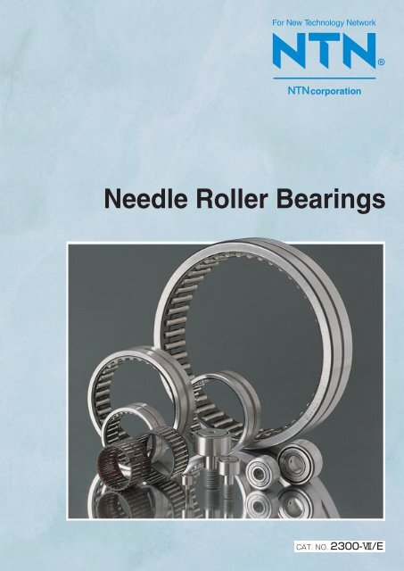
<strong>Needle</strong> <strong>Roller</strong> <strong>Bearings</strong><br />
&
CONTENTS
Technical Data<br />
A-001058<br />
<strong>Needle</strong> roller and cage assemblies<br />
B-003020<br />
<strong>Needle</strong> roller and cage assemblies<br />
for connecting rod bearings<br />
B-021028<br />
Drawn cup needle roller bearings<br />
B-029052<br />
Machined-ring needle roller bearings<br />
B-053096<br />
Machined-ring needle roller bearings,<br />
separable<br />
B-097114<br />
Inner rings<br />
B-115132<br />
Clearance-adjustable needle roller bearings<br />
B-133138<br />
Complex bearings<br />
B-139160<br />
<strong>Roller</strong> followers<br />
B-161173<br />
Cam followers<br />
B-174204<br />
Thrust roller bearings<br />
B-205220<br />
Components<br />
<strong>Needle</strong> rollers / Snap rings / Seals<br />
B-221234<br />
Linear bearings<br />
B-235254<br />
One-way clutches<br />
B-255259<br />
Bottom roller bearings for textile machinery<br />
Tension pulleys for textile machinery<br />
B-260266<br />
Appendixes<br />
C-001020
Warranty<br />
NTN warrants, to the original purchaser only, that the delivered product which is the subject of this sale (a)<br />
will conform to drawings and specifications mutually established in writing as applicable to the contract, and (b)<br />
be free from defects in material or fabrication. The duration of this warranty is one year from date of delivery.<br />
If the buyer discovers within this period a failure of the product to conform to drawings or specifications, or a<br />
defect in material or fabrication, it must promptly notify NTN in writing. In no event shall such notification be<br />
received by NTN later than 13 months from the date of delivery. Within a reasonable time after such<br />
notification, NTN will, at its option, (a) correct any failure of the product to conform to drawings, specifications<br />
or any defect in material or workmanship, with either replacement or repair of the product, or (b) refund, in part<br />
or in whole, the purchase price. Such replacement and repair, excluding charges for labor, is at NTN's<br />
expense. All warranty service will be performed at service centers designated by NTN. These remedies are<br />
the purchaser's exclusive remedies for breach of warranty.<br />
NTN does not warrant (a) any product, <strong>com</strong>ponents or parts not manufactured by NTN, (b) defects caused<br />
by failure to provide a suitable installation environment for the product, (c) damage caused by use of the<br />
product for purposes other than those for which it was designed, (d) damage caused by disasters such as fire,<br />
flood, wind, and lightning, (e) damage caused by unauthorized attachments or modification, (f) damage during<br />
shipment, or (g) any other abuse or misuse by the purchaser.<br />
THE FOREGOING WARRANTIES ARE IN LIEU OF ALL OTHER WARRANTIES, EXPRESS OR IMPLIED,<br />
INCLUDING BUT NOT LIMITED TO THE IMPLIED WARRANTIES OF MERCHANTABILITY AND FITNESS<br />
FOR A PARTICULAR PURPOSE.<br />
In no case shall NTN be liable for any special, incidental, or consequential damages based upon breach of<br />
warranty, breach of contract, negligence, strict tort, or any other legal theory,and in no case shall total liability<br />
of NTN exceed the purchase price of the part upon which such liability is based. Such damages include, but<br />
are not limited to, loss of profits, loss of savings or revenue, loss of use of the product or any associated<br />
equipment, cost of capital, cost of any substitute equipment, facilities or services, downtime, the claims of third<br />
parties including customers, and injury to property. Some states do not allow limits on warranties, or on<br />
remedies for breach in certain transactions. In such states, the limits in this paragraph and in paragraph (2)<br />
shall apply to the extent allowable under case law and statutes in such states.<br />
Any action for breach of warranty or any other legal theory must be <strong>com</strong>menced within 15 months following<br />
delivery of the goods.<br />
Unless modified in a writing signed by both parties, this agreement is understood to be the <strong>com</strong>plete and<br />
exclusive agreement between the parties, superceding all prior agreements, oral or written, and all other<br />
<strong>com</strong>munications between the parties relating to the subject matter of this agreement. No employee of NTN or<br />
any other party is authorized to make any warranty in addition to those made in this agreement.<br />
This agreement allocates the risks of product failure between NTN and the purchaser. This allocation is<br />
recognized by both parties and is reflected in the price of the goods. The purchaser acknowledges that it has<br />
read this agreement, understands it, and is bound by its terms.<br />
© NTN Corporation. 2002<br />
Although care has been taken to assure the accuracy of the data <strong>com</strong>piled in this catalog, NTN does not<br />
assume any liability to any <strong>com</strong>pany or person for errors or omissions.
<strong>Needle</strong> <strong>Roller</strong> <strong>Bearings</strong>
TECHNICAL DATA CONTENTS<br />
1. Classification and Characteristics<br />
of <strong>Bearings</strong> ⋯⋯⋯⋯⋯⋯⋯⋯⋯⋯⋯⋯⋯⋯⋯⋯⋯⋯A- 4<br />
2. Load Rating and Life ⋯⋯⋯⋯⋯⋯⋯⋯⋯⋯⋯⋯⋯A-14<br />
2. 1 Bearing life ⋯⋯⋯⋯⋯⋯⋯⋯⋯⋯⋯⋯⋯⋯⋯⋯⋯⋯⋯A-14<br />
2. 2 Basic rated life and basic dynamic load rating ⋯⋯⋯⋯A-14<br />
2. 3 Bearing-applied machine and requisite life of bearing ⋯A-14<br />
2. 4 Bearing life using adjusted life rating factors ⋯⋯⋯⋯⋯A-15<br />
2.4.1 Reliability adjustment factor1⋯⋯⋯⋯⋯⋯⋯⋯⋯⋯⋯A-15<br />
2.4.2 Bearing characteristic adjustment factor2 ⋯⋯⋯⋯⋯⋯A-15<br />
2.4.3 Operating condition adjustment factor3⋯⋯⋯⋯⋯⋯⋯A-16<br />
2. 5 Affect on basic dynamic load rating by the hardness of<br />
raceway ⋯⋯⋯⋯⋯⋯⋯⋯⋯⋯⋯⋯⋯⋯⋯⋯⋯⋯⋯⋯A-16<br />
2. 6 Life of bearing with oscillating motion ⋯⋯⋯⋯⋯⋯⋯⋯A-16<br />
2. 7 Life of bearing with linear motion ⋯⋯⋯⋯⋯⋯⋯⋯⋯⋯A-17<br />
2. 8 Various factors influencing bearing life ⋯⋯⋯⋯⋯⋯⋯A-17<br />
2. 9 Mounting deviation and crowning ⋯⋯⋯⋯⋯⋯⋯⋯⋯A-18<br />
2.10 Relation of bearing life to radial internal clearance,<br />
surface roughness and surface hardness ⋯⋯⋯⋯⋯⋯A-19<br />
2.11 Basic static load rating ⋯⋯⋯⋯⋯⋯⋯⋯⋯⋯⋯⋯⋯⋯A-19<br />
2.12 Allowable static bearing load ⋯⋯⋯⋯⋯⋯⋯⋯⋯⋯⋯A-19<br />
3. Calculation of Bearing Loads⋯⋯⋯⋯⋯⋯⋯⋯⋯A-20<br />
3.1 Loads acting on shafting ⋯⋯⋯⋯⋯⋯⋯⋯⋯⋯⋯⋯⋯⋯A-20<br />
3.1.1 Loads acting on gears ⋯⋯⋯⋯⋯⋯⋯⋯⋯⋯⋯⋯⋯⋯A-20<br />
3.1.2 Loads acting on chain and belt shafts ⋯⋯⋯⋯⋯⋯⋯⋯A-22<br />
3.1.3 Load factor ⋯⋯⋯⋯⋯⋯⋯⋯⋯⋯⋯⋯⋯⋯⋯⋯⋯⋯A-22<br />
3.2 Load distribution to bearing⋯⋯⋯⋯⋯⋯⋯⋯⋯⋯⋯⋯⋯A-23<br />
3.3 Mean load ⋯⋯⋯⋯⋯⋯⋯⋯⋯⋯⋯⋯⋯⋯⋯⋯⋯⋯⋯⋯A-25<br />
4. Bearing Accuracy ⋯⋯⋯⋯⋯⋯⋯⋯⋯⋯⋯⋯⋯⋯⋯A-25<br />
5. Bearing Clearance ⋯⋯⋯⋯⋯⋯⋯⋯⋯⋯⋯⋯⋯⋯⋯A-30<br />
5.1 Radial clearance in bearing⋯⋯⋯⋯⋯⋯⋯⋯⋯⋯⋯⋯⋯A-30<br />
5.2 Running clearance ⋯⋯⋯⋯⋯⋯⋯⋯⋯⋯⋯⋯⋯⋯⋯⋯A-30<br />
5.2.1 Setting up running clearance ⋯⋯⋯⋯⋯⋯⋯⋯⋯⋯⋯A-30<br />
5.2.2 Calculation of running clearance ⋯⋯⋯⋯⋯⋯⋯⋯⋯⋯A-30<br />
5.3 Bearing fit and bearing radial clearance ⋯⋯⋯⋯⋯⋯⋯A-31<br />
6. Bearing Fits ⋯⋯⋯⋯⋯⋯⋯⋯⋯⋯⋯⋯⋯⋯⋯⋯⋯⋯A-32<br />
6.1 Clamping allowance ⋯⋯⋯⋯⋯⋯⋯⋯⋯⋯⋯⋯⋯⋯⋯A-32<br />
6.2 Necessity of proper fit ⋯⋯⋯⋯⋯⋯⋯⋯⋯⋯⋯⋯⋯⋯⋯A-32<br />
6.3 Fit selection ⋯⋯⋯⋯⋯⋯⋯⋯⋯⋯⋯⋯⋯⋯⋯⋯⋯⋯⋯A-32<br />
6.4 Re<strong>com</strong>mended fits ⋯⋯⋯⋯⋯⋯⋯⋯⋯⋯⋯⋯⋯⋯⋯⋯A-33<br />
6.5 Calculation of clamping allowance ⋯⋯⋯⋯⋯⋯⋯⋯⋯A-35<br />
7. Shaft and Housing Design ⋯⋯⋯⋯⋯⋯⋯⋯⋯⋯A-36<br />
7.1 Design of bearing mount ⋯⋯⋯⋯⋯⋯⋯⋯⋯⋯⋯⋯⋯A-36<br />
7.2 Bearing fitting dimensions ⋯⋯⋯⋯⋯⋯⋯⋯⋯⋯⋯⋯⋯A-38<br />
7.3 Shaft and housing accuracy ⋯⋯⋯⋯⋯⋯⋯⋯⋯⋯⋯⋯A-39<br />
7.4 Raceway surface accuracy ⋯⋯⋯⋯⋯⋯⋯⋯⋯⋯⋯⋯A-39<br />
7.5 Raceway material and its hardness ⋯⋯⋯⋯⋯⋯⋯⋯⋯A-39<br />
7.6 Allowable bearing misalignment ⋯⋯⋯⋯⋯⋯⋯⋯⋯⋯A-39<br />
8. Lubrication ⋯⋯⋯⋯⋯⋯⋯⋯⋯⋯⋯⋯⋯⋯⋯⋯⋯⋯⋯A-40<br />
8.1 Grease lubrication ⋯⋯⋯⋯⋯⋯⋯⋯⋯⋯⋯⋯⋯⋯⋯⋯A-40<br />
8.1.1 Types and properties of grease ⋯⋯⋯⋯⋯⋯⋯⋯⋯⋯A-40<br />
8.1.2 Base oil ⋯⋯⋯⋯⋯⋯⋯⋯⋯⋯⋯⋯⋯⋯⋯⋯⋯⋯⋯A-40<br />
8.1.3 Thickening agent ⋯⋯⋯⋯⋯⋯⋯⋯⋯⋯⋯⋯⋯⋯⋯⋯A-40<br />
8.1.4 Additives ⋯⋯⋯⋯⋯⋯⋯⋯⋯⋯⋯⋯⋯⋯⋯⋯⋯⋯⋯A-41<br />
8.1.5 Consistency⋯⋯⋯⋯⋯⋯⋯⋯⋯⋯⋯⋯⋯⋯⋯⋯⋯⋯A-41<br />
8.1.6 Grease mixing ⋯⋯⋯⋯⋯⋯⋯⋯⋯⋯⋯⋯⋯⋯⋯⋯⋯A-41<br />
8.1.7 Grease fill amount ⋯⋯⋯⋯⋯⋯⋯⋯⋯⋯⋯⋯⋯⋯⋯A-41<br />
8.1.8 Grease replenishing ⋯⋯⋯⋯⋯⋯⋯⋯⋯⋯⋯⋯⋯⋯A-42<br />
8.2 Oil lubrication ⋯⋯⋯⋯⋯⋯⋯⋯⋯⋯⋯⋯⋯⋯⋯⋯⋯⋯A-42<br />
8.2.1 Lubrication method ⋯⋯⋯⋯⋯⋯⋯⋯⋯⋯⋯⋯⋯⋯⋯A-42<br />
8.2.2 Lubrication oils⋯⋯⋯⋯⋯⋯⋯⋯⋯⋯⋯⋯⋯⋯⋯⋯⋯A-43<br />
8.2.3 Oiling rate ⋯⋯⋯⋯⋯⋯⋯⋯⋯⋯⋯⋯⋯⋯⋯⋯⋯⋯A-44<br />
8.2.4 Lubrication oil replacement cycle⋯⋯⋯⋯⋯⋯⋯⋯⋯⋯A-44<br />
9. Seals ⋯⋯⋯⋯⋯⋯⋯⋯⋯⋯⋯⋯⋯⋯⋯⋯⋯⋯⋯⋯⋯⋯A-45<br />
9.1 Non-contact seal, contact seal ⋯⋯⋯⋯⋯⋯⋯⋯⋯⋯⋯A-45<br />
9.2 Duplex seal ⋯⋯⋯⋯⋯⋯⋯⋯⋯⋯⋯⋯⋯⋯⋯⋯⋯⋯⋯A-47<br />
9.3 Clearance setting⋯⋯⋯⋯⋯⋯⋯⋯⋯⋯⋯⋯⋯⋯⋯⋯⋯A-47<br />
9.4 NTN seals ⋯⋯⋯⋯⋯⋯⋯⋯⋯⋯⋯⋯⋯⋯⋯⋯⋯⋯⋯A-47<br />
9.5 Seal materials and operating temperature ⋯⋯⋯⋯⋯⋯A-47<br />
9.6 Seal type and allowable speed ⋯⋯⋯⋯⋯⋯⋯⋯⋯⋯⋯A-47<br />
9.7 Shaft surface hardness ⋯⋯⋯⋯⋯⋯⋯⋯⋯⋯⋯⋯⋯⋯A-48<br />
10. Bearing Handling ⋯⋯⋯⋯⋯⋯⋯⋯⋯⋯⋯⋯⋯⋯⋯A-49<br />
10.1 Bearing storage ⋯⋯⋯⋯⋯⋯⋯⋯⋯⋯⋯⋯⋯⋯⋯⋯⋯A-49<br />
10.2 Bearing installation ⋯⋯⋯⋯⋯⋯⋯⋯⋯⋯⋯⋯⋯⋯⋯A-49<br />
10.3 Post-installation running test ⋯⋯⋯⋯⋯⋯⋯⋯⋯⋯⋯A-50<br />
10.4 Bearing disassembly⋯⋯⋯⋯⋯⋯⋯⋯⋯⋯⋯⋯⋯⋯⋯A-50<br />
10.5 Required press-fit and pull-out forces ⋯⋯⋯⋯⋯⋯⋯A-51<br />
10.6 Washing ⋯⋯⋯⋯⋯⋯⋯⋯⋯⋯⋯⋯⋯⋯⋯⋯⋯⋯⋯⋯A-51<br />
11. Technical Data ⋯⋯⋯⋯⋯⋯⋯⋯⋯⋯⋯⋯⋯⋯⋯⋯A-52<br />
11.1 HL bearing ⋯⋯⋯⋯⋯⋯⋯⋯⋯⋯⋯⋯⋯⋯⋯⋯⋯⋯⋯A-52<br />
11.1.1 Basic concept of HL bearing ⋯⋯⋯⋯⋯⋯⋯⋯⋯⋯⋯A-52<br />
11.1.2 HL surface ⋯⋯⋯⋯⋯⋯⋯⋯⋯⋯⋯⋯⋯⋯⋯⋯⋯⋯A-52<br />
11.1.3 Application examples⋯⋯⋯⋯⋯⋯⋯⋯⋯⋯⋯⋯⋯⋯A-52<br />
11.2 <strong>Bearings</strong> with solid grease ⋯⋯⋯⋯⋯⋯⋯⋯⋯⋯⋯⋯A-53<br />
11.2.1 Features of bearings with solid grease ⋯⋯⋯⋯⋯⋯⋯A-53<br />
11.2.2 Precautions in use of bearings with solid grease ⋯⋯⋯A-53<br />
11.2.3 Application examples of bearings with solid grease ⋯⋯A-53<br />
11.3 Calculation examples ⋯⋯⋯⋯⋯⋯⋯⋯⋯⋯⋯⋯⋯⋯A-54<br />
11.3.1 Shrinkage of drawn-cup needle roller bearing and<br />
post-installation clearance⋯⋯⋯⋯⋯⋯⋯⋯⋯⋯⋯⋯A-54<br />
11.3.2 Track load capacity of cam follower/roller follower⋯⋯⋯A-55<br />
11.3.3 Outer ring strength⋯⋯⋯⋯⋯⋯⋯⋯⋯⋯⋯⋯⋯⋯⋯A-56<br />
11.3.4 Stud strength of cam follower ⋯⋯⋯⋯⋯⋯⋯⋯⋯⋯A-56<br />
12. Bearing Type Codes and Auxiliary Codes ⋯A-57<br />
A-2
DIMENSIONAL DATA CONTENTS<br />
<strong>Needle</strong> <strong>Roller</strong> and Cage Assemblies ⋯⋯⋯⋯⋯⋯B- 3<br />
K, KT2, KS, KZW, KMJ, KMJS, KJS, KVS ⋯⋯⋯⋯⋯B- 6<br />
PCJ⋯⋯⋯⋯⋯⋯⋯⋯⋯⋯⋯⋯⋯⋯⋯⋯⋯⋯⋯⋯⋯⋯⋯⋯⋯B-18<br />
<strong>Needle</strong> <strong>Roller</strong> and Cage Assemblies for<br />
Connecting Rod ⋯⋯⋯⋯⋯⋯⋯⋯⋯⋯⋯⋯⋯⋯⋯⋯⋯⋯B-21<br />
PK,KBK ⋯⋯⋯⋯⋯⋯⋯⋯⋯⋯⋯⋯⋯⋯⋯⋯⋯⋯⋯⋯⋯⋯⋯B-25<br />
Drawn Cup <strong>Needle</strong> <strong>Roller</strong> <strong>Bearings</strong> ⋯⋯⋯⋯⋯⋯⋯B-29<br />
HK, HKZWD, HMK, HMKZWD, BK, BKZWD ⋯⋯⋯⋯B-36<br />
HKL, HMKL, HKLL, HMKLL, BKL ⋯⋯⋯⋯⋯⋯⋯B-44<br />
DCL ⋯⋯⋯⋯⋯⋯⋯⋯⋯⋯⋯⋯⋯⋯⋯⋯⋯⋯⋯⋯⋯⋯⋯⋯B-48<br />
HCK ⋯⋯⋯⋯⋯⋯⋯⋯⋯⋯⋯⋯⋯⋯⋯⋯⋯⋯⋯⋯⋯⋯⋯⋯B-52<br />
Machined-Ring <strong>Needle</strong> <strong>Roller</strong> <strong>Bearings</strong> ⋯⋯⋯⋯⋯B-53<br />
RNA48, RNA49, RNA59, RNA69, NK ⋯⋯⋯⋯⋯⋯⋯⋯⋯⋯B-58<br />
NA48, NA49, NA59, NA69, NK+IR ⋯⋯⋯⋯⋯⋯⋯⋯⋯⋯⋯B-66<br />
MR ⋯⋯⋯⋯⋯⋯⋯⋯⋯⋯⋯⋯⋯⋯⋯⋯⋯⋯⋯⋯⋯⋯⋯⋯⋯B-80<br />
MR+MI ⋯⋯⋯⋯⋯⋯⋯⋯⋯⋯⋯⋯⋯⋯⋯⋯⋯⋯⋯⋯⋯⋯⋯B-86<br />
RNA49L, RNA49LL ⋯⋯⋯⋯⋯⋯⋯⋯⋯⋯⋯⋯⋯⋯⋯⋯B-94<br />
NA49L,NA49LL ⋯⋯⋯⋯⋯⋯⋯⋯⋯⋯⋯⋯⋯⋯⋯⋯⋯B-95<br />
Machine-ring <strong>Needle</strong> <strong>Roller</strong> <strong>Bearings</strong>,<br />
Separable Type ⋯⋯⋯⋯⋯⋯⋯⋯⋯⋯⋯⋯⋯⋯⋯⋯⋯⋯B-97<br />
RNAO, RNAOZW ⋯⋯⋯⋯⋯⋯⋯⋯⋯⋯⋯⋯⋯⋯⋯⋯⋯B-100<br />
NAO, NAOZW ⋯⋯⋯⋯⋯⋯⋯⋯⋯⋯⋯⋯⋯⋯⋯⋯⋯⋯B-108<br />
Inner ring ⋯⋯⋯⋯⋯⋯⋯⋯⋯⋯⋯⋯⋯⋯⋯⋯⋯⋯⋯⋯⋯B-115<br />
IR ⋯⋯⋯⋯⋯⋯⋯⋯⋯⋯⋯⋯⋯⋯⋯⋯⋯⋯⋯⋯⋯⋯⋯⋯⋯B-117<br />
MI ⋯⋯⋯⋯⋯⋯⋯⋯⋯⋯⋯⋯⋯⋯⋯⋯⋯⋯⋯⋯⋯⋯⋯⋯⋯B-129<br />
Clearance-Adjustable <strong>Needle</strong> <strong>Roller</strong> <strong>Bearings</strong> B-133<br />
RNA49S ⋯⋯⋯⋯⋯⋯⋯⋯⋯⋯⋯⋯⋯⋯⋯⋯⋯⋯⋯⋯⋯B-136<br />
NA49S ⋯⋯⋯⋯⋯⋯⋯⋯⋯⋯⋯⋯⋯⋯⋯⋯⋯⋯⋯⋯⋯⋯B-137<br />
Complex <strong>Bearings</strong> ⋯⋯⋯⋯⋯⋯⋯⋯⋯⋯⋯⋯⋯⋯⋯⋯B-139<br />
NKX, NKXZ⋯⋯⋯⋯⋯⋯⋯⋯⋯⋯⋯⋯⋯⋯⋯⋯⋯⋯⋯⋯B-144<br />
NKX+IR, NKXZ+IR ⋯⋯⋯⋯⋯⋯⋯⋯⋯⋯⋯⋯⋯⋯⋯⋯B-146<br />
NKXR, NKXRZ ⋯⋯⋯⋯⋯⋯⋯⋯⋯⋯⋯⋯⋯⋯⋯⋯⋯⋯B-148<br />
NKXR+IR, NKXRZ+IR ⋯⋯⋯⋯⋯⋯⋯⋯⋯⋯⋯⋯⋯⋯⋯B-150<br />
NKIA⋯⋯⋯⋯⋯⋯⋯⋯⋯⋯⋯⋯⋯⋯⋯⋯⋯⋯⋯⋯⋯⋯⋯⋯B-152<br />
NKIB⋯⋯⋯⋯⋯⋯⋯⋯⋯⋯⋯⋯⋯⋯⋯⋯⋯⋯⋯⋯⋯⋯⋯⋯B-154<br />
AXN ⋯⋯⋯⋯⋯⋯⋯⋯⋯⋯⋯⋯⋯⋯⋯⋯⋯⋯⋯⋯⋯⋯⋯⋯B-156<br />
ARN ⋯⋯⋯⋯⋯⋯⋯⋯⋯⋯⋯⋯⋯⋯⋯⋯⋯⋯⋯⋯⋯⋯⋯⋯B-158<br />
<strong>Roller</strong> Followers ⋯⋯⋯⋯⋯⋯⋯⋯⋯⋯⋯⋯⋯⋯⋯⋯⋯B-161<br />
NA22LL, RNA22LL ⋯⋯⋯⋯⋯⋯⋯⋯⋯⋯⋯⋯⋯⋯⋯B-166<br />
NATR, NATRLL, NATV, NATVLL ⋯⋯⋯⋯⋯⋯⋯⋯⋯B-168<br />
NACVX, NACVXLL ⋯⋯⋯⋯⋯⋯⋯⋯⋯⋯⋯⋯⋯⋯⋯B-170<br />
NUTR ⋯⋯⋯⋯⋯⋯⋯⋯⋯⋯⋯⋯⋯⋯⋯⋯⋯⋯⋯⋯⋯⋯⋯B-172<br />
NUTW ⋯⋯⋯⋯⋯⋯⋯⋯⋯⋯⋯⋯⋯⋯⋯⋯⋯⋯⋯⋯⋯⋯⋯B-173<br />
Cam Followers ⋯⋯⋯⋯⋯⋯⋯⋯⋯⋯⋯⋯⋯⋯⋯⋯⋯⋯B-174<br />
KR, KRLL, KRV, KRVLL ⋯⋯⋯⋯⋯⋯⋯⋯⋯⋯⋯⋯⋯B-182<br />
KRT, KRTX, KRTLL, KRTXLL⋯⋯⋯⋯⋯⋯⋯⋯⋯⋯B-186<br />
KRVT, KRVTX, KRVTLL, KRVTXLL ⋯⋯⋯⋯⋯⋯⋯B-188<br />
KRU, KRULL, KRVU, KRVULL ⋯⋯⋯⋯⋯⋯⋯⋯⋯⋯B-190<br />
NUKR ⋯⋯⋯⋯⋯⋯⋯⋯⋯⋯⋯⋯⋯⋯⋯⋯⋯⋯⋯⋯⋯⋯⋯B-194<br />
NUKRT, NUKRTX ⋯⋯⋯⋯⋯⋯⋯⋯⋯⋯⋯⋯⋯⋯⋯⋯⋯B-196<br />
NUKRU, NUKRUX⋯⋯⋯⋯⋯⋯⋯⋯⋯⋯⋯⋯⋯⋯⋯⋯⋯B-198<br />
CR, CRLL ⋯⋯⋯⋯⋯⋯⋯⋯⋯⋯⋯⋯⋯⋯⋯⋯⋯⋯⋯⋯B-200<br />
CRVX, CRVXLL⋯⋯⋯⋯⋯⋯⋯⋯⋯⋯⋯⋯⋯⋯⋯⋯⋯B-202<br />
Thrust <strong>Roller</strong> <strong>Bearings</strong> ⋯⋯⋯⋯⋯⋯⋯⋯⋯⋯⋯⋯⋯B-205<br />
AXK11, AS11, WS811, GS811 ⋯⋯⋯⋯⋯⋯⋯⋯⋯⋯⋯⋯B-210<br />
811, 812, 893, K811, K812, K893, WS811,WS812, WS893,<br />
GS811, GS812, GS893 ⋯⋯⋯⋯⋯⋯⋯⋯⋯⋯⋯⋯⋯⋯⋯B-214<br />
Components / <strong>Needle</strong> rollers ⋯⋯⋯⋯⋯⋯⋯⋯⋯⋯B-221<br />
A, F ⋯⋯⋯⋯⋯⋯⋯⋯⋯⋯⋯⋯⋯⋯⋯⋯⋯⋯⋯⋯⋯⋯⋯⋯B-224<br />
Components / Snap rings ⋯⋯⋯⋯⋯⋯⋯⋯⋯⋯⋯⋯B-226<br />
WR ⋯⋯⋯⋯⋯⋯⋯⋯⋯⋯⋯⋯⋯⋯⋯⋯⋯⋯⋯⋯⋯⋯⋯⋯B-227<br />
BR ⋯⋯⋯⋯⋯⋯⋯⋯⋯⋯⋯⋯⋯⋯⋯⋯⋯⋯⋯⋯⋯⋯⋯⋯B-229<br />
Components / Seals ⋯⋯⋯⋯⋯⋯⋯⋯⋯⋯⋯⋯⋯⋯⋯B-232<br />
G, GD ⋯⋯⋯⋯⋯⋯⋯⋯⋯⋯⋯⋯⋯⋯⋯⋯⋯⋯⋯⋯⋯⋯⋯B-233<br />
Machined-Ring and Drawn-cup Linear Ball<br />
<strong>Bearings</strong> ⋯⋯⋯⋯⋯⋯⋯⋯⋯⋯⋯⋯⋯⋯⋯⋯⋯⋯⋯⋯⋯B-235<br />
KLM, KLMLL, KLMS, KLMSLL, KLMP, KLMPLL B-241<br />
KH, KHLL ⋯⋯⋯⋯⋯⋯⋯⋯⋯⋯⋯⋯⋯⋯⋯⋯⋯⋯⋯⋯B-243<br />
Stroking Linear Ball <strong>Bearings</strong> ⋯⋯⋯⋯⋯⋯⋯⋯⋯B-244<br />
KD, KDLL ⋯⋯⋯⋯⋯⋯⋯⋯⋯⋯⋯⋯⋯⋯⋯⋯⋯⋯⋯⋯B-246<br />
Linear Flat <strong>Roller</strong> <strong>Bearings</strong> ⋯⋯⋯⋯⋯⋯⋯⋯⋯⋯⋯B-248<br />
FF, FFZW ⋯⋯⋯⋯⋯⋯⋯⋯⋯⋯⋯⋯⋯⋯⋯⋯⋯⋯⋯⋯B-250<br />
BF, RF ⋯⋯⋯⋯⋯⋯⋯⋯⋯⋯⋯⋯⋯⋯⋯⋯⋯⋯⋯⋯⋯⋯⋯B-251<br />
Linear <strong>Roller</strong> <strong>Bearings</strong>⋯⋯⋯⋯⋯⋯⋯⋯⋯⋯⋯⋯⋯⋯B-252<br />
RLM ⋯⋯⋯⋯⋯⋯⋯⋯⋯⋯⋯⋯⋯⋯⋯⋯⋯⋯⋯⋯⋯⋯⋯⋯B-253<br />
One-way Clutches ⋯⋯⋯⋯⋯⋯⋯⋯⋯⋯⋯⋯⋯⋯⋯⋯B-255<br />
HF⋯⋯⋯⋯⋯⋯⋯⋯⋯⋯⋯⋯⋯⋯⋯⋯⋯⋯⋯⋯⋯⋯⋯⋯⋯B-258<br />
HFL ⋯⋯⋯⋯⋯⋯⋯⋯⋯⋯⋯⋯⋯⋯⋯⋯⋯⋯⋯⋯⋯⋯⋯⋯B-259<br />
Bottom <strong>Roller</strong> <strong>Bearings</strong> for Textile Machinery B-260<br />
FRIS (Series A) ⋯⋯⋯⋯⋯⋯⋯⋯⋯⋯⋯⋯⋯⋯⋯⋯⋯⋯⋯B-261<br />
FRIS (Series B) ⋯⋯⋯⋯⋯⋯⋯⋯⋯⋯⋯⋯⋯⋯⋯⋯⋯⋯⋯B-263<br />
FR⋯⋯⋯⋯⋯⋯⋯⋯⋯⋯⋯⋯⋯⋯⋯⋯⋯⋯⋯⋯⋯⋯⋯⋯⋯B-264<br />
Tension Pulleys for Textile Machinery ⋯⋯⋯⋯⋯B-265<br />
JPUS, JPUS+JFS ⋯⋯⋯⋯⋯⋯⋯⋯⋯⋯⋯⋯⋯⋯⋯B-266<br />
Appendix⋯⋯⋯⋯⋯⋯⋯⋯⋯⋯⋯⋯⋯⋯⋯⋯⋯⋯⋯⋯⋯⋯C- 1<br />
A-3
Classification and Characteristics of <strong>Bearings</strong><br />
NTN<br />
1. Classification and Characteristics <strong>Bearings</strong><br />
<strong>Needle</strong> roller bearings have relatively smaller diameter<br />
cylindrical rolling elements whose length is much larger<br />
than their diameter.<br />
Compared with other types of rolling bearings, needle<br />
roller bearings have a small cross-sectional height and<br />
significant load-bearing capacity and rigidity relative to<br />
their volume. Also, because the inertial force action on<br />
them is limited, they are ideal choice for oscillating<br />
motion. <strong>Needle</strong> roller bearings contribute to <strong>com</strong>pact and<br />
lightweight machine designs. They serve also as a ready<br />
replacement for sliding bearings.<br />
NTN offers the following types of needle roller bearings.<br />
<strong>Needle</strong> roller and cage assembly<br />
This assembly, a major <strong>com</strong>ponent of a<br />
needle roller bearing, <strong>com</strong>prises needle rollers<br />
and a cage to support the rollers.<br />
¡Using the shaft and housing as raceway<br />
surfaces reduces the cross-sectional<br />
height: it is equal to the diameter of the<br />
needle roller bearing.<br />
¡This structure eliminating the outer and<br />
inner rings allows the bearing to be fitted<br />
more easily.<br />
¡The assembly is available in both single-row<br />
and double-row configurations.<br />
¡As long as the tolerance limit of the shaft<br />
and housing is satisfied, the radial internal<br />
clearance can be made adjustable.<br />
<strong>Needle</strong> roller and cage assembly for connecting rods<br />
This assembly, a major <strong>com</strong>ponent of a needle roller bearing, <strong>com</strong>prising needle rollers and a cage to support the<br />
rollers, is used typically for connecting rods in reciprocating <strong>com</strong>pressors and small- and mid-sized internal <strong>com</strong>bustion<br />
engines such as those for motorbikes, light cars, outboard motors and versatile engines. This assembly features such a<br />
cage that is specifically optimized for severe operating conditions involving high impact loads, <strong>com</strong>plicated motions, highspeed<br />
revolution and/or high operating temperatures.<br />
<strong>Needle</strong> roller and cage assembly for large end<br />
¡This assembly, subjected to a cranking motion with a<br />
simultaneous action of the rolling elements’ rotation<br />
and revolution, must be light but have a high rigidity,<br />
and must have a precise dimension of the outer<br />
diameter of the cage so that the guiding system can<br />
keep an appropriate gap.<br />
¡The cage is made of high-tensile special steel with a<br />
surface hardening treatment.<br />
¡The guiding system employed is an outer diameter<br />
guiding system.<br />
¡The cage that may be subjected to poor lubrication<br />
can be protected with a surface treatment using a<br />
non-ferrous metal.<br />
¡For applications with a one-piece structure of crank<br />
shaft, the cage of split type is also available.<br />
A-4
Classification and Characteristics of <strong>Bearings</strong><br />
NTN<br />
<strong>Needle</strong> roller and cage assembly for small end<br />
¡Strong impact load acts on this bearing and it<br />
oscillates at high speed. Therefore, the cage bore<br />
surface is finished with high precision so as to secure<br />
lightweight, high rigidity and proper guide clearance.<br />
¡The cage is made of high tensile special steel and its<br />
surface is hardened ideally.<br />
¡The cage is of bore guide type and the guide surface<br />
is designed as long as possible to thereby reduce the<br />
surface pressure.<br />
¡The roller length is designed to the possible<br />
maximum value against the connecting width and a<br />
number of small-size needle rollers are fitted in the<br />
cage to minimize the contact pressure.<br />
Drawn-cup needle roller bearing<br />
This bearing <strong>com</strong>prises an outer ring and needle<br />
rollers, which were both drawn from special thin steel<br />
plate by precision deep drawing, and a cage intended<br />
to guide precisely the needle rollers.<br />
¡This bearing is the type of the lowest section height,<br />
of the rolling bearings with outer ring, best-suited to<br />
space-saving design.<br />
¡A hardened and ground shaft or inner ring (IR Series)<br />
is used as the raceway.<br />
¡This bearing needs no axial locking due to easy<br />
installation and press-fit in the housing.<br />
¡The close end type to close shaft end is available in<br />
addition to the open end type.<br />
¡Furthermore, the type with seal fitted in at single side<br />
or double sides is also available.<br />
¡The standard type <strong>com</strong>prises a needle roller and<br />
cage assembly. In addition to this type, special type<br />
<strong>com</strong>prising full <strong>com</strong>plement rollers is available at<br />
option.<br />
Machined-ring needle roller bearings<br />
This bearing type <strong>com</strong>prises a machined outer ring<br />
and machined needle rollers, and a cage to guide<br />
properly the needle rollers.<br />
In the case of this bearing, the cage or the needle<br />
rollers are guided by the ribs of the outer ring or the<br />
face ring. Hence, this bearing is non-separable type. In<br />
addition, the type with no inner ring is also available for<br />
enabling a shaft to be used as the raceway surface. (Of<br />
course, the type with inner ring is available.)<br />
¡Selectively available for both of the metric system<br />
and the inch system.<br />
¡Best-suited to space-saving design due to its low<br />
section height, then having the large load capacity.<br />
¡High rigidity and high bearing accuracy due to its<br />
machined (precut) outer ring<br />
¡can be used with a housing made of light metal, etc.<br />
due to its outer ring of high rigidity.<br />
¡Outer ring with lubrication hole and lubrication groove<br />
¡Single row and double row types available.<br />
¡The type with seal fitted in at single side or double<br />
sides is also available.<br />
A-5
Classification and Characteristics of <strong>Bearings</strong><br />
NTN<br />
Machined-ring needle roller bearing separable type<br />
This bearing type <strong>com</strong>prises a machined outer ring<br />
and machined needle rollers, and a cage to guide and<br />
retain properly the needle rollers. And the needle roller<br />
and cage assembly is separable from the outer ring. In<br />
addition to the standard type, the type with no inner ring<br />
is also available for enabling a shaft to be used as<br />
direct raceway surface. (Of course, the type with inner<br />
ring available, too.)<br />
¡Easy to install, the needle roller and cage<br />
assembly, the outer ring, and the inner ring can be<br />
mounted independently from each other.<br />
¡Any optional radial internal clearance is selectable by<br />
<strong>com</strong>bining the individual independent <strong>com</strong>ponents.<br />
¡Best-suited to space-saving design due to its low<br />
section height, then having the large load capacity.<br />
¡High rigidity and high bearing accuracy due to its<br />
machined (precut) outer ring.<br />
¡Can be used with a housing made of light metal, etc.<br />
due to its outer ring of high rigidity.<br />
¡Single row and double row types available. And the<br />
outer ring of the double row bearing is provided with<br />
lubrication hole and lubrication groove.<br />
Inner ring<br />
For the needle roller bearings, usually a shaft is used<br />
as the raceway surface, but this inner ring is used<br />
where the shaft surface can not be machined to the<br />
specific hardness and roughness. This inner ring is<br />
suited to space-saving design due to its low section<br />
height. This is made of high carbon chrome bearing<br />
steel, finished by high precision grinding after heattreated.<br />
¡Can also be used as a bush.<br />
¡Selectively available for both of the metric system<br />
and the inch system.<br />
¡The type with lubrication hole at the raceway center<br />
also available.<br />
Clearance-adjustable needle roller bearing<br />
This bearing type <strong>com</strong>prises a machined outer ring<br />
and machined needle rollers, and a cage to guide and<br />
retain properly the needle rollers, but the needle roller<br />
and cage assembly is non-separable from the outer<br />
ring. In addition to the standard type, the type with no<br />
inner ring is also available for enabling a shaft to be<br />
used as direct raceway surface. (Of course, the type<br />
with inner ring available, too.)<br />
¡The raceway diameter of the outer ring is shrunk by<br />
pressing the outer ring in axial direction, which then<br />
enables to reduce the roller set bore diameter<br />
correspondingly.<br />
¡Radial clearance is finely adjustable by adjusting<br />
axial pressing load and thereby changing shrinkage<br />
of the outer ring raceway diameter.<br />
¡This bearing is applied to the work spindle of a<br />
machine tool and other similar portions which require<br />
the high speed rotational accuracy of JIS Grade-4.<br />
A-6
Classification and Characteristics of <strong>Bearings</strong><br />
NTN<br />
Thrust roller bearing<br />
This bearing <strong>com</strong>prises needle rollers or cylindrical<br />
rollers, a cage to guide and retain properly the rollers,<br />
and disc-shaped rolling bearing ring. This is a bearing<br />
capable of supporting one-way axial load. Furthermore,<br />
this bearing can be used without rolling bearing ring,<br />
where the heat-treated and ground bearing mount<br />
surface can be used as the raceway surface.<br />
¡Best-suited to space-saving design due to its small<br />
section height, then having the large load capacity.<br />
¡Available are AS type rolling bearing ring made of<br />
thin steel plate with hardened surface and WS type<br />
and GS type machined rings.<br />
Complex needle roller bearings <strong>Needle</strong> roller bearing with thrust bearing <br />
This <strong>com</strong>plex bearing <strong>com</strong>prises a radial needle roller<br />
bearing for supporting radial load and a thrust bearing<br />
for supporting axial load which are assembled integrally.<br />
Both thrust ball bearing type and thrust axial roller<br />
bearing type are available as the bearing intended to<br />
support axial load.<br />
¡The thrust bearing with dust-proof cover is also<br />
available, which has a good effect in preventing<br />
scattering of oil and grease and invasion of external<br />
dust, etc.<br />
Complex needle roller bearings<br />
<strong>Needle</strong> roller bearing with angular ball bearing, needle roller bearing with three-point contact ball bearing <br />
This <strong>com</strong>plex bearing <strong>com</strong>prises a radial needle roller<br />
bearing for supporting radial load, a ball bearing for<br />
supporting <strong>com</strong>paratively small axial load and a<br />
machined inner ring which are all assembled integrally.<br />
Both angular ball bearing and three-point contact ball<br />
bearing are available as the ball bearing intended to<br />
support axial load.<br />
¡The <strong>com</strong>plex needle roller bearings (NKIA<br />
Series)using an angular ball bearing as the thrust<br />
bearing can support one-directional angular load.<br />
¡The <strong>com</strong>plex needle roller bearings (NKIB Series)<br />
using a three-point contact ball bearing as the thrust<br />
bearing can support double-directional axial load and<br />
furthermore its position in axial direction can be fixed,<br />
too.<br />
<strong>Needle</strong> roller bearing with double thrust roller bearing<br />
This is a <strong>com</strong>plex bearing wherein a thrust needle<br />
roller bearing or a thrust cylindrical roller bearing<br />
intended to support axial load is configured at the double<br />
sides of a radial needle roller bearing for supporting<br />
radial load.<br />
¡Can support large axial load acting thereon from the<br />
double sides.<br />
¡Used as the bearing (precision bearing) for supporting<br />
the ball screw of a machine tool.<br />
A-7
Classification and Characteristics of <strong>Bearings</strong><br />
NTN<br />
The track roller bearing is a needle roller bearing with thick outer ring, which is applied to cam roller, guide roller,<br />
eccentric roller and rocker arm.<br />
The track roller bearings are mainly categorized into a yoke type track roller bearing (roller follower) and a stud type<br />
track roller bearing (cam follower). Various types of the roller follower and the cam follower are available as described<br />
hereunder.<br />
<strong>Roller</strong> follower Without axial guide <br />
This roller follower is a bearing designed for<br />
rotation of the outer ring wherein a needle roller and<br />
cage assembly and a synthetic rubber seal<br />
reinforced with steel plate are assembled in the thickwalled<br />
outer ring.<br />
¡The outer ring, the needle roller and cage<br />
assembly, and the rubber seal are non-separable<br />
from each other.<br />
¡The outer ring is thick-walled type so that it is<br />
resistible to high load and impact load.<br />
¡The shaft must be provided with a thrust washer<br />
and a flange, because of the outer ring with no<br />
ribs (or face ring) and no axial guide function.<br />
¡The outer surface is available in both spherical<br />
(crowning) profile and cylindrical profile.<br />
¡The bearing with spherical outer ring is effective in<br />
damping bias load which is caused by deviation in<br />
installing.<br />
¡The bearing with cylindrical outer ring is suitable to<br />
the cases of large load and low-hardness track<br />
surface,due to its large area of contact with the<br />
mating track surface.<br />
<strong>Roller</strong> follower With axial guide <br />
This roller follower is a bearing designed for<br />
rotation of the outer ring wherein a needle roller and<br />
cage assembly, an inner ring, and a face ring are<br />
assembled in the thick-walled outer ring.<br />
This bearing uses needle rollers as its rolling<br />
element and furthermore classified into bearing with<br />
cage and full <strong>com</strong>plement roller bearing without<br />
cage. The outer ring is guided axially by a face ring<br />
which is press-fitted in the inner ring.<br />
¡The outer ring is thick-walled type so that it is<br />
resistible to high load and impact load.<br />
¡The outer surface is available in both spherical<br />
(crowning) profile and cylindrical profile.<br />
¡The bearing with spherical outer ring is effective in<br />
damping bias load which is caused by deviation in<br />
installing.<br />
¡The bearing with cylindrical outer ring is suitable to<br />
the cases of large load and low-hardness track<br />
surface,due to its large area of contact with the<br />
mating track surface.<br />
¡This bearing is easier to handle because it needs<br />
no mounting of a guide (thrust washer, etc.) on the<br />
shaft unlike other types without axial guide<br />
(RNA22, NA22).<br />
A-8
Classification and Characteristics of <strong>Bearings</strong><br />
NTN<br />
Cam follower <strong>Needle</strong> roller type <br />
This is a bearing designed for rotation of the outer ring in<br />
which a needle roller and cage assembly and a stud in lieu of<br />
inner ring are fitted in the thick-walled outer ring. The stud is<br />
so threaded as to be mounted easily. This cam follower<br />
(bearing) uses needle rollers as its rolling element and it is<br />
further classified into one bearing type with cage and another<br />
full <strong>com</strong>plement roller bearing type without cage.<br />
¡The bearing type with cage is suitable to <strong>com</strong>paratively high<br />
speed running because its rollers are guided by the cage.<br />
¡The full <strong>com</strong>plement roller type enabling to use more needle<br />
rollers than the type with cage has large load capacity.<br />
¡The outer surface is available in both spherical (crowning)<br />
profile and cylindrical profile.<br />
¡This cam follower (bearing) is selectively available for both<br />
of the metric system and the inch system.<br />
¡Furthermore, the seal built-in type is also available.<br />
¡The stud is of either recessed head type allowing use of a<br />
screwdriver or hexagon socket head type so as to be<br />
mounted and adjusted easily.<br />
Cam follower Cylindrical roller type <br />
This is a full <strong>com</strong>plement roller bearing designed for rotation<br />
of the outer ring in which double-row cylindrical rollers and a<br />
stud in lieu of inner ring are fitted in the thick-walled outer ring.<br />
The stud is so threaded as to be mounted easily.<br />
¡This cam follower (bearing) has the radial /axial load<br />
capacity larger than the needle roller type.<br />
¡A steel plate is press-fitted in the outer ring and a labyrinth<br />
seal is formed between the face ring and the outer ring.<br />
¡The outer surface is available in both spherical (crowing)<br />
profile and cylindrical profile.<br />
¡The stud is of either recessed head type allowing use of a<br />
screwdriver or of hexagon socket head type so as to be<br />
mounted and adjusted easily.<br />
Cam follower Eccentric type <br />
This is a cam follower (bearing) wherein the studs of the<br />
needle roller type and cylindrical roller type prescribed above<br />
were made eccentric, which can then be adjusted by making<br />
eccentric the outer ring relative position against the raceway.<br />
¡Load distribution is easily adjustable in configuring two or<br />
more cam followers in linear form.<br />
¡Preload can be applied by adjustment of load distribution.<br />
¡Alignment is possible even when the mounting hole is not<br />
processed in high accuracy.<br />
¡The outer surface is selectively available in both spherical<br />
(crowning) profile and cylindrical profile.<br />
¡The stud is of either recessed head type allowing use of a<br />
screwdriver or hexagon socket head type so as to be<br />
mounted and adjusted easily.<br />
A-9
Classification and Characteristics of <strong>Bearings</strong><br />
NTN<br />
The <strong>com</strong>ponents described hereunder are for needle roller bearing.<br />
<strong>Needle</strong> rollers<br />
The needle rollers with flat end face and round end face<br />
are standard. These rollers are made of high-carbon<br />
chrome bearing steel, surface-finished by grinding and<br />
buffing after heat-treated. The standard accuracy of these<br />
rollers is "Precision Grade".<br />
¡A-Inter-diameter tolerance of the needle rollers is 2mm<br />
maximum.<br />
¡The roller type with crowned rolling surface is also<br />
available, which can damp edge load.<br />
¡These needle rollers are supplied as an individual for<br />
applications (pin, shaft) other than rolling element.<br />
Snap rings<br />
These are special-purposed rings used for axially<br />
positioning or guiding the inner and outer rings or the<br />
needle roller and cage assembly in needle roller bearing.<br />
The ring material is a hard steel wire rod and chemical<br />
conversion treatment is applied to its surface so as to<br />
provide high rigidity.<br />
¡Two types are available for shaft and housing use.<br />
¡The section height is lowered flexibly according to the<br />
dimensions of needle roller bearings. In addition,<br />
manufacture of these rings is available up to the<br />
possible minimum dimensional range.<br />
¡For the axial guide it is re<strong>com</strong>mended to provide a<br />
spacer between the cage and the snap ring.<br />
Seals<br />
This is a special-purposed seal which was designed so<br />
as to match the small section height of needle roller<br />
bearings.<br />
¡G-type seal with one lip and GD-type seal with two lips<br />
are selectively available on application.<br />
¡These seals <strong>com</strong>prising steel ring and synthetic rubber<br />
can be used at the operating temperature ranging from<br />
-25 to 120˚C, but continuous use thereof is subject to<br />
100˚C and less.<br />
¡These seals act to prevent invasion of external foreign<br />
matter and over-consumption of lubrication grease.<br />
¡The radial section height of each seal is designed so as<br />
to match the drawn-cup needle roller bearings. Hence,<br />
these seals require no additional finishing of the<br />
housing. This facilitates handling.<br />
A-10
Classification and Characteristics of <strong>Bearings</strong><br />
NTN<br />
This catalogue describes the following ones of linear motion bearings.<br />
Linear ball bearing Machined ring type <br />
This is a high precision bearing which <strong>com</strong>prises a<br />
machined outer ring and face ring, steel balls and a<br />
synthetic resin cage for retaining the balls and rolls<br />
on a shaft, maintaining the endless linear motion.<br />
¡Standard type, clearance-adjustable type and<br />
open type are selectively available on application.<br />
¡Some bearings of these types are provided with a<br />
synthetic rubber seal at single side or double<br />
sides to prevent invasion of foreign matter therein.<br />
¡The steel balls are guided precisely by the cage so<br />
that stable linear motion can be achieved with less<br />
friction resistance.<br />
¡No rotational motion is available.<br />
Linear ball bearing Drawn cup type <br />
This is a high precision bearing which <strong>com</strong>prises<br />
an outer ring drawn from thin special steel plate by<br />
precision deep drawing, steel balls and a synthetic<br />
resin cage for retaining the balls and rolls on a shaft,<br />
maintaining the endless linear motion.<br />
¡The outer ring made of thin steel plate enables to<br />
make less the section height and to design the<br />
linear motion system of <strong>com</strong>pact structure.<br />
¡Easy to install This bearing is press-fitted in the<br />
housing so that it requires no axial fixing.<br />
¡No rotational motion available.<br />
¡Some bearings of this type are provided with a<br />
synthetic rubber seal at double sides to prevent<br />
invasion of foreign matter therein.<br />
Linear ball bearing Stroking type <br />
This bearing <strong>com</strong>prises a machined outer ring and<br />
face ring, steel balls and a cage for retaining the<br />
balls and reciprocates finitely on a shaft as well as<br />
rotates on a shaft. The outer ring is provided with a<br />
snap ring as the cage stopper at its double sides<br />
and, furthermore, a wavy spring is provided between<br />
the snap ring and the cage to damp impact acting the<br />
cage and to thereby prevent wear of the cage.<br />
¡Some bearings of this stroking type are provided<br />
with a synthetic rubber seal at its double sides to<br />
prevent invasion of foreign matter therein.<br />
¡The outer ring is so grooved that snap ring can be<br />
fitted and fixed easily.<br />
A-11
Classification and Characteristics of <strong>Bearings</strong><br />
NTN<br />
Linear flat roller<br />
This is a flat roller bearing which <strong>com</strong>prises a flat<br />
cage and needle rollers and reciprocates on a flat<br />
raceway in linear direction by motion of its linear<br />
movable <strong>com</strong>ponents.<br />
¡The molded polyamide resin cage and pressformed<br />
steel plate cage are selectively available<br />
on application.<br />
¡FF type molded resin cage Several cages can<br />
be used with them jointed with each other in<br />
parallel configuration.<br />
¡The press-formed steel plate cage Cage to<br />
cage jointing is unavailable, but it can be supplied<br />
at any optional length.<br />
¡In the case of double-row resin cage, it is provided<br />
with an elastic joint at its center part so it can be<br />
reformed at any optional angle by dipping it in an<br />
oil of 70 to 90˚C and can be mounted on a Veegrooved<br />
surface.<br />
Linear roller bearing<br />
This bearing <strong>com</strong>prising cylindrical rollers capable<br />
of turning internally around the track frame moves<br />
endlessly on a flat surface in linear direction.<br />
¡Low friction factor due to the case assemblies<br />
preventing neighboring roller from touching.<br />
¡High load rating due to use of cylindrical rollers.<br />
A-12
Classification and Characteristics of <strong>Bearings</strong><br />
NTN<br />
This catalogue describes the following products, too.<br />
One-way clutch<br />
This one-way clutch <strong>com</strong>prises an outer ring<br />
drawn from thin special steel plate by precision deep<br />
drawing, spring, needle rollers and cage and can<br />
transmit a torque in only one way.<br />
¡Less friction torque against over-running, great<br />
transmission torque for small section height.<br />
¡Various types are available as follows; one-way<br />
clutch with bearing built therein to support radial<br />
load, one-way clutch with outer ring plated for<br />
improvement of erosion resistance, one-way<br />
clutch integrated with gear, pulley, etc.<br />
¡HF type and HFL type can be locked axially by<br />
being only press-fitted in the housing.<br />
¡These one-way clutches use the outer ring drawn<br />
by precision deep drawing, which needs the<br />
housing with wall thickness of a specified value or<br />
more.<br />
¡HF type is subjected to configuration of a radial<br />
ball bearing at its double ends. (On the other<br />
hand, HFL type is <strong>com</strong>plete with radial bearings<br />
built-in at its double sides.)<br />
Bottom roller bearing For textile machinery <br />
This is a grease pre-filled needle roller bearing<br />
intended to support the bottom rollers. The spherical<br />
outer surface of the outer ring can allow bottom roller<br />
mounting error to some extent. On the other hand,<br />
the inner ring is provided with ribs at its double ends.<br />
A clearance between the outer ring ribs and the inner<br />
ring ribs is kept less and, in addition, the outer<br />
surface of each inner ring rib is knurled so as not to<br />
allow easy invasion of mist, etc. into the bearing.<br />
Tension Pulley For Textile Machinery <br />
This pulley is used to guide the tapered portion or<br />
belt of the spindle drive unit in each of a fine spinning<br />
machine, a rough spinning machine, a pre-twisting<br />
machine, etc. as well as to apply tension to them.<br />
The pulley drawn from steel plate by precision deep<br />
drawing is press-fitted on the outer ring of shaft<br />
bearing instead of inner ring.<br />
A-13
Load Rating and Life<br />
NTN<br />
2. Load Rating and Life<br />
2.1 Bearing life<br />
Even when bearings are in running under normal<br />
condition, the raceway surface and the surfaces of the<br />
rolling elements inevitably subjected to repetitive<br />
<strong>com</strong>pression stress result in flaking due to fatigue of the<br />
raceway an element materials and can resist no longer to<br />
further running even under normal condition. "Bearing life"<br />
is defined as the total cumulative bearing revolutions until<br />
flaking occurs thus on the raceway surface or the element<br />
rolling surfaces.<br />
Further use of bearings be<strong>com</strong>es unavailable, caused<br />
by various defects such as seizure, wear, crack, chipping,<br />
chattering, rusting, etc. in addition to the flaking<br />
phenomenon stated above. However, these phenomena<br />
should be deemed as defects of bearing itself and,<br />
therefore, be discriminated from bearing life. And the<br />
defect causes are such as incorrect selection of bearing,<br />
improper mounting, improper lubrication, imperfect<br />
sealing, etc. Hence, bearing trouble can be avoided by<br />
removing the said causes.<br />
2.2 Basic rated life and basic dynamic load rating<br />
Even when a group of same bearings have been in<br />
running under the same condition, considerably great<br />
variation is found among the individual bearing lives. This<br />
<strong>com</strong>es from variation in material fatigue itself. Hence, the<br />
basic rated life defined below considering statistically this<br />
variation in material fatigue is applied as the bearing life.<br />
The basic rated life means the substantial total<br />
cumulative revolutions of the individual bearings 90%<br />
(90% reliability) of which can revolve without resulting in<br />
flaking due to rolling fatigue when a group of same<br />
bearings have been put individually in continuous running<br />
under same condition. When bearings have been in<br />
running in constant revolution, the basic rated life is<br />
expressed as the total cumulative revolutions of the<br />
individual bearings.<br />
On the other hand, the basic dynamic load rating<br />
represents the load capacity of rolling bearing, then<br />
meaning a constant load under which the basic rated life<br />
of 1,000,000 revolutions is achieved. This constant load<br />
of radial bearing is expressed with net radial load, while<br />
that of thrust bearing is expressed with net axial load.<br />
The bearing dimensions table in this catalogue<br />
describes the respective basic dynamic load ratings of the<br />
bearings that were manufactured using NTN’s standard<br />
materials and manufacturing processes in current use.<br />
For the respective basic rated lives of the bearings<br />
manufactured using the special materials and special<br />
manufacturing processes, feel free to contact NTN for<br />
inquiry.<br />
The relationship among the basic rated life, the basic<br />
dynamic load rating and the axial load can be expressed<br />
in formula (2.1).<br />
Basic Rated Life specified in ISO 281.<br />
L 10 C p ⋯⋯⋯⋯⋯⋯⋯⋯⋯⋯⋯⋯⋯(2.1)<br />
P<br />
where,<br />
p= 10/3 For roller bearing<br />
p= 3. For ball bearings<br />
L10 : Basic rated life (10 6 revolutions)<br />
C : Basic dynamic rated load, (N) (kgf)<br />
(radial bearings: Cr, thrust bearings: Ca)<br />
P : Bearing load, (N) (kgf)<br />
(radial bearings: Pr, thrust bearings: Pa)<br />
Furthermore, the basic rated life cab be determined by<br />
formula (2.2), where it is expressed in the operating<br />
hours.<br />
L10h 500 f h p (2.2)<br />
C<br />
f h f n (2.3)<br />
P<br />
f n<br />
where,<br />
33.3 1p (2.4)<br />
n<br />
L10h : Basic rated life, h<br />
fh : Life factor<br />
fn : Speed factor<br />
n : Rotational speed, r/ min<br />
The formula (2.2) can also expressed as formula (2.5).<br />
L 10h 106 <br />
C p (2.5)<br />
60 n P<br />
Considering the life of either one, of several bearings<br />
installed in a machine or an equipment, until it breaks<br />
down due to rolling fatigue as the total bearing life as a<br />
whole, it can be determined by formula (2.6).<br />
L<br />
1<br />
(2.6)<br />
1 1 1 1e<br />
L1 e L2 e Ln e<br />
where,<br />
e = 9/8 ⋯⋯⋯For roller bearings<br />
e = 10/9 ⋯⋯⋯For ball bearings<br />
L : Total basic rated life of bwaring as a whole, h<br />
L1 L2 Ln : Individual basic rated life of bearings,<br />
1, 2,n, h<br />
2.3 Bearing-applied machines and requisite life<br />
In selecting a bearing, it is essential to set up the<br />
requisite life of the bearing under the intended operating<br />
conditions, but the requisite life is mainly determined by<br />
the durability period and in-running reliability required for<br />
a machine to which the bearing is applied. In general, the<br />
requisite lifetime as a guideline is as shown in Table 2.1.<br />
The fatigue life of bearing is an important factor to<br />
decide the bearing size to be applied. In addition to this<br />
factor, however, the strengths and rigidities of shaft and<br />
housing must be taken into consideration.<br />
A-14
Load Rating and Life<br />
NTN<br />
Table 2.1 Operating conditions and requisite lifetime<br />
Operating conditions<br />
Lifetime L10h<br />
Tools and devices requiring no all-time running<br />
Ex) Door switcher, etc.<br />
Machines which are operated for a short time or intermittently and do not cause <strong>com</strong>paratively great affect on others<br />
even if they shut down incidentally due to trouble.<br />
Ex.) Hand tools, heavy material handling hoist in a machining shop, general hand-operated machines, agricultural machines,<br />
crane in a casting shop, material automatic feeder, home appliances, etc.<br />
Machines which are not put in continuous running but required to run very precisely<br />
Ex.) Auxiliary machines in a power station, conveyor in a flow process, elevator, general cargo handling crane,<br />
machine tool of low frequency in use, etc.<br />
Machines which are operated for 8 hours per day but not put in all-time continuous running<br />
Ex.) Power generator in a factory, general geared unit, etc.<br />
Machines which are operated for 8 hours per day<br />
Ex.) General machines in a machining shop, crane in all-time operation.<br />
Machines which are put in 24-hour continuous running<br />
Ex.) Separator, <strong>com</strong>pressor, pump, main shaft, table roller of rolling mill, conveyor roller, winding engine in a mine,<br />
driving motor in a factory, etc.<br />
Machines which are put in 24-hour continuous running and, in addition, are not allowed absolutely trouble shutdown.<br />
Ex.) Cellulose manufacturing machine, paper making machine, power station, drainage pump in a mine,<br />
urban city water related equipment, etc.<br />
500<br />
4 000 8 000<br />
8 000 14 000<br />
14 000 20 000<br />
20 000 30 000<br />
50 000 60 000<br />
100 000 200 000<br />
2.4 Bearing life using the adjusted life rating factor<br />
The basic bearing life rating (90% reliability) can be<br />
calculated using the formulas prescribed in Subsection<br />
2.2, but on occasion the bearing life of over-90% reliability<br />
must be determined on application. Also, the bearing life<br />
can be further extended by using a specially improved<br />
bearing material and special manufacturing<br />
process/technique. Furthermore, it was clarified by the<br />
elastohydrodynamic lubrication theory that the bearing life<br />
would be influenced by bearing operating conditions<br />
(lubrication, temperature, speed, etc.)<br />
The bearing life considering the above factors can be<br />
determined by formula (2.7) using "Life Adjustment<br />
Factor" specified in ISO 281.<br />
where,<br />
Lna a1a2a3CP p (2.7)<br />
Lna : Adjusted life rating 10 6 revolutions<br />
a1 : Reliability adjustment factor<br />
a2 : Bearing material adjustment factor<br />
a3 : Operating condition adjustment factor<br />
2.4.1 Reliability adjustment factor a1<br />
The values of reliability adjustment factor a1 for 90%<br />
and higher reliability are as shown in Table 2.2.<br />
2.4.2 Life adjustment factor for bearing material a2<br />
Where bearing material used is special type and quality<br />
and manufactured in the special process, the life-related<br />
bearing characteristics are inevitably variable depending<br />
on the specialties of the material. In such a case, the<br />
bearing life is adjusted using the life adjustment factor for<br />
bearing material a2.<br />
The basic dynamic load ratings described in "Bearing<br />
Dimensions Table" are subject to use of the standard<br />
Table 2.2 Values of reliability adjustment factor a1<br />
Reliability % Ln Reliability adjustment factor a1<br />
90<br />
95<br />
96<br />
97<br />
98<br />
99<br />
L10<br />
L5<br />
L4<br />
L3<br />
L2<br />
L1<br />
1.00<br />
0.62<br />
0.53<br />
0.44<br />
0.33<br />
0.21<br />
materials and manufacturing processes / techniques<br />
being used in NTN, and usually a2=1 rating is used.<br />
Furthermore, a2>1 is eventually applied to the bearings<br />
manufactured using the specially improved material and<br />
manufacturing process / technique. In such a case, feel<br />
free to contact NTN for further instruction.<br />
Where bearings made of high carbon chrome bearing<br />
steel are used at 120˚C and over throughout a long term,<br />
the dimension of the normal heat-treated bearing varies<br />
significantly and, therefore, dimension-stabilizing heattreatment<br />
(TS treatment) must be done to the bearings<br />
according to the maximum operating temperature.<br />
However, this dimension-stabilizing treatment causes the<br />
bearing hardness to reduce, finally an inverse affect on<br />
the bearing life. To avoid it, the bearing life is adjusted<br />
(<strong>com</strong>pensated) by multiplying the life rating by the life<br />
adjustment factor for bearing material a2 shown in Table<br />
2.3.<br />
Table 2.3 Values of life adjustment factor for bearing material a2 for<br />
dimension-stabilizing heat-treated (TS-treated) bearings<br />
Code<br />
TS2-<br />
TS3-<br />
TS4-<br />
Maximum operating<br />
temperature<br />
160˚C<br />
200˚C<br />
250˚C<br />
Life adjustment factor<br />
for bearing material a2<br />
1.00<br />
0.73<br />
0.48<br />
A-15
Load Rating and Life<br />
NTN<br />
2.4.3 Life adjustment factor for operating conditions a3<br />
The life adjustment factor for operating conditions a3 is<br />
used for adjustment(<strong>com</strong>pensation) of the bearing life,<br />
where the lubricated bearing condition gets worse and the<br />
lubricant deteriorates or foreign matter is included in the<br />
bearing, caused by the rotational speed, temperature rise,<br />
etc. of the bearing in running.<br />
Generally the life adjustment factor in the case of good<br />
lubricated bearing condition is a3=1 and, particularly<br />
where the lubricated bearing condition is good and other<br />
factors for the bearing are normal, a3>1 can be applied to<br />
adjustment of the bearing life. However, a3
Load Rating and Life<br />
NTN<br />
When the oscillation angle 2 is very small, difficulty in<br />
forming an oil film on the contact surface of rolling ring to<br />
rolling element could result in fretting corrosion.<br />
In the case of inner ring oscillation, the critical<br />
oscillation angle is expressed in formula (2.9).<br />
360˚ dp<br />
Critical oscillation angle ⋯⋯(2.9)<br />
Z dpDa cos<br />
Where,<br />
Z : Number of rolling elements (per row)<br />
dp : Pitch circle diameter (PCD) of rolling element<br />
Dp: Rolling element diameter<br />
e : Contact angle<br />
(In the case of outer ring oscillation, the right side<br />
denominator is dp + Da cos .)<br />
2.7 Life of bearing with linear motion<br />
In the case of bearings with linear motion such as linear<br />
ball bearing, linear flat roller bearing, etc., the relationship<br />
among axial travel distance, bearing load and load rating<br />
can be expressed in formulas (2.10), (2.11).<br />
When the rolling elements are balls;<br />
L 50 Cr 3<br />
Pr<br />
⋯⋯⋯⋯⋯⋯⋯⋯⋯⋯⋯⋯(2.10)<br />
When the rolling elements are rollers;<br />
L 100 Cr 10/3<br />
⋯⋯⋯⋯⋯⋯⋯⋯⋯⋯(2.11)<br />
Pr<br />
where,<br />
L Load rating km<br />
CrBasic dynamic load rating N (kgf)<br />
PrBearing load N (kgf)<br />
Fig.2.4 shows the relationship of Cr/Pr to L.<br />
Furthermore, when the travel motion cycle and travel<br />
distance remain unchanged, the lifetime of bearing can<br />
be determined by formulas (2.12), (2.13).<br />
When the rolling elements are balls;<br />
Lh 50103 Cr 3 (2.12)<br />
60S Pr<br />
When the rolling elements are rollers;<br />
Lh 100103 Cr 10/3<br />
(2.13)<br />
60S Pr<br />
where,<br />
Lh: Travel life h<br />
S : Travel distance per minute m/min<br />
S =2Ln<br />
L : Stroke length m<br />
n : Stroke cycle N (kgf)<br />
2.8 Various factors influencing bearing life<br />
Bearing life is influenced by not only bearing load and<br />
rotational speed but also various factors such as<br />
lubricating condition, internal clearance, surface<br />
roughness and hardness of raceway, heat-treated<br />
structure, misalignment, etc. In using bearings, therefore,<br />
these influence factors must be taken into full<br />
consideration. Table 2.4 shows the bearing operating<br />
conditions as a guideline. (For the detail refer to<br />
Commentary" described in Bearing Dimensions Table<br />
every each bearing type.)<br />
Table 2.4 Guideline of the bearing operating conditions<br />
Allowable rotational speed (r/min)<br />
Surface roughness of raceway<br />
Surface hardness of raceway<br />
Misalignment<br />
Radial internal clearance<br />
See Dimensions Table<br />
within 0.2a<br />
HRC58 to 64<br />
Note: Refer to Subsection 7.5 for<br />
various materials and heat-treated<br />
hardness thereof.<br />
1/2000 or less (for radial bearing)<br />
Ordinary level (C2, C3, C4)<br />
Cr /Pr<br />
10<br />
8<br />
6<br />
5<br />
4<br />
3<br />
2<br />
Ball bearing<br />
<strong>Roller</strong> bearing<br />
0.05 0.1 0.2 0.3 0.4 0.6 0.8 1 2 3 4 6 8 10 20 30 40 60 100<br />
L10 3 km<br />
Fig. 2.4 Life of bearing with axial motion<br />
A-17
Load Rating and Life<br />
NTN<br />
2.9 Fitting misalignment and crowning<br />
Generally it is well known that stress concentration at<br />
edge portion (so called, edge load) arising from fitting<br />
misalignment would result in rapid reduction of bearing<br />
lifetime. "Crowning" is adopted as a countermeasure<br />
against such rapid reduction of bearing lifetime. In that<br />
case, however, unless it is designed properly this<br />
crowning would cause the effective contact length of roller<br />
to reduce, which could then lead to shorter life of bearing.<br />
It is therefore necessary to calculate a proper crowning<br />
value though depending on the extent of fitting<br />
misalignment.<br />
And load condition. For reference, Figs.2.5 to 2.7<br />
show the examples of contact surface pressure analysis<br />
by a <strong>com</strong>puter.<br />
As seen from Figs.2.5 to 2.7 (Examples of contact<br />
surface pressure analysis), the rollers with no crowning<br />
have high edge surface pressure, while the rollers with<br />
crowning restrain the edge surface pressure lower in the<br />
range of specific allowable fitting misalignment. Fig.2.8<br />
shows the relationship of allowable fitting misalignment to<br />
bearing lifetime. (example of <strong>com</strong>puter analysis) It is<br />
possible to see from this Figure how the bearing lifetime<br />
is influenced by fitting misalignment.<br />
Contact surface pressure<br />
Contact surface pressure<br />
Effective length of roller<br />
<strong>Roller</strong>s with no crowning and<br />
free from fitting misalignment<br />
Effective length of roller<br />
<strong>Roller</strong>s with crowning and<br />
fitting misalignment<br />
Fig. 2.5<br />
Fig. 2.7<br />
Contact surface pressure<br />
Life ratioLL10<br />
1.0<br />
Effective length of roller<br />
<strong>Roller</strong>s with no crowning and<br />
free from fitting misalignment<br />
Fig. 2.6<br />
0<br />
0 1.0 2.0<br />
Fitting misalignment10 -3<br />
Fig. 2.8 Relationship of fitting misalignment to bearing lifetime<br />
A-18
Load Rating and Life<br />
NTN<br />
2.10 Radial internal clearance, surface<br />
roughness and surface hardness, and<br />
bearing life<br />
The relationship of radial internal clearance to bearing<br />
life is as shown in Fig. 2.9 and the relationship of surface<br />
roughness to bearing life as shown in Fig.2.10.<br />
It is possible to see from these Figures how the bearing<br />
life is influenced by each factor.<br />
1.0<br />
"Basic static load rating" is defined as such a constant<br />
static load that results in permanent deformation of the<br />
said limit value, which is then expressed in net radial load<br />
for radial bearings and in net axial load for thrust<br />
bearings.<br />
Regarding this load value, each table of bearing<br />
dimensions describes it in the Cor, field for radial bearings<br />
and in Coa field for thrust bearings respectively.<br />
When the load defined above acts on a bearing,<br />
contact stress at the contact center of rolling element to<br />
raceway, which are subjected to maximum load, reaches<br />
the following value.<br />
For roller bearing ⋯⋯⋯4000MPa (408kgf/mm 2 )<br />
For ball bearing ⋯⋯⋯4200MPa (428kgf/mm 2 )<br />
Fig. 2.9 Relationship of radial internal clearance to bearing life<br />
L10 life10 4<br />
Life ratioLL<br />
3000<br />
2000<br />
1000<br />
0<br />
0 0 20 40<br />
(1.0)<br />
1.0<br />
0.25<br />
Radial internal clearance10 -3<br />
(0.85)<br />
2.0<br />
0.5<br />
(0.37)<br />
(0.18)<br />
3.0<br />
0.75<br />
4.0<br />
1.0<br />
5.0<br />
1.25<br />
(0.09)<br />
6.0<br />
1.5<br />
The sum of surface roughnesses of test specimens in relative<br />
position before testing R max m ( ) showing Ra<br />
2.12 Allowable static bearing load<br />
The basic static load rating prescribed in Subsection<br />
2.11 is generally deemed as an allowable static bearing<br />
limit load, but in some cases this allowable limit load is<br />
set up larger than the basic static load rating and in some<br />
other cases it is set up smaller, according to the<br />
requirements for revolving smoothness and friction.<br />
Generally this allowable limit load is decided<br />
considering the safety factor So in the following formula<br />
(2.14) and Table 2.5.<br />
So CoPo(2.14)<br />
where,<br />
So : Safety factor<br />
Co : Basic static rated load, N (kgf)<br />
(For radial bearings: Cor,<br />
For thrust bearings: Coa)<br />
Po max : Maximum static bearing load, N (kgf)<br />
(For radial bearings: Por max,<br />
For thrust bearings: Coa max)<br />
Table 2.5 Lower limit value of safety factor S0<br />
Operating conditions<br />
Requirement for high revolving accuracy<br />
<strong>Roller</strong><br />
bearings<br />
3<br />
Ball<br />
bearings<br />
2<br />
Fig. 2.10 Relationship of surface roughness to bearing life<br />
Requirement for ordinal revolving<br />
accuracy (ordinary-purposed)<br />
1.5<br />
1<br />
2.11 Basic static load rating<br />
Load acting on a bearing, when acted, results in locally<br />
permanent deformation of the contract surface of rolling<br />
elements to bearing ring. And this deformation value<br />
increases inevitably with the increasing load and smooth<br />
rotation of the bearing is interfered with by the<br />
deformation when it exceeded a certain limit value.<br />
It is known experimentally that the total permanent<br />
deformation value 0.0001 times as large as the rolling<br />
element diameter at the contact center of rolling elements<br />
to raceway both of which are subjected to maximum<br />
stress is an allowable deformation limit which does not<br />
interfere with smooth rotation of bearing.<br />
Where minor deterioration of revolving<br />
accuracy is allowed<br />
(Ex. Low speed revolution, duty load<br />
application, etc.)<br />
Remarks: 1. For the drawn-cup needle roller bearings, 3 shall be adopted<br />
as So lower limit value.<br />
2. Where vibration and shock load act on bearing, Po max shall<br />
be determined considering the shock load factor.<br />
1<br />
0.5<br />
A-19
Calculation of Bearing Loads<br />
NTN<br />
3. Calculation of Bearing Loads<br />
3.1 Load acting on shafts<br />
The loads acting on the shaft to be supported with the<br />
bearing must be determined for calculation of bearing<br />
loads. These loads include the self-weight of rotor assy,<br />
loads inevitably resulting from a machine in running,<br />
loads arising from power transmission, etc. These loads<br />
are mostly difficult to calculate though some of them can<br />
be calculated numerically and theoretically.<br />
The following paragraphs describe how to calculate<br />
the loads acting on a power transmission shaft as one of<br />
the main bearing applications.<br />
Ks<br />
Kt<br />
3.1.1 Load acting on gears<br />
The loads acting on gears can be divided into<br />
tangential load (Kt), radial load (Ks) and axial load (Ka).<br />
The magnitude and acting direction of each load differ<br />
depending on the types of gear. This paragraph<br />
describes how to calculate the loads acting on parallel<br />
shaft gears and cross shaft gears for general use.<br />
For calculation of the loads acting on other gears, feel<br />
free to contact NTN for inquiry.<br />
(1) Load acting on parallel shaft gear<br />
Figs. 3.1 to 3.3 illustrate the loads acting on spur gear<br />
and helical gear which are used with a parallel shaft. The<br />
magnitude of each load can be determined using the<br />
formulas (3.1) to (3.4).<br />
Fig. 3.1 Load acting on spur gear<br />
Ks Ka<br />
Kt<br />
Fig. 3.2 Load acting on helical gear<br />
19.110 6 HP 1.9510 6 HP<br />
Kt <br />
<br />
(3.1)<br />
Dpn<br />
Dpn<br />
KsKttan(Spur gear)<br />
(3.2a)<br />
Kt<br />
tan<br />
Kt (for helical gear) (3.2b)<br />
cos<br />
Kr<br />
Ks<br />
Kr Kt 2 Ks 2 (3.3a)<br />
KaKttan(for helical gear)(3.4)<br />
where,<br />
Kt Tangential load acting on gear<br />
(Tangential force) N (kgf)<br />
Ks Radial load acting on gear<br />
(separating force) N (kgf)<br />
Kr Load acting perpendicularly on gear shaft<br />
(<strong>com</strong>posite force of tangential force and<br />
separating force) N (kgf)<br />
Ka Parallel load acting on gear shaft N (kgf)<br />
HPTransmission power kw<br />
n Rotational speed r/min<br />
Dp Pitch circle diameter of gear mm<br />
Gear pressure angle<br />
Gear helix angle<br />
Fig. 3.3 Composite radial force acting on gear<br />
Table 3.1 Gear factor fz<br />
Types of gear<br />
Precision ground gears<br />
(Pitch and profile errors of less than 0.02mm)<br />
Ordinary machined gears<br />
(Pitch and profile errors of less than 0.1mm)<br />
Dp<br />
fz<br />
1.051.1<br />
1.11.3<br />
Actual gear load is determined by multiplying the<br />
theoretical load by the gear factor described in Table 3.1,<br />
because vibration and shock are added to each<br />
theoretical load determined by the above formulas.<br />
A-20
Calculation of Bearing Loads<br />
NTN<br />
(2) Loads acting on cross shaft gears<br />
Figs. 3.4 and 3.5 illustrate the loads acting on straighttoo<br />
bevel gears and spiral bevel gears which are used<br />
with cross shafts.<br />
Table 3.2 shows how to calculate these loads.<br />
The load acting on straight-tooth bevel gear can be<br />
determined from Table 3.2, assuming the helix angle as<br />
=0.<br />
The symbols and units used in this table are as follows.<br />
Kt Tangential load acting on gear<br />
(Tangential force) N (kgf)<br />
Ks Radial load acting on gear<br />
(separating force) N (kgf)<br />
Ka Parallel load acting on gear shaft<br />
(axial load) N (kgf)<br />
HP Transmission power kw<br />
n Rotational speed r/min<br />
Dpm Mean pitch circle diameter mm<br />
Gear pressure angle<br />
Gear helix angle<br />
Pitch cone angle of gear<br />
In general, the relationship between the loads acting on<br />
pinion and pinion gear can be expressed as follows, due<br />
to the perpendicular intersection of two shafts.<br />
The separating force (Ks) acting direction and axial load<br />
(Ka) acting direction illustrated in Fig.3.5 are the positive<br />
direction respectively. On the other hand, the rotational<br />
direction and helix angle direction are to be defined<br />
viewing from the large end side of the gear. Hence, for<br />
the gear illustrated in Fig. 3.5 these directions are<br />
clockwise and to right.<br />
K ag<br />
K sg<br />
K tg<br />
K tp<br />
K ap<br />
K sp<br />
Fig. 3.4 Load acting on bevel gears<br />
K t<br />
KspKag (3.5)<br />
KapKsg (3.6)<br />
where,<br />
KspKsg Pinion and pinion gear separating force N (kgf)<br />
KapKagAxial load acting on pinion and pinion gear N (kgf)<br />
<br />
K s<br />
K a<br />
D pm<br />
2<br />
For spiral bevel gears, the loading direction differs<br />
depending on the direction of helix angle, rotational<br />
direction and whether the spiral bevel gear is located at<br />
the drive side or the driven side.<br />
Fig.3.5 Bevel gear diagram<br />
Table 3.2 Loads acting on bevel gears<br />
Driving gears<br />
Rotational<br />
direction<br />
Helix angle<br />
Clockwise Counter clockwise Clockwise Counter clockwise<br />
To right To left To left To right<br />
Unit N<br />
Tangential loadKt<br />
Kt 19.1106 H<br />
Dpmn<br />
<br />
1.9510 6 H<br />
Dpmn<br />
Drive side<br />
KsKt<br />
tan cos tansin <br />
cos<br />
KsKt<br />
tan cos tansin <br />
cos<br />
Separating forceKs<br />
Driven side<br />
KsKt<br />
tan cos tansin KsKt tan cos tansin <br />
cos<br />
cos<br />
Axial load Ka<br />
Drive side<br />
KaKt<br />
tan sin tancos KaKt tan sin tancos<br />
<br />
cos<br />
cos<br />
Driven side<br />
KaKt<br />
tan sin tan <br />
KaKt tan sin tancos<br />
cos<br />
cos<br />
A-21
Calculation of Bearing Loads<br />
NTN<br />
3.1.2 Loads acting on chain and belt shafts<br />
In the case of power transmission by a chain and a<br />
belt, the load acting tangentially on the sprocket or the<br />
pulley can be determined by formula (3.7).<br />
19.110 6 HP 1.9510 6 HP<br />
Kt <br />
<br />
(3.7)<br />
Dpn<br />
Dpn<br />
where,<br />
Kt Tangential load acting on sprocket or pulley N (kgf)<br />
HPTransmission power kW<br />
Dp Pitch circle diameter of sprocket or pulley mm<br />
In the case of belt driving, initial tension is applied to<br />
the belt so the pulley and the belt are both always<br />
pressed down with a proper load.<br />
where<br />
K Actual load acting on shaft N(kgf)<br />
Kc Theoretically calculated value N (kgf)<br />
fw Load factor (Table 3.4)<br />
Table 3.4 Load factor fw<br />
Extent of shock<br />
Nearly no shock 1.01.2<br />
Light shock<br />
Heavy shock<br />
fw<br />
1.21.5<br />
1.53.0<br />
Application<br />
Electrical machines, machine tools,<br />
measuring instruments<br />
Railway vehicles, automobiles,<br />
rolling mills, metal working machines,<br />
paper making machines, rubber mixing<br />
machines, printing machines, aircraft,<br />
textile machines, electrical units,<br />
office equipment<br />
Crushers, agricultural machines,<br />
construction machines, cranes<br />
Dp<br />
F1<br />
F2<br />
Slackening side<br />
Kr<br />
Tension side<br />
Fig. 3.6 Loads acting on chain/ belt<br />
3.2 Load distribution to bearings<br />
Any loads acting on shafts are distributed to the<br />
bearings considering static tension to be supported with<br />
the bearings.<br />
For example, the loads acting on the bearings in the<br />
gear shaft illustrated in Fig. 3.7 can be expressed in<br />
formulas (3.10) and (3.11).<br />
Considering this initial tension, radial load acting on the<br />
pulley is expressed in formula (3.8).<br />
In the case of chain driving, the radial load acting<br />
thereon can be expressed using the same formula, if<br />
vibration and shock are taken into consideration.<br />
Krf bKt (3.8)<br />
where,<br />
KrRadial load acting on sprocket or pulley N (kgf)<br />
f bChain/belt factor (Table 3.3)<br />
Table 3.3 Chain/belt factor f b<br />
Type of chain / belt<br />
Chain (single row type)<br />
Vee-belt<br />
Timing belt<br />
Flat belt (with tension pulley)<br />
Flat belt<br />
f b<br />
1.21.5<br />
1.52.0<br />
1.11.3<br />
2.53.0<br />
3.04.0<br />
b c Dp<br />
FrAKr!Kr@Ka(3.10)<br />
l l 2l<br />
a abc Dp<br />
FrBKr!Kr@Ka<br />
l l 2l<br />
(3.11)<br />
where,<br />
FrA Radial load acting on bearing-A N (kgf)<br />
FrB Radial load acting on bearing-B N (kgf)<br />
Kr1 Radial load acting on gear-! N (kgf)<br />
Ka Axial load acting on gear-! N (kgf)<br />
Kr2 Axial load acting on gear-! N (kgf)<br />
Dp Pitch circle diameter of gear-! mm<br />
l Bearing to bearing distance mm<br />
l<br />
Gear-!<br />
Gear- !<br />
Kr!<br />
Ka<br />
Kr@<br />
Dp<br />
3.1.3 Load factor<br />
In an actual machine, the shaft load is mostly greater<br />
than the theoretically calculated load due to vibration,<br />
shock, etc. The load acting on the shafts of a machine<br />
can be determined by formula (3.9).<br />
K fWKC<br />
(3.9)<br />
FrA<br />
Bearing-A<br />
FrB<br />
Bearing-B<br />
a<br />
b<br />
Fig. 3.7 Gear shaft<br />
c<br />
A-22
Calculation of Bearing Loads<br />
NTN<br />
3.3 Mean load<br />
The loads acting on bearings used in ordinary<br />
machines fluctuate mostly depending on the<br />
predetermined operation cycle or work plan. In such a<br />
case, the mean load Fm converted so the same lifetime is<br />
assigned to the bearings is used as the bearing load.<br />
(3) Load fluctuating in nearly linear form<br />
The mean load Fm can be determined approximately by<br />
formula (3.14).<br />
Fmin2Fmax<br />
Fm<br />
3<br />
(3.14)<br />
(1) Stepped fluctuating load<br />
Where bearing loads F1 , F2 ....... Fn act on and the<br />
rotational speed and running time are n1, n2.......nn and<br />
t1, t2....... tn respectively, the mean load Fm of these<br />
loads can be expressed in formula (3.12).<br />
F<br />
Fmax<br />
Fm<br />
Fi p ni ti 1p<br />
Fm (3.12)<br />
ni ti<br />
Fmin<br />
where:<br />
p103<br />
p3<br />
for roller bearing<br />
for ball bearing<br />
Fig. 3.10 Load fluctuating in linear form<br />
t<br />
F<br />
F1<br />
F2<br />
Fm<br />
(4) Sinusoidal fluctuating load<br />
The mean load Fm, can be determined approximately by<br />
formulas (3.15), (3.16).<br />
case of (a) Fm0.75Fmax (3.15)<br />
case of (b) Fm0.65Fmax (3.16)<br />
Fn<br />
n1 t1<br />
n2t2<br />
nn tn<br />
Fig. 3.8 Stepped fluctuating load<br />
F<br />
Fmax<br />
(2) Consecutive series load<br />
Where load is load cycle "to" and it can be expressed in<br />
the function F(t) of time t, the mean load can be<br />
expressed in formula (3.13).<br />
1 t0 p<br />
Fm Ftp dt<br />
(3.13)<br />
t0 0<br />
F<br />
Fm<br />
a<br />
t<br />
Fmax<br />
F<br />
Fm<br />
F(t)<br />
Fm<br />
b<br />
t<br />
0 to 2to t<br />
Fig. 3.11 Sinusoidal fluctuating load<br />
Fig. 3.9 Load fluctuating as a time function<br />
A-23
A-24
Bearing Accuracy<br />
NTN<br />
4. Bearing Accuracy<br />
The dimensional, profile and running accuracies of<br />
rolling bearings are specified in ISO Standard as<br />
applicable and JIS B 1514 (Accuracy of Rolling <strong>Bearings</strong>).<br />
"Dimensional accuracy" and "Profile accuracy" are<br />
the items indispensable in installing the rolling bearings on<br />
a shaft and in a bearing housing, and allowable bearing<br />
run-out in running is specified as the running accuracy.<br />
Dimensional accuracy:<br />
Dimensional accuracy means the respective allowable<br />
values for bore diameter, outer diameter, width or height<br />
(limaited to thrust bearing) and chamfering dimension.<br />
Profile accuracy:<br />
This means the allowable value for variation of each of<br />
bore diameter, mean bore diameter, outer diameter,<br />
mean outer diameter, and width or thickness of bearing<br />
ring (limited to thrust bearing).<br />
Running accuracy:<br />
This means the respective allowable values for radial<br />
run-out and axial run-out of both inner ring and outer ring,<br />
lateral run-out of inner ring, and outer diameter run-out of<br />
outer ring.<br />
Regarding the accuracy class of the machined ring<br />
needle roller bearings, class-0 is equivalent to bearings of<br />
the normal precision class, and precision be<strong>com</strong>es<br />
progressively higher as the class number be<strong>com</strong>es<br />
smaller; i.e. Class 6 is less precise than Class 5, which is<br />
less precise than Class 4, and so on.<br />
<strong>Bearings</strong> of Class-0 are mostly used for general<br />
application, while bearings of Class-5 or Class-4 are<br />
used, where the required running accuracies and<br />
revolutions are high or less friction and less fluctuation<br />
are required for bearings.<br />
Various bearing types are available for NTN needle<br />
roller bearings and the representative types and the<br />
accuracy classes applicable to them are as shown in<br />
Table 4.1.<br />
Dimensional item symbols used in the accuracy<br />
standard are given in Table 4.2, the radial bearing<br />
accuracy specified every accuracy class given in Table<br />
4.3, the thrust bearing accuracy specified every accuracy<br />
class given in Table 4.4, and the allowable values for<br />
chamfering dimension given in Table 4.5.<br />
Table 4.2 Dimensional item symbols used in applicable standards<br />
Classification Symbols<br />
Dimensional<br />
accuracy<br />
Profile<br />
accuracy<br />
Running<br />
accuracy<br />
dmp<br />
ds<br />
Dmp<br />
Ds<br />
Bs<br />
Cs<br />
Vdp<br />
Vdmp<br />
VDp<br />
VDmp<br />
VBs<br />
VCs<br />
Kia<br />
Kea<br />
Sia<br />
Sea<br />
Sd<br />
SD<br />
Symbol representation<br />
Dimensional tolerance for in-plane<br />
mean bore diameter<br />
Dimensional tolerance for bore diameter<br />
Dimensional tolerance for in-plane<br />
mean outer diameter<br />
Symbols under<br />
JIS B 0021 (Reference)<br />
Dimensional tolerance for outer diameter<br />
Dimensional tolerance for inner ring width<br />
Dimensional tolerance for outer ring width<br />
Variation of in-plane bore diameter Roundness<br />
Variation of in-plane mean bore diameter Cylindricality<br />
Variation of in-plane outer diameter Roundness<br />
Variation of in-plane mean outer diameter Cylindricality<br />
Variation of inner ring width Parallelism<br />
Variation of outer ring width Parallelism<br />
Radial run-out of inner ring Run-out<br />
Radial run-out of outer ring Run-out<br />
Axial run-out of inner ring<br />
Axial run-out of outer ring<br />
Lateral run-out (inner ring) Run-out<br />
Outer diameter run-out (outer ring) Run-out<br />
1) The roundness specified in JIS B 0021 is applicable to the tolerance Vdp for<br />
variation of radial in-plane bore diameter or nearly half of VDp.<br />
2) The cylindricality specified in JIS B 0021 is applicable to the tolerance Vdmp<br />
for in-uniformity of radial in-plane mean diameter or nearly half of VDmp.<br />
1<br />
2<br />
1<br />
2<br />
Table 4.1 Bearing types and corresponding accuracy classes<br />
Bearing type Applicable accuracy class Applicable table<br />
<strong>Needle</strong> roller bearing,<br />
Clearance-adjustable needle roller bearing<br />
JIS Class-0<br />
<br />
JIS Class-6<br />
<br />
JIS Class-5<br />
<br />
JIS class-4<br />
JIS class-4<br />
Table 4.3<br />
Table 4.3<br />
Complex bearing<br />
Radial bearing<br />
Thrust bearing<br />
JIS Class-0<br />
NTN Class 0<br />
JIS Class-6<br />
NTN Class 6<br />
JIS Class-5<br />
NTN Class 5<br />
<br />
NTN Class 4<br />
Table 4.3<br />
Table 4.4<br />
<strong>Needle</strong> roller bearing<br />
with double-direction<br />
thrust roller bearing<br />
Radial bearing<br />
Thrust bearing<br />
<br />
<br />
<br />
<br />
JIS Class-5<br />
NTN Class 5<br />
JIS Class-4<br />
NTN Class 4<br />
Table 4.3<br />
Table 4.4<br />
Thrust roller bearing<br />
<strong>Roller</strong> follower/cam follower<br />
NTN Class 0<br />
JIS Class-0<br />
NTN Class 6<br />
<br />
NTN Class 5<br />
<br />
NTN Class 4<br />
<br />
Table 4.4<br />
Table 4.3<br />
A-25
Bearing Accuracy<br />
NTN<br />
Table 4.3 Tolerances for radial bearings<br />
Table 4.3(1) Inner rings<br />
Nominal bore<br />
diameter<br />
d<br />
mm<br />
over<br />
2.5 1<br />
10<br />
18<br />
30<br />
50<br />
80<br />
120<br />
150<br />
180<br />
250<br />
315<br />
400<br />
incl.<br />
10<br />
18<br />
30<br />
50<br />
80<br />
120<br />
150<br />
180<br />
250<br />
315<br />
400<br />
500<br />
Dimensional tolerance for mean bore diameter <br />
∆dmp<br />
<br />
<br />
Class 0 Class 6 Class 5 Class 4<br />
0<br />
0<br />
0<br />
0<br />
0<br />
0<br />
0<br />
0<br />
0<br />
0<br />
0<br />
0<br />
8<br />
8<br />
10<br />
12<br />
15<br />
20<br />
25<br />
25<br />
30<br />
35<br />
40<br />
45<br />
0<br />
0<br />
0<br />
0<br />
0<br />
0<br />
0<br />
0<br />
0<br />
0<br />
0<br />
0<br />
1 2.5mm is included in this dimensional category.<br />
2 This table is applied to the ball bearings.<br />
high low high low high low high low<br />
7<br />
7<br />
8<br />
10<br />
12<br />
15<br />
18<br />
18<br />
22<br />
25<br />
30<br />
35<br />
0<br />
0<br />
0<br />
0<br />
0<br />
0<br />
0<br />
0<br />
0<br />
0<br />
0<br />
<br />
5<br />
5<br />
6<br />
8<br />
9<br />
10<br />
13<br />
13<br />
15<br />
18<br />
23<br />
<br />
0<br />
0<br />
0<br />
0<br />
0<br />
0<br />
0<br />
0<br />
0<br />
<br />
<br />
<br />
4<br />
4<br />
5<br />
6<br />
7<br />
8<br />
10<br />
10<br />
12<br />
<br />
<br />
<br />
Class<br />
0<br />
10<br />
10<br />
13<br />
15<br />
19<br />
25<br />
31<br />
31<br />
38<br />
44<br />
50<br />
56<br />
Variation of mean<br />
bore diameter<br />
9<br />
9<br />
10<br />
13<br />
15<br />
19<br />
23<br />
23<br />
28<br />
31<br />
38<br />
44<br />
Vdp<br />
Class Class<br />
6 5<br />
max<br />
5<br />
5<br />
6<br />
8<br />
9<br />
10<br />
13<br />
13<br />
15<br />
18<br />
23<br />
<br />
Class<br />
4<br />
4<br />
4<br />
5<br />
6<br />
7<br />
8<br />
10<br />
10<br />
12<br />
<br />
<br />
<br />
Allowable variation of<br />
bore diameter<br />
Class<br />
0<br />
6<br />
6<br />
8<br />
9<br />
11<br />
15<br />
19<br />
19<br />
23<br />
26<br />
30<br />
34<br />
Vdmp<br />
Class Class<br />
6 5<br />
max<br />
5<br />
5<br />
6<br />
8<br />
9<br />
11<br />
14<br />
14<br />
17<br />
19<br />
23<br />
26<br />
3<br />
3<br />
3<br />
4<br />
5<br />
5<br />
7<br />
7<br />
8<br />
9<br />
12<br />
<br />
Class<br />
4<br />
2<br />
2<br />
2.5<br />
3<br />
3.5<br />
4<br />
5<br />
5<br />
6<br />
<br />
<br />
<br />
Table 4.3 (2) Outer rings<br />
Nominal outer<br />
diameter <br />
D<br />
mm<br />
over<br />
incl.<br />
Dimensional tolerance for mean outer diameter <br />
∆Dmp<br />
<br />
<br />
Class 0 Class 6 Class 5 Class 4<br />
high low high low high low high low<br />
Allowable variation of<br />
outer diameter<br />
Class<br />
0<br />
VDp<br />
Class Class<br />
6 5<br />
max.<br />
Class<br />
4<br />
Allowable variation of<br />
mean outer diameter<br />
Class<br />
0<br />
VDmp<br />
Class Class<br />
6 5<br />
max.<br />
Class<br />
4<br />
6<br />
18<br />
30<br />
3<br />
18<br />
30<br />
50<br />
0<br />
0<br />
0<br />
8<br />
9<br />
11<br />
0<br />
0<br />
0<br />
7<br />
8<br />
9<br />
0<br />
0<br />
0<br />
5<br />
6<br />
7<br />
0<br />
0<br />
0<br />
4<br />
5<br />
6<br />
10<br />
12<br />
14<br />
9<br />
10<br />
11<br />
5<br />
6<br />
7<br />
4<br />
5<br />
6<br />
6<br />
7<br />
8<br />
5<br />
6<br />
7<br />
3<br />
3<br />
4<br />
2<br />
2.5<br />
3<br />
50<br />
80<br />
120<br />
80<br />
120<br />
150<br />
0<br />
0<br />
0<br />
13<br />
15<br />
18<br />
0<br />
0<br />
0<br />
11<br />
13<br />
15<br />
0<br />
0<br />
0<br />
9<br />
10<br />
11<br />
0<br />
0<br />
0<br />
7<br />
8<br />
9<br />
16<br />
19<br />
23<br />
14<br />
16<br />
19<br />
9<br />
10<br />
11<br />
7<br />
8<br />
9<br />
10<br />
11<br />
14<br />
8<br />
10<br />
11<br />
5<br />
5<br />
6<br />
3.5<br />
4<br />
5<br />
150<br />
180<br />
250<br />
180<br />
250<br />
315<br />
0<br />
0<br />
0<br />
25<br />
30<br />
35<br />
0<br />
0<br />
0<br />
18<br />
20<br />
25<br />
0<br />
0<br />
0<br />
13<br />
15<br />
18<br />
0<br />
0<br />
0<br />
10<br />
11<br />
13<br />
31<br />
38<br />
44<br />
23<br />
25<br />
31<br />
13<br />
15<br />
18<br />
10<br />
11<br />
13<br />
19<br />
23<br />
26<br />
14<br />
15<br />
19<br />
7<br />
8<br />
9<br />
5<br />
6<br />
7<br />
315<br />
400<br />
500<br />
400<br />
500<br />
630<br />
0<br />
0<br />
0<br />
40<br />
45<br />
50<br />
0<br />
0<br />
0<br />
28<br />
33<br />
38<br />
0<br />
0<br />
0<br />
20<br />
23<br />
28<br />
0<br />
<br />
<br />
15<br />
<br />
<br />
50<br />
56<br />
63<br />
35<br />
41<br />
48<br />
20<br />
23<br />
28<br />
15<br />
<br />
<br />
30<br />
34<br />
38<br />
21<br />
25<br />
29<br />
10<br />
12<br />
14<br />
8<br />
<br />
<br />
1 6mm is included in this dimensional category.<br />
2 This table is applied to the ball bearings.<br />
A-26
A-27<br />
Bearing Accuracy<br />
NTN<br />
7<br />
7<br />
8<br />
8<br />
8<br />
9<br />
10<br />
10<br />
11<br />
13<br />
15<br />
<br />
3<br />
3<br />
4<br />
4<br />
5<br />
5<br />
6<br />
6<br />
7<br />
<br />
<br />
<br />
m<br />
Face run-out<br />
Sd<br />
<br />
<br />
<br />
Axial run-out<br />
Sia<br />
<br />
<br />
7<br />
7<br />
8<br />
8<br />
8<br />
9<br />
10<br />
10<br />
13<br />
15<br />
20<br />
<br />
3<br />
3<br />
4<br />
4<br />
5<br />
5<br />
7<br />
7<br />
8<br />
<br />
<br />
<br />
2.5<br />
2.5<br />
2.5<br />
3<br />
4<br />
4<br />
5<br />
5<br />
6<br />
<br />
<br />
<br />
Allowable width deviation<br />
∆B<br />
<br />
<br />
0<br />
0<br />
0<br />
0<br />
0<br />
0<br />
0<br />
0<br />
0<br />
0<br />
0<br />
0<br />
120<br />
120<br />
120<br />
120<br />
150<br />
200<br />
250<br />
250<br />
300<br />
350<br />
400<br />
450<br />
0<br />
0<br />
0<br />
0<br />
0<br />
0<br />
0<br />
0<br />
0<br />
0<br />
0<br />
<br />
40<br />
80<br />
120<br />
120<br />
150<br />
200<br />
250<br />
250<br />
300<br />
350<br />
400<br />
<br />
Allowable width variation<br />
VB<br />
<br />
<br />
<br />
15<br />
20<br />
20<br />
20<br />
25<br />
25<br />
30<br />
30<br />
30<br />
35<br />
40<br />
50<br />
15<br />
20<br />
20<br />
20<br />
25<br />
25<br />
30<br />
30<br />
30<br />
35<br />
40<br />
45<br />
5<br />
5<br />
5<br />
5<br />
6<br />
7<br />
8<br />
8<br />
10<br />
13<br />
15<br />
<br />
2<br />
Class<br />
5<br />
Class<br />
4<br />
max<br />
Class<br />
5<br />
Class<br />
4<br />
max high low high low<br />
Class<br />
0,6<br />
Class<br />
5,4<br />
Class<br />
0<br />
Class<br />
6<br />
Class<br />
5<br />
Class<br />
4<br />
max<br />
Nominal bore<br />
diameter <br />
d<br />
mm<br />
2.5<br />
10<br />
18<br />
30<br />
50<br />
80<br />
120<br />
150<br />
180<br />
250<br />
315<br />
400<br />
10<br />
18<br />
30<br />
50<br />
80<br />
120<br />
150<br />
180<br />
250<br />
315<br />
400<br />
500<br />
1<br />
Class<br />
0<br />
Class<br />
6<br />
Class<br />
5<br />
Class<br />
4<br />
10<br />
10<br />
13<br />
15<br />
20<br />
25<br />
30<br />
30<br />
40<br />
50<br />
60<br />
65<br />
6<br />
7<br />
8<br />
10<br />
10<br />
13<br />
18<br />
18<br />
20<br />
25<br />
30<br />
35<br />
4<br />
4<br />
4<br />
5<br />
5<br />
6<br />
8<br />
8<br />
10<br />
13<br />
15<br />
<br />
2.5<br />
2.5<br />
3<br />
4<br />
4<br />
5<br />
6<br />
6<br />
8<br />
<br />
<br />
<br />
Radial run-out<br />
Kia<br />
<br />
<br />
<br />
max over incl.<br />
m<br />
2.5<br />
2.5<br />
2.5<br />
3<br />
4<br />
5<br />
5<br />
7<br />
7<br />
8<br />
<br />
<br />
Outside surface<br />
inclination<br />
SD<br />
<br />
<br />
Class<br />
0<br />
Class<br />
6<br />
5<br />
5<br />
5<br />
6<br />
8<br />
8<br />
8<br />
10<br />
11<br />
13<br />
15<br />
18<br />
8<br />
8<br />
8<br />
8<br />
9<br />
10<br />
10<br />
11<br />
13<br />
13<br />
15<br />
18<br />
4<br />
4<br />
4<br />
4<br />
5<br />
5<br />
5<br />
7<br />
8<br />
10<br />
<br />
<br />
Axial run-out<br />
Sea<br />
<br />
<br />
8<br />
8<br />
8<br />
10<br />
11<br />
13<br />
14<br />
15<br />
18<br />
20<br />
23<br />
25<br />
5<br />
5<br />
5<br />
5<br />
6<br />
7<br />
8<br />
10<br />
10<br />
13<br />
<br />
<br />
Allowable width deviation<br />
∆Cs<br />
Depending on the tolerance<br />
of ∆Bs for d of same bearing.<br />
Depending on<br />
the applicable<br />
allowable<br />
value of VBs<br />
for d of same<br />
bearing.<br />
4<br />
Class<br />
5<br />
Class<br />
4<br />
max<br />
Class<br />
5<br />
Class<br />
4<br />
Class 0,6,5,4<br />
max<br />
Class<br />
5<br />
Class<br />
4<br />
max<br />
Allowable width variation<br />
VCs<br />
<br />
Nominal outer<br />
diameter <br />
D<br />
mm<br />
6<br />
18<br />
30<br />
50<br />
80<br />
120<br />
150<br />
180<br />
250<br />
315<br />
400<br />
500<br />
18<br />
30<br />
50<br />
80<br />
120<br />
150<br />
180<br />
250<br />
315<br />
400<br />
500<br />
630<br />
3<br />
Class<br />
0<br />
Class<br />
6<br />
Class<br />
5<br />
Class<br />
4<br />
Radial run-out<br />
Kea<br />
15<br />
15<br />
20<br />
25<br />
35<br />
40<br />
45<br />
50<br />
60<br />
70<br />
80<br />
100<br />
8<br />
9<br />
10<br />
13<br />
18<br />
20<br />
23<br />
25<br />
30<br />
35<br />
40<br />
50<br />
5<br />
6<br />
7<br />
8<br />
10<br />
11<br />
13<br />
15<br />
18<br />
20<br />
23<br />
25<br />
3<br />
4<br />
5<br />
5<br />
6<br />
7<br />
8<br />
10<br />
11<br />
13<br />
<br />
<br />
max over incl.
Bearing Accuracy<br />
NTN<br />
Table 4.4 Tolerances of thrust roller bearings<br />
Table 4.4 (1) Inner rings and center rings<br />
Nominal bore diameter<br />
d or d2<br />
over<br />
<br />
18<br />
30<br />
50<br />
80<br />
120<br />
180<br />
250<br />
315<br />
400<br />
500<br />
<br />
incl.<br />
18<br />
30<br />
50<br />
80<br />
120<br />
180<br />
250<br />
315<br />
400<br />
500<br />
630<br />
Allowable deviation of mean diameter <br />
<br />
<br />
∆dmp or ∆d2mp<br />
<br />
<br />
<br />
<br />
Class 0, 6, 5<br />
<br />
<br />
Class 4<br />
low high low<br />
high<br />
0<br />
0<br />
0<br />
0<br />
0<br />
0<br />
0<br />
0<br />
0<br />
0<br />
0<br />
8<br />
10<br />
12<br />
15<br />
20<br />
25<br />
30<br />
35<br />
40<br />
45<br />
50<br />
0<br />
0<br />
0<br />
0<br />
0<br />
0<br />
0<br />
0<br />
0<br />
0<br />
0<br />
7<br />
8<br />
10<br />
12<br />
15<br />
18<br />
22<br />
25<br />
30<br />
35<br />
40<br />
Allowable variation of<br />
bore diameter <br />
<br />
Vdp or Vd2p<br />
<br />
<br />
Class 0, 6, 5 Class 4<br />
lo w<br />
6<br />
8<br />
9<br />
11<br />
15<br />
19<br />
23<br />
26<br />
30<br />
34<br />
38<br />
5<br />
6<br />
8<br />
9<br />
11<br />
14<br />
17<br />
19<br />
23<br />
26<br />
30<br />
10<br />
10<br />
10<br />
10<br />
15<br />
15<br />
20<br />
25<br />
30<br />
30<br />
35<br />
5<br />
5<br />
6<br />
7<br />
8<br />
9<br />
10<br />
13<br />
15<br />
18<br />
21<br />
3<br />
3<br />
3<br />
4<br />
4<br />
5<br />
5<br />
7<br />
7<br />
9<br />
11<br />
m<br />
Allowable variation of raceway thickness<br />
1<br />
<br />
<br />
<br />
<br />
Si<br />
<br />
<br />
<br />
<br />
<br />
<br />
<br />
<br />
<br />
<br />
<br />
<br />
Class 0 Class 6 Class 5 Class 4<br />
max<br />
2<br />
2<br />
2<br />
3<br />
3<br />
4<br />
4<br />
5<br />
5<br />
6<br />
7<br />
1 The <strong>com</strong>plex bearings are applicable to the category of single plane bearing d which corresponds to the same nominal outer diameter of same diameter<br />
series, without being applicable to d2 category.<br />
Table 4.4 (2) Outer rings<br />
m<br />
Nominal outer<br />
diameter<br />
D<br />
mm<br />
over<br />
incl.<br />
Allowable deviation of mean outer diameter <br />
<br />
<br />
∆Dmp<br />
<br />
<br />
<br />
<br />
<br />
<br />
Class 0,6,5<br />
<br />
<br />
<br />
Class 4<br />
high low high low<br />
Allowable variation <br />
of outer diameter <br />
<br />
VDp<br />
<br />
<br />
<br />
<br />
<br />
Class 0,6,5<br />
<br />
Class 4<br />
max<br />
Allowable variation ofraceway <br />
thickness<br />
<br />
Se<br />
<br />
<br />
<br />
Class 0,6,5,4<br />
max<br />
10<br />
18<br />
30<br />
18<br />
30<br />
50<br />
0<br />
0<br />
0<br />
11<br />
13<br />
16<br />
0<br />
0<br />
0<br />
7<br />
8<br />
9<br />
8<br />
10<br />
12<br />
5<br />
6<br />
7<br />
50<br />
80<br />
120<br />
180<br />
250<br />
315<br />
80<br />
120<br />
180<br />
250<br />
315<br />
400<br />
0<br />
0<br />
0<br />
0<br />
0<br />
0<br />
19<br />
22<br />
25<br />
30<br />
35<br />
40<br />
0<br />
0<br />
0<br />
0<br />
0<br />
0<br />
11<br />
13<br />
15<br />
20<br />
25<br />
28<br />
14<br />
17<br />
19<br />
23<br />
26<br />
30<br />
8<br />
10<br />
11<br />
15<br />
19<br />
21<br />
Depending on the applicable allowable value<br />
of S1 for d or d2 of same bearing.<br />
400<br />
500<br />
630<br />
500<br />
630<br />
800<br />
0<br />
0<br />
0<br />
45<br />
50<br />
75<br />
0<br />
0<br />
0<br />
33<br />
38<br />
45<br />
34<br />
38<br />
55<br />
25<br />
29<br />
34<br />
A-28
Bearing Accuracy<br />
NTN<br />
Table 4.5 Allowable critical value for chamfering dimension<br />
Table 4.5 (1) Radial bearings<br />
mm<br />
Nominal bore diameter<br />
rs min 1<br />
d<br />
Radial direction Axial direction<br />
<br />
over incl. rs max<br />
0.15<br />
0.2<br />
0.3<br />
0.6<br />
1<br />
1.1<br />
1.5<br />
2<br />
2.1<br />
2.5<br />
3<br />
<br />
<br />
<br />
40<br />
<br />
40<br />
<br />
50<br />
<br />
120<br />
<br />
120<br />
<br />
80<br />
220<br />
<br />
280<br />
<br />
100<br />
280<br />
<br />
280<br />
<br />
<br />
40<br />
<br />
40<br />
<br />
50<br />
<br />
120<br />
<br />
120<br />
<br />
80<br />
220<br />
<br />
280<br />
<br />
100<br />
280<br />
<br />
280<br />
<br />
0.3<br />
0.5<br />
0.6<br />
0.8<br />
1<br />
1.3<br />
1.5<br />
1.9<br />
2<br />
2.5<br />
2.3<br />
3<br />
3<br />
3.5<br />
3.8<br />
4<br />
4.5<br />
3.8<br />
4.5<br />
5<br />
5<br />
5.5<br />
0.6<br />
0.8<br />
1<br />
1<br />
2<br />
2<br />
3<br />
3<br />
3.5<br />
4<br />
4<br />
5<br />
4.5<br />
5<br />
6<br />
6.5<br />
7<br />
6<br />
6<br />
7<br />
8<br />
8<br />
<br />
6.5<br />
9<br />
1 Allowable minimum values for the chamfering dimension "r" .<br />
Bearing bore surface<br />
(or outer surface)<br />
Table 4.5 (2) Thrust bearings<br />
rs min 1<br />
rs min<br />
rs max<br />
rs min<br />
Axial direction<br />
Inner ring side face<br />
(or outer ring side face)<br />
0.3<br />
0.8<br />
0.6<br />
1.5<br />
1<br />
2.2<br />
1.1<br />
2.7<br />
1.5<br />
3.5<br />
2<br />
4<br />
2.1<br />
4.5<br />
3<br />
5.5<br />
1 Allowable minimum values for the chamfering dimension "r" .<br />
rsmin<br />
rsmax<br />
Radial and axial directions <br />
rs max<br />
Radial direction<br />
mm<br />
Table 4.6 Basic tolerances<br />
m<br />
Basic dimension<br />
IT basic tolerance classes<br />
(mm)<br />
over incl. IT1 IT2 IT3 IT4 IT5 IT6 IT7 IT8 IT9 IT10<br />
3<br />
6<br />
3<br />
6<br />
10<br />
0.8<br />
1<br />
1<br />
1.2<br />
1.5<br />
1.5<br />
2<br />
2.5<br />
2.5<br />
3<br />
4<br />
4<br />
4<br />
5<br />
6<br />
6<br />
8<br />
9<br />
10<br />
12<br />
15<br />
14<br />
18<br />
22<br />
25<br />
30<br />
36<br />
40<br />
48<br />
58<br />
10<br />
18<br />
30<br />
18<br />
30<br />
50<br />
1.2<br />
1.5<br />
1.5<br />
2<br />
2.5<br />
2.5<br />
3<br />
4<br />
4<br />
5<br />
6<br />
7<br />
8<br />
9<br />
11<br />
11<br />
13<br />
16<br />
18<br />
21<br />
25<br />
27<br />
33<br />
39<br />
43<br />
52<br />
62<br />
70<br />
84<br />
100<br />
50<br />
80<br />
120<br />
80<br />
120<br />
180<br />
2<br />
2.5<br />
3.5<br />
3<br />
4<br />
5<br />
5<br />
6<br />
8<br />
8<br />
10<br />
12<br />
13<br />
15<br />
18<br />
19<br />
22<br />
25<br />
30<br />
35<br />
40<br />
46<br />
54<br />
63<br />
74<br />
87<br />
100<br />
120<br />
140<br />
160<br />
180<br />
250<br />
315<br />
250<br />
315<br />
400<br />
4.5<br />
6<br />
7<br />
7<br />
8<br />
9<br />
10<br />
12<br />
13<br />
14<br />
16<br />
18<br />
20<br />
23<br />
25<br />
29<br />
32<br />
36<br />
46<br />
52<br />
57<br />
72<br />
81<br />
89<br />
115<br />
130<br />
140<br />
185<br />
210<br />
230<br />
400<br />
500<br />
630<br />
500<br />
630<br />
800<br />
8<br />
9<br />
10<br />
10<br />
11<br />
13<br />
15<br />
16<br />
18<br />
20<br />
22<br />
25<br />
27<br />
30<br />
35<br />
40<br />
44<br />
50<br />
63<br />
70<br />
80<br />
97<br />
110<br />
125<br />
155<br />
175<br />
200<br />
250<br />
280<br />
320<br />
800<br />
1 000<br />
1 250<br />
1 000<br />
1 250<br />
1 600<br />
11<br />
13<br />
15<br />
15<br />
18<br />
21<br />
21<br />
24<br />
29<br />
29<br />
34<br />
40<br />
40<br />
46<br />
54<br />
56<br />
66<br />
78<br />
90<br />
105<br />
125<br />
140<br />
165<br />
195<br />
230<br />
260<br />
310<br />
360<br />
420<br />
500<br />
1 600<br />
2 000<br />
2 500<br />
2 000<br />
2 500<br />
3 150<br />
18<br />
22<br />
26<br />
25<br />
30<br />
36<br />
35<br />
41<br />
50<br />
48<br />
57<br />
69<br />
65<br />
77<br />
93<br />
92<br />
110<br />
135<br />
150<br />
175<br />
210<br />
230<br />
280<br />
330<br />
370<br />
440<br />
540<br />
600<br />
700<br />
860<br />
A-29
Bearing Internal Clearance<br />
NTN<br />
5. Bearing Internal Clearance<br />
5.1 Radial clearance<br />
Radial clearance in bearing (initial radial clearance)<br />
means the displacement value of bearing ring when the<br />
non-fixed ring was displaced in radial direction with either<br />
one of the inner ring and outer ring remained fixed, before<br />
the bearing is installed on a shaft or in a housing.<br />
Machined ring needle roller bearing (with inner ring) ;<br />
The initial clearance values for this bearing type are as<br />
shown in Table 5.1. Table 5.1 (1) shows the<br />
interchangeable clearances, which are remained<br />
unchanged even after inner ring or outer ring was<br />
reassembled in. Table 5.1(2) shows non-interchangeable<br />
clearances, which do not allow reassembly of inner ring<br />
or outer ring due to the narrow clearance range. The<br />
bearing clearances are represented by the symbols of<br />
C2, ordinary, C3 and C4 in the order from the smallest<br />
one and the non-interchangeable clearance symbols are<br />
followed by "NA" for identification.<br />
For the radial clearance values for bearing types<br />
other than the machined ring needle roller bearings,<br />
refer to "Commentary" described in the respective<br />
Dimensions Table.<br />
5.2 Running clearance<br />
5.2.1 Setting up running clearance<br />
Bearing clearance in running, that is, running clearance<br />
gets generally smaller than the initial radial clearance,<br />
depending on the fits and temperature difference<br />
between the inner ring and the outer ring. This running<br />
clearance must be set up optimally because setting up it<br />
improperly would lead to shorter life, overheat and<br />
vibration or running noise of bearing.<br />
Theoretically the bearing life <strong>com</strong>es to the maximum<br />
when the running clearance of bearing in normal running<br />
is slightly negative, but it is difficult to always hold this<br />
optimal condition during actual running. If the negative<br />
clearance value gets larger due to change of somewhat<br />
operating condition, it would cause significant reduction<br />
of bearing lifetime and overheat. To avoid such<br />
phenomena, generally proper initial radial clearance is<br />
selected and set up so the running clearance gets slightly<br />
larger than 0 (zero).<br />
In the case of usual operating conditions, in other words,<br />
application of the fits based on ordinary load, usual<br />
rotational speed and running temperature, etc., an<br />
optimal running clearance can be got by selecting an<br />
ordinary clearance.<br />
Table 5.1 Radial clearance in machined ring needle roller bearings<br />
Table 5.1 (1) Interchangeable bearings<br />
Unit m<br />
Nominal bore<br />
Radial clearance<br />
diameter <br />
d (mm) C2 Normal 1 C3 C4<br />
over incl. min max min max min max min max<br />
10 0 30 10 40 25 55 35 65<br />
10 18 0 30 10 40 25 55 35 65<br />
18 24 0 30 10 40 25 55 35 65<br />
24 30 0 30 10 45 30 65 40 70<br />
30 40 0 35 15 50 35 70 45 80<br />
40 50 5 40 20 55 40 75 55 90<br />
50 65 5 45 20 65 45 90 65 105<br />
65 80 5 55 25 75 55 105 75 125<br />
80 100 10 60 30 80 65 115 90 140<br />
100 120 10 65 35 90 80 135 105 160<br />
120 140 10 75 40 105 90 155 115 180<br />
140 160 15 80 50 115 100 165 130 195<br />
160 180 20 85 60 125 110 175 150 215<br />
180 200 25 95 65 135 125 195 165 235<br />
200 225 30 105 75 150 140 215 180 255<br />
225 250 40 115 90 165 155 230 205 280<br />
250 280 45 125 100 180 175 255 230 310<br />
280 315 50 135 110 195 195 280 255 340<br />
315 355 55 145 125 215 215 305 280 370<br />
355 400 65 160 140 235 245 340 320 415<br />
400 450 70 190 155 275 270 390 355 465<br />
1 Supplementary suffix codes of clearance is not added to bearing<br />
numbers.<br />
Table 5.1 (2) Non-interchangeable bearings<br />
Unit m<br />
Nominal bore<br />
Radial clearance<br />
diameter <br />
d (mm) C2NA NA 2 C3NA C4NA<br />
over incl. min max min max min max min max<br />
10 10 20 20 30 35 45 45 55<br />
10 18 10 20 20 30 35 45 45 55<br />
18 24 10 20 20 30 35 45 45 55<br />
24 30 10 25 25 35 40 50 50 60<br />
30 40 12 25 25 40 45 55 55 70<br />
40 50 15 30 30 45 50 65 65 80<br />
50 65 15 35 35 50 55 75 75 90<br />
65 80 20 40 40 60 70 90 90 110<br />
80 100 25 45 45 70 80 105 105 125<br />
100 120 25 50 50 80 95 120 120 145<br />
120 140 30 60 60 90 105 135 135 160<br />
140 60 35 65 65 100 115 150 150 180<br />
160 180 35 75 75 110 125 165 165 200<br />
180 200 40 80 80 120 140 180 180 220<br />
200 225 45 90 90 135 155 200 200 240<br />
225 250 50 100 100 150 170 215 215 265<br />
250 280 55 110 110 165 185 240 240 295<br />
280 315 60 120 120 180 205 265 265 325<br />
315 355 65 135 135 200 225 295 295 360<br />
355 400 75 150 150 225 255 330 330 405<br />
400 450 85 170 170 255 285 370 370 455<br />
2 For bearing with normal clearance, only NA is added to bearing numbers.<br />
EX. NA4920NA<br />
A-30
Bearing Internal Clearance<br />
NTN<br />
5.2.2 Calculation of running clearance<br />
The running clearance in bearing can be determined from<br />
initial radial clearance, reduced internal clearance<br />
incurred by effective interference, and temperature<br />
difference between inner ring and outer ring, using<br />
formula (5.1).<br />
eff o f t (5.1)<br />
where,<br />
eff : Running clearance mm<br />
o : Initial radial clearance mm<br />
f : Reduced internal clearance incurred by<br />
effective interference mm<br />
t : Reduced internal clearance incurred by<br />
temperature difference between inner ring<br />
and outer ring mm<br />
(1) Reduced internal clearance incurred by effective<br />
interference<br />
When a bearing is installed on a shaft or in a housing<br />
with some effective interference, the inner ring expands<br />
and the outer ring shrinks and, as the result, the radial<br />
clearance in the bearing reduces correspondingly.<br />
The expansion or shrinkage of inner ring or outer ring<br />
is approximately equivalent to 85% of the effective<br />
interference though depending on bearing type, shaft or<br />
housing profile, dimension and material. For the detail<br />
refer to Table 6.4 on page A-35.<br />
f 0.85∆deff<br />
(5.2)<br />
where,<br />
f : Reduced internal clearance incurred by<br />
effective interference mm<br />
∆deff : Effective interference mm<br />
(2) Reduced internal clearance incurred by<br />
temperature difference between inner ring and<br />
outer ring<br />
When a bearing is in running, the temperature of its<br />
outer ring is lower by 5 to 10˚C than that of its inner ring<br />
or rolling elements. Also, temperature difference between<br />
the inner ring and the outer ring gets larger when heat is<br />
radiated more from the housing or when the bearing shaft<br />
is <strong>com</strong>municated with a heat source and a heated fluid is<br />
flowing through a hollowed shaft. In such a case, the<br />
internal clearance reduces corresponding to thermal<br />
expansion difference between the inner ring and the<br />
outer ring which is incurred by this temperature<br />
difference.<br />
t ∆TDo (5.3)<br />
where,<br />
t : Reduced clearance value incurred by<br />
temperature difference mm<br />
: Linear expansion coefficient of bearing steel<br />
12.5 10 -6 /˚C<br />
∆T : Inner ring – outer ring temperature difference <br />
Do : Outer ring raceway diameter mm<br />
d : Bearing bore diameter mm<br />
D : Bearing outer diameter mm<br />
When a shaft or a housing is used as a direct raceway,<br />
temperature difference between the shaft and the<br />
housing is applied as temperature difference (∆T).<br />
5.3 Fits and bearing radial clearance<br />
Where the allowable tolerances for the shaft and the<br />
housing hole are already decided, the simple nomogram<br />
as shown in Fig. 5.1 is available as a guideline to<br />
decision of the initial radial clearance of bearing so as to<br />
enable to get an optimal clearance after the bearing was<br />
installed on the shaft/in the housing. The nomogram in<br />
Fig. 5.1 is used as the guideline as stated above. For the<br />
detail feel free to contact NTN.<br />
For example, where the fit condition for needle roller<br />
bearing with inner ring is already given as J7m6, Fig.5.1<br />
shows that clearance C3 must be secured to get the<br />
standard running clearance after installation.<br />
H6/7 J6<br />
Ordinary<br />
Tolerance range class<br />
for housing hole<br />
J7 K6 K7 M6 M7 N6 N7<br />
C3<br />
Radial clearance<br />
C4<br />
Tolerance range class<br />
for shaft<br />
h5/6 j5 j6 k5 k6 m5 m6 n5 n6<br />
Fig. 5.1 Relationship between bearing fits and radial clearance<br />
A-31
Bearing Fits<br />
NTN<br />
7. Bearing Fits<br />
6.1 Interference<br />
For rolling bearings, the inner ring and outer ring are<br />
fixed on the shaft or in the housing so that relative<br />
movement does not occur between the fitted surfaces of<br />
the bearing ring and the shaft or housing in radial, axial<br />
and rotational directions when a load acts on the bearing.<br />
Such a relative movement, if occurred, would result in<br />
wear, fretting corrosion, friction crack, etc. on the fitted<br />
surfaces, which would then cause damage of the bearing<br />
and the shaft or the housing. Furthermore, wear powder<br />
invades into the bearing, then causing imperfect rotation,<br />
abnormal overheat, vibration, etc.<br />
The most effective way to fix a bearing is to assign an<br />
proper interference to the fitted surfaces between the<br />
bearing ring and the shaft or the housing and to thereby<br />
apply "tight fit" to the bearing. Furthermore, as its<br />
advantage this tight fit method supports the thin-walled<br />
bearing ring with uniform load throughout its entire<br />
circumference without any loss of load carrying capacity.<br />
The needle roller bearing is a bearing type enabling to<br />
separate the inner ring and the outer ring from one<br />
another and, therefore, it can be installed on a shaft or in<br />
a housing with an interference applied to both of its inner<br />
ring and outer ring. In the case of "tight fit", the easiness<br />
of bearing installation and removal is lost and, therefore,<br />
the bearing ring subjected to stationary load can be<br />
"loose-fitted".<br />
6.2 Necessity of proper fit<br />
Improper fit could lead to damage and shorter life of<br />
bearing. Therefore, advance careful analysis is needed<br />
for selection of proper fit. Representative examples of<br />
bearing defects caused by improper fit are as described<br />
below.<br />
¡Crack and earlier separation of bearing ring, and<br />
displacement of bearing ring<br />
¡Wear of bearing ring, shaft and housing caused by<br />
creep and fretting corrosion<br />
¡Seizure (sticking) caused by less internal clearance<br />
¡Insufficient running accuracy and abnormal noise<br />
caused by deformed raceway surface<br />
6.3 Fit selection<br />
Fit selection is generally done in accordance with the<br />
rule specified hereunder.<br />
The loads acting on each bearing ring are divided into<br />
running load, stationary load and directionally unstable<br />
load according to the direction and characteristic of loads<br />
acting on the bearing.<br />
"Tight fit" can be selected for a bearing ring subjected<br />
to running load and directionally unstable load and<br />
"stationary fit" or "loose fit" be selected for a bearing ring<br />
subjected to stationary load. (See Table 6.1)<br />
Where load of high magnitude or vibration and shock<br />
loads act on a bearing or a light alloy/plastic housing is<br />
used, it is necessary to secure a large interference. In<br />
that case, however, the housing rigidity must be<br />
considered carefully so as not allow occurrence of<br />
split damage, etc.<br />
For an application subjected to high running accuracy,<br />
bearings of high accuracy must be used with a shaft and<br />
a housing of higher dimensional accuracy so as not to<br />
apply a large interference thereto. Applying a large<br />
interference would cause the shaft or housing profile to<br />
be transferred to the bearing track, which could then<br />
interfere with the bearing running accuracy. The said<br />
bearings of high accuracy are used to prevent such<br />
possible phenomena.<br />
Table 6.1 Radial load and bearing fit<br />
Bearing running conditions<br />
Sketch<br />
Load<br />
characteristic<br />
Bearing fit<br />
Inner ring Outer ring<br />
Inner ring : Rotation<br />
Outer ring: static<br />
Load direction: constant<br />
Inner ring: static<br />
Outer ring: rotation<br />
Load direction: rotating<br />
with outer ring<br />
Rotating inner<br />
ring load<br />
Static outer<br />
ring load<br />
Tight fit<br />
Loose fit<br />
acceptable, too<br />
Inner ring: static<br />
Outer ring: rotation<br />
Load direction: constant<br />
Inner ring: rotation<br />
Outer ring: static<br />
Load direction : rotating<br />
with inner ring<br />
Inner ring: rotation or static<br />
Outer ring: rotation or static<br />
Load direction: The direction<br />
can not be fixed.<br />
Rotating inner<br />
ring load<br />
Static outer<br />
ring load<br />
Loose fit<br />
acceptable, too<br />
Tight fit<br />
Load direction is<br />
non-constant due to<br />
directional fluctuation,<br />
unbalanced load, etc.<br />
Directionally<br />
unstable load<br />
Tight fit<br />
Tight fit<br />
A-32
Bearing Fits<br />
NTN<br />
6.4 Re<strong>com</strong>mended Fits<br />
The dimensional tolerances for the diameter of a shaft<br />
and the hole diameter of a bearing housing, on/in which a<br />
bearing is installed, are standardized under the metric<br />
system in ISO 286 and JIS B 0401 (Dimensional<br />
Tolerances and Bearing Fits). Hence, bearing fits is<br />
determined by selection of the dimensional tolerances for<br />
shaft diameter and hole diameter as applicable. Fig. 6.1<br />
shows the relationship between shaft diameter and<br />
bearing bore diameter and between housing hole<br />
diameter and bearing outer diameter.<br />
Table 6.2 shows the re<strong>com</strong>mended fits for the<br />
machined ring needle roller bearings (with inner ring) that<br />
are generally selected based on the dimensional and load<br />
conditions. Table 6.3 shows the numerical fit values.<br />
For the re<strong>com</strong>mended fits for others than the<br />
machined ring needle roller bearings, refer to<br />
"Commentary" described in the respective Dimension<br />
Tables.<br />
50m<br />
0<br />
50m<br />
f6<br />
g5<br />
g6<br />
h5<br />
h6<br />
js5<br />
js6<br />
k5<br />
n6 p6<br />
k6 m5 m6<br />
dmp<br />
50m<br />
50m<br />
0<br />
F6 F7 G7<br />
G6<br />
H6<br />
Dmp<br />
H7<br />
JS6 JS7<br />
K6 K7<br />
M6 M7 N6 N7 P6 P7<br />
R7<br />
Fig. 6.1 (a) Bearing fits on shaft<br />
Fig.6.1(b) Bearing fits in housing hole<br />
Table 6.2 Machined ring needle roller bearing fits<br />
Table 6.2 (1) Dimensional tolerance for shaft diameter<br />
Table 6.2 (2) Dimensional tolerances for housing<br />
Conditions<br />
Load characteristic Load magnitude Shaft diameter d<br />
mm<br />
Light load<br />
50<br />
50<br />
Rotating inner ring Ordinary load<br />
50150<br />
load or directionally<br />
unstable load<br />
150<br />
Heavy load and<br />
150<br />
shock load<br />
150<br />
Inner ring static<br />
load<br />
Medium- and low-speed<br />
rotation, light load<br />
General application<br />
When high rotational<br />
accuracy is required<br />
All dimensions<br />
Tolerance<br />
range class<br />
j5<br />
k5<br />
m5<br />
m6<br />
m6<br />
n6<br />
g6<br />
h6<br />
h5<br />
Conditions<br />
Tolerance<br />
range class<br />
Outer ring static load<br />
Ordinary and heavy load<br />
J7<br />
Two-split housing, ordinary load H7<br />
Rotating outer ring load<br />
Directionally unstable load<br />
Light load<br />
Ordinary load<br />
Heavy load and shock load <br />
Light load<br />
Ordinary load<br />
Heavy load and shock load<br />
M7<br />
N7<br />
P7<br />
J7<br />
K7<br />
M7<br />
When high rotational accuracy under light load is required K6<br />
Remarks: Light load, ordinary load and heavy load are classified per the<br />
following criteria.<br />
Light load : Pr0.06Cr<br />
Ordinary load : 0.06Cr< Pr0.12Cr<br />
Heavy load : Pr>0.12Cr<br />
A-33
Bearing Fits<br />
NTN<br />
Table 6.3 Numerical fit values for radial bearing (JIS Class-0)<br />
Table 6.3(1) Bearing fits on shaft<br />
Nominal bore<br />
diameter<br />
d<br />
mm<br />
Allowable<br />
deviation of<br />
mean bore<br />
diameter <br />
∆dmp<br />
g6<br />
h5 h6 j5<br />
Bearing Shaft Bearing Shaft Bearing Shaft Bearing Shaft Bearing<br />
k5<br />
Shaft Bearing<br />
m5<br />
Shaft<br />
Bearing<br />
m6<br />
Shaft<br />
Unit m<br />
n6<br />
Bearing Shaft<br />
pver incl. high low<br />
3<br />
6<br />
0<br />
8<br />
4T12L<br />
8T<br />
5L<br />
8T<br />
8L<br />
11T<br />
2L<br />
14T1T<br />
17T<br />
4T<br />
20T<br />
4T<br />
24T<br />
8T<br />
6<br />
10<br />
0<br />
8<br />
3T14L<br />
8T<br />
6L<br />
8T<br />
9L<br />
12T<br />
2L<br />
15T1T<br />
20T<br />
6T<br />
23T<br />
6T<br />
27T10T<br />
10<br />
18<br />
0<br />
8<br />
2T17L<br />
8T<br />
8L<br />
8T11L<br />
13T<br />
3L<br />
17T1T<br />
23T<br />
7T<br />
26T<br />
7T<br />
31T12T<br />
18<br />
30<br />
0 10<br />
3T20L<br />
10T<br />
9L<br />
10T13L<br />
15T<br />
4L<br />
21T2T<br />
27T<br />
8T<br />
31T<br />
8T<br />
38T15T<br />
30<br />
50<br />
0 12<br />
3T25L<br />
12T 11L<br />
12T16L<br />
18T<br />
5L<br />
25T2T<br />
32T<br />
9T<br />
37T<br />
9T<br />
45T17T<br />
50<br />
80<br />
0 15<br />
5T29L<br />
15T 13L<br />
15T19L<br />
21T<br />
7L<br />
30T2T<br />
39T11T<br />
45T11T<br />
54T20T<br />
80<br />
120<br />
0 20<br />
8T34L<br />
20T 15L<br />
20T22L<br />
26T<br />
9L<br />
38T3T<br />
48T13T<br />
55T13T<br />
65T23T<br />
120<br />
140<br />
160<br />
140<br />
160<br />
180<br />
0 25<br />
11T39L<br />
25T 18L<br />
25T25L<br />
32T11L<br />
46T3T<br />
58T15T<br />
65T15T<br />
77T27T<br />
180<br />
200<br />
225<br />
200<br />
225<br />
250<br />
0 30<br />
15T44L<br />
30T 20L<br />
30T29L<br />
37T13L<br />
54T4T<br />
67T17T<br />
76T17T<br />
90T31T<br />
250<br />
280<br />
280<br />
315<br />
0 35<br />
18T49L<br />
35T 23L<br />
35T32L<br />
42T16L<br />
62T4T<br />
78T20T<br />
87T20T<br />
101T34T<br />
315<br />
355<br />
355<br />
400<br />
0 40<br />
22T54L<br />
40T 25L<br />
40T36L<br />
47T18L<br />
69T4T<br />
86T21T<br />
97T21T<br />
113T37T<br />
400<br />
450<br />
450<br />
500<br />
0 45<br />
25T60L<br />
45T 27L<br />
45T40L<br />
52T20L<br />
77T5T<br />
95T23T<br />
108T23T<br />
125T40T<br />
Table 6.3 (2) Bearing fits in housing hole<br />
Nominal outer<br />
diameter<br />
D<br />
mm<br />
Allowable<br />
deviation of<br />
mean outer<br />
diameter<br />
∆Dmp<br />
H7 J7 K6<br />
Unit m<br />
K7 M7 N7 P7<br />
Housing Bearing Housing Bearing Housing Bearing Housing Bearing Housing Bearing Housing Bearing Housing Bearing<br />
over incl. high low<br />
6<br />
10<br />
0<br />
8<br />
0<br />
23L<br />
7T16L<br />
7T10L<br />
10T13L<br />
15T<br />
8L<br />
19T<br />
4L<br />
24T<br />
1L<br />
10<br />
18<br />
0<br />
8<br />
0<br />
26L<br />
8T18L<br />
9T10L<br />
12T14L<br />
18T<br />
8L<br />
23T<br />
3L<br />
29T<br />
3L<br />
18<br />
30<br />
0<br />
9<br />
0<br />
30L<br />
9T21L<br />
11T11L<br />
15T15L<br />
21T<br />
9L<br />
28T<br />
2L<br />
35T<br />
5L<br />
30<br />
50<br />
0 11<br />
0<br />
36L<br />
11T25L<br />
13T14L<br />
18T18L<br />
25T11L<br />
33T<br />
3L<br />
42T<br />
6L<br />
50<br />
80<br />
0 13<br />
0<br />
43L<br />
12T31L<br />
15T17L<br />
21T22L<br />
30T13L<br />
39T<br />
4L<br />
52T<br />
8L<br />
80<br />
120<br />
0 15<br />
0<br />
50L<br />
13T37L<br />
18T19L<br />
25T25L<br />
35T15L<br />
45T<br />
5L<br />
59T<br />
9L<br />
120<br />
150<br />
0 18<br />
0<br />
58L<br />
14T44L<br />
21T22L<br />
28T30L<br />
40T18L<br />
52T<br />
6L<br />
68T10L<br />
150<br />
180<br />
0 25<br />
0<br />
65L<br />
14T51L<br />
21T29L<br />
28T37L<br />
40T25L<br />
52T13L<br />
68T<br />
3L<br />
180<br />
250<br />
0 30<br />
0<br />
76L<br />
16T60L<br />
24T35L<br />
33T43L<br />
46T30L<br />
60T16L<br />
79T<br />
3L<br />
250<br />
315<br />
0 35<br />
0<br />
87L<br />
16T71L<br />
27T40L<br />
36T51L<br />
52T35L<br />
66T21L<br />
88T<br />
1L<br />
315<br />
400<br />
0 40<br />
0<br />
97L<br />
18T79L<br />
29T47L<br />
40T57L<br />
57T40L<br />
73T24L<br />
98T<br />
1L<br />
400 500 0 45 0108L<br />
20T88L<br />
32T53L<br />
Remarks: Fit symbols “L” and “T” represent bearing clearance and interference respectively.<br />
45T63L<br />
63T45L<br />
80T28L<br />
108T<br />
0<br />
A-34
Bearing Fits<br />
NTN<br />
6.5 Interference Calculation<br />
(1) Load and required interference<br />
When radial load acts on a bearing, the interference<br />
required to prevent a clearance between its inner ring and<br />
a steel solid shaft can be expressed in formulas (6.1)<br />
and (6.2).<br />
For Fr0.3 Cor,<br />
dFr dFr<br />
dF0.08 0.25<br />
<br />
(6.1)<br />
B<br />
B<br />
For Fr0.3 Cor,<br />
Fr<br />
Fr<br />
dF0.02 <br />
0.2 <br />
(6.2)<br />
B<br />
B<br />
Where,<br />
dF : Required effective interference mm<br />
d : Bearing bore diameter mm<br />
B : Inner ring width mm<br />
Fr : Radial load N (kgf)<br />
C0r : Basic static load rating N (kgf)<br />
(2) Temperature rise and required interference<br />
When temperature rise of bearing (difference between<br />
bearing temperature and ambient temperature) is<br />
inevitable incurred by bearing running, the interference<br />
required to prevent a clearance between the inner ring<br />
and a steel shaft can be expressed in formula (6.3).<br />
dF0.0015dT(6.3)<br />
Table 6.4 Deformation and stress caused by bearing fit<br />
Where,<br />
dT : Required effective interference for temperature<br />
difference m<br />
T : Difference between bearing temperature and<br />
ambient temperature ˚C<br />
d : Bearing bore diameter mm<br />
(3) Fitting surface roughness and required<br />
interference<br />
The fitting surface is smoothed (surface roughness is<br />
made less) by bearing fits so that the interference<br />
reduces correspondingly. The interference reduced value<br />
differs depending on the fitting surface roughness and<br />
generally the following reduction values must be<br />
prospected.<br />
For ground shafts : 1.0 to 2.5mm<br />
For lathe-turned shafts : 5.0 to 7.0 mm<br />
(4) Maximum interference<br />
Bearing ring fitted, with interference, on a shaft or in a<br />
housing results in tensile stress or <strong>com</strong>pressive stress.<br />
Over-interference could cause cracking /splitting of<br />
bearing and short fatigue life of bearing. Therefore, in<br />
general the maximum interference is secured at 1/1000<br />
and less of shaft diameter or otherwise it is secured so<br />
the circumferential maximum stress generating on the<br />
fitting surface <strong>com</strong>es to 130MPa or less. (See Table 6.4)<br />
(5) Stress and deformation caused by interference<br />
When bearing ring (solid) is fitted with interference, it<br />
deforms elastically and this elastic deformation results in<br />
stress.(See Fig.6.2) The fitting surface pressure of<br />
bearing ring, circumferential tensile stress (inner ring),<br />
<strong>com</strong>pressive stress (outer ring) and radial expansion of<br />
raceway (inner ring), and shrinkage(outer ring) can be<br />
calculated from Table 6.4.<br />
Item Inner ring Outer ring<br />
Surface<br />
pressure<br />
E deff 1k 2 2 1k0 <br />
pi <br />
E Deff 1h 2 2 h0 <br />
pe <br />
pMPa 2 d 1k 2 2 k0 2 D 1h 2 2 h0<br />
Circumferential 1k 2<br />
2<br />
maximum stress ipi (Tensile stress)<br />
1k 2<br />
epe (Compressive stress)<br />
MPa<br />
1h 2<br />
Radial elastic<br />
1k0 1h0<br />
deformation of ideffk (Expansion) eDeffh (Shrinkage)<br />
raceway <br />
1k 2 2 k0 1h 2 2 h0<br />
Where,<br />
d d0 De D<br />
kk0hh0<br />
di d D D0<br />
Remarks (Symbol representation)<br />
d Inner ring bore diameter (shaft diameter) mm <br />
d0 Hollowed shaft bore diameter<br />
(For solid shaft, d00) mm <br />
di Inner ring raceway diameter mm<br />
deff Effective interference for inner ring mm<br />
D Outer ring outer diameter<br />
(housing hole diameter) mm<br />
D0 Housing outer diameter<br />
(For sufficient housing size, D0) mm<br />
De Outer ring raceway diameter mm<br />
Deff Effective interference for outer ring mm<br />
E Modulus of elasticity (Young factor) <br />
2.0710 6 (21200)<br />
MPa (kgf/mm 2 )<br />
<br />
p<br />
Fig.6.2<br />
<br />
A-35
Shaft Bearing and Fits Housing Design<br />
NTN<br />
7. Shaft and Housing Design<br />
Even if the bearing to be used is selected correctly, it<br />
can not fulfill its specific function unless the shaft/housing<br />
on/in which it is installed is designed correctly.<br />
Particularly for needle roller bearings the shaft and the<br />
housing must be designed under special consideration<br />
because the bearing ring thickness is thinner than that of<br />
other rolling bearings.<br />
7.1 Design of bearing installing portions<br />
Where a needle roller bearing with cage is used as an<br />
individual and is guided in axial direction directly by shaft<br />
shoulder (Fig.7.1), the shaft shoulder with which the cage<br />
side face <strong>com</strong>es in contact must be finished accurately<br />
and also is not allowed to have any raiser thereon. For a<br />
needle roller bearing subjected to high speed running, its<br />
contact surface is hardened and thereafter fine-finished<br />
by grinding.<br />
When a snap ring is used for axial guide of the cage<br />
(Fig.7.1), a thrust ring is inserted between the cage and<br />
the snap ring to prevent the cut section of the snap ring<br />
from contacting directly the cage. NTN shaft snap ring<br />
WR type specially designed for NTN needle roller<br />
bearings is available as the snap ring intended for axial<br />
guide of bearing cage. (Refer to Dimensions Table on<br />
page B-227.)<br />
On other hand, radial needle roller bearing can move<br />
freely in axial direction so that a ball bearing or a thrust<br />
bearing is used at single side for axial positioning of the<br />
shaft. Where axial load is less and, in addition, rotational<br />
speed is not so high(Ex. idle gear in a gear box), a thrust<br />
ring is fitted on the shaft, as illustrated in Fig. 7.2 and a<br />
sliding bearing is formed between the thrust ring and the<br />
outer ring or the housing end face for the purpose of axial<br />
positioning. In such a design, good care must be<br />
exercised so the guide surface is fully lubricated. Fig.7.3<br />
illustrates an example of the above thrust ring with oil<br />
groove on its guide surface. The boundary between this<br />
oil groove and the plane area must be chamfered for<br />
deburring.<br />
In general, for proper installation of needle roller<br />
bearing the inner ring and outer ring are both positioned<br />
in axial direction so that the bearing displaces in axial<br />
direction while running.<br />
Fig. 7.1 Bearing fixing by thrust ring<br />
Fig. 7.2 Bearing fixing in axial direction<br />
0.61mm<br />
56mm<br />
Round a corner<br />
Fig. 7.3 Design of thrust ring guide surface<br />
A-36
Shaft Bearing and Fits Housing Design<br />
NTN<br />
(1) Inner ring<br />
For fixing inner ring correctly on a shaft, the shaft<br />
shoulder face is finished at the right angle against the<br />
shaft axial center and, in addition, the shaft corner is<br />
rounded smaller than the inner ring chamfer dimension.<br />
Where the corner roundness ra max must be made<br />
larger for specific shaft strength (Fig.7.4a) or the shaft<br />
shoulder is low (Fig. 7.4b), a spacer must be inserted<br />
between the shaft shoulder and the inner ring to hold a<br />
full contact surface with the inner ring. Furthermore, for<br />
facilitating inner ring pull-out work the shaft shoulder is<br />
provided with a notched groove,as illustrated in Fig. 7.5,<br />
to accept an inner ring pull-out jig (puller).<br />
NTN snap ring WR type for shaft use (Refer to<br />
Dimensions Table on page B-227) can be used for simply<br />
fixing inner ring in axial direction. (Fig. 7.6) Moreover,<br />
inner ring can be fixed in axial direction using an end<br />
plate or a side ring as illustrated in Figs. 7.7 and 7.8.<br />
Fig. 7.6 Inner ring fixing by snap ring<br />
ramax<br />
Fig. 7.7 Inner ring fixing by end plate<br />
rsmin<br />
a<br />
rsmin<br />
b<br />
Fig. 7.4 Inner ring fixing by use of spacer<br />
Fig. 7.5 Inner ring pull-out jig(puller)<br />
Fig.7.8 Inner ring fixing by side ring<br />
A-37
Shaft Bearing and Fits Housing Design<br />
NTN<br />
(2) Outer ring<br />
Similarly to Para. 7.1(1) "Inner Ring", good care<br />
exercised of the shoulder profile of bearing housing for<br />
fixing outer ring in axial direction.<br />
Figs. 7.9 and 7.10 illustrate the methods of fixing outer<br />
ring in axial direction.<br />
NTN housing snap ring BR type (Refer to Dimensions<br />
Table on page B-229) can be used for fixing outer ring in<br />
axial direction. NTN BR type snap rings are designed to<br />
the dimensions adaptable to the needle roller bearings<br />
with low section height. However, <strong>com</strong>mercially available<br />
snap rings conforming to JIS standard as applicable can<br />
also be used for the same bearings with adequately high<br />
section height.<br />
7.2 Bearing fitting dimensions<br />
The respective shoulder heights "h" of shaft and<br />
housing are designed larger than the maximum chamfer<br />
dimension rs max for bearing so the bearing end face<br />
<strong>com</strong>es in contact with the flat zone. And the corner<br />
roundness "ras" is designed smaller than the minimum<br />
chamfer dimension "rs" of bearing so as not to interfere<br />
with the bearing. Generally the radius of shaft and<br />
housing corner roundness shown in Table 7.1 is used as<br />
the shoulder heights of shaft and housing.<br />
The dimensions of the shafts and housings related to<br />
bearing installation are as described in the dimensions<br />
table for each bearing type. The shoulder diameter shown<br />
in this table means the effective shoulder diameter which<br />
<strong>com</strong>es in contact with the side face of bearing excluding<br />
the chamfered portion of shoulder.<br />
When the fitting surface of shaft or housing is finished<br />
by grinding, the shoulder corner must be provided with a<br />
relief. This relief dimension is as shown in Table 7.2.<br />
Table 7.1 Radius of shaft /housing corner roundness and<br />
shoulder height<br />
Unit mm<br />
rs min ras max h (min)<br />
0.15<br />
0.2<br />
0.3<br />
0.15<br />
0.2<br />
0.3<br />
0.6<br />
0.8<br />
1<br />
rs min<br />
ras max<br />
rs min<br />
h<br />
Fig. 7.9 Outer ring fixing by lid<br />
0.6<br />
1<br />
1.1<br />
1.5<br />
2<br />
2.1<br />
0.6<br />
1<br />
1<br />
1.5<br />
2<br />
2<br />
2<br />
2.5<br />
3.25<br />
4<br />
4.5<br />
5.5<br />
ras max<br />
rs min<br />
rs min<br />
h<br />
2.5<br />
3<br />
4<br />
2<br />
2.5<br />
3<br />
6<br />
6.5<br />
8<br />
Table 7.2 Relief grinding dimension for shaft and housing corners<br />
Unit mm<br />
rsmin b t rcs<br />
1<br />
1.1<br />
1.5<br />
2<br />
2.4<br />
3.2<br />
0.2<br />
0.3<br />
0.4<br />
1.3<br />
1.5<br />
2<br />
t<br />
b<br />
rs min<br />
rcs<br />
2<br />
2.1<br />
3<br />
4<br />
4<br />
4<br />
3.7<br />
5.9<br />
0.5<br />
0.5<br />
0.5<br />
0.5<br />
2.5<br />
2.5<br />
3<br />
4<br />
t<br />
rcs<br />
b<br />
rs min<br />
Fig. 7.10 Outer ring fixing by snap ring<br />
A-38
Shaft Bearing and Fits Housing Design<br />
NTN<br />
7.3 Shaft and housing accuracy<br />
Because of its thin wall, the raceway surface accuracy<br />
of needle roller bearing ring is influenced by the<br />
respective fitting surface accuracy of a shaft /a housing<br />
on/in which the needle roller bearing is installed. In the<br />
case of general operating conditions, the fitting surfaces<br />
of shaft and housing may be finished by lathe-turning, but<br />
those must be finished by grinding where the acting load<br />
is great and, in addition, the requirements for accuracy<br />
and sound are strict.<br />
Table 7.3 shows the fitting surface accuracy, profile<br />
accuracy, surface roughness, and shoulder<br />
perpendicularity to fitting surface of each of shaft and<br />
housing under ordinary operating conditions.<br />
Table 7.3 Shaft and housing accuracy<br />
Characteristic item Shaft Housing<br />
Dimensional accuracy<br />
Roundness<br />
(max)<br />
cylindricality<br />
Shoulder perpendicularity (max)<br />
IT6IT5<br />
IT3IT2<br />
IT5IT4<br />
IT7IT6<br />
IT4IT3<br />
IT5IT4<br />
Fitting surface roughness<br />
0.8a 1.6a<br />
Remarks: The parenthesized values are applied to the bearings of accuracy<br />
class 5 and higher.<br />
Where a two-split housing is used, deformation of outer<br />
ring by housing clamping can be minimized by providing a<br />
relief on the mating surface at bore side.<br />
7.4 Raceway surface accuracy<br />
For needle roller bearings, shaft and housing are used<br />
as the raceway surface on application. The raceway<br />
dimensional accuracy, profile accuracy and surface<br />
roughness of shaft/housing must be equivalent to the<br />
raceway accuracy of bearing itself. Table 7.4 shows the<br />
specified surface accuracy and surface roughness of<br />
shaft/housing raceway.<br />
Table 7.4 Raceway surface accuracy (re<strong>com</strong>mendation)<br />
Characteristic item Shaft Housing<br />
Dimensional accuracy IT5IT4 IT6IT5<br />
Roundness<br />
(max)<br />
cylindricality<br />
IT3IT2 IT4IT3<br />
Shoulder perpendicularity<br />
(max)<br />
Axial run-out<br />
Thrust bearing<br />
(max)<br />
IT3IT2<br />
IT5IT4<br />
IT3IT2<br />
7.5 Material and hardness of raceway surface<br />
When the outer surface or bore surface of<br />
shaft(hollowed) or housing is used as raceway, it must be<br />
hardened to HRC58 to 64 for getting sufficient load<br />
capacity. For that, the materials shown in Table 7.5 are<br />
used after heat-treated properly.<br />
Table 7.5 Materials used for raceway<br />
When steel is surface-hardened by carburizing or<br />
carbonitriding, JIS Standard as applicable defines the<br />
depth from surface up to HV550 as an effective hardened<br />
layer. The minimum value of effective hardened layer<br />
depth is approximately expressed in formula (7.1).<br />
Eht min0.8Dw0.1+0.002 Dw (7.1)<br />
Where,<br />
Kinds of steel<br />
High carbon chrome bearing steel<br />
Carbon tool steel<br />
Nickel chrome molybdenum steel<br />
Chrome steel<br />
Chrome molybdenum steel<br />
Nickel chrome steel<br />
Representative<br />
example<br />
Related standards<br />
SUJ2 JIS G 4805<br />
SK3 JIS G 4401<br />
SNCM420 JIS G 4103<br />
SCr420 JIS G 4104<br />
SCM420 JIS G 4105<br />
SNC420 JIS G 4102<br />
Eht min : Minimum effective hardened layer depth mm<br />
Dw : <strong>Roller</strong> diameter mm<br />
7.6 Allowable bearing inclination<br />
The inner ring and outer ring of bearing incline a little<br />
eventually against one another depending on shaft<br />
deflection, shaft /housing machining accuracy, fitting<br />
deviation, etc. Although this allowable inclination differs<br />
depending on bearing type, bearing load, internal<br />
clearance, etc., the inclination degree shown in Table 7.6<br />
must be used as a guideline in the case of general<br />
applications because even minor inclination of inner ring<br />
and outer ring could cause reduction of bearing life and<br />
damage of cage.<br />
Table 7.6<br />
Bearing type Allowable inclination<br />
Radial needle roller bearing 1/2 000<br />
Thrust bearing 1/10 000<br />
Surface roughness<br />
For shaft diameter of 80 and less :0.2a<br />
For shaft diameter of over 80 to 120 :0.3a<br />
For shaft diameter of over 120 :0.4a<br />
Note) The parenthesized values are applied where high rotational accuracy is<br />
required.<br />
A-39
Lubrication<br />
NTN<br />
8. Lubrication<br />
The purpose of lubricating bearings is to form a thin oil<br />
film on the rolling and sliding surfaces and to thereby<br />
prevent metal to metal direct contact. Furthermore,<br />
lubricating rolling bearings has the following effects.<br />
(1) Reduction of friction and wear<br />
(2) Discharge of friction heat<br />
(3) Further extension of bearing life<br />
(4) Rusting prevention<br />
(5) Prevention of foreign matter invasion<br />
For achieving these lubrication effects it is necessary to<br />
select a good quality lubricant, to remove dust from the<br />
lubricant, and to design a proper seal structure for<br />
prevention of lubricant leak as well as to adopt the<br />
lubrication method suitable to the respective actual<br />
operating conditions.<br />
Rolling bearings are mostly lubricated with grease or<br />
oil, but solid lubricants such as molybdenum disulfide,<br />
graphite, etc. are used for special application.<br />
Further, the <strong>com</strong>parative data of grease lubrication and<br />
oil lubrication given in Table 8.1 can be utilized as the<br />
selection guide.<br />
Table 8.1 Characteristic <strong>com</strong>parison of grease lubrication with<br />
oil lubrication<br />
Lubrication method<br />
Comparative items<br />
Handling<br />
Grease<br />
lubrication<br />
<br />
Oil lubrication<br />
<br />
Fig. 8.1 An example of bearing unit with grease sector and<br />
grease valve<br />
8.1.1 Types and characteristics of grease<br />
Lubrication oil is <strong>com</strong>posed of a lubrication base oil (ex.<br />
mineral oil base or a synthetic oil base) held with a<br />
thickener and various additives added thereto. The<br />
properties of grease is determined by the kinds and<br />
<strong>com</strong>bination of base oil, thickener and additives.<br />
Table 8.2 shows the general types of grease and their<br />
characteristics. Even the grease of same type is<br />
significantly different in the performance depending on<br />
the grease brand selected. In selecting a grease brand,<br />
therefore, it is necessary to verify the property data<br />
submitted from the grease manufacturer.<br />
Reliability<br />
Cooling effect<br />
Seal structure<br />
Power loss<br />
Environmental pollution<br />
High speed running of bearing<br />
Extraordinarily advantageous<br />
Fairly advantageous<br />
<br />
<br />
<br />
(Recirculation needed)<br />
<br />
<br />
<br />
<br />
<br />
<br />
<br />
<br />
Advantageous<br />
Disadvantageous<br />
8.1.2 Base oil<br />
Mineral oil or synthetic oils such as diester oil, and<br />
synthetic oil such as silicone oil, fluorocarbon oil, etc. are<br />
used as the base oil for grease.<br />
The lubrication performance of grease is mainly<br />
determined by the lubrication performance of the base oil.<br />
In general, a grease <strong>com</strong>posed of low viscosity base oil is<br />
excellent in low temperature characteristic and high<br />
speed performance and, on the other hand, a grease<br />
<strong>com</strong>posed of high viscosity base oil is excellent in high<br />
load characteristic.<br />
8.1 Grease lubrication<br />
Grease lubrication is the simplest lubrication method.<br />
This method enabling to simplify design of the seal<br />
structure is broadly used.<br />
Important points in this lubrication method are to select<br />
an optimum grease and to fill it securely in a bearing.<br />
Particularly where the cage is guided by the inner ring or<br />
outer ring of bearing, good care must be exercised so the<br />
guide surface is fully greased throughout its entire area.<br />
Furthermore, for grease replenishment it is desirable to<br />
provide a grease sector and a grease valve, etc. as a<br />
grease replenisher. Fig. 8.1 illustrates an example of<br />
bearing unit with grease sector and grease valve.<br />
8.1.3 Thickener<br />
Thickener is blended and diffused in base oil to hold<br />
grease in semi-solid form. And various thickeners are<br />
available for use as follows; thickener <strong>com</strong>posed of<br />
metallic soap such as lithium, sodium or calcium, etc.,<br />
thickener <strong>com</strong>posed of inorganic material such as silica<br />
gel, bentonite, etc., and non-soap base thickener<br />
<strong>com</strong>posed of organic material such as polyurea,<br />
fluorocarbon, etc.<br />
The grease characteristics such as critical operating<br />
temperature, mechanical stability, durability, etc. are<br />
mainly determined by the kind of thickener used. In<br />
general, the sodium soap base grease is inferior to others<br />
in water resistance. Non-metallic soap base thickener<br />
<strong>com</strong>posed of bentone, polyurea, etc. is excellent in high<br />
temperature characteristic.<br />
A-40
Lubrication<br />
NTN<br />
Table 8.2 Grease varieties and characteristics<br />
Grease name<br />
Lithium grease<br />
Sodium grease<br />
(Fiber grease)<br />
Calcium<br />
<strong>com</strong>pound base<br />
grease<br />
Aluminum<br />
grease<br />
Non-soap grease<br />
Thickener<br />
Ca+Na soap<br />
Li soap Na soap Al soap<br />
Ca+Li soap<br />
Bentone, silica gel, urea,<br />
carbon black, etc.<br />
Base oil<br />
Mineral oil<br />
Dropping point ˚C 170190<br />
Operating<br />
temperature range ˚C 30130<br />
Mechanical stability Excellent<br />
Pressure resistance Good<br />
Water resistance Good<br />
Broadest<br />
application.<br />
Applications<br />
Grease for<br />
universal type<br />
rolling bearings.<br />
Diester oil<br />
170190<br />
50130<br />
Good<br />
Good<br />
Good<br />
Excellent in low<br />
temperature<br />
characteristic and<br />
anti-friction<br />
characteristic.<br />
Silicone oil<br />
200250<br />
50160<br />
Good<br />
Poor<br />
Good<br />
suited to high<br />
temperature and<br />
low temperature.<br />
Low oil film<br />
strength and<br />
unsuitable for<br />
high load<br />
application.<br />
Mineral oil<br />
150180<br />
20130<br />
Excellent to good<br />
Good<br />
Good to poor<br />
emulsified by<br />
inclusion of water<br />
content.<br />
Comparatively<br />
excellent in high<br />
temperature<br />
characteristic.<br />
Mineral oil<br />
150180<br />
20120<br />
Excellent to good<br />
Excellent to good<br />
Good to poor<br />
Excellent in water<br />
resistance and<br />
mechanical<br />
stability.<br />
Suitable for<br />
bearing subjected<br />
to shock load.<br />
Mineral oil<br />
7090<br />
1080<br />
Good to poor<br />
Good<br />
Good<br />
Excellent in<br />
viscosity<br />
characteristic.<br />
Suitable for<br />
bearing subjected<br />
to vibration.<br />
Mineral oil<br />
250 or more<br />
10130<br />
Good<br />
Good<br />
Good<br />
Synthetic oil<br />
250 or more<br />
50200<br />
Good<br />
Good<br />
Good<br />
Available for use in wide temperature<br />
range from low to high temperature.<br />
Some of non-soap base greases are<br />
excellent in heat resistance, cold<br />
resistance, chemical resistance, etc.<br />
subject to proper <strong>com</strong>bination of base<br />
oil and thickener.<br />
Grease for universal type rolling<br />
bearings.<br />
Remarks: The operating temperature range in this table is the general characteristic value, not the guaranteed value.<br />
8.1.4 Additives<br />
Any greases contain various additives to improve the<br />
performance, for example, containing oxidation inhibitor,<br />
extreme pressure additives (EP additives), rust inhibitor,<br />
corrosion inhibitor, etc.<br />
A grease containing extreme pressure additives is used<br />
for bearings subjected to high load or shock load. A<br />
grease containing oxidation stabilizer is used for bearing<br />
applications wherein the operating temperature is<br />
<strong>com</strong>paratively high and no grease is replenished for a<br />
long time.<br />
8.1.5 Consistency<br />
"Consistency" is an index showing the hardness or<br />
fluidity of grease. The greater numerical value thereof is<br />
the softer hardness. This consistency is determined by<br />
the amount of thickener and the viscosity of base oil.<br />
Usually NLGI consistency codes 1 and 2 or 3 are used for<br />
lubrication of bearings.<br />
Table 8.3 shows the general relationship of grease<br />
consistency to application.<br />
8.1.6 Grease mixing<br />
When different greases are mixed together, the<br />
consistency of the mixed grease varies (generally<br />
softens) so that the allowable operating temperature gets<br />
lower. To avoid such characteristic variation of grease, it<br />
is not allowed to mix different greases, except mixing<br />
greases of same brand.<br />
Where mixing of different greases is inevitable, greases<br />
<strong>com</strong>posed of thickener of same kind and similar base oil must<br />
be selected. Even when greases of same kind are mixed<br />
together, thus, the properties of the mixed grease could vary<br />
depending on difference in additives, etc. It is therefore<br />
necessary to check the property variation in advance.<br />
Table 8.3 Grease consistency<br />
NLGI<br />
consistency No.<br />
0<br />
1<br />
2<br />
3<br />
4<br />
Soft<br />
Hard<br />
JIS (ASTM)<br />
60-cycle mixed<br />
grease consistency<br />
355385<br />
310340<br />
265295<br />
220250<br />
175205<br />
Application<br />
For centralized greasing<br />
For centralized greasing<br />
For general application, for tight-sealed bearing<br />
For general application, for high temperature<br />
Special application<br />
8.1.7 Grease fill amount<br />
Grease fill amount differs depending on housing<br />
design, spacing volume, rotational speed, kind of grease,<br />
etc.<br />
Around 50% to 80% of static spacing volume in bearing<br />
and housing is deemed as a guideline to the fill amount.<br />
In the case of high rotational speed, this fill amount must<br />
be set up a little bit less for controlling temperature rise to<br />
a low rate. Too much fill amount of grease would<br />
cause the grease temperature to rise higher, which<br />
would then lead to reduction of the specific<br />
lubrication performance due to leak of the softened<br />
grease or quality change such as oxidation, etc.<br />
Further, for the machined ring needle roller bearing with<br />
inner ring the approximate value of spacing volume in the<br />
bearing can be determined by formula (8.1).<br />
V35W ⋯⋯⋯⋯⋯⋯⋯⋯⋯⋯⋯⋯⋯⋯⋯⋯(8.1)<br />
where,<br />
V : Internal spacing volume (approximate value) cm 3<br />
W : Bearing weight kg (See Dimensions Table)<br />
A-41
Lubrication<br />
NTN<br />
8.1.8 Grease replenishment<br />
Lubrication grease must be replenished at an proper<br />
interval because its lubrication performance deteriorates<br />
with elapse of the bearing running time. However, this<br />
replenishing interval differs depending on bearing type,<br />
dimension, rotational speed, bearing temperature, kind of<br />
grease used, etc.<br />
Fig.8.2 gives the replenishing interval chart as a<br />
guideline. This chart is subject to use of a grease for<br />
ordinary rolling bearings under usual operating<br />
conditions.<br />
<strong>Needle</strong>ss to say, the grease replenishing interval must<br />
be the shorter as the bearing temperature gets higher. As<br />
an approximate guideline, when the bearing temperature<br />
is 80˚C or more, the replenishing interval shall be<br />
shortened by 1/1.5 whenever the bearing temperature<br />
rises by 10˚C.<br />
<br />
[Ex.] Determine the grease replenishing interval<br />
in the case when bearing NA4910R is in running<br />
under the conditions of radial load Pr 5kN510kgf<br />
and rotational speed n 1 600r/min.<br />
<br />
d =50mm<br />
no =4700 is determined from NA4910R<br />
Cr =48kN (4900kgf) and allowable rotational speed<br />
=4,700 r/min in the Dimensions Table.<br />
Accordingly,<br />
no 4700<br />
2.9<br />
n 1600<br />
Plot a line horizontally from d =50 point in Fig. 8.2 and<br />
Shaft diameter d<br />
mm<br />
400<br />
300<br />
200<br />
100<br />
50<br />
40<br />
30<br />
20<br />
10<br />
5<br />
Grease refilling<br />
deadline <br />
h<br />
#<br />
! 30 000<br />
20 000<br />
A<br />
10 000<br />
5 000 C<br />
4 000<br />
3 000<br />
2 000<br />
1 000<br />
500<br />
400<br />
300<br />
noAllowable rotational speed (See Dimensions Table)<br />
n Operating rotational speed<br />
no/n<br />
@<br />
20.0<br />
Fig.8.2 Chart for determination of grease replenishing interval<br />
15.0<br />
10.0<br />
9.0<br />
8.0<br />
7.0<br />
6.0<br />
5.0<br />
4.0<br />
3.0<br />
2.0<br />
1.5<br />
1.0<br />
0.9<br />
0.8<br />
0.7<br />
B<br />
deem the intersection point with the vertical line ! as A.<br />
Thereafter, connect no /n=3 point B on the vertical line @<br />
and said A point together, with a straight line, and<br />
determine the intersection point C with the vertical line #.<br />
And the grease replenishing interval of approximately<br />
4600 hours can be read from the intersection point C.<br />
8.2 Oil lubrication<br />
In general, oil lubrication is more suitable for high<br />
speed running application or high temperature application<br />
than grease lubrication. Oil lubrication is suitable for the<br />
case where heat value generating from a bearing or heat<br />
value being transferred to a bearing must be discharged<br />
outside the bearing.<br />
8.2.1 Lubrication method<br />
(1) Oil bath lubrication<br />
This oil bath lubrication is the most <strong>com</strong>mon of the<br />
currently available oil lubrication methods, which is<br />
applied to bearings running at low or medium speed.<br />
An important point in this method is control of oil level<br />
in an oil bath.<br />
For that, when bearings are installed on a horizontal<br />
shaft, it is <strong>com</strong>mon that a point close to the center of<br />
the rolling element in the lowest position should be<br />
deemed as the oil level to be secured during<br />
shutdown. In this case, the housing must be designed<br />
in such a profile as to minimize variation in oil level<br />
therein. Furthermore, it is desirable to provide the<br />
housing with an oil gauge to facilitate level check<br />
during running as well as shutdown.<br />
When bearings are installed on a vertical shaft, it is<br />
okay if 50 to 80% of the rolling elements are dipped in<br />
an oil bath under low speed running, but in the cases<br />
of high speed running and bearings used in multiple<br />
rows it is desirable to adopt the drip lubrication and<br />
circulating lubrication methods, and others described<br />
hereunder.<br />
(2) Spray lubrication<br />
This method sprays lubrication oil by an impeller of<br />
simple structure, which is mounted on the shaft,<br />
without directly dipping a bearing in an oil batch. This<br />
can be applied to bearings running at considerably<br />
high speed.<br />
(3) Drip lubrication<br />
This lubrication method is used where bearing runs at<br />
<strong>com</strong>paratively high speed and medium and less loads<br />
act on thereon. In this method, oil drips from an oiler<br />
provided on the top of a bearing unit strikes the rolling<br />
elements in its housing for atomizing lubrication (Fig.<br />
8.3) or otherwise<br />
a small amount of oil passes through the bearing. In<br />
many cases bearing is lubricated with several drips<br />
per minute though the number of oil drips per specific<br />
unit differs depending on bearing type and dimension.<br />
A-42
Lubrication<br />
NTN<br />
(4) Circulating lubrication<br />
This circulating lubrication method is adopted to cool<br />
down bearings or to lubricate automatically many<br />
lubricating portions by a centralized lubrication<br />
system. In more detail, as the features of this method<br />
the oil feed line is equipped with a cooler to cool down<br />
the lubrication oil and, in addition, provided with an oil<br />
filter to purify the lubrication oil.<br />
Under this circulating lubrication system, the<br />
lubrication oil must securely be discharged from each<br />
bearing after having passed through it. For that, it is<br />
important to provide an oil inlet and an oil outlet on<br />
each bearing in opposite position and to make the oil<br />
discharge port size as large as possible or otherwise<br />
to discharge the oil <strong>com</strong>pulsorily. (Fig.8.4)<br />
(5) Others<br />
Jet lubrication, oil mist lubrication, air-operated oil<br />
lubrication, etc. are available as other lubrication<br />
methods.<br />
8.2.2 Lubrication oil<br />
Mineral oils such as spindle oil, machine oil, turbine oil,<br />
etc. are mostly used as the lubrication oil for bearings.<br />
However, synthetic oils such as diester oil, silicone oil,<br />
fluorocarbon oil, etc. are used under the operating<br />
conditions wherein bearings are subjected to running at<br />
high temperature of 150˚C and over or low temperature of<br />
-30˚C and less.<br />
For lubrication oil, its viscosity is one of the important<br />
characteristics that determine the lubrication<br />
performance. Too low viscosity of lubrication oil would<br />
cause imperfect forming of an oil film and finally cause<br />
damage of bearing surface, while too high viscosity of<br />
lubrication oil would cause great viscosity resistance,<br />
which would then lead to temperature rise and increase of<br />
friction loss.<br />
Generally lubrication oil of lower viscosity is used for<br />
the faster rotational speed of bearing, while lubrication oil<br />
of higher viscosity is used for the heavier bearing load.<br />
Lubrication of bearings needs the oil viscosity every<br />
each operating temperature which is specified in Table<br />
8.4. Fig. 8.5 shows the lubrication oil viscosity -<br />
temperature characteristic chart, which is referred to in<br />
selecting a lubrication oil of optimal viscosity under actual<br />
operating temperature.<br />
Furthermore, Table 8.5 shows the criterion for selection<br />
of the lubrication oil viscosity according to the actual<br />
bearing operating conditions.<br />
Table 8.4 Oil viscosity required for each bearing type<br />
Bearing type Required<br />
viscosity<br />
mm 2 /s<br />
Radial needle roller bearing<br />
Thrust needle roller bearing<br />
13<br />
20<br />
Fig. 8.3 Drip lubrication<br />
Viscositymm 2 /s<br />
3,000<br />
2,000<br />
1,000<br />
500<br />
300<br />
200<br />
100<br />
50<br />
30<br />
20<br />
15<br />
10<br />
8<br />
6<br />
5<br />
4<br />
<br />
<br />
<br />
<br />
<br />
<br />
<br />
<br />
<br />
<br />
<br />
<br />
<br />
<br />
<br />
<br />
<br />
<br />
<br />
<br />
<br />
3<br />
- 30 - 20 - 10 0 10 20 30 40 50 60 70 80 90 100 110 120 130 140 150 160<br />
Temperature ˚C<br />
Fig. 8.5 Lubrication oil viscosity - temperature characteristic chart<br />
Fig.8.4 Circulating lubrication<br />
A-43
Lubrication<br />
NTN<br />
Table 8.5 Criteria for selection of lubrication oil (Reference)<br />
Bearing operating<br />
ISO viscosity grades for lubrication oil (VG)<br />
dn<br />
temperature ˚C<br />
value<br />
Ordinary load Heavy load or shock load<br />
300<br />
060<br />
up to allowable rotational speed<br />
up to 15000<br />
15 00080 000<br />
80 000150 000<br />
22<br />
46<br />
32<br />
22<br />
32<br />
68<br />
46<br />
32<br />
46<br />
100<br />
68<br />
32<br />
60100<br />
up to 15000<br />
15 00080 000<br />
80 000150 000<br />
150<br />
100<br />
68<br />
220<br />
150<br />
100150<br />
100150<br />
up to allowable rotational speed<br />
320<br />
Remarks:<br />
1. Subject to oil bath lubrication or circulating<br />
lubrication.<br />
2. Apply to NTN for other operating conditions<br />
other than those specified in this Table.<br />
8.2.3 Oil quantity<br />
Under an forced oil lubrication system, heat value<br />
generating from bearing, etc. is equal to the sum of heat<br />
value radiated from housing and heat value carried away<br />
by lubrication oil.<br />
Where a standard housing is used, the oil lubrication<br />
quantity as a guideline can be determined by formula<br />
(8.2). The radiated heat value differs depending on the<br />
shape /profile of a housing used. It is therefore desirable<br />
to determine the lubrication quantity best-suited to an<br />
actual equipment by adjusting it from a value<br />
approximately 1.5 to 2 times as much as the lubrication<br />
rate determined by formula (8.2). In addition, Where the<br />
lubrication quantity is calculated assuming that the<br />
generated heat value is all carried away by the oil, with no<br />
heat radiation from the housing, the oil quantity q can be<br />
determined, assuming that the shaft diameter on 2nd<br />
vertical line from the right side in (Fig. 8.6) Chart for<br />
Determination of Oil Quantity q is d=0.<br />
Q= Kq ⋯⋯⋯⋯⋯⋯⋯⋯⋯⋯⋯⋯⋯⋯⋯⋯⋯⋯(8.2)<br />
Where,<br />
Q: Oil quantity per bearing cm 3 /min<br />
K: Coefficient being determined by operating<br />
temperature rise of oil (Table 8.6)<br />
q : Oil quantity that can be determined from the chart<br />
cm 3 /min (Fig.8.6)<br />
8.2.4 Fresh oil refilling interval<br />
Although it depends on actual operating<br />
conditions, oil quantity and the kind of lubrication oil<br />
used, the fresh oil refilling interval as a guideline is<br />
around one year where bearings are lubricated with<br />
oil of 50˚C and lower temperature by the oil bath<br />
method and is at least 3 months where bearings are<br />
lubricated with oil of 80 to 100˚C.<br />
For an important equipment it is desirable to<br />
monitor periodically the lubrication performance,<br />
cleanliness deterioration, etc. of the lubrication oil in<br />
use and to specify the fresh oil refilling interval under<br />
the monitor data.<br />
Table 8.6 K-value<br />
Discharged oil temperature -<br />
lubricating oil temperature ˚C<br />
10<br />
15<br />
20<br />
25<br />
<strong>Needle</strong> roller bearing<br />
K<br />
1.5<br />
1<br />
0.75<br />
0.6<br />
Auxiliary line<br />
2<br />
3<br />
4<br />
5<br />
6<br />
8<br />
10<br />
15<br />
20<br />
30<br />
40<br />
dn10 4<br />
1<br />
Auxiliary line<br />
Load Pr<br />
N<br />
300 000<br />
200 000<br />
100 000<br />
70 000<br />
60 000<br />
40 000<br />
30 000<br />
10 000<br />
20 000<br />
15 000<br />
8 000<br />
6 000<br />
4 000<br />
2 000<br />
Auxiliary line<br />
Shaft diameter<br />
d<br />
mm<br />
40<br />
0<br />
160<br />
140<br />
100<br />
80<br />
60<br />
20<br />
Lubricating oil<br />
quantity q<br />
cm 3 /min<br />
100<br />
200<br />
300<br />
400<br />
500<br />
600<br />
700<br />
800<br />
900<br />
1,000<br />
1,100<br />
1,200<br />
Fig. 8.6 Chart for determination of lubricating oil quantity<br />
A-44
Sealing Devices<br />
NTN<br />
9. Sealing Devices<br />
9.1 Non-contact seal and contact seal<br />
The purpose of using a seal is to prevent a lubricant<br />
held in a bearing from leaking outside the bearing and to<br />
prevent powder, water content, etc. from invading into the<br />
bearing from outside.<br />
It is very important to design a sealing device with good<br />
care, under full consideration of the operating conditions,<br />
lubricating condition, environmental condition, economical<br />
merit, etc., so that bearing running is not inversely<br />
affected by the sealing device.<br />
The bearing seals are mainly classified into non-contact<br />
seal, contact seal, etc. as shown in Tables 9.1 and 9.2,<br />
which must then be selected correctly according to each<br />
application,under full consideration of the characteristics<br />
of each sealing type.<br />
Table 9.1 Seals (Non-contact seals)<br />
Non-contact seals<br />
Type<br />
Seal type using a spacing Seal type using a centrifuge Seal type using air pressure<br />
Seal name<br />
Oil groove seal<br />
Labyrinth seal (axial, radial)<br />
Slinger seal<br />
Air seal<br />
Features<br />
<br />
This seal is fitted at either one side of a housing or a shaft, or<br />
fitted at the both sides for sealing action. In this case, this seal<br />
has also an effect in preventing invasion of foreign matter from<br />
outside by holding grease in the oil groove.<br />
< Labyrinth seal ><br />
This seal having a high sealing effect due to its multi-stage<br />
labyrinths and long passage is mainly used for grease lubrication.<br />
Generally it is suited to high speed bearing running, but it has a<br />
dust-proofing effect even under low speed running if the seal<br />
grooves are filled up with grease. It is convenient if this seal is<br />
provided with a grease nipple.<br />
In oil lubrication, this seal has<br />
an effect in slinging and returning<br />
the oil flown out along its sleeve<br />
by a centrifugal force if its sleeve<br />
is provided with projections.<br />
A seal example illustrated in<br />
Fig. 9.6 prevents invasion of<br />
foreign matter from outside.<br />
Fig. 9.1 Oil groove seal<br />
Fig. 9.4 Slinger with projections<br />
Application examples<br />
Fig. 9.2 Axial labyrinth seal<br />
Fig. 9.5 Slinger intended for back flow of flown-out oil by centrifuge<br />
Fig. 9.3 Radial labyrinth seal<br />
Fig. 9.6 Slinger provided at outer side<br />
A-45
Sealing Devices<br />
NTN<br />
Table 9.2 Seals (Contact seals)<br />
Seal type<br />
Seal using mainly direct contact<br />
Contact seals<br />
Seal using mainly fluid lubrication and boundary lubrication<br />
Seal name<br />
Seal ring (felt seal, etc.)<br />
O-ring,<br />
piston ring<br />
Oil seal,<br />
V-shaped ring seal,<br />
mechanical seal<br />
Features<br />
This seal type seals a fluid perfectly by pressing its elastic body<br />
onto the sliding surface with a constant contact pressure.<br />
Generally the contact seals are more excellent in sealing<br />
performance than the non-contact seals, but the friction torque<br />
and temperature rise thereof are greater than those of the<br />
non-contact seals.<br />
<br />
This is the simplest of the contact seals, which is mainly used for<br />
grease lubrication and suited to prevention of fine dust, but oil<br />
penetration and outflow are occasionally unavoidable to some<br />
extent.<br />
< Oil seal ><br />
This seal type intended to seal lubricant at the sliding portion<br />
between its lip and a shaft has good sealing effect and is an<br />
effective seal in the most frequent use.<br />
The lip must be oriented outward to prevent invasion of water<br />
content and foreign matter from outside and oriented inward to<br />
prevent lubricant from leaking out of the housing. Furthermore,<br />
another seal type with two or more lips is also available for<br />
preventing lubricant leak and dust-proofing individually.<br />
Fig. 9. 7 Felt seal<br />
Application examples<br />
Fig. 9. 8 Z type grease seal<br />
Fig. 9.10 Oil seal<br />
Fig. 9. 9 GS type grease seal<br />
A-46
Sealing Devices<br />
NTN<br />
9.2 Combined seals<br />
Several seal types are used in <strong>com</strong>bination for a seal<br />
application under an environment where dust, water<br />
content, etc. exist so much or for mechanical portions<br />
which are not allowed to be contaminated by lubricant<br />
leak.<br />
Table 9.3 Clearances<br />
Seal type<br />
Oil groove seal<br />
Labyrinth seal<br />
Shaft diameter<br />
Radial<br />
clearance<br />
50 and less 0.20.4<br />
Over 50 to 200 0.51.0<br />
50 and less 0.20.4<br />
Over 50 to 200 0.51.0<br />
Axial<br />
clearance<br />
1.02.0<br />
3.05.0<br />
9.4 NTN seals<br />
Special-purposed NTN seals are available for the<br />
needle roller bearings.(Refer to Table 9.4 on page A-48.)<br />
For the more detailed information refer to "Dimensions<br />
Table" on page B-233.<br />
Fig. 9.11 Combined non-contact seal<br />
Combination of labyrinth seal and oil groove seal<br />
9.5 Seal materials and corresponding operating<br />
temperature ranges<br />
The oil seal lip is ordinarily made of nitril rubber, but<br />
acrylic rubber, silicone rubber and fluoro-rubber are used<br />
as the lip material according to atmosphere temperature,<br />
an objective to be sealed, etc. Table 9.5 shows the<br />
operating temperature ranges available for the respective<br />
materials.<br />
Table 9.5 Seal materials and corresponding operating<br />
temperature ranges (Reference)<br />
Seal materials<br />
Nitril rubber<br />
Acrylic rubber<br />
Silicone rubber<br />
Fluoro-rubber<br />
Felt<br />
Operating temperature ranges ˚C<br />
25100<br />
15130<br />
70150<br />
30180<br />
40120<br />
9.6 Seal types and allowable speed<br />
The allowable speed for the contact seal type depends<br />
on the surface roughness, accuracy and lubrication<br />
property of sliding surface, operating temperature, etc.<br />
Table 9.6 shows the allowable speed every each seal<br />
type, as a guideline.<br />
Fig. 9.12 Combined seal<br />
Combination of contact seal and non-contact seal<br />
Table 9.6 Seal types and corresponding allowable speed<br />
(Reference)<br />
9.3 Clearance setting<br />
Oil groove seal and labyrinth seal have the better<br />
sealing effect as the shaft - housing clearance gets the<br />
smaller, but the actual clearance is generally selected<br />
from the following clearance values, under consideration<br />
of machining and assembling conditions, shaft<br />
deformation, etc.<br />
Seal types<br />
Felt seal<br />
Grease seal<br />
Oil seal (Nitril rubber)<br />
Oil seal (Fluoro-rubber)<br />
V-ring seal<br />
Allowable peripheral speed m/s<br />
4<br />
6<br />
15<br />
32<br />
40<br />
A-47
Sealing Devices<br />
NTN<br />
Table 9.4 Seals (NTN contact seals)<br />
Seal type<br />
Features<br />
Contact seals (G type, GD type)<br />
Seal using mainly direct contact<br />
This seal type is a special-purposed seal for needle roller bearings which was designed for smaller section height so as to correspond<br />
flexibly to the said bearings.<br />
This is a synthetic rubber contact seal reinforced with steel plate, being then used in the operating temperature range of -25 to +120˚C<br />
and, under continuous running condition, used at 100˚C and less. For application under special operating conditions of over 120˚C at<br />
operating temperature, etc., feel free to contact NTN for any inquiry.<br />
Application examples<br />
Fig. 9.13 Bearing sealing by NTN seals (Example)<br />
9.7 Shaft surface roughness<br />
Sealing performance and seal life depend on the<br />
surface roughness, accuracy and hardness of shaft<br />
sliding surface with which the seal lip <strong>com</strong>es in contact.<br />
Table 9.7 shows the surface roughness as a guideline.<br />
For improving better the wear resistance of shaft surface<br />
it is desirable to secure the shaft surface hardness at<br />
least at HRC40 and over (at HRC55 and over if possible)<br />
by heat treatment and hard chrome plating.<br />
Table 9.7 Shaft surface hardness (Reference)<br />
Peripheral speed m/s<br />
over incl.<br />
5<br />
5 10<br />
10<br />
Surface roughness<br />
Ra<br />
0.8a<br />
0.4a<br />
0.2a<br />
A-48
Bearing Handling<br />
NTN<br />
10. Bearing Handling<br />
A rolling bearing is a precision part. It must be handled<br />
very carefully to keep its preciseness unchanged.<br />
Particularly the handling instructions given hereunder<br />
must be observed in handling.<br />
[1] Keeping bearing and other related parts clean<br />
Foreign matters such as mist, dust, etc. would cause<br />
harmful affect on bearing running and life. To avoid<br />
such harmful effect, bearing and other parts mounted<br />
adjacent to the bearing must be kept clean and, in<br />
addition, handling tools, lubricant, washing oil, work<br />
environment, etc. must always be maintained in clean<br />
condition respectively.<br />
[2] Careful handling<br />
Any shock to a bearing in handling would result in<br />
surface flaw and indent of its raceway surface and<br />
rolling elements and, in the worst case, result in<br />
cracking and chipping. To avoid such defects and<br />
trouble, bearings must be handled with good care.<br />
[3] Use of proper handling tools<br />
It should be avoided to use another inappropriate tool<br />
as an alternative of the specific tool in installing and<br />
removing.<br />
Specific tools suited to the individual bearing types<br />
must be used. The special-purposed handling tools<br />
must be used particularly when installing a drawn cup<br />
needle roller bearing.<br />
[4] Protection of bearing from rusting<br />
A rust preventive oil is coated on all of bearings, as a<br />
rule. However, direct handling of bearings by the bare<br />
hands would cause rusting of the bearings from<br />
adhesion of hand sweat thereto. To protect bearings<br />
from rusting, a pair of gloves must be put on or<br />
otherwise mineral oil be coated on the hands in the<br />
case of direct handling by the bare hands.<br />
10.1 Bearing storage<br />
<strong>Bearings</strong> are all shipped after coated with rust inhibitor<br />
and packaged. It is desirable to store bearings at room<br />
temperature and relative humidity of 60% and less. The<br />
storage period of a grease-filled and sealed bearing is<br />
limited to the specific lifetime of non-greased bearing.<br />
10.2 Installation<br />
Although depending on bearing type and fitting<br />
conditions, the bearing installing methods described<br />
hereunder are selectively available as the general<br />
method. However, refer to Commentary given in the<br />
Dimensions Table for installation of the drawn cup needle<br />
roller bearings.<br />
(1) Preparations prior to installing<br />
For installation of bearings it is desirable to prepare a<br />
cleaned and dried work place.<br />
Contaminant, burr, chips, etc. must be removed<br />
<strong>com</strong>pletely from all the parts related to a shaft and a<br />
housing before installing.<br />
Furthermore, the bearing mount must be inspected to<br />
verify whether its dimensional accuracy, profile<br />
accuracy and surface roughness are within the<br />
respective specified tolerance ranges.<br />
<strong>Bearings</strong> are all unpacked before installing. In the<br />
case of using bearings with grease lubrication,<br />
generally they may be installed as are without<br />
washing off the rust inhibitor coated thereon.<br />
Where a bearing is used with oil lubrication or the<br />
lubricating function of a grease-lubricated bearing is<br />
impaired by a mixture of grease and rust inhibitor,<br />
however, the bearing must be installed after <strong>com</strong>plete<br />
removal of the rust inhibitor by clean washing oil.<br />
It is not allowed to wash shield type and seal type<br />
bearings and one-way clutch.<br />
(2) Press-fit by a press machine<br />
In general, the press-fit method using a press machine<br />
is widely used for installation of bearings. In detail, the<br />
bearing ring (inner ring or outer ring) is press-fitted<br />
slowly via a backing strip as illustrated in Fig. 10.1. It<br />
is not allowed to apply the press force to a bearing<br />
via its rolling elements like a bad example<br />
illustrated in Fig. 10.2 (page A-50).<br />
Further, a small size bearing with small interference<br />
may be installed by hammering the bearing ring with a<br />
plastic hammer or the like. In that case, however, the<br />
uniform hammering force must be applied to the<br />
bearing side face via the backing strip as<br />
illustrated in Fig. 10.1, because direct hammering<br />
to the bearing end face or partial hammering by<br />
use of a punch could impair the specific bearing<br />
performance.<br />
Fitting the inner ring on a shaft by hammering the<br />
outer ring or fitting the inner ring by hammering itself<br />
would result in surface flaw and indent of the raceway<br />
surface and the rolling elements. Therefore, doing so<br />
must be avoided absolutely.<br />
Also, friction of the fitting surface can be reduced by<br />
coating high viscosity oil on the surface.<br />
Stagger to be provided<br />
between the fitting jig<br />
and the inner ring.<br />
Fig. 10.1 Press-fitting of inner ring<br />
Air vent<br />
A-49
Bearing Handling<br />
NTN<br />
Good example<br />
Fig.10.2 Press-fit<br />
Bad example<br />
(3) Shrinkage fit<br />
This shrinkage fit method is to fit the inner ring on a<br />
shaft after dipping it in hot oil for thermal expansion of<br />
its bore. This method is also widely used for<br />
installation of bearings. In heating the inner ring, lowcorrosive<br />
mineral oil or the like is used. In this case,<br />
the heated inner ring is natural-cooled down after<br />
shrinkage-fit, but simultaneously it shrinks in axial<br />
direction, too. Therefore, the inner ring must be<br />
pressed to the shaft shoulder until adequate cooldown,<br />
so as not to allow a clearance between the<br />
inner ring and the shoulder.<br />
In any case, however, it is not allowed to heat the<br />
inner ring up to over 120˚C.<br />
Fig. 10.3 shows the relationship of inner ring bore<br />
thermal expansion to heating temperature.<br />
Thermal expansion of inner ring bore m<br />
Required rising temperature = Heating temperature - room temperature<br />
280<br />
260<br />
240<br />
220<br />
200<br />
180<br />
160<br />
140<br />
120<br />
100<br />
80<br />
60<br />
40<br />
20<br />
Rising temperature 90˚C<br />
k5<br />
j5<br />
80˚C<br />
70˚C<br />
50 100 150 200 250 300 350 400 450 500 550 600<br />
Bearing bore diameter mm<br />
Fig. 10.3 Rising temperature required for shrinkage fit of inner ring<br />
60˚C<br />
r6<br />
p6<br />
n6<br />
m6<br />
50˚C<br />
40˚C<br />
30˚C<br />
280<br />
260<br />
240<br />
220<br />
200<br />
180<br />
160<br />
140<br />
120<br />
100<br />
80<br />
60<br />
40<br />
20<br />
10.3 Post-installation running test<br />
Bearing running test must be conducted on an installed<br />
bearing to check whether it was installed correctly. In this<br />
case, accelerating immediately the running speed up to<br />
the rated speed must be avoided absolutely. Doing so<br />
could result in damage of the bearing in the case of<br />
imperfect installation and seizure of the bearing in the<br />
case of inadequate lubrication. In testing, therefore, the<br />
shaft or the housing must first be rotated by hand and<br />
thereafter the shaft be rotated at low speed under no-load<br />
condition by the driving power, unless any failure is<br />
detected upon checking. After that, the running speed<br />
and load on the bearing must be accelerated and<br />
increased gradually while checking the running condition.<br />
Running sound level and tone of a bearing can be<br />
checked by a sound scope held in contact with the<br />
bearing housing. The sound is normal if it is a pure sound<br />
upon checking. In this case, high metallic sound or<br />
irregular sound from the bearing, if any, reveals<br />
occurrence of somewhat failure. In such a case, possible<br />
cause of the failure can be presumed by measuring<br />
quantitatively vibration amplitude and frequency using a<br />
vibrometer.<br />
Generally bearing temperature is presumed from the<br />
circumferential temperature of a housing. However, it can<br />
be judged more exactly if possible to measure directly the<br />
outer ring temperature by utilizing the oil hole thereof, etc.<br />
<strong>Needle</strong>ss to say, bearing temperature rises with elapse<br />
of the running time and reaches a constant level after a<br />
certain time. Rapid bearing temperature rise or continued<br />
temperature rise in excess to the constant level or<br />
abnormally high bearing temperature would reveals<br />
occurrence of somewhat failure. In such a case, careful<br />
check is required.<br />
Table 10.1 shows the required check items.<br />
Table 10.1<br />
Hand<br />
operation<br />
Power<br />
operation<br />
Variation in torque<br />
Over-torque<br />
Chattering<br />
Abnormal sound<br />
Abnormal noise<br />
and vibration<br />
Abnormal<br />
temperature<br />
<br />
Imperfect installation<br />
Under-clearance, great seal friction, etc.<br />
Indent and flaw on raceway surface<br />
Inclusion of dust and other foreign matter<br />
Inclusion of dust and other foreign matter,<br />
indent on raceway surface,over-clearance,<br />
inadequate lubrication<br />
Use of improper lubricant, imperfect<br />
installation, under-clearance<br />
10.4 Bearing removal (dismounting)<br />
Some related bearings are removed from each shaft,<br />
incurred by periodic disassembly or incidental trouble of a<br />
machine. In this case, these bearings must be handled<br />
with good care similarly to the case of installation, when<br />
they are reused or the condition thereof is examined after<br />
removed (dismounted). Too tight fit of a bearing would<br />
incur difficulty in dismounting and, therefore, the bearingrelated<br />
construction must be fully considered in design of<br />
A-50
Bearing Handling<br />
NTN<br />
the bearing fixing method.<br />
Regarding the dismounting method, generally the press<br />
method (Fig. 10.4) and the puller method (Fig.10.5) are<br />
available for dismounting inner ring though depending on<br />
bearing type and fitting conditions.<br />
When inner ring is dismounted from a shaft by heating,<br />
good care must be exercised not to over-heat the inner ring.<br />
d<br />
f E B1 2 <br />
F1<br />
B Inner ring width mm<br />
d Inner ring bore diameter mm<br />
F1 Mean outer diameter of inner ring mm<br />
dFApparent interference m<br />
Actual press-fit force and pull-out force could eventually<br />
exceed the respective calculate value due to installing<br />
error. Hence, it is re<strong>com</strong>mended to design the<br />
dismounting tools so as to have the strength (rigidity)<br />
resistible to a load 5 times as much as the calculated<br />
press-fit force and pull-out force.<br />
Fig. 10.4 Bearing removal by a press machine<br />
10.6 Washing<br />
Rotating a bearing with foreign matter adhered thereto<br />
could result in damage of the raceway surface, etc.<br />
Therefore, any dismounted bearing is usually washed by<br />
light oil or kerosene or the like for <strong>com</strong>plete removal of<br />
foreign matter. In this case, two washing vessels must be<br />
used as follows; one for rough washing and another for<br />
finish washing. Rough washing is done for removal of oil<br />
and foreign matter from bearing, while finish washing is<br />
done for fine washing of the roughly-washed bearing.<br />
Further, any vessels used for washing must be provided<br />
with a steel net as the middle bottom above the vessel<br />
bottom, as illustrated in Fig. 10.6, to prevent the bearing<br />
from <strong>com</strong>ing in direct contact with the vessel bottom.<br />
Furthermore, rust preventive treatment must be applied<br />
to the washed bearing immediately after washing, to<br />
thereby protect it from a risk of corrosion.<br />
In addition, the legal requirements as applicable<br />
(environmental preservation, industrial labor safety and<br />
health, etc.) and the washing specification submitted from<br />
a detergent manufacturer must be taken in consideration<br />
in washing.<br />
Fig. 10.5 Bearing removal by a puller<br />
10.5 Force required for press-fit and pull-out<br />
The force required for press-fitting or pulling out inner<br />
ring on / from a shaft can be determined by formula<br />
(10.1).<br />
d<br />
Kaf K f E d F (10.1)<br />
d3<br />
Where,<br />
Ka Force required for press-fitting or pulling-out N (kgf)<br />
f K Resistance factor being determined by shaft to<br />
inner ring friction factor<br />
For press-fitting 40 (4)<br />
For pulling-out60 (6)<br />
Coefficient depending on inner ring dimension<br />
f E<br />
Fig. 10.6 Washing tank<br />
A-51
Technical Data<br />
NTN<br />
11. Technical Data<br />
11. 1 HL Bearing<br />
The form of bearing separation life can be mainly<br />
classified into the internal origin type and the surface<br />
origin type. Bearing separation of the surface origin type<br />
is said to occur in an inadequately lubricated area and it<br />
is widely recognized that the bearing separation life<br />
correlates to the oil film parameter that can be determined<br />
by "Elastic Fluid Lubrication Theory (EHL Theory)".<br />
This oil film parameter must be increased for controlling<br />
the surface origin type separation and, for that, the<br />
bearing manufacturers have made possible effort for<br />
better improvement of lubricant and for upgrading of the<br />
bearing rolling raceway surface roughness.<br />
In recent years it has been proposed by the relative<br />
field that the capability of forming an oil film on contact<br />
surfaces could be improved better by changing the form<br />
and directivity of surface roughness of machined parts.<br />
On the other hand, NTN developed successfully long<br />
life HL (High Lubrication) bearings under "Micro EHL<br />
Theory" as one of the countermeasures against surface<br />
origin type separation. And these HL bearings have been<br />
widely used in each field since developed.<br />
11.1.1 Basic concept of HL bearing<br />
Fig. 11.1 illustrates the basic concept of the HL<br />
bearing.<br />
In this Figure, the hatched area shows a contact<br />
portion deformed elastically and the dotted line shows the<br />
lubrication flow, based on "Internal lubrication fluid flow<br />
model in contact portion" disclosed by H.S. Cheng and<br />
others.<br />
Lubricant flow in (B) has a resistance greater than that<br />
in (A). This means that the quantity of a fluid existing<br />
internally in the contact portion increases. In other words,<br />
the thickness of an oil film formed on the rolling contact<br />
surface increases with increase of the fluid quantity.<br />
11.1.2 HL surface<br />
Fig. 11.2 is a magnified photo showing roller surface. In<br />
this Figure the blackened spots are micro recessed spots<br />
and, as seen from this Figure, a number of micro oil pots<br />
of around several tens mm exist at random. The recessed<br />
spots on this surface can be modified into any optional<br />
size and the number of spots by changing the machining<br />
conditions. Fig. 11.3 shows the bus line form of the HL<br />
surface, from which the depth of the micro recessed spots<br />
is nearly 1 mm.<br />
11.1.3 HL bearing application examples<br />
The HL surface-treated bearings are widely used in<br />
various fields. For example, they are used for car<br />
transmission, hydraulic devices, various reduction gears,<br />
etc.<br />
As an example of special application, HL surface<br />
treatment is applied to the special-purposed bearing for<br />
the rocker arm of car engine. This is highly appreciated<br />
as an effective seizure preventive measure.<br />
Fig. 11.2 Magnified photo showing roller surface<br />
A<br />
B<br />
1m<br />
0.1mm<br />
Fig. 11.1 Directivity of finished surface and lubrication fluid<br />
flow model<br />
Fig. 11.3 Bus line form of HL surface<br />
A-52
Technical Data<br />
NTN<br />
11.2 <strong>Bearings</strong> with Solid Grease<br />
<strong>Bearings</strong> with Solid Grease means a bearing in which<br />
thermal solidification type grease (mainly <strong>com</strong>posed of<br />
lubrication grease and resin) is filled as a lubricant<br />
material.<br />
Once this thermal solidification type grease (referred to<br />
as <strong>Bearings</strong> with Solid Grease) was heated and cooled<br />
down (hereinafter referred to "heat treatment"), the pastelike<br />
grease hardens as much lubricant held unchanged.<br />
The <strong>Bearings</strong> with Solid Grease is solidified after heat<br />
treatment so that the lubricant does not leak easily even<br />
in the case wide amplitude vibration and strong centrifuge<br />
act on the bearing, thus contributing to prevention of<br />
lubricant leak and longer bearing life.<br />
The spot pack specification in which <strong>Bearings</strong> with<br />
Solid Grease was packed at multiple points on the cage<br />
and the full pack specification in which <strong>Bearings</strong> with<br />
Solid Grease was nearly full-packed in the spacing<br />
volume of bearing are both available for the <strong>Bearings</strong> with<br />
Solid Grease. Further, the needle roller bearings are all<br />
based on the full pack specification.<br />
11.2.1 Characteristics of <strong>Bearings</strong> with Solid Grease<br />
(1) Less lubricant leak<br />
<strong>Bearings</strong> with Solid Grease holds much lubricant<br />
internally in bearing because it is solidified after heat<br />
treatment. This lubricant is gradually fed onto the<br />
rolling surface by heat generating from the bearing<br />
and centrifuge, whereby lubricant leak is minimized.<br />
This serves to prevent the peripheral environment<br />
from being contaminated, <strong>com</strong>paring with general<br />
lubrication greases.<br />
(2) Good lubricating characteristic<br />
Even when wide amplitude vibration and strong<br />
centrifuge act on a bearing, lubricant does not leak<br />
easily and, in addition, <strong>Bearings</strong> with Solid Grease<br />
does not emulsify and flow out easily, because of its<br />
solid type, even in the case of water content inflow to<br />
bearing.<br />
Thus, the lubricating characteristic is more excellent<br />
than general lubrication greases.<br />
11.2.2 Attentive points in using <strong>Bearings</strong> with Solid Grease<br />
(1) The needle roller bearing dimension to accept<br />
<strong>Bearings</strong> with Solid Grease differs every each bearing<br />
type. Feel free to contact NTN for the detail.<br />
(2) The allowable temperature range is -20˚C to 80˚C, but<br />
60˚C and less for continuous long term running. Fully<br />
note the operating temperature.<br />
(3) Allowable rotational speed Fwn value (Fw = inscribed<br />
circle diameter [mm]) (n= operating rotational<br />
speed [r/min]) is differs from that in use of general<br />
grease and lubrication oil.<br />
Fully note this matter.<br />
Use any needle roller bearings on Fwn value =<br />
30,000 and less.<br />
(4) For the bearings of the full pack specification,<br />
minimum load equivalent to at least around 1% of the<br />
basic dynamic load rating is needed for enabling the<br />
rolling elements to run without slipping.<br />
(5) <strong>Bearings</strong> with Solid Grease acts as a preventive<br />
barrier against foreign matter invading from outside,<br />
but does not function perfectly as a seal. Therefore,<br />
<strong>com</strong>bined use of <strong>Bearings</strong> with Solid Grease and<br />
rubber seal is re<strong>com</strong>mended particularly when high<br />
sealing performance is required.<br />
11.2.3 Application examples of <strong>Bearings</strong> with Solid<br />
Grease bearings<br />
¡Bearing for the paper feeder of a printing machine<br />
¡Bearing for the mast roller guide of a forklift<br />
¡Support bearing for the swing arm of a two-wheeled car<br />
¡Bearing for a machine tool<br />
¡Guide bearing for the guide unit of a press machine<br />
¡Bearing for the link mechanism of an automatic loom<br />
¡Bearing for the conveyor guide of a food packaging<br />
machine<br />
(3) Sealing effect<br />
<strong>Bearings</strong> with Solid Grease acts as a preventive<br />
barrier against foreign matters (water content, dust,<br />
etc.) invading from outside, but does not function<br />
perfectly as a seal. Therefore, use of the contact type<br />
rubber seal (for deep groove ball bearing, bearing<br />
unit) or another seal (for other bearings) is<br />
re<strong>com</strong>mended particularly when high sealing<br />
performance is required.<br />
A-53
Technical Data<br />
NTN<br />
11.3 Calculation Examples<br />
11.3.1 Shrinkage factor and post-installation<br />
clearance of drawn cup needle roller bearing<br />
The re<strong>com</strong>mended fit data for the standard bearings is<br />
as described in Table 1 on page B-33. This paragraph<br />
describes hereunder the calculation methods to be used<br />
when the bearing fit conditions are reviewed in detail.<br />
2) Inscribed circle diameter after <strong>com</strong>plete bearing fit<br />
in the housing on actual machine<br />
[1] Inscribed circle diameter in press-fitting of master ring<br />
T<br />
1) Calculation of bearing shrinkage factor<br />
For the drawn cup bearings, the shrinkage factor is<br />
calculated using the following method.<br />
H<br />
Fig. 11.5<br />
D<br />
DH<br />
Housing<br />
de<br />
Drawn cup bearing<br />
1S 2<br />
2t<br />
0.7S 2 1.31t 2 0.71.3t 2 1S 2 11.1<br />
E 2<br />
<br />
E 1 E 2<br />
Where,<br />
Outer ring shrinkage factor<br />
DH Housing outer diameter mm<br />
dnom Nominal diameter of fitting portion mm<br />
de Rolling surface diameter of outer ring mm<br />
E Modulus of housing vertical elasticity<br />
(Young’s modulus) MPa (kgfmm 2 )<br />
E Modulus of outer ring vertical elasticity<br />
(Young’s modulus)<br />
2.0710 6 MPa (21 200kgfmm 2 )<br />
dnom<br />
S <br />
DH<br />
de<br />
t <br />
dnom<br />
Fig. 11.4<br />
dnom<br />
H Housing inner diameter mm<br />
T <strong>Roller</strong> diameter + plate thickness mm<br />
D Outer diameter of drawn cup needle roller bearing mm<br />
Li Post press-fit inscribed circle diameter mm<br />
When the master ring is press-fitted, the dimension of<br />
"roller diameter + plate thickness" remains unchanged.<br />
Hence, the inscribed circle diameter Li is determined by<br />
the following formula.<br />
LiD2TDH1D2TH<br />
(11.2)<br />
Determine the mean value of "roller diameter + plate<br />
thickness" (=T) and standard deviation from formula<br />
(11.2). The mean value of formula (11.2) is determined<br />
as follows.<br />
mLi1mDm2TmH<br />
Standard deviation of formula (11.2)<br />
(11.3)<br />
Li212D22T 22H 2 (11.4)<br />
In the case of master ring, due to H 2=0 the formula<br />
(11.4) is expressed as follows.<br />
Li212D22T 2 (11.5)<br />
The unknown values in formulas (11.3), (11.5) are only<br />
mT and 2T 2 . Hence, substitute the known numerical<br />
values for formulas (11.3), (11.5) to determine m2T and<br />
2T 2 .<br />
[2] Even when bearing ring is press-fitted in the housing<br />
on actual machine, consider the inscribed circle<br />
diameter similarly to the master ring press-fit.<br />
Herein, the calculation formulas for press-fit in the<br />
housing on actual machine can be discriminated as<br />
follows from formula (11.3), (11.4) by adding " " to<br />
each formula.<br />
mLi1mDm2TmH (11.6)<br />
Li212D22T 22H2 (11.7)<br />
[3] For m2T and 2T 2 in formula (11.6), (11.7), substitute<br />
the values determined previously for the respective<br />
formula.<br />
[4] From the calculations, the inscribed circle diameter in<br />
press-fitting in the housing on actual machine can be<br />
A-54
Technical Data<br />
NTN<br />
expressed in the following formula<br />
LimLi3Li<br />
(11.8)<br />
[5] Radial internal clearance can be determined<br />
considering the mean value and standard deviation of<br />
shaft in formulas (11.6), (11.7).<br />
[6] The aiming radial internal clearance value is generally<br />
set up so an ordinary clearance can be got. However,<br />
the re<strong>com</strong>mended clearance values are available<br />
every the individual portions in the case of bearing<br />
application to automobile. Feel free to contact NTN for<br />
the detail.<br />
11.3.2 Track load capacity of cam follower and roller<br />
follower<br />
The reference hardness (reference tensile stress) was<br />
set up from the relationship between the follower<br />
hardness and net tensile stress of the material and the<br />
track load capacity was determined<br />
from the relationship of the setup reference stress to<br />
hertz stress.<br />
How to set up the reference hardness (tensile stress)<br />
differs a little bit depending on each bearing<br />
manufacturer. Herein, the relevant Table appended to<br />
"JIS Handbook for Irons and Steels" was used as the<br />
hardness - tensile stress relationship.<br />
(Approximate numerical value under JIS Z8413<br />
Revised Conversion Table)<br />
For HRC40, = 1.245MPa (127kgf/mm 2 ) was adopted<br />
as the reference hardness (tensile stress).<br />
<br />
The tensile stress strength of the follower material<br />
increases with increase of its hardness, and the track<br />
load capacity of the follower increases incurred by<br />
increase of the tensile strength strength. In this case, the<br />
load capacity increase rate can be determined by<br />
multiplying the track load capacity by applicable track<br />
load capacity adjustment factor shown in Table 11.1.<br />
Note) The track load capacity determined herein is based<br />
on net tensile stress as the reference, not allowable<br />
hertz stress. Generally stress (specific stress)<br />
resulting in creep of follower material is greater than<br />
the tensile stress. Particularly in the case of static<br />
load, this track load capacity <strong>com</strong>es to a safety side<br />
value.<br />
[Ex.] Determination of load capacity Tc of track with<br />
certain hardness by use of track load capacity<br />
adjustment factor.<br />
Assuming track load capacity described in<br />
Dimensions Table as Tc and track load capacity<br />
adjustment factor at applicable hardness as G<br />
respectively, the track load capacity Tc can be<br />
determined as follows.<br />
TcGTc<br />
For hardness HRC50 at NATR15X,<br />
Tc11 900N (1 220kgf) G1.987<br />
Tc1.98711 900N (1 220kgf)<br />
23 645N (2 424kgf)<br />
Reference (Track load capacity calculation process)<br />
<br />
¡For a cylindrical outer ring<br />
<br />
1 Tc<br />
max 60.9 Beff<br />
<br />
¡For spherical R outer<br />
<br />
187<br />
3<br />
max<br />
2 Tc<br />
1 245MPa (127kgfmm 2 )<br />
Tc Track load capacity N (kgf)<br />
Sum of curvature<br />
BeffEffective contact length mm<br />
Herein (Outer ring width - chamfer)<br />
Factor being determined by curvature<br />
Table 11.1 Track load capacity adjustment factor<br />
Hardness<br />
HRC<br />
20<br />
21<br />
22<br />
23<br />
24<br />
25<br />
26<br />
27<br />
28<br />
29<br />
30<br />
31<br />
32<br />
33<br />
34<br />
35<br />
36<br />
37<br />
38<br />
39<br />
40<br />
41<br />
42<br />
43<br />
44<br />
45<br />
46<br />
47<br />
48<br />
49<br />
50<br />
51<br />
52<br />
53<br />
54<br />
55<br />
Tensile strength Adjustment factorG<br />
MPakgfmm 2 for cylindrical outer ring for spherical R outer ring<br />
755 77<br />
774 79<br />
784 80<br />
804 82<br />
823 84<br />
843 86<br />
862 88<br />
882 90<br />
911 93<br />
931 95<br />
951 97<br />
980 100<br />
1 000 102<br />
1 029 105<br />
1 058 108<br />
1 078 110<br />
1 117 114<br />
1 156 118<br />
1 176 120<br />
1 215 124<br />
1 245 127<br />
1 294 132<br />
1 333 136<br />
1 382 141<br />
1 431 146<br />
1 480 151<br />
1 529 156<br />
1 578 161<br />
1 637 167<br />
1 686 172<br />
1 754 179<br />
1 823 186<br />
1 882 192<br />
1 950 199<br />
2 009 205<br />
2 078 212<br />
0.368<br />
0.387<br />
0.397<br />
0.417<br />
0.437<br />
0.459<br />
0.480<br />
0.502<br />
0.536<br />
0.560<br />
0.583<br />
0.620<br />
0.645<br />
0.684<br />
0.723<br />
0.750<br />
0.806<br />
0.863<br />
0.893<br />
0.953<br />
1.0<br />
1.080<br />
1.147<br />
1.233<br />
1.322<br />
1.414<br />
1.509<br />
1.607<br />
1.729<br />
1.834<br />
1.987<br />
2.145<br />
2.286<br />
2.455<br />
2.606<br />
2.787<br />
0.223<br />
0.241<br />
0.250<br />
0.269<br />
0.289<br />
0.311<br />
0.333<br />
0.356<br />
0.393<br />
0.419<br />
0.446<br />
0.488<br />
0.518<br />
0.565<br />
0.615<br />
0.650<br />
0.723<br />
0.802<br />
0.844<br />
0.931<br />
1.0<br />
1.123<br />
1.228<br />
1.369<br />
1.519<br />
1.681<br />
1.853<br />
2.037<br />
2.274<br />
2.484<br />
2.800<br />
3.141<br />
3.455<br />
3.847<br />
4.206<br />
4.652<br />
A-55
Technical Data<br />
NTN<br />
11.3.3 Outer ring strength<br />
Generally any outer ring never breaks down as long as<br />
the load acting it is a usual operating load. This<br />
paragraph describes hereunder the strength calculation<br />
method to be used when the outer ring strength under<br />
shock load and heavy load is reviewed.<br />
The outer ring strength can be determined using the<br />
formula given hereunder, assuming the respective outer<br />
ring profiles as illustrated in Fig. 11.6. In this case, the<br />
outer ring rupture strength means the bridged rupture<br />
strength of roller.<br />
11.3.4 Stud strength of cam follower<br />
Fr<br />
Shaft section view<br />
R A<br />
Fig. 11.7<br />
h2<br />
h2<br />
h<br />
Centroid<br />
D2h<br />
D<br />
h<br />
KR,KRV,NATR,NATV<br />
Fig. 11.6<br />
NUKR,NUTR<br />
Centroid<br />
D2h<br />
D<br />
When load Fr acts on the center point of outer ring as<br />
illustrated in Fig.11.7, bending moment FrRgenerates<br />
and consequently bending stress 1 (deemed as tensile<br />
stress) acts on the stud surface. In addition to this<br />
bending stress, tensile stress 2 generates from screw<br />
tightening because the stud itself is clamped to machine<br />
body with nuts. The stud strength can be reviewed from<br />
<strong>com</strong>parison of the sum (1 + 2) of these two tensile<br />
stresses with allowable stress for the stud material.<br />
Regarding how to set up breaking stress, in general<br />
1760MPa (180kg/mm 2 ) can be set up as the breaking<br />
stress for bearing steel, but it is desirable to set up the<br />
breaking strength with safety-side value (1170MPa<br />
[120kgf/mm 2 ]), where stress concentration is taken into<br />
account. Generally any outer ring never break down as<br />
long as the load acting on it is usual operating load, but it<br />
necessary to check the rupture structure of outer ring,<br />
where shock load and heavy load act on it.<br />
4 D2h<br />
PI<br />
1f hD2h 2 2<br />
Where,<br />
sin1cos<br />
f<br />
2cos<br />
<br />
rad.<br />
Z<br />
P Breaking load (N)<br />
I Secondary moment of outer ring section (mm 4 )<br />
Z Number of rollers<br />
Breaking stress (MPa)<br />
Dhh2per Fig. 11.6 (mm)<br />
12<br />
FrR<br />
1 Z<br />
Fr Maximum radial load<br />
Z Coefficient of shaft section through Point-A<br />
298MPa (10kgf/mm 2 )<br />
Tensile stress generating from maximum tightening<br />
torque described in "Dimensions Table"<br />
Allowable stress for material<br />
The following values are adopted from the repeated<br />
bending test result of the stud material.<br />
Where the stud material is subjected to static<br />
bending stress;<br />
1372MPa (140kgf/mm 2 )<br />
Where the stud material is subjected to repeated<br />
bending stress (single direction)<br />
784MPa (80kgf/mm 2 )<br />
Where the stud material is subjected to repeated<br />
bending stress (double directions)<br />
392MPa (40kgf/mm 2 )<br />
Accordingly,<br />
Z<br />
Fr2<br />
R<br />
A-56
Bearing Type Symbols and Auxiliary Symbols<br />
NTN<br />
12. Bearing Type Symbols and Auxiliary Symbols<br />
Table 12.1 Bearing Type Symbols<br />
Type code<br />
Bearing type<br />
Type code<br />
Bearing type<br />
811<br />
812<br />
893<br />
A<br />
AS11<br />
ARN<br />
AXK11<br />
AXN<br />
BF<br />
BK<br />
BR<br />
CRV<br />
DCL<br />
F<br />
FF<br />
FR<br />
FRIS<br />
G<br />
GD<br />
GK<br />
GS811<br />
GS812<br />
GS893<br />
HCK<br />
HF<br />
HFL<br />
HK<br />
HMK<br />
IR<br />
JFS<br />
JPUS<br />
K<br />
K811<br />
K812<br />
K893<br />
KBK<br />
KD<br />
KH<br />
KLM<br />
KLMS<br />
KLMP<br />
KR<br />
KRU<br />
KRV<br />
KRVU<br />
Single-direction thrust cylindrical roller bearing, dimension series 11<br />
Single-direction thrust cylindrical roller bearing, dimension series 12<br />
Single-direction thrust cylindrical roller bearing, dimension series 93<br />
<strong>Needle</strong> roller, spherical type<br />
Steel plate thrust washer, dimension series 11<br />
<strong>Needle</strong> roller bearing with double-direction thrust cylindrical roller bearing<br />
Thrust needle roller bearing, dimension series 11<br />
<strong>Needle</strong> roller bearing with double-direction thrust needle roller bearing<br />
Metallic flat cage for linear flat rollers<br />
Drawn cup needle roller bearing with close end<br />
Snap ring for bearing housing<br />
Full <strong>com</strong>plement roller for cam follower,<br />
inch series<br />
Drawn cup needle roller bearing with open end, inch series<br />
<strong>Needle</strong> roller, plane type<br />
Linear flat roller<br />
Bottom roller, for drawing frame (textile machine)<br />
Bottom roller<br />
Synthetic rubber seal, one-lip type<br />
Synthetic rubber seal, double-lip type<br />
<strong>Needle</strong> rollers with split type cage<br />
Outer ring for thrust bearing, dimension series 11<br />
Outer ring for thrust bearing, dimension series 12<br />
Outer ring for thrust bearing, dimension series 93<br />
Drawn cup needle roller bearing for cross joint<br />
One-way clutch<br />
One-way clutch integral with bearing<br />
Drawn cup needle roller bearing with open end<br />
Drawn cup needle roller bearing with open end, for heavy load application<br />
Inner ring<br />
Arms for tension pulley and jockey pulley<br />
Tension pulley and jockey pulley<br />
<strong>Needle</strong> rollers with cage<br />
Thrust cylindrical roller, dimension series 11<br />
Thrust cylindrical roller, dimension series 12<br />
Thrust cylindrical roller, dimension series 93<br />
<strong>Needle</strong> roller and cage assembly for small ends<br />
Linear ball bearing, stroking type<br />
Linear ball bearing, drawn cup type<br />
Linear ball bearing, machined ring type<br />
Linear ball bearing, clearance-adjustable type<br />
Linear ball bearing, open type<br />
Cam follower<br />
Cam follower, shaft eccentric type<br />
Cam follower, full <strong>com</strong>plement roller type<br />
Cam follower, full <strong>com</strong>plement roller and shaft eccentric type<br />
MI<br />
MR<br />
NA22<br />
NA48<br />
NA49<br />
NA59<br />
NA69<br />
NA49S<br />
NAO<br />
NATR<br />
NATV<br />
NIP<br />
NK<br />
NKIA59<br />
NKIB59<br />
NKX<br />
NKXZ<br />
NKXR<br />
NKXRZ<br />
NUKR<br />
NUTR2<br />
NUTR33<br />
NUTW<br />
PK<br />
RF<br />
RLM<br />
RNA22<br />
RNA48<br />
RNA49<br />
RNA59<br />
RNA69<br />
RNA49S<br />
RNAB2<br />
RNAO<br />
WR<br />
WS811<br />
WS812<br />
WS893<br />
Inner ring, inch series<br />
Machined ring needle roller bearing without inner ring, inch series<br />
<strong>Roller</strong> follower with inner ring, dimension series 22<br />
Machined ring needle roller bearing with inner ring, dimension series 48<br />
Machined ring needle roller bearing with inner ring, dimension series 49<br />
Machined ring needle roller bearing with inner ring, dimension series 59<br />
Machined ring needle roller bearing with inner ring, dimension series 69<br />
Clearance-adjustable needle roller bearing with inner ring<br />
Machined ring needle roller bearing, separable type, with inner ring<br />
<strong>Roller</strong> follower<br />
<strong>Roller</strong> follower, full <strong>com</strong>plement roller type<br />
Grease nipple<br />
Machined ring needle roller bearing without inner ring<br />
Complex bearing : <strong>Needle</strong> roller bearing with angular ball bearing<br />
dimension series 59 Complex bearing<br />
<strong>Needle</strong> roller bearing with three-point contact type ball bearing<br />
dimension series 59<br />
Complex bearing : needle roller bearing with thrust ball bearing<br />
without dust-proof cover<br />
Complex bearing: <strong>Needle</strong> roller bearing with thrust ball bearing<br />
with dust-proof cover<br />
Complex bearing: <strong>Needle</strong> roller bearing with thrust cylindrical roller bearing<br />
without dust-proof cover<br />
Complex bearing: <strong>Needle</strong> roller bearing with thrust cylindrical roller bearing<br />
with dust-proof cover<br />
Cam follower, full <strong>com</strong>plement roller type<br />
<strong>Roller</strong> follower, diameter series 2<br />
<strong>Roller</strong> follower, diameter series 3<br />
<strong>Roller</strong> follower outer ring, middle rib type<br />
<strong>Needle</strong> roller and cage assembly<br />
Polyamide resin cage for linear flat rollers<br />
Linear roller bearing<br />
<strong>Roller</strong> follower without inner ring, dimension series 22<br />
Machined ring needle roller bearing without inner ring, dimension series 48<br />
Machined ring needle roller bearing without inner ring, dimension series 49<br />
Machined ring needle roller bearing without inner ring, dimension series 59<br />
Machined ring needle roller bearing without inner ring, dimension series 69<br />
Clearance-adjustable needle roller bearing, without inner ring<br />
Open type roller follower without inner ring, diameter series 2<br />
Machined ring needle roller bearing, separable type, without inner ring<br />
Snap ring for shaft<br />
Thrust inner ring, dimension series 11<br />
Thrust inner ring, dimension series 12<br />
Thrust inner ring, dimension series 93<br />
A-57
Bearing Type Symbols and Auxiliary Symbols<br />
NTN<br />
Table 1.2.2 Auxiliary symbols<br />
Symbol<br />
Symbol representation<br />
Initial symbols<br />
Material<br />
heat-treatment<br />
symbols<br />
TS-<br />
M-<br />
E-<br />
F-<br />
H-<br />
C-<br />
Bearing for high temperature application which was<br />
heat-treated for dimensional stabilization<br />
Plated bearing<br />
Bearing made of case-hardened steel<br />
Bearing made of stainless steel<br />
Bearing made of high speed steel<br />
Bearing made of carbon steel<br />
Expansion <strong>com</strong>pensation<br />
EC-<br />
Expansion-<strong>com</strong>pensated bearing<br />
Basic symbols<br />
Internal construction<br />
symbols<br />
ZW<br />
A,B,C<br />
Double-row cage<br />
Internal construction change<br />
Cage symbols<br />
J<br />
F1<br />
L1<br />
T2<br />
L3<br />
L5<br />
S<br />
Steel plate punched cage<br />
Machined iron cage<br />
High-strengh yellow copper cage<br />
Polyamide resin cage<br />
Aluminum alloy cage<br />
Sintered alloy cage<br />
Welded cage<br />
Seal symbols<br />
L,LL<br />
P,PP<br />
With synthetic rubber seal<br />
With plastic seal<br />
Tail codes<br />
Bearing ring profile<br />
symbols<br />
K<br />
N<br />
NR<br />
W<br />
D<br />
D1<br />
H<br />
Bearing with 1/12 tapered bore<br />
Grooved snap ring<br />
With snap ring<br />
Bearing ring with notched knock hole<br />
With oil hole<br />
With oil hole and oil groove<br />
Cam follower with hexagon hole<br />
Combination symbols<br />
D2,Dn<br />
+<br />
-P<br />
Complex bearing using two or more same bearings<br />
With spacer<br />
Without cross roller stud<br />
Clearance symbols<br />
C2<br />
C3<br />
C4<br />
NA<br />
Clearance smaller than ordinary clearance<br />
Clearance larger than ordinary clearance<br />
Radial clearance larger than C3<br />
Non-interchangeable clearance<br />
Accuracy class<br />
symbols<br />
P6<br />
P5<br />
P4<br />
Bearing of JIS Class-6<br />
Bearing of JIS Class-5<br />
Bearing of JIS Class-4<br />
Lubrication symbols<br />
/2A<br />
/3A<br />
SHELL ALVANIA Grease 2<br />
SHELL ALVANIA Grease 3<br />
Special symbols<br />
V1Vn<br />
Special specification, requirements<br />
A-58
<strong>Needle</strong> roller and cage assemblies<br />
B-003020<br />
<strong>Needle</strong> roller and cage assemblies<br />
for connecting rod bearings<br />
B-021028<br />
Drawn cup needle roller bearings<br />
B-029052<br />
<strong>Needle</strong> <strong>Roller</strong> <strong>Bearings</strong><br />
BEARING TABLES<br />
Machined-ring needle roller bearings<br />
Machined-ring needle roller bearings,<br />
separable<br />
B-053096<br />
B-097114<br />
Inner rings<br />
B-115132<br />
Clearance-adjustable needle roller bearings<br />
B-133138<br />
Complex bearings<br />
B-139160<br />
<strong>Roller</strong> followers<br />
B-161173<br />
Cam followers<br />
B-174204<br />
Thrust roller bearings<br />
B-205220<br />
Components<br />
<strong>Needle</strong> rollers / Snap rings / Seals<br />
B-221234<br />
Linear bearings<br />
B-235254<br />
One-way clutches<br />
B-255259<br />
Bottom roller bearings for textile machinery<br />
Tension pulleys for textile machinery<br />
B-260266
B-2
<strong>Needle</strong> <strong>Roller</strong> and Cage Assemblies
<strong>Needle</strong> roller and cage assemblies<br />
NTN<br />
<strong>Needle</strong> <strong>Roller</strong> and Cage Assemblies<br />
This needle roller and cage assembly is one of the<br />
basic <strong>com</strong>ponents for the needle roller bearing of a<br />
construction wherein the needle rollers are fitted with a<br />
cage so as not to separate from each other. The use of<br />
this roller and cage assembly enables to design a<br />
<strong>com</strong>pact and lightweight construction by utilizing a shaft<br />
or a housing as the direct raceway surface, without using<br />
inner ring and outer ring.<br />
The needle rollers are guided by the cage more<br />
precisely than the full <strong>com</strong>plement roller type, hence<br />
enabling high speed running of bearing. In addition, its<br />
rigidity and load capacity are high for the specific space.<br />
Type of<br />
needle roller and cage assembly<br />
Cage type<br />
Applied shaft<br />
diameter (mm)<br />
Composition of<br />
nominal bearing number<br />
Nominal<br />
bearing number<br />
Code items and<br />
respective dimensions<br />
K<br />
KS<br />
KT2<br />
Machined ring type<br />
Polyamide resin type<br />
Welded type<br />
3285<br />
10100<br />
K 20 24 10 S<br />
Tail code<br />
Width<br />
<strong>Roller</strong> set outer diameter<br />
Inscribed circle diameter<br />
Type code<br />
K202410S<br />
Inscribed circle<br />
diameter : 20<br />
<strong>Roller</strong> set outer<br />
diameter : 24<br />
Width : 10<br />
S : Welded type<br />
KMJ<br />
KMJS<br />
PCJ<br />
Punched type<br />
Welded type<br />
15100<br />
1040<br />
KMJ 20 26 13<br />
Width<br />
<strong>Roller</strong> set outer diameter<br />
Inscribed circle diameter<br />
Type code<br />
KMJ202613<br />
Inscribed circle<br />
diameter : 20<br />
<strong>Roller</strong> set outer<br />
diameter : 26<br />
Width : 13<br />
KJS<br />
Welded type<br />
2040<br />
KJ 30 35 17 S<br />
Tail code<br />
Width<br />
<strong>Roller</strong> set outer diameter<br />
Inscribed circle diameter<br />
Type code<br />
KJ303517S<br />
Inscribed circle<br />
diameter : 30<br />
<strong>Roller</strong> set outer<br />
diameter : 35<br />
Width : 17<br />
S : Welded type<br />
KVS<br />
Welded type<br />
7100<br />
KV 30 35 17 S<br />
Tail code<br />
Width<br />
<strong>Roller</strong> set outer diameter<br />
Inscribed circle diameter<br />
Type code<br />
KV303517S<br />
Inscribed circle<br />
diameter : 30<br />
<strong>Roller</strong> set outer<br />
diameter : 35<br />
Width : 17<br />
S : Welded type<br />
KZW<br />
Machined ring type<br />
8285<br />
K 20 24 45 ZW<br />
Tail code<br />
Width<br />
<strong>Roller</strong> set outer diameter<br />
Inscribed circle diameter<br />
Type code<br />
K202445ZW<br />
Inscribed circle<br />
diameter : 20<br />
<strong>Roller</strong> set outer<br />
diameter : 24<br />
Width : 45<br />
ZW : Double-row type<br />
GK<br />
Machined ring type<br />
Split type<br />
8285<br />
GK 30 35 17<br />
Width<br />
<strong>Roller</strong> set outer diameter<br />
Inscribed circle diameter<br />
Type code<br />
GK303517<br />
Inscribed circle<br />
diameter : 30<br />
<strong>Roller</strong> set outer<br />
diameter : 35<br />
Width : 17<br />
The ones with tail code T2 using polyamide resin cage shall be used at allowable temperature 120˚C and, under continuous running, at 100˚C or less.<br />
The applied shaft diameter of welded type are described based on size that manufacturers can deal with a manufacturing. Therefore, it has nothing to do with the Demention Table.<br />
B-4
<strong>Needle</strong> roller and cage assemblies<br />
NTN<br />
Inter-roller diameter deviation of needle rollers<br />
Inter-roller diameter deviation of needle rollers which<br />
are built in one cage is within 2um. The respective<br />
specified diameter tolerances for built-in needle rollers<br />
are identified by identification colors on the package label,<br />
as shown in Table 1.<br />
The standard identification colors marked on each label<br />
are red, dark blue, blue, black and white, unless<br />
otherwise specially indicated.<br />
Where two or more bearings are used in tandem, those<br />
of same identification color must be used for equal<br />
distribution of bearing load.<br />
Table 1 Color identification of diameter tolerances for needle roller bearings<br />
Identification color on label Diameter tolerance m Classification<br />
Shaft and housing specifications<br />
Where a shaft and a housing are used as the direct<br />
raceway surface, the raceway surface must meet the<br />
specifications described in Table 3.<br />
Table 3 Shaft and housing specifications<br />
Characteristics<br />
Roundness (max)<br />
Cylindricality (max)<br />
Surface roughness (max)<br />
Surface hardness<br />
Depth of hardened layer (min)<br />
Shaft<br />
Housing<br />
IT3<br />
IT4<br />
IT3<br />
IT4<br />
Refer to Table 7.4 on page A-39.<br />
HRC5864<br />
Refer to formula (7.1) on page A-39<br />
Red<br />
Dark blue<br />
Blue<br />
Black<br />
White<br />
Gray<br />
Green<br />
Brown<br />
Yellow<br />
0 2<br />
1 3<br />
2 4<br />
3 5<br />
4 6<br />
5 7<br />
6 8<br />
7 9<br />
810<br />
Standard<br />
Semi-standard<br />
Bearing installation related dimensions<br />
The tolerances for the nominal dimension "Bc" of cage<br />
specified in Table 4 are re<strong>com</strong>mended as the guide width<br />
b of cage.<br />
Table 4 Guide width tolerances<br />
Unit : mm<br />
Tolerances for guide width b<br />
Classification<br />
Single row Double row<br />
Metric system<br />
Bc 0.2<br />
0<br />
Bc 0.3<br />
0.1<br />
Radial Clearance<br />
Inch system<br />
Bc 0.4<br />
0.2<br />
Bc 0.5<br />
0.3<br />
When a shaft and a housing are used as the direct<br />
raceway surface, the radial clearance is determined by<br />
the shaft diameter and the housing hole dimension.<br />
Where the diameter tolerances for needle rollers are<br />
standard (tolerances color-identified in red, dark blue,<br />
blue, black, white), the shaft diameters and housing hole<br />
dimensions shown in Table 2 are used.<br />
b<br />
Bc<br />
Table 2 Re<strong>com</strong>mended fits<br />
Shaft diameter mm<br />
Smaller than ordinary clearance<br />
Radial<br />
Ordinary clearance<br />
clearance<br />
Larger than ordinary clearance<br />
80<br />
j5/G6<br />
h5/G6<br />
g6/G6<br />
80140<br />
h5/G6<br />
g5/G6<br />
f6/G6<br />
140<br />
h5/G6<br />
f5/H6<br />
f6/G6<br />
Shaft guide<br />
b<br />
Bc<br />
<br />
Housing guide<br />
Fig. 1<br />
B-5
<strong>Needle</strong> roller and cage assemblies<br />
NTN<br />
Type K<br />
Type KT2<br />
Type KS<br />
Type KZW<br />
Type KMJ<br />
BC<br />
BC<br />
EW<br />
FW<br />
EW<br />
FW<br />
Type K<br />
Type KT2<br />
Type KS<br />
Type KZW<br />
FW<br />
312mm<br />
Boundary dimensions Basic load ratings Limiting speeds Bearing numbers Mass<br />
dynamic static dynamic static<br />
mm N kgf r/min kg<br />
grease oil<br />
Fw Ew Bc Cr Cor Cr Cor (approx.)<br />
3 6 7 0.2<br />
0.55 1 460 970 149 99 33 000 50 000 K367T2 0.0004<br />
4 7<br />
0.2<br />
7 0.55 1 770 1 270 180 129 30 000 45 000 K477T2 0.0005<br />
5<br />
8 8 0.2 2 640 2 190 269 224 27 000 40 000 K588T2 0.0007<br />
8<br />
0.55<br />
10 2 720 2 250 277 230 27 000 40 000 K5810T2 0.0009<br />
9 8 2 660 2 280 272 233 25 000 37 000 K698T2 0.0009<br />
6 9<br />
0.2<br />
10 0.55 3 400 3 150 345 320 25 000 37 000 K6910T2 0.0011<br />
10 13 4 400 3 700 450 380 25 000 37 000 K61013T2 0.0019<br />
7<br />
8<br />
9<br />
10 8 0.2 2 670 2 350 272 239 23 000 34 000 K7108T2 0.0009<br />
10<br />
0.55<br />
10 3 400 3 200 345 330 23 000 34 000 K71010T2 0.0011<br />
11 8 3 150 3 000 320 305 21 000 32 000 K8118T2 0.0011<br />
11 10 4 000 4 100 410 420 21 000 32 000 K81110T2 0.0013<br />
11 13 0.2 4 850 5 200 495 535 21 000 32 000 K81113 0.0026<br />
12<br />
0.55<br />
10 4 650 4 150 475 425 21 000 32 000 K81210T2 0.0020<br />
12 12 5 600 5 300 570 540 21 000 32 000 K81212 0.0034<br />
12 13 5 600 5 300 570 540 21 000 32 000 K81213 0.0036<br />
12 10 0.2 4 550 5 000 465 510 20 000 30 000 K91210T2 0.0015<br />
12<br />
0.55<br />
13 5 500 6 400 560 650 20 000 30 000 K91213T2 0.0021<br />
10<br />
13 10 4 550 5 100 460 520 19 000 28 000 K101310T2 0.0016<br />
13 13 5 450 6 450 555 660 19 000 28 000 K101313 0.0031<br />
14 8 0.2 4 300 3 950 435 405 19 000 28 000 K10148 0.0027<br />
14<br />
0.55<br />
10 5 500 5 450 560 555 19 000 28 000 K101410 0.0034<br />
14 13 6 600 6 900 675 705 19 000 28 000 K101413 0.0044<br />
16 12 7 100 5 950 720 610 19 000 28 000 K101612 0.0066<br />
0.2<br />
11 14 10 0.55 5 050 6 000 515 615 18 000 27 000 K111410 0.0028<br />
15 9 4 450 5 250 455 535 17 000 26 000 K12159 0.0027<br />
15 10 5 000 6 100 510 620 17 000 26 000 K121510S 0.0033<br />
12 15<br />
0.2<br />
13 0.55 6 000 7 700 615 785 17 000 26 000 K121513 0.0038<br />
15 20 8 550 12 200 875 1 240 17 000 26 000 K121520ZW 0.0059<br />
16 8 4 850 4 900 495 500 17 000 26 000 K12168 0.0034<br />
Remarks: Even when an order is placed with reference to “Nominal bearing number” listed in this table, the ordered bearings are subject to being delivered with<br />
different cage type.<br />
B-6
<strong>Needle</strong> roller and cage assemblies<br />
NTN<br />
BC<br />
EW<br />
FW<br />
Type KMJ<br />
FW<br />
1216mm<br />
Boundary dimensions Basic load ratings Limiting speeds Bearing numbers Mass<br />
dynamic static dynamic static<br />
mm N kgf r/min kg<br />
grease oil<br />
Fw Ew Bc Cr Cor Cr Cor (approx.)<br />
16 13 7 500 8 500 765 870 17 000 26 000 K121613 0.0055<br />
12 17<br />
0.2<br />
13 0.55 9 000 9 400 920 960 17 000 26 000 K121713 0.0075<br />
18 12 8 650 8 000 880 815 17 000 26 000 K121812 0.0084<br />
14<br />
17 10 5 400 7 050 550 720 16 000 24 000 K141710 0.0033<br />
18 10 6 900 8 000 705 815 16 000 24 000 K141810 0.0046<br />
18 11 7 600 9 050 775 925 16 000 24 000 K141811 0.0053<br />
18 13 8 300 10 100 845 1 030 16 000 24 000 K141813 0.0063<br />
18 15 0.2 9 650 12 300 985 1 250 16 000 24 000 K141815S 0.0076<br />
18<br />
0.55<br />
17 10 900 14 400 1 120 1 470 16 000 24 000 K141817 0.0081<br />
18 39 18 800 28 900 1 910 2 950 16 000 24 000 K141839ZW 0.0180<br />
19 13 8 950 9 650 915 985 16 000 24 000 K141913 0.0080<br />
20 12 9 350 9 150 955 930 16 000 24 000 K142012 0.0095<br />
20 17 13 500 14 600 1 370 1 490 16 000 24 000 K142017 0.0140<br />
18 14 7 850 11 600 800 1 190 15 000 23 000 K151814 0.0060<br />
19 10 6 850 8 050 700 820 15 000 23 000 K151910S 0.0051<br />
19 13 8 250 10 200 840 1 040 15 000 23 000 K151913S 0.0067<br />
19 17 10 900 14 600 1 110 1 490 15 000 23 000 K151917 0.0090<br />
15 19<br />
0.2<br />
24 0.55 14 100 20 400 1 440 2 080 15 000 23 000 K151924ZW 0.0130<br />
20 13 10 100 11 500 1 030 1 170 15 000 23 000 K152013 0.0088<br />
21 15 11 900 12 500 1 210 1 280 15 000 23 000 K152115 0.0130<br />
21 17 15 100 17 200 1 540 1 750 15 000 23 000 KMJ152117 0.0140<br />
21 21 16 500 19 100 1 680 1 950 15 000 23 000 K152121 0.0170<br />
16<br />
20 10 7 500 9 250 765 945 15 000 23 000 K162010 0.0057<br />
20 11 8 300 10 500 845 1 070 15 000 23 000 K162011 0.0061<br />
20 13 9 050 11 800 925 1 200 15 000 23 000 K162013 0.0071<br />
20 17<br />
0.2 11 900 16 800 1 220 1 710 15 000 23 000 K162017S 0.0092<br />
22 12 0.55<br />
11 700 12 500 1 190 1 280 15 000 23 000 K162212 0.0100<br />
22 13 12 600 13 900 1 290 1 410 15 000 23 000 KMJ162213 0.0110<br />
22 16 14 200 16 100 1 450 1 650 15 000 23 000 KMJ162216 0.0140<br />
22 17 14 400 16 400 1 470 1 670 15 000 23 000 K162217 0.0150<br />
Remarks: Even when an order is placed with reference to “Nominal bearing number” listed in this table, the ordered bearings are subject to being delivered with<br />
different cage type.<br />
B-7
<strong>Needle</strong> roller and cage assemblies<br />
NTN<br />
Type K<br />
Type KS<br />
Type KZW<br />
Type KMJ<br />
Type KMJS<br />
BC<br />
BC<br />
EW<br />
FW<br />
EW<br />
FW<br />
Type K<br />
Type KS<br />
Type KZW<br />
FW<br />
1620mm<br />
Boundary dimensions Basic load ratings Limiting speeds Bearing numbers Mass<br />
dynamic static dynamic static<br />
mm N kgf r/min kg<br />
grease oil<br />
Fw Ew Bc Cr Cor Cr Cor (approx.)<br />
0.2<br />
16 22 20 0.55 16 000 18 800 1 640 1 920 15 000 23 000 K162220 0.0170<br />
17<br />
21 10 7 450 9 300 760 950 15 000 22 000 K172110S 0.0056<br />
21 13 9 400 12 600 960 1 280 15 000 22 000 K172113S 0.0075<br />
21 15 0.2 10 400 14 400 1 060 1 460 15 000 22 000 K172115 0.0089<br />
21<br />
0.55<br />
17 11 800 16 900 1 210 1 720 15 000 22 000 K172117 0.0095<br />
22 20 14 700 19 200 1 500 1 960 15 000 22 000 K172220 0.0150<br />
23 17 14 400 16 500 1 460 1 690 15 000 22 000 K172317 0.0160<br />
18<br />
19<br />
22 10 7 400 9 400 755 955 14 000 21 000 K182210 0.0061<br />
22 13 8 900 11 900 910 1 210 14 000 21 000 K182213 0.0077<br />
22 17 11 700 17 000 1 200 1 730 14 000 21 000 K182217 0.0110<br />
23 20 14 600 19 300 1 490 1 970 14 000 21 000 K182320S 0.0150<br />
24 12 0.2 12 300 13 800 1 250 1 410 14 000 21 000 K182412 0.0120<br />
24<br />
0.55<br />
13 11 600 12 800 1 180 1 300 14 000 21 000 K182413 0.0130<br />
24 17 16 000 19 300 1 630 1 970 14 000 21 000 KMJ182417S 0.0140<br />
24 20 17 000 20 900 1 730 2 130 14 000 21 000 K182420 0.0190<br />
25 17 18 000 20 400 1 830 2 080 14 000 21 000 K182517 0.0190<br />
25 22 22 100 26 600 2 250 2 710 14 000 21 000 K182522 0.0240<br />
23 13 0.2 9 650 13 500 985 1 370 14 000 21 000 K192313 0.0082<br />
23<br />
0.55<br />
17 12 700 19 200 1 300 1 960 14 000 21 000 K192317 0.0110<br />
24 10 8 300 11 200 845 1 150 13 000 20 000 K202410S 0.0065<br />
24 11 9 500 13 400 970 1 370 13 000 20 000 K202411 0.0072<br />
24 13 10 000 14 300 1 020 1 460 13 000 20 000 K202413S 0.0086<br />
24 17 13 200 20 400 1 340 2 080 13 000 20 000 K202417S 0.0110<br />
24 45 16 400 27 100 1 680 2 760 13 000 20 000 K202445ZW 0.0280<br />
20 25<br />
0.2<br />
40 0.55 29 000 48 000 2 950 4 900 13 000 20 000 K202540ZW 0.0330<br />
26 12 12 900 15 100 1 320 1 540 13 000 20 000 K202612 0.0130<br />
26 13 14 000 16 700 1 420 1 700 13 000 20 000 KMJ202613 0.0120<br />
26 17 17 800 22 800 1 810 2 330 13 000 20 000 KMJ202617S 0.0160<br />
26 20 20 600 27 600 2 100 2 820 13 000 20 000 KMJ202620S 0.0190<br />
28 25 27 100 32 500 2 760 3 300 13 000 20 000 K202825 0.0370<br />
Remarks: Even when an order is placed with reference to “Nominal bearing number” listed in this table, the ordered bearings are subject to being delivered with<br />
different cage type.<br />
B-8
<strong>Needle</strong> roller and cage assemblies<br />
NTN<br />
BC<br />
EW<br />
FW<br />
Type KMJ<br />
Type KMJS<br />
FW<br />
2125mm<br />
Boundary dimensions Basic load ratings Limiting speeds Bearing numbers Mass<br />
dynamic static dynamic static<br />
mm N kgf r/min kg<br />
grease oil<br />
Fw Ew Bc Cr Cor Cr Cor (approx.)<br />
21<br />
25 13<br />
0.2 10 300 15 100 1 050 1 540 13 000 19 000 K212513 0.0090<br />
25 17 0.55<br />
13 600 21 500 1 380 2 200 13 000 19 000 K212517 0.0120<br />
26 10 8 500 11 900 865 1 220 12 000 18 000 K222610S 0.0071<br />
26 11 10 100 14 900 1 030 1 520 12 000 18 000 K222611S 0.0079<br />
26 13 10 200 15 200 1 040 1 550 12 000 18 000 K222613 0.0094<br />
26 17 13 500 21 600 1 370 2 200 12 000 18 000 K222617S 0.0120<br />
22 27<br />
0.2<br />
20 0.55 17 500 25 900 1 780 2 640 12 000 18 000 K222720 0.0200<br />
27 40 29 900 51 500 3 050 5 250 12 000 18 000 K222740ZW 0.0390<br />
28 17 17 700 23 300 1 810 2 380 12 000 18 000 K222817 0.0200<br />
29 16 18 700 22 700 1 910 2 310 12 000 18 000 KMJ222916 0.0220<br />
30 15 19 300 21 700 1 970 2 210 12 000 18 000 K223015 0.0220<br />
23 28<br />
0.2<br />
24 0.55 19 800 31 000 2 020 3 150 11 000 17 000 K232824 0.0230<br />
28 10 9 000 13 200 915 1 350 11 000 17 000 K242810S 0.0081<br />
28 13 10 800 16 800 1 100 1 710 11 000 17 000 K242813 0.0100<br />
24<br />
28 17 0.2 14 300 23 900 1 460 2 440 11 000 17 000 K242817 0.0130<br />
29<br />
0.55<br />
13 12 300 16 900 1 250 1 720 11 000 17 000 K242913 0.0120<br />
30 17 18 400 25 200 1 880 2 570 11 000 17 000 K243017 0.0220<br />
30 31 27 900 43 000 2 840 4 350 11 000 17 000 K243031ZW 0.0390<br />
25<br />
29 10 8 950 13 300 910 1 350 11 000 16 000 K252910 0.0083<br />
29 13 10 800 16 900 1 100 1 720 11 000 16 000 K252913 0.0100<br />
29 17 14 200 24 000 1 450 2 450 11 000 16 000 K252917S 0.0140<br />
30 13 13 200 18 800 1 350 1 920 11 000 16 000 K253013 0.0130<br />
30 17 17 400 26 800 1 770 2 730 11 000 16 000 K253017S 0.0170<br />
30 20 0.2 19 400 31 000 1 980 3 150 11 000 16 000 K253020S 0.0210<br />
30<br />
0.55<br />
26 21 800 35 500 2 220 3 650 11 000 16 000 K253026ZW 0.0270<br />
30 39 29 800 53 500 3 050 5 450 11 000 16 000 K253039ZW 0.0400<br />
31 13 15 200 19 900 1 550 2 030 11 000 16 000 K253113 0.0160<br />
31 14 16 500 22 100 1 680 2 250 11 000 16 000 K253114 0.0180<br />
31 17 18 300 25 300 1 870 2 580 11 000 16 000 K253117 0.0220<br />
31 21 22 500 33 000 2 290 3 350 11 000 16 000 K253121 0.0260<br />
Remarks: Even when an order is placed with reference to “Nominal bearing number” listed in this table, the ordered bearings are subject to being delivered with<br />
different cage type.<br />
B-9
<strong>Needle</strong> roller and cage assemblies<br />
NTN<br />
Type K<br />
Type KS<br />
Type KZW<br />
Type KMJ<br />
Type KMJS<br />
Type KJS<br />
EW<br />
BC<br />
FW<br />
EW<br />
BC<br />
FW<br />
Type K<br />
Type KS<br />
Type KZW<br />
FW<br />
2532mm<br />
Boundary dimensions Basic load ratings Limiting speeds Bearing numbers Mass<br />
dynamic static dynamic static<br />
mm N kgf r/min kg<br />
grease oil<br />
Fw Ew Bc Cr Cor Cr Cor (approx.)<br />
25<br />
32 16 0.2 19 500 24 700 1 990 2 520 11 000 16 000 KMJ253216 0.025<br />
33 24 0.55<br />
34 500 47 000 3 500 4 800 11 000 16 000 KMJ253324S 0.040<br />
30 13 11 800 19 200 1 200 1 960 10 000 15 000 K263013 0.011<br />
26 30<br />
0.2<br />
17 0.55 15 500 27 400 1 580 2 790 10 000 15 000 K263017 0.015<br />
34 22 24 200 30 000 2 470 3 050 10 000 15 000 K263422 0.041<br />
28<br />
29<br />
32 17 15 300 27 500 1 560 2 810 9 500 14 000 K283217 0.017<br />
32 21 18 700 35 500 1 910 3 650 9 500 14 000 K283221 0.020<br />
33 13 13 900 20 900 1 420 2 130 9 500 14 000 K283313 0.015<br />
33 17 18 300 29 800 1 870 3 050 9 500 14 000 K283317S 0.020<br />
33 26 0.2 23 900 42 000 2 430 4 250 9 500 14 000 K283326ZW 0.033<br />
33<br />
0.55<br />
27 28 300 52 000 2 890 5 300 9 500 14 000 K283327 0.032<br />
34 14 17 500 24 800 1 790 2 530 9 500 14 000 K283414 0.020<br />
34 17 18 100 25 800 1 850 2 630 9 500 14 000 K283417 0.024<br />
35 16 21 200 28 400 2 160 2 900 9 500 14 000 K283516 0.029<br />
35 18 21 500 28 900 2 190 2 950 9 500 14 000 K283518 0.031<br />
34 17 0.2 18 900 31 000 1 920 3 200 9 500 14 000 K293417S 0.022<br />
34<br />
0.55<br />
27 28 100 52 000 2 870 5 300 9 500 14 000 K293427 0.033<br />
35 11 12 200 18 000 1 240 1 840 8 500 13 000 K303511S 0.014<br />
35 13 14 700 22 900 1 500 2 340 8 500 13 000 K303513S 0.016<br />
35 17 19 400 32 500 1 970 3 350 8 500 13 000 KJ303517S 0.021<br />
35 20 21 600 37 500 2 200 3 850 8 500 13 000 K303520S 0.025<br />
35 26 25 200 46 000 2 570 4 650 8 500 13 000 K303526ZW 0.032<br />
30<br />
35 27 0.2 29 900 57 000 3 050 5 800 8 500 13 000 K303527S 0.033<br />
36<br />
0.55<br />
14 18 600 27 400 1 900 2 790 8 500 13 000 KMJ303614 0.022<br />
37 16 21 900 30 500 2 230 3 100 8 500 13 000 K303716 0.029<br />
37 18 23 300 33 000 2 370 3 350 8 500 13 000 K303718 0.034<br />
37 20 26 200 38 000 2 670 3 850 8 500 13 000 KMJ303720 0.038<br />
37 48 40 000 65 500 4 050 6 700 8 500 13 000 K303748ZW 0.075<br />
38 18 25 000 33 000 2 550 3 350 8 500 13 000 K303818 0.036<br />
32 36<br />
0.2<br />
15 0.55 14 300 26 400 1 460 2 700 8 500 13 000 K323615S 0.017<br />
Remarks: Even when an order is placed with reference to “Nominal bearing number” listed in this table, the ordered bearings are subject to being delivered with<br />
different cage type.<br />
B-10
<strong>Needle</strong> roller and cage assemblies<br />
NTN<br />
BC<br />
BC<br />
EW<br />
FW<br />
EW<br />
FW<br />
Type KMJ<br />
Type KMJS<br />
Type KJS<br />
FW<br />
3238mm<br />
Boundary dimensions Basic load ratings Limiting speeds Bearing numbers Mass<br />
dynamic static dynamic static<br />
mm N kgf r/min kg<br />
grease oil<br />
Fw Ew Bc Cr Cor Cr Cor (approx.)<br />
32<br />
37 13 14 500 23 000 1 480 2 350 8 500 13 000 K323713 0.018<br />
37 17 19 200 33 000 1 950 3 350 8 500 13 000 K323717S 0.022<br />
37 26 24 900 46 000 2 540 4 700 8 500 13 000 K323726ZW 0.034<br />
37 27 29 600 57 500 3 000 5 850 8 500 13 000 KJ323727S 0.037<br />
38 14<br />
0.2 19 800 30 500 2 020 3 100 8 500 13 000 KMJ323814 0.022<br />
38 20 0.55<br />
25 100 41 000 2 560 4 150 8 500 13 000 KJ323820S 0.031<br />
38 26 31 500 54 000 3 200 5 550 8 500 13 000 K323826 0.041<br />
39 16 22 600 32 000 2 310 3 300 8 500 13 000 K323916 0.034<br />
39 18 24 000 35 000 2 450 3 550 8 500 13 000 K323918 0.037<br />
39 20 26 800 40 000 2 740 4 100 8 500 13 000 KJ323920S 0.041<br />
40 13 15 200 25 100 1 550 2 560 7 500 11 000 K354013 0.019<br />
40 17 20 000 36 000 2 040 3 650 7 500 11 000 K354017 0.025<br />
40 26 26 100 50 000 2 660 5 100 7 500 11 000 K354026ZW 0.037<br />
40 27 32 000 65 000 3 250 6 600 7 500 11 000 KJ354027S 0.039<br />
40 30 26 100 50 000 2 660 5 100 7 500 11 000 K354030ZW 0.043<br />
41 14 19 400 30 500 1 980 3 100 7 500 11 000 K354114 0.026<br />
35 41<br />
0.2<br />
15 0.55 20 900 33 500 2 130 3 400 7 500 11 000 K354115 0.027<br />
41 40 43 000 84 000 4 400 8 550 7 500 11 000 K354140ZW 0.055<br />
42 16 24 100 36 000 2 450 3 650 7 500 11 000 K354216 0.035<br />
42 18 24 700 37 000 2 510 3 750 7 500 11 000 K354218 0.039<br />
42 20 28 500 44 500 2 910 4 550 7 500 11 000 K354220 0.041<br />
42 30 39 500 68 000 4 050 6 950 7 500 11 000 K354230 0.062<br />
42 45 42 500 74 000 4 300 7 550 7 500 11 000 K354245ZW 0.106<br />
36 42<br />
0.2<br />
46 0.55 51 000 106 000 5 200 10 800 7 500 11 000 K364246ZW 0.086<br />
42 13 15 900 27 100 1 620 2 770 7 500 11 000 K374213 0.021<br />
37<br />
42 17 0.2 20 400 37 500 2 080 3 800 7 500 11 000 KJ374217S 0.026<br />
42<br />
0.55<br />
27 32 500 67 500 3 300 6 900 7 500 11 000 KJ374227S 0.041<br />
44 18 26 300 41 000 2 680 4 150 7 500 11 000 K374418 0.042<br />
38<br />
43 17 0.2 20 900 38 500 2 130 3 950 7 500 11 000 K384317 0.026<br />
43<br />
0.55<br />
27 32 000 67 500 3 300 6 900 7 500 11 000 K384327 0.043<br />
Remarks: Even when an order is placed with reference to “Nominal bearing number” listed in this table, the ordered bearings are subject to being delivered with<br />
different cage type.<br />
B-11
<strong>Needle</strong> roller and cage assemblies<br />
NTN<br />
Type K<br />
Type KZW<br />
Type KMJ<br />
Type KJS<br />
BC<br />
BC<br />
EW<br />
FW<br />
EW<br />
FW<br />
Type K<br />
Type KZW<br />
FW<br />
3848mm<br />
Boundary dimensions Basic load ratings Limiting speeds Bearing numbers Mass<br />
dynamic static dynamic static<br />
mm N kgf r/min kg<br />
grease oil<br />
Fw Ew Bc Cr Cor Cr Cor (approx.)<br />
38<br />
46 20<br />
0.2 34 000 52 000 3 450 5 350 7 500 11 000 KMJ384620 0.046<br />
46 32 0.55<br />
54 000 95 500 5 500 9 700 7 500 11 000 K384632 0.073<br />
45 13 16 500 29 200 1 680 2 980 6 500 10 000 K404513 0.022<br />
45 17 21 800 41 500 2 220 4 250 6 500 10 000 K404517 0.027<br />
45 21 26 700 54 000 2 720 5 500 6 500 10 000 K404521 0.037<br />
45 27 33 500 72 500 3 400 7 400 6 500 10 000 K404527 0.044<br />
40 46<br />
0.2<br />
17 0.55 24 600 43 000 2 500 4 350 6 500 10 000 K404617 0.030<br />
47 18 27 700 45 000 2 820 4 550 6 500 10 000 K404718 0.045<br />
47 20 31 000 51 500 3 150 5 250 6 500 10 000 K404720 0.048<br />
48 20 33 000 51 000 3 350 5 200 6 500 10 000 K404820 0.052<br />
48 25 42 500 71 000 4 350 7 250 6 500 10 000 K404825 0.065<br />
42<br />
47 17 22 100 43 000 2 250 4 400 6 500 9 500 K424717 0.028<br />
47 27 0.2 34 000 75 500 3 450 7 700 6 500 9 500 K424727 0.047<br />
48<br />
0.55<br />
17 25 700 46 000 2 630 4 700 6 500 9 500 K424817 0.036<br />
50 20 34 000 53 500 3 450 5 500 6 500 9 500 K425020 0.054<br />
48 17 22 000 43 000 2 240 4 400 6 500 9 500 K434817 0.029<br />
43 48<br />
0.2<br />
27 0.55 34 000 75 500 3 450 7 700 6 500 9 500 K434827 0.046<br />
50 18 29 100 49 000 2 960 5 000 6 500 9 500 K435018 0.049<br />
45<br />
49 19 22 100 52 000 2 260 5 300 6 000 9 000 K454919 0.027<br />
50 17 22 800 46 000 2 330 4 700 6 000 9 000 KJ455017S 0.031<br />
50 27 34 500 78 000 3 500 7 950 6 000 9 000 K455027 0.050<br />
52 18 0.2 29 700 51 000 3 000 5 200 6 000 9 000 K455218 0.051<br />
52<br />
0.55<br />
21 32 000 56 500 3 300 5 750 6 000 9 000 K455221 0.061<br />
53 20 36 000 59 000 3 650 6 000 6 000 9 000 K455320 0.062<br />
53 25 46 500 82 000 4 700 8 400 6 000 9 000 K455325 0.077<br />
53 28 49 500 90 000 5 050 9 200 6 000 9 000 KJ455328S 0.078<br />
52 17 0.2 23 200 47 500 2 360 4 850 5 500 8 500 K475217 0.033<br />
47<br />
0.55<br />
52 27 35 500 83 000 3 650 8 450 5 500 8 500 K475227 0.051<br />
0.2<br />
48 53 37.5 0.55 41 500 101 000 4 200 10 300 5 500 8 500 K485337.5ZW 0.072<br />
Remarks: Even when an order is placed with reference to “Nominal bearing number” listed in this table, the ordered bearings are subject to being delivered with<br />
different cage type.<br />
B-12
<strong>Needle</strong> roller and cage assemblies<br />
NTN<br />
BC<br />
BC<br />
BC<br />
EW<br />
FW<br />
EW<br />
FW<br />
EW<br />
FW<br />
Type KMJ Type KJS Type KVS<br />
FW<br />
4860mm<br />
Boundary dimensions Basic load ratings Limiting speeds Bearing numbers Mass<br />
dynamic static dynamic static<br />
mm N kgf r/min kg<br />
grease oil<br />
Fw Ew Bc Cr Cor Cr Cor (approx.)<br />
48 54 19 0.2<br />
31 000 61 000 3 150 6 250 5 500 8 500 K485419 0.044<br />
0.55<br />
55 13.5 18 100 35 500 1 850 3 600 5 500 8 000 K505513.5 0.023<br />
55 20 27 900 62 000 2 850 6 300 5 500 8 000 K505520 0.042<br />
55 27 37 000 88 500 3 750 9 000 5 500 8 000 K505527 0.053<br />
50 55<br />
0.2<br />
30 0.55 39 500 97 000 4 050 9 900 5 500 8 000 K505530 0.059<br />
57 18 31 500 57 000 3 200 5 800 5 500 8 000 K505718 0.053<br />
58 20 38 500 67 500 3 950 6 850 5 500 8 000 K505820 0.065<br />
58 25 48 500 90 000 4 950 9 150 5 500 8 000 K505825 0.081<br />
0.2<br />
52 58 19 0.55 32 000 65 500 3 250 6 650 5 000 7 500 K525819 0.048<br />
55<br />
60 17 25 800 58 000 2 630 5 900 5 000 7 500 K556017 0.043<br />
60 20 28 800 66 500 2 940 6 750 5 000 7 500 K556020 0.045<br />
60 30 42 000 108 000 4 300 11 000 5 000 7 500 KV556030S 0.069<br />
61 19 33 000 69 500 3 350 7 100 5 000 7 500 K556119 0.051<br />
61 20 0.2 33 000 69 500 3 350 7 100 5 000 7 500 K556120 0.054<br />
61<br />
0.55<br />
30 48 000 113 000 4 900 11 500 5 000 7 500 K556130 0.081<br />
62 18 33 500 63 000 3 400 6 450 5 000 7 500 K556218 0.054<br />
63 20 39 000 70 000 3 950 7 100 5 000 7 500 K556320 0.073<br />
63 25 50 500 97 500 5 150 9 950 5 000 7 500 K556325 0.088<br />
63 32 61 000 125 000 6 200 12 700 5 000 7 500 K556332 0.117<br />
0.2<br />
58 64 19 0.55 34 000 73 500 3 450 7 500 4 700 7 000 K586419 0.052<br />
60<br />
65 20 29 800 71 500 3 050 7 300 4 300 6 500 K606520 0.051<br />
65 30 43 500 116 000 4 450 11 800 4 300 6 500 K606530 0.071<br />
66 19 33 500 73 500 3 450 7 500 4 300 6 500 K606619 0.053<br />
66 20 33 500 73 500 3 450 7 500 4 300 6 500 K606620 0.056<br />
66 30 0.2 49 000 119 000 5 000 12 200 4 300 6 500 K606630 0.084<br />
68<br />
0.55<br />
15 27 200 45 500 2 780 4 650 4 300 6 500 K606815 0.058<br />
68 20 40 000 75 000 4 100 7 650 4 300 6 500 K606820 0.077<br />
68 23 44 500 85 000 4 500 8 700 4 300 6 500 K606823 0.092<br />
68 25 52 000 105 000 5 300 10 700 4 300 6 500 K606825 0.097<br />
68 27 52 000 105 000 5 300 10 700 4 300 6 500 K606827 0.098<br />
Remarks: Even when an order is placed with reference to “Nominal bearing number” listed in this table, the ordered bearings are subject to being delivered with<br />
different cage type.<br />
B-13
<strong>Needle</strong> roller and cage assemblies<br />
NTN<br />
Type K<br />
Type KZW<br />
Type KMJ<br />
BC<br />
BC<br />
EW<br />
FW<br />
EW<br />
FW<br />
Type K<br />
Type KZW<br />
FW<br />
6080mm<br />
Boundary dimensions Basic load ratings Limiting speeds Bearing numbers Mass<br />
dynamic static dynamic static<br />
mm N kgf r/min kg<br />
grease oil<br />
Fw Ew Bc Cr Cor Cr Cor (approx.)<br />
60 68 30 0.2<br />
46 500 91 000 4 750 9 300 4 300 6 500 K606830ZW 0.119<br />
0.55<br />
61<br />
66 20 0.2 29 700 71 500 3 050 7 300 4 300 6 500 K616620 0.054<br />
66<br />
0.55<br />
30 43 500 116 000 4 400 11 900 4 300 6 500 K616630 0.073<br />
63 70<br />
0.2<br />
21 0.55 44 500 95 500 4 500 9 700 4 300 6 500 K637021 0.075<br />
64 70<br />
0.2<br />
16 0.55 28 400 60 500 2 900 6 150 4 300 6 500 K647016 0.053<br />
65<br />
70 20 30 500 75 000 3 100 7 650 4 000 6 000 K657020 0.055<br />
70 30 0.2 45 000 124 000 4 600 12 700 4 000 6 000 K657030 0.083<br />
73<br />
0.55<br />
23 47 000 94 000 4 800 9 600 4 000 6 000 K657323 0.100<br />
73 30 61 000 132 000 6 200 13 400 4 000 6 000 K657330 0.126<br />
68<br />
74 20 36 000 83 500 3 700 8 550 4 000 6 000 K687420 0.065<br />
74 30 0.2 51 500 133 000 5 250 13 500 4 000 6 000 K687430 0.097<br />
74<br />
0.55<br />
35 49 500 125 000 5 050 12 800 4 000 6 000 K687435ZW 0.116<br />
75 21 45 500 101 000 4 600 10 300 4 000 6 000 K687521 0.077<br />
76 20 36 500 86 000 3 700 8 750 3 700 5 500 K707620 0.070<br />
76 30 53 000 139 000 5 400 14 200 3 700 5 500 K707630 0.100<br />
70 77<br />
0.2<br />
21 0.55 45 000 101 000 4 600 10 300 3 700 5 500 K707721 0.080<br />
78 23 49 500 103 000 5 050 10 500 3 700 5 500 K707823 0.107<br />
78 30 65 500 149 000 6 700 15 200 3 700 5 500 K707830 0.136<br />
72 79<br />
0.2<br />
21 0.55 46 500 106 000 4 750 10 800 3 700 5 500 K727921 0.085<br />
73<br />
79 20 0.2 39 500 95 500 4 000 9 750 3 700 5 500 KMJ737920 0.063<br />
79<br />
0.55<br />
30 54 500 146 000 5 550 14 900 3 700 5 500 K737930 0.106<br />
81 20 40 500 100 000 4 100 10 200 3 700 5 500 KMJ758120 0.064<br />
81 30 56 000 152 000 5 700 15 500 3 700 5 500 K758130 0.108<br />
75 82<br />
0.2<br />
21 0.55 46 000 106 000 4 700 10 800 3 700 5 500 K758221 0.088<br />
83 23 50 500 109 000 5 150 11 100 3 700 5 500 K758323 0.113<br />
83 30 67 500 157 000 6 850 16 100 3 700 5 500 K758330 0.147<br />
80<br />
86 20 0.2 39 000 98 000 4 000 10 000 3 300 5 000 K808620 0.077<br />
86<br />
0.55<br />
30 57 000 159 000 5 800 16 200 3 300 5 000 K808630 0.110<br />
Remarks: Even when an order is placed with reference to “Nominal bearing number” listed in this table, the ordered bearings are subject to being delivered with<br />
different cage type.<br />
B-14
<strong>Needle</strong> roller and cage assemblies<br />
NTN<br />
BC<br />
BC<br />
EW<br />
FW<br />
EW<br />
FW<br />
Type KMJ<br />
Type KVS<br />
FW<br />
80120mm<br />
Boundary dimensions Basic load ratings Limiting speeds Bearing numbers Mass<br />
dynamic static dynamic static<br />
mm N kgf r/min kg<br />
grease oil<br />
Fw Ew Bc Cr Cor Cr Cor (approx.)<br />
88 23 53 000 118 000 5 400 12 100 3 300 5 000 K808823 0.125<br />
80 88 26 0.2<br />
0.55 61 000 142 000 6 250 14 500 3 300 5 000 K808826 0.131<br />
88 30 69 000 166 000 7 050 17 000 3 300 5 000 K808830 0.157<br />
85<br />
92 20 47 500 115 000 4 850 11 700 3 100 4 700 KMJ859220 0.083<br />
92 30 0.2 66 000 176 000 6 750 18 000 3 100 4 700 K859230 0.142<br />
93<br />
0.55<br />
27 64 000 153 000 6 500 15 600 3 100 4 700 K859327 0.145<br />
93 30 71 000 175 000 7 200 17 900 3 100 4 700 K859330 0.160<br />
97 20 46 000 113 000 4 700 11 500 2 900 4 400 K909720 0.103<br />
97 30 67 500 184 000 6 850 18 700 2 900 4 400 K909730 0.151<br />
90 98<br />
0.2<br />
26 0.55 64 000 157 000 6 550 16 000 2 900 4 400 K909826 0.148<br />
98 27 64 000 157 000 6 550 16 000 2 900 4 400 K909827 0.150<br />
98 30 72 500 184 000 7 400 18 800 2 900 4 400 K909830 0.172<br />
95<br />
100<br />
102 21 48 000 122 000 4 900 12 400 2 800 4 200 K9510221 0.115<br />
102 31 0.2 70 500 199 000 7 200 20 300 2 800 4 200 K9510231 0.172<br />
103<br />
0.55<br />
27 65 500 165 000 6 700 16 800 2 800 4 200 K9510327 0.159<br />
103 30 74 000 193 000 7 550 19 600 2 800 4 200 K9510330 0.165<br />
107 21 49 000 127 000 5 000 12 900 2 700 4 000 KV10010721S 0.120<br />
107 31 0.3 71 500 207 000 7 300 21 100 2 700 4 000 K10010731 0.173<br />
108<br />
0.65<br />
27 61 000 153 000 6 250 15 600 2 700 4 000 K10010827 0.176<br />
108 30 76 000 201 000 7 700 20 500 2 700 4 000 K10010830 0.190<br />
112 21 48 500 127 000 4 950 12 900 2 500 3 800 K10511221 0.130<br />
105 112<br />
0.3<br />
31 0.65 71 000 207 000 7 250 21 100 2 500 3 800 K10511231 0.176<br />
113 30 77 500 210 000 7 900 21 400 2 500 3 800 K10511330 0.198<br />
117 24 54 500 149 000 5 550 15 200 2 400 3 600 K11011724 0.145<br />
110 117<br />
0.3<br />
34 0.65 77 500 235 000 7 900 24 000 2 400 3 600 K11011734 0.205<br />
118 30 79 000 219 000 8 050 22 300 2 400 3 600 K11011830 0.217<br />
115<br />
123 27 0.3 64 000 170 000 6 550 17 300 2 300 3 500 K11512327 0.200<br />
125<br />
0.65<br />
34 95 000 241 000 9 700 24 600 2 300 3 500 K11512534 0.330<br />
120 127 24 0.3<br />
57 500 165 000 5 850 16 800 2 200 3 300 K12012724 0.160<br />
0.65<br />
Remarks: Even when an order is placed with reference to “Nominal bearing number” listed in this table, the ordered bearings are subject to being delivered with<br />
different cage type.<br />
B-15
<strong>Needle</strong> roller and cage assemblies<br />
NTN<br />
Type K<br />
Bc<br />
EW<br />
FW<br />
Type K<br />
FW<br />
120265mm<br />
Boundary dimensions Basic load ratings Limiting speeds Bearing numbers Mass<br />
dynamic static dynamic static<br />
mm N kgf r/min kg<br />
grease oil<br />
Fw Ew Bc Cr Cor Cr Cor (approx.)<br />
120 127 34 0.3<br />
82 000 260 000 8 350 26 600 2 200 3 300 K12012734 0.235<br />
0.65<br />
125<br />
133 35 0.3 87 000 260 000 8 900 26 500 2 100 3 200 K12513335 0.275<br />
135<br />
0.65<br />
34 100 000 265 000 10 200 27 000 2 100 3 200 K12513534 0.350<br />
130<br />
135<br />
137 24 0.3 59 000 175 000 6 000 17 900 2 100 3 100 K13013724 0.170<br />
137<br />
0.65<br />
34 84 500 277 000 8 600 28 300 2 100 3 100 K13013734 0.240<br />
143 35 0.3 92 500 288 000 9 450 29 400 2 000 3 000 K13514335 0.300<br />
150<br />
0.65<br />
38 145 000 325 000 14 800 33 500 2 000 3 000 K13515038 0.590<br />
153 26 72 000 214 000 7 350 21 800 1 900 2 800 K14515326 0.250<br />
145 153<br />
0.3<br />
28 0.65 80 500 247 000 8 200 25 200 1 900 2 800 K14515328 0.252<br />
153 36 100 000 325 000 10 200 33 000 1 900 2 800 K14515336 0.335<br />
150 160<br />
0.3<br />
46 0.65 149 000 470 000 15 200 48 000 1 800 2 700 K15016046 0.550<br />
155<br />
163 26 0.3 73 500 224 000 7 500 22 800 1 700 2 600 K15516326 0.270<br />
163<br />
0.65<br />
36 102 000 340 000 10 400 34 500 1 700 2 600 K15516336 0.355<br />
160 170<br />
0.3<br />
46 0.65 155 000 505 000 15 800 51 500 1 700 2 500 K16017046 0.570<br />
173 26 79 000 251 000 8 050 25 600 1 600 2 400 K16517326 0.290<br />
165 173<br />
0.3<br />
32 0.65 97 000 330 000 9 900 33 500 1 600 2 400 K16517332 0.340<br />
173 36 109 000 380 000 11 100 39 000 1 600 2 400 K16517336 0.375<br />
170 180<br />
0.3<br />
46 0.65 160 000 540 000 16 400 55 000 1 600 2 400 K17018046 0.620<br />
175 183<br />
0.3<br />
32 0.65 101 000 350 000 10 300 35 500 1 500 2 300 K17518332 0.360<br />
185 195<br />
0.3<br />
37 0.65 131 000 425 000 13 300 43 500 1 500 2 200 K18519537 0.560<br />
195 205<br />
0.3<br />
37 0.65 135 000 450 000 13 800 46 000 1 400 2 100 K19520537 0.620<br />
210 220<br />
0.3<br />
42 0.65 156 000 560 000 15 900 57 000 1 300 1 900 K21022042 0.740<br />
220 230<br />
0.3<br />
42 0.65 161 000 590 000 16 400 60 000 1 200 1 800 K22023042 0.790<br />
240 250<br />
0.3<br />
42 0.65 167 000 635 000 17 000 64 500 1 100 1 700 K24025042 0.850<br />
265 280<br />
0.3<br />
50 0.65 256 000 850 000 26 100 87 000 1 000 1 500 K26528050 1.810<br />
Remarks: Even when an order is placed with reference to “Nominal bearing number” listed in this table, the ordered bearings are subject to being delivered with<br />
different cage type.<br />
B-16
<strong>Needle</strong> roller and cage assemblies<br />
NTN<br />
FW<br />
285mm<br />
Boundary dimensions Basic load ratings Limiting speeds Bearing numbers Mass<br />
dynamic static dynamic static<br />
mm N kgf r/min kg<br />
grease oil<br />
Fw Ew Bc Cr Cor Cr Cor (approx.)<br />
285 300 50 268 000 930 000 27 300 94 500 950 1 400 K28530050 1.970<br />
0.3<br />
0.65<br />
Remarks: Even when an order is placed with reference to “Nominal bearing number” listed in this table, the ordered bearings are subject to being delivered with<br />
different cage type.<br />
B-17
<strong>Needle</strong> roller and cage assemblies<br />
NTN<br />
Inch System<br />
Type PCJ<br />
BC<br />
EW<br />
FW<br />
FW<br />
12.70063.500mm<br />
Boundary dimensions Basic load ratings Limiting speeds Bearing Mass<br />
dynamic static dynamic static numbers<br />
mm N kgf r/min kg<br />
Fw Ew Bc grease oil<br />
0<br />
0.35 0.014<br />
0<br />
<br />
Cr Cor Cr Cor (approx.)<br />
12.700(!/2) 15.875(%/8) 12.70(!/2) 6 650 8 600 680 875 16 000 24 000 PCJ081008 0.003<br />
19.050(#/4) 25.400(1) 25.40(1) 25 700 35 000 2 620 3 550 13 000 20 000 PCJ121616 0.023<br />
22.225(&/8) 28.575(1!/8) 25.40(1) 29 600 44 000 3 000 4 450 11 000 17 000 PCJ141816 0.028<br />
25.400(1)<br />
28.575(1!/8)<br />
33.338(1%/16) 19.05(#/4) 29 200 38 500 2 980 3 950 10 000 15 000 PCJ162112 0.032<br />
33.338(1%/16) 25.40(1) 38 000 54 000 3 850 5 500 10 000 15 000 PCJ162116 0.044<br />
38.100(1!/2) 25.40(1) 44 000 60 000 4 500 6 100 9 500 14 000 PCJ182416 0.058<br />
38.100(1!/2) 31.75(1!/4) 53 500 77 000 5 450 7 850 9 500 14 000 PCJ182420 0.073<br />
41.275(1%/8) 19.05(#/4) 35 000 46 000 3 600 4 700 8 500 13 000 PCJ202612 0.045<br />
31.750(1!/4) 41.275(1%/8) 25.40(1) 45 500 64 500 4 650 6 600 8 500 13 000 PCJ202616 0.062<br />
41.275(1%/8) 38.10(1!/2) 65 000 102 000 6 650 10 400 8 500 13 000 PCJ202624 0.096<br />
34.925(1#/8) 44.450(1#/4) 31.75(1!/4) 60 000 94 500 6 150 9 650 7 500 11 000 PCJ222820 0.090<br />
47.625(1&/8) 25.40(1) 51 000 78 500 5 200 8 000 6 500 10 000 PCJ243016 0.075<br />
38.100(1!/2) 47.625(1&/8) 31.75(1!/4) 62 000 101 000 6 300 10 300 6 500 10 000 PCJ243020 0.095<br />
47.625(1&/8) 38.10(1!/2) 72 500 124 000 7 400 12 600 6 500 10 000 PCJ243024 0.114<br />
53.975(2!/8) 25.40(1) 56 000 92 500 5 700 9 450 6 000 9 000 PCJ283416 0.086<br />
44.450(1#/4) 53.975(2!/8) 31.75(1!/4) 68 000 119 000 6 900 12 100 6 000 9 000 PCJ283420 0.110<br />
53.975(2!/8) 38.10(1!/2) 79 500 145 000 8 100 14 800 6 000 9 000 PCJ283424 0.132<br />
60.325(2#/8) 25.40(1) 58 500 102 000 5 950 10 400 5 000 7 500 PCJ323816 0.094<br />
50.800(2) 60.325(2#/8) 31.75(1!/4) 71 000 131 000 7 250 13 400 5 000 7 500 PCJ323820 0.120<br />
60.325(2#/8) 38.10(1!/2) 83 000 160 000 8 450 16 300 5 000 7 500 PCJ323824 0.144<br />
52.388(2!/16) 61.913(2&/16) 25.40(1) 55 000 95 500 5 600 9 750 5 000 7 500 PCJ333916 0.087<br />
53.975(2!/8)<br />
63.500(2!/2) 25.40(1) 56 500 99 500 5 750 10 200 5 000 7 500 PCJ344016 0.091<br />
63.500(2!/2) 38.10(1!/2) 82 000 161 000 8 350 16 400 5 000 7 500 PCJ344024 0.144<br />
57.150(2!/4) 66.675(2%/8) 25.40(1) 57 500 104 000 5 900 10 600 4 300 6 500 PCJ364216 0.094<br />
60.325(2#/8) 69.850(2#/4) 38.10(1!/2) 87 500 182 000 8 950 18 500 4 300 6 500 PCJ384424 0.161<br />
63.500(2!/2) 73.025(2&/8) 25.40(1) 61 500 117 000 6 250 11 900 4 000 6 000 PCJ404616 0.105<br />
B-18
Cage and roller type needle roller bearings<br />
NTN<br />
FW<br />
63.500101.600mm<br />
Boundary dimensions Basic load ratings Limiting speeds Bearing Mass<br />
dynamic static dynamic static numbers<br />
mm N kgf r/min kg<br />
Fw Ew Bc grease oil<br />
0<br />
0.35 0.014<br />
0<br />
<br />
Cr Cor Cr Cor (approx.)<br />
63.500(2!/2) 73.025(2&/8) 38.10(1!/2) 89 000 189 000 9 100 19 300 4 000 4 000 PCJ404624 0.167<br />
69.850(2#/4) 79.375(3!/8) 25.40(1) 65 000 130 000 6 650 13 200 3 700 5 500 PCJ445016 0.116<br />
76.200(3)<br />
85.725(3#/8) 25.40(1) 68 500 143 000 7 000 14 600 3 300 5 000 PCJ485416 0.127<br />
85.725(3#/8) 38.10(1!/2) 99 500 231 000 10 100 23 500 3 300 5 000 PCJ485424 0.201<br />
98.425(3&/8) 25.40(1) 75 000 169 000 7 650 17 200 2 900 4 400 PCJ566216 0.149<br />
88.900(3!/2) 101.600(4) 25.40(1) 82 000 154 000 8 350 15 700 2 900 4 400 PCJ566416 0.187<br />
101.600(4) 38.10(1!/2) 121 000 253 000 12 300 25 800 2 900 4 400 PCJ566424 0.305<br />
101.600(4)<br />
114.300(4!/2) 25.40(1) 87 500 176 000 8 950 18 000 2 500 3 800 PCJ647216 0.212<br />
114.300(4!/2) 38.10(1!/2) 129 000 290 000 13 200 29 500 2 500 3 800 PCJ647224 0.345<br />
B-19
B-20
<strong>Needle</strong> <strong>Roller</strong> and Cage Assemblies<br />
for connecting rod bearings
<strong>Needle</strong> roller and cage assemblies for connecting rod bearings<br />
NTN<br />
<strong>Needle</strong> <strong>Roller</strong> and Cage Assemblies for connecting rod bearings<br />
These needle roller and cage assemblies are<br />
specially designed so as to be adaptable to the<br />
operating environmental conditions for the connecting<br />
rods of small and medium reciprocal engines and<br />
<strong>com</strong>pressors.<br />
The connecting rods are used under a severe<br />
operating condition wherein acting load magnitude and<br />
direction fluctuate rapidly as well as under an high<br />
temperature and strict lubrication environment.<br />
Therefore, special measures are manly undertaken for<br />
the cage structure, material and machining method so<br />
that the needle roller and cage assemblies are<br />
resistible to the said operating condition and<br />
environment.<br />
Type of<br />
needle roller and cage assembly<br />
Location<br />
Cage type<br />
Applied shaft<br />
diameter (mm)<br />
Composition of nominal bearing number<br />
PK<br />
PK 202613.8 1<br />
Tail code<br />
1038<br />
Width<br />
<strong>Roller</strong> set outer diameter<br />
Inscribed circle diameter<br />
Type code<br />
GPK<br />
Machined ring type<br />
GPK 20 26 13.8 X<br />
Large end side<br />
1038<br />
Tail code<br />
Width<br />
<strong>Roller</strong> set outer diameter<br />
Inscribed circle diameter<br />
Type code<br />
KMJS<br />
KMJ 10 14 8.8 S<br />
Tail code<br />
Welded type<br />
1038<br />
Width<br />
<strong>Roller</strong> set outer diameter<br />
Inscribed circle diameter<br />
Type code<br />
KBK<br />
KBK 14 18 17<br />
KVS<br />
Small end side<br />
Machined ring type<br />
Welded type<br />
725<br />
7100<br />
KV 8 11 8 S V4<br />
Width<br />
<strong>Roller</strong> set outer diameter<br />
Inscribed circle diameter<br />
Type code<br />
Tail code<br />
Tail code<br />
Width<br />
<strong>Roller</strong> set outer diameter<br />
Inscribed circle diameter<br />
Type code<br />
B-22
<strong>Needle</strong> roller and cage assemblies for connecting rod bearings<br />
NTN<br />
Nominal<br />
bearing number<br />
Code items and<br />
respective dimensions<br />
Remarks<br />
PK202613.81<br />
Inscribed circle diameter :20<br />
<strong>Roller</strong> set outer diamete r:26<br />
Width : 13.8<br />
X1 : numbering up<br />
Cage intended to guide outer ring,<br />
eventually surface- treated by nonferrous<br />
plating, etc.<br />
GPK20 26 13.8X<br />
Inscribed circle diameter :20<br />
<strong>Roller</strong> set outer diameter :26<br />
Width :13.8<br />
Cage intended to guide outer ring,<br />
eventually surface- treated by nonferrous<br />
plating, etc.<br />
Can be applied to a crank of integral<br />
structure.<br />
KMJ10148.8<br />
Inscribed circle diameter :10<br />
<strong>Roller</strong> set outer diameter :14<br />
Width :8.8<br />
S : welded type<br />
Cage intended to guide outer ring,<br />
eventually surface- treated by nonferrous<br />
plating, etc.<br />
KBK141817<br />
V8118SV4<br />
Inscribed circle diameter :14<br />
<strong>Roller</strong> set outer diameter :18<br />
Width : 17<br />
Inscribed circle diameter :8<br />
<strong>Roller</strong> set outer diameter :11<br />
Width : 8<br />
S : welded type<br />
V4 : numbering up<br />
Type KBK is intended to guide inner<br />
ring, which of the guide surface is<br />
designed as long as possible to<br />
thereby reduce the surface pressure.<br />
In addition, the roller length is so<br />
designed as to be maximum against<br />
the width of connecting rod, for high<br />
load capacity. On the other hand,<br />
Type VS intended for outer ring<br />
guide needs a guide along the bore<br />
surface of connecting rod.<br />
B-23
<strong>Needle</strong> roller and cage assemblies for connecting rod bearings<br />
NTN<br />
Radial clearance<br />
Table 1 shows the re<strong>com</strong>mended clearance values<br />
though the radial clearance differs depending on bearing<br />
clearance, load, revolutions and ambient temperature.<br />
The proper radial clearance can be got by proper<br />
selection and <strong>com</strong>bination of roller diameter, connecting<br />
rod hole diameter and pin diameter. Table 2 shows the<br />
examples of selection and <strong>com</strong>bination of those.<br />
Table 1 Re<strong>com</strong>mended clearance values<br />
Pin diameter <br />
mm<br />
Over incl.<br />
6<br />
10<br />
18<br />
30<br />
10<br />
18<br />
30<br />
40<br />
Large end side<br />
923<br />
1024<br />
1024<br />
1833<br />
Unit : m<br />
Small end side<br />
517<br />
517<br />
517<br />
<br />
The respective profile accuracy of connecting rod hole,<br />
crank and piston pin outer surfaces shall be as specified<br />
in Table 3.<br />
Furthermore, the parallelism of crank pin and piston pin<br />
shall be 0.02mm or less against 100mm. (Fig. 1)<br />
The surface roughness shall be 0.2a for connecting rod<br />
and 0.1a for pin outer surface as a guideline.<br />
Table 3 Re<strong>com</strong>mended accuracy of connecting rod and pin<br />
Unit : m<br />
Parts<br />
Connecting<br />
rod<br />
Pin<br />
Characteristics<br />
Pin diameter classification mm<br />
14 1418 1825 2530 3040<br />
Roundness (max)<br />
Cylindricality (max)<br />
Roundness (max)<br />
Cylindricality (max)<br />
3<br />
2<br />
2<br />
1<br />
4<br />
3<br />
2<br />
1<br />
4<br />
3<br />
3<br />
2<br />
5<br />
4<br />
3<br />
2<br />
5<br />
4<br />
4<br />
3<br />
Table 2 Radial clearance values obtainable by selection and<br />
<strong>com</strong>bination<br />
Case of needle roller and cage assembly Type PK for crank pin<br />
Crank pin hole diameter 22mm H6 (0 to +13m)<br />
Crank pin diameter 14mm h5 (0 to -8m)<br />
Pin diameter<br />
sorting class<br />
Hole diameter<br />
sorting class<br />
Sorting class of<br />
needle roller used<br />
03<br />
36<br />
68<br />
04 48 813<br />
46 24 02<br />
1017<br />
1320<br />
1622<br />
1017<br />
1320<br />
1622<br />
Unit : m<br />
1018<br />
1321<br />
1623<br />
100<br />
0.02<br />
Connecting rod and pin specifications<br />
Connecting rod (bore surface), crank pin and piston pin<br />
(outer surface) can be used as direct raceway surface.<br />
However, these surfaces must be resistible to great load<br />
while maintaining high accuracy. For that, connecting<br />
rods and pins acting as the direct raceway surface must<br />
<strong>com</strong>ply with the specifications specified hereunder.<br />
Any connecting rods shall be made of cement steel,<br />
e.g. chrome molybdenum steel (SCM415, etc.), nickel<br />
chrome molybdenum steel (SNCM420, etc.) and any<br />
crank pins and piston pins shall also be made of cement<br />
steel, e.g. chrome steel (SCr420, etc.), all of which shall<br />
be surface-hardened by carburizing.<br />
The surface hardness of each shall range from HRC58<br />
to 64 and adequate depth of effective carburizinghardened<br />
layer shall be secured up to Hv550. The depth<br />
of effective carburizing-hardened layer differs depending<br />
on actual load and pin diameter.<br />
Feel free to contact NTN for the more detailed<br />
information.<br />
Fig. 1<br />
B-24
<strong>Needle</strong> roller and cage assemblies for connecting rod bearings<br />
NTN<br />
Regulation to connecting rod<br />
Two methods are available as follows to regulate axial<br />
motion of a connecting rod; one method is to make<br />
smaller a clearance between the rod and crank web at<br />
large end side (Method of regulating at large end side)<br />
and another method is to narrow a clearance between the<br />
rod and piston boss at the small end side (Method of<br />
regulating at small end side).<br />
In general, the method of regulation at large end side is<br />
mostly adopted to get accurate motion of a connecting<br />
rod.<br />
On the other hand, the method of regulation at small<br />
end side is adopted when regulation at large end side<br />
disables to secure good lubrication to the bearing and the<br />
guide surface at large end side due to short connecting<br />
rod and <strong>com</strong>paratively high revolutions.<br />
Small end side<br />
Large end side<br />
Fig. 2. Regulation at large end side Fig. 3 Regulation at small end side<br />
Regulation at large end side<br />
This method regulates axial motion of a connecting rod<br />
by forming a sliding surface between the large end of the<br />
connecting rod and the side face of crank web. For the<br />
use of this method, however, the connecting rod must be<br />
provided, on its bore surface, with oil hole, slot and oil<br />
groove to feed lubrication oil in and onto the bearing and<br />
guide surface at large end side.<br />
The crank web end face shall be surface-hardened as<br />
necessary or otherwise a side washer of copper alloy or<br />
hardened steel shall be fitted on the guide surface.<br />
On the other hand, the needle roller and cage<br />
assembly at small end side shall be guided in axial<br />
direction by the side face of piston boss. A great play<br />
shall be secured between the piston boss and the<br />
connecting rod.<br />
Regulation at small end side<br />
This method regulates axial motion at the small end<br />
face of a connecting rod and the side face of a piston rod.<br />
Generally a connecting rod is not provided with oil groove<br />
and slot to lubricate the guide surface at small end side,<br />
but on occasion it is surface-hardened and uses a side<br />
washer.<br />
Usually a connecting rod shall be provided with a<br />
through-hole (at its small end side) to lubricate the<br />
bearing unit.<br />
On the other hand, at the large end side a free<br />
clearance exists between the connecting rod and the<br />
crank web and, therefore, generally special measures<br />
such as oil groove to lubricate, etc.<br />
may be omitted.<br />
B-25
<strong>Needle</strong> roller and cage assemblies for connecting rod bearings<br />
NTN<br />
For crank-pin<br />
Bc<br />
Type PK<br />
EW<br />
FW<br />
FW<br />
1030mm<br />
Boundary dimensions Basic load ratings Bearing numbers Mass<br />
dynamic static dynamic static<br />
mm N kgf kg<br />
Fw Ew Bc<br />
0<br />
0.2<br />
Cr Cor Cr Cor (approx.)<br />
10 14 9.8 5 050 4 900 515 500 PK1014 9.8X1 0.0037<br />
12<br />
16 10 5 450 5 600 555 570 PK121610.2 0.0044<br />
17 9.8 6 800 6 550 695 670 PK1217 9.8X2 0.0051<br />
14 19 9.7 7 300 7 400 745 755 PK1419 9.7X1 0.0065<br />
15<br />
16<br />
18<br />
19<br />
20 9.8 7 250 7 450 740 760 PK1520 9.8X 0.0067<br />
21 11.8 10 000 10 200 1 020 1 040 PK152111.8X1 0.0096<br />
22 11.8 10 000 10 300 1 020 1 050 PK162211.8X2 0.0097<br />
22 13.2 10 900 11 500 1 110 1 170 PK162213.2X 0.0110<br />
24 11.8 11 300 12 400 1 150 1 260 PK182411.8X3 0.0110<br />
24 13.3 13 300 15 300 1 360 1 560 PK182413.3X1 0.0120<br />
24 13.9 11 900 15 200 1 220 1 550 PK192413.9X 0.0110<br />
25 15.8 14 300 17 000 1 460 1 730 PK192515.8X1 0.0150<br />
20 26 13.8 14 000 16 700 1 420 1 700 PK202613.8X6 0.0140<br />
22<br />
24<br />
26<br />
28 15.8 15 900 20 200 1 620 2 060 PK222815.8X1 0.0170<br />
29 17.8 18 800 22 800 1 920 2 320 PK222917.8X7 0.0240<br />
30 14.7 16 900 18 200 1 720 1 860 PK223014.7X2 0.0240<br />
30 17.8 21 900 25 400 2 230 2 590 PK223017.8X2 0.0270<br />
31 16.8 20 800 26 600 2 120 2 710 PK243116.8X7 0.0240<br />
32 19.8 22 900 27 500 2 340 2 810 PK243219.8X6 0.0330<br />
31 13.8 14 200 20 900 1 450 2 130 PK263113.8X2 0.0150<br />
34 16.8 21 600 26 100 2 200 2 660 PK263416.8X7 0.0320<br />
27 36 20.8 30 500 38 500 3 150 3 950 PK273620.8X1 0.0440<br />
28<br />
36 15.8 23 700 30 000 2 410 3 050 PK283615.8X6 0.0310<br />
37 20.8 32 500 41 500 3 300 4 250 PK283720.8X 0.0480<br />
29 39 21.4 32 500 39 500 3 300 4 000 PK293921.4X2 0.0550<br />
30<br />
37 15.9 21 900 30 500 2 230 3 100 PK303715.9X 0.0280<br />
38 15.8 24 600 32 000 2 510 3 300 PK303815.8X 0.0320<br />
B-26
<strong>Needle</strong> roller and cage assemblies for connecting rod bearings<br />
NTN<br />
FW<br />
3038mm<br />
Boundary dimensions Basic load ratings Bearing numbers Mass<br />
dynamic static dynamic static<br />
mm N kgf kg<br />
Fw Ew Bc<br />
0<br />
0.2<br />
Cr Cor Cr Cor (approx.)<br />
30 38 17.8 27 700 37 500 2 820 3 800 PK303817.8X1 0.037<br />
31 41 21.4 34 000 43 000 3 500 4 350 PK314121.4X 0.057<br />
32 43 22.4 40 000 49 500 4 100 5 050 PK324322.4X 0.069<br />
34 42 19.8 31 500 45 500 3 200 4 650 PK344219.8X 0.046<br />
38 47 19.8 35 500 51 000 3 600 5 200 PK384719.8X1 0.056<br />
B-27
<strong>Needle</strong> roller and cage assemblies for connecting rod bearings<br />
NTN<br />
For piston-pin<br />
Type KBK<br />
Bc<br />
LW<br />
EW<br />
FW<br />
FW<br />
722mm<br />
Boundary dimensions Basic load ratings Bearing numbers Mass<br />
dynamic static dynamic static<br />
mm N kgf kg<br />
Fw Ew Bc Lw<br />
0<br />
0.2<br />
Cr Cor Cr Cor (approx.)<br />
7 10 9.8 6.8 3 050 2 780 310 284 KBK 710 9.8X 0.0022<br />
8 11 11.8 8.8 4 100 4 200 415 430 KBK 81111.8X1 0.0028<br />
9 12 11.5 8.8 4 400 4 750 450 485 KBK 91211.7 0.0030<br />
14 9.8 6.8 4 500 4 200 460 430 KBK1014 9.8X 0.0042<br />
10 14 12.5 9.8 6 100 6 200 620 635 KBK101412.5X1 0.0053<br />
14 14.8 9.8 6 100 6 200 620 635 KBK101414.8X 0.0064<br />
11 14 13.5 10.8 5 850 7 250 595 740 KBK111413.5X1 0.0044<br />
15 16.4 13.8 7 500 10 200 765 1 040 KBK121516.6 0.0055<br />
16 14.8 11.8 7 600 8 600 775 875 KBK121614.8X 0.0072<br />
12 16 15.4 9.8 7 000 7 800 715 795 KBK121615.6 0.0079<br />
16 15.8 12.8 8 100 9 350 825 955 KBK121616 0.0073<br />
17 14.8 9.8 8 400 8 550 855 875 KBK121714.8X 0.0094<br />
18 16.8 13.8 9 750 12 400 995 1 260 KBK141817 0.0089<br />
14 18 19.8 13.8 9 150 11 300 930 1 160 KBK141820 0.0130<br />
19 17.1 12.8 11 100 12 700 1 130 1 300 KBK141917.1X 0.0120<br />
15 19 17.3 13.8 10 900 14 600 1 110 1 490 KBK151917.3X 0.0100<br />
16<br />
20 16.8 13.8 10 800 14 700 1 100 1 500 KBK162017 0.0100<br />
20 19.6 13.8 10 200 13 600 1 040 1 390 KBK162019.8 0.0130<br />
20 23.8 19.8 13 600 19 700 1 390 2 010 KBK162023.8X 0.0150<br />
21 19.6 15.8 13 900 17 600 1 420 1 790 KBK162119.6X 0.0160<br />
21 23 15.8 13 200 19 400 1 340 1 980 KBK172123.2 0.0160<br />
17 21 25 17.8 13 100 19 200 1 340 1 960 KBK172125X 0.0170<br />
22 22 18.8 16 900 22 900 1 720 2 340 KBK172222X1 0.0170<br />
18<br />
22 21.8 15.8 12 500 18 300 1 270 1 870 KBK182221.8X3 0.0150<br />
22 23.8 17.8 13 000 19 300 1 330 1 970 KBK182223.8X1 0.0160<br />
20 25 27.9 21.8 20 800 31 500 2 120 3 200 KBK202527.9X 0.0270<br />
22 28 29.9 23.8 26 000 38 000 2 650 3 900 KBK222829.9X1 0.0390<br />
B-28
Drawn Cup <strong>Needle</strong> <strong>Roller</strong> <strong>Bearings</strong>
Drawn cup needle roller bearings<br />
NTN<br />
Drawn Cup <strong>Needle</strong> <strong>Roller</strong> <strong>Bearings</strong><br />
This bearing type is <strong>com</strong>posed of an outer ring drawn<br />
from a thin steel plate by precision drawing, needle rollers<br />
and a cage assembled in the outer ring after the raceway<br />
surface thereof was hardened. Of the bearings with outer<br />
ring, this bearing type is a bearing with the smallest<br />
section height which enables space-saving and costsaving.<br />
Usually design is so made as to use a shaft as the<br />
direct raceway surface without using inner ring. The<br />
outer ring of this bearing type is of such a construction<br />
that the needle rollers and the cage are not separated<br />
from one another, so that the bearing is only press-fitted<br />
in a rigid housing with proper fit torque. Thus, this<br />
bearing type needs no snap ring, etc. to fix itself in axial<br />
direction and, in addition, is easy to handle.<br />
Type of bearing <br />
Applied shaft<br />
diameter (mm)<br />
Composition of<br />
nominal bearing number<br />
Nominal<br />
bearing number<br />
Code items<br />
and dimensions<br />
Remarks<br />
HK<br />
HKT2<br />
Open end<br />
350<br />
HK 06 09 T2<br />
Tail code<br />
Width<br />
Inscribed circle<br />
diameter<br />
Type code<br />
[Tail code]<br />
T2 : Resin cage<br />
C : Welding cage<br />
HK0609T2<br />
Inscribed circle<br />
diameter :6<br />
Width : 9<br />
T2 : Resin cage<br />
The bearings with tail<br />
code T2 using polyamide<br />
resin cage shall be used<br />
at allowable temperature<br />
120˚C and, under<br />
continuous running, at<br />
100˚C and less.<br />
HKL<br />
HKLL<br />
Standard series<br />
Open end<br />
single side seal<br />
1250<br />
HK 20 18 L This seal type (Tail code :<br />
L or LL) synthetic rubber<br />
Inscribed circle<br />
Tail code<br />
seal built in at its single<br />
diameter :20<br />
Width HK2018L<br />
side or double sides is<br />
Width : 18<br />
Inscribed circle<br />
internally filled with lithium<br />
diameter<br />
L : single side seal<br />
soap base grease.<br />
Type code<br />
The operating temperature<br />
shall range from -25 to<br />
100˚C maximum to<br />
prevent deterioration of<br />
the seal and filled-up<br />
HK 20 20 LL<br />
grease.<br />
Open end<br />
double-side seal<br />
1250<br />
Tail code<br />
Width<br />
Inscribed circle<br />
diameter<br />
Type code<br />
HK2020LL<br />
Inscribed circle<br />
diameter :20<br />
Width : 20<br />
LL: Double-side seal<br />
The roller length and rated<br />
load of this bearing type<br />
are shorter and smaller<br />
than those of the open<br />
type of same dimension.<br />
HKZWD<br />
Open end<br />
double-row type<br />
1530<br />
HK 20 30 ZW D<br />
Tail code<br />
Tail code<br />
Width<br />
Inscribed circle<br />
diameter<br />
Type code<br />
HK2030ZWD<br />
Inscribed circle<br />
diameter :20<br />
Width : 30<br />
ZW : Double-row<br />
cage<br />
D : Outer ring with<br />
oil hole<br />
This type is provided with<br />
oil hole on its outer ring.<br />
B-30
Drawn cup needle roller bearings<br />
NTN<br />
HMK<br />
HMKT2<br />
Type of bearing<br />
Open end<br />
Applied shaft<br />
diameter (mm)<br />
850<br />
Composition of<br />
nominal bearing number<br />
HMK 20 15<br />
Width<br />
Inscribed circle<br />
diameter<br />
Type code<br />
Nominal<br />
bearing number<br />
HMK2015<br />
Code items<br />
and dimensions<br />
Inscribed circle<br />
diameter :20<br />
Width : 15<br />
Remarks<br />
The bearings with tail<br />
code T2 using polyamide<br />
resin cage shall be used<br />
at allowable temperature<br />
120˚C and, under<br />
continuous running, at<br />
100˚C and less.<br />
HMKL<br />
HMKLL<br />
Heavy load series<br />
Open end<br />
single side seal<br />
850<br />
HMK 20 18 L<br />
HMK 20 21 LL<br />
Tail code<br />
Width<br />
Inscribed circle<br />
diameter<br />
Type code<br />
HMK2018L<br />
This seal type (Tail code :<br />
L or LL) synthetic rubber<br />
Inscribed circle<br />
seal built in at its single<br />
diameter :20<br />
side or double sides is<br />
Width : 18<br />
internally filled with lithium<br />
L : single side seal<br />
soap base grease.<br />
The operating temperature<br />
shall range from -25 to<br />
100˚C maximum to<br />
prevent deterioration of<br />
the seal and filled-up<br />
grease.<br />
Open end<br />
double-side seal<br />
850<br />
Tail code<br />
Width<br />
Inscribed circle<br />
diameter<br />
Type code<br />
M2021LL<br />
Inscribed circle The roller length and rated<br />
diameter :20 load of this bearing type<br />
Width : 21 are shorter and smaller<br />
LL: Double-side seal than those of the open<br />
type of same dimension.<br />
HMKZWD<br />
Open end<br />
double-row type<br />
3850<br />
HMK 38 45 ZW D<br />
Tail code<br />
Tail code<br />
Width<br />
Inscribed circle<br />
diameter<br />
Type code<br />
HK3845ZWD<br />
Inscribed circle<br />
diameter :38<br />
Width : 45<br />
ZW : Double-row<br />
cage<br />
D : Outer ring with<br />
oil hole<br />
This type is provided with<br />
oil hole on its outer ring.<br />
B-31
Drawn cup needle roller bearings<br />
NTN<br />
BK<br />
BKT2<br />
Type of bearing<br />
Closed end<br />
Applied shaft<br />
diameter (mm)<br />
350<br />
Composition of<br />
nominal bearing number<br />
BK 20 20 C<br />
Tail code<br />
Width<br />
Inscribed circle<br />
diameter<br />
Type code<br />
Nominal<br />
bearing number<br />
BK2020C<br />
Code items<br />
and dimensions<br />
Inscribed circle<br />
diameter :20<br />
Width : 20<br />
C : Welding cage<br />
Remarks<br />
The bearings with tail<br />
code T2 using polyamide<br />
resin cage shall be used<br />
at allowable temperature<br />
120˚C and, under<br />
continuous running, at<br />
100˚C and less.<br />
BKL<br />
Standard series<br />
Closed end<br />
single side seal<br />
1250<br />
BK 20 18 L<br />
Tail code<br />
Width<br />
Inscribed circle<br />
diameter<br />
Type code<br />
BK2018L<br />
Inscribed circle<br />
diameter :20<br />
Width : 18<br />
L : single side seal<br />
This seal type (Tail code:<br />
L) is internally filled up<br />
with lithium soap base<br />
grease.<br />
The operating temperature<br />
shall range from -25 to<br />
100˚C maximum to<br />
prevent deterioration of<br />
the seal and filled-up<br />
grease.<br />
BKZWD<br />
Closed end<br />
double-row type<br />
1530<br />
BK 20 30 ZW D<br />
Tail code<br />
Tail code<br />
Width<br />
Inscribed circle<br />
diameter<br />
Type code<br />
BK2030ZWD<br />
Inscribed circle<br />
diameter :20<br />
Width : 30<br />
ZW : Double-row<br />
cage<br />
D : Outer ring with<br />
oil hole<br />
Inscribed circle<br />
diameter<br />
DCL<br />
DCL 16 20<br />
Inch series<br />
Open end<br />
6.35<br />
50.8<br />
Width code<br />
Inscribed circle<br />
diameter code<br />
Type code<br />
DCL1620<br />
Inscribed circle<br />
diameter :25.4<br />
Width : 31.75<br />
HCK<br />
Bearing series for universal joints<br />
Closed end<br />
1020<br />
HCK 16 22<br />
Outer diameter<br />
Inscribed circle<br />
diameter<br />
Type code<br />
HCK1622<br />
Inscribed circle<br />
diameter :16<br />
Width : 22<br />
Full <strong>com</strong>plement roller<br />
type with no cage.<br />
Already filled up with<br />
specific grease.<br />
B-32
Drawn cup needle roller bearings<br />
NTN<br />
Bearing Fits<br />
It is <strong>com</strong>mon that drawn cup needle bearing is pressfitted<br />
in a housing by shrinkage fit so post press-fit<br />
inscribed circle diameter (Fw) <strong>com</strong>es to ISO Tolerance<br />
Rang Class F8. The post press-fit inscribed circle<br />
diameter (Fw) depends on the housing material and<br />
rigidity. It is therefore desirable to decide the interference<br />
based on the data measured in pre-testing.<br />
Where the housing rigidity is adequately high, the post<br />
press-fit inscribed circle diameter (Fw) is secured in nearly<br />
F8 range and nearly ordinary radial clearance can be got<br />
by adopting the data of bearing fit in housing and on shaft<br />
as shown in Table-1.<br />
Table 1 Bearing fit in housing and on shaft<br />
Bearing type<br />
HK,BK<br />
HMK,DCL<br />
HCK<br />
Housing<br />
Shaft<br />
Iron series Light alloy Without inner ring With inner ring<br />
N6 (N7)<br />
J6 (J7)<br />
F7<br />
R6 (R7)<br />
M6 (M7)<br />
––––<br />
h5 (h6)<br />
k6<br />
k5 (j6)<br />
––––<br />
Bearing installation<br />
Any drawn cup needle roller bearings must be pressfitted<br />
in the housing in specific position by holding a<br />
specific jig in perfect contact with the mark-stamped side<br />
face of the bearing, without fail.<br />
Further, hammering directly the bearing ring in<br />
installing (press-fitting) is not allowed absolutely. In<br />
installing, it is re<strong>com</strong>mended to use a mandrel with O-ring<br />
as illustrated in Fig.1 as a press-fitting jig. The use of this<br />
mandrel would enable to insert easily any drawn cup<br />
needle bearing in a housing without risk of twisting and<br />
fall-down.<br />
Drawn cup needle roller bearing needs no a snap ring<br />
and a shoulder for positioning itself in a housing, but the<br />
bearing must be press-fitted so carefully as not to<br />
allow its side face to strike the shoulder for<br />
preventing it from deforming, where press-fitted in a<br />
housing with shoulder.<br />
15˚<br />
Accuracy of housing bore<br />
Because of its thin-walled outer ring, the performance<br />
of drawn cup needle roller bearing is greatly affected by<br />
the dimensional accuracy, profile accuracy and bore<br />
surface roughness of a housing in which the bearing is<br />
press-fitted. To avoid such an inverse affect, the housing<br />
bore(hole) must have the accuracy as specified in Table<br />
2. For the shaft accuracy refer to Subsection 7.3<br />
"Accuracy of Shaft and Housing" (on page A-39).<br />
Table 2 Accuracy of housing bore<br />
Marking side<br />
O-ring<br />
A<br />
B<br />
A<br />
Fig. 1<br />
AD(0.20.3) mm<br />
B=Fw(00.025) mm<br />
Property<br />
Roundness (Max)<br />
Cylindricality (Max)<br />
Surface roughness (Max)<br />
Tolerance<br />
IT4 or less<br />
IT4 or less<br />
1.6a<br />
The Type HCK for application to universal joints is fixed<br />
to the joint yoke by caulking, using a special-purposed<br />
assembler. Feel free to contact NTN for any inquiry about<br />
the special-purposed assembler (IPH Machine).<br />
Oil hole dimension in outer ring<br />
The outer rings of double-row (Tail code : ZW) needle<br />
roller and cage assembly Type HK and Type BK are<br />
provided with an oil hole to facilitate oil lubrication to the<br />
bearing. Table 3 shows the nominal oil hole diameter.<br />
Caulking<br />
Type HCK<br />
Seal<br />
Cross joint<br />
Table 3 Diameter of oil hole in outer ring (Metric system)<br />
Outer ring diameter<br />
Over<br />
incl.<br />
Nominal oil hole diameter<br />
5<br />
10<br />
1.5<br />
10<br />
20<br />
2.0<br />
20<br />
40<br />
2.5<br />
Yoke<br />
40<br />
80<br />
3.0<br />
80<br />
200<br />
3.5<br />
Fig. 2<br />
B-33
Drawn cup needle roller bearings<br />
NTN<br />
Bearing Tolerances and Measuring Methods<br />
The outer ring of drawn cup needle roller bearing is so<br />
thin-walled that deformation thereof to a certain extent is<br />
unavoidable in the manufacturing processes, particularly<br />
in the heat-treating process. However, the outer ring is so<br />
designed that it is reformed normally from such<br />
deformation when being press-fitted in a housing with<br />
specific dimensional accuracy and, as a result, it can<br />
have the accuracy required to fulfill its specific function.<br />
Hence, it is meaningless to measure the<br />
dimensional accuracy of bearing itself before being<br />
press-fitted. So, the following measuring method is<br />
used; a bearing to be measured is press-fitted in a<br />
linkage of specific dimension (20mm or more in wall<br />
thickness) and thereafter the inscribed circle<br />
diameter (Fw) is measured using a plug gauge or a<br />
taper gauge to evaluate the bearing accuracy.<br />
Tables 4 to 7 show the dimensional tolerances for the<br />
bore diameter of each ring gauge and the inscribed circle<br />
diameter (Fw) each of standard metric series drawn cup<br />
needle roller bearings Type HK and BK, heavy load<br />
series Type HMK (metric series), inch series Type DCL,<br />
and inch series HCK for application to universal joints.<br />
When measuring the inscribed circle diameter of roller,<br />
the low tolerance for the inscribed circle diameter shall be<br />
applied to the dimension at "GO" side and the value of<br />
the high tolerance for the inscribed circle diameter plus<br />
(+) 2m shall be applied to the dimension at "NOT GO"<br />
side in <strong>com</strong>pliance with the relevant ISO standard.<br />
Table 4 Dimensional tolerance for inscribed circle diameter (Type HK and BK)<br />
Unit : mm<br />
Nominal inscribed<br />
circle dia.<br />
Fw<br />
3<br />
4<br />
5<br />
6<br />
7<br />
8<br />
9<br />
10<br />
12<br />
12<br />
13<br />
14<br />
15<br />
16<br />
17<br />
18<br />
20<br />
22<br />
25<br />
28<br />
30<br />
35<br />
40<br />
45<br />
50<br />
55<br />
60<br />
Nominal outer<br />
ring outer dia.<br />
D<br />
6.5<br />
8<br />
9<br />
10<br />
11<br />
12<br />
13<br />
14<br />
16<br />
18<br />
19<br />
20<br />
21<br />
22<br />
23<br />
24<br />
26<br />
28<br />
32<br />
35<br />
37<br />
42<br />
47<br />
52<br />
58<br />
63<br />
68<br />
Ring gauge<br />
bore dia.<br />
6.484<br />
7.984<br />
8.984<br />
9.984<br />
10.980<br />
11.980<br />
12.980<br />
13.980<br />
15.980<br />
17.980<br />
18.976<br />
19.976<br />
20.976<br />
21.976<br />
22.976<br />
23.976<br />
25.976<br />
27.976<br />
31.972<br />
34.972<br />
36.972<br />
41.972<br />
46.972<br />
51.967<br />
57.967<br />
62.967<br />
67.967<br />
Tolerance for<br />
inscribed circle diameter<br />
High<br />
3.016<br />
4.022<br />
5.022<br />
6.022<br />
7.028<br />
8.028<br />
9.028<br />
10.028<br />
12.034<br />
12.034<br />
13.034<br />
14.034<br />
15.034<br />
16.034<br />
17.034<br />
18.034<br />
20.041<br />
22.041<br />
25.041<br />
28.041<br />
30.041<br />
35.050<br />
40.050<br />
45.050<br />
50.050<br />
55.060<br />
60.060<br />
Low<br />
3.006<br />
4.010<br />
5.010<br />
6.010<br />
7.013<br />
8.013<br />
9.013<br />
10.013<br />
12.016<br />
12.016<br />
13.016<br />
14.016<br />
15.016<br />
16.016<br />
17.016<br />
18.016<br />
20.020<br />
22.020<br />
25.020<br />
28.020<br />
30.020<br />
35.025<br />
40.025<br />
45.025<br />
50.025<br />
55.030<br />
60.030<br />
Table 5 Dimensional tolerance for inscribed circle diameter (Type HMK)<br />
Nominal inscribed<br />
circle dia.<br />
Fw<br />
8<br />
9<br />
10<br />
12<br />
14<br />
15<br />
16<br />
17<br />
18<br />
19<br />
20<br />
21<br />
22<br />
24<br />
25<br />
26<br />
28<br />
29<br />
30<br />
32<br />
35<br />
37<br />
38<br />
40<br />
45<br />
50<br />
Nominal outer<br />
ring outer dia.<br />
D<br />
15<br />
16<br />
17<br />
19<br />
22<br />
22<br />
24<br />
24<br />
25<br />
27<br />
27<br />
29<br />
29<br />
31<br />
33<br />
34<br />
37<br />
38<br />
40<br />
42<br />
45<br />
47<br />
48<br />
50<br />
55<br />
62<br />
Ring gauge<br />
bore dia.<br />
14.995<br />
15.995<br />
16.995<br />
18.995<br />
21.995<br />
21.995<br />
23.995<br />
23.995<br />
24.995<br />
26.995<br />
26.995<br />
28.995<br />
28.995<br />
30.994<br />
32.994<br />
33.994<br />
36.994<br />
37.994<br />
39.994<br />
41.994<br />
44.994<br />
46.994<br />
47.994<br />
49.994<br />
54.994<br />
61.994<br />
Unit : mm<br />
Tolerance for<br />
inscribed circle diameter<br />
High Low<br />
8.028<br />
9.028<br />
10.028<br />
12.034<br />
14.034<br />
15.034<br />
16.034<br />
17.034<br />
18.034<br />
19.041<br />
20.041<br />
21.041<br />
22.041<br />
24.041<br />
25.041<br />
26.041<br />
28.041<br />
29.041<br />
30.041<br />
32.050<br />
35.050<br />
37.050<br />
38.050<br />
40.050<br />
45.050<br />
50.050<br />
8.013<br />
9.013<br />
10.013<br />
12.016<br />
14.016<br />
15.016<br />
16.016<br />
17.016<br />
18.016<br />
19.020<br />
20.020<br />
21.020<br />
22.020<br />
24.020<br />
25.020<br />
26.020<br />
28.020<br />
29.020<br />
30.020<br />
32.025<br />
35.025<br />
37.025<br />
38.025<br />
40.025<br />
45.025<br />
50.025<br />
B-34
Drawn cup needle roller bearings<br />
NTN<br />
Table 6 Dimensional tolerance for inscribed circle diameter (Type DCL)<br />
Nominal inscribed<br />
circle dia.<br />
Fw<br />
6.350<br />
7.938<br />
9.525<br />
11.112<br />
12.700<br />
14.288<br />
15.875<br />
17.462<br />
19.050<br />
20.638<br />
22.225<br />
23.812<br />
25.400<br />
26.988<br />
28.575<br />
30.162<br />
31.750<br />
34.925<br />
38.100<br />
41.275<br />
44.450<br />
47.625<br />
50.800<br />
Nominal outer<br />
ring outer dia.<br />
D<br />
11.112<br />
12.700<br />
14.288<br />
15.875<br />
17.462<br />
19.050<br />
20.638<br />
22.225<br />
25.400<br />
26.988<br />
28.575<br />
30.162<br />
31.750<br />
33.338<br />
34.925<br />
38.100<br />
38.100<br />
41.275<br />
47.625<br />
50.800<br />
53.975<br />
57.150<br />
60.325<br />
Ring gauge<br />
bore dia.<br />
11.125<br />
12.713<br />
14.300<br />
15.888<br />
17.475<br />
19.063<br />
20.650<br />
22.238<br />
25.387<br />
26.975<br />
28.562<br />
30.150<br />
31.737<br />
33.325<br />
34.912<br />
38.087<br />
38.087<br />
41.262<br />
47.612<br />
50.787<br />
53.962<br />
57.137<br />
60.312<br />
Unit : mm<br />
Tolerance for<br />
inscribed circle diameter<br />
High Low<br />
6.411<br />
7.998<br />
9.586<br />
11.173<br />
12.761<br />
14.348<br />
15.936<br />
17.523<br />
19.086<br />
20.673<br />
22.261<br />
23.848<br />
25.436<br />
27.023<br />
28.611<br />
30.198<br />
31.786<br />
34.963<br />
38.141<br />
41.316<br />
44.493<br />
47.668<br />
50.846<br />
6.388<br />
7.976<br />
9.563<br />
11.151<br />
12.738<br />
14.326<br />
15.913<br />
17.501<br />
19.063<br />
20.650<br />
22.238<br />
23.825<br />
25.413<br />
27.000<br />
28.588<br />
30.175<br />
31.763<br />
34.938<br />
38.113<br />
41.288<br />
44.463<br />
47.638<br />
50.815<br />
Table 7 Dimensional tolerance for inscribed circle diameter (Type HCK)<br />
Nominal inscribed<br />
circle dia.<br />
Fw<br />
10<br />
11.656<br />
13<br />
14<br />
16<br />
18<br />
18<br />
20<br />
Nominal outer<br />
ring outer dia.<br />
D<br />
15<br />
17.1<br />
19<br />
20<br />
22<br />
24<br />
24.6<br />
27.9<br />
Ring gauge<br />
bore dia.<br />
15.016<br />
17.116<br />
19.020<br />
20.020<br />
22.020<br />
24.020<br />
24.620<br />
27.920<br />
Unit : mm<br />
Tolerance for<br />
inscribed circle diameter<br />
High Low<br />
10.026<br />
11.687<br />
13.031<br />
14.031<br />
16.031<br />
18.031<br />
18.031<br />
20.038<br />
10.011<br />
11.669<br />
13.013<br />
14.013<br />
16.013<br />
18.013<br />
18.013<br />
20.017<br />
B-35
Drawn cup needle roller bearings<br />
NTN<br />
Type HK, Type HKZWD<br />
Type HMK<br />
Type BKType BKZWD<br />
C<br />
C<br />
D<br />
FW<br />
D<br />
FW<br />
Type HK, Type HMK<br />
Opened End Type<br />
Type HKZWD<br />
FW<br />
310mm<br />
Boundary dimensions Basic load ratings Limiting speeds Bearing numbers Mass Appropriate 1)<br />
dynamic static dynamic static inner ring<br />
mm<br />
N kgf r/min kg<br />
Fw D C C1<br />
grease oil open end closed end<br />
0 max<br />
-0.2 Cr Cor Cr Cor design design (approx.) (as a reference)<br />
6.5 6 925 565 94 58 33 000 50 000 HK0306T2 0.0006 <br />
3<br />
6.5 6 0.8 925 565 94 58 33 000 50 000 BK0306T2 0.0007 <br />
4<br />
5<br />
6<br />
7<br />
8 8 1 770 1 270 180 129 30 000 45 000 HK0408T2 0.0016 <br />
8 8 1.6 1 770 1 270 180 129 30 000 45 000 BK0408T2 0.0018 <br />
9 9 2 640 2 190 269 224 27 000 40 000 HK0509T2 0.0019 <br />
9 9 1.6 2 640 2 190 269 224 27 000 40 000 BK0509T2 0.0021 <br />
10 9 2 660 2 280 272 233 25 000 37 000 HK0609T2 0.0022 <br />
10 9 1.6 2 660 2 280 272 233 25 000 37 000 BK0609T2 0.0024 <br />
11 9 3 400 3 250 345 330 23 000 34 000 HK0709 0.0025 <br />
11 9 1.6 3 400 3 250 345 330 23 000 34 000 BK0709 0.0027 <br />
12 10 3 850 3 950 395 400 20 000 30 000 HK0810C 0.0032 IR 5 812<br />
12 10 1.6 3 850 3 950 395 400 20 000 30 000 BK0810C 0.0034 IR 5 812<br />
8 15 10 3 800 2 870 390 293 20 000 30 000 HMK0810 0.0067 IR 5 812<br />
15 15 6 600 5 800 675 590 20 000 30 000 HMK0815 0.0100 IR 5 816<br />
15 20 9 050 8 750 925 890 20 000 30 000 HMK0820T2 0.0130 <br />
9<br />
10<br />
13 10 4 750 5 300 485 540 18 000 27 000 HK0910 0.0035 IR 6 912<br />
13 10 1.6 4 750 5 300 485 540 18 000 27 000 BK0910 0.0039 IR 6 912<br />
13 12 5 650 6 650 575 680 18 000 27 000 HK0912 0.0042 IR 6 912<br />
13 12 1.6 5 650 6 650 575 680 18 000 27 000 BK0912 0.0045 IR 6 912<br />
16 12 5 300 4 450 540 455 18 000 27 000 HMK0912 0.0087 IR 6 916<br />
16 16 7 400 6 850 755 700 18 000 27 000 HMK0916 0.0120 <br />
14 10 4 500 5 100 460 520 16 000 24 000 HK1010 0.0038 IR 71010.5<br />
14 10 1.6 4 500 5 100 460 520 16 000 24 000 BK1010 0.0042 IR 71010.5<br />
14 12 5 900 7 250 605 735 16 000 24 000 HK1012 0.0045 IR 71016<br />
14 12 1.6 5 900 7 250 605 735 16 000 24 000 BK1012 0.0050 IR 71016<br />
14 15 7 100 9 150 725 935 16 000 24 000 HK1015 0.0056 IR 71016<br />
14 15 1.6 7 100 9 150 725 935 16 000 24 000 BK1015 0.0062 IR 71016<br />
17 10 4 250 3 450 435 350 16 000 24 000 HMK1010 0.0079 IR 71010.5<br />
17 12 5 600 4 850 570 495 16 000 24 000 HMK1012 0.0094 IR 71016<br />
Note 1) Bearing with inner ring is represented by HK+IR. (Refer to "Inner Ring Dimensions Table" on page B-117.)<br />
EX. HK1012 + IR71016.5<br />
B-36
Drawn cup needle roller bearings<br />
NTN<br />
C<br />
C<br />
<br />
C1<br />
C1<br />
D<br />
FW<br />
D<br />
FW<br />
Type BK<br />
Closed End Type<br />
Type BKZWD<br />
FW<br />
1016mm<br />
Boundary dimensions Basic load ratings Limiting speeds Bearing numbers Mass Appropriate 1)<br />
dynamic static dynamic static inner ring<br />
mm<br />
N kgf r/min kg<br />
Fw D C C1<br />
grease oil open end closed end<br />
0 max<br />
-0.2 Cr Cor Cr Cor design design (approx.) (as a reference)<br />
17 15 7 400 6 950 755 710 16 000 24 000 HMK1015 0.0120 IR 71016<br />
10<br />
17 20 10 200 10 500 1 040 1 070 16 000 24 000 HMK1020 0.0160 <br />
12<br />
13<br />
14<br />
16 10 5 050 6 250 515 635 13 000 20 000 HK1210 0.0046 IR 81210.5<br />
16 10 1.6 5 050 6 250 515 635 13 000 20 000 BK1210 0.0052 IR 81210.5<br />
18 12 6 600 7 300 675 745 13 000 20 000 HK1212 0.0091 IR 81212.5<br />
18 12 2.7 6 600 7 300 675 745 13 000 20 000 BK1212 0.0100 IR 81212.5<br />
19 12 7 100 6 900 725 705 13 000 20 000 HMK1212 0.0110 IR 81212.5<br />
19 15 9 400 9 900 955 1 010 13 000 20 000 HMK1215 0.0140 IR 91216<br />
19 20 12 300 14 000 1 260 1 430 13 000 20 000 HMK1220 0.0180 <br />
19 25 15 300 18 600 1 560 1 890 13 000 20 000 HMK1225 0.0230 <br />
19 12 6 950 7 900 705 805 12 000 18 000 HK1312 0.0100 IR101312.5<br />
19 12 2.7 6 950 7 900 705 805 12 000 18 000 BK1312 0.0110 IR101312.5<br />
20 12 7 200 8 500 735 865 11 000 17 000 HK1412 0.0110 IR101413<br />
20 12 2.7 7 200 8 500 735 865 11 000 17 000 BK1412 0.0120 IR101413<br />
20 16 10 700 14 000 1 090 1 430 11 000 17 000 HK1416 0.0150 <br />
20 16 2.7 10 700 14 000 1 090 1 430 11 000 17 000 BK1416 0.0160 <br />
22 16 11 500 12 000 1 180 1 220 11 000 17 000 HMK1416 0.0190 IR101420<br />
22 20 14 600 16 200 1 490 1 650 11 000 17 000 HMK1420 0.0240 <br />
21 12 7 500 9 100 765 930 11 000 16 000 HK1512 0.0110 IR121512.5<br />
21 12 2.7 7 500 9 100 765 930 11 000 16 000 BK1512 0.0130 IR121512.5<br />
21 16 10 700 14 400 1 090 1 470 11 000 16 000 HK1516 0.0150 IR121516.5<br />
21 16 2.7 10 700 14 400 1 090 1 470 11 000 16 000 BK1516 0.0170 IR121516.5<br />
21 22 12 900 18 200 1 310 1 860 11 000 16 000 HK1522ZWD 0.0200 IR121522.5<br />
15 21 22 2.7 12 900 18 200 1 310 1 860 11 000 16 000 BK1522ZWD 0.0220 IR121522.5<br />
22 10 6 100 6 000 620 610 11 000 16 000 HMK1510 0.0110 IR101512.5<br />
22 12 7 950 8 450 810 860 11 000 16 000 HMK1512 0.0130 IR121512.5<br />
22 15 10 900 12 700 1 120 1 300 11 000 16 000 HMK1515 0.0160 IR121516<br />
22 20 14 900 18 900 1 510 1 920 11 000 16 000 HMK1520 0.0220 IR121522.5<br />
22 25 18 500 25 000 1 880 2 550 11 000 16 000 HMK1525 0.0270 <br />
16 22 12 7 750 9 700 795 990 10 000 15 000 HK1612 0.0120 IR121613<br />
Note 1) Bearing with inner ring is represented by HK+IR. (Refer to "Inner Ring Dimensions Table" on page B-117, B118.)<br />
EX. HK1312 + IR101312.5<br />
B-37
Drawn cup needle roller bearings<br />
NTN<br />
Type HK, Type HKZWD<br />
Type HMK<br />
Type BK, Type BKZWD<br />
C<br />
C<br />
D<br />
FW<br />
D<br />
FW<br />
Type HK, Type HMK<br />
Opened End Type<br />
Type HKZWD<br />
FW<br />
1620mm<br />
Boundary dimensions Basic load ratings Limiting speeds Bearing numbers Mass Appropriate 1)<br />
dynamic static dynamic static inner ring<br />
mm<br />
N kgf r/min kg<br />
Fw D C C1<br />
grease oil open end closed end<br />
0 max<br />
-0.2 Cr Cor Cr Cor design design (approx.) (as a reference)<br />
22 12 2.7 7 750 9 700 795 990 10 000 15 000 BK1612 0.014 IR121613<br />
22 16 11 100 15 300 1 130 1 560 10 000 15 000 HK1616 0.016 IR121620<br />
22 16 2.7 11 100 15 300 1 130 1 560 10 000 15 000 BK1616 0.018 IR121620<br />
16 22 22 13 300 19 400 1 360 1 980 10 000 15 000 HK1622ZWD 0.022 <br />
22 22 2.7 13 300 19 400 1 360 1 980 10 000 15 000 BK1622ZWD 0.023 <br />
24 16 12 400 13 500 1 260 1 370 10 000 15 000 HMK1616 0.021 IR121620<br />
24 20 15 600 18 200 1 590 1 860 10 000 15 000 HMK1620 0.027 IR121622<br />
23 12 8 500 11 100 865 1 130 9 500 14 000 HK1712 0.012 <br />
23 12 2.7 8 500 11 100 865 1 130 9 500 14 000 BK1712 0.015 <br />
17 24 15 12 100 15 000 1 230 1 530 9 500 14 000 HMK1715 0.018 IR141717<br />
24 20 15 200 20 000 1 540 2 040 9 500 14 000 HMK1720C 0.024 IR121720.5<br />
24 25 19 300 27 400 1 970 2 790 9 500 14 000 HMK1725B 0.030 IR121725.5<br />
18<br />
19<br />
20<br />
24 12 8 300 10 900 845 1 110 8 500 13 000 HK1812 0.013 IR151812.5<br />
24 12 2.7 8 300 10 900 845 1 110 8 500 13 000 BK1812 0.015 IR151812.5<br />
24 16 11 800 17 300 1 210 1 760 8 500 13 000 HK1816 0.018 IR151816.5<br />
24 16 2.7 11 800 17 300 1 210 1 760 8 500 13 000 BK1816 0.020 IR151816.5<br />
25 13 10 200 12 200 1 040 1 240 8 500 13 000 HMK1813 0.016 IR151816<br />
25 15 12 000 15 100 1 220 1 540 8 500 13 000 HMK1815 0.019 IR151816<br />
25 17 13 800 18 000 1 400 1 830 8 500 13 000 HMK1817 0.021 IR151817.5<br />
25 19 15 500 20 900 1 580 2 130 8 500 13 000 HMK1819 0.024 IR151820.5<br />
25 20 16 300 22 300 1 660 2 280 8 500 13 000 HMK1820 0.025 IR151820.5<br />
25 25 20 300 29 600 2 070 3 000 8 500 13 000 HMK1825 0.031 IR151825.5<br />
27 16 13 900 16 300 1 410 1 660 8 500 13 000 HMK1916 0.025 IR151920<br />
27 20 17 500 22 100 1 790 2 250 8 500 13 000 HMK1920 0.031 <br />
26 12 9 250 13 000 945 1330 8 000 12 000 HK2012C 0.014 IR152013<br />
26 12 2.7 9 250 13 000 945 1330 8 000 12 000 BK2012 0.017 IR152013<br />
26 16 13 000 20 100 1 320 2 050 8 000 12 000 HK2016 0.019 IR172016.5<br />
26 16 2.7 13 000 20 100 1 320 2 050 8 000 12 000 BK2016 0.022 IR172016.5<br />
26 20 16 400 27 100 1 670 2 760 8 000 12 000 HK2020C 0.024 IR172020.5<br />
26 20 2.7 16 400 27 100 1 670 2 760 8 000 12 000 BK2020C 0.027 IR172020.5<br />
Note 1) Bearing with inner ring is represented by HK+IR. (Refer to "Inner Ring Dimensions Table" on page B-118, B119.)<br />
EX. HK1812 + IR151812.5<br />
B-38
Drawn cup needle roller bearings<br />
NTN<br />
C<br />
C<br />
<br />
C1<br />
C1<br />
D<br />
FW<br />
D<br />
FW<br />
Type BK<br />
Closed End Type<br />
Type BKZWD<br />
FW<br />
2025mm<br />
Boundary dimensions Basic load ratings Limiting speeds Bearing numbers Mass Appropriate 1)<br />
dynamic static dynamic static inner ring<br />
mm<br />
N kgf r/min kg<br />
Fw D C C1<br />
grease oil open end closed end<br />
0 max<br />
-0.2 Cr Cor Cr Cor design design (approx.) (as a reference)<br />
26 30 22 200 40 000 2 270 4 100 8 000 12 000 HK2030ZWD 0.035 IR172030.5<br />
26 30 2.7 22 200 40 000 2 270 4 100 8 000 12 000 BK2030ZWD 0.037 IR172030.5<br />
20<br />
27 15 13 000 17 300 1 330 1 760 8 000 12 000 HMK2015 0.021 IR172016.5<br />
27 20 17 700 25 600 1 800 2 610 8 000 12 000 HMK2020 0.027 IR172020.5<br />
27 25 22 000 34 000 2 240 3 450 8 000 12 000 HMK2025 0.034 IR152026<br />
27 30 26 100 42 000 2 660 4 300 8 000 12 000 HMK2030 0.041 IR172030.5<br />
21<br />
29 16 15 300 19 100 1 560 1 940 7 500 11 000 HMK2116 0.027 IR172120<br />
29 20 19 400 25 800 1 970 2 630 7 500 11 000 HMK2120 0.033 <br />
28 12 9 750 14 300 995 1 460 7 500 11 000 HK2212 0.013 IR172213<br />
28 12 2.7 9 750 14 300 995 1 460 7 500 11 000 BK2212 0.015 IR172213<br />
28 16 13 600 22 100 1 390 2 250 7 500 11 000 HK2216C 0.021 IR172218<br />
28 16 2.7 13 600 22 100 1 390 2 250 7 500 11 000 BK2216 0.024 IR172218<br />
28 20 17 200 29 800 1 760 3 050 7 500 11 000 HK2220C 0.026 IR172220.5<br />
22 28 20 2.7 17 200 29 800 1 760 3 050 7 500 11 000 BK2220 0.030 IR172220.5<br />
29 10 8 400 10 100 855 1 030 7 500 11 000 HMK2210 0.015 IR172213<br />
29 15 13 400 18 500 1 370 1 890 7 500 11 000 HMK2215 0.022 IR172216D<br />
29 20 18 200 27 400 1 860 2 790 7 500 11 000 HMK2220 0.030 IR172220.5<br />
29 25 23 600 38 500 2 410 3 900 7 500 11 000 HMK2225 0.037 IR172226<br />
29 30 26 900 45 000 2 740 4 600 7 500 11 000 HMK2230 0.045 IR172232<br />
24<br />
31 20 18 800 29 100 1 910 2 970 6 500 10 000 HMK2420 0.032 <br />
31 28 26 000 44 500 2 650 4 500 6 500 10 000 HMK2428 0.045 IR202428.5<br />
32 12 11 800 16 300 1 200 1 660 6 500 9 500 HK2512 0.021 IR202512.5<br />
32 12 2.7 11 800 16 300 1 200 1 660 6 500 9 500 BK2512 0.023 IR202512.5<br />
32 16 15 900 24 000 1 620 2 450 6 500 9 500 HK2516 0.027 IR202517<br />
32 16 2.7 15 900 24 000 1 620 2 450 6 500 9 500 BK2516 0.031 IR202517<br />
25 32 20 20 300 33 000 2 070 3 350 6 500 9 500 HK2520 0.034 IR202520.5<br />
32 20 2.7 20 300 33 000 2 070 3 350 6 500 9 500 BK2520 0.039 IR202520.5<br />
32 26 26 400 46 000 2 690 4 700 6 500 9 500 HK2526 0.045 IR202526.5<br />
32 26 2.7 26 400 46 000 2 690 4 700 6 500 9 500 BK2526 0.049 IR202526.5<br />
32 38 35 000 65 500 3 550 6 700 6 500 9 500 HK2538ZWD 0.065 IR202538.5<br />
Note 1) Bearing with inner ring is represented by HK+IR. (Refer to "Inner Ring Dimensions Table" on page B-119, B120.)<br />
EX. HK2512 + IR202512.5<br />
B-39
Drawn cup needle roller bearings<br />
NTN<br />
Type HK, Type HKZWD<br />
Type HMK, Type HMKZWD<br />
Type BK, Type BKZWD<br />
C<br />
C<br />
D<br />
FW<br />
D<br />
FW<br />
Type HK, Type HMK<br />
Opened End Type<br />
Type HKZWD<br />
Type HMKZWD<br />
FW<br />
2530mm<br />
Boundary dimensions Basic load ratings Limiting speeds Bearing numbers Mass Appropriate 1)<br />
dynamic static dynamic static inner ring<br />
mm<br />
N kgf r/min kg<br />
Fw D C C1<br />
grease oil open end closed end<br />
0 max<br />
-0.2 Cr Cor Cr Cor design design (approx.) (as a reference)<br />
32 38 2.7 35 000 65 500 3 550 6 700 6 500 9 500 BK2538ZWD 0.069 IR202538.5<br />
33 10 9 150 10 400 935 1 060 6 500 9 500 HMK2510 0.019 IR202512.5<br />
25<br />
33 15 15 200 19 900 1 550 2 030 6 500 9 500 HMK2515C 0.029 IR202516<br />
33 20 21 800 31 500 2 220 3 200 6 500 9 500 HMK2520 0.039 IR202520.5<br />
33 25 26 700 41 000 2 720 4 200 6 500 9 500 HMK2525 0.048 IR202526.5<br />
33 30 32 500 53 000 3 300 5 400 6 500 9 500 HMK2530 0.058 IR202532<br />
26<br />
28<br />
29<br />
30<br />
34 16 17 200 23 300 1 750 2 380 6 000 9 000 HMK2616 0.032 IR222620<br />
34 20 21 800 31 500 2 220 3 200 6 000 9 000 HMK2620 0.040 <br />
35 16 17 300 27 600 1 760 2 820 5 500 8 500 HK2816 0.030 IR222817<br />
35 16 2.7 17 300 27 600 1 760 2 820 5 500 8 500 BK2816 0.034 IR222817<br />
35 20 21 300 36 000 2 170 3 700 5 500 8 500 HK2820 0.038 IR222820.5<br />
35 20 2.7 21 300 36 000 2 170 3 700 5 500 8 500 BK2820 0.043 IR222820.5<br />
37 20 23 600 32 500 2 410 3 350 5 500 8 500 HMK2820 0.049 IR222820.5<br />
37 30 35 000 54 500 3 600 5 550 5 500 8 500 HMK2830 0.073 <br />
38 20 24 600 35 000 2 510 3 550 5 500 8 500 HMK2920 0.050 <br />
38 30 34 500 54 000 3 550 5 550 5 500 8 500 HMK2930 0.075 <br />
37 12 13 000 19 500 1 320 1 990 5 500 8 000 HK3012 0.024 IR253012.5<br />
37 12 2.7 13 000 19 500 1 320 1 990 5 500 8 000 BK3012 0.028 IR253012.5<br />
37 16 18 100 30 000 1 850 3 050 5 500 8 000 HK3016 0.032 IR253017<br />
37 16 2.7 18 100 30 000 1 850 3 050 5 500 8 000 BK3016C 0.037 IR253017<br />
37 20 22 300 39 500 2 280 4 000 5 500 8 000 HK3020 0.040 IR253020.5<br />
37 20 2.7 22 300 39 500 2 280 4 000 5 500 8 000 BK3020 0.047 IR253020.5<br />
37 26 28 500 54 000 2 910 5 500 5 500 8 000 HK3026 0.053 IR253026.5<br />
37 26 2.7 29 100 55 000 2 960 5 650 5 500 8 000 BK3026 0.059 IR253026.5<br />
37 38 38 500 78 500 3 900 8 000 5 500 8 000 HK3038ZWD 0.076 IR253038.5<br />
37 38 2.7 38 500 78 500 3 900 8 000 5 500 8 000 BK3038ZWD 0.083 IR253038.5<br />
40 13 14 100 17 100 1 430 1 750 5 500 8 000 HMK3013 0.040 IR253016<br />
40 15 17 100 22 100 1 750 2 250 5 500 8 000 HMK3015 0.044 IR253016<br />
40 20 24 200 34 500 2 470 3 500 5 500 8 000 HMK3020 0.058 IR253020.5<br />
40 25 31 000 47 000 3 150 4 800 5 500 8 000 HMK3025 0.073 IR253026.5<br />
Note 1) Bearing with inner ring is represented by HK+IR. (Refer to "Inner Ring Dimensions Table" on page B-120.)<br />
EX. HK2820 + IR222820.5<br />
B-40
Drawn cup needle roller bearings<br />
NTN<br />
C<br />
C<br />
<br />
C1<br />
C1<br />
D<br />
FW<br />
D<br />
FW<br />
Type BK<br />
Closed End Type<br />
Type BKZWD<br />
FW<br />
<br />
Boundary dimensions Basic load ratings Limiting speeds Bearing numbers Mass Appropriate 1)<br />
dynamic static dynamic static inner ring<br />
mm<br />
N kgf r/min kg<br />
Fw D C C1<br />
grease oil open end closed end<br />
0 max<br />
-0.2 Cr Cor Cr Cor design design (approx.) (as a reference)<br />
30 40 30 36 000 57 500 3 700 5 850 5 500 8 000 HMK3030 0.087 IR253032<br />
32<br />
42 20 27 500 38 000 2 800 3 850 5 000 7 500 HMK3220 0.062 <br />
42 30 41 500 64 500 4 250 6 550 5 000 7 500 HMK3230 0.092 <br />
42 12 14 000 22 800 1 430 2 320 4 700 7 000 HK3512 0.028 <br />
42 12 2.7 14 000 22 800 1 430 2 320 4 700 7 000 BK3512 0.033 <br />
42 16 19 700 35 000 2 000 3 600 4 700 7 000 HK3516 0.037 <br />
42 16 2.7 19 700 35 000 2 000 3 600 4 700 7 000 BK3516 0.044 <br />
42 20 24 800 47 500 2 530 4 850 4 700 7 000 HK3520 0.046 <br />
35 42 20 2.7 24 800 47 500 2 530 4 850 4 700 7 000 BK3520 0.055 <br />
45 12 14 900 17 600 1 520 1 800 4 700 7 000 HMK3512 0.040 <br />
45 15 20 200 26 200 2 060 2 670 4 700 7 000 HMK3515 0.050 <br />
45 20 28 400 40 500 2 890 4 100 4 700 7 000 HMK3520 0.067 <br />
45 25 36 000 54 500 3 650 5 550 4 700 7 000 HMK3525 0.083 <br />
45 30 43 000 69 000 4 400 7 000 4 700 7 000 HMK3530 0.100 <br />
37<br />
47 20 29 300 43 000 2 990 4 350 4 300 6 500 HMK3720 0.070 <br />
47 30 44 500 73 000 4 550 7 450 4 300 6 500 HMK3730 0.105 <br />
48 15 21 700 29 300 2 210 2 990 4 300 6 500 HMK3815 0.054 <br />
48 20 30 500 45 000 3 100 4 600 4 300 6 500 HMK3820 0.072 <br />
38 48 25 38 500 61 000 3 900 6 250 4 300 6 500 HMK3825 0.090 <br />
48 30 46 000 77 000 4 700 7 850 4 300 6 500 HMK3830 0.107 IR323832<br />
48 45 62 000 113 000 6 300 11 500 4 300 6 500 HMK3845ZWD 0.161 <br />
47 12 15 100 26 000 1 540 2 660 4 000 6 000 HK4012 0.031 IR354012.5<br />
47 12 2.7 15 100 26 000 1 540 2 660 4 000 6 000 BK4012 0.038 IR354012.5<br />
47 16 21 100 40 000 2 150 4 100 4 000 6 000 HK4016 0.041 IR354017<br />
47 16 2.7 21 100 40 000 2 150 4 100 4 000 6 000 BK4016 0.051 IR354017<br />
40 47 20 25 900 52 500 2 650 5 350 4 000 6 000 HK4020 0.052 IR354020.5<br />
47 20 2.7 25 900 52 500 2 650 5 350 4 000 6 000 BK4020 0.064 IR354020.5<br />
50 15 23 100 32 500 2 350 3 300 4 000 6 000 HMK4015 0.056 IR354017<br />
50 20 32 500 50 000 3 300 5 100 4 000 6 000 HMK4020 0.075 IR354020.5<br />
50 25 41 000 67 500 4 150 6 900 4 000 6 000 HMK4025 0.094 <br />
Note 1) Bearing with inner ring is represented by HK+IR. (Refer to "Inner Ring Dimensions Table" on page B-121, B122.)<br />
EX. HK4012 + IR354012.5<br />
B-41
Drawn cup needle roller bearings<br />
NTN<br />
Type HK<br />
Type HMK, Type HMKZWD<br />
Type BK<br />
C<br />
C<br />
D<br />
FW<br />
D<br />
FW<br />
Type HK, Type HMK<br />
Type HMKZWD<br />
Opened End Type<br />
FW<br />
4050mm<br />
Boundary dimensions Basic load ratings Limiting speeds Bearing numbers Mass Appropriate 1)<br />
dynamic static dynamic static inner ring<br />
mm<br />
N kgf r/min kg<br />
Fw D C C1<br />
grease oil open end closed end<br />
0 max<br />
-0.2 Cr Cor Cr Cor design design (approx.) (as a reference)<br />
50 30 49 000 85 000 5 000 8 700 4 000 6 000 HMK4030 0.112 IR354034<br />
40<br />
50 40 58 500 107 000 5 950 10 900 4 000 6 000 HMK4040ZWD 0.150 <br />
45<br />
52 16 21 600 43 000 2 210 4 400 3 700 5 500 HK4516 0.046 IR404517<br />
52 16 2.7 21 600 43 000 2 210 4 400 3 700 5 500 BK4516 0.058 IR404517<br />
52 20 27 600 59 000 2 810 6 000 3 700 5 500 HK4520 0.058 IR404520.5<br />
52 20 2.7 27 600 59 000 2 810 6 000 3 700 5 500 BK4520 0.072 IR404520.5<br />
55 20 33 000 53 000 3 350 5 400 3 700 5 500 HMK4520 0.083 IR404520.5<br />
55 25 41 500 71 500 4 250 7 300 3 700 5 500 HMK4525 0.104 IR404526.5<br />
55 30 49 500 90 000 5 050 9 150 3 700 5 500 HMK4530 0.125 IR404534<br />
55 40 59 500 113 000 6 050 11 500 3 700 5 500 HMK4540ZWD 0.167 <br />
58 20 31 500 63 000 3 200 6 450 3 200 4 800 HK5020 0.072 IR405022<br />
58 20 2.7 31 500 63 000 3 200 6 450 3 200 4 800 BK5020 0.087 IR405022<br />
58 25 38 500 82 000 3 900 8 400 3 200 4 800 HK5025 0.090 IR455025.5<br />
58 25 2.7 38 500 82 000 3 900 8 400 3 200 4 800 BK5025 0.109 IR455025.5<br />
62 12 18 200 23 600 1 860 2 410 3 200 4 800 HMK5012 0.067 <br />
50 62 15 25 900 37 000 2 650 3 800 3 200 4 800 HMK5015 0.084 <br />
62 20 37 500 60 000 3 850 6 100 3 200 4 800 HMK5020 0.112 IR405022<br />
62 25 48 000 82 500 4 900 8 450 3 200 4 800 HMK5025 0.140 IR455025.5<br />
62 30 58 500 105 000 5 950 10 700 3 200 4 800 HMK5030B 0.168 IR455032<br />
62 40 70 000 134 000 7 150 13 600 3 200 4 800 HMK5040ZWD 0.224 <br />
62 45 79 000 156 000 8 050 15 900 3 200 4 800 HMK5045ZWBD 0.252 <br />
Note 1) Bearing with inner ring is represented by HK+IR. (Refer to "Inner Ring Dimensions Table" on page B-122, B123.)<br />
EX. HK4516 + IR404517<br />
B-42
Drawn cup needle roller bearings<br />
NTN<br />
C<br />
C1<br />
D<br />
FW<br />
Type BK<br />
Closed End Type<br />
B-43
Drawn cup needle roller bearings sealed type<br />
NTN<br />
Type HKL<br />
Type HMKL<br />
Type HKLL<br />
Type HMKLL<br />
Type BKL<br />
Type HKL, Type HMKL<br />
(Opened end and single-side seal type)<br />
Type HKLL, Type HMKLL<br />
(Opened end and double-side seal type)<br />
FW<br />
825mm<br />
Boundary dimensions Basic load ratings Limiting Bearing numbers<br />
dynamic static dynamic static speeds<br />
mm N kgf r/min<br />
Fw D C1 C2 C3 grease open end open end closed end<br />
0<br />
0.2<br />
0<br />
0.2<br />
max<br />
Cr Cor Cr Cor single seal double seal single seal<br />
8 15 12 14 3 800 2 870 390 293 10 000 HMK0812L HMK0814LL <br />
10 17 12 14 4 250 3 450 435 350 10 000 HMK1012L HMK1014LL <br />
12<br />
14<br />
18 14 16 2.7 6 600 7 300 675 745 10 000 HK 1214L HK 1216LL BK1214L<br />
19 14 16 7 100 6 900 725 705 10 000 HMK1214L HMK1216LL <br />
20 14 16 2.7 7 200 8 500 735 865 10 000 HK 1414L HK 1416LL BK1414L<br />
22 19 22 11 500 12 000 1 180 1 220 10 000 HMK1419L HMK1422LL <br />
21 14 16 2.7 7 500 9 100 765 930 10 000 HK 1514L HK 1516LL BK1514L<br />
15 22 13 16 6 100 6 000 620 610 10 000 HMK1513L HMK1516LL <br />
22 18 21 10 900 12 700 1 120 1 300 10 000 HMK1518L HMK1521LL <br />
16<br />
22 14 16 2.7 7 750 9 700 795 990 10 000 HK 1614L HK 1616LL BK1614L<br />
24 23 26 15 600 18 200 1 590 1 860 10 000 HMK1623L HMK1626LL <br />
17 24 18 21 12 100 15 000 1 230 1 530 9 500 HMK1718L HMK1721LL <br />
24 14 16 2.7 8 300 10 900 845 1 110 9 000 HK 1814L HK 1816LL BK1814L<br />
18 25 18 21 12 000 15 100 1 220 1 540 9 000 HMK1818L HMK1821LL <br />
25 20 23 13 800 18 000 1 400 1 830 9 000 HMK1820L HMK1823LL <br />
19 27 19 22 13 900 16 300 1 410 1 660 8 500 HMK1919L HMK1922LL <br />
20<br />
22<br />
26 16 9 250 13 000 945 1 330 8 000 HK 2016LL <br />
26 18 20 2.7 13 000 20 100 1 320 2 050 8 000 HK 2018L HK 2020LL BK2018L<br />
27 18 21 13 000 17 300 1 330 1 760 8 000 HMK2018L HMK2021LL <br />
27 23 26 17 700 25 600 1 800 2 610 8 000 HMK2023L HMK2026LL <br />
28 16 9 750 14 300 995 1 460 7 500 HK 2216LL <br />
28 18 20 2.7 13 600 22 100 1 390 2 250 7 500 HK 2218L HK 2220LL BK2218L<br />
29 18 21 13 400 18 500 1 370 1 890 7 500 HMK2218L HMK2221LL <br />
29 23 26 18 200 27 400 1 860 2 790 7 500 HMK2223L HMK2226LL <br />
24 31 23 26 18 800 29 100 1 910 2 970 6 500 HMK2423L HMK2426LL <br />
25<br />
32 16 11 800 16 300 1 200 1 660 6 500 HK 2516LL <br />
32 18 20 2.7 15 900 24 000 1 620 2 450 6 500 HK 2518L HK 2520LL BK2518L<br />
Note 1) Bearing with inner ring is represented by HK+IR. (Refer to "Inner Ring Dimensions Table" on page B-117 to B119.)<br />
EX. HK1416LL + IR101420<br />
B-44
Drawn cup needle roller bearings sealed type<br />
NTN<br />
Type BKL<br />
(Closed end and single-side seal type)<br />
Mass Appropriate 1)<br />
kg<br />
inner ring<br />
(approx.)<br />
(as a reference)<br />
open end open end closed end single seal double seal<br />
single seal double seal single seal<br />
0.0071 0.0075 IR 5816 IR 5 816<br />
0.0084 0.0089 IR 71016 IR 71016<br />
0.011 0.0120 0.012 IR 91216 <br />
0.011 0.0120 IR 91216 <br />
0.012 0.0140 0.014 IR101416 IR101420<br />
0.020 0.0210 IR101420 <br />
0.013 0.0140 0.014 IR121516.5 IR121516.5<br />
0.014 0.0150 IR121516 IR121516.5<br />
0.017 0.0180 IR121522.5 IR121522.5<br />
0.013 0.0150 0.015 IR121616 IR121620<br />
0.028 0.0290 <br />
0.019 0.0200 IR121720.5 IR121725.5<br />
0.015 0.0170 0.017 IR151816 IR151817.5<br />
0.020 0.0210 IR151820.5 IR151825.5<br />
0.023 0.0240 IR151820.5 IR151825.5<br />
0.027 0.0290 IR151920 <br />
0.0190 IR152018<br />
0.021 0.0240 0.024 IR172020 IR172020.5<br />
0.022 0.0240 IR172020 IR152023<br />
0.029 0.0310 IR152026 IR172030.5<br />
0.0200 IR172218<br />
0.024 0.0260 0.027 IR172220.5 IR172223<br />
0.024 0.0260 IR172220.5 IR172223<br />
0.032 0.0330 IR172226 <br />
0.035 0.0370 IR202428.5<br />
0.0270 IR202518D<br />
0.031 0.0330 0.035 IR202520 IR202523<br />
B-45
Drawn cup needle roller bearings sealed type<br />
NTN<br />
Type HKL<br />
Type HMKL<br />
Type HKLL<br />
Type HMKLL<br />
Type BKL<br />
Type HKL, Type HMKL<br />
(Opened end and single-side seal type)<br />
Type HKLL, Type HMKLL<br />
(Opened end and double-side seal type)<br />
FW<br />
2550mm<br />
Boundary dimensions Basic load ratings Limiting Bearing numbers<br />
dynamic static dynamic static speeds<br />
mm N kgf r/min<br />
Fw D C1 C2 C3 grease open end open end closed end<br />
25<br />
0<br />
0.2<br />
0<br />
0.2<br />
max<br />
Cr Cor Cr Cor single seal double seal single seal<br />
33 18 21 15 800 21 000 1 610 2 140 6 500 HMK2518L HMK2521LL <br />
33 23 26 21 800 31 500 2 220 3 200 6 500 HMK2523L HMK2526LL <br />
28<br />
30<br />
35 20 17 300 27 600 1 760 2 820 5 500 HK 2820LL <br />
37 23 26 23 600 32 500 2 410 3 350 5 500 HMK2823L HMK2826LL <br />
37 16 13 000 19 500 1 320 1 990 5 500 HK 3016LL <br />
37 18 20 2.7 18 100 30 000 1 850 3 050 5 500 HK 3018L HK 3020LL BK3018L<br />
40 23 26 24 200 34 500 2 470 3 500 5 500 HMK3023L HMK3026LL <br />
40 28 31 31 000 47 000 3 150 4 800 5 500 HMK3028L HMK3031LL <br />
32 42 23 26 27 500 38 000 2 800 3 850 5 000 HMK3223L HMK3226LL <br />
35<br />
42 16 14 000 22 800 1 430 2 320 4 600 HK 3516LL <br />
42 18 20 2.7 19 700 35 000 2 000 3 600 4 600 HK 3518L HK 3520LL BK3518L<br />
45 18 21 20 200 26 200 2 060 2 670 4 600 HMK3518L HMK3521LL <br />
45 28 31 36 000 54 500 3 650 5 550 4 600 HMK3528L HMK3531LL <br />
38 48 28 31 38 500 61 000 3 900 6 250 4 200 HMK3828L HMK3831LL <br />
40<br />
45<br />
50<br />
47 16 15 100 26 000 1 540 2 660 4 000 HK 4016LL <br />
47 18 20 2.7 21 100 40 000 2 150 4 100 4 000 HK 4018L HK 4020LL BK4018L<br />
50 18 21 23 100 32 500 2 350 3 300 4 000 HMK4018L HMK4021LL <br />
50 28 31 41 000 67 500 4 150 6 900 4 000 HMK4028L HMK4031LL <br />
52 18 20 2.7 21 600 43 000 2 210 4 400 3 600 HK 4518L HK 4520LL BK4518L<br />
55 23 26 33 000 53 000 3 350 5 400 3 600 HMK4523L HMK4526LL <br />
58 22 24 2.7 31 500 63 000 3 200 6 450 3 200 HK 5022L HK 5024LL BK5022L<br />
62 28 31 48 000 82 500 4 900 8 450 3 200 HMK5028L HMK5031LL <br />
Note 1) Bearing with inner ring is represented by HK+IR. (Refer to "Inner Ring Dimensions Table" on page B-119 to B123.)<br />
EX. HK5022L + IR455025<br />
B-46
Drawn cup needle roller bearings sealed type<br />
NTN<br />
Type BKL<br />
(Closed end and single-side seal type)<br />
Mass Appropriate 1)<br />
kg<br />
inner ring<br />
(approx.)<br />
(as a reference)<br />
open end open end closed end single seal double seal<br />
single seal double seal single seal<br />
0.031 0.034 IR202520 IR202523<br />
0.041 0.043 IR202526.5 IR202526.5<br />
0.037 IR222823<br />
0.051 0.054 IR222830<br />
0.027 IR253018D<br />
0.037 0.039 0.045 IR253020 IR253023<br />
0.061 0.064 IR253026 IR253026.5<br />
0.076 0.078 IR253030 IR253032<br />
0.065 0.069 IR283230<br />
0.036 <br />
0.037 0.040 0.047 <br />
0.053 0.056 <br />
0.086 0.089 <br />
0.094 0.098 IR323832 IR323832<br />
0.041 IR354017<br />
0.047 0.050 0.062 IR354020 <br />
0.060 0.063 IR354020 <br />
0.097 0.100 IR354030 IR324036<br />
0.054 0.057 0.072 IR404520 <br />
0.087 0.091 IR404526.5 IR404526.5<br />
0.086 0.089 0.104 IR455025 IR455025.5<br />
0.144 0.149 IR455032 IR455032<br />
B-47
Drawn cup needle roller bearings<br />
NTN<br />
Inch series<br />
Type DCL<br />
FW<br />
6.35015.875mm<br />
Boundary dimensions Basic load ratings Limiting speeds Bearing Mass Appropriate 1)<br />
dynamic static dynamic static numbers inner ring<br />
mm (!/25.4mm)<br />
N kgf r/min kg<br />
Fw D C grease oil<br />
0<br />
0.2<br />
Cr Cor Cr Cor (approx.) (as a reference)<br />
11.112(&/16) 6.350(!/4) 1 580 1 110 161 113 25 000 38 000 DCL 44T2 0.0022 <br />
6.350(!/4) 11.112(&/16) 7.938(%/16) 2 160 1 670 221 170 25 000 38 000 DCL 45T2 0.0033 <br />
11.112(&/16) 11.112(&/16) 3 550 3 150 360 320 25 000 38 000 DCL 47T2 0.0038 <br />
7.938(%/16)<br />
9.525(#/8)<br />
12.700(!/2) 7.938(%/16) 2 940 2 610 300 266 20 000 30 000 DCL 55 0.0032 <br />
12.700(!/2) 9.525(#/8) 3 900 3 750 400 385 20 000 30 000 DCL 56 0.0039 <br />
12.700(!/2) 11.112(&/16) 4 800 4 950 490 505 20 000 30 000 DCL 57 0.0048 <br />
12.700(!/2) 14.288((/16) 6 500 7 250 665 740 20 000 30 000 DCL 59 0.0058 <br />
14.288((/16) 7.938(%/16) 3 100 2 910 315 297 17 000 25 000 DCL 65 0.0037 <br />
14.288((/16) 9.525(#/8) 4 100 4 200 420 430 17 000 25 000 DCL 66 0.0045 <br />
14.288((/16) 12.700(!/2) 5 900 6 650 600 675 17 000 25 000 DCL 68 0.0065 <br />
14.288((/16) 15.875(%/8) 7 500 9 050 765 925 17 000 25 000 DCL 610 0.0075 <br />
11.112(&/16) 15.875(%/8) 12.700(!/2) 6 450 7 800 660 795 15 000 22 000 DCL 78 0.0068 <br />
12.700(!/2)<br />
14.288((/16)<br />
17.462(!!/16) 7.938(%/16) 3 550 3 700 360 380 13 000 19 000 DCL 85 0.0047 <br />
17.462(!!/16) 9.525(#/8) 4 700 5 350 480 550 13 000 19 000 DCL 86 0.0057 <br />
17.462(!!/16) 11.112(&/16) 5 800 7 050 590 715 13 000 19 000 DCL 87 0.0066 <br />
17.462(!!/16) 12.700(!/2) 6 700 8 500 685 865 13 000 19 000 DCL 88 0.0080 <br />
17.462(!!/16) 15.875(%/8) 8 550 11 600 870 1 180 13 000 19 000 DCL 810 0.0095 <br />
17.462(!!/16) 19.050(#/4) 10 400 14 900 1 060 1 520 13 000 19 000 DCL 812 0.0120 <br />
19.050(#/4) 7.938(%/16) 3 800 4 250 390 430 11 000 17 000 DCL 95 0.0052 <br />
19.050(#/4) 9.525(#/8) 5 050 6 150 515 625 11 000 17 000 DCL 96 0.0063 MI-060908<br />
19.050(#/4) 11.112(&/16) 6 250 8 000 635 815 11 000 17 000 DCL 97 0.0073 MI-060908<br />
19.050(#/4) 12.700(!/2) 7 200 9 650 735 985 11 000 17 000 DCL 98 0.0086 MI-060908<br />
19.050(#/4) 15.875(%/8) 9 200 13 200 935 1 350 11 000 17 000 DCL 910 0.0110 <br />
19.050(#/4) 19.050(#/4) 11 200 17 000 1 140 1 730 11 000 17 000 DCL 912 0.0130 <br />
20.638(!#/16) 7.938(%/16) 4 050 4 750 415 485 10 000 15 000 DCL 105 0.0075 <br />
20.638(!#/16) 11.112(&/16) 6 650 9 000 680 915 10 000 15 000 DCL 107 0.0080 <br />
15.875(%/8) 20.638(!#/16) 12.700(!/2) 7 700 10 800 785 1 110 10 000 15 000 DCL 108 0.0091 <br />
20.638(!#/16) 15.875(%/8) 9 800 14 800 1 000 1 510 10 000 15 000 DCL1010 0.0130 MI061012<br />
20.638(!#/16) 19.050(#/4) 11 900 19 000 1 220 1 940 10 000 15 000 DCL1012 0.0140 MI-061012<br />
Note 1) Bearing with inner ring is represented by DCL-MI. (Refer to Inner Ring Dimension Table on page B-129.)<br />
EX. DCL96 + MI-060908<br />
Remarks: Manufacture of the closed end type bearings under this Table is also available.<br />
B-48
Drawn cup needle roller bearings<br />
NTN<br />
FW<br />
15.87525.400mm<br />
Boundary dimensions Basic load ratings Limiting speeds Bearing Mass Appropriate 1)<br />
dynamic static dynamic static numbers inner ring<br />
mm (!/25.4mm)<br />
N kgf r/min kg<br />
Fw D C grease oil<br />
0<br />
0.2<br />
Cr Cor Cr Cor (approx.) (as a reference)<br />
15.875(%/8) 20.638(!#/16) 22.225(&/8) 14 100 23 500 1 430 2 400 10 000 15 000 DCL1014 0.0160 MI-061016<br />
17.462(!!/16)<br />
19.050(#/4)<br />
22.225(&/8) 9.525(#/8) 5 700 7 650 585 780 9 500 14 000 DCL 116 0.0075 <br />
22.225(&/8) 12.700(!/2) 8 150 12 000 830 1 230 9 500 14 000 DCL 118 0.0110 <br />
22.225(&/8) 15.875(%/8) 10 400 16 400 1 060 1 680 9 500 14 000 DCL1110 0.0130 <br />
22.225(&/8) 19.050(#/4) 12 600 21 100 1 290 2 150 9 500 14 000 DCL1112 0.0160 <br />
25.400(1) 9.525(#/8) 6 450 6 950 660 705 8 500 13 000 DCL 126 0.0110 <br />
25.400(1) 12.700(!/2) 9 800 11 900 1 000 1 210 8 500 13 000 DCL 128 0.0140 MI-081210<br />
25.400(1) 15.875(%/8) 12 900 16 800 1 310 1 720 8 500 13 000 DCL1210 0.0170 MI-081210<br />
25.400(1) 19.050(#/4) 15 900 22 100 1 620 2 250 8 500 13 000 DCL1212 0.0210 MI-081212<br />
25.400(1) 22.225(&/8) 19 000 27 700 1 930 2 830 8 500 13 000 DCL1214 0.0260 MI-081216<br />
25.400(1) 25.400(1) 21 700 33 000 2 210 3 350 8 500 13 000 DCL1216 0.0300 MI-081216<br />
26.988(1 !/16) 9.525(#/8) 6 950 7 800 710 795 8 000 12 000 DCL 136 0.0120 <br />
26.988(1 !/16) 12.700(!/2) 10 600 13 400 1 080 1 370 8 000 12 000 DCL 138 0.0160 <br />
26.988(1 !/16) 15.875(%/8) 13 900 19 000 1 410 1 930 8 000 12 000 DCL1310 0.0200 <br />
20.638(!#/16) 26.988(1 !/16) 19.050(#/4) 17 100 24 900 1 750 2 540 8 000 12 000 DCL1312 0.0230 <br />
26.988(1 !/16) 22.225(&/8) 20 400 31 500 2 080 3 200 8 000 12 000 DCL1314 0.0280 <br />
26.988(1 !/16) 25.400(1) 23 400 37 000 2 380 3 800 8 000 12 000 DCL1316 0.0320 <br />
26.988(1 !/16) 31.750(1 !/4) 29 000 49 000 2 960 5 000 8 000 12 000 DCL1320 0.0400 <br />
28.575(1 !/8) 9.525(#/8) 7 150 8 300 730 845 7 500 11 000 DCL 146 0.0130 MI-101406<br />
28.575(1 !/8) 12.700(!/2) 10 900 14 200 1 110 1 450 7 500 11 000 DCL 148 0.0170 MI-101408<br />
22.225(&/8) 28.575(1 !/8) 19.050(#/4) 17 600 26 400 1 800 2 700 7 500 11 000 DCL1412 0.0250 MI-101412<br />
28.575(1 !/8) 22.225(&/8) 21 000 33 000 2 140 3 400 7 500 11 000 DCL1414 0.0340 MI-101416<br />
28.575(1 !/8) 25.400(1) 24 100 39 500 2 450 4 000 7 500 11 000 DCL1416 0.0340 MI-101416<br />
23.812(!%/16)<br />
25.400(1)<br />
30.162(1 #/16) 15.875(%/8) 14 600 21 300 1 490 2 170 6 500 10 000 DCL1510 0.0230 <br />
30.162(1 #/16) 25.400(1) 24 700 41 500 2 520 4 250 6 500 10 000 DCL1516 0.0360 <br />
31.750(1 !/4) 9.525(#/8) 7 550 9 250 770 940 6 500 9 500 DCL 166 0.0140 <br />
31.750(1 !/4) 12.700(!/2) 11 500 15 800 1 170 1 610 6 500 9 500 DCL 168 0.0190 <br />
31.750(1 !/4) 19.050(#/4) 18 600 29 500 1 890 3 000 6 500 9 500 DCL1612 0.0310 MI-121612<br />
31.750(1 !/4) 22.225(&/8) 22 100 37 000 2 260 3 750 6 500 9 500 DCL1614 0.0340 MI-121616<br />
Note 1) Bearing with inner ring is represented by DCL-MI. (Refer to Inner Ring Dimension Table on page B-129.)<br />
EX. DCL128 + MI-081210<br />
Remarks: Manufacture of the closed end type bearings under this Table is also available.<br />
B-49
Drawn cup needle roller bearings<br />
NTN<br />
Inch series<br />
Type DCL<br />
FW<br />
25.40041.275mm<br />
Boundary dimensions Basic load ratings Limiting speeds Bearing Mass Appropriate 1)<br />
dynamic static dynamic static numbers inner ring<br />
mm (!/25.4mm)<br />
N kgf r/min kg<br />
Fw D C grease oil<br />
0<br />
0.2<br />
Cr Cor Cr Cor (approx.) (as a reference)<br />
25.400(1)<br />
31.750(1 !/4) 25.400(1) 25 400 44 000 2 590 4 500 6 500 9 500 DCL1616 0.038 MI-121616<br />
31.750(1 !/4) 31.750(1 !/4) 31 500 58 000 3 200 5 900 6 500 9 500 DCL1620 0.048 <br />
26.988(1 !/16) 33.338(1 %/16) 15.875(%/8) 15 900 24 600 1 620 2 510 6 000 9 000 DCL1710 0.025 <br />
34.925(1 #/8) 9.525(#/8) 8 150 10 600 830 1 080 5 500 8 500 DCL 186 0.016 MI-141808<br />
34.925(1 #/8) 12.700(!/2) 12 400 18 200 1 260 1 850 5 500 8 500 DCL 188 0.021 MI-141808<br />
28.575(1 !/8) 34.925(1 #/8) 19.050(#/4) 20 100 34 000 2 050 3 450 5 500 8 500 DCL1812 0.032 MI-141812<br />
34.925(1 #/8) 25.400(1) 27 400 50 500 2 790 5 150 5 500 8 500 DCL1816 0.043 MI-141816<br />
34.925(1 #/8) 31.750(1 !/4) 34 000 66 500 3 450 6 800 5 500 8 500 DCL1820 0.053 MI-141820<br />
30.162(1 #/16) 38.100(1 !/2) 25.400(1) 33 000 54 000 3 350 5 500 5 500 8 000 DCL1916 0.057 <br />
38.100(1 !/2) 12.700(!/2) 12 500 19 000 1 280 1 940 5 000 7 500 DCL 208 0.023 <br />
38.100(1 !/2) 15.875(%/8) 16 400 27 000 1 670 2 750 5 000 7 500 DCL2010 0.029 <br />
31.750(1 !/4) 38.100(1 !/2) 19.050(#/4) 20 300 35 500 2 070 3 600 5 000 7 500 DCL2012 0.036 <br />
38.100(1 !/2) 25.400(1) 27 700 53 000 2 830 5 400 5 000 7 500 DCL2016 0.047 <br />
38.100(1 !/2) 31.750(1 !/4) 34 500 70 000 3 500 7 100 5 000 7 500 DCL2020 0.058 <br />
34.925(1 #/8)<br />
38.100(1 !/2)<br />
41.275(1 %/8)<br />
41.275(1 %/8) 12.700(!/2) 13 400 21 400 1 360 2 180 4 700 7 000 DCL 228 0.027 <br />
41.275(1 %/8) 19.050(#/4) 21 700 40 000 2 210 4 050 4 700 7 000 DCL2212 0.038 <br />
41.275(1 %/8) 25.400(1) 29 600 59 500 3 000 6 050 4 700 7 000 DCL2216 0.051 <br />
41.275(1 %/8) 31.750(1 !/4) 36 500 78 500 3 750 8 000 4 700 7 000 DCL2220 0.064 <br />
47.625(1 &/8) 12.700(!/2) 17 100 22 800 1 750 2 320 4 300 6 500 DCL 248 0.043 <br />
47.625(1 &/8) 15.875(%/8) 21 000 29 700 2 150 3 050 4 300 6 500 DCL2410 0.054 <br />
47.625(1 &/8) 19.050(#/4) 26 600 40 000 2 710 4 100 4 300 6 500 DCL2412 0.065 <br />
47.625(1 &/8) 22.225(&/8) 32 000 50 500 3 250 5 150 4 300 6 500 DCL2414 0.076 MI-202416<br />
47.625(1 &/8) 25.400(1) 36 500 60 500 3 750 6 200 4 300 6 500 DCL2416 0.087 MI-202416<br />
47.625(1 &/8) 31.750(1 !/4) 46 500 82 000 4 750 8 350 4 300 6 500 DCL2420 0.107 MI-202420<br />
50.800(2) 12.700(!/2) 18 000 24 900 1 840 2 540 4 000 6 000 DCL 268 0.046 MI-222610<br />
50.800(2) 15.875(%/8) 22 100 32 500 2 260 3 300 4 000 6 000 DCL2610 0.058 MI-222610<br />
50.800(2) 25.400(1) 38 500 66 500 3 950 6 800 4 000 6 000 DCL2616 0.106 <br />
50.800(2) 31.750(1 !/4) 49 000 90 000 5 000 9 150 4 000 6 000 DCL2620 0.116 MI-212620<br />
Note 1) Bearing with inner ring is represented by DCL-MI. (Refer to Inner Ring Dimension Table on page B-130.)<br />
EX. DCL2414 + MI-202416<br />
Remarks: Manufacture of the closed end type bearings under this Table is also available.<br />
B-50
Drawn cup needle roller bearings<br />
NTN<br />
FW<br />
44.45050.800mm<br />
Boundary dimensions Basic load ratings Limiting speeds Bearing Mass Appropriate 1)<br />
dynamic static dynamic static numbers inner ring<br />
mm (!/25.4mm)<br />
N kgf r/min kg<br />
Fw D C grease oil<br />
0<br />
0.2<br />
Cr Cor Cr Cor (approx.) (as a reference)<br />
53.975(2 !/8) 19.050(#/4) 29 200 47 500 2 980 4 850 3 700 5 500 DCL2812 0.074 MI-242812<br />
44.450(1 #/4) 53.975(2 !/8) 25.400(1) 40 500 72 000 4 100 7 350 3 700 5 500 DCL2816 0.099 MI-242816<br />
53.975(2 !/8) 38.100(1 !/2) 62 000 126 000 6 350 12 800 3 700 5 500 DCL2824 0.149 <br />
57.150(2 !/4) 12.700(!/2) 19 700 29 200 2 000 2 980 3 300 5 000 DCL 308 0.053 <br />
47.625(1 &/8) 57.150(2 !/4) 15.875(%/8) 24 200 38 000 2 460 3 900 3 300 5 000 DCL3010 0.066 <br />
57.150(2 !/4) 25.400(1) 42 000 78 000 4 300 7 950 3 300 5 000 DCL3016 0.106 <br />
50.800(2)<br />
60.325(2 #/8) 12.700(!/2) 20 400 31 500 2 080 3 200 3 100 4 700 DCL 328 0.056 <br />
60.325(2 #/8) 25.400(1) 44 000 83 500 4 450 8 550 3 100 4 700 DCL3216 0.112 <br />
60.325(2 #/8) 31.750(1 !/4) 55 500 113 000 5 650 11 500 3 100 4 700 DCL3220 0.140 <br />
60.325(2 #/8) 38.100(1 !/2) 67 500 146 000 6 850 14 800 3 100 4 700 DCL3224 0.168 <br />
Note 1) Bearing with inner ring is represented by DCL-MI. (Refer to Inner Ring Dimension Table on page B-130.)<br />
EX. DCL2816 + MI-242816<br />
Remarks: Manufacture of the closed end type bearings under this Table is also available.<br />
B-51
Drawn cup needle roller bearings for universal joint<br />
NTN<br />
Type HCK<br />
Standard type<br />
Waffle type<br />
FW<br />
1020mm<br />
Boundary dimensions Basic load ratings Bearing numbers Mass<br />
dynamic static dynamic static<br />
mm N kgf kg<br />
standard type waffle type<br />
Fw D C b C1 Cr Cor Cr Cor (approx.)<br />
10 15 9.35 7.6 1.75 6 200 9 250 635 940 HCK1015 0.007<br />
11.656 17.1 11.85 9.6 2.25 8 850 13 800 905 1 400 HCK1217 0.011<br />
13 19 11.85 9.6 2.25 10 000 15 000 1 020 1 530 HCK1319 0.013<br />
14 20 11.85 9.6 2.25 10 500 16 600 1 070 1 690 HCK1420 0.014<br />
16 22 12.85 10.6 2.25 12 200 20 700 1 240 2 110 HCK1622 0.017<br />
18 24 13.85 11.6 2.25 13 900 25 300 1 420 2 580 HCK1824 0.021<br />
18 24.6 13.85 11.6 2.25 13 900 25 300 1 420 2 580 HCK1825 0.025<br />
20 27.9 15.82 13.1 2.72 17 800 31 000 1 810 3 150 HCK2028 0.037<br />
B-52
Machined Ring <strong>Needle</strong> <strong>Roller</strong> <strong>Bearings</strong>
Machined ring needle roller bearings<br />
NTN<br />
Machined Ring <strong>Needle</strong> <strong>Roller</strong> <strong>Bearings</strong><br />
The machined ring of this bearing type contains needle<br />
rollers and a cage. And the outer ring and the needle<br />
rollers are inseparable from each other by means of<br />
double-side ribs on the outer ring or side plates.<br />
Because of its machined (solid) outer ring enabling to<br />
make it more rigid and to thereby upgrade the bearing<br />
accuracy, this bearing type is suitable for an application<br />
requiring high speed, high load and high running<br />
accuracy. These machined ring needle roller bearings are<br />
available in two types -- one without inner ring and<br />
another with inner ring -- considering the case of using a<br />
shaft as the direct raceway surface without using inner<br />
ring.<br />
Bearing type <br />
Applied shaft<br />
diameter (mm)<br />
Composition of<br />
nominal bearing number<br />
Remarks<br />
Type RNA49<br />
712<br />
Type NA49<br />
RNA 49 5 T2<br />
Tail code<br />
Bore dia. No.<br />
Dimension series<br />
Type code<br />
Bearing with tail code T2 uses a polyamide<br />
resin cage and, therefore, it shall be used<br />
at allowable temperature 120˚C and, under<br />
continuous running, at 100˚C and less.<br />
The dimension series is in <strong>com</strong>pliance<br />
with JIS B 1512 or ISO 15.<br />
59<br />
[Tail code]<br />
T2: Resin cage<br />
Type RNA49R<br />
14490<br />
With seal<br />
1458<br />
RNA 49 02 R<br />
Tail code<br />
Bore dia. No.<br />
Dimension series<br />
Bearing with seal type (Tail code: L or LL)<br />
- synthetic rubber seal built in at single side<br />
or double sides is internally filled up with<br />
ithium soap base grease.<br />
Type NA49R<br />
10440<br />
With seal<br />
1050<br />
Type code<br />
[Tail code]<br />
R: Rib type<br />
L: Single-side seal type<br />
LL: Double-side seal type<br />
The sealed bearing type shall be used<br />
within the temperature range of -25 to<br />
100˚C to prevent deterioration of the seal<br />
and filled-up grease.<br />
The dimension series is in <strong>com</strong>pliance with<br />
JIS B 15 or ISO 15.<br />
B-54
Machined ring needle roller bearings<br />
NTN<br />
Bearing type <br />
Applied shaft<br />
diameter (mm)<br />
Composition of<br />
nominal bearing number<br />
Remarks<br />
Type RNA59<br />
RNA 59 02<br />
20160<br />
Type No.<br />
Dimension series<br />
Type code<br />
Type NA59<br />
NA 59 22<br />
15140<br />
Type No.<br />
Dimension series<br />
Type code<br />
Type RNA69R<br />
The dimension series is in <strong>com</strong>pliance with<br />
JIS B 1512 or ISO 15.<br />
1635<br />
RNA 69 01 R<br />
40110<br />
Built-in cage<br />
double-row type<br />
Tail code<br />
Type No.<br />
Dimension series<br />
Type code<br />
Type NA49R<br />
1230<br />
NA 69 22<br />
3295<br />
Built-in cage<br />
double-row type<br />
Type No.<br />
Dimension series<br />
Type code<br />
B-55
Machined ring needle roller bearings<br />
NTN<br />
Bearing type <br />
Applied shaft<br />
diameter (mm)<br />
Composition of<br />
nominal bearing number<br />
Remarks<br />
Type NK<br />
NK 7 10 T2<br />
512<br />
Tail code<br />
Width<br />
Inscribed circle<br />
diameter<br />
Type code<br />
Type NK+IR<br />
NK2416R IR 20 24 16<br />
Type code<br />
Bore diameter<br />
59<br />
Outer diameter<br />
Width<br />
Type NKR<br />
Type MR<br />
(Inch series)<br />
NK<br />
14165<br />
[Tail code]<br />
R: Rib type<br />
T2: Resin cage<br />
MR 10 18 12<br />
Bearing with tail code T2 uses a<br />
polyamide resin cage and,<br />
therefore, it shall be used at<br />
allowable temperature 120˚C and,<br />
under continuous running, at<br />
100˚C and less.<br />
Width code<br />
Outer diameter code<br />
MR<br />
15.875<br />
234.95<br />
Inscribed circle dia. code<br />
Type code<br />
NKType R+IR<br />
Type MR+MI<br />
(Inch series)<br />
NKRIR<br />
10150<br />
MR101812 MI 06 10 12<br />
Type code<br />
Inscribed circle<br />
dia. code<br />
Outer diameter code<br />
Width code<br />
Bearing Tolerances<br />
The dimensional accuracy, profile accuracy and<br />
running accuracy of machined ring needle roller bearings<br />
are specified in JIS B 1514 (Accuracy of Rolling<br />
<strong>Bearings</strong>). (Refer to Section 4 "Bearing Tolerances",<br />
Table 4.3 on page A-26.) Although the accuracy of NTN<br />
standard bearings conforms to JIS Class-0, NTN can also<br />
supply bearings conforming to JIS Class-6, -5 and -4.<br />
Feel free to contact NTN for the further detail of these<br />
bearings.<br />
The dimensional tolerances for the roller inscribed<br />
circle diameters (Fw) of bearing type NK, RNA and MR<br />
conform to ISO Tolerance Range Class-F6. Refer to this<br />
ISO Tolerance Class<br />
in selecting shaft diameter and radial clearance.<br />
Radial clearance and bearing fits<br />
NTN machined ring needle roller bearings (with inner<br />
ring) are all manufactured within the radial clearance<br />
range specified in Table 5.1 of Subsection 5.1 "Radial<br />
Clearance in <strong>Bearings</strong>" (page A-30). Because of the<br />
narrow non-interchangeable clearance range, the<br />
bearings shipped after adjusted to a specific noninterchangeable<br />
clearance must be installed with the<br />
clearance remained unchanged.<br />
The respective dimensional tolerances for shaft and<br />
housing bore sizes on/in which bearing with inner ring is<br />
press-fitted are per Table 6,3 of 6.4 "Re<strong>com</strong>mended<br />
Bearing Fits" (page A-34) which specifies them<br />
according to load characteristic, load magnitude, and<br />
shaft and housing bore sizes.The profile accuracy and<br />
B-56
Machined ring needle roller bearings<br />
NTN<br />
surface roughness of shaft and housing to be applied are<br />
as specified in Table 7.3 of 7.3 "Shaft and Housing<br />
Accuracy" (page A-39).<br />
A shaft is used as the direct raceway surface for a<br />
bearing without inner ring and, in this case, the shaft<br />
diameter (raceway diameter) tolerance is per Table 1<br />
specifying the tolerances according to each running<br />
clearance. And K7 tolerance generally in broad use is<br />
applied as the dimensional tolerance for the housing<br />
bore. Feel free to contact NTN for application of housing<br />
bore tolerance other than K7.<br />
For the profile accuracy, surface roughness and<br />
hardness of a shaft acting as the raceway surface, refer<br />
to Table 7.4 of 7.4 "Raceway Surface Accuracy"(page<br />
A-39).<br />
Table 1 Shaft diameter (raceway diameter) tolerance<br />
Mounting relations<br />
In the case of raceway with an oil hole, the bearing<br />
must be installed so the oil hole locates within the nonload<br />
area. In addition, any bearing with inner ring must be<br />
used within the allowable stroking value (s) (with the<br />
rollers retained within the effective contact length range of<br />
inner ring).<br />
For the allowable stroking value (s), refer to Fig. 1 and<br />
applicable "Dimensions Table".<br />
The inner ring and outer ring of machined ring needle<br />
roller bearing must be positioned in axial direction by<br />
shoulder or snap ring in this case. For the shoulder<br />
dimension and corner roundness (ra) of the shaft and the<br />
housing are as specified in applicable "Dimensions<br />
Table".<br />
<strong>Roller</strong> inscribed circle dia.<br />
Fw<br />
mm<br />
Over incl.<br />
80<br />
160<br />
180<br />
200<br />
250<br />
315<br />
80<br />
160<br />
180<br />
200<br />
250<br />
315<br />
400<br />
Smaller than<br />
ordinary<br />
clearance<br />
k5<br />
k5<br />
k5<br />
j5<br />
j5<br />
h5<br />
g5<br />
Tolerance range class for shaft<br />
Ordinary class<br />
h5<br />
g5<br />
g5<br />
g5<br />
f6<br />
f6<br />
f6<br />
Larger than<br />
ordinary<br />
clearance<br />
f6<br />
f6<br />
e6<br />
e6<br />
e6<br />
e6<br />
d6<br />
s<br />
Dimension of oil hole in outer ring<br />
The outer ring is provided with an oil hole and an oil<br />
groove to facilitate oil lubrication to bearing. (but<br />
excluding Type NK with roller inscribed circle diameter<br />
(Fw) of 12mm and less.)<br />
Table 2 shows the oil hole dimension every outer ring<br />
diameter.<br />
Fig. 1<br />
Table 2 Oil hole dimension<br />
Outer ring outer diameter<br />
Over incl.<br />
<br />
20<br />
40<br />
80<br />
200<br />
350<br />
20<br />
40<br />
80<br />
200<br />
350<br />
<br />
Oil hole dia. (mm)<br />
2.0<br />
2.5<br />
3.0<br />
3.5<br />
4.0<br />
5.0<br />
Number of<br />
oil hole<br />
1<br />
1<br />
1<br />
1<br />
1<br />
1<br />
B-57
Machined-ring needle roller bearings<br />
NTN<br />
Without Inner Ring<br />
C<br />
C<br />
C<br />
Type RNA49<br />
Type RNA59<br />
Type RNA69<br />
Type NK<br />
D<br />
r<br />
FW<br />
D<br />
r<br />
FW<br />
D<br />
r<br />
FW<br />
Type NK<br />
FW12mm<br />
<br />
Type RNA49FW12mm<br />
<br />
Type RNA49RFW14mm<br />
Type RNA59<br />
Type RNA69R<br />
Type NKRFW14mm<br />
<br />
FW<br />
516mm<br />
Boundary dimensions Basic load ratings Limiting speeds Bearing Abutment Mass<br />
dimensions<br />
dynamic static dynamic static numbers<br />
mm N kgf r/min mm kg<br />
grease oil Da ras<br />
Fw D C rs min 1) Cr Cor Cr Cor max max (approx.)<br />
+0.018<br />
5 +0.010<br />
+0.018<br />
6 +0.010<br />
10 10 0.15 2 640 2 190 269 224 27 000 40 000 NK5/10T2 6.5 0.15 0.0031<br />
10 12 0.15 2 720 2 250 277 230 27 000 40 000 NK5/12T2 6.5 0.15 0.0037<br />
12 10 0.15 2 660 2 280 272 233 25 000 37 000 NK6/10T2 7.5 0.15 0.0047<br />
12 12 0.15 3 400 3 150 345 320 25 000 37 000 NK6/12T2 7.5 0.15 0.0057<br />
13 10 0.15 2 670 2 350 272 239 23 000 34 000 RNA495T2 8.5 0.15 0.0055<br />
+0.022<br />
7 +0.013 14<br />
14<br />
10<br />
12<br />
0.3<br />
0.3<br />
2 670<br />
3 400<br />
2 350<br />
3 200<br />
272<br />
345<br />
239<br />
330<br />
23 000<br />
23 000<br />
34 000<br />
34 000<br />
NK7/10T2<br />
NK7/12T2<br />
8.5<br />
8.5<br />
0.3<br />
0.3<br />
0.0069<br />
0.0082<br />
15 10 0.15 3 150 3 000 320 305 21 000 32 000 RNA496 9.5 0.15 0.0073<br />
+0.022<br />
8 +0.013 15<br />
15<br />
12<br />
16<br />
0.3<br />
0.3<br />
4 000<br />
4 850<br />
4 100<br />
5 200<br />
410<br />
495<br />
420<br />
535<br />
21 000<br />
21 000<br />
32 000<br />
32 000<br />
NK8/12T2<br />
NK8/16T2<br />
9.5<br />
9.5<br />
0.3<br />
0.3<br />
0.0087<br />
0.0120<br />
16 12 0.3 4 550 5 000 465 510 20 000 30 000 NK9/12T2 10.5 0.3 0.0100<br />
+0.022<br />
9 +0.013 16<br />
17<br />
16<br />
10<br />
0.3<br />
0.15<br />
5 500<br />
3 600<br />
6 400<br />
3 650<br />
560<br />
365<br />
650<br />
375<br />
20 000<br />
20 000<br />
30 000<br />
30 000<br />
NK9/16T2<br />
RNA497<br />
10.5<br />
10.5<br />
0.3<br />
0.15<br />
0.0130<br />
0.0095<br />
17 12 0.3 4 550 5 100 460 520 19 000 28 000 NK10/12T2 11.5 0.3 0.0100<br />
+0.022<br />
10 +0.013 17<br />
19<br />
16<br />
11<br />
0.3<br />
0.15<br />
5 450<br />
4 300<br />
6 450<br />
3 950<br />
555<br />
435<br />
660<br />
405<br />
19 000<br />
19 000<br />
28 000<br />
28 000<br />
NK10/16<br />
RNA498<br />
11.5<br />
12<br />
0.3<br />
0.15<br />
0.0130<br />
0.0130<br />
19 12 0.3 5 000 6 100 510 620 17 000 26 000 NK12/12 13.5 0.3 0.0130<br />
+0.027<br />
12 +0.016 19<br />
20<br />
16<br />
11<br />
0.3<br />
0.3<br />
6 000<br />
4 850<br />
7 700<br />
4 900<br />
615<br />
495<br />
785<br />
500<br />
17 000<br />
17 000<br />
26 000<br />
26 000<br />
NK12/16<br />
RNA499<br />
13.5<br />
14<br />
0.3<br />
0.3<br />
0.0160<br />
0.0130<br />
22 13 0.3 8 600 9 200 875 935 16 000 24 000 RNA4900R 20 0.3 0.0170<br />
+0.027<br />
14 +0.016 22 16 0.3 10 300 11 500 1 050 1 170 16 000 24 000 NK14/16R 20 0.3 0.0210<br />
22 20 0.3 13 000 15 600 1 330 1 590 16 000 24 000 NK14/20R 20 0.3 0.0260<br />
+0.027<br />
15 +0.016<br />
+0.027<br />
16 +0.016<br />
23 16 0.3 10 900 12 700 1 110 1 290 15 000 23 000 NK15/16R 21 0.3 0.0220<br />
23 20 0.3 13 800 17 200 1 410 1 750 15 000 23 000 NK15/20R 21 0.3 0.0270<br />
24 13 0.3 9 550 10 900 975 1 110 15 000 23 000 RNA4901R 22 0.3 0.0170<br />
24 16 0.3 12 200 14 900 1 240 1 520 15 000 23 000 NK16/16R 22 0.3 0.0220<br />
24 20 0.3 14 600 18 800 1 490 1 920 15 000 23 000 NK16/20R 22 0.3 0.0280<br />
24 22 0.3 15 400 20 000 1 570 2 040 15 000 23 000 RNA6901R 22 0.3 0.0310<br />
Note 1) Allowable minimum chamfer dimension r.<br />
B-58
Machined-ring needle roller bearings<br />
NTN<br />
ra<br />
ra<br />
Da<br />
Da<br />
FW<br />
1728mm<br />
Boundary dimensions Basic load ratings Limiting speeds Bearing Abutment Mass<br />
dimensions<br />
dynamic static dynamic static numbers<br />
mm N kgf r/min mm kg<br />
grease oil Da ras<br />
Fw D C rs min 1) Cr Cor Cr Cor max max (approx.)<br />
+0.027<br />
17 +0.016<br />
+0.027<br />
18 +0.016<br />
+0.033<br />
19 +0.020<br />
25 16 0.3 12 100 15 000 1 240 1 530 15 000 22 000 NK17/16R 23 0.3 0.024<br />
25 20 0.3 15 400 20 400 1 570 2 080 15 000 22 000 NK17/20R 23 0.3 0.030<br />
26 16 0.3 12 700 16 200 1 300 1 650 14 000 21 000 NK18/16R 24 0.3 0.025<br />
26 20 0.3 16 100 22 000 1 640 2 250 14 000 21 000 NK18/20R 24 0.3 0.031<br />
27 16 0.3 13 300 17 400 1 350 1 780 14 000 21 000 NK19/16R 25 0.3 0.026<br />
27 20 0.3 16 000 22 200 1 630 2 260 14 000 21 000 NK19/20R 25 0.3 0.032<br />
28 13 0.3 10 300 12 800 1 050 1 310 13 000 20 000 RNA4902R 26 0.3 0.022<br />
28 16 0.3 13 200 17 500 1 340 1 790 13 000 20 000 NK20/16R 26 0.3 0.027<br />
+0.033<br />
20 +0.020 28 18 0.3 14 100 19 100 1 440 1 950 13 000 20 000 RNA5902 26 0.3 0.033<br />
28 20 0.3 16 700 23 800 1 700 2 420 13 000 20 000 NK20/20R 26 0.3 0.034<br />
28 23 0.3 17 600 25 300 1 790 2 580 13 000 20 000 RNA6902R 26 0.3 0.040<br />
+0.033<br />
21 +0.020<br />
29 16 0.3 13 700 18 700 1 400 1 910 13 000 19 000 NK21/16R 27 0.3 0.028<br />
29 20 0.3 18 300 27 100 1 860 2 760 13 000 19 000 NK21/20R 27 0.3 0.035<br />
30 16 0.3 14 200 19 900 1 450 2 030 12 000 18 000 NK22/16R 28 0.3 0.034<br />
30 20 0.3 18 000 27 000 1 840 2 760 12 000 18 000 NK22/20R 28 0.3 0.037<br />
+0.033<br />
22 +0.020 30 13 0.3 11 200 14 600 1 140 1 490 12 000 18 000 RNA4903R 28 0.3 0.022<br />
30 18 0.3 15 200 21 700 1 550 2 210 12 000 18 000 RNA5903 28 0.3 0.035<br />
30 23 0.3 18 200 27 200 1 850 2 770 12 000 18 000 RNA6903R 28 0.3 0.042<br />
+0.033<br />
24 +0.020<br />
32 16 0.3 15 200 22 300 1 550 2 280 11 000 170 00 NK24/16R 30 0.3 0.032<br />
32 20 0.3 18 600 28 800 1 890 2 930 11 000 17 000 NK24/20R 30 0.3 0.040<br />
33 16 0.3 15 100 22 400 1 540 2 280 11 000 16 000 NK25/16R 31 0.3 0.033<br />
33 20 0.3 19 200 30 500 1 960 3 100 11 000 16 000 NK25/20R 31 0.3 0.042<br />
+0.033<br />
25 +0.020 37 17 0.3 21 300 25 500 2 170 2 600 11 000 16 000 RNA4904R 35 0.3 0.052<br />
37 23 0.3 28 400 37 000 2 900 3 750 11 000 16 000 RNA5904 35 0.3 0.084<br />
37 30 0.3 36 500 50 500 3 700 5 150 11 000 16 000 RNA6904R 35 0.3 0.100<br />
+0.033<br />
26 +0.020<br />
34 16 0.3 15 600 23 600 1 590 2 410 10 000 15 000 NK26/16R 32 0.3 0.034<br />
34 20 0.3 19 100 30 500 1 940 3 100 10 000 15 000 NK26/20R 32 0.3 0.042<br />
+0.033 37 20 0.3 22 300 34 000 2 280 3 450 9 500 14 000 NK28/20R 35 0.3 0.052<br />
28 +0.020<br />
37 30 0.3 26 700 48 000 2 720 4 900 9 500 14 000 NK28/30R 35 0.3 0.082<br />
Note 1) Allowable minimum chamfer dimension r.<br />
B-59
Machined-ring needle roller bearings<br />
NTN<br />
Without Inner Ring<br />
Type RNA49<br />
Type RNA59<br />
Type RNA69<br />
Type NK<br />
D<br />
C<br />
r<br />
FW<br />
D<br />
C<br />
r<br />
FW<br />
Type RNA49R<br />
Type RNA69Type RFW40mm<br />
Type RNA59<br />
Type RNA69RFW35mm<br />
Type NKR<br />
FW<br />
2840mm<br />
Boundary dimensions Basic load ratings Limiting speeds Bearing Abutment Mass<br />
dimensions<br />
dynamic static dynamic static numbers<br />
mm N kgf r/min mm kg<br />
grease oil Da ras<br />
Fw D C rs min 1) Cr Cor Cr Cor max max (approx.)<br />
39 17 0.3 23 200 29 300 2 360 2 990 9 500 14 000 RNA49/22R 37 0.3 0.050<br />
+0.033<br />
28 +0.020 39 23 0.3 26 400 37 500 2 690 3 850 9 500 14 000 RNA59/22 37 0.3 0.092<br />
39 30 0.3 40 000 58 500 4 050 6 000 9 500 14 000 RNA69/22R 37 0.3 0.100<br />
+0.033<br />
29 +0.020<br />
38 20 0.3 22 200 34 000 2 270 3 450 9 500 14 000 NK29/20R 36 0.3 0.054<br />
38 30 0.3 27 500 50 500 2 810 5 150 9 500 14 000 NK29/30R 36 0.3 0.084<br />
40 20 0.3 22 100 34 000 2 260 3 500 8 500 13 000 NK30/20R 38 0.3 0.065<br />
40 30 0.3 33 000 57 000 3 350 5 800 8 500 13 000 NK30/30R 38 0.3 0.098<br />
+0.033<br />
30 +0.020 42 17 0.3 24 000 31 500 2 450 3 200 8 500 13 000 RNA4905R 40 0.3 0.061<br />
42 23 0.3 30 500 43 000 3 150 4 350 8 500 13 000 RNA5905 40 0.3 0.101<br />
42 30 0.3 41 500 63 000 4 200 6 400 8 500 13 000 RNA6905R 40 0.3 0.112<br />
42 20 0.3 23 500 37 500 2 400 3 850 8 500 13 000 NK32/20R 40 0.3 0.068<br />
42 30 0.3 34 000 60 500 3 450 6 150 8 500 13 000 NK32/30R 40 0.3 0.102<br />
+0.041<br />
32 +0.025 45 17 0.3 24 800 33 500 2 530 3 400 8 500 13 000 RNA49/28R 43 0.3 0.073<br />
45 23 0.3 32 000 45 500 3 250 4 650 8 500 13 000 RNA59/28 43 0.3 0.108<br />
45 30 0.3 43 000 67 000 4 350 6 850 8 500 13 000 RNA69/28R 43 0.3 0.135<br />
45 20 0.3 24 800 41 500 2 520 4 250 7 500 11 000 NK35/20R 43 0.3 0.074<br />
45 30 0.3 36 000 66 500 3 650 6 800 7 500 11 000 NK35/30R 43 0.3 0.112<br />
+0.041<br />
35 +0.025 47 17 0.3 25 500 35 500 2 600 3 600 7 500 11 000 RNA4906R 45 0.3 0.069<br />
47 23 0.3 32 500 48 500 3 350 4 950 7 500 11 000 RNA5906 45 0.3 0.108<br />
47 30 0.3 42 500 67 500 4 300 6 900 7 500 11 000 RNA6906R 45 0.3 0.126<br />
+0.041<br />
37 +0.025<br />
+0.041<br />
38 +0.025<br />
47 20 0.3 25 300 43 500 2 580 4 400 7 500 11 000 NK37/20R 45 0.3 0.077<br />
47 30 0.3 36 500 69 500 3 750 7 100 7 500 11 000 NK37/30R 45 0.3 0.107<br />
48 20 0.3 25 900 45 000 2 640 4 600 7 500 11 000 NK38/20R 46 0.3 0.079<br />
48 30 0.3 37 500 73 000 3 850 7 400 7 500 11 000 NK38/30R 46 0.3 0.107<br />
50 20 0.3 26 400 47 000 2 700 4 800 6 500 10 000 NK40/20R 48 0.3 0.083<br />
50 30 0.3 38 500 76 000 3 900 7 750 6 500 10 000 NK40/30R 48 0.3 0.125<br />
+0.041<br />
40 +0.025 52 20 0.6 31 500 47 500 3 200 4 850 6 500 10 000 RNA49/32R 48 0.6 0.089<br />
52 27 0.6 38 000 61 000 3 850 6 250 6 500 10 000 RNA59/32 48 0.6 0.149<br />
52 36 0.6 47 500 82 000 4 850 8 350 6 500 10 000 RNA69/32R 48 0.6 0.162<br />
Note 1) Allowable minimum chamfer dimension r.<br />
B-60
Machined-ring needle roller bearings<br />
NTN<br />
ra<br />
ra<br />
Da<br />
Da<br />
FW<br />
4263mm<br />
Boundary dimensions Basic load ratings Limiting speeds Bearing Abutment Mass<br />
dimensions<br />
dynamic static dynamic static numbers<br />
mm N kgf r/min mm kg<br />
grease oil Da ras<br />
Fw D C rs min 1) Cr Cor Cr Cor max max (approx.)<br />
52 20 0.3 26 900 49 000 2 750 5 000 6 500 9 500 NK42/20R 50 0.3 0.086<br />
52 30 0.3 39 000 79 000 4 000 8 050 6 500 9 500 NK42/30R 50 0.3 0.130<br />
+0.041<br />
42 +0.025 55 20 0.6 32 000 50 000 3 300 5 100 6 500 9 500 RNA4907R 51 0.6 0.107<br />
55 27 0.6 39 000 64 500 3 950 6 550 6 500 9 500 RNA5907 51 0.6 0.176<br />
55 36 0.6 49 000 86 500 5 000 8 800 6 500 9 500 RNA6907R 51 0.6 0.193<br />
+0.041<br />
43 +0.025<br />
+0.041<br />
45 +0.025<br />
+0.041<br />
47 +0.025<br />
53 20 0.3 27 500 51 000 2 810 5 200 6 500 9 500 NK43/20R 51 0.3 0.086<br />
53 30 0.3 40 000 82 000 4 100 8 400 6 500 9 500 NK43/30R 51 0.3 0.133<br />
55 20 0.3 28 000 52 500 2 860 5 400 6 000 9 000 NK45/20R 53 0.3 0.092<br />
55 30 0.3 41 000 85 500 4 150 8 700 6 000 9 000 NK45/30R 53 0.3 0.139<br />
57 20 0.3 28 800 55 500 2 940 5 650 5 500 8 500 NK47/20R 55 0.3 0.095<br />
57 30 0.3 42 500 91 500 4 350 9 350 5 500 8 500 NK47/30R 55 0.3 0.142<br />
62 22 0.6 43 500 66 500 4 450 6 800 5 500 8 500 RNA4908R 58 0.6 0.140<br />
+0.041<br />
48 +0.025 62 30 0.6 53 000 92 500 5 450 9 450 5 500 8 500 RNA5908 58 0.6 0.225<br />
62 40 0.6 67 000 116 000 6 850 11 800 5 500 8 500 RNA6908R 58 0.6 0.256<br />
+0.041<br />
50 +0.025<br />
62 25 0.6 38 500 74 500 3 950 7 550 5 500 8 000 NK50/25R 58 0.6 0.158<br />
62 35 0.6 51 000 106 000 5 200 10 800 5 500 8 000 NK50/35R 58 0.6 0.221<br />
68 22 0.6 46 000 73 000 4 700 7 450 5 000 7 500 RNA4909R 64 0.6 0.182<br />
+0.049<br />
52 +0.030 68 30 0.6 56 000 101 000 5 700 10 300 5 000 7 500 RNA5909 64 0.6 0.232<br />
68 40 0.6 70 500 127 000 7 200 13 000 5 000 7 500 RNA6909R 64 0.6 0.273<br />
+0.049<br />
55 +0.030<br />
68 25 0.6 41 000 82 000 4 150 8 400 5 000 7 500 NK55/25R 64 0.6 0.193<br />
68 35 0.6 54 000 118 000 5 500 12 000 5 000 7 500 NK55/35R 64 0.6 0.267<br />
72 22 0.6 48 000 80 000 4 900 8 150 4 700 7 000 RNA4910R 68 0.6 0.163<br />
+0.049<br />
58 +0.030 72 30 0.6 58 000 110 000 5 950 11 200 4 700 7 000 RNA5910 68 0.6 0.289<br />
72 40 0.6 74 000 139 000 7 500 14 200 4 700 7 000 RNA6910R 68 0.6 0.320<br />
+0.049<br />
60 +0.030<br />
+0.049<br />
63 +0.030<br />
72 25 0.6 41 000 85 000 4 200 8 700 4 300 6 500 NK60/25R 68 0.6 0.185<br />
72 35 0.6 57 000 130 000 5 800 13 200 4 300 6 500 NK60/35R 68 0.6 0.258<br />
80 25 1 58 500 99 500 6 000 10 100 4 300 6 500 RNA4911R 75 1 0.255<br />
80 34 1 76 500 140 000 7 800 14 300 4 300 6 500 RNA5911 75 1 0.367<br />
Note 1) Allowable minimum chamfer dimension r.<br />
B-61
Machined-ring needle roller bearings<br />
NTN<br />
Without Inner Ring<br />
Type RNA49<br />
Type RNA59<br />
Type RNA69<br />
Type NK<br />
D<br />
C<br />
r<br />
FW<br />
D<br />
C<br />
r<br />
FW<br />
Type RNA48<br />
Type RNA49RType RNA49<br />
RNA59 type<br />
Type NKRType NK<br />
Type RNA69R<br />
FW<br />
6385mm<br />
Boundary dimensions Basic load ratings Limiting speeds Bearing Abutment Mass<br />
dimensions<br />
dynamic static dynamic static numbers<br />
mm N kgf r/min mm kg<br />
grease oil Da ras<br />
Fw D C rs min 1) Cr Cor Cr Cor max max (approx.)<br />
+0.049<br />
63 +0.030 80 45 1 94 000 183 000 9 600 18 600 4 300 6 500 RNA6911R 75 1 0.470<br />
+0.049<br />
65 +0.030<br />
78 25 0.6 45 000 98 000 4 550 10 000 4 000 6 000 NK65/25R 74 0.6 0.221<br />
78 35 0.6 60 000 142 000 6 100 14 400 4 000 6 000 NK65/35R 74 0.6 0.310<br />
82 25 1 44 500 89 000 4 500 9 050 4 000 6 000 NK68/25R 77 0.6 0.241<br />
82 35 0.6 63 000 139 000 6 400 14 200 4 000 6 000 NK68/35R 78 0.6 0.338<br />
+0.049<br />
68 +0.030 85 25 1 61 500 108 000 6 250 11 000 4 000 6 000 RNA4912R 80 1 0.275<br />
85 34 1 80 500 153 000 8 200 15 600 4 000 6 000 RNA5912 80 1 0.408<br />
85 45 1 95 500 191 000 9 750 19 400 4 000 6 000 RNA6912R 80 1 0.488<br />
+0.049<br />
70 +0.030<br />
85 25 0.6 45 000 91 500 4 600 9 350 3 700 5 500 NK70/25R 81 0.6 0.275<br />
85 35 0.6 64 000 144 000 6 550 14 700 3 700 5 500 NK70/35R 81 0.6 0.386<br />
90 25 1 62 500 112 000 6 350 11 400 3 700 5 500 RNA4913R 85 1 0.312<br />
+0.049<br />
72 +0.030 90 34 1 84 000 165 000 8 600 16 800 3 700 5 500 RNA5913 85 1 0.462<br />
90 45 1 97 000 198 000 9 900 20 200 3 700 5 500 RNA6913R 85 1 0.520<br />
+0.049<br />
73 +0.030<br />
+0.049<br />
75 +0.030<br />
90 25 0.6 54 000 100 000 5 500 10 200 3 700 5 500 NK73/25R 86 0.6 0.302<br />
90 35 0.6 76 500 156 000 7 800 16 000 3 700 5 500 NK73/35R 86 0.6 0.428<br />
92 25 0.6 55 000 104 000 5 600 10 600 3 700 5 500 NK75/25R 88 0.6 0.315<br />
92 35 0.6 78 000 162 000 7 950 16 500 3 700 5 500 NK75/35R 88 0.6 0.492<br />
95 25 1 57 000 119 000 5 800 12 200 3 300 5 000 NK80/25R 90 1 0.301<br />
95 35 1 79 500 184 000 8 150 18 700 3 300 5 000 NK80/35R 90 1 0.425<br />
+0.049<br />
80 +0.030 100 30 1 85 500 156 000 8 750 15 900 3 300 5 000 RNA4914R 95 1 0.460<br />
100 40 1 103 000 187 000 10 500 19 100 3 300 5 000 RNA5914 95 1 0.706<br />
100 54 1 130 000 267 000 13 300 27 200 3 300 5 000 RNA6914R 95 1 0.857<br />
105 25 1 70 500 123 000 7 200 12 600 3 100 4 700 NK85/25R 100 1 0.404<br />
105 30 1 87 000 162 000 8 900 16 500 3 100 4 700 RNA4915R 100 1 0.489<br />
+0.058<br />
85 +0.036 105 35 1 100 000 193 000 10 200 19 700 3 100 4 700 NK85/35R 100 1 0.517<br />
105 40 1 109 000 205 000 11 100 20 900 3 100 4 700 RNA5915 100 1 0.745<br />
105 54 1 132 000 277 000 13 500 28 300 3 100 4 700 RNA6915R 100 1 0.935<br />
Note 1) Allowable minimum chamfer dimension r.<br />
B-62
Machined-ring needle roller bearings<br />
NTN<br />
ra<br />
ra<br />
Da<br />
Da<br />
FW<br />
90130mm<br />
Boundary dimensions Basic load ratings Limiting speeds Bearing Abutment Mass<br />
and fillet<br />
dynamic static dynamic static numbers dimensions<br />
mm N kgf r/min mm kg<br />
grease oil Da ras<br />
Fw D Be rs min 1 Cr Cor Cr Cor max max (approx.)<br />
110 25 1 71 500 128 000 7 300 13 100 2 900 4 400 NK90/25R 105 1 0.426<br />
110 30 1 90 500 174 000 9 250 17 700 2 900 4 400 RNA4916R 105 1 0.516<br />
+0.058<br />
90 +0.036 110 35 1 104 000 208 000 10 600 21 200 2 900 4 400 NK90/35R 105 1 0.604<br />
110 40 1 115 000 223 000 11 700 22 700 2 900 4 400 RNA5916 105 1 0.787<br />
110 54 1 137 000 298 000 14 000 30 500 2 900 4 400 RNA6916R 105 1 0.987<br />
+0.058 115 26 1 74 500 137 000 7 600 14 000 2 800 4 200 NK95/26R 110 1 0.364<br />
95 +0.036<br />
115 36 1 108 000 223 000 11 100 22 700 2 800 4 200 NK95/36R 110 1 0.652<br />
120 26 1 73 500 137 000 7 500 14 000 2 700 4 000 NK100/26R 115 1 0.487<br />
120 35 1.1 112 000 237 000 11 500 24 200 2 700 4 000 RNA4917R 113.5 1 0.657<br />
+0.058<br />
100 +0.036 120 36 1 107 000 223 000 11 000 22 800 2 700 4 000 NK100/36R 115 1 0.679<br />
120 46 1.1 137 000 290 000 14 000 29 600 2 700 4 000 RNA5917 113.5 1 1.00<br />
120 63 1.1 169 000 400 000 17 300 41 000 2 700 4 000 RNA6917R 113.5 1 1.20<br />
125 26 1 76 500 147 000 7 800 14 900 2 500 3 800 NK105/26R 120 1 0.506<br />
125 35 1.1 116 000 252 000 11 900 25 700 2 500 3 800 RNA4918R 118.5 1 0.697<br />
+0.058<br />
105 +0.036 125 36 1 111 000 238 000 11 400 24 300 2 500 3 800 NK105/36R 120 1 0.713<br />
125 46 1.1 143 000 310 000 14 600 32 000 2 500 3 800 RNA5918 118.5 1 1.04<br />
125 63 1.1 175 000 425 000 17 900 43 500 2 500 3 800 RNA6918R 118.5 1 1.33<br />
130 30 1.1 97 500 204 000 9 950 20 800 2 400 3 600 NK110/30R 123.5 1 0.612<br />
130 35 1.1 118 000 260 000 12 000 26 500 2 400 3 600 RNA4919R 123.5 1 0.719<br />
+0.058<br />
110 +0.036 130 40 1.1 129 000 292 000 13 100 29 700 2 400 3 600 NK110/40R 123.5 1 0.830<br />
130 46 1.1 149 000 335 000 15 200 34 000 2 400 3 600 RNA5919 123.5 1 1.13<br />
130 63 1.1 177 000 440 000 18 100 45 000 2 400 3 600 RNA6919R 123.5 1 1.46<br />
+0.058 140 40 1.1 127 000 260 000 12 900 26 500 2 300 3 500 RNA4920 133.5 1 1.15<br />
115 +0.036<br />
140 54 1.1 182 000 395 000 18 600 40 500 2 300 3 500 RNA5920 133.5 1 1.76<br />
+0.058 140 30 1 93 500 210 000 9 550 21 400 2 200 3 300 RNA4822 135 1 0.670<br />
120 +0.036<br />
140 40 1.1 113 000 268 000 11 500 27 300 2 200 3 300 NK120/40 133.5 1 0.910<br />
+0.068 150 40 1.1 131 000 279 000 13 300 28 400 2 100 3 200 RNA4922 143.5 1 1.24<br />
125 +0.043<br />
150 54 1.1 193 000 440 000 19 700 45 000 2 100 3 200 RNA5922 143.5 1 1.89<br />
+0.068<br />
130 +0.043 150 30 1 99 500 233 000 10 100 23 800 2 100 3 100 RNA4824 145 1 0.730<br />
Note 1) Allowable minimum chamfer dimension r.<br />
B-63
Machined-ring needle roller bearings<br />
NTN<br />
Without Inner Ring<br />
Type RNA48<br />
Type RNA49<br />
Type RNA59<br />
Type NK<br />
D<br />
C<br />
r<br />
FW<br />
FW<br />
130220mm<br />
Boundary dimensions Basic load ratings Limiting speeds Bearing Abutment Mass<br />
dimensions<br />
dynamic static dynamic static numbers<br />
mm N kgf r/min mm kg<br />
grease oil Da ras<br />
Fw D C rs min 1) Cr Cor Cr Cor max max (approx.)<br />
+0.068<br />
130 +0.043 150 40 1.1 116 000 283 000 11 800 28 800 2 100 3 100 NK130/40 143.5 1 0.98<br />
+0.068 165 45 1.1 180 000 380 000 18 300 38 500 2 000 3 000 RNA4924 158.5 1 1.86<br />
135 +0.043<br />
165 60 1.1 245 000 525 000 25 000 53 500 2 000 3 000 RNA5924 158.5 1 2.67<br />
165 35 1.1 118 000 305 000 12 100 31 000 1 900 2 800 RNA4826 158.5 1 0.95<br />
+0.068<br />
145 +0.043 170 32 1.5 111 000 238 000 11 300 24 300 1 900 2 800 NK145/32 162.5 1.5 1.12<br />
170 42 1.5 153 000 360 000 15 600 36 500 1 900 2 800 NK145/42 162.5 1.5 1.49<br />
+0.068 180 50 1.5 202 000 455 000 20 600 46 500 1 800 2 700 RNA4926 172 1.5 2.21<br />
150 +0.043<br />
180 67 1.5 294 000 685 000 30 000 70 000 1 800 2 700 RNA5926 172 1.5 3.21<br />
175 35 1.1 121 000 315 000 12 300 32 500 1 700 2 600 RNA4828 168.5 1 1.02<br />
+0.068<br />
155 +0.043 180 32 1.5 114 000 252 000 11 600 25 700 1 700 2 600 NK155/32 172 1.5 1.20<br />
180 42 1.5 156 000 380 000 16 000 38 500 1 700 2 600 NK155/42 172 1.5 1.59<br />
+0.068 190 50 1.5 209 000 485 000 21 300 49 500 1 700 2 500 RNA4928 182 1.5 2.35<br />
160 +0.043<br />
190 67 1.5 310 000 755 000 31 500 77 000 1 700 2 500 RNA5928 182 1.5 3.48<br />
190 32 1.5 117 000 265 000 11 900 27 000 1 600 2 400 NK165/32 182 1.5 1.42<br />
+0.068<br />
165 +0.043 190 40 1.1 152 000 390 000 15 500 40 000 1 600 2 400 RNA4830 183.5 1 1.60<br />
190 42 1.5 160 000 400 000 16 300 40 500 1 600 2 400 NK165/42 182 1.5 1.66<br />
+0.068<br />
170 +0.043 210 60 2 261 000 610 000 26 600 62 500 1 600 2 400 RNA4930 201 2 2.98<br />
+0.068<br />
175 +0.043 200 40 1.1 160 000 425 000 16 300 43 500 1 500 2 300 RNA4832 193.5 1 1.70<br />
+0.068<br />
180 +0.043 220 60 2 270 000 650 000 27 600 66 500 1 500 2 200 RNA4932 211 2 3.10<br />
+0.079<br />
185 +0.050 215 45 1.1 185 000 495 000 18 800 50 500 1 500 2 200 RNA4834 208.5 1 2.54<br />
+0.079<br />
190 +0.050 230 60 2 279 000 690 000 28 500 70 500 1 400 2 100 RNA4934 221 2 3.22<br />
+0.079<br />
195 +0.050 225 45 1.1 195 000 540 000 19 800 55 000 1 400 2 100 RNA4836 218.5 1 2.68<br />
+0.079<br />
205 +0.050 250 69 2 375 000 890 000 38 500 90 500 1 300 2 000 RNA4936 241 2 4.48<br />
+0.079<br />
210 +0.050 240 50 1.5 227 000 680 000 23 200 69 000 1 300 1 900 RNA4838 232 1.5 3.21<br />
+0.079<br />
215 +0.050 260 69 2 390 000 945 000 40 000 96 500 1 300 1 900 RNA4938 251 2 4.53<br />
+0.079<br />
220 +0.050 250 50 1.5 231 000 705 000 23 600 71 500 1 200 1 800 RNA4840 242 1.5 3.35<br />
Note 1) Allowable minimum chamfer dimension r.<br />
B-64
Machined-ring needle roller bearings<br />
NTN<br />
ra<br />
Da<br />
FW<br />
225490mm<br />
Boundary dimensions Basic load ratings Limiting speeds Bearing Abutment Mass<br />
and fillet<br />
dynamic static dynamic static numbers dimensions<br />
mm N kgf r/min mm kg<br />
grease oil Da ras<br />
Fw D Be rs min 1 Cr Cor Cr Cor max max (approx.)<br />
+0.079 225 +0.050 280 80 2.1 505 000 1 180 000 51 500 120 000 1 200 1 800 RNA4940 269 2 7.20<br />
+0.079<br />
240 +0.050 270 50 1.5 242 000 770 000 24 700 78 500 1 100 1 700 RNA4844 262 1.5 3.62<br />
+0.079<br />
245 +0.050 300 80 2.1 525 000 1 270 000 53 500 129 000 1 100 1 600 RNA4944 289 2 7.81<br />
+0.088 300 60 2 360 000 1 080 000 37 000 110 000 1 000 1 500 RNA4848 291 2 5.40<br />
265 +0.056<br />
320 80 2.1 540 000 1 350 000 55 000 138 000 1 000 1 500 RNA4948 309 2 8.40<br />
+0.088<br />
285 +0.056 320 60 2 375 000 1 160 000 38 000 119 000 950 1 400 RNA4852 311 2 5.80<br />
+0.088<br />
290 +0.056 360 100 2.1 805 000 1 900 000 82 000 193 000 950 1 400 RNA4952 349 2 15.90<br />
+0.088<br />
305 +0.056 350 69 2 455 000 1 300 000 46 500 133 000 850 1 300 RNA4856 341 2 9.30<br />
+0.088<br />
310 +0.056 380 100 2.1 835 000 2 030 000 85 000 207 000 850 1 300 RNA4956 369 2 16.70<br />
+0.098<br />
330 +0.062 380 80 2.1 625 000 1 770 000 64 000 180 000 800 1 200 RNA4860 369 2 12.70<br />
+0.098<br />
340 +0.062 420 118 3 1 080 000 2 640 000 110 000 269 000 800 1 200 RNA4960 407 2.5 24.00<br />
+0.098<br />
350 +0.062 400 80 2.1 640 000 1 850 000 65 500 189 000 750 1 100 RNA4864 389 2 13.40<br />
+0.098<br />
360 +0.062 440 118 3 1 120 000 2 820 000 114 000 288 000 750 1 100 RNA4964 427 2.5 25.20<br />
+0.098<br />
370 +0.062 420 80 2.1 655 000 1 940 000 66 500 197 000 750 1 100 RNA4868 409 2 14.00<br />
+0.098<br />
380 +0.062 460 118 3 1 160 000 3 000 000 118 000 305 000 750 1 100 RNA4968 447 2.5 26.50<br />
+0.098<br />
390 +0.062 440 80 2.1 665 000 2 020 000 68 000 206 000 650 1 000 RNA4872 429 2 14.80<br />
+0.108<br />
400 +0.068 480 118 3 1 200 000 3 200 000 122 000 325 000 650 1 000 RNA4972 467 2.5 28.20<br />
+0.108<br />
415 +0.068 480 100 2.1 1 000 000 2 840 000 102 000 289 000 650 950 RNA4876 469 2 26.00<br />
+0.108<br />
430 +0.068 520 140 4 1 400 000 3 750 000 143 000 385 000 650 950 RNA4976 504 3 38.60<br />
+0.108<br />
450 +0.068 540 140 4 1 450 000 4 000 000 148 000 410 000 600 900 RNA4980 524 3 40.10<br />
+0.108<br />
470 +0.068 560 140 4 1 500 000 4 250 000 153 000 430 000 550 850 RNA4984 544 3 51.60<br />
+0.108<br />
490 +0.068 600 160 4 1 750 000 4 600 000 179 000 470 000 550 800 RNA4988 584 3 66.90<br />
Note 1) Allowable minimum chamfer dimension r.<br />
B-65
Machined-ring needle roller bearings<br />
NTN<br />
With inner ring<br />
Type NA49<br />
Type NA59<br />
Type NA69<br />
Type NKIR<br />
D<br />
r<br />
C<br />
r<br />
d F<br />
D<br />
r<br />
C<br />
r<br />
d F<br />
D<br />
r<br />
C<br />
r<br />
d F<br />
Type NA49d9mm Type NKIRd9mm Type NA49Rd10mm<br />
Type NA59<br />
Type NA69R<br />
Type NKIRd10mm<br />
d<br />
517mm<br />
Boundary dimensions Basic load ratings Limiting speeds Bearing numbers<br />
dynamic static dynamic static<br />
mm N kgf r/min<br />
grease oil<br />
d D C rs min 1) F s 2) Cr Cor Cr Cor<br />
13 10 0.15 7 2 670 2 350 272 239 23 000 34 000 NA495T2<br />
5 15 12 0.3 8 1.5 4 000 4 100 410 420 21 000 32 000 NK8/12T2IR5812<br />
15 16 0.3 8 2 4 850 5 200 495 535 21 000 32 000 NK8/16T2IR5816<br />
15 10 0.15 8 3 150 3 000 320 305 21 000 32 000 NA496<br />
6 16 12 0.3 9 1.5 4 550 5 000 465 510 20 000 30 000 NK9/12T2IR6912<br />
16 16 0.3 9 2 5 500 6 400 560 650 20 000 30 000 NK9/16T2IR6916<br />
17 10 0.15 9 3 600 3 650 365 375 20 000 30 000 NA497<br />
7 17 12 0.3 10 1.5 4 550 5 100 460 520 19 000 28 000 NK10/12T2IR71012<br />
17 16 0.3 10 2 5 450 6 450 555 660 19 000 28 000 NK10/16IR71016<br />
8 19 11 0.15 10 4 300 3 950 435 405 19 000 28 000 NA498<br />
19 12 0.3 12 1.5 5 000 6 100 510 620 17 000 26 000 NK12/12IR91212<br />
9 19 16 0.3 12 2 6 000 7 700 615 785 17 000 26 000 NK12/16IR91216<br />
20 11 0.3 12 4 850 4 900 495 500 17 000 26 000 NA499<br />
22 13 0.3 14 0.5 8 600 9 200 875 935 16 000 24 000 NA4900R<br />
10 22 16 0.3 14 0.5 10 300 11 500 1 050 1 170 16 000 24 000 NK14/16RIR101416<br />
22 20 0.3 14 0.5 13 000 15 600 1 330 1 590 16 000 24 000 NK14/20RIR101420<br />
12<br />
24 13 0.3 16 0.5 9 550 10 900 975 1 110 15 000 23 000 NA4901R<br />
24 16 0.3 16 0.5 12 200 14 900 1 240 1 520 15 000 23 000 NK16/16RIR121616<br />
24 20 0.3 16 0.5 14 600 18 800 1 490 1 920 15 000 23 000 NK16/20RIR121620<br />
24 22 0.3 16 1 15 400 20 000 1 570 2 040 15 000 23 000 NA6901R<br />
27 16 0.3 19 0.5 13 300 17 400 1 350 1 780 14 000 21 000 NK19/16RIR151916<br />
27 20 0.3 19 0.5 16 000 22 200 1 630 2 260 14 000 21 000 NK19/20RIR151920<br />
15 28 13 0.3 20 0.5 10 300 12 800 1 050 1 310 13 000 20 000 NA4902R<br />
28 18 0.3 20 0.5 14 100 19 100 1 440 1 950 13 000 20 000 NA5902<br />
28 23 0.3 20 1 17 600 25 300 1 790 2 580 13 000 20 000 NA6902R<br />
17<br />
29 16 0.3 21 0.5 13 700 18 700 1 400 1 910 13 000 19 000 NK21/16RIR172116<br />
29 20 0.3 21 0.5 18 300 27 100 1 860 2 760 13 000 19 000 NK21/20RIR172120<br />
30 13 0.3 22 0.5 11 200 14 600 1 140 1 490 12 000 18 000 NA4903R<br />
30 18 0.3 22 0.5 15 200 21 700 1 550 2 210 12 000 18 000 NA5903<br />
Note 1) Allowable minimum chamfer dimension r . 2) Allowable axial stroking value of inner ring against outer ring.<br />
Remarks: Nominal code number of inner ring (IR) <strong>com</strong>prises the codes of IR bore diameterouter diameterwidth.<br />
B-66
Machined-ring needle roller bearings<br />
NTN<br />
ra<br />
ra<br />
s<br />
ra<br />
ra<br />
Da<br />
da<br />
Da<br />
da<br />
Abutment Mass<br />
dimensions<br />
mm<br />
kg<br />
da Da ras<br />
min max max (approx.)<br />
6.2 8.5 0.15 0.007<br />
7 9.5 0.3 0.012<br />
7 9.5 0.3 0.016<br />
8 9.5 0.15 0.009<br />
8 10.5 0.3 0.013<br />
8 10.5 0.3 0.017<br />
9 10.5 0.15 0.010<br />
9 11.5 0.3 0.014<br />
9 11.5 0.3 0.018<br />
10 12 0.15 0.016<br />
11 13.5 0.3 0.018<br />
11 13.5 0.3 0.022<br />
11 14 0.3 0.017<br />
12 20 0.3 0.024<br />
12 20 0.3 0.030<br />
12 20 0.3 0.038<br />
14 22 0.3 0.026<br />
14 22 0.3 0.033<br />
14 22 0.3 0.042<br />
14 22 0.3 0.046<br />
17 25 0.3 0.039<br />
17 25 0.3 0.045<br />
17 26 0.3 0.036<br />
17 26 0.3 0.052<br />
17 26 0.3 0.064<br />
19 27 0.3 0.042<br />
19 27 0.3 0.053<br />
19 28 0.3 0.037<br />
19 28 0.3 0.056<br />
B-67
Machined-ring needle roller bearings<br />
NTN<br />
With inner ring<br />
Type NA49<br />
Type NA59<br />
Type NA69<br />
Type NKIR<br />
D<br />
r<br />
C<br />
r<br />
dF<br />
s<br />
Type NA49R<br />
Type NA59<br />
Type NA69R d30mm<br />
Type NKIR<br />
d<br />
1732mm<br />
Boundary dimensions Basic load ratings Limiting speeds Bearing numbers<br />
dynamic static dynamic static<br />
mm N kgf r/min<br />
grease oil<br />
d D C rs min 1) F s 2) Cr Cor Cr Cor<br />
17 30 23 0.3 22 1 18 200 27 200 1 850 2 770 12 000 18 000 NA6903R<br />
32 16 0.3 24 0.5 15 200 22 300 1 550 2 280 11 000 17 000 NK24/16RIR202416<br />
32 20 0.3 24 0.5 18 600 28 800 1 890 2 930 11 000 17 000 NK24/20RIR202420<br />
20 37 17 0.3 25 0.8 21 300 25 500 2 170 2 600 11 000 16 000 NA4904R<br />
37 23 0.3 25 0.8 28 400 37 000 2 900 3 750 11 000 16 000 NA5904<br />
37 30 0.3 25 1 36 500 50 500 3 700 5 150 11 000 16 000 NA6904R<br />
34 16 0.3 26 0.5 15 600 23 600 1 590 2 410 10 000 15 000 NK26/16RIR222616<br />
34 20 0.3 26 0.5 19 100 30 500 1 940 3 100 10 000 15 000 NK26/20RIR222620<br />
22 39 17 0.3 28 0.8 23 200 29 300 2 360 2 990 9 500 14 000 NA49/22R<br />
39 23 0.3 28 0.8 26 400 37 500 2 690 3 850 9 500 14 000 NA59/22<br />
39 30 0.3 28 0.5 40 000 58 500 4 050 6 000 9 500 14 000 NA69/22R<br />
38 20 0.3 29 1 22 200 34 000 2 270 3 450 9 500 14 000 NK29/20RIR252920<br />
38 30 0.3 29 1.5 27 500 50 500 2 810 5 150 9 500 14 000 NK29/30RIR252930<br />
25 42 17 0.3 30 0.8 24 000 31 500 2 450 3 200 8 500 13 000 NA4905R<br />
42 23 0.3 30 0.8 30 500 43 000 3 150 4 350 8 500 13 000 NA5905<br />
42 30 0.3 30 1 41 500 63 000 4 200 6 400 8 500 13 000 NA6905R<br />
42 20 0.3 32 1 23 500 37 500 2 400 3 850 8 500 13 000 NK32/20RIR283220<br />
42 30 0.3 32 1.5 34 000 60 500 3 450 6 150 8 500 13 000 NK32/30RIR283230<br />
28 45 17 0.3 32 0.8 24 800 33 500 2 530 3 400 8 500 13 000 NA49/28R<br />
45 23 0.3 32 0.8 32 000 45 500 3 250 4 650 8 500 13 000 NA59/28<br />
45 30 0.3 32 1 43 000 67 000 4 350 6 850 8 500 13 000 NA69/28R<br />
45 20 0.3 35 0.5 24 800 41 500 2 520 4 250 7 500 11 000 NK35/20RIR303520<br />
45 30 0.3 35 1 36 000 66 500 3 650 6 800 7 500 11 000 NK35/30RIR303530<br />
30 47 17 0.3 35 0.8 25 500 35 500 2 600 3 600 7 500 11 000 NA4906R<br />
47 23 0.3 35 0.8 32 500 48 500 3 350 4 950 7 500 11 000 NA5906<br />
47 30 0.3 35 1 42 500 67 500 4 300 6 900 7 500 11 000 NA6906R<br />
47 20 0.3 37 0.5 25 300 43 500 2 580 4 400 7 500 11 000 NK37/20RIR323720<br />
32 47 30 0.3 37 1 36 500 69 500 3 750 7 100 7 500 11 000 NK37/30RIR323730<br />
52 20 0.6 40 0.8 31 500 47 500 3 200 4 850 6 500 10 000 NA49/32R<br />
Note 1) Allowable minimum chamfer dimension r . 2) Allowable axial stroking value of inner ring against outer ring.<br />
Remarks: Nominal code number of inner ring (IR) <strong>com</strong>prises the codes of IR bore diameterouter diameterwidth.<br />
B-68
Machined-ring needle roller bearings<br />
NTN<br />
ra<br />
ra<br />
Da<br />
da<br />
Abutment Mass<br />
dimensions<br />
mm<br />
kg<br />
da Da ras<br />
min max max (approx.)<br />
19 28 0.3 0.069<br />
22 30 0.3 0.049<br />
22 30 0.3 0.061<br />
22 35 0.3 0.074<br />
22 35 0.3 0.115<br />
22 35 0.3 0.141<br />
24 32 0.3 0.046<br />
24 32 0.3 0.064<br />
24 37 0.3 0.080<br />
24 37 0.3 0.134<br />
24 37 0.3 0.154<br />
27 36 0.3 0.079<br />
27 36 0.3 0.123<br />
27 40 0.3 0.088<br />
27 40 0.3 0.139<br />
27 40 0.3 0.162<br />
30 40 0.3 0.096<br />
30 40 0.3 0.146<br />
30 43 0.3 0.098<br />
30 43 0.3 0.142<br />
30 43 0.3 0.179<br />
32 43 0.3 0.112<br />
32 43 0.3 0.171<br />
32 45 0.3 0.101<br />
32 45 0.3 0.152<br />
32 45 0.3 0.185<br />
34 45 0.3 0.117<br />
34 45 0.3 0.170<br />
36 48 0.6 0.157<br />
B-69
Machined-ring needle roller bearings<br />
NTN<br />
With inner ring<br />
Type NA49<br />
Type NA59<br />
Type NA69<br />
Type NKIR<br />
D<br />
r<br />
C<br />
r<br />
d F<br />
D<br />
r<br />
C<br />
r<br />
d F<br />
Type NA49R<br />
Type NA59<br />
Type NKRIR<br />
Type NA69R<br />
d<br />
3255mm<br />
Boundary dimensions Basic load ratings Limiting speeds Bearing numbers<br />
dynamic static dynamic static<br />
mm N kgf r/min<br />
grease oil<br />
d D C rs min 1) F s 2) Cr Cor Cr Cor<br />
32<br />
52 27 0.6 40 0.8 38 000 61 000 3 850 6 250 6 500 10 000 NA59/32<br />
52 36 0.6 40 0.5 47 500 82 000 4 850 4 350 6 500 10 000 NA69/32R<br />
50 20 0.3 40 0.5 26 400 47 000 2 700 4 800 6 500 10 000 NK40/20RIR354020<br />
50 30 0.3 40 1 38 500 76 000 3 900 7 750 6 500 10 000 NK40/30RIR354030<br />
35 55 20 0.6 42 0.8 32 000 50 000 3 300 5 100 6 500 9 500 NA4907R<br />
55 27 0.6 42 0.8 39 000 64 500 3 950 6 550 6 500 9 500 NA5907<br />
55 36 0.6 42 0.5 49 000 86 500 5 000 8 800 6 500 9 500 NA6907R<br />
38<br />
53 20 0.3 43 0.5 27 500 51 000 2 810 5 200 6 500 9 500 NK43/20RIR384320<br />
53 30 0.3 43 1 40 000 82 000 4 100 8 400 6 500 9 500 NK43/30RIR384330<br />
55 20 0.3 45 0.5 28 000 52 500 2 860 5 400 6 000 9 000 NK45/20RIR404520<br />
55 30 0.3 45 1 41 000 85 500 4 150 8 700 6 000 9 000 NK45/30RIR404530<br />
40 62 22 0.6 48 1 43 500 66 500 4 450 6 800 5 500 8 500 NA4908R<br />
62 30 0.6 48 1 53 000 92 500 5 450 9 450 5 500 8 500 NA5908<br />
62 40 0.6 48 0.5 67 000 116 000 6 850 11 800 5 500 8 500 NA6908R<br />
42<br />
57 20 0.3 47 0.5 28 800 55 500 2 940 5 650 5 500 8 500 NK47/20RIR424720<br />
57 30 0.3 47 1 42 500 91 500 4 350 9 350 5 500 8 500 NK47/30RIR424730<br />
62 25 0.6 50 1.5 38 500 74 500 3 950 7 550 5 500 8 000 NK50/25RIR455025<br />
62 35 0.6 50 2 51 000 106 000 5 200 10 800 5 500 8 000 NK50/35RIR455035<br />
45 68 22 0.6 52 1 46 000 73 000 4 700 7 450 5 000 7 500 NA4909R<br />
68 30 0.6 52 1 56 000 101 000 5 700 10 300 5 000 7 500 NA5909<br />
68 40 0.6 52 0.5 70 500 127 000 7 200 13 000 5 000 7 500 NA6909R<br />
68 25 0.6 55 1.5 41 000 82 000 4 150 8 400 5 000 7 500 NK55/25RIR505525<br />
68 35 0.6 55 2 54 000 118 000 5 500 12 000 5 000 7 500 NK55/35RIR505535<br />
50 72 22 0.6 58 1 48 000 80 000 4 900 8 150 4 700 7 000 NA4910R<br />
72 30 0.6 58 1 58 000 110 000 5 950 11 200 4 700 7 000 NA5910<br />
72 40 0.6 58 0.5 74 000 139 000 7 500 14 200 4 700 7 000 NA6910R<br />
72 25 0.6 60 1.5 41 000 85 000 4 200 8 700 4 300 6 500 NK60/25RIR556025<br />
55 72 35 0.6 60 2 57 000 130 000 5 800 13 200 4 300 6 500 NK60/35RIR556035<br />
80 25 1 63 1.5 58 500 99 500 6 000 10 100 4 300 6 500 NA4911R<br />
Note 1) Allowable minimum chamfer dimension r . 2) Allowable axial stroking value of inner ring against outer ring.<br />
Remarks: Nominal code number of inner ring (IR) <strong>com</strong>prises the codes of IR bore diameterouter diameterwidth.<br />
B-70
Machined-ring needle roller bearings<br />
NTN<br />
ra<br />
ra<br />
s<br />
ra<br />
ra<br />
Da<br />
da<br />
Da<br />
da<br />
Abutment Mass<br />
dimensions<br />
mm<br />
kg<br />
da Da ras<br />
min max max (approx.)<br />
36 48 0.6 0.241<br />
36 48 0.6 0.286<br />
37 48 0.3 0.130<br />
37 48 0.3 0.193<br />
39 51 0.6 0.171<br />
39 51 0.6 0.256<br />
39 51 0.6 0.310<br />
40 51 0.3 0.134<br />
40 51 0.3 0.207<br />
42 53 0.3 0.143<br />
42 53 0.3 0.216<br />
44 58 0.6 0.232<br />
44 58 0.6 0.348<br />
44 58 0.6 0.426<br />
44 55 0.3 0.148<br />
44 55 0.3 0.222<br />
48 58 0.6 0.229<br />
48 58 0.6 0.322<br />
49 64 0.6 0.270<br />
49 64 0.6 0.396<br />
49 64 0.6 0.437<br />
53 64 0.6 0.271<br />
53 64 0.6 0.379<br />
54 68 0.6 0.276<br />
54 68 0.6 0.498<br />
54 68 0.6 0.529<br />
58 68 0.6 0.271<br />
58 68 0.6 0.379<br />
60 75 1 0.396<br />
B-71
Machined-ring needle roller bearings<br />
NTN<br />
With inner ring<br />
Type NA49<br />
Type NA59<br />
Type NA69<br />
Type NKIR<br />
D<br />
r<br />
C<br />
r<br />
d F<br />
D<br />
r<br />
C<br />
r<br />
d F<br />
Type NA49R<br />
Type NA59<br />
Type NKRIR<br />
Type NA69R<br />
d<br />
5585mm<br />
Boundary dimensions Basic load ratings Limiting speeds Bearing numbers<br />
dynamic static dynamic static<br />
mm N kgf r/min<br />
grease oil<br />
d D C rs min 1) F s 2) Cr Cor Cr Cor<br />
55<br />
80 34 1 63 1.5 76 500 140 000 7 800 14 300 4 300 6 500 NA5911<br />
80 45 1 63 1.5 94 000 183 000 9 600 18 600 4 300 6 500 NA6911R<br />
82 25 1 68 1 44 500 89 000 4 500 9 050 4 000 6 000 NK68/25RIR606825<br />
82 35 0.6 68 1 63 000 139 000 6 400 14 200 4 000 6 000 NK68/35RIR606835<br />
60 85 25 1 68 1.5 61 500 108 000 6 250 11 000 4 000 6 000 NA4912R<br />
85 34 1 68 1.5 80 500 153 000 8 200 15 600 4 000 6 000 NA5912<br />
85 45 1 68 1.5 95 500 191 000 9 750 19 400 4 000 6 000 NA6912R<br />
90 25 0.6 73 1 54 000 100 000 5 500 10 200 3 700 5 500 NK73/25RIR657325<br />
90 25 1 72 1.5 62 500 112 000 6 350 11 400 3 700 5 500 NA4913R<br />
65 90 34 1 72 1.5 84 000 165 000 8 600 16 800 3 700 5 500 NA5913<br />
90 35 0.6 73 1 76 500 156 000 7 800 16 000 3 700 5 500 NK73/35RIR657335<br />
90 45 1 72 1.5 97 000 198 000 9 900 20 200 3 700 5 500 NA6913R<br />
95 25 1 80 0.8 57 000 119 000 5 800 12 200 3 300 5 000 NK80/25RIR708025<br />
95 35 1 80 0.8 79 500 184 000 8 150 18 700 3 300 5 000 NK80/35RIR708035<br />
70 100 30 1 80 1.5 85 500 156 000 8 750 15 900 3 300 5 000 NA4914R<br />
100 40 1 80 1.5 103 000 187 000 10 500 19 100 3 300 5 000 NA5914<br />
100 54 1 80 1 130 000 267 000 13 300 27 200 3 300 5 000 NA6914R<br />
105 25 1 85 1 70 500 123 000 7 200 12 600 3 100 4 700 NK85/25RIR758525<br />
105 30 1 85 1.5 87 000 162 000 8 900 16 500 3 100 4 700 NA4915R<br />
75 105 35 1 85 1 100 000 193 000 10 200 19 700 3 100 4 700 NK85/35RIR758535<br />
105 40 1 85 1.5 109 000 205 000 11 100 20 900 3 100 4 700 NA5915<br />
105 54 1 85 1 132 000 277 000 13 500 28 300 3 100 4 700 NA6915R<br />
110 25 1 90 1 71 500 128 000 7 300 13 100 2 900 4 400 NK90/25RIR809025<br />
110 30 1 90 1.5 90 500 174 000 9 250 17 700 2 900 4 400 NA4916R<br />
80 110 35 1 90 1 104 000 208 000 10 600 21 200 2 900 4 400 NK90/35RIR809035<br />
110 40 1 90 1.5 115 000 223 000 11 700 22 700 2 900 4 400 NA5916<br />
110 54 1 90 1.5 137 000 298 000 14 000 30 500 2 900 4 400 NA6916R<br />
85<br />
115 26 1 95 1.5 74 500 137 000 7 600 14 000 2 800 4 200 NK95/26RIR859526<br />
115 36 1 95 1.5 108 000 223 000 11 100 22 700 2 800 4 200 NK95/36RIR859536<br />
Note 1) Allowable minimum chamfer dimension r . 2) Allowable axial stroking value of inner ring against outer ring.<br />
Remarks: Nominal code number of inner ring (IR) <strong>com</strong>prises the codes of IR bore diameterouter diameterwidth.<br />
B-72
Machined-ring needle roller bearings<br />
NTN<br />
ra<br />
ra<br />
s<br />
ra<br />
ra<br />
Da<br />
da<br />
Da<br />
da<br />
Abutment Mass<br />
dimensions<br />
mm<br />
kg<br />
da Da ras<br />
min max max (approx.)<br />
60 75 1 0.559<br />
60 75 1 0.726<br />
65 77 0.6 0.393<br />
64 78 0.6 0.551<br />
65 80 1 0.427<br />
65 80 1 0.614<br />
65 80 1 0.758<br />
69 86 0.6 0.466<br />
70 85 1 0.454<br />
70 85 1 0.655<br />
69 86 0.6 0.660<br />
70 85 1 0.779<br />
75 90 1 0.525<br />
75 90 1 0.738<br />
75 95 1 0.727<br />
75 95 1 1.06<br />
75 95 1 1.34<br />
80 100 1 0.642<br />
80 100 1 0.776<br />
80 100 1 0.853<br />
80 100 1 1.13<br />
80 100 1 1.45<br />
85 105 1 0.680<br />
85 105 1 0.820<br />
85 105 1 0.959<br />
85 105 1 1.15<br />
85 105 1 1.53<br />
90 110 1 0.644<br />
90 110 1 1.05<br />
B-73
Machined-ring needle roller bearings<br />
NTN<br />
With inner ring<br />
Type NA48<br />
Type NA49<br />
Type NA59<br />
Type NKIR<br />
D<br />
r<br />
C<br />
r<br />
d F<br />
D<br />
r<br />
C<br />
r<br />
d F<br />
Type NA49RType NA49<br />
Type NA59<br />
Type NKRIRType NKIR<br />
Type NA69R<br />
d<br />
85130mm<br />
Boundary dimensions Basic load ratings Limiting speeds Bearing numbers<br />
dynamic static dynamic static<br />
mm N kgf r/min<br />
grease oil<br />
d D C rs min 1) F s 2) Cr Cor Cr Cor<br />
120 35 1.1 100 1 112 000 237 000 11 500 24 200 2 700 4 000 NA4917R<br />
85 120 46 1.1 100 1.5 137 000 290 000 14 000 29 600 2 700 4 000 NA5917<br />
120 63 1.1 100 1 169 000 400 000 17 300 41 000 2 700 4 000 NA6917R<br />
120 26 1 100 1.5 73 500 137 000 7 500 14 000 2 700 4 000 NK100/26RIR9010026<br />
120 36 1 100 1.5 107 000 223 000 11 000 22 800 2 700 4 000 NK100/36RIR9010036<br />
90 125 35 1.1 105 1 116 000 252 000 11 900 25 700 2 500 3 800 NA4918R<br />
125 46 1.1 105 1 143 000 310 000 14 600 32 000 2 500 3 800 NA5918<br />
125 63 1.1 105 1 175 000 425 000 17 900 43 500 2 500 3 800 NA6918R<br />
125 26 1 105 1.5 76 500 147 000 7 800 14 900 2 500 3 800 NK105/26RIR9510526<br />
125 36 1 105 1.5 111 000 238 000 11 400 24 300 2 500 3 800 NK105/36RIR9510536<br />
95 130 35 1.1 110 1 118 000 260 000 12 000 26 500 2 400 3 600 NA4919R<br />
130 46 1.1 110 1 149 000 335 000 15 200 34 000 2 400 3 600 NA5919<br />
130 63 1.1 110 1 177 000 440 000 18 100 45 000 2 400 3 600 NA6919R<br />
100<br />
130 30 1.1 110 1.5 97 500 204 000 9 950 20 800 2 400 3 600 NK110/30RIR10011030<br />
130 40 1.1 110 2 129 000 292 000 13 100 29 700 2 400 3 600 NK110/40RIR10011040<br />
140 40 1.1 115 2 127 000 260 000 12 900 26 500 2 300 3 500 NA4920<br />
140 54 1.1 115 2 182 000 395 000 18 600 40 500 2 300 3 500 NA5920<br />
110<br />
120<br />
130<br />
140 30 1 120 0.8 93 500 210 000 9 550 21 400 2 200 3 300 NA4822<br />
140 40 1.1 120 113 000 268 000 11 500 27 300 2 200 3 300 NK120/40IR11012040<br />
150 40 1.1 125 2 131 000 279 000 13 300 28 400 2 100 3 200 NA4922<br />
150 54 1.1 125 2 193 000 440 000 19 700 45 000 2 100 3 200 NA5922<br />
150 30 1 130 0.8 99 500 233 000 10 100 23 800 2 100 3 100 NA4824<br />
150 40 1.1 130 116 000 283 000 11 800 28 800 2 100 3 100 NK130/40IR12013040<br />
165 45 1.1 135 2 180 000 380 000 18 300 38 500 2 000 3 000 NA4924<br />
165 60 1.1 135 2 245 000 525 000 25 000 53 500 2 000 3 000 NA5924<br />
165 35 1.1 145 1 118 000 305 000 12 100 31 000 1 900 2 800 NA4826<br />
170 32 1.5 145 111 000 238 000 11 300 24 300 1 900 2 800 NK145/32IR13014532<br />
170 42 1.5 145 153 000 360 000 15 600 36 500 1 900 2 800 NK145/42IR13014542<br />
180 50 1.5 150 1.5 202 000 455 000 20 600 46 500 1 800 2 700 NA4926<br />
Note 1) Allowable minimum chamfer dimension r . 2) Allowable axial stroking value of inner ring against outer ring.<br />
Remarks: Nominal code number of inner ring (IR) <strong>com</strong>prises the codes of IR bore diameterouter diameterwidth.<br />
B-74
Machined-ring needle roller bearings<br />
NTN<br />
ra<br />
ra<br />
s<br />
ra<br />
ra<br />
Da<br />
da<br />
Da<br />
da<br />
Abutment Mass<br />
dimensions<br />
mm<br />
kg<br />
da Da ras<br />
min max max (approx.)<br />
91.5 113.5 1 1.24<br />
91.5 113.5 1 1.76<br />
91.5 113.5 1 2.25<br />
95 115 1 0.781<br />
95 115 1 1.09<br />
96.5 118.5 1 1.31<br />
96.5 118.5 1 1.84<br />
96.5 118.5 1 2.44<br />
100 120 1 0.819<br />
100 120 1 1.15<br />
101.5 123.5 1 1.36<br />
101.5 123.5 1 1.98<br />
101.5 123.5 1 2.63<br />
106.5 123.5 1 0.990<br />
106.5 123.5 1 1.34<br />
106.5 133.5 1 1.93<br />
106.5 133.5 1 2.85<br />
115 135 1 1.11<br />
116.5 133.5 1 1.49<br />
116.5 143.5 1 2.08<br />
116.5 143.5 1 2.98<br />
125 145 1 1.17<br />
126.5 143.5 1 1.57<br />
126.5 158.5 1 2.84<br />
126.5 158.5 1 3.92<br />
136.5 158.5 1 1.60<br />
138 162.5 1.5 1.90<br />
138 162.5 1.5 2.54<br />
138 172 1.5 3.90<br />
B-75
Machined-ring needle roller bearings<br />
NTN<br />
With inner ring<br />
Type NA48<br />
Type NA49<br />
Type NA59<br />
Type NKIR<br />
r<br />
C<br />
r<br />
s<br />
D<br />
dF<br />
d<br />
130280mm<br />
Boundary dimensions Basic load ratings Limiting speeds Bearing numbers<br />
dynamic static dynamic static<br />
mm N kgf r/min<br />
grease oil<br />
d D C rs min 1) F s 2) Cr Cor Cr Cor<br />
130 180 67 1.5 150 1.5 294 000 685 000 30 000 70 000 1 800 2 700 NA5926<br />
175 35 1.1 155 1 121 000 315 000 12 300 32 500 1 700 2 600 NA4828<br />
180 32 1.5 155 114 000 252 000 11 600 25 700 1 700 2 600 NK155/32IR14015532<br />
140 180 42 1.5 155 156 000 380 000 16 000 38 500 1 700 2 600 NK155/42IR14015542<br />
190 50 1.5 160 1.5 209 000 485 000 21 300 49 500 1 700 2 500 NA4928<br />
190 67 1.5 160 1.5 310 000 755 000 31 500 77 000 1 700 2 500 NA5928<br />
150<br />
190 32 1.5 165 117 000 265 000 11 900 27 000 1 600 2 400 NK165/32IR15016532<br />
190 40 1.1 165 1.5 152 000 390 000 15 500 40 000 1 600 2 400 NA4830<br />
190 42 1.5 165 160 000 400 000 16 300 40 500 1 600 2 400 NK165/42IR15016542<br />
210 60 2 170 1.5 261 000 610 000 26 600 62 500 1 600 2 400 NA4930<br />
160<br />
170<br />
180<br />
190<br />
200<br />
220<br />
240<br />
260<br />
280<br />
200 40 1.1 175 1.5 160 000 425 000 16 300 43 500 1 500 2 300 NA4832<br />
220 60 2 180 1.5 270 000 650 000 27 600 66 500 1 500 2 200 NA4932<br />
215 45 1.1 185 1.5 185 000 495 000 18 800 50 500 1 500 2 200 NA4834<br />
230 60 2 190 1.5 279 000 690 000 28 500 70 500 1 400 2 100 NA4934<br />
225 45 1.1 195 1.5 195 000 540 000 19 800 55 000 1 400 2 100 NA4836<br />
250 69 2 205 1.5 375 000 890 000 38 500 90 500 1 300 2 000 NA4936<br />
240 50 1.5 210 1.5 227 000 680 000 23 200 69 000 1 300 1 900 NA4838<br />
260 69 2 215 1.5 390 000 945 000 40 000 96 500 1 300 1 900 NA4938<br />
250 50 1.5 220 1.5 231 000 705 000 23 600 71 500 1 200 1 800 NA4840<br />
280 80 2.1 225 1.5 505 000 1 180 000 51 500 120 000 1 200 1 800 NA4940<br />
270 50 1.5 240 1.5 244 000 780 000 24 900 79 500 1 100 1 700 NA4844<br />
300 80 2.1 245 1.5 525 000 1 270 000 53 500 129 000 1 100 1 600 NA4944<br />
300 60 2 265 2 360 000 1 080 000 37 000 110 000 1 000 1 500 NA4848<br />
320 80 2.1 265 2 540 000 1 350 000 55 000 138 000 1 000 1 500 NA4948<br />
320 60 2 285 2 375 000 1 160 000 38 000 119 000 950 1 400 NA4852<br />
360 100 2.1 290 2 805 000 1 900 000 82 000 193 000 950 1 400 NA4952<br />
350 69 2 305 2.5 455 000 1 300 000 46 500 133 000 850 1 300 NA4856<br />
380 100 2.1 310 2.5 835 000 2 030 000 85 000 207 000 850 1 300 NA4956<br />
Note 1) Allowable minimum chamfer dimension r . 2) Allowable axial stroking value of inner ring against outer ring.<br />
Remarks: Nominal code number of inner ring (IR) <strong>com</strong>prises the codes of IR bore diameterouter diameterwidth.<br />
B-76
Machined-ring needle roller bearings<br />
NTN<br />
ra<br />
ra<br />
Da<br />
da<br />
Abutment Mass<br />
dimensions<br />
mm<br />
kg<br />
da Da ras<br />
min max max (approx.)<br />
138 172 1.5 5.60<br />
146.5 168.5 1 1.82<br />
148 172 1.5 2.04<br />
148 172 1.5 2.69<br />
148 182 1.5 4.05<br />
148 182 1.5 6.18<br />
158 182 1.5 2.32<br />
156.5 183.5 1 2.72<br />
158 182 1.5 2.84<br />
159 201 2 5.33<br />
166.5 193.5 1 2.90<br />
169 211 2 5.60<br />
176.5 208.5 1 3.99<br />
179 221 2 5.87<br />
186.5 218.5 1 4.19<br />
189 241 2 8.58<br />
198 232 1.5 5.62<br />
199 251 2 8.68<br />
208 242 1.5 5.84<br />
211 269 2 12.2<br />
228 262 1.5 6.37<br />
231 289 2 13.5<br />
249 291 2 10.0<br />
251 309 2 14.7<br />
269 311 2 10.8<br />
271 349 2 25.9<br />
289 341 2 15.5<br />
291 369 2 27.5<br />
B-77
Machined-ring needle roller bearings<br />
NTN<br />
With inner ring<br />
Type NA48<br />
Type NA49<br />
r<br />
C<br />
r<br />
s<br />
D<br />
dF<br />
d<br />
300440mm<br />
Boundary dimensions Basic load ratings Limiting speeds Bearing numbers<br />
dynamic static dynamic static<br />
mm N kgf r/min<br />
grease oil<br />
d D C rs min 1 F s 2 Cr Cor Cr Cor<br />
300<br />
320<br />
340<br />
360<br />
380<br />
380 80 2.1 330 2 625 000 1 770 000 64 000 180 000 800 1 200 NA4860<br />
420 118 3 340 2 1 080 000 2 640 000 110 000 269 000 800 1 200 NA4960<br />
400 80 2.1 350 2 640 000 1 850 000 65 500 189 000 750 1 100 NA4864<br />
440 118 3 360 2 1 120 000 2 820 000 114 000 288 000 750 1 100 NA4964<br />
420 80 2.1 370 2 655 000 1 940 000 66 500 197 000 750 1 100 NA4868<br />
460 118 3 380 2 1 160 000 3 000 000 118 000 305 000 750 1 100 NA4968<br />
440 80 2.1 390 2 665 000 2 020 000 68 000 206 000 650 1 000 NA4872<br />
480 118 3 400 2 1 200 000 3 200 000 122 000 325 000 650 1 000 NA4972<br />
480 100 2.1 415 2 1 000 000 2 840 000 102 000 289 000 650 950 NA4876<br />
520 140 4 430 2 1 400 000 3 750 000 143 000 385 000 650 950 NA4976<br />
400 540 140 4 450 2.5 1 450 000 4 000 000 148 000 410 000 600 900 NA4980<br />
420 560 140 4 470 2.5 1 500 000 4 250 000 153 000 430 000 550 850 NA4984<br />
440 600 160 4 490 2.5 1 750 000 4 600 000 179 000 470 000 550 800 NA4988<br />
Note 1) Allowable minimum chamfer dimension r .<br />
2) Allowable axial stroking value of inner ring against outer ring.<br />
B-78
Machined-ring needle roller bearings<br />
NTN<br />
ra<br />
ra<br />
Da<br />
da<br />
Abutment Mass<br />
dimensions<br />
mm<br />
kg<br />
da Da ras<br />
min max max (approx.)<br />
311 369 2 22.0<br />
313 407 2.5 42.5<br />
331 389 2 23.2<br />
333 427 2.5 45.2<br />
351 409 2 24.1<br />
353 447 2.5 47.3<br />
371 429 2 25.7<br />
373 467 2.5 49.0<br />
391 469 2 44.5<br />
396 504 3 73.6<br />
416 524 3 76.6<br />
436 544 3 89.8<br />
456 584 3 123<br />
B-79
Machined-ring needle roller bearings<br />
NTN<br />
Inch series<br />
Without inner ring<br />
Type MR<br />
FW<br />
15.87563.500mm<br />
Boundary dimensions Basic load ratings Limiting speeds<br />
dynamic static dynamic static<br />
mm (!/25.4mm) N kgf r/min<br />
grease oil<br />
Fw D C rs min 1) Cr Cor Cr Cor (approx.)<br />
15.875(%/8)<br />
19.050(#/4)<br />
22.225(&/8)<br />
25.400(1)<br />
28.575(1 !/8)<br />
31.750(1 !/4)<br />
34.925(1 #/8)<br />
38.100(1 !/2)<br />
41.275(1 %/8)<br />
+0.027<br />
+0.016<br />
+0.033<br />
+0.020<br />
+0.033<br />
+0.020<br />
+0.033<br />
+0.020<br />
+0.033<br />
+0.020<br />
+0.041<br />
+0.025<br />
+0.041<br />
+0.025<br />
+0.041<br />
+0.025<br />
+0.041<br />
+0.025<br />
28.575(1 !/8) 19.05(#/4) 0.6 16 700 16 700 1 700 1 700 17 000 25 000<br />
28.575(1 !/8) 25.40(1) 0.6 21 500 23 000 2 190 2 350 17 000 25 000<br />
31.750(1 !/4) 19.05(#/4) 1 19 500 21 100 1 980 2 150 14 000 21 000<br />
31.750(1 !/4) 25.40(1) 1 25 000 29 100 2 550 2 970 14 000 21 000<br />
34.925(1 #/8) 19.05(#/4) 1 21 900 25 600 2 240 2 610 12 000 18 000<br />
34.925(1 #/8) 25.40(1) 1 28 200 35 500 2 870 3 600 12 000 18 000<br />
38.100(1 !/2) 19.05(#/4) 1 23 000 28 100 2 340 2 870 11 000 16 000<br />
38.100(1 !/2) 25.40(1) 1 29 500 38 500 3 000 3 950 11 000 16 000<br />
41.275(1 %/8) 25.40(1) 1 32 500 45 000 3 300 4 600 9 500 14 000<br />
41.275(1 %/8) 31.75(1 !/4) 1 40 500 60 000 4 100 6 100 9 500 14 000<br />
44.450(1 #/4) 25.40(1) 1 35 000 51 000 3 550 5 200 8 500 13 000<br />
44.450(1 #/4) 31.75(1 !/4) 1 43 500 68 000 4 450 6 950 8 500 13 000<br />
47.625(1 &/8) 25.40(1) 1 37 000 57 500 3 800 5 850 7 500 11 000<br />
47.625(1 &/8) 31.75(1 !/4) 1 46 500 76 500 4 750 7 800 7 500 11 000<br />
52.388(2 !/16) 25.40(1) 1.5 41 000 61 000 4 150 6 250 7 500 11 000<br />
52.388(2 !/16) 31.75(1 !/4) 1.5 51 000 81 500 5 200 8 300 7 500 11 000<br />
55.562(2 #/16) 25.40(1) 1.5 43 500 68 000 4 450 6 950 6 500 9 500<br />
55.562(2 #/16) 31.75(1 !/4) 1.5 54 500 90 500 5 550 9 250 6 500 9 500<br />
44.450(1 #/4)<br />
58.738(2 %/16) 25.40(1) 1.5 44 500 72 000 4 550 7 350 6 000 9 000<br />
58.738(2 %/16) 31.75(1 !/4) 1.5 55 500 95 500 5 700 9 750 6 000 9 000<br />
+0.041<br />
47.625(1 &/8) +0.025 61.912(2 &/16) 31.75(1 !/4) 1.5 59 000 105 000 6 000 10 700 5 500 8 500<br />
50.800(2)<br />
57.150(2 !/4)<br />
+0.041<br />
+0.025<br />
+0.049<br />
+0.030<br />
+0.049<br />
+0.030<br />
65.088(2 (/16) 25.40(1) 1.5 49 500 86 000 5 050 8 800 5 500 8 000<br />
65.088(2 (/16) 31.75(1 !/4) 1.5 62 000 114 000 6 300 11 700 5 500 8 000<br />
76.200(3) 38.10(1 !/2) 1.5 83 500 142 000 8 500 14 500 4 700 7 000<br />
76.200(3) 44.45(1 #/4) 1.5 97 000 173 000 9 850 17 600 4 700 7 000<br />
+0.049<br />
63.500(2 !/2) +0.030 82.550(3 !/4) 38.10(1 !/2) 2 88 000 158 000 8 950 16 100 4 300 6 500<br />
Note 1) Allowable minimum chamfer dimension r.<br />
B-80
Machined-ring needle roller bearings<br />
NTN<br />
Bearing Abutment Mass<br />
numbers dimensions<br />
mm<br />
kg<br />
Da<br />
ras<br />
max max (approx.)<br />
MR101812 24.5 0.6 0.050<br />
MR101816 24.5 0.6 0.068<br />
MR122012 26.5 1 0.055<br />
MR122016 26.5 1 0.073<br />
MR142212 30 1 0.059<br />
MR142216 30 1 0.082<br />
MR162412 33 1 0.068<br />
MR162416 33 1 0.091<br />
MR182616 36.5 1 0.100<br />
MR182620 36.5 1 0.127<br />
MR202816 39.5 1 0.109<br />
MR202820 39.5 1 0.136<br />
MR223016 42.5 1 0.118<br />
MR223020 42.5 1 0.150<br />
MR243316 46 1.5 0.143<br />
MR243320 46 1.5 0.180<br />
MR263516 49 1.5 0.153<br />
MR263520 49 1.5 0.191<br />
MR283716 52 1.5 0.163<br />
MR283720 52 1.5 0.204<br />
MR303920 55.5 1.5 0.216<br />
MR324116 58.5 1.5 0.183<br />
MR324120 58.5 1.5 0.227<br />
MR364824 69.5 1.5 0.422<br />
MR364828 69.5 1.5 0.493<br />
MR405224 74.5 2 0.472<br />
B-81
Machined-ring needle roller bearings<br />
NTN<br />
Inch series<br />
Without inner ring<br />
Type MR<br />
FW<br />
63.500184.150mm<br />
Boundary dimensions Basic load ratings Limiting speeds<br />
dynamic static dynamic static<br />
mm N kgf r/min<br />
grease oil<br />
Fw D C rs min 1) Cr Cor Cr Cor (approx.)<br />
+0.049<br />
63.500(2 !/2)<br />
+0.030 82.550(3 !/4) 44.45(1 #/4) 2 102 000 191 000 10 400 19 500 4 300 6 500<br />
88.900(3 !/2) 25.40(1) 2 66 000 112 000 6 700 11 400 3 700 5 500<br />
69.850(2 #/4)<br />
+0.049<br />
+0.030 88.900(3 !/2) 38.10(1 !/2) 2 92 000 173 000 9 400 17 600 3 700 5 500<br />
88.900(3 !/2) 44.45(1 #/4) 2 107 000 209 000 10 900 21 300 3 700 5 500<br />
76.200(3)<br />
+0.049<br />
+0.030<br />
95.250(3 #/4) 38.10(1 !/2) 2 96 000 188 000 9 800 19 100 3 300 5 000<br />
95.250(3 #/4) 44.45(1 #/4) 2 112 000 227 000 11 400 23 200 3 300 5 000<br />
82.550(3 !/4)<br />
+0.058<br />
+0.036<br />
107.950(4 !/4) 44.45(1 #/4) 2 134 000 240 000 13 600 24 500 3 300 5 000<br />
107.950(4 !/4) 50.80(2) 2 146 000 268 000 14 900 27 400 3 300 5 000<br />
88.900(3 !/2)<br />
114.300(4 !/2) 44.45(1 #/4) 2 141 000 264 000 14 400 26 900 3 000 4 500<br />
114.300(4 !/2) 50.80(2) 2 154 000 295 000 15 700 30 000 3 000 4 500<br />
95.250(3 #/4)<br />
+0.058<br />
+0.036 120.650(4 #/4) 50.80(2) 2.5 162 000 320 000 16 500 32 500 2 800 4 200<br />
101.600(4)<br />
+0.058<br />
+0.036 127.000(5) 50.80(2) 2.5 169 000 345 000 17 200 35 500 2 600 3 900<br />
107.950(4 !/4)<br />
+0.058<br />
+0.036 133.350(5 !/4) 50.80(2) 2.5 172 000 360 000 17 500 37 000 2 500 3 700<br />
114.300(4 !/2)<br />
152.400(6) 57.15(2 !/4) 2.5 238 000 435 000 24 300 44 500 2 300 3 500<br />
152.400(6) 63.50(2 !/2) 2.5 260 000 485 000 26 500 49 500 2 300 3 500<br />
165.100(6 !/2) 50.80(2) 2.5 227 000 425 000 23 200 43 000 2 100 3 100<br />
127.000(5)<br />
+0.068<br />
+0.043 165.100(6 !/2) 57.15(2 !/4) 2.5 250 000 480 000 25 500 49 000 2 100 3 100<br />
165.100(6 !/2) 63.50(2 !/2) 2.5 273 000 535 000 27 800 54 500 2 100 3 100<br />
139.700(5 !/2)<br />
177.800(7) 63.50(2 !/2) 2.5 285 000 585 000 29 100 59 500 1 900 2 900<br />
177.800(7) 76.20(3) 2.5 345 000 740 000 35 000 75 500 1 900 2 900<br />
+0.068<br />
146.050(5 #/4) +0.043 184.150(7 !/4) 76.20(3) 3 360 000 775 000 36 500 79 000 1 800 2 700<br />
152.400(6)<br />
165.100(6 !/2)<br />
+0.058<br />
+0.036<br />
+0.058<br />
+0.036<br />
+0.068<br />
+0.043<br />
+0.068<br />
+0.043<br />
+0.068<br />
+0.043<br />
190.500(7 !/2) 63.50(2 !/2) 3 310 000 630 000 31 500 64 000 1 700 2 600<br />
190.500(7 !/2) 76.20(3) 3 375 000 800 000 38 000 81 500 1 700 2 600<br />
203.200(8) 63.50(2 !/2) 3 325 000 680 000 33 000 69 500 1 600 2 400<br />
203.200(8) 76.20(3) 3 390 000 870 000 39 500 88 500 1 600 2 400<br />
+0.079<br />
184.150(7 !/4) +0.050 231.775(9 !/8) 76.20(3) 3 435 000 915 000 44 500 93 000 1 500 2 200<br />
Note 1) Allowable minimum chamfer dimension r.<br />
B-82
Machined-ring needle roller bearings<br />
NTN<br />
Bearing Abutment Mass<br />
numbers dimensions<br />
mm<br />
kg<br />
Da<br />
ras<br />
max max (approx.)<br />
MR405228 74.5 2 0.533<br />
MR445616 81 2 0.343<br />
MR445624 81 2 0.504<br />
MR445628 81 2 0.580<br />
MR486024 87 2 0.558<br />
MR486028 87 2 0.651<br />
MR526828 100 2 1.02<br />
MR526832 100 2 1.17<br />
MR567228 106.5 2 1.08<br />
MR567232 106.5 2 1.27<br />
MR607632 111.5 2.5 1.28<br />
MR648032 118 2.5 1.29<br />
MR688432 124.5 2.5 1.36<br />
MR729636 143.5 2.5 2.62<br />
MR729640 143.5 2.5 2.91<br />
MR8010432 156 2.5 2.53<br />
MR8010436 156 2.5 2.87<br />
MR8010440 156 2.5 3.19<br />
MR8811240 169 2.5 3.46<br />
MR8811248 169 2.5 4.16<br />
MR9211648 172 3 4.30<br />
MR9612040 177.5 3 3.74<br />
MR9612048 177.5 3 4.49<br />
MR10412840 190 3 4.02<br />
MR10412848 190 3 4.82<br />
MR11614648 219 3 7.36<br />
B-83
Machined-ring needle roller bearings<br />
NTN<br />
Inch series<br />
Without inner ring<br />
Type MR<br />
FW<br />
196.850234.950mm<br />
Boundary dimensions Basic load ratings Limiting speeds<br />
dynamic static dynamic static<br />
mm N kgf r/min<br />
grease oil<br />
Fw D C rs min 1) Cr Cor Cr Cor (approx.)<br />
196.850(7 #/4)<br />
+0.079<br />
+0.050 244.475(9 %/8) 76.20(3) 3 455 000 990 000 46 500 101 000 1 300 2 000<br />
209.550(8 !/4)<br />
+0.079<br />
+0.050 257.175(10 !/8) 76.20(3) 3 475 000 1 060 000 48 500 109 000 1 300 1 900<br />
222.250(8 #/4)<br />
+0.079<br />
+0.050 269.875(10 %/8) 76.20(3) 4 495 000 1 140 000 50 500 116 000 1 200 1 800<br />
234.950(9 !/4)<br />
+0.079<br />
+0.050 282.575(11 !/8) 76.20(3) 4 510 000 1 210 000 52 000 124 000 1 100 1 700<br />
Note 1) Allowable minimum chamfer dimension r.<br />
B-84
Machined-ring needle roller bearings<br />
NTN<br />
Bearing Abutment Mass<br />
numbers dimensions<br />
mm<br />
kg<br />
Da<br />
ras<br />
max max (approx.)<br />
MR12415448 231.5 3 7.80<br />
MR13216248 244 3 8.36<br />
MR14017048 254 4 8.81<br />
MR14817848 266.5 4 9.27<br />
B-85
Machined-ring needle roller bearings<br />
NTN<br />
Inch series<br />
With inner ring<br />
Type MRMI<br />
d<br />
9.52534.925mm<br />
Boundary dimensions<br />
Basic load ratings<br />
dynamic static dynamic static<br />
mm (!/25.4mm) N kgf<br />
d D B C rs min 1) F s 2) Cr Cor Cr Cor<br />
9.525(#/8)<br />
12.700(!/2)<br />
15.875(%/8)<br />
28.575(1 !/8) 19.30 19.05(#/4) 0.6 15.875 2 16 700 16 700 1 700 1 700<br />
28.575(1 !/8) 25.65 25.40(1) 0.6 15.875 3 21 500 23 000 2 190 2 350<br />
31.750(1 !/4) 19.30 19.05(#/4) 1 19.050 4 19 500 21 100 1 980 2 150<br />
31.750(1 !/4) 25.65 25.40(1) 1 19.050 2 25 000 29 100 2 550 2 970<br />
34.925(1 #/8) 19.30 19.05(#/4) 1 22.225 1 21 900 25 600 2 240 2 610<br />
34.925(1 #/8) 25.65 25.40(1) 1 22.225 2 28 200 35 500 2 870 3 600<br />
17.462(!!/16) 34.925(1 #/8) 19.30 19.05(#/4) 1 22.225 1.5 21 900 25 600 2 240 2 610<br />
19.050(#/4)<br />
38.100(1 !/2) 19.30 19.05(#/4) 1 25.400 1 23 000 28 100 2 340 2 870<br />
38.100(1 !/2) 25.65 25.40(1) 1 25.400 1.5 29 500 38 500 3 000 3 950<br />
20.638(!#/16) 38.100(1 !/2) 25.65 25.40(1) 1 25.400 2 29 500 38 500 3 000 3 950<br />
22.225(&/8)<br />
23.812(!%/16)<br />
25.400(1)<br />
28.575(1 !/8)<br />
41.275(1 %/8) 25.65 25.40(1) 1 28.575 1.5 32 500 45 000 3 300 4 600<br />
41.275(1 %/8) 32.00 31.75(1 !/4) 1 28.575 2 40 500 60 000 4 100 6 100<br />
41.275(1 %/8) 25.65 25.40(1) 1 28.575 2 32 500 45 000 3 300 4 600<br />
41.275(1 %/8) 32.00 31.75(1 !/4) 1 28.575 2 40 500 60 000 4 100 6 100<br />
44.450(1 #/4) 25.65 25.40(1) 1 31.750 1.5 35 000 51 000 3 550 5 200<br />
44.450(1 #/4) 32.00 31.75(1 !/4) 1 31.750 2 43 500 68 000 4 450 6 950<br />
47.625(1 &/8) 25.65 25.40(1) 1 34.925 3 37 000 57 500 3 800 5 850<br />
47.625(1 &/8) 32.00 31.75(1 !/4) 1 34.925 2 46 500 76 500 4 750 7 800<br />
30.162(1 #/16) 52.388(2 !/16) 32.00 31.75(1 !/4) 1 38.100 2 51 000 81 500 5 200 8 300<br />
31.750(1 !/4)<br />
33.338(1 %/16)<br />
52.388(2 !/16) 25.65 25.40(1) 1.5 38.100 0.5 41 000 61 000 4 150 6 250<br />
52.388(2 !/16) 32.00 31.75(1 !/4) 1.5 38.100 1 51 000 81 500 5 200 8 300<br />
55.562(2 #/16) 25.65 25.40(1) 1.5 41.275 0.5 43 500 68 000 4 450 6 950<br />
55.562(2 #/16) 32.00 31.75(1 !/4) 1.5 41.275 1 54 500 90 500 5 550 9 250<br />
55.562(2 #/16) 32.00 31.75(1 !/4) 1.5 41.275 0.5 54 500 90 500 5 550 9 250<br />
34.925(1 #/8) 58.738(2 %/16) 25.65 25.40(1) 1.5 44.450 0.5 44 500 72 000 4 550 7 350<br />
58.738(2 %/16) 32.00 31.75(1 !/4) 1.5 44.450 1 55 500 95 500 5 700 9 750<br />
Note 1) Allowable minimum chamfer dimension r .<br />
2) Allowable axial stroking value of inner ring against outer ring.<br />
B-86
Machined-ring needle roller bearings<br />
NTN<br />
Limiting speeds Bearing numbers Abutment dimensions Mass<br />
r/min mm kg<br />
grease oil da Da ras<br />
min max max (approx.)<br />
17 000 25 000 MR101812MI-061012 13.5 24.5 0.6 0.069<br />
17 000 25 000 MR101816MI-061016 13.5 24.5 0.6 0.093<br />
14 000 21 000 MR122012MI-081212 17.5 26.5 1 0.079<br />
14 000 21 000 MR122016MI-081216 17.5 26.5 1 0.105<br />
12 000 18 000 MR142212MI-101412 21 30 1 0.086<br />
12 000 18 000 MR142216MI-101416 21 30 1 0.118<br />
12 000 18 000 MR142212MI-111412 21 30 1 0.079<br />
11 000 16 000 MR162412MI-121612 24 33 1 0.102<br />
11 000 16 000 MR162416MI-121616 24 33 1 0.136<br />
11 000 16 000 MR162416MI-131616 24 33 1 0.125<br />
9 500 14 000 MR182616MI-141816 27 36.5 1 0.152<br />
9 500 14 000 MR182620MI-141820 27 36.5 1 0.193<br />
9 500 14 000 MR182616MI-151816 27 36.5 1 0.139<br />
9 500 14 000 MR182620MI-151820 27 36.5 1 0.176<br />
8 500 13 000 MR202816MI-162016 30.5 39.5 1 0.161<br />
8 500 13 000 MR202820MI-162020 30.5 39.5 1 0.201<br />
7 500 11 000 MR223016MI-182216 33.5 42.5 1 0.181<br />
7 500 11 000 MR223020MI-182220 33.5 42.5 1 0.229<br />
7 500 11 000 MR243320MI-192420 35 46 1.5 0.286<br />
7 500 11 000 MR243316MI-202416 37 46 1.5 0.230<br />
7 500 11 000 MR243320MI-202420 37 46 1.5 0.285<br />
6 500 9 500 MR263516MI-212616 40 49 1.5 0.257<br />
6 500 9 500 MR263520MI-212620 40 49 1.5 0.325<br />
6 500 9 500 MR263520MI-222620 40 49 1.5 0.286<br />
6 000 9 000 MR283716MI-222816 41.5 52 1.5 0.294<br />
6 000 9 000 MR283720MI-222820 41.5 52 1.5 0.364<br />
B-87
Machined-ring needle roller bearings<br />
NTN<br />
Inch series<br />
With inner ring<br />
Type MRMI<br />
d<br />
<br />
Boundary dimensions<br />
Basic load ratings<br />
dynamic static dynamic static<br />
mm (!/25.4mm) N kgf<br />
d D B C rs min 1) F s 2) Cr Cor Cr Cor<br />
36.512(1 &/16)<br />
58.738(2 %/16) 25.65 25.40(1) 1.5 44.450 0.5 44 500 72 000 4 550 7 350<br />
58.738(2 %/16) 32.00 31.75(1 !/4) 1.5 44.450 0.5 55 500 95 500 5 700 9 750<br />
58.738(2 %/16) 25.65 25.40(1) 1.5 44.450 0.5 44 500 72 000 4 550 7 350<br />
38.100(1 !/2) 58.738(2 %/16) 32.00 31.75(1 !/4) 1.5 44.450 0.5 55 500 95 500 5 700 9 750<br />
65.088(2 (/16) 32.00 31.75(1 !/4) 1.5 50.800 0.5 62 000 114 000 6 300 11 700<br />
39.688(1 (/16)<br />
41.275(1 %/8)<br />
42.682(1 !!/16)<br />
44.450(1 #/4)<br />
49.212(1 !%/16)<br />
50.800(2)<br />
61.912(2 &/16) 32.00 31.75(1 !/4) 1.5 47.625 1 59 000 105 000 6 000 10 700<br />
65.088(2 (/16) 32.00 31.75(1 !/4) 1.5 50.800 0.5 62 000 114 000 6 300 11 700<br />
65.088(2 (/16) 25.65 25.40(1) 1.5 50.800 0.5 49 500 86 000 5 050 8 800<br />
65.088(2 (/16) 32.00 31.75(1 !/4) 1.5 50.800 1 62 000 114 000 6 300 11 700<br />
65.088(2 (/16) 25.65 25.40(1) 1.5 50.800 0.5 49 500 86 000 5 050 8 800<br />
65.088(2 (/16) 32.00 31.75(1 !/4) 1.5 50.800 0.5 62 000 114 000 6 300 11 700<br />
76.200(3) 38.35 38.10(1 !/2) 1.5 57.150 3.5 83 500 142 000 8 500 14 500<br />
76.200(3) 44.70 44.45(1 #/4) 1.5 57.150 3.5 97 000 173 000 9 850 17 600<br />
82.550(3 !/4) 38.35 38.10(1 !/2) 2 63.500 1.5 88 000 158 000 8 950 16 100<br />
82.550(3 !/4) 44.70 44.45(1 #/4) 2 63.500 2 102 000 191 000 10 400 19 500<br />
82.550(3 !/4) 38.35 25.40(1) 2 63.500 2.5 88 000 158 000 8 950 16 100<br />
82.550(3 !/4) 44.70 44.45(1 #/4) 2 63.500 3 102 000 191 000 10 400 19 500<br />
55.562(2 #/16) 88.900(3 !/2) 44.70 44.45(1 #/4) 2 69.850 1.5 107 000 209 000 10 900 21 300<br />
88.900(3 !/2) 25.65 25.40(1) 2 69.850 0.5 66 000 112 000 6 700 11 400<br />
57.150(2 !/4) 88.900(3 !/2) 38.35 38.10(1 !/2) 2 69.850 2.5 92 000 173 000 9 400 17 600<br />
88.900(3 !/2) 44.70 44.45(1 #/4) 2 69.850 3 107 000 209 000 10 900 21 300<br />
60.325(2 #/8) 95.250(3 #/4) 44.70 44.45(1 #/4) 2 76.200 1.5 112 000 227 000 11 400 23 200<br />
63.500(!/2)<br />
66.675(2 %/8)<br />
95.250(3 #/4) 38.35 38.10(1 !/2) 2 76.200 2.5 96 000 188 000 9 800 19 100<br />
95.250(3 #/4) 44.70 44.45(1 #/4) 2 76.200 3 112 000 227 000 11 400 23 200<br />
107.950(4 !/4) 44.70 44.45(1 #/4) 2 82.550 3 134 000 240 000 13 600 24 500<br />
107.950(4 !/4) 51.05 50.80(2) 2 82.550 5.5 146 000 268 000 14 900 27 400<br />
Note 1) Allowable minimum chamfer dimension r .<br />
2) Allowable axial stroking value of inner ring against outer ring.<br />
B-88
Machined-ring needle roller bearings<br />
NTN<br />
Limiting speeds Bearing numbers Abutment dimensions Mass<br />
r/min mm kg<br />
grease oil da Da ras<br />
min max max (approx.)<br />
6 000 9 000 MR283716MI-232816 43 52 1.5 0.264<br />
6 000 9 000 MR283720MI-232820 43 52 1.5 0.330<br />
6 000 9 000 MR283716MI-242816 43 52 1.5 0.246<br />
6 000 9 000 MR283720MI-242820 43 52 1.5 0.307<br />
5 500 8 000 MR324120MI-243220 44.5 58.5 1.5 0.448<br />
5 500 8 500 MR303920MI-253020 46.5 55.5 1.5 0.368<br />
5 500 8 000 MR324120MI-253220 46 58.5 1.5 0.424<br />
5 500 8 000 MR324116MI-263216 48 58.5 1.5 0.317<br />
5 500 8 000 MR324120MI-263220 48 58.5 1.5 0.402<br />
5 500 8 000 MR324116MI-273216 49.5 58.5 1.5 0.300<br />
5 500 8 000 MR324120MI-273220 49.5 58.5 1.5 0.373<br />
4 700 7 000 MR364824MI-283624 51 69.5 1.5 0.732<br />
4 700 7 000 MR364828MI-283628 51 69.5 1.5 0.853<br />
4 300 6 500 MR405224MI-314024 56 74.5 2 0.848<br />
4 300 6 500 MR405228MI-314028 56 74.5 2 0.975<br />
4 300 6 500 MR405224MI-324024 59 74.5 2 0.812<br />
4 300 6 500 MR405228MI-324028 59 74.5 2 0.923<br />
3 700 5 500 MR445628MI-354428 63.5 81 2 1.07<br />
3 700 5 500 MR445616MI-364416 65 81 2 0.594<br />
3 700 5 500 MR445624MI-364424 65 81 2 0.884<br />
3 700 5 500 MR445628MI-364428 65 81 2 1.02<br />
3 300 5 000 MR486028MI-384828 68 87 2 1.25<br />
3 300 5 000 MR486024MI-404824 71.5 87 2 0.978<br />
3 300 5 000 MR486028MI-404828 71.5 87 2 1.14<br />
3 300 5 000 MR526828MI-425228 74.5 100 2 1.67<br />
3 300 5 000 MR526832MI-425232 74.5 100 2 1.92<br />
B-89
Machined-ring needle roller bearings<br />
NTN<br />
Inch series<br />
With inner ring<br />
Type MRMI<br />
d<br />
69.850127.000mm<br />
Boundary dimensions<br />
Basic load ratings<br />
dynamic static dynamic static<br />
mm (!/25.4mm) N kgf<br />
d D B C rs min 1) F s 2) Cr Cor Cr Cor<br />
69.850(2 #/4)<br />
107.950(4 !/4) 44.70 44.45(1 #/4) 2 82.550 1.5 134 000 240 000 13 600 24 500<br />
107.950(4 !/4) 51.05 50.80(2) 2 82.550 3 146 000 268 000 14 900 27 400<br />
74.612(2 !%/16) 114.300(4 !/2) 51.05 50.80(2) 2 88.900 3 154 000 295 000 15 700 30 000<br />
76.200(3)<br />
114.300(4 !/2) 44.70 44.45(1 #/4) 2 88.900 3 141 000 264 000 14 400 26 900<br />
114.300(4 !/2) 51.05 50.80(2) 2 88.900 5.5 154 000 295 000 15 700 30 000<br />
79.375(3 !/8) 120.650(4 #/4) 51.05 50.80(2) 2.5 95.250 5.5 162 000 320 000 16 500 32 500<br />
82.550(3 !/4)<br />
120.650(4 #/4) 51.05 50.80(2) 2.5 95.250 2.5 162 000 320 000 16 500 32 500<br />
127.000(5) 51.05 50.80(2) 2.5 101.600 2.5 169 000 345 000 17 200 35 500<br />
85.725(3 #/8) 127.000(5) 51.05 50.80(2) 2.5 101.600 4.5 169 000 345 000 17 200 35 500<br />
88.900(3 !/2)<br />
127.000(5) 51.05 50.80(2) 2.5 101.600 2.5 169 000 345 000 17 200 35 500<br />
133.350(5 !/4) 51.05 50.80(2) 2.5 107.950 2.5 172 000 360 000 17 500 37 000<br />
92.075(3 %/8) 133.350(5 !/4) 51.05 50.80(2) 2.5 107.950 4.5 172 000 360 000 17 500 37 000<br />
133.350(5 !/4) 51.05 50.80(2) 2.5 107.950 2.5 172 000 360 000 17 500 37 000<br />
95.250(3 #/4) 152.400(6) 57.40 57.15(2 !/4) 2.5 114.300 3 238 000 435 000 24 300 44 500<br />
152.400(6) 63.88 63.50(2 !/2) 2.5 114.300 4 260 000 485 000 26 500 49 500<br />
98.425(3 &/8)<br />
152.400(6) 57.40 57.15(2 !/4) 2.5 114.300 5.5 238 000 435 000 24 300 44 500<br />
152.400(6) 63.88 63.50(2 !/2) 2.5 114.300 7 260 000 485 000 26 500 49 500<br />
165.100(6 !/2) 51.05 50.80(2) 2.5 127.000 2.5 227 000 425 000 23 200 43 000<br />
101.600(4) 165.100(6 !/2) 57.40 57.15(2 !/4) 2.5 127.000 5.5 250 000 480 000 25 500 49 000<br />
165.100(6 !/2) 63.88 57.15(2 !/4) 2.5 127.000 7 273 000 535 000 27 800 54 500<br />
107.950(4 !/4) 165.100(6 !/2) 57.40 57.15(2 !/4) 2.5 127.000 3 250 000 480 000 25 500 49 000<br />
114.300(4 !/2)<br />
177.800(7) 63.88 63.50(2 !/2) 2.5 139.700 5.5 285 000 585 000 29 100 59 500<br />
177.800(7) 76.58 76.20(3) 2.5 139.700 7 345 000 740 000 35 000 75 500<br />
120.650(4 #/4) 184.150(7 !/4) 82.55 76.20(3) 3 146.050 3 360 000 775 000 36 500 79 000<br />
127.000(5)<br />
190.500(7 !/2) 63.88 63.50(2 !/2) 3 152.400 7 310 000 630 000 31 500 64 000<br />
190.500(7 !/2) 76.58 76.20(3) 3 152.400 5.5 375 000 800 000 38 000 81 500<br />
Note 1) Allowable minimum chamfer dimension r .<br />
2) Allowable axial stroking value of inner ring against outer ring.<br />
B-90
Machined-ring needle roller bearings<br />
NTN<br />
Limiting speeds Bearing numbers Abutment dimensions Mass<br />
r/min mm kg<br />
grease oil da Da ras<br />
min max max (approx.)<br />
3 300 5 000 MR526828 MI-445228 78 100 2 1.55<br />
3 300 5 000 MR526832 MI-445232 78 100 2 1.77<br />
3 000 4 500 MR567232 MI-475632 83 106.5 2 2.00<br />
3 000 4 500 MR567228 MI-485628 84 106.5 2 1.65<br />
3 000 4 500 MR567232 MI-485632 84 106.5 2 1.92<br />
2 800 4 200 MR607632 MI-506032 88.5 111.5 2.5 2.15<br />
2 800 4 200 MR607632 MI-526032 91.5 111.5 2.5 1.99<br />
2 600 3 900 MR648032 MI-526432 91.5 118 2.5 2.39<br />
2 600 3 900 MR648032 MI-546432 94.5 118 2.5 2.22<br />
2 600 3 900 MR648032 MI-566432 98 118 2.5 2.05<br />
2 500 3 700 MR688432 MI-566832 98 124.5 2.5 2.53<br />
2 500 3 700 MR688432 MI-586832 101 124.5 2.5 2.36<br />
2 500 3 700 MR688432 MI-606832 104.5 124.5 2.5 2.17<br />
2 300 3 500 MR729636 MI-607236 104.5 143.5 2.5 4.02<br />
2 300 3 500 MR729640 MI-607240 104.5 143.5 2.5 4.47<br />
2 300 3 500 MR729636 MI-627236 107.5 143.5 2.5 3.77<br />
2 300 3 500 MR729640 MI-627240 107.5 143.5 2.5 4.19<br />
2 100 3 100 MR8010432MI-648032 110.5 156 2.5 3.60<br />
2 100 3 100 MR8010436MI-648036 110.5 156 2.5 4.92<br />
2 100 3 100 MR8010440MI-648040 110.5 156 2.5 5.47<br />
2 100 3 100 MR8010436MI-688036 117 156 2.5 4.44<br />
1 900 2 900 MR8811240MI-728840 123.5 169 2.5 6.04<br />
1 900 2 900 MR8811248MI-728848 123.5 169 2.5 7.26<br />
1 800 2 700 MR9211648MI-769248 132 172 3 7.48<br />
1 700 2 600 MR9612040MI-809640 140 177.5 3 6.54<br />
1 700 2 600 MR9612048MI-809648 140 177.5 3 7.84<br />
B-91
Machined-ring needle roller bearings<br />
NTN<br />
Inch series<br />
With inner ring<br />
Type MRMI<br />
d<br />
139.700203.200mm<br />
Boundary dimensions<br />
Basic load ratings<br />
dynamic static dynamic static<br />
mm (!/25.4mm) N kgf<br />
d D B C rs min 1) F s 2) Cr Cor Cr Cor<br />
139.700(5 !/2)<br />
203.200( 8) 63.88 63.50(2 !/2) 3 165.100 6 325 000 680 000 33 000 69 500<br />
203.200( 8) 76.58 76.20(3) 3 165.100 5.5 390 000 870 000 39 500 88 500<br />
152.400(6) 231.775( 9 !/8) 76.58 76.20(3) 3 184.150 8.5 435 000 915 000 44 500 93 000<br />
165.100(6 !/2) 244.475( 9 %/8) 76.58 76.20(3) 3 196.850 8.5 455 000 990 000 46 500 101 000<br />
177.800(7) 257.175(10 !/8) 76.58 76.20(3) 3 209.550 8.5 475 000 1 060 000 48 500 109 000<br />
190.500(7 !/2) 269.875(10 %/8) 76.58 76.20(3) 4 222.250 7 495 000 1 140 000 50 500 116 000<br />
203.200(8) 282.575(11 !/8) 76.58 76.20(3) 4 234.950 7 510 000 1 210 000 52 000 124 000<br />
Note 1) Allowable minimum chamfer dimension r .<br />
2) Allowable axial stroking value of inner ring against outer ring.<br />
B-92
Machined-ring needle roller bearings<br />
NTN<br />
Limiting speeds Bearing numbers Abutment dimensions Mass<br />
r/min mm kg<br />
grease oil da Da ras<br />
min max max (approx.)<br />
1 600 2 400 MR10412840MI-8810440 152.5 190 3 6.86<br />
1 600 2 400 MR10412848MI-8810448 152.5 190 3 8.22<br />
1 500 2 200 MR11614648MI-9611648 165.5 219 3 12.2<br />
1 300 2 000 MR12415448MI-10412448 178 231.5 3 13.1<br />
1 300 1 900 MR13216248MI-11213248 191 244 3 14.0<br />
1 200 1 800 MR14017048MI-12014048 206.5 254 4 15.0<br />
1 100 1 700 MR14817848MI-12814848 219 266.5 4 15.8<br />
B-93
Machined-ring needle roller bearings sealed type<br />
NTN<br />
Without inner ring<br />
Type RNA49L<br />
Type RNA49LL<br />
Type RNA49L<br />
(With single seal)<br />
Type RNA49LL<br />
(With double seal)<br />
FW<br />
1458mm<br />
Boundary dimensions Basic load ratings Limiting Bearing numbers Abutment Mass<br />
dynamic static dynamic static speeds dimensions<br />
mm N kgf r/min mm kg<br />
grease Type Type Da Db ras<br />
Fw D C rs min 1) Cr Cor Cr Cor RNA49L RNA49LL max max max (approx.)<br />
+0.027<br />
14 +0.016 22 13 0.3 7 200 8 500 735 865 10 000 RNA4900L RNA4900LL 16 20 0.3 0.016<br />
+0.027<br />
16 +0.016 24 13 0.3 7 750 9 700 795 990 10 000 RNA4901L RNA4901LL 18 22 0.3 0.018<br />
+0.033<br />
20 +0.020 28 13 0.3 8 300 11 200 845 1 150 10 000 RNA4902L RNA4902LL 22 26 0.3 0.022<br />
+0.033<br />
22 +0.020 30 13 0.3 8 500 11 900 865 1 220 9 000 RNA4903L RNA4903LL 24 28 0.3 0.022<br />
+0.033<br />
25 +0.020 37 17 0.3 15 200 19 900 1 550 2 030 8 000 RNA4904L RNA4904LL 28 35 0.3 0.055<br />
+0.033<br />
30 +0.020 42 17 0.3 16 000 22 600 1 640 2 300 6 500 RNA4905L RNA4905LL 33 40 0.3 0.063<br />
+0.041<br />
35 +0.025 47 17 0.3 18 000 27 400 1 830 2 800 5 500 RNA4906L RNA4906LL 38 45 0.3 0.072<br />
+0.041<br />
42 +0.025 55 20 0.6 22 700 39 500 2 320 4 000 4 800 RNA4907L RNA4907LL 45 51 0.6 0.113<br />
+0.041<br />
48 +0.025 62 22 0.6 27 800 53 500 2 830 5 450 4 200 RNA4908L RNA4908LL 51 58 0.6 0.154<br />
+0.049<br />
52 +0.030 68 22 0.6 28 600 57 000 2 920 5 800 3 800 RNA4909L RNA4909LL 55 64 0.6 0.157<br />
+0.049<br />
58 +0.030 72 22 0.6 30 500 64 000 3 100 6 500 3 400 RNA4910L RNA4910LL 61 68 0.6 0.160<br />
Note 1) Allowable minimum chamfer dimension r .<br />
B-94
Machined-ring needle roller bearings sealed type<br />
NTN<br />
With inner ring<br />
Type NA49L<br />
Type NA49LL<br />
Type NA49L<br />
(With single seal)<br />
Type NA49LL<br />
(With double seal)<br />
d<br />
1050mm<br />
Boundary dimensions Basic load ratings Limiting Bearing numbers Abutment Mass<br />
dynamic static dynamic static speeds dimensions<br />
mm N kgf r/min mm kg<br />
grease Type Type da Da Db ras<br />
d D B C rs min 1) F Cr Cor Cr Cor NA49L RNA49LL min max max max (approx.)<br />
10 22 14 13 0.3 14 7 200 8 500 735 865 10 000 NA4900L NA4900LL 12 16 20 0.3 0.025<br />
12 24 14 13 0.3 16 7 750 9 700 795 990 10 000 NA4901L NA4901LL 14 18 22 0.3 0.028<br />
15 28 14 13 0.3 20 8 300 11 200 845 1 150 10 000 NA4902L NA4902LL 17 22 26 0.3 0.036<br />
17 30 14 13 0.3 22 8 500 11 900 865 1 220 9 000 NA4903L NA4903LL 19 24 28 0.3 0.039<br />
20 37 18 17 0.3 25 15 200 19 900 1 550 2 030 8 000 NA4904L NA4904LL 22 28 35 0.3 0.080<br />
25 42 18 17 0.3 30 16 000 22 600 1 640 2 300 6 500 NA4905L NA4905LL 27 33 40 0.3 0.093<br />
30 47 18 17 0.3 35 18 000 27 400 1 830 2 800 5 500 NA4906L NA4906LL 32 38 45 0.3 0.107<br />
35 55 21 20 0.6 42 22 700 39 500 2 320 4 000 4 800 NA4907L NA4907LL 39 45 51 0.6 0.175<br />
40 62 23 22 0.6 48 27 800 53 500 2 830 5 450 4 200 NA4908L NA4908LL 44 51 58 0.6 0.252<br />
45 68 23 22 0.6 52 28 600 57 000 2 920 5 800 3 800 NA4909L NA4909LL 49 55 64 0.6 0.290<br />
50 72 23 22 0.6 58 30 500 64 000 3 100 6 500 3 400 NA4910L NA4910LL 54 61 68 0.6 0.295<br />
Note 1) Allowable minimum chamfer dimension r .<br />
B-95
B-96
Machined Ring <strong>Needle</strong> <strong>Roller</strong> <strong>Bearings</strong>,<br />
Separable Type
Machined ring needle roller bearings, separable Type<br />
NTN<br />
Machined Ring <strong>Needle</strong> <strong>Roller</strong> <strong>Bearings</strong>, Separable Type<br />
The machined ring of this bearing type has no rib or<br />
side plate and, hence, the outer ring and the needle roller<br />
and cage assembly are separable from each other.<br />
The outer ring can’t regulate axial displacement of the<br />
needle roller and cage assembly and, therefore, the<br />
bearing construction must be so designed that the needle<br />
roller and cage assembly can be guided by a shaft or a<br />
housing. Furthermore, the outer ring, the needle roller<br />
and cage assembly separable from one another, and the<br />
inner ring can be press-fitted individually in a shaft or a<br />
housing. This could facilitate the bearing mounting work.<br />
This bearing type is suitable for an application requiring<br />
high running accuracy because the resultant radial<br />
clearance can be retained in a narrow range by selection<br />
and <strong>com</strong>bination of appropriate inner ring, outer ring and<br />
needle roller and cage assembly.<br />
Bearing type<br />
Applied shaft<br />
diameter (mm)<br />
Composition of<br />
nominal bearing number<br />
Remarks<br />
Type RNAO<br />
5100<br />
RNAO101710 T2<br />
Type RNAOZW<br />
Tail code<br />
Width<br />
Outer diameter<br />
Bore diameter<br />
Type code<br />
Type NAO<br />
<br />
880<br />
890<br />
[Tail code]<br />
T2 : Resin cage<br />
ZW: Double-row type<br />
NAO101710 ZW<br />
Bearing with tail code T2 uses a<br />
polyamide resin cage and,<br />
therefore, it shall be used at<br />
allowable temperature 120˚C and,<br />
under continuous running, at<br />
100˚C and less.<br />
For an application requiring high<br />
running accuracy, manufacture of<br />
the bearings conforming to JIS<br />
Class-6, -5 and -4 is also available<br />
on special request.<br />
Type NAOZW<br />
Tail code<br />
Width<br />
Outer diameter<br />
Bore diameter<br />
Type code<br />
1070<br />
[Tail code]<br />
T2 : Resin cage<br />
ZW: Double-row type<br />
B-98
Machined ring needle roller bearings, separable Type<br />
NTN<br />
Accuracy of bearing<br />
The dimensional accuracy, profile accuracy and<br />
running accuracy of machined ring needle roller bearing,<br />
separate type (with inner ring) are specified in JIS B 1514<br />
(Accuracy of Rolling <strong>Bearings</strong>). (Refer to Table 4.3 of<br />
Section 4. "Bearing Tolerances" on page A-26.)<br />
Although the accuracy of NTN standard bearings<br />
conforms to JIS Class-0, NTN can also supply bearings<br />
conforming to JIS Class-6, -5 and -4. Feel free to contact<br />
NTN for the further detail of these bearings.<br />
The dimensional tolerances for the roller inscribed<br />
circle diameters (Fw) of the bearing type without inner ring<br />
conform to ISO Tolerance Range Class-F6. The outer<br />
ring and the needle roller and cage assembly are<br />
supplied in set and, therefore, the bearing must be<br />
installed with the <strong>com</strong>bination of these two in set<br />
remained unchanged.<br />
Particularly when high bearing accuracy is required, a<br />
bearing with grinding allowance for its inner ring raceway<br />
surface can be supplied upon request from a client. In<br />
that case, however, the client is requested to finish the<br />
inner ring to the intended dimension after having installed<br />
on a shaft.<br />
Radial clearance and bearing fits<br />
Table 5.1 of Subsection 5.1 "Radial Clearance in<br />
<strong>Bearings</strong>" (page A-30) shows the radial clearance of<br />
bearings with inner ring. Because of the narrow noninterchangeable<br />
clearance range, the bearings shipped<br />
after adjusted to a specific non-interchangeable clearance<br />
must be installed with the clearance remained<br />
unchanged.<br />
The respective fitting tolerances for shaft and housing<br />
bore on/in which bearing with inner ring is press-fitted are<br />
per Table 6.3 of 6.4 "Re<strong>com</strong>mended Bearing Fits"<br />
(page A-34) which specifies them according to load<br />
characteristic, load magnitude, and shaft and housing<br />
bore sizes.<br />
The profile accuracy and surface roughness of shaft<br />
and housing to be applied are as specified in Table 7.3 of<br />
7.3 "Shaft and Housing Accuracy" (page A-39).<br />
A shaft is used as the direct raceway surface for a<br />
bearing without inner ring and, in this case, the shaft<br />
diameter (raceway diameter) tolerance is per Table 1<br />
specifying the tolerances according to each running<br />
clearance. And K7 tolerance generally in broad use is<br />
applied as the dimensional tolerance for the housing<br />
bore. Feel free to contact NTN for application of housing<br />
bore tolerance other than K7.<br />
For the profile accuracy, surface roughness and<br />
hardness of a shaft acting as the raceway surface, refer<br />
to Table 7.4 of 7.4 "Raceway Surface Accuracy" (page<br />
A-39).<br />
Dimension of oil hole in outer ring<br />
The outer ring of bearing Type ZW is provided with an<br />
oil hole and an oil groove to facilitate oil lubrication to<br />
bearing.<br />
Table 1 shows the oil hole dimension every outer ring<br />
diameter.<br />
Table 1 Oil hole dimension<br />
Outer ring outer diameter<br />
over incl.<br />
<br />
20<br />
40<br />
80<br />
20<br />
40<br />
80<br />
200<br />
Oil hole dia.<br />
(mm)<br />
2.0<br />
2.5<br />
3.0<br />
3.5<br />
Number of<br />
oil hole<br />
Mounting relations<br />
The inner ring and outer ring of any machined ring<br />
needle roller bearing, separable type must both be<br />
positioned in axial direction by shoulder or a snap ring.<br />
For the shoulder dimension and corner roundness (ra)<br />
of the shaft and the housing are as specified in applicable<br />
"Dimensions Table". The cage must be guided by the<br />
shaft or the side face of the housing shoulder, but the<br />
guide surface must be finished by, at least, grinding for<br />
deburring.<br />
1<br />
1<br />
1<br />
1<br />
B-99
Machined ring needle roller bearings, separable Type<br />
NTN<br />
Without inner ring<br />
Type RNAO<br />
Type RNAOZW<br />
Type RNAO<br />
Type RNAOZW<br />
FW<br />
520mm<br />
Boundary dimensions Basic load ratings Limiting speeds Bearing numbers<br />
dynamic static dynamic static<br />
mm N kgf r/min<br />
grease oil<br />
Fw D C rs min 1) E Cr Cor Cr Cor<br />
5 +0.018<br />
+0.010 10 8 0.15 8 2 640 2 190 269 224 27 000 40 000 RNAO- 5108T2<br />
6<br />
+0.018<br />
+0.010 13 8 0.3 9 2 660 2 280 272 233 25 000 37 000 RNAO- 6138T2<br />
7<br />
+0.022<br />
+0.013 14 8 0.3 10 2 670 2 350 272 239 23 000 34 000 RNAO- 7148T2<br />
8<br />
+0.022<br />
+0.013<br />
15 10 0.3 11 4 000 4 100 410 420 21 000 32 000 RNAO- 81510T2<br />
16 20 0.3 12 7 950 8 350 810 850 21 000 32 000 RNAO- 81620ZWT2<br />
10<br />
12<br />
+0.022<br />
+0.013<br />
+0.027<br />
+0.016<br />
17 10 0.3 13 4 550 5 100 460 520 19 000 28 000 RNAO-101710T2<br />
20 12 0.3 16 7 100 5 950 720 610 19 000 28 000 RNAO-102012<br />
19 13.5 0.3 15 6 000 7 700 615 785 17 000 26 000 RNAO-121913.5<br />
22 12 0.3 18 8 650 8 000 880 815 17 000 26 000 RNAO-122212<br />
22 13 0.3 18 8 300 10 100 845 1 030 16 000 24 000 RNAO-142213<br />
14<br />
+0.027<br />
+0.016 22 20 0.3 18 11 800 16 000 1 210 1 630 16 000 24 000 RNAO-142220ZW<br />
26 12 0.3 20 9 350 9 150 955 930 16 000 24 000 RNAO-142612<br />
15<br />
+0.027<br />
+0.016<br />
23 13 0.3 19 8 250 10 200 840 1 040 15 000 23 000 RNAO-152313<br />
23 20 0.3 19 11 700 16 100 1 200 1 640 15 000 23 000 RNAO-152320ZW<br />
24 13 0.3 20 9 050 11 800 925 1 200 15 000 23 000 RNAO-162413<br />
16<br />
+0.027<br />
+0.016 24 20 0.3 20 12 900 18 500 1 310 1 890 15 000 23 000 RNAO-162420ZW<br />
28 12 0.3 22 11 700 12 500 1 190 1 280 15 000 23 000 RNAO-162812<br />
25 13 0.3 21 9 400 12 600 960 1 280 15 000 22 000 RNAO-172513<br />
17<br />
+0.027<br />
+0.016 25 20 0.3 21 12 800 18 600 1 300 1 900 15 000 22 000 RNAO-172520ZW<br />
25 26 0.3 21 16 100 25 200 1 640 2 570 15 000 22 000 RNAO-172526ZW<br />
18<br />
+0.027<br />
+0.016<br />
26 13 0.3 22 8 900 11 900 910 1 210 14 000 21 000 RNAO-182613<br />
26 20 0.3 22 12 700 18 800 1 290 1 910 14 000 21 000 RNAO-182620ZW<br />
30 12 0.3 24 12 300 13 800 1 250 1 410 14 000 21 000 RNAO-183012<br />
30 24 0.3 24 21 100 27 700 2 150 2 820 14 000 21 000 RNAO-183024ZW<br />
28 13 0.3 24 10 000 14 300 1 020 1 460 13 000 20 000 RNAO-202813<br />
20 +0.033<br />
+0.020<br />
28 26 0.3 24 17 100 28 600 1 750 2 910 13 000 20 000 RNAO-202826ZW<br />
32 12 0.3 26 12 900 15 100 1 320 1 540 13 000 20 000 RNAO-203212<br />
Note 1) Allowable minimum chamfer dimension r.<br />
B-100
Machined ring needle roller bearings, separable Type<br />
NTN<br />
Abutment<br />
dimensions<br />
mm<br />
Mass<br />
kg<br />
db Da Db ras<br />
max max (approx.)<br />
7.7 8.8 5.3 0.15 0.003<br />
8.7 11 6.3 0.3 0.006<br />
9.7 12 7.3 0.3 0.006<br />
10.7 13 8.3 0.3 0.008<br />
11.7 14 8.3 0.3 0.017<br />
12.7 15 10.3 0.3 0.010<br />
15.7 18 10.3 0.3 0.018<br />
14.7 17 12.3 0.3 0.015<br />
17.6 20 12.3 0.3 0.019<br />
17.6 20 14.4 0.3 0.018<br />
17.6 20 14.4 0.3 0.027<br />
19.6 24 14.4 0.3 0.029<br />
18.6 21 15.4 0.3 0.020<br />
18.6 21 15.4 0.3 0.031<br />
19.6 22 16.4 0.3 0.021<br />
19.6 22 16.4 0.3 0.032<br />
21.6 26 16.4 0.3 0.032<br />
20.6 23 17.4 0.3 0.022<br />
20.6 23 17.4 0.3 0.034<br />
20.6 23 17.4 0.3 0.044<br />
21.6 24 18.4 0.3 0.022<br />
21.6 24 18.4 0.3 0.033<br />
23.6 28 18.4 0.3 0.035<br />
23.6 28 18.4 0.3 0.069<br />
23.6 26 20.4 0.3 0.025<br />
23.6 26 20.4 0.3 0.050<br />
25.6 30 20.4 0.3 0.038<br />
B-101
Machined ring needle roller bearings, separable Type<br />
NTN<br />
Without inner ring<br />
Type RNAO<br />
Type RNAOZW<br />
Type RNAO<br />
Type RNAOZW<br />
FW<br />
2040mm<br />
Boundary dimensions Basic load ratings Limiting speeds Bearing numbers<br />
dynamic static dynamic static<br />
mm N kgf r/min<br />
grease oil<br />
Fw D C rs min 1) E Cr Cor Cr Cor<br />
20 +0.033 32 24 0.3 26 22 100 30 000 2 260 3 100 13 000 20 000 RNAO-203224ZW<br />
+0.020<br />
22<br />
25<br />
30 13 0.3 26 10 200 15 200 1 040 1 550 12 000 18 000 RNAO-223013<br />
30 26 0.3 26 17 500 30 500 1 790 3 100 12 000 18 000 RNAO-223026ZW<br />
35 16 0.3 29 18 700 22 700 1 910 2 310 12 000 18 000 RNAO-223516<br />
35 32 0.3 29 32 000 45 500 3 300 4 650 12 000 18 000 RNAO-223532ZW<br />
35 17 0.3 29 14 200 24 000 1 450 2 450 11 000 16 000 RNAO-253517<br />
35 26 0.3 29 18 400 33 500 1 880 3 450 11 000 16 000 RNAO-253526ZW<br />
37 16 0.3 32 19 500 24 700 1 990 2 520 11 000 16 000 RNAO-253716<br />
37 32 0.3 32 33 500 49 500 3 400 5 050 11 000 16 000 RNAO-253732ZW<br />
+0.033<br />
26 +0.020 39 13 0.3 30 11 800 19 200 1 200 1 960 10 000 15 000 RNAO-263913<br />
28<br />
30<br />
40 16 0.3 35 21 200 28 400 2 160 2 900 9 500 14 000 RNAO-284016<br />
40 32 0.3 35 36 500 57 000 3 700 5 800 9 500 14 000 RNAO-284032ZW<br />
40 17 0.3 35 19 400 32 500 1 970 3 350 9 000 13 000 RNAO-304017<br />
40 26 0.3 35 25 200 46 000 2 570 4 650 9 000 13 000 RNAO-304026ZW<br />
42 16 0.3 37 21 900 30 500 2 230 3 100 9 000 13 000 RNAO-304216<br />
42 32 0.3 37 37 500 60 500 3 850 6 200 9 000 13 000 RNAO-304232ZW<br />
+0.041<br />
32 +0.025 42 13 0.3 37 14 500 23 000 1 480 2 350 8 500 13 000 RNAO-324213<br />
35<br />
+0.033<br />
+0.020<br />
+0.033<br />
+0.020<br />
+0.033<br />
+0.020<br />
+0.033<br />
+0.020<br />
+0.041<br />
+0.025<br />
45 13 0.3 40 15 200 25 100 1 550 2 560 7 500 11 000 RNAO-354513<br />
45 17 0.3 40 20 000 36 000 2 040 3 650 7 500 11 000 RNAO-354517<br />
45 26 0.3 40 26 100 50 000 2 660 5 100 7 500 11 000 RNAO-354526ZW<br />
47 16 0.3 42 24 100 36 000 2 450 3 650 7 500 11 000 RNAO-354716<br />
47 18 0.3 42 24 700 37 000 2 510 3 750 7 500 11 000 RNAO-354718<br />
47 32 0.3 42 41 500 71 500 4 200 7 300 7 500 11 000 RNAO-354732ZW<br />
37<br />
+0.041<br />
+0.025<br />
47 13 0.3 42 15 900 27 100 1 620 2 770 7 000 11 000 RNAO-374713<br />
52 18 0.3 44 26 300 41 000 2 680 4 150 7 000 11 000 RNAO-375218<br />
50 17 0.3 45 21 800 41 500 2 220 4 250 6 500 10 000 RNAO-405017<br />
40<br />
+0.041<br />
+0.025 50 34 0.3 45 37 500 83 000 3 800 8 500 6 500 10 000 RNAO-405034ZW<br />
55 20 0.3 47 31 000 51 500 3 150 5 250 6 500 10 000 RNAO-405520<br />
Note 1) Allowable minimum chamfer dimension r.<br />
B-102
Machined ring needle roller bearings, separable Type<br />
NTN<br />
Abutment<br />
dimensions<br />
mm<br />
Mass<br />
kg<br />
db Da Db ras<br />
max max (approx.)<br />
25.6 30 20.4 0.3 0.080<br />
25.6 28 22.4 0.3 0.027<br />
25.6 28 22.4 0.3 0.054<br />
28.4 33 22.4 0.3 0.059<br />
28.4 33 22.4 0.3 0.118<br />
28.4 33 25.6 0.3 0.053<br />
28.4 33 25.6 0.3 0.076<br />
31.4 35 25.6 0.3 0.060<br />
31.4 35 25.6 0.3 0.119<br />
29.4 37 26.6 0.3 0.060<br />
34.4 38 28.6 0.3 0.061<br />
34.4 38 28.6 0.3 0.122<br />
34.4 38 30.6 0.3 0.060<br />
34.4 38 30.6 0.3 0.094<br />
36.4 40 30.6 0.3 0.069<br />
36.4 40 30.6 0.3 0.137<br />
36.4 40 32.6 0.3 0.049<br />
39.4 43 35.6 0.3 0.053<br />
39.4 43 35.6 0.3 0.069<br />
39.4 43 35.6 0.3 0.091<br />
41.4 45 35.6 0.3 0.078<br />
41.4 45 35.6 0.3 0.089<br />
41.4 45 35.6 0.3 0.156<br />
41.4 45 37.6 0.3 0.056<br />
43.4 50 37.6 0.3 0.125<br />
44.4 48 40.6 0.3 0.074<br />
44.4 48 40.6 0.3 0.152<br />
46.2 53 40.6 0.3 0.145<br />
B-103
Machined ring needle roller bearings, separable Type<br />
NTN<br />
Without inner ring<br />
Type RNAO<br />
Type RNAOZW<br />
Type RNAO<br />
Type RNAOZW<br />
FW<br />
4085mm<br />
Boundary dimensions Basic load ratings Limiting speeds Bearing numbers<br />
dynamic static dynamic static<br />
mm N kgf r/min<br />
grease oil<br />
Fw D C rs min 1) E Cr Cor Cr Cor<br />
40 +0.041 55 40 0.3 48 56 500 102 000 5 750 10 400 6 500 10 000 RNAO-40 5540ZW<br />
+0.025<br />
45<br />
+0.041<br />
+0.025<br />
55 17 0.3 50 22 300 44 500 2 280 4 550 6 000 9 000 RNAO-45 5517<br />
55 34 0.3 50 38 500 89 500 3 900 9 100 6 000 9 000 RNAO-45 5534ZW<br />
62 20 0.3 53 36 000 59 000 3 650 6 000 6 000 9 000 RNAO-45 6220<br />
62 40 0.3 53 61 500 118 000 6 250 12 000 6 000 9 000 RNAO-45 6240ZW<br />
50<br />
+0.041<br />
+0.025<br />
62 20 0.3 55 27 900 62 000 2 850 6 300 5 500 8 000 RNAO-50 6220<br />
62 40 0.3 55 48 000 124 000 4 900 12 600 5 500 8 000 RNAO-50 6240ZW<br />
65 20 0.3 58 38 500 67 500 3 950 6 850 5 500 8 000 RNAO-50 6520<br />
65 40 0.6 58 66 500 135 000 6 750 13 700 5 500 8 000 RNAO-50 6540ZW<br />
68 20 0.6 60 28 800 66 500 2 940 6 750 4 800 7 500 RNAO-55 6820<br />
68 25 0.6 63 50 500 97 500 5 150 9 950 4 800 7 500 RNAO-55 6825<br />
55<br />
+0.049<br />
+0.030 68 40 0.6 60 49 500 133 000 5 050 13 500 4 800 7 500 RNAO-55 6840ZW<br />
72 20 0.6 63 39 000 70 000 3 950 7 100 4 800 7 500 RNAO-55 7220<br />
72 40 0.6 63 66 500 140 000 6 800 14 200 4 800 7 500 RNAO-55 7240ZW<br />
75 46 1 68 76 000 170 000 7 750 17 400 4 400 6 500 RNAO-60 7546ZW<br />
60<br />
+0.049<br />
+0.030 78 20 1 68 40 000 75 000 4 100 7 650 4 400 6 500 RNAO-60 7820<br />
78 40 1 68 69 000 150 000 7 050 15 300 4 400 6 500 RNAO-60 7840ZW<br />
65<br />
70<br />
75<br />
+0.049<br />
+0.030<br />
+0.049<br />
+0.030<br />
+0.049<br />
+0.030<br />
85 30 1 73 61 000 132 000 6 200 13 400 4 100 6 000 RNAO-65 8530<br />
85 60 1 73 104 000 263 000 10 600 26 800 4 100 6 000 RNAO-65 8560ZW<br />
90 30 1 78 65 500 149 000 6 700 15 200 3 800 5 500 RNAO-70 9030<br />
90 60 1 78 112 000 297 000 11 500 30 500 3 800 5 500 RNAO-70 9060ZW<br />
95 30 1 83 67 500 157 000 6 850 16 100 3 600 5 500 RNAO-75 9530<br />
95 60 1 83 115 000 315 000 11 800 32 000 3 600 5 500 RNAO-75 9560ZW<br />
80<br />
+0.049<br />
+0.030<br />
95 30 1 86 57 000 159 000 5 800 16 200 3 300 5 000 RNAO-80 9530<br />
95 56 1 88 105 000 284 000 10 700 29 000 3 300 5 000 RNAO-80 9556ZW<br />
100 30 1 88 69 000 166 000 7 050 17 000 3 300 5 000 RNAO-8010030<br />
100 60 1 88 119 000 335 000 12 100 34 000 3 300 5 000 RNAO-8010060ZW<br />
+0.058<br />
85 +0.036 105 25 1 93 61 500 146 000 6 250 14 900 3 100 4 700 RNAO-8510525<br />
Note 1) Allowable minimum chamfer dimension r.<br />
B-104
Machined ring needle roller bearings, separable Type<br />
NTN<br />
Abutment<br />
dimensions<br />
mm<br />
Mass<br />
kg<br />
db Da Db ras<br />
max max (approx.)<br />
47.2 53 40.6 0.3 0.275<br />
49.2 53 45.6 0.3 0.083<br />
49.2 53 45.6 0.3 0.165<br />
52.2 60 45.6 0.3 0.175<br />
52.2 60 45.6 0.3 0.377<br />
54.2 60 50.6 0.3 0.140<br />
54.2 60 50.6 0.3 0.295<br />
57.2 63 50.6 0.3 0.168<br />
57.2 61 50.6 0.6 0.355<br />
59.4 64 55.8 0.6 0.166<br />
62.4 64 55.8 0.6 0.200<br />
59.4 64 55.8 0.6 0.310<br />
62.4 68 55.8 0.6 0.216<br />
62.4 68 55.8 0.6 0.425<br />
67.2 70 60.8 1 0.461<br />
67.2 73 60.8 1 0.255<br />
67.2 73 60.8 1 0.500<br />
72.2 80 66 1 0.464<br />
72.2 80 66 1 0.951<br />
77.2 85 71 1 0.499<br />
77.2 85 71 1 1.00<br />
82.2 90 76 1 0.520<br />
82.2 90 76 1 1.04<br />
85.2 90 81 1 0.405<br />
87.2 90 81 1 0.755<br />
87.2 95 81 1 0.580<br />
87.2 95 81 1 1.10<br />
92.2 100 86 1 0.459<br />
B-105
Machined ring needle roller bearings, separable Type<br />
NTN<br />
Without inner ring<br />
Type RNAO<br />
Type RNAO<br />
FW<br />
85100mm<br />
Boundary dimensions Basic load ratings Limiting speeds Bearing numbers<br />
dynamic static dynamic static<br />
mm N kgf r/min<br />
grease oil<br />
Fw D C rs min 1) E Cr Cor Cr Cor<br />
85 +0.058 105 30 1 93 71 000 175 000 7 200 17 900 3 100 4 700 RNAO- 8510530<br />
+0.036<br />
90<br />
+0.058<br />
+0.036<br />
105 26 1 98 64 000 157 000 6 550 16 000 3 000 4 400 RNAO- 9010526<br />
110 30 1 98 72 500 184 000 7 400 18 800 3 000 4 400 RNAO- 9011030<br />
95<br />
+0.058<br />
+0.036 115 30 1 103 74 000 193 000 7 550 19 600 2 800 4 200 RNAO- 9511530<br />
100<br />
+0.058<br />
+0.035 120 30 1 108 76 000 201 000 7 700 20 500 2 700 4 000 RNAO-10012030<br />
Note 1) Allowable minimum chamfer dimension r.<br />
B-106
Machined ring needle roller bearings, separable Type<br />
NTN<br />
Abutment<br />
dimensions<br />
mm<br />
Mass<br />
kg<br />
db Da Db ras<br />
max max (approx.)<br />
92.2 100 86 1 0.585<br />
97.2 100 91 1 0.373<br />
97.2 105 91 1 0.610<br />
102.2 110 96 1 0.640<br />
107.2 115 101 1 0.694<br />
B-107
Machined ring needle roller bearings, separable Type<br />
NTN<br />
With inner ring<br />
Type NAO<br />
Type NAOZW<br />
Type NAO<br />
Type NAOZW<br />
d<br />
630mm<br />
Boundary dimensions Basic load ratings Limiting speeds Bearing numbers<br />
dynamic static dynamic static<br />
mm N kgf r/min<br />
grease oil<br />
d D C rs min 1) F E Cr Cor Cr Cor<br />
6 17 10 0.3 10 13 4 550 5 100 460 520 19 000 28 000 NAO- 61710T2<br />
7 20 12 0.3 10 16 7 100 5 950 720 610 19 000 28 000 NAO- 72012<br />
9 22 12 0.3 12 18 8 650 8 000 880 815 17 000 26 000 NAO- 92212<br />
22 13 0.3 14 18 8 300 10 100 845 1 030 16 000 24 000 NAO-102213<br />
10 22 20 0.3 14 18 11 800 16 000 1 210 1 630 16 000 24 000 NAO-102220ZW<br />
26 12 0.3 14 20 9 350 9 150 955 930 16 000 24 000 NAO-102612<br />
24 13 0.3 16 20 9 050 11 800 925 1 200 15 000 23 000 NAO-122413<br />
12 24 20 0.3 16 20 12 900 18 500 1 310 1 890 15 000 23 000 NAO-122420ZW<br />
28 12 0.3 16 22 11 700 12 500 1 190 1 280 15 000 23 000 NAO-122812<br />
28 13 0.3 20 24 10 000 14 300 1 020 1 460 13 000 20 000 NAO-152813<br />
15 28 26 0.3 20 24 17 100 28 600 1 750 2 910 13 000 20 000 NAO-152826ZW<br />
32 12 0.3 20 26 12 900 15 100 1 320 1 540 13 000 20 000 NAO-153212<br />
17<br />
20<br />
25<br />
30 13 0.3 22 26 10 200 15 200 1 040 1 550 12 000 18 000 NAO-173013<br />
30 26 0.3 22 26 17 500 30 500 1 790 3 100 12 000 18 000 NAO-173026ZW<br />
35 16 0.3 22 29 18 700 22 700 1 910 2 310 12 000 18 000 NAO-173516<br />
35 32 0.3 22 29 32 000 45 500 3 300 4 650 12 000 18 000 NAO-173532ZW<br />
35 17 0.3 25 29 14 200 24 000 1 450 2 450 11 000 16 000 NAO-203517<br />
35 26 0.3 25 29 18 400 33 500 1 880 3 450 11 000 16 000 NAO-203526ZW<br />
37 16 0.3 25 32 19 500 24 700 1 990 2 520 11 000 16 000 NAO-203716<br />
37 32 0.3 25 32 33 500 49 500 3 400 5 050 11 000 16 000 NAO-203732ZW<br />
40 17 0.3 30 35 19 400 32 500 1 970 3 350 9 000 13 000 NAO-254017<br />
40 26 0.3 30 35 25 200 46 000 2 570 4 650 9 000 13 000 NAO-254026ZW<br />
42 16 0.3 30 37 21 900 30 500 2 230 3 100 9 000 13 000 NAO-254216<br />
42 32 0.3 30 37 37 500 60 500 3 850 6 200 9 000 13 000 NAO-254232ZW<br />
29 42 13 0.3 32 37 14 500 23 000 1 480 2 350 8 500 13 000 NAO-294213<br />
45 13 0.3 35 40 15 200 25 100 1 550 2 560 7 500 11 000 NAO-304513<br />
30 45 17 0.3 35 40 20 000 36 000 2 040 3 650 7 500 11 000 NAO-304517<br />
45 26 0.3 35 40 26 100 50 000 2 660 5 100 7 500 11 000 NAO-304526ZW<br />
Note 1) Allowable minimum chamfer dimension r.<br />
B-108
Machined ring needle roller bearings, separable Type<br />
NTN<br />
Abutment<br />
dimensions<br />
mm<br />
Mass<br />
da db Da Db ras<br />
min max max (approx.)<br />
8 12.7 15 10.3 0.3 0.014<br />
9 15.7 18 10.3 0.3 0.022<br />
11 17.6 20 12.3 0.3 0.024<br />
12 17.6 20 14.4 0.3 0.026<br />
12 17.6 20 14.4 0.3 0.039<br />
12 19.6 24 14.4 0.3 0.036<br />
14 19.6 22 16.4 0.3 0.030<br />
14 19.6 22 16.4 0.3 0.044<br />
14 21.6 26 16.4 0.3 0.040<br />
17 23.6 26 20.4 0.3 0.029<br />
17 23.6 26 20.4 0.3 0.075<br />
17 25.6 30 20.4 0.3 0.050<br />
19 25.6 28 22.4 0.3 0.042<br />
19 25.6 28 22.4 0.3 0.081<br />
19 28.4 33 22.4 0.3 0.078<br />
19 28.4 33 22.4 0.3 0.148<br />
22 28.4 33 25.6 0.3 0.076<br />
22 28.4 33 25.6 0.3 0.112<br />
22 31.4 35 25.6 0.3 0.082<br />
22 31.4 35 25.6 0.3 0.155<br />
27 34.4 38 30.6 0.3 0.088<br />
27 34.4 38 30.6 0.3 0.130<br />
27 36.4 40 30.6 0.3 0.086<br />
27 36.4 40 30.6 0.3 0.190<br />
31 36.4 40 32.6 0.3 0.062<br />
32 39.4 43 35.6 0.3 0.077<br />
32 39.4 43 35.6 0.3 0.102<br />
32 39.4 43 35.6 0.3 0.157<br />
kg<br />
B-109
Machined ring needle roller bearings, separable Type<br />
NTN<br />
With inner ring<br />
Type NAO<br />
Type NAOZW<br />
Type NAO<br />
Type NAOZW<br />
d<br />
3065mm<br />
Boundary dimensions Basic load ratings Limiting speeds Bearing numbers<br />
dynamic static dynamic static<br />
mm N kgf r/min<br />
grease oil<br />
d D C rs min 1) F E Cr Cor Cr Cor<br />
30<br />
47 16 0.3 35 42 24 100 36 000 2 450 3 650 7 500 11 000 NAO-304716<br />
47 18 0.3 35 42 24 700 37 000 2 510 3 750 7 500 11 000 NAO-304718<br />
47 32 0.3 35 42 41 500 71 500 4 200 3 700 7 500 11 000 NAO-304732ZW<br />
52 18 0.3 37 44 26 300 41 000 2 680 4 150 7 000 11 000 NAO-305218<br />
33 47 13 0.3 37 42 15 900 27 100 1 620 2 770 7 000 11 000 NAO-334713<br />
35<br />
50 17 0.3 40 45 21 800 41 500 2 220 4 250 6 500 10 000 NAO-355017<br />
50 34 0.3 40 45 37 500 83 000 3 800 8 500 6 500 10 000 NAO-355034ZW<br />
55 20 0.3 40 47 31 000 51 500 3 150 5 250 6 500 10 000 NAO-355520<br />
55 40 0.3 40 48 56 500 102 000 5 750 10 400 6 500 10 000 NAO-355540ZW<br />
55 17 0.3 45 50 22 300 44 500 2 280 4 550 6 000 9 000 NAO-405517<br />
55 34 0.3 45 50 38 500 89 500 3 900 9 100 6 000 9 000 NAO-405534ZW<br />
40 62 20 0.3 45 53 36 000 59 000 3 650 6 000 6 000 9 000 NAO-406220<br />
62 40 0.3 45 53 61 500 118 000 6 250 12 000 6 000 9 000 NAO-406240ZW<br />
65 20 0.3 50 58 38 500 67 500 3 950 6 850 5 500 8 000 NAO-406520<br />
45<br />
50<br />
55<br />
60<br />
65<br />
62 20 0.3 50 55 27 900 62 000 2 850 6 300 5 500 8 000 NAO-456220<br />
62 40 0.3 50 55 48 000 124 000 4 900 12 600 5 500 8 000 NAO-456240ZW<br />
72 20 0.6 55 63 39 000 70 000 3 950 7 100 4 800 7 500 NAO-457220<br />
72 40 0.6 55 63 66 500 140 000 6 800 14 200 4 800 7 500 NAO-457240ZW<br />
68 20 0.6 55 60 28 800 66 500 2 940 6 750 4 800 7 500 NAO-506820<br />
68 40 0.6 55 60 49 500 133 000 5 050 13 500 4 800 7 500 NAO-506840ZW<br />
78 20 1 60 68 40 000 75 000 4 100 7 650 4 400 6 500 NAO-507820<br />
78 40 1 60 68 69 000 150 000 7 050 15 300 4 400 6 500 NAO-507840ZW<br />
85 30 1 65 73 61 000 132 000 6 200 13 400 4 100 6 000 NAO-558530<br />
85 60 1 65 73 104 000 263 000 10 600 26 800 4 100 6 000 NAO-558560ZW<br />
90 30 1 70 78 65 500 149 000 6 700 15 200 3 800 5 500 NAO-609030<br />
90 60 1 70 78 112 000 297 000 11 500 30 500 3 800 5 500 NAO-609060ZW<br />
95 30 1 75 83 67 500 157 000 6 850 16 100 3 600 5 500 NAO-659530<br />
95 60 1 75 83 115 000 315 000 11 800 32 000 3 600 5 500 NAO-659560ZW<br />
Note 1) Allowable minimum chamfer dimension r.<br />
B-110
Machined ring needle roller bearings, separable Type<br />
NTN<br />
Abutment<br />
dimensions<br />
mm<br />
Mass<br />
da db Da Db ras<br />
min max max (approx.)<br />
32 41.4 45 35.6 0.3 0.109<br />
32 41.4 45 35.6 0.3 0.119<br />
32 41.4 45 35.6 0.3 0.205<br />
32 43.4 50 37.6 0.3 0.177<br />
35 41.4 45 37.6 0.3 0.085<br />
37 44.4 48 40.6 0.3 0.113<br />
37 44.4 48 40.6 0.3 0.225<br />
37 46.2 53 40.6 0.3 0.190<br />
37 47.2 53 40.6 0.3 0.360<br />
42 49.2 53 45.6 0.3 0.127<br />
42 49.2 53 45.6 0.3 0.250<br />
42 52.2 60 45.6 0.3 0.230<br />
42 52.2 60 45.6 0.3 0.385<br />
42 57.2 63 50.6 0.3 0.279<br />
47 54.2 60 50.6 0.3 0.192<br />
47 54.2 60 50.6 0.3 0.385<br />
49 62.4 68 55.8 0.6 0.335<br />
49 62.4 68 55.8 0.6 0.660<br />
54 59.4 64 55.8 0.6 0.230<br />
54 59.4 64 55.8 0.6 0.440<br />
55 67.2 73 60.8 1 0.410<br />
55 67.2 73 60.8 1 0.755<br />
60 72.2 80 66 1 0.680<br />
60 72.2 80 66 1 1.35<br />
65 77.2 85 71 1 0.720<br />
65 77.2 85 71 1 1.45<br />
70 82.2 90 76 1 0.770<br />
70 82.2 90 76 1 1.54<br />
kg<br />
B-111
Machined ring needle roller bearings, separable Type<br />
NTN<br />
With inner ring<br />
Type NAO<br />
Type NAOZW<br />
Type NAO<br />
Type NAOZW<br />
d<br />
7090mm<br />
Boundary dimensions Basic load ratings Limiting speeds Bearing numbers<br />
dynamic static dynamic static<br />
mm N kgf r/min<br />
grease oil<br />
d D C rs min 1) F E Cr Cor Cr Cor<br />
70<br />
75<br />
95 30 1 80 86 57 000 159 000 5 800 16 200 3 300 5 000 NAO-70 9530<br />
95 56 1 80 88 105 000 284 000 10 700 29 000 3 300 5 000 NAO-70 9556ZW<br />
100 30 1 80 88 69 000 166 000 7 050 17 000 3 300 5 000 NAO-7010030<br />
100 60 1 80 88 119 000 335 000 12 100 34 000 3 300 5 000 NAO-7010060ZW<br />
105 25 1 85 93 61 500 146 000 6 250 14 900 3 100 4 700 NAO-7510525<br />
105 30 1 85 93 71 000 175 000 7 200 17 900 3 100 4 700 NAO-7510530<br />
80 110 30 1 90 98 72 500 184 000 7 400 18 800 3 000 4 400 NAO-8011030<br />
85 115 30 1 95 103 74 000 193 000 7 550 19 600 2 800 4 200 NAO-8511530<br />
90 120 30 1 100 108 76 000 201 000 7 700 20 500 2 700 4 000 NAO-9012030<br />
Note 1) Allowable minimum chamfer dimension r.<br />
B-112
Machined ring needle roller bearings, separable Type<br />
NTN<br />
Abutment<br />
dimensions<br />
mm<br />
Mass<br />
da db Da Db ras<br />
min max max (approx.)<br />
75 85.2 90 81 1 0.675<br />
75 87.2 90 81 1 1.26<br />
75 87.2 95 81 1 0.850<br />
75 87.2 95 81 1 1.70<br />
80 92.2 100 86 1 0.700<br />
80 92.2 100 86 1 0.880<br />
85 97.2 105 91 1 0.920<br />
90 102.2 110 96 1 0.960<br />
95 107.2 115 101 1 1.04<br />
kg<br />
B-113
B-114
Inner Rings
Inner Rings<br />
NTN<br />
Inner Rings<br />
Inner Rings<br />
Many of the needle roller bearings use a shaft as the<br />
direct raceway surface without using inner ring. However,<br />
it is re<strong>com</strong>mended to use any of the inner rings described<br />
hereunder, together with needle roller bearing, where<br />
applicable shaft can not be surface-hardened and<br />
surface-finished by grinding. Any inner rings are made of<br />
high carbon chrome bearing steel and finished by<br />
grinding after heat-treated.<br />
It is desirable to use an inner ring of wide width, where<br />
the axial displacement of a shaft is great and also a seal<br />
is used at the outer side of bearing.<br />
Types and Designs<br />
NTN inner rings are available in both of IR type with<br />
boundary dimensions of metric system and MI type with<br />
boundary dimensions of inch system. The both ends of<br />
inner ring raceway are chamfered in taper form to<br />
facilitate fitting of the inner ring. On the other hand, any<br />
inner rings with an asterisk -mark are fine-chamfered<br />
so as to allow greater axial displacement. In addition to<br />
these inner rings, manufacture of special inner ring type<br />
(with tail code: D) with oil hole on its center is also<br />
available.<br />
Particularly where high running accuracy is required, on<br />
occasion the raceway surface of inner ring is finished by<br />
grinding after fitted on a shaft. In such a case, an inner<br />
ring with grinding allowance for its raceway can be<br />
supplied. Feel free to contact NTN for the detail of such<br />
an inner ring.<br />
Dimensional accuracy for inner ring<br />
The dimensional accuracy (bore diameter "d", width "B"<br />
and chamfer dimension "rs min"), profile accuracy and<br />
running accuracy of the inner rings are as shown in<br />
Tables 4.3 and 4.5 of Section 4 "Bearing accuracy"<br />
(page A-26). And the standard accuracy class of these<br />
items conforms to JIS Class-0, but other inner rings<br />
conforming to JIS Class-5 and -4 are also offerable on<br />
request.<br />
For the dimensional tolerance for raceway diameter (F)<br />
shown in applicable Dimension Table, the inner ring is<br />
finished so the radial clearance <strong>com</strong>es to ordinary<br />
clearance (refer to Table 5.1 of 5.2 "Running clearance"<br />
(page A-30) when it is <strong>com</strong>bined with needle rollers.<br />
Feel free to contact NTN for use of an inner ring<br />
subjected to radial clearance other than ordinary<br />
clearance.<br />
Composition of nominal number<br />
Nominal number <strong>com</strong>prises type code (IR or MI),<br />
dimension code [bore dia. (d)raceway dia. (F)width<br />
(B)] and tail code.<br />
The dimension of inch series MI type is expressed at<br />
the unit of 1/16 inch.<br />
IR 202518 D<br />
Tail code<br />
Dimension code<br />
Fig. 1<br />
Type code<br />
B-116
Inner rings<br />
NTN<br />
Type IR<br />
d<br />
510mm<br />
Boundary dimensions Bearing numbers Abutment Mass<br />
dimensions<br />
mm mm kg<br />
d F 1) B rs min 2) t min max (approx.)<br />
7 10 0.15 1 IR 5 710 6.2 0.15 0.0014<br />
5 8 0<br />
0.006 12 0.3 1 IR 5 812 7 0.3 0.0028<br />
8 16 0.3 IR 5 816 7 0.3 0.0038<br />
da<br />
ras<br />
6<br />
8 10 0.15 1 IR 6 810 7.2 0.15 0.0017<br />
9 12 0.3 1 IR 6 912 8 0.3 0.0032<br />
9 0 16 0.3 1 IR 6 916 8 0.3 0.0043<br />
10<br />
0.006<br />
10 0.3 1 IR 61010 8 0.3 0.0037<br />
10 12 0.3 IR 61012D 8 0.3 0.0046<br />
10 13 0.3 1 IR 61013 8 0.3 0.0050<br />
9 10 0.15 1 IR 7 910 8.2 0.15 0.0019<br />
10<br />
0<br />
10.5 0.3 1 IR 71010.5 9 0.3 0.0031<br />
7 10 0.006 12 0.3 1 IR 71012 9 0.3 0.0036<br />
10 16 0.3 1 IR 71016 9 0.3 0.0049<br />
12<br />
0<br />
0.008 16 0.3 1 IR 71216 9 0.3 0.0093<br />
10<br />
0<br />
0.006 11 0.15 1 IR 81011 9.2 0.15 0.0024<br />
12 10 0.3 1 IR 81210 10 0.3 0.0048<br />
8<br />
12 10.5 0.3 1 IR 81210.5 10 0.3 0.0050<br />
12 0<br />
0.008<br />
12 0.3 IR 81212D 10 0.3 0.0057<br />
12 12.5 0.3 1 IR 81212.5 10 0.3 0.0059<br />
14 16 0.3 1 IR 81416 10 0.3 0.013<br />
9<br />
12 11 0.3 1 IR 91211 11 0.3 0.0041<br />
12 0 12 0.3 1 IR 91212 11 0.3 0.0045<br />
12<br />
0.008<br />
16 0.3 1 IR 91216 11 0.3 0.0061<br />
15 16 0.3 1 IR 91516 11 0.3 0.014<br />
10<br />
13 12.5 0.3 1 IR101312.5 12 0.3 0.0052<br />
14 12 0.3 1 IR101412 12 0.3 0.0073<br />
14 0 13 0.3 1 IR101413 12 0.3 0.0074<br />
14<br />
0.008<br />
14 0.3 IR101414D 12 0.3 0.0080<br />
14 16 0.3 IR101416 12 0.3 0.0092<br />
14 20 0.3 1 IR101420 12 0.3 0.012<br />
Note 1) Dimensional tolerance to secure ordinary clearance when any of these inner rings is <strong>com</strong>bined with needle roller bearing with no inner ring.<br />
2) Allowable minimum chamfer dimension r .<br />
Remarks: 1. Nominal number plus code "D" represents inner ring with oil hole.<br />
2. Nominal number plus -mark represents inner ring with fine-chamfered outer surface.<br />
B-117
Inner rings<br />
NTN<br />
Type IR<br />
d<br />
1015mm<br />
Boundary dimensions Bearing numbers Abutment Mass<br />
dimensions<br />
mm mm kg<br />
d F 1) B rs min 2) t min max (approx.)<br />
15 15.5 0.3 1 IR101515.5 12 0.3 0.012<br />
10 15<br />
0<br />
0.008 20.5 0.3 1 IR101520.5 12 0.3 0.015<br />
16 16 0.3 1 IR101616 12 0.3 0.015<br />
12<br />
15 12 0.3 1 IR121512 14 0.3 0.0058<br />
15 12.5 0.3 1 IR121512.5 14 0.3 0.0061<br />
15 16 0.3 1 IR121516 14 0.3 0.0078<br />
15 16.5 0.3 IR121516.5 14 0.3 0.0080<br />
15 22.5 0.3 IR121522.5 14 0.3 0.011<br />
16 12 0.3 1.5 IR121612 14 0.3 0.0079<br />
16 0 13 0.3 1.5 IR121613 14 0.3 0.0087<br />
16 0.008<br />
14 0.3 IR121614D 14 0.3 0.0095<br />
16 16 0.3 1.5 IR121616 14 0.3 0.011<br />
16 20 0.3 1.5 IR121620 14 0.3 0.014<br />
16 22 0.3 1.5 IR121622 14 0.3 0.015<br />
17 20.5 0.3 1.5 IR121720.5 14 0.3 0.019<br />
17 25.5 0.3 1.5 IR121725.5 14 0.3 0.024<br />
18 16 0.3 1.5 IR121816 14 0.3 0.018<br />
0<br />
14 17 0.008 17 0.3 1.5 IR141717 16 0.3 0.0095<br />
18 12.5 0.3 1.5 IR151812.5 17 0.3 0.0072<br />
18 16 0.3 1.5 IR151816 17 0.3 0.0093<br />
18 0 16.5 0.3 1.5 IR151816.5 17 0.3 0.0096<br />
18 0.008<br />
17.5 0.3 1.5 IR151817.5 17 0.3 0.010<br />
18 20.5 0.3 1.5 IR151820.5 17 0.3 0.012<br />
18 25.5 0.3 1.5 IR151825.5 17 0.3 0.015<br />
15 19 16 0.3 1.5 IR151916 17 0.3 0.013<br />
19 20 0.3 1.5 IR151920 17 0.3 0.016<br />
20 12 0.3 1.5 IR152012 17 0.3 0.012<br />
20<br />
0<br />
0.009 13 0.3 1.5 IR152013 17 0.3 0.014<br />
20 14 0.3 IR152014D 17 0.3 0.015<br />
20 18 0.3 1.5 IR152018 17 0.3 0.019<br />
20 20.5 0.3 1.5 IR152020.5 17 0.3 0.021<br />
Note 1) Dimensional tolerance to secure ordinary clearance when any of these inner rings is <strong>com</strong>bined with needle roller bearing with no inner ring.<br />
2) Allowable minimum chamfer dimension r .<br />
Remarks: 1. Nominal number plus code "D" represents inner ring with oil hole.<br />
2. Nominal number plus -mark represents inner ring with fine-chamfered outer surface.<br />
B-118<br />
da<br />
ras
Inner rings<br />
NTN<br />
d<br />
1520mm<br />
Boundary dimensions Bearing numbers Abutment Mass<br />
dimensions<br />
mm mm kg<br />
d F 1) B rs min 2) t min max (approx.)<br />
da<br />
ras<br />
15<br />
17<br />
20 23 0.3 IR152023 17 0.3 0.024<br />
20 0 26 0.3 1.5 IR152026 17 0.3 0.027<br />
20 0.009 30.5 0.3 1.5 IR152030.5 17 0.3 0.032<br />
22 20 0.6 1.5 IR152220 19 0.6 0.032<br />
20 16 0.3 1.5 IR172016 19 0.3 0.011<br />
20 16.5 0.3 1.5 IR172016.5 19 0.3 0.011<br />
20 20 0.3 1.5 IR172020 19 0.3 0.014<br />
20 20.5 0.3 IR172020.5 19 0.3 0.014<br />
20 30.5 0.3 IR172030.5 19 0.3 0.021<br />
21 16 0.3 1.5 IR172116 19 0.3 0.014<br />
21 20 0.3 IR172120 19 0.3 0.018<br />
22 0 13 0.3 1.5 IR172213 19 0.3 0.015<br />
22<br />
0.009<br />
14 0.3 IR172214D 19 0.3 0.016<br />
22 16 0.3 IR172216 19 0.3 0.019<br />
22 18 0.3 1.5 IR172218 19 0.3 0.021<br />
22 20.5 0.3 1.5 IR172220.5 19 0.3 0.024<br />
22 23 0.3 IR172223 19 0.3 0.027<br />
22 26 0.3 1.5 IR172226 19 0.3 0.030<br />
22 32 0.3 1.5 IR172232 19 0.3 0.036<br />
24 20 0.6 1.5 IR172420 21 0.6 0.034<br />
24 16 0.3 1.8 IR202416 22 0.3 0.017<br />
24 20 0.3 IR202420 22 0.3 0.021<br />
24 28.5 0.3 IR202428.5 22 0.3 0.030<br />
25 12.5 0.3 1.8 IR202512.5 22 0.3 0.016<br />
25 16 0.3 IR202516 22 0.3 0.021<br />
20 25<br />
0<br />
0.009 16.5 0.3 1.8 IR202516.5 22 0.3 0.022<br />
25 17 0.3 1.8 IR202517 22 0.3 0.022<br />
25 18 0.3 IR202518D 22 0.3 0.024<br />
25 20 0.3 IR202520 22 0.3 0.027<br />
25 20.5 0.3 1.8 IR202520.5 22 0.3 0.028<br />
25 23 0.3 1.8 IR202523 22 0.3 0.031<br />
Note 1) Dimensional tolerance to secure ordinary clearance when any of these inner rings is <strong>com</strong>bined with needle roller bearing with no inner ring.<br />
2) Allowable minimum chamfer dimension r .<br />
Remarks: 1. Nominal number plus code "D" represents inner ring with oil hole.<br />
2. Nominal number plus -mark represents inner ring with fine-chamfered outer surface.<br />
B-119
Inner rings<br />
NTN<br />
Type IR<br />
d<br />
2028mm<br />
Boundary dimensions Bearing numbers Abutment Mass<br />
dimensions<br />
mm mm kg<br />
d F 1) B rs min 2) t min max (approx.)<br />
da<br />
ras<br />
20<br />
25 26 0.3 1.8 IR202526 22 0.3 0.034<br />
25 26.5 0.3 IR202526.5 22 0.3 0.036<br />
25 0 30 0.3 1.8 IR202530 22 0.3 0.041<br />
25 0.009<br />
32 0.3 1.8 IR202532 22 0.3 0.041<br />
25 38.5 0.3 IR202538.5 22 0.3 0.053<br />
28 20 0.6 1.8 IR202820 24 0.6 0.045<br />
26 16 0.3 1.8 IR222616 24 0.3 0.017<br />
26 20 0.3 IR222620 24 0.3 0.022<br />
28 17 0.3 1.8 IR222817 24 0.3 0.030<br />
22 28<br />
0<br />
0.009 20 0.3 1.8 IR222820 24 0.3 0.035<br />
28 20.5 0.3 1.8 IR222820.5 24 0.3 0.036<br />
28 23 0.3 1.8 IR222823 24 0.3 0.042<br />
28 30 0.3 IR222830 24 0.3 0.054<br />
29 20 0.3 IR252920 27 0.3 0.026<br />
29 30 0.3 1.8 IR252930 27 0.3 0.039<br />
30 12.5 0.3 1.8 IR253012.5 27 0.3 0.020<br />
30 16 0.3 1 IR253016 27 0.3 0.024<br />
30 16.5 0.3 1.8 IR253016.5 27 0.3 0.026<br />
30 17 0.3 1.8 IR253017 27 0.3 0.027<br />
30 18 0.3 IR253018 27 0.3 0.030<br />
30<br />
0<br />
0.009 20 0.3 1.8 IR253020 27 0.3 0.033<br />
25 30 20.5 0.3 1.8 IR253020.5 27 0.3 0.034<br />
30 23 0.3 1.8 IR253023 27 0.3 0.038<br />
30 26 0.3 1.8 IR253026 27 0.3 0.041<br />
30 26.5 0.3 IR253026.5 27 0.3 0.043<br />
30 30 0.3 1.8 IR253030 27 0.3 0.050<br />
30 32 0.3 1 IR253032 27 0.3 0.054<br />
30 38.5 0.3 IR253038.5 27 0.3 0.064<br />
32 0.008 22 0.6 1.8 IR253222 29 0.6 0.052<br />
32<br />
0.002<br />
30.5 0.6 1.8 IR253230.5 29 0.6 0.072<br />
28 32<br />
0.008<br />
0.002 17 0.3 1.8 IR283217 30 0.3 0.025<br />
Note 1) Dimensional tolerance to secure ordinary clearance when any of these inner rings is <strong>com</strong>bined with needle roller bearing with no inner ring.<br />
2) Allowable minimum chamfer dimension r .<br />
Remarks: 1. Nominal number plus -mark represents inner ring with fine-chamfered outer surface.<br />
B-120
Inner rings<br />
NTN<br />
d<br />
2835mm<br />
Boundary dimensions Bearing numbers Abutment Mass<br />
dimensions<br />
mm mm kg<br />
d F 1) B rs min 2) t min max (approx.)<br />
32 20 0.3 1.8 IR283220 30 0.3 0.028<br />
28 32 0.008<br />
0.002 23 0.3 1.8 IR283223 30 0.3 0.034<br />
32 30 0.3 IR283230 30 0.3 0.044<br />
0.008<br />
29 32 0.002 13 0.3 1.8 IR293213 31 0.3 0.015<br />
35 12.5 0.3 1.8 IR303512.5 32 0.3 0.024<br />
35 13 0.3 1.3 IR303513 32 0.3 0.025<br />
35 16 0.3 IR303516 32 0.3 0.031<br />
35 16.5 0.3 1.8 IR303516.5 32 0.3 0.032<br />
35 17 0.3 1.8 IR303517 32 0.3 0.032<br />
35 18 0.3 IR303518D 32 0.3 0.035<br />
35 20 0.3 IR303520 32 0.3 0.038<br />
30 35<br />
0.008<br />
0.002 20.5 0.3 1.8 IR303520.5 32 0.3 0.039<br />
35 23 0.3 1.8 IR303523 32 0.3 0.044<br />
35 26 0.3 1.8 IR303526 32 0.3 0.050<br />
35 30 0.3 IR303530 32 0.3 0.059<br />
35 32 0.3 1.8 IR303532 32 0.3 0.063<br />
37 18 0.3 1.8 IR303718 32 0.3 0.050<br />
37 22 0.6 1.8 IR303722 34 0.6 0.061<br />
38 20 0.6 IR303820 34 0.6 0.065<br />
32<br />
37 20 0.3 2 IR323720 34 0.3 0.040<br />
37 30 0.3 IR323730 34 0.3 0.063<br />
38 0 32 0.3 2 IR323832 34 0.3 0.082<br />
40<br />
0.011<br />
20 0.6 2 IR324020 36 0.6 0.068<br />
40 27 0.6 2 IR324027 36 0.6 0.092<br />
40 36 0.6 2 IR324036 36 0.6 0.124<br />
0<br />
33 37 0.011 13 0.3 2 IR333713 35 0.3 0.022<br />
35<br />
40 12.5 0.3 2 IR354012.5 37 0.3 0.027<br />
40 0 16.5 0.3 2 IR354016.5 37 0.3 0.037<br />
40<br />
0.011<br />
17 0.3 2 IR354017 37 0.3 0.038<br />
40 20 0.3 2 IR354020 37 0.3 0.044<br />
da<br />
ras<br />
Note 1) Dimensional tolerance to secure ordinary clearance when any of these inner rings is <strong>com</strong>bined with needle roller bearing with no inner ring.<br />
2) Allowable minimum chamfer dimension r .<br />
Remarks: 1. Nominal number plus code "D" represents inner ring with oil hole.<br />
2. Nominal number plus -mark represents inner ring with fine-chamfered outer surface.<br />
B-121
Inner rings<br />
NTN<br />
Type IR<br />
d<br />
3545mm<br />
Boundary dimensions Bearing numbers Abutment Mass<br />
dimensions<br />
mm mm kg<br />
d F 1) B rs min 2) t min max (approx.)<br />
da<br />
ras<br />
35<br />
38<br />
40<br />
42<br />
45<br />
40 20.5 0.3 2 IR354020.5 37 0.3 0.046<br />
40 30 0.3 IR354030 37 0.3 0.068<br />
40 34 0.3 1.8 IR354034 37 0.3 0.079<br />
40 40 0.3 2 IR354040 37 0.3 0.091<br />
42 0 20 0.6 1.8 IR354220 39 0.6 0.064<br />
42<br />
0.011<br />
21 0.6 IR354221 39 0.6 0.068<br />
42 23 0.6 IR354223D 39 0.6 0.074<br />
42 27 0.6 2 IR354227 39 0.6 0.080<br />
42 36 0.6 2 IR354236 39 0.6 0.117<br />
43 22 0.6 2 IR354322 39 0.6 0.081<br />
43 0 20 0.3 1.8 IR384320 40 0.3 0.048<br />
43<br />
0.011<br />
30 0.3 IR384330 40 0.3 0.074<br />
45 16.5 0.3 2 IR404516.5 42 0.3 0.042<br />
45 17 0.3 2 IR404517 42 0.3 0.043<br />
45 20 0.3 2 IR404520 42 0.3 0.051<br />
45 20.5 0.3 2 IR404520.5 42 0.3 0.053<br />
45 26.5 0.3 IR404526.5 42 0.3 0.068<br />
45 30 0.3 2 IR404530 42 0.3 0.077<br />
45 0 34 0.3 2 IR404534 42 0.3 0.088<br />
45<br />
0.011<br />
40 0.3 2 IR404540 42 0.3 0.106<br />
48 22 0.6 2 IR404822 44 0.6 0.092<br />
48 23 0.6 IR404823 44 0.6 0.097<br />
48 30 0.6 2 IR404830 44 0.6 0.123<br />
48 40 0.6 2 IR404840 44 0.6 0.170<br />
50 20 0.3 0.8 IR405020 44 0.3 0.106<br />
50 22 1 2 IR405022 45 1 0.118<br />
47 0 20 0.3 2 IR424720 44 0.3 0.053<br />
47<br />
0.011<br />
30 0.3 2 IR424730 44 0.3 0.080<br />
50 0 20 0.3 2 IR455020 47 0.3 0.057<br />
50<br />
0.011<br />
25 0.6 2 IR455025 49 0.6 0.071<br />
Note 1) Dimensional tolerance to secure ordinary clearance when any of these inner rings is <strong>com</strong>bined with needle roller bearing with no inner ring.<br />
2) Allowable minimum chamfer dimension r .<br />
Remarks: 1. Nominal number plus code "D" represents inner ring with oil hole.<br />
2. Nominal number plus -mark represents inner ring with fine-chamfered outer surface.<br />
B-122
Inner rings<br />
NTN<br />
d<br />
4555mm<br />
Boundary dimensions Bearing numbers Abutment Mass<br />
dimensions<br />
mm mm kg<br />
d F 1) B rs min 2) t min max (approx.)<br />
50 25.5 0.3 IR455025.5 47 0.3 0.074<br />
50 0 32 0.6 IR455032 49 0.6 0.092<br />
50<br />
0.011<br />
35 0.6 2 IR455035 49 0.6 0.101<br />
50 40 0.3 1.5 IR455040 47 0.3 0.115<br />
52 22 0.6 2 IR455222 49 0.6 0.088<br />
45 52 23 0.6 IR455223D 49 0.6 0.093<br />
52 30 0.6 2 IR455230 49 0.6 0.123<br />
52<br />
0.008<br />
0.004 40 0.6 2 IR455240 49 0.6 0.164<br />
55 20 0.6 2 IR455520 49 0.6 0.116<br />
55 22 1 2 IR455522 50 1 0.130<br />
55 40 0.6 2 IR455540 49 0.6 0.173<br />
da<br />
ras<br />
50<br />
55<br />
55 20 0.6 2 IR505520 54 0.6 0.063<br />
55 25 0.6 2 IR505525 54 0.6 0.078<br />
55 35 0.6 2 IR505535 54 0.6 0.112<br />
55 40 0.6 2 IR505540 54 0.6 0.128<br />
58 22 0.6 2 IR505822 54 0.6 0.113<br />
58 0.008 23 0.6 IR505823D 54 0.6 0.119<br />
58<br />
0.004<br />
30 0.6 2 IR505830 54 0.6 0.159<br />
58 40 0.6 2 IR505840 54 0.6 0.209<br />
60 20 1 2 IR506020 55 1 0.129<br />
60 25 1 2 IR506025 55 1 0.163<br />
60 28 1.1 2 IR506028 56.5 1 0.183<br />
60 40 1 2 IR506040 55 1 0.262<br />
60 25 0.6 2.2 IR556025 59 0.6 0.086<br />
60 35 0.6 2 IR556035 59 0.6 0.121<br />
63 25 1 2 IR556325 60 1 0.141<br />
63 0 34 1 2.2 IR556334 60 1 0.192<br />
63<br />
0.013<br />
45 1 2.2 IR556345 60 1 0.256<br />
65 28 1.1 2.2 IR556528 61.5 1 0.206<br />
65 30 1 2.2 IR556530 60 1 0.220<br />
65 60 1 1.5 IR556560 60 1 0.440<br />
Note 1) Dimensional tolerance to secure ordinary clearance when any of these inner rings is <strong>com</strong>bined with needle roller bearing with no inner ring.<br />
2) Allowable minimum chamfer dimension r .<br />
Remarks: 1. Nominal number plus code "D" represents inner ring with oil hole.<br />
2. Nominal number plus -mark represents inner ring with fine-chamfered outer surface.<br />
B-123
Inner rings<br />
NTN<br />
Type IR<br />
d<br />
6075mm<br />
Boundary dimensions Bearing numbers Abutment Mass<br />
dimensions<br />
mm mm kg<br />
d F 1) B rs min 2) t min max (approx.)<br />
da<br />
ras<br />
60<br />
65<br />
70<br />
75<br />
68 25 1 2.2 IR606825 65 1 0.152<br />
68 34 1 2.2 IR606834 65 1 0.206<br />
68 35 0.6 2.2 IR606835 64 0.6 0.213<br />
68 0 45 1 2.2 IR606845 65 1 0.270<br />
0.013<br />
70 25 1 2.2 IR607025 65 1 0.195<br />
70 28 1.1 2.2 IR607028 66.5 1 0.216<br />
70 30 1 2.2 IR607030 65 1 0.232<br />
70 60 1 2.2 IR607060 65 1 0.463<br />
72 25 1 2.2 IR657225 70 1 0.142<br />
72 34 1 2.2 IR657234 70 1 0.193<br />
72 45 1 2.2 IR657245 70 1 0.259<br />
73 0 25 0.6 2.2 IR657325 69 0.6 0.164<br />
73<br />
0.013<br />
35 0.6 2.2 IR657335 69 0.6 0.232<br />
75 28 1.1 2.2 IR657528 71.5 1 0.240<br />
75 30 1 2.2 IR657530 70 1 0.256<br />
75 60 1 2.2 IR657560 70 1 0.513<br />
80 25 1 2.2 IR708025 75 1 0.224<br />
80 28 1.1 2.2 IR708028 76.5 1 0.250<br />
80 30 1 2.2 IR708030 75 1 0.267<br />
80 0 35 1 2.2 IR708035 75 1 0.313<br />
80<br />
0.013<br />
40 1 2.2 IR708040 75 1 0.358<br />
80 54 1 2.2 IR708054 75 1 0.483<br />
80 56 1 2.2 IR708056 75 1 0.502<br />
80 60 1 2.2 IR708060 75 1 0.540<br />
85 25 1 2.2 IR758525 80 1 0.238<br />
85 30 1 2.2 IR758530 80 1 0.287<br />
85 0 35 1 2.2 IR758535 80 1 0.336<br />
85<br />
0.015<br />
40 1 2.2 IR758540 80 1 0.385<br />
85 54 1 2.2 IR758554 80 1 0.515<br />
90 32 1.1 2.2 IR759032 81.5 1 0.480<br />
Note 1) Dimensional tolerance to secure ordinary clearance when any of these inner rings is <strong>com</strong>bined with needle roller bearing with no inner ring.<br />
2) Allowable minimum chamfer dimension r .<br />
B-124
Inner rings<br />
NTN<br />
d<br />
80100mm<br />
Boundary dimensions Bearing numbers Abutment Mass<br />
dimensions<br />
mm mm kg<br />
d F 1) B rs min 2) t min max (approx.)<br />
da<br />
ras<br />
80<br />
90 25 1 2.2 IR 80 9025 85 1 0.254<br />
90 30 1 2.2 IR 80 9030 85 1 0.304<br />
90 0 35 1 2.2 IR 80 9035 85 1 0.355<br />
90<br />
0.015<br />
40 1 2.2 IR 80 9040 85 1 0.408<br />
90 54 1 2.2 IR 80 9054 85 1 0.543<br />
95 32 1.1 2.2 IR 80 9532 86.5 1 0.510<br />
95 26 1 2.5 IR 85 9526 90 1 0.280<br />
95 30 1 2.5 IR 85 9530 90 1 0.323<br />
95 36 1 2.5 IR 85 9536 90 1 0.398<br />
85 100<br />
0<br />
0.015 32 1.1 2.5 IR 8510032 91.5 1 0.530<br />
100 35 1.1 2.5 IR 8510035 91.5 1 0.580<br />
100 46 1.1 2.5 IR 8510046 91.5 1 0.760<br />
100 63 1.1 2.5 IR 8510063 91.5 1 1.05<br />
100 26 1 2.5 IR 9010026 95 1 0.294<br />
100 30 1 2.5 IR 9010030 95 1 0.340<br />
100 36 1 2.5 IR 9010036 95 1 0.406<br />
90 105<br />
0<br />
0.015 32 1.1 2.5 IR 9010532 96.5 1 0.560<br />
105 35 1.1 2.5 IR 9010535 96.5 1 0.610<br />
105 46 1.1 2.5 IR 9010546 96.5 1 0.800<br />
105 63 1.1 2.5 IR 9010563 96.5 1 1.11<br />
95<br />
100<br />
105 26 1 2.5 IR 9510526 100 1 0.313<br />
105 36 1 2.5 IR 9510536 100 1 0.430<br />
110 0 32 1.1 2.5 IR 9511032 101.5 1 0.590<br />
110<br />
0.015<br />
35 1.1 2.5 IR 9511035 101.5 1 0.640<br />
110 46 1.1 2.5 IR 9511046 101.5 1 0.850<br />
110 63 1.1 2.5 IR 9511063 101.5 1 1.17<br />
110 30 1.1 2.5 IR10011030 106.5 1 0.375<br />
110 0 40 1.1 2.5 IR10011040 106.5 1 0.505<br />
115 0.015<br />
32 1.1 2.5 IR10011532 106.5 1 0.620<br />
115 40 1.1 2.5 IR10011540 106.5 1 0.775<br />
Note 1) Dimensional tolerance to secure ordinary clearance when any of these inner rings is <strong>com</strong>bined with needle roller bearing with no inner ring.<br />
2) Allowable minimum chamfer dimension r .<br />
B-125
Inner rings<br />
NTN<br />
Type IR<br />
d<br />
100160mm<br />
Boundary dimensions Bearing numbers Abutment Mass<br />
dimensions<br />
mm mm kg<br />
d F 1) B rs min 2) t min max (approx.)<br />
0<br />
100 115 54 1.1 2.5 IR10011554 106.5 1 1.09<br />
0.015<br />
110<br />
120 0 30 1 2.5 IR11012030 115 1 0.440<br />
120<br />
0.015<br />
40 1.1 2.5 IR11012040 116.5 1 0.580<br />
125 0 40 1.1 2.5 IR11012540 116.5 1 0.840<br />
125<br />
0.018<br />
54 1.1 2.5 IR11012554 116.5 1 1.16<br />
130 30 1 2.2 IR12013030 125 1 0.440<br />
130 40 1.1 2.5 IR12013040 126.5 1 0.590<br />
120 135<br />
0<br />
0.018 40 2 2.5 IR12013540 129 2 0.870<br />
135 45 1.1 2.5 IR12013545 126.5 1 0.980<br />
135 60 1.1 2.5 IR12013560 126.5 1 1.25<br />
da<br />
ras<br />
130<br />
140<br />
145 32 1.5 3 IR13014532 138 1.5 0.780<br />
145 35 1.1 3 IR13014535 136.5 1 0.855<br />
145 0 42 1.5 3 IR13014542 138 1.5 1.05<br />
150<br />
0.018<br />
50 1.5 3 IR13015050 138 1.5 1.69<br />
150 52 2 3 IR13015052 139 2 1.75<br />
150 67 1.5 3 IR13015067 138 1.5 2.25<br />
155 32 1.5 3 IR14015532 148 1.5 0.840<br />
155 35 1.1 3 IR14015535 146.5 1 0.917<br />
155 0 42 1.5 3 IR14015542 148 1.5 1.10<br />
160<br />
0.018<br />
50 1.5 3 IR14016050 148 1.5 1.70<br />
160 52 2 3 IR14016052 149 2 1.78<br />
160 67 1.5 3 IR14016067 148 1.5 2.30<br />
165 32 1.5 3 IR15016532 158 1.5 0.900<br />
165 40 1.1 3 IR15016540 156.5 1 1.12<br />
150 165<br />
0.017<br />
0.035 42 1.5 3 IR15016542 158 1.5 1.18<br />
170 52 2 3 IR15017052 159 2 2.00<br />
170 60 2 3 IR15017060 159 2 2.35<br />
160<br />
175 0.017 40 1.1 3 IR16017540 166.5 1 1.20<br />
180<br />
0.035<br />
60 2 3 IR16018060 169 2 2.50<br />
Note 1) Dimensional tolerance to secure ordinary clearance when any of these inner rings is <strong>com</strong>bined with needle roller bearing with no inner ring.<br />
2) Allowable minimum chamfer dimension r .<br />
B-126
Inner rings<br />
NTN<br />
d<br />
170380mm<br />
Boundary dimensions Bearing numbers Abutment Mass<br />
dimensions<br />
mm mm kg<br />
d F 1) B rs min 2) t min max (approx.)<br />
da<br />
ras<br />
170<br />
180<br />
190<br />
200<br />
220<br />
240<br />
260<br />
280<br />
300<br />
320<br />
340<br />
360<br />
380<br />
185 45 1.1 3 IR170185 45 176.5 1 1.45<br />
0.013<br />
190 0.043<br />
60 2 3 IR170190 60 179 2 2.65<br />
195 45 1.1 3 IR180195 45 186.5 1 1.51<br />
0.013<br />
205 0.043<br />
69 2 3 IR180205 69 189 2 4.10<br />
210 0.020 50 1.5 3.5 IR190210 50 198 1.5 2.41<br />
0.050<br />
215 69 2 3.5 IR190215 69 199 2 4.10<br />
220 0.020 50 1.5 3.5 IR200220 50 208 1.5 2.49<br />
0.050<br />
225 80 2.1 3.5 IR200225 80 211 2 5.10<br />
240 0.033 50 1.5 3.5 IR220240 50 228 1.5 2.75<br />
0.063<br />
245 80 2.1 3.5 IR220245 80 231 2 5.70<br />
265 0.037 60 2 3.5 IR240265 60 249 2 4.60<br />
0.069<br />
265 80 2.1 3.5 IR240265 80 251 2 6.30<br />
285 0.064 60 2 4 IR260285 60 269 2 4.98<br />
0.092<br />
290 100 2.1 4 IR260290100 271 2 10.0<br />
305 0.064 69 2 4 IR280305 69 289 2 6.20<br />
0.092<br />
310 100 2.1 4 IR280310100 291 2 10.8<br />
330 0.062 80 2.1 4 IR300330 80 311 2 9.30<br />
0.098<br />
340 118 3 4 IR300340118 313 2.5 18.5<br />
350 0.062 80 2.1 5 IR320350 80 331 2 9.80<br />
0.098<br />
360 118 3 5 IR320360118 333 2.5 20.0<br />
370 0.062 80 2.1 5 IR340370 80 351 2 10.1<br />
0.098<br />
380 118 3 5 IR340380118 353 2.5 22.0<br />
390 0.090 80 2.1 5 IR360390 80 371 2 10.9<br />
0.126<br />
400 118 3 5 IR360400118 373 2.5 22.0<br />
415 0.080 100 2.1 5 IR380415100 391 2 18.5<br />
0.120<br />
430 140 4 5 IR380430140 396 3 35.0<br />
Note 1) Dimensional tolerance to secure ordinary clearance when any of these inner rings is <strong>com</strong>bined with needle roller bearing with no inner ring.<br />
2) Allowable minimum chamfer dimension r .<br />
B-127
Inner rings<br />
NTN<br />
Type IR<br />
d<br />
400440mm<br />
Boundary dimensions Bearing numbers Abutment Mass<br />
dimensions<br />
mm mm kg<br />
d F 1) B rs min 2) t min max (approx.)<br />
400 450 0.080<br />
0.120 140 4 5 IR400450140 416 3 36.5<br />
420 470<br />
0.105<br />
0.145 140 4 5 IR420470140 436 3 38.2<br />
440 490<br />
0.105<br />
0.145 160 4 5 IR440490160 456 3 46.5<br />
da<br />
ras<br />
Note 1) Dimensional tolerance to secure ordinary clearance when any of these inner rings is <strong>com</strong>bined with needle roller bearing with no inner ring.<br />
2) Allowable minimum chamfer dimension r .<br />
B-128
Inner rings<br />
NTN<br />
Inch series<br />
Type MI<br />
d<br />
z9.52534.925mm<br />
Boundary dimensions Bearing numbers Abutment Mass<br />
dimensions<br />
mm (!/25.4mm) mm kg<br />
d F 1) B rs min 2) t min max (approx.)<br />
14.288((/16) 12.95 0.6 MI-060908 13.5 0.6 0.013<br />
9.525(#/8) 15.875(%/8)<br />
0<br />
0.008 19.30 0.6 1 MI-061012 13.5 0.6 0.019<br />
15.875(%/8) 25.65 0.6 1 MI-061016 13.5 0.6 0.025<br />
19.050(#/4) 16.13 1 MI-081210 17.5 1 0.020<br />
12.700(!/2) 19.050(#/4)<br />
0<br />
0.009 19.30 1 MI-081212 17.5 1 0.024<br />
19.050(#/4) 25.65 1 MI-081216 17.5 1 0.032<br />
da<br />
ras<br />
15.875(%/8)<br />
19.050(#/4)<br />
22.225(&/8)<br />
22.225(&/8) 9.78 1 MI-101406 21 1 0.014<br />
22.225(&/8) 0 12.95 1 MI-101408 21 1 0.018<br />
22.225(&/8) 0.009 19.30 1 MI-101412 21 1 0.027<br />
22.225(&/8) 25.65 1 MI-101416 21 1 0.036<br />
25.400(1) 0 19.30 1 MI-121612 24 1 0.034<br />
25.400(1)<br />
0.009<br />
25.65 1 MI-121616 24 1 0.045<br />
28.575(1 !/8) 12.95 1 MI-141808 27 1 0.027<br />
28.575(1 !/8)<br />
0<br />
19.30 1 MI-141812 27 1 0.040<br />
28.575(1 !/8)<br />
0.009 25.65 1 MI-141816 27 1 0.052<br />
28.575(1 !/8) 32.00 1 MI-141820 27 1 0.066<br />
31.750(1 !/4) 19.30 1 MI-162012 30.5 1 0.039<br />
25.400(1)<br />
0.008<br />
31.750(1 !/4) 0.002 25.65 1 MI-162016 30.5 1 0.052<br />
31.750(1 !/4) 32.00 1 MI-162020 30.5 1 0.065<br />
34.925(1 #/8) 12.95 1 MI-182208 33.5 1 0.032<br />
28.575(1 !/8)<br />
0.008<br />
34.925(1 #/8)<br />
0.002 25.65 1 MI-182216 33.5 1 0.063<br />
34.925(1 #/8) 32.00 1 MI-182220 33.5 1 0.079<br />
31.750(1 !/4)<br />
33.338(1 %/16)<br />
34.925(1 #/8)<br />
38.100(1 !/2)<br />
0 25.65 1.5 MI-202416 37 1.5 0.075<br />
38.100(1 !/2)<br />
0.011<br />
32.00 1.5 MI-202420 37 1.5 0.094<br />
41.275(1 %/8)<br />
0 25.65 1.5 2 MI-212616 40 1.5 0.093<br />
41.275(1 %/8)<br />
0.011<br />
32.00 1.5 2 MI-212620 40 1.5 0.116<br />
41.275(1 %/8)<br />
0 16.13 1.5 2 MI-222610 40 1.5 0.073<br />
0.011<br />
44.450(1 #/4) 25.65 1.5 2 MI-222816 41.5 1.5 0.117<br />
Note 1) Dimensional tolerance to secure ordinary clearance when any of these inner rings is <strong>com</strong>bined with needle roller bearing with no inner ring.<br />
2) Allowable minimum chamfer dimension r .<br />
Remarks: 1. Nominal number plus -mark represents inner ring with fine-chamfered outer surface. r<br />
B-129
Inner rings<br />
NTN<br />
Inch series<br />
Type MI<br />
d<br />
34.92598.425mm<br />
Boundary dimensions Bearing numbers Abutment Mass<br />
dimensions<br />
mm (!/25.4mm) mm kg<br />
d F 1) B rs min 2) t min max (approx.)<br />
0<br />
34.925(1 #/8) 44.450(1 #/4) 32.00 1.5 2 MI-222820 41.5 1.5 0.146<br />
0.011<br />
44.450(1 #/4) 0 19.30 1.5 2 MI-242812 43 1.5 0.062<br />
38.100(1 !/2)<br />
0.011<br />
44.450(1 #/4) 25.65 1.5 2 MI-242816 43 1.5 0.083<br />
0<br />
39.688(1 (/16) 47.625(1 &/8)<br />
0.011 32.00 1.5 2 MI-253020 46 1.5 0.136<br />
41.275(1 %/8)<br />
50.800(2) 0.008 25.65 1.5 2 MI-263216 48 1.5 0.140<br />
50.800(2)<br />
0.004<br />
32.00 1.5 2 MI-263220 48 1.5 0.175<br />
da<br />
ras<br />
44.450(1 #/4)<br />
50.800(2)<br />
57.150(2 !/4) 0.008 38.35 1.5 2 MI-283624 51 1.5 0.310<br />
0.004<br />
57.150(2 !/4) 44.70 1.5 2 MI-283628 51 1.5 0.360<br />
63.500(2 !/2) 0 38.35 2 2 MI-324024 59 2 0.340<br />
0.013<br />
63.500(2 !/2) 44.70 2 2 MI-324028 59 2 0.420<br />
69.850(2 #/4) 25.65 2 2.2 MI-364416 65 2 0.257<br />
57.150(2 !/4)<br />
0<br />
69.850(2 #/4) 0.013 38.35 2 2.2 MI-364424 65 2 0.384<br />
69.850(2 #/4) 44.70 2 2.2 MI-364428 65 2 0.447<br />
63.500(2 !/2)<br />
76.200(3) 0 38.35 2 2.2 MI-404824 71.5 2 0.417<br />
76.200(3)<br />
0.013<br />
44.70 2 2.2 MI-404828 71.5 2 0.486<br />
66.675(2 %/8)<br />
82.550(3 !/4) 0 44.70 2 2.2 MI-425228 74.5 2 0.648<br />
0.015<br />
82.550(3 !/4) 51.05 2 2.2 MI-425232 74.5 2 0.740<br />
69.850(2 #/4)<br />
0<br />
82.550(3 !/4) 0.015 44.70 2 2.2 MI-445228 78 2 0.530<br />
76.200(3)<br />
88.900(3 !/2) 0 44.70 2 2.2 MI-485628 84 2 0.574<br />
0.015<br />
88.900(3 !/2) 51.05 2 2.2 MI-485632 84 2 0.655<br />
79.375(3 !/8)<br />
0<br />
95.250(3 #/4) 0.015 51.05 2.5 2.2 MI-506032 88.5 2.5 0.862<br />
85.725(3 #/8) 101.600(4)<br />
0<br />
0.015 51.05 2.5 2.5 MI-546432 94.5 2.5 0.930<br />
92.075(3 %/8)<br />
0<br />
107.950(4 !/4) 0.015 51.05 2.5 2.5 MI-586832 101 2.5 1.00<br />
95.250(3 #/4)<br />
0<br />
114.300(4 !/2) 0.015 57.40 2.5 2.5 MI-607236 104 2.5 1.40<br />
98.425(3 &/8)<br />
114.300(4 !/2)<br />
0 57.40 2.5 2.5 MI-627236 107.5 2.5 1.15<br />
114.300(4 !/2)<br />
0.015<br />
63.88 2.5 2.5 MI-627240 107.5 2.5 1.28<br />
Note 1) Dimensional tolerance to secure ordinary clearance when any of these inner rings is <strong>com</strong>bined with needle roller bearing with no inner ring.<br />
2) Allowable minimum chamfer dimension r .<br />
B-130
Inner rings<br />
NTN<br />
d<br />
101.600203.200mm<br />
Boundary dimensions Bearing numbers Abutment Mass<br />
dimensions<br />
mm (!/25.4mm) mm kg<br />
d F 1) B rs min 2) t min max (approx.)<br />
127.000(5) 51.05 2.5 2.5 MI-648032 110.5 2.5 1.82<br />
101.600(4) 127.000(5)<br />
0<br />
0.018 57.40 2.5 2.5 MI-648036 110.5 2.5 2.05<br />
127.000(5) 63.88 2.5 2.5 MI-648040 110.5 2.5 2.28<br />
139.700(5 !/2) 0 63.88 2.5 2.5 MI-728840 123.5 2.5 2.58<br />
114.300(4 !/2)<br />
0.018<br />
139.700(5 !/2) 76.58 2.5 2.5 MI-728848 123.5 2.5 3.10<br />
0<br />
120.650(4 #/4) 146.050(5 #/4) 0.018 76.58 3 3 MI-769248 132 3 3.18<br />
127.000(5)<br />
152.400(6) 0 63.88 3 3 MI-809640 140 3 2.80<br />
152.400(6)<br />
0.018<br />
76.58 3 3 MI-809648 140 3 3.35<br />
139.700(5 !/2)<br />
165.100(6 !/2) 0.010 63.88 3 3 MI-8810440 152.5 3 2.84<br />
0.028<br />
165.100(6 !/2) 76.58 3 3 MI-8810448 152.5 3 3.40<br />
152.400(6)<br />
0.013<br />
184.150(7 !/4) 0.033 76.58 3 3 MI-9611648 165.5 3 4.80<br />
165.100(6 !/2)<br />
0.013<br />
196.850(7 #/4) 0.043 76.58 3 3 MI-10412448 178 3 5.30<br />
177.800(7)<br />
0.013<br />
209.550(8 !/4) 0.043 76.58 3 3 MI-11213248 191 3 5.60<br />
190.500(7 !/2)<br />
0.020<br />
222.250(8 #/4) 0.050 76.58 4 3 MI-12014048 206.5 4 6.10<br />
203.200(8)<br />
0.033<br />
234.950(9 !/4) 0.063 76.58 4 3.5 MI-12814848 219 4 6.50<br />
da<br />
ras<br />
Note 1) Dimensional tolerance to secure ordinary clearance when any of these inner rings is <strong>com</strong>bined with needle roller bearing with no inner ring.<br />
2) Allowable minimum chamfer dimension r .<br />
B-131
B-132
Adjustable-Clearance <strong>Needle</strong> <strong>Roller</strong> <strong>Bearings</strong>
Clearance-adjustable needle roller bearings<br />
NTN<br />
Clearance-Adjustable <strong>Needle</strong> <strong>Roller</strong> <strong>Bearings</strong><br />
This bearing type <strong>com</strong>prises a solid outer ring with<br />
special machined section and needle rollers and cage<br />
built in the outer ring. The outer ring, needle rollers and<br />
cage are inseparable from each other. The raceway<br />
diameter of the outer ring is shrunk and the roller<br />
inscribed circle diameter (Fw) is reduced correspondingly<br />
by pressing the outer ring in axial direction.<br />
The radial clearance is fine-adjustable by an load to be<br />
applied to the bearing in axial direction, that is, axial<br />
shrinkage of the outer ring. This bearing type is mainly<br />
applied to the work spindle of a machine tool etc. which<br />
require high running accuracy, whose accuracy class is<br />
JIS Class-4.<br />
Bearing type<br />
Applied shaft<br />
diameter (mm)<br />
Composition of<br />
nominal bearing number<br />
Remarks<br />
Type RNA49S<br />
30125<br />
RNA 49 05 S<br />
Type NA49S<br />
25110<br />
Type code<br />
Dimension series<br />
Bore diameter number<br />
Tail code<br />
[Tail code]<br />
S: Clearance-adjustable type<br />
The dimensional accuracy, profile<br />
accuracy and running accuracy<br />
conform to JIS Class-4 so as to be<br />
available for applications requiring<br />
high running accuracy.<br />
Another inner ring type with<br />
grinding allowance for its raceway<br />
surface can also be supplied upon<br />
request.<br />
Bearing accuracy<br />
Application of this bearing type is limited to the portions<br />
of a machine which require high running accuracy.<br />
Therefore, the dimensional accuracy, profile accuracy<br />
and running accuracy of this bearing type conform to JIS<br />
Class-4. Higher running accuracy can be achieved by<br />
finishing the inner ring raceway surface with grinding<br />
allowance by grinding, after the inner ring was press-fitted<br />
on a shaft. Feel free to contact NTN for the more detailed<br />
information.<br />
Radial clearance and bearing fits<br />
The Type NA49S with inner ring has a radial<br />
clearance smaller than the specific ordinary clearance,<br />
while the radial clearance of Type RNA49S without<br />
inner ring is determined by shaft diameter being selected<br />
per applicable "Dimensions Table" which specifies the<br />
dimensional tolerances for the roller inscribed circle<br />
diameter (Fw).<br />
The outer ring must be fitted in a housing by "close fit"<br />
or "tight fit" (interference of approximately 5m) to shrink<br />
the raceway diameter by pressing the outer ring in axial<br />
direction.<br />
Bearing fit on a shaft and in a housing shall be per<br />
Table 1.<br />
Table 1 Bearing fit in shaft and housing<br />
Bearing type<br />
RNA49S<br />
NA49S<br />
Shaft<br />
m5<br />
k5<br />
Shaft and housing accuracy<br />
Housing<br />
This bearing type which is applied to the portions of a<br />
machine requiring high running accuracy is clamped with<br />
the outer ring inclination in installing restrained as less as<br />
possible. Therefore, the profile accuracy of the shaft and<br />
the housing must be made higher than that for general<br />
machined ring needle roller bearings. (Table 2)<br />
Table 2 Shaft and housing accuracy<br />
Characteristics<br />
Roundness (max)<br />
Cylindricality (max)<br />
Shoulder perpendicularity (max)<br />
K4<br />
Shaft<br />
IT2<br />
IT2<br />
IT3<br />
Housing<br />
IT3<br />
IT3<br />
IT3<br />
B-134
Clearance-adjustable needle roller bearings<br />
NTN<br />
How to adjust radial clearance<br />
The ratio of outer ring axial shrinkage to shrinkage of<br />
roller inscribed circle diameter (Fw) is nearly 3:1. In other<br />
words, the outer ring must be tightened by 3 mm in axial<br />
direction to make the radial clearance smaller by 1 mm.<br />
For adjustment of the radial clearance, the outer ring<br />
must be tightened uniformly in parallel to the shaft center.<br />
In the case of adjustment by the method illustrated in<br />
Fig.1, a specific axial tightening value can be obtained by<br />
changing the thickness of a spacer, which was inserted<br />
between the housing and the lid, by lapping the spacer or<br />
replacing it with another spacer. In the case of<br />
adjustment by the method illustrated in Fig.2, the fixed<br />
ring 2 is fitted in the housing and, thereafter, the threaded<br />
lid 1 is screwed in until it <strong>com</strong>es in contact with the outer<br />
ring for zero setting. Then, the threaded lid 1 is further<br />
screwed in by the required value, after the fixed ring was<br />
loosened, and thereafter the fixed ring 2 is retightened.<br />
Further, it is re<strong>com</strong>mended to use a saw-toothed<br />
tightening screw as illustrated in Fig. 3 because<br />
accuracy-down can be minimized by use of such a screw.<br />
Fig. 2<br />
2<br />
1<br />
47˚<br />
Fig. 3<br />
Fig. 1<br />
B-135
Clearance-adjustable needle roller bearings<br />
NTN<br />
Without inner ring<br />
Type RNA49S<br />
FW<br />
30125mm<br />
Boundary dimensions Basic load ratings Limiting speeds Bearing Abutment Mass<br />
dynamic static dynamic static numbers dimensions<br />
mm N kgf r/min mm kg<br />
grease oil Da ras<br />
Fw D B rs min 1) Cr Cor Cr Cor max max (approx.)<br />
30<br />
+0.031<br />
+0.022 42 17 0.3 12 300 16 000 1 260 1 630 8 700 13 000 RNA 4905S 36 0.3 0.070<br />
35<br />
+0.038<br />
+0.028 47 17 0.3 14 900 21 600 1 520 2 200 7 300 11 000 RNA 4906S 41 0.3 0.086<br />
40<br />
+0.038<br />
+0.028 52 20 0.6 17 600 27 800 1 790 2 830 6 700 10 000 RNA49/32S 46 0.6 0.088<br />
42<br />
+0.038<br />
+0.028 55 20 0.6 18 300 29 800 1 870 3 050 6 300 9 500 RNA 4907S 48 0.6 0.099<br />
48<br />
+0.038<br />
+0.028 62 22 0.6 22 500 40 500 2 300 4 150 5 700 8 500 RNA 4908S 54 0.6 0.134<br />
52<br />
+0.045<br />
+0.035 68 22 0.6 23 100 43 500 2 360 4 400 5 000 7 500 RNA 4909S 58 0.6 0.168<br />
58<br />
+0.045<br />
+0.035 72 22 0.6 24 700 49 000 2 520 5 000 4 700 7 000 RNA 4910S 64 0.6 0.189<br />
63<br />
+0.045<br />
+0.035 80 25 1 33 000 65 500 3 350 6 650 4 300 6 500 RNA 4911S 70 1 0.212<br />
68<br />
+0.045<br />
+0.035 85 25 1 34 000 69 000 3 450 7 050 4 000 6 000 RNA 4912S 75 1 0.257<br />
72<br />
+0.045<br />
+0.035 90 25 1 34 000 70 500 3 450 7 200 3 700 5 500 RNA 4913S 79 1 0.286<br />
80<br />
+0.045<br />
+0.035 100 30 1 44 500 94 000 4 550 9 600 3 300 5 000 RNA 4914S 88 1 0.422<br />
85<br />
+0.055<br />
+0.040 105 30 1 45 500 99 000 4 650 10 100 3 100 4 700 RNA 4915S 93 1 0.451<br />
90<br />
+0.055<br />
+0.040 110 30 1 46 500 104 000 4 750 10 600 2 900 4 400 RNA 4916S 98 1 0.468<br />
100<br />
+0.055<br />
+0.040 120 35 1.1 57 000 140 000 5 800 14 300 2 700 4 000 RNA 4917S 108 1 0.594<br />
105<br />
+0.055<br />
+0.040 125 35 1.1 58 500 146 000 5 950 14 900 2 500 3 800 RNA 4918S 113 1 0.617<br />
110<br />
+0.055<br />
+0.040 130 35 1.1 59 500 152 000 6 050 15 500 2 400 3 600 RNA 4919S 118 1 0.735<br />
115<br />
+0.055<br />
+0.040 140 40 1.1 72 000 168 000 7 350 17 100 2 300 3 500 RNA 4920S 125 1 0.980<br />
125<br />
+0.065<br />
+0.050 150 40 1.1 75 500 184 000 7 700 18 800 2 100 3 200 RNA 4922S 135 1 1.04<br />
Note 1) Allowable minimum chamfer dimension r.<br />
B-136
Clearance-adjustable needle roller bearings<br />
NTN<br />
With inner ring<br />
Type NA49S<br />
d<br />
25110mm<br />
Boundary dimensions Basic load ratings Limiting Bearing Bearing Abutment Mass<br />
dynamic static dynamic static speeds numbers clearanc dimensions<br />
before<br />
mm N kgf r/min<br />
installation mm<br />
kg<br />
grease oil<br />
da Da ras<br />
d D B rs min 1) F Cr Cor Cr Cor m min max max (approx.)<br />
25 42 17 0.3 30 12 300 16 000 1 260 1 630 8 700 13 000 NA 4905S 1025 27 36 0.3 0.084<br />
30 47 17 0.3 35 14 900 21 600 1 520 2 200 7 300 11 000 NA 4906S 1225 32 41 0.3 0.099<br />
32 52 20 0.6 40 17 600 27 800 1 790 2 830 6 700 10 000 NA49/32S 1225 36 46 0.6 0.157<br />
35 55 20 0.6 42 18 300 29 800 1 870 3 050 6 300 9 500 NA 4907S 1530 39 48 0.6 0.164<br />
40 62 22 0.6 48 22 500 40 500 2 300 4 150 5 700 8 500 NA 4908S 1530 44 54 0.6 0.227<br />
45 68 22 0.6 52 23 100 43 500 2 360 4 400 5 000 7 500 NA 4909S 1535 49 58 0.6 0.257<br />
50 72 22 0.6 58 24 700 49 000 2 520 5 000 4 700 7 000 NA 4910S 1535 54 64 0.6 0.271<br />
55 80 25 1 63 33 000 65 500 3 350 6 650 4 300 6 500 NA 4911S 1535 60 70 1 0.382<br />
60 85 25 1 68 34 000 69 000 3 450 7 050 4 000 6 000 NA 4912S 2040 65 75 1 0.410<br />
65 90 25 1 72 34 000 70 500 3 450 7 200 3 700 5 500 NA 4913S 2040 70 79 1 0.427<br />
70 100 30 1 80 44 500 94 000 4 550 9 600 3 300 5 000 NA 4914S 2040 75 88 1 0.689<br />
75 105 30 1 85 45 500 99 000 4 650 10 100 3 100 4 700 NA 4915S 2545 80 93 1 0.740<br />
80 110 30 1 90 46 500 104 000 4 750 10 600 2 900 4 400 NA 4916S 2545 85 98 1 0.774<br />
85 120 35 1.1 100 57 000 140 000 5 800 14 300 2 700 4 000 NA 4917S 2545 91.5 108 1 1.18<br />
90 125 35 1.1 105 58 500 146 000 5 950 14 900 2 500 3 800 NA 4918S 2550 96.5 113 1 1.23<br />
95 130 35 1.1 110 59 500 152 000 6 050 15 500 2 400 3 600 NA 4919S 2550 101.5 118 1 1.40<br />
100 140 40 1.1 115 72 000 168 000 7 350 17 100 2 300 3 500 NA 4920S 2550 106.5 125 1 1.91<br />
110 150 40 1.1 125 75 500 184 000 7 700 18 800 2 100 3 200 NA 4922S 3060 116.5 135 1 2.12<br />
Note 1) Allowable minimum chamfer dimension r.<br />
B-137
B-138
Complex <strong>Bearings</strong>
Complex bearings<br />
NTN<br />
Complex <strong>Bearings</strong><br />
NTN <strong>com</strong>plex bearing is <strong>com</strong>posed of a radial needle<br />
roller bearing to support radial load and a thrust ball<br />
bearing or a thrust roller bearing to support axial load<br />
which are integrated into one bearing unit. Comparing<br />
with individual use of a radial bearing and a thrust bearing<br />
for the same purpose, this <strong>com</strong>plex bearing saves the<br />
required installation space and thereby can contribute to<br />
making the overall construction of an equipment more<br />
<strong>com</strong>pact.<br />
Bearing type<br />
Applied shaft<br />
diameter (mm)<br />
Load capacity<br />
Composition of<br />
nominal bearing number<br />
Type NKX<br />
NKX 20 T2<br />
Tail code<br />
T2: Resin cage<br />
Dimension code<br />
(shaft diameter)<br />
Type NKXZ<br />
1070<br />
Cr<br />
Ca<br />
NKX 20 T2 Z<br />
Type code<br />
Tail code<br />
T2: Resin cage<br />
Z: with dust-proof cover<br />
Dimension code<br />
(shaft diameter)<br />
Type code<br />
Type NKXR<br />
NKXR 20 T2<br />
Tail code<br />
T2: Resin cage<br />
Dimension code<br />
(shaft diameter)<br />
Type NKXRZ<br />
1550<br />
Cr<br />
Ca<br />
Type code<br />
NKXR 20 T2Z<br />
Tail code<br />
T2: Resin cage<br />
Z: with dust-proof cover<br />
Dimension code<br />
(shaft diameter)<br />
Type code<br />
Type NKIA<br />
1570<br />
Cr<br />
Ca<br />
NKIA 59 04<br />
Bore diameter code<br />
Dimension series code<br />
Type code<br />
Type NKIB<br />
NKIB 59 04 R<br />
1570<br />
Cr<br />
Ca<br />
Tail code<br />
R: outer ring with rib<br />
Bore diameter code<br />
Dimension series code<br />
Type code<br />
Type AXN<br />
AXN 20 52<br />
2050<br />
Cr<br />
Ca<br />
Outer diameter code<br />
Bore diameter code<br />
Type code<br />
Type ARN<br />
ARN 20 62<br />
2070<br />
Cr<br />
Ca<br />
Outer diameter code<br />
Bore diameter code<br />
Type code<br />
Each listed load capacity is subject to reference bearing bore diameter of 20.<br />
B-140
Complex bearings<br />
NTN<br />
Bearing <strong>com</strong>ponents Handling characteristic Features<br />
Inscribed circle diameter<br />
(shaft dia.)<br />
: 20<br />
Radial bearing : <strong>Needle</strong> roller type<br />
Iron cage<br />
Thrust bearing : Ball type<br />
Resin cage<br />
Dust-proof cover : without<br />
Thrust plate : Separable<br />
Inscribed circle diameter<br />
(shaft dia.) : 20<br />
Radial bearing : <strong>Needle</strong> roller type<br />
Iron cage<br />
Thrust bearing : Ball type<br />
Resin cage<br />
Dust-proof cover : with<br />
Thrust plate : Non-separable,<br />
integral type<br />
Inscribed circle diameter<br />
(shaft dia.) : 20<br />
Radial bearing : <strong>Needle</strong> roller type<br />
Iron cage<br />
Thrust bearing : Ball type<br />
Resin cage<br />
Dust-proof cover : without<br />
Thrust plate : Separable<br />
Inscribed circle diameter<br />
(shaft dia.) : 20<br />
Radial bearing : <strong>Needle</strong> roller type<br />
Iron cage<br />
Thrust bearing : Ball type<br />
Resin cage<br />
Dust-proof cover : with<br />
Thrust plate : Non-separable,<br />
integral type<br />
<br />
Separable thrust plate<br />
Without dust-proof cover<br />
<br />
Integral thrust plate<br />
With dust-proof cover<br />
<br />
Separable thrust plate<br />
Without dust-proof cover<br />
<br />
Integral thrust plate<br />
With dust-proof cover<br />
Can be applied to high speed running under light axial load,<br />
due to use of ball type thrust bearing.<br />
This type is identical to NKZ, but its thrust bearing is<br />
provided with dust-proof cover to prevent grease scattering.<br />
Furthermore, the handling characteristic is good because<br />
the dust-proof cover makes the thrust plate non-separable<br />
integral.<br />
Due to the use of needle roller bearing as its thrust bearing,<br />
this type can support greater axial load than NKX.<br />
This type is identical to NKXR, but its thrust bearing is<br />
provided with dust-proof cover to prevent grease scattering.<br />
Furthermore, the handling characteristic is good because<br />
the dust-proof cover makes the thrust plate non-separable<br />
and integral.<br />
Inscribed circle diameter<br />
(shaft dia.) : 20<br />
Radial bearing : <strong>Needle</strong> roller type<br />
Thrust bearing : Angular type<br />
<br />
Integral angular bearing<br />
Inner ring separable<br />
This type is <strong>com</strong>posed of needle roller bearing and angular<br />
bearing which were integrated into one unit. The angular<br />
bearing supports axial load. Hence, this type can support<br />
one-way axial load only. Best-suited to high speed and light<br />
load application.<br />
Inscribed circle diameter<br />
(shaft dia.) : 20<br />
Radial bearing : <strong>Needle</strong> roller type<br />
Outer ring with rib<br />
Thrust bearing : Three-point contact<br />
angular type<br />
<br />
Double inner ring type<br />
Inner ring separable<br />
This type is <strong>com</strong>posed of needle roller bearing and<br />
three-point contact angular bearing which were integrated<br />
into one unit. Unlike KN1A, this type can support<br />
bi-directional axial load.<br />
Inscribed circle diameter<br />
(shaft dia.)<br />
: 20<br />
Outer ring outer diameter : 52<br />
Radial bearing : <strong>Needle</strong> roller type<br />
Thrust bearing : <strong>Needle</strong> roller type<br />
<br />
Separable<br />
This type is a special-purposed bearing to support a<br />
precision ball screw. This type uses the side face of the<br />
radial bearing as the raceway surface of thrust bearing.<br />
This can support axial load from both directions.<br />
Inscribed circle diameter<br />
(shaft dia.)<br />
: 20<br />
Outer ring outer diameter : 62<br />
Radial bearing : <strong>Needle</strong> roller type<br />
Thrust bearing : Cylindrical roller type<br />
<br />
Separable<br />
This type is a special-purposed bearing to support a<br />
precision ball screw. This can support bi-directional axial<br />
load. This type is identical to AXN, but its axial load capacity<br />
is greater.<br />
B-141
Complex bearings<br />
NTN<br />
Bearing Accuracy<br />
Regarding the dimensional tolerances for radial needle<br />
roller bearing, refer to Table 4.3 of 4. "Bearing<br />
Tolerances" (page A-26) for others than the<br />
characteristics described in Dimensions Table and to<br />
Table 4.4 (page A-26) for thrust bearing tolerances<br />
respectively. Manufacture of bearing Type AXN and<br />
ARN is limited to those of JIS accuracy class-5 and -4<br />
only. (Allowable radial run-out values for Type AXN and<br />
ARN is as specified in Table 1.)<br />
Calculation of rated life<br />
The rated life (L) of any <strong>com</strong>plex bearing is determined<br />
as follows. Determine individually the rated life (Lr) of<br />
radial needle roller bearing from radial load acting thereon<br />
and the rated life (La) of thrust bearing from axial load<br />
acting thereon. And determine the rated life (L) from<br />
these determined rated lives (Lr, La) using the following<br />
formula<br />
Table 1 Allowable radial run-out values for Type AXN and ARN<br />
Unit: m<br />
Nominal bearing bore dia. d or<br />
nominal bearing outer dia. D<br />
(mm)<br />
Over Incl.<br />
18<br />
30<br />
50<br />
80<br />
120<br />
30<br />
50<br />
80<br />
120<br />
150<br />
1 To be determined based on “d”.<br />
2 To be determined based on “D”.<br />
Radial runout of 1<br />
radial inner ring<br />
Kia<br />
Class 5 Class 4<br />
4 3<br />
5 4<br />
5 4<br />
<br />
<br />
Allowable radial 2<br />
run-out for outer ring<br />
Kea<br />
Class 5 Class 4<br />
<br />
<br />
8<br />
10<br />
11<br />
<br />
<br />
5<br />
6<br />
7<br />
Life La of thrust bearing<br />
Rated life L of <strong>com</strong>plex bearing<br />
Life Lr of radial bearing<br />
Radial clearance<br />
The respective radial clearances of Type NKX+IR,<br />
NKXR+IR, NKIA and NKIB shall <strong>com</strong>ply with the<br />
interchangeable clearances specified in Table 5.1 (1) of<br />
5.1 "Radial Clearances of <strong>Bearings</strong>" (page A-30). The<br />
standard bearings are manufactured subject to the<br />
regular clearances.<br />
The radial clearances of Type AXN and ARN is special<br />
clearance, as specified in applicable Dimensions Table.<br />
1<br />
L⋯⋯⋯⋯⋯⋯⋯⋯⋯⋯⋯(1)<br />
1 1 0.91<br />
()<br />
Lr 1.1 La 1.1<br />
Bearing fits<br />
Radial needle roller bearings shall be fitted on shaft/in<br />
housing in <strong>com</strong>pliance with Table 2. The thrust bearing<br />
washers of Type NKX and NKXR shall be fitted in a<br />
housing with hole diameter larger by 0.5mm or over than<br />
the washer outer diameter D1 or D2. For Type NKIA and<br />
NKIB it is not allowed to make the interference greater<br />
than k5/M6.<br />
Table 2 Bearing fit on shaft and in housing<br />
Bearing type Shaft Housing<br />
Series NKX, NKXR<br />
Series NKIA, NKIB<br />
Series AXN, ARN<br />
k5<br />
k5<br />
j5<br />
K6 (M6)<br />
M6<br />
J6<br />
Remarks: The parenthesized housing code is applied,<br />
where high rigidity is required.<br />
B-142
Complex bearings<br />
NTN<br />
B-143
<strong>Needle</strong> roller bearings with thrust ball bearings<br />
NTN<br />
Without inner ring<br />
Type NKX<br />
Type NKXZ<br />
Type NKX<br />
(Open type)<br />
Type NKXZ<br />
(With cover)<br />
FW<br />
1070mm<br />
Boundary dimensions<br />
Basic load ratings<br />
dynamic static dynamic static<br />
mm N kgf<br />
Fw dw D D1 D2 C C1 C2 a rs min 1) Radial<br />
–0 –0<br />
–0.25 –0.20<br />
Cr Cor Cr Cor<br />
+0.022<br />
+0.040<br />
10 +0.013 10 +0.025 19 24 25 23 9 6.5 19.7 0.3 5 450 6 450 555 660<br />
12 +0.027<br />
+0.016 12 +0.050<br />
+0.032 21 26 27 23 9 6.5 21.7 0.3 6 000 7 700 615 785<br />
15 +0.027<br />
+0.016 15 +0.050<br />
+0.032 24 28 29 23 9 6.5 23.7 0.3 8 250 10 200 840 1 040<br />
17 +0.027<br />
+0.016 17 +0.050<br />
+0.032 26 30 31 25 9 8 25.7 0.3 10 400 14 400 1 060 1 460<br />
20 +0.033<br />
+0.020 20 +0.061<br />
+0.040 30 35 36 30 10 10.5 30.7 0.3 16 400 27 100 1 670 2 760<br />
25 +0.033<br />
+0.020 25 +0.061<br />
+0.040 37 42 43 30 11 9.5 37.7 0.6 14 200 24 000 1 450 2 450<br />
30 +0.033<br />
+0.020 30 +0.061<br />
+0.040 42 47 48 30 11 9.5 42.7 0.6 22 300 39 500 2 280 4 000<br />
35 +0.041<br />
+0.025 35 +0.075<br />
+0.050 47 52 53 30 12 9 47.7 0.6 20 000 36 000 2 040 3 650<br />
40 +0.041<br />
+0.025 40 +0.075<br />
+0.050 52 60 61 32 13 10 55.7 0.6 25 900 52 500 2 650 5 350<br />
45 +0.041<br />
+0.025 45 +0.075<br />
+0.050 58 65 66.5 32 14 9 60.5 0.6 27 600 59 000 2 810 6 000<br />
50 +0.041<br />
+0.025 50 +0.075<br />
+0.050 62 70 71.5 35 14 10 65.5 0.6 27 900 62 000 2 850 6 300<br />
60 +0.049<br />
+0.030 60 +0.090<br />
+0.060 72 85 86.5 40 17 12 80.5 1 29 800 71 500 3 050 7 300<br />
70 +0.049<br />
+0.030 70 +0.090<br />
+0.060 85 95 96.5 40 18 11 90.5 1 36 500 86 000 3 700 8 750<br />
Note 1) Allowable minimum chamfer dimension r.<br />
B-144
<strong>Needle</strong> roller bearings with thrust ball bearings<br />
NTN<br />
Basic load ratings Limiting Bearing numbers Abutment Mass<br />
dynamic static dynamic static dimensions dimensions (approx.)<br />
N kgf r/min mm kg<br />
Axial grease oil Type NKX NKXZ Type Da da ras Type NKX NKXZ Type<br />
Ca Cr Coa Cor Ca Cr Coa Cor grease oil NKX NKXZ max min max NKX(approx.)<br />
NKXZ<br />
10 000 14 000 1 020 1 420 6 700 9 500 NKX10T2 NKX10T2Z 18 0.3 0.037 0.039<br />
10 300 15 400 1 050 1 570 6 400 9 200 NKX12T2 NKX12T2Z 20 0.3 0.042 0.044<br />
10 500 16 800 1 070 1 710 6 200 8 800 NKX15T2 NKX15T2Z 23 0.3 0.044 0.048<br />
10 800 18 200 1 100 1 850 6 000 8 500 NKX17T2 NKX17T2Z 25 0.3 0.051 0.056<br />
14 200 24 700 1 450 2 520 5 200 7 500 NKX20T2 NKX20T2Z 29 0.3 0.085 0.090<br />
19 600 37 000 1 990 3 800 4 600 6 500 NKX25T2 NKX25T2Z 35 0.6 0.125 0.132<br />
20 400 42 000 2 080 4 300 4 300 6 200 NKX30T2 NKX30T2Z 40 0.6 0.140 0.148<br />
20 400 44 500 2 080 4 550 3 900 5 600 NKX35T2 NKX35T2Z 45 0.6 0.167 0.175<br />
26 900 63 000 2 740 6 400 3 500 5 000 NKX40 NKX40Z 52 0.6 0.216 0.225<br />
27 900 69 000 2 840 7 050 3 200 4 600 NKX45 NKX45Z 57 0.6 0.252 0.265<br />
28 800 75 500 2 930 7 700 3 100 4 500 NKX50 NKX50Z 62 0.6 0.302 0.318<br />
41 500 113 000 4 200 11 500 2 600 3 700 NKX60 NKX60Z 75 1 0.465 0.484<br />
43 000 127 000 4 400 12 900 2 400 3 400 NKX70 NKX70Z 85 1 0.612 0.635<br />
B-145
<strong>Needle</strong> roller bearings with thrust ball bearings<br />
NTN<br />
With inner ring<br />
Type NKXIR<br />
Type NKXZIR<br />
Type NKXIR<br />
(Open type)<br />
Type NKXZIR<br />
(With cover)<br />
d<br />
760mm<br />
Boundary dimensions<br />
Basic load ratings<br />
dynamic static dynamic static dynamic static dynamic static<br />
N kgf N kgf<br />
d dw D D1 D2 B C C1 C2 F a rs min 1) r1s min 1) Radial Axial<br />
–0<br />
–0.25 –0<br />
–0.20<br />
Cr Cor Cr Cor Ca Coa Ca Coa<br />
+0.040<br />
7 10 +0.025 19 24 25 16 23 9 6.5 10 19.7 0.3 0.3 5 450 6 450 555 660 10 000 14 000 1 020 1 420<br />
9<br />
+0.050<br />
12 +0.032 21 26 27 16 23 9 6.5 12 21.7 0.3 0.3 6 000 7 700 615 785 10 300 15 400 1 050 1 570<br />
12<br />
+0.050<br />
15 +0.032 24 28 29 16 23 9 6.5 15 23.7 0.3 0.3 8 250 10 200 840 1 040 10 500 16 800 1 070 1 710<br />
14<br />
+0.050<br />
17 +0.032 26 30 31 17 25 9 8 17 25.7 0.3 0.3 10 400 14 400 1 060 1 460 10 800 18 200 1 100 1 850<br />
17<br />
+0.061<br />
20 +0.040 30 35 36 20 30 10 10.5 20 30.7 0.3 0.3 16 400 27 100 1 670 2 760 14 200 24 700 1 450 2 520<br />
20<br />
+0.061<br />
25 +0.040 37 42 43 20 30 11 9.5 25 37.7 0.6 0.3 14 200 24 000 1 450 2 450 19 600 37 000 1 990 3 800<br />
25<br />
+0.061<br />
30 +0.040 42 47 48 20 30 11 9.5 30 42.7 0.6 0.3 22 300 39 500 2 280 4 000 20 400 42 000 2 080 4 300<br />
30<br />
+0.075<br />
35 +0.050 47 52 53 20 30 12 9 35 47.7 0.6 0.3 20 000 36 000 2 040 3 650 20 400 44 500 2 080 4 550<br />
35<br />
+0.075<br />
40 +0.050 52 60 61 20 32 13 10 40 55.7 0.6 0.3 25 900 52 500 2 650 5 350 26 900 63 000 2 740 6 400<br />
40<br />
+0.075<br />
45 +0.050 58 65 66.5 20 32 14 9 45 60.5 0.6 0.3 27 600 59 000 2 810 6 000 27 900 69 000 2 840 7 050<br />
45<br />
+0.075<br />
50 +0.050 62 70 71.5 25 35 14 10 50 65.5 0.6 0.6 27 900 62 000 2 850 6 300 28 800 75 500 2 930 7 700<br />
50<br />
+0.090<br />
60 +0.060 72 85 86.5 25 40 17 12 60 80.5 1 1 29 800 71 500 3 050 7 300 41 500 113 000 4 200 11 500<br />
60<br />
+0.090<br />
70 +0.060 85 95 96.5 25 40 18 11 70 90.5 1 1 36 500 86 000 3 700 8 750 43 000 127 000 4 400 12 900<br />
Note 1) Allowable minimum chamfer dimension r.<br />
Remarks: Nominal code number of inner ring <strong>com</strong>prises IR. Bore diameterouter diameterwidth.<br />
B-146
<strong>Needle</strong> roller bearings with thrust ball bearings<br />
NTN<br />
Limiting Bearing numbers Abutment Mass<br />
dimensions dimensions (approx.)<br />
r/min mm kg<br />
grease oil da db ras r1as Type Type<br />
Type NKXIR Type NKXZIR min min max max NKXIR NKXZIR<br />
6 700 9 500 NKX10T2IR 71016 NKX10T2ZIR 71016 18 9 0.3 0.3 0.042 0.044<br />
6 400 9 200 NKX12T2IR 91216 NKX12T2ZIR 91216 20 11 0.3 0.3 0.048 0.050<br />
6 200 8 800 NKX15T2IR121516 NKX15T2ZIR121516 23 14 0.3 0.3 0.052 0.056<br />
6 000 8 500 NKX17T2IR141717 NKX17T2ZIR141717 25 16 0.3 0.3 0.061 0.066<br />
5 200 7 500 NKX20T2IR172020 NKX20T2ZIR172020 29 19 0.3 0.3 0.099 0.104<br />
4 600 6 500 NKX25T2IR202520 NKX25T2ZIR202520 35 22 0.6 0.3 0.152 0.159<br />
4 300 6 200 NKX30T2IR253020 NKX30T2ZIR253020 40 27 0.6 0.3 0.173 0.181<br />
3 900 5 600 NKX35T2IR303520 NKX35T2ZIR303520 45 32 0.6 0.3 0.205 0.213<br />
3 500 5 000 NKX40 IR354020 NKX40Z IR354020 52 37 0.6 0.3 0.260 0.269<br />
3 200 4 600 NKX45 IR404520 NKX45Z IR404520 57 42 0.6 0.3 0.293 0.316<br />
3 100 4 500 NKX50 IR455025 NKX50Z IR455025 62 48 0.6 0.6 0.373 0.389<br />
2 600 3 700 NKX60 IR506025 NKX60Z IR506025 75 55 1 1 0.635 0.654<br />
2 400 3 400 NKX70 IR607025 NKX70Z IR607025 85 65 1 1 0.814 0.837<br />
B-147
<strong>Needle</strong> roller bearings with thrust cylindrical roller bearings<br />
NTN<br />
Without inner ring<br />
Type NKXR<br />
Type NKXRZ<br />
Type NKXR<br />
(Open type)<br />
Type NKXRZ<br />
(With cover)<br />
FW<br />
1550mm<br />
Boundary dimensions<br />
Basic load ratings<br />
dynamic static dynamic static<br />
mm N kgf<br />
Fw dw D D1 D2 C C1 C2 a rs min 1) Radial<br />
–0 –0<br />
–0.25 –0.20<br />
Cr Cor Cr Cor<br />
+0.027 +0.050<br />
15 +0.016 15 +0.032 24 28 29 23 9 6.5 23.7 0.3 8 250 10 200 840 1 040<br />
17<br />
+0.027<br />
+0.016 17<br />
+0.050<br />
+0.032 26 30 31 25 9 8 25.7 0.3 10 400 14 400 1 060 1 460<br />
20<br />
+0.033<br />
+0.020 20<br />
+0.061<br />
+0.040 30 35 36 30 10 10.5 30.7 0.3 16 400 27 100 1 670 2 760<br />
25<br />
+0.033<br />
+0.020 25<br />
+0.061<br />
+0.040 37 42 43 30 11 9.5 37.7 0.6 14 200 24 000 1 450 2 450<br />
30<br />
+0.033<br />
+0.020 30<br />
+0.061<br />
+0.040 42 47 48 30 11 9.5 42.7 0.6 22 300 39 500 2 280 4 000<br />
35<br />
+0.041<br />
+0.025 35<br />
+0.075<br />
+0.050 47 52 53 30 12 9 47.7 0.6 20 000 36 000 2 040 3 650<br />
40<br />
+0.041<br />
+0.025 40<br />
+0.075<br />
+0.050 52 60 61 32 13 10 55.7 0.6 25 900 52 500 2 650 5 350<br />
45<br />
+0.041<br />
+0.025 45<br />
+0.075<br />
+0.050 58 65 66.5 32 14 9 60.5 0.6 27 600 59 000 2 810 6 000<br />
50<br />
+0.041<br />
+0.025 50<br />
+0.075<br />
+0.050 62 70 71.5 35 14 10 65.5 0.6 27 900 62 000 2 850 6 300<br />
Note 1) Allowable minimum chamfer dimension r.<br />
B-148
<strong>Needle</strong> roller bearings with thrust cylindrical roller bearings<br />
NTN<br />
Basic load ratings Limiting Bearing numbers Abutment Mass<br />
dynamic static dynamic static dimensions dimensions (approx.)<br />
N kgf r/min mm kg<br />
Axial grease oil da ras Type Type<br />
Ca Coa Ca Coa Type NKXR Type NKXRZ min max NKXR NKXRZ<br />
12 900 28 600 1 310 2 920 2 800 11 000 NKXR15T2 NKXR15T2Z 25 0.3 0.048 0.052<br />
13 400 31 000 1 370 3 150 2 500 10 000 NKXR17T2 NKXR17T2Z 27 0.3 0.050 0.053<br />
20 200 46 500 2 060 4 700 2 100 8 500 NKXR20T2 NKXR20T2Z 32 0.3 0.090 0.095<br />
27 300 68 000 2 780 6 900 1 800 7 000 NKXR25T2 NKXR25T2Z 39 0.6 0.128 0.135<br />
27 800 72 500 2 840 7 400 1 500 6 000 NKXR30T2 NKXR30T2Z 44 0.6 0.162 0.169<br />
31 000 87 000 3 150 8 900 1 400 5 500 NKXR35T2 NKXR35T2Z 49 0.6 0.184 0.195<br />
43 000 121 000 4 350 12 400 1 200 4 800 NKXR40T2 NKXR40T2Z 56 0.6 0.226 0.237<br />
45 500 135 000 4 650 13 800 1 100 4 400 NKXR45T2 NKXR45T2Z 61 0.6 0.267 0.286<br />
48 000 150 000 4 900 15 300 1 000 4 000 NKXR50T2 NKXR50T2Z 66 0.6 0.309 0.329<br />
B-149
<strong>Needle</strong> roller bearings with thrust cylindrical roller bearings<br />
NTN<br />
With inner ring<br />
Type NKXRIR<br />
Type NKXRZIR<br />
Type NKXRIR<br />
(Open type)<br />
Type NKXRZIR<br />
(With cover)<br />
d<br />
1245mm<br />
Boundary dimensions<br />
Basic load ratings<br />
dynamic static dynamic static dynamic static dynamic static<br />
mm N kgf N kgf<br />
d dw D D1 D2 B C C1 C2 F a rs min 1) r1s min 1) Radial Axial<br />
–0<br />
–0.25 –0<br />
–0.20<br />
Cr Cor Cr Cor Ca Coa Ca Coa<br />
+0.050<br />
12 15 +0.032 24 28 29 16 23 9 6.5 15 23.7 0.3 0.3 8 250 10 200 840 1 040 12 900 28 600 1 310 2 920<br />
14<br />
+0.050<br />
17 +0.032 26 30 31 17 25 9 8 17 25.7 0.3 0.3 10 400 14 400 1 060 1 460 13 400 31 000 1 370 3 150<br />
17<br />
+0.061<br />
20 +0.040 30 35 36 20 30 10 10.5 20 30.7 0.3 0.3 16 400 27 100 1 670 2 760 20 200 46 500 2 060 4 700<br />
20<br />
+0.061<br />
25 +0.040 37 42 43 20 30 11 9.5 25 37.7 0.6 0.3 14 200 24 000 1 450 2 450 27 300 68 000 2 780 6 900<br />
25<br />
+0.061<br />
30 +0.040 42 47 48 20 30 11 9.5 30 42.7 0.6 0.3 22 300 39 500 2 280 4 000 27 800 72 500 2 840 7 400<br />
30<br />
+0.075<br />
35 +0.050 47 52 53 20 30 12 9 35 47.7 0.6 0.3 20 000 36 000 2 040 3 650 31 000 87 000 3 150 8 900<br />
35<br />
+0.075<br />
40 +0.050 52 60 61 20 32 13 10 40 55.7 0.6 0.3 25 900 52 500 2 650 5 350 43 000 121 000 4 350 12 400<br />
40<br />
+0.075<br />
45 +0.050 58 65 66.5 20 32 14 9 45 60.5 0.6 0.3 27 600 59 000 2 810 6 000 45 500 135 000 4 650 13 800<br />
45<br />
+0.075<br />
50 +0.050 62 70 71.5 25 35 14 10 50 65.5 0.6 0.6 27 900 62 000 2 850 6 300 48 000 150 000 4 900 15 300<br />
Note 1) Allowable minimum chamfer dimension r or r1.<br />
Remarks: Nominal code number of inner ring <strong>com</strong>prises IR. Bore diameterouter diameterwidth.<br />
B-150
<strong>Needle</strong> roller bearings with thrust cylindrical roller bearings<br />
NTN<br />
Limiting Bearing numbers Abutment Mass<br />
dimensions dimensions (approx.)<br />
r/min mm kg<br />
grease oil da db ras r1as Type Type<br />
Type NKXRIR Type NKXRZIR min min max max NKXRIR NKXRZIR<br />
2 800 11 000 NKXR15T2IR121516 NKXR15T2ZIR121516 25 14 0.3 0.3 0.056 0.060<br />
2 500 10 000 NKXR17T2IR141717 NKXR17T2ZIR141717 27 16 0.3 0.3 0.060 0.063<br />
2 100 8 500 NKXR20T2IR172020 NKXR20T2ZIR172020 32 19 0.3 0.3 0.105 0.110<br />
1 800 7 000 NKXR25T2IR202520 NKXR25T2ZIR202520 39 22 0.6 0.3 0.155 0.162<br />
1 500 6 000 NKXR30T2IR253020 NKXR30T2ZIR253020 44 27 0.6 0.3 0.197 0.202<br />
1 400 5 500 NKXR35T2IR303520 NKXR35T2ZIR303520 49 32 0.6 0.3 0.224 0.235<br />
1 200 4 800 NKXR40T2IR354020 NKXR40T2ZIR354020 56 37 0.6 0.3 0.270 0.281<br />
1 100 4 400 NKXR45T2IR404520 NKXR45T2ZIR404520 61 42 0.6 0.3 0.318 0.337<br />
1 000 4 000 NKXR50T2IR455025 NKXR50T2ZIR455025 66 48 0.6 0.6 0.379 0.400<br />
B-151
<strong>Needle</strong> roller bearings with angular contact ball bearings<br />
NTN<br />
Type NKIA59<br />
d<br />
1570mm<br />
Boundary dimensions Basic load ratings Limiting<br />
dynamic static dynamic static dynamic static dynamic static dimensions<br />
mm N kgf N kgf r/min<br />
Radial Axial grease oil<br />
d D C F rs min 1) Cr Cor Cr Cor Ca Coa Ca Coa<br />
15 28 18 20 0.3 9 500 13 400 970 1 370 2 340 3 050 239 310 13 000 20 000<br />
17 30 18 22 0.3 10 100 14 900 1 030 1 520 2 530 3 550 258 360 12 000 18 000<br />
20 37 23 25 0.3 16 500 22 100 1 680 2 250 4 700 6 150 480 625 11 000 16 000<br />
22 39 23 28 0.3 17 500 24 800 1 790 2 530 4 900 6 750 500 690 9 500 14 000<br />
25 42 23 30 0.3 17 400 25 000 1 770 2 550 5 100 7 350 520 750 8 500 13 000<br />
30 47 23 35 0.3 19 400 30 500 1 980 3 100 5 400 8 550 550 870 7 500 11 000<br />
35 55 27 42 0.6 25 700 46 000 2 630 4 700 7 400 12 300 755 1 260 6 500 9 500<br />
40 62 30 48 0.6 31 000 61 000 3 150 6 250 7 750 14 000 790 1 430 5 500 8 500<br />
45 68 30 55 0.6 33 000 69 500 3 350 7 100 8 500 17 100 870 1 740 5 000 7 500<br />
50 72 30 60 0.6 33 500 73 500 3 450 7 500 8 800 18 700 900 1 910 4 300 6 500<br />
55 80 34 63 1 44 500 95 500 4 500 9 700 14 300 33 000 1 460 3 350 4 300 6 500<br />
60 85 34 68 1 45 500 101 000 4 600 10 300 14 800 36 000 1 510 3 650 4 000 6 000<br />
65 90 34 75 1 46 000 106 000 4 700 10 800 15 200 39 000 1 550 4 000 3 700 5 500<br />
70 100 40 80 1 62 500 146 000 6 350 14 900 18 600 47 500 1 890 4 850 3 300 5 000<br />
Note 1) Allowable minimum chamfer dimension r or r1.<br />
Remarks: This <strong>com</strong>plex can support bi-directional axial load.<br />
B-152
<strong>Needle</strong> roller bearings with angular contact ball bearings<br />
NTN<br />
Bearing Abutment Mass<br />
numbers<br />
dimensions<br />
mm<br />
kg<br />
da Da Db ras<br />
min max max max (approx.)<br />
NKIA 5902 17.5 22 25.5 0.3 0.050<br />
NKIA 5903 19.5 24 27.5 0.3 0.056<br />
NKIA 5904 22.5 28 34.5 0.3 0.111<br />
NKIA59/22 24.5 31 36.5 0.3 0.120<br />
NKIA 5905 27.5 33 39.5 0.3 0.130<br />
NKIA 5906 32.5 38 44.5 0.3 0.147<br />
NKIA 5907 40 45 50 0.6 0.243<br />
NKIA 5908 45 51 57 0.6 0.347<br />
NKIA 5909 50 58 63 0.6 0.401<br />
NKIA 5910 55 63 67 0.6 0.410<br />
NKIA 5911 61 66.5 74 1 0.590<br />
NKIA 5912 66 71.5 79 1 0.632<br />
NKIA 5913 71 78.5 84 1 0.708<br />
NKIA 5914 76 84 94 1 1.05<br />
B-153
<strong>Needle</strong> roller bearings with three-point contact ball bearing<br />
NTN<br />
Type NKIB 59<br />
d<br />
1570mm<br />
Boundary dimensions Basic load ratings Limiting<br />
dynamic static dynamic static dynamic static dynamic static dimensions<br />
mm N kgf N kgf r/min<br />
d D B C F rs min 1) Radial Axial grease oil<br />
–0<br />
–0.3<br />
Cr Cor Cr Cor Ca Coa Ca Coa<br />
15 28 20 18 20 0.3 10 800 13 600 1 100 1 390 2 750 4 200 280 430 13 000 20 000<br />
17 30 20 18 22 0.3 11 200 14 600 1 140 1 490 2 960 4 900 300 495 12 000 18 000<br />
20 37 25 23 25 0.3 21 300 25 500 2 170 2 600 4 650 7 400 475 755 11 000 16 000<br />
22 39 25 23 28 0.3 23 200 29 300 2 360 2 990 5 000 8 650 510 880 9 500 14 000<br />
25 42 25 23 30 0.3 24 000 31 500 2 450 3 200 5 150 9 250 525 945 8 500 13 000<br />
30 47 25 23 35 0.3 25 500 35 500 2 600 3 600 5 600 11 200 570 1 140 7 500 11 000<br />
35 55 30 27 42 0.6 32 000 50 000 3 300 5 100 7 050 14 900 720 1 520 6 500 9 500<br />
40 62 34 30 48 0.6 43 500 66 500 4 450 6 800 8 700 19 400 890 1 980 5 500 8 500<br />
45 68 34 30 52 0.6 46 000 73 000 4 700 7 450 9 100 21 400 925 2 180 5 000 7 500<br />
50 72 34 30 58 0.6 48 000 80 000 4 900 8 150 9 600 24 300 980 2 480 4 300 6 500<br />
55 80 38 34 63 1 58 500 99 500 6 000 10 100 11 400 29 400 1 170 3 000 4 300 6 500<br />
60 85 38 34 68 1 61 500 108 000 6 250 11 000 11 800 32 000 1 200 3 250 4 000 6 000<br />
65 90 38 34 72 1 62 500 112 000 6 350 11 400 12 100 34 000 1 240 3 500 3 700 5 500<br />
70 100 45 40 80 1 85 500 156 000 8 750 15 900 15 900 44 500 1 620 4 550 3 300 5 000<br />
Note 1) Allowable minimum chamfer dimension r.<br />
Remarks: 1. This <strong>com</strong>plex can support bi-directional axial load.<br />
2. The ball bearing of this <strong>com</strong>plex bearing is <strong>com</strong>plete with a synthetic resin cage, and the allowable operating temperature shall be 120˚C and, under continuous running, 100˚C or less.<br />
3. This bearing type is the imported product from INA, Germany.<br />
B-154
<strong>Needle</strong> roller bearings with three-point contact ball bearing<br />
NTN<br />
Bearing Abutment Mass<br />
numbers<br />
dimensions<br />
mm<br />
kg<br />
da Da ras<br />
min max max (approx.)<br />
NKIB 5902R 17.5 25.5 0.3 0.052<br />
NKIB 5903R 19.5 27.5 0.3 0.058<br />
NKIB 5904R 22.5 34.5 0.3 0.107<br />
NKIB59/22R 24.5 36.5 0.3 0.122<br />
NKIB 5905R 27.5 39.5 0.3 0.134<br />
NKIB 5906R 32.5 44.5 0.3 0.151<br />
NKIB 5907R 40 50 0.6 0.247<br />
NKIB 5908R 45 57 0.6 0.320<br />
NKIB 5909R 50 63 0.6 0.380<br />
NKIB 5910R 55 67 0.6 0.385<br />
NKIB 5911R 61 74 1 0.555<br />
NKIB 5912R 66 79 1 0.595<br />
NKIB 5913R 71 84 1 0.640<br />
NKIB 5914R 76 94 1 0.985<br />
B-155
<strong>Needle</strong> roller bearings with double-direction thrust needle roller bearing<br />
NTN<br />
Type AXN<br />
d<br />
2050mm<br />
Boundary dimensions<br />
Basic load ratings<br />
dynamic static dynamic static dynamic static dynamic static<br />
mm N kgf N kgf<br />
d dw D D1 T C F Dw rs min 1) r1s min 1) Radial Axial<br />
–0.20 –0<br />
–0.50 –0.370 –0<br />
–0.130<br />
Cr Cor Cr Cor Ca Coa Ca Coa<br />
+0.061<br />
20 20 +0.040 52 42 40 16 25 2 0.6 0.6 15 100 22 400 1 540 2 280 14 600 58 000 1 490 5 900<br />
25<br />
+0.061<br />
25 +0.040 57 47 44 20 30 2 0.6 0.6 22 100 34 000 2 260 3 500 16 300 69 500 1 660 7 100<br />
30<br />
+0.061<br />
30 +0.040 62 52 44 20 35 2 0.6 0.6 24 800 41 500 2 520 4 250 17 800 81 500 1 820 8 300<br />
35<br />
+0.075<br />
35 +0.050 70 60 48 20 40 3 1 0.6 26 400 47 000 2 700 4 800 27 400 110 000 2 790 11 300<br />
40<br />
+0.075<br />
40 +0.050 75 65 48 20 45 3 1 0.6 28 000 52 500 2 860 5 400 29 800 128 000 3 050 13 100<br />
45<br />
+0.075<br />
45 +0.050 80 70 54 25 50 3 1 0.6 38 500 74 500 3 950 7 550 31 500 143 000 3 250 14 500<br />
50<br />
+0.075<br />
50 +0.050 90 78 54 25 55 3 1 0.6 41 000 82 000 4 150 8 400 38 000 186 000 3 850 19 000<br />
Note 1) Allowable minimum chamfer dimension r or r1.<br />
B-156
<strong>Needle</strong> roller bearings with double-direction thrust needle roller bearing<br />
NTN<br />
Limiting Bearing Radial Abutment Preload Starting torque 2) Mass<br />
dimensions numbers clearance dimensions<br />
r/min m mm N kgf Nmm kgfmm kg<br />
grease oil da Da ras r1as<br />
min max min max max max (approx.)<br />
1 800 7 000 AXN2052 10 30 39 46 0.6 0.6 1 300 130 330 33 0.400<br />
1 500 6 000 AXN2557 10 30 44 51 0.6 0.6 1 450 145 400 40 0.520<br />
1 400 5 500 AXN3062 10 40 50 56 0.6 0.6 1 600 160 550 55 0.590<br />
1 200 4 700 AXN3570 10 40 56 64 1 0.6 2 450 245 900 90 0.800<br />
1 100 4 300 AXN4075 10 40 62 69 1 0.6 2 650 265 1 050 105 0.890<br />
1 000 3 900 AXN4580 10 40 67 74 1 0.6 2 800 280 1 200 120 1.00<br />
900 3 500 AXN5090 15 50 75 83 1 0.6 3 400 340 1 600 160 1.42<br />
Note 2) Starting torque subject to standard preload.<br />
B-157
<strong>Needle</strong> roller bearings with double-direction thrust needle roller bearing<br />
NTN<br />
Type ARN<br />
d<br />
2070mm<br />
Boundary dimensions<br />
Basic load ratings<br />
dynamic static dynamic static dynamic static dynamic static<br />
mm N kgf N kgf<br />
d dw D D1 T C F Dw rs min 1) r1s min 1) Radial Axial<br />
–0.20 –0<br />
–0.50 –0.370 –0<br />
–0.130<br />
Cr Cor Cr Cor Ca Coa Ca Coa<br />
20<br />
+0.061<br />
20 +0.040 52 42 46 16 25 5 0.6 0.6 15 100 22 400 1 540 2 280 27 300 68 000 2 780 6 900<br />
20<br />
+0.061<br />
20 +0.040 62 52 60 20 30 7.5 1 0.6 22 100 34 000 2 260 3 500 53 500 129 000 5 450 13 100<br />
25<br />
+0.061<br />
25 +0.040 57 47 50 20 30 5 0.6 0.6 22 100 34 000 2 260 3 500 27 800 72 500 2 840 7 400<br />
25<br />
+0.061<br />
25 +0.040 72 62 60 20 35 7.5 1 0.6 24 800 41 500 2 520 4 250 54 500 139 000 5 550 14 200<br />
30<br />
+0.061<br />
30 +0.040 62 52 50 20 35 5 0.6 0.6 24 800 41 500 2 520 4 250 31 000 87 000 3 150 8 900<br />
30<br />
+0.061<br />
30 +0.040 80 68 66 20 40 9 1 0.6 26 400 47 000 2 700 4 800 74 500 190 000 7 600 19 400<br />
35<br />
+0.075<br />
35 +0.050 70 60 54 20 40 6 1 0.6 26 400 47 000 2 700 4 800 43 000 121 000 4 350 12 400<br />
35<br />
+0.075<br />
35 +0.050 85 73 66 20 45 9 1 0.6 28 000 52 500 2 860 5 400 82 000 222 000 8 350 22 600<br />
40<br />
+0.075<br />
40 +0.050 75 65 54 20 45 6 1 0.6 28 000 52 500 2 860 5 400 45 500 135 000 4 650 13 800<br />
40<br />
+0.075<br />
40 +0.050 90 78 75 25 50 9 1 0.6 38 500 74 500 3 950 7 550 85 000 238 000 8 650 24 200<br />
45<br />
+0.075<br />
45 +0.050 80 70 60 25 50 6 1 0.6 38 500 74 500 3 950 7 550 48 000 150 000 4 900 15 300<br />
45<br />
+0.075<br />
45 +0.050 105 90 82 25 55 11 1 0.6 41 000 82 000 4 150 8 400 121 000 340 000 12 300 34 500<br />
50<br />
+0.075<br />
50 +0.050 90 78 60 25 55 6 1 0.6 41 000 82 000 4 150 8 400 62 500 215 000 6 350 21 900<br />
50<br />
+0.075<br />
50 +0.050 110 95 82 25 60 11 1.1 0.6 41 000 85 000 4 200 8 700 125 000 365 000 12 800 37 000<br />
55<br />
+0.090<br />
55 +0.060 115 100 82 25 65 11 1.1 0.6 44 500 98 000 4 550 10 000 130 000 385 000 13 200 39 500<br />
60<br />
+0.090<br />
60 +0.060 120 105 82 25 70 11 1.1 0.6 45 000 91 500 4 600 9 350 134 000 410 000 13 700 42 000<br />
65<br />
+0.090<br />
65 +0.060 125 110 82 25 75 11 1.1 0.6 55 000 104 000 5 600 10 600 138 000 435 000 14 100 44 500<br />
70<br />
+0.090<br />
70 +0.060 130 115 82 25 80 11 1.1 0.6 57 000 119 000 5 800 12 200 142 000 460 000 14 500 47 000<br />
Note 1) Allowable minimum chamfer dimension r or r1.<br />
B-158
<strong>Needle</strong> roller bearings with double-direction thrust needle roller bearing<br />
NTN<br />
Limiting Bearing Radial Abutment Preload Starting torque 2) Mass<br />
dimensions numbers clearance dimensions<br />
r/min m mm N kgf Nmm kgfmm kg<br />
grease oil da Da ras r1as<br />
min max min max max max (approx.)<br />
1 800 7 000 ARN2052T2 10 30 39 46 0.6 0.6 2 500 250 430 43 0.440<br />
1 500 6 000 ARN2062 10 30 48 56 1 0.6 4 950 495 1 150 115 0.910<br />
1 500 6 000 ARN2557T2 10 30 44 51 0.6 0.6 2 600 260 500 50 0.560<br />
1 200 4 900 ARN2572 10 40 56 66 1 0.6 5 050 505 1 400 140 1.22<br />
1 400 5 500 ARN3062T2 10 40 49 56 0.6 0.6 2 900 290 650 65 0.630<br />
1 100 4 400 ARN3080 10 40 63 73 1 0.6 6 900 690 2 100 210 1.54<br />
1 200 4 800 ARN3570T2 10 40 56 64 1 0.6 3 950 395 1 050 105 0.850<br />
1 000 4 100 ARN3585 10 40 68 77 1 0.6 7 600 760 2 500 250 1.67<br />
1 100 4 400 ARN4075T2 10 40 61 69 1 0.6 4 200 420 1 250 125 0.930<br />
950 3 800 ARN4090 10 40 73 87 1 0.6 7 850 785 2 850 285 2.15<br />
1 000 4 000 ARN4580T2 10 40 66 74 1 0.6 4 450 445 1 550 155 1.16<br />
850 3 300 ARN45105 15 50 83 96 1 0.6 11 200 1 120 4 350 435 3.16<br />
900 3 600 ARN5090 15 50 75 83 1 0.6 5 800 580 2 050 205 1.48<br />
800 3 100 ARN50110 15 50 88 101 1 0.6 11 600 1 160 4 900 490 3.38<br />
750 2 900 ARN55115 15 50 93 106 1 0.6 12 000 1 200 5 500 550 3.61<br />
700 2 700 ARN60120 15 50 98 111 1 0.6 12 400 1 240 6 000 600 3.81<br />
650 2 600 ARN65125 15 50 103 116 1 0.6 12 800 1 280 6 500 650 4.00<br />
650 2 500 ARN70130 15 50 106 121 1 0.6 13 200 1 320 7 000 700 4.25<br />
Note 2) Starting torque subject to standard preload.<br />
B-159
B-160
<strong>Roller</strong> Followers / Cam Followers
<strong>Roller</strong> followers: Yoke-type track rollers<br />
NTN<br />
<strong>Roller</strong> Followers (Yoke Type Track <strong>Roller</strong>s)<br />
NTN Yoke Type Track <strong>Roller</strong>s is the rolling<br />
mechanisms whose outer ring rolls on a track. For<br />
example, these track rollers are applied to eccentric roller,<br />
guide roller, rocker arm roller, cam roller and pressure<br />
roller. For that, the outer ring is designed to such a wall<br />
thickness as to be resistible to high load and shock load.<br />
Both of spherical outer surface (rolling surface) and<br />
cylindrical outer surface are available for the outer ring.<br />
The spherical outer ring can damp edge-load acting on<br />
the contact surface between the track and the track roller,<br />
while the cylindrical outer ring (Tail code: X) has track<br />
load capacity greater than the spherical outer ring.<br />
Bearing type <br />
Applied shaft<br />
diameter (mm)<br />
Load capacity<br />
Composition of<br />
nominal bearing number<br />
RNA22<br />
RNA 22 / 6 LL<br />
Tail code <br />
LL: Seal<br />
Dimension code<br />
Dimension series code<br />
NA22<br />
658<br />
Cor<br />
Cr<br />
NA 22 06 X LL<br />
Type code<br />
Tail code<br />
LL: Seal<br />
Tail code<br />
X: Cylinder outer diameter<br />
Dimension code<br />
Dimension series code<br />
Type code<br />
NATR<br />
NATR 30 X LL<br />
550<br />
Cor<br />
Cr<br />
Tail code<br />
LL: Seal<br />
Tail code<br />
X: Cylinder outer diameter<br />
Dimension code<br />
Type code<br />
NATV<br />
NATV 25 LL<br />
550<br />
Cor<br />
Tail code<br />
LL: Seal<br />
Cr<br />
Dimension code<br />
Type code<br />
NACV<br />
NACV 32 X LL<br />
6.3557.15<br />
Cor<br />
Cr<br />
Tail code<br />
LL: Seal<br />
Tail code<br />
X: Cylinder outer diameter<br />
Dimension code<br />
Type code<br />
NUTR<br />
NUTR 3 10<br />
1550<br />
Cor<br />
Cr<br />
Dimension code<br />
Dimension series code<br />
Type code<br />
NUTW<br />
NUTW 2 05 X<br />
<br />
Cor<br />
Tail code<br />
X: Cylinder outer diameter<br />
Dimension code<br />
Cr<br />
Dimension series code<br />
Type code<br />
Each listed load capacity is subject to reference bearing bore diameter of 50 or 50.8<br />
B-162
<strong>Roller</strong> followers: Yoke-type track rollers<br />
NTN<br />
Track roller <strong>com</strong>ponents<br />
Features<br />
Inscribed circle diameter :6<br />
Type with cage<br />
Inner ring<br />
: without<br />
Outer profile<br />
: spherical<br />
Seal<br />
: with<br />
Inscribed circle diameter :30<br />
Type with cage<br />
Inner ring<br />
: with<br />
Outer profile<br />
: cylindrical<br />
Seal<br />
: with<br />
¡The needle rollers and the cage are retained in the outer ring with a steel plate<br />
reinforced synthetic rubber seal, and these are inseparable from each other.<br />
¡The needle rollers guided by cage.<br />
¡Shaft (Pin) must be provided with a thrust washer or a flange to guide the outer ring.<br />
Inscribed circle diameter :30<br />
Type with cage<br />
Outer profile<br />
: cylindrical<br />
Seal<br />
: with<br />
¡<strong>Needle</strong> rollers guided by cage. <br />
¡The outer ring is guided in axial direction by the thrust washer press-fitted in the inner<br />
ring.<br />
¡Labyrinth is formed between the outer ring and the thrust<br />
washer.<br />
Inscribed circle diameter :30<br />
Full <strong>com</strong>plement roller type<br />
Outer profile<br />
: cylindrical<br />
Seal<br />
: with<br />
Inscribed circle diameter :15.875<br />
Full <strong>com</strong>plement roller type<br />
Outer profile<br />
: cylindrical<br />
Seal<br />
: with<br />
¡The outer ring is guided in axial direction by the thrust washer press-fitted in the inner<br />
ring.<br />
¡Great rated load due to the full <strong>com</strong>plement roller type. <br />
¡Lower allowable running speed than bearing with cage.<br />
¡Labyrinth is formed between the outer ring and the thrust washer.<br />
Inscribed circle diameter :50<br />
Double-row cylindrical<br />
Full-<strong>com</strong>plement roller type<br />
Labyrinth seal<br />
Outer profile<br />
: spherical<br />
Inscribed circle diameter :25<br />
Double-row cylindrical<br />
Full-<strong>com</strong>plement roller type with<br />
center rib<br />
Labyrinth seal<br />
Outer profile<br />
: spherical<br />
¡Greater rated load, best-suited to applications subjected to high load and shock load.<br />
¡A steel plate is press-fitted in the outer ring to form labyrinth between the plate and<br />
the side plates at both sides of the inner ring, whereby the required sealing<br />
performance is secured and the side plates are held so as not to separate from<br />
one another.<br />
¡The inner ring and the side plates are tightened together in axial direction for<br />
non-clearance.<br />
¡The outer ring is guided in axial direction by the outer ring ribs and the end faces of<br />
cylindrical roller.<br />
Particularly Type NUTW provides the following features.<br />
¡The greatest rated load, of the roller followers.<br />
¡Due to the outer ring with inner ribs, this type is excellently resistible to axial load and<br />
moment load and, in addition, runs smoothly, though depending on actual<br />
operatingconditions.<br />
¡Good lubrication effect and longer life are expectable by increasing thegrease fill volume.<br />
B-163
<strong>Roller</strong> followers: Yoke-type track rollers<br />
NTN<br />
Bearing Tolerances<br />
The respective dimensional accuracy, profile accuracy<br />
and running accuracy of the bearing bore diameter (d),<br />
cylindrical roller outer diameter (D), and outer ring width<br />
(C) are as shown in Table 4.3 of Section 4. "Bearing<br />
Accuracy" (page A-26). (Conforming to JIS Accuracy<br />
Class-0)<br />
On the other hand, the dimensional tolerances for<br />
spherical roller outer diameter (D) and the roller inscribed<br />
circle diameter (FW) of Type RNA22 are as shown in<br />
applicable Dimensions Table.<br />
(2) Where the roller follower is mounted, locate the inner<br />
ring oil hole within the non-load area (load free side).<br />
(Fig. 2)<br />
If the oil hole locates within the load area, it would<br />
cause shorter life.<br />
Oil hole<br />
Bearing fits and radial clearance<br />
The tolerance range class of shaft against bearing with<br />
inner ring shall be g6 (h6) and, where a shaft is used as<br />
the direct raceway surface (Type RNA22), the tolerance<br />
range class of the shaft shall be k5 (k6). In general, the<br />
outer ring is not fitted in a housing. Mounting relations<br />
Table 1 Radial clearances<br />
Nominal roller<br />
inscribed circle dia.<br />
Fw (mm) C2<br />
Clearance<br />
Ordinary C3 C4<br />
over Incl. min max min max min max min max<br />
3<br />
6<br />
10<br />
18<br />
30<br />
50<br />
80<br />
6<br />
10<br />
18<br />
30<br />
50<br />
80<br />
100<br />
0<br />
0<br />
0<br />
0<br />
0<br />
0<br />
0<br />
10<br />
12<br />
15<br />
20<br />
25<br />
30<br />
35<br />
3<br />
5<br />
5<br />
10<br />
10<br />
15<br />
20<br />
17<br />
20<br />
25<br />
30<br />
40<br />
50<br />
55<br />
15<br />
15<br />
15<br />
20<br />
25<br />
30<br />
35<br />
30<br />
30<br />
35<br />
40<br />
55<br />
65<br />
75<br />
20<br />
25<br />
30<br />
40<br />
50<br />
60<br />
70<br />
Unit: m<br />
40<br />
45<br />
55<br />
65<br />
80<br />
100<br />
115<br />
Fig.2<br />
Load<br />
(3) Type NA22LL and RNA22 are of separable type<br />
and, hence, the outer ring is guided by flange or thrust<br />
washer mounted on shaft (pin). Therefore, the guide<br />
surface must be finished more precisely than by latheturning<br />
and deburred <strong>com</strong>pletely for surface<br />
smoothing. In addition, when the guide surface is not<br />
hardened the outer ring must be guided at A-<br />
dimension shown in Fig.3. When it is hardened, even<br />
a little smaller guide surface can be used.<br />
1<br />
ADe<br />
2<br />
For D and e dimensions refer to applicable Dimensions Table.<br />
(1) The side face height in the roller follower mount must<br />
be made larger than “e” dimension described in<br />
applicable Dimensions Table. (Fig.1) In mounting,<br />
chamfer the mounting surface at R as small as<br />
possible (around 0.545˚) and bring the inner ring<br />
and the end face of side plate in precise contact with<br />
one another.<br />
Fig.3<br />
In assembling this bearing, it must be handled with<br />
good care to protect the seal lip from bending and flaw.<br />
Side face<br />
height<br />
Fig.1<br />
Where any of NTN roller followers was stubmounted,<br />
non-uniform load (bias load) could act<br />
on the bearing, inversely affected by fitting<br />
loose arising from further continued running.<br />
Good care must be exercised of such fitting<br />
loose, for stable running of the equipment.<br />
B-164
<strong>Roller</strong> followers: Yoke-type track rollers<br />
NTN<br />
Lubrication<br />
The roller followers with synthetic rubber seal (with tail<br />
code : LL) and the full <strong>com</strong>plement roller type followers<br />
are filled up with lithium soap base grease so that they<br />
can be used in the temperature range of -25 to +100˚C.<br />
Lubricant feeding and replenishing into the bearing are<br />
done through an oil hole provided on the inner ring. In this<br />
case, the inner ring must be fitted so the oil hole locates<br />
within non-load area. For the full <strong>com</strong>plement roller type<br />
roller followers NATV, NACV, NUTR and NUTW with no<br />
cage, it is necessary to shorten the grease replenishing<br />
interval.<br />
Further, a roller follower with cage and without seal is<br />
not filled up with lubrication grease. When needing a<br />
follower with grease-filled cage, feel free to contact NTN.<br />
The outer ring outer surface of bearing and<br />
the track surface must both be lubricated.<br />
Failure to lubricate could result earlier in<br />
damage of the bearing.<br />
Track load capacity<br />
Statically allowable maximum radial load on the contact<br />
surface of track to track roller is referred to as "track load<br />
capacity", which differs depending on the track hardness.<br />
The track load capacity described in applicable<br />
Dimensions Table is subject to track hardness HRC40. If<br />
the hardness value is other than HRC40, multiply the<br />
track load capacity in the Dimensions Table by the<br />
adjustment factor G in Table 2, for determining the track<br />
load capacity. However, the track load capacity shall be<br />
C0r if the calculated track load capacity exceeds the basic<br />
static load rating C0r of bearing.<br />
Refer to page A-55 for the detail.<br />
Table 2 Adjustment factor G<br />
Hardness<br />
HRC<br />
20<br />
25<br />
30<br />
35<br />
40<br />
45<br />
50<br />
55<br />
Adjustment factor G<br />
Cylindrical surface Spherical surface<br />
0.37<br />
0.46<br />
0.58<br />
0.75<br />
1.00<br />
1.40<br />
2.00<br />
2.80<br />
0.22<br />
0.31<br />
0.45<br />
0.65<br />
1.00<br />
1.70<br />
2.80<br />
4.70<br />
B-165
<strong>Roller</strong> followers : Yoke type truck rollers (sealed type)<br />
NTN<br />
Metric series<br />
Type NA22LL<br />
Type RNA22LL<br />
Type NA22LL<br />
(With inner ring)<br />
Type RNA22LL<br />
(Without inner ring)<br />
D<br />
1990mm<br />
Boundary dimentions Basic load ratings Load ratings of truck<br />
dynamic static dynamic static<br />
mm N kgf N kgf<br />
0<br />
0.05<br />
Cr Cor Cr Cor<br />
D B C d Fw e F rs min 1)<br />
19 <br />
0.022<br />
0.013 <br />
24 <br />
0.027<br />
0.016 <br />
30 <br />
0.027<br />
0.016 <br />
32 <br />
0.027<br />
0.016 <br />
35 <br />
0.033<br />
0.020 <br />
40 <br />
0.033<br />
0.020 <br />
47 <br />
0.033<br />
0.020 <br />
52 <br />
0.033<br />
0.020 <br />
62 <br />
0.041<br />
0.025 <br />
72 <br />
0.041<br />
0.025 <br />
80 <br />
0.041<br />
0.025 <br />
85 <br />
0.049<br />
0.030 <br />
90 <br />
0.049<br />
0.030 <br />
Note 1) Allowable minimum chamfer dimension r.<br />
2) For bearing with cylindrical outer surface, the nominal bearing is followed by "X". In this case, the bearing is manufactured with outer ring diameter tolerance<br />
conforming to JIS Class-0. Ex. NA2203XLL<br />
B-166
<strong>Roller</strong> followers : Yoke type truck rollers (sealed type)<br />
Limiting Bearing numbers Mass<br />
speeds<br />
(approx.)<br />
r/min<br />
kg<br />
grease Type Type Type Type<br />
NA22LL 2) RNA22LL 2) NA22LL RNA22LL<br />
10 000 NA22/6LL RNA22/6LL 0.023 0.018<br />
10 000 NA22/8LL RNA22/8LL 0.035 0.027<br />
10 000 NA2200LL RNA2200LL 0.060 0.052<br />
9 500 NA2201LL RNA2201LL 0.067 0.057<br />
7 500 NA2202LL RNA2202LL 0.075 0.060<br />
7 000 NA2203LL RNA2203LL 0.113 0.094<br />
6 000 NA2204LL RNA2204LL 0.176 0.152<br />
5 000 NA2205LL RNA2205LL 0.209 0.179<br />
4 300 NA2206LL RNA2206LL 0.322 0.284<br />
3 600 NA2207LL RNA2207LL 0.506 0.432<br />
3 100 NA2208LL RNA2208LL 0.623 0.530<br />
2 900 NA2209LL RNA2209LL 0.638 0.545<br />
2 600 NA2210LL RNA2210LL 0.682 0.563<br />
B-167
<strong>Roller</strong> followers: Yoke-type track rollers<br />
NTN<br />
Metric series<br />
Type NATR<br />
Type NATRLL<br />
Type NATV<br />
Type NATVLL<br />
D<br />
B<br />
C<br />
R500<br />
d F e<br />
Type NATR<br />
(With cage)<br />
Type NATRLL<br />
(Sealed type with cage)<br />
D<br />
1690mm<br />
Boundary dimensions Basic load ratings Load ratings of truck Limiting speeds<br />
dynamic static dynamic static<br />
mm N kgf N kgf r/min<br />
D B C d e Fw grease oil<br />
0<br />
0.05<br />
16<br />
Cr Cor Cr Cor<br />
12 11 5 12 8 4 050 4 200 415 430 1 080 3 400 110 350 19 000 25 000<br />
0<br />
120.180<br />
11 5 12 8 6 500 9 350 665 955 1 080 3 400 110 350 13 000 16 000<br />
19<br />
24<br />
30<br />
32<br />
35<br />
40<br />
47<br />
52<br />
62<br />
72<br />
12 0 11 6 14 10 4 750 5 400 480 555 1 380 4 050 141 415 15 000 20 000<br />
0.180<br />
12 11 6 14 10 7 450 11 700 760 1 190 1 380 4 050 141 415 10 000 13 000<br />
15 0 14 8 19 12 6 900 7 700 705 785 1 900 6 650 193 680 12 000 16 000<br />
0.180<br />
15 14 8 19 12 10 700 16 200 1 090 1 650 1 900 6 650 193 680 8 500 11 000<br />
15 0 14 10 23 15 7 850 9 650 800 985 2 620 7 700 267 785 10 000 13 000<br />
0.180<br />
15 14 10 23 15 12 000 20 300 1 230 2 070 2 620 7 700 267 785 6 500 8 500<br />
15 0 14 12 25 17 8 850 11 700 900 1 190 2 860 8 200 291 835 9 000 12 000<br />
0.180<br />
15 14 12 25 17 13 000 23 000 1 330 2 350 2 860 8 200 291 835 6 000 7 500<br />
19 0 18 15 27 20 13 300 20 800 1 360 2 120 3 200 11 900 325 1 220 7 500 10 000<br />
0.210<br />
19 18 15 27 20 18 400 38 000 1 870 3 900 3 200 11 900 325 1 220 5 000 6 500<br />
21 0 20 17 32 22 14 000 22 800 1 430 2 330 3 850 14 500 390 1 480 7 000 9 000<br />
0.210<br />
21 20 17 32 22 19 400 42 000 1 980 4 250 3 850 14 500 390 1 480 4 500 6 000<br />
25 0 24 20 37 25 20 700 33 500 2 110 3 450 4 700 21 000 480 2 150 6 000 8 000<br />
0.210<br />
25 24 20 37 25 28 800 61 000 2 940 6 250 4 700 21 000 480 2 150 4 000 5 000<br />
25 0 24 25 42 30 22 800 40 500 2 320 4 100 5 500 23 300 565 2 370 5 000 6 500<br />
0.210<br />
25 24 25 42 30 31 500 73 500 3 200 7 500 5 500 23 300 565 2 370 3 300 4 500<br />
29 0 28 30 51 38 36 000 66 000 3 650 6 750 6 950 33 000 710 3 350 4 000 5 500<br />
0.210<br />
29 28 30 51 38 47 500 115 000 4 850 11 700 6 950 33 000 710 3 350 2 600 3 500<br />
29 0 28 35 58 44.5 39 000 77 000 3 950 7 850 8 050 37 000 820 3 750 3 300 4 500<br />
0.210<br />
29 28 35 58 44.5 52 000 134 000 5 300 13 600 8 050 37 000 820 3 750 2 200 2 900<br />
32 0 30 40 66 50 49 500 92 500 5 050 9 400 9 800 44 500 1 000 4 500 3 000 4 000<br />
80 0.250<br />
32 30 40 66 50 68 500 171 000 7 000 17 500 9 800 44 500 1 000 4 500 2 000 2 600<br />
0<br />
85 320.250<br />
30 45 71 55 51 500 100 000 5 250 10 200 10 400 47 000 1 060 4 800 2 700 3 600<br />
32 0 30 50 76 60 53 000 108 000 5 450 11 000 11 400 50 000 1 160 5 100 2 500 3 300<br />
90 0.250<br />
32 30 50 76 60 76 000 205 000 7 750 20 900 11 400 50 000 1 160 5 100 1 600 2 100<br />
Note 1) For bearing with cylindrical outer surface, the nominal bearing is followed by "X". In this case, the bearing is manufactured with outer ring diameter tolerance<br />
conforming to JIS Class-0. Ex. NATR5X<br />
Remarks: For the follower with seal, the maximum revolutions is allowable up to 10 000 r/min.<br />
B-168
<strong>Roller</strong> followers: Yoke-type track rollers<br />
NTN<br />
B<br />
C<br />
D<br />
R<br />
d F e<br />
Type NATV<br />
(Full <strong>com</strong>plement type)<br />
Type NATVLL<br />
(Full <strong>com</strong>plement type with seals)<br />
Bearing numbers 1<br />
Mass<br />
kg<br />
Type NATR Type NATRLL<br />
Type NATV Type NATVLL (approx.)<br />
NATR5 NATR5LL 0.018<br />
NATV5 NATV5LL 0.020<br />
NATR6 NATR6LL 0.025<br />
NATV6 NATV6LL 0.027<br />
NATR8 NATR8LL 0.042<br />
NATV8 NATV8LL 0.044<br />
NATR10 NATR10LL 0.061<br />
NATV10 NATV10LL 0.065<br />
NATR12 NATR12LL 0.069<br />
NATV12 NATV12LL 0.074<br />
NATR15 NATR15LL 0.098<br />
NATV15 NATV15LL 0.102<br />
NATR17 NATR17LL 0.140<br />
NATV17 NATV17LL 0.145<br />
NATR20 NATR20LL 0.246<br />
NATV20 NATV20LL 0.254<br />
NATR25 NATR25LL 0.275<br />
NATV25 NATV25LL 0.285<br />
NATR30 NATR30LL 0.470<br />
NATV30 NATV30LL 0.481<br />
NATR35 NATR35LL 0.635<br />
NATV35 NATV35LL 0.647<br />
NATR40 NATR40LL 0.875<br />
NATV40 NATV40LL 0.890<br />
NATR45 NATR45LL 0.910<br />
NATR50 NATR50LL 0.960<br />
NATV50 NATV50LL 0.990<br />
B-169
<strong>Roller</strong> followers: Yoke-type track rollers<br />
NTN<br />
Inch series<br />
Type NACVX<br />
Type NACVXLL<br />
Type NACVX<br />
(Full <strong>com</strong>plement)<br />
D<br />
19.050152.400mm<br />
Boundary dimentions<br />
Basic load ratings<br />
dynamic static dynamic static<br />
mm (!/25.4mm) N kgf<br />
D B C d e Fw<br />
–0<br />
–0<br />
–0<br />
–0.025<br />
–0.250<br />
–0.130<br />
Cr Cor Cr Cor<br />
19.050(#/4) 14.288((/16) 12.700(!/2) 6.350(!/4)<br />
0.005<br />
0.010 15.5 11 8 050 13 300 825 1 360<br />
22.225(&/8) 14.288((/16) 12.700(!/2) 6.350(!/4)<br />
0.005<br />
0.010 15.5 11 8 050 13 300 825 1 360<br />
25.400(1) 17.462(!!/16) 15.875(%/8) 7.938(%/16)<br />
0.005<br />
0.010 19.5 14 11 700 18 900 1 190 1 920<br />
28.575(1 !/8) 17.462(!!/16) 15.875(%/8) 7.938(%/16)<br />
0.005<br />
0.010 19.5 14 11 700 18 900 1 190 1 920<br />
31.750(1 !/4) 20.638(!#/16) 19.050(#/4) 9.525(#/8)<br />
0.005<br />
0.010 25 18.47 17 700 35 000 1 810 3 600<br />
34.925(1 #/8) 20.638(!#/16) 19.050(#/4) 9.525(#/8)<br />
0.005<br />
0.010 25 18.47 17 700 35 000 1 810 3 600<br />
38.100(1 !/2) 23.812(!%/16) 22.225(&/8) 11.112(&/16)<br />
0.005<br />
0.010 27 21 21 100 45 500 2 150 4 650<br />
41.275(1 %/8) 23.812(!%/16) 22.225(&/8) 11.112(&/16)<br />
0.005<br />
0.010 27 21 21 100 45 500 2 150 4 650<br />
44.450(1 #/4) 26.988(1 !/16) 25.400(1) 12.700(!/2)<br />
0.005<br />
0.010 31.5 24.65 28 400 60 500 2 900 6 150<br />
47.625(1 &/8) 26.988(1 !/16) 25.400(1) 12.700(!/2)<br />
0.005<br />
0.010 31.5 24.65 28 400 60 500 2 900 6 150<br />
50.800(2) 33.338(1 %/16) 31.750(1 !/4) 15.875(%/8)<br />
0.005<br />
0.010 36.5 26.71 41 000 87 500 4 200 8 950<br />
57.150(2 !/4) 33.338(1 %/16) 31.750(1 !/4) 15.875(%/8)<br />
0.005<br />
0.010 36.5 26.71 41 000 87 500 4 200 8 950<br />
63.500(2 !/2) 39.688(1 (/16) 38.100(1 !/2) 19.050(#/4)<br />
0.005<br />
0.010 44 31.15 54 500 119 000 5 600 12 200<br />
69.850(2 #/4) 39.688(1 (/16) 38.100(1 !/2) 19.050(#/4)<br />
0.005<br />
0.010 44 31.15 54 500 119 000 5 600 12 200<br />
76.200(3) 46.038(1 !#/16) 44.450(1 #/4) 25.400(1)<br />
0.002<br />
0.013 53 36.85 76 500 177 000 7 800 18 000<br />
82.550(3 !/4) 46.038(1 !#/16) 44.450(1 #/4) 25.400(1)<br />
0.002<br />
0.013 53 36.85 76 500 177 000 7 800 18 000<br />
88.900(3 !/2) 52.388(2 !/16) 50.800(2)<br />
0.002<br />
28.575(1 !/8)<br />
0.013 60 44.5 84 500 214 000 8 650 21 800<br />
101.600(4) 58.738(2 %/16) 57.150(2 !/4)<br />
0.002<br />
31.750(1 !/4)<br />
0.013 63 44.5 106 000 244 000 10 800 24 900<br />
127.000(5) 73.025(2 &/8) 69.850(2 #/4)<br />
0.002<br />
44.450(1 #/4)<br />
0.013 89 68.7 189 000 520 000 19 300 53 000<br />
152.400(6) 85.725(3 #/8) 82.550(3 !/4)<br />
0.002<br />
57.150(2 !/4)<br />
0.013 110 81.35 260 000 675 000 26 500 68 500<br />
Note 1) For the bearing with spherical outer surface, "X" symbol shall be deleted from the Nominal number. In this case, spherical bearing (R=500) is manufactured<br />
with tolerance 0/ -0.05 against the outer ring outer diameter "D". Ex. NACV12<br />
B-170
<strong>Roller</strong> followers: Yoke-type track rollers<br />
NTN<br />
Type NACVXLL<br />
(Full <strong>com</strong>plement sealed type)<br />
Load ratings of truck Limiting Bearing numbers Mass<br />
speeds<br />
(approx.)<br />
N kgf r/min kg<br />
grease oil Type Type Type<br />
NACVX 1 NACVXLL 1 NACVX<br />
4 600 1 380 470 140 9 000 11 000 NACV12X NACV12XLL 0.027<br />
5 350 1 710 545 174 9 000 11 000 NACV14X NACV14XLL 0.036<br />
7 400 2 060 755 210 7 100 9 200 NACV16X NACV16XLL 0.059<br />
8 350 2 430 850 248 7 100 9 200 NACV18X NACV18XLL 0.073<br />
11 400 2 840 1 160 290 5 400 7 000 NACV20X NACV20XLL 0.109<br />
12 500 3 250 1 280 330 5 400 7 000 NACV22X NACV22XLL 0.132<br />
16 300 3 600 1 660 365 4 800 6 200 NACV24X NACV24XLL 0.177<br />
17 600 4 050 1 800 410 4 800 6 200 NACV26X NACV26XLL 0.218<br />
21 600 4 400 2 200 450 4 100 5 300 NACV28X NACV28XLL 0.281<br />
23 200 4 850 2 360 495 4 100 5 300 NACV30X NACV30XLL 0.327<br />
31 000 5 300 3 150 540 3 700 4 800 NACV32X NACV32XLL 0.454<br />
35 000 6 200 3 550 635 3 700 4 800 NACV36X NACV36XLL 0.585<br />
44 500 7 200 4 550 735 3 200 4 100 NACV40X NACV40XLL 0.902<br />
49 000 8 250 5 000 840 3 200 4 100 NACV44X NACV44XLL 1.05<br />
64 000 9 150 6 500 935 2 700 3 500 NACV48X NACV48XLL 1.39<br />
69 000 10 000 7 050 1 020 2 700 3 500 NACV52X NACV52XLL 1.66<br />
86 000 11 100 8 800 1 130 2 200 2 800 NACV56X NACV56XLL 2.19<br />
112 500 13 200 11 500 1 350 2 200 2 800 NACV64X NACV64XLL 3.22<br />
165 500 17 900 16 900 1 830 1 500 1 900 NACV80X NACV80XLL 6.08<br />
239 500 22 100 24 400 2 250 1 200 1 500 NACV96X NACV96XLL 10.0<br />
Remarks: For the follower with seal, the maximum revolutions is allowable up to 10 000 r/min.<br />
B-171
<strong>Roller</strong> followers: Yoke-type track rollers<br />
NTN<br />
Metric series<br />
Type NUTR2<br />
Type NUTR3<br />
B<br />
C<br />
r<br />
D<br />
R500<br />
d<br />
F<br />
e<br />
D<br />
35110mm<br />
Boundary dimensions Basic load ratings Load ratings of truck Limiting Bearing 2) Mass<br />
mm dynamic static dynamic static speeds numbers<br />
N kgf N kgf r/min kg<br />
D B C d e Fw rs min 1) grease<br />
0<br />
0.05<br />
Cr Cor Cr Cor (approx.)<br />
0<br />
35 190.210<br />
18 15 20 19 0.3 22 300 25 700 2 280 2 620 3 200 11 900 325 1 220 5 500 NUTR202 0.100<br />
0<br />
40 210.210<br />
20 17 22 21.5 0.3 24 100 29 100 2 450 2 970 3 850 14 500 390 1 480 4 700 NUTR203 0.147<br />
0<br />
42 190.210<br />
18 15 20 19 0.3 22 300 25 700 2 280 2 620 4 100 14 300 415 1 460 5 500 NUTR302 0.160<br />
47<br />
21 0 20 17 22 21.5 0.3 24 100 29 100 2 450 2 970 4 700 17 000 480 1 740 4 700 NUTR303 0.222<br />
0.210<br />
25 24 20 27 25.5 0.3 38 500 48 000 3 950 4 900 4 700 21 000 480 2 150 4 000 NUTR204 0.245<br />
52<br />
62<br />
25 0 24 20 27 25.5 0.3 38 500 48 000 3 950 4 900 5 550 23 300 565 2 370 4 000 NUTR304 0.321<br />
0.210<br />
25 24 25 31 30 0.3 42 500 57 500 4 350 5 850 5 550 23 300 565 2 370 3 300 NUTR205 0.281<br />
25 0 24 25 31 30 0.3 42 500 57 500 4 350 5 850 6 950 27 800 710 2 830 3 300 NUTR305 0.450<br />
0.210<br />
29 28 30 38 35 0.3 56 500 72 500 5 750 7 400 6 950 33 000 710 3 350 2 900 NUTR206 0.466<br />
29 0 28 30 38 35 0.3 56 500 72 500 5 750 7 400 8 050 38 500 820 3 900 2 900 NUTR306 0.697<br />
72 0.210<br />
29 28 35 44 41.5 0.6 62 000 85 500 6 350 8 700 8 050 37 000 820 3 750 2 400 NUTR207 0.630<br />
0<br />
290.210<br />
28 35 44 41.5 0.6 62 000 85 500 6 350 8 700 9 800 41 000 1 000 4 150 2 400 NUTR307 0.840<br />
80 0 32 30 40 51 47.5 0.6 87 000 125 000 8 850 12 700 9 800 44 500 1 000 4 500 2 100 NUTR208 0.817<br />
0.250<br />
0<br />
85 320.250<br />
30 45 55 52.5 0.6 92 000 137 000 9 350 14 000 10 400 47 000 1 060 4 800 1 900 NUTR209 0.883<br />
32 0 30 40 51 47.5 0.6 87 000 125 000 8 850 12 700 11 400 50 000 1 160 5 100 2 100 NUTR308 1.13<br />
90 0.250<br />
32 30 50 60 57 0.6 96 500 150 000 9 800 15 300 11 400 50 000 1 160 5 100 1 800 NUTR210 0.950<br />
0<br />
100 320.250<br />
30 45 55 52.5 0.6 92 000 137 000 9 350 14 000 13 000 55 500 1 330 5 650 1 900 NUTR309 1.40<br />
0<br />
110 320.250<br />
30 50 60 57 0.6 96 500 150 000 9 800 15 300 14 700 61 000 1 500 6 200 1 800 NUTR310 1.69<br />
Note 1) Allowable minimum chamfer dimension r.<br />
2) For bearing with cylindrical outer surface, the nominal bearing is followed by "X". In this case, the bearing is manufactured with outer ring diameter tolerance<br />
conforming to JIS Class-0. Ex. NUTR208X<br />
B-172
<strong>Roller</strong> followers: Yoke-type track rollers<br />
NTN<br />
Metric series<br />
Type NUTW2<br />
D<br />
3590mm<br />
Boundary dimensions Basic load ratings Load ratings of truck Limiting Bearing 2) Mass<br />
mm dynamic static dynamic static speeds numbers<br />
N kgf N kgf r/min kg<br />
D B C d e Fw rs min 1) grease<br />
0<br />
0.05<br />
Cr Cor Cr Cor (approx.)<br />
0<br />
35 220.210<br />
21 15 20 19 0.3 24 100 28 300 2 460 2 880 3 200 14 200 325 1 450 5 500 NUTW202 0.115<br />
0<br />
40 240.210<br />
23 17 22 21.5 0.3 26 000 32 000 2 650 3 250 3 850 17 100 390 1 740 4 700 NUTW203 0.167<br />
0<br />
47 290.210<br />
28 20 27 25.5 0.3 40 500 51 500 4 150 5 250 4 700 25 100 480 2 560 4 000 NUTW204 0.280<br />
0<br />
52 290.210<br />
28 25 31 30 0.3 45 000 61 500 4 600 6 250 5 550 27 700 565 2 830 3 300 NUTW205 0.322<br />
0<br />
62 350.210<br />
34 30 38 35 0.3 59 500 77 000 6 050 7 900 6 950 41 000 710 4 200 2 900 NUTW206 0.549<br />
0<br />
72 350.210<br />
34 35 44 41.5 0.6 65 000 91 000 6 650 9 250 8 050 46 000 820 4 700 2 400 NUTW207 0.747<br />
0<br />
80 380.250<br />
36 40 51 47.5 0.6 90 500 131 000 9 250 13 400 9 800 54 500 1 000 5 550 2 100 NUTW208 0.953<br />
0<br />
85 380.250<br />
36 45 55 52.5 0.6 95 500 144 000 9 750 14 700 10 400 58 000 1 060 5 900 1 900 NUTW209 1.03<br />
0<br />
90 380.250<br />
36 50 60 57 0.6 100 000 158 000 10 200 16 100 11 400 61 500 1 160 6 250 1 800 NUTW210 1.11<br />
B-173
Cam followers stud type truck rollers<br />
NTN<br />
Cam Followers (Stud Type Track <strong>Roller</strong>)<br />
This is a track roller <strong>com</strong>plete with stud instead of inner<br />
ring, which of the outer ring rolls on the track. These NTN<br />
stud type track rollers are applied to eccentric roller, guide<br />
roller, rocker arm roller, etc. similarly to the roller<br />
followers. One end of the stud is so threaded as to<br />
facilitate mounting thereof. And the outer ring is guided in<br />
axial direction by the side plates which are press-fitted in<br />
the flange end of the stud and the stud itself.<br />
The outer ring has a thick wall and both of spherical<br />
outer profile and cylindrical outer surface (tail code: X) are<br />
available for it similarly to the outer ring of the roller<br />
follower.<br />
Follower type<br />
Applied shaft<br />
diameter (mm)<br />
Load capacity<br />
Composition of<br />
nominal bearing number<br />
KR<br />
CR<br />
KR 12 T2 H / 3A<br />
KR<br />
330<br />
CR<br />
4.82622.225<br />
Tailed code<br />
T2: Resin cage<br />
H: With hexagon hole<br />
3A: grease<br />
Dimension code<br />
Type code<br />
Cor<br />
KRT<br />
Cr<br />
KRT 32 X LL<br />
KR90<br />
Tail code<br />
LL: Seal<br />
630<br />
Tailed code<br />
X: Cylinder outer diameter<br />
Dimension code<br />
Type code<br />
KRV<br />
CRV<br />
CRV 30 X LL<br />
KRV<br />
330<br />
CRV<br />
4.82663.5<br />
Tail code<br />
LL: Seal<br />
Tailed code<br />
X: Cylinder outer diameter<br />
Dimension code<br />
Type code<br />
Cor<br />
KRVT<br />
Cr<br />
KRVT 52 X LL<br />
630<br />
KRV90<br />
Tail code<br />
LL: Seal<br />
Tailed code<br />
X: Cylinder outer diameter<br />
Dimension code<br />
Type code<br />
Each listed load capacity is subject to the reference bearing diameter of 30.<br />
B-174
Cam followers stud type truck rollers<br />
NTN<br />
Follower <strong>com</strong>ponents<br />
Features<br />
Outer ring outer diameter :12<br />
With metric series cage<br />
Without seal<br />
Outer profile : spherical<br />
Stud head : with hexagon hole<br />
Cage : resin cage<br />
Grease : already filled<br />
Outer ring outer diameter :32<br />
With metric series cage<br />
Stud head : with recessed slot<br />
for screwdriver use<br />
and tapped hole<br />
Outer surface profile : cylindrical<br />
Seal<br />
: with<br />
Grease<br />
: already filled.<br />
¡Standard cage is of steel plate punched type. <br />
¡Polyamide resin cage (Tail code: T2) can be used, too. <br />
Allowable temperature: 120˚C<br />
Continuous operating temperature: 100˚C or less<br />
¡Suited to high speed.<br />
¡Due to much filled grease, these types can be used for a long time<br />
without additional greasing though actual operating conditions.<br />
¡The standard follower of Type KRT has no hexagon hole (tail code: H),<br />
but with a threaded plug with hexagon socket as standard.<br />
¡The follower with neither seal nor grease code as tail code is of<br />
grease non-filled type.<br />
Outer ring outer diameter :47.825<br />
Inch series full-<strong>com</strong>plement roller type<br />
Stud head : with recessed slot<br />
for screwdriver use<br />
Outer surface profile : cylindrical<br />
Seal<br />
: with<br />
Grease<br />
: already filled.<br />
Outer ring outer diameter :32<br />
With metric series cage<br />
Stud head : With recessed slot<br />
for screwdriver use<br />
and tapped hole<br />
Outer surface profile : cylindrical<br />
Seal<br />
: with<br />
Grease<br />
: already filled.<br />
¡Suited to high load.<br />
¡Lower allowable running speed than the type with cage.<br />
¡Grease replenishing interval must be shortened due to the small<br />
spacing volume.<br />
¡he standard follower of Type KRVT has no hexagon hole (tail code H),<br />
but with a threaded plug with hexagon socket as standard.<br />
B-175
Cam followers stud type truck rollers<br />
NTN<br />
Follower type<br />
Applied shaft<br />
diameter (mm)<br />
Load capacity<br />
Composition of<br />
nominal bearing number<br />
KRU<br />
KRU 32 LL<br />
630<br />
Cor<br />
Tail code<br />
LL: seal<br />
Cr<br />
KRU90<br />
Dimension code<br />
Type code<br />
KRVU<br />
KRVU 62 X LL<br />
630<br />
Cor<br />
Cr<br />
<br />
Tail code<br />
LL: seal<br />
Tail code<br />
X: Cylinder outer<br />
diameter<br />
Dimension code<br />
KRVU90<br />
Type code<br />
NUKR<br />
NUKR 80 H<br />
1264<br />
Tail code<br />
H: with hexagon<br />
socket<br />
Dimension code<br />
Type code<br />
NUKRT<br />
NUKRT 90<br />
1264<br />
Cor<br />
Dimension code<br />
Cr<br />
Type code<br />
NUKR90<br />
NUKRU<br />
NUKRU 140 X<br />
1264<br />
Tail code<br />
X: Cylinder outer<br />
diameter<br />
Dimension code<br />
Dimension code<br />
Each listed load capacity is subject to the reference bearing diameter of 30.<br />
B-176
Cam followers stud type truck rollers<br />
NTN<br />
Follower <strong>com</strong>ponents<br />
Features<br />
Outer ring outer diameter:32<br />
Metric series stud with cage, eccentric type<br />
Stud head : with recessed slot for screwdriver<br />
use and tapped hole<br />
Outer profile : spherical<br />
Seal : with<br />
Grease : already filled<br />
Outer ring outer diameter:62<br />
Metric series stud with cage, eccentric type<br />
Stud head : Metric series full-<strong>com</strong>plement<br />
roller type stud, eccentric type<br />
Seal : with<br />
Outer profile : cylindrical<br />
Grease : already filled<br />
¡Unlike Type KRT and KRVT, Type KRU and KRVU have the eccentric<br />
stud (eccentricity : 0.25 to 1.0mm) so as to enable to adjust positional<br />
variation of the stud mounting hole.<br />
¡The standard follower has no hexagon hole (tail code H), but with a<br />
threaded plug with hexagon socket as standard.<br />
¡Type KRU --without seal. In addition, the same follower with no grease<br />
code is of grease non-filled type.<br />
Outer ring outer diameter:80<br />
Metric series double-row cylindrical roller type<br />
Shielded full-<strong>com</strong>plement roller type<br />
Stud head : with hexagon socket<br />
Seal : with<br />
Outer profile : spherical<br />
Grease : already filled<br />
Outer ring outer diameter:90<br />
Metric series double-row cylindrical roller type<br />
Shielded full-<strong>com</strong>plement roller type<br />
Stud head : with recessed slot for screwdriver<br />
use and tapped hole<br />
Outer profile : spherical<br />
Grease : already filled<br />
¡Highest rated load, best-suited to applications subjected to high load<br />
and shock load.<br />
¡The outer ring is guided in axial direction by the outer ring ribs and the<br />
end faces of cylindrical roller.<br />
¡Grease replenishing interval must be shortened due to the small<br />
spacing volume.<br />
¡Type NUKRU has the eccentric stud (eccentricity: 0.4 to 2.5mm) so<br />
as to enable to adjust positional variation of the stud mounting hole.<br />
¡The standard followers of Type NUKRT and NUKRU have no hexagon<br />
hole (tail code H), but with a threaded plug with hexagon socket as<br />
standard.<br />
Outer ring outer diameter:140<br />
Metric series double-row cylindrical roller type<br />
Shielded full-<strong>com</strong>plement roller type stud,<br />
eccentric type<br />
Stud head : with recessed slot for screwdriver<br />
use and tapped hole<br />
Outer profile : cylindrical<br />
Grease : already filled<br />
<br />
B-177
Cam followers stud type truck rollers<br />
NTN<br />
Bearing accuracy<br />
The dimensional accuracy and profile accuracy of<br />
cylindrical roller outer diameter (D) and outer ring width<br />
(C), and the running accuracy of bearing assy are as<br />
shown in Tables 4.3 and 4.4 of Section 4 "Bearing<br />
Tolerances" (page A-26) and the accuracy class of each<br />
conforms to JIS Class-0. The dimensional accuracy of<br />
spherical outer diameter (D) and stud diameter (d1) are as<br />
shown in applicable Dimensions Table.<br />
Bearing fit and radial internal clearance<br />
Table 1 shows the re<strong>com</strong>mended fitting tolerance for<br />
the stud mounting hole.<br />
And Table 2 shows the radial internal clearance.<br />
Fitting relations<br />
(1) Make the face height at the cam follower mount<br />
greater than "e" dimension given in applicable<br />
Dimension Table. (Fig.1)<br />
Furthermore, chamfer the stud mounting hole at R as<br />
small as possible (around 0.545˚) and bring the side<br />
faces of side face in precise contact.<br />
e<br />
Face height<br />
Table 1 Re<strong>com</strong>mended tolerance<br />
Tolerance range class<br />
Classification for mounting hole<br />
Metric series H7<br />
Inch series<br />
F7<br />
Table 2 Radial internal clearance<br />
Unit : m<br />
Nominal roller<br />
inscribed circle<br />
Clearance<br />
diameter<br />
Fwmm C2 CN (ordinary) C3 C4<br />
over incl. min max min max min max min max<br />
3<br />
6<br />
10<br />
18<br />
30<br />
50<br />
80<br />
6<br />
10<br />
18<br />
30<br />
50<br />
80<br />
100<br />
0<br />
0<br />
0<br />
0<br />
0<br />
0<br />
0<br />
10<br />
12<br />
15<br />
20<br />
25<br />
30<br />
35<br />
3<br />
5<br />
5<br />
10<br />
10<br />
15<br />
20<br />
17<br />
20<br />
25<br />
30<br />
40<br />
50<br />
55<br />
15<br />
15<br />
15<br />
20<br />
25<br />
30<br />
35<br />
30<br />
30<br />
35<br />
40<br />
55<br />
65<br />
75<br />
20<br />
25<br />
30<br />
40<br />
50<br />
60<br />
70<br />
Note) When shock load acts on, make the stud - hole<br />
clearance as less as possible in assembling.<br />
40<br />
45<br />
55<br />
65<br />
80<br />
100<br />
115<br />
Fig. 1<br />
(2) Don't hammer directly the cam follower rib. Doing<br />
so would cause breakdown and rotation failure of<br />
the rib.<br />
Fig. 2<br />
(3) The oil hole position on the stud raceway surface is<br />
shown with NTN mark stamped on the stud rib<br />
surface. Mount the stud so the oil hole locates within<br />
the non-load area (non-load side). (Fig. 3) If the oil<br />
hole locates within the load area, it would cause<br />
shorter life of the follower.<br />
Loading<br />
Loading<br />
Fig. 3<br />
B-178
Cam followers stud type truck rollers<br />
NTN<br />
(4) Particularly where loose of the mounting screw is<br />
forecast due to wide amplitude vibration during<br />
running, the mounting methods as illustrated in Fig. 4<br />
are available.<br />
[a] Use JIS B 1181 Class-3<br />
thin type nut as double<br />
nut for tightening.<br />
Fig. 4<br />
[b] Use a specific washer<br />
with standard nut.<br />
(5) The stud is subjected to bending stress and tensile<br />
force arising from bearing load. Tighten the stud screws<br />
with tightening torque which does not exceed the<br />
torque value specified in applicable Dimension Table.<br />
Too tight tightening torque could result in rupture<br />
of the threaded portion.<br />
(6) A hole is provided on the stud center at right angle to<br />
the shaft axial center, as illustrated in Fig. 5. Use this<br />
hole for locking or grease replenishment.<br />
Fig. 5<br />
(7) For mounting and adjusting the eccentric stud type<br />
cam follower, follow the sequence given hereunder.<br />
1. Insert the stud in the mounting hole so that the NTN<br />
mark (showing oil hole position) locates in relative to<br />
load acting direction as illustrated in Fig. 3.<br />
2. Turn the stud using the recessed slot for screwdriver<br />
on the stud head or the accessory threaded plug with<br />
hexagon socket, to adjust a clearance from the mating<br />
contact surface.<br />
3. After adjustment, tighten the stud nut with specific<br />
tightening torque described in applicable Dimensions<br />
Table.<br />
Lubrication and how to feed and replenish<br />
grease into the follower<br />
Lubrication<br />
The cam follower type with synthetic rubber seal (with<br />
tail code LL) and the full-<strong>com</strong>plement roller type are prefilled<br />
up with lithium soap base grease so they can be<br />
used in the operating temperature range of -25 to<br />
+100˚C.<br />
The type with cage and with no seal is not filled up with<br />
grease. If a grease pre-filled type is needed, feel free to<br />
contact NTN.<br />
Further, NTN <strong>Bearings</strong> with Solid Drease using solid<br />
lubricant of less leakage is also available on request. Feel<br />
free to contact NTN for the detailed information.<br />
The outer ring outer surface of bearing and the<br />
track surface must both be lubricated. Failure to<br />
lubricate could result earlier in damage of bearing.<br />
How to feed and replenish grease<br />
Feed and replenish grease through a grease nipple<br />
provided on the flange end face or threaded-side end<br />
face of the stud. In this case, plug the grease-feed hole<br />
or the tapped hole at non-greasing side (with a specialpurposed<br />
plug or a threaded plug with hexagon socket.)<br />
These grease nipple and plug are enclosed in each<br />
cam follower package. Screw-in them in specific position<br />
before mounting the cam follower.<br />
Special grease nipple and that specified in JIS<br />
Standard as applicable are available for use. The<br />
dimensions thereof and the applicable bearing types are<br />
as specified in Tables 3 and 4 respectively.<br />
Furthermore, special press-fit type plug and threaded<br />
plug with hexagon socket are available for use. The<br />
dimensions thereof and the applicable bearing types are<br />
as specified in Tables 5-1, -2 and Table 6 respectively.<br />
When using the special-purposed press-fit plug, pressfit<br />
it in the grease feed hole using a mandrel of applicable<br />
dimension shown in Table 7.<br />
L1<br />
L<br />
d<br />
D<br />
Table 3 Grease nipple dimension<br />
Nominal<br />
nipple<br />
number<br />
NIP-B3<br />
NIP-B4<br />
NIP-B6<br />
NIP-B8<br />
Dimension<br />
mm<br />
d D L L1<br />
3<br />
4<br />
6<br />
8<br />
7.5<br />
7.5<br />
8<br />
10<br />
9<br />
10<br />
13<br />
16<br />
5.5<br />
5.5<br />
6<br />
7<br />
NTN cam follower is generally stud-mounted so<br />
that non-uniform load (bias load) could act on the<br />
bearing, inversely affected by fitting loose arising<br />
from continuous running.<br />
So, good care must be exercised of fitting loose<br />
for stable running of an equipment.<br />
(Hexagon<br />
width across<br />
flats)<br />
B<br />
d<br />
H<br />
r L<br />
Nominal<br />
nipple<br />
number<br />
NIP-X30<br />
JIS A-M6F<br />
JIS A-PT1/8<br />
Dimension<br />
mm<br />
d H R L B<br />
M40.7<br />
M60.75<br />
PT1/8<br />
13.9<br />
13.5<br />
20<br />
4<br />
4<br />
8<br />
5<br />
5.4<br />
9.5<br />
7<br />
7<br />
10<br />
B-179
Cam followers stud type truck rollers<br />
NTN<br />
Table 4 Grease nipple applied bearing types and grease nipple dimension codes<br />
Nominal<br />
nipple number<br />
KRKRV<br />
KRH<br />
KRVH<br />
Nipple applied bearing types<br />
CRV CRVH NUKR NUKRH KRTKRVT NUKRT KRUKRVU NUKRU<br />
NIP-B3<br />
<br />
<br />
8.8-1<br />
<br />
<br />
<br />
<br />
<br />
<br />
<br />
NIP-B4<br />
1626<br />
2226<br />
1018<br />
1218<br />
<br />
<br />
<br />
<br />
<br />
<br />
NIP-B6<br />
3040<br />
3040<br />
2044<br />
2044<br />
3040<br />
3040<br />
<br />
<br />
<br />
<br />
NIP-B8<br />
4790<br />
4790<br />
4896<br />
4896<br />
4790<br />
4790<br />
<br />
<br />
<br />
<br />
NIP-X30<br />
<br />
<br />
<br />
<br />
<br />
<br />
1626<br />
<br />
1626<br />
<br />
JIS A-M6F<br />
<br />
<br />
<br />
<br />
<br />
<br />
3032<br />
30<br />
3035<br />
3035<br />
JIS A-PT1/8<br />
<br />
<br />
<br />
<br />
100180<br />
(Threaded side)<br />
100180<br />
3590<br />
35180<br />
4090<br />
40180<br />
Special-purposed<br />
plug<br />
D<br />
H<br />
Table 5-1 Plug dimension<br />
unit : mm<br />
Nominal number D H<br />
SEN 3 3 3<br />
SEN 4 4 4<br />
SEN 6 6 6<br />
SEN 8 8 8<br />
Threaded plug<br />
with hexagon socket<br />
Table 5-2 Plug dimension<br />
Nominal number d H<br />
M4X0.7X4R M4X0.7 4<br />
M6X0.75X6R M6X0.75 6<br />
PT1/8X7R PT1/8 7<br />
unit : mm<br />
Width across<br />
flatsh<br />
2<br />
3<br />
5<br />
Table 6 Plug applied bearing types and plug dimension codes<br />
Plug<br />
KRKRV<br />
KRH<br />
KRVH<br />
Plug applied bearing types<br />
CRV CRVH NUKR NUKRH KRTKRVT NUKRT KRUKRVU NUKRU<br />
SEN3<br />
<br />
<br />
8.8-1<br />
<br />
<br />
<br />
<br />
<br />
<br />
<br />
SEN4<br />
1626<br />
2226<br />
1018<br />
1218<br />
<br />
<br />
<br />
<br />
<br />
<br />
SEN6<br />
3040<br />
3040<br />
2044<br />
2044<br />
3040<br />
3040<br />
<br />
<br />
<br />
<br />
SEN8<br />
4790<br />
4790<br />
4896<br />
4896<br />
47180<br />
4790<br />
<br />
<br />
<br />
<br />
M4X0.7X4R<br />
<br />
<br />
<br />
<br />
<br />
<br />
1626<br />
<br />
1626<br />
<br />
M6X0.75X6R<br />
<br />
<br />
<br />
<br />
<br />
<br />
3032<br />
30<br />
3035<br />
3035<br />
PT1/8X7R<br />
<br />
<br />
<br />
<br />
<br />
100180<br />
3590<br />
35180<br />
4090<br />
40180<br />
Da Db<br />
La<br />
Plug<br />
n<br />
Table 7 Mandrels used for plug press-fitting<br />
unit : mm<br />
Grease feed hole dia. Mandrel dimension<br />
n 0<br />
0<br />
Da Db –0.1 La –0.1<br />
3<br />
4<br />
6<br />
8<br />
8<br />
10<br />
12<br />
15<br />
2.8<br />
3.8<br />
5.8<br />
7.8<br />
1.5<br />
1.5<br />
1.5<br />
2.5<br />
B-180
Cam followers stud type truck rollers<br />
NTN<br />
Track load capacity<br />
Maximum radial load which is statically allowable on<br />
the track roller to track contact surface is referred to as<br />
"track load capacity", and the track load capacity subject<br />
to track surface hardness HRC40 is as described in<br />
applicable Dimensions Table.<br />
Where the track surface hardness is other than HRD40,<br />
adjust the track load capacity using the adjustment factor<br />
shown in Table 11.1.<br />
B-181
Cam followers stud type truck rollers<br />
NTN<br />
Metric series<br />
C<br />
B3<br />
Type KR<br />
Type KRLL<br />
Type KRV<br />
Type KRVLL<br />
D<br />
F n<br />
R500<br />
a<br />
d1 e n G<br />
G1<br />
C1<br />
B2<br />
B1<br />
Type KR<br />
(With cage)<br />
D<br />
1052mm<br />
Boundary dimensions<br />
mm<br />
D C d1 F B1 B2 G G1 C1 n B3 a e h<br />
0<br />
0.050<br />
10<br />
7 3 0 4.0 17 9 M 30.5 5 0.5 7 2.5 3)<br />
0.010<br />
7 3 4.0 17 9 M 30.5 5 0.5 7 2.5 3)<br />
12<br />
13<br />
16<br />
19<br />
22<br />
26<br />
30<br />
32<br />
35<br />
40<br />
47<br />
52<br />
8 4 0 4.8 20 11 M 40.7 6 0.5 8.5 2.5 3)<br />
0.012<br />
8 4 4.8 20 11 M 40.7 6 0.5 8.5 2.5 3)<br />
9 5 0 5.75 23 13 M 50.8 7.5 0.5 9.5 3 3)<br />
0.012<br />
9 5 5.75 23 13 M 50.8 7.5 0.5 9.5 3 3)<br />
11 6 0 8 28 16 M 61 8 0.6 4 2) 12 3<br />
0.012<br />
11 6 8 28 16 M 61 8 0.6 4 2) 12 3<br />
11 8 0 10 32 20 M 81.25 10 0.6 4 2) 14 4<br />
0.015<br />
11 8 10 32 20 M 81.25 10 0.6 4 2) 14 4<br />
12 10 0 12 36 23 M101.25 12 0.6 4 17 4<br />
0.015<br />
12 10 12 36 23 M101.25 12 0.6 4 17 4<br />
12 10 0 12 36 23 M101.25 12 0.6 4 17 4<br />
0.015<br />
12 10 12 36 23 M101.25 12 0.6 4 17 4<br />
14 12 0 15 40 25 M121.5 13 0.6 6 6 3 23 6<br />
0.018<br />
14 12 15 40 25 M121.5 13 0.6 6 6 3 23 6<br />
14 12 0 15 40 25 M121.5 13 0.6 6 6 3 23 6<br />
0.018<br />
14 12 15 40 25 M121.5 13 0.6 6 6 3 23 6<br />
18 16 0 18 52 32.5 M161.5 17 0.8 6 8 3 27 6<br />
0.018<br />
18 16 18 52 32.5 M161.5 17 0.8 6 8 3 27 6<br />
20 18 0 22 58 36.5 M181.5 19 0.8 6 8 3 32 6<br />
0.018<br />
20 18 22 58 36.5 M181.5 19 0.8 6 8 3 32 6<br />
24 20 0 25 66 40.5 M201.5 21 0.8 8 9 4 37 8<br />
0.021<br />
24 20 25 66 40.5 M201.5 21 0.8 8 9 4 37 8<br />
24 20 0 25 66 40.5 M201.5 21 0.8 8 9 4 37 8<br />
0.021<br />
24 20 25 66 40.5 M201.5 21 0.8 8 9 4 37 8<br />
Note 1) For bearing with cylindrical outer surface, the nominal number is followed by "X" code. In this case, the cylindrical bearing is manufactured with the tolerance for outer ring<br />
outer diameter D which conforms to JIS Class-0. Ex. KR22XLL<br />
2) Grease replenishing hole is provided at front side only (on left side-face in the above sketch). However, in the case with "hexagon hole" no grease replenishing hole is provided.<br />
B-182
Cam followers stud type truck rollers<br />
NTN<br />
h<br />
Type KRLL<br />
(Sealed type with cage)<br />
Type KRV<br />
(Full <strong>com</strong>plement type)<br />
Type KRVLL<br />
(Full <strong>com</strong>plement type with seal)<br />
Type KRH<br />
(With hexagonal wrench socket)<br />
<br />
Basic load ratings Load ratings of truck Limiting speeds Maximum Bearing Mass Stud<br />
dynamicstatic dynamic static tightening numbers (approx.) diameter<br />
N kgf N kgf r /min<br />
torque<br />
kg mm<br />
grease oil Nm kgfm Type NR 1) Type NRLL 1) Spherical Cylindrical Spherical Cylindrical<br />
Type Type<br />
Cr Cor Cr Cor outer ring outer ring outer ring outer ring Type KRV Type KRVLL KR KRV<br />
1 640 1 270 168 130 560 1 360 57 139 27 000 40 000 0.5 0.05 KR10T2H/3A KR10T2LLH 0.005 3<br />
2 500 2 610 255 267 560 1 360 57 139 25 000 32 000 0.5 0.05 KRV10H KRV10LLH 0.005 3<br />
2 170 1 690 221 172 725 1 790 74 183 25 000 36 000 1 0.1 KR12T2H/3A KR12T2LLH 0.008 4<br />
3 500 3 800 360 385 725 1 790 74 183 20 000 27 000 1 0.1 KRV12H KRV12LLH 0.008 4<br />
2 650 2 260 270 231 805 2 220 82 226 23 000 33 000 2 0.2 KR13T2H/3A KR13T2LLH 0.010 5<br />
4 500 5 350 455 545 805 2 220 82 226 17 000 22 000 2 0.2 KRV13H KRV13LLH 0.011 5<br />
4 050 4 200 415 430 1 080 3 400 110 350 19 000 25 000 3 0.3 KR16 KR16LL 0.019 6<br />
6 500 9 350 665 955 1 080 3 400 110 350 13 000 16 000 3 0.3 KRV16 KRV16LL 0.020 6<br />
4 750 5 400 480 555 1 380 4 050 141 415 15 000 20 000 8 0.8 KR19 KR19LL 0.031 8<br />
7 450 11 700 760 1 190 1 380 4 050 141 415 10 000 13 000 8 0.8 KRV19 KRV19LL 0.032 8<br />
5 300 6 650 540 680 1 690 5 150 172 525 12 000 16 000 14 1.4 KR22 KR22LL 0.046 10<br />
8 200 14 000 840 1 420 1 690 5 150 172 525 8 500 11 000 14 1.4 KRV22 KRV22LL 0.047 10<br />
5 300 6 650 540 680 2 120 6 100 216 620 12 000 16 000 14 1.4 KR26 KR26LL 0.059 10<br />
8 200 14 000 840 1 420 2 120 6 100 216 620 8 500 11 000 14 1.4 KRV26 KRV26LL 0.061 10<br />
7 850 9 650 800 985 2 620 7 700 267 785 10 000 13 000 20 2 KR30 KR30LL 0.087 12<br />
12 000 20 300 1 230 2 070 2 620 7 700 267 785 6 500 8 500 20 2 KRV30 KRV30LL 0.089 12<br />
7 850 9 650 800 985 2 860 8 200 291 835 10 000 13 000 20 2 KR32 KR32LL 0.097 12<br />
12 000 20 300 1 230 2 070 2 860 8 200 291 835 6 500 8 500 20 2 KRV32 KRV32LL 0.100 12<br />
12 200 17 900 1 240 1 830 3 200 11 900 325 1 220 8 000 11 000 52 5.3 KR35 KR35LL 0.169 16<br />
17 600 34 000 1 790 3 500 3 200 11 900 325 1 220 5 500 7 000 52 5.3 KRV35 KRV35LL 0.172 16<br />
14 000 22 800 1 430 2 330 3 850 14 500 390 1 480 7 000 9 000 76 7.8 KR40 KR40LL 0.248 18<br />
19 400 42 000 1 980 4 250 3 850 14 500 390 1 480 4 500 6 000 76 7.8 KRV40 KRV40LL 0.252 18<br />
20 700 33 500 2 110 3 450 4 700 21 000 480 2 150 6 000 8 000 98 10 KR47 KR47LL 0.386 20<br />
28 800 61 000 2 940 6 250 4 700 21 000 480 2 150 4 000 5 000 98 10 KRV47 KRV47LL 0.390 20<br />
20 700 33 500 2 110 3 450 5 550 23 300 565 2 370 6 000 8 000 98 10 KR52 KR52LL 0.461 20<br />
28 800 61 000 2 940 6 250 5 550 23 300 565 2 370 4 000 5 000 98 10 KRV52 KRV52LL 0.465 20<br />
Note 3) Cam follower with hexagon hole is standard.<br />
Remarks: For the cam follower with marked seal, the allowable running speed is approximately 10 000 r/min.<br />
B-183
Cam followers stud type truck rollers<br />
NTN<br />
Metric series<br />
C<br />
B3<br />
Type KR<br />
Type KRLL<br />
Type KRV<br />
Type KRVLL<br />
D<br />
F n<br />
R500<br />
a<br />
d1 e n G<br />
G1<br />
C1<br />
B2<br />
B1<br />
Type KR<br />
(With cage)<br />
D<br />
6290mm<br />
Boundary dimensions<br />
mm<br />
D C d1 F B1 B2 G G1 C1 n B3 a e h<br />
0<br />
0.050<br />
62<br />
29 24 0 30 80 49.5 M241.5 25 0.8 8 11 4 44 8<br />
29 24 0.021<br />
30 80 49.5 M241.5 25 0.8 8 11 4 44 8<br />
72<br />
29 24 0 30 80 49.5 M241.5 25 0.8 8 11 4 44 8<br />
0.021<br />
29 24 30 80 49.5 M241.5 25 0.8 8 11 4 44 8<br />
35 30 0 38 100 63 M301.5 32 1 8 15 4 53 8<br />
80<br />
0.021<br />
35 30 38 100 63 M301.5 32 1 8 15 4 53 8<br />
0<br />
85 35 30 0.021 38 100 63 M301.5 32 1 8 15 4 53 8<br />
35 30 0 38 100 63 M301.5 32 1 8 15 4 53 8<br />
90<br />
0.021<br />
35 30 38 100 63 M301.5 32 1 8 15 4 53 8<br />
Note 1) For bearing with cylindrical outer surface, the nominal number is followed by "X" code. In this case, the cylindrical bearing is manufactured with the tolerance for outer ring<br />
outer diameter D which conforms to JIS Class-0. Ex. KR62XLL<br />
B-184
Cam followers stud type truck rollers<br />
NTN<br />
h<br />
Type KRLL<br />
(Sealed type with cage)<br />
Type KRV<br />
(Full <strong>com</strong>plement type)<br />
Type KRVLL<br />
(Full <strong>com</strong>plement type with seal)<br />
Type KRH<br />
(With hexagonal wrench socket)<br />
<br />
Basic load ratings Load ratings of truck Limiting speeds Maximum Bearing Mass Stud<br />
dynamicstatic dynamic static tightening numbers (approx.) diameter<br />
N kgf N kgf r /min<br />
torque<br />
kg mm<br />
grease oil Nm kgfm Type NR 1) Type NRLL 1) Spherical Cylindrical Spherical Cylindrical<br />
Type Type<br />
Cr Cor Cr Cor outer ring outer ring outer ring outer ring Type KRV Type KRVLL KR KRV<br />
28 900 55 000 2 950 5 600 6 950 34 500 710 3 500 5 000 6 500 178 18 KR62 KR62LL 0.790 24<br />
39 500 98 500 4 000 10 000 6 950 34 500 710 3 500 3 300 4 500 178 18 KRV62 KRV62LL 0.800 24<br />
28 900 55 000 2 950 5 600 8 050 38 500 820 3 900 5 000 6 500 178 18 KR72 KR72LL 1.04 24<br />
39 500 98 500 4 000 10 000 8 050 38 500 820 3 900 3 300 4 500 178 18 KRV72 KRV72LL 1.05 24<br />
45 000 88 500 4 600 9 050 9 800 53 000 1 000 5 400 40 00 5 500 360 37 KR80 KR80LL 1.55 30<br />
58 000 147 000 5 900 15 000 9 800 53 000 1 000 5 400 2 600 3 500 360 37 KRV80 KRV80LL 1.56 30<br />
45 000 88 500 4 600 9 050 10 400 56 000 1 060 5 750 4 000 5 500 360 37 KR85 KR85LL 1.74 30<br />
45 000 88 500 4 600 9 050 11 400 59 000 1 160 6 100 4 000 5 500 360 37 KR90 KR90LL 1.95 30<br />
58 000 147 000 5 900 15 000 11 400 59 000 1 160 6 100 2 600 3 500 360 37 KRV90 KRV90LL 1.97 30<br />
.<br />
B-185
Cam followers stud type truck rollers (With recessed slot for screwdriver use and tapped hole)<br />
NTN<br />
Metric series<br />
Type KRT<br />
Type KRTX<br />
Type KRTLL<br />
Type KRTXLL<br />
D<br />
1690mm<br />
Type KRT<br />
(With cage)<br />
Boundary dimensions<br />
Basic load ratings<br />
dynamic static dynamic static<br />
mm N kgf<br />
D 1) C d1 F B1 B2 G G1 C1 e m Cr Cor Cr Cor<br />
16 11<br />
0<br />
6 0.012 8 28 16 M 61 8 0.6 12 M40.7 2) 4 050 4 200 415 430<br />
19 11<br />
0<br />
8 0.015 10 32 20 M 81.25 10 0.6 14 M40.7 2) 4 750 5 400 480 555<br />
22 12<br />
0<br />
10 0.015 12 36 23 M101.25 12 0.6 17 M40.7 5 300 6 650 540 680<br />
26 12<br />
0<br />
10 0.015 12 36 23 M101.25 12 0.6 17 M40.7 5 300 6 650 540 680<br />
30 14<br />
0<br />
12 0.018 15 40 25 M121.5 13 0.6 23 M60.75 7 850 9 650 800 985<br />
32 14<br />
0<br />
12 0.018 15 40 25 M121.5 13 0.6 23 M60.75 7 850 9 650 800 985<br />
35 18<br />
0<br />
16 0.018 18 52 32.5 M161.5 17 0.8 27 PT!/8 12 200 17 900 1 240 1 830<br />
40 20<br />
0<br />
18 0.018 22 58 36.5 M181.5 19 0.8 32 PT!/8 14 000 22 800 1 430 2 330<br />
47 24<br />
0<br />
20 0.021 25 66 40.5 M201.5 21 0.8 37 PT!/8 20 700 33 500 2 110 3 450<br />
52 24<br />
0<br />
20 0.021 25 66 40.5 M201.5 21 0.8 37 PT!/8 20 700 33 500 2 110 3 450<br />
62 29<br />
0<br />
24 0.021 30 80 49.5 M241.5 25 0.8 44 PT!/8 28 900 55 000 2 950 5 600<br />
72 29<br />
0<br />
24 0.021 30 80 49.5 M241.5 25 0.8 44 PT!/8 28 900 55 000 2 950 5 600<br />
80 35<br />
0<br />
30 0.021 38 100 63 M301.5 32 1 53 PT!/8 45 000 88 500 4 600 9 050<br />
85 35<br />
0<br />
30 0.021 38 100 63 M301.5 32 1 53 PT!/8 45 000 88 500 4 600 9 050<br />
90 35<br />
0<br />
30 0.021 38 100 63 M301.5 32 1 53 PT!/8 45 000 88 500 4 600 9 050<br />
Note 1) The dimensional tolerances for the outer ring outer diameter D of Type KRTX and KRTXLL with cylindrical outer surface conform to JIS Class -0.<br />
2) A tapped hole is provided at front side only (on left end-face in the above sketch).<br />
B-186
Cam followers stud type truck rollers (With recessed slot for screwdriver use and tapped hole)<br />
NTN<br />
Accessories<br />
Nominal<br />
number of<br />
applied bearing<br />
Nominal No.<br />
of<br />
grease nipple<br />
Nominal No. of<br />
threaded plug with<br />
hexagon socket<br />
Nominal No. of<br />
applied hexagon nut<br />
3035 JIS A-M6F M60.756R 1M121.51M161.5<br />
40180 JIS A-PT!/8 PT!/87R 1M181.51M643<br />
Table 3 on B-179 and Table 5-2 on B-180 shows the respective<br />
boundary dimensions of grease nipple and threaded plug with<br />
hexagon socket.<br />
Type KRLL<br />
(with cage, sealed type)<br />
Load ratings of truck Limiting speeds Maximum Bearing numbers Mass Stud<br />
tightening torque<br />
diameter<br />
N kgf r/min Nm kgfm Without seal With seal kg mm<br />
grease oil<br />
Spherical Cylindrical Spherical Cylindrical<br />
Cylindrical Spherical Cylindrical Spherical<br />
outer ring outer ring outer ring outer ring outer ring outer ring outer ring outer ring (approx.)<br />
1 080 3 400 110 350 19 000 25 000 3 0.3 KRT16 KRT16X KRT16LL KRT16XLL 0.019 6<br />
1 380 4 050 141 415 15 000 20 000 8 0.8 KRT19 KRT19X KRT19LL KRT19XLL 0.031 8<br />
1 690 5 150 172 525 12 000 16 000 14 1.4 KRT22 KRT22X KRT22LL KRT22XLL 0.046 10<br />
2 120 6 100 216 620 12 000 16 000 14 1.4 KRT26 KRT26X KRT26LL KRT26XLL 0.059 10<br />
2 620 7 700 267 785 10 000 13 000 20 2 KRT30 KRT30X KRT30LL KRT30XLL 0.087 12<br />
2 860 8 200 291 835 10 000 13 000 20 2 KRT32 KRT32X KRT32LL KRT32XLL 0.097 12<br />
3 200 11 900 325 1 220 8 000 11 000 52 5.3 KRT35 KRT35X KRT35LL KRT35XLL 0.169 16<br />
3 850 14 500 390 1 480 7 000 9 000 76 7.8 KRT40 KRT40X KRT40LL KRT40XLL 0.248 18<br />
4 700 21 000 480 2 150 6 000 8 000 98 10 KRT47 KRT47X KRT47LL KRT47XLL 0.386 20<br />
5 550 23 300 565 2 370 6 000 8 000 98 10 KRT52 KRT52X KRT52LL KRT52XLL 0.461 20<br />
6 950 34 500 710 3 500 5 000 6 500 178 18 KRT62 KRT62X KRT62LL KRT62XLL 0.790 24<br />
8 050 38 500 820 3 900 5 000 6 500 178 18 KRT72 KRT72X KRT72LL KRT72XLL 1.04 24<br />
9 800 53 000 1 000 5 400 4 000 5 500 360 37 KRT80 KRT80X KRT80LL KRT80XLL 1.55 30<br />
10 400 56 000 1 060 5 750 4 000 5 500 360 37 KRT85 KRT85X KRT85LL KRT85XLL 1.74 30<br />
11 400 59 000 1 160 6 100 4 000 5 500 360 37 KRT90 KRT90X KRT90LL KRT90XLL 1.95 30<br />
Remarks: The allowable running speed of Type KRTLL and KRTXLL with marked seal is approximately 10 000r/min.<br />
B-187
Cam followers stud type truck rollers (With recessed slot for screwdriver use and tapped hole)<br />
NTN<br />
Metric series<br />
Type KRT<br />
Type RTX<br />
Type KRTLL<br />
Type KRTXLL<br />
Type KRV<br />
(Full-<strong>com</strong>plement roller type)<br />
D<br />
1690mm<br />
Boundary dimensions<br />
Basic load ratings<br />
dynamic static dynamic static<br />
mm N kgf<br />
D 1) C d1 F B1 B2 G G1 C1 e m Cr Cor Cr Cor<br />
16 11<br />
0<br />
6 0.012 8 28 16 M 61 8 0.6 12 M40.7 2) 6 500 9 350 665 955<br />
19 11<br />
0<br />
8 0.015 10 32 20 M 81.25 10 0.6 14 M40.7 2) 7 450 11 700 760 1 190<br />
22 12<br />
0<br />
10 0.015 12 36 23 M101.25 12 0.6 17 M40.7 8 200 14 000 840 1 420<br />
26 12<br />
0<br />
10 0.015 12 36 23 M101.25 12 0.6 17 M40.7 8 200 14 000 840 1 420<br />
30 14<br />
0<br />
12 0.018 15 40 25 M121.5 13 0.6 23 M60.75 12 000 20 300 1 230 2 070<br />
32 14<br />
0<br />
12 0.018 15 40 25 M121.5 13 0.6 23 M60.75 12 000 20 300 1 230 2 070<br />
35 18<br />
0<br />
16 0.018 18 52 32.5 M161.5 17 0.8 27 PT!/8 17 600 34 000 1 790 3 500<br />
40 20<br />
0<br />
18 0.018 22 58 36.5 M181.5 19 0.8 32 PT!/8 19 400 42 000 1 980 4 250<br />
47 24<br />
0<br />
20 0.021 25 66 40.5 M201.5 21 0.8 37 PT!/8 28 800 61 000 2 940 6 250<br />
52 24<br />
0<br />
20 0.021 25 66 40.5 M201.5 21 0.8 37 PT!/8 28 800 61 000 2 940 6 250<br />
62 29<br />
0<br />
24 0.021 30 80 49.5 M241.5 25 0.8 44 PT!/8 39 500 98 500 4 000 10 000<br />
72 29<br />
0<br />
24 0.021 30 80 49.5 M241.5 25 0.8 44 PT!/8 39 500 98 500 4 000 10 000<br />
80 35<br />
0<br />
30 0.021 38 100 63 M301.5 32 1 53 PT!/8 58 000 147 000 5 900 15 000<br />
90 35<br />
0<br />
30 0.021 38 100 63 M301.5 32 1 53 PT!/8 58 000 147 000 5 900 15 000<br />
Note 1) The dimensional tolerances for the outer ring outer diameter D of Type KRVTX and KRVTXLL with cylindrical outer surface conform to JIS Class-0.<br />
2) A tapped hole is provided at front side only (on left end-face in the above sketch).<br />
B-188
Cam followers stud type truck rollers (With recessed slot for screwdriver use and tapped hole)<br />
NTN<br />
Accessories<br />
Nominal<br />
number of<br />
applied bearing<br />
Nominal No.<br />
of<br />
grease nipple<br />
Nominal No. of<br />
threaded plug with<br />
hexagon socket<br />
Nominal No. of<br />
applied hexagon nut<br />
3035 JIS A-M6F M60.756R 1M121.51M161.5<br />
40180 JIS A-PT!/8 PT!/87R 1M181.51M643<br />
Table 3 on B-179 and Table 5-2 on B-180 shows the respective<br />
boundary dimensions of grease nipple and threaded plug with<br />
hexagon socket.<br />
Type KRVTLL<br />
(Full-<strong>com</strong>plement roller and sealed type)<br />
Load ratings of truck Limiting speeds Maximum Bearing numbers Mass Stud<br />
tightening torque<br />
diameter<br />
N kgf r/min Nm kgfm Without seal With seal kg mm<br />
grease oil<br />
Spherical Cylindrical Spherical Cylindrical<br />
Cylindrical Spherical Cylindrical Spherical<br />
outer ring outer ring outer ring outer ring outer ring outer ring outer ring outer ring (approx.)<br />
1 080 3 400 110 350 13 000 16 000 3 0.3 KRVT16 KRVT16X KRVT16LL KRVT16XLL 0.020 6<br />
1 380 4 050 141 415 10 000 13 000 8 0.8 KRVT19 KRVT19X KRVT19LL KRVT19XLL 0.032 8<br />
1 690 5 150 172 525 8 500 11 000 14 1.4 KRVT22 KRVT22X KRVT22LL KRVT22XLL 0.047 10<br />
2 120 6 100 216 620 8 500 11 000 14 1.4 KRVT26 KRVT26X KRVT26LL KRVT26XLL 0.061 10<br />
2 620 7 700 267 785 6 500 8 500 20 2 KRVT30 KRVT30X KRVT30LL KRVT30XLL 0.089 12<br />
2 860 8 200 291 835 6 500 8 500 20 2 KRVT32 KRVT32X KRVT32LL KRVT32XLL 0.100 12<br />
3 200 11 900 325 1 220 5 500 7 000 52 5.3 KRVT35 KRVT35X KRVT35LL KRVT35XLL 0.172 16<br />
3 850 14 500 390 1 480 4 500 6 000 76 7.8 KRVT40 KRVT40X KRVT40LL KRVT40XLL 0.252 18<br />
4 700 21 000 480 2 150 4 000 5 000 98 10 KRVT47 KRVT47X KRVT47LL KRVT47XLL 0.390 20<br />
5 550 23 300 565 2 370 4 000 5 000 98 10 KRVT52 KRVT52X KRVT52LL KRVT52XLL 0.465 20<br />
6 950 34 500 710 3 500 3 300 4 500 178 18 KRVT62 KRVT62X KRVT62LL KRVT62XLL 0.800 24<br />
8 050 38 500 820 3 900 3 300 4 500 178 18 KRVT72 KRVT72X KRVT72LL KRVT72XLL 1.05 24<br />
9 800 53 000 1 000 5 400 2 600 3 500 360 37 KRVT80 KRVT80X KRVT80LL KRVT80XLL 1.56 30<br />
11 400 59 000 1 160 6 100 2 600 3 500 360 37 KRVT90 KRVT90X KRVT90LL KRVT90XLL 1.97 30<br />
Remarks: The allowable running speed of Type KRVTLL and KRVTXLL with marked seal is approximately 10 000r/min.<br />
B-189
Cam followers stud type truck rollersEccentric shaft type<br />
NTN<br />
Metric Series<br />
Type KRU<br />
Type KRULL<br />
Type KRVU<br />
Type KRVULL<br />
Eccentric<br />
position<br />
Eccentric<br />
position<br />
Type KRU<br />
(With cage)<br />
Type KRULL<br />
(with cage, sealed type)<br />
D<br />
1680mm<br />
Boundary dimensions<br />
Basic load ratings<br />
dynamic static dynamic static<br />
mm N kgf<br />
D C d1 F B1 B2 G G1 C1 e m E<br />
0<br />
0.050<br />
eccentricity Cr Cor Cr Cor<br />
16<br />
19<br />
22<br />
26<br />
30<br />
32<br />
35<br />
40<br />
47<br />
52<br />
62<br />
72<br />
80<br />
11 6 0 8 28 16 M 61 8 0.6 12 M40.7 2) 0.25 4 050 4 200 415 430<br />
0.012<br />
11 6 8 28 16 M 61 8 0.6 12 M40.7 2) 0.25 6 500 9 350 665 955<br />
11 8 0 10 32 20 M 81.25 10 0.6 14 M40.7 2) 0.25 4 750 5 400 480 555<br />
0.015<br />
11 8 10 32 20 M 81.25 10 0.6 14 M40.7 2) 0.25 7 450 11 700 760 1 190<br />
12 10 0 12 36 23 M101.25 12 0.6 17 M40.7 0.3 5 300 6 650 540 680<br />
0.015<br />
12 10 12 36 23 M101.25 12 0.6 17 M40.7 0.3 8 200 14 000 840 1 420<br />
12 10 0 12 36 23 M101.25 12 0.6 17 M40.7 0.3 5 300 6 650 540 680<br />
0.015<br />
12 10 12 36 23 M101.25 12 0.6 17 M40.7 0.3 8 200 14 000 840 1 420<br />
14 12 0 15 40 25 M121.5 13 0.6 23 M60.75 0.4 7 850 9 650 800 985<br />
0.018<br />
14 12 15 40 25 M121.5 13 0.6 23 M60.75 0.4 12 000 20 300 1 230 2 070<br />
14 12 0 15 40 25 M121.5 13 0.6 23 M60.75 0.4 7 850 9 650 800 985<br />
0.018<br />
14 12 15 40 25 M121.5 13 0.6 23 M60.75 0.4 12 000 20 300 1 230 2 070<br />
18 16 0 18 52 32.5 M161.5 17 0.8 27 M60.75 0.5 12 500 18 900 1 280 1 930<br />
0.018<br />
18 16 18 52 32.5 M161.5 17 0.8 27 M60.75 0.5 18 000 36 500 1 840 3 700<br />
20 18 0 22 58 36.5 M181.5 19 0.8 32 PT!/8 0.6 14 000 22 800 1 430 2 330<br />
0.018<br />
20 18 22 58 36.5 M181.5 19 0.8 32 PT!/8 0.6 19 400 42 000 1 980 4 250<br />
24 20 0 25 66 40.5 M201.5 21 0.8 37 PT!/8 0.7 20 700 33 500 2 110 3 450<br />
0.021<br />
24 20 25 66 40.5 M201.5 21 0.8 37 PT!/8 0.7 28 800 61 000 2 940 6 250<br />
24 20 0 25 66 40.5 M201.5 21 0.8 37 PT!/8 0.7 20 700 33 500 2 110 3 450<br />
0.021<br />
24 20 25 66 40.5 M201.5 21 0.8 37 PT!/8 0.7 28 800 61 000 2 940 6 250<br />
29 24 0 30 80 49.5 M241.5 25 0.8 44 PT!/8 0.8 28 900 55 000 2 950 5 600<br />
0.021<br />
29 24 30 80 49.5 M241.5 25 0.8 44 PT!/8 0.8 39 500 98 500 4 000 10 000<br />
29 24 0 30 80 49.5 M241.5 25 0.8 44 PT!/8 0.8 28 900 55 000 2 950 5 600<br />
0.021<br />
29 24 30 80 49.5 M241.5 25 0.8 44 PT!/8 0.8 39 500 98 500 4 000 10 000<br />
35 30 0 38 100 63 M301.5 32 1 53 PT!/8 1.0 45 000 88 500 4 600 9 050<br />
35 30 0.021<br />
38 100 63 M301.5 32 1 53 PT!/8 1.0 58 000 147 000 5 900 15 000<br />
Note 1) For bearing with cylindrical outer surface, the nominal number is followed by “X” code. In this case, the cylindrical bearing is manufactured with the tolerance<br />
for outer ring outer diameter D which conforms to JIS Class-0. Ex. KRU52XLL<br />
2) A tapped hole is provided at front side only (on left side-face in the above sketch).<br />
B-190
Cam followers stud type truck rollersEccentric shaft type<br />
NTN<br />
Eccentric<br />
position<br />
Eccentric<br />
position<br />
Accessories<br />
Nominal<br />
number of<br />
applied bearing<br />
Nominal No.<br />
of<br />
grease nipple<br />
Nominal No. of<br />
threaded plug with<br />
hexagon socket<br />
Nominal No. of<br />
applied hexagon nut<br />
1626 NIP-X30 M40.7 4R 1M 61 1M101.25<br />
3035 JIS A-M6F M60.756R 1M121.51M161.5<br />
4090 JIS A-PT!/8 PT!/87R 1M181.51M301.5<br />
Table 3 on B-179 and Table 5-2 on B-180 shows the respective<br />
boundary dimensions of grease nipple and threaded plug with<br />
hexagon socket.<br />
Type KRVU<br />
(Full <strong>com</strong>plement)<br />
Type KRVULL<br />
(Full <strong>com</strong>plement sealed type)<br />
Load ratings of truck Limiting speeds Maximum Bearing numbers Mass Stud<br />
tightening (approx.) diameter<br />
N kgf r/min<br />
torque<br />
kg mm<br />
Cylindrical Spherical Cylindrical Spherical grease oil Nm kgfm Type KRU 1 Type KRULL 1 Type Type<br />
outer ring outer ring outer ring outer ring Type KRVU Type KRVULL KRU KRVU<br />
1 080 3 400 110 350 19 000 25 000 3 0.3 KRU16 KRU16LL 0.019 6<br />
1 080 3 400 110 350 13 000 16 000 3 0.3 KRVU16 KRVU16LL 0.020 6<br />
1 380 4 050 141 415 15 000 20 000 8 0.8 KRU19 KRU19LL 0.031 8<br />
1 380 4 050 141 415 10 000 13 000 8 0.8 KRVU19 KRVU19LL 0.032 8<br />
1 690 5 150 172 525 12 000 16 000 14 1.4 KRU22 KRU22LL 0.046 10<br />
1 690 5 150 172 525 8 500 11 000 14 1.4 KRVU22 KRVU22LL 0.047 10<br />
2 120 6 100 216 620 12 000 16 000 14 1.4 KRU26 KRU26LL 0.059 10<br />
2 120 6 100 216 620 8 500 11 000 14 1.4 KRVU26 KRVU26LL 0.061 10<br />
2 620 7 700 267 785 10 000 13 000 20 2 KRU30 KRU30LL 0.087 12<br />
2 620 7 700 267 785 6 500 8 500 20 2 KRVU30 KRVU30LL 0.089 12<br />
2 860 8 200 291 835 10 000 13 000 20 2 KRU32 KRU32LL 0.097 12<br />
2 860 8 200 291 835 6 500 8 500 20 2 KRVU32 KRVU32LL 0.100 12<br />
3 200 11 900 325 1 220 8 000 11 000 52 5.3 KRU35 KRU35LL 0.169 16<br />
3 200 11 900 325 1 220 5 500 7 000 52 5.3 KRVU35 KRVU35LL 0.172 16<br />
3 850 14 500 390 1 480 7 000 9 000 76 7.8 KRU40 KRU40LL 0.248 18<br />
3 850 14 500 390 1 480 4 500 6 000 76 7.8 KRVU40 KRVU40LL 0.252 18<br />
4 700 21 000 480 2 150 6 000 8 000 98 10 KRU47 KRU47LL 0.386 20<br />
4 700 21 000 480 2 150 4 000 5 000 98 10 KRVU47 KRVU47LL 0.390 20<br />
5 550 23 300 565 2 370 6 000 8 000 98 10 KRU52 KRU52LL 0.461 20<br />
5 550 23 300 565 2 370 4 000 5 000 98 10 KRVU52 KRVU52LL 0.465 20<br />
6 950 34 500 710 3 500 5 000 6 500 178 18 KRU62 KRU62LL 0.790 24<br />
6 950 34 500 710 3 500 3 300 4 500 178 18 KRVU62 KRVU62LL 0.800 24<br />
8 050 38 500 820 3 900 5 000 6 500 178 18 KRU72 KRU72LL 1.04 24<br />
8 050 38 500 820 3 900 3 300 4 500 178 18 KRVU72 KRVU72LL 1.05 24<br />
9 800 53 000 1 000 5 400 4 000 5 500 360 37 KRU80 KRU80LL 1.55 30<br />
9 800 53 000 1 000 5 400 2 600 3 500 360 37 KRVU80 KRVU80LL 1.56 30<br />
Remarks: For the cam follower with marked seal, the allowable running speed is approximately 10 000 r/min.<br />
B-191
Cam followers stud type truck rollersEccentric shaft type<br />
NTN<br />
Metric Series<br />
Type KRU<br />
Type KRULL<br />
Type KRVU<br />
Type KRVULL<br />
Eccentric<br />
position<br />
Eccentric<br />
position<br />
Type KRU<br />
(With cage)<br />
Type KRULL<br />
(with cage, sealed type)<br />
D<br />
8590mm<br />
Boundary dimensions<br />
Basic load ratings<br />
dynamic static dynamic static<br />
mm N kgf<br />
D C d1 F B1 B2 G G1 C1 e m E<br />
0<br />
0.050<br />
eccentricity Cr Cor Cr Cor<br />
0<br />
85 35 30 0.021 38 100 63 M301.5 32 1 53 PT!/8 1.0 45 000 88 500 4 600 9 050<br />
90<br />
35 30 0 38 100 63 M301.5 32 1 53 PT!/8 1.0 45 000 88 500 4 600 9 050<br />
0.021<br />
35 30 38 100 63 M301.5 32 1 53 PT!/8 1.0 58 000 147 000 5 900 15 000<br />
Note 1) For bearing with cylindrical outer surface, the nominal number is followed by “X” code. In this case, the cylindrical bearing is manufactured with the tolerance<br />
for outer ring outer diameter D which conforms to JIS Class-0. Ex. KRU85XLL<br />
B-192
Cam followers stud type truck rollersEccentric shaft type<br />
NTN<br />
Eccentric<br />
position<br />
Eccentric<br />
position<br />
Accessories<br />
Nominal<br />
number of<br />
applied bearing<br />
Nominal No.<br />
of<br />
grease nipple<br />
Nominal No. of<br />
threaded plug with<br />
hexagon socket<br />
Nominal No. of<br />
applied hexagon nut<br />
1626 NIP-X30 M40.7 4R 1M 61 1M101.25<br />
3035 JIS A-M6F M60.756R 1M121.51M161.5<br />
4090 JIS A-PT!/8 PT!/87R 1M181.51M301.5<br />
Table 3 on B-179 and Table 5-2 on B-180 shows the respective<br />
boundary dimensions of grease nipple and threaded plug with<br />
hexagon socket.<br />
Type KRVU<br />
(Full <strong>com</strong>plement)<br />
Type KRVULL<br />
(Full <strong>com</strong>plement sealed type)<br />
Load ratings of truck Limiting speeds Maximum Bearing numbers Mass Stud<br />
tightening (approx.) diameter<br />
N kgf r/min<br />
torque<br />
kg mm<br />
Cylindrical Spherical Cylindrical Spherical grease oil Nm kgfm Type KRU 1 Type KRULL 1 Type Type<br />
outer ring outer ring outer ring outer ring Type KRVU Type KRVULL KRU KRVU<br />
10 400 56 000 1 060 5 750 4 000 5 500 360 37 KRU85 KRU85LL 1.74 30<br />
11 400 59 000 1 160 6 100 4 000 5 500 360 37 KRU90 KRU90LL 1.95 30<br />
11 400 59 000 1 160 6 100 2 600 3 500 360 37 KRVU90 KRVU90LL 1.97 30<br />
B-193
Cam followers stud type truck rollers (Multi-row cylindrical roller bearings)<br />
NTN<br />
Metric Series<br />
C<br />
B3<br />
Type NUKR<br />
a<br />
D F n<br />
R500<br />
d1<br />
e<br />
n G<br />
G1<br />
C1<br />
B2<br />
Type NUKRD100mm Double row type full<br />
<strong>com</strong>plement with seal<br />
B1<br />
<br />
D<br />
30180mm<br />
Boundary dimensions<br />
mm<br />
D C d1 F B1 B2 G G1 C1 n m B3 a e h<br />
0<br />
0.050<br />
30 14<br />
0<br />
12 0.018 14.5 40 25 M121.5 13 0.6 6 6 3 15 6<br />
35 18 16 0<br />
0.018<br />
19 52 32.5 M161.5 17 0.8 6 8 3 21 6<br />
40 20<br />
0<br />
18 0.018 21.5 58 36.5 M181.5 19 0.8 6 8 3 23 6<br />
47 24<br />
0<br />
20 0.021 25.5 66 40.5 M201.5 21 0.8 8 9 4 27 8<br />
52 24<br />
0<br />
20 0.021 30 66 40.5 M201.5 21 0.8 8 9 4 31 8<br />
62 29<br />
0<br />
24 0.021 35 80 49.5 M241.5 25 0.8 8 11 4 38 8<br />
72 29<br />
0<br />
24 0.021 41.5 80 49.5 M241.5 25 0.8 8 11 4 44 8<br />
80 35<br />
0<br />
30 0.021 47.5 100 63 M301.5 32 1 8 15 4 51 8<br />
90 35<br />
0<br />
30 0.021 47.5 100 63 M301.5 32 1 8 15 4 51 8<br />
100 43<br />
0<br />
36 0.025 48.5 120 74 M361.5 38 1.5 8 PT!/8 53 14<br />
120 50<br />
0<br />
42 0.025 60.5 140 87 M421.5 44 1.5 8 PT!/8 66 14<br />
140 57<br />
0<br />
48 0.025 65 160 100 M481.5 52 1.5 8 PT!/8 72.5 14<br />
150 60<br />
0<br />
52 0.030 75.5 170 107 M521.5 52 1.5 8 PT!/8 85.5 17<br />
160 63<br />
0<br />
56 0.030 80.5 180 113 M563 58 2 8 PT!/8 89.5 17<br />
170 66<br />
0<br />
60 0.030 86 190 120 M603 58 2 8 PT!/8 96.5 17<br />
180 72<br />
0<br />
64 0.030 91.5 200 124 M643 65 2 8 PT!/8 103.5 17<br />
Note 1) For bearing with cylindrical outer surface, the nominal number is followed by “X” code. In this case, the cylindrical bearing is manufactured with the tolerance<br />
for outer ring outer diameter D which conforms to JIS Class-0. Ex. NUKR52X<br />
B-194
Cam followers stud type truck rollers (Multi-row cylindrical roller bearings)<br />
NTN<br />
C<br />
D F n<br />
R500<br />
d1<br />
e<br />
m<br />
G<br />
h<br />
G1<br />
C1<br />
B2<br />
B1<br />
Type NUKRD100mm<br />
Type NUKRH<br />
(With hexagonal wrench socket)<br />
Basic load ratings Load ratings of truck Limiting Maximum Bearing Mass Stud<br />
dynamic static dynamic static speeds tightening numbers (approx.) diameter<br />
N kgf N kgf r/min<br />
torque<br />
kg mm<br />
grease Nm kgfm<br />
Spherical Cylindrical Spherical<br />
Type<br />
Cr Cor Cr Cor outer ring outer ring outer ring<br />
Cylindrical<br />
outer ring<br />
Type KUKR 1 KUKR<br />
13 300 13 500 1 360 1 380 2 620 7 700 267 785 6 900 20 2 NUKR 30 0.088 16<br />
22 300 25 700 2 280 2 620 3 200 11 900 325 1 220 5 500 52 5.3 NUKR 35 0.165 16<br />
24 100 29 100 2 450 2 970 3 850 14 500 390 1 480 4 700 76 7.8 NUKR 40 0.242 18<br />
38 500 48 000 3 950 4 900 4 700 21 000 480 2 150 4 000 98 10 NUKR 47 0.380 20<br />
42 500 57 500 4 350 5 850 5 550 23 300 565 2 370 3 300 98 10 NUKR 52 0.450 20<br />
56 500 72 500 5 750 7 400 6 950 34 500 710 3 500 2 900 178 18 NUKR 62 0.795 24<br />
62 000 85 500 6 350 8 700 8 050 38 500 820 3 900 2 400 178 18 NUKR 72 1.01 24<br />
101 000 151 000 10 300 15 400 9 800 53 000 1 000 5 400 2 100 360 37 NUKR 80 1.54 30<br />
101 000 151 000 10 300 15 400 11 400 59 000 1 160 6 100 2 100 360 37 NUKR 90 1.96 30<br />
119 000 167 000 12 100 17 000 13 000 79 000 1 300 8 050 2 000 630 65 NUKR100 3.08 36<br />
172 000 266 000 17 600 27 100 16 400 113 000 1 670 11 500 1 700 1 020 105 NUKR120 5.17 42<br />
201 000 294 000 20 500 30 000 20 000 152 000 2 040 15 500 1 500 1 540 160 NUKR140 7.98 48<br />
258 000 380 000 26 300 39 000 22 000 173 000 2 250 17 600 1 300 1 950 200 NUKR150 9.70 52<br />
274 000 400 000 27 900 41 000 24 000 194 000 2 450 19 800 1 200 2 480 250 NUKR160 11.7 56<br />
320 000 475 000 32 500 48 500 26 000 218 000 2 650 22 200 1 100 3 030 310 NUKR170 13.9 60<br />
365 000 555 000 37 500 56 500 27 900 253 000 2 840 25 800 1 000 3 670 375 NUKR180 17.0 64<br />
B-195
Cam followers stud type truck rollers (With recessed slot for screwdriver use and tapped hole)<br />
NTN<br />
Metric Series<br />
Type NUKRT<br />
Type NUKRTX<br />
D<br />
30180mm<br />
Type NUKRT<br />
(Shielded full-<strong>com</strong>plement roller, double -row cylindrical roller type)<br />
Boundary dimensions<br />
Basic load ratings<br />
dynamic static dynamic static<br />
mm N kgf<br />
D 1) C d1 F B1 B2 G G1 C1 e m<br />
Cr Cor Cr Cor<br />
0<br />
30 14 12 0.018 14.5 40 25 M121.5 13 0.6 15 M60.75 13 300 13 500 1 360 1 380<br />
35 18 16<br />
0<br />
0.018 19 52 32.5 M161.5 17 0.8 21 PT!/8 22 300 25 700 2 280 2 620<br />
40 20 18<br />
0<br />
0.018 21.5 58 36.5 M181.5 19 0.8 23 PT!/8 24 100 29 100 2 450 2 970<br />
47 24 20<br />
0<br />
0.021 25.5 66 40.5 M201.5 21 0.8 27 PT!/8 38 500 48 000 3 950 4 900<br />
52 24 20<br />
0<br />
0.021 30 66 40.5 M201.5 21 0.8 31 PT!/8 42 500 57 500 4 350 5 850<br />
62 29 24<br />
0<br />
0.021 35 80 49.5 M241.5 25 0.8 38 PT!/8 56 500 72 500 5 750 7 400<br />
72 29 24<br />
0<br />
0.021 41.5 80 49.5 M241.5 25 0.8 44 PT!/8 62 000 85 500 6 350 8 700<br />
80 35 30<br />
0<br />
0.021 47.5 100 63 M301.5 32 1 51 PT!/8 101 000 151 000 10 300 15 400<br />
90 35 30<br />
0<br />
0.021 47.5 100 63 M301.5 32 1 51 PT!/8 101 000 151 000 10 300 15 400<br />
100 43 36<br />
0<br />
0.025 48.5 120 74 M361.5 38 1.5 53 PT!/8 119 000 167 000 12 100 17 000<br />
120 50 42<br />
0<br />
0.025 60.5 140 87 M421.5 44 1.5 66 PT!/8 172 000 266 000 17 600 27 100<br />
140 57 48<br />
0<br />
0.025 65 160 100 M481.5 52 1.5 72.5 PT!/8 201 000 294 000 20 500 30 000<br />
150 60 52<br />
0<br />
0.030 75.5 170 107 M521.5 52 1.5 85.5 PT!/8 258 000 380 000 26 300 39 000<br />
160 63 56<br />
0<br />
0.030 80.5 180 113 M563 58 2 89.5 PT!/8 274 000 400 000 27 900 41 000<br />
170 66 60<br />
0<br />
0.030 86 190 120 M603 58 2 96.5 PT!/8 320 000 475 000 32 500 48 500<br />
180 72 64<br />
0<br />
0.030 91.5 200 124 M643 65 2 103.5 PT!/8 365 000 555 000 37 500 56 500<br />
Note 1) The dimensional tolerance for the outer ring outer diameter D of Type NUKRTX with cylindrical outer surface conforms to JIS Class-0.<br />
B-196
Cam followers stud type truck rollers (With recessed slot for screwdriver use and tapped hole)<br />
NTN<br />
Accessories<br />
Nominal<br />
number of<br />
applied bearing<br />
Nominal No.<br />
of<br />
grease nipple<br />
Nominal No. of<br />
threaded plug with<br />
hexagon socket<br />
Nominal No. of<br />
applied hexagon nut<br />
30 JIS A-M6F M60.756R 1M121.5<br />
35180 JIS A-PT!/8 PT!/87R 1M161.51M643<br />
Table 3 on B-179 and Table 5-2 on B-180 shows the respective<br />
boundary dimensions of grease nipple and threaded plug with<br />
hexagon socket.<br />
Load ratings of truck Limiting Maximum Bearing numbers Mass Stud<br />
speeds tightening torque diameter<br />
N kgf r/min Nm kgfm kg mm<br />
Spherical Cylindrical Spherical Cylindrical<br />
Cylindrical Spherical<br />
outer ring outer ring outer ring outer ring grease outer ring outer ring (approx.)<br />
2 620 7 700 267 785 6 900 20 2 NUKRT30 NUKRT30X 0.088 12<br />
3 200 11 900 325 1 220 5 500 52 5.3 NUKRT35 NUKRT35X 0.165 16<br />
3 850 14 500 390 1 480 4 700 76 7.8 NUKRT40 NUKRT40X 0.242 18<br />
4 700 21 000 480 2 150 4 000 98 10 NUKRT47 NUKRT47X 0.380 20<br />
5 550 23 300 565 2 370 3 300 98 10 NUKRT52 NUKRT52X 0.450 20<br />
6 950 34 500 710 3 500 2 900 178 18 NUKRT62 NUKRT62X 0.795 24<br />
8 050 38 500 820 3 900 2 400 178 18 NUKRT72 NUKRT72X 1.01 24<br />
9 800 53 000 1 000 5 400 2 100 360 37 NUKRT80 NUKRT80X 1.54 30<br />
11 400 59 000 1 160 6 100 2 100 360 37 NUKRT90 NUKRT90X 1.96 30<br />
13 000 79 000 1 300 8 050 2 000 630 65 NUKRT100 NUKRT100X 3.08 36<br />
16 400 113 000 1 670 11 500 1 700 1 020 105 NUKRT120 NUKRT120X 5.17 42<br />
20 000 152 000 2 040 15 500 1 500 1 540 160 NUKRT140 NUKRT140X 7.98 48<br />
22 000 173 000 2 250 17 600 1 300 1 950 200 NUKRT150 NUKRT150X 9.70 52<br />
24 000 194 000 2 450 19 800 1 200 2 480 250 NUKRT160 NUKRT160X 11.7 56<br />
26 000 218 000 2 650 22 200 1 100 3 030 310 NUKRT170 NUKRT170X 13.9 60<br />
27 900 253 000 2 840 25 800 1 000 3 670 375 NUKRT180 NUKRT180X 17.0 64<br />
B-197
Cam followers stud type truck rollers (With recessed slot for screwdriver use and tapped hole)<br />
NTN<br />
Metric Series<br />
Type NUKRU<br />
Type NUKRUX<br />
D<br />
30180mm<br />
Type NUKRU<br />
(Shielded full-<strong>com</strong>plement roller, double -row cylindrical roller type)<br />
Boundary dimensions<br />
Basic load ratings<br />
dynamic static<br />
mm<br />
N<br />
D 1) C d1 F B1 B2 G G1 C1 e m E<br />
eccentricity Cr Cor<br />
0<br />
30 14 12 0.018 14.5 40 25 M121.5 13 0.6 15 M60.75 0.4 13 300 13 500<br />
35 18<br />
0<br />
16 0.018 19 52 32.5 M161.5 17 0.8 21 M60.75 0.5 22 300 25 700<br />
40 20<br />
0<br />
18 0.018 21.5 58 36.5 M181.5 19 0.8 23 PT!/8 0.6 24 100 29 100<br />
47 24<br />
0<br />
20 0.021 25.5 66 40.5 M201.5 21 0.8 27 PT!/8 0.7 38 500 48 000<br />
52 24<br />
0<br />
20 0.021 30 66 40.5 M201.5 21 0.8 31 PT!/8 0.7 42 500 57 500<br />
62 29<br />
0<br />
24 0.021 35 80 49.5 M241.5 25 0.8 38 PT!/8 0.8 56 500 72 500<br />
72 29<br />
0<br />
24 0.021 41.5 80 49.5 M241.5 25 0.8 44 PT!/8 1.0 62 000 85 500<br />
80 35<br />
0<br />
30 0.021 47.5 100 63 M301.5 32 1 51 PT!/8 1.0 101 000 151 000<br />
90 35<br />
0<br />
30 0.021 47.5 100 63 M301.5 32 1 51 PT!/8 1.0 101 000 151 000<br />
100 43<br />
0<br />
36 0.025 48.5 120 74 M361.5 38 1.5 53 PT!/8 1.5 119 000 167 000<br />
120 50<br />
0<br />
42 0.025 60.5 140 87 M421.5 44 1.5 66 PT!/8 1.5 172 000 266 000<br />
140 57<br />
0<br />
48 0.025 65 160 100 M481.5 52 1.5 72.5 PT!/8 2 201 000 294 000<br />
150 60<br />
0<br />
52 0.030 75.5 170 107 M521.5 52 1.5 85.5 PT!/8 2 258 000 380 000<br />
160 63<br />
0<br />
56 0.030 80.5 180 113 M563 58 2 89.5 PT!/8 2 274 000 400 000<br />
170 66<br />
0<br />
60 0.030 86 190 120 M603 58 2 96.5 PT!/8 2.5 320 000 475 000<br />
180 72<br />
0<br />
64 0.030 91.5 200 124 M643 65 2 103.5 PT!/8 2.5 365 000 555 000<br />
Note 1) The dimensional tolerance for the outer ring outer diameter D of Type NUKRUX with cylindrical outer surface conforms to JIS Class-0.<br />
B-198
Cam followers stud type truck rollers (With recessed slot for screwdriver use and tapped hole)<br />
NTN<br />
Accessories<br />
Nominal<br />
number of<br />
applied bearing<br />
Nominal No.<br />
of<br />
grease nipple<br />
Nominal No. of<br />
threaded plug with<br />
hexagon socket<br />
Nominal No. of<br />
applied hexagon nut<br />
3035 JIS A-M6F M60.756R 1M121.51M161.5<br />
40180 JIS A-PT!/8 PT!/87R 1M181.51M643<br />
Table 3 on B-179 and Table 5-2 on B-180 shows the respective<br />
boundary dimensions of grease nipple and threaded plug with<br />
hexagon socket.<br />
Basic load ratings Load ratings of truck Limiting Maximum Bearing numbers Mass Stud<br />
dynamic static speeds tightening torque diameter<br />
kgf N kgf r/min Nm kgfm kg mm<br />
Spherical Cylindrical Spherical Cylindrical<br />
Cylindrical Spherical<br />
Cr Cor outer ring outer ring outer ring outer ring grease outer ring outer ring (approx.)<br />
1 360 1 380 2 620 7 700 267 785 6 900 20 2 NUKRU30 NUKRU30X 0.088 12<br />
2 280 2 620 3 200 11 900 325 1 220 5 500 52 5.3 NUKRU35 NUKRU35X 0.165 16<br />
2 450 2 970 3 850 14 500 390 1 480 4 700 76 7.8 NUKRU40 NUKRU40X 0.242 18<br />
3 950 4 900 4 700 21 000 480 2 150 4 000 98 10 NUKRU47 NUKRU47X 0.380 20<br />
4 350 5 850 5 550 23 300 565 2 370 3 300 98 10 NUKRU52 NUKRU52X 0.450 20<br />
5 750 7 400 6 950 34 500 710 3 500 2 900 178 18 NUKRU62 NUKRU62X 0.795 24<br />
6 350 8 700 8 050 38 500 820 3 900 2 400 178 18 NUKRU72 NUKRU72X 1.01 24<br />
10 300 15 400 9 800 53 000 1 000 5 400 2 100 360 37 NUKRU80 NUKRU80X 1.54 30<br />
10 300 15 400 11 400 59 000 1 160 6 100 2 100 360 37 NUKRU90 NUKRU90X 1.96 30<br />
12 100 17 000 13 000 79 000 1 300 8 050 2 000 630 65 NUKRU100 NUKRU100X 3.08 36<br />
17 600 27 100 16 400 113 000 1 670 11 500 1 700 1 020 105 NUKRU120 NUKRU120X 5.17 42<br />
20 500 30 000 20 000 152 000 2 040 15 500 1 500 1 540 160 NUKRU140 NUKRU140X 7.98 48<br />
26 300 39 000 22 000 173 000 2 250 17 600 1 300 1 950 200 NUKRU150 NUKRU150X 9.70 52<br />
27 900 41 000 24 000 194 000 2 450 19 800 1 200 2 480 250 NUKRU160 NUKRU160X 11.7 56<br />
32 500 48 500 26 000 218 000 2 650 22 200 1 100 3 030 310 NUKRU170 NUKRU170X 13.9 60<br />
37 500 56 500 27 900 253 000 2 840 25 800 1 000 3 670 375 NUKRU180 NUKRU180X 17.0 64<br />
B-199
Cam followers stud type truck rollers<br />
NTN<br />
Inch series<br />
Type CRVX<br />
Type CRVXLL<br />
Type CR<br />
(with cage)<br />
D<br />
12.700152.400mm<br />
Boundary dimensions<br />
mm (!/25.4mm)<br />
D C d1 F B1 B2 G G1 C1 n B3 a e h<br />
0<br />
0.025<br />
0<br />
0.130<br />
0.025<br />
0<br />
12.700(!/2)<br />
15.875(%/8)<br />
8.731(!!/32) 4.762() 6 23 12.7 NO-10-32UNF 6.4 0.8 3 2) 10 !/8<br />
9.525(#/8) 4.762() 6 27 15.9 NO-10-32UNF 6.4 0.8 3 2) 10 !/8<br />
10.319(!#/32) 6.350(!/4) 8 27.8 15.9 !/4-28UNF 7.9 0.8 4 2) 12.5 !/8<br />
11.112(&/16) 6.350(!/4) 8 31.8 19.1 !/4-28UNF 7.9 0.8 4 2) 12.5 !/8<br />
19.050(#/4) 12.700(!/2) 9.525(#/8) 12 36.5 22.2 #/8-24UNF 9.5 0.8 4 6.35 3 16.2 #/16<br />
22.225(&/8) 12.700(!/2) 9.525(#/8) 12 36.5 22.2 #/8-24UNF 9.5 0.8 4 6.35 3 16.2 #/16<br />
25.400(1) 15.875(%/8) 11.112(&/16) 13 42.8 25.4 &/16-20UNF 12.7 0.8 4 6.35 3 21 !/4<br />
28.575(1 !/8) 15.875(%/8) 11.112(&/16) 13 42.8 25.4 &/16-20UNF 12.7 0.8 4 6.35 3 21 !/4<br />
31.750(1 !/4) 19.050(#/4) 12.700(!/2) 16 52.4 31.8 !/2-20UNF 15.9 0.8 6 7.94 3 25 !/4<br />
34.925(1 #/8) 19.050(#/4) 12.700(!/2) 16 52.4 31.8 !/2-20UNF 15.9 0.8 6 7.94 3 25 !/4<br />
38.100(1 !/2) 22.225(&/8) 15.875(%/8) 20 61.9 38.1 %/8-18UNF 19.1 0.8 6 9.53 4 30 %/16<br />
41.275(1 %/8) 22.225(&/8) 15.875(%/8) 20 61.9 38.1 %/8-18UNF 19.1 0.8 6 9.53 4 30 %/16<br />
44.450(1 #/4) 25.400(1) 19.050(#/4) 25 71.4 44.4 #/4-16UNF 22.2 0.8 6 11.11 4 36.5 %/16<br />
47.625(1 &/8) 25.400(1) 19.050(#/4) 25 71.4 44.4 #/4-16UNF 22.2 0.8 6 11.11 4 36.5 %/16<br />
50.800(2) 31.750(1 !/4) 22.225(&/8) 30 84.1 50.8 &/8-14UNF 25.4 0.8 8 12.7 5 41.5 &/16<br />
57.150(2 !/4) 31.750(1 !/4) 22.225(&/8) 30 84.1 50.8 &/8-14UNF 25.4 0.8 8 12.7 5 41.5 &/16<br />
1) For bearing with cylindrical outer surface, the nominal number is followed by "X" code. In this case, the cylindrical bearing is manufactured with the tolerance for<br />
outer ring outer diameter D which conforms to JIS Class-0. Ex. CR10XLL<br />
B-200
Cam followers stud type truck rollers<br />
NTN<br />
Type CRLL<br />
(with cage, sealed type)<br />
Type CRH<br />
(with hexagon hole)<br />
Basic load ratings Load ratings of truck Limiting speeds Maximum Bearing numbers Mass<br />
dynamic static dynamic static tightening (approx.)<br />
N kgf N kgf r/min<br />
torque<br />
kg<br />
Spherical Cylindrical Spherical Cylindrical grease oil Nm kgfm Type Type Type<br />
Cr Cor Cr Cor outer ring outer ring outer ring outer ring<br />
CRVX 1) CRVXLL 1) CRVX<br />
2 820 2 450 287 250 2 090 790 213 81 20 000 28 000 2 0.2 CR8T2 0.009<br />
2 820 2 450 287 250 2 310 790 235 81 20 000 28 000 2 0.2 CR8-1T2 0.010<br />
4 050 4 000 415 405 3 000 1 080 310 110 18 000 25 000 4 0.4 CR10 0.020<br />
4 050 4 000 415 405 3 300 1 080 335 110 18 000 25 000 4 0.4 CR10-1 CR10-1LL 0.022<br />
5 300 6 650 540 680 4 600 1 380 470 140 13 000 16 000 13 1.3 CR12 CR12LL 0.037<br />
5 300 6 650 540 680 5 350 1 710 545 174 13 000 16 000 13 1.3 CR14 CR14LL 0.048<br />
7 250 8 350 740 850 7 400 2 060 755 210 12 000 15 000 18 1.9 CR16 CR16LL 0.087<br />
7 250 8 350 740 850 8 350 2 430 850 248 12 000 15 000 18 1.9 CR18 CR18LL 0.100<br />
11 400 15 900 1 160 1 620 11 400 2 840 1 160 290 9 000 13 000 24 2.4 CR20 CR20LL 0.150<br />
11 400 15 900 1 160 1 620 12 500 3 250 1 280 330 9 000 13 000 24 2.4 CR22 CR22LL 0.166<br />
13 300 20 100 1 360 2 120 16 300 3 600 1 660 365 7 500 10 000 51 5.2 CR24 CR24LL 0.235<br />
13 300 20 100 1 360 2 120 17 600 4 050 1 800 410 7 500 10 000 51 5.2 CR26 CR26LL 0.265<br />
20 700 33 500 2 110 3 450 21 600 4 400 2 200 450 6 000 8 000 92 9.3 CR28 CR28LL 0.375<br />
20 700 33 500 2 110 3 450 23 200 4 850 2 360 495 6 000 8 000 92 9..3 CR30 CR30LL 0.420<br />
28 900 55 000 2 950 5 600 31 000 5 300 3 150 540 5 000 6 600 150 15 CR32 CR32LL 0.505<br />
28 900 55 000 2 950 5 600 35 000 6 200 3 550 635 5 000 6 600 150 15 CR36 CR36LL 0.750<br />
Note 2) Grease replenishing hole is provided at front side only (on left side-face in the above sketch). However, in the case with "hexagon hole" no grease<br />
replenishing hole is provided.<br />
Remarks: For the cam follower with marked seal, the allowable running speed is approximately 10 000 r/min.<br />
B-201
Cam followers stud type truck rollers<br />
NTN<br />
Inch series<br />
Type CRVX<br />
Type CRVXLL<br />
Type CRVX<br />
(Full-<strong>com</strong>plement roller type)<br />
D<br />
12.700152.400mm<br />
Boundary dimensions<br />
mm (!/25.4mm)<br />
D C d1 F B1 B2 G G1 C1 n B3 a e h<br />
0<br />
0.025<br />
0<br />
0.130<br />
+0.025<br />
0<br />
12.700(!/2)<br />
15.875(%/8)<br />
8.731(!!/32) 4.826() 5.75 23 12.7 NO-10-32UNF 6.4 0.8 3 2) 10 !/8<br />
9.525(#/8) 4.826() 5.75 27 15.9 NO-10-32UNF 6.4 0.8 3 2) 10 !/8<br />
10.319(!#/32) 6.350(!/4) 8.11 27.8 15.9 !/4-28UNF 7.9 0.8 4 2) 12.5 !/8<br />
11.112(&/16) 6.350(!/4) 8.11 31.8 19.1 !/4-28UNF 7.9 0.8 4 2) 12.5 !/8<br />
19.050(#/4) 12.700(!/2) 9.525(#/8) 11 36.5 22.2 #/8-24UNF 9.5 0.8 4 6.35 3 15.5 #/16<br />
22.225(&/8) 12.700(!/2) 9.525(#/8) 11 36.5 22.2 #/8-24UNF 9.5 0.8 4 6.35 3 15.5 #/16<br />
25.400(1) 15.875(%/8) 11.112(&/16) 14 43 25.4 &/16-20UNF 12.7 0.8 4 6.35 3 19.5 !/4<br />
28.575(1 !/8) 15.875(%/8) 11.112(&/16) 14 43 25.4 &/16-20UNF 12.7 0.8 4 6.35 3 19.5 !/4<br />
31.750(1 !/4) 19.050(#/4) 12.700(!/2) 18.47 52.4 31.8 !/2-20UNF 15.9 0.8 6 7.94 3 25 !/4<br />
34.925(1 #/8) 19.050(#/4) 12.700(!/2) 18.47 52.4 31.8 !/2-20UNF 15.9 0.8 6 7.94 3 25 !/4<br />
38.100(1 !/2) 22.225(&/8) 15.875(%/8) 21 61.9 38.1 %/8-18UNF 19.1 0.8 6 9.53 4 27 %/16<br />
41.275(1 %/8) 22.225(&/8) 15.875(%/8) 21 61.9 38.1 %/8-18UNF 19.1 0.8 6 9.53 4 27 %/16<br />
44.450(1 #/4) 25.400(1) 19.050(#/4) 24.65 71.4 44.5 #/4-16UNF 22.2 0.8 6 11.11 4 36.5 %/16<br />
47.625(1 &/8) 25.400(1) 19.050(#/4) 24.65 71.4 44.5 #/4-16UNF 22.2 0.8 6 11.11 4 36.5 %/16<br />
50.800(2) 31.750(1 !/4) 22.225(&/8) 26.71 84.1 50.8 &/8-14UNF 25.4 0.8 6 12.7 5 36.5 &/16<br />
57.150(2 !/4) 31.750(1 !/4) 22.225(&/8) 26.71 84.1 50.8 &/8-14UNF 25.4 0.8 6 12.7 5 36.5 &/16<br />
63.500(2 !/2) 38.100(1 !/2) 25.400(1) 31.15 96.8 57.2 1-14UNF 28.6 0.8 6 14.29 5 44 !/2<br />
69.850(2 #/4) 38.100(1 !/2) 25.400(1) 31.15 96.8 57.2 1-14UNF 28.6 0.8 6 14.29 5 44 !/2<br />
76.200(3) 44.450(1 #/4) 31.750(1 !/4) 36.85 109.5 63.5 1 !/4-12UNF 31.8 0.8 8 15.88 5 53 %/8<br />
82.550(3 !/4) 44.450(1 #/4) 31.750(1 !/4) 36.85 109.5 63.5 1 !/4-12UNF 31.8 0.8 8 15.88 5 53 %/8<br />
88.900(3 !/2) 50.800(2) 34.925(1 #/8) 44.5 122.2 69.9 1 #/8-12UNF 34.9 0.8 8 17.46 5 60 %/8<br />
101.600(4) 57.150(2 !/4) 38.100(1 !/2) 44.5 147.6 88.9 1 !/2-12UNF 38.1 0.8 8 19.05 5 63 #/4<br />
127.000(5) 69.850(2 #/4) 50.800(2) 68.7 200 128.6 2-12UNF 65.1 0.8 8 22.23 5 89 &/8<br />
152.400(6) 82.550(3 !/4) 63.500(2 !/2) 81.35 236.6 152.4 2 !/2-12UNF 76.2 0.8 8 25.4 5 110 1<br />
Note 1) For bearing with spherical outer surface, the nominal number is followed by "X" code. In this case, the spherical bearing (R=500) is manufactured with the<br />
tolerance 0,-0.05 for the outer ring outer diameter D.<br />
B-202
Cam followers stud type truck rollers<br />
NTN<br />
Type CRVXLL<br />
(Full-<strong>com</strong>plement roller and sealed type)<br />
Type CRVH<br />
(with hexagon hole)<br />
Basic load ratings Load ratings of truck Limiting speeds Maximum Bearing numbers Mass<br />
dynamic static dynamic static tightening (approx.)<br />
N kgf N kgf r/min<br />
torque<br />
kg<br />
Spherical Cylindrical Spherical Cylindrical grease oil Nm kgfm Type Type Type<br />
Cr Cor Cr Cor outer ring outer ring outer ring outer ring<br />
CRVX 1) CRVXLL 1) CRVX<br />
3 400 3 750 350 385 2 090 790 213 81 17 000 22 000 2 0.2 CRV8X CRV8XLL 0.010<br />
3 950 4 550 405 465 2 310 790 235 81 17 000 22 000 2 0.2 CRV8-1X CRV8-1XLL 0.011<br />
5 550 7 600 565 770 3 000 1 080 310 110 12 000 15 000 4 0.4 CRV10X CRV10XLL 0.020<br />
6 200 8 700 630 885 3 300 1 080 335 110 12 000 15 000 4 0.4 CRV10-1X CRV10-1XLL 0.022<br />
8 050 13 300 825 1 360 4 600 1 380 470 140 9 000 11 000 13 1.3 CRV12X CRV12XLL 0.038<br />
8 050 13 300 825 1 360 5 350 1 710 545 174 9 000 11 000 13 1.3 CRV14X CRV14XLL 0.048<br />
11 700 18 900 1 190 1 920 7 400 2 060 755 210 7 100 9 200 18 1.9 CRV16X CRV16XLL 0.080<br />
11 700 18 900 1 190 1 920 8 350 2 430 850 248 7 100 9 200 18 1.9 CRV18X CRV18XLL 0.096<br />
17 700 35 000 1 810 3 600 11 400 2 840 1 160 290 5 400 7 000 24 2.4 CRV20X CRV20XLL 0.140<br />
17 700 35 000 1 810 3 600 12 500 3 250 1 280 330 5 400 7 000 24 2.4 CRV22X CRV22XLL 0.165<br />
21 100 45 500 2 150 4 650 16 300 3 600 1 660 365 4 800 6 200 51 5.2 CRV24X CRV24XLL 0.240<br />
21 100 45 500 2 150 4 650 17 600 4 050 1 800 410 4 800 6 200 51 5.2 CRV26X CRV26XLL 0.280<br />
28 400 60 500 2 900 6 150 21 600 4 400 2 200 450 4 100 5 300 92 9.3 CRV28X CRV28XLL 0.400<br />
28 400 60 500 2 900 6 150 23 200 4 850 2 360 495 4 100 5 300 92 9.3 CRV30X CRV30XLL 0.440<br />
41 000 87 500 4 200 8 950 31 000 5 300 3 150 540 3 700 4 800 150 15 CRV32X CRV32XLL 0.650<br />
41 000 87 500 4 200 8 950 35 000 6 200 3 550 635 3 700 4 800 150 15 CRV36X CRV36XLL 0.780<br />
54 500 119 000 5 600 12 200 44 500 7 200 4 550 735 3 200 4 100 230 23 CRV40X CRV40XLL 1.20<br />
54 500 119 000 5 600 12 200 49 000 8 250 5 000 840 3 200 4 100 230 23 CRV44X CRV44XLL 1.34<br />
76 500 177 000 7 800 18 000 64 000 9 150 6 500 935 2 700 3 500 435 45 CRV48X CRV48XLL 1.92<br />
76 500 177 000 7 800 18 000 69 000 10 000 7 050 1 020 2 700 3 500 435 45 CRV52X CRV52XLL 2.20<br />
84 500 214 000 8 650 21 800 86 500 11 100 8 800 1 130 2 200 2 800 580 60 CRV56X CRV56XLL 2.92<br />
106 000 244 000 10 800 24 900 113 000 13 200 11 500 1 350 2 200 2 800 760 78 CRV64X CRV64XLL 4.32<br />
189 000 520 000 19 300 53 000 165 000 17 900 16 900 1 830 1 500 1 900 1 820 190 CRV80X CRV80XLL 8.80<br />
260 000 675 000 26 500 68 500 240 000 22 100 24 400 2 250 1 200 1 500 3 550 360 CRV96X CRV96XLL 15.3<br />
Note 2) Grease replenishing hole is provided at front side only (on left side-face in the above sketch). However, in the case with "hexagon hole" no grease<br />
replenishing hole is provided.<br />
Remarks: For the cam follower with marked seal, the allowable running speed is approximately 10 000 r/min.<br />
B-203
B-204
Thrust <strong>Roller</strong> <strong>Bearings</strong>
Thrust roller bearings<br />
NTN<br />
Thrust <strong>Roller</strong> <strong>Bearings</strong><br />
This thrust roller bearing <strong>com</strong>posed of a thrust roller<br />
and cage assembly, wherein needle rollers or cylindrical<br />
rollers are configured radially in the cage, and a bearing<br />
ring of disc form is intended to support one-directional<br />
axial load.<br />
In mounting, it is possible to use a shaft or a housing<br />
as the direct raceway surface without using the bearing<br />
ring, whereby design of a low height and lightweight<br />
<strong>com</strong>pact construction is enabled.<br />
This type of thrust roller bearing results in slipping on<br />
raceway surface because theoretically it can’t roll<br />
perfectly, but in most cases it is practically trouble-free<br />
and can rotates at <strong>com</strong>paratively high speed.<br />
Applied shaft Composition of Nominal<br />
Bearing type Cage type Remarks<br />
dia (mm)<br />
nominal number number<br />
AXK<br />
Punched steel<br />
plate cage<br />
10120<br />
AXK 11 04<br />
High tensile<br />
brass cage<br />
130160<br />
Bore diameter<br />
code<br />
Dimension<br />
series code<br />
Type code<br />
AXK1104<br />
Possible to use in <strong>com</strong>bination with<br />
AS type bearing ring.<br />
K811 K812<br />
Standard type<br />
Polyamide resin<br />
cage<br />
Aluminum alloy<br />
cage<br />
Type K811<br />
10120<br />
Type K812<br />
3080<br />
Type K811<br />
130160<br />
Type K812<br />
85140<br />
K8 11 10 T2<br />
Tail code<br />
Bore diameter<br />
code<br />
Dimension<br />
series code<br />
Type code<br />
K81110T2<br />
Any bearing type with tail code T2,<br />
that is, with polyamide resin cage<br />
shall be used at allowable<br />
temperature 120˚C and, under<br />
continuous running, at 100˚C and<br />
less.<br />
Feel free to contact NTN for the<br />
detail of the punched steel plate<br />
cage.<br />
Possible to use in <strong>com</strong>bination<br />
with GS and WS bearing rings.<br />
Punched steel<br />
plate cage<br />
1090<br />
[Tail code]<br />
T2: resin cage<br />
JW: Punched steel plate<br />
cage<br />
K811 conforms to the Dimension<br />
Series 11 specified in JIS B 1512.<br />
K812 conforms to the Dimension<br />
Series 12 specified in JIS B 1512.<br />
K893<br />
K8 93 10<br />
Aluminum alloy<br />
cage<br />
30110<br />
Bore diameter<br />
code<br />
Dimension<br />
series code<br />
Type code<br />
K89310<br />
K893 conforms to the Dimension<br />
Series 93 specified in JIS B 1512.<br />
B-206
Thrust roller bearings<br />
NTN<br />
Bearing type<br />
Applied shaft<br />
dia (mm)<br />
Composition of<br />
nominal number<br />
Nominal<br />
number<br />
Remarks<br />
811<br />
812<br />
10160<br />
8 11 10 T2<br />
Tail code<br />
Bore diameter<br />
code<br />
Dimension<br />
series code<br />
Type code<br />
[Tail code]<br />
T2: resin cage<br />
J: Punched steel plate cage<br />
81110T2<br />
Any bearing type with tail code T2, that is, with<br />
polyamide resin cage shall be used at allowable<br />
temperature 120˚C and, under continuous<br />
running, at 100˚C and less.<br />
WS and GS bearing rings are used in set.<br />
811 conforms to the Dimension Series 11<br />
specified in JIS B 1512.<br />
812 conforms to the Dimension Series 12<br />
specified in JIS B 1512.<br />
893<br />
8 93 10<br />
30110<br />
Bore diameter<br />
code<br />
Dimension<br />
series code<br />
Type code<br />
89310<br />
WS and GS bearing rings are used in set.<br />
893 conforms to the Dimension Series 93<br />
specified in JIS B 1512.<br />
AS<br />
Punched steel<br />
plate cage<br />
10130<br />
AS 11 04<br />
Bore diameter<br />
code<br />
Dimension<br />
series code<br />
Type code<br />
AS1104<br />
Because of its 1mm thick steel plate ring, this<br />
thrust bearing needs adequate rigidity and<br />
profile accuracy of machine parts adjacent to<br />
the bearing.<br />
As an individual, on occasion this thrust bearing<br />
results in slight camber, but it is flattened when<br />
specific thrust load acts thereon, having no<br />
problem in practical use.<br />
WS811<br />
WS812<br />
WS8 11 04<br />
Solid type<br />
bore guide<br />
10160<br />
Bore diameter<br />
code<br />
Dimension<br />
series code<br />
Type code<br />
WS81104<br />
Higher rigidity and higher running accuracy<br />
than AS bearing ring .<br />
GS811<br />
GS812<br />
GS8 11 04<br />
Solid type<br />
outer guide<br />
10160<br />
Bore diameter<br />
code<br />
Dimension<br />
series code<br />
Type code<br />
GS81104<br />
Higher rigidity and higher running accuracy<br />
than AS bearing ring .<br />
B-207
Thrust roller bearings<br />
NTN<br />
Bearing accuracy<br />
The respective dimensional accuracy, profile accuracy<br />
and running accuracy of thrust cylindrical roller bearings<br />
811, 812 and 893 are as shown in Table 4.4 of Section 4<br />
"Bearing Accuracy" (page A-28).<br />
The thrust roller and cage assemblies (AXK, K811,<br />
K812, K893) are machined with dimensional tolerance<br />
E11 for the bore diameter (De1) (E12 for bearing number<br />
with T2 code) and with dimensional tolerance c12 for the<br />
outer diameter (De) of Type AXK and a13 for the<br />
diameter (De) of K811, K812 and K893.<br />
Bearing fit in bearing ring<br />
Table 2 shows the tolerances for fitting of the thrust<br />
bearing rings (AS, WS and GS) on shaft or in housing.<br />
Table 2 Bearing ring fit in shaft and housing<br />
Bearing ring<br />
Series AS<br />
Series WS<br />
Series GS<br />
Shaft<br />
h10<br />
h6<br />
<br />
Housing<br />
H11<br />
<br />
H7<br />
Raceway surface requirements:<br />
Where the plane portion of a shaft/a housing is used as<br />
the direct raceway surface of thrust roller and cage<br />
assembly, the raceway surface must meet the<br />
requirements specified as a guideline in Table 1.<br />
Table 1 Raceway surface requirements<br />
Characteristics<br />
Specified requirements<br />
Mounting related dimensions<br />
The dimensions related to fitting of WS and GS bearing<br />
rings on shaft and in housing are as described in<br />
applicable Dimensions Table.<br />
The fitting surface of AS bearing ring must be flat and<br />
have the rigidity sufficient to support thrust load<br />
throughout its entire surface.<br />
Perpendicularity (Max)<br />
IT6 (IT4)<br />
Surface roughness<br />
0.2a<br />
Surface hardness<br />
HRC5864<br />
Effective hardened layer depth Refer to Formula (7.1) on page A-39.<br />
Reference : The parenthesized value shall be applied for high running accuracy.<br />
Cage guiding<br />
The thrust roller and cage assemblies (AXK, K811,<br />
K812 and K893) must be guided at either the bore side<br />
(shaft side) or the outer surface side (housing side) for inrunning<br />
centering.<br />
In general, the bore-side guide of low relative speed<br />
against the cage is mostly used. It should be used<br />
particularly for high speed running. The dimensional<br />
tolerances for shaft and housing, when the cage is guided<br />
thereby, shall be h8 for shaft diameter (bore guide) and<br />
H9 for housing bore diameter (outer surface guide)<br />
respectively, which of the guide surface shall be finefinished<br />
by grinding.<br />
B-208
Thrust roller bearings<br />
NTN<br />
B-209
Thrust needle roller bearings<br />
NTN<br />
Type AXK11<br />
Type AS11<br />
Type WS811<br />
Type GS811<br />
DW S B<br />
r<br />
DCDC1<br />
Eb Ea<br />
Dp<br />
Dp1<br />
d1<br />
d<br />
Type AXK<br />
(Thrust needle roller<br />
and cage assy)<br />
AS bearing ring<br />
(washer)<br />
WS bearing ring<br />
(Inner ring)<br />
Dc1<br />
10140mm<br />
Boundary dimensions<br />
Basic load ratings<br />
dynamic static dynamic static<br />
mm<br />
N kgf<br />
Dc1 Dc Dw Dp Dp1 S 2) d d1 D D1 B rs min 1)<br />
E11 c12 0<br />
-0.01 e13 E12 0.05 -0.2<br />
-0.5<br />
+0.5<br />
+0.2<br />
Ca Coa Ca Coa<br />
10 24 2 24 10 1 10 24 24 10<br />
0<br />
2.750.060<br />
0.3 9 150 25 300 935 2 580<br />
12 26 2 26 12 1 12 26 26 12<br />
0<br />
2.750.060<br />
0.3 9 850 28 900 1 010 2 940<br />
15 28 2 28 15 1 15 28 28 16<br />
0<br />
2.750.060<br />
0.3 11 300 36 000 1 150 3 700<br />
17 30 2 30 17 1 17 30 30 18<br />
0<br />
2.750.060<br />
0.3 11 900 39 500 1 220 4 050<br />
20 35 2 35 20 1 20 35 35 21<br />
0<br />
2.750.060<br />
0.3 13 200 46 500 1 340 4 750<br />
25 42 2 42 25 1 25 42 42 26 3<br />
0<br />
0.060 0.6 14 600 58 000 1 490 5 900<br />
30 47 2 47 30 1 30 47 47 32 3<br />
0<br />
0.060 0.6 16 300 69 500 1 660 7 100<br />
35 52 2 52 35 1 35 52 52 37 3.5<br />
0<br />
0.075 0.6 17 800 81 500 1 820 8 300<br />
40 60 3 60 40 1 40 60 60 42 3.5<br />
0<br />
0.075 0.6 27 400 110 000 2 790 11 300<br />
45 65 3 65 45 1 45 65 65 47 4<br />
0<br />
0.075 0.6 29 800 128 000 3 050 13 100<br />
50 70 3 70 50 1 50 70 70 52 4<br />
0<br />
0.075 0.6 31 500 143 000 3 250 14 500<br />
55 78 3 78 55 1 55 78 78 57 5<br />
0<br />
0.075 0.6 38 000 186 000 3 850 19 000<br />
60 85 3 85 60 1 60 85 85 62<br />
0<br />
4.750.075<br />
1 44 500 234 000 4 550 23 900<br />
65 90 3 90 65 1 65 90 90 67<br />
0<br />
5.250.075<br />
1 46 500 254 000 4 750 25 900<br />
70 95 4 95 70 1 70 95 95 72<br />
0<br />
5.250.075<br />
1 53 500 253 000 5 500 25 800<br />
75 100 4 100 75 1 75 100 100 77<br />
0<br />
5.750.075<br />
1 55 000 266 000 5 650 27 100<br />
80 105 4 105 80 1 80 105 105 82<br />
0<br />
5.750.075<br />
1 56 500 279 000 5 750 28 400<br />
85 110 4 110 85 1 85 110 110 87<br />
0<br />
5.750.075<br />
1 57 500 291 000 5 900 29 700<br />
90 120 4 120 90 1 90 120 120 92 6.5<br />
0<br />
0.090 1 71 000 390 000 7 250 39 500<br />
100 135 4 135 100 1 100 135 135 102 7<br />
0<br />
0.090 1 90 500 550 000 9 200 56 500<br />
110 145 4 145 110 1 110 145 145 112 7<br />
0<br />
0.090 1 93 500 590 000 9 550 60 500<br />
120 155 4 155 120 1 120 155 155 122 7<br />
0<br />
0.090 1 99 000 650 000 10 100 66 500<br />
130 170 5 170 130 1 130 170 170 132 9<br />
0<br />
0.090 1 140 000 900 000 14 300 92 000<br />
140 180 5 180 140 1 140 178 180 142 9.5<br />
0<br />
0.090 1 145 000 960 000 14 800 97 500<br />
Note 1) Allowable minimum chamfer dimension r.<br />
2) Subject to measured thrust load of 20kg or more.<br />
B-210
Thrust needle roller bearings<br />
NTN<br />
B<br />
r<br />
D<br />
D1<br />
GS bearing ring<br />
(Outer ring)<br />
Limiting speeds Bearing numbers Reference Mass<br />
dimensions<br />
kg<br />
grease<br />
r/min mm (approx.)<br />
thrust needle roller<br />
oil<br />
and cage assembly<br />
washer inner ring outer ring<br />
WS811<br />
AXK11 AS11<br />
Eb Ea GS811<br />
3 500 14 000 AXK1100 AS1100 WS81100 GS81100 12.3 21.7 0.0028 0.003 0.008<br />
3 300 13 000 AXK1101 AS1101 WS81101 GS81101 14.3 23.7 0.003 0.0033 0.009<br />
2 800 11 000 AXK1102 AS1102 WS81102 GS81102 17.2 26.5 0.0035 0.0035 0.01<br />
2 500 10 000 AXK1103 AS1103 WS81103 GS81103 19.2 28.5 0.004 0.0038 0.011<br />
2 100 8 500 AXK1104 AS1104 WS81104 GS81104 21.3 31.3 0.005 0.0051 0.014<br />
1 800 7 000 AXK1105 AS1105 WS81105 GS81105 29.5 39.4 0.007 0.007 0.021<br />
1 500 6 000 AXK1106 AS1106 WS81106 GS81106 34.5 44.4 0.008 0.008 0.025<br />
1 400 5 500 AXK1107 AS1107 WS81107 GS81107 39.5 49.4 0.01 0.0091 0.033<br />
1 200 4 700 AXK1108 AS1108 WS81108 GS81108 44.2 56.2 0.0185 0.0123 0.044<br />
1 100 4 300 AXK1109 AS1109 WS81109 GS81109 50.5 62.4 0.0205 0.0136 0.055<br />
1 000 3 900 AXK1110 AS1110 WS81110 GS81110 55.5 67.4 0.0235 0.0148 0.06<br />
900 3 500 AXK1111 AS1111 WS81111 GS81111 61.0 74.9 0.0308 0.0189 0.095<br />
800 3 200 AXK1112 AS1112 WS81112 GS81112 66.0 81.9 0.0390 0.0223 0.101<br />
750 3 000 AXK1113 AS1113 WS81113 GS81113 71.0 86.9 0.04 0.0239 0.125<br />
750 2 900 AXK1114 AS1114 WS81114 GS81114 75.5 91.4 0.06 0.0254 0.134<br />
700 2 700 AXK1115 AS1115 WS81115 GS81115 80.5 96.4 0.061 0.027 0.155<br />
650 2 600 AXK1116 AS1116 WS81116 GS81116 84.4 100.3 0.063 0.0284 0.163<br />
600 2 400 AXK1117 AS1117 WS81117 GS81117 90.5 106.4 0.0668 0.0301 0.175<br />
600 2 300 AXK1118 AS1118 WS81118 GS81118 96.5 116.4 0.086 0.0388 0.25<br />
500 2 000 AXK1120 AS1120 WS81120 GS81120 107.5 131.4 0.112 0.0505 0.35<br />
480 1 900 AXK1122 AS1122 WS81122 GS81122 115.5 139.4 0.122 0.0549 0.385<br />
430 1 700 AXK1124 AS1124 WS81124 GS81124 125.5 149.4 0.131 0.0592 0.415<br />
400 1 600 AXK1126 AS1126 WS81126 GS81126 136.0 164.0 0.205 0.074 0.663<br />
380 1 500 AXK1128 AS1128 WS81128 GS81128 146.0 174.0 0.219 0.079 0.749<br />
B-211
Thrust needle roller bearings<br />
NTN<br />
Type AXK11<br />
Type AS11<br />
Type WS811<br />
Type GS811<br />
DW S B<br />
r<br />
DCDC1<br />
Eb Ea<br />
Dp<br />
Dp1<br />
d1<br />
d<br />
Type AXK<br />
(Thrust needle roller<br />
and cage assy)<br />
AS bearing ring<br />
(washer)<br />
WS bearing ring<br />
(Inner ring)<br />
Dc1<br />
150160mm<br />
Boundary dimensions<br />
Basic load ratings<br />
dynamic static dynamic static<br />
mm<br />
N kgf<br />
Dc1 Dc Dw Dp Dp1 S 2) d d1 D D1 B rs min 1)<br />
E11 c12 0<br />
-0.01 e13 E12 0.05 -0.2<br />
-0.5<br />
+0.5<br />
+0.2<br />
Ca Coa Ca Coa<br />
150 190 5 190 150 1 150 188 190 152<br />
0<br />
9.5 0.090 1 149 000 1 020 000 15 200 104 000<br />
160 200 5 200 160 1 160 198 200 162<br />
0<br />
9.5 0.090 1 154 000 1 070 000 15 700 110 000<br />
Note 1) Allowable minimum chamfer dimension r.<br />
2) Subject to measured thrust load of 20kg or more.<br />
B-212
Thrust needle roller bearings<br />
NTN<br />
B<br />
r<br />
D<br />
D1<br />
GS bearing ring<br />
(Outer ring)<br />
Limiting speeds Bearing numbers Reference Mass<br />
dimensions<br />
kg<br />
r/min mm (approx.)<br />
grease oil thrust needle roller washer inner ring outer ring<br />
WS811<br />
AXK11 AS11<br />
and cage assembly Eb Ea GS811<br />
350 1 400 AXK1130 AS1130 WS81130 GS81130 156.0 184.2 0.232 0.084 0.796<br />
330 1 300 AXK1132 AS1132 WS81132 GS81132 166.0 194.2 0.246 0.089 0.842<br />
B-213
Thrust cylindrical roller bearing<br />
NTN<br />
Type 811<br />
Type 812<br />
Type 893<br />
r<br />
T<br />
DW<br />
r<br />
D D1<br />
d d1<br />
Dc Dc1 EbEa<br />
Type 811<br />
Type 812<br />
(Bearing)<br />
Type 893<br />
(Bearing)<br />
Type K811, type K812<br />
(Thrust needle roller<br />
and cage assy)<br />
d<br />
1060mm<br />
Boundary dimensions Basic load ratings Limiting speeds<br />
dynamic static dynamic static<br />
mm N kgf r/min<br />
d D d1 D1 T Dc1 2) Dc Dw B rs min 1) grease oil<br />
0.2<br />
0.5<br />
0.5<br />
0.2<br />
E11 a13 0 h11 Ca Coa Ca Coa<br />
0.010<br />
10 24 24 10 9 10 24 3.5 2.75 0.3 10 800 21 500 1 110 2 190 3 400 13 000<br />
12 26 26 12 9 12 26 3.5 2.75 0.3 11 500 23 900 1 170 2 430 3 000 12 000<br />
15 28 28 16 9 15 28 3.5 2.75 0.3 12 900 28 600 1 310 2 920 2 800 11 000<br />
17 30 30 18 9 17 30 3.5 2.75 0.3 13 400 31 000 1 370 3 150 2 500 10 000<br />
20 35 35 21 10 20 35 4.5 2.75 0.3 20 200 46 500 2 060 4 700 2 100 8 500<br />
25 42 42 26 11 25 42 5 3 0.6 27 300 68 000 2 780 6 900 1 800 7 000<br />
47 47 32 11 30 47 5 3 0.6 27 800 72 500 2 840 7 400 1 500 6 000<br />
30 52 52 32 16 30 52 7.5 4.25 0.6 53 000 129 000 5 450 13 100 1 500 6 000<br />
60 60 32 18 30 60 5.5 6.25 1 54 000 166 000 5 500 16 900 1 300 5 000<br />
52 52 37 12 35 52 5 3.5 0.6 31 000 87 000 3 150 8 900 1 400 5 500<br />
35 62 62 37 18 35 62 7.5 5.25 1 54 500 139 000 5 550 14 200 1 200 4 900<br />
68 68 37 20 35 68 6 7 1 66 000 214 000 6 750 21 800 1 200 4 600<br />
60 60 42 13 40 60 6 3.5 0.6 43 000 121 000 4 350 12 400 1 200 4 800<br />
40 68 68 42 19 40 68 9 5 1 74 500 190 000 7 600 19 400 1 100 4 400<br />
78 78 42 22 40 78 7 7.5 1 85 000 277 000 8 700 28 300 1 000 4 000<br />
65 65 47 14 45 65 6 4 0.6 45 500 135 000 4 650 13 800 1 100 4 400<br />
45 73 73 47 20 45 73 9 5.5 1 82 000 222 000 8 350 22 600 1 000 4 100<br />
85 85 47 24 45 85 7.5 8.25 1 102 000 345 000 10 400 35 000 900 3 600<br />
70 70 52 14 50 70 6 4 0.6 48 000 150 000 4 900 15 300 1 000 4 000<br />
50 78 78 52 22 50 78 9 6.5 1 85 000 238 000 8 650 24 200 950 3 800<br />
95 95 52 27 50 95 8 9.5 1.1 125 000 445 000 12 700 45 000 800 3 200<br />
78 78 57 16 55 78 6 5 0.6 62 500 215 000 6 350 21 900 900 3 600<br />
55 90 90 57 25 55 90 11 7 1 121 000 340 000 12 300 34 500 830 3 300<br />
105 105 57 30 55 105 9 10.5 1.1 158 000 570 000 16 100 58 000 730 2 900<br />
85 85 62 17 60 85 7.5 4.75 1 69 000 215 000 7 000 21 900 830 3 300<br />
60 95 95 62 26 60 95 11 7.5 1 125 000 365 000 12 800 37 000 780 3 100<br />
110 110 62 30 60 110 9 10.5 1.1 162 000 600 000 16 500 61 500 680 2 700<br />
Note 1) Allowable minimum chamfer dimension r .<br />
2) The dimensional tolerance for a bearing with a T2 suffix is E12.<br />
B-214
Thrust cylindrical roller bearing<br />
NTN<br />
B<br />
B<br />
r<br />
ra<br />
r<br />
ra<br />
d1<br />
d<br />
D<br />
D1<br />
Db<br />
da<br />
Type K893<br />
(Thrust needle roller<br />
and cage assy)<br />
WS bearing ring<br />
(Inner ring)<br />
GS bearing ring<br />
(Outer ring)<br />
Bearing numbers Reference Abutment Mass<br />
dimensions<br />
dimensions<br />
kg<br />
mm<br />
mm<br />
bearing thrust cylindrical roller inner ring outer ring da Db ras <br />
<br />
and cage assembly Eb Ea min max max <br />
<br />
<br />
81100T2 K81100T2 WS81100 GS81100 13.5 21.3 21 14 0.3 0.0195 0.0035 0.008<br />
81101T2 K81101T2 WS81101 GS81101 15.5 23.3 23 16 0.3 0.022 0.004 0.009<br />
81102T2 K81102T2 WS81102 GS81102 17.2 25.0 25 18 0.3 0.026 0.006 0.010<br />
81103T2 K81103T2 WS81103 GS81103 19.2 27.0 27 20 0.3 0.030 0.008 0.011<br />
81104T2 K81104T2 WS81104 GS81104 22.4 32.3 32 23 0.3 0.040 0.012 0.014<br />
81105T2 K81105T2 WS81105 GS81105 27.6 38.7 39 28 0.6 0.060 0.018 0.021<br />
81106T2 K81106T2 WS81106 GS81106 33.1 43.9 44 33 0.6 0.070 0.020 0.025<br />
81206T2 K81206T2 WS81206 GS81206 32.8 49.0 48 33 0.6 0.140 0.050 0.045<br />
89306 K89306 WS89306 GS89306 34.0 56.4 56 34 1 0.250 0.046 0.100<br />
81107T2 K81107T2 WS81107 GS81107 38.0 48.9 49 38 0.6 0.090 0.024 0.033<br />
81207T2 K81207T2 WS81207 GS81207 39.8 56.0 56 41 1 0.235 0.065 0.085<br />
89307 K89307 WS89307 GS89307 40.0 64.4 64 40 1 0.360 0.064 0.150<br />
81108T2 K81108T2 WS81108 GS81108 43.2 56.4 56 44 0.6 0.135 0.035 0.044<br />
81208T2 K81208T2 WS81208 GS81208 43.7 62.9 63 44 1 0.265 0.085 0.090<br />
89308 K89308 WS89308 GS89308 46.0 74.4 74 46 1 0.520 0.100 0.210<br />
81109T2 K81109T2 WS81109 GS81109 48.4 61.6 61 49 0.6 0.150 0.040 0.055<br />
81209T2 K81209T2 WS81209 GS81209 48.8 68.0 68 49 1 0.310 0.100 0.105<br />
89309 K89309 WS89309 GS89309 50.9 81.3 81 51 1 0.670 0.140 0.270<br />
81110T2 K81110T2 WS81110 GS81110 53.2 66.4 66 54 0.6 0.165 0.045 0.060<br />
81210T2 K81210T2 WS81210 GS81210 53.7 73.1 73 54 1 0.385 0.105 0.140<br />
89310 K89310 WS89310 GS89310 58.0 90.4 90 58 1 0.940 0.180 0.380<br />
81111T2 K81111T2 WS81111 GS81111 57.8 75.2 75 58 0.6 0.250 0.060 0.095<br />
81211T2 K81211T2 WS81211 GS81211 60.1 83.4 83 61 1 0.610 0.190 0.210<br />
89311 K89311 WS89311 GS89311 63.9 100.3 100 64 1 1.270 0.240 0.520<br />
81112T2 K81112T2 WS81112 GS81112 63.7 80.1 80 65 1 0.285 0.083 0.101<br />
81212T2 K81212T2 WS81212 GS81212 64.9 88.4 88 66 1 0.660 0.200 0.230<br />
89312 K89312 WS89312 GS89312 68.9 105.3 105 69 1 1.350 0.250 0.550<br />
B-215
Thrust cylindrical roller bearing<br />
NTN<br />
Type 811<br />
Type 812<br />
Type 893<br />
r<br />
T<br />
DW<br />
r<br />
D D1<br />
d d1<br />
Dc Dc1 EbEa<br />
Type 811<br />
Type 812<br />
(Bearing)<br />
Type 893<br />
(Bearing)<br />
Type K811, type K812<br />
(Thrust needle roller<br />
and cage assy)<br />
d<br />
65130mm<br />
Boundary dimensions Basic load ratings Limiting speeds<br />
dynamic static dynamic static<br />
mm N kgf r/min<br />
d D d1 D1 T Dc1 Dc Dw B rs min 1) grease oil<br />
0.2<br />
0.5<br />
0.5<br />
0.2<br />
E11 a13 0 h11 Ca Coa Ca Coa<br />
0.010<br />
90 90 67 18 65 90 7.5 5.25 1 73 000 236 000 7 400 24 100 780 3 100<br />
65 100 100 67 27 65 100 11 8 1 130 000 385 000 13 200 39 500 730 2 900<br />
115 115 67 30 65 115 9 10.5 1.1 166 000 635 000 17 000 64 500 650 2 600<br />
95 95 72 18 70 95 7.5 5.25 1 76 500 257 000 7 800 26 200 730 2 900<br />
70 105 105 72 27 70 105 11 8 1 134 000 410 000 13 700 42 000 680 2 700<br />
125 125 72 34 70 125 10 12 1.1 205 000 790 000 20 900 81 000 600 2 400<br />
100 100 77 19 75 100 7.5 5.75 1 78 000 268 000 7 950 27 300 680 2 700<br />
75 110 110 77 27 75 110 11 8 1 138 000 435 000 14 100 44 500 650 2 600<br />
135 135 77 36 75 135 11 12.5 1.5 239 000 920 000 24 400 94 000 550 2 200<br />
105 105 82 19 80 105 7.5 5.75 1 79 500 279 000 8 100 28 400 650 2 600<br />
80 115 115 82 28 80 115 11 8.5 1 142 000 460 000 14 500 47 000 630 2 500<br />
140 140 82 36 80 140 11 12.5 1.5 246 000 970 000 25 100 98 500 530 2 100<br />
110 110 87 19 85 110 7.5 5.75 1 83 000 300 000 8 450 30 500 630 2 500<br />
85 125 125 88 31 85 125 12 9.5 1 169 000 550 000 17 200 56 500 580 2 300<br />
150 150 88 39 85 150 12 13.5 1.5 281 000 1 100 000 28 600 113 000 500 2 000<br />
120 120 92 22 90 120 9 6.5 1 112 000 395 000 11 400 40 500 580 2 300<br />
90 135 135 93 35 90 135 14 10.5 1.1 213 000 680 000 21 700 69 500 530 2 100<br />
155 155 93 39 90 155 12 13.5 1.5 289 000 1 160 000 29 500 118 000 480 1 900<br />
135 135 102 25 100 135 11 7 1 158 000 555 000 16 100 57 000 500 2 000<br />
100 150 150 103 38 100 150 15 11.5 1.1 243 000 795 000 24 800 81 000 480 1 900<br />
170 170 103 42 100 170 13 14.5 1.5 335 000 1 370 000 34 500 140 000 430 1 700<br />
145 145 112 25 110 145 11 7 1 165 000 605 000 16 800 61 500 480 1 900<br />
110 160 160 113 38 110 160 15 11.5 1.1 259 000 885 000 26 400 90 000 450 1 800<br />
190 190 113 48 110 190 15 16.5 2 430 000 1 770 000 44 000 180 000 400 1 600<br />
120<br />
130<br />
155 155 122 25 120 155 11 7 1 172 000 655 000 17 500 66 500 450 1 800<br />
170 170 123 39 120 170 15 12 1.1 264 000 930 000 26 900 94 500 430 1 700<br />
170 170 132 30 130 170 12 9 1 197 000 755 000 20 100 77 000 400 1 600<br />
190 187 133 45 130 190 19 13 1.5 360 000 1 210 000 36 500 123 000 380 1 500<br />
Note 1) Allowable minimum chamfer dimension r .<br />
2) The dimensional tolerance for a bearing with a T2 suffix is E12.<br />
B-216
Thrust cylindrical roller bearing<br />
NTN<br />
B<br />
B<br />
r<br />
ra<br />
r<br />
ra<br />
d1<br />
d<br />
D<br />
D1<br />
Db<br />
da<br />
Type K893<br />
(Thrust needle roller<br />
and cage assy)<br />
WS bearing ring<br />
(Inner ring)<br />
GS bearing ring<br />
(Outer ring)<br />
Bearing numbers Reference Abutment Mass<br />
dimensions<br />
dimensions<br />
kg<br />
mm<br />
mm<br />
bearing thrust cylindrical roller inner ring outer ring da Db ras <br />
<br />
and cage assembly Eb Ea min max max <br />
<br />
<br />
81113T2 K81113T2 WS81113 GS81113 68.8 85.2 85 70 1 0.340 0.090 0.125<br />
81213T2 K81213T2 WS81213 GS81213 69.9 93.3 93 71 1 0.775 0.215 0.280<br />
89313 K89313 WS89313 GS89313 73.9 110.3 110 74 1 1.430 0.260 0.580<br />
81114T2 K81114T2 WS81114 GS81114 73.7 90.1 90 74 1 0.365 0.097 0.135<br />
81214T2 K81214T2 WS81214 GS81214 75.0 98.4 98 76 1 0.815 0.225 0.295<br />
89314 K89314 WS89314 GS89314 79.8 120.2 120 80 1 1.930 0.340 0.800<br />
81115T2 K81115T2 WS81115 GS81115 78.7 95.1 95 80 1 0.425 0.115 0.155<br />
81215T2 K81215T2 WS81215 GS81215 80.1 103.7 103 81 1 0.860 0.240 0.310<br />
89315 K89315 WS89315 GS89315 84.7 129.2 129 85 1.5 2.410 0.470 0.970<br />
81116T2 K81116T2 WS81116 GS81116 83.7 100.1 100 85 1 0.445 0.119 0.165<br />
81216T2 K81216T2 WS81216 GS81216 84.8 108.4 106 86 1 0.950 0.250 0.350<br />
89316 K89316 WS89316 GS89316 89.8 134.2 134 90 1.5 2.530 0.490 1.020<br />
81117T2 K81117T2 WS81117 GS81117 88.7 105.3 105 89 1 0.475 0.125 0.175<br />
81217 K81217 WS81217 GS81217 92.2 116.9 116 92 1 1.280 0.300 0.490<br />
89317 K89317 WS89317 GS89317 95.8 144.2 144 96 1.5 3.140 0.590 1.280<br />
81118T2 K81118T2 WS81118 GS81118 94.7 114.3 114 95 1 0.670 0.170 0.250<br />
81218J K81218J WS81218 GS81218 97.9 126.7 126 97 1 1.820 0.540 0.640<br />
89318 K89318 WS89318 GS89318 100.8 149.2 149 101 1.5 3.280 0.620 1.330<br />
81120T2 K81120T2 WS81120 GS81120 105.1 128.7 128 106 1 1.000 0.300 0.350<br />
81220 K81220 WS81220 GS81220 109.2 140.0 139 109 1 2.240 0.620 0.810<br />
89320 K89320 WS89320 GS89320 110.6 163.0 163 110 1.5 4.190 0.810 1.690<br />
81122T2 K81122T2 WS81122 GS81122 115.0 138.8 138 116 1 1.100 0.325 0.385<br />
81222 K81222 WS81222 GS81222 119.2 150.0 149 119 1 2.450 0.685 0.880<br />
89322 K89322 WS89322 GS89322 122.5 183.0 183 122 2 6.030 1.150 2.440<br />
81124T2 K81124T2 WS81124 GS81124 125.0 148.8 148 126 1 1.170 0.340 0.415<br />
81224 K81224 WS81224 GS81224 129.2 160.0 159 129 1 2.690 0.730 0.980<br />
81126 K81126 WS81126 GS81126 137.7 162.4 162 137 1 1.740 0.415 0.663<br />
81226 K81226 WS81226 GS81226 140.1 179.0 173 140 1.5 4.200 1.140 1.530<br />
B-217
Thrust cylindrical roller bearing<br />
NTN<br />
Type 811<br />
Type 812<br />
r<br />
T<br />
DW<br />
r<br />
D D1<br />
d d1<br />
Dc Dc1 EbEa<br />
Type 811<br />
Type 812<br />
(Bearing)<br />
Type K811, type K812<br />
(Thrust needle roller<br />
and cage assy)<br />
d<br />
140160mm<br />
Boundary dimensions Basic load ratings Limiting speeds<br />
dynamic static dynamic static<br />
mm N kgf r/min<br />
d D d1 D1 T Dc1 Dc Dw B rs min 1) grease oil<br />
140<br />
0.2<br />
0.5<br />
0.5<br />
0.2<br />
E11 a13 0 h11 Ca Coa Ca Coa<br />
0.010<br />
180 178 142 31 140 180 12 9.5 1 206 000 815 000 21 000 83 000 380 1 500<br />
200 197 143 46 140 200 19 13.5 1.5 370 000 1 280 000 38 000 130 000 350 1 400<br />
150 190 188 152 31 150 190 12 9.5 1 214 000 870 000 21 800 89 000 350 1 400<br />
160 200 198 162 31 160 200 12 9.5 1 221 000 930 000 22 600 95 000 330 1 300<br />
Note 1) Allowable minimum chamfer dimension r .<br />
B-218
Thrust cylindrical roller bearing<br />
NTN<br />
B<br />
B<br />
r<br />
ra<br />
r<br />
ra<br />
d1<br />
d<br />
D<br />
D1<br />
Db<br />
da<br />
WS bearing ring<br />
(Inner ring)<br />
GS bearing ring<br />
(Outer ring)<br />
Bearing numbers Reference Abutment Mass<br />
dimensions<br />
dimensions<br />
kg<br />
mm<br />
mm<br />
bearing thrust cylindrical roller inner ring outer ring da Db ras<br />
<br />
<br />
and cage assembly Eb Ea min max max <br />
<br />
<br />
81128 K81128 WS81128 GS81128 147.8 172.5 172 147 1 1.950 0.450 0.750<br />
81228 K81228 WS81228 GS81228 150.1 189.0 188 150 1.5 4.570 1.200 1.690<br />
81130 K81130 WS81130 GS81130 157.7 182.4 182 157 1 2.070 0.470 0.800<br />
81132 K81132 WS81132 GS81132 167.8 192.5 192 167 1 2.190 0.500 0.840<br />
B-219
B-220
COMPONENTS<br />
<strong>Needle</strong> <strong>Roller</strong>s/Snap Rings/Seals
<strong>Needle</strong> rollers<br />
NTN<br />
<strong>Needle</strong> <strong>Roller</strong>s<br />
NTN needle rollers are all made of high carbon chrome<br />
bearing steel, fine-finished by grinding and polishing after<br />
heat-treated, and the hardness thereof ranges from<br />
HRC60 to 65. These needle rollers are supplied as not<br />
only rolling element but also pin and shaft individuals.<br />
<strong>Needle</strong> roller tolerances<br />
Any needle rollers are manufactured with dimensional<br />
accuracy and profile accuracy conforming to JIS B 1506<br />
(<strong>Roller</strong>s for <strong>Roller</strong> <strong>Bearings</strong>). (Table 2)<br />
End face profile of needle roller<br />
F-type needle roller bearing with flat end face is<br />
standard type, while A-type with round end face is semistandard<br />
type. In addition to these two types, another<br />
needle roller type (nominal number with tail code E)<br />
capable of damping edge load is also available. Feel free<br />
to contact NTN for the detail thereof.<br />
Table 2 <strong>Needle</strong> roller tolerances<br />
Characteristics<br />
Tolerance for mean value of diameter Dw<br />
Mutual deviation of diameter Dw<br />
Roundness of diameter Dw,<br />
variation in diameter<br />
Tolerance for length Lw<br />
Accuracy class<br />
Tolerance and allowable value<br />
010<br />
2<br />
1.0 (Lw/Dw6)<br />
1.5 (Lw/Dw6)<br />
h13<br />
Class-2<br />
Unit: m<br />
Table 1 End face profile<br />
Type Name Profile<br />
F<br />
A<br />
Flat<br />
Round<br />
Composition of nominal code<br />
The nominal number <strong>com</strong>prises type code (end face<br />
profile), dimension code [diameter (Dw)length (Lw)] and<br />
tail code.<br />
The needle rollers are delivered contained in same<br />
package after the mutual deviation of diameter Dw was<br />
assorted to 2m and less. Before being delivered, the<br />
needle rollers are identified by label colors such as red,<br />
dark blue, blue, etc. according to the respective<br />
dimensional tolerances.<br />
Further, mixed use of needle rollers contained in<br />
packages of different label colors is prohibited.<br />
Table 3 Discrimination of needle rollers<br />
Label color Dimensional tolerance range m Discrimination<br />
F 317.8 E<br />
Tail code<br />
Dimension code E with crowning<br />
AS Special heat treatment<br />
Type code<br />
applied<br />
(See Table 1)<br />
1<br />
HL Specially surface-finished<br />
SF Fine surface-finished<br />
G Polished end face<br />
Red<br />
Dark blue<br />
Blue<br />
Black<br />
White<br />
Gray<br />
Green<br />
Brown<br />
Yellow<br />
0 2<br />
1 3<br />
2 4<br />
3 5<br />
4 6<br />
5 7<br />
6 8<br />
7 9<br />
810<br />
Standard<br />
Semistandard<br />
1) For HL refer to Subsection 11.1 “HL <strong>Bearings</strong>” on page A-52.<br />
Fig. 1<br />
B-222
<strong>Needle</strong> rollers<br />
NTN<br />
Application of needle rollers<br />
When <strong>com</strong>posing a full-<strong>com</strong>plement roller type needle<br />
roller bearing using standard needle rollers, shaft<br />
diameter (d), housing hole diameter (D), circumferential<br />
clearance (∆C)<br />
and radial clearance (∆r) must be determined<br />
respectively. These can be calculated as follows from<br />
needle roller diameter (Dw) and number of rollers (Z).<br />
(Refer to Fig. 2)<br />
Determine the minimum value of circumferential<br />
clearance (∆C) using formula (1). And select radial<br />
clearance (∆r) according to applicable shaft diameter and<br />
operating conditions, in reference to Table 5.1, as the<br />
guideline, of 5.1 “Bearing Radial Clearance” (page A-<br />
30). In general, full-<strong>com</strong>plement roller type bearing needs<br />
radial clearance larger than that in needle roller and cage<br />
assembly type roller bearing.<br />
∆C (0.0050.020) Z mm (minimum value) (1)<br />
Then, determine the minimum value of housing bore<br />
diameter (D) and the maximum value of shaft diameter<br />
(d) using the formulas (2) and (3).<br />
1 ∆C<br />
Dw (minimum value)<br />
<br />
<br />
sin ()<br />
⋯⋯⋯⋯⋯(2)<br />
Z<br />
dD 2Dw ∆r mm (maximum value)⋯⋯⋯(3)<br />
D [ 1 ]<br />
∆C<br />
Dw<br />
Number of rollers Z<br />
d<br />
∆r<br />
D<br />
The maximum value of housing bore diameter (D)<br />
required to retain needle rollers in a housing by a<br />
keystone can be determined from the minimum diameter<br />
value (Dw min) of the roller and the number of rollers using<br />
formula (4). The coefficient K to be used in that time is as<br />
shown in Table 4.<br />
DK Dw min mm (max.) ⋯⋯⋯⋯⋯⋯⋯⋯⋯⋯(4)<br />
Table 4 Coefficient K value<br />
Z<br />
K<br />
8<br />
9<br />
10<br />
11<br />
12<br />
13<br />
14<br />
15<br />
16<br />
Number of rollers Z<br />
3.6763333<br />
3.9709394<br />
4.2727719<br />
4.5789545<br />
4.8879667<br />
5.1989251<br />
5.5112799<br />
5.8246707<br />
6.1388508<br />
Dw<br />
Fig. 3<br />
Z<br />
17<br />
18<br />
19<br />
20<br />
21<br />
22<br />
23<br />
24<br />
25<br />
K<br />
6.4536463<br />
6.7689303<br />
7.0846088<br />
7.4006100<br />
7.7168786<br />
8.0333713<br />
8.3500534<br />
8.6668970<br />
8.9838796<br />
D<br />
Fig. 2<br />
B-223
<strong>Needle</strong> rollers<br />
NTN<br />
Type F<br />
Type A<br />
Type F<br />
Type A<br />
DW<br />
1.54.5mm<br />
Boundary Bearing numbers Mass<br />
dimensions<br />
mm<br />
kg<br />
per<br />
Dw Lw flat type disk type 1 000 pcs<br />
Boundary Bearing numbers Mass<br />
dimensions<br />
mm<br />
kg<br />
per<br />
Dw Lw flat type disk type 1 000 pcs<br />
1.5<br />
2<br />
5.8 F1.5 5.8 A1.5 5.8 0.080<br />
6.8 F1.5 6.8 A1.5 6.8 0.090<br />
7.8 F1.5 7.8 A1.5 7.8 0.104<br />
9.8 F1.5 9.8 A1.5 9.8 0.131<br />
11.8 F1.511.8 A1.511.8 0.159<br />
13.8 F1.513.8 A1.513.8 0.186<br />
6.8 F2 6.8 A2 6.8 0.158<br />
7.8 F2 7.8 A2 7.8 0.183<br />
9.8 F2 9.8 A2 9.8 0.232<br />
11.8 F2 11.8 A2 11.8 0.281<br />
13.8 F2 13.8 A2 13.8 0.330<br />
15.8 F2 15.8 A2 15.8 0.379<br />
17.8 F2 17.8 A2 17.8 0.428<br />
19.8 F2 19.8 A2 19.8 0.477<br />
23.8 F3 23.8 A3 23.8 1.34<br />
3 25.8 F3 25.8 A3 25.8 1.45<br />
27.8 F3 27.8 A3 27.8 1.56<br />
11.8 F3.511.8 A3.511.8 0.849<br />
13.8 F3.513.8 A3.513.8 1.00<br />
15.8 F3.515.8 A3.515.8 1.15<br />
17.8 F3.517.8 A3.517.8 1.30<br />
19.8 F3.519.8 A3.519.8 1.45<br />
3.5 21.8 F3.521.8 A3.521.8 1.60<br />
23.8 F3.523.8 A3.523.8 1.75<br />
25.8 F3.525.8 A3.525.8 1.90<br />
29.8 F3.529.8 A3.529.8 2.20<br />
31.8 F3.531.8 A3.531.8 2.35<br />
34.8 F3.534.8 A3.534.8 2.58<br />
7.8 F2.5 7.8 A2.5 7.8 0.284<br />
9.8 F2.5 9.8 A2.5 9.8 0.351<br />
11.8 F2.511.8 A2.511.8 0.438<br />
13.8 F2.513.8 A2.513.8 0.514<br />
2.5 15.8 F2.515.8 A2.515.8 0.591<br />
17.8 F2.517.8 A2.517.8 0.668<br />
19.8 F2.519.8 A2.519.8 0.745<br />
21.8 F2.521.8 A2.521.8 0.821<br />
23.8 F2.523.8 A2.523.8 0.898<br />
9.8 F3 9.8 A3 9.8 0.556<br />
11.8 F3 11.8 A3 11.8 0.671<br />
13.8 F3 13.8 A3 13.8 0.784<br />
3 15.8 F3 15.8 A3 15.8 0.897<br />
17.8 F3 17.8 A3 17.8 1.01<br />
19.8 F3 19.8 A3 19.8 1.12<br />
21.8 F3 21.8 A3 21.8 1.23<br />
13.8 F4 13.8 A4 13.8 1.27<br />
15.8 F4 15.8 A4 15.8 1.50<br />
17.8 F4 17.8 A4 17.8 1.70<br />
19.8 F4 19.8 A4 19.8 1.89<br />
21.8 F4 21.8 A4 21.8 2.09<br />
23.8 F4 23.8 A4 23.8 2.26<br />
4 25.8 F4 25.8 A4 25.8 2.48<br />
27.8 F4 27.8 A4 27.8 2.68<br />
29.8 F4 29.8 A4 29.8 2.87<br />
31.8 F4 31.8 A4 31.8 3.07<br />
34.8 F4 34.8 A4 34.8 3.31<br />
37.8 F4 37.8 A4 37.8 3.62<br />
39.8 F4 39.8 A4 39.8 3.82<br />
17.8 F4.517.8 A4.517.8 2.11<br />
4.5 19.8 F4.519.8 A4.519.8 2.36<br />
21.8 F4.521.8 A4.521.8 2.61<br />
B-224
<strong>Needle</strong> rollers<br />
NTN<br />
DW<br />
4.55mm<br />
Boundary Bearing numbers Mass<br />
dimensions<br />
mm<br />
kg<br />
per<br />
Dw Lw flat type disk type 1 000 pcs<br />
4.5<br />
5<br />
23.8 F4.523.8 A4.523.8 2.86<br />
25.8 F4.525.8 A4.525.8 3.11<br />
29.8 F4.529.8 A4.529.8 3.62<br />
31.8 F4.531.8 A4.531.8 3.87<br />
34.8 F4.534.8 A4.534.8 4.25<br />
37.8 F4.537.8 A4.537.8 4.63<br />
39.8 F4.539.8 A4.539.8 4.88<br />
44.8 F4.544.8 A4.544.8 5.51<br />
19.8 F5 19.8 A5 19.8 2.89<br />
21.8 F5 21.8 A5 21.8 3.20<br />
23.8 F5 23.8 A5 23.8 3.52<br />
25.8 F5 25.8 A5 25.8 3.82<br />
29.8 F5 29.8 A5 29.8 4.45<br />
31.8 F5 31.8 A5 31.8 4.74<br />
34.8 F5 34.8 A5 34.8 5.11<br />
37.8 F5 37.8 A5 37.8 5.55<br />
39.8 F5 39.8 A5 39.8 5.85<br />
49.8 F5 49.8 A5 49.8 7.33<br />
B-225
Snap rings<br />
NTN<br />
Snap Rings<br />
These snap rings are used exclusively for fixing or<br />
guiding a needle roller bearing ring or cage in axial<br />
direction. Furthermore, these snap rings have the profile<br />
identical to C-type concentric snap ring specified in JIS B<br />
2806 and, in addition, snap rings with smaller section<br />
height (b) and also available in smaller dimension range<br />
are manufactured according to application of needle roller<br />
bearings. These snap rings are manufactured using hard<br />
steel wire rod and, after manufactured, chemical<br />
conversion treatment is applied to the surface thereof.<br />
Composition of nominal number<br />
The snap ring nominal number is <strong>com</strong>posed of type<br />
code (WR or BR) and dimension code. The dimension<br />
code represents applicable shaft diameter in Type WR<br />
and applicable housing bore diameter in Type BR.<br />
WR 38<br />
Types of snap ring<br />
Two types of snap ring are available; one is Type WR<br />
designed for application to shaft and another is Type BR<br />
for application to bearing housing.<br />
Fig. 3<br />
Dimension code<br />
Type code<br />
Allowable running speed<br />
The allowable running speed for Type WR for shaft<br />
application is as described in applicable Dimensions<br />
Table. This means the running speed when snap ring<br />
begins to get loose with opening of its cut ends.<br />
Fig. 1 WR snap ring<br />
Mounting relation<br />
It is re<strong>com</strong>mended to insert a spacer between snap ring<br />
and cage for guiding the cage in axial direction. On<br />
occasion, snap ring is difficult to remove, but limited to a<br />
portion in which a pull-out<br />
tool can not be inserted easily. In such a case, it is<br />
necessary to consider the use of general snap rings<br />
specified in JIS B 2804 (C-type snap rings) or B 2806 (Ctype<br />
concentric snap rings).<br />
Fig. 2 BR snap ring<br />
Table 1 Cut section angle of snap ring ()<br />
Type Nominal number Cut section angle()<br />
Type WR WR4WR5<br />
40<br />
Type WR6 up to<br />
60<br />
Type BR<br />
All nominal numbers<br />
90<br />
B-226
Snap rings<br />
NTN<br />
For shaft<br />
Type WR<br />
Bearing Boundary dimensions Limiting<br />
numbers<br />
speeds<br />
mm<br />
r/min<br />
d1 d3 b s d2<br />
max 0.06<br />
WR 4 4 3.7 0.8 0.5 3.8 275 000<br />
WR 5 5 4.7 1 0.5 4.8 192 000<br />
WR 6 6 5.6 1.1 0.7 5.7 141 000<br />
WR 7 7 6.5 1.2 0.7<br />
0<br />
6.7 0.09 134 000<br />
WR 8 8 7.4 1.3 1 7.6 108 000<br />
WR 9 9 8.4 1.3 1 8.6 80 000<br />
WR10 10 9.4 1.3 1 9.6 68 000<br />
WR11 11 10.2 1.3 1 10.5 64 500<br />
WR12 12 11.2 1.3 1 11.5 53 000<br />
WR13 13 12.2 1.3 1 12.5 49 600<br />
WR14 14 13.1 1.5 1.2 13.5 0 45 900<br />
WR15 15 14 1.75 1.2<br />
0.11<br />
14.4 44 500<br />
WR16 16 15 1.75 1.2 15.4 38 000<br />
WR17 17 16 1.75 1.2 16.4 34 500<br />
WR18 18 17 1.75 1.2 17.4 30 000<br />
WR19 19 17.9 1.75 1.2 18.4 28 900<br />
WR20 20 18.7 1.75 1.2 19.2 26 200<br />
WR21 21 19.7 1.75 1.2 20.2 23 400<br />
WR22 22 20.7 1.75 1.2 21.2 20 800<br />
WR23 23 21.7 1.75 1.2 22.2 19 500<br />
WR24 24 22.5 1.75 1.2 23<br />
0<br />
0.13 18 100<br />
WR25 25 23.5 1.75 1.2 24 16 400<br />
WR26 26 24.5 1.75 1.2 25 14 800<br />
WR28 28 26.5 2.3 1.5 27 15 400<br />
WR29 29 27.5 2.3 1.5 28 14 400<br />
WR30 30 28.5 2.3 1.5 29 13 200<br />
WR32 32 30.2 2.3 1.5 30.8<br />
0<br />
13 300<br />
WR35 35 33.2 2.3 1.5 33.8 0.16 10 700<br />
Bearing Boundary dimensions Limiting<br />
numbers<br />
speeds<br />
mm<br />
r/min<br />
d1 d3 b s d2<br />
max 0.06<br />
WR 37 37 35.2 2.3 1.5 35.8 9 200<br />
WR 38 38 36.2 2.3 1.5 36.8 8 700<br />
WR 40 40 37.8 2.3 1.5 38.5 8 100<br />
WR 42 42 39.8 2.3 1.5 40.5 7 000<br />
WR 43 43 40.8 2.3 1.5<br />
0<br />
41.5 0.16 6 800<br />
WR 45 45 42.8 2.3 1.5 43.5 5 800<br />
WR 47 47 44.8 2.3 1.5 45.5 5 500<br />
WR 48 48 45.8 2.3 1.5 46.5 5 300<br />
WR 50 50 47.8 2.3 1.5 48.5 4 800<br />
WR 52 52 49.8 2.3 1.5 50.5 4 300<br />
WR 55 55 52.6 2.3 1.5 53.5 4 400<br />
WR 58 58 55.6 2.3 1.5 56.5 3 900<br />
WR 60 60 57.6 2.3 1.5 58.5 3 500<br />
WR 61 61 58.6 2.3 1.5 59.5 3 300<br />
WR 62 62 59.6 2.3 1.5 60.5 3 200<br />
WR 63 63 60.6 2.3 1.5 61.5 3 100<br />
WR 64 64 61.6 2.3 1.5<br />
0<br />
62.5<br />
0.19 2 900<br />
WR 65 65 62.6 2.3 1.5 63.5 2 800<br />
WR 68 68 65.4 2.8 2 66.2 2 900<br />
WR 70 70 67.4 2.8 2 68.2 2 700<br />
WR 72 72 69.4 2.8 2 70.2 2 600<br />
WR 73 73 70.4 2.8 2 71.2 2 500<br />
WR 75 75 72.4 2.8 2 73.2 2 300<br />
WR 80 80 77.4 2.8 2 78.2 1 950<br />
WR 85 85 82 3.4 2.5 83 2 300<br />
WR 90 90 87 3.4 2.5 88<br />
0<br />
2 000<br />
WR 95 95 92 3.4 2.5 93<br />
0.22<br />
1 750<br />
WR100 100 97 3.4 2.5 98 1 560<br />
B-227
Snap rings<br />
NTN<br />
For shaft<br />
Type WR<br />
Bearing Boundary dimensions Limiting<br />
numbers<br />
speeds<br />
mm<br />
r/min<br />
d1 d3 b s d2<br />
max 0.06<br />
WR105 105 101.7 3.4 2.5 102.7 1 390<br />
WR110 110 106.7 3.4 2.5 107.7 0 1 240<br />
WR115 115 111.7 3.4 2.5<br />
0.22<br />
112.7 1 100<br />
WR120 120 116.7 3.4 2.5 117.7 1 000<br />
WR125 125 121.7 3.4 2.5 122.7 920<br />
WR130 130 126.7 3.4 2.5 127.7 830<br />
WR135 135 131.6 4 2.5 132.4 830<br />
WR140 140 136.6 4 2.5 137.4 760<br />
WR145 145 141.6 4 2.5 142.4 690<br />
WR150 150 146.6 4 2.5 147.4<br />
0<br />
640<br />
WR155 155 151.6 4 2.5<br />
0.25<br />
152.4 590<br />
WR160 160 156.6 4 2.5 157.4 550<br />
WR165 165 161.6 4 2.5 162.4 500<br />
WR170 170 166.6 4 2.5 167.4 470<br />
WR175 175 171.6 4 2.5 172.4 440<br />
WR180 180 175.6 5 3 177 430<br />
Bearing Boundary dimensions Limiting<br />
numbers<br />
speeds<br />
mm<br />
r/min<br />
d1 d3 b s d2<br />
max 0.06<br />
WR270 270 263 7.5 4 265 380<br />
WR280 280 273 7.5 4 275 360<br />
WR285 285 278 7.5 4 280 350<br />
WR290 290 283 7.5 4 285 0 340<br />
WR300 300 293 7.5 4 295<br />
0.32<br />
300<br />
WR305 305 298 7.5 4 300 290<br />
WR310 310 303 7.5 4 305 280<br />
WR320 320 313 7.5 4 315 260<br />
WR330 330 323 7.5 4 325 240<br />
WR340 340 333 7.5 4 335 220<br />
WR350 350 343 7.5 4 345 210<br />
WR360 360 353 7.5 4 355<br />
0<br />
190<br />
WR370 370 363 7.5 4 365<br />
0.36<br />
180<br />
WR380 380 373 7.5 4 375 170<br />
WR390 390 383 7.5 4 385 160<br />
WR400 400 393 7.5 4 395 150<br />
WR185 185 180.6 5 3 182 590<br />
WR190 190 185.6 5 3 187 540<br />
WR195 195 190.6 5 3 192 510<br />
WR200 200 195.6 5 3 197 480<br />
WR210 210 205.6 5 3 207<br />
0<br />
420<br />
WR220 220 215.6 5 3 217 0.29 380<br />
WR225 225 220.6 5 3 222 360<br />
WR230 230 225.6 5 3 227 350<br />
WR240 240 235.6 5 3 237 310<br />
WR250 250 245.6 5 3 247 270<br />
WR260 260 253 7.5 4 255<br />
0<br />
430<br />
WR265 265 258 7.5 4 260 0.32 410<br />
B-228
Snap rings<br />
NTN<br />
For housing<br />
Type BR<br />
Bearing<br />
numbers<br />
Boundary dimensions<br />
mm<br />
Bearing<br />
numbers<br />
Boundary dimensions<br />
mm<br />
d1 d3 b s d2<br />
min 0.06<br />
d1 d3 b s d2<br />
min 0.06<br />
BR 7 7 7.5 1 0.8 7.3<br />
BR 8 8 8.5 1 0.8 8.3<br />
BR 9 9 9.5 1.1 0.8 9.3<br />
BR10 10 10.6 1.2 0.8 10.4<br />
BR11 11 11.6 1.3 1 11.4<br />
BR12 12 12.7 1.3 1 12.4<br />
BR13 13 13.8 1.3 1 13.5<br />
BR14 14 14.8 1.3 1 14.5<br />
BR15 15 15.8 1.3 1 15.5<br />
BR16 16 16.8 1.6 1.2 16.5<br />
BR17 17 17.8 1.6 1.2 17.5<br />
BR18 18 18.9 1.75 1.2 18.5<br />
BR19 19 19.9 1.75 1.2 19.6<br />
BR20 20 21 1.75 1.2 20.6<br />
BR21 21 22 1.75 1.2 21.6<br />
BR22 22 23 1.75 1.2 22.6<br />
BR23 23 24 1.75 1.2 23.6<br />
BR24 24 25.2 1.75 1.2 24.8<br />
BR25 25 26.2 1.75 1.2 25.8<br />
BR26 26 27.2 1.75 1.2 26.8<br />
BR27 27 28.2 1.75 1.2 27.8<br />
BR28 28 29.2 1.75 1.2 28.8<br />
BR29 29 30.2 1.75 1.2 29.8<br />
BR30 30 31.4 2.3 1.5 31<br />
BR31 31 32.4 2.3 1.5 32<br />
BR32 32 33.4 2.3 1.5 33<br />
BR33 33 34.4 2.3 1.5 34<br />
BR34 34 35.4 2.3 1.5 35<br />
0.09<br />
0<br />
0.11<br />
0<br />
0.13<br />
0<br />
0.16<br />
0<br />
BR35 35 36.4 2.3 1.5 36<br />
BR36 36 37.8 2.3 1.5 37.2<br />
BR37 37 38.8 2.3 1.5 38.2<br />
BR38 38 39.8 2.3 1.5 39.2<br />
BR39 39 40.8 2.3 1.5 40.2<br />
BR40 40 41.8 2.3 1.5 41.2<br />
BR41 41 42.8 2.3 1.5 42.2<br />
BR42 42 43.8 2.3 1.5 43.2<br />
BR43 43 44.8 2.3 1.5 44.2<br />
BR44 44 45.8 2.3 1.5 45.2<br />
BR45 45 46.8 2.3 1.5 46.2<br />
BR46 46 47.8 2.3 1.5 47.2<br />
BR47 47 48.8 2.3 1.5 48.2<br />
BR48 48 49.8 2.3 1.5 49.2<br />
BR49 49 50.8 2.3 1.5 50.2<br />
BR50 50 51.8 2.3 1.5 51.2<br />
BR52 52 54.3 2.3 1.5 53.5<br />
BR53 53 55.3 2.3 1.5 54.5<br />
BR54 54 56.3 2.3 1.5 55.5<br />
BR55 55 57.3 2.3 1.5 56.5<br />
BR57 57 59.3 2.3 1.5 58.5<br />
BR58 58 60.3 2.3 1.5 59.5<br />
BR60 60 62.3 2.3 1.5 61.5<br />
BR61 61 63.3 2.3 1.5 62.5<br />
BR62 62 64.3 2.3 1.5 63.5<br />
BR63 63 65.3 2.3 1.5 64.5<br />
BR64 64 66.3 2.3 1.5 65.5<br />
BR65 65 67.3 2.3 1.5 66.5<br />
0.16<br />
0<br />
0.19<br />
0<br />
B-229
Snap rings<br />
NTN<br />
For housing<br />
Type BR<br />
Bearing<br />
numbers<br />
Boundary dimensions<br />
mm<br />
Bearing<br />
numbers<br />
Boundary dimensions<br />
mm<br />
d1 d3 b s d2<br />
min 0.06<br />
d1 d3 b s d2<br />
min 0.06<br />
BR 66 66 68.3 2.3 1.5 67.5<br />
BR 68 68 70.3 2.3 1.5 69.5<br />
BR 70 70 72.3 2.3 1.5 71.5<br />
BR 72 72 74.6 2.8 2 73.8<br />
BR 73 73 75.6 2.8 2 74.8<br />
BR 74 74 76.6 2.8 2 75.8<br />
BR 75 75 77.6 2.8 2 76.8<br />
BR 76 76 78.6 2.8 2 77.8<br />
BR 77 77 79.6 2.8 2 78.8<br />
BR 78 78 80.6 2.8 2 79.8<br />
BR 79 79 81.6 2.8 2 80.8<br />
BR 81 81 83.6 2.8 2 82.8<br />
BR 82 82 84.6 2.8 2 83.8<br />
BR 83 83 85.6 2.8 2 84.8<br />
BR 85 85 87.6 2.8 2 86.8<br />
BR 86 86 88.6 2.8 2 87.8<br />
BR 88 88 91 3.4 2.5 90<br />
BR 90 90 93 3.4 2.5 92<br />
BR 92 92 95 3.4 2.5 94<br />
BR 93 93 96 3.4 2.5 95<br />
BR 95 95 98 3.4 2.5 97<br />
BR 97 97 100 3.4 2.5 99<br />
BR 98 98 101 3.4 2.5 100<br />
BR100 100 103 3.4 2.5 102<br />
BR102 102 105.3 3.4 2.5 104.3<br />
BR103 103 106.3 3.4 2.5 105.3<br />
BR105 105 108.3 3.4 2.5 107.3<br />
BR107 107 110.3 3.4 2.5 109.3<br />
0.19<br />
0<br />
0.22<br />
0<br />
BR108 108 111.3 3.4 2.5 110.3<br />
BR110 110 113.3 3.4 2.5 112.3<br />
BR112 112 115.3 3.4 2.5 114.3<br />
BR113 113 116.3 3.4 2.5 115.3<br />
BR115 115 118.3 3.4 2.5 117.3<br />
BR117 117 120.3 3.4 2.5 119.3<br />
BR118 118 121.3 3.4 2.5 120.3<br />
BR120 120 123.3 3.4 2.5 122.3<br />
BR123 123 126.3 3.4 2.5 125.3<br />
BR125 125 128.3 3.4 2.5 127.3<br />
BR127 127 130.3 3.4 2.5 129.3<br />
BR130 130 133.3 3.4 2.5 132.3<br />
BR133 133 136.3 3.4 2.5 135.3<br />
BR135 135 138.3 3.4 2.5 137.3<br />
BR137 137 140.3 3.4 2.5 139.3<br />
BR140 140 143.6 4 2.5 142.6<br />
BR143 143 146.6 4 2.5 145.6<br />
BR150 150 153.6 4 2.5 152.6<br />
BR153 153 156.6 4 2.5 155.6<br />
BR160 160 163.6 4 2.5 162.6<br />
BR163 163 166.6 4 2.5 165.6<br />
BR165 165 168.6 4 2.5 167.6<br />
BR170 170 173.6 4 2.5 172.6<br />
BR173 173 176.6 4 2.5 175.6<br />
BR175 175 178.6 4 2.5 177.6<br />
BR180 180 183.6 4 2.5 182.6<br />
BR183 183 186.6 4 2.5 185.6<br />
BR190 190 194.5 5 3 193<br />
0.22<br />
0<br />
0.25<br />
0<br />
0.29<br />
0<br />
B-230
Snap rings<br />
NTN<br />
Bearing<br />
numbers<br />
Boundary dimensions<br />
mm<br />
d1 d3 b s d2<br />
min 0.06<br />
BR195 195 199.5 5 3 198<br />
BR200 200 204.5 5 3 203<br />
BR205 205 209.5 5 3 208<br />
BR210 210 214.5 5 3 213<br />
BR215 215 219.5 5 3 218<br />
0.29<br />
0<br />
BR220 220 224.5 5 3 223<br />
BR225 225 229.5 5 3 228<br />
BR230 230 234.5 5 3 233<br />
BR240 240 244.5 5 3 243<br />
BR250 250 254.5 5 3 253<br />
BR260 260 267 7.5 4 265<br />
BR270 270 277 7.5 4 275<br />
BR280 280 287 7.5 4 285<br />
BR300 300 307 7.5 4 305<br />
0.32<br />
0<br />
BR320 320 327 7.5 4 325<br />
BR325 325 332 7.5 4 330<br />
BR350 350 357 7.5 4 355<br />
BR355 355 362 7.5 4 360<br />
BR360 360 367 7.5 4 365<br />
BR375 375 382 7.5 4 380<br />
0.36<br />
0<br />
BR380 380 387 7.5 4 385<br />
BR385 385 392 7.5 4 390<br />
BR395 395 402 7.5 4 400<br />
BR400 400 407 7.5 4 405<br />
BR415 415 422 7.5 4 420<br />
BR420 420 427 7.5 4 425<br />
BR440 440 447 7.5 4 445<br />
0.40<br />
0<br />
B-231
Seals<br />
NTN<br />
Seals<br />
Seals<br />
These are the special-purposed seals for needle roller<br />
bearings whose cross sectional height is designed so<br />
small as to match applicable needle roller bearings.<br />
These contact seals are made of synthetic rubber<br />
reinforced with steel plate, being then used in operating<br />
temperature range of -25 to +120˚C and, under<br />
continuous running, at 100˚C and less. Further, feel free<br />
to contact NTN for the use of these seals under special<br />
operating condition, e.g. operating temperature of over<br />
120˚C.<br />
Types of seal<br />
Two different seal types are available; one is Type G<br />
with one lip and another is Type GD with two lips. In<br />
addition to these two, sliding rubber seals (LEG, LEGD),<br />
wherein lubrication property was assigned to a rubber<br />
material fulfilling low torque under an non-lubrication<br />
environment, are also manufactured. Feel free to contact<br />
NTN for the detail of these seal types.<br />
Fitting relations<br />
The seal contact surface must be finished by grinding,<br />
after hardened, to get its good sealing performance. In<br />
addition, harmful flaw and indent are not allowed to exist<br />
on the seal contact surface. Where the inner ring raceway<br />
surface is used as seal contact surface, a wide inner ring<br />
must be used.<br />
When fitting a seal in a bearing, it is desirable to taper<br />
the shaft end face or the housing end face so as to<br />
protect the seal lip and outer surface from damaging, as<br />
illustrated in Fig. 4. Where shaft end is not tapered or<br />
chamfered (rounded), it is re<strong>com</strong>mended to a fitting jig as<br />
illustrated in Fig.5. Regarding the seal to housing<br />
interference, a adequate interference can be got in the<br />
usual housing tolerance range of G7 toR7.<br />
Furthermore, it is re<strong>com</strong>mended to apply pre-coat<br />
of a lubricant to the seal lip before fitting seals G and<br />
GD, for better lubrication. Further, when fitting a seal<br />
and inserting it through a shaft, take good care to<br />
protect its lip from deforming.<br />
30˚<br />
Fitting jig<br />
Fig. 4<br />
Fig. 5<br />
Fig. 1 Type G (LEG)<br />
Fig. 2 Type GD (LEGD)<br />
Seal application examples<br />
Figs.6 to 8 illustrate design examples using these seals.<br />
Where seal contact surface and lubricating condition<br />
are good, Type G with one lip can be used up to 10m/s<br />
maximum at peripheral speed and Type GD with two lips<br />
used up to 6m/s maximum.<br />
This seal is intended to hold grease and to<br />
prevent dust invasion from outside. It has no<br />
function to hold lubrication oil, etc. unlike oil<br />
seal.<br />
Fig. 6<br />
Composition of nominal number<br />
Nominal seal number is <strong>com</strong>posed of type code (G,<br />
GD) and dimension code (bore dia.outer dia.width).<br />
Fig. 7<br />
G 20264<br />
Dimension code<br />
Type code<br />
Fig. 3<br />
Fig. 8<br />
B-232
Seals<br />
NTN<br />
Type G<br />
Type GD<br />
Type G<br />
Type GD<br />
Bearing numbers Boundary Mass<br />
dimensions<br />
mm 10 -3 kg<br />
d D 1) b<br />
Type G Type GD +0.2<br />
0 G GD<br />
G 4 82 4 8 2 0.18 <br />
G 5 92 5 90.081<br />
2 0.19 <br />
G 5102 5<br />
0.023<br />
10 2 0.22 <br />
G 6102 6 10 2 0.21 <br />
G 6122 6 12 2 0.38 <br />
G 7112 7 11 2 0.25 <br />
G 7142 7 14 2 0.52 <br />
G 8123 8 12 3 0.41 <br />
G 8153 8 15 3 0.74 <br />
G 9133 9<br />
0.098<br />
130.028<br />
3 0.44 <br />
G 9163 9 16 3 0.69 <br />
G10143 10 14 3 0.50 <br />
G10173 10 17 3 0.87 <br />
G12163 12 16 3 0.56 <br />
G12183 12 18 3 0.86 <br />
G12193 12 19 3 0.94 <br />
G13193 13 19 3 0.87 <br />
G14203 GD14203 14 20 3 0.96 0.99<br />
G14213 GD14213 14 21 3 1.1 1.1<br />
G14223 GD14223 14 22 3 1.3 1.2<br />
G15213 GD15213 15 21 3 1.0 1.0<br />
G15233 GD15233 15 230.119<br />
0.035<br />
3 1.3 1.3<br />
G16223 GD16223 16 22 3 1.3 1.1<br />
G16243 GD16243 16 24 3 1.3 1.3<br />
G16253 GD16253 16 25 3 1.6 1.6<br />
G17233 GD17233 17 23 3 1.3 1.1<br />
G17253 GD17253 17 25 3 1.5 1.4<br />
G18243 GD18243 18 24 3 1.2 1.2<br />
Bearing numbers Boundary Mass<br />
dimensions<br />
mm 10 -3 kg<br />
d D 1) b<br />
Type G Type GD +0.2<br />
0 G GD<br />
G18264 GD18264 18 26 4 1.8 1.8<br />
G19274 GD19274 19 27 4 2.0 1.9<br />
G20264 GD20264 20 26 4 1.8 1.8<br />
G20284 GD20284 20<br />
0.119<br />
280.035<br />
4 2.1 2.1<br />
G21294 GD21294 21 29 4 2.2 2.1<br />
G22284 GD22284 22 28 4 1.8 1.9<br />
G22304 GD22304 22 30 4 2.2 2.3<br />
G24324 GD24324 24 32 4 2.5 2.4<br />
G25324 GD25324 25 32 4 2.3 2.2<br />
G25334 GD25334 25 33 4 2.5 2.5<br />
G25354 GD25354 25 35 4 2.6 2.6<br />
G26344 GD26344 26 34 4 2.6 2.6<br />
G28354 GD28354 28 35 4 2.4 2.5<br />
G28374 GD28374 28 37 4 3.1 2.8<br />
G29374 GD29374 29 37 4 2.7 2.7<br />
G29384 GD29384 29 38 4 3.2 2.9<br />
G30374 GD30374 30<br />
0.143<br />
370.043<br />
4 2.7 2.6<br />
G30404 GD30404 30 40 4 3.6 3.3<br />
G32424 GD32424 32 42 4 3.7 3.9<br />
G32454 GD32454 32 45 4 5.1 5.2<br />
G35424 GD35424 35 42 4 3.0 2.9<br />
G35454 GD35454 35 45 4 4.1 3.6<br />
G37474 GD37474 37 47 4 4.0 3.8<br />
G38484 GD38484 38 48 4 4.4 4.0<br />
G40474 GD40474 40 47 4 3.3 3.5<br />
G40504 GD40504 40 50 4 4.6 4.0<br />
G40525 GD40525 40 520.173<br />
5 4.8 4.7<br />
G42524 GD42524 42<br />
0.053<br />
52 4 4.7 4.2<br />
Note 1) The outer diameter tolerance is the mean value of the measured values at two measuring points.<br />
B-233
Seals<br />
NTN<br />
Type G<br />
Type GD<br />
Type G<br />
Type GD<br />
Bearing numbers Boundary Mass<br />
dimensions<br />
mm 10 -3 kg<br />
d D 1) b<br />
Type G Type GD +0.2<br />
0 G GD<br />
G43534 GD43534 43 53 4 4.8 4.3<br />
G45524 GD45524 45 52 4 3.8 3.8<br />
G45554 GD45554 45 550.173<br />
0.053<br />
4 5.2 5.5<br />
G50584 GD50584 50 58 4 4.5 5.2<br />
G50625 GD50625 50 62 5 10.4 10<br />
Note 1) The outer diameter tolerance is the mean value of the measured values at two measuring points.<br />
B-234
LINEAR BALL BEARINGS:<br />
Solid, Drawn Cup, Stroke, Linear Flat <strong>Roller</strong>, and<br />
Linear <strong>Roller</strong> Bearing Types
Linear Ball <strong>Bearings</strong><br />
NTN<br />
Linear Ball <strong>Bearings</strong><br />
<br />
Type<br />
Applied shaft<br />
diameter (mm)<br />
Composition of nominal number<br />
KLM<br />
This type <strong>com</strong>posed of an outer ring,<br />
steel balls and a cage is a cylindrical<br />
bearing for the most universal<br />
applications, which ensures precise and<br />
smooth infinite linear motion due to its<br />
outer ring of high rigidity.<br />
340<br />
KLM 06 L<br />
Tail code<br />
Inscribed circle<br />
diameter<br />
Type code<br />
KLMS<br />
his type is <strong>com</strong>posed of an outer ring,<br />
steel balls and a cage. And both of the<br />
outer ring and the cage have an axial slit,<br />
as illustrated, so as to enable to shrink<br />
the inscribed circle diameter of the cage<br />
by pressing the outer ring in radial<br />
direction from the housing and to thereby<br />
adjust radial clearance from shaft.<br />
Thus, this type also ensures precise and<br />
smooth infinite linear motion.<br />
1640<br />
KLM 30 S<br />
Tail code<br />
Inscribed circle<br />
diameter<br />
Type code<br />
KLMP<br />
This type is <strong>com</strong>posed of an outer ring,<br />
steel balls and a cage. And the outer ring<br />
and the cage are of arc sectional shape,<br />
from which one row of balls (equivalent to<br />
50˚ to 60˚ degree spacing) is removed.<br />
Thus, the arc cross-sectional ring and<br />
cage with 50˚ to 60˚ degree opening<br />
allows the bearing assy to pass through<br />
a shaft support truss or a shaft support<br />
stand on midway of the shaft stroke.<br />
This type also ensures precise and<br />
smooth infinite linear motion, similarly to<br />
other types.<br />
The bearing radial clearance can be also<br />
adjusted.<br />
1640<br />
KLM 30 P LL<br />
Tail code<br />
Tail code<br />
Inscribed circle<br />
diameter<br />
Type code<br />
KH<br />
This type is <strong>com</strong>posed of an outer ring,<br />
steel balls and a cage and the outer ring<br />
is cylindrical similarly to that of Type KLM<br />
and drawn from a steel plate by precision<br />
deep drawing, then enabling to design a<br />
<strong>com</strong>pact bearing construction of low<br />
section and lightweight. This type also<br />
ensures precise and smooth infinite linear<br />
motion similarly to other types.<br />
650<br />
With seal<br />
1050<br />
KH 20 30 LL<br />
Tail code<br />
Width<br />
Inscribed circle<br />
diameter<br />
Type code<br />
B-236
Linear Ball <strong>Bearings</strong><br />
NTN<br />
Components<br />
<br />
Infinite<br />
motion<br />
Finite<br />
motion<br />
Rotating<br />
motion<br />
Remarks<br />
Inscribed circle diameter: 6<br />
L: Single-side seal<br />
<br />
Inscribed circle diameter: 6<br />
S: Clearance-adjustable type<br />
<br />
The cages of the bearing types KLM,<br />
KLM, S, KLM,P and KH are all molded<br />
from polyamide resin and, therefore,<br />
these bearing types shall be used at<br />
allowable temperature 120˚C and, under<br />
continuous running, at 100˚C and less.<br />
Inscribed circle diameter: 30<br />
P: Open type<br />
LL: Double-side seal<br />
<br />
Furthermore, the operating temperature<br />
shall be held within the range of -25 to<br />
100˚C to prevent deterioration of seal<br />
and grease.<br />
These bearing types can’t rotate.<br />
Inscribed circle diameter: 20<br />
Width: 30<br />
LL: Double-side seal<br />
<br />
B-237
Linear Ball <strong>Bearings</strong><br />
NTN<br />
<br />
Type<br />
Applied shaft<br />
diameter (mm)<br />
Composition of nominal number<br />
KD<br />
KD 20 32 45 LL<br />
This type <strong>com</strong>posed of an outer ring,<br />
steel balls and a cage is a cylindrical<br />
bearing for the most universal<br />
applications, which ensures precise and<br />
smooth infinite linear motion due to its<br />
outer ring of high rigidity.<br />
Shaft diameter<br />
1080<br />
Tail code<br />
Width<br />
Outer diameter<br />
Inscribed circle<br />
diameter<br />
Type code<br />
FF<br />
FFZW<br />
This type <strong>com</strong>posed of a cage and<br />
needle rollers ensures smooth<br />
reciprocating motion of less friction<br />
actor by being inserted between two<br />
planes in relative position. The cage<br />
made of polyamide resin is provided<br />
with grooved joint at its both ends so<br />
several cages can be jointed together<br />
into one unit.<br />
<strong>Roller</strong> diameter<br />
23.5<br />
FF 25 18 ZW<br />
Tail code<br />
Width<br />
<strong>Roller</strong> diameter<br />
10<br />
Type code<br />
BFRF<br />
This type <strong>com</strong>posed of a cage and<br />
needle rollers ensures smooth<br />
reciprocating motion of less friction<br />
factor by being inserted between two<br />
planes in relative position. Press-formed<br />
steel plate cage (BF) and polyamde<br />
resin cage (RF) are selectively available.<br />
However, in the case of this bearing type<br />
several bearings can't not be jointed<br />
together into one unit.<br />
<strong>Roller</strong> diameter<br />
37<br />
BF 30 20 / 1000<br />
Cage overall<br />
length<br />
Width<br />
<strong>Roller</strong> diameter<br />
10<br />
Type code<br />
RLM<br />
This type is <strong>com</strong>posed of a track frame,<br />
a separator and rollers. This type has<br />
the function enabling cylindrical rollers to<br />
circulate within the track frame and<br />
ensures infinite linear motion on a plane.<br />
Section height<br />
1638<br />
RLM 26 86<br />
Bearing overall<br />
length<br />
Section height<br />
Type code<br />
B-238
Linear Ball <strong>Bearings</strong><br />
NTN<br />
Components<br />
<br />
Infinite<br />
motion<br />
Finite<br />
motion<br />
Rotating<br />
motion<br />
Remarks<br />
Inscribed circle diameter: 20<br />
Outer diameter: 32<br />
Width: 45<br />
<br />
The operating temperature shall be held within the range of<br />
-25 to 100˚C, to prevent deterioration of seal and grease.<br />
<strong>Roller</strong> diameter: f2.5<br />
Width: 18<br />
ZW: Double-row type<br />
<br />
Due to its resin cage, this bearing shall be used at allowable<br />
temperature 90˚C and, under continuous running, at 80˚C<br />
and less. The double-row type has an elastic joint on the cage<br />
center so double rows of flat rollers can be bent to any<br />
optional angle along the elastic joint by heating them in oil of<br />
70 to 90˚C. By cooling down the double-row rollers with the<br />
bent angle held unchanged for several seconds after having<br />
bent them to any optional angle, the bent shape of the double<br />
rows can be held unchanged so that the double-row rollers<br />
can be mounted on a V-shaped surface as illustrated.<br />
<strong>Roller</strong> diameter: f3<br />
Width: 20<br />
Cage length: 1000<br />
<br />
Where the resin cage RF is used, the bearing shall be used at<br />
allowable temperature 90˚C and, under continuous running, at<br />
80˚C and less.<br />
The standard length of the bearing unit with BF cage is<br />
1000 mm.<br />
The standard length of the bearing unit with RF cage is 705 mm.<br />
Two or more bearings of this type can’t be jointed with each<br />
other, but it can be supplied at any desired length on request.<br />
Section height: 26<br />
Bearing overall length: 86<br />
<br />
B-239
Linear Ball <strong>Bearings</strong>, Solid and Drawn Cup Types<br />
NTN<br />
Linear Ball <strong>Bearings</strong>, Solid and Drawn Cup Types<br />
Four to nine rows of balls are configured equally in the<br />
outer ring (outer cylinder). The ball rows circulate in axial<br />
direction while being guided by the cage. Thus, these<br />
bearing types move infinitely on a shaft in axial direction.<br />
However, these bearing types can't rotate.<br />
Shaft and housing requirements<br />
Any shaft /housing on/in which these bearing types are<br />
fitted must meet the requirements specified in Table 2.<br />
Table 2 Shaft and housing requirements<br />
Ball row<br />
Outer ring<br />
Characteristics<br />
Roundness (max)<br />
Shaft<br />
IT3<br />
Housing<br />
IT4<br />
Cylindricality (max)<br />
IT2<br />
IT4<br />
Surface roughness (max.)<br />
0.4a<br />
1.6a<br />
Surface hardness<br />
HRC5864<br />
<br />
Hardened layer depth (min)<br />
0.4mm<br />
<br />
Cage<br />
Dimensional accuracy<br />
Table 1 Bearing fit<br />
Type<br />
series KLM<br />
Solid type<br />
series HK<br />
Drawn-cup type<br />
Shaft<br />
g6 (g5)<br />
h6 (j5)<br />
Fig. 1<br />
The respective accuracy of the boundary dimensions ,<br />
inscribed circle diameter (Fw) , outer diameter (D), and<br />
width (C) of Type KLM (solid type bearing) are as<br />
described in applicable Dimensions Table. Same bearing<br />
with higher dimensional accuracy is offerable on special<br />
request. Feel free to contact NTN when such a bearing is<br />
needed.<br />
For Type KH (drawn cup type), its outer ring is so thinwalled<br />
that it deforms inevitably to some extent in the<br />
manufacturing processes, particularly heat-treating<br />
process, but it is so designed as to be restored normally<br />
from such deformation and fulfill its specific function with<br />
the required accuracy by being press-fitted in a housing<br />
with the required dimensional accuracy.<br />
Feel free to contact NTN for the method of measuring<br />
the dimensional accurracy.<br />
Bearing fit<br />
The use of a shaft or a housing with the dimensional<br />
tolerance shown in Table 1 would ensure proper radial<br />
clearance. Where further small radial clearance is<br />
wanted or preload is applied, the radial clearance is<br />
adjusted using a split housing or otherwise bearing fit<br />
required for smaller clearance or preload is selected.<br />
Housing<br />
H7 (H6)<br />
H7 (H6) - steel series -<br />
K7 (K6) - light metal alloy series -<br />
Note) The parenthesized data is applied to shaft/housing subjected to higher<br />
accuracy or of vertical construction.<br />
How to mount<br />
The housing for Type KLM (solid type) cant be fixed<br />
perfectly with interference only and, therefore, must be<br />
fixed in axial direction using a snap ring.<br />
On the other hand, Type KH (drawn cup type) needs<br />
no axial fixing by a snap ring because it is press-fitted in a<br />
housing with interference. For press-fitting, press the<br />
outer ring at its stamped mark side(hardened side) using<br />
a mandrel illustrated in Fig.2.<br />
A<br />
B<br />
Fig. 2 Series KH<br />
15˚<br />
AFw(0.030.04) mm<br />
BD(0.20.3) mm<br />
Accessories<br />
Shafts, shaft support stands and housings exclusive for<br />
NTN linear ball bearings are also offerable. Feel free to<br />
contact NTN for the detailed information.<br />
B-240
Solid type linear ball bearings<br />
NTN<br />
Type KLM<br />
Type KLMS<br />
Type KLMP<br />
Type KLMLL<br />
Type KLMSLL<br />
Type KLMPLL<br />
With seal<br />
FW<br />
335mm<br />
Boundary dimensions Basic load ratings Bearing Number Mass<br />
dynamic static dynamic static numbers of<br />
ball<br />
mm N kgf<br />
rows kg<br />
Fw D C C1 C2 D1 g h <br />
0.240 Cr Cor Cr Cor (approx.)<br />
0<br />
0<br />
0<br />
3 7 10<br />
0.008 0.010 0.120 51 40 5 4 KLM03 4 0.002<br />
0<br />
0<br />
0<br />
4 0.008 8 0.010 12 0.120 71 52 7 5.5 KLM04 4 0.003<br />
0<br />
0<br />
0<br />
5 0.009 10 0.010 15 0.120 118 90 12 9 KLM05 4 0.005<br />
0<br />
0<br />
0<br />
6 0.009 12 0.010 19 0.120 13.3 1.1 11.5 130 107 13 11 KLM06 4 0.009<br />
0<br />
0<br />
0 15 0.010 17 0.120 11.3 1.1 14.3 116 94 12 9.5 KLM08 4 0.012<br />
8 0.009 0<br />
0<br />
15 0.010 24 0.120 17.3 1.1 14.3 234 187 24 19 KLM08-1 4 0.017<br />
0<br />
0<br />
0<br />
10 0.009 19 0.012 29 0.120 21.7 1.3 18 435 297 45 30 KLM10 4 0.028<br />
0<br />
0 0<br />
12 0.009 22 0.012 32 0.120 22.7 1.3 21 480 380 49 39 KLM12 5 0.042<br />
0<br />
0<br />
0<br />
13 0.009 23 0.012 32 0.120 22.7 1.3 22 540 455 55 47 KLM13 5 0.045<br />
28 37 26.5 1.6 27 875 670 89 68 KLM16 5 0.075<br />
0<br />
0<br />
0<br />
16 0.009 28 0.012 37 0.120 26.5 1.6 27 0.6 875 670 89 68 KLM16S 5 0.075<br />
28 37 26.5 1.6 27 8.2 60˚ 875 670 89 68 KLM16P 4 0.062<br />
32 42 30.3 1.6 30.5 1 190 985 121 100 KLM20 6 0.10<br />
0<br />
0<br />
0<br />
20 0.010 32 0.014 42 0.120 30.3 1.6 30.5 0.6 1 190 985 121 100 KLM20S 6 0.10<br />
32 42 30.3 1.6 30.5 8.6 50˚ 1 190 985 121 100 KLM20P 5 0.085<br />
40 59 40.7 1.85 38 2 640 2 340 269 239 KLM25 6 0.22<br />
0<br />
0<br />
0<br />
25 0.010 40 0.014 59 0.120 40.7 1.85 38 0.6 2 640 2 340 269 239 KLM25S 6 0.22<br />
40 59 40.7 1.85 38 10.8 50˚ 2 640 2 340 269 239 KLM25P 5 0.19<br />
45 64 44.2 1.85 43 2 540 2 360 259 241 KLM30 6 0.26<br />
0<br />
0<br />
0<br />
30 0.010 45 0.014 64 0.120 44.2 1.85 43 0.6 2 540 2 360 259 241 KLM30S 6 0.26<br />
45 64 44.2 1.85 43 13.0 50˚ 2 540 2 360 259 241 KLM30P 5 0.22<br />
52 70 49.2 2.2 49 3 400 2 970 345 305 KLM35 6 0.40<br />
0<br />
0<br />
0<br />
35 0.012 52 0.017 70 0.120 49.2 2.2 49 1.2 3 400 2 970 345 305 KLM35S 6 0.40<br />
52 70 49.2 2.2 49 15.1 50˚ 3 400 2 970 345 305 KLM35P 5 0.34<br />
B-241
Solid type linear ball bearings<br />
NTN<br />
Type KLM<br />
(Standard type)<br />
Type KLMS<br />
(Clearance-adjustable type)<br />
Type KLMP<br />
(Open type)<br />
FW<br />
40mm<br />
Boundary dimensions Basic load ratings Bearing Number Mass<br />
dynamic static dynamic static numbers of<br />
ball<br />
mm N kgf<br />
rows kg<br />
Fw D C C1 C2 D1 g h <br />
0.300 Cr Cor Cr Cor (approx.)<br />
0<br />
0<br />
60 0.017 800.120<br />
60.3 2.1 57 3 950 3 750 400 385 KLM40 6 0.62<br />
40 0<br />
0<br />
0<br />
60 80<br />
0.012 0.017 0.120 60.3 2.1 57 1.2 3 950 3 750 400 385 KLM40S 6 0.62<br />
60 0 80 0<br />
0.017 0.120<br />
60.3 2.1 57 17.2 50˚ 3 950 3 750 400 385 KLM40P 5 0.53<br />
B-242
Machined cup linear ball bearings<br />
NTN<br />
Type KH<br />
Type KHLL<br />
With seal<br />
FW<br />
650mm<br />
Boundary dimensions Bearing Basic load ratings Number of Mass<br />
numbers dynamic static dynamic static ball rows<br />
mm N kgf kg<br />
Fw D C a 1) Cr Cor Cr Cor (approx.)<br />
6 12 22 4 KH0622 380 225 39 23 4 0.007<br />
8 15 24 5 KH0824 420 255 43 26 4 0.012<br />
10 17 26 5 KH1026 480 325 49 33 4 0.015<br />
12<br />
19 28 6 KH1228 605 495 62 51 5 0.018<br />
19 28 6 KH1228LL 605 495 62 51 5 0.018<br />
14 21 28 6 KH1428 600 505 61 51 5 0.021<br />
16<br />
20<br />
25<br />
30<br />
24 30 7 KH1630 775 600 79 61 5 0.027<br />
24 30 7 KH1630LL 775 600 79 61 5 0.027<br />
28 30 7 KH2030 1 050 880 107 90 6 0.033<br />
28 30 7 KH2030LL 1 050 880 107 90 6 0.033<br />
35 40 8 KH2540 1 930 1 560 197 159 6 0.066<br />
35 40 8 KH2540LL 1 930 1 560 197 159 6 0.066<br />
40 50 8 KH3050 2 700 2 450 275 250 7 0.095<br />
40 50 8 KH3050LL 2 700 2 450 275 250 7 0.095<br />
40 52 60 9 KH4060 4 250 4 000 435 410 8 0.18<br />
50 62 70 9 KH5070 5 300 5 700 540 580 9 0.24<br />
Note 1) Showing a-value from the side face with stamped mark thereon.<br />
2) Imported product from INA, Germany.<br />
B-243
Linear ball bearings, stroke type<br />
NTN<br />
Linear Ball <strong>Bearings</strong>, Stroke Type<br />
The bearing cage with multiple ball rows (several balls<br />
per row) configured circumferentially therein can move<br />
within the outer ring in both circumferential and axial<br />
directions. Thus, this bearing type can rotate and<br />
reciprocate (but at a limited stroke) on a shaft.<br />
Bearing construction<br />
Maximum available length of the reciprocal stroke is<br />
two times as long as the stroke at which the cage can<br />
reciprocate within the outer ring. The outer ring is<br />
provided at its both ends with a snap ring acting as a<br />
stopper and a wave spring is provided between the snap<br />
ring and the cage to damp a shock acting on the cage as<br />
well as to prevent wear of the cage.<br />
In addition to the standard type, a special type with<br />
synthetic rubber seal (Tail code: LL) on the both ends of<br />
its outer ring is also available.<br />
Dimensional accuracy of Bearing<br />
Table 1 the bearing tolerance.<br />
Shaft and housing requirements<br />
Table 3 specifies the requirements for shaft and<br />
housing which of the outer surfaces are used as the direct<br />
raceway.<br />
Table 3 Shaft and housing requirements<br />
Characteristics<br />
Roundness (max)<br />
Cylindricality (max)<br />
Surface roughness (max)<br />
Surface hardness<br />
Hardened layer depth (min)<br />
How to mount<br />
Shaft<br />
IT2<br />
IT2<br />
0.2a<br />
HRC5864<br />
0.4mm<br />
Housing<br />
IT4<br />
IT4<br />
1.6a<br />
<br />
<br />
This bearing type can't be fixed perfectly to a housing<br />
with interference only and, therefore, it is fixed in axial<br />
direction using a snap ring. (Refer to Fig. 1)<br />
Table 1 Dimensional accuracy<br />
Characteristics<br />
Ball inscribed circle diameter (Fw)<br />
Outer ring outer diameter (D)<br />
Dimensional tolerance<br />
F6<br />
h5<br />
Bearing fit and radial clearance<br />
Any linear ball bearings must be used with radial<br />
clearance as less as possible. Particularly where linear<br />
ball bearing is applied to a vertical shaft or high accuracy<br />
is required, it is desirable to select and <strong>com</strong>bine<br />
appropriate bearing and shaft for securing radial<br />
clearance in the range of 0 to -10m (by preloading).<br />
Table 2 shows the bearing fits on shaft and in housing.<br />
Table 2 Bearing fits<br />
Operating conditions<br />
Usual operating conditions<br />
Vertical shaft and high accuracy applications<br />
1 Selective fit<br />
Shaft<br />
k5 (m5)<br />
n5 (p5) 1<br />
Housing<br />
H6 (H7)<br />
J6 (J7)<br />
Fig. 1 Axial fixing of bearing<br />
B-244
Linear ball bearings, stroke type<br />
NTN<br />
For adjusting the cage so it locates at the outer ring<br />
center after a shaft was mounted, push the cage in the<br />
arrow direction in Fig. 2 by inserting the shaft into the<br />
outer ring that was press-fitted in the housing. (Fig. 2)<br />
In this condition, insert slowly the shaft up to the center<br />
point of the reciprocating stroke and, thereafter, further<br />
push-in the shaft by 1/2 of the stroke. (Fig. 3) Then,<br />
return the shaft by 1/2 of the stroke to thereby locate the<br />
cage at the outer ring center and the shaft at the center<br />
point of the reciprocating stroke. (Fig. 4)<br />
Fig. 2<br />
SStroke<br />
S2<br />
Fig. 3<br />
S4<br />
S4<br />
Fig. 4<br />
The outer ring must be press-fitted so its<br />
grease feed hole locates at load non-acting side.<br />
Where moment load acts on a bearing due to<br />
use of a vertical shaft, the load could act on the<br />
grease feed hole. Caution it.<br />
B-245
Machined ring linear ball bearings<br />
NTN<br />
Type KD<br />
Type KDLL<br />
Type KD<br />
(Open type)<br />
Type KDLL<br />
(With seal)<br />
FW<br />
1080mm<br />
Boundary dimensions Bearing numbers Basic load ratings Mass<br />
mm dynamic static dynamic static (approx.)<br />
Type KD Type KDLL N kgf kg<br />
Fw D C 1) T t d1 C1 Max. C1 Max. Type Type<br />
F6 h5 stroke stroke Type KD Type KDLL Cr Cor Cr Cor KD KDLL<br />
10 19 30 1.7 0.4 1.5 22.7 27 15.5 19 KD101930 KD101930LL 725 535 74 55 0.028 0.030<br />
12 23 32 1.7 0.4 1.5 24.5 30 17.1 22 KD122332 KD122332LL 925 725 94 74 0.052 0.055<br />
16 28 37 1.7 0.5 1.5 29.1 33 21.1 26 KD162837 KD162837LL 1 490 1 070 152 110 0.073 0.078<br />
20 32 45 2.2 0.5 2 35.8 55 26.8 46 KD203245 KD203245LL 1 680 1 230 171 125 0.100 0.105<br />
25 37 45 2.2 0.6 2 35.8 55 26.8 46 KD253745 KD253745LL 1 890 1 410 193 144 0.115 0.120<br />
30 45 65 2.7 0.7 2.5 53.5 81 45.1 73 KD304565 KD304565LL 3 850 3 100 390 315 0.265 0.265<br />
35 52 70 2.7 0.7 2.5 58.5 90 50.1 79 KD355270 KD355270LL 4 200 3 500 430 355 0.405 0.405<br />
40 60 80 2.7 0.7 2.5 68.3 103 59.9 93 KD406080 KD406080LL 5 900 4 750 600 485 0.635 0.635<br />
45 65 80 2.7 0.7 2.5 68.3 103 59.9 93 KD456580 KD456580LL 6 450 5 300 655 540 0.675 0.680<br />
50 72 100 3.2 1 3 86.4 136 77.4 125 KD5072100 KD5072100LL 8 500 6 850 870 695 1.00 1.02<br />
55 80 100 3.2 1 3 86.4 136 77.4 125 KD5580100 KD5580100LL 9 250 7 550 945 770 1.34 1.36<br />
60 85 100 3.2 1 3 86.4 136 77.4 122 KD6085100 KD6085100LL 9 900 8 250 1 010 845 1.41 1.43<br />
70 95 100 3.2 1 3 86.4 136 77.4 122 KD7095100 KD7095100LL 10 600 9 000 1 090 920 1.61 1.63<br />
80 110 100 3.2 1.2 3 86 129 77 116 KD80110100 KD80110100LL 13 300 10 900 1 360 1 110 2.37 2.40<br />
Note 1) The tolerance for dimension-C is 0, -0.120 mm against Fw50 mm and 0, -0.150 mm against Fw50 mm.<br />
B-246
Machined ring linear ball bearings<br />
NTN<br />
B-247
Linear flat rollers<br />
NTN<br />
Linear Flat <strong>Roller</strong>s<br />
Linear Flat <strong>Roller</strong>s<br />
This bearing type <strong>com</strong>posed of a needle roller and flat<br />
cage assembly (needle rollers are configured in the flat<br />
cage) ensures smooth reciprocating motion with less<br />
friction coefficient.<br />
Types<br />
For Type FF, the polyamide resin cage has a dovetail<br />
joint groove on its both ends so that several cages can be<br />
jointed together into one unit.<br />
For Type FFZW, two rows of needle rollers are<br />
configured in the cage and the cage has an elastic joint<br />
on its center so as to enable to bend two rows of flat<br />
rollers to any optional angle at the elastic joint by heating<br />
them in oil of 70 to 90˚C. The two roller rows bent to any<br />
optional angle can hold the bent shape unchanged, even<br />
under normal operating temperature, by being cooled<br />
down for several seconds, with the bending angle held<br />
unchanged.<br />
For Type BF, the cage is press-formed from steel plate<br />
and the standard length of the bearing unit is 1000 mm.<br />
For Type RF, the cage is of polyamide resin and the<br />
standard length of the bearing unit is 705 mm. The both<br />
are unavailable for cage to cage inter-jointing, but a<br />
bearing unit of any desired length is offerable upon<br />
request. Feel free to contact NTN for the detailed<br />
information.<br />
<strong>Needle</strong> roller tolerance<br />
The needle rollers contained in the flat roller cage are<br />
manufactured within the dimensional tolerance range of 0<br />
to -2 mm against the nominal diameter (Dw).<br />
How to mount<br />
Theoretically the linear flat roller bearing moves by 1/2<br />
of table moving stroke in same direction as the table<br />
moving direction. The relationship of bed length (L) -<br />
stroke (S) - cage length (L1) can be expressed in formula<br />
(1). (Fig. 2)<br />
LS2L<br />
1<br />
L1<br />
L<br />
Fig. 2<br />
The linear flat roller bearing results in moving deviation<br />
due to profile deviation of raceway surface, uneven load<br />
or vibration. Therefore, the table or the bed must be<br />
equipped with a stopper at its end portion to prevent overrun<br />
of the flat roller bearing. (Fig. 5)<br />
Figs. 3 and 4 illustrate application examples of the<br />
linear flat roller bearing unit.<br />
S/2<br />
S<br />
Raceway surface requirements<br />
Table 1 shows the requirements for raceway surface<br />
applied to the linear flat roller bearings.<br />
Table 1 Raceway surface requirements<br />
Fig. 3 General application<br />
Characteristics<br />
Tolerance<br />
Surface roughness (max)<br />
0.2a<br />
Surface hardness 1<br />
HRC5864<br />
Effective hardened layer depth (min)<br />
0.4mm<br />
Mounting accuracy (max) 2 0.1 mm per 1000 mm<br />
1 Where raceway surface hardening not allowed, a quenched spring plate<br />
may be used.<br />
2 Mounting accuracy is expressed with an inclination value in Fig. 1.<br />
Fig. 4 When overhung load acts on<br />
Inclination<br />
Fig. 1<br />
B-248
Linear flat rollers<br />
NTN<br />
Stopper<br />
Fig. 5<br />
B-249
Linear flat rollers<br />
NTN<br />
Type FF<br />
Type FFZW<br />
<br />
<br />
DW<br />
23.5mm<br />
Boundary dimensions Basic load ratings Bearing Number Abutment Mass<br />
dynamic static dynamic static numbers of dimensions<br />
rolls<br />
mm N kgf<br />
mm<br />
kg<br />
Dw 1) b B L Lw a Cr Cor Cr Cor E H (approx.)<br />
2 10 32 6.8 2 8 500 19 700 865 2 010 FF2010 7 10.3 0.1 0<br />
0 1.70.2<br />
0.0020<br />
2 10 25 32 6.8 2 15 500 39 500 1 580 4 000 FF2025ZW 14<br />
0.1 0<br />
25.3 0 1.70.2<br />
0.0043<br />
2.5 15 45 9.8 2.4 17 100 41 400 1 740 4 200 FF2515 8 15.3 0.1 0<br />
0 2.2<br />
0.2 0.0038<br />
2.5 15 35 45 9.8 2.4 29 300 82 500 2 980 8 450 FF2535ZW 16<br />
0.1 0<br />
35.3 0 2.20.2<br />
0.0082<br />
3 20 60 13.8 3 31 000 79 500 3 150 8 100 FF3020 9 20.4 0.1 0<br />
0 2.7<br />
0.2 0.0089<br />
3 20 45 60 13.8 3 53 500 145 000 5 450 14 800 FF3045ZW 18<br />
0.1 0<br />
45.4 0 2.70.2<br />
0.019<br />
3.5 25 75 17.8 3.2 50 000 132 000 5 100 13 500 FF3525 10 25.4 0.1 3.2 0<br />
0 0.2 0.017<br />
3.5 25 55 75 17.8 3.2 86 000 265 000 8 800 27 000 FF3555ZW 20<br />
0.1 0<br />
55.4 0 3.20.2<br />
0.035<br />
Note 1) The dimensional tolerance for needle roller diameter Dw is 0 to -2 m.<br />
B-250
Linear flat rollers<br />
NTN<br />
Type BF<br />
Type RF<br />
<br />
<br />
DW<br />
37mm<br />
Boundary dimensions Basic load ratings 3) Bearing Abutment Mass 4)<br />
dynamic static dynamic static numbers dimensions<br />
mm N kgf mm kg<br />
Dw 1) b L1 2) Lw l a Cr Cor Cr Cor E H (approx.)<br />
3 20 705 13.8 6 4.5 34 000 88 500 3 450 9 000 RF3020/705<br />
0.1 0<br />
20.4 0 2.70.2<br />
0.015<br />
3 20 1 000 15.8 6 5 38 000 102 000 3 850 10 400 BF3020/1000<br />
0.1 0<br />
20.4 0 2.70.2<br />
0.037<br />
5 23 1 000 19.8 8 8 87 000 211 000 8 850 21 500 BF5023/1000<br />
0.1 0<br />
23.4 0 4.70.2<br />
0.054<br />
5 32 1 000 27.8 8 8 114 000 299 000 11 600 30 500 BF5032/1000<br />
0.1 0<br />
32.4 0 4.70.2<br />
0.073<br />
7 28 1 000 24 11 10.5 155 000 355 000 15 800 36 000 BF7028/1000<br />
0.1 0<br />
28.5 0 6.70.2<br />
0.091<br />
7 35 1 000 30 11 10.5 185 000 445 000 18 900 45 500 BF7035/1000<br />
0.1 0<br />
35.5 0 6.70.2<br />
0.110<br />
Note 1) The dimensional tolerance for needle roller diameter Dw is 0 to -2 m.<br />
2) The standard length L1 of the cage shall be 1000 mm for Type BF and 705 mm for Type RF.<br />
Where special cage length is required, the nominal bearing number is followed by the numerical length value as exemplified below.<br />
Ex. Where L1 = 500 mm is required for BF3020, BF302/500<br />
3) The listed basic load ratings are subject to use of 10 flat rollers. Calculate the basic load ratings for any optional cage length L1 by the<br />
following formula.<br />
C = f1 7/9 Cr<br />
C0 = f1C0r<br />
Herein, f1=0.1 (L1l2a) / l<br />
4) The listed weights are subject to L1 = 100 mm.<br />
Remarks: For Type BF<br />
1. On occasion, the length of an ordered unit could be shorter by l dimension shown in each Dimensions Table because the roller and<br />
cage assy is cut at the minimum unit of each pocket so as to match the required length.<br />
2. Where this bearing unit is used frequently at various lengths, it is more economical to cut the standard bearing of 1000 mm length to<br />
each desired length at your side.<br />
B-251
Linear roller bearings<br />
NTN<br />
Linear <strong>Roller</strong> <strong>Bearings</strong><br />
This roller bearing with cylindrical rollers having the<br />
function capable of circulating within the raceway block<br />
ensures smooth infinite linear motion on a flat surface.<br />
The cylindrical rollers are retained and guided by the<br />
cage and the ribs of the raceway block.<br />
The cage is of such a construction as not allow<br />
adjacent rollers to contact with one another. Hence, the<br />
friction coefficient is low.<br />
Requirements and tolerances for raceway<br />
surface and mounting surface<br />
Table 2 shows the requirements and tolerances for the<br />
raceway surface, on which linear roller bearing rolls, and<br />
the bearing mounting surface. Where adhesion of a hard<br />
foreign matter to the raceway surface is forecast, the<br />
raceway surface must be protected with a proper<br />
protective cover.<br />
The reference surface for mounting is the back face<br />
and opposite face to NTN mark.<br />
Table 2 Requirements for raceway surface and mounting surface<br />
Fig. 1<br />
Characteristics<br />
Raceway surface roughness (max)<br />
Raceway surface hardness<br />
Effective hardened layer depth of<br />
raceway surface (min)<br />
Parallelism of mounting surface<br />
∆ x See Fig. 2<br />
∆ ySee Fig. 3<br />
Allowable value or tolerance range<br />
0.2a<br />
HRC5864<br />
as described in applicable<br />
Dimensions Table<br />
0.05 mm per 100 mm<br />
0.01 mm per 100 mm<br />
Bearing accuracy<br />
All the linear roller bearings are manufactured within<br />
the dimensional tolerance range of 0 to -2.5m for<br />
bearing height (H). And these bearings are delivered<br />
classified into 5-stepped tolerance classes. (See Table 1)<br />
NTN mark here<br />
Table 1 Classification of bearing height H by accuracy class<br />
Unit : m<br />
Class code Tolerance for height (H)<br />
Fig. 2<br />
1H<br />
2H<br />
3H<br />
4H<br />
5H<br />
0 5<br />
510<br />
1015<br />
1520<br />
2025<br />
Fig. 3<br />
How to mount<br />
Fix linear roller bearing using the tapped holes which<br />
are provided on the mounting reference surface. (See<br />
Fig. 4)<br />
Fig. 4<br />
B-252
Linear roller bearings<br />
NTN<br />
Type RLM<br />
Section ZZ<br />
H<br />
1638mm<br />
Boundary dimensions Bearing Basic load ratings Required Mass<br />
numbers dynamic static dynamic static case depth<br />
on track<br />
mm N kgf<br />
kg<br />
min.<br />
H C L Lw E F G Lt e g K Cr Cor Cr Cor mm (approx.)<br />
16 25 62 8 17 19 M4 35.5 12.5 6 3.2 RLM16 62 15 400 34 000 1 570 3 450 0.3 0.11<br />
19 27 69 10 25.5 20.6 M4 43.4 15.5 6 3.2 RLM19 69 26 100 58 000 2 670 5 900 0.3 0.16<br />
26 40 86 14 28 30 M6 52.4 21 10 4.5 RLM26 86 50 000 106 000 5 100 10 800 0.4 0.41<br />
26 40 102 14 44 30 M6 67.9 21 10 4.5 RLM26102 62 500 142 000 6 400 14 500 0.4 0.53<br />
26 40 126 14 68 30 M6 91.8 21 10 4.5 RLM26126 80 000 195 000 8 150 19 900 0.4 0.70<br />
38 52 134 20 51 41 M8 85.7 31 14 6.5 RLM38134 124 000 270 000 12 700 27 500 0.5 1.3<br />
B-253
B-254
One-way Clutches<br />
Tension Pulleys,<br />
Bottom <strong>Roller</strong> <strong>Bearings</strong>
One-way clutches<br />
NTN<br />
One-way Clutches<br />
This is a <strong>com</strong>pact and roller type one-way clutch which<br />
formed a cam face on its outer ring. (Available shaft<br />
diameter range: 6 to 35 mm) When the outer ring is<br />
going to rotate counterclockwise against shaft rotation<br />
(arrow direction on outer ring widthay surface), the<br />
rollers advance to the position of engagement with the<br />
outer ring cam face by spring action and drive the shaft<br />
by acting as a wedge between the outer ring cam face<br />
and the shaft. (See Fig. 1) When the outer ring rotates<br />
clockwise against the shaft, the shaft rotates<br />
counterclockwise relatively to the outer ring and, as the<br />
result, the rollers get away from the outer ring cam face<br />
and simultaneously the outer ring idles against the shaft.<br />
(See Fig. 2)<br />
Fig. 1<br />
One-way clutch in engagement<br />
Fig. 2<br />
One-way clutch in idling<br />
Type<br />
Applied shaft<br />
diameter (mm)<br />
Composition of<br />
nominal clutch number<br />
Remarks<br />
Type HF<br />
635<br />
HF 10 12<br />
Width<br />
Bore diameter<br />
Type code<br />
One-way clutch HF <strong>com</strong>posed of an outer ring drawn from<br />
a thin steel plate by precision drawing has the clutching<br />
function only.<br />
This one-way clutch must be provided with a bearing<br />
at its both sides to support radial load acting thereon<br />
and to ensure smooth rotating motion.<br />
Type HFL<br />
835<br />
HFL 10 22<br />
Width<br />
Bore diameter<br />
Type code<br />
One-way clutch HFL has an outer ring drawn from thin<br />
steel plate by precision drawing, a clutching function, and<br />
an integral needle roller and cage assembly capable of<br />
supporting radial load at its both ends respectively.<br />
Thus, this HFL can function as clutch and, in addition,<br />
support radial load.<br />
Both of Type HF and HFL use a polyamide resin cage<br />
and press the needle rollers to a wedge, which is formed<br />
between the outer ring cam face and the shaft, by action<br />
of a plate spring supported with the cage.<br />
Clutch fit<br />
Table 1 shows the one-way clutch fits on shaft and in<br />
housing. Both of Type HF and HFL are only press-fitted in<br />
a housing, needing no axial fixing by use of a snap ring,<br />
etc.<br />
However, due to the outer ring drawn from thin steel by<br />
precision drawing, the performance of the both is directly<br />
affected by the dimensional and profile deviations of the<br />
shaft/housing. To avoid such an inverse affect, shaft and<br />
housing accuracy must be controlled with good care. Any<br />
housing is required to have the wall thickness of a<br />
specified value or more. Table 2 shows the<br />
re<strong>com</strong>mended value.<br />
Table 1 Clutch fits<br />
Type<br />
HF<br />
HFL<br />
Shaft<br />
Housing<br />
Iron series Light metal alloy<br />
h5 (h6) N6 (N7) R6 (R7)<br />
Table 2 Re<strong>com</strong>mended housing wall thickness<br />
Housing material<br />
Steel, cast iron <br />
Light metal alloy<br />
Housing wall thickness<br />
0.75DFwand over<br />
1.5DFwand over<br />
B-256
One-way clutches<br />
NTN<br />
Shaft and housing requirements<br />
Table 3 shows the shaft and housing requirements.<br />
A<br />
Table 3 Shaft and housing requirements (re<strong>com</strong>mended)<br />
Characteristics<br />
Roundness (max)<br />
Cylindricality (max)<br />
Surface roughness<br />
Surface hardness<br />
Effective hardened<br />
layer depth (min)<br />
Shaft<br />
Housing<br />
Type HF Type HFL Type HF Type HFL<br />
IT3 (IT4)<br />
IT3 (IT4)<br />
0.2a<br />
HRC5864<br />
0.4mm<br />
IT4 (IT5)<br />
IT4 (IT5)<br />
1.6a<br />
<br />
<br />
B<br />
˚<br />
AD0.20.3mm<br />
BFw00.025mm<br />
DOuter diameter of one-way clutch mm<br />
Fw<strong>Roller</strong> inscribed circle diameter mm<br />
(Refer to applicable Dimensions Table.)<br />
Fig. 3<br />
Lubrication<br />
Oil lubrication is optimum for these one-way clutches,<br />
but generally grease lubrication is mostly applied to this<br />
type of one-way clutch. NTN one-way clutches are filled<br />
up with a suitable grease. These clutches need no further<br />
grease replenishment, but subject to general applications.<br />
In replenishing, good care must be exercised of too<br />
much grease filling. Too much filling could cause<br />
interference with smooth clutching.<br />
Allowable operating temperature<br />
For Type HF and HFLOil lubrication : -10 to 120˚C<br />
Grease lubrication : -10 to 70˚C<br />
However, consult with NTN for application under<br />
temperature exceeding the said temperature range.<br />
How to mount<br />
It is convenient to use a press-fitting mandrel as<br />
illustrated in Fig. 3 for assembling and mounting these<br />
one-way clutches. In that case, press-fit the outer ring,<br />
with its stamped mark side kept in contact with the<br />
mandrel shoulder.<br />
In assembling, be careful to prevent the outer ring<br />
from twisting. Avoid to hammer directly the outer ring<br />
and, in press-fitting, bring a proper jig in contact with<br />
the outer ring side face without fail. Furthermore,<br />
when press-fitting in an housing with shoulder, good<br />
care must be exercised to prevent the bearing side<br />
face from <strong>com</strong>ing into contact with the housing<br />
shoulder and to thereby avoid deformation of the<br />
bearing.<br />
Also, shaft can be easily assembled by turning it in<br />
clutch idling direction. Where impossible to do so, provide<br />
the shaft end with a tapered (chamfered) guide to<br />
facilitate assembling-in.<br />
Precautions in selecting<br />
NTN makes it a rule to conduct functional verification<br />
tests on its manufactured one-way clutches under various<br />
test conditions. However, be noted that the clutch lifetime<br />
could reduce depending on the following factors;<br />
application to high load torque, high oscillation cycle and<br />
fine oscillation, etc., large radial load acting on one-way<br />
clutch unit, and use of a shaft with lower hardness.<br />
Furthermore, lock failure could occur in the cases of<br />
fast idling speed, frequent use in idling, and application<br />
incurring vibration.<br />
When using these one-way clutches under the special<br />
conditions stated above, feel free to contact NTN for<br />
further instructions.<br />
When it is forecast that clutching function<br />
failure of one-way clutch(ex. clutch slip in<br />
engaging) could result in serious damage to<br />
person or equipment, appropriate safety devices<br />
must be provided separately.<br />
B-257
One-way clutch miniature type<br />
NTN<br />
Type HF<br />
Type HF<br />
FW<br />
635mm<br />
Boundary dimensions Torque capacity Bearing Mass Part number by radial load<br />
Md<br />
numbers<br />
mm Nm kgfm kg (approx.)<br />
Fw D C<br />
needle roller oil retaining<br />
(approx.) bearing bearing<br />
0<br />
0.25<br />
6 10 12 1.76 0.18 HF0612 0.003 HK0609T2 B-S6-22<br />
8 12 12 3.15 0.32 HF0812 0.0035 HK0810 B-S8-25<br />
10 14 12 5.30 0.54 HF1012 0.004 HK1010 B-S10-21<br />
12 18 16 12.2 1.24 HF1216 0.0116 HK1212 B-S12-32<br />
14 20 16 17.3 1.76 HF1416 0.013 HK1412 B-S14-13<br />
16 22 16 20.5 2.09 HF1616 0.014 HK1612 B-S16-13<br />
18 24 16 24.1 2.46 HF1816 0.0155 HK1812 B-S18-8<br />
20 26 16 28.5 2.91 HF2016 0.017 HK2012 B-S20-19<br />
25 32 20 66 6.73 HF2520 0.0309 HK2512 B-S25-11<br />
30 37 20 90 9.18 HF3020 0.036 HK3012 B-S30-19<br />
35 42 20 121 12.3 HF3520 0.040 HK3512 B-S35-7<br />
Remarks: Type HF is subject to delivery of INA product instead.<br />
Type HFL is the imported product from INA, Germany.<br />
B-258
One-way clutch miniature type<br />
NTN<br />
Type HFL<br />
C<br />
D<br />
FW<br />
Type HFL<br />
d<br />
835mm<br />
Shaft dia Boundary dimensions Basic load ratings Bearing Torque capacity Mass<br />
dynamic static dynamic static numbers<br />
mm mm N kgf Nmm kgfm kg<br />
d Fw D C<br />
0<br />
0.25<br />
Cr Cor Cr Cor (approx.)<br />
8 8 12 22 4 050 413 4 150 423 HFL0822 3.15 0.32 0.0063<br />
10 10 14 22 4 300 438 4 650 474 HFL1022 5.30 0.54 0.0074<br />
12 12 18 26 6 300 642 6 500 663 HFL1226 12.2 1.24 0.018<br />
14 14 20 26 7 100 724 7 700 785 HFL1426 17.3 1.76 0.020<br />
16 16 22 26 7 300 744 8 400 857 HFL1626 20.5 2.09 0.022<br />
18 18 24 26 8 300 846 10 300 1 050 HFL1826 24.1 2.46 0.024<br />
20 20 26 26 8 200 836 10 400 1 060 HFL2026 28.5 2.91 0.027<br />
25 25 32 30 10 900 1 110 14 100 1 440 HFL2530 66.0 6.73 0.044<br />
30 30 37 30 12 600 1 280 17 600 1 790 HFL3030 90.0 9.18 0.051<br />
35 35 42 30 13 000 1 330 19 300 1 970 HFL3530 121 12.3 0.058<br />
B-259
Bottom roller bearings for textile machinery<br />
NTN<br />
Bottom <strong>Roller</strong> <strong>Bearings</strong> for Textile Machinery<br />
These bottom roller bearings for textile machinery are<br />
grease-prefilled needle roller bearings intended to support<br />
the bottom rollers (fluted rollers) of a fine spinning<br />
machine, a roving frame or a drawing frame. Type FRIS<br />
is applied to a fine spinning machine and a roving frame,<br />
and Type FR applied to a drawing frame.<br />
Types and construction<br />
Bottom roller bearing FRIS is used to support the<br />
bottom rollers of a fine spinning machine and a roving<br />
frame. The outer ring outer profile of this bearing type is<br />
spherical, which can allow, to some extent, mounting<br />
error in the bottom rollers. On the other hand, the inner<br />
ring is provided with a rib at its both ends and a clearance<br />
between the outer ring and each inner ring rib is<br />
minimized. Furthermore, the rib outer surface is knurled<br />
to prevent invasion of cotton pieces into the bearing.<br />
These bottom roller bearings are classified into<br />
internationally interchangeable A-series bearings with<br />
bearing fixing saddle (to fix a bearing to a support stand)<br />
and B-series bearings adaptable to the dimensions of JIS<br />
Fluted <strong>Roller</strong>s.<br />
A-series bearings are further classified into one<br />
bearing type (bearing number + tail code SA) wherein<br />
inner ring and outer ring are separable from one another<br />
according to saddle type and another bearing type<br />
(bearing number + tail code SB) wherein inner ring and<br />
outer ring are non-separable. Of course, these bearings<br />
can also be supplied without saddle.<br />
W) (latter two types---classified by the fixing method<br />
applied).<br />
These bearings can be supplied with saddle thereon on<br />
request, similarly to A-series.<br />
Type FR is used to support the rollers of a drawing<br />
frame. This bearing type is <strong>com</strong>posed of two drawn cup<br />
type needle roller bearings which are configured in a<br />
housing. These have no inner ring and use a shaft as the<br />
direct raceway surface. Synthetic rubber seal is fitted in<br />
the both ends of the housing. This bearing type is fixed to<br />
a support stand with knock pins press-fitted in the<br />
housing. The knock pin is provided with an grease hole<br />
to enable grease replenishing.<br />
Fig. 4 Type FR<br />
Nominal bearing number<br />
Nominal bearing number <strong>com</strong>prises type code,<br />
dimension code [shaft dia. (d or Fw)] and tail code.<br />
FRIS 19 SB<br />
Tail code<br />
Dimension code<br />
Type code<br />
Fig. 1 Type FRISSA<br />
Fig. 2 Type FRISSB<br />
Fig.5<br />
On the other hand, B-series bearings are further<br />
classified into bearing type with grease nipple (bearing<br />
number + tail code N) , bearing type with knock pin on its<br />
outer ring (bearing number + tail code P) and bearing<br />
type with knock hole on its outer ring (bearing number +<br />
Bearing fits<br />
Table 1 shows bearing fits on/in shaft and housing.<br />
Table 1 Bearing fits<br />
Bearing type<br />
FRIS<br />
FR<br />
Shaft<br />
Screwed joint Spline joint<br />
g5 (g6) j5 (j6)<br />
h5 (h6)<br />
Housing (stand)<br />
H10<br />
H10<br />
Fig.3 Type FRIS<br />
B-260
Bottom roller bearings<br />
NTN<br />
Type FRIS Series A<br />
(For fine spinning machine/<br />
roving frame)<br />
Type FRIS<br />
Type FRISSA<br />
(Separable)<br />
Type FRISSB<br />
(Non-separable)<br />
d<br />
16.525mm<br />
Boundary dimensions<br />
Basic load ratings<br />
dynamic static dynamic static<br />
mm N kgf<br />
d D B C E rs min 1) L K<br />
0<br />
0<br />
0<br />
0.010<br />
0.050 0.120<br />
Cr Cor Cr Cor<br />
0<br />
16.5 28 –0.020 19 22 23.5 0.3 22.2 7.7 10 200 14 600 1 040 1 480<br />
19<br />
32 0 20 23 27 0.3 22.2 7.7 11 800 18 500 1 200 1 880<br />
36<br />
–0.025<br />
22 25 29 0.3 22.2 9.8 12 700 17 600 1 300 1 800<br />
22 42<br />
0<br />
–0.025 25 29 35 0.3 26.4 10.2 19 500 25 300 1 980 2 580<br />
25 45<br />
0<br />
–0.025 25 29 37 0.3 26.4 10.2 21 300 29 100 2 170 2 970<br />
Note 1) Allowable minimum chamfer dimension r.<br />
B-261
Bottom roller bearings<br />
NTN<br />
Bearing numbers Abutment dimensions Mass<br />
bearing bearing with saddle mm kg<br />
bearing with saddle<br />
Type SA Type SB L1 d1 G H (approx.)<br />
FRIS16.5 FRIS16.5SA FRIS16.5SB 22 21 13 2426 0.059<br />
FRIS19 FRIS19SA FRIS19SB 22 24 15 2729 0.081<br />
FRIS19-5 FRIS19-5SA FRIS19-5SB 22 26 15 3032 0.120<br />
FRIS22-2 FRIS22-2SA 26 30 15 3537 0.208<br />
FRIS25 FRIS25SA 26 33 15 3739 0.226<br />
B-262
Bottom roller bearings<br />
NTN<br />
Type FRIS Series B<br />
(For fine spinning machine/<br />
roving frame)<br />
Type FRIS<br />
Type FRISNP<br />
(With grease nipple/knock pin) 2<br />
d<br />
1525mm<br />
Boundary dimensions Basic load ratings Bearing numbers Mass<br />
dynamic static dynamic static (approx.)<br />
mm N kgf kg<br />
d D B C J rs min 1) K Type<br />
0<br />
0.010<br />
Cr Cor Cr Cor Type FRIS Type FRISNP FRISNP<br />
15 28<br />
0<br />
0.020 24 22 22 0.3 7.7 10 200 14 600 1 040 1 480 FRIS15 FRIS15NP 0.070<br />
15.875 30<br />
0<br />
0.020 25.4 22 22 0.3 7.1 10 200 14 600 1 040 1 480 FRIS15.87 FRIS15.87NP 0.082<br />
16<br />
0<br />
0.050<br />
0<br />
0.120<br />
28 0 26 22 22 0.3 7.7 10 200 14 600 1 040 1 480 FRIS16 FRIS16NP 0.083<br />
30<br />
0.020<br />
26 22 22 0.3 7.1 10 200 14 600 1 040 1 480 FRIS16-2 FRIS16-2NP 0.098<br />
18<br />
19.050<br />
31.750 0 24 23 24 0.3 7.7 11 800 18 500 1 200 1 880 FRIS18 FRIS18NP 0.083<br />
32<br />
0.025<br />
26 23 24 0.3 7.7 11 800 18 500 1 200 1 880 FRIS18-2 FRIS18-2NP 0.088<br />
31.750 0 23.81 23 24 0.3 7.7 11 800 18 500 1 200 1 880 FRIS19.05 FRIS19.05NP 0.078<br />
34<br />
0.025<br />
25.4 23 26 0.3 7.7 12 700 17 600 1 300 1 800 FRIS19.05-1 FRIS19.05-1NP 0.098<br />
34 24 23 26 0.3 7.7 12 700 17 600 1 300 1 800 FRIS20-2 FRIS20-2NP 0.089<br />
20 34<br />
0<br />
0.025 26 23 26 0.3 7.7 12 700 17 600 1 300 1 800 FRIS20-4 FRIS20-4NP 0.097<br />
36 26 23 26 0.3 7.1 12 700 17 600 1 300 1 800 FRIS20-7 FRIS20-7NP 0.125<br />
22 40<br />
0<br />
0.025 26 24 30 0.6 7.1 16 200 22 300 1 650 2 280 FRIS22-1 FRIS22-1NP 0.154<br />
22.225 40<br />
0<br />
0.025 25.4 24 30 0.6 7.1 16 200 22 300 1 650 2 280 FRIS22.22 FRIS22.22NP 0.145<br />
25<br />
42 0 26 24 32 0.6 7.1 16 000 22 500 1 640 2 290 FRIS25-1 FRIS25-1NP 0.154<br />
44<br />
0.025<br />
26 24 34 0.6 7.1 17 200 25 100 1 750 2 560 FRIS25-2 FRIS25-2NP 0.174<br />
Note 1) Allowable minimum chamfer dimension r.<br />
2) Example of bearing with grease nipple: Ex. FRIS 18N<br />
Bearing with knock pin only: Ex. FRIS 15.87P<br />
B-263
Bottom roller bearings<br />
NTN<br />
Type FR<br />
(Drawing frame)<br />
Type FR<br />
FW<br />
17.46222mm<br />
17.462<br />
Boundary dimensions Basic load ratings Bearing Mass<br />
dynamic static dynamic static numbers<br />
mm N kgf kg<br />
Fw D C E G H K D1<br />
0<br />
0<br />
0.050 0.20<br />
Cr Cor Cr Cor (approx.)<br />
+0.053<br />
+0.010<br />
26.5 46 24 31 5 5 26 10 200 16 600 1 040 1 690 FR17.46P 0.066<br />
26.5 47.6 24.6 42.86 4.76 4.76 26 14 400 25 900 1 470 2 640 FR17.46-1P 0.075<br />
26.5 52.38 24.6 42.86 4.76 4.76 26 14 400 25 900 1 470 2 640 FR17.46-2P 0.082<br />
26.988 41.28 24 31 5 5 26.5 10 200 16 600 1 040 1 690 FR17.46-3P 0.068<br />
+0.053<br />
19.050 +0.020 31.750 52.38 28 42.86 4.76 4.76 31.2 16 700 25 800 1 700 2 630 FR19.05P 0.134<br />
+0.053<br />
22 +0.020 34 46 28 43 4.76 4.76 33.5 23 400 44 000 2 380 4 500 FR22P 0.150<br />
B-264
Tensioner pulleys for textile machinery<br />
NTN<br />
Tensioner Pulleys for Textile Machinery<br />
These pulleys are used to guide and tension the tapes<br />
and belts driving the spindles of a fine spinning machine,<br />
a roving frame, a false twister, etc.<br />
A pulley drawn precisely from steel plate by precision<br />
deep drawing is press-fitted in the outer ring of shaft<br />
bearing in in place of inner ring.<br />
Composition of nominal number<br />
Nominal number <strong>com</strong>prises type code (JPUS) ,<br />
dimension code (Pulley outer dia. (D) and tail code.<br />
Tension pulley with special-purposed holder is<br />
represented by nominal number + tail code (holder<br />
nominal number).<br />
Types and construction<br />
Single-row or double-row ball bearing is built in this<br />
pulley, which is internally prefilled with lithium soap base<br />
grease. Grease is replenished through a grease hole<br />
which is internally provided in the stud. Two different<br />
mounting methods are available as follows for these<br />
pulleys; one method is to bolt a pulley to the roller carrier<br />
of machine with holder bolt using a special-purposed<br />
holder (Type code: JFS) and another method is to bolt<br />
directly a pulley to machine frame using the bolting hole<br />
drilled in the stud and a corresponding hexagon head<br />
bolt. A knock pin press-fitted in the stud end face is to<br />
lock the bolt after tightened.<br />
When a pulley is directly bolted to machine frame,<br />
provide the hexagon head bolt center with a grease<br />
through-hole for grease replenishing and screw a grease<br />
nipple in its end face.<br />
In mounting a double-row ball bearing type tension<br />
pulley, insert the stud directly into machine frame and<br />
tighten it with nut, without using the special-purposed<br />
holder. Replenish grease using the box nut.<br />
JPU 90 SJF4S<br />
Fig. 4<br />
Holder nominal number<br />
Tail code<br />
Dimension code<br />
Type code<br />
Fig. 1<br />
Single-row bearing type<br />
ension pulley<br />
Fig. 2<br />
Tension pulley<br />
with holder<br />
Box nut<br />
Fig. 3<br />
Double-row bearing type<br />
tension pulley<br />
B-265
Tensioner pulleys<br />
NTN<br />
Section x-x<br />
Example 1 Example 2<br />
Example 3<br />
D<br />
60100mm<br />
Boundary dimensions Bearing Sample Mass<br />
numbers number<br />
mm<br />
kg<br />
D B B1 H d1 a b S L B2<br />
0<br />
0.3<br />
(approx.)<br />
60 25 3.5 JPU60S 1 0.140<br />
25 3.5 JPU70S 1 0.160<br />
25 3.5 48 39 10.2 JPU70SJF1S 2 0.235<br />
70 30 2 21 67 71 59 JPU70-2S 3 0.245<br />
32 JPU70-1S 1 0.175<br />
32 48 46 10.2 JPU70-1SJF2S 2 0.250<br />
90<br />
100<br />
25 3.5 JPU90S 1 0.215<br />
25 3.5 58 39 10.2 JPU90SJF3S 2 0.300<br />
32 JPU90-1S 1 0.230<br />
32 58 46 10.2 JPU90-1SJF4S 2 0.320<br />
32 3.5 21 70.574.5 59 JPU90-9S 3 0.325<br />
45 3.5 21 83.587.5 59 JPU90-10S 3 0.380<br />
32 3.5 21 70.574.5 59 JPU100-14S 3 0.290<br />
40 3.5 21 78.582.5 59 JPU100-12S 3 0.390<br />
B-266
Contents of Appendix<br />
Approximate conversion values against Rockwell C hardness of steel materials ⋯C-2<br />
˚C-˚F temperature conversion table⋯⋯⋯⋯⋯⋯⋯⋯⋯⋯⋯⋯⋯⋯⋯⋯⋯⋯⋯C-3<br />
Approximate conversion values against Vickers hardness of steel materials ⋯C-4<br />
Contrast table of SI and CGS system units, gravitation system units ⋯⋯⋯⋯⋯C-6<br />
Conversion to SI units ⋯⋯⋯⋯⋯⋯⋯⋯⋯⋯⋯⋯⋯⋯⋯⋯⋯⋯⋯⋯⋯⋯⋯⋯⋯C-6<br />
Integer multiplication of SI unit 10 ⋯⋯⋯⋯⋯⋯⋯⋯⋯⋯⋯⋯⋯⋯⋯⋯⋯⋯⋯⋯C-7<br />
kgf-N conversion table⋯⋯⋯⋯⋯⋯⋯⋯⋯⋯⋯⋯⋯⋯⋯⋯⋯⋯⋯⋯⋯⋯⋯⋯⋯C-8<br />
Viscosity conversion table ⋯⋯⋯⋯⋯⋯⋯⋯⋯⋯⋯⋯⋯⋯⋯⋯⋯⋯⋯⋯⋯⋯⋯C-9<br />
Ordinary tolerance for cutting dimensions ⋯⋯⋯⋯⋯⋯⋯⋯⋯⋯⋯⋯⋯⋯⋯⋯C-10<br />
Ordinary tolerances for castings ⋯⋯⋯⋯⋯⋯⋯⋯⋯⋯⋯⋯⋯⋯⋯⋯⋯⋯⋯⋯C-10<br />
Ordinary tolerances for press-formed metal parts ⋯⋯⋯⋯⋯⋯⋯⋯⋯⋯⋯⋯C-10<br />
Ordinary tolerance for die casts ⋯⋯⋯⋯⋯⋯⋯⋯⋯⋯⋯⋯⋯⋯⋯⋯⋯⋯⋯⋯C-11<br />
Ordinary tolerances for sheared metal plates ⋯⋯⋯⋯⋯⋯⋯⋯⋯⋯⋯⋯⋯⋯C-12<br />
Ordinary tolerance for sintered metal parts ⋯⋯⋯⋯⋯⋯⋯⋯⋯⋯⋯⋯⋯⋯⋯C-13<br />
Ordinary tolerance for steel castings ⋯⋯⋯⋯⋯⋯⋯⋯⋯⋯⋯⋯⋯⋯⋯⋯⋯⋯C-14<br />
Ordinary tolerance for aluminum alloy castings ⋯⋯⋯⋯⋯⋯⋯⋯⋯⋯⋯⋯⋯C-14<br />
Ordinary tolerance for length ⋯⋯⋯⋯⋯⋯⋯⋯⋯⋯⋯⋯⋯⋯⋯⋯⋯⋯⋯⋯⋯C-15<br />
Ordinary tolerance for wall thickness ⋯⋯⋯⋯⋯⋯⋯⋯⋯⋯⋯⋯⋯⋯⋯⋯⋯⋯C-15<br />
Maximum draft angle value ⋯⋯⋯⋯⋯⋯⋯⋯⋯⋯⋯⋯⋯⋯⋯⋯⋯⋯⋯⋯⋯⋯C-15<br />
Tolerance for shaft diameter ⋯⋯⋯⋯⋯⋯⋯⋯⋯⋯⋯⋯⋯⋯⋯⋯⋯⋯⋯⋯⋯C-16<br />
Dimensional tolerance for housing bore⋯⋯⋯⋯⋯⋯⋯⋯⋯⋯⋯⋯⋯⋯⋯⋯⋯C-18<br />
Inch - Millimeter conversion table ⋯⋯⋯⋯⋯⋯⋯⋯⋯⋯⋯⋯⋯⋯⋯⋯⋯⋯⋯C-20<br />
C-1
C-2<br />
Appendix<br />
NTN<br />
Approximate conversion values against Rockwell C hardness of steel materials 1<br />
940<br />
900<br />
865<br />
832<br />
800<br />
772<br />
746<br />
720<br />
697<br />
674<br />
653<br />
633<br />
613<br />
595<br />
577<br />
560<br />
544<br />
528<br />
513<br />
498<br />
484<br />
471<br />
458<br />
446<br />
434<br />
423<br />
412<br />
402<br />
392<br />
382<br />
372<br />
363<br />
354<br />
345<br />
336<br />
327<br />
318<br />
310<br />
302<br />
294<br />
286<br />
279<br />
272<br />
266<br />
260<br />
254<br />
248<br />
243<br />
238<br />
230<br />
222<br />
213<br />
204<br />
196<br />
188<br />
180<br />
173<br />
166<br />
160<br />
<br />
<br />
<br />
<br />
<br />
<br />
<br />
<br />
<br />
<br />
<br />
<br />
<br />
<br />
<br />
<br />
500<br />
487<br />
475<br />
464<br />
451<br />
442<br />
432<br />
421<br />
409<br />
400<br />
390<br />
381<br />
371<br />
362<br />
353<br />
344<br />
336<br />
327<br />
319<br />
311<br />
301<br />
294<br />
286<br />
279<br />
271<br />
264<br />
258<br />
253<br />
247<br />
243<br />
237<br />
231<br />
226<br />
219<br />
212<br />
203<br />
194<br />
187<br />
179<br />
171<br />
165<br />
158<br />
152<br />
<br />
<br />
<br />
<br />
<br />
<br />
<br />
<br />
613<br />
599<br />
587<br />
575<br />
561<br />
546<br />
534<br />
519<br />
508<br />
494<br />
481<br />
469<br />
455<br />
443<br />
432<br />
421<br />
409<br />
400<br />
390<br />
381<br />
371<br />
362<br />
353<br />
344<br />
336<br />
327<br />
319<br />
311<br />
301<br />
294<br />
286<br />
279<br />
271<br />
264<br />
258<br />
253<br />
247<br />
243<br />
237<br />
231<br />
226<br />
219<br />
212<br />
203<br />
194<br />
187<br />
179<br />
171<br />
165<br />
158<br />
152<br />
<br />
<br />
<br />
739<br />
722<br />
705<br />
688<br />
670<br />
654<br />
634<br />
615<br />
595<br />
577<br />
560<br />
543<br />
525<br />
512<br />
496<br />
481<br />
469<br />
455<br />
443<br />
432<br />
421<br />
409<br />
400<br />
390<br />
381<br />
371<br />
362<br />
353<br />
344<br />
336<br />
327<br />
319<br />
311<br />
301<br />
294<br />
286<br />
279<br />
271<br />
264<br />
258<br />
253<br />
247<br />
243<br />
237<br />
231<br />
226<br />
219<br />
212<br />
203<br />
194<br />
187<br />
179<br />
171<br />
165<br />
158<br />
152<br />
85.6<br />
85.0<br />
84.5<br />
83.9<br />
83.4<br />
82.8<br />
82.3<br />
81.8<br />
81.2<br />
80.7<br />
80.1<br />
79.6<br />
79.0<br />
78.5<br />
78.0<br />
77.4<br />
76.8<br />
76.3<br />
75.9<br />
75.2<br />
74.7<br />
74.1<br />
73.6<br />
73.1<br />
72.5<br />
72.0<br />
71.5<br />
70.9<br />
70.4<br />
69.9<br />
69.4<br />
68.9<br />
68.4<br />
67.9<br />
67.4<br />
66.8<br />
66.3<br />
65.8<br />
65.3<br />
64.7<br />
64.3<br />
63.8<br />
63.3<br />
62.8<br />
62.4<br />
62.0<br />
61.5<br />
61.0<br />
60.5<br />
<br />
<br />
<br />
<br />
<br />
<br />
<br />
<br />
<br />
<br />
<br />
<br />
<br />
<br />
<br />
<br />
<br />
<br />
<br />
<br />
<br />
<br />
<br />
<br />
<br />
<br />
<br />
<br />
<br />
<br />
<br />
<br />
<br />
<br />
<br />
<br />
<br />
<br />
<br />
<br />
<br />
<br />
109.0<br />
108.5<br />
108.0<br />
107.5<br />
107.0<br />
106.0<br />
105.5<br />
104.5<br />
104.0<br />
103.0<br />
102.5<br />
101.5<br />
101.0<br />
100.0<br />
99.0<br />
98.5<br />
97.8<br />
96.7<br />
95.5<br />
93.9<br />
92.3<br />
90.7<br />
89.5<br />
87.1<br />
85.5<br />
83.5<br />
81.7<br />
76.9<br />
76.1<br />
75.4<br />
74.5<br />
73.8<br />
73.0<br />
72.2<br />
71.5<br />
70.7<br />
69.9<br />
69.2<br />
68.5<br />
67.7<br />
66.9<br />
66.1<br />
65.4<br />
64.6<br />
63.8<br />
63.1<br />
62.1<br />
61.4<br />
60.8<br />
60.0<br />
59.2<br />
58.5<br />
57.7<br />
56.9<br />
56.2<br />
55.4<br />
54.6<br />
53.8<br />
53.1<br />
52.3<br />
51.5<br />
50.8<br />
50.0<br />
49.2<br />
48.4<br />
47.7<br />
47.0<br />
46.1<br />
45.2<br />
44.6<br />
43.8<br />
43.1<br />
42.1<br />
41.6<br />
40.9<br />
40.1<br />
<br />
<br />
<br />
<br />
<br />
<br />
<br />
<br />
<br />
<br />
93.2<br />
92.9<br />
92.5<br />
92.2<br />
91.8<br />
91.4<br />
91.1<br />
90.7<br />
90.2<br />
89.8<br />
89.3<br />
88.9<br />
88.3<br />
87.9<br />
87.4<br />
86.9<br />
86.4<br />
85.9<br />
85.5<br />
85.0<br />
84.5<br />
83.9<br />
83.5<br />
83.0<br />
82.5<br />
82.0<br />
81.5<br />
80.9<br />
80.4<br />
79.9<br />
79.4<br />
78.8<br />
78.3<br />
77.7<br />
77.2<br />
76.6<br />
76.1<br />
75.6<br />
75.0<br />
74.5<br />
73.9<br />
73.3<br />
72.8<br />
72.2<br />
71.6<br />
71.0<br />
70.5<br />
69.9<br />
69.4<br />
<br />
<br />
<br />
<br />
<br />
<br />
<br />
<br />
<br />
<br />
84.4<br />
83.6<br />
82.8<br />
81.9<br />
81.1<br />
80.1<br />
79.3<br />
78.4<br />
77.5<br />
76.6<br />
75.7<br />
74.8<br />
73.9<br />
73.0<br />
72.0<br />
71.2<br />
70.2<br />
69.4<br />
68.5<br />
67.6<br />
66.7<br />
65.8<br />
64.8<br />
64.0<br />
63.1<br />
62.2<br />
61.3<br />
60.4<br />
59.5<br />
58.6<br />
57.7<br />
56.8<br />
55.9<br />
55.0<br />
54.2<br />
53.3<br />
52.1<br />
51.3<br />
50.4<br />
49.5<br />
48.6<br />
47.7<br />
46.8<br />
45.9<br />
45.0<br />
44.0<br />
43.2<br />
42.3<br />
41.5<br />
<br />
<br />
<br />
<br />
<br />
<br />
<br />
<br />
<br />
<br />
75.4<br />
74.2<br />
73.3<br />
72.0<br />
71.0<br />
69.9<br />
68.8<br />
67.7<br />
66.6<br />
65.5<br />
64.3<br />
63.2<br />
62.0<br />
60.9<br />
59.8<br />
58.6<br />
57.4<br />
56.1<br />
55.0<br />
53.8<br />
52.5<br />
51.4<br />
50.3<br />
49.0<br />
47.8<br />
46.7<br />
45.5<br />
44.3<br />
43.1<br />
41.9<br />
40.8<br />
39.6<br />
38.4<br />
37.2<br />
36.1<br />
34.9<br />
33.7<br />
32.5<br />
31.3<br />
30.1<br />
28.9<br />
27.8<br />
26.7<br />
25.5<br />
24.3<br />
23.1<br />
22.0<br />
20.7<br />
19.6<br />
<br />
<br />
<br />
<br />
<br />
<br />
<br />
<br />
<br />
<br />
97<br />
95<br />
92<br />
91<br />
88<br />
87<br />
85<br />
83<br />
81<br />
80<br />
78<br />
76<br />
75<br />
74<br />
72<br />
71<br />
69<br />
68<br />
67<br />
66<br />
64<br />
63<br />
62<br />
60<br />
58<br />
57<br />
56<br />
55<br />
54<br />
52<br />
51<br />
50<br />
49<br />
48<br />
47<br />
46<br />
44<br />
43<br />
42<br />
41<br />
41<br />
40<br />
38<br />
38<br />
37<br />
36<br />
35<br />
35<br />
34<br />
33<br />
32<br />
31<br />
29<br />
28<br />
27<br />
26<br />
25<br />
24<br />
24<br />
68<br />
67<br />
66<br />
65<br />
64<br />
63<br />
62<br />
61<br />
60<br />
59<br />
58<br />
57<br />
56<br />
55<br />
54<br />
53<br />
52<br />
51<br />
50<br />
49<br />
48<br />
47<br />
46<br />
45<br />
44<br />
43<br />
42<br />
41<br />
40<br />
39<br />
38<br />
37<br />
36<br />
35<br />
34<br />
33<br />
32<br />
31<br />
30<br />
29<br />
28<br />
27<br />
26<br />
25<br />
24<br />
23<br />
22<br />
21<br />
20<br />
18<br />
16<br />
14<br />
12<br />
10<br />
8<br />
6<br />
4<br />
2<br />
0<br />
<br />
<br />
<br />
<br />
<br />
<br />
<br />
<br />
<br />
<br />
<br />
<br />
<br />
212<br />
205<br />
199<br />
192<br />
186<br />
179<br />
172<br />
167<br />
161<br />
156<br />
151<br />
146<br />
141<br />
136<br />
132<br />
127<br />
124<br />
120<br />
118<br />
114<br />
110<br />
108<br />
105<br />
102<br />
100<br />
97<br />
95<br />
93<br />
90<br />
88<br />
86<br />
84<br />
82<br />
80<br />
79<br />
77<br />
75<br />
72<br />
69<br />
66<br />
63<br />
61<br />
59<br />
56<br />
54<br />
53<br />
Standard<br />
ball<br />
Hultgren<br />
ball<br />
Tungsten<br />
carbite ball<br />
Brinnel hardness<br />
100 mm ball, load 3000 kgf<br />
Rockwell special hardness<br />
special brake indenter<br />
Rockwell hardness 2<br />
A scale<br />
Load<br />
60kgf<br />
brale<br />
identer<br />
B scale<br />
Load<br />
100 kgf dia.<br />
1/16in.<br />
ball<br />
D-scale<br />
Load<br />
100 kgf<br />
brale<br />
indenter<br />
15-N scale<br />
Load<br />
15 kgfkgf<br />
30-N scale<br />
Load<br />
30 kgf<br />
45-N scale<br />
load<br />
45 kgf<br />
Tensile<br />
strength<br />
kgf/mm 2<br />
Approx.<br />
value<br />
Rockwell<br />
C scale<br />
hardness<br />
68<br />
67<br />
66<br />
65<br />
64<br />
63<br />
62<br />
61<br />
60<br />
59<br />
58<br />
57<br />
56<br />
55<br />
54<br />
53<br />
52<br />
51<br />
50<br />
49<br />
48<br />
47<br />
46<br />
45<br />
44<br />
43<br />
42<br />
41<br />
40<br />
39<br />
38<br />
37<br />
36<br />
35<br />
34<br />
33<br />
32<br />
31<br />
30<br />
29<br />
28<br />
27<br />
26<br />
25<br />
24<br />
23<br />
22<br />
21<br />
20<br />
18<br />
16<br />
14<br />
12<br />
10<br />
8<br />
6<br />
4<br />
2<br />
0<br />
Rockwell<br />
C scale<br />
hardness<br />
Pickers<br />
hardness<br />
Shore<br />
hardness<br />
DPH<br />
Note 1) Approximate values were determined from “Conversion Tables” of JIS Z 8413 and Z 8438.<br />
2) Some of the parenthesized values in the above table are not used so frequently.<br />
2) 2)
Appendix<br />
NTN<br />
˚C-˚F temperature conversion table<br />
˚C<br />
F<br />
˚C<br />
F<br />
˚C<br />
F<br />
˚C<br />
F<br />
73<br />
62<br />
51<br />
100<br />
80<br />
60<br />
148<br />
112<br />
76<br />
1.6<br />
1.1<br />
0.6<br />
29<br />
30<br />
31<br />
84.2<br />
86.0<br />
87.8<br />
17.7<br />
18.2<br />
18.8<br />
64<br />
65<br />
66<br />
147.2<br />
149.0<br />
150.8<br />
37.1<br />
37.7<br />
40.6<br />
99<br />
100<br />
105<br />
210.2<br />
212<br />
221<br />
40<br />
29<br />
23.3<br />
40<br />
20<br />
10<br />
40<br />
4<br />
14<br />
0<br />
0.5<br />
1.1<br />
32<br />
33<br />
34<br />
89.6<br />
91.4<br />
93.2<br />
19.3<br />
19.9<br />
20.4<br />
67<br />
68<br />
69<br />
152.6<br />
154.4<br />
156.2<br />
43<br />
49<br />
54<br />
110<br />
120<br />
130<br />
230<br />
248<br />
266<br />
17.7<br />
17.2<br />
16.6<br />
0<br />
1<br />
2<br />
32<br />
33.8<br />
35.6<br />
1.6<br />
2.2<br />
2.7<br />
35<br />
36<br />
37<br />
95.0<br />
96.8<br />
98.6<br />
21.0<br />
21.5<br />
22.2<br />
70<br />
71<br />
72<br />
158.0<br />
159.8<br />
161.6<br />
60<br />
65<br />
71<br />
140<br />
150<br />
160<br />
284<br />
302<br />
320<br />
16.1<br />
15.5<br />
15.0<br />
3<br />
4<br />
5<br />
37.4<br />
39.2<br />
41.0<br />
3.3<br />
3.8<br />
4.4<br />
38<br />
39<br />
40<br />
100.4<br />
102.2<br />
104.0<br />
22.7<br />
23.3<br />
23.8<br />
73<br />
74<br />
75<br />
163.4<br />
165.2<br />
167.0<br />
76<br />
83<br />
88<br />
170<br />
180<br />
190<br />
338<br />
356<br />
374<br />
14.4<br />
13.9<br />
13.3<br />
6<br />
7<br />
8<br />
42.8<br />
44.6<br />
46.4<br />
4.9<br />
5.4<br />
6.0<br />
41<br />
42<br />
43<br />
105.8<br />
107.6<br />
109.4<br />
24.4<br />
25.0<br />
25.5<br />
76<br />
77<br />
78<br />
168.8<br />
170.6<br />
172.4<br />
93<br />
121<br />
149<br />
200<br />
250<br />
300<br />
392<br />
482<br />
572<br />
12.7<br />
12.2<br />
11.6<br />
9<br />
10<br />
11<br />
48.2<br />
50.0<br />
51.8<br />
6.6<br />
7.1<br />
7.7<br />
44<br />
45<br />
46<br />
111.2<br />
113.0<br />
114.8<br />
26.2<br />
26.8<br />
27.3<br />
79<br />
80<br />
81<br />
174.2<br />
176.0<br />
177.8<br />
177<br />
204<br />
232<br />
350<br />
400<br />
450<br />
662<br />
752<br />
842<br />
11.1<br />
10.5<br />
10.0<br />
12<br />
13<br />
14<br />
53.6<br />
55.4<br />
57.2<br />
8.2<br />
8.8<br />
9.3<br />
47<br />
48<br />
49<br />
116.6<br />
118.4<br />
120.2<br />
27.7<br />
28.2<br />
28.8<br />
82<br />
83<br />
84<br />
179.6<br />
181.4<br />
183.2<br />
260<br />
288<br />
315<br />
500<br />
550<br />
600<br />
932<br />
1 022<br />
1 112<br />
9.4<br />
8.8<br />
8.3<br />
15<br />
16<br />
17<br />
59.0<br />
61.8<br />
63.6<br />
9.9<br />
10.4<br />
11.1<br />
50<br />
51<br />
52<br />
122.0<br />
123.8<br />
125.6<br />
29.3<br />
29.9<br />
30.4<br />
85<br />
86<br />
87<br />
185.0<br />
186.8<br />
188.6<br />
343<br />
371<br />
399<br />
650<br />
700<br />
750<br />
1 202<br />
1 292<br />
1 382<br />
7.7<br />
7.2<br />
6.6<br />
18<br />
19<br />
20<br />
65.4<br />
67.2<br />
68.0<br />
11.5<br />
12.1<br />
12.6<br />
53<br />
54<br />
55<br />
127.4<br />
129.2<br />
131.0<br />
31.0<br />
31.5<br />
32.1<br />
88<br />
89<br />
90<br />
190.4<br />
192.2<br />
194.0<br />
426<br />
454<br />
482<br />
800<br />
850<br />
900<br />
1 472<br />
1 562<br />
1 652<br />
6.1<br />
5.5<br />
5.0<br />
21<br />
22<br />
23<br />
69.8<br />
71.6<br />
73.4<br />
13.2<br />
13.7<br />
14.3<br />
56<br />
57<br />
58<br />
132.8<br />
134.6<br />
136.4<br />
32.6<br />
33.3<br />
33.8<br />
91<br />
92<br />
93<br />
195.8<br />
197.6<br />
199.4<br />
510<br />
538<br />
593<br />
950<br />
1 000<br />
1 100<br />
1 742<br />
1 832<br />
2 012<br />
4.4<br />
3.9<br />
3.3<br />
24<br />
25<br />
26<br />
75.2<br />
77.0<br />
78.8<br />
14.8<br />
15.6<br />
16.1<br />
59<br />
60<br />
61<br />
138.2<br />
140.0<br />
141.8<br />
34.4<br />
34.9<br />
35.5<br />
94<br />
95<br />
96<br />
201.2<br />
203.0<br />
204.8<br />
648<br />
704<br />
760<br />
1 200<br />
1 300<br />
1 400<br />
2 192<br />
2 372<br />
2 552<br />
2.8<br />
2.2<br />
27<br />
28<br />
80.6<br />
82.4<br />
16.6<br />
17.1<br />
62<br />
63<br />
143.6<br />
145.4<br />
36.1<br />
36.6<br />
97<br />
98<br />
206.6<br />
208.4<br />
815<br />
871<br />
1 500<br />
1 600<br />
2 732<br />
2 937<br />
(How to read this table)<br />
For example, for conversion from 38˚C to ˚F read 38 in 4th row box (10th line from the top) and then read the right-side ˚F box.<br />
38˚C is equivalent to 100.4˚F upon reading. Furthermore, for conversion from 38˚F to ˚C read the left-side ˚C box.<br />
˚F38 is equivalent to 3.3˚C upon reading.<br />
C5/9F32<br />
F9/5C+32<br />
C-3
C-4<br />
Appendix<br />
NTN<br />
Approximate conversion values against Vickers hardness of steel materials<br />
940<br />
920<br />
900<br />
880<br />
860<br />
840<br />
820<br />
800<br />
780<br />
760<br />
740<br />
720<br />
700<br />
690<br />
680<br />
670<br />
660<br />
650<br />
640<br />
630<br />
620<br />
610<br />
600<br />
590<br />
580<br />
570<br />
560<br />
550<br />
540<br />
530<br />
520<br />
510<br />
500<br />
490<br />
480<br />
470<br />
460<br />
450<br />
440<br />
430<br />
420<br />
410<br />
400<br />
390<br />
380<br />
<br />
<br />
<br />
<br />
<br />
<br />
<br />
<br />
<br />
<br />
<br />
<br />
<br />
<br />
<br />
<br />
<br />
<br />
<br />
<br />
<br />
<br />
<br />
<br />
<br />
<br />
<br />
505<br />
496<br />
488<br />
480<br />
473<br />
465<br />
456<br />
448<br />
441<br />
433<br />
425<br />
415<br />
405<br />
397<br />
388<br />
379<br />
369<br />
360<br />
<br />
<br />
<br />
<br />
<br />
<br />
<br />
<br />
<br />
<br />
<br />
<br />
615<br />
610<br />
603<br />
597<br />
590<br />
585<br />
578<br />
571<br />
564<br />
557<br />
550<br />
542<br />
535<br />
527<br />
519<br />
512<br />
503<br />
495<br />
487<br />
479<br />
471<br />
460<br />
452<br />
442<br />
433<br />
425<br />
415<br />
405<br />
397<br />
388<br />
379<br />
369<br />
360<br />
<br />
<br />
<br />
767<br />
757<br />
745<br />
733<br />
722<br />
710<br />
698<br />
684<br />
670<br />
656<br />
647<br />
638<br />
630<br />
620<br />
611<br />
601<br />
591<br />
582<br />
573<br />
564<br />
554<br />
545<br />
535<br />
525<br />
517<br />
507<br />
497<br />
488<br />
479<br />
471<br />
460<br />
452<br />
442<br />
433<br />
425<br />
415<br />
405<br />
397<br />
388<br />
379<br />
369<br />
360<br />
85.6<br />
85.3<br />
85.0<br />
84.7<br />
84.4<br />
84.1<br />
83.8<br />
83.4<br />
83.0<br />
82.6<br />
82.2<br />
81.8<br />
81.3<br />
81.1<br />
80.8<br />
80.5<br />
80.3<br />
80.0<br />
79.8<br />
79.5<br />
79.2<br />
78.9<br />
78.6<br />
78.4<br />
78.0<br />
77.8<br />
77.4<br />
77.0<br />
76.7<br />
76.4<br />
76.1<br />
75.7<br />
75.3<br />
74.9<br />
74.5<br />
74.1<br />
73.6<br />
73.3<br />
72.8<br />
72.3<br />
71.8<br />
71.4<br />
70.8<br />
70.3<br />
69.8<br />
<br />
<br />
<br />
<br />
<br />
<br />
<br />
<br />
<br />
<br />
<br />
<br />
<br />
<br />
<br />
<br />
<br />
<br />
<br />
<br />
<br />
<br />
<br />
<br />
<br />
<br />
<br />
<br />
<br />
<br />
<br />
<br />
<br />
<br />
<br />
<br />
<br />
<br />
<br />
<br />
<br />
<br />
<br />
<br />
110.0<br />
68.0<br />
67.5<br />
67.0<br />
66.4<br />
65.9<br />
65.3<br />
64.7<br />
64.0<br />
63.3<br />
62.5<br />
61.8<br />
61.0<br />
60.1<br />
59.7<br />
59.2<br />
58.8<br />
58.3<br />
57.8<br />
57.3<br />
56.8<br />
56.3<br />
55.7<br />
55.2<br />
54.7<br />
54.1<br />
53.6<br />
53.0<br />
52.3<br />
51.7<br />
51.1<br />
50.5<br />
49.8<br />
49.1<br />
48.4<br />
47.7<br />
46.9<br />
46.1<br />
45.3<br />
44.5<br />
43.6<br />
42.7<br />
41.8<br />
40.8<br />
39.8<br />
38.8<br />
76.9<br />
76.5<br />
76.1<br />
75.7<br />
75.3<br />
74.8<br />
74.3<br />
73.8<br />
73.3<br />
72.6<br />
72.1<br />
71.5<br />
70.8<br />
70.5<br />
70.1<br />
69.8<br />
69.4<br />
69.0<br />
68.7<br />
68.3<br />
67.9<br />
67.5<br />
67.0<br />
66.7<br />
66.2<br />
65.8<br />
65.4<br />
64.8<br />
64.4<br />
63.9<br />
63.5<br />
62.9<br />
62.2<br />
61.6<br />
61.3<br />
60.7<br />
60.1<br />
59.4<br />
58.8<br />
58.2<br />
57.5<br />
56.8<br />
56.0<br />
55.2<br />
54.4<br />
93.2<br />
93.0<br />
92.9<br />
92.7<br />
92.5<br />
92.3<br />
92.1<br />
91.8<br />
91.5<br />
91.2<br />
91.0<br />
90.7<br />
90.3<br />
90.1<br />
89.8<br />
89.7<br />
89.5<br />
89.2<br />
89.0<br />
88.8<br />
88.5<br />
88.2<br />
88.0<br />
87.8<br />
87.5<br />
87.2<br />
86.9<br />
86.6<br />
86.3<br />
86.0<br />
85.7<br />
85.4<br />
85.0<br />
84.7<br />
84.3<br />
83.9<br />
83.6<br />
83.2<br />
82.8<br />
82.3<br />
81.8<br />
81.4<br />
81.0<br />
80.3<br />
79.8<br />
84.4<br />
84.0<br />
83.6<br />
83.1<br />
82.7<br />
82.2<br />
81.7<br />
81.1<br />
80.4<br />
79.7<br />
79.1<br />
78.4<br />
77.6<br />
77.2<br />
76.8<br />
76.4<br />
75.9<br />
75.5<br />
75.1<br />
74.6<br />
74.2<br />
73.6<br />
73.2<br />
72.7<br />
72.1<br />
71.7<br />
71.2<br />
70.5<br />
70.0<br />
69.5<br />
69.0<br />
68.3<br />
67.7<br />
67.1<br />
66.4<br />
65.7<br />
64.9<br />
64.3<br />
63.5<br />
62.7<br />
61.9<br />
61.1<br />
60.2<br />
59.3<br />
58.4<br />
75.4<br />
74.8<br />
74.2<br />
73.6<br />
73.1<br />
72.2<br />
71.8<br />
71.0<br />
70.2<br />
69.4<br />
68.6<br />
67.7<br />
66.7<br />
66.2<br />
65.7<br />
65.3<br />
64.7<br />
64.1<br />
63.5<br />
63.0<br />
62.4<br />
61.7<br />
61.2<br />
60.5<br />
59.9<br />
59.3<br />
58.6<br />
57.8<br />
57.0<br />
56.2<br />
55.6<br />
54.7<br />
53.9<br />
53.1<br />
52.2<br />
51.3<br />
50.4<br />
49.4<br />
48.4<br />
47.4<br />
46.4<br />
45.3<br />
44.1<br />
42.9<br />
41.7<br />
97<br />
96<br />
95<br />
93<br />
92<br />
91<br />
90<br />
88<br />
87<br />
86<br />
84<br />
83<br />
81<br />
<br />
80<br />
<br />
79<br />
<br />
77<br />
<br />
75<br />
<br />
74<br />
<br />
72<br />
<br />
71<br />
<br />
69<br />
<br />
67<br />
<br />
66<br />
<br />
64<br />
<br />
62<br />
<br />
59<br />
<br />
57<br />
<br />
55<br />
<br />
52<br />
940<br />
920<br />
900<br />
880<br />
860<br />
840<br />
820<br />
800<br />
780<br />
760<br />
740<br />
720<br />
700<br />
690<br />
680<br />
670<br />
660<br />
650<br />
640<br />
630<br />
620<br />
610<br />
600<br />
590<br />
580<br />
570<br />
560<br />
550<br />
540<br />
530<br />
520<br />
510<br />
500<br />
490<br />
480<br />
470<br />
460<br />
450<br />
440<br />
430<br />
420<br />
410<br />
400<br />
390<br />
380<br />
<br />
<br />
<br />
<br />
<br />
<br />
<br />
<br />
<br />
<br />
<br />
<br />
<br />
<br />
<br />
<br />
<br />
<br />
<br />
<br />
<br />
<br />
<br />
210<br />
206<br />
202<br />
199<br />
195<br />
190<br />
186<br />
183<br />
179<br />
174<br />
169<br />
165<br />
160<br />
156<br />
153<br />
149<br />
144<br />
140<br />
136<br />
131<br />
127<br />
123<br />
Standard<br />
ball<br />
Hultgren<br />
ball<br />
Brinnel hardness<br />
10 mm ball, load 3000 kgf<br />
Rockwell special hardness<br />
special brake indenter<br />
Rockwell hardness 2<br />
Tungsten<br />
carbite ball<br />
A scale<br />
Load<br />
60 kgf<br />
brale<br />
identer<br />
B scale<br />
Load<br />
100 kgf dia.<br />
1/16in.<br />
ball<br />
C-scale<br />
Load<br />
150 kgf<br />
brale<br />
indenter<br />
D-scale<br />
Load<br />
100 kgf<br />
brale<br />
indenter<br />
15-N scale<br />
Load<br />
15 kgf<br />
30-N scale<br />
Load<br />
30 kgf<br />
45-N scale<br />
load<br />
45 kgf<br />
Tensile<br />
strength<br />
kgf/mm 2<br />
Approx.<br />
value<br />
Vickers<br />
hardness<br />
Load<br />
50kgf<br />
Shore<br />
hardness<br />
DPH<br />
Vickers<br />
hardness
C-5<br />
Appendix<br />
NTN<br />
Standard<br />
ball<br />
Hultgren<br />
ball<br />
Brinnel hardness<br />
10 mm ball, load 3000 kgf<br />
Rockwell special hardness<br />
special brake indenter<br />
Rockwell hardness 2<br />
Tungsten<br />
carbite ball<br />
A scale<br />
Load<br />
60 kgf<br />
brale<br />
identer<br />
B scale<br />
Load<br />
100 kgf dia.<br />
1/16in.<br />
ball<br />
C-scale<br />
Load<br />
150 kgf<br />
brale<br />
indenter<br />
D-scale<br />
Load<br />
100 kgf<br />
brale<br />
indenter<br />
15-N scale<br />
Load<br />
15 kgf<br />
30-N scale<br />
Load<br />
30 kgf<br />
45-N scale<br />
load<br />
45 kgf<br />
Tensile<br />
strength<br />
kgf/mm 2<br />
Approx.<br />
value<br />
Vickers<br />
hardness<br />
Load<br />
50kgf<br />
Shore<br />
hardness<br />
DPH<br />
Vickers<br />
hardness<br />
continued<br />
370<br />
360<br />
350<br />
340<br />
330<br />
320<br />
310<br />
300<br />
295<br />
290<br />
285<br />
280<br />
275<br />
270<br />
265<br />
260<br />
255<br />
250<br />
245<br />
240<br />
230<br />
220<br />
210<br />
200<br />
190<br />
180<br />
170<br />
160<br />
150<br />
140<br />
130<br />
120<br />
110<br />
100<br />
95<br />
90<br />
85<br />
350<br />
341<br />
331<br />
322<br />
313<br />
303<br />
294<br />
284<br />
280<br />
275<br />
270<br />
265<br />
261<br />
256<br />
252<br />
247<br />
243<br />
238<br />
233<br />
228<br />
219<br />
209<br />
200<br />
190<br />
181<br />
171<br />
162<br />
152<br />
143<br />
133<br />
124<br />
114<br />
105<br />
95<br />
90<br />
86<br />
81<br />
69.2<br />
68.7<br />
68.1<br />
67.6<br />
67.0<br />
66.4<br />
65.8<br />
65.2<br />
64.8<br />
64.5<br />
64.2<br />
63.8<br />
63.5<br />
63.1<br />
62.7<br />
62.4<br />
62.0<br />
61.6<br />
61.2<br />
60.7<br />
<br />
<br />
<br />
<br />
<br />
<br />
<br />
<br />
<br />
<br />
<br />
<br />
<br />
<br />
<br />
<br />
<br />
<br />
109.0<br />
<br />
108.0<br />
<br />
107.0<br />
<br />
105.5<br />
<br />
104.5<br />
<br />
103.5<br />
<br />
102.0<br />
<br />
101.0<br />
<br />
99.5<br />
<br />
98.1<br />
96.7<br />
95.0<br />
93.4<br />
91.5<br />
89.5<br />
87.1<br />
85.0<br />
81.7<br />
78.7<br />
75.0<br />
71.2<br />
66.7<br />
62.3<br />
56.2<br />
52.0<br />
48.0<br />
41.0<br />
37.7<br />
36.6<br />
35.5<br />
34.4<br />
33.3<br />
32.2<br />
31.0<br />
29.8<br />
29.2<br />
28.5<br />
27.8<br />
27.1<br />
26.4<br />
25.6<br />
24.8<br />
24.0<br />
23.1<br />
22.2<br />
21.3<br />
20.3<br />
18.0<br />
15.7<br />
13.4<br />
11.0<br />
8.5<br />
6.0<br />
3.0<br />
0.0<br />
<br />
<br />
<br />
<br />
<br />
<br />
<br />
<br />
<br />
53.6<br />
52.8<br />
51.9<br />
51.1<br />
50.2<br />
49.4<br />
48.4<br />
47.5<br />
47.1<br />
46.5<br />
46.0<br />
45.3<br />
44.9<br />
44.3<br />
43.7<br />
43.1<br />
42.2<br />
41.7<br />
41.1<br />
40.3<br />
<br />
<br />
<br />
<br />
<br />
<br />
<br />
<br />
<br />
<br />
<br />
<br />
<br />
<br />
<br />
<br />
<br />
79.2<br />
78.6<br />
78.0<br />
77.4<br />
76.8<br />
76.2<br />
75.6<br />
74.9<br />
74.6<br />
74.2<br />
73.8<br />
73.4<br />
73.0<br />
72.6<br />
72.1<br />
71.6<br />
71.1<br />
70.6<br />
70.1<br />
69.6<br />
<br />
<br />
<br />
<br />
<br />
<br />
<br />
<br />
<br />
<br />
<br />
<br />
<br />
<br />
<br />
<br />
<br />
57.4<br />
56.4<br />
55.4<br />
54.4<br />
53.6<br />
52.3<br />
51.3<br />
50.2<br />
49.7<br />
49.0<br />
48.4<br />
47.8<br />
47.2<br />
46.4<br />
45.7<br />
45.0<br />
44.2<br />
43.4<br />
42.5<br />
41.7<br />
<br />
<br />
<br />
<br />
<br />
<br />
<br />
<br />
<br />
<br />
<br />
<br />
<br />
<br />
<br />
<br />
<br />
40.4<br />
39.1<br />
37.8<br />
36.5<br />
35.2<br />
33.9<br />
32.5<br />
31.1<br />
30.4<br />
29.5<br />
28.7<br />
27.9<br />
27.1<br />
26.2<br />
25.2<br />
24.3<br />
23.2<br />
22.2<br />
21.1<br />
19.9<br />
<br />
<br />
<br />
<br />
<br />
<br />
<br />
<br />
<br />
<br />
<br />
<br />
<br />
<br />
<br />
<br />
<br />
<br />
50<br />
<br />
47<br />
<br />
45<br />
<br />
42<br />
<br />
41<br />
<br />
40<br />
<br />
38<br />
<br />
37<br />
<br />
36<br />
<br />
34<br />
33<br />
32<br />
30<br />
29<br />
28<br />
26<br />
25<br />
24<br />
22<br />
21<br />
20<br />
<br />
<br />
<br />
<br />
<br />
<br />
370<br />
360<br />
350<br />
340<br />
330<br />
320<br />
310<br />
300<br />
295<br />
290<br />
285<br />
280<br />
275<br />
270<br />
265<br />
260<br />
255<br />
250<br />
245<br />
240<br />
230<br />
220<br />
210<br />
200<br />
190<br />
180<br />
170<br />
160<br />
150<br />
140<br />
130<br />
120<br />
110<br />
100<br />
95<br />
90<br />
85<br />
120<br />
115<br />
112<br />
109<br />
105<br />
103<br />
100<br />
97<br />
96<br />
94<br />
92<br />
91<br />
89<br />
87<br />
86<br />
84<br />
82<br />
81<br />
79<br />
78<br />
75<br />
71<br />
68<br />
65<br />
62<br />
59<br />
56<br />
53<br />
50<br />
46<br />
44<br />
40<br />
<br />
<br />
<br />
<br />
<br />
1) Some of the parenthesized values in the above table are not used so frequently.<br />
2) Approximate values were determined from “Conversion Tables” of JIS Z 8413 and Z 8438.
Appendix<br />
NTN<br />
Unit system Quantity Length L Mass M Time T Acceleration Force Stress<br />
Contrast table of SI and CGS system units, gravitation system units<br />
SI<br />
CGS system<br />
Gravitation system<br />
m<br />
cm<br />
m<br />
kg<br />
g<br />
kgfs 2 /m<br />
s<br />
s<br />
s<br />
m/s 2<br />
Gal<br />
m/s 2<br />
N<br />
dyn<br />
kgf<br />
Pa<br />
dyn/cm 2<br />
kgf/m 2<br />
Quantity<br />
<br />
Angle<br />
<br />
<br />
Length<br />
<br />
<br />
Area<br />
<br />
Volume<br />
<br />
<br />
Mass<br />
<br />
<br />
Time<br />
<br />
<br />
Speed<br />
<br />
Unit designation<br />
Degree<br />
Minute<br />
Second<br />
Meter<br />
Micron<br />
Angstrom<br />
Square meter<br />
Are<br />
Hector <br />
Cubic meter <br />
Liter<br />
kilogram<br />
Ton<br />
Weight kilogram.square second per meter<br />
Second<br />
Minute<br />
Hour<br />
Day<br />
Meter per second<br />
Knot<br />
Frequency and vibration Cycle<br />
Revolutions (rotational speed) Revolutions per minute per second<br />
Angular speed Radian per second<br />
Meter per second per second<br />
Acceleration<br />
G<br />
Weight kilogram<br />
Force Weight ton<br />
Dyne<br />
Force moment Weight kilogram meter<br />
Inertia moment Weight kilogram per square meter<br />
Stress Weight kilogram per square meter<br />
Weight kilogram per square meter<br />
Water column meter<br />
Pressure Mercury column meter<br />
Torr<br />
Atmospheric pressure<br />
Bar<br />
Erg<br />
IT calorie<br />
Energy Weight kilogram meter<br />
<br />
Kilowatt per hour<br />
Horse power per hour<br />
Watt<br />
Power rate and power Horse power<br />
Weight kilogram meter per second<br />
Pressure<br />
Pa<br />
dyn/cm 2<br />
kgf/m 2<br />
Conversion to SI unit<br />
Symbol Conversion rate to SI SI unit designation<br />
<br />
<br />
sec<br />
m<br />
<br />
Å<br />
m 2<br />
a<br />
ha<br />
/180 <br />
/10 800<br />
/648 000<br />
1<br />
10 6<br />
10 10<br />
1<br />
10 2<br />
10 4<br />
<br />
Radian<br />
<br />
<br />
Meter<br />
<br />
<br />
Square meter<br />
<br />
m 3 1<br />
Cubic meter <br />
R.L 10 3<br />
kg 1<br />
<br />
t<br />
kgfs 2 /m<br />
s<br />
10 3<br />
9.806 65<br />
1<br />
Kilogram<br />
<br />
<br />
min 60<br />
Second<br />
h 3 600 <br />
d 86 400 <br />
m/s 1<br />
Meter per second<br />
kn 1 852/3 600 <br />
s 1 pps<br />
rpmr/min<br />
rad/s<br />
1<br />
1/60<br />
1<br />
Hertz<br />
Per second<br />
Radian per second<br />
m/s 2 1<br />
Meter per second per second<br />
G 9.806 65<br />
<br />
kgf 9.806 65<br />
<br />
tf 9 806.65 Newton<br />
dyn<br />
kgfm<br />
kgfms 2<br />
kgf/m 2<br />
kgf/m 2<br />
mH2O<br />
10 5<br />
9.806 65<br />
9.806 65<br />
9.806 65<br />
9.806 65<br />
9 806.65<br />
<br />
Newton meter<br />
kilogram square meter<br />
Pascal or Newton per square meter<br />
<br />
<br />
mHg 101 325/0.76<br />
Pascal<br />
Torr 101 325/760 <br />
atm<br />
bar<br />
erg<br />
calIT<br />
101 325<br />
10 5<br />
10 7<br />
4.186 8<br />
<br />
<br />
<br />
<br />
kgfm 9.806 65 Joule<br />
<br />
kWh 3.60010 6<br />
PSh<br />
W<br />
PS<br />
kgfm/s<br />
2.647 7910 6<br />
1<br />
735.5<br />
9.806 65<br />
<br />
<br />
Watt<br />
Energy<br />
J<br />
erg<br />
kgfm<br />
<br />
Symbol<br />
rad<br />
m<br />
m 2<br />
m 3<br />
kg<br />
s<br />
m/s<br />
Hz<br />
s 1<br />
rad/s<br />
m/s 2<br />
N<br />
Nm<br />
kgm 2<br />
Pa or N/m 2<br />
Pa<br />
J<br />
W<br />
C-6
Appendix<br />
NTN<br />
Unit system<br />
Quantity<br />
Power rate<br />
Temperature<br />
Viscosity<br />
Dynamic viscosity<br />
Magnetic flux<br />
Flux density<br />
Magnetic field strength<br />
SI<br />
W<br />
K<br />
Pas<br />
m 2 /s<br />
Wb<br />
T<br />
A/m<br />
CGS system<br />
erg/s<br />
˚C<br />
P<br />
St<br />
Mx<br />
Gs<br />
Oe<br />
Gravitation system<br />
kgfm/s<br />
˚C<br />
kgfs/m 2<br />
m 2 /s<br />
<br />
<br />
<br />
Conversion to SI unit<br />
Quantity<br />
Unit designation<br />
Symbol<br />
Conversion rate to SI<br />
SI unit designation<br />
Symbol<br />
Poise<br />
P<br />
10 1<br />
Viscosity<br />
Centi poise<br />
cP<br />
10 3<br />
Pascal second<br />
Pas<br />
Weight kilogram second per square meter<br />
kgfs/m 2<br />
9.806 65<br />
Dynamic viscosity<br />
Stokes<br />
Centistokes<br />
St<br />
cSt<br />
10 4<br />
10 6<br />
Square meter per second<br />
m 2 /s<br />
Temperature<br />
Degree<br />
C<br />
+273.15<br />
Kelvin<br />
K<br />
Radioactive<br />
Curie<br />
Ci<br />
3.710 10<br />
Becquere<br />
Bq<br />
Dosage<br />
Roentgen<br />
R<br />
2.5810 4<br />
Coulomb per kilogram<br />
C/kg<br />
Absorption dosage<br />
Rad<br />
rad<br />
10 2<br />
Gray<br />
Gy<br />
Dosage equivalent<br />
Rem<br />
rem<br />
10 2<br />
Sivert<br />
Sv<br />
Magnetic flux<br />
Maxwell<br />
Mx<br />
10 8<br />
Weber<br />
Wb<br />
Flux density<br />
Gamma<br />
Gauss<br />
<br />
Gs<br />
10 9<br />
10 4<br />
Tesler<br />
T<br />
Magnetic field strength<br />
Oersted<br />
Oe<br />
10 3 /4<br />
Ampere per meter<br />
A/m<br />
Quantity of electricity<br />
Coulomb<br />
C<br />
1<br />
Coulomb<br />
C<br />
Potential difference<br />
Volt<br />
V<br />
1<br />
Volt<br />
V<br />
Electric resistance<br />
Ohm<br />
<br />
1<br />
Ohm<br />
<br />
Current<br />
Ampere<br />
A<br />
1<br />
Ampere<br />
A<br />
Integer multiplication of SI unit 10<br />
Unitmultiple<br />
10 18<br />
10 15<br />
10 12<br />
10 9<br />
10 6<br />
10 3<br />
10 2<br />
10<br />
10 1<br />
10 2<br />
10 3<br />
10 6<br />
10 9<br />
10 12<br />
10 15<br />
10 18<br />
Initial letter<br />
Name Symbol<br />
Exa E<br />
Peta P<br />
Tera T<br />
Guiga G<br />
Mega M<br />
Kilo k<br />
Hect h<br />
Daca da<br />
Deci d<br />
Centi c<br />
Mili m<br />
Micro <br />
Nano n<br />
Pico p<br />
Femt f<br />
Atto a<br />
C-7
Appendix<br />
NTN<br />
kgf-N conversion table<br />
kgf N kgf N<br />
kgf<br />
N<br />
0.1020<br />
0.2039<br />
0.3059<br />
0.4079<br />
0.5099<br />
0.6118<br />
0.7138<br />
0.8158<br />
0.9177<br />
1.0197<br />
1.1217<br />
1.2237<br />
1.3256<br />
1.4276<br />
1.5296<br />
1.6316<br />
1.7335<br />
1.8355<br />
1.9375<br />
2.0394<br />
2.1414<br />
2.2434<br />
2.3454<br />
2.4473<br />
2.5493<br />
2.6513<br />
2.7532<br />
2.8552<br />
2.9572<br />
3.0592<br />
3.1611<br />
3.2631<br />
3.3651<br />
1<br />
2<br />
3<br />
4<br />
5<br />
6<br />
7<br />
8<br />
9<br />
10<br />
11<br />
12<br />
13<br />
14<br />
15<br />
16<br />
17<br />
18<br />
19<br />
20<br />
21<br />
22<br />
23<br />
24<br />
25<br />
26<br />
27<br />
28<br />
29<br />
30<br />
31<br />
32<br />
33<br />
9.8066<br />
19.613<br />
29.420<br />
39.227<br />
49.033<br />
58.840<br />
68.646<br />
78.453<br />
88.260<br />
98.066<br />
107.87<br />
117.68<br />
127.49<br />
137.29<br />
147.10<br />
156.91<br />
166.71<br />
176.52<br />
186.33<br />
196.13<br />
205.94<br />
215.75<br />
225.55<br />
235.36<br />
245.17<br />
254.97<br />
264.78<br />
274.59<br />
284.39<br />
294.20<br />
304.01<br />
313.81<br />
323.62<br />
3.4670<br />
3.5690<br />
3.6710<br />
3.7730<br />
3.8749<br />
3.9769<br />
4.0789<br />
4.1808<br />
4.2828<br />
4.3848<br />
4.4868<br />
4.5887<br />
4.6907<br />
4.7927<br />
4.8946<br />
4.9966<br />
5.0986<br />
5.2006<br />
5.3025<br />
5.4045<br />
5.5065<br />
5.6085<br />
5.7104<br />
5.8124<br />
5.9144<br />
6.0163<br />
6.1183<br />
6.2203<br />
6.3223<br />
6.4242<br />
6.5262<br />
6.6282<br />
6.7302<br />
34<br />
35<br />
36<br />
37<br />
38<br />
39<br />
40<br />
41<br />
42<br />
43<br />
44<br />
45<br />
46<br />
47<br />
48<br />
49<br />
50<br />
51<br />
52<br />
53<br />
54<br />
55<br />
56<br />
57<br />
58<br />
59<br />
60<br />
61<br />
62<br />
63<br />
64<br />
65<br />
66<br />
333.43<br />
343.23<br />
353.04<br />
362.85<br />
372.65<br />
382.46<br />
392.27<br />
402.07<br />
411.88<br />
421.68<br />
431.49<br />
441.30<br />
451.10<br />
460.91<br />
470.72<br />
480.52<br />
490.33<br />
500.14<br />
509.94<br />
519.75<br />
529.56<br />
539.36<br />
549.17<br />
558.98<br />
568.78<br />
578.59<br />
588.40<br />
598.20<br />
608.01<br />
617.82<br />
627.62<br />
637.43<br />
647.24<br />
6.8321<br />
6.9341<br />
7.0361<br />
7.1380<br />
7.2400<br />
7.3420<br />
7.4440<br />
7.5459<br />
7.6479<br />
7.7499<br />
7.8518<br />
7.9538<br />
8.0558<br />
8.1578<br />
8.2597<br />
8.3617<br />
8.4637<br />
8.5656<br />
8.6676<br />
8.7696<br />
8.8716<br />
8.9735<br />
9.0755<br />
9.1775<br />
9.2794<br />
9.3814<br />
9.4834<br />
9.5854<br />
9.6873<br />
9.7893<br />
9.8913<br />
9.9932<br />
10.0952<br />
67<br />
68<br />
69<br />
70<br />
71<br />
72<br />
73<br />
74<br />
75<br />
76<br />
77<br />
78<br />
79<br />
80<br />
81<br />
82<br />
83<br />
84<br />
85<br />
86<br />
87<br />
88<br />
89<br />
90<br />
91<br />
92<br />
93<br />
94<br />
95<br />
96<br />
97<br />
98<br />
99<br />
657.04<br />
666.85<br />
676.66<br />
686.46<br />
696.27<br />
706.08<br />
715.88<br />
725.69<br />
735.50<br />
745.30<br />
755.11<br />
764.92<br />
774.72<br />
784.53<br />
794.34<br />
804.14<br />
813.95<br />
823.76<br />
833.56<br />
843.37<br />
853.18<br />
862.98<br />
872.79<br />
882.60<br />
892.40<br />
902.21<br />
912.02<br />
921.82<br />
931.63<br />
941.44<br />
951.24<br />
961.05<br />
970.86<br />
[How to read the table]<br />
For example, for conversion from 10kgf to N read 10 on center stage of 1st row box and then read the right-side N.<br />
10kgf is equivalent to 98.066 upon reading. Furthermore, for conversion from 10N to kfg read the right side kgf box.<br />
10N is equivalent to 1.0197kg upon reading.<br />
1kgf9.80665N<br />
1N0.101972kgf<br />
C-8
Appendix<br />
NTN<br />
Viscosity conversion table<br />
Dynamic viscosity<br />
mm 2 /s<br />
Saybolt<br />
SUS (sec)<br />
Redwood<br />
R" (sec)<br />
Engler<br />
E (deg.)<br />
Dynamic viscosity<br />
mm 2 /s<br />
Saybolt<br />
SUS (sec)<br />
Redwood<br />
R" (sec)<br />
Engler<br />
E (deg.)<br />
2.7<br />
4.3<br />
5.9<br />
7.4<br />
8.9<br />
35<br />
40<br />
45<br />
50<br />
55<br />
32.2<br />
36.2<br />
40.6<br />
44.9<br />
49.1<br />
1.18<br />
1.32<br />
1.46<br />
1.60<br />
1.75<br />
103<br />
108<br />
119<br />
130<br />
141<br />
475<br />
500<br />
550<br />
600<br />
650<br />
419<br />
441<br />
485<br />
529<br />
573<br />
13.5<br />
14.2<br />
15.6<br />
17.0<br />
18.5<br />
10.4<br />
11.8<br />
13.1<br />
14.5<br />
15.8<br />
60<br />
65<br />
70<br />
75<br />
80<br />
53.5<br />
57.9<br />
62.3<br />
67.6<br />
71.0<br />
1.88<br />
2.02<br />
2.15<br />
2.31<br />
2.42<br />
152<br />
163<br />
173<br />
184<br />
195<br />
700<br />
750<br />
800<br />
850<br />
900<br />
617<br />
661<br />
705<br />
749<br />
793<br />
19.9<br />
21.3<br />
22.7<br />
24.2<br />
25.6<br />
17.0<br />
18.2<br />
19.4<br />
20.6<br />
23.0<br />
85<br />
90<br />
95<br />
100<br />
110<br />
75.1<br />
79.6<br />
84.2<br />
88.4<br />
97.1<br />
2.55<br />
2.68<br />
2.81<br />
2.95<br />
3.21<br />
206<br />
217<br />
260<br />
302<br />
347<br />
950<br />
1 000<br />
1 200<br />
1 400<br />
1 600<br />
837<br />
882<br />
1 058<br />
1 234<br />
1 411<br />
27.0<br />
28.4<br />
34.1<br />
39.8<br />
45.5<br />
25.0<br />
27.5<br />
29.8<br />
32.1<br />
34.3<br />
120<br />
130<br />
140<br />
150<br />
160<br />
105.9<br />
114.8<br />
123.6<br />
132.4<br />
141.1<br />
3.49<br />
3.77<br />
4.04<br />
4.32<br />
4.59<br />
390<br />
433<br />
542<br />
650<br />
758<br />
1 800<br />
2 000<br />
2 500<br />
3 000<br />
3 500<br />
1 587<br />
1 763<br />
2 204<br />
2 646<br />
3 087<br />
51<br />
57<br />
71<br />
85<br />
99<br />
36.5<br />
38.8<br />
41.0<br />
43.2<br />
47.5<br />
170<br />
180<br />
190<br />
200<br />
220<br />
150.0<br />
158.8<br />
167.5<br />
176.4<br />
194.0<br />
4.88<br />
5.15<br />
5.44<br />
5.72<br />
6.28<br />
867<br />
974<br />
1 082<br />
1 150<br />
1 300<br />
4 000<br />
4 500<br />
5 000<br />
5 500<br />
6 000<br />
3 526<br />
3 967<br />
4 408<br />
4 849<br />
5 290<br />
114<br />
128<br />
142<br />
156<br />
170<br />
51.9<br />
56.5<br />
60.5<br />
64.9<br />
70.3<br />
240<br />
260<br />
280<br />
300<br />
325<br />
212<br />
229<br />
247<br />
265<br />
287<br />
6.85<br />
7.38<br />
7.95<br />
8.51<br />
9.24<br />
1 400<br />
1 510<br />
1 630<br />
1 740<br />
1 850<br />
6 500<br />
7 000<br />
7 500<br />
8 000<br />
8 500<br />
5 730<br />
6 171<br />
6 612<br />
7 053<br />
7 494<br />
185<br />
199<br />
213<br />
227<br />
242<br />
75.8<br />
81.2<br />
86.8<br />
92.0<br />
97.4<br />
350<br />
375<br />
400<br />
425<br />
450<br />
309<br />
331<br />
353<br />
375<br />
397<br />
9.95<br />
10.7<br />
11.4<br />
12.1<br />
12.8<br />
1 960<br />
2 070<br />
2 200<br />
9 000<br />
9 500<br />
10 000<br />
7 934<br />
8 375<br />
8 816<br />
256<br />
270<br />
284<br />
C-9
Appendix<br />
NTN<br />
Ordinary tolerance for cutting dimensions<br />
JIS B 0405<br />
Ordinary tolerance is applied to cutting dimensions for<br />
which special accuracy is not required functionally and,<br />
therefore, applicable tolerances are indicated in batch,<br />
without individual indication of them, in relevant<br />
specification, drawings, etc.<br />
Ordinary tolerances shall be indicated by either one of<br />
the following methods (1) and (2).<br />
(1) Numerical value table for each dimensional division<br />
(2) Applicable Standard No. and tolerance class<br />
Ex. Ordinary tolerance shall conform to the "Medium<br />
Class" specified in JIS B 0405.<br />
Dimensional division<br />
0.5 and over 3 incl.<br />
Over 3 6 incl.<br />
Over 6<br />
Over 30<br />
Over 120<br />
Class<br />
30 incl.<br />
120 incl.<br />
315 incl.<br />
Over 315 1000 incl.<br />
Over 1000 2000 incl.<br />
Fine class<br />
(Class-12)<br />
0.05<br />
0.1<br />
0.15<br />
0.2<br />
0.3<br />
0.5<br />
Medium class<br />
(Class-14)<br />
0.1<br />
0.2<br />
0.3<br />
0.5<br />
0.8<br />
1.2<br />
Unit : mm<br />
Coarse class<br />
(Class-16)<br />
<br />
0.2<br />
0.5<br />
0.8<br />
1.2<br />
2<br />
3<br />
Reference: The numerical values given above every each of “Fine Class”,<br />
“Medium class” and “Coarse Class” match “Fine series, Medium<br />
series”, and Coarse series” specified in ISO 2768<br />
(Permissible Machining Variations in Dimensions without Tolerance<br />
I di ti )<br />
Ordinary tolerances for castings<br />
JIS B 0407<br />
This Standard specifies the ordinary tolerances for the<br />
as-casted length and wall thickness dimensions<br />
(hereinafter referred to as" ordinary tolerance") of gray<br />
castings and spherical graphite<br />
castings molded using sand molds (excluding precision<br />
mold and other equivalent).<br />
The ordinary tolerance shall be indicated by either one<br />
of the following methods (1) and (2).<br />
(1) Numerical value table for each dimensional division<br />
(2) Applicable Standard No. and tolerance class<br />
Ex. JIS B 0407, Coarse class<br />
Ordinary tolerance for wall thickness<br />
Unit : mm<br />
Material Gray castings Spherical graphite castings<br />
Dimensional division<br />
Class<br />
Fine class Coarse class Fine class Coarse class<br />
10 incl.<br />
Over 10 18 incl.<br />
Over 18 30 incl.<br />
Over 30 50 incl.<br />
Dimension-A for draft angle<br />
Dimensional divisionl<br />
18 incl.<br />
Over 18 30 incl.<br />
Over 30 50 incl.<br />
Over 50 120 incl.<br />
Over 120 315 incl.<br />
Over 315 630 incl.<br />
Over 630 1000 incl.<br />
1<br />
1.5<br />
2<br />
2<br />
Unit : mm<br />
Dimension<br />
A (max)<br />
1<br />
1.5<br />
2<br />
2.5<br />
3.5<br />
6<br />
9<br />
Remarks : l means l1 and l2 in the above sketch.<br />
A means A1, A2 in the above sketch.<br />
1.5<br />
2<br />
3<br />
3.5<br />
draft A1<br />
angle l1<br />
l1<br />
A1<br />
1.2<br />
1.5<br />
2<br />
2.5<br />
2<br />
2.5<br />
3<br />
4<br />
Specified length<br />
Specified wall thickness<br />
A2 draft A2<br />
angle l2<br />
Ordinary tolerances for press-formed metal parts<br />
JIS B 0408<br />
This Standard specifies the ordinary tolerances for the<br />
punching, bending and drawing dimensions, bending<br />
angle of press-formed metal parts (hereinafter referred to<br />
as "ordinary tolerance").<br />
Ordinary tolerance is applied to the dimensions for<br />
which special accuracy is not required functionally and,<br />
therefore, applicable tolerances are indicated in batch,<br />
without individual indication of them, in relevant<br />
specification, drawings, etc.<br />
Ordinary tolerance shall be indicated by either one of<br />
the following methods (1) and (2).<br />
(1) Numerical value table for each dimensional division<br />
(2) Applicable Standard No. and tolerance class<br />
Ex. JIS B0408, Class-A<br />
l2<br />
Ordinary tolerance for length<br />
Unit : mm<br />
Material Gray castings Spherical graphite castings<br />
Dimensional division<br />
Class<br />
Fine class Coarse class Fine class Coarse class<br />
120 incl.<br />
Over 120 250 incl.<br />
Over 250 400 incl.<br />
Over 400 800 incl.<br />
Over 800 1600 incl.<br />
Over 1600 3150 incl.<br />
1<br />
1.5<br />
2<br />
3<br />
4<br />
<br />
1.5<br />
2<br />
3<br />
4<br />
6<br />
10<br />
1.5<br />
2<br />
2.5<br />
4<br />
5<br />
<br />
2<br />
2.5<br />
3.5<br />
5<br />
7<br />
10<br />
C-10
Appendix<br />
NTN<br />
Ordinary tolerance for punching, bending and drawing dimensions<br />
Unit : mm<br />
Class<br />
Dimensional division<br />
Class-A Class-B Class-C Class-D Class-E<br />
30 incl.<br />
Over 30 120 incl.<br />
Over 120 315 incl.<br />
Over 315 1000 incl.<br />
Over 1000 2000 incl.<br />
0.1<br />
0.15<br />
0.2<br />
0.3<br />
0.5<br />
0.15<br />
0.25<br />
0.4<br />
0.7<br />
1.1<br />
0.25<br />
0.45<br />
0.6<br />
1.1<br />
1.8<br />
0.4<br />
0.7<br />
1<br />
1.8<br />
3<br />
0.6<br />
1.1<br />
1.6<br />
2.8<br />
4.5<br />
Ordinary tolerance for bending angle<br />
Unit : degree<br />
Type of bending<br />
Class<br />
Class<br />
B, C<br />
Class<br />
D, E<br />
Perpendicular bending<br />
Other bending<br />
1<br />
1.5<br />
2<br />
3<br />
Remarks: The ordinary tolerance for bending angle<br />
shall be applied to Class-A tolerance.<br />
Ordinary tolerance for die casts<br />
JIS B 0409<br />
This Standard specifies the ordinary tolerance for the<br />
as-casted dimensions of zinc allow die casts and<br />
aluminum alloy die casts.<br />
The ordinary tolerance shall be indicated by either one<br />
of the following methods (1) and (2).<br />
(1) Numerical value table for each dimensional division<br />
(2) Applicable standard No. Ex.:JIS B 0409<br />
Ordinary tolerance for dimensions<br />
Unit : mm<br />
Classification by<br />
application<br />
Portions casted by solid die and movable die<br />
Perpendicular to die<br />
split surface l2<br />
Portions casted<br />
by movable core<br />
l2<br />
Dimensional<br />
division<br />
Parallel to<br />
die split<br />
surface<br />
Projected area of castings<br />
perpendicular to die split<br />
surface cm 2<br />
600 and<br />
below<br />
over 600<br />
2400 incl.<br />
Projected area of casting<br />
portion perpendicular<br />
to moving direction of<br />
movable core cm 2<br />
150 and<br />
below<br />
over 150<br />
600 incl.<br />
l1<br />
l2<br />
Die split<br />
surface<br />
30 incl.<br />
0.25<br />
0.5<br />
0.6<br />
0.5<br />
0.6<br />
l2<br />
Over 30 50 incl.<br />
0.3<br />
0.5<br />
0.6<br />
0.5<br />
0.6<br />
l1<br />
Over 50 80 incl.<br />
0.35<br />
0.6<br />
0.6<br />
0.6<br />
0.6<br />
Over 80 120 incl.<br />
0.45<br />
0.7<br />
0.7<br />
0.7<br />
0.7<br />
Over 120 180 incl.<br />
Over 180 250 incl.<br />
Over 250 315 incl.<br />
Over 315 400 incl.<br />
0.5<br />
0.55<br />
0.6<br />
0.7<br />
0.8<br />
0.9<br />
1<br />
<br />
0.8<br />
0.9<br />
1<br />
<br />
0.8<br />
0.9<br />
1<br />
<br />
0.8<br />
0.9<br />
1<br />
<br />
l2<br />
l1<br />
l2<br />
l1<br />
l3<br />
Die split<br />
surface<br />
Over 400 500 incl.<br />
0.8<br />
<br />
<br />
<br />
<br />
Over 500 630 incl.<br />
0.9<br />
<br />
<br />
<br />
<br />
Over 630 800 incl.<br />
1<br />
<br />
<br />
<br />
<br />
Over 800 1000 incl.<br />
1.1<br />
<br />
<br />
<br />
<br />
Note 1) The dimensional tolerance for l1 shall be applied to partial dimension of die split surface which<br />
does not influence the length.<br />
2) “Projected area of castings” means the circumference internal projected area of as-casted<br />
castings.<br />
C-11
Appendix<br />
NTN<br />
Maximum draft angle value<br />
Chart showing the relationship of drafted portion length (h) vs draft angle dimension ()<br />
Draft angle<br />
<br />
h<br />
Material<br />
Length of<br />
draft portion(mm)<br />
3 and less<br />
Over 3 - 10 incl.<br />
Over 10 - 50 incl.<br />
Over 50 - 315 incl.<br />
h<br />
Draft angle<br />
Aluminum<br />
alloy<br />
10<br />
5<br />
3<br />
2<br />
Unit : degree<br />
Zinc<br />
alloy<br />
6<br />
3<br />
2<br />
1.5<br />
Draft angle dimensionmm<br />
<br />
<br />
<br />
<br />
<br />
<br />
<br />
<br />
<br />
<br />
<br />
<br />
<br />
<br />
<br />
<br />
<br />
<br />
<br />
<br />
<br />
<br />
<br />
<br />
<br />
<br />
<br />
<br />
Aluminum alloy<br />
Zinc alloy<br />
<br />
Length of draft portionh<br />
h<br />
<br />
<br />
h<br />
Ordinary tolerances for sheared metal plates<br />
JIS B 0410<br />
This Standard specifies the ordinary tolerances for the<br />
shearing width and ordinary tolerances for the<br />
straightness and perpendicularity (hereinafter generically<br />
referred to as ordinary tolerance) of metal plates of 12mm<br />
and less in thickness which were sheared by direct shearing<br />
machines such as gear pusher, square shear, etc.<br />
The ordinary tolerance shall be indicated by either one<br />
of the following methods (1) and (2).<br />
(1) Numerical value table for each dimensional division<br />
(2) Applicable standard No. and tolerance class<br />
Ex. 1. JIS B 0410, Class-B<br />
2. Cutting width, straightness: JIS B 0410, Class-B<br />
Perpendicularity: JIS B 0410, Class-A<br />
Definition of the terms: The terms used in this Standard<br />
are as defined in JIS B 0111 (Terminology relating to<br />
press machines) and, in addition, defined as follows.<br />
(1) Cutting width: Distance from one side sheared by<br />
shear cutter to opposite side, as illustrated in Fig. b<br />
(2) Cutting length: length of one side sheared by shear<br />
cutter, as illustrated in Fig. l.<br />
Ordinary tolerance for shearing width<br />
Classification by plate thickness<br />
Tolerance class<br />
Cutting width division<br />
120 and less<br />
Over 120 - 315 incl.<br />
Over 315 - 1000 incl.<br />
Over 1000 - 2000 incl.<br />
Over 2000 - 3150 incl.<br />
1.6 and less<br />
Class-A<br />
0.2<br />
0.3<br />
0.5<br />
0.8<br />
1.0<br />
Class-B<br />
0.5<br />
0.6<br />
1.0<br />
1.2<br />
1.4<br />
Over 1.6 3 incl.<br />
Class-A<br />
0.3<br />
0.4<br />
0.5<br />
0.8<br />
1.0<br />
Class-B<br />
0.5<br />
0.8<br />
1.2<br />
1.6<br />
1.6<br />
Remarks: non-applicable to cutting length exceeding 3150 mm.<br />
Over 3 6 incl.<br />
Class-A<br />
0.7<br />
0.9<br />
1.6<br />
2.0<br />
2.8<br />
Class-B<br />
1.2<br />
1.6<br />
2.0<br />
3.0<br />
3.0<br />
Unit : mm<br />
Over 6 12 incl.<br />
Class-A Class-B<br />
1.6<br />
2.0<br />
2.5<br />
3.0<br />
3.5<br />
product<br />
b<br />
Sheared side<br />
product<br />
b<br />
l<br />
Sheared side<br />
C-12
Appendix<br />
NTN<br />
Ordinary tolerance for straightness<br />
Unit : mm<br />
Classification by plate thickness 1.6 and less Over 1.6 3 incl. Over 3 6 incl.<br />
Tolerance class<br />
Cutting width division<br />
Class-A Class-B Class-A Class-B Class-A Class-B<br />
120 and less<br />
Over 120 - 315 incl.<br />
Over 315 - 1000 incl.<br />
Over 1000 - 2000 incl.<br />
Over 2000 - 3150 incl.<br />
0.2<br />
0.3<br />
0.4<br />
0.6<br />
0.9<br />
0.3<br />
0.5<br />
0.9<br />
1.2<br />
1.6<br />
0.2<br />
0.3<br />
0.5<br />
0.8<br />
1.0<br />
0.3<br />
0.6<br />
1.0<br />
1.6<br />
2.2<br />
0.5<br />
1.0<br />
1.4<br />
2.5<br />
2.8<br />
0.8<br />
1.6<br />
2.0<br />
3.0<br />
4.5<br />
Remarks: Non-applicable to cutting width of less than 20 times as much as<br />
plate thickness or cutting width of less than 30mm.<br />
Ordinary tolerance for straightness<br />
Unit : mm<br />
Classification by plate thickness<br />
3 and less Over 3 6 incl. Over 6 12 incl.<br />
Tolerance class<br />
Cutting width division<br />
Class-A Class-B Class-A Class-B Class-A Class-B<br />
120 and less<br />
Over 120 - 315 incl.<br />
Over 315 - 1000 incl.<br />
Over 1000 - 2000 incl.<br />
Over 2000 - 3150 incl.<br />
0.3<br />
0.6<br />
1.6<br />
3.0<br />
4.5<br />
0.5<br />
1.2<br />
3.0<br />
6.0<br />
9.0<br />
0.5<br />
0.8<br />
2.0<br />
4.0<br />
5.5<br />
1.0<br />
1.6<br />
3.0<br />
6.0<br />
9.0<br />
<br />
<br />
<br />
<br />
<br />
1.6<br />
2.0<br />
3.0<br />
6.0<br />
9.0<br />
Ordinary tolerance for sintered metal parts<br />
JIS B 0411<br />
This Standard specifies the ordinary tolerance which is<br />
applied to the machining dimensions of sintered<br />
mechanical parts and sintered oil-contained bearing, of<br />
sintered metal parts, but excluding machining methods<br />
other (e.g. cutting, etc.) than the machining method<br />
specific for sintered metal parts.<br />
Ordinary tolerance is applied to the dimensions for<br />
which special accuracy is not required functionally and,<br />
therefore, applicable tolerances are indicated in batch,<br />
without individual indication of them, in relevant<br />
specification, drawings, etc.<br />
Ordinary tolerance shall be indicated by either one of<br />
the following methods (1) and (2).<br />
(1) Numerical value table for each dimensional division<br />
(2) Applicable Standard No. and tolerance class<br />
Ex. JIS B0411, Fine Class<br />
Definition of terms: The terms used in this Standard are<br />
as defined below.<br />
(1) Width: Perpendicular dimension against<br />
<strong>com</strong>pressing direction in <strong>com</strong>pressive molding of<br />
powders, as illustrated in Fig. a.<br />
(2) Height: Dimension parallel to <strong>com</strong>pressing direction<br />
in molding of powders, as illustrated in Fig. b.<br />
Ordinary tolerance for width<br />
class<br />
Fine class<br />
Dimensional division<br />
6 and less<br />
0.05<br />
Over 6 - 30 incl. 0.1<br />
Over 30 - 120 incl. 0.15<br />
Over 120 - 315 incl. 0.2<br />
Ordinary tolerance for height<br />
class<br />
Fine class<br />
Dimensional division<br />
6 and less<br />
0.1<br />
Over 6 - 30 incl.<br />
0.2<br />
Over 30 - 120 incl. 0.3<br />
Unit : mm<br />
Medium class Coarse class<br />
0.1 0.2<br />
0.2 0.5<br />
0.3 0.8<br />
0.5 1.2<br />
Unit : mm<br />
Medium class Coarse class<br />
0.2 0.6<br />
0.5 1<br />
0.8 1.8<br />
Compressing<br />
direction<br />
Compressing<br />
direction<br />
b<br />
a1<br />
a2<br />
a1<br />
a2<br />
b1<br />
b2<br />
a3<br />
a3<br />
Class: The ordinary tolerance class shall be three classes of “Fine<br />
Class”, “Medium Class” and “Coarse class”.<br />
Reference: The numerical values every each class of “Fine Class”,<br />
“Medium Class” and “Coarse class” match “Fine Series,<br />
Medium Series and Coarse Series specified in ISO 2768<br />
(Permissible machining variations in dimensions without<br />
tolerance indication)<br />
C-13
Appendix<br />
NTN<br />
Ordinary tolerance for steel castings<br />
JIS B 0412<br />
This Standard specifies the ordinary tolerances for the<br />
length and as-casted wall thickness (hereinafter referred<br />
to as "ordinary tolerance") of steel castings casted by<br />
sand molds.<br />
Ordinary tolerance shall be indicated by either one of<br />
the following methods (1) and (2).<br />
(1) Numerical value table for each dimensional division<br />
(2) Applicable Standard No. and tolerance class<br />
Ex. JIS B0412, Medium Class<br />
Tolerance class: The ordinary tolerance class shall be<br />
three classes of "Fine Class", "Medium Class" and<br />
"Coarse Class".<br />
Dimension-A for draft angle<br />
Dimensional divisionl<br />
18 incl.<br />
Over 18 50 incl.<br />
Over 50 120 incl.<br />
Over 120 250 incl.<br />
Over 250 400 incl.<br />
Over 400 630 incl.<br />
Over 630 1000 incl.<br />
Unit : mm<br />
Dimension<br />
A (max)<br />
1.4<br />
2<br />
2.8<br />
3.5<br />
4.5<br />
5.5<br />
7<br />
Remarks: l means l1 and l2 in the above sketch.<br />
A means A1, A2 in the above sketch.<br />
draft A1<br />
angle l1<br />
l1<br />
A1<br />
Specified length<br />
Specified wall thickness<br />
A2<br />
draft<br />
angle<br />
l2<br />
A2<br />
l2<br />
Ordinary tolerance for length<br />
Dimensional division<br />
class<br />
120 and less<br />
Over 120 - 315 incl.<br />
Over 315 - 630 incl.<br />
Over 630 - 1250 incl.<br />
Over 1250 - 2500 incl.<br />
Over 2500 - 5000 incl.<br />
Over 5000 - 10000 incl.<br />
18 and less<br />
Over 18 - 50 incl.<br />
Over 50 - 120 incl.<br />
Over 120 - 250 incl.<br />
Over 250 - 400 incl.<br />
Over 400 - 630 incl.<br />
Over 630 - 1000 incl.<br />
Fine class<br />
1.8<br />
2.5<br />
3.5<br />
5<br />
9<br />
<br />
<br />
Ordinary tolerance for wall thickness<br />
Dimensional division<br />
1.4<br />
2<br />
<br />
<br />
<br />
<br />
<br />
Medium class Coarse class<br />
2.8<br />
4<br />
5.5<br />
8<br />
14<br />
20<br />
<br />
2.2<br />
3<br />
4.5<br />
5.5<br />
7<br />
9<br />
<br />
Unit : mm<br />
4.5<br />
6<br />
9<br />
12<br />
22<br />
35<br />
63<br />
Unit : mm<br />
class Fine class Medium class Coarse class<br />
3.5<br />
5<br />
7<br />
9<br />
11<br />
14<br />
18<br />
Remarks: “Fine Class” shall be applied to minor steel castings subjected to<br />
special accuracy.<br />
Ordinary tolerance for aluminum alloy castings<br />
JIS B 0414<br />
This Standard specifies the ordinary tolerances<br />
(hereinafter referred to as ordinary tolerance) for the<br />
length and wall thickness of aluminum alloy castings<br />
(hereinafter referred to as castings molded by sand<br />
mold and mold. However, this Standard is not applied to<br />
castings molded by precision molds using Lost Wax<br />
Method, etc.<br />
Ordinary tolerance shall be indicated by either one of<br />
the following methods (1) and (2).<br />
(1) Numerical value table for each dimensional division<br />
(2) Applicable Standard No. , classification and<br />
tolerance class by casting mold<br />
Ex. JIS 0414 , Sand mold, Coarse Class<br />
Definition of terms: The terms used in this Standard are<br />
as defined below.<br />
Mold split surface: Two or more splitted surfaces of<br />
mold for drafting a model or a castings out of a<br />
casting mold.<br />
Length including<br />
mold split surface<br />
Length excluding mold<br />
split surface<br />
Mold split surface<br />
C-14
Appendix<br />
NTN<br />
Ordinary tolerance for length<br />
Type<br />
Castings by<br />
sand mold<br />
Castings by<br />
casting mold<br />
Dimensional<br />
division<br />
class<br />
Portion<br />
including no<br />
mold split<br />
surface<br />
Portion<br />
including<br />
mold split<br />
surface<br />
Portion<br />
including no<br />
mold split<br />
surface<br />
Portion<br />
including<br />
mold split<br />
surface<br />
Fine<br />
class<br />
0.5<br />
0.8<br />
0.3<br />
0.5<br />
50 incl.<br />
Coarse<br />
class<br />
1.1<br />
1.5<br />
0.5<br />
0.6<br />
Over 50<br />
120 incl.<br />
Fine<br />
class<br />
0.7<br />
1.1<br />
0.45<br />
0.7<br />
Coarse<br />
class<br />
1.2<br />
1.8<br />
0.7<br />
0.8<br />
Over 120<br />
250 incl.<br />
Fine<br />
class<br />
0.9<br />
1.4<br />
0.55<br />
0.9<br />
Coarse<br />
class<br />
1.4<br />
2.2<br />
0.9<br />
1.0<br />
Over 250<br />
400 incl.<br />
Fine<br />
class<br />
1.1<br />
1.8<br />
0.7<br />
1.1<br />
Coarse<br />
class<br />
1.8<br />
2.8<br />
1.1<br />
1.2<br />
Note 1) Conforming to Appendix-2 to JIS B 0404 (Rule for Ordinary Dimensional Tolerances)<br />
Over 400<br />
800 incl.<br />
Fine<br />
class<br />
1.6<br />
2.5<br />
1.0<br />
1.6<br />
Coarse<br />
class<br />
2.5<br />
4.0<br />
1.6<br />
1.8<br />
Over 800<br />
1600 incl.<br />
Fine<br />
class<br />
<br />
<br />
<br />
<br />
Coarse<br />
class<br />
4<br />
6<br />
<br />
<br />
Over 1600<br />
3150 incl.<br />
Fine<br />
class<br />
<br />
<br />
<br />
<br />
Coarse<br />
class<br />
7<br />
<br />
<br />
<br />
Unit : mm<br />
Ref. 1<br />
Correspond to standard<br />
tolerance grade<br />
Fine Coarse<br />
class class<br />
15<br />
16<br />
14<br />
15<br />
16<br />
17<br />
15<br />
15<br />
Ordinary tolerance for wall thickness<br />
Dimensional division<br />
Type<br />
Castings by<br />
sand mold<br />
Tolerance class<br />
Max. length of castings<br />
120 incl.<br />
Over 120 250 incl.<br />
Over 250 400 incl.<br />
Over 400 800 incl.<br />
Fine<br />
class<br />
0.6<br />
0.7<br />
0.8<br />
1.0<br />
6 incl.<br />
Coarse<br />
class<br />
1.2<br />
1.3<br />
1.4<br />
1.6<br />
Fine<br />
class<br />
0.7<br />
0.8<br />
0.9<br />
1.1<br />
Over 6<br />
10 incl.<br />
Coarse<br />
class<br />
1.4<br />
1.5<br />
1.6<br />
1.8<br />
Fine<br />
class<br />
0.8<br />
0.9<br />
1.0<br />
1.2<br />
Over 10<br />
18 incl.<br />
Coarse<br />
class<br />
1.6<br />
1.7<br />
1.8<br />
2.0<br />
Fine<br />
class<br />
0.9<br />
1.0<br />
1.1<br />
1.3<br />
Over 18<br />
30 incl.<br />
Coarse<br />
class<br />
1.8<br />
1.9<br />
2.0<br />
2.2<br />
Fine<br />
class<br />
<br />
1.2<br />
1.3<br />
1.5<br />
Over 30<br />
50 incl.<br />
Unit : mm<br />
Coarse<br />
class<br />
<br />
2.3<br />
2.4<br />
2.6<br />
Castings by<br />
casting mold<br />
120 incl.<br />
Over 120 250 incl.<br />
Over 250 400 incl.<br />
0.3<br />
0.4<br />
0.5<br />
0.7<br />
0.8<br />
0.9<br />
0.4<br />
0.5<br />
0.6<br />
0.9<br />
1.0<br />
1.1<br />
0.5<br />
0.6<br />
0.7<br />
1.1<br />
1.2<br />
1.3<br />
0.6<br />
0.7<br />
0.8<br />
1.3<br />
1.4<br />
1.5<br />
<br />
0.9<br />
1.0<br />
<br />
1.8<br />
1.9<br />
Maximum draft angle value<br />
Unit : degree<br />
Classification by draft angle Outer Inner<br />
Tolerance class Fine Coarse Fine Coarse<br />
Type of castings class class class class<br />
Fine class<br />
Coarse class<br />
1 2 2 3<br />
Remarks: The numerical values in this table shall be applied to draft portions<br />
of 400 mm and less in length.<br />
Outer draft angle<br />
Inner draft angle<br />
C-15
Appendix<br />
NTN<br />
Dimensional tolerance for shaft<br />
Diameter division<br />
a13 c12 d6 e6 e13 f5 f6 g5 g6<br />
mm<br />
Over incl. High Low High Low High Low High Low High Low High Low High Low High Low High Low<br />
3<br />
6<br />
10<br />
18<br />
30<br />
40<br />
50<br />
65<br />
80<br />
100<br />
120<br />
140<br />
160<br />
180<br />
200<br />
225<br />
250<br />
280<br />
315<br />
355<br />
400<br />
450<br />
500<br />
560<br />
630<br />
710<br />
800<br />
900<br />
1 000<br />
1 120<br />
1 250<br />
1 400<br />
1 600<br />
270<br />
280<br />
290<br />
300<br />
310<br />
320<br />
340<br />
360<br />
380<br />
410<br />
460<br />
520<br />
580<br />
660<br />
740<br />
820<br />
920<br />
1 050<br />
1 200<br />
1 350<br />
1 500<br />
1 650<br />
<br />
<br />
<br />
<br />
<br />
450<br />
500<br />
560<br />
630<br />
700<br />
710<br />
800<br />
820<br />
920<br />
950<br />
1 090<br />
1 150<br />
1 210<br />
1 380<br />
1 460<br />
1 540<br />
1 730<br />
1 860<br />
2 090<br />
2 240<br />
2 470<br />
2 620<br />
<br />
<br />
<br />
<br />
<br />
70<br />
80<br />
95<br />
110<br />
120<br />
130<br />
140<br />
150<br />
170<br />
180<br />
200<br />
210<br />
230<br />
240<br />
260<br />
280<br />
300<br />
330<br />
360<br />
400<br />
440<br />
480<br />
<br />
<br />
<br />
<br />
<br />
190<br />
230<br />
275<br />
320<br />
370<br />
380<br />
440<br />
450<br />
520<br />
530<br />
600<br />
610<br />
630<br />
700<br />
720<br />
740<br />
820<br />
850<br />
930<br />
970<br />
1 070<br />
1 110<br />
<br />
<br />
<br />
<br />
<br />
30<br />
40<br />
50<br />
65<br />
80<br />
100<br />
120<br />
145<br />
170<br />
190<br />
210<br />
230<br />
260<br />
290<br />
320<br />
350<br />
390<br />
38<br />
49<br />
61<br />
78<br />
96<br />
119<br />
142<br />
170<br />
199<br />
222<br />
246<br />
270<br />
304<br />
340<br />
376<br />
416<br />
468<br />
20<br />
25<br />
32<br />
40<br />
50<br />
60<br />
72<br />
85<br />
100<br />
110<br />
125<br />
135<br />
145<br />
160<br />
170<br />
195<br />
220<br />
28<br />
34<br />
43<br />
53<br />
66<br />
79<br />
94<br />
110<br />
129<br />
142<br />
161<br />
175<br />
189<br />
210<br />
226<br />
261<br />
298<br />
20<br />
25<br />
32<br />
40<br />
50<br />
60<br />
72<br />
85<br />
100<br />
110<br />
125<br />
135<br />
<br />
<br />
<br />
<br />
<br />
200<br />
245<br />
302<br />
370<br />
440<br />
520<br />
612<br />
715<br />
820<br />
920<br />
1 015<br />
1 105<br />
<br />
<br />
<br />
<br />
<br />
10<br />
13<br />
16<br />
20<br />
25<br />
30<br />
36<br />
43<br />
50<br />
56<br />
62<br />
68<br />
<br />
<br />
<br />
<br />
<br />
15<br />
19<br />
24<br />
29<br />
36<br />
43<br />
51<br />
61<br />
70<br />
79<br />
87<br />
95<br />
<br />
<br />
<br />
<br />
<br />
10<br />
13<br />
16<br />
20<br />
25<br />
30<br />
36<br />
43<br />
50<br />
56<br />
62<br />
68<br />
76<br />
80<br />
86<br />
98<br />
110<br />
18<br />
22<br />
27<br />
33<br />
41<br />
49<br />
58<br />
68<br />
79<br />
88<br />
98<br />
108<br />
120<br />
130<br />
142<br />
164<br />
188<br />
4<br />
5<br />
6<br />
7<br />
9<br />
10<br />
12<br />
14<br />
15<br />
17<br />
18<br />
20<br />
<br />
<br />
<br />
<br />
<br />
9<br />
11<br />
14<br />
16<br />
20<br />
23<br />
27<br />
32<br />
35<br />
40<br />
43<br />
47<br />
<br />
<br />
<br />
<br />
<br />
4<br />
5<br />
6<br />
7<br />
9<br />
10<br />
12<br />
14<br />
15<br />
17<br />
18<br />
20<br />
22<br />
24<br />
26<br />
28<br />
30<br />
12<br />
14<br />
17<br />
20<br />
25<br />
29<br />
34<br />
39<br />
44<br />
49<br />
54<br />
60<br />
66<br />
74<br />
82<br />
94<br />
108<br />
Diameter division<br />
j5 js5 j6 js6 j7 k4 k5 k6 m5<br />
mm<br />
Over incl. High Low High Low High Low High Low High Low High Low High Low High Low High Low<br />
3<br />
6<br />
10<br />
18<br />
30<br />
40<br />
50<br />
65<br />
80<br />
100<br />
120<br />
140<br />
160<br />
180<br />
200<br />
225<br />
250<br />
280<br />
315<br />
355<br />
400<br />
450<br />
500<br />
560<br />
630<br />
710<br />
800<br />
900<br />
1 000<br />
1 120<br />
1 250<br />
1 400<br />
6<br />
10<br />
18<br />
30<br />
40<br />
50<br />
65<br />
80<br />
100<br />
120<br />
140<br />
160<br />
180<br />
200<br />
225<br />
250<br />
280<br />
315<br />
355<br />
400<br />
450<br />
500<br />
560<br />
630<br />
710<br />
800<br />
900<br />
1 000<br />
1 120<br />
1 250<br />
1 400<br />
1 600<br />
3<br />
4<br />
5<br />
5<br />
6<br />
6<br />
6<br />
7<br />
7<br />
7<br />
7<br />
7<br />
<br />
<br />
<br />
<br />
<br />
2<br />
2<br />
3<br />
4<br />
5<br />
7<br />
9<br />
11<br />
13<br />
16<br />
18<br />
20<br />
<br />
<br />
<br />
<br />
<br />
2.5<br />
3<br />
4<br />
4.5<br />
5.5<br />
6.5<br />
7.5<br />
9<br />
10<br />
11.5<br />
12.5<br />
13.5<br />
<br />
<br />
<br />
<br />
<br />
2.5<br />
3<br />
4<br />
4.5<br />
5.5<br />
6.5<br />
7.5<br />
9<br />
10<br />
11.5<br />
12.5<br />
13.5<br />
<br />
<br />
<br />
<br />
<br />
6<br />
7<br />
8<br />
9<br />
11<br />
12<br />
13<br />
14<br />
16<br />
16<br />
18<br />
20<br />
<br />
<br />
<br />
<br />
<br />
2<br />
2<br />
3<br />
4<br />
5<br />
7<br />
9<br />
11<br />
13<br />
16<br />
18<br />
20<br />
<br />
<br />
<br />
<br />
<br />
4<br />
4.5<br />
5.5<br />
6.5<br />
8<br />
9.5<br />
11<br />
12.5<br />
14.5<br />
16<br />
18<br />
20<br />
22<br />
25<br />
28<br />
33<br />
39<br />
4<br />
4.5<br />
5.5<br />
6.5<br />
8<br />
9.5<br />
11<br />
12.5<br />
14.5<br />
16<br />
18<br />
20<br />
22<br />
25<br />
28<br />
33<br />
39<br />
8<br />
10<br />
12<br />
13<br />
15<br />
18<br />
20<br />
22<br />
25<br />
26<br />
29<br />
31<br />
<br />
<br />
<br />
<br />
<br />
4<br />
5<br />
6<br />
8<br />
10<br />
12<br />
15<br />
18<br />
21<br />
26<br />
28<br />
32<br />
<br />
<br />
<br />
<br />
<br />
5<br />
5<br />
6<br />
8<br />
9<br />
10<br />
13<br />
15<br />
18<br />
20<br />
22<br />
25<br />
<br />
<br />
<br />
<br />
<br />
1<br />
1<br />
1<br />
2<br />
2<br />
2<br />
3<br />
3<br />
4<br />
4<br />
4<br />
5<br />
<br />
<br />
<br />
<br />
<br />
6<br />
7<br />
9<br />
11<br />
13<br />
15<br />
18<br />
21<br />
24<br />
27<br />
29<br />
32<br />
<br />
<br />
<br />
<br />
<br />
1<br />
1<br />
1<br />
2<br />
2<br />
2<br />
3<br />
3<br />
4<br />
4<br />
4<br />
5<br />
<br />
<br />
<br />
<br />
<br />
9<br />
10<br />
12<br />
15<br />
18<br />
21<br />
25<br />
28<br />
33<br />
36<br />
40<br />
45<br />
44<br />
50<br />
56<br />
66<br />
78<br />
1<br />
1<br />
1<br />
2<br />
2<br />
2<br />
3<br />
3<br />
4<br />
4<br />
4<br />
5<br />
0<br />
0<br />
0<br />
0<br />
0<br />
9<br />
12<br />
15<br />
17<br />
20<br />
24<br />
28<br />
33<br />
37<br />
43<br />
46<br />
50<br />
<br />
<br />
<br />
<br />
<br />
4<br />
6<br />
7<br />
8<br />
9<br />
11<br />
13<br />
15<br />
17<br />
20<br />
21<br />
23<br />
<br />
<br />
<br />
<br />
<br />
C-16
Appendix<br />
NTN<br />
<br />
<br />
High Low High Low High Low High Low High Low High Low High Low High Low High Low High Low<br />
0<br />
0<br />
0<br />
0<br />
0<br />
0<br />
0<br />
0<br />
0<br />
0<br />
0<br />
0<br />
<br />
<br />
<br />
<br />
<br />
High<br />
4<br />
4<br />
5<br />
6<br />
7<br />
8<br />
10<br />
12<br />
14<br />
16<br />
18<br />
20<br />
<br />
<br />
<br />
<br />
<br />
12<br />
15<br />
18<br />
21<br />
25<br />
30<br />
35<br />
40<br />
46<br />
52<br />
57<br />
63<br />
70<br />
80<br />
90<br />
106<br />
126<br />
0<br />
0<br />
0<br />
0<br />
0<br />
0<br />
0<br />
0<br />
0<br />
0<br />
0<br />
0<br />
<br />
<br />
<br />
<br />
<br />
5<br />
6<br />
8<br />
9<br />
11<br />
13<br />
15<br />
18<br />
20<br />
23<br />
25<br />
27<br />
<br />
<br />
<br />
<br />
<br />
0<br />
0<br />
0<br />
0<br />
0<br />
0<br />
0<br />
0<br />
0<br />
0<br />
0<br />
0<br />
0<br />
0<br />
0<br />
0<br />
0<br />
8<br />
9<br />
11<br />
13<br />
16<br />
19<br />
22<br />
25<br />
29<br />
32<br />
36<br />
40<br />
44<br />
50<br />
56<br />
66<br />
78<br />
0<br />
0<br />
0<br />
0<br />
0<br />
0<br />
0<br />
0<br />
0<br />
0<br />
0<br />
0<br />
0<br />
0<br />
0<br />
0<br />
0<br />
12<br />
15<br />
18<br />
21<br />
25<br />
30<br />
35<br />
40<br />
46<br />
52<br />
57<br />
63<br />
70<br />
80<br />
90<br />
105<br />
125<br />
0<br />
0<br />
0<br />
0<br />
0<br />
0<br />
0<br />
0<br />
0<br />
0<br />
0<br />
0<br />
0<br />
0<br />
0<br />
0<br />
0<br />
18<br />
22<br />
27<br />
33<br />
39<br />
46<br />
54<br />
63<br />
72<br />
81<br />
89<br />
97<br />
110<br />
125<br />
140<br />
165<br />
195<br />
0<br />
0<br />
0<br />
0<br />
0<br />
0<br />
0<br />
0<br />
0<br />
0<br />
0<br />
0<br />
0<br />
0<br />
0<br />
0<br />
0<br />
30<br />
36<br />
43<br />
52<br />
62<br />
74<br />
87<br />
100<br />
115<br />
130<br />
140<br />
155<br />
175<br />
200<br />
230<br />
260<br />
310<br />
0<br />
0<br />
0<br />
0<br />
0<br />
0<br />
0<br />
0<br />
0<br />
0<br />
0<br />
0<br />
0<br />
0<br />
0<br />
0<br />
0<br />
48<br />
58<br />
70<br />
84<br />
100<br />
120<br />
140<br />
160<br />
185<br />
210<br />
230<br />
250<br />
280<br />
320<br />
360<br />
420<br />
500<br />
0<br />
0<br />
0<br />
0<br />
0<br />
0<br />
0<br />
0<br />
0<br />
0<br />
0<br />
0<br />
0<br />
0<br />
0<br />
0<br />
0<br />
75<br />
90<br />
110<br />
130<br />
160<br />
190<br />
220<br />
250<br />
290<br />
320<br />
360<br />
400<br />
440<br />
500<br />
560<br />
660<br />
780<br />
0<br />
0<br />
0<br />
0<br />
0<br />
0<br />
0<br />
0<br />
0<br />
0<br />
0<br />
0<br />
0<br />
0<br />
0<br />
0<br />
0<br />
180<br />
220<br />
270<br />
330<br />
390<br />
460<br />
540<br />
630<br />
720<br />
810<br />
890<br />
970<br />
<br />
<br />
<br />
<br />
<br />
2<br />
2<br />
2.5<br />
3<br />
<br />
Basic tolerance<br />
11<br />
13<br />
15<br />
17<br />
20<br />
21<br />
23<br />
26<br />
30<br />
34<br />
40<br />
48<br />
33<br />
38<br />
45<br />
51<br />
57<br />
62<br />
67<br />
<br />
<br />
<br />
<br />
<br />
20<br />
23<br />
27<br />
31<br />
34<br />
37<br />
40<br />
<br />
<br />
<br />
<br />
<br />
39<br />
45<br />
52<br />
60<br />
66<br />
73<br />
80<br />
88<br />
100<br />
112<br />
132<br />
156<br />
3.5<br />
4<br />
5<br />
6<br />
7<br />
8<br />
9<br />
10<br />
<br />
<br />
<br />
<br />
<br />
2<br />
2<br />
2.5<br />
3<br />
Low High Low High Low High Low High Low High Low High Low IT2 IT3 IT5 IT7<br />
4 13 8 16 8 17 12 20 12 23 15 27 15 1.5 2.5 5 12<br />
6 16 10 19 10 21 15 24 15 28 19 34 19 1.5 2.5 6 15<br />
7 20 12 23 12 26 18 29 18 34 23 41 23 2 3 8 18<br />
8 24 15 28 15 31 22 35 22 41 28 49 28 2.5 4 9 21<br />
9 28 17 33 17 37 26 42 26 50 34 59 34 2.5 4 11 25<br />
20<br />
23<br />
27<br />
31<br />
34<br />
37<br />
40<br />
44<br />
50<br />
56<br />
66<br />
78<br />
45<br />
52<br />
61<br />
70<br />
79<br />
87<br />
95<br />
<br />
<br />
<br />
<br />
<br />
32<br />
37<br />
43<br />
50<br />
56<br />
62<br />
68<br />
<br />
<br />
<br />
<br />
<br />
51<br />
59<br />
68<br />
79<br />
88<br />
98<br />
108<br />
122<br />
138<br />
156<br />
186<br />
218<br />
32<br />
37<br />
43<br />
50<br />
56<br />
62<br />
68<br />
78<br />
88<br />
100<br />
120<br />
140<br />
60<br />
62<br />
73<br />
76<br />
88<br />
90<br />
93<br />
106<br />
109<br />
113<br />
126<br />
130<br />
144<br />
150<br />
166<br />
172<br />
194<br />
199<br />
225<br />
235<br />
266<br />
276<br />
316<br />
326<br />
378<br />
408<br />
41<br />
43<br />
51<br />
54<br />
63<br />
65<br />
68<br />
77<br />
80<br />
84<br />
94<br />
98<br />
108<br />
114<br />
126<br />
132<br />
150<br />
155<br />
175<br />
185<br />
210<br />
220<br />
250<br />
260<br />
300<br />
330<br />
71<br />
73<br />
86<br />
89<br />
103<br />
105<br />
108<br />
123<br />
126<br />
130<br />
146<br />
150<br />
165<br />
171<br />
189<br />
195<br />
220<br />
225<br />
255<br />
265<br />
300<br />
310<br />
355<br />
365<br />
425<br />
455<br />
41<br />
43<br />
51<br />
54<br />
63<br />
65<br />
68<br />
77<br />
80<br />
84<br />
94<br />
98<br />
108<br />
114<br />
126<br />
132<br />
150<br />
155<br />
175<br />
185<br />
210<br />
220<br />
250<br />
260<br />
300<br />
330<br />
3<br />
4<br />
5<br />
7<br />
8<br />
9<br />
10<br />
<br />
<br />
<br />
<br />
<br />
5<br />
6<br />
8<br />
10<br />
12<br />
13<br />
15<br />
<br />
<br />
<br />
<br />
<br />
13<br />
15<br />
18<br />
20<br />
23<br />
25<br />
27<br />
<br />
<br />
<br />
<br />
<br />
3.5<br />
4<br />
5<br />
6<br />
7<br />
8<br />
9<br />
10<br />
<br />
<br />
<br />
<br />
<br />
30<br />
35<br />
40<br />
46<br />
52<br />
57<br />
63<br />
70<br />
80<br />
90<br />
105<br />
125<br />
Diameter division<br />
mm<br />
Over incl.<br />
3<br />
6<br />
10<br />
18<br />
30<br />
40<br />
50<br />
65<br />
80<br />
100<br />
120<br />
140<br />
160<br />
180<br />
200<br />
225<br />
250<br />
280<br />
315<br />
355<br />
400<br />
450<br />
500<br />
560<br />
630<br />
710<br />
800<br />
900<br />
1 000<br />
1 120<br />
1 250<br />
1 400<br />
6<br />
10<br />
18<br />
30<br />
40<br />
50<br />
65<br />
80<br />
100<br />
120<br />
140<br />
160<br />
180<br />
200<br />
225<br />
250<br />
280<br />
315<br />
355<br />
400<br />
450<br />
500<br />
560<br />
630<br />
710<br />
800<br />
900<br />
1 000<br />
1 120<br />
1 250<br />
<br />
<br />
Diameter division<br />
mm<br />
Over incl.<br />
3<br />
6<br />
10<br />
18<br />
30<br />
40<br />
50<br />
65<br />
80<br />
100<br />
120<br />
140<br />
160<br />
180<br />
200<br />
225<br />
250<br />
280<br />
315<br />
355<br />
400<br />
450<br />
500<br />
560<br />
630<br />
710<br />
800<br />
900<br />
1 000<br />
1 120<br />
1 250<br />
1 400<br />
Unit : <br />
Unit : <br />
6<br />
10<br />
18<br />
30<br />
40<br />
50<br />
65<br />
80<br />
100<br />
120<br />
140<br />
160<br />
180<br />
200<br />
225<br />
250<br />
280<br />
315<br />
355<br />
400<br />
450<br />
500<br />
560<br />
630<br />
710<br />
800<br />
900<br />
1 000<br />
1 120<br />
1 250<br />
1 400<br />
1 600<br />
C-17
Appendix<br />
NTN<br />
Dimensional tolerance for housing bore<br />
Diameter division<br />
E7 E10 E11 E12 F6 F7 F8 G6 G7<br />
H6<br />
mm<br />
Over incl. High Low High Low High Low High Low High Low High Low High Low High Low High Low High Low<br />
3<br />
6<br />
10<br />
18<br />
30<br />
40<br />
50<br />
65<br />
80<br />
100<br />
120<br />
140<br />
160<br />
180<br />
200<br />
225<br />
250<br />
280<br />
315<br />
355<br />
400<br />
450<br />
500<br />
560<br />
630<br />
710<br />
800<br />
900<br />
1 000<br />
1 120<br />
1 250<br />
1 400<br />
1 600<br />
1 800<br />
6<br />
10<br />
18<br />
30<br />
40<br />
50<br />
65<br />
80<br />
100<br />
120<br />
140<br />
160<br />
180<br />
200<br />
225<br />
250<br />
280<br />
315<br />
355<br />
400<br />
450<br />
500<br />
560<br />
630<br />
710<br />
800<br />
900<br />
1 000<br />
1 120<br />
1 250<br />
1 400<br />
1 600<br />
32<br />
40<br />
50<br />
61<br />
75<br />
90<br />
107<br />
125<br />
146<br />
162<br />
20<br />
25<br />
32<br />
40<br />
50<br />
60<br />
72<br />
85<br />
100<br />
110<br />
68<br />
83<br />
102<br />
124<br />
150<br />
180<br />
212<br />
245<br />
285<br />
320<br />
355<br />
385<br />
<br />
<br />
20<br />
25<br />
32<br />
40<br />
50<br />
60<br />
72<br />
85<br />
100<br />
110<br />
125<br />
135<br />
<br />
<br />
95<br />
115<br />
142<br />
170<br />
210<br />
250<br />
292<br />
335<br />
390<br />
430<br />
485<br />
535<br />
<br />
<br />
20<br />
25<br />
32<br />
40<br />
50<br />
60<br />
72<br />
85<br />
100<br />
110<br />
125<br />
135<br />
140<br />
175<br />
212<br />
250<br />
300<br />
360<br />
422<br />
485<br />
560<br />
630<br />
695<br />
765<br />
<br />
<br />
<br />
<br />
20<br />
25<br />
32<br />
40<br />
50<br />
60<br />
72<br />
85<br />
100<br />
110<br />
125<br />
135<br />
<br />
<br />
<br />
<br />
<br />
<br />
<br />
<br />
18<br />
22<br />
27<br />
33<br />
41<br />
49<br />
58<br />
68<br />
79<br />
88<br />
98<br />
108<br />
120<br />
130<br />
142<br />
164<br />
188<br />
212<br />
<br />
Unit : <br />
Diameter division<br />
K7 M6 M7 N6<br />
N7 P6 P7 R6 R7<br />
mm<br />
Over incl. High Low High Low High Low High Low High Low High Low High Low High Low High Low High Low<br />
3<br />
6<br />
10<br />
18<br />
30<br />
40<br />
50<br />
65<br />
80<br />
100<br />
120<br />
140<br />
160<br />
180<br />
200<br />
225<br />
250<br />
280<br />
315<br />
355<br />
400<br />
450<br />
500<br />
560<br />
630<br />
710<br />
800<br />
900<br />
1 000<br />
1 120<br />
1 250<br />
1 400<br />
1 600<br />
1 800<br />
1 800<br />
6<br />
10<br />
18<br />
30<br />
40<br />
50<br />
65<br />
80<br />
100<br />
120<br />
140<br />
160<br />
180<br />
200<br />
225<br />
250<br />
280<br />
315<br />
355<br />
400<br />
450<br />
500<br />
560<br />
630<br />
710<br />
800<br />
900<br />
1 000<br />
1 120<br />
1 250<br />
1 400<br />
1 600<br />
1 800<br />
2 000<br />
182<br />
198<br />
215<br />
240<br />
260<br />
300<br />
345<br />
3<br />
4<br />
4<br />
4<br />
5<br />
5<br />
7<br />
8<br />
0<br />
0<br />
0<br />
0<br />
0<br />
0<br />
125<br />
135<br />
145<br />
160<br />
170<br />
195<br />
220<br />
13<br />
15<br />
18<br />
21<br />
24<br />
27<br />
29<br />
32<br />
44<br />
50<br />
56<br />
66<br />
78<br />
92<br />
7<br />
9<br />
10<br />
12<br />
13<br />
16<br />
17<br />
18<br />
0<br />
0<br />
0<br />
0<br />
0<br />
0<br />
<br />
<br />
390 240 0<br />
2 6 3 9 1 9<br />
2 000<br />
2<br />
2<br />
2<br />
7<br />
9<br />
11<br />
5<br />
6<br />
6<br />
10<br />
12<br />
15<br />
3<br />
4<br />
4<br />
12<br />
15<br />
17<br />
0<br />
0<br />
0<br />
18<br />
21<br />
25<br />
28<br />
33<br />
36<br />
40<br />
45<br />
70<br />
80<br />
90<br />
105<br />
125<br />
150<br />
<br />
<br />
4<br />
5<br />
6<br />
8<br />
8<br />
9<br />
10<br />
10<br />
26<br />
30<br />
34<br />
40<br />
48<br />
58<br />
<br />
<br />
20<br />
24<br />
28<br />
33<br />
37<br />
41<br />
46<br />
50<br />
70<br />
80<br />
90<br />
106<br />
126<br />
150<br />
<br />
<br />
0<br />
0<br />
0<br />
0<br />
0<br />
0<br />
0<br />
0<br />
26<br />
30<br />
34<br />
40<br />
48<br />
58<br />
12<br />
15<br />
18<br />
21<br />
25<br />
30<br />
35<br />
40<br />
46<br />
52<br />
57<br />
63<br />
96<br />
100<br />
124<br />
145<br />
173<br />
208<br />
5<br />
7<br />
9<br />
11<br />
12<br />
14<br />
16<br />
20<br />
22<br />
25<br />
26<br />
27<br />
44<br />
50<br />
56<br />
66<br />
78<br />
92<br />
13<br />
16<br />
20<br />
24<br />
28<br />
33<br />
38<br />
45<br />
57<br />
62<br />
67<br />
88<br />
100<br />
112<br />
132<br />
156<br />
184<br />
10<br />
13<br />
16<br />
20<br />
25<br />
30<br />
36<br />
43<br />
50<br />
56<br />
62<br />
68<br />
76<br />
80<br />
86<br />
98<br />
110<br />
120<br />
4<br />
4<br />
5<br />
7<br />
8<br />
9<br />
10<br />
22<br />
28<br />
34<br />
41<br />
50<br />
60<br />
71<br />
83<br />
96<br />
108<br />
119<br />
131<br />
146<br />
160<br />
176<br />
203<br />
235<br />
270<br />
10<br />
13<br />
16<br />
20<br />
25<br />
30<br />
36<br />
43<br />
50<br />
56<br />
62<br />
68<br />
76<br />
80<br />
86<br />
98<br />
110<br />
120<br />
21<br />
26<br />
30<br />
28<br />
35<br />
43<br />
53<br />
64<br />
76<br />
90<br />
106<br />
122<br />
137<br />
151<br />
165<br />
186<br />
205<br />
226<br />
263<br />
305<br />
350<br />
51 14 60 41 70<br />
14 66 47 79<br />
16<br />
17<br />
44<br />
50<br />
56<br />
66<br />
78<br />
92<br />
16<br />
19<br />
23<br />
28<br />
33<br />
39<br />
45<br />
12 52<br />
73<br />
80<br />
114<br />
130<br />
146<br />
171<br />
203<br />
242<br />
9<br />
12<br />
15<br />
18<br />
36<br />
51<br />
55<br />
78<br />
88<br />
100<br />
120<br />
140<br />
170<br />
17<br />
21<br />
26<br />
31<br />
37<br />
45<br />
52<br />
61<br />
87<br />
95<br />
122<br />
138<br />
156<br />
186<br />
213<br />
262<br />
10<br />
13<br />
16<br />
20<br />
25<br />
30<br />
36<br />
43<br />
50<br />
56<br />
62<br />
68<br />
76<br />
80<br />
86<br />
98<br />
110<br />
120<br />
8<br />
9<br />
11<br />
14<br />
17<br />
12<br />
14<br />
17<br />
20<br />
25<br />
29<br />
34<br />
39<br />
44<br />
49<br />
54<br />
60<br />
66<br />
74<br />
82<br />
94<br />
108<br />
124<br />
20<br />
24<br />
29<br />
35<br />
42<br />
4<br />
5<br />
6<br />
7<br />
9<br />
10<br />
12<br />
14<br />
15<br />
17<br />
18<br />
20<br />
22<br />
24<br />
26<br />
28<br />
30<br />
32<br />
12<br />
16<br />
20<br />
24<br />
16<br />
20<br />
24<br />
28<br />
34<br />
40<br />
47<br />
54<br />
61<br />
69<br />
75<br />
83<br />
92<br />
104<br />
116<br />
133<br />
155<br />
182<br />
20<br />
25<br />
31<br />
37<br />
29 42<br />
4<br />
5<br />
6<br />
7<br />
9<br />
10<br />
12<br />
14<br />
15<br />
17<br />
18<br />
20<br />
22<br />
24<br />
26<br />
28<br />
30<br />
32<br />
11<br />
13<br />
16<br />
20<br />
8<br />
9<br />
11<br />
13<br />
16<br />
19<br />
22<br />
25<br />
29<br />
32<br />
36<br />
40<br />
44<br />
50<br />
56<br />
66<br />
78<br />
92<br />
0<br />
0<br />
0<br />
0<br />
0<br />
0<br />
0<br />
0<br />
0<br />
0<br />
0<br />
0<br />
0<br />
0<br />
0<br />
0<br />
0<br />
0<br />
23<br />
28<br />
34<br />
41<br />
25 50<br />
21<br />
24<br />
51<br />
59<br />
35<br />
44<br />
54<br />
66<br />
37<br />
47<br />
56<br />
69<br />
56 81<br />
28 68 58 83<br />
61 86<br />
68 97<br />
33 79 71 100<br />
75 104<br />
36 88<br />
85 117 74<br />
89 121 78<br />
97 133 87<br />
41 98<br />
103 139 93<br />
45 108<br />
113 153 103<br />
119 159 109<br />
78 148<br />
150 194 150<br />
155 199 155<br />
88 168<br />
175 225 175<br />
185 235 185<br />
100 190<br />
210 266 210<br />
220 276 220<br />
120 225<br />
250 316 250<br />
260 326 260<br />
140 265<br />
300 378 300<br />
330 408 330<br />
170 320<br />
370 462 370<br />
400<br />
30 60<br />
32 62<br />
38 73<br />
41 76<br />
48 88<br />
50 90<br />
53 93<br />
60 106<br />
63 109<br />
67 113<br />
126<br />
130<br />
144<br />
150<br />
166<br />
172<br />
220<br />
225<br />
225<br />
265<br />
300<br />
310<br />
355<br />
365<br />
425<br />
455<br />
520<br />
550<br />
C-18
Appendix<br />
NTN<br />
H7 H8 H9 H10 H11 H13 J6 Js6 J7 Js7 K5<br />
High Low<br />
12<br />
15<br />
18<br />
21<br />
25<br />
30<br />
35<br />
52<br />
57<br />
63<br />
70<br />
80<br />
0<br />
0<br />
0<br />
0<br />
0<br />
0<br />
0<br />
0<br />
0<br />
0<br />
0<br />
0<br />
High Low High Low High Low High Low High Low High Low High Low High Low High Low High Low<br />
18<br />
22<br />
27<br />
33<br />
39<br />
46<br />
54<br />
81<br />
89<br />
97<br />
110<br />
125<br />
0<br />
0<br />
0<br />
0<br />
0<br />
0<br />
0<br />
0<br />
0<br />
0<br />
0<br />
0<br />
30<br />
36<br />
43<br />
52<br />
62<br />
74<br />
87<br />
130<br />
140<br />
155<br />
175<br />
200<br />
0<br />
0<br />
0<br />
0<br />
0<br />
0<br />
0<br />
0<br />
0<br />
0<br />
0<br />
0<br />
48<br />
58<br />
70<br />
84<br />
100<br />
120<br />
140<br />
210<br />
230<br />
250<br />
280<br />
320<br />
0<br />
0<br />
0<br />
0<br />
0<br />
0<br />
0<br />
0<br />
0<br />
0<br />
0<br />
0<br />
75<br />
90<br />
110<br />
130<br />
160<br />
190<br />
220<br />
320<br />
360<br />
400<br />
440<br />
500<br />
0<br />
0<br />
0<br />
0<br />
0<br />
0<br />
0<br />
0<br />
0<br />
0<br />
0<br />
0<br />
180<br />
220<br />
270<br />
330<br />
390<br />
460<br />
540<br />
810<br />
890<br />
970<br />
0<br />
0<br />
0<br />
0<br />
0<br />
0<br />
0<br />
0<br />
0<br />
0<br />
0<br />
0<br />
5<br />
5<br />
6<br />
8<br />
10<br />
13<br />
16<br />
25<br />
29<br />
33<br />
3<br />
4<br />
5<br />
5<br />
6<br />
6<br />
6<br />
7<br />
7<br />
7<br />
4<br />
4.5<br />
5.5<br />
6.5<br />
8<br />
9.5<br />
11<br />
16<br />
18<br />
20<br />
22<br />
25<br />
4<br />
4.5<br />
5.5<br />
6.5<br />
8<br />
9.5<br />
11<br />
16<br />
18<br />
20<br />
22<br />
25<br />
6<br />
8<br />
10<br />
12<br />
14<br />
18<br />
22<br />
36<br />
39<br />
43<br />
6<br />
7<br />
8<br />
9<br />
11<br />
12<br />
13<br />
16<br />
18<br />
20<br />
6<br />
7.5<br />
9<br />
10.5<br />
12.5<br />
15<br />
17.5<br />
26<br />
28.5<br />
31.5<br />
35<br />
40<br />
6<br />
7.5<br />
9<br />
10.5<br />
40 0 63 0 100 0 160 0 250 0 630 0 18 7 12.5 12.5 26 14 20 20 3 15<br />
46 0 72 0 115 0 185 0 290 0 720 0 22 7 14.5 14.5 30 16 23 23 2 18<br />
<br />
<br />
90 0 140 0 230 0 360 0 560 0 0 28 28 45 45 <br />
105 0 165 0 260 0 420 0 660 0 0 33 33 52.5 52.5 <br />
125 0 195 0 310 0 500 0 780 0 0 39 39 62.5 62.5 <br />
<br />
<br />
<br />
<br />
<br />
<br />
<br />
<br />
<br />
12.5<br />
15<br />
17.5<br />
26<br />
28.5<br />
31.5<br />
35<br />
40<br />
0<br />
1<br />
2<br />
1<br />
2<br />
3<br />
2<br />
3<br />
3<br />
2<br />
<br />
<br />
5<br />
5<br />
6<br />
8<br />
9<br />
10<br />
13<br />
20<br />
22<br />
25<br />
<br />
<br />
Unit : <br />
Diameter division<br />
mm<br />
Over incl.<br />
3<br />
6<br />
10<br />
18<br />
30<br />
40<br />
50<br />
65<br />
80<br />
100<br />
120<br />
140<br />
160<br />
180<br />
200<br />
225<br />
250<br />
280<br />
315<br />
355<br />
400<br />
450<br />
500<br />
560<br />
630<br />
710<br />
800<br />
900<br />
1 000<br />
1 120<br />
1 250<br />
1 400<br />
1 600<br />
1 800<br />
2 000<br />
C-19
C-20<br />
Appendix<br />
NTN<br />
1/64<br />
1/32<br />
3/64<br />
1/16<br />
5/64<br />
3/32<br />
7/64<br />
1/ 8<br />
9/64<br />
5/32<br />
11/64<br />
3/16<br />
13/64<br />
7/32<br />
15/64<br />
1/ 4<br />
17/64<br />
9/32<br />
19/64<br />
5/16<br />
21/64<br />
11/32<br />
23/64<br />
3/ 8<br />
25/64<br />
13/32<br />
27/64<br />
7/16<br />
29/64<br />
15/32<br />
31/64<br />
1/ 2<br />
33/64<br />
17/32<br />
35/64<br />
9/16<br />
37/64<br />
19/32<br />
39/64<br />
5/ 8<br />
41/64<br />
21/32<br />
43/64<br />
11/16<br />
45/64<br />
23/32<br />
47/64<br />
3/ 4<br />
49/64<br />
25/32<br />
51/64<br />
13/16<br />
53/64<br />
27/32<br />
55/64<br />
7/ 8<br />
57/64<br />
39/32<br />
59/64<br />
15/16<br />
61/64<br />
31/32<br />
63/64<br />
0.015625<br />
0.031250<br />
0.046875<br />
0.062500<br />
0.078125<br />
0.093750<br />
0.109375<br />
0.125000<br />
0.140625<br />
0.156250<br />
0.171875<br />
0.187500<br />
0.203125<br />
0.218750<br />
0.234375<br />
0.250000<br />
0.265625<br />
0.281250<br />
0.296875<br />
0.312500<br />
0.328125<br />
0.343750<br />
0.359375<br />
0.375000<br />
0.390625<br />
0.406250<br />
0.421875<br />
0.437500<br />
0.453125<br />
0.468750<br />
0.484375<br />
0.500000<br />
0.515625<br />
0.531250<br />
0.546875<br />
0.562500<br />
0.578125<br />
0.593750<br />
0.609375<br />
0.625000<br />
0.640625<br />
0.656250<br />
0.671875<br />
0.687500<br />
0.703125<br />
0.718750<br />
0.734375<br />
0.750000<br />
0.765625<br />
0.781250<br />
0.796875<br />
0.812500<br />
0.828125<br />
0.843750<br />
0.859375<br />
0.875000<br />
0.890625<br />
0.906250<br />
0.921875<br />
0.937500<br />
0.953125<br />
0.968750<br />
0.984375<br />
0.397<br />
0.794<br />
1.191<br />
1.588<br />
1.984<br />
2.381<br />
2.778<br />
3.175<br />
3.572<br />
3.969<br />
4.366<br />
4.762<br />
5.159<br />
5.556<br />
5.953<br />
6.350<br />
6.747<br />
7.144<br />
7.541<br />
7.938<br />
8.334<br />
8.731<br />
9.128<br />
9.525<br />
9.922<br />
10.319<br />
10.716<br />
11.112<br />
11.509<br />
11.906<br />
12.303<br />
12.700<br />
13.097<br />
13.494<br />
13.891<br />
14.288<br />
14.684<br />
15.081<br />
15.478<br />
15.875<br />
16.272<br />
16.669<br />
17.066<br />
17.462<br />
17.859<br />
18.256<br />
18.653<br />
19.050<br />
19.447<br />
19.844<br />
20.241<br />
20.638<br />
21.034<br />
21.431<br />
21.828<br />
22.225<br />
22.622<br />
23.019<br />
23.416<br />
23.812<br />
24.209<br />
24.606<br />
25.003<br />
25.400<br />
25.797<br />
26.194<br />
26.591<br />
26.988<br />
27.384<br />
27.781<br />
28.178<br />
28.575<br />
28.972<br />
29.369<br />
29.766<br />
30.162<br />
30.559<br />
30.956<br />
31.353<br />
31.750<br />
32.147<br />
32.544<br />
32.941<br />
33.338<br />
33.734<br />
34.131<br />
34.528<br />
34.925<br />
35.322<br />
35.719<br />
36.116<br />
36.512<br />
36.909<br />
37.306<br />
37.703<br />
38.100<br />
38.497<br />
38.894<br />
39.291<br />
39.688<br />
40.084<br />
40.481<br />
40.878<br />
41.275<br />
41.672<br />
42.069<br />
42.466<br />
42.862<br />
43.259<br />
43.656<br />
44.053<br />
44.450<br />
44.847<br />
45.244<br />
45.641<br />
46.038<br />
46.434<br />
46.831<br />
47.228<br />
47.625<br />
48.022<br />
48.419<br />
48.816<br />
49.212<br />
49.609<br />
50.006<br />
50.403<br />
50.800<br />
51.197<br />
51.594<br />
51.991<br />
52.388<br />
52.784<br />
53.181<br />
53.578<br />
53.975<br />
54.372<br />
54.769<br />
55.166<br />
55.562<br />
55.959<br />
56.356<br />
56.753<br />
57.150<br />
57.547<br />
57.944<br />
58.341<br />
58.738<br />
59.134<br />
59.531<br />
59.928<br />
60.325<br />
60.722<br />
61.119<br />
61.516<br />
61.912<br />
62.309<br />
62.706<br />
63.103<br />
63.500<br />
63.897<br />
64.294<br />
64.691<br />
65.088<br />
65.484<br />
65.881<br />
66.278<br />
66.675<br />
67.072<br />
67.469<br />
67.866<br />
68.262<br />
68.659<br />
69.056<br />
69.453<br />
69.850<br />
70.247<br />
70.644<br />
71.041<br />
71.438<br />
71.834<br />
72.231<br />
72.628<br />
73.025<br />
73.422<br />
73.819<br />
74.216<br />
74.612<br />
75.009<br />
75406<br />
75.803<br />
76.200<br />
76.597<br />
76.994<br />
77.391<br />
77.788<br />
78.184<br />
48.581<br />
78.978<br />
79.375<br />
79.772<br />
80.169<br />
80.566<br />
80.962<br />
81.359<br />
81.756<br />
82.153<br />
82.550<br />
82.947<br />
83.344<br />
83.741<br />
84.138<br />
84.534<br />
84.931<br />
85.328<br />
85.725<br />
86.122<br />
86.519<br />
86.916<br />
87.312<br />
87.709<br />
88.106<br />
88.503<br />
88.900<br />
89.297<br />
89.694<br />
90.091<br />
90.488<br />
90.884<br />
91.281<br />
91.678<br />
92.075<br />
92.472<br />
92.869<br />
93.266<br />
93.662<br />
94.059<br />
94.456<br />
94.853<br />
95.250<br />
95.647<br />
96.044<br />
96.441<br />
96.838<br />
97.234<br />
97.631<br />
98.028<br />
98.425<br />
98.822<br />
99.219<br />
99.616<br />
100.012<br />
100.409<br />
100.806<br />
101.203<br />
101.600<br />
101.997<br />
102.394<br />
102.791<br />
103.188<br />
103.584<br />
103.981<br />
104.378<br />
104.775<br />
105.172<br />
105.569<br />
105.966<br />
106.362<br />
106.759<br />
107.156<br />
107.553<br />
107.950<br />
108.347<br />
108.744<br />
109.141<br />
109.538<br />
109.934<br />
110.331<br />
110.728<br />
111.125<br />
111.522<br />
111.919<br />
112.316<br />
112.721<br />
113.109<br />
113.506<br />
113.903<br />
114.300<br />
114.697<br />
115.094<br />
115.491<br />
115.888<br />
116.284<br />
116.681<br />
117.078<br />
117.475<br />
117.872<br />
118.269<br />
118.666<br />
119.062<br />
119.459<br />
119.856<br />
120.253<br />
120.650<br />
121.047<br />
121.444<br />
121.841<br />
122.238<br />
122.634<br />
123.031<br />
123.428<br />
123.825<br />
124.222<br />
124.619<br />
125.016<br />
125.412<br />
125.809<br />
126.206<br />
126.603<br />
127.000<br />
127.397<br />
127.794<br />
128.191<br />
128.588<br />
128.984<br />
129.381<br />
129.778<br />
130.175<br />
130.572<br />
130.969<br />
131.366<br />
131.762<br />
132.159<br />
132.556<br />
132.953<br />
133.350<br />
133.747<br />
134.144<br />
134.541<br />
134.938<br />
135.334<br />
135.731<br />
136.128<br />
136.525<br />
136.922<br />
137.319<br />
137.716<br />
138.112<br />
138.509<br />
138.906<br />
139.303<br />
139.700<br />
140.097<br />
140.494<br />
140.891<br />
141.283<br />
141.684<br />
142.081<br />
142.478<br />
142.875<br />
143.272<br />
143.669<br />
144.066<br />
144.462<br />
144.859<br />
145.256<br />
145.653<br />
146.050<br />
146.447<br />
146.844<br />
147.241<br />
147.638<br />
148.034<br />
148.431<br />
148.828<br />
149.225<br />
149.622<br />
150.019<br />
150.416<br />
150.812<br />
151.209<br />
151.606<br />
152.003<br />
152.400<br />
152.797<br />
153.194<br />
153.591<br />
153.988<br />
154.384<br />
154.781<br />
155.178<br />
155.575<br />
155.972<br />
156.369<br />
156.766<br />
157.162<br />
157.559<br />
157.956<br />
158.353<br />
158.750<br />
159.147<br />
159.544<br />
159.941<br />
160.338<br />
160.734<br />
161.131<br />
161.528<br />
161.925<br />
162.322<br />
162.719<br />
163.116<br />
163.512<br />
163.909<br />
164.306<br />
164.703<br />
165.100<br />
165.497<br />
165.894<br />
166.291<br />
166.688<br />
167.084<br />
167.481<br />
167.878<br />
168.275<br />
168.672<br />
169.069<br />
169.466<br />
169.862<br />
170.259<br />
170.656<br />
171.053<br />
171.450<br />
171.847<br />
172.244<br />
172.641<br />
173.038<br />
173.434<br />
173.831<br />
174.228<br />
174.625<br />
175.022<br />
175.419<br />
175.816<br />
176.212<br />
176.609<br />
177.006<br />
177.403<br />
203.200<br />
203.597<br />
203.994<br />
204.391<br />
204.788<br />
205.184<br />
205.581<br />
205.978<br />
206.375<br />
206.772<br />
207.169<br />
207.566<br />
207.962<br />
208.359<br />
208.756<br />
209.153<br />
209.550<br />
209.947<br />
210.344<br />
210.741<br />
211.138<br />
211.534<br />
211.931<br />
212.328<br />
212.725<br />
213.122<br />
213.519<br />
213.916<br />
214.312<br />
214.709<br />
215.106<br />
215.503<br />
215.900<br />
216.297<br />
216.694<br />
217.091<br />
217.488<br />
217.884<br />
218.281<br />
218.678<br />
219.075<br />
219.472<br />
219.869<br />
220.266<br />
220.662<br />
221.056<br />
221.456<br />
221.853<br />
222.250<br />
222.647<br />
223.044<br />
223.441<br />
223.838<br />
224.234<br />
224.631<br />
225.028<br />
225.425<br />
225.822<br />
226.219<br />
226.616<br />
227.012<br />
227.409<br />
227.806<br />
228.203<br />
177.800<br />
178.197<br />
178.594<br />
178.991<br />
179.388<br />
179.784<br />
180.181<br />
180.578<br />
180.975<br />
181.372<br />
181.769<br />
182.166<br />
182.562<br />
182.959<br />
183.356<br />
183.753<br />
184.150<br />
184.547<br />
184.944<br />
185.341<br />
185.738<br />
186.134<br />
186.531<br />
186.928<br />
187.325<br />
187.722<br />
188.119<br />
188.516<br />
188.912<br />
189.309<br />
189.706<br />
190.103<br />
190.500<br />
190.897<br />
191.294<br />
191.691<br />
192.088<br />
192.484<br />
192.881<br />
193.278<br />
193.675<br />
194.072<br />
194.469<br />
194.866<br />
195.262<br />
195.659<br />
196.056<br />
196.453<br />
196.850<br />
197.247<br />
197.644<br />
198.041<br />
198.438<br />
198.834<br />
199.231<br />
199.628<br />
200.025<br />
200.422<br />
200.819<br />
201.216<br />
201.612<br />
202.009<br />
202.406<br />
202.803<br />
228.600<br />
228.997<br />
229.394<br />
229.791<br />
230.188<br />
230.584<br />
230.981<br />
231.378<br />
231.775<br />
232.172<br />
232.569<br />
232.966<br />
233.362<br />
233.759<br />
234.156<br />
234.553<br />
234.950<br />
235.347<br />
235.744<br />
236.141<br />
236.538<br />
236.934<br />
237.331<br />
237.728<br />
238.125<br />
238.522<br />
238.919<br />
239.316<br />
239.712<br />
240.109<br />
240.506<br />
240.903<br />
241.300<br />
241.697<br />
242.094<br />
242.491<br />
242.888<br />
243.284<br />
243.681<br />
244.078<br />
244.475<br />
244.872<br />
245.269<br />
245.666<br />
246.062<br />
246.459<br />
246.856<br />
247.253<br />
247.650<br />
248.047<br />
248.444<br />
248.841<br />
249.238<br />
249.634<br />
250.031<br />
250.428<br />
250.825<br />
251.222<br />
251.619<br />
252.016<br />
252.412<br />
252.809<br />
253.206<br />
253.603<br />
Inch<br />
Fraction<br />
Decimals<br />
0" 1" 2" 3" 4" 5" 6" 7" 8" 9"<br />
Inch - Millimeter conversion table<br />
1in.=25.4mm