
Create successful ePaper yourself
Turn your PDF publications into a flip-book with our unique Google optimized e-Paper software.
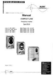
2354235 11/2008<br />
Soft start - soft stop unit<br />
SH31<br />
User manual<br />
09/2010<br />
BLEMO ® Frequenzumrichter<br />
Siemensstraße 4<br />
D-63110 Rodgau – Dudenhofen<br />
Germany<br />
Tel.: ++49 / 6106 / 82 95-0<br />
Fax: ++49 / 6106 / 82 95-20<br />
Internet: www.blemo.com<br />
E-Mail: info@blemo.com
Content<br />
Important Information __________________________________________________________________________________________ 4<br />
Before you begin______________________________________________________________________________________________ 5<br />
Documentation structure________________________________________________________________________________________ 6<br />
Steps for setting up the soft starter ___________________________________________________________________ 7<br />
Receiving and handling ________________________________________________________________________________________ 8<br />
Selection ___________________________________________________________________________________________________ 10<br />
Dimensions and weights_______________________________________________________________________________________ 14<br />
Mounting ___________________________________________________________________________________________________ 17<br />
Mounting - Fan option_________________________________________________________________________________________ 20<br />
Thermal protection ___________________________________________________________________________________________ 22<br />
Wiring _____________________________________________________________________________________________________ 26<br />
Wiring - power terminals_______________________________________________________________________________________ 32<br />
Wiring - control terminals ______________________________________________________________________________________ 35<br />
Wiring - in line connection - application diagram ____________________________________________________________________ 38<br />
Display terminal _____________________________________________________________________________________________ 42<br />
Remote keypad display - option _________________________________________________________________________________ 44<br />
Programming _______________________________________________________________________________________________ 45<br />
List of parameters____________________________________________________________________________________________ 48<br />
Parameter settings ___________________________________________________________________________________________ 49<br />
Configuration menu (ConF) ____________________________________________________________________________________ 50<br />
Settings menu (SEt) __________________________________________________________________________________________ 51<br />
Advanced adjustments menu (AdJ) ______________________________________________________________________________ 53<br />
Advanced settings menu (SEt2) _________________________________________________________________________________ 55<br />
Advanced protections menu (PrO) _______________________________________________________________________________ 56<br />
Advanced IO menu (IO) _______________________________________________________________________________________ 60<br />
Advanced communication menu (COP) ___________________________________________________________________________ 62<br />
Advanced monitoring menu (SUP) _______________________________________________________________________________ 63<br />
Utility menu (UtIL)____________________________________________________________________________________________ 64<br />
Command channel ___________________________________________________________________________________________ 65<br />
Modbus Function ____________________________________________________________________________________________ 68<br />
Connection to RS485 bus______________________________________________________________________________________ 73<br />
Maintenance ________________________________________________________________________________________________ 74<br />
Diagnostics / Troubleshooting __________________________________________________________________________________ 75<br />
Parameter Index and Modbus addresses__________________________________________________________________________ 77<br />
Annex 1: UL508 schematics____________________________________________________________________________________ 82<br />
Annex 2: Short-circuit rating and branch circuit protection _____________________________________________________________ 84<br />
3
AlImportant Information<br />
NOTICE<br />
Read these instructions carefully, and look at the equipment to become familiar with the device before trying to install, operate, or maintain<br />
it. The following special messages may appear throughout this documentation or on the equipment to warn of potential hazards or to call<br />
attention to information that clarifies or simplifies a procedure.<br />
PLEASE NOTE<br />
Electrical equipment should be installed, operated, serviced, and maintained only by qualified personnel. No responsibility is assumed by<br />
BLEMO for any consequences arising out of the use of this product.<br />
© 2010 BLEMO All Rights Reserved. Before you begin:<br />
Read and understand these instructions before performing any procedure with this soft starter.<br />
4<br />
The addition of this symbol to a Danger or Warning safety label indicates that an electrical hazard exists, which will result in<br />
personal injury if the instructions are not followed.<br />
This is the safety alert symbol. It is used to alert you to potential personal injury hazards. Obey all safety messages that follow<br />
this symbol to avoid possible injury or death.<br />
<strong>DANGER</strong><br />
<strong>DANGER</strong> indicates an imminently hazardous situation, which, if not avoided, will result in death or serious injury.<br />
WARNING<br />
WARNING indicates a potentially hazardous situation, which, if not avoided, can result in death, serious injury or<br />
equipment damage.<br />
CAUTION<br />
CAUTION indicates a potentially hazardous situation, which, if not avoided, can result in injury or equipment<br />
damage.<br />
CAUTION<br />
CAUTION, used without the safety alert symbol, indicates a potentially hazardous situation which, if not avoided,<br />
can result in equipment damage.<br />
<strong>DANGER</strong>
HAZARD OF ELECTRIC SHOCK, EXPLOSION, OR ARC FLASH<br />
• Read and understand this manual before installing or operating the SH31. Installation, adjustment, repair, and maintenance must be<br />
performed by qualified personnel.<br />
• The user is responsible for compliance with all international and national electrical code requirements with respect to grounding of<br />
all equipment.<br />
• Many parts of this soft starter, including the printed circuit boards, operate at the line voltage. DO NOT TOUCH. Use only electrically<br />
insulated tools.<br />
• DO NOT touch unshielded components or terminal strip screw connections with voltage present.<br />
• Before servicing the soft starter:<br />
- Disconnect all power, including external control power that may be present.<br />
- Place a “DO NOT TURN ON” label on all power disconnects.<br />
- Lock all power disconnects in the open position.<br />
• Install and close all covers before applying power or starting and stopping the soft starter.<br />
Failure to follow these instructions will result in death or serious injury.<br />
UNINTENDED EQUIPMENT OPERATION<br />
<strong>DANGER</strong><br />
• Read and understand this manual before installing or operating the SH31.<br />
• Any changes made to the parameter settings must be performed by qualified personnel.<br />
Failure to follow these instructions will result in death or serious injury.<br />
DAMAGED SOFT STARTER EQUIPMENT<br />
WARNING<br />
Do not operate or install any soft starter or soft starter accessory that appears damaged.<br />
Failure to follow these instructions can result in death, serious injury, or equipment damage.<br />
LOSS OF CONTROL<br />
WARNING<br />
• The designer of any control scheme must<br />
- consider the potential failure modes of control paths and, for certain critical control functions,<br />
- provide a means to achieve a safe state during and after a path failure.<br />
Examples of critical control functions are emergency stop and overtravel stop.<br />
• Separate or redundant control paths must be provided for critical control functions.<br />
• System control paths may include communication links. Consideration must be given to the implications of unanticipated<br />
transmission delays or failures of the link. (1)<br />
• Each implementation of an SH31 soft starter must be individually and thoroughly tested for proper operation before being placed into<br />
service.<br />
Failure to follow these instructions can result in death, serious injury, or equipment damage.<br />
(1)For additional information, refer to NEMA ICS 1.1 (latest edition), “Safety Guidelines for the Application, Installation, and Maintenance<br />
of Solid State Control”.<br />
5
Documentation structure<br />
The following SH31 technical documents are available on the BLEMO website (www.blemo.com).<br />
User manual<br />
This manual describes how to install, commission, operate and program the soft starter.<br />
Quick Start guide<br />
This document is delivered with the soft starter, and you can download it on www.blemo.com.<br />
6
Steps for setting up the soft starter (also refer to Quick Start guide)<br />
Steps 1 to 4 are<br />
performed with<br />
the power off.<br />
1. Receive and Inspect the soft starter<br />
Check that the soft starter reference on the nameplate is similar to the purchase order.<br />
Remove the SH31 from packaging and check that it has not been damaged<br />
2. Check the line voltage compatibility<br />
Check that the line voltage, and control voltage are compatible with the soft<br />
starter (pages 11 to 13).<br />
3. Mount the soft starter vertically<br />
Mount the soft starter in accordance with the instructions in this<br />
document (page 17).<br />
4. Wire the soft starter (page 29)<br />
Connect the motor, ensuring that its connections correspond to<br />
the voltage.<br />
Connect the line supply, after making sure that the power is off.<br />
Check and Connect the control supply on CL1-CL2<br />
5. Configure the soft starter<br />
(page 45)<br />
Power on control, and do not give a start command.<br />
Adjust UIn line voltage.<br />
AdjustIn motor rated current.<br />
6. Start<br />
7
Receiving and handling<br />
Introduction<br />
The SH31 offers acceleration and deceleration control of standard three-phase asynchronous induction (squirrel cage) motors. The SH31<br />
controls the motor performance based on the motor torque rather than simple voltage or current based control. Advanced control algorithms<br />
are incorporated to help smooth rotation throughout the starting ramp and reducing mechanical instability at the end of starting.<br />
A digital keypad display is provided for soft starter setup and motor performance display.<br />
The SH31 is available in 15 current ratings from 17 to 590 A. SH31 are rated for use from 208 to 600 V motors, and are self-adjusting for<br />
a 50 or 60 Hz supply frequency.<br />
This user manual covers the technical characteristics, specifications, installation, wiring, programming, and troubleshooting of SH31.<br />
Terminology<br />
Some of the terms and acronyms used in this manual are defined in the table below:<br />
Receiving and Preliminary Inspection<br />
Before installing the SH31 soft starter, read this manual and follow all precautions.<br />
Before removing the SH31 soft starter from its packing material, verify that the packing carton is not damaged from shipping. Damage to<br />
the packing carton usually indicates improper handling. If any damage is found, notify the carrier and your BLEMO representative.<br />
After removing the SH31 soft starter from its packaging, inspect it for damage. If any shipping damage is found, notify the carrier and your<br />
sales representative. Verify that the SH31 soft starter nameplate and label conform to the packing slip and corresponding purchase order.<br />
Storing and Shipping<br />
If the SH31 soft starter is not being immediately installed, store it in a clean, dry area where the ambient temperature is between -25° C and<br />
+70°C (-13°F and +158°F).<br />
If the SH31 soft starter must be shipped to another location, use the original shipping material and carton to help protect it.<br />
8<br />
Term Definition<br />
Soft starter FLA<br />
Motor FLA<br />
Soft starter Full Load Amps<br />
This value is on the soft starter nameplate IcL.<br />
IcL: Soft starter rated current<br />
Motor Full Load Amps<br />
This value is on the motor nameplate.<br />
The current rating of an induction motor at rated speed and load.<br />
Soft starter in line connection: In = rated current of the motor FLA.<br />
Soft starter inside delta connection: In = rated current of the motor FLA / 3.<br />
OCPD Overcurrent protective device.<br />
DAMAGED SOFT STARTER EQUIPMENT<br />
Do not operate or install any soft starter that appears damaged.<br />
WARNING<br />
Failure to follow these instructions can result in death, serious injury, or equipment damage.
Receiving and handling<br />
Handling the soft starter<br />
Hoisting the SH31<br />
The SH31 range comprises 5 frame sizes, with various weights and dimensions.<br />
Small soft starters can be removed from their packaging and installed without a handling device. A handling device must be used from<br />
SH31-110/4; for this reason they are supplied with lifting holes.<br />
HANDLING AND LIFTING HAZARD<br />
Package content<br />
• Soft starter<br />
• Quick Install guide<br />
• Package of screws for frame sizes C, D and E<br />
• Allen key, supplied with size B products<br />
WARNING<br />
Keep the area below any equipment being lifted clear of all personnel and property. Use the lifting method as shown below.<br />
Failure to follow these instructions can result in death, serious injury, or equipment damage.<br />
45°<br />
maxi<br />
Do not remove the SH31 from the carton until it is at the final installation site. Handle<br />
the soft starter carefully after removing it from the carton to avoid damage to the<br />
internal components, frame, or exterior. Once removed from the carton, the soft starter<br />
can be handled:<br />
• With a hoist. When hoisting the soft starter, attach a spreader bar to the two<br />
lifting holes on top as shown below.<br />
• In a horizontal position, with the back of the soft starter resting on a pallet.<br />
9
Selection<br />
Torque characteristic<br />
Soft starter selection<br />
S1 motor duty corresponds to starting followed by operation at constant load enabling the thermal stability to be reached.<br />
S4 motor duty corresponds to a cycle comprising starting, operation at constant load and an idle period. This cycle is characterized by a<br />
load factor.<br />
The SH31 must be selected depending on the type of application ("standard" or "severe") and the nominal power of the motor. "Standard"<br />
or "severe" applications define the limiting values of the current and the cycle for motor duties S1 and S4. These duties are described in the<br />
IEC 60034-1.<br />
Standard application<br />
Example: centrifugal pump<br />
In standard application, the SH31 is designed to provide:<br />
• in S1 duty: starting at 3.5 In for 40 seconds from a cold state.<br />
• in S4 duty: a load factor of 90% and n starts per hour (see table below), with 3.5 In for 20 seconds or an equivalent thermal cycle.<br />
In this case, the motor thermal protection must conform to protection class 10.<br />
:<br />
Framesize In S4 duty, number of<br />
starts (1) per hour<br />
Standard With fan<br />
A 6 10<br />
B 6 10<br />
C 4 10<br />
D NA 4<br />
E NA 4<br />
(1) Note : in case of both soft starts and soft stops, the number of starts has to be divided by 2.<br />
Severe application<br />
The SH31 rating is limited to 3.5 IcL, see table page 19.IcL is the nominal current of the SH31. If the application requires a higher rated<br />
starting current (> 3.5 IcL), the soft starter must be oversized. See soft starter selection table, page 11.<br />
Soft starter sizing according to thermal protection class<br />
Starting current Protection class<br />
Class 10 Class 20 Class 30<br />
y 3.5In<br />
Nominal* Nominal + 1** Nominal + 2***<br />
max starting time 16 s<br />
32 s<br />
48 s<br />
* Nominal = nominal size of the soft starter according to the nominal motor current (Motor FLA).<br />
** Nominal + 1 = oversize the soft starter by one rating compared to the nominal motor current (Motor FLA).<br />
*** Nominal + 2 = oversize the soft starter by 2 ratings compared to the nominal motor current (Motor FLA).<br />
10<br />
Ts and Is: Direct on line starting of an asynchronous motor.<br />
Ts1: Total torque range available with an SH31, which is dependent on the limiting<br />
current ILt, page 51.<br />
The progression of the soft starter is controlled by the motor torque within this range.<br />
Tr: Resistive torque, which must always be less than the Ts1 torque.
Selection<br />
Standard application, SH31-.../4, 230/440 V supply,<br />
soft starter in line connection<br />
Motor SH31-.../4, 230/440 V (+ 10% - 15%) - 50/60 Hz (+/- 10%)<br />
Nominal motor power Motor nominal<br />
230 V 400 V 440 V<br />
current In<br />
(Motor FLA)<br />
kW kW kW A A<br />
The nominal motor current In must not exceed the maximum permanent current in class 10.<br />
See wiring page 30.<br />
Maximum surrounding temperature<br />
Soft starter rating IcL<br />
(Soft starter FLA)<br />
Reference<br />
4 7.5 7.5 14.8 17 SH31-7.5/4<br />
7.5 15 15 28.5 32 SH31-15.0/4<br />
11 22 22 42 47 SH31-22.0/4<br />
15 30 30 57 62 SH31-30.0/4<br />
18.5 37 37 69 75 SH31-37.0/4<br />
22 45 45 81 88 SH31-45.0/4<br />
30 55 55 100 110 SH31-55.0/4<br />
37 75 75 131 140 SH31-75.0/4<br />
45 90 90 162 170 SH31-90.0/4<br />
55 110 110 195 210 SH31-110/4<br />
75 132 132 233 250 SH31-132/4<br />
90 160 160 285 320 SH31-160/4<br />
110 220 220 388 410 SH31-200/4<br />
132 250 250 437 480 SH31-250/4<br />
160 315 355 560 590 SH31-315/4<br />
The information in the table above is based on operation at a maximum ambient temperature of 40°C (104 °F).<br />
The SH31 can be used up to an ambient temperature of 60°C (140°F) as long as the max. permanent curren t in class 10 is derated by 2.2%<br />
for each degree above 40°C (104°F).<br />
Example: SH31-15.0/4 at 50°C (122°F) derated by 10 x 2.2% = 22%, 32 A becomes 32 x (1-0.22) = 24.96 A (max. nominal motor current).<br />
11
Selection<br />
Standard application, SH31-.../4, 230/440 V supply,<br />
soft starter inside delta connection<br />
Only the SH31-.../4 can be installed inside delta connection.<br />
(1)Line current is maximum 1.5 IcL. Also, the In setting must not exceed IcL.<br />
Example: for a 400 V - 110 kW motor with a line current of 195 A, the minimum soft starter rating,IcL = 195/1.5 = 130 A.<br />
Thus select SH31-75.0/4<br />
The nominal motor current In must not exceed the max. permanent current in class 10.<br />
See wiring page 26.<br />
Maximum surrounding temperature<br />
The information in the table above is based on operation at a maximum ambient temperature of 40°C (104 °F).<br />
The SH31 can be used up to an ambient temperature of 60°C (140°F) as long as the max. permanent curren t in class 10 is derated by 2.2%<br />
for each degree above 40°C (104°F).<br />
Example: SH31-15.0/4 at 50°C (122°F) derated by 10 x 2.2% = 22%, 48 A becomes 48 x 0.78 = 37.5 A (max. nominal motor current).<br />
12<br />
RISK OF DAMAGE TO THE MOTOR<br />
SH31-.../6 must not be installed inside delta connection.<br />
CAUTION<br />
Failure to follow these instructions can result in equipment damage.<br />
Motor Soft starter 230/440 V (+ 10% - 15%) - 50/60 Hz (+/- 10%)<br />
Nominal motor power Line current<br />
230 V 400 V 440 V (Motor FLA) (1)<br />
In setting<br />
(Line current/3)<br />
kW kW kW A A A<br />
Soft starter<br />
rating IcL<br />
(soft starter FLA)<br />
Soft starter<br />
reference<br />
5.5 11 15 25 14,4 17 SH31-7.5/4<br />
11 22 22 48 27,7 32 SH31-15.0/4<br />
18.5 45 45 70 40,4 47 SH31-22.0/4<br />
22 55 55 93 53,7 62 SH31-30.0/4<br />
30 55 75 112 64,7 75 SH31-37.0/4<br />
37 75 75 132 76,2 88 SH31-45.0/4<br />
45 90 90 165 95,3 110 SH31-55.0/4<br />
55 110 110 210 121,2 140 SH31-75.0/4<br />
15 132 132 255 147,2 170 SH31-90.0/4<br />
90 160 160 315 181,9 210 SH31-110/4<br />
110 220 220 375 216,5 250 SH31-132/4<br />
132 250 250 480 277,1 320 SH31-160/4<br />
160 315 355 615 355,1 410 SH31-200/4<br />
220 355 400 720 415,7 480 SH31-250/4<br />
250 400 500 885 511,0 590 SH31-315/4
Selection<br />
Standard application, SH31.../6, 208/600 V supply, soft starter in line connection<br />
Motor Soft starter 208/600 V (+ 10% - 15%) 50/60 Hz (+/- 10%)<br />
Nominal motor power Motor<br />
208 V 230 V 230 V 400 V 440 V 460 V 500 V 575 V nominal<br />
current In<br />
(Motor FLA)<br />
HP HP kW kW kW HP kW HP A A<br />
(1) 200 160 315 355 400 400 500 477 590 SH31-315/6<br />
(1)Value not indicated when there is no corresponding standardized motor.<br />
The nominal motor current In must not exceed the max. permanent current in class 10.<br />
Maximum surrounding temperature<br />
Soft starter<br />
ratingIcL<br />
(Soft starter FLA)<br />
Soft starter<br />
reference<br />
3 5 4 7.5 7.5 10 9 15 14 17 SH31-7.5/6<br />
7.5 10 7.5 15 15 20 18.5 25 27 32 SH31-15.0/6<br />
(1) 15 11 22 22 30 30 40 40 47 SH31-22.0/6<br />
15 20 15 30 30 40 37 50 52 62 SH31-30.0/6<br />
20 25 18.5 37 37 50 45 60 65 75 SH31-37.0/6<br />
25 30 22 45 45 60 55 75 77 88 SH31-45.0/6<br />
30 40 30 55 55 75 75 100 96 110 SH31-55.0/6<br />
40 50 37 75 75 100 90 125 124 140 SH31-75.0/6<br />
50 60 45 90 90 125 110 150 156 170 SH31-90.0/6<br />
60 75 55 110 110 150 132 200 180 210 SH31-110/6<br />
75 100 75 132 132 200 160 250 240 250 SH31-132/6<br />
100 125 90 160 160 250 220 300 302 320 SH31-160/6<br />
125 150 110 220 220 300 250 350 361 410 SH31-200/6<br />
150 -(1) 132 250 250 350 315 400 414 480 SH31-250/6<br />
The information in the table above is based on operation at a maximum ambient temperature of 40°C (104 °F).<br />
The SH31 can be used up to an ambient temperature of 60°C (140°F) as long as the max. permanent curren t in class 10 is derated by 2.2%<br />
for each degree above 40°C (104°F).<br />
Example: SH31-15.0/6 at 50°C (122°F) derated by 10 x 2.2% = 22%, 27 A becomes 27 x 0.78 =21.06 A (max. nominal motor current).<br />
13
Dimensions and weights<br />
SH31-7.5 to 45.0/4 and /6<br />
For frame sizes 7.5 kW to 45.0 kW, the fan is sold separately. (1)<br />
c: dimension of the product alone.<br />
c1: dimension of the product with its fan.<br />
(1) The voltage of the fan has to match the control voltage of the soft starter:<br />
SH31-.../4 or SH31-.../6 Fan 230V<br />
SH31-.../6 in US edition Fan 110V<br />
14<br />
SH31- Frame<br />
size<br />
7.5/4/6 A<br />
15.0/4/6 A<br />
22.0/4/6 A<br />
30.0/4/6 B<br />
37.0/4/6 B<br />
45.0/4/6 B<br />
a b c c1 e H Standard<br />
G<br />
mm mm mm mm mm mm mm<br />
(in.) (in.) (in.) (in.) (in.) (in.) (in.)<br />
130<br />
(5.1)<br />
145<br />
(5.7)<br />
265<br />
(10.4)<br />
295<br />
(11.6)<br />
169<br />
(6.6)<br />
207<br />
(8.1)<br />
209<br />
(8.2)<br />
247<br />
(9.7)<br />
6.5<br />
(0.3)<br />
10.5<br />
(0.4)<br />
250<br />
(9.8)<br />
276<br />
(10.9)<br />
100<br />
(3.9)<br />
115<br />
(4.5)<br />
With fan<br />
G1<br />
mm<br />
(in.)<br />
65<br />
(2.6)<br />
80<br />
(3.15)<br />
D<br />
mm<br />
mm<br />
(in.)<br />
7<br />
(0.28)<br />
7<br />
(0.28)<br />
Weight<br />
kg (lb)<br />
5.5<br />
(12.1)<br />
7.8<br />
(17.2)
Dimensions and weights<br />
SH31-55.0 to 90.0/4 and /6<br />
For frame sizes 55.0 kW to 90.0 kW, the fan is sold separately. (1)<br />
SH31-<br />
Frame<br />
size C<br />
55.0/4/<br />
6<br />
75.0/4/<br />
6<br />
90.0/4/<br />
6<br />
a b c c1 e H G1 P Q Q1 S D1 D2 D3 Weight<br />
mm<br />
(in.)<br />
150<br />
(5.9)<br />
mm<br />
(in.)<br />
356<br />
(14)<br />
mm<br />
(in.)<br />
229.5<br />
(9)<br />
mm<br />
(in.)<br />
269.5<br />
(10.6)<br />
mm<br />
(in.)<br />
10.5<br />
(0.41)<br />
mm<br />
(in.)<br />
331<br />
(13)<br />
mm<br />
(in.)<br />
120<br />
(4.7)<br />
mm<br />
(in.)<br />
40.5<br />
(1.6)<br />
c: dimension of the product alone.<br />
c1: dimension of the product with its fan.<br />
(1) The voltage of the fan has to match the control voltage of the soft starter:<br />
SH31-.../4 or SH31-.../6 Fan 230V<br />
SH31-.../6 in US edition Fan 110V<br />
mm<br />
(in.)<br />
34.5<br />
(1.3)<br />
mm<br />
(in.)<br />
5<br />
(0.2)<br />
mm<br />
(in.)<br />
20<br />
(0.8)<br />
mm<br />
(in.)<br />
9<br />
(0.35)<br />
mm<br />
(in.)<br />
7<br />
(0.28)<br />
mm<br />
(in.)<br />
6<br />
(0.23)<br />
kg<br />
(lb)<br />
12.2<br />
(26.9)<br />
15
Dimensions and weights<br />
SH31-110 to 315/4 and /6<br />
For frame sizes 110 kW to 315 kW, the fan is integrated.<br />
16<br />
SH31- Frame<br />
size<br />
110/4/<br />
6<br />
132/4/<br />
6<br />
160/4/<br />
6<br />
200/4/<br />
6<br />
250/4/<br />
6<br />
315/4/<br />
6<br />
D<br />
D<br />
D<br />
D<br />
E<br />
E<br />
a b c e H G1 P Q Q1 S D1 D2 Weight<br />
mm<br />
(in.)<br />
206<br />
(8.1)<br />
304<br />
(11.9)<br />
mm<br />
(in.)<br />
425<br />
(16.7)<br />
455<br />
(17.9)<br />
mm<br />
(in.)<br />
299<br />
(11.8)<br />
339.7<br />
(13.4)<br />
mm<br />
(in.)<br />
15<br />
(0.59)<br />
15<br />
(0.59)<br />
mm<br />
(in.)<br />
396<br />
(15.6)<br />
426<br />
(16.8)<br />
mm<br />
(in.)<br />
157<br />
(6.2)<br />
264<br />
(10.4)<br />
mm<br />
(in.)<br />
60<br />
(2.4)<br />
94<br />
(3.7)<br />
mm<br />
(in.)<br />
40<br />
(1.6)<br />
55<br />
(2.2)<br />
mm<br />
(in.)<br />
1.3<br />
(0.05)<br />
1<br />
(0.04)<br />
mm<br />
(in.)<br />
30<br />
(1.2)<br />
40<br />
(1.6)<br />
mm<br />
(in.)<br />
13.5<br />
(0.53)<br />
13.5<br />
(0.53)<br />
mm<br />
(in.)<br />
9<br />
(0.35)<br />
9<br />
(0.35)<br />
kg (lb)<br />
20.5<br />
(45.2)<br />
33<br />
(73.3)
Mounting<br />
Mounting Precautions<br />
Follow these precautions when mounting the SH31 soft starter:<br />
• The soft starter is compliant with pollution Degree 2 as defined in NEMA ICS1-1 or IEC 60664-1.<br />
• For environment pollution degree 3 install the product inside a cabinet type 12 or IP54.<br />
<strong>DANGER</strong><br />
HAZARD OF ELECTRIC SHOCK, EXPLOSION, OR ARC FLASH<br />
SH31 soft starters are open devices and must be mounted in a suitable enclosure.<br />
Failure to follow these instructions will result in death or serious injury.<br />
• The SH31 soft starter generates heat and must be properly ventilated. Refer to "Thermal considerations for sizing enclosures” page<br />
19 to determine power dissipated.<br />
• When several soft starters are installed in a control panel, arrange them in a row. Do not stack soft starters. Heat generated from the<br />
bottom soft starter can adversely affect the ambient temperature around the top soft starter.<br />
• Install the SH31 vertically, within ± 10° (other p ositions are not allowed).<br />
• Do not place it close to heating elements. Leave sufficient free space so that the air required for cooling purposes can circulate from<br />
the bottom to the top of the unit.<br />
• Electrical current through the SH31 will result in heat losses that must be dissipated into the ambient air immediately surrounding the<br />
soft starter. To help prevent a thermal fault, provide sufficient enclosure cooling and/or ventilation to limit the ambient temperature<br />
around the soft starter.<br />
S ≥ 50 mm<br />
(1.95 in.)<br />
S ≥ 100 mm (3.9 in)<br />
S ≥ 100 mm (3.9 in)<br />
S ≥ 50 mm<br />
(1.95 in.)<br />
Note: For the soft starters mounted side-by-side, the free space<br />
must be ≥ 50 mm (1.95 in.)<br />
<strong>DANGER</strong><br />
HAZARD OF ELECTRIC SHOCK, EXPLOSION, OR ARC FLASH<br />
Check that no liquid, dust or conductive object can fall into the soft starter (degree of protection IP00 from above).<br />
Failure to follow these instructions will result in death or serious injury.<br />
17
Mounting<br />
Soft starter ventilation<br />
On soft starters installed with a cooling fan, the fan is factory set to switch on automatically as soon as the heatsink temperature reaches<br />
46°C (114.8°F).<br />
It is switched off when the heatsink temperature falls back to 43°C (109.4°F). This behavior can be mo dified by adjusting the FAn parameter<br />
in IO menu on page 61.<br />
Fan flow rates<br />
(1)Cubic Feet / Minute<br />
Mounting in a General Purpose Metal Enclosure<br />
Observe the mounting recommendations on the previous page.<br />
To help proper air circulation in the soft starter:<br />
• Install ventilation grilles.<br />
• Verify that ventilation is adequate: if not install a forced ventilation unit, with a<br />
filter if necessary.<br />
Derate the soft starter current IcL by 2.2% per °C for temperatures above 40°C up to<br />
60°C (104°F up to 140°F).<br />
18<br />
Reference Frame<br />
size<br />
Unit Standard With optional fan kit<br />
110 V 230 V 110 V 230 V<br />
SH31-7.5, 15.0, 22.0 A m 3 /hour - - 28 31<br />
CFM (1) - - 16 18<br />
SH31-30.0, 37.0, 45.0 B m 3 /hour - - 28 31<br />
CFM (1) - - 16 18<br />
SH31- 55.0, 75.0, 90.0 C m 3 /hour - - 108 108<br />
CFM (1) - - 64 64<br />
SH31-110, 132, 160, 200 D m 3 /hour 148 148 - -<br />
CFM (1) 87 87 - -<br />
SH31-250, 315 E m 3 /hour 148 148 - -<br />
CFM (1) 87 87 - -
Mounting<br />
Mounting in a dust and damp-proof metal enclosure<br />
Ventilation for dust and damp- proof enclosure<br />
Follow the instructions in this section in order to meet NEMA Type 12 (IP54) degree of protection.<br />
Do not use insulated or non-metallic enclosures as they have poor thermal conduction. Provide a stirring fan to circulate air inside the<br />
enclosure and to help prevent hot spots in the soft starter. This allows operation of the soft starter in an enclosure with a maximum internal<br />
temperature of 60°C (140°F). Ensure that the ambien t temperature around the soft starters does not exceed this limit.<br />
Derate the soft starter current IcL by 2.2% per °C for temperatures above 40°C up to 6 0°C (104°F up to 140°F).<br />
Thermal considerations for sizing enclosures<br />
When mounting the SH31 soft starter in an enclosure, use the enclosure manufacturers’ recommendations for proper sizing based on<br />
thermal considerations. For this, it is necessary to sum the power dissipated by each device in the enclosure. Table hereafter lists the steady<br />
state and starting power dissipations for the SH31 soft starter, operating at rated current.<br />
Power dissipated by the soft starters, at their nominal current<br />
Soft starter<br />
reference<br />
θ°i = internal ambient temperature<br />
θ°e = external ambient temperature<br />
Power Control supply<br />
Frame<br />
size<br />
IcL During starting<br />
total power<br />
at 3.5 IcL<br />
SH31-7.5/4/6 A 17 208 5<br />
SH31-15.0/4/6 A 32 404 10<br />
SH31-22.0/4/6 A 47 562 14<br />
SH31-30.0/4/6 B 62 781 19<br />
SH31-37.0/4/6 B 75 1016 23<br />
SH31-45.0/4/6 B 88 1060 26<br />
SH31-55.0/4/6 C 110 1345 33<br />
SH31-75.0/4/6 C 140 1548 42<br />
SH31-90.0/4/6 C 170 1922 51<br />
SH31-110/4/6 D 210 2596 63<br />
SH31-132/4/6 D 250 3275 75<br />
SH31-160/4/6 D 320 3699 96<br />
SH31-200/4/6 D 410 5147 123<br />
SH31-250/4/6 E 480 6396 144<br />
SH31-315/4/6 E 590 7599 177<br />
Steady state<br />
total power<br />
bypass<br />
Electronics Shorting<br />
contactors<br />
(1)<br />
A W W W W W<br />
(1)For SH31-.../4, SH31-.../6 and US edition, frame sizes A, B and C the shorting contactor power is included in the electronics.<br />
(2)Optional fan kit<br />
Fans<br />
20 - 14 (2)<br />
20 - 20 (2)<br />
20 - 20 (2)<br />
20 14 20<br />
20 14 40<br />
Example: for an SH31-22.0/4/6 Example: for an SH31-250/4/6<br />
Power dissipated during starting: 562 W<br />
Power dissipated in steady state: 14 W<br />
Power for Control supply: 20 W without fan, 34 W with fan<br />
Power dissipated during starting: 6396 W<br />
Power dissipated in steady state: 144 W<br />
Power for Control supply: 74 W<br />
19
Mounting - Fan option<br />
Fan for frame sizes A, B and C<br />
Connections between the fan and the SH31<br />
SH31-.../4 or SH31-.../6 Fan 230 V<br />
SH31-.../& in US edition Fan 110 V<br />
20<br />
Tightening torque: 3.5 N·m (31 lb.in)<br />
* As 2 different fan options could be connected to the SH31<br />
according to the fan voltage (matching the SH31 control<br />
voltage), the connector is different according to the voltage, to<br />
help avoid wrong assembly and misuse.<br />
(1) The voltage of the fan has to match the control voltage of<br />
the soft starter:
Mounting - Fan option<br />
Fan dimensions for frame sizes SH31-7.5 to 90.0<br />
For frame sizes 7.5 kW to 45.0 kW, the fan is sold separately. (1)<br />
Fan kit SH31- a b k e H G G1 X D Weight<br />
A<br />
B<br />
C<br />
7.5<br />
15.0<br />
22.0<br />
30.0<br />
37.0<br />
45.0<br />
55.0<br />
75.0<br />
90.0<br />
mm<br />
(in.)<br />
130<br />
(5.1)<br />
145<br />
(5.7)<br />
150<br />
(5.9)<br />
mm<br />
(in.)<br />
265<br />
(10.4)<br />
295<br />
(11.6)<br />
350<br />
(13.8)<br />
mm<br />
(in.)<br />
40<br />
(1.6)<br />
40<br />
(1.6)<br />
40<br />
(1.6)<br />
mm<br />
(in.)<br />
8.5<br />
(0.33)<br />
8.5<br />
(0.33)<br />
8.5<br />
(0.33)<br />
mm<br />
(in.)<br />
248<br />
(9.8)<br />
278<br />
(10.9)<br />
333<br />
(13.1)<br />
(1) The voltage of the fan has to match the control voltage of the soft starter.<br />
SH31-.../4 or SH31-.../6 Fan 230V<br />
SH31-.../6 in US edition Fan 110V<br />
mm<br />
(in.)<br />
100<br />
(3.9)<br />
115<br />
(4.5)<br />
120<br />
(4.7)<br />
mm<br />
(in.)<br />
65<br />
(2.6)<br />
80<br />
(3.1)<br />
85<br />
(3.3)<br />
mm<br />
(in.)<br />
250<br />
(9.8)<br />
276<br />
(10.9)<br />
331<br />
(13)<br />
mm<br />
(in.)<br />
7<br />
(0.28)<br />
7<br />
(0.28)<br />
7<br />
(0.28)<br />
kg<br />
(lb)<br />
1.2<br />
(2.6)<br />
1.4<br />
(3.1)<br />
1.6<br />
(3.5)<br />
21
Thermal protection<br />
Soft starter thermal protection<br />
The thermal protection is provided by the temperature sensor installed on the heatsink.<br />
Motor thermal protection<br />
Standard IEC 60947-4-2 defines the protection classes giving the starting capacities of the motor (warm or cold start) without thermal faults.<br />
Different protection classes are given for a COLD state (corresponding to a stabilized motor thermal state, switched off) and for a WARM<br />
state (corresponding to a stabilized motor thermal state, at nominal power).<br />
22<br />
• The soft starter is factory set to protection class 10.<br />
• This protection class can be modified using tHP parameter in SEt menu.<br />
• The motor thermal state is stored in memory. No estimate of motor cooling is calculated while power of the control part is off.<br />
• An overload alarm is activated if motor thermal state exceeds 110%.<br />
• A thermal trip OLF stops the motor if motor thermal state exceeds 125%.<br />
• If the thermal protection has not been disabled, the thermal trip can be indicated by a relay depending on output assignment.<br />
• After the motor has stopped or the soft starter has been switched off, the thermal state is saved. At next start or switch on, the thermal<br />
protection value is restored.<br />
• If a special motor is used (explosion proof, submersible, etc.), the thermal protection should be provided by PTC probes.<br />
RISK OF DAMAGE TO THE MOTOR<br />
See Motor thermal protection with PTC probes, page 25.<br />
CAUTION<br />
The use of external overload protection is required under the following conditions:<br />
• Running multiple motors<br />
• Running motors rated at less than 40% of the nominal soft starter current<br />
• Using motor switching<br />
• Using special motor (explosion proof, submersible, etc...)<br />
Failure to follow these instructions can result in equipment damage.
Thermal protection<br />
Cold curves<br />
t (s)<br />
Trip time for a standard application<br />
(class 10)<br />
Trip time for a severe application<br />
(class 20)<br />
Class 30<br />
Class 20<br />
Class 10<br />
Trip time for a severe application<br />
(class 30)<br />
3.5 In 3.5 In 3.5 In<br />
32 s 63 s 95 s<br />
23
Thermal protection<br />
Warm curves<br />
24<br />
t (s)<br />
Trip time for a standard application<br />
(class 10)<br />
Trip time for a severe application<br />
(class 20)<br />
Class 30<br />
Class 20<br />
Class 10<br />
Trip time for a severe application<br />
(class 30)<br />
3.5 In 3.5 In 3.5 In<br />
16 s 32 s 48 s
Thermal protection<br />
Motor thermal protection with PTC probes<br />
PTC probes integrated in the motor to measure its temperature can be connected to the control card terminals.<br />
Note:<br />
PTC probe protection does not deactivate the motor thermal protection provided by the soft starter calculation. Both types of protection can<br />
operate in parallel.<br />
PTC wiring<br />
(1) Shielded cable is optional.<br />
Characteristics<br />
(1)<br />
Total resistance of the probe circuit: 750 Ω at 25°C (77°F).<br />
Tripping: between 2700 Ω and 3100 Ω.<br />
25
Wiring<br />
Installation Precautions<br />
Good wiring practice requires the separation of control circuit wiring from all power (line and load) wiring. Power wiring to the motor must<br />
have the maximum possible separation from all other power wiring. Do not run them in the same conduit. This separation reduces the<br />
possibility of coupling electrical noise between circuits.<br />
Follow these precautions when installing the SH31 soft starter:<br />
• Voltage and frequency specifications for the input line must match the soft starter configuration.<br />
• A disconnect switch must be installed between the input line and the soft starter.<br />
26<br />
<strong>DANGER</strong><br />
HAZARD OF ELECTRIC SHOCK, EXPLOSION, OR ARC FLASH<br />
• Read and understand this manual before installing or operating the SH31. Installation, adjustment, repair, and maintenance must be<br />
performed by qualified personnel.<br />
• The user is responsible for compliance with all international and national electrical code requirements with respect to grounding of<br />
all equipment.<br />
• Many parts of this soft starter, including the printed circuit boards, operate at the line voltage. DO NOT TOUCH. Use only electrically<br />
insulated tools.<br />
• DO NOT touch unshielded components or terminal strip screw connections with voltage present.<br />
• Before servicing the soft starter:<br />
- Disconnect all power, including external control power that may be present.<br />
- Place a “DO NOT TURN ON” label on all power disconnects.<br />
- Lock all power disconnects in the open position.<br />
• Install and close all covers before applying power or starting and stopping the soft starter.<br />
Failure to follow these instructions will result in death or serious injury.<br />
<strong>DANGER</strong><br />
HAZARD OF ELECTRIC SHOCK, EXPLOSION, OR ARC FLASH<br />
• The solid state switches of the SH31 soft starter’s power circuit do not provide complete isolation from the AC line. Due to leakage<br />
currents through the solid-state switches, hazardous voltages can be present on the soft starter load-side power circuit whenever<br />
power is applied to the line side of the soft starter.<br />
• Disconnect all power before servicing the soft starter or motor.<br />
Failure to follow these instructions will result in death or serious injury.<br />
• When using an isolation contactor, the contactor must close before or at the same time as the application of the soft starter run<br />
command. If line power is not detected at the L1, L2, and L3 terminals of the soft starter within 500 ms of this run command, a Phase<br />
Failure trip will occur.<br />
• External overcurrent protection devices (OCPD), either fuses or a circuit breaker, must be installed on the line-side connections of<br />
the SH31 soft starter. The maximum recommended OCPD rating, along with the associated soft starter short circuit withstand rating,<br />
is listed on page 84.
Wiring<br />
INADEQUATE OVERCURRENT PROTECTION<br />
WARNING<br />
• An overcurrent protective device must be installed on the line-side of the SH31 to achieve published short-circuit withstand ratings.<br />
• Do not exceed the maximum overcurrent protective device ratings shown on page 84.<br />
• Do not connect the soft starter to a power feeder whose short circuit capacity exceeds the soft starter short circuit withstand rating<br />
shown on page 84.<br />
Failure to follow these instructions can result in death, serious injury, or equipment damage.<br />
• Power factor correction capacitors should not be connected to a motor controlled by an SH31 soft starter. If power factor correction<br />
is required, the capacitors must be located on the line-side of the soft starter. A separate contactor should be used to switch the<br />
capacitors off when the motor is off, or during acceleration and deceleration. Refer to bulletin No 8638PD9603.<br />
RISK OF DAMAGE TO THE SOFT STARTER<br />
CAUTION<br />
• Do not connect power factor correction capacitors to the load-side power circuit of the SH31.<br />
• Do not connect loads other than motors (for example transformers and resistors are forbidden).<br />
Failure to follow these instructions can result in equipment damage.<br />
• The SH31 uses solid-state power switches to control motor power. When checking the condition of conductor or motor insulation, do<br />
not connect the high potential dielectric test equipment or insulation resistance tester to the soft starter since the test voltages used<br />
may damage the soft starter. Always disconnect the soft starter from the conductors or motor before performing such tests.<br />
RISK OF DAMAGE TO THE SOFT STARTER<br />
CAUTION<br />
• Do not perform high potential dielectric tests on circuits while the circuits are connected to the SH31 soft starter.<br />
• Any circuit requiring high potential dielectric tests must be disconnected from the soft starter prior to performing the test.<br />
Failure to follow these instructions can result in equipment damage.<br />
• The SH31 contains electronic circuitry to detect and signal when the solid-state switches have become inoperable.<br />
• Since the solid-state switches may be incapable of completely blocking the motor power should the soft starter detect a fault, auxiliary<br />
isolation on the line side of the soft starter is required. Use either a circuit breaker equipped with a shunt trip coil or an electromagnetic<br />
contactor. Connect the isolation device to the detected fault relay of the soft starter so that it opens the soft starter power circuit in the<br />
event of a soft starter trip. The isolation device must be capable of interrupting motor locked rotor current.<br />
27
Wiring<br />
Refer to application diagrams that display the logic controlling the isolation device via the detected fault relay.<br />
System Grounding<br />
If system grounding is not adequate to handle ground trip levels which can exceed 1300% of motor full load amps (Motor FLA), then this<br />
device may not protect the branch circuit conductors. In this case, external ground trip protection must be properly coordinated.<br />
Recommended solutions include:<br />
• Time delay fuses coordinated to 125% of motor FLA. The fuses listed in the chapter Branch circuit protection are sized to provide<br />
proper coordination and may be used for applications that do not require start times longer than 50 seconds at 300% current limit or<br />
20 seconds at 500% current limit.<br />
• External overload relay. For multi-motor applications, applications in which motor does not match the soft starter size, or applications<br />
that use a full voltage bypass scheme, an external overload relay can be coordinated to protect conductors from a high-impedance<br />
ground trip.<br />
General wiring practices<br />
When wiring SH31 soft starter, follow the wiring practices required by national and local electrical codes. In addition, follow these<br />
guidelines:<br />
• Use metallic conduit for all soft starter wiring. Do not run control and power wiring in the same conduit.<br />
• Separate metallic conduits carrying power wiring or low-level control wiring by at least 80 mm (3 in).<br />
• Separate non-metallic conduits or cable trays used to carry power wiring from metallic conduit carrying low-level control wiring by at<br />
least 305 mm (12 in).<br />
• Always cross power and control wiring at right angles.<br />
• Keep the control circuits away from the power cables.<br />
Adaptation to line input<br />
The control circuit is completely independent of the power circuit. To apply control voltage, follow the instructions on the label located on<br />
the soft starter terminal strip. Connect single phase voltage of 110 or 230 Vac supply to terminals CL1 and CL2.<br />
The power circuit adapts automatically to the input line voltage and frequency over a range of 230 to 440 V for SH31-.../4 soft starters, and<br />
over a range of 208 to 600 V for SH31-.../6 soft starters.<br />
28<br />
MOTOR OVERHEATING HAZARD<br />
CAUTION<br />
If the solid-state switches on the SH31 become inoperable, single-phase operation of the motor can result.<br />
• Use an isolation device consisting of either a circuit breaker equipped with a shunt trip coil or an electromagnetic contactor to open<br />
the line-side of the soft starter.<br />
• The isolation device must be capable of interrupting the motor locked rotor current.<br />
• Connect the detected fault relay of the soft starter to open the isolation device in the event of a soft starter trip.<br />
Failure to follow these instructions can result in injury or equipment damage.<br />
WARNING<br />
INADEQUATE SYSTEM GROUNDING- BRANCH CIRCUIT CONDUCTOR HAZARD<br />
If system grounding is not adequate for ground fault levels, use properly coordinated external ground fault protection. Possible solutions<br />
include:<br />
• Time delay fuses coordinated to 125% of motor FLA.<br />
• A properly coordinated external overload relay.<br />
Failure to follow these instructions can result in death, serious injury, or equipment damage.
Wiring<br />
Power Requirements<br />
Connect the control supply (CL1-CL2), ensuring that it is off, according to the model number of the soft starter.<br />
SH31-.../4<br />
and<br />
SH31-.../6<br />
SH31-.../6<br />
US edition<br />
Connect the power line supply (1/L1-3/L2-5/L3), ensuring that it is off, according to the model number of the soft starter.<br />
SH31-.../4<br />
SH31-.../6 and<br />
US edition<br />
230 V +10%<br />
220 V –15%<br />
115 V +10%<br />
110 V –15%<br />
230 V<br />
440 V<br />
208 V<br />
600 V<br />
Connect the motor (2/T1 - 4/T2 - 6/T3), ensuring that its coupling corresponds to the supply voltage.<br />
Note: If the SH31-.../4 is used inside delta connection, follow the recommendations on page 12, and the diagrams on page 30.<br />
Bypass contactor<br />
+10% –15%<br />
+10% –15%<br />
An internal bypass contactor is integrated into all SH31 soft starters.<br />
The bypass contactor is activated when :<br />
I motor < 120% In<br />
AND<br />
U motor = 100% input line voltage<br />
Block diagram of the power part of the SH31<br />
SH31-.../4 range SH31-.../6 and US edition<br />
29
Wiring<br />
The SH31-.../4 range (230-440 V) can be connected in the motor supply line or inside delta connection of the motor.<br />
The SH31 in line connection<br />
The motor connection depends on the supply voltage. Two possibilities are shown below: star connection and delta connection.<br />
The SH31 connected inside delta connection<br />
30<br />
SH31<br />
Motor<br />
Star connection Delta connection<br />
SH31<br />
Motor<br />
CAUTION<br />
RISK OF DAMAGE TO THE SOFT STARTER<br />
• Only the SH31-.../4 range can be installed inside delta connection.<br />
• Ensure connection exactly as shown on the example.<br />
• Line voltage should not exceed 440 V.<br />
• The parameter dLtA must be set to dLt.<br />
Failure to follow these instructions can result in equipment damage.<br />
Note: Phase sequence must be 1 - 2 - 3
Wiring<br />
The SH31.../4 connected inside delta connection<br />
SH31-.../4 soft starters can be inserted inside delta connection of the motor.<br />
Only the SH31-.../4 range can be installed inside delta connection. Set the parameter dLtA to dLt.<br />
See the tables on page 12 for more information about soft starter-motor combinations.<br />
Note: To reverse the direction of the motor as shown on the figure:<br />
- reverse the two outputs U1 and V1,<br />
- reverse the two inputs L1 and L3.<br />
31
Wiring - power terminals<br />
Power<br />
Observe the cable cross-sectional areas recommended in the standards.<br />
The soft starter must be grounded to conform to the regulations concerning leakage currents. If the installation involves several soft starters<br />
on the same line, each soft starter must be grounded separately.<br />
Keep the power cables separate from circuits in the installation with low-level signals (sensors, PLCs, measuring devices, video, telephone).<br />
Cage style connectors for frame sizes A and B<br />
Power connections, minimum and maximum wiring capabilities, tightening torque<br />
(a) The cable gauge affects the IP protection of the soft starter. To keep IP20 value with a connected cable on frame B, the minimum cable<br />
gauge is: 16 mm² or 4 AWG.<br />
Allen key, supplied with size B products<br />
32<br />
1L1 3L2 5L3<br />
Frame<br />
size<br />
Rdy<br />
Com<br />
Ground connection bottom view<br />
Run<br />
Trip<br />
2T1 4T2 6T3<br />
Ground connection<br />
2/T1 4/T2 6/T3<br />
Ground connections, screw size<br />
Frame size Screw<br />
A M6<br />
B M6<br />
C M6<br />
D M10<br />
E M10<br />
SH31- IEC cable UL cable<br />
1/L1 3/L2 5/L3 and 2/T1 4/T2 6/T3<br />
power supply and output to motor<br />
1/L1 3/L2 5/L3 and 2/T1 4/T2 6/T3<br />
power supply and output to motor<br />
Size Tightening torque Strip Gauge Tightening torque Strip<br />
min. max min. max<br />
length<br />
min. max min. max<br />
length<br />
mm² mm² N·m N·m mm AWG AWG lb·in lb·in in.<br />
A 7.5, 15.0, 22.0 2.5 16 3 3 10 12 4 26 26 0.4<br />
B 30.0, 37.0, 45.0 4 (a) 50 10 10 15 10 (a) 1/0 89 89 0.6<br />
<strong>DANGER</strong><br />
FIRE HAZARD DUE TO LACK OF TIGHTENING TORQUE<br />
• Ensure correct connector tightening torque for power terminals.<br />
• For size B, use the Allen key provided with the product.<br />
Failure to follow these instructions will result in death or serious injury.
Wiring - power terminals<br />
Bus bar connections for frame sizes C to E<br />
Frame<br />
Size<br />
Depth<br />
SH31- 1/L1 3/L2 5/L3 and 2/T1 4/T2 6/T3<br />
power supply and output to motor<br />
For more details, see Dimensions and weights paragraph page 14.<br />
Ground connection<br />
Width<br />
Bar Cable and cover<br />
Width Depth Bolt Size Gauge Cover Tightening torque<br />
mm (in.) mm (in.) M mm² MCM Ref N·m lb·in<br />
C 55.0, 75.0, 90.0 20 (0.79) 5 (0.2) 8 (0.31) 95 250 LA9F702 18 159<br />
D 110, 132, 160, 200 30 (1.18) 5 (0.2) 12 (0.47) 2x150 2x250 LA9F703 57 503<br />
E 250, 315 40 (1.57) 5 (0.2) 12 (0.47) 2x240 2x500 LA9F703 57 503<br />
33
Wiring - power terminals<br />
Power connections, minimum required wiring section<br />
315 2 x 185 2 x 500 MCM<br />
(1)at max ambient temperature of 40°C (104 °F)<br />
34<br />
Frame Size SH31 IEC cable<br />
mm² (Cu 70°C/158 °F) (1)<br />
A 7.5 2.5 10<br />
15.0 6 8<br />
22.0 10 6<br />
B 30.0 16 4<br />
37.0 25 3<br />
45.0 35 2<br />
C 55.0 35 1/0<br />
75.0 50 2/0<br />
90.0 70 4/0<br />
D 110 95 300 MCM<br />
132 120 350 MCM<br />
160 185 2 x 3/0<br />
200 2 x 150 2 x 250 MCM<br />
E 250 2x 150 2 x 350 MCM<br />
UL cable<br />
AWG (Cu 75°C/167 °F) (1)
Wiring - control terminals<br />
Electrical characteristics for SH31-.../4 and SH31-.../6 ranges (230 Vac with 24 Vdc logic input)<br />
Terminal Function Characteristics<br />
CL1<br />
CL2<br />
SH31 control power supply<br />
230 Vac +10%<br />
220 Vac -15%<br />
R1B<br />
R1C<br />
R1A<br />
R2B<br />
R2C<br />
R2A<br />
Relay1 normally closed<br />
Relay1 common<br />
Relay1 normally open<br />
Relay2 normally closed<br />
Relay2 common<br />
Relay2 normally open<br />
Max switching capability:<br />
5 A- 250 Vac or 30 Vdc on resistive load ( p.f. =1)<br />
2 A-250 Vac or 30 Vdc on inductive load ( p.f.=0.4)<br />
Minimimal commutation capability:<br />
100 mA 12 Vdc<br />
LI1 Logic input 1 3 x 24 V logic inputs with 4.3 kΩ impedance<br />
LI2 Logic input 2<br />
Umax = 30 V, Imax = 8 mA<br />
LI3 Logic input 3<br />
state 1: U>11 V - I>5 mA<br />
+24 Vdc Float 24 Vdc(+) (1)<br />
state 0: U
Wiring - control terminals<br />
Electrical characteristics for SH31-.../6 in US edition (110 Vac with 110 Vac logic inputs)<br />
Terminal Function Characteristics<br />
CL1<br />
CL2<br />
SH31 control power supply 110 Vac +10% -15%<br />
R1B<br />
R1C<br />
R1A<br />
R2B<br />
R2C<br />
R2A<br />
Relay1 normally closed<br />
Relay1 common<br />
Relay1 normally open<br />
Relay2 normally closed<br />
Relay2 common<br />
Relay2 normally open<br />
Max switching capability:<br />
5 A- 250 Vac or 30 Vdc on resistive load ( p.f. =1)<br />
2 A-250 Vac or 30 Vdc on inductive load ( p.f.=0.4)<br />
Minimimal commutation capability:<br />
100 mA 12 Vdc<br />
LI1 Logic input 1 3 x 110 V logic inputs with 20 kΩ<br />
LI2 Logic input 2<br />
impedance<br />
LI3 Logic input 3<br />
Umax = 121 Vac, Imax = 5 mA<br />
NC Not connected<br />
state 1: U>79 V - I>2 mA<br />
state 0: U
Wiring - control terminals<br />
Types of command<br />
LI1 stop behavior<br />
LI1 assignment is stop and cannot be changed by HMI or serial link.<br />
This input is active on level (Low level (0) = stop).<br />
RUN and START management<br />
RUN and START can only be assigned to LI2 (not LI3).<br />
In 2-wire control<br />
On power-up or on manual trip reset, the motor will restart if the RUN command is present.<br />
Control<br />
supply<br />
LI2<br />
Motor<br />
In 3-wire control<br />
On power-up or a manual trip reset or after a stop command, or a change of assignment, the motor can only be powered once the START<br />
input has been opened (state 0) followed by a new pulse (state 1).<br />
When switching from remote command to local command, with Run order present on the terminal control, the motor doesn’t start in 3-wire<br />
control: need to remove Run order and apply it again.<br />
Control<br />
supply<br />
Motor<br />
37
Wiring - in line connection - application diagram<br />
SH31-.../4 and SH31-.../6: 230 Vac control, logic Inputs (LI) 24 Vdc, 3-wire control<br />
(1)Check the operating limits of the contact, for example when connecting to high rating contactors. See “Electrical characteristics” page 35.<br />
(2)Select a voltage transformer in accordance with the mains voltage.<br />
3-wire control setting<br />
In the menu Advanced I/O COP, set the following parameters:<br />
38<br />
Parameter Value Description<br />
LI2 Strt Logic Input 2 is set to start<br />
r2 trlP Trip relay is de-energized upon trip
Wiring - in line connection - application diagram<br />
SH31.../4 and SH31-.../6: 230 Vac control, logic Inputs (LI) 24 Vdc,<br />
2-wire control, freewheel stop<br />
(1)Check the operating limits of the contact, for example when connecting to high rating contactors. See “Electrical characteristics” page 35.<br />
(2)Insert a voltage transformer if the power voltage is higher than the SH31 acceptable value. Characteristics: min 100 VA page 13.<br />
2-wire control setting<br />
In the menu Advanced I/O COP, set the following parameters:<br />
Parameter Value Description<br />
LI2 rUn Logic Input 2 is set to Run<br />
r2 trlP Trip relay is de-energized upon trip<br />
Note: For UL508 schematics, see page 82.<br />
39
Wiring - in line connection - application diagram<br />
SH31-.../6 in US edition: 110 Vac control, Logic Inputs (LI) 110 Vac, 3-wire control<br />
(1)Check the operating limits of the contact, for example when connecting to high rating contactors. See “Electrical characteristics” page 36.<br />
(2)Insert a voltage transformer if the power voltage is higher than the SH31 acceptable value. Characteristics: min 100 VA page 13.<br />
3-wire control setting<br />
In the menu Advanced I/O COP, set the following parameters:<br />
40<br />
Parameter Value Description<br />
LI2 Strt Logic Input 2 is set to start<br />
r2 trlP Trip relay is de-energized upon trip
Wiring - in line connection - application diagram<br />
SH31-.../6 in US edition: 110 Vac control, Logic Inputs (LI) 110 Vac, 2-wire control,<br />
freewheel stop<br />
(1)Check the operating limits of the contact, for example when connecting to high rating contactors. See “Electrical characteristics” page 36.<br />
(2)Insert a voltage transformer if the power voltage is higher than the SH31 acceptable value. Characteristics: min 100 VA page 13.<br />
2-wire control setting<br />
In the menu Advanced I/O COP, set the following parameters:<br />
Parameter Value Description<br />
LI2 rUn Logic Input 2 is set to Run<br />
r2 trlP Trip relay is de-energized upon trip<br />
Note: For UL508 schematics, see page 83.<br />
41
Display terminal<br />
Functions of the keys and the display<br />
Selection process<br />
The selection process takes you through three levels:<br />
1-Scroll to a parameter menu and press the ENT key.<br />
2-Scroll to a specific parameter and press the ENT key.<br />
3-Scroll to a value and press the ENT key to save the value. A<br />
parameter value becomes valid and takes effect immediately, before<br />
you press the ENT key.<br />
This means that, if for example you increase the current limit during<br />
the start process, the motor current will increase immediately (until<br />
15 seconds maximum). Once you find the correct value, you can<br />
either decide to store it (press the ENT key) or return the SH31 to its<br />
previous value (press the ESC key), or wait 15 seconds.<br />
Special key combinations<br />
Special keys combinations are used as shortcuts, see below.<br />
42<br />
4 signalizing LEDS<br />
ESC<br />
Exits to the previous level<br />
Scroll backward<br />
Key combination Description<br />
ESC +<br />
ESC<br />
+<br />
+<br />
+<br />
+<br />
Displays UtIL menu (Utility)<br />
Clear the trip message and reset the soft starter<br />
Soft starter not locked (see Cod parameter)<br />
4 x seven segment display<br />
Scroll forward<br />
ENT<br />
Enters the menu or parameter, or saves<br />
the displayed parameter value<br />
Parameter menu<br />
ESC ENT<br />
Parameter<br />
ESC ENT<br />
Value<br />
Save value<br />
ENT
Display terminal<br />
LED’s display<br />
The front cover of the control board contains four LEDs above the seven segment display that display the SH31 status and activity.<br />
Name Location Description<br />
Rdy Green - front cover<br />
Com Green - front cover<br />
Run Yellow - front cover<br />
Trip Red - front cover<br />
NOTE: see LED parameter, page 78.<br />
LEDs included inside the seven segment display<br />
Name Location Description<br />
Example: LCr1= 88 A<br />
ON = line and control supplied<br />
OFF = no voltage on control<br />
Flashing = control supplied but no power line nrdY or Snb reached<br />
ON = Modbus status OK; Communication present.<br />
OFF = Modbus status not OK<br />
ON = motor runs at full voltage and bypass contactor on<br />
OFF = motor stopped<br />
Flashing = ACC or DEC phase<br />
ON = trip with immediate stop<br />
OFF = no problem<br />
Flashing = alarm warning - no stop<br />
LCr1 Led upper left 7 segments Current phase 1 display<br />
LCr2 Led middle left 7 segments Current phase 2 display<br />
LCr3 Led down left 7 segments Current phase 3 display<br />
Note: When the soft starter is inside delta connection, LCr1, LCr2, LCr3 values are current inside the windings. The line current = LCr x 3.<br />
43
Remote keypad display - option<br />
The remote keypad IP54 or the remote keypad IP65 can be mounted on the door of the wall-mounted or floor-standing enclosure with a<br />
seal which offers IP65 protection. Any display restrictions applied to the soft starter by the remote terminal switch will still be in force once<br />
the soft starter has been disconnected and even after it has been switched off.<br />
Note: Set the remote keypad with<br />
• Modbus rate = 19.2 Kbps, (see tbr)<br />
• Modbus format = 8E1, 8 bit, even parity, 1 stop bit (see For)<br />
44<br />
RJ45<br />
connector<br />
Cable 1m or 3m<br />
1L1 3L2 5L3<br />
Rdy<br />
Com<br />
Run<br />
Trip<br />
2T1 4T2 6T3<br />
RJ45<br />
connector
Programming<br />
Programming and setup<br />
Preliminary recommendations<br />
LOSS OF CONTROL<br />
WARNING<br />
• The designer of any control scheme must<br />
- consider the potential failure modes of control paths and, for certain critical control functions,<br />
- provide a means to achieve a safe state during and after a path failure.<br />
Examples of critical control functions are emergency stop and overtravel stop.<br />
• Separate or redundant control paths must be provided for critical control functions.<br />
• System control paths may include communication links. Consideration must be given to the implications of unanticipated<br />
transmission delays or failures of the link. (1)<br />
• Each implementation of an SH31 soft starter must be individually and thoroughly tested for proper operation before being placed into<br />
service.<br />
Failure to follow these instructions can result in death, serious injury, or equipment damage.<br />
(1)For additional information, refer to NEMA ICS 1.1 (latest edition), “Safety Guidelines for the Application, Installation, and Maintenance<br />
of Solid State Control”.<br />
When changing the factory configuration, record your parameter settings in the Parameter Index and Modbus addresses table, starting<br />
page 77.<br />
45
Programming<br />
Menu structure<br />
Two menu levels are provided.<br />
"Easy start up" level - factory setting<br />
Access to basic parameters which define the characteristics of the application to manage: acceleration ramp, boost level.<br />
"Advanced level"<br />
Access to dedicated parameters which define the characteristics of the motor protections, interface, communication,…<br />
This selection will add some menus and, in the particular case of Monitoring menu, it will add some parameters.<br />
Menu selection: "Easy start up" level or "Advanced" level<br />
1. Scroll up or down using the forward and backward keys until you reach conF menu and press the ENT key. This enters Configuration<br />
menu.<br />
2. Scroll up or down using the forward and backward keys until you reach LAC setting in conF menu and press the ENT key.<br />
3. Select the desired parameter (oFF for the easy start up level or On for the advanced level) then press the ENT key. Repeat for each<br />
level of submenus and parameters until you reach the desired parameter and value.<br />
4. Press the ENT key to save the value.<br />
Note: A parameter value becomes valid and takes effect immediately upon changing its value. If ESC is pressed, the value previously stored<br />
in the EEPROM is restored.<br />
Menu description<br />
(1)Status displays the state of the soft starter: rdY nrdY rUn.<br />
See next page for Status menu.<br />
46<br />
Easy start up level Advanced level<br />
Status (1)<br />
conF<br />
SEt<br />
Actual Data<br />
Configuration<br />
Settings<br />
SUP<br />
Advanced<br />
monitoring<br />
Status (1)<br />
conF<br />
SEt<br />
AdJ<br />
SEt2<br />
PrO<br />
IO<br />
COP<br />
SUP<br />
UtIL Utility<br />
Actual Data<br />
Configuration<br />
Settings<br />
Advanced<br />
adjustments<br />
Advanced<br />
Settings<br />
Advanced<br />
protections<br />
Advanced<br />
I/O<br />
Advanced<br />
communication<br />
Advanced<br />
monitoring
Programming<br />
Status and actual data monitoring<br />
Status Actual data<br />
USF<br />
nrdY<br />
rdY<br />
rUN<br />
ACC<br />
Note: When the soft starter is inside delta connection, LCr1, LCr2, LCr3 values are current inside the windings.<br />
The line current = LCr x 3.<br />
Status Description<br />
ACC During acceleration<br />
For the trip codes, see chapter Diagnostics / Troubleshooting page 75.<br />
Current phase 1 display, value in Amp<br />
Current phase 2 display, value in Amp<br />
Current phase 3 display, value in Amp<br />
Logic input status:<br />
1=logic input ON Example: LI3 ON, LI2 OFF, LI1 OFF<br />
0=logic input OFF<br />
Logic Output relays status (r2 and r1):<br />
1=relay ON Example: R2 ON, R1 OFF<br />
0=relay OFF<br />
tbS The soft starter has tripped in SnbF, too many starts, see Diagnostics/Troubleshooting page 76.<br />
dEC During deceleration<br />
LCr1<br />
LCr2<br />
LCr3<br />
nrdY A stop command is present, with line and control power on<br />
LI1 = 0 and LI2 = 1 in 2-wire control<br />
LI1 = 1 and LI2 = 1 at power up in 3-wire control<br />
Or main power is switched off<br />
rdY Soft starter is ready to start<br />
rUn Steady state, the bypass contactor is closed<br />
LI<br />
Lo<br />
47
List of parameters<br />
Parameters access control<br />
48<br />
• R (Read): parameter value on read ONLY.<br />
• R/W (Read/Write): Parameter value can be changed when motor is running (except during soft start and soft stop when command is<br />
given by Modbus).<br />
• R/W* (Read/Write): parameter value can be changed only when the soft starter is stopped.<br />
Code Description R/W Code Description R/W<br />
Actual data PrO Advanced Protections (continued) (1)<br />
LCr1 Current phase 1 display (p. 47) R PHr Phase sequence (p. 57) R/W*<br />
LCr2 Current phase 2 display (p. 47) R PHL Phase loss detection (p. 58) R/W<br />
LCr3 Current phase 3 display (p. 47) R USd Under voltage threshold (p. 58) R/W<br />
LI Logic input status (p. 47) R USt Under voltage time delay (p. 58) R/W<br />
Lo Logic Output relays status (p. 47) R OSd Over voltage threshold (p. 59) R/W<br />
OSt Over voltage time delay (p. 59) R/W<br />
conF Configuration PtC PTC probes motor monitoring (p. 59) R/W<br />
IcL Soft starter rated current (p. 50) R ItH Overload protection (p. 59) R/W*<br />
dLtA Connection type (line or delta) (p. 50) R/W*<br />
Uln Line voltage (p. 50) R/W IO Advanced IO (1)<br />
In Motor rated current (p. 50) R/W* LI2 Logic input 2 (p. 60) R/W*<br />
Cod Setting lock (p. 50) R/W LI3 Logic input 3 (p. 60) R/W*<br />
LAC Advanced mode (p. 50) R/W r1 Relay 1 (p. 61) R/W*<br />
r2 Relay 2 (p. 61) R/W*<br />
SEt Settings FAn Fan management (p. 61) R/W<br />
t90 Initial voltage (p. 51) R/W<br />
ILt Current limit (p. 51) R/W COP Advanced communication (1)<br />
tLS Max start time (p. 51) R/W Add Modbus address (p. 62) R/W*<br />
ACC Acceleration time (p. 52) R/W tbr Modbus baudrate (p. 62) R/W*<br />
dEC Deceleration time (p. 52) R/W For Modbus format (p. 62) R/W*<br />
EdC End of deceleration (p. 52) R/W ttO Modbus time out (p. 62) R/W*<br />
tHP Motor thermal protection (p. 52) R/W CtrL Command channel (p. 62) R/W*<br />
AdJ Advanced level (1) SUP Advanced monitoring<br />
Snb Number of starts (p. 53) R/W StPr Last starting time (p. 63) R<br />
SLG Starts period (p. 53) R/W SICL Last start maximum current (p. 63) R<br />
bSt Boost time (p. 53) R/W LFt Last trip (p. 63) R<br />
SSC Start-stop control (p. 54) R/W* dICL Trip current (p. 63) R<br />
SPCU Start-stop profile control voltage (p. 54) R/W* rnt Total run time (p. 63) R<br />
Stnb Total number of starts (p. 63) R<br />
SEt2 Advanced settings (1) dEFt Total number of trips (p. 63) R<br />
t92 2nd initial voltage (p. 55) R/W dEF1 Trip history 1 (p. 63) R<br />
ILt2 2nd current limit (p. 55) R/W dEF2 Trip history 2 (1) (p. 63) R<br />
ACC2 2nd acceleration time (p. 55) R/W dEF3 Trip history 3 (1) (p. 63) R<br />
dEC2 2nd deceleration time (p. 55) R/W dEF4 Trip history 4 (1) (p. 63) R<br />
In2 2nd motor rated Current (p. 55) R/W* dEF5 Trip history 5 (1) (p. 63) R<br />
dEF6 Trip history 6 (1) (p. 63) R<br />
PrO Advanced Protections (1) dEF7 Trip history 7 (1) (p. 63) R<br />
UId Under current threshold (p. 56) R/W dEF8 Trip history 8 (1) (p. 63) R<br />
UIt Under current time delay (p. 56) R/W dEF9 Trip history 9 (1) (p. 63) R<br />
OId Overcurrent threshold (p. 56) R/W<br />
OIt Overcurrent time delay (p. 57) R/W UtIL Utility (2)<br />
Ubd Unbalance threshold (p. 57) R/W tESt Soft starter self test (p. 64) R/W*<br />
Ubt Unbalance time delay (p. 57) R/W UdP Soft starter software version (p. 64) R<br />
Grdd Ground leakage current threshold (p. 57) R/W FCS Back to factory settings (p. 64) R/W*<br />
Grdt Ground leakage current time delay (p. 57) R/W rPr Reset of trip history and counters (p. 64) R/W*<br />
(1)Only available when Advanced mode LAC page 50 is set to<br />
On<br />
(2) Accessible, except motor in run state, using the key shortcut<br />
ESC +
Parameter settings<br />
Structure of parameter tables<br />
Parameter tables contain the descriptions of the various menus and are exploitable as well with the remote terminal and with the integrated<br />
terminal.<br />
Example:<br />
Code Name/Description R/W Adjustment range Factory setting<br />
conF 2 Configuration menu<br />
5<br />
dLtA • Connection type R/W* 6<br />
Line<br />
LInE<br />
dLt<br />
- In line connection<br />
- Inside delta connection<br />
Uln • Line voltage<br />
4<br />
3<br />
Set to the nominal voltage of the mains.<br />
1. Menu name<br />
2. Menu code on display<br />
3. Description of the parameter and complementary information<br />
4. Parameter code on display<br />
5. Parameter value code(s) on display<br />
1<br />
R/W Q range:<br />
200 to 440 V<br />
S6-S6U ranges:<br />
200 to 600 V<br />
7 Q range: 8<br />
400 V<br />
S6-S6U ranges:<br />
480 V<br />
6. Access control:<br />
• R (Read): parameter value on read ONLY<br />
• R/W (Read/Write): parameter value can be changed when<br />
motor is running (except during soft start and soft stop when<br />
command is given by Modbus).<br />
• R/W* (Read/Write): parameter value can be changed only<br />
when the soft starter is stopped.<br />
• Write (R/W): parameter value can be changed when the soft<br />
starter is running<br />
7. If any, adjustment range of the parameter<br />
8. Factory setting of the parameter, if write is possible the<br />
parameter can be modified by the user.<br />
49
Configuration menu (ConF)<br />
*: Write only when the soft starter is stopped<br />
50<br />
Code Name/Description R/W Adjustment range Factory setting<br />
conF Configuration menu<br />
IcL • Soft starter rated current R According to the soft<br />
starter rating<br />
Maximum rated continuous current of the soft starter (see pages 11 to 84).<br />
IcL value is on the soft starter nameplate (Soft starter FLA). Read only parameter between 17 A and 590 A.<br />
dLtA • Connection type<br />
LInE<br />
dLt<br />
CAUTION<br />
RISK OF DAMAGE TO THE SOFT STARTER<br />
• This parameter must be set in accordance with the wiring type, see page 30.<br />
• When dLtA is set to dLt:<br />
- Only the SH31-.../4 range can be installed inside delta connection.<br />
- Ensure connection exactly as shown page 30.<br />
- Line voltage should not exceed 440 V.<br />
Failure to follow these instructions can result in equipment damage.<br />
Uln • Line voltage<br />
- Line: in line connection<br />
- Inside delta connection of the motor.<br />
Parameters automatically set when dLtA = dLt<br />
Parameter Set Description<br />
code value<br />
bSt 0 Boost time, see page 53<br />
SSC oFF Start-stop control, see page 54<br />
SPCU 0 Start-stop profile control voltage, see page 54<br />
PHr 123 Phase sequence, see page 57<br />
EdC inactive End of deceleration, see page 52<br />
R/W* LInE<br />
R/W /4 range:<br />
200 to 440 V<br />
/6 range:<br />
200 to 600 V<br />
/4 range:<br />
400 V<br />
/6 range:<br />
480 V<br />
Set to the nominal voltage of the mains.<br />
Note: Improper setting may cause unnecessary tripping, because Uln is the reference for over voltage and under<br />
voltage protections.<br />
In • Motor rated current<br />
Cod • Setting lock<br />
nLOC<br />
LOC<br />
R/W* 0.4 IcL<br />
up to IcL<br />
• Soft starter in line connection:In = rated current of the motor.<br />
• Soft starter inside delta connection:In = rated current of the motor / √3.<br />
R/W nLOC<br />
According to the<br />
soft starter rating<br />
(pages 11 to 22)<br />
Used to enable or disable parameters modification on the displays.<br />
- not locked: all R/W parameters can be modified. Also accessible with key combination<br />
- locked: all parameters are read only on local display or remote keypad display (the parameters can be<br />
still modified by serial link and BLEMOsoft software).<br />
LAC • Advanced mode<br />
oFF<br />
On<br />
R/W oFF<br />
Allows you to access to the Advanced level, see page 46 for detailed description.<br />
- off: Easy start up level<br />
- on: Advanced level<br />
Note: It also allows to display a longer trip history list:<br />
LAC set to oFF: Total number of trips dEFtand Trip history 1 dEF1, page 63.<br />
LAC set to On: Total number of trips dEFt and Trip history 1 dEF1 to Trip history 9 dEF9, page 63.
Settings menu (SEt)<br />
Code Name/Description R/W Adjustment range Factory setting<br />
SEt Settings menu<br />
t90 • Initial voltage R/W 10..50% of full<br />
voltage, by<br />
increment of 5<br />
Sets the motor’s initial starting voltage.<br />
Initial voltage should be set in order to produce motor rotation as soon as the voltage is applied to the motor.<br />
If set too low, the motor will rotate later after the "Run" signal.<br />
Voltage%<br />
Run<br />
ILt • Current limit<br />
Time (s)<br />
30%<br />
t90 is set by increment of 5 with the HMI.<br />
And t90 is set by increment of 1 only with the communication<br />
network.<br />
R/W 200..700% of In with<br />
max 350% of IcL<br />
Set the motor current limit applied during the soft start.<br />
With the maximum load, the ILt should be set to a high enough value to allow motor start.<br />
Current limit is not operating during Run and Soft stop.<br />
ILt<br />
Time (s)<br />
350%<br />
If the application requires more 350% IcL, the soft starter must be<br />
oversized.<br />
CAUTION<br />
RISK OF DAMAGE TO THE SOFT STARTER<br />
By communication network, do not set ILt above 350% of IcL.<br />
Failure to follow these instructions can result in equipment damage.<br />
tLS • Max start time R/W 1..250 s 15 s<br />
Set the maximum start time. The time calculation is between the "start" order and "Run" Led light on (motor runs at<br />
full voltage and bypass contactor on).<br />
Used to prevent a longer start time than expected.<br />
Note: Check that ACC is lower than tLS.<br />
Example: jammed motor<br />
If the starting time exceeds the value of tLS, the Soft starter displays StF “Too Long StartTime” trip, page 76.<br />
51
Settings menu (SEt)<br />
52<br />
Code Name/Description R/W Adjustment range Factory setting<br />
SEt Settings menu (continued)<br />
ACC • Acceleration time R/W 1..60 s 10 s<br />
Determines motor’s voltage ramp up time, if SSC is set to OFF.<br />
Determines motor’s torque ramp up time, if SSC is set to ON.<br />
Run command<br />
dEC • Deceleration time R/W FrEE, 1...60 s Free<br />
1 to 60<br />
FrEE<br />
Determines motor’s voltage ramp down time, if SSC is set to OFF.<br />
Determines motor’s torque ramp down time, if SSC is set to ON.<br />
- Deceleration time<br />
- Freewheel deceleration<br />
%<br />
Run<br />
EdC • End of deceleration<br />
Time(s)<br />
R/W 0..10 0<br />
Threshold for changing to freewheel stop mode at the end of deceleration.<br />
Soft deceleration will end when the estimated torque falls below the EdC value.<br />
Note: Edc is inactive when dLtA = dLt. In this case, EdC value is not used and is not relevant.<br />
Motor<br />
voltage<br />
tHP • Motor thermal protection<br />
10<br />
20<br />
30<br />
dEC<br />
Freewheel<br />
Time(s)<br />
Motor<br />
voltage<br />
R/W 10<br />
To select the class of motor thermal protection, see explanations and curves page 22.<br />
- IEC class 10<br />
- IEC class 20<br />
- IEC class 30 (heavy duty)<br />
Note: To activate the Motor thermal protection, set ItH to ErUn or On, page 59<br />
Freewheel
Advanced adjustments menu (AdJ)<br />
Code Name/Description R/W Adjustment range Factory setting<br />
AdJ (1) Advanced adjustments menu<br />
Snb • Number of starts R/W oFF, 1..10 oFF<br />
Limiting the number of soft starts and soft stops during an adjustable period of time. This period is set with SLG.<br />
When the number of soft starts and soft stops is above the Snb value, during SLG period, the trip message is SnbF<br />
or tbS.<br />
Example 1: Snb = 6, SLG = 30 min and dEC = Free<br />
6 starts are allowed in 30 min period. If you do 7 starts, you will have SnbF trip message.<br />
Example 2: Snb = 6, SLG = 30 min and dEC = 10<br />
3 starts and 3 stops are allowed in 30 min period. If you do 4 starts, you will have SnbF trip message.<br />
SLG • Starts period<br />
See Snb above.<br />
bSt • Boost time<br />
(1)Only available when Advanced mode LAC page 50 is set to On.<br />
*: Write only when the soft starter is stopped<br />
R/W 1..60 min 30 min<br />
R/W 0.0 .. 1.0<br />
by increment of 0.1<br />
0 (no pulse)<br />
Intended to start high friction loads that require high starting torque for a short time.<br />
A pulse of 80% Uln, without current limit, is initiated to break the load free. Pulse duration is adjustable, 0.1 – 1sec.<br />
After this pulse, the voltage is ramped down to the initial voltage setting, before ramping up again to full voltage<br />
according to start parameters settings.<br />
Voltage %<br />
Run 0.1 to 1s<br />
Note: bSt is inactive (=0) when dLtA = dLt. In this case, bSt value is not used<br />
and is not relevant.<br />
0.1 s on keypad becomes 1 with Modbus (1/10th s value with Modbus).<br />
Time (s)<br />
53
Advanced adjustments menu (AdJ)<br />
(1)Only available when Advanced mode LAC page 50 is set to On.<br />
*: Write only when the soft starter is stopped<br />
54<br />
Code Name/Description R/W Adjustment range Factory setting<br />
AdJ (1) Advanced adjustments menu (continued)<br />
SSC • Start-stop control R/W* On<br />
On<br />
oFF<br />
- On : Acceleration ACC and deceleration dEC are controlled by torque.<br />
When SSC=On the soft starter will set automatically the Start-stop profile control voltage, SPCU<br />
DEACTIVATED.<br />
This configuration is suitable for most of the applications, and especially pumps. However, other controls<br />
are available with SPCU (activated when SSC=oFF)<br />
- Off<br />
Note: SSC is set to oFF when dLtA =dLt. In this case, SSC value is not used and is not relevant.<br />
SPCU • Start-stop profile control voltage R/W* 0<br />
0<br />
1<br />
2<br />
3<br />
Acceleration and deceleration are controlled by voltage variation<br />
Note: SPCU is forced to "profile 0" when dLtA = dLt. SPCU is inactive When SSC = On.<br />
In these cases, SPCU values are not used and are not relevant.<br />
- Start-stop profile 0: open loop with simple voltage ramp-up.<br />
- Start-stop profile 1<br />
- Start-stop profile 2<br />
- Start-stop profile 3<br />
Profiles 1, 2 and 3, are controlling voltage ramp-up with reduction of the over-torque at the end of starting.<br />
Advice : evaluate behavior on the application from profile 0 up to profile 3. If the application is instable, come back<br />
to the previous profile.<br />
Torque<br />
Parameters affected when SSC = oFF<br />
Parameter<br />
code<br />
Status Description<br />
ACC controlled by Acceleration time, see page 52.<br />
dEC voltage variation Deceleration time, see page 52.<br />
SPCU active Start-stop profile control voltage<br />
time
Advanced settings menu (SEt2)<br />
Code Name/Description R/W Adjustment range Factory setting<br />
SEt2 (1) Advanced settings menu<br />
SEt2 allows you to have a 2nd set for the 5 parameters below.<br />
These parameters have the same definition as SEt.<br />
They can be validated with 2 possibilities:<br />
• Remotely by communication.<br />
• With logic input.<br />
t92 • 2nd initial voltage R/W 10..50 % of full voltage<br />
Uln, by increment of 5<br />
Same as Initial voltage t90 page 51.<br />
ILt2 • 2nd current limit<br />
Same as Current limit ILt page 51.<br />
(1)Only available when Advanced mode LAC page 50 is set to On.<br />
R/W 200..700 of In2 with max<br />
350% IcL<br />
ACC2 • 2nd acceleration time R/W 1..60 s 10 s<br />
Same as acceleration time ACC page 52.<br />
dEC2 • 2nd deceleration time R/W FrEE, 1..60 s FrEE<br />
Same as deceleration time dEC page 52.<br />
In2 • 2nd motor rated Current<br />
Same as motor rated current In page 50.<br />
30%<br />
350%<br />
R/W* 0.4 IcL up to IcL According to the soft<br />
starter rating (see<br />
pages 11 to 22)<br />
55
Advanced protections menu (PrO)<br />
(1)Only available when Advanced mode LAC page 50 is set to On.<br />
56<br />
Code Name/Description R/W Adjustment range Factory setting<br />
PrO (1) Advanced protections menu<br />
UId • Under current threshold R/W Off, 20..90 (%In) oFF<br />
Trips the soft starter when motor current drops below set level for a time longer than under current time delay (UIt).<br />
Active in running state.<br />
Note: Trip message is UCF.<br />
Current (A)<br />
UCF<br />
trip message<br />
Time (s)<br />
UIt • Under current time delay R/W<br />
Adjusts the time delay linked with the parameter under current threshold UId.<br />
OId • Overcurrent threshold<br />
1..40 s<br />
by increment of 1 s<br />
R/W 100..300 (%In)<br />
by increment of 5<br />
10 s<br />
200%<br />
Trips the soft starter when motor current rises above a set level for a time longer than overcurrent time delay (OIt).<br />
Active in running state.<br />
Note: Trip message is OCF.<br />
Current (A)<br />
OCF<br />
Trip message<br />
Time (s)
Advanced protections menu (PrO)<br />
Code Name/Description R/W Adjustment range Factory setting<br />
PrO (1) Advanced protections menu (continued)<br />
OIt • Overcurrent time delay R/W<br />
Adjusts the time delay linked with the parameter OId.<br />
(1)Only available when Advanced mode LAC page 50 is set to On.<br />
*: Write only when the soft starter is stopped<br />
0.0 .. 5.0<br />
by increment of 0.1<br />
Ubd • Unbalance threshold R/W Off,10..100 (% of In) 25<br />
Trips the soft starter in case of motor current unbalance, between 2 or 3 phases.<br />
This is depending also to the soft starter range.<br />
This is linked with the unbalance time delay Ubt.<br />
Adjusts the motor current unbalance. Combined with unbalance delay Ubt.<br />
Note: Trip message is PHbd.<br />
Ubt • Unbalance time delay<br />
Adjusts the time of unbalance threshold Ubd.<br />
Grdd • Ground leakage current threshold<br />
Only in the SH31-.../6 ranges<br />
Automatically set to oFF on SH31-.../4 range<br />
Combined with Ground leakage current time delay (Grdt).<br />
Note: Trip message is GrdF.<br />
Grdt • Ground leakage current time delay<br />
Adjusts time delay of ground leakage current threshold Grdd.<br />
R/W 1..60 s<br />
by increment of 1<br />
0.5 s<br />
10 s<br />
R/W Off, 10..100 % of In 25 for S6 and S6U<br />
oFF for Q<br />
R/W 1..60 s 5 s<br />
PHr • Phase sequence R/W* oFF<br />
321<br />
123<br />
oFF<br />
- 3 2 1: reverse (L3 - L2 - L1)<br />
- 1 2 3: Forward (L1 - L2 - L3)<br />
- Off: not monitoring<br />
If the line phases are not in the order confugured, the soft starter trips and displays PIF.<br />
Note: When dLtA is set to dLt (the soft starter is connected Inside delta connection), PHr is forced to 123.<br />
In this case, PHr value is not used and is not relevant.<br />
57
Advanced protections menu (PrO)<br />
(1)Only available when Advanced mode LAC page 50 is set to On.<br />
(2)Only available by Modbus.<br />
58<br />
Code Name/Description R/W Adjustment range Factory setting<br />
PrO (1) Advanced protections menu (continued)<br />
PHL • Phase loss detection R/W* On<br />
On<br />
oFF<br />
Manage the input (or line) phase loss controls.<br />
- on<br />
- off<br />
Note: Trip message is PHF.<br />
USd • Under voltage threshold R/W 50..90 (% of ULn) 70%<br />
Trips the soft starter when the voltage drops below the set level for a time longer than under voltage time delay<br />
(USt).<br />
Line voltage (V)<br />
Note:<br />
Becomes operational only after start signal. When voltage drops to zero (voltage outage), the soft starter will trip<br />
immediately, overriding the delay. Trip message is USF.<br />
USt • Under voltage time delay R/W 1..10 5 s<br />
Adjusts the time of under voltage threshold USd.<br />
Time<br />
(s)
Advanced protections menu (PrO)<br />
Code Name/Description R/W Adjustment range Factory setting<br />
PrO (1) Advanced protections menu (continued)<br />
OSd • Over voltage threshold R/W* 110..125% of Uln 120%<br />
Trips the soft starter when mains voltage increases above the set level for a time longer than over voltage time<br />
delay (OSt).<br />
Line voltage (V)<br />
(1)Only available when Advanced mode LAC page 50 is set to On.<br />
*: Write only when the soft starter is stopped<br />
Time<br />
(s)<br />
Note: Trip message is OSF. The trip appears only after a Run command.<br />
OSt • Over voltage time delay R/W 1..10 2 s<br />
Trips the soft starter when mains voltage increases above the set level for a time longer than overvolt delay.<br />
Note: Trip message is OSF.<br />
PtC • PTC probes motor monitoring R/W oFF<br />
oFF<br />
On<br />
The PTC probes on the motor must be connected to the correct analog input (see page 25).<br />
This protection is independent of the Motor thermal protection tHP.<br />
Both types of protection can be used simultaneously.<br />
- off (No PTC probes are not activated)<br />
- on (PTC probes activated. Wire the probes)<br />
Note: Trip message is OtF.<br />
ItH • Overload protection R/W* On<br />
oFF<br />
ErUn<br />
On<br />
ItH determines if and when the overload protection is active<br />
- off: the overload protection is disabled<br />
- Erun: the overload protection is enable only during the steady state (rUn)<br />
- On: the overload protection is always enable.<br />
Note: Trip message is OLF.ItH set to oFF resets the thermal state of the motor when the soft starter is stopped.<br />
CAUTION<br />
RISK OF DAMAGE TO THE SOFT STARTER AND THE MOTOR<br />
• When ItH = oFF, it is recommended to use PtC probes to protect the motor against overheating.<br />
• When ItH = ErUn, it is recommended to set tLS to the maximum start time of the installation, to protect the<br />
installation in case of motor stalling.<br />
Failure to follow these instructions can result in equipment damage.<br />
59
Advanced IO menu (IO)<br />
(1)Only available when Advanced mode LAC page 50 is set to On.<br />
*: Write only when the soft starter is stopped<br />
60<br />
Code Name/Description R/W Adjustment range Factory setting<br />
IO (1) Advanced IO menu<br />
LI2 • Logic input 2 R/W* rUn<br />
Strt<br />
rUn<br />
2nd<br />
EtF<br />
rSt<br />
FAn<br />
FI<br />
LIL<br />
- start: for a 3-wire control<br />
- run: for a 2-wire control<br />
- 2nd: 2nd set of parameters<br />
- EtF: external detected fault<br />
- rSt: remote reset<br />
- FAn: fan control<br />
- FI: trip inhibition: assigned after a continuous press of ENTER key during 2s.<br />
- LIL: Forced local command (by control terminals)<br />
Note: the modification will be taken into account only at the next control power on.<br />
<strong>DANGER</strong><br />
LOSS OF PERSONNEL AND EQUIPMENT PROTECTION<br />
• Enabling Logic input to FI will disable the soft starter protection features, except PIF, PHF, SCF, CFF, trAP.<br />
• It should not be enabled for typical applications of this equipment.<br />
• It should be enabled only in extraordinary situations where a thorough risk analysis demonstrates that the<br />
presence of soft starter protection poses a greater risk than personnel injury or equipment damage.<br />
Failure to follow these instructions will result in death or serious injury.<br />
LI3 • Logic input 3 R/W* rSt<br />
2nd<br />
EtF<br />
rSt<br />
FAn<br />
FI<br />
LIL<br />
- 2nd: 2nd set of parameters<br />
- EtF: external detected fault<br />
- rSt: remote reset<br />
- FAn: fan control<br />
- FI: trip inhibition: assigned after a continuous press of ENTER key during 2s.<br />
- LIL: Forced local command (by control terminals)<br />
Note: the modification will be taken into account only at the next control power on.<br />
LOSS OF PERSONNEL AND EQUIPMENT PROTECTION<br />
<strong>DANGER</strong><br />
• Enabling Logic input to FI will disable the soft starter protection features, except PIF, PHF, SCF, CFF, trAP.<br />
• It should not be enabled for typical applications of this equipment.<br />
• It should be enabled only in extraordinary situations where a thorough risk analysis demonstrates that the<br />
presence of soft starter protection poses a greater risk than personnel injury or equipment damage.<br />
Failure to follow these instructions will result in death or serious injury.
Advanced IO menu (IO)<br />
Code Name/Description R/W Adjustment range Factory setting<br />
IO (1) Advanced IO menu (continued)<br />
r1 • Relay 1 R/W* nStP<br />
StPd<br />
nStP<br />
Strt<br />
rUn<br />
rdY<br />
trIp<br />
ALr<br />
UNINTENDED EQUIPMENT OPERATION<br />
(1)Only available when Advanced mode LAC page 50 is set to On.<br />
*: Write only when the soft starter is stopped<br />
<strong>DANGER</strong><br />
It is mandatory that:<br />
- One of the relay (R1 or R2) must be set to trIP.<br />
- Relay R1 or R2 set to trip must be wired as shown on page 38 through 41.<br />
Failure to follow these instructions will result in death or serious injury.<br />
- stopped - Relay is energized at stop<br />
- not stopped - Relay is not energized at stop and is energized at all other times<br />
- starting - Relay is energized during the start process until the bypass contactor is closed<br />
- running - Relay is energized when the bypass contactor is closed<br />
- ready - Relay is energized when the soft starter is ready to be started (mains is connected, no trip and<br />
the maximum number of starts (Snb) is not reached)<br />
- trip - Relay is de-energized in case of trip<br />
- alarm - Relay is de-energized upon alarm, Overload alarm: thermal state of overload protection is above<br />
110%.<br />
Note: An alarm indicates the presence of non critical event.<br />
r2 • Relay 2 R/W* trIP<br />
Same as r1.<br />
FAn • Fan management R/W AUto<br />
AUto<br />
On<br />
oFF<br />
HAnd<br />
- auto: the soft starter manages automatically the fan.<br />
- on: always on<br />
- off: always oFF<br />
- Hand: manual Fan is controlled by a Logic input (LI2 or LI3)<br />
RISK OF DAMAGE TO THE SOFT STARTER<br />
CAUTION<br />
When FAn is set to oFF or HAnd, ensure that the soft starter mets the mounting recommendations described<br />
page 18.<br />
Failure to follow these instructions can result in equipment damage.<br />
61
Advanced communication menu (COP)<br />
(1)Only available when Advanced mode LAC page 50 is set to On.<br />
*: Write only when the soft starter is stopped.<br />
62<br />
Code Name/Description R/W Adjustment range Factory setting<br />
COP Advanced communication menu<br />
Add • Modbus address R/W* 1..247 oFF<br />
oFF<br />
1 to 247<br />
- off<br />
- Modbus address<br />
Note: the modification will be taken into account only at the next control power on.<br />
tbr • Modbus baudrate R/W* 4.8, 9.6, 19.2 Kbps 19.2 Kbps<br />
Note: the modification will be taken into account only at the next control power on.<br />
With the remote keypad, set 19.2 Kbps<br />
For • Modbus format R/W* 8E1<br />
8o1<br />
8E1<br />
8n1<br />
8n2<br />
- 8 bit, odd parity, 1 stop bit<br />
- 8 bit, even parity, 1 stop bit<br />
- 8 bit, no parity, 1 stop bit<br />
- 8 bit, no parity, 2 stop bit<br />
Note: the modification will be taken into account only at the next control power on.<br />
With the remote keypad, set 8E1<br />
ttO • Modbus time out<br />
Note: 0.1s on keypad becomes 1 with Modbus (1/10th s value with Modbus).<br />
Trip message is SLF.<br />
LOSS OF CONTROL<br />
WARNING<br />
R/W* 0.1..60.0 s 5.0 s<br />
Check that the selection of Modbus time out will not endanger personnel or equipment in any way.<br />
Failure to follow this instruction can result in death or serious injury or equipment damage.<br />
CtrL • Command channel R/W* LCL<br />
LCL<br />
dbS<br />
- local command: with the control terminals<br />
- remote command: Modbus<br />
Note: During soft start and soft stop, parameters values written by Modbus are not taken into account.<br />
LI1 must be activated (LI1 = 1) to allow the remote command.
Advanced monitoring menu (SUP)<br />
Code Name/Description R/W Range<br />
SUP Advanced monitoring menu<br />
StPr • Last starting time R 0-999 s<br />
Starting time is the duration to start the motor.<br />
SICL • Last start maximum current<br />
Displays last starting maximum current.<br />
LFt • Last trip<br />
Displays last trip message. See trip codes page 75.<br />
dICL • Trip current<br />
Displays motor current value upon last trip.<br />
rnt • Total run time<br />
Displays motor total run time.<br />
Stnb • Total number of starts<br />
Displays total number of starts.<br />
dEFt • Total number of trips<br />
Displays total number of trips.<br />
dEF1 • Trip history 1<br />
Displays the trip message occurred before LFt.<br />
dEF2 • Trip history 2<br />
(1) Displays the trip message occurred before dEF1.<br />
dEF3 • Trip history 3<br />
(1) Displays the trip message occurred before dEF2.<br />
dEF4 • Trip history 4<br />
(1) Displays the trip message occurred before dEF3.<br />
dEF5 • Trip history 5<br />
(1) Displays the trip message occurred before dEF4.<br />
dEF6 • Trip history 6<br />
(1) Displays the trip message occurred before dEF5.<br />
dEF7 • Trip history 7<br />
(1) Displays the trip message occurred before dEF6.<br />
dEF8 • Trip history 8<br />
(1) Displays the trip message occurred before dEF7.<br />
dEF9 • Trip history 9<br />
(1) Displays the trip message occurred before dEF8.<br />
(1)Only available when Advanced mode LAC page 50 is set to On.<br />
R 0-999 A<br />
R -<br />
R 0-999 A<br />
R hours<br />
R -<br />
R -<br />
R -<br />
R -<br />
R -<br />
R -<br />
R -<br />
R -<br />
R -<br />
R -<br />
R -<br />
63
Utility menu (UtIL)<br />
*: Write only when the soft starter is stopped<br />
(1) Accessible, except motor in run state, using the key shortcut<br />
64<br />
Code Name/Description R/W Adjustment range Factory setting<br />
UtIL (1) Utility menu<br />
tESt • Soft starter self test R/W* On oFF<br />
Result<br />
Good<br />
BAd. Possible causes :<br />
- Improper internal voltage,<br />
- Checksum error,<br />
- Disconnected keyboard,<br />
- Disconnected heatsink thermal sensor,<br />
- Disconnected bypass relay (frame size C).<br />
If the detected fault persists, contact BLEMO product support.<br />
UdP • Soft starter software version R 0000..9999<br />
Two first digits: version<br />
Two last digits: sub version<br />
FCS • Back to factory settings R/W*<br />
UNINTENDED EQUIPMENT OPERATION<br />
<strong>DANGER</strong><br />
Check that the modification of the current configuration is compatible with the wiring diagram used.<br />
Failure to follow these instructions will result in death or serious injury.<br />
After press "Enter", SUrE is displayed. After press "Enter", parameters go back to factory settings.<br />
rPr • Reset of trip history and counters R/W*<br />
ESC +<br />
After press "Enter", SUrE is displayed. After press "Enter", trip history and counters are reset (rnt, dEF1 to dEF9<br />
in the SUP menu).
Command channel<br />
Command channel: local or remote command<br />
A command channel gives the possibility to command the motor by the soft starter (start, stop…).<br />
it can also read or write parameters.<br />
In local command mode, the SH31 can be set from the display terminal:<br />
• Use the 4 keys to enter into the menu.<br />
In remote command, the SH31 soft starter can be set from the remote keypad:<br />
• The remote keypad can be used in a similar way than the embedded keypad, it means that the HMI on the remote keypad has the<br />
same behavior as the HMI on the product.<br />
Note: Some command channels can also read or write parameters.<br />
Keypad<br />
In this example, LI3 is configured to forced local command (LIL).<br />
If CtrL = Modbus + forced local: it’s forced local in first.<br />
or<br />
PLC<br />
Modbus<br />
Priority stop<br />
Active channel<br />
CtrL<br />
configuration parameter<br />
(CtrL = Modbus)<br />
LOCAL mode: The soft starter is entirely controlled via the terminals. The parameters can be read and written via Modbus. The soft starter<br />
remains in LOCAL mode as long as the CtrL = 0.<br />
FORCED LOCAL mode: The soft starter is entirely controlled via the terminals. Write access to the parameters from the Modbus link is<br />
prohibited. Reading is possible.<br />
Note: LI1 must be activated (LI1 = 1) to allow the remote command.<br />
A switch can be used on LI1 if a local stop by the terminal is needed. In this case, the stop will be in freewheel.<br />
Soft starter<br />
command<br />
Forced local:<br />
LI3= LIL<br />
or<br />
Command word, bit 15 = 1<br />
65
Command channel<br />
Behavior on channel change<br />
In the COP menu (Advanced communication), the active channel can be changed via CtrL parameter:<br />
CtrL parameter is a configuration parameter that can be modified when the motor is stopped.<br />
In the IO menu (Advanced IO), a Logic input can be assigned to local command: :<br />
The local remote input is active at level 1.<br />
When the input local remote is active, the active command channel is the local channel.<br />
When the local force function is active from a Logic input, the parameters can only be written by the local HMI or the external keypad. If<br />
written by Modbus function 6 or 16, the exception 1 bad function is sent back.<br />
When the local force function is active Modbus command word, parameters can be written also by Modbus.<br />
The Logic input assign to "Forced local command" has the priority on bit 15 from Modbus command word. If LI3 is assigned to LIL and<br />
LI3=1, even if bit 15=1 the "Forced local command" is active.<br />
When CTRL = Modbus and LI force local command activated, then a Modbus request 6 or 16 sends back an exception code 1 illegal<br />
function.<br />
When on Modbus, only LI1 stop is taken into account.<br />
Command word<br />
The control register write definition is changed as follows:<br />
The SH31 incorporates one control register intended for controlling the SH31.<br />
Address: The control register address is: 752.<br />
In order to control the SH31 using the control register:<br />
• Use Function 16 or function 6<br />
• Use Address_High (page) = 2<br />
• Use Address_Low = 240 (0F0H)<br />
• Write to one register only<br />
• Set comm_control (CtrL) to 1 for Modbus<br />
66<br />
Code Name Range Default value<br />
CtrL command channel 0: local command<br />
1: Remote command: Modbus<br />
Code Name Value<br />
LI2<br />
or LI3<br />
Logic input 2<br />
or logic input 3<br />
Bit Function Comment<br />
LIL: Forced Local command<br />
bit 0 RUN/STOP Write "1" (On) to RUN<br />
Write "0" (oFF) to STOP, in configured stop (DEC parameter)<br />
bit 1 reserved<br />
bit 2 reserved<br />
bit 3 trip reset Write "1" to reset<br />
bit 4 reserved<br />
bit 5 reserved<br />
bit 6 reserved<br />
bit 7 reserved<br />
bit 8 reserved<br />
bit 9 reserved<br />
bit 10 Freewheel stop Write "1" to set freewheel deceleration, linked with bit 0<br />
bit 11 2nd set of parameters Write "1" to enable second set of parameters<br />
bit 12 reserved<br />
bit 13 reserved<br />
bit 14 reserved<br />
bit 15 Forced local command Write "1" (On) forces local command<br />
0
Command channel<br />
Status word<br />
The Status register address is: 256<br />
• Use Function 3 only<br />
• Use Address_High (page) = 1<br />
• Use Address_Low = 0 (00H)<br />
• Read one register only<br />
Bit Function Comment<br />
bit 0 Ready<br />
bit 1 On<br />
bit 2 Trip A trip condition exists.<br />
bit 3 Warning A warning condition exists.<br />
bit 4 Reserved<br />
bit 6 LI2<br />
bit 7 LI1<br />
bit 8<br />
bit 9<br />
bit 10<br />
bit 11<br />
bit 12<br />
bit 13<br />
(Motor current in %)<br />
bit 14 Local control<br />
All the conditions that will permit the operation of a switching device by the remote host controller have<br />
been fulfilled.<br />
The main circuit contacts are closed or the semiconductor switches of semiconductor switching device<br />
are in the conducting state (ACC, DEC and BYPASS).<br />
The motor current is expressed as a percentage of the motor rated current.<br />
Range is 0-200%.<br />
6 bits code<br />
200% = 63 (decimal) = 111111 (binary)<br />
The indication to a remote host controller that as a result of operator intervention, commands received<br />
will not be accepted or acted upon (forced local command).<br />
bit 15 Ramping Accelerating or decelerating the motor.<br />
67
Modbus Function<br />
This section describes the connection to the bus or network, signaling, diagnostics, and configuration of the communication-specific<br />
parameters via the 7-segment LED display.<br />
It also describes the communication services of the Modbus protocol.<br />
Modbus Protocol<br />
The transmission mode used is RTU mode. The frame contains no message header byte, nor end of message bytes.<br />
It is defined as follows:<br />
The data is transmitted in binary code.<br />
CRC16: cyclical redundancy check.<br />
The end of the frame is detected on a silence greater than or equal to 3 characters.<br />
Principle<br />
The Modbus protocol is a master-slave protocol.<br />
Master Only one device can transmit on the line at any time.<br />
The master manages the exchanges and only it can take<br />
the initiative.<br />
It interrogates each of the slaves in succession.<br />
No slave can send a message unless it is invited to do so.<br />
The master repeats the question when there is an incorrect<br />
exchange, and declares the interrogated slave absent if no<br />
response is received within a given time period.<br />
If a slave does not understand a message, it sends an<br />
exception response to the master. The master may or may<br />
not repeat the request.<br />
Slave i Slave j Slave k<br />
Direct slave-to-slave communications are not possible.<br />
For slave-to-slave communication, the application software must therefore be designed to interrogate a slave and send back data received<br />
to the other slave.<br />
Two types of dialogue are possible between master and slaves:<br />
• the master sends a request to a slave and waits for its response<br />
• the master sends a request to all slaves without waiting for a response (broadcasting principle)<br />
Addresses<br />
• The soft starter Modbus address can be configured from 1 to 247.<br />
• Address 0 coded in a request sent by the master is reserved for broadcasting. SH31 take account of the request, but do not respond to it.<br />
Supported Modbus functions<br />
The SH31 supports the following Modbus functions.<br />
68<br />
Slave<br />
address<br />
Request code Data CRC16<br />
Function name Code Description Remarks<br />
Read holding registers 03<br />
16#03<br />
Write one output word 06<br />
16#06<br />
Write multiple registers 16<br />
16#10<br />
(Sub-function)<br />
Read device Identification<br />
43<br />
16#2B<br />
Read N output words Max PDU length : 63 words<br />
Write one output word<br />
Write N output word Max PDU length : 61 words<br />
Read device identification
Modbus Function<br />
The following paragraphs describes each supported function.<br />
Read Holding registers<br />
Request<br />
Function code 1 Byte 0x03<br />
Starting Address 2 Bytes 0x0000 to 0xFFFF<br />
Quantity of Registers 2 Bytes 1 to 63 (0x 3F)<br />
Response<br />
Function code 1 Byte 0x03<br />
Byte count 1 Byte 2 x N*<br />
Register value N* x 2 Bytes<br />
*N: Quantity of Registers<br />
Error<br />
Error code 1 Byte 0x83<br />
Exception code 1 Byte 01 or 02 or 03 or 04 (see details on<br />
page 72)<br />
Example<br />
Note: Hi = high order byte, Lo = low order byte.<br />
This function can be used to read all SH31 words, both input words and output words.<br />
Request<br />
Slave<br />
no.<br />
Response<br />
Example: read 2 words 'ACC and DEC at Modbus address 19 and 20 to W3105 (16#0013 to 16#0014) in slave 2, using function 3, where:<br />
• ACC - Acceleration = 10<br />
• DEC - Deceleration = 0<br />
03 No. of first word Number of words CRC16<br />
Hi Lo Hi Lo Lo Hi<br />
1 byte 1 byte 2 bytes 2 bytes 2 bytes<br />
Slave<br />
no.<br />
03 Number of<br />
bytes read<br />
First word value ------- Last word value CRC16<br />
Hi Lo Hi Lo Lo Hi<br />
1 byte 1 byte 1 byte 2 bytes 2 bytes 2 bytes<br />
Request 02 03 0019 0002 CRC16<br />
Response 02 03 04 000A 0000 CRC16<br />
Value of: W0019 W020<br />
Parameters: ACC DEC<br />
69
Modbus Function<br />
Write one output word<br />
Request<br />
Response<br />
Error<br />
Example<br />
Request and response (the frame format is identical)<br />
Example: write value 16#0008 in word W0022 (16#2329) in slave 2 Snb Number of starts 8.<br />
70<br />
Function code 1 Byte 0x06<br />
Register Address 2 Bytes 0x0000 to 0xFFFF<br />
Register value 2 Bytes 0x0000 to 0xFFFF<br />
Function code 1 Byte 0x06<br />
Register Address 2 Bytes 0x0000 to 0xFFFF<br />
Register value 2 Bytes 0x0000 to 0xFFFF<br />
Error code 1 Byte 0x86<br />
Exception code 1 Byte 01 or 02 or 03 or 04 (see details on<br />
page 72)<br />
Slave<br />
no.<br />
06 Word number Value of word CRC16<br />
Hi Lo Hi Lo Lo Hi<br />
1 byte 1 byte 2 bytes 2 bytes 2 bytes<br />
Request and response 02 06 0016 0008 CRC16
Modbus Function<br />
Read Device Identification<br />
ID Name / Description Type<br />
0x00 VendorName ASCII String<br />
0x01 ProductCode ASCII String<br />
0x02 MajorMinorRevision ASCII String<br />
Example<br />
Default values to be detailed<br />
Request<br />
Slave<br />
no.<br />
Response<br />
2B Type of MEI<br />
0E<br />
The total response size equals 49 bytes<br />
ReadDeviceId<br />
01<br />
Object Id<br />
00<br />
The three objects contained in the response correspond to the following objects:<br />
CRC16<br />
Lo Hi<br />
1 byte 1 byte 1 byte 1 byte 1 byte 2 bytes<br />
Slave<br />
no.<br />
2B Type of MEI<br />
0E<br />
ReadDeviceId<br />
01<br />
Degree of conformity<br />
02<br />
1 byte 1 byte 1 byte 1 byte 1 byte<br />
------- Number of additional frames<br />
00<br />
------- Id of object no. 1<br />
00<br />
------- Id of object no. 2<br />
01<br />
------- Id of object no. 3<br />
02<br />
------- CRC16<br />
Next object Id<br />
00<br />
Note: The response to function 43 may be negative; in this case, the response located at the top of the next page is sent by the SH31 rather<br />
than the response described above.<br />
-------<br />
Number of objects<br />
03<br />
1 byte 1 byte 1 byte<br />
Length of object no. 1<br />
12<br />
Value of object no. 1<br />
“BLEMO”<br />
1 byte 1 byte 18 bytes<br />
Length of object no. 2<br />
0B<br />
Value of object no. 2<br />
“SH31XXXXXX”<br />
1 byte 1 byte 11 bytes<br />
Length of object no. 3<br />
04<br />
Value of object no. 3<br />
“0201”<br />
1 byte 1 byte 04 bytes<br />
Lo Hi<br />
1 byte 1 byte<br />
• Object no. 1: Manufacturer name (always “BLEMO”, ie. 18 bytes).<br />
• Object no. 2: Device reference (ASCII string; for example: “SH31XXXXXX”, ie. 11 bytes).<br />
• Object no. 3: Device version, in “MMmm” format where “MM” represents the determinant and “mm” the subdeterminant (4-bytes<br />
ASCII string; for example: “0201” for version 2.1).<br />
-------<br />
-------<br />
-------<br />
-------<br />
71
Modbus Function<br />
Error management<br />
Exception responses<br />
An exception response is returned by a slave when it is unable to perform the request which is addressed to it.<br />
Format of an exception response:<br />
Response code: request function code + 16#80.<br />
Error code:<br />
1 = The function requested is not recognized by the slave<br />
2 = The bit or word addresses indicated in the request do not exist in the slave<br />
3 = The bit or word values indicated in the request are not permissible in the slave<br />
4 = The slave has started to execute the request but cannot continue to process it completely<br />
CRC16 calculation<br />
The CRC16 is calculated on all the message bytes by applying the following method:<br />
Initialize the CRC (16-bit register) to 16#FFFF.<br />
Enter the first to the last byte of the message:<br />
The CRC obtained will be transmitted with the low order bytes sent first, followed by the high order ones (unlike the other data contained in<br />
Modbus frames).<br />
XOR = exclusive OR.<br />
72<br />
Slave<br />
no.<br />
Response<br />
code<br />
Error<br />
code<br />
CRC16<br />
Lo Hi<br />
1 byte 1 byte 1 byte 2 bytes<br />
End enter<br />
CRC XOR —> CRC<br />
Enter 8 times<br />
End enter<br />
Move the CRC one bit to the right<br />
If the output bit = 1, enter CRC XOR 16#A001—> CRC
Connection to RS485 bus<br />
Standard schematic<br />
The standard schematic corresponds to the Modbus specification published on the Modbus.org site in 2002<br />
(Modbus_over_serial_line_V1.pdf, Nov 2002) and in particular to the schematic of the 2-wire multidrop serial bus.<br />
The SH31 follows this specification.<br />
Schematic diagram:<br />
Master<br />
Slave 1 Slave n<br />
Type of trunk cable Shielded cable with 1 twisted pair and at least a 3 rd conductor<br />
Maximum length of bus 1000 m at 19200 bps<br />
Maximum number of stations (without<br />
repeater)<br />
32 stations, ie. 31 slaves<br />
Maximum length of tap links • 20 m for one tap link<br />
• 40 m divided by the number of tap links on a multiple junction box<br />
Bus polarisation • One 450 to 650 Ω pulldown resistor at 5 V (650 Ω recommended)<br />
• One 450 to 650 Ω pulldown resistor at the Common (650 Ω recommended)<br />
This polarization is recommended for the master.<br />
Line terminator One 120 Ω 0.25 W resistor in series with a 1 nF 10 V capacitor<br />
Common polarity Yes (Common), connected to the protective ground at one or more points on the bus<br />
73
Maintenance<br />
Servicing<br />
It is advisable to perform the following actions regularly:<br />
• Check the condition and tightness of connections.<br />
• Ensure that the temperature around the unit remains at an acceptable level and that ventilation is effective (average service life of<br />
fans: 3 to 5 years depending on the operating conditions).<br />
• Ensure proper fan operation.<br />
• Remove any dust from the soft starter.<br />
• Check physical damages to the soft starter.<br />
Spare parts and repairs<br />
Consult BLEMO products support.<br />
74
Diagnostics / Troubleshooting<br />
Soft starter does not start, no trip code displayed<br />
• No display:<br />
- check that the line supply is present on the control supply CL1/CL2,<br />
- check if a short circuit is not existing on the Modbus network cable (especially between RJ45 pin 7 and RJ45 pin3 or pin8. See<br />
pages 35 and 36).<br />
• Check that the code displayed does not correspond to the normal state of the soft starter (see page 46).<br />
• Check for the presence of the RUN/STOP commands (see page 37).<br />
Soft starter does not start, trip code displayed<br />
• Trip code flashes on the display.<br />
• Storing of the last 7 trips, visible with BLEMOsoft software.<br />
• The soft starter locks and the motor stops with to freewheel mode.<br />
<strong>DANGER</strong><br />
HAZARD OF ELECTRIC SHOCK, EXPLOSION, OR ARC FLASH<br />
• Read and understand this manual before installing or operating the SH31. Installation, adjustment, repair, and maintenance must be<br />
performed by qualified personnel.<br />
• The user is responsible for compliance with all international and national electrical code requirements with respect to grounding of<br />
all equipment.<br />
• Many parts of this soft starter, including the printed circuit boards, operate at the line voltage. DO NOT TOUCH. Use only electrically<br />
insulated tools.<br />
• DO NOT touch unshielded components or terminal strip screw connections with voltage present.<br />
• Before servicing the soft starter:<br />
- Disconnect all power, including external control power that may be present.<br />
- Place a “DO NOT TURN ON” label on all power disconnects.<br />
- Lock all power disconnects in the open position.<br />
• Install and close all covers before applying power or starting and stopping the soft starter.<br />
Failure to follow these instructions will result in death or serious injury.<br />
Trip code<br />
displayed<br />
Name Remedy<br />
bPF Bypass contactor detected fault • Check for a welded bypass contactor or shorted SCR<br />
• Replace it if necessary<br />
CFF Invalid configuration on power-up • Revert to the factory setting in the soft starter UtIL menu<br />
• Reconfigure the soft starter<br />
EtF External detected fault • Clear the cause of the detected fault<br />
GrdF Ground leakage current detected<br />
fault<br />
• Check the electrical insulation of the motor<br />
• Check the installation<br />
• Check the values of Grdd, Grdt parameters in PrO menu page 57<br />
InF Internal detected fault • Disconnect and reconnect the control supply. If the detected fault persists, contact<br />
BLEMO product support<br />
OCF Motor overcurrent • Check the values of OId and OIt parameters in PrO menu page 56<br />
OHF Over heat detected fault • Check the sizing of the soft starter in relation to the motor and the mechanical<br />
requirement<br />
• Check the operation of the fan (if the SH31 used has one), ensuring that the air<br />
passage is not obstructed in any way and the heatsink is clean. Ensure that the<br />
mounting recommendations are observed<br />
• Wait for the SH31 cooling before restarting<br />
OLF Overload motor • Check the mechanism (wear, mechanical play, lubrication, blockages, etc.)<br />
• Check the sizing of the soft starter motor in relation to the mechanical requirement<br />
• Check the value of tHP parameter in SEt menu page 52 andIn parameter in conF<br />
menu page 50<br />
• Wait for the motor to cool before restarting<br />
OSF Overvoltage • Check ULn parameter in conF menu<br />
• Check the power supply circuit and voltage<br />
• Check OSd and OSt parameters in PrO menu<br />
DtF Motor Over Temperature<br />
• Motor thermal trip detected by<br />
the PTC probes<br />
• Check the mechanism (wear, mechanical play, lubrication, blockages, etc.)<br />
• Check the sizing of the soft starter motor in relation to the mechanical requirement<br />
• Check the value of PtC setting in PrO menu page 59<br />
• Wait for the motor to cool before restarting<br />
75
Diagnostics / Troubleshooting<br />
Remote keypad messages<br />
76<br />
Trip code<br />
displayed<br />
Name Remedy<br />
PHbd Phase unbalance • Check the line voltage.<br />
• Check the values of Ubd, Ubt parameters in PrO menu page 57.<br />
PHF Loss of a line phase • Check the line voltage, the connection to the soft starter and any isolating devices<br />
located between the line and the soft starter (contactors, fuses, circuit breakers, etc.).<br />
• Check the motor connection and any isolating devices located between the soft<br />
starter and the motor (contactors, circuit breakers, etc.).<br />
• Check the motor state.<br />
Line frequency, out of tolerance<br />
This detected fault can be<br />
configured in PrO menu<br />
PIF Phase inversion<br />
Line phase inversion does not<br />
conform to the selection made by<br />
PHr in PrO menu<br />
• Check the line frequency.<br />
• Check the configuration of PHL.<br />
• Invert two lines phases or set PHr = oFF.<br />
trAP Trap code • Disconnect and reconnect the control supply. If the detected fault persists, contact<br />
BLEMO support.<br />
SCF Short circuit:<br />
• short-circuit on soft starter<br />
output<br />
• Switch the soft starter off.<br />
• Check the connecting cables and the motor insulation.<br />
• Check the thyristors.<br />
• Check the bypass contactor (contact stuck).<br />
SLF Modbus Time Out • Serial link detected fault. Check the RS485 connection.<br />
SnbF Too many starts • The number of soft starts has exceeded the maximum allowed by Snb in SLG period.<br />
See Snb page 53.<br />
SSCr Shorted thyristor or wrong<br />
connection<br />
StF Starting time detected fault<br />
• Too long start time<br />
• Check the thyristors.<br />
• Check the bypass contactor (contact stuck).<br />
• Check the motor connections.<br />
• Check the mechanism (wear, mechanical play, lubrication, blockages, etc.)<br />
• Check that tLS (Max start time) is bigger than ACC (Acceleration time). See SEt<br />
menu page 51.<br />
• Check the sizing of the soft starter motor in relation to the mechanical requirement<br />
• Check ILt value : if the value is too low, the motor may not reach acceleration and full<br />
speed.<br />
tbS Too many starts • Wait 5 minutes for frame size A.<br />
• Wait 15 minutes for frame sizes B, C, D and E.<br />
tbS appears after SnbF trip message, when trying to reset the soft starter before end of<br />
the timer.<br />
UCF Motor underload (undercurrent) • Check the values of UId and UIt parameters in PrO menu page 57.<br />
USF Under voltage or no voltage • Check UIn, USd and USt parameters in PrO menu<br />
• Check line voltage.<br />
Display Message Description<br />
InIt On initializing itself Microcontroller initializing.<br />
Communication configuration searching.<br />
COME flashing Communication<br />
interruption<br />
It has 50 ms time out.<br />
This message is shown after 20 times retrying.<br />
A-17 flashing Key alarm • Key has been held consecutively more than 10 seconds.<br />
• Membrane switch disconnected.<br />
• Keypad waked up while a key is holding.<br />
CLr flashing Confirm trip reset This is shown when :<br />
First time STOP key has been pressed while the soft starter has tripped in detected<br />
fault.<br />
dEUE flashing Soft starter mismatch Soft starter type (brand) did not match with keypad type (brand).<br />
rOME flashing ROM trip Keypad ROM detected fault.<br />
rAME flashing RAM trip Keypad RAM detected fault.<br />
CPUE flashing CPU trip Keypad CPU detected fault.
Parameter Index and Modbus addresses<br />
Code Page Name Unit<br />
Modbus<br />
code and<br />
Adjustment<br />
Range (1)<br />
Description<br />
(1) Modbus code = Soft starter message<br />
example : oFF on the soft starter will be equivalent to "0" with Modbus protocol (remote command)<br />
* : parameter visible only with Modbus<br />
Modbus<br />
address<br />
ACC 52 Acceleration time s 1 to 60 - 19 10<br />
ACC2 55 2nd acceleration time s 1 to 60 - 42 10<br />
Add 62 Modbus address -<br />
0 = oFF<br />
1 to 247<br />
off<br />
Modbus address<br />
Factory<br />
setting<br />
80 oFF<br />
bSt 53 Boost time s 0.0 to 1.0 1 with Modbus = 0.1s 34 0<br />
Cod 50 Setting lock -<br />
CtrL 62 Command channel -<br />
dEC 52 Deceleration time s<br />
dEC2 55 2nd deceleration time s<br />
0 = nLOC<br />
1 = LOC<br />
0 = LCL<br />
1 = dbS<br />
0 = FrEE<br />
1 to 60<br />
0 = FrEE<br />
1 to 60<br />
not locked<br />
locked<br />
0 – Local (LCL)<br />
1 – Modbus (dbS)<br />
freewheel deceleration<br />
-<br />
freewheel deceleration<br />
-<br />
4 nLoc<br />
84 LCL<br />
20 FrEE<br />
43 FrEE<br />
dEF1 63 Trip history 1 -<br />
01 = UCF<br />
02 = OCF<br />
01 = Motor underload (undercurrent)<br />
02 = Motor overcurrent<br />
282 -<br />
03 = PHbd 03 = Phase unbalance<br />
dEF2 63 Trip history 2 - 04 = GrdF 04 = Ground leakage current detected<br />
fault<br />
283 -<br />
dEF3 63 Trip history 3 -<br />
05 = OLF<br />
06 = OtF<br />
05 = Overload motor<br />
06 = Motor Over Temperature<br />
284 -<br />
07 = OHF 07 = Over heat detected fault<br />
dEF4 63 Trip history 4 - 08 = PIF 08 = Phase inversion<br />
285 -<br />
09 = PHF 09 = Loss of a line phase<br />
dEF5 63 Trip history 5 -<br />
10 = USF<br />
11 = OSF<br />
10 = Under voltage or no voltage<br />
11 = Over Voltage<br />
286 -<br />
12 = StF 12 = Starting time detected fault<br />
dEF6 63 Trip history 6 - 13 = SnbF 13 = Too Many Starts<br />
287 -<br />
14 = SSCr 14 = Shorted thyristor or wrong connection<br />
dEF7 63 Trip history 7 -<br />
15 = EtF<br />
16 = InF<br />
15 = External detected fault<br />
16 = Internal detected fault<br />
288 -<br />
17 = SLF 17 = Modbus Time Out<br />
dEF8 63 Trip history 8 - 18 = trAp 18 = Trap code<br />
289 -<br />
19 = SCF 19 = Short-circuit<br />
dEF9 63 Trip history 9 - 20 = bPF<br />
21 = CFF<br />
20 = Bypass contactor detected fault<br />
21 = Invalid configuration on power-up<br />
290 -<br />
dEFt 63 Total number of trips - - - 278 -<br />
dICL 63 Trip current A 0 to 999 - 280 -<br />
dLtA 50 Connection type -<br />
0 = LInE<br />
1 = dLt<br />
in line connection<br />
inside delta connection<br />
1 LInE<br />
EdC 52 End of deceleration - 0 to 10 - 21 0<br />
FAn 61 Fan management -<br />
FCS 64<br />
Back to factory<br />
settings<br />
0 = AUto<br />
1 = On<br />
2 = oFF<br />
3 = HAnd<br />
auto<br />
on<br />
off<br />
manual<br />
76 AUto<br />
- 1 = 1 to perform FCS 130 -<br />
User<br />
setting<br />
77
Parameter Index and Modbus addresses<br />
(1) Modbus code = Soft starter message<br />
example : oFF on the soft starter will be equivalent to "0" with Modbus protocol (remote command)<br />
* : parameter visible only with Modbus<br />
78<br />
Code Page Name Unit<br />
For 62 Modbus format -<br />
Modbus<br />
code and<br />
Adjustment<br />
Range (1)<br />
0 = 8o1<br />
1 = 8E1<br />
2 = 8n1<br />
3 = 8n2<br />
Description<br />
8 bit, odd parity, 1 stop bit<br />
8 bit, even parity, 1 stop bit<br />
8 bit, no parity, 1 stop bit<br />
8 bit, no parity, 2 stop bit<br />
Modbus<br />
address<br />
Factory<br />
setting<br />
82 8E1<br />
Freq* Frequency Hz - - 265 -<br />
Grdd 57<br />
Grdt 57<br />
IcL 50<br />
Ground leakage<br />
current<br />
threshold<br />
Ground leakage<br />
current time<br />
delay<br />
Soft starter<br />
rated current<br />
%<br />
ofIn<br />
10 to 100<br />
101 = oFF<br />
IG* Integral gain % 0 to 100%<br />
ILt 51 Current limit<br />
ILt2 55 2nd current limit<br />
In 50<br />
In2 55<br />
ItH 59<br />
Motor rated<br />
current<br />
2nd motor rated<br />
Current<br />
Overload<br />
protection<br />
-<br />
Off<br />
54<br />
25 for S6<br />
and S6U<br />
OFF for Q<br />
s 1 to 60 - 55 5<br />
A - - 0<br />
%<br />
ofIn<br />
%<br />
ofIn<br />
LAC 50 Advanced mode -<br />
200 to 700%<br />
max. value:<br />
350% of IcL<br />
200 to 700%<br />
max. value:<br />
350% of IcL<br />
This parameter is reserved for<br />
expert mode.<br />
Active when SSC = On<br />
Read from<br />
the power<br />
card’s serial<br />
EEPROM<br />
38 20<br />
- 17 350<br />
- 41 350<br />
A 0.4 IcL to IcL - 3<br />
A 0.4 IcL to IcL - 44<br />
-<br />
0 = oFF<br />
1 = rUn<br />
2 = On<br />
0 = oFF<br />
1 = On<br />
LCr1 47 LCr1 Phase 1 Current, Amp 257<br />
LCr2 47 LCr2 Phase 2 Current, Amp 258<br />
LCr3 47 LCr3 Phase 3 Current, Amp 259<br />
LED* LEDS Status<br />
off<br />
run<br />
on<br />
off<br />
on<br />
d4: COMM LED (0=OFF,1=ON)<br />
d6: Ready LED (0=OFF,1=ON)<br />
d7: Run LED (0=OFF,1=ON). Flashing during soft start<br />
/ soft stop.<br />
d8: Trip LED (0=OFF,1=ON)<br />
Note: other bits are reserved.<br />
According to<br />
the soft<br />
starter rating<br />
According to<br />
the soft<br />
starter rating<br />
63 On<br />
5 oFF<br />
LFt 63 Last trip - same as dEF1 to dEF9 279 -<br />
269<br />
User<br />
setting
Parameter Index and Modbus addresses<br />
Code Page Name Unit<br />
LI* Logical inputs<br />
LI2 60 Logic input 2 -<br />
LI3 60 Logic input 3 -<br />
Lo 47<br />
OIt 57<br />
OId 56<br />
OSd 59<br />
OSt 58<br />
Logic Output relays<br />
status<br />
Overcurrent time<br />
delay<br />
Overcurrent<br />
threshold<br />
Over voltage<br />
threshold<br />
Under voltage time<br />
delay<br />
(1) Modbus code = Soft starter message<br />
example : oFF on the soft starter will be equivalent to "0" with Modbus protocol (remote command)<br />
* : parameter visible only with Modbus<br />
Modbus<br />
code and<br />
Adjustment<br />
Range (1)<br />
d0: Input 1. 0 – open, 1 – closed.<br />
d1: Input 2.<br />
d2: Input 3.<br />
d3...d15: Reserved<br />
0 = Strt<br />
1 = rUn<br />
2 = 2nd<br />
3 = EtF<br />
4 = rSt<br />
5 = FAn<br />
6 = FI<br />
7 = LIL<br />
2 = 2nd<br />
3 = EtF<br />
4 = rSt<br />
5 = FAn<br />
6 = FI<br />
7 = LIL<br />
Description<br />
start:for a 3-wire control<br />
run:for a 2-wire control<br />
2nd set of parameters<br />
external detected fault<br />
remote reset<br />
fan control<br />
trip inhibition<br />
forced local command<br />
2nd set of parameters<br />
external detected fault<br />
remote reset<br />
fan control<br />
trip inhibition<br />
forced local command<br />
d0: Relay 1. 0 – not energized, 1 - energized<br />
d1: Relay 2<br />
d2...d15: reserved<br />
s 0 to 50 s<br />
%<br />
ofIn<br />
%<br />
of Uln<br />
100 to 300, by<br />
increment of 5<br />
PG* Proportional gain % 0 to 100%<br />
PHL 58<br />
Phase loss<br />
detection<br />
PHr 57 Phase sequence -<br />
PtC 59<br />
PTC probes motor<br />
monitoring<br />
5 with Modbus = 0.5s<br />
50 with Modbus = 5.0s<br />
Modbus<br />
address<br />
261<br />
Factory<br />
setting<br />
72 rUn<br />
73 rSt<br />
262<br />
51 0.5<br />
- 50 200<br />
110 to 125 - 60 120<br />
s 1 to 10 - 61 2<br />
-<br />
-<br />
0 = oFF<br />
1 = On<br />
0 = 123<br />
1 = 321<br />
2 = oFF<br />
0 = oFF<br />
1 = On<br />
This parameter is reserved<br />
for expert mode.<br />
Active when SSC = On<br />
off<br />
on<br />
123<br />
321<br />
off<br />
off<br />
on<br />
37 60<br />
57 On<br />
56 oFF<br />
62 oFF<br />
User<br />
setting<br />
79
Parameter Index and Modbus addresses<br />
(1) Modbus code = Soft starter message<br />
example : oFF on the soft starter will be equivalent to "0" with Modbus protocol (remote command)<br />
* : parameter visible only with Modbus<br />
80<br />
Code Page Name Unit<br />
r1 61 Relay 1 -<br />
Modbus<br />
code and<br />
Adjustment<br />
Range (1)<br />
0 = StPd<br />
1 = nStP<br />
2 = Strt<br />
3 = rUn<br />
4 = rdY<br />
5 = trIp<br />
6 = ALr<br />
Description<br />
stopped<br />
not stopped<br />
starting<br />
running<br />
ready<br />
trip<br />
alarm<br />
Modbus<br />
address<br />
Factory<br />
setting<br />
74 nStP<br />
r2 61 Relay 2 - as r1 as r1 75 trIP<br />
rnt 63 Total run time hours - - 273 -<br />
rPr 64<br />
SICL 63<br />
Reset of trip history<br />
and counters<br />
Last start maximum<br />
current<br />
- - - NA -<br />
A 0 to 999 - 276 -<br />
SLG 53 Starts period min 1 to 60 - 33 30<br />
Snb 53 Number of starts -<br />
SPCU 54<br />
Start-stop profile<br />
control voltage<br />
SSC 54 Start-stop control -<br />
-<br />
1 to 10<br />
11 = oFF<br />
0<br />
1<br />
2<br />
3<br />
0 = oFF<br />
1 = On<br />
Number of starts<br />
off<br />
0<br />
1<br />
2<br />
3<br />
off<br />
on<br />
32 oFF<br />
36 0<br />
35 On<br />
Stnb 63 Total number of starts - - - 274 -<br />
StPr 63 Last starting time s 0 to 999 - 275 -<br />
t90 51 Initial voltage %<br />
t92 55 2nd initial voltage %<br />
10 to 50% of full<br />
voltage, by<br />
increment of 5<br />
10 to 50% of full<br />
voltage Uln, by<br />
increment of 5<br />
- 16 30%<br />
- 40 30%<br />
User<br />
setting
Parameter Index and Modbus addresses<br />
Code Page Name Unit<br />
tbr 62 Modbus baudrate Kbps<br />
tESt 64 Soft starter self test -<br />
tHP 52<br />
Motor thermal<br />
protection<br />
(1) Modbus code = Soft starter message<br />
example : oFF on the soft starter will be equivalent to "0" with Modbus protocol (remote command)<br />
* : parameter visible only with Modbus<br />
-<br />
0 = 4.8<br />
1 = 9.6<br />
2 = 19.2<br />
on<br />
off<br />
1 = 10<br />
2 = 20<br />
3 = 30<br />
Modbus<br />
code and<br />
Adjustment<br />
Range (1)<br />
Description<br />
Modbus<br />
address<br />
Factory<br />
setting<br />
- 81 19.2<br />
on<br />
off<br />
class 10<br />
class 20<br />
class 30 (heavy duty)<br />
NA -<br />
22 10<br />
tLS 51 Max start time s 1 to 250 - 18 15<br />
ttO 62 Modbus time out s<br />
Ubd 57 Unbalance threshold<br />
% of<br />
In<br />
1 = 0.1 to<br />
600 = 60.0<br />
101 = oFF<br />
10 to 100%<br />
1 with Modbus = 0.1s<br />
600 with<br />
Modbus = 60.0s<br />
83 5.0<br />
- 52 25<br />
Ubt 57 Unbalance time delay s 1 to 60 - 53 10<br />
UdP 64<br />
UId 56<br />
Soft starter software<br />
version<br />
Under current<br />
threshold<br />
- 0000 to 9999 - 317<br />
% of<br />
In<br />
Uln 50 Line voltage V<br />
UIt 56<br />
USd 58<br />
USt 58<br />
Under current time<br />
delay<br />
Under voltage<br />
threshold<br />
Under voltage time<br />
delay<br />
0 = oFF<br />
20 to 90% of In<br />
Q range: 200 to 440<br />
S6-S6U ranges: 200 to<br />
600<br />
- 48 oFF<br />
- 2<br />
Q range: 400<br />
S6-S6U<br />
ranges: 480<br />
s 1 to 40 - 49 10<br />
% of<br />
In<br />
50 to 90% of Uln - 58 70<br />
s 1 to 10 - 59 5<br />
Voltage* Voltage V Line voltage, volts 260<br />
User<br />
setting<br />
81
Annex 1: UL508 schematics<br />
SH31.../4 or SH31.../6: 230 V, 2-wire control, freewheel stop<br />
(1)Check the operating limits of the contact, for example when connecting to high rating contactors. See “Electrical characteristics” page 35.<br />
(2)Insert a voltage transformer if the power voltage is higher than the SH31 acceptable value. Characteristics: min 100 VA page 13.<br />
2-wire control setting<br />
In the menu Advanced I/O COP, set the following parameters:<br />
82<br />
Z1<br />
Parameter Value Description<br />
LI2 rUn Logic Input 2 is set to Run<br />
r2 trlP Trip relay is de-energized upon trip
Annex 1: UL508 schematics<br />
SH31.../6 US edition: 110V, 2-wire control, freewheel stop<br />
Z1<br />
(1)Check the operating limits of the contact, for example when connecting to high rating contactors. See “Electrical characteristics” page 36.<br />
(2)Insert a voltage transformer if the power voltage is higher than the SH31 acceptable value. Characteristics: min 100 VA page 13.<br />
2-wire control setting<br />
In the menu Advanced I/O COP, set the following parameters:<br />
Parameter Value Description<br />
LI2 rUn Logic Input 2 is set to Run<br />
r2 trlP Trip relay is denergized upon trip<br />
83
Annex 2: Short-circuit rating and branch circuit protection<br />
Recommended fuse ratings for UL and CSA requirements<br />
Components for use together in accordance with standard UL508<br />
Soft starter 208/600 V- 60 Hz (+10% -15%) - Standard rating.<br />
SH31<br />
Stand-alone<br />
product<br />
Suitable For Use On A Circuit Capable Of Delivering Not More Than ___X____ rms Symmetrical Amperes, 575 Volts Maximum, When<br />
Protected by __Z 1____ with a Maximum rating of__Z 2___.<br />
(1) Ferraz Shawmut manufacturer.<br />
Enclosed products<br />
Suitable For Use On A Circuit Capable Of Delivering Not More Than ___X____ rms Symmetrical Amperes, 575 Volts Maximum, When<br />
Protected by __Z 1____ with a Maximum rating of__Z 2___.<br />
84<br />
SH31-7.5/6<br />
Max. short circuit<br />
current rating<br />
(SCCR) X<br />
Branch circuit<br />
protection Z1<br />
(1)<br />
kA A<br />
AJT40 40<br />
SH31-15.0/6 5<br />
AJT70 70<br />
Rating<br />
Z2<br />
SH31-22.0/6 AJT100 100<br />
SH31-30.0/6<br />
AJT125 125<br />
SH31-37.0/6 AJT175 175<br />
SH31-45.0/6 AJT200 200<br />
10<br />
SH31-55.0/6 AJT250 250<br />
SH31-75.0/6 AJT300 300<br />
SH31-90.0/6 AJT400 400<br />
SH31-110/6<br />
AJT500 500<br />
SH31-132/6 AJT600 600<br />
SH31-160/6 18<br />
2 x AJT350 2 x 350<br />
SH31-200/6 2 x AJT400 2 x 400<br />
SH31-250/6 2 x AJT500 2 x 500<br />
SH31-315/6 30 2 x AJT600 2 x 600<br />
SH31<br />
US edition<br />
SH31-7.5/6<br />
Max. short circuit<br />
current rating<br />
(SCCR) X<br />
Branch circuit<br />
protection Z1<br />
Rating<br />
Z2<br />
kA A cm 3<br />
Minimum enclosure<br />
volume<br />
inch 3<br />
30 40 2406<br />
SH31-15.0/6 60 40 2406<br />
SH31-22.0/6 90 40 2406<br />
SH31-30.0/6 110 52 3149<br />
SH31-37.0/6 150 52 3149<br />
SH31-45.0/6 175 52 3149<br />
Class J<br />
SH31-55.0/6 200 125 7630<br />
time delay<br />
SH31-75.0/6 100<br />
250 125 7630<br />
SH31-90.0/6 300 125 7630<br />
SH31-110/6 400 130 7892<br />
SH31-132/6 450 130 7892<br />
SH31-160/6 600 130 7892<br />
SH31-200/6 600 130 7892<br />
SH31-250/6 Class L 800 195 11869<br />
SH31-315/6 time delay 800 195 11869
BLEMO ® Frequenzumrichter<br />
Siemensstraße 4<br />
D-63110 Rodgau – Dudenhofen<br />
Germany<br />
Tel.: ++49 / 6106 / 82 95-0<br />
Fax: ++49 / 6106 / 82 95-20<br />
Web: www.blemo.com<br />
Mail: info@blemo.com