INTELLI+ - Fluid Control Services
INTELLI+ - Fluid Control Services
INTELLI+ - Fluid Control Services

You also want an ePaper? Increase the reach of your titles
YUMPU automatically turns print PDFs into web optimized ePapers that Google loves.
NR 1112 Rev.B GB<br />
<strong>INTELLI+</strong><br />
controls<br />
handbook<br />
L. BERNARD s.a.<br />
4 rue d'Arsonval - BP 91 - 95505 GONESSE CEDEX (FRANCE)<br />
Tél : (33).01.34.07.71.00 - Fax : (33).01.34.07.71.01 - E-mail : mail @ bernard-actuators.com
2<br />
Getting started<br />
CONTENTS<br />
1 PRESENTATION . . . . . . . . . . . . . . . . . . . . . . . . . . . . . . . . . . . . . . . . . . . . . . . . . . . . . . . . . . . . . . . . . .4<br />
2 CHECK BEFORE POWER UP . . . . . . . . . . . . . . . . . . . . . . . . . . . . . . . . . . . . . . . . . . . . . . . . . . . . . . .4<br />
3 LOCAL CONTROL . . . . . . . . . . . . . . . . . . . . . . . . . . . . . . . . . . . . . . . . . . . . . . . . . . . . . . . . . . . . . . . .5<br />
4 REMOTE CONTROL . . . . . . . . . . . . . . . . . . . . . . . . . . . . . . . . . . . . . . . . . . . . . . . . . . . . . . . . . . . . . .5<br />
4.1 DRY CONTACT CONTROL . . . . . . . . . . . . . . . . . . . . . . . . . . . . . . . . . . . . . . . . . . . . . . . .5<br />
4.2 VOLTAGE CONTROL . . . . . . . . . . . . . . . . . . . . . . . . . . . . . . . . . . . . . . . . . . . . . . . . . . . . .6<br />
5 NAVIGATING IN THE MENU . . . . . . . . . . . . . . . . . . . . . . . . . . . . . . . . . . . . . . . . . . . . . . . . . . . . . . . . .5<br />
6 SELECTING THE DISPLAY LANGUAGE . . . . . . . . . . . . . . . . . . . . . . . . . . . . . . . . . . . . . . . . . . . . . . .6<br />
7 PASSWORD . . . . . . . . . . . . . . . . . . . . . . . . . . . . . . . . . . . . . . . . . . . . . . . . . . . . . . . . . . . . . . . . . . . . .6<br />
8 ADJUSTING AN ACTUATOR ON A VALVE . . . . . . . . . . . . . . . . . . . . . . . . . . . . . . . . . . . . . . . . . . . . .7<br />
8.1 MANUAL SETTING . . . . . . . . . . . . . . . . . . . . . . . . . . . . . . . . . . . . . . . . . . . . . . . . . . . . . .8<br />
8.2 AUTOMATIC SETTING . . . . . . . . . . . . . . . . . . . . . . . . . . . . . . . . . . . . . . . . . . . . . . . . . . .8<br />
9 POSITION SIGNAL AND POSITIONER . . . . . . . . . . . . . . . . . . . . . . . . . . . . . . . . . . . . . . . . . . . . . . . .8<br />
And more…<br />
10 COMMANDS . . . . . . . . . . . . . . . . . . . . . . . . . . . . . . . . . . . . . . . . . . . . . . . . . . . . . . . . . . . . . . . . . . . .8<br />
10.1 REMOTE CONTROL BY SINGLE CONTACT . . . . . . . . . . . . . . . . . . . . . . . . . . . . . . . . . . .8<br />
10.2 AUXILIARY REMOTE COMMANDS . . . . . . . . . . . . . . . . . . . . . . . . . . . . . . . . . . . . . . . . . .9<br />
10.3 LOCAL COMMAND . . . . . . . . . . . . . . . . . . . . . . . . . . . . . . . . . . . . . . . . . . . . . . . . . . . . .10<br />
10.4 OPEN OR CLOSE PRIORITY . . . . . . . . . . . . . . . . . . . . . . . . . . . . . . . . . . . . . . . . . . . . .10<br />
10.5 FAULT TOLERANCE ESD . . . . . . . . . . . . . . . . . . . . . . . . . . . . . . . . . . . . . . . . . . . . . . . .10<br />
11 LOCAL IR LINK COMMUNICATION . . . . . . . . . . . . . . . . . . . . . . . . . . . . . . . . . . . . . . . . . . . . . . . . . .10<br />
12 SETTING AND READING TORQUE VALUES . . . . . . . . . . . . . . . . . . . . . . . . . . . . . . . . . . . . . . . . . . .11<br />
12.1 CLOSING MODE . . . . . . . . . . . . . . . . . . . . . . . . . . . . . . . . . . . . . . . . . . . . . . . . . . . . . . .11<br />
12.2 SETTING THE TORQUE . . . . . . . . . . . . . . . . . . . . . . . . . . . . . . . . . . . . . . . . . . . . . . . . .11<br />
12.3 READING THE MEASURED TORQUE VALUES AND COMPARING THEM WITH ORIGINAL<br />
TORQUE VALUES . . . . . . . . . . . . . . . . . . . . . . . . . . . . . . . . . . . . . . . . . . . . . . . . . . . . . .12
13 CUSTOMIZING REMOTE INDICATIONS . . . . . . . . . . . . . . . . . . . . . . . . . . . . . . . . . . . . . . . . . . . . . . .12<br />
13.1 RELAYS . . . . . . . . . . . . . . . . . . . . . . . . . . . . . . . . . . . . . . . . . . . . . . . . . . . . . . . . . . . . .12<br />
14 CUSTOMIZING THE FAULT RELAY . . . . . . . . . . . . . . . . . . . . . . . . . . . . . . . . . . . . . . . . . . . . . . . . . .13<br />
15 TIMING CONTROL DURING ACTUATION . . . . . . . . . . . . . . . . . . . . . . . . . . . . . . . . . . . . . . . . . . . . .14<br />
16 MONITORING ACTUATOR ACTIVITY . . . . . . . . . . . . . . . . . . . . . . . . . . . . . . . . . . . . . . . . . . . . . . . . .15<br />
16.1 ACTIVITY . . . . . . . . . . . . . . . . . . . . . . . . . . . . . . . . . . . . . . . . . . . . . . . . . . . . . . . . . . . .15<br />
16.2 ALARMS . . . . . . . . . . . . . . . . . . . . . . . . . . . . . . . . . . . . . . . . . . . . . . . . . . . . . . . . . . . . .15<br />
17 ACCESSING THE DATA SHEET . . . . . . . . . . . . . . . . . . . . . . . . . . . . . . . . . . . . . . . . . . . . . . . . . . . . .15<br />
18 CREATING OR CHANGING THE PASSWORD . . . . . . . . . . . . . . . . . . . . . . . . . . . . . . . . . . . . . . . . . .16<br />
19 USING THE ANALOG SIGNAL POSITION AND TORQUE REMOTE INDICATION<br />
(ACCORDING TO EQUIPMENT) . . . . . . . . . . . . . . . . . . . . . . . . . . . . . . . . . . . . . . . . . . . . . . . . . . . . .17<br />
19.1 POSITION REMOTE INDICATION . . . . . . . . . . . . . . . . . . . . . . . . . . . . . . . . . . . . . . . . . .17<br />
19.2 TORQUE SIGNAL . . . . . . . . . . . . . . . . . . . . . . . . . . . . . . . . . . . . . . . . . . . . . . . . . . . . . .17<br />
20 USING THE EQUIPMENT AS A POSITIONER FROM AN ANALOG CONTROL SIGNAL<br />
(ACCORDING TO EQUIPMENT) . . . . . . . . . . . . . . . . . . . . . . . . . . . . . . . . . . . . . . . . . . . . . . . . . . . . .17<br />
20.1 INPUT SIGNAL . . . . . . . . . . . . . . . . . . . . . . . . . . . . . . . . . . . . . . . . . . . . . . . . . . . . . . . .17<br />
20.2 DEAD BAND SETTING . . . . . . . . . . . . . . . . . . . . . . . . . . . . . . . . . . . . . . . . . . . . . . . . . .18<br />
20.3 FAIL-SAFE POSITION . . . . . . . . . . . . . . . . . . . . . . . . . . . . . . . . . . . . . . . . . . . . . . . . . . .18<br />
20.4 PROPORTIONAL PULSES . . . . . . . . . . . . . . . . . . . . . . . . . . . . . . . . . . . . . . . . . . . . . . .18<br />
21 USING FIELD BUS CONTROL (ACCORDING TO EQUIPMENT) . . . . . . . . . . . . . . . . . . . . . . . . . . . .18<br />
22 PROTECTION BY FUSES . . . . . . . . . . . . . . . . . . . . . . . . . . . . . . . . . . . . . . . . . . . . . . . . . . . . . . . . .18<br />
23 OPERATING FAULTS . . . . . . . . . . . . . . . . . . . . . . . . . . . . . . . . . . . . . . . . . . . . . . . . . . . . . . . . . . . . .18<br />
23.1 <strong>INTELLI+</strong> . . . . . . . . . . . . . . . . . . . . . . . . . . . . . . . . . . . . . . . . . . . . . . . . . . . . . . . . . . . . .18<br />
23.2 POSITIONER OPTION . . . . . . . . . . . . . . . . . . . . . . . . . . . . . . . . . . . . . . . . . . . . . . . . . .21<br />
24 MAINTENANCE . . . . . . . . . . . . . . . . . . . . . . . . . . . . . . . . . . . . . . . . . . . . . . . . . . . . . . . . . . . . . . . . .21<br />
25 STORAGE . . . . . . . . . . . . . . . . . . . . . . . . . . . . . . . . . . . . . . . . . . . . . . . . . . . . . . . . . . . . . . . . . . . .21<br />
26 CHECK MENU FLOWCHART . . . . . . . . . . . . . . . . . . . . . . . . . . . . . . . . . . . . . . . . . . . . . . . . . . . . . . .22<br />
27 SET UP AND CHANGE MENU FLOWCHART . . . . . . . . . . . . . . . . . . . . . . . . . . . . . . . . . . . . . . . . . .23<br />
3
4<br />
1 PRESENTATION<br />
open and closed<br />
valve lights<br />
infrared link<br />
2 CHECK BEFORE POWER UP<br />
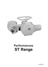
ST <strong>INTELLI+</strong> motorization systems are multi-turn actuators resulting from many years of experience in valve systems<br />
remote control.<br />
Functions to set up, check and control the actuator are included in <strong>INTELLI+</strong>.<br />
All settings and configurations are carried out from outside without opening the covers.<br />
Do not attempt to open covers so as to avoid humidity ingress in the control system. Only open terminal box cover (fig.2)<br />
just long enough to make connections.<br />
Every actuator is tested, adjusted and checked in works before delivery. It is lubricated for life and designed to operate<br />
in any position or location.<br />
MANUAL HANDWHEEL<br />
All ST <strong>INTELLI+</strong> actuators are provided with an automatic declutching handwheel, with motor drive priority. Operating<br />
direction is normally indicated on the handwheel.<br />
The ST6 actuator includes a handwheel clutch button. In order to operate the actuator manually, turn the arrow of the<br />
button opposite the triangular sign (fig. 1) on the housing (it could be necessary to turn the handwheel by a few degrees<br />
to position the claws). When the motor starts, the button automatically returns to its declutched position.<br />
(fig 1) (fig 2)<br />
ELECTRICAL CONNECTIONS<br />
local/remote/ stop selector<br />
and OK in menu<br />
✱<br />
display<br />
handwheel<br />
open, close button and scrolling up<br />
and down the menu<br />
a) Check the power supply characteristics.<br />
In 3 phase, the order in phase is not important. <strong>INTELLI+</strong> automatically corrects the direction of rotation.<br />
b) Open terminal box (fig. 2), connect power and control circuitry, check wiring.
3 LOCAL CONTROL<br />
Local control is used to drive the actuator without the help of an external control circuit. A local selector allows to choose<br />
between remote or local and off. The button for local control open/close allows to operate the actuator in the appropriate<br />
direction. Local stop is done by a momentary rotation of the local/remote selector.<br />
A display gives the valve open percentage.<br />
20% OPEN<br />
A black square in right corner informs of presence of an alarm<br />
(see para. 16.2 how to read alarm type).<br />
4 REMOTE CONTROL<br />
Remote control of an actuator equipped with the <strong>INTELLI+</strong> can be done from an external voltage supply or an internal<br />
voltage supply.<br />
Inputs on the board are completely isolated by opto-isolators.<br />
Pulse commands (with self-holding) require 4 wires connected to the customer terminal board : Common, stop, open<br />
and close. If the stop button is not used, do not connect the STOP wire, open (or close) contact must be maintained<br />
to operate the actuator.<br />
4.1 Dry contact control<br />
In case of dry contact control, a jumper must be fitted across customer terminals 31-32.<br />
30<br />
31<br />
32<br />
33<br />
34<br />
35<br />
36<br />
Pulse remote command<br />
(self-holding)<br />
STOP<br />
CLOSE<br />
OPEN<br />
4.2 Voltage control<br />
Remote control can be done either in AC or DC voltage.<br />
For lower voltages, from 10 to 55V, use common terminal 31.<br />
For higher voltages, from 55 to 250V, use common terminal 30.<br />
Caution : never connect voltages higher than 55V on common terminal 31.<br />
30<br />
31<br />
32<br />
33<br />
34<br />
35<br />
36<br />
10 - 55 V<br />
CLOSE<br />
OPEN<br />
5 NAVIGATING IN THE MENU<br />
30<br />
31<br />
32<br />
33<br />
34<br />
35<br />
36<br />
30<br />
31<br />
32<br />
33<br />
34<br />
35<br />
36<br />
To cancel self-holding<br />
do not connect terminal 34<br />
Remote command<br />
without self-holding<br />
55 - 250 V<br />
Buttons are normally used to operate the actuator electrically. To set<br />
up and adjust the unit, go to MENU mode as follows :<br />
- set selector to local<br />
- hold the button to local stop while simultaneously actuating the<br />
right-hand button upwards then downwards.<br />
MENU<br />
The display reads :<br />
exit setup<br />
To read the menu, actuate the blue button upwards or downwards<br />
which causes the menu items to scroll on the bottom line of the<br />
display.<br />
CLOSE<br />
OPEN<br />
CLOSE<br />
OPEN<br />
STOP<br />
5
6<br />
MENU<br />
exit setup<br />
language<br />
check<br />
set up<br />
change<br />
exit setup<br />
MENU<br />
language<br />
check<br />
set up<br />
change<br />
exit setup<br />
When the desired item is displayed, actuate the red button (local stop) to OK. The item is then displayed in upper case<br />
on the 1st line and the list of the sub-menu can be checked on the 2nd line.<br />
Main menu items :<br />
Language : used to choose the display language.<br />
Check : used to read all the parameters and configuration of the actuator. No change is possible. Access requires no<br />
password.<br />
Set up : used to adjust the actuator on the valve. If a password has been stored, this password will be required for<br />
access.<br />
Change : used to change the actuator configuration. If a password has been stored, this password will be required for<br />
access.<br />
Exiting the menu<br />
It is possible to exit the menu at any time by setting the red button to OFF.<br />
However, to store the changes made in the CHANGE menu, the menus must be exited by selecting return until the<br />
(change ok ?) message is displayed.<br />
Select (no change) and confirm by OK to retain the original values.<br />
6 SELECTING THE DISPLAY LANGUAGE<br />
Select language in the MENU and confirm by OK.<br />
Select the desired language and confirm by OK.<br />
7 PASSWORD<br />
To access the change or set up menus, a password is required to<br />
continue.<br />
By default, no password is entered and confirming by OK provides<br />
access to the change or set up menus.<br />
The user may decide to use a password to protect access to changes.<br />
Creating a password<br />
See section : creating or changing the password (para 18)<br />
Entering the password<br />
To enter the password, at the prompt<br />
CODE ?<br />
Enter the 1st digit using the blue button then confirm by OK.<br />
Enter the 2nd digit using the blue button then confirm by OK.<br />
Enter the 3rd digit using the blue button then confirm by OK.<br />
If the code is correct, access is authorized.<br />
Confirm by OK.<br />
LANGUAGE<br />
français<br />
english<br />
deutsch<br />
Select ➨ Confirm ➨<br />
Select then confirm<br />
TORQUE<br />
return<br />
torque setting<br />
measured torque<br />
closing mode<br />
return<br />
Select return then<br />
click on ok to confirm<br />
CHANGE<br />
return<br />
activity<br />
commands<br />
torque<br />
data sheet<br />
Select return then<br />
click on ok to confirm<br />
ok<br />
CHANGE<br />
(change ok ?)<br />
(no change)<br />
Confirm the change<br />
by clicking on ok<br />
LANGUAGE<br />
français<br />
english<br />
deutsch<br />
USER CODE<br />
OK<br />
CODE ?<br />
0<br />
USER CODE<br />
OK<br />
ok<br />
ok<br />
ok
8 ADJUSTING AN ACTUATOR ON A VALVE<br />
The SET UP menu is used to set the open and closed positions after the actuator is installed on the valve. Setting can<br />
be achieved manually by selecting the open and closed positions, or automatically. In automatic mode, the actuator<br />
operates and stops under the effect of a load limiter at the end positions. The <strong>INTELLI+</strong> then determines the stop positions.<br />
To avoid a stop under the effect of the load limiter, or choose the stop positions, use the manual setting procedure.<br />
8.1 Manual setting<br />
Select set up in the MENU and confirm by OK.<br />
Select closing mode in the SET UP menu and confirm by OK.<br />
Choose to close the valve based on torque or based on position and<br />
confirm by OK.<br />
Select close direction and confirm by OK.<br />
Choose the normal closing direction (clockwise, generally) and<br />
confirm by OK.<br />
Select position setting and confirm by OK.<br />
Select valve closed ? to achieve setting in the closed position and<br />
confirm by OK.<br />
When (no) is displayed confirm by OK.<br />
The display is as follows :<br />
Place the valve in the closed position either using the handwheel or<br />
electric control.<br />
Observe the closing mode selected above, i.e. close up to the load<br />
limiter for closing based on torque, and without triggering the load<br />
limiter for closing based on position.<br />
When the position is achieved, do a local stop to return to the menu.<br />
When (yes) is displayed confirm by OK.<br />
If in doubt, select (no) and repeat the procedure.<br />
Position ok is displayed. Continue by OK.<br />
The next step is setting of the open position.<br />
When valve open ? is displayed, confirm by OK.<br />
When (no) is displayed, confirm by OK.<br />
The display is as follows :<br />
Set the valve in open position either using the handwheel or using<br />
electric control. Check that the actuator will not go to mechanical stop.<br />
When the position is achieved, do a local stop to return to the menu.<br />
When (yes) is displayed, confirm by OK.<br />
If in doubt, select (no) and repeat the procedure.<br />
Position ok is displayed. Continue by OK.<br />
Upon completing of setting, the stroke is displayed.<br />
Return to control mode after confirming by OK.<br />
8.2 Automatic setting<br />
Select set up in the MENU and confirm by OK.<br />
Select closing mode in the SET UP menu and confirm by OK.<br />
Choose to close the valve based on torque or based on position and<br />
confirm by OK.<br />
When close direction is displayed, confirm by OK.<br />
Choose the normal closing direction (clockwise, generally)) and<br />
confirm by OK.<br />
When position setting is displayed, confirm by OK.<br />
SET UP<br />
return<br />
closing mode<br />
close direction<br />
position setting<br />
return<br />
POSITION SETTING<br />
return<br />
valve closed ?<br />
valve open ?<br />
automatic<br />
return<br />
close with knob<br />
back = local stop<br />
Remark : At this stage of setting operations,<br />
the buttons used to navigate<br />
through the menu are again active to<br />
control the actuator. Hold the button until<br />
the desired position is achieved. No selfhold<br />
is provided during setting operations.<br />
position ok<br />
open with knob<br />
back = local stop<br />
measured stroke<br />
19 mm<br />
ok<br />
ok<br />
Remark : to immediately stop the<br />
cycle during automatic setting and<br />
return to the menu, use the local<br />
stop command. The setting procedure<br />
is then cancelled.<br />
7
8<br />
Select automatic in the POSITION SETTING menu.<br />
After confirming by OK the automatic setting cycle starts.<br />
The actuator detects the end positions by triggering the load limiter<br />
then positions itself at mid-stroke to test its inertia in both directions<br />
of rotation.<br />
The <strong>INTELLI+</strong> determines the 0 and 100% stop positions taking<br />
account of the set up closing type and the actuator inertia.<br />
Upon completion of setting, the stroke is displayed.<br />
Return to control mode after confirming by OK.<br />
9 POSITION SIGNAL AND POSITIONER<br />
Position signal<br />
According to the actuator equipment, a voltage or current position signal may be available.<br />
No setting is necessary, as the signal is set automatically when setting the 0 to 100% position.<br />
See para. 19 for more details.<br />
Positioner<br />
According to the actuator equipment, it may be operated in regulationfrom a control signal ( e.g. : 4 - 20 mA).<br />
No setting is necessary, as the signal is set automatically to the 0 to 100% position setting.<br />
To check positioning locally, local control must be set up from 0 to 100% in increments (see para. 10.3).<br />
After the setting up is completed and returning to local control mode, the display reads the opening position and the<br />
control in %.<br />
Using the blue button, increase or decrease the control % and check that the actuator follows the requested position.<br />
For remote control, either in automatic (e.g. : 4 - 20 mA) mode, or in on/off mode, use an auxiliary command programmed<br />
as AUTO/ON-OFF.<br />
This auxiliary command enables you to select automatic or on/off control (see para. 10.2)<br />
See para. 20 for more details, in particular for dead band setting, as required.<br />
10 COMMANDS<br />
See above the description of standard remote commands (para. 4). A description of additional control facilities follows.<br />
10.1 Remote control by single contact<br />
The actuator can be controlled by a single external contact.<br />
- Contact closed : valve opening<br />
- Contact open : valve closing<br />
The actuator must be set up as "priority to open" (see para. 10.4).<br />
30<br />
31<br />
32<br />
33<br />
34<br />
35<br />
36<br />
Opening by single<br />
contact closing<br />
OPEN<br />
The reverse control setting is possible :<br />
- Contact closed : valve closing<br />
- Contact open : valve opening<br />
30<br />
31<br />
32<br />
33<br />
34<br />
35<br />
36<br />
Closing by single<br />
contact closing<br />
CLOSE<br />
In this case, the actuator must be set up as "priority to close" (see para. 10.4).<br />
measured stroke<br />
19 mm<br />
Configuration : priority to open Configuration : priority to close<br />
ok
10.2 Auxiliary remote commands<br />
Two additional remote commands are available and can be set up.<br />
30<br />
31<br />
32<br />
33<br />
34<br />
35<br />
36<br />
37<br />
38<br />
These commands can be assigned to special functions.<br />
Select change in the MENU and confirm by OK.<br />
Select commands in the CHANGE menu and confirm by OK.<br />
Select aux. command 1 or aux. command 2 in the COMMANDS<br />
menu and confirm by OK.<br />
Select a command using the blue button.<br />
By default aux. command 1 is assigned to local command inhibition<br />
and aux. command 2 to emergency command close.<br />
Description of commands :<br />
STOP<br />
CLOSE CLOSE<br />
OPEN OPEN<br />
aux. command 1 aux. command 1<br />
aux. command 2<br />
30<br />
31<br />
32<br />
33<br />
34<br />
35<br />
36<br />
37<br />
38<br />
❡ local/ remote : substitutes for the local/remote selector of the actuator<br />
and is used to remotely enable either remote control or local<br />
control.<br />
After confirming by OK the contact status must be selected for this<br />
command to be achieved :<br />
Confirm by OK.<br />
To check the menu<br />
without making changes,<br />
in the main<br />
menu, select check<br />
instead of change.<br />
actuator<br />
terminal<br />
❡ local + remote / remote : same definition as above, but local and remote control can be enabled simultaneously.<br />
❡ local command inhibit : the local command inhibit is remotely controlled. This command inhibits the local opening<br />
and closing commands, and enables remote commands, even if the local/remote selector of the actuator is set to local.<br />
After confirming by OK, the operator needs to decide to retain local<br />
stop or not. As standard, local stop and general stop remain possible<br />
at the actuator. To also inhibit local stop and general stop, select local<br />
off (no).<br />
After confirming by OK, the contact status must be selected for this<br />
command to be achieved (as described above).<br />
Confirm by OK.<br />
❡ open, close inhibit : this command is used to inhibit opening or closing<br />
of the actuator.<br />
For example, a main valve equipped with a by-pass valve must open<br />
only if the by-pass valve is already open. A by-pass valve opening<br />
limit-switch can then inhibit opening of the main valve as long as the<br />
limit-switch is not actuated.<br />
After confirming by OK, the contact status must be selected for this<br />
command to be achieved (as described above).<br />
Confirm by OK.<br />
37<br />
aux. command 1<br />
55 - 250 V<br />
10 - 55 V<br />
aux. command 2<br />
AUX. COMMAND 1<br />
(no assigned)<br />
(local/remote)<br />
(local + remote/remote)<br />
(local command inhibit)<br />
(open inhibit)<br />
(close inhibit)<br />
(auto/on-off)<br />
(ESD close)<br />
(ESD open)<br />
(ESD stop)<br />
LOCAL/REMOTE<br />
contact (c) = remote<br />
contact (o) = remote<br />
selector local/remote<br />
1st choice : close contact = remote commands<br />
2nd choice : open contact = remote commands<br />
LOC CMD INHIBIT<br />
local off (yes)<br />
local off (no)<br />
LOC CMD INHIBIT<br />
contact (c) = inhibit<br />
contact (o) = inhibit<br />
OPEN INHIBIT<br />
contact (c) = inhibit<br />
contact (o) = inhibit<br />
9
10<br />
❡ auto/on-off : for an actuator used in regulation with positioner function,<br />
it is possible to issue remote commands via a continuous signal<br />
(ex : 4 - 20 mA) or via opening/closing/stop commands. The auto/onoff<br />
command is used to switch over from one type of command to<br />
another.<br />
After confirming by OK, the contact status must be selected for this<br />
command to be achieved (as described above).<br />
Confirm by OK.<br />
❡ ESD close, open, stop : the ESD (Emergency Shut Down) is an<br />
emergency remote command, which overrides all other commands.<br />
According to the valve operation, the emergency command will be an<br />
opening, closing or immediate stop.<br />
After confirming by OK, the contact status must be selected for this<br />
command to be achieved (as described above).<br />
Confirm by OK.<br />
10.3 Local command<br />
As standard, the local command is self-held (a pulse is enough to achieve an opening or closing command).<br />
To override the self-hold feature (the opening or closing command must be held during actuation) :<br />
Select change in the MENU and confirm by OK.<br />
Select commands in the CHANGE menu and confirm by OK.<br />
Select local command in the COMMANDS menu and confirm by OK.<br />
Choose (maintained) and confirm by OK.<br />
For local command by increments from 0 to 100 %, choose (0 - 100%). In this case, the command assumes the current<br />
position value and will be displayed under the position. The blue button can then be used to change the command<br />
value in 1% increments.<br />
10.4 Local stop<br />
In standard, it is possible to stop the actuator locally, even if the selector local/remote is on remote position. To inhibit<br />
a local stop when the selector is on remote position, select local stop in the CHANGE menu and choose (no).<br />
10.5 Open or close priority<br />
As standard, there are no open or close priorities. Priorities are used :<br />
ð to reverse the direction of travel during actuation, without the need for a stop command. In this case an open and close<br />
priority is required.<br />
ð give priority to a direction of travel : if the actuator receives 2 simultaneous open and close commands, and an open<br />
priority has been selected, the actuator operates in the open direction.<br />
ð to achieve single contact commands (see para. 10.1).<br />
Select change in the MENU and confirm by OK.<br />
Select commands in the CHANGE menu and confirm by OK.<br />
Select priority in the COMMANDS menu and confirm by OK.<br />
Choose (open), (close) or (open and close) and confirm by OK.<br />
10.6 Fault tolerance ESD<br />
As standard, the protection devices are active and therefore stop the<br />
actuator in case of defect.<br />
In the case of an emergency command (see description of aux. commands<br />
1 or 2), it is possible to bypass certain protection devices to<br />
achieve operation even in the presence of defects.<br />
Select change in the MENU and confirm by OK.<br />
Select commands in the CHANGE menu and confirm by OK.<br />
Select fault tolerance esd in the COMMANDS menu and confirm by OK.<br />
AUTO / ON - OFF<br />
contact (c) = auto<br />
contact (o) = auto<br />
ESD CLOSE<br />
contact (c) = command<br />
contact (o) = command<br />
Note : the emergency command is not possible when the local/remote selector is set to "OFF".<br />
FAULT TOLERAN. ESD<br />
return<br />
(no thermal overload)<br />
(100% torque)<br />
return<br />
Several items can be selected. Each time a selection is made, the brackets disappear and a star appears opposite the<br />
selection.<br />
To cancel the selection, confirm by OK.
11 LOCAL IR LINK COMMUNICATION<br />
The actuator is equipped with a two-way (read and write) IR link used to communicate with a laptop computer by means<br />
of an IR module connected to the laptop RS232 port.<br />
An IR kit is available for this connexion. The kit also includes the CD-ROM for the communication program to be loaded<br />
in the PC.<br />
This IR module can be clipped to the actuator window for easy communication even if the window orientation is not<br />
adequate.<br />
The cable lenght is 2 m (an extension is available as an option).<br />
The CD-ROM software provides on-screen access to all the <strong>INTELLI+</strong> functions. It is also used to load instantaneously<br />
preset configurations and to acquire the torque/position graph of the last electrical actuation.<br />
For more details, see the software handbook enclosed with the CD-ROM.<br />
Access by IR communication is only possible if the actuator is not in menu mode. To CHANGE or SET UP, the unit<br />
must be set to local mode (i.e. the local / remote selector must be set to local). In this case, the IR link overrides<br />
control by buttons.<br />
After communication is established, IR (for infrared) is displayed in the upper right-hand corner of the actuator display.<br />
12 SETTING AND READING TORQUE VALUES<br />
12.1 Closing mode<br />
As standard, the actuator closes based on position. The settings for the actuator to close based on torque can be changed<br />
in the SET UP menu, however, it is possible to do so in the CHANGE menu :<br />
Select change in the MENU and confirm by OK.<br />
Select torque in the CHANGE menu and confirm by OK.<br />
Select closing mode in the TORQUE menu and confirm by OK.<br />
Choose on (torque) and confirm by OK.<br />
12.2 Setting the torque<br />
The actuator is delivered with a torque limiting system set in accordance<br />
with the order.<br />
If the torque limiter is triggered in operation, check :<br />
❡ that the valve stem is clean and well lubricated<br />
❡ that the valve stem does not jam in the actuating nut<br />
❡ that the packing gland of the valve is not too tight<br />
If the torque needs to be increased, and further to the valve manufacturer's<br />
approval, proceed as follows :<br />
Select change in the MENU and confirm by OK.<br />
Select torque in the CHANGE menu and confirm by OK.<br />
Select torque setting in the TORQUE menu and confirm by OK.<br />
Select the desired setting and confirm by OK.<br />
Increment or decrement the value using the blue button. When holding<br />
the button, the digit scrolling motion is accelerated.<br />
Description of the torque limiting feature :<br />
All torque values are expressed in percent. 100 % corresponds to the<br />
actuator max. setting. The corresponding value in Nm is indicated on<br />
the actuator identification plate.<br />
- closing % : limits the torque during closing<br />
- close tight % : this option only appears if closing must be based on<br />
torque. In this case, the sealing torque applied to the valve seat may<br />
be different from the torque limiting during closing.<br />
- open breakout % : this option only appears if closing must be based<br />
on torque. In this case, torque limiting at valve seat separation may be<br />
different (in general greater) than torque limiting during opening.<br />
If setting is greater than 100%, the display reads no limitation which<br />
amounts to shunting the load limiter at beginning of opening.<br />
- opening % : limits torque during opening<br />
To check the menu<br />
without making changes,<br />
in the menu, select<br />
check instead of change.<br />
TORQUE SETTING<br />
return<br />
closing %<br />
close tight %<br />
open breakout %<br />
opening %<br />
return<br />
CLOSING %<br />
(100)<br />
Remark : after changing<br />
the sealing torque<br />
(valves closing based<br />
on torque) the actuator<br />
must be reset.<br />
Reminder : to store<br />
changes, exit the<br />
menus by hitting return<br />
until the (change ok ?)<br />
message is displayed.<br />
11
12<br />
12.3 Reading the measured torque values and comparing them with original torque values<br />
At each electrical actuation, the max. resistive torque values are measured<br />
and may be checked.<br />
It is possible to store the torque values from an actuation to subsequently<br />
compare them to the torque values from the last electrical<br />
actuation.<br />
Select change in the MENU and confirm by OK.<br />
Select torque in the CHANGE menu and confirm by OK.<br />
Select measured torque in the TORQUE menu and confirm by OK.<br />
Select the desired torque and confirm by OK.<br />
The display provides the max. torque measured during the last electrical<br />
actuation.<br />
(nota: actuations during setting are not stored)<br />
If the torque values of a previous electrical actuation have been stored,<br />
they may be read on the next line for reference.<br />
Example : in the case shown above, the torque stored during an initial<br />
actuation was 12% and the torque during the last actuation was 18%.<br />
These two values can be compared to take preventive maintenance<br />
action, as required.<br />
Storing electrical actuation torque values<br />
To store the torque values of an electrical actuation in the menu,<br />
select save then choose :<br />
torque ➨ ref (yes). torque values marked ref then take the last electrical<br />
actuation torque values. In case of error, select again<br />
torque ➨ ref (no). The reference torque values will be restored.<br />
The values will only actually be stored in memory after exiting the<br />
CHANGE menu and validating (change ok ?).<br />
Torque display<br />
Select this option to read on the actuator display on a permanent<br />
basis the instantaneous torque simultaneously with the position.<br />
13 CUSTOMIZING REMOTE INDICATIONS<br />
13.1 Relays<br />
Signals indicating the status of the actuator are transmitted by bistable<br />
relays. Each relay can be set up according to a list of available<br />
options. As standard, the <strong>INTELLI+</strong> is equipped with 4 bistable relays.<br />
3 additional monostable relays (the contact is open when the relay is<br />
de-energized) can be added as an option. The equipment is factoryset<br />
in accordance with the order. To change the setting, proceed as<br />
follows :<br />
Select change in the MENU and confirm by OK.<br />
Select signaling in the CHANGE menu and confirm by OK.<br />
Select the relay in the SIGNALING menu and confirm by OK.<br />
Choose the contact type, i.e. the contact status when no action and<br />
confirm by OK.<br />
Choose the desired function(s) :<br />
Several items can be selected for the same relay.<br />
Each time a selection is made, the brackets disappear and a star ♠<br />
appears opposite the selection.<br />
To cancel the selection, confirm again by OK.<br />
To check the menu<br />
without making changes,<br />
in the menu, select check<br />
instead of change.<br />
MEASURED TORQUE<br />
return<br />
closing %<br />
close tight %<br />
open breakout %<br />
opening %<br />
save<br />
torque display<br />
return<br />
CLOSING %<br />
18<br />
réf. 12<br />
SAVE<br />
torque ➨ ref (no)<br />
torque ➨ ref (yes)<br />
20 % OPEN<br />
TORQUE 12 %<br />
Display in command mode<br />
SIGNALING<br />
return<br />
relay 1<br />
relay 2<br />
relay ...<br />
RELAY 1<br />
(open contact)<br />
(close contact)<br />
RELAY 1<br />
return<br />
♠ valve open<br />
(valve closed)<br />
(torque limit open)<br />
(....
List : Détails<br />
♠ valve open confirms that the valve is open<br />
(valve closed) confirms that the valve is closed<br />
(torque limit open) torque limiter action in the opening direction<br />
(torque limit closed) torque limiter action in the closing direction<br />
(from x% to y%) ( 1 ) intermediate limit switch<br />
(selector in local) selector status<br />
(selector in remote) selector status<br />
(selector in off) selector status<br />
(running) ( 2 ) the actuator is actuated<br />
(opening) ( 2 ) the actuator is actuated in the opening direction<br />
(closing ) ( 2 ) the actuator is actuated in the closing direction<br />
(emergency command) the actuator receives an emergency command<br />
(stop mid-travel) the actuator is at a stop, neither open nor closed<br />
(power on) the actuator is normally powered<br />
(thermal overload) the motor thermal relay has tripped<br />
(jammed valve) actuation could not be completed due to excess torque<br />
(lost phase) in three-phase, a phase is missing<br />
(lost signal) 4-20 mA lost signal (if positioner option installed)<br />
(handwheel action) the handwheel has been actuated since the last electrical actuation<br />
(bus command) ( 3 ) if field bus option installed, this relay is assigned to an external command<br />
Certain selections offer additional options :<br />
( 1 ) (from x% to y%)<br />
After confirming by OK, choose the contact action range :<br />
Select x% and confirm by OK.<br />
Increment or decrement the value using the blue button.<br />
Select y% and confirm by OK.<br />
Increment or decrement the value using the blue button.<br />
Confirm by OK.<br />
( 2 ) (running)<br />
(opening)<br />
(closing)<br />
After confirming by OK, choose whether the contact must be held or<br />
blinking :<br />
Confirm by OK.<br />
( 3 ) (bus command)<br />
This function is only applicable with the field bus communication option installed. In this case, relays are useless for<br />
signaling as signaling is routed over the field bus. These relays can however be used for commands in the actuator<br />
environment, with the commands sent from the control room over the field bus and relayed by the actuator.<br />
14 CUSTOMIZING THE FAULT RELAY<br />
Fault signaling is transmitted by a changeover relay normally energized, which breaks when de-energized or if the<br />
actuator is unavailable. This relay can be set up according to a list of options. The relay is factory set in accordance with<br />
the order. To change set-up, proceed as follows :<br />
Select change in the MENU and confirm by OK.<br />
Select signaling in the CHANGE menu and confirm by OK.<br />
Select fault relay in the SIGNALING menu and confirm by OK.<br />
FROM X% TO Y%<br />
return<br />
x %<br />
y %<br />
return<br />
X %<br />
(0)<br />
Y %<br />
(100)<br />
RUNNING<br />
hold signal<br />
blinker<br />
FAULT RELAY<br />
return<br />
power off<br />
fuse<br />
thermal overload<br />
....<br />
13
14<br />
Including additional faults :<br />
Non-modifiable included faults are shown without brackets, options are between brackets and selected options are<br />
denoted by a star ♠.<br />
To cancel the selection again, confirm by OK.<br />
List : Détails :<br />
power off control circuit power lost<br />
fuse fuse blown<br />
thermal overload thermal relay has tripped<br />
lost phase in three-phase, a phase is missing<br />
locked rotor the motor is locked<br />
(jammed valve) actuation could not be completed due to excess torque<br />
♠ selector in local local/remote select set to local<br />
♠ selector in off local/remote select set to off<br />
(emergency command) the actuator receives an emergency command<br />
(command inhibit) the actuator receives a command inhibit<br />
(overtravel) position overshoot > 5% after motor shutdown<br />
(lost signal) 4 - 20 mA signal lost (if positioner option installed)<br />
15 TIMING CONTROL DURING ACTUATION<br />
The <strong>INTELLI+</strong> contains a timing module used to reduce the actuator operating speed, for example to protect a pipe<br />
against pressure surges.<br />
When an opening or closing command is sent, a timer alternately turns the motor on and off. The valve actuation time<br />
may therefore be very long. This time is adjustable on site.<br />
Settings in the opening and closing directions are independent.<br />
It is also possible to apply timing only on part of the stroke, and the rest of the stroke is covered at normal speed.<br />
The setting only consists in indicating the total desired time, and the <strong>INTELLI+</strong> calculates the on and off times.<br />
Select change in the MENU and confirm by OK.<br />
Select timer in the CHANGE menu and confirm by OK.<br />
Select operating time and confirm by OK.<br />
Indicate the actuation time at normal actuator speed.<br />
Increment or decrement the value using the blue button.<br />
When holding the button, the digit scrolling motion is accelerated.<br />
Confirm by OK.<br />
Select timer open time and confirm by OK.<br />
Indicate the total time desired for valve opening and confirm by OK.<br />
Select timer close time and confirm by OK.<br />
Indicate the total time desired for valve closing and confirm by OK.<br />
To cancel the timer function : check that the timer opening and<br />
timer closing times are not greater than the travel time.<br />
To apply timing only to part of the stroke : select temporized zone<br />
and confirm by OK.<br />
In order to start opening timing at a given position only select open :<br />
start % and confirm by OK. Increment or decrement the value using<br />
the blue button until the desired position is achieved between 0 and<br />
100 % and confirm by OK. Proceed in the same way with the other<br />
values, which determines an opening temporized zone and a closing<br />
temporized zone.<br />
To apply timing to the complete stroke, check the default values :<br />
open : start % (0) close : start %(100)<br />
open : end %(100) close : end % (0)<br />
TIMER<br />
return<br />
operating time<br />
timer open time<br />
timer close time<br />
temporized zone<br />
return<br />
OPERATING TIME<br />
(0)<br />
TIMER OPEN TIME<br />
(0)<br />
TEMPORIZED ZONE<br />
return<br />
open : start %<br />
open : end %<br />
close : start %<br />
close : end %<br />
return<br />
OPEN : START %<br />
(0)
16 MONITORING ACTUATOR ACTIVITY<br />
16.1 Activity<br />
Select change in the MENU and confirm by OK.<br />
Select activity in the CHANGE menu and confirm by OK.<br />
Select number of starts or running time to obtain the accumulated<br />
figures since actuator manufacturing. A partial counter is available<br />
and can be reset by the user.<br />
Select total to obtain the total number of starts.<br />
To reset the partial counter, select reset partial (only appears when<br />
in the change menu), then choose yes or no.<br />
Starts last 12 hours : this data corresponds to the number of actuator starts during the last twelve hours and provides<br />
information on the actuator recent activity. It is of interest to know whether the actuator has not been excessively<br />
operated, when used for regulation purposes, for example.<br />
handwheel action : indicates whether the handwheel has been actuated since the last electrical actuation (only deviations<br />
in excess of 10% of stroke are stored).<br />
16.2 Alarms<br />
Alarms are used for fault location purposes. They are not permanent and disappear when the fault is cleared. A black<br />
square is displayed in the right-hand corner of the display to indicate the presence of an alarm.<br />
To read the alarms :<br />
Select check in the MENU and confirm by OK.<br />
Select alarms in the CHECK menu and confirm by OK.<br />
Using the blue button, scroll through any alarms present.<br />
List of alarms : Détails :<br />
locked motor open motor locked in the opening direction<br />
locked motor close motor locked in the closing direction<br />
torque sensor torque sensor power supply fault<br />
position sensor position sensor power supply fault<br />
direc of rot open opening direction of rotation discrepant<br />
direc of rot close closing direction of rotation discrepant<br />
overtravel position overshoot >5% after motor shutdown<br />
too many starts starting rate exceeding the actuator class average<br />
lost phase in three-phase, a phase is missing<br />
lost signal 4 - 20 mA signal lost (if positioner option installed)<br />
thermal overload the motor thermal relay has tripped<br />
too long travel the total stroke requested exceeds the encoder capacity<br />
pumping actuator pumping detected<br />
config. memory configuration data memory fault<br />
activity memory activity data memory fault<br />
base memory base memory fault<br />
torque switch electrical contact fault (according to equipment)<br />
travel switch electrical contact fault (according to equipment)<br />
24V auxiliary auxiliary power supply fault for external circuits (terminals 32-33)<br />
17 ACCESSING THE DATA SHEET<br />
Select change in the MENU and confirm by OK.<br />
Select data sheet in the CHANGE menu and confirm by OK.<br />
To check the menu without<br />
making changes, in the menu,<br />
select check instead of change.<br />
ACTIVITE<br />
retour<br />
nombre de démarrages<br />
temps de marche<br />
démarrages / 12 heures<br />
action volant<br />
retour<br />
NBRE DEMARRAGES<br />
total<br />
partiel<br />
RAZ partiel<br />
To check without making<br />
changes, in the menu, select<br />
check instead of change.<br />
15
16<br />
Valve tag number :<br />
Select valve tag number to read or write the valve tag number.<br />
Use the blue button to change the 1 st character and confirm by OK.<br />
Then change each character in the same way.<br />
After all characters have been entered, confirm by OK until the system<br />
returns to the menu.<br />
actuator number : this is the actuator serial number.<br />
entry code : used to create or change the password : see below<br />
"Creating or changing the password"<br />
characteristics : parameters necessary for correct operation for the<br />
actuator (see details below)<br />
The following data only appear in the CHECK menu.<br />
operating class : indicates whether the actuator is designed for<br />
off/on operation, class III regulation or class II regulation<br />
manufacture date : indicates the ex-works manufacturing date<br />
software version : installed software release<br />
Details of the characteristics menu<br />
motor : this option specifies whether the motor is three-phase, single-phase or DC (manufacturer data)<br />
locked motor/s : indicates the time the motor is locked while energized before removal of power supply (manufacturer<br />
data)<br />
reverse delay/ms : indicates the stop timeout following reversion of direction of rotation (manufacturer data)<br />
ratio position system : indication of the reduction ratio between output shaft and position sensor, to display the stroke<br />
in number of revolutions (manufacturer data)<br />
ext gear ratio 1/ : indicates the reduction ratio of an additional reduction gear. For example, a gear with ratio 1/120,<br />
enter 120. Stroke will be now in degrees.<br />
thread mm : indicates the pitch of a linear system allowing the stroke to be displayed in mm, rather than in number of<br />
revolutions<br />
stroke : indicates the stroke measured when adjusting the valve<br />
18 CREATING OR CHANGING THE PASSWORD<br />
Select change in the MENU and confirm by OK.<br />
Select data sheet in the CHANGE menu and confirm by OK.<br />
Select entry code in the DATA SHEET menu and confirm by OK.<br />
Enter the 1 st digit using the blue button<br />
Then confirm by OK.<br />
Enter the 2 nd digit using the blue button<br />
Then confirm by OK.<br />
Enter the 3 rd digit using the blue button<br />
Then confirm by OK.<br />
DATA SHEET<br />
return<br />
valve tag number<br />
actuator number<br />
entry code<br />
operating class<br />
manufacture date<br />
characteristics<br />
software version<br />
return<br />
VALVE TAG NUMBER<br />
MOV55VV<br />
CHARACTERISTICS<br />
return<br />
motor<br />
locked motor/s<br />
reverse delay/ms<br />
ratio position system<br />
ext gear ratio 1/<br />
thread mm<br />
stroke<br />
return<br />
ENTRY CODE<br />
(000)<br />
The new code will only be taken into account after exiting the change menu and confirming the request (change ok?).<br />
Take note of this code to be capable to access again the change menu.<br />
If the code has been lost or forgotten : after turning the unit off, open the control unit<br />
- Remove the connexion box cover<br />
- Unscrew the 4 screws adjacent to the cover screws<br />
- Extract the electrical block by a few centimeters to gain access to the side of the printed<br />
circuit board<br />
- Move jumper 1 on the printed circuit board from position A to position B then turn the unit<br />
back on. This operation resets the password to zero.<br />
- Fit the jumper back to original position A otherwise entering a new password will be<br />
impossible.<br />
cav1<br />
B A
19 USING THE ANALOG SIGNAL POSITION AND TORQUE REMOTE INDICATION<br />
(ACCORDING TO EQUIPMENT)<br />
19.1 position remote indication<br />
According to the equipment, the actuator can remotely indicate its position (0 - 100 %) by sending an analog signal.<br />
The output signals are set automatically to the actuator 0 - 100 % stroke which eliminates the need for setting the remote<br />
indication signal.<br />
The remote indication signals are fully isolated from the <strong>INTELLI+</strong> circuits.<br />
The available signals are :<br />
4 - 20 mA, 0 - 20 mA, 4 - 12mA or 12 - 20 mA and 0 - 10 V (distinct output)<br />
To choose the signal variation direction and the type :<br />
Select change in the MENU and confirm by OK.<br />
Select position in the CHANGE menu and confirm by OK.<br />
Select opt position signal in the POSITION menu and confirm by OK.<br />
Choose the signal variation direction and confirm by OK.<br />
Choose the type of signal and confirm by OK.<br />
19.2 Torque signal<br />
The signal representing the 0 to 100 % actuator torque is also available in 4 -20 mA (0% = 4mA, 100% = 15 mA).<br />
The torque signals are fully isolated from the <strong>INTELLI+</strong> circuits, except that the minus is common with the position<br />
remote indication signal.<br />
See electrical diagram for connection of these signals.<br />
20 USING THE EQUIPMENT AS A POSITIONER FROM AN ANALOG CONTROL SIGNAL<br />
(ACCORDING TO EQUIPMENT)<br />
20.1 Input signal<br />
According to the equipment, the actuator can operate as a positioner, from an analog signal (4 - 20 mA for example).<br />
The input signals are set automatically to the actuator 0 - 100 % stroke which eliminates the need for setting the actuator<br />
operating range.<br />
The input signals are fully isolated from the <strong>INTELLI+</strong> control circuits and the torque and position remote indication<br />
signals.<br />
<strong>Control</strong> signal :<br />
4 - 20 mA, 0 - 20 mA, 4 - 12mA ,12 - 20 mA ou 0 - 10 V<br />
To choose the signal direction of variation and the type :<br />
Select change in the MENU and confirm by OK.<br />
Select positioner in the CHANGE menu and confirm by OK.<br />
Select signal range in the POSITIONER menu and<br />
confirm by OK.<br />
Choose the signal direction of variation and confirm by OK.<br />
Choose the type of signal and confirm by OK.<br />
In the case of 0 - 10 V signal, also check on the GAMB board located<br />
in the FPX control unit that the microswitches are set to Volt.<br />
OPT POSIT SIGNAL<br />
signal (➬) opening<br />
signal (➮) opening<br />
SIGNAL (➬) OPENING<br />
(4 -20 mA)<br />
(0 - 20 mA) / (0 - 10 V)<br />
(4 -12 mA)<br />
(12 -20 mA)<br />
SIGNAL RANGE<br />
signal (➬) opening<br />
signal (➮) opening<br />
SIGNAL (➬) OPENING<br />
(4 -20 mA)<br />
(0 - 20 mA) / (0 - 10 V)<br />
(4 -12 mA)<br />
(12 -20 mA)<br />
mA<br />
Volt<br />
17
18<br />
20.2 Dead band setting<br />
This is a factory setting, but it is possible to adjust the dead band.<br />
If the dead band is too narrow, the actuator may pump. If the dead band is too wide, positioning is less accurate.<br />
In the POSITIONER menu, select dead band % and confirm by OK.<br />
Increment or decrement the value using the blue button.<br />
Confirm by OK.<br />
20.3 Fail-safe position<br />
With a 4-20 mA input signal, it is possible to set up a fail-safe position in case the control signal is lost.<br />
As standard, the function is active and the actuator remains in position in the case of signal loss.<br />
It is possible to choose opening or closing.<br />
In the POSITIONER menu, select lost signal and confirm by OK.<br />
Select the desired function and confirm by OK.<br />
20.4 Proportional pulses<br />
This is a control mode where the position is reached by pulses. This mode is used for relatively stable regulations allowing<br />
the actuator inertia to be partly compensated. The actuator is cycled more often than by a conventional command.<br />
In the POSITIONER menu, select proportional pulse and confirm by OK.<br />
Select (no) or (yes) and confirm by OK.<br />
21 USING FIELD BUS CONTROL (ACCORDING TO EQUIPMENT)<br />
The field bus interface can be used to control and transmit all data over a single line. A specific documentation specifies<br />
how each actuator can be addressed and provides a list of addresses for accessing each command or data.<br />
Fail-safe position<br />
In case of loss of communication, it is possible to set up a fail-safe position.<br />
As standard, the function is active, and the actuator remains in position in the case of a loss of communication.<br />
It is possible to choose opening or closing.<br />
Select change in the MENU and confirm by OK.<br />
Select fieldbus in the CHANGE menu and confirm by OK.<br />
Select lost communication in the FIELDBUS menu and confirm by OK.<br />
Select the desired function and confirm by OK.<br />
22 PROTECTION BY FUSES<br />
Accessibility :<br />
- turn the actuator off<br />
- remove the connexion box cover<br />
- unscrew the 4 screws adjacent to the cover screws<br />
- extract the electrical block by a few centimeters to gain access to the side of the fuse holders<br />
- unscrew the caps and replace the fuses as required<br />
Characteristics of the fuses :<br />
FU1 : transformer primary fuse 6,3 x 32mm - 0,5A - 500V<br />
FU2 : transformer secondary fuse 5 x 20mm - 0,5A<br />
FU3 : transformer secondary fuse 5 x 20mm - 0,05A<br />
23 OPERATING FAULTS<br />
23.1 <strong>INTELLI+</strong><br />
LOST SIGNAL<br />
(closing)<br />
(stayput)<br />
(opening)<br />
LOST COMMUNIC<br />
(closing)<br />
(stayput)<br />
(opening)<br />
In case of doubt as to correct operation of the unit, first set the local/remote selector to local, and actuate the opening<br />
and closing commands.
PROBLEM CAUSE CORRECTIVE ACTION<br />
The display is off Actuator power supply Check the power supply voltage (terminals L1, L2, L3 in<br />
three-phase). The voltage is indicated on the identification<br />
plate.<br />
No operation The display is in menu<br />
mode<br />
No operation and an<br />
icon as a key or the<br />
acronym ESD is<br />
displayed<br />
The actuator is operating<br />
in local, not in<br />
remote mode<br />
The actuator is operating<br />
in remote, not in<br />
local mode<br />
Fuse blown Check the fuses and replace as required.<br />
Set the local/remote selector to off then to local to switch to<br />
control mode (display : %position)<br />
An IR link is established If an IR link has been established (IR is displayed in the<br />
upper right-hand corner of the display) it is not possible to<br />
use the control buttons. Remove the IR link.<br />
Motor thermal relay has<br />
tripped<br />
A local control inhibit<br />
command or an emergency<br />
command is present<br />
Local/remote selector<br />
set to local or off<br />
Contact control : no voltage<br />
across terminals<br />
32 and 33<br />
Voltage control : voltage<br />
not adapted to input<br />
Local/remote selector<br />
set to remote or off<br />
A local control inhibit<br />
command is present or<br />
the local/remote selection<br />
is performed remotely<br />
A black square is displayed in the upper right-hand corner<br />
of the display to indicate the presence of an alarm. Go to<br />
menu/check/alarms to check whether a motor thermal<br />
relay alarm is present. The actuator will again be available<br />
after the motor has cooled down.<br />
In the commands/aux. commands 1 or 2 menu, check whether<br />
an inhibit command (or emergency command) is set<br />
up or not, as well as the status of the contact (open or closed)<br />
to perform this command remotely. Then check that<br />
the connexion made on the client terminal strip does not<br />
correspond to an inhibit command (or emergency command).<br />
Ex. : if the configuration is set to aux. command 1, loc cmd<br />
inhibit and contact (o) = inhibit it is then necessary to<br />
establish a remote contact on terminal 37 to cancel the<br />
inhibit.<br />
Set the local/remote selector to remote.<br />
Check the client terminal strip for a shunt across terminals<br />
31 and 32.<br />
Check presence of an alarm "24V auxiliary"<br />
Check fuse FU3 on the <strong>INTELLI+</strong> board.<br />
Check voltage control connexion :<br />
10 to 55 V voltage : terminal 31<br />
55 to 250 V voltage : terminal 30<br />
Set the local/remote selector to local.<br />
In the commands / aux. commands 1 or 2 menu, check<br />
whether an inhibit is set up, as well as the contact status<br />
(open or closed) to perform this command remotely. Then<br />
check that the connection made on the client terminal strip<br />
does not correspond to a command inhibit.<br />
Ex. if the configuration is set to aux. command 1, loc cmd<br />
inhibit and contact (o) = inhibit it is then necessary to<br />
establish a remote contact on terminal 37 to cancel the<br />
inhibit.<br />
19
20<br />
PROBLEM CAUSE CORRECTIVE ACTION<br />
The actuator is not<br />
rotating in the correct<br />
direction of rotation<br />
Entering the menu is<br />
impossible<br />
The parameters in the<br />
menu can not be<br />
changed<br />
The changes made<br />
have not been taken<br />
into account.<br />
The handwheel action<br />
has not been detected<br />
The excessive number<br />
of starts alarm is<br />
displayed<br />
Actuator jerky operation<br />
during actuation<br />
Incorrect configuration In the change / position / closing direction menu, check:<br />
Clockwise or counterclockwise closing.<br />
The motor has been<br />
reverse-wired and rotates<br />
in the reverse direction<br />
(when replacing the<br />
motor)<br />
Selector set to remote<br />
or off or presence of a<br />
local command inhibit<br />
No change can be<br />
made to the check<br />
menu.<br />
During modification, no<br />
change is actually<br />
made. To be stored, the<br />
modification must be<br />
validated<br />
The handwheel action<br />
has been detected<br />
since the last electrical<br />
actuation and provided<br />
the actuator remains<br />
normally powered.<br />
Detection only indicates<br />
a motion in excess of<br />
10% of stroke<br />
The <strong>INTELLI+</strong> monitors<br />
the number of starts<br />
performed during the<br />
last 12 hours and compares<br />
it with that of the<br />
actuator operating class<br />
The timing function has<br />
been set up<br />
When replacing the motor, wire markings must be observed.<br />
In case of doubt, check that the motor is rotating in the<br />
correct direction. Reversing the motor direction of rotation<br />
is by switching over wires 2 and 3 of the motor terminal<br />
strip.<br />
Access to the menu by means of the buttons is only possible<br />
in local mode, i.e. with the selector set to local, in the<br />
absence of a local command inhibit. Set selector to local<br />
and see above for checks to be performed on aux. commands<br />
1 and 2.<br />
Go to the change menu.<br />
Some parameters can only be checked.<br />
After changes have been made, select return then OK as<br />
many times as necessary to read :<br />
(change ok?)<br />
Confirm by OK to store the changes<br />
Repeat detection under correct conditions.<br />
This alarm does not limit actuator operation, but indicates<br />
intensive operation of the actuator. If the start rate again<br />
becomes compliant with the unit intended use, the alarm<br />
disappears.<br />
This function, set up in the timer menu is used, at the user's<br />
request, to increase the actuator actuation time.
23.2 OPTION POSITIONNEUR<br />
Below are a few additions applicable to the control version by positioner analog signal.<br />
The actuator is operating<br />
in local opening<br />
closing command<br />
mode, not in positioner<br />
mode<br />
The actuator is operating<br />
as a positioner<br />
in local mode, not in<br />
remote mode<br />
24 MAINTENANCE<br />
All ST actuators are lubricated for life and therefore require no specific maintenance. The condition of the valve stem<br />
and its nut must nevertheless be checked periodically to make sure they are clean and well lubricated. We recommend<br />
that a programm of periodic maintenance should be drawn up for actuators that are operated infrequently.<br />
25 STORAGE<br />
Introduction<br />
The actuator includes electric equipment as well as grease lubricated gear stages. In spite of the weatherproof enclosing,<br />
oxidation, jamming and other alterations are possible if actuator is not correctly stored.<br />
Storage<br />
The actuators should be stored under a shelter in a clean, dry place and protected from constant changes in temperature.<br />
Avoid placing the actuators directly on the floor. If the place of storage is humid it is recommended that you connect<br />
and give supply to the actuator to have the heater effect.<br />
Check that the temporary sealing plugs of the cable entries are correctly installed. In case of humidity, use metal plugs.<br />
Make sure that the covers and the boxes are well closed to ensure weatherproof sealing.<br />
<strong>Control</strong> after storage<br />
Local / remote selector<br />
set to local or off<br />
An Auto / On Off command<br />
is present and<br />
inhibits positioner use<br />
Incorrect adaptation of<br />
the input signal<br />
The local / remote<br />
selector is set to local<br />
The input signal is<br />
defective<br />
The signal polarity is<br />
not compliant<br />
1. Storage not exceeding one year :<br />
Maintain a visual check of electric equipment<br />
Operate manually the buttons, selectors, etc ... to insure the correct mechanical function<br />
Operate apparatus manually<br />
Verify the correct grease consistency<br />
Follow instructions included in the commissioning instructions heregiven<br />
2. Storage exceeding one year :<br />
Long time stocking change grease consistency. The grease thin thickness on stem dries up. Remove all the old grease<br />
of the actuator mechanical parts and replace with new grease.<br />
Maintain a visual check of electric equipment.<br />
Operate manually the buttons, selectors, etc ... to insure the correct mechanical function.<br />
Follow instructions included in the commissioning instructions heregiven.<br />
Set the local / remote selector to remote to use the positioner.<br />
In the commands / aux. commands 1 or 2, check whether<br />
auto / On Off is set up or not as well as the contact status<br />
(open or closed) to perform this command remotely. Then<br />
check that the connection made at the client terminal strip<br />
does not correspond to an On Off command.<br />
Ex.: if the configuration is set to aux. command 1, (auto /<br />
on-off) and contact (c)= auto it is then necessary to establish<br />
a contact remotely on terminal 37 to switch to auto<br />
command.<br />
Check the configuration of the input signal in the menu and<br />
the setting of the switches on the positioner board (see<br />
para. 20.1)<br />
Set selector to remote<br />
Check the reference signal using a milliammeter connected<br />
in series (terminal 70)<br />
Check that the signal (+) is present on terminal 70.<br />
21
22<br />
26 CHECK MENU FLOWCHART<br />
MENU<br />
MENU<br />
EXIT SET UP<br />
LANGUAGE<br />
CHECK<br />
SET UP<br />
CHANGE<br />
EXIT SET UP<br />
RETURN<br />
ACTIVITY<br />
ALARMS<br />
COMMANDS<br />
TORQUE<br />
DATA SHEET<br />
POSITION<br />
POSITIONER<br />
SIGNALING<br />
TIMER<br />
FIELDBUS<br />
no alarm<br />
return<br />
aux. command 1<br />
aux. command 2<br />
local command<br />
local stop<br />
priority<br />
fault tolerance ESD<br />
return<br />
valve tag number<br />
actuator number<br />
operating class<br />
manufacture date<br />
characteristics<br />
software version<br />
return<br />
signal range<br />
dead band %<br />
lost signal<br />
proportional pulse<br />
return<br />
operating time<br />
timer open time<br />
timer close time<br />
temporized zone<br />
return<br />
lost communication<br />
return<br />
number of starts<br />
running time<br />
starts last 12 h<br />
handwheel action<br />
return<br />
torque setting<br />
measured torque<br />
closing mode<br />
torque sensor<br />
return<br />
close direction<br />
opt position signal<br />
sensor model<br />
return<br />
relay 1<br />
relay 2<br />
relay 3<br />
relay 4<br />
relay 5<br />
relay 6<br />
relay 7<br />
fault relay
27 SET UP AND CHANGE MENU FLOWCHART<br />
MENU<br />
MENU<br />
EXIT SET UP<br />
LANGUAGE<br />
CHECK<br />
SET UP<br />
CHANGE<br />
EXIT SET UP<br />
RETURN<br />
CLOSING MODE<br />
CLOSE DIRECTION<br />
POSITION SETTING<br />
RETURN<br />
RETURN<br />
ACTIVITY<br />
COMMANDS<br />
TORQUE<br />
DATA SHEET<br />
POSITION<br />
POSITIONER<br />
SIGNALING<br />
TIMER<br />
FIELDBUS<br />
on (position)<br />
on (torque)<br />
return<br />
valve closed ?<br />
valve open ?<br />
automatic<br />
return<br />
(change ok ?)<br />
(no change)<br />
return<br />
aux. command 1<br />
aux. command .2<br />
local command<br />
local stop<br />
priority<br />
fault tolerance ESD<br />
return<br />
valve tag number<br />
entry code<br />
characteristics<br />
return<br />
signal range<br />
dead band %<br />
lost signal<br />
proportional pulse<br />
return<br />
operating time<br />
timer open time<br />
timer close time<br />
temporized zone<br />
return<br />
lost communication<br />
(cw)<br />
(ccw)<br />
return<br />
number of starts<br />
running time<br />
starts last 12 h<br />
handwheel action<br />
return<br />
torque setting<br />
measured torque<br />
closing mode<br />
return<br />
close direction<br />
opt position signal<br />
return<br />
relay 1<br />
relay 2<br />
relay 3<br />
relay 4<br />
relay 5<br />
relay 6<br />
relay 7<br />
fault relay<br />
23
AUSTRALIA BEACON Pty<br />
beacon@atkinscar.com.au 25 South Street Rydalmere<br />
NSW 2116 AUSTRALIA<br />
Tel : + 61 2 9841 2345<br />
Fax : + 61 2 9684 6439<br />
AUSTRIA IPU ING PAUL UNGER<br />
Hardtmuthgasse 53<br />
1100 WIEN<br />
Tel : +43 1 6024549<br />
Fax : +43 1 6032943<br />
BELGIUM BERNARD BENELUX SA<br />
christian.baert@ Rue Saint-Denis, 135<br />
bernard-benelux.com 1190 BRUXELLES<br />
Tel : +32 2 3434122<br />
Fax : +32 2 3472843<br />
CHINA TADELLA LIMITED<br />
tadella@public.east.cn.net 5th floor, Ping-an mansion,<br />
23 Financial street Xicheng district<br />
BEIJING - CHINA 100032<br />
Tel : +86 10 6621 0395 / 0396 / 0397<br />
Fax : +86 10 6621 0399<br />
DENMARK ARMATEC A/S<br />
www.armatec.dk Mjolnersvej 4-8<br />
DK 2600 Glostrup<br />
Tel : +45 46 96 00 00<br />
Fax : +45 46 96 00 01<br />
EGYPT E.K.E.O.<br />
3 El-Emam Hassan Maamoun 6th Zone<br />
Naser City - CAIRO<br />
Tel : +202 27 40 550 / 559<br />
Fax : +202 27 40 558<br />
FINLAND OY SOFFCO AB<br />
www.soffco.fi Karapellontie 11<br />
FIN-02610 ESPOO<br />
Tel : +358 9 54 04 620<br />
Fax : +358 9 54 04 62 50<br />
GERMANY DEUFRA GMBH<br />
bernard@deufra.de Kasinostrasse 22<br />
53840 TROISDORF<br />
Tel : +49 2241 98340<br />
Fax : +49 2241 983444<br />
INDIA INSTRUMENTATION LTD<br />
Kanjikode West 678623<br />
PALGHAT-KERALA<br />
Tel : +91 491 566127 / 566128<br />
Fax : +91 491 566135 / 566240<br />
ITALY PECHINEY ITALIA S.P.A.<br />
derman_vanni@pechiney.com Viale F. Restelli 5<br />
20124 MILAN<br />
Tel : +39 2 668931<br />
Fax : +39 2 6081513<br />
JAPAN PECHINEY<br />
n.suzuki@pechineyj.co.jp 29 Fl. Shinjuku Mitsui Bldg<br />
2-1-1 Nishi Shinjuku, Shinjuku-ku, Tokyo<br />
163-0429 JAPON<br />
Tél : (03) 3349 6658<br />
Fax : (03) 3349 6770<br />
KOREA (Rep of) SEWON INTERNATIONAL CO<br />
sewonkim@unitel.co.kr 1501, Korea Business Center<br />
1338-32 Seocho Dong, Seocho-ku SEOUL<br />
Tel : +82 2 581 72 29 / 72 27<br />
Fax : +82 2 581 72 28<br />
MALAYSIA ACTUATION & CONTROLS ENGINEER<br />
tcmeng@pc.jaring.my 7, Jalan Bayu 2/5 - Taman Perindustrian.<br />
Tampoi Jaya - 81100 JOHOR BAHRU<br />
Tel : +60 7 2350277 / 2350281<br />
Fax : +60 7 2350280 / 2350285<br />
NETHERLAND BERNARD BENELUX NV<br />
Sophialaan 5<br />
3542 AR UTRECHT<br />
Tel : +31 30 24 14 700<br />
Fax : +31 30 24 13 949<br />
NORWAY G. FAGERBERG NORGE<br />
www.fagerberg.no Postboks 536 - HØDEN<br />
1522 MOSS<br />
Tel : +47 69 26 50 44<br />
Fax : +47 69 26 73 33<br />
POLAND MARCO<br />
U1. Nowolipki 23/2<br />
01-006 WARSZAWA<br />
Tel : +48 22 63 68 626<br />
Fax : +48 22 63 63 577<br />
PORTUGAL PINHOL, GOMES & GOMES LDA.<br />
pinhol@mail.telepac.pt Avenida 24 de Julho, 174<br />
1300 LISBOA<br />
Tel : +351 1 39 71 165<br />
Fax : +351 1 39 06 858<br />
SINGAPORE ACTUATION &CONTROLS ENG. (ASIA)<br />
trisom@mbox3.singnet.com.sg Block 3029A UBI RD 3<br />
#01-97 SINGAPORE 408661<br />
Tel : +65 74 27 248<br />
Fax : +65 74 29 857<br />
SOUTH AFRICA (Rep) ACTUATOR TECHNICAL SERVICES<br />
actuator@jhbmail.co.za Patrick RD, Jet Park<br />
KEMPTON PARK 1620<br />
Tel : +27 11 397 47 56<br />
Fax : +27 11 397 47 68<br />
SOUTH-EAST ASIA BERNARD SOUTH-EAST ASIA<br />
pinvidic@ksc7.th.com 25, soi Sang-Ngen<br />
Sukhumvit 55, Sukhumvit Road<br />
Bangkok 10110. Thailand<br />
Tel : +66 2 391 46 51<br />
Fax : +66 2 391 34 90<br />
SPAIN BERNARD SERVOMOTORES<br />
bernardservo@wanadoo.es C/ Valentin Beato, 11 - 1°D<br />
28037 MADRID<br />
Tel : +34 91 3041139<br />
Fax : +34 91 3273442<br />
SWEDEN G. FAGERBERG AB<br />
www.fagerberg.se Postbox 12105<br />
40241 GOETEBORG<br />
Tel : +46 31 69 37 00<br />
Fax : +46 31 69 38 00<br />
SWITZERLAND INOXLINE<br />
Binningerstrasse 86<br />
CH - 4123 ALSCHWILL<br />
Tel : +41 61 481 51 00<br />
Fax : +41 61 481 50 05<br />
TURKEY CIMTEK A.S.<br />
Kenedy Caddesi Yalim Sok N°3<br />
KAVAKLIDERE<br />
06660 - ANKARRA<br />
Tel : +90 312 41 74 900<br />
Fax : +90 312 41 89 716<br />
UNITED-KINGDOM ZOEDALE Plc<br />
www.zoedale.co.uk Stannard Way / Priory Business Park<br />
enquiries@zoedale.co.uk BEDFORD MK44 3WG<br />
Tel : +44 12 83 28 32<br />
Fax : +44 12 83 28 00<br />
USA BERNARD CONTROLS Inc<br />
www.bernardcontrols.com 15740 Park Row, Suite 100<br />
richard.upton@bernardcontrols.com HOUSTON - TEXAS 77084<br />
Tel : +1 281 578 66 66<br />
Fax : +1 281 578 27 97<br />
L. BERNARD 4, rue d'Arsonval - BP 91 - 95505 GONESSE Cedex France<br />
Tel. +33.1.34.07.71.00 - Fax. +33.1.34.07.71.01<br />
E-mail : mail@bernard-actuators.com - Internet . http://www.bernard-actuators.com