Installation Manual COLOR GPS PLOTTER GP-7000 - Furuno USA
Installation Manual COLOR GPS PLOTTER GP-7000 - Furuno USA
Installation Manual COLOR GPS PLOTTER GP-7000 - Furuno USA

You also want an ePaper? Increase the reach of your titles
YUMPU automatically turns print PDFs into web optimized ePapers that Google loves.
<strong>Installation</strong> <strong>Manual</strong><br />
<strong>COLOR</strong> <strong><strong>GP</strong>S</strong> <strong>PLOTTER</strong> <strong>GP</strong>-<strong>7000</strong><br />
SAFETY INSTRUCTIONS ............................................................................i<br />
SYSTEM CONFIGURATION ....................................................................... ii<br />
EQUIPMENT LISTS....................................................................................iii<br />
1. INSTALLATION ..................................................................................... 1<br />
1.1 Display Unit .................................................................................................................. 1<br />
1.2 Antenna Unit.................................................................................................................4<br />
2. WIRING .................................................................................................. 5<br />
3. ADJUSTMENTS .................................................................................... 9<br />
3.1 Choosing Position Data Source....................................................................................9<br />
3.2 Choosing Port I/O Format...........................................................................................11<br />
3.3 Calibrating NMEA Depth, Speed and Water Temperature Data ................................13<br />
3.4 Waypoint, Route Format.............................................................................................14<br />
3.5 External Event Format................................................................................................14<br />
3.6 C-link (primary and secondary stations) .....................................................................15<br />
PACKING LIST........................................................................................ A-1<br />
OUTLINE DRAWINGS............................................................................. D-1<br />
INTERCONNECTION DIAGRAM ............................................................ S-1<br />
www.furuno.co.jp
SAFETY INSTRUCTIONS<br />
WARNING<br />
ELECTRICAL SHOCK HAZARD<br />
Do not open the equipment<br />
unless totally familiar with<br />
electrical circuits and<br />
service manual.<br />
Only qualified personnel<br />
should work inside the<br />
equipment.<br />
Turn off the power at the switchboard<br />
before beginning the installation.<br />
Fire or electrical shock can result if the<br />
power is left on.<br />
i<br />
CAUTION<br />
Observe the following compass safe<br />
distances to prevent interference to a<br />
magnetic compass:<br />
Display<br />
unit<br />
Use the power cable supplied with the<br />
installation materials.<br />
Use of other power cables may cause fire<br />
or damage the equipment.<br />
Use the proper fuse.<br />
Standard Steering<br />
compass compass<br />
0.70 m 0.45 m<br />
Use of the wrong fuse may damage the<br />
equipment.<br />
Organic solvent<br />
Do not apply paint, anti-corrosive sealant<br />
or contact spray to coating or plastic<br />
parts of the equipment.<br />
Those items contain organic solvents that<br />
can damage coating and plastic parts,<br />
especially plastic connectors.
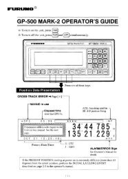
SYSTEM CONFIGURATION<br />
Power Source<br />
12-24 VDC<br />
ANTENNA UNIT <strong>GP</strong>A-017<br />
DISPLAY UNIT<br />
<strong>GP</strong>-<strong>7000</strong><br />
How to remove the hard cover<br />
Place your thumbs at the center<br />
of the cover, and then lift the cover<br />
while pressing it with your thumbs.<br />
ii<br />
NMEA1 and NMEA2 ports:<br />
Radar, autopilot, video sounder,<br />
temperature indicator, etc.<br />
PC/NMEA IN port:<br />
PC, NMEA device, buzzer<br />
: Standard<br />
: Option<br />
: User Supply
EQUIPMENT LISTS<br />
Standard supply<br />
Name Type Code No. Qty Remarks<br />
Display Unit <strong>GP</strong>-<strong>7000</strong> — 1<br />
Antenna Unit<br />
<strong>GP</strong>A-017<br />
iii<br />
— 1<br />
<strong>Installation</strong><br />
Materials*<br />
CP14-06400 000-041-183 1<br />
Accessories* FP20-01100 000-042-239 1<br />
Spare Parts* SP14-03201 004-371-980 1<br />
* See packing list at back of this manual.<br />
Optional equipment<br />
System also available<br />
without antenna (for boats<br />
which already have an<br />
appropriate antenna)<br />
Name Type Code No. Qty<br />
<strong><strong>GP</strong>S</strong> Antenna <strong>GP</strong>A-017S 000-040-541<br />
Antenna Cable Set CP20-01700 004-372-110 30 m, antenna cable extension<br />
CP20-01710 004-372-120 50 m, antenna cable extension<br />
Right Angle Antenna<br />
Base<br />
No.13-QA330 000-803-239<br />
L-angle Antenna<br />
Base<br />
No.13-QA310 000-803-240 For mounting antenna unit<br />
Antenna Base for<br />
Rail Mounting<br />
No.13-RC5160 000-806-114<br />
Mast Mounting Kit CP20-01111 004-365-780 For mounting antenna unit on a<br />
mast<br />
Cable Assy.<br />
MJ-A6SPF0012-050C 000-154-053-10 6P – 6P, 5 m<br />
MJ-A6SPF0012-100C 000-154-037-10 6P – 6P, 10 m<br />
MJ-A6SPF0003-050C 000-154-054-10 6P, 5 m<br />
MJ-A7SPF0007-050C 000-154-028-10 For connecting a PC, 5 m, with<br />
7P connector
1. INSTALLATION<br />
1.1 Display Unit<br />
The display unit may be mounted on a desktop, overhead or flush mounted in a console.<br />
Mounting considerations<br />
Choose a mounting location for the display unit considering the following points:<br />
• Choose a location where the controls can be easily operated.<br />
• Leave sufficient space around the unit to facilitate checking and maintenance. See the<br />
outline drawing at the back of this manual for recommended maintenance space.<br />
• Locate the unit out of direct sunlight because of heat that can build up inside the cabinet.<br />
• The operating temperature range is -15°C to 55°C (5°F to 131°F).<br />
• Locate the unit well away from exhaust gases and other active gases.<br />
• The location should be well ventilated.<br />
• Choose a location where shock and vibration are minimal.<br />
• Be sure the mounting location is strong enough to support the weight of the unit,<br />
particularly in overhead mounting. If necessary reinforce the mounting location.<br />
• A magnetic compass will be affected if the display unit is placed too close to the compass.<br />
Observe the following compass safe distances to prevent deviation to the compass.<br />
Standard compass, 0.70 m, Steering compass, 0.45 m.<br />
1
Mounting<br />
Desktop, overhead mounting<br />
1. Fix the hanger to the mounting location with four self-tapping screws (5X20). See the<br />
outline drawing on page D-1 for complete mounting dimensions.<br />
2. Loosely screw the knob bolts into the display unit.<br />
3. Set the display unit to the hanger and tighten the knob bolts.<br />
4. Attach the hard cover to the display unit to protect the LCD.<br />
FIXING<br />
HOLE<br />
Unit: mm<br />
Display unit, mounting dimensions for desktop or overhead mounting<br />
2
Flush mounting<br />
If the thickness of the console is 11-14 mm, use the washer<br />
head screws (M4X20) supplied with the installation materials.<br />
If it is thicker than those dimensions, the length of the screws<br />
should be the thickness of the console plus 7.3 mm ±1.5 mm.<br />
The length of the threaded portion to be inserted to the display<br />
unit should not exceed 7 mm (B≤7).<br />
1. Prepare a cutout in the mounting location using the template provided.<br />
2. Fix the display unit with six washer head screws (M4X20) provided.<br />
52 80 150<br />
Service<br />
Clearance<br />
Mounting dimensions for flush mounting<br />
3<br />
B A<br />
A: Thickness of console<br />
Unit: mm
1.2 Antenna Unit<br />
Refer to the antenna unit outline drawing at the back of this manual for mounting<br />
instructions.<br />
When selecting a mounting location consider the following points:<br />
• Select a location out of the radar and Inmarsat beams. Those beams will obstruct or<br />
prevent reception of the <strong><strong>GP</strong>S</strong> satellite signal.<br />
• There should be no interfering object within the line-of-sight to the satellites. Objects<br />
within line-of-sight to a satellite, for example, a mast, may block reception or prolong<br />
acquisition time.<br />
• Locate the antenna well away from the antenna of a VHF radiotelephone to prevent<br />
interference.<br />
• Mount the antenna unit as high as possible. Mounting it this way keeps it free of<br />
interfering objects and water spray, which can interrupt reception of <strong><strong>GP</strong>S</strong> satellite signal if<br />
the water freezes.<br />
Note: If the antenna cable is to be passed through a hole in a bulkhead which is too small<br />
to pass the connector, disassemble the connector with radio pincers and a monkey<br />
wrench. After passing the cable through the hole assemble the connector as below.<br />
Clamping Nut<br />
Washer<br />
Gasket<br />
Shield<br />
How to assemble the antenna connector<br />
4<br />
Pin (Solder.)<br />
Housing
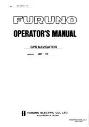
2. WIRING<br />
The figure below shows the basic wiring scheme.<br />
Power source<br />
ANTENNA UNIT<br />
<strong>GP</strong>A-017<br />
Antenna Cable, 10 m<br />
FROM LEFT<br />
PC/NMEA IN: PC, NMEA device, buzzer, AIS<br />
NMEA 2: Radar, autopilot, video sounder,<br />
temperature indicator, etc.<br />
NMEA 1: Same as NMEA 2<br />
Display unit, rear view<br />
The power source is a 12-24 VDC battery. Be sure the power cable is tightly fastened to the power<br />
source and the polarity (plus and minus) is correct. Connect the white lead to the positive terminal<br />
(+) and the black lead to the negative terminal (-).<br />
5<br />
Ground<br />
Power<br />
Source<br />
Black<br />
MJ-A15A3F0013-035-3A,<br />
3.5 m<br />
White<br />
Shield
Ground<br />
Connect the ground wire to the boat's grounding bus. If the unit is not grounded, noise may result.<br />
If noise is a problem on an FRP vessel, fasten a ground plate of 20 cm x 30 cm to the outside of<br />
the ship's hull and connect the ground wire there.<br />
Use a closed-type lug ( ) for the connection on the display unit. Do not use an open-type lug<br />
( ).<br />
Antenna cable<br />
Types of antenna cables<br />
If a longer length of antenna cable is required, use the optional antenna cable set, which is available<br />
in 30 and 50 m lengths.<br />
Antenna cable<br />
set<br />
CP20-01700 004-372-110<br />
CP20-01710 004-372-120<br />
Connecting the antenna cable<br />
Antenna cable set<br />
Code no. Contents<br />
Antenna Unit<br />
<strong>GP</strong>A-017<br />
Antenna Unit<br />
<strong>GP</strong>A-017S<br />
20 cm<br />
1m<br />
1) Converter cable assy. NJ-T-3DX-1, Code No. 000-123<br />
2) Vinyl tape NO.360 Code No. 000-835-215<br />
3) Connector N-P-8DFB-CF, Code No. 000-156-918-10<br />
4) Self-bonding tape U-tape, Code No. 000-165-833-10<br />
5) Antenna cable assy. 8D-FB-CV*30m*, Code No. 000-117-547<br />
Items 1) - 4) above plus:<br />
Antenna cable assy. 8D-FB-CV*50m*, Code No. 000-117-549<br />
Antenna Cable<br />
10 m<br />
Connection of antenna unit <strong>GP</strong>A-017<br />
ANTENNA CABLE KIT<br />
Conversion Cable<br />
Assy.<br />
Antenna Cable<br />
30 m or 50 m<br />
Attached during installation<br />
(See page 8.)<br />
Connection of antenna cable set on antenna unit <strong>GP</strong>A-017S (option)<br />
6<br />
Connector fitted at factory.<br />
Connect at<br />
rear of<br />
display unit<br />
Connector fitted at factory<br />
1 m<br />
Connect at<br />
rear of<br />
display unit
Waterproofing the connector<br />
If you are using the extension cable, connect the cable and then wrap the connector with<br />
self-vulcanizing tape and then vinyl tape to waterproof it. Bind ends of vinyl tape with cable<br />
ties (local supply) to prevent unraveling.<br />
How to waterproof the connector<br />
7
How to attach N-P-8DFB connector (for extension cable kit)<br />
Outer Sheath<br />
Armor<br />
Dimensions in millimeters.<br />
Inner Sheath Shield<br />
Cover with heat-shrink tubing and heat.<br />
30<br />
Clamping<br />
Nut<br />
50 30<br />
Flat Washer<br />
10<br />
Gasket Clamp<br />
(reddish<br />
brown)<br />
Aluminum Foil<br />
Trim shield here.<br />
Insulator<br />
Trim aluminum<br />
tape foil here.<br />
5<br />
Clamping Nut Pin<br />
Solder through<br />
the hole.<br />
Spacer<br />
Washer 2<br />
Housing<br />
Remove outer sheath and armor by the dimensions<br />
shown left.<br />
Expose inner sheath and shield by the dimensions<br />
shown left.<br />
Cut off insulator and core by 10 mm.<br />
Twist shield end.<br />
Slip on clamping nut, flat washer, gasket and clamp<br />
as shown left.<br />
Fold back shield over clamp and trim.<br />
Cut aluminum foil at four places, 90° from one<br />
another.<br />
Fold back aluminum foil onto shield and trim.<br />
Remove insulator up to edge of washer 2.<br />
Expose the core by 5 mm.<br />
Slip the pin onto the conductor. Solder them together<br />
through the hole on the pin.<br />
Insert the spacer and housing. Screw the clamping<br />
nut into the housing.<br />
(Tighten by turning the clamping nut. Do not tighten<br />
by turning the housing.)<br />
How to attach N-P-8DFB connector<br />
8
3. ADJUSTMENTS<br />
This chapter shows you how to adjust your unit, from the menu. When choosing item or option<br />
from the menu, you may use the [ENTER] knob or the CursorPad ( ). For sake of brevity the<br />
descriptions contained herein use the [ENTER] knob.<br />
3.1 Choosing Position Data Source<br />
If you intend to use a position data from a source other than the internal <strong><strong>GP</strong>S</strong> receiver follow the<br />
procedure below. Otherwise, go to paragraph 3.2.<br />
1. Press the [MENU] key to show the menu bar.<br />
Menu Bar GENERAL <strong>PLOTTER</strong> MAP ALARMS ADVANCED INFO FIND<br />
Menu bar<br />
2. Rotate the [ENTER] knob to choose ADVANCED from the menu bar and then push the<br />
[ENTER] knob.<br />
FIX<br />
NAVIGATE<br />
COMPASS<br />
INPUT/OUTPUT<br />
EXT NMEA<br />
<strong><strong>GP</strong>S</strong> SIMULATION<br />
ECHO SOUNDER SIMULATION On<br />
AIS SETUP<br />
C-MAP WEATHER SERVICE<br />
SYSTEM UPDATE<br />
ADVANCED menu<br />
9
3. Rotate the [ENTER] knob to choose INPUT/OUTPUT and then push the [ENTER] knob.<br />
INTERNAL <strong><strong>GP</strong>S</strong> SETUP<br />
NMEA 1 INPUT NMEA-0183 4800-N81-N<br />
NMEA 1 OUTPUT<br />
NMEA 2 INPUT NMEA-0183 4800-N81-N<br />
NMEA 2 OUTPUT<br />
RS232/NMEA 3 INPUT NMEA-0183 4800-N81-N<br />
RS232C 3 OUTPUT<br />
INPUT 3 MODE RS232C<br />
WPL/RTE FORMAT Standard<br />
EXTERNAL EVENT Off<br />
C-LINK Off<br />
INPUT/OUTPUT menu<br />
4. Rotate the [ENTER] knob to choose INTERNAL <strong><strong>GP</strong>S</strong> SETUP and then push the<br />
[ENTER] knob.<br />
RESTART <strong><strong>GP</strong>S</strong><br />
INTERNAL <strong><strong>GP</strong>S</strong> On<br />
DIFF CORR SOURCE WAAS<br />
WAAS SEARCH Auto<br />
INTERNAL <strong><strong>GP</strong>S</strong> SETUP menu<br />
5. Rotate the [ENTER] knob to choose INTERNAL <strong><strong>GP</strong>S</strong> and then push the [ENTER] knob.<br />
6. Rotate the [ENTER] knob to choose Off or On and then push the [ENTER] knob.<br />
Off: Use external navigator<br />
On: Use internal <strong><strong>GP</strong>S</strong> navigator<br />
7. Press the [MENU] key to close all open windows and erase the menu bar.<br />
Off<br />
On<br />
10
3.2 Choosing Port I/O Format<br />
1. Press the [MENU] key to show the menu bar.<br />
2. Rotate the [ENTER] knob to choose ADVANCED from the menu bar and then push the<br />
[ENTER] knob.<br />
3. Rotate the [ENTER] knob to choose INPUT/OUTPUT and then push the [ENTER] knob.<br />
4. Rotate the [ENTER] knob to choose appropriate INPUT or OUTPUT item and then push the<br />
[ENTER] knob.<br />
NMEA-0183 1200-N81-N<br />
NMEA-0183 4800-N81-N<br />
NMEA-0183 4800-N82-N<br />
NMEA-0183 9600-N81-N<br />
NMEA-0183 9600-O81-N<br />
C-COM<br />
AIS 38400<br />
Disabled<br />
NMEA 1/NMEA 2/<br />
RS232/NMEA 3 Input*<br />
NMEA 1 INPUT, NMEA 1 OUTPUT menus<br />
5. Do one of the following depending on item selected.<br />
Input<br />
1) Rotate the [ENTER] knob to choose appropriate option and then push the [ENTER] knob.<br />
Below is the meaning of the NMEA options. "C-COM" is for connection of a GSM modem.<br />
For details about the GSM modem, see its owner's manual.<br />
2) Press to close the window.<br />
GLL On<br />
VTG On<br />
BWR Off<br />
DBT Off<br />
DPT Off<br />
MTW Off<br />
VHW Off<br />
WCV Off<br />
APA Off<br />
APB On<br />
HDG Off<br />
BOD Off<br />
XTE Off<br />
RMA Off<br />
RMB On<br />
RMC On<br />
GGA Off<br />
HSC Off<br />
AAM Off<br />
GTD Off<br />
MWV Off<br />
ZDA Off<br />
WPL On<br />
RTE On<br />
TLL OUT On<br />
NMEA1/NMEA2/RS232 Output<br />
NMEA-0183 4800-N81-N<br />
1 2 3 4 5 6<br />
1 Data format<br />
2 Baud rate: 1200, 4800, 9600(bps)<br />
3 Parity: N (No parity) or O (Odd parity)<br />
4 Character length (8)<br />
5 Stop bit: 1 or 2<br />
6 X-On/Off (non)<br />
Description of NMEA options<br />
11<br />
RS232CW<br />
NMEA<br />
INPUT 3 MODE*<br />
(Choose format for<br />
PC/NMEA IN port)<br />
*: For AIS, set as below.<br />
RS232/NMEA3 INPUT: "AIS 38400"<br />
INPUT 3 MODE: "RS232C"
Output<br />
1) Rotate the [ENTER] knob to choose appropriate option and then push the [ENTER] knob.<br />
2) Rotate the [ENTER] knob to choose Off or On as appropriate and then push the [ENTER]<br />
knob followed by .<br />
6. Repeat step 5 to set up other ports.<br />
7. Press the [MENU] key to close all open windows and erase the menu bar.<br />
I/O format<br />
Input data, sentence priority<br />
Port I/O format Data sentence Remarks<br />
Input NMEA 1, NMEA 2 IEC-61162-1,<br />
NMEA-0183<br />
Ver. 1.5/2.0/3.0<br />
PC/NMEA IN RS232, and IEC<br />
and NMEA above<br />
Output NMEA 1, NMEA 2 IEC-61162-1,<br />
NMEA-0183<br />
Ver. 1.5/2.0/3.0<br />
PC/NMEA IN RS232<br />
12<br />
See table below.<br />
For NMEA IN, see<br />
table below.<br />
GLL, VTG, BWR, DBT,<br />
DPT, MTW, VHW,<br />
WCV, APA, APB, HDG,<br />
BOD, XTE, RMA,<br />
RMB, RMC, GGA,<br />
HSC, WPL, RTE, TLL,<br />
AAM, GTD, MWV, ZDA<br />
BWR: Rhumb line<br />
Data Sentence priority order Remarks<br />
Speed thru water VHW<br />
True heading HDT, HDG, HDM<br />
Magnetic heading HDT, HDG, HDM<br />
Target position TLL<br />
Radiotelephone target position DSC, DSE<br />
Waypoint data RMB<br />
Depth DPT, DBT<br />
Water temperature MTW<br />
Wind current, speed MWV<br />
Off<br />
On
3.3 Calibrating NMEA Depth, Speed and Water<br />
Temperature Data<br />
NMEA speed, depth and water temperature data may be corrected from the <strong>GP</strong>-<strong>7000</strong> if they<br />
cannot be done from the equipment that outputs the data. Enter a minus value if the actual<br />
value is lower than the NMEA data, or a plus value if the actual value is higher than the<br />
NMEA data. For example, if the actual water temperature is 20° and the water temperature<br />
data output by the sensor is 17°, enter +3(°).<br />
1. Press the [MENU] key to show the menu bar.<br />
2. Rotate the [ENTER] knob to choose ADVANCED from the menu bar and then push the<br />
[ENTER] knob.<br />
3. Rotate the [ENTER] knob to choose EXT NMEA and then push the [ENTER] knob.<br />
DRAFT SETUP +00.0 Ft<br />
SPEED CALIBRATION +00 %<br />
TEMP CALIBRATION +00.00 F<br />
EXT NMEA menu<br />
4. Rotate the [ENTER] knob to choose appropriate item.<br />
DRAFT SETUP: Enter ship’s draft to get NMEA depth from sea surface (instead of<br />
transducer).<br />
SPEED CALIBRATION: Enter offset in percentage points to correct NMEA speed<br />
indication.<br />
TEMP CALIBRATION: Enter offset to correct NMEA water temperature indication.<br />
5. Push the [ENTER] knob. The cursor is selecting the plus sign (or minus sign). If it is<br />
necessary to switch from plus to minus or vice versa, rotate the [ENTER] knob to<br />
choose plus or minus and then push the [ENTER] knob. If not necessary, go to step 6.<br />
6. Push the [ENTER] knob, rotate the [ENTER] knob to set digit and then push the<br />
[ENTER] knob. To clear a line of data, press the [CLR FLD] soft key, which is the third<br />
key from the left of the keys below the screen.<br />
Setting range<br />
Draft setup: -20 - +39.9(ft)<br />
Speed calibration: -50 - +50(%)<br />
Temp calibration: -50 - +50(°F)<br />
7. Set other digits as you did in step 6.<br />
8. Press the [SAVE] soft key, which is the fourth key from the left of the keys below the<br />
screen.<br />
9. If necessary, repeat step 4-8 to choose and set another calibration item.<br />
10. Press the [MENU] key to close all open windows and erase the menu bar.<br />
13
3.4 Waypoint, Route Format<br />
You may transfer waypoint and route data to another <strong>GP</strong>-<strong>7000</strong> series unit or a PC in Standard or<br />
<strong>Furuno</strong> format, via the NMEA1 port, NMEA2 port or PC NMEA IN port.<br />
1. Press the [MENU] key to show the menu bar.<br />
2. Rotate the [ENTER] knob to choose ADVANCED from the menu bar and then push the<br />
[ENTER] knob.<br />
3. Rotate the [ENTER] knob to choose INPUT/OUTPUT and then push the [ENTER] knob.<br />
4. Rotate the [ENTER] knob to choose WPL/RTE FORMAT and then push the [ENTER] knob.<br />
Standard<br />
<strong>Furuno</strong><br />
5. Choose <strong>Furuno</strong> or Standard as appropriate and then push the [ENTER] knob.<br />
Standard: NMEA format WPL and RTE sentences are output when "SEND" is executed to<br />
transfer waypoint list or route list.<br />
<strong>Furuno</strong>: <strong>Furuno</strong> format WPL and RTE sentences are output when "SEND" is executed to<br />
transfer waypoint list or route list. Waypoint color, shape and comment data are sent.<br />
6. Press the [MENU] key to close the menu.<br />
3.5 External Event Format<br />
If the equipment is equipped with an external event switch you may choose what mark is inscribed<br />
on the screen when the switch is pressed. For connection of an external event switch, see the interconnection<br />
diagram.<br />
1. Press the [MENU] key to show the menu bar.<br />
2. Rotate the [ENTER] knob to choose ADVANCED from the menu bar and then push the<br />
[ENTER] knob.<br />
3. Rotate the [ENTER] knob to choose INPUT/OUTPUT and then push the [ENTER] knob.<br />
4. Rotate the [ENTER] knob to choose EXTERNAL EVENT and then push the [ENTER] knob.<br />
Off<br />
WPT<br />
MOB<br />
5. Choose Off, WPT or MOB as appropriate and then push the [ENTER] knob.<br />
Off: No event switch is connected.<br />
WPT: Waypoint is registered at ship's position if the cursor is not displayed, or at cursor position<br />
if the cursor is displayed.<br />
MOB: MOB is registered at ship's position.<br />
6. Press the [MENU] key to close the menu.<br />
14
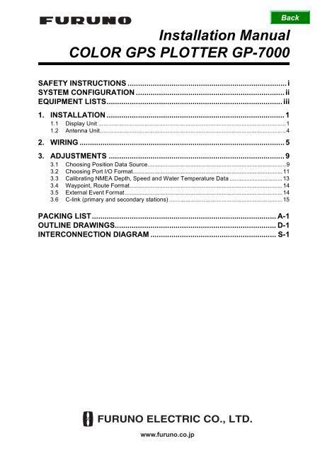
3.6 C-link (primary and secondary stations)<br />
The C-link feature, available when several <strong>GP</strong>-<strong>7000</strong> series units are interconnected via<br />
NMEA ports or PC/NMEA IN ports (see the illustration below), lets you duplicate on<br />
secondary stations the destination set at the primary station. With this feature active<br />
destination may only be set from the primary station.<br />
Primary station<br />
<strong>GP</strong>-<strong>7000</strong><br />
series<br />
Secondary station<br />
<strong>GP</strong>-<strong>7000</strong><br />
series<br />
Secondary station<br />
<strong>GP</strong>-<strong>7000</strong><br />
series<br />
Secondary station<br />
<strong>GP</strong>-<strong>7000</strong><br />
series<br />
NMEA1<br />
NMEA2<br />
PC/NMEA IN<br />
NMEA1<br />
NMEA2<br />
PC/NMEA IN<br />
NMEA1<br />
NMEA2<br />
PC/NMEA IN<br />
NMEA1<br />
NMEA2<br />
PC/NMEA IN<br />
*<br />
*<br />
**<br />
**<br />
Note: Secondary stations cannot<br />
be connected to one another.<br />
15<br />
*: Either port<br />
**: Either port<br />
1. Press the [MENU] key to show the menu bar.<br />
2. Rotate the [ENTER] knob to choose ADVANCED from the menu bar and then push the<br />
[ENTER] knob.<br />
3. Rotate the [ENTER] knob to choose INPUT/OUTPUT and then push the [ENTER] knob.<br />
4. Rotate the [ENTER] knob to choose C-LINK and then push the [ENTER] knob.<br />
Secondary Station<br />
Primary Station<br />
Off<br />
5. Choose Secondary Station, Primary Station or Off as appropriate and then push the<br />
[ENTER] knob.<br />
Secondary Station: This unit is designated as the secondary station. Destination<br />
cannot be set or changed from the secondary station.<br />
Primary Station: This unit is designated as the primary station.<br />
Off: C-link feature is turned off.<br />
Note: When three or more units are installed, designate only one unit as the primary<br />
station. All other units should be designated as secondary stations. If you<br />
designate two units as primary units, the message “Both chart plotters are set as<br />
Primary station” appears and the buzzer sounds.<br />
6. Press the [MENU] key to close the menu.
1/1<br />
14CR-X-9851 -12<br />
<strong>GP</strong>-<strong>7000</strong>/F-E-C-017,<strong>GP</strong>-<strong>7000</strong>/F-E-N-017<br />
PACKING LIST<br />
NAME OUTLINE DESCRIPTION/CODE № Q'TY<br />
NAME OUTLINE DESCRIPTION/CODE № Q'TY<br />
1<br />
ケーブル組品MJ<br />
ユニット UNIT<br />
MJ-A6SPF0003-050C<br />
SIGNAL CABLE ASSEMBLY<br />
000-154-054-10<br />
1<br />
ケーブル組品MJ<br />
MJ-A15A3F0013-035-3A<br />
POWER CABLE<br />
000-145-880-00<br />
図書 DOCUMENT<br />
1<br />
装備要領書<br />
IM*-44290-*<br />
INSTALLATION MANUAL<br />
**<br />
000-149-136-1*<br />
1<br />
操作要領書(英)<br />
OS*-44290-*<br />
空中線部<br />
<strong>GP</strong>A-017<br />
1<br />
ANTENNA UNIT<br />
000-041-403-00<br />
指示器<br />
<strong>GP</strong>-<strong>7000</strong>-E-C<br />
1<br />
DISPLAY UNIT<br />
000-041-184-00 **<br />
予備品 SPARE PARTS SP14-03201<br />
ヒューズ<br />
FGB0-A 125V 3A PBF<br />
FGBO-A 3A AC125V 1<br />
FUSE<br />
000-155-850-10<br />
000-549-063-00<br />
付属品 ACCESSORIES FP20-01100<br />
OPERATOR'S GUIDE<br />
**<br />
000-149-135-1*<br />
1<br />
取扱説明書<br />
OM*-44290-*<br />
OPERATOR'S MANUAL<br />
**<br />
000-149-134-1*<br />
フイルタークリーナー<br />
02-155-1082-1<br />
1<br />
FILTER CLEANER<br />
100-332-651-10<br />
工事材料 INSTALLATION MATERIALS CP14-06400<br />
1<br />
フラッシュマウント型紙<br />
E42-00401-*<br />
1<br />
Fマウントヨウスポンジ<br />
14-074-1032-0<br />
TEMPLATE<br />
000-149-985-1*<br />
FLUSH MOUNTING SPONGE<br />
6<br />
100-323-890-00<br />
M4X20 SUS304<br />
M4X20 SUS304<br />
000-162-652-10<br />
000-804-742-00<br />
5X20 SUS304<br />
5X20 SUS304<br />
000-162-608-10<br />
000-802-081-00<br />
+ナベセムスネジB<br />
WASHER HEAD SCREW<br />
4<br />
+トラスタッピンネジ 1シュ<br />
SELF-TAPPING SCREW<br />
1.コ-ド番号末尾の[**]は、選択品の代表型式/コードを表します。<br />
CODE NUMBER ENDED BY "**" INDICATES THE NUMBER OF TYPICAL MATERIAL.<br />
型式/コード番号が2段の場合、下段より上段に代わる過渡期品であり、どちらかが入っています。 なお、品質は変わりません。<br />
TWO TYPES AND CODES MAY BE LISTED FOR AN ITEM. THE LOWER PRODUCT MAY BE SHIPPED IN PLACE OF<br />
THE UPPER PRODUCT. QUALITY IS THE SAME.<br />
14CR-X-9851<br />
(略図の寸法は、参考値です。 DIMENSIONS IN DRAWING FOR REFERENCE ONLY.)
1/1<br />
14CR-X-9852 -13<br />
<strong>GP</strong>-<strong>7000</strong>/F-E-C,<strong>GP</strong>-<strong>7000</strong>/F-E-N<br />
PACKING LIST<br />
NAME OUTLINE DESCRIPTION/CODE № Q'TY<br />
NAME OUTLINE DESCRIPTION/CODE № Q'TY<br />
1<br />
ケーブル組品MJ<br />
ユニット UNIT<br />
MJ-A15A3F0013-035-3A<br />
POWER CABLE<br />
000-145-880-00<br />
図書 DOCUMENT<br />
1<br />
装備要領書<br />
IM*-44290-*<br />
INSTALLATION MANUAL<br />
**<br />
000-149-136-1*<br />
1<br />
操作要領書(英)<br />
OS*-44290-*<br />
指示器<br />
<strong>GP</strong>-<strong>7000</strong>-E-C<br />
1<br />
DISPLAY UNIT<br />
000-041-184-00 **<br />
予備品 SPARE PARTS SP14-03201<br />
ヒューズ<br />
FGB0-A 125V 3A PBF<br />
FGBO-A 3A AC125V 1<br />
FUSE<br />
000-155-850-10<br />
000-549-063-00<br />
付属品 ACCESSORIES FP20-01100<br />
OPERATOR'S GUIDE<br />
**<br />
000-149-135-1*<br />
1<br />
取扱説明書<br />
OM*-44290-*<br />
OPERATOR'S MANUAL<br />
**<br />
000-149-134-1*<br />
フイルタークリーナー<br />
02-155-1082-1<br />
1<br />
FILTER CLEANER<br />
100-332-651-10<br />
工事材料 INSTALLATION MATERIALS CP14-06400<br />
1<br />
フラッシュマウント型紙<br />
E42-00401-*<br />
1<br />
Fマウントヨウスポンジ<br />
14-074-1032-0<br />
TEMPLATE<br />
000-149-985-1*<br />
FLUSH MOUNTING SPONGE<br />
6<br />
100-323-890-00<br />
M4X20 SUS304<br />
M4X20 SUS304<br />
000-162-652-10<br />
000-804-742-00<br />
5X20 SUS304<br />
5X20 SUS304<br />
000-162-608-10<br />
000-802-081-00<br />
+ナベセムスネジB<br />
WASHER HEAD SCREW<br />
4<br />
+トラスタッピンネジ 1シュ<br />
SELF-TAPPING SCREW<br />
1<br />
ケーブル組品MJ<br />
MJ-A6SPF0003-050C<br />
SIGNAL CABLE ASSEMBLY<br />
000-154-054-10<br />
1.コ-ド番号末尾の[**]は、選択品の代表型式/コードを表します。<br />
CODE NUMBER ENDED BY "**" INDICATES THE NUMBER OF TYPICAL MATERIAL.<br />
型式/コード番号が2段の場合、下段より上段に代わる過渡期品であり、どちらかが入っています。 なお、品質は変わりません。<br />
TWO TYPES AND CODES MAY BE LISTED FOR AN ITEM. THE LOWER PRODUCT MAY BE SHIPPED IN PLACE OF<br />
THE UPPER PRODUCT. QUALITY IS THE SAME.<br />
14CR-X-9852<br />
(略図の寸法は、参考値です。 DIMENSIONS IN DRAWING FOR REFERENCE ONLY.)
Y. Hatai<br />
hatai<br />
2005.12.19<br />
11:57:12<br />
+09'00'
1 2 3<br />
4<br />
*2<br />
空中線部<br />
ANTENNA UNIT<br />
<strong>GP</strong>A-017S<br />
空中線部<br />
ANTENNA UNIT<br />
<strong>GP</strong>A-017<br />
MJ-A6SPF0003-050C,5m,φ6<br />
シロ WHT<br />
クロ BLK<br />
キ YEL<br />
ミドリ GRN<br />
MJ-A6SPF<br />
P<br />
NMEA0183 Ver1.5/2.0/3.0<br />
IEC 61162-1<br />
1<br />
2<br />
3<br />
4<br />
5<br />
6<br />
NMEA1<br />
TD1-A<br />
TD1-B<br />
RD1-H<br />
RD1-C<br />
NC<br />
SHIELD<br />
0.2m<br />
A<br />
P<br />
指示部<br />
DISPLAY UNIT<br />
<strong>GP</strong>-<strong>7000</strong><br />
NJTP-3DXV-1<br />
1m,φ5.3<br />
N-P-8DFB<br />
N-J-3<br />
*3<br />
N-P-8DFB<br />
N-J-3<br />
NJTP-3DXV-1<br />
1m,φ5.3<br />
TNC-J-3<br />
TNC-P-3<br />
8D-FB-CV<br />
30/50m,φ14.3<br />
TNC-P-3<br />
*2<br />
MJ-A6SPF0003-050C,5m,φ6<br />
MJ-A6SPF<br />
MJ-A6SPF0012-050C/100C,5/10m<br />
1 シロ WHT<br />
P<br />
クロ BLK<br />
キ YEL<br />
P<br />
ミドリ GRN<br />
ANT<br />
<strong><strong>GP</strong>S</strong>-SIG<br />
<strong><strong>GP</strong>S</strong>-SHIELD<br />
TNC-P-3<br />
2<br />
3<br />
4<br />
5<br />
6<br />
NMEA2<br />
TD2-A<br />
TD2-B<br />
RD2-H<br />
RD2-C<br />
NC<br />
SHIELD<br />
10m,φ5.5<br />
NMEA0183 Ver1.5/2.0/3.0<br />
IEC 61162-1<br />
*2<br />
MJ-A7SPF0007-050C,5m,φ6<br />
シロ WHT<br />
アオ BLU<br />
キ YEL<br />
ミドリ GRN<br />
MJ-A7SPF<br />
1<br />
P<br />
2<br />
3<br />
P<br />
4<br />
5<br />
6<br />
7<br />
PC/NMEA IN<br />
12-24 VDC<br />
RS232C_TD<br />
RS232C_RD<br />
RD3-H<br />
RD3-C<br />
12V_P<br />
BUZZER<br />
SHIELD<br />
(+)<br />
(-)<br />
SHIELD<br />
MJ-A3SPF<br />
シロ WHT<br />
クロ BLK<br />
3A<br />
1<br />
2<br />
3<br />
MJ-A15A3F0013<br />
3.5m,φ8.0<br />
12-24 VDC<br />
パソコンなど<br />
PC ETC.<br />
B<br />
NMEA0183<br />
Ver1.5/2.0/3.0<br />
キ YEL<br />
ミドリ GRN<br />
P<br />
3<br />
4<br />
7<br />
RD3-H<br />
RD3-C<br />
SHIELD<br />
ブザー<br />
BUZZER<br />
(0.1A)<br />
アカ RED<br />
クロ BLK<br />
5<br />
6<br />
12V_P<br />
BUZZER<br />
BUZZER 6 イベントスイッチ<br />
SHIELD 7<br />
EVENT SW<br />
GND *1<br />
IV-1.25sq.<br />
C<br />
<strong>GP</strong>-<strong>7000</strong><br />
カラー<strong><strong>GP</strong>S</strong>プロッタ<br />
TITLE<br />
E. MIYOSHI<br />
名称<br />
DRAWN<br />
MAY 8, '06<br />
CHECKED<br />
TAKAHASHI.T<br />
相互結線図<br />
<strong>COLOR</strong> <strong><strong>GP</strong>S</strong> <strong>PLOTTER</strong><br />
INTERCONNECTION DIAGRAM<br />
APPROVED<br />
NAME<br />
MASS<br />
SCALE<br />
kg<br />
REF No.<br />
DWG No.<br />
注記<br />
*1)造船所手配。<br />
*2)オプション。<br />
*3)コネクタは現地にて取付け。<br />
NOTE<br />
*1. SHIPYARD SUPPLY<br />
*2. OPTION<br />
*3. ATTACH CONNECTOR LOCALLY.<br />
14-074-5000<br />
C4429-C01- F
9-52 Ashihara-cho,<br />
Nishinomiya, 662-8580, JAPAN<br />
Telephone : +81-(0)798-65-2111<br />
Fax : +81-(0)798-65-4200<br />
All rights reserved.<br />
Printed in Japan<br />
Pub. No. IME-44290-C1<br />
(HIMA ) <strong>GP</strong>-<strong>7000</strong><br />
・FURUNO Authorized Distributor/Dealer<br />
The paper used in this manual<br />
is elemental chlorine free.<br />
A : AUG . 2004<br />
C1 : JUN . 21, 2007<br />
*00014913612*<br />
*00014913612*<br />
* 0 0 0 1 4 9 1 3 6 1 2 *