TM 11-6625-2837-14&P-7 TECHNICAL MANUAL OPERATOR'S ...
TM 11-6625-2837-14&P-7 TECHNICAL MANUAL OPERATOR'S ...
TM 11-6625-2837-14&P-7 TECHNICAL MANUAL OPERATOR'S ...

You also want an ePaper? Increase the reach of your titles
YUMPU automatically turns print PDFs into web optimized ePapers that Google loves.
<strong>TECHNICAL</strong> <strong>MANUAL</strong><br />
OPERATOR’S, ORGANIZATIONAL,<br />
DIRECT SUPPORT,AND GENERAL SUPPORT<br />
MAINTENANCE <strong>MANUAL</strong><br />
INCLUDING REPAIR PARTS AND<br />
SPECIAL TOOLS LIST<br />
(INCLUDING DEPOT MAINTENANCE REPAIR<br />
PARTS AND SPECIAL TOOLS)<br />
FOR<br />
RF SECTION HP-86602B<br />
(NSN <strong>6625</strong>-01-031-8853)<br />
HEADQUARTERS, DEPAR<strong>TM</strong>ENT OF THE ARMY<br />
OCTOBER 1981<br />
<strong>TM</strong> <strong>11</strong>-<strong>6625</strong>-<strong>2837</strong>-14&P-7
SAFETY<br />
WARNING<br />
Although this instrument has been designed in<br />
accordance with international safety standards, this<br />
manual contains information, cautions, and warnings<br />
which must be followed to retain the instrument in safe<br />
condition. Be sure to read and follow the safety<br />
information in Sections <strong>11</strong>, III, V, an VIII.<br />
BEFORE CONNECTING THIS SYSTEM TO LINE<br />
(MAINS) VOLTAGE, the safety and installation<br />
instructions found in Sections II and III of the mainframe<br />
manual should be followed.<br />
HIGH VOLTAGE<br />
Adjustments and troubleshooting are often performed<br />
with power supplied to the instrument while protective<br />
covers are removed. Energy available at many points<br />
may constitute a shock hazard<br />
The multi-pin plug connector which provides inter<br />
connection from mainframe to RF Section, will be<br />
exposed with the RF Section removed from the righthand<br />
mainframe cavity. With the Line (Mains Voltage off<br />
and power cord disconnected, power supply voltages<br />
may still remain and may constitute a shock hazard.<br />
WARNING<br />
COMPATIBILITY<br />
<strong>TM</strong> <strong>11</strong>-<strong>6625</strong>-<strong>2837</strong>-14&P-7<br />
Damage to the synthesized signal generator system may<br />
result if an option 002 RF Section is used with<br />
unmodified Model 8660A or 8660B main-frames with<br />
serial prefixes 1349A and below.<br />
PERFORMANCE TESTING<br />
To avoid the possibility of damage to the instrument or<br />
test equipment, read completely through each test before<br />
starting it. Then make any preliminary control settings<br />
necessary before continuing with the procedure.<br />
PLUG-IN REMOVAL<br />
Before removing the RF Section plug-in from the<br />
mainframe, remove the line (Mains) voltage by<br />
disconnecting the power cable from the power outlet.<br />
SEMI-RIGID COAX<br />
Slight but repeated bending of the semi-rigid coaxial<br />
cable will damage them very quickly. Bend the cables as<br />
little as possible. If necessary, loosen the assembly to<br />
release the cable.<br />
Voltages are present in this instrument, when energized, which can<br />
cause death on contact.<br />
The multi-pin plug connector which provides interconnection from<br />
mainframe to RF Section, will be exposed with the RF Section removed<br />
from the righthand mainframe cavity. With the line voltage off and power<br />
cord disconnected, power supply voltage may still remain and may<br />
constitute a shock hazard.<br />
A
<strong>TM</strong> <strong>11</strong>-<strong>6625</strong>-<strong>2837</strong>-14&P-7<br />
This manual contains copyrighted material reproduced by permission of the Hewlett-Packard Company. All rights<br />
reserved.<br />
<strong>TM</strong> <strong>11</strong>-<strong>6625</strong>-2825-14&p-7<br />
<strong>TECHNICAL</strong> <strong>MANUAL</strong> ) HEADQUARTERS<br />
) DEPAR<strong>TM</strong>ENT OF THE ARMY<br />
No. <strong>11</strong>-<strong>6625</strong>-2825-14&p-7 ) Washington, D.C., 18 October 1981<br />
OPERATOR’S, ORGANIZATIONAL, DIRECT SUPPORT<br />
AND GENERAL SUPPORT MAINTENANCE <strong>MANUAL</strong><br />
INCLUDING REPAIR PARTS AND SPECIAL TOOLS LISTS<br />
FOR<br />
RF SECTION PLUG-IN, HEWLETT-PACKARD MODEL 86602B<br />
(NSN <strong>6625</strong>-01-031-8853)<br />
CURRENT AS OF 30 JANUARY 1981<br />
REPORTING ERRORS AND RECOMMENDING IMPROVEMENTS<br />
You can help improve this manual. If you find any mistakes or if you know of a way to improve the procedures,<br />
please let us know. Mail your letter or DA Form 2028 (Recommended Changes to Publications and Blank Forms), direct<br />
to: Commander, US Army Communications and Electronics Materiel Readiness Command, ATTN: DRSEL-ME-MQ, Fort<br />
Monmouth, New Jersey 07703. In either case, a reply will be furnished direct to you.<br />
This manual is an authentication of the manufacturer’s commercial literature which, through usage, has been found to<br />
cover the data required to operate and maintain this equipment. The manual was not prepared in accordance with military<br />
specifications; therefore, the format has not been structured to consider categories of maintenance. Section IX contains<br />
improvements made after the printing of the manufacturer’s manual.<br />
CONTENTS<br />
SECTION 0 INTRODUCTION PAGE<br />
0-1. Scope 0-1<br />
0-2. Indexes of Publications 0-1<br />
0-3. Maintenance Forms, Records and Reports 0-1<br />
0-4. Reporting Equipment Improvement Recommendations (EIR) 0-1<br />
0-5. Administrative Storage 0-2<br />
0-6. Destruction of Army Electronics Materiel 0-2<br />
i
Section Page<br />
I GENERAL INFORMATION ......................... 1-1<br />
1-1. Introduction....................................... 1-1<br />
1-7. Specifications .................................. 1-1<br />
1-9. Instruments Covered by Manual....... 1-1<br />
1-12. Manual Change Supplements.......... 1-1<br />
1-15. Description........................................ 1-5<br />
1-20. Options ............................................ 1-5<br />
1-24. Compatibility..................................... 1-5<br />
1-27. Equipment Required but not<br />
Supplied........................................ 1-5<br />
1-28. System Mainframe ........................... 1-5<br />
1-31. Frequency Extension Module........... 1-6<br />
1-33. Auxiliary Section............................... 1-6<br />
1-35. Modulation Section Plug-ins............. 1-6<br />
1-37. Equipment Available......................... 1-6<br />
1-40. Safety Considerations...................... 1-6<br />
1-43. Recommended Test Equipment....... 1-6<br />
II INSTALLATION........................................... 2-1<br />
2-1. Introduction....................................... 2-1<br />
2-3. Initial Inspection ............................... 2-1<br />
2-5. Preparation For Use......................... 2-1<br />
2-6. Power Requirements........................ 2-1<br />
2-8. Interconnections............................... 2-1<br />
2-10. Modifications..................................... 2-1<br />
2-13. Operating Environment..................... 2-1<br />
2-15. Installation Instructions..................... 2-1<br />
2-17. Storage and Shipment...................... 2-2<br />
2-18. Environment..................................... 2-2<br />
2-20. Packaging......................................... 2-2<br />
III OPERATION........................................... 3-1<br />
3-1. Introduction ...................................... 3-1<br />
3-3. Panel Features................................. 3-1<br />
3-5. Operator’s Check.............................. 3-1<br />
3-8. Operating Instructions ..................... 3-1<br />
IV PERFORMANCE TESTS ....................... 4-1<br />
4-1. Introduction....................................... 4-1<br />
4-3. Equipment Required......................... 4-1<br />
4-5. Test Record...................................... 4-1<br />
4-7. Performance Tests........................... 4-1<br />
4-9. Frequency Range............................. 4-2<br />
4-10. Frequency Accuracy and Stability.... 4-3<br />
4-<strong>11</strong>. Frequency Switching Time............... 4-3<br />
4-12. Output Level Switching Time............. 4-5<br />
4-13A . Output Accuracy.......................... 4-7<br />
4-13B . Output Accuracy- Alternate<br />
Procedure...................................... 4-12<br />
4-14. Output Flatness................................ 4-15<br />
4-15. Harmonic Signals............................. 4-16<br />
CONTENTS<br />
ii<br />
<strong>TM</strong> <strong>11</strong>-<strong>6625</strong>-<strong>2837</strong>-14&P-7<br />
Section Page<br />
4-16. Pulse Modulation Risetime............... 4-17<br />
4-17. Pulse Modulation On/Off Ratio......... 4-19<br />
4-18. Amplitude Modulation Depth and<br />
3 dB Bandwidth............................. 4-19<br />
4-19. Frequency Modulation Rate and<br />
Deviation....................................... 4-23<br />
4-20. Output Impedance and VSWR......... 4-23<br />
4-21. Signal-to-Phase Noise Ratio............ 4-25<br />
4-22. Signal-to-AM Noise Ratio................. 4-27<br />
4-23. Residual FM..................................... 4-29<br />
4-24. Amplitude Modulation Distortion...... 4-31<br />
4-25. Incidental Phase Modulation ........... 4-33<br />
4-26. Frequency Modulation Distortion...... 4-35<br />
4-27. Incidental AM................................... 4-38<br />
4-28. Spurious Signals, Narrowband......... 4-40<br />
4-29. Spurious Signals, Wideband........... . 4-41<br />
4-30. Phase Modulation Peak Deviation... 4-43<br />
4-31A. Phase Modulation Distortion........... 4-43<br />
4-31B. Phase Modulation Distortion -<br />
Alternate Procedure...................... 4-45<br />
V ADJUS<strong>TM</strong>ENTS.......................................... 5-1<br />
5-1. Introduction...................................... 5-1<br />
5-4. Equipment Required........................ 5-1<br />
5-8. Safety Considerations...................... 5-1<br />
5-12. Factory Selected Components......... 5-1<br />
5-14. Related Adjustments........................ 5-1<br />
5-18. Adjustment Locations....................... 5-2<br />
5-20. Adjustments........................... .......... 5-2<br />
5-22. Post Adjustment Tests ............... ..... 5-2<br />
5-24. RF Output Level Adjustment............ 5-3<br />
5-25. 1 dB Step Attenuator Adjustment..... 5-4<br />
5-26. Amplitude Modulation Input Circuit<br />
Adjustment.................................... 5-5<br />
5-27. Phase Modulator Driver Frequency<br />
Response Adjustments................. 5-7<br />
5-28A. Phase Modulation Level and<br />
Distortion Adjustments.................. 5-8<br />
5-28B. Phase Modulation Level and Distortion<br />
Adjustments - Alternate Procedure5-<strong>11</strong><br />
VI REPLACEABLE PARTS.......................... 6-1<br />
6-1. Introduction...................................... 6-1<br />
6-3. Exchange Assemblies...................... 6-1<br />
6-5. Abbreviations............................. ...... 6-1<br />
6-7. Replaceable Parts List..................... 6-1
Section Page<br />
VII <strong>MANUAL</strong> CHANGES ............................... 7-1<br />
7-1. Introduction ...................................... 7-1<br />
7-3. Manual Changes.............................. 7-1<br />
7-6. Manual Change Instructions............. 7-2<br />
VIII SERVICE................................................... 8-1<br />
8-1. Introduction....................................... 8-1<br />
8-8. Safety Considerations...................... 8-1<br />
8-12. Principles of Operation..................... 8-1<br />
8-16. Troubleshooting................................ 8-1<br />
Figure Page<br />
1-1. HP Model 86602B RF Section (Opt. 002<br />
Shown)<br />
1-2. 40 dB Test Amplifier................................ 1-0<br />
1-3. 15 kHz Low Pass Filter .......................... 1-<strong>11</strong><br />
1-4. Low Pass Filters...................................... 1-<strong>11</strong><br />
2-1. RF Section Partially Inserted into<br />
Mainframe ........................................ 2-2<br />
3-1. Front Panel Controls, Connectors, and<br />
Indicators.......................................... 3-2<br />
3-2. Rear Panel Connectors and Indicators... 3-3<br />
3-3. Operator’s Check.................................... 3-4<br />
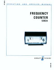
4-1. Frequency Range Test Setup................. 4-2<br />
4-2. Frequency Switching Time Test Setup... 4-4<br />
4-3. Output Level Switching Time Test Setup 4-6<br />
4-4A. Output Accuracy Test Setup.................. 4-8<br />
4-4B. Output Accuracy Test Setup (Alternate<br />
Procedure......................................... 4-13<br />
4-5. Pulse Modulation Risetime Test Setup . . 4-18<br />
4-6. Amplitude Modulation, Depth and 3 dB<br />
Bandwidth Test Setup...................... 4-20<br />
4-7. Output Impedance Test Setup................ 4-24<br />
4-8. Signal-to-Phase Noise Ratio Test Setup. 4-26<br />
4-9. Signal-to-AM Noise Ratio Test Setup..... 4-28<br />
4-10. Residual FM Test Setup ......................... 4-29<br />
4-<strong>11</strong>. Amplitude Modulation Distortion Test<br />
Setup................................................ 4-30<br />
4-12. Incidental Phase Modulation Test Setup 4-32<br />
4-13. Frequency Modulation Distortion Test<br />
Setup................................................ 4-35<br />
4-14. Incidental AM Test Setup ....................... 4-38<br />
4-15. Narrowband Spurious Signal Test Setup. 4-39<br />
4-16. Wideband Spurious Signal Test Setup... 4-41<br />
CONTENTS (Cont’d)<br />
ILLUSTRATIONS<br />
iii<br />
<strong>TM</strong> <strong>11</strong>-<strong>6625</strong>-<strong>2837</strong>-14&P-7<br />
Section Page<br />
8-17. System Troubleshooting.................. 8-2<br />
8-19. RF Section Troubleshooting............. 8-2<br />
8-21. Troubleshooting Aids....................... 8-2<br />
8-28. Recommended Test Equipment ...... 8-2<br />
8-30. Repair............................................... 8-2<br />
8-31. General Disassembly Procedures.... 8-2<br />
8-34. Non-Repairable Assemblies............. 8-2<br />
8-36. Module Exchange Program.............. 8-3<br />
8-38. Repair Procedures........................... 8-3<br />
8-42. Post Repair Adjustments ................. 8-3<br />
IX ERRATA<br />
Figure Page<br />
4-17A. Phase Modulation Distortion Test Setup 4-44<br />
4-17B.Phase Modulation Distortion Test Setup<br />
(Alternate Procedure)....................... 4-46<br />
5-1. RF Output Level Adjustment Test Setup 5-3<br />
5-2. 1 dB Step Attenuator Adjustment Test<br />
Setup................................................ 5-4<br />
5-3. Amplitude Modulation Input Circuit<br />
Adjustment Test Setup..................... 5-5<br />
5-4. Phase Modulator Driver Frequency<br />
Response Adjustment Test Setup ... 5-7<br />
5-5A. Phase Modulation Level and Distortion<br />
Adjustment Test Setup..................... 5-9<br />
5-5B. Phase Modulation Level and Distortion<br />
Adjustment Test Setup (Alternate<br />
Procedure)....................................... 5-12<br />
7-1. Phase Modulator Driver Frequency Response<br />
Adjustment Test Setup (Change B). 7-2<br />
7-2. A16 Phase Modulator Driver Assembly<br />
Component and Test Point Locations<br />
(Change B)....................................... 7-6<br />
7-3. Phase Modulation Section Schematic<br />
Diagram (Option 002) (Change B).. . 7-8<br />
7-4. A17 Phase Modulator Assembly<br />
Component Locations (Change C) .. 7-9<br />
7-5. P/O Phase Modulation Section Schematic<br />
Diagram (Change C)........................ 7-<strong>11</strong><br />
7-6. P/O Attenuator Section Schematic<br />
Diagram (Change D)........................ 7-<strong>11</strong><br />
7-7. P/O All Logic Assembly Schematic<br />
Diagram (Change E)........................ 7-12<br />
8-1. LO Signal Circuits Repair....................... 8-4
Figure Page<br />
8-2. Rear Panel Disassembly......................... 8-8<br />
8-3. Schematic Diagram Notes...................... 8-9<br />
8-4. System Test Point Locations.................. 8-17<br />
8-5. Mainframe Interconnect Jack.................. 8-17<br />
8-6. System Troubleshooting Block<br />
Diagram............................................ 8-17<br />
8-7. RF Section Simplified Block Diagram..... 8-19<br />
8-8. Main Troubleshooting Block Diagram .... 8-19<br />
8-9. Logic Troubleshooting Block Diagram . .. 8-21<br />
8-10. A7 Mixer Assembly’s Subassembly and<br />
Component Location........................ 8-22<br />
8-<strong>11</strong>. Mixer Section Schematic Diagram.......... 8-23<br />
8-12. A16 Phase Modulator Driver Assembly<br />
Component and Test Point Locations 8-25<br />
8-13. A17 Phase Modulator Assembly<br />
Component Locations . .................... 8-25<br />
8-14. Phase Modulation Section Schematic<br />
Diagram (Option 002)....................... 8-25<br />
8-15. A4 Detector Amplifier Assembly<br />
Component and Test Point Locations 8-27<br />
Table Page<br />
1-1. Models 86602B/<strong>11</strong>661 Specifications..... 1-2<br />
1-2. Recommended Test Equipment............. 1-7<br />
3-1. Operating Instructions ............................ 3-6<br />
4-1. dB to Power Ratio Conversion................ 4-37<br />
4-2. Narrowband Spurious Signal Checks..... 4-40<br />
4-3. Wideband Spurious Signal Checks ........ 4-41<br />
4-4. Performance Test Record ...................... 4-47<br />
5-1. Factory Selected Components................ 5-2<br />
ILLUSTRATIONS (Cont’d)<br />
TABLES<br />
APPENDICES<br />
<strong>TM</strong> <strong>11</strong>-<strong>6625</strong>-<strong>2837</strong>-14&P-7<br />
Figure Page<br />
8-16. .Amplifier/Detector Section<br />
Schematic Diagram.......................... 8-27<br />
8-17. A3 ALC Amplifier Assembly Component<br />
and Test Point Locations.................. 8-28<br />
8-18. A10 Reference Assembly<br />
Component Locations ..................... 8-29<br />
8-19. A2 ALC Mother Board Assembly<br />
Component Locations...................... 8-29<br />
8-20. ALC Section<br />
Schematic Diagram.......................... 8-29<br />
8-21. A9 Attenuator Driver Assembly<br />
Component Locations ..................... 8-31<br />
8-22. Attenuator Section<br />
Schematic Diagram.......................... 8-31<br />
8-23. All Logic Assembly<br />
Component Locations...................... 8-33<br />
8-24. All Logic Assembly<br />
Schematic Diagram.......................... 8-33<br />
8-25. Assemblies, Chassis Parts, and Adjustable<br />
Component Locations ............... ...... 8-35<br />
Table Page<br />
6-1. Reference Designations & Abbreviations6-3<br />
6-2. Replaceable Parts.................................. 6-5<br />
6-3. Code Lists of Manufacturers................... 6-15<br />
6-4. Parts to NSN Cross Refererence........... 6-16<br />
7-1. Manual Changes by Serial Prefix........... 7-1<br />
7-2. Summary of Changes by Component.... 7-1<br />
7-3. Replaceable Parts (P/O Change B)........ 7-7<br />
8-1. Front Panel Housing Repair................... 8-7<br />
8-2. Adjustable Components Locations .. 8-34<br />
Page<br />
APPENDIX A. References............................................................................................. A-1<br />
APPENDIX B. Maintenance Allocation<br />
Section I. Introduction............................................................................................. B-1<br />
II. Maintenance Allocation.......................................................................... B-5<br />
III. Tool and Test Equipment Requirements ............................................ B-6<br />
NOTE<br />
Users of this manual are advised to consult SECTION IX, ERRATA. SECTION IX<br />
contains errors and changes in text and illustrations. The user should correct the errors<br />
and perform the changes indicated, as needed.<br />
iv
0-1. Scope<br />
SECTION 0<br />
INTRODUCTION<br />
<strong>TM</strong> <strong>11</strong>-<strong>6625</strong>-<strong>2837</strong>-14&P-7<br />
This manual describes RF Section Hewlett-Packard Model 86602B, hereinafter referred to as the RF Section, and<br />
provides instructions for its operation and maintenance.<br />
This manual applies directly to instruments with serial numbers prefixed 1638A. It is also applicable to instruments with<br />
other serial number prefixes for which manual changes are given in SECTION VII.<br />
SECTION VI includes Table 6-4, a cross reference between the Hewlett-Packard part numbers and the equivalent<br />
NATO/NATIONAL Stock Numbers (NSN).<br />
Appendix A provides a reference of pertinent Department of the Army publications.<br />
Appendix B contains the Maintenance Allocation Chart (MAC) which defines the levels and scope of maintenance<br />
functions for the equipment in the Army system and a list of the tools and test equipment required.<br />
0-2. Indexes of Publications<br />
a. DA Pam 310-4. Refer to the latest issue of the DA Pam 310-4 to determine whether there are new editions,<br />
changes or additional publications pertaining to the equipment.<br />
b. DA Pam 310-7. Refer to DA Pam 310-7 to determine whether there are Modification Work Orders (MWOs)<br />
pertaining to the equipment.<br />
0-3. Maintenance Forms, Records and Reports<br />
a. Reports of Maintenance and Unsatisfactory Equipment. Department of the Army forms and procedures<br />
used for equipment maintenance will be those prescribed by <strong>TM</strong> 38-750, the Army Maintenance Management System.<br />
b. Report of Item and Packaging Discrepancies. Fill out and forward SF 364 (Report of Discrepancy (ROD) as<br />
prescribed in AR 735-<strong>11</strong>-2/DLAR 4140.55/NAVSUPINST 4440.127E/AFR 400.54/MCO 4430.E.<br />
c. Discrepancy in Shipment Report (DISREP) (SF 361). Fill out and forward Discrepancy in Shipment Report<br />
(DISREP) (SF 361) as prescribed in AR 55-38/NAVSUPINST 4610.33B/AFR 75-18/MCO P4610.19C and DLAR 4500.15.<br />
0-4. Reporting Equipment Improvement Recommendations (EIR)<br />
If your HP 86602B RF Section needs improvement, let us know. Send us an EIR. You, the user, are the only one<br />
who can tell us what you don’t like about your equipment. Let us know why you don’t like the design. Tell us why a<br />
procedure is hard to perform. Put it on an SF 368 (Quality Deficiency Report). Mail it to: Commander, US Army<br />
Communications - Electronics Command, ATTN: DRSEL-ME-MQ, Fort Monmouth, New Jersey 07703. We’ll send you a<br />
reply.<br />
0-1
0-5. Administrative Storage.<br />
Store in accordance with Paragraphs 2-17 through 2-22.<br />
0-6. Destruction of Army Electronics Materiel<br />
<strong>TM</strong> <strong>11</strong>-<strong>6625</strong>-<strong>2837</strong>-14&P-7<br />
Destruction of Army electronics materiel to prevent enemy use shall be in accordance with <strong>TM</strong> 750-244-2.<br />
0-2
Section 1 <strong>TM</strong> <strong>11</strong>-<strong>6625</strong>-<strong>2837</strong>-14&P-7<br />
Figure 1-1. HP Model 86602B RF Section (Option 002 Shown)<br />
1-0
Section 1 <strong>TM</strong> <strong>11</strong>-<strong>6625</strong>-<strong>2837</strong>-14&P-7<br />
1-1. INTRODUCTION<br />
1-2. This manual contains all information required to<br />
install, operate, test, adjust and service the Hewlett-<br />
Packard Model 86602B RF Section plug-in, hereinafter<br />
referred to as the RF Section. For information<br />
concerning related equipment, such as the Hewlett-<br />
Packard Model 8660-series mainframes or the Model<br />
<strong>11</strong>661 Frequency Extension Module, refer to the<br />
appropriate manual or manuals.<br />
1-3. This manual is divided into eight sections which<br />
provide information as follows:<br />
a. SECTION I, GENERAL INFORMATION,<br />
contains the instrument description and specifications as<br />
well as the accessory and recommended test equipment<br />
list.<br />
b. SECTION II, INSTALLATION, contains<br />
information relative to receiving inspection, preparation<br />
for use, mounting, packing, and shipping.<br />
c. SECTION III, OPERATION, contains<br />
operating instructions for the instrument.<br />
d. SECTION IV, PERFORMANCE TESTS,<br />
contains information required to verify that instrument<br />
performance is in accordance with published<br />
specifications.<br />
e. SECTION V, ADJUS<strong>TM</strong>ENTS, contains<br />
information required to properly adjust and align the<br />
instrument after repair.<br />
f. SECTION VI, REPLACEABLE PARTS,<br />
contains information required to order all replacement<br />
parts and assemblies.<br />
g. SECTION VII, <strong>MANUAL</strong> CHANGES, provides<br />
information to document all serial number prefixes listed<br />
on the title page.<br />
h. SECTION VIII, SERVICE, contains<br />
descriptions of the circuits, schematic diagrams, parts<br />
location diagrams, and troubleshooting procedures to aid<br />
the user in maintaining the instrument.<br />
SECTION I<br />
GENERAL INFORMATION<br />
1-1<br />
1-4. Figure 1-1 shows the Option 002 RF Section.<br />
1-5. DELETED<br />
1-6. On the title page of this manual, below the manual<br />
part number, is a “Microfiche” part number. This number<br />
may be used to order 4 x 6-inch microfilm transparencies<br />
of the manual. Each microfiche contains up to 60 photoduplicates<br />
of the manual pages. The microfiche<br />
package also includes the latest Manual Changes<br />
supplement as well as all pertinent Service Notes.<br />
1-7. SPECIFICATIONS<br />
1-8. Instrument specifications are listed in Table 1-1.<br />
These specifications are the performance standards, or<br />
limits against which the instrument may be tested.<br />
1-9. INSTRUMENTS COVERED BY <strong>MANUAL</strong> 1-10.<br />
This instrument has a two-part serial number. The first<br />
four digits and the letter comprise the serial number<br />
prefix. The last five digits form the sequential suffix that<br />
is unique to each instrument. The contents of this<br />
manual apply directly to instruments having the same<br />
serial number prefix(es) as listed under SERIAL<br />
NUMBERS on the title page.<br />
1-<strong>11</strong>. For information concerning a serial number prefix<br />
not listed on the title page or in the Manual Changes<br />
supplement, contact your nearest Hewlett-Packard<br />
office.<br />
1-12. <strong>MANUAL</strong> CHANGE SUPPLEMENTS<br />
1-13. An instrument manufactured after the printing of<br />
this manual may have a serial prefix that is not listed on<br />
the title page. This unlisted serial
Section 1 <strong>TM</strong> <strong>11</strong>-<strong>6625</strong>-<strong>2837</strong>-14&P-7<br />
FREQUENCY CHARACTERISTICS<br />
Range: 1.0 to 1299.999999 MHz selectable in 1 Hz<br />
steps. Frequencies from 200 kHz to 1 MHz may also be<br />
selected with some degradation in specifications.<br />
Accuracy and Stability 1 : CW frequency accuracy and<br />
long term stability are determined by the aging rate of the<br />
time base (internal or external) and its sensitivity to<br />
changes in temperature and line voltage. Internal<br />
reference oscillator accuracy = + aging rate ± 3 x 10 -10<br />
/°C + 3 x 10 -10 /1% change in line voltage<br />
Switching Time: 6 ms to be within 50 Hz of any new<br />
frequency selected; 100 ms to be within 5 Hz of any new<br />
frequency delected.<br />
Typical 86602B/<strong>11</strong>661 Frequency Switching<br />
Characteristics<br />
Harmonic Signals:<br />
All harmonically related signals are at least 30 dB below<br />
the desired output signal for output levels 45 MHz from carrier at<br />
frequencies >700 MHz<br />
50 dB down from carrier on the +10 dBm range.<br />
All Power Line Related spurious signals are 70 dB down<br />
from carrier.<br />
Signal-to-Phase Noise Ratio (CW, AM, and OM only):<br />
Greater than 45 dB in a 30 kHz band centered<br />
on the carrier and excluding a 1 Hz band<br />
centered on the carrier.<br />
Typical SSB Phase Noise Curve:<br />
Typical 86602B Phase Noise<br />
Signal-to-AM Noise Ratio: Greater than 65 dB down in<br />
a 30 kHz bandwidth centered on the carrier and<br />
excluding a 1 Hz band centered on the carrier
Section 1 <strong>TM</strong> <strong>11</strong>-<strong>6625</strong>-<strong>2837</strong>-14&P-7<br />
OUTPUT CHARACTERISTICS<br />
Level: Continuously adjustable from +10 to -146 dBm<br />
(0.7 Vrms to 0.01 /Vrms) into a 50Q resistive<br />
load. Output attenuator calibrated in 10 dB steps<br />
from 1.OV full scale (+10 dBm range) to 0.03<br />
pVrms full scale (-140 dBm range). Vernier<br />
provides continuous adjustment between<br />
attenuator ranges. Output level indicated on<br />
output level meter calibrated in volts and dBm<br />
into 50 ohms.<br />
Accuracy: (Local and remote modes)<br />
+ 1.5 dB to -76 dBm; + 2.0 dB to -146 dBm at<br />
meter readings between +3 and -6 dB.<br />
Flatness: Output level variation with frequency is less<br />
than ±1.0 dB from 1-1300 MHz at meter<br />
readings between +3 and --6 dB.<br />
Level Switching Time: In the remote mode any level<br />
change can be accomplished in less than 50 ms.<br />
Any change to another level on the same<br />
attenuator range can be accomplished in less<br />
than 5 ms.<br />
Impedance: 50Q.<br />
VSWR:
Section 1 <strong>TM</strong> <strong>11</strong>-<strong>6625</strong>-<strong>2837</strong>-14&P-7<br />
FREQUENCY MODULATION<br />
Rate: DC to 200 kHz with the 86632B and 86635A.<br />
20 Hz to 100 kHz with the 86633B.<br />
Maximum Deviation (peak):<br />
200 kHz with the 86632B and 86635A<br />
100 kHz with the 86633B<br />
Incidental AM: AM sidebands are greater than 60 dB<br />
down from the carrier with 75 kHz peak deviation<br />
at a 1 kHz rate.<br />
FM Total Harmonic Distortion (at rates up to 20 kHz);<br />
Section 1 <strong>TM</strong> <strong>11</strong>-<strong>6625</strong>-<strong>2837</strong>-14&P-7<br />
prefix indicates that the instrument is different from those<br />
documented in this manual. The manual for this<br />
instrument is supplied with a yellow Manual Changes<br />
supplement that contains “change information” that<br />
documents the differences.<br />
1-14. In addition to change information, the supplement<br />
may contain information for correcting errors in the<br />
manual. To keep this manual as current and accurate as<br />
possible, Hewlett-Packard recommends that you<br />
periodically request the latest Manual Changes<br />
supplement. The supplement for this manual is keyed to<br />
this manual’s print date and part number, both of which<br />
appear on the title page. Complimentary copies of the<br />
supplement are available from Hewlett-Packard.<br />
1-15. DESCRIPTION<br />
1-16. The HP Model 86602B RF Section is one of<br />
several RF Sections available for use in an 8660-series<br />
Synthesized Signal Generator System. This RF Section<br />
plug-in is used with an option 100 8660-series<br />
mainframe (Frequency Extension Module installed). The<br />
RF Section provides precisely tuned RF output<br />
frequencies over the 1 to 1300 MHz range with 1 Hz<br />
frequency resolution (8660-series option 004 instruments<br />
have resolutions of 100 Hz.) Frequencies from 200 kHz<br />
to 1 MHz can also be generated with some degradation<br />
in the amplitude leveling and other related specifications.<br />
1-17. The output power can be set to any level between<br />
+10 and --146 dBm by means of the front panel<br />
VERNIER and calibrated OUTPUT RANGE controls. A<br />
front panel-mounted meter and the OUTPUT RANGE<br />
switch indicate the output power and voltage levels<br />
delivered by the RF Section to any external load having a<br />
characteristic impedance of 50 ohms. Output power<br />
levels are maintained within + 1 dB of selected values<br />
through internal leveling of the output signal over the full<br />
frequency range of the instrument.<br />
1-18. Amplitude, frequency, phase, or pulse modulation<br />
of the RF OUTPUT signal can be accomplished within<br />
the RF Section by using the appropriate Auxiliary or<br />
Modulation Section plug-in.<br />
1-19. External programming permits remote selection of<br />
the output signal frequency in 1 Hz steps (100 Hz for<br />
option 004 mainframes) and the output power in 1 dB<br />
steps over the full operating<br />
1-5<br />
range of the instrument. External programming is<br />
accomplished via the mainframe computer-compatible<br />
interface and digital control unit circuits.<br />
1-20. OPTIONS<br />
1-21. This RF Section has two options available. They<br />
affect the instrument’s RF output level, and phase<br />
modulation capabilities.<br />
1-22. Option 001. The RF output attenuator is<br />
removed. This limits the RF output level range from +10<br />
to -6 dBm.<br />
1-23. Option 002. Circuits are added to provide the<br />
phase modulation capability. A compatible modulation<br />
section is required.<br />
1-24. COMPATIBILITY<br />
1-25. Except for Option 002 instruments, the Model<br />
86602B is compatible with all 8660-series option 100<br />
mainframes, all AM-FM Modulation Sections and the<br />
Auxiliary Section. This RF Section is partially compatible<br />
with the FM/OM Modulation Section.<br />
Damage to the signal generator system<br />
may result if an option 002 RF Section<br />
is used with Model 8660A or 8660B<br />
main-frames with serial prefixes 1349A<br />
and below.<br />
1-26. Option 002 instruments are compatible with all<br />
instruments which are part of the Model 8660-series<br />
Synthesized Signal Generator System except early<br />
model 8660A and 8660B Mainframes. Refer to the<br />
paragraph entitled Modifications in Section II of this<br />
manual for further information.<br />
1-27. EQUIPMENT REQUIRED BUT NOT<br />
SUPPLIED<br />
1-28. System Mainframe<br />
1-29. The mainframe uses phase-locked loops to<br />
accurately generate clock, reference, and tuning signals<br />
required for operation of the Synthesized Signal<br />
Generator System. Front panel-mounted mainframe<br />
controls are used to digitally tune two phase-locked loops<br />
in the Frequency Extension Module which, in turn,<br />
produce two high-frequency output signals that are<br />
applied to the RF Section. The RF Section mixes the<br />
two signals
Section 1 <strong>TM</strong> <strong>11</strong>-<strong>6625</strong>-<strong>2837</strong>-14&P-7<br />
and presents their frequency difference at the front panel<br />
OUTPUT jack. The output frequency is either the value<br />
selected by the mainframe front panel controls or<br />
external programming.<br />
1-30. The mainframe power supply provides all dc<br />
operating voltages required by the RF Section,<br />
Frequency Extension Module, and Modulation Section<br />
plug-ins. Remote programming of the plug-ins is<br />
accomplished via the mainframe interface and digital<br />
control unit circuits.<br />
1-31. Frequency Extension Module<br />
1-32. The Frequency Extension Module plug-in extends<br />
the output frequency range of the main-frame to meet<br />
the input requirements of the RF Section. The<br />
Frequency Extension Module plug-in contains two highfrequency<br />
phase-locked loops which receive digital<br />
tuning signals, variable synthesized signals, and fixed<br />
synthesized signals from the mainframe. The phaselocked<br />
loops use the main-frame signals, in conjunction<br />
with the output frequency from a 4.43 GHz oscillator that<br />
is common to both loops, to produce two high-frequency<br />
output signals that are supplied to the RF Section. One<br />
output signal is generated by a phase-locked loop using<br />
a Voltage Controlled Oscillator (VCO) that is tuneable in<br />
1 Hz steps (100 Hz steps for option 004 mainframe) over<br />
the 3.95 to 4.05 GHz range. The other output signal is<br />
generated by a phase-locked loop using a Yittrium-Iron-<br />
Garnet (YIG) oscillator that is tunable in 100 MHz steps<br />
over the 3.95 to 2.75 GHz range. The two outputs from<br />
the Frequency Extension Module plug-in are applied to<br />
the RF Section for mixing, amplification of the converted<br />
signal, and final output power level control.<br />
1-33. Auxiliary Section<br />
1-34. The Auxiliary Section plug-in provides a means of<br />
applying externally generated amplitude or pulse<br />
modulation drive signals to modulate the RF Section’s<br />
output carrier.<br />
1-6<br />
1-35. Modulation Section Plug-ins<br />
1-36. The Model 86630-series Modulation Section plugins<br />
can accept external modulation drive signals or<br />
generate internal drive signals to amplitude, frequency,<br />
phase or pulse modulate the RF Sections output signal.<br />
1-37. EQUIPMENT AVAILABLE<br />
1-38. Extender cables, coaxial adapters, and an<br />
adjustment tool are available for use in performance<br />
testing, adjusting, and maintaining the RF Section. Each<br />
piece may be ordered separately or as part of the<br />
<strong>11</strong>672A Service Kit.<br />
1-39. Extender cards for use in servicing the RF Section<br />
and a type N to BNC adapter for use on the front panel<br />
RF OUTPUT connector are contained in the HP Rack<br />
Mount Kit, Part Number 08660-60070, that is supplied<br />
with the mainframe.<br />
1-40. SAFETY CONSIDERATIONS<br />
1-41. This instrument has been designed in accord-ance<br />
with international safety standards and has been<br />
supplied in safe condition.<br />
1-42. Although this instrument has been designed in<br />
accordance with international safety standards, this<br />
manual contains information, cautions, and warnings<br />
which must be followed to retain the instrument in safe<br />
condition. Be sure to read and follow the safety<br />
information in Sections II, III, V, and VIII.<br />
1-43. RECOMMENDED TEST EQUIPMENT 1-44.<br />
Table 1-2 lists the test equipment and accessories<br />
recommended for use in testing, adjusting, and servicing<br />
the RF Section. If any of the recommended test<br />
equipment is unavailable, instruments with equivalent<br />
specifications may be used. See Appendix B, Section III.
Section 1 <strong>TM</strong> <strong>11</strong>-<strong>6625</strong>-<strong>2837</strong>-14&P-7<br />
See Appendix B, Section III<br />
Table 1-2. Recommended Test Equipment (1 of 4)<br />
Item Critical Specifications Suggested Model Use*<br />
Adapter (Male Type N Frequency range 100 MHz to 1.3 GHz HP 1250-0847 P<br />
to GR874 )<br />
Adapter, SMA-to-BNC 2 required OSM 2<strong>11</strong>90 P<br />
Adapter, SMA-to-OSM OSM 219 P<br />
Right Angle<br />
Adapter, Type N-to- OSM 21040 P<br />
SMA<br />
Amplifier, 20 dB -20 dB gain at 30 MHz HP 8447A P<br />
Input SWR
Section 1 <strong>TM</strong> <strong>11</strong>-<strong>6625</strong>-<strong>2837</strong>-14&P-7<br />
Table 1-2. Recommended Test Equipment (2 of 4)<br />
Item Critical Specifications Suggested Model Use*<br />
Counter, Computing 50 kHz to 50 MHz with a 1 ms gate time and HP 5360A with HP 5365A P<br />
external trigger; 1 Hz resolution plug-in<br />
Counter, Frequency Range: 0.2-1300 MHz HP 5340A P<br />
Resolution: 1 Hz<br />
10 MHz external reference output<br />
7.2 Vrms output into 170 ohms<br />
Coupler, Directional Frequency range 100 MHz to 1.3 GHz HP 778D Option 12 P<br />
Detector, Crystal 1 to 1200 MHz HP 8471A P<br />
Detector, Crystal 10 MHz to 1.3 GHz HP 423A P, A<br />
FM Discriminator Input frequency 100 kHz to 10 MHz HP 5210A P, A<br />
Linear Analog Output 1V full scale<br />
Filter Kit Accessory for HP 5210A HP 10513A P, A<br />
Filter, Low Pass, Special (see Figure 1-3) P<br />
15 kHz<br />
Filter, Low Pass, Cutoff frequency: 4 MHz CIR-Q-TEL P<br />
4 MHz FLT/21B-4-3/50-3A/3B<br />
Filter, Low Pass, Cutoff frequency: 2200 MHz HP 360C P<br />
2200 MHz<br />
Filters, Low Pass, 100 kHz at 50 and 600 ohms Specials (See Figure 1-4) A<br />
100 kHz<br />
Filters, Low Pass, 1 MHz - 50 and 600 ohms Specials (See Figure 1-4) P, A<br />
1 MHz<br />
Filters, Low Pass, 5 and 10 MHz - 50 ohms Specials (See Figure 1-4) P<br />
5 and 10 MHz<br />
Filter, Band Pass Pass band 1-2 GHz HP 8430A P<br />
Generator, Distortion less than 0.3% HP 203A P<br />
Function Range: 0.5 Hz to 20 kHz<br />
Output level: 0.1 to 2.0 Vrms into 600 ohms<br />
Generator, Pulse Output -10 Vpk with 0.5V into 170 ohms<br />
*Use: P = Performance Tests, A = Adjustments, T = Troubleshooting<br />
1-8
Section 1 <strong>TM</strong> <strong>11</strong>-<strong>6625</strong>-<strong>2837</strong>-14&P-7<br />
Table 1-2. Recommended Test Equipment (3 of 4)<br />
Item Critical Specifications Suggested Model Use*<br />
Mixer, Double 1 MHz to <strong>11</strong>0 MHz HP 10514A A<br />
Balanced<br />
Mixer, Double 300 to 1300 MHz Watkins-Johnson M1J P<br />
Balanced<br />
Oscillator, Test 1 kHz to 10 MHz HP 651B P, A<br />
1.0 to 2.0 Vrms into 600<br />
or 50 ohms<br />
Oscilloscope Vertical: HP 180C with HP 1801A P, A, T<br />
Bandwidth 50 MHz with sensitivity of and HP 1821A plug-ins<br />
5mV/ division minimum<br />
Horizontal:<br />
Sweep time 10 ns to 1 s<br />
Delayed sweep<br />
External triggering to 100 MHz<br />
Oscilloscope, Input impedance HP 10004 P, A, T<br />
10:1 divider probes 10 megohm shunted by 10 pF<br />
Power MeterISensor Range: -10 to +10 dBm from 10 MHz to 1.3 HP 435A/8481A P, A, T<br />
GHz<br />
Power Supply, DC 0-10 volts HP 721A P<br />
Programmer, Marked Capable of programming BCD or HP-IB data HP 3260A Option 001 P, A<br />
Card<br />
Probe, Logic TTL Compatible HP 10525T T<br />
Resistor, 1000 ohm +2% HP 0757-0280 P, A<br />
Resistor, 10K ohm +2% HP 0757-0442 P<br />
Resistor, 100K ohm f2% HP 0698-7284 P<br />
Service Kit Interconnect cables, adaptors, and coaxial HP <strong>11</strong>672A (See A, T<br />
cables compatible to 8660-series plus and Operating Note or<br />
jacks mainframe manual for<br />
parts list)<br />
Stub, Adjustable Frequency range 100 MHz to 1.3 GHz General Radio 874-D50L P<br />
Tee, Coaxial 2 required HP 1250-0781 (BNC) P, A<br />
Termination, 50 50 ohm HP <strong>11</strong>048C P<br />
ohm Feed Thru<br />
*Use: P = Performance, A = Adjustments, T = Troubleshooting<br />
1-9
Section 1 <strong>TM</strong> <strong>11</strong>-<strong>6625</strong>-<strong>2837</strong>-14&P-7<br />
Table 1-2. Recommended Test Equipment (4 of 4)<br />
Item Critical Specifications Suggested Model Use*<br />
Termination, 50 ohm 50 ohm, (2 required) HP <strong>11</strong>593A P<br />
Test Set, Phase Input Frequency Range 250 to 950 MHz HP 8660C-K10 (only) P, A<br />
Modulation Distortion<br />
Section 1 <strong>TM</strong> <strong>11</strong>-<strong>6625</strong>-<strong>2837</strong>-14&P-7<br />
40 dB TEST AMPLIFIER<br />
Amplifier Specifications<br />
Gain 44 dB at 25°C<br />
Bandwidth 100 kHz (3 dB down)<br />
Noise Bandwidth 157 kHz<br />
Input Impedance 75K Ohms<br />
Output Impedance 12K Ohms<br />
Current Drain 260 Microamperes<br />
Output (Maximum) 1 Volt<br />
Dynamic Range 66 dB<br />
Figure 1-2. 40 dB Test Amlifier<br />
Figure 1-3. 15 kHz Low Pass Filter<br />
1-<strong>11</strong>
Section 1 <strong>TM</strong> <strong>11</strong>-<strong>6625</strong>-<strong>2837</strong>-14&P-7<br />
100 kHz - 50 ohms 100 kHz - 600 ohms<br />
C1, C4 0.015 μF Mylar 0160-0194 C1, C4 1300 pF 0160-2221<br />
C2 0.027 μF Mylar 0170-0066 C2 3000 pF 0160-2229<br />
C3 0.022 μF Mylar 0160-0162 C3 <strong>11</strong>00 pF 0160-2219<br />
L1, L2 100 μH 9140-0210 L1, L2 1200 μH 9100-1655<br />
1 MHz -50 ohms 1 MHz - 600 ohms<br />
C1, C4 1500 pF 0160-2222 C1, C4 130 pF 0140-0195<br />
C2 3300 pF 0160-2230 C2 300 pF 0160-2207<br />
C3 1600 pF 0160-2223 C3 120, μH 0140-0194<br />
L1, L2 10H ±10% 9140-0<strong>11</strong>4 L1, L2 120 μ 9100-1637<br />
5 MHz - 50 ohms 10 MHz - 50 ohms<br />
C1, C2, C4 300 pF 0160-2207 C1, C4 150 pF 0140-0196<br />
C3 680 pF 0160-3537 C2 330 pF 0160-2208<br />
L1, L2 2 μH 9100-3345 C3 160 pH 0160-2206<br />
L1, L2 1 μH±10% 9140-0096<br />
NOTE<br />
Unless otherwise noted, tolerance of components is + 5%<br />
and capacitors are mica. Part numbers are Hewlett-Packard<br />
Figure 1-4. Low Pass Filters<br />
1-12
Section 2 <strong>TM</strong> <strong>11</strong>-<strong>6625</strong>-<strong>2837</strong>-14&P-7<br />
2-1. INTRODUCTION<br />
2-2. This section provides information relative to initial<br />
inspection, preparation for use, and storage and<br />
shipment of the Model 86602B RF Section plug-in. Initial<br />
Inspection provides instructions to be followed when an<br />
instrument is received in a damaged condition.<br />
Preparation For Use gives all necessary interconnection<br />
and installation instructions. Storage and Shipment<br />
provides instructions and environmental limitations<br />
pertaining to instrument storage. Also provided are<br />
packing and packaging instructions which should be<br />
followed in preparing the instrument for shipment.<br />
2-3. INITIAL INSPECTION<br />
2-4. Inspect the shipping container for damage. If the<br />
shipping container or cushioning material is damaged, it<br />
should be kept until the contents of the shipment have<br />
been checked for completeness and the instrument has<br />
been checked mechanically and electrically. The<br />
contents of the shipment should be as shown in Figure<br />
1-1, and procedures for checking electrical performance<br />
are given in Section IV. If the contents are incomplete, if<br />
there is mechanical damage or defect, or if the instrument<br />
does not pass the electrical performance test,<br />
notify the nearest Hewlett-Packard office. If the shipping<br />
container is damaged, or the cushioning material shows<br />
signs of stress, notify the carrier as well as the Hewlett-<br />
Packard office. Keep the shipping materials for carrier’s<br />
inspection. The HP office will arrange for repair or<br />
replacement without waiting for claim settlement.<br />
2-5. PREPARATION FOR USE<br />
2-6. Power Requirements<br />
2-7. All power required for operation of the RF Section<br />
is furnished by the mainframe. This RF Section requires<br />
approximately 40 volt-amperes.<br />
2-8. Interconnections<br />
2-9. Prior to installing the RF Section plug-in into the<br />
mainframe, verify that the Frequency Extension Module<br />
plug-in and interconnecting cable assemblies have been<br />
installed in accordance with the instructions contained in<br />
the Frequency Extension Module manual.<br />
SECTION II<br />
INSTALLATION<br />
2-1<br />
2-10. Modifications<br />
2-<strong>11</strong>. A power supply modification to older versions of<br />
Model 8660A and 8660B mainframes are required if they<br />
are to be used with the option 002 RF Section.<br />
Damage to the synthesized signal generator<br />
system may result if an option 002 RF<br />
Section is used with an older 8660A or 8660B<br />
mainframe.<br />
2-12. Due to the increased power consumption of the<br />
option 002 instrument, mainframes with serial prefixes<br />
1349A and below must be modified by installing a Field<br />
Update Kit. For mainframe configurations other than<br />
option 003 (60 Hz line operation), order kit number<br />
08660-60273. For option 003 mainframes (50 - 400 Hz<br />
line operation) order kit number 08660-60274.<br />
NOTE<br />
Verify that a new higher current fuse, HP Part<br />
Number 2<strong>11</strong>0-0365, 4A Slow Blow, is used in<br />
mainframes with the power supply modification.<br />
2-13. Operating Environment<br />
2-14. The RF Section is designed to operate within the<br />
following environmental conditions:<br />
Temperature ........................................ 0° to +55°C<br />
Humidity ..................................... less than 95% relative<br />
Altitude ....................................... less than 15,000 feet<br />
2-15. Installation Instructions<br />
WARNING<br />
The multi-pin plug connector which provides<br />
interconnection from mainframe to RF<br />
Section, will be exposed with the RF Section<br />
removed from the right-hand mainframe<br />
cavity. With the Line (Mains) Voltage off and<br />
power cord disconnected, power supply<br />
voltages may still remain which, if contacted,<br />
may constitute a shock hazard.
Section 1 <strong>TM</strong> <strong>11</strong>-<strong>6625</strong>-<strong>2837</strong>-14&P-7<br />
2-16. Insert the plug-in approximately half-way into the<br />
right cavity of the mainframe. Rotate the latch (lower<br />
right corner) to the left until it protrudes perpendicular to<br />
the front panel. Refer to Figure 2-1, which shows the<br />
plug-in partially inserted into the mainframe and the latch<br />
rotated to a position that is perpendicular to the plug-in<br />
front panel. Push the plug-in all the way into the<br />
mainframe cavity and then rotate the latch to the right<br />
until it snaps into position.<br />
2-17. STORAGE AND SHIPMENT<br />
2-18. Environment<br />
2-19. The storage and shipping environment of the RF<br />
Section should not exceed the following limits:<br />
Temperature................................ 40° to +75°C<br />
Humidity....................................... less than 95% relative<br />
Altitude......................................... less than 25,000 feet<br />
2-20. Packaging<br />
2-21. Original Type Packaging. Containers and<br />
materials identical to those used in factory packaging are<br />
available through Hewlett-Packard offices. If the<br />
instrument is being returned to Hewlett-Packard for<br />
servicing, attach a tag indicating the type of service<br />
required, return address, model number, and full serial<br />
Figure 2-1. RF Section Partially Inserted into Mainframe<br />
Figure 2-1. RF Section Partially Inserted into Mainframe<br />
2-2<br />
number. Also mark the container FRAGILE to assure<br />
careful handling. In any correspondence, refer to the<br />
instrument by model number and full serial number.<br />
2-22. Other Packaging. The following general<br />
instructions should be used for re-packaging with<br />
commercially available materials:<br />
a. Wrap the instrument in heavy paper or<br />
plastic. (If shipping to a Hewlett-Packard office or<br />
service center, attach a tag indicating the type of service<br />
required, return address, model number, and full serial<br />
number.)<br />
b. Use a strong shipping container. A doublewall<br />
carton made of 350-pound test material is adequate.<br />
c. Use enough shock-absorbing material (3 to 4inch<br />
layer) around all the sides of the instrument to<br />
provide firm cushion and prevent movement inside the<br />
container. Protect the control panel with cardboard.<br />
d. Seal the shipping container securely.<br />
e. Mark the shipping container FRAGILE to<br />
assure careful handling.
Section 3 <strong>TM</strong> <strong>11</strong>-<strong>6625</strong>-<strong>2837</strong>-14&P-7<br />
3-1. INTRODUCTION<br />
3-2. This section contains information which will enable<br />
the operator to learn to operate and quickly check for<br />
proper operation of the RF Section plug-in as part of the<br />
Synthesized Signal Generator System.<br />
3-3. PANEL FEATURES<br />
3-4. The front and rear panel controls, connectors, and<br />
indicators of the RF Section and its options are<br />
described by Figure 3-1 and 3-2.<br />
3-5. OPERATOR’S CHECKS<br />
3-6. The RF Section, as part of the Synthesized Signal<br />
Generator System, accepts inputs from the rest of the<br />
system but controls only the RF output level. Even<br />
though the controlled circuits for most other functions are<br />
within the RF Section, the actual checks are found in the<br />
manual of the instrument which controls that function.<br />
SECTION III<br />
OPERATION<br />
3-1<br />
3-7. The Operator’s Checks in this manual are intended<br />
to verify proper operation of the circuits which control and<br />
are controlled by the RF output level controls. This<br />
includes the meter, the VERNIER control, the OUTPUT<br />
RANGE switch, and the Output Range Attenuator when<br />
operating in the local mode. When the system is being<br />
remotely controlled, the 1 dB and 10 dB remote step<br />
attentator switches are checked in place of the VERNIER<br />
control and OUTPUT RANGE switch. Refer to Figure 3-<br />
3.<br />
3-8. OPERATING INSTRUCTIONS<br />
3-9. In this system, the mainframe and plug-ins contain<br />
the controls for frequency, modulation, and RF level<br />
selection. The mainframe controls frequency, the<br />
Modulation Section plug-in controls modulation type and<br />
level, and the RF Section plug-in controls RF output<br />
level. The Operating Instructions for the RF Section<br />
plug-in are included in Table 3-1.
Section 3 <strong>TM</strong> <strong>11</strong>-<strong>6625</strong>-<strong>2837</strong>-14&P-7<br />
1 Meter. Indicates the RF Output level in Vrms and<br />
dBm (50w) with the scale reference indicated by the<br />
OUTPUT RANGE switch.<br />
2 Mechanical Meter Zero Control. Sets the Panel<br />
Meter indicator to zero when the mainframe LINE Switch<br />
is set to STBY.<br />
3 OUTPUT RANGE Switch. Sets the output level<br />
range of all except option 001 instruments from<br />
NOTE<br />
The front panel of the option 002 instrument is shown.<br />
The standard instrument does not have the term PHASE<br />
MODULATION after 1-1300 MHz. The option 001<br />
instrument has an OUTPUT RANGE switch which shows<br />
only the +10 and 0 dBm ranges.<br />
Figure 3-1. Front Panel Controls, Connectors, and Indicators<br />
3-2<br />
+10 to -140 dBm (502) in 10 dB steps. For option 001<br />
instruments, +10 and 0 dBm ranges only.<br />
4 OUTPUT Jack. Type-N female coaxial connector.<br />
RF Output level +10 to -146 dBm (0.7 Vrms to 0.01<br />
/IVrms) into a 50Q load. Frequency range is 1 to<br />
1299.999 999 MHz in 1 Hz steps.<br />
5 VERNIER Control. RF Output continuously var-iable<br />
within the useable range (+3 to --6 dB) as indicated by<br />
the meter.
Section 3 <strong>TM</strong> <strong>11</strong>-<strong>6625</strong>-<strong>2837</strong>-14&P-7<br />
1 Coaxial Plug. Connects the 3.95 to 2.75 GHz RF<br />
Input signal to the RF Section from the Frequency<br />
Extension Module.<br />
2 Interconnect Plug. Provides interconnection of<br />
power supply voltages; RF and control signals between<br />
the RF Section plug-in and the Main-frame, Frequency<br />
Extension Module, and Modulation Section plug-in.<br />
Figure 3-2. Rear Panel Connectors and Indicators<br />
3-3<br />
3 Coaxial Plug. Connects the 3.95 to 4.05 GHz LO<br />
Input signal to the RF Section plug-in from the Frequency<br />
Extension Module.<br />
4 Serial Number Plate. Metal plate with stamped<br />
serial number. Four-digit and letter for prefix. Suffix is<br />
unique to an instrument.
Section 3 <strong>TM</strong> <strong>11</strong>-<strong>6625</strong>-<strong>2837</strong>-14&P-7<br />
1. Set the System controls as follows:<br />
WARNING<br />
BEFORE CONNECTING THIS SYSTEM TO LINE (MAINS) VOLTAGE,<br />
the safety and installation instructions found in Sections II and III of the<br />
mainframe manual should be followed.<br />
Damage to the signal generator system may occur if option 002 RF<br />
Sections are used with unmodified 8660A and 8660B main frames with<br />
serial prefixes 1349A and below. See the paragraph entitled<br />
Modifications in Section II.<br />
NOTE<br />
Refer to Section HI for RF Section Installation instructions.<br />
Mainframe<br />
LINE Switch .................................................................................... ON<br />
REFERENCESELECTOR .............................................................. EXT<br />
CENTER FREQUENCY ................................................................. 500 MHz<br />
Modulation Section plug-in<br />
MODE Switch ................................................................................. OFF<br />
RF Section plug-in<br />
OUTPUT RANGE Switch ............................................................... 0 dBm<br />
VERNIER Control ........................................................................... +3 dB meter reading<br />
Figure 3-3. Operator’s Checks (1 of 2)<br />
3-4
Section 3 <strong>TM</strong> <strong>11</strong>-<strong>6625</strong>-<strong>2837</strong>-14&P-7<br />
OPERATOR’S CHECKS<br />
2. Connect the RF Section OUTPUT to the power sensor input. Verify that the amplitude of the 500 MHz signal<br />
is approximately +3 dBm.<br />
3. Set the OUTPUT RANGE Switch to +10 dBm and adjust the VERNIER control for a -3 dB meter reading.<br />
Verify that the output level is approximately +7 dBm.<br />
4. Connect the RF Section OUTPUT to the frequency counter input through the 3 dB attenuator. Verify that the<br />
signal is accurate within +1 Hz.<br />
5. To check the remote control capabilities of the RF Section, connect a control unit to the mainframe. Repeat<br />
steps 1 through 4 while the system is remotely programmed from an external source. Application Note 164-1<br />
"Programming the 8660A/B Synthesized Signal Generator" provides the information needed for remote BCD<br />
operation of this system. Application Note 164-2 "Calculator Control of the 8660A/B/C Synthesized Signal<br />
Generator" provides the information needed for calculator control of the system using the HP-IB (option 005).<br />
Section III of the mainframe manual contains the same information in abridged form.<br />
Figure 3-3. Operator’s Checks (2 of 2)<br />
3-5
Section 3 <strong>TM</strong> <strong>11</strong>-<strong>6625</strong>-<strong>2837</strong>-14&P-7<br />
TURN ON<br />
Table 3-1. Operating Instructions (1 of 2)<br />
OPERATING INSTRUCTIONS<br />
BEFORE CONNECTING THIS SYSTEM TO THE LINE (MAINS)<br />
VOLTAGE, the safety and installation instructions found in Sections<br />
II and III of the mainframe manual should be followed.<br />
Damage to the signal generator system may occur if option 002 RF<br />
Sections are used with unmodified 8660A and 8660B main- frames<br />
with serial prefixes 1349A and below. See the paragraph entitled<br />
Modifications in Section II.<br />
NOTE<br />
Refer to Section II for RF Section Installation Instructions.<br />
1. Set the mainframe’s LINE Switch to ON and the rear panel REFERENCE SELECTOR Switch to INT. Wait for the<br />
mainframe "oven" indication to go out.<br />
FREQUENCY SELECTION<br />
2. Refer to Section III of the mainframe operating and service manual for information on system frequency selection.<br />
RF OUTPUT LEVEL<br />
3. dBm. Set the OUTPUT RANGE switch to within +3 and --6 dB of the desired output level. Adjust the VERNIER<br />
control for a meter reading which when added to the OUTPUT RANGE switch indication equals the desired output<br />
level.<br />
4. VOLTS. To set the RF output level in rms volts, the OUTPUT RANGE switch selected the full scale meter reading<br />
and the VERNIER control is adjusted for the correct voltage reading on the meter. The voltage level for meter<br />
scale 1.0 should not be set below 0.32 of full scale. The voltage level should not be set below 1 when using the<br />
meter scale of 3.<br />
NOTE<br />
In order to achieve the output level accuracy specified, the level<br />
selected must be S
Section 3 <strong>TM</strong> <strong>11</strong>-<strong>6625</strong>-<strong>2837</strong>-14&P-7<br />
Table 3-1. Operating Instructions (2 of 2)<br />
MODULATION SELECTION<br />
6. Refer to Section III of the Modulation Section plug-in operating and service manual for information relating to<br />
selection of modulation type and level.<br />
REMOTE OPERATION<br />
7. Application Note 164-1 "Programming the 8660A/B Synthesized Signal Generator" provides most of the<br />
information needed for remote BCD operation of this system. AN 164-2 "Calculator Control of the 8660A/B/C<br />
Synthesized Signal Generator" provides information for remote HP-IB operation of this system. In abridged form,<br />
Section III of the mainframe manuals contain the same information.<br />
3-7
Section 4 <strong>TM</strong> <strong>11</strong>-<strong>6625</strong>-<strong>2837</strong>-14&P-7<br />
4-1. INTRODUCTION<br />
4-2. The procedures in this section test the<br />
instrument’s electrical performance using the<br />
specifications of Table 1-1 as the performance standard<br />
All tests can be performed without access to l interior of<br />
the instrument. A simpler operation test is included in<br />
Section III under Operator’s Checks.<br />
4-3. EQUIPMENT REQUIRED<br />
4-4. Equipment required for the performance tests is<br />
listed in the Recommended Test Equipment table in<br />
Section I. Any equipment that satisfies critical<br />
specifications given in the table may substituted for the<br />
recommended model(s).<br />
4-5. TEST RECORD<br />
4-6. Results of the performance tests may tabulated<br />
on the Test Record at the end of the procedures. The<br />
Test Record lists all of the test specifications and their<br />
acceptable limits. Test results recorded at incoming<br />
SECTION IV<br />
PERFORMANCE TESTS<br />
4-1<br />
inspection can be used for comparison in periodic<br />
maintenance and trouble-shooting, and after repairs or<br />
adjustments.<br />
4-7. PERFORMANCE TESTS<br />
4-8. For each test, the specifications are written<br />
exactly as they appear in the specification table in<br />
Section I. Next, a description of the test and any special<br />
instructions or problem areas are included. Most tests<br />
that require test equipment have a setup drawing; each<br />
has a list of required equipment. The initial steps of each<br />
procedure give control settings required for that<br />
particular list.<br />
To avoid the possibility of damage to the<br />
instrument or test equipment, read<br />
completely through each test before starting<br />
it. Then make any preliminary control<br />
settings before continuing with the<br />
procedure.
Section 4 <strong>TM</strong> <strong>11</strong>-<strong>6625</strong>-<strong>2837</strong>-14&P-7<br />
4-9. FREQUENCY RANGE<br />
PERFORMANCE TESTS<br />
SPECIFICATION:<br />
1 to 1299.999999 MHz selectable in 1 Hz steps. Frequencies from 200 to kHz to 1 MHz may also be selected with some<br />
degradation in specifications.<br />
DESCRIPTION:<br />
The Synthesized Signal Generator System RF OUTPUT is monitored by a frequency counter which supplies a common<br />
time base reference signal. The frequencies are checked at the extremes. Any specified frequency may be checked.<br />
EQUIPMENT:<br />
Figure 4-1. Frequency Range Test Setup<br />
Frequency Counter... .................................HP 5340A<br />
10 dB Fixed Attenuator ..............................HP 8491A Opt 003<br />
NOTE<br />
In the following procedure, allow for accuracy of counter used. -Model<br />
recommended is specified at +1 count.<br />
1. Connect frequency counter 10 MHz output reference signal to mainframe EXT REF input as shown in Figure 4-1<br />
and set mainframe rear panel REF switch to EXT.<br />
2. Set the RF Section OUTPUT RANGE switch to 0 dBm; set the VERNIER control full CW.<br />
3. Set mainframe center frequency to 1.000 000 MHz and check RF section output frequency with counter. Record<br />
the frequency.<br />
0.999999_______________________1.000001 MHz<br />
4. Set mainframe center frequency to 1299.999 999 MHz (Option 004 mainframe set to 1299.,space 9999 MHz) and<br />
check RF Section output frequency with counter. Record the frequency.<br />
4-2<br />
1299.999 998________________1300.000 000 MHz
Section 4 <strong>TM</strong> <strong>11</strong>-<strong>6625</strong>-<strong>2837</strong>-14&P-7<br />
4-10. FREQUENCY ACCURACY AND STABILITY<br />
PERFORMANCE TESTS<br />
SPECIFICATION:<br />
CW frequency accuracy and long term stability are determined by the aging rate of the time base (internal or external) and<br />
its sensitivity to changes in temperature and line voltage. Internal reference oscillator accuracy = + aging rate +3 x 10⁻¹⁰/°<br />
C + 3 x 10⁻¹⁰/1% change in line voltage. (Aging rate for the time base in the standard mainframe is 3 x 10- 8/day; for<br />
option 001 mainframes, 3 x 10⁻⁹/day.)<br />
_______________________________________<br />
4-<strong>11</strong>. FREQUENCY SWITCHING TIME<br />
NOTE<br />
If there is any reason to doubt the mainframe crystal oscillator<br />
accuracy or stability, refer to the performance test in Section IV of<br />
the mainframe manual.<br />
SPECIFICATION:<br />
6 ms to be within 50 Hz of any new frequency selected; 100 ms to be within 0.5 Hz of any new frequency selected.<br />
DESCRIPTION:<br />
A change in the Synthesized Signal Generator System's frequency is remotely programmed; after a preset time interval<br />
the frequency is measured. A trigger pulse from the programming device is first coupled to the oscilloscope. The pulse is<br />
delayed a preset interval by the oscilloscope and then coupled to the computing counter at which time the frequency is<br />
measured.<br />
NOTE<br />
The frequencies in this test were selected for worst-case<br />
conditions (longest switching time).<br />
4-3
Section 4 <strong>TM</strong> <strong>11</strong>-<strong>6625</strong>-<strong>2837</strong>-14&P-7<br />
4-<strong>11</strong>. FREQUENCY SWITCHING TIME (Cont’d)<br />
EQUIPMENT:<br />
PERFORMANCE TESTS<br />
Figure 4-2. Frequency Switching Time Test Setup<br />
DC Power Supply.......................................HP 721A<br />
Computing Counter....................................HP 5360A/5365A<br />
Marked Card Programmer .........................HP 3260A Opt 001<br />
Oscilloscope...............................................HP 180C/1801A/1821A<br />
Coaxial Tee................................................HP 1250-0781<br />
PROCEDURE:<br />
1. Connect the dc power supply +5 volt output through a 1000 ohm resistor to pin 17 of the mating connector for J3.<br />
Pin 17 (flag) of the Marked Card Programmer output connector is also connected to the oscilloscope ext trigger<br />
input.<br />
2. Connect the marked card programmer to mainframe rear panel connector J3.<br />
3. Connect oscilloscope delayed sweep output through a BNC TEE to oscilloscope channel A vertical input and to<br />
computing counter rear panel external time measurement input.<br />
4. Set counter controls as follows: rear panel switch to trigger; "B" channel to X1 sensitivity; module switch pressed;<br />
digits displayed for necessary resolution; measurement time to 1; counter gate time to 1 ms.<br />
5 Program the System for 29.999 999 MHz. Set the mainframe rear panel reference switch to external.<br />
6. Set oscilloscope controls as follows: trigger to ac slow; ext, negative slope, trigger level at about 9:00 o’clock;<br />
sweep mode auto; delay trigger auto; main sweep 1 ms; delay sweep 0.1 ps; main sweep mode.<br />
7. Set oscilloscope trace to start at left vertical graticule line. Use oscilloscope delay control to delay spike 5.5<br />
divisions from CRT left graticule line.<br />
8. Switch oscilloscope sweep mode from auto to normal.<br />
4-4
Section 4 <strong>TM</strong> <strong>11</strong>-<strong>6625</strong>-<strong>2837</strong>-14&P-7<br />
4-<strong>11</strong>. FREQUENCY SWITCHING TIME (Cont’d)<br />
PERFORMANCE TESTS<br />
9 Program the system for 30.000 000 MHz. Frequency displayed on computing counter should be 30 MHz + 50 Hz.<br />
Record the frequency.<br />
29.999950__________________30.000050 MHz<br />
10. Program the system for 29.999 999 MHz. Frequency displayed on counter should be within + 50 Hz of 29.999 999<br />
MHz.<br />
29.999949__________________30.000049 MHz<br />
<strong>11</strong>. Set Oscilloscope normal sweep for 10 ms and delay sweep to 1 us.<br />
12. Set Oscilloscope sweep mode to auto and delay control for delay spike 9.5 divisions from the CRT left graticule<br />
line.<br />
13. Set Oscilloscope main trigger to normal and computing counter gate time to 10 ms.<br />
14. Program the System for 30.000 000 MHz. Frequency displayed on computing counter should be within + 5 Hz or<br />
programmed frequency.<br />
29.999995__________________30.000005 MHz<br />
15. Program the System for 29.999 999 MHz. Frequency Displayed on computing counter should be within + 5 Hz of<br />
programmed frequency.<br />
29.999994___________________30.000004 MHz<br />
NOTE<br />
To reduce the effect of random errors, steps 5 through 10 and 13 through<br />
15 may be repeated several times (5 minimum). Record the average<br />
frequency.<br />
______________________________________________<br />
4-12. OUTPUT LEVEL SWITCHING TIME<br />
SPECIFICATION:<br />
In remote mode, any level change can be accomplished in less than 50 ms. Any change to another level on the same<br />
attenuator range can be accomplished in 5 ms.<br />
DESCRIPTION:<br />
The Synthesized Signal Generator System RF OUTPUT level (attenuation) is remotely programmed while the RF<br />
OUTPUT is detected and monitored by an oscilloscope. Because the oscilloscope is triggered by the programming<br />
device, the time needed to effect the level change may be measured directly on the oscilloscope CRT.<br />
4-5
Section 4 <strong>TM</strong> <strong>11</strong>-<strong>6625</strong>-<strong>2837</strong>-14&P-7<br />
4-12 OUTPUT LEVEL SWITCHING TIME (Cont’d)<br />
EQUIPMENT:<br />
PERFORMANCE TESTS<br />
Figure 4-3. Output Level Switching Time Test Setup<br />
Marked Card Programmer ...................................... HP 3260A Opt 001<br />
Oscilloscope............................................................ HP 180C/1801A/1821A<br />
Crystal Detector . .................................................... HP 8471A<br />
Power Supply.......................................................... HP 721A<br />
PROCEDURE:<br />
1. Connect equipment as illustrated in Figure 4-3. Note that + 5 volt output from DC Power Supply is connected<br />
through a 1000 ohm resistor to pin 17 of mating connector to J3 and to Oscilloscope external trigger input.<br />
2. Connect RF Section OUTPUT through crystal detector to oscilloscope Channel A input.<br />
3. Set Oscilloscope controls as follows: Main Time/Div, 5 ms; Vertical input, dc coupled, 0.2 V/Div; Normal Sweep;<br />
Ext Trigger, negative slope, AC slow Trigger level about 9:00 o’clock.<br />
4. Program the System’s center frequency for 500 MHz and 10 dB attenuation of the RF output signal. Reprogram<br />
for 19 dB attenuation. Switching time should be less than 5 ms. Record switching time.<br />
10 to 19 dB_______________________5 ms<br />
5. Program RF Section attenuation for 10 dB, then for 30 dB. Switching time should be less than 50 ms.<br />
4-6<br />
10 to 30 dB_______________________50 ms
Section 4 <strong>TM</strong> <strong>11</strong>-<strong>6625</strong>-<strong>2837</strong>-14&P-7<br />
4-12. OUTPUT LEVEL SWITCHING TIME (Cont’d)<br />
PERFORMANCE TESTS<br />
6. Repeat steps 4 and 5 with center frequency set to 1 MHz.<br />
_______________________________________________<br />
4-13A. OUTPUT ACCURACY<br />
SPECIFICATION: (for local and remote modes)<br />
+1.5 dB to -76 dBm; +2.0 dB to -146 dBm at meter readings between +3 and -6 dB.<br />
10 to 19 dB__________________________5 ms<br />
DESCRIPTION:<br />
The RF level accuracy for the +10 and 0 dBm ranges is measured with a power meter. For the lower ranges, an IF<br />
substitution measurement technique is used.<br />
RF level (attenuation) measurements using IF substitution is accomplished by 1) converting the RF output to a low<br />
frequency IF signal, 2) offsetting the decrease in RF level (increase in attenuation) by an equal decrease in IF attenuation.<br />
This maintains a fairly constant output level at the IF load. The intermediate frequency is selected on the basis of<br />
availability of a precision attenuator. Therefore, any variation in output level from an established reference is primarily due<br />
to the RF attenuator.<br />
4-7
Section 4 <strong>TM</strong> <strong>11</strong>-<strong>6625</strong>-<strong>2837</strong>-14&P-7<br />
4-13A. OUTPUT ACCURACY (Cont’d)<br />
EQUIPMENT:<br />
PERFORMANCE TESTS<br />
Figure 4-4A. Output Accuracy Test Setup<br />
Power Meter/Sensor ............................................... HP 435A/8481A<br />
Synthesized Signal Generator ............................... HP 8660C/86602B/86631B<br />
40 dB Attenuator..................................................... HP 8491A Option 040<br />
Mixer. ...................................................................... Watkins-Johnson M1J<br />
4 MHz Low Pass Filter............................................ CIRC-Q-TEL FLT/21B-<br />
4-3/50-3A/3B<br />
Coaxial Tee............................................................. 1250-0781 (BNC)<br />
50 Ohm Termination... ............................................ HP <strong>11</strong>593A<br />
40 dB Amplifier........................................................ (See Figure 1-2)<br />
Double Shielded Cables (5 required)...................... HP 08708-6033<br />
Capacitor, 100 #F ................................................... .HP 0180-2207<br />
Resistor, 100 k. ....................................................... HP 0698-7284<br />
Type N-to SMA Adaptor.......................................... OSM 21040<br />
SMA-to-OSM Right Angle Adapter ......................... OSM 219<br />
SMA-to-BNC Adapter (2) ........................................ OSM 2<strong>11</strong>90<br />
10 dB Step Attenuator............................................. HP 355D Option H38<br />
Wave Analyzer........................................................ HP 3581A<br />
4-8
Section 4 <strong>TM</strong> <strong>11</strong>-<strong>6625</strong>-<strong>2837</strong>-14&P-7<br />
4-13A. OUTPUT ACCURACY (Cont’d)<br />
PROCEDURE:<br />
PERFORMANCE TESTS<br />
1. Set the System Under Test Controls for a center frequency of 1000.000000 MHz and an output level of +10 dBm.<br />
2. Set the power meter controls for the +15 dBm range.<br />
3. Connect the power sensor to the RF Section OUTPUT jack of the System Under Test.<br />
4. Set the RF Section controls as shown in the table below and verify that the RF output level is within the specified<br />
tolerance.<br />
Synthesized Signal Generator System<br />
OUTPUT RANGE<br />
Switch<br />
(dBm)<br />
Panel Meter<br />
Reading<br />
(dB)<br />
Power Reading<br />
Reading<br />
(dBm)<br />
+10 0 +8.5________+<strong>11</strong>.5<br />
+10 -3 +5.5________+ 8.5<br />
+10 -6 +2.5________+ 5.5<br />
0 -6 -7.5_________- 4.5<br />
0 -3 -4.5_________- 1.5<br />
0 0 -1.5_________+ 1.5<br />
0 +3 +1.5_________+ 4.5<br />
NOTE<br />
Be careful not to vary the RF Section ‘s VERNIER control setting<br />
throughout the rest of this procedure.<br />
5. Connect the 40 dB attenuator directly to the OUTPUT jack of the RF Section in place of the power sensor.<br />
6. Connect the “R” port of the mixer directly to the 40 dB attenuator using the Type N-to SMA adapter and the SMAto-OSM<br />
right angle adapter.<br />
7. Connect the 4 MHz Low Pass Filter to the “I” port of the mixer with a SMA-to-BNC adapter.<br />
8. Connect the cable from the Reference System output to the “L” port of the mixer with a SMA-to-BNC adapter.<br />
NOTE<br />
Be sure all connections are tight to prevent RF leakage.<br />
9. Set the reference system controls for a center frequency of 1000.0<strong>11</strong>000 and an output level of +7 dBm. Set the<br />
rear panel reference selector to external.<br />
10. Set the 10 dB Step Attenuator to 50 dB.<br />
4-9
Section 4 <strong>TM</strong> <strong>11</strong>-<strong>6625</strong>-<strong>2837</strong>-14&P-7<br />
4-13A. OUTPUT ACCURACY (Cont’d)<br />
PERFORMANCE TESTS<br />
<strong>11</strong>. Set the wave analyzer controls as follows: frequency <strong>11</strong> kHz, resolution bandwidth 3 Hz, sweep mode off, dBv/LIN<br />
- dBm 600:1 switch to dBv/LIN, amplitude reference level -40 dB, AFC switch unlock and scale 10 dB.<br />
12. Connect the other equipment which follows the 4 MHz Low Pass Filter as shown in Figure 4-4A.<br />
13. Tune the wave analyzer frequency control for the maximum meter reading. Adjust the input sensitivity and vernier<br />
controls for a midscale meter reading. Press the AFC control for frequency lock.<br />
14. Wait 30 seconds for the DVM reading to stabilize. Record the DVM reading. This is the reference level equivalent<br />
to the last power meter reading ( +3 dBm).<br />
15. Use the following formula to calculate the obsolute RF output level from the System Under Test:<br />
dBm = dBm1 -A dB +2(V-Vreff<br />
dBm is the RF output level<br />
dBm1 is the actual RF level measured at the +3 dBm (O dBm OUTPUT RANGE setting) in Step 4.<br />
A dB is the difference in 10 dB step attenuator setting.<br />
V is the DVM reading for each individual OUTPUT RANGE.<br />
Vref is the reference DVM reading.<br />
NOTE<br />
The wave analyzer recorder output sensitivity is 2dB/volt.<br />
16. Set the RF Section OUTPUT RANGE switch to -10 dBm; set the 10 dB step attenuator to the 40 dB. Wait 30<br />
seconds for the reading to stabilize. Record the DVM reading in the table following step 17. Calculate and record<br />
the RF level in the table.<br />
EXAMPLE:<br />
dBm = dBm1 --(ΔdB) +2 (V1 -Vref)<br />
dBm1 = 2.8 dBm<br />
ΔdB = 10 dB<br />
V1= 2.388 Vdc<br />
Vref = 2.433 Vdc (from step 14)<br />
dBm = 2.8 - (10) +2(2.388-2.433)<br />
= 2.8 -10 +2(-0.045)<br />
= -7.29 dBm<br />
4-10
Section 4 <strong>TM</strong> <strong>11</strong>-<strong>6625</strong>-<strong>2837</strong>-14&P-7<br />
4-13A. OUTPUT ACCURACY (Cont’d)<br />
PERFORMANCE TESTS<br />
17. Continue as in step 16,space to measure, record and calculate the DVM reading and RF level for each OUTPUT<br />
RANGE setting as shown in the following table.<br />
Absolute RF Output<br />
Output Range 10dB Step DVM Level (dBm)<br />
Switch Attenuator Reading<br />
(dB) (Vdc) Min. Actual Max.<br />
0 50 _________ + 1.5 __________ + 4.5<br />
- 10 40 _________ - 8.5 __________ - 5.5<br />
-20 30 _________ -18.5 __________ -15.5<br />
-40 10 _________ -38.5 __________ -35.5<br />
-50 0 _________ -48.5 __________ -45.5<br />
18. Set the 10 dB step attenuator to 50 dB.<br />
19. Remove the 40 dB attenuator and connect the mixer directly to the OUTPUT jack of the system under test.<br />
20. Increase the wave analyzer’s input sensitivity by 10 dB. If necessary,space adjust the input sensitivity vernier for a<br />
midscale meter reading.<br />
21. Transfer the last calculated RF output level on the preceding table to the first line on the following table. Wait 30<br />
seconds and record the new DVM reading (Vref).<br />
22. Use the formula and the new Vref level to calculate the RF level for each range shown in the following table.<br />
Absolute RF Output<br />
Output Range 10 dB Step DVM Level (dBm)<br />
Switch (dBm) Attenuator Reading<br />
(dB) (Vdc) Min. Actual Max.<br />
-50 50 ________ -48.5 ________ -45.5<br />
-60 40 ________ -58.5 ________ -55.5<br />
-70 30 ________ -68.5 ________ -65.5<br />
-80 20 ________ -79.0 ________ -75.0<br />
-90 10 ________ -89.0 ________ -85.0<br />
-100 0 ________ -99.0 ________ -95.0<br />
23. Set the wave analyzer’s AFC switch to unlock (OFF). Adjust the frequency control for the peak reading equal to<br />
the last recorded DVM reading on the previous table.<br />
24 Set the 10 dB step attenuator to 30 dB.<br />
4-<strong>11</strong>
Section 4 <strong>TM</strong> <strong>11</strong>-<strong>6625</strong>-<strong>2837</strong>-14&P-7<br />
4-13A. OUTPUT ACCURACY (Cont’d)<br />
PERFORMANCE TESTS<br />
25. Set the wave analyzer amplitude reference level to -60 dB. Increase the input sensitivity 10 dB.<br />
26 Transfer the last RF output level reading on the preceding table to the first line of the following table. After 30<br />
seconds record the new DVM reference on the first line of the following table.<br />
27. Measure, calculate,space and record the DVM reading and RF level for each OUTPUT RANGE Setting as shown<br />
in the following table. Due to the high noise levels evident on this test, there is appreciable deviation in the wave<br />
analyzer and DVM readings. Record the average reading.<br />
Absolute RF Output<br />
Output Range 10dB Step DVM Level (dBm)<br />
Switch (dBm) Attenuator Reading<br />
(dB) (Vdc) Min. Actual Max.<br />
-100 30 _______ -99.0 _________ -95.0<br />
-<strong>11</strong>0 20 _______ -109.0 _________ -105.0<br />
-120 10 _______ -<strong>11</strong>9.0 _________ -<strong>11</strong>5.0<br />
-130 0 _______ -129.0 _________ 125.0<br />
NOTE<br />
Output level accuracy may be checked at any frequency between 300<br />
and 2000 MHz using this procedure. This procedure may also be used at<br />
the frequency extremes if a well shielded mixer specified for the desired<br />
frequency range is used in place of the Watkins Johnson M1J.<br />
4-13B. OUTPUT ACCURACY - ALTERNATE PROCEDURE<br />
SPECIFICATION:<br />
+1.5 dB to -76 dBm; +2.0 dB to -146 dBm at meter readings between +3 and -6 dB.<br />
DESCRIPTION:<br />
The RF Level Accuracy for the +10 and 0 dBm ranges is measured with a power meter. A reference level is established<br />
and accuracy is checked from 0 dBm to -80 dBm by comparing the RF Section attenuation against a calibrated 10 dB step<br />
attenuator.<br />
NOTE<br />
This procedure checks all sections of the RF Section Attenuator<br />
separately. Also, the 10 dB, 20 dB, and 40 dB sections are checked in all<br />
possible combinations. The sum of the -70 dBm inaccuracy at -80 dBm<br />
shall not exceed +1.0 dB.<br />
4-12
Section 4 <strong>TM</strong> <strong>11</strong>-<strong>6625</strong>-<strong>2837</strong>-14&P-7<br />
PERFORMANCE TESTS<br />
4-13B. OUTPUT ACCURACY - ALTERNATE PROCEDURE (Cont’d)<br />
EQUIPMENT:<br />
Figure 4-4B. Output Accuracy Test Setup (Alternate Procedure)<br />
Spectrum Analyzer.................................................. HP 8555A/8552B/140T<br />
Power Meter/Sensor. .............................................. HP 435A/8481A<br />
10 dB Step Attenuator............................................. HP 355D Option H38<br />
20 dB Amplifier........................................................ HP 8447A<br />
PROCEDURE:<br />
1. Set the system controls for a frequency of 30 MHz and an output level of +10 dBm.<br />
2. Connect the power sensor to the RF Section’s OUTPUT jack.<br />
3. Set the RF Output Level as shown in the table below and verify that the level is within the specified tolerance.<br />
Synthesized Signal Generator System<br />
Output Range<br />
Switch<br />
(dBm)<br />
Panel Meter<br />
Reading<br />
(dB)<br />
Power Meter<br />
Reading<br />
(dBm)<br />
+10 0 +8.5_______+<strong>11</strong>.5<br />
+10 -3 +5.5_______+ 8.5<br />
+10 -6 +2.5_______+ 5.5<br />
0 -6 -7.5________-4.5<br />
0 -3 -4.5________-1.5<br />
0 0 -1.5________+1.5<br />
0 +3 +1.5________+4.5<br />
4-13
Section 4 <strong>TM</strong> <strong>11</strong>-<strong>6625</strong>-<strong>2837</strong>-14&P-7<br />
PERFORMANCE TESTS<br />
4-13B. OUTPUT ACCURACY - ALTERNATE PROCEDURE (Cont’d)<br />
NOTE<br />
Do not change the RF Section VERNIER Control Setting until this<br />
procedure is completed.<br />
4. Set the spectrum analyzer controls as follows: center frequency 30 MHz, frequency span per division 5 kHz,<br />
resolution bandwidth 3 kHz, input attenutation 10 dB, vertical sensitivity per division 2 dB and sweep time per<br />
division 5 ms.<br />
5. Set the 10 dB Step attenuator switch to the 80 dB range.<br />
6. Connect the equipment as shown in Figure 4-4B.<br />
7. Adjust the reference level range and vernier to extablish a reference level on the analyzer display.<br />
8. On the first line of the following table, record the power meter reading shown on the preceding table for the<br />
OUTPUT RANGE Setting of 0 dBm and the panel meter reading of +3 dB. This is the absolute RF level which<br />
corresponds to the display reference.<br />
9. Set the OUTPUT RANGE switch and the 10 dB step attenuator range switch settings as shown on each line of the<br />
following table. Record the display variation from the established reference.<br />
10. Calculate the RF level using the following formula:<br />
dBm = dBm1 - ΔAdB10 + ΔdB<br />
dBm is the RF output level<br />
dBm1 is the RF level measured at +3 dBm (0 dBm OUTPUT RANGE setting) in step 3.<br />
Δ dB10 is the change in 10 dB Step Attenuator level<br />
Δ dB is the variation from the established display reference for each OUTPUT RANGE setting.<br />
For example, results of the first step are:<br />
dBm1 =+2.8<br />
ΔA dB10 = 10<br />
ΔA dB= -0.2<br />
dBm = +2.8 dBm -10 dB +(-0.2) dB<br />
= -7.4 dBm<br />
4-14
Section 4 <strong>TM</strong> <strong>11</strong>-<strong>6625</strong>-<strong>2837</strong>-14&P-7<br />
PERFORMANCE TESTS<br />
4-13B. OUTPUT ACCURACY - ALTERNATE PROCEDURE (Cont’d)<br />
10 dB Step RF Output Level<br />
Output Range Attenuator (dBm)<br />
Switch (dBm) (dB) Min. Measured Max.<br />
0 80 + 1.5 ________ + 4.5<br />
-10 70 -8.5 ________ - 5.5<br />
-20 60 -18.5 ________ -15.5<br />
-30 50 -28.5 ________ -25.5<br />
-40 40 -38.5 ________ -35.5<br />
-50 30 -48.5 ________ -45.5<br />
-60 20 -58.5 ________ -55.5<br />
-70 10 -68.5 ________ -65.5<br />
-80 0 -79.0 ________ -75.0<br />
<strong>11</strong>. Subtract the two levels obtained for OUTPUT RANGES of -70 and -80 dBm. The level change should be 10 + 1<br />
dB.<br />
4-14. OUTPUT FLATNESS<br />
9 dB_________________________________<strong>11</strong> dB<br />
SPECIFICATION:<br />
Output level variation with frequency is less than +1.0 dB from 1-1300 MHz at front panel meter readings between +3 and -<br />
6 dB.<br />
DESCRIPTION:<br />
After an output level reference is established, power level measurements are made at various frequencies across the<br />
range of the Synthesized Signal Generator System. The Output levels must fall within the limits specified.<br />
EQUIPMENT:<br />
PROCEDURE:<br />
1. Zero the Power Meter.<br />
Power Meter/Sensor ............................................... HP 435A/8481A<br />
2. Set the system center frequency to 1000 MHz.<br />
3. Set the Power Meter range switch to 0 dBm; set the RF Section OUTPUT RANGE Switch and VERNIER Control<br />
for an output level of -1.0 dBm as read on the power meter.<br />
4-15
Section 4 <strong>TM</strong> <strong>11</strong>-<strong>6625</strong>-<strong>2837</strong>-14&P-7<br />
4-14. OUTPUT FLATNESS (Cont’d)<br />
PERFORMANCE TESTS<br />
4. Measure and record the power level indicated by the Power Meter at the following center frequencies: 1 MHz, 10<br />
MHz, 100 MHz, 200,space 400,space 600,space 800,space and 1299 MHz.<br />
4-15. HARMONIC SIGNALS<br />
1 MHz -2.0_______________0.0 dBm<br />
10 MHz -2.0_______________0.0 dBm<br />
100 MHz -2.0_______________0.0 dBm<br />
200 MHz -2.0_______________0.0 dBm<br />
400 MHz -2.0_______________0.0 dBm<br />
600 MHz -2.0_______________0.0 dBm<br />
800 MHz -2.0_______________0.0 dBm<br />
1299 MHz -2.0_______________0.0 dBm<br />
SPECIFICATION:<br />
All harmonically related signals are at least 30 dB below the desired output signal for output levels < +3 dBm. (25 dB down<br />
for output levels above +3 dBm.)<br />
DESCRIPTION:<br />
A spectrum analyzer is used to measure the relative levels of the second and third carrier harmonics with respect to the<br />
carrier fundamental at various center frequencies.<br />
EQUIPMENT:<br />
Spectrum Analyzer.................................................. HP 8555A/8552B/140T<br />
PROCEDURE:<br />
1. Set the system center frequency to 1299 MHz; set the RF Section OUTPUT RANGE switch and VERNIER control<br />
for an output level of +10 dBm.<br />
2. Connect the power meter/sensor to the system RF OUTPUT jack.<br />
3. Readjust the VERNIER control for a power meter reading of +10 dBm.<br />
4. Set the spectrum analyzer input attenuation to 30 dB. Connect the RF Section OUTPUT jack to the spectrum<br />
analyzer RF input.<br />
5. Set the other spectrum analyzer controls for convenient viewing of the carrier. Adjust the controls as necessary to<br />
view the second and third harmonics. Record the harmonic levels relative to the fundamental signal.<br />
Second Third<br />
1299 MHz >,space 25 dB down ______ ______<br />
4-16
Section 4 <strong>TM</strong> <strong>11</strong>-<strong>6625</strong>-<strong>2837</strong>-14&P-7<br />
4-15. HARMONIC SIGNALS (Cont’d)<br />
PERFORMANCE TESTS<br />
6. Repeat steps 1 through 5 at the other frequencies listed. Record the levels.<br />
Second Third<br />
1000 MHz>-25 dB down ______ ______<br />
500 MHz>25 dB down ______ ______<br />
100 MHz>25 dB down ______ ______<br />
10 MHz >25 dB down ______ ______<br />
7. Set the system center frequency to 100 MHz; set the RF Section OUTPUT RANGE switch to 0 dBm and the<br />
VERNIER control for a front panel meter reading of +3 dB. Record the harmonic levels.<br />
4-16 PULSE MODULATION RISETIME<br />
SPECIFICATION:<br />
50 nanoseconds.<br />
Second Third<br />
100 MHz >-30 dB down ______ ______<br />
DESCRIPTION:<br />
The external pulse generator output is coupled to the RF Section plug-in through the Model 86631B Auxiliary Section. The<br />
pulse modulated signal is detected and the rise time measured with an oscilloscope.<br />
4-17
Section 4 <strong>TM</strong> <strong>11</strong>-<strong>6625</strong>-<strong>2837</strong>-14&P-7<br />
4-16. PULSE MODULATION RISETIME (Cont’d)<br />
EQUIPMENT:<br />
PERFORMANCE TESTS<br />
Figure 4-5. Pulse Modulation Risetime Test Setup<br />
Pulse Generator...................................................... HP 8013A<br />
Oscilloscope............................................................ HP 180C/1801A/1821A<br />
Crystal Detector ...................................................... HP 423A<br />
Termination, 50Ω Feedthru..................................... HP <strong>11</strong>048C<br />
Band Pass Filter...................................................... HP 8430A PROCEDURE:<br />
1. Set System center frequency to 1200 MHz.<br />
2. Set the RF Section OUTPUT RANGE switch and VERNIER control for an output of +10 dBm.<br />
3. Set the Auxiliary Section external modulation switch to pulse; set pulse level control full cw.<br />
4. Adjust pulse generator output for -10 Vpk (into 50Q) with risetime
Section 4 <strong>TM</strong> <strong>11</strong>-<strong>6625</strong>-<strong>2837</strong>-14&P-7<br />
4-17. PULSE MODULATION ON/OFF RATIO<br />
SPECIFICATION:<br />
At least 40 dB<br />
PERFORMANCE TESTS<br />
DESCRIPTION:<br />
An HP Model 86631B Auxiliary Section is inserted in the left cavity of the mainframe. Inputs of -9.5Vdc (pulse-on) and 0<br />
Vdc (pulse-off) are input to the Auxiliary Section while the RF output of the system is monitored by a spectrum analyzer.<br />
The ratio of the pulse-off and pulse-on RF levels is the on/off ratio.<br />
EQUIPMENT:<br />
PROCEDURE:<br />
Spectrum Analyzer.................................................. HP 8555A/8552B/140T<br />
Power Supply.......................................................... HP 6215A<br />
1. Set System center frequency to 500 MHz, RF Section OUTPUT RANGE Switch and VERNIER control for an<br />
output level of +10 dBm, and Auxiliary Section external modulation switch to pulse.<br />
2. Set spectrum analyzer input attenuation to 30 dB; connect the RF Section OUTPUT to the analyzer RF input.<br />
3. Connect -9.5 Vdc from the power supply to the Auxiliary Section input.<br />
4. Adjust the analyzer controls for a CRT display of the carrier. Establish the reference by positioning the carrier<br />
peak on the top horizontal graticule line.<br />
5. Set the power supply output to 0.0 Vdc. Set the Pulse Level control fully clockwise. The signal displayed on<br />
Spectrum Analyzer should be >40 dB down with respect to the reference. Record the displayed level.<br />
4-18. AMPLITUDE MODULATION DEPTH AND 3 dB BANDWIDTH<br />
SPECIFICATION:<br />
Depth: 0-90% for RF output level meter readings from +3 to -6 dB and only at +3 dBm and below. 3 dB<br />
Bandwidth: At center frequencies 10 MHz<br />
100 kHz from 0 - 30% AM<br />
60 kHz from 0 - 70% AM<br />
50 kHz from 0 --90% AM<br />
NOTE<br />
To check AM accuracy, refer to section IV of the appropriate modulation<br />
section Operating and Service manual.<br />
4-19<br />
40 dB down__________
Section 4 <strong>TM</strong> <strong>11</strong>-<strong>6625</strong>-<strong>2837</strong>-14&P-7<br />
PERFORMANCE TESTS<br />
4-18. AMPLITUDE MODULATION DEPTH AND 3 dB BANDWIDTH (Cont’d)<br />
DESCRIPTION:<br />
The system Rf output is amplitude modulated. The signal is demodulated by a peak detector in a spectrum analyzer (the<br />
frequency span width is set to zero). The ac and dc components are measured with a voltmeter at the detector (vertical)<br />
output. First, the dc component is set to -283 mVdc plus a detector offset correction. Then, the ac component is<br />
measured. The AM level (%) is ½ (one half) the rms output.<br />
Because of the required measurement accuracy, the accuracy of the spectrum analyzer’s detector offset must be known to<br />
+2 mVdc. The offset voltage is calculated by measuring the change in the detector output for a change in the RF input<br />
and assuming a linear detector over the range of the levels used.<br />
EQUIPMENT:<br />
Figure 4-6. Amplitude Modulation Depth and 3 dB Bandwidth Test Setup<br />
Test Oscillator ......................................................... HP 651B<br />
AC Voltmeter........................................................... HP 403B<br />
10 dB Step Attenuator............................................. HP 3550 Option H38<br />
Spectrum Analyzer.................................................. HP 8555A/8552B/140T<br />
Digital Voltmeter ..................................................... HP 34740A/34702A<br />
Coaxial Tee (2 required) ......................................... HP 1250-0781<br />
Crystal Detector ...................................................... HP 423A<br />
Oscilloscope............................................................ HP 180C/1801A/1821A<br />
Resistor 1K ............................................................ HP 0757-0280<br />
4-20
Section 4 <strong>TM</strong> <strong>11</strong>-<strong>6625</strong>-<strong>2837</strong>-14&P-7<br />
PERFORMANCE TESTS<br />
4-18. AMPLITUDE MODULATION DEPTH AND 3 dB BANDWIDTH (Cont’d)<br />
PROCEDURE:<br />
1. Connect the equipment as shown in Figure 4-6 (step 1).<br />
2. Set the synthesized signal generator controls as follows: center frequency 30 MHz, OUTPUT RANGE 10 dBm,<br />
VERNIER control for a panel meter reading of 0 dB, and AM off.<br />
3. Let the spectrum analyzer warm up for 1 hour to minimize drift of the spectrum analyzer detector output. Set 10<br />
dB step attenuator to 10 dB attenuation.<br />
4. Set the spectrum analyzer center frequency to 30 MHz, frequency span per division 5 MHz, resolution bandwidth<br />
300 kHz; input attenuation to 20 dB, and vertical sensitivity per division 10 dB. Adjust the center frequency control<br />
to center the display. Set the frequency span to zero and tune to peak the trace.<br />
NOTE<br />
Throughout this test, continually check that the signal is peaked for<br />
maximum deflection. Tune the center frequency control for maximum<br />
signal deflection.<br />
5. Set the vertical scale to linear and adjust the reference level vernier for a digital voltmeter reading of 200 mVdc.<br />
6. Set the 10 dB step attenuator to 0 dB and record the digital voltmeter reading.<br />
7. Set the 10 dB Step Attenuator to 20 dB and record the digital voltmeter reading.<br />
8. Calculate the offset voltage using the following formula:<br />
mVdc + 200a<br />
Voff =<br />
1-a<br />
Where Voff is the offset voltage in millivolts<br />
mVdc is the DVM reading in millivolts a is 3.16<br />
(step 5) or 0.316 (step 6).<br />
For example:<br />
mVdc = -687 in step 5<br />
-687 + 200 (3.16 )<br />
therefore Voff= = +25.5 mVdc<br />
1 -(3.16)<br />
_______________mVdc<br />
_______________mVdc<br />
9. Find the value of Voff for step 6. The difference between the two should be < 4 m Vdc. Use the average value of<br />
Voff.<br />
10. Set the 10 dB step Attenuator to 10 dB.<br />
4-21
Section 4 <strong>TM</strong> <strong>11</strong>-<strong>6625</strong>-<strong>2837</strong>-14&P-7<br />
PERFORMANCE TESTS<br />
4-18. AMPLITUDE MODULATION DEPTH AND 3 dB BANDWIDTH (Cont’d)<br />
<strong>11</strong>. Set the system center frequency to 500 MHz, the modulation mode to AM, the modulation source to external, and<br />
a modulation level of 30% (0.3 Vrms input to an Auxiliary Section; 1.5 Vrms to a Modulation Section) at a 1 kHz<br />
rate.<br />
12. Set the spectrum analyzer center frequency control to 500 MHz, frequency span to zero, and peak the trace. Set<br />
the reference level vernier for a digital voltmeter reading of -283 mVdc + Voff. See Steps 8 and 9.<br />
13. Set the DVM controls to measure the peak detector’s ac component. The modulation level (%) is 1/2 (one-half)<br />
the DVM reading (Vrms). Record the reading for 30% AM.<br />
50 mVrms_______________________70 mVrms<br />
14. Set the modulation section (test oscillator) controls for 70% AM. Record the DVM reading.<br />
130 mVrms_____________________150 mVrms<br />
15. Set the modulation section (test oscillator) controls for 90% AM. Record the DVM reading<br />
170 mVrms_____________________190 mVrms<br />
16. Connect the crystal detector to the RF Section OUTPUT jack.<br />
17. Set the modulation section and test oscillator controls for an AM level of 30% (0.3 Vrms input to an auxiliary<br />
section; 1.5 Vrms to a modulation section) at a 5 kHz rate.<br />
18. Set the oscilloscope controls for a 5 division peak-to-peak display of the demodulated signal.<br />
19. Increase the test oscillator frequency to 100 kHz. The signal amplitude should be >3.5 divisions peak-to-peak.<br />
20. Install the 1500 Pf capacitor as shown in Figure 4-6.<br />
3.5 div. p-p_________________<br />
21. Repeat steps 17 through 19 with center frequency set to 9 MHz. Increase the test oscillator frequency from 5 to<br />
10 kHz. Record the signal amplitude.<br />
4-22<br />
3.5 div. p-p_________________
Section 4 <strong>TM</strong> <strong>11</strong>-<strong>6625</strong>-<strong>2837</strong>-14&P-7<br />
PERFORMANCE TESTS<br />
4-19. FREQUENCY MODULATION RATE AND DEVIATION<br />
SPECIFICATION:<br />
Rate: DC to 200 kHz with the 86632B or 86635A.<br />
20 Hz to 100 kHz with the 86633B.<br />
Maximum Deviation (Peak):<br />
200 kHz with the 86632B and 86635A.<br />
100 kHz with the 86633B.<br />
4-20. OUTPUT IMPEDANCE AND VSWR<br />
SPECIFICATION:<br />
NOTE<br />
To check the frequency modulation rate and deviation, refer to the<br />
performance test in Section IV of the applicable modulation section<br />
manual.<br />
Impedance: 50Ω<br />
VSWR:
Section 4 <strong>TM</strong> <strong>11</strong>-<strong>6625</strong>-<strong>2837</strong>-14&P-7<br />
4-20. OUTPUT IMPEDANCE AND VSWR (Cont’d)<br />
EQUIPMENT:<br />
PROCEDURE:<br />
PERFORMANCE TESTS<br />
Figure 4-7. Output Impedance Test Setup<br />
Directional Coupler ................................................. HP 778D Opt 12<br />
Adapter (Male Type N to GR 874) .......................... HP 1250-0847<br />
Adjustable Stub....................................................... General Radio 874-D50L<br />
Spectrum Analyzer ................................................. HP 8555/8552B/140T<br />
5052 Termination.................................................... HP <strong>11</strong>593A<br />
1. Set the Synthesized Signal Generator system center frequency to 500 MHz, the OUTPUT RANGE switch to +10<br />
dBm, and the VERNIER control for a panel meter reading of 0 dB.<br />
2. Set up the equipment as shown in Figure 4-7.<br />
3. Set the spectrum analyzer controls for a convenient display of the signal. Set the vertical sensitivity to 2 dB per<br />
division.<br />
4. Adjust the stub for a minimum indication on the spectrum analyzer display. Adjust the reference level range and<br />
vernier controls for a convenient reference level.<br />
5. Adjust the stub for a maximum indication on the display. The signal level increase should be
Section 4 <strong>TM</strong> <strong>11</strong>-<strong>6625</strong>-<strong>2837</strong>-14&P-7<br />
4-20. OUTPUT IMPEDANCE AND VSWR (Cont’d)<br />
PERFORMANCE TESTS<br />
9. Repeat steps 3 and 4. The signal level increase should be
Section 4 <strong>TM</strong> <strong>11</strong>-<strong>6625</strong>-<strong>2837</strong>-14&P-7<br />
4-21 SIGNAL-TO-PHASE NOISE RATIO (Cont’d)<br />
EQUIPMENT:<br />
PERFORMANCE TESTS<br />
Figure 4-8. Signal-to-Phase Nose Ratio Test Setup<br />
Synthesized Signal Generator System ................... HP 8660C/86602B/86631B<br />
Oscilloscope............................................................ HP 180C/1801A/1821A<br />
Coaxial Tee............................................................. HP 1250-0781 (BNC)<br />
Double Balanced Mixer........................................... Watkins-Johnson M1J<br />
AC Voltmeter........................................................... HP 403B<br />
40 dB Amplifier........................................................ (See Figure 1-2)<br />
15 kHz Low Pass Filter ........................................... (See Figure 1-3)<br />
502 Termination ...................................................... HP <strong>11</strong>593A<br />
PROCEDURE:<br />
1. Set the controls of the system under test as follows: center frequency 500.001000 MHz and the output level to -47<br />
dBm (OUTPUT RANGE switch set to -50 dBm).<br />
2. Set the controls of the reference system as follows: center frequency 500.000000 MHz and the output level to +7<br />
dBm.<br />
3. Connect the equipment as shown in Figure 4-8.<br />
4. Record the relative ac voltmeter reading.<br />
4-26<br />
_______________dB
Section 4 <strong>TM</strong> <strong>11</strong>-<strong>6625</strong>-<strong>2837</strong>-14&P-7<br />
4-21. SIGNAL-TO-PHASE NOISE RATIO (Cont’d)<br />
PERFORMANCE TESTS<br />
5. Set the system under test OUTPUT RANGE switch to -10 dBm (-7 dBm output level).<br />
6. Adjust the oscilloscope display of the 1 kHz signal for an amplitude of eight divisions. Set the oscilloscope vertical<br />
input to ground and adjust the vertical position control so the trace lies over the center horizontal line of the<br />
graticule. Set the vertical input to dc coupled.<br />
7. Set the system under test center frequency to 500.000001 MHz and note that oscilloscope baseline trace<br />
alternately rises and falls over eight-division display. (510.0001 MHz; Option 004).<br />
8. Reset the center frequency to 500.000000 MHz at a time that causes the oscilloscope baseline trace to stop within<br />
+ 1/10 division of the center horizontal line of the graticule.<br />
9. Read the noise level on the ac voltmeter. Signal-to-phase noise ratio equals the sum of the attenuator change<br />
and the reference system noise contribution minus the change in voltmeter reading (in dB). Signal-to-phase noise<br />
ratio = 40 dB +3 dB - (+A dB). For example, the voltmeter reading is 8 dB below the reference (-8 dB). Therefore,<br />
the signal-to-phase noise ratio = 40 + 3 - (-8) = 51 dB down.<br />
10. Record the ratio.<br />
4-22. SIGNAL-TO-AM NOISE RATIO<br />
45 dB down__________<br />
SPECIFICATION:<br />
Greater than 65 dB in a 30 kHz bandwidth centered on the carrier excluding a 1 Hz band centered on the carrier.<br />
DESCRIPTION:<br />
A comparison of ac voltage measurements proportional to carrier amplitude and AM noise yields the signal-to-AM noise<br />
ratio. First, a carrier reference level is determined by measuring the detected ac voltage for 30% AM (the detected signal<br />
is 10.5 dB below the carrier level). Then the AM noise level is measured and the signal-to-AM noise ratio is determined.<br />
4-27
Section 4 <strong>TM</strong> <strong>11</strong>-<strong>6625</strong>-<strong>2837</strong>-14&P-7<br />
4-22. SIGNAL-TO-AM NOISE RATIO (Cont’d)<br />
EQUIPMENT:<br />
PROCEDURE:<br />
PERFORMANCE TESTS<br />
Figure 4-9. Signal-to-AM Noise Test Setup<br />
10 dB Step Attenuator............................................. HP 355D Option H38<br />
40 dB Amplifier........................................................ Special (See figure 1-2)<br />
Crystal Detector ...................................................... HP 423A<br />
15 kHz Low Pass Filter ........................................... Special (See figure 1-3)<br />
Test Oscillator... ...................................................... HP 651B<br />
502 Termination ..................................................... HP <strong>11</strong>593A<br />
Coaxial Tee............................................................. HP 1250-0781<br />
AC Voltmeter........................................................... HP 403B<br />
1. Set the 10 dB step attenuator to 50 dB.<br />
2. Set the system center frequency to 500 MHz and the RF output level to +3 dBm (O dBm OUTPUT RANGE).<br />
3. Connect the equipment as shown in Figure 4-9.<br />
4. Set the system’s modulation section controls for the AM mode and an external modulation source. The<br />
modulation level control and/or the test oscillator controls are set for a modulation level of 30% (0.3 Vrms to an<br />
auxiliary section; 1.5 Vrms to a modulation section) at a 1 kHz rate.<br />
NOTE<br />
The ac voltmeter can be used to monitor the modulation or auxiliary<br />
section input voltage while it is being set.<br />
5. Record the ac voltmeter reading of the 40 dB amplifier output in dB.<br />
4-28<br />
______________dB
Section 4 <strong>TM</strong> <strong>11</strong>-<strong>6625</strong>-<strong>2837</strong>-14&P-7<br />
4-22. SIGNAL-TO-AM NOISE RATIO (Cont’d)<br />
6. Set the system’s modulation mode to off.<br />
7. Set the 10 dB step attenuator to 0 dB.<br />
8. Record the ac voltmeter reading.dB<br />
PERFORMANCE TESTS<br />
9. The signal-to-AM noise ratio is equal to the sum of the change in attenuation level and the level of the 30% AM<br />
level relative to the carrier minus the change in ac voltmeter reading in dB. Therefore, signal-to-AM noise ratio =<br />
50 dB + 10.5 dB - (+A dB). For example,space the ac voltmeter reading is 12 dB down (below) the reference<br />
level and the signal-to-AM noise ratio = 50 + 10.5 - (-12) or 72.5 dB down.<br />
10. Record the ratio.<br />
4-23. RESIDUAL FM<br />
SPECIFICATION:<br />
In the FM XO.1 MODE,
Section 4 <strong>TM</strong> <strong>11</strong>-<strong>6625</strong>-<strong>2837</strong>-14&P-7<br />
4-23. RESIDUAL FM (Cont’d)<br />
EQUIPMENT:<br />
PROCEDURE:<br />
PERFORMANCE TESTS<br />
Synthesized Signal Generator System ................... HP 8660C/86602B/86631B<br />
Coaxial Tee............................................................. HP 1250-0781 (BNC)<br />
FM Discriminator..................................................... HP 5210A<br />
50 Ohm Termination ............................................... HP <strong>11</strong>593A<br />
40 dB Amplifier (34 dB into 502 )............................ HP 465A<br />
AC Voltmeter........................................................... HP 403B<br />
Capacitor, 5 μF ....................................................... HP 0180-22<strong>11</strong><br />
Mixer ...................................................................... Watkins-Johnson M1J<br />
3 kHz Low Pass Filter ............................................. CIR-Q-TEL FLT/21B-3K-5/50-3A/3B<br />
Spectrum Analyzer.................................................. HP 8555A/8552B/140T<br />
1. Set the system under test center frequency to 1200.0 MHz, the output level to +10 dBm, the modulation mode to<br />
FM XO.1 modulation source to internal 1 kHz, and set the modulation level control for a meter reading of 2.4 kHzpeak.<br />
2. Set the spectrum analyzer controls for a center frequency of 1200 MHz, frequency span per division 2 kHz,<br />
resolution bandwidth 0.3 kHz, input attenuation 40 dB, vertical sensitivity per division 10 dB, and sweep time per<br />
division to 50 ms. Adjust the controls as necessary for a convenient display of the FM signal.<br />
3. Connect the System Under Test OUTPUT jack to the spectrum analyzer’s RF input jack as shown in Figure 4-10.<br />
4. Adjust the signal generator’s modulation level control to null the carrier (2.4048 kHz-pk).<br />
5. Set the Reference System center frequency to 1200.1 MHz, the RF output level to +10 dBm, and modulation off.<br />
6. Disconnect the spectrum analyzer from the System Under Test and connect the other equipment as shown in<br />
Figure 4-10.<br />
7. Set the FM discriminator controls to the 100 kHz range and the sensitivity to 0.01 Vrms (full scale). Install a 10<br />
kHz Butterworth Low Pass Filter in the discriminator output. (Refer to the FM discriminator’s operating and service<br />
manual).<br />
8. Adjust the FM discriminator’s sensitivity control for an ac voltmeter reading of 0.850 Vrms. (This ensures the<br />
sensitivity of the measurement is 2.00/vO/Hz-rms per millivolt-rms. The V2 factor accounts for the residual FM<br />
contributed by the reference system.)<br />
9. Set the System Under Test modulation source switch for external ac (leveled); set the modulation level control full<br />
clockwise.<br />
10. Press the CF CAL switch (Models 86632A and 86635A only) several times.<br />
<strong>11</strong>. Verify and record that the residual FM is less than 10 Hz-rms (less than 7.10 mVrms).<br />
4-30<br />
__________< 7.10 mVrms
Section 4 <strong>TM</strong> <strong>11</strong>-<strong>6625</strong>-<strong>2837</strong>-14&P-7<br />
4-24. AMPLITUDE MODULATION DISTORTION<br />
PERFORMANCE TESTS<br />
SPECIFICATION:<br />
AM distortion at 30% AM is < 1%, at 70% AM is < 3%, and at 90% AM is < 5%.<br />
NOTES<br />
1. The AM distortion specification applies only at 400 and 1000 Hz rates, with<br />
a front panel meter indication of 0 to +3 dB, and at OUTPUT RANGE switch<br />
settings of < 0 dBm. At a meter indication of -6 dB, the distortion<br />
approximately doubles. The modulating signal distortion must be < 0.3%<br />
for the system performance to meet the specifications.<br />
2. If the signal generator system does not meet the AM distortion<br />
specification, refer to the Systems Troubleshooting information in Section<br />
VIII (Service Sheet 1) in this manual.<br />
DESCRIPTION:<br />
To measure AM distortion, a distortion analyzer is connected to the video output of a spectrum analyzer. In the zero<br />
frequency-span mode, the video output of the spectrum analyzer is the detected RF signal. The signal generator system<br />
controls are set for a specific AM level and the distortion level is measured.<br />
EQUIPMENT:<br />
Figure 4-<strong>11</strong>. Amplitude Modulation Distortion Test Setup.<br />
Distortion Analyzer.................................... .HP 333A<br />
Spectrum Analyzer.................................... HP 8555A/8552B/140T<br />
Function Generator................................... HP 203A<br />
AC Voltmeter............................................. HP 403B<br />
4-31
Section 4 <strong>TM</strong> <strong>11</strong>-<strong>6625</strong>-<strong>2837</strong>-14&P-7<br />
4-24. AMPLITUDE MODULATION DISTORTION (Cont’d)<br />
PROCEDURE:<br />
PERFORMANCE TESTS<br />
1. Set the signal generator system controls for a center frequency of 1000 MHz, the output level to -20 dBm<br />
(OUTPUT RANGE -20 dBm), and the modulation mode to off.<br />
2. Set the spectrum analyzer center frequency to 1000 MHz, frequency span per division 1 MHz, resolution<br />
bandwidth 300 kHz, input attenuation 20 dB, vertical sensitivity per division 10 dB and video filter to 10 kHz.<br />
3. Connect the equipment as shown in Figure 4-<strong>11</strong>.<br />
4. Set the spectrum analyzer’s tuning stabilizer to on. Adjust the center frequency fine tune to center the signal on<br />
the display. Set the reference switch and vernier to center the trace vertically.<br />
5. Set the frequency span per division to zero, and the vertical scale to linear. Peak the trace by adjusting the fine<br />
tune center frequency control. Center the trace vertically with the vertical sensitivity and vernier controls.<br />
6. Set the signal generator system’s modulation mode to AM, the source to external, and set the modulation level to<br />
30%. If a modulation section plug-in is installed in the Signal Generator mainframe, set the test oscillator controls<br />
to 1.5 Vrms at 1000 Hz. If an auxiliary section plug-in is installed, set the test oscillator controls to 0.3 Vrms at<br />
1000 Hz.<br />
7. Measure the total harmonic distortion. With the trace peaked on the display, the distortion should be less than 1%.<br />
8. Set the System modulation level to 70% AM. If the Auxiliary Section plug-in is being used, set the test oscillator to<br />
an output of 0.7 Vrms.<br />
9. Measure the total harmonic distortion. With the trace peaked on the display, the distortion should be less than 3%.<br />
10. Set the system modulation level to 90% AM.3%<br />
10. Set the system modulation level to 90% AM. If the Auxiliary Section plug-in is being used, set the test oscillator to<br />
an output of 0.9 Vrms.<br />
<strong>11</strong>. Measure the total harmonic distortion. With the trace peaked on the display, the distortion should be less than 5%.<br />
4-32<br />
1%<br />
3%<br />
5%
Section 4 <strong>TM</strong> <strong>11</strong>-<strong>6625</strong>-<strong>2837</strong>-14&P-7<br />
4-25. INCIDENTAL PHASE MODULATION<br />
SPECIFICATION:<br />
At 30% AM < 0.2 radians<br />
PERFORMANCE TESTS<br />
DESCRIPTION:<br />
The phase difference between the signal generators is monitored with a vector voltmeter. Amplitude modulation is applied<br />
to the system under test. The peak-to-peak phase variation incidental to the amplitude modulation is read on the vector<br />
voltmeter.<br />
EQUIPMENT:<br />
Figure 4-12. Incidental Phase Modulation Test Setup<br />
Synthesized Signal Generator ................. HP 8660C/86602B/86631B<br />
Function Generator .................................. HP 203A<br />
Vector Voltmeter (with 10:1 voltage<br />
divider probe) ....................................... HP 8405A<br />
AC Voltmeter............................................. HP 403B<br />
Mixer ......................................................... Watkins-Johnson M1J<br />
4-33
Section 4 <strong>TM</strong> <strong>11</strong>-<strong>6625</strong>-<strong>2837</strong>-14&P-7<br />
4-25. INCIDENTAL PHASE MODULATION (Cont’d)<br />
PROCEDURE:<br />
PERFORMANCE TESTS<br />
1. Set the system under test rear panel reference selector to external, center frequency 500 MHz, output level -10<br />
dBm (OUTPUT RANGE -10 dBm) and AM mode to off.<br />
2. Set the reference system center frequency to 510 MHz and the output level to +7 dBm (OUTPUT RANGE +10<br />
dBm).<br />
3. Connect the equipment as shown in Figure 4-12.<br />
4. Adjust the vector voltmeter’s frequency range control to 10 MHz, phase range switch to +180, and the phase<br />
meter offset switch for a near or on scale phase reading (Phase reading will drift somewhat due to phase drift in<br />
the synthesized signal generator outputs).<br />
5. Set the system under test modulation mode to AM, the source to external, and the modulation level to 30%. Set<br />
the input level to 0.3 Vrms at 1 kHz if an auxiliary section is inserted into the mainframe of the system under test.<br />
If a modulation section is used, the input level should be 1.5 Vrms at 1 kHz. Use the external dc source if an<br />
86632B or 86633B Modulation Section is used.<br />
6. Set the function generator controls for a modulation rate of 0.5 Hz. (The low rate is necessary for the vector<br />
voltmeter’s metering circuitry. The modulation level is still 30%.)<br />
7. The phase reading will vary at a 0.5 Hz rate. If necessary, readjust the vector voltmeter’s phase meter offset<br />
switch for an on scale reading.<br />
8. Note the peak-to-peak phase variation caused by the 0.5 Hz AM. Visually disregard the random phase variations<br />
caused by phase drift in the synthesized signal generator outputs. Divide the reading by 2 to obtain the peak<br />
phase deviation. The phase deviation should be less than <strong>11</strong>.50 - peak (0.2 radians-peak)<br />
4-34<br />
<strong>11</strong>.5°-pk
Section 4 <strong>TM</strong> <strong>11</strong>-<strong>6625</strong>-<strong>2837</strong>-14&P-7<br />
4-26. FREQUENCY MODULATION DISTORTION<br />
PERFORMANCE TESTS<br />
SPECIFICATION:<br />
Total harmonic distortion for modulation rates up to 20 kHz, < 1% up to 200 kHz peak deviation. Distortion from an<br />
external source must be < 0.3% to meet these specifications.<br />
DESCRIPTION:<br />
NOTES<br />
1. In the FM mode, typical Residual FM in a 0.3 to 3 kHz audio bandwidth is<br />
Section 4 <strong>TM</strong> <strong>11</strong>-<strong>6625</strong>-<strong>2837</strong>-14&P-7<br />
PERFORMANCE TESTS<br />
4-26. FREQUENCY MODULATION DISTORTION (Cont’d)<br />
EQUIPMENT:<br />
Figure 4-13. Frequency Modulation Distortion Test Setup<br />
FM Discriminator....................................... HP 5210A<br />
Wave Analyzer.......................................... HP 3581A<br />
Function Generator................................... HP 203A<br />
NOTE<br />
This performance test is normally performed with either an HP model<br />
86632B or 86635A Modulation Section inserted into the signal generator<br />
mainframe. Control settings in parenthesis apply only to the Model<br />
86633B.<br />
1. Set the signal generator system center frequency to 8.5 MHz and set the OUTPUT RANGE switch to +10 dBm.<br />
Adjust the VERNIER control for a -3 dB meter reading.<br />
2. Connect equipment as illustrated in Figure 4-13.<br />
3. Set Modulation Section MODE to FM X10 (FM X1) and source switch to EXTERNAL AC. Adjust Modulation<br />
Section modulation level control for 200 kHz (100 kHz) peak deviation and press FM CF CAL switch.<br />
NOTE<br />
The 86633B does not have an FM CF CAL switch.<br />
4. Set the function generator output for 10 kHz at 1.5 Vrms.<br />
5. Install a 100 kHz low pass filter in the FM Discriminator. (Refer to the FM Discriminator Operating and Service<br />
Manual for details ).<br />
4-36
Section 4 <strong>TM</strong> <strong>11</strong>-<strong>6625</strong>-<strong>2837</strong>-14&P-7<br />
PERFORMANCE TESTS<br />
4-26. FREQUENCY MODULATION DISTORTION (Cont’d)<br />
6. Adjust the FM Discriminator for 1 volt rms input sensitivity. Set the controls for the 10 MHz range.<br />
7. Set the wave analyzer scale switch to 90 dB, reference level to normal, resolution bandwidth 30 Hz, sweep mode<br />
off, and AFC on.<br />
8. Peak the meter reading near 10 kHz with the frequency control. Verify that the AFC locks and the amplitude is ~-<br />
37 dBV (14.4 mVrms). Use the input sensitivity switch and vernier control and the amplitude reference level<br />
control to establish a reference level at 0 dB.<br />
9. Set the frequency to ~ 20 kHz (second harmonic) and peak the meter reading. Record the meter reading.<br />
10. Set the frequency to ~ 30 kHz (third harmonic) and peak the meter reading. Record the meter reading.<br />
<strong>11</strong>. Use Table 4-1 to obtain power ratios for the levels recorded in steps 8 and 9. Then use Table 4-1 to find the dB<br />
level corresponding to the sum of the ratios. The resultant level should be -> 40 dB down from the fundamental<br />
frequency level. Record the level.<br />
4-37<br />
dB<br />
dB<br />
40 dB down
Section 4 <strong>TM</strong> <strong>11</strong>-<strong>6625</strong>-<strong>2837</strong>-14&P-7<br />
PERFORMANCE TESTS<br />
4-26. FREQUENCY MODULATION DISTORTION (Cont’d)<br />
4-27. INCIDENTAL AM<br />
SPECIFICATION:<br />
Table 4-1. dB To Power Ratio Conversion<br />
AM sidebands > 60 dB down from carrier with FM peak deviation of 75 kHz at a 1 kHz rate.<br />
DESCRIPTION:<br />
A reference is established on the wave analyzer by detecting an AM signal of known modulation level and rate from the<br />
Synthesized Signal Generator System. The output is frequency modulated at a specified rate and level. The incidental<br />
AM level is detected during frequency modulation and compared to the carrier amplitude.<br />
4-38
Section 4 <strong>TM</strong> <strong>11</strong>-<strong>6625</strong>-<strong>2837</strong>-14&P-7<br />
4-27. INCIDENTAL AM (Cont’d)<br />
EQUIPMENT:<br />
PROCEDURE:<br />
PERFORMANCE TESTS<br />
Figure 4-14. Incidental AM Test Setup<br />
Wave Analyzer ......................................... HP 3581A<br />
Crystal Detector ........................................ HP 8471A<br />
15 kHz Low Pass Filter ............................. (See Figure 1-3)<br />
Resistor 10K .............................................. HP 0757-0442<br />
Capacitor 1500 p....................................... HP 0160-2222<br />
1. Set the signal generator system controls for a center frequency of 100 MHz, a +3 dBm output level, the amplitude<br />
modulation mode, an internal source at 1 kHz rate, and a modulation level of 50%.<br />
2. Connect the equipment together as shown in Figure 4-14.<br />
3. Set the wave analyzer controls for the 90 dB scale, AFC on, and resolution bandwidth 30 Hz. Tune the wave<br />
analyzer for a peak meter indication near 1 kHz. Set a reference level of 0 dB using the input sensitivity switch<br />
and the amplitude reference switch. This reference level (AM sidebands) is 12 dB down from carrier signal (50%<br />
AM).<br />
4. Set the system modulation section controls for FM mode, and a modulation level of 75 kHz peak deviation.<br />
5. The meter reading should be > 48 dB down (> 60 dB down from carrier).<br />
4-39<br />
60 dB down
Section 4 <strong>TM</strong> <strong>11</strong>-<strong>6625</strong>-<strong>2837</strong>-14&P-7<br />
4-28. SPURIOUS SIGNALS, NARROWBAND<br />
PERFORMANCE TESTS<br />
SPECIFICATION:<br />
All narrowband spurious signals in the CW, AM, and OM modes are:<br />
80 dB down from carrier at frequencies < 700 MHz<br />
80 dB down from carrier within 45 MHz of the carrier at frequencies >- 700 MHz<br />
50 dB down from carrier on the +10 dBm range.<br />
ALL power line related spurious signals are 70 dB down from the carrier.<br />
DESCRIPTION:<br />
The outputs of two Synthesized Signal Generator Systems which use the same time base reference are mixed and the<br />
difference frequency is amplified and coupled to the wave analyzer. A reference level is established, various selected<br />
frequencies are then set on the two generator systems, and the spurious signal levels are measured.<br />
EQUIPMENT:<br />
PROCEDURE:<br />
1. Connect the equipment as illustrated in Figure 4-15.<br />
Figure 4-15. Narrowband Spurious Signal Test Setup.<br />
Synthesized Signal Generator ................. HP 8660C/86602B/86631B<br />
Double Balanced Mixer............................. Watkins Johnson M1J<br />
Wave Analyzer ......................................... HP 3581A<br />
40 dB Amplifier.......................................... See Figure 1-2<br />
2. Connect rear panel REFERENCE OUTPUT from reference system to rear panel REFERENCE INPUT of system<br />
under test. Set REFERENCE SELECTOR of system under test to EXT.<br />
3. On reference system. set the mainframe center frequency to 500.001 MHz, the OUTPUT RANGE switch to +10<br />
dBm, and adjust VERNIER control to a -3 dB meter reading.<br />
4-40
Section 4 <strong>TM</strong> <strong>11</strong>-<strong>6625</strong>-<strong>2837</strong>-14&P-7<br />
4-28. SPURIOUS SIGNALS, NARROWBAND (Cont’d)<br />
PERFORMANCE TESTS<br />
4. On system under test, set mainframe center frequency to 500 MHz, the RF Section OUTPUT RANGE switch to -<br />
80 dBm, and adjust VERNIER control to 0 dB indication on meter scale.<br />
5. Set the wave analyzer scale switch to 90 dB, amplitude reference to -60, dBV mode, resolution band-width 3 Hz,<br />
display smoothing to max, and AFC on.<br />
6. Set wave analyzer frequency control to 1 kHz and adjust the input sensitivity for a 0 dB indication on meter scale.<br />
7. On system under test, set the OUTPUT RANGE switch to -10 dBm and adjust VERNIER to 0 dB indication on<br />
meter scale.<br />
8. On reference system and system under test, set mainframe center frequency values to those listed in Table 4-2<br />
and verify that levels of corresponding spurious signals are in accordance with specification. The corrected<br />
reading of spurious level relative to carrier is 70 dB - (+ difference level), therefore a reading of -13 dB relative to<br />
the reference level (step 6) gives the spurious signal level. 70 dB -(-13 dB) = 83 dB down.<br />
4-29. SPURIOUS SIGNALS, WIDEBAND<br />
SPECIFICATION:<br />
NOTE<br />
It may be necessary to slightly readjust the Wave Analyzer Frequency<br />
control to locate the spurious signal.<br />
Table 4-2. Narrowband Spurious Signals Checks<br />
System Under Test Reference System Level Measured<br />
(dBdown)<br />
100.280000 MHz 100.561000 MHz 80 dB<br />
200.280000 MHz 200.561000 MHz 80 dB<br />
409.720000 MHz 409.441000 MHz 80 dB<br />
509.720000 MHz 509.441000 MHz 80 dB<br />
<strong>11</strong>09.720000 MHz <strong>11</strong>09.441000 MHz 80 dB<br />
1209.720000 MHz 1209.441000 MHz 80 dB<br />
All wideband non-harmonically related spurious signals in the CW, AM, and OM modes are:<br />
80 dB down from carrier at frequencies < 700 MHz<br />
80 dB down from carrier > 45 MHz from carrier at frequencies > 700 MHz<br />
50 dB down from carrier on the +10 dBm range.<br />
4-41
Section 4 <strong>TM</strong> <strong>11</strong>-<strong>6625</strong>-<strong>2837</strong>-14&P-7<br />
4-29. SPURIOUS SIGNALS, WIDEBAND (Cont’d)<br />
DESCRIPTION:<br />
PERFORMANCE TESTS<br />
The RF OUTPUT of the Synthesized Signal Generator System is monitored by a spectrum analyzer after being passed<br />
through a 2200 MHz low pass filter. Selected signals which fall within the specified range are measured.<br />
EQUIPMENT:<br />
PROCEDURE:<br />
1. Connect equipment as illustrated in Figure 4-16.<br />
Figure 4-16. Wideband Spurious Signal Test Setup<br />
Spectrum Analyzer ................................... HP 8555A/8552B/140T<br />
Low Pass Filter (2200 MHz)...................... HP 360C<br />
2. With the RF Section OUTPUT RANGE switch set to +10 dBm and VERNIER control adjusted for 0 dB meter<br />
indication, set mainframe center frequency to those values listed in Table 4-3 and adjust the Spectrum Analyzer to<br />
measure corresponding spurious signal level relative to the carrier.<br />
Table 4-3. Wideband Spurious Signals Checks<br />
Mainframe Frequency Spurious Frequency Level Measured<br />
1299.9 MHz 150 MHz 50 dB down<br />
<strong>11</strong>50 MHz 50 dB down<br />
1450 MHz 50 dB down<br />
1000 MHz 950 MHz 50 dB down<br />
1050 MHz 50 dB down<br />
999.9 MHz 950 MHz 50 dB down<br />
1050 MHz 50 dB down<br />
800.0 MHz 750 MHz 50 dB down<br />
799.9 MHz 850 MHz 50 dB down<br />
4-42
Section 4 <strong>TM</strong> <strong>11</strong>-<strong>6625</strong>-<strong>2837</strong>-14&P-7<br />
4-30. PHASE MODULATION PEAK DEVIATION<br />
PERFORMANCE TESTS<br />
SPECIFICATION:<br />
0 to 100 degrees peak. May be overdriven to 2 radians (<strong>11</strong>50) in Modulation Section external dc mode.<br />
NOTE<br />
To check Phase Modulation peak deviation, refer to Section IV of the<br />
appropriate Modulation Section Operating and Service Manual.<br />
4-31A. PHASE MODULATION DISTORTION<br />
SPECIFICATION:<br />
Section 4 <strong>TM</strong> <strong>11</strong>-<strong>6625</strong>-<strong>2837</strong>-14&P-7<br />
4-31A. PHASE MODULATION DISTORTION (Cont’d)<br />
EQUIPMENT:<br />
PROCEDURE:<br />
PERFORMANCE TESTS<br />
Figure 4-17A. Phase Modulation Distortion Test Setup<br />
Vector Voltmeter ..................................................... HP 8405A<br />
Test Oscillator . ........................................................ HP 651B<br />
Distortion Analyzer ................................................. HP 333A<br />
50Ω Termination . ................................................... HP <strong>11</strong>593A<br />
Coaxial Tee............................................................. HP 1250-0781<br />
1. Set the Synthesized Signal Generator System controls for a center frequency of 10.000 000 MHz and an<br />
output level of +3 dBm (O dBm range).<br />
2. Set the test oscillator output to 1.5 Vrms at 20 Hz. Set the signal generator system’s modulation mode to off.<br />
3. Connect the instruments as shown in Figure 4-17A.<br />
4. Set the vector voltmeter’s phase range switch to +180 °. Set the meter offset switch for a phase meter reading<br />
of 0 +100.<br />
5. Set the modulation section controls for the OM mode and a modulation level of 1000 as indicated by the front<br />
panel meter.<br />
*In Figure 4-16A, the test oscillator output is 50 ohms when the modulation section is a Model 86634A and 600 ohms<br />
when used with a Model 86635A.<br />
4-44
Section 4 <strong>TM</strong> <strong>11</strong>-<strong>6625</strong>-<strong>2837</strong>-14&P-7<br />
4-31A. PHASE MODULATION DISTORTION (Cont’d)<br />
PERFORMANCE TESTS<br />
6. Measure the total harmonic distortion of the 20 Hz demodulated signal using the distortion analyzer. Distortion<br />
should be
Section 4 <strong>TM</strong> <strong>11</strong>-<strong>6625</strong>-<strong>2837</strong>-14&P-6<br />
EQUIPMENT:<br />
PROCEDURE:<br />
PERFORMANCE TESTS<br />
Figure 4-17B. Phase Modulation Distortion Test Setup (Alternate Procedure)<br />
Synthesized Signal Generator ................. HP 8660C/86602B/86631B<br />
Test Oscillator........................................... HP 651B<br />
Mixer ......................................................... Watkins Johnson M1J<br />
Phase Modulation Test Set....................... HP 8660C-K10<br />
Spectrum Analyzer.................................... HP 8553B/8552B/140T<br />
Low Pass Filters (1 MHz 600Ω; 1, 5, and<br />
10 MHz --50Ω) .......................................... Specials (See Figure 1-4)<br />
1. Set the Test Oscillator to 1 MHz, connect a 1 MHz low pass filter (50 ohm for 86634A, 600 ohm for 86635A) to<br />
appropriate test oscillator output and adjust for 1.7 Vrms output. Connect the rest of the equipment as shown in<br />
Figure 4-17B.<br />
2. Set the system under test for 300 MHz center frequency and +3 dBm output (O dBm range). Connect the RF<br />
output jack directly to the RF input of the phase modulation test set.<br />
3. Set the system under test controls for OM with a modulation level of 1000 peak deviation.<br />
*In Figure 4-16B. the test oscillator output impedance and Low Pass Filter impedance is 50 ohms when the modulation<br />
section is a<br />
Model 86634A and 600 ohms with a Model 86635A.<br />
4-46
Section 4 <strong>TM</strong> <strong>11</strong>-<strong>6625</strong>-<strong>2837</strong>-14&P-7<br />
PERFORMANCE TESTS<br />
4-31B. PHASE MODULATION DISTORTION - ALTERNATE PROCEDURE (Cont’d)<br />
4. View the signal generator output on the spectrum analyzer display. Record the level of the second and third<br />
harmonics of the demodulated output signal with respect to the fundamental.<br />
5. Use Table 4-1 to obtain power ratios of the harmonics. Then use Table 4-1 to find the dB level corresponding to<br />
sum of the two ratios. The resultant level should be < 5% or >- 26 dB down.<br />
86634A 26 dB down<br />
86635A 26 dB down<br />
6. Set the center frequency of the system under test to 299.9 MHz.<br />
7. Set the test oscillator to 1 MHz (10 MHz), connect the 1 MHz (10 MHz) low pass filter to the appropriate oscillator<br />
output (50 or 600Ω) and adjust for an output of 1.7 Vrms.<br />
8. Repeat steps 3-5. Total harmonic distortion should be < 5% or > 26 dB down (< 15% or >- 16.5 dB down).<br />
86634A 16.5 dB down<br />
86635A 26 dB down<br />
9. Set the center frequency of the system under test to 1200 MHz. Connect the mixer and the reference system as<br />
shown in Figure 4-17B.<br />
10. Set the reference system center frequency to 900 MHz with an RF output level of +7 dBm.<br />
<strong>11</strong>. Increase the RF output level of the system under test (if necessary) until the Phase Modulation Test Set phase<br />
locks.<br />
12. Set the test oscillator frequency to 1 MHz (5 MHz). Connect the 1 MHz (5 MHz) low pass filter (50 or 600Ω) to the<br />
oscillator output. Adjust the test oscillator output level to 1.7 Vrms. Set the system under test modulation level to<br />
1000 peak deviation.<br />
13. Repeat steps 3-5. Total harmonic distortion should be < 5% or > 26 dB down (< 7% or >- 23.1 dB down).<br />
86634A 23.1 dB down<br />
86635A 26 dB down<br />
4-47
Section 4 <strong>TM</strong> <strong>11</strong>-<strong>6625</strong>-<strong>2837</strong>-14&P-7<br />
Table 4-4. Performance Test Record (1 of 6)<br />
4-9.<br />
4-<strong>11</strong>.<br />
4-12.<br />
4-48
Section 4 <strong>TM</strong> <strong>11</strong>-<strong>6625</strong>-<strong>2837</strong>-14&P-7<br />
4-13A.<br />
4-13B.<br />
Table 4-4. Performance Test Record (2 of 6)<br />
4-49
Section 4 <strong>TM</strong> <strong>11</strong>-<strong>6625</strong>-<strong>2837</strong>-14&P-7<br />
4-14.<br />
4-15.<br />
4-16.<br />
4-17.<br />
Table 4-4. Performance Test Record (3 of 6)<br />
4-50
Section 4 <strong>TM</strong> <strong>11</strong>-<strong>6625</strong>-<strong>2837</strong>-14&P-7<br />
4-18.<br />
4-20.<br />
4-21.<br />
4-22.<br />
4-23.<br />
Table 4-4. Performance Test Record (4 of 6)<br />
4-51
Section 4 <strong>TM</strong> <strong>11</strong>-<strong>6625</strong>-<strong>2837</strong>-14&P-7<br />
4-24.<br />
4-25.<br />
4-26.<br />
4-27.<br />
4-28.<br />
4-29.<br />
Table 4-4. Performance Test Record (5 of 6)<br />
4-52
Section 4 <strong>TM</strong> <strong>11</strong>-<strong>6625</strong>-<strong>2837</strong>-14&P-7<br />
4-31A.<br />
4-31B.<br />
Table 4-4. Performance Test Record (6 of 6)<br />
4-53
Section 5 <strong>TM</strong> <strong>11</strong>-<strong>6625</strong>-<strong>2837</strong>-14&P-7<br />
5-1. INTRODUCTION<br />
5-2. This section contains adjustment procedure:<br />
required to assure peak performance of the Mode<br />
86602B RF Section. The RF Section should be adjusted<br />
after any repair or if the unit, in conjunction with the<br />
Frequency Extension Module, fails to meet the<br />
specifications listed in Section IV of this manual. Prior to<br />
making any adjustments, allow the RF Section warmup<br />
for 30minutes.<br />
5-3. The order in which some adjustments are made<br />
to the RF Section is critical. Perform the adjustments<br />
under the conditions presented in this section. Do not<br />
attempt to make adjustment randomly to the instrument.<br />
Prior to making any adjustments to the RF Section, refer<br />
to the paragraph entitled Related Adjustments.<br />
5-4. EQUIPMENT REQUIRED<br />
5-5. Each adjustment procedure in this section<br />
contains a list of test equipment and accessories:<br />
required to perform the adjustment. The test equipment<br />
is also identified by callouts in the test setup diagrams<br />
included with each procedure.<br />
5-6. If substitutions must be made for the specified<br />
test equipment, refer to Table 1-2 for the minimum<br />
specifications of the test equipment to be used in the<br />
adjustment procedures. Since the Synthesized Signal<br />
Generator System is extremely accurate, it is particularly<br />
important that the test equipment used in the adjustment<br />
procedure meets the critical specifications listed in the<br />
table<br />
5-7. The HP <strong>11</strong>672A Service Kit is an accessories<br />
item available from Hewlett-Packard for use it<br />
maintaining the RF Section. A detailed listing of the<br />
items contained in the service kit is provided in the<br />
<strong>11</strong>672A Operating Note and in Section I of the<br />
mainframe manuals. Any item in the kit may be ordered<br />
separately.<br />
5-8. SAFETY CONSIDERATIONS<br />
5-9. Although this instrument has been designed in<br />
accordance with international safety standards, this<br />
manual and the system mainframe manual contain<br />
SECTION V<br />
ADJUS<strong>TM</strong>ENTS<br />
5-1<br />
information, cautions, and warnings which must be<br />
followed to ensure safe operation and to retain the<br />
complete system in safe condition. Service adjustments<br />
should be performed only by qualified service personnel.<br />
NOTE<br />
Refer to the mainframe manual for safety<br />
information relating to ac line (Mains)<br />
voltage, fuses, protective earth grounding,<br />
etc.<br />
5-10. Any adjustment, maintenance, and repair of the<br />
opened instrument under voltage should be avoided as<br />
much as possible and, when inevitable, should be carried<br />
out only by a skilled person who is aware of the hazard<br />
involved.<br />
5-<strong>11</strong>. Capacitors inside the instrument may still be<br />
charged even if the instrument has been disconnected<br />
from its source of supply.<br />
WARNING<br />
Adjustments described herein are<br />
performed with power supplied to the<br />
instrument while protective covers are<br />
removed. Energy available at many<br />
points may constitute a shock hazard.<br />
5-12. FACTORY SELECTED COMPONENTS<br />
5-13. Factory selected components are identified on<br />
the schematics and parts list by an asterisk which follows<br />
the reference designator. The normal value of the<br />
components are shown. The manual change sheets will<br />
provide updated information pertaining to the selected<br />
components. Table 5-1 lists the reference designator,<br />
the criterion used for selecting a particular value, the<br />
normal value range, and the service sheet where the<br />
component part is shown.<br />
5-14. RELATED ADJUS<strong>TM</strong>ENTS<br />
5-15. The RF Output Level and 1 dB Step Attenuator<br />
Adjustments interact. The Amplitude Modulation Input<br />
Circuit Adjustment is dependent on
Section 5 <strong>TM</strong> <strong>11</strong>-<strong>6625</strong>-<strong>2837</strong>-14&P-7<br />
and should be performed after the previous mentioned<br />
adjustments. The Phase Modulation Level and<br />
Distortion Adjustment is affected by and should he<br />
performed after the Phase Modulator Driver Frequency<br />
Response Adjustment. All other adjustments are<br />
independent.<br />
5-16. If the RF Output Level Adjustment is performed,<br />
the 1 dB Step Attenuator Adjustment should follow<br />
immediately. Repeat these procedures until the RF<br />
levels are within the stated limits without further<br />
adjustment. Then perform the Amplitude Modulation<br />
Input Circuit Adjustment If the Phase Modulator Driver<br />
Frequency Response Adjustment is performed, the<br />
Phase Modulator Level and Distortion Adjustment should<br />
be performed.<br />
5-17. If the RF Output Level and 1 dB Steel Attenuator<br />
Adjustments are not performed, the Amplitude<br />
Modulation Input Circuit Adjustment may be considered<br />
independent. If the Phase Modulator Driver Frequency<br />
Response Adjustment is not performed, the Phase<br />
Modulation Level and Distortion Adjustment may be<br />
considered independent.<br />
5-18. ADJUS<strong>TM</strong>ENT LOCATIONS<br />
5-19. The last foldout in this manual contains table<br />
which cross-references pictorial and schematic locations<br />
of the adjustable controls. The figure accompanying the<br />
table shows the locations of adjustable controls,<br />
assemblies, and chassis-mounted parts.<br />
5-20. ADJUS<strong>TM</strong>ENTS<br />
5-21. Before performing the adjustment procedures (1)<br />
disconnect the mainframe (Mains) Power<br />
Cable, (2) remove the RF Section from the main-frame,<br />
and (3) remove the RF Section covers. At this point, the<br />
RF Section is either reinserted into the mainframe or<br />
connected to the mainframe with interconnection cables<br />
supplied in the Service Kit. If the RF Section is<br />
reinserted into the mainframe for adjustments, the<br />
mainframe top and/or right side covers must be<br />
removed. Refer to the left-hand foldout page<br />
immediately preceding the last foldout in this manual for<br />
procedures explaining how to remove the RF Section<br />
from the main-frame, the RF Section cover removal, and<br />
how to interconnect the RF Section and mainframe for<br />
adjustments.<br />
NOTE<br />
It may be necessary to remove the upper guide<br />
rail to gain access to some of the adjustable<br />
components.<br />
5-22. POST ADJUS<strong>TM</strong>ENT TESTS<br />
5-23. After adjustments are performed verify that the<br />
system performance is within the parameters specified<br />
for the RF Section and Frequency Extension Module.<br />
Perform the applicable performance test(s) found in<br />
Section IV.<br />
WARNING<br />
The multi-pin plug connector (on mainframe),<br />
which provides interconnection to<br />
the RF Section, will expose power supply<br />
voltages which may remain on the pins after<br />
the RF Section is removed and after the<br />
(Mains) power cable is disconnected from<br />
the mainframe. Be careful to avoid contact<br />
with the pins during interconnection with RF<br />
Section.<br />
Table 5-1. Factory Selected components<br />
Reference Selected For Normal Value Service<br />
Designator Range Sheet<br />
A4R17 Accurately sets the 10 dB difference in 237Ω 6<br />
the power output between OUTPUT<br />
RANGE switch settings of +10 and 0 dBm<br />
(the VERNIER control is not moved).<br />
A16R5 Sets the adjustment range of the Gain 10 to 316Ω 5<br />
Tracking Control A16R4. Refer to the<br />
Phase Modulator Driver Adjustments<br />
procedure.<br />
5-2
Section 5 <strong>TM</strong> <strong>11</strong>-<strong>6625</strong>-<strong>2837</strong>-14&P-7<br />
5-24. RF OUTPUT LEVEL ADJUS<strong>TM</strong>ENT<br />
REFERENCE:<br />
Service Sheet 6.<br />
DESCRIPTION:<br />
ADJUS<strong>TM</strong>ENTS<br />
The Meter and Detector Bias controls are adjusted alternately at specific RF Output levels until the VERNIER’S control of<br />
the RF Output is linear across the control range.<br />
EQUIPMENT:<br />
PROCEDURE:<br />
Figure 5-1. RF Output Level Adjustment Test Setup<br />
Power Meter/Sensor ............................................... .HP 435A/8481A<br />
NOTE<br />
Prior to performing the procedure, clean the meter face with antistatic glass cleaner.*<br />
1. Extract the RF Section from the mainframe. Remove the mainframe top cover and the RF Section covers. Insert<br />
the RF Section into the mainframe.<br />
2. Zero the external Power Meter.<br />
3. Interconnect the equipment as illustrated in Figure 5-1.<br />
4. Set the system’s center frequency to 1000 MHz and the RF Section’s OUTPUT RANGE switch to the 0 dBm<br />
position.<br />
5. Adjust the VERNIER control for a +3.0 dBm indication on the external Power Meter.<br />
6. Adjust MTR potentiometer A4R26 for a +3.0 dB indication on the front panel meter.<br />
7. Adjust the VERNIER control for a front panel meter indication of --6.0 dB.<br />
8. Adjust the BIAS potentiometer A4R13 for a -6.0 dBm indication on external Power Meter.<br />
9. Repeat steps 5 through 8 until the RF Section's front panel meter indicates power levels that are with-in ±0.3 dB of<br />
the external Power Meter indications with no further adjustment.<br />
*STATNUL by Weston Instrument Inc., Newark, New Jersey<br />
5-3
Section 5 <strong>TM</strong> <strong>11</strong>-<strong>6625</strong>-<strong>2837</strong>-14&P-7<br />
5-25. 1 dB STEP ATTENUATOR ADJUS<strong>TM</strong>ENT<br />
REFERENCE:<br />
Service Sheet 7.<br />
DESCRIPTION:<br />
ADJUS<strong>TM</strong>ENTS<br />
RF Level and RF Linearity controls are adjusted alternately at specific RF Output levels until the programmed 1 dB step<br />
control of RF Output is linear across the range (10 dB).<br />
EQUIPMENT:<br />
Figure 5-2. 1 dB Step Attenuator Adjustment Test Setup<br />
Marked Card Programmer ..................................... HP 3260A Opt 001<br />
Power Meter/Sensor .............................................. HP 435A/8481A<br />
PROCEDURE:<br />
1. Connect the equipment as illustrated in Figure 5-2.<br />
2. Zero the external Power Meter.<br />
3. Use a Marked Card Programmer to program the mainframe for a center frequency of 1000 MHz and the RF<br />
Section for an output power level of +3 dBm.<br />
4. Adjust the RF Section’s RF Level Control A10OR7 for a +3.0 dBm indication on the power meter.<br />
5. Use the Marked Card Programmer to program the RF Section for an output power level of -6 dBm.<br />
6. Adjust the Linearity control A3R4 for a -6.0 dBm indication on the power meter.<br />
7. Repeat steps 3 through 6 until the programmed output power levels are within ± 0.3 dB of the required power<br />
meter indication.<br />
8. Recheck the power meter readings for the RF Output Level Adjustments. If necessary, perform the adjustments<br />
again. Then check the power meter readings for this procedure. Alternately perform one procedure and check<br />
the power meter readings on the other until the RF levels are within tolerance without further adjustment.<br />
5-4
Section 5 <strong>TM</strong> 31-<strong>6625</strong>-<strong>2837</strong>-14&P-7<br />
5-25. 1 dB STEP ATTENUATOR ADJUS<strong>TM</strong>ENT (Cont’d)<br />
ADJUS<strong>TM</strong>ENTS<br />
9. Perform the Amplitude Modulation Input Circuit Adjustments.<br />
5-26. AMPLITUDE MODULATION INPUT CIRCUIT ADJUS<strong>TM</strong>ENT<br />
REFERENCE:<br />
Service Sheet 7.<br />
DESCRIPTION:<br />
A specific modulation drive level is coupled to the RF Section. The RF output signal is demodulated by a peak detector in<br />
a spectrum analyzer (when the frequency-span width is set to zero). The ac and dc components are measured with a<br />
voltmeter at the detector (vertical) output. First, the dc component is set to 283 mVdc plus the detector offset correction.<br />
Then, the ac component is measured. The AM level (%) is 1/2 (one half) the rms output.<br />
Because of the required measurement accuracy, the accuracy of the spectrum analyzer’s detector offset must be known to<br />
±2m Vdc. The offset voltage is calculated by measuring the change in the detector output for a change in the RF input and<br />
assuming a linear detector over the range of the levels used.<br />
EQUIPMENT:<br />
Figure 5-3. Amplitude Modulation Input Circuit Adjustment Test Setup<br />
Test Oscillator ........................................................ HP 651B<br />
AC Voltmeter........................................................... HP 403B<br />
10 dB Step Attenuator ............................................ HP H38-355D<br />
Spectrum Analyzer ................................................. HP 8555A/8552B/140T<br />
Digital Voltmeter...................................................... HP 34740A/34702A<br />
Coaxial Tee (2 required) ......................................... HP 1250-0781<br />
Crystal Detector ...................................................... HP 423A<br />
Oscilloscope ........................................................... HP 180C/1801A/1821A<br />
Resistor, 1K . .......................................................... HP 0757-0280<br />
5-5
Section 5 <strong>TM</strong> <strong>11</strong>-<strong>6625</strong>-<strong>2837</strong>-14&P-7<br />
ADJUS<strong>TM</strong>ENTS<br />
5-26. AMPLITUDE MODULATION INPUT CIRCUIT ADJUS<strong>TM</strong>ENT (Cont’d)<br />
PROCEDURE:<br />
1. Remove the RF Section from the mainframe. Remove the mainframe top cover and the RF Section covers.<br />
Insert the RF Section into the mainframe.<br />
2. Connect the equipment as shown in Figure 5-3.<br />
3. Set the synthesized signal generator controls as follows: center frequency 30 MHz, OUTPUT RANGE 0 dBm.<br />
VERNIER control for a panel meter reading of +3 dB, and AM off.<br />
4. Let the spectrum analyzer warm up for 1 hour to minimize drift of the spectrum analyzer detector output. Set the<br />
10 dB step attenuator to 10 dB attenuation.<br />
5. Set the spectrum analyzer center frequency to 30 MHz, frequency span per division 5 MHz, resolution bandwidth<br />
300 kHz; input attenuation to 20 dB, and vertical sensitivity per division 10 dB. Adjust the center frequency<br />
control to center the display. Set the frequency span to zero and tune to peak the trace.<br />
NOTE<br />
Throughout this test, continually check that the signal is peaked for maximum deflection.<br />
Tune the center frequency control for maximum signal deflection.<br />
6. Set the vertical scale to linear and adjust the reference level vernier for a digital voltmeter reading of -200 mVdc.<br />
7. Set the 10 dB step attenuator to 0 dB and record the digital voltmeter reading.<br />
8. Set the 10 dB Step Attenuator to 20 dB and record the digital voltmeter reading.<br />
9.Calculate the offset voltage using the following formula:<br />
For example:<br />
V off = mVdc + 200a<br />
1- α<br />
Where Voff is the offset voltage in millivolts mVdc is<br />
the DVM reading in millivolts. α is 3.16 (step<br />
7) and 0.316 (step 8).<br />
mVdc = ⎯-687 in step 7<br />
Therefore Voff =⎯ 687+200(3.16) =+25.5 mVdc<br />
1 - (3.16)-+5 m<br />
10. Find the value of Voff for step 8. The difference between the two should be
Section 5 <strong>TM</strong> <strong>11</strong>-<strong>6625</strong>-<strong>2837</strong>-14&P-7<br />
ADJUS<strong>TM</strong>ENTS<br />
5-26. AMPLITUDE MODULATION INPUT CIRCUIT ADJUS<strong>TM</strong>ENT (Cont’d)<br />
<strong>11</strong>. Set the 10 dB step attenuator to 10 dB.<br />
12. Set the system center frequency to 1000 MHz, the modulation mode to AM, the modulation source to external, and<br />
a modulation level of 50% (0.5 Vrms input to an Auxiliary Section) at a 1 kHz rate.<br />
13. Set the spectrum analyzer center frequency control to 1000 MHz, and set the reference level vernier for digital<br />
voltmeter reading of ⎯ 283 mVdc + Voff. See Step 10.<br />
14. Set the DVM controls to measure the peak detector’s ac component. The modulation level (%) is 1/2 (one-half)<br />
the DVM reading (Vrms). Adjust the AM CAL Control A10R5 for a reading of 100 mVrms.<br />
15. Set the RF Section’s VERNIER control for a front panel meter reading of ⎯ -6 dB.<br />
16. Set the DVM to monitor the dc vertical output. Reset the DVM reading of ⎯283 mVdc + Voff.<br />
17. Set the DVM to monitor the ac vertical output. Adjust the AM Linearity control A10OR2 for a DVM reading of 100<br />
mVrms.<br />
18. Repeat steps 13 through 17 until the DVM reading is 100 ±2 mVrms at RF Section meter readings of +3 and -6 dB<br />
without further adjustment.<br />
5-27. PHASE MODULATOR DRIVER FREQUENCY RESPONSE ADJUS<strong>TM</strong>ENTS<br />
REFERENCE:<br />
Service Sheet 5.<br />
DESCRIPTION:<br />
The output of a sweep generator is connected to the A16 Phase Modulator Driver Assembly input while a spectrum<br />
analyzer monitors the system’s phase modulated RF output. The frequency response control is adjusted for maximum<br />
flatness to ±40 MHz and for minimum peaking at 80 MHz.<br />
Figure 5-4. Phase Modulator Driver Frequency Response Adjustment Test Setup<br />
5-7
Section 5 <strong>TM</strong> <strong>11</strong>-<strong>6625</strong>-<strong>2837</strong>-14&P-7<br />
ADJUS<strong>TM</strong>ENTS<br />
5-27. PHASE MODULATOR DRIVER FREQUENCY RESPONSE ADJUS<strong>TM</strong>ENTS (Cont’d)<br />
EQUIPMENT:<br />
Sweep Generator............................................................ HP 8601A<br />
Spectrum Analyzer.......................................................... HP 8555A/8552B/140T<br />
Digital Voltmeter ............................................................. HP 34740A/34702A<br />
PROCEDURE:<br />
1. Remove the RF Section from the mainframe. Remove the mainframe top cover and the RF Section covers and<br />
top guide rail.<br />
2. Remove cable W12 from the OM Input A16J1 and wrap the connector with insulating tape. Connect <strong>11</strong>672-60005<br />
(from the Service Kit) to A16J1. Route the BNC end of cable into the cavity and out through the top of the<br />
mainframe. Carefully reinstall the RF Section so as not to damage the cables.<br />
3. Set the sweep generator controls as follows: sweep range <strong>11</strong>0 MHz, frequency 100 MHz, output level -10 dBm,<br />
sweep video, sweep mode free-slow, and sweep vernier full clockwise.<br />
4. Connect the equipment as shown in Figure 5-4.<br />
5. Set the synthesized signal generator controls for a center frequency of 1.05 GHz and an output level of 0 dBm.<br />
6. Set the spectrum analyzer controls for center frequency of 1.05 GHz, frequency span per division 20 MHz,<br />
resolution bandwidth 300 kHz, input attenuation 30 dB, vertical sensitivity per division linear, and sweep time per<br />
division 2 ms.<br />
7. Center the RF Section’s Gain Tracking Adj control, A16R27.<br />
8. Set the Second Harmonic Adj control for +7.0 Vdc on A16TP2.<br />
9. Remove the DVM connection to A16TP2 before continuing.<br />
10. Set the Third Harmonic and Gain Adj controls (A16R1 and A16R2) to their full counter clockwise position.<br />
<strong>11</strong>. Adjust the sweep generator output level so the sidebands are approximately 34 dB below carrier level.<br />
12. Adjust the Frequency Response Control A16C7 for maximum flatness within 40 MHz of the carrier and for the<br />
minimum peaking at frequencies from 60 to 80 MHz.<br />
13. Disconnect sweep generator from the A16 Assembly and set signal generator LINE switch to STBY.<br />
14. Carefully remove the RF Section. Be careful not to damage the cables. Reconnect W12 to A16J1.<br />
5-28A. PHASE MODULATION LEVEL AND DISTORTION ADJUS<strong>TM</strong>ENTS<br />
REFERENCE:<br />
Service Sheet 5.<br />
DESCRIPTION:<br />
The phase modulated signal from the synthesized signal generator is monitored by a spectrum analyzer and is adjusted to<br />
the modulation level indicated by the modulation level meter. The phase modulated signal is then mixed down, the<br />
difference frequency is connected to an FM discriminator, and the detected output is connected to the spectrum analyzer.<br />
The adjustments are set to minimize harmonic distortion. The modulation level and distortion adjustments are repeated<br />
until both are within the required accuracy.<br />
5-8
Section 5 <strong>TM</strong> <strong>11</strong>-<strong>6625</strong>-<strong>2837</strong>-14 & P-7<br />
ADJUS<strong>TM</strong>ENTS<br />
5-28 A. PHASE MODULATION LEVEL AND DISTORTION ADJUS<strong>TM</strong>ENTS (Cont’d)<br />
EQUIPMENT:<br />
Figure 5-5A. Phase Modulation Level and Distortion Adjustment Test Setup<br />
Spectrum Analyzer...............................HP 8553B/8552B/140T<br />
Synthesized Signal Generator System ............HP 8660C/86603A/86631B<br />
Test Oscillator .....................................HP 651B<br />
FM Discriminator..................................HP 5210A<br />
Mixer, Doubler Balanced......................HP 10514A<br />
Low Pass Filters (100 kHz at 5012 or 6001 )....Special (See Figure 1-4)<br />
PROCEDURE:<br />
1. Extract the RF Section from mainframe. Remove the mainframe top cover, the RF Section covers, and the top<br />
guide rail. Insert the RF Section back into the mainframe.<br />
2. Connect the equipment as shown in Figure 5-5A. Connect the output of the System Under Test directly to the<br />
spectrum analyzer RF input. Be sure to use the correct impedance test oscillator output and the correct low pass<br />
filter.<br />
3. Set the test oscillator output to 100 kHz at 1.5 Vrms.<br />
4. Set the System Under Test center frequency to 100 MHz with a 0 dBm OUTPUT level.<br />
*In Figure 5-5A. the test oscillator output and low pass filter impedances are 50s when the modulation section being used<br />
is a Model 86634A<br />
and 60012 when used with an 86635A.<br />
5-9
Section 5<br />
ADJUS<strong>TM</strong>ENTS<br />
5-28A. PHASE MODULATION LEVEL AND DISTORTION ADJUS<strong>TM</strong>ENTS (Cont’d)<br />
<strong>TM</strong> <strong>11</strong>-<strong>6625</strong>-<strong>2837</strong>-14 & P-7<br />
5. Set the spectrum analyzer controls for a center frequency of 100 MHz, resolution bandwidth of 10 kHz, frequency<br />
span per division of 0.5 MHz, sweep time per division of 10 ms, input attenuation of 30 dB, vertical scale per<br />
division to 2 dB and adjust the reference level to a readable level.<br />
6. Set the Modulation Section controls for OM mode, external AC source, and a modulation level of exactly 82° as<br />
read on the front panel meter.<br />
7. Adjust A16R2 so the carrier and first sidebands are of equal amplitude.<br />
8. Step the System Under Test center frequency down 1 Hz to 99.999999 MHz. Adjust A16R27 so the carrier and<br />
first sidebands are equal.<br />
9. Set the FM discriminator controls for the 10 MHz range and 0.1V sensitivity, and insert an internal 1 MHz lowpass<br />
filter.<br />
10. Set the spectrum analyzer controls for a center frequency of 100 kHz, resolution bandwidth to 3 kHz, frequency<br />
span per division to 100 kHz, input attenuation to 0 dB, log reference level to a convenient level, vertical<br />
sensitivity per division to 10 dB, and scan time per division to 20 ms.<br />
<strong>11</strong>. Set the Reference System controls for a center frequency of 109 MHz and an output level of +7 dBm.<br />
12. Set the System Under Test center frequency to 100 MHz; set the modulation level to 100° as read on the front<br />
panel meter.<br />
13. Refer to Figure 5-5 and connect the System Under Test OUTPUT to the "RF" input of the mixer. Connect the FM<br />
Discriminator output to the spectrum analyzer RF input.<br />
14. Adjust the spectrum analyzer's reference level control so the peak of the fundamental 100 kHz signal is viewed on<br />
the CRT display at the log reference graticule line.<br />
15. Adjust A16R36 to null the second harmonic level; adjust A16R1 to null the third harmonic level.<br />
NOTE<br />
Observing harmonic distortion of a OM signal after passing it through an FM discriminator<br />
results in an increase in level of 6 dB per octave. There- fore, the measured second<br />
harmonic level will be 6 dB higher and the third harmonic level 9.5 dB higher than with a<br />
phase demodulator.<br />
16. Step the System Under Test center frequency down 1 Hz. Note the direction and amount of readjustment of<br />
A16R36 and R1 necessary to null the second and third harmonics.<br />
17. Set A16R36 and R1 for the best compromise (minimum second and third harmonic levels) at both center<br />
frequency settings of 99.999999 and 100.000000 MHz.<br />
18. Set the System Under Test center frequency to 100 MHz; set the modulation level to 82 degrees as indicated on<br />
the Modulation Section meter.<br />
19. Reconnect the RF Section output directly to the spectrum analyzer input.<br />
5-10
Section 5<br />
ADJUS<strong>TM</strong>ENTS<br />
5-28A. PHASE MODULATION LEVEL AND DISTORTION ADJUS<strong>TM</strong>ENTS (Cont’d)<br />
20. Adjust A16R2 for equal carrier and first sideband levels.<br />
<strong>TM</strong> <strong>11</strong>-<strong>6625</strong>-<strong>2837</strong>-14 & P-7<br />
21. Step center frequency down 1 Hz to 99.999999 MHz and adjust A16R27 for equal amplitude carrier and first<br />
sidebands.<br />
22. Repeat steps 4 through 22 until all the conditions below are met without further adjustment.<br />
a. Carrier and first sidebands are equal within 0.5 dB when changing Center Frequency of System Under Test<br />
between 100 and 99.999999 MHz (Steps 7-8).<br />
b. Second harmonic levels are equal within 4 dB or >40 dB down from the fundamental as indicated by the<br />
spectrum analyzer at center frequencies of 100 an,, 99.999999 MHz (Step 17).<br />
c. Third harmonic levels are equal within 4 dB or >35 dB down from the fundamental as indicated by spectrum<br />
analyzer at center frequencies of 300 and 299.999999 MHz (Step 17).<br />
23. Replace the RF Section top guide rail and covers, and the mainframe cover.<br />
5-28B. PHASE MODULATION LEVEL AND DISTORTION ADJUS<strong>TM</strong>ENTS - ALTERNATE PROCEDURE<br />
REFERENCE:<br />
Service Sheet 5.<br />
DESCRIPTION:<br />
The phase modulated signal from the synthesized signal generator is monitored by a spectrum analyzer and is adjusted to<br />
the modulation level indicated by the modulation level meter. The phase modulated signal is then mixed down, the<br />
difference frequency is connected to a phase demodulator, and the detected output is connected to the spectrum analyzer.<br />
The adjustments are set to minimize harmonic distortion. The modulation level and distortion adjustments are repeated<br />
until both are within the required accuracy.<br />
5-<strong>11</strong>
ADJUS<strong>TM</strong>ENTS<br />
5-28B. PHASE MODULATION LEVEL AND DISTORTION ADJUS<strong>TM</strong>ENTS - ALTERNATE<br />
PROCEDURE (Cont’d)<br />
EQUIPMENT:<br />
PROCEDURE:<br />
<strong>TM</strong> <strong>11</strong>-<strong>6625</strong>-<strong>2837</strong>-14 & P-7<br />
Figure 5-5B. Phase Modulation Level and Distortion Adjustment Test Setup (Alternate Procedure)<br />
Spectrum Analyzer ...........................HP 8553B/8552B/140T<br />
Test Oscillator...................................HP 651B<br />
Low Pass Filters (1 MHz at 500 or 6002) .....Special (See Figure 1-4)<br />
Phase Modulation Test Set...............HP 8660C-K10<br />
1. Extract the RF Section from mainframe. Remove the mainframe top cover, the RF Section covers, and the top guide<br />
rail. Insert the RF Section back into the mainframe.<br />
2. Connect the equipment as shown in Figure 5-5A. Connect the output of the System Under Test directly to the<br />
spectrum analyzer RF input. Be sure to use the correct impedance test oscillator output and the correct low pass<br />
filter.<br />
3. Set the test oscillator output to 100 kHz at 1.5 Vrms.<br />
4. Set the System Under Test center frequency to 100 MHz with a 0 dBm OUTPUT level.<br />
5. Set the spectrum analzer controls for a center frequency of 100 MHz, resolution bandwidth of 10 kHz, frequency span<br />
per division of 0.5 MHz, sweep time per division of 10 ms, input attenuation of 30 dB, vertical scale per division of 2 dB,<br />
and adjust the reference level to a readable level.<br />
6. Set the Modulation Section controls for OM mode, external AC source, and a modulation level of exactly 82° as read<br />
on the front panel meter.<br />
*In Figure 5-5B, the test oscillator output and low pass filter impedances are 50 ohms when the modulation section being<br />
used is a Model<br />
86634A and 600 ohm when used with an 86635A.<br />
5-12
Section 5<br />
ADJUS<strong>TM</strong>ENTS<br />
<strong>TM</strong> <strong>11</strong>-<strong>6625</strong>-<strong>2837</strong>-14 & P-7<br />
5-28B. PHASE MODULATION LEVEL AND DISTORTION ADJUS<strong>TM</strong>ENTS - ALTERNATE PROCEDURE (Cont’d)<br />
7. Adjust A16R2 so the carrier and first sidebands are of equal amplitude.<br />
8. Step the System Under Test center frequency down 1 Hz to 99.999999 MHz. Adjust A16R27 so the carrier and first<br />
sidebands are equal.<br />
9. Set the spectrum analyzer controls for a center frequency of 2 MHz, resolution bandwidth to 30 kHz, frequency span<br />
per division to 0.5 MHz, input attenuation to 30 dB, log reference level to a convenient level, vertical sensitivity per<br />
division to 10 dB, and scan time per division to 10 ms.<br />
10. Set the System Under Test center frequency to 300 MHz with a modulation level of 100° as read on the front panel<br />
meter.<br />
<strong>11</strong>. Connect the phase modulation test set between the signal generator output and the spectrum analyzer input as<br />
shown in Figure 5-5B.<br />
12. Adjust the spectrum analyzer's reference level so the peak of the fundamental 1 MHz signal is viewed on the CRT<br />
display at the log reference graticule line.<br />
13. Adjust A16R36 to null the second harmonic level; adjust A16R1 to null the third harmonic level.<br />
14. Step the System Under Test center frequency down 1 Hz. Note the direction and amount of readjustment of A16R36<br />
and R1 necessary to null the second and third harmonics.<br />
15. Set A16R36 and R1 for the best compromise (minimum second and third harmonic levels) at both center frequency<br />
settings of 299.999999 and 300 MHz*<br />
16. Set the System Under Test center frequency to 100 MHz; set the modulation level to 82° as indicated on the<br />
Modulation Section meter.<br />
17. Reconnect the RF Section output directly to the spectrum analyzer input.<br />
18. Adjust A16R2 for equal carrier and first sideband levels.<br />
19. Step the center frequency down 1 Hz to 99.999999 MHz and adjust A16R27 for equal amplitude carrier and first<br />
sidebands.<br />
20. Repeat steps 4 through 20 until all the conditions below are met without further adjustment.<br />
a. Carrier and first sidebands are equal within 0.5 dB when changing Center Frequency of System under<br />
Test between 100 and 99.999999 MHz (Steps 7-8).<br />
b. Second harmonic levels are equal within 4 dB or > 46 down from the fundamental. at center<br />
frequencies of 300 and 299.999999 MHz (Step 15).<br />
c. Third harmonic levels are equal within 4 dB or >46 dB down from the fundamental at center frequencies<br />
of 300 and 299.999999 MHz (Step 15).<br />
21. Replace the RF Section top guide rail and covers, and the mainframe cover.<br />
5-13
Section 6<br />
6-1. INTRODUCTION<br />
6-2. This section contains information for ordering parts.<br />
Table 6-1 lists abbreviations used in the par list and<br />
throughout the manual. Table 6-2 lists a replaceable<br />
parts in reference designation order Table 6-3 contains<br />
the names and addresses that correspond with the<br />
manufacturers’ code numbers<br />
6-3. EXCHANGE ASSEMBLIES<br />
6-4. The A13 Attenuator Assembly may be re placed on<br />
an exchange basis, thus affording a con siderable cost<br />
saving. Exchange, factory-repaired and tested<br />
assemblies are available only on a trade basis; therefore,<br />
the defective assemblies must be returned for credit.<br />
For this reason, assemblies required for spare parts<br />
stock must be ordered by the new assembly part<br />
number. The A13 assembly exchange part number is<br />
86601-60109.<br />
6-5. ABBREVIATIONS<br />
6-6. Table 6-1 lists abbreviations used in the part list,<br />
schematics and throughout the manual. I some cases,<br />
two forms of the abbreviation are used one all in capital<br />
letters, and one partial or n capitals. This occurs<br />
because the abbreviations i the parts list are always all<br />
capitals. However, in the schematics and other parts of<br />
the manual other abbreviation forms are used with both<br />
lower case and upper case letters.<br />
6-7. REPLACEABLE PARTS LIST<br />
6-8. Table 6-2 is the list of replaceable parts and in<br />
organized as follows:<br />
a. Electrical assemblies and their components in<br />
alpha-numerical order by reference designation.<br />
b. Chassis-mounted parts in alpha-numerical order<br />
by reference designation.<br />
c. Miscellaneous parts.<br />
The information given for each part consists of the<br />
following:<br />
a. The Hewlett-Packard part number.<br />
SECTION VI<br />
REPLACEABLE PARTS<br />
(Next printed page is 6-3)<br />
6-1<br />
<strong>TM</strong> <strong>11</strong>-<strong>6625</strong>-<strong>2837</strong>-14 & P-7<br />
b. The total quantity (Qty) used in the instrument.<br />
c. The description of the part.<br />
d. A typical manufacturer of the part in a five-digit<br />
code.<br />
e The manufacturer’s number for the part.<br />
The total quantity for each part is given only at the first<br />
appearance of the part number in the list.
Section 6<br />
Table 6-1. Reference Designations and Abbreviations (1 of 2)<br />
6-3<br />
<strong>TM</strong> <strong>11</strong>-<strong>6625</strong>-<strong>2837</strong>-14 & P-7
Section 6<br />
Table 6-1. Reference Designations and Abbreviations (1 of 2)<br />
6-4<br />
<strong>TM</strong> <strong>11</strong>-<strong>6625</strong>-<strong>2837</strong>-14&P-7
Section 6<br />
Reference<br />
Designatio<br />
n<br />
HP Part<br />
Number<br />
See TABLE 6-4, Parts to National Stock Number Cross Reference<br />
Table 6-2. Replaceable Parts<br />
Qty Description Mfr<br />
Code<br />
<strong>TM</strong> <strong>11</strong>-<strong>6625</strong>-<strong>2837</strong>-14 & P-7<br />
Mfr Part Number<br />
A1 86602-60002 1 MODULATOR FILTER ASSY 28480 86602-60002<br />
A1C1 0160-3874 1 CAPACITOR-FXD 1OPf: +-.PF 200WVDC CER 28480 060-3874<br />
AJ<strong>11</strong> 0360-1514 TERMINAL-STUD SGL-PIN PRESS-MTG 28480 0360-1514<br />
A1J2 0360-1514 TERMINAL-STUD SGL-PIN PRESS-MTG 28480 9360-1514<br />
A1L1 9140-0158 2 COIL-FXD MOLDED RF CHOKE IUH 10 24226 O/10<strong>11</strong>01<br />
A1L2 9140-0158 COIL-FXD MOLDED RF CHOKE IUH l10 24226 10/101<br />
A1L3 9100-2247 1 COIL-FXD MOLDED RF CHOKELUH 10 24226 10D100<br />
A1P1 1251-3172 5 CONNECTOR;1-CONT SKT .03 DIA 00779 2-331677-9<br />
A1P2 1251-3172 CONNECTOR;1-CONT SKT .03 DIA 00779 2-331677-9<br />
A1P3 1251-3172 CONNECTOR 1-CONT SKT .03 DIA 00779 2-331677-9<br />
A1P4 1251-3<strong>11</strong>2 CONNECTOR;1-CONT SKT .03 DIA 00779 2-331677-9<br />
A1P5 1251--3172 CONNECTOR;1-CONT SKT .03 DIA 00779 2-3316177-9<br />
A2 86603-60001 1 ALC MOTHER BCARD ASSY 28480 86603-60001<br />
A2C1 0160-2204 2 CAPACITOP-FXD 100IPF-51 300WVOC MICA 28480 0160-2204<br />
A2C2 060-3457 1 CAPACITOR-FXC 2000PF +-10T 250WVDC CER 28480 0160-3457<br />
A2J1 1250-1255 1 CONNECTOR-RF SMB M PC 98291 SL-O51-0000<br />
A2K1 0490-0916 3 RELAY-REED 1A .56 50V CONT 5V-COIL 28480 0490-0916<br />
A201 1854-0404 5 TRANSISTOR NPN SI TO-18 P09360MW 28480 1854-0404<br />
A2R1 069-0084 1 RESISTOR 2.15K 1t .125W F TC-0-100 16299 C4-1/8-TO-2151-F<br />
A282 0757-1060 1 RESISTOR 196 IT .5w F TC=0-10O 19701 MFTCI/2-TO0196R-F<br />
A2R3 0757-0441 1 RESISTOR 8.25K It .125w F TC-0-100 24546 C4-1/8-TD-8251-F<br />
A2R4 0698-3405 1 RESISTOR 422 1 .5W F TC-0+-100 19701 MFTC/2-TO-422R-F<br />
A205 0757-0438 10 RESISTOR 5.<strong>11</strong>K T .125w F TC-0--100 24546 C4-1/8-TO -5<strong>11</strong>1-F<br />
A209 0757-0276 1 RESISTOR 61.9 <strong>11</strong> .125w F TC-0-100 24546 C4-1/8-TD-6192-F<br />
A2Vet 1902-3139 1 DIODE-ZNR 8.25V 5% DO-7 PD0.4w TC-a.0531 04713 S2 10939-158<br />
A2XA3 1251-1626 3 CONNECTOR-PC EDGE 12-CONT/ROw 2-ROWS 71785 252-12-30-300<br />
A2XA4 1251-1626 CONNECTOR-PC EDGE l2-CONT/ROW 2-ROWS 71785 252-12-30-300<br />
A2XA16 1251-1626 CONNECTOR-PC EDGE I2-CONTIROW 2-ROWS 71785 252-12-30-300<br />
A2 MISCELLANEOUS<br />
0360-1514 6 TERMINAL-STUD SOL-PIN PRESS-ITG 28480 0360-1514<br />
A3 8660260040 1 ALC AMNPLIFIER ASSY 28480 86602-60040<br />
A3C1 3180-tOS8 2 CAPACITOR-FXO 50UFa75-10t 25¥DC AL 56289 300506G025CC2<br />
A3C2 0180-0058 CAPACITOR-FXD 50UF+75T10t 25VDC AL 56289 300506G025CC2<br />
A3C3 0140-0193 1 CAPACITOR-FXD 82PF a-51 300WVDC MICA 04522 DM15E820J0300WV1CR<br />
A3C4 0160-2199 2 CAPACITOR-FXO 30PF t51300WVDC MICA 28480 0160-2199<br />
AI3CS 0160-2199 1 CAPACITOR-FXO300PF +-51 300WVDC MICA 28480 0160-2199<br />
A3C6 0160-0302 1 CAPACITOR-FXD.018UF +-10% 200WVDC POLYE 56289 292P18392<br />
63C7 0160-3468 1 CAPACITOR-FXDZ2UF +1.03 BOWVOC POLYE 56289 292P1249"8<br />
A3C8 0160-2204 CAPACITOR-FXC 100PF a-51 300WVOC MICA 28480 0160-2204<br />
A3C9 0160-2238 1 CAPACITOR-FXD1.5PF +.25PF 500WVDC CER 28480 0160-2238<br />
A3CR1 1901-0047 3 DIODE-SWITCHING 20V 75MA IONS 28480 1901-0047<br />
A3CR2 1901-0047 DIODE-SWITCHING 20V 75MA IONS 28480 1901-0047<br />
A3CR3 1901-0047 DIODE-SWITCHING 20V 75MA IONS 28480 1901-0047<br />
A3CR4 1901-0050 2 DIODE-SWITCHING8OV 2OONA 2NS 00-7 28480 1901-0050<br />
A3K1 0490-0916 RELAY-REED IA .56 50V CONT 5V-COIL 2R480 0490-0916<br />
A3L1 91402--0237 4 COIL-FOE MOLDED RF CHOKE 0ZO0UH 51 24226 151203<br />
A3L2 9140-0237 COIL-FXD MOLDED RF CHOKE 200UH S51 24226 15/203<br />
A313 9140-0105 1 COIL-FXD MOLDED RF CHOKE 8.2UH 10 24226 151821<br />
A301 1853-0020 3 TRANSISTOR PNP SI PD-300MW FT-I1SOMHZ 28480 1853-0020<br />
A302 1854-0404 TRANSISTOR NPN SI TO-18 PD-36OMW 20480 1854-0404<br />
A303 1855-0020 1 TRANSISTOR J-FET N-CHAN D-MODE0-18 SI 28480 1805-0020<br />
A304 1853-0034 5 TRANSISTOR PNP SI T-18 P9036ONW 28480 1853-0034<br />
A305 18S3-0020 TRANSISTOR PNP SI PD-300RW FT-1SOMHZ 28480 1853-0020<br />
A306 1853-0034 TRANSISTOR PNP SI TO-is PD0360AW 28480 1853-0034<br />
A307 1854-0404 TRANSISTOR NPN S1 70-8 PD-360MW 28480 1854-0404<br />
6308 1854-0404 TRANSISTOR NPN SI T0-18 PD0360MW 28490 1R54-0404<br />
A309 1853-0034 TRANSISTOR PNP SI TO-l8 PD9360MW 28480 1853-0034<br />
A3010 1854-0221 2 TRANSISTOR-DUAL NPPO-T950MW 28480 1854-0221<br />
A3Q<strong>11</strong> 1854-0053 1 TRANSISTOR NPN 2N2218 SI TI-5 P0=800Mw 04713 2N2218<br />
See Introduction to this section for ordering information<br />
6-5
Section 6<br />
Reference<br />
Designation<br />
HP Part<br />
Number<br />
Qty<br />
Table 6-2. Replaceable Parts<br />
Description Mfr<br />
Code<br />
<strong>TM</strong> <strong>11</strong>-<strong>6625</strong>-<strong>2837</strong>-14 & P-7<br />
Mfr Part Number<br />
A4R16 0698-0083 RESISTOR 1.96K 1% .125W F TO-04-100 16299 C4-1/8-TO-1961-F<br />
A4R17* 0689-3442 1 RESISTOR 237 1% .125 F TO-0+-100 16299 C4-1/8-TO-237R-F<br />
A4R18 0757-0280 *FACTORY SELECTED PART 24546 C4-1/8-TO-1001-F<br />
A4R19 0698-3447 2 RESISTOR 1K 1% .125W F TO+-100 16299 C4-1/8-TO-422R-F<br />
A4R20 0698-0082 2 RESISTOR 422 1%.125W F TO +-100 16299 C4-1/8-TO 4640-F<br />
A4R21 0698-3447 1 RESISTOR 464 1% .125W F TO +-100 16299 C4-1/8-TO-422R-F<br />
A4R22 0698-3157 1 RESISTOR 422 1% .125W F TO +-100 16299 C4-1/8-TO-1962-F<br />
A4R23 0698-3455 1 RESISTOR 19.6K 1% .125W F TO +-100 16299 C4-1/8-TO-2613-F<br />
A4R24 0757-0439 RESISTOR 261K 1% .125W F TO +-100 24546 C4-1/8-TO-68<strong>11</strong>-F<br />
A4R25 0698-0082 1 RESISTOR 6.81K 1% .125W F TO+-100 16299 C4-1/8-TO-4640-F<br />
A4R26 2100-2489 1 RESISTOR 19701 ET50X02<br />
A451 3101-0973 1 SWITCH-SL DPDT-NS MINTR .5A 125VAC/DC PC 79727 GF126-0018<br />
A4TP1 0360-1514 TERMINAL-STUD SGL-PIN PRESS-MTG 28480 0360-1514<br />
A4TP12 0360-1514 TERMINAL-STUD SGL-PIN PRESS MTG 28480 0360-1514<br />
A4U1 1826-0013 1 IC DP AMP 28480 1826-0013<br />
A4 MISCELLANEOUS<br />
4040-0748 EXTRACTOR -PC BD BLK POLYC .062-BD-THNKS 28480 4040-0748<br />
1480-0073 4 PIN:DRIVE 0.25”LG 00000 OBD<br />
4040-0751 1 EXTRACTOR-PC BD ORN POLYC 0.62-BD-THNKS 28480 4040-0751<br />
1480-0073 PIN:DRIVE 0.25”LG 00000 OBD<br />
A5 5086-7049 1 MODULATOR ASSY 28480 5086-7049<br />
A5J1 NSR<br />
A5J2 NSR<br />
A5J3 NSR<br />
A5J4 NSR<br />
A5J5 NSR<br />
A5J6 NSR<br />
A6 5086-7048 1 AMPLIFIER DETECTOR ASSEMBLY 28480 5086-7048<br />
A6J1 NSR<br />
A6J2 NSR<br />
A6J3 NSR<br />
A6J4 NSR<br />
A6J5 NSR<br />
A6J6 NSR<br />
A7 86602-60044 1 MIXER ASSY (EXCEPT OPTION 002) 28480 86602-60044<br />
A7J1 86601-20022 3 CONNECT, BULKHEAD 28480 86602-20022<br />
A7J2 86602-20022 CONNECT, BULKHEAD 28480 86602-20022<br />
A7J3 86602-20022 CONNECT, BULKHEAD 28480 86602-20022<br />
A7 MISCELLANEOUS 28480<br />
0360-0124 3 TERMINAL-STUD SGL-PIN PRESS-MTG 28480 0360-0124<br />
5001-002 1 COVER, FILTER 28480 5001-0002<br />
86602-00003 1 COVER,MIXER,SMALL 28480 86602-00003<br />
86602-20026 1 BUSHING 28480 86602-20026<br />
86602-20029 1 SUPPRESSOR 28480 86602-20029<br />
86603-00005 1 COVER,MIXER,LARGE 28480 86603-00005<br />
86603-20024 1 HOUSING, MIXER 28480 86603-20024<br />
A7A1 86602-20009 1 BALUN MIXER ASSY 28480 86602-20009<br />
A7A2 86602-60008 1 BALANCE MIXER ASSY 28480 86602-60008<br />
A7A2CR1 5080-0271 1 DIODE, SILICON, MATCHED QUAD 28480 5080-0271<br />
A7A3 5086-7066 1 LOW PASS FILTER ASSY, 1.45GHZ 28480 5086-7066<br />
A7A4 86603-20023 1 TRANSISTOR ASSY 28480 86603-20023<br />
A7A5 86602-20044 1 TRANSISTOR ASSY 28480 86602-20044<br />
See introduction to this section for ordering information<br />
6-6
Reference<br />
Designation<br />
HP Part<br />
Number<br />
Qty<br />
Table 6-2. Replaceable Parts<br />
Description Mfr<br />
Code<br />
<strong>TM</strong> <strong>11</strong>-<strong>6625</strong>-<strong>2837</strong>-14 & P-7<br />
Mfr Part Number<br />
A7 86603-60023 1 MIXER ASSY (OPTION 002 ONLY) 28480 86603-60023<br />
A7 C1 0160-4082 1 CAPACITOR-FXD 1000PF +-20% 200WVDC CER 28480 0160-4082<br />
A7 J1 86602-20022 3 CONNECTOR, BULKHEAD 28480 86602-20022<br />
A7 J2 86602-20022 CONNECTOR, BULKHEAD 28480 86602-20022<br />
A7 J3 86602-20022 CONNECTOR, BULKHEAD 28480 86602-20022<br />
A7 L1 9100-1666 1 COIL-FXD MOLDED RF CHOKE 3.6MH 5% 24226 22/364<br />
A7 MISCELLANEOUS 83330<br />
0340-0044 1 TERMINAL-STUD DBL-TUR PRESS MTG 28480 92-1500<br />
0360-0124 1 TERMINAL-STUD SGL-PIN PRESS-MTG 28480 0360-0124<br />
5001-0002 1 COVER, FILTER 28480 5001-0002<br />
86602-00003 1 COVER, MIXER, SMALL 28480 86602-00003<br />
86602-20026 1 BUSHING 28480 86602-20026<br />
86602-20029 1 SUPPRESSOR 28480 86602-20029<br />
86603-00005 1 COVER, MIXER, LARGE 28480 86603-00005<br />
86603-20024 1 HOUSING, MIXER 28480 86603-20024<br />
A7A1 86603-20009 1 BALUN MIXER ASSY 28480 86603-20009<br />
A7A2 86603-60008 1 BALANCE MIXER ASSY 28480 86602-60008<br />
A7A2CR1 5080-0271 1 DIODE SILICON , MATCHED QUAD 28480 5080-0271<br />
A7A3 5086-7066 1 LOW PASS FILTER ASSY, 1.45 GHZ 28480 5086-7066<br />
A7A4 86603-20023 1 TRANSISTOR ASSY 28480 86603-20023<br />
A7A5 86603-60010 1 LOW PASS FILTER ASSY, 50 MHz (OPT 002 ONLY) 28480 86603-60010<br />
A7A5 C1 0160-4303 2 CAPACITOR-FXD .027UF +-10% 50WVDC CER 26654 38X050S273K<br />
A7A5 C2 0160-4305 2 CAPACITOR-FXD 47PF +-10% 100WVDC CER 28480 0160-4305<br />
A7A5 C3 0160-4308 1 CAPACITOR-FXD 33PF +-10% 100WVDC CER 26654 2BN100S330K<br />
A7A5 C4 0160-4247 CAPACITOR-FXD .047 UF +-10% 100WVDC CER 28480 0160-4247<br />
A7A5 C5 0160-4303 CAPACITOR-FXD .027 UF +-10% 100WVDC CER 26654 38X050S273K<br />
A7A5 C6 0160-4305 1 CAPACITOR-FXD 47 PF +- 10% 100WVDC CER 28480 0160-4305<br />
A7A5 CR1 1901-0639 2 DIODE-PIN <strong>11</strong>0V 28480 1901-0639<br />
A7A5 CR2 1901-0639 DIODE-PIN <strong>11</strong>0V 28480 1901-0639<br />
A7A5 L1 86603-80001 2 INDUCTOR, TOROID 28480 86603-80001<br />
A7A5 L2 86603-80001 INDUCTOR, TOROID 28480 86603-80001<br />
A7A5 R1 0698-7222 2 RESISTOR 261 2% .05W F TO-0-+-100 24546 C3-1/8-TO-261R-G<br />
A7A5 R2 0698-7222 RESISTOR 261 2% .05W F TO 0-+-100 24546 C3-1/8-TO-261R-G<br />
A7A5 R3 0698-7229 1 RESISTOR 261 2% .05W F TO-0-+-100 28480 C3-1/8-TO-5<strong>11</strong>R-G<br />
A8 86603-67003 1 4 GHZ AMPLIFIER ASSY (EXCEPT OPTION 002) 28480 86603-67003<br />
A8 86603-67001 1 4 GHZ AMPLIFIER ASSY (OPTION 002 ONLY) 28480 8660-67001<br />
A8J1 NSR<br />
A8J2 NSR<br />
A9 86602-60040 1 ATTENUATOR DRIVER ASSY 28480 86602-60040<br />
(EXCEPT OPTION 001)<br />
A9CR1 1901-0025 8 DIODE-GEN PRP 100V 200NA DO-7 28480 1901-0025<br />
A9CR2 1901-0025 DIODE-GEN PRP 100V 200NA DO-7 28480 1901-0025<br />
A9CR3 1901-0025 DIODE-GEN PRP 100V 200NA DO-7 28480 1901-0025<br />
A9CR4 1901-0025 DIODE-GEN PRP 100V 200NA DO-7 28480 1901-0025<br />
A9CR5 1901-0025 DIODE-GEN PRP 100V 200NA DO-7 28480 1901-0025<br />
A9CR6 1901-0025 DIODE-GEN PRP 100V 200NA DO-7 28480 1901-0025<br />
A9CR7 1901-0025 DIODE-GEN PRP 100V 200NA DO-7 28480 1901-0025<br />
A9CR8 1901-0025 DIODE-GEN PRP 100V 200NA DO-7 28480 1901-0025<br />
A9Q1 1853-0213 4 TRANSISTOR PNP 2N4236 SI TO-5 PD=1W 04713 2N4236<br />
A9Q2 1854-0361 4 TRANSISTOR PNP 2N4239 SI TO-5 PD =800MW 04713 2N4239<br />
A9Q3 1853-0020 17 TRANSISTOR PNP SI PD=300MW FT=150MHz 28480 1853-0020<br />
A9Q4 1854-0071 4 TRANSISTOR PNP SI PD=300MW FT=200MHz 28480 1854-0071<br />
A9Q5 1854-0404 5 TRANSISTOR PNP SI TD=18 PD 360MW 28480 1854-0404<br />
A9Q6 1853-0020 TRANSISTOR PNP SI PD=300MW FT=150MHz 28480 1853-0020<br />
A9Q7 1853-0213 TRANSISTOR PNP 2N4236 SI TO=5 PD=1W 04713 2N4236<br />
A9Q8 1854-0361 TRANSISTOR PNP 2N4239 SI TO=5 PD=800MW 04713 2N4239<br />
A9Q9 1853-0020 TRANSISTOR PNP SI PD=300MW FT=150MHz 28480 1853-0020<br />
A9Q10 1854-0071 TRANSISTOR PNP SI PD=300MW FT=200MHz 28480 18540071<br />
A9Q<strong>11</strong> 1854-0404 TRANSISTOR PNP SI TD=18 PD 360MW 28480 1854-0404<br />
A9Q12 1853-0020 TRANSISTOR PNP SI PD=300MW FT=150MHz 28480 1853-0020<br />
A9Q13 1854-0213 TRANSISTOR PNP 2N4236 SI TO=5 PD=1W 04713 2N4236<br />
A9Q14 1850-361 TRANSISTOR PNP 2N4239 SI TO=5 PD=800MW 24713 2N4239<br />
A9Q15 1853-0020 TRANSISTOR PNP SI PD=300MW FT=150MHz 28480 1853-0020<br />
See introduction to this section for ordering information<br />
6-8
Section 6<br />
Reference<br />
Designation<br />
HP Part<br />
Number<br />
Qty<br />
Table 6-2. Replaceable Parts<br />
Description Mfr<br />
Code<br />
<strong>TM</strong> <strong>11</strong>-<strong>6625</strong>-<strong>2837</strong>-14 & P-7<br />
Mfr Part Number<br />
A9016 1853-0071 TRANSISTOR NPN SI PO-300NM FT-200MHz 28480 1854-0071<br />
A9017 1853-0404 TRANSISTOR NPN SI TD-18 PD.360NM 28480 185-0404<br />
A9Q18 1853-0020 TRANSISTOR PNP SI PD-3001i FT.150MH 28480 1853-0020<br />
A9019 1853-0213 TRANSISTOR PNP 2N4236 SI TO-5 PD-W 04713 2N4236<br />
A9020 1853-0036 TRANSISTCR NPN 2N4239 SI T-S5 PD-800M 04713 2N4239<br />
A9021 1853-0020 TRANSISTOR PNP SI PD-300WM FT-101HHZ 28480 1853-0020<br />
A9022 1854-0071 TRANSISTOR NPN SI PD-300MW FT-200MHZ 28480 1854-0071<br />
A9023 1054-0404 TRANSISTOR NPN SI TD-18 PO-360NM 28480 185-0404<br />
A9024 1853-0020 TRANSISTOR PNP SI PD-300NM FT-150HZ 28480 1853-0020<br />
A9R1 0757-0280 <strong>11</strong> RESISTOR 1K LI .125W F TD-0-100 24546 C4-1/8-TO-1001-F<br />
A9R2 0757-0159 8 RESISTOR 1K IS .5F TD-0+-100 19701 MF7C1/2-TO-IRO-F<br />
A9R3 0757-0159 RESISTOR 1K It .5W F TD-0+-IO0 19701 F7TCIZ2-TO-IRO-F<br />
A9R4 0698-3440 4 RESISTOR 196 It .125H F TD-0-100 16299 C4-1/8-TO-1 96R-F<br />
A9R5t 0683-0335 6 RESISTOR 3.3 51 .25WFC TD--400/+500 0<strong>11</strong>21 C833G5<br />
A9R6t 0683-0335 RESISTOR 3.3 5S .25N FC TD--400/+500 0<strong>11</strong>21 CB33GS<br />
A9R7 0757-0401 8 RESISTOR 100 <strong>11</strong>.125N F TO-0-100 24546 C4-<strong>11</strong>8-TO-101-F<br />
A9R8 0757-0401 RESISTOR 100 <strong>11</strong> .125i F TO-0+-100 24546 C4-18-T-L101-F<br />
A9R9 DELETED<br />
A9R10 DELETED<br />
A9R<strong>11</strong> 0757-0280 RESISTOR IK 1I .125M F TO-0+-100 24546 C4-1/8-TO-1001-F<br />
A9R12 0757-0159 RESISTOR IK <strong>11</strong> .5W F TO-0+-100 19701 NF7C1/2-TO-IRO-F<br />
A9R13 0757-0159 RESISTOR IK 1 .5W F TO-0+-100 19701 NF7CI/2-TO-IRO-F<br />
A9R14 0698-3440 RESISTOR 196 13 .125N F TO-0+-100 16299 C4-1/8-TO-196R-F<br />
A9R15 0683-0335 RESISTOR 3.3 51 .25W FC TO--400/+500 0<strong>11</strong>21 CR3365<br />
A9R16 0683-0335 RESISTOR 3.3 51 .25S FC TO--400/+500 0<strong>11</strong>21 C833G5<br />
A9R17 0757-0401 RESISTOR 100 I1 .1251 F TO-0- 100 24546 C4-1/8-TO-101-F<br />
A9R18 0757-0401 RESISTOR 100 <strong>11</strong> .125W F TO-0+-100 24546 C4l/8-TO-101-F<br />
A9R19 DELETED<br />
A9R20t DELETED<br />
A9R21 0757-0280 RESISTOR IK I1 .125W F TO-0+-100 24546 C4-18-TO-1001-F<br />
A9R22 0757-0159 RESISTOR IK 13 .5w F TO-0+-100 19701 HFTC1/2-TO-IRO-F<br />
A9R23 0757-0159 RESISTOR 1K 1I .SW F TO-0+-100 19701 HF7C2lZ-TO-lRO-F<br />
A9R24 0698-3440 RESISTOR 196 <strong>11</strong> .125W F TO-0-+-100 16299 C4-1/8-TO-196R-F<br />
A9R25 0683-0335 RESISTOR 3.3 5S .25W FC TC--4,00/+500 3<strong>11</strong>21 C833G5<br />
A9R26 0683 0335 PRSISTOP 3.3 51 .25L FC TC--4001+500 0<strong>11</strong>21 CR33G5<br />
A9R27 0757-0401 RESISTOR 100 <strong>11</strong> .125M F TC-O,I00 24546 C4-128-TO-101-F<br />
A9R28 0757-0401 RESISTOR 100 <strong>11</strong> .125W F TC-O+-100 24546 C4-1/8-TO-101-F<br />
A9R29 DELETED<br />
A9R30 t DELETED<br />
A9R31 0757-0280 RESISTOR 1K <strong>11</strong> .125L F TO-0100 24546 C4-18-TO-1001-F<br />
A9R32 0757-0159 RESISTOR 1K IX .SW F TO-0+-100 19701 MFT7C/2-TO-IPO-F<br />
A9R33 0757-0159 RESISTOR IK 1t .5S F TC-O+-100 19701 F7C1IZ-TO-IRO-F<br />
A9R34 0698-3440 RESISTOR 196 <strong>11</strong> .125W F TC-O’100 16299 C4-18-TO-196R-F<br />
A9R35 08<strong>11</strong>-2815 2 RESISTOR 1.’ 5S .75L PW TC-O, 50 91637 PSI12-T2-RS5-J<br />
A9R36 08<strong>11</strong>-2815 RESISTOR 1.5 51 .75M PW TC-O+-50 91637 PS1/2-T2—IR5-J<br />
A9R37 0757-0401 RESISTOR 100 <strong>11</strong> .125L F TC-O+-100 24546 C4-1/8-TO-101-F<br />
A9R38 0757-0401 RESISTOR 100 I3 .125W F TC.O+ 100 24546 C4-18-TO-101-F<br />
A9R39t DELETED<br />
A9R40 t DELETED<br />
A9VR1 1902-3002 4 DIODE-ZNR 2.37V 53 DO 7 PO-.4W TC--.0742 04713 SI 10939-2<br />
A9VRZ 1902-3002 DIODE-ZNR 2.37V 51 DO-7 PDO.4W TC--.074S 04713 SZ 10939-2<br />
A9VR3 1902-3002 DIODE-ZNR 2.371 5S D0-T PCD-.4 TC--.0742 04713 SZ 10939-2<br />
A9VR4 1902-3002 DIODE-ZNR 2.37V 5S 00-7 PD-.4W TC--.074S 04713 SZ 10939-2<br />
A9 P MISCELLANEOUS<br />
1480-0073 7 PIN:ORIVF 0.250' LG 00000 080<br />
4040-0752 2 EXTRACTOR-PC BD YEL POLYC .062-BD-THNKS<br />
A10 86602-60006 1 REFERENCE ASSY 28480 86602-60006<br />
A1C1 NOT ASSIGNED<br />
A10C2 01800291 2 CAPACITOR FXO IUF+10 35VDC TA 56289 1500105X9035A2<br />
A10K1 0490-0916 6 RELAY-REED IA .5A 50V CONT 5V-COIL 28480 0490-0916<br />
A10K2 0490-0916 RELAY-REED IA .5A SOV CONT 5Y-COIL 28480 0490-0916<br />
A10K3 0490-0916 RELAY-REED IA .5A 50V CONT 5V-COIL 28480 0490-0916<br />
A10K4 0490 0916 RELAY-REEO IA 5A 50V CONT 5V-COIL 28480 0490-0916<br />
A10K5 0490-0916 RELAY-REED IA .5A 50V CONT 5V-COIL 28480 0490-C916<br />
A10K6 0490-0916 RELAY-REED IA .5A 50V CONT 5V-COIL 28480 0490-0916<br />
A10Q1 1853-0020 TRANSISTOR PNP SI PO-300HM FT-150NHZ 28480 1853-0020<br />
AIC02 1853-0020 TRANSISTCR PNP SI PO-300NW FT-150NHZ 28480 1853-0020<br />
Ai003 1853-0020 TRANSISTOR PNP SI PO-3001M FT.150MHZ 28480 1853-0020<br />
AO14 1853-0020 TRANSISTOR PNP SI PD-300MW FT-150NHZ 28480 1853-0020<br />
A1005 1853-0020 TRANSISTOR PRP SI PO-300MN FT-150HHZ 28480 1853-0020<br />
See introduction to this section for ordering information<br />
FOR BACKDATING, SEE TABLE 7-1.<br />
6-9
Section 6<br />
Reference<br />
Designation<br />
HP Part<br />
Number<br />
Table 6-2. Replaceable Parts<br />
Qty Description Mfr<br />
Code<br />
<strong>TM</strong> <strong>11</strong>-<strong>6625</strong>-<strong>2837</strong>-14 & P-7<br />
Mfr Part Number<br />
A10Q6 1853-0020 TRANSISTOR PFNP SPO-30OMW FT.ISOMHZ 28480 1853-0020<br />
A10Q7 1853-OC20 TRANSISTOR PNP SI PDO300MW FTS150HHn 28480 1853-0020<br />
A10Q8 1853-0020 TRANSISTOR PNP SI PD-30OMW FTI1SOMHZ 2840 1853-0020<br />
A10Q9 1853-0020 TRANSISTOR PNP SI PD-30o0N FT-150MHZ 28480 1853-OC2J<br />
A10Q10 1854-0404 TRANSISTOR NPN SI TO-I8 PD-360MW 28480 1854-004<br />
A10Q<strong>11</strong> 1855-0082 1 TRANSISTOR MOSFET P-CHAN O-MODE SI 28480 1855-0082<br />
A10R1 0757-0279 1 RESISTOR 3.16K 1 .125W F TC-O-100 24546 C4-1/8-T-3161-F<br />
A10R2 2100-2517 1 RESISTOR-TRMR 50K 10t C SIDE-AOJ I-TURN 30993 ET5X50O3<br />
A10R3 0757-0280 RESISTOR IK It .125w F TC-O=100 24546 C4-1/8-TO-1001-F<br />
A10R4 0757-0817 1 RESI STOR 750 1I .5W F TC-O+-100 19701 MFTClZ2-TO-751-F<br />
A10R5 2100-2633 3 RESISTOR-TRMR IK 10X C SIDE-ADJ I-TURN 30983 ETSOX1O2<br />
A10R6 0757-0443 1 RESISTOR IIK 1I .125w F TC-O+-1OO 24546 C4-1/8-TO-lOZ-F<br />
A10R7 2100-2633 RESISTOR-TRMR 1K 10% C SIDE-AD0J 1-TURN 30983 ETSOX102<br />
A10R8 0757-0416 2 RESISTOR 5<strong>11</strong> 1I .125W F TC-O0100 24546 C4-1/8-TO-5<strong>11</strong>R-F<br />
A10R9 0757-0280 RESISTOR LI 1X .125w F TC-O+-100 24546 C4-1/8-TO-1001-F<br />
A10R10 0698-3260 2 RESISTOR 464K IS .125W F TC-O-100 0388 PME55SSS<br />
A10R<strong>11</strong> 0698-3260 RESISTOR 464K I1 .125 F TC=-.100 03888 PFME5S<br />
A10R12 0698-3453 1 RESISTOR 196K 1t .125w F TC-O-100 16299 CI1/8-TO-1963-F<br />
A10R13 0757-0439 1 RESISTOR 6.81K <strong>11</strong> .125W F TC-O= -100 24546 C4-1/8-TO-68<strong>11</strong>-F<br />
A10R14 0683-1065 1 RESISTOR 10ON 5 .25w FC TC--900/+<strong>11</strong>00 0<strong>11</strong>21 C81065<br />
A10R15 0757-0280 RESISTOR IK 1I .125w F TC-O+-100 24546 C4-1/8-TO-1001-F<br />
A10R16 0690-3450 1 RESISTOR 42.2K <strong>11</strong> .IZS F TC-O-100 16299 C4-1/8-TO-4222-F<br />
A10R10 0757-0280 RESISTOR IK I1 .125w F TC-O+-100 24546 C4-1/8-TO-1001-F<br />
A10R18 0698-0083 10 RESISTOR 1.96K 1IS .125 F TC-100 16299 C4-1I8-TO-1961-F<br />
A10R19 0698-0083 RESISTOR 1.96K <strong>11</strong> .125W F TC=-100 16299 C4-<strong>11</strong>8-TI-1961-F<br />
A10R20 0698-0083 RESISTOR 1.96K 1 .125w F TC-O-100 16299 C4-1/8-TO-1961-F<br />
A10R21 069-4406 2 RESISTOR <strong>11</strong>5 1I .125w F TC-0O*100 16299 C4I1/8-TO-L15R-F<br />
A10R22 0698-4482 1 RESISTOR 17.4K <strong>11</strong> .125 F TC-O+-100 03888 PME55-1/8-T0-1742-F<br />
A10R23 0698-4406 RESISTOR <strong>11</strong>5 1I .125w F TC-O+-100 16299 CI-/8-TO-<strong>11</strong>5P- F<br />
A10R24 0698-0083 RESISTOR 1.96K <strong>11</strong> .125w F TC-Oe100 16299 C4-1/8-TO-1961-F<br />
A10R25 0698-0083 RESISTOR 1.96K 1I .125w F TC-O+-100 16299 C4-I18-TO-1961-F<br />
A10R26 0698-3486 2 RESISTOR 232 1% .125w F TO-O+-100 16299 C4-1/8-TO-232R-F<br />
A10R27 0698-3498 1 RESISTOR 8.66K 1% .125w F TO-O-100 16299 C4-1/8-TO-866R-F<br />
A10R28 0698-3486 RESISTOR 232 1% .125W F TO-O+-l00 16299 C4-1/8-TO-232R-F<br />
A10R29 0690-0083 RESISTOR 1.96% 1% .125W F TO-O-100 16299 C4-1/8-TO-1961-F<br />
A10R30 0698-0083 RESISTOR 1.96K 1% .125w F TO-O 100 16299 C4-1/8-TO-1961-F<br />
A10R31 0698-3510 2 RESISTOR 453 1% .125w F TO-O+-100 16299 C4-1/8-TO-453R-F<br />
A10R32 0698-3154 1 RESISTOR 4.22K 1% .125W F TO-O+I00 16299 C4-1/8-TO-4221-F<br />
A10R33 0698-3510 RESISTOR 453 1% .125w F TO+-0100 16299 C4-1/8-TO-453R-F<br />
A10R34 0698-0083 RESISTOR 1.96K 1% .125w F TO-0100 16299 C4-1/8-TO-1961-F<br />
A10R3S 0691-0083 RESISTOR 1.96K 1% .125I F TO-O I100 16299 C4-1/8-TO-1961-F<br />
A10R36 0698-3495 2 RESISTOR 866 1% .125W F TO-O-100I 16299 C4-1/8-TO-866R-F<br />
A10R37 0698-4430 1 RESISTOR 1.91K 1% .125w F TO-O100 16299 C4-1/8-TO-19<strong>11</strong>-F<br />
A10R38 0698-3495 RESISTOR 866 I% .Z15N F TO-O- 100 16299 C4-1/8-TO-866R-F<br />
A10R39 0757-0280 RESISTOR 1K 1% .125w F TO*-100 24546 C4-1/8-TO-1001-F<br />
A10R40 0757-0442 3 RESISTOR 10K 1% .125W F TO-O-100 24546 C4-1/8-TO-1002-F<br />
A10R41 0757-0442 RESISTOR 10K 1 % .125W F TO-O- 100 24546 C4-1/8-TO-1002-F<br />
A10U1 1826-0081 1 IC LM 318 OP ANP 27014 LM318H<br />
A10VR1 1902-0041 DIODE-ZNR 5.<strong>11</strong>V 53 DO-7 PDI-.4TC--.009 04T13 SZ 10939-98<br />
A10 MISCELLANEOUS<br />
4040-0753 2 EXTRACTOR-PC 80 GRN POLYC .062-8D-THKNS 28480 4040-0753<br />
1480-0073 PIN:DRIVE 0.250- LG 00000 080<br />
4040-0753 EXTRACTOR-PC 80 GRN POLYC .062-6D-THKNS 28480 4040-0753<br />
1480-0073 PIN:ORIVE 0.250" LG 0000G 080<br />
A<strong>11</strong> 86603-60029 1 LOGIC ASSY 28480 86603-60029<br />
A<strong>11</strong>C1 0180-2206 1 CAPACITOR-FXO 60UFILOl 6VOC TA 56289 1500606X900682<br />
A<strong>11</strong>L1 9140-0105 1 COIL-FXO MOLOED RF CHCKE 8.2UH 10 24226 15/821<br />
A<strong>11</strong>U1 1820-0508 1 IC N8202N RGTR 18324 N8202N<br />
A<strong>11</strong>U2 1820-0077 1 IC SN74 74 N FLIP-FLOP 01295 SN74744<br />
A<strong>11</strong>U3 1820-0069 1 IC SN74 20 N GATE 01295 SN742ON<br />
A<strong>11</strong>U4 1820-0305 2 IC:TTL 4-81T BINARY FULL ADDER 01295 SN7483N<br />
A<strong>11</strong>U5 1820-0054 4 IC SNT4 00 N GATE 01295 SN7400N<br />
A<strong>11</strong>U6 1820-0054 IC SNT4 00 N GATE 01295 SNT400N<br />
A<strong>11</strong>U7 1820-0305 IC:TTL 4-BIT BINARY FULL ADDER 01295 SN7483N<br />
A<strong>11</strong>U8 1820-0<strong>11</strong>4 2 IC SN74 04 N INV 01295 SN7404N<br />
A1LI9 1820-0054 IC SN74 00 N GATE 01295 SN740ON<br />
A<strong>11</strong>U10 1820-0054 IC SN74 00 N GATE 01295 SN7400N<br />
See introduction to this section for ordering information<br />
6-10
<strong>TM</strong> <strong>11</strong>-<strong>6625</strong>-<strong>2837</strong>-14 & P-7<br />
Section 6<br />
Reference HP Part Qty<br />
Table 6-2. Replaceable Parts<br />
Description Mfr Mfr Part Number<br />
Designation Number Code<br />
4040-0754 1<br />
A<strong>11</strong> MISCELLANEOUS<br />
EXTRACTOR, PC BD BLU POLYC .062-D-THKNS 28480 4040-0754<br />
1480-0073 1 PIN: DRIVE 0.250” LG 00000 0BD<br />
86603-00007 1 INSULATOR 28480 9200-6-B-091<br />
A12 86602-60038 1 LOGIC MOTHER BOARD ASSY 28480 86602-60038<br />
A12C1 0160-2055 2 CAPACITOR-FXD .01UF +80-20% 100WVDC CER 28480 0160-2055<br />
A12C2 0160-2055 CAPACITOR-FXD .01UF +80-20% 100WVDC CER 28480 0160-2055<br />
A12L1 9140-0144 2 COIL-FXD MOLDED RF CHOKE 4.7UH 10% 24226 10/471<br />
A12L2 9140-0144 COIL-FXD MOLDED RF CHOKE 4.7UH 10% 24226 10/471<br />
A12XA9 1251-<strong>11</strong>626 1 CONNECTOR-PC EDGE 12-CONT/ROW 2-ROWS 71785 252-12-30-300<br />
A12XA10 1251-2034 1 CONNECTOR-PC EDGE 10-CONT/ROW 2-ROWS 71785 252-10-30-300<br />
A12XA<strong>11</strong> 1251-1388 1 CONNECTOR-PC EDGE 15 CONT/ROW 2-ROWS 71785 252-15-30-008<br />
A13 86603-60043 1 ATTENUATOR ASSY(EXCEPT OPTION 001) 28480 86603-60043<br />
A13 86601-60109 RESTORED 86603-60043, REQUIRES EXCHANGE 28480 86601-60109<br />
A13J1 NSR<br />
A13J2 NSR<br />
A14 86602-60041 1 WIRING HARNESS, MAIN(EXCEPT OPT’S 001-002<br />
(INCLUDES P5, P7, P8, P13 & P14<br />
28480 86602-60041<br />
WIRING HARNESS, MAIN (OPTION 001 ONLY)<br />
28480 86602-60042<br />
A14 86602-60045 WIRING HARNESS,MAIN (OPTION 002 ONLY)<br />
28480 86602-60045<br />
(INCLUDES P5, P7, P8, P13 & P14<br />
A15 86602-60035 1 20 MHz AMPLIFIER ASSY 28480 86602-60035<br />
A15C1 0160-2437 7 CAPACITOR-FXD 5000PF +80-20% 200WVDC CER<br />
NSR<br />
28480 0160-2437<br />
A15J1 1250-<strong>11</strong>94 3 CONNECTOR-RF SM-SLD M SGL-HOLE-FR 50-OHM<br />
NSR<br />
28480 1250-<strong>11</strong>94<br />
A15J2 1250-<strong>11</strong>94 CONNECTOR-RF SM-SLD M SGL-HOLE-FR 50-OHM<br />
NSR<br />
28480 1250-<strong>11</strong>94<br />
A16 86603-60041 1 BOARD ASSEMBLY, PHASE MODULATOR DRIVER<br />
28480 86603-60041<br />
(OPTION 002)<br />
A16C1 0180-0228 1 CAPACITOR-FXD 22UF +-10% 15 VDC TA 56289 150D226X9015B2<br />
A16C2 0160-0575 5 CAPACITOR-FXD .047UF +-20% 50WVDC CER 28480 0160-0575<br />
A16C3 0160-0127 1 CAPACITOR-FXD 1UF +-20% 25WVDC CER 28480 0160-0127<br />
A16C4 0160-0575 CAPACITOR-FXD .047UF +-20% 50WVDC CER 28480 0160-0575<br />
A16C5 0160-0575 CAPACITOR-FXD .047UF +-20% 50WVDC CER 28480 0160-0575<br />
A16C6 0180-0374 1 CAPACITOR-FXD 10UF +-10% 20VDC TA 56289 150D106X9020B2<br />
A16C7 0121-0494 1 CAPACITOR-V TRMR-CER 2/6.5PF 250V PC-MTG 0086s 7-S TRIKO-13<br />
A16C8 0160-4084 CAPACITOR-FXD 0.1 UF +-20% 50WVDC CER 28480 0160-0575<br />
A16C9 0160-0575 CAPACITOR-FXD .047UF +-20% 50WVDC CER 28480 0160-0575<br />
A16CR1 1901-0179 2 DIODE-SWITCHING 15V 50NA 750PS DO-7 28480 1901-0179<br />
A16CR2 1901-0179 DIODE-SWITCHING 15V 50NA 750PS DO-7 28480 1901-0179<br />
A16CR3 1901-0033 6 DIODE-GEN PRP 180V 200NA DO-7 28480 1901-0033<br />
A16CR4 1901-0033 DIODE-GEN PRP 180V 200NA DO-7 28480 1901-0033<br />
A16CR5 1901-0033 DIODE-GEN PRP 180V 200NA DO-7 28480 1901-0033<br />
A16CR6 1901-0539 1 DIODE-SCHOTTKY 28480 1901-0539<br />
A16CR7 1901-0033 DIODE-GEN PRP 180V 200NA DO-7 28480 1901-0033<br />
A16CR8 1901-0033 DIODE-GEN PRP 180V 200NA DO-7 28480 1901-0033<br />
A16CR9 1901-0033 DIODE-GEN PRP 180V 200NA DO-7 28480 1901-0033<br />
A16E1 0410-0184 1 OVEN:COMPONENT 01295 5ST1-2<br />
A16J1 1250-1377 2 CONNECTOR-RF SMB FEM PC 2K497 700214<br />
A16J2 1250-1377 CONNECTOR-RF SMB FEM PC 2K497 700214<br />
A16L1 9140-0158 1 COIL-FXD MOLDED RF CHOKE 1UH 10% 24226 10/101<br />
A16Q1 1853-0075 2 TRANSISTOR-DUAL PNP PD=400MW 28480 1853-0075<br />
A16Q2 1854-0295 1 TRANSISTOR-DUAL NPN PD=400MW 28480 1854-0295<br />
A16Q3 1853-0075 TRANSISTOR-DUAL PNP PD+400MW 28480 1853-0075<br />
A16Q4 1855-0327 1 TRANSISTOR J-FET 2N4416 N-CHAN D-MODE 01295 2N4416<br />
A16Q5 1854-0457 1 TRANSISTOR-DUAL NPN PD+400MW 28480 1854-0457<br />
A16Q6 1853-0352 1 TRANSISTOR PNP SI TO-92 PD+350MW FT=1GHZ 28480 1853-0352<br />
A16Q7 1854-0013 1 TRANSISTOR NPN 2N2218A SI TO-5 PD=880MW 04713 2N2218A<br />
A16Q8 1853-0012 1 TRANSISTOR PNP 2N2904A SI TO-5 PD=600MW 01295 2N2904A<br />
0340-0850 2 INSULATOR-XSTR NYLON WHITE 28480 0340-0850<br />
A16Q9 1853-0451 1 TRANSISTOR PNP SI TO-18 PD=360MW 28480 1853-<br />
A16Q10 1854-0023 1 TRANSISTOR NPN SI TO-18 PD=360MW 28480 1854-0023<br />
A16R1 2100-3095 2 RESISTOR -TRMR 200 10% C SIDE ADJ-17-TURN 32997 3006P-I-201<br />
A16R2 2100-3095 RESISTOR-TRMR 200 10% C SIDE ADJ 17-TURN 32997 3006P-I-201<br />
A16R3 0698-7236 7 RESISTOR 1K 2% .05W F TO=0+-100 24546 C3-1/8-TO-1001-G<br />
A16R4 0698-7241 1 RESISTOR 1.62K 2% F TO-+-100 16299 C3-1/8-TO-1621-G<br />
A16R5 0698-7236 RESISTOR 1K 2% .05W F TO-0-+10C 24546 C3-1/8-TO-1001-G<br />
See introduction to this section for ordering information<br />
FOR BACKDATING, SEE TABLE 7-1.<br />
6-<strong>11</strong>
Section 6<br />
Reference<br />
Designation<br />
HP Part<br />
Number<br />
Table 6-2. Replaceable Parts<br />
Qty Description Mfr<br />
Code<br />
<strong>TM</strong> <strong>11</strong>-<strong>6625</strong>-<strong>2837</strong>-14 & P-7<br />
Mfr Part Number<br />
A16R6 0698-7234 1 RESISTOR 825 2% .05W F TO=0+-100 24546 C3-1/8-TO-825R-G<br />
A16R7 0698-7236 RESISTOR 1K 2% .05W F TO=0+-100 24546 C3-1/8-TO-1001-G<br />
A16R8 0698-7226 1 RESISTOR 383 2% .05W F TO =0+-100 24546 C3-1/8-TO-383R-G<br />
A16R9 0698-7236 RESISTOR 1K 2% .05W F TO=0+-100 24546 C3-1/8-TO-1001-G<br />
A16R10 0698-7216 1 RESISTOR 147 2% .05W F TO=0+-100 24546 C3-1/8-TO-147R-G<br />
A16R<strong>11</strong> 0698-7260 4 RESISTOR 10K 2% .05W F TO=0+-100 24546 C3-1/8-TO-1002-G<br />
A16R12 0698-7217 2 RESISTOR 162 2% .05W F TO=0+-100 24546 C3-1/8-TO-162R-G<br />
A16R13 0698-7212 3 RESISTOR 100 2% .05W F TO=0+-100 24546 C3-1/8-TO-100R-G<br />
A16R14 0698-7260 RESISTOR 10K 2% .05W F TO=0+-100 24546 C3-1/8-TO-1002-G<br />
A16R15 0698-0083 3 RESISTOR 1.96K 1% .125 F TO=0+-100 24546 C3-1/8-TO-1961-F<br />
A16R16 0698-7280 2 RESISTOR 31.6 2% .05W F TO=0+-100 24546 C3-1/8-TO-31R6-G<br />
A16R17 0698-7221 2 RESISTOR 237 2% .05W F TO=0+-100 24546 C3-1/8-TO-237R-G<br />
A16R18 0698-7260 RESISTOR 10K 2% .05W F TO=0+-100 24546 C3-1/8-TO-1002-G<br />
A16R19 0698-7200 RESISTOR 31.6 2% .05W F TO=0+-100 24546 C3-1/8-TO-31R6-G<br />
A16R20 0698-7221 RESISTOR 237 2% .05W F TO=0+-100 24546 C3-1/8-TO-237R-G<br />
A16R21 0698-7260 RESISTOR 10K 2% .05W F TO=0+-100 24546 C3-1/8-TO-1002-G<br />
A16R22 0698-7217 RESISTOR 162 2% .05W F TO=0+-100 24546 C3-1/8-TO-162R-G<br />
A16R23 0698-7212 RESISTOR 100 2% .05W F TO=0+-100 24546 C3-1/8-TO-100R-G<br />
A16R24 0698-7209 1 RESISTOR 75 2% .05W F TO=0+-100 24546 C3-1/8-TO-750R-G<br />
A16R25 0698-0083 RESISTOR 1.96K 1% .05W F TO=0+-100 24546 C3-1/8-TO-1961-F<br />
A16R26 0698-7213 3 RESISTOR <strong>11</strong>0 2% .05W F TO=0+-100 24546 C3-1/8-TO-<strong>11</strong>0R-G<br />
A16R27 2100-2633 1 RESISTOR TRMR 1K 10% .C SIDE-ACJ 17-TURN 30983 ET050X102<br />
A16R28 0698-0083 RESISTOR 1.96K 1% .05W F TO=0+-100 16299 C3-1/8-TO-1961-F<br />
A16R29 0698-7213 RESISTOR <strong>11</strong>0 2% .05W F TO=0+-100 24546 C3-1/8-TO-<strong>11</strong>0R-G<br />
A16R30 0698-7219 2 RESISTOR 196 2% .05W F TO=0+-100 24546 C3-1/8-TO-196R-G<br />
A16R31 0698-7236 RESISTOR 1K 2% .05W F TO=0+-100 24546 C3-1/8-TO-1001-G<br />
A16R32 0698-7248 2 RESISTOR 3.16K 2%.05W F TO=0+-100 24546 C3-1/8-TO-3161-G<br />
A16R33 0698-7219 RESISTOR 196 2% .05W F TO=0+-100 24546 C3-1/8-TO-196R-G<br />
A16R34 0698-7243 1 RESISTOR 1.96K.05W F TO=0+-100 24546 C3-1/8-TO-1961-G<br />
A16R35 0757-0418 1 RESISTOR 619 1% .125W F TO=0+-100 24546 C3-1/8-TO-619R-F<br />
A16R36 2100-3123 1 RESISTOR TRMR 1K 10% .C SIDE-ACJ 17-TURN 24546 3006P-1-501<br />
A16R37 0757-0421 1 RESISTOR 825 1% .125W F TO=0+-100 24546 C3-1/8-TO-825R-F<br />
A16R38 0698-7213 RESISTOR <strong>11</strong>0 2% .05W F TO=0+-100 24546 C3-1/8-TO-<strong>11</strong>0R-G<br />
A16R39 0698-7233 1 RESISTOR 750K 2% .05W F TO=0+-100 24546 C3-1/8-TO-750R-G<br />
A16R40 0698-7202 2 RESISTOR 38.3 2% .05W F TO=0+-100 24546 C3-1/8-TO-383R-G<br />
A16R41 0698-7202 RESISTOR 38.3 2% .05W F TO=0+-100 24546 C3-1/8-TO-383R-G<br />
A16R42 0757-0280 1 RESISTOR 1K 1% .05W F TO=0+-100 24546 C3-1/8-TO-1001-G<br />
A16R43 0698-212 RESISTOR 100 2% .05W F TO=0+-100 24546 C3-1/8-TO-100R-G<br />
A16R44 0698-7236 RESISTOR 1K 2% .05W F TO=0+-100 24546 C3-1/8-TO-1001-G<br />
A16R45 0698-0085 1 RESISTOR 2.61K 1% .05W F TO=0+-100 24546 C3-1/8-TO-26<strong>11</strong>-F<br />
A16R46 0698-7195 RESISTOR 19.6 2% .05W F TO=0+-100 24546 C3-1/8-TO-196R-G<br />
A16R47 0698-7188 2 RESISTOR 10 2% .05W F TO=0+-100 24546 C3-1/8-TO-10R-G<br />
A16R48 0698-7188 2 RESISTOR 10 2% .05W F TO=0+-100 24546 C3-1/8-TO-10R-G<br />
A16R49 0698-7236 RESISTOR 1K 2% .05W F TO=0+-100 24546 C3-1/8-TO-1001-G<br />
A16R50 0698-7248 RESISTOR 3.16K 2% .05W F TO=0+-100 24546 C3-1/8-TO-3161-G<br />
A16R51 0698-7195 RESISTOR 19.6 2% .05W F TO=0+-100 24546 C3-1/8-TO-196R-G<br />
A16RT1 0839-0004 1 THERMISTOR NEG TO 2K BEAD 83196 32A3<br />
A16TP1 0360-0124 2 TERMINAL-STUD SGL-PIN PRESS-MTG 28480 0360-0124<br />
A16TP2 0360-0124 2 TERMIANL-STUD SGL-PIN PRESS-MTG 28480 0360-0124<br />
A16U1 1858-0032 1 IC CA3146E XSTR ARRAY 02735 CA3146E<br />
A16VR1 1902-0554 1 DIODE-ZNR 10V 5% DO-15 PD-1W TO-+.06% 28480 1902-0554<br />
A16VR2 1902-0579 1 DIODE-ZNR 5.<strong>11</strong>V 5% DO-15 PD-1W TO--.009 28480 1902-0579<br />
A16 MISCELLANEOUS<br />
4040-0748 1 EXTRACTOR -PC BD REG POLYC .062-BD-THNKS 28480 4040-0748<br />
1480-0073 2 PIN DRIVE 0.250M LG 00000 OBD<br />
4040-0750 1 EXTRACTOR-PC BD REG POLYC .062-BD-THNKS 28480 4040-0750<br />
1480-0073 1 PIN DRIVE 0.250M LG 00000 OBD<br />
A17 86603-60042 1 PHASE MODULATOR ASSEMBLY 28480 86603-60042<br />
A17C1 0160-4304 4 CAPACITOR-FXD 10PF +-10% 100WVDC CER 28480 0160-4304<br />
A17C2 0160-4304 CAPACITOR-FXD 10PF +-10% 100WVDC CER 28480 0160-4304<br />
A17C3 0160-4304 CAPACITOR-FXD 10PF +-10% 100WVDC CER 29480 0160-4304<br />
A17C4 0160-4304 CAPACITOR-FXD 10PF +-10% 100WVDC CER 28480 0160-4304<br />
A17CR1 0122-0074 2 DIODE-WC.7PF 10% CO/C25-MIN-4 BVR-40V 96341 MA45644<br />
A17CR2 0122-0074 DIODE-WC.7PF 10% CO/C25-MIN-4 BVR-40V 96341 MA45644<br />
A17J1 1250-<strong>11</strong>94 1 CONNECTOR-RF SM-SLD M SGL-HOLE-FR 50OHM 28480 1250-<strong>11</strong>94<br />
A17P1 1250-0563 2 CONNECTOR-RF SMA M 4 HOLE FLG FR 28480 1250-0563<br />
A17P2 1250-0563 CONNECTOR-RF SMA M 4 HOLE FKLG FR 28480 1250-0563<br />
A17 MISCELLANEOUS<br />
86603-00004 1 COVER, PHASE MODULATOR HOUSING 28480 86603-00004<br />
86603-200<strong>11</strong> 1 HOUSING. PHASE MODULATOR 28480 86603-200<strong>11</strong><br />
See introduction to this section for ordering information<br />
6-12
Section 6<br />
Reference<br />
Designation<br />
HP Part<br />
Number<br />
Qty<br />
Table 6-2. Replaceable Parts<br />
Description Mfr<br />
Code<br />
<strong>TM</strong> <strong>11</strong>-<strong>6625</strong>-<strong>2837</strong>-14 & P-7<br />
Mfr Part Number<br />
86602-00006 1 Support, Bottom 28480 86602-00006<br />
86602-00007 1 Panel, Front (OPTION 001 ONLY) 28480 86602-00007<br />
86602-20019 2 Plate, Front Support 28480 86602-00019<br />
86603-20028 Plate, Rear Support 28480 86603-20028<br />
86602-20028 2 Guide, Connector 28480 86602-20028<br />
86603-00001 1 Support, Right Front 28480<br />
86603-00002 1 Support, Right Rear 28480 86603-0001<br />
86603-00003 1 Support, Mixer 28480 86603-00002<br />
86603-00008 1 Support, Left 28480 86603-00008<br />
86602-20041 1 Window (EXCEPT OPTION 002) 28480 86602-20041<br />
86602-20042 1 Window (OPTION 002 ON LY) 28480 86602-20042<br />
Table 6-3. Code List of Manufacturers<br />
Mfr Manufacturer Name Address Zip Code<br />
Code<br />
00000 U.S.A. COMMON ANY SUPPLIER OF THE U.S.A.<br />
007<strong>11</strong>9 AMP INC HARRISBURG PA 17105<br />
0086S STETTNER-TRUSH INC CAZENOVIA NY 13035<br />
0<strong>11</strong>21 ALLEN-BRAULEY Co MILWAUKEE WI 53212<br />
01295 TEXAS INSTR INC SENICONO CMPNT DIV DALLAS TX 75231<br />
02735 RCA CORP SOLID STATE DIV SOMMERVILLE NJ 08876<br />
03888 PYROFILM CORP WHIPPANY NJ 07981<br />
04713 NOTOROLA SEHICONDUCTOR PRODUCTS PHOENIX AZ 8(008<br />
06540 ANATOH ELEK HARDWARE DIV OF MITE NEW ROCHELLE NY 10"L2<br />
16299 CORNING GL wK ELEC CMPNT DIV RALEIGH NC 27604<br />
18324 SIGNETICS CORP SUNNYVALE CA 94086<br />
19701 MEPCO/ELECTRA CORP MINERAL WELLS TX 7606?<br />
2K497 CABLEWAVE SYSTEMS INC NORTH HAVEN CT 06473<br />
24226 IGOANDA ELECTRONICS CORP GOMANDA NY 14070<br />
24546 CORNING GLASS WORKS (BRADFORD) BRADFORO PA 16701<br />
24931 SPECIALTY CONNECTOR CO INC INDIANAPOLIS IN 46227<br />
26654 VARADYNE INC SANTA MONICA CA 90403<br />
27014 NATIONAL SEMICONDUCTOR CORP SANTA CLARA CA 95051<br />
28480 HEWLETT-PACKARD CO CORPORATE NH PALO ALTO CA 94304<br />
30983 NEPCO/ELECTRA CORP SAN DIEGO CA 92121<br />
32171 MOOUTEC INC NORWALK CT 06854<br />
32997 BOURNS INC TRIMPOT PROD DIV RIVERSIDE CA 92507<br />
56289 SPRAGUE ELECTRIC CO NORTH ADAMS KA 01247<br />
71002 BIRNBACK CO INC FREEPORT LI NY <strong>11</strong>520<br />
71785 TRW ELEK COMPONENTS CINCH DIV ELK GROVE VILLAGE IL 60007<br />
73734 FEDERAL SCRE PROOUCTS CO CHICAGO IL 60618<br />
78189 ILLINOIS TOOL WORKS INC SHAKEPROOF ELGIN IL 60126<br />
79727 C-W INDUSTRIES WARMINSTER PA 18974<br />
81312 WINCHESTER ELEK DIV LITTON INO INC DAKVILLE CT 06779<br />
90949 AMPHENOL SALES DIV OF BUNKER-RAHO HAZELWOOD NO 63042<br />
91637 DALE ELECTRONICS INC COLUMBUS NE 68601<br />
95238 CONTINENTAL CONNECTOR CORP WOODSIDE NY <strong>11</strong>377<br />
96341 MICROWAVE ASSOCIATES INC BURLINGTON IA 01801<br />
98291 SEALECTRO CORP MAMARONECK NY 10544<br />
6-15
Table 6-4.<br />
PART NUMBER - NATIONAL STOCK NUMBER<br />
CROSS REFERENCE INDEX<br />
<strong>TM</strong> <strong>11</strong>-<strong>6625</strong>-<strong>2837</strong>-14 & P-7<br />
NATIONAL NATIONAL<br />
PART STOCK PART STOCK<br />
NUMBER FSCM NUMBER NUMBER FSCM NUMBER<br />
CB33G5 0<strong>11</strong>21 5905-00-485-2918 0698-0084 28480 5905-00-974-6073<br />
ET50X502 19701 5905-01-013-2344 0698-0085 28480 5905-00-998-1814<br />
GF126-0018 79727 5930-00-412-0939 0698-3154 28480 5905-00-891-4215<br />
SN7400N 01295 5962-00-922-3138 0698-3155 28480 5905-00-976-3418<br />
SN7404N 01295 5962-00-404-2559 0698-3157 28480 5905-00-433-6904<br />
SN7420N 01295 5962-00-927-1567 0698-3159 28480 5905-00-407-0053<br />
SN7432N 01295 5962-00-276-9929 0698-3260 28480 5905-00-998-1809<br />
SN7474N 01295 5962-00-106-4287 0698-3403 28480 5905-00-469-2957<br />
SN7483N 01295 5962-00-0<strong>11</strong>-2762 0698-3405 28480 5905-00-405-3723<br />
0140-0193 28480 5910-00-774-7319 0698-3430 28480 5905-00-420-7136<br />
0160-0127 28480 5910-00-809-5484 0698-3440 28480 5905-00-828-0377<br />
0160-2055 28480 5910-00-2<strong>11</strong>-16<strong>11</strong> 0698-3442 28480 5905-00-489-6773<br />
0160-2199 28480 5910-00-244-7164 0698-3447 28480 5905-00-828-0404<br />
0160-2204 28480 5910-00-463-5949 0698-3450 28480 5905-00-826-3262<br />
0160-2207 28480 5910-00-430-5675 0698-3453 28480 5905-00-078-1548<br />
0160-2244 28480 5910-00-008-4451 0698-3455 28480 5905-00-407-0060<br />
0160-2436 28480 5910-00-472-5005 0698-3486 28480 5905-00-998-1919<br />
0160-2437 28480 5910-00-431-3956 0698-3495 28480 5905-01-042-5033<br />
0160-3457 28480 5910-00-832-9122 0698-3498 28480 5905-00-478-2244<br />
0160-3874 28480 5910-01-057-8163 0698-3510 28480 5905-00-407-0107<br />
0160-3879 28480 5910-00-477-80<strong>11</strong> 0698-4002 28480 5905-00-009-4322<br />
0160-4084 28480 5910-01-057-8158 0698-4482 28480 5905-00-407-0<strong>11</strong>6<br />
0180-0058 28480 5910-00-027-7069 0698-7188 28480 5905-00-138-7304<br />
0180-0<strong>11</strong>6 28480 5910-00-809-4701 0698-7195 28480 5905-00-161-8921<br />
0180-0228 28480 5910-00-719-9907 0698-7200 28480 5905-00-161-8936<br />
0180-0291 28480 5910-00-931-7055 0698-7212 28480 5905-00-138-7305<br />
0180-0374 28480 5910-00-931-7050 0698-7216 28480 5905-00-138-7307<br />
0180-1743 28480 5910-00-430-6017 0698-7229 28480 5905-01-009-7560<br />
0180-2206 28480 5910-00-879-7313 0698-7233 28480 5905-00-160-5437<br />
0360-0124 28480 5940-00-993-9338 0757-0159 28480 5905-00-830-6677<br />
0698-0082 28480 5905-00-974-6075 0757-0198 28480 5905-00-830-6188<br />
0698-0083 28480 5905-00-407-0052 0757-0276 28480 5905-00-479-4628<br />
6-16
TABLE 6-4 (continued)<br />
PART NUMBER—NATIONAL STOCK NUMBER<br />
CROSS-REFERENCE INDEX<br />
<strong>TM</strong> <strong>11</strong>-<strong>6625</strong>-<strong>2837</strong>-14 & P-7<br />
NATIONAL NATIONAL<br />
PART STOCK PART STOCK<br />
NUMBER FSCM NUMBER NUMBER FSCM NUMBER<br />
0757-0279 28480 5905-00-221-8310 1251-2034 28480 5935-00-267-2973<br />
0757-0280 28480 5905-00-853-8190 1251-2262 28480 5935-01-026-0952<br />
0757-0346 28480 5905-00-998-1906 1251-2293 28480 5999-00-477-1360<br />
0757-0394 28480 5905-00-412-4036 1251-3087 28480 5999-01-029-9983<br />
0757-0399 28480 5905-00-929-7774 150D104X9035A2 56289 5910-00-189-3178<br />
0757-0401 28480 5905-00-981-7529 150D105X9035A2 56289 5910-00-421-8346<br />
0757-0416 28480 5905-00-998-1795 150D106X9020B2 56289 5910-00-936-1522<br />
0757-0418 28480 5905-00-412-4037 150D226X9015B2 56289 5910-00-807-7253<br />
0757-0420 28480 5905-00-493-5404 150D685X9035B2 56289 5910-00-104-0145<br />
0757-0438 28480 5905-00-929-2529 1820-0054 28480 5962-00-138-5248<br />
0757-0439 28480 5905-00-990-0303 1820-0077 28480 5962-00-138-5250<br />
0757-0441 28480 5905-00-858-6799 1820-0174 28480 5962-00-404-2559<br />
0757-0442 28480 5905-00-998-1792 1820-0305 28480 5962-00-0<strong>11</strong>-2762<br />
0757-0443 28480 5905-00-891-4252 1826-0013 28480 5962-00-247-9568<br />
0757-0465 28480 5905-00-904-4412 1826-0081 28480 5962-01-021-5220<br />
0757-0482 28480 5905-00-857-0060 1853-0018 28480 5961-00-989-2747<br />
0757-0817 28480 5905-00-909-1778 1853-0020 28480 5961-00-904-2540<br />
0757-1060 28480 5905-00-405-8094 1853-0034 28480 5961-00-987-4700<br />
0757-1094 28480 5905-00-917-0580 1853-0050 28480 5961-00-138-7314<br />
0764-0013 28480 5905-00-931-6977 1853-0075 28480 5961-00-758-5355<br />
0839-0004 28480 5905-00-539-2095 1853-0213 28480 5961-00-937-1409<br />
08555-20093 28480 5999-00-008-8444 1853-0352 28480 5961-01-051-4015<br />
08731-210 28480 5310-00-401-6934 1854-0023 28480 5961-00-998-1923<br />
0960-0084 28480 5985-00-787-2899 1854-0071 28480 5961-00-137-4608<br />
10/471 24226 5950-00-961-9600 1854-0221 28480 5961-00-836-1887<br />
<strong>11</strong>20-0543 28480 <strong>6625</strong>-01-057-4031 1854-0247 28480 5961-00-464-4049<br />
1200-0173 28480 5999-00-008-7037 1854-0295 28480 5961-00-493-0789<br />
1250-0872 28480 5935-00-147-4284 1854-0345 28480 5961-00-401-0507<br />
1250-0914 28480 5935-00-434-3040 1854-0361 28480 5961-00-400-5973<br />
1250-<strong>11</strong>94 28480 5935-00-446-4102 1854-0404 28480 5961-00-408-9807<br />
1250-1221 28480 5935-00-594-0720 1854-0457 28480 5961-01-055-4186<br />
1250-1227 28480 5935-00-009-1329 1855-0020 28480 5961-00-105-8867<br />
6-17
TABLE 6-4 (continued)<br />
PART NUMBER --NATIONAL STOCK NUMBER<br />
CROSS REFERENCE INDEX<br />
<strong>TM</strong> <strong>11</strong>-<strong>6625</strong>-<strong>2837</strong>-14 & P-7’<br />
NATIONAL NATIONAL<br />
PART STOCK PART STOCK<br />
NUMBER FSCM NUMBER NUMBER FSCM NUMBER<br />
1855-0081 28480 5961-00-350-8299 3006P-1-102 32997 5905-00-107-4881<br />
1855-0082 28480 5961-00-442-9470 3006P-1-201 32997 5905-00-101-2350<br />
1855-0327 28480 5961-00-107-2678 3006P-1-501 32997 5905-00-428-5335<br />
1901-0025 28480 5961-00-978-7468 3100-3050 28480 5930-01-064-<strong>11</strong>50<br />
1901-0033 28480 5961-00-821-0710 3101-0973 28480 5930-00-455-0120<br />
1901-0047 28480 5961-00-929-7778 4040-0748 28480 5999-00-230-8834<br />
1901-0050 28480 5961-00-914-7496 4040-0749 28480 <strong>6625</strong>-00-031-4796<br />
1901-0179 28480 5961-00-853-7934 4040-0750 28480 5999-00-415-1213<br />
1901-0539 28480 5961-00-577-0558 4040-0751 28480 5999-00-230-8835<br />
1901-0639 28480 5961-00-787-3394 4040-0752 28480 5999-00-230-8832<br />
1902-0041 28480 5961-00-858-7372 4040-0753 28480 5999-00-230-8836<br />
1902-0554 28480 5961-00-918-7501 4040-0754 28480 5999-00-230-8837<br />
1902-0579 28480 5961-00-452-0438 5040-0306 28480 5970-00-470-7622<br />
1902-3002 28480 5961-00-252-1307 5080-0271 28480 5961-00-513-2726<br />
1902-3036 28480 5961-00-350-2205 5086-7049 28480 5840-01-039-2123<br />
1902-3139 28480 5961-00-494-4848 51-051-0000 98291 5935-00-539-1940<br />
2-331677-9 00779 5935-01-017-6539 52-328-0019 98291 5935-00-506-7332<br />
2N2218 04713 5961-00-985-2363 60373-2 00779 5999-00-173-3441<br />
2N2218A 04713 5961-00-922-2944 86601-60109 28480 5895-01-037-5355<br />
2N4236 04713 5961-00-937-1409 86602-20022 28480 5935-01-057-3785<br />
2N4239 04713 5961-00-400-5973 86602-20044 28480 <strong>6625</strong>-01-063-5591<br />
2N5179 04713 5961-00-401-0507 86602-60008 28480 <strong>6625</strong>-01-051-6623<br />
2N5245 01295 5961-00-350-8299 86602-60035 28480 <strong>6625</strong>-01-040-0827<br />
2100-2489 28480 5905-00-105-1774 86603-67003 28480 <strong>6625</strong>-01-028-9762<br />
2100-2517 28480 5905-00-161-9090 9100-1629 28480 5950-00-430-6864<br />
2100-2633 28480 5905-00-476-5796 9100-1640 28480 5950-00-765-2814<br />
2100-3095 28480 5905-01-052-9092 9100-2247 28480 5950-00-405-3735<br />
2100-3<strong>11</strong>3 28480 5905-00-470-3420 9135-0009 28480 5915-01-039-0268<br />
2100-3154 28480 5905-00-615-8<strong>11</strong>1 9140-0105 28480 5950-01-009-9864<br />
251-10-30-400 71785 5935-01-026-0952 9140-0144 28480 5950-00-837-6029<br />
252-12-30-300 71785 5935-00-448-2236 9140-0158 28480 5950-00-059-5920<br />
252-15-30-008 71785 5935-00-138-5209 9140-0210 28480 5950-00-431-3215<br />
30D506G025CC2 56289 5910-00-247-2075 9140-0237 28480 5950-00-431-3216<br />
6-18
Section 7<br />
7-1. INTRODUCTION<br />
7-2. This section contains manual change instructions<br />
for backdating this manual for HP M 86602B RF<br />
Sections that have serial number fixes that are lower<br />
than 1638A. This section contains modification<br />
suggestions and proceed that are recommended to<br />
improve the perform, and reliability of your instrument.<br />
7-3. <strong>MANUAL</strong> CHANGES<br />
7-4. To adapt this manual to your instrument,<br />
refer to Table 7-1 and make all of the ma<br />
SECTION VII<br />
<strong>MANUAL</strong> CHANGES<br />
Table 7-1. Manual Changes by Serial Number<br />
<strong>TM</strong> <strong>11</strong>-<strong>6625</strong>-<strong>2837</strong>-14 &P<br />
changes listed opposite your instrument’s serial prefix.<br />
The manual changes are listed in serial pre- fix<br />
sequence and should be made in the sequence listed.<br />
For example, Change A should be made after Change B;<br />
Change B should be made after Change C; etc. Table 7-<br />
2 is a summary of changes by component.<br />
7-5. If your instrument’s serial prefix is not listed on<br />
the title page of this manual or in Table 7-1, it may be<br />
documented in a <strong>MANUAL</strong> CHANGES supplement. For<br />
additional important information about serial number<br />
coverage, refer to INSTRUMENTS COVERED BY<br />
<strong>MANUAL</strong> in Section I.<br />
Serial Prefix Make Manual Changes<br />
1433A, 1518A E, D, C, B, A<br />
1519A E, D, C, B<br />
1524A E, D, C<br />
1543A E, D<br />
1551A E<br />
Table 7-2. Summary of Changes by Component<br />
Change A9 A<strong>11</strong> A13 A16 A17<br />
A R5,R6,R15,<br />
R16,R25,R26<br />
B Assy Part No. Assy Part No. Assy Part No.<br />
& Parts List & Parts List<br />
C C4<br />
R9,R10,R19,<br />
D R20,R29,<br />
R39,R40<br />
E U7<br />
7-1
7-6. <strong>MANUAL</strong> CHANGE INSTRUCTIONS<br />
CHANGE A<br />
Section 7<br />
Table 6-2:<br />
Change A9R5, R6, R15, R16, R25, and R26 to 08<strong>11</strong>-2815 RESISTOR 1.5 OHM 5% 0.75W PW<br />
TC=0+-50.<br />
Service Sheet 8:<br />
Change the value of A9R5, R6, R15, R16, R25, and R26 to 1.5 OHM.<br />
CHANGE B<br />
Figure 5-4:<br />
Replace with Figure 7-1.<br />
Figure 7-1. Phase Modulator Driver Frequency Response Adjustment Test Setup (Change B)<br />
<strong>TM</strong> <strong>11</strong>-<strong>6625</strong>-<strong>2837</strong>-14 & P-7<br />
Paragraph 5-27, EQUIPMENT:<br />
Delete Digital Voltmeter.<br />
Change the PROCEDURE as follows:<br />
3. Set the sweep generator controls as follows: sweep range to <strong>11</strong>0 MHz, frequency to 80 MHz, output level at<br />
-10 dBm, sweep video, and sweep mode free-slow.<br />
6. Set the spectrum analyzer controls for center frequency of 1.05 GHz, frequency span per division 20 MHz, resolution<br />
bandwidth 300 kHz, input attenuation 30 dB, vertical sensitivity per division 10 dB, and sweep time per division 2 ms.<br />
7. Adjust the sweep generator output level so the sidebands are approximately 34 dB below the carrier level.<br />
8. Set the spectrum analyzer vertical sensitivity per division to 2 dB.<br />
9. Adjust the Frequency Response control (A16C8) for maximum flatness within 40 MHz of the carrier and for the<br />
minimum peaking at 80 MHz.<br />
10. Disconnect the sweep generator from the A16 Assembly and set the signal generator LINE switch to STBY.<br />
<strong>11</strong>. Carefully remove the RF Section. Be careful not to damage the cables. Reconnect W12 to A16J1.<br />
Figure 5-5A:<br />
Change the reference "step 13" to "step 15" in two places.<br />
7-2
Section 7 <strong>TM</strong> <strong>11</strong>-<strong>6625</strong>-<strong>2837</strong>-14 & P-7<br />
CHANGE B (Cont’d)<br />
Paragraph 5-28A:<br />
Change the last sentence of step 2 to "Be sure to use the correct test oscillator output and the correct low<br />
pass filter."<br />
Paragraph 5-28A:<br />
Replace steps 8 through 15 with the following:<br />
8. Step the System Under Test center frequency down 1 Hz to 99.999999 MHz. The carrier and first sidebands should<br />
be within 0.5 dB. If the difference is less than or equal to 0.4 dB, proceed to step <strong>11</strong>. If the difference is greater than<br />
0.5 dB and if the OM deviation is 82° proceed to step 10.<br />
9. Adjust A16R4 one-eighth turn cw. If A16R4 is in contact with the ccw stop, increase the value of A16R5. (The normal<br />
value range is 10 to 316Q.) Set the frequency of the System Under Test to 100 MHz and repeat steps 7 and 8.<br />
10. Adjust A16R4 one-eighth turn cw. If A16R4 is in contact with the cw stop, decrease the value of A16R5. (The normal<br />
value range is 10 to 316f.) Set the frequency of the System Under Test to 100 MHz and repeat steps 7 and 8.<br />
<strong>11</strong>. Set the FM discriminator controls for the 10 MHz range and the 0.1V sensitivity, and insert an internal 1 MHz low-pass<br />
filter.<br />
12 Set the spectrum analyzer controls for a center frequency of 200 kHz, resolution bandwidth to 3 kHz, frequency span<br />
per division to 50 kHz, input attenuation to 0 dB, log reference level to a convenient level, vertical sensitivity per<br />
division to 10 dB, and scan time per division to 10 ms.<br />
13. Set the Reference System controls for a center frequency of 309 MHz and an output level of +7 dBm.<br />
14. Set the System Under Test center frequency to 300 MHz with a modulation level of 100° as read on the front panel<br />
meter.<br />
15. Refer to Figure 5-5A and connect the System Under Test OUTPUT to the "RF" input of the mixer. Connect the<br />
FM Discriminator output to the spectrum analyzer RF input.<br />
16. Adjust the spectrum analyzer's reference level control so the peak of the fundamental 100 kHz signal is viewed on<br />
the CRT display at the log reference graticule line.<br />
17. Adjust A16R3 to null the second harmonic level; adjust A16R1 to null the third harmonic level.<br />
NOTE<br />
Observing harmonic distortion of a OM signal after passing it through an FM discriminator<br />
results in an increase in level of 6 dB per octave. Therefore, the second harmonic will be<br />
6 dB higher and the third harmonic 9.5 dB higher than with a phase demodulator.<br />
Paragraph 5-28A:<br />
Replace steps 16 through 23 with the following:<br />
18. Step the System Under Test center frequency down 1 Hz. Note the direction and amount of re- adjustment of<br />
A16R3 and R1 necessary to null the second and third harmonics.<br />
7-3
CHANGE B (Cont’d)<br />
Paragraph 5-28A (cont’d)<br />
<strong>TM</strong> <strong>11</strong>-<strong>6625</strong>-<strong>2837</strong>-14 & P-7<br />
19. Set A16R3 and Ri for the best compromise (minimum second and third harmonic levels) at both center frequency<br />
settings of 299.999999 and 300 MHz.<br />
20. Repeat steps 4 through 20 until all the conditions below are met without further adjustment.<br />
a Carrier and first sidebands are equal within 0.5 dB when changing Center Frequency of System Under<br />
Test between 100 and 99.999999 MHz (Steps 7-8).<br />
b. Second harmonic levels are equal within 4 dB or >40 dB down from the fundamental as indicated by<br />
the spectrum analyzer at center frequencies of 300 and 299.999999 MHz (Step 19).<br />
c. Third harmonic levels are equal within 4 dB or>35 dB down from the fundamental as indicated by the<br />
spectrum analyzer frequencies of 300 and 299.999999 MHz (Step 19).<br />
21. Replace the mainframe cover and wait 10 minutes. Check to see if the conditions outlined in step 21 are still met.<br />
If not repeat steps 4 through 21.<br />
Figure 5-5B:<br />
Change the reference "step <strong>11</strong>" to "step 13".<br />
Figure 5-28B:<br />
Change the second sentence of step 2 to "Be sure to use the correct test oscillator output and the correct low<br />
pass filter."<br />
Paragraph 5-28B:<br />
Replace steps 8 through 21 with the following:<br />
8. Step the System Under Test center frequency down 1 Hz to 99.999999 MHz. The carrier and first sidebands should<br />
be within 0.5 dB. If the difference is less than or equal to 0.5 dB, proceed to Step <strong>11</strong>. If the difference is greater than<br />
0.5 dB and if the OM deviation is 82° proceed to Step 10.<br />
9. Adjust A16R4 one-eighth turn ccw. If A16R4 is in contact with the ccw stop, increase the value of A16R5. (The normal<br />
value range is 10 to 316 ohms.) Set the frequency of the System Under Test to 100 MHz and repeat Steps 7 and 8.<br />
10. Adjust A16R4 one-eighth turn cw. If A16R4 is in contact with the cw stop, decrease the value of A16R5. (The normal<br />
value range is 10 to 316 ohms.) Set the frequency of the System Under Test to 100 MHz and repeat Steps 7 and 8.<br />
<strong>11</strong>. Set the spectrum analyzer controls for a center frequency of 2 MHz, resolution bandwidth to 30 kHz, frequency span<br />
per division to 0.5 MHz, input attenuation to 0 dB, log reference level to a convenient level, vertical sensitivity per<br />
division to 10 dB, and scan time per division to 10 ms.<br />
12. Set the System Under Test center frequency to 300 MHz with a modulation level of 100° as read on the front panel<br />
meter.<br />
13. Connect the phase modulation test set between the signal generator output and the spectrum analyzer input as<br />
shown in Figure 5-5B.<br />
14. Adjust the spectrum analyzer's reference level so the peak of the fundamental 1 MHz signal is viewed on the CRT<br />
display at the log reference graticule line.<br />
7-4
CHANGE B (Cont’d)<br />
15. Adjust A16R3 to null the second harmonic level; adjust A16R1 to null the third harmonic level.<br />
<strong>TM</strong> <strong>11</strong>-<strong>6625</strong>-<strong>2837</strong>-14 & P-7<br />
16. Step the System Under Test center frequency down 1 Hz. Note the direction and amount of read- injustment of<br />
A16R3 and R1 necessary to null the second and third harmonics.<br />
17. Set A16R3 and R1 for the best compromise (minimum second and third harmonic levels) at both center frequency<br />
settings of 299.999999 and 300 MHz.<br />
18. Repeat steps 4 through 20 until all the conditions below are met without further adjustment.<br />
a. Carrier and first sidebands are equal within 0.5 dB when changing Center Frequency of System Under<br />
Test between 100 and 99.999999 MHz (Steps 7-8).<br />
b. Second harmonic levels are equal within 4 dB or >40 dB down from the fundamental at center<br />
frequencies of 300 and 299.999999 MHz (Step 17).<br />
c. Third harmonic levels are equal within 4 dB or >35 dB down from the fundamental at center<br />
frequencies of 300 and 299.999999 MHz (Step 17).<br />
19. Replace the mainframe cover and wait 10 minutes. Check to see if the conditions outlined in Step 18 are still met. If<br />
not, repeat steps 4 through 19.<br />
Table 6-2:<br />
Change A13 to 86601-60039 ATTENUATOR ASSY (except Option 001).<br />
Replace the A16 Assembly parts list with the one in this change.<br />
Figure 8-12:<br />
Replace with Figure 7-2.<br />
7-5
Change B (Cont’d)<br />
<strong>TM</strong> <strong>11</strong>-<strong>6625</strong>-<strong>2837</strong>-34-&P-7<br />
Figure 7-2. A16 Phase Modulator Driver Assembly Component and Test Point Locations (Change B<br />
7-6
Section 7 <strong>TM</strong> <strong>11</strong>-<strong>6625</strong>-<strong>2837</strong>-14 & P-7<br />
Table 7-3. P/O Table 6-2. Replaceable Parts (P/O Change B)<br />
Reference<br />
Designation<br />
HP Part<br />
Number<br />
Qty Description Mfr<br />
Code<br />
Mfr Part Number<br />
A16 86603-60002 1 PHASE MODULATOR DRIVER ASSY<br />
(OPTION 002 ONLY)<br />
28480 86603-60002<br />
A16C1 0160-4247 CAPACITOR-FXD 28480 0160-4247<br />
A16C2 0160-0127 1 CAPACITOR-FXD 28480 0160-0127<br />
A16C3 0160-4247 CAPACITOR-FXD 28480 0160-4247<br />
A16C4 0180-0374 4 CAPACITOR-FXD 56289 150D106X9020B2<br />
A16C5 0160-3874 1 CAPACITOR-FXD 28480 0160-3874<br />
A16C6 0160-3879 1 CAPACITOR-FXD 28480 0160-3879<br />
A16C7 0180-0228 2 CAPACITOR-FXD 56289 150D106X9010B2<br />
A16C8 0121-0447 1 CAPACITOR-FXD 00865 5S-TRIKO-04<br />
A16C9 0180-0374 CAPACITOR-FXD 56289 150D106X9020B2<br />
A16C10 0180-0228 CAPACITOR-FXD 56289 150D106X9010B2<br />
A16CR1 1901-0179 2 DIODE-SWITCHING 15V 50NA 750PS DO-7 28480 1901-0179<br />
A16CR2 1901-0179 DIODE-SWITCHING 15V 50NA 750PS DO-7 28480 1901-0179<br />
A16CR3 1901-0033 1 DIODE-GEN PRP 180V 200NA DO-7 28480 1901-0033<br />
A16E1 0410-0184 1 OVEN: COMPONENT 01295 5ST1-2<br />
A16J1 1250-1377 2 CONNECTOR-RF SMB FEM PC 2K497 700214<br />
A16J2 1250-1377 CONNECTOR-RF SMB FEM PC 2K497 700214<br />
A16L1 9140-0158 1 COIL-FXD MOLDED RF CHOKE 1UH 10% 24226 10/101<br />
A16Q1 1855-0327 1 TRANSISTOR J-FET 2N4416 N-CHAN D-MODE 01295 2N4416<br />
A16Q2 1854-0023 2 TRANSISTOR NPN SI TO-18 PD-360MW 28480 1854-0023<br />
A16Q3 1853-0050 1 TRANSISTOR PNP SI TO-18 PD-360MW 28480 1853-0050<br />
A16Q4 1853-0018 2 TRANSISTOR PNP SI TO-72 PD-200MW FT-1GHZ 28480 1853-0018<br />
A16Q5 1853-0018 TRANSISTOR PNP SI TO-72 PD-200MW FT-1GHZ 28480 1853-0018<br />
A16Q6 1854-0345 2 TRANSISTOR PNP 2N5179 SI TO-72 PD-200MW 04713 2N5179<br />
A16Q7 1854-0345 TRANSISTOR NPN 2N5179 SI TO-72 PD-200MW 04713 2N5179<br />
A16Q8 1853-0034 1 TRANSISTOR NPN SI TO-18 PD-360MW 28480 1853-0034<br />
A16Q9 1855-0081 1 TRANSISTOR J-FET 2N5245 N-CHAN D-MODE SI 01295 2N5245<br />
A16Q10 1854-0247 1 TRANSISTOR NPN SI TO-39 PD-1W FT-800MW 28480 1854-0247<br />
A16Q<strong>11</strong> 1854-0023 TRANSISTOR NPN SI TO-18 PD-360MW 28480 1854-0023<br />
A16R1 2100-3123 1 RESISTOR-TRMR 500 10% C SIDE -ADJ 17-TURN 28480 3006P-1-501<br />
A16R2 2100-3095 1 RESISTOR-TRMR 200 10% C SIDE-ADJ 17-TURN 32997 3006P-1-201<br />
A16R3 2100-3154 1 RESISTOR-TRMR 1K 10% C SIDE-ADJ 17-TURN 32997 3006P-1-102<br />
A16R4 2100-2633 RESISTOR-TRMR 1K 10% C SIDE-ADJ 17-TURN 32997 ET50X102<br />
A16R5 0698-7216 1 RESISTOR 147 2% .05W F TO-0+-100 30983 C3-1/8-TO-1002-G<br />
A16R6 0698-7260 4 RESISTOR 10K 2% .05W F TO-0+-100 24546 C3-1/8-TO-8251-G<br />
A16R7 0698-7258 1 RESISTOR 8.25K 2% .05W F TO-0+-100 24546 C3-1/8-TO-1002-G<br />
A16R8 0698-7260 RESISTOR 10K 2% .05W F TO-0+-100 24546 C3-1/8-TO-3831-G<br />
A16R9 0698-7250 1 RESISTOR 3.83K 2% .05W F TO-0+-100 24546 C3-1/8-TO-1002-G<br />
A16R10 0698-7260 RESISTOR 10K 2% .05W F TO-0+-100 24546 C3-1/8-TO-1961-G<br />
A16R<strong>11</strong> 0698-7243 1 RESISTOR 1.96K 2% .05W F TO-0+-100 24546 C3-1/8-TO-1002-G<br />
A16R12 0698-7260 RESISTOR 10K 2% .05W F TO-0+-100 24546 C3-1/8-TO-1001-G<br />
A16R13 0698-7236 RESISTOR 1K 2% .05W F TO-0+-100 24546 C3-1/8-TO-2151-G<br />
A16R14 0698-7244 3 RESISTOR 2.15K 2% .05W F TO-0+-100 24546 C3-1/8-TO-2151-G<br />
A16R15 0698-7244 3 RESISTOR 2.15K 2% .05W F TO-0+-100 24546 C3-1/8-TO-2151-G<br />
A16R16 0698-7244 RESISTOR 2.15K 2% .05W F TO-0+-100 24546 C3-1/8-TO-196R-<br />
A16R17 0698-7219 2 RESISTOR 196 2% .05W F TO-0+-100 24546 C3-1/8-TO-196R-G<br />
A16R18 0698-7219 RESISTOR 196 2% .05W F TO-0+-100 24546 C3-1/8-TO-3161-G<br />
A16R19 0698-7248 1 RESISTOR 3.16K 2% .05W F TO-0+-100 24546 C3-1/8-TO-619RG<br />
A16R20 0757-0418 2 RESISTOR 619 1% .05W F TO-0+-100 24546 C3-1/8-TO-619R-G<br />
A16R21 0757-0418 RESISTOR 619 1% .05W F TO-0+-100 24546 C3-1/8-TO-1961-G<br />
A16R22 0698-0083 RESISTOR 1.96K 1% .05W F TO-0+-100 16299 C3-1/8-TO-100R-G<br />
A16R23 0698-7212 4 RESISTOR 100 2% .05W F TO-0+-100 24546 C3-1/8-TO-5<strong>11</strong>R-F<br />
A16R24 0757-0416 RESISTOR 5<strong>11</strong> 1% .05W F TO-0+-100 24546 C3-1/8-TO-100R-F<br />
A16R25 0698-7212 RESISTOR 100 2% .05W F TO-0+-100 24546 C3-1/8-TO-1001-F<br />
A16R26 0698-7236 RESISTOR 1K 2% .05W F TO-0+-100 24546 C3-1/8-TO-10R-G<br />
A16R27 0698-7188 2 RESISTOR 10 2% .05W F TO-0+-100 24546 C3-1/8-TO-1001-F<br />
A16R28 0757-0280 RESISTOR 1K 1% .05W F TO-0+-100 24546 C3-1/8-TO-100R-G<br />
A16R29 0698-7212 RESISTOR 100 2% .05W F TO-0+-100 24546 C3-1/8-TO-10R-G<br />
A16R30 0698-7188 RESISTOR 10 2% .05W F TO-0+-100 24546 C3-1/8-TO-19R6-G<br />
A16R31 0698-7195 3 RESISTOR 19.6 2% .05W F TO-0+-100 24546 C3-1/8-TO-19R6-G<br />
A16R32 0698-7195 RESISTOR 19.6 2% .05W F TO-0+-100 24546 C3-1/8-TO-100R-G<br />
A16R33 0698-7212 RESISTOR 100 2% .05W F TO-0+-100 24546 C3-1/8-TO-1001-G<br />
A16R34 0757-0280 RESISTOR 1K 1% .05W F TO-0+-100 24546 C3-1/8-TO-390R-F<br />
A16R35 0698-3633 1 RESISTOR 390 2% .05W F TO-0+-100 24546 FP42-2-TOO-390R-J<br />
A16R36 0698-7236 RESISTOR 1K 2% .05W F TO-0+-100 24546 C3-1/8-TO-1001-G<br />
A1637 0698-7195 RESISTOR 19.6 2% .05W F TO-0+-100 24546 C3-1/8-TOO-19R6-G<br />
A16U1 1858-0032 1 IC CA3146E XSTR ARRAY 02735 CA3146E<br />
A16U2 1820-0174 IC SN74 04 N INV<br />
A16 MISCELLANEOUS<br />
01295 SN7404N<br />
1200-0173 1 INSUALTOR-XSTR TO-5 .075-THK 28480 1200-0173<br />
1480-0073 PIN: DRIVE 0.250" LG 00000 OBD<br />
4040-0748 1 EXTRACTOR-PC BD BLK POLYC .062-BD-THKNS- 28480 4040-0748<br />
4040-0750 1 EXTRACTOR -PC BD-RED POLYC .062-BD-THKNS 28480 4040-0750<br />
See introduction to this section for ordering information<br />
7-7
Reference<br />
Designation<br />
HP Part<br />
Number<br />
Table 7-3. P/O Table 6-2 Replaceable Parts<br />
Qty Description Mfr<br />
Code<br />
<strong>TM</strong> <strong>11</strong>-<strong>6625</strong>-<strong>2837</strong>-14 & P-7<br />
Mfr Part Number<br />
A17 86603-60019 1 PHASE MODULATOR ASSY (O\0 PT. 002 28480 86603-60019<br />
ONLY)<br />
86603-00004 1 COVER, PHASE MODULATOR HOUSING 28480 86603-00004<br />
86603-2000<strong>11</strong> 1 HOUSING, PHASE MODULATOR 28480 86603-200<strong>11</strong><br />
A17J1 1250-<strong>11</strong>94 CONNECTOR-RF SM-SLD M SGL-HOLE- 28480 1250-<strong>11</strong>94<br />
FR 50 OHM<br />
A17P1 1250-0563 2 CONNECTOR-RF SMA M 4 HOLE FLG FR 28480 1250-0563<br />
A17P2 1250-0563 CONNECTOR-RF SMA M 4 HOLE FLG FR 28480 1250-0563<br />
A17A1 86603-60003 1 PHASE MODULATOR BOARD ASSY 28480 86603-60003<br />
A17A1C1 0160-0559 3 CAPACITOR-FXD 10PF+-10% 28480 0160-0559<br />
100WVDC CER<br />
A17A1C2 0160-0559 CAPACITOR-FXD 10PF+-10% 28480 0160-0559<br />
100WVDC CER<br />
A17A1C3 0160-0559 CAPACITOR-FXD 10PF+-10% 28480 0160-0559<br />
100WVDC CER<br />
A17A1CR1 0122-0074 2 DIODE VVC.7PF 10% CO/C25-MIN=4 96341 MA45644<br />
BVR=40V<br />
A17A1CR2 0122-0074 DIODE VVC.7PF 10% CO/C25 MIN=4 96341 MA45644<br />
BVR=40V<br />
7-8
Section 7 <strong>TM</strong> <strong>11</strong>-<strong>6625</strong>-<strong>2837</strong>-14 & P-7<br />
Figure 7-3. Phase Modulation Section Schematic Diagram (Option 002) (Change B)<br />
7-9
Section 7 <strong>TM</strong> <strong>11</strong>-<strong>6625</strong>-<strong>2837</strong>-14 & P-7<br />
CHANGE C<br />
Page 6-12, Table 6-2:<br />
Change:<br />
A17C1 to A17A1C1<br />
A17C2 to A17AlC2<br />
A17C3 to A17AlC3<br />
A17CR1 to A17AlCR1<br />
A17CR2 to A17AlCR2<br />
Add A17A1, 86603-60003, 1, PHASE MODULATOR BOARD ASSY, 28480, 86603-60003.<br />
Delete A17C4.<br />
Figure 8-13:<br />
Replace with Figure 7-4.<br />
A17 ASSEMBLY<br />
Figure 7-4. A17 Phase Modulator Assembly Component Locations (Change C)<br />
7-10
Section 7 <strong>TM</strong> <strong>11</strong>-<strong>6625</strong>-<strong>2837</strong>-14 & P-7<br />
CHANGE C (Cont’d)<br />
Figure 8-14:<br />
Change the diagram as shown in the partial schematic, Figure 7-5:<br />
CHANGE D<br />
Figure 7-5. P/O Phase Modulation Section Schematic Diagram (Change C)<br />
Table 6-2:<br />
Add A9R9, R10, R19, R20, R29, R30, R39, R40 0698-4002 RESISTOR 5K 1% 125W.<br />
Figure 8-21:<br />
Mark the locations of:<br />
R29, 30 between Q1 and Q2<br />
R19, 20 between Q7 and Q8<br />
R39, 40 between Q13 and Q14<br />
R9, 10 between Q19 and Q20<br />
Figure 8-22:<br />
Change the schematic as shown in Figure 7-6.<br />
Figure 7-6. P/O Attenuator Section Schematic Diagram (Change D)<br />
7-<strong>11</strong>
Section 7 <strong>TM</strong> <strong>11</strong>-<strong>6625</strong>-<strong>2837</strong>-14 & P-7<br />
CHANGE E<br />
Table 6-2:<br />
Change A<strong>11</strong>U7 to 1820-0639 IC MC 4001P CONV.<br />
Service Sheet 9:<br />
Change the schematic as shown in Figure 7-7.<br />
Figure 7-7. P/O All Logic Assembly Schematic Diagram (Change E)<br />
7-12
Section 8 <strong>TM</strong> <strong>11</strong>-<strong>6625</strong>-<strong>2837</strong>-14 & P-7<br />
8-1. INTRODUCTION<br />
8-2. This section contains troubleshooting and repair<br />
information for the RF Section plug-in. Safety of<br />
technical personnel is considered. Circuit operation and<br />
troubleshooting on system, plug-in and assembly levels<br />
is provided.<br />
8-3. The service sheets normally include principles of<br />
operation and troubleshooting information, a component<br />
location diagram, and a schematic, all of which apply to a<br />
specific portion of circuitry within the instrument.<br />
8-4. Information related to operation of the RF<br />
Section plug-in as part of the 8660-series Synthesized<br />
Signal Generator System is provided in Service Sheet 1.<br />
8-5. Service Sheets 2 and 3 include an overview of<br />
RF Section operation, troubleshooting on an assembly or<br />
stage level, and a troubleshooting block diagram. The<br />
block diagrams also serve as an index for the remaining<br />
service sheets.<br />
8-6. The Schematic Diagram Notes, Figure 8-3, aid<br />
in interpreting the schematics.<br />
8-7. The last foldout in the manual includes a table<br />
which cross-references all pictorial and schematic<br />
locations of each assembly, chassis mounted<br />
component, and adjustable component. The figure is a<br />
pictorial representation of the RF Section and shows<br />
location of the aforementioned parts.<br />
8-8. SAFETY CONSIDERATIONS<br />
8-9. Although this instrument has been designed in<br />
accordance with international safety standards, this<br />
manual contains information, cautions, and warnings<br />
which must be followed to ensure safe operation and to<br />
retain the instrument in safe condition (see Sections II,<br />
III, and V). Service and adjustments should be<br />
performed only by qualified service personnel.<br />
8-10. Any adjustment, maintenance, and repair of the<br />
opened instrument under voltage should be avoided as<br />
much as possible and, when inevitable, should be carried<br />
out only by a skilled person who is aware of the hazard<br />
involved.<br />
SECTION VIII<br />
SERVICE<br />
8-1<br />
8-<strong>11</strong>. Capacitors inside the instrument may still be<br />
charged even if the instrument has been disconnected<br />
from its source of supply.<br />
WARNING<br />
The service information is often used with power<br />
supplied and protective covers removed from the<br />
instrument. Energy available at many points<br />
may constitute a shock hazard.<br />
8-12. PRINCIPLES OF OPERATION<br />
8-13. The Principles of System Operation ex-plains<br />
how the RF Section operates within the Synthesized<br />
Signal Generator System, i.e., how other sections affect<br />
the RF Section and in turn how they are affected by the<br />
RF Section. Control functions in both local and remote<br />
modes are also explained.<br />
8-14. Service Sheet 1 includes a block diagram and an<br />
explanation of system operation with respect to the RF<br />
Section.<br />
8-15. Overall operation of the RF Section is discussed<br />
in Service Sheet 2 and 3. The remaining service sheets<br />
are concerned only with sections and/or circuit<br />
assemblies within the RF Section plug-in.<br />
8-16. TROUBLESHOOTING<br />
NOTE<br />
When a malfunction occurs, refer to Section VIII<br />
of the HP Model 8660-series mainframe<br />
Operating and Service Manual to begin<br />
troubleshooting (System Troubleshooting<br />
Guide). Then, if that information indicates<br />
possible problems in the RF Section, refer to the<br />
Systems Troubleshooting information in Service<br />
Sheet 1. This information may be used to isolate<br />
the defect to the RF Section, another plug-in, or<br />
the main-frame. If the problem is in this plug-in,<br />
turn to Service Sheet 2 for further<br />
troubleshooting information.
Section 8 <strong>TM</strong> <strong>11</strong>-<strong>6625</strong>-<strong>2837</strong>-14 & P-7<br />
8-17. System Troubleshooting<br />
8-18. The System Troubleshooting information in Section<br />
VIII of the HP 8660-series mainframe manual should be<br />
used when first attempting to isolate a circuit defect. If<br />
the defect cannot be isolated to an individual instrument<br />
in the system the technician is normally directed to the<br />
System Troubleshooting in the RF Section manual<br />
(Service Sheet 1). The problem may then be isolated to<br />
the RF Section, Modulation Section, Frequency<br />
Extension Module, or the mainframe.<br />
8-19. RF Section Troubleshooting<br />
8-20. When the defect has been isolated to the RF<br />
Section, refer to Service Sheet 2. This information is<br />
used to isolate the problem to a section or assembly.<br />
8-21. Troubleshooting Aids<br />
8-22. Circuit Board Aids. Test points are physically<br />
located on the circuit boards as metal posts or circuit<br />
pads and usually have either a reference designator<br />
(such as TP1) or a label which relates to the function<br />
(AM, Pulse, ID, etc.). Transistor emitters, diode<br />
cathodes, the positive lead of electrolytic capacitors, and<br />
pin 1 of integrated circuits are indicated by a variety of<br />
symbols such as E, a diode symbol, +, and a tear-drop<br />
shape respectively. Also, a square circuit pad (as<br />
opposed to the round pad) may be used in place of any<br />
of the previously mentioned symbols.<br />
8-23. Service Sheet Aids. RF levels, ac voltages and<br />
dc voltages are often shown on schematic diagrams.<br />
Integrated circuit connection diagram plus diagrams of<br />
relays and printed circuit connectors help to locate<br />
specific inputs and outputs Notes are used to explain<br />
certain circuits or mechanical configurations not easily<br />
shown on the schematic.<br />
8-24. The locations of individual component mounted<br />
on printed circuit boards are found or individual service<br />
sheets on the pictorial representation of the circuit<br />
boards. Chassis mounted parts, major assemblies, and<br />
adjustable component locations are found on the last<br />
foldout in this manual.<br />
8-25. Table 8-3, Schematic Diagram Notes, provides<br />
information relative to symbols and value shown on the<br />
schematic diagrams.<br />
8-2<br />
8-26. Service Kit and Extender Boards. The HP<br />
<strong>11</strong>672A Service Kit contains interconnect cables, RF<br />
cables, various coaxial adaptors, and an adjustment tool,<br />
all of which are useful in servicing the RF Section plug-in.<br />
Refer to the HP <strong>11</strong>672A Operating Note for a listing and<br />
pictorial representation of the contents. A list of the<br />
service kit contents is also found in the Test Equipment<br />
and accessories list in Section I of the mainframe<br />
manual.<br />
8-27. Circuit board extenders are provided with the<br />
mainframe. These extender boards enable the<br />
technician to extend plug-in boards clear of the assembly<br />
to provide easy access to components and test points.<br />
Refer to the list found under Accessories Supplied in<br />
Section I of the mainframe manual.<br />
8-28. RECOMMENDED TEST EQUIPMENT<br />
8-29. Table 1-2 lists the test equipment and<br />
accessories recommended for use in servicing the<br />
instrument. If any of the recommended test equipment is<br />
unavailable, instruments with equivalent specifications<br />
may be used.<br />
See Appendix B, Section III.<br />
8-30. REPAIR<br />
8-31. General Disassembly Procedures<br />
8-32. Procedures for removing the RF Section plug-in<br />
from the mainframe and the covers from the plug-in are<br />
found on the left-hand foldout page immediately<br />
preceding the last foldout in the manual.<br />
8-33. The machine screws used throughout the plug-in<br />
have a Pozidriv head. Pozidriv is very similar in<br />
appearance to the Phillips head, but using a Phillips<br />
screwdriver may damage the Pozidriv screw head.<br />
8-34. Non-Repairable Assemblies<br />
8-35. Repairs should not be attempted on the following<br />
assemblies if any is found to be defective<br />
during troubleshooting:<br />
A5 Modulator Assembly<br />
A6 1-1300 MHz Amplifier Assembly<br />
A8 4 GHz Amplifier Assembly<br />
A13 Attenuator Assembly<br />
A15 20 MHz Amplifier Assembly<br />
A18 Circulator Assembly<br />
A19 3.9 - 4.1 GHz Isolator Assembly<br />
AT1 Isolator<br />
AT2 3 dB Attenuator<br />
FL1 4 GHz Band Pass Filter
Section 8 <strong>TM</strong><strong>11</strong>-<strong>6625</strong>-<strong>2837</strong>-14 & P-7<br />
8-36. Module Exchange Program<br />
8-37. Only the A13 Attenuator is available as restored<br />
assembly. It may be ordered as a replacement under the<br />
Module Exchange Program. Refer to Section VI for<br />
ordering information.<br />
8-38. Repair Procedures<br />
8-39. LO Signal Circuits Repair Procedure. Refer to<br />
Figure 8-1. This procedure is used in conjunction with<br />
Service Sheet 2 for isolating circuit defect which are<br />
evident as a phase modulation problem or an incorrect<br />
LO signal level (option 002 instruments only). Perform<br />
the procedure if one of the following components is<br />
suspected of being defective: W1, W2, W10, W13, W14,<br />
A7, A8, A17, A1 A19, or AT2.<br />
8-40. Front Panel Housing Disassembly and Repair<br />
Procedure. Circuits and parts located in the front<br />
8-3<br />
Panel Housing are the meter, output range switch, and<br />
vernier control. Perform the procedure in Table 8-1 to<br />
gain access to these circuits for purposes of repair.<br />
8-41. Rear Panel Disassembly Procedure. To gain<br />
access to assemblies and parts mounted on or behind<br />
the rear panel, refer to Figure 8-2. The A12 Logic Mother<br />
Board, A15 20 MHz Amplifier, and the P6 Interconnect<br />
Plug are accessible only after removing the panel.<br />
8-42. Post Repair Adjustments<br />
8-43. After a defective circuit is repaired, refer to<br />
Section V and perform the adjustment procedure(s) for<br />
circuits which may be affected by the change. Consider<br />
the instructions under paragraphs entitled Related<br />
Adjustments and Post Adjustment Tests.
Section 8 <strong>TM</strong> <strong>11</strong>-<strong>6625</strong>-<strong>2837</strong>-14 & P-7<br />
NOTE<br />
In conjunction with this procedure, use the troubleshooting information on Service Sheet 2 to isolate a<br />
circuit malfunction to one of the following assemblies, circuits, or cables: A 7, A8, A18, A19, AT2, W1, W2,<br />
W10, or W13 (RF problem); A 1 7 or W14 (phase modulation problem). The procedure applies for option<br />
002 instruments only.<br />
a. Set the System Line switch to Standby.<br />
b. Remove screws 2, 7 and 14 to release the A17 Phase Modulator 3 and A18 Circulator 5 Assemblies.<br />
c. With a 5/16” open end wrench, loosen the SMA connectors 6 , 8, and 3 . Carefully pull the<br />
assemblies 3 and 5 away from the aluminum decking until A17 3 slips past AT1 1 .<br />
Figure 8-1. LO Signal Circuits Repair (1 of 3)<br />
8-4
Section 8 <strong>TM</strong> <strong>11</strong>-<strong>6625</strong>-2737-14 & P-7<br />
d. Phase Modulation Problems. Separate A17 and A18 at connectors 4 and <strong>11</strong> . Set the system LINE switch<br />
to ON. Measure the output of W14 at connector<br />
e. Set the system LINE switch to Standby, replace the defective part of assembly. Reassemble the items in the<br />
reverse order given for disassembly.<br />
Be sure W14 13 runs under connector <strong>11</strong> and is not crushed<br />
under A17 7 .<br />
f. RF Problems. To measure the LO signal at the output of A18 10 , remove the SMA connectors 6 and 8<br />
,and set the System LINE switch to ON.<br />
g. If the output from A18 is correct, proceed to step h. Otherwise, determine which of A18, W13, A19, or W1 is<br />
defective by measuring the outputs of W13, A19, and W1. Refer to Service Sheet 2.<br />
h. Disconnect the System’s line (Mains) power. Release the A20 Assembly by removing the screws (one each where<br />
circuit board and aluminum decking meet). Lift the assembly straight up. Connect a ground lead from the chassis to the<br />
angle bracket which is connected to the ground point on the circuit board.<br />
i. Remove cable W2 at the A8 Assembly output. (The A8 output jack is closer to the top of the RF Section).<br />
j. Reconnect the System’s line (Mains) power. Measure the output level from A8 (refer to Service Sheet 2). If the<br />
output level is correct, determine if cable W2 or the A7 Mixer Assembly is defective. If the level is incorrect, proceed to<br />
step k.<br />
k. Remove the three screws which secure the A8 Assembly. Remove the cable connector 9 at the output of A18.<br />
Carefully pull A8 away from the decking so the end of AT2 (connected to the input of A8) is exposed.<br />
I. With the wrench, loosen and remove AT2 from A8. Carefully remove W10 and AT2 from between the decking.<br />
m. Reconnect the cable to the output of A18 10 .Check the outputs from AT2 and W10 to determine if AT2, W10,<br />
or A8 is defective (refer to Service Sheet 2).<br />
Figure 8-1. LO Signal Circuits Repair (2 of 3)<br />
8-5
Section 8 <strong>TM</strong> <strong>11</strong>-<strong>6625</strong>-<strong>2837</strong>-14 & P-7<br />
n. Discard the defective part or assembly. Reassemble the items removed in the reverse order (leave A20 till last).<br />
CAUTION<br />
When tightening the coaxial connectors, be sure the other end of the cable can be connected without<br />
bending the cable. Be sure all connectors are tightened but only enough to ensure a good connection.<br />
Excessive bending of semi-rigid coax or excessive tightening of the connectors may damage the cables<br />
and/or connectors beyond repair.<br />
Figure 8-1. LO Signal Circuits Repair (3 of 3)<br />
8-6
Section 8 <strong>TM</strong> <strong>11</strong>-<strong>6625</strong>-<strong>2837</strong>-14 & P-7<br />
Table 8-1. Front Panel Housing Repair<br />
FRONT PANEL HOUSING DISASSEMBLY AND REPAIR<br />
a. Place the RF Section in the normal upright position.<br />
b. With a Pozidriv screwdriver, remove the two screws which hold the top of the front panel to the housing.<br />
c. Turn the plug-in over with the bottom up. Remove the screw which is seen through the curved cutout slot in the<br />
latch when it is in the closed or latched position.<br />
d. With a knurled nut wrench, loosen the knurled nut on the OUTPUT jack. Remove the nut by hand.<br />
e. Pull the front panel away from the housing.<br />
f. Determine what part or assembly is defective and replace it.<br />
g. Reinstall the front panel by following the preceding steps in the reverse order. Be careful not to crush any wires<br />
between the front panel and the chassis.<br />
8-7
Section 8 <strong>TM</strong> <strong>11</strong>-<strong>6625</strong>-<strong>2837</strong>-14 & P-7<br />
REAR PANEL DISASSEMBLY<br />
a. On the rear panel, remove screws 1 and 2 which hold the A13 Assembly in place. Screw 1 is<br />
located under the Option 002 sticker.<br />
b. Remove the screws 5 and 6 which hold the top rear deck to the rear panel.<br />
c. Remove the screws 3 and 4 which hold the rear panel to the left rear deck. Carefully pull the rear panel<br />
back and away to expose the assemblies and parts.<br />
Figure 8-2. Rear Panel Disassembly<br />
8-8
Section 8 <strong>TM</strong> <strong>11</strong>-<strong>6625</strong>-2RI7-14 & P-7<br />
SCHEMATIC DIAGRAM NOTES<br />
Resistance in ohms, capacitance in microfarads,<br />
inductance in microhenries other otherwise noted.<br />
Asterisk denotes a factory-selected value. Value shown<br />
is typical. Part may be omitted.<br />
Indicates backdating. Refer to Table 7-2.<br />
Tool-aided adjustment.<br />
Manual control.<br />
Encloses front-panel designation.<br />
Encloses rear-panel designation.<br />
Circuit assembly borderline.<br />
Other assembly borderline. Also used to indicate<br />
mechanical inter-connection (ganging).<br />
Heavy line with arrows indicates path and direction of<br />
main signal.<br />
Heavy dashed line with arrows indicates path and<br />
direction of main feedback.<br />
Wiper moves toward CW with clockwise rotation of<br />
control (as viewed from shaft or knob.)<br />
Numbered Test Lettered Test point.<br />
point Measure- No measurement<br />
ment aid provided. Aid provided.<br />
Encloses wire color code. Code used is the same as the<br />
resistor color code. First number identifies the base<br />
color, second number identifies the wider strip, third<br />
number identifies the narrower stripe. E.g., 9 denotes<br />
white base, yellow wide stripe, violet narrow stripe.<br />
A direct conducting connection to the earth, or a<br />
conducting<br />
connection to a structure that has a similar function (e.g.,<br />
the frame of an air, sea, or land vehicle).<br />
Coaxial or shielded cable.<br />
Figure 8-3. Schematic Diagram Notes (1 of 3)<br />
8-9<br />
Stripline (i.e., RF transmission line above ground).
Section 8 <strong>TM</strong> <strong>11</strong>-<strong>6625</strong>-<strong>2837</strong>-14 & P-7<br />
EXAMPLE: A3S1AR(2-1/2)<br />
A3S1 = SWITCH SI WITHIN<br />
ASSEMBLY A3<br />
A = 1STWAFER FROM<br />
FRONT (A=IST, ETC)<br />
R = REAR OF WAFER<br />
(F=FRONT)<br />
(2-1/2) =TERMINAL LOCATION<br />
(2-1/2) (VIEWED FROM<br />
FRONT)<br />
SCHEMATIC DIAGRAM NOTES<br />
SWITCH DESIGNATIONS<br />
Arrows on relays indicate direction of arm movement<br />
when energized.<br />
Filters. Specific type indicated by crosses on curved<br />
lines.<br />
Example of Highpass Filter.<br />
Figure 8-3. Schematic Diagram Notes (2 3)<br />
8-10
Section 8 <strong>TM</strong> <strong>11</strong>-<strong>6625</strong>-<strong>2837</strong>-14 & P-7<br />
Figure 8-3. Schematic Diagram Notes (3 of 3)<br />
8-<strong>11</strong>
Section 8 <strong>TM</strong> <strong>11</strong>-<strong>6625</strong>-<strong>2837</strong>-14 & P-7<br />
SERVICE SHEET 1<br />
NOTE<br />
When a malfunction occurs, refer to Section<br />
VIII of the HP Model 8660- series mainframe<br />
Operating and Service Manual to begin<br />
troubleshooting (System Troubleshooting<br />
Guide). Then, if that information indicates<br />
possible problems in the RF Section, refer to<br />
the Systems Troubleshooting information in<br />
this manual (Service Sheet 1). This information<br />
may be used to Isolate the defect to the RF<br />
Section, another plug-in, or the mainframe. If<br />
the problem Is In this plug-in, refer to Service<br />
Sheet 2 for further troubleshooting information.<br />
RF SECTION OPERATION IN THE SYNTHE<br />
SIZED SIGNAL GENERATOR SYSTEM<br />
In order to understand the operation of the RF Section or<br />
to effectively troubleshoot it, the entire Synthesized<br />
Signal Generator System must be understood. The<br />
emphasis here is on the RF Section and its<br />
relationship with the other units which make up the<br />
system.<br />
PRINCIPLES OF OPERATION<br />
The HP Model 86602B RF Section Plug-in (as par of the<br />
HP 8660-series Synthesized Signal Generator System,<br />
has an RF Output of +10 to -146 dBm across 5092 from<br />
1 to 1299.999999 MHz. The RF signals coupled from<br />
mainframe to the Frequency Extension Module are<br />
converted to two phase. locked outputs which are<br />
coupled to the RF Section. The signals are mixed,<br />
amplified, and coupled to the OUTPUT jack through the<br />
RF Attenuator. The RF detector produces a dc output<br />
proportional to the RF output signal. The dc output is<br />
compared to a reference voltage. Any difference in dc<br />
levels produces an error current which drives the PIN<br />
diode modulator. The current flow through the PIN<br />
diodes controls the RF output level. The negative<br />
feedback loop described, is an ALC loop which holds the<br />
RF output level constant.<br />
Output Frequency Selection The desired output<br />
frequency is selected by the Digital Control Unit (DCU) in<br />
the mainframe Control logic levels to the mainframe RF<br />
circuits set the frequencies of the signals to the<br />
Frequency<br />
8-12<br />
Extension Module. Other logic levels are coupled to the<br />
extension module from the mainframe to set the<br />
frequency of the generated RF outputs which are<br />
coupled to RF Section. The signals are mixed and the<br />
converted signal is coupled to the OUTPUT jack.<br />
Modulation Selection<br />
Depending on the Auxiliary or Modulation Section,<br />
amplitude, frequency, phase, or pulse modulation may<br />
be selected.<br />
a. The amplitude modulation drive signal is coupled<br />
to the RF Section from the Modulation Section. The drive<br />
signal is superimposed on the reference level which<br />
controls the ALC loop. Thus, the ALC loop causes the<br />
RF output level to change at the modulation signal rate.<br />
b. Frequency modulation is accomplished by<br />
setting the modulation mode control to FM. The<br />
modulation drive signal frequency modulates a 20 MHz<br />
VCO signal which is generated in the Modulation<br />
Section. This signal is coupled to the RF Section,<br />
amplified, and coupled on to the Frequency Extension<br />
Module. The extension module circuits transfer the<br />
frequency modulation information from the 20 MHz<br />
signal to the 3.95 to 2.75 GHz oscillator signal. This<br />
signal is then coupled to the RF Section circuits.<br />
c. Phase modulation occurs when the selected<br />
modulation mode is set to M. The modulation drive<br />
signal from the modulation section is applied to the LO<br />
signal so its phase deviation varies with the drive signal<br />
amplitude.<br />
d. The Pulse ID logic input opens the ALC loop so<br />
there is no RF output without a pulse modulation drive<br />
signal. A -10 volt peak pulse will momentarily bias the RF<br />
output on.<br />
RF Output Level Selection<br />
The RF output level is selected by the front panel<br />
OUTPUT RANGE switch and the VERNIER control. The<br />
VERNIER control (in conjunction with the front panel<br />
meter) is used to set the output within a usable range of<br />
10 dB. The OUTPUT RANGE switch controls the output<br />
level range by inserting attenuation in 10 dB steps to 150<br />
dB.
Section 8 <strong>TM</strong> <strong>11</strong>-<strong>6625</strong>-<strong>2837</strong>-14-P-7<br />
SERVICE SHEET 1 (Cont’d)<br />
Remote Operation<br />
In remote mode the frequency, modulation, and RF<br />
output levels are programmed into the DCU. Through<br />
parallel BCD PI (plug-in) control lines, an input is sent to<br />
the various storage registers. A one-of-six address<br />
selects the register which will accept the information.<br />
Frequency information is routed into one of 3 registers:<br />
center frequency, step (except 8660A), and sweep<br />
(except 8660A). Modulation information is routed to<br />
either the Modulation Mode/Source register or the<br />
Modulation Level register. RF output level (attenuation)<br />
information is routed to the attenuation storage register<br />
in the RF Section by addressing the ATTN CLK.<br />
The attenuation information is stored in the register until<br />
new data is received. Until that time the stored<br />
information is connected through various logic and<br />
decoding circuits and applied to the relays and switches<br />
which set the RF output level to the desired value. The<br />
RF Section front panel controls are inoperative in the<br />
remote mode.<br />
SYSTEM TROUBLESHOOTING<br />
When a malfunction occurs, refer to Section VIII of the<br />
HP Model 8660-series mainframe Operating and Service<br />
Manual to begin troubleshooting (System<br />
Troubleshooting Guide). Then, if that information<br />
indicates possible problems in the RF Section, return to<br />
this service sheet and perform the following tests which<br />
may help isolate the problem to an instrument<br />
(mainframe or a plug-in).<br />
Preparing the R F Section for Troubleshooting<br />
Follow the Removal and Disassembly Procedures on the<br />
foldout page which just preceeds the last foldout in the<br />
manual. Follow the directions for removing the RF<br />
Section from mainframe, removing its covers, and<br />
making the interconnections from mainframe to RF<br />
Section for troubleshooting purposes.<br />
Output Level Incorrect<br />
The following steps check the signal levels input to the<br />
RF Section from the Frequency Extension Module. Also,<br />
the attenuation data input to the RF Section must be<br />
checked if the instrument is being operated in the remote<br />
mode.<br />
8-13<br />
a. Disconnect the RF cable connected to P2 (on<br />
rear panel above the multi-pin connector P6). Measure<br />
the level of the 3.95 to 2.75 GHz signal from the cable<br />
with a spectrum analyzer (>+10 dBm). Reconnect the<br />
cable to P2.<br />
b. Disconnect the RF cable connected to P1 (on<br />
rear panel below the multi-pin connector). Measure the<br />
level of the 3.95 to 4.05 GHz signal from the cable with a<br />
spectrum analyzer (>-4 dBm). Reconnect the cable to<br />
P1.<br />
c. If either signal level from the extension module is<br />
incorrect, the problem is either in the extension module<br />
or the interconnections to the RF Section. Check the<br />
continuity of the cables and, if necessary, refer to the<br />
extension module manual for further troubleshooting<br />
information.<br />
d. If both signal levels are correct and the system is<br />
being operated in the remote mode, switch to local (front<br />
panel) control. If the problem is still evident, refer to<br />
Service Sheet 2 for further troubleshooting information.<br />
e. If the problem disappears, check continuity of<br />
the input data lines (PI-1, PI-2, PI-4, and PI-8) and the<br />
ATTN CLK input to the mainframe. If continuity exists,<br />
proceed to Section VIII of the mainframe manual and<br />
troubleshoot the DCU. Otherwise, refer to Service Sheet<br />
3.<br />
Frequency Problems<br />
The mainframe center frequency readout is correct but<br />
the frequency at the RF Section’s front panel jack is<br />
incorrect. The mainframe, and the frequency Extension<br />
Module contain the only controlled frequency sections. If<br />
the RF frequencies to the extension module are incorrect<br />
or if the levels are too low, the circuit defect is in the<br />
mainframe or the interconnections to the extension<br />
module (including the A15 20 MHz Amplifier Assembly).<br />
If these levels and frequencies are all correct, the<br />
extension module is malfunctioning or the data input<br />
from the mainframe DCU is incorrect.<br />
NOTE<br />
If the coaxial test cable <strong>11</strong>672-60008<br />
(for checking outputs from the multi-pin<br />
connector J6) is not available, proceed<br />
to step b.
Section 8 <strong>TM</strong> <strong>11</strong>-<strong>6625</strong>-<strong>2837</strong>-14 & P-7<br />
SERVICE SHEET 1 (Cont’d)<br />
RF Signal Levels<br />
Pin<br />
Numbers<br />
J6 (Main- Signal<br />
frame) or Frequency* (MHz) Level<br />
Inter- (dBm)<br />
connect<br />
Cable<br />
62 20 MHz ± 1 Hz >-7 dBm<br />
63 20 to 30 MHz + 1 Hz >-7 dBm<br />
64 360 to 450 MHz + 1 Hz >+10 dBm<br />
65 100 MHz + 1 Hz >+10 dBm<br />
*To achieve the 1 <strong>11</strong>7 tolerance, the System<br />
mainframe and the frequency counter must share<br />
a common timebase.<br />
a. Check the low frequency RF inputs to the<br />
RF Section. Set the mainframe Line switch to standby<br />
(STBY), disconnect the interconnect cable from the<br />
multi-pin connector P6 on the RF Section rear panel.<br />
Return the mainframe line switch to the ON position.<br />
Check the frequencies and levels according to the tables<br />
with a spectrum analyzer and a frequency counter. If the<br />
levels and frequencies are all correct, the same signals<br />
must be checked to ensure continuity into the Frequency<br />
Extension Module. Refer to the Troubleshooting<br />
Information in the extension module manual. Otherwise,<br />
proceed to step b.<br />
b. Check the RF signal levels and frequencies<br />
at their assembly outputs’ in the mainframe. Refer to the<br />
Section VIII of the mainframe manual. Check the 20<br />
Mhz FM/CW signal at A4J7, 100 MHz at A4J8, and 360<br />
to 450 MHz at A4J12. The 20 to 30 MHz signal is found<br />
on the A2 Mother Board Assembly which is located<br />
directly beneath the A4 Assembly. The tables of<br />
frequencies and levels still apply for these<br />
measurements. If any of the outputs are incorrect, refer<br />
to the appropriate troubleshooting information relating to<br />
the circuits which generate that particular frequency in<br />
Section VIII of the mainframe manual.<br />
c. If all inputs (step b) are correct and if any<br />
of the J6 outputs (step a) were incorrect, check continuity<br />
of the interconnections to the RF Section. In the case of<br />
problems with the 20 MHz CW’/FMI signal, refer to the<br />
Modulation Section manual. If all inputs (step b) are<br />
correct and the J6 outputs to the RF Section were not<br />
checked, proceed to the extension module for further<br />
troubleshooting Information.<br />
8-14<br />
Center Frequency Versus<br />
Frequency of 360 to 450 MHz Signal<br />
Center Frequency Actual Frequency<br />
Readout (350 to 450 MHz Signal)<br />
0.00 GHz 450 MHz<br />
0.01 440<br />
0.02 430<br />
0.03 420<br />
0.04 410<br />
0.05 400<br />
0.06 390<br />
0.07 380<br />
0.08 370<br />
0.09 360<br />
0.10 450<br />
NOTE<br />
If the problem is not in the RF Section or<br />
interconnections, the information in the<br />
Frequency Extension Module will<br />
determine if the problem is in the digit 8, 9,<br />
and 10 logic control units from the<br />
mainframe or the frequency controlled<br />
circuits in the extension module.<br />
Modulation Problems<br />
Amplitude, Frequency, and Phase Modulation.<br />
Defects in modulation circuits can usually be classed as<br />
either accuracy or distortion problems. In each case it<br />
must be determined if the problem is in the Modulation<br />
Section, RF Section, or (in FM mode only), the<br />
Frequency Extension Module.<br />
a. System modulation accuracy is checked by<br />
performing the appropriate performance test in Section<br />
IV of the modulation section manual. If the results<br />
indicate a problem exists, check the modulation section<br />
output with a full scale level setting. The table indicates<br />
where to make the measurement, the type of<br />
measurement, and the normal signal measured. A<br />
coaxial cable from the <strong>11</strong>672A Service Kit (<strong>11</strong>672-<br />
60008) connects to the appropriate signal on J6 (the<br />
mainframe-to-RF Section interconnect jack).<br />
If the measured signal shows the output modulation<br />
signal is incorrect, perform the appropriate adjustment in<br />
Section V of the modulation section manual. If the signal<br />
cannot be properly adjusted, refer to Section VIII of the<br />
modulation section
Section 8 <strong>TM</strong> <strong>11</strong>-<strong>6625</strong>-<strong>2837</strong>-14 & P-7<br />
SERVICE SHEET 1 (Cont’d)<br />
Assembly (refer to the last foldout for its location). If<br />
either the signal or dc voltage is not present, check<br />
continuity back to the Auxiliary Section. If necessary,<br />
refer to the H<br />
Center Frequency Versus Frequency of 20 to 30 MHz Signal<br />
8-15<br />
Model 86631B Operating Note and troubleshoot the<br />
Auxiliary Section. Otherwise, refer to Service Sheet 1 for<br />
more troubleshooting information.
Section 8 <strong>TM</strong> <strong>11</strong>-<strong>6625</strong>-<strong>2837</strong>-14 & P-7<br />
SERVICE SHEET 1 (Cont’d)<br />
manual for further troubleshooting information. Once the<br />
adjustment is satisfactorily made, recheck the system<br />
modulation accuracy. If the system accuracy is still<br />
incorrect, perform the appropriate adjustment procedure<br />
in Section V of the RF Section manual. If this adjustment<br />
cannot satisfactorily be made, refer to the<br />
troubleshooting information of Service Sheet 2.<br />
b. Modulation distortion problems are verified<br />
by performing the appropriate distortion test determined<br />
by the modulation type (refer to Section IV of this<br />
manual). If the test indicates an excessive distortion<br />
level is present in the RF output signal, the source of the<br />
distortion must be determined. Measurements of the<br />
signals from the Modulation<br />
Section may be made at the J6 connector after the RF<br />
Section has been removed. For each modulation type,<br />
the output distortion is typically
Section 8 <strong>TM</strong> <strong>11</strong>-<strong>6625</strong>-<strong>2837</strong>-14 & P-7<br />
Figure 8-4. System Test Point Locations<br />
8-17
Section 8 <strong>TM</strong> <strong>11</strong>-<strong>6625</strong>-<strong>2837</strong>-14 & P-7<br />
MAINFRAME INTERCONNECT JACK<br />
Figure 8-5. Mainframe Interconnect Jack<br />
8-17A
Figure 8-6. System Troubleshooting Block Diagram<br />
8-17B<br />
<strong>TM</strong> <strong>11</strong>-<strong>6625</strong>-<strong>2837</strong>-14 & P-7
SERVICE SHEET 2<br />
NOTE<br />
When a malfunction occurs, refer to Section VIII of<br />
the HP Model 8660-series mainframe Operating and<br />
Service Manual to begin trouble-shooting (System<br />
Troubleshooting Guide). Then, if that information<br />
indicates possible problems in the RF Section, refer<br />
to the System Troubleshooting information (Service<br />
Sheet 1) in this manual. This information may be<br />
used to isolate the defect to the RF Section, another<br />
plug-in, or the mainframe. If the problem is in this<br />
plug-in, return to this service sheet for further<br />
troubleshooting information.<br />
ANALOG CIRCUITS<br />
PRINCIPLES OF OPERATION<br />
General<br />
The LO and RF input signals from the frequency Extension<br />
Module are mixed and the difference frequency output is<br />
amplified and coupled to the OUTPUT jack. Thus, frequencies<br />
between 1 and 1300 MHz may be selected in 1 Hz steps.<br />
The RF output voltage level is detected and compared to a<br />
stable reference. The result-ant error voltage is used to<br />
control the level of the RF signal as it is passed through the<br />
Modulator assembly. This ALC (Automatic Level Control)<br />
loop, therefore, maintains a relatively constant output level<br />
across the system’s specified output range.<br />
The RF output level may be either locally controlled (front<br />
panel operation) or remotely controlled (programmed input).<br />
In either case, the logic control input is coupled to the Logic<br />
Section. This input data is manipulated so it selects the level<br />
of attenuation of the RF output signal by controlling the 10<br />
and/or 1 dB Step Attenuators.<br />
A power supply, RF interconnections, and a 20 MHz amplifier<br />
are contained in the RF Section. They supply the power and<br />
RF signals which operate the Frequency Extension Module.<br />
Phase Modulator Section<br />
The phase modulation drive signal from the Modulation section<br />
is coupled to the A16 Phase Modulation Driver Assembly<br />
where it passes through a gain tracking circuit (frequency<br />
variable attenuator). This circuit keeps the phase deviation<br />
constant with change in system center frequency because the<br />
sensitivity of the phase modulator circuitry changes with<br />
respect to the LO frequency. The signal is then amplified and<br />
coupled to the Phase Modulator Assembly.<br />
Phase modulation of the LO signal occurs when the signal<br />
(which passes through the Circulator Assembly to the Phase<br />
Modulator Assembly) is reflected back into the circulator. The<br />
phase of the reflected signal with respect to the incident signal<br />
is dependent on the instantaneous modulation drive voltage<br />
present at the phase modulator. The LO signal is first passed<br />
8-18<br />
<strong>TM</strong> <strong>11</strong>-<strong>6625</strong>-<strong>2837</strong>-14 & P-7<br />
through the isolator, through port 1 (J1) to port 2 (J2) of the<br />
circulator, and on to the phase modulator. The reflected signal<br />
is passed from port 2 to port 3 (J3) where it is again reflected<br />
from the phase modulator with additional phase shift<br />
approximately equal to that which occurred at port 2. The<br />
signal is passed from port 3 to port 4 (J4) and through the 3 dB<br />
attenuator to the 4 GHz Amplifier Assembly.<br />
In other than option 002 instruments (no phase modulation<br />
circuits), the LO signal is coupled directly from FL1 to the A8<br />
4.0 GHz Amplifier Assembly.<br />
Mixer Section<br />
The mixer output is derived from mixing the LO and RF inputs.<br />
The phase modulated or cw LO signal is amplified and<br />
coupled to the Mixer Assembly. The RF signal passes through<br />
the Isolator (20 dB reverse isolation) to the Modulator<br />
Assembly where it encounters variable series attenuation.<br />
The series attenuation is controlled by the bias signal from the<br />
ALC feedback loop. The modulator’s RF output signal is<br />
coupled directly to the Mixer where it is mixed with the LO<br />
signal. The difference frequency output is coupled to the<br />
Amplifier/Detector Assembly.<br />
Amplifier/Detector Section<br />
The RF input to the Amplifier/Detector Assembly is amplified<br />
41 dB. This high level signal is coupled to the 10 dB Step<br />
Attenuator.<br />
The Amplifier/Detector Assembly also contains the RF<br />
Detector circuit. It produces a dc voltage which is proportional<br />
to the peak RF output voltage. This signal, which is amplified<br />
to drive the front panel meter and the AM Gain compensation<br />
circuits in the Reference Assembly, is also coupled to the ALC<br />
Amplifier Assembly.<br />
ALC Section<br />
Reference Assembly. In the Local Mode, the RF output level<br />
is set by the front panel controls. The unmodulated RF level to<br />
the 10 dB Attenuator is set by the ALC loop’s dc bias voltage<br />
which, in turn, is controlled by the VERNIER setting.<br />
In the AM mode the modulation drive signal is superimposed<br />
on the reference voltage. The average amplitude of the RF<br />
output is dependent on the average dc level (which is equal to<br />
the dc reference voltage) while the instantaneous RF output<br />
voltage and its rate of change (modulation characteristics) are<br />
dependent on the superimposed modulation drive signal.<br />
In the remote mode, the entire system responds to<br />
programmed inputs; the front panel controls of all instruments<br />
are inhibited. In the RF Section, the reference output is<br />
coupled to the ALC Assembly through the 1 dB Step<br />
Attenuator. Therefore, the vernier function is controlled by the<br />
1 dB Step Attenuator.<br />
ALC Amplifier. The ALC Amplifier compares the Detector<br />
Amplifier Assembly output to the Reference Assembly output.<br />
Any change
SERVICE SHEET 2 (Cont’d)<br />
in the detected RF level or the reference level is immediately<br />
reflected at the ALC assembly output. This output is coupled<br />
to the A5 Modulator Assembly as the Modulator Bias signal.<br />
Because the RF input to the 10 dB Step Attenuator is directly<br />
proportional to the Modulator RF output level (which is<br />
controlled by the Modulation Bias Signal), the ALC feedback<br />
loop is completed.<br />
Pulse Modulation Circuits. During Pulse Modulation, the<br />
ALC loop is opened at the ALC Amplifier output. With no<br />
signal input, a positive bias voltage to the A5 Modulation<br />
Assembly causes the RF signal output to be at least 40 dB<br />
down (60 dB down at center frequencies >1300 MHz) from the<br />
"on-condition". A -10 Vdc pulse biases the RF "on".<br />
Attenuation Section<br />
The Attenuator Section operates identically in local and remote<br />
modes. The inputs from the Logic Section (10D, 20D, 40D,<br />
and 80D) select the level of attenuation of the RF signal<br />
passing through the 10 dB Step Attenuator.<br />
TROUBLESHOOTING<br />
It is assumed that a problem has been isolated to the RF<br />
Section as a result of using the System Troubleshooting Guide<br />
found in Section VIII of the HP Model 8660-series mainframe<br />
Operating and Service Manual and the information entitled<br />
System Troubleshooting on Service Sheet 1. Troubleshoot the<br />
RF Section using the test equipment, information, and<br />
procedures which follow.<br />
Test Equipment<br />
Spectrum Analyzer ......................HP 8555A/8552B/140T<br />
Oscilloscope ...............................HP 180C/1801A/1821A<br />
Digital Voltmeter ..........................HP 34740A/34702A<br />
Test 1. It is good practice to first check the power supply<br />
inputs to the RF Section and at the same time, it may help to<br />
check AM, Pulse ID or any other inputs which relate to the<br />
problem. The inputs may be checked at the A12 Assembly<br />
test points on the right-side rear of this plug-in.<br />
A12 Assembly Test Points<br />
-10V -10.0 + 0.1 Vdc<br />
+ 20V + 20.0 + 0.1 Vdc<br />
-20Vu -21.0 + 0.2 Vdc<br />
+ 20VI +20.0 + 0.2 Vdc<br />
Test 2. If the problem is related to incorrect output level,<br />
proceed to Test 3. If it is a unique type problem such as<br />
amplitude modulation, noise, etc., refer to the following items<br />
for additional troubleshooting hints.<br />
a. Frequency Problems. Normally not caused by RF<br />
Section. Refer to Section VIII of the mainframe manual or<br />
Service Sheet 1 of this manual.<br />
8-18A<br />
<strong>TM</strong> <strong>11</strong>-<strong>6625</strong>-<strong>2837</strong>-14 & P-7<br />
b. Spurious Signals. May be isolated by checking for<br />
signal at various locations in the RF Section. Setting the A4S1<br />
switch to Test may help to isolate the problem to the RF<br />
circuitry or ALC loop.<br />
c. Noise. Generally, noise originates in Frequency<br />
Extension Module or the A15 20 MHz Amplifier Assembly.<br />
d. Amplitude Modulation. Verify that the AM signal<br />
reaches the A10 Reference Assembly.<br />
If amplitude modulation level changes with an RF level<br />
change, check the RF Section front panel meter reading<br />
versus measured RF OUTPUT level. If the panel meter<br />
reading is correct, refer to Service Sheet 7 (check AM Gain<br />
input and related circuits). Otherwise, check the meter driver<br />
amplifier and related components shown on Service Sheet 6.<br />
Distortion problems may be caused by defective components<br />
associated with the ALC Bandwidth Input. Check the logic<br />
inputs from Service Sheet 3. Then refer to Service Sheet 3, 6,<br />
or 7.<br />
If the amplitude modulation level differs from the level shown,<br />
perform the related adjustment procedures in Section V to see<br />
if the error is corrected. Be sure the fault isn’t in the<br />
Modulation Section. An input of 1.0 Vrms to the A10<br />
Reference Assembly should equal 100% AM level.<br />
e. Phase Modulation. The output of the A16 Phase<br />
Modulator Driver Assembly is a distorted sinusoidal waveform<br />
of approximately 7.5 Vp-p a full scale Modulation Section<br />
meter indication. If the output is incorrect, check the output of<br />
the cable, W12, to determine if W12 or A16 is defective. The<br />
output should be 1.5 Vrms. If the output of the A16 assembly<br />
is correct, either W14 or A17 is defective. Refer to the<br />
paragraph entitled LO Signal Circuits Repair procedure in<br />
Section VIII of this manual for disassembly and repair<br />
procedures.<br />
Phase modulation distortion problems in the RF section will<br />
generally be caused by the A16 Phase Modulator Driver<br />
Assembly or the A17 Phase Modulator Assembly. Refer to<br />
Service Sheet 5.<br />
NOTE<br />
Excessive incidental AM during phase modulation<br />
may be caused by incorrect operation of the 50 MHz<br />
Low Pass Filter. Check the control input and the RF<br />
output level of the filter. Refer to Service Sheet 4.<br />
f. Pulse Modulation. Problems may be isolated by<br />
checking Pulse In and Pulse ID inputs. Also, check continuity<br />
from A5 Modulator Assembly inputs from Auxiliary Section.<br />
g. Incorrect Front Panel Meter Reading. Refer to<br />
Test 3.<br />
Test 3. If the RF output level is incorrect by more than 1 or 2<br />
dB, proceed to Test 4. Otherwise check the 10H input to the<br />
A10
SERVICE SHEET 2 (Cont’d)<br />
<strong>TM</strong> <strong>11</strong>-<strong>6625</strong>-<strong>2837</strong>-14 & P-7<br />
Assembly related components. Refer to Service Sheet 3 if the input is incorrect. If necessary refer to Section V and perform the RF<br />
Output Level and 1 dB Step Attenuator Adjustment procedures. If the Adjustments cannot be done or do not correct the tracking<br />
across the VERNIER range, check the Meter Driver and meter circuitry, and the AM Gain circuits. Refer to Service Sheets 6 and 7<br />
respectively. Also check the circuits in the A4 Assembly which are influenced by the 10H input.<br />
Test 4. Proceed to Test 5 if the RF output level is higher than normal. The RF outputs listed in each step of this test (4) are lower<br />
than normal. The voltages enclosed in parenthesis are Modulator Bias Signal ranges. They indicate that the ALC loop is (1) holding<br />
the RF output low, (2) is trying to increase the RF output or (3) that a quiescent level, although incorrect, has been reached. Refer to<br />
the block diagram for the normal range of Modulator Bias Signal levels.<br />
a. The RF output is low but the ALC loop is trying to increase the level (>-3 Vdc). Check the RF outputs of FL1,<br />
A7, and A6 to isolate the problem to Service Sheets 4 (for other than option 002 instruments), Service Sheets 4 or 5 (option 002<br />
instruments only), or Service Sheet 6 respectively.<br />
If the output of FL1 is correct and the output of A7 is incorrect, the problem may be on either Service Sheets 4 or 5 in option 002<br />
instruments. In this case, refer to the LO Signal Circuits Repair procedure and the Troubleshooting Block Diagram to isolate the<br />
problem to an assembly or cable.<br />
On other than option 002 instruments, if the output of A7 is defective, refer to Service Sheet 4.<br />
Each of these assemblies and circuits, if defective, must be replaced as a unit with the exception of A7. If A7 is defective, refer to<br />
Service Sheet 4 for further troubleshooting information.<br />
b. The RF output is low and the ALC loop is holding the modulator Bias Signal level low (>+10 Vdc). First, check<br />
the A10 reference Assembly output with the VERNIER control set to the pw and ccw position with A4S1 in the Normal position. If the<br />
output is abnormal, refer to the troubleshooting information on Service Sheet 7. A normal output indicates the defect is either on the<br />
A3 ALC Assembly, or the A4 Detector Amplifier Assembly.<br />
Set the A4S1 switch to the Test position. If the Modulator Bias Signal exhibits the same response as shown in the following table, the<br />
problem is probably in the A4 Detector Amplifier Assembly. (Check the Detector Signal input at A4 pin <strong>11</strong>.)<br />
System Troubleshooting Block Diagram<br />
SERVICE SHEET 1<br />
8-18B
Section 8 <strong>TM</strong> <strong>11</strong>-<strong>6625</strong>-<strong>2837</strong>-14 & P-7<br />
SERVICE SHEET 2 (Cont’d)<br />
Modulator Bias Signal<br />
A4S1 Vernier Control Settings<br />
Switch CW CCW<br />
904 907 904 907<br />
Normal +0.2 Vdc +0.4 Vdc +1 to +0.8 Vdc<br />
+<strong>11</strong> Vdc<br />
Test -4 Vdc -3.0Vdc +0.3Vdc +0.5Vdc<br />
c. The Modulator Bias Signal is at a quiescent level<br />
but is lower (more positive) than normal.<br />
Check the A10 Reference Assembly output level. If the output<br />
is lower (more positive than normal), check the 1A, 2A, 4A,<br />
and 8A inputs to the A10 Assembly (remote mode only). If<br />
they are correct or the instrument is in local mode, refer to<br />
Service Sheet 7. If the remote inputs are incorrect or the<br />
problem is associated with the 10 dB Step Attenuator, refer to<br />
troubleshooting information on Service Sheet 3. Otherwise,<br />
check the detector output and reference at A4 pin 10 and <strong>11</strong>.<br />
Refer to Service Sheet 6.<br />
Test 5. The RF outputs listed in each step of this test are<br />
higher than normal. The voltages enclosed in parentheses are<br />
Modulator Bias Signal ranges. They indicate that the ALC loop<br />
(1) is holding the RF output high, (2) is trying to decrease the<br />
output level or (3) that a quiescent level, although incorrect,<br />
has been reached. Refer to the block diagram for normal<br />
values of Modulator Bias Signal.<br />
3-18 C<br />
a. High RF output level; the ALC has in-creased the<br />
level (>, -3 Vdc). Check the A10 Reference Assembly output.<br />
If the response to VERNIER control settings is abnormal, refer<br />
to Service Sheet 7 and troubleshoot the A10 Assembly. If the<br />
response is normal, set the A4S1 switch to test. If the<br />
Modulator Bias Signal responds to the VERNIER control<br />
settings as indicated by the table of Test 4b, check that the<br />
detector output responds properly to the increased RF signal<br />
level (check A4 pin 10 and <strong>11</strong>) and refer to Service Sheet 6.<br />
Otherwise, turn to Service Sheet 7 and continue<br />
troubleshooting.<br />
b. High RF output level; the ALC is trying to<br />
decrease the level (, >+10 Vdc). The A5 Modulator<br />
Assembly or associated circuitry is probably defective (refer to<br />
Service Sheet 4).<br />
c. The Modulator Bias Signal is at a quiescent level<br />
but higher (more negative) than normal.<br />
Check the A10 Reference Assembly output. If the A10 output<br />
is more negative than normal, check the 1A, 2A, 4A, and 8A<br />
inputs to the A10 assembly (remote mode only). If the A10<br />
outputs are correct or the instrument is in local mode, refer to<br />
Service sheet 7. If the remote inputs are incorrect or the<br />
problem is associated with the 10 dB Step Attenuator, refer to<br />
the troubleshooting information on Service Sheet 3.<br />
Otherwise, check that the detector output responds properly to<br />
the increased RF signal level (check A4 pins 10 and <strong>11</strong>).<br />
Refer to Service Sheet 6.
Figure 8-7. RF Section Simplified Block Diagram<br />
8-19<br />
<strong>TM</strong> <strong>11</strong>-<strong>6625</strong>-<strong>2837</strong>-14 & P-7
Figure 8-8. Main Troubleshooting Block Diagram<br />
8-19A<br />
<strong>TM</strong> <strong>11</strong>-<strong>6625</strong>-<strong>2837</strong>-14 & P-7
SERVICE SHEET 3<br />
NOTE<br />
When a malfunction occurs, refer to Section VIII of<br />
the HP Model 8660-series mainframe Operating and<br />
Service Manual to begin troubleshooting (System<br />
Trouble-shooting Guide). Then, if that information<br />
indicates possible problems in the RF Section, refer<br />
to the System Troubleshooting information in Service<br />
Sheet 1. This information may be used to isolate the<br />
defect to the RF Section, another plug-in, or the<br />
mainframe. If the problem is in this plug-in, return to<br />
Service Sheet 2 for further troubleshooting<br />
information.<br />
LOGIC CIRCUITRY<br />
PRINCIPLES OF OPERATION<br />
General<br />
In this instrument, logic inputs to the analog circuits control<br />
functions such as 1 dB and 10 dB steps of attenuation of the<br />
RF output signal. These inputs also influence the phase<br />
modulation signal.<br />
In the remote mode, all control signals are external to the RF<br />
Section. In the local mode, the OUTPUT RANGE switch<br />
selects the range by using a binary coded hexadecimal output<br />
with an extra overrange line. Also, the VERNIER control is<br />
analog in nature.<br />
Filter Control Assembly<br />
The ninth and tenth digit BCD inputs from the mainframe (100<br />
MHz and 1 GHz) are used to control the A7A5 50 MHz Low<br />
Pass Filter.<br />
The decoder circuit determines when the frequency output<br />
from the A7 Assembly is greater than 100 MHz. The A7A5 50<br />
MHz High Pass Filter is switched on which effectively traps<br />
any low frequency phase modulation drive signals which would<br />
otherwise be amplified and passed on to the RF output.<br />
Logic Assembly<br />
Local operation of the 10 dB Step Attenuator is selected by a<br />
logic high on the LCL/RMT input. Thus, control of the 10 dB<br />
Step Attenuator by the inputs from the front panel OUTPUT<br />
RANGE switch is enabled while the remote inputs are<br />
inhibited.<br />
In Remote mode, a logic low in the LCL/RMT inputs inhibits<br />
front panel control and enables data information flow from the<br />
mainframe to the Logic Assembly. The ATTN CLK controls<br />
the actual data input on the PI-1, PI-2, PI-4, and PI-8 lines.<br />
The OUTPUTS to the 10 dB Step Attenuator (10L, 20L, 40L,<br />
8-20<br />
<strong>TM</strong> <strong>11</strong>-<strong>6625</strong>-<strong>2837</strong>-14 & P-7<br />
80L), the over-range (10H), and the 1 dB Step Attenuator<br />
outputs (1A, 2A, 4A, 8A) are all controlled by external<br />
programming in the Remote Mode. A safety feature, the<br />
RESET input, sets the 10 dB Step Attenuator to the maximum<br />
attenuation when the Remote mode is first initiated.<br />
Attenuator Driver Assembly<br />
The inputs from the Logic Assembly (10L, 20L, 40L, and 80L)<br />
switch the equivalent attenuator drive outputs (10D, 20D, 40D,<br />
and 80D). These outputs provide the higher voltages and<br />
current needed to drive the relays in the A13 Attenuator<br />
Assembly.<br />
TROUBLESHOOTING<br />
Malfunctions in the RF Section which appear to be a logic<br />
problem may be an analog circuit problem. Refer to Service<br />
Sheet 2 to begin troubleshooting and return here if necessary.<br />
Test Equipment<br />
Oscilloscope ......................................HP 180C/1801A/1821A<br />
Digital Voltmeter ................................HP 34740A/34702A<br />
Logic Probe .......................................HP 10525T<br />
General<br />
If the malfunction is isolated to the logic circuits, the related<br />
inputs must be checked before an attempt is made to<br />
troubleshoot the individual circuit assemblies. The control<br />
levels are fixed and may change when a new center frequency<br />
or mode of operation (local or remote) has been selected. The<br />
clocked or momentary inputs, PI (plug-in), ATTN CLK, and<br />
RESET occur only at the instant the center frequency or mode<br />
change is made.<br />
Local Mode<br />
In local mode, the inputs mentioned in the preceding<br />
paragraph are not used. The 1A, 2A, 4A, and 8A outputs are<br />
also not used. (VERNIER control replaces the 1 dB step<br />
attenuator.) Check the 1F, 2F, 4F, 8F, and 1H inputs against<br />
the levels shown for the S1 switch in the diagram.<br />
Remote Mode<br />
Check the Logic Assembly PI, ATTN CLK, and RESET inputs.<br />
Switch to the local mode and then back to the remote mode of<br />
operation. Verify that the attenuation level has reset to 150 dB<br />
by checking the 10L, 20L, 40L, 80L, and 10H outputs [10H and<br />
10L should be low (+2.0 Vdc)]. The momentary low<br />
input (O Vdc as compared to the normal +5 Vdc) may be<br />
observed on an oscilloscope at the instant of switching. A<br />
logic probe may also be used to verify the presence of the<br />
reset pulse. To verify that the PI (data) and ATTN CLK inputs<br />
are correct, program the information shown in the table at the<br />
Main Troubleshooting Block Diagram<br />
SERVICE SHEET 2
Section 8 <strong>TM</strong> <strong>11</strong>-<strong>6625</strong>-<strong>2837</strong>-14 & P-7<br />
SERVICE SHEET 3 (Cont’d)<br />
bottom of this page. Check each output for the correct level.<br />
If any level is incorrect, the presence of the data and/or the<br />
ATTN CLK inputs may be checked at the instant of<br />
programming with an oscilloscope or logic probe.<br />
Check the A9 Attenuator Driver Assembly outputs against the<br />
inputs.<br />
8-20A<br />
NOTE<br />
If the problem is isolated between the inputs and<br />
outputs of an assembly, refer to the appropriate<br />
Service Sheet as indicated on the diagram.
Figure 8-9. Logic Troubleshooting Block Diagram<br />
8-21<br />
<strong>TM</strong> <strong>11</strong>-<strong>6625</strong>-<strong>2837</strong>-14 & P-7
SERVICE SHEET 4<br />
<strong>TM</strong> <strong>11</strong>-<strong>6625</strong>-<strong>2837</strong>-14 & P-7<br />
NOTE<br />
When a malfunction occurs, refer to Section VIII of the HP Model 8660-series mainframe Operating and Service<br />
Manual to begin troubleshooting (System Troubleshooting Guide). Then, if that information indicates possible<br />
problems in the RF Section, refer to the Systems Troubleshooting information (Service Sheet 1). This information<br />
maybe used to isolate the defect to the RF Section, another plug-in, or the mainframe. If the problem is in this plugin,<br />
refer to Service Sheet 2 for further troubleshooting information.<br />
MIXER SECTION<br />
PRINCIPLES OF OPERATION<br />
General<br />
The LO signal is filtered and amplified to drive the mixer. The RF signal is leveled and may be amplitude modulated at the A5<br />
Modulator Assembly. After passing through the Modulator, the RF Signal and LO Signal are mixed; the difference frequency is passed<br />
on for further amplification.<br />
4 GHz Bandpass Filter/Amplifier<br />
Unwanted sidebands are eliminated from the LO signal by passing the signal through a bandpass filter. In option 002 instruments, the<br />
LO signal is coupled to the phase modulation circuits before being input to the 4 GHz Amplifier. The signal is amplified to a high level<br />
to drive the mixer.<br />
Isolator<br />
The 3.95 to 2.75 GHz RF Signal is passed through the Isolator to the Modulator Assembly. Reverse signal attenuation is about 20 dB.<br />
Modulator Assembly<br />
The effect of the PIN diode Modulator on the RF Signal is that of a variable attenuator. The level of attenuation and therefore the<br />
modulator RF output is dependent on the Modulator Bias Signal dc level.<br />
The PIN Diode Modulator has dynamic attenuation range of >50 dB. A more positive modulator bias signal turns off the series diodes<br />
while the shunt diodes are forward biased. The shunt diodes and the series resistor form a voltage divider which attenuates the RF<br />
Signal. As the bias voltage goes more negative, the impedance of the shunt diodes increases while the series diodes impedance<br />
decreases. Therefore, the RF signal attenuation decreases. The shunt diodes effectively control the attenuation from 12 to >50 dB<br />
down while the series diodes are effective only to about 12 dB down.<br />
8-22<br />
Logic Troubleshooting Block Diagram<br />
SERVICE SHEET 3
Section 8 <strong>TM</strong> <strong>11</strong>-<strong>6625</strong>-<strong>2837</strong>-14 & P-7<br />
SERVICE SHEET 4 (Cont’d)<br />
The RF output level at the front panel jack is directly<br />
proportional to the Modulator Assembly RF output. The<br />
Modulator Bias Signal controls the A5 Modulator Assembly<br />
output and is dependent on an error voltage derived from<br />
comparing the RF detector output to the reference dc level.<br />
Mixer Assembly<br />
The RF Signal is passed through a low pass filter and<br />
attenuator before leaving the Modulator Assembly. Then the<br />
RF signal is mixed with the LO signal in the Mixer Assembly,<br />
the mixer output passes through a low pass filter, and the<br />
difference frequency is a 1-1300 MHz phase-locked signal with<br />
frequency resolution of 1 Hz.<br />
At center frequencies >, 100 MHz, the High Pass Filter Control<br />
input from the A20 Filter Control Assembly to the A7A5<br />
Assembly causes the mixer output to pass through the 50 MHz<br />
High Pass Filter. This reduces incidental AM distortion<br />
generated by the phase modulated signal in the balanced<br />
mixer.<br />
TROUBLESHOOTING<br />
It is assumed that the troubleshooting information on Service<br />
Sheet 1 was used to isolate a circuit defect to the assemblies<br />
or cables shown on the accompanying diagram. Troubleshoot<br />
the Mixer Section by using the test equipment and procedures<br />
given below.<br />
NOTE<br />
In Option 002 instruments, a defect cannot easily be<br />
isolated to circuits shown on this schematic diagram.<br />
Refer to Service Sheet 2 and the repair procedure<br />
entitled LO Signal Circuits Repair.<br />
8-22A<br />
Test Equipment<br />
Spectrum Analyzer ...................HP 8555A/8552B/140T<br />
Power Meter .............................HP 435A/8481A<br />
Digital Voltmeter .......................HP 34740A/34702A<br />
Service Kit ..............................HP <strong>11</strong>672A<br />
Test 1. Check the power supply inputs to the A8 Assembly<br />
(+20V and -10V). If correct, proceed to Test 2. Otherwise<br />
check for continuity of interconnections to mainframe or an A8<br />
Assembly defect.<br />
Slight but repeated bending of semi-rigid coaxial<br />
cables will damage them very quickly. Bend the<br />
cables as little as possible. If necessary, loosen<br />
the assembly to release the cable.<br />
Test 2. If the RF power output is greater than normal (refer to<br />
the schematic), the A5 Modulator Assembly is probably<br />
defective. If the power output is less than normal, checking<br />
the difference assembly outputs will quickly isolate the<br />
defective assembly or cable.<br />
NOTE<br />
Defects in the A15 20 MHz Amplifier Assembly and<br />
RF interconnections from mainframe to Frequency<br />
Extension Module (through the RF Section) normally<br />
will be isolated by using the Systems Troubleshooting<br />
(Service Sheet 1).
Figure 8-10. A7 Mixer Assembly’s subAssembly and Component Locations<br />
8-23<br />
<strong>TM</strong> <strong>11</strong>-<strong>6625</strong>-<strong>2837</strong>-14 & P-7
Figure 8-<strong>11</strong>. Mixer Section Schematic Diagram<br />
8-23A<br />
<strong>TM</strong> <strong>11</strong>-<strong>6625</strong>-<strong>2837</strong>-14 & P-7
SERVICE SHEET 5<br />
<strong>TM</strong> <strong>11</strong>-<strong>6625</strong>-<strong>2837</strong>-14 & P-7<br />
NOTE<br />
When a malfunction occurs, refer to Section VIII of the HP Model 8660-series mainframe Operating and Service<br />
Manual to begin troubleshooting (System Troubleshooting Guide). Then, if that information indicates possible<br />
problems in the RF Section, refer to the Systems Troubleshoot- ing information which precedes Service Sheet 1.<br />
This information may be used to isolate the defect to the RF Section, another plug-in, or the mainframe. If the<br />
problem is in this plug-in, refer to Service Sheet 1 for further troubleshooting information.<br />
PRINCIPLES OF OPERATION<br />
General<br />
The phase modulation drive signal from the modulation section is coupled to the A16 Phase Modulation Driver Assembly. The signal<br />
is predistorted and the overall gain is varied (with respect to LC frequency) to compensate for the frequency sensitivity of the Al’7<br />
Phase Modulator Assembly. The signal is amplified before being connected to the phase modulator.<br />
With minimal loss, the LO signal passes through the A19 3.9-4.1 GHz Isolator Assembly to the A18 Circulator Assembly. The signal<br />
passes from port 1 to port 2 and on to the phase modulator. In the phase modulator, the varactor diode, A17A1CR1, reactively<br />
terminates the stripline transmission line which reflects the LO signal. Changing the bias voltage applied to the varactor diode<br />
changes the termination reactance. This causes the reflected signal to shift in phase with respect to the incident input signal. The<br />
reflected LO signal travels back down the transmission line and through port 2 to port 3, where it again enters the phase modulator.<br />
The same sequence of events occurs. Thus, the phase shift of the LO signal reflected back to port 3 is approximately doubled.<br />
The phase modulated LO signal continues from port 3 to port 4, through the AT2 3 dB Attenuator and on to the A8 4 GHz Amplifier<br />
Assembly. Due to the high input reflection coefficient of the 4 GHz: Amplifier, a large portion of the signal is reflected back to port 4,<br />
through to port 1, and on to the Frequency Extension Module. The AT2 3 dB Attenuator and A19 3.9-4.1 GHz Isolator Assemblies,<br />
reduce the level of the reflected signal to minimize the interference created in the extension module VCO circuits.<br />
A16 Phase Modulator Driver Assembly<br />
The shunt capacity of W12 and A16L1 forms a low pass filter which improves the frequency response of the input modulation drive<br />
signal up to 10 MHz.<br />
8-24
SERVICE SHEET 5 (Cont’d)<br />
Diode Shaping Network. The shaping network introduces<br />
third order distortion to higher level input signals (when the<br />
A16CR2 diode begins to conduct). The level of distortion is<br />
adjusted with A16R1 to compensate for the third order<br />
distortion inherent in the phase modulator transfer<br />
characteristics. The demodulated third order phase<br />
modulation sidebands are minimized by adjusting A16R1, the<br />
Third Harmonic Adjust control.<br />
Gain Tracking. Gain tracking of the modulation drive signal is<br />
introduced to compensate for the phase modulator’s inability to<br />
produce a constant phase deviation at different LO<br />
frequencies. At higher LO frequencies, the phase modulator<br />
sensitivity is lower and a higher level modulation drive signal is<br />
required to produce the same phase deviation. The<br />
modulation drive signal level is changed, with respect to the<br />
LO frequency, by the digitally controlled attenuator A16U1 and<br />
differential amplifiers A16Q1 and Q2. At system center<br />
frequencies where digit 8 (10 MHz steps) is zero (LO<br />
frequency is 3.95 MHz) logic lows (< +0.8 Vdc) are present at<br />
inputs to A16U1. Lows cause cause the attenuator stage to<br />
be off with minimum attenuation of the signal at the junction of<br />
A16R12, R13. The differential voltage across the bases of<br />
A16Q1 is essentially zero and the gain is unity. When an input<br />
to A16U1 is high the transistor stage is turned on, current<br />
flows from the modulator drive signal path through either<br />
A16R4, R6, R8, or R10. Any difference in amplitude between<br />
the bases of A16Q1 is amplified and coupled to A16Q2 where<br />
it is further amplified. The differential output voltage across<br />
A16R27 is coupled to the gate of A16Q4. The gain control,<br />
A16R2, sets the modulation level at 3.95 GHz (unity gain).<br />
The Gain Tracking control adjusts the rate of change of<br />
attenuation with respect to the LO frequency by setting the<br />
phase modulation level at 4.05 GHz (maxi- mum gain).<br />
J-FET Shaping Circuit. The J-FET A16Q1 is biased so it<br />
introduces second order distortion to the modulation drive<br />
signal. This distortion compensates for the second order<br />
distortion in the transfer characteristics of the phase<br />
modulator. The transfer characteristics of the phase<br />
modulator are varied by changing the dc output from the A16<br />
Assembly. The Second Harmonic Adjust Control A16R3 sets<br />
the second order distortion level of A16Q1 (by controlling the<br />
drain current flow) and the dc output from A16 (which is<br />
proportional to the A16Q1 drain voltage). The distortion level<br />
is set by demodulating the system’s RF output and nulling the<br />
second order harmonic distortion.<br />
Modulation Driver Amplifier. The J-FET output is coupled to<br />
the discrete component operational amplifier made up of<br />
A16Q5 through Q7 and their associated components. The<br />
amplifier’s high frequency rolloff is set by A16C7. The gain of<br />
approximately 10 is determined primarily by A16R49, 100O2,<br />
and A16R38, <strong>11</strong>0. The network of A16RT1, A16R38 and R39<br />
aid in reducing gain changes due to J-FET drift with<br />
temperature.<br />
8-24A<br />
<strong>TM</strong> <strong>11</strong>-<strong>6625</strong>-<strong>2837</strong>-14 & P-7<br />
A17 Phase Modulator Assembly. In the phase modulator,<br />
the LO signal passes through the blocking capacitors and<br />
down the stripline transmission lines to the varactor diode<br />
terminations, A17A1CR1 and CR2. The amount of phase shift<br />
between the incident and reflected signals is determined by<br />
the varactor capacitance.<br />
The varactor capacitance is voltage variable. The dc bias<br />
input sets the quiescent phase shift. The instantaneous phase<br />
shift is dependent on the sum of the dc bias and the ac<br />
modulation drive signal input to the phase modulator.<br />
TROUBLESHOOTING<br />
It is assumed that the troubleshooting information on Service<br />
Sheet 2 and the LO Signal Circuits Repair procedure were<br />
used to isolate the defect to one of the Assemblies.<br />
Troubleshoot the A16 or A17 Assemblies by using the<br />
following procedure.<br />
Test Equipment<br />
Digital Voltmeter ..............................HP 34740A/34702A<br />
Oscilloscope.. ..................................HP 180C/1801A/1821A<br />
Spectrum Analyzer ..........................HP 8555A/8552B/140T<br />
A16 and A17 Assembly circuit malfunctions usually result in<br />
incorrect or no modulation drive, incorrect gain tracking, or<br />
unwanted distortion. Distortion may be due to misadjusted or<br />
defective components.<br />
Set the system’s modulation section switches for OM mode,<br />
internal 1 kHz source, and adjust the modulation level control<br />
for a full scale meter reading (100° or 200°). Refer to the<br />
schematics for the typical voltages.<br />
Al Modulator Filter Assembly<br />
A2 ALC Mother Board Assembly<br />
A5 Modulator Assembly<br />
A7 Mixer Assembly<br />
A8 4 GHz Amplifier Assembly<br />
A12 Logic Mother Board Assembly<br />
A15 20 MHz Amplifier Assembly<br />
AT1 Isolator<br />
FL1 4 GHz Band Pass Filter<br />
SERVICE SHEET 4
SERVICE SHEET 5 (Cont’d)<br />
1 kHz source, and adjust the modulation level control for a full<br />
scale meter reading (1000 or 200°). Refer to the schematics<br />
for the typical voltages.<br />
A16 Assembly<br />
Test 1. Check the power supply inputs to the A16 Assembly.<br />
Test 2. Check the peak-to-peak ac voltages at the various<br />
points as indicated on the schematic. If all seem to be correct,<br />
refer to Section V and readjust the phase modulation circuits.<br />
Test 3. If the output of the discrete component operational<br />
amplifier is defective, check the dc output and compare it to<br />
the dc inputs. If the change in dc output voltage from normal<br />
does not<br />
8-24B<br />
<strong>TM</strong> <strong>11</strong>-<strong>6625</strong>-<strong>2837</strong>-14 & P-7<br />
follow the change in input dc voltage, the problem is probably<br />
in Q4 through Q10 or their associated components. For<br />
example, the output voltage is more positive than normal.<br />
Test 4. Check the dc voltages on A16Q1 through Q3 and Qll.<br />
Test 5. If the gain tracking is incorrect, check and compare<br />
the inputs and outputs of A16U1 and U2.<br />
A17 Assembly<br />
Test 1. Remove the assembly cover. Check for the presence<br />
of the dc bias and ac voltage on the varactor diodes, A17CR1<br />
and CR2.<br />
Test 2. Verify that A17C1 and C3 are not defective.
Section 8<br />
Figure 8-12. A16 Phase Modulator Driver Assembly Component and Test Point Locations<br />
Figure 8-13. A17 Phase Modulator Assembly component Locations<br />
8-25<br />
<strong>TM</strong> <strong>11</strong>-<strong>6625</strong>-<strong>2837</strong>-14 & P-7
Figure 8-14. Phase Modulation Section Schematic Diagram (Option 002)<br />
8-25A<br />
<strong>TM</strong> <strong>11</strong>-<strong>6625</strong>-<strong>2837</strong>-14 & P-7
<strong>TM</strong> <strong>11</strong>-<strong>6625</strong>-<strong>2837</strong>-14 & P-7<br />
SERVICE SHEET 6<br />
NOTE<br />
When a malfunction occurs, refer to Section VIII of the Model 8660-series mainframe Operating and Service Manual<br />
to begin troubleshooting (Systems Troubleshooting Guide). Then, if that information indicates possible problems in<br />
the RF Section, refer to the Systems troubleshoot- ing information in Service Sheet 1 in this manual. This<br />
information may be used to isolate the defect to the RF Section, another plug-in, or the mainframe. If the problem is<br />
in this plug-in, refer to Service Sheet 2 for further troubleshooting information.<br />
PRINCIPLES OF OPERATION<br />
Amplifier/Detector Assembly<br />
The A6 1-1300 MHz Amplifier Assembly contains an RF Preamplifier and Amplifier which are separated by an elliptic low pass filter.<br />
The combined RF gain is approximately 41 dB.<br />
The RF Detector provides a dc output which is proportional to the peak RF output from the A6 Assembly. The dc level charges the 68<br />
pF capacitor which is coupled to the A3 Detector Amplifier Assembly.<br />
Detector Amplifier Assembly<br />
A small bias current through the RF and Reference Diodes is set by the A4R13 Detector Bias Adjustment for maximum detector<br />
sensitivity. Beyond the initial bias current, any further change in current flow is due to temperature variations. Because the two diodes<br />
are located in the same thermal environment, an increase in current flow through the RF Detector Diode is matched by an equal<br />
increase in current flow through the Reference Diode. The Reference Diode current is coupled to the non-inverting input of the<br />
Detector Amplifier (a discrete operational amplifier comprised of A4Q3, A4Q2, A4Q1 and associated components) while the RF<br />
Detector Diode output is coupled to the inverting output. Therefore, any change in current flow due to a change in temperature is<br />
cancelled in the operational amplifier which leaves the output level dependent only on the peak RF output from the A6 Assembly.<br />
At center frequenices of
Section 8 <strong>TM</strong> <strong>11</strong>-<strong>6625</strong>-<strong>2837</strong>-14 & P-7<br />
SERVICE SHEET 6 (Cont’d)<br />
As the center frequency is decreased, the detector output<br />
needs to be retained for a longer period of time so the leveling<br />
circuits respond to the average RF level rather than the<br />
instantaneous level.<br />
In output ranges of SO dBm, the Detector Amplifier is coupled<br />
directly to the A3 ALC Amplifier Assembly. The output is<br />
compared to a dc reference level and an error signal results<br />
which is coupled to the A5 Modulator Assembly to complete<br />
the ALC loop. When OUTPUT RANGE switch is set to +10<br />
dBm, the 10OH logic input goes high (x+5 Vdc) and turns<br />
A4Q5 off. Relay A4K1 opens and the dc voltage is attenuated<br />
10 dB by A4R19, A4R20, A4R21, and resistors on the A3<br />
assembly. The RF output signal increases 10 dB which brings<br />
the dc output to the A3 ALC Amplifier input back to the<br />
quiescent level present before switching to the +10 dBm<br />
range.<br />
Amplifier A4U1 functions as an active low pass filter because<br />
of A4R23 and A4C5 which are connected in the feedback<br />
loop. The amplifier drives the meter and provides a<br />
compensating dc level which varies the AM drive input to keep<br />
the amplifier modulation level constant with change in RF<br />
output level (VERNIER Control setting).<br />
TROUBLESHOOTING<br />
It is assumed that the troubleshooting information Service<br />
Sheet 2 was used to isolate a circuit defect to the assemblies<br />
shown on the accompany- ing diagram. Troubleshoot the<br />
Amplifier/Detector and Detector Amplifier Assemblies by using<br />
the test equipment and procedures given below.<br />
8-26A<br />
Test Equipment<br />
Spectrum Analyzer ..........................HP 8555A/8552B/140T<br />
Digital Voltmeter ..............................HP 34740A/34702A<br />
Test 1. If the circuit problem is associated with the meter and<br />
AM Gain output rather than the RF Output level, proceed to<br />
Test 2. Check the Detector Output, Detector Amplifier Output<br />
A4TP1, and output to ALC Amplifier to see if they are tracking<br />
the RF output level. Set A4S1 to the test position. If the RF<br />
Amplifier output remains low, the A6 assembly or an<br />
associated cable is probably defective. If the RF output<br />
increases, measure the detector and A4TP1 and A4TP2<br />
voltages. If the detector output doesn’t respond properly, the<br />
A6 assembly or an associated input component on the A4<br />
assembly, is probably defective. If the detector output<br />
increases but the A4TP1 voltage doesn’t go more negative,<br />
the Detector Amplifier or an associated component is probably<br />
defective.<br />
If the RF output level is incorrect only in the +10 dBm range or<br />
is correct only in the +10 dBm range, and the 10H input is<br />
correct for all ranges, the 10 dB attenuator, the relay (A4K1),<br />
or an associated component is probably defective.<br />
Test 2. Monitor the RF output with a Spectrum Analyzer. If<br />
the modulation level changes with respect to the RF carrier<br />
amplitude (change the VERNIER control to three or four<br />
different settings), A4U1 or associated components are<br />
probably defective. Otherwise, the meter control is<br />
misadjusted or the meter connections or an associated<br />
component is probably defective.
Section 8 <strong>TM</strong> <strong>11</strong>-<strong>6625</strong>-<strong>2837</strong>-14 & P-7<br />
Figure 8-15. A4 Detector Amplifier Assembly Component and Test Point Locations.<br />
8-27
Figure 8-16. Amplifier/Detector Section Schematic Diagram<br />
8-27A<br />
<strong>TM</strong> <strong>11</strong>-<strong>6625</strong>-<strong>2837</strong>-14 & P-7
SERVICE SHEET 7<br />
<strong>TM</strong> <strong>11</strong>-<strong>6625</strong>-<strong>2837</strong>-14 & P-7<br />
NOTE<br />
When a malfunction occurs, refer to Section VIII of the Model 8660-series mainframe manual to begin<br />
troubleshooting (Systems Troubleshooting Guide). If the information then indicates possible problems in the RF<br />
Section, refer to the Systems Troubleshooting information Service Sheet 1 in this manual. This information may be<br />
used to isolate the defect to the RF Section, another plug-in, or the mainframe. If the problem is in this plug-in, refer<br />
to Service Sheet 2 for further troubleshooting information .<br />
PRINCIPLES OF OPERATION<br />
General<br />
The detected signal output from the A4 Detector Amplifier Assembly is coupled into the A3 ALC Amplifier Assembly where it is<br />
compared to the reference input. Any difference in dc input levels causes an error output signal (i.e., a change from the loop quiescent<br />
state) at the difference amplifier output A3TP1. The error signal is coupled through the Gain-Shaping Amplifier to the A5 Modulator<br />
Assembly which controls the RF output level. The change in RF output level is reflected in a dc level change at the input to the dc<br />
amplifier. The change serves to balance the original error output signal at A3TP1.<br />
A10 Reference Assembly<br />
The Reference Assembly output is coupled to the ALC circuit where it is compared to the Detector Amplifier output. An error signal is<br />
generated which causes the RF signal to follow the reference dc level or, in AM mode, a low frequency ac signal which is<br />
superimposed on the reference dc output.<br />
A reference dc level is established by A1OVR1. This dc level is coupled to the inverting input of AlOUl where (in the +10 dBm range<br />
only) a small RF Detector diode linearity compensation current is added from the 10H input through resistor AlOR14. The output of<br />
AlOUl passes through a remotely controlled attenuator or an adjustable voltage divider which includes R1 VERNIER Control. This<br />
provides fine adjustment of the reference output, i.e., the RF Output level over a 10 dB range.<br />
The Amplitude Modulation drive signal is input at the non-inverting input of A1OU1. The AM Gain input is a dc compensation signal<br />
which effects the level of the AM drive input. As the VERNIER control is rotated cw, the dc level goes more negative which increases<br />
the RF Output level. At the same time a negative change of the AM Gain compensation increases the modulation drive signal<br />
attenuation of the AM drive signal input to A10U1. The resulting increase in modulation drive signal at the output of AlOUl tends to<br />
keep the percentage modulation level constant with change in RF output level.<br />
In the remote mode, the front panel VERNIER control of the RF output level is inhibited and the 1 dB step attenuator assumes<br />
"vernier" control over<br />
8-28
SERVICE SHEET 7 (Cont’d)<br />
a 10 dB range. A logic low (40 dB down). A -10<br />
Vdc input pulse is required to cause the Modulator to exhibit<br />
minimum attenuation to the RF Signal.<br />
TROUBLESHOOTING<br />
It is assumed that the Troubleshooting information on Service<br />
Sheet 1 was used to isolate a circuit defect to the assemblies<br />
shown on the accompanying diagram. Troubleshoot the<br />
Reference and ALC Amplifier Assemblies and pulse<br />
modulation circuits by using the test equipment and<br />
procedures given below.<br />
Test Equipment<br />
Digital Voltmeter .........................................HP 34740A/34702A<br />
Test 1. Check the power supply inputs to the A3 and A10<br />
assemblies at A2XA3 pin 5 (+20V), pin 3 (+5V), and pin 8 (-<br />
10V) and A12XA10 pin D (+20V), pin C (+5V), and pin 5(-10V).<br />
If the voltages are correct proceed to Test 2. If incorrect,<br />
check the continuity of the inputs from the A12 Assembly.<br />
Test 2. Check the Reference Output at P14 Pin E. If the<br />
output level is incorrect for the extreme settings of the vernier<br />
control or 1 dB Step Attenuator settings, (see schematic for<br />
levels) proceed to Test 3. If the output is correct, set A4S1<br />
and check the levels at A3TP1 with the VERNIER (or 1 dB<br />
Step Attenuator) set to one extreme and then the other. If the<br />
output levels are normal, the Gain-Shaping Amplifier or the<br />
Modulator Bias Signal resistors are probably defective. Also<br />
check the Pulse ID input and the relays. Otherwise, the<br />
Difference Amplifier is probably defective.<br />
A4 Detector Amplifier Assembly<br />
A6 Amplifier/Detector Assembly<br />
SERVICE SHEET 6
Section 8 <strong>TM</strong> <strong>11</strong>-<strong>6625</strong>-<strong>2837</strong>-14 & P-7<br />
SERVICE SHEET 7 (Cont’d)<br />
Test 3. Check the reference diode A1OVR1, and Reference<br />
Amplifier AlOUl and their associated components. If the unit<br />
responds only to the local control or responds to remote<br />
control and not to the VERNIER, check the LCL/RMT input<br />
and the relay. If the reference output is incorrect in remote<br />
mode only, check the 1 dB Step Attenuator, relays, transistor<br />
switches, and other associated components. Small changes<br />
in RF Output level may be traceable to defective components<br />
coupled to the 10H input. If it was found that the amplitude<br />
modulation level varies with RF Output level, check the<br />
components associated with the AM Gain input. If the AM<br />
drive signal is reaching the RF Section, verify that it is<br />
reaching the A10 Assembly circuitry. Determine which<br />
component or part is defective, repair or replace it.<br />
Figure 8-17. A3 ALC Amplifier Assembly Component and Test Point Locations<br />
8-28B
Section 8 <strong>TM</strong> <strong>11</strong>-<strong>6625</strong>-<strong>2837</strong>-14 & P-7<br />
Figure 8-18. A10 Reference Assembly Component Locations<br />
Figure 8-19. A2 ALC Mother Board Assembly Component Locations<br />
8-29
Section 8 <strong>TM</strong> <strong>11</strong>-<strong>6625</strong>-<strong>2837</strong>-14 & P-7<br />
Figure 8-20. ALC Section Schematic Diagram<br />
8-29A
Section 8 <strong>TM</strong> <strong>11</strong>-<strong>6625</strong>-<strong>2837</strong>-14 & P-7<br />
SERVICE SHEET 8<br />
NOTE<br />
When a malfunction occurs, refer to Section VIII of<br />
the Model 8660-series mainframe manual to begin<br />
troubleshooting (System Troubleshooting Guide). If<br />
the information then indicates possible problems in<br />
the RF Section, refer to the Systems Troubleshooting<br />
information in Service Sheet 1 of this manual. This<br />
information may be used to isolate the defect to the<br />
RF Section, another plug-in or the mainframe. If the<br />
problem is in this plug-in refer to Service Sheet 2 for<br />
further troubleshooting information before returning<br />
here.<br />
PRINCIPLES OF OPERATION<br />
Logic high inputs (>+2.0 Vdc) from the All Logic Board<br />
Assembly will cause the driver transistors supply current to<br />
switch the appropriate attenuator section in the A13 Attenuator<br />
Assembly. A logic low (
Section 8 <strong>TM</strong> <strong>11</strong>-<strong>6625</strong>-<strong>2837</strong>-14 & P-7<br />
Figure 8-21. A9 Attenuator Driver Assembly Component Locations.<br />
8-31
Figure 8-22. Attenuator Section Schematic Diagram<br />
8-31A<br />
<strong>TM</strong> <strong>11</strong>-<strong>6625</strong>-<strong>2837</strong>-14 & P-7
SERVICE SHEET 9 <strong>TM</strong> <strong>11</strong>-<strong>6625</strong>-<strong>2837</strong>-14 & P-7<br />
NOTE<br />
When a malfunction occurs, refer to Section VIII of<br />
the Model 8660-series mainframe manual to begin<br />
troubleshooting (Systems Troubleshooting Guide). If<br />
the information then indicates possible problems in<br />
the RF Section, refer to the Systems Troubleshooting<br />
information in Service Sheet 1 of this manual. This<br />
information is used to isolate the defect to the RF<br />
Section, another plug-in, or the. mainframe. If the<br />
problem is in this plug-in, refer to Service Sheet 2 for<br />
preliminary troubleshooting information.<br />
PRINCIPLES OF OPERATION<br />
Local (Front panel) Control<br />
The front panel OUTPUT RANGE switch provides a binary<br />
coded hexadecimal input (1F, 2F, 4F, 8F) and an over range<br />
input (1H) to the All Assembly in the local mode. The<br />
LCL/RMT input is logic high (>+1.3 Vdc) which causes the<br />
switch inputs to be gated directly to the outputs to the<br />
attenuator driver circuits and the 10H output. The following<br />
table shows the logic states of the inputs from the OUTPUT<br />
RANGE switch S1. The input signals are all active highs<br />
(attenuation) as are the outputs.<br />
Local Inputs to A<strong>11</strong> Logic Assembly<br />
8-32<br />
Remote Operation<br />
In the remote mode, 3 digits of BCD attenuation information<br />
are clocked into the All Assembly Shift Registers from the<br />
System mainframe. On the ATTN CLK input, a series of 10<br />
pulses are received at pin K. These pulses are coupled to the<br />
trigger (T) input to the shift registers. The data input, which is<br />
synchronized with the pulses, contain no usable information<br />
for the first seven pulses. On the eighth pulse, units<br />
information is clocked into the left-handed column of registers<br />
with logic highs indicating data ones and lows indicating<br />
zeroes. On the ninth pulse, the units information is shifted to<br />
the center column of registers while tens information is entered<br />
into the left hand registers. On the tenth pulse, the units word<br />
is shifted into and stored in the right hand column, the tens<br />
information in the center registers, and the hundreds<br />
information in the left registers.<br />
The BCD information stored in the units registers is coupled to<br />
the 1 dB Step Attenuator on the A10 Reference Assembly. (In<br />
local mode these outputs are not used. The VERNIER control<br />
is used for fine control of output level.)<br />
The other two digits of BCD information are coupled to the<br />
BCD-to-Binary Decoder. The binary tens line actually<br />
bypasses the decoder because it expresses odd or even value<br />
in either the BCD or binary coded hexadecimal format. The<br />
second digit (20, 40 and 80) and third digit (100) in BCD<br />
format are output from the BCD-to-Binary Decoder in a 20, 40,<br />
and 80 binary format. With the tens level, these outputs are<br />
binary coded hexadecimal. In order to obtain the over-range<br />
output (10H), the 10, 20, 40 and 80 coded signals are inverted<br />
and coupled to a four input nand gate. The nand gate (overrange)<br />
output is low only with zero input attenuation (i.e., all<br />
the BCD-to-Binary Decoder output lines are low). The overrange<br />
level is coupled to All U5C and therefore to the 10H<br />
output. It is also coupled to the Full Adder along with the 10,<br />
20, 40, and 80 lines. The inputs to the adder are connected so<br />
a value of 10 is subtracted from the input with the Over-Range<br />
inactive (high); when the over-range line is low the output<br />
follows the input directly. The following tables express the<br />
assembly inputs and outputs, the BCD-to-Binary converter<br />
inputs and outputs, and the Full Adder inputs and outputs. In<br />
each case, a level of >+2.0 Vdc is a logic high and
SERVICE SHEET 9 (Cont’d) <strong>TM</strong> <strong>11</strong>-<strong>6625</strong>-<strong>2837</strong>-14 & P-7<br />
8-32A
Section 8 <strong>TM</strong> <strong>11</strong>-<strong>6625</strong>-<strong>2837</strong>-14 & P-7<br />
SERVICE SHEET 9 (Cont’d)<br />
Full Adder<br />
Inputs Outputs<br />
A A A A C, B, B, B 4 3 2 1<br />
80 40 20 10 Over-Range 80 40 20 10<br />
L<br />
L L L<br />
L<br />
L<br />
L L L<br />
L<br />
L L H<br />
H<br />
L<br />
L L L<br />
L<br />
L H L<br />
H<br />
L<br />
L L H<br />
L<br />
L H H<br />
H<br />
L<br />
L H L<br />
L<br />
H L L<br />
H<br />
L<br />
L H H<br />
L<br />
H L H<br />
H<br />
L H L L<br />
L<br />
H H L<br />
H<br />
L H L H<br />
L<br />
H H H<br />
H<br />
L H H L<br />
H<br />
L L L<br />
H<br />
L H H H<br />
H<br />
L L H<br />
H<br />
H L L L<br />
H<br />
L H L<br />
H<br />
H L L H<br />
H<br />
L H H<br />
H<br />
H L H L<br />
H<br />
H L L<br />
H<br />
L<br />
L H H<br />
H<br />
H L H<br />
H<br />
H H L L<br />
H<br />
H H L<br />
H<br />
H H L H<br />
H<br />
H H H<br />
H<br />
H H H L<br />
Local Remote Multiplex<br />
The LCL/RMT input is a logic low in the remote mode.<br />
This enables the gates which are connected to the<br />
remote attenuation inputs (Full Adder and Over-range)<br />
so the remote signals drive the 10 Db Step Attenuator.<br />
At the same time logic inputs from the OUTPUT RANGE<br />
switch are inhibited.<br />
TROUBLESHOOTING<br />
It is assumed that the troubleshooting information on<br />
Service Sheet 1 was used to isolate a circuit defect to the<br />
assembly shown on the accompanying diagram.<br />
Troubleshoot the Logic Assembly by using the test<br />
equipment and procedures given below.<br />
Test Equipment<br />
Digital Voltmeter .........................HP 34740A/34702A<br />
If the problem is evident only in the local mode of<br />
operation, check the OUTPUT RANGE switch, continuity<br />
of the connections to the All assembly, and the<br />
Local/Remote Multiplexer. Refer to the table showing<br />
8-32B<br />
the OUTPUT RANGE switch output. If the defect is<br />
evident only in the remote mode of operation, check the<br />
shift registers, the BCD-to-Binary Decoder, the Full<br />
Adder, and the Local/Remote Multiplexer for proper<br />
operation. Use the tables showing inputs versus outputs<br />
as a tool to isolate the defective component. If the defect<br />
is evident in both the Local and Remote modes, the<br />
Local/Remote Multiplexer or an associated component is<br />
probably defective.<br />
NOTE<br />
If the inputs and outputs of the All Logic<br />
Assembly are correct, check the 10 dB step<br />
attenuator (Service Sheet 6) in all ranges, the 10<br />
dB attenuator in the A4 Detector Amplifier<br />
Assembly, and the 1 dB Step Attenuator in the<br />
A10 Reference Assembly (also the 10OH inputs<br />
and associated components). Also, check<br />
the 1 dB and 10 dB Step Attenuator outputs with<br />
attenuation inputs of 1, 2, 4, and 8 dB and 10,<br />
20, 40, and 80 dB.
Figure 8-23. A<strong>11</strong> Logic Assembly Component Locations.<br />
8-33<br />
<strong>TM</strong> <strong>11</strong>-<strong>6625</strong>-<strong>2837</strong>-14 & P-7
Figure 8-24. A<strong>11</strong> Logic Assembly Schematic Diagram.<br />
8-33A<br />
<strong>TM</strong> <strong>11</strong>-<strong>6625</strong>-<strong>2837</strong>-14 & P-7
Section 8 <strong>TM</strong> <strong>11</strong>-<strong>6625</strong>-<strong>2837</strong>-14 & P-7<br />
DISASSEMBLY AND INTERCONNECTION PROCEDURES<br />
Before removing the RF Section plug-in from the<br />
mainframe, remove the main (Mains) voltage by<br />
disconnecting the power cable from the power<br />
outlet.<br />
RF Section Plug-in Removal<br />
a. Release the latch below the front panel<br />
OUTPUT jack.<br />
b. Pull the latch out while rotating it to the left until<br />
it is perpendicular to the front panel. This separates the<br />
mating plug and jack (plug-in to mainframe).<br />
c. Grasp the latch and pull the plug-in straight out<br />
from mainframe.<br />
Plug-in Cover Removal<br />
a. Remove the 16 Pozidriv screws from both<br />
covers.<br />
b. Loosen the 4 screws which hold the<br />
teflon/aluminum plug-in guide in place.<br />
c. Remove the covers and set them aside.<br />
d. If necessary, remove the plug-in guides by<br />
removing the screws.<br />
Interconnection of RF Section to Mainframe for<br />
Troubleshooting Purposes<br />
After the RF Section is removed from the mainframe and its<br />
covers have been removed, the RF Section must be<br />
reconnected to the mainframe with interconnecting extender<br />
cables before troubleshooting can begin.<br />
With the mainframe top cover removed, power is<br />
supplied to the system during troubleshooting.<br />
Energy available at many points may constitute a<br />
shock hazard.<br />
a. Remove the mainframe top cover. First remove<br />
the 4 Pozidriv screws; then slide the cover back and off the<br />
mainframe siderails.<br />
NOTE<br />
The interconnect cables and adapters are parts found<br />
in the HP <strong>11</strong>672A Service Kit. They may all be<br />
ordered in the kit or as individual pieces. Refer to the<br />
<strong>11</strong>672A Operating Note for a pictorial cross<br />
reference.<br />
8-34<br />
DISASSEMBLY AND INTERCONNECTION<br />
PROCEDURES (Cont’d)<br />
b. Make connection from J6 (mainframe) to P6 (RF<br />
Section rear panel) with the <strong>11</strong>672-60001 multi-pin<br />
interconnect cable.<br />
To avoid contact with the line voltage, remove the<br />
line (main) power cable from the power outlet<br />
before removing or connecting cables to the<br />
Frequency Extension Module.<br />
c. Connect the 1250-1236 adapter to the <strong>11</strong>672-<br />
60005 gray coaxial cable. Insert the adapter into P2 (on the<br />
RF Section rear panel above the multipin connector).<br />
d. Remove the gray-blue cable from the jack on<br />
the rear side of the Frequency Extension Module. Connect the<br />
gray coaxial cable to the extension module jack.<br />
e. Take the <strong>11</strong>672-60004 red coaxial cable and<br />
connect it to P1 (RF Section rear panel below the multi-pin<br />
connector).<br />
f. Disconnect the gray cable from the other<br />
extension module output jack. Connect the red coaxial cable<br />
to the jack.<br />
g. Reconnect the mainframe line (Main) power<br />
cable to the power outlet and set the mainframe line switch to<br />
ON.<br />
All Logic Assembly<br />
SERVICE SHEET 9
Section 8 <strong>TM</strong> <strong>11</strong>-<strong>6625</strong>-<strong>2837</strong>-14 & P-7<br />
Table 8-2. Assemblies, Chassis Mounted Parts, and Adjustable Component Locations (1 of 2)<br />
8-34A
Section 8 <strong>TM</strong> <strong>11</strong>-<strong>6625</strong>-<strong>2837</strong>-14 & P-7<br />
Table 8-2. Assemblies, Chassis Mounted Parts, and Adjustable Component Locations (2 of 2)<br />
8-35
Section 8 <strong>TM</strong> <strong>11</strong>-<strong>6625</strong>-’<strong>2837</strong>-14 & P-7<br />
Figure 8-25. Assemblies, Chassis Parts, and Adjustable<br />
Component Locations<br />
8-35A
<strong>TM</strong> <strong>11</strong>-<strong>6625</strong>-<strong>2837</strong>-14 & P-7<br />
SECTION IX <strong>MANUAL</strong> CHANGES<br />
ERRATA<br />
<strong>MANUAL</strong> IDENTIFICATION<br />
Model Number: 86602B<br />
RF SECTION 1-1300 MHz Date Printed: Oct. 1977<br />
Part Number: 86602-90021<br />
This supplement contains important information for correcting manual errors and for adapting the manual to instruments<br />
containing improvements made after the printing of the manual.<br />
To use this supplement:<br />
Make all ERRATA corrections<br />
ERRATA<br />
Page 6-7 and 6-8,space Table 6-2:<br />
Delete A7A3 HP Part Number. Not separately field replaceable, order new A7 Assembly.<br />
CHANGE 1<br />
Page 6-8, Table 6-2:<br />
Replace the parts list for the A9 Attenuator Driver Assembly found in this supplement (Part of Change 1).<br />
Page 8-31, Figure 8-21:<br />
Replace Figure 8-21 with the component locations diagram in this supplement (Part of Change 1).<br />
Page 8-31, Figure 8-22 (Service Sheet 8):<br />
Replace Figure 8-22 with the schematic found in this supplement (Part of Change 1).<br />
NOTE<br />
Manual change supplements are revised as often as necessary to keep manuals as current and accurate as possible.<br />
Hewlett-Packard recommends that you periodically request the latest edition of this supplement. Free copies are available<br />
from all HP offices. When requesting copies quote the manual identification information from your supplement, or the<br />
model number and print date from the title page of the manual.<br />
9-1
Section IX <strong>TM</strong> <strong>11</strong>-<strong>6625</strong>-<strong>2837</strong>-14 & P-7<br />
TABLE 6-2. Replaceable Parts (P/O Change 1)<br />
Reference HP Part Qty Description Mfr Mfr Part Number<br />
Designation Number<br />
Code<br />
A9 86601-60129 1 ATTENUATOR DRIVER ASSEMBLY 28480 68801-60129<br />
A9C1 0160-0127 4 CAPACITOR-FXD 1UF +-20% 25VDC CER 28480 0160-0127<br />
A9C2 0160-0127 CAPACITOR-FXD 1UF +-20% 25VDC CER 28480 0160-0127<br />
A9C3 0160-0127 CAPACITOR-FXD 1UF +-20% 25VDC CER 28480 0160-0127<br />
A9C4 0160-0127 CAPACITOR-FXD 1UF +-20% 25VDC CER 28480 0160-0127<br />
A9MP1 1480-0073 2 PIN: DRIVE 0.250” LG 0000J OBD<br />
A9MP2 1480-0073 PIN: DRIVE 0.250” LG 0000J OBD<br />
A9MP3 4080-0073 2 EXTRACTOR-PC BOARD YEL POLYC 28480 4040-0752<br />
A9MP4 4080-0073 EXTRACTOR-PC BOARD YEL POLYC 28480 4040-0752<br />
A9Q1 1853-0213 4 TRANSISTOR PNP 2N4236 SI TO-5PD=1W 04713 2N4236<br />
A9Q2 1854-0361 4 TRANSISTOR NPN 2N4239 SI TO-5 PD=800MW 04713 2N4239<br />
A9Q3 1853-0213 TRANSISTOR PNP 2N4236 SI TO-5 PD=1W 04713 2N4236<br />
A9Q4 1854-0361 TRANSISTOR NPN 2N4239 SI TO-5 PD=800MW 04713 2N4239<br />
A9Q5 1854-0071 4 TRANSISTOR NPN SI PD=300MW FT=200MHZ 28480 1854-0071<br />
A9Q6 1853-0020 4 TRANSISTOR PNP SI PD=300MW FT=150MHZ 28480 1853-0020<br />
A9Q7 1854-0071 TRANSISTOR NPN SI PD=300MW FT=200MHZ 28480 1584-0071<br />
A9Q8 1853-0020 TRANSISTOR PNP SI PD=300MW FT=150MHZ 28480 1853-0020<br />
A9Q9 1853-0213 TRANSISTOR PNP 2N4236 SI TO-5 PD=1W 04713 2N4236<br />
A9Q10 1854-0361 TRANSISTOR NPN 2N4239 SI TO-5 PD=800MW 04713 2N4239<br />
A9Q<strong>11</strong> 1853-0213 TRANSISTOR PNP 2N4236 SI TO-5 PD=1W 04713 2N4236<br />
A9Q12 1854-0361 TRANSISTOR NPN 2N4239 SI TO-5 PD=800MW 04713 2N4239<br />
A9Q13 1854-0071 TRANSISTOR NPN SI PD=300MW FT=200MHZ 28480 1854-0071<br />
A9Q14 1853-0020 TRANSISTOR PNP SI PD=300MW FT=150MHZ 28480 1853-0020<br />
A9Q15 1854-0071 TRANSISTOR NPN SI PD=300MW FT=200MHZ 28480 1854-0071<br />
A9Q16 1853-0020 TRANSISTOR PNP SI PD=300MW FT=150MHZ 28480 1853-0020<br />
A9R1 0757-0280 4 RESISTOR 1K 1% .125W F TC=0+-100 24546 C4-1/8-TO-1001-F<br />
A9R2 0757-0280 RESISTOR 1K 1% .125W F TC=0+-100 24546 C4-1/8-TO-1001-F<br />
A9R3 0757-0280 RESISTOR 1K 1% .125W F TC=0+-100 24546 C4-1/8-TO-1001-F<br />
A9R4 0757-0280 RESISTOR 1K 1% .125W F TC=0+-100 24546 C4-1/8-TO-1001-F<br />
A0R5 0757-0159 8 RESISTOR 1K 1% .5W F TC=0+-100 19701 MF7C1/2-TO-196R-F<br />
A9R6 0698-3440 3 RESISTOR 196 1% .125W F TC=0+-100 24546 C4-1/8-TO-196R-F<br />
A9R7 0757-0159 RESISTOR 1K 1% .5W F TC=0+-100 19701 MF7C1/2-TO-1R0-F<br />
A9R8 0757-0159 RESISTOR 1K 1% .5W F TC=0+-100 19701 MF7C1/2-TO-1R0-F<br />
A9R9 0698-3440 RESISTOR196 1% .125W F TC=0+-100 24546 C4-1/8-TO-196R-F<br />
A9R10 0757-0159 RESISTOR 1K 1% ,5W F TC=0+-100 19701 MF7C1/2-TO-1R0-F<br />
A9R<strong>11</strong> 0757-0159 RESISTOR 1K 1% .5W F TC=0+-100 19701 MF7C1/2-TO-1R0-F<br />
A9R12 0698-3440 RESISTOR 196 1% .125W F TC=0+-100 24546 C4-1/8-TO-196R-F<br />
A9R13 0757-0159 RESISTOR 1K 1% .5W F TC=0+-100 19701 MF7C1/2-TO-1R0-F<br />
A9R14 0757-0159 RESISTOR 1K 1% .5W F TC=0+-100 19701 MF7C1/2-TO-1R0-F<br />
A9R15 0757-0401 1 RESISTOR 100 1% .125W F TC=0+-100 24546 C4-1/8-TO-101-F<br />
A9R16 0757-0159 RESISTOR 1K 1% .5W F TC=0+-100 19701 MF7C1/2-TO-1R0-F<br />
A9R17 0698-0082 8 RESISTOR 464 1% .125W F TC=0+-100 24546 C4-1/8-TO-4640-F<br />
A9R18 0698-0082 RESISTOR 464 1% .125W F TC=0+-100 24546 C4-1/8-TO-4640-F<br />
A9R19 0698-0082 RESISTOR 464 1% .125W F TC=0+-100 24546 C4-1/8-TO-4640-F<br />
A9R20 0698-0082 RESISTOR 464 1% .125W F TC=0+-100 24546 C4-1/8-TO-4640-F<br />
A9R21 0698-0082 RESISTOR 464 1% .125W F TC=0+-100 24546 C4-1/8-TO-4640-F<br />
A9R22 0698-0082 RESISTOR 464 1% .125W F TC=0+-100 24546 C4-1/8-TO-4640-F<br />
A9R23 0698-0082 RESISTOR 464 1% .125W F TC=0+-100 24546 C4-1/8-TO-4640-F<br />
A9R24 0698-0082 RESISTOR 464 1% .125W F TC=0+-100 24546 C4-1/8-TO-4640-F<br />
A9VR1 1902-3002 4 DIODE-ZNR 2.37V 5% 00-7 PD=.4W TC=-.074% 04713 8Z 10930-2<br />
A9VR2 1902-3002 DIODE-ZNR 2.37V 5% 00-7 PD=.4W TC=-.074% 04713 8Z 10930-2<br />
A9VR3 1902-3002 DIODE-ZNR 2.37V 5% 00-7 PD=.4W TC=-.074% 04713 8Z 10930-2<br />
A9VR4 1902-3002 DIODE-ZNR 2.37V 5% 00-7 PD=.4W TC=-.074% 04713 8Z 10930-2<br />
9-2
Section IX <strong>TM</strong> <strong>11</strong>-<strong>6625</strong>-<strong>2837</strong>-14 & P-7<br />
Figure 8-21. A9 Attenuator Driver Assembly Component Locations (P/O Change 1)<br />
9-3
Section IX <strong>TM</strong> <strong>11</strong>-<strong>6625</strong>-<strong>2837</strong>-14 & P-7<br />
Figure 8-22. Attenuator Section Schematic Diagram (P/O Change 1)<br />
9-4
Section IX <strong>TM</strong> <strong>11</strong>-<strong>6625</strong>-<strong>2837</strong>-14 & P-7<br />
CHANGE 2<br />
Page 6-13, Table 6-2:<br />
Add under CHASSIS PARTS, L3 9170-0499 CORE TOROID AL-2135-NH/T.<br />
Page 8-23, Figure 8-<strong>11</strong> (Service Sheet 4):<br />
Add L3 in series with +20V line (red wire) between A12P13 pins 9,K and P5.<br />
CHANGE 3<br />
Page 5-2, Table 5-1:<br />
Add to the table:<br />
Reference Designator Selected For Normal Value Range Service Sheet<br />
A20R4 Current limiting in R1, R2, and None to 1.96k 4<br />
R3 of the 50 MHZ High Pass Filter<br />
The procedure for selecting the resistor (A20R4) is:<br />
1. Measure the voltage (Vdc) to ground at the junction of A7L1 and A7C1.<br />
2. If Vdc A <strong>11</strong>.0, no resistor is needed.<br />
3. If <strong>11</strong>.0 < Vdc < 14.0, select a 1.96K resistor.<br />
4. If Vdc > 14.0, select a 1.OK resistor.<br />
Page 6-13, Table 6-2:<br />
Add A20R4* 0698-7236 RESISTOR 1K 1% 0.05W F TC-O+100. *FACTORY SELECTED PART.<br />
Page 8-23, Figure 8-<strong>11</strong> (Service Sheet 4):<br />
Add, to the A20 Filter Control Assembly, R4* 1000 from the junction of L1 and C3 to ground.<br />
Add to the REFERENCE DESIGNATION BOX, under A20, R4.<br />
CHANGE 4<br />
Page 6-5, Table 6-2:<br />
Change A2R9 to 0764-0013 RESISTOR 56 5%0 2W MO TC - 0 + 200.<br />
Page 8-29, Figure 8.20 (Service Sheet 7):<br />
Change A2R9 to 56.<br />
9-5
APPENDIX A<br />
REFERENCES<br />
DA Pam 310-4 Index of Technical Publications.<br />
<strong>TM</strong> 38-750 The Army Maintenance Management System (TAIMS).<br />
<strong>TM</strong> 750-244-2 Procedures for Destruction of Electronics Materiel<br />
to Prevent Enemy Use (Electronics Command).<br />
A-1<br />
<strong>TM</strong> <strong>11</strong>-<strong>6625</strong>-<strong>2837</strong>-14 & P-7
D-1. General<br />
APPENDIX B<br />
MAINTENANCE ALLOCATION<br />
SECTION I. INTRODUCTION<br />
<strong>TM</strong> <strong>11</strong>-<strong>6625</strong>-<strong>2837</strong>-14 & P-7<br />
This appendix provides a summary of the maintenance operations for the Model 86602B RF Section. It authorizes<br />
categories of maintenance for specific maintenance functions on repairable items and components and the tools and<br />
equipment required to perform each function. This appendix may be used as an aid in planning maintenance operations.<br />
D-2. Maintenance Function<br />
Maintenance functions will be limited to and defined as follows:<br />
a. Inspect. To determine the serviceability of an item by comparing its physical, mechanical and/or electrical<br />
characteristics with established standards through examination.<br />
b. Test. To verify serviceability and to detect incipient failure by measuring the mechanical or electrical<br />
characteristics of an item and comparing those characteristics with prescribed standards.<br />
c. Service. Operations required periodically to keep an item in proper operating condition, i.e., to clean<br />
(decontaminate), to preserve, to drain, to paint, or to replenish fuel, lubricants, hydraulic fluids, or compressed air supplies.<br />
d. Adjust. To maintain, within prescribed limits, by bringing into proper or exact position, or by setting the<br />
operating characteristics to the specified parameters.<br />
e. Align. To adjust specified variable elements of an item to bring about optimum or desired performance.<br />
f. Calibrate. To determine and cause corrections to be made or to be adjusted on instruments or test<br />
measuring and diagnostic equipments used in precision measurement.<br />
g. Install. The act of emplacing, seating or fixing into position an item, part, module (component or assembly) in<br />
a manner to allow the proper functioning of the equipment or system.<br />
h. Replace. The act of substituting a serviceable like type part, subassembly or module (component or<br />
assembly) for an unserviceable counterpart.<br />
B-1
<strong>TM</strong> <strong>11</strong>-<strong>6625</strong>-<strong>2837</strong>-14 & P-7<br />
i. Repair. The application of maintenance services (inspect, test, service, adjust, align, calibrate, replace) or<br />
other maintenance actions (welding, grinding, riveting, straightening, facing, remachining or resurfacing) to restore<br />
serviceability to an item by correcting specific damage, fault, malfunction, or failure in part, subassembly, module<br />
(component or assembly), end item or system.<br />
j. Overhaul. That maintenance effort (service/action) necessary to restore an item to a completely<br />
serviceable/operational condition as prescribed by maintenance standards (i.e., DMWR) in appropriate technical<br />
publications. Overhaul is normally the highest degree of maintenance per-formed by the Army. Overhaul does not normally<br />
return an item to like new condition.<br />
k. Rebuild. Consists of those services/actions necessary for the restoration of unserviceable equipment to a like<br />
new condition in accordance with original manufacturing standards. Rebuild is the highest degree of materiel maintenance<br />
applied to Army equipment. The rebuild operation includes the act of returning to zero those age measurements (hours,<br />
miles, etc.) considered in classifying Army equipments/components.<br />
D-3. Column Entries<br />
a. Column 1, Group Number. Column 1 lists group numbers, the purpose of which is to identify components,<br />
assemblies, subassemblies and modules with the next higher assembly.<br />
b. Column 2, Component/Assembly. Column 2 contains the noun names of components, assemblies,<br />
subassemblies and modules for which maintenance is authorized.<br />
c. Column 3, Maintenance Functions. Column 3 lists the functions to be performed on the item listed in column<br />
2. When items are listed without maintenance functions, it is solely for purpose of having the group numbers in the MAC<br />
and RPSTL coincide.<br />
d. Column 4, Maintenance Category. Column 4 specifies, by the listing of a “work time” figure in the appropriate<br />
subcolumn(s), the lowest level of maintenance authorized to perform the function listed in column 3. This figure represents<br />
the active time required to perform that maintenance function at the indicated category of maintenance. If the number or<br />
complexity of the tasks within the listed maintenance function vary at different categories, appropriate “work time” figures<br />
will be shown for each category. The number of task-hours specified by the “work time” figure represents the average time<br />
required to restore an item (assembly, subassembly, component, module, end item or system) to a serviceable condition<br />
under typical field operating conditions. This time includes preparation time, troubleshooting time, and quality<br />
assurance/quality control time in addition to the time required to perform the specific tasks identified for the maintenance<br />
functions authorized in the Maintenance<br />
B-2
Allocation Chart. Subcolumns of column 4 are as follows:<br />
C - Operator/Crew<br />
0 - Organizational<br />
F - Direct Support<br />
H - General Support<br />
D - Depot<br />
<strong>TM</strong> <strong>11</strong>-<strong>6625</strong>-<strong>2837</strong>-14 & P-7<br />
e. Column 5, Tools and Equipment. Column 5 specifies by code, those common tool sets (not individual tools)<br />
and special tools, test and support equipment required to perform the designated function.<br />
f. Column 6, Remarks. Column 6 contains an alphabetic code which leads to the remark in section IV,<br />
Remarks, which is pertinent to the item opposite the particular code.<br />
D-4. Tool and Test Equipment Requirements (Sect. III).<br />
a. Tool or Test Equipment Reference Code. The numbers in this column coincide with the numbers used in the<br />
tools and equipment column of the MAC. The numbers indicate the applicable tool or test equipment for the main-tenance<br />
functions.<br />
b. Maintenance Category. The codes in this column indicate the maintenance category allocated the tool or test<br />
equipment.<br />
c. Nomenclature. This column lists the noun name amd nomenclature of the tools and test equipment required<br />
to perform the maintenance functions.<br />
d. National/NATO Stock Number. This column lists the National/NATO stock number of the specific tool or test<br />
equipment.<br />
e. Tool Number. This column lists the manufacturer’s part number of the tool followed by the Federal Supply<br />
Code for manufacturers (5-digit) in parentheses.<br />
D-5. Remarks (Sect. IV).<br />
a. Reference Code. This code refers to the appropriate item in section II, column 6.<br />
b. Remarks. This column provides the required explanatory information necessary to clarify items appearing in<br />
section II.<br />
B-3<br />
The next page is B-5.
SECTION II MAINTENANCE ALLOCATION CHART<br />
FOR<br />
RF SECTION HP-86602A & B<br />
<strong>TM</strong> <strong>11</strong>-<strong>6625</strong>-<strong>2837</strong>-14 & =P-7<br />
(1) (2) (3) (4) (5) (6)<br />
GROUP MAINTENANCE MAINTENANCE CATEGORY TOOLS AND<br />
NUMBER COMPONENT ASSEMBLY FUNCTION C O F H D EQUIPMENT REMARKS<br />
00 RF SECTION Inspect 0.3<br />
Test 2 1-27<br />
Adjust 3 27<br />
Repair 2 27<br />
01 MODULATOR FILTER ASSEMBLY (Al) Inspect 0.3 27<br />
Test 0.5 1,5,13,26<br />
Replace 0.1 27<br />
Repair 0.5 27<br />
02 ALC MOTHER BOARD ASSEMBLY (A2) Inspect 0.3 27<br />
Test 0.5 1,5.13,26<br />
Replace 0.1 27<br />
Repair 0.5 27<br />
03 ALC AMPLIFIER ASSEMBLY (A3) Inspect 0.3 27<br />
Test 0.5 1<br />
Replace 0.1 27<br />
Repair 0.5 27<br />
04 DETECTOR AMPLIFIER ASSEMBLY (A4) Inspect 0.3 27<br />
Test 0.5 1,5<br />
Replace 0.1 27<br />
Repair 0.5 27<br />
05 2.75 - 3.95 GHz NODULATOR ASSEMBLY (A5) Inspect 0.3 27<br />
Test 0.5 1,5,13,26<br />
Replace 0.1 27<br />
06 1-1300 MHz AMPLIFIER/DETECTOR<br />
ASSEMBLY (A6) Inspect 0.3 27<br />
Test 0.5 1,5<br />
Replace 0.1 27<br />
07 MIXER ASSEMBLY (A7) Inspect 0.3 27<br />
Test 0.5 1,5,13,26<br />
Replace 0.1 27<br />
Repair 0.5 27<br />
08 4.0 GHz AMPLIFIER ASSEMBLY (A8) Inspect 0.3 27<br />
Test 0.5 1,5,13,26<br />
Replace 0.1 27<br />
09 ATTENUATOR DRIVER ASSEMBLY (A9) Inspect 0.3 27<br />
Test 0.5 1<br />
Replace 0.1 27<br />
Repair 0.5 27<br />
10 REFERENCE ASSEMBLY (A10) Inspect 0.3 27<br />
Test 0.5 1<br />
Replace 0.1 27<br />
Repair 0.5 27<br />
<strong>11</strong> LOGIC ASSEMBLY (All) Inspect 0.3 27<br />
Test 0.5 1<br />
Replace 0.1 27<br />
Repair 0.5 27<br />
12 10 DB STEP ATTENUATOR ASSEMBLY (A13) Inspect 0.3 27<br />
Test 0.5 1<br />
Replace 0.1 27<br />
13 20 MHz AMPLIFIER (A15) Inspect 0.3 27<br />
Test 0.5 1,5,13,26<br />
Replace 0.1 27<br />
B-5
SECTION III TOOL AND TEST EQUIPMENT REQUIREMENTS<br />
FOR<br />
RF SECTION 86602A & B<br />
<strong>TM</strong> <strong>11</strong>-<strong>6625</strong>-<strong>2837</strong>-14 & P-7<br />
TOOL OR TEST MAINTENANCE NATIONAL/NATO<br />
EQUIPMENT CATEGORY NOMENCLATURE STOCK NUMBER TOOL<br />
REF CODE NUMBER<br />
1 H DIGITAL VOL<strong>TM</strong>ETER HP 34740A <strong>6625</strong>-00-578-6751<br />
2 D VOL<strong>TM</strong>ETER, ELECTRONIC ME-30C/U <strong>6625</strong>-00-929-1897<br />
3 D VECTOR VOL<strong>TM</strong>ETER ME-512/U <strong>6625</strong>-00-929-1897<br />
4 D OSCILLOSCOPE TEK 5440<br />
5 H SPECTRUM ANALYZER TEK 80009 <strong>6625</strong>-00-558-2329<br />
6 D TEST OSCILLATOR HP 651B <strong>6625</strong>-00-937-4961<br />
7 D SYNTESIZED SIGNAL 8660A <strong>6625</strong>-01-008-3284<br />
8 D MODULATOR SECTION HP 86632A <strong>6625</strong>-00-607-9858<br />
9 D COMPUTING COUNTER HP 5360A w/HP 5365A<br />
PLUG-IN 7025-00-607-9858<br />
10 D WAVE ANALYZER HP 3581A <strong>6625</strong>-21-872-1210<br />
<strong>11</strong> D POWER SUPPLY JF 332 <strong>6625</strong>-00-481-8901<br />
12 D FREQUENCY METER HP 5345 AULF 4935-01-034-9167<br />
13 H POWER METER ME-441/U <strong>6625</strong>-00-436-4883<br />
14 D ATTENUATOR HP 355C <strong>6625</strong>-00-866-9462<br />
15 D PULSE GENERATOR SC-<strong>11</strong>05OS/U <strong>6625</strong>-01-010-3524<br />
16 D CRYSTAL DETECTOR HP 8471A OR EQUIVALENT 5985-00-125-1313<br />
17 D MARKED CARD PROGRAMMER HP 3260A OPTION 001<br />
18 D DOUBLE BALANCED MIXER HP 10514A OR<br />
EQUIVALENT 5985-00-895-4608<br />
19 D FUNCTION GENERATOR HP 203A OR EQUIVALENT <strong>6625</strong>-00-456-2712<br />
20 D MICROWAVE FREQUENCY COUNTER HP 5340A <strong>6625</strong>-00-498-8946<br />
21 D POWER METER HP 435A <strong>6625</strong>-01-033-6593<br />
22 D THERMISTOR MOUNT HP 8478B <strong>6625</strong>-00-8<strong>11</strong>-2435<br />
23 D PULSE GENERATOR HP 8013A <strong>6625</strong>-01-010-3524<br />
24 D TERMINATION 50s’ HP <strong>11</strong>048C OR EQUIVALENT<br />
25 D DOUBLE BALANCED MIXER WATKINS JOHNSON MIJ<br />
26 H SERVICE KIT HP <strong>11</strong>672A 5895-01-031-5210<br />
27 H COMMON TOOLS AVALIABLE TO REPAIR PERSON<br />
* U.S. GOVERNMENT PRINTING OFFICE: 1981-703-029/1292<br />
B-6
By Order of the Secretary of the Army:<br />
E. C. MEYER<br />
General, United States Army<br />
Official: Chief of Staff<br />
ROBERT M. JOYCE<br />
Brigadier General, United States Army<br />
The Adjutant General
PIN: 049778-000
![[6]](https://img.yumpu.com/23901941/1/184x260/6.jpg?quality=85)