Service Manual - Burner Components - Danfoss
Service Manual - Burner Components - Danfoss
Service Manual - Burner Components - Danfoss

You also want an ePaper? Increase the reach of your titles
YUMPU automatically turns print PDFs into web optimized ePapers that Google loves.
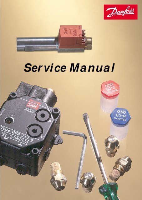
<strong>Service</strong> <strong>Manual</strong>
Dear <strong>Danfoss</strong> partner,<br />
In the field of components for burners and boilers, <strong>Danfoss</strong> offers a complete range for most oil<br />
burners on the market, right from the smallest domestic burners to the largest industrial burners.<br />
The construction of burners available today varies widely; therefore a high degree of adaptability<br />
is demanded from the individual components.<br />
An example: The new series of BFP service pumps from <strong>Danfoss</strong> give the greatest possible<br />
flexibility where the range of functions and connections is concerned. These pumps are<br />
therefore ideal as replacement units for both older <strong>Danfoss</strong> pumps and pumps from other<br />
makers. If you would like precise details of how pump replacement can be simplified - please<br />
read on.<br />
<strong>Danfoss</strong> will of course be pleased to help with the conversions outlined in<br />
this service manual and make the work of finding an alternative easier.<br />
In other words, we will make it as easy as possible for you to find the most<br />
suitable components and service from the comprehensive <strong>Danfoss</strong> range.<br />
The service manual is intended as an aid in the daily routine. We therefore<br />
hope that the manual will make your work with <strong>Danfoss</strong> burner components<br />
easier so that we will be able to look forward to your continued custom.<br />
Your <strong>Danfoss</strong> Team
Contents<br />
1. Oil pumps<br />
Contents oil pump conversion ............................................................................. Page 3<br />
Introduction ............................................................................................... Page 4<br />
Conversion <strong>Danfoss</strong> RS -> RSA ............................................................... Page 7<br />
Conversion <strong>Danfoss</strong> RSL -> BFP service ................................................. Page 8<br />
Conversion <strong>Danfoss</strong> MSL -> BFP service ................................................. Page 10<br />
Conversion <strong>Danfoss</strong> MS -> BFP service ................................................... Page 13<br />
Conversion <strong>Danfoss</strong> BFP -> BFP service ................................................. Page 15<br />
Conversion Suntec -> BFP service ........................................................... Page 20<br />
Conversion Eckerle -> BFP service ........................................................... Page 25<br />
Conversion Delta ....................................................................................... Page 33<br />
Dimensions / accessories / connections .............................................................. Page 39<br />
2. Oil burner controls<br />
Contents oil burner control conversion ................................................................ Page 56<br />
Introduction ............................................................................................... Page 57<br />
Conversion Older <strong>Danfoss</strong> series -> BHO ................................................. Page 58<br />
Conversion Landis & Gyr -> BHO ............................................................. Page 61<br />
Conversion BHO -> BHO .......................................................................... Page 62<br />
Dimensions / accessories .................................................................................... Page 63-66<br />
Oil pumps<br />
1
Oil pumps<br />
3. Ignition units<br />
Contents Ignition unit conversion ....................................................................... Page 67<br />
Introduction ............................................................................................... Page 68<br />
Conversion 52 L -> EBI ............................................................................. Page 69-70<br />
Dimensions / accessories .................................................................................... Page 71-72<br />
4. Nozzles<br />
EH + ES series nozzles, contents ............................................................................ Page 73<br />
Introduction ............................................................................................... Page 74<br />
Conversion ............................................................................................... Page 75<br />
Ordering tables ............................................................................................... Page 76-77<br />
Marking / dimensions / capacity .......................................................................... Page 78-81<br />
OD series nozzles<br />
Contents oil nozzle conversion ........................................................................... Page 82<br />
Introduction ............................................................................................... Page 83<br />
Conversion Delavan -> <strong>Danfoss</strong> ................................................................ Page 85<br />
Conversion Fluidics -> <strong>Danfoss</strong> ................................................................. Page 85<br />
Conversion Hago -> <strong>Danfoss</strong> .................................................................... Page 85<br />
Conversion Monarch -> <strong>Danfoss</strong> ............................................................... Page 85<br />
Conversion Steinen -> <strong>Danfoss</strong> ................................................................. Page 85<br />
Nozzle markings / dimensions / capacity / reference pressure ........................... Page 86-90<br />
5. Oil preheaters<br />
Contents oil preheater conversion ...................................................................... Page 91<br />
Introduction ............................................................................................... Page 92<br />
<strong>Danfoss</strong> standard types ....................................................................................... Page 92<br />
Dimensions ............................................................................................... Page 93-94<br />
2
Oil pump conversion<br />
Contents<br />
Oil pumps<br />
Introduction ................................................................................................ Page 4<br />
Conversion <strong>Danfoss</strong> RS -> RSA ................................................................. Page 7<br />
Conversion <strong>Danfoss</strong> RSL -> BFP <strong>Service</strong> .................................................. Page 8<br />
Conversion <strong>Danfoss</strong> MSL -> BFP <strong>Service</strong>.................................................. Page 10<br />
Conversion <strong>Danfoss</strong> MS -> BFP <strong>Service</strong> .................................................... Page 13<br />
Conversion <strong>Danfoss</strong> BFP -> BFP <strong>Service</strong> .................................................. Page 15<br />
Conversion Suntec -> BFP <strong>Service</strong> ............................................................ Page 20<br />
Conversion Eckerle -> BFP <strong>Service</strong> ........................................................... Page 25<br />
Conversion DELTA -> BFP <strong>Service</strong> ............................................................ Page 33<br />
Dimensions RSA ......................................................................................... Page 39<br />
Accessories RSA ......................................................................................... Page 40<br />
Dimensions RSL, MSL, MS, BFP ................................................................ Page 41<br />
Accessories RSL, MSL, MS, BFP ................................................................ Page 51<br />
Connections ................................................................................................ Page 52<br />
3
Oil pumps<br />
Oil pump conversion<br />
The tables below give the following pump<br />
conversions:<br />
• <strong>Danfoss</strong> RS pumps to RSA pumps<br />
• <strong>Danfoss</strong> RSL/MSL/MS/BFP pumps to BFP<br />
service pumps<br />
• Suntec pumps to BFP service pumps<br />
• Eckerle pumps to BFP service pumps<br />
• Delta pumps to BFP service pumps<br />
Using <strong>Danfoss</strong> service pumps BFP 21 L3 and<br />
BFP 21 R3 it is possible to maintain 90% of<br />
existing small burners. In other cases it can<br />
be difficult to find the correct <strong>Danfoss</strong> service<br />
pump. The main purpose of the conversion<br />
tables is to make the replacement of such<br />
pumps easier.<br />
The tables are compiled as follows:<br />
• Column 1 always gives the pump type to<br />
be replaced.<br />
• Column 2 gives the code number of the<br />
pump to be replaced.<br />
Note: Where Eckerle pumps are<br />
concerned, column 1 gives the old and<br />
column 2 the new designation.<br />
• Column 3 states whether the pump is for<br />
1-pipe or 2-pipe operation.<br />
Note: With the MS pump, the numbers<br />
“1 + 2” are shown together because this<br />
particular unit has automatic changeover.<br />
Eckerle pumps have no suffixes.<br />
• Column 5 gives the <strong>Danfoss</strong> pump type<br />
able to replace the existing pump.<br />
• Column 6 gives the corresponding <strong>Danfoss</strong><br />
code number.<br />
• The last column, »Comments/accessories«,<br />
refers to special characteristics and<br />
features. Please note that in some cases<br />
accessories are necessary.<br />
4
Explanation - code number and comments:<br />
When changing over from pumps with<br />
hydraulic shut-off valve (RSL and MSLC) to<br />
BFP with electric shut-off valve (BFP 11, 21<br />
and 41) a cable must be ordered for<br />
connection to the motor terminals in the oil<br />
burner control.<br />
Some pump types carry the comment “No<br />
repl.”. There are several possible<br />
explanations, among them:<br />
• The BFP service pump cannot supply the<br />
required nozzle capacity.<br />
• The BFP service pump does not have the<br />
required coil voltage. BFP coils are only<br />
available for 220-240 V a.c., 110-120 V a.c.<br />
and 24 V a.c.<br />
• The shaft of the BFP service pump is not of<br />
a suitable diameter.<br />
• With the BFP service pump it is possible<br />
that a hydraulic cylinder might be<br />
Oil pumps<br />
connected to the pressure gauge port on<br />
the front.<br />
The position of connections and clockwise/<br />
counterclockwise indication are always given<br />
when looking on the shaft end. See ill. on<br />
page 6).<br />
Before fitting a service pump, a check<br />
must be made of whether it is set<br />
for 1-pipe or 2-pipe operation. If<br />
necessary, the pump must be<br />
reset to suit the system in<br />
which it is being<br />
installed.<br />
5
Oil pumps<br />
Note:<br />
All information is given looking at the pump on<br />
its shaft end (counterclockwise/clockwise), i.e.<br />
• Direction of shaft rotation<br />
• Valve position<br />
• Connections<br />
Clockwise<br />
Counter<br />
clockwise<br />
View orientation<br />
Changeover from 2-pipe to 1-pipe operation<br />
BFP 11<br />
1-pipe: with horseshoe<br />
washer fitted<br />
2-pipe: with horseshoe<br />
washer removed<br />
BFP 20 / 21 / 41<br />
1-pipe: without screw<br />
2-pipe: screw inserted<br />
6
Oil pumps – <strong>Danfoss</strong> RS<br />
Oil pumps<br />
<strong>Danfoss</strong> oil pumps - older series ➨ Replacement <strong>Danfoss</strong> types<br />
Type Code no.<br />
1/2pipe<br />
RS 28 070-5300 1 ➨ RSA 28 070-5370<br />
RS 28 070L5300 1 ➨ RSA 28 070L5370<br />
RS 28 070-5302 2 ➨ RSA 28 070-5372<br />
RS 28 070L5302 2 ➨ RSA 28 070L5372<br />
RS 28 070-5310 1 ➨ RSA 28 070-5380<br />
RS 28 070L5310 1 ➨ RSA 28 070L5380<br />
RS 28 070-5312 2 ➨ RSA 28 070-5382<br />
RS 28 070L5312 2 ➨ RSA 28 070L5382<br />
RS 28 070-5322 2 ➨ RSA 28 070-5332<br />
RS 28 070L5322 2 ➨ RSA 28 070L5332<br />
RS 40 070-3200 1 ➨ RSA 40 070-3230<br />
RS 40 070L3200 1 ➨ RSA 40 070L3230<br />
RS 40 070-3202 2 ➨ RSA 40 070-3232<br />
RS 40 070L3202 2 ➨ RSA 40 070L3232<br />
RS 40 070-3210 1 ➨ RSA 40 070-3240<br />
RS 40 070L3210 1 ➨ RSA 40 070L3240<br />
RS 40 070-3212 2 ➨ RSA 40 070-3242<br />
RS 40 070L3212 2 ➨ RSA 40 070L3242<br />
RS 40 070-3222 2 ➨ RSA 40 070-3249<br />
RS 40 070L3222 2 ➨ RSA 40 070L3249<br />
RS 60 070-3300 1 ➨ RSA 60 070-3350<br />
RS 60 070L3300 1 ➨ RSA 60 070L3350<br />
RS 60 070-3302 2 ➨ RSA 60 070-3352<br />
RS 60 070L3302 2 ➨ RSA 60 070L3352<br />
RS 60 070-3310 1 ➨ RSA 60 070-3360<br />
RS 60 070L3310 1 ➨ RSA 60 070L3360<br />
➨ Type Code no. Comments/accessories<br />
7
Oil pumps<br />
Oil pumps – <strong>Danfoss</strong> RS<br />
<strong>Danfoss</strong> oil pumps - older series ➨ Replacement <strong>Danfoss</strong> types<br />
Type Code no.<br />
1/2pipe<br />
RS 60 070-3312 2 ➨ RSA 60 070-3362<br />
RS 60 070L3312 2 ➨ RSA 60 070L3362<br />
Oil pumps – <strong>Danfoss</strong> RSL<br />
➨ Type Code no. Comments/accessories<br />
<strong>Danfoss</strong> oil pumps - older series ➨ Replacement <strong>Danfoss</strong> types<br />
Type Code no.<br />
1/2pipe<br />
➨ Type Code no. Comments/accessories<br />
RSL 028 070-4330 1 ➨ BFP 21 R3 071N01571) RSL 028 070L4330 1 ➨ BFP 21 L3 071N01566) + cable, L = 710 mm: 071G0204<br />
RSL 028 070-4332 2 ➨ BFP 21 R3 1) 7)<br />
071N0157<br />
RSL 028 070L4332 2 ➨ BFP 21 L3 6) 7)<br />
071N0156<br />
RSL 028 070-4340 1 ➨ BFP 21 R3 071N01571) RSL 028 070L4340 1 ➨ BFP 21 L3 071N01566) + cable, L = 710 mm: 071G0204<br />
RSL 028 070-4342 2 ➨ BFP 21 R3 071N01571) 7) + bush ∅54: 071B0011<br />
RSL 028 070L4342 2 ➨ BFP 21 L3 6) 7)<br />
071N0156<br />
RSL 050 070-3130 1 ➨ BFP 21 R5 071N01732) RSL 050 070L3130 1 ➨ BFP 21 L5 071N0172<br />
+ cable, L = 710 mm: 071G0204<br />
2)<br />
RSL 050 070-3132 2 ➨ BFP 21 R5 071N01732) RSL 050 070L3132 2 ➨ BFP 21 L5 071N01722) RSL 050 070-3140 1 ➨ BFP 21 R5 071N01732) + cable, L = 710 mm: 071G0204<br />
RSL 050 070L3140 1 ➨ RFP 21 L5 071N01722) + bush ∅54: 071B0011<br />
1) The solenoid coil must be connected in parallel with the burner motor.<br />
2) Important: These pumps are delivered for two-pipe operation. If the pumps are mounted on a one-pipe system, the changeover screw must be removed<br />
(fig. page 6) and the return port must be stopped with a metal plug.<br />
6) If the pump is wanted delivered incl. cable, bush and flange, please order 071N0132.<br />
7) This pump is for one-pipe operation. On pumps for two-pipe operation the changeover screw must be fitted.<br />
8
Oil pumps – <strong>Danfoss</strong> RSL<br />
Oil pumps – <strong>Danfoss</strong> RSLB<br />
Oil pumps<br />
<strong>Danfoss</strong> oil pumps - older series ➨ Replacement <strong>Danfoss</strong> types<br />
Type Code no.<br />
<strong>Danfoss</strong> oil pumps - older series ➨ Replacement <strong>Danfoss</strong> types<br />
Type Code no.<br />
1/2pipe<br />
1/2pipe<br />
RSLB 028 070-4030 1 ➨ BFP 20 R3 071N01692) RSLB 028 070L4030 1 ➨ BFP 20 L3 071N01682) RSLB 028 070-4032 2 ➨ BFP 20 R3 071N01692) RSLB 028 070L4032 2 ➨ BFP 20 L3 071N01682) RSLB 028 070-4040 1 ➨ BFP 20 R3 071N01692) RSLB 028 070L4040 1 ➨ BFP 20 L3 071N01682) RSLB 028 070-4042 2 ➨ BFP 20 R3 071N01692) RSLB 028 070L4042 2 ➨ BFP 20 L3 071N01682) RSLB 050 070-4130 1 ➨ BFP 20 R5 071N01292) RSLB 050 070L4130 1 ➨ BFP 20 L5 071N01262) RSLB 050 070-4132 2 ➨ BFP 20 R5 071N01292) RSLB 050 070L4132 2 ➨ BFP 20 L5 071N01262) RSLB 050 070-4140 1 ➨ BFP 20 R5 071N01292) RSLB 050 070L4140 1 ➨ BFP 20 L5 071N01262) RSLB 050 070-4142 2 ➨ BFP 20 R5 071N01292) RSLB 050 070L4142 2 ➨ BFP 20 L5 071N01262) ➨ Type Code no. Comments/accessories<br />
RSL 050 070-3142 2 ➨ BFP 21 R5 071N0173 2) + cable, L = 710 mm: 071G0204<br />
RSL 050 070L3142 2 ➨ BFP 21 L5 071N0172 2) + bush ∅54: 071B0011<br />
➨ Type Code no. Comments/accessories<br />
+ bush ∅54: 071B0011<br />
+ bush ∅54: 071B0011<br />
Please note:<br />
If a BFP 20 is used on<br />
a gravity feed<br />
installation, a solenoid<br />
valve (it not existing)<br />
must be fitted in the<br />
nozzle line to ensure<br />
“shut off” on burner<br />
stop.<br />
If a valve is not fitted,<br />
then use a BFP 21<br />
and wire the pump’s<br />
solenoid valve into<br />
the control box.<br />
2) Important: These pumps are delivered for two-pipe operation. If the pumps are mounted on a one-pipe system, the changeover screw must be removed<br />
(fig. page 6) and the return port must be stopped with a metal plug.<br />
9
Oil pumps<br />
Oil pumps – <strong>Danfoss</strong> MSLA<br />
<strong>Danfoss</strong> oil pumps - older series ➨ Replacemet <strong>Danfoss</strong> types<br />
Type Code no.<br />
1/2pipe<br />
➨ Type Code no. Comments/accessories<br />
MSLA 032 071B0101 1 ➨ BFP 21 R3 071N0157<br />
MSLA 032 071B0102 2 ➨ BFP 21 R3 071N01577) MSLA 032 071B0103 1 ➨ BFP 21 R3 071N0157 MSLA = + coil 110-120 V a.c.:<br />
MSLA 032 071B0104 2 ➨ BFP 21 R3 071N01577) 100 V a.c 071N0061<br />
MSLA 032 071B0105 1 ➨ BFP 21 R3 071N0157 + coil 110-120 V a.c.: 071N0061<br />
MSLA 032 071B0108 2 ➨ BFP 21 R3 071N01577) MSLA = 200 V a.c.<br />
MSLA 032 071B0112 2 ➨ BFP 21 R3 071N01577) MSLA 032 071B0113 1 ➨ BFP 21 R3 071N0157<br />
MSLA 032 071B0132 2 ➨ BFP 21 R3 071N01577) + coil 24 V a.c.: 071N0062<br />
MSLA 032 071B1101 1 ➨ BFP 21 L3 071N01566) + cable,<br />
MSLA 032 071B1102 2 ➨ BFP 21 L3 6) 7) 071N0156 L = 710 mm:<br />
MSLA 032 071B1103 1 ➨ BFP 21 L3 071N01566) MSLA = + coil 110-120 V a.c.: 071G0204<br />
MSLA 032 071B1104 2 ➨ BFP 21 L3 071N01567) 100 V a.c. 071N0061<br />
MSLA 032 071B1105 1 ➨ BFP 21 L3 071N01566) + coil 110-120 V a.c.: 071N0061<br />
MSLA 032 071B1111 1 ➨ BFP 21 L3 071N01566) MSLA 032 071B1112 2 ➨ BFP 21 L3 6) 7)<br />
071N0156<br />
MSLA 032 071B1114 2 ➨ BFP 21 L3 6) 7)<br />
071N0156<br />
MSLA 032 071B1118 2 ➨ BFP 21 L3 6) 7)<br />
071N0156<br />
MSLA 032 071B1120 2 ➨ BFP 21 L3 6) 7)<br />
071N0156<br />
MSLA 032 071B1126 2 ➨ BFP 21 L3 6) 7)<br />
071N0156<br />
MSLA 032 071B1128 2 ➨ BFP 21 L3 6) 7)<br />
071N0156<br />
MSLA 032 071B1132 2 ➨ BFP 21 L3 071N01566) 7) + coil 24 V a.c.: 071N0062<br />
MSLA 032 071B1134 2 ➨ BFP 21 L3 6) 7)<br />
071N0156<br />
MSLA 032 071B1136 2 ➨ BFP 21 L3 6) 7)<br />
071N0156<br />
MSLA 032 071B1138 2 ➨ BFP 21 L3 6) 7)<br />
071N0156<br />
6) If the pump is wanted delivered incl. cable, bush and flange, please order 071N0132.<br />
7) This pump is for one-pipe operation. On pumps for two-pipe operation the changeover screw must be fitted.<br />
10
Oil pumps – <strong>Danfoss</strong> MSLA/MSLB<br />
Oil pumps<br />
<strong>Danfoss</strong> oil pumps - older series ➨ Replacement <strong>Danfoss</strong> types<br />
Type Code no.<br />
1/2pipe<br />
➨ Type Code no. Comments/accessories<br />
MSLA 050 071B0201 1 ➨ BFP 21 R5 071N01732) MSLA 050 071B0202 2 ➨ BFP 21 R5 071N01732) MSLA 050 071B0203 1 ➨ BFP 21 R5 071N01732) MSLA = + coil 110-120 V a.c.:<br />
MSLA 050 071B0204 2 ➨ BFP 21 R5 071N01732) 100 V a.c. 071N0061<br />
MSLA 050 071B0205 1 ➨ BFP 21 R5 071N01732) + coil 110-120 V a.c.: 071N0061 + cable,<br />
MSLA 050 071B0208 2 ➨ BFP 21 R5 071N01732) MSLA = 200 V a.c. L = 710 mm,<br />
MSLA 050 071B1201 1 ➨ BFP 21 L5 2) 071N0172 071G0204<br />
MSLA 050 071B1202 2 ➨ BFP 21 L5 071N01722) MSLA 050 071B1203 1 ➨ BFP 21 L5 071N01722) MSLA = + coil 110-120 V a.c.:<br />
MSLA 050 071B1204 2 ➨ BFP 21 L5 071N01722) 100 V a.c. 071N0061<br />
MSLB 032 071B2101 1 ➨ BFP 20 R3 071N01692) MSLB 032 071B3101 1 ➨ BFP 20 L3 071N01682) MSLB 032 071B2102 2 ➨ BFP 20 R3 071N0169 2)<br />
MSLB 032 071B2104 2 ➨ BFP 20 R3 071N0169 2)<br />
MSLB 032 071B3102 2 ➨ BFP 20 L3 071N0168 2)<br />
MSLB 050 071B2201 1 ➨ BFP 20 R5 071N0129 2)<br />
MSLB 050 071B3201 1 ➨ BFP 20 L5 071N0126 2)<br />
MSLB 050 071B2202 2 ➨ BFP 20 R5 071N0129 2)<br />
MSLB 050 071B2203 1 ➨ BFP 20 R5 071N0129 2)<br />
MSLB 050 071B3202 2 ➨ BFP 20 L5 071N0126 2)<br />
Please note:<br />
If a BFP 20 is used on a gravity feed installation, a<br />
solenoid valve (it not existing) must be fitted in the<br />
nozzle line to ensure “shut off” on burner stop.<br />
If a valve is not fitted, then use a BFP 21 and wire<br />
the pump’s solenoid valve into the control box.<br />
2) Important: These pumps are delivered for two-pipe operation. If the pumps are mounted on a one-pipe system, the changeover screw must be removed<br />
(fig. page 6) and the return port must be stopped with a metal plug.<br />
11
Oil pumps<br />
Oil pumps – <strong>Danfoss</strong> MSLC/MSLD<br />
<strong>Danfoss</strong> oil pumps - older series ➨ Replacement <strong>Danfoss</strong> types<br />
Type Code no.<br />
1/2pipe<br />
➨ Type Code no. Comments/accessories<br />
MSLC 032 071B4101 1 ➨ BFP 21 R3 071N01571) MSLC 032 071B5101 1 ➨ BFP 21 L3 071N01561) 6) + cable, L = 710 mm: 071G0204<br />
MSLC 032 071B4102 2 ➨ BFP 21 R3 1) 7)<br />
071N0157<br />
MSLC 032 071B5102 2 ➨ BFP 21 L3 1) 6) 7)<br />
071N0156<br />
MSLC 032 071B4103 1 ➨ BFP 21 R5 1) 2)<br />
071N0173<br />
MSLC 032 071B4105 1 ➨ BFP 21 R3 071N01571) MSLC 050 071B4201 1 ➨ BFP 21 R5 071N01731) 2) + cable, L = 710 mm: 071G0204<br />
MSLC 050 071B5201 1 ➨ BFP 21 L5 1) 2)<br />
071N0172<br />
MSLC 050 071B4202 2 ➨ BFP 21 R5 1) 2)<br />
071N0173<br />
MSLC 050 071B5202 2 ➨ BFP 21 L5 1) 2)<br />
071N0172<br />
MSLD 032 071B6101 1 ➨ BFP 20 R3 071N01692) MSLD 032 071B6102 2 ➨ BFP 20 R3 071N01692) MSLD 032 071B7101 1 ➨ BFP 20 L3 071N01682) MSLD 032 071B7102 2 ➨ BFP 20 L3 071N01682) MSLD 032 071B6201 1 ➨ BFP 20 R5 071N01292) MSLD 050 071B6202 2 ➨ BFP 20 R5 071N01292) MSLD 050 071B7201 1 ➨ BFP 20 L5 071N01262) MSLD 050 071B7202 2 ➨ BFP 20 L5 071N01262) 1) The solenoid coil must be connected in parallel with the burner motor.<br />
2) Important: These pumps are delivered for two-pipe operation. If the pumps are mounted on a one-pipe system, the changeover screw must be removed<br />
(fig. page 6) and the return port must be stopped with a metal plug.<br />
6) If the pump is wanted delivered incl. cable, bush and flange, please order 071N0132.<br />
7) This pump is for one-pipe operation. On pumps for two-pipe operation the changeover screw must be fitted.<br />
12
Oil pumps – <strong>Danfoss</strong> MS<br />
2) Important: These pumps are delivered for two-pipe operation. If the pumps are mounted on a one-pipe system, the changeover screw must be removed<br />
(fig. page 6) and the return port must be stopped with a metal plug.<br />
6) If the pump is wanted delivered incl. cable, bush and flange, please order 071N0132.<br />
7) This pump is for one-pipe operation. On pumps for two-pipe operation the changeover screw must be fitted.<br />
Oil pumps<br />
<strong>Danfoss</strong> oil pumps - older series ➨ Replacement <strong>Danfoss</strong> types<br />
Type Code no.<br />
1/2pipe<br />
➨ Type Code no. Comments/accessories<br />
MS 10 L3 071G0125 1 + 2 ➨ BFP 20 L3 071N01682) MS 10 R3 071G0123 1 + 2 ➨ BFP 20 R3 071N01692) MS 10 L3 071G0153 1 + 2 ➨ No repl.<br />
MS 10 R3 071G0175 1 + 2 ➨ BFP 20 R3 071N01692) MS 10 R5 071G0176 1 + 2 ➨ BFP 20 R5 071N01292) MS 10 L5 071G0128 1 + 2 ➨ BFP 20 L5 071N01262) MS 10 R5 071G0124 1 + 2 ➨ BFP 20 R5 071N01292) MS 11 L3 071G0117 1 + 2 ➨ BFP 21 L3 6) 7)<br />
071N0156<br />
MS 11 R3 071G0118 1 + 2 ➨ BFP 21 R3 071N01577) MS 11 L3 071G0121 1 + 2 ➨ BFP 21 L3 6) 7)<br />
071N0156<br />
MS 11 L3 071G0134 1 + 2 ➨ BFP 21 L3 6) 7)<br />
071N0156<br />
MS 11 L3 071G0137 1 + 2 ➨ BFP 21 L3 6) 7)<br />
071N0156<br />
MS 11 L3 071G0139 1 + 2 ➨ BFP 21 L3 6) 7)<br />
071N0156<br />
MS 11 L3 071G0154 1 + 2 ➨ BFP 21 L3 071N01566) 7) + coupling with single flat in hole (D-shaped)<br />
MS 11 L3 071G0156 1 + 2 ➨ BFP 21 L3 071N01566) 7) + coil 24 V a.c.: 071N0062<br />
MS 11 L3 071G0158 1 + 2 ➨ BFP 21 L3 6) 7)<br />
071N0156<br />
MS 11 R3 071G0160 1 + 2 ➨ BFP 21 R3 071N01577) + coil 24 V a.c.: 071N0062<br />
MS 11 L3 071G0162 1 + 2 ➨ BFP 21 L3 6) 7)<br />
071N0156<br />
MS 11 L3 071G0163 1 + 2 ➨ BFP 21 L3 071N01566) 7) + coil 24 V a.c.: 071N0062<br />
MS 11 L3 071G0165 1 ➨ BFP 21 L3 071N01566) MS 11 R3 071G0173 1 + 2 ➨ BFP 21 R3 071N01577) MS 11 R5 071G0174 1 + 2 ➨ BFP 21 R5 071N01732) MS 11 R3 071G0177 1 + 2 ➨ BFP 21 R3 071N01577) MS 11 L3 071G0178 1 + 2 ➨ BFP 21 L3 6) 7)<br />
071N0156<br />
13
Oil pumps<br />
Oilpumps – <strong>Danfoss</strong> MS<br />
<strong>Danfoss</strong> oil pumps - older series ➨ Replacement <strong>Danfoss</strong> types<br />
Type Code no.<br />
1/2pipe<br />
➨ Type Code no. Comments/accessories<br />
MS 11 L3 071G0179 1 + 2 ➨ BFP 21 L3 6) 071N0156<br />
Any hydraulic cylinder must be connected<br />
to the pressure gauge port on the front.<br />
MS 11 L5 071G0127 1 + 2 ➨ BFP 21 L5 071N01722) MS 11 R5 071G0126 1 + 2 ➨ BFP 21 R5 071N01732) MS 12 L3 071G0115 1 + 2 ➨ No repl.<br />
MS 12 R3 071G0113 1 + 2 ➨ No repl.<br />
MS 12 L5 071G0116 1 + 2 ➨ No repl.<br />
MS 12 R5 071G0114 1 + 2 ➨ No repl.<br />
MS 12 L3 071G0161 1 + 2 ➨ No repl.<br />
MS 12E L3 071G0130 1 + 2 ➨ BFP 52E L3 071N22012) MS 12E R3 071G0129 1 + 2 ➨ BFP 52E R3 071N22032) MS 12E L5 071G0120 1 + 2 ➨ BFP 52E L5 071N22022) MS 12E R5 071G0119 1 + 2 ➨ BFP 52E R5 071N22042) MS 12E L3 071G0140 1 + 2 ➨ BFP 52E L3 071N22012) MS 12E L5 071G0181 1 + 2 ➨ BFP 52E L5 071N22022) MS 21 L3 071G0157 1 + 2 ➨ BFP 21 L3 071N01566) MS 21 R3 071G0167 1 + 2 ➨ BFP 21 R3 071N0157<br />
2) Important: These pumps are delivered for two-pipe operation. If the pumps are mounted on a one-pipe system, the changeover screw must be removed<br />
(fig. page 6) and the return port must be stopped with a metal plug.<br />
6) If the pump is wanted delivered incl. cable, bush and flange, please order 071N0132.<br />
14
Oil pumps – <strong>Danfoss</strong> BFP<br />
Type Code no.<br />
BFP ➨ BFP-<strong>Service</strong> pumps<br />
1/2pipe<br />
➨ Type Code no. Comments/accessories<br />
BFP 11 L3 071N0101 2 ➨ BFP 11 L3 071N01413) BFP 21 L3 071N0102 2 ➨ BFP 21 L3 6) 7)<br />
071N0156<br />
BFP 11 L3 071N0103 2 ➨ BFP 21 L3 6) 7)<br />
071N0156<br />
BFP 21 L3 071N0104 2 ➨ BFP 21 L3 6) 7)<br />
071N0156<br />
BFP 11 L5 071N0105 2 ➨ BFP 21 L5 071N01722) BFP 21 L5 071N0107 2 ➨ BFP 21 L3 071N01577) BFP 20 L3 071N0108 1 ➨ BFP 20 L3 071N01682) BFP 21 R3 071N0109 2 ➨ BFP 21 R3 071N01577) Any hydraulic cylinder must be connected<br />
to the pressure gauge port on the front.<br />
BFP 21 L3 071N0111 2 ➨ BFP 21 L3 6) 7)<br />
071N0156<br />
BFP 21 R3 071N0112 2 ➨ BFP 21 R3 071N01577) BFP 21 L3 071N0113 2 ➨ BFP 21 L3 6) 7)<br />
071N0156<br />
BFP 11 L3 071N01145) 2 ➨ BFP 21 L3 071N01566) 7) + coupling with single flat in hole (D-shaped)<br />
BFP 31 L3 071N0115 2 ➨ BFP 21 L3 6) 7)<br />
071N0156<br />
BFP 21 L5 071N0116 2 ➨ BFP 21 L5 071N0172<br />
15<br />
Oil pumps<br />
2) Any hydraulic cylinder must be connected<br />
to the pressure gauge port on the front.<br />
BFP 20 R3 071N0118 1 ➨ BFP 20 R3 071N01692) BFP 21 L3 071N0119 2 ➨ BFP 21 L3 071N01567) BFP 21 R5 071N0120 1 ➨ BFP 21 R5 071N01722) BFP 21 L3 071N0122 1 ➨ BFP 21 L3 071N01566) BFP 21 L3 071N0123 2 ➨ BFP 21 L3 071N01567) + coil 110 V: 071N0061<br />
BFP 20 L3 071N0125 2 ➨ BFP 20 L3 071N01682) BFP 20 L5 071N0126 2 ➨ BFP 20 L5 071N01262) 2) Important: These pumps are delivered for two-pipe operation. If the pumps are mounted on a one-pipe system, the changeover screw must be removed<br />
(fig. page 6) and the return port must be stopped with a metal plug.<br />
3) A screw for 2-pipe operation is fitted under the cover of these pumps.<br />
Without horseshoe washer: Pump set for 2-pipe operation. With horseshoe washer: Pump set for 1-pipe operation.<br />
6) If the pump is wanted delivered incl. cable, bush and flange, please order 071N0132.<br />
7) This pump is for one-pipe operation. On pumps for two-pipe operation the changeover screw must be fitted.
Oil pumps<br />
Oil pumps – <strong>Danfoss</strong> BFP<br />
Type Code no.<br />
BFP ➨ BFP-<strong>Service</strong> pumps<br />
1/2pipe<br />
➨ Type Code no. Comments/accessories<br />
BFP 20 L3 071N0127 1 ➨ BFP 20 L3 071N0168<br />
2) Important: These pumps are delivered for two-pipe operation. If the pumps are mounted on a one-pipe system, the changeover screw must be removed<br />
(fig. page 6) and the return port must be stopped with a metal plug.<br />
3) A screw for 2-pipe operation is fitted under the cover of these pumps.<br />
Without horseshoe washer: Pump set for 2-pipe operation. With horseshoe washer: Pump set for 1-pipe operation.<br />
7) This pump is for one-pipe operation. On pumps for two-pipe operation the changeover screw must be fitted.<br />
2)<br />
BFP 20 R3 071N0128 1 ➨ BFP 20 L3 071N01692) BFP 20 R5 071N0129 2 ➨ BFP 20 R5 071N01292) BFP 21 L3 071N0130 2 ➨ BFP 21 L3 071N0156 7)<br />
BFP 21 L3 071N0132 1 ➨ BFP 21 L3 071N0156<br />
BFP 31 L3 071N0133 2 ➨ BFP 21 L3 071N01567) + coupling with single flat in hole (D-shaped)<br />
BFP 41 L3 071N0135 2 ➨ BFP 41 L3 071N01607) BFP 21 R3 071N0136 1 ➨ BFP 21 R3 071N0157<br />
BFP 41 R3 071N0137 2 ➨ BFP 21 R3 071N01577) BFP 11 L3 071N01413) 1 ➨ BFP 11 L3 071N01413) BFP 11 L3 071N01423) 1 ➨ BFP 11 L3 071N01413) BFP 11 R3 071N01433) 1 ➨ BFP 11 R3 071N01553) BFP 11 L3 071N01443) 2 ➨ BFP 11 L3 071N01413) BFP 11 R3 071N01453) 2 ➨ BFP 11 R3 071N01553) BFP 11 L3 071N01463) 2 ➨ BFP 11 L3 071N01413) Old coil might be usable.<br />
BFP 21 L3 071N0147 2 ➨ BFP 21 L3 071N01567) BFP 21 L3 071N0148 2 ➨ BFP 21 L3 071N01567) BFP 31 L3 071N0149 2 ➨ BFP 21 L3 071N01567) BFP 21 L3 071N0150 2 ➨ BFP 21 L3 071N01567) BFP 21 L3 071N0151 2 ➨ BFP 21 L3 071N01567) BFP 11 L3 071N01523) 2 ➨ BFP 11 L3 071N01413) BFP 11 L3 071N01533) 2 ➨ BFP 11 L3 071N01413) + coil 24 V a.c.: 071N0062<br />
16
Oil pumps – <strong>Danfoss</strong> BFP<br />
Oil pumps<br />
Type Code no.<br />
BFP ➨ BFP-<strong>Service</strong> pumps<br />
1/2pipe<br />
➨ Type Code no. Comments/accessories<br />
BFP 21 R3 071N0154 1 ➨ BFP 21 R3 071N0157<br />
BFP 11 R3 071N0155 3) 1 ➨ BFP 11 R3 071N0155 3)<br />
BFP 21 L3 071N0156 1 ➨ BFP 21 L3 071N0156<br />
BFP 21 R3 071N0157 1 ➨ BFP 21 R3 071N0157<br />
BFP 21 L5 071N0158 1 ➨ BFP 21 L5 071N0172 2)<br />
BFP 21 R5 071N0159 1 ➨ BFP 21 R5 071N0173 2)<br />
BFP 41 L3 071N0160 1 ➨ BFP 41 L3 071N0160<br />
BFP 20 L3 071N0161 1 ➨ BFP 20 L3 071N0168 2)<br />
BFP 20 R3 071N0162 1 ➨ BFP 20 R3 071N0169 2)<br />
BFP 11 R5 071N0163 2 ➨ BFP 21 R5 071N0173 2)<br />
BFP 21 L3 071N0164 2 ➨ BFP 21 L3 071N0156 7)<br />
BFP 11 R5 071N0165 3) 2 ➨ BFP 21 R5 071N0173 2)<br />
BFP 10 R5 071N0166 2 ➨ BFP 20 R5 071N0129 2)<br />
BFP 21 R3 071N0167 2 ➨ BFP 21 R3 071N0157 7)<br />
BFP 20 L3 071N0168 2 ➨ BFP 20 L3 071N0168 2)<br />
BFP 20 R3 071N0169 2 ➨ BFP 20 R3 071N0169 2)<br />
BFP 21 L3 071N0170 2 ➨ BFP 21 L3 071N0160 7)<br />
BFP 21 R3 071N0171 2 ➨ BFP 21 R3 071N0157 7)<br />
BFP 21 L5 071N0172 2 ➨ BFP 21 L5 071N0172 2)<br />
BFP 21 R5 071N0173 2 ➨ BFP 21 R5 071N0173 2)<br />
BFP 41 L3 071N0174 2 ➨ BFP 41 L3 071N0160 7)<br />
BFP 21 L3 071N0175 1 ➨ BFP 21 L3 071N0156<br />
BFP 21 L3 071N0176 1 ➨ BFP 21 L3 071N0156 + coil: 071N0061<br />
2) Important: These pumps are delivered for two-pipe operation. If the pumps are mounted on a one-pipe system, the changeover screw must be removed<br />
(fig. page 6) and the return port must be stopped with a metal plug.<br />
3) A screw for 2-pipe operation is fitted under the cover of these pumps.<br />
Without horseshoe washer: Pump set for 2-pipe operation. With horseshoe washer: Pump set for 1-pipe operation.<br />
7) This pump is for one-pipe operation. On pumps for two-pipe operation the changeover screw must be fitted<br />
17
Oil pumps<br />
Oil pumps – <strong>Danfoss</strong> BFP<br />
Type Code no.<br />
BFP ➨ BFP-<strong>Service</strong> pumps<br />
1/2pipe<br />
➨ Type Code no. Comments/accessories<br />
BFP 10 R3 071N0177 2 ➨ BFP 20 R3 071N01692) BFP 11 L5 071N0178 2 ➨ BFP 21 L5 071N01722) BFP 21 L3 071N0179 2 ➨ BFP 21 L3 071N0156<br />
BFP 20 R5 071N0180 2 ➨ BFP 20 R5 071N01292) BFP 11 R3 071N0181 2 ➨ BFP 11 R3 071N01553) BFP 21 L3 071N0182 2 ➨ BFP 21 L3 071N01567) BFP 11 R3 071N0183 2 ➨ BFP 11 R3 3) 7)<br />
071N0155<br />
BFP 11 L3 071N01842) 2 ➨ BFP 11 L3 071N01413) BFP 21 L3 071N0185 2 ➨ BFP 21 L3 071N0156 7)<br />
BFP 41 L3 071N0188 2 ➨ BFP 41 L3 071N01607) BFP 21 L3 071N0189 2 ➨ BFP 21 L3 071N01567) + coil: 071N0062<br />
BFP 31 L3 071N0190 2 ➨ BFP 11 L3 071N01413) BFP 31 R3 071N0191 2 ➨ BFP 11 R3 071N01553) BFP 31 L3 071N0192 1 ➨ BFP 11 L3 071N01413) BFP 21 L3 071N0193 1 ➨ BFP 21 L3 071N01566) BFP 21 L5 071N0194 1 ➨ BFP 21 L5 071N01722) BFP 21 R5 071N0195 1 ➨ BFP 21 R5 071N01732) BFP 41 R3 071N0196 1 ➨ BFP 21 R3 071N0157<br />
BFP 21 L3 071N0197 2 ➨ BFP 21 L3 071N01567) BFP 21 R3 071N0198 1 ➨ BFP 21 R3 071N0157<br />
BFP 21 L5 071N0202 2 ➨ BFP 21 L5 071N01722) BFP 21 L3 071N0204 2 ➨ No repl.<br />
2) Important: These pumps are delivered for two-pipe operation. If the pumps are mounted on a one-pipe system, the changeover screw must be removed<br />
(fig. page 6) and the return port must be stopped with a metal plug.<br />
3) A screw for 2-pipe operation is fitted under the cover of these pumps.<br />
Without horseshoe washer: Pump set for 2-pipe operation. With horseshoe washer: Pump set for 1-pipe operation.<br />
7) This pump is for one-pipe operation. On pumps for two-pipe operation the changeover screw must be fitted.<br />
18
Oil pumps – <strong>Danfoss</strong> BFP<br />
2) Important: These pumps are delivered for two-pipe operation. If the pumps are mounted on a one-pipe system, the changeover screw must be removed<br />
(fig. page 6) and the return port must be stopped with a metal plug.<br />
3) A screw for 2-pipe operation is fitted under the cover of these pumps.<br />
Without horseshoe washer: Pump set for 2-pipe operation. With horseshoe washer: Pump set for 1-pipe operation.<br />
7) This pump is for one-pipe operation. On pumps for two-pipe operation the changeover screw must be fitted.<br />
Oil pumps<br />
Type Code no.<br />
BFP ➨ BFP-<strong>Service</strong> pumps<br />
1/2pipe<br />
➨ Type Code no. Comments/accessories<br />
BFP 21 R5 071N0207 2 ➨ BFP 21 R5 071N0173 2)<br />
BFP 21 R3 071N0208 2 ➨ BFP 21 R3 071N0157 7)<br />
BFP 11 L3 071N0210 3) 1 ➨ BFP 11 L3 071N0141 3)<br />
BFP 20 L3 071N0212 2 ➨ BFP 20 L3 071N0168 2) + coupling with single flat in hole (D-shaped)<br />
BFP 11 L3 071N0213 3) 1 ➨ BFP 11 L3 071N0141 3)<br />
BFP 21 R3 071N0214 1 ➨ BFP 21 R3 071N0157<br />
BFP 21 R3 071N0215 2 ➨ BFP 21 R3 071N0157 7) 071N0215 has G 1 /8 in S+R<br />
BFP 21 L3 071N0217 2 ➨ BFP 21 L3 071N0156 7)<br />
BFP21L3-LE 071N2103 2 ➨ BFP 21 L3 LE 071N2113<br />
BFP21L3-LE 071N2104 2 ➨ BFP 21 L3 LE 071N2113<br />
BFP21R3LE 071N2107 2 ➨ BFP 21 R3 LE 071N2107<br />
BFP31L3-LE 071N2109 2 ➨ BFP 21 L3 LE 071N2113<br />
BFP21L3-LE 071N2113 2 ➨ BFP 21 L3 LE 071N2113<br />
BFP21L3-LE 071N2114 2 ➨ BFP 21 L3 LE 071N2113<br />
BFP 52E L3 071N2201 2 ➨ BFP 52E L3 071N2201<br />
BFP 52E L5 071N2202 2 ➨ BFP 52E L5 071N2202<br />
BFP 52E R3 071N2203 2 ➨ BFP 52E R3 071N2203<br />
BFP 52E R5 071N2204 2 ➨ BFP 52E R5 071N2204<br />
BFP 52E L5 071N2205 2 ➨ BFP 52E L5 071N2202<br />
BFP 52E R5 071N2206 2 ➨ BFP 52E R5 071N2204<br />
BFP 52E L3 071N2211 2 ➨ BFP 52E L3 071N2201<br />
+ coupling with single flat in hole (D-shaped)<br />
BFP 52E L5 071N2212 2 ➨ BFP 52E L5 071N2202<br />
BFP 52E L3 071N2213 2 ➨ BFP 52E L3 071N2201<br />
19
Oil pumps<br />
Oil pumps – Suntec<br />
Suntec ➨ <strong>Danfoss</strong> oil pumps<br />
Type Code no.<br />
1/2pipe<br />
➨ Type Code no. Comments/accessories<br />
AN47A 13261P 2 ➨ BFP 20 R3 071N01692) AN47D 13391P 2 ➨ BFP 20 L3 071N01682) AN47C 13421P 2 ➨ BFP 20 L3 071N01682) AN47B 13951P 2 ➨ BFP 20 R3 071N01692) AN47A 72163P 2 ➨ BFP 20 R3 071N01692) AN47B 72173P 2 ➨ BFP 20 R3 071N01692) AN47C 72183P 2 ➨ BFP 20 L3 071N0168<br />
+ flange and bush ∅54: 071N0047<br />
2)<br />
AN47D 72193P 2 ➨ BFP 20 L3 071N01682) AN47A 72263P 2 ➨ BFP 20 R3 071N01692) AN47B 72273P 2 ➨ BFP 20 R3 071N01692) AN47C 72283P 2 ➨ BFP 20 L3 071N0168<br />
+ bush ∅54: 071B0011<br />
2)<br />
AN47D 72293P 2 ➨ BFP 20 L3 071N01682) AN47C 72473M 1 ➨ BFP 20 L3 071N01682) AN47A 72832M 1 ➨ BFP 20 R3 071N0169<br />
+ 071N0047, possible changeover to 1-pipe operation<br />
2)<br />
AN47A 73263P 2 ➨ BFP 20 R3 071N01692) AN47B 73273P 2 ➨ BFP 20 R3 071N01692) AN47C 73283P 2 ➨ BFP 20 L3 071N01682) AN47A 73443P 2 ➨ BFP 20 R3 071N01692) AN57B 13301P 2 ➨ BFP 20 R5 071N01292) AN57A 72433P 2 ➨ BFP 20 R5 071N01292) AN57C 72823P 2 ➨ BFP 20 L5 071N0126<br />
+ flange and bush ∅54: 071N0047<br />
2)<br />
AN67B 13351P 2 ➨ BFP 20 R5 071N01292) AN67C 13361P 2 ➨ BFP 20 L5 071N01262) Suntec: 80 l/h, BFP: 40 l/h at 12 bar<br />
AN67D 13571P 2 ➨ BFP 20 L5 071N01262) AN67C 72333P 2 ➨ RSA 40 070L32492) + flange: 070-0211<br />
2) Important: These pumps are delivered for two-pipe operation. If the pumps are mounted on a one-pipe system, the changeover screw must be removed<br />
(fig. page 6) and the return port must be stopped with a metal plug.<br />
20
Oil pumps – Suntec<br />
Suntec ➨ <strong>Danfoss</strong> oil pumps<br />
Type Code no.<br />
1/2pipe<br />
➨ Type Code no. Comments/accessories<br />
AN67A 72383P 2 ➨ BFP 20 R5 2) 071N0129 + flange: 071N0047<br />
Suntec: 80 l/h, BFP: 40 l/h at 12 bar<br />
AN67C 72423P 2 ➨ RSA 40 070L32492) AN67B 72513P 2 ➨ RSA 40 070-3249<br />
+ flange: 070-0211<br />
2)<br />
AN67D 72523P 2 ➨ BFP 20 L5 071N01262) AN67B 73353P 2 ➨ BFP 20 R5 071N0129<br />
+ flange: 071N0047<br />
2)<br />
AN67A 73453P 2 ➨ BFP 20 R5 071N0129<br />
Suntec: 80 l/h, BFP: 40 l/h at 12 bar<br />
2)<br />
AL35B 95202P0200 2 ➨ BFP 21 R3 071N01577) + 24 V a.c. coil: 071N0062<br />
AL35B 95202P0500 2 ➨ BFP 21 R3 071N01577) AL35C 95212P0500 2 ➨ BFP 21 L3 6) 7)<br />
071N0156<br />
AL35C 95242M0500 1 ➨ BFP 21 L3 071N01566) AL35A 95262P0500 2 ➨ BFP 21 R3 071N01577) AL35C 95282P0500 2 ➨ BFP 21 L3 6) 7)<br />
071N0156<br />
AL35D 95292P0200 2 ➨ BFP 21 L3 071N01566) 7) + 24 V a.c. coil: 071N0062<br />
AL35C 95402P0500 2 ➨ BFP 21 L3 071N01566) 7) Suntec: G 1 /8 in S+R<br />
AL35C 95652M0500 1 ➨ BFP 21 L3 071N01566) AL35A 95702P0500 2 ➨ BFP 21 R3 071N01577) AL35C 95782P0500 2 ➨ BFP 21 L3 6) 7)<br />
071N0156<br />
AL35B 95802P0500 2 ➨ BFP 21 R3 071N01577) AL35C 95402P0500R 2 ➨ BFP 21 L3 6) 7)<br />
071N0156<br />
AL55B 95312P0500 2 ➨ BFP 21 R5 071N01732) AS47A 15361P0500 2 ➨ BFP 21 R3 071N01577) AS47B 15371P0500 2 ➨ BFP 21 R3 071N01577) AS47C 15381P0500 2 ➨ BFP 21 L3 6) 7)<br />
071N0156<br />
AS47D 15391P0500 2 ➨ BFP 21 L3 6) 7)<br />
071N0156<br />
2) Important: These pumps are delivered for two-pipe operation. If the pumps are mounted on a one-pipe system, the changeover screw must be removed<br />
(fig. page 6) and the return port must be stopped with a metal plug.<br />
6) If the pump is wanted delivered incl. cable, bush and flange, please order 071N0132.<br />
7) This pump is for one-pipe operation. On pumps for two-pipe operation the changeover screw must be fitted.<br />
21<br />
Oil pumps
Oil pumps<br />
Oil pumps – Suntec<br />
Suntec ➨ <strong>Danfoss</strong> oil pumps<br />
Type Code no.<br />
1/2pipe<br />
➨ Type Code no. Comments/accessories<br />
AS47D 15501P0500 2 ➨ BFP 21 L3 6) 7)<br />
071N0156<br />
AS47B 15511P0500 2 ➨ BFP 21 R3 071N01577) AS47C 15541P0500 2 ➨ BFP 21 L3 6) 7)<br />
071N0156<br />
AS47D 15571P0500 2 ➨ BFP 21 L3 071N01566) 7) + coupling with single flat in hole (D-shaped)<br />
AS47D 15621P0500 2 ➨ BFP 21 L3 6) 7)<br />
071N0156<br />
AS47D 15681P0500 2 ➨ BFP 21 L3 6) 7)<br />
071N0156<br />
AS47C 15691P0500 2 ➨ BFP 21 L3 6) 7)<br />
071N0156<br />
AS47D 15721P0500 2 ➨ BFP 21 L3 6) 7)<br />
071N0156<br />
AS47D 15801P0500 2 ➨ BFP 21 L3 6) 7)<br />
071N0156<br />
AS47A 74323P0500 2 ➨ BFP 21 R3 071N01577) AS47C 74343P0500 2 ➨ BFP 21 L3 071N01566) 7) + flange and bush ∅54: 071N0047<br />
AS47D 74353P0500 2 ➨ BFP 21 L3 6) 7)<br />
071N0156<br />
AS47A 74363P0500 2 ➨ BFP 21 R3 071N01577) AS47C 74383P0500 2 ➨ BFP 21 L3 071N01566) 7) + bush ∅54: 071B0011<br />
AS47D 74393P0500 2 ➨ BFP 21 L3 6) 7)<br />
071N0156<br />
AS47C 74443P0500 2 ➨ BFP 21 L3 6) 7)<br />
071N0156<br />
AS47B 74453P0500 2 ➨ BFP 21 R3 071N0157 + flange and bush ∅54: 071N0047<br />
7)<br />
AS47C 74513M0500 1 ➨ BFP 21 L3 071N01566) AS47C 74613P0500 2 ➨ BFP 21 L3 6) 7)<br />
071N0156<br />
AS47C 75543P0500 2 ➨ BFP 21 L3 6) 7)<br />
071N0156<br />
AS47D 75623P0500 2 ➨ BFP 21 L3 6) 7)<br />
071N0156<br />
AS47A 75643P0500 2 ➨ BFP 21 R3 071N01577) AS57C 15441P0500 2 ➨ BFP 21 L5 2) 7)<br />
071N0172<br />
AS57C 74413P0500 2 ➨ BFP 21 L5 071N01722) AS57B 74423P0500 2 ➨ BFP 21 R5 071N0173<br />
+ flange and bush ∅54: 071N0047<br />
2)<br />
2) Important: These pumps are delivered for two-pipe operation. If the pumps are mounted on a one-pipe system, the changeover screw must be removed<br />
(fig. page 6) and the return port must be stopped with a metal plug.<br />
6) If the pump is wanted delivered incl. cable, bush and flange, please order 071N0132.<br />
7) This pump is for one-pipe operation. On pumps for two-pipe operation the changeover screw must be fitted.<br />
22
Oil pumps – Suntec<br />
Oil pumps<br />
Suntec ➨ <strong>Danfoss</strong> oil pumps<br />
Type Code no.<br />
1/2pipe<br />
AS57C 75443P0500 2 ➨ BFP 21 L5 071N0172 2)<br />
AE45C 13601P 2 ➨ BFP 20 L5 071N0126 2)<br />
➨ Type Code no. Comments/accessories<br />
AE45C 13701M 1 ➨ BFP 20 L5 071N01262) Possible changeover to 1-pipe operation<br />
Suntec: 1/8 NPTF in nozzle outlet<br />
AE47B 13661P 2 ➨ BFP 20 R5 071N01292) AE47D 13781M 1 ➨ BFP 20 L5 071N01262) AE47A 13841M 1 ➨ BFP 20 R5 071N0129<br />
Possible changeover to 1-pipe operation<br />
2)<br />
AE47D 13851P 2 ➨ BFP 20 L5 071N01262) AE47C 13861P 2 ➨ BFP 20 L5 071N01262) AE47C 13871P 2 ➨ BFP 20 L5 071N01262) AE47B 72673P 2 ➨ BFP 20 R5 071N01292) + bush ∅54: 071B0011<br />
AE47C 72743M 1 ➨ BFP 20 L5 071N01262) + flange and bush ∅54: 071N0047,<br />
Possible changeover to 1-pipe operation<br />
AE47C 73683P 2 ➨ BFP 20 L5 071N01262) AE57B 13641M 1 ➨ BFP 20 R5 071N01292) Possible changeover to 1-pipe operation<br />
AE57C 73733P 2 ➨ BFP 20 L5 071N01262) AE67D 72783P 2 ➨ BFP 20 L5 071N01262) + flange: 071N0047<br />
Suntec: 80 l/h, BFP: 40 l/h at 12 bar<br />
AE67C 73613P 2 ➨ BFP 20 L5 071N01262) Suntec: 80 l/h, BFP: 40 l/h at 12 bar<br />
AE77C 72702P 2 ➨ RSA 60 070L33472) + flange: 070-0211<br />
Possible changeover to 1-pipe operation<br />
AE77C 73802P 2 ➨ BFP 20 L5 071N01262) Suntec: 80 l/h, BFP: 40 l/h at 12 bar<br />
AE97C 73902P 2 ➨ BFP 20 L5 071N01262) Suntec: 130 l/h, BFP: 40 l/h at 12 bar<br />
AP47A 75553P0500 2 ➨ No repl.<br />
AP47C 75563P0500 2 ➨ BFP 52E L5 2) 4)<br />
071N2202<br />
2) Important: These pumps are delivered for two-pipe operation. If the pumps are mounted on a one-pipe system, the changeover screw must be removed<br />
(fig. page 6) and the return port must be stopped with a metal plug.<br />
4) The pump NC valve must be connected in parallel to the NC valve in the nozzle line.<br />
23
Oil pumps<br />
Oil pumps – Suntec<br />
Suntec ➨ <strong>Danfoss</strong> oil pumps<br />
Type Code no.<br />
1/2pipe<br />
➨ Type Code no. Comments/accessories<br />
AP47B 75613P0500 2 ➨ BFP 52E R5 071N22044) AP47C 74603P0500 2 ➨ BFP 52E L5 071N22024) + flange and bush ∅54: 071N0047<br />
AP57C 74433P0500 2 ➨ BFP 52E L5 071N22024) Suntec: 35 l/h, BFP: 26 l/h at 22 bar + 071N0047<br />
AP57C 75453P0500 2 ➨ BFP 52E L5 071N22024) AP57A 75493P0500 2 ➨ BFP 52E R5 071N2204<br />
Suntec: 35 l/h, BFP: 26 l/h at 22 bar<br />
4)<br />
AP67C 74583P0500 2 ➨ BFP 52E L5 071N22024) Suntec: 58 l/h, BFP: 26 l/h at 22 bar + 071N0047<br />
AP67C 75593P0500 2 ➨ BFP 52E L5 071N22024) Suntec: 58 l/h, BFP: 26 l/h at 22 bar<br />
AP245C 95541P0500 2 ➨ BFP 52E L5 071N22024) AP245C 95601P0500 2 ➨ BFP 52E L5 071N22024) AP265C 95111P0500 2 ➨ BFP 52E L5 071N22024) Suntec: 68 l/h, BFP: 26 l/h at 22 bar<br />
AP345C 95101P0500 2 ➨ No repl.<br />
Suntec: No pressure on the measuring port on the<br />
front in stage 1.<br />
AT245C 95412P0500 2 ➨ BFP 52E L5 071N2202<br />
AT245D 95442P0500 2 ➨ No repl.<br />
AT245A 95472P0500 2 ➨ No repl. Suntec: Nozzle output on right<br />
AT245D 95482M0500 1 ➨ No repl.<br />
AT255C 95492P0500 2 ➨ BFP 52E L5 071N2202 Suntec: 47 l/h, BFP: 26 l/h at 22 bar<br />
AT255A 95522P0500 2 ➨ No repl. Suntec: Nozzle output on right<br />
AT265C 95562P0500 2 ➨ BFP 52E L5 071N2202 Suntec: 68 l/h, BFP: 26 l/h at 22 bar<br />
AT3.... ➨ No repl. Special pump<br />
4) The pump NC valve must be connected in parallel to the NC valve in the nozzle line.<br />
24
Oil pumps – Eckerle<br />
Oil pumps<br />
Eckerle ➨ <strong>Danfoss</strong> oil pumps<br />
Old New<br />
Code<br />
➨ Type<br />
designation designation no.<br />
Comments/accessories<br />
UNI 1.1 L5 L64W UNI-E 2.1 L1 L64 ➨ BFP 20 L3 071N01682) Eckerle: G 1 UNI 1.2 L1 L64-50 UNI 2.12 L1 L64 ➨ BFP 21 L3 071N0156<br />
/8 in S+R<br />
6)<br />
UNI 1.2 L5 L14 UNI 2.12 L1 L14 ➨ BFP 21 L3 071N01566) UNI 1.2 L5 L64-M1 UNI-E 2.1 L1 L64-21 ➨ BFP 21 L3 071N01566) Eckerle: G 1 UNI 1.2 L5 L64-50 UNI 2.12 L1 L64 ➨ BFP 21 L3 071N0156<br />
/8 in S+R<br />
6)<br />
UNI 1.2 L5 M14-50 UNI 2.12 L1 M14 ➨ BFP 21 L3 071N01566) UNI 1.2 L5 M64-50-W UNI 2.12 L1 M64-65 ➨ BFP 21 L3 071N01566) Eckerle: G 1 /8 in S+R<br />
UNI 1.2 L62 M14-01-W UNI 2.12 L6 M14-65 ➨ BFP 21 L5 071N01722) UNI 1.2 L62 L14W ➨ BFP 21 L5 071N0172<br />
Eckerle: max. 75 l/h, BFP: max 40 l/h at 12 bar<br />
2)<br />
UNI 1.42 L5 A64-W UNI 2.42 L5 L64-65 ➨ BFP 52E L5 071N22022) UNI 1.42 L5 L64W ➨ BFP 52E L3 071N22012) Eckerle: G 1 /8 in S+R<br />
UNI 1.42 L6 L64W ➨ BFP 52E L5 071N22022) UNI 1.72 L62 L14-W UNI 2.17 L6 M14-65 ➨ No repl.<br />
UNI 2.1 L1 L40 UNI-E 2.1 L1 L10 (-22,-30) ➨ BFP 20 L3 071N01682) + coupling with single flat in hole (D-shaped)<br />
UNI 2.1 L1 L44 UNI-E 2.1 L1 L14 ➨ BFP 20 L3 071N01682) UNI 2.1 L1 L44H UNI-E 2.1 L14 ➨ BFP 20 L3 071N01682) UNI 2.1 R1 L40 UNI-E 2.1 R1 L10 ➨ BFP 20 R3 071N01692) + coupling with single flat in hole (D-shaped)<br />
UNI 2.1 R1 L44-21 UNI-E 2.1 R1 L14 ➨ BFP 20 R3 071N01692) UNI 2.1 L5 L40-21 UNI-E 2.1 L5 L10 ➨ BFP 20 L5 071N01262) + coupling with single flat in hole (D-shaped)<br />
UNI 2.1 L5 L42 UNI-E 2.1 L5 L12 ➨ BFP 20 L5 071N01262) + coupling with single flat in hole (D-shaped) + 071B0011<br />
UNI 2.1 L5 L44 UNI-E 2.1 L5 L14 (-13) ➨ BFP 20 L5 071N01262) UNI 2.1 L5 L50 UNI-E 2.1 L5 L10 ➨ BFP 20 L5 2) 071N0126 Eckerle: 10-25 bar, BFP max. 20 bar<br />
+ coupling with single flat in hole (D-shaped)<br />
UNI 2.1 L5 R44 UNI-E 2.1 L5 R14 (-13) ➨ BFP 20 L5 071N01262) UNI 2.1 L5 R94 UNI-E 2.1 L5 R74 ➨ BFP 20 L5 071N01262) Eckerle: G 1 /8 in S+R<br />
2) Important: These pumps are delivered for two-pipe operation. If the pumps are mounted on a one-pipe system, the changeover screw must be removed<br />
(fig. page 6) and the return port must be stopped with a metal plug.<br />
6) If the pump is wanted delivered incl. cable, bush and flange, please order 071N0132.<br />
25
Oil pumps<br />
Oil pumps – Eckerle<br />
Eckerle ➨ <strong>Danfoss</strong> oil pumps<br />
Old New<br />
Bestell-<br />
➨ Type<br />
designation designation nummer<br />
Comments/accessories<br />
UNI 2.1 R5 L42-UI-21 UNI-E 2.1 R5 L12-80 ➨ BFP 20 R5 071N01292) + coupling with single flat in hole (D-shaped)<br />
UNI 2.1 R5 L43-UI-21 UNI-E 2.1 R5 L13-80 ➨ BFP 20 R5 071N01292) + flange: 071N0047<br />
UNI 2.1 R5 L43 ➨ BFP 20 R5 071N01292) UNI 2.1 R5 L44 UNI-E 2.1 R5 L14 ➨ BFP 20 R5 071N01292) UNI 2.1 R5 L54 UNI-E 2.1 R5 L24 ➨ BFP 20 R5 071N01292) Eckerle: max 25 bar<br />
UNI 2.1 R5 R42 ➨ BFP 20 R5 071N01292) UNI 2.1 R5 R44 UNI-E 2.1 R5 R14 ➨ BFP 20 R5 071N01292) UNI 2.1 R5 R45-21 UNI-E 2.1 R5 R15 ➨ BFP 20 R5 071N01292) + bush : 071B0011<br />
UNI-E 2.1 R5 R60 ➨ BFP 20 R5 071N01292) G1 /8 in S+R + coupling with single flat in hole (D-shaped)<br />
UNI 2.1 R5 R80 UNI-E 2.1 R5 R40 ➨ BFP 20 R5 071N01292) + coupling with single flat in hole (D-shaped)<br />
UNI 2.1 L6 L54<br />
UNI 2.1 L6 L54-06<br />
UNI-E 2.1 L6 L24<br />
UNI-E 2.1 L6 L24<br />
➨<br />
➨<br />
No repl.<br />
No repl.<br />
Eckerle: ∅32, RSA 40: ∅54 neck diameter<br />
UNI 2.1 R6 L25 UNI-E 2.1 R6 L25 ➨ RSA 40 070-3249<br />
UNI 2.1 R6 R54 UNI-E 2.1 R6 L24 ➨ No repl. Eckerle: ∅32, RSA: ∅54 neck diameter<br />
UNI 2.1 L7 L55 UNI-E 2.1 L7 L15 ➨ RSA 60 070L3347<br />
UNI 2.1 L7 L55-05 UNI-E 2.1 L7 L25 ➨ RSA 60 070L3347<br />
UNI 2.1 R7 L55 UNI-E 2.1 R7 L15 ➨ RSA 60 070L3352 Shaft: Eckerle: ∅8, RSA: ∅10<br />
UNI 2.1 G22 L1 L10/L40 UNI-E 2.1 G22 ➨ BFP 20 L3 071N01682) + coupling with single flat in hole (D-shaped)<br />
UNI-E 2.1 L1 L64 (-21) ➨ BFP 20 L3 071N01682) G1 UNI-E 2.1 L5 R74 ➨ BFP 20 L5 071N0172<br />
/8 in S+R<br />
2)<br />
UNI 2.1 G41-21 L1 L10 UNI-E 2.1 G41 ➨ BFP 20 L3 071N01682) UNI-E 2.1 G41-13 ➨ BFP 20 L3 071N01682) + coupling with single flat in hole (D-shaped)<br />
UNI- E 2.2 L1 L10 ➨ BFP 21 L3 071N01566) 2) Important: These pumps are delivered for two-pipe operation. If the pumps are mounted on a one-pipe system, the changeover screw must be removed<br />
(fig. page 6) and the return port must be stopped with a metal plug.<br />
6) If the pump is wanted delivered incl. cable, bush and flange, please order 071N0132.<br />
26
Oil pumps – Eckerle<br />
Oil pumps<br />
Eckerle ➨ <strong>Danfoss</strong> oil pumps<br />
Old New<br />
Code<br />
➨ Type<br />
designation designation no.<br />
Comments/accessories<br />
UNI 2.2 L1 L14 UNI-E 2.2 L1 L14 ➨ BFP 21 L3 071N0156 6)<br />
UNI 2.2 L1 L16W UNI-E 2.2 L1 L16-10 ➨ BFP 21 L3 071N0156 6) + flange: 071N0047<br />
UNI 2.2 L1 L44 UNI-E 2.2 L1 L14 ➨ BFP 21 L3 071N0156 6)<br />
UNI 2.2 L1 R14 UNI-E 2.2 L1 R14-12 ➨ BFP 21 L3 071N0156 6)<br />
UNI 2.2 R1 L40 UNI-E 2.2 R1 L10 ➨ BFP 21 R3 071N0157 + coupling with single flat in hole (D-shaped)<br />
UNI 2.2 R1 M14 UNI-E 2.2 R1 M14 ➨ BFP 21 R3 071N0157<br />
UNI 2.2 R1 R24 UNI-E 2.2 R1 R24 ➨ BFP 21 R3 071N0157 Eckerle: max 25 bar<br />
UNI-E 2.2 R1 S14 ➨ BFP 21 R3 071N0157<br />
UNI 2.2 L5 L14 UNI-E 2.2 L5 L14-92 ➨ BFP 21 L5 071N01722) Eckerle: G 1 /8 in S+R<br />
Eckerle: 10-25 bar, BFP: max. 20 bar<br />
UNI 2.2 L5 L15-21-05 UNI-E 2.2 L5 L15 ➨ BFP 21 L5 071N01722) + bush: 071B0011<br />
UNI 2.2 L5 L40-X UNI-E 2.2 L5 L10-50 ➨ BFP 21 L5 071N01722) + coupling with single flat in hole (D-shaped)<br />
UNI 2.2 L5 L42 UNI-E 2.2 L5 L12 ➨ BFP 21 L5 2) 071N0172 + bush: 071B0011<br />
+ coupling with single flat in hole (D-shaped)<br />
UNI 2.2 L5 L60 ➨ BFP 21 L5 071N01722) + coupling with single flat in hole (D-shaped)<br />
UNI-E 2.2 L5 L60 ➨ BFP 21 L5 071N01722) Eckerle: G 1 /8 in S+R<br />
+ coupling with single flat in hole (D-shaped)<br />
UNI 2.2 L5 L62 ➨ BFP 21 L5 071N01722) UNI 2.2 L5 M14-C1 UNI.E 2.2 L5 M14-12 ➨ BFP 21 L5 071N01722) UNI 2.2 L5 S20 UNI-E 2.2 L5 S20 ➨ BFP 21 L5 2) 071N0172 Eckerle: 10-25 bar, BFP: max. 20 bar<br />
+ coupling with single flat in hole (D-shaped)<br />
UNI 2.2 L5 S20-21-BUD UNI-E 2.2 L5 S20 BUD ➨ BFP 21 L5 2) 071N0172 Eckerle: max 25 bar, BFP: max. 20 bar<br />
+ coupling with single flat in hole (D-shaped)<br />
UNI 2.2 L5 S74 UNI-E 2.2 L5 L14 ➨ BFP 21 L5 2) 071N0172 Eckerle: 10-25 bar, BFP: max. 20 bar<br />
+ coupling with single flat in hole (D-shaped)<br />
2) Important: These pumps are delivered for two-pipe operation. If the pumps are mounted on a one-pipe system, the changeover screw must be removed<br />
(fig. page 6) and the return port must be stopped with a metal plug.<br />
6) If the pump is wanted delivered incl. cable, bush and flange, please order 071N0132.<br />
27
Oil pumps<br />
Oil pumps – Eckerle<br />
Eckerle ➨ <strong>Danfoss</strong> oil pumps<br />
Old New<br />
Code<br />
➨ Type<br />
designation designation no.<br />
Comments/accessories<br />
UNI-E 2.2 L5 S74 ➨ BFP 21 L5 071N01722) G1 /8 in S+R. Eckerle: max 25 bar<br />
UNI 2.2 R5 L14 UNI-E 2.2 R5 L14 ➨ BFP 21 R5 071N01732) UNI-E 22 R5 M14 ➨ BFP 21 R5 071N01732) UNI 2.2 R5 M45 UNI-E 2.2 R5 M15 ➨ BFP 21 R5 071N01732) + bush: 071B0011<br />
UNI 2.2 R5 R14 UNI-E 2.2 R5 R14 ➨ BFP 21 R5 071N01732) UNI 2.2 R5 R60-21 UNI-E 2.2 R5 R60 ➨ BFP 21 R5 071N01732) Eckerle: G 1/8 in S+R<br />
UNI 2.2 R5 R80B UNI-E 2.2 R5 R60 ➨ BFP 21 R5 071N01732) + coupling with single flat in hole (D-shaped)<br />
UNI-E 2.2 R5 S14 ➨ BFP 21 R5 071N01732) UNI 2.2 R5 S60 UNI-E 2.2 R5 S60 ➨ BFP 21 R5 071N01732) UNI-E 2.2 L6 L14 ➨ BFP 21 L5 071N0172 2) Eckerle: max 75 l/h, BFP: 40 l/h at 12 bar<br />
UNI 2.2 L6 L16W UNI-E 2.2 L6 L16-10 ➨ BFP 21 L5 2) 071N0172 Eckerle: max 75 l/h,<br />
BFP: max 40 l/h at 12 bar + 071N0047<br />
UNI 2.2 L6 L24 UNI-E 2.2 L6 L24 ➨ BFP 21 L5 071N01722) UNI-E 2.2 L6 LR14-81 ➨ BFP 21 L5 071N01722) UNI 2.2 R6 M24 UNI-E 2.2 R6 M24 ➨ BFP 21 R5 071N01732) Eckerle: 75 l/h, BFP: max 40 l/h at 12 bar<br />
UNI 2.2 R6 S24-ET UNI-E 2.2 R6 S24 (-40) ➨ BFP 21 R5 071N01732) UNI 2.2 R6 S24 ET(R1) UNI-E 2.2 R6 S24-40 ➨ BFP 21 R5 071N01732) UNI 2.2 L7 L26 ➨ BFP 21 L5 2) 071N0172 Eckerle: 120 l/h,<br />
BFP: max 40 l/h at 12 bar + 071N0047<br />
UNI 2.2 L7 L24 ➨ BFP 21 L5 071N01722) UNI-E 2.2 L7 L28 ➨ BFP 21 L5 071N01722) UNI-E 2.2 L7 LR14-61 ➨ BFP 21 L5 071N01722) UNI 2.2 R7 L24-05 UNI-E 2.2 R7 L24 ➨ BFP 21 R5 071N0173<br />
Eckerle: 120 l/h, BFP: max 40 l/h at 12 bar<br />
2)<br />
UNI 2.2 R7 R24-R1(-ET) UNI-E 2.2 R7 R24-40 ➨ BFP 21 R5 071N01732) UNI 2.2 R7 R54-5 (-ET) UNI-E 2.2 R7 R24 ➨ BFP 21 R5 071N01732) 2) Important: These pumps are delivered for two-pipe operation. If the pumps are mounted on a one-pipe system, the changeover screw must be removed<br />
(fig. page 6) and the return port must be stopped with a metal plug.<br />
28
Oil pumps – Eckerle<br />
UNI-E 2.3 L5 L64 ➨ BFP 20 L5 071N0126<br />
2) Important: These pumps are delivered for two-pipe operation. If the pumps are mounted on a one-pipe system, the changeover screw must be removed<br />
(fig. page 6) and the return port must be stopped with a metal plug.<br />
4) The pump NC valve must be connected in parallel to the NC valve in the nozzle line.<br />
2) Eckerle: G 1 /8 in S+R<br />
UNI 2.3 L5 R54-S UNI-E 2.3 L5 R24-13 ➨ BFP 20 L5 071N01262) UNI 2.3 R5 L54-05 UNI-E 2.3 R5 L24 ➨ BFP 20 R5 071N01292) Eckerle: max 25 bar, BFP: max 20 bar<br />
UNI-E 2.3 R5 R24-13 ➨ BFP 20 R5 071N01292) UNI 2.3 R5 R54 ➨ BFP 20 R5 071N01292) Eckerle: 10-25 bar, BFP: max 20 bar<br />
UNI 2.3 R5 R64-I UNI-E 2.3 R5 R24-93 ➨ BFP 20 R5 071N01292) Eckerle: max 25 bar, BFP: max 20 bar<br />
UNI 2.3 R6 L55-05 UNI-E 2.3 R6 L25 ➨ BFP 20 R5 071N01292) Eckerle: max 75 l/h, BFP: 40 l/h at 12 bar<br />
UNI 2.4 L1 M10-VO UNI-E 2.4 L1 M10-22 ➨ BFP 52E L3 071N22012) 4) + coupling with single flat in hole (D-shaped)<br />
UNI 2.4 L1 M14-C1 UNI-E 2.4 L1 M14-12 ➨ 2) 4)<br />
BFP 52E L3 071N2201<br />
UNI 2.4 L1 R14-C ➨ No repl.<br />
UNI 2.4 L1 R14-V1-21 UNI-E 2.4 L1 R14-12 ➨ No repl. Righthand nozzle output on Eckerle<br />
UNI 2.4 L1 R44 UNI-E 2.4 L1 R14 ➨ No repl.<br />
UNI-E 2.4 L5 L20 ➨ BFP 52E L5 071N22022) 4) + coupling with single flat in hole (D-shaped)<br />
UNI 2.4 L5 L24 UNI-E 2.4 L5 L24 ➨ 2) 4)<br />
BFP 52E L5 071N2202<br />
UNI-E 2.4 L5 M20 ➨ BFP 52E L5 071N22022) 4) + coupling with single flat in hole (D-shaped)<br />
UNI 2.4 L5 M24 ➨ BFP 52E L5 071N22022) UNI 2.4 L5 M20-21 UNI-E 2.4 L5 M20 ➨ BFP 52E L5 071N22022) 4) + coupling with single flat in hole (D-shaped)<br />
Oil pumps<br />
Eckerle ➨ <strong>Danfoss</strong> oil pumps<br />
Old New<br />
Code<br />
➨ Type<br />
designation designation no.<br />
UNI 2.2 R7 R56-H-ET UNI-E 2.2 R7 R24 ➨ BFP 21 R5 071N0173 2)<br />
Comments/accessories<br />
UNI 2.3 L1 L56 (W-1-05) UNI-E 2.3 L1 L26-80 ➨ BFP 20 L3 2) 071N0168 Eckerle: 10-25 bar<br />
BFP: max. 20 bar + flange: 071N0047<br />
UNI 2.3 L1 R54 UNI-E 2.3 L1 R24-13 ➨ BFP 20 L3 071N01682) Eckerle: 10-25 bar, BFP: max 20 bar<br />
UNI-E L5 L24-13 ➨ BFP 20 L5 071N01262) Eckerle: max 25 bar, BFP: max 20 bar<br />
UNI 2.3 L5 L54 UNI-E 2.3 L5 L24-13 ➨ BFP 20 L5 071N01262) Eckerle: 10-25 bar, BFP: max 20 bar<br />
2) UNI 2.3 L5 L56-I (W-06) UNI-E 2.3 L5 L26-80 ➨ BFP 20 L5 071N0126 Eckerle: 10-25 bar, BFP: max 20 bar<br />
+ flange: 071N0047<br />
29
Oil pumps<br />
Oil pumps – Eckerle<br />
Eckerle ➨ <strong>Danfoss</strong> oil pumps<br />
Old New<br />
Code<br />
➨ Type<br />
designation designation no.<br />
Comments/accessories<br />
UNI 2.4 L5 R24 ➨ No repl. Righthand nozzle output on Eckerle<br />
UNI 2.4 L5 R24<br />
UNI 2.4 L5 S24 UNI-E 2.4 L5 S24<br />
➨<br />
➨<br />
No repl.<br />
No repl.<br />
Righthand nozzle output on Eckerle<br />
UNI 2.4 R5 L24 ➨ BFP 52E R5 071N22044) UNI 2.4 R5 L24-05 UNI-E 2.4 R5 L24 ➨ BFP 52E R5 071N22044) UNI 2.4 R5 R24 UNI-E 2.4 R5 R24 ➨ No repl.<br />
UNI 2.4 R5 S70<br />
UNI 2.4 R5 S70-ET UNI-E 2.4 R5 S70<br />
➨<br />
➨<br />
No repl.<br />
No repl.<br />
Righthand nozzle output on Eckerle<br />
UNI 2.4 R5.5 L24 UNI-E 2.4 R5.5 L24 ➨ No repl.<br />
UNI 2.4 L6 L22 UNI-E 2.4 L6 L22 ➨ 4) BFP 52E L5 071N2202 Eckerle: max 75 l/h, BFP: max. 40 l/h at 12 bar<br />
+ bush: 071B0011<br />
UNI 2.4 L6 L24 ➨ BFP 52E L5 071N22024) UNI 2.4 L6 L24-05 UNI-E 2.4 L6 L24 ➨ BFP 52E L5 071N22024) Eckerle: max 75 l/h, BFP: max. 40 l/h at 12 bar<br />
UNI 2.4 L6 M24-C1 UNI-E 2.4 L6 M24-12 ➨ BFP 52E L5 071N22024) UNI 2.4 R6 S24<br />
UNI 2.4 R6 S24 ET UNI-E 2.4 R6 S24<br />
➨<br />
➨<br />
No repl.<br />
No repl.<br />
Righthand nozzle output on Eckerle<br />
UNI 2.4 L7 L23 UNI-E 2.4 L7 L22 ➨ 4) BFP 52E L5 071N2202 Eckerle: 120 l/h, BFP 40 l/h at 12 bar<br />
+ 071N0047 + coupling with single flat in hole (D-shaped)<br />
UNI 2.4 L7 L24 ➨ BFP 52E L5 071N22024) UNI 2.4 L7 L24-05 UNI-E 2.4 L7 L24 ➨ BFP 52E L5 071N2202<br />
Eckerle: max 120 l/h, BFP: max. 40 l/h at 12 bar<br />
4)<br />
UNI 2.4 L7 L25-K UNI-E 2.4 L7 L25-20 ➨ 4) BFP 52E L5 071N2202 Eckerle: max 120 l/h, BFP: max. 40 l/h at 12 bar<br />
+ bush: 071B0011<br />
UNI 2.4 L7 L26 ➨ BFP 52E L5 071N22024) Eckerle: max 120 l/h, BFP: max. 40 l/h at 12 bar<br />
4) The pump NC valve must be connected in parallel to the NC valve in the nozzle line.<br />
30
Oil pumps – Eckerle<br />
Eckerle ➨ <strong>Danfoss</strong> oil pumps<br />
Old New<br />
Code<br />
➨ Type<br />
designation designation no.<br />
Comments/accessories<br />
UNI 2.4 L7 L58 UNI-E 2.4 L7 L26 (-05) ➨ 4) BFP 52E L5 071N2202 Eckerle: max 120 l/h, BFP: max. 40 l/hbei 12 bar<br />
+ cable + flange: 071N0047<br />
UNI 2.4 L7 M26 UNI-E 2.4 L7 M25 ➨ 4) BFP 52E L5 071N2202 Eckerle: max 120 l/h, BFP: max 40 l/hbei 12 bar<br />
+ flange: 071N0047<br />
UNI 2.4 R7 R54-06<br />
UNI 2.42 R5 R70-ET<br />
UNI-E 2.4 R7 R24<br />
UNI-E 2.42 R5 R70<br />
➨<br />
➨<br />
No repl.<br />
No repl.<br />
Eckerle: Righthand nozzle output on Eckerle<br />
UNI-E 2.42 L5 L64-65 ➨ BFP 52E L5 071N2202 Eckerle: G<br />
31<br />
Oil pumps<br />
1 /8 in S+R<br />
UNI-E 2.6 L5 L14 ➨ BFP 20 L5 071N01262) UNI 2.6 L5 L44 ➨ BFP 20 L5 071N01262) Possible changeover to 1-pipe operation<br />
UNI-E 2.6 L6 L14 ➨ BFP 20 L5 071N01262) UNI 2.6 L6 L44 UNI-E 2.6 L6 L14 ➨ BFP 20 L5 071N0126<br />
Eckerle: 75 l/h, BFP: 40 l/h at 12 bar<br />
2)<br />
UNI 2.6 Stage 6 ➨ No repl.<br />
UNI 2.6 Stage 7 ➨ No repl.<br />
UNI 2.7 L5 L44 ➨ BFP 20 L5 071N01262) UNI 2.7 R5 R44 UNI-E 2.7 R5 R14 ➨ BFP 20 R5 071N01292) UNI 2.8 L5 L16 ➨ BFP 21 L5 071N01722) BFP without remote setting + flange: 071N0047<br />
UNI 2.91 L5 L44 UNI-E 2.91 L5 L14 ➨ No repl.<br />
UNI 2.91 L7 L44-05 UNI-E 2.91 L7 L14 ➨ No repl.<br />
UNI 2.91 R7 L44 UNI-E 2.91 R7 L14 ➨ No repl.<br />
UNI 2.93 L1 R44 UNI-E 2.93 L1 R14 ➨ No repl.<br />
UNI 2.96 L5 L44-05 UNI-E 2.96 L5 L14 ➨ No repl.<br />
UNI 2.96 L7 L44 UNI-E 2.96 L7 L14 ➨ No repl.<br />
UNI 2.10 L7 L56-S-W UNI-E 2.10 L7 L26-11 ➨ RSA 60 070L3362<br />
UNI 2.10 L7 L56-W1-05 UNI-E 2.10 L7 L26-11 ➨ RSA 60 070L3362 + flange: 070-0211<br />
UNI 2.10 L8 L56-S-W UNI-E 2.10 L8 L26-11 ➨ RSA 95 070L3482<br />
2) Important: These pumps are delivered for two-pipe operation. If the pumps are mounted on a one-pipe system, the changeover screw must be removed<br />
(fig. page 6) and the return port must be stopped with a metal plug.<br />
4) The pump NC valve must be connected in parallel to the NC valve in the nozzle line.
Oil pumps<br />
Oil pumps – Eckerle<br />
Eckerle ➨ <strong>Danfoss</strong> oil pumps<br />
Old New<br />
Code<br />
➨ Type<br />
designation designation no.<br />
Comments/accessories<br />
UNI 2.10 L8 L56-W1-05 UNI-E 2.10 L8 L26-11 ➨ RSA 95 070L3482 + flange: 070-0211<br />
UNI 2.12 L1 L14 ➨ BFP 21 L3 071N01566) UNI 2.12 L1 L64 ➨ BFP 21 L3 071N01566) Eckerle: G 1 /8 in S+R<br />
UNI 2.12 L1 M14 ➨ BFP 21 L3 071N01566) UNI 2.12 L1 M64 ➨ BFP 21 L3 071N01566) Eckerle: G 1 UNI 2.12 L1 M64-65 ➨ BFP 21 L3 071N0156<br />
/8 in S+R<br />
6)<br />
UNI 2.12 L6 M14 ➨ BFP 21 L5 071N01722) UNI 2.12 L6 M14-65 ➨ BFP 21 L5 071N0172<br />
Eckerle: 75 l/h, BFP: 40 l/h at 12 bar<br />
2)<br />
UNI 2.13 L8 L56-S UNI-E 2.13 L8 L26-11 ➨ No repl.<br />
UNI 2.17 L6 M14-65 ➨ No repl.<br />
UNI 2.20 11L7 L26-W-01 UNI-E 2.20 L7 L26 ➨ No repl.<br />
2) Important: These pumps are delivered for two-pipe operation. If the pumps are mounted on a one-pipe system, the changeover screw must be removed<br />
(fig. page 6) and the return port must be stopped with a metal plug.<br />
6) If the pump is wanted delivered incl. cable, bush and flange, please order 071N0132.<br />
32
Oil pumps – DELTA<br />
Type Code no.<br />
Oil pumps<br />
DELTA ➨ <strong>Danfoss</strong> oil pumps<br />
1 or 2 ➨ Type Code no. Remarks<br />
pipe<br />
V V1LR2 4 (or 5) 2 ➨ BFP 20 L3 071N01682) V V1LR1 4 (or 5) 1 ➨ BFP 20 L3 071N01682) V V1LL2 4 (or 5) 2 ➨ BFP 20 L3 071N01682) V V1LL1 4 (or 5) 1 ➨ BFP 20 L3 071N01682) V V1RL2 4 (or 5) 2 ➨ BFP 20 R3 071N01692) V V1RL1 4 (or 5) 1 ➨ BFP 20 R3 071N01692) V V1RR2 4 (or 5) 2 ➨ BFP 20 R3 071N01692) V V1RR1 4 (or 5) 1 ➨ BFP 20 R3 071N01692) V V2LR2 4 (or 5) 2 ➨ BFP 20 L5 071N01262) V V2LR1 4 (or 5) 1 ➨ BFP 20 L5 071N01262) V V2LL2 4 (or 5) 2 ➨ BFP 20 L5 071N01262) V V2LL1 4 (or 5) 1 ➨ BFP 20 L5 071N01262) V V2RL2 4 (or 5) 2 ➨ BFP 20 R5 071N01292) V V2RL1 4 (or 5) 1 ➨ BFP 20 R5 071N01292) V V2RR2 4 (or 5) 2 ➨ BFP 20 R5 071N01292) V V2RR1 4 (or 5) 1 ➨ BFP 20 R5 071N01292) V VU 3 ... No repl. Delta 75 l/h at 10 bar<br />
V VU 4 ... No repl. Delta 95 l/h at 10 bar<br />
V VU 5 ... No repl. Delta 110 l/h at 10 bar<br />
2) Important: These pumps are delivered for two-pipe operation. If the pumps are mounted on a one-pipe system, the changeover screw must be removed<br />
(fig. page 6) and the return port must be stopped with a metal plug.<br />
33
Oil pumps<br />
Oil pumps – DELTA<br />
Type Code no.<br />
DELTA ➨ <strong>Danfoss</strong> oil pumps<br />
1 or 2 ➨ Type Code no. Remarks<br />
pipe<br />
VD VD1LR2 4 (or 5) 2 ➨ BFP 20 L3 071N01682) VD VD1LR1 4 (or 5) 1 ➨ BFP 20 L3 071N01682) VD VD1LL2 4 (or 5) 2 ➨ BFP 20 L3 071N01682) VD VD1LL1 (4 or 5) 1 ➨ BFP 20 L3 071N01682) VD VD1RL2 4 (or 5) 2 ➨ BFP 20 R3 071N01692) VD VD1RL1 4 (or 5) 1 ➨ BFP 20 R3 071N01692) VD VD1RR2 4 (or 5) 2 ➨ BFP 20 R3 071N01692) VD VD1RR1 4 (or 5) 1 ➨ BFP 20 R3 071N01692) VD VD2LR2 4 (or 5) 2 ➨ BFP 20 L5 071N01262) VD VD2LR1 4 (or 5) 1 ➨ BFP 20 L5 071N01262) VD VD2LL2 4 (or 5) 2 ➨ BFP 20 L5 071N01262) VD VD2LL1 4 (or 5) 1 ➨ BFP 20 L5 071N01262) VD VD2RL2 4 (or 5) 2 ➨ BFP 20 R5 071N01292) VD VD2RL1 4 (or 5) 1 ➨ BFP 20 R5 071N01292) VD VD2RR2 4 (or 5) 2 ➨ BFP 20 R5 071N01292) VD VD2RR1 4 (or 5) 1 ➨ BFP 20 R5 071N01292) VD VD 3 ... No repl. Delta 75 l/h at 10 bar<br />
VD VD 4 ... No repl. Delta 95 l/h at 10 bar<br />
2) Important: These pumps are delivered for two-pipe operation. If the pumps are mounted on a one-pipe system, the changeover screw must be removed<br />
(fig. page 6) and the return port must be stopped with a metal plug.<br />
34
Oil pumps – DELTA<br />
Type Code no.<br />
Oil pumps<br />
DELTA ➨ <strong>Danfoss</strong> oil pumps<br />
1 or 2 ➨ Type Code no. Remarks<br />
pipe<br />
VM VM1LR2 4 (or 5) F84-220 2 ➨ BFP 21 L3 6) 7)<br />
071N0156<br />
VM VM1LR1 4 (or 5) F84-220 1 ➨ BFP 21 L3 071N01566) VM VM1LL2 4 (or 5) F84-220 2 ➨ BFP 21 L3 6) 7)<br />
071N0156<br />
VM VM1LL1 4 (or 5) F84-220 1 ➨ BFP 21 L3 071N01566) VM VM1RL2 4 (or 5) F84-220 2 ➨ BFP 21 R3 071N01577) VM VM1RL1 4 (or 5) F84-220 1 ➨ BFP 21 R3 071N0157<br />
VM VD1RR2 4 (or 5) F84-220 2 ➨ BFP 21 R3 071N01577) VM VM1RR1 4 (or 5) F84-220 1 ➨ BFP 21 R3 071N0157<br />
VM VM2LR2 4 (or 5) F84-220 2 ➨ BFP 21 L5 071N01722) VM VM2LR1 4 (or 5) F84-220 1 ➨ BFP 21 L5 071N01722) VM VM2LL2 4 (or 5) F84-220 2 ➨ BFP 21 L5 071N01722) VM VM2LL1 4 (or 5) F84-220 1 ➨ BFP 21 L5 071N01722) VM VM2RL2 4 (or 5) F84-220 2 ➨ BFP 21 R5 071N01732) VM VM2RL1 4 (or 5) F84-220 1 ➨ BFP 21 R5 071N01732) VM VM2RR2 4 (or 5) F84-220 2 ➨ BFP 21 R5 071N01732) VM VM2RR1 4 (or 5) F84-220 1 ➨ BFP 21 R5 071N01732) VM VM 3 ... No repla. Delta 75 l/h at 10 bar<br />
F84-220:<br />
Indicates coil with loose cable and for 220 V, 50 Hz.<br />
If using other voltages the following<br />
must be ordered extra:<br />
Coil no. 071N0061 for 110/120 VAC or<br />
Coil no. 071N0062 for 24 VAC<br />
NB:<br />
VM1 and VM2 are delivered with G1 /8 and G1 /4<br />
respectively in the suction and the return outlet.<br />
2) Important: These pumps are delivered for two-pipe operation. If the pumps are mounted on a one-pipe system, the changeover screw must be removed<br />
(fig. page 6) and the return port must be stopped with a metal plug.<br />
6) If the pump is wanted delivered incl. cable, bush and flange, please order 071N0132.<br />
7) This pump is for one-pipe operation. On pumps for two-pipe operation the changeover screw must be fitted.<br />
35
Oil pumps<br />
Oil pumps – DELTA<br />
Type Code no.<br />
DELTA ➨ <strong>Danfoss</strong> oil pumps<br />
1 or 2 ➨ Type Code no. Remarks<br />
pipe<br />
VM VM1LR2 4 (or 5) M8-220 2 ➨ BFP 21 L3 6) 7)<br />
071N0156<br />
VM VM1LR1 4 (or 5) M8-220 1 ➨ BFP 21 L3 071N01566) VM VM1LL2 4 (or 5) M8-220 2 ➨ BFP 21 L3 6) 7)<br />
071N0156<br />
VM VM1LL1 4 (or 5) M8-220 1 ➨ BFP 21 L3 071N01566) VM VM1RL2 4 (or 5) M8-220 2 ➨ BFP 21 R3 071N01577) VM VM1RL1 4 (or 5) M8-220 1 ➨ BFP 21 R3 071N0157<br />
VM VD1RR2 4 (or 5) M8-220 2 ➨ BFP 21 R3 071N01577) VM<br />
VM<br />
VM1RR1 4 (or 5) M8-220<br />
VM2LR2 4 (or 5) M8-220<br />
1<br />
2<br />
➨<br />
➨<br />
BFP 21 R3<br />
BFP 21 L5<br />
071N0157<br />
071N01722) VM VM2LR1 4 (or 5) M8-220 1 ➨ BFP 21 L5 071N01722) VM VM2LL2 4 (or 5) M8-220 2 ➨ BFP 21 L5 071N01722) VM VM2LL1 4 (or 5) M8-220 1 ➨ BFP 21 L5 071N01722) VM VM2RL2 4 (or 5) M8-220 2 ➨ BFP 21 R5 071N01732) VM VM2RL1 4 (or 5) M8-220 1 ➨ BFP 21 R5 071N01732) VM VM2RR2 4 (or 5) M8-220 2 ➨ BFP 21 R5 071N01732) VM VM2RR1 4 (or 5) M8-220 1 ➨ BFP 21 R5 071N01732) M8-220:<br />
Indicates coil with fixed cable and for 220 V, 50 Hz.<br />
Generally the following cable should be<br />
ordered here:<br />
Cable no. 071G0200 L = 500 mm or<br />
Cable no. 071G0202 L = 280 mm or<br />
Cable no. 071G0204 L = 710 mm<br />
If using other voltages the following must be<br />
ordered extra:<br />
Coil no. 071N0061 for 110/120 VAC or<br />
Coil no. 071N0062 for 24VAC<br />
NB:<br />
VM1 and VM2 are delivered with G<br />
VM VM 3 ... No repla. Delta 75 l/h at 10 bar<br />
1 /8 and G1 /4<br />
respectively in the suction and the return outlet.<br />
2) Important: These pumps are delivered for two-pipe operation. If the pumps are mounted on a one-pipe system, the changeover screw must be removed<br />
(fig. page 6) and the return port must be stopped with a metal plug.<br />
6) If the pump is wanted delivered incl. cable, bush and flange, please order 071N0132.<br />
7) This pump is for one-pipe operation. On pumps for two-pipe operation the changeover screw must be fitted.<br />
36
Oil pumps – DELTA<br />
Type Code no.<br />
Oil pumps<br />
DELTA ➨ <strong>Danfoss</strong> oil pumps<br />
1 or 2 ➨ Type Code no. Remarks<br />
pipe<br />
VMK VMK1LR2 4-6 / F84-220 2 ➨ BFP 52E L3 071N02201 4)<br />
VMK VMK1LR1 4-6 / F84-220 1 ➨ BFP 52E L3 071N02201 4)<br />
VMK VMK1LL2 4-6 / F84-220 2 ➨ No repl.<br />
VMK VMK1LL1 4-6 / F84-220 1 ➨ No repl.<br />
VMK VMK1RL2 4-6 / F84-220 2 ➨ No repl.<br />
VMK VMK1RL1 4-6 / F84-220 1 ➨ No repl.<br />
VMK VMK1RR2 4-6 / F84-220 2 ➨ BFP 52E R3 071N2203 4)<br />
VMK VMK1RR1 4-6 / F84-220 1 ➨ BFP 52E R3 071N2203 4)<br />
VMK VMK2LR2 4-6 / F84-220 2 ➨ BFP 52E L5 071N2202 4)<br />
VMK VMK2LR1 4-6 / F84-220 1 ➨ BFP 52E L5 071N2202 4)<br />
VMK VMK2LL2 4-6 / F84-220 2 ➨ No repl.<br />
VMK VMK2LL1 4-6 / F84-220 1 ➨ No repl.<br />
VMK VMK2RL2 4-6 / F84-220 2 ➨ No repl.<br />
VMK VMK2RL1 4-6 / F84-220 1 ➨ No repl.<br />
VMK VMK2RR2 4-6 / F84-220 2 ➨ BFP 52E R5 071N2204 4)<br />
VMK VMK2RR1 4-6 / F84-220 1 ➨ BFP 52E R5 071N2204 4)<br />
VMK VMK 3 ... No repl. Delta 75 l/h at 10 bar<br />
4) The NC-solenoid coil must be connetcted in parallel with the burner motor.<br />
F84-220:<br />
Indicates coil with loose cable and for 220 V, 50 Hz.<br />
BFP52E is not delivered for other voltages.<br />
NB:<br />
VMK1 and VMK2 are delivered with G 1 /8 and G 1 /4<br />
respectively in the suction and the return outlet.<br />
37
Oil pumps – DELTA<br />
Type Code no.<br />
Oil pumps<br />
DELTA ➨ <strong>Danfoss</strong> oil pumps<br />
1 or 2 ➨ Type Code no. Remarks<br />
pipe<br />
VMK VMK1LR2 4-6 / M8-220 2 ➨ BFP 52E L3 071N02201 4)<br />
VMK VMK1LR1 4-6 / M8-220 1 ➨ BFP 52E L3 071N02201 4)<br />
VMK VMK1LL2 4-6 / M8-220 2 ➨ No repl.<br />
VMK VMK1LL1 4-6 / M8-220 1 ➨ No repl.<br />
VMK VMK1RL2 4-6 / M8-220 2 ➨ No repl.<br />
VMK VMK1RL1 4-6 / M8-220 1 ➨ No repl.<br />
VMK VMK1RR2 4-6 / M8-220 2 ➨ BFP 52E R3 071N2203 4)<br />
VMK VMK1RR1 4-6 / M8-220 1 ➨ BFP 52E R3 071N2203 4)<br />
VMK VMK2LR2 4-6 / M8-220 2 ➨ BFP 52E L5 071N2202 4)<br />
VMK VMK2LR1 4-6 / M8-220 1 ➨ BFP 52E L5 071N2202 4)<br />
VMK VMK2LL2 4-6 / M8-220 2 ➨ No repl.<br />
VMK VMK2LL1 4-6 / M8-220 1 ➨ No repl.<br />
VMK VMK2RL2 4-6 / M8-220 2 ➨ No repl.<br />
VMK VMK2RL1 4-6 / M8-220 1 ➨ No repl.<br />
VMK VMK2RR2 4-6 / M8-220 2 ➨ BFP 52E R5 071N2204 4)<br />
VMK VMK2RR1 4-6 / M8-220 1 ➨ BFP 52E R5 071N2204 4)<br />
VMK VMK 3 ... No repl. Delta 75 l/h at 10 bar<br />
4) The NC-solenoid coil must be connetcted in parallel with the burner motor.<br />
M8-220:<br />
Indicates coil with fixed cable and for 220 V, 50 Hz.<br />
Generally the following cable should<br />
be ordered here:<br />
Cable no. 071G0200 L = 500 mm for the NC-valve or<br />
Cable no. 071G0202 L = 280 mm for the NC-valve or<br />
Cable no. 071G0204 L = 710 mm for the NC-valve<br />
and<br />
Cable no. 071G0201 L = 500 mm for the NO-valve or<br />
Cable no. 071G0203 L = 280 mm for the NO-valve or<br />
Cable no. 071G0205 L = 710 mm for the NO-valve<br />
BFP52E is not delivered for other voltages.<br />
NB:<br />
VMK1 and VMK2 are delivered with G 1 /8 and G 1 /4<br />
respectively in the suction and the return outlet.<br />
38
Dimensions – RSA<br />
RSA 28 – RSA 40 – RSA 60<br />
Oil pumps<br />
Type L1 L2 L3<br />
RSA 28 30,0 62,0 11,4<br />
RSA 40 28,8 60,8 10,2<br />
RSA 60 26,8 58,8 –<br />
39
Oil pumps<br />
Accessories – RSA<br />
RSA 28 – RSA 40 – RSA 60<br />
Flange 070-0211<br />
Type L1 L2 L3<br />
RSA 28 30,0 62,0 11,4<br />
RSA 40 28,8 60,8 10,2<br />
RSA 60 26,8 58,8 –<br />
40
Dimensions – RSL<br />
RSL 028<br />
Oil pumps<br />
41
Oil pumps<br />
Dimensions – RSL<br />
RSL 050<br />
42
Dimensions – MSL<br />
MSLA – MSLB – MSLC – MSLD<br />
The illustrations show MSLA (MSLB, MSLC and MSLD are without solenoid valve and coil)<br />
Oil pumps<br />
43
Oil pumps<br />
Dimensions – MS<br />
MS 21<br />
44
Dimensions – MS<br />
MS 12E<br />
MS 10: without solenoid valves<br />
MS 11: without NO valve (dotted lines)<br />
Oil pumps<br />
45
Oil pumps<br />
Dimensions – BFP<br />
BFP 11R3<br />
BFP 11L3<br />
46
Dimensions – BFP<br />
BFP 20<br />
Min. 45 mm height clearance is necessary when replacing the cartridge filter.<br />
Oil pumps<br />
47
Oil pumps<br />
Dimensions – BFP<br />
BFP 21<br />
Min. 45 mm height clearance is necessary when replacing the cartridge filter.<br />
48
Dimensions – BFP<br />
BFP 41<br />
Min. 45 mm height clearance is necessary when replacing the cartridge filter.<br />
Oil pumps<br />
49
Oil pumps<br />
Dimensions – BFP<br />
BFP 52E<br />
Min. 45 mm height clearance is necessary when replacing the cartridge filter.<br />
50
Accessories – RSL / MSL / MS / BFP<br />
Oil pumps<br />
Screws and bush Screws, bush and flange<br />
Code no. 071B0011 Code no. 071N0047<br />
51
Oil pumps<br />
Connections – BFP<br />
BFP 11<br />
BFP 20<br />
Lefthand version Righthand version<br />
P1 Pressure regulation<br />
S Suction line G 1 /4<br />
R Return line G 1 /4<br />
Nozzle line G 1 /8<br />
Pressure gauge connection on<br />
front G 1 /8<br />
Connection for vacuum gauge G 1 /8<br />
F Cartridge filter<br />
52
Connections – BFP<br />
BFP 21<br />
Oil pumps<br />
P1 Pressure regulation<br />
S Suction line G 1 /4<br />
R Return line G 1 /4<br />
Nozzle line G 1 /8<br />
Pressure gauge connection on<br />
front G 1 /8<br />
Connection for vacuum gauge G 1 /8<br />
F Cartridge filter<br />
53
Oil pumps<br />
Connections – BFP<br />
BFP 41<br />
P1 Pressure regulation<br />
S Suction line G 1 /4<br />
R Return line G 1 /4<br />
Nozzle line G 1 /8<br />
Pressure gauge connection on<br />
front G 1 /8<br />
Connection for vacuum gauge G 1 /8<br />
F Cartridge filter<br />
54
Connections – BFP<br />
BFP 52E<br />
Oil pumps<br />
P1 Pressure regulation 1<br />
P2 Pressure regulation 2<br />
S Suction line G 1 /4<br />
R Return line G 1 /4<br />
Nozzle line G 1 /8<br />
Pressure gauge connection on<br />
front G 1 /8<br />
Connection for vacuum gauge G 1 /8<br />
F Cartridge filter<br />
55
Oil burner controls<br />
2. Oil burner control conversion<br />
Contents<br />
Introduction .................................................................................................... Page 57<br />
Conversion 57F, 57H, 57L -> BHO ................................................................ Page 58<br />
Conversion BHO, older series -> BHO ........................................................... Page 58<br />
Conversion BHO 1 WLE and BHO 4 WLE -> LOA 44 .................................... Page 59<br />
Conversion BHO 21/25 and BHOV 22 -> LOA 44 .......................................... Page 60<br />
Conversion LOA -> BHO ................................................................................ Page 61<br />
Conversion BHO -> BHO ............................................................................... Page 62<br />
Dimensions BHO ............................................................................................ Page 63<br />
Dimensions <strong>Service</strong> pack A ............................................................................ Page 64<br />
Accessories BHO ............................................................................................ Page 65<br />
56
Oil burner controls conversion<br />
Oil burner control conversions are given in<br />
the tables below:<br />
The following old <strong>Danfoss</strong> oil burner controls<br />
can be replaced: types 57F, 57H, 57L and<br />
BHO.<br />
According to the European<br />
standard EN 230, oil burner<br />
controls must in<br />
future have<br />
undervoltage<br />
protection.<br />
Oil burner controls<br />
BHO 64 incorporates this protection.<br />
Therefore it is this oil burner control that most<br />
often replaces the old <strong>Danfoss</strong> types.<br />
The overview is built up as follows:<br />
• Column 1 always gives the old oil burner<br />
control types that are to be replaced.<br />
• Column 2 gives the code numbers of the oil<br />
burner controls that are to be replaced.<br />
• Column 4 gives the new types of <strong>Danfoss</strong><br />
oil burner controls.<br />
• Column 5 gives the corresponding code<br />
numbers.<br />
• The last column gives the code numbers of<br />
the corresponding accessories.<br />
57
Oil burner controls<br />
Oil burner controls<br />
Older <strong>Danfoss</strong> series ➨ Replacement <strong>Danfoss</strong> oil burner controls<br />
Type<br />
Code ➨<br />
Code<br />
Type<br />
no. no.<br />
Comments/accessories<br />
57F1 057F0001 ➨ BHO 64 057H7036 + 057H7010 + 057H7011 + 057H7087 + 057H7071 + 057H7072<br />
57F3 057F0003 ➨ BHO 64 057H7036 (see page 63-64)<br />
57H1 057H0062 ➨ BHO 64 057H7036<br />
57H1 057H0072 ➨ BHO 64 057H7036<br />
57H1 057H1002 ➨ BHO 64 057H7036<br />
57H3 057H1003 ➨ BHO 64 057H7036<br />
57H1 WLE 057H0042 ➨ LOA 44 057H7040 + 057H7022 (see page 64)<br />
57H1 057H0052 ➨ BHO 64 057H7036<br />
57H2 057H0053 ➨ BHO 64 057H7036<br />
57H2 057H0063 ➨ BHO 64 057H7036<br />
57H3 057H10051) ➨ BHO 64 057H7036<br />
57H3 057H00541) ➨ BHO 64.1 057H7037 + 057H7010 + 057H7011 + 057H7087 + 057H7071 + 057H7072<br />
57H3 057H00641) ➨ BHO 64.1 057H7037 (see page 62-63)<br />
57H5 057H0045 ➨ LOA 44 057H7040<br />
57H5 057H0055 ➨ BHO 64 057H7036 + 057H7022 (see page 64)<br />
57H5 057H0065 ➨ BHO 64 057H7036<br />
57H6 057H0032 ➨ No repl.<br />
57L 1 057L0001 ➨ BHO 64 057H7036<br />
57L 1d 057L0002 ➨ BHO 64 057H7036<br />
57L 3<br />
57L 3d<br />
057L0003<br />
057L0004<br />
➨<br />
➨<br />
BHO 64.1<br />
BHO 64.1<br />
057H7037<br />
057H7037<br />
+ 057H7010 + 057H7011 + 057H7087 + 057H7071 + 057H7072<br />
(see p. 63-64). Use motor starter on 380 V<br />
BCG 1d 057L1001 ➨ No repl.<br />
BCG 1d 057L1002 ➨ No repl.<br />
BCG 1d 057L1003 ➨ No repl.<br />
BCG 3,3d 057L1004 ➨ No repl.<br />
1) Units supplied with L&G (Stäfa) reset button placing only<br />
3) Preignition of 6 sec.<br />
58
Oil burner controls<br />
Older <strong>Danfoss</strong> series ➨ Replacement <strong>Danfoss</strong> oil burner controls<br />
Type<br />
Code ➨<br />
Code<br />
Type<br />
no. no.<br />
Oil burner controls<br />
Comments/accessories<br />
BCG 3.5d 057L1005 ➨ No repl.<br />
BHO 1A 057H3013 ➨ BHO 64 057H7036<br />
BHO 1B 057H3014 ➨ BHO 64 057H7036<br />
BHO 1 057H3011 ➨ BHO 64 057H7036<br />
BHO 1 WLE 057H3010 ➨ LOA 44 057H7040<br />
BHO 1 WLE 057H3054 ➨ LOA 44 057H7040<br />
BHO 3B 057H3018 ➨ BHO 64.1 057H7037<br />
BHO 3B 057H3020 ➨ BHO 64.1 057H7037 + 057H7022 (see page 64)<br />
BHO 4 057H4104 ➨ BHO 64 057H7036<br />
BHO 4B 057H4144 ➨ BHO 64 057H7036<br />
BHO 4 WLE 057H4110 ➨ LOA 44 057H7040<br />
BHO 4.1 057H3012 ➨ BHO 64 057H7036<br />
BHO 4.1B 057H3039 ➨ BHO 64 057H7036<br />
BHO 4.1B 057H3044 ➨ BHO 64 057H7036<br />
BHO 5 057H4105 ➨ BHO 64 057H7036 + 057H7010 + 057H7011 + 057H7087 + 057H7071 + 057H7072<br />
BHO 5.1 057H3015 ➨ BHO 64 057H7036 (see page 63-64)<br />
BHO 6 057H3032 ➨ No repl.<br />
BHO 11 057H2011 ➨ BHO 64 057H7036<br />
BHO 11.1 057H2011 ➨ BHO 64 057H7036<br />
BHO 11.1 057H2013 ➨ BHO 64 057H7036<br />
BHO 11.1 057H2014 ➨ BHO 64 057H7036 + 057H7022 (see page 64)<br />
BHO 12 057H2031 ➨ BHO 64 057H7036<br />
BHO 12 057H2012 ➨ BHO 64 057H7036<br />
BHO 12.1 057H2005 ➨ BHO 64 057H7036<br />
BHO 12.1 057H2012 ➨ BHO 64 057H7036 + 057H7022 (see page 64)<br />
3) Preignition of 6 sec.<br />
59
Oil burner controls<br />
Oil burner controls<br />
Older <strong>Danfoss</strong> series ➨ Replacement <strong>Danfoss</strong> oil burner controls<br />
Type<br />
Code ➨<br />
Code<br />
Type<br />
no. no.<br />
BHO 15 057H2015 ➨ BHO 64 057H7036<br />
BHO 21 057H2042 ➨ LOA 44 057H7040<br />
BHO 25 057H2045 ➨ LOA 44 057H7040<br />
BHOV 1 057H3016 ➨ BHO 64 057H7036<br />
BHOV 4 057H3030 ➨ BHO 64 057H7036<br />
BHOV 4A 057H3033 ➨ BHO 64 057H7036<br />
BHOV 4B 057H3034 ➨ BHO 64 057H7036<br />
BHOV 12.2 057H2030 ➨ BHO 64 057H7036<br />
BHOV 12.2 057H2033 ➨ BHO 64 057H7036<br />
BHOV 12.2 057H2034 ➨ BHO 64 057H7036<br />
BHOV 22 057H2054 ➨ LOA 44 057H7040<br />
Comments/accessories<br />
+ 057H7010 + 057H7011 + 057H7079 + 057H7071 + 057H7072<br />
(see page 63-64)<br />
+ 057H7022 (see page 64)<br />
FRA 086B0090 ➨ LAE 10 Landis Not supplied by <strong>Danfoss</strong><br />
LFE 10 Stäfa<br />
FRU 086B0091 ➨ LFE Landis Stäfa Not supplied by <strong>Danfoss</strong><br />
2) Ionisation<br />
60
Oil burner controls<br />
Landis & Gyr ➨ Replacement <strong>Danfoss</strong> oil burner controls<br />
Type<br />
Code ➨<br />
Code<br />
Type<br />
no. no.<br />
LOA 21.1 71B27 ➨ BHO 64 057H7036<br />
LOA 21.1 73A27 ➨ BHO 64A4) 057H7030<br />
LOA 22.1 71B27 ➨ BHO 64 057H7036<br />
LOA 22 “DF” ➨ BHO 64 057H7036<br />
LOA 24.1 71B27 ➨ BHO 64 057H7036<br />
LOA 24.5 71C27 ➨ BHO 64 057H7037<br />
LOA 44.2<br />
4) Post ignition 2 sec.<br />
52A27 ➨ LOA 44 057H7040<br />
Oil burner controls<br />
Comments/accessories<br />
61
Oil burner controls<br />
Oil burner controls<br />
BHO ➨ BHO<br />
Type<br />
Code<br />
no.<br />
Comments/<br />
accessories<br />
➨<br />
Type<br />
Code<br />
no.<br />
Comments/<br />
accessories<br />
BHO 61A 057H7031 ➨ BHO 64A4) 057H7030<br />
BHO 61 057H7032 ➨ BHO 64 057H7036<br />
BHO 62 057H7034 ➨ BHO 64 057H7036<br />
BHO 62D 057H7035 ➨ BHO 64 057H7036<br />
BHO 64 057H7036 ➨ BHO 64 057H7036<br />
BHO 64A 057H7030 ➨ BHO 64A4) 057H7030<br />
BHO 64.1<br />
4) Post ignition 2 sec.<br />
057H7037 ➨ BHO 64.1 057H7037<br />
Defective components Replacement components 7000 series code no.<br />
Older oil burner controls BHO 60 series + photo unit<br />
BHO 60 series BHO 60 series only<br />
Old LD/LDS<br />
057H0020 etc. BHO 60 series + photo unit<br />
057H2000 series<br />
New LD/LDS Photo unit only<br />
057H7000 series<br />
In burners without solenoid valve the motor must be connnected to the solenoid valve terminals so that instead of prepurge, only pre-ignition<br />
takes place.<br />
E.g. during maintenance work on the burner, if the oil burner control or photo unit shows defects it must be noted that there are different series<br />
of these components. In some circumstances both components must be replaced even though only one of them is defective. See table.<br />
Units supplied with L&G (Stäfa) reset button placing only.<br />
62
Dimensions - BHO<br />
Oil burner control<br />
057H7036<br />
Oil burner controls<br />
Cable entry<br />
057H7011<br />
Base 057H7010<br />
The cross-hatched part<br />
can be replaced.<br />
63
Oil burner controls<br />
Dimensions - service pack A 057H7022<br />
Contents<br />
057H7020<br />
057H7071<br />
057H7072<br />
H = 65,5<br />
L = 520<br />
057H7087<br />
64
Accessories<br />
<strong>Service</strong> pack A - code no. 057H7022 - contains the following components:<br />
Designation Code no. Comments<br />
BHA 11/12 057H7020 Adapter<br />
Photo unit 057H7087 Elongated housing and high light sensitivity<br />
Flange 057H7071 As the old LD photo unit<br />
Clamping ring 057H7072<br />
Please note that the BHO 64 is equipped with a hold - in relay for<br />
preheater applications.<br />
Therefore, if you are using the adapter kit to replace a 57H, or old<br />
series BHO with the BHO 64, you will need to check if the boiler<br />
thermostat has been wired between terminals 7 & 9 in the old<br />
base. If it has this needs to be removed and rewired according to<br />
the yellow instruction sheet supplied with the adapter kit.<br />
Failure to do this will result in the boiler thermostat being<br />
bypassed and the boiler not shutting down.<br />
Oil burner controls<br />
65
Accessories<br />
Oil burner controls<br />
When servicing, the photo unit must also be replaced if reliable operation is to continue.<br />
Top cover with 12 connections<br />
Adapter BHA 11/12<br />
Base with 9 connections<br />
Adapter + BHO 64 have together the same height as BHO 11/12.<br />
66
3. Ignition transformer/unit conversion<br />
Contents<br />
Introduction .................................................................................................... Page 68<br />
Conversion 52L -> EBI ................................................................................... Page 69<br />
Dimensions EBI .............................................................................................. Page 71<br />
Accessories .................................................................................................... Page 72<br />
Ignition transformers/units<br />
67
Ignition transformer/unitconversion<br />
The following tables give information on the<br />
conversion of ignition units.<br />
The following old <strong>Danfoss</strong> ignition transformers<br />
are to be replaced: Type 52L.<br />
Ignition transformers/units<br />
The overview is compiled as follows:<br />
• Column 1 always gives the type of ignition<br />
transformers that are to be replaced.<br />
• Column 2 gives the code numbers of the<br />
ignition transformers that are to be<br />
replaced.<br />
• Column 4 gives the new electronic ignition<br />
units from <strong>Danfoss</strong>.<br />
• Column 5 gives the corresponding code<br />
numbers.<br />
• The last column gives the code numbers of<br />
the corresponding accessories.<br />
68
Ignition transformers/units<br />
52L ➨ EBI<br />
Type<br />
Code.<br />
no.<br />
Comments/<br />
accessories<br />
➨ Type<br />
Code<br />
no.<br />
Comments/<br />
accssories<br />
52L 052L0000-03 ➨ EBI 052F0030 + 052F0102 + 052F0061<br />
52L 052L0005 ➨ EBI 052F0030 + 052F0102 + 052F0061<br />
52L 052L0007-09 ➨ EBI 052F0030 + 052F0102 + 052F0061<br />
52L 052L0014-15 ➨ EBI 052F0030 + 052F0102 + 052F0061<br />
52L 052L0017 ➨ EBI 052F0030 + 052F0102 + 052F0061<br />
52L 052L0019-20 ➨ EBI 052F0030 + 052F0102 + 052F0061<br />
52L 052L0023 ➨ EBI 052F0030 + 052F0102 + 052F0061<br />
52L 052L0028 ➨ EBI 052F0030 + 052F0102 + 052F0061<br />
52L 052L0034 ➨ EBI 052F0030 + 052F0102 + 052F0061<br />
52L 052L0036-39 ➨ EBI 052F0030 + 052F0102 + 052F0061<br />
52L 052L0041-42 ➨ EBI 052F0030 + 052F0102 + 052F0061<br />
52L 052L0045-48 ➨ EBI 052F0030 + 052F0102 + 052F0061<br />
52L 052L0050-56 ➨ EBI 052F0030 + 052F0102 + 052F0061<br />
52L 052L0058-61 ➨ EBI 052F0030 + 052F0102 + 052F0061<br />
52L 052L0063-64 ➨ EBI 052F0030 + 052F0102 + 052F0061<br />
52L 052L0066-79 ➨ EBI 052F0030 + 052F0102 + 052F0061<br />
52L 052L0082 ➨ EBI 052F0030 + 052F0102 + 052F0061<br />
52L 052L0086-87 ➨ EBI 052F0030 + 052F0102 + 052F0061<br />
52L 052L0089-93 ➨ EBI 052F0030 + 052F0102 + 052F0061<br />
52L 052L0095-98 ➨ EBI 052F0030 + 052F0102 + 052F0061<br />
52L 052L1033 ➨ EBI 052F0030 + 052F0102 + 052F0061<br />
52L 052L1011 ➨ EBI 052F0030 + 052F0102 + 052F0061<br />
52L 052L1050-51 ➨ EBI 052F0030 + 052F0102 + 052F0061<br />
52L 052L1054-57 ➨ EBI 052F0030 + 052F0102 + 052F0061<br />
Note: 052F0102 is a primary cable of 630 mm length.<br />
For 052F0061 see page 72.<br />
Ignition transformers/units<br />
69
Ignition transformers/units<br />
Ignition transformers/units<br />
52L ➨ EBI<br />
Type<br />
Code.<br />
no.<br />
Comments/<br />
accessories<br />
➨ Type<br />
Code<br />
no.<br />
Comments/<br />
accssories<br />
52L 052L1075-76 ➨ EBI 052F0030 + 052F0102 + 052F0061<br />
52L 052L1080 ➨ EBI 052F0030 + 052F0102 + 052F0061<br />
52L 052L1085 ➨ EBI 052F0030 + 052F0102 + 052F0061<br />
52L 052L0040 ➨ EBI 052F00402) + 052F0102 + 052F0061<br />
52L 052L0049 ➨ EBI 052F00402) + 052F0102 + 052F0061<br />
52L 052L0018 ➨ EBI 052F00402) + 052F0102 + 052F0061<br />
52L 052L0026 ➨ EBI 052F00402) + 052F0102 + 052F0061<br />
52L 052L0030 ➨ EBI 052F00402) + 052F0102 + 052F0061<br />
52L 052L0065 ➨ EBI 052F00402) + 052F0102 + 052F006<br />
52L 052L0088 ➨ EBI 052F00402) + 052F0102 + 052F0061<br />
52L 052L1058 ➨ EBI 052F00402) + 052F0102 + 052F0061<br />
52L 052L0006 ➨ No replacement<br />
52L 052L0013 ➨ No replacement<br />
52L 052L0016 ➨ No replacement<br />
52L 052L0021 ➨ No replacement<br />
52L 052L0044 ➨ No replacement<br />
52L 052L0062 ➨ No replacement<br />
52L 052L0099-1002 ➨ No replacement<br />
52L 052L1007-08 ➨ No replacement<br />
52L 052L1010 ➨ No replacement<br />
52L 052L1019 ➨ No replacement<br />
52L 052L1021-22 ➨ No replacement<br />
52L 052L0010 ➨ No replacement<br />
52L 052L0027 ➨ No replacement<br />
2) One pole ignition unit.<br />
70
Dimensions- EBI<br />
EBI EBI M EBI 1P<br />
a + b a + b + c b + c<br />
a: Lefthand secondary connection<br />
b: Righthand secondary connection<br />
c: Earth terminal<br />
Ignition transformers/units<br />
71
Accessories<br />
EBI service packs<br />
Accessory set 052F0061<br />
2 ignition cables with ∅4 mm electrode plugs<br />
2 x ∅4 mm electrode plugs<br />
2 x ∅6.35 mm electrode plugs<br />
2 x M4 screws<br />
2 x M5 screws<br />
2 x 4.2 mm self-tapping screws<br />
1 x double-sided adhesive pad<br />
Ignition transformers/units<br />
The EBI accessory set<br />
052F0061 is used, for<br />
example, when replacing a<br />
<strong>Danfoss</strong> type 52L ignition<br />
transformer or another<br />
make.<br />
In addition to the highvoltage<br />
cables and<br />
electrode plugs, the<br />
accessory set also<br />
contains an assortment of<br />
screws. When fitting EBI<br />
only one screw and the<br />
double-sided adhesive pad<br />
are necessary. EBI can<br />
thus be used in most<br />
existing installations<br />
without it being necessary<br />
to drill new holes in the<br />
burner.<br />
EBI accessory set<br />
052F0063 contains an EBI<br />
(052F0030) with primary<br />
cable (052F0102) and<br />
accessory set 052F0061.<br />
72
4. EH + ES series nozzles - conversion<br />
Contents<br />
Introduction ............................................................................................ Page 74<br />
Conversion data ............................................................................................ Page 75<br />
Ordering tables ............................................................................................ Page 76 + 77<br />
Marking ............................................................................................ Page 78<br />
Dimensions ............................................................................................ Page 79<br />
Nozzle capacities as function of pressure ............................................................. Page 80<br />
Nozzle capacities, net calorific values ................................................................... Page 81<br />
Oil nozzles<br />
73
EH + ES series nozzles<br />
Introduction<br />
<strong>Danfoss</strong> has developed a series of oil nozzles<br />
types EH and ES for the optimum combustion<br />
of kerosene in domestic oil burners.<br />
The standard oil nozzles type OD-CEN can<br />
also be used for the atomizing and dosing of<br />
kerosene - however, these oil nozzles have<br />
been calibrated and defined for the operation of<br />
standard fuel oil (3.4 cSt, density 840 kg/m 3<br />
and 10 bar).<br />
Our existing oil nozzles e.g. 60°S and 80°H can<br />
directly be replaced by our new 60°ES - 80°EH.<br />
If standard oil nozzles OD-CEN are used in<br />
media with essentially changed specifications<br />
as e.g. kerosene, the tolerances of the oil<br />
Oil nozzles<br />
nozzle will be increased. With the new EH and<br />
ES nozzles the tolerance for throughput has<br />
been improved to ±5% for kerosene.<br />
Reference Test Conditions<br />
The EH + ES nozzles have been tested under<br />
the following reference conditions:<br />
Viscosity 1.65 sCt - density 790kg/m 3 ,<br />
atomizing pressure 8 bar. Before leaving the<br />
production department, each nozzle is tested<br />
for:<br />
• capacity<br />
• spray angle<br />
• atomizing characteristics and uniformity<br />
74
Conversion<br />
Nozzle Interchange Chart<br />
Hago H.SS ➨ <strong>Danfoss</strong> EH/H<br />
Hago P, ES ➨ <strong>Danfoss</strong> ES/S<br />
Delavan A ➨ <strong>Danfoss</strong> EH/H<br />
Delevan B, W ➨ <strong>Danfoss</strong> ES/S<br />
Monarch NS ➨ <strong>Danfoss</strong> EH/H<br />
Monarch PLP, AR, R ➨ <strong>Danfoss</strong> ES/S<br />
Steinen H, PH ➨ <strong>Danfoss</strong> EH/H<br />
Steinen SS, Q ➨ <strong>Danfoss</strong> ES/S<br />
Oil nozzles<br />
75
Ordering tables – Type EH hollow spray pattern<br />
Oil nozzles<br />
Marking Nominal l/h Filter mesh Filter<br />
USgal/h 60° 80° kg/h (rounded) µm type<br />
0.40 030H8304 1.20 1.50 45 Sinter<br />
0.45 030H6306 030H8306 1.35 1.70 45 Sinter<br />
0.50 030H6308 030H8308 1.50 1.90 75 Sinter<br />
0.55 030H6310 030H8310 1.65 2.10 75 Sinter<br />
0.60 030H6312 030H8312 1.80 2.25 75 Sinter<br />
0.65 030H6314 030H8314 1.95 2.45 75 Sinter<br />
0.75 030H6316 030H8316 2.25 2.85 75 Sinter<br />
0.85 030H6318 030H8318 2.55 3.20 75 Sinter<br />
1.00 030H6320 030H8320 3.00 3.80 75 Sinter<br />
1.10 030H6322 030H8322 3.30 4.15 120 Sinter<br />
Test specification (kg/h): 1.65 cSt<br />
790 kg/m 3<br />
8 bar (115 psi)<br />
kg/h<br />
l/h ~ ––––<br />
0.79<br />
76
Ordering tables – Type ES solid spray pattern<br />
Marking Nominal l/h Filter mesh Filter<br />
USgal/h 60° 80° kg/h (rounded) µm type<br />
0.40 030F6304 030F8304 1.20 1.50 45 Sinter<br />
0.45 030F6306 030F8306 1.35 1.70 45 Sinter<br />
0.50 030F6308 030F8308 1.50 1.90 75 Sinter<br />
0.55 030F6310 030F8310 1.65 2.10 75 Sinter<br />
0.60 030F6312 030F8312 1.80 2.25 75 Sinter<br />
0.65 030F6314 030F8314 1.95 2.45 75 Sinter<br />
0.75 030F6316 030F8316 2.25 2.85 75 Sinter<br />
0.85 030F6318 030F8318 2.55 3.20 75 Sinter<br />
1.00 030F6320 030F8320 3.00 3.80 75 Sinter<br />
1.10 030F6322 030F8322 3.30 4.15 120 Sinter<br />
Test specification (kg/h): 1.65 cSt<br />
790 kg/m 3<br />
8 bar (115 psi)<br />
kg/h<br />
l/h ~ ––––<br />
0.79<br />
Oil nozzles<br />
77
Marking on EH + ES nozzle<br />
New OFTEC DATA<br />
Internal manufacturing code<br />
Oil nozzles<br />
E = kerosene reference test conditions<br />
Existing OD data<br />
The nominal kg/h throughputs are at a test pressure of 8 bar with a permisable tolerance of ±5%<br />
78
Dimension<br />
Oil nozzles<br />
79
Nozzle capacities as function of pressure<br />
Oil nozzles<br />
Nozzle 6 bar 7 bar 8 bar 9 bar 10 bar<br />
size GPH GPH GPH GPH GPH<br />
0.40 0.37 0.40 0.43 0.45 0.48<br />
0.50 0.46 0.50 0.53 0.57 0.60<br />
0.55 0.51 0.55 0.59 0.62 0.66<br />
0.60 0.55 0.60 0.64 0.68 0.72<br />
0.65 0.60 0.65 0.69 0.74 0.78<br />
0.75 0.69 0.75 0.80 0.85 0.90<br />
0.85 0.79 0.85 0.91 0.96 1.02<br />
1.00 0.92 1.00 1.07 1.13 1.19<br />
1.10 1.01 1.10 1.17 1.25 1.31<br />
1.20 1.11 1.20 1.28 1.36 1.43<br />
1.25 1.16 1.25 1.34 1.42 1.49<br />
1.35 1.25 1.35 1.44 1.53 1.61<br />
1.50 1.39 1.50 1.60 1.70 1.79<br />
1.65 1.52 1.65 1.76 1.87 1.97<br />
1.75<br />
Nozzle Reference Test conditions<br />
CEN Standard<br />
1.62 1.75 1.87 1.98 2.09<br />
Viscosity 3.40 cSt – density 840 kg/m3 atomizing pressure 10 bar.<br />
Capacity kg/h.<br />
OFTEC Reference Conditions<br />
Viscosity 1.65 cSt – density 790 kg/m3 atomizing pressure 8 bar.<br />
Capacity kg/h.<br />
USgal Reference Conditions<br />
Viscosity 3.40 cSt – density 820 kg/m3 atomizing pressure 7 bar.<br />
P2<br />
Capacity USgal/h.<br />
Note: when comparing nozzle capacity, kg/h or USgal – remember the definition point. Q2 ~ Q1 √ P1<br />
80
EH + ES series nozzles. Capacities, net calorific values* # (rounded figs.)<br />
Nozzle Size 6 bar 7 bar 8 bar 9 bar 10 bar<br />
kg/h** USgal *** kW Btu’s kW Btu’s kW Btu’s kW Btu’s kW Btu’s<br />
1.20 0.40 12.50 42500 13.50 46000 14.45 49250 15.30 52250 16.15 55000<br />
1.35 0.45 14.00 48000 15.20 51750 16.25 55500 17.25 58750 18.15 62000<br />
1.50 0.50 15.65 53250 16.85 57500 18.00 61500 19.15 65250 20.15 68750<br />
1.65 0.55 17.20 58500 18.50 63250 19.85 67750 21.00 71750 22.20 75750<br />
1.80 0.60 18.75 64000 20.25 69000 21.65 73750 23.00 78250 24.20 82500<br />
1.95 0.65 20.30 69250 22.20 74750 23.45 80000 24.85 84750 26.20 89500<br />
2.25 0.75 23.45 80000 25.30 86250 27.00 92250 28.65 97750 30.25 103000<br />
2.55 0.85 26.50 90500 28.65 97750 30.65 104500 32.50 111000 34.25 117000<br />
3.00 1.00 31.25 106500 33.75 115000 36.00 123000 38.25 130500 40.30 137500<br />
3.30 1.10 34.35 117250 37.00 126500 39.70 135250 42.00 143500 44.35 151250<br />
3.60 1.20 37.50 128000 40.50 138250 43.30 147750 46.00 157000 48.40 165250<br />
3.75 1.25 39.00 133000 42.20 145000 45.00 153500 47.85 163250 50.50 172500<br />
* Nett value 43.30 MJ/kg<br />
** Approx 12.00 kW/kg<br />
*** Approx 123.000 Btu’s/USgal/h<br />
# For gross calorific values multiply by 1.069.<br />
The above information gives a quick guide to nozzle output at different pump pressures. .<br />
Remember to take into account boiler efficiency.<br />
Example: Boiler rating 19.00 kW (65000 Btu’s) Boiler eff. 85%, 19 ÷ 0.85 = 22.35 kW<br />
(76,268 Btu’s) imput req’d.<br />
Nozzle selection: 1.80 kg/h (0.60 USgal/h) Nozzle at approx 8.54 bar<br />
Oil nozzles<br />
81
4. OD series oil nozzles - conversion<br />
Contents<br />
Oil nozzles<br />
Introduction .................................................................................................... Page 83<br />
Range overview .................................................................................................... Page 84<br />
Conversion data .................................................................................................... Page 85<br />
Marking .................................................................................................... Page 86<br />
Dimensions .................................................................................................... Page 87<br />
Nozzle capacity / reference pressure ............................................................................ Page 88<br />
Nozzle capacity / reference pressure CEN nozzles ..................................................... Page 89<br />
82
OD series oil nozzles - conversion<br />
By far the most application requirements are<br />
met with only three basic types (S-H-B).<br />
S = solid atomising pattern<br />
H = hollow atomising pattern<br />
B = semi-solid atomising pattern<br />
The nozzles are available with four different<br />
spray angles:<br />
30°, 45°, 60° and 80°.<br />
<strong>Danfoss</strong> oil nozzles cover capacities from<br />
1.25 kg/h to 110 kg/h. (0.40 USgal/h to<br />
35 USgal/h)<br />
Note:<br />
<strong>Danfoss</strong> oil nozzles are available with the<br />
following filters:<br />
Capacity range<br />
0.40 to 0.45 USgal/h<br />
45 µm sinterbronze filter<br />
Capacity range<br />
0.50 to 1.00 USgal/h<br />
75 µm sinterbronze filter<br />
Capacity range<br />
1.10 to 1.35 USgal/h<br />
120 µm sinterbronze filter<br />
Capacity range<br />
1.50 to 11.00 USgal/h<br />
140 µm monel mesh filter<br />
Capacity range<br />
12.0 USgal/h and above,<br />
without filter<br />
Oil nozzles<br />
Type<br />
OD-S<br />
Type<br />
OD-H<br />
Type<br />
OD-B<br />
83
<strong>Danfoss</strong> oil nozzles, OD series<br />
USgal/h 30° 45° 60° 80° CENkg/h<br />
0,40 S S H 1,46<br />
0,45 S H S H 1,66<br />
0,50 S H S H S H S H 1,87<br />
0,55 S H S H S H S H 2,11<br />
0,60 S H S H S H B S H B 2,37<br />
0,65 S H B S H B S H B S H B 2,67<br />
0,75 S H B S H B S H B S H B 2,94<br />
0,85 S H B S H B S H B S H B 3,31<br />
1,00 S H B S H B S H B S H B 3,72<br />
1,10 S H S H S H S H 4,24<br />
1,20 S H S H S H S H 4,45<br />
1,25 S H B S H B S H B S H B 4,71<br />
1,35 S H B S H B S H B S H B 5,17<br />
1,50 S H B S H B S H B S H B 5,84<br />
1,65 S H S H S H S H 6,08<br />
1,75 S H S H S H S H 6,55<br />
2,00 S H B S H B S H B S H B<br />
2,25 S H B S H B S H B S H B<br />
2,50 S H B S H B S H B S H B<br />
2,75 S H B S H B S H B S H B<br />
3,00 S H B S H B S H B S H B<br />
3,50 S S S S<br />
Oil nozzles<br />
USgal/h 30° 45° 60° 80° CENkg/h<br />
3,75 B B B B<br />
4,00 S S S<br />
4,50 S B S B S B<br />
5,00 S B S B S B<br />
5,50 S B S B S B<br />
6,00 S B S B S B<br />
6,50 B B B<br />
7,50 B B B<br />
8,50 B B B<br />
10,00 B B B<br />
11,00 B B B<br />
12,00 B B B<br />
13,50 B B B<br />
15,00 B B B<br />
17,00 B B<br />
19,50 B B<br />
22,00 B B B<br />
25,00 B B<br />
28,00 B B<br />
31,50 B B B<br />
35,00 B<br />
■ These oil nozzles are manufactured in accordance with European standard EN 293.<br />
84
<strong>Danfoss</strong> oil nozzles type S, H and B can be used to replace the following nozzles of other makes:<br />
Conversion to <strong>Danfoss</strong> oil nozzles<br />
Delavan A ➨ <strong>Danfoss</strong> H<br />
Delavan B ➨ <strong>Danfoss</strong> S<br />
Delavan W ➨ <strong>Danfoss</strong> B<br />
Fluidics SF ➨ <strong>Danfoss</strong> S<br />
Fluidics HF ➨ <strong>Danfoss</strong> H<br />
Fluidics S ➨ <strong>Danfoss</strong> S<br />
Fluidics H ➨ <strong>Danfoss</strong> H<br />
Monarch PL ➨ <strong>Danfoss</strong> H/B<br />
Monarch NS ➨ <strong>Danfoss</strong> H<br />
Monarch PLP ➨ <strong>Danfoss</strong> B<br />
Monarch AR ➨ <strong>Danfoss</strong> S<br />
Monarch R ➨ <strong>Danfoss</strong> S<br />
Hago B ➨ <strong>Danfoss</strong> S<br />
Hago H ➨ <strong>Danfoss</strong> H<br />
Hago SS ➨ <strong>Danfoss</strong> H/B<br />
Hago P ➨ <strong>Danfoss</strong> S<br />
Hago ES ➨ <strong>Danfoss</strong> S<br />
Steinen PH ➨ <strong>Danfoss</strong> H/B<br />
Steinen H ➨ <strong>Danfoss</strong> H<br />
Steinen SS ➨ <strong>Danfoss</strong> B<br />
Steinen Q ➨ <strong>Danfoss</strong> S<br />
Steinen S ➨ <strong>Danfoss</strong> S<br />
The values given are based on experience and should therefore only be considered as a guide.<br />
Oil nozzles<br />
85
Nozzle markings<br />
Marking on CEN nozzles<br />
The new CEN marking applies to the CEN<br />
definition point and nozzles are marked EN<br />
(European standard):<br />
The nozzle capacity in kg/h is measured at an<br />
atomising pressure of 1000 kPa (x10 -2 bar)<br />
using a test oil with a viscosity of 3.4 mm 2 /s<br />
and a density of 840 kg/m 3 .<br />
Data as per the Internal Previous<br />
CEN standard production nozzle<br />
code designation<br />
Oil nozzles<br />
Marking on standard nozzles<br />
The marking on standard nozzles gives the<br />
capacity in USgal/h, the spray pattern and<br />
spray angle at 700 kPa (x10 -2 bar) using a<br />
test oil with a viscosity of 3.4 mm 2 /s and a<br />
density of 820 kg/m 3 .<br />
86
Dimensions<br />
CEN standard<br />
Oil nozzles<br />
87
Nozzle capacities<br />
Oil nozzles<br />
CEN<br />
Nozzle capacities in kg/h as a function of the atomising pressure with an oil of viscosity 3.4 mm 2 /s and density<br />
840 kg/m 3 .<br />
6 bar 7 bar 8 bar<br />
Reference pressure<br />
10 bar 12 bar 14 bar<br />
kg/h kg/h kg/h kg/h kg/h kg/h<br />
1,13 1,22 1,30 1,46 1,59 1,72<br />
1,28 1,38 1,48 1,66 1,81 1,96<br />
1,44 1,56 1,67 1,87 2,04 2,21<br />
1,63 1,76 1,88 2,11 2,31 2,49<br />
1,83 1,98 2,11 2,37 2,59 2,80<br />
2,06 2,23 2,38 2,67 2,92 3,15<br />
2,27 2,45 2,62 2,94 3,22 3,47<br />
2,56 2,76 2,96 3,31 3,62 3,91<br />
2,88 3,11 3,32 3,72 4,07 4,40<br />
3,28 3,54 3,79 4,24 4,64 5,01<br />
3,44 3,72 3,98 4,45 4,87 5,26<br />
3,64 3,94 4,21 4,71 5,15 5,57<br />
4,00 4,32 4,62 5,17 5,66 6,11<br />
4,52 4,88 5,22 5,84 6,39 6,90<br />
4,70 5,08 5,43 6,08 6,66 7,19<br />
5,07 5,48 5,85 6,55 7,17 7,55<br />
88
Nozzle capacities<br />
Nozzle capacities in USgal/h as a function of the atomising pressure with an oil of viscosity 3.4 mm 2 /s and<br />
density 820 kg/m 3 .<br />
6 bar<br />
Reference pressure<br />
7 bar 8 bar 10 bar 12 bar 14 bar<br />
GPH GPH GPH GPH GPH GPH<br />
0,37 0,40 0,43 0,48 0,52 0,56<br />
0,42 0,45 0,48 0,54 0,59 0,64<br />
0,46 0,50 0,53 0,60 0,65 0,71<br />
0,51 0,55 0,59 0,66 0,72 0,78<br />
0,55 0,60 0,64 0,72 0,78 0,85<br />
0,60 0,65 0,69 0,78 0,85 0,92<br />
0,69 0,75 0,80 0,90 0,98 1,06<br />
0,79 0,85 0,91 1,02 1,11 1,20<br />
0,92 1,00 1,07 1,19 1,31 1,41<br />
1,01 1,10 1,17 1,31 1,44 1,55<br />
1,11 1,20 1,28 1,43 1,57 1,70<br />
1,16 1,25 1,34 1,49 1,64 1,77<br />
1,25 1,35 1,44 1,61 1,77 1,97<br />
1,39 1,50 1,60 1,79 1,96 2,12<br />
1,52 1,65 1,76 1,97 2,16 2,33<br />
1,62 1,75 1,87 2,09 2,29 2,47<br />
1,85 2,00 2,14 2,39 2,62 2,83<br />
2,08 2,25 2,41 2,69 2,95 3,18<br />
2,31 2,50 2,67 2,99 3,27 3,54<br />
2,54 2,75 2,92 3,29 3,60 3,89<br />
Oil nozzles<br />
89
Oil nozzles<br />
6 bar<br />
Reference pressure<br />
7 bar 8 bar 10 bar 12 bar 14 bar<br />
GPH GPH GPH GPH GPH GPH<br />
2,78 3,00 3,21 3,59 3,93 4,24<br />
3,24 3,50 3,74 4,18 4,58 4,95<br />
3,47 3,75 4,01 4,48 4,91 5,30<br />
3,70 4,00 4,28 4,78 5,24 5,66<br />
4,17 4,50 4,81 5,38 5,89 6,36<br />
4,64 5,00 5,35 5,98 6,55 7,07<br />
5,09 5,50 5,88 6,57 7,20 7,78<br />
5,55 6,00 6,41 7,17 7,85 8,48<br />
6,02 6,50 6,95 7,77 8,51 9,19<br />
6,94 7,50 8,02 8,96 9,82 10,61<br />
7,87 8,50 9,09 10,16 11,13 12,02<br />
9,26 10,00 10,69 11,95 13,09 14,14<br />
10,18 11,00 11,76 13,15 14,40 15,56<br />
11,11 12,00 12,83 14,34 15,71 16,97<br />
12,50 13,50 14,43 16,14 17,67 19,09<br />
13,89 15,00 16,04 17,93 19,64 21,21<br />
15,74 17,00 18,17 20,32 22,26 24,04<br />
18,05 19,50 20,85 23,31 25,53 27,58<br />
20,37 22,00 23,52 26,29 28,80 31,11<br />
23,14 25,00 26,73 29,88 32,73 35,35<br />
25,92 28,00 29,93 33,47 36,66 39,60<br />
29,16 31,50 33,67 37,65 41,24 44,55<br />
P 2<br />
Q 2 ~ Q 1 · √ 1 USgal ~ 3,785 l<br />
P 1<br />
90
5. Oil preheater conversion<br />
Contents<br />
Introduction .................................................................................................... Page 92<br />
<strong>Danfoss</strong> standard Types .......................................................................................... Page 92<br />
Dimensions FPHB 5 ........................................................................................ Page 93<br />
Dimensions FPHB 10 ...................................................................................... Page 94<br />
91<br />
Oil preheaters
Preheater conversions<br />
If the preheater needs replacing, consult the<br />
burner manufacturer. If a standard preheater<br />
is involved, it can also be purchased from an<br />
oil burner stockist or from <strong>Danfoss</strong>.<br />
<strong>Danfoss</strong> standard types:<br />
Type Connection Neck dia. PTC Code no.<br />
FPHB 5 M8 x 1 18.5 1 x 70° 030N1201<br />
FPHB 5 G 1 /8 18.5 1 x 70° 030N1202<br />
FPHB 5 G 1 /8 18.2 1 x 70° 030N1218<br />
FPHB 5 M8 x 1 18.2 1 x 70° 030N1219<br />
FPHB 5 M16 x 1 18.5 1 x 120° 030N1223<br />
FPHB 5 G 1 /8 18.2 1 x 120° 030N1208<br />
FPHB 10 G 1 /8 18.5 2 x 120° 030N1220<br />
FPHB 10 M8 x 1 18.2 2 x 120° 030N1224<br />
FPHB 10 G 1 /8 18.2 2 x 120° 030N1221<br />
Oil preheaters<br />
92
Dimensions – oil preheaters<br />
FPHB 5<br />
* Thread (see code no.)<br />
** Neck diameter (see code no.)<br />
93<br />
Oil preheaters
Dimensions<br />
FPHB 10<br />
* Thread (see code no.)<br />
** Neck diameter (see code no.)<br />
Oil preheaters<br />
94
Notes<br />
95
Notes<br />
96
<strong>Danfoss</strong> can accept no responsibility for possible errors in catalogues, brochures and other printed material. <strong>Danfoss</strong> reserves the right to alter its products without notice. This also applies to<br />
products already on order provided that such alterations can be made without subsequential changes being necessary in specifications already agreed.<br />
All trademarks in this material are property of the respective companies. <strong>Danfoss</strong> and the <strong>Danfoss</strong> logotype are trademarks of <strong>Danfoss</strong> A/S. All rights reserved.<br />
520F0020 – DKBG.PS.000.A1.15<br />
<strong>Danfoss</strong> G1 advertising agency 02.09.FO.R