

User manual for force feedback yoke (english) - Flight illusion
User manual for force feedback yoke (english) - Flight illusion
User manual for force feedback yoke (english) - Flight illusion

Create successful ePaper yourself
Turn your PDF publications into a flip-book with our unique Google optimized e-Paper software.
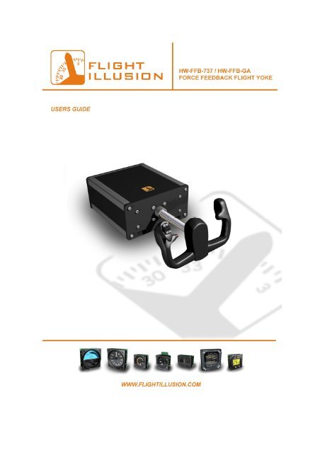
Introduction<br />
The HW- FFB-737/GA <strong>Flight</strong> <strong>yoke</strong> has been designed to give the user the sturdy and robust<br />
feeling like flying a real aircraft. The concept was to develop a reliable control loading <strong>yoke</strong><br />
as can be found in many professional trainers, but also at a price that keeps it in reach <strong>for</strong> the<br />
dedicated flightsim enthusiasts and home cockpit builders.<br />
By using standard available but at the same time heavy duty components we think we’ve<br />
succeeded in creating one of the best control <strong>yoke</strong>s available in it’s class. Once you take<br />
control of your virtual plane with this <strong>yoke</strong>, it will feel as if you actually have a real aircraft in<br />
your hands.<br />
The <strong>Flight</strong> Illusion team<br />
Safety<br />
Please remember that the <strong>for</strong>ce <strong>feedback</strong> <strong>yoke</strong> is not a toy. Make sure it is firmly<br />
attached to your desk be<strong>for</strong>e use. As the <strong>for</strong>ces can be significant in some cases, it’s not<br />
recommended to be used by small children.<br />
Do not open the casing when the <strong>yoke</strong> is in use and switch the power off when leaving<br />
the <strong>yoke</strong> unattended.<br />
Although the <strong>yoke</strong> has a safety feature to prevent it from overheating (it will<br />
automatically switch of after a couple of minutes when not in use) it is recommended to<br />
check it from time to time <strong>for</strong> overheating.<br />
Never leave the power supply unattended when on, as it can generate heat. Also make<br />
sure the power supply is operated in a ventilated area so it’s able to release its heat to<br />
the surrounding air.<br />
Be careful after switching on the <strong>yoke</strong>, in some cases it can make an abrupt movement<br />
towards its centre position.<br />
2
Index<br />
- Installation Page 4<br />
- Software Page 5<br />
Main (opening) screen Page 6<br />
Configuration screen Page 7<br />
Default configuration files Page 8<br />
Yoke configuration screen Page 8<br />
- Maintenance Page 13<br />
- Technical Specs Page 16<br />
3
Installation<br />
Step 1. Make sure the <strong>yoke</strong> is firmly attached to your desk. This can be done by using the two<br />
mounting holes on the bottom side of the <strong>yoke</strong> housing (see illustration below) You can use<br />
the two supplied bolts <strong>for</strong> it or use your own (metric: M6) You can also use the two square<br />
holes that are on the lower front of the casing by using two small clamps.<br />
Step 2. Connect the <strong>yoke</strong> to your PC using the USB cable.<br />
Step 3. Install the following software on your PC:<br />
- USB Driver<br />
- FFB Yoke Control (you can download the latest version on www.flight<strong>illusion</strong>.com)<br />
Note: FSUIPC is required to run the <strong>yoke</strong> with Microsoft <strong>Flight</strong> Simulator.<br />
Step 4. Connect the power supply<br />
4
Software<br />
After starting the control program the opening screen appears:<br />
Here you can select a configuration file <strong>for</strong> a specific type of airplane or select your own<br />
configuration files. You can also check if the control software is connected to <strong>Flight</strong><br />
Simulator (FS link status)<br />
After clicking on ‘Continue’, the <strong>yoke</strong> is ready to be used and the main screen will appear.<br />
When using the <strong>yoke</strong> <strong>for</strong> the first time, click on ‘Configure’ to adjust the basic settings <strong>for</strong><br />
the <strong>yoke</strong>.<br />
Note: we’re always working to improve our software and this is an ongoing process. If you<br />
have any suggestions or tips that might improve our software we like to hear from you! You<br />
can send your e-mail to info@flight<strong>illusion</strong>.com or support@flight<strong>illusion</strong>.com.<br />
5
The main screen:<br />
In the main screen the current configuration file is showed and the mode the <strong>yoke</strong> is in. The<br />
status of a second <strong>yoke</strong> is also shown as it is possible to connect two <strong>yoke</strong>s. Yoke one is<br />
standard set to be the master <strong>yoke</strong> and is in <strong>for</strong>ce <strong>feedback</strong> mode.<br />
The <strong>yoke</strong> can be used in different modes:<br />
1. Force Feedback Mode (FFB Mode): the <strong>yoke</strong> follows and reacts to values coming<br />
out of <strong>Flight</strong> Simulator<br />
2. Centre Mode: the <strong>yoke</strong> will return to centre (like a <strong>yoke</strong> or joystick with springs)<br />
6
3. Servo Mode: the <strong>yoke</strong> will follow the movements of a second <strong>yoke</strong> as if mechanically<br />
linked (if it is assigned as ‘slave’)<br />
4. Follow AP Mode: the <strong>yoke</strong> follows inputs as given by the autopilot in <strong>Flight</strong><br />
Simulator.<br />
Click on ‘Run’ to activate the <strong>yoke</strong>, or click on ‘Configuration’ to adjust the basic settings<br />
<strong>for</strong> the <strong>yoke</strong>.<br />
The configuration screen:<br />
In the general configuration screen you can set the correct port settings and save or load a<br />
configuration file. To access the advanced settings you can click on ‘Configure Yoke #1’ or<br />
‘Configure Yoke #2’<br />
Note: Due to the complexity of the advanced settings it is recommended to save the<br />
configuration file under a new name or make a backup of the standard configuration files.<br />
7
Default configuration files<br />
There are 4 standard configuration files in the control program, and they are largely based on<br />
the airspeed ranges and weight that different types of aircraft have:<br />
- Single piston engine (GA lightweight planes like the Cessna 172 or Mooney Bravo)<br />
- Twin turboprop (Dual engine planes like e.g. the Beechcraft Kingair 350)<br />
- Airliner (Larger aircraft like the Boeing 737)<br />
To define your own settings, click on ‘show <strong>yoke</strong> #1’ (or <strong>yoke</strong> #2) in the main screen or<br />
click on ‘configure <strong>yoke</strong> #1’ or 2 in the configuration screen.<br />
After opening the <strong>yoke</strong> configuration file you should see the following screen:<br />
The <strong>yoke</strong> configuration screen<br />
Here you are able to tweak the <strong>for</strong>ces that effect the <strong>yoke</strong> and set multiple options like<br />
switches, autopilot settings etc. Make sure the ‘Control Mode (1)’ is on the right setting<br />
because these are the settings you’re able to change <strong>for</strong> that particular mode.<br />
8
You can click on ‘Save settings <strong>for</strong> (particular) mode’ to save your setting temporary <strong>for</strong><br />
testing. To save the settings permanent as a configuration file you’ll need to click on ‘File’<br />
and name it.<br />
Overview of the functions in the Yoke Configuration Screen (see illustration above)<br />
1. Control Mode<br />
The Yoke can work in several modes.<br />
- Centre mode: In this mode the Force Control mechanism behaves as two springs.<br />
- FFB Mode: The <strong>for</strong>ces on the Yoke depend on the status of the aircraft. The <strong>for</strong>ces<br />
depend on airflow along the Ailerons and Elevator surfaces. Also Turbulence and<br />
wheel shocks -when rolling- are send to the <strong>yoke</strong>.<br />
- Follow Autopilot: The Yoke follows the controls as commanded by the Autopilot.<br />
Up/Down follows the vertical trim and Left/right follows the horizontal trim<br />
- Servo mode: In case two <strong>yoke</strong>s are connected, the Yoke will follow the position of the<br />
other Yoke. Or, in case the other control is another device it will follow the values read<br />
from the Simulator<br />
- Switch Off Forces: The <strong>for</strong>ces are switched Off.<br />
2. Simulator Interface:<br />
This part shows the status and action read from or written to the simulator. Ailerons and<br />
Elevator position is given in a percentage from -100% to +100%. Centre position is 0.<br />
Trim values are the integer values as read from the simulator. The Read ad Write<br />
9
indicators show the Read/Write actions on the Simulator interface. Warnings are read<br />
from the simulator.<br />
3. Trim Switch.<br />
In case the trim switch <strong>for</strong> trim Up/Down trim is selected, the function can de enabled and<br />
disabled here. When the Trim switch is kept in the Up or Down position the Trim will be<br />
increased or decreased at a certain speed. This speed is adjustable by the slider in this part.<br />
Trim position is shown as send to the Simulator. This value can vary from -16383 to<br />
+16383.<br />
4. Connection and Activation Yoke Control<br />
This frame shows the actual status of the interface between the Yoke and the Control<br />
Program. It shows the status of the connection, the actual <strong>for</strong>ces and position of the Yoke<br />
and the number of updates per second.<br />
5. Power Mgt.<br />
The Yoke has a protection mechanisms to prevent Overheating and permanent <strong>for</strong>ces to<br />
one of its mechanical limits. If a <strong>for</strong>ce is constant within a certain limit (the threshold<br />
percentage) <strong>for</strong> a certain time (the value in seconds) the <strong>for</strong>ce of that direction will be<br />
switched off and go to Stand By mode. As soon as the <strong>for</strong>ce changes over the given<br />
threshold, the <strong>for</strong>ce will be switched on again.<br />
6. Configuration File<br />
The Control Program can be set to one or more Aircraft types using a configuration File.<br />
Each mode (see 1) has its own set of parameters and can be saved or loaded. The settings<br />
are saved in memory and can be saved in a particular Configuration File. In case two<br />
<strong>yoke</strong>s are connected, you can (to prevent double work) copy the basic settings from the<br />
other <strong>yoke</strong>. The Control Program can automatically start when activated. In this case it<br />
will select the file named: Default.cfg. So in case that is wanted, the file –or copy thereof-<br />
must be saved under that name.<br />
7. Auto Pilot Status<br />
This frame shows the status of the switches of the Simulator Auto Pilot. In the check box<br />
the automatic switch between Force Feedback Mode and Follow Autopilot mode can be<br />
selected.<br />
8. Setting Configuration Variables Force Feedback Mode.<br />
In this frame the behaviour of the Yoke in Force Feedback Mode can be configured.<br />
• The Wheel Shock Force. When on ground and wheels rolling over the strip, both<br />
Wheel Shock Force and Wheel Shock Frequency are used to simulate the <strong>feedback</strong> of<br />
rolling wheels to the Yoke. The Force defines the strength of the <strong>for</strong>ce, whilst the<br />
frequency defines the frequency of the shocks. The latter one will depend on the speed<br />
of the aircraft. As soon as Aircraft will be airborne the wheel shock simulation will be<br />
disabled<br />
• Turbulence Effect. By turbulence the Aircraft can roll or go up/down by changing<br />
airflow. The Up/Down movements will give <strong>for</strong>ces on the Elevator, whilst roll will<br />
give <strong>for</strong>ces on the ailerons. The level of these <strong>for</strong>ces transferred to the Yoke can be set<br />
by both sliders.<br />
10
• Elevator Weight correction. When on ground and no airflow along the elevator will<br />
drop down the elevator by gravity. The effect thereof can be simulated by the Elevator<br />
Weight correction slider.<br />
• FFB Effect. Depending on aircraft type the flow of air along the surfaces will result in<br />
a <strong>for</strong>ce needed to move the surfaces from middle position. By using both sliders, the<br />
effect thereof can be adjusted. The <strong>for</strong>ce needed will depend on the airspeed. In the<br />
box below in this frame the effects and the results of these calculations is shown.<br />
Force increases by the square of the airspeed.<br />
9. Configuration Variables Centre Mode.<br />
The sliders Ailerons and Elevator Centre are to match the mechanical and electrical<br />
centres of the Yoke. Centre is factory adjusted so in general the sliders can be set to zero.<br />
Range of the sliders is -100% to +100%<br />
10. Stick Shaker enable/disable.<br />
Yoke has a stick shaker function. In the selection boxes can be selected to activate this at<br />
stall and/or over speed (see Frame 10)<br />
11. Generic Yoke Configuration Variables.<br />
• Sensitivities.<br />
The sensitivity is the relation between <strong>for</strong>ce and the divergence from the position the<br />
Yoke wants to go to. E.g. at high sensitivity a small rotation will quickly result in the<br />
maximum <strong>for</strong>ce.. It is the “steepness” of the relation between the rotation from wanted<br />
position and the <strong>for</strong>ce that must be exercised to move it from that position.<br />
• Dead band.<br />
The Yoke mechanism is designed to be equipped with many <strong>yoke</strong>s. Depending on the<br />
mass of the actual Yoke type there is a chance that the mechanism will oscillate due to<br />
the inertia of the <strong>yoke</strong>. By setting dead band to a higher value there will be some<br />
margin to stop that oscillation. In general these sliders can be kept zero.<br />
• Force Threshold.<br />
Force Threshold is also used in case <strong>yoke</strong> is oscillating. In general these sliders can be<br />
kept zero.<br />
• Maximum Force.<br />
By these sliders the maximum <strong>for</strong>ce of the <strong>yoke</strong>s can be limited to a certain value. The<br />
value can be set from zero to maximum (100%)<br />
12. Configuration Variables Follow Autopilot.<br />
Autopilot Ailerons and Elevator swing. To enable more aircraft types the values generated<br />
by the auto pilot that control heading and altitude settings, the translation from the auto<br />
pilot outputs and related swings of the Yoke is made configurable by sliders. Depending<br />
on the setting of these sliders the values generated by the autopilot will be translated into a<br />
roll- and pitch-swing of the Yoke. The best setting must be found by getting the<br />
maximum outputs of the autopilot ( which is Aileron and Elevator trim). This maximum<br />
should correspond with the limits of the Yoke or somewhat lower.<br />
Autopilot overrule. By <strong>for</strong>cing the <strong>yoke</strong> to another position than commanded by the auto<br />
pilot, the auto pilot can be switched off. In that case the check box Enable Overrule must<br />
be set. The auto pilot will be switched of when a certain counter <strong>for</strong>ce (slider Overrule<br />
<strong>for</strong>ce) is maintained during a certain time (slider Overrule time).<br />
13. Switch Assignments<br />
11
The Yoke has at maximum 6 switches. When a switch is activated in Running mode, the<br />
square of the related switch will change from green to red. Using the Pull Down menue a<br />
function can be assigned to that switch. To save the switch setting it is needed to pust the<br />
Set switch in this frame<br />
14. Follow AP/Servo Mode Status<br />
This frame shows the actual status of the Yoke when externally controlled. It can follow<br />
the auto pilot, the master <strong>yoke</strong> in case it is in slave mode or the simulator when controls<br />
are done in another manner. The commanded position (where the <strong>yoke</strong> should go) is given<br />
in the + and – percentages.<br />
15. Configuration Servo Mode<br />
In this frame can be selected what the <strong>yoke</strong> should do when in Slave mode. It can either<br />
follow the master <strong>yoke</strong> or follow the autopilot.<br />
12
Maintenance<br />
The <strong>Flight</strong> Illusion Force Feedback Yoke is a sturdy construction. Where needed axial and<br />
linear ball bearings are used and the shifting mechanism is constructed from high precision<br />
silver steel bars. Also a metal chain is part of this mechanism.<br />
Although very solid, it needs like other mechanical constructions some maintenance.<br />
Over time the components need some greasing and after some time it will be needed to adjust<br />
the chain tension.<br />
The following regular maintenance is advised:<br />
- Greasing the silver steel bars.<br />
- Greasing the main steering axle.<br />
- Adjusting the chain tension.<br />
- Inspecting the mechanics.<br />
For opening the case to get access to the mechanical parts only a screwdriver is needed. After<br />
removing one of the four metal corner profiles you can shift the top- and side plate out (see<br />
illustration below) Make sure that when you close the casing again, all the parts are lined up<br />
correctly. Note: opening the case will not void warranty.<br />
13
The main steering axle that holds the control <strong>yoke</strong> has to be lubricated most often. There’s<br />
no need to open the casing <strong>for</strong> this as you can apply it from the outside. The silver steel<br />
bars that guide the linear motion only need greasing once in a while or when you notice<br />
the motion gets less smooth. See illustration below <strong>for</strong> the main axle and the silver steel<br />
guiding bars.<br />
14
To adjust the chain tension you’ll need to turn the nuts that are on the two long screw rods<br />
(see illustration below) Tension on the chain is right when the <strong>yoke</strong> moves smooth<br />
without rattling noises. Never tighten the chain tension too much.<br />
15
Technical Specs:<br />
Power supply: 24V/5A<br />
Linear mechanical range: approx. 17 cm / 6.7 Inch<br />
Rotational range: approx. 90 degrees left / 90 degrees right<br />
Interface: USB<br />
Dimensions (excluding control wheel):<br />
For further technical questions or support you can contact <strong>Flight</strong> Illusion at:<br />
support@flight<strong>illusion</strong>.com or info@flight<strong>illusion</strong>.com<br />
16