The UB80E/F family of transmissions used in Toyota L4 applications, and the UA80E/F used in V6 engine applications, should not be confused with the AWF8G30 transmission. Although similar, they are significantly different.
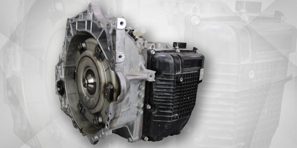
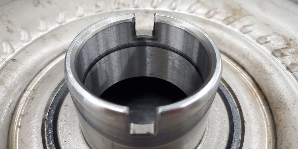
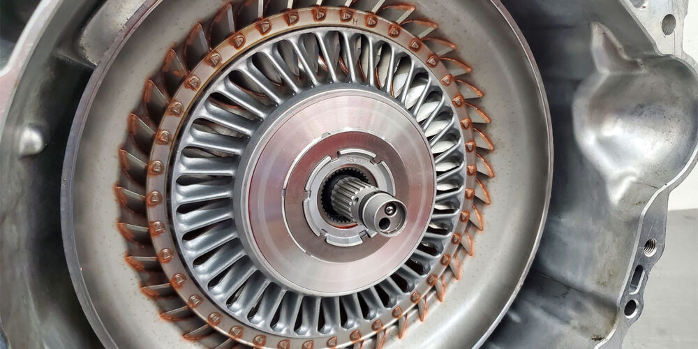
The converters used in these applications are like other known systems. Within this system, there are two very important sealing rings that need to seal properly for the converter to function correctly. The converter used in this article came out of a UB80E from a 2021 RAV4 2.5L (see Figure 1, above).
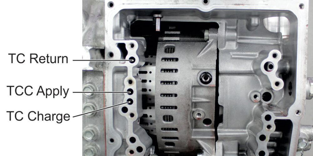
From the case passage ID seen in Figure 2, this is a three-stage converter, with the stages being:
- Torque converter charge where fluid enters and fills the converter.
- Torque converter return where the returning pressure going back into the transmission is then routed to a clutch exhaust valve located in the rear valve body.
- A separate circuit to apply a multiple disc clutch assembly inside the torque converter.
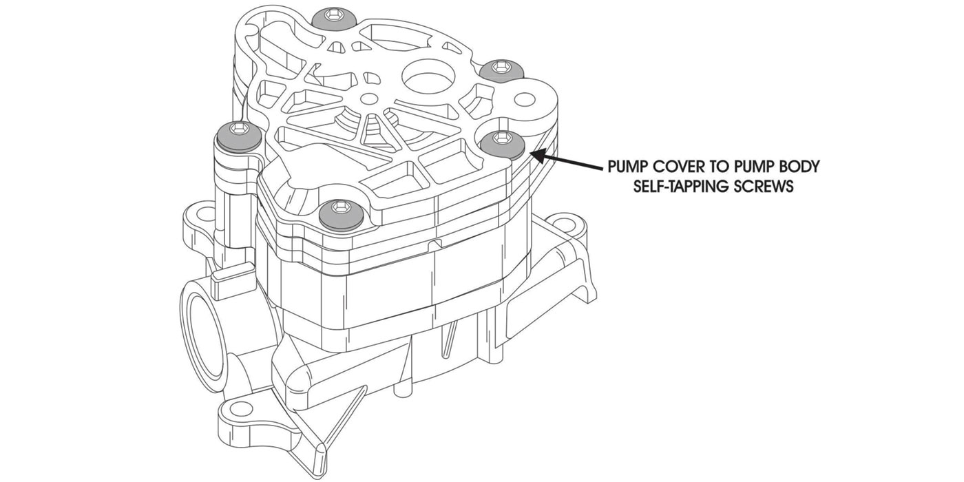
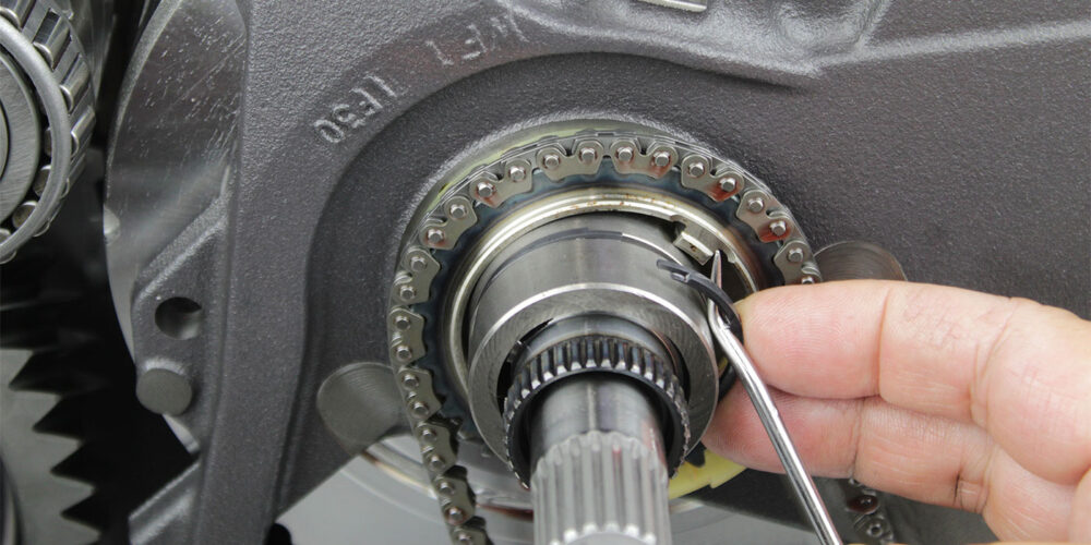
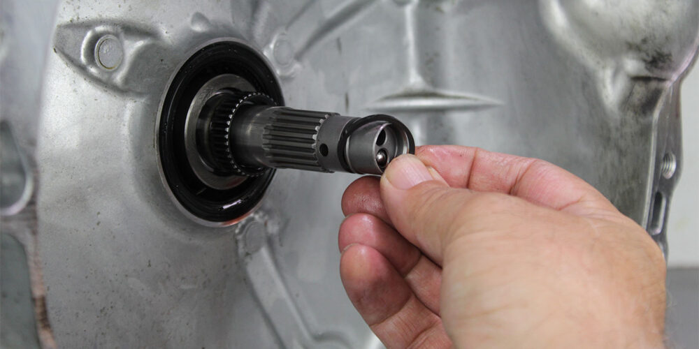
The torque converter drives an off-axis pump. One of the important seals in the converter’s hydraulic system is in front of the drive gear support, as seen in Figure 3. This seals on the inside of the converter hub as seen in Figure 4. The other important seal sits on the tip of the turbine shaft (Figure 5).
Precision International tells us that the ring which seals inside the converter hub is a Japanese-based PEEK plastic compound, while the ring that is on the tip of the turbine shaft is a Polytetrafluoroethylene ring with a 15% graphite blend compound. These rings are designed to handle heat without shrinking.
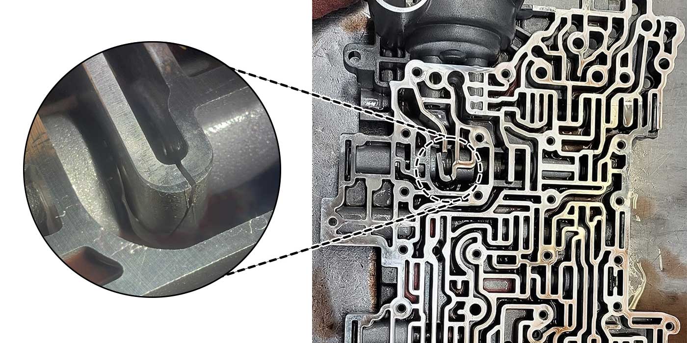
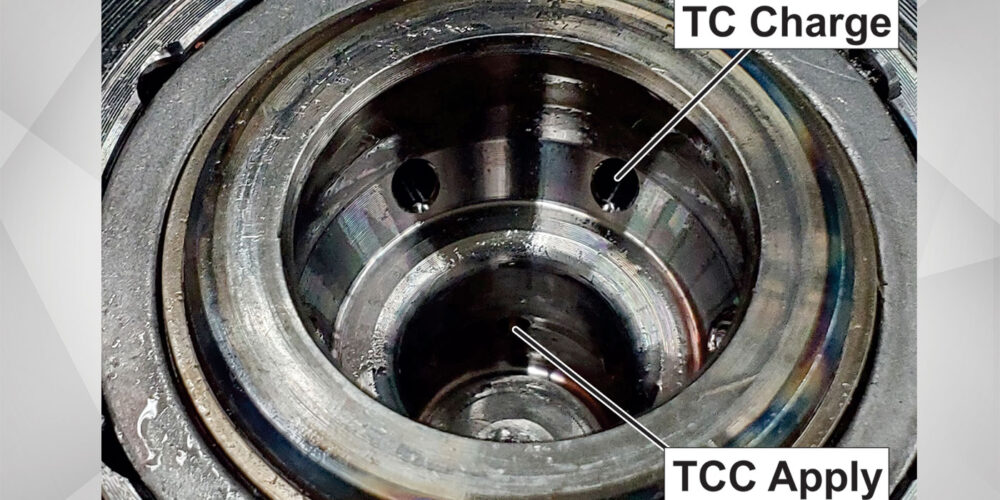
To begin seeing how critical these seals are, Figure 6 identifies these the circuits in the front of the transmission. Just a quick glance and you can see how important the ring is on the tip of the turbine shaft. It prevents TC charge pressure from intruding into the TCC apply pressure.
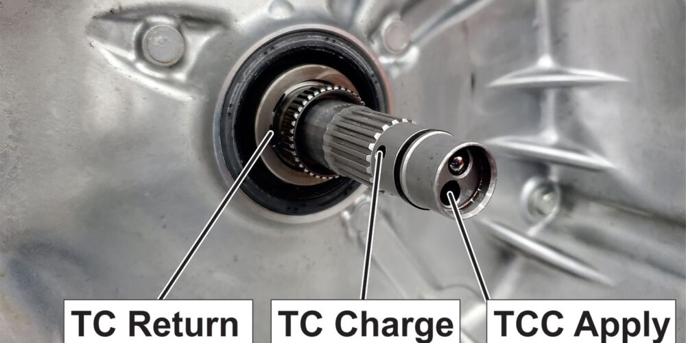
The TC return circuit is located below the stator shaft spline and the inner diameter of the pump drive sprocket support. The sealing ring that seals inside the converter hub sits right behind the converter hub seal. The front turbine shaft ring and the rear converter hub sealing ring maintain converter charge pressure. If the converter hub sealing ring is compromised, flow through the converter will change, dropping pressure and affecting torque transfer efficiency.
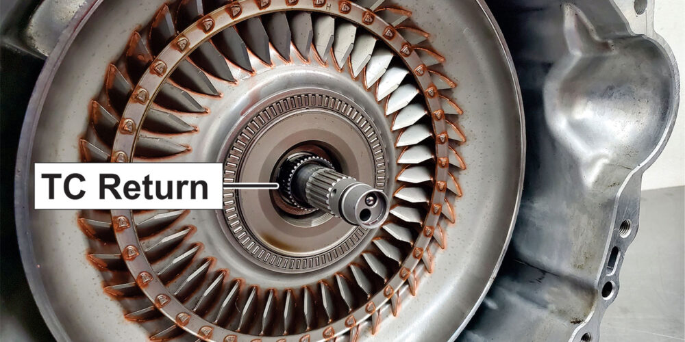
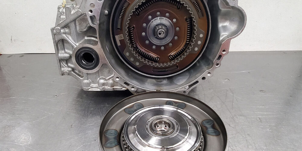
With the converter cut open, each individual component can be inserted into place. Figure 7 shows the converter impeller (pump) and hub inserted first. This perspective shows the importance of the inside converter hub sealing ring: It forces the fluid to enter the return slots going back to and through the valve body. Without the seal, this return fluid will have an additional path to exhaust.
The return fluid is also part of the flow which is returned to the impeller through the stator, which is the next component seen in Figure 8. The turbine and damper assembly which includes a multi-disc clutch hub is the next component to be installed (see Figure 9).
The multi-disc clutch assembly is built into the cover as seen in Figure 10. When this clutch assembly applies, it locks on to the turbine assembly driving the turbine shaft at engine speeds. The fluid pressure used to apply this clutch assembly comes out of the tip of the turbine shaft as seen in Figure 6. But there is one more aspect to the function of this converter that hasn’t yet been covered.
A closer look into the center of the multi-disc clutch assembly where the turbine shaft goes into two separate feed circuits can be seen in Figure 10. The deepest circuit closest to the cover is the clutch apply circuit. The next one up distributes converter charge pressure into this multi-disc clutch assembly. This pressure is constant and is used to push the apply piston into a released position. The TCC apply pressure works on enough surface area of the piston to overcome the charge pressure trying to release the clutch. With this further explanation of the function of the multi-disc clutch assembly, the importance of the sealing ring separating these two pressures becomes more evident.
The TCC Apply pressure is controlled by the blue connector SLU solenoid on the valve body shown in Figure 11.
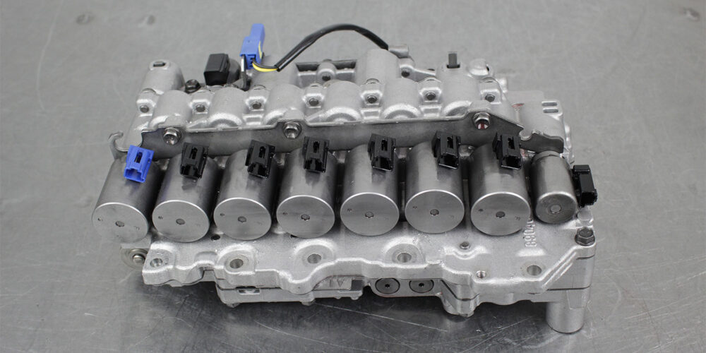
As with all the shift solenoids and line pressure solenoids, this SLU solenoid provides hydraulic pressures that are proportional to the current that flows to the coil. The engagement of this multi-clutch assembly in this converter is controlled by this pressure regulation.
In short, this is a busy torque converter, much of which relies on two sealing rings for it to function correctly.