Scanning the Internet for External Cloud Exposures via SSL Certs
Ap 5131 access point antenna connection guide
1. M
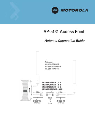
AP-5131 Access Point
Antenna Connection Guide
Antennas:
ML-5299-PTA1-01R
ML-5299-WPNA1-01R
ML-5299-HPA1-01R
ML-1499-10JK-01R - 10 ft.
ML-1499-25JK-01R - 25 ft.
ML-1499-50JK-01R - 50 ft.
ML-1499-100JK-01R - 100ft.
3.5 in. 3.5 in.
2.9 dB
4 dB
25-85392-01R 7 dB 25-90262-01R
0.3 dB loss 15.5 dB 0.3 dB loss
3. AP-5131 Antenna Connections
This guide describes how 2.4 and 5 GHz antennas are physically connected to an AP-5131 model access
point. Central in this discussion are descriptions of the single and dual-band antennas supported, their
supported connector models and how lightning arrestors are supported for specific antenna and connector
combinations.
For more information, see:
• 2.4 GHz AP-5131 Antenna Connections
• 5 GHz AP-5131 Antenna Connections
P/N Length Conn 1 Conn 2 Attn 2.4 Attn 5.5
25-72178-01 3.1 in. RSMA-m RBNC-f 0.2 N/A
25-85391-01R 3.5 in RSMA-m N-m 0.2 0.3
25-85392-01R 3.5 in RSMA-m N-f bulkhead 0.2 0.3
25-90262-01R 3.55 in. RSMA-f N-f bulkhead 0.2 0.3
25-90263-01R 3.55 in. RSMA-f N-m 0.2 0.3
25-97261-01R 48 in. N-m RBNC-m 1.5 N/A
25-99175-01R 1.5 in. N-f N-f 0.2 0.3
ML-1499-100JK-01R 100 ft N-m N-m 10.6 15.5
ML-1499-10JK-01R 10 ft N-m N-m 2 2.9
ML-1499-25JK-01R 25 ft N-m N-m 2.5 4
ML-1499-50JK-01R 50 ft N-m N-m 4.5 7
ML-1499-72PJ-01R 6 ft RPBNC-f RBNC-m 2.3 N/A
ML-1499-LAK1 Cable 12 in. N-m RBNC-m 0.6 N/A
ML-1499-LAK1/2 Arrestor 2.25 in N-f N-f 0.24 N/A
ML-1499-LAK2 Adapter 1.5 in. N-m N-m 0.15 N/A
ML-1499-RBNCA1-01R 1 ft N-f RBNC-f 0.85 N/A
ML-1499-RBNCA2-01R 1 ft N-m RBNC-f 0.85 N/A
ML-2452-LAK1 Arrestor 1.75 in. N-m N-m 0.14 0.35
ML-2452-LAK1 Cable 12 in. N-m RSMA-m 0.6 1.4
4. 1-2 AP-5131 Access Point Antenna Connection Guide
1.1 2.4 GHz AP-5131 Antenna Connections
This section describes how components are used collectively in the following AP-5131 installation scenarios
supporting the 2.4 GHz band:
• RP-BNC Male Antenna Installation
• Type N Female Connector Installation
• Type N Male Connector Installation
5. AP-5131 Antenna Connections 1-3
1.1.1 RP-BNC Male Antenna Installation
Refer to the following for a graphical depiction of the parts and connection options available for cabling a
2.4 GHz AP-5131 model access point using RP-BNC male antennas:
Antennas:
ML-2499-7PNA2-01R
ML-2499-11PNA2-01R
ML-2499-APA2-01R
ML-2499-HPA3-01R
ML-2499-PNAHD-01R
ML-2499-SD3-01R
3.11 in. 6 ft.
25-72178-01 ML-1499-72PJ-01R
0.2 dB loss
2.3 dB loss
(optional)
ML-1499-10JK-01R - 10 ft.
ML-1499-25JK-01R - 25 ft.
ML-1499-50JK-01R - 50 ft.
ML-1499-100JK-01R - 100ft.
3.5 in. 12 in.
25-99175-01
2.0 dB
0.3 dB loss
2.5 dB
25-85392-01R ML-1499-RBNCA2-01R
4.5 dB
0.3 dB loss 0.9 dB loss
10.6 dB
6. 1-4 AP-5131 Access Point Antenna Connection Guide
Lightning Aresstor, Antenna side
Antennas:
ML-5299-PTA1-01R
ML-5299-WPNA1-01R
ML-5299-HPA1-01R
ML-1499-10JK-01R - 10 ft.
ML-1499-25JK-01R - 25 ft.
ML-1499-50JK-01R - 50 ft.
ML-1499-100JK-01R - 100ft.
3.5 in. 3.55 in.
2.9 dB
4 dB ML-2452-LAK1-01R 25-90263-01R
25-85392-01R 7 dB
0.3 dB loss 0.35 dB loss 0.3 dB loss
15.5 dB
Lightning Aresstor, AP side
Antennas:
ML-5299-PTA1-01R
ML-5299-WPNA1-01R
ML-5299-HPA1-01R
ML-1499-10JK-01R - 10 ft.
ML-1499-25JK-01R - 25 ft.
ML-1499-50JK-01R - 50 ft.
ML-1499-100JK-01R - 100ft.
14 in. 3.5 in.
2.9 dB
4 dB
ML-2452-LAK1-01R 7 dB 25-90262-01R
1.6 dB loss @ 5.5 GHz 15.5 dB 0.3 dB loss
7. AP-5131 Antenna Connections 1-5
1.1.2 Type N Female Connector Installation
Refer to the following for a graphical depiction of the parts and connection options available for cabling a
2.4 GHz AP-5131 model access point using Type N female connectors:
Antennas:
ML-2499-BPDA1-01R
ML-2499-BPNA3-01R
ML-2499-BYGA2-01R
3.5 in.
25-85391-01R
0.3 dB loss
ML-1499-10JK-01R - 10 ft.
ML-1499-25JK-01R - 25 ft.
ML-1499-50JK-01R - 50 ft.
ML-1499-100JK-01R - 100ft.
3.5 in.
2.0 dB
2.5 dB
25-85392-01R 4.5 dB
0.3 dB loss 10.6 dB
CAUTION: The minimum cable configuration is required to meet regulatory requirements.
!
CAUTION: The installation of lightning arrestors must meet local electrical codes.
!
8. 1-6 AP-5131 Access Point Antenna Connection Guide
Lightning Aresstor, Antenna side
Antennas:
ML-2499-BPDA1-01R
ML-2499-BPNA3-01R
ML-2499-BYGA2-01R
ML-1499-10JK-01R - 10 ft.
ML-1499-25JK-01R - 25 ft.
ML-1499-50JK-01R - 50 ft.
ML-1499-100JK-01R - 100ft.
3.75 in.
3.5 in.
2.0 dB
2.5 dB ML-1499-LAK2-01R
25-85392-01R 4.5 dB
0.3 dB loss 0.4 dB loss
10.6 dB
Lightning Aresstor, AP side
Antennas:
ML-2499-BPDA1-01R
ML-2499-BPNA3-01R
ML-2499-BYGA2-01R
ML-1499-10JK-01R - 10 ft.
ML-1499-25JK-01R - 25 ft.
ML-1499-50JK-01R - 50 ft.
ML-1499-100JK-01R - 100ft.
14 in.
2.0 dB
2.5 dB
ML-2452-LAK1-01R 4.5 dB
1.6 dB loss @ 5.5 GHz 10.6 dB
9. AP-5131 Antenna Connections 1-7
1.1.3 Type N Male Connector Installation
Refer to the following for a graphical depiction of the parts and connection options available for cabling a
2.4 GHz AP-5131 model access point using Type N male connectors:
Antennas:
ML-2499-5PNL-72-N
ML-2499-FHPA5-01R
ML-2499-FHPA9-01R
ML-1499-10JK-01R - 10 ft.
ML-1499-25JK-01R - 25 ft.
ML-1499-50JK-01R - 50 ft.
ML-1499-100JK-01R - 100ft.
3.5 in.
25-99175-01
2.0 dB
0.3 dB loss
2.5 dB
25-85392-01R 4.5 dB
0.3 dB loss 10.6 dB
Antennas:
ML-2499-5PNL-72-N
ML-2499-FHPA5-01R
ML-2499-FHPA9-01R
3.5 in.
25-85392-01R
0.3 dB loss
10. 1-8 AP-5131 Access Point Antenna Connection Guide
Antennas:
ML-2499-HPA3-01R
ML-1499-10JK-01R - 10 ft.
ML-1499-25JK-01R - 25 ft.
ML-1499-50JK-01R - 50 ft.
ML-1499-100JK-01R - 100ft.
3.5 in. 12 in.
2.0 dB
2.5 dB ML-2452-LAK1-01R
25-85392-01R 0.35 dB loss ML-1499-RBNCA2-01R
4.5 dB
0.3 dB loss 0.9 dB loss
10.6 dB
Lightning Arrestor, AP side
ML-1499-10JK-01R - 10 ft.
ML-1499-25JK-01R - 25 ft.
ML-1499-50JK-01R - 50 ft.
ML-1499-100JK-01R - 100ft.
14 in. 12 in.
2.0 dB
2.5 dB ML-1499-RBNCA1-01R
ML-2452-LAK1-01R 4.5 dB 0.9 dB loss
1.6 dB loss @ 5.5 GHz 10.6 dB
OR
12 in.
ML-1499-RBNCA2-01R
0.9 dB loss
11. AP-5131 Antenna Connections 1-9
1.2 5 GHz AP-5131 Antenna Connections
This section describes how components are used collectively in the following AP-5131 installation scenarios
supporting the 5 GHz band:
• RP-SMA Male Antenna Installation
• Type N Male Connector Installation
1.2.1 RP-SMA Male Antenna Installation
Refer to the following for a graphical depiction of the parts and connection options available for cabling an
5 GHz AP-5131 model access point using a RP-SMA male antenna (with no lightning arrestor):
Antennas:
ML-5299-PTA1-01R
ML-5299-WPNA1-01R
ML-5299-HPA1-01R
ML-1499-10JK-01R - 10 ft.
ML-1499-25JK-01R - 25 ft.
ML-1499-50JK-01R - 50 ft.
ML-1499-100JK-01R - 100ft.
3.5 in. 3.5 in.
2.9 dB
4 dB
25-85392-01R 7 dB 25-90262-01R
0.3 dB loss 15.5 dB 0.3 dB loss
12. 1-10 AP-5131 Access Point Antenna Connection Guide
Refer to the following for a graphical depiction of the parts and connection options available for cabling a
5 GHz AP-5131 model access point using a RP-SMA male antenna (with a lightning arrestor):
Lightning Aresstor, Antenna side
Antennas:
ML-5299-PTA1-01R
ML-5299-WPNA1-01R
ML-5299-HPA1-01R
ML-1499-10JK-01R - 10 ft.
ML-1499-25JK-01R - 25 ft.
ML-1499-50JK-01R - 50 ft.
ML-1499-100JK-01R - 100ft.
3.5 in. 3.55 in.
2.9 dB
4 dB ML-2452-LAK1-01R 25-90263-01R
25-85392-01R 7 dB
0.3 dB loss 0.35 dB loss 0.3 dB loss
15.5 dB
Lightning Aresstor, AP side
Antennas:
ML-5299-PTA1-01R
ML-5299-WPNA1-01R
ML-5299-HPA1-01R
ML-1499-10JK-01R - 10 ft.
ML-1499-25JK-01R - 25 ft.
ML-1499-50JK-01R - 50 ft.
ML-1499-100JK-01R - 100ft.
14 in. 3.5 in.
2.9 dB
4 dB
ML-2452-LAK1-01R 7 dB 25-90262-01R
1.6 dB loss @ 5.5 GHz 15.5 dB 0.3 dB loss
13. AP-5131 Antenna Connections 1-11
1.2.2 Type N Male Connector Installation
Refer to the following for a graphical depiction of the parts and connection options available for cabling an
5 GHz AP-5131 model access point using Type N male connectors:
Antennas:
ML-2452-PNA5-01R
ML-5299-FHPA10-01R
ML-1499-10JK-01R - 10 ft.
ML-1499-25JK-01R - 25 ft.
ML-1499-50JK-01R - 50 ft.
ML-1499-100JK-01R - 100ft.
3.5 in.
25-99175-01
2.0 dB
0.3 dB loss
2.5 dB
25-85392-01R 4.5 dB
0.3 dB loss 10.6 dB
14. 1-12 AP-5131 Access Point Antenna Connection Guide
Lightning Aresstor, Antenna side
Antennas:
ML-2452-PNA5-01R
ML-5299-FHPA10-01R
ML-1499-10JK-01R - 10 ft.
ML-1499-25JK-01R - 25 ft.
ML-1499-50JK-01R - 50 ft.
ML-1499-100JK-01R - 100ft.
3.5 in.
2.9 dB
4 dB ML-2452-LAK1-01R
25-85392-01R
7 dB 0.3 dB loss
0.3 dB loss 15.5 dB
Lightning Aresstor, AP side
Antennas:
ML-2452-PNA5-01R
ML-5299-FHPA10-01R
ML-1499-10JK-01R - 10 ft.
ML-1499-25JK-01R - 25 ft.
ML-1499-50JK-01R - 50 ft.
ML-1499-100JK-01R - 100ft.
14 in.
25-99175-01
2.9 dB 0.3 dB loss
ML-2452-LAK1-01R 4 dB
1.6 dB loss @ 5.5 GHz 7 dB
15.5 dB
15. Technical Support
Comprehensive on-line support is available at the Support Central site at http://www.symbol.com/support/. Support
Central provides our customers with a wealth of information and online assistance including developer tools, software
downloads, product manuals and online repair requests.
When contacting the Motorola Support Center, please provide the following information:
• serial number of unit
• model number or product name
• software type and version number.
16. A-2 AP-5131 Access Point Antenna Connection Guide
North American Contacts
Support (for warranty and service information):
telephone: 1-800-653-5350
fax: (631) 738-5410
Email: emb.support@motorola.com
International Contacts
Outside North America:
Motorola, inc.
Symbol Place
Winnersh Triangle, Berkshire, RG41 5TP
United Kingdom
0800-328-2424 (Inside UK)
+44 118 945 7529 (Outside UK)
Web Support Sites
Product Downloads
http://www.symbol.com/downloads
Manuals
http://support.symbol.com/support/product/manuals.do
Additional Information
Obtain additional information by contacting Motorola at:
1-800-722-6234, inside North America
+1-516-738-5200, in/outside North America
http://www.motorola.com/
17.
18. MOTOROLA INC.
1303 E. ALGONQUIN ROAD
SCHAUMBURG, IL 60196
http://www.motorola.com
72E-116638-01 Revision A
October 2008