
Direct Current Triboelectric Nanogenerators, a Perspective from Material Selections


1
Beijing Institute of Nanoenergy and Nanosystems, Chinese Academy of Sciences, Beijing 101400, China
2
School of Nanoscience and Engineering, University of Chinese Academy of Sciences, Beijing 100049, China
3
School of Materials Science and Engineering, Georgia Institute of Technology, Atlanta, GA 30332-0245, USA
*
Authors to whom correspondence should be addressed.
Nanoenergy Adv. 2023, 3(4), 343-375; https://doi.org/10.3390/nanoenergyadv3040018
Submission received: 22 July 2023
/
Revised: 21 September 2023
/
Accepted: 1 November 2023
/
Published: 3 November 2023
(This article belongs to the Special Issue Celebrating the 18th Anniversary of the Invention of the First Nanogenerators)
Abstract
:With the global energy shortages, sustainable energy scavenging from the natural environment is desperately needed. Unlike solar cell or wind power, which depends heavily on weather conditions, triboelectric nanogenerator (TENG) has received extensive attention as an efficient all–weather energy–harvesting technology. Based on the coupling principle of contact electrification (CE) and electrostatic induction, conventional TENGs convert mechanical energy into an alternating current (AC) output. However, the typically distributed sensor systems in the ubiquitous Internet of Things (IoTs) request a direct current (DC) input. Direct current triboelectric nanogenerators (DC-TENGs) with the constant output characteristic are critical to satisfy the above requirements. Here, DC-TENGs were reviewed from the perspective of material selections. As device performance is mainly determined by material properties, the development of DC-TENGs could be divided into three categories based on dielectric materials, semiconductor materials, and materials for iontronic rectifications. The operating mechanism and influencing factors of various types of DC-TENG were summarized, representative applications were demonstrated, and the main challenges of future developments were also discussed.
1. Introduction
Since the industrial revolution, fossil energy has rewritten the development process of human civilization with its unique advantages and achieved the ’carbon prosperity’ of human society [1,2,3,4,5,6]. However, with the continuous large–scale development and utilization of fossil energy, it has not only caused a global energy crisis but also resulted in serious environmental pollution [7,8,9,10,11,12]. In particular in the past 20 years, with the era advent of the ubiquitous Internet of Things [13,14,15,16,17] (IoTs), a large number of independent micro-sensor nodes have been applied in infrastructure fields–industry [18,19,20,21], agriculture [22,23,24,25], and many others [26,27,28,29]. The large–scale distributed energy it requires is difficult to satisfy by the centralized energy supply based on fossil energy [30,31,32,33]. To meet the ever–growing appetite for data and information, in–depth development of sustainable energy with environmentally friendly and distributed characteristics will not only help alleviate the resource shortage but also effectively reduce carbon emissions [34,35,36,37,38,39]. Traditional electromagnetic generators have the characteristics of high costs and large structures that are obviously not suitable for distributed systems [40,41,42]. Therefore, exploring a unique distributed energy–harvesting technology that can effectively collect renewable energy becomes critical.
With the first invention of the triboelectric nanogenerator (TENG) by Wang’s group in 2012 [43], the displacement current was used as the driving force to convert mechanical energy into electric energy [44,45,46]. It opened up an effective alternative for harvesting high–entropy environmental energy with random and low–frequency characteristics [47,48,49,50,51]—wind [52,53,54,55,56], ocean [57,58,59,60,61], biological motion [62,63,64,65,66,67,68,69], mechanical movement [70,71,72,73,74], vibrational energy [75,76,77,78,79], raindrop [80,81,82,83,84], and others [85,86,87,88,89]. Compared with other energy–harvesting technologies [90,91,92], TENGs based on the unique coupling principle of contact electrification (CE) and electrostatic induction [93,94,95,96] have outstanding power density [97,98,99,100], rich material selection [101,102,103,104], low–cost consumption [105,106,107,108], and other fundamental advantages [109,110]. It enabled TENGs to have unique benefits in many important applications in the self–powered system [111,112,113,114]—environmental monitoring [115,116,117,118,119], motion monitoring [120,121,122,123], self–driven electrochemistry [124,125,126], and biomedical sensing [127,128,129,130,131], etc. [132,133,134,135]. However, conventional TENGs are limited by the alternating current (AC) output signal [136,137] and cannot directly satisfy the above electronics with direct current (DC) demands. The AC signals can be generally converted to DC signals by an external rectifier bridge, which would inevitably cause additional energy consumption, and complexity in the design, further limiting its applications in many areas such as flexible or conformable electronics [138,139,140,141]. For this purpose, various types of direct current triboelectric nanogenerators (DC-TENGs) have been developed based on considerate structural design and rich material selection.
The performance of the device would depend on the intrinsic properties of the material. To effectively integrate different material characteristics with various mechanisms of DC-TENGs, it is necessary to review it from the perspective of material selections. In this review, the development of DC-TENGs was generally divided into three categories based on dielectric materials, semiconductor materials, and materials for iontronic rectifications (Figure 1). Firstly, DC-TENGs based on dielectric materials were divided into three operating modes—mechanical rectification by current commutation units (Figure 1a) [142,143,144], phase coupling (Figure 1b) [145,146,147], and dielectric breakdown due to the electrostatic breakdown effect (Figure 1c) [148,149]. Thanks to the insulation properties of dielectric materials, they could achieve a high voltage output. Secondly, DC-TENGs based on semiconductor materials [150] were realized due to the tribovoltaic effect of semiconductor–semiconductor contact (Figure 1d) [151,152,153], metal–semiconductor contact (Figure 1e) [154,155,156], metal/semiconductor—insulator–metal/semiconductor contact (Figure 1f) [157,158,159], and liquid–semiconductor contact (Figure 1g) [160,161], respectively. Such DC-TENGs could generate high–amplitude currents with relatively low internal resistance due to the physical properties of semiconductors. Thirdly, in DC-TENG based on materials for iontronic rectifications (Figure 1h) [162,163,164,165], the DC output was realized by the unidirectional flow of ionic charge carriers, which not only further reduced the internal resistance to improve performance, but also effectively solved the friction and wear between solid materials to enhance operational stability. Finally, the typical applications of DC-TENG in the energy–harvesting field and self–powered systems were prominently demonstrated in this review.
2. DC-TENGs Based on Different Types of Materials
2.1. Operating Mechanism of TENG
When the surfaces of two dissimilar materials were separated by mechanical force, the electrostatic charges generated by their physical contact could generate a potential drop. It could drive electrons to flow between the two electrodes on the top and bottom surfaces of the two materials. TENGs based on the above theory have four basic modes [167]: the contact–separation mode, the lateral–sliding mode, the single–electrode mode, and the freestanding triboelectric–layer mode, as elaborated in Figure 2a–d, respectively. Generally speaking, physical contact between the two dielectric films creates oppositely charged surfaces. During the regular relative motion between dielectric layers and electrodes, electrons are driven to continuously transfer alternately between the electrode and electrode or electrode and earth to form the AC output. To avoid the energy dissipation caused by the rectifier bridge and improve the practicality of TENG as a flexible energy–harvesting and self–powered sensing device, DC-TENGs based on different mechanisms with various materials properties were developed.
2.2. DC-TENGs Based on Dielectric Materials
2.2.1. Mechanical Rectification
DC-TENGs based on dielectric materials can be obtained by the current commutation units, in which the alternating contact with the electrode is ensured to realize the mechanical rectification. It is equivalent to continuously exchanging the position between two electrodes as the direction of electron flow changes, ensuring the unidirectional flow of charge carriers between the two current commutation units. In 2014, a rotating–disk–based DC-TENG [166] was reported by Zhang et al. shown in Figure 3a, in which two pairs of parallel flexible electric brushes were designed as the current commutation units. During the operation of the DC-TENG, as the top friction electrode (aluminum, Al) continued to rotate, it constantly contacted and separated from the dielectric layer (polyvinyl chloride, PVC), driving electrons to alternately transfer between the top friction electrode and the bottom charge–collecting electrode (Al) to generate AC output. In the second half cycle of the generated AC signal, the contact relationship between the two pairs of electric brushes and the electrodes was exchanged. So the current direction between the two electric brushes was converted to the same direction as the first half cycle to generate the DC output. The peak power density of the DC-TENG reached 25 mW/m2 at the rotating speed of 750 r/min. In the kind of DC-TENG with the electric brush as the commutation unit, the friction and wear between brush and electrode is an important factor affecting the stability of device operation. To deal with this problem, the carbon fiber material was selected to make the flexible electric brush in the rotating–disk–based DC-TENG. Converting the fixed sliding friction between electric brushes and electrodes to free sliding friction was another effective way to reduce friction and wear, as rotary–tubular DC-TENG was reported by Wang et al. in 2019 [168]. Its prototype structure was mainly composed of a fluorinated ethylene propylene (FEP) ring tube and copper (Cu) charge–collecting electrodes as shown in Figure 3b(i). When the DC-TENG started to operate, the pre–filled liquid was in full contact with the tube, and the negative charge in the liquid was transferred to the inner surface of the tube. As the device continued to rotate, Cu electric brushes fixed on both sides of the tube alternately swept across the surface of charge–collecting electrodes to ensure that the current direction between brushes remained unchanged, forming the DC output [Figure 3b(ii)]. In this DC-TENG, not only the free sliding mode was used to effectively reduce the friction and wear between the electric brushes and the charge–collecting electrodes, but also the use of liquid friction materials could completely avoid faster friction and wear between solid materials. Furthermore, in terms of friction reduction, rolling friction is undoubtedly better than sliding friction. In 2021, Qiao et al. reported a bidirectional DC-TENG [169] (Figure 3c), in which the rolling electric brushes were used as the current commutation units. During the operation of DC-TENG, the electric brushes alternately rolled through the friction electrode surfaces, which made the equipment produce DC output and effectively reduce friction and wear between the electric brushes and friction electrode to improve durability. In addition, the FEP dielectric layer was designed to the arched structure, which allowed the DC-TENG can harvest efficiently bidirectional rotating mechanical energy. At the rotation speed of 180 r/min, it could obtain a peak output power of 0.96 W/m2.
In addition to the electric brushes, the time–delay switches could also be used as the current commutation units of DC-TENG. For example, Fu et al. invented a DC-TENG inspired by the primary battery in 2022 [170] [Figure 3d(i)]. Analog to the cathode and anode electrodes in the primary battery shown in Figure 3d(ii), the DC-TENG was mainly composed of three parts: negative and positive charge–collecting electrodes, and conductive carbon gel. In the device, the ability of FEP, carbon gel, and nylon to obtain electrons decreases in turn based on the difference in electronegativity. The specific operating mechanism was shown in Figure 3d(iii). The carbon gel first contacted the left nylon dielectric layer and adsorbed electrons on the gel surface. Next, it contacted the right FEP dielectric layer to generate a displacement current in the external circuit, and then the time–delay switch between the carbon gel and the right charge–collecting electrode was turned on to generate a conduction current from the electrode to the gel, making the carbon gel positively charged. When it contacted the left nylon dielectric layer again, the displacement current in the same direction was generated again in the external circuit. Then, the time–delay switch between the carbon gel and the left charge–collecting electrode was turned on to generate a conduction current from the electrode to the gel, and it made the carbon gel negatively charged again. Therefore, as the carbon gel moved alternately between the left and right charge–collecting electrodes, DC-TENG continued to operate stably. The design of the time–delay switch as the current commutation unit completely avoided the friction and wear between electric brushes and electrodes in DC-TENG from mechanical rectification. Based on the similar current commutation unit, Du et al. developed a high–performance DC-TENG in 2022 [171] [Figure 3e(i)]. During the operation, as the slider composed of an FEP dielectric layer and a charge–collecting electrode slid on the upper surface of the fixed nylon dielectric layer, the time–delay switch regularly closed and disconnected, prompting the one–way flow of electrons between the two charge–collecting electrodes on the stator lower surface to generate the DC output, as demonstrated in Figure 3e(ii). Particularly, the blank–tribo–area was designed in the DC-TENG, which could increase power output by promoting charge accumulation. When the DC-TENG was designed as a disk structure, the open–circuit voltage, short–circuit current, and peak power could reach 3000 V, 106.9 μA, and 75.69 mW, respectively, at the excitation speed of 60 r/min.
2.2.2. Phase Coupling
Although DC-TENGs from mechanical rectification could generate DC output without the assistance of the rectifier bridge, the current signals were generally pulsed with a high crest factor, which cannot constantly power electronics. To further reduce the crest factor of the DC signal and enable the device to achieve more stable output, the principle of phase coupling began to be explored. Ryu et al. invented a multiphase rotating DC-TENG in 2018 [145] [Figure 4a(i)], in which the rotator was made of alternating polytetrafluoroethylene (PTFE) and nylon dielectric layers, and the stator was composed of PTFE dielectric layers and charge–collecting electrodes on its lower surface. In the physical structure of DC-TENG, by adjusting the quantitative relationship between the dielectric layers in the rotor and the charge–collecting electrodes in the stator, a regular phase difference was constructed between them. The charge–collecting electrodes were connected according to the equivalent rectifier circuit shown in Figure 4a(ii). During the operation of the DC-TENG, as the rotor continued to rotate, each charge–collecting electrode generated a similar AC signal with the regular phase difference. These AC signals were converted into constant DC signals by the equivalent rectifier circuit, including the constant open–circuit voltage and constant short–circuit current, as shown in Figure 4a(iii,iv). Experiments showed that with the increase in the number of phases, the output was more stable, and the crest factor was closer to 1. When the phase number was 5, the current crest factor of the multiphase rotating DC-TENG was 1.26. In addition to the sliding mode DC-TENG from phase coupling, the constant output could also be achieved by using multiple contact–separation mode TENGs, as Dharmasena et al. developed the DC-TENG in 2020 [172] [Figure 4b(i)]. In the DC-TENG, multiple contact–separated TENGs were installed in the device shell according to the regular angle difference [Figure 4b(ii)], and they were connected to the equivalent rectifier circuit in the way shown in Figure 4b(iii). Each contact–separated TENGs could generate similar AC electrical signals with regular phase differences when they were sequentially excited, which was finally converted into a constant output by the equivalent rectifier circuit. After testing, the current crest factor of this contact-mode DC-TENG with six phases was 1.08 at an oscillation frequency of 5 Hz.
The regular phase difference is the basis for the DC-TENG from phase coupling, so how to design an accurate regular phase difference becomes critical to affecting the stability of the device. In 2020, Wang et al. reported a cylindrical DC-TENG [173], which consisted of multiple TENGs with a regular phase difference as shown in Figure 4c(i). Different from the complex design of the regular phase difference in the conventional DC-TENGs from phase coupling, as long as the same angle difference was guaranteed between each TENG shown in Figure 4c(ii), the regular phase difference could be guaranteed. So, it undoubtedly effectively reduced the complexity. Experiments showed that with the increase in the number of friction electrode groups in each TENG, the constant short–circuit current of the DC-TENG output was increased. In the DC-TENG with three phases and five groups, the short–circuit current could reach 21.6 μA, and the current crest factor remained at 1.08. To further ensure the accuracy of the designed regular phase difference, Hu et al. also reported a low crest factor DC-TENG [174], as shown in Figure 4d(i). In the DC-TENG, the bracket for installing the dielectric layer was processed by 3D digital printing technology exhibited in Figure 4d(ii), which effectively controlled the accuracy of the regular phase difference. On this basis, the crest factor of the DC-TENG was reduced to 1.07 at the rotation speed of 8 r/s. In particular, a nested DC-TENG array was designed by the coaxial superposition of multiple stators and rotors, which effectively improved the space utilization and output performance [Figure 4d(iii)]. The nested DC-TENG array obtained a constant short–circuit current of 140 μA at 8 r/s, which was 1.7–fold higher than that of a single stator. Compared with the pulse output method, DC-TENG with constant output had a higher average power density, as in 2022, Li et al. reported a constant–voltage DC-TENG [175] shown in Figure 4e(i), which achieved better output performance based on the phase coupling principle [Figure 4e(ii)]. When the rotation frequency was 8 Hz, it could achieve a constant voltage output of 1400 V [Figure 4e(iii)] and a constant current output of 0.26 mA [Figure 4e(iv)], and the crest factor of the voltage was reduced to 1.03. Compared with the 2.33 mW of pulsed TENG without regular phase difference, the average power of the constant–voltage DC-TENG reached 4.56 mW and was increased by 1.9 fold.
2.2.3. Dielectric Breakdown
In addition to mechanical rectification and phase coupling, DC-TENG based on dielectric materials could also achieve constant DC output in a much simpler structure by the introduction of the electrostatic breakdown effect. In terms of pulsed DC output, Yang et al. developed a rotating DC-TENG based on the dielectric breakdown effect in 2014 [148], which consisted of two rotating wheels connected by a rubber belt [Figure 5a(i)]. Its operating mechanism was shown in Figure 5a(ii). During the DC-TENG operation, electrons on the surface of Al wheels were first transferred to the inner surface of the belt and then to the surface of PTFE wheels due to the difference in material electronegativity. The charge–collecting electrode surface continuously accumulated positive charges thanks to the electrostatic induction effect. When the electrostatic potential between charge–collecting electrode and the PTFE wheel reached the breakdown voltage, the air medium was broken down to produce pulse discharge, which would drive electrons from the charge–collecting electrode to the friction electrode, resulting in a DC pulse signal. It could generate an open–circuit voltage of approximately 3200 V at the rotation speed of 1000 r/min, so the DC-TENG from the dielectric breakdown was an important means to produce a high voltage output. In addition to rigid physical devices, DC-TENG from dielectric breakdown could also operate normally when it was made into wearable fabrics as a flexible energy–harvesting device. In 2020, Chen et al. developed a fabric DC-TENG [176], which used flexible conductive yarn to generate the dielectric breakdown effect to harvest biological motion energy [Figure 5b(i)]. As demonstrated in Figure 5b(ii), when the fabric slid forward on the PTFE dielectric surface, the left yarn as the friction electrode contacted the dielectric layer and transferred electrons to the dielectric layer surface. Then, the fabric moved in the opposite direction, based on the electrostatic induction effect, and the right yarn as the charge–collecting electrode continued to accumulate positive charges on the surface. When the electrostatic breakdown occurred between the charge–collecting electrode and the dielectric layer, the breakdown current drove electrons to flow unidirectionally between the friction electrode and the charge–collecting electrode to generate the DC pulse output. A small fabric DC-TENG (15 mm × 35 mm) could generate an open–circuit voltage of 4500 V, which was enough to light more than 400 light–emitting diodes (LEDs). The rapid accumulation of charge density on the surface of the charge–collecting electrode was an important factor in the dielectric breakdown effect. Compared with the CE between metal and dielectric materials, there was no doubt that the two dielectric materials with greater electronegativity difference have more electron transfer and faster potential difference growth during contact. So, Li et al. developed a dual–breakdown DC-TENG in 2022 [177], which uses dielectric materials with different electronegativity as friction materials shown in Figure 5c(i). As shown in the equivalent circuit of Figure 5c(ii), the DC-TENG consisted of two dielectric materials as charge sources and corresponding charge–collecting electrodes. When the two dielectric layers contacted each other, based on the difference in material electronegativity, an equal amount of different electric charges was generated on their contact surfaces. When they were separated from each other, electrostatic breakdown effects were generated between them and the corresponding charge–collecting electrodes to exert a synergistic enhancement effect. It led to the unidirectional flow of electrons in the external circuit between the two charge–collecting electrodes, resulting in a synergistic pulsed DC output.
In DC-TENG from dielectric breakdown, constant electric signals also could be generated. Liu et al. invented a constant current DC-TENG in 2019 [178] [Figure 5d(i)], and its working mechanism was shown in Figure 5d(ii). When the Cu friction electrode contacted the PTFE dielectric layer, its electrons on the surface were transferred to the dielectric layer surface. As the slider slid forward, under the electrostatic induction of electrons on the surface of the dielectric layer, positive charges gradually accumulated on the charge–collecting electrode surface. In this kind of DC-TENG, the equivalent model consisted of a charge source together with a breakdown capacitor [Figure 5d(iii)], and the continuous unidirectional dielectric breakdown in the capacitor caused the DC-TENG to produce the constant output between the friction electrode and the charge–collecting electrode [Figure 5d(iv)]. The DC-TENG could obtain a higher charge density of approximately 430 μC/m2, which was much higher than that of conventional TENG. To further explore the effective way to achieve higher performance of this kind of DC-TENG, Zhao et al. proposed a patterned electrode optimization method in 2020 [179], which could achieve ultra–high surface charge density output, as shown in Figure 5e(i). Based on the similar dielectric breakdown mechanism shown in Figure 5e(ii), the output performance of the DC-TENG was effectively improved by the rationally patterned structure design of the friction electrode and charge–collecting electrode [Figure 5e(iii)]. The parallel connection of multiple output units was shown in Figure 5e(iv). Its charge density reached 5.4 mC/m2 [Figure 5e(v)], which was more than 10 fold that of conventional DC-TENG. In DC-TENG based on dielectric materials, friction and wear between materials have always been important factors affecting stable output. To effectively solve such problems, Gao et al. designed a robust rolling–mode DC-TENG [180] [Figure 5f(i)]. As shown in Figure 5f(ii), the planar friction electrode was converted into the roller structure in the DC-TENG, which converted the sliding friction between the friction electrode and the dielectric layer into rolling friction while enabling the device to achieve constant current output. It effectively reduced the friction and wear and improved the stability of DC-TENG, as shown in Figure 5f(iii). According to the analysis of DC-TENG based on dielectric materials, high voltage output characteristics due to the insulation characteristics of the dielectric materials would effectively broaden the practical application field of the TENG.
2.3. DC-TENGs Based on Semiconductor Materials
In DC-TENGs based on dielectric materials, the insulation characteristics of the dielectric layer caused higher internal resistance, which would reduce the short–circuit current density and its energy supply for electronic devices. To effectively improve the current density of the DC-TENGs, they could be combined with the electromagnetic or piezoelectric nanogenerator. However, such hybrid nanogenerators [181,182,183,184] inevitably led to the complexity of the device structure and affected its robustness. In particular when the internal resistance between different types of generators was not in the same order of magnitude, it resulted in unsatisfactory output performance. To effectively reduce the internal resistance of TENG to increase the output current, DC-TENG based on semiconductor materials had been developed. The DC output was realized based on the tribovoltaic effect between different types of friction materials, which was mainly divided into four types—semiconductor–semiconductor contact, metal–semiconductor contact, metal/semiconductor–insulator–metal/semiconductor contact, and liquid–semiconductor contact.
2.3.1. Semiconductor–Semiconductor Contact
The tribovoltaic effect generated by the sliding of the semiconductor materials could directly generate constant signals [150], and the specific output mechanism was shown in Figure 6a. When the p–type silicon (Si) and n–type Si were in contact with each other, based on the Fermi energy level difference, electrons were transferred from n–type semiconductors to p–type semiconductors, and holes were transferred in the opposite direction. So, a built–in electric field in the direction from the n–type semiconductor to the p–type semiconductor was generated at the contact surface to form a p–n junction, as demonstrated in [Figure 6a(i)]. When the relative motion occurred between the two semiconductors, the atoms on the two surfaces interacted to form the new chemical bonds and release the frictional energy (“Bindington”) [Figure 6a(ii)]. The frictional energy (“Bindington”) in the tribovoltaic effect was similar to the role of the excitions in the photovoltaic effect, which excited the electron–hole pair at the contact interface to move along/against the built–in electric field, thereby forming the constant output in the external circuit [Figure 6a(iii)]. Based on this principle, Xu et al. reported a DC-TENG based on the mutual sliding between p-n type Si in 2019 [151], as shown in Figure 6b(i). Experiments showed that in the tribovoltaic effect between the two, the direction of the constant current was the same as that of the built-in electric field [Figure 6b(ii)] and was independent of the relative sliding direction [Figure 6b(iii)]. During the DC-TENG operation, as the contact force between semiconductors increased, they were contacted more fully so that the output performance was increased [Figure 6b(iv)]. Similarly, as the relative sliding speed increased, the transfer speed of charge carriers in DC-TENG continued to increase, so the short–circuit current was increased, as shown in Figure 6b(v).
When the different types of semiconductors were in contact with each other to form heterojunctions, the constant current output could also be generated based on the tribovoltaic effect between the two. Chen et al. developed a DC-TENG based on the mutual sliding between gallium nitride (GaN) and Si in 2022 [185] shown in Figure 6c(i). Experiments showed that when the n–type and p–type GaN slid on the Si surface, respectively, the direction of the generated voltage or current was the same and the amplitude was not equal, as demonstrated in Figure 6c(ii). It indicated that the direction of the generated current might not depend only on the direction of the built–in electric field between different types of semiconductors. After analysis, when different types of semiconductors contacted each other, in addition to the built–in electric field thanks to heterojunction, based on the difference in electronegativity, the interface electric field generated by the CE between the two played a stronger role [Figure 6c(iii)]. As shown in Figure 6c(iv), when n–type GaN and Si contacted each other, the two electric fields were in the same direction, and the superposition of the two effectively increased the output performance of DC-TENG. When p–type GaN contacted Si, the two electric fields were in opposite directions, and their mutual suppression weaken the output performance of DC-TENG [Figure 6c(v)]. Therefore, the DC-TENG based on the contact of different types of semiconductor materials could produce higher output under the superposition of the built–in electric field and the interface electric field. When the sliding speed of the DC-TENG was 10 cm/s, the open–circuit voltage reached 25 V and the short–circuit current density reached 0.1 A/m2. Based on a similar power generation principle, Wang et al. constructed a high–voltage DC-TENG based on the contact of n–type GaN and p–type Si in 2022 [186], as shown in Figure 6d(i). In the DC-TENG, under the combined action of a built–in electric field and interface electric field, the open–circuit voltage was up to 130 V, which was approximately 20 fold that of conventional semiconductor–based TENG [Figure 6d(ii)]. Its peak power density reached 2.8 W/m2, which was approximately 46 fold that of the conventional centimeter–level semiconductor-based TENG. To further improve the power density, in 2022, Zhang et al. developed DC-TENG based on the contact between the p–type bismuth telluride (Bi2Te3) and n–type GaN [187], as shown in Figure 6e(i). Under the combined action of a strong interface electric field and a built–in electric field, its average power density reached 9.23 W/m2 shown in Figure 6e(ii), which was several orders of magnitude higher than that of conventional TENG based on semiconductor materials. The tribovoltaic effect also occurred between the organic polymer and the inorganic semiconductor. In 2023, Lee et al. invented a high–performance DC-TENG based on n–type perovskite (CsFAMA) and p–type conductive poly(3,4–ethylenedioxythiophene): poly(styrene sulfonate) (PEDOT: PSS) [188] as shown in Figure 6f(i). In the DC-TENG, the internal defect of CsFAMA was passivated by choline chloride (ChCl) to improve the charge density and carrier mobility, so that the short–circuit current density reached 11 μA/cm2 shown in Figure 6f(ii).
2.3.2. Metal–Semiconductor Contact
There was a wide choice of friction materials in the tribovoltaic effect. In addition to the p–n junction between semiconductor–semiconductor materials, the DC-TENG based on the Schottky junction between metal–semiconductor materials could also achieve the DC output. In 2020, Zhang et al. invented low–impedance DC-TENG based on the contact between stainless steel metal and Si semiconductor [154] [Figure 7a(i)], and the specific working mechanism was shown in Figure 7a(ii). The Schottky junction was constructed when the stainless steel with a large work function was in static contact with the n–type Si with a small work function, and electrons transferred from the semiconductor side to the metal side, forming a built–in electric field. Then, the friction energy released by the formation of atomic bonds during the sliding process of the metal on the semiconductor surface could excite non–equilibrium carriers, which included the excited electron–hole pairs in the semiconductor space charge region and the excited electron composition of the metal and semiconductor surface states. Under the action of the built–in electric field, the non–equilibrium carriers could drift along or against the direction of the built–in electric field, generating constant output in the external circuit. Correspondingly, the energy band diagram between the stainless steel and n–type Si was shown in Figure 7a(iii) at different operating stages of the DC-TENG. On the other hand, when the stainless steel and p–type Si slid with each other [Figure 7a(iv)], electrons transferred from the metal side to the p–type Si side, and a reverse built–in electric field was constructed, due to a higher work function and a lower Fermi level of p–type Si. With the relative sliding of stainless steel and p–type Si, the reverse built–in electric field drove the electrons to flow unidirectionally in the external circuit to generate reverse DC output, and the change process of the energy band diagram was shown in Figure 7a(v). The tribovoltaic effect could also occur when the metal and the flexible organic semiconductor polymers slide relatively. In 2021, Meng et al. proposed a flexible textile DC-TENG based on the contact between the metal Al and the conducting polymer PEDOT [189], as shown in Figure 7b(i). In this DC-TENG, The direction of the built–in electric field was from Al to PEDOT, which drove the non–equilibrium carriers generated during the sliding process to move along or against the direction of the built–in electric field to generate constant output [Figure 7b(ii)]. Through the way of increasing voltage in series and increasing current in parallel of multiple power generation units, the open–circuit voltage of 3.5V [Figure 7b(iii)] and the short–circuit current of 70 μA [Figure 7b(iv)] could be generated, respectively, by two integration methods from seven DC-TENGs.
Similar to DC-TENG based on the dielectric layer, rapid friction and wear between materials were also negative factors affecting the stability of DC-TENG based on semiconductor materials. To solve this problem effectively, a superlubric DC-TENG was invented by Huang et al. in 2021 [190] as shown in Figure 7c(i), and its optical microscopic image was shown in Figure 7c(ii). The DC output was generated based on the tribovoltaic effect between the graphite and the n–type Si. Due to the lubrication of graphite, it was in a super–lubrication state with the silicon surface, that is, ultra–low friction and wear–free state. Such DC-TENG could not only produce excellent short–current density (approximately 210 A/m2) and peak power density (approximately 7 W/m2) shown in Figure 7c(iii), but also achieve stable operation of at least 5000 cycles. In particular, the output current and friction had no obvious attenuation [Figure 7c(iv)], indicating that it could achieve longer stable operation. In addition to the application of anti–friction materials, the conversion of sliding friction to rolling friction can also effectively reduce friction and wear between materials. In 2022, Yuan et al. developed a rolling–mode DC-TENG [191] as shown in Figure 7d(i), which generated constant output based on the tribovoltaic effect between Al and all–inorganic perovskite (CsPbBr3). In such DC-TENG, the friction and wear were significantly reduced, so that the device operated more stably and the output performance did not decrease significantly after more than 10 min of cycling [Figure 7d(ii)]. Based on synergistic the photovoltaic effect of CsPbBr3 and the tribovoltaic effect, the DC-TENG coupled the two effects to form the tribo–photovoltaic effect, as demonstrated in Figure 7d(iii). Due to the excite electron–hole pairs from both effects, the output could be generated when the electric field directions were the same to effectively increase the output performance. Under illumination, the open–circuit voltage and short–circuit current density of DC-TENG reached 3.69 V and 11.46 A/m2, respectively, as shown in Figure 7d(iv,v).
2.3.3. Metal/Semiconductor–Insulator–Metal/Semiconductor Contact
To further reduce the rapid friction and wear in DC-TENG based on semiconductor materials, a thin insulating layer was introduced between the semiconductor–semiconductor contact or metal–semiconductor contact to form the tribo–tunneling effect. In 2018, Liu et al. developed a DC-TENG based on metal–insulator–semiconductor contact [157] shown in Figure 8a(i). When the probe (platinum, Pt) of the electrical–atomic force microscopy contacted with the silicon oxide of p–type Si, under the action of Schottky junction, electrons tunneled through the insulating layer from the metal side with a high Fermi level to the semiconductor side with a low Fermi level, forming a built–in electric field. When the relative sliding occurs between the Pt and the insulating layer, the released friction energy stimulated the non–equilibrium carriers to tunnel through the insulating layer along or against the built–in electric field, driving a constant open–circuit voltage and short–circuit current generated as shown in Figure 8a(ii,iii), and the energy band diagram between Pt and p–type Si was shown in Figure 8a(iv). Experiments showed that the output performance of DC-TENG based on the tribo–tunneling effect decreased with the increase in insulating layer thickness due to the hindrance of the insulating layer to charge carriers, as shown in Figure 8a(v). In this DC-TENG based on the AFM probe sliding on the insulating surface of the semiconductor, a high current density (1–10 A/m2) was generated, but the manufacturing process of the probe was more complicated, and it could cause strong material wear. To solve such problems, Liu et al. proposed a DC-TENG based on the tribo–tunneling effect of carbon aerogel–insulator–semiconductor contact [192] in 2019, as shown in Figure 8b(i). The built–in electric field formed by the Schottky junction between carbon aerogel and p–type Si drove the charge carriers to tunnel through the insulating layer to form a constant output in the external circuit. Experiments showed that the open–circuit voltage and short–circuit current of the DC-TENG increased with the increase in relative sliding speed, as shown in Figure 8b(ii). Particularly, based on the material properties of carbon aerogel, when it contacted the insulating layer, not only the friction and wear between the materials were effectively reduced, but also a large number of nano–contact points on the contact interface were constructed acting as the superposition of multiple power generation units to effectively improve the output performance of DC-TENG. The open–circuit voltage reached 2 V [Figure 8b(iii)], short–circuit current reached 15 μA [Figure 8b(iv)], and the theoretical current density reached 100 A/m2.
In the tribo–tunneling effect, charge carriers could also be driven by p–n junctions between semiconductors to tunnel through the insulating layer. In 2019, Liu et al. constructed a class of DC-TENGs based on the molybdenum disulfide (MoS2) material [193] [Figure 8c(i)], in which the DC output was realized based on the tribo–tunneling effect of MoS2–SiO2–Si contact [Figure 8c(ii)]. When MoS2 slid on the oxidized surface of p–type Si, the built–in electric field in the positive direction from MoS2 to p–type Si drove the charge carriers to tunnel through the SiO2 insulating layer to form the constant output in the positive direction, as shown in Figure 8c(iii,iv). When MoS2 slid on the oxidized surface of n–type Si, the charge carriers were driven by the built–in electric field in the opposite direction to tunnel through the SiO2 insulating layer to form the DC output, as demonstrated in Figure 8c(v,vi). In addition to semiconductor materials, the tribo–tunneling effect could also occur between two metal materials, resulting in constant output. Zhang et al. developed a high tunneling current DC-TENG based on the metal–insulator–metal contact [194] in 2023 [Figure 8d(i)]. In this DC-TENG, the oligoacene 4–(trifluoromethyl)benzenethiol was grown on the gold electrode as a self–assembled monolayer (SAM) based on the strong electronegativity and outstanding lubricity. When the Pt probe was in static contact with the SAM layer, based on the electronegativity difference, electrons were transferred from the probe tip to the surface of the SAM layer [Figure 8d(ii)], and the energy band diagram was shown in Figure 8d(iii). In the sliding process of the probe, electrons tunneling through the SAM layer was generated under the synergistic effect of the interface potential difference and the tribovoltage generated by contact electrification to achieve a maximum constant short–circuit current density of 7.6 × 10⁶ A/m2 [Figure 8d(vi)], with the energy band change shown in Figure 8d(v).
2.3.4. Liquid–Semiconductor Contact
The tribovoltaic effect could also be generated between liquid and semiconductor, which could effectively reduce friction and wear. In 2020, Lin et al. invented a DC-TENG by driving droplets to slide on the Si surface [160], as shown in Figure 9a(i). When the deionized (DI) water droplets slid on the p–type silicon surface, the DC-TENG generated constant open–circuit voltage and short–circuit current, which was independent of the relative sliding direction [Figure 9a(ii,iii)]. The Fermi level of water was higher than that of p–type Si, and when they were separated from each other, the energy band diagram was shown in Figure 9a(iv). When the droplet contacted the p–type Si, the electrons were transferred from the droplet to the Si surface, forming a built–in electric field. At the same time, new chemical bonds might be formed at the contact interface, and the energy band diagram was shown in Figure 9a(v). Electrons transfer and the formation of new chemical bonds both led to the release of friction energy at the contact interface, which could excite the generation of electron–hole pairs on the p–type Si surface [Figure 9a(vi)]. Under the action of the built–in electric field, the electron–hole pairs would transfer along/against the electric field direction, forming the constant output in the external circuit [Figure 9a(vii)]. When the DI water droplet contacted with n–type Si with a higher Fermi level, the electrons were transferred from the Si surface to the droplet, forming a reverse built–in electric field. It drove the electron–hole pairs to perform directional motion to form a reverse constant output, and the energy band diagrams at different operating stages were shown in Figure 9a(viii–xi).
Furthermore, Zheng et al. studied the effect of temperature on the performance of DC-TENG based on the liquid–semiconductor contact [195], as shown in Figure 9b(i). As the temperature increases from 30 °C to 90 °C, the contact angle of DI water droplets on the Si surface decreases from 86.72 to 60.36° [Figure 9b(ii)], which could increase the contact area of droplets on the Si surface to improve the output performance. When the DI water droplet was in contact with n–type Si, the electron–hole pairs density excited by the friction energy increased during the sliding process of the droplet and the n–type silicon surface as the temperature increased [Figure 9b(iii, iv)]. It could effectively promote the output performance of the DC-TENG as shown in Figure 9b(v). When the droplet was in contact with p–type Si, as the temperature increased, the reverse constant output was also improved, as demonstrated in Figure 9b(vi–viii). According to the analysis of DC-TENG based on semiconductor materials, due to the material properties of semiconductors, it could effectively improve the output performance by reducing the internal resistance of the device to effectively increase the current density.
2.4. DC-TENGs Based on Materials for Iontronic Rectification
In DC-TENGs based on solid dielectric/semiconductor materials, the friction and wear between solid materials were an inevitable problem. The DC output mechanism formed by the unidirectional flow of ionic charge based on materials for iontronic rectification could avoid the above challenges. In 2015, Zhang et al. invented a microfluidic DC-TENG [162] [Figure 10a(i)], which could effectively convert liquid flow energy into constant electric output. When the 1 μmol/L KCl solution contacted the polydimethylsiloxane (PDMS) replica, based on the CE principle, the electrons were transferred from the liquid to the PDMS surface to form the electrical double layer (EDL), and the cation concentration was higher than that of the anion in the liquid. As the liquid was pushed through the PDMS surface, the net positive charge was transmitted to form the streaming current. The induced electric field generated by the charge distribution along the liquid flow direction led to the streaming potential, which drove the unidirectional flow of electrons in the external circuit to form the constant output, as shown in Figure 10a(ii). As demonstrated in Figure 10a(iii), with the continuous change in liquid flow rate, the amplitude of the short–circuit current generated by the DC-TENG altered accordingly. Once the flow direction of the liquid was changed, the direction of the output current altered accordingly, as shown in Figure 10a(iv). To effectively improve the output performance of this type of DC generator, Dong et al. invented a high–voltage DC-TENG [196] by using a pre–negative charged dielectric layer [Figure 10b(i)]. In the falling process of the water droplet, the electric field constructed by negative charges on the PTFE dielectric layer drove the cations and anions in the water droplet to move along and against the electric field, respectively. When the droplet contacted the PTFE surface, the anions in the upper layer of the droplet contacted and transferred to the top Cu electrode, and it drove electrons to transfer from the top electrode to the bottom Cu electrode in the external circuit, forming the current Peak I. When the droplet slid along the dielectric layer and contacted with bottom electrode, the cations were transferred to the bottom electrode, which drove electrons to move in the same direction in the external circuit, forming the current Peak II. The two current signals in the same direction of DC-TENG were shown in Figure 10b(ii). When the droplets were dropped at a frequency of 2.5 Hz, a constant voltage output of more than 1600 V could be generated in this high–voltage DC-TENG [Figure 10b(iii)].To further achieve an effective constant output, Chi et al. developed a DC-TENG [197] in 2022 [Figure 10c(i)], which could produce constant electricity based on the action of water evaporation and capillary force. It consisted of a superhydrophilic porous aluminum oxide (Al2O3) ceramic sheet and electrodes arranged, respectively, at the top and bottom of the sheet. When the bottom electrode on the ceramic sheet was immersed in water, under the combined action of water evaporation and capillary force, the water continuously flowed upward along the nanopores inside the ceramic sheet and evaporated at the top of the sheet. In the process of liquid flow, electrons in water were transferred to the ceramic surface to form an EDL, and the net cations in the liquid continued to flow with the liquid to form a streaming current. It drove electrons to transfer from the top electrode to the bottom electrode to form the DC output in the external circuit, as shown in Figure 10c(ii). Experiments showed that the DC-TENG could work normally only when the liquid could evaporate. It had stronger stability and could produce stable output (0.7 V and 0.3 μA) for at least 5000 s [Figure 10c(iii)].
In DC-TENGs based on dielectric/semiconductor materials, the continuous attenuation of the surface charge density of the material is another challenge that affects the stability of the output performance. Even in DC-TENGs based on materials for iontronic rectification, the surface of the dielectric layer would gradually be covered with the EDL, which could prevent the electrons in the liquid from continuously transferring to its surface, invaliding the ionic rectification effect. To effectively avoid this challenge, Li et al. invented a direct–current triboiontronic nanogenerator (DC-TING) in 2023 [198], which could achieve efficient DC ionic–electronic coupling output [Figure 10d(i)]. When the DC-TING was in a separate state, the pre–positive charged DI water was sprayed on the dielectric layer to form EDL. When the water film on the diffuse layer surface was contacted with the separate electrode, positive charges in the diffuse layer would be rapidly transferred onto the separate electrode surface, generating the ionic current Ii. When the dielectric layer contacted the separate electrode, electrons from the separate electrode were transferred to the dielectric layer surface. When the dielectric layer was separated from the separate electrode, electrons from the back electrode were transferred to the separate electrode to generate the electronic displacement current Ie. Ii and Ie were in the same direction and DC ionic–electronic coupling output was generated by the DC-TING. Experiments show that when the pre–charged DI water was sprayed onto the PTFE film, DC-TING started to output the short–circuit current in DC form [Figure 10d(ii)]. As the ionic charge accumulated, the short–circuit current continued to increase to approximately 6.0 μA. DC-TING as a triboiontronic device based on the in situ ionic charge supplement strategy could maintain a high charge density on the dielectric insulator. It achieved the ultra–high peak power density of 126.40 W/m2 at 0.10 Hz [Figure 10d(iii)]. Similarly, to achieve the charge supplementation, the opto–iontronic DC-TENG [199] was developed by Ouyang et al. in 2023, its ionic charge could be remotely replenished by UV light to maintain effective DC output [Figure 10e(i)]. Based on the TENG structure, the unidirectional Ii provided by the graphene oxide (GO)/reduced graphene oxide (rGO, containing K+) junction was introduced to realize the rectification by counteracting Ie generated by TENG in the opposite direction. Hence, the electronic–ionic coupling presented a DC current in the external circuit. However, the gradient balance of K+ would cause Ii to decay to a certain threshold (defined as I’i), which could not achieve the rectification effect on Ie. At this point, the built–in electric field (Ebulit) could be generated by irradiating rGO with a UV light source to construct a new ion concentration gradient and enhance the ionic current. The current generated by the UV was defined as Ibulit, and the opto–iontronic strategy could achieve the sustainable rectification of the ionic current to the electronic current. Experiments have demonstrated that UV supplementation had an outstanding effect on maintaining the DC output of the device [Figure 10e(ii)]. The opto–iontronic DC-TENG could be used to perceive the light irradiation including UV light in the environment to realize the early warning protection function. After the ion concentration balance, an AC signal would be presented, which was set to the ‘Calm’ state [Figure 10e(iii)]. When the GO/rGO junction was irradiated by UV, the current signal transferred from AC signal to DC signal. At this time, it becomes an ‘Alarm’ state and warns against UV irradiation [Figure 10e(iv)].
3. Various Applications of DC-TENGs
The advantages and disadvantages of DC-TENGs based on different material types have been summarized. To show them more intuitively, a comparison Table 1 was constructed. Based on these advantages, DC-TENGs had a wide range of application fields in energy–harvesting and the self–powered system, as shown in Figure 11. The mechanical energy from water, wind, biological motion, mechanical movement, raindrops, and many others could be effectively harvested by DC-TENGs. In 2018, Lim et al. designed a DC-TENG [200] based on the phase coupling principle, which could effectively harvest the water flow energy with the assistance of the propeller to drive the LED board to operate normally [Figure 11a]. Its practical application in the natural river environment proved that the TENG has good environmental adaptability and operational stability. In terms of wind energy harvesting, Yu et al. developed a DC-TENG based on the tribovoltaic effect between the Cu and p–type Si [201] in 2021 [Figure 11b]. It could output a constant current with an average of 4.4 mA (the maximum value was 8.4 mA), several orders of magnitude over previous generators based on the metal and semiconductor contact. In addition to natural resources, to effectively collect biological movement energy, Tao et al. developed a DC-TENG from the phase coupling [202] in 2023 shown in [Figure 11c]. Due to the advantages of the lightweight and small size of TENG, it could be installed in shoes to convert the low–frequency motion energy of the human walking into an approximately constant output with an average power of approximately 3.95 mW for supplying the micro biosensors. In addition, DC-TENG also could effectively harvest the mechanical movement energy widely existing in human life, such as vehicle operation and mechanical vibration. In 2021, the DC-TENG based on the phase coupling principle developed by Chen et al. [203] [Figure 11d], which was mounted on a bicycle to harvest the rotational energy of the wheels. It could effectively drive the relevant sensor nodes to work normally for collecting information on motion speed, real–time position, and energy consumption, thus opening the era of green travel. In the future, the DC-TENGs based on dielectric materials are generally more suitable for building large–scale energy–harvesting devices due to their cost–effectiveness, especially for harvesting large–scale high–entropy energy sources, such as ocean energy, wind energy, and mechanical movement energy. The DC-TENGs based on semiconductor materials could generate higher energy density caused by lower internal resistance, and their simpler structure design makes them more suitable to harvest biological motion energy for wearable electronics. Furthermore, the DC-TENGs based on the materials for iontronic rectification could generate higher energy due to the lowest resistance. It could overcome the challenges for traditional TENGs, such as materials friction and wear, and depletion of surface charge. It could extend the applications of DC-TENG for more power–hungry applications.
DC-TENGs also had a wide range of practical applications in the self–powered system, such as smart building, motion monitoring, medical sterilization, and biomedical sensing. To effectively monitor the structural health of large buildings, Li et al. developed a dual–mode TENG [204] shown in Figure 11e, which could effectively monitor the vibration amplitude of buildings such as bridges in real time. It consisted of two parts: conventional TENG and DC-TENG based on the dielectric breakdown effect. When the vibration amplitude of the building was within the safe range, the conventional TENG in the dual–mode DC-TENG operated to output AC signals, and once it exceeded the safe amplitude DC-TENG would immediately start the operation to play the alarm role. In addition, similar dual–mode DC-TENGs could also be designed as a vector motion monitoring system to detect the driving direction of the vehicle [205] [Figure 11f] and an weight detection system [208] to control the weight of the object. In the field of medical sterilization, ozone was a rapid and effective choice, which could be prepared by DC-TENG of dielectric breakdown [206] proposed by Wang et al. in 2022 [Figure 11g]. It used high–energy electrons transferred during dielectric breakdown to ionize oxygen molecules to form ozone molecules, thus effectively sterilizing. In other self–powered systems, Yu et al. constructed a bionic artificial synapse based on the tribovoltaic effect between graphene and MoS2 to play the role of image recognition in 2021 [207] [Figure 11h], which consisted of a phototransistor based on heterostructure and a TENG. In this artificial protrusion, the charge transfer in the heterojunction was controlled by the potential difference generated by TENG, which could easily regulate the behavior of photoelectron synapses. By referring to the neural network, the image recognition accuracy was improved by 92%. The artificial synapse had a high prospect of simulating complex biological nervous systems and promoting the development of interactive artificial intelligence. Therefore, as a self–powered solution, DC-TENG, as the power generation unit in the field of natural mechanical energy–harvesting and the sensor node in the era of the IoTs, has a wide range of application scenarios and is increasingly attractive to researchers.
According to the extensive application scenarios of DC-TENGs based on different material selections, its scalability and commercialization could be realized in two scenarios, i.e., environmental high–entropy energy–harvesting and the self–powered sensing system. With the rapid development of the Internet of Things, the high maintenance costs of sensor nodes widely distributed around the world make the traditional power supply method via battery unsustainable. On the other hand, DC-TENGs are of efficient energy scavenging method from the environment to replace batteries for sensor nodes, especially in remote and sparsely populated areas. In addition, the development of self–powered sensors is also a great progress brought about by the continuous development of the Internet of Things. Based on the advantages of wide material selection, low cost, and strong environmental adaptation, DC-TENGs have been widely used as an effective self–powered sensor method.
4. Conclusions and Perspectives
With the advent of the IoTs, TENGs received tremendous attention due to their rich material selection and outstanding power density. In particular, the distributed ubiquitous micro–sensor nodes in IoTs requested DC input, and extensive research was carried out on DC-TENGs. As device performance is mainly determined by material properties, in this paper, the development of DC-TENGs was reviewed from the perspective of material selections. It was divided into three categories according to different material types—dielectric materials, semiconductor materials, and materials for iontronic rectifications. DC-TENGs based on dielectric materials mainly included three modes: mechanical rectification, phase coupling, and dielectric breakdown. The insulation characteristics of dielectric materials enabled devices to achieve high–voltage DC output to effectively broaden their application range of TENGs. There were problems such as low current density due to high internal resistance. Although the DC-TENGs could be combined with the electromagnetic or piezoelectric nanogenerator to solve this problem, such hybrid nanogenerators inevitably led to the complexity of the device structure and affected its robustness. In particular when the internal resistance between different types of generators was not in the same order of magnitude, it resulted in unsatisfactory output performance. Due to the tribovoltaic effect of semiconductor–semiconductor contact, metal–semiconductor contact, metal/semiconductor–insulator–metal/semiconductor contact, and liquid–semiconductor contact, respectively, DC-TENGs based on semiconductor materials were realized. It effectively reduced the internal resistance of the device to increase the current density, but the friction and wear between solid materials had not been effectively solved and the rapid loss of the space charge region in the semiconductor was also a bottleneck problem affecting the stable operation. Based on materials for iontronic rectification, DC-TENGs using the unidirectional flow of ionic charge carries as the rectification mechanism had been proposed. The direct contact between the charged droplet and the charge–collecting electrode could not only further reduce the internal resistance of the device to improve the output performance, but also avoid the friction and wear between the solid materials to improve operational stability. In particular, based on the current ion charge replenishment strategy, the problem of surface charge density dissipation of materials has been avoided. In future development, in most application scenarios requiring DC-TENG based on solid dielectric/semiconductor materials, the friction and wear of materials and the continuous loss of surface charge density are important challenges affecting the stable and efficient operation of devices. Although DC-TENGs based on materials for iontronic rectification could effectively avoid these challenges, it does not completely solve them. To completely solve these problems, it is necessary to continuously develop new types of materials. It not only might extend the existing rectification mechanisms, but also offer the possibility to promote a more effective DC-TENG with higher energy density, broadening its practical application scenarios.
Author Contributions
Conceptualization, D.W. and Z.L.W.; writing—original draft preparation, X.L. and D.W.; writing—review and editing, X.L. and D.W.; supervision, D.W. and Z.L.W.; project administration, D.W.; funding acquisition, D.W. All authors have read and agreed to the published version of the manuscript.
Funding
This work was supported by the Beijing Natural Science Foundation (Grant No. IS23040).
Data Availability Statement
No new data were created or analyzed in this study. Data sharing is not applicable to this article.
Conflicts of Interest
The authors declare no conflict of interest.
References
- Kennedy, C. The energy embodied in the first and second industrial revolutions. J. Ind. Ecol. 2020, 24, 887–898. [Google Scholar] [CrossRef]
- Balat, M. Status of fossil energy resources: A global perspective. Energy Sources Part B 2007, 2, 31–47. [Google Scholar] [CrossRef]
- Wrigley, E.A. Energy and the English industrial revolution. Philos. Trans. R. Soc. A 2013, 371, 20110568. [Google Scholar] [CrossRef]
- Qiao, S.; Dang, Y.J.; Ren, Z.Y.; Zhang, K.Q. The dynamic spillovers among carbon, fossil energy and electricity markets based on a TVP-VAR-SV method. Energy 2023, 266, 126344. [Google Scholar] [CrossRef]
- Gong, X.; Shi, R.; Xu, J.; Lin, B. Analyzing spillover effects between carbon and fossil energy markets from a time-varying perspective. Appl. Energy 2021, 285, 116384. [Google Scholar] [CrossRef]
- Fernández, A.M.; Ferrándiz, E.; Medina, J. The diffusion of energy technologies. Evidence from renewable, fossil, and nuclear energy patents. Technol. Forecast. Soc. 2022, 178, 121566. [Google Scholar] [CrossRef]
- Tollefson, J. Carbon emissions hit new high: Warning from COP27. Nature 2022. [Google Scholar] [CrossRef]
- Su, C.W.; Pang, L.D.; Qin, M.; Lobont, O.R.; Umar, M. The spillover effects among fossil fuel, renewables and carbon markets: Evidence under the dual dilemma of climate change and energy crises. Energy 2023, 274, 127304. [Google Scholar] [CrossRef]
- Perera, F.P. Multiple threats to child health from fossil fuel combustion: Impacts of air pollution and climate change. Environ. Health Perspect. 2017, 125, 141–148. [Google Scholar] [CrossRef]
- Slamersak, A.; Kallis, G.; O’Neill, D.W. Energy requirements and carbon emissions for a low-carbon energy transition. Nat. Commun. 2022, 13, 6932. [Google Scholar] [CrossRef]
- Guan, Y.; Yan, J.; Shan, Y.; Zhou, Y.; Hang, Y.; Li, R.; Liu, Y.; Liu, B.; Nie, Q.; Bruckner, B.; et al. Burden of the global energy price crisis on households. Nat. Energy 2023, 8, 304–316. [Google Scholar] [CrossRef]
- Long, C.; Jiang, Z.; Shangguan, J.; Qing, T.; Zhang, P.; Feng, B. Applications of carbon dots in environmental pollution control: A review. Chem. Eng. J. 2021, 406, 126848. [Google Scholar] [CrossRef]
- Fahrenkamp-Uppenbrink, J. Cost of the “Internet of Things”. Science 2019, 364, 347–349. [Google Scholar] [CrossRef]
- Silva, J.S.; Zhang, P.; Pering, T.; Boavida, F.; Hara, T.; Liebau, N.C. People-centric Internet of Things. IEEE Commun. Mag. 2017, 55, 18–19. [Google Scholar] [CrossRef]
- Siow, E.; Tiropanis, T.; Hall, W. Analytics for the Internet of Things. ACM Comput. Surv. 2018, 51, 1–36. [Google Scholar] [CrossRef]
- Andreev, S.; Dobre, C.; Misra, P. The Internet of Things and sensor networks. IEEE Commun. Mag. 2019, 57, 64. [Google Scholar] [CrossRef]
- Pikul, J.H.; Ning, H. Powering the Internet of Things. Joule 2018, 2, 1036–1038. [Google Scholar] [CrossRef]
- Sisinni, E.; Saifullah, A.; Han, S.; Jennehag, U.; Gidlund, M. Industrial Internet of Things: Challenges, opportunities, and directions. IEEE Trans. Ind. Inform. 2018, 14, 4724–4734. [Google Scholar] [CrossRef]
- Boyes, H.; Hallaq, B.; Cunningham, J.; Watson, T. The industrial internet of things (IIoT): An analysis framework. Comput. Ind. 2018, 101, 1–12. [Google Scholar] [CrossRef]
- Zhang, X.; Ge, Z. Local parameter optimization of LSSVM for industrial soft sensing with Big Data and cloud implementation. IEEE Trans. Ind. Inform. 2020, 16, 2917–2928. [Google Scholar] [CrossRef]
- Sengupta, J.; Ruj, S.; Bit, S.D. A secure fog-based architecture for industrial Internet of Things and Industry 4.0. IEEE Trans. Ind. Inform. 2021, 17, 2316–2324. [Google Scholar] [CrossRef]
- Ojha, T.; Misra, S.; Raghuwanshi, N.S. Internet of things for agricultural applications: The state of the art. IEEE Internet Things J. 2021, 8, 10973–10997. [Google Scholar] [CrossRef]
- Ruan, J.; Jiang, H.; Zhu, C.; Hu, X.; Shi, Y.; Liu, T.; Rao, W.; Chan, F.T.S. Agriculture IoT: Emerging trends, cooperation networks, and outlook. IEEE Wirel. Commun. 2019, 26, 56–63. [Google Scholar] [CrossRef]
- Misra, N.N.; Dixit, Y.; Al-Mallahi, A.; Bhullar, M.S.; Upadhyay, R.; Martynenko, A. IoT, Big Data, and artificial intelligence in agriculture and food industry. IEEE Internet Things J. 2022, 9, 6305–6324. [Google Scholar] [CrossRef]
- Zhu, Z.; Bai, Y.; Dai, W.; Liu, D.; Hu, Y. Quality of e-commerce agricultural products and the safety of the ecological environment of the origin based on 5G Internet of Things technology. Environ. Technol. Innov. 2021, 22, 101462. [Google Scholar] [CrossRef]
- Zhu, F.; Lv, Y.; Chen, Y.; Wang, X.; Xiong, G.; Wang, F.-Y. Parallel transportation systems: Toward IoT-enabled smart urban traffic control and management. IEEE Trans. Intell. Transp. Syst. 2020, 21, 4063–4071. [Google Scholar] [CrossRef]
- Kim, B.-S.; Kim, K.-I.; Shah, B.; Chow, F.; Kim, K.H. Wireless sensor networks for Big Data systems. Sensors 2019, 19, 1565. [Google Scholar] [CrossRef]
- Dai, H.-N.; Zheng, Z.; Zhang, Y. Blockchain for Internet of Things: A Survey. IEEE Internet Things 2019, 6, 8076–8094. [Google Scholar] [CrossRef]
- Yao, L.; Sheng, Q.Z.; Ngu, A.H.H.; Li, X. Things of interest recommendation by leveraging heterogeneous relations in the Internet of Things. ACM Trans. Internet Technol. 2016, 16, 1–25. [Google Scholar] [CrossRef]
- Haight, R.; Haensch, W.; Friedman, D. Solar-powering the Internet of Things. Science 2016, 353, 124–125. [Google Scholar] [CrossRef]
- Facchini, A. Distributed energy resources: Planning for the future. Nat. Energy 2017, 2, 17129. [Google Scholar] [CrossRef]
- Hittinger, E.; Jaramillo, P. Internet of Things: Energy boon or bane? Science 2019, 364, 326–328. [Google Scholar] [CrossRef]
- Zhang, H.; Li, Y.; Gao, D.W.; Zhou, J. Distributed optimal energy management for energy internet. IEEE Trans. Ind. Inform. 2017, 13, 3081–3097. [Google Scholar] [CrossRef]
- Leicester, R.J.; Newman, V.G.; Wright, J.K. Renewable energy sources and storage. Nature 1978, 272, 518–521. [Google Scholar] [CrossRef]
- Kammen, D.M.; Sunter, D.A. City-integrated renewable energy for urban sustainability. Science 2016, 352, 922–928. [Google Scholar] [CrossRef]
- Chu, S.; Majumdar, A. Opportunities and challenges for a sustainable energy future. Nature 2012, 488, 294–303. [Google Scholar] [CrossRef] [PubMed]
- Kittner, N.; Lill, F.; Kammen, D.M. Energy storage deployment and innovation for the clean energy transition. Nat. Energy 2017, 2, 17125. [Google Scholar] [CrossRef]
- Mitchell, C. Momentum is increasing towards a flexible electricity system based on renewables. Nat. Energy 2016, 1, 15030. [Google Scholar] [CrossRef]
- Bossink, B.A.G. Demonstrating sustainable energy: A review based model of sustainable energy demonstration projects. Renew. Sustain. Energy Rev. 2017, 77, 1349–1362. [Google Scholar] [CrossRef]
- Kurt, E.; Gör, H.; Döner, U. Electromagnetic design of a new axial and radial flux generator with the rotor back-irons. Int. J. Hydrogen Energy 2016, 41, 7019–7026. [Google Scholar] [CrossRef]
- Wang, X.; Pang, W.; Gao, P.; Zhao, X. Electromagnetic design and analysis of axial flux permanent magnet generator with unequal-width PCB winding. IEEE Access 2019, 7, 164696–164707. [Google Scholar] [CrossRef]
- Wang, X.; Zhang, Y.; Xue, S.; Wang, T.; Fu, G.; Mao, X.; Lu, C. Bi-stable electromagnetic generator with asymmetrical potential wells for low frequency vibration energy harvesting. Mech. Syst. Signal Process. 2023, 199, 110478. [Google Scholar] [CrossRef]
- Fan, F.-R.; Tian, Z.-Q.; Wang, Z.L. Flexible triboelectric generator. Nano Energy 2012, 1, 328–334. [Google Scholar] [CrossRef]
- Wang, Z.L. Triboelectric nanogenerators as new energy technology and self-powered sensors—Principles, problems and perspectives. Faraday Discuss. 2014, 176, 447–458. [Google Scholar] [CrossRef] [PubMed]
- Cui, X.; Zhang, Y.; Hu, G.; Zhang, L.; Zhang, Y. Dynamical charge transfer model for high surface charge density triboelectric nanogenerators. Nano Energy 2020, 70, 104513. [Google Scholar] [CrossRef]
- Liu, L.; Li, J.; Ou-Yang, W.; Guan, Z.; Hu, X.; Xie, M.; Tian, Z. Ferromagnetic-assisted Maxwell’s displacement current based on iron/polymer composite for improving the triboelectric nanogenerator output. Nano Energy 2022, 96, 107139. [Google Scholar] [CrossRef]
- Zi, Y.; Guo, H.; Wen, Z.; Yeh, M.-H.; Hu, C.; Wang, Z.L. Harvesting low-frequency (<5 Hz) irregular mechanical energy: A possible killer application of triboelectric nanogenerator. ACS Nano 2016, 10, 4797–4805. [Google Scholar]
- Xing, F.; Jie, Y.; Cao, X.; Li, T.; Wang, N. Natural triboelectric nanogenerator based on soles for harvesting low-frequency walking energy. Nano Energy 2017, 42, 138–142. [Google Scholar] [CrossRef]
- Zhang, D.; Shi, J.; Si, Y.; Li, T. Multi-grating triboelectric nanogenerator for harvesting low-frequency ocean wave energy. Nano Energy 2019, 61, 132–140. [Google Scholar] [CrossRef]
- Fan, K.; Wei, D.; Zhang, Y.; Wang, P.; Tao, K.; Yang, R. A whirligig-inspired intermittent-contact triboelectric nanogenerator for efficient low-frequency vibration energy harvesting. Nano Energy 2021, 90, 106576. [Google Scholar] [CrossRef]
- Wang, Z.; Liu, W.; He, W.; Guo, H.; Long, L.; Xi, Y.; Wang, X.; Liu, A.; Hu, C. Ultrahigh electricity generation from low-frequency mechanical energy by efficient energy management. Joule 2021, 5, 441–455. [Google Scholar] [CrossRef]
- Barrows, S.E.; Homer, J.S.; Orrell, A.C. Valuing wind as a distributed energy resource: A literature review. Renew. Sustain. Energy Rev. 2021, 152, 111678. [Google Scholar] [CrossRef]
- Zhang, L.; Meng, B.; Tian, Y.; Meng, X.; Lin, X.; He, Y.; Xing, C.; Dai, H.; Wang, L. Vortex-induced vibration triboelectric nanogenerator for low speed wind energy harvesting. Nano Energy 2022, 95, 107029. [Google Scholar] [CrossRef]
- Cheng, B.; Qi, C.; Ding, Y.; Jia, X.; Bai, S.; Xu, Q.; Yu, Y.; Wen, J.; Qin, Y. High output performance flutter-driven triboelectric nanogenerator. Nano Energy 2023, 106, 108106. [Google Scholar] [CrossRef]
- Ren, Z.; Wu, L.; Pang, Y.; Zhang, W.; Yang, R. Strategies for effectively harvesting wind energy based on triboelectric nanogenerators. Nano Energy 2022, 100, 107522. [Google Scholar] [CrossRef]
- Hu, J.; Pu, X.; Yang, H.; Zeng, Q.; Tang, Q.; Zhang, D.; Hu, C.; Xi, Y. A flutter-effect-based triboelectric nanogenerator for breeze energy collection from arbitrary directions and self-powered wind speed sensor. Nano Res. 2019, 12, 3018–3023. [Google Scholar] [CrossRef]
- Wang, Z.L. Catch wave power in floating nets. Nature 2017, 542, 159–160. [Google Scholar] [CrossRef]
- Cheng, J.; Zhang, X.; Jia, T.; Wu, Q.; Dong, Y.; Wang, D. Triboelectric nanogenerator with a seesaw structure for harvesting ocean energy. Nano Energy 2022, 102, 107622. [Google Scholar] [CrossRef]
- Ahn, J.; Kim, J.S.; Jeong, Y.; Hwang, S.; Yoo, H.; Jeong, Y.; Gu, J.; Mahato, M.; Ko, J.; Jeon, S.; et al. All-recyclable triboelectric nanogenerator for sustainable ocean monitoring systems. Adv. Energy Mater. 2022, 12, 2201341. [Google Scholar] [CrossRef]
- Sun, W.; Zheng, Y.; Li, T.; Feng, M.; Cui, S.; Liu, Y.; Chen, S.; Wang, D. Liquid-solid triboelectric nanogenerators array and its applications for wave energy harvesting and self-powered cathodic protection. Energy 2021, 217, 119388. [Google Scholar] [CrossRef]
- Xu, Q.; Shang, C.; Ma, H.; Hong, Q.; Li, C.; Ding, S.; Xue, L.; Sun, X.; Pan, Y.; Sugahara, T.; et al. A guided-liquid-based hybrid triboelectric nanogenerator for omnidirectional and high-performance ocean wave energy harvesting. Nano Energy 2023, 109, 108240. [Google Scholar] [CrossRef]
- Dassanayaka, D.G.; Alves, T.M.; Wanasekara, N.D.; Dharmasena, I.G.; Ventura, J. Recent progresses in wearable triboelectric nanogenerators. Adv. Funct. Mater. 2022, 32, 2205438. [Google Scholar] [CrossRef]
- Wang, H.; Han, M.; Song, Y.; Zhang, H. Design, manufacturing and applications of wearable triboelectric nanogenerators. Nano Energy 2021, 81, 105627. [Google Scholar] [CrossRef]
- Xiao, X.; Chen, G.; Libanori, A.; Chen, J. Wearable triboelectric nanogenerators for therapeutics. Trends Chem. 2021, 3, 279–290. [Google Scholar] [CrossRef]
- Mariello, M. Heart energy harvesting and cardiac bioelectronics: Technologies and perspectives. Nanoenergy Adv. 2022, 2, 344–385. [Google Scholar] [CrossRef]
- Quan, Y.; Wu, X.; Zhu, S.; Zeng, X.; Zeng, Z.; Zheng, Q. Triboelectric nanogenerators for clinical diagnosis and therapy: A report of recent progress. Med. Nov. Technol. Devices 2022, 16, 100195. [Google Scholar] [CrossRef]
- Naval, S.; Jain, A.; Mallick, D. Direct current triboelectric nanogenerators: A review. J. Micromech. Microeng. 2022, 33, 013001. [Google Scholar] [CrossRef]
- Zhang, R.; Hummelgård, M.; Örtegren, J.; Olsen, M.; Andersson, H.; Olin, H. Interaction of the human body with triboelectric nanogenerators. Nano Energy 2019, 57, 279–292. [Google Scholar] [CrossRef]
- Yu, B.; Yu, H.; Wang, H.; Zhang, Q.; Zhu, M. High-power triboelectric nanogenerator prepared from electrospun mats with spongy parenchyma-like structure. Nano Energy 2017, 34, 69–75. [Google Scholar] [CrossRef]
- Thakur, V.N.; Han, J.I. Triboelectric nanogenerator for smart traffic monitoring and safety. J. Ind. Eng. Chem. 2023, 124, 89–101. [Google Scholar] [CrossRef]
- Hu, Y.Q.; Wang, X.L.; Qin, Y.C.; Li, Z.H.; Wang, C.F.; Wu, H. A robust hybrid generator for harvesting vehicle suspension vibration energy from random road excitation. Appl. Energy 2022, 309, 118506. [Google Scholar] [CrossRef]
- Zhong, W.; Xu, B.; Gao, Y. Engraved pattern spacer triboelectric nanogenerators for mechanical energy harvesting. Nano Energy 2022, 92, 106782. [Google Scholar] [CrossRef]
- Cao, J.; Lin, Y.; Fu, X.; Wang, Z.; Liu, G.; Zhang, Z.; Qin, Y.; Zhou, H.; Dong, S.; Cheng, G.; et al. Self-powered overspeed wake-up alarm system based on triboelectric nanogenerators for intelligent transportation. Nano Energy 2023, 107, 108150. [Google Scholar] [CrossRef]
- Pang, Y.; Zhu, X.; Jin, Y.; Yang, Z.; Liu, S.; Shen, L.; Li, X.; Lee, C. Textile-inspired triboelectric nanogenerator as intelligent pavement energy harvester and self-powered skid resistance sensor. Appl. Energy 2023, 348, 121515. [Google Scholar] [CrossRef]
- Shi, Q.; Yang, J.; Gui, H.; Gui, Y.; Tang, C.; Yu, Y.; Zhao, Z. Self-powered circular-honeycomb triboelectric nanogenerator for vibration energy harvesting and resonance detection of synchronous machine. Sens. Actuators A Phys. 2023, 354, 114291. [Google Scholar] [CrossRef]
- Yang, C.; Liu, G.; Wang, X.; Liu, B.; Xiao, L.; Wan, L.; Yao, H. Harvesting wide frequency micromechanical vibration energy and wind energy with a multi-mode triboelectric nanogenerator for traffic monitoring and warning. Adv. Mater. Technol. 2022, 8, 2200465. [Google Scholar] [CrossRef]
- Chen, Y.; Zhang, H.; Xu, C.; Deng, L.; Yang, Q.; Zhang, H.; Xing, J.; Xie, L. Characteristic of solid-ferrofluid triboelectric nanogenerator for ultra-low-frequency vibration energy harvesting. Nano Energy 2023, 111, 108395. [Google Scholar] [CrossRef]
- Tan, D.; Zhou, J.; Wang, K.; Zhang, C.; Li, Z.; Xu, D. Wearable bistable triboelectric nanogenerator for harvesting torsional vibration energy from human motion. Nano Energy 2023, 109, 108315. [Google Scholar] [CrossRef]
- Qi, Y.; Liu, G.; Gao, Y.; Bu, T.; Zhang, X.; Xu, C.; Lin, Y.; Zhang, C. Frequency band characteristics of a triboelectric nanogenerator and ultra-wide-band vibrational energy harvesting. ACS Appl. Mater. Interfaces 2021, 13, 26084–26092. [Google Scholar] [CrossRef] [PubMed]
- Zheng, Y.; Liu, T.; Wu, J.; Xu, T.; Wang, X.; Han, X.; Cui, H.; Xu, X.; Pan, C.; Li, X. Energy conversion analysis of multilayered triboelectric nanogenerators for synergistic rain and solar energy harvesting. Adv. Mater. 2022, 34, e2202238. [Google Scholar] [CrossRef]
- Im, B.; Lee, S.-K.; Kang, G.; Moon, J.; Byun, D.; Cho, D.-H. Electrohydrodynamic jet printed silver-grid electrode for transparent raindrop energy-based triboelectric nanogenerator. Nano Energy 2022, 95, 107049. [Google Scholar] [CrossRef]
- Cheng, B.; Niu, S.; Xu, Q.; Wen, J.; Bai, S.; Qin, Y. Gridding triboelectric nanogenerator for raindrop energy harvesting. ACS Appl. Mater. Interfaces 2021, 13, 59975–59982. [Google Scholar] [CrossRef] [PubMed]
- Liu, X.; Yu, A.; Qin, A.; Zhai, J. Highly integrated triboelectric nanogenerator for efficiently harvesting raindrop energy. Adv. Mater. Technol. 2019, 4, 1900608. [Google Scholar] [CrossRef]
- Zhang, Q.; Jiang, C.; Li, X.; Dai, S.; Ying, Y.; Ping, J. Highly efficient raindrop energy-based triboelectric nanogenerator for self-powered intelligent greenhouse. ACS Nano 2021, 15, 12314–12323. [Google Scholar] [CrossRef] [PubMed]
- Cheng, B.; Xu, Q.; Ding, Y.; Bai, S.; Jia, X.; Yu, Y.; Wen, J.; Qin, Y. High performance temperature difference triboelectric nanogenerator. Nat. Commun. 2021, 12, 4782. [Google Scholar] [CrossRef]
- Guo, W.; Long, Y.; Bai, Z.; Wang, X.; Liu, H.; Guo, Z.; Tan, S.; Guo, H.; Wang, Y.; Miao, Y. Variable stiffness triboelectric nano-generator to harvest high-speed railway bridge’s vibration energy. Energy Convers. Manag. 2022, 268, 115969. [Google Scholar] [CrossRef]
- Li, X.; Zhang, D.; Zhang, D.; Li, Z.; Wu, H.; Zhou, Y.; Wang, B.; Guo, H.; Peng, Y. Solid-liquid triboelectric nanogenerator based on vortex-induced resonance. Nanomaterials 2023, 13, 1036. [Google Scholar] [CrossRef]
- Huang, L.-b.; Xu, W.; Bai, G.; Wong, M.-C.; Yang, Z.; Hao, J. Wind energy and blue energy harvesting based on magnetic-assisted noncontact triboelectric nanogenerator. Nano Energy 2016, 30, 36–42. [Google Scholar] [CrossRef]
- Zhang, Q.; Liang, Q.; Liao, Q.; Ma, M.; Gao, F.; Zhao, X.; Song, Y.; Song, L.; Xun, X.; Zhang, Y. An amphiphobic hydraulic triboelectric nanogenerator for a self-cleaning and self-charging power system. Adv. Funct. Mater. 2018, 28, 1803117. [Google Scholar] [CrossRef]
- Li, Z.; Jiang, X.; Xu, W.; Gong, Y.; Peng, Y.; Zhong, S.; Xie, S. Performance comparison of electromagnetic generators based on different circular magnet arrangements. Energy 2022, 258, 124759. [Google Scholar] [CrossRef]
- Cabrera-Tobar, A.; Bullich-Massagué, E.; Aragüés-Peñalba, M.; Gomis-Bellmunt, O. Review of advanced grid requirements for the integration of large scale photovoltaic power plants in the transmission system. Renew. Sustain. Energy Rev. 2016, 62, 971–987. [Google Scholar] [CrossRef]
- Hu, C.J.; Lin, Y.H.; Tang, C.W.; Tsai, M.Y.; Hsu, W.K.; Kuo, H.F. ZnO-coated carbon nanotubes: Flexible piezoelectric generators. Adv. Mater. 2011, 23, 2941–2945. [Google Scholar] [CrossRef]
- Wang, Z.L.; Wang, A.C. On the origin of contact-electrification. Mater. Today 2019, 30, 34–51. [Google Scholar] [CrossRef]
- Zhang, Z.; Yin, N.; Wu, Z.; Pan, S.; Wang, D. Research methods of contact electrification: Theoretical simulation and experiment. Nano Energy 2021, 79, 105501. [Google Scholar] [CrossRef]
- Shi, K.; Chai, B.; Zou, H.; Wen, Z.; He, M.; Chen, J.; Jiang, P.; Huang, X. Contact electrification at adhesive interface: Boosting charge transfer for high-performance triboelectric nanogenerators. Adv. Funct. Mater. 2023, 2307678. [Google Scholar] [CrossRef]
- Wu, J.; Wang, X.; Li, H.; Wang, F.; Yang, W.; Hu, Y. Insights into the mechanism of metal-polymer contact electrification for triboelectric nanogenerator via first-principles investigations. Nano Energy 2018, 48, 607–616. [Google Scholar] [CrossRef]
- Xu, W.; Zheng, H.; Liu, Y.; Zhou, X.; Zhang, C.; Song, Y.; Deng, X.; Leung, M.; Yang, Z.; Xu, R.X.; et al. A droplet-based electricity generator with high instantaneous power density. Nature 2020, 578, 392–396. [Google Scholar] [CrossRef] [PubMed]
- Wu, H.; Wang, S.; Wang, Z.; Zi, Y. Achieving ultrahigh instantaneous power density of 10 MW/m2 by leveraging the opposite-charge-enhanced transistor-like triboelectric nanogenerator (OCT-TENG). Nat. Commun. 2021, 12, 5470. [Google Scholar] [CrossRef]
- Cao, V.A.; Lee, S.; Kim, M.; Alam, M.M.; Park, P.; Nah, J. Output power density enhancement of triboelectric nanogenerators via ferroelectric polymer composite interfacial layers. Nano Energy 2020, 67, 104300. [Google Scholar] [CrossRef]
- Kim, M.; Park, D.; Alam, M.M.; Lee, S.; Park, P.; Nah, J. Remarkable output power density enhancement of triboelectric nanogenerators via polarized ferroelectric polymers and bulk MoS2 composites. ACS Nano 2019, 13, 4640–4646. [Google Scholar] [CrossRef]
- Yu, Y.; Li, H.; Zhao, D.; Gao, Q.; Li, X.; Wang, J.; Wang, Z.L.; Cheng, T. Material’s selection rules for high performance triboelectric nanogenerators. Mater. Today 2023, 64, 61–71. [Google Scholar] [CrossRef]
- Zhou, Y.; Deng, W.; Xu, J.; Chen, J. Engineering materials at the nanoscale for triboelectric nanogenerators. Cell Rep. Phys. Sci. 2020, 1, 100142. [Google Scholar] [CrossRef]
- Haider, Z.; Haleem, A.; Ahmad, R.u.S.; Farooq, U.; Shi, L.; Claver, U.P.; Memon, K.; Fareed, A.; Khan, I.; Mbogba, M.K.; et al. Highly porous polymer cryogel based tribopositive material for high performance triboelectric nanogenerators. Nano Energy 2020, 68, 104294. [Google Scholar] [CrossRef]
- Candido, I.C.M.; Oliveira, G.d.S.; Ribeiro, S.J.L.; Cavicchioli, M.; Barud, H.S.; Silva, L.G.; de Oliveira, H.P. PVA-silk fibroin bio-based triboelectric nanogenerator. Nano Energy 2023, 105, 108035. [Google Scholar] [CrossRef]
- Mao, R.; Zhang, D.; Wang, Z.; Zhang, H.; Wang, D.; Tang, M.; Zhou, L.; Cai, H.; Xia, H. Deep-learning-assisted low-cost flexible cotton yarn-based triboelectric nanogenerator for ultra-sensitive human-computer merging interfaces. Nano Energy 2023, 111, 108418. [Google Scholar] [CrossRef]
- Fan, J.-C.; Tang, X.-G.; Sun, Q.-J.; Jiang, Y.-P.; Li, W.-H.; Liu, Q.-X. Low-cost composite film triboelectric nanogenerators for a self-powered touch sensor. Nanoscale 2023, 15, 6263–6272. [Google Scholar] [CrossRef]
- Peng, F.; Liu, D.; Zhao, W.; Zheng, G.; Ji, Y.; Dai, K.; Mi, L.; Zhang, D.; Liu, C.; Shen, C. Facile fabrication of triboelectric nanogenerator based on low-cost thermoplastic polymeric fabrics for large-area energy harvesting and self-powered sensing. Nano Energy 2019, 65, 104068. [Google Scholar] [CrossRef]
- Bukhari, M.U.; Khan, A.; Maqbool, K.Q.; Arshad, A.; Riaz, K.; Bermak, A. Waste to energy: Facile, low-cost and environment-friendly triboelectric nanogenerators using recycled plastic and electronic wastes for self-powered portable electronics. Energy Rep. 2022, 8, 1687–1695. [Google Scholar] [CrossRef]
- Jiang, C.M.; Wu, C.; Li, X.J.; Yao, Y.; Lan, L.Y.; Zhao, F.N.; Ye, Z.Z.; Ying, Y.B.; Ping, J.F. All-electrospun flexible triboelectric nanogenerator based on metallic MXene nanosheets. Nano Energy 2019, 59, 268–276. [Google Scholar] [CrossRef]
- Dharmasena, R.D.I.G.; Silva, S.R.P. Towards optimized triboelectric nanogenerators. Nano Energy 2019, 62, 530–549. [Google Scholar] [CrossRef]
- Wang, Z.L.; Wu, W. Nanotechnology-enabled energy harvesting for self-powered micro-/nanosystems. Angew. Chem. 2012, 51, 11700–11721. [Google Scholar] [CrossRef]
- Zhao, Z.; Lu, Y.; Mi, Y.; Meng, J.; Cao, X.; Wang, N. Structural flexibility in triboelectric nanogenerators: A review on the adaptive design for self-powered systems. Micromachines 2022, 13, 1586. [Google Scholar] [CrossRef]
- Xia, X.; Wang, H.; Basset, P.; Zhu, Y.; Zi, Y. Inductor-free output multiplier for power promotion and management of triboelectric nanogenerators toward self-powered systems. ACS Appl. Mater. Interfaces 2020, 12, 5892–5900. [Google Scholar] [CrossRef] [PubMed]
- Hurtado, C.; Lyu, X.; Ferrie, S.; Le Brun, A.P.; MacGregor, M.; Ciampi, S. Organic Monolayers on Si(211) for Triboelectricity Generation: Etching Optimization and Relationship between the Electrochemistry and Current Output. ACS Appl. Nano Mater. 2022, 5, 14263–14274. [Google Scholar] [CrossRef]
- Chang, A.; Uy, C.; Xiao, X.; Xiao, X.; Chen, J. Self-powered environmental monitoring via a triboelectric nanogenerator. Nano Energy 2022, 98, 107282. [Google Scholar] [CrossRef]
- Qin, Y.; Fu, X.; Lin, Y.; Wang, Z.; Cao, J.; Zhang, C. Self-powered Internet of Things sensing node based on triboelectric nanogenerator for sustainable environmental monitoring. Nano Res. 2023, 16, 11878–11884. [Google Scholar] [CrossRef]
- Xia, K.; Xu, Z.; Hong, Y.; Wang, L. A free-floating structure triboelectric nanogenerator based on natural wool ball for offshore wind turbine environmental monitoring. Mater. Today Sustain. 2023, 24, 100467. [Google Scholar] [CrossRef]
- Wang, D.; Zhang, D.; Tang, M.; Zhang, H.; Sun, T.; Yang, C.; Mao, R.; Li, K.; Wang, J. Ethylene chlorotrifluoroethylene/hydrogel-based liquid-solid triboelectric nanogenerator driven self-powered MXene-based sensor system for marine environmental monitoring. Nano Energy 2022, 100, 107509. [Google Scholar] [CrossRef]
- Yang, Y.; Guo, X.; Zhu, M.; Sun, Z.; Zhang, Z.; He, T.; Lee, C. Triboelectric nanogenerator enabled wearable sensors and electronics for sustainable Internet of Things integrated green earth. Adv. Energy Mater. 2022, 13, 2203040. [Google Scholar] [CrossRef]
- Sun, F.; Zhu, Y.; Jia, C.; Zhao, T.; Chu, L.; Mao, Y. Advances in self-powered sports monitoring sensors based on triboelectric nanogenerators. J. Energy Chem. 2023, 79, 477–488. [Google Scholar] [CrossRef]
- Wang, T.; Shen, Y.; Chen, L.; Wang, K.; Niu, L.; Liu, G.; He, H.; Cong, H.; Jiang, G.; Zhang, Q.; et al. Large-scale production of the 3D warp knitted terry fabric triboelectric nanogenerators for motion monitoring and energy harvesting. Nano Energy 2023, 109, 108309. [Google Scholar] [CrossRef]
- Zhao, Z.; Zhang, Z.; Xu, L.; Gao, F.; Zhao, B.; Kang, Z.; Liao, Q.; Zhang, Y. Tumbler-shaped hybrid triboelectric nanogenerators for amphibious self-powered environmental monitoring. Nano Energy 2020, 76, 104960. [Google Scholar] [CrossRef]
- So, M.Y.; Xu, B.; Li, Z.; Lai, C.L.; Jiang, C. Flexible corrugated triboelectric nanogenerators for efficient biomechanical energy harvesting and human motion monitoring. Nano Energy 2023, 106, 108033. [Google Scholar] [CrossRef]
- Zhou, Q.; Pan, J.; Deng, S.; Xia, F.; Kim, T. Triboelectric nanogenerator-based sensor systems for chemical or biological detection. Adv. Mater. 2021, 33, e2008276. [Google Scholar] [CrossRef]
- Huang, L.; Shi, Y.; Ren, Y.; Yang, D.; Huang, F.; Liu, Z.; Chen, Y.; Li, H.; Chen, X.; Bian, Z. Sustainable electrochemical gold dissolution process based on triboelectric nanogenerator. Nano Energy 2023, 113, 108531. [Google Scholar] [CrossRef]
- Jiang, Q.; Jie, Y.; Han, Y.; Gao, C.; Zhu, H.; Willander, M.; Zhang, X.; Cao, X. Self-powered electrochemical water treatment system for sterilization and algae removal using water wave energy. Nano Energy 2015, 18, 81–88. [Google Scholar] [CrossRef]
- Su, Y.; Chen, G.; Chen, C.; Gong, Q.; Xie, G.; Yao, M.; Tai, H.; Jiang, Y.; Chen, J. Self-powered respiration monitoring enabled by a triboelectric nanogenerator. Adv. Mater. 2021, 33, e2101262. [Google Scholar] [CrossRef]
- Li, X.; Jiang, C.; Zhao, F.; Lan, L.; Yao, Y.; Yu, Y.; Ping, J.; Ying, Y. Fully stretchable triboelectric nanogenerator for energy harvesting and self-powered sensing. Nano Energy 2019, 61, 78–85. [Google Scholar] [CrossRef]
- Haghayegh, M.; Cao, R.; Zabihi, F.; Bagherzadeh, R.; Yang, S.; Zhu, M. Recent advances in stretchable, wearable and bio-compatible triboelectric nanogenerators. J. Mater. Chem. C 2022, 10, 11439–11471. [Google Scholar] [CrossRef]
- Xi, Y.; Hua, J.; Shi, Y. Noncontact triboelectric nanogenerator for human motion monitoring and energy harvesting. Nano Energy 2020, 69, 104390. [Google Scholar] [CrossRef]
- Che, Z.; O’Donovan, S.; Xiao, X.; Wan, X.; Chen, G.; Zhao, X.; Zhou, Y.; Yin, J.; Chen, J. Implantable Triboelectric Nanogenerators for Self-Powered Cardiovascular Healthcare. Small 2023, 2207600. [Google Scholar] [CrossRef] [PubMed]
- Chen, C.; Wen, Z.; Shi, J.; Jian, X.; Li, P.; Yeow, J.T.W.; Sun, X. Micro triboelectric ultrasonic device for acoustic energy transfer and signal communication. Nat. Commun. 2020, 11, 4143. [Google Scholar] [CrossRef] [PubMed]
- Wang, S.; Xu, P.; Wang, X.; Zheng, J.; Liu, X.; Liu, J.; Chen, T.; Wang, H.; Xie, G.; Tao, J.; et al. Underwater bionic whisker sensor based on triboelectric nanogenerator for passive vortex perception. Nano Energy 2022, 97, 107210. [Google Scholar] [CrossRef]
- Shi, X.; Han, K.; Pang, Y.; Mai, W.; Luo, J. Triboelectric nanogenerators as self-powered sensors for biometric authentication. Nanoscale 2023, 15, 9635–9651. [Google Scholar] [CrossRef]
- Wen, Z.; Fu, J.; Han, L.; Liu, Y.; Peng, M.; Zheng, L.; Zhu, Y.; Sun, X.; Zi, Y. Toward self-powered photodetection enabled by triboelectric nanogenerators. J. Mater. Chem. C 2018, 6, 11893–11902. [Google Scholar] [CrossRef]
- Wang, Z.L. On the expanded Maxwell’s equations for moving charged media system—General theory, mathematical solutions and applications in TENG. Mater. Today 2022, 52, 348–363. [Google Scholar] [CrossRef]
- Liu, X.; Zhang, M.; Yang, Z.; Wang, H.; Chen, J.; Wang, Z.; Lu, Y.; Chen, Y.; Ji, L.; Cheng, J. Alternating current electroluminescent device powered by triboelectric nanogenerator with capacitively driven circuit strategy. Adv. Funct. Mater. 2021, 32, 2106411. [Google Scholar] [CrossRef]
- Song, Y.; Wang, N.; Wang, Y.; Zhang, R.; Olin, H.; Yang, Y. Direct current triboelectric nanogenerators. Adv. Energy Mater. 2020, 10, 2002756. [Google Scholar] [CrossRef]
- Shan, C.; Li, K.; Cheng, Y.; Hu, C. Harvesting environment mechanical energy by direct current triboelectric nanogenerators. Nano-micro Lett. 2023, 15, 127. [Google Scholar] [CrossRef]
- Shi, Q.; He, T.; Lee, C. More than energy harvesting—Combining triboelectric nanogenerator and flexible electronics technology for enabling novel micro-/nano-systems. Nano Energy 2019, 57, 851–871. [Google Scholar] [CrossRef]
- Li, Z.B.; Li, H.Y.; Fan, Y.J.; Liu, L.; Chen, Y.H.; Zhang, C.; Zhu, G. Small-sized, lightweight, and flexible triboelectric nanogenerator enhanced by PTFE/PDMS nanocomposite electret. ACS Appl. Mater. Interfaces 2019, 11, 20370–20377. [Google Scholar] [CrossRef]
- Zhu, J.; Wang, H.; Zhang, Z.; Ren, Z.; Shi, Q.; Liu, W.; Lee, C. Continuous direct current by charge transportation for next-generation IoT and real-time virtual reality applications. Nano Energy 2020, 73, 104760. [Google Scholar] [CrossRef]
- Han, J.Y.; Singh, H.H.; Won, S.; Kong, D.S.; Hu, Y.C.; Ko, Y.J.; Lee, K.-T.; Wie, J.J.; Jung, J.H. Highly durable direct-current power generation in polarity-controlled and soft-triggered rotational triboelectric nanogenerator. Appl. Energy 2022, 314, 119006. [Google Scholar] [CrossRef]
- Naval, S.; Beigh, N.T.; Mukherjee, D.; Jain, A.; Mallick, D. Multi-output AC/DC triboelectric generator with dual rectification. Nano Energy 2023, 105, 108004. [Google Scholar] [CrossRef]
- Ryu, H.; Lee, J.H.; Khan, U.; Kwak, S.S.; Hinchet, R.; Kim, S.-W. Sustainable direct current powering a triboelectric nanogenerator via a novel asymmetrical design. Energy Environ. Sci. 2018, 11, 2057–2063. [Google Scholar] [CrossRef]
- Wu, Z.; Wang, S.; Cao, Z.; Ding, R.; Ye, X. Rotary disk multi-phase freestanding-electret generator with enhanced power and low ripple output. Nano Energy 2021, 83, 105787. [Google Scholar] [CrossRef]
- Li, M.; Jiang, T.; Ren, Y.; Jiang, H. Constant direct current triboelectric nanogenerator based on soft-contact mode for self-powered cathodic protection. Nano Energy 2022, 103, 107777. [Google Scholar] [CrossRef]
- Yang, Y.; Zhang, H.; Wang, Z.L. Direct-current triboelectric generator. Adv. Funct. Mater. 2014, 24, 3745–3750. [Google Scholar] [CrossRef]
- Yoon, H.J.; Kang, M.; Seung, W.; Kwak, S.S.; Kim, J.; Kim, H.T.; Kim, S.W. Microdischarge-based direct current triboelectric nanogenerator via accumulation of triboelectric charge in atmospheric condition. Adv. Energy Mater. 2020, 10, 2000730. [Google Scholar] [CrossRef]
- Lin, S.; Lin Wang, Z. The tribovoltaic effect. Mater. Today 2023, 62, 111–128. [Google Scholar] [CrossRef]
- Xu, R.; Zhang, Q.; Wang, J.Y.; Liu, D.; Wang, J.; Wang, Z.L. Direct current triboelectric cell by sliding an n–type semiconductor on a p–type semiconductor. Nano Energy 2019, 66, 104185. [Google Scholar] [CrossRef]
- Wang, H.; Huang, S.; Kuang, H.; Zou, T.; Rajagopalan, P.; Wang, X.; Li, Y.; Jin, H.; Dong, S.; Zhou, H.; et al. Coexistence of contact electrification and dynamic p-n Junction modulation effects in triboelectrification. ACS Appl. Mater. Interfaces 2022, 14, 30410–30419. [Google Scholar] [CrossRef] [PubMed]
- Ma, C.; Kim, B.; Kim, S.-W.; Park, N.-G. Dynamic halide perovskite heterojunction generates direct current. Energy Environ. Sci. 2021, 14, 374–381. [Google Scholar] [CrossRef]
- Zhang, Z.; Jiang, D.; Zhao, J.; Liu, G.; Bu, T.; Zhang, C.; Wang, Z.L. Tribovoltaic effect on metal–semiconductor interface for direct-current low-impedance triboelectric nanogenerators. Adv. Energy Mater. 2020, 10, 1903713. [Google Scholar] [CrossRef]
- Deng, S.; Xu, R.; Seh, W.; Sun, J.; Cai, W.; Zou, J.; Zhang, Q. Current degradation mechanism of tip contact metal-silicon Schottky nanogenerator. Nano Energy 2022, 94, 106888. [Google Scholar] [CrossRef]
- You, Z.y.; Wang, X.; Lu, F.; Wang, S.; Hu, B.; Li, L.; Fang, W.; Liu, Y. An organic semiconductor/metal Schottky heterojunction based direct current triboelectric nanogenerator windmill for wind energy harvesting. Nano Energy 2023, 109, 108302. [Google Scholar] [CrossRef]
- Liu, J.; Miao, M.; Jiang, K.; Khan, F.; Goswami, A.; McGee, R.; Li, Z.; Nguyen, L.; Hu, Z.; Lee, J.; et al. Sustained electron tunneling at unbiased metal-insulator-semiconductor triboelectric contacts. Nano Energy 2018, 48, 320–326. [Google Scholar] [CrossRef]
- Liu, J.; Jiang, K.; Nguyen, L.; Li, Z.; Thundat, T. Interfacial friction-induced electronic excitation mechanism for tribo-tunneling current generation. Mater. Horiz. 2019, 6, 1020–1026. [Google Scholar] [CrossRef]
- Benner, M.; Yang, R.; Lin, L.; Liu, M.; Li, H.; Liu, J. Mechanism of in-plane and out-of-plane tribovoltaic direct-current transport with a metal/oxide/metal dynamic heterojunction. ACS Appl. Mater. Interfaces 2022, 14, 2968–2978. [Google Scholar] [CrossRef] [PubMed]
- Lin, S.; Chen, X.; Wang, Z.L. The tribovoltaic effect and electron transfer at a liquid-semiconductor interface. Nano Energy 2020, 76, 105070. [Google Scholar] [CrossRef]
- Zheng, M.; Lin, S.; Tang, Z.; Feng, Y.; Wang, Z.L. Photovoltaic effect and tribovoltaic effect at liquid-semiconductor interface. Nano Energy 2021, 83, 105810. [Google Scholar] [CrossRef]
- Zhang, R.; Wang, S.; Yeh, M.-H.; Pan, C.; Lin, L.; Yu, R.; Zhang, Y.; Zheng, L.; Jiao, Z.; Wang, Z.L. A streaming potential/current-based microfluidic direct current generator for self-powered nanosystems. Adv. Mater. 2015, 27, 6482–6487. [Google Scholar] [CrossRef]
- Hwang, J.Y.; Ahn, K.K. DC power harvesting system using streaming electrification and an opposite charge extractor. Nano Energy 2020, 78, 105144. [Google Scholar] [CrossRef]
- Nguyen, Q.T.; Vo, C.P.; Nguyen, T.H.; Ahn, K.K. A direct-current triboelectric nanogenerator energy harvesting system based on water electrification for self-powered electronics. Appl. Sci. 2022, 12, 2724. [Google Scholar] [CrossRef]
- Liu, S.; Xu, W.; Yang, J.; Liu, S.; Meng, Y.; Jia, L.; Chen, G.; Qin, Y.; Li, X. DC output water droplet energy harvester enhanced by the triboelectric effect. ACS Appl. Electron. Mater. 2022, 4, 2851–2858. [Google Scholar] [CrossRef]
- Zhang, C.; Zhou, T.; Tang, W.; Han, C.; Zhang, L.; Wang, Z.L. Rotating-disk-based direct-current triboelectric nanogenerator. Adv. Energy Mater. 2014, 4, 1301798. [Google Scholar] [CrossRef]
- Wang, S.; Lin, L.; Wang, Z.L. Triboelectric nanogenerators as self-powered active sensors. Nano Energy 2015, 11, 436–462. [Google Scholar] [CrossRef]
- Wang, J.; Wu, Z.; Pan, L.; Gao, R.; Zhang, B.; Yang, L.; Guo, H.; Liao, R.; Wang, Z.L. Direct-current rotary-tubular triboelectric nanogenerators based on liquid-dielectrics contact for sustainable energy harvesting and chemical composition analysis. ACS Nano 2019, 13, 2587–2598. [Google Scholar] [CrossRef]
- Qiao, G.; Wang, J.; Yu, X.; Jia, R.; Cheng, T.; Wang, Z.L. A bidirectional direct current triboelectric nanogenerator with the mechanical rectifier. Nano Energy 2021, 79, 105408. [Google Scholar] [CrossRef]
- Fu, S.; He, W.; Wu, H.; Shan, C.; Du, Y.; Li, G.; Wang, P.; Guo, H.; Chen, J.; Hu, C. High output performance and ultra-durable DC output for triboelectric nanogenerator inspired by primary cell. Nano-Micro Lett. 2022, 14, 155. [Google Scholar] [CrossRef]
- Du, Y.; Fu, S.; Shan, C.; Wu, H.; He, W.; Wang, J.; Guo, H.; Li, G.; Wang, Z.; Hu, C. A novel design based on mechanical time-delay switch and charge space accumulation for high output performance direct-current triboelectric nanogenerator. Adv. Funct. Mater. 2022, 32, 2208783. [Google Scholar] [CrossRef]
- Dharmasena, R.D.I.G.; Cronin, H.M.; Dorey, R.A.; Silva, S.R.P. Direct current contact-mode triboelectric nanogenerators via systematic phase shifting. Nano Energy 2020, 75, 104887. [Google Scholar] [CrossRef]
- Wang, J.; Li, Y.; Xie, Z.; Xu, Y.; Zhou, J.; Cheng, T.; Zhao, H.; Wang, Z.L. Cylindrical direct-current triboelectric nanogenerator with constant output current. Adv. Energy Mater. 2020, 10, 1904227. [Google Scholar] [CrossRef]
- Hu, Y.; Li, X.; Zhao, Z.; Zhang, C.; Zhou, L.; Li, Y.; Liu, Y.; Wang, J.; Wang, Z.L. Triboelectric nanogenerator with low crest factor via precise phase difference design realized by 3D printing. Small Methods 2021, 5, e2100936. [Google Scholar] [CrossRef] [PubMed]
- Li, X.; Zhang, C.; Gao, Y.; Zhao, Z.; Hu, Y.; Yang, O.; Liu, L.; Zhou, L.; Wang, J.; Wang, Z.L. A highly efficient constant-voltage triboelectric nanogenerator. Energy Environ. Sci. 2022, 15, 1334–1345. [Google Scholar] [CrossRef]
- Chen, C.; Guo, H.; Chen, L.; Wang, Y.-C.; Pu, X.; Yu, W.; Wang, F.; Du, Z.; Wang, Z.L. Direct current fabric triboelectric nanogenerator for biomotion energy harvesting. ACS Nano 2020, 14, 4585–4594. [Google Scholar] [CrossRef]
- Li, G.; Wu, S.; Sha, Z.; Zhou, Y.; Wang, C.-H.; Peng, S. Dual-breakdown direct-current triboelectric nanogenerator with synergistically enhanced performance. Nano Energy 2022, 99, 107355. [Google Scholar] [CrossRef]
- Liu, D.; Yin, X.; Guo, H.; Zhou, L.; Li, X.; Zhang, C.; Wang, J.; Wang, Z.L. A constant current triboelectric nanogenerator arising from electrostatic breakdown. Sci. Adv. 2019, 5, eaav6437. [Google Scholar] [CrossRef]
- Zhao, Z.; Dai, Y.; Liu, D.; Zhou, L.; Li, S.; Wang, Z.L.; Wang, J. Rationally patterned electrode of direct-current triboelectric nanogenerators for ultrahigh effective surface charge density. Nat. Commun. 2020, 11, 6186. [Google Scholar] [CrossRef]
- Gao, Y.; Liu, D.; Zhou, L.; Li, S.; Zhao, Z.; Yin, X.; Chen, S.; Wang, Z.L.; Wang, J. A robust rolling-mode direct-current triboelectric nanogenerator arising from electrostatic breakdown effect. Nano Energy 2021, 85, 106014. [Google Scholar] [CrossRef]
- Chen, J.; Gong, S.; Gong, T.; Yang, X.; Guo, H. Stackable direct current triboelectric-electromagnetic hybrid nanogenerator for self-powered air purification and quality monitoring. Adv. Energy Mater. 2023, 13, 2203689. [Google Scholar] [CrossRef]
- Mariello, M. Recent advances on hybrid piezo-triboelectric bio-nanogenerators: Materials, architectures and circuitry. Nanoenergy Adv. 2022, 2, 64–109. [Google Scholar] [CrossRef]
- Zhang, Y.; Zeng, Q.; Wu, Y.; Wu, J.; Yuan, S.; Tan, D.; Hu, C.; Wang, X. An ultra-durable windmill-like hybrid nanogenerator for steady and efficient harvesting of low-speed wind energy. Nano-Micro Lett. 2020, 12, 175. [Google Scholar] [CrossRef] [PubMed]
- Zhang, J.-H.; Zhou, Z.; Li, J.; Shen, B.; Zhu, T.; Gao, X.; Tao, R.; Guo, X.; Hu, X.; Shi, Y.; et al. Coupling enhanced performance of triboelectric–piezoelectric hybrid nanogenerator based on nanoporous film of poly(vinylidene fluoride)/BaTiO3 composite electrospun fibers. ACS Mater. Lett. 2022, 4, 847–852. [Google Scholar] [CrossRef]
- Chen, Y.; Zhang, Z.; Wang, Z.; Bu, T.; Dong, S.; Wei, W.; Chen, Z.; Lin, Y.; Lv, Y.; Zhou, H.; et al. Friction-dominated carrier excitation and transport mechanism for GaN-based direct-current triboelectric nanogenerators. ACS Appl. Mater. Interfaces 2022, 14, 24020–24027. [Google Scholar] [CrossRef]
- Wang, Z.; Zhang, Z.; Chen, Y.; Gong, L.; Dong, S.; Zhou, H.; Lin, Y.; Lv, Y.; Liu, G.; Zhang, C. Achieving an ultrahigh direct-current voltage of 130 V by semiconductor heterojunction power generation based on the tribovoltaic effect. Energy Environ. Sci. 2022, 15, 2366–2373. [Google Scholar] [CrossRef]
- Zhang, Z.; Wang, Z.; Chen, Y.; Feng, Y.; Dong, S.; Zhou, H.; Wang, Z.L.; Zhang, C. Semiconductor contact-electrification-dominated tribovoltaic effect for ultrahigh power generation. Adv. Mater. 2022, 34, e2200146. [Google Scholar] [CrossRef]
- Lee, Y.-S.; Jeon, S.; Kim, D.; Lee, D.-M.; Kim, D.; Kim, S.-W. High performance direct current-generating triboelectric nanogenerators based on tribovoltaic p-n junction with ChCl-passivated CsFAMA perovskite. Nano Energy 2023, 106, 108066. [Google Scholar] [CrossRef]
- Meng, J.; Guo, Z.H.; Pan, C.; Wang, L.; Chang, C.; Li, L.; Pu, X.; Wang, Z.L. Flexible textile direct-current generator based on the tribovoltaic effect at dynamic metal-semiconducting polymer interfaces. ACS Energy Lett. 2021, 6, 2442–2450. [Google Scholar] [CrossRef]
- Huang, X.; Xiang, X.; Nie, J.; Peng, D.; Yang, F.; Wu, Z.; Jiang, H.; Xu, Z.; Zheng, Q. Microscale Schottky superlubric generator with high direct-current density and ultralong life. Nat. Commun. 2021, 12, 2268. [Google Scholar] [CrossRef]
- Yuan, H.; Xiao, Z.; Wan, J.; Xiang, Y.; Dai, G.; Li, H.; Yang, J. A rolling-mode Al/CsPbBr3 Schottky junction direct-current triboelectric nanogenerator for harvesting mechanical and solar energy. Adv. Energy Mater. 2022, 12, 2200550. [Google Scholar] [CrossRef]
- Liu, J.; Cheikh, M.I.; Bao, R.; Peng, H.; Liu, F.; Li, Z.; Jiang, K.; Chen, J.; Thundat, T. Tribo-tunneling DC generator with carbon aerogel/silicon multi-nanocontacts. Adv. Electron. Mater. 2019, 5, 1900464. [Google Scholar] [CrossRef]
- Liu, J.; Liu, F.; Bao, R.; Jiang, K.; Khan, F.; Li, Z.; Peng, H.; Chen, J.; Alodhayb, A.; Thundat, T. Scaled-up direct-current generation in MoS2 multilayer-based moving heterojunctions. ACS Appl. Mater. Interfaces 2019, 11, 35404–35409. [Google Scholar] [CrossRef] [PubMed]
- Zhang, L.; Shalabny, A.; Su, C.; Cui, X.; Sweedan, A.; Zhang, K.; Harilal, S.; Sadhujan, S.; Bashouti, M.Y. Dynamic molecular tunnel junctions based on self-assembled monolayers for high tunneling current triboelectricity generation. J. Mater. Chem. A 2023, 11, 4946–4956. [Google Scholar] [CrossRef]
- Zheng, M.; Lin, S.; Zhu, L.; Tang, Z.; Wang, Z.L. Effects of temperature on the tribovoltaic effect at liquid-solid interfaces. Adv. Mater. Interfaces 2021, 9, 2101757. [Google Scholar] [CrossRef]
- Dong, J.; Xu, C.; Zhu, L.; Zhao, X.; Zhou, H.; Liu, H.; Xu, G.; Wang, G.; Zhou, G.; Zeng, Q.; et al. A high voltage direct current droplet-based electricity generator inspired by thunderbolts. Nano Energy 2021, 90, 106567. [Google Scholar] [CrossRef]
- Chi, J.; Liu, C.; Che, L.; Li, D.; Fan, K.; Li, Q.; Yang, W.; Dong, L.; Wang, G.; Wang, Z.L. Harvesting Water-Evaporation-Induced Electricity Based on Liquid-Solid Triboelectric Nanogenerator. Adv. Sci. 2022, 9, e2201586. [Google Scholar] [CrossRef] [PubMed]
- Li, X.; Li, S.; Guo, X.; Shao, J.; Wang, Z.L.; Wei, D. Triboiontronics for efficient energy and information flow. Matter 2023, 6, 1–15. [Google Scholar] [CrossRef]
- Ouyang, Y.; Li, X.; Peng, P.; Yang, F.; Wang, Z.L.; Wei, D. Opto-iontronic coupling in triboelectric nanogenerator. Nano Energy 2023, 116, 108796. [Google Scholar] [CrossRef]
- Kim, T.; Kim, D.Y.; Yun, J.; Kim, B.; Lee, S.H.; Kim, D.; Lee, S. Direct-current triboelectric nanogenerator via water electrification and phase control. Nano Energy 2018, 52, 95–104. [Google Scholar] [CrossRef]
- Yu, X.; Zheng, H.; Lu, Y.; Shen, R.; Yan, Y.; Hao, Z.; Yang, Y.; Lin, S. Wind driven semiconductor electricity generator with high direct current output based on a dynamic Schottky junction. RSC Adv. 2021, 11, 19106–19112. [Google Scholar] [CrossRef] [PubMed]
- Tao, K.; Zhao, Z.; Mao, X.; Shen, W.; Qiu, C.; Qi, H.; Ye, T.; Zhang, X.; Wu, J.; Fan, K.; et al. Direct-current, long-lasting and highly efficient electret energy harvesting from ultra-low-frequency motions using toothed clutch mechanism. Nano Energy 2023, 105, 107998. [Google Scholar] [CrossRef]
- Chen, P.; An, J.; Cheng, R.; Shu, S.; Berbille, A.; Jiang, T.; Wang, Z.L. Rationally segmented triboelectric nanogenerator with a constant direct-current output and low crest factor. Energy Environ. Sci. 2021, 14, 4523–4532. [Google Scholar] [CrossRef]
- Li, S.; Liu, D.; Zhao, Z.; Zhou, L.; Yin, X.; Li, X.; Gao, Y.; Zhang, C.; Zhang, Q.; Wang, J.; et al. A fully self-powered vibration monitoring system driven by dual-mode triboelectric nanogenerators. ACS Nano 2020, 14, 2475–2482. [Google Scholar] [CrossRef]
- Li, S.; Zhao, Z.; Liu, D.; An, J.; Gao, Y.; Zhou, L.; Li, Y.; Cui, S.; Wang, J.; Wang, Z.L. A self-powered dual–type signal vector sensor for smart robotics and automatic vehicles. Adv. Mater. 2022, 34, e2110363. [Google Scholar] [CrossRef]
- Wang, Y.; Huang, T.; Gao, Q.; Li, J.; Wen, J.; Wang, Z.L.; Cheng, T. High-voltage output triboelectric nanogenerator with DC/AC optimal combination method. Nano Res. 2021, 15, 3239–3245. [Google Scholar] [CrossRef]
- Yu, J.R.; Yang, X.X.; Gao, G.Y.; Xiong, Y.; Wang, Y.F.; Han, J.; Chen, Y.H.; Zhang, H.; Sun, Q.J.; Wang, Z.L. Bioinspired mechano-photonic artificial synapse based on graphene/MoS2 heterostructure. Sci. Adv. 2021, 7, eabd9117. [Google Scholar] [CrossRef] [PubMed]
- Qiao, W.; Zhao, Z.; Zhou, L.; Liu, D.; Li, S.; Yang, P.; Li, X.; Liu, J.; Wang, J.; Wang, Z.L. Simultaneously enhancing direct-current density and lifetime of tribovotaic nanogenerator via interface lubrication. Adv. Funct. Mater. 2022, 32, 2208544. [Google Scholar] [CrossRef]
Figure 1.
DC-TENGs based on different types of materials. There are three kinds of operating modes in DC-TENGs based on dielectric materials—(a) mechanical rectification [166], (b) phase coupling [145], and (c) dielectric breakdown [148], respectively. DC-TENGs based on semiconductor materials were realized due to the tribovoltaic effect of (d) semiconductor–semiconductor contact [151], (e) metal–semiconductor contact [154], (f) metal/semiconductor–insulator–metal/semiconductor contact [157], and (g) liquid–semiconductor contact [160], respectively. (h) DC-TENGs based on materials for iontronic rectification [162] were realized by the unidirectional flow of ionic charge carriers.

Figure 2.
Four basic working modes of TENGs. (a) The contact–separation mode. (b) The lateral–sliding mode. (c) The single–electrode mode. (d) The freestanding triboelectric–layer mode.
Figure 2.
Four basic working modes of TENGs. (a) The contact–separation mode. (b) The lateral–sliding mode. (c) The single–electrode mode. (d) The freestanding triboelectric–layer mode.

Figure 3.
DC-TENGs based on mechanical rectification. (a) The rotating–disk–based DC-TENG was reported by Zhang et al. in 2014 [166]. (b) The rotary–tubular DC-TENG based on liquid–dielectric contact was designed by Wang et al. in 2019 [168]—(i) the schematic diagram of the rotary–tubular DC-TENG; (ii) the operating principle display. (c) The bidirectional DC-TENG based on the rolling electric brush structure was invented by Qiao et al. in 2021 [169]. (d) The DC-TENG based on the mechanical delay switch design was reported by Fu et al. in 2022 [170]—(i) the schematic diagram of the DC-TENG; (ii) the DC-TENG was analog to the primary battery; (iii) the operating principle display. (e) The high–performance DC-TENG based on the mechanical delay switch and blank–tribo–area was invented by Du et al. in 2022 [171]—(i) the schematic diagram of the DC-TENG; (ii) the operating principle display.

Figure 4.
The DC-TENG based on phase coupling. (a) The multiphase rotating DC-TENG was invented by Ryu et al. in 2018 [145]—(i) the schematic diagram of the multiphase rotating DC-TENG; (ii) the charge–collecting electrodes were connected according to the equivalent rectifier circuit; (iii,iv) the effect of the number of phases on the output performance. (b) The contact–mode DC-TENG was developed by Dharmasena et al. in 2020 [172]—(i) the schematic diagram of the contact–mode DC-TENG; (ii) multiple contact-separated TENGs were installed in the device shell according to the regular angle difference in the DC-TENG; (iii) multiple contact–separated TENGs were connected according to the equivalent rectifier circuit. (c) The cylindrical DC-TENG was designed by Wang et al. in 2020 [173]—(i) the schematic diagram of the cylindrical DC-TENG; (ii) the same phase difference between the different phases of the DC-TENG. (d) The DC-TENG with a low current crest factor was reported by Hu et al. in 2021 [174]—(i) the schematic diagram of the DC-TENG; (ii) the bracket for installing the dielectric layer was processed by 3D digital printing technology in the DC-TENG; (iii) the nested DC-TENG array was designed by the coaxial superposition of multiple stators and rotors to effectively improved the space utilization and output performance. (e) The constant–voltage DC-TENG was invented by Li et al. in 2022 [175]—(i) the schematic diagram of the constant–voltage DC-TENG; (ii) the AC signals generated by different phases were integrated into the approximate constant DC signals; (iii,iv) the influence of operating frequency on open–circuit voltage and short–circuit current of the DC-TENG.

Figure 5.
DC-TENGs based on the dielectric breakdown. (a) The rotating DC-TENG was developed by Yang et al. in 2014 [148]—(i) the schematic diagram of the rotating DC-TENG; (ii) the operating principle of the DC-TENG. (b) The fabric DC-TENG was invented by Chen et al. in 2020 [176]—(i) the schematic diagram of the fabric DC-TENG; (ii) the operating principle display. (c) The dual–breakdown DC-TENG was reported by Li et al. in 2022 [177]—(i) the schematic diagram of the dual–breakdown DC-TENG; (ii) the electrical mode of DC-TENG. (d) The constant current DC-TENG was designed by Liu et al. in 2019 [178]—(i) the schematic diagram of the constant current DC-TENG; (ii) the working principle of the DC-TENG; (iii) the electrical mode of DC-TENG; (iv) the constant open–circuit voltage output from the DC-TENG. (e) The DC-TENG with ultra–high surface charge density was invented by Zhao et al. 2020 [179]—(i) the schematic diagram of the DC-TENG; (ii) the working principle display; (iii) the output performance of the DC-TENG was effectively improved by the rationally patterned structure design of the friction electrode and charge–collecting electrode; (iv) the parallel connection of multiple output units of the DC-TENGs; (v) the charge density of the DC-TENGs reached 5.4 mC/m2. (f) The robust rolling–mode DC-TENG was developed by Gao et al. in 2021 [180]—(i) the schematic diagram of the rolling–mode DC-TENG; (ii) the working principle display; (iii) the rolling operation method effectively reduced the friction and wear and improved the stability of DC-TENG.

Figure 6.
The DC-TENG based on the semiconductor–semiconductor contact. (a) Energy band diagrams during the sliding of the p–type semiconductor and the n–type semiconductor were reported by Lin et al. in 2023 [150]—(i) the built–in electric field in the direction from the n–type semiconductor to the p–type semiconductor was generated at the contact surface to form a p–n junction; (ii) when the relative motion occurred between the two semiconductors, the atoms on the two surfaces interacted to form the new chemical bonds and release the frictional energy (“Bindington”); (iii) The frictional energy excited the electron–hole pair at the contact interface to move along/against the built–in electric field, thereby forming the constant output in the external circuit. (b) The DC-TENG based on the mutual sliding between p–n type Si was developed by Xu et al. in 2019 [151]—(i) the schematic diagram of the DC-TENG; (ii) the working principle of the DC-TENG; (iii) the output signals of the DC-TENG was independent of the relative sliding direction; (iv,v) the influence of contact pressure and relative sliding speed on output performance. (c) The gallium nitride–based DC-TENG was invented by Chen et al. in 2022 [185]—(i) the schematic diagram of the DC-TENG; (ii) the output performance when the Si was sliding relative to n–type GaN and p–type GaN, respectively; (iii) the CE effect between Si and GaN; (iv,v) the energy band diagrams when the Si was sliding relative to n–type GaN and p–type GaN, respectively. (d) The DC-TENG with an ultra–high voltage output was designed by Wang et al. in 2022 [186]—(i) the schematic diagram of the DC-TENG; (ii) the open–circuit voltage of the DC-TENG. (e) The DC-TENG with ultra–high power density was developed by Li et al. in 2022 [187]—(i) the schematic diagram of the DC-TENG; (ii) the peak power density of the DC-TENG. (f) The high–performance DC-TENG based on n–type perovskite (CsFAMA) and p–type conductive polymer (PEDOT: PSS) was invented by Lee et al. in 2023 [188]—(i) the schematic diagram of the high–performance DC-TENG; (ii) the influence of relative sliding speed on output performance.

Figure 7.
The DC-TENG based on the metal–semiconductor contact. (a) The low–impedance DC-TENG was invented by Zhang et al. in 2020 [154]—(i) the schematic diagram of the low–impedance DC-TENG; (ii,iii) the working principle and the energy band diagram of the DC-TENG when the metal slider slid on the n–type Si surface; (iv,v) the working principle and the energy band diagram of the DC-TENG when the metal slider slid on the p–type Si surface. (b) The flexible textile DC-TENG was proposed by Meng et al. in 2021 [189]—(i) the schematic diagram of the flexible textile DC-TENG; (ii) the working principle of the DC-TENG; (iii,iv) the output performance of the DC-TENGs with different connections modes. (c) The superlubric DC-TENG was designed by Huang et al. in 2021 [190]—(i,ii) the schematic diagram and the optical microscopic image of the superlubric DC-TENG; (iii) the peak power density of the DC-TENG; (iv) the stability test of the DC-TENG. (d) The rolling–mode DC-TENG was proposed by Yuan et al. in 2022 [191]—(i) the schematic diagram and the working principle of the rolling-mode DC-TENG; (ii) the stability test of the DC-TENG; (iii) the change of energy band diagram during the operation of the DC-TENG; (iv,v) the effect of illumination on the output performance of DC-TENG.

Figure 8.
The DC-TENG based on the metal/semiconductor–insulator–metal/semiconductor contact. (a) The DC-TENG based on metal–insulator–semiconductor contact was developed by Liu et al. in 2018 [157]—(i) the schematic diagram and working principle of the DC-TENG; (ii,iii) the open–circuit voltage and short–circuit current of the DC-TENG; (iv) the energy band diagram of the DC-TENG, (v) the effect of insulator thickness on output performance. (b) prepared The DC-TENG based on the carbon aerogel–silicon oxide–p type silicon contact was proposed by Liu et al. in 2019 [192]—(i) the schematic diagram and working principle of the DC-TENG; (ii) the influence of relative sliding speed on the output performance of the DC-TENG; (iii,iv) the output performance of the DC-TENG. (c) A class of DC-TENGs based on the MoS2 material was constructed by Liu et al. in 2019 [193]—(i,ii) the schematic diagram of the DC-TENG; (iii,iv) the energy band diagram and the output of DC-TENG when the MoS2 slid on the p–type Si surface; (v,vi) the energy band diagram and the output of DC-TENG when the MoS2 slid on the n–type Si surface. (d) A high tunneling current DC-TENG based on the metal–insulator–metal contact was developed by Zhang et al. in 2023 [194]—(i) the schematic diagram of the DC-TENG; (ii,iii) the DC-TENG was in the static contact state and the energy band diagram in this state, (iv,v) the DC-TENG was in the relative sliding state and the energy band diagram in this state.

Figure 9.
The DC-TENG based on the liquid and semiconductor contact. (a) The DC-TENG by driving droplets to slide on the Si surface was invented by Lin et al. in 2020 [160]—(i) the experimental test system of the DC-TENG; (ii,iii) the output of DC-TENG was independent of the flow direction of water droplets; (iv–vii) the energy band change diagram when the droplet slid on the p–type Si surface, (viii–xi) the energy band change diagram when the droplet slid on the n–type Si surface. (b) The effect of temperature on the tribovoltaic effect at the liquid–semiconductor interface has been studied by Zheng et al. in 2021 [195]—(i) the experimental test system; (ii) the effect of temperature on the hydrophilicity of liquid; (iii–v) the energy band change diagram when the droplet slid on the n–type Si surface and the effect of temperature on output performance, (vi–viii) the energy band change diagram when the droplet slid on the p–type Si surface and the effect of temperature on output performance.

Figure 10.
DC-TENGs based on materials for iontronic rectification. (a) The microfluidic DC-TENG was invented by Zhang et al. in 2015 [162]—(i) the schematic diagram of the microfluidic DC-TENG; (ii) operation principle display; (iii,iv) the influence of liquid flow direction and velocity on output performance. (b) The DC-TENG by using a pre–negative charged dielectric layer was developed by Dong et al. in 2021 [196]—(i) the operation principle of the device; (ii) two current signals caused by the sliding process of a single droplet; (iii) the stable open–circuit voltage of the device. (c) The DC-TENG based on the self–evaporation effect of water was designed by Chi et al. in 2022 [197]—(i) the schematic diagram of the DC-TENG; (ii) operation principle display; (iii) the stable open–circuit voltage and short–circuit current of the DC-TENG. (d) The DC-TING with efficient DC ionic-electronic coupling output was invented by Li et al. in 2023 [198]—(i) the operation principle of the DC-TING; (ii) the conversion process of DC-TING generating DC signals; (iii) DC-TING achieved the ultra–high peak power density of 126.40 W/m2 at 0.10 Hz. (e) The opto–iontronic DC-TENG could be remotely replenished by UV light and was developed by Ouyang et al. in 2023 [199]—(i) the operation principle of the opto–iontronic DC-TENG; (ii) the influence of UV supplementation on the output performance of the device; (iii,iv) the DC-TENG could be used to perceive the light irradiation including UV light in the environment to realize the early warning protection function.

Figure 11.
Various applications of DC-TENGs in the energy–harvesting field and the self–powered system. (a–d) DC-TENGs are used to harvest environmental energy such as water energy [200], wind energy [201], biological motion energy [202], and mechanical movement energy [203]. (e–h) DC-TENGs are used in the self–powered system such as smart building [204], motion monitoring [205], medical sterilization [206], and biomedical sensing [207].


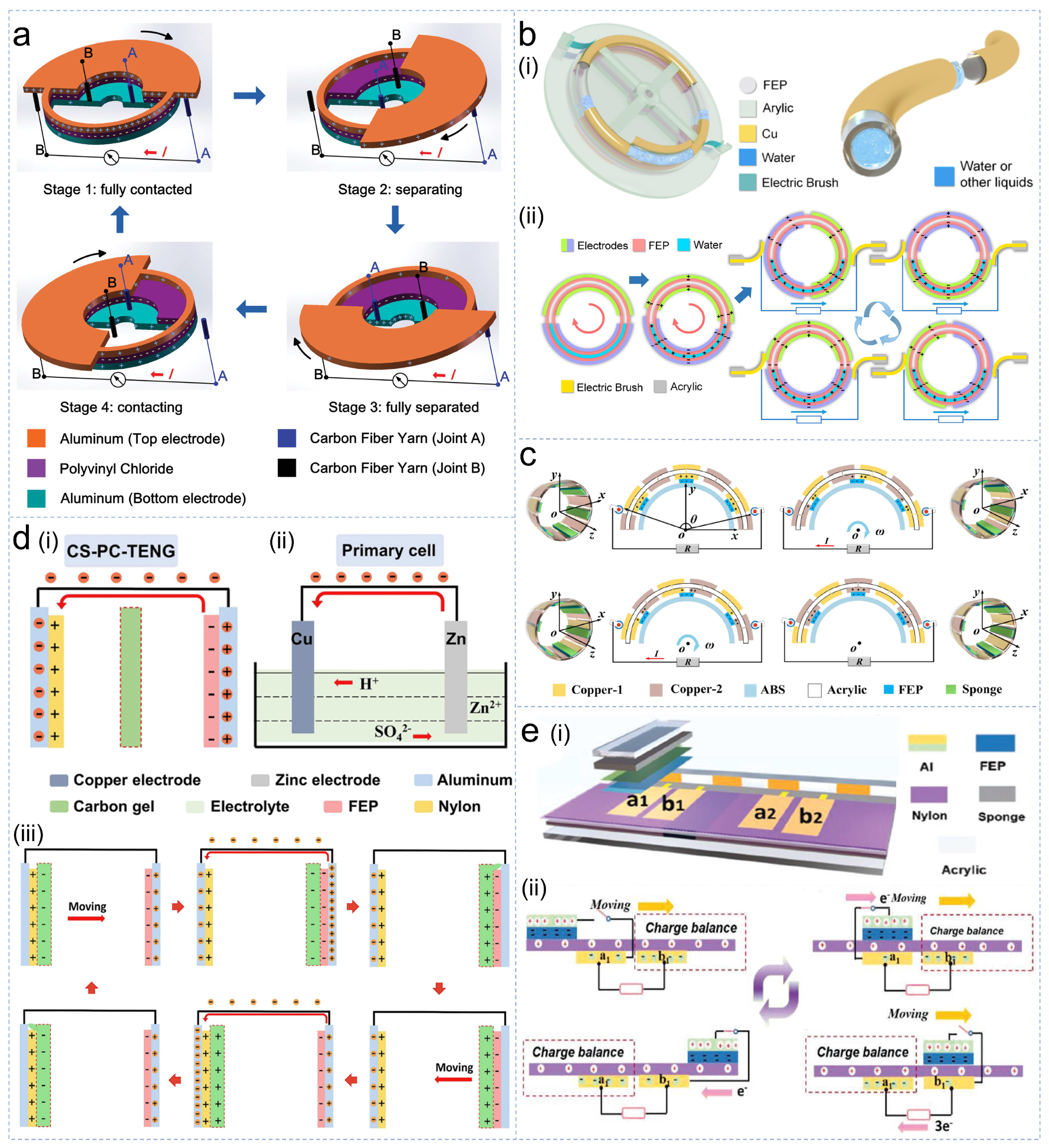
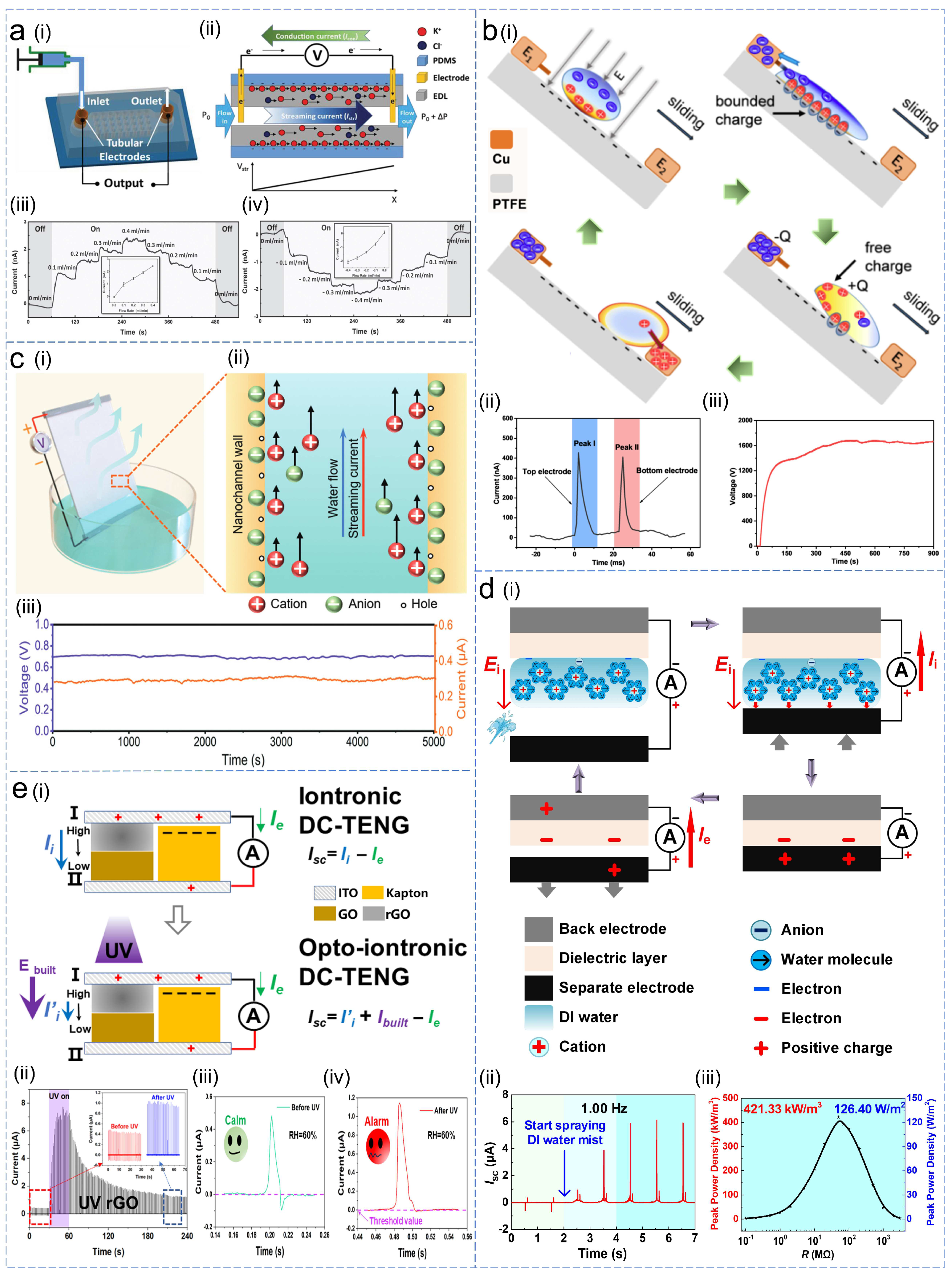
Table 1.
Comparison of the advantages and disadvantages of DC-TENGs based on different types of materials.
Table 1.
Comparison of the advantages and disadvantages of DC-TENGs based on different types of materials.
| Advantages | Disadvantages | |
|---|---|---|
| DC-TENGs based on dielectric materials | higher voltage output | higher internal resistance prone to friction and wear |
| DC-TENGs based on semiconductor materials | higher current density lower internal resistance | prone to friction and wear depletion of space charge |
| DC-TENGs based on materials for iontronic rectifications | free from friction and wear suppletion of surface charge | additional ionic source |
Disclaimer/Publisher’s Note: The statements, opinions and data contained in all publications are solely those of the individual author(s) and contributor(s) and not of MDPI and/or the editor(s). MDPI and/or the editor(s) disclaim responsibility for any injury to people or property resulting from any ideas, methods, instructions or products referred to in the content. |
© 2023 by the authors. Licensee MDPI, Basel, Switzerland. This article is an open access article distributed under the terms and conditions of the Creative Commons Attribution (CC BY) license (https://creativecommons.org/licenses/by/4.0/).
Share and Cite
MDPI and ACS Style
Li, X.; Wei, D.; Wang, Z.L. Direct Current Triboelectric Nanogenerators, a Perspective from Material Selections. Nanoenergy Adv. 2023, 3, 343-375. https://doi.org/10.3390/nanoenergyadv3040018
AMA Style
Li X, Wei D, Wang ZL. Direct Current Triboelectric Nanogenerators, a Perspective from Material Selections. Nanoenergy Advances. 2023; 3(4):343-375. https://doi.org/10.3390/nanoenergyadv3040018
Chicago/Turabian StyleLi, Xiang, Di Wei, and Zhong Lin Wang. 2023. "Direct Current Triboelectric Nanogenerators, a Perspective from Material Selections" Nanoenergy Advances 3, no. 4: 343-375. https://doi.org/10.3390/nanoenergyadv3040018